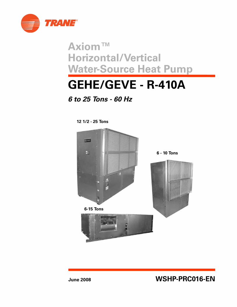
Axiom™ Horizontal/Vertical Water-Source Heat Pump
108
Axiom™ Horizontal/Vertical Water-Source Heat Pump June 2008 WSHP-PRC016-EN GEHE/GEVE - R-410A 6 to 25 Tons - 60 Hz 12 1/2 - 25 Tons 6 - 10 Tons 6-15 Tons
-
Upload
khangminh22 -
Category
Documents
-
view
3 -
download
0
Transcript of Axiom™ Horizontal/Vertical Water-Source Heat Pump
Axiom™ Horizontal/Vertical Water-Source Heat Pump
June 2008 WSHP-PRC016-EN
GEHE/GEVE - R-410A6 to 25 Tons - 60 Hz
12 1/2 - 25 Tons
6 - 10 Tons
6-15 Tons
© 2008 Trane All rights reserved WSHP-PRC016-EN
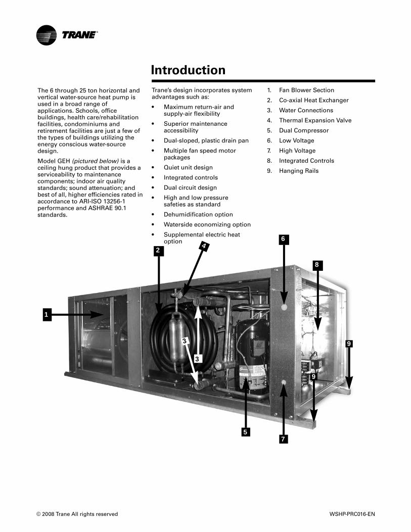
1. Fan Blower Section
2. Co-axial Heat Exchanger
3. Water Connections
4. Thermal Expansion Valve
5. Dual Compressor
6. Low Voltage
7. High Voltage
8. Integrated Controls
9. Hanging Rails
Trane’s design incorporates system advantages such as:
• Maximum return-air andsupply-air flexibility
• Superior maintenanceaccessibility
• Dual-sloped, plastic drain pan
• Multiple fan speed motor packages
• Quiet unit design
• Integrated controls
• Dual circuit design
• High and low pressuresafeties as standard
• Dehumidification option
• Waterside economizing option
• Supplemental electric heat option
The 6 through 25 ton horizontal and vertical water-source heat pump is used in a broad range of applications. Schools, office buildings, health care/rehabilitation facilities, condominiums and retirement facilities are just a few of the types of buildings utilizing the energy conscious water-source design.
Model GEH (pictured below) is a ceiling hung product that provides a serviceability to maintenance components; indoor air quality standards; sound attenuation; and best of all, higher efficiencies rated in accordance to ARI-ISO 13256-1 performance and ASHRAE 90.1 standards.
3
3
57
8
9
9
Introduction
1
24
6
WSHP-PRC016-EN 3
Introduction . . . . . . . . . . . . . . . . . . . . . . . . . . . . . . . . . . . . . . . . . . . . . . . . . . . . . . . 2
Features and Benefits . . . . . . . . . . . . . . . . . . . . . . . . . . . . . . . . . . . . . . . . . . . . . . 4
Application Considerations . . . . . . . . . . . . . . . . . . . . . . . . . . . . . . . . . . . . . . . . . 8
Selection Procedure . . . . . . . . . . . . . . . . . . . . . . . . . . . . . . . . . . . . . . . . . . . . . . .10
Model Number Description . . . . . . . . . . . . . . . . . . . . . . . . . . . . . . . . . . . . . . . . .11
General Data . . . . . . . . . . . . . . . . . . . . . . . . . . . . . . . . . . . . . . . . . . . . . . . . . . . . . .12
Performance Data . . . . . . . . . . . . . . . . . . . . . . . . . . . . . . . . . . . . . . . . . . . . . . . . . .14
Electrical Data . . . . . . . . . . . . . . . . . . . . . . . . . . . . . . . . . . . . . . . . . . . . . . . . . . . . 42
Fan Performance Data . . . . . . . . . . . . . . . . . . . . . . . . . . . . . . . . . . . . . . . . . . . . . 47Waterside Economizer Performance Data . . . . . . . . . . . . . . . . . . . . . . . . . . . . . . 68
Controls . . . . . . . . . . . . . . . . . . . . . . . . . . . . . . . . . . . . . . . . . . . . . . . . . . . . . . . . . 70Deluxe 24V features include: . . . . . . . . . . . . . . . . . . . . . . . . . . . . . . . . . . . . . . . . 71Tracer ZN524 functions include: . . . . . . . . . . . . . . . . . . . . . . . . . . . . . . . . . . . . . . . . . . . . . . . . . 73High and Low Pressure . . . . . . . . . . . . . . . . . . . . . . . . . . . . . . . . . . . . . . . . . . . . 73Control Wiring: Deluxe 24V . . . . . . . . . . . . . . . . . . . . . . . . . . . . . . . . . . . . . . . . . 75Controls Wiring: Tracer ZN524 . . . . . . . . . . . . . . . . . . . . . . . . . . . . . . . . . . . . . . . 76
Dimensional Data . . . . . . . . . . . . . . . . . . . . . . . . . . . . . . . . . . . . . . . . . . . . . . . . . 77
Accessories . . . . . . . . . . . . . . . . . . . . . . . . . . . . . . . . . . . . . . . . . . . . . . . . . . . . . .102
Mechanical Specifications . . . . . . . . . . . . . . . . . . . . . . . . . . . . . . . . . . . . . . . . .105
Table of Contents

4 WSHP-PRC016-EN
Features and Benefits
The four combinations include:
1. Front return-air with back supply-air combination
2. Front return-air with top supply-air combination
3. Back return-air with front supply-air combination
4. Back return-air with top supply-air combination
Figure 1. GEH Airflow Options
Co
ntr
ol B
oxC
on
tro
l Box
Co
ntr
ol B
oxC
on
tro
l Box
LEFT RETURN-AIR
LEFT RETURN-AIR
RIGHT RETURN-AIR
RIGHT RETURN-AIR
BA
CK
SU
PP
LY-A
IR
BA
CK
SU
PP
LY-A
IR
LEFT
SUPPLY-AIR
RIGHT
SUPPLY-AIR
1
2
3
4
Access Panels
The upper panels of the 12 1/2 through 25-ton verticals feature a key hole hanging design for ease of maintenance of the unit, allowing the panel to be hooked into place when attaching the panel to the unit. The panels are also sealed with a rubber gasket at all four edges to help eliminate air from escaping around the panel’s edge.
Figure 2. GEV Airflow Options
FRONT RETURN-AIR
FRONT RETURN-AIR
TOP
SUPPLY
BACK RETURN-AIR
BACK RETURN-AIR
BACK SUPPLY-AIR
FRONT SUPPLY-AIR
TOP
SUPPLY
1
2
3
4
Cabinet Description
The cabinet design incorporates sturdy (non-painted) galvanized metal form maximum durability and corrosive resistive exterior. The equipment offers superior installation flexibility with service accessibility.
The cabinet front allows service access for the controls. The horizontal and vertical design offers four product variations of return-air and supply-air combinations. All combinations are order specific and may not be modified at the job site. See Figure 1, p. 4 for airside combinations.
Hanging the horizontal configuration is accomplished through the robust metal stiffeners located beneath the unit. Optional vibration isolators are available to help decrease sound vibration during equipment operation.
Airflow Combinations
The 6 through 15-ton horizontal’s airflow flexibility includes the following combinations to aid in applications where the equipment is required to hug a corridor or wall.
The four configurations are:
1. Left return-air with back supply-air combination
2. Left return-air with right supply-air combination
3. Right return-air with back supply-air combination
4. Right return-air with left supply-air combination
The sleek, narrow cabinet of the 6 to 25-ton vertical is designed to fit through a standard 36" doorway for installation during new or retrofit construction. The equipment is available in four supply-air/return-air combinations. These combinations are order specific via the unit model number.
Features and Benefits
WSHP-PRC016-EN 5
Features and Benefits
Hanging Device
The hanging channel for the horizontal unit runs the length of the equipment. The structural integrity of the design helps assure no bracket deflection or unit bowing from the unit’s weight.
Optional isolation for the hanging bracket is provided with a rubber grommet design. This isolation device helps prevent sound vibration from reaching the structural support members of the building during compressor start and stop.
Drain Pan
The unit drain pan is composed of plastic, corrosive resistive material. The pan is positively sloped to comply with ASHRAE 62 for (IAQ) indoor air quality conformity.
Access to the drain pan is provided through two access panels for cleaning purposes for all models.
Cabinet Insulation
The cabinet insulation design meets UL 181 requirements. The air stream surface of the insulation is fabricated of a non-biodegradable source.
Refrigeration Piping
The unit’s copper tubing is created from a 99% pure copper formation that conforms to the American Society of Testing (ASTM) B743 for seamless, light-annealed processing.
The unit’s copper refrigeration system is designed to be free from contaminants and conditions such as drilling fragments, dirt, or oil. This excludes the possibility of these contaminants from damaging the compressor motor.
Compressor
Dual circuit designs of the GEH and GEV models feature scroll compressors. The compressors are highly efficient, and incorporate
external vibration isolators and thermal overload protection.
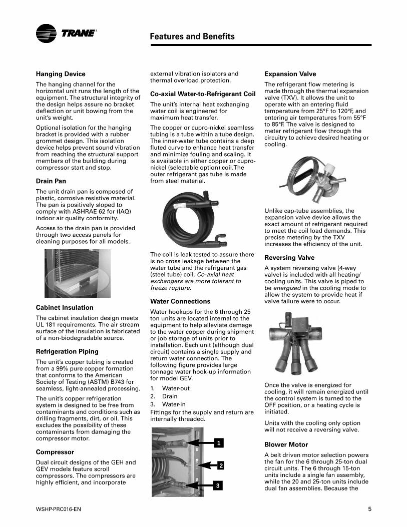
Co-axial Water-to-Refrigerant Coil
The unit’s internal heat exchanging water coil is engineered for maximum heat transfer.
The copper or cupro-nickel seamless tubing is a tube within a tube design. The inner-water tube contains a deep fluted curve to enhance heat transfer and minimize fouling and scaling. It is available in either copper or cupro-nickel (selectable option) coil.The outer refrigerant gas tube is made from steel material.
The coil is leak tested to assure there is no cross leakage between the water tube and the refrigerant gas (steel tube) coil. Co-axial heat exchangers are more tolerant to freeze rupture.
Water Connections
Water hookups for the 6 through 25 ton units are located internal to the equipment to help alleviate damage to the water copper during shipment or job storage of units prior to installation. Each unit (although dual circuit) contains a single supply and return water connection. The following figure provides large tonnage water hook-up information for model GEV.
1. Water-out2. Drain3. Water-inFittings for the supply and return are internally threaded.
1
3
2
Expansion Valve
The refrigerant flow metering is made through the thermal expansion valve (TXV). It allows the unit to operate with an entering fluid temperature from 25°F to 120°F, and entering air temperatures from 55°F to 85°F. The valve is designed to meter refrigerant flow through the circuitry to achieve desired heating or cooling.
Unlike cap-tube assemblies, the expansion valve device allows the exact amount of refrigerant required to meet the coil load demands. This precise metering by the TXV increases the efficiency of the unit.
Reversing Valve
A system reversing valve (4-way valve) is included with all heating/cooling units. This valve is piped to be energized in the cooling mode to allow the system to provide heat if valve failure were to occur.
Once the valve is energized for cooling, it will remain energized until the control system is turned to the OFF position, or a heating cycle is initiated.
Units with the cooling only option will not receive a reversing valve.
Blower Motor
A belt driven motor selection powers the fan for the 6 through 25-ton dual circuit units. The 6 through 15-ton units include a single fan assembly, while the 20 and 25-ton units include dual fan assemblies. Because the
6 WSHP-PRC016-EN
Features and Benefits
motor sheave and the motor base are adjustable in the field, a greater variation in external static pressures are available. The large tonnage units are capable of providing 0 ESP to 3.0 ESP allowing a higher static ductwork to be applied on the mechanical system when the application requires extensive ductwork design. This is a low cost alternative to purchasing, installing, and maintaining multiple smaller tonnage units to meet the required air flow demand for the space.
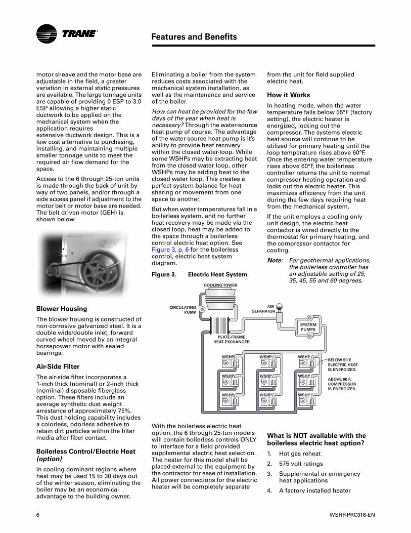
Access to the 6 through 25-ton units is made through the back of unit by way of two panels, and/or through a side access panel if adjustment to the motor belt or motor base are needed. The belt driven motor (GEH) is shown below.
Blower Housing
The blower housing is constructed of non-corrosive galvanized steel. It is a double wide/double inlet, forward curved wheel moved by an integral horsepower motor with sealed bearings.
Air-Side Filter
The air-side filter incorporates a 1-inch thick (nominal) or 2-inch thick (nominal) disposable fiberglass option. These filters include an average synthetic dust weight arrestance of approximately 75%. This dust holding capability includes a colorless, odorless adhesive to retain dirt particles within the filter media after fiber contact.
Boilerless Control/Electric Heat (option)
In cooling dominant regions where heat may be used 15 to 30 days out of the winter season, eliminating the boiler may be an economical advantage to the building owner.
Eliminating a boiler from the system reduces costs associated with the mechanical system installation, as well as the maintenance and service of the boiler.
How can heat be provided for the few days of the year when heat is necessary? Through the water-source heat pump of course. The advantage of the water-source heat pump is it’s ability to provide heat recovery within the closed water-loop. While some WSHPs may be extracting heat from the closed water loop, other WSHPs may be adding heat to the closed water loop. This creates a perfect system balance for heat sharing or movement from one space to another.
But when water temperatures fall in a boilerless system, and no further heat recovery may be made via the closed loop, heat may be added to the space through a boilerless control electric heat option. See Figure 3, p. 6 for the boilerless control, electric heat system diagram.
With the boilerless electric heat option, the 6 through 25-ton models will contain boilerless controls ONLY to interface for a field provided supplemental electric heat selection. The heater for this model shall be placed external to the equipment by the contractor for ease of installation. All power connections for the electric heater will be completely separate
Figure 3. Electric Heat System
WSHP
WSHP
WSHP
WSHP
WSHP
WSHP
WSHP
WSHP
WSHP
PLATE-FRAME
HEAT EXCHANGER
BELOW 50 F,
ELECTRIC HEAT
IS ENERGIZED.
ABOVE 60 F,
COMPRESSOR
IS ENERGIZED.
CIRCULATING
PUMP
COOLING TOWER
AIR
SEPARATOR
SYSTEM
PUMPS
from the unit for field supplied electric heat.
How it Works
In heating mode, when the water temperature falls below 55°F (factory setting), the electric heater is energized, locking out the compressor. The systems electric heat source will continue to be utilized for primary heating until the loop temperature rises above 60°F. Once the entering water temperature rises above 60°F, the boilerless controller returns the unit to normal compressor heating operation and locks out the electric heater. This maximizes efficiency from the unit during the few days requiring heat from the mechanical system.
If the unit employs a cooling only unit design, the electric heat contactor is wired directly to the thermostat for primary heating, and the compressor contactor for cooling.
Note: For geothermal applications, the boilerless controller has an adjustable setting of 25, 35, 45, 55 and 60 degrees.
What is NOT available with the boilerless electric heat option?
1. Hot gas reheat
2. 575 volt ratings
3. Supplemental or emergency heat applications
4. A factory installed heater
WSHP-PRC016-EN 7
Features and Benefits
Waterside Economizer (option)
The beauty of the waterside economizer is it’s ability to take advantage of any loop condition that results in cool water temperatures. A prime example would be during fall, winter and spring when cooling towers have more capacity than required and could be controlled to lower temperatures for economizer support.
Another more common inexpensive means of free comfort cooling includes buildings systems where perimeter heating and core cooling are needed. In this system, the perimeter units extract heat from the building loop while in the heating mode, forcing the building loop temperature to drop. Where as, the core are of a building may require cooling in summer or in winter based upon lighting, people and equipment.
If the water-source system design contained an economizing coil option, the moderate temperature loop water circulated through a core water-source system can provide an inexpensive means to satisfy room comfort without operating the water-source heat pump’s compressor.
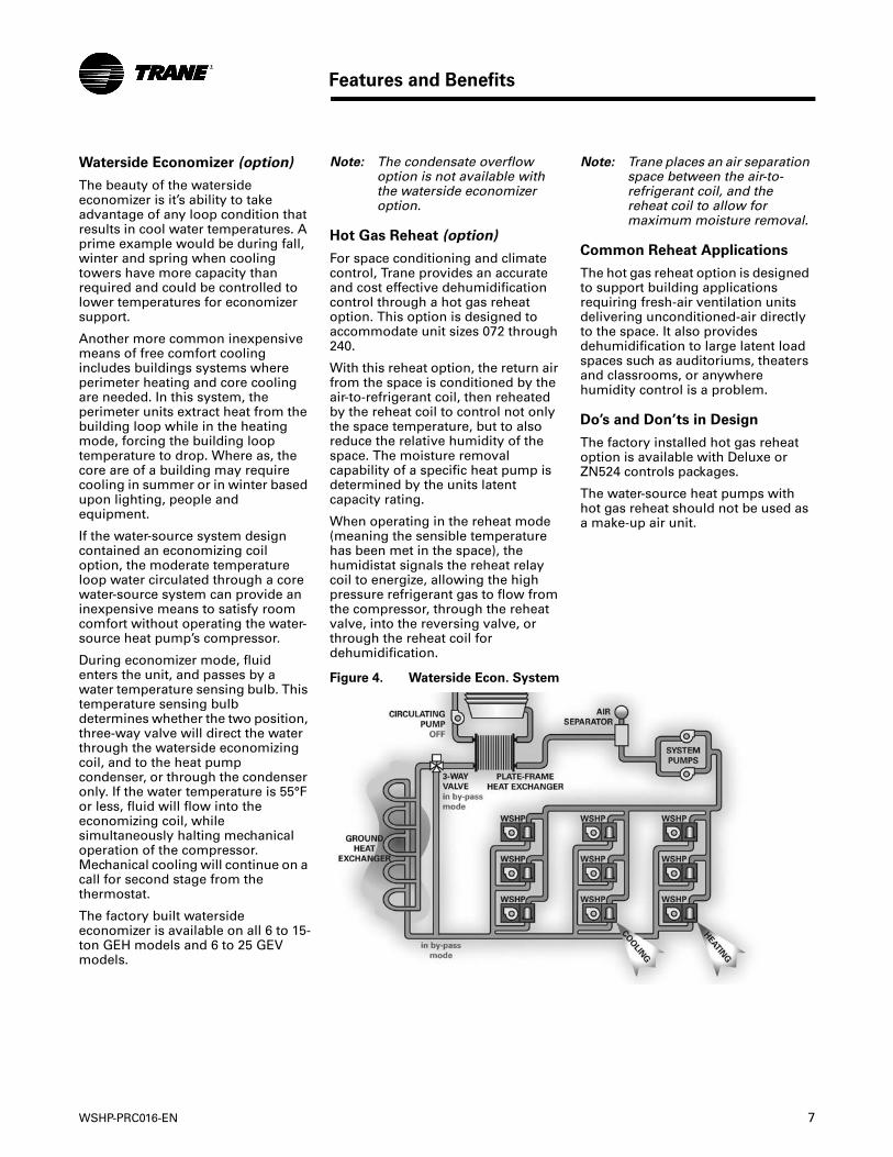
During economizer mode, fluid enters the unit, and passes by a water temperature sensing bulb. This temperature sensing bulb determines whether the two position, three-way valve will direct the water through the waterside economizing coil, and to the heat pump condenser, or through the condenser only. If the water temperature is 55°F or less, fluid will flow into the economizing coil, while simultaneously halting mechanical operation of the compressor. Mechanical cooling will continue on a call for second stage from the thermostat.
The factory built waterside economizer is available on all 6 to 15-ton GEH models and 6 to 25 GEV models.
Note: The condensate overflow option is not available with the waterside economizer option.
Hot Gas Reheat (option)
For space conditioning and climate control, Trane provides an accurate and cost effective dehumidification control through a hot gas reheat option. This option is designed to accommodate unit sizes 072 through 240.
With this reheat option, the return air from the space is conditioned by the air-to-refrigerant coil, then reheated by the reheat coil to control not only the space temperature, but to also reduce the relative humidity of the space. The moisture removal capability of a specific heat pump is determined by the units latent capacity rating.
When operating in the reheat mode (meaning the sensible temperature has been met in the space), the humidistat signals the reheat relay coil to energize, allowing the high pressure refrigerant gas to flow from the compressor, through the reheat valve, into the reversing valve, or through the reheat coil for dehumidification.
Figure 4. Waterside Econ. System
Note: Trane places an air separation space between the air-to-refrigerant coil, and the reheat coil to allow for maximum moisture removal.
Common Reheat Applications
The hot gas reheat option is designed to support building applications requiring fresh-air ventilation units delivering unconditioned-air directly to the space. It also provides dehumidification to large latent load spaces such as auditoriums, theaters and classrooms, or anywhere humidity control is a problem.
Do’s and Don’ts in Design
The factory installed hot gas reheat option is available with Deluxe or ZN524 controls packages.
The water-source heat pumps with hot gas reheat should not be used as a make-up air unit.
8 WSHP-PRC016-EN
Application Considerations
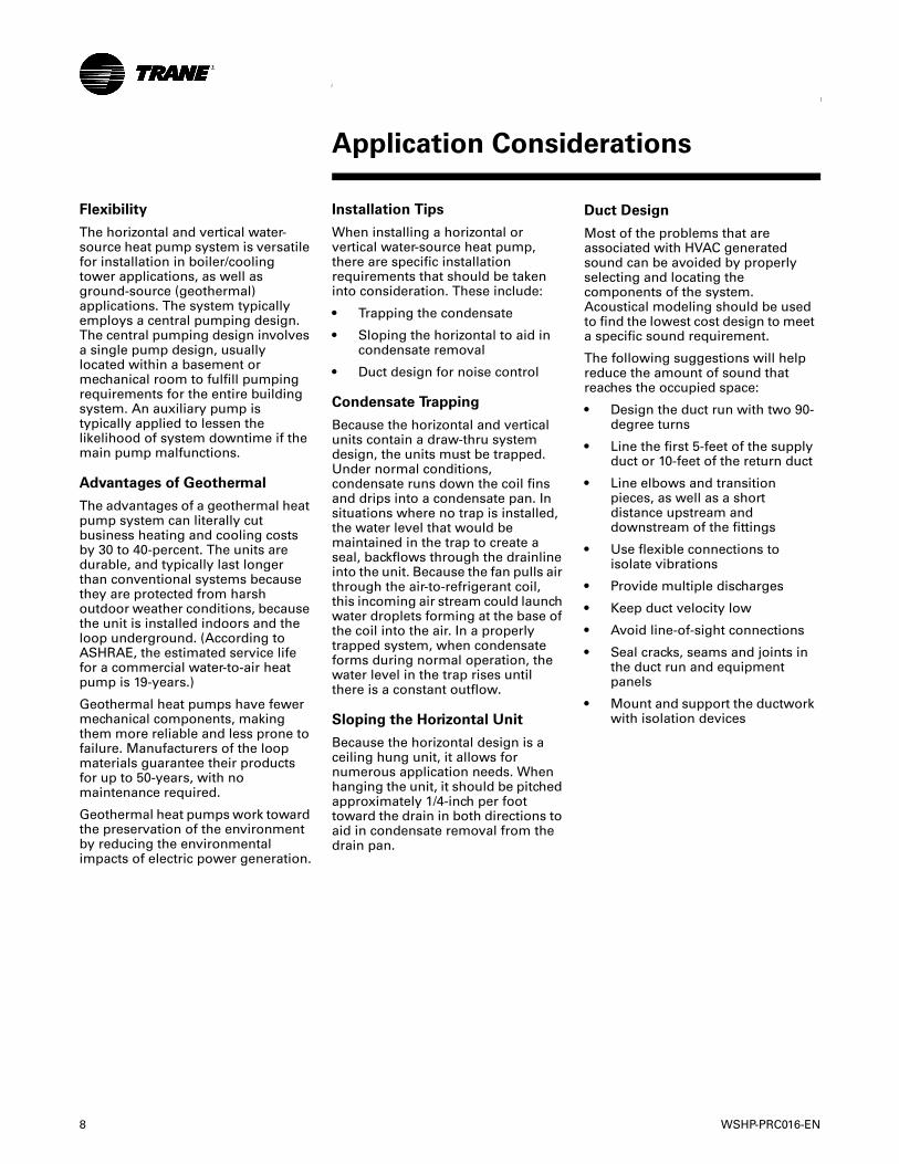
Flexibility
The horizontal and vertical water-source heat pump system is versatile for installation in boiler/cooling tower applications, as well as ground-source (geothermal) applications. The system typically employs a central pumping design. The central pumping design involves a single pump design, usually located within a basement or mechanical room to fulfill pumping requirements for the entire building system. An auxiliary pump is typically applied to lessen the likelihood of system downtime if the main pump malfunctions.
Advantages of Geothermal
The advantages of a geothermal heat pump system can literally cut business heating and cooling costs by 30 to 40-percent. The units are durable, and typically last longer than conventional systems because they are protected from harsh outdoor weather conditions, because the unit is installed indoors and the loop underground. (According to ASHRAE, the estimated service life for a commercial water-to-air heat pump is 19-years.)
Geothermal heat pumps have fewer mechanical components, making them more reliable and less prone to failure. Manufacturers of the loop materials guarantee their products for up to 50-years, with no maintenance required.
Geothermal heat pumps work toward the preservation of the environment by reducing the environmental impacts of electric power generation.
Installation Tips
When installing a horizontal or vertical water-source heat pump, there are specific installation requirements that should be taken into consideration. These include:
• Trapping the condensate
• Sloping the horizontal to aid in condensate removal
• Duct design for noise control
Condensate Trapping
Because the horizontal and vertical units contain a draw-thru system design, the units must be trapped. Under normal conditions, condensate runs down the coil fins and drips into a condensate pan. In situations where no trap is installed, the water level that would be maintained in the trap to create a seal, backflows through the drainline into the unit. Because the fan pulls air through the air-to-refrigerant coil, this incoming air stream could launch water droplets forming at the base of the coil into the air. In a properly trapped system, when condensate forms during normal operation, the water level in the trap rises until there is a constant outflow.
Sloping the Horizontal Unit
Because the horizontal design is a ceiling hung unit, it allows for numerous application needs. When hanging the unit, it should be pitched approximately 1/4-inch per foot toward the drain in both directions to aid in condensate removal from the drain pan.
Duct Design
Most of the problems that are associated with HVAC generated sound can be avoided by properly selecting and locating the components of the system. Acoustical modeling should be used to find the lowest cost design to meet a specific sound requirement.
The following suggestions will help reduce the amount of sound that reaches the occupied space:
• Design the duct run with two 90-degree turns
• Line the first 5-feet of the supply duct or 10-feet of the return duct
• Line elbows and transition pieces, as well as a short distance upstream and downstream of the fittings
• Use flexible connections to isolate vibrations
• Provide multiple discharges
• Keep duct velocity low
• Avoid line-of-sight connections
• Seal cracks, seams and joints in the duct run and equipment panels
• Mount and support the ductwork with isolation devices
Application Considerations

WSHP-PRC016-EN 9
Application Considerations
Types of Applications
In systems that use a boiler/cooling tower design, water pumps are placed between the auxiliary equipment (boiler, cooling tower, etc.) and the WSHPs to ensure positive water pressure throughout the system. Through this placement, the pump is able to pressurize the piping that serves the units, allowing the regulated makeup water to pressurize the pump section.
With this application, the cooling tower is used to dissipate heat from the condensing process. The condensing water is cooled for recirculation back to the water-to-refrigerant heat exchanger by using a combination of heat and mass transfer by evaporation. The type of cooling tower chosen for the application may include an open-circuit cooling tower with a gasket-plate heat exchanger to close the loop, or a closed-circuit fluid cooler design.
Hybrid Systems
Some systems have evolved into a hybrid (combination) system due to building additions/phases or new requirements.
A hybrid system may have began with a geothermal ground loop heat exchanger used to extract or add heat to the building. As additional rooms or buildings were added onto the system, the ground loop design became undersized for the new demand. A cooling tower may be the solution to off-load the peak demand of the new building addition. This may be an inexpensive means of tempering the loop to it’s appropriate working conditions. The cooling tower may be used in conjunction with the loop to lower loop temperatures during off-peak hours (at night) to support the peak load of the loop during the day.
Other additions may include a requirement for fresh-air ventilation. A fresh-air, air handler, along with a chiller may be introduced to the closed loop system to allow tempered fresh-air into the building.
The buildings heating and cooling needs are not based off of one type of component, but perform harmonious of each other. Because the loop is closed, heat recovery from
the loop itself can be shared with the other major components.
The heat pumps are capable of heating or cooling a space independent of one another to provide individual heating and cooling needs.
A hybrid system should be considered on existing building design when an offset of cooling energy is a requirement.
Figure 5. Hybrid System
AIR
HANDLER
WSHP
WSHP
WSHP
WSHP
WSHP
WSHP
GROUND
HEAT
EXCHANGER
PLATE-FRAME
HEAT EXCHANGER
CIRCULATING
PUMP
COOLING TOWER
AIR
SEPARATOR
SYSTEM
PUMPS
Hybrid Systems
10 WSHP-PRC016-EN
Selection Procedure
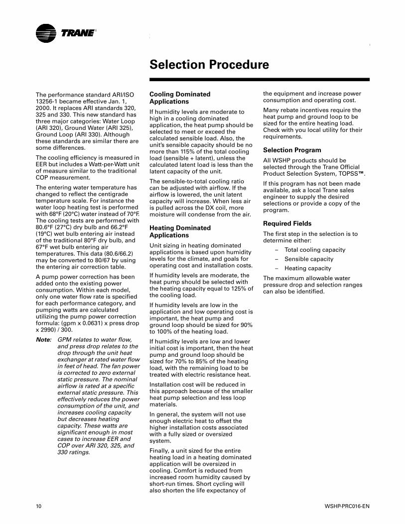
The performance standard ARI/ISO 13256-1 became effective Jan. 1, 2000. It replaces ARI standards 320, 325 and 330. This new standard has three major categories: Water Loop (ARI 320), Ground Water (ARI 325), Ground Loop (ARI 330). Although these standards are similar there are some differences.
The cooling efficiency is measured in EER but includes a Watt-per-Watt unit of measure similar to the traditional COP measurement.
The entering water temperature has changed to reflect the centigrade temperature scale. For instance the water loop heating test is performed with 68°F (20°C) water instead of 70°F. The cooling tests are performed with 80.6°F (27°C) dry bulb and 66.2°F (19°C) wet bulb entering air instead of the traditional 80°F dry bulb, and 67°F wet bulb entering air temperatures. This data (80.6/66.2) may be converted to 80/67 by using the entering air correction table.
A pump power correction has been added onto the existing power consumption. Within each model, only one water flow rate is specified for each performance category, and pumping watts are calculated utilizing the pump power correction formula: (gpm x 0.0631) x press drop x 2990) / 300.
Note: GPM relates to water flow, and press drop relates to the drop through the unit heat exchanger at rated water flow in feet of head. The fan power is corrected to zero external static pressure. The nominal airflow is rated at a specific external static pressure. This effectively reduces the power consumption of the unit, and increases cooling capacity but decreases heating capacity. These watts are significant enough in most cases to increase EER and COP over ARI 320, 325, and 330 ratings.
Cooling Dominated Applications
If humidity levels are moderate to high in a cooling dominated application, the heat pump should be selected to meet or exceed the calculated sensible load. Also, the unit’s sensible capacity should be no more than 115% of the total cooling load (sensible + latent), unless the calculated latent load is less than the latent capacity of the unit.
The sensible-to-total cooling ratio can be adjusted with airflow. If the airflow is lowered, the unit latent capacity will increase. When less air is pulled across the DX coil, more moisture will condense from the air.
Heating DominatedApplications
Unit sizing in heating dominated applications is based upon humidity levels for the climate, and goals for operating cost and installation costs.
If humidity levels are moderate, the heat pump should be selected with the heating capacity equal to 125% of the cooling load.
If humidity levels are low in the application and low operating cost is important, the heat pump and ground loop should be sized for 90% to 100% of the heating load.
If humidity levels are low and lower initial cost is important, then the heat pump and ground loop should be sized for 70% to 85% of the heating load, with the remaining load to be treated with electric resistance heat.
Installation cost will be reduced in this approach because of the smaller heat pump selection and less loop materials.
In general, the system will not use enough electric heat to offset the higher installation costs associated with a fully sized or oversized system.
Finally, a unit sized for the entire heating load in a heating dominated application will be oversized in cooling. Comfort is reduced from increased room humidity caused by short-run times. Short cycling will also shorten the life expectancy of
the equipment and increase power consumption and operating cost.
Many rebate incentives require the heat pump and ground loop to be sized for the entire heating load. Check with you local utility for their requirements.
Selection Program
All WSHP products should be selected through the Trane Official Product Selection System, TOPSS™.
If this program has not been made available, ask a local Trane sales engineer to supply the desired selections or provide a copy of the program.
Required Fields
The first step in the selection is to determine either:
– Total cooling capacity
– Sensible capacity
– Heating capacity
The maximum allowable water pressure drop and selection ranges can also be identified.
Selection Procedure
WSHP-PRC016-EN 11
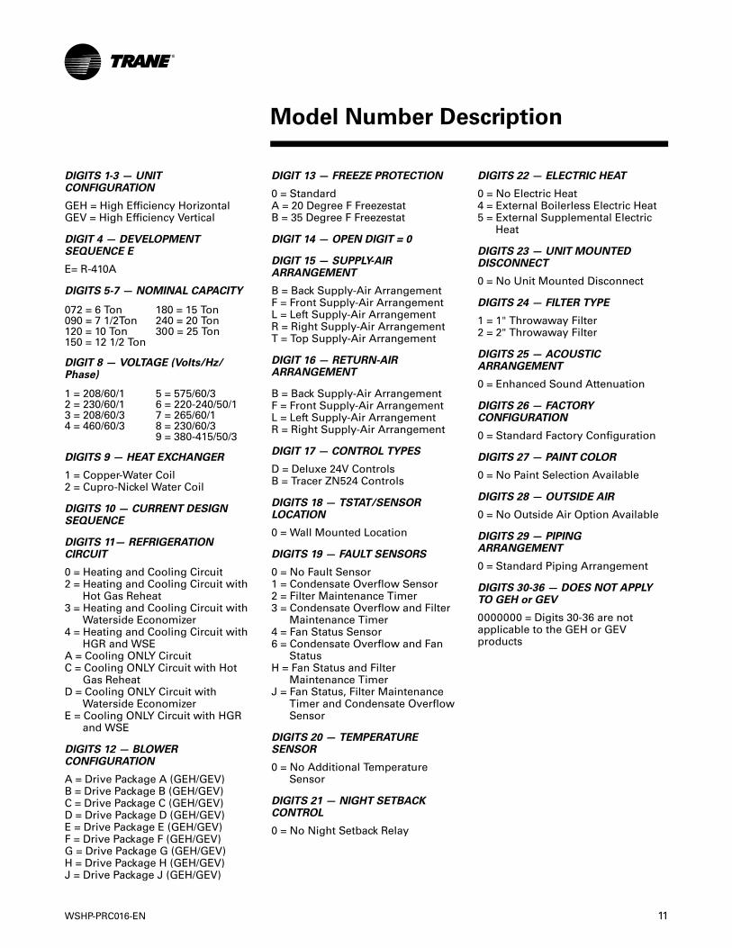
DIGITS 1-3 — UNIT CONFIGURATION
GEH = High Efficiency HorizontalGEV = High Efficiency Vertical
DIGIT 4 — DEVELOPMENT SEQUENCE E
E= R-410A
DIGITS 5-7 — NOMINAL CAPACITY
DIGIT 8 — VOLTAGE (Volts/Hz/Phase)
DIGITS 9 — HEAT EXCHANGER
1 = Copper-Water Coil2 = Cupro-Nickel Water Coil
DIGITS 10 — CURRENT DESIGN SEQUENCE
DIGITS 11— REFRIGERATION CIRCUIT
0 = Heating and Cooling Circuit2 = Heating and Cooling Circuit with
Hot Gas Reheat3 = Heating and Cooling Circuit with
Waterside Economizer4 = Heating and Cooling Circuit with
HGR and WSEA = Cooling ONLY CircuitC = Cooling ONLY Circuit with Hot
Gas ReheatD = Cooling ONLY Circuit with
Waterside EconomizerE = Cooling ONLY Circuit with HGR
and WSE
DIGITS 12 — BLOWER CONFIGURATION
A = Drive Package A (GEH/GEV)B = Drive Package B (GEH/GEV)C = Drive Package C (GEH/GEV)D = Drive Package D (GEH/GEV)E = Drive Package E (GEH/GEV)F = Drive Package F (GEH/GEV)G = Drive Package G (GEH/GEV)H = Drive Package H (GEH/GEV)J = Drive Package J (GEH/GEV)
072 = 6 Ton 180 = 15 Ton090 = 7 1/2Ton 240 = 20 Ton120 = 10 Ton 300 = 25 Ton150 = 12 1/2 Ton
1 = 208/60/1 5 = 575/60/32 = 230/60/1 6 = 220-240/50/13 = 208/60/3 7 = 265/60/14 = 460/60/3 8 = 230/60/3
9 = 380-415/50/3
DIGIT 13 — FREEZE PROTECTION
0 = StandardA = 20 Degree F FreezestatB = 35 Degree F Freezestat
DIGIT 14 — OPEN DIGIT = 0
DIGIT 15 — SUPPLY-AIR ARRANGEMENT
B = Back Supply-Air ArrangementF = Front Supply-Air ArrangementL = Left Supply-Air ArrangementR = Right Supply-Air ArrangementT = Top Supply-Air Arrangement
DIGIT 16 — RETURN-AIR ARRANGEMENT
B = Back Supply-Air ArrangementF = Front Supply-Air ArrangementL = Left Supply-Air ArrangementR = Right Supply-Air Arrangement
DIGIT 17 — CONTROL TYPES
D = Deluxe 24V ControlsB = Tracer ZN524 Controls
DIGITS 18 — TSTAT/SENSORLOCATION
0 = Wall Mounted Location
DIGITS 19 — FAULT SENSORS
0 = No Fault Sensor1 = Condensate Overflow Sensor2 = Filter Maintenance Timer3 = Condensate Overflow and Filter
Maintenance Timer4 = Fan Status Sensor6 = Condensate Overflow and Fan
StatusH = Fan Status and Filter
Maintenance TimerJ = Fan Status, Filter Maintenance
Timer and Condensate OverflowSensor
DIGITS 20 — TEMPERATURE SENSOR
0 = No Additional TemperatureSensor
DIGITS 21 — NIGHT SETBACK CONTROL
0 = No Night Setback Relay
DIGITS 22 — ELECTRIC HEAT
0 = No Electric Heat4 = External Boilerless Electric Heat5 = External Supplemental Electric
Heat
DIGITS 23 — UNIT MOUNTED DISCONNECT
0 = No Unit Mounted Disconnect
DIGITS 24 — FILTER TYPE
1 = 1" Throwaway Filter2 = 2" Throwaway Filter
DIGITS 25 — ACOUSTIC ARRANGEMENT
0 = Enhanced Sound Attenuation
DIGITS 26 — FACTORY CONFIGURATION
0 = Standard Factory Configuration
DIGITS 27 — PAINT COLOR
0 = No Paint Selection Available
DIGITS 28 — OUTSIDE AIR
0 = No Outside Air Option Available
DIGITS 29 — PIPING ARRANGEMENT
0 = Standard Piping Arrangement
DIGITS 30-36 — DOES NOT APPLY TO GEH or GEV
0000000 = Digits 30-36 are not applicable to the GEH or GEV products
Model Number Description
12 WSHP-PRC016-EN
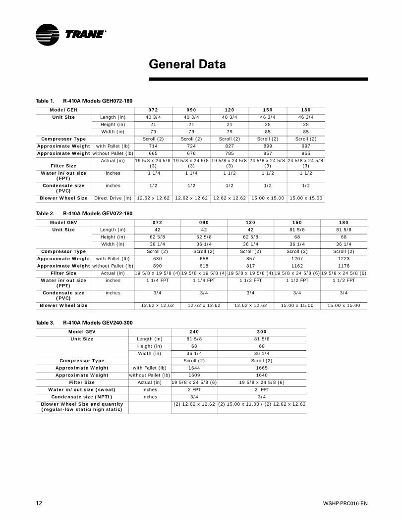
General Data
Table 1. R-410A Models GEH072-180
Model GEH 072 090 120 150 180
Unit Size Length (in) 40 3/4 40 3/4 40 3/4 46 3/4 46 3/4
Height (in) 21 21 21 28 28
Width (in) 79 79 79 85 85
Compressor Type Scroll (2) Scroll (2) Scroll (2) Scroll (2) Scroll (2)
Approximate Weight with Pallet (lb) 714 724 827 899 997
Approximate Weight without Pallet (lb) 665 676 785 857 955
Filter SizeActual (in) 19 5/8 x 24 5/8
(3)19 5/8 x 24 5/8
(3)19 5/8 x 24 5/8
(3)24 5/8 x 24 5/8
(3)24 5/8 x 24 5/8
(3)
Water in/out size (FPT)
inches 1 1/4 1 1/4 1 1/2 1 1/2 1 1/2
Condensate size (PVC)
inches 1/2 1/2 1/2 1/2 1/2
Blower Wheel Size Direct Drive (in) 12.62 x 12.62 12.62 x 12.62 12.62 x 12.62 15.00 x 15.00 15.00 x 15.00
Table 2. R-410A Models GEV072-180
Model GEV 072 090 120 150 180
Unit Size Length (in) 42 42 42 81 5/8 81 5/8
Height (in) 62 5/8 62 5/8 62 5/8 68 68
Width (in) 36 1/4 36 1/4 36 1/4 36 1/4 36 1/4
Compressor Type Scroll (2) Scroll (2) Scroll (2) Scroll (2) Scroll (2)
Approximate Weight with Pallet (lb) 630 658 857 1207 1223
Approximate Weight without Pallet (lb) 890 618 817 1162 1178
Filter Size Actual (in) 19 5/8 x 19 5/8 (4) 19 5/8 x 19 5/8 (4) 19 5/8 x 19 5/8 (4) 19 5/8 x 24 5/8 (6) 19 5/8 x 24 5/8 (6)
Water in/out size (FPT)
inches 1 1/4 FPT 1 1/4 FPT 1 1/2 FPT 1 1/2 FPT 1 1/2 FPT
Condensate size (PVC)
inches 3/4 3/4 3/4 3/4 3/4
Blower Wheel Size 12.62 x 12.62 12.62 x 12.62 12.62 x 12.62 15.00 x 15.00 15.00 x 15.00
Table 3. R-410A Models GEV240-300
Model GEV 240 300
Unit Size Length (in) 81 5/8 81 5/8
Height (in) 68 68
Width (in) 36 1/4 36 1/4
Compressor Type Scroll (2) Scroll (2)
Approximate Weight with Pallet (lb) 1644 1665
Approximate Weight without Pallet (lb) 1609 1640
Filter Size Actual (in) 19 5/8 x 24 5/8 (6) 19 5/8 x 24 5/8 (6)
Water in/out size (sweat) inches 2 FPT 2 FPT
Condensate size (NPTI) inches 3/4 3/4
Blower Wheel Size and quantity (regular-low static/high static)
(2) 12.62 x 12.62 (2) 15.00 x 11.00 / (2) 12.62 x 12.62
WSHP-PRC016-EN 13
General Data
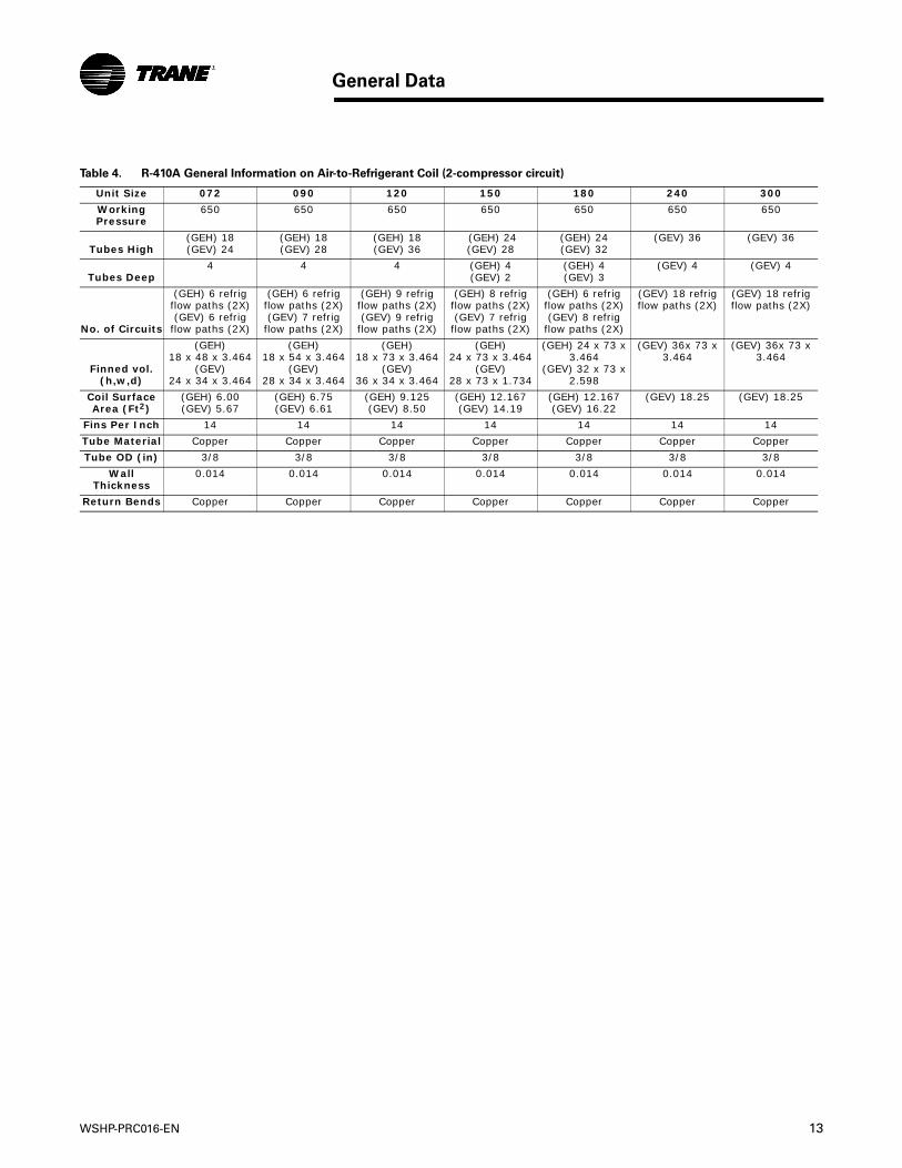
Table 4. R-410A General Information on Air-to-Refrigerant Coil (2-compressor circuit)
Unit Size 072 090 120 150 180 240 300
Working Pressure
650 650 650 650 650 650 650
Tubes High(GEH) 18 (GEV) 24
(GEH) 18 (GEV) 28
(GEH) 18 (GEV) 36
(GEH) 24(GEV) 28
(GEH) 24 (GEV) 32
(GEV) 36 (GEV) 36
Tubes Deep4 4 4 (GEH) 4
(GEV) 2 (GEH) 4 (GEV) 3
(GEV) 4 (GEV) 4
No. of Circuits
(GEH) 6 refrig flow paths (2X)(GEV) 6 refrig
flow paths (2X)
(GEH) 6 refrig flow paths (2X)(GEV) 7 refrig
flow paths (2X)
(GEH) 9 refrig flow paths (2X)(GEV) 9 refrig
flow paths (2X)
(GEH) 8 refrig flow paths (2X)(GEV) 7 refrig
flow paths (2X)
(GEH) 6 refrig flow paths (2X)(GEV) 8 refrig
flow paths (2X)
(GEV) 18 refrig flow paths (2X)
(GEV) 18 refrig flow paths (2X)
Finned vol. (h,w,d)
(GEH)18 x 48 x 3.464
(GEV)24 x 34 x 3.464
(GEH)18 x 54 x 3.464
(GEV)28 x 34 x 3.464
(GEH) 18 x 73 x 3.464
(GEV)36 x 34 x 3.464
(GEH) 24 x 73 x 3.464
(GEV)28 x 73 x 1.734
(GEH) 24 x 73 x 3.464
(GEV) 32 x 73 x 2.598
(GEV) 36x 73 x 3.464
(GEV) 36x 73 x 3.464
Coil Surface Area (Ft2)
(GEH) 6.00 (GEV) 5.67
(GEH) 6.75 (GEV) 6.61
(GEH) 9.125 (GEV) 8.50
(GEH) 12.167 (GEV) 14.19
(GEH) 12.167 (GEV) 16.22
(GEV) 18.25 (GEV) 18.25
Fins Per Inch 14 14 14 14 14 14 14
Tube Material Copper Copper Copper Copper Copper Copper Copper
Tube OD (in) 3/8 3/8 3/8 3/8 3/8 3/8 3/8
Wall Thickness
0.014 0.014 0.014 0.014 0.014 0.014 0.014
Return Bends Copper Copper Copper Copper Copper Copper Copper
14 WSHP-PRC016-EN
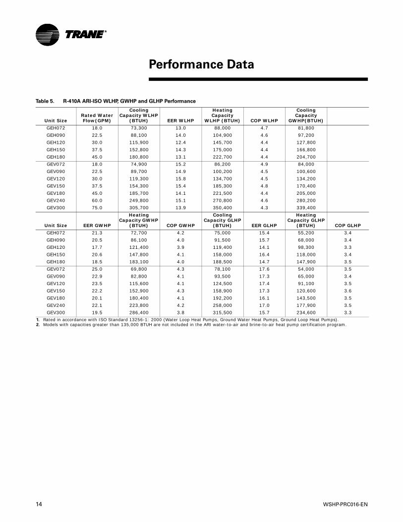
Table 5. R-410A ARI-ISO WLHP, GWHP and GLHP Performance
Unit SizeRated WaterFlow(GPM)
Cooling Capacity WLHP
(BTUH) EER WLHP
Heating Capacity
WLHP (BTUH) COP WLHP
CoolingCapacity
GWHP(BTUH)
GEH072 18.0 73,300 13.0 88,000 4.7 81,800
GEH090 22.5 88,100 14.0 104,900 4.6 97,200
GEH120 30.0 115,900 12.4 145,700 4.4 127,800
GEH150 37.5 152,800 14.3 175,000 4.4 166,800
GEH180 45.0 180,800 13.1 222,700 4.4 204,700
GEV072 18.0 74,900 15.2 86,200 4.9 84,000
GEV090 22.5 89,700 14.9 100,200 4.5 100,600
GEV120 30.0 119,300 15.8 134,700 4.5 134,200
GEV150 37.5 154,300 15.4 185,300 4.8 170,400
GEV180 45.0 185,700 14.1 221,500 4.4 205,000
GEV240 60.0 249,800 15.1 270,800 4.6 280,200
GEV300 75.0 305,700 13.9 350,400 4.3 339,400
Unit Size EER GWHP
Heating Capacity GWHP
(BTUH) COP GWHP
Cooling Capacity GLHP
(BTUH) EER GLHP
Heating Capacity GLHP
(BTUH) COP GLHP
GEH072 21.3 72,700 4.2 75,000 15.4 55,200 3.4
GEH090 20.5 86,100 4.0 91,500 15.7 68,000 3.4
GEH120 17.7 121,400 3.9 119,400 14.1 98,300 3.3
GEH150 20.6 147,800 4.1 158,000 16.4 118,000 3.4
GEH180 18.5 183,100 4.0 188,500 14.7 147,900 3.5
GEV072 25.0 69,800 4.3 78,100 17.6 54,000 3.5
GEV090 22.9 82,800 4.1 93,500 17.3 65,000 3.4
GEV120 23.5 115,600 4.1 124,500 17.4 91,100 3.5
GEV150 22.2 152,900 4.3 158,900 17.3 120,600 3.6
GEV180 20.1 180,400 4.1 192,200 16.1 143,500 3.5
GEV240 22.1 223,800 4.2 258,000 17.0 177,900 3.5
GEV300 19.5 286,400 3.8 315,500 15.7 234,600 3.3
1. Rated in accordance with ISO Standard 13256-1: 2000 (Water Loop Heat Pumps, Ground Water Heat Pumps, Ground Loop Heat Pumps).2. Models with capacities greater than 135,000 BTUH are not included in the ARI water-to-air and brine-to-air heat pump certification program.
Performance Data
WSHP-PRC016-EN 15
Performance Data
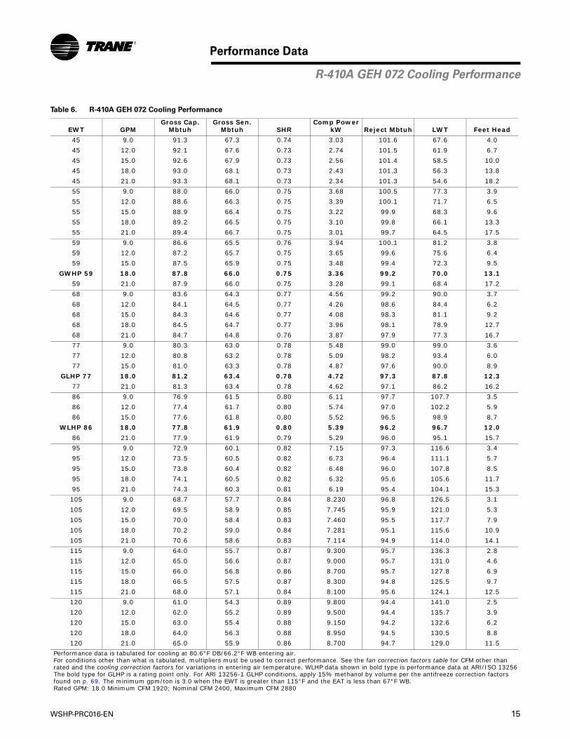
Table 6. R-410A GEH 072 Cooling Performance
EWT GPMGross Cap.
MbtuhGross Sen.
Mbtuh SHRComp Power
kW Reject Mbtuh LWT Feet Head
45 9.0 91.3 67.3 0.74 3.03 101.6 67.6 4.0
45 12.0 92.1 67.6 0.73 2.74 101.5 61.9 6.7
45 15.0 92.6 67.9 0.73 2.56 101.4 58.5 10.0
45 18.0 93.0 68.1 0.73 2.43 101.3 56.3 13.8
45 21.0 93.3 68.1 0.73 2.34 101.3 54.6 18.2
55 9.0 88.0 66.0 0.75 3.68 100.5 77.3 3.9
55 12.0 88.6 66.3 0.75 3.39 100.1 71.7 6.5
55 15.0 88.9 66.4 0.75 3.22 99.9 68.3 9.6
55 18.0 89.2 66.5 0.75 3.10 99.8 66.1 13.3
55 21.0 89.4 66.7 0.75 3.01 99.7 64.5 17.5
59 9.0 86.6 65.5 0.76 3.94 100.1 81.2 3.8
59 12.0 87.2 65.7 0.75 3.65 99.6 75.6 6.4
59 15.0 87.5 65.9 0.75 3.48 99.4 72.3 9.5
GWHP 59 18.0 87.8 66.0 0.75 3.36 99.2 70.0 13.1
59 21.0 87.9 66.0 0.75 3.28 99.1 68.4 17.2
68 9.0 83.6 64.3 0.77 4.56 99.2 90.0 3.7
68 12.0 84.1 64.5 0.77 4.26 98.6 84.4 6.2
68 15.0 84.3 64.6 0.77 4.08 98.3 81.1 9.2
68 18.0 84.5 64.7 0.77 3.96 98.1 78.9 12.7
68 21.0 84.7 64.8 0.76 3.87 97.9 77.3 16.7
77 9.0 80.3 63.0 0.78 5.48 99.0 99.0 3.6
77 12.0 80.8 63.2 0.78 5.09 98.2 93.4 6.0
77 15.0 81.0 63.3 0.78 4.87 97.6 90.0 8.9
GLHP 77 18.0 81.2 63.4 0.78 4.72 97.3 87.8 12.3
77 21.0 81.3 63.4 0.78 4.62 97.1 86.2 16.2
86 9.0 76.9 61.5 0.80 6.11 97.7 107.7 3.5
86 12.0 77.4 61.7 0.80 5.74 97.0 102.2 5.9
86 15.0 77.6 61.8 0.80 5.52 96.5 98.9 8.7
WLHP 86 18.0 77.8 61.9 0.80 5.39 96.2 96.7 12.0
86 21.0 77.9 61.9 0.79 5.29 96.0 95.1 15.7
95 9.0 72.9 60.1 0.82 7.15 97.3 116.6 3.4
95 12.0 73.5 60.5 0.82 6.73 96.4 111.1 5.7
95 15.0 73.8 60.4 0.82 6.48 96.0 107.8 8.5
95 18.0 74.1 60.5 0.82 6.32 95.6 105.6 11.7
95 21.0 74.3 60.3 0.81 6.19 95.4 104.1 15.3
105 9.0 68.7 57.7 0.84 8.230 96.8 126.5 3.1
105 12.0 69.5 58.9 0.85 7.745 95.9 121.0 5.3
105 15.0 70.0 58.4 0.83 7.460 95.5 117.7 7.9
105 18.0 70.2 59.0 0.84 7.281 95.1 115.6 10.9
105 21.0 70.6 58.6 0.83 7.114 94.9 114.0 14.1
115 9.0 64.0 55.7 0.87 9.300 95.7 136.3 2.8
115 12.0 65.0 56.6 0.87 9.000 95.7 131.0 4.6
115 15.0 66.0 56.8 0.86 8.700 95.7 127.8 6.9
115 18.0 66.5 57.5 0.87 8.300 94.8 125.5 9.7
115 21.0 68.0 57.1 0.84 8.100 95.6 124.1 12.5
120 9.0 61.0 54.3 0.89 9.800 94.4 141.0 2.5
120 12.0 62.0 55.2 0.89 9.500 94.4 135.7 3.9
120 15.0 63.0 55.4 0.88 9.150 94.2 132.6 6.2
120 18.0 64.0 56.3 0.88 8.950 94.5 130.5 8.8
120 21.0 65.0 55.9 0.86 8.700 94.7 129.0 11.5
Performance data is tabulated for cooling at 80.6°F DB/66.2°F WB entering air.For conditions other than what is tabulated, multipliers must be used to correct performance. See the fan correction factors table for CFM other thanrated and the cooling correction factors for variations in entering air temperature. WLHP data shown in bold type is performance data at ARI/ISO 13256The bold type for GLHP is a rating point only. For ARI 13256-1 GLHP conditions, apply 15% methanol by volume per the antifreeze correction factorsfound on p. 69. The minimum gpm/ton is 3.0 when the EWT is greater than 115°F and the EAT is less than 67°F WB.Rated GPM: 18.0 Minimum CFM 1920; Nominal CFM 2400, Maximum CFM 2880
R-410A GEH 072 Cooling Performance

16 WSHP-PRC016-EN
Performance Data
Table 7. R-410A GEH 072 Heating Performance
EWT GPMGross Cap
MbtuhAbsorbMbtuh
Comp Power kW LWT Feet Head
25 9.0 41.5 28.4 3.83 18.7 4.9
25 12.0 44.2 31.1 3.84 19.8 8.0
25 15.0 43.7 30.6 3.84 20.9 11.8
25 18.0 44.2 31.1 3.85 21.5 16.2
25 21.0 44.9 31.7 3.86 22.0 21.2
32 9.0 47.2 33.9 3.90 24.5 4.7
32 12.0 48.8 35.4 3.93 26.1 7.8
32 15.0 49.9 36.5 3.94 27.1 11.4
GLHP 32 18.0 50.7 37.2 3.95 27.9 15.7
32 21.0 51.3 37.8 3.96 28.4 20.6
45 9.0 57.2 43.4 4.04 35.4 4.6
45 12.0 59.2 45.4 4.07 37.4 7.6
45 15.0 60.7 46.7 4.09 38.8 11.1
45 18.0 61.7 47.6 4.11 39.7 15.3
45 21.0 62.4 48.3 4.11 40.4 20.0
50 9.0 62.1 48.0 4.12 39.3 4.5
50 12.0 64.4 50.2 4.15 41.6 7.3
50 15.0 65.8 51.5 4.17 43.1 10.8
GWHP 50 18.0 66.8 52.5 4.18 44.2 14.9
50 21.0 67.6 53.2 4.21 44.9 19.4
55 9.0 66.1 51.8 4.18 43.5 4.4
55 12.0 68.7 54.3 4.23 46.0 7.2
55 15.0 70.5 55.9 4.26 47.5 10.6
55 18.0 71.4 56.8 4.27 48.7 14.6
55 21.0 72.2 57.6 4.28 49.5 19.0
68 9.0 77.2 62.3 4.37 54.2 4.2
68 12.0 80.2 65.2 4.41 57.1 6.9
68 15.0 82.1 67.0 4.44 59.1 10.1
WLHP 68 18.0 83.8 68.5 4.48 60.4 13.9
68 21.0 84.5 69.2 4.48 61.4 18.2
75 9.0 83.2 68.0 4.47 59.9 4.1
75 12.0 86.6 71.1 4.53 63.1 6.7
75 15.0 88.8 73.2 4.56 65.2 9.9
75 18.0 90.1 74.5 4.58 66.7 13.6
75 21.0 91.2 75.5 4.60 67.8 17.7
86 9.0 93.0 77.2 4.65 68.9 3.9
86 12.0 96.6 80.6 4.69 72.6 6.5
86 15.0 99.1 82.9 4.73 74.9 9.5
86 18.0 100.5 84.3 4.75 76.6 13.1
86 21.0 101.7 85.5 4.77 77.9 17.1
Performance data is tabulated for heating at 68°F DB entering air.For conditions other than what is tabulated, multipliers must be used to correct performance. See the fancorrection factors table for CFM other than rated and the heating correction factors for variations in enteringair temperature. WLHP data shown in bold type is performance data at ARI/ISO 13256-1. The bold type forGLHP is a rating point only. For ARI 13256-1 GLHP conditions, apply 15% methanol by volume per the antifreeze correction factors found on p. 69.Rated GPM: 18.0 Minimum CFM 1920; Nominal CFM 2400, Maximum CFM 2880
Table 8. R-410A 072 Fan Correction Factors
EnteringCFM
CoolingCapacity
SensibleCapacity
CoolingInputWatts
HeatingCapacity
HeatingInputWatts
1920 0.953 0.879 1.008 0.980 1.082
2160 0.979 0.940 1.004 0.989 1.035
2400 1.000 1.000 1.000 1.000 1.000
2640 1.019 1.060 0.996 1.003 0.967
2880 1.034 1.116 0.994 1.008 0.941
R-410A GEH 072 Heating Performance, Correction
WSHP-PRC016-EN 17
Performance Data
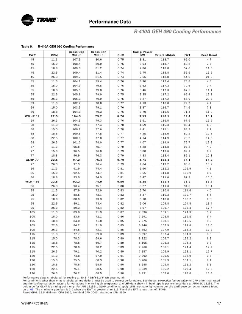
R-410A GEH 090 Cooling Performance
Table 9. R-410A GEH 090 Cooling Performance
EWT GPMGross Cap
MbtuhGross Sen
Mbtuh SHRComp Power
kW Reject Mbtuh LWT Feet Head
45 11.3 107.5 80.6 0.75 3.31 118.7 66.0 4.7
45 15.0 108.4 80.9 0.75 3.04 118.7 60.8 7.7
45 18.8 109.0 81.2 0.74 2.86 118.8 57.6 11.6
45 22.5 109.4 81.4 0.74 2.75 118.8 55.6 15.9
45 26.3 109.7 81.5 0.74 2.66 118.8 54.0 21.0
55 11.3 104.1 79.4 0.76 3.90 117.4 75.8 4.5
55 15.0 104.9 79.5 0.76 3.62 117.3 70.6 7.4
55 18.8 105.5 79.8 0.76 3.46 117.3 67.5 11.1
55 22.5 105.8 79.9 0.75 3.35 117.2 65.4 15.3
55 26.3 106.0 79.9 0.75 3.27 117.2 63.9 20.2
59 11.3 102.7 78.8 0.77 4.13 116.8 79.7 4.4
59 15.0 103.5 79.1 0.76 3.87 116.7 74.6 7.3
59 18.8 104.0 79.3 0.76 3.70 116.6 71.4 11.0
GWHP 59 22.5 104.3 79.2 0.76 3.59 116.5 69.4 15.1
59 26.3 104.5 79.3 0.76 3.51 116.5 67.9 19.9
68 11.3 99.4 77.4 0.78 4.69 115.3 88.4 4.3
68 15.0 100.1 77.6 0.78 4.41 115.1 83.3 7.1
68 18.8 100.5 77.8 0.77 4.25 115.0 80.2 10.6
68 22.5 100.8 77.8 0.77 4.14 114.9 78.2 14.6
68 26.3 101.0 78.0 0.77 4.07 114.9 76.7 19.2
77 11.3 95.8 75.7 0.79 5.28 113.8 97.2 4.2
77 15.0 96.5 76.0 0.79 5.00 113.6 92.1 6.9
77 18.8 96.9 76.3 0.79 4.83 113.4 89.1 10.3
GLHP 77 22.5 97.2 76.4 0.79 4.71 113.3 87.1 14.2
77 26.3 97.3 76.4 0.79 4.64 113.2 85.6 18.7
86 11.3 91.9 74.4 0.81 5.96 112.2 105.9 4.1
86 15.0 92.5 74.7 0.81 5.65 111.8 100.9 6.7
86 18.8 93.0 74.9 0.81 5.47 111.6 97.9 10.0
WLHP 86 22.5 93.2 74.9 0.80 5.35 111.4 95.9 13.8
86 26.3 93.4 75.1 0.80 5.27 111.3 94.5 18.1
95 11.3 87.9 72.9 0.83 6.70 110.8 114.6 4.0
95 15.0 88.5 73.1 0.83 6.37 110.3 109.7 6.6
95 18.8 88.9 73.3 0.82 6.18 110.0 106.7 9.8
95 22.5 89.1 73.4 0.82 6.06 109.8 104.8 13.4
95 26.3 89.3 73.4 0.82 5.97 109.7 103.3 17.7
105 11.3 83.0 71.9 0.87 7.636 109.1 124.3 3.9
105 15.0 83.6 72.1 0.86 7.291 108.5 119.5 6.4
105 18.8 84.0 71.8 0.85 7.075 108.1 116.5 9.5
105 22.5 84.2 71.9 0.85 6.946 107.9 114.6 13.0
105 26.3 84.5 72.1 0.85 6.852 107.9 113.2 17.2
115 11.3 77.7 69.3 0.89 8.697 107.4 134.0 3.8
115 15.0 78.3 69.6 0.89 8.322 106.7 129.2 6.2
115 18.8 78.6 69.7 0.89 8.105 106.3 126.3 9.3
115 22.5 78.9 70.2 0.89 7.960 106.1 124.4 12.7
115 26.3 79.1 70.2 0.89 7.857 105.9 123.1 16.7
120 11.3 74.8 67.9 0.91 9.292 106.5 138.9 3.7
120 15.0 75.5 68.3 0.90 8.906 105.9 134.1 6.1
120 18.8 75.8 68.5 0.90 8.685 105.5 131.2 9.1
120 22.5 76.1 68.5 0.90 8.539 105.2 129.4 12.6
120 26.3 76.2 68.5 0.90 8.431 105.0 128.0 16.5
Performance data is tabulated for cooling at 80.6°F DB/66.2°F WB entering air. For conditions other than what is tabulated, multipliers must be used to correct performance. See the fan correction factors table for CFM other than ratedand the cooling correction factors for variations in entering air temperature. WLHP data shown in bold type is performance data at ARI/ISO 13256. The bold type for GLHP is a rating point only. For ARI 13256-1 GLHP conditions, apply 15% methanol by volume per the antifreeze correction factors foundon p. 69. The minimum gpm/ton is 3.0 when the EWT is greater than 115°F and the EAT is less than 67°F WB.Rated GPM: 22.5 Minimum CFM 2400; Nominal CFM 3000, Maximum CFM 3600

18 WSHP-PRC016-EN
Performance Data
Table 10. R-410A GEH 090 Heating Performance
EWT GPMGross Cap
MbtuhAbsorbMbtuh
Comp Power
kW LWT Feet Head
25 11.3 54.8 39.3 4.55 18.0 5.5
25 15.0 56.6 41.0 4.57 19.5 9.1
25 18.8 58.5 42.9 4.58 20.4 13.4
25 22.5 59.6 43.9 4.59 21.1 18.3
25 26.3 60.7 45.0 4.60 21.6 24.1
32 11.3 60.9 45.1 4.62 24.0 5.4
32 15.0 62.3 46.5 4.64 25.8 8.8
32 18.8 64.2 48.3 4.66 26.9 13.0
GLHP 32 22.5 65.2 49.3 4.67 27.6 17.8
32 26.3 65.8 49.8 4.68 28.2 23.4
45 11.3 72.8 56.5 4.77 35.0 5.2
45 15.0 75.5 59.1 4.81 37.1 8.6
45 18.8 77.2 60.7 4.83 38.5 12.7
45 22.5 78.6 62.0 4.86 39.5 17.3
45 26.3 79.3 62.7 4.86 40.2 22.7
50 11.3 79.2 62.5 4.89 38.9 5.1
50 15.0 81.9 65.1 4.92 41.3 8.3
50 18.8 83.8 66.9 4.95 42.9 12.3
GWHP 50 22.5 84.9 68.0 4.96 44.0 16.8
50 26.3 85.8 68.8 4.97 44.8 22.1
55 11.3 84.3 67.3 4.97 43.1 5.0
55 15.0 87.3 70.2 5.01 45.6 8.2
55 18.8 89.2 72.1 5.03 47.3 12.1
55 22.5 90.4 73.2 5.04 48.5 16.5
55 26.3 91.5 74.3 5.06 49.4 21.7
68 11.3 98.4 80.6 5.20 53.7 4.8
68 15.0 102.0 84.1 5.26 56.8 7.8
68 18.8 104.4 86.4 5.28 58.8 11.5
WLHP 68 22.5 106.0 87.9 5.30 60.2 15.7
68 26.3 107.2 89.1 5.32 61.2 20.7
75 11.3 106.1 87.9 5.34 59.4 4.7
75 15.0 110.0 91.6 5.38 62.8 7.6
75 18.8 113.4 94.8 5.45 64.9 11.3
75 22.5 115.1 96.4 5.47 66.4 15.4
75 26.3 116.4 97.7 5.49 67.6 20.2
86 11.3 118.6 99.7 5.55 68.4 4.5
86 15.0 123.8 104.6 5.63 72.1 7.4
86 18.8 127.1 107.7 5.69 74.5 10.9
86 22.5 129.2 109.7 5.72 76.2 14.8
86 26.3 130.7 111.1 5.74 77.5 19.5
Performance data is tabulated for heating at 68°F DB entering air. For conditions other than what is tabulated, multipliers must be used to correct performance. See the fan correction factors table for CFMother than rated and the heating correction factors for variations in entering air temperature. WLHP datashown in bold type is performance data at ARI/ISO 13256-1. The bold type for GLHP is a rating point only.For ARI 13256-1 GLHP conditions, apply 15% methanol by volume per the antifreeze correction factorsfound on p. 69.Rated GPM: 22.5 Minimum CFM 2400; Rated CFM 3000, Maximum CFM 3600
Table 11. R-410A 090 Fan Correction Factors
EnteringCFM
CoolingCapacity
SensibleCapacity
CoolingInputWatts
HeatingCapacity
HeatingInputWatts
2400 0.959 0.878 1.002 0.989 1.090
2700 0.981 0.939 1.002 0.997 1.043
3000 1.000 1.000 1.000 1.000 1.000
3300 1.016 1.059 0.999 1.006 0.968
3600 1.030 1.121 0.996 1.013 0.944
R-410A GEH 090 Heating Performance, Correction

WSHP-PRC016-EN 19
Performance Data
Table 12. R-410A GEH 120 Cooling Performance
EWT GPMGross Cap
MbtuhGross Sen
Mbtuh SHRComp Power
kW Reject Mbtuh LWT Feet Head
45 15.0 142.9 108.1 0.76 4.54 158.4 66.1 4.7
45 20.0 143.9 108.5 0.75 4.19 158.2 60.8 7.9
45 25.0 144.4 108.7 0.75 3.99 158.0 57.6 11.7
45 30.0 144.8 108.9 0.75 3.85 157.9 55.5 16.2
45 35.0 145.1 109.0 0.75 3.75 157.9 54.0 21.3
55 15.0 138.5 106.2 0.77 5.29 156.5 75.9 4.6
55 20.0 139.4 106.6 0.77 4.94 156.3 70.6 7.6
55 25.0 139.9 106.8 0.76 4.74 156.1 67.5 11.3
55 30.0 140.2 107.0 0.76 4.60 155.9 65.4 15.6
55 35.0 140.5 107.1 0.76 4.51 155.9 63.9 20.5
59 15.0 136.6 105.5 0.77 5.60 155.7 79.8 4.5
59 20.0 137.5 105.8 0.77 5.25 155.4 74.5 7.5
59 25.0 138.0 106.1 0.77 5.05 155.2 71.4 11.1
GWHP 59 30.0 138.4 106.3 0.77 4.91 155.1 69.3 15.4
59 35.0 138.6 106.3 0.77 4.81 155.0 67.9 20.2
68 15.0 132.2 103.6 0.78 6.34 153.8 88.5 4.4
68 20.0 133.1 104.0 0.78 5.97 153.5 83.3 7.3
68 25.0 133.6 104.1 0.78 5.76 153.2 80.3 10.8
68 30.0 133.9 104.3 0.78 5.62 153.1 78.2 14.9
68 35.0 134.1 104.5 0.78 5.52 153.0 76.7 19.6
77 15.0 127.6 101.7 0.80 7.11 151.8 97.2 4.2
77 20.0 128.4 102.0 0.79 6.74 151.4 92.1 7.1
77 25.0 128.9 102.2 0.79 6.53 151.2 89.1 10.5
GLHP 77 30.0 129.2 102.4 0.79 6.39 151.0 87.1 14.5
77 35.0 129.5 102.4 0.79 6.29 150.9 85.6 19.0
86 15.0 122.7 99.6 0.81 7.95 149.8 106.0 4.1
86 20.0 123.5 100.0 0.81 7.57 149.3 100.9 6.9
86 25.0 124.0 100.2 0.81 7.34 149.1 97.9 10.2
WLHP 86 30.0 124.3 100.3 0.81 7.19 148.8 95.9 14.1
86 35.0 124.5 100.4 0.81 7.08 148.7 94.5 18.4
95 15.0 117.5 97.4 0.83 8.86 147.7 114.7 4.0
95 20.0 118.3 97.8 0.83 8.46 147.2 109.7 6.7
95 25.0 118.8 98.0 0.82 8.23 146.9 106.8 9.9
95 30.0 119.1 98.1 0.82 8.08 146.7 104.8 13.7
95 35.0 119.4 98.2 0.82 7.97 146.6 103.4 18.0
105 15.0 110.8 95.9 0.87 9.960 144.8 124.3 3.9
105 20.0 112.3 95.4 0.85 9.576 144.9 119.5 6.5
105 25.0 112.7 95.5 0.85 9.309 144.5 116.6 9.6
105 30.0 113.0 95.6 0.85 9.147 144.2 114.6 13.3
105 35.0 113.2 95.7 0.84 9.033 144.0 113.2 17.5
115 15.0 103.7 93.4 0.90 11.231 142.0 133.9 3.8
115 20.0 104.6 93.6 0.90 10.795 141.4 129.1 6.3
115 25.0 105.1 93.9 0.89 10.539 141.0 126.3 9.4
115 30.0 105.3 94.0 0.89 10.370 140.7 124.4 13.0
115 35.0 105.6 94.0 0.89 10.250 140.5 123.0 17.0
120 15.0 100.1 92.2 0.92 11.909 140.8 138.8 3.8
120 20.0 101.0 92.4 0.92 11.465 140.1 134.0 6.3
120 25.0 101.4 92.6 0.91 11.199 139.7 131.2 9.3
120 30.0 101.7 92.7 0.91 11.030 139.4 129.3 12.8
120 35.0 102.0 92.7 0.91 10.907 139.2 128.0 16.8
Performance data is tabulated for cooling at 80.6°F DB/66.2°F WB entering air.For conditions other than what is tabulated, multipliers must be used to correct performance. See the fan correction factors table for CFM other than ratedand the cooling correction factors for variations in entering air temperature. WLHP data shown in bold type is performance data at ARI/ISO 13256. Thebold type for GLHP is a rating point only. For ARI 13256-1 GLHP conditions, apply 15% methanol by volume per the antifreeze correction factors found onp. 69. The minimum gpm/ton is 3.0 when the EWT is greater than 115°F and the EAT is less than 67°F WB.Rated GPM: 30.0 Minimum CFM 3200; Nominal CFM 4000, Maximum CFM 4800
R-410A GEH 120 Cooling Performance

20 WSHP-PRC016-EN
Performance Data
Table 13. R-410A GEH 120 Heating Performance
EWT GPMGross Cap
MbtuhAbsorbMbtuh
Comp Power
kW LWT Feet Head
25 15.0 71.9 52.7 5.62 18.0 5.6
25 20.0 73.1 53.9 5.63 19.6 9.2
25 25.0 73.7 54.5 5.63 20.6 13.6
25 30.0 74.5 55.3 5.62 21.3 18.7
25 35.0 75.4 56.2 5.62 21.8 24.4
32 15.0 79.2 59.7 5.71 24.0 5.4
32 20.0 80.6 61.1 5.72 25.9 9.0
32 25.0 81.5 62.0 5.72 27.0 13.2
GLHP 32 30.0 81.4 61.9 5.71 27.9 18.1
32 35.0 81.9 62.3 5.72 28.4 23.7
45 15.0 94.3 74.0 5.93 35.1 5.3
45 20.0 95.5 75.3 5.93 37.5 8.7
45 25.0 96.1 75.9 5.93 38.9 12.8
45 30.0 97.3 77.0 5.95 39.9 17.6
45 35.0 96.3 76.1 5.91 40.7 23.0
50 15.0 103.5 82.6 6.10 39.0 5.1
50 20.0 104.4 83.6 6.09 41.6 8.5
50 25.0 104.2 83.5 6.06 43.3 12.5
GWHP 50 30.0 104.1 83.5 6.05 44.4 17.1
50 35.0 103.8 83.2 6.03 45.2 22.4
55 15.0 109.7 88.5 6.21 43.2 5.1
55 20.0 111.4 90.2 6.21 46.0 8.3
55 25.0 110.8 89.7 6.17 47.8 12.2
55 30.0 110.3 89.4 6.14 49.0 16.8
55 35.0 110.0 89.1 6.13 49.9 21.9
68 15.0 127.7 105.5 6.51 53.9 4.8
68 20.0 129.1 106.9 6.51 57.3 7.9
68 25.0 129.2 107.0 6.49 59.4 11.7
WLHP 68 30.0 129.3 107.2 6.48 60.9 16.0
68 35.0 127.7 105.8 6.43 62.0 20.9
75 15.0 137.9 115.0 6.71 59.7 4.7
75 20.0 139.6 116.7 6.72 63.3 7.7
75 25.0 139.8 116.9 6.70 65.6 11.4
75 30.0 140.2 117.3 6.71 67.2 15.6
75 35.0 137.6 115.0 6.63 68.4 20.4
86 15.0 154.9 130.7 7.07 68.6 4.6
86 20.0 157.0 132.8 7.11 72.7 7.5
86 25.0 158.2 133.8 7.13 75.3 11.0
86 30.0 155.3 131.3 7.05 77.2 15.1
86 35.0 153.7 129.8 7.00 78.6 19.7
Performance data is tabulated for heating at 68°F DB entering air.For conditions other than what is tabulated, multipliers must be used to correct performance. See the fancorrection factors table for CFM other than rated and the heating correction factors for variations in enteringair temperature. WLHP data shown in bold type is performance data at ARI/ISO 13256-1. The bold type forGLHP is a rating point only. For ARI 13256-1 GLHP conditions, apply 15% methanol by volume per the antifreeze correction factors found on p. 69.Rated GPM: 30.0 Minimum CFM 3200; Nominal CFM 4000, Maximum CFM 4800
Table 14. R-410A 120 Fan Correction Factors
EnteringCFM
CoolingCapacity
SensibleCapacity
CoolingInputWatts
HeatingCapacity
HeatingInputWatts
3200 0.958 0.881 0.999 0.971 0.961
3600 0.981 0.941 1.001 0.986 0.928
4000 1.000 1.000 1.000 1.000 1.000
4400 1.016 1.057 1.001 1.003 0.876
4800 1.031 1.112 1.001 1.019 0.860
R-410A GEH 120 Heating Performance, Correction
WSHP-PRC016-EN 21
Performance Data
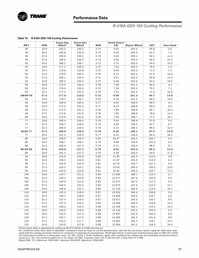
Table 15. R-410A GEH 150 Cooling Performance
EWT GPMGross Cap
MbtuhGross Sen
Mbtuh SHRComp Power
kW Reject Mbtuh LWT Feet Head
45 18.8 182.2 135.2 0.74 6.52 204.5 66.8 4.5
45 25.0 183.8 135.8 0.74 6.16 204.9 61.4 7.5
45 31.3 184.8 136.2 0.74 5.94 205.1 58.1 11.2
45 37.5 185.5 136.5 0.74 5.80 205.3 56.0 15.4
45 43.8 186.1 136.7 0.73 5.70 205.5 54.4 20.3
55 18.8 177.1 133.3 0.75 7.34 202.2 76.5 4.4
55 25.0 178.6 133.8 0.75 6.94 202.2 71.2 7.2
55 31.3 179.5 134.2 0.75 6.71 202.4 67.9 10.8
55 37.5 180.1 134.4 0.75 6.57 202.5 65.8 14.9
55 43.8 180.5 134.6 0.75 6.46 202.6 64.2 19.6
59 18.8 175.0 132.4 0.76 7.68 201.2 80.4 4.3
59 25.0 176.4 133.0 0.75 7.29 201.3 75.1 7.1
59 31.3 177.2 133.3 0.75 7.04 201.3 71.9 10.6
GWHP 59 37.5 177.8 133.5 0.75 6.89 201.3 69.7 14.6
59 43.8 178.2 133.7 0.75 6.79 201.4 68.2 19.3
68 18.8 169.9 130.5 0.77 8.52 199.0 89.2 4.2
68 25.0 171.2 131.0 0.77 8.10 198.8 83.9 6.9
68 31.3 172.0 131.3 0.76 7.85 198.8 80.7 10.3
68 37.5 172.5 131.5 0.76 7.69 198.8 78.6 14.2
68 43.8 172.9 131.6 0.76 7.58 198.7 77.1 18.7
77 18.8 164.4 128.4 0.78 9.44 196.6 97.9 4.0
77 25.0 165.7 128.9 0.78 9.00 196.4 92.7 6.7
77 31.3 166.4 129.2 0.78 8.72 196.2 89.5 10.0
GLHP 77 37.5 166.9 129.3 0.78 8.56 196.1 87.5 13.8
77 43.8 167.2 129.5 0.77 8.43 196.0 85.9 18.1
86 18.8 158.5 126.3 0.80 10.47 194.2 106.7 3.9
86 25.0 159.7 126.7 0.79 9.99 193.8 101.5 6.5
86 31.3 160.4 127.0 0.79 9.71 193.6 98.4 9.7
WLHP 86 37.5 160.9 127.1 0.79 9.52 193.4 96.3 13.4
86 43.8 161.2 127.3 0.79 9.39 193.3 94.8 17.6
95 18.8 152.0 123.9 0.82 11.55 191.4 115.4 3.8
95 25.0 153.2 124.3 0.81 11.07 191.0 110.3 6.4
95 31.3 153.9 124.6 0.81 10.78 190.7 107.2 9.5
95 37.5 154.3 124.7 0.81 10.59 190.5 105.2 13.0
95 43.8 154.6 124.8 0.81 10.46 190.3 103.7 17.1
105 18.8 144.1 121.2 0.84 12.896 188.1 125.0 3.7
105 25.0 145.3 121.6 0.84 12.377 187.6 120.0 6.2
105 31.3 146.0 121.9 0.83 12.072 187.2 117.0 9.2
105 37.5 146.5 122.0 0.83 11.874 187.0 115.0 12.7
105 43.8 146.8 122.1 0.83 11.733 186.9 113.5 16.7
115 18.8 135.4 118.4 0.87 14.355 184.4 134.6 3.6
115 25.0 136.7 118.8 0.87 13.828 183.9 129.7 6.0
115 31.3 137.4 119.0 0.87 13.511 183.5 126.7 9.0
115 37.5 137.9 119.2 0.86 13.306 183.3 124.8 12.3
115 43.8 138.2 119.3 0.86 13.158 183.1 123.4 16.2
120 18.8 130.6 116.9 0.89 15.132 182.3 139.4 3.6
120 25.0 132.0 117.3 0.89 14.597 181.8 134.5 6.0
120 31.3 132.7 117.5 0.89 14.292 181.5 131.6 8.9
120 37.5 133.2 117.7 0.88 14.081 181.2 129.7 12.2
120 43.8 133.5 117.8 0.88 13.959 181.2 128.3 16.0
Performance data is tabulated for cooling at 80.6°F DB/66.2°F WB entering air.For conditions other than what is tabulated, multipliers must be used to correct performance. See the fan correction factors table for CFM other thanrated and the cooling correction factors for variations in entering air temperature. WLHP data shown in bold type is performance data at ARI/ISO 13256.The bold type for GLHP is a rating point only. For ARI 13256-1 GLHP conditions, apply 15% methanol by volume per the antifreeze correction factorsfound on p. 69. The minimum gpm/ton is 3.0 when the EWT is greater than 115°F and the EAT is less than 67°F WB.Rated GPM: 37.5 Minimum CFM 4000; Nominal CFM 5000, Maximum CFM 6000
R-410A GEH 150 Cooling Performance

22 WSHP-PRC016-EN
Performance Data
Table 16. R-410A GEH 150 Heating Performance
EWT GPMGross Cap
MbtuhAbsorbMbtuh
Comp Power
kW LWT Feet Head
25 18.8 98.9 70.2 8.41 17.5 5.2
25 25.0 102.2 73.4 8.45 19.1 8.5
25 31.3 104.1 75.2 8.47 20.2 12.6
25 37.5 105.2 76.3 8.47 20.9 17.3
25 43.8 106.1 77.2 8.48 21.5 22.6
32 18.8 109.0 79.7 8.58 23.5 5.1
32 25.0 112.6 83.2 8.62 25.3 8.3
32 31.3 114.8 85.3 8.64 26.6 12.2
GLHP 32 37.5 116.4 86.9 8.64 27.4 16.8
32 43.8 117.6 88.1 8.65 28.0 22.0
45 18.8 128.7 98.9 8.74 34.5 4.9
45 25.0 133.3 103.3 8.79 36.7 8.1
45 31.3 136.2 106.2 8.82 38.2 11.9
45 37.5 138.4 108.2 8.84 39.2 16.3
45 43.8 139.9 109.7 8.85 40.0 21.4
50 18.8 138.7 108.3 8.91 38.5 4.8
50 25.0 143.6 113.1 8.94 41.0 7.8
50 31.3 146.8 116.2 8.96 42.6 11.6
GWHP 50 37.5 148.9 118.2 8.98 43.7 15.8
50 43.8 150.4 119.7 9.00 44.5 20.8
55 18.8 147.1 116.4 9.00 42.6 4.7
55 25.0 152.6 121.7 9.06 45.3 7.7
55 31.3 156.1 125.0 9.09 47.0 11.4
55 37.5 158.4 127.3 9.12 48.2 15.5
55 43.8 160.2 129.0 9.13 49.1 20.4
68 18.8 170.4 138.5 9.33 53.3 4.5
68 25.0 177.2 145.1 9.40 56.4 7.3
68 31.3 181.7 149.5 9.44 58.4 10.8
WLHP 68 37.5 184.9 152.5 9.47 59.9 14.8
68 43.8 187.1 154.7 9.49 60.9 19.4
75 18.8 183.2 150.8 9.50 59.0 4.4
75 25.0 191.1 158.3 9.61 62.3 7.2
75 31.3 196.6 163.5 9.69 64.6 10.6
75 37.5 200.6 167.3 9.75 66.1 14.5
75 43.8 203.1 169.9 9.75 67.2 19.0
86 18.8 205.2 171.4 9.89 67.8 4.2
86 25.0 214.9 180.8 10.01 71.5 6.9
86 31.3 221.3 186.8 10.09 74.1 10.2
86 37.5 225.6 191.0 10.14 75.8 14.0
86 43.8 228.8 194.1 10.17 77.1 18.3
Performance data is tabulated for heating at 68°F DB entering air. For conditions other than what is tabulated, multipliers must be used to correct performance. See the fancorrection factors table for CFM other than rated and the heating correction factors for variations in enteringair temperature. WLHP data shown in bold type is performance data at ARI/ISO 13256-1. The bold type forGLHP is a rating point only. For ARI 13256-1 GLHP conditions, apply 15% methanol by volume per the antifreeze correction factors found on p. 69.Rated GPM: 37.5 Minimum CFM 4000; Nominal CFM 5000, Maximum CFM 6000
Table 17. R-410A 150 Fan Correction Factors
EnteringCFM
CoolingCapacity
SensibleCapacity
CoolingInputWatts
HeatingCapacity
HeatingInputWatts
4000 0.959 0.880 1.003 1.075 1.144
4500 0.981 0.940 1.003 0.987 1.040
5000 1.000 1.000 1.000 1.000 1.000
5500 1.016 1.059 0.999 1.011 0.968
6000 1.030 1.118 0.997 1.020 0.943
R-410A GEH 150 Heating Performance, Correction
WSHP-PRC016-EN 23
Performance Data
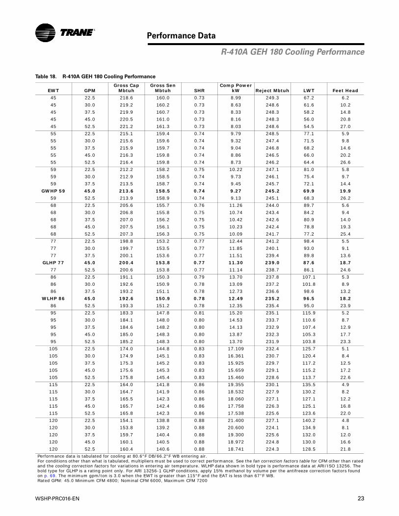
Table 18. R-410A GEH 180 Cooling Performance
EWT GPMGross Cap
MbtuhGross Sen
Mbtuh SHRComp Power
kW Reject Mbtuh LWT Feet Head
45 22.5 218.6 160.0 0.73 8.99 249.3 67.2 6.2
45 30.0 219.2 160.2 0.73 8.63 248.6 61.6 10.2
45 37.5 219.9 160.7 0.73 8.33 248.3 58.2 14.8
45 45.0 220.5 161.0 0.73 8.16 248.3 56.0 20.8
45 52.5 221.2 161.3 0.73 8.03 248.6 54.5 27.0
55 22.5 215.1 159.4 0.74 9.79 248.5 77.1 5.9
55 30.0 215.6 159.6 0.74 9.32 247.4 71.5 9.8
55 37.5 215.9 159.7 0.74 9.04 246.8 68.2 14.6
55 45.0 216.3 159.8 0.74 8.86 246.5 66.0 20.2
55 52.5 216.4 159.8 0.74 8.73 246.2 64.4 26.6
59 22.5 212.2 158.2 0.75 10.22 247.1 81.0 5.8
59 30.0 212.9 158.5 0.74 9.73 246.1 75.4 9.7
59 37.5 213.5 158.7 0.74 9.45 245.7 72.1 14.4
GWHP 59 45.0 213.6 158.5 0.74 9.27 245.2 69.9 19.9
59 52.5 213.9 158.9 0.74 9.13 245.1 68.3 26.2
68 22.5 205.6 155.7 0.76 11.26 244.0 89.7 5.6
68 30.0 206.8 155.8 0.75 10.74 243.4 84.2 9.4
68 37.5 207.0 156.2 0.75 10.42 242.6 80.9 14.0
68 45.0 207.5 156.1 0.75 10.23 242.4 78.8 19.3
68 52.5 207.3 156.3 0.75 10.09 241.7 77.2 25.4
77 22.5 198.8 153.2 0.77 12.44 241.2 98.4 5.5
77 30.0 199.7 153.5 0.77 11.85 240.1 93.0 9.1
77 37.5 200.1 153.6 0.77 11.51 239.4 89.8 13.6
GLHP 77 45.0 200.4 153.8 0.77 11.30 239.0 87.6 18.7
77 52.5 200.6 153.8 0.77 11.14 238.7 86.1 24.6
86 22.5 191.1 150.3 0.79 13.70 237.8 107.1 5.3
86 30.0 192.6 150.9 0.78 13.09 237.2 101.8 8.9
86 37.5 193.2 151.1 0.78 12.73 236.6 98.6 13.2
WLHP 86 45.0 192.6 150.9 0.78 12.49 235.2 96.5 18.2
86 52.5 193.3 151.2 0.78 12.35 235.4 95.0 23.9
95 22.5 183.3 147.8 0.81 15.20 235.1 115.9 5.2
95 30.0 184.1 148.0 0.80 14.53 233.7 110.6 8.7
95 37.5 184.6 148.2 0.80 14.13 232.9 107.4 12.9
95 45.0 185.0 148.3 0.80 13.87 232.3 105.3 17.7
95 52.5 185.2 148.3 0.80 13.70 231.9 103.8 23.3
105 22.5 174.0 144.8 0.83 17.109 232.4 125.7 5.1
105 30.0 174.9 145.1 0.83 16.361 230.7 120.4 8.4
105 37.5 175.3 145.2 0.83 15.925 229.7 117.2 12.5
105 45.0 175.6 145.3 0.83 15.659 229.1 115.2 17.2
105 52.5 175.8 145.4 0.83 15.460 228.6 113.7 22.6
115 22.5 164.0 141.8 0.86 19.355 230.1 135.5 4.9
115 30.0 164.7 141.9 0.86 18.532 227.9 130.2 8.2
115 37.5 165.5 142.3 0.86 18.060 227.1 127.1 12.2
115 45.0 165.7 142.4 0.86 17.758 226.3 125.1 16.8
115 52.5 165.8 142.3 0.86 17.538 225.6 123.6 22.0
120 22.5 154.1 138.8 0.88 21.400 227.1 140.2 4.8
120 30.0 153.8 139.2 0.88 20.600 224.1 134.9 8.1
120 37.5 159.7 140.4 0.88 19.300 225.6 132.0 12.0
120 45.0 160.1 140.5 0.88 18.972 224.8 130.0 16.6
120 52.5 160.4 140.6 0.88 18.741 224.3 128.5 21.8
Performance data is tabulated for cooling at 80.6°F DB/66.2°F WB entering air. For conditions other than what is tabulated, multipliers must be used to correct performance. See the fan correction factors table for CFM other than ratedand the cooling correction factors for variations in entering air temperature. WLHP data shown in bold type is performance data at ARI/ISO 13256. Thebold type for GLHP is a rating point only. For ARI 13256-1 GLHP conditions, apply 15% methanol by volume per the antifreeze correction factors foundon p. 69. The minimum gpm/ton is 3.0 when the EWT is greater than 115°F and the EAT is less than 67°F WB.Rated GPM: 45.0 Minimum CFM 4800; Nominal CFM 6000, Maximum CFM 7200
R-410A GEH 180 Cooling Performance
24 WSHP-PRC016-EN
Performance Data
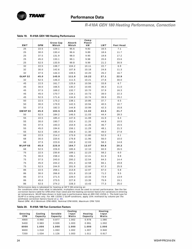
Table 19. R-410A GEH 180 Heating Performance
EWT GPMGross Cap
MbtuhAbsorbMbtuh
Comp Power
kW LWT Feet Head
25 22.5 129.1 95.6 9.82 16.5 7.1
25 30.0 130.4 96.6 9.89 18.6 11.7
25 37.5 131.9 98.0 9.95 19.8 17.2
25 45.0 133.1 99.1 9.98 20.6 23.6
25 52.5 133.9 99.8 9.99 21.2 30.9
32 22.5 138.7 104.2 10.11 22.7 6.9
32 30.0 142.6 107.8 10.18 24.8 11.3
32 37.5 144.3 109.5 10.20 26.2 16.7
GLHP 32 45.0 145.9 111.0 10.22 27.1 22.9
32 52.5 146.3 111.5 10.21 27.8 30.0
45 22.5 161.7 125.6 10.56 33.8 6.7
45 30.0 166.5 130.2 10.65 36.3 11.0
45 37.5 169.2 132.7 10.70 37.9 16.3
45 45.0 170.7 134.1 10.73 39.0 22.3
45 52.5 171.6 134.9 10.74 39.9 29.2
50 22.5 175.2 138.1 10.86 37.7 6.5
50 30.0 179.9 142.5 10.94 40.5 10.7
50 37.5 182.3 144.8 10.99 42.3 15.8
GWHP 50 45.0 183.5 145.9 11.02 43.5 21.7
50 52.5 184.2 146.5 11.03 44.4 28.3
55 22.5 185.4 147.6 11.08 41.9 6.4
55 30.0 190.7 152.4 11.20 44.8 10.5
55 37.5 193.3 154.9 11.26 46.7 15.5
55 45.0 194.6 156.1 11.29 48.1 21.3
55 52.5 195.4 156.9 11.30 49.0 27.8
68 22.5 214.2 173.9 11.80 52.5 6.1
68 30.0 220.6 179.8 11.96 56.0 10.0
68 37.5 223.9 182.8 12.03 58.3 14.8
WLHP 68 45.0 225.9 184.7 12.07 59.8 20.3
68 52.5 226.9 185.6 12.10 60.9 26.5
75 22.5 230.8 189.1 12.23 58.2 6.0
75 30.0 238.4 196.1 12.41 61.9 9.8
75 37.5 243.0 200.2 12.54 64.3 14.4
75 45.0 244.2 201.3 12.58 66.1 19.8
75 52.5 244.9 201.9 12.60 67.3 25.9
86 22.5 258.1 213.8 12.97 67.0 5.8
86 30.0 266.8 221.8 13.18 71.2 9.5
86 37.5 271.5 226.0 13.33 73.9 13.9
86 45.0 273.5 227.8 13.39 75.9 19.1
86 52.5 274.2 228.3 13.43 77.3 25.0
Performance data is tabulated for heating at 68°F DB entering air. For conditions other than what is tabulated, multipliers must be used to correct performance. See the fancorrection factors table for CFM other than rated and the heating correction factors for variations in enteringair temperature. WLHP data shown in bold type is performance data at ARI/ISO 13256-1. The bold type forGLHP is a rating point only. For ARI 13256-1 GLHP conditions, apply 15% methanol by volume per the antifreeze correction factors found on p. 69.Rated GPM: 45.0 Minimum CFM 4800; Nominal CFM 6000, Maximum CFM 7200
Table 20. R-410A 180 Fan Correction Factors
EnteringCFM
CoolingCapacity
SensibleCapacity
CoolingInputWatts
HeatingCapacity
HeatingInputWatts
4800 0.960 0.877 1.002 0.978 1.080
5400 0.983 0.939 1.003 0.991 1.002
6000 1.000 1.000 1.000 1.000 1.000
6600 1.018 1.063 1.002 1.007 0.940
7200 1.034 1.126 1.003 1.011 0.917
R-410A GEH 180 Heating Performance, Correction
WSHP-PRC016-EN 25
Performance Data
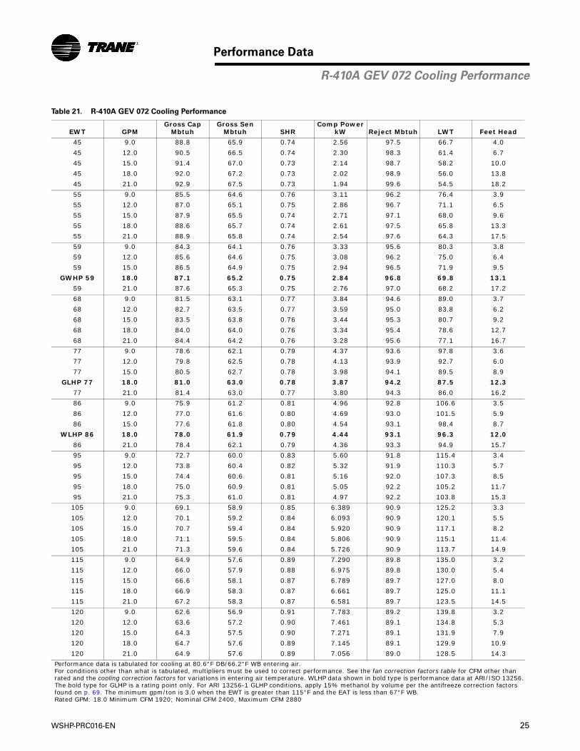
Table 21. R-410A GEV 072 Cooling Performance
EWT GPMGross Cap
MbtuhGross Sen
Mbtuh SHRComp Power
kW Reject Mbtuh LWT Feet Head
45 9.0 88.8 65.9 0.74 2.56 97.5 66.7 4.0
45 12.0 90.5 66.5 0.74 2.30 98.3 61.4 6.7
45 15.0 91.4 67.0 0.73 2.14 98.7 58.2 10.0
45 18.0 92.0 67.2 0.73 2.02 98.9 56.0 13.8
45 21.0 92.9 67.5 0.73 1.94 99.6 54.5 18.2
55 9.0 85.5 64.6 0.76 3.11 96.2 76.4 3.9
55 12.0 87.0 65.1 0.75 2.86 96.7 71.1 6.5
55 15.0 87.9 65.5 0.74 2.71 97.1 68.0 9.6
55 18.0 88.6 65.7 0.74 2.61 97.5 65.8 13.3
55 21.0 88.9 65.8 0.74 2.54 97.6 64.3 17.5
59 9.0 84.3 64.1 0.76 3.33 95.6 80.3 3.8
59 12.0 85.6 64.6 0.75 3.08 96.2 75.0 6.4
59 15.0 86.5 64.9 0.75 2.94 96.5 71.9 9.5
GWHP 59 18.0 87.1 65.2 0.75 2.84 96.8 69.8 13.1
59 21.0 87.6 65.3 0.75 2.76 97.0 68.2 17.2
68 9.0 81.5 63.1 0.77 3.84 94.6 89.0 3.7
68 12.0 82.7 63.5 0.77 3.59 95.0 83.8 6.2
68 15.0 83.5 63.8 0.76 3.44 95.3 80.7 9.2
68 18.0 84.0 64.0 0.76 3.34 95.4 78.6 12.7
68 21.0 84.4 64.2 0.76 3.28 95.6 77.1 16.7
77 9.0 78.6 62.1 0.79 4.37 93.6 97.8 3.6
77 12.0 79.8 62.5 0.78 4.13 93.9 92.7 6.0
77 15.0 80.5 62.7 0.78 3.98 94.1 89.5 8.9
GLHP 77 18.0 81.0 63.0 0.78 3.87 94.2 87.5 12.3
77 21.0 81.4 63.0 0.77 3.80 94.3 86.0 16.2
86 9.0 75.9 61.2 0.81 4.96 92.8 106.6 3.5
86 12.0 77.0 61.6 0.80 4.69 93.0 101.5 5.9
86 15.0 77.6 61.8 0.80 4.54 93.1 98.4 8.7
WLHP 86 18.0 78.0 61.9 0.79 4.44 93.1 96.3 12.0
86 21.0 78.4 62.1 0.79 4.36 93.3 94.9 15.7
95 9.0 72.7 60.0 0.83 5.60 91.8 115.4 3.4
95 12.0 73.8 60.4 0.82 5.32 91.9 110.3 5.7
95 15.0 74.4 60.6 0.81 5.16 92.0 107.3 8.5
95 18.0 75.0 60.9 0.81 5.05 92.2 105.2 11.7
95 21.0 75.3 61.0 0.81 4.97 92.2 103.8 15.3
105 9.0 69.1 58.9 0.85 6.389 90.9 125.2 3.3
105 12.0 70.1 59.2 0.84 6.093 90.9 120.1 5.5
105 15.0 70.7 59.4 0.84 5.920 90.9 117.1 8.2
105 18.0 71.1 59.5 0.84 5.806 90.9 115.1 11.4
105 21.0 71.3 59.6 0.84 5.726 90.9 113.7 14.9
115 9.0 64.9 57.6 0.89 7.290 89.8 135.0 3.2
115 12.0 66.0 57.9 0.88 6.975 89.8 130.0 5.4
115 15.0 66.6 58.1 0.87 6.789 89.7 127.0 8.0
115 18.0 66.9 58.3 0.87 6.661 89.7 125.0 11.1
115 21.0 67.2 58.3 0.87 6.581 89.7 123.5 14.5
120 9.0 62.6 56.9 0.91 7.783 89.2 139.8 3.2
120 12.0 63.6 57.2 0.90 7.461 89.1 134.8 5.3
120 15.0 64.3 57.5 0.90 7.271 89.1 131.9 7.9
120 18.0 64.7 57.6 0.89 7.145 89.1 129.9 10.9
120 21.0 64.9 57.6 0.89 7.056 89.0 128.5 14.3
Performance data is tabulated for cooling at 80.6°F DB/66.2°F WB entering air.For conditions other than what is tabulated, multipliers must be used to correct performance. See the fan correction factors table for CFM other thanrated and the cooling correction factors for variations in entering air temperature. WLHP data shown in bold type is performance data at ARI/ISO 13256.The bold type for GLHP is a rating point only. For ARI 13256-1 GLHP conditions, apply 15% methanol by volume per the antifreeze correction factorsfound on p. 69. The minimum gpm/ton is 3.0 when the EWT is greater than 115°F and the EAT is less than 67°F WB.Rated GPM: 18.0 Minimum CFM 1920; Nominal CFM 2400, Maximum CFM 2880
R-410A GEV 072 Cooling Performance

26 WSHP-PRC016-EN
Performance Data
Table 22. R-410A GEV 072 Heating Performance
EWT GPMGross Cap
MbtuhAbsorbMbtuh
Comp Power
kW LWT Feet Head
25 9.0 44.1 30.7 3.92 18.2 4.9
25 12.0 45.3 31.8 3.95 19.7 8.0
25 15.0 46.2 32.7 3.96 20.6 11.8
25 18.0 47.1 33.6 3.97 21.3 16.2
25 21.0 47.8 34.2 3.98 21.7 21.2
32 9.0 49.1 35.5 3.98 24.1 4.7
32 12.0 50.9 37.2 4.01 25.8 7.8
32 15.0 51.8 38.1 4.01 26.9 11.5
GLHP 32 18.0 52.6 38.9 4.02 27.7 15.7
32 21.0 53.1 39.4 4.03 28.3 20.6
45 9.0 58.9 44.9 4.11 35.0 4.6
45 12.0 61.2 47.0 4.14 37.2 7.6
45 15.0 62.5 48.3 4.16 38.6 11.1
45 18.0 63.4 49.2 4.17 39.5 15.3
45 21.0 64.1 49.8 4.18 40.3 20.0
50 9.0 64.0 49.7 4.19 39.0 4.5
50 12.0 66.4 52.0 4.23 41.3 7.3
50 15.0 67.6 53.1 4.24 42.9 10.8
GWHP 50 18.0 68.6 54.1 4.26 44.0 14.9
50 21.0 69.3 54.7 4.27 44.8 19.4
55 9.0 68.2 53.6 4.26 43.1 4.4
55 12.0 70.7 56.0 4.30 45.7 7.2
55 15.0 72.2 57.4 4.32 47.3 10.6
55 18.0 73.2 58.4 4.33 48.5 14.6
55 21.0 73.8 59.0 4.34 49.4 19.0
68 9.0 79.4 64.3 4.44 53.7 4.2
68 12.0 82.4 67.1 4.49 56.8 6.9
68 15.0 84.2 68.8 4.51 58.8 10.1
WLHP 68 18.0 85.4 69.9 4.53 60.2 13.9
68 21.0 86.2 70.7 4.54 61.3 18.2
75 9.0 85.6 70.1 4.55 59.4 4.1
75 12.0 88.9 73.2 4.60 62.8 6.7
75 15.0 90.7 75.0 4.61 65.0 9.9
75 18.0 92.1 76.3 4.63 66.5 13.6
75 21.0 93.0 77.2 4.65 67.7 17.7
86 9.0 95.4 79.3 4.71 68.4 3.9
86 12.0 99.0 82.8 4.76 72.2 6.5
86 15.0 101.1 84.8 4.79 74.7 9.5
86 18.0 102.5 86.1 4.81 76.4 13.1
86 21.0 103.3 86.9 4.81 77.7 17.1
Performance data is tabulated for heating at 68°F DB entering air.For conditions other than what is tabulated, multipliers must be used to correct performance. See the fancorrection factors table for CFM other than rated and the heating correction factors for variations in enteringair temperature. WLHP data shown in bold type is performance data at ARI/ISO 13256-1. The bold type forGLHP is a rating point only. For ARI 13256-1 GLHP conditions, apply 15% methanol by volume per the antifreeze correction factors found on p. 69.Rated GPM: 18.0 Minimum CFM 1920; Nominal CFM 2400, Maximum CFM 2800
Table 23. R-410A 072 Fan Correction Factors
EnteringCFM
CoolingCapacity
SensibleCapacity
CoolingInputWatts
HeatingCapacity
HeatingInputWatts
1920 0.962 0.880 1.004 0.978 1.098
2160 0.983 0.939 1.003 0.994 1.068
2400 1.000 1.000 1.000 1.000 1.000
2640 1.013 1.059 0.997 1.008 0.986
2880 1.026 1.122 0.996 1.015 0.957
R-410A GEV 072 Heating Performance, Correction

WSHP-PRC016-EN 27
Performance Data
Table 24. R-410A GEV 090 Cooling Performance
EWT GPMGross Cap
MbtuhGross Sen
Mbtuh SHRComp Power
kW Reject Mbtuh LWT Feet Head
45 11.3 108.3 80.0 0.74 3.40 119.9 66.2 4.5
45 15.0 109.3 80.4 0.74 3.13 120.0 61.0 7.5
45 18.8 109.9 80.6 0.73 2.96 120.0 57.8 11.3
45 22.5 110.4 80.8 0.73 2.85 120.1 55.7 15.5
45 26.3 110.7 80.9 0.73 2.77 120.1 54.1 20.4
55 11.3 105.1 78.8 0.75 3.98 118.7 76.0 4.4
55 15.0 106.0 79.1 0.75 3.72 118.7 70.8 7.3
55 18.8 106.5 79.3 0.74 3.54 118.6 67.6 10.8
55 22.5 106.9 79.5 0.74 3.44 118.7 65.5 14.9
55 26.3 107.2 79.6 0.74 3.36 118.7 64.0 19.6
59 11.3 103.8 78.4 0.76 4.22 118.2 79.9 4.3
59 15.0 104.6 78.6 0.75 3.95 118.1 74.7 7.2
59 18.8 105.1 78.8 0.75 3.79 118.1 71.6 10.7
GWHP 59 22.5 105.5 78.9 0.75 3.68 118.1 69.5 14.7
59 26.3 105.7 79.0 0.75 3.60 118.0 68.0 19.4
68 11.3 100.6 77.1 0.77 4.77 116.9 88.7 4.2
68 15.0 101.3 77.4 0.76 4.49 116.7 83.6 6.9
68 18.8 101.8 77.6 0.76 4.33 116.6 80.4 10.4
68 22.5 102.1 77.7 0.76 4.22 116.5 78.4 14.2
68 26.3 102.3 77.7 0.76 4.15 116.5 76.9 18.7
77 11.3 97.2 76.0 0.78 5.38 115.5 97.5 4.1
77 15.0 97.9 76.2 0.78 5.09 115.3 92.4 6.7
77 18.8 98.3 76.3 0.78 4.91 115.1 89.2 10.0
GLHP 77 22.5 98.6 76.4 0.77 4.80 115.0 87.2 13.8
77 26.3 98.8 76.5 0.77 4.72 114.9 85.7 18.2
86 11.3 93.4 74.5 0.80 6.05 114.1 106.2 4.0
86 15.0 94.1 74.8 0.79 5.74 113.7 101.2 6.6
86 18.8 94.5 74.9 0.79 5.54 113.5 98.1 9.8
WLHP 86 22.5 94.8 75.0 0.79 5.43 113.3 96.1 13.4
86 26.3 95.0 75.1 0.79 5.34 113.2 94.6 17.7
95 11.3 89.6 73.3 0.82 6.81 112.8 115.0 3.9
95 15.0 90.2 73.4 0.81 6.47 112.3 110.0 6.4
95 18.8 90.6 73.5 0.81 6.28 112.0 106.9 9.5
95 22.5 90.8 73.6 0.81 6.15 111.8 104.9 13.1
95 26.3 91.0 73.7 0.81 6.05 111.7 103.5 17.2
105 11.3 85.0 71.8 0.84 7.770 111.5 124.7 3.8
105 15.0 85.6 71.8 0.84 7.409 110.9 119.8 6.2
105 18.8 86.0 72.0 0.84 7.187 110.5 116.8 9.3
105 22.5 86.2 72.1 0.84 7.050 110.3 114.8 12.7
105 26.3 86.4 72.2 0.84 6.951 110.1 113.4 16.7
115 11.3 80.0 69.9 0.87 8.904 110.4 134.5 3.7
115 15.0 80.7 70.3 0.87 8.504 109.7 129.6 6.1
115 18.8 81.1 70.5 0.87 8.261 109.3 126.6 9.0
115 22.5 81.3 70.6 0.87 8.111 109.0 124.7 12.4
115 26.3 81.5 70.7 0.87 8.008 108.8 123.3 16.3
120 11.3 77.3 69.1 0.89 9.534 109.9 139.4 3.6
120 15.0 78.0 69.4 0.89 9.119 109.1 134.5 6.0
120 18.8 78.4 69.6 0.89 8.882 108.7 131.6 8.9
120 22.5 78.6 69.6 0.89 8.722 108.4 129.6 12.2
120 26.3 78.7 69.7 0.88 8.611 108.1 128.2 16.1
Performance data is tabulated for cooling at 80.6°F DB/66.2°F WB entering air.For conditions other than what is tabulated, multipliers must be used to correct performance. See the fan correction factors table for CFM other thanrated and the cooling correction factors for variations in entering air temperature. WLHP data shown in bold type is performance data at ARI/ISO 13256.The bold type for GLHP is a rating point only. For ARI 13256-1 GLHP conditions, apply 15% methanol by volume per the antifreeze correction factorsfound on p. 69. The minimum gpm/ton is 3.0 when the EWT is greater than 115°F and the EAT is less than 67°F WB.Rated GPM: 22.5 Minimum CFM 2400; Nominal CFM 3000, Maximum CFM 3600
R-410A GEV 090 Cooling Performance
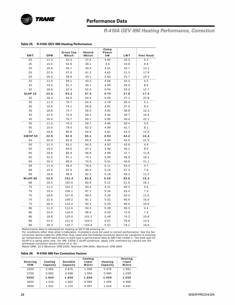
28 WSHP-PRC016-EN
Performance Data
Table 25. R-410A GEV 090 Heating Performance
EWT GPMGross Cap
MbtuhAbsorbMbtuh
Comp Power
kW LWT Feet Head
25 11.3 53.3 37.6 4.60 18.3 5.4
25 15.0 54.8 39.1 4.6 19.8 8.8
25 18.8 55.7 40.0 4.61 20.7 13.1
25 22.5 57.0 41.2 4.62 21.3 17.9
25 26.3 58.9 43.1 4.63 21.7 23.4
32 11.3 59.1 43.2 4.66 24.3 5.2
32 15.0 61.1 45.1 4.68 26.0 8.6
32 18.8 62.4 62.4 0.00 25.4 12.7
GLHP 32 22.5 63.3 47.3 4.70 27.8 17.4
32 26.3 64.5 64.5 0.00 27.1 22.8
45 11.3 70.7 54.4 4.78 35.4 5.1
45 15.0 73.1 56.6 4.81 37.4 8.3
45 18.8 74.7 58.2 4.82 38.8 12.3
45 22.5 75.8 59.2 4.84 39.7 16.9
45 26.3 76.7 60.1 4.85 40.4 22.1
50 11.3 76.3 59.7 4.86 39.4 5.0
50 15.0 79.0 62.3 4.89 41.7 8.1
50 18.8 80.8 64.0 4.91 43.2 12.0
GWHP 50 22.5 82.0 65.1 4.93 44.2 16.4
50 26.3 82.8 65.9 4.94 45.0 21.5
55 11.3 81.1 64.3 4.92 43.6 4.9
55 15.0 84.0 67.1 4.96 46.1 8.0
55 18.8 85.9 68.9 4.99 47.7 11.8
55 22.5 87.1 70.1 5.00 48.8 16.1
55 26.3 88.0 70.9 5.01 49.6 21.1
68 11.3 94.0 76.6 5.11 54.4 4.7
68 15.0 97.6 80.0 5.15 57.3 7.6
68 18.8 99.9 82.2 5.18 59.3 11.2
WLHP 68 22.5 101.4 83.6 5.20 60.6 15.3
68 26.3 102.6 84.8 5.21 61.6 20.1
75 11.3 101.2 83.4 5.21 60.2 4.5
75 15.0 105.1 87.1 5.26 63.4 7.4
75 18.8 107.6 89.5 5.29 65.5 11.0
75 22.5 109.2 91.1 5.32 66.9 15.0
75 26.3 110.4 92.2 5.33 68.0 19.6
86 11.3 112.6 94.3 5.39 69.3 4.4
86 15.0 116.9 98.4 5.44 72.9 7.2
86 18.8 120.0 101.2 5.49 75.2 10.6
86 22.5 121.9 103.0 5.51 76.8 14.5
86 26.3 122.7 103.9 5.52 78.1 18.9
Performance data is tabulated for heating at 68°F DB entering air.For conditions other than what is tabulated, multipliers must be used to correct performance. See the fancorrection factors table for CFM other than rated and the heating correction factors for variations in enteringair temperature. WLHP data shown in bold type is performance data at ARI/ISO 13256-1. The bold type forGLHP is a rating point only. For ARI 13256-1 GLHP conditions, apply 15% methanol by volume per the antifreeze correction factors found on p. 69.Rated GPM: 22.5 Minimum CFM 2400; Nominal CFM 3000, Maximum CFM 3600
Table 26. R-410A 090 Fan Correction Factors
EnteringCFM
CoolingCapacity
SensibleCapacity
CoolingInputWatts
HeatingCapacity
HeatingInputWatts
2400 0.960 0.876 1.006 0.978 1.091
2700 0.982 0.938 1.003 0.990 1.039
3000 1.000 1.000 1.000 1.000 1.000
3300 1.016 1.062 0.999 1.009 0.968
3600 1.031 1.124 0.997 1.016 0.942
R-410A GEV 090 Heating Performance, Correction

WSHP-PRC016-EN 29
Performance Data
Table 27. R-410A GEV 120 Cooling Performance
EWT GPMGross Cap
MbtuhGross Sen
Mbtuh SHRComp Power
kW Reject Mbtuh LWT Feet Head
45 15.0 144.4 105.4 0.73 4.25 158.9 66.2 4.7
45 20.0 145.9 106.0 0.73 3.87 159.1 60.9 7.9
45 25.0 146.8 106.4 0.72 3.65 159.3 57.7 11.7
45 30.0 147.4 106.6 0.72 3.50 159.4 55.6 16.2
45 35.0 147.9 106.8 0.72 3.40 159.5 54.1 21.3
55 15.0 139.9 103.8 0.74 5.02 157.1 75.9 4.6
55 20.0 141.4 104.3 0.74 4.68 157.4 70.7 7.6
55 25.0 142.3 104.6 0.74 4.46 157.5 67.6 11.3
55 30.0 142.9 104.8 0.73 4.32 157.6 65.5 15.6
55 35.0 143.3 105.0 0.73 4.22 157.7 64.0 20.5
59 15.0 138.0 102.9 0.75 5.34 156.2 79.8 4.5
59 20.0 139.4 103.5 0.74 4.99 156.4 74.6 7.5
59 25.0 140.4 103.9 0.74 4.79 156.7 71.5 11.1
GWHP 59 30.0 141.0 104.1 0.74 4.65 156.8 69.5 15.4
59 35.0 141.4 104.3 0.74 4.54 156.9 68.0 20.2
68 15.0 133.4 101.3 0.76 6.05 154.0 88.5 4.4
68 20.0 134.8 101.8 0.76 5.71 154.3 83.4 7.3
68 25.0 135.8 102.3 0.75 5.50 154.6 80.4 10.8
68 30.0 136.3 102.5 0.75 5.37 154.6 78.3 14.9
68 35.0 136.7 102.5 0.75 5.27 154.7 76.8 19.6
77 15.0 128.7 99.5 0.77 6.81 152.0 97.3 4.2
77 20.0 130.1 99.9 0.77 6.46 152.1 92.2 7.1
77 25.0 130.9 100.2 0.77 6.25 152.2 89.2 10.5
GLHP 77 30.0 131.4 100.5 0.76 6.11 152.3 87.2 14.5
77 35.0 131.8 100.6 0.76 6.02 152.3 85.7 19.0
86 15.0 123.8 97.9 0.79 7.62 149.8 106.0 4.1
86 20.0 125.1 98.3 0.79 7.26 149.9 101.0 6.9
86 25.0 125.9 98.5 0.78 7.04 149.9 98.0 10.2
WLHP 86 30.0 126.4 98.7 0.78 6.90 150.0 96.0 14.1
86 35.0 126.8 98.9 0.78 6.80 150.0 94.6 18.4
95 15.0 118.5 96.1 0.81 8.51 147.5 114.7 4.0
95 20.0 119.9 96.6 0.81 8.13 147.6 109.8 6.7
95 25.0 120.6 96.8 0.80 7.92 147.7 106.8 9.9
95 30.0 121.2 96.9 0.80 7.77 147.7 104.8 13.7
95 35.0 121.5 97.0 0.80 7.65 147.6 103.4 18.0
105 15.0 112.1 94.0 0.84 9.555 144.7 124.3 3.9
105 20.0 113.6 94.6 0.83 9.174 144.9 119.5 6.5
105 25.0 114.4 94.8 0.83 8.947 144.9 116.6 9.6
105 30.0 114.9 95.0 0.83 8.798 144.9 114.7 13.3
105 35.0 115.3 95.1 0.83 8.696 145.0 113.3 17.5
115 15.0 105.2 91.8 0.87 10.713 141.8 133.9 3.8
115 20.0 106.6 92.4 0.87 10.316 141.8 129.2 6.3
115 25.0 107.4 92.6 0.86 10.093 141.9 126.3 9.4
115 30.0 107.9 92.6 0.86 9.930 141.8 124.5 13.0
115 35.0 108.3 92.8 0.86 9.821 141.8 123.1 17.0
120 15.0 101.5 90.8 0.89 11.322 140.2 138.7 3.8
120 20.0 102.9 91.2 0.89 10.937 140.2 134.0 6.3
120 25.0 103.7 91.4 0.88 10.702 140.2 131.2 9.3
120 30.0 104.2 91.5 0.88 10.546 140.2 129.3 12.8
120 35.0 104.6 91.7 0.88 10.437 140.2 128.0 16.8
Performance data is tabulated for cooling at 80.6°F DB/66.2°F WB entering air.For conditions other than what is tabulated, multipliers must be used to correct performance. See the fan correction factors table for CFM other than ratedand the cooling correction factors for variations in entering air temperature. WLHP data shown in bold type is performance data at ARI/ISO 13256. Thebold type for GLHP is a rating point only. For ARI 13256-1 GLHP conditions, apply 15% methanol by volume per the antifreeze correction factors found onp. 69. The minimum gpm/ton is 3.0 when the EWT is greater than 115°F and the EAT is less than 67°F WB.Rated GPM: 30.0 Minimum CFM 3200; Nominal CFM 4000, Maximum CFM 4800
R-410A GEV 120 Cooling Performance
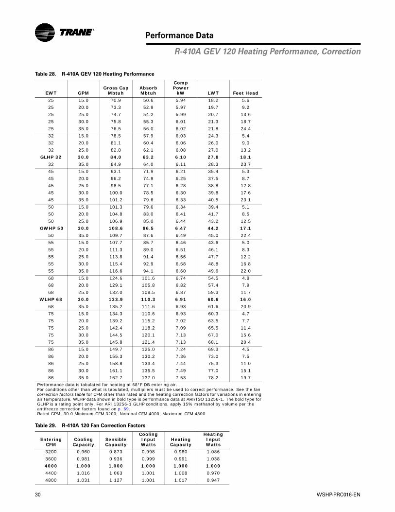
30 WSHP-PRC016-EN
Performance Data
Table 28. R-410A GEV 120 Heating Performance
EWT GPMGross Cap
MbtuhAbsorbMbtuh
Comp Power
kW LWT Feet Head
25 15.0 70.9 50.6 5.94 18.2 5.6
25 20.0 73.3 52.9 5.97 19.7 9.2
25 25.0 74.7 54.2 5.99 20.7 13.6
25 30.0 75.8 55.3 6.01 21.3 18.7
25 35.0 76.5 56.0 6.02 21.8 24.4
32 15.0 78.5 57.9 6.03 24.3 5.4
32 20.0 81.1 60.4 6.06 26.0 9.0
32 25.0 82.8 62.1 6.08 27.0 13.2
GLHP 32 30.0 84.0 63.2 6.10 27.8 18.1
32 35.0 84.9 64.0 6.11 28.3 23.7
45 15.0 93.1 71.9 6.21 35.4 5.3
45 20.0 96.2 74.9 6.25 37.5 8.7
45 25.0 98.5 77.1 6.28 38.8 12.8
45 30.0 100.0 78.5 6.30 39.8 17.6
45 35.0 101.2 79.6 6.33 40.5 23.1
50 15.0 101.3 79.6 6.34 39.4 5.1
50 20.0 104.8 83.0 6.41 41.7 8.5
50 25.0 106.9 85.0 6.44 43.2 12.5
GWHP 50 30.0 108.6 86.5 6.47 44.2 17.1
50 35.0 109.7 87.6 6.49 45.0 22.4
55 15.0 107.7 85.7 6.46 43.6 5.0
55 20.0 111.3 89.0 6.51 46.1 8.3
55 25.0 113.8 91.4 6.56 47.7 12.2
55 30.0 115.4 92.9 6.58 48.8 16.8
55 35.0 116.6 94.1 6.60 49.6 22.0
68 15.0 124.6 101.6 6.74 54.5 4.8
68 20.0 129.1 105.8 6.82 57.4 7.9
68 25.0 132.0 108.5 6.87 59.3 11.7
WLHP 68 30.0 133.9 110.3 6.91 60.6 16.0
68 35.0 135.2 111.6 6.93 61.6 20.9
75 15.0 134.3 110.6 6.93 60.3 4.7
75 20.0 139.2 115.2 7.02 63.5 7.7
75 25.0 142.4 118.2 7.09 65.5 11.4
75 30.0 144.5 120.1 7.13 67.0 15.6
75 35.0 145.8 121.4 7.13 68.1 20.4
86 15.0 149.7 125.0 7.24 69.3 4.5
86 20.0 155.3 130.2 7.36 73.0 7.5
86 25.0 158.8 133.4 7.44 75.3 11.0
86 30.0 161.1 135.5 7.49 77.0 15.1
86 35.0 162.7 137.0 7.53 78.2 19.7
Performance data is tabulated for heating at 68°F DB entering air. For conditions other than what is tabulated, multipliers must be used to correct performance. See the fancorrection factors table for CFM other than rated and the heating correction factors for variations in enteringair temperature. WLHP data shown in bold type is performance data at ARI/ISO 13256-1. The bold type forGLHP is a rating point only. For ARI 13256-1 GLHP conditions, apply 15% methanol by volume per the antifreeze correction factors found on p. 69.Rated GPM: 30.0 Minimum CFM 3200; Nominal CFM 4000, Maximum CFM 4800
Table 29. R-410A 120 Fan Correction Factors
EnteringCFM
CoolingCapacity
SensibleCapacity
CoolingInputWatts
HeatingCapacity
HeatingInputWatts
3200 0.960 0.873 0.998 0.980 1.086
3600 0.981 0.936 0.999 0.991 1.038
4000 1.000 1.000 1.000 1.000 1.000
4400 1.016 1.063 1.001 1.008 0.970
4800 1.031 1.127 1.001 1.017 0.947
R-410A GEV 120 Heating Performance, Correction

WSHP-PRC016-EN 31
Performance Data
Table 30. R-410A GEV 150 Cooling Performance
EWT GPMGross Cap
MbtuhGross Sen
Mbtuh SHRComp Power
kW Reject Mbtuh LWT Feet Head
45 18.8 183.1 131.4 0.72 6.72 206.0 66.9 4.5
45 25.0 184.8 132.1 0.71 6.31 206.4 61.5 7.5
45 31.3 186.0 132.6 0.71 6.08 206.8 58.2 11.2
45 37.5 186.8 132.9 0.71 5.93 207.0 56.0 15.4
45 43.8 188.2 133.8 0.71 5.61 207.3 54.5 20.1
55 18.8 177.3 129.4 0.73 7.47 202.8 76.6 4.4
55 25.0 179.0 130.0 0.73 7.06 203.1 71.2 7.2
55 31.3 180.1 130.4 0.72 6.81 203.3 68.0 10.8
55 37.5 180.8 130.6 0.72 6.65 203.5 65.9 14.9
55 43.8 181.3 130.8 0.72 6.54 203.6 64.3 19.6
59 18.8 174.9 128.6 0.74 7.79 201.5 80.4 4.3
59 25.0 176.6 129.2 0.73 7.38 201.8 75.1 7.1
59 31.3 177.6 129.5 0.73 7.13 202.0 71.9 10.6
GWHP 59 37.5 178.3 129.8 0.73 6.96 202.1 69.8 14.6
59 43.8 178.8 129.9 0.73 6.85 202.2 68.2 19.3
68 18.8 169.5 126.8 0.75 8.60 198.8 89.1 4.2
68 25.0 171.0 127.3 0.74 8.14 198.8 83.9 6.9
68 31.3 172.0 127.6 0.74 7.88 198.9 80.7 10.3
68 37.5 172.6 127.8 0.74 7.71 198.9 78.6 14.2
68 43.8 173.1 128.0 0.74 7.58 199.0 77.1 18.7
77 18.8 163.7 124.8 0.76 9.47 196.0 97.9 4.0
77 25.0 165.2 125.4 0.76 9.00 196.0 92.7 6.7
77 31.3 166.2 125.7 0.76 8.72 195.9 89.5 10.0
GLHP 77 37.5 166.8 125.9 0.75 8.53 195.9 87.4 13.8
77 43.8 167.2 126.0 0.75 8.40 195.8 85.9 18.1
86 18.8 157.4 122.9 0.78 10.43 193.0 106.5 3.9
86 25.0 159.1 123.4 0.78 9.96 193.1 101.4 6.5
86 31.3 160.0 123.7 0.77 9.64 192.9 98.3 9.7
WLHP 86 37.5 160.6 123.9 0.77 9.46 192.8 96.3 13.4
86 43.8 161.0 124.0 0.77 9.32 192.8 94.8 17.6
95 18.8 150.5 120.1 0.80 11.46 189.6 115.2 3.8
95 25.0 152.1 121.1 0.80 10.95 189.5 110.2 6.4
95 31.3 152.8 120.9 0.79 10.66 189.2 107.1 9.5
95 37.5 153.6 121.3 0.79 10.47 189.3 105.1 13.0
95 43.8 154.3 121.8 0.79 10.32 189.5 103.7 17.1
105 18.8 142.5 117.7 0.83 12.691 185.8 124.8 3.7
105 25.0 144.1 118.1 0.82 12.178 185.6 119.9 6.2
105 31.3 145.0 118.3 0.82 11.871 185.5 116.9 9.2
105 37.5 145.7 118.6 0.81 11.670 185.5 114.9 12.7
105 43.8 146.0 118.7 0.81 11.522 185.3 113.5 16.7
115 18.8 133.5 114.8 0.86 14.028 181.4 134.3 3.6
115 25.0 135.4 115.3 0.85 13.513 181.5 129.5 6.0
115 31.3 136.3 115.7 0.85 13.197 181.4 126.6 9.0
115 37.5 137.0 116.0 0.85 12.986 181.3 124.7 12.4
115 43.8 137.4 116.1 0.85 12.834 181.2 123.3 16.2
120 18.8 129.0 113.3 0.88 14.730 179.3 139.1 3.6
120 25.0 130.6 114.0 0.87 14.218 179.2 134.3 6.0
120 31.3 131.6 114.3 0.87 13.898 179.0 131.4 8.9
120 37.5 132.2 114.4 0.87 13.689 178.9 129.5 12.2
120 43.8 133.1 114.7 0.86 13.543 179.3 128.2 16.0
Performance data is tabulated for cooling at 80.6°F DB/66.2°F WB entering air.For conditions other than what is tabulated, multipliers must be used to correct performance. See the fan correction factors table for CFM other thanrated and the cooling correction factors for variations in entering air temperature. WLHP data shown in bold type is performance data at ARI/ISO 13256.The bold type for GLHP is a rating point only. For ARI 13256-1 GLHP conditions, apply 15% methanol by volume per the antifreeze correction factorsfound on p. 69. The minimum gpm/ton is 3.0 when the EWT is greater than 115°F and the EAT is less than 67°F WB.Rated GPM: 37.5 Minimum CFM 4000; Nominal CFM 5000, Maximum CFM 6000
R-410A GEV 150 Cooling Performance

32 WSHP-PRC016-EN
Performance Data
Table 31. R-410A GEV 150 Heating Performance
EWT GPMGross Cap
MbtuhAbsorbMbtuh
Comp Power
kW LWT Feet Head
25 18.8 101.0 72.1 8.48 17.3 5.2
25 25.0 103.8 74.8 8.51 19.0 8.5
25 31.3 106.0 76.8 8.54 20.1 12.6
25 37.5 107.2 78.0 8.54 20.8 17.3
25 43.8 108.3 79.1 8.56 21.4 22.6
32 18.8 111.2 81.9 8.60 23.3 5.1
32 25.0 114.8 85.4 8.63 25.2 8.3
32 31.3 116.5 87.0 8.62 26.4 12.3
GLHP 32 37.5 118.1 88.6 8.65 27.3 16.8
32 43.8 119.1 89.6 8.65 27.9 22.0
45 18.8 131.3 101.2 8.83 34.2 4.9
45 25.0 135.4 105.1 8.87 36.6 8.1
45 31.3 138.0 107.7 8.88 38.1 11.9
45 37.5 139.5 109.2 8.89 39.2 16.3
45 43.8 140.7 110.4 8.90 40.0 21.4
50 18.8 142.2 111.5 8.99 38.1 4.8
50 25.0 146.7 115.9 9.05 40.7 7.8
50 31.3 149.4 118.5 9.07 42.4 11.6
GWHP 50 37.5 151.0 120.0 9.08 43.6 15.9
50 43.8 151.9 120.9 9.08 44.5 20.8
55 18.8 150.8 119.7 9.12 42.3 4.7
55 25.0 155.9 124.5 9.18 45.0 7.7
55 31.3 158.6 127.2 9.21 46.9 11.4
55 37.5 160.1 128.7 9.22 48.1 15.5
55 43.8 161.3 129.8 9.22 49.1 20.4
68 18.8 174.1 141.7 9.49 52.9 4.5
68 25.0 180.1 147.4 9.56 56.2 7.3
68 31.3 183.6 150.9 9.59 58.4 10.8
WLHP 68 37.5 185.7 152.9 9.61 59.8 14.8
68 43.8 186.9 154.1 9.62 61.0 19.4
75 18.8 187.3 154.2 9.70 58.6 4.4
75 25.0 194.0 160.6 9.79 62.2 7.2
75 31.3 198.1 164.5 9.83 64.5 10.6
75 37.5 200.4 166.8 9.86 66.1 14.5
75 43.8 201.5 167.9 9.84 67.3 19.0
86 18.8 209.0 174.6 10.06 67.4 4.2
86 25.0 217.2 182.4 10.18 71.4 6.9
86 31.3 222.0 187.1 10.25 74.0 10.2
86 37.5 224.5 189.4 10.27 75.9 14.0
86 43.8 225.7 190.6 10.27 77.3 18.3
Performance data is tabulated for heating at 68°F DB entering air. For conditions other than what is tabulated, multipliers must be used to correct performance. See the fancorrection factors table for CFM other than rated and the heating correction factors for variations in enteringair temperature. WLHP data shown in bold type is performance data at ARI/ISO 13256-1. The bold type forGLHP is a rating point only. For ARI 13256-1 GLHP conditions, apply 15% methanol by volume per the antifreeze correction factors found on p. 69.Rated GPM: 37.5 Minimum CFM 4000; Nominal CFM 5000, Maximum CFM 6000
Table 32. R-410A 150 Fan Correction Factors
EnteringCFM
CoolingCapacity
SensibleCapacity
CoolingInputWatts
HeatingCapacity
HeatingInputWatts
4000 0.958 0.873 0.998 0.980 1.086
4500 0.980 0.936 0.999 0.991 1.038
5000 1.000 1.000 1.000 1.000 1.000
5500 1.017 1.063 1.001 1.008 0.970
6000 1.032 1.127 1.001 1.017 0.947
R-410A GEV 150 Heating Performance, Correction
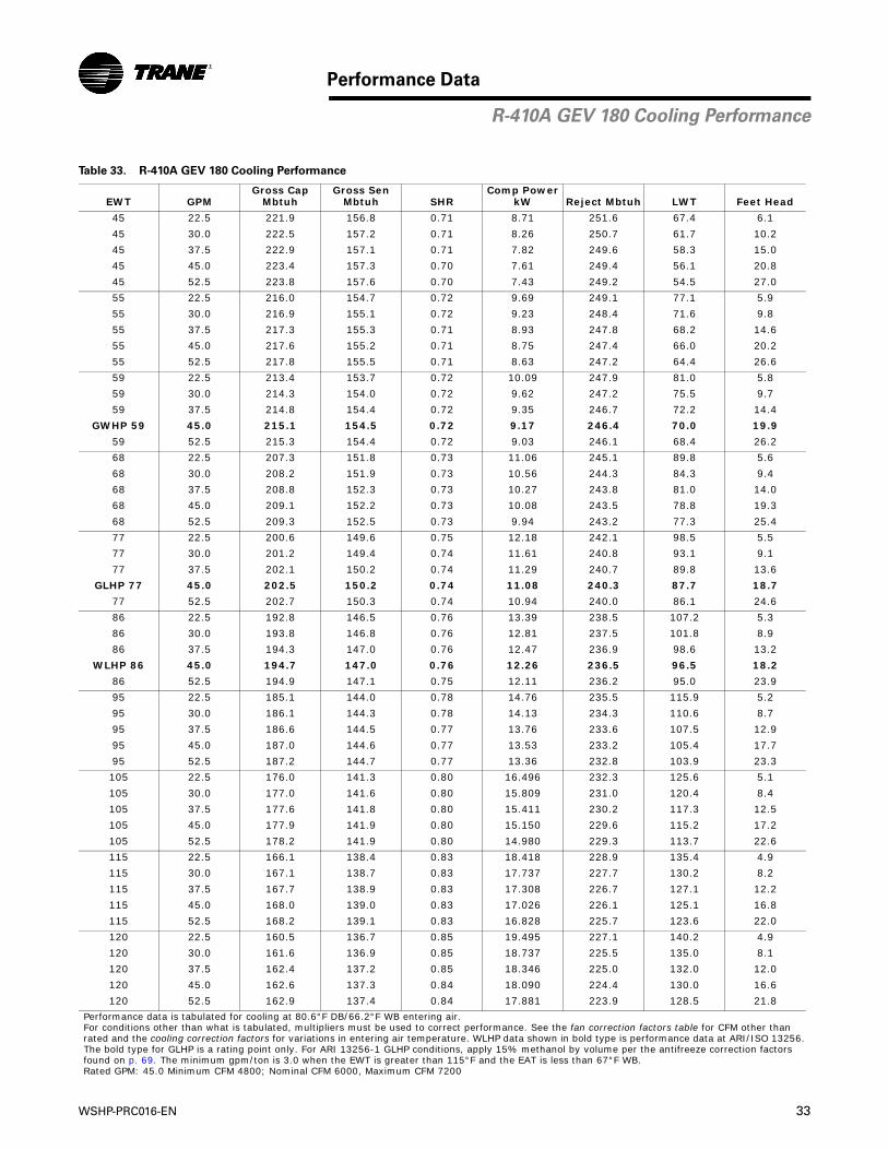
WSHP-PRC016-EN 33
Performance Data
Table 33. R-410A GEV 180 Cooling Performance
EWT GPMGross Cap
MbtuhGross Sen
Mbtuh SHRComp Power
kW Reject Mbtuh LWT Feet Head
45 22.5 221.9 156.8 0.71 8.71 251.6 67.4 6.1
45 30.0 222.5 157.2 0.71 8.26 250.7 61.7 10.2
45 37.5 222.9 157.1 0.71 7.82 249.6 58.3 15.0
45 45.0 223.4 157.3 0.70 7.61 249.4 56.1 20.8
45 52.5 223.8 157.6 0.70 7.43 249.2 54.5 27.0
55 22.5 216.0 154.7 0.72 9.69 249.1 77.1 5.9
55 30.0 216.9 155.1 0.72 9.23 248.4 71.6 9.8
55 37.5 217.3 155.3 0.71 8.93 247.8 68.2 14.6
55 45.0 217.6 155.2 0.71 8.75 247.4 66.0 20.2
55 52.5 217.8 155.5 0.71 8.63 247.2 64.4 26.6
59 22.5 213.4 153.7 0.72 10.09 247.9 81.0 5.8
59 30.0 214.3 154.0 0.72 9.62 247.2 75.5 9.7
59 37.5 214.8 154.4 0.72 9.35 246.7 72.2 14.4
GWHP 59 45.0 215.1 154.5 0.72 9.17 246.4 70.0 19.9
59 52.5 215.3 154.4 0.72 9.03 246.1 68.4 26.2
68 22.5 207.3 151.8 0.73 11.06 245.1 89.8 5.6
68 30.0 208.2 151.9 0.73 10.56 244.3 84.3 9.4
68 37.5 208.8 152.3 0.73 10.27 243.8 81.0 14.0
68 45.0 209.1 152.2 0.73 10.08 243.5 78.8 19.3
68 52.5 209.3 152.5 0.73 9.94 243.2 77.3 25.4
77 22.5 200.6 149.6 0.75 12.18 242.1 98.5 5.5
77 30.0 201.2 149.4 0.74 11.61 240.8 93.1 9.1
77 37.5 202.1 150.2 0.74 11.29 240.7 89.8 13.6
GLHP 77 45.0 202.5 150.2 0.74 11.08 240.3 87.7 18.7
77 52.5 202.7 150.3 0.74 10.94 240.0 86.1 24.6
86 22.5 192.8 146.5 0.76 13.39 238.5 107.2 5.3
86 30.0 193.8 146.8 0.76 12.81 237.5 101.8 8.9
86 37.5 194.3 147.0 0.76 12.47 236.9 98.6 13.2
WLHP 86 45.0 194.7 147.0 0.76 12.26 236.5 96.5 18.2
86 52.5 194.9 147.1 0.75 12.11 236.2 95.0 23.9
95 22.5 185.1 144.0 0.78 14.76 235.5 115.9 5.2
95 30.0 186.1 144.3 0.78 14.13 234.3 110.6 8.7
95 37.5 186.6 144.5 0.77 13.76 233.6 107.5 12.9
95 45.0 187.0 144.6 0.77 13.53 233.2 105.4 17.7
95 52.5 187.2 144.7 0.77 13.36 232.8 103.9 23.3
105 22.5 176.0 141.3 0.80 16.496 232.3 125.6 5.1
105 30.0 177.0 141.6 0.80 15.809 231.0 120.4 8.4
105 37.5 177.6 141.8 0.80 15.411 230.2 117.3 12.5
105 45.0 177.9 141.9 0.80 15.150 229.6 115.2 17.2
105 52.5 178.2 141.9 0.80 14.980 229.3 113.7 22.6
115 22.5 166.1 138.4 0.83 18.418 228.9 135.4 4.9
115 30.0 167.1 138.7 0.83 17.737 227.7 130.2 8.2
115 37.5 167.7 138.9 0.83 17.308 226.7 127.1 12.2
115 45.0 168.0 139.0 0.83 17.026 226.1 125.1 16.8
115 52.5 168.2 139.1 0.83 16.828 225.7 123.6 22.0
120 22.5 160.5 136.7 0.85 19.495 227.1 140.2 4.9
120 30.0 161.6 136.9 0.85 18.737 225.5 135.0 8.1
120 37.5 162.4 137.2 0.85 18.346 225.0 132.0 12.0
120 45.0 162.6 137.3 0.84 18.090 224.4 130.0 16.6
120 52.5 162.9 137.4 0.84 17.881 223.9 128.5 21.8
Performance data is tabulated for cooling at 80.6°F DB/66.2°F WB entering air.For conditions other than what is tabulated, multipliers must be used to correct performance. See the fan correction factors table for CFM other thanrated and the cooling correction factors for variations in entering air temperature. WLHP data shown in bold type is performance data at ARI/ISO 13256.The bold type for GLHP is a rating point only. For ARI 13256-1 GLHP conditions, apply 15% methanol by volume per the antifreeze correction factorsfound on p. 69. The minimum gpm/ton is 3.0 when the EWT is greater than 115°F and the EAT is less than 67°F WB.Rated GPM: 45.0 Minimum CFM 4800; Nominal CFM 6000, Maximum CFM 7200
R-410A GEV 180 Cooling Performance
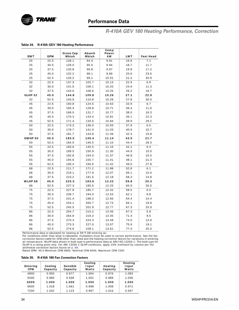
34 WSHP-PRC016-EN
Performance Data
Table 34. R-410A GEV 180 Heating Performance
EWT GPMGross Cap
MbtuhAbsorbMbtuh
Comp Power
kW LWT Feet Head
25 22.5 128.1 94.3 9.91 16.6 7.1
25 30.0 129.0 95.0 9.94 18.7 11.7
25 37.5 130.8 96.8 9.97 19.8 17.2
25 45.0 132.2 98.1 9.99 20.6 23.6
25 52.5 133.2 99.1 10.01 21.2 30.9
32 22.5 137.3 102.7 10.13 22.9 6.9
32 30.0 141.0 106.1 10.20 24.9 11.3
32 37.5 143.6 108.6 10.25 26.2 16.7
GLHP 32 45.0 144.8 109.8 10.26 27.1 22.9
32 52.5 145.9 110.8 10.28 27.8 30.0
45 22.5 160.8 124.5 10.63 33.9 6.7
45 30.0 165.4 128.8 10.71 36.4 11.0
45 37.5 168.5 131.7 10.77 38.0 16.3
45 45.0 170.3 133.4 10.81 39.1 22.3
45 52.5 171.4 134.5 10.84 39.9 29.2
50 22.5 173.3 136.0 10.93 37.9 6.5
50 30.0 178.7 141.0 11.03 40.6 10.7
50 37.5 181.7 143.8 11.09 42.3 15.8
GWHP 50 45.0 183.5 145.4 11.14 43.5 21.7
50 52.5 184.5 146.5 11.15 44.4 28.3
55 22.5 183.6 145.5 11.16 42.1 6.4
55 30.0 189.5 150.9 11.30 44.9 10.5
55 37.5 192.8 154.0 11.37 46.8 15.5
55 45.0 194.6 155.7 11.41 48.1 21.3
55 52.5 195.4 156.5 11.42 49.0 27.8
68 22.5 211.7 171.2 11.88 52.8 6.1
68 30.0 219.1 177.9 12.07 56.1 10.0
68 37.5 223.2 181.6 12.18 58.3 14.8
WLHP 68 45.0 225.3 183.6 12.22 59.8 20.3
68 52.5 227.3 185.5 12.25 60.9 26.5
75 22.5 227.8 185.7 12.32 58.5 6.0
75 30.0 236.7 194.0 12.53 62.1 9.8
75 37.5 241.4 198.2 12.66 64.4 14.4
75 45.0 244.1 200.7 12.73 66.1 19.8
75 52.5 245.5 201.9 12.77 67.3 25.9
86 22.5 254.7 210.2 13.06 67.3 5.8
86 30.0 264.8 219.2 13.35 71.4 9.5
86 37.5 270.3 224.3 13.48 74.0 13.9
86 45.0 273.3 227.0 13.57 75.9 19.1
86 52.5 274.6 228.1 13.61 77.3 25.0
Performance data is tabulated for heating at 68°F DB entering air.For conditions other than what is tabulated, multipliers must be used to correct performance. See the fancorrection factors table for CFM other than rated and the heating correction factors for variations in enteringair temperature. WLHP data shown in bold type is performance data at ARI/ISO 13256-1. The bold type forGLHP is a rating point only. For ARI 13256-1 GLHP conditions, apply 15% methanol by volume per the antifreeze correction factors found on p. 69.Rated GPM: 45.0 Minimum CFM 4800; Nominal CFM 6000, Maximum CFM 7200
Table 35. R-410A 180 Fan Correction Factors
EnteringCFM
CoolingCapacity
SensibleCapacity
CoolingInputWatts
HeatingCapacity
HeatingInputWatts
4800 0.955 0.877 1.004 0.976 1.083
5400 0.980 0.938 1.001 0.989 1.036
6000 1.000 1.000 1.000 1.000 1.000
6600 1.018 1.061 0.998 1.008 0.971
7200 1.032 1.123 0.997 1.016 0.947
R-410A GEV 180 Heating Performance, Correction

WSHP-PRC016-EN 35
Performance Data
Table 36. R-410A GEV 240 Cooling Performance
EWT GPMGross Cap
MbtuhGross Sen
Mbtuh SHRComp Power
kW Reject Mbtuh LWT Feet Head
45 30.0 296.8 219.9 0.74 9.96 330.8 67.1 4.7
45 40.0 298.7 220.8 0.74 9.40 330.8 61.5 7.9
45 50.0 299.5 220.7 0.74 9.11 330.6 58.2 11.5
45 60.0 301.5 221.7 0.74 8.82 331.6 56.1 16.2
45 70.0 303.2 222.2 0.73 8.59 332.5 54.5 20.8
55 30.0 288.5 217.3 0.75 11.23 326.9 76.8 4.5
55 40.0 290.6 218.1 0.75 10.65 326.9 71.3 7.6
55 50.0 291.9 218.5 0.75 10.30 327.0 68.1 11.3
55 60.0 292.7 218.8 0.75 10.07 327.1 65.9 15.6
55 70.0 293.4 219.0 0.75 9.91 327.2 64.3 20.5
59 30.0 285.2 215.9 0.76 11.78 325.4 80.7 4.5
59 40.0 287.2 216.8 0.75 11.16 325.3 75.3 7.5
59 50.0 288.3 217.0 0.75 10.81 325.2 72.0 11.1
GWHP 59 60.0 289.1 217.5 0.75 10.58 325.2 69.8 15.4
59 70.0 289.7 217.5 0.75 10.42 325.2 68.3 20.2
68 30.0 277.5 213.1 0.77 13.04 322.0 89.5 4.3
68 40.0 279.1 213.7 0.77 12.42 321.5 84.1 7.3
68 50.0 280.2 214.1 0.76 12.04 321.3 80.9 10.8
68 60.0 280.8 214.3 0.76 11.81 321.1 78.7 14.9
68 70.0 281.3 214.5 0.76 11.64 321.0 77.2 19.5
77 30.0 269.1 210.1 0.78 14.44 318.4 98.2 4.2
77 40.0 270.7 210.6 0.78 13.78 317.7 92.9 7.0
77 50.0 271.5 210.9 0.78 13.40 317.3 89.7 10.5
GLHP 77 60.0 272.2 211.1 0.78 13.15 317.0 87.6 14.4
77 70.0 272.6 211.3 0.78 12.97 316.8 86.1 19.0
86 30.0 260.0 206.8 0.80 15.98 314.6 107.0 4.1
86 40.0 261.5 207.3 0.79 15.23 313.5 101.7 6.9
86 50.0 262.4 207.6 0.79 14.82 312.9 98.5 10.2
WLHP 86 60.0 262.9 207.8 0.79 14.55 312.6 96.4 14.0
86 70.0 263.3 207.9 0.79 14.36 312.3 94.9 18.4
95 30.0 250.2 203.5 0.81 17.68 310.6 115.7 4.0
95 40.0 251.6 204.0 0.81 16.92 309.4 110.5 6.7
95 50.0 252.4 204.3 0.81 16.48 308.7 107.3 9.9
95 60.0 253.0 204.5 0.81 16.20 308.2 105.3 13.7
95 70.0 253.3 204.6 0.81 16.00 307.9 103.8 17.9
105 30.0 238.2 199.5 0.84 19.841 305.9 125.4 3.9
105 40.0 239.6 200.0 0.83 18.996 304.4 120.2 6.5
105 50.0 240.4 200.2 0.83 18.516 303.6 117.1 9.6
105 60.0 240.9 200.4 0.83 18.205 303.0 115.1 13.3
105 70.0 241.3 200.5 0.83 17.987 302.7 113.6 17.4
115 30.0 224.7 195.4 0.87 22.283 300.8 135.1 3.8
115 40.0 226.3 195.9 0.87 21.396 299.3 130.0 6.3
115 50.0 227.1 196.2 0.86 20.879 298.4 126.9 9.4
115 60.0 227.6 196.4 0.86 20.540 297.7 124.9 13.0
115 70.0 228.0 196.5 0.86 20.303 297.3 123.5 17.0
120 30.0 217.1 193.0 0.89 23.680 297.9 139.9 3.8
120 40.0 218.8 193.5 0.88 22.787 296.5 134.8 6.3
120 50.0 219.6 193.7 0.88 22.245 295.5 131.8 9.3
120 60.0 220.2 193.9 0.88 21.893 294.9 129.8 12.8
120 70.0 219.9 193.9 0.88 21.602 293.6 128.4 16.8
Performance data is tabulated for cooling at 80.6°F DB/66.2°F WB entering air.For conditions other than what is tabulated, multipliers must be used to correct performance. See the fan correction factors table for CFM other thanrated and the cooling correction factors for variations in entering air temperature. WLHP data shown in bold type is performance data at ARI/ISO 13256.The bold type for GLHP is a rating point only. For ARI 13256-1 GLHP conditions, apply 15% methanol by volume per the antifreeze correction factorsfound on p. 69. The minimum gpm/ton is 3.0 when the EWT is greater than 115°F and the EAT is less than 67°F WB.Rated GPM: 60.0 Minimum CFM 6400; Nominal CFM 8000, Maximum CFM 9600
R-410A GEV 240 Cooling Performance

36 WSHP-PRC016-EN
Performance Data
Table 37. R-410A GEV 240 Heating Performance
EWT GPMGross Cap
MbtuhAbsorbMbtuh
Comp Power
kW LWT Feet Head
25 30.0 147.5 106.2 12.09 17.9 5.6
25 40.0 152.0 110.4 12.18 19.5 9.2
25 50.0 154.9 113.2 12.24 20.5 13.6
25 60.0 157.0 115.1 12.29 21.2 18.7
25 70.0 158.6 116.5 12.33 21.7 24.4
32 30.0 162.8 120.7 12.36 24.0 5.4
32 40.0 168.1 125.6 12.45 25.7 9.0
32 50.0 171.6 128.8 12.51 26.8 13.2
GLHP 32 60.0 173.9 131.1 12.54 27.6 18.1
32 70.0 175.7 132.8 12.58 28.2 23.7
45 30.0 192.9 149.1 12.82 35.1 5.3
45 40.0 199.9 155.7 12.95 37.2 8.7
45 50.0 204.5 160.0 13.04 38.6 12.8
45 60.0 207.7 163.0 13.10 39.6 17.6
45 70.0 210.1 165.3 13.14 40.3 23.1
50 30.0 208.1 163.2 13.14 39.1 5.1
50 40.0 215.5 170.2 13.26 41.5 8.5
50 50.0 220.3 174.7 13.35 43.0 12.5
GWHP 50 60.0 223.7 177.9 13.43 44.1 17.1
50 70.0 226.3 180.3 13.48 44.8 22.4
55 30.0 221.0 175.4 13.38 43.3 5.1
55 40.0 229.2 183.0 13.54 45.8 8.3
55 50.0 234.6 188.1 13.64 47.5 12.2
55 60.0 238.4 191.6 13.72 48.6 16.8
55 70.0 241.3 194.2 13.78 49.5 22.0
68 30.0 256.8 208.6 14.13 54.1 4.8
68 40.0 267.2 218.3 14.33 57.1 7.9
68 50.0 274.1 224.7 14.48 59.0 11.7
WLHP 68 60.0 279.1 229.3 14.60 60.4 16.0
68 70.0 282.8 232.7 14.69 61.4 21.0
75 30.0 277.2 227.5 14.56 59.8 4.7
75 40.0 289.1 238.4 14.85 63.1 7.7
75 50.0 297.2 245.8 15.05 65.2 11.4
75 60.0 302.7 250.8 15.19 66.6 15.7
75 70.0 307.0 254.7 15.31 67.7 20.5
86 30.0 310.9 258.3 15.42 68.8 4.6
86 40.0 325.4 271.5 15.77 72.4 7.5
86 50.0 334.7 280.0 16.03 74.8 11.0
86 60.0 341.1 285.8 16.21 76.5 15.1
86 70.0 345.9 290.1 16.35 77.7 19.7
Performance data is tabulated for heating at 68°F DB entering air. For conditions other than what is tabulated, multipliers must be used to correct performance. See the fancorrection factors table for CFM other than rated and the heating correction factors for variations in enteringair temperature. WLHP data shown in bold type is performance data at ARI/ISO 13256-1. The bold type forGLHP is a rating point only. For ARI 13256-1 GLHP conditions, apply 15% methanol by volume per the antifreeze correction factors found on p. 69.Rated GPM: 60.0 Minimum CFM 6400; Nominal CFM 8000, Maximum CFM 9600
Table 38. R-410A 240 Fan Correction Factors
EnteringCFM
CoolingCapacity
SensibleCapacity
CoolingInputWatts
HeatingCapacity
HeatingInputWatts
6400 0.958 0.872 0.997 0.973 1.074
7200 0.981 0.936 0.998 0.988 1.031
8000 1.000 1.000 1.000 1.000 1.000
8800 1.017 1.065 1.001 1.010 0.975
9600 1.032 1.130 1.003 1.018 0.955
R-410A GEV 240 Heating Performance, Correction
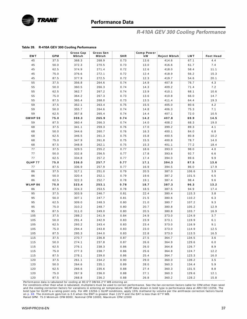
WSHP-PRC016-EN 37
Performance Data
Table 39. R-410A GEV 300 Cooling Performance
EWT GPMGross Cap
MbtuhGross Sen
Mbtuh SHRComp Power
kW Reject Mbtuh LWT Feet Head
45 37.5 368.3 268.9 0.73 13.6 414.6 67.1 4.4
45 50.0 372.3 270.5 0.73 13.0 416.6 61.7 7.4
45 62.5 374.9 271.4 0.72 12.6 418.0 58.4 11.1
45 75.0 376.6 272.1 0.72 12.4 418.9 56.2 15.3
45 87.5 377.9 272.5 0.72 12.3 419.7 54.6 20.1
55 37.5 356.8 264.6 0.74 14.9 407.8 76.7 4.3
55 50.0 360.5 266.3 0.74 14.3 409.2 71.4 7.2
55 62.5 362.7 267.2 0.74 13.9 410.1 68.1 10.6
55 75.0 364.2 267.3 0.73 13.6 410.8 66.0 14.7
55 87.5 365.4 268.0 0.73 13.5 411.4 64.4 19.3
59 37.5 352.1 263.4 0.75 15.5 405.0 80.6 4.2
59 50.0 355.7 264.6 0.74 14.8 406.3 75.3 7.1
59 62.5 357.8 265.4 0.74 14.4 407.1 72.0 10.5
GWHP 59 75.0 359.3 265.9 0.74 14.2 407.8 69.9 14.5
59 87.5 360.4 266.3 0.74 14.0 408.2 68.3 19.0
68 37.5 341.1 259.3 0.76 17.0 399.2 89.3 4.1
68 50.0 344.6 260.7 0.76 16.3 400.1 84.0 6.8
68 62.5 346.5 261.3 0.75 15.8 400.5 80.8 10.2
68 75.0 347.9 261.8 0.75 15.5 400.8 78.7 14.0
68 87.5 348.8 262.1 0.75 15.3 401.1 77.2 18.4
77 37.5 329.5 255.2 0.77 18.6 393.0 98.0 4.0
77 50.0 332.8 256.5 0.77 17.8 393.6 92.7 6.6
77 62.5 334.8 257.2 0.77 17.4 394.0 89.6 9.9
GLHP 77 75.0 336.0 257.7 0.77 17.1 394.3 87.5 13.6
77 87.5 336.9 257.9 0.77 16.9 394.5 86.0 17.9
86 37.5 317.1 251.0 0.79 20.5 387.0 106.6 3.9
86 50.0 320.4 252.1 0.79 19.6 387.2 101.5 6.5
86 62.5 322.3 252.7 0.78 19.1 387.4 98.4 9.6
WLHP 86 75.0 323.4 253.1 0.78 18.7 387.3 96.3 13.2
86 87.5 324.3 253.5 0.78 18.5 387.5 94.9 17.4
95 37.5 303.9 246.7 0.81 22.4 380.4 115.3 3.8
95 50.0 307.1 247.7 0.81 21.5 380.6 110.2 6.3
95 62.5 309.0 248.3 0.80 21.0 380.7 107.2 9.3
95 75.0 310.2 248.7 0.80 20.7 380.8 105.2 12.9
95 87.5 311.0 249.0 0.80 20.5 380.8 103.7 16.9
105 37.5 288.2 241.9 0.84 24.9 373.0 124.9 3.7
105 50.0 291.4 242.9 0.83 23.9 373.1 119.9 6.1
105 62.5 293.2 243.4 0.83 23.4 373.0 116.9 9.1
105 75.0 294.4 243.8 0.83 23.0 373.0 114.9 12.5
105 87.5 295.3 244.0 0.83 22.8 373.0 113.5 16.5
115 37.5 270.7 236.8 0.87 27.5 364.7 134.5 3.6
115 50.0 274.1 237.8 0.87 26.6 364.9 129.6 6.0
115 62.5 276.1 238.3 0.86 26.0 364.8 126.7 8.9
115 75.0 277.3 238.7 0.86 25.6 364.8 124.7 12.2
115 87.5 278.1 239.0 0.86 25.4 364.7 123.3 16.0
120 37.5 261.1 234.2 0.90 29.0 360.0 139.2 3.5
120 50.0 264.6 235.1 0.89 28.0 360.3 134.4 5.9
120 62.5 266.6 235.6 0.88 27.4 360.3 131.5 8.8
120 75.0 267.9 236.0 0.88 27.1 360.3 129.6 12.1
120 87.5 268.8 236.2 0.88 26.8 360.2 128.2 15.8
Performance data is tabulated for cooling at 80.6°F DB/66.2°F WB entering air.For conditions other than what is tabulated, multipliers must be used to correct performance. See the fan correction factors table for CFM other than ratedand the cooling correction factors for variations in entering air temperature. WLHP data shown in bold type is performance data at ARI/ISO 13256. Thebold type for GLHP is a rating point only. For ARI 13256-1 GLHP conditions, apply 15% methanol by volume per the antifreeze correction factors foundon p. 69. The minimum gpm/ton is 3.0 when the EWT is greater than 115°F and the EAT is less than 67°F WB.Rated GPM: 75.0 Minimum CFM 8000; Nominal CFM 10000, Maximum CFM 12000
R-410A GEV 300 Cooling Performance

38 WSHP-PRC016-EN
Performance Data
Table 40. R-410A GEV 300 Heating Performance
EWT GPMGross Cap
MbtuhAbsorbMbtuh
Comp Power
kW LWT Feet Head
25 37.5 196.7 139.7 16.7 17.5 5.2
25 50.0 202.7 145.2 16.8 19.2 8.5
25 62.5 206.6 148.8 16.9 20.2 12.6
25 75.0 209.3 151.3 17.0 21.0 17.3
25 87.5 211.4 153.1 17.1 21.5 22.6
32 37.5 216.0 157.8 17.04 23.6 5.0
32 50.0 223.0 164.3 17.22 25.4 8.3
32 62.5 227.6 168.5 17.33 26.6 12.2
GLHP 32 75.0 230.9 171.4 17.41 27.4 16.8
32 87.5 233.3 173.7 17.48 28.0 21.9
45 37.5 254.4 193.5 17.83 34.7 4.9
45 50.0 263.6 202.1 18.02 36.9 8.1
45 62.5 269.6 207.6 18.17 38.4 11.9
45 75.0 273.7 211.5 18.25 39.4 16.3
45 87.5 276.9 214.4 18.31 40.1 21.3
50 37.5 273.9 211.1 18.41 38.7 4.8
50 50.0 283.6 220.1 18.62 41.2 7.8
50 62.5 289.9 225.9 18.74 42.8 11.5
GWHP 50 75.0 294.2 230.0 18.83 43.9 15.8
50 87.5 297.6 233.0 18.90 44.7 20.7
55 37.5 290.3 226.2 18.77 42.9 4.7
55 50.0 300.9 236.1 19.00 45.6 7.7
55 62.5 307.8 242.5 19.14 47.2 11.3
55 75.0 312.7 247.0 19.26 48.4 15.5
55 87.5 316.5 250.5 19.34 49.3 20.3
68 37.5 335.3 267.4 19.87 53.7 4.5
68 50.0 348.7 279.8 20.19 56.8 7.3
68 62.5 357.6 287.9 20.40 58.8 10.8
WLHP 68 75.0 363.7 293.6 20.56 60.2 14.8
68 87.5 368.2 297.7 20.66 61.2 19.4
75 37.5 360.7 290.6 20.55 59.5 4.4
75 50.0 375.8 304.5 20.90 62.8 7.2
75 62.5 385.6 313.5 21.15 65.0 10.5
75 75.0 392.4 319.7 21.28 66.5 14.5
75 87.5 397.4 324.4 21.41 67.6 18.9
86 37.5 402.2 328.3 21.65 68.5 4.2
86 50.0 419.9 344.4 22.13 72.2 6.9
86 62.5 432.0 355.2 22.49 74.6 10.2
86 75.0 440.0 362.5 22.71 76.3 14.0
86 87.5 445.9 368.0 22.83 77.6 18.3
Performance data is tabulated for heating at 68°F DB entering air. For conditions other than what is tabulated, multipliers must be used to correct performance. See the fancorrection factors table for CFM other than rated and the heating correction factors for variations in enteringair temperature. WLHP data shown in bold type is performance data at ARI/ISO 13256-1. The bold type forGLHP is a rating point only. For ARI 13256-1 GLHP conditions, apply 15% methanol by volume per the antifreeze correction factors found on p. 69.Rated GPM: 75.0 Minimum CFM 8000; Nominal CFM 10000, Maximum CFM 12000
Table 41. R-410A 300 Fan Correction Factors
EnteringCFM
CoolingCapacity
SensibleCapacity
CoolingInputWatts
HeatingCapacity
HeatingInputWatts
8000 0.958 0.872 0.997 0.973 1.074
9000 0.981 0.936 0.998 0.988 1.031
10000 1.000 1.000 1.000 1.000 1.000
11000 1.017 1.065 1.001 1.010 0.975
12000 1.032 1.130 1.003 1.018 0.955
R-410A GEV 300 Heating Performance, Correction
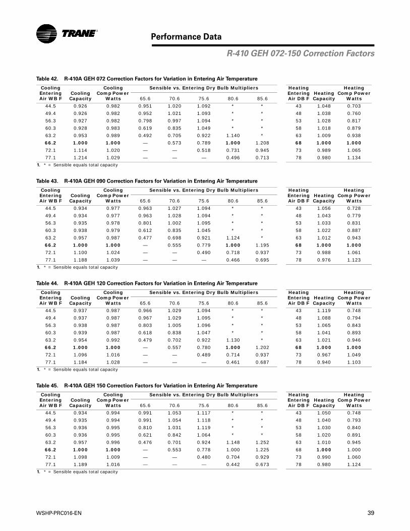
WSHP-PRC016-EN 39
Performance Data
Table 42. R-410A GEH 072 Correction Factors for Variation in Entering Air Temperature
Cooling Entering Air WB F
Cooling Capacity
Cooling Comp Power
Watts
Sensible vs. Entering Dry Bulb Multipliers Heating Entering Air DB F
Heating Capacity
Heating Comp Power
Watts65.6 70.6 75.6 80.6 85.6
44.5 0.926 0.982 0.951 1.020 1.092 * * 43 1.048 0.703
49.4 0.926 0.982 0.952 1.021 1.093 * * 48 1.038 0.760
56.3 0.927 0.982 0.798 0.997 1.094 * * 53 1.028 0.817
60.3 0.928 0.983 0.619 0.835 1.049 * * 58 1.018 0.879
63.2 0.953 0.989 0.492 0.705 0.922 1.140 * 63 1.009 0.938
66.2 1.000 1.000 — 0.573 0.789 1.000 1.208 68 1.000 1.000
72.1 1.114 1.020 — — 0.518 0.731 0.945 73 0.989 1.065
77.1 1.214 1.029 — — — 0.496 0.713 78 0.980 1.134
1. * = Sensible equals total capacity
Table 43. R-410A GEH 090 Correction Factors for Variation in Entering Air Temperature
Cooling Entering Air WB F
Cooling Capacity
Cooling Comp Power
Watts
Sensible vs. Entering Dry Bulb Multipliers Heating Entering Air DB F
Heating Capacity
Heating Comp Power
Watts65.6 70.6 75.6 80.6 85.6
44.5 0.934 0.977 0.963 1.027 1.094 * * 43 1.056 0.728
49.4 0.934 0.977 0.963 1.028 1.094 * * 48 1.043 0.779
56.3 0.935 0.978 0.801 1.002 1.095 * * 53 1.033 0.831
60.3 0.938 0.979 0.612 0.835 1.045 * * 58 1.022 0.887
63.2 0.957 0.987 0.477 0.698 0.921 1.124 * 63 1.012 0.943
66.2 1.000 1.000 — 0.555 0.779 1.000 1.195 68 1.000 1.000
72.1 1.100 1.024 — — 0.490 0.718 0.937 73 0.988 1.061
77.1 1.188 1.039 — — — 0.466 0.695 78 0.976 1.123
1. * = Sensible equals total capacity
Table 44. R-410A GEH 120 Correction Factors for Variation in Entering Air Temperature
Cooling Entering Air WB F
Cooling Capacity
Cooling Comp Power
Watts
Sensible vs. Entering Dry Bulb Multipliers Heating Entering Air DB F
Heating Capacity
Heating Comp Power
Watts65.6 70.6 75.6 80.6 85.6
44.5 0.937 0.987 0.966 1.029 1.094 * * 43 1.119 0.748
49.4 0.937 0.987 0.967 1.029 1.095 * * 48 1.088 0.794
56.3 0.938 0.987 0.803 1.005 1.096 * * 53 1.065 0.843
60.3 0.939 0.987 0.618 0.838 1.047 * * 58 1.041 0.893
63.2 0.954 0.992 0.479 0.702 0.922 1.130 * 63 1.021 0.946
66.2 1.000 1.000 — 0.557 0.780 1.000 1.202 68 1.000 1.000
72.1 1.096 1.016 — — 0.489 0.714 0.937 73 0.967 1.049
77.1 1.184 1.028 — — — 0.461 0.687 78 0.940 1.103
1. * = Sensible equals total capacity
Table 45. R-410A GEH 150 Correction Factors for Variation in Entering Air Temperature
Cooling Entering Air WB F
Cooling Capacity
Cooling Comp Power
Watts
Sensible vs. Entering Dry Bulb Multipliers Heating Entering Air DB F
Heating Capacity
Heating Comp Power
Watts65.6 70.6 75.6 80.6 85.6
44.5 0.934 0.994 0.991 1.053 1.117 * * 43 1.050 0.748
49.4 0.935 0.994 0.991 1.054 1.118 * * 48 1.040 0.793
56.3 0.936 0.995 0.810 1.031 1.119 * * 53 1.030 0.840
60.3 0.936 0.995 0.621 0.842 1.064 * * 58 1.020 0.891
63.2 0.957 0.996 0.476 0.701 0.924 1.148 1.252 63 1.010 0.945
66.2 1.000 1.000 — 0.553 0.778 1.000 1.225 68 1.000 1.000
72.1 1.098 1.009 — — 0.480 0.704 0.929 73 0.990 1.060
77.1 1.189 1.016 — — — 0.442 0.673 78 0.980 1.124
1. * = Sensible equals total capacity
R-410 GEH 072-150 Correction Factors
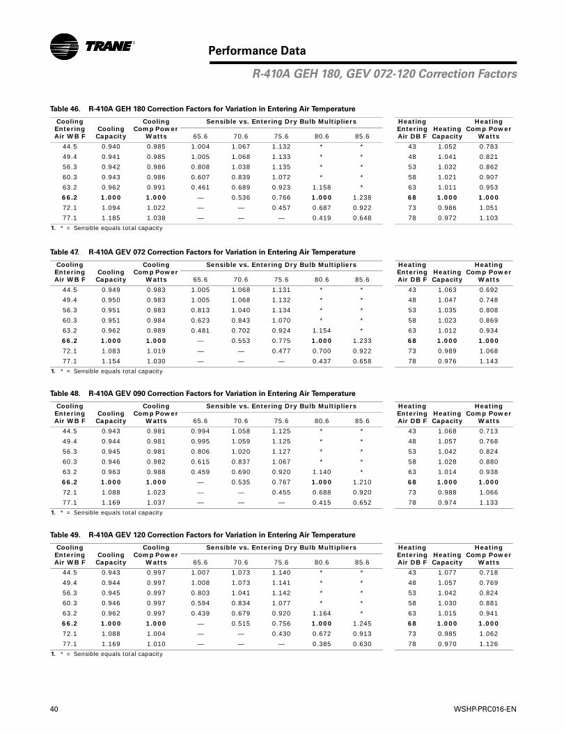
40 WSHP-PRC016-EN
Performance Data
Table 46. R-410A GEH 180 Correction Factors for Variation in Entering Air Temperature
Cooling Entering Air WB F
Cooling Capacity
Cooling Comp Power
Watts
Sensible vs. Entering Dry Bulb Multipliers Heating Entering Air DB F
Heating Capacity
Heating Comp Power
Watts65.6 70.6 75.6 80.6 85.6
44.5 0.940 0.985 1.004 1.067 1.132 * * 43 1.052 0.783
49.4 0.941 0.985 1.005 1.068 1.133 * * 48 1.041 0.821
56.3 0.942 0.986 0.808 1.038 1.135 * * 53 1.032 0.862
60.3 0.943 0.986 0.607 0.839 1.072 * * 58 1.021 0.907
63.2 0.962 0.991 0.461 0.689 0.923 1.158 * 63 1.011 0.953
66.2 1.000 1.000 — 0.536 0.766 1.000 1.238 68 1.000 1.000
72.1 1.094 1.022 — — 0.457 0.687 0.922 73 0.986 1.051
77.1 1.185 1.038 — — — 0.419 0.648 78 0.972 1.103
1. * = Sensible equals total capacity
Table 47. R-410A GEV 072 Correction Factors for Variation in Entering Air Temperature
Cooling Entering Air WB F
Cooling Capacity
Cooling Comp Power
Watts
Sensible vs. Entering Dry Bulb Multipliers Heating Entering Air DB F
Heating Capacity
Heating Comp Power
Watts65.6 70.6 75.6 80.6 85.6
44.5 0.949 0.983 1.005 1.068 1.131 * * 43 1.063 0.692
49.4 0.950 0.983 1.005 1.068 1.132 * * 48 1.047 0.748
56.3 0.951 0.983 0.813 1.040 1.134 * * 53 1.035 0.808
60.3 0.951 0.984 0.623 0.843 1.070 * * 58 1.023 0.869
63.2 0.962 0.989 0.481 0.702 0.924 1.154 * 63 1.012 0.934
66.2 1.000 1.000 — 0.553 0.775 1.000 1.233 68 1.000 1.000
72.1 1.083 1.019 — — 0.477 0.700 0.922 73 0.989 1.068
77.1 1.154 1.030 — — — 0.437 0.658 78 0.976 1.143
1. * = Sensible equals total capacity
Table 48. R-410A GEV 090 Correction Factors for Variation in Entering Air Temperature
Cooling Entering Air WB F
Cooling Capacity
Cooling Comp Power
Watts
Sensible vs. Entering Dry Bulb Multipliers Heating Entering Air DB F
Heating Capacity
Heating Comp Power
Watts65.6 70.6 75.6 80.6 85.6
44.5 0.943 0.981 0.994 1.058 1.125 * * 43 1.068 0.713
49.4 0.944 0.981 0.995 1.059 1.125 * * 48 1.057 0.768
56.3 0.945 0.981 0.806 1.020 1.127 * * 53 1.042 0.824
60.3 0.946 0.982 0.615 0.837 1.067 * * 58 1.028 0.880
63.2 0.963 0.988 0.459 0.690 0.920 1.140 * 63 1.014 0.938
66.2 1.000 1.000 — 0.535 0.767 1.000 1.210 68 1.000 1.000
72.1 1.088 1.023 — — 0.455 0.688 0.920 73 0.988 1.066
77.1 1.169 1.037 — — — 0.415 0.652 78 0.974 1.133
1. * = Sensible equals total capacity
Table 49. R-410A GEV 120 Correction Factors for Variation in Entering Air Temperature
Cooling Entering Air WB F
Cooling Capacity
Cooling Comp Power
Watts
Sensible vs. Entering Dry Bulb Multipliers Heating Entering Air DB F
Heating Capacity
Heating Comp Power
Watts65.6 70.6 75.6 80.6 85.6
44.5 0.943 0.997 1.007 1.073 1.140 * * 43 1.077 0.718
49.4 0.944 0.997 1.008 1.073 1.141 * * 48 1.057 0.769
56.3 0.945 0.997 0.803 1.041 1.142 * * 53 1.042 0.824
60.3 0.946 0.997 0.594 0.834 1.077 * * 58 1.030 0.881
63.2 0.962 0.997 0.439 0.679 0.920 1.164 * 63 1.015 0.941
66.2 1.000 1.000 — 0.515 0.756 1.000 1.245 68 1.000 1.000
72.1 1.088 1.004 — — 0.430 0.672 0.913 73 0.985 1.062
77.1 1.169 1.010 — — — 0.385 0.630 78 0.970 1.126
1. * = Sensible equals total capacity
R-410A GEH 180, GEV 072-120 Correction Factors
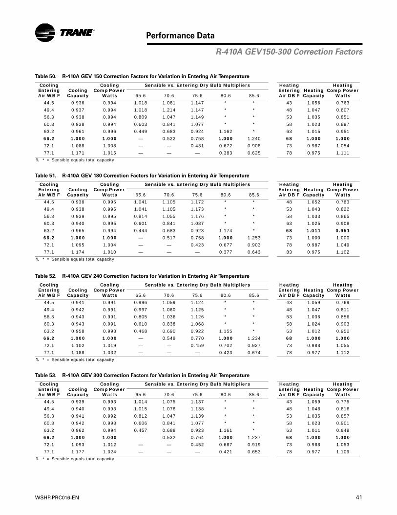
WSHP-PRC016-EN 41
Performance Data
Table 50. R-410A GEV 150 Correction Factors for Variation in Entering Air Temperature
Cooling Entering Air WB F
Cooling Capacity
Cooling Comp Power
Watts
Sensible vs. Entering Dry Bulb Multipliers Heating Entering Air DB F
Heating Capacity
Heating Comp Power
Watts65.6 70.6 75.6 80.6 85.6
44.5 0.936 0.994 1.018 1.081 1.147 * * 43 1.056 0.763
49.4 0.937 0.994 1.018 1.214 1.147 * * 48 1.047 0.807
56.3 0.938 0.994 0.809 1.047 1.149 * * 53 1.035 0.851
60.3 0.938 0.994 0.603 0.841 1.077 * * 58 1.023 0.897
63.2 0.961 0.996 0.449 0.683 0.924 1.162 * 63 1.015 0.951
66.2 1.000 1.000 — 0.522 0.758 1.000 1.240 68 1.000 1.000
72.1 1.088 1.008 — — 0.431 0.672 0.908 73 0.987 1.054
77.1 1.171 1.015 — — — 0.383 0.625 78 0.975 1.111
1. * = Sensible equals total capacity
Table 51. R-410A GEV 180 Correction Factors for Variation in Entering Air Temperature
Cooling Entering Air WB F
Cooling Capacity
Cooling Comp Power
Watts
Sensible vs. Entering Dry Bulb Multipliers Heating Entering Air DB F
Heating Capacity
Heating Comp Power
Watts65.6 70.6 75.6 80.6 85.6
44.5 0.938 0.995 1.041 1.105 1.172 * * 48 1.052 0.783
49.4 0.938 0.995 1.041 1.105 1.173 * * 53 1.043 0.822
56.3 0.939 0.995 0.814 1.055 1.176 * * 58 1.033 0.865
60.3 0.940 0.995 0.601 0.841 1.087 * * 63 1.025 0.908
63.2 0.965 0.994 0.444 0.683 0.923 1.174 * 68 1.011 0.951
66.2 1.000 1.000 — 0.517 0.758 1.000 1.253 73 1.000 1.000
72.1 1.095 1.004 — — 0.423 0.677 0.903 78 0.987 1.049
77.1 1.174 1.010 — — — 0.377 0.643 83 0.975 1.102
1. * = Sensible equals total capacity
Table 52. R-410A GEV 240 Correction Factors for Variation in Entering Air Temperature
Cooling Entering Air WB F
Cooling Capacity
Cooling Comp Power
Watts
Sensible vs. Entering Dry Bulb Multipliers Heating Entering Air DB F
Heating Capacity
Heating Comp Power
Watts65.6 70.6 75.6 80.6 85.6
44.5 0.941 0.991 0.996 1.059 1.124 * * 43 1.059 0.769
49.4 0.942 0.991 0.997 1.060 1.125 * * 48 1.047 0.811
56.3 0.943 0.991 0.805 1.036 1.126 * * 53 1.036 0.856
60.3 0.943 0.991 0.610 0.838 1.068 * * 58 1.024 0.903
63.2 0.958 0.993 0.468 0.690 0.922 1.155 * 63 1.012 0.950
66.2 1.000 1.000 — 0.549 0.770 1.000 1.234 68 1.000 1.000
72.1 1.102 1.019 — — 0.459 0.702 0.927 73 0.988 1.055
77.1 1.188 1.032 — — — 0.423 0.674 78 0.977 1.112
1. * = Sensible equals total capacity
Table 53. R-410A GEV 300 Correction Factors for Variation in Entering Air Temperature
Cooling Entering Air WB F
Cooling Capacity
Cooling Comp Power
Watts
Sensible vs. Entering Dry Bulb Multipliers Heating Entering Air DB F
Heating Capacity
Heating Comp Power
Watts65.6 70.6 75.6 80.6 85.6
44.5 0.939 0.993 1.014 1.075 1.137 * * 43 1.059 0.775
49.4 0.940 0.993 1.015 1.076 1.138 * * 48 1.048 0.816
56.3 0.941 0.992 0.812 1.047 1.139 * * 53 1.035 0.857
60.3 0.942 0.993 0.606 0.841 1.077 * * 58 1.023 0.901
63.2 0.962 0.994 0.457 0.688 0.923 1.161 * 63 1.011 0.949
66.2 1.000 1.000 — 0.532 0.764 1.000 1.237 68 1.000 1.000
72.1 1.093 1.012 — — 0.452 0.687 0.919 73 0.988 1.053
77.1 1.177 1.024 — — — 0.421 0.653 78 0.977 1.109
1. * = Sensible equals total capacity
R-410A GEV150-300 Correction Factors
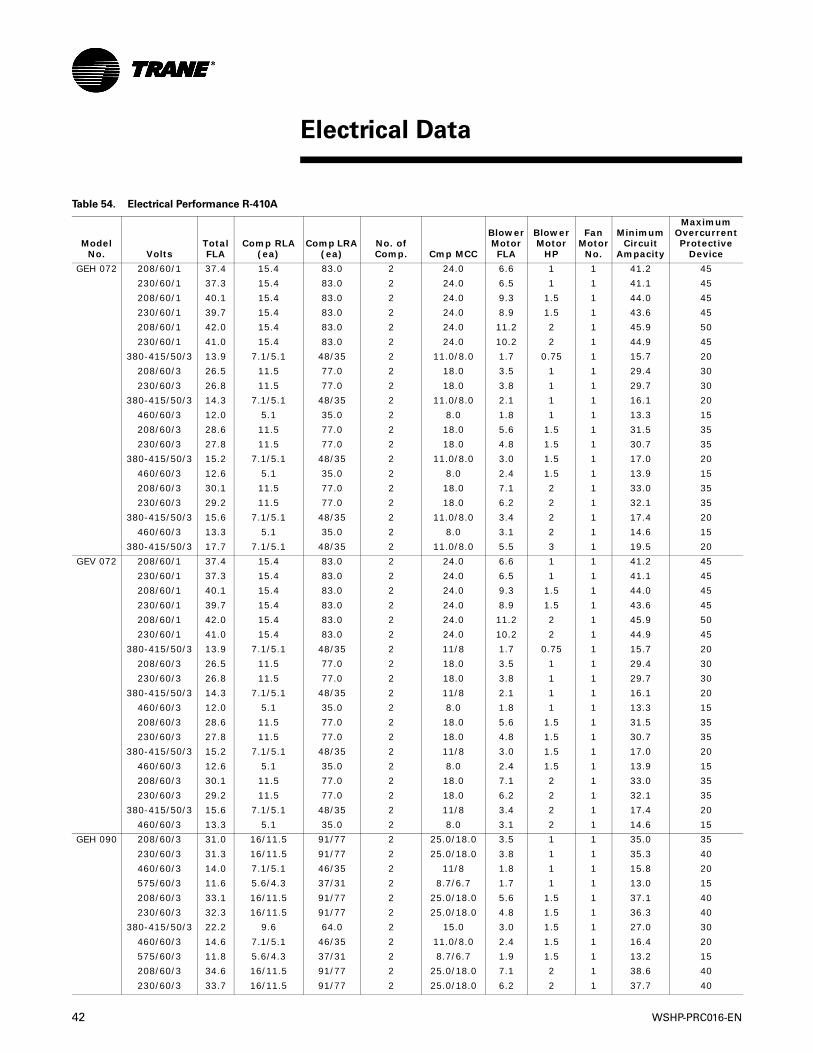
42 WSHP-PRC016-EN
Table 54. Electrical Performance R-410A
Model No. Volts
Total FLA
Comp RLA (ea)
Comp LRA (ea)
No. of Comp. Cmp MCC
Blower Motor FLA
Blower Motor
HP
Fan Motor
No.
Minimum Circuit
Ampacity
Maximum Overcurrent Protective
Device
GEH 072 208/60/1 37.4 15.4 83.0 2 24.0 6.6 1 1 41.2 45
230/60/1 37.3 15.4 83.0 2 24.0 6.5 1 1 41.1 45
208/60/1 40.1 15.4 83.0 2 24.0 9.3 1.5 1 44.0 45
230/60/1 39.7 15.4 83.0 2 24.0 8.9 1.5 1 43.6 45
208/60/1 42.0 15.4 83.0 2 24.0 11.2 2 1 45.9 50
230/60/1 41.0 15.4 83.0 2 24.0 10.2 2 1 44.9 45
380-415/50/3 13.9 7.1/5.1 48/35 2 11.0/8.0 1.7 0.75 1 15.7 20
208/60/3 26.5 11.5 77.0 2 18.0 3.5 1 1 29.4 30
230/60/3 26.8 11.5 77.0 2 18.0 3.8 1 1 29.7 30
380-415/50/3 14.3 7.1/5.1 48/35 2 11.0/8.0 2.1 1 1 16.1 20
460/60/3 12.0 5.1 35.0 2 8.0 1.8 1 1 13.3 15
208/60/3 28.6 11.5 77.0 2 18.0 5.6 1.5 1 31.5 35
230/60/3 27.8 11.5 77.0 2 18.0 4.8 1.5 1 30.7 35
380-415/50/3 15.2 7.1/5.1 48/35 2 11.0/8.0 3.0 1.5 1 17.0 20
460/60/3 12.6 5.1 35.0 2 8.0 2.4 1.5 1 13.9 15
208/60/3 30.1 11.5 77.0 2 18.0 7.1 2 1 33.0 35
230/60/3 29.2 11.5 77.0 2 18.0 6.2 2 1 32.1 35
380-415/50/3 15.6 7.1/5.1 48/35 2 11.0/8.0 3.4 2 1 17.4 20
460/60/3 13.3 5.1 35.0 2 8.0 3.1 2 1 14.6 15
380-415/50/3 17.7 7.1/5.1 48/35 2 11.0/8.0 5.5 3 1 19.5 20
GEV 072 208/60/1 37.4 15.4 83.0 2 24.0 6.6 1 1 41.2 45
230/60/1 37.3 15.4 83.0 2 24.0 6.5 1 1 41.1 45
208/60/1 40.1 15.4 83.0 2 24.0 9.3 1.5 1 44.0 45
230/60/1 39.7 15.4 83.0 2 24.0 8.9 1.5 1 43.6 45
208/60/1 42.0 15.4 83.0 2 24.0 11.2 2 1 45.9 50
230/60/1 41.0 15.4 83.0 2 24.0 10.2 2 1 44.9 45
380-415/50/3 13.9 7.1/5.1 48/35 2 11/8 1.7 0.75 1 15.7 20
208/60/3 26.5 11.5 77.0 2 18.0 3.5 1 1 29.4 30
230/60/3 26.8 11.5 77.0 2 18.0 3.8 1 1 29.7 30
380-415/50/3 14.3 7.1/5.1 48/35 2 11/8 2.1 1 1 16.1 20
460/60/3 12.0 5.1 35.0 2 8.0 1.8 1 1 13.3 15
208/60/3 28.6 11.5 77.0 2 18.0 5.6 1.5 1 31.5 35
230/60/3 27.8 11.5 77.0 2 18.0 4.8 1.5 1 30.7 35
380-415/50/3 15.2 7.1/5.1 48/35 2 11/8 3.0 1.5 1 17.0 20
460/60/3 12.6 5.1 35.0 2 8.0 2.4 1.5 1 13.9 15
208/60/3 30.1 11.5 77.0 2 18.0 7.1 2 1 33.0 35
230/60/3 29.2 11.5 77.0 2 18.0 6.2 2 1 32.1 35
380-415/50/3 15.6 7.1/5.1 48/35 2 11/8 3.4 2 1 17.4 20
460/60/3 13.3 5.1 35.0 2 8.0 3.1 2 1 14.6 15
GEH 090 208/60/3 31.0 16/11.5 91/77 2 25.0/18.0 3.5 1 1 35.0 35
230/60/3 31.3 16/11.5 91/77 2 25.0/18.0 3.8 1 1 35.3 40
460/60/3 14.0 7.1/5.1 46/35 2 11/8 1.8 1 1 15.8 20
575/60/3 11.6 5.6/4.3 37/31 2 8.7/6.7 1.7 1 1 13.0 15
208/60/3 33.1 16/11.5 91/77 2 25.0/18.0 5.6 1.5 1 37.1 40
230/60/3 32.3 16/11.5 91/77 2 25.0/18.0 4.8 1.5 1 36.3 40
380-415/50/3 22.2 9.6 64.0 2 15.0 3.0 1.5 1 27.0 30
460/60/3 14.6 7.1/5.1 46/35 2 11.0/8.0 2.4 1.5 1 16.4 20
575/60/3 11.8 5.6/4.3 37/31 2 8.7/6.7 1.9 1.5 1 13.2 15
208/60/3 34.6 16/11.5 91/77 2 25.0/18.0 7.1 2 1 38.6 40
230/60/3 33.7 16/11.5 91/77 2 25.0/18.0 6.2 2 1 37.7 40
Electrical Data

WSHP-PRC016-EN 43
Electrical Data
Model No. Volts
Total FLA
Comp RLA (ea)
Comp LRA (ea)
No. of Comp. Cmp MCC
Blower Motor FLA
Blower Motor
HP
Fan Motor
No.
Minimum Circuit
Ampacity
Maximum Overcurrent Protective
Device
GEH 090 380-415/50/3 22.6 9.6 64.0 2 15.0 3.4 2 1 27.4 30
460/60/3 15.3 7.1/5.1 46/35 2 11.0/8.0 3.1 2 1 17.1 20
575/60/3 12.2 5.6/4.3 37/31 2 8.7/6.7 2.3 2 1 13.6 15
208/60/3 36.9 16/11.5 91/77 2 25.0/18.0 9.4 3 1 40.9 45
230/60/3 35.7 16/11.5 91/77 2 25.0/18.0 8.2 3 1 39.7 40
380-415/50/3 24.7 9.6 64.0 2 15.0 5.5 3 1 29.5 30
460/60/3 16.3 7.1/5.1 46/35 2 11.0/8.0 4.1 3 1 18.1 20
575/60/3 13.2 5.6/4.3 37/31 2 8.7/6.7 3.3 3 1 14.6 15
GEV 090 208/60/3 31.0 16/11.5 91/77 2 25/18 3.5 1 1 35.0 35
230/60/3 31.3 16/11.5 91/77 2 25/18 3.8 1 1 35.3 40
380-415/50/3 21.3 9.6 64.0 2 15.0 2.1 1 1 26.1 30
460/60/3 14.0 7.1/5.1 46/35 2 11/8 1.8 1 1 15.8 20
575/60/3 11.6 5.6/4.3 37/31 2 8.7/6.7 1.7 1 1 13.0 15
208/60/3 33.1 16/11.5 91/77 2 25/18 5.6 1.5 1 37.1 40
230/60/3 32.3 16/11.5 91/77 2 25/18 4.8 1.5 1 36.3 40
380-415/50/3 22.2 9.6 64.0 2 15.0 3.0 1.5 1 27.0 30
460/60/3 14.6 7.1/5.1 46/35 2 11/8 2.4 1.5 1 16.4 20
575/60/3 11.8 5.6/4.3 37/31 2 8.7/6.7 1.9 1.5 1 13.2 15
208/60/3 34.6 16/11.5 91/77 2 25/18 7.1 2 1 38.6 40
230/60/3 33.7 16/11.5 91/77 2 25/18 6.2 2 1 37.7 40
380-415/50/3 22.6 9.6 64.0 2 15.0 3.4 2 1 27.4 30
460/60/3 15.3 7.1/5.1 46/35 2 11/8 3.1 2 1 17.1 20
575/60/3 12.2 5.6/4.3 37/31 2 8.7/6.7 2.3 2 1 13.6 15
208/60/3 36.9 16/11.5 91/77 2 25/18 9.4 3 1 40.9 45
230/60/3 35.7 16/11.5 91/77 2 25/18 8.2 3 1 39.7 40
380-415/50/3 24.7 9.6 64.0 2 15.0 5.5 3 1 29.5 30
460/60/3 16.3 7.1/5.1 46/35 2 11/8 4.1 3 1 18.1 20
575/60/3 13.2 5.6/4.3 37/31 2 8.7/6.7 3.3 3 1 14.6 15
GEH 120 380-415/50/3 23.3 10.6 74.0 2 16.5 2.1 1 1 28.6 30
208/60/3 40.8 17.6 123.0 2 27.5 5.6 1.5 1 49.6 50
230/60/3 40.0 17.6 123.0 2 27.5 4.8 1.5 1 48.8 50
380-415/50/3 24.2 10.6 74.0 2 16.5 3.0 1.5 1 29.5 30
460/60/3 21.6 9.6 62.0 2 15.0 2.4 1.5 1 26.4 30
575/60/3 14.1 6.1 40.0 2 9.5 1.9 1.5 1 17.2 20
208/60/3 42.3 17.6 123.0 2 27.5 7.1 2 1 51.1 60
230/60/3 41.4 17.6 123.0 2 27.5 6.2 2 1 50.2 60
380-415/50/3 24.6 10.6 74.0 2 16.5 3.4 2 1 29.9 30
460/60/3 22.3 9.6 62.0 2 15.0 3.1 2 1 27.1 30
575/60/3 14.5 6.1 40.0 2 9.5 2.3 2 1 17.6 20
208/60/3 44.6 17.6 123.0 2 27.5 9.4 3 1 53.4 60
230/60/3 43.4 17.6 123.0 2 27.5 8.2 3 1 52.2 60
380-415/50/3 26.7 10.6 74.0 2 16.5 5.5 3 1 32.0 35
460/60/3 23.3 9.6 62.0 2 15.0 4.1 3 1 28.1 30
575/60/3 15.5 6.1 40.0 2 9.5 3.3 3 1 18.6 20
208/60/3 51.2 17.6 123.0 2 27.5 16.0 5 1 60.0 70
230/60/3 49.2 17.6 123.0 2 27.5 14.0 5 1 58.0 60
380-415/50/3 30.5 10.6 74.0 2 16.5 9.3 5 1 35.8 40
460/60/3 26.2 9.6 62.0 2 15.0 7.0 5 1 31.0 35
575/60/3 17.4 6.1 40.0 2 9.5 5.2 5 1 20.5 25
GEV 120 208/60/3 40.8 17.6 123.0 2 27.5 5.6 1.5 1 49.6 50
230/60/3 40.0 17.6 123.0 2 27.5 4.8 1.5 1 48.8 50
460/60/3 21.6 9.6 62.0 2 15.0 2.4 1.5 1 26.4 30
575/60/3 14.1 6.1 40.0 2 9.5 1.9 1.5 1 17.2 20
208/60/3 42.3 17.6 123.0 2 27.5 7.1 2 1 51.1 60
Table 54. Electrical Performance R-410A (continued)
R-410A Electrical Performance
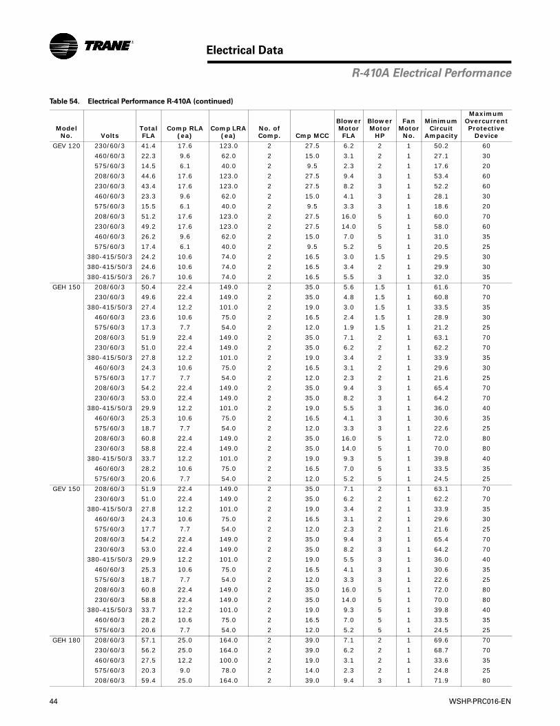
44 WSHP-PRC016-EN
Electrical Data
Model No. Volts
Total FLA
Comp RLA (ea)
Comp LRA (ea)
No. of Comp. Cmp MCC
Blower Motor FLA
Blower Motor
HP
Fan Motor
No.
Minimum Circuit
Ampacity
Maximum Overcurrent Protective
Device
GEV 120 230/60/3 41.4 17.6 123.0 2 27.5 6.2 2 1 50.2 60
460/60/3 22.3 9.6 62.0 2 15.0 3.1 2 1 27.1 30
575/60/3 14.5 6.1 40.0 2 9.5 2.3 2 1 17.6 20
208/60/3 44.6 17.6 123.0 2 27.5 9.4 3 1 53.4 60
230/60/3 43.4 17.6 123.0 2 27.5 8.2 3 1 52.2 60
460/60/3 23.3 9.6 62.0 2 15.0 4.1 3 1 28.1 30
575/60/3 15.5 6.1 40.0 2 9.5 3.3 3 1 18.6 20
208/60/3 51.2 17.6 123.0 2 27.5 16.0 5 1 60.0 70
230/60/3 49.2 17.6 123.0 2 27.5 14.0 5 1 58.0 60
460/60/3 26.2 9.6 62.0 2 15.0 7.0 5 1 31.0 35
575/60/3 17.4 6.1 40.0 2 9.5 5.2 5 1 20.5 25
380-415/50/3 24.2 10.6 74.0 2 16.5 3.0 1.5 1 29.5 30
380-415/50/3 24.6 10.6 74.0 2 16.5 3.4 2 1 29.9 30
380-415/50/3 26.7 10.6 74.0 2 16.5 5.5 3 1 32.0 35
GEH 150 208/60/3 50.4 22.4 149.0 2 35.0 5.6 1.5 1 61.6 70
230/60/3 49.6 22.4 149.0 2 35.0 4.8 1.5 1 60.8 70
380-415/50/3 27.4 12.2 101.0 2 19.0 3.0 1.5 1 33.5 35
460/60/3 23.6 10.6 75.0 2 16.5 2.4 1.5 1 28.9 30
575/60/3 17.3 7.7 54.0 2 12.0 1.9 1.5 1 21.2 25
208/60/3 51.9 22.4 149.0 2 35.0 7.1 2 1 63.1 70
230/60/3 51.0 22.4 149.0 2 35.0 6.2 2 1 62.2 70
380-415/50/3 27.8 12.2 101.0 2 19.0 3.4 2 1 33.9 35
460/60/3 24.3 10.6 75.0 2 16.5 3.1 2 1 29.6 30
575/60/3 17.7 7.7 54.0 2 12.0 2.3 2 1 21.6 25
208/60/3 54.2 22.4 149.0 2 35.0 9.4 3 1 65.4 70
230/60/3 53.0 22.4 149.0 2 35.0 8.2 3 1 64.2 70
380-415/50/3 29.9 12.2 101.0 2 19.0 5.5 3 1 36.0 40
460/60/3 25.3 10.6 75.0 2 16.5 4.1 3 1 30.6 35
575/60/3 18.7 7.7 54.0 2 12.0 3.3 3 1 22.6 25
208/60/3 60.8 22.4 149.0 2 35.0 16.0 5 1 72.0 80
230/60/3 58.8 22.4 149.0 2 35.0 14.0 5 1 70.0 80
380-415/50/3 33.7 12.2 101.0 2 19.0 9.3 5 1 39.8 40
460/60/3 28.2 10.6 75.0 2 16.5 7.0 5 1 33.5 35
575/60/3 20.6 7.7 54.0 2 12.0 5.2 5 1 24.5 25
GEV 150 208/60/3 51.9 22.4 149.0 2 35.0 7.1 2 1 63.1 70
230/60/3 51.0 22.4 149.0 2 35.0 6.2 2 1 62.2 70
380-415/50/3 27.8 12.2 101.0 2 19.0 3.4 2 1 33.9 35
460/60/3 24.3 10.6 75.0 2 16.5 3.1 2 1 29.6 30
575/60/3 17.7 7.7 54.0 2 12.0 2.3 2 1 21.6 25
208/60/3 54.2 22.4 149.0 2 35.0 9.4 3 1 65.4 70
230/60/3 53.0 22.4 149.0 2 35.0 8.2 3 1 64.2 70
380-415/50/3 29.9 12.2 101.0 2 19.0 5.5 3 1 36.0 40
460/60/3 25.3 10.6 75.0 2 16.5 4.1 3 1 30.6 35
575/60/3 18.7 7.7 54.0 2 12.0 3.3 3 1 22.6 25
208/60/3 60.8 22.4 149.0 2 35.0 16.0 5 1 72.0 80
230/60/3 58.8 22.4 149.0 2 35.0 14.0 5 1 70.0 80
380-415/50/3 33.7 12.2 101.0 2 19.0 9.3 5 1 39.8 40
460/60/3 28.2 10.6 75.0 2 16.5 7.0 5 1 33.5 35
575/60/3 20.6 7.7 54.0 2 12.0 5.2 5 1 24.5 25
GEH 180 208/60/3 57.1 25.0 164.0 2 39.0 7.1 2 1 69.6 70
230/60/3 56.2 25.0 164.0 2 39.0 6.2 2 1 68.7 70
460/60/3 27.5 12.2 100.0 2 19.0 3.1 2 1 33.6 35
575/60/3 20.3 9.0 78.0 2 14.0 2.3 2 1 24.8 25
208/60/3 59.4 25.0 164.0 2 39.0 9.4 3 1 71.9 80
Table 54. Electrical Performance R-410A (continued)
R-410A Electrical Performance
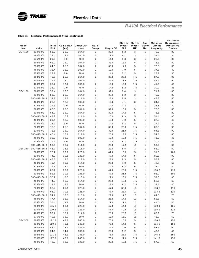
WSHP-PRC016-EN 45
Electrical Data
Model No. Volts
Total FLA
Comp RLA (ea)
Comp LRA (ea)
No. of Comp. Cmp MCC
Blower Motor FLA
Blower Motor
HP
Fan Motor
No.
Minimum Circuit
Ampacity
Maximum Overcurrent Protective
Device
GEH 180 230/60/3 58.2 25.0 164.0 2 39.0 8.2 3 1 70.7 80
460/60/3 28.5 12.2 100.0 2 19.0 4.1 3 1 34.6 35
575/60/3 21.3 9.0 78.0 2 14.0 3.3 3 1 25.8 30
208/60/3 66.0 25.0 164.0 2 39.0 16.0 5 1 78.5 80
230/60/3 64.0 25.0 164.0 2 39.0 14.0 5 1 76.5 80
460/60/3 31.4 12.2 100.0 2 19.0 7.0 5 1 37.5 40
575/60/3 23.2 9.0 78.0 2 14.0 5.2 5 1 27.7 30
208/60/3 75.0 25.0 164.0 2 39.0 25.0 7.5 1 87.5 90
230/60/3 71.6 25.0 164.0 2 39.0 21.6 7.5 1 84.1 90
460/60/3 35.2 12.2 100.0 2 19.0 10.8 7.5 1 41.3 45
575/60/3 26.2 9.0 78.0 2 14.0 8.2 7.5 1 30.7 35
GEV 180 208/60/3 59.4 25.0 164.0 2 39.0 9.4 3 1 71.9 80
230/60/3 58.2 25.0 164.0 2 39.0 8.2 3 1 70.7 80
380-415/50/3 38.9 16.7 111.0 2 26.0 5.5 3 1 47.3 50
460/60/3 28.5 12.2 100.0 2 19.0 4.1 3 1 34.6 35
575/60/3 21.3 9.0 78.0 2 14.0 3.3 3 1 25.8 30
208/60/3 66.0 25.0 164.0 2 39.0 16.0 5 1 78.5 80
230/60/3 64.0 25.0 164.0 2 39.0 14.0 5 1 76.5 80
380-415/50/3 42.7 16.7 111.0 2 26.0 9.3 5 1 51.1 60
460/60/3 31.4 12.2 100.0 2 19.0 7.0 5 1 37.5 40
575/60/3 23.2 9.0 78.0 2 14.0 5.2 5 1 27.7 30
208/60/3 75.0 25.0 164.0 2 39.0 25.0 7.5 1 87.5 90
230/60/3 71.6 25.0 164.0 2 39.0 21.6 7.5 1 84.1 90
380-415/50/3 46.4 16.7 111.0 2 26.0 13.0 7.5 1 54.8 60
460/60/3 35.2 12.2 100.0 2 19.0 10.8 7.5 1 41.3 45
575/60/3 26.2 9.0 78.0 2 14.0 8.2 7.5 1 30.7 35
380-415/50/3 50.9 16.7 111.0 2 26.0 17.5 10 1 59.3 60
GEV 240 380-415/50/3 42.7 18.6 118.0 2 29.0 5.5 3 1 52.0 60
208/60/3 76.2 30.1 225.0 2 47.0 16.0 5 1 91.3 100
230/60/3 74.2 30.1 225.0 2 47.0 14.0 5 1 89.3 90
380-415/50/3 46.5 18.6 118.0 2 29.0 9.3 5 1 55.8 60
460/60/3 40.4 16.7 114.0 2 26.0 7.0 5 1 48.8 50
575/60/3 29.6 12.2 80.0 2 19.0 5.2 5 1 35.7 40
208/60/3 85.2 30.1 225.0 2 47.0 25.0 7.5 1 100.3 110
230/60/3 81.8 30.1 225.0 2 47.0 21.6 7.5 1 96.9 100
380-415/50/3 50.2 18.6 118.0 2 29.0 13.0 7.5 1 59.5 60
460/60/3 44.2 16.7 114.0 2 26.0 10.8 7.5 1 52.6 60
575/60/3 32.6 12.2 80.0 2 19.0 8.2 7.5 1 38.7 40
208/60/3 93.2 30.1 225.0 2 47.0 33.0 10 1 108.3 110
230/60/3 88.2 30.1 225.0 2 47.0 28.0 10 1 103.3 110
380-415/50/3 54.7 18.6 118.0 2 29.0 17.5 10 1 64.0 70
460/60/3 47.4 16.7 114.0 2 26.0 14.0 10 1 55.8 60
575/60/3 35.4 12.2 80.0 2 19.0 11.0 10 1 41.5 45
208/60/3 105.0 30.1 225.0 2 47.0 44.8 15 1 120.1 125
230/60/3 100.8 30.1 225.0 2 47.0 40.6 15 1 115.9 125
460/60/3 53.7 16.7 114.0 2 26.0 20.3 15 1 62.1 70
575/60/3 40.6 12.2 80.0 2 19.0 16.2 15 1 46.7 50
GEV 300 208/60/3 112.2 48.1 245.0 2 75.0 16.0 5 1 136.3 150
230/60/3 110.2 48.1 245.0 2 75.0 14.0 5 1 134.3 150
460/60/3 44.2 18.6 125.0 2 29.0 7.0 5 1 53.5 60
575/60/3 34.6 14.7 100.0 2 23.0 5.2 5 1 42.0 45
208/60/3 121.2 48.1 245.0 2 75.0 25.0 7.5 1 145.3 150
230/60/3 117.8 48.1 245.0 2 75.0 21.6 7.5 1 141.9 150
460/60/3 48.0 18.6 125.0 2 29.0 10.8 7.5 1 57.3 60
Table 54. Electrical Performance R-410A (continued)
R-410A Electrical Performance
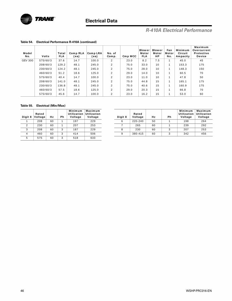
46 WSHP-PRC016-EN
Electrical Data
Model No. Volts
Total FLA
Comp RLA (ea)
Comp LRA (ea)
No. of Comp. Cmp MCC
Blower Motor FLA
Blower Motor
HP
Fan Motor
No.
Minimum Circuit
Ampacity
Maximum Overcurrent Protective
Device
GEV 300 575/60/3 37.6 14.7 100.0 2 23.0 8.2 7.5 1 45.0 45
208/60/3 129.2 48.1 245.0 2 75.0 33.0 10 1 153.3 175
230/60/3 124.2 48.1 245.0 2 75.0 28.0 10 1 148.3 150
460/60/3 51.2 18.6 125.0 2 29.0 14.0 10 1 60.5 70
575/60/3 40.4 14.7 100.0 2 23.0 11.0 10 1 47.8 50
208/60/3 141.0 48.1 245.0 2 75.0 44.8 15 1 165.1 175
230/60/3 136.8 48.1 245.0 2 75.0 40.6 15 1 160.9 175
460/60/3 57.5 18.6 125.0 2 29.0 20.3 15 1 66.8 70
575/60/3 45.6 14.7 100.0 2 23.0 16.2 15 1 53.0 60
Table 55. Electrical (Min/Max)
Digit 8Rated
Voltage Hz Ph
MinimumUtilization
Voltage
Maximum Utilization
Voltage Digit 8Rated
Voltage Hz Ph
MinimumUtilization
Voltage
Maximum Utilization
Voltage
1 208 60 1 197 229 6 220-240 50 1 198 264
2 230 60 1 207 253 7 265 60 1 239 292
3 208 60 3 187 229 8 230 60 3 207 253
4 460 60 3 414 506 9 380-415 60 3 342 456
5 575 60 3 518 633
Table 54. Electrical Performance R-410A (continued)
R-410A Electrical Performance
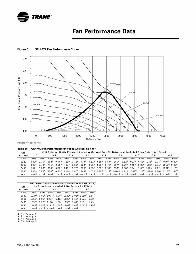
WSHP-PRC016-EN 47
Figure 6. GEH 072 Fan Performance Curve
Includes wet coil, no filter
Table 56. GEH 072 Fan Performance (includes wet coil, no filter)
Std Airflow
Unit External Static Pressure inches W.G. (Wet Coil, No Drive Loss Included & No Return Air Filter)0.1 0.2 0.3 0.4 0.5 0.6 0.7 0.8 0.9
CFM RPM BHP RPM BHP RPM BHP RPM BHP RPM BHP RPM BHP RPM BHP RPM BHP RPM BHP1920 632A 0.35A 682A 0.40A 729A 0.46A 774A 0.51A 818A 0.57A 860A 0.62A 901A 0.68A 941B 0.74B 979B 0.80B
2160 699A 0.49A 745A 0.55A 787A 0.60A 829A 0.66A 869A 0.72A 907A 0.79A 945B 0.85B 982B 0.91B 1018B 0.98B
2400 767A 0.66A 808A 0.72A 848A 0.78A 886A 0.85A 923A 0.91A 959B 0.98B 994C 1.05C 1029C 1.12C 1062C 1.19C
2640 836A 0.86A 874A 0.93A 911A 1.00A 946C 1.07C 980C 1.14C 1014C 1.21C 1047C 1.28C 1078C 1.36C 1111C 1.44C
2880 905C 1.10C 940C 1.17C 974C 1.25C 1008C 1.33C 1039C 1.40C 1071C 1.48C 1102D 1.56D 1132D 1.64D 1161D 1.72D
Std Airflow
Unit External Static Pressure inches W.G. (Wet Coil, No Drive Loss Included & No Return Air Filter)
1.0 1.1 1.2 1.3CFM RPM BHP RPM BHP RPM BHP RPM BHP1920 1027B 0.89B 1077B 0.98B 1120C 1.06C 1159C 1.14C
2160 1053C 1.05C 1087C 1.12C 1122C 1.19C 1171C 1.30C
2400 1095C 1.26C 1128C 1.33C 1159C 1.41C 1191C 1.49C
2640 1142D 1.51D 1171D 1.59D 1202D 1.67D 1231D 1.75D
2880 1191D 1.80D 1220D 1.89D 1248D 1.97D — —
1. A = Package A2. B = Package B3. C = Package C4. D = Package D
MPR006
3.0
2.5
2.0
1.5
1.0
0.5
0.0
0 500 1000 1500 2000 2500 3000 3500 4000 4500Airflow (cfm)
Tota
l Sta
tic
Pres
sure
(in
H20
)
1.00
bh
p
1.50
bh
p
2.00
bh
p
55%WO60%WO
70% WO
80% WO
90% WO700 RPM
800 RPM
900 RPM
1000 RPM
1100 RPM
1200 RPM
1300 RPM
Fan Performance Data
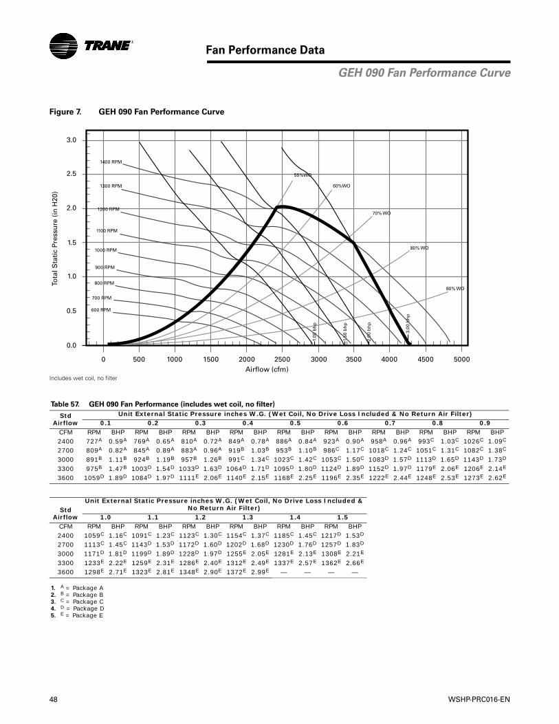
48 WSHP-PRC016-EN
Fan Performance Data
Figure 7. GEH 090 Fan Performance Curve
Includes wet coil, no filter
Table 57. GEH 090 Fan Performance (includes wet coil, no filter)
Std Airflow
Unit External Static Pressure inches W.G. (Wet Coil, No Drive Loss Included & No Return Air Filter)0.1 0.2 0.3 0.4 0.5 0.6 0.7 0.8 0.9
CFM RPM BHP RPM BHP RPM BHP RPM BHP RPM BHP RPM BHP RPM BHP RPM BHP RPM BHP2400 727A 0.59A 769A 0.65A 810A 0.72A 849A 0.78A 886A 0.84A 923A 0.90A 958A 0.96A 993C 1.03C 1026C 1.09C
2700 809A 0.82A 845A 0.89A 883A 0.96A 919B 1.03B 953B 1.10B 986C 1.17C 1018C 1.24C 1051C 1.31C 1082C 1.38C
3000 891B 1.11B 924B 1.19B 957B 1.26B 991C 1.34C 1023C 1.42C 1053C 1.50C 1083D 1.57D 1113D 1.65D 1143D 1.73D
3300 975B 1.47B 1003D 1.54D 1033D 1.63D 1064D 1.71D 1095D 1.80D 1124D 1.89D 1152D 1.97D 1179E 2.06E 1206E 2.14E
3600 1059D 1.89D 1084D 1.97D 1111E 2.06E 1140E 2.15E 1168E 2.25E 1196E 2.35E 1222E 2.44E 1248E 2.53E 1273E 2.62E
Std Airflow
Unit External Static Pressure inches W.G. (Wet Coil, No Drive Loss Included & No Return Air Filter)
1.0 1.1 1.2 1.3 1.4 1.5CFM RPM BHP RPM BHP RPM BHP RPM BHP RPM BHP RPM BHP2400 1059C 1.16C 1091C 1.23C 1123C 1.30C 1154C 1.37C 1185C 1.45C 1217D 1.53D
2700 1113C 1.45C 1143D 1.53D 1172D 1.60D 1202D 1.68D 1230D 1.76D 1257D 1.83D
3000 1171D 1.81D 1199D 1.89D 1228D 1.97D 1255E 2.05E 1281E 2.13E 1308E 2.21E
3300 1233E 2.22E 1259E 2.31E 1286E 2.40E 1312E 2.49E 1337E 2.57E 1362E 2.66E
3600 1298E 2.71E 1323E 2.81E 1348E 2.90E 1372E 2.99E — — — —
1. A = Package A2. B = Package B3. C = Package C4. D = Package D5. E = Package E
MPR006
3.0
2.5
2.0
1.5
1.0
0.5
0.0
0 500 1000 1500 2000 2500 3000 3500 4000 4500 5000Airflow (cfm)
Tota
l Sta
tic
Pres
sure
(in
H20
)
1.00
bh
p
1.50
bh
p
2.00
bh
p
3.00
bh
p
55%WO
60%WO
70% WO
80% WO
90% WO
700 RPM
800 RPM
900 RPM
1000 RPM
1100 RPM
1200 RPM
1300 RPM
1400 RPM
GEH 090 Fan Performance Curve

WSHP-PRC016-EN 49
Fan Performance Data
Figure 8. GEH 120 Fan Performance Curve
Includes wet coil, no filter
Table 58. GEH 120 Fan Performance (includes wet coil, no filter)
StdAirflow
Unit External Static Pressure inches W.G. (Wet Coil, No Drive Loss Included & No Return Air Filter)0.1 0.2 0.3 0.4 0.5 0.6 0.7 0.8 0.9 1.0
CFM RPM BHP RPM BHP RPM BHP RPM BHP RPM BHP RPM BHP RPM BHP RPM BHP RPM BHP RPM BHP3200 897A 1.23A 916A 1.27A 935A 1.31A 958A 1.36A 987A 1.43A 1018B 1.51B 1051B 1.60B 1081B 1.68B 1109B 1.76B 1138B 1.84B
3600 1005B 1.74B 1022B 1.78B 1038B 1.83B 1055B 1.87B 1076B 1.94B 1102C 2.01C 1129C 2.10C 1158C 2.20C 1186C 2.29C 1213C 2.39C
4000 1114C 2.37C 1128C 2.42C 1143C 2.47C 1158C 2.52C 1173C 2.57C 1192C 2.64C 1214C 2.72C 1238C 2.82C 1264C 2.92C 1289E 3.02E
4400 1222E 3.15E 1235E 3.20E 1249E 3.26E 1262E 3.31E 1276E 3.37E 1290E 3.42E 1306E 3.49E 1326E 3.58E 1347F 3.68F 1369F 3.78F
4800 1331E 4.08E 1343F 4.14F 1355F 4.19F 1368F 4.25F 1380F 4.31F 1392F 4.37F 1405F 4.43F 1419F 4.50F 1437F 4.60F 1455F 4.70F
StdAirflow
Unit External Static Pressure inches W.G. (Wet Coil, No Drive Loss Included & No Return Air Filter)1.1 1.2 1.3 1.4 1.5 1.6 1.7 1.8 1.9 2.0
CFM RPM BHP RPM BHP RPM BHP RPM BHP RPM BHP RPM BHP RPM BHP RPM BHP RPM BHP RPM BHP3200 1164B 1.92B 1192C 2.01C 1219C 2.09C 1246C 2.17C 1272C 2.25C 1298C 2.34C 1323D 2.42D 1349D 2.51D 1374D 2.60D 1398D 2.68D
3600 1239C 2.48C 1264C 2.57C 1288C 2.65C 1312C 2.74C 1336D 2.83D 1361D 2.93D 1384F 3.02F 1408F 3.12F 1431F 3.21F 1454F 3.30F
4000 1315F 3.13F 1340F 3.24F 1363F 3.34F 1385F 3.43F 1408F 3.54F 1429F 3.63F 1452F 3.74F 1474F 3.84F 1496F 3.94F 1517F 4.04F
4400 1392F 3.90F 1416F 4.02F 1440F 4.13F 1463F 4.25F 1484F 4.36F 1505F 4.47F 1526F 4.58F 1546F 4.69F 1565F 4.80F 1586F 4.91F
4800 1475F 4.81F 1496F 4.93F — — — — — — — — — — — — — — — —
1. A = Package A2. B = Package B3. C = Package C4. D = Package D5. E = Package E6. F = Package F
3.0
3.5
4.0
2.5
2.0
1.5
1.0
0.5
0.0
0 500 1000 1500 2000 2500 3000 3500 4000 4500 5000 5500 6000Airflow (cfm)
Tota
l Sta
tic
Pres
sure
(in
H20
)
1.00
bh
p
1.50
bh
p
2.00
bh
p
3.00
bh
p
5.00
bh
p
55%WO
60%WO
70% WO
80% WO
90% WO
900 RPM
1000 RPM
1100 RPM
1200 RPM
1300 RPM
1400 RPM
1500 RPM
1600 RPM
GEH 120 Fan Performance Curve
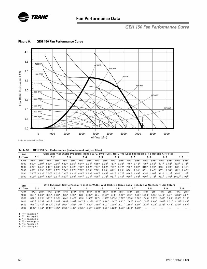
50 WSHP-PRC016-EN
Fan Performance Data
Figure 9. GEH 150 Fan Performance Curve
Includes wet coil, no filter
Table 59. GEH 150 Fan Performance (includes wet coil, no filter)
StdAirflow
Unit External Static Pressure inches W.G. (Wet Coil, No Drive Loss Included & No Return Air Filter)0.1 0.2 0.3 0.4 0.5 0.6 0.7 0.8 0.9 1.0
CFM RPM BHP RPM BHP RPM BHP RPM BHP RPM BHP RPM BHP RPM BHP RPM BHP RPM BHP RPM BHP4000 559A 0.89A 590A 0.96A 622A 1.05A 654A 1.14A 685A 1.23A 717A 1.32A 749A 1.42A 779B 1.52B 807B 1.61B 833B 1.71B
4500 622A 1.24A 648A 1.33A 677A 1.42A 706B 1.52B 734B 1.62B 761B 1.72B 790B 1.82B 819B 1.93B 846C 2.04C 872C 2.15C
5000 686B 1.69B 709B 1.77B 734B 1.87B 760B 1.98B 786C 2.09C 811C 2.20C 836C 2.31C 861C 2.42C 887C 2.54C 912D 2.66D
5500 750C 2.23C 771C 2.32C 793C 2.42C 816C 2.53C 840C 2.65C 863C 2.77C 886C 2.89C 909E 3.02E 932E 3.14E 954E 3.26E
6000 815C 2.88C 833C 2.97C 853E 3.08E 874E 3.20E 895E 3.32E 917E 3.45E 939E 3.58E 960E 3.71E 981E 3.85E 1002E 3.98E
StdAirflow
Unit External Static Pressure inches W.G. (Wet Coil, No Drive Loss Included & No Return Air Filter)1.1 1.2 1.3 1.4 1.5 1.6 1.7 1.8 1.9 2.0
CFM RPM BHP RPM BHP RPM BHP RPM BHP RPM BHP RPM BHP RPM BHP RPM BHP RPM BHP RPM BHP4000 857B 1.80B 881B 1.89B 905B 1.98B 928D 2.07D 951D 2.16D 974D 2.26D 996D 2.36D 1018D 2.46D 1040D 2.57D 1061D 2.67D
4500 898C 2.26C 921D 2.36D 944D 2.46D 965D 2.56D 987D 2.66D 1009D 2.77D 1030D 2.88D 1049D 2.97D 1069F 3.08F 1090F 3.19F
5000 937D 2.78D 962D 2.91D 985E 3.03E 1007E 3.14E 1027F 3.26F 1047F 3.37F 1067F 3.48F 1087F 3.60F 1106F 3.71F 1125F 3.83F
5500 978E 3.40E 1002E 3.53E 1024F 3.66F 1047F 3.80F 1068F 3.93F 1090F 4.07F 1109F 4.19F 1127F 4.32F 1146F 4.44F 1164F 4.57F
6000 1022F 4.11F 1044F 4.26F 1065F 4.40F 1086F 4.54F 1108F 4.69F 1128F 4.83F 1148F 4.98F — — — — — —
1. A = Package A2. B = Package B3. C = Package C4. D = Package D5. E = Package E6. F = Package F
3.0
3.5
4.0
2.5
2.0
1.5
1.0
0.5
0.0
0 1000 2000 3000 4000 70005000 8000 90006000Airflow (cfm)
Tota
l Sta
tic
Pres
sure
(in
H20
)
1.00
bh
p
1.50
bh
p
2.00
bh
p
3.00
bh
p
5.00
bh
p
50%WO
40%WO
60%WO
70% WO
80% WO
90% WO
500 RPM
600 RPM
700 RPM
800 RPM
900 RPM
1000 RPM
1100 RPM
1200 RPM
GEH 150 Fan Performance Curve
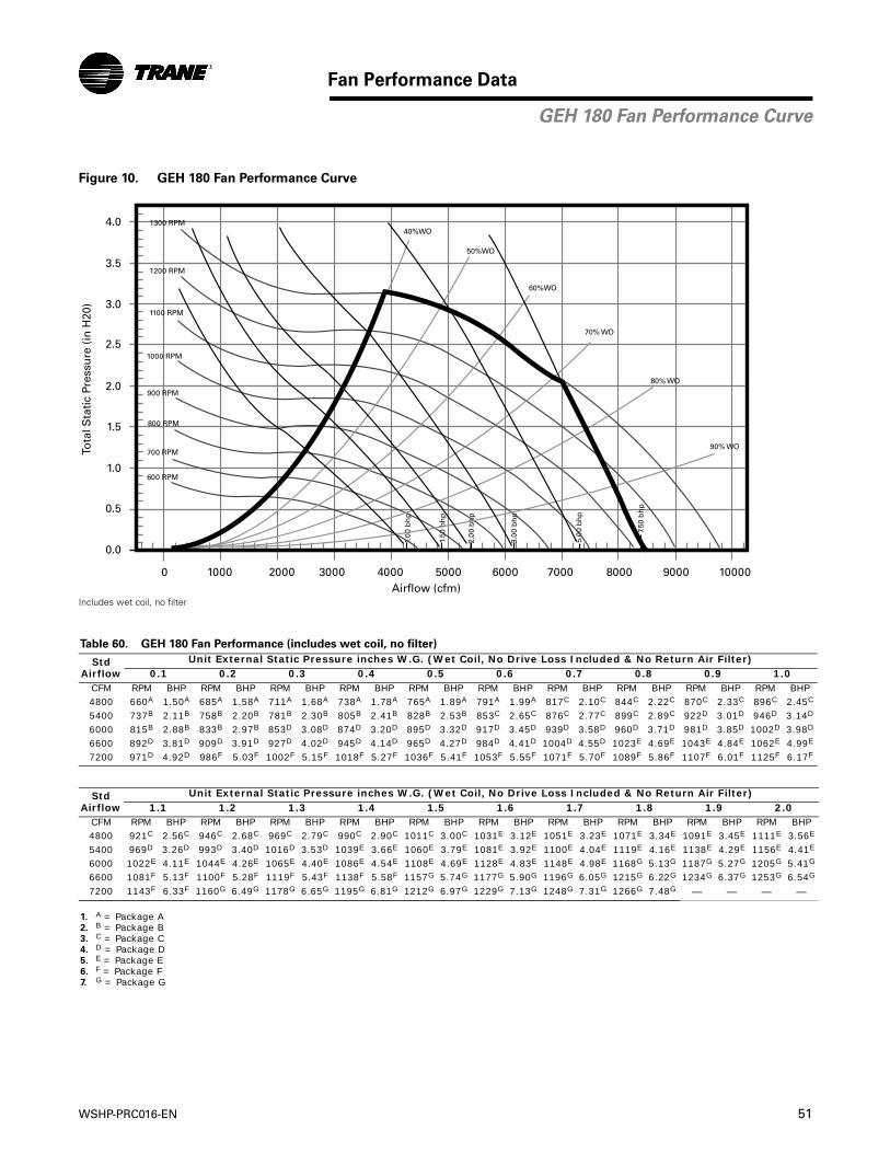
WSHP-PRC016-EN 51
Fan Performance Data
Figure 10. GEH 180 Fan Performance Curve
Includes wet coil, no filter
Table 60. GEH 180 Fan Performance (includes wet coil, no filter)
StdAirflow
Unit External Static Pressure inches W.G. (Wet Coil, No Drive Loss Included & No Return Air Filter)0.1 0.2 0.3 0.4 0.5 0.6 0.7 0.8 0.9 1.0
CFM RPM BHP RPM BHP RPM BHP RPM BHP RPM BHP RPM BHP RPM BHP RPM BHP RPM BHP RPM BHP4800 660A 1.50A 685A 1.58A 711A 1.68A 738A 1.78A 765A 1.89A 791A 1.99A 817C 2.10C 844C 2.22C 870C 2.33C 896C 2.45C
5400 737B 2.11B 758B 2.20B 781B 2.30B 805B 2.41B 828B 2.53B 853C 2.65C 876C 2.77C 899C 2.89C 922D 3.01D 946D 3.14D
6000 815B 2.88B 833B 2.97B 853D 3.08D 874D 3.20D 895D 3.32D 917D 3.45D 939D 3.58D 960D 3.71D 981D 3.85D 1002D 3.98D
6600 892D 3.81D 909D 3.91D 927D 4.02D 945D 4.14D 965D 4.27D 984D 4.41D 1004D 4.55D 1023E 4.69E 1043E 4.84E 1062E 4.99E
7200 971D 4.92D 986F 5.03F 1002F 5.15F 1018F 5.27F 1036F 5.41F 1053F 5.55F 1071F 5.70F 1089F 5.86F 1107F 6.01F 1125F 6.17F
StdAirflow
Unit External Static Pressure inches W.G. (Wet Coil, No Drive Loss Included & No Return Air Filter)1.1 1.2 1.3 1.4 1.5 1.6 1.7 1.8 1.9 2.0
CFM RPM BHP RPM BHP RPM BHP RPM BHP RPM BHP RPM BHP RPM BHP RPM BHP RPM BHP RPM BHP4800 921C 2.56C 946C 2.68C 969C 2.79C 990C 2.90C 1011C 3.00C 1031E 3.12E 1051E 3.23E 1071E 3.34E 1091E 3.45E 1111E 3.56E
5400 969D 3.26D 993D 3.40D 1016D 3.53D 1039E 3.66E 1060E 3.79E 1081E 3.92E 1100E 4.04E 1119E 4.16E 1138E 4.29E 1156E 4.41E
6000 1022E 4.11E 1044E 4.26E 1065E 4.40E 1086E 4.54E 1108E 4.69E 1128E 4.83E 1148E 4.98E 1168G 5.13G 1187G 5.27G 1205G 5.41G
6600 1081F 5.13F 1100F 5.28F 1119F 5.43F 1138F 5.58F 1157G 5.74G 1177G 5.90G 1196G 6.05G 1215G 6.22G 1234G 6.37G 1253G 6.54G
7200 1143F 6.33F 1160G 6.49G 1178G 6.65G 1195G 6.81G 1212G 6.97G 1229G 7.13G 1248G 7.31G 1266G 7.48G — — — —
1. A = Package A2. B = Package B3. C = Package C4. D = Package D5. E = Package E6. F = Package F7. G = Package G
3.0
3.5
4.0
2.5
2.0
1.5
1.0
0.5
0.0
0 1000 2000 3000 4000 70005000 8000 9000 100006000Airflow (cfm)
Tota
l Sta
tic
Pres
sure
(in
H20
)
1.00
bh
p
1.50
bh
p
2.00
bh
p
3.00
bh
p
5.00
bh
p
7.50
bh
p
50%WO
40%WO
60%WO
70% WO
80% WO
90% WO
600 RPM
700 RPM
800 RPM
900 RPM
1000 RPM
1100 RPM
1300 RPM
1200 RPM
GEH 180 Fan Performance Curve
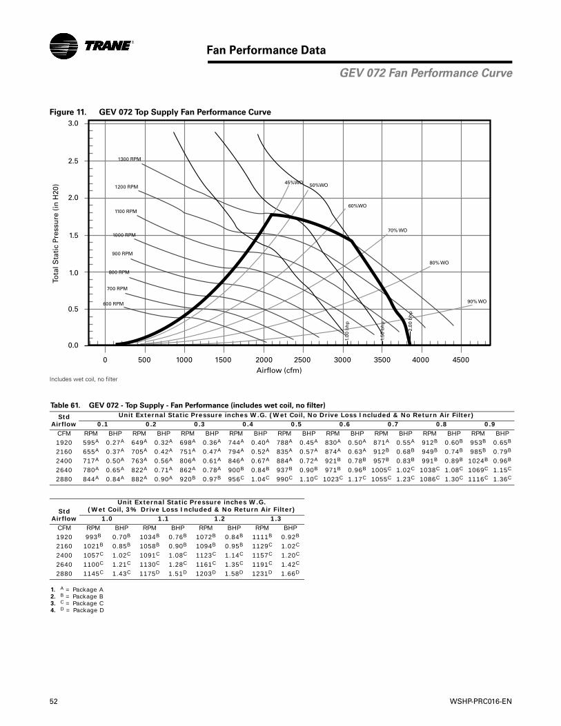
52 WSHP-PRC016-EN
Fan Performance Data
Figure 11. GEV 072 Top Supply Fan Performance Curve
Includes wet coil, no filter
Table 61. GEV 072 - Top Supply - Fan Performance (includes wet coil, no filter)
Std Airflow
Unit External Static Pressure inches W.G. (Wet Coil, No Drive Loss Included & No Return Air Filter)0.1 0.2 0.3 0.4 0.5 0.6 0.7 0.8 0.9
CFM RPM BHP RPM BHP RPM BHP RPM BHP RPM BHP RPM BHP RPM BHP RPM BHP RPM BHP1920 595A 0.27A 649A 0.32A 698A 0.36A 744A 0.40A 788A 0.45A 830A 0.50A 871A 0.55A 912B 0.60B 953B 0.65B
2160 655A 0.37A 705A 0.42A 751A 0.47A 794A 0.52A 835A 0.57A 874A 0.63A 912B 0.68B 949B 0.74B 985B 0.79B
2400 717A 0.50A 763A 0.56A 806A 0.61A 846A 0.67A 884A 0.72A 921B 0.78B 957B 0.83B 991B 0.89B 1024B 0.96B
2640 780A 0.65A 822A 0.71A 862A 0.78A 900B 0.84B 937B 0.90B 971B 0.96B 1005C 1.02C 1038C 1.08C 1069C 1.15C
2880 844A 0.84A 882A 0.90A 920B 0.97B 956C 1.04C 990C 1.10C 1023C 1.17C 1055C 1.23C 1086C 1.30C 1116C 1.36C
Std Airflow
Unit External Static Pressure inches W.G.(Wet Coil, 3% Drive Loss Included & No Return Air Filter)
1.0 1.1 1.2 1.3CFM RPM BHP RPM BHP RPM BHP RPM BHP1920 993B 0.70B 1034B 0.76B 1072B 0.84B 1111B 0.92B
2160 1021B 0.85B 1058B 0.90B 1094B 0.95B 1129C 1.02C
2400 1057C 1.02C 1091C 1.08C 1123C 1.14C 1157C 1.20C
2640 1100C 1.21C 1130C 1.28C 1161C 1.35C 1191C 1.42C
2880 1145C 1.43C 1175D 1.51D 1203D 1.58D 1231D 1.66D
1. A = Package A2. B = Package B3. C = Package C4. D = Package D
3.0
2.5
2.0
1.5
1.0
0.5
0.0
0 500 1000 1500 2000 2500 3000 3500 4000 4500Airflow (cfm)
Tota
l Sta
tic
Pres
sure
(in
H20
)
1.00
bh
p
1.50
bh
p
2.00
bh
p
50%WO45%WO
60%WO
70% WO
80% WO
90% WO
700 RPM
600 RPM
800 RPM
900 RPM
1000 RPM
1100 RPM
1200 RPM
1300 RPM
GEV 072 Fan Performance Curve
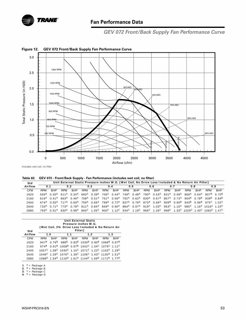
WSHP-PRC016-EN 53
Fan Performance Data
Figure 12. GEV 072 Front/Back Supply Fan Performance Curve
Includes wet coil, no filter
Table 62. GEV 072 - Front/Back Supply - Fan Performance (includes wet coil, no filter)
Std Airflow
Unit External Static Pressure inches W.G. (Wet Coil, No Drive Loss Included & No Return Air Filter)0.1 0.2 0.3 0.4 0.5 0.6 0.7 0.8 0.9
CFM RPM BHP RPM BHP RPM BHP RPM BHP RPM BHP RPM BHP RPM BHP RPM BHP RPM BHP1920 559A 0.30A 611A 0.34A 660A 0.39A 706A 0.44A 749A 0.48A 790A 0.53A 831A 0.59A 869A 0.64A 907B 0.70B
2160 616A 0.41A 663A 0.46A 708A 0.51A 751A 0.56A 792A 0.62A 830A 0.67A 867A 0.73A 904B 0.78B 939B 0.84B
2400 674A 0.55A 717A 0.60A 759A 0.66A 799A 0.72A 837A 0.78A 873A 0.84A 909B 0.90B 943B 0.96B 975C 1.02C
2640 733A 0.71A 773A 0.78A 811A 0.84A 849A 0.90A 884A 0.97A 919C 1.03C 953C 1.10C 985C 1.16C 1016C 1.23C
2880 793A 0.91A 830A 0.98A 865C 1.05C 900C 1.12C 934C 1.19C 966C 1.26C 998C 1.33C 1029C 1.40C 1060C 1.47C
Std Airflow
Unit External Static Pressure inches W.G.
(Wet Coil, 3% Drive Loss Included & No Return Air Filter)
1.0 1.1 1.2 1.3CFM RPM BHP RPM BHP RPM BHP RPM BHP1920 947B 0.76B 988B 0.83B 1030B 0.90B 1068B 0.97B
2160 974B 0.91B 1008B 0.97B 1042C 1.04C 1079C 1.11C
2400 1007C 1.08C 1040C 1.15C 1071C 1.22C 1102C 1.29C
2640 1046C 1.29C 1076C 1.36C 1106C 1.43C 1135D 1.51D
2880 1088D 1.54D 1116D 1.61D 1144D 1.69D 1172D 1.77D
1. A = Package A2. B = Package B3. C = Package C4. D = Package D
3.0
2.5
2.0
1.5
1.0
0.5
0.0
0 500 1000 1500 2000 2500 3000 3500 4000 4500Airflow (cfm)
Tota
l Sta
tic
Pres
sure
(in
H20
)
1.00
bh
p
1.50
bh
p
2.00
bh
p
50%WO45%WO
60%WO
70% WO
80% WO
90% WO
700 RPM
600 RPM
800 RPM
900 RPM
1000 RPM
1100 RPM
1200 RPM
1300 RPM
GEV 072 Front/Back Supply Fan Performance Curve
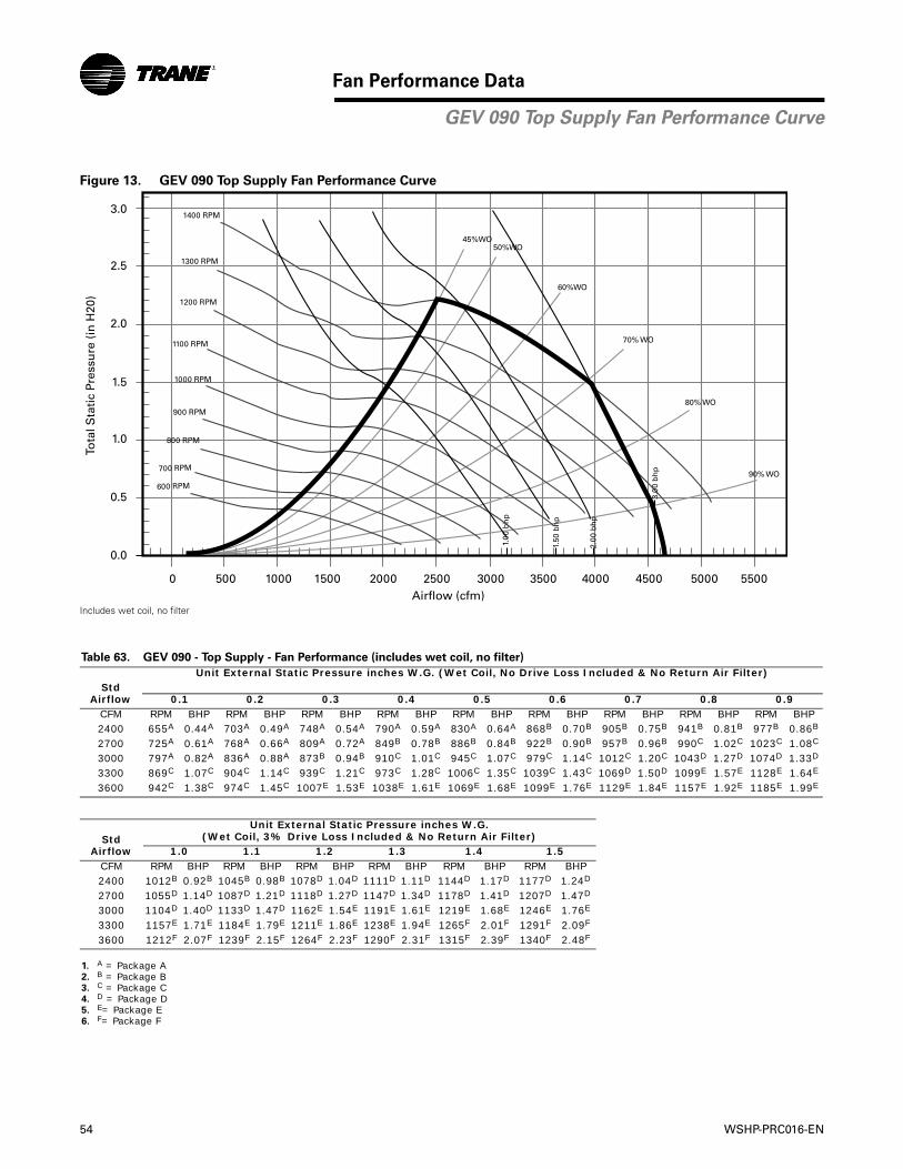
54 WSHP-PRC016-EN
Fan Performance Data
Figure 13. GEV 090 Top Supply Fan Performance Curve
Includes wet coil, no filter
Table 63. GEV 090 - Top Supply - Fan Performance (includes wet coil, no filter)
Std Airflow
Unit External Static Pressure inches W.G. (Wet Coil, No Drive Loss Included & No Return Air Filter)
0.1 0.2 0.3 0.4 0.5 0.6 0.7 0.8 0.9CFM RPM BHP RPM BHP RPM BHP RPM BHP RPM BHP RPM BHP RPM BHP RPM BHP RPM BHP2400 655A 0.44A 703A 0.49A 748A 0.54A 790A 0.59A 830A 0.64A 868B 0.70B 905B 0.75B 941B 0.81B 977B 0.86B
2700 725A 0.61A 768A 0.66A 809A 0.72A 849B 0.78B 886B 0.84B 922B 0.90B 957B 0.96B 990C 1.02C 1023C 1.08C
3000 797A 0.82A 836A 0.88A 873B 0.94B 910C 1.01C 945C 1.07C 979C 1.14C 1012C 1.20C 1043D 1.27D 1074D 1.33D
3300 869C 1.07C 904C 1.14C 939C 1.21C 973C 1.28C 1006C 1.35C 1039C 1.43C 1069D 1.50D 1099E 1.57E 1128E 1.64E
3600 942C 1.38C 974C 1.45C 1007E 1.53E 1038E 1.61E 1069E 1.68E 1099E 1.76E 1129E 1.84E 1157E 1.92E 1185E 1.99E
Std Airflow
Unit External Static Pressure inches W.G. (Wet Coil, 3% Drive Loss Included & No Return Air Filter)
1.0 1.1 1.2 1.3 1.4 1.5CFM RPM BHP RPM BHP RPM BHP RPM BHP RPM BHP RPM BHP2400 1012B 0.92B 1045B 0.98B 1078D 1.04D 1111D 1.11D 1144D 1.17D 1177D 1.24D
2700 1055D 1.14D 1087D 1.21D 1118D 1.27D 1147D 1.34D 1178D 1.41D 1207D 1.47D
3000 1104D 1.40D 1133D 1.47D 1162E 1.54E 1191E 1.61E 1219E 1.68E 1246E 1.76E
3300 1157E 1.71E 1184E 1.79E 1211E 1.86E 1238E 1.94E 1265F 2.01F 1291F 2.09F
3600 1212F 2.07F 1239F 2.15F 1264F 2.23F 1290F 2.31F 1315F 2.39F 1340F 2.48F
1. A = Package A2. B = Package B3. C = Package C4. D = Package D5. E= Package E6. F= Package F
3.0
2.5
2.0
1.5
1.0
0.5
0.0
0 500 1000 1500 2000 2500 3000 3500 4000 4500 55005000Airflow (cfm)
Tota
l Sta
tic
Pres
sure
(in
H20
)
1.00
bh
p
50%WO45%WO
60%WO
70% WO
80% WO
90% WO700 RPM
600 RPM
800 RPM
900 RPM
1000 RPM
1100 RPM
1200 RPM
1300 RPM
1400 RPM
1.50
bh
p
2.00
bh
p
3.00
bh
p
GEV 090 Top Supply Fan Performance Curve
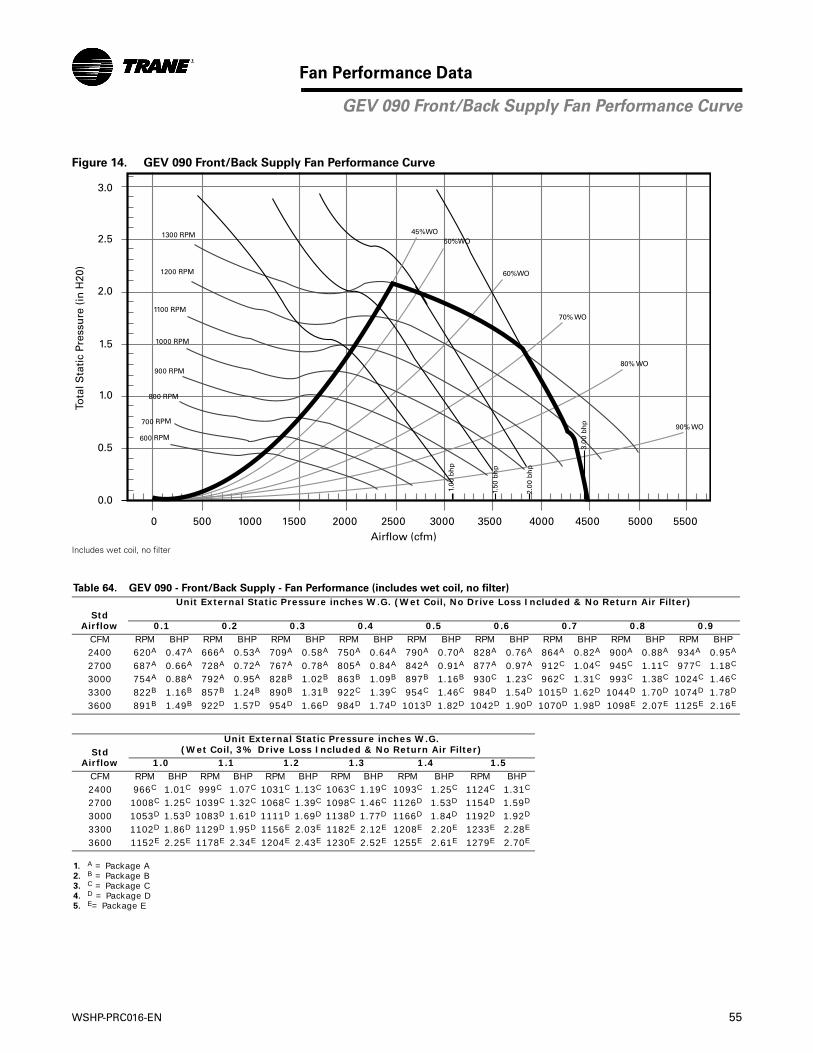
WSHP-PRC016-EN 55
Fan Performance Data
Figure 14. GEV 090 Front/Back Supply Fan Performance Curve
Includes wet coil, no filter
Table 64. GEV 090 - Front/Back Supply - Fan Performance (includes wet coil, no filter)
Std Airflow
Unit External Static Pressure inches W.G. (Wet Coil, No Drive Loss Included & No Return Air Filter)
0.1 0.2 0.3 0.4 0.5 0.6 0.7 0.8 0.9CFM RPM BHP RPM BHP RPM BHP RPM BHP RPM BHP RPM BHP RPM BHP RPM BHP RPM BHP2400 620A 0.47A 666A 0.53A 709A 0.58A 750A 0.64A 790A 0.70A 828A 0.76A 864A 0.82A 900A 0.88A 934A 0.95A
2700 687A 0.66A 728A 0.72A 767A 0.78A 805A 0.84A 842A 0.91A 877A 0.97A 912C 1.04C 945C 1.11C 977C 1.18C
3000 754A 0.88A 792A 0.95A 828B 1.02B 863B 1.09B 897B 1.16B 930C 1.23C 962C 1.31C 993C 1.38C 1024C 1.46C
3300 822B 1.16B 857B 1.24B 890B 1.31B 922C 1.39C 954C 1.46C 984D 1.54D 1015D 1.62D 1044D 1.70D 1074D 1.78D
3600 891B 1.49B 922D 1.57D 954D 1.66D 984D 1.74D 1013D 1.82D 1042D 1.90D 1070D 1.98D 1098E 2.07E 1125E 2.16E
Std Airflow
Unit External Static Pressure inches W.G. (Wet Coil, 3% Drive Loss Included & No Return Air Filter)
1.0 1.1 1.2 1.3 1.4 1.5CFM RPM BHP RPM BHP RPM BHP RPM BHP RPM BHP RPM BHP2400 966C 1.01C 999C 1.07C 1031C 1.13C 1063C 1.19C 1093C 1.25C 1124C 1.31C
2700 1008C 1.25C 1039C 1.32C 1068C 1.39C 1098C 1.46C 1126D 1.53D 1154D 1.59D
3000 1053D 1.53D 1083D 1.61D 1111D 1.69D 1138D 1.77D 1166D 1.84D 1192D 1.92D
3300 1102D 1.86D 1129D 1.95D 1156E 2.03E 1182E 2.12E 1208E 2.20E 1233E 2.28E
3600 1152E 2.25E 1178E 2.34E 1204E 2.43E 1230E 2.52E 1255E 2.61E 1279E 2.70E
1. A = Package A2. B = Package B3. C = Package C4. D = Package D5. E= Package E
3.0
2.5
2.0
1.5
1.0
0.5
0.0
0 500 1000 1500 2000 2500 3000 3500 4000 4500 55005000Airflow (cfm)
Tota
l Sta
tic
Pres
sure
(in
H20
)
50%WO45%WO
60%WO
70% WO
80% WO
90% WO700 RPM
600 RPM
800 RPM
900 RPM
1000 RPM
1100 RPM
1200 RPM
1300 RPM
1.00
bh
p
1.50
bh
p
2.00
bh
p
3.00
bh
p
GEV 090 Front/Back Supply Fan Performance Curve
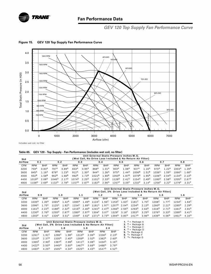
56 WSHP-PRC016-EN
Fan Performance Data
Figure 15. GEV 120 Top Supply Fan Performance Curve
Includes wet coil, no filter
Table 65. GEV 120 - Top Supply - Fan Performance (includes wet coil, no filter)
Std Airflow
Unit External Static Pressure inches W.G. (Wet Coil, No Drive Loss Included & No Return Air Filter)
0.1 0.2 0.3 0.4 0.5 0.6 0.7 0.8CFM RPM BHP RPM BHP RPM BHP RPM BHP RPM BHP RPM BHP RPM BHP RPM BHP3200 759A 0.83A 797A 0.89A 833A 0.95A 868A 1.01A 903A 1.08A 937A 1.16A 970A 1.22A 1003A 1.29A
3600 845A 1.16A 878A 1.23A 912A 1.30A 944A 1.36A 975A 1.44A 1006B 1.51B 1036C 1.59C 1066C 1.68C
4000 932B 1.58B 962B 1.66B 992B 1.73B 1021B 1.80B 1050B 1.87B 1079B 1.95B 1106D 2.04D 1134D 2.13D
4400 1019D 2.08D 1046D 2.17D 1074D 2.25D 1101D 2.33D 1128D 2.41D 1154D 2.49D 1180D 2.58D 1205D 2.67D
4800 1108D 2.69D 1132D 2.78D 1157D 2.87D 1182D 2.96D 1207F 3.05F 1232F 3.14F 1256F 3.22F 1279F 3.31F
Std Airflow
Unit External Static Pressure inches W.G. (Wet Coil, 3% Drive Loss Included & No Return Air Filter)
0.9 1.0 1.1 1.2 1.3 1.4 1.5 1.6CFM RPM BHP RPM BHP RPM BHP RPM BHP RPM BHP RPM BHP RPM BHP RPM BHP3200 1035A 1.35A 1065A 1.42A 1095A 1.49A 1124C 1.56C 1153C 1.63C 1181C 1.70C 1208C 1.77C 1234C 1.84C
3600 1096C 1.75C 1125C 1.82C 1154C 1.89C 1181C 1.97C 1207D 2.04D 1234D 2.13D 1260D 2.21D 1285D 2.29D
4000 1161D 2.22D 1188D 2.32D 1215D 2.40D 1241D 2.47D 1266D 2.55D 1293D 2.63D 1316D 2.71D 1341E 2.81E
4400 1230D 2.76D 1255D 2.87D 1280D 2.97D 1304F 3.07F 1329F 3.16F 1353G 3.25G 1376G 3.33G 1399G 3.41G
4800 1303F 3.41F 1326F 3.51F 1349F 3.62F 1371G 3.73G 1394G 3.85G 1417G 3.96G 1439G 4.06G 1461G 4.16G
Std Airflow
Unit External Static Pressure inches W.G. (Wet Coil, 3% Drive Loss Included & No Return Air Filter)
1. A = Package A2. B = Package B3. C = Package C4. D = Package D5. E= Package E6. F= Package F7. G= Package G
1.7 1.8 1.9 2.0CFM RPM BHP RPM BHP RPM BHP RPM BHP3200 1261C 1.91C 1286C 1.98C 1313D 2.06D 1336E 2.13E
3600 1310D 2.37D 1335D 2.45D 1359E 2.52E 1382E 2.60E
4000 1365E 2.90E 1387E 2.99E 1411G 3.08G 1434G 3.16G
4400 1422G 3.50G 1445G 3.60G 1467G 3.69G 1488G 3.79G
4800 1483G 4.25G 1505G 4.34G 1525G 4.43G 1547G 4.52G
3.0
3.5
4.0
2.5
2.0
1.5
1.0
0.5
0.0
0 1000 2000 3000 4000 70005000 6000Airflow (cfm)
Tota
l Sta
tic
Pres
sure
(in
H20
)
1.50
bh
p
2.00
bh
p
3.00
bh
p
5.00
bh
p
50%WO45%WO
60%WO
70% WO
80% WO
90% WO
700 RPM
800 RPM
900 RPM
1000 RPM
1100 RPM
1200 RPM
1300 RPM
1400 RPM
1500 RPM
1600 RPM
GEV 120 Top Supply Fan Performance Curve
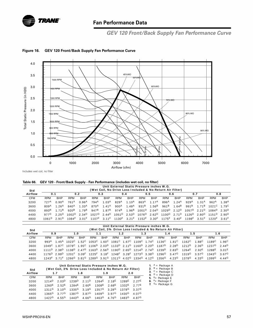
WSHP-PRC016-EN 57
Fan Performance Data
Figure 16. GEV 120 Front/Back Supply Fan Performance Curve
Includes wet coil, no filter
Table 66. GEV 120 - Front/Back Supply - Fan Performance (includes wet coil, no filter)
Std Airflow
Unit External Static Pressure inches W.G. (Wet Coil, No Drive Loss Included & No Return Air Filter)
0.1 0.2 0.3 0.4 0.5 0.6 0.7 0.8CFM RPM BHP RPM BHP RPM BHP RPM BHP RPM BHP RPM BHP RPM BHP RPM BHP3200 727A 0.90A 761A 0.96A 794A 1.03A 829A 1.10A 863A 1.17A 896A 1.24A 929A 1.31A 962A 1.38A
3600 809A 1.26A 840A 1.33A 870A 1.41A 900A 1.48A 931B 1.56B 961B 1.64B 991B 1.71B 1021C 1.79C
4000 893B 1.71B 920B 1.79B 947B 1.87B 974B 1.96B 1001D 2.04D 1029D 2.12D 1057D 2.21D 1084D 2.30D
4400 977D 2.25D 1002D 2.34D 1027D 2.44D 1051D 2.53D 1076D 2.62D 1100D 2.71D 1126D 2.80D 1151D 2.90D
4800 1061D 2.91D 1084F 3.01F 1107F 3.11F 1130F 3.21F 1152F 3.30F 1175F 3.40F 1198F 3.51F 1220F 3.61F
Std Airflow
Unit External Static Pressure inches W.G. (Wet Coil, 3% Drive Loss Included & No Return Air Filter)
0.9 1.0 1.1 1.2 1.3 1.4 1.5 1.6CFM RPM BHP RPM BHP RPM BHP RPM BHP RPM BHP RPM BHP RPM BHP RPM BHP3200 993A 1.45A 1023C 1.52C 1053C 1.60C 1081C 1.67C 1109C 1.74C 1136C 1.81C 1162C 1.88C 1189C 1.96C
3600 1049C 1.87C 1078C 1.95C 1106D 2.03D 1133D 2.11D 1160D 2.20D 1187D 2.28D 1212D 2.36D 1237D 2.44D
4000 1111D 2.38D 1138D 2.47D 1163D 2.56D 1190D 2.65D 1214D 2.74D 1239D 2.83D 1264E 2.92E 1288E 3.01E
4400 1176D 2.99D 1201F 3.09F 1225F 3.18F 1248F 3.28F 1273G 3.38G 1296G 3.47G 1319G 3.57G 1343G 3.67G
4800 1243F 3.71F 1266G 3.81G 1289G 3.91G 1311G 4.02G 1334G 4.12G 1356G 4.23G 1378G 4.33G 1399G 4.44G
Std Airflow
Unit External Static Pressure inches W.G. (Wet Coil, 3% Drive Loss Included & No Return Air Filter)
1. A = Package A2. B = Package B3. C = Package C4. D = Package D5. E= Package E6. F= Package F7. G= Package G
1.7 1.8 1.9 2.0CFM RPM BHP RPM BHP RPM BHP RPM BHP3200 1214D 2.03D 1239D 2.11D 1264E 2.18E 1289E 2.27E
3600 1260E 2.52E 1284E 2.60E 1308E 2.68E 1332E 2.77E
4000 1311G 3.10G 1335G 3.19G 1357G 3.28G 1378G 3.37G
4400 1365G 3.77G 1387G 3.87G 1409G 3.97G 1430G 4.07G
4800 1422G 4.55G 1443G 4.66G 1463G 4.76G 1483G 4.87G
3.0
3.5
4.0
2.5
2.0
1.5
1.0
0.5
0.0
0 1000 2000 3000 4000 70005000 6000Airflow (cfm)
Tota
l Sta
tic
Pres
sure
(in
H20
)
1.50
bh
p
2.00
bh
p
3.00
bh
p
5.00
bh
p
50%WO45%WO
60%WO
70% WO
80% WO
90% WO
700 RPM
800 RPM
900 RPM
1000 RPM
1100 RPM
1200 RPM
1300 RPM
1400 RPM
1500 RPM
GEV 120 Front/Back Supply Fan Performance Curve
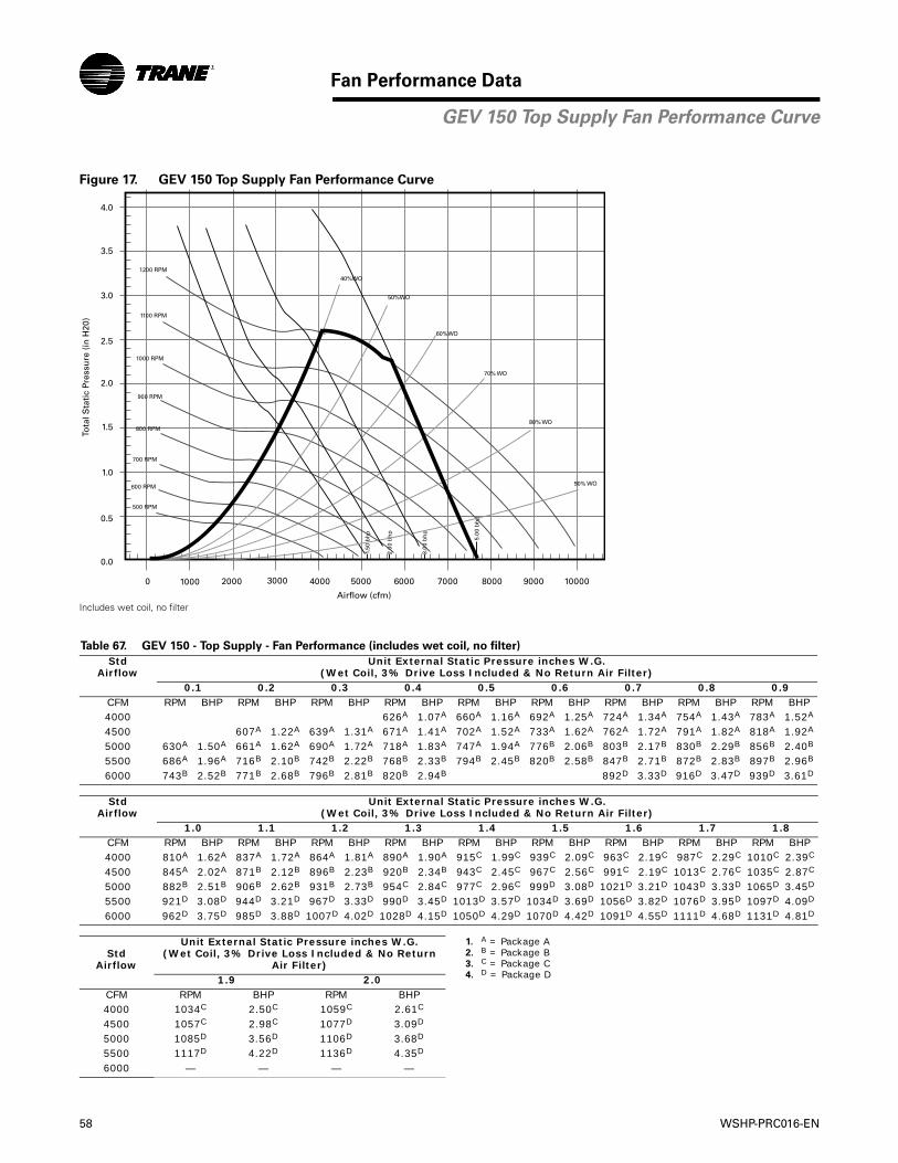
58 WSHP-PRC016-EN
Fan Performance Data
Figure 17. GEV 150 Top Supply Fan Performance Curve
Includes wet coil, no filter
Table 67. GEV 150 - Top Supply - Fan Performance (includes wet coil, no filter)
Std Airflow
Unit External Static Pressure inches W.G. (Wet Coil, 3% Drive Loss Included & No Return Air Filter)
0.1 0.2 0.3 0.4 0.5 0.6 0.7 0.8 0.9CFM RPM BHP RPM BHP RPM BHP RPM BHP RPM BHP RPM BHP RPM BHP RPM BHP RPM BHP4000 626A 1.07A 660A 1.16A 692A 1.25A 724A 1.34A 754A 1.43A 783A 1.52A
4500 607A 1.22A 639A 1.31A 671A 1.41A 702A 1.52A 733A 1.62A 762A 1.72A 791A 1.82A 818A 1.92A
5000 630A 1.50A 661A 1.62A 690A 1.72A 718A 1.83A 747A 1.94A 776B 2.06B 803B 2.17B 830B 2.29B 856B 2.40B
5500 686A 1.96A 716B 2.10B 742B 2.22B 768B 2.33B 794B 2.45B 820B 2.58B 847B 2.71B 872B 2.83B 897B 2.96B
6000 743B 2.52B 771B 2.68B 796B 2.81B 820B 2.94B 892D 3.33D 916D 3.47D 939D 3.61D
Std Airflow
Unit External Static Pressure inches W.G. (Wet Coil, 3% Drive Loss Included & No Return Air Filter)
1.0 1.1 1.2 1.3 1.4 1.5 1.6 1.7 1.8CFM RPM BHP RPM BHP RPM BHP RPM BHP RPM BHP RPM BHP RPM BHP RPM BHP RPM BHP4000 810A 1.62A 837A 1.72A 864A 1.81A 890A 1.90A 915C 1.99C 939C 2.09C 963C 2.19C 987C 2.29C 1010C 2.39C
4500 845A 2.02A 871B 2.12B 896B 2.23B 920B 2.34B 943C 2.45C 967C 2.56C 991C 2.19C 1013C 2.76C 1035C 2.87C
5000 882B 2.51B 906B 2.62B 931B 2.73B 954C 2.84C 977C 2.96C 999D 3.08D 1021D 3.21D 1043D 3.33D 1065D 3.45D
5500 921D 3.08D 944D 3.21D 967D 3.33D 990D 3.45D 1013D 3.57D 1034D 3.69D 1056D 3.82D 1076D 3.95D 1097D 4.09D
6000 962D 3.75D 985D 3.88D 1007D 4.02D 1028D 4.15D 1050D 4.29D 1070D 4.42D 1091D 4.55D 1111D 4.68D 1131D 4.81D
Std Airflow
Unit External Static Pressure inches W.G. (Wet Coil, 3% Drive Loss Included & No Return
Air Filter)
1. A = Package A2. B = Package B3. C = Package C4. D = Package D1.9 2.0
CFM RPM BHP RPM BHP4000 1034C 2.50C 1059C 2.61C
4500 1057C 2.98C 1077D 3.09D
5000 1085D 3.56D 1106D 3.68D
5500 1117D 4.22D 1136D 4.35D
6000 — — — —
4.0
3.5
3.0
2.5
2.0
1.5
1.0
0.5
0.0
0 1000 2000 3000 4000 5000 6000 7000 8000 9000 10000
Airflow (cfm)
Tota
l Sta
tic
Pres
sure
(in
H20
)
1.50
bh
p
2.00
bh
p
3.00
bh
p
5.00
bh
p
50%WO
40%WO
60%WO
70% WO
80% WO
90% WO
700 RPM
600 RPM
500 RPM
800 RPM
900 RPM
1000 RPM
1100 RPM
1200 RPM
GEV 150 Top Supply Fan Performance Curve
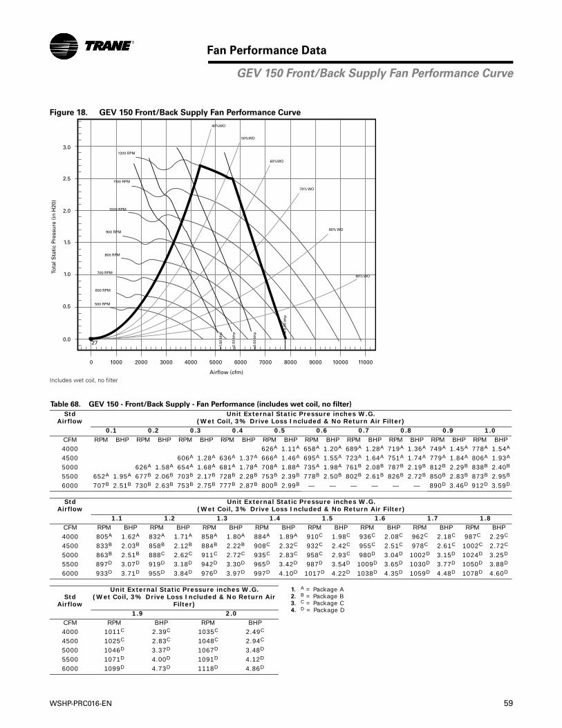
WSHP-PRC016-EN 59
Fan Performance Data
Figure 18. GEV 150 Front/Back Supply Fan Performance Curve
Includes wet coil, no filter
Table 68. GEV 150 - Front/Back Supply - Fan Performance (includes wet coil, no filter)
Std Airflow
Unit External Static Pressure inches W.G. (Wet Coil, 3% Drive Loss Included & No Return Air Filter)
0.1 0.2 0.3 0.4 0.5 0.6 0.7 0.8 0.9 1.0CFM RPM BHP RPM BHP RPM BHP RPM BHP RPM BHP RPM BHP RPM BHP RPM BHP RPM BHP RPM BHP4000 626A 1.11A 658A 1.20A 689A 1.28A 719A 1.36A 749A 1.45A 778A 1.54A
4500 606A 1.28A 636A 1.37A 666A 1.46A 695A 1.55A 723A 1.64A 751A 1.74A 779A 1.84A 806A 1.93A
5000 626A 1.58A 654A 1.68A 681A 1.78A 708A 1.88A 735A 1.98A 761B 2.08B 787B 2.19B 812B 2.29B 838B 2.40B
5500 652A 1.95A 677B 2.06B 703B 2.17B 728B 2.28B 753B 2.39B 778B 2.50B 802B 2.61B 826B 2.72B 850B 2.83B 873B 2.95B
6000 707B 2.51B 730B 2.63B 753B 2.75B 777B 2.87B 800B 2.99B — — — — — — 890D 3.46D 912D 3.59D
Std Airflow
Unit External Static Pressure inches W.G. (Wet Coil, 3% Drive Loss Included & No Return Air Filter)
1.1 1.2 1.3 1.4 1.5 1.6 1.7 1.8CFM RPM BHP RPM BHP RPM BHP RPM BHP RPM BHP RPM BHP RPM BHP RPM BHP4000 805A 1.62A 832A 1.71A 858A 1.80A 884A 1.89A 910C 1.98C 936C 2.08C 962C 2.18C 987C 2.29C
4500 833B 2.03B 858B 2.12B 884B 2.22B 908C 2.32C 932C 2.42C 955C 2.51C 978C 2.61C 1002C 2.72C
5000 863B 2.51B 888C 2.62C 911C 2.72C 935C 2.83C 958C 2.93C 980D 3.04D 1002D 3.15D 1024D 3.25D
5500 897D 3.07D 919D 3.18D 942D 3.30D 965D 3.42D 987D 3.54D 1009D 3.65D 1030D 3.77D 1050D 3.88D
6000 933D 3.71D 955D 3.84D 976D 3.97D 997D 4.10D 1017D 4.22D 1038D 4.35D 1059D 4.48D 1078D 4.60D
Std Airflow
Unit External Static Pressure inches W.G.(Wet Coil, 3% Drive Loss Included & No Return Air
Filter)
1. A = Package A2. B = Package B3. C = Package C4. D = Package D1.9 2.0
CFM RPM BHP RPM BHP4000 1011C 2.39C 1035C 2.49C
4500 1025C 2.83C 1048C 2.94C
5000 1046D 3.37D 1067D 3.48D
5500 1071D 4.00D 1091D 4.12D
6000 1099D 4.73D 1118D 4.86D
3.0
2.5
2.0
1.5
1.0
0.5
0.0
0
27
1000 2000 3000 4000 5000 6000 7000 8000 9000 10000 11000
Airflow (cfm)
Tota
l Sta
tic
Pres
sure
(in
H20
)
1.50
bh
p
2.00
bh
p
3.00
bh
p
5.00
bh
p
50%WO
40%WO
60%WO
70% WO
80% WO
90% WO700 RPM
600 RPM
500 RPM
800 RPM
900 RPM
1000 RPM
1100 RPM
1200 RPM
GEV 150 Front/Back Supply Fan Performance Curve
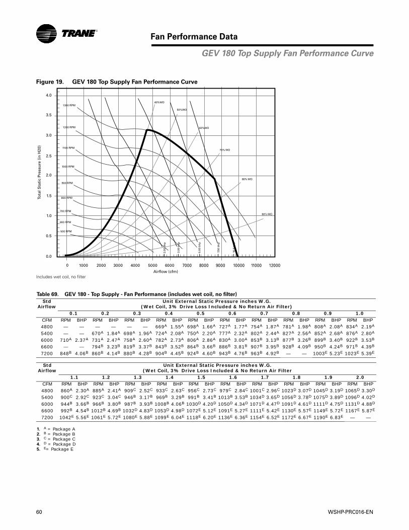
60 WSHP-PRC016-EN
Fan Performance Data
Figure 19. GEV 180 Top Supply Fan Performance Curve
Includes wet coil, no filter
Table 69. GEV 180 - Top Supply - Fan Performance (includes wet coil, no filter)
Std Airflow
Unit External Static Pressure inches W.G. (Wet Coil, 3% Drive Loss Included & No Return Air Filter)
0.1 0.2 0.3 0.4 0.5 0.6 0.7 0.8 0.9 1.0CFM RPM BHP RPM BHP RPM BHP RPM BHP RPM BHP RPM BHP RPM BHP RPM BHP RPM BHP RPM BHP4800 — — — — — — 669A 1.55A 698A 1.66A 727A 1.77A 754A 1.87A 781A 1.98A 808A 2.08A 834A 2.19A
5400 — — 670A 1.84A 698A 1.96A 724A 2.08A 750A 2.20A 777A 2.32A 802A 2.44A 827A 2.56A 852A 2.68A 876A 2.80A
6000 710A 2.37A 731A 2.47A 758A 2.60A 782A 2.73A 806A 2.86A 830A 3.00A 853B 3.13B 877B 3.26B 899B 3.40B 922B 3.53B
6600 — — 794B 3.23B 819B 3.37B 843B 3.52B 864B 3.66B 886B 3.81B 907B 3.95B 928B 4.09B 950B 4.24B 971B 4.39B
7200 848B 4.06B 860B 4.14B 880B 4.28B 904B 4.45B 924B 4.60B 943B 4.76B 963B 4.92B — — 1003E 5.23E 1023E 5.39E
Std Airflow
Unit External Static Pressure inches W.G. (Wet Coil, 3% Drive Loss Included & No Return Air Filter
1.1 1.2 1.3 1.4 1.5 1.6 1.7 1.8 1.9 2.0CFM RPM BHP RPM BHP RPM BHP RPM BHP RPM BHP RPM BHP RPM BHP RPM BHP RPM BHP RPM BHP4800 860A 2.30A 885A 2.41A 909C 2.52C 933C 2.63C 956C 2.73C 979C 2.84C 1001C 2.96C 1023D 3.07D 1045D 3.19D 1065D 3.30D
5400 900C 2.92C 923C 3.04C 946B 3.17B 969B 3.29B 991B 3.41B 1013B 3.53B 1034D 3.65D 1056D 3.78D 1075D 3.89D 1096D 4.02D
6000 944B 3.66B 966B 3.80B 987B 3.93B 1008B 4.06B 1030D 4.20D 1050D 4.34D 1071D 4.47D 1091D 4.61D 1111D 4.75D 1131D 4.88D
6600 992B 4.54B 1012B 4.69B 1032D 4.83D 1053D 4.98D 1072E 5.12E 1091E 5.27E 1111E 5.42E 1130E 5.57E 1149E 5.72E 1167E 5.87E
7200 1042E 5.56E 1061E 5.72E 1080E 5.88E 1099E 6.04E 1118E 6.20E 1136E 6.36E 1154E 6.52E 1172E 6.67E 1190E 6.83E — —
1. A = Package A2. B = Package B3. C = Package C4. D = Package D5. E= Package E
4.0
3.5
3.0
2.5
2.0
1.5
1.0
0.5
0.0
0 1000 2000 3000 4000 5000 6000 7000 8000 9000 10000 11000 12000Airflow (cfm)
Tota
l Sta
tic
Pres
sure
(in
H20
)
2.00
bh
p
3.00
bh
p
5.00
bh
p
7.50
bh
p
10.0
bh
p
50%WO
40%WO
60%WO
70% WO
80% WO
90% WO700 RPM
600 RPM
500 RPM
800 RPM
900 RPM
1000 RPM
1100 RPM
1200 RPM
1300 RPM
GEV 180 Top Supply Fan Performance Curve
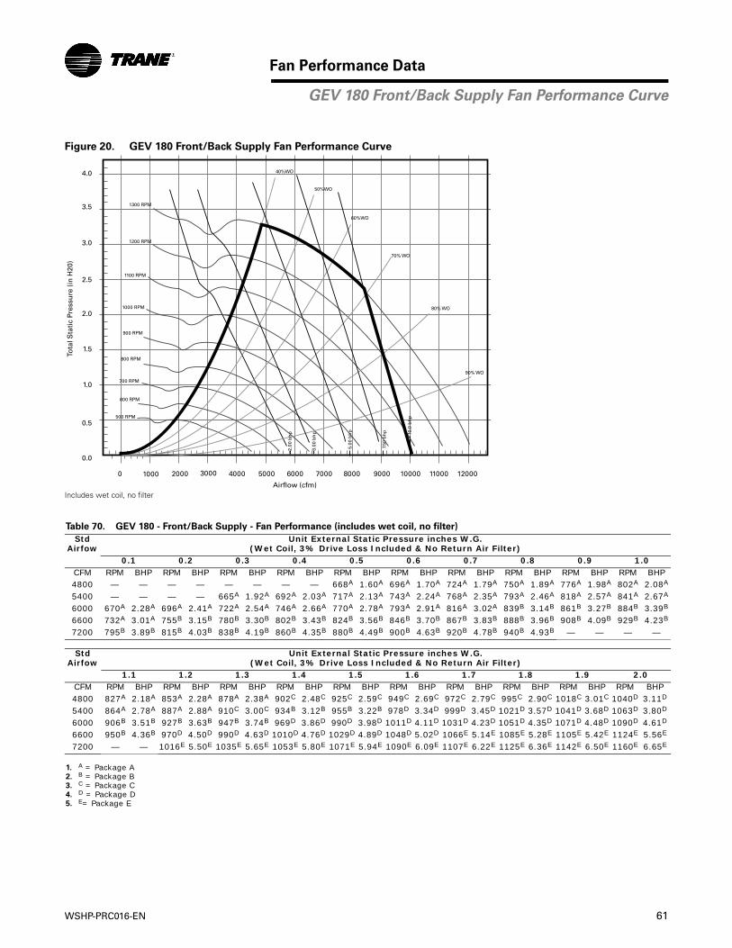
WSHP-PRC016-EN 61
Fan Performance Data
Figure 20. GEV 180 Front/Back Supply Fan Performance Curve
Includes wet coil, no filter
Table 70. GEV 180 - Front/Back Supply - Fan Performance (includes wet coil, no filter)
Std Airfow
Unit External Static Pressure inches W.G. (Wet Coil, 3% Drive Loss Included & No Return Air Filter)
0.1 0.2 0.3 0.4 0.5 0.6 0.7 0.8 0.9 1.0CFM RPM BHP RPM BHP RPM BHP RPM BHP RPM BHP RPM BHP RPM BHP RPM BHP RPM BHP RPM BHP4800 — — — — — — — — 668A 1.60A 696A 1.70A 724A 1.79A 750A 1.89A 776A 1.98A 802A 2.08A
5400 — — — — 665A 1.92A 692A 2.03A 717A 2.13A 743A 2.24A 768A 2.35A 793A 2.46A 818A 2.57A 841A 2.67A
6000 670A 2.28A 696A 2.41A 722A 2.54A 746A 2.66A 770A 2.78A 793A 2.91A 816A 3.02A 839B 3.14B 861B 3.27B 884B 3.39B
6600 732A 3.01A 755B 3.15B 780B 3.30B 802B 3.43B 824B 3.56B 846B 3.70B 867B 3.83B 888B 3.96B 908B 4.09B 929B 4.23B
7200 795B 3.89B 815B 4.03B 838B 4.19B 860B 4.35B 880B 4.49B 900B 4.63B 920B 4.78B 940B 4.93B — — — —
Std Airfow
Unit External Static Pressure inches W.G. (Wet Coil, 3% Drive Loss Included & No Return Air Filter)
1.1 1.2 1.3 1.4 1.5 1.6 1.7 1.8 1.9 2.0CFM RPM BHP RPM BHP RPM BHP RPM BHP RPM BHP RPM BHP RPM BHP RPM BHP RPM BHP RPM BHP4800 827A 2.18A 853A 2.28A 878A 2.38A 902C 2.48C 925C 2.59C 949C 2.69C 972C 2.79C 995C 2.90C 1018C 3.01C 1040D 3.11D
5400 864A 2.78A 887A 2.88A 910C 3.00C 934B 3.12B 955B 3.22B 978D 3.34D 999D 3.45D 1021D 3.57D 1041D 3.68D 1063D 3.80D
6000 906B 3.51B 927B 3.63B 947B 3.74B 969D 3.86D 990D 3.98D 1011D 4.11D 1031D 4.23D 1051D 4.35D 1071D 4.48D 1090D 4.61D
6600 950B 4.36B 970D 4.50D 990D 4.63D 1010D 4.76D 1029D 4.89D 1048D 5.02D 1066E 5.14E 1085E 5.28E 1105E 5.42E 1124E 5.56E
7200 — — 1016E 5.50E 1035E 5.65E 1053E 5.80E 1071E 5.94E 1090E 6.09E 1107E 6.22E 1125E 6.36E 1142E 6.50E 1160E 6.65E
1. A = Package A2. B = Package B3. C = Package C4. D = Package D5. E= Package E
4.0
3.5
3.0
2.5
2.0
1.5
1.0
0.5
0.0
0 1000 2000 3000 4000 5000 6000 7000 8000 9000 10000 11000 12000
Airflow (cfm)
Tota
l Sta
tic
Pres
sure
(in
H20
)
2.00
bh
p
3.00
bh
p
5.00
bh
p 10.0
bh
p
7.50
bh
p
50%WO
40%WO
60%WO
70% WO
80% WO
90% WO
700 RPM
600 RPM
500 RPM
800 RPM
900 RPM
1000 RPM
1100 RPM
1200 RPM
1300 RPM
GEV 180 Front/Back Supply Fan Performance Curve
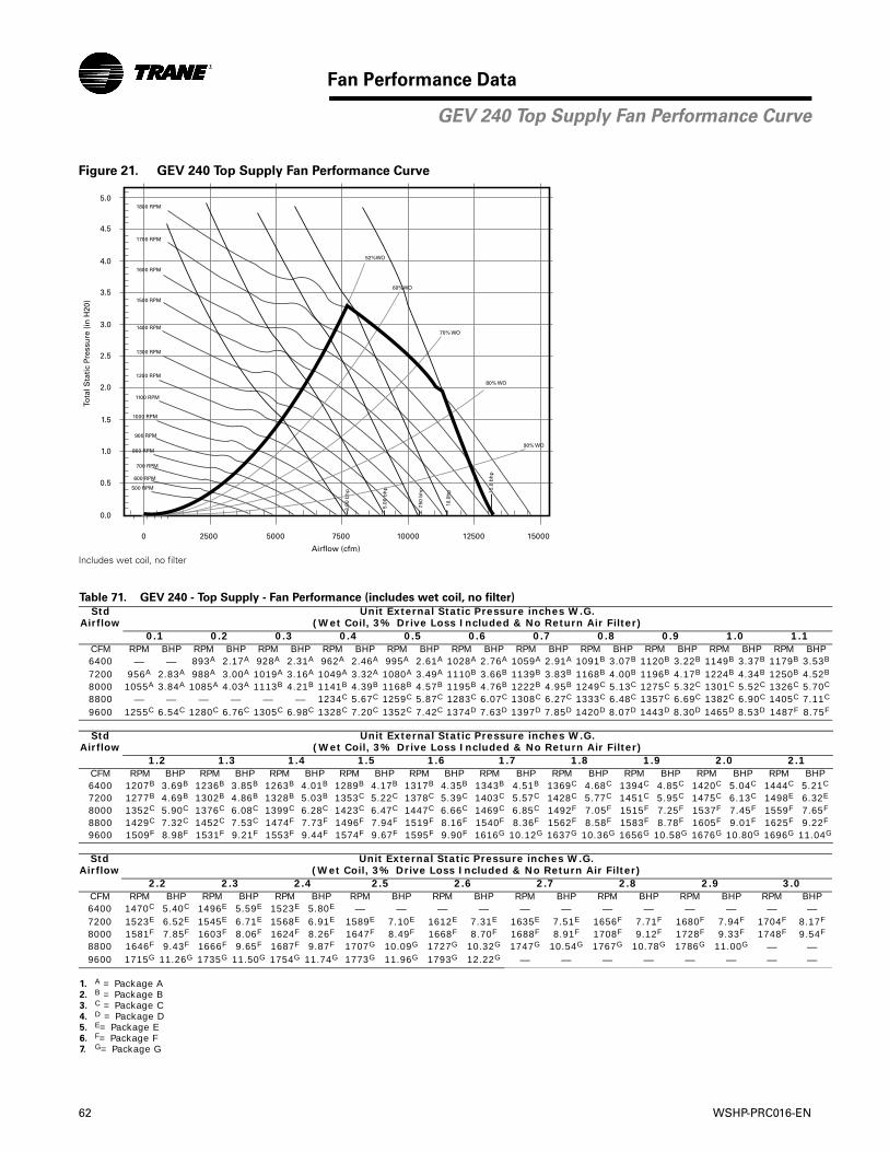
62 WSHP-PRC016-EN
Fan Performance Data
Figure 21. GEV 240 Top Supply Fan Performance Curve
Includes wet coil, no filter
Table 71. GEV 240 - Top Supply - Fan Performance (includes wet coil, no filter)
Std Airflow
Unit External Static Pressure inches W.G. (Wet Coil, 3% Drive Loss Included & No Return Air Filter)
0.1 0.2 0.3 0.4 0.5 0.6 0.7 0.8 0.9 1.0 1.1CFM RPM BHP RPM BHP RPM BHP RPM BHP RPM BHP RPM BHP RPM BHP RPM BHP RPM BHP RPM BHP RPM BHP6400 — — 893A 2.17A 928A 2.31A 962A 2.46A 995A 2.61A 1028A 2.76A 1059A 2.91A 1091B 3.07B 1120B 3.22B 1149B 3.37B 1179B 3.53B
7200 956A 2.83A 988A 3.00A 1019A 3.16A 1049A 3.32A 1080A 3.49A 1110B 3.66B 1139B 3.83B 1168B 4.00B 1196B 4.17B 1224B 4.34B 1250B 4.52B
8000 1055A 3.84A 1085A 4.03A 1113B 4.21B 1141B 4.39B 1168B 4.57B 1195B 4.76B 1222B 4.95B 1249C 5.13C 1275C 5.32C 1301C 5.52C 1326C 5.70C
8800 — — — — — — 1234C 5.67C 1259C 5.87C 1283C 6.07C 1308C 6.27C 1333C 6.48C 1357C 6.69C 1382C 6.90C 1405C 7.11C
9600 1255C 6.54C 1280C 6.76C 1305C 6.98C 1328C 7.20C 1352C 7.42C 1374D 7.63D 1397D 7.85D 1420D 8.07D 1443D 8.30D 1465D 8.53D 1487F 8.75F
Std Airflow
Unit External Static Pressure inches W.G. (Wet Coil, 3% Drive Loss Included & No Return Air Filter)
1.2 1.3 1.4 1.5 1.6 1.7 1.8 1.9 2.0 2.1CFM RPM BHP RPM BHP RPM BHP RPM BHP RPM BHP RPM BHP RPM BHP RPM BHP RPM BHP RPM BHP6400 1207B 3.69B 1236B 3.85B 1263B 4.01B 1289B 4.17B 1317B 4.35B 1343B 4.51B 1369C 4.68C 1394C 4.85C 1420C 5.04C 1444C 5.21C
7200 1277B 4.69B 1302B 4.86B 1328B 5.03B 1353C 5.22C 1378C 5.39C 1403C 5.57C 1428C 5.77C 1451C 5.95C 1475C 6.13C 1498E 6.32E
8000 1352C 5.90C 1376C 6.08C 1399C 6.28C 1423C 6.47C 1447C 6.66C 1469C 6.85C 1492F 7.05F 1515F 7.25F 1537F 7.45F 1559F 7.65F
8800 1429C 7.32C 1452C 7.53C 1474F 7.73F 1496F 7.94F 1519F 8.16F 1540F 8.36F 1562F 8.58F 1583F 8.78F 1605F 9.01F 1625F 9.22F
9600 1509F 8.98F 1531F 9.21F 1553F 9.44F 1574F 9.67F 1595F 9.90F 1616G 10.12G 1637G 10.36G 1656G 10.58G 1676G 10.80G 1696G 11.04G
Std Airflow
Unit External Static Pressure inches W.G.(Wet Coil, 3% Drive Loss Included & No Return Air Filter)
2.2 2.3 2.4 2.5 2.6 2.7 2.8 2.9 3.0CFM RPM BHP RPM BHP RPM BHP RPM BHP RPM BHP RPM BHP RPM BHP RPM BHP RPM BHP6400 1470C 5.40C 1496E 5.59E 1523E 5.80E — — — — — — — — — — — —7200 1523E 6.52E 1545E 6.71E 1568E 6.91E 1589E 7.10E 1612E 7.31E 1635E 7.51E 1656F 7.71F 1680F 7.94F 1704F 8.17F
8000 1581F 7.85F 1603F 8.06F 1624F 8.26F 1647F 8.49F 1668F 8.70F 1688F 8.91F 1708F 9.12F 1728F 9.33F 1748F 9.54F
8800 1646F 9.43F 1666F 9.65F 1687F 9.87F 1707G 10.09G 1727G 10.32G 1747G 10.54G 1767G 10.78G 1786G 11.00G — —9600 1715G 11.26G 1735G 11.50G 1754G 11.74G 1773G 11.96G 1793G 12.22G — — — — — — — —
1. A = Package A2. B = Package B3. C = Package C4. D = Package D5. E= Package E6. F= Package F7. G= Package G
4.0
4.5
5.0
3.5
3.0
2.5
2.0
1.5
1.0
0.5
0.0
0 2500 5000 7500 10000 12500 15000
Airflow (cfm)
Tota
l Sta
tic
Pres
sure
(in
H20
)
3.00
bh
p
5.00
bh
p 15.0
bh
p
7.50
bh
p
10.0
hp
52%WO
60%WO
70% WO
80% WO
90% WO
700 RPM
600 RPM
500 RPM
800 RPM
900 RPM
1000 RPM
1100 RPM
1200 RPM
1300 RPM
1400 RPM
1500 RPM
1600 RPM
1700 RPM
1800 RPM
GEV 240 Top Supply Fan Performance Curve
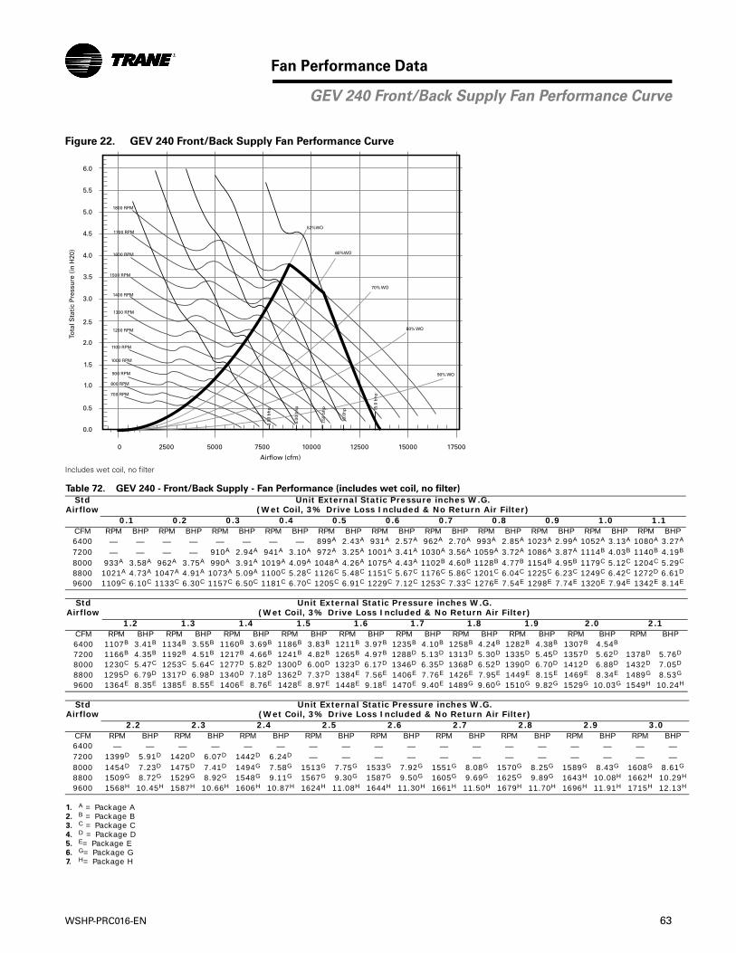
WSHP-PRC016-EN 63
Fan Performance Data
Figure 22. GEV 240 Front/Back Supply Fan Performance Curve
Includes wet coil, no filter
Table 72. GEV 240 - Front/Back Supply - Fan Performance (includes wet coil, no filter)
Std Airflow
Unit External Static Pressure inches W.G. (Wet Coil, 3% Drive Loss Included & No Return Air Filter)
0.1 0.2 0.3 0.4 0.5 0.6 0.7 0.8 0.9 1.0 1.1CFM RPM BHP RPM BHP RPM BHP RPM BHP RPM BHP RPM BHP RPM BHP RPM BHP RPM BHP RPM BHP RPM BHP6400 — — — — — — — — 899A 2.43A 931A 2.57A 962A 2.70A 993A 2.85A 1023A 2.99A 1052A 3.13A 1080A 3.27A
7200 — — — — 910A 2.94A 941A 3.10A 972A 3.25A 1001A 3.41A 1030A 3.56A 1059A 3.72A 1086A 3.87A 1114B 4.03B 1140B 4.19B
8000 933A 3.58A 962A 3.75A 990A 3.91A 1019A 4.09A 1048A 4.26A 1075A 4.43A 1102B 4.60B 1128B 4.77B 1154B 4.95B 1179C 5.12C 1204C 5.29C
8800 1021A 4.73A 1047A 4.91A 1073A 5.09A 1100C 5.28C 1126C 5.48C 1151C 5.67C 1176C 5.86C 1201C 6.04C 1225C 6.23C 1249C 6.42C 1272D 6.61D
9600 1109C 6.10C 1133C 6.30C 1157C 6.50C 1181C 6.70C 1205C 6.91C 1229C 7.12C 1253C 7.33C 1276E 7.54E 1298E 7.74E 1320E 7.94E 1342E 8.14E
Std Airflow
Unit External Static Pressure inches W.G. (Wet Coil, 3% Drive Loss Included & No Return Air Filter)
1.2 1.3 1.4 1.5 1.6 1.7 1.8 1.9 2.0 2.1CFM RPM BHP RPM BHP RPM BHP RPM BHP RPM BHP RPM BHP RPM BHP RPM BHP RPM BHP RPM BHP6400 1107B 3.41B 1134B 3.55B 1160B 3.69B 1186B 3.83B 1211B 3.97B 1235B 4.10B 1258B 4.24B 1282B 4.38B 1307B 4.54B
7200 1166B 4.35B 1192B 4.51B 1217B 4.66B 1241B 4.82B 1265B 4.97B 1288D 5.13D 1313D 5.30D 1335D 5.45D 1357D 5.62D 1378D 5.76D
8000 1230C 5.47C 1253C 5.64C 1277D 5.82D 1300D 6.00D 1323D 6.17D 1346D 6.35D 1368D 6.52D 1390D 6.70D 1412D 6.88D 1432D 7.05D
8800 1295D 6.79D 1317D 6.98D 1340D 7.18D 1362D 7.37D 1384E 7.56E 1406E 7.76E 1426E 7.95E 1449E 8.15E 1469E 8.34E 1489G 8.53G
9600 1364E 8.35E 1385E 8.55E 1406E 8.76E 1428E 8.97E 1448E 9.18E 1470E 9.40E 1489G 9.60G 1510G 9.82G 1529G 10.03G 1549H 10.24H
Std Airflow
Unit External Static Pressure inches W.G. (Wet Coil, 3% Drive Loss Included & No Return Air Filter)
2.2 2.3 2.4 2.5 2.6 2.7 2.8 2.9 3.0CFM RPM BHP RPM BHP RPM BHP RPM BHP RPM BHP RPM BHP RPM BHP RPM BHP RPM BHP6400 — — — — — — — — — — — — — — — — — —7200 1399D 5.91D 1420D 6.07D 1442D 6.24D — — — — — — — — — — — —8000 1454D 7.23D 1475D 7.41D 1494G 7.58G 1513G 7.75G 1533G 7.92G 1551G 8.08G 1570G 8.25G 1589G 8.43G 1608G 8.61G
8800 1509G 8.72G 1529G 8.92G 1548G 9.11G 1567G 9.30G 1587G 9.50G 1605G 9.69G 1625G 9.89G 1643H 10.08H 1662H 10.29H
9600 1568H 10.45H 1587H 10.66H 1606H 10.87H 1624H 11.08H 1644H 11.30H 1661H 11.50H 1679H 11.70H 1696H 11.91H 1715H 12.13H
1. A = Package A2. B = Package B3. C = Package C4. D = Package D5. E= Package E6. G= Package G7. H= Package H
4.0
4.5
5.0
5.5
6.0
3.5
3.0
2.5
2.0
1.5
1.0
0.5
0.0
0 2500 5000 7500 10000 12500 15000 17500
Airflow (cfm)
Tota
l Sta
tic
Pres
sure
(in
H20
)
3.00
bh
p
5.00
bh
p 15.0
bh
p
7.50
bh
p
10.0
hp
52%WO
60%WO
70% WO
80% WO
90% WO
700 RPM
800 RPM
900 RPM
1000 RPM
1100 RPM
1200 RPM
1300 RPM
1400 RPM
1500 RPM
1600 RPM
1700 RPM
1800 RPM
GEV 240 Front/Back Supply Fan Performance Curve
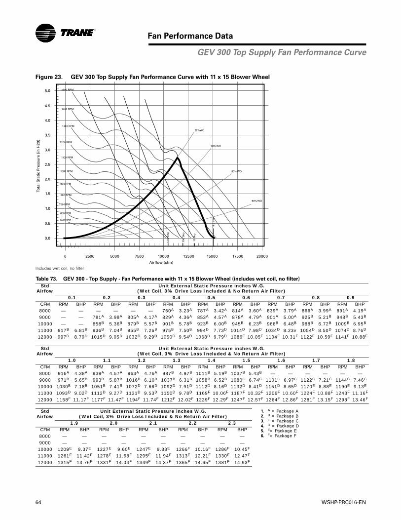
64 WSHP-PRC016-EN
Fan Performance Data
Figure 23. GEV 300 Top Supply Fan Performance Curve with 11 x 15 Blower Wheel
Includes wet coil, no filter
Table 73. GEV 300 - Top Supply - Fan Performance with 11 x 15 Blower Wheel (includes wet coil, no filter)
Std Airfow
Unit External Static Pressure inches W.G. (Wet Coil, 3% Drive Loss Included & No Return Air Filter)
0.1 0.2 0.3 0.4 0.5 0.6 0.7 0.8 0.9CFM RPM BHP RPM BHP RPM BHP RPM BHP RPM BHP RPM BHP RPM BHP RPM BHP RPM BHP8000 — — — — — — 760A 3.23A 787A 3.42A 814A 3.60A 839A 3.79A 866A 3.99A 891A 4.19A
9000 — — 781A 3.98A 805A 4.17A 829A 4.36A 853A 4.57A 878A 4.79A 901A 5.00A 925B 5.21B 948B 5.43B
10000 — — 858B 5.36B 879B 5.57B 901B 5.78B 923B 6.00B 945B 6.23B 966B 6.48B 988B 6.72B 1009B 6.95B
11000 917B 6.81B 936B 7.04B 955B 7.26B 975B 7.50B 994D 7.73D 1014D 7.98D 1034D 8.23v 1054D 8.50D 1074D 8.76D
12000 997D 8.79D 1015D 9.05D 1032D 9.29D 1050D 9.54D 1068D 9.79D 1086F 10.05F 1104F 10.31F 1122F 10.59F 1141F 10.88F
Std Airfow
Unit External Static Pressure inches W.G. (Wet Coil, 3% Drive Loss Included & No Return Air Filter)
1.0 1.1 1.2 1.3 1.4 1.5 1.6 1.7 1.8CFM RPM BHP RPM BHP RPM BHP RPM BHP RPM BHP RPM BHP RPM BHP RPM BHP RPM BHP8000 916A 4.38A 939A 4.57A 963A 4.76A 987B 4.97B 1011B 5.19B 1037B 5.43B — — — — — —9000 971B 5.65B 993B 5.87B 1016B 6.10B 1037B 6.31B 1058B 6.52B 1080C 6.74C 1101C 6.97C 1122C 7.21C 1144C 7.46C
10000 1030B 7.18B 1051B 7.41B 1072D 7.66D 1092D 7.91D 1112D 8.16D 1132D 8.41D 1151D 8.65D 1170E 8.88E 1190E 9.13E
11000 1093D 9.02D 1112D 9.27D 1131D 9.53D 1150D 9.78D 1169F 10.06F 1187F 10.32F 1206F 10.60F 1224F 10.88F 1243F 11.16F
12000 1158F 11.17F 1177F 11.47F 1194F 11.74F 1212F 12.02F 1229F 12.29F 1247F 12.57F 1264F 12.86F 1281F 13.15F 1298F 13.46F
Std Airfow
Unit External Static Pressure inches W.G. (Wet Coil, 3% Drive Loss Included & No Return Air Filter)
1. A = Package A2. B = Package B3. C = Package C4. D = Package D5. E= Package E6. F= Package F
1.9 2.0 2.1 2.2 2.3CFM RPM BHP RPM BHP RPM BHP RPM BHP RPM BHP8000 — — — — — — — — — —9000 — — — — — — — — — —10000 1209E 9.37E 1227E 9.60E 1247E 9.88E 1266F 10.16F 1286F 10.45F
11000 1261F 11.42F 1278F 11.68F 1295F 11.94F 1313F 12.21F 1330F 12.47F
12000 1315F 13.76F 1331F 14.04F 1349F 14.37F 1365F 14.65F 1381F 14.93F
4.0
4.5
5.0
3.5
3.0
2.5
2.0
1.5
1.0
0.5
0.0
0 2500 5000 7500 10000 12500 15000 17500 20000
Airflow (cfm)
Tota
l Sta
tic
Pres
sure
(in
H20
)
5.00
bh
p
15.0
bh
p
7.50
bh
p
10.0
hp
62%WO
70% WO
80% WO
90% WO
500 RPM
800 RPM
700 RPM
600 RPM
900 RPM
1000 RPM
1100 RPM
1200 RPM
1300 RPM
1400 RPM
1500 RPM
GEV 300 Top Supply Fan Performance Curve
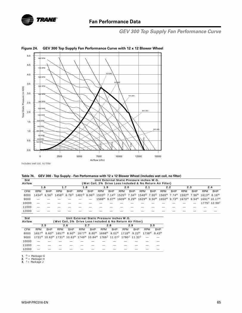
WSHP-PRC016-EN 65
Fan Performance Data
Figure 24. GEV 300 Top Supply Fan Performance Curve with 12 x 12 Blower Wheel
Includes wet coil, no filter
Table 74. GEV 300 - Top Supply - Fan Performance with 12 x 12 Blower Wheel (includes wet coil, no filter)
Std Airfow
Unit External Static Pressure inches W.G. (Wet Coil, 3% Drive Loss Included & No Return Air Filter)
1.6 1.7 1.8 1.9 2.0 2.1 2.2 2.3 2.4CFM RPM BHP RPM BHP RPM BHP RPM BHP RPM BHP RPM BHP RPM BHP RPM BHP RPM BHP8000 1434G 6.56G 1458G 6.76G 1481G 6.96G 1503G 7.14G 1525G 7.34G 1548G 7.55G 1569H 7.74H 1592H 7.96H 1613H 8.16H
9000 — — — — — — 1588H 9.07H 1609H 9.29H 1629H 9.50H 1650H 9.73H 1670H 9.94H 1691H 10.17H
10000 — — — — — — — — — — — — — — — — 1775J 12.58J
11000 — — — — — — — — — — — — — — — — — —12000 — — — — — — — — — — — — — — — — — —
Std Airfow
Unit External Static Pressure inches W.G. (Wet Coil, 3% Drive Loss Included & No Return Air Filter)
2.5 2.6 2.7 2.8 2.9 3.0CFM RPM BHP RPM BHP RPM BHP RPM BHP RPM BHP RPM BHP8000 1657H 8.60H 1657H 8.60H 1677H 8.80H 1698H 9.01H 1718H 9.22H 1738H 9.43H
9000 1731H 10.63H 1731H 10.63H 1749H 10.84H 1769J 11.07J 1790J 11.32J — —10000 — — — — — — — — — — — —11000 — — — — — — — — — — — —12000 — — — — — — — — — — — —
1. G = Package G2. H = Package H3. J = Package J
4.0
4.5
5.0
3.5
3.0
2.5
2.0
1.5
1.0
0.5
0.0
0 2500 5000 7500 10000 12500 15000
Airflow (cfm)
Tota
l Sta
tic
Pres
sure
(in
H20
)
3.00
bh
p
5.00
bh
p 15.0
bh
p
7.50
bh
p
10.0
hp
52%WO
60%WO
70% WO
80% WO
90% WO
700 RPM
600 RPM
500 RPM
800 RPM
900 RPM
1000 RPM
1100 RPM
1200 RPM
1300 RPM
1400 RPM
1500 RPM
1600 RPM
1700 RPM
1800 RPM
GEV 300 Top Supply Fan Performance Curve
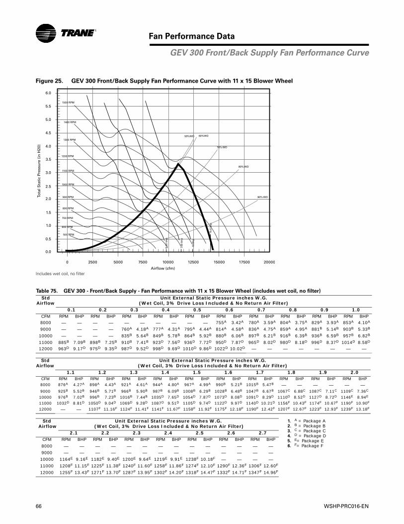
66 WSHP-PRC016-EN
Fan Performance Data
Figure 25. GEV 300 Front/Back Supply Fan Performance Curve with 11 x 15 Blower Wheel
Includes wet coil, no filter
Table 75. GEV 300 - Front/Back Supply - Fan Performance with 11 x 15 Blower Wheel (includes wet coil, no filter)
Std Airflow
Unit External Static Pressure inches W.G. (Wet Coil, 3% Drive Loss Included & No Return Air Filter)
0.1 0.2 0.3 0.4 0.5 0.6 0.7 0.8 0.9 1.0CFM RPM BHP RPM BHP RPM BHP RPM BHP RPM BHP RPM BHP RPM BHP RPM BHP RPM BHP RPM BHP8000 — — — — — — — — — — 755A 3.42A 780A 3.59A 804A 3.75A 829A 3.93A 853A 4.10A
9000 — — — — 760A 4.18A 777A 4.31A 795A 4.44A 814A 4.58A 836A 4.75A 859A 4.95A 881B 5.14B 903B 5.33B
10000 — — — — 835B 5.64B 849B 5.78B 864B 5.92B 880B 6.06B 897B 6.21B 916B 6.39B 936B 6.59B 957B 6.82B
11000 885B 7.09B 898B 7.25B 910B 7.41B 923D 7.56D 936D 7.72D 950D 7.87D 965D 8.02D 980D 8.18D 996D 8.37D 1014D 8.58D
12000 963D 9.17D 975D 9.35D 987D 9.52D 998D 9.69D 1010D 9.86D 1022D 10.02D — — — — — — — —
StdAirflow
Unit External Static Pressure inches W.G. (Wet Coil, 3% Drive Loss Included & No Return Air Filter)
1.1 1.2 1.3 1.4 1.5 1.6 1.7 1.8 1.9 2.0CFM RPM BHP RPM BHP RPM BHP RPM BHP RPM BHP RPM BHP RPM BHP RPM BHP RPM BHP RPM BHP8000 876A 4.27A 898A 4.43A 921A 4.61A 944A 4.80A 967A 4.99A 990B 5.21B 1015B 5.47B — — — — — —9000 925B 5.52B 946B 5.71B 966B 5.90B 987B 6.09B 1008B 6.29B 1028B 6.48B 1047B 6.67B 1067C 6.88C 1087C 7.11C 1109C 7.36C
10000 976B 7.02B 996B 7.23B 1016B 7.44B 1035D 7.65D 1054D 7.87D 1073D 8.08D 1091D 8.29D 1110D 8.52D 1127D 8.72D 1146E 8.94E
11000 1032D 8.81D 1050D 9.04D 1069D 9.28D 1087D 9.51D 1105D 9.74D 1122D 9.97D 1140D 10.21D 1156F 10.43F 1174F 10.67F 1190F 10.90F
12000 — — 1107F 11.16F 1124F 11.41F 1141F 11.67F 1158F 11.92F 1175F 12.18F 1190F 12.42F 1207F 12.67F 1223F 12.93F 1239F 13.18F
Std Airflow
Unit External Static Pressure inches W.G. (Wet Coil, 3% Drive Loss Included & No Return Air Filter)
1. A = Package A2. B = Package B3. C = Package C4. D = Package D5. E= Package E6. F= Package F
2.1 2.2 2.3 2.4 2.5 2.6 2.7CFM RPM BHP RPM BHP RPM BHP RPM BHP RPM BHP RPM BHP RPM BHP
8000 — — — — — — — — — — — — — —9000 — — — — — — — — — — — — — —10000 1164E 9.16E 1182E 9.40E 1200E 9.64E 1219E 9.91E 1238F 10.18F — — — —11000 1208F 11.15F 1225F 11.38F 1240F 11.60F 1258F 11.86F 1274F 12.10F 1290F 12.36F 1306F 12.60F
12000 1255F 13.43F 1271F 13.70F 1287F 13.95F 1302F 14.20F 1318F 14.47F 1332F 14.71F 1347F 14.96F
4.0
4.5
5.0
5.5
6.0
3.5
3.0
2.5
2.0
1.5
1.0
0.5
0.0
0 2500 5000 7500 10000 12500 15000 17500 20000
Airflow (cfm)
Tota
l Sta
tic
Pres
sure
(in
H20
)
5.00
bh
p
15.0
bh
p
7.50
bh
p
10.0
hp
59%WO 60%WO
70% WO
80% WO
90% WO
500 RPM
800 RPM
700 RPM
600 RPM
900 RPM
1000 RPM
1100 RPM
1200 RPM
1300 RPM
1400 RPM
1500 RPM
GEV 300 Front/Back Supply Fan Performance Curve
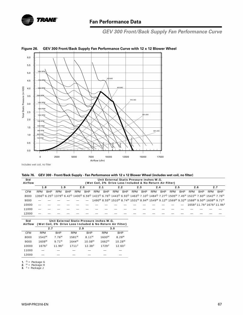
WSHP-PRC016-EN 67
Fan Performance Data
Figure 26. GEV 300 Front/Back Supply Fan Performance Curve with 12 x 12 Blower Wheel
Includes wet coil, no filter
Table 76. GEV 300 - Front/Back Supply - Fan Performance with 12 x 12 Blower Wheel (includes wet coil, no filter)
Std Airflow
Unit External Static Pressure inches W.G. (Wet Coil, 3% Drive Loss Included & No Return Air Filter)
1.8 1.9 2.0 2.1 2.2 2.3 2.4 2.5 2.6 2.7
CFM RPM BHP RPM BHP RPM BHP RPM BHP RPM BHP RPM BHP RPM BHP RPM BHP RPM BHP RPM BHP
8000 1356G 6.25G 1379G 6.42G 1400G 6.59G 1422G 6.76G 1443G 6.93G 1463G 7.10G 1484G 7.27G 1505H 7.45H 1522H 7.60H 1542H 7.76H
9000 — — — — — — 1490H 8.55H 1510H 8.74H 1531H 8.94H 1549H 9.12H 1569H 9.32H 1588H 9.50H 1608H 9.71H
10000 — — — — — — — — — — — — — — — — 1658J 11.76J 1676J 11.96J
11000 — — — — — — — — — — — — — — — — — — — —
12000 — — — — — — — — — — — — — — — — — — — —
Std Airflow
Unit External Static Pressure inches W.G. (Wet Coil, 3% Drive Loss Included & No Return Air Filter)
2.7 2.9 3.0
CFM RPM BHP RPM BHP RPM BHP
8000 1542H 7.76H 1581H 8.11H 1600H 8.29H
9000 1608H 9.71H 1644H 10.08H 1662H 10.28H
10000 1676J 11.96J 1711J 12.38J 1729J 12.60J
11000 — — — — — —
12000 — — — — — —
1. G = Package G2. H = Package H3. J = Package J
4.0
4.5
5.0
5.5
6.0
3.5
3.0
2.5
2.0
1.5
1.0
0.5
0.0
0 2500 5000 7500 10000 12500 15000 17500
Airflow (cfm)
Tota
l Sta
tic
Pres
sure
(in
H20
)
3.00
bh
p
5.00
bh
p 15.0
bh
p
7.50
bh
p
10.0
hp
52%WO
60%WO
70% WO
80% WO
90% WO
700 RPM
800 RPM
900 RPM
1000 RPM
1100 RPM
1200 RPM
1300 RPM
1400 RPM
1500 RPM
1600 RPM
1700 RPM
1800 RPM
GEV 300 Front/Back Supply Fan Performance Curve
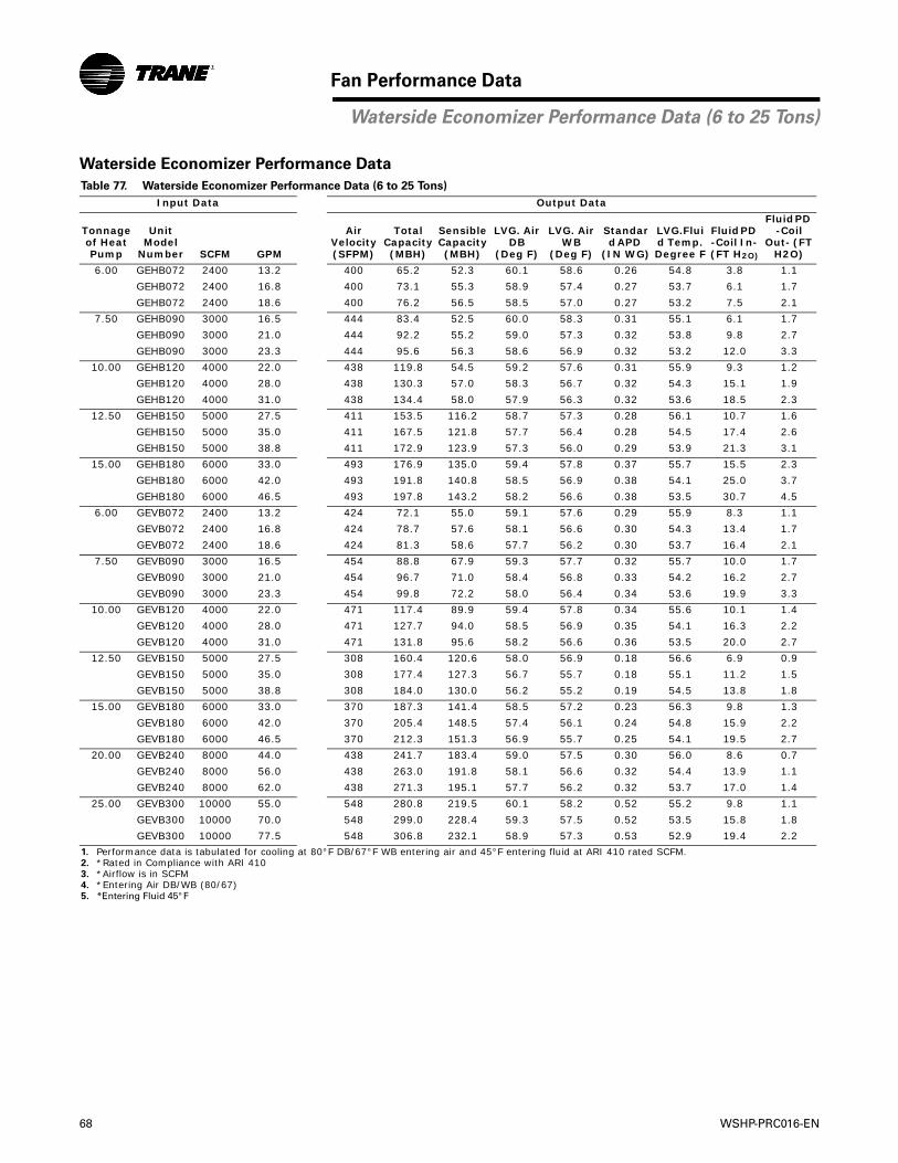
68 WSHP-PRC016-EN
Fan Performance Data
Waterside Economizer Performance Data
Table 77. Waterside Economizer Performance Data (6 to 25 Tons)
Input Data Output Data
Tonnage of Heat Pump
Unit Model
Number SCFM GPM
Air Velocity (SFPM)
Total Capacity (MBH)
Sensible Capacity (MBH)
LVG. Air DB
(Deg F)
LVG. Air WB
(Deg F)
Standard APD
(IN WG)
LVG.Fluid Temp. Degree F
Fluid PD -Coil In- (FT H2O)
Fluid PD -Coil
Out- (FT H2O)
6.00 GEHB072 2400 13.2 400 65.2 52.3 60.1 58.6 0.26 54.8 3.8 1.1
GEHB072 2400 16.8 400 73.1 55.3 58.9 57.4 0.27 53.7 6.1 1.7
GEHB072 2400 18.6 400 76.2 56.5 58.5 57.0 0.27 53.2 7.5 2.1
7.50 GEHB090 3000 16.5 444 83.4 52.5 60.0 58.3 0.31 55.1 6.1 1.7
GEHB090 3000 21.0 444 92.2 55.2 59.0 57.3 0.32 53.8 9.8 2.7
GEHB090 3000 23.3 444 95.6 56.3 58.6 56.9 0.32 53.2 12.0 3.3
10.00 GEHB120 4000 22.0 438 119.8 54.5 59.2 57.6 0.31 55.9 9.3 1.2
GEHB120 4000 28.0 438 130.3 57.0 58.3 56.7 0.32 54.3 15.1 1.9
GEHB120 4000 31.0 438 134.4 58.0 57.9 56.3 0.32 53.6 18.5 2.3
12.50 GEHB150 5000 27.5 411 153.5 116.2 58.7 57.3 0.28 56.1 10.7 1.6
GEHB150 5000 35.0 411 167.5 121.8 57.7 56.4 0.28 54.5 17.4 2.6
GEHB150 5000 38.8 411 172.9 123.9 57.3 56.0 0.29 53.9 21.3 3.1
15.00 GEHB180 6000 33.0 493 176.9 135.0 59.4 57.8 0.37 55.7 15.5 2.3
GEHB180 6000 42.0 493 191.8 140.8 58.5 56.9 0.38 54.1 25.0 3.7
GEHB180 6000 46.5 493 197.8 143.2 58.2 56.6 0.38 53.5 30.7 4.5
6.00 GEVB072 2400 13.2 424 72.1 55.0 59.1 57.6 0.29 55.9 8.3 1.1
GEVB072 2400 16.8 424 78.7 57.6 58.1 56.6 0.30 54.3 13.4 1.7
GEVB072 2400 18.6 424 81.3 58.6 57.7 56.2 0.30 53.7 16.4 2.1
7.50 GEVB090 3000 16.5 454 88.8 67.9 59.3 57.7 0.32 55.7 10.0 1.7
GEVB090 3000 21.0 454 96.7 71.0 58.4 56.8 0.33 54.2 16.2 2.7
GEVB090 3000 23.3 454 99.8 72.2 58.0 56.4 0.34 53.6 19.9 3.3
10.00 GEVB120 4000 22.0 471 117.4 89.9 59.4 57.8 0.34 55.6 10.1 1.4
GEVB120 4000 28.0 471 127.7 94.0 58.5 56.9 0.35 54.1 16.3 2.2
GEVB120 4000 31.0 471 131.8 95.6 58.2 56.6 0.36 53.5 20.0 2.7
12.50 GEVB150 5000 27.5 308 160.4 120.6 58.0 56.9 0.18 56.6 6.9 0.9
GEVB150 5000 35.0 308 177.4 127.3 56.7 55.7 0.18 55.1 11.2 1.5
GEVB150 5000 38.8 308 184.0 130.0 56.2 55.2 0.19 54.5 13.8 1.8
15.00 GEVB180 6000 33.0 370 187.3 141.4 58.5 57.2 0.23 56.3 9.8 1.3
GEVB180 6000 42.0 370 205.4 148.5 57.4 56.1 0.24 54.8 15.9 2.2
GEVB180 6000 46.5 370 212.3 151.3 56.9 55.7 0.25 54.1 19.5 2.7
20.00 GEVB240 8000 44.0 438 241.7 183.4 59.0 57.5 0.30 56.0 8.6 0.7
GEVB240 8000 56.0 438 263.0 191.8 58.1 56.6 0.32 54.4 13.9 1.1
GEVB240 8000 62.0 438 271.3 195.1 57.7 56.2 0.32 53.7 17.0 1.4
25.00 GEVB300 10000 55.0 548 280.8 219.5 60.1 58.2 0.52 55.2 9.8 1.1
GEVB300 10000 70.0 548 299.0 228.4 59.3 57.5 0.52 53.5 15.8 1.8
GEVB300 10000 77.5 548 306.8 232.1 58.9 57.3 0.53 52.9 19.4 2.2
1. Performance data is tabulated for cooling at 80°F DB/67°F WB entering air and 45°F entering fluid at ARI 410 rated SCFM.2. *Rated in Compliance with ARI 4103. *Airflow is in SCFM4. *Entering Air DB/WB (80/67)5. *Entering Fluid 45°F
Waterside Economizer Performance Data (6 to 25 Tons)

WSHP-PRC016-EN 69
Fan Performance Data
Example 1 - R-410A (Ethylene Glycol): The antifreeze solution is 20% by volume of Ethylene Glycol. Determine the corrected cooling capacity and waterside pressure drop for a GEHE 072 when the EWT is 86°F and the GPM is 18.0.
From the catalog data, the cooling capacity at these conditions with 100% water is 77.8 MBTUH, and the waterside pressure drop is 12.0 feet of head. At 20% Ethylene Glycol, the correction factor for cool capacity is 0.9912 and the pressure drop is 1.068.
The corrected cooling capacity (MBTUH) = 77.8 * 0.9912 = 77.1. The corrected water side pressure drop (Ft. head) = 12.0 * 1.068 = 12.8.
Example 2 - R-410A (Propylene Glycol): The antifreeze solution is 30% by volume of Propylene Glycol. Determine the corrected heating capacity and waterside pressure drop for a GEHE 072 when the EWT is 45°F and the GPM is 18.0.
From the catalog data, the heating capacity at these conditions with 100% water is 61.7 MBTUH, and the waterside pressure drop is 15.3 feet of head. At 30% Propylene Glycol, the
Table 78. Antifreeze Correction Factors
Methanol
Item
Concentration by Volume
10% 20% 30% 40% 50%
Cool Capacity
.9980 .9965 .9949 .9932 .9915
HeatCapacity
.9950 .9898 .9846 .9794 .9742
PressureDrop
1.023 1.057 1.091 1.122 1.160
Ethylene Glycol
Cool Capacity
.9955 .9912 .9870 .9830 .9790
HeatCapacity
.9925 .9848 .9770 .9690 .9610
PressureDrop
1.024 1.068 1.124 1.188 1.263
Propylene Glycol
Cool Capacity
.9934 .9869 .9804 .9739 .9681
HeatCapacity
.9863 .9732 .9603 .9477 .9350
PressureDrop
1.040 1.098 1.174 1.273 1.405
1. Performance data is tabulated for cooling at 80°F DB/67 F WB entering air and 45°F entering fluid at ARI 410 rated SCFM.
2. *Rated in Compliance with ARI 4103. *Airflow is in SCFM4. *Entering Air DB/WB (80/67)5. *Entering Fluid 45°F
correction factor for heat capacity is 0.9603 and the pressure drop is 1.174.
The corrected cooling capacity (MBTUH) = 61.7 * 0.9603 = 59.3. The corrected water side pressure drop (Ft. head) = 15.3 * 1.174 = 18.0.
Cooling Capacity Correction Factor
0.965
0.970
0.975
0.980
0.985
0.990
0.995
1.000
0 5 10 15 20 25 30 35 40 45 50
Percent Volume of Antifreeze
Meth
EG
PGC
orr
ecti
on
Fac
tor
Heating Capacity Correction Factor
0.930
0.940
0.950
0.960
0.970
0.980
0.990
1.000
0 5 10 15 20 25 30 35 40 45 50
Percent Volume Antifreeze
Meth
EG
PG
Co
rrec
tio
n F
acto
r
Water Pressure Drop Correction Factor
1.00
1.05
1.10
1.15
1.20
1.25
1.30
1.35
1.40
1.45
0 5 10 15 20 25 30 35 40 45 50
Percent Volume of Antifreeze
Meth
EG
PG
Co
rrec
tio
n F
acto
r
Antifreeze Correction Factors R-410A
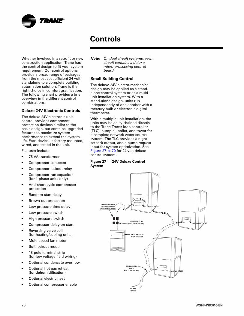
70 WSHP-PRC016-EN
Controls
Whether involved in a retrofit or new construction application, Trane has the control design to fit your system requirement. Our control options provide a broad range of packages from the most cost efficient 24 volt standalone to a complete building automation solution, Trane is the right choice in comfort gratification. The following chart provides a brief overview in the different control combinations.
Deluxe 24V Electronic Controls
The deluxe 24V electronic unit control provides component protection devices similar to the basic design, but contains upgraded features to maximize system performance to extend the system life. Each device, is factory mounted, wired, and tested in the unit.
Features include:
• 75 VA transformer
• Compressor contactor
• Compressor lockout relay
• Compressor run capacitor (for 1-phase units only)
• Anti-short cycle compressor protection
• Random start delay
• Brown-out protection
• Low pressure time delay
• Low pressure switch
• High pressure switch
• Compressor delay on start
• Reversing valve coil(for heating/cooling units)
• Multi-speed fan motor
• Soft lockout mode
• 18-pole terminal strip(for low voltage field wiring)
• Optional condensate overflow
• Optional hot gas reheat(for dehumidification)
• Optional electric heat
• Optional compressor enable
Note: On dual circuit systems, each circuit contains a deluxe micro-processing control board.
Small Building Control
The deluxe 24V electro-mechanical design may be applied as a stand-alone control system or as a multi-unit installation system. With a stand-alone design, units run independently of one another with a mercury bulb or electronic digital thermostat.
With a multiple unit installation, the units may be daisy-chained directly to the Trane Tracer loop controller (TLC), pump(s), boiler, and tower for a complete network water-source system. The TLC provides a night setback output, and a pump request input for system optimization. See Figure 27, p. 70 for 24 volt deluxe control system.
Figure 27. 24V Deluxe Control
System
COMPR ENABLE
TRANSFORMER
(FIELD PROVIDED)
SYSTEM RELAY
(FIELD PROVIDED)
TRACER LOOP
CONTROLLER
DAISY CHAIN
WIRE
(FIELD PROVIDED)
TO
OTHER
UNITS
DIGITAL TSTAT
DIGITAL TSTAT
DIGITAL TSTAT
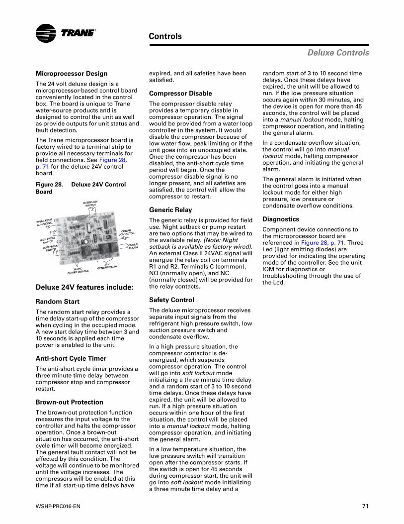
WSHP-PRC016-EN 71
Controls
Deluxe Controls
Microprocessor Design
The 24 volt deluxe design is a microprocessor-based control board conveniently located in the control box. The board is unique to Trane water-source products and is designed to control the unit as well as provide outputs for unit status and fault detection.
The Trane microprocessor board is factory wired to a terminal strip to provide all necessary terminals for field connections. See Figure 28, p. 71 for the deluxe 24V control board.
Deluxe 24V features include:
Random Start
The random start relay provides a time delay start-up of the compressor when cycling in the occupied mode. A new start delay time between 3 and 10 seconds is applied each time power is enabled to the unit.
Anti-short Cycle Timer
The anti-short cycle timer provides a three minute time delay between compressor stop and compressor restart.
Brown-out Protection
The brown-out protection function measures the input voltage to the controller and halts the compressor operation. Once a brown-out situation has occurred, the anti-short cycle timer will become energized. The general fault contact will not be affected by this condition. The voltage will continue to be monitored until the voltage increases. The compressors will be enabled at this time if all start-up time delays have
Figure 28. Deluxe 24V Control
Board
24 VAC
COMPR DISABLE
OVERFLOW
SWITCH
COMPR
CONTACTOR
GENERAL
ALARM
24 V
GENERIC RELAY
LOW PRESS
SWITCH
HIGH PRESS
SWITCH
24VAC TSTAT
RUN SIGNAL
Y
expired, and all safeties have been satisfied.
Compressor Disable
The compressor disable relay provides a temporary disable in compressor operation. The signal would be provided from a water loop controller in the system. It would disable the compressor because of low water flow, peak limiting or if the unit goes into an unoccupied state. Once the compressor has been disabled, the anti-short cycle time period will begin. Once the compressor disable signal is no longer present, and all safeties are satisfied, the control will allow the compressor to restart.
Generic Relay
The generic relay is provided for field use. Night setback or pump restart are two options that may be wired to the available relay. (Note: Night setback is available as factory wired). An external Class II 24VAC signal will energize the relay coil on terminals R1 and R2. Terminals C (common), NO (normally open), and NC (normally closed) will be provided for the relay contacts.
Safety Control
The deluxe microprocessor receives separate input signals from the refrigerant high pressure switch, low suction pressure switch and condensate overflow.
In a high pressure situation, the compressor contactor is de-energized, which suspends compressor operation. The control will go into soft lockout mode initializing a three minute time delay and a random start of 3 to 10 second time delays. Once these delays have expired, the unit will be allowed to run. If a high pressure situation occurs within one hour of the first situation, the control will be placed into a manual lockout mode, halting compressor operation, and initiating the general alarm.
In a low temperature situation, the low pressure switch will transition open after the compressor starts. If the switch is open for 45 seconds during compressor start, the unit will go into soft lockout mode initializing a three minute time delay and a
random start of 3 to 10 second time delays. Once these delays have expired, the unit will be allowed to run. If the low pressure situation occurs again within 30 minutes, and the device is open for more than 45 seconds, the control will be placed into a manual lockout mode, halting compressor operation, and initiating the general alarm.
In a condensate overflow situation, the control will go into manual lockout mode, halting compressor operation, and initiating the general alarm.
The general alarm is initiated when the control goes into a manual lockout mode for either high pressure, low pressure or condensate overflow conditions.
Diagnostics
Component device connections to the microprocessor board are referenced in Figure 28, p. 71. Three Led (light emitting diodes) are provided for indicating the operating mode of the controller. See the unit IOM for diagnostics or troubleshooting through the use of the Led.
72 WSHP-PRC016-EN
Controls
Tracer ZN524 Controls
Tracer ZN524 Controls
The Tracer ZN524 is a direct digital control (DDC) system specifically designed for single and dual circuit water-source equipment to provide control of the entire unit, as well as outputs for unit status and fault detection. The device is factory installed, commissioned, and tested to ensure the highest level of quality in unit design.
ZN524 features include:
• 75 VA or 100 VA transformer
• Compressor contactor
• Compressor lockout relay
• Compressor run capacitor (for 1-phase units only)
• Random start delay
• Heating/cooling status
• Occupied/unoccupied mode
• Low pressure switch
• High pressure switch
• Fan and filter status
• Reversing valve coil(for heating/cooling units)
• Multi-speed fan motor
• 18-pole terminal strip(for low voltage field wiring)
• Optional condensate overflow
• Water isolation valve support(for variable speed pumping)
• Optional boilerless control for electric heat
• Optional waterside economizer
• Optional hot gas reheat(for dehumidification)
The controller’s features and options were selected to coordinate with the unit hardware to provide greater energy efficiency and equipment safety to prolong the equipment life.
In addition to being factory configured for control of the unit fan, compressor and reversing valve, the ZN524 controllers is designed to coordinate the waterside of the water-source system through the Tracer Loop Controller (TLC). If applied in a peer-to-peer communication environment, data between similar controllers may be exchanged without requiring a building automation system.
By teaming the ZN524 with the TLC, a low first-cost for the mechanical equipment, water loop, and water pump optimization is provided to the owner.
For owners who require a full building integrated "open protocol" system, The ZN524/TLC application is upgradable to support complete building control through Tracer Summit®. Because the ZN524 is LonTalk certified, it is capable of working with, and talking to other LonTalk certified controllers providing the building owner more choices, and the design engineers more flexibility to meet the challenges of building automation.
Building Control Advantages
The Tracer ZN524 controller has the ability to share information with one or several units on the same communication link. This sharing of information is made possible via a twisted pair of wire and a building automation system or through Trane’s RoverTM service tool.
An advantage of installing a ZN524 is its capability to work with other LonTalk certified controllers. This provides greater flexibility to the building owner, as well as greater flexibility in design.
Integrating the ZN524 on water-source equipment, and tying it to a Tracer Summit system provides a complete building management system. Each Tracer Summit can connect to a maximum of 120 controllers. With the ICS system, the Tracer can initiate an alarm on a loss of performance on equipment malfunctions; allowing problems to be handled in a timely manner before compromising comfort.
This type of application would most commonly be used for a large space(s) that may require more than one unit. In addition to this application design, the TracerZN524 controller provides a way for units located within the same space to share the same zone sensor to prevent units from simultaneously heating and cooling in the same space.
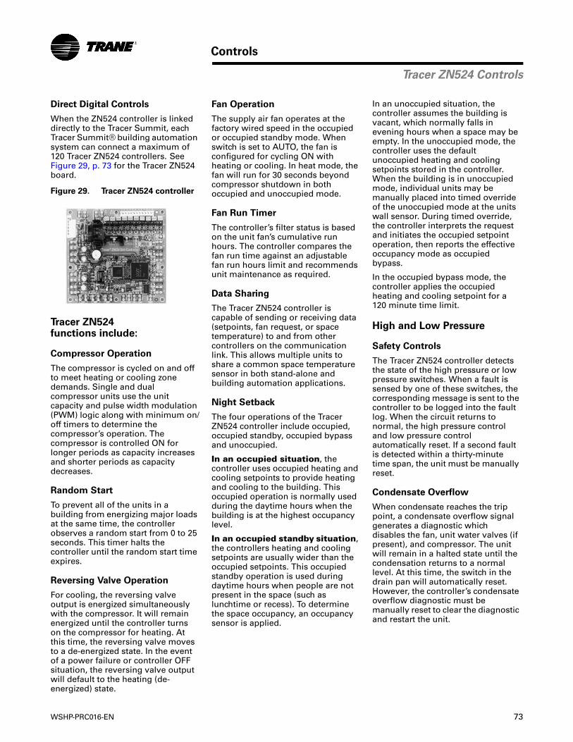
WSHP-PRC016-EN 73
Controls
Tracer ZN524 Controls
Direct Digital Controls
When the ZN524 controller is linked directly to the Tracer Summit, each Tracer Summit® building automation system can connect a maximum of 120 Tracer ZN524 controllers. See Figure 29, p. 73 for the Tracer ZN524 board.
Tracer ZN524 functions include:
Compressor Operation
The compressor is cycled on and off to meet heating or cooling zone demands. Single and dual compressor units use the unit capacity and pulse width modulation (PWM) logic along with minimum on/off timers to determine the compressor’s operation. The compressor is controlled ON for longer periods as capacity increases and shorter periods as capacity decreases.
Random Start
To prevent all of the units in a building from energizing major loads at the same time, the controller observes a random start from 0 to 25 seconds. This timer halts the controller until the random start time expires.
Reversing Valve Operation
For cooling, the reversing valve output is energized simultaneously with the compressor. It will remain energized until the controller turns on the compressor for heating. At this time, the reversing valve moves to a de-energized state. In the event of a power failure or controller OFF situation, the reversing valve output will default to the heating (de-energized) state.
Figure 29. Tracer ZN524 controller
Fan Operation
The supply air fan operates at the factory wired speed in the occupied or occupied standby mode. When switch is set to AUTO, the fan is configured for cycling ON with heating or cooling. In heat mode, the fan will run for 30 seconds beyond compressor shutdown in both occupied and unoccupied mode.
Fan Run Timer
The controller’s filter status is based on the unit fan’s cumulative run hours. The controller compares the fan run time against an adjustable fan run hours limit and recommends unit maintenance as required.
Data Sharing
The Tracer ZN524 controller is capable of sending or receiving data (setpoints, fan request, or space temperature) to and from other controllers on the communication link. This allows multiple units to share a common space temperature sensor in both stand-alone and building automation applications.
Night Setback
The four operations of the Tracer ZN524 controller include occupied, occupied standby, occupied bypass and unoccupied.
In an occupied situation, the controller uses occupied heating and cooling setpoints to provide heating and cooling to the building. This occupied operation is normally used during the daytime hours when the building is at the highest occupancy level.
In an occupied standby situation, the controllers heating and cooling setpoints are usually wider than the occupied setpoints. This occupied standby operation is used during daytime hours when people are not present in the space (such as lunchtime or recess). To determine the space occupancy, an occupancy sensor is applied.
In an unoccupied situation, the controller assumes the building is vacant, which normally falls in evening hours when a space may be empty. In the unoccupied mode, the controller uses the default unoccupied heating and cooling setpoints stored in the controller. When the building is in unoccupied mode, individual units may be manually placed into timed override of the unoccupied mode at the units wall sensor. During timed override, the controller interprets the request and initiates the occupied setpoint operation, then reports the effective occupancy mode as occupied bypass.
In the occupied bypass mode, the controller applies the occupied heating and cooling setpoint for a 120 minute time limit.
High and Low Pressure
Safety Controls
The Tracer ZN524 controller detects the state of the high pressure or low pressure switches. When a fault is sensed by one of these switches, the corresponding message is sent to the controller to be logged into the fault log. When the circuit returns to normal, the high pressure control and low pressure control automatically reset. If a second fault is detected within a thirty-minute time span, the unit must be manually reset.
Condensate Overflow
When condensate reaches the trip point, a condensate overflow signal generates a diagnostic which disables the fan, unit water valves (if present), and compressor. The unit will remain in a halted state until the condensation returns to a normal level. At this time, the switch in the drain pan will automatically reset. However, the controller’s condensate overflow diagnostic must be manually reset to clear the diagnostic and restart the unit.
74 WSHP-PRC016-EN
Controls
Tracer ZN524 Controls
Additional Functions of the ZN524 Controller
When the building owners choice is Trane Tracer controls, the ZN524 controller is required when any of the following applications are selected on a single and dual circuit equipment.
• Waterside Economizer
• Hot Gas Reheat (for Dehumidification)
• Boilerless Control for Electric Heat
• Water Isolation Valve Control(for Variable Speed Pumping)
Entering Water Temperature Sampling
The ZN524 controller will sample the entering water temperature to determine proper control action for units equipped with boilerless electric heat or waterside economizer.
Waterside Economizer:
Entering water temperature (EWT) sampling will automatically occur at power up when the unit is equipped with a waterside economizer (WSE). The EWT is used to determine if economizing is feasible. When the conditions are met, the isolation valve(s) are driven open for three minutes and the EWT reading is taken. The determination as to whether or not the economizer can be enabled will be made and the controller will take appropriate action. The isolation valve will remain open regardless if the WSE or the DX cooling is enabled.
The unit’s waterside economizer will contain a 2-position water valve wired to the ZN524. The economizing water coil will be optimized to provide 100% of the unit capacity at 80.6°F/66.2°F return air temperature with 45°F entering water. The flow rate is established at 86°F entering water temperature and 96°F leaving water temperature.
Low leaving air protection will be furnished to protect the unit against delivering air that is cold enough to sweat discharge air grilles. Coil icing protection will also be provided.
Waterside economizer cooling will be active during occupied, unoccupied and standby cooling modes.
Boilerless Control Electric Heat and Supplemental Electric Heat:
The ZN524 supports a single stage of boilerless electric heat operation or concurrent heating.
When the unit is configured for boilerless control, the EWT will be used to determine whether DX heating should be disabled and the electric heater enabled. When these conditions are met, the isolation valve(s) are driven open for three minutes and the entering water temperature reading is taken. The determination as to whether or not to utilize electric heat will be made and the controller will take appropriate action. If boilerless electric heat is enabled, then the isolation valve will be closed, shutting down the water flow to the unit.
When the unit is configured for concurrent operation of DX heating (compressor in heat pump mode) and electric heat, the electric heat will act as a second stage of heat for single compressor units, and a third stage of heat for dual compressor units.
Note: With concurrent (or supplemental) electric heat, the electric heater is field provided.
Water Isolation Valves
Variable speed pumping systems are supported by the ZN524 controller when water isolation valves are present. Up to two isolation valves are supported by the controller (one for each compressor circuit).
The valves are normally closed unless DX heating, DX cooling, waterside economizer or dehumidification is requested. When the isolation valves are driven open for operation, the outputs will be driven for 20 seconds to ensure adequate water flow before the compressor outputs are energized. Once an isolation valve has been opened, it will remain open for a 10 minute minimum to reduce excessive cycling of the valve.
Dehumidification
Dehumidification for the single and dual circuit water-source heat pump is applicable with the ZN524 controller. The controller is capable of directing one stage of DX cooling in conjunction with one stage of reheat (hot gas reheat).
Dehumidification can only occur when the controller is in the cooling mode. A humidity transmitter is used to measure the zone’s relative humidity (RH), then compares the zone relative humidity to the relative humidity enable/disable setpoint parameters. The default values for dehumidification enable is 60% RH with the disable point at 52% RH. These values are configurable.
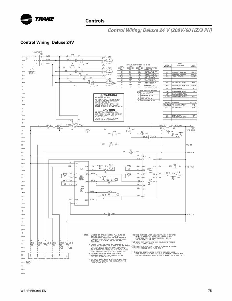
WSHP-PRC016-EN 75
Controls
Control Wiring: Deluxe 24V
Control Wiring; Deluxe 24 V (208V/60 HZ/3 PH)
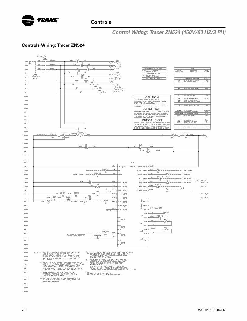
76 WSHP-PRC016-EN
Controls
Controls Wiring: Tracer ZN524
Control Wiring; Tracer ZN524 (460V/60 HZ/3 PH)
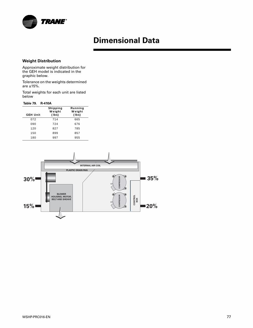
WSHP-PRC016-EN 77
Dimensional Data
Weight Distribution
Approximate weight distribution for the GEH model is indicated in the graphic below.
Tolerance on the weights determined are ±15%.
Total weights for each unit are listed below
Table 79. R-410A
GEH Unit
Shipping Weight(lbs)
Running Weight (lbs)
072 714 665
090 724 676
120 827 785
150 899 857
180 997 955
CO
MP
RE
SS
OR
CO
NT
RO
L
BO
X
INTERNAL AIR COIL
PLASTIC DRAIN PAN
BLOWER
HOUSING, MOTOR,
BELT AND SHEAVE
35%
20%
30%
15% CO
MP
RE
SS
OR
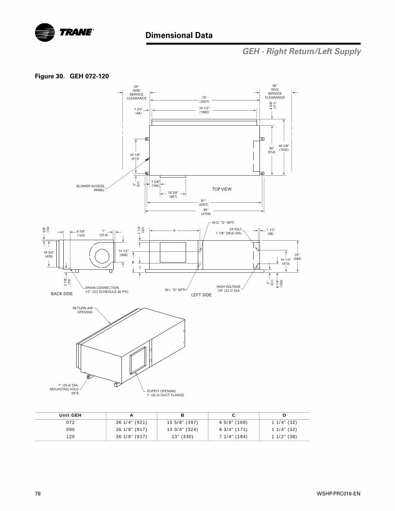
78 WSHP-PRC016-EN
Dimensional Data
GEH - Right Return/Left Supply
Figure 30. GEH 072-120
Unit GEH A B C D
072 36 1/4" (921) 15 5/8" (397) 6 5/8" (168) 1 1/4" (32)
090 36 1/8" (917) 12 3/4" (324) 6 3/4" (171) 1 1/4" (32)
120 36 1/8" (917) 13" (330) 7 1/4" (184) 1 1/2" (38)
20"(508)
SERVICECLEARANCE 79"
(2007)
74 1/2"(1892)
1 3/4"(44)
36"(914)
SERVICECLEARANCE
4 5/
8"(1
17)
36"(914)
40 5/8"(1032)
7 5/8"(194)
18 3/8"(467)
81"(2057)
2" (51)
24 1/8"(613)
BLOWER ACCESSPANEL
2 7/
8"(7
3)
4 7/8"(124)
1"(25.4)
5/8"
(16)
18 3/4"(476)
14 1/2"(368)
DRAIN CONNECTION1/2" (22) SCHEDULE 40 PVC
1 1/
4"(3
2)
C
B
A
W.O. "D" NPTI
W.I. "D" NPTI
24 VOLT1 1/8" (28.6) DIA.
HIGH VOLTAGE7/8" (22.2) DIA.
23"(584)16 1/4"
(413)2" (51)
6 1/
4"(1
59)
1 1/2"(38)
RETURN AIROPENING
1" (25.4) DIA.MOUNTING HOLE
4X'SSUPPLY OPENING1" (25.4) DUCT FLANGE
TOP VIEW
BACK SIDE LEFT SIDE
85"(2159)
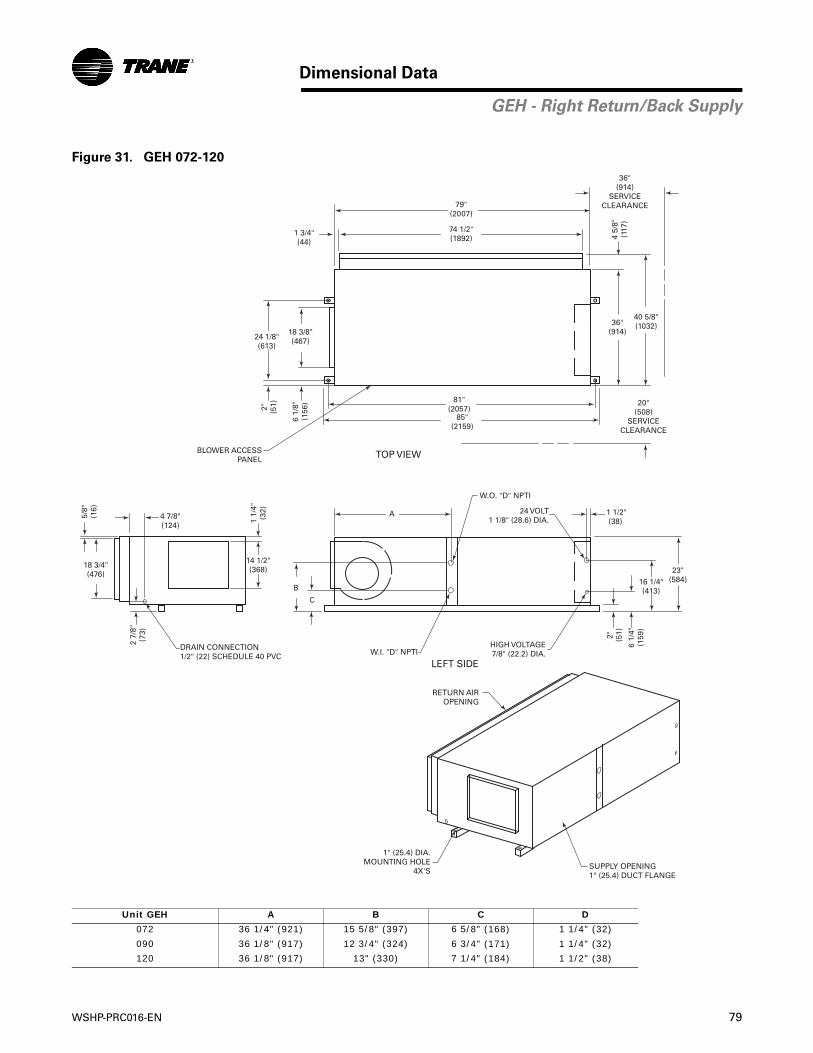
WSHP-PRC016-EN 79
Dimensional Data
GEH - Right Return/Back Supply
Figure 31. GEH 072-120
Unit GEH A B C D
072 36 1/4" (921) 15 5/8" (397) 6 5/8" (168) 1 1/4" (32)
090 36 1/8" (917) 12 3/4" (324) 6 3/4" (171) 1 1/4" (32)
120 36 1/8" (917) 13" (330) 7 1/4" (184) 1 1/2" (38)
79"(2007)
74 1/2"(1892)
36"(914)
40 5/8"(1032)
81"(2057)
85"(2159)
2" (51)
24 1/8"(613)
TOP VIEW
18 3/8"(467)
6 1/
8"(1
56)
4 5/
8"(1
17)
36"(914)
SERVICECLEARANCE
1 3/4"(44)
20"(508)
SERVICECLEARANCE
BLOWER ACCESSPANEL
2 7/
8"(7
3)
4 7/8"(124)
5/8"
(16)
18 3/4"(476)
DRAIN CONNECTION1/2" (22) SCHEDULE 40 PVC
1 1/
4"(3
2)
14 1/2"(368)
C
B
A
W.O. "D" NPTI
W.I. "D" NPTI
24 VOLT1 1/8" (28.6) DIA.
HIGH VOLTAGE7/8" (22.2) DIA.
23"(584)16 1/4"
(413)
2" (51)
6 1/
4"(1
59)
1 1/2"(38)
LEFT SIDE
RETURN AIROPENING
1" (25.4) DIA.MOUNTING HOLE
4X'SSUPPLY OPENING1" (25.4) DUCT FLANGE
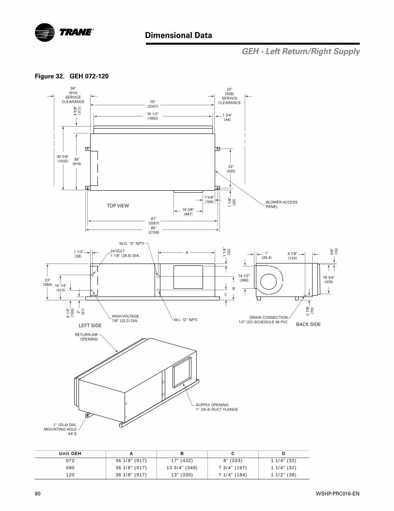
80 WSHP-PRC016-EN
Dimensional Data
GEH - Left Return/Right Supply
Figure 32. GEH 072-120
Unit GEH A B C D
072 36 1/8" (917) 17" (432) 8" (203) 1 1/4" (32)
090 36 1/8" (917) 13 3/4" (349) 7 3/4" (197) 1 1/4" (32)
120 36 1/8" (917) 13" (330) 7 1/4" (184) 1 1/2" (38)
20"(508)
SERVICECLEARANCE79"
(2007)
74 1/2"(1892)
1 3/4"(44)
36"(914)
SERVICECLEARANCE
4 5/
8"(1
17)
36"(914)
40 5/8"(1032)
7 5/8"(194)
18 3/8"(467)
81"(2057)
85"(2159)
1 1/
8"(2
9)
25"(635)
BLOWER ACCESSPANEL
2 7/
8"(7
3)
4 7/8"(124)
1"(25.4)
5/8"
(16)
18 3/4"(476)
14 1/2"(368)
DRAIN CONNECTION1/2" (22) SCHEDULE 40 PVC
1 1/
4"(3
2)
C
B
A
W.O. "D" NPTI
W.I. "D" NPTI
24 VOLT1 1/8" (28.6) DIA.
HIGH VOLTAGE7/8" (22.2) DIA.
23"(584) 16 1/4"
(413)
2" (51)
6 1/
4"(1
59)
1 1/2"(38)
TOP VIEW
BACK SIDELEFT SIDE
RETURN AIROPENING
1" (25.4) DIA.MOUNTING HOLE
4X'S
SUPPLY OPENING1" (25.4) DUCT FLANGE
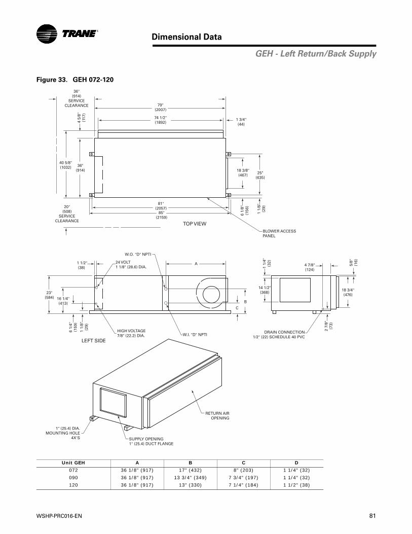
WSHP-PRC016-EN 81
Dimensional Data
GEH - Left Return/Back Supply
Figure 33. GEH 072-120
Unit GEH A B C D
072 36 1/8" (917) 17" (432) 8" (203) 1 1/4" (32)
090 36 1/8" (917) 13 3/4" (349) 7 3/4" (197) 1 1/4" (32)
120 36 1/8" (917) 13" (330) 7 1/4" (184) 1 1/2" (38)
79"(2007)
74 1/2"(1892)
36"(914)
40 5/8"(1032)
81"(2057)
85"(2159)
1 1/
8"(2
9)
25"(635)
TOP VIEW
18 3/8"(467)
6 1/
8"(1
56)
4 5/
8"(1
17)
36"(914)
SERVICECLEARANCE
1 3/4"(44)
20"(508)
SERVICECLEARANCE
BLOWER ACCESSPANEL
2 7/
8"(7
3)
4 7/8"(124)
5/8"
(16)
18 3/4"(476)
DRAIN CONNECTION1/2" (22) SCHEDULE 40 PVC
1 1/
4"(3
2)
14 1/2"(368)
C
B
A
W.O. "D" NPTI
W.I. "D" NPTI
24 VOLT1 1/8" (28.6) DIA.
HIGH VOLTAGE7/8" (22.2) DIA.
23"(584) 16 1/4"
(413)
1 1/
8"(2
9)
6 1/
4"(1
59)
1 1/2"(38)
LEFT SIDE
RETURN AIROPENING
1" (25.4) DIA.MOUNTING HOLE
4X'S SUPPLY OPENING1" (25.4) DUCT FLANGE
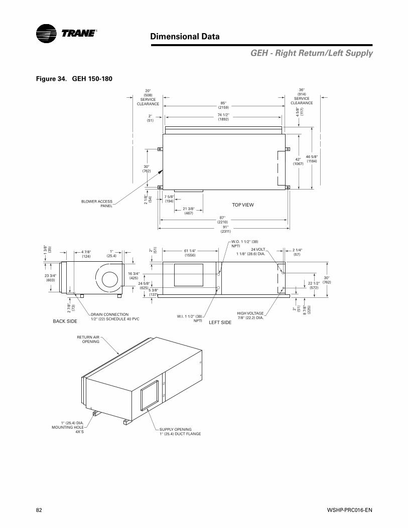
82 WSHP-PRC016-EN
Dimensional Data
GEH - Right Return/Left Supply
Figure 34. GEH 150-180
20"(508)
SERVICECLEARANCE 85"
(2159)
74 1/2"(1892)
2"(51)
36"(914)
SERVICECLEARANCE
4 5/
8"(1
17)
42"(1067)
46 5/8"(1184)
7 5/8"(194)
21 3/8"(467)
87"(2210)
91"(2311)
2 1/
8"(5
4)
30"(762)
BLOWER ACCESSPANEL
2 7/
8"(7
3)
4 7/8"(124)
1"(25.4)
1 3/
8"(3
5)
23 3/4"(603)
16 3/4"(425)
DRAIN CONNECTION1/2" (22) SCHEDULE 40 PVC
2" (51)
5 3/8"(137)
24 5/8"(625)
61 1/4"(1556)
W.O. 1 1/2" (38)NPTI
W.I. 1 1/2" (38) NPTI
24 VOLT1 1/8" (28.6) DIA.
HIGH VOLTAGE7/8" (22.2) DIA.
30"(762)22 1/2"
(572)
2" (51)
8 7/
8"(2
25)
2 1/4"(57)
RETURN AIROPENING
1" (25.4) DIA.MOUNTING HOLE
4X'SSUPPLY OPENING1" (25.4) DUCT FLANGE
TOP VIEW
BACK SIDE LEFT SIDE
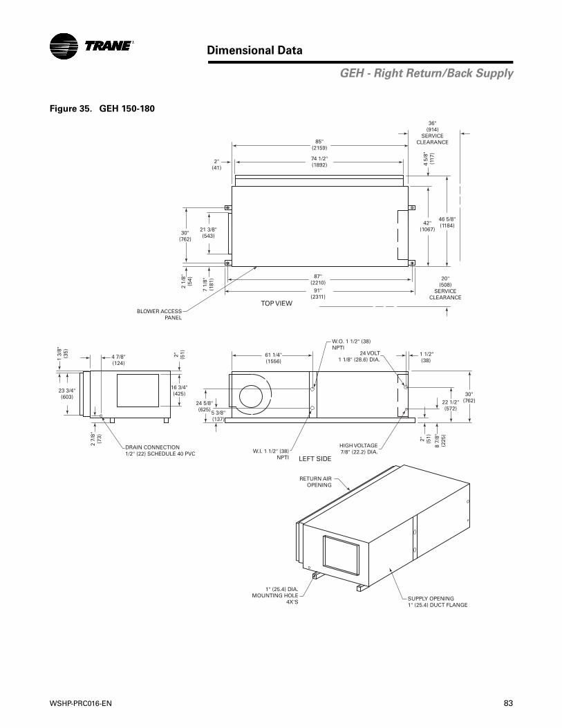
WSHP-PRC016-EN 83
Dimensional Data
GEH - Right Return/Back Supply
Figure 35. GEH 150-180
85"(2159)
74 1/2"(1892)
42"(1067)
46 5/8"(1184)
87"(2210)
91"(2311)
2 1/
8"(5
4)
30"(762)
TOP VIEW
21 3/8"(543)
7 1/
8"(1
81)
4 5/
8"(1
17)
36"(914)
SERVICECLEARANCE
2"(41)
20"(508)
SERVICECLEARANCE
BLOWER ACCESSPANEL
2 7/
8"(7
3)
4 7/8"(124)
1 3/
8"(3
5)
23 3/4"(603)
DRAIN CONNECTION1/2" (22) SCHEDULE 40 PVC
2" (51)
16 3/4"(425)
5 3/8"(137)
24 5/8"(625)
61 1/4"(1556)
W.O. 1 1/2" (38)NPTI
W.I. 1 1/2" (38)NPTI
24 VOLT1 1/8" (28.6) DIA.
HIGH VOLTAGE7/8" (22.2) DIA.
30"(762)22 1/2"
(572)
2" (51)
8 7/
8"(2
25)
1 1/2"(38)
LEFT SIDE
RETURN AIROPENING
1" (25.4) DIA.MOUNTING HOLE
4X'SSUPPLY OPENING1" (25.4) DUCT FLANGE
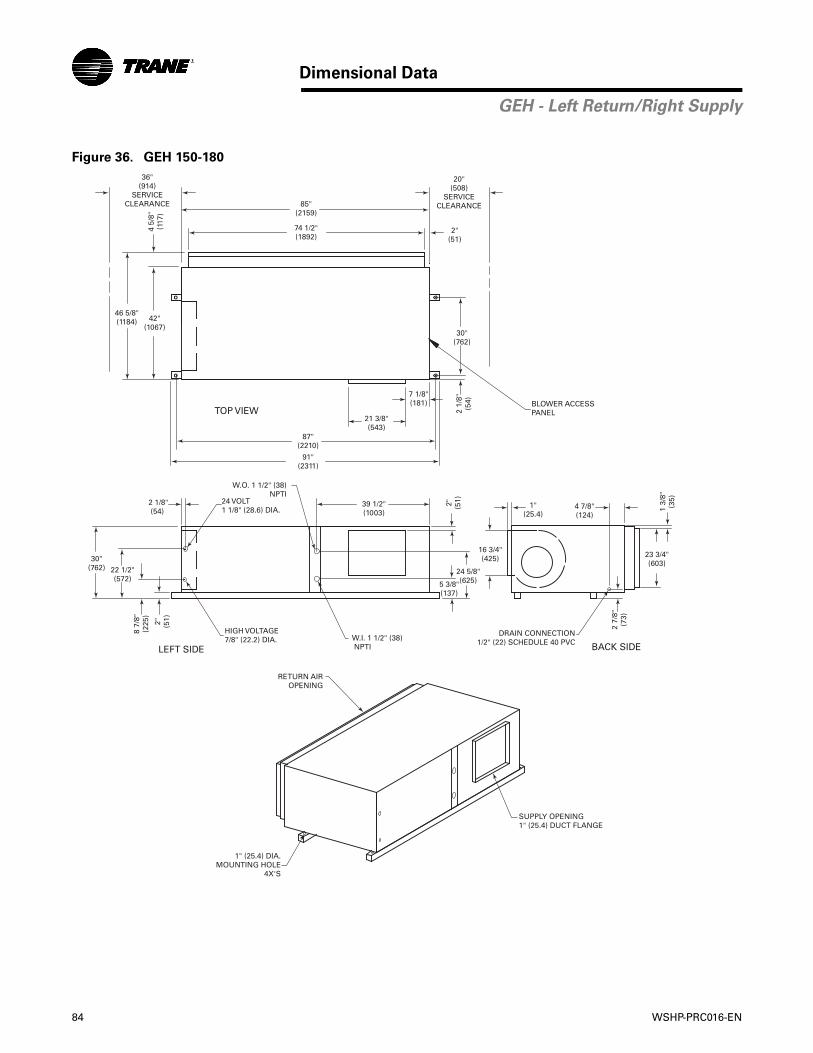
84 WSHP-PRC016-EN
Dimensional Data
GEH - Left Return/Right Supply
Figure 36. GEH 150-180
20"(508)
SERVICECLEARANCE85"
(2159)
74 1/2"(1892)
2"(51)
36"(914)
SERVICECLEARANCE
4 5/
8"(1
17)
42"(1067)
46 5/8"(1184)
7 1/8"(181)
21 3/8"(543)
87"(2210)
91"(2311)
2 1/
8"(5
4)
30"(762)
BLOWER ACCESSPANEL
2 7/
8"(7
3)
4 7/8"(124)
1"(25.4)
1 3/
8"(3
5)
23 3/4"(603)
16 3/4"(425)
DRAIN CONNECTION1/2" (22) SCHEDULE 40 PVC
2" (51)
5 3/8"(137)
24 5/8"(625)
39 1/2"(1003)
W.O. 1 1/2" (38) NPTI
W.I. 1 1/2" (38) NPTI
24 VOLT1 1/8" (28.6) DIA.
HIGH VOLTAGE7/8" (22.2) DIA.
30"(762) 22 1/2"
(572)
2" (51)
8 7/
8"(2
25)
2 1/8"(54)
TOP VIEW
BACK SIDELEFT SIDE
RETURN AIROPENING
1" (25.4) DIA.MOUNTING HOLE
4X'S
SUPPLY OPENING1" (25.4) DUCT FLANGE
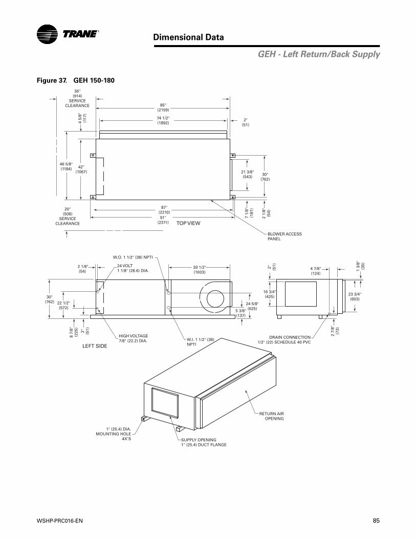
WSHP-PRC016-EN 85
Dimensional Data
GEH - Left Return/Back Supply
Figure 37. GEH 150-180
85"(2159)
74 1/2"(1892)
42"(1067)
46 5/8"(1184)
87"(2210)91"
(2311)
2 1/
8"(5
4)
30"(762)
TOP VIEW
21 3/8"(543)
7 1/
8"(1
81)
4 5/
8"(1
17)
36"(914)
SERVICECLEARANCE
2"(51)
20"(508)
SERVICECLEARANCE
BLOWER ACCESSPANEL
2 7/
8"(7
3)
4 7/8"(124)
1 3/
8"(3
5)
23 3/4"(603)
DRAIN CONNECTION1/2" (22) SCHEDULE 40 PVC
2" (51)
16 3/4"(425)
5 3/8"(137)
24 5/8"(625)
39 1/2"(1003)
W.O. 1 1/2" (38) NPTI
W.I. 1 1/2" (38)NPTI
24 VOLT1 1/8" (28.6) DIA.
HIGH VOLTAGE7/8" (22.2) DIA.
30"(762) 22 1/2"
(572)
2" (51)
8 7/
8"(2
25)
2 1/8"(54)
LEFT SIDE
RETURN AIROPENING
1" (25.4) DIA.MOUNTING HOLE
4X'S SUPPLY OPENING1" (25.4) DUCT FLANGE
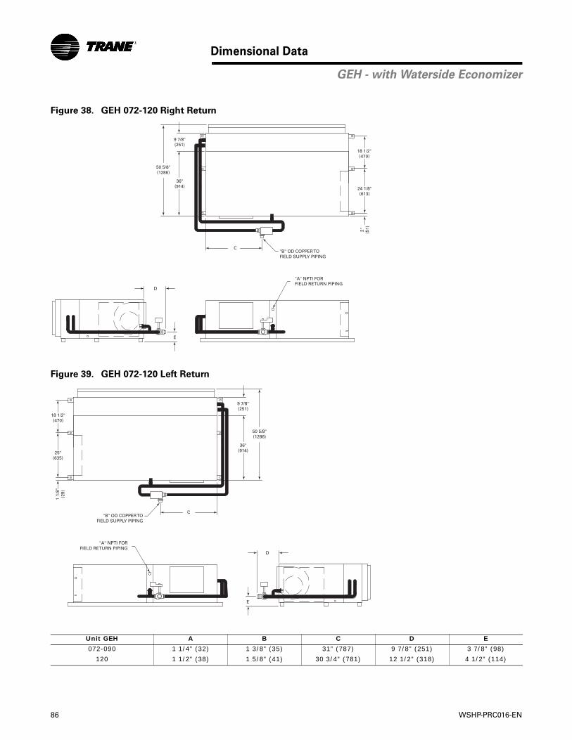
86 WSHP-PRC016-EN
Dimensional Data
GEH - with Waterside Economizer
Figure 38. GEH 072-120 Right Return
Figure 39. GEH 072-120 Left Return
Unit GEH A B C D E
072-090 1 1/4” (32) 1 3/8” (35) 31” (787) 9 7/8” (251) 3 7/8” (98)
120 1 1/2” (38) 1 5/8” (41) 30 3/4” (781) 12 1/2” (318) 4 1/2” (114)
C
9 7/8"(251)
36"(914)
50 5/8"(1286)
"B" OD COPPER TOFIELD SUPPLY PIPING
18 1/2"(470)
24 1/8"(613)
2" (51)
D
E
"A" NPTI FORFIELD RETURN PIPING
C
9 7/8"(251)
36"(914)
50 5/8"(1286)
"B" OD COPPER TOFIELD SUPPLY PIPING
18 1/2"(470)
25"(635)
1 1/
8"(2
9)
D
E
"A" NPTI FORFIELD RETURN PIPING
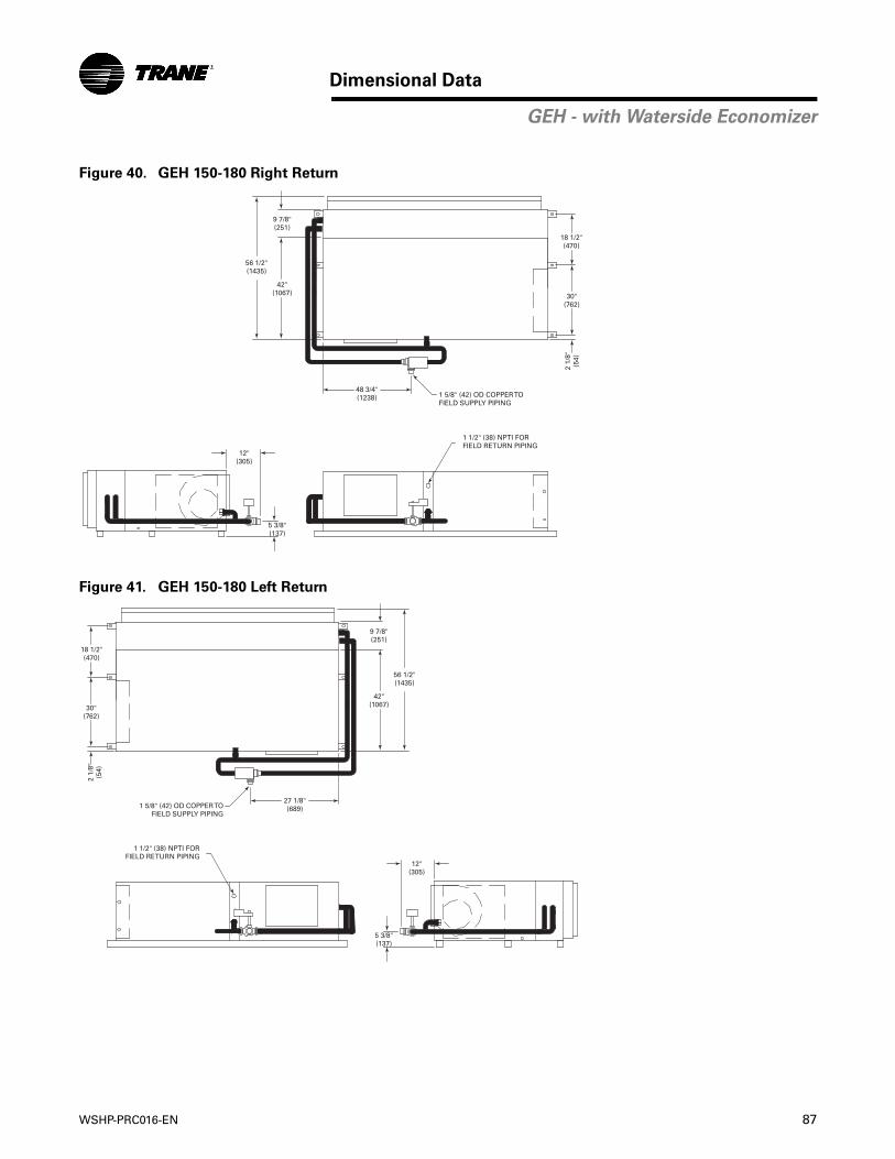
WSHP-PRC016-EN 87
Dimensional Data
GEH - with Waterside Economizer
Figure 40. GEH 150-180 Right Return
Figure 41. GEH 150-180 Left Return
48 3/4"(1238)
9 7/8"(251)
42"(1067)
56 1/2"(1435)
1 5/8" (42) OD COPPER TOFIELD SUPPLY PIPING
18 1/2"(470)
30"(762)
2 1/
8"(5
4)
12"(305)
5 3/8"(137)
1 1/2" (38) NPTI FORFIELD RETURN PIPING
27 1/8"(689)
9 7/8"(251)
42"(1067)
56 1/2"(1435)
1 5/8" (42) OD COPPER TOFIELD SUPPLY PIPING
18 1/2"(470)
30"(762)
2 1/
8"(5
4)
12"(305)
5 3/8"(137)
1 1/2" (38) NPTI FORFIELD RETURN PIPING
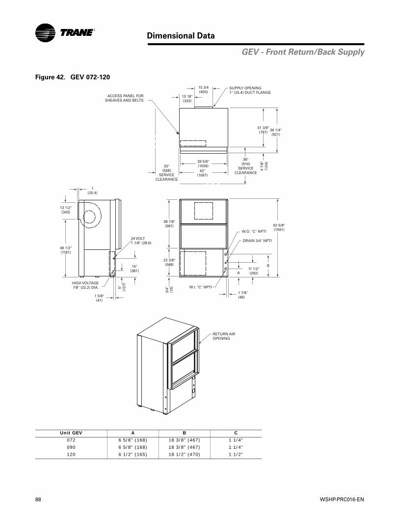
88 WSHP-PRC016-EN
Dimensional Data
GEV - Front Return/Back Supply
Figure 42. GEV 072-120
Unit GEV A B C
072 6 5/8” (168) 18 3/8” (467) 1 1/4”
090 6 5/8” (168) 18 3/8” (467) 1 1/4”
120 6 1/2” (165) 18 1/2” (470) 1 1/2”
39 5/8"(1006)
ACCESS PANEL FORSHEAVES AND BELTS
13 18"(333)
15 3/4(400)
20"(508)
SERVICECLEARANCE
42"(1067)
4 7/
8"(1
24)
1(25.4)
31 3/8"(797) 36 1/4"
(921)
13 1/2"(343)
46 1/2"(1181)
36"(914)
SERVICECLEARANCE
62 5/8"(1591)
B
W.O. "C" NPTI
DRAIN 3/4" NPTI
A11 1/2"(292)
1 7/8"(48)
W.I. "C" NPTIHIGH VOLTAGE7/8" (22.2) DIA.
1 5/8"(41)
5"(1
27)
15"(381)
24 VOLT1 1/8" (28.6)
22 3/8"(568)
38 7/8"(987)
3/4"
(19)
SUPPLY OPENING1" (25.4) DUCT FLANGE
RETURN AIROPENING

WSHP-PRC016-EN 89
Dimensional Data
GEV - Front Return/Top Supply
Figure 43. GEV 072-120
Unit GEV A B C
072 6 5/8” (168) 18 3/8” (467) 1 1/4”
090 6 5/8” (168) 18 3/8” (467) 1 1/4”
120 6 1/2” (165) 18 1/2” (470) 1 1/2”
39 5/8"(1006)
ACCESS PANEL FORSHEAVES AND BELTS
13 1/4"(337)
15 5/8(397)
20"(508)
SERVICECLEARANCE
42"(1067)
4 7/
8"(1
24)
1 1/
8"(2
9)
31 3/8"(797) 36 1/4"
(921)
13 3/8"(343)
36"(914)
SERVICECLEARANCE
63"(1600)
62 5/8"(1591)
B
W.O. "C" NPTI
DRAIN 3/4" NPTI
A11 1/2"(292)
1 7/8"(48)
W.I. "C" NPTIHIGH VOLTAGE7/8" (22.2) DIA.
1 5/8"(41)
5"(1
27)
15"(381)
24 VOLT1 1/8" (28.6)
22 3/8"(568)
38 7/8"(987)
3/4"
(19)
1"(2
5.4)
SUPPLY OPENING1" (25.4) DUCT FLANGE
RETURN AIROPENING
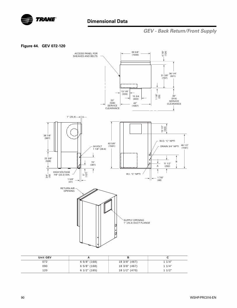
90 WSHP-PRC016-EN
Dimensional Data
GEV - Back Return/Front Supply
Figure 44. GEV 072-120
Unit GEV A B C
072 6 5/8” (168) 18 3/8” (467) 1 1/4”
090 6 5/8” (168) 18 3/8” (467) 1 1/4”
120 6 1/2” (165) 18 1/2” (470) 1 1/2”
1" (25.4)
20"(508)
SERVICECLEARANCE
39 5/8"(1006)ACCESS PANEL FOR
SHEAVES AND BELTS
13 1/8"(333)
15 3/4(400)
42"(1067)
4 7/
8"(1
24)
1 1/
8"(2
9)
36 1/4"(921)31 3/8"
(797)
36"(914)
SERVICECLEARANCE
62 5/8"(1591) 46 1/2"
(1181)
B
W.O. "C" NPTI
DRAIN 3/4" NPTI
A11 1/2"(292)
1 7/8"(48)
W.I. "C" NPTIHIGH VOLTAGE7/8" (22.2) DIA.
1 5/8"(41)
5"(1
27)
15"(381)
38 7/8"(987)
22 3/8"(568)
3/4"
(19)
SUPPLY OPENING1" (25.4) DUCT FLANGE
RETURN AIROPENING
24 VOLT1 1/8" (28.6)
13 1
/2"
(343
)
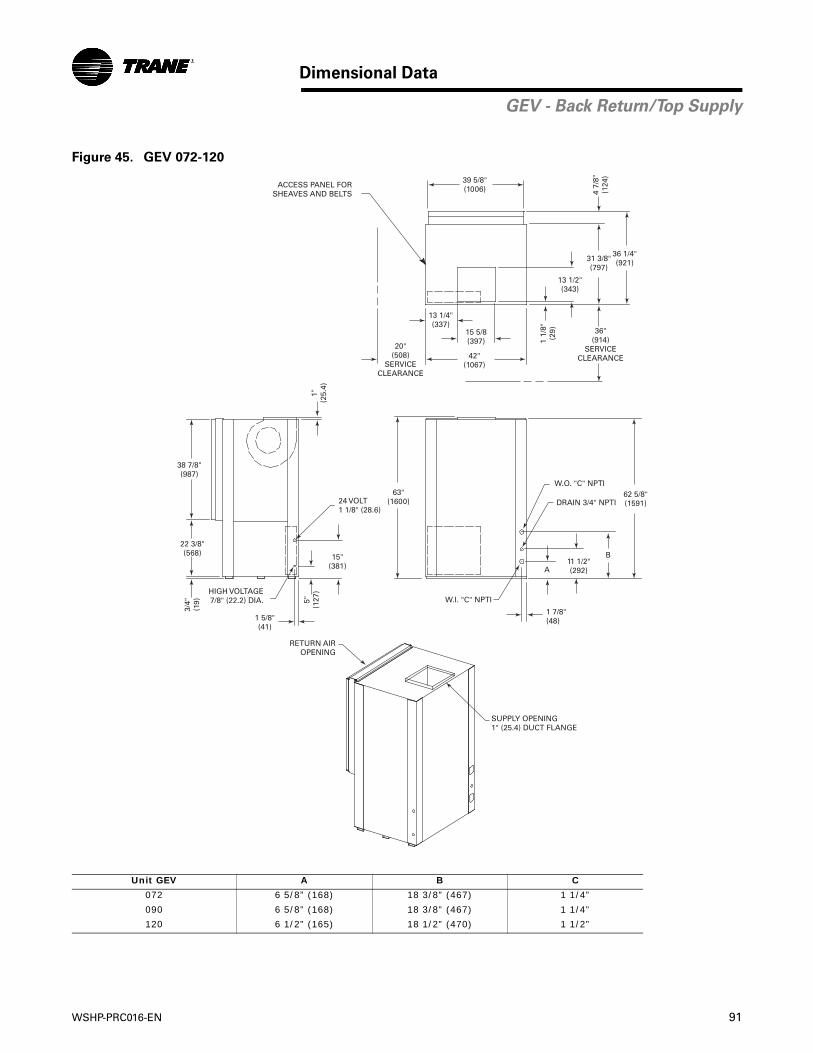
WSHP-PRC016-EN 91
Dimensional Data
GEV - Back Return/Top Supply
Figure 45. GEV 072-120
Unit GEV A B C
072 6 5/8” (168) 18 3/8” (467) 1 1/4”
090 6 5/8” (168) 18 3/8” (467) 1 1/4”
120 6 1/2” (165) 18 1/2” (470) 1 1/2”
20"(508)
SERVICECLEARANCE
39 5/8"(1006)ACCESS PANEL FOR
SHEAVES AND BELTS
13 1/4"(337)
15 5/8(397)
42"(1067)
4 7/
8"(1
24)
1 1/
8"(2
9)
31 3/8"(797)
36 1/4"(921)
13 1/2"(343)
36"(914)
SERVICECLEARANCE
63"(1600)
62 5/8"(1591)
B
W.O. "C" NPTI
DRAIN 3/4" NPTI
A11 1/2"(292)
1 7/8"(48)
W.I. "C" NPTIHIGH VOLTAGE7/8" (22.2) DIA.
1 5/8"(41)
5"(1
27)
15"(381)
24 VOLT1 1/8" (28.6)
38 7/8"(987)
22 3/8"(568)
3/4"
(19)
1"(2
5.4)
SUPPLY OPENING1" (25.4) DUCT FLANGE
RETURN AIROPENING
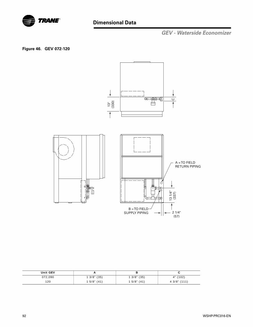
92 WSHP-PRC016-EN
Dimensional Data
GEV - Waterside Economizer
Figure 46. GEV 072-120
Unit GEV A B C
072,090 1 3/8” (35) 1 3/8” (35) 4” (102)
120 1 5/8” (41) 1 5/8” (41) 4 3/8” (111)
A = TO FIELDRETURN PIPING
B = TO FIELDSUPPLY PIPING
13 1
/4"
(337
)
13"
(330
) C
2 1/4"(57)
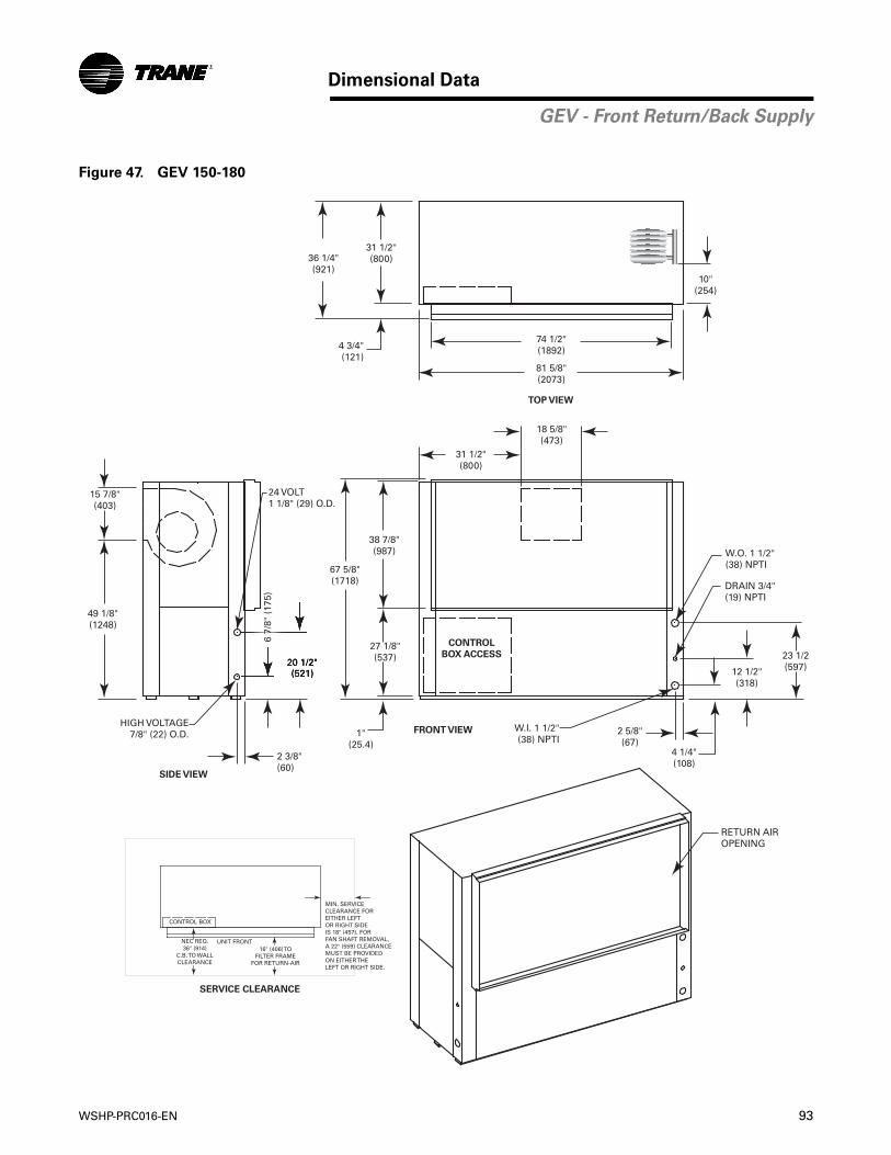
WSHP-PRC016-EN 93
Dimensional Data
GEV - Front Return/Back Supply
Figure 47. GEV 150-180
RETURN AIROPENING
W.I. 1 1/2"(38) NPTI
2 5/8"(67)
4 1/4"(108)
12 1/2"(318)
23 1/2(597)
DRAIN 3/4"(19) NPTI
W.O. 1 1/2"(38) NPTI
38 7/8"(987)
27 1/8"(537)
67 5/8"(1718)
31 1/2"(800)
18 5/8"(473)
1"(25.4)
HIGH VOLTAGE7/8" (22) O.D.
20 1/2"(521)
6 7/
8" (
175)
2 3/8"(60)
15 7/8"(403)
49 1/8"(1248)
24 VOLT1 1/8" (29) O.D.
74 1/2"(1892)
81 5/8"(2073)
31 1/2"(800)36 1/4"
(921)
4 3/4"(121)
CONTROL
BOX ACCESS
TOP VIEW
FRONT VIEW
SIDE VIEW
10"(254)
SERVICE CLEARANCE
CONTROL BOX
UNIT FRONTNEC REQ.36" (914)
C.B. TO WALLCLEARANCE
16" (406) TOFILTER FRAME
FOR RETURN-AIR
MIN. SERVICECLEARANCE FOREITHER LEFTOR RIGHT SIDEIS 18" (457). FORFAN SHAFT REMOVAL,A 22" (559) CLEARANCEMUST BE PROVIDED ON EITHER THELEFT OR RIGHT SIDE.
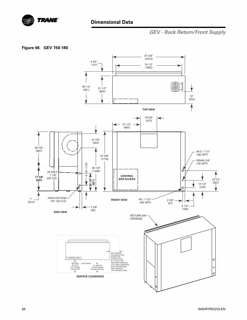
94 WSHP-PRC016-EN
Dimensional Data
GEV - Back Return/Front Supply
Figure 48. GEV 150-180
RETURN AIROPENING
W.I. 1 1/2"(38) NPTI
2 5/8"(67)
4 1/4"(108)
12 1/2"(318)
10"(254)
23 1/2(597)
DRAIN 3/4"(19) NPTI
W.O. 1 1/2"(38) NPTI
38 7/8"(987)
27 1/8"(537)
67 5/8"(1718)
31 1/2"(800)
18 5/8"(473)
1"(25.4)
HIGH VOLTAGE7/8" (22) O.D.
20 1
/2"
(521
)
6 7/
8" (
175)
2 3/8"(60)
15 7/8"(403)
49 1/8"(1248)
74 1/2"(1892)
81 5/8"(2073)
31 1/2"(800)
36 1/4"(921)
4 3/4"(121)
CONTROL
BOX ACCESS
TOP VIEW
FRONT VIEW
SIDE VIEW
SERVICE CLEARANCE
24 VOLT1 1/8"
(29) O.D.
CONTROL BOX
UNIT FRONTNEC REQ.36" (914)
C.B. TO WALLCLEARANCE
16" (406) TOFILTER FRAME
FOR RETURN-AIR
MIN. SERVICECLEARANCE FOREITHER LEFTOR RIGHT SIDEIS 18" (457). FORFAN SHAFT REMOVAL,A 22" (559) CLEARANCEMUST BE PROVIDED ON EITHER THELEFT OR RIGHT SIDE.

WSHP-PRC016-EN 95
Dimensional Data
GEV - Front Return/Top Supply
Figure 49. GEV 150-180
RETURN AIROPENING
SUPPLY OPENINGWITH 1" (25.4) DUCTFLANGE
W.I. 1 1/2"(38) NPTI
2 5/8"(67)
4 1/4"(108)
12 1/2"(318)
23 1/2(597)
15 7/8"(403)
14 3/8"(365)
DRAIN 3/4"(19) NPTI
W.O. 1 1/2"(38) NPTI
38 7/8"(987)
27 1/8"(537)
68"(1727)
31 1/2"(800)
18 5/8"(473)
1"(25.4)
HIGH VOLTAGE7/8" (22) O.D.
20 1
/2"
(521
)
2 3/8"(60)
74 1/2"(1892)
81 5/8"(2073)
31 1/2"(800)36 1/4"
(921)
4 3/4"(121)
6 7/
8" (
175)
10"(254)
CONTROL
BOX ACCESS
TOP VIEW
FRONT VIEW
SIDE VIEW
24 VOLT1 1/8"
(29) O.D.
SERVICE CLEARANCE
CONTROL BOX
UNIT FRONTNEC REQ.36" (914)
C.B. TO WALLCLEARANCE
16" (406) TOFILTER FRAME
FOR RETURN-AIR
MIN. SERVICECLEARANCE FOREITHER LEFTOR RIGHT SIDEIS 18" (457). FORFAN SHAFT REMOVAL,A 22" (559) CLEARANCEMUST BE PROVIDED ON EITHER THELEFT OR RIGHT SIDE.
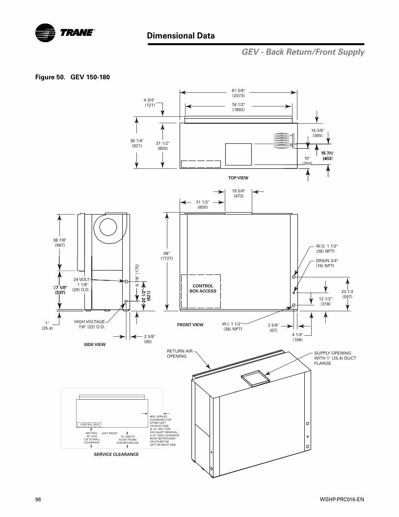
96 WSHP-PRC016-EN
Dimensional Data
GEV - Back Return/Front Supply
Figure 50. GEV 150-180
RETURN AIROPENING
SUPPLY OPENINGWITH 1" (25.4) DUCTFLANGE
W.I. 1 1/2"(38) NPTI
2 5/8"(67)
4 1/4"(108)
12 1/2"(318)
23 1/2(597)
15 7/8"(403)
14 3/8"(365)
DRAIN 3/4"(19) NPTI
W.O. 1 1/2"(38) NPTI
38 7/8"(987)
27 1/8"(537)
68"(1727)
31 1/2"(800)
18 5/8"(473)
1"(25.4)
HIGH VOLTAGE7/8" (22) O.D.
20 1
/2"
(521
)
6 7/
8" (
175)
2 3/8"(60)
74 1/2"(1892)
81 5/8"(2073)
31 1/2"(800)
36 1/4"(921)
4 3/4"(121)
CONTROL
BOX ACCESS
TOP VIEW
FRONT VIEW
SIDE VIEW
24 VOLT1 1/8"
(29) O.D.
10"(254)
SERVICE CLEARANCE
CONTROL BOX
UNIT FRONTNEC REQ.36" (914)
C.B. TO WALLCLEARANCE
16" (406) TOFILTER FRAME
FOR RETURN-AIR
MIN. SERVICECLEARANCE FOREITHER LEFTOR RIGHT SIDEIS 18" (457). FORFAN SHAFT REMOVAL,A 22" (559) CLEARANCEMUST BE PROVIDED ON EITHER THELEFT OR RIGHT SIDE.
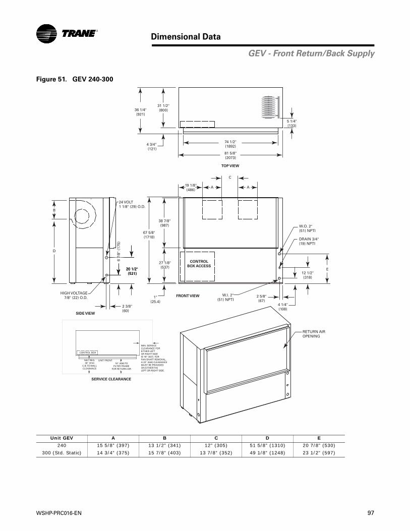
WSHP-PRC016-EN 97
Dimensional Data
GEV - Front Return/Back Supply
Figure 51. GEV 240-300
Unit GEV A B C D E
240 15 5/8” (397) 13 1/2” (341) 12” (305) 51 5/8” (1310) 20 7/8” (530)
300 (Std. Static) 14 3/4” (375) 15 7/8” (403) 13 7/8” (352) 49 1/8” (1248) 23 1/2” (597)
RETURN AIROPENING
W.I. 2"(51) NPTI
2 5/8"(67)
4 1/4"(108)
12 1/2"(318)
E
DRAIN 3/4"(19) NPTI
W.O. 2"(51) NPTI
38 7/8"(987)
27 1/8"(537)
67 5/8"(1718)
19 1/8"(486)
AA
C
1"(25.4)
HIGH VOLTAGE7/8" (22) O.D.
20 1/2"(521)
6 7/
8" (
175)
2 3/8"(60)
B
D
24 VOLT1 1/8" (29) O.D.
74 1/2"(1892)
81 5/8"(2073)
31 1/2"(800)36 1/4"
(921)
4 3/4"(121)
5 1/4"(133)
CONTROL
BOX ACCESS
TOP VIEW
FRONT VIEW
SIDE VIEW
SERVICE CLEARANCE
CONTROL BOX
UNIT FRONTNEC REQ.36" (914)
C.B. TO WALLCLEARANCE
16" (406) TOFILTER FRAME
FOR RETURN-AIR
MIN. SERVICECLEARANCE FOREITHER LEFTOR RIGHT SIDEIS 18" (457). FORFAN SHAFT REMOVAL,A 22" (559) CLEARANCEMUST BE PROVIDED ON EITHER THELEFT OR RIGHT SIDE.
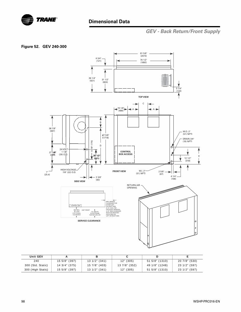
98 WSHP-PRC016-EN
Dimensional Data
GEV - Back Return/Front Supply
Figure 52. GEV 240-300
Unit GEV A B C D E
240 15 5/8” (397) 13 1/2” (341) 12” (305) 51 5/8” (1310) 20 7/8” (530)
300 (Std. Static) 14 3/4” (375) 15 7/8” (403) 13 7/8” (352) 49 1/8” (1248) 23 1/2” (597)
300 (High Static) 15 5/8” (397) 13 1/2” (341) 12” (305) 51 5/8” (1310) 23 1/2” (597)
W.I. 2"(51) NPTI
2 5/8"(67)
4 1/4"(108)
12 1/2"(318)
E
DRAIN 3/4"(19) NPTI
W.O. 2"(51) NPTI
38 7/8"(987)
27 1/8"(537)
67 5/8"(1718)
19 1/8"(486)
AA
C
1"(25.4)
HIGH VOLTAGE7/8" (22) O.D.
20 1/2"(521)
6 7/
8" (
175)
2 3/8"(60)
B
D
74 1/2"(1892)
81 5/8"(2073)
31 1/2"(800)
36 1/4"(921)
4 3/4"(121)
5 1/4"(133)
CONTROL
BOX ACCESS
TOP VIEW
FRONT VIEW
SIDE VIEW
RETURN AIROPENING
24 VOLT1 1/8"
(29) O.D.
SERVICE CLEARANCE
CONTROL BOX
UNIT FRONTNEC REQ.36" (914)
C.B. TO WALLCLEARANCE
16" (406) TOFILTER FRAME
FOR RETURN-AIR
MIN. SERVICECLEARANCE FOREITHER LEFTOR RIGHT SIDEIS 18" (457). FORFAN SHAFT REMOVAL,A 22" (559) CLEARANCEMUST BE PROVIDED ON EITHER THELEFT OR RIGHT SIDE.
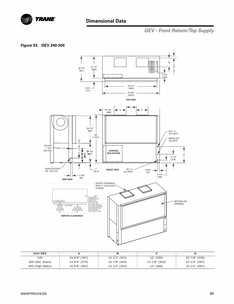
WSHP-PRC016-EN 99
Dimensional Data
GEV - Front Return/Top Supply
Figure 53. GEV 240-300
Unit GEV A B C D
240 15 5/8” (397) 13 1/2” (341) 12” (305) 20 7/8” (530)
300 (Std. Static) 14 3/4” (375) 15 7/8” (403) 13 7/8” (352) 23 1/2” (597)
300 (High Static) 15 5/8” (397) 13 1/2” (341) 12” (305) 23 1/2” (597)
RETURN AIROPENING
SUPPLY OPENINGSWITH 1" (25.4) DUCTFLANGE
W.I. 2"(51) NPTI
2 5/8"(67)
4 1/4"(108)
12 1/2"(318)
D
B
DRAIN 3/4"(19) NPTI
W.O. 2"(51) NPTI
38 7/8"(987)
27 1/8"(537)
68"(1727)
AC
A
1"(25.4)
HIGH VOLTAGE7/8" (22) O.D.
20 1
/2"
(521
)
2 3/8"(60)
74 1/2"(1892)
81 5/8"(2073)
31 1/2"(800)36 1/4"
(921)
4 3/4"(121)
6 7/
8" (
175)
19 1/8"(486)
1 1/
4" (
32)
5 1/4"(133)
CONTROL
BOX ACCESS
TOP VIEW
FRONT VIEW
SIDE VIEW
24 VOLT1 1/8"
(29) O.D.
SERVICE CLEARANCE
CONTROL BOX
UNIT FRONTNEC REQ.36" (914)
C.B. TO WALLCLEARANCE
16" (406) TOFILTER FRAME
FOR RETURN-AIR
MIN. SERVICECLEARANCE FOREITHER LEFTOR RIGHT SIDEIS 18" (457). FORFAN SHAFT REMOVAL,A 22" (559) CLEARANCEMUST BE PROVIDED ON EITHER THELEFT OR RIGHT SIDE.
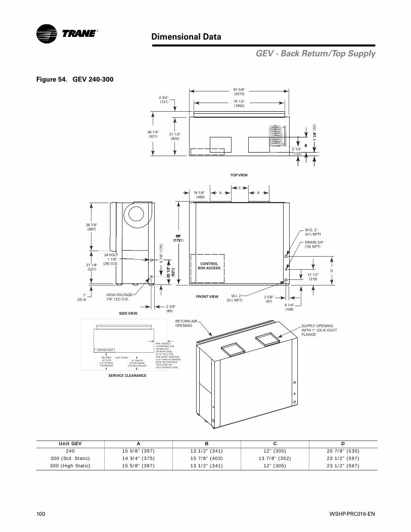
100 WSHP-PRC016-EN
Dimensional Data
GEV - Back Return/Top Supply
Figure 54. GEV 240-300
Unit GEV A B C D
240 15 5/8” (397) 13 1/2” (341) 12” (305) 20 7/8” (530)
300 (Std. Static) 14 3/4” (375) 15 7/8” (403) 13 7/8” (352) 23 1/2” (597)
300 (High Static) 15 5/8” (397) 13 1/2” (341) 12” (305) 23 1/2” (597)
W.I. 2"(51) NPTI
2 5/8"(67)
4 1/4"(108)
12 1/2"(318)
D
B
DRAIN 3/4"(19) NPTI
W.O. 2"(51) NPTI
38 7/8"(987)
27 1/8"(537)
68"(1727)
AC
A
1"(25.4)
HIGH VOLTAGE7/8" (22) O.D.
20 1
/2"
(521
)
2 3/8"(60)
74 1/2"(1892)
81 5/8"(2073)
31 1/2"(800)
36 1/4"(921)
4 3/4"(121)
6 7/
8" (
175)
19 1/8"(486)
1 1/
4" (
32)
RETURN AIROPENING SUPPLY OPENING
WITH 1" (25.4) DUCTFLANGE
5 1/4"(133)
SERVICE CLEARANCE
CONTROL BOX
UNIT FRONTNEC REQ.36" (914)
C.B. TO WALLCLEARANCE
16" (406) TOFILTER FRAME
FOR RETURN-AIR
MIN. SERVICECLEARANCE FOREITHER LEFTOR RIGHT SIDEIS 18" (457). FORFAN SHAFT REMOVAL,A 22" (559) CLEARANCEMUST BE PROVIDED ON EITHER THELEFT OR RIGHT SIDE.
CONTROL
BOX ACCESS
TOP VIEW
FRONT VIEW
SIDE VIEW
24 VOLT1 1/8"
(29) O.D.
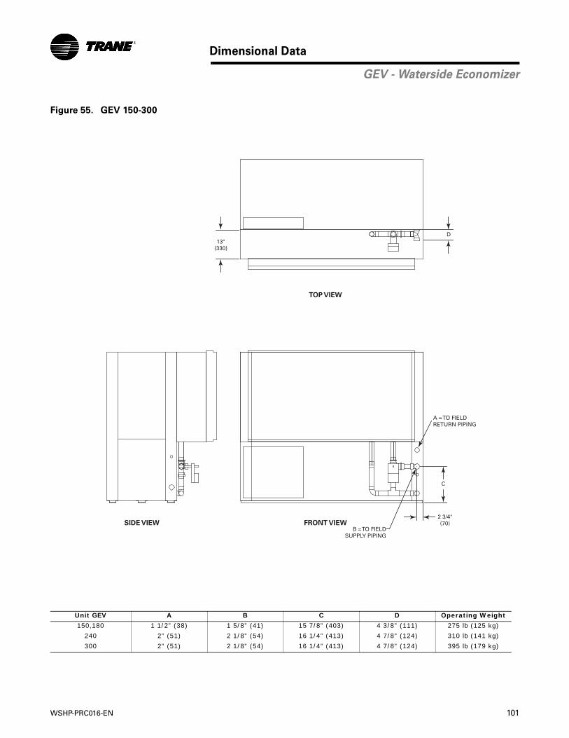
WSHP-PRC016-EN 101
Dimensional Data
GEV - Waterside Economizer
Figure 55. GEV 150-300
Unit GEV A B C D Operating Weight
150,180 1 1/2” (38) 1 5/8” (41) 15 7/8” (403) 4 3/8” (111) 275 lb (125 kg)
240 2” (51) 2 1/8” (54) 16 1/4” (413) 4 7/8” (124) 310 lb (141 kg)
300 2” (51) 2 1/8” (54) 16 1/4” (413) 4 7/8” (124) 395 lb (179 kg)
TOP VIEW
FRONT VIEWSIDE VIEW
13"(330)
D
C
A = TO FIELDRETURN PIPING
2 3/4"(70)
B = TO FIELDSUPPLY PIPING
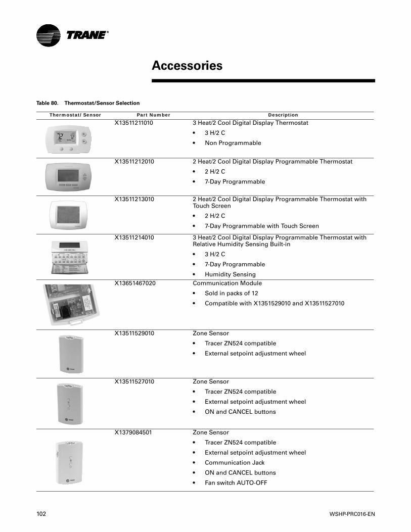
102 WSHP-PRC016-EN
Accessories
Table 80. Thermostat/Sensor Selection
Thermostat/Sensor Part Number Description
X13511211010 3 Heat/2 Cool Digital Display Thermostat
• 3 H/2 C
• Non Programmable
X13511212010 2 Heat/2 Cool Digital Display Programmable Thermostat
• 2 H/2 C
• 7-Day Programmable
X13511213010 2 Heat/2 Cool Digital Display Programmable Thermostat with Touch Screen
• 2 H/2 C
• 7-Day Programmable with Touch Screen
X13511214010 3 Heat/2 Cool Digital Display Programmable Thermostat with Relative Humidity Sensing Built-in
• 3 H/2 C
• 7-Day Programmable
• Humidity SensingX13651467020 Communication Module
• Sold in packs of 12
• Compatible with X1351529010 and X13511527010
X13511529010 Zone Sensor
• Tracer ZN524 compatible
• External setpoint adjustment wheel
X13511527010 Zone Sensor
• Tracer ZN524 compatible
• External setpoint adjustment wheel
• ON and CANCEL buttons
X1379084501 Zone Sensor
• Tracer ZN524 compatible
• External setpoint adjustment wheel
• Communication Jack
• ON and CANCEL buttons
• Fan switch AUTO-OFF
WSHP-PRC016-EN 103
Accessories
Thermostat/Sensor Part Number Description
X1379044010 Relative Humidity and Temperature Sensor
• Tracer ZN542 compatible
Table 80. Thermostat/Sensor Selection (continued)
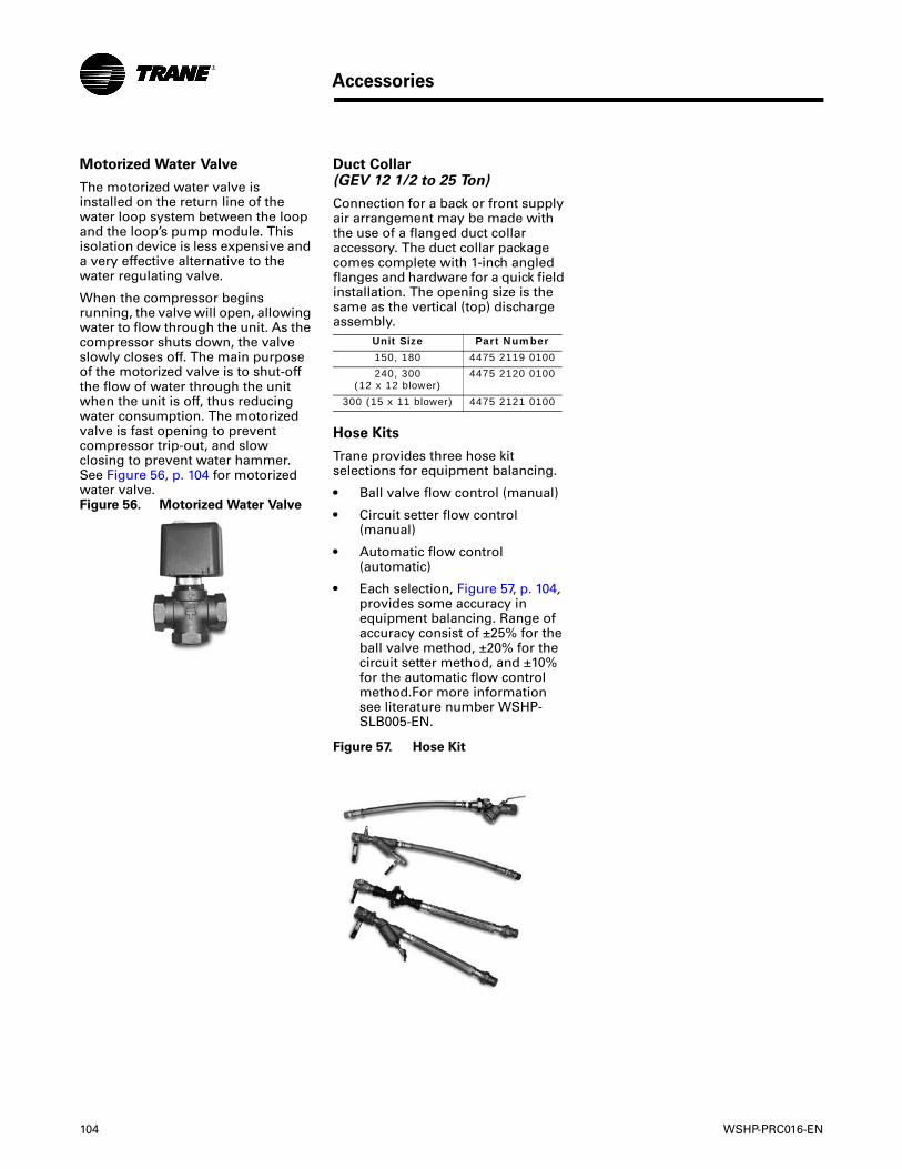
104 WSHP-PRC016-EN
Accessories
Motorized Water Valve
The motorized water valve is installed on the return line of the water loop system between the loop and the loop’s pump module. This isolation device is less expensive and a very effective alternative to the water regulating valve.
When the compressor begins running, the valve will open, allowing water to flow through the unit. As the compressor shuts down, the valve slowly closes off. The main purpose of the motorized valve is to shut-off the flow of water through the unit when the unit is off, thus reducing water consumption. The motorized valve is fast opening to prevent compressor trip-out, and slow closing to prevent water hammer. See Figure 56, p. 104 for motorized water valve.Figure 56. Motorized Water Valve
Duct Collar (GEV 12 1/2 to 25 Ton)
Connection for a back or front supply air arrangement may be made with the use of a flanged duct collar accessory. The duct collar package comes complete with 1-inch angled flanges and hardware for a quick field installation. The opening size is the same as the vertical (top) discharge assembly.
Hose Kits
Trane provides three hose kit selections for equipment balancing.
• Ball valve flow control (manual)
• Circuit setter flow control (manual)
• Automatic flow control (automatic)
• Each selection, Figure 57, p. 104, provides some accuracy in equipment balancing. Range of accuracy consist of ±25% for the ball valve method, ±20% for the circuit setter method, and ±10% for the automatic flow control method.For more information see literature number WSHP-SLB005-EN.
Unit Size Part Number
150, 180 4475 2119 0100
240, 300 (12 x 12 blower)
4475 2120 0100
300 (15 x 11 blower) 4475 2121 0100
Figure 57. Hose Kit
WSHP-PRC016-EN 105
Mechanical Specifications
Mechanical Specifications
All units are tested and rated in accordance with ARI 260.
Compressors
The R-410A unit contains a high efficiency scroll compressor. External vibration isolation is provided by rubber mounting devices located underneath the mounting base of the compressor. A second isolation of the refrigeration assembly is supported under the compressor mounting base.
Internal thermal overload protection is provided. Protection against excessive discharge pressure is provided by means of a high pressure switch. A loss of charge is provided by a low pressure safety.
Refrigerant Tubing
The refrigerant tubing is of 99% pure copper. This system shall be free from contaminants and conditions such as drilling fragments, dirt and oil. All refrigerant and water lines are insulated with an elastomeric insulation that has a 3/8-inch thick wall in the air-side section of the unit.
Refrigerant Circuits
The refrigerant circuit contains a thermal expansion device. Service pressure ports are factory supplied on the high and low pressure sides for easy refrigerant pressure or temperature testing.
Air-to-Refrigerant Coil
Internally finned, 3/8-inch copper tubes mechanically bonded to a configured aluminum plate fin are standard. Coils are leak tested at the factory to ensure the pressure integrity. The R-410A coil is leak tested to 450 psig and pressure tested to 650 psig. The tubes are to be completely evacuated of air and correctly charged with proper volume of refrigerant prior to shipment.
The refrigerant coil distributor assembly is of orifice style with round copper distributor tubes. The tubes are sized consistently with the capacity of the coil. Suction header is fabricated from rounded copper pipe.
A thermostatic expansion valve is factory selected and installed for a wide range of control.
Drain Pan
The condensate pan is constructed of corrosion resistant material and insulated to prevent sweating. The bottom of the drain pan is sloped on two planes which pitches the condensate to the drain connection. The drain pan is flame rated per UL945V-B. When the unit is installed and trapped per the manufacturers installation manual, and local city specifications, the drain pan shall be designed to leave puddles no more than 2-inch in diameter, no more than 1/8-inch deep, no longer than 3 minutes following the step 3 of the following test.
• Temporarily plug the drain pan.
• Fill the drain pan with 1/2-inch of water or the maximum allowed by the drain pan depth, whichever is smaller.
• Remove the temporary plug.
Water-to-Refrigerant Heat Exchanger
The water-to-refrigerant heat exchanger is of a high quality co-axial coil for maximum heat transfer. The copper or optional cupro-nickel coil shall be deeply fluted to enhance heat transfer and minimize fouling and scaling. The R-410A coil has a working pressure of 650 psig on both the refrigerant and water sides.
General
Equipment is completely assembled, piped, internally wired, fully charged with R-410A and test operated at the factory. Filters, thermostat field interface terminal strip, and all safety controls are furnished and factory installed.
The system water inlet and outlet connections are female NPT composed of either a copper or a bronze option.
The 6 through 10-ton equipment contain ETL, CETL and ISO-ARI 13256-1 listings and labels prior to leaving the factory. Larger units are rated in accordance with ISO-ARI 13256-1. Service and caution area labels are placed on the unit in their appropriate locations.
Cabinet
Unit casing is constructed of zinc coated, heavy gauge, galvanized steel.
Access to the refrigerant and controls is provided through the front and side access panels.
All panels are insulated with 1/2-inch thick dual density bonded glass fiber. The exposed side is a high density erosion proof material suitable for use in air streams up to 3600 feet per minute (FPM). The insulation meets the erosion requirements of UL 181. It has a flame spread of less than 25 and a smoke developed classification of less than 50 per ASTM E-84 and UL 723.
Access for inspection and cleaning of the unit drain pan, coils and fan section are provided. The unit shall be installed for proper access.
Filters
One inch or two inch, throwaway filters are standard and factory installed. The filters have an average arrestance of 75% and dust holding capacity of 26-grams per square foot.
Sound Attenuation
Sound attenuation is applied as a standard feature in the product design.
106 WSHP-PRC016-EN
Mechanical Specifications
Indoor Fan
The blower has nine blower motor/sheave combinations available.
Options of the blower motor/fan packages are selected and wired from the factory to match performance criteria suggested in the performance section.
The fan(s) are placed in a draw-through configuration. They are constructed of corrosion resistant galvanized material.
Electrical
The unit control box contains all necessary devices to allow heating and cooling operation to occur from a remote wall thermostat. These devices are as follows:
• 24 VAC energy limiting class II 75 VA (minimum) transformer.
• 24 VAC blower motor relay.
• 24 VAC compressor contactor for compressor control.
• Field thermostat connections shall be provided for ease of hook-up to a terminal strip located in the unit’s control box.
• Lockout relay which controls cycling of the compressor shall be provided to protect the compressor during adverse operating conditions. The device may be reset by interrupting power to the 24 VAC control circuit. Reset may be done either at a remote thermostat or through a momentary main power interruption.
• R-410A - A high pressure switch shall protect the compressor against operation at refrigerant system pressures exceeding 650 psig.
• The low-water temperature switch or sensor shall prevent the compressor operation with leaving water temperatures below 20°F.
• Factory installed wire harness shall be available for the Deluxe and ZN524 control packages.
Nameplate information shall be provided for the application of either time-delay fuses or HACR circuit breakers for branch circuit protection from the primary source of power.
Deluxe Controls (option)
The deluxe control package provides a 75 VA transformer with circuit breaker. The controller includes a lockout relay, anti-short cycle compressor protection, random start delay, brown-out protection, low pressure time delay, compressor delay on start and an open relay for night setback or pump request. Optional wiring from the factory for night setback, condensate overflow, hot gas reheat, electric heat, and compressor enable is also provided. Three LEDs (light emitting diodes) are included for diagnostics of the equipment.
Tracer ZN524 Controller (option)
The ZN524 controller utilizes factory furnished and mounted DDC controls for operation of up to 120 units on a Comm 5 (LonMark) link. The Tracer ZN524 control package includes a 75 VA (minimum) transformer. The controller provides random start delay, heating/cooling status, occupied/unoccupied mode, fan status and filter maintenance options. Optional wiring from the factory for condensate overflow is available. Three LEDs (light emitting diodes) are included for diagnostics of the equipment.
The ZN524 is capable of a standalone application, or as applied to a full building automation installation.
With this controller, the unit is capable of a hot gas reheat (for dehumidification), boilerless control for electric heat, waterside economizing, and support of variable speed pump control applications.
Economizing Coil (option)
The waterside economizing package is an external unit accessory piping kit and wiring ready for turn-key installation to the unit. The economizing coil is designed to perform with the WSHP at unit measured flow rate of 80.6°F DB/66.2°F WB with 45°F EWT.
All hydronic coils are of 3/8" (6-20 ton units), 1/2" (25 ton unit) copper and aluminum plate fin combination. All coils are proof and leak tested from the manufacturer.
The proof test is performed at 1.5 times the maximum operating
pressure and the leak test at the maximum operating pressure.
A dual sloped non corrosive drain pan is easily accessible and cleanable for the hydronic economizing coil.
An electronic two-position, 3-way valve meters water flow to the economizing coil during the economizing mode. It is factory set to energize the economizing mode at 55°F, while simultaneously halting mechanical operation of the compressor.
The economizer is field attached to the equipment.
Electric Heat (option)
Boilerless control electric heat is factory wired and tested.
The boilerless control option is composed of a controls interface for a field provided boilerless or supplemental electric heat selection. The heater for this model is placed external to the equipment by the contractor for ease of installation. All power connections for the electric heater will be completely separate from the unit for field supplied electric heat.
Hot Gas Reheat (option)
Dehumidification is provided through a hot gas reheat option. The coil consists of 3/8"/1/2" copper tubes mechanically expanded into evenly spaced aluminum fins. All coils are proof and leak tested. The proof test must be performed at 1.5 time the maximum operating pressure and the leak test performed at the maximum operating pressure.
Ball Valves (option)
Ball valves are field installed between the unit and the supply and return lines of the loop to stop water flow to the unit in a maintenance or service situation.
Motorized Water Valve (option)
When extreme fluid temperature conditions do not exist with an open loop system, a motorized water valve may be applied to each water-source heat pump. The motorized valve shall stop flow to the unit, causing pressures to rise. This rise in pressure will halt pump operation to
WSHP-PRC016-EN 107
Mechanical Specifications
provide greater energy savings of the entire system.
Hoses (option)
Hoses consists of a stainless steel outer braid with an inner core of tube made of a nontoxic synthetic polymer material. The hoses are suitable for water temperatures ranging between 33°F and 211°F without the use of glycol.
Automatic Flow Devices (option)
The automatic flow kit contains a Hays Mesurflo® automatic flow control valve, two ball valves, two flexible hoses, a high flow Y-strainer, and may include a strainer blow-down and various other accessories.
The automatic flow control valve is factory set to a rated flow, and shall automatically control the flow to within 10% of the rated value over a 40 to 1 differential pressure, operating range (2 to 80 PSID). Operational temperature is rated from fluid freezing, to 225°F. The valve body shall be constructed from hot forged brass UNS C37700 per ASTM B-283 latest revision. For more information pertaining to the automatic balancing hose kits, see literature documentation WSHP-SLB005-EN.

www.trane.com
For more information, contact your local Trane office or e-mail us at [email protected]
Literature Order Number WSHP-PRC016-EN
Date June 2008
Supersedes New
Trane has a policy of continuous product and product data improvement and reserves the right to change design and specifications without notice.