AutoVue® Lane Departure Warning (LDW) System by Bendix ...
20
1 AutoVue ® Lane Departure Warning (LDW) System by Bendix CVS SD-64-4976 1.0 DESCRIPTION The AutoVue ® Lane Departure Warning (LDW) System by Bendix CVS gives drivers the ability to combat lane drift related to drowsiness/fatigue, distractions, and/or extreme lightning conditions. At speeds above 37 mph (59 kph), the AutoVue system tracks visible lane markings including both solid and dashed shoulder lines, center lines, and lines between lanes. When an unexpected lane change takes place – a lane change without an activated turn signal – the system alerts (audible or haptic) the driver to make a correction. The AutoVue LDW system is intended only as an aid for a conscientious and alert driver. It may not provide any warning of unintended lane departures under certain conditions. Do not rely solely on the system to safely operate the vehicle. It does not warn of all possible hazards. For example, the system cannot help prevent an accident if the driver is impaired or not driving safely. Ultimate responsibility for the safe operation of the vehicle remains with the driver at all times. 1.1 SYSTEM COMPONENTS The system components include a digital camera mounted near the middle of the windshield inside the cab and pointed toward the road, a bracket to attach the camera to the windshield, an enable/disable switch (typically with status lamps), a driver alert system (speakers and/ or a vibrating seat), and a central processing unit in the overhead console. Some vehicles connect the AutoVue LDW system to the vehicle’s telematics communication system (See Appendix A: SafetyDirect ® by Bendix CVS system). Figure 1 – AutoVue ® LDW System by Bendix CVS (boxes added to illustrate active lane detection) Figure 2 – AutoVue LDW System - Operational View Painted Road Stripes CAMERA FIELD OF VIEW Vehicle Equipped with AutoVue ® LDW System by Bendix CVS The rectangles illustrate zones where the AutoVue LDW system makes specific measurements about the lane ahead. For vehicles traveling above 37 mph (59 kph), the GRAY area approximates the zone where the system’s processor is evaluating the vehicle’s position in the lane. Windshield Mounted Camera NOT TO SCALE Windshield-Mounted Camera
-
Upload
khangminh22 -
Category
Documents
-
view
4 -
download
0
Transcript of AutoVue® Lane Departure Warning (LDW) System by Bendix ...

1
AutoVue® Lane Departure Warning (LDW) System by Bendix CVS
SD-6
4-49
76
1.0 DESCRIPTIONThe AutoVue® Lane Departure Warning (LDW) System by Bendix CVS gives drivers the ability to combat lane drift related to drowsiness/fatigue, distractions, and/or extreme lightning conditions.
At speeds above 37 mph (59 kph), the AutoVue system tracks visible lane markings including both solid and dashed shoulder lines, center lines, and lines between lanes.
When an unexpected lane change takes place – a lane change without an activated turn signal – the system alerts (audible or haptic) the driver to make a correction.
The AutoVue LDW system is intended only as an aid for a conscientious and alert driver. It may not provide any warning of unintended lane departures under certain conditions. Do not rely solely on the system to safely operate the vehicle. It does not warn of all possible hazards. For example, the system cannot help prevent an accident if the driver is impaired or not driving safely.Ultimate responsibility for the safe operation of the vehicle remains with the driver at all times.
1.1 SYSTEM COMPONENTSThe system components include a digital camera mounted near the middle of the windshield inside the cab and pointed toward the road, a bracket to attach the camera to the windshield, an enable/disable switch (typically with status lamps), a driver alert system (speakers and/or a vibrating seat), and a central processing unit in the overhead console.
Some vehicles connect the AutoVue LDW system to the vehicle’s telematics communication system (See Appendix A: SafetyDirect® by Bendix CVS system).
Figure 1 – AutoVue® LDW System by Bendix CVS (boxes added to illustrate active lane detection)
Figure 2 – AutoVue LDW System - Operational View
Painted Road Stripes
CAMERA FIELD OF VIEW
Vehicle Equipped with AutoVue® LDW System by Bendix CVS
The rectangles illustrate zones where the AutoVue LDW system makes specific measurements about the lane ahead.
For vehicles traveling above 37 mph (59 kph), the GRAY area approximates the zone where the system’s processor is evaluating the vehicle’s position in the lane.
Windshield Mounted Camera
NOT TO SCALE
Windshield-Mounted Camera

2
GENERAL SAFETY GUIDELINESWARNING! PLEASE READ AND FOLLOW THESE INSTRUCTIONS
TO AVOID PERSONAL INJURY OR DEATH:When working on or around a vehicle, the following guidelines should be observed AT ALL TIMES:
▲ Park the vehicle on a level surface, apply the parking brakes, and always block the wheels. Always wear personal protection equipment.
▲ Stop the engine and remove the ignition key when working under or around the vehicle. When working in the engine compartment, the engine should be shut off and the ignition key should be removed. Where circumstances require that the engine be in operation, EXTREME CAUTION should be used to prevent personal injury resulting from contact with moving, rotating, leaking, heated, or electrically charged components.
▲ Do not attempt to install, remove, disassemble, or assemble a component until you have read, and thoroughly understand, the recommended procedures. Use only the proper tools and observe all precautions pertaining to use of those tools.
▲ If the work is being performed on the vehicle’s air brake system, or any auxiliary pressurized air systems, make certain to drain the air pressure from all reservoirs before beginning ANY work on the vehicle. If the vehicle is equipped with a Bendix® AD-IS® air dryer system, a Bendix® DRM™ dryer reservoir module, a Bendix® AD-9si®, AD-HF®, or AD-HFi™ air dryer, be sure to drain the purge reservoir.
▲ Fol lowing the vehic le manufac turer ’s recommended procedures, deactivate the electrical system in a manner that safely removes all electrical power from the vehicle.
▲ Never exceed manufacturer’s recommended pressures.
▲ Never connect or disconnect a hose or line containing pressure; it may whip and/or cause hazardous airborne dust and dirt particles. Wear eye protection. Slowly open connections with care, and verify that no pressure is present. Never remove a component or plug unless you are certain all system pressure has been depleted.
▲ Use only genuine Bendix® brand replacement parts, components, and kits. Replacement hardware, tubing, hose, fittings, wiring, etc. must be of equivalent size, type, and strength as original equipment and be designed specifi cally for such applications and systems.
▲ Components with stripped threads or damaged parts should be replaced rather than repaired. Do not attempt repairs requiring machining or welding unless specifi cally stated and approved by the vehicle and component manufacturer.
▲ Prior to returning the vehicle to service, make certain all components and systems are restored to their proper operating condition.
▲ For vehicles with Automatic Traction Control (ATC), the ATC function must be disabled (ATC indicator lamp should be ON) prior to performing any vehicle maintenance where one or more wheels on a drive axle are lifted off the ground and moving.
▲ The power MUST be temporarily disconnected from the radar sensor whenever any tests USING A DYNAMOMETER are conducted on a vehicle equipped with a Bendix® Wingman® system.
▲ You should consult the vehicle manufacturer's operating and service manuals, and any related literature, in conjunction with the Guidelines above.
Due to the inherent limitations of image recognition technology, the lane departure warning (LDW)technology – on rare occasions – may not be able to detect or may misinterpret lane markings. At these times, alerts may not occur, or erroneous alerts may occur.
Bendix active and supportive safety technologies, including AutoVue® LDW by Bendix CVS, do not replace the need for safe drivers. No commercial vehicle safety technology replaces the most important safety component of all – a skilled, alert professional driver exercising safe driving habits, as well as continuous, comprehensive driver training.Ultimate responsibility for the safe operation of the vehicle remains with the driver at all times. IMPORTANT
It is the responsibility of the driver to remain vigilant and change driving practices depending on traffic and road conditions.

3
The system uses speakers to emit a distinctive sound on the appropriate side (or optional vibration from the driver’s seat if a non-audible warning is preferred).
The AutoVue® LDW system by Bendix CVS is optimized to reduce false alarms. However, the driver may use the enable/disable switch to temporarily silence the alarms.
Camera Lens
Mounting Bracket
(affixed to the windshield)
Note: The camera is removed from the bracket by
sliding upwards
Figure 4 – AutoVue® Camera
The AutoVue LDW system has two lamps: an amber status lamp and a green enable/disable lamp. There is also a switch to permit the driver to temporarily disable the system. Some vehicles have the lamps and switch combined. See Figure 5 below.
Green Enable/Disable Lamp
Amber Status Lamp
The design will vary by
vehicle OEM. The switch and lamps may be
separate.
Figure 5 – Example of an AutoVue System Switch
SD SHEET INDEX1.0 Description . . . . . . . . . . . . . . . . . . . . . . . . . . . . . . . . . . . . . . . . . . . . . . 11.1 System Components . . . . . . . . . . . . . . . . . . . . . . . . . . . . . . . . . . . . . . . . . 12.0 System Operation: What To Expect When Using The AutoVue® LDW System By Bendix CVS . . . 42.1 Potential False And Missed Alerts . . . . . . . . . . . . . . . . . . . . . . . . . . . . . . . . . . 52.2 Setting Diagnostic Trouble Codes (DTCs) . . . . . . . . . . . . . . . . . . . . . . . . . . . . . . 52.3 Maintenance . . . . . . . . . . . . . . . . . . . . . . . . . . . . . . . . . . . . . . . . . . . . . 52.4 Camera and Electronic Control Unit (ECU) Interchangeability . . . . . . . . . . . . . . . . . . . . 52.5 Alert Volume . . . . . . . . . . . . . . . . . . . . . . . . . . . . . . . . . . . . . . . . . . . . . 52.6 Windshield Mounting Information . . . . . . . . . . . . . . . . . . . . . . . . . . . . . . . . . . . 63.0 Troubleshooting. . . . . . . . . . . . . . . . . . . . . . . . . . . . . . . . . . . . . . . . . . . . 73.1 General Safety Guidelines . . . . . . . . . . . . . . . . . . . . . . . . . . . . . . . . . . . . . . 73.2 Diagnostic Trouble Codes (DTCs) . . . . . . . . . . . . . . . . . . . . . . . . . . . . . . . . . . 73.3 Table of AutoVue LDW System DTCs . . . . . . . . . . . . . . . . . . . . . . . . . . . . . . 7-143.4 Advanced Troubleshooting . . . . . . . . . . . . . . . . . . . . . . . . . . . . . . . . . . . . . 16 3.5 Clearing DTCs . . . . . . . . . . . . . . . . . . . . . . . . . . . . . . . . . . . . . . . . . . . 17Appendix A - SafetyDirect® by Bendix CVS . . . . . . . . . . . . . . . . . . . . . . . . . . . . . . . 18
Kit Contents
Key Description Qty
1 Lane Departure Warning processor 12 Camera with windshield bracket 1
3 Two 3½-inch speakers with covers (optional) 2
4 Vibrating seat motors (optional) 25 Enable/disable switch 1
2
1
3
5
4
Figure 3 – AutoVue® LDW System by Bendix CVS

4
2.0 SYSTEM OPERATION: WHAT TO EXPECT WHEN USING THE AUTOVUE® LDW SYSTEM BY BENDIX CVS
What to Expect in Normal Operating Conditions
Situation
Green Enable/Disable
LampAmber
Status Lamp Typical System Actions
At Start-
Up
Self-test at power-up. On and remains illuminated.
On and remains illuminated.
Starting the vehicle supplies power to the system. At start-up, the system performs a self-test, then sounds two chirps through [first the left, then the right] the speakers. For vehicles which have systems with vibrating seat motors, the same sequence is followed to indicate the system is ready. Once the vehicle is running and the system is ready, the green ENABLED lamp and amber STATUS lamp illuminate.
Driver may test the enable/disable switch: press ONCE.
Lamp off. Lamp off. None.
Driver may test the enable/disable switch: press AGAIN.
Lamp illuminated. Lamp illuminated.
None.
On the
Road
Active system Diagnostic Trouble Code (DTC) is present.
Lamp off. Lamp illuminated.
System disabled.(Awaits system service).
Vehicle exceeds 37 mph (59 kph), lane markings on both sides are being tracked, and there are no active system DTCs.
Lamp remains illuminated.
Lamp off. None. (System is now active).
(With turn signal ON) Driver changes lanes.
Lamp remains illuminated.
Lamp off. None.
(With turn signal OFF) Driver drifts out of lane/changes lanes.
Lamp remains illuminated.
Lamp off. The speaker on the side of the vehicle towards which it is moving/drifting will emit a “rumble strip” sound. (If installed, driver’s seat vibration will also/instead be activated.)
Vehicle slows to 37 mph (59 kph), or below, and/or one or both lane markings are no longer able to be tracked by the system.
Lamp remains illuminated.
Lamp illuminated.
None (system is NOT active).
Driver temporarily disables the system by pressing the disable switch (for example, construction areas with poorly marked lines may cause multiple false alerts.)
Lamp off. Lamp off. The system will automatically re-enable after 15 minutes.
Table 1 – Operational Scenarios with the AutoVue LDW System

5
2.1 POTENTIAL FALSE AND MISSED ALERTSIn certain unusual traffic or roadway conditions, the AutoVue® LDW system by Bendix CVS may issue a false alert.
Drivers should take into account the road conditions, and any other factors they are encountering, as they choose how to react to any alerts they receive from the AutoVue LDW system.
Overview of Potential IssuesIssue Description
A system Diagnostic Trouble Code (DTC) is present.
If the AutoVue LDW system finds a problem at power-up or during operation, it will set a DTC and will disable the system. The amber lamp will be ON, and the green lamp OFF.Use J1939 detection software to find the Diagnostic Trouble Code (DTC). Go to the Troubleshooting Section (page 7) to find the recommended repair.
System cannot discover right and left lane markings.
• Mis-installed camera (incorrect placement, not level, loose, etc. See page 6 for full details of camera installation specifications.) Note: When re-mounting a camera bracket, use Bendix windshield adhesive - Bendix part number 493088201 - do not use substitutes.
• Road markings are hard to see (faded/missing lane markings, standing water, snow, or mud/sand/dirt/debris on the road).
• Inclement weather (heavy rain, fog, snow, smoke, ice or sleet, etc. is blocking the lane markings).
• Camera’s view is not clear (glass not clean, chipped or cracked, not installed where the windshield wiper cleans the glass, or other distortion).
• Headlight(s) are not operating or are mis-aimed.• Sun glare or other light source blinds the camera, obscures the lane markings, or makes
other road markings (e.g. tar strips) look like lane markings. NOTE: These are potential situations and responses that might occur when using the AutoVue LDW system.
All possible situations and responses are not covered here.
Table 2 – Examples of Potential Issues
2.2 SETTING DIAGNOSTIC TROUBLE CODES (DTCS)
The AutoVue LDW system is self-monitoring and if any malfunction is detected, a DTC will be set and the driver will be alerted by the amber status lamp being illuminated, and the green enabled lamp will be OFF. See the Troubleshooting Section (page 7), for more information.
2.3 MAINTENANCEIn normal use, the AutoVue LDW system needs only a clean, properly maintained windshield to ensure a clear view of the road ahead.
2.4 CAMERA AND ELECTRONIC CONTROL UNIT (ECU)INTERCHANGEABILITY
AutoVue LDW systems are vehicle make and model specific. Each part number is customized to a windshield configuration and offset. When troubleshooting, or when replacing cameras or Electronic Control Units (ECUs), only use replacements with the same part number (or a direct superceding replacement number supplied by Bendix).
2.5 ALERT VOLUMEDefault audible alert levels are pre-set at the factory. Alert volumes and Start-up Chirp volumes are adjustable with Bendix® ACom® PRO™ Diagnostic Software.
IMPORTANT
Bendix®-brand Electronic Control Units (ECUs) are not designed to store data for purposes of accident reconstruction and Bendix® ACom® PRO™ Diagnostic Software is not intended to retrieve data for purposes of accident reconstruction. Bendix makes no representations as to the accuracy of data or video retrieved and interpreted from ECUs for purposes of accident reconstruction. Bendix does not offer accident reconstruction services or interpretation of stored data. Bendix ECUs are not protected from fire, loss of power, impact damage, or other conditions that may be sustained in a crash situation and may cause data to be unavailable or irretrievable.

6
2.6 WINDSHIELD MOUNTING INFORMATION
Figure 6 – Locating the Correct Point to Mount the Camera Bracket
* All trademarks shown here are the property of their respective owners and are used for reference only.
Top of Windshield
A
Notch in the Camera
Bracket
B
To determine the correct point on the windshield to line up to the notch in the camera bracket, use the Make/Model columns of the table (left) to find the Camera Location Code. The second table (below) shows the correct vertical and horizontal offset to use for each Code.
Cent
er L
ine
“Torpedo” Level Rests on the Bracket Tabs
Left: Use only Bendix windshield adhesive when re-mounting a camera bracket.
Make* Model
Camera Location
Code
Freightliner®
Argosy® 1Cascadia® P3 (AM) 8Cascadia P3 (OEM) 10Century®/Columbia® 1Classic XL®
2Coronado®
FL70M2 106 (AM)M2 114SD (AM)M2 106 (OEM)
12M2 112 (OEM)M2 114SD (OEM)New Cascadia® P4
Hino®
195 13268
2338
International®
9100/9200/9400
29900DuraStar®/4000 SeriesLT/ProStar®
TranStar®/8000 SeriesLoneStar® 9WorkStar®/7000 Series 2
Kenworth®
T2701
T370T600/800 Curved Windshield 3T600/800 Flat Windshield 7T660 3T680 9T700 2T880 9
Mack® Pinnacle™
2Vision®
Peterbilt
220
2
348367 Flat Windshield384/386 Curved Windshield384/386 Flat Windshield LDW Only 384/386 Flat Windshield SafetyDirect® by Bendix CVS Enabled385387/587388/389579 9
Sterling® A-Line 2Volvo VN 2
Western Star® 47002
4900
Camera Location
Code
Horizontal Offset
“A”
Vertical Offset
“B”
1 9 ± 0.25 in. 2 ± 0.5 in.
2 6 ± 0.25 in. 2 ± 0.5 in.
3 9 ± 0.25 in. 3 ± 0.5 in.
7 7 ± 0.25 in. 3 ± 0.5 in.
8 7 ± 0.25 in. 2 ± 0.5 in.
9 6 ± 0.25 in. 3 ± 0.5 in.
10 8 ± 0.25 in. 2 ± 0.5 in.
12 0 ± 0.25 in. 3 ± 0.5 in.
13 6 ± 0.25 in. 4 ± 0.5 in.
7
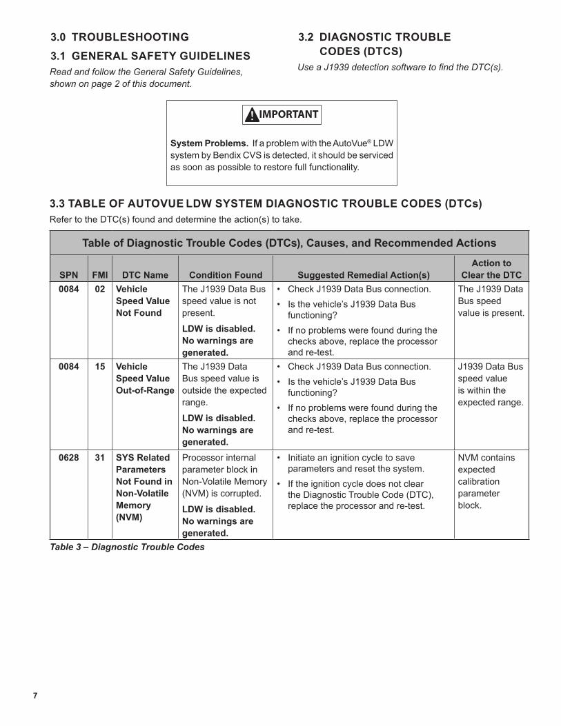
3.0 TROUBLESHOOTING3.1 GENERAL SAFETY GUIDELINESRead and follow the General Safety Guidelines, shown on page 2 of this document.
3.2 DIAGNOSTIC TROUBLE CODES (DTCS)
Use a J1939 detection software to find the DTC(s).
3.3 TABLE OF AUTOVUE LDW SYSTEM DIAGNOSTIC TROUBLE CODES (DTCs)Refer to the DTC(s) found and determine the action(s) to take.
Table of Diagnostic Trouble Codes (DTCs), Causes, and Recommended Actions
SPN FMI DTC Name Condition Found Suggested Remedial Action(s)Action to
Clear the DTC0084 02 Vehicle
Speed Value Not Found
The J1939 Data Bus speed value is not present.
LDW is disabled. No warnings are generated.
• Check J1939 Data Bus connection.• Is the vehicle’s J1939 Data Bus
functioning?• If no problems were found during the
checks above, replace the processor and re-test.
The J1939 Data Bus speed value is present.
0084 15 Vehicle Speed Value Out-of-Range
The J1939 Data Bus speed value is outside the expected range.
LDW is disabled. No warnings are generated.
• Check J1939 Data Bus connection.• Is the vehicle’s J1939 Data Bus
functioning?• If no problems were found during the
checks above, replace the processor and re-test.
J1939 Data Bus speed value is within the expected range.
0628 31 SYS Related Parameters Not Found in Non-Volatile Memory (NVM)
Processor internal parameter block in Non-Volatile Memory (NVM) is corrupted.
LDW is disabled. No warnings are generated.
• Initiate an ignition cycle to save parameters and reset the system.
• If the ignition cycle does not clear the Diagnostic Trouble Code (DTC), replace the processor and re-test.
NVM contains expected calibration parameter block.
IMPORTANT
System Problems. If a problem with the AutoVue® LDW system by Bendix CVS is detected, it should be serviced as soon as possible to restore full functionality.
Table 3 – Diagnostic Trouble Codes

8
Table of Diagnostic Trouble Codes (DTCs), Causes, and Recommended Actions
SPN FMI DTC Name Condition Found Suggested Remedial Action(s)Action to
Clear the DTC0639 02 J1939 Data
Bus Receive Failure
Processor is not receiving messages on the J1939 Data Bus.
LDW is disabled. No warnings are generated.
• Check for damaged or reversed J1939 wiring.
• Check for corroded or damaged connectors and loose connections.
• Using procedures described by the vehicle manufacturer, verify the presence of the J1939 link.
• Check for other devices inhibiting J1939 communications.
• If no problems were found during the checks above, replace the processor and re-test.
Ability to successfully receive on the J1939 Data Bus.
0886 09 Radar COMM Failure(Only Reported on SafetyDirect® by Bendix
CVS Portal, Not Logged in the Bendix® ACom® PRO™ Diagnostic Software)
Radar message is not received while the vehicle is moving at speeds greater than 30 mph.
Following distances, Forward Collision Warnings (FCW), and Collision Mitigation Braking (CMB) events are not detected.
• Check J1939 Data Bus connection to the Radar.
J1939 Data Bus ACC1 message successfully received.
1702 02 Switch Failure
Private communications input message signals switch failure or discrete momentary switch input is stuck in the ‘pressed’ state for more than 60 seconds.
LDW is disabled. No warnings are generated.
• Check the wiring between the enable/disable switch and the processor.
• Test by temporarily installing a known good switch.
• If no problems were found with the wiring, and the test with a good switch did not clear the Diagnostic Trouble Code (DTC), replace the processor and re-test.
J1939 LDW switch message field no longer reports error state.
Discrete momentary switch is unstuck.
1703 03 Right Speaker is Shorted to Power
Resistance from right speaker positive or negative output pins to power input is less than 10 Ω during sound generation.
LDW is disabled. No warnings are generated.
• Check the wiring between the right speaker and the processor.
• Test by temporarily installing a known good speaker in the right speaker location.
• If no problems were found with the wiring, and the test with a good speaker did not solve the problem, replace the processor and re-test.
System reset is required.
Resistance from right speaker positive or negative output pins to power input is greater than 10 Ω during sound generation.

9
Table of Diagnostic Trouble Codes (DTCs), Causes, and Recommended Actions
SPN FMI DTC Name Condition Found Suggested Remedial Action(s)Action to
Clear the DTC1703 05 Right
Speaker has an Open Circuit
Resistance between right speaker output pins is greater than 40 Ω during sound generation.
LDW is disabled. No warnings are generated.
• Check the wiring between the right speaker and the processor.
• Test by temporarily installing a known good speaker in the right speaker location.
• If no problems were found with the wiring, and the test with a good speaker did not clear the Diagnostic Trouble Code (DTC), replace the processor and re-test.
Resistance between right speaker output pins is less than 40 Ω for 15 seconds.
1703 06 Right Speaker is Shorted to Ground
Resistance between right speaker positive or negative output pins and ground is less than 10 Ω during sound generation.ORShort circuit condition between right speaker positive and negative output pins has a resistance of less than 1 Ω during sound generation.
LDW is disabled. No warnings are generated.
• Check the wiring between the right speaker and the processor.
• Test by temporarily installing a known good speaker in the right speaker location.
• If no problems were found with the wiring, and the test with a good speaker did not clear the DTC, replace the processor and re-test.
System reset is required.
Resistance between right speaker positive or negative output pins and ground is greater than 10 Ω during sound generation.ORSystem reset is required.
Resistance between right speaker positive and negative output pins is greater than 4 Ω during sound generation.
1704 03 Left Speaker is Shorted to Power
Resistance from left speaker positive or negative output pins to power input is less than 10 Ω during sound generation.
LDW is disabled.No warnings are generated.
• Check the wiring between the left speaker and the processor.
• Test by temporarily installing a known good speaker in the left speaker location.
• If no problems were found with the wiring, and the test with a good speaker did not clear the Diagnostic Trouble Code (DTC), replace the processor and re-test.
System reset is required.
Resistance from left speaker positive or negative output pins to power input is greater than 10 Ω during sound generation.

10
Table of Diagnostic Trouble Codes (DTCs), Causes, and Recommended Actions
SPN FMI DTC Name Condition Found Suggested Remedial Action(s)Action to
Clear the DTC1704 05 Left Speaker
Has an Open Circuit
Resistance between left speaker output pins is greater than 40 Ω during sound generation.
LDW is disabled.No warnings are generated.
• Check the wiring between the left speaker and the processor.
• Test by temporarily installing a known good speaker in the left speaker location.
• If no problems were found with the wiring, and the test with a good speaker did not clear the DTC, replace the processor and re-test.
Resistance between left speaker output pins is less than 40 Ω for 15 seconds.
1704 06 Left Speaker is Shorted to Ground
Resistance between left speaker positive or negative output pins and ground is less than 10 Ω during sound generation.ORShort circuit condition between left speaker positive and negative output pins has a resistance of less than 1 Ω during sound generation.
LDW is disabled. No warnings are generated.
• Check the wiring between the left speaker and the processor.
• Test by temporarily installing a known good speaker in the left speaker location.
• If no problems were found with the wiring, and the test with a good speaker did not clear the DTC, replace the processor and re-test.
System reset is required.Resistance from left speaker positive or negative output pins and ground is greater than 10 Ω during sound generation.
ORSystem reset is required.Resistance between left speaker positive and negative output pins is greater than 4 Ω during sound generation.

11
Table of Diagnostic Trouble Codes (DTCs), Causes, and Recommended Actions
SPN FMI DTC Name Condition Found Suggested Remedial Action(s)Action to
Clear the DTC1705 02 Turn Signal
Input Remains High
Turn signal input is stuck at high level for more than three (3) seconds.
• Check the wiring between the processor and the turn signal.
• Verify that the common wire of the turn signal/brake lamp circuit was not used.
• Replace any non-functioning turn signal bulb(s).
• Test by temporarily installing a known good turn signal flasher.
• Connect a test lamp or multi-meter to the turn signal wires one at a time (orange for left, white for right) and notice the state of the test lamp or the voltage readout on the multi-meter. With the ignition on, test and observe the following.
• Readings should be off or 0 V when the turn signal is off.
• Readings should pulse to 12 V when the turn signal is on.
• If the signal pulses with both turn signals, turn the signal off before continuing.
• Readings should be 0 V when the service brake pedal is applied.
• Readings should be 0 V when the parking brake is disengaged.
• Readings should be 0 V when the headlights are ON.
• If the turn signal circuit does not pass any of the above tests, you must relocate the turn signal connection.
• If no problems were found with the wiring/bulbs, and the test with a good signal flasher did not clear the Diagnostic Trouble Code (DTC), replace the processor and re-test.
Turn signal input is low for three (3) seconds.
1705 03 Input Voltage is Too High
Input voltage is above 16 V.
• Measure the ignition voltage. Ensure that the ignition voltage is not greater than 16 VDC. Check the vehicle battery and associated components.
• Inspect for damaged wiring, damaged or corroded connectors and loose connections. Check the wiring between the ignition and the processor.
• If no problems were found during the checks above, replace the processor and re-test.
Input voltage is below 16 V.
12
Table of Diagnostic Trouble Codes (DTCs), Causes, and Recommended Actions
SPN FMI DTC Name Condition Found Suggested Remedial Action(s)Action to
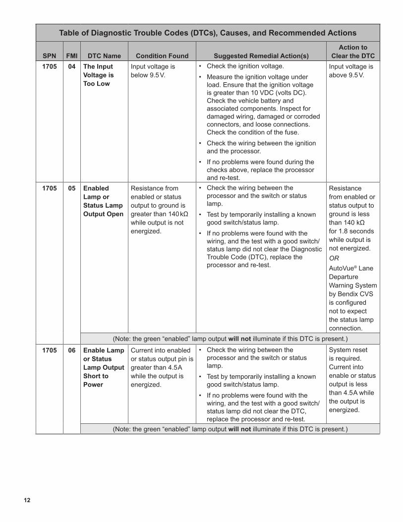
Clear the DTC1705 04 The Input
Voltage is Too Low
Input voltage is below 9.5 V.
• Check the ignition voltage.• Measure the ignition voltage under
load. Ensure that the ignition voltage is greater than 10 VDC (volts DC). Check the vehicle battery and associated components. Inspect for damaged wiring, damaged or corroded connectors, and loose connections. Check the condition of the fuse.
• Check the wiring between the ignition and the processor.
• If no problems were found during the checks above, replace the processor and re-test.
Input voltage is above 9.5 V.
1705 05 Enabled Lamp or Status Lamp Output Open
Resistance from enabled or status output to ground is greater than 140 kΩ while output is not energized.
• Check the wiring between the processor and the switch or status lamp.
• Test by temporarily installing a known good switch/status lamp.
• If no problems were found with the wiring, and the test with a good switch/status lamp did not clear the Diagnostic Trouble Code (DTC), replace the processor and re-test.
Resistance from enabled or status output to ground is less than 140 kΩ for 1.8 seconds while output is not energized.ORAutoVue® Lane Departure Warning System by Bendix CVS is configured not to expect the status lamp connection.
(Note: the green “enabled” lamp output will not illuminate if this DTC is present.)
1705 06 Enable Lamp or Status Lamp Output Short to Power
Current into enabled or status output pin is greater than 4.5 A while the output is energized.
• Check the wiring between the processor and the switch or status lamp.
• Test by temporarily installing a known good switch/status lamp.
• If no problems were found with the wiring, and the test with a good switch/status lamp did not clear the DTC, replace the processor and re-test.
System reset is required. Current into enable or status output is less than 4.5 A while the output is energized.
(Note: the green “enabled” lamp output will not illuminate if this DTC is present.)

13
Table of Diagnostic Trouble Codes (DTCs), Causes, and Recommended Actions
SPN FMI DTC Name Condition Found Suggested Remedial Action(s)Action to
Clear the DTC1705 14 Battery line
pin A11 (red/yellow)Wire Not Connected (Only Reported on SafetyDirect®
by Bendix CVS Portal, Not Logged in the Bendix® ACom® PRO™ Diagnostic Software)
The processor detected no constant battery power input.
The SafetyDirect ignition off process cannot be executed.
• Check the wiring between the processor Pin A11 and the battery positive (+) terminal.
Constant battery power is detected by the processor for 5 seconds.
1705 31 Internal Failure
Internal programing failure.
• Initiate an ignition cycle to save parameters and reset the system.
• If the ignition cycle does not clear the Diagnostic Trouble Code (DTC), replace the processor and re-test.
System reset is required.
CAN configuration parameters consistent with internal programing.
520194 06 Enable Lamp, Status Lamp, or Mute Output Shorted to Ground
Voltage at the low side driver output to ground is less than 2.5 VDC while the output is not energized.
• Check the mute wiring connections, the processor,1 and the radio mute.
• Verify the radio is correctly configured to support mute line discrete input.
Voltage at the low side driver output to ground is greater than 3.7 VDC for more than 1.8 seconds while the output is not energized.
OR
AutoVue® Lane Departure Warning System by Bendix CVS is configured not to expect the mute output connection.
520195 15 Semaphore Error Log Failure
New Error Log Semaphore entries are not recorded in Non-Volatile Memory (NVM).Lane Departure Warning (LDW) is disabled.No warnings are generated.
• Delete Error logs.• Initiate an ignition cycle to reset the
system.• Replace processor and re-test.
System reset is required.
Successfully access Error Log in NVM.

14
Table of Diagnostic Trouble Codes (DTCs), Causes, and Recommended Actions
SPN FMI DTC Name Condition Found Suggested Remedial Action(s)Action to
Clear the DTC520196 09 Turn
Indicator Signal Not Found
J1939 Data Bus turn indicator value not present.LDW is not suppressed from turn indicator state.
• Check J1939 Data Bus connection.• Is the vehicle’s J1939 Data Bus
functioning?• If no problems were found during the
checks above, replace processor and re-test.
J1939 Data Bus turn indicator value is received by processor.
OR
AutoVue® Lane Departure Warning System by Bendix CVS is configured to expect turn indicator state from discrete inputs.
520197 09 LDW Enable Switch Signal Not Found
J1939 Data Bus LDW enable switch value not present.LDW is disabled.No warnings are generated.
• Check J1939 Data Bus connection.• Is the vehicle’s J1939 Data Bus
functioning?• Test by temporarily installing a known
good LDW enable switch.• If no problems were found during the
checks above, replace processor and re-test.
J1939 Data Bus LDW enable switch value is received by processor.
OR
AutoVue is configured to expect LDW switch state from discrete input.
520198 15 SafetyDirect®
web portal by Bendix CVS Statistics Log Failure
SafetyDirect Statistics Log entries are not recorded in NVM.Warnings continue to generate.
• Delete SafetyDirect (SD) Event logs.• Update Software.• Initiate an ignition cycle to reset the
system.
System reset is required.
Successfully write to Statistics Log.
520199 02 I2C Bus Failure
Internal failure of I2C Bus.The processor does not receive accelerometer data from camera.
• Check the RS-232 cable between the telematics device and the processor.
• Check camera cable for noise on the ground wire.
Connect the cable. System reset is required.
I2C Bus failure clears.
For all other DTCs, or problems after re-testing a replacement ECU, contact the Bendix Tech Team.For direct telephone technical support, the Bendix Tech Team is available at 1-800-AIR-BRAKE
(1-800-247-2725) option 2, Monday through Thursday from 8:00 a.m. - 6:00 p.m. and Friday from 8:00 a.m. - 5:00 p.m. ET. Follow the instructions in the recorded message.
The Bendix Tech Team can also be reached by email at: [email protected].
15
12345678
12 11 10 9 8 7 6 5 4 3
12 11 10 9 8 7 6 5 4 3 2 1
2 1
A
B
+-
+-
++-
+-
++
10212
11914
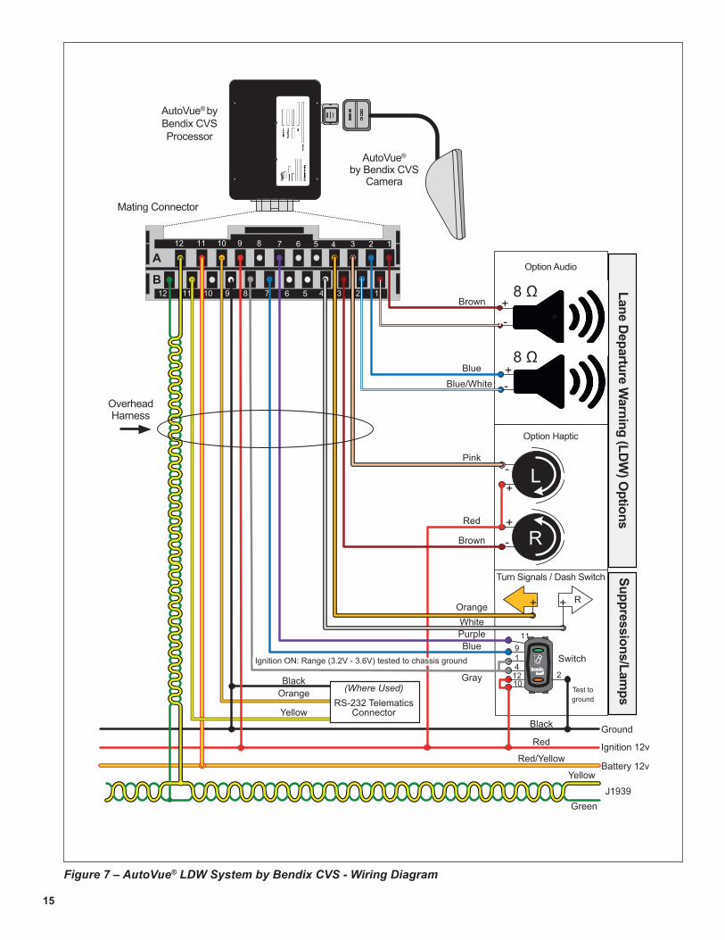
Figure 7 – AutoVue® LDW System by Bendix CVS - Wiring Diagram
WhiteOrange
L
R
Turn Signals / Dash Switch
Option Haptic
Option Audio
AutoVue® by Bendix CVS
Camera
AutoVue® by Bendix CVSProcessor
Mating Connector
OverheadHarness
Lane Departure Warning (LDW
) Options
Suppressions/LampsOrange
Brown
Red
Pink
Blue/WhiteBlue
Brown
PurpleBlue
Switch
Gray
Ignition ON: Range (3.2V - 3.6V) tested to chassis ground
Test to ground
Black
Black
RedGround
Red/YellowIgnition 12v
Yellow
Yellow
Battery 12v
GreenJ1939
R
8 Ω
8 Ω
(Where Used)RS-232 Telematics
Connector

16
3.4 ADVANCED TROUBLESHOOTINGRefer to the AutoVue® Lane Departure Warning (LDW) system by Bendix CVS wiring diagram on page 15, during these procedures.
General. Inspect the camera and its lens for any damage, and the wiring for any pinching or cuts. If a camera bracket appears to have been reinstalled, check if the bracket is level by removing the camera (slide upwards), and use a torpedo level on the bracket tabs (See Figure 6, on page 6). Note that the other vehicle cab accessories must be carefully installed since mounting screws, etc. that penetrate locations where the AutoVue system components or wiring are routed can cause shorts or wiring breaks.
If you do not have the capability to read the J1939 error codes it is recommended to – in turn – swap out components with known good system components in the following order: 1) switch; 2) processor; and 3) camera.
In practice, this would result in:
• Temporarily replacing the switch with a known good switch, then re-test. If this does not correct the problem put the original switch back in.
• Temporarily replace the processor box with a known working unit. If this does not correct the problem put the original box back in.
• Temporarily replace the camera with a known working unit. If this does not correct the problem put the original camera back in.
If after temporarily replacing all the major components the green lamp still fails to illuminate, hardware issues have been eliminated and the technician can focus elsewhere (wiring, mis-installation, etc.) for the source of the problem.
Confirm the processor part number: Potentially a processor may have been programmed for one vehicle model but was mis-installed or moved to a different vehicle model. Call Bendix to verify that you have the correct processor part number on the vehicle.
In cases where – after start-up – an Enable/Disable switch is pressed but the “enable” (green) and “status” (amber) lamps remain on:1. Conditions: Vehicle parked, with the ignition on. Using
a voltmeter, connect the positive (+) lead to gray wire and the negative lead (-) to a good chassis ground; do not use the black wire on switch for ground.
• The voltage reading should be between 3.2 V to 3.6 V.
2. Using a voltmeter, connect the positive (+) lead to the switch pin black wire and the negative lead (-) to a good chassis ground.
• The voltage reading should be between -0.10 V to 0.1 V.
3. If the above voltages are not correct, turn off the ignition and remove the switch from the switch socket.
4. Using an ohmmeter, connect the positive (+) lead to the gray wire, and the negative lead (-) to a good chassis ground; do not use the black wire.
• The resistance reading should be between 30 kΩ and 70 kΩ.
5. If the resistance reading is less than 30 kΩ, disconnect the main connector from the processor and recheck the resistance of the gray wire. If the resistance is still less than 30 kΩ, then a short may exist in the wiring harness (for example, a screw may have been driven into the wire).
6. If the resistance reading is greater than 70 kΩ, an open circuit may exist in the wiring harness.
7. Using an ohmmeter, connect the positive (+) lead to the black wire and the negative lead (-) to a good chassis ground.
• The resistance reading should be less than 1 Ω.
• If the resistance reading is greater than 1 Ω, an open circuit may exist in the wiring harness.
8. If the above voltages are correct, turn off the ignition and remove the switch from the switch socket.
9. Using an ohmmeter, connect the positive (+) lead to blue wire and the negative lead (-) to a good chassis ground; do not use the black wire.
• The resistance reading should be greater than 10 kΩ,
10. Using an ohmmeter, connect the positive (+) lead to violet wire and the negative lead (-) to a good chassis ground; do not use the black wire.
• The resistance reading should be greater than 10 kΩ.

17
In cases where – after start-up – an Enable/Disable switch is pressed but the “enable” (green) lamp remains on and the “status” (amber) lamp does not remain on:With the vehicle parked, the ignition on, and all AutoVue® Lane Departure Warning (LDW) by Bendix CVS system components (camera, processor, and switch) connected.
1. Turn off the ignition and remove the switch from the switch socket.
2. Using an ohmmeter, connect the positive (+) lead to blue wire and the negative lead (-) to a good chassis ground; do not use the black wire.
• The resistance reading should be greater than 10 kΩ.
3. If the resistance is less than 10 kΩ, disconnect the main connector from the processor and recheck the resistance on the blue wire. If the resistance is still less than 10 kΩ, then a short may exist in the wiring harness (a screw may have been driven into the wire). If the resistance is greater than 10 kΩ, temporarily replace the processor with a known good unit and re-test.
4. Reconnect the main connector to the processor and recheck the resistance on the blue wire. If the resistance is greater than 10 kΩ, temporarily replace the processor with a known good unit and re-test.
3.5 CLEARING DIAGNOSTIC TROUBLE CODES (DTCs)Once the problem has been found and resolved, clear the AutoVue® LDW system by Bendix CVS DTCs by cycling the ignition power.

18
APPENDIX A - SAFETYDIRECT® BY BENDIX CVS
Appendix A
Appendix ASafetyDirect® by Bendix CVS
SAFETYDIRECT FUNCTIONWhen the SafetyDirect system function is enabled, the AutoVue® Lane Departure Warning (LDW) system by Bendix
CVS processor has the ability to collect relevant driver and vehicle performance data via the LDW system and the J1939 CAN Bus. When a trigger event occurs, vehicle data and, in some cases, video, is saved in the system for later download via the vehicle telematics system.
In-Vehicle Hardware
AutoVue® by Bendix CVS Camera
AutoVue® by Bendix CVSProcessor
J1939Data Link
Telematics Provider On Board Computer (OBC) Telematics
Antenna
Over the Air Provider
Optional Data Path
TelematicsServers
SafetyDirect® by Bendix CVSServers
SafetyDirect® by Bendix CVS Web Portal
Network
Figure 8 – AutoVue® LDW System Communication with SafetyDirect® by Bendix CVS System

19
Trademark acknowledgements:Any references in this manual to FREIGHTLINER, INTERNATIONAL, KENWORTH, MACK, PETERBILT, STERLING, VOLVO, WESTERN STAR, and any other company or trademark are solely for identification and cross reference purposes. The trademarks are the property of their respective companies and are not affiliated with or endorsing Bendix Commercial Vehicle Systems LLC. Bendix Commercial Vehicle Systems LLC does not represent any parts shown as products manufactured or remanufactured by the companies so named herein.
ADDITIONAL SUPPORT ATBENDIX.COM/1-800-AIR-BRAKE (1-800-247-2725), OPTION 2For the latest information, and for downloads of the Bendix® ACom® PRO™ Diagnostic Software, and its User Guide, visit the Bendix website at www.bendix.com.
For direct telephone technical support, the Bendix Tech Team is available at 1-800-AIR-BRAKE (1-800-247-2725) option 2, Monday through Thursday, 8:00 A.M. to 6:00 P.M. and Friday, 8:00 A.M. to 5:00 P.M. ET. Follow the instructions in the recorded message.
The Bendix Tech Team can also be reached by email at: [email protected].

20SD-64-4976 © 2022 Bendix Commercial Vehicle Systems LLC, a member of Knorr-Bremse • 2/22 • All Rights Reserved
Printed on recycled paper
������������24/7/365 ACCESS
FULL SERVICE AT YOUR FINGERTIPS
������������������BLOGS, PODCASTS, AND MORE
INDUSTRY INSIGHTS FROM INDUSTRY EXPERTS
������ ���������WEB-BASED TRAINING
LOG ON AND LEARN FROM THE BEST