Automated integrated support for requirements-area and validation processes related to system...
7
Alarcon, P.P.; Garbajosa, J.; Crespo, A.; Magro, B., "Automated integrated support for requirements‐area and validation processes related to system development," Industrial Informatics, 2004. INDIN '04. 2004 2nd IEEE International Conference on , vol., no., pp.287,292, 26‐26 June 2004 doi: 10.1109/INDIN.2004.1417346 Abstract: This paper describes a research work to enhance the automation of system development with the particularity of obtaining an increased degree of integration for requirements analysis and validation processes. The automated support described within this paper requirements and validation tests become a pivot of the development process. In combination with simulation, the current approach provides a good support for incremental component‐based development processes, useful for large systems keywords: {program testing;program verification;software engineering;automated integrated support;requirements analysis;system development;validation process;Automation;Electronic mail;Embedded software;Paints;Product design;Product development;Solids;Standards development;System testing;Usability}, URL: http://ieeexplore.ieee.org/stamp/stamp.jsp?tp=&arnumber=1417346&i snumber=30671
Transcript of Automated integrated support for requirements-area and validation processes related to system...

Alarcon, P.P.; Garbajosa, J.; Crespo, A.; Magro, B., "Automated integrated
support for requirements‐area and validation processes related to system
development," Industrial Informatics, 2004. INDIN '04. 2004 2nd IEEE
International Conference on , vol., no., pp.287,292, 26‐26 June 2004
doi: 10.1109/INDIN.2004.1417346
Abstract: This paper describes a research work to enhance the automation of
system development with the particularity of obtaining an increased degree
of integration for requirements analysis and validation processes. The
automated support described within this paper requirements and validation
tests become a pivot of the development process. In combination with
simulation, the current approach provides a good support for incremental
component‐based development processes, useful for large systems
keywords: {program testing;program verification;software
engineering;automated integrated support;requirements analysis;system
development;validation process;Automation;Electronic mail;Embedded
software;Paints;Product design;Product development;Solids;Standards
development;System testing;Usability},
URL: http://ieeexplore.ieee.org/stamp/stamp.jsp?tp=&arnumber=1417346&i
snumber=30671

Abstract—This paper describes a research work to enhance
the automation of system development with the particularity of obtaining an increased degree of integration for require-ments analysis and validation processes. Thanks to the auto-mated support described within this paper requirements and validation tests become a pivot of the development process. In combination with simulation, the current approach provides a good support for incremental component-based development processes, useful for large systems
Index Terms—System Testing, software/system engineering environment, tool integration, component-based development, process model standards
I. INTRODUCTION
One of the keys issues in the development of complex-products, with embedded software components, is process automation support. Product conception, design and devel-opment, production and also, why not, utilization, and sup-port require a wide range of processes. To achieve a proper support is a task that depends on multiple issues such as the extent that system/software environments and tools support specific processes and methods, product –i.e. tool outputs- expected features, or tool and environment usability. A sin-gle tool is not, obviously, able to provide all the needed functionalities even if our focus area is restricted to, for in-stance, design and development. Therefore environments that would integrate the required tools become necessary.
Two processes have an outstanding importance in the system lifecycle for different reasons: Requirements analy-sis, and validation. From the requirements analysis the whole system is developed and validation shows that devel-oped system is, exactly, what was initially expected. How-ever a look at standards such as ISO/IEC 12207:1995 amended at 2002 [1] and ISO/IEC 15288:2002 [2]1 intro-duce a number of process issues of great importance from the product development point of view. One of these fea-tures is traceability. Traceability can be advantageously used to support an integrated view of development in which system requirements and validation activities are integrated and become a keystone in engineering activities. One of the advantages of this kind of integration is that it provides a product and a process perspective. The issue is then, how process automation can provide support for this integrated approach.
This paper presents an approach in which requirements engineering and validation processes are integrated in close relationship with the engineering products, output from each process. Once this integration is achieved a more solid development process is obtained. The possibility to develop systems using validation testing as a joint process to re-quirements engineering is enabled.
The first section of this paper, this one, is Introduction. Then a integrated view of requirements analysis and valida-tion testing processes is presented. Third section describes the automation environment. Fourth section presents how the integration is performed and last section introduces a number of conclusions.
II. INTEGRATED PROCESS VIEW
One of the driver ideas for this research work is a vision of system development that support a unifying view for processes that focus on the product from different perspec-tives but a similar level of abstraction with respect to the product. This is the case of requirement analysis and valida-tion. As asserted in [2] the purpose of the Requirements Analysis Process is to transform the stakeholder, require-ment-driven view of desired services into a technical view of a required product that could deliver those services. The purpose of the Validation Process is to provide objective evidence that the services provided by a system when in use comply with stakeholders’ requirements. Validation per-forms a comparative assessment and confirms that the stakeholders’ requirements are correctly defined. Fig. 1 shows synoptically the process model approach.
The proposed model is based on tightly integrated requirements analysis and validation, as the focal center of the system development. Integration is obtained through traceability between stakeholder requirements, and valida-tion tests.
A system can be seen as a set of interrelated components. Traceability between stakeholder requirements, system re-quirements and the rest of the architectural components and units must be achieved. This is the basis for an incremental development model. Components are developed and inte-grated either with other developed components or with simulated components. Validation tests can be run as long as components not yet developed are simulated. This helps the development team keep a closer eye on stakeholders re-
1 These two standards are undergoing a harmonization process con-vened by ISO/IEC JTC1 SC7.
Pedro P. Alarcón1, Juan Garbajosa2, Alberto Crespo3, Belén Magro4
1,2,3Pedro P. Alarcón, Juan Garbajosa, Alberto Crespo, Technical University of Madrid (UPM), Madrid, Spain, e-mail:(pcavero, jgs, [email protected])
4Belén Magro, Invensys, Madrid, Spain, e-mail: [email protected]
Automated Integrated Support for Requirements-Area and Validation Processes Related to System Development

quirements.
III. AUTOMATION ENVIRONMENT
The automation described within this paper is focused on two issues:
1. A uniform support to all processes accom-plished through a System/Software Engineering Environment (SEE). This environment is docu-ment centric but, and more important, document driven. As long as documents are defined ac-cording to a standard process model, it can be also considered as process driven.
2. An automated support, test-engineer oriented, user-friendly, for validation test definition and execution. The validation testing environment named TOPEN (Test and Operation ENviron-ment). The specification, execution and man-agement of validation (acceptance or confor-mance) tests are complex and tedious activities.
Even when it is not one of the functional objectives, the automation approach should be low cost; this issue has also be one of the concerns of this research work.
A. System/Software Engineering Environment
The SEE is a system/software engineering environment devised to support the development of systems and conform to a given process model. At present it supports the E-40 Part 1B standard [3], but it could potentially support other standards to define process models. E-40 Part 1B has been produced taking [1] as its baseline. When the design of this SEE was started the main concern for it was on-board, de-
pendable software components; at present, however, it is being deployed to support system development.
SEE is document-centric. As long as a well-defined process model is used, all the project data is available as documents. The document-centric approach is useful for managing project information and specially for projects with big amounts of documents and references among them. If we consider together these two issues, we reach the con-clusion that managing documents is equivalent to managing all the project data. As documents are defined according to the process model, i.e. ECSS standard process model, the document centric approach, as understood within the SEE, supports part of process integration, as well as, obviously, data integration. At present SEE supports Development (re-quirements engineering, design engineering), Verification and Validation processes.
Documents are defined in CASEML, a language derived from XML with the purpose of supporting process model documents features in general, and, specifically ECSS proc-ess model documents. An example of a CASEML docu-ment is presented in Fig.2, describing a project tree. Fig. 3 is a synoptic display compliant with Fig. 2 for a Require-ments Document; nodes include the document structure to-gether with nodes to support traceability to other document nodes. Therefore traceability is introduced in a very natural way. Configurations is also supported for et of documents. Fig. 4 presents a SEE window; this window shows the pro-ject tree, conform to [1], the content of the design document and one of its sections, Introduction. Some of the features of the SEE have been described in [4]. Documents derived from a Metaschema defined according to XML-Schema.
SEE has been implemented in Tcl/Tk and C languages in order to maximize portability issues.
B. Test and Operation Environment (TOPEN)
Validation (acceptance, conformance, system…) testing of complex systems is an essential process. It is only possi-ble to generate the tests fully automatically, deriving them from the system specification, for a reduced set of cases. Therefore tests have to be defined by an expert test engi-neer. Because of system complexity the test process has to be exhaustive, and it is not usually possible to assure that it will be complete. The process requires the execution of a large number commands in a repetitive fashion. For those systems with inter-operating components it is not sufficient to test each component solely. The dynamic behavior of the
Fig.1 Proposed process model
<CASEML ID="1" V="*" STRUCTURE=""><HEADER ID="2" V="*" CLASS="" TYPE="" NAME="SS STRUCTURE" ...../><COMMENT ID="3" V=""/><CONTENT ID="4" V="">
<TAGS ID="5" V=""><TAG ID="*" V="*" TAGNAME="CASEML" CLASS="ROOT" TYPE="CASEML">
<DEFAULTVALUES ID="*" V="*"><ATTR_VALUE ID="" V="" NAME="SEETREENAME" DEFAULT="SS"/>
</DEFAULTVALUES><CHILDREN ID="*" V="*">
<CHILD ID="*" V="*" NAME="HEADER" MIN="1" MAX="1"/><CHILD ID="*" V="*" NAME="COMMENT" MIN="1" MAX="1"/><CHILD ID="*" V="*" NAME="CONTENT" MIN="1" MAX="1"/><CHILD ID="*" V="*" NAME="TRACES" MIN="1" MAX="1"/><CHILD ID="*" V="*" NAME="CM" MIN="1" MAX="1"/>
</CHILDREN></TAG>............
</TAGS></CONTENT><subarbol ATTRIBUTES><subarbol OPERATIONS>
</CASEML>
Fig.2 Example of CASEML SEE Project tree Fig.3 Schematic view of a CASEML Requirements Document

whole system must be tested. Application domain concepts are one of the relevant issues for the validation testing.
The use of programming languages, C, Tcl/Tk, or Atlas, requires working at a low abstraction level, away from what the real problem is. The test preparation and execution in-cludes
• To design -define- the test procedures that will validate the system.
• To translate these test procedures into a programming language.
• To execute these tests procedures with little or no help of the test environment.
Derived problems to cope with are the following: • To maintain the tests procedures • Guarantee a full test coverage
Test activities involve the execution of actions and, the visualization and analysis of measurements. Measurements verify that the actions performed -by means of the test engi-neer commands- get the desired effect. In object oriented terms, actions may be associated to object operations and measurements to values returned. The system to be tested shall be named as Unit Under Test (UUT).
This process, desirably, should be assisted and motivated the definition and design of the Test and Operation ENvi-ronment (TOPEN), described in [5]. TOPEN is an envi-ronment that has been envisaged to simplify the process of defining and executing tests of complex systems. The de-sign considered deployment to any industrial systems with a reduced effort by means of an architecture independent from the application domain. TOPEN supports tele-testing with a client-server architecture. Fig. 5 describes TOPEN
generals for a specific application domain, a decoder. TOPEN Man Machine Interface, Fig. 6, offers two dif-
ferent interfaces: a graphical iconic object oriented inter-face, and a command line interface for advanced users. Test engineer can define tests using the graphical MMI and these tests are compiled and presented in the command line form. MMI is informed of the changes occurred at UUT by means of messages, such as replies to test procedure commands, and alarms and notifications. TOPEN architecture is de-scribed in Fig. 7. The System Environment Control subsys-tem allows the test engineer to update the state of the sys-tem according to presumed incidents (to simulate system failure or anomalous behavior). The Mission Information Base, MIB, is a data and knowledge repository that stores information on the UUT element’s model, a historic record of executed commands and replies, and received notifica-
Fig.4 Example of the SEE window display
Fig.5 Schematic view of the TOPEN environment for a decoder

tions and alarms. Monitoring is performed working with this MIB data. A good candidate as a monitoring compo-nent is the XnetMod System [8]This record can be analysed to provide prospects on future behavior and prevention of undesirable situations. The Code Generator, CG, supports code translation/generation features, which generates the
code that will be sent to the UUT. Finally, a low-level inter-face, a Gateway between the industrial system (UUT) and TOPEN would be needed.
TOPEN has been implemented in Java. All main compo-nents, displayed on Fig.7, can be distributed components. This provides a great flexibility to TOPEN.
C. CASEL documents and integration
A number of CASEML documents are relevant for the described integration. These documents are Requirements Document (See Fig. 3), the Software Validation Test Speci-fication (SVTS) and the Software Validation Test Report. In order to get a better understanding of the CASEML
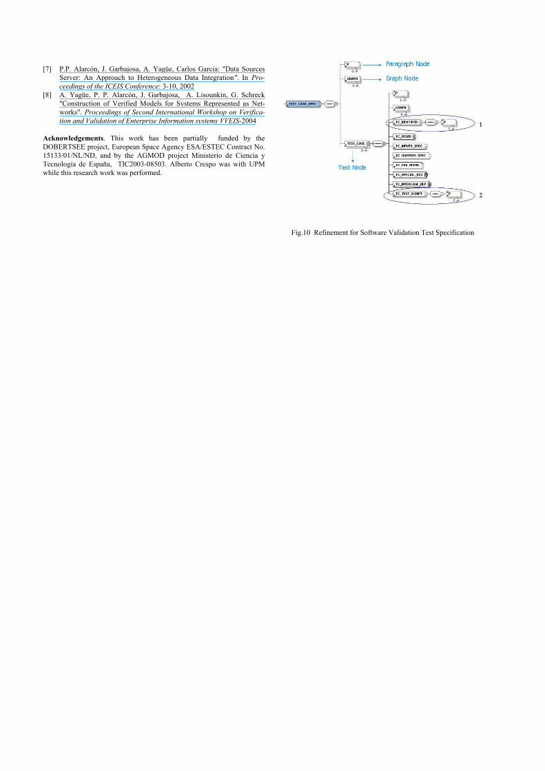
document structure attention will be focused on the Soft-ware Validation Test Specification. Its CASEML schema, see Fig. 9 includes the required information to reflect the process as described by [3]. Actually it follows the same structure as any other CASEML schema. Nodes in Fig. 9 match sections. Additionally nodes for traces and Configu-ration management are included. From the integration point of view the Test_Case_Spec node (subtree) is of relevance, and is marked with an arrow in Fig. 9, and is further devel-oped in Fig. 10. The Test_Case_Spec node represents test cases specified conforming to [3]. Figure 10 displays three types of nodes: paragraph, graph and test. In this case test is the node more relevant.
Traceability plays an important role in integration in the direction of processes. Thanks to the traceability support at the level of document node it is possible to have permanent relationship, between requirements and validation tests. The processes to build requirements and tests are no longer in-dependent, and these documents are produced conforming the process model defined in [3].
Attributes and operations specific for the integration of test tools will be associated to the test node. This is a SEE native mechanism.
IV. TOOL INTEGRATION STRATEGIES
An issue of special relevance is how tools can be inte-grated in a capable way [6]. Data integration, i.e. tools can share or exchange information, is mandatory but not suffi-cient to have a number of collaborating tools collaborating. Very often tool integration is only achieved off-line. Full control integration, i.e. tools can interact while in execution and be aware of the state of each other, is difficult to ac-complish. Process integration has been traditionally a goal difficult to cope with. The approach proposed within this
User Interface
Code_GeneratorUUT _gateway
MIB
System Environment Control
Monitoring
Fig.7 TOPEN architecture
Fig.6 TOPEN MMI

paper opens a new viewpoint for process integration. One important issue in integration has been the possibil-
ity of associating operations and documents nodes. This to-gether with the introduction of traces related to document nodes are the essential topics. Node TEST will have associ-ated the operation TOPEN. In Fig. 10 node TEST_CASE node, is of type TEST; this is used to associate SEE and TOPEN.
The integration of SEE and TOPEN has been performed by means of a new component, TOPEN_Interface (TI). This component facilitates the data access and execution control of TOPEN from SEE. This TOPEN_Interface is based on a component developed in-house Data Source Server [7] as works as a mediator. This component supports data access to distributed systems. Therefore TOPEN is handled as a client with respect to SEE. The Operation TOPEN invokes this TOPEN_Interface.
One aspect important for integration purposes is that tests managed by TOPEN can be identified with the test script item of the SVTS Template, compliant with [3].
Offline data integration is achieved executing TOPEN in a standalone fashion from the SEE. This is the lowest inte-gration level. SEE system invokes to “Topen Client” com-ponent. SEE must have an operation or menu option to in-voke the TOPEN client. Test_Integrator should send que-ries to TOPEN repository (MIB database) to obtain all the information of the executed test procedure.
The information received from database includes, the commands of test procedure, results of all executions and notifications from UUT to TOPEN. The communication between TOPEN_Interface and MIB database is performed via ODBC and it is not necessary any change on the TOPEN system. TOPEN_Interface builds the correct sub-tree with the data received and it sends it to the SEE in or-der to include it into the corresponding CASEML document
nodes. Relevant documents, conform to [3], will be Soft-ware Validation Test Specification Document and Software Validation Test Report.
A tighter integration is achieved having TOPEN execut-ing on-line. This approach implements real control integra-tion. Compilation and execution of test procedures can be performed as an operation associated to CASEML nodes.
Both, data results and TOPEN operations are integrated into the SEE system. TOPEN_Interface invokes directly to TOPEN MMI component for executing o retrieve a test procedure. The results of executing test procedure that TOPEN obtains are sent to the TOPEN_Interface. This re-quires to modify TOPEN MMI to accept requests from TOPEN_Integrator and to return results to it. This approach is far more complex than the shallow one.
V. CONCLUSIONS
This paper has described a research work to enhance the automation of system development with the particularity of obtaining an increased degree of integration for require-ments analysis and validation processes. This automated support includes a system/software engineering environ-ment, that provides support for engineering (e.g. design) and support processes (e.g. traceability). This environment supports the integration of third parties tools as is the case of TOPEN, an environment for assisted validation testing. The integration of both environments has an added value.
Thanks to the automated support described within this paper, requirements and validation tests become a pivot of the development process.
In combination with simulation, the current approach provides a good support for incremental component-based development processes, useful for large systems.
VI. REFERENCES
[1] ISO/IEC, ISO/IEC 12207:1995/Amd 1:2002 Information technology -- Software life cycle processes
[2] ISO/IEC, ISO/IEC 15288:2002 Systems engineering -- System life cycle processes
[3] European Consortium for Space Standardisation, ECSS, E-40 Part 1B, Software – Part 1: Principles and requirements, 2003
[4] M. Bollaín, P. P. Alarcón, J. Garbajosa, J. Amador, “A low-cost document-centric Software/System Engineering Environment” in Proceedings of the ICSSEA Conference, 2003.
[5] J. Garbajosa, M. Alandes, M.A. Mahillo, M. Piattini , " Assisting the Definition and Execution of Test Suites for Complex Systems", in Proceedings of the 7th International Conference on Engineering of Computer Based Systems, 2000, 327-333, ISBN 0-7695-0604-6
[6] A. W. Brown , D. J. Carney, Ed. J. Morris, D. B. Smith, P. F. Zarrella, Principles of CASE tool integrationTool integration, Oxford Univer-sity Press, Inc.New York, NY, USA, 1994, ISBN:0-19-509478-6
Fig.8 SEE – TOPEN integration architecture
Fig.9 CASEML Software Validation Test Specification
[7] P.P. Alarcón, J. Garbajosa, A. Yagüe, Carlos Garcia: "Data Sources Server: An Approach to Heterogeneous Data Integration". In Pro-ceedings of the ICEIS Conference: 3-10, 2002
[8] A. Yagüe, P. P. Alarcón, J. Garbajosa, A. Lisounkin, G. Schreck "Construction of Verified Models for Systems Represented as Net-works". Proceedings of Second International Workshop on Verifica-tion and Validation of Enterprise Information systems VVEIS-2004
Acknowledgements. This work has been partially funded by the DOBERTSEE project, European Space Agency ESA/ESTEC Contract No. 15133/01/NL/ND, and by the AGMOD project Ministerio de Ciencia y Tecnología de España, TIC2003-08503. Alberto Crespo was with UPM while this research work was performed.
Fig.10 Refinement for Software Validation Test Specification