Autodesk Inventor Programming in C++ by Owen Ransen
549
(C) 2021 Owen F Ransen Autodesk Inventor Programming in C++ by Owen Ransen
-
Upload
khangminh22 -
Category
Documents
-
view
1 -
download
0
Transcript of Autodesk Inventor Programming in C++ by Owen Ransen

(C) 2021 Owen F Ransen
Autodesk Inventor Programming in C++ byOwen Ransen

All rights reserved. No parts of this work may be reproduced in any form or by any means - graphic, electronic, ormechanical, including photocopying, recording, taping, or information storage and retrieval systems - without thewritten permission of the publisher.
Products that are referred to in this document may be either trademarks and/or registered trademarks of therespective owners. The publisher and the author make no claim to these trademarks.
While every precaution has been taken in the preparation of this document, the publisher and the author assume noresponsibility for errors or omissions, or for damages resulting from the use of information contained in this documentor from the use of programs and source code that may accompany it. In no event shall the publisher and the author beliable for any loss of profit or any other commercial damage caused or alleged to have been caused directly orindirectly by this document.
Printed: maggio 2022 in San Giorgio su Legnano, Italy.
Autodesk Inventor Programming in C++ byOwen Ransen(C) 2021 Owen F Ransen
Publisher
Managing Editor
Technical Editor
Cover Designer
Ransen Software
Owen Ransen
O. F. Ransen
O. Ransen
Production
Owen F. Ransen
Team Coordinator
Owen Frederick Ransen

3Contents
(C) 2021 Owen F Ransen
Table of Contents
Foreword 0
Part I Autodesk Inventor Programmingin C++ 15
Part II 0) Installing the SDK 15
Part III 1) How to use this help file (READTHIS FIRST) 17
Part IV 2) Introduction 18
Part V 3) Connecting to Inventor from aWindows MFC app. 18
Part VI 4) Pointers to Inventor and usefulInventor API objects. 20
Part VII 5) Running Inventorprogramatically 22
Part VIII 6) Creating a part document and asketch 22
Part IX 7) Some tips for Autodesk InventorC++ programmers 25
Part X Right hand coordinate system 27
Part XI iLogic and VBA 27
................................................................................................................................... 271 iLogic editing
................................................................................................................................... 282 iLogic and suppression of parts in assemblies
................................................................................................................................... 293 Run an EXE from inside an iLogc rule
................................................................................................................................... 304 iLogic suppression of features in a part
................................................................................................................................... 305 iLogic and part parameters
................................................................................................................................... 316 iLogic to delete suppressed compoents
................................................................................................................................... 317 iLogic debugging statements, Trace
................................................................................................................................... 338 iLogic to change dimensions in sketches
................................................................................................................................... 339 iLogic to add parts to an assembly
................................................................................................................................... 3410 iLogic iProperties example
Autodesk Inventor Programming in C++ by Owen Ransen4
(C) 2021 Owen F Ransen
................................................................................................................................... 3511 Local or global VBA?
................................................................................................................................... 3612 Listing documents open in Inventor with VBA
................................................................................................................................... 3713 VBA document type
................................................................................................................................... 3814 Inventor VBA and Excel
................................................................................................................................... 3815 Update custom iproperty with VBA and iLogic
................................................................................................................................... 3916 Shared global variables in iLogic
................................................................................................................................... 3917 Declaring variables in iLogic
................................................................................................................................... 4018 iLogic dialog form modification
................................................................................................................................... 4019 iLogic, adding a new form
................................................................................................................................... 4120 When do iLogic rules run?
................................................................................................................................... 4321 Inventor from inside Access
................................................................................................................................... 4422 Custom iProperties in component with VBA
Part XII Programming Inventor in C++ 44
................................................................................................................................... 451 Get the name of a part
................................................................................................................................... 462 Zoom
................................................................................................................................... 463 GetWorkPlaneName GetOccurrenceName
................................................................................................................................... 474 Investigating Asset Libraries Progamatically
................................................................................................................................... 495 Bounding box of a part occurrence in an assembly
................................................................................................................................... 496 Parallel planes programatically
................................................................................................................................... 517 Change size of a hole
................................................................................................................................... 528 Materials API
................................................................................................................................... 579 Model and User parameters programatically
................................................................................................................................... 5910 FlipNormal failure
................................................................................................................................... 6011 Adaptive geometry
................................................................................................................................... 6112 Add a sketch to an assembly or part
................................................................................................................................... 6313 How to get the value of a user parameter
................................................................................................................................... 6514 Getting the value of a custom iProperty
................................................................................................................................... 6615 Add a part to an assembly
................................................................................................................................... 6816 Open an assembly part programatically
................................................................................................................................... 7017 Landscape and Portrait orientation getting and setting
................................................................................................................................... 7118 Adding a sheet to a drawing
................................................................................................................................... 7319 Compile/Link Errors and how to correct them
......................................................................................................................................................... 73_WIN32_WINNT error
......................................................................................................................................................... 74error MSB3075: The command regsvr32 /s /c...
......................................................................................................................................................... 74Error MK_E_UNAVAILABLE 0x800401e3
......................................................................................................................................................... 75Include file paths
......................................................................................................................................................... 76CLSIDFromProgID error resolution
......................................................................................................................................................... 77C2064: term does not evaluate to a function taking 0 arguments
......................................................................................................................................................... 77C2774 compile error
......................................................................................................................................................... 78Failed to register
......................................................................................................................................................... 78Four API methods warning when compiling for MFC

5Contents
(C) 2021 Owen F Ransen
................................................................................................................................... 7920 Open an Inventor part programatically
................................................................................................................................... 8021 PutFullFileName exception
................................................................................................................................... 8022 MessageBox vs MsgBox
................................................................................................................................... 8123 InternalName vs DisplayName
................................................................................................................................... 8124 Add a circle to a sketch function
................................................................................................................................... 8225 Standard WorkPlane getting
................................................................................................................................... 8326 Creating folders in the browser programatically
................................................................................................................................... 8427 Getting the names of browser folders
................................................................................................................................... 8528 How to set the BOM Reference property in a part occurrence
................................................................................................................................... 8529 Listing the contents of a model view BOM
................................................................................................................................... 8730 Static quantity in a BOM
................................................................................................................................... 8831 Documents referenced by a 2d view in an IDW
................................................................................................................................... 8932 Add a DrawingSketch to a DrawingDocument
................................................................................................................................... 9033 Adding lines text and circles to a DrawingSketch
................................................................................................................................... 9234 Constrain a sketch point to a coordinate
................................................................................................................................... 9535 Get a Document from a Definition
................................................................................................................................... 9636 CreateSafeStringArray and CreateSafeDoubleArray
................................................................................................................................... 9737 Listing 2d points in a sketch
................................................................................................................................... 9738 gkVarEmpty
................................................................................................................................... 9739 Add an iMate (based on a point) into an assembly
................................................................................................................................... 9940 Part Lists programatically
................................................................................................................................... 10141 Add an assembly into another assembly programatically
................................................................................................................................... 10242 Hide a sketch in a part
................................................................................................................................... 10343 Range BBox of a PartsList
................................................................................................................................... 10344 Add a unitless user parameter into an assembly
................................................................................................................................... 10445 Create an ObjectCollection of parts in an assembly
................................................................................................................................... 10646 Delete a feature in a part
................................................................................................................................... 10647 Loop over part occurences in an assembly
................................................................................................................................... 10848 Add a rectangle to a sketch
................................................................................................................................... 10949 Rectangular cut with extrusion
................................................................................................................................... 11150 WorkAxis constraints
................................................................................................................................... 11251 Getting hold of the standard workpoint called "Center Point"
................................................................................................................................... 11252 Add a WorkPoint into an assembly programatically
................................................................................................................................... 11353 Add a WorkPoint at the intersection of a line and a plane
................................................................................................................................... 11454 Add grounded WorkAxis in an assembly
................................................................................................................................... 11755 List iMates in an assembly
................................................................................................................................... 11856 Filename of referenced doc
................................................................................................................................... 11857 Referenced Document of a View
................................................................................................................................... 12058 put_Name, how to use it
Autodesk Inventor Programming in C++ by Owen Ransen6
(C) 2021 Owen F Ransen
................................................................................................................................... 12059 Retrievable Dimensions
................................................................................................................................... 12660 DrawingDimensions vs GeneralDimensions
................................................................................................................................... 12761 Negative Dimensions
................................................................................................................................... 12862 Show a dimension programatically
................................................................................................................................... 13163 Dimensions in a drawing sheet
................................................................................................................................... 13264 Plane object, getting its geometry
................................................................................................................................... 13365 Open a part from a view
................................................................................................................................... 13466 getType and ObjectTypeEnum
................................................................................................................................... 13767 Listing types of dimensions in a view
................................................................................................................................... 13868 Getting the version of Inventor programatically
................................................................................................................................... 13969 QueryInterface and Release Etc
................................................................................................................................... 14070 CComQIPtr is better than QueryInterface
................................................................................................................................... 14071 How to get iPart factory parent from child member
................................................................................................................................... 14172 Counting the number of documents open in Inventor
................................................................................................................................... 14373 CustomTables in Sheets and Drawings
................................................................................................................................... 14674 Positioning objects in a Sheet.
................................................................................................................................... 14675 New line within table cells
................................................................................................................................... 14776 CreateDoubleVariantArray
................................................................................................................................... 14877 Create a drawing file (IDW or DWG)
................................................................................................................................... 14978 How to add views to a drawing sheet (Inventor API)
................................................................................................................................... 15279 Names of views programatically
................................................................................................................................... 15380 Creating projected views from base views
................................................................................................................................... 15481 Drawing View Styles
................................................................................................................................... 15582 Close function for Parts and Assemblies
................................................................................................................................... 15583 GetInventorDocTypeDesc
................................................................................................................................... 15684 Getting the current document of Inventor
................................................................................................................................... 15885 HRESULT codes
................................................................................................................................... 16086 Add a mate constraint with two planes programatically
................................................................................................................................... 16287 GetGeometryProxy
................................................................................................................................... 16388 Proxies, why and what?
................................................................................................................................... 16689 ErrorManager, errors and warnings, ShowCOMError and ReturnAndShowCOMError
................................................................................................................................... 16890 Looping over views in sheets
................................................................................................................................... 16991 Listing and checking constraints
................................................................................................................................... 17092 Saving apparently disabled (SilentOperation)
................................................................................................................................... 17093 WorkAxes in Inventor programs
................................................................................................................................... 17294 Wrapping COM and C++
................................................................................................................................... 17395 Units when programming Inventor
................................................................................................................................... 17496 Exporting Paramenters
................................................................................................................................... 17497 Placing objects in space Vector and Matrix

7Contents
(C) 2021 Owen F Ransen
................................................................................................................................... 17698 ObjectCollections in the Inventor API (transient object collections)
................................................................................................................................... 17799 Creating a new Part Document
................................................................................................................................... 178100 How to extrude a sketch programatically
................................................................................................................................... 183101 Transient Geometry
................................................................................................................................... 185102 Changing the application visibility
................................................................................................................................... 185103 A matrix to rotate an object
................................................................................................................................... 187104 Proxies, WorkAxes, Vectors and Points
................................................................................................................................... 188105 WorkFeatures and iParts
................................................................................................................................... 190106 What are PatternElements?
................................................................................................................................... 191107 Listing the contents of Patterns
................................................................................................................................... 194108 Pattern counts
................................................................................................................................... 194109 What sort of WorkFeature is this?
................................................................................................................................... 195110 IDispatch
................................................................................................................................... 196111 AddByPlaneAndOffset example
................................................................................................................................... 197112 Interrogating rectangular patterns
................................................................................................................................... 198113 Name of part in a component occurrence
................................................................................................................................... 201114 Add an occurrence to an assembly does not work
................................................................................................................................... 201115 Listing constraints in an assembly programatically
................................................................................................................................... 203116 Listing members in an iPartFactory programatically
................................................................................................................................... 205117 PartComponentDefinition from an occurrence
................................................................................................................................... 206118 AddiPartMember
................................................................................................................................... 207119 Getting the workplanes of a part occurrence in an assembly
................................................................................................................................... 208120 SubOccurrences
................................................................................................................................... 208121 SaveAs function
................................................................................................................................... 209122 Save programatically
................................................................................................................................... 210123 FullDocumentName and GetLocationFoundIn
................................................................................................................................... 211124 Close function, Inventor API
................................................................................................................................... 211125 Making workfeatures of a part invisible in the assembly
................................................................................................................................... 213126 Visibility programatically in Inventor
................................................................................................................................... 213127 AddCustomiPartMember details and tips
................................................................................................................................... 214128 Add in the occurrence of a custom iPart into an assembly
................................................................................................................................... 216129 Occurrences and component definitions
................................................................................................................................... 218130 How to get the parameters of an assembly
................................................................................................................................... 220131 get_Item and Item, what sort of parameter?
................................................................................................................................... 221132 Suppression and Unsuppression of features
................................................................................................................................... 223133 Compute and Suppress from an iPart table programatically
................................................................................................................................... 223134 Skipping missing components programatically
................................................................................................................................... 224135 How to open a document programatically
................................................................................................................................... 224136 Function calls in Autodesk Inventor C++ programming
Autodesk Inventor Programming in C++ by Owen Ransen8
(C) 2021 Owen F Ransen
................................................................................................................................... 225137 Names of objects inside sketches
................................................................................................................................... 225138 COM pointers when programming AutoDesk Inventor
................................................................................................................................... 229139 VARIANT_BOOL
................................................................................................................................... 230140 ParameterPtr and get_XCount
................................................................................................................................... 231141 Gettings objects by name
................................................................................................................................... 233142 How to get the RectangularPatterns in a PartComponentDefinition
................................................................................................................................... 234143 ResultFeatures
................................................................................................................................... 235144 ObjectsEnumerator, a list of objects
................................................................................................................................... 235145 Parameter types
................................................................................................................................... 236146 Face Edge EdgeProxy
................................................................................................................................... 238147 Attributes
................................................................................................................................... 242148 CreateExtrudeDefinition
................................................................................................................................... 242149 Inserting an extrusion in a Part
................................................................................................................................... 244150 Optional parameters and empty COM values
................................................................................................................................... 245151 Points and CenterPoints
................................................................................................................................... 246152 GetTemplateFile
................................................................................................................................... 247153 Add a (planar) sketch to a workplane programatically
................................................................................................................................... 249154 Component Definition
................................................................................................................................... 251155 Adding a workplane to a Part programatically
................................................................................................................................... 253156 Set the visibility of all workplanes in a part
................................................................................................................................... 254157 Listing the names of axes in a part
................................................................................................................................... 255158 get_ActiveDocument
................................................................................................................................... 255159 Get and Set the name of an Inventor document
................................................................................................................................... 257160 The .AddIn file
................................................................................................................................... 258161 Adding a flush constraint programatically
................................................................................................................................... 260162 Adding a flush constraint using workplanes
................................................................................................................................... 262163 Constraints and parts from a programmer's point of view
................................................................................................................................... 263164 Loading your DLL
................................................................................................................................... 264165 Sketches in an Inventor Part
................................................................................................................................... 265166 Default workplanes and default sketches programatically
................................................................................................................................... 268167 Add a work point at a sketch point
................................................................................................................................... 271168 Getting and setting the sketch name (as well as other objects)
................................................................................................................................... 271169 PatternSpacingTypeEnum
................................................................................................................................... 271170 PatternOrientationEnum
................................................................................................................................... 272171 Occurences as Xrefs
................................................................................................................................... 272172 VT_I4
................................................................................................................................... 272173 rgs file for Inventor AddIns, what is it?
................................................................................................................................... 272174 BSTR OLECHAR wchar_t
................................................................................................................................... 274175 AddForSolid
9Contents
(C) 2021 Owen F Ransen
................................................................................................................................... 275176 VBA, VB.NET, C# or C++
................................................................................................................................... 275177 Profiles in sketches programatically
................................................................................................................................... 275178 Creating an Assembly
................................................................................................................................... 278179 Getting the project file location and other options programatically
................................................................................................................................... 281180 regsvr32
................................................................................................................................... 281181 What and where is the AddIn manager?
................................................................................................................................... 282182 RxInventor.tlb
................................................................................................................................... 284183 Adding a rectangle to a sketch programatically
................................................................................................................................... 286184 get_ and Get ?
................................................................................................................................... 286185 UserInterfaceVersion
................................................................................................................................... 287186 Difference between CComPtr and CComQIPtr?
................................................................................................................................... 287187 VARIANT and CComVariant
................................................................................................................................... 288188 Getting items from collections
................................................................................................................................... 289189 Assembly.Document Assembly
................................................................................................................................... 290190 64bit vs 32bit
................................................................................................................................... 290191 Client Graphics
................................................................................................................................... 290192 Hierarchy of objects
................................................................................................................................... 291193 Getting or running an Inventor Instance
................................................................................................................................... 291194 Add a part to an assembly programatically
................................................................................................................................... 294195 Coordinates of a WorkAxis
................................................................................................................................... 295196 Invisibilize components in a collection
................................................................................................................................... 295197 Delete a WorkAxis
................................................................................................................................... 295198 Add a plane by offset from another plane
................................................................................................................................... 300199 Getting hold of the surfaces and faces of a solid object
................................................................................................................................... 302200 Adding an AngleConstraint
................................................................................................................................... 302201 Creating a 64 bit plugin using the Wizard
................................................................................................................................... 303202 Purging Material Assets
................................................................................................................................... 304203 View orientations
................................................................................................................................... 307204 Functions for project files .IPT
................................................................................................................................... 309205 Listing RevolveFeatures of a part programatically
................................................................................................................................... 309206 Create a rectangular pattern of parts programatically
................................................................................................................................... 310207 Suppression and Unsuppression of elements in a pattern
................................................................................................................................... 311208 Accessing mass properties
................................................................................................................................... 312209 Is Excel installed on your computer?
................................................................................................................................... 312210 ConnectToInventor
................................................................................................................................... 313211 gLogger
................................................................................................................................... 314212 iProperties programatically
......................................................................................................................................................... 314iProperties overview
......................................................................................................................................................... 316Listing iProperties of an Inventor document
......................................................................................................................................................... 318iProperties, add a custom value programatically

Autodesk Inventor Programming in C++ by Owen Ransen10
(C) 2021 Owen F Ransen
......................................................................................................................................................... 320iProperties, create a new property set
......................................................................................................................................................... 321iProperties, read the value of a custom property
Part XIII Programming Inventor in C# 322
................................................................................................................................... 3221 Starting Inventor in C#
................................................................................................................................... 3262 MSB3277: Found conflicts between different versions
................................................................................................................................... 3283 C# plugin making
................................................................................................................................... 3324 C# plugins, adding a button and a command
................................................................................................................................... 3385 Button Definition
................................................................................................................................... 3416 C# plugin removal
................................................................................................................................... 3427 C# message box
................................................................................................................................... 3438 Custom iProperties using C#
................................................................................................................................... 3449 Open an Inventor file using C#
................................................................................................................................... 34410 ItemByName for Document
................................................................................................................................... 34411 Get user parameters using C#
................................................................................................................................... 34512 Looping over components inside an assembly in C#
................................................................................................................................... 34713 GetActiveObject does not exist in Marshal
................................................................................................................................... 34714 Calling iLogic from C#
................................................................................................................................... 35115 Listing iLogic rules using C#
................................................................................................................................... 35216 Save programatically in C#
................................................................................................................................... 35317 "Member not found" error in C# add-in
................................................................................................................................... 35518 Browser panes in C#
................................................................................................................................... 35519 Assembly document or part document?
................................................................................................................................... 35620 Listing parameters in an assembly, C#
................................................................................................................................... 35721 Getting the value of a parameter in a part
................................................................................................................................... 35722 Value of a Param
................................................................................................................................... 35823 Getting the GUI language of Inventor
................................................................................................................................... 35824 Changing parameters with C#
................................................................................................................................... 36125 get_Units crashes
................................................................................................................................... 36326 Listing holes in a face of folded metal
................................................................................................................................... 36527 Listing holes in a face of folded metal VB
................................................................................................................................... 37328 Direction of a workaxis
................................................................................................................................... 37429 HoleFeature HoleFeatureProxy C#
................................................................................................................................... 37630 Items in lists by string
................................................................................................................................... 37731 Constrain work axes C#
................................................................................................................................... 37932 Constrain work things of a part to the work things of the containing assembly
................................................................................................................................... 38033 Bounding box of a part
................................................................................................................................... 38034 Matrix Vector and SetTranslation, C#
................................................................................................................................... 38135 WorkPlane orientation in C#
................................................................................................................................... 38536 Standard WorkAxes in C#

11Contents
(C) 2021 Owen F Ransen
................................................................................................................................... 38537 Constrain a part to an assembly level work axis
................................................................................................................................... 38938 Create an assembly document C#
................................................................................................................................... 39239 Listing the profiles of a face in C#
................................................................................................................................... 39540 List all planes in a part, C#
................................................................................................................................... 39741 Get a WorkPlane by name
................................................................................................................................... 39742 kReferenceFeatureObject is a derived part
................................................................................................................................... 39843 Reading values from an iPart table in C#
Part XIV Using Inventor manually 400
................................................................................................................................... 4001 Parallel constraint, not coplanar
................................................................................................................................... 4012 BOMs and Part Lists
......................................................................................................................................................... 401BOM vs Parts List
......................................................................................................................................................... 402Adding a flat parts list in a drawing
......................................................................................................................................................... 402BOM Bill of materials
......................................................................................................................................................... 404Remove something from a Parts List
......................................................................................................................................................... 404Parts list modification
......................................................................................................................................................... 405Parts Only (disabled) problem
......................................................................................................................................................... 406Virtual components
......................................................................................................................................................... 410Parts List Style (Default)
......................................................................................................................................................... 413Alternative to a virtual component in a BOM
................................................................................................................................... 4163 iParts
......................................................................................................................................................... 416iParts general info
......................................................................................................................................................... 417iPart - standard vs custom
......................................................................................................................................................... 417iPart author
......................................................................................................................................................... 417iPart Member and PartNumber
......................................................................................................................................................... 419Custom iParts
......................................................................................................................................................... 422Changing Custom Ipart Parameters
......................................................................................................................................................... 424Suppression of features parametrically using the iPart Author
......................................................................................................................................................... 424Changing from iPart back to normal part
......................................................................................................................................................... 425Custom column in an iPart table
......................................................................................................................................................... 426Create iPart icon is grey
................................................................................................................................... 4264 Suppress and Level Of Detail
................................................................................................................................... 4265 Offset of a point
................................................................................................................................... 4276 Pack And Go
................................................................................................................................... 4297 WorkAxes at assembly level
................................................................................................................................... 4308 Insert constraint
................................................................................................................................... 4339 Faces as objects
................................................................................................................................... 43410 Show hidden lines in a drawing manually
................................................................................................................................... 43511 Axis directions
................................................................................................................................... 43612 Creating folders in the browser manually
................................................................................................................................... 43713 Construction lines in sketches
................................................................................................................................... 43814 Formulas inside parameter settings
................................................................................................................................... 43915 Explode a pattern
................................................................................................................................... 44016 Assembly WorkPoints and Part WorkPoints
................................................................................................................................... 44117 Erase pattern elements

Autodesk Inventor Programming in C++ by Owen Ransen12
(C) 2021 Owen F Ransen
................................................................................................................................... 44218 Axis perpendicular to sketch point, how to
................................................................................................................................... 44519 Delete a dimension manually
................................................................................................................................... 44520 Mass Volume Calculation
................................................................................................................................... 44521 Add a WorkPlane in an Assembly
................................................................................................................................... 44922 Add a feature to an existing pattern
................................................................................................................................... 45023 Add a point to the surface of a tube manually
................................................................................................................................... 45024 General Note and text
................................................................................................................................... 45125 Add an angular dimension
................................................................................................................................... 45226 Adding a Dimension in a sketch
................................................................................................................................... 45227 Application Options Settings
................................................................................................................................... 45228 Backup options for Inventor files
................................................................................................................................... 45329 Add-In automatic load suppression
................................................................................................................................... 45430 Strange material problem
................................................................................................................................... 45531 Browser is missing! Get it back!
................................................................................................................................... 45532 Change material / color of a solid
................................................................................................................................... 45633 Change the offset elevation of a plane
................................................................................................................................... 45734 Changing home view setting
................................................................................................................................... 45835 Changing manipulator snap
................................................................................................................................... 45836 Changing the default units
................................................................................................................................... 45937 Completely and adequately constrained sketches
................................................................................................................................... 46138 Constrain 2 pairs of axes
................................................................................................................................... 46339 Constrain vertically and horizontally
................................................................................................................................... 46540 Contact set
................................................................................................................................... 46541 Contraints between 3D part objects
................................................................................................................................... 46642 Crash when creating a new drawing
................................................................................................................................... 46743 Create a sketch by default on creating a new part
................................................................................................................................... 46744 Creating a big tube with holes in it
................................................................................................................................... 47445 Creating a drawing of an assembly or part
................................................................................................................................... 47546 Creating a workplane offset from another plane
................................................................................................................................... 47647 Customizing the menu
................................................................................................................................... 47748 Delete a parameter
................................................................................................................................... 47749 Deleting, removing a constraint
................................................................................................................................... 47750 Driven Dimensions and their Removal/Change
................................................................................................................................... 47751 Editing a sketch flatly
................................................................................................................................... 47752 Editing Model Parameters and how they are displayed
................................................................................................................................... 47853 Enable and Disable parts and assemblies
................................................................................................................................... 47854 Example of dimensions and parameters in a sketch
................................................................................................................................... 48255 Extruding sketches with multiple concentric circles
................................................................................................................................... 48356 Extruding with widening angles

13Contents
(C) 2021 Owen F Ransen
................................................................................................................................... 48457 File types
................................................................................................................................... 48558 FlipNormal and WorkPlane constraints
................................................................................................................................... 48659 Flush Mate And Axis Constraint Example
................................................................................................................................... 48760 Free Move and Free Rotate
................................................................................................................................... 48761 fx: and parameters and formulas
................................................................................................................................... 48862 Get the browser pane back
................................................................................................................................... 48863 Getting into and out of sketches
................................................................................................................................... 48964 Getting to the constrain icon in Inventor
................................................................................................................................... 48965 Grounded Parts
................................................................................................................................... 49066 Holes in tubes
................................................................................................................................... 49267 How to change the background of the Inventor screen
................................................................................................................................... 49268 How to make a hollow tube
................................................................................................................................... 49369 How to move a 3D object
................................................................................................................................... 49470 Inches problem
................................................................................................................................... 49471 Insert constraint
................................................................................................................................... 49472 Inserting an inclined workplane
................................................................................................................................... 49673 Inventor Apprentice
................................................................................................................................... 49774 Mate vs Flush constraints
................................................................................................................................... 49875 Mini tool bar autofade
................................................................................................................................... 49876 No visible unadaptive sketches
................................................................................................................................... 49877 Pattern inside a sketch
................................................................................................................................... 49978 Patterns (arrays) of features
................................................................................................................................... 50179 Plane on the surface of a tube at an angle
................................................................................................................................... 50280 Problem when inserting iParts into Assemblies
................................................................................................................................... 50381 Problems encountered while executing this command.
................................................................................................................................... 50382 Problems with sketch extrusion and revsurf
................................................................................................................................... 50383 Project files
................................................................................................................................... 50584 Putting 2d dxf files in 3D assemblies, manually
................................................................................................................................... 50585 Removing material with the cut extrusion command
................................................................................................................................... 50686 HealthStatusEnum
................................................................................................................................... 50787 Showing dimensions temporarily
................................................................................................................................... 50788 Showing expressions in a sketch
................................................................................................................................... 50789 Sketch plane
................................................................................................................................... 50790 Sketches and Features
................................................................................................................................... 50991 Suppression and mirrored features
................................................................................................................................... 50992 Templates and Template files
................................................................................................................................... 51193 The Marking Menu
................................................................................................................................... 51294 Trim and Fillet
................................................................................................................................... 51395 ul as a dimension

Autodesk Inventor Programming in C++ by Owen Ransen14
(C) 2021 Owen F Ransen
................................................................................................................................... 51396 Units, Inches, Mm
................................................................................................................................... 51397 Vault
................................................................................................................................... 51398 View face command
................................................................................................................................... 51399 Viewing Multiple Documents in Inventor
................................................................................................................................... 514100 Work Axis Thru Circular Hole
................................................................................................................................... 515101 Work Point in center of a hole (COPY)
................................................................................................................................... 515102 Workplanes and Sketches, Creating a sketch on an arbitrary plane
................................................................................................................................... 517103 WorkPoint in center of a hole
................................................................................................................................... 518104 Yellow Dot Green Dot Constraints
Part XV Acknowledgements 518
Index 520

15Autodesk Inventor Programming in C++
(C) 2021 Owen F Ransen
1 Autodesk Inventor Programming in C++
Inventor Programming in C++
Contact Owen Ransen at [email protected] for more details.
2 0) Installing the SDK
After you have installed Inventor you'll have a directory like this:
C:\Users\Public\Documents\Autodesk\Inventor 2019\SDK
or something very similar.

16 Autodesk Inventor Programming in C++ by Owen Ransen
(C) 2021 Owen F Ransen
Click on the DeveloperTools.msi . UserTools.msi has real toolstogether with source code, so maybe good for looking at samples.
Once you have installed the SDK you'll find another .msi file for theWizards which create application skeletons for you. It will besomewhere like this:
C:\Users\Public\Documents\Autodesk\Inventor 2019\SDK\DeveloperTools\Tools\Wizards\InventorWizards.msi
Visually:

170) Installing the SDK
(C) 2021 Owen F Ransen
Note also the trickeries of RxInventor.
3 1) How to use this help file (READ THIS FIRST)
Please read this first.
You should read in sequence the numbered parts 1) to 7), startingwith this one. These will give you a brief rough overview of theInventor API.
Then you should use the index (at the top of the contents page) tofind answers to specific questions as they pop up when you createyour own Autodesk Inventor C++ programs.
Apart from this brief introduction, this help file is a set of codefragments, nothing more.
You can contact me, Owen Ransen, at [email protected].
I've also included tips on Using Inventor Manually. You may be aprogrammer, but you do need how to use Inventor as a normal userbefore you can hope to program it! There are a ton of tutorials outthere about using Inventor. If neccessary please do at least some ofthem before attempting the rest of this book.
The code fragments are designed to help you understand how to dothings. Some of them are identical to functions in my Inventor helperlibrary. The library is updated more often than this text, ask me if youwant the sources of the library.
Compilation error codes are included in the index. If you get C2064then there may be an explanation in this help file. Use the index forC2064.
You need to be a decent C++ programmer and have a good workingknowledge of Windows MFC .
Now, go to 2) Introduction.

18 Autodesk Inventor Programming in C++ by Owen Ransen
(C) 2021 Owen F Ransen
4 2) Introduction
If you've decided to program Inventor in C++ you can do it in manydifferent ways, but basically either you create an AddIn (not coveredhere) or you create an external exe file. See the diagrams below:
Both systems use the COM interface, and this book is useful for bothtypes. However this book covers the external EXE solution usingC++. Since both methods use the COM interface most of this book isapplicable to both types of application.
If you are not familiar with the COM interface don't worry, I give lots ofexamples, explanations and tips on its use.
I use Visual Studio 2015, C++ with MFC, and so do the examplesources.
3) Connecting to Inventor from a Windows MFC app.
5 3) Connecting to Inventor from a Windows MFC app.
Here is what your init of you MFC Windows application could looklike:
BOOL CCollMakeApp::InitInstance(){

193) Connecting to Inventor from a Windows MFC app.
(C) 2021 Owen F Ransen
INITCOMMONCONTROLSEX InitCtrls;InitCtrls.dwSize = sizeof(InitCtrls);// Effettuare questa impostazione in modo da includere tutte le classi
di controlli comuni da utilizzare// nell'applicazione.InitCtrls.dwICC = ICC_WIN95_CLASSES;InitCommonControlsEx(&InitCtrls);
::CoInitialize (NULL) ;
if (!ExcelIsPresent()) { // Required if you use tabular iParts gLogger.Printf (ekErrMsg,L"Is Excel installed for Inventor?") ; }
const bool kbInventorOK = ConnectToInventor();
if (!kbInventorOK) { return FALSE ; }
CWinApp::InitInstance();
// Creare il gestore della shell se la finestra di dialogo contiene// controlli della visualizzazione elenco o struttura ad albero della
shell.CShellManager* pShellManager = new CShellManager;
// Initialization finished, run the main dialog of the application... {
CMainDlg dlg; m_pMainWnd = &dlg; (void)dlg.DoModal();
}
// Program finished, tidy up...
// Let the user see dialogs etc... GetInvAppPtr()->SilentOperation = VARIANT_FALSE ;
// Free up Inventor interface globals DestroyInventorGlobals () ;
::CoUninitialize();
// Eliminare il gestore della shell creato in precedenza.if (pShellManager != NULL){
delete pShellManager; }
return FALSE;}

20 Autodesk Inventor Programming in C++ by Owen Ransen
(C) 2021 Owen F Ransen
CoInitialize and CoUninitialize are required to be able to use COMand its pointers. What I do is, in sequence:
1. CoInitialize starts up COM and COM pointer handling.2. CreateInventorGlobals, sets up things useful to me as my Inventor
program is running. It also starts Inventor running.3. dlg.DoModal would be a dialog with buttons which the user can use
to make objects with the Inventor API.4. DestroyInventorGlobals tidies up my pointers after the dialog has
finished (i.e. when I come out of DoModal).5. ::CoUninitialize for the final tidy up of the COM pointers and
interface
Step 3 above is the heart of the program, a dialog box which talks toInventor. You have to write that!
4) Inventor pointers and DestroyInventorGlobals
6 4) Pointers to Inventor and useful Inventor API objects.
In the library, file InventorSupp.cpp there are these pointers:
static CComPtr<Application> pInvApp = nullptr;static CComPtr<TransientGeometry> pTransGeom = nullptr;static CComPtr<TransientObjects> pTransientObjects = nullptr;static CComPtr<Matrix> pIdMatrix = nullptr;
pInvApp is initialised by a call to ConnectToInventor.
The last three are initialised as required, for example:
CComPtr<TransientGeometry> GetTransGeomPtr (){ if (pInvApp == nullptr) { gLogger.Printf (ekErrMsg,L"GetTransGeomPtr failed, no app") ;

214) Pointers to Inventor and useful Inventor API objects.
(C) 2021 Owen F Ransen
return nullptr ; }
if (pTransGeom == nullptr) { // Not yet initialised... pInvApp->get_TransientGeometry(&pTransGeom); }
if (pTransGeom == nullptr) { // Something went wrong gLogger.Printf (ekErrMsg,L"CCollMakeApp::GetTransGeomPtr failed, notransient geometry") ; return nullptr ; }
return pTransGeom ;}
The Inventor application pointer is the main method for getting datafrom Inventor and sending commands to it.
The transient geometry pointer lets you create matrices, vectors etc.Explained more here.
The transient objects pointer is used to make temporary collections ofobjects you need to operate on, for example a list of holes in a solidobject or some workplanes arranged somewhere in a part. TransientObjectCollections are explained more here.
And pIdMatrix is an often used object, so rather than creating it everytime its need I create it once and use it often.
DestroyInventorGlobals should be called at the end of your program:
void DestroyInventorGlobals() { // These are smart pointers and setting them to nullptr will release thememory too... pInvApp = nullptr ; pTransGeom = nullptr ; pTransientObjects = nullptr ; pIdMatrix = nullptr ;}
5) Running Inventor programatically.

22 Autodesk Inventor Programming in C++ by Owen Ransen
(C) 2021 Owen F Ransen
7 5) Running Inventor programatically
Inventor has to be running before you can get at objects inside it. ConnectToInventor will try to run Inventor if it is not already running.
On some computers starting Inventor can take several seconds.
This is what actually starts Inventor:
hRes = CoCreateInstance (InvAppClsid, NULL, CLSCTX_LOCAL_SERVER, __uuidof(IUnknown), (void **) &pInvAppUnk); if (FAILED (hRes)){ pInvApp = nullptr ; ShowCOMError (hRes,L"ConnectToInventor,CoCreateInstance failed") ; return false; }
If you are not familiar with COM have a quick read of this explanationof the FAILED macro, and other HRESULT codes and macros.
The function ReturnAndShowCOMError is used to give you moreinformation about any failure, and to return the fail code. More here.
6) Creating a part document and a sketch
8 6) Creating a part document and a sketch
The first thing most users do with Inventor is to create a sketch insidea part document. Here is my function for creating a new Partdocument in Inventor:
HRESULT CreateNewPartDoc(CComPtr<Application> pInventorApp, CComPtr<PartDocument> &pPartDoc, const wchar_t* const pszPartName){ HRESULT hr = S_OK;
CComVariant pSubDocType; CComBSTR sTemplate;

236) Creating a part document and a sketch
(C) 2021 Owen F Ransen
hr = pInventorApp->GetTemplateFile (kPartDocumentObject, // We arecreating a PartDocument kMetricSystemOfMeasure, // mm kDefault_DraftingStandard, pSubDocType, &sTemplate);
if(hr != S_OK) { return hr; }
gLogger.Printf(ekLogMsg, L"Template file is <%s>\n", CString(sTemplate));
CComPtr<Document> pDoc; hr = pInventorApp->Documents->Add (kPartDocumentObject, sTemplate, VARIANT_TRUE, &pDoc);
if (hr != S_OK) { return hr; }
pPartDoc = CComQIPtr<PartDocument>(pDoc);
if ((pszPartName != nullptr) && (wcslen (pszPartName) > 0)) { BSTR bstrName ; pDoc->get_DisplayName (&bstrName) ; pPartDoc->DisplayName = pszPartName ; pDoc->get_DisplayName (&bstrName) ; ::SysFreeString (bstrName) ; }
return hr;}
I'm assuming that we will always use wide char, wchar_t, UNICODEor CStrings for our string data. In the function above the part name ispassed as a wchar_t pointer.
A "part" is usually a collection if solid objects with holes or cuts orextrusions. An assembly is usually a collection of parts, or moreformally a set of occurrences of parts. See here for the file types inInventor.
Unfortunately, the part document isn't really where all the "stuff" is. Allthe "stuff" is inside a PartComponentDefinition:
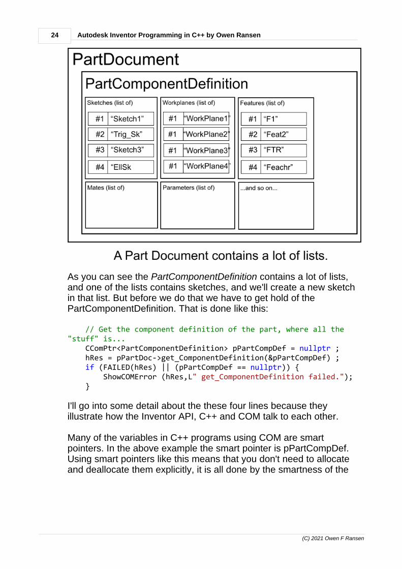
24 Autodesk Inventor Programming in C++ by Owen Ransen
(C) 2021 Owen F Ransen
As you can see the PartComponentDefinition contains a lot of lists,and one of the lists contains sketches, and we'll create a new sketchin that list. But before we do that we have to get hold of thePartComponentDefinition. That is done like this:
// Get the component definition of the part, where all the"stuff" is... CComPtr<PartComponentDefinition> pPartCompDef = nullptr ; hRes = pPartDoc->get_ComponentDefinition(&pPartCompDef) ; if (FAILED(hRes) || (pPartCompDef == nullptr)) { ShowCOMError (hRes,L" get_ComponentDefinition failed."); }
I'll go into some detail about the these four lines because theyillustrate how the Inventor API, C++ and COM talk to each other.
Many of the variables in C++ programs using COM are smartpointers. In the above example the smart pointer is pPartCompDef.Using smart pointers like this means that you don't need to allocateand deallocate them explicitly, it is all done by the smartness of the

256) Creating a part document and a sketch
(C) 2021 Owen F Ransen
pointer. So when we do this:
CComPtr<PartComponentDefinition>pPartCompDef = nullptr ;
we don't need to delete or release pPartCompDef after use, it will allhappen automatically when the pointer goes out of scope.
Also note that I've initialised it to nullptr. This is my own personalstyle, it means it is initialised even if I forget to call a function toinitialise it.
In general many functions we call in the Inventor API take theaddress of a pointer and initialise it, as well as returning a status. Forexample:
hRes = pPartDoc->get_ComponentDefinition(&pPartCompDef) ;
pPartCompDef will be initialised to point at an object, and you'll get areturn value placed in hRes. Why two return values? Because insome circumstances the pointer returned can be validly nullptr. hResmight return S_OK, because the function did not fail, but the pointercould still be nullptr because the object you were looking for does notexist. It is for that reason that I always look at both return values:
if (FAILED(hRes) || (pPartCompDef == nullptr)) {
Click here for more about S_OK, HRESULT and FAILED.
7) Some tips...
9 7) Some tips for Autodesk Inventor C++ programmers
Here are some tips, in no particular order, I've found useful whenprogramming AutoDesk Inventor in C++
Tip1) Check your return values, hRes and COM pointers etc. I know itmakes your code look messy, but you are flying blind otherwise. Ifspeed is really a problem then take the out the checks only at thevery end of the development.

26 Autodesk Inventor Programming in C++ by Owen Ransen
(C) 2021 Owen F Ransen
Tip 2) Make sure that you know how to do manually what you aretrying to do programatically. Else you may end up trying to debugsource code when you should be debugging the manual method.
Tip 3) Name objects sensibly. "Part1" and "Assemby3" are less usefulwhen debugging than "InnerTube" and "MainBikeAssembly".
Tip 4) Don't do programatically what may be easier to do by hand. Forexample you can make a parametric object by hand and simplychange the parameters with your program.
Tip 5) If you know VB or C# then when in difficulty test using thoselanguages. These are far more interactive than C++, even with theIDE.

27Right hand coordinate system
(C) 2021 Owen F Ransen
10 Right hand coordinate system
It seems like Inventor uses the right hand coordinate system:
(Not left hand)
11 iLogic and VBA
11.1 iLogic editing
You can create new iLogic rules or edit existing ones like this:

28 Autodesk Inventor Programming in C++ by Owen Ransen
(C) 2021 Owen F Ransen
11.2 iLogic and suppression of parts in assemblies
This has some useful info...
http://inventbetter.blogspot.com/2012/01/setting-level-of-detail-with-ilogic.html
...but basically you need a custom level of detail to be present andactive if you want to suppress parts inside assemblies with iLogic.
Setting the Level of Detail with iLogic
iLogic requires a custom Level of Detail (LoD) before it can performan operation that suppresses a component. If a custom LoD is notactive or one does not exist you will get an error message. I get a lotof enquires about this dialog box and how one can avoid the hassle.

29iLogic and VBA
(C) 2021 Owen F Ransen
First create a rule called “LoD” and populate with the following code:
Dim doc as AssemblyDocument = ThisDoc.Document Dim oLOD As LevelOfDetailRepresentation Dim oAsmCompDef As ComponentDefinition oAsmCompDef = doc.ComponentDefinitionTry oLOD = oAsmCompDef.RepresentationsManager.LevelOfDetailRepresentations.Item("iLogic").Activate(True)Catch Dim nLOD As LevelOfDetailRepresentation nLOD = oAsmCompDef.RepresentationsManager.LevelOfDetailRepresentations.Add("iLogic") oLOD = nLODFinally oLOD = oAsmCompDef.RepresentationsManager.LevelOfDetailRepresentations.Item("iLogic").Activate(True)End Try
11.3 Run an EXE from inside an iLogc rule
Here is an example:
Sub Main()
Dim sProgramName As String Dim sArgument As String Dim Q As String Q=Chr(34) ' Quote character
sProgramName = "C:\PLMProgs\Simu.Exe"
' Note that "Latest Working" must have quotes around it in thisexample... sArguments = " Ransen.IAM " & Q & "Latest Working" & Q
Call Shell(sProgramName & " " & sArguments, vbNormalFocus)End Sub
Note that when you exit the iLogic editor Inventor will try to run theprogram

30 Autodesk Inventor Programming in C++ by Owen Ransen
(C) 2021 Owen F Ransen
11.4 iLogic suppression of features in a part
Here's an example:
If Assecondo < 1000 Then Feature.IsActive ("Extrusion4") = FalseElse Feature.IsActive ("Extrusion4") = TrueEnd If
Assecondo is a parameter and "Extrusion4" is a feature in an iPart.But suppression is only for LOD (level of detail) stuff.
11.5 iLogic and part parameters
I think this is how you access them:
If Parameter("Bombato") Then ' do somethingElse ' do something elseEnd If
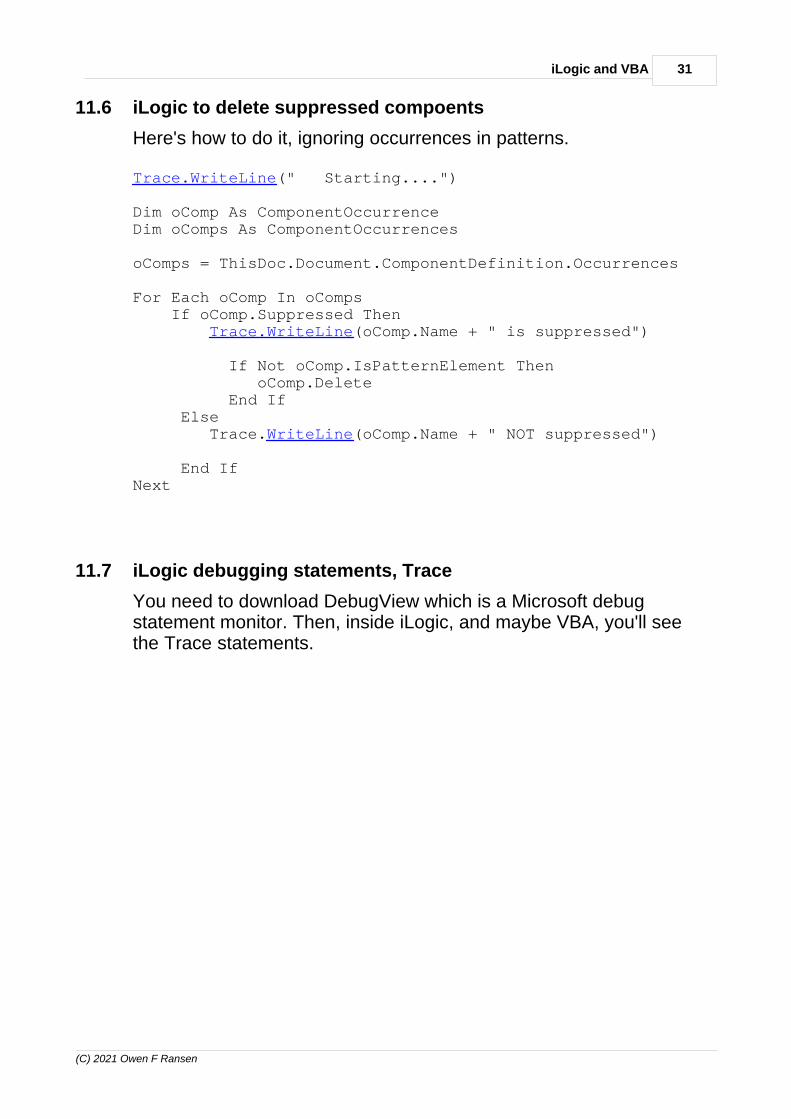
31iLogic and VBA
(C) 2021 Owen F Ransen
11.6 iLogic to delete suppressed compoents
Here's how to do it, ignoring occurrences in patterns.
Trace.WriteLine(" Starting....")
Dim oComp As ComponentOccurrenceDim oComps As ComponentOccurrences
oComps = ThisDoc.Document.ComponentDefinition.Occurrences
For Each oComp In oComps If oComp.Suppressed Then Trace.WriteLine(oComp.Name + " is suppressed")
If Not oComp.IsPatternElement Then oComp.Delete
End If Else
Trace.WriteLine(oComp.Name + " NOT suppressed")
End If Next
11.7 iLogic debugging statements, Trace
You need to download DebugView which is a Microsoft debugstatement monitor. Then, inside iLogic, and maybe VBA, you'll seethe Trace statements.

32 Autodesk Inventor Programming in C++ by Owen Ransen
(C) 2021 Owen F Ransen
Here's an example Trace statement in an iLogic macro:
Trace.WriteLine(oComp.Name + " is suppressed")

33iLogic and VBA
(C) 2021 Owen F Ransen
11.8 iLogic to change dimensions in sketches
It is a bit tricky but you can add a new rule and inside that rule set thenamed dimensions and parameters.
Inside a part add a rule. Here is an example, Blue words areparameters/dimensions from the part or sketch, so this block uses thetwo objects (DiamColl and DiamAtt) to change a diameter called Dcoll .
Dim RagColl as DoubleDim RagAtt As DoubleRagColl = DiamColl/2.0RagAtt = DiamAtt/2.0If RagAtt < RagColl Then Dcoll = Sqrt((RagColl*RagColl) - (RagAtt*RagAtt))Else Dcoll = 0.0 End If
What is also a bit tricky is when things get triggered.
11.9 iLogic to add parts to an assembly
Here you go, follow the comments...
Dim sExcelFileName As String = "Pippo.xlsx"Dim oPath As StringDim Row2 As String '= RowDim Rowchange2 As String '= RowchangeDim text2 As String = x1Dim text3 As String = x1
'file path to useoPath = ThisDoc.Path & "\"'file to useoFile = "40050457.ipt"
' set a reference to the assembly component definintion.' This assumes an assembly document is open.Dim oAsmCompDef As AssemblyComponentDefinitionoAsmCompDef = ThisApplication.ActiveDocument.ComponentDefinition
' These four lines create a matrix, which has default values scale 1 andpos 0,0,0Dim oTG As TransientGeometryoTG = ThisApplication.TransientGeometryDim oMatrix As MatrixoMatrix = oTG.CreateMatrix

34 Autodesk Inventor Programming in C++ by Owen Ransen
(C) 2021 Owen F Ransen
'Iterate through all of the occurrencesDim oOccurrence As ComponentOccurrence
Dim i As Integer
For i = 2 To 6 ' Form the cell address text2="C" + String.Format(i,"#")
oFile = GoExcel.CellValue(sExcelFileName, "Sheet1",text2)
'place an instance of the component 'in this case at 0,0,0
oOccurrence = oAsmCompDef.Occurrences.Add(oPath & oFile, oMatrix) oOccurrence.Grounded = False
Next
11.10 iLogic iProperties example
Here you go:
Option Explicit
Public Sub Main()
' Get the Documents collection object. Dim invDocs As Documents invDocs = ThisApplication.Documents Dim sExt As String ' Iterate through the contents of the Documents collection. Dim invDocument As Document Dim SubDoc As Document Dim Asm As AssemblyDocument Dim DocsInAsm As DocumentsEnumerator Dim SubDocAsAsm As AssemblyDocument For Each invDocument In invDocs ' Display the full filename of the document in the Immediatewindow. If invDocument.DocumentType = kAssemblyDocumentObject Then Asm = invDocument DocsInAsm = Asm.AllReferencedDocuments MessageBox.Show ("Assembly " & invDocument.FullFileName & "has " & DocsInAsm.Count & " sub documents") ListUserParameters (Asm) End If Next
End Sub

35iLogic and VBA
(C) 2021 Owen F Ransen
Private Sub ListUserParameters(ByRef Asm As AssemblyDocument) Dim oDef As AssemblyComponentDefinition Dim AsmUserParams As UserParameters Dim AsmUserParam As UserParameter Dim doc As Document doc = ThisApplication.ActiveDocument
' Get the custom property set. Dim customPropSet As PropertySet customPropSet = doc.PropertySets.Item("Inventor User DefinedProperties")
Dim customProp As Object
customProp = customPropSet.Item ("CIRCUITS")
oDef = Asm.ComponentDefinition AsmUserParams = oDef.Parameters.UserParameters For Each AsmUserParam In AsmUserParams ' Debug.Print ("param is <" & UserParam.Name & ">") If AsmUserParam.Name = "CIRCUITS" Then MessageBox.Show ("CIRCUITS = " & AsmUserParam.ModelValue)
customProp.Value = AsmUserParam.ModelValue End If Next End Sub
Enter topic text here.
11.11 Local or global VBA?
Whether the VBA functions you make are local or global depends onwhere they are written:
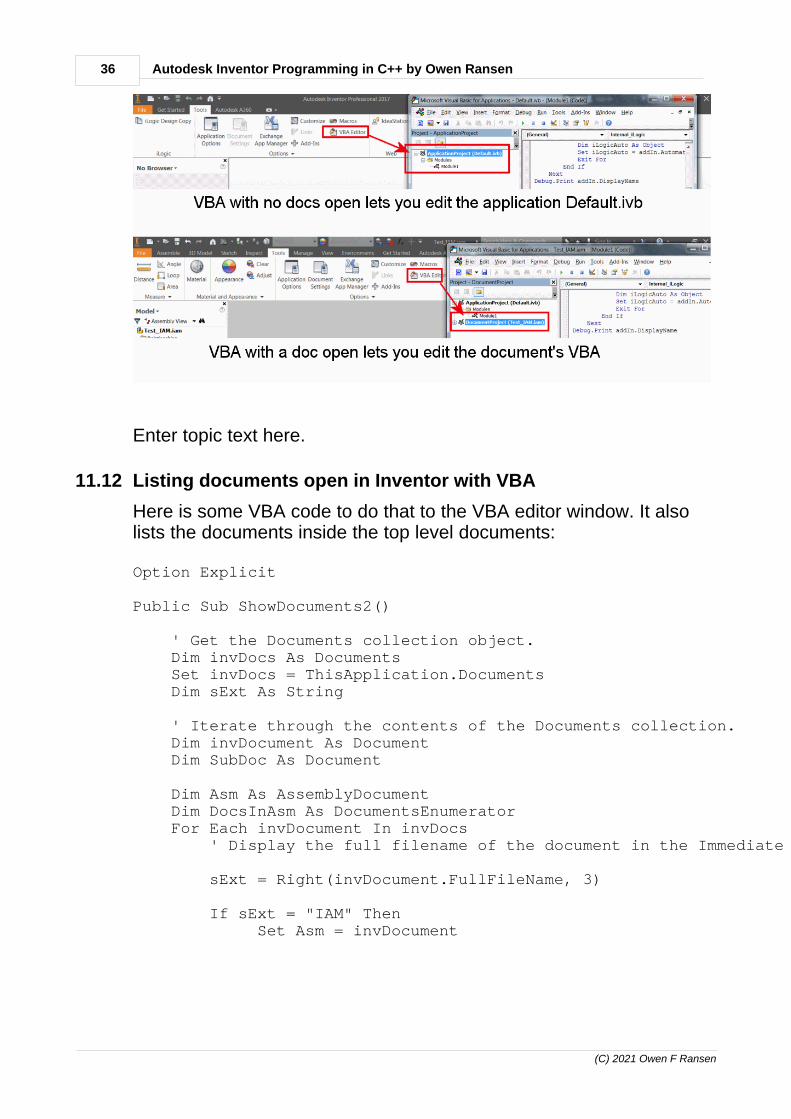
36 Autodesk Inventor Programming in C++ by Owen Ransen
(C) 2021 Owen F Ransen
Enter topic text here.
11.12 Listing documents open in Inventor with VBA
Here is some VBA code to do that to the VBA editor window. It alsolists the documents inside the top level documents:
Option Explicit
Public Sub ShowDocuments2()
' Get the Documents collection object. Dim invDocs As Documents Set invDocs = ThisApplication.Documents Dim sExt As String ' Iterate through the contents of the Documents collection. Dim invDocument As Document Dim SubDoc As Document Dim Asm As AssemblyDocument Dim DocsInAsm As DocumentsEnumerator For Each invDocument In invDocs ' Display the full filename of the document in the Immediate window. sExt = Right(invDocument.FullFileName, 3) If sExt = "IAM" Then Set Asm = invDocument

37iLogic and VBA
(C) 2021 Owen F Ransen
Set DocsInAsm = Asm.AllReferencedDocuments Debug.Print "Assembly " & invDocument.FullFileName & " has " & DocsInAsm.Count & " sub documents" For Each SubDoc In DocsInAsm Debug.Print " SubDoc " & SubDoc.FullFileName Next End If Next
End Sub
11.13 VBA document type
There is .Type and .DocumentType, you need to use the latter:
Public Sub ShowDocuments2()
' Get the Documents collection object. Dim invDocs As Documents Set invDocs = ThisApplication.Documents ' Iterate through the contents of the Documents collection. Dim invDocument As Document For Each invDocument In invDocs ' Display the full filename of the document in the Immediate window.
Select Case invDocument.DocumentType Case DocumentTypeEnum.kAssemblyDocumentObject Debug.Print "IAM " + invDocument.FullFileName
Case Else Debug.Print "OTHER " + invDocument.FullFileName
End Select Next
End Sub

38 Autodesk Inventor Programming in C++ by Owen Ransen
(C) 2021 Owen F Ransen
11.14 Inventor VBA and Excel
To use Excel from a VBA Macro in Inventor you need to add areference:
...else you'll get a
user defined type not defined
...error message.
11.15 Update custom iproperty with VBA and iLogic
This function will do that, but note how it must be called (with aVariant, not with a string or integer):
' Note that the third parameter must be a Variant, not an integer or stringPublic Sub UpdateCustomiProperty(ByRef Doc As Document, ByRef PropertyName As String, ByRef PropertyValue As Variant) ' Get the custom property set. Dim customPropSet As PropertySet Set customPropSet = Doc.PropertySets.Item("Inventor User Defined Properties")
' Get the existing property, if it exists. Dim prop As Property On Error Resume Next ' How we know if the iProperty already exists

39iLogic and VBA
(C) 2021 Owen F Ransen
Set prop = customPropSet.Item(PropertyName)
' Check to see if the above call failed. If it failed ' then the property doesn't exist. If Err.Number <> 0 Then ' Failed to get the existing property so create a new one. Call customPropSet.Add(PropertyValue, PropertyName) Debug.Print ("Property does not exist so adding it") Else ' Change the value of the existing property. prop.Value = PropertyValue Debug.Print ("Property exists,just changing it to " & prop.Value) End If End Sub
11.16 Shared global variables in iLogic
When declaring variables in an iLogic rule, that variable is onlyaccessible within the context of that rule. If you need to create avariable and set its value to use within numerous rules, then SharedVariables are the answer.
' Declaring shared variablesSharedVariable("VariableName") = "This is the value" SharedVariable("cylinderHeight") = Parameter("CylinderHeight")
Once a Shared Variable has been declared and a value provided,then it can be consumed and updated as necessary.
' Using shared variables Dim cylinderHieght As Double = SharedVariable("cylinderHeight")
11.17 Declaring variables in iLogic
I've found this helpful:
https://www.autodesk.com/autodesk-university/article/iLogic-Best-Practices-and-Fundamentals-for-Success
They recommend explicitly declaring variables, like this:

40 Autodesk Inventor Programming in C++ by Owen Ransen
(C) 2021 Owen F Ransen
Dim cylinderHeight As Double = Parameter("CylinderHeight")Dim fileName As String = "This is a string value!"Dim holeCount As Integer = 2Dim occurrenceName As String = String.EmptyDim plateWidth As Double = Nothing
11.18 iLogic dialog form modification
Here's how to modify an existing iLogic form:
11.19 iLogic, adding a new form
Right click in the iLogic tab, but not on an existing button. ChooseAdd Form and you'll get this:

41iLogic and VBA
(C) 2021 Owen F Ransen
Drag a rule from the left of the into the list of controls to add a rule asa button.
11.20 When do iLogic rules run?
It seems that if an iLogic rule contains a parameter in its text then ifthat parameter is changed then the rule is run.
The rule called FinBlock will be run whenever the parameterFinBlockMaterial is changed:
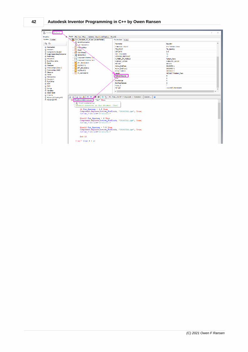
42 Autodesk Inventor Programming in C++ by Owen Ransen
(C) 2021 Owen F Ransen

43iLogic and VBA
(C) 2021 Owen F Ransen
11.21 Inventor from inside Access
Here is what I use:
Dim invApp As Inventor.Application
Public Function GetInventorApp() As Inventor.Application
' This is an essential part beause GetObject could throw an exceptionOn Error GoTo InvMissing
If Not invApp Is Nothing Then Debug.Print "InvApp already ok" Set GetInventorApp = invApp Exit Function End If
'try to get open instance of Excel Application Set invApp = GetObject(, "Inventor.Application") 'tries to retrieve running instance of Inventor Set GetInventorApp = invApp Debug.Print "InvApp found ok " Exit Function InvMissing: ' We hope that GetObject has thrown an exception only because Inventor is not already running Set invApp = CreateObject("Inventor.Application") If invApp Is Nothing Then Call MsgBox("Failed to Get or Create Inventor Application instance. Exiting.", , "") Else Debug.Print "InvApp created ok " End If End Function

44 Autodesk Inventor Programming in C++ by Owen Ransen
(C) 2021 Owen F Ransen
11.22 Custom iProperties in component with VBA
Here is an example:
Dim Inv As Inventor.Application Set Inv = GetInventorApp() Dim invAsm As Inventor.AssemblyDocument Set invAsm = Inv.Documents.Open(sComponentFullFileName) ' from iProperties ' CC_FIN_GEOMETRY ' CC_NUM_RANGHI ' TC_NAME = T014_R006_N014_T55_E02R_U01R_V1_V02 Set PropSet = invAsm.PropertySets.Item("Inventor User Defined Properties") sGeom = PropSet.Count For p = 1 To PropSet.Count If PropSet.Item(p).Name = "CC_NUM_RANGHI" Then iNumRanghi = PropSet.Item(p).Value ElseIf PropSet.Item(p).Name = "CC_FIN_GEOMETRY" Then sGeom = PropSet.Item(p).Value ElseIf PropSet.Item(p).Name = "TC_NAME" Then sTcName = PropSet.Item(p).Value End If Next p Debug.Print "G= <" & sGeom & ">, numranghi = <" & iNumRanghi & ">"
12 Programming Inventor in C++
Click on the book icon to the left to open this section.

45Programming Inventor in C++
(C) 2021 Owen F Ransen
12.1 Get the name of a part
See also GetOccurenceName
First note the difference between DisplayName and PartName:
If you have the occurrence of a part you can get the display name of it(with its :count part), the filename, like this:
CComPtr<ReferencedFileDescriptor> pRefFileDescA = pOccA->ReferencedFileDescriptor ; CComBSTR bstrAName; HRESULT hRes = pRefFileDescA->get_DisplayName (&bstrAName) ; CString csAName ; if (SUCCEEDED(hRes)) { csAName = CString (bstrAName) ; }
If you have a part component definition:
CString GetPartName (CComPtr<PartComponentDefinition>&pPartCompDef){ CString csPartName; CComPtr<Document> pDocument; HRESULT hRes =pPartCompDef->get_Document((IDispatch**)&pDocument);
if (FAILED(hRes)) { ShowCOMError(hRes, L"Could not get part name pDocument"); return csPartName; }

46 Autodesk Inventor Programming in C++ by Owen Ransen
(C) 2021 Owen F Ransen
CComBSTR bstrPartName; hRes = pDocument->get_DisplayName(&bstrPartName);
if (FAILED(hRes)) { ShowCOMError(hRes, L"Could not get part name displayname"); return csPartName; }
csPartName = CString (bstrPartName) ;
return csPartName;}
12.2 Zoom
// This will zoom all the current document...void ZoomAll(){ CComPtr<Application> pInvApp = GetInvAppPtr () ; if (pInvApp == nullptr) { return ; }
CComPtr<Document> pCurrentDoc ; HRESULT hRes = pInvApp->get_ActiveDocument (&pCurrentDoc) ; if (FAILED(hRes)) { return ; }
CameraPtr pCam = pInvApp->ActiveView->Camera ; pCam->Fit() ; pCam->Apply () ;}
12.3 GetWorkPlaneName GetOccurrenceName
These two functions are useful when your constraints do not work:
CString GetWorkPlaneName(CComPtr<WorkPlane>& pWorkPlaneA){ CString csWPName; if (pWorkPlaneA != nullptr) { csWPName = CString(pWorkPlaneA->Name.GetBSTR()); }

47Programming Inventor in C++
(C) 2021 Owen F Ransen
return csWPName;}
/**********************************************************************************************/
// This actually gets the name of the document being referencedby the occurrence// It could be something like "3312345.IPT" CString GetOccurrenceName(CComPtr<ComponentOccurrence>& pOcc){ CString csOccName ;
if (pOcc != nullptr) { CComPtr<ReferencedFileDescriptor> pRefFileDesc = pOcc->ReferencedFileDescriptor ; CComBSTR bstrAName; pRefFileDesc->get_DisplayName (&bstrAName) ; csOccName = CString (bstrAName) ; }
return csOccName;}
/**********************************************************************************************/
12.4 Investigating Asset Libraries Progamatically
You can loop over all the asset libraries loaded into Inventor like this:
CComPtr<AssetLibraries> pAssLibs ; HRESULT hRes = pInvApp->get_AssetLibraries (&pAssLibs) ; if (FAILED(hRes) || (pAssLibs == nullptr)) { ShowCOMError (hRes,L"Could not get asset libraries"); return ; }
long iNumAssLibs ; pAssLibs->get_Count(&iNumAssLibs) ; WalertBoxA ("There are %d asset libraries",iNumAssLibs) ;
for (long iLib = 1 ; iLib <= iNumAssLibs ; iLib++) { CComPtr<AssetLibrary> pAssLib ; pAssLibs->get_Item (CComVariant(iLib),&pAssLib) ;

48 Autodesk Inventor Programming in C++ by Owen Ransen
(C) 2021 Owen F Ransen
CComBSTRbstrDisplayName,bstrFullFileName,bstrInternalName ; pAssLib->get_DisplayName (&bstrDisplayName) ; pAssLib->get_FullFileName (&bstrFullFileName) ; pAssLib->get_InternalName (&bstrInternalName) ;
TRACE (L"Lib %d has <%s>, <%s>, <%s>.\n",iLib,bstrDisplayName,bstrFullFileName,bstrInternalName); }
And you'll get a result something like this:
Lib 1 has <Autodesk Material Library>, <C:\Program Files (x86)\Common Files\AutodeskShared\Materials\2015\PhysicalMaterial.adsklib>, <AD121259-C03E-4A1D-92D8-59A22B4807AD>.Lib 2 has <Autodesk Appearance Library>, <C:\Program Files (x86)\Common Files\AutodeskShared\Materials\2015\assetlibrary_base.adsklib>, <314DE259-5443-4621-BFBD-1730C6CC9AE9>.Lib 3 has <Favorites>, <C:\Users\Owen\AppData\Roaming\Autodesk\Inventor2015\FavoriteMaterials.adsklib>, <D07F930C-485A-4658-AD69-C91D17FEB99B>.Lib 4 has <Inventor Material Library>, <C:\Users\Public\Documents\Autodesk\Inventor2015\Design Data\Materials\InventorMaterialLibrary.adsklib>, <AFEFC330-5E61-4E24-814F-AE810148B79D>.
The internal name is a GUID it looks like.
Note that it seems that you need to have loaded at least one part,else the assets can be null pointers. It seems like loading a part loadsthe materials.
Once you have an asset lib you can loop over its contents like this:
CComPtr<AssetsEnumerator> pAssEnum ; pAssLib->get_MaterialAssets (&pAssEnum) ;
const long ikNumAssets = pAssEnum->Count ;
for (long iAss = 1 ; iAss <= ikNumAssets ; iAss++) { CComPtr<Asset> pAsset ; pAssEnum->get_Item (CComVariant(iAss),&pAsset) ;
CComBSTR bstrDispName,bstrName,bstrCatName ; pAsset->get_DisplayName (&bstrDispName) ; pAsset->get_Name (&bstrName) ; pAsset->get_CategoryName (&bstrCatName) ; TRACE (L" DisplayName=<%s> Name=<%s> CatName=<%s>\n", bstrDispName,bstrName,bstrCatName) ; }

49Programming Inventor in C++
(C) 2021 Owen F Ransen
And the results will look something like this:
DisplayName=<GFRC> Name=<Material-010> CatName=<Concrete> DisplayName=<Gold> Name=<Material-068> CatName=<Metal> DisplayName=<Iron, Ductile> Name=<Material-071> CatName=<Metal> DisplayName=<Lead> Name=<Material-072> CatName=<Metal> DisplayName=<Silver> Name=<Material-076> CatName=<Metal> DisplayName=<Steel> Name=<Material-077> CatName=<Metal> DisplayName=<Steel, Galvanized> Name=<Material-079> CatName=<Metal>
I think the display name will change from language to language, but Ineed to investigate further. Categories are clearly Metal, Concrete,Wood etc.
12.5 Bounding box of a part occurrence in an assembly
This is probably what you are looking for:
BoxPtr pBox = pOcc->RangeBox ; PointPtr Min = pBox->GetMinPoint () ; PointPtr Max = pBox->GetMaxPoint () ;
12.6 Parallel planes programatically
The software way of doing this...

50 Autodesk Inventor Programming in C++ by Owen Ransen
(C) 2021 Owen F Ransen
...is illustrated below:
/*Given two occurrences which contain workplanes to be flush constrained togetherthis function creates a flush constraint between them*/bool AddFlushConstraintOfTwoPlanes (CComPtr<AssemblyComponentDefinition>& pAsmCompDef, CComPtr<ComponentOccurrence>& pOccA, CComPtr<WorkPlane>& pWorkPlaneA, CComPtr<ComponentOccurrence>& pOccB, CComPtr<WorkPlane>& pWorkPlaneB, const double kOffsetMm, /*=0.0*/ const wchar_t* const pszConstraintName /*=nullptr*/, const double kmmMax /*= 0.0*/){ CComPtr<WorkPlaneProxy> pWPProxyA ; HRESULT hRes = pOccA->CreateGeometryProxy (pWorkPlaneA,(IDispatch**)&pWPProxyA) ; if (FAILED(hRes)) { ShowCOMError (hRes,L"AFCOTP could not get pWPProxyA.") ; return false ; }
CComPtr<WorkPlaneProxy> pWPProxyB ; pOccB->CreateGeometryProxy (pWorkPlaneB,(IDispatch**)&pWPProxyB) ; if (FAILED(hRes)) { ShowCOMError (hRes,L"AFCOTP could not get pWPProxyB.") ; return false ; }
// Get the list of constraints of the assembly so you can add a new one CComPtr<AssemblyConstraints> pConstraintList ; hRes = pAsmCompDef->get_Constraints(&pConstraintList) ; if (FAILED(hRes)) { ShowCOMError (hRes,L"AFCOTP could not get constraints.") ; return false ; }
CComVariant varOffset(kOffsetMm/10.0); // Convert to offset in cm CComPtr<FlushConstraint> pFlushConstraint ; hRes = pConstraintList->AddFlushConstraint(pWPProxyA, pWPProxyB, varOffset, gkvarEmpty, gkvarEmpty, &pFlushConstraint); if (FAILED(hRes)) { ShowCOMError (hRes,L"AFCOTP AddFlushConstraint failed") ; return false ; }
if (kmmMax > 0.0) {

51Programming Inventor in C++
(C) 2021 Owen F Ransen
// This allows planes to be parallel constrained, but distant from each other const double kcmMax = kmmMax/10.0 ; CComPtr<ConstraintLimits> pLimits = pFlushConstraint->GetConstraintLimits() ; pLimits->MaximumEnabled = VARIANT_TRUE ; CString csMax ; csMax.Format (L"%.3f",kcmMax) ; CComBSTR TempBstr (csMax) ; pLimits->Maximum->Expression = TempBstr.m_str ; //!!!OWEN!!! .Value in cm is also possible }
if ((pszConstraintName != nullptr) && (wcslen(pszConstraintName) > 0)) { const CString kcsConsName = GetFreeConstraintName(pszConstraintName,pAsmCompDef); CComBSTR bstrName(kcsConsName); pFlushConstraint->put_Name(bstrName); }
return true ;}
Enter topic text here.
12.7 Change size of a hole
Here is an example:
void ChangeForoValvolinaDiam (CComPtr<PartComponentDefinition>&pPartCompDef, const double kmmNewDiam){ // Get the list of features... CComPtr<PartFeatures> pFeaturesList ; HRESULT hRes = pPartCompDef->get_Features(&pFeaturesList) ; if (FAILED(hRes)) { ShowCOMError(ekLogMsg,hRes,L"CFVD get_Features failed"); return ; }
// Find the feature which is the hole I want to change... CComPtr<PartFeature> pFeature; hRes = pFeaturesList->get_Item (CComVariant(L"ForoValvolina"), &pFeature); if (FAILED(hRes)) { ShowCOMError(ekLogMsg,hRes,L"CFVD get_Item failed"); return ; }

52 Autodesk Inventor Programming in C++ by Owen Ransen
(C) 2021 Owen F Ransen
// The name is correct, see if it is actually a hole... if (pFeature->GetType() == kHoleFeatureObject) {
// Convert the general pFeature it into the specificpHoleFeature // This is an example of using a CComQIPtr CComQIPtr<HoleFeature> pHoleFeature (pFeature) ; if (pHoleFeature == nullptr) { gLogger.Printf (ekLogMsg,L"Cannot cast") ; return ; }
// Get the value of the parameter as a variant... CComVariant cmDiam (pHoleFeature->HoleDiameter->GetValue()) ; const double kmmDiam = cmDiam.dblVal*10.0 ; gLogger.Printf (ekLogMsg,L"hole diam = %6.3fmm",kmmDiam);
// Change into centimeters... cmDiam.dblVal = kmmNewDiam/10.0 ;
// Actually change the size of the hole... pHoleFeature->HoleDiameter->Value = cmDiam ; }}
Enter topic text here.
12.8 Materials API
A part has "assets" which define the material of that part, assetsdescribe the material name, properties appearance etc.
You can use this code to examine the assets in a part document:
const long ikNumAssets = pPartDoc->Assets->GetCount(); for (long i = 0; i < ikNumAssets; i++) { CComPtr<Asset> pTempAsset = nullptr ; CComVariant iVar(i + 1); pPartDoc->Assets->get_Item(iVar,&pTempAsset); TRACE (L"%d material asset type %d has display name <%s> fixed name<%s> and category name <%s>", i+1, pTempAsset->AssetType, LPCWSTR(pTempAsset->DisplayName),
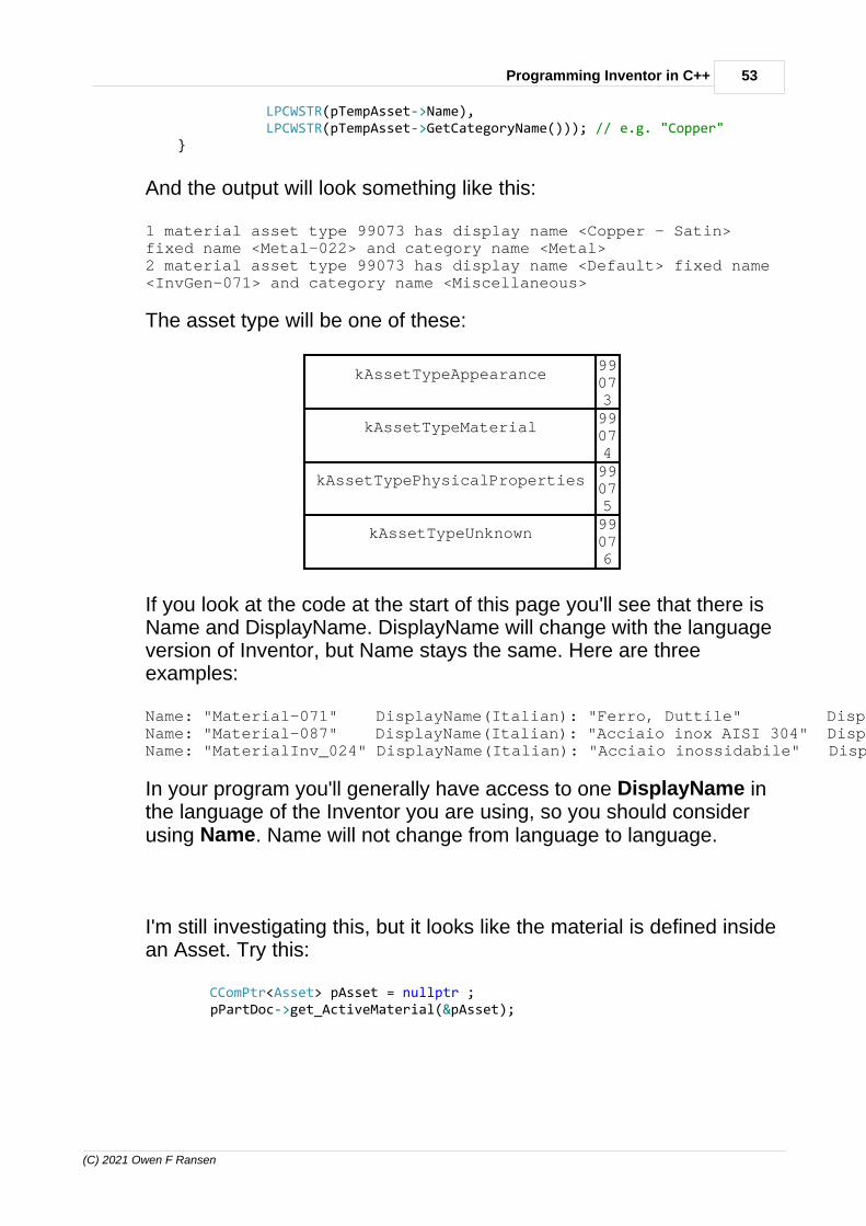
53Programming Inventor in C++
(C) 2021 Owen F Ransen
LPCWSTR(pTempAsset->Name), LPCWSTR(pTempAsset->GetCategoryName())); // e.g. "Copper" }
And the output will look something like this:
1 material asset type 99073 has display name <Copper - Satin>fixed name <Metal-022> and category name <Metal>2 material asset type 99073 has display name <Default> fixed name<InvGen-071> and category name <Miscellaneous>
The asset type will be one of these:
kAssetTypeAppearance99073
kAssetTypeMaterial99074
kAssetTypePhysicalProperties99075
kAssetTypeUnknown99076
If you look at the code at the start of this page you'll see that there isName and DisplayName. DisplayName will change with the languageversion of Inventor, but Name stays the same. Here are threeexamples:
Name: "Material-071" DisplayName(Italian): "Ferro, Duttile" DisplayName(English): "Iron, Ductile"Name: "Material-087" DisplayName(Italian): "Acciaio inox AISI 304" DisplayName(English): "Stainless Steel AISI 304"Name: "MaterialInv_024" DisplayName(Italian): "Acciaio inossidabile" DisplayName(English): "Stainless Steel"
In your program you'll generally have access to one DisplayName inthe language of the Inventor you are using, so you should considerusing Name. Name will not change from language to language.
I'm still investigating this, but it looks like the material is defined insidean Asset. Try this:
CComPtr<Asset> pAsset = nullptr ; pPartDoc->get_ActiveMaterial(&pAsset);

54 Autodesk Inventor Programming in C++ by Owen Ransen
(C) 2021 Owen F Ransen
TRACE (L"Active material asset has name <%s>", LPCWSTR(pAsset->DisplayName)); // e.g. "Copper"
TRACE (L"Active material asset has category name <%s>", LPCWSTR(pAsset->GetCategoryName())); // e.g. "Metal"
You can also get hold of the asset type, which will be one of these:
kAssetTypeAppearance 99073
kAssetTypeMaterial 99074
kAssetTypePhysicalProperties 99075
kAssetTypeUnknown 99076
You can loop over all the asset libraries loaded into inventor like this:
CComPtr<AssetLibraries> pAssLibs ; HRESULT hRes = pInvApp->get_AssetLibraries (&pAssLibs) ; if (FAILED(hRes) || (pAssLibs == nullptr)) { ShowCOMError (hRes,L"Could not get asset libraries"); return ; }
long iNumAssLibs ; pAssLibs->get_Count(&iNumAssLibs) ; WalertBoxA ("There are %d asset libraries",iNumAssLibs) ;
for (long iLib = 1 ; iLib <= iNumAssLibs ; iLib++) { CComPtr<AssetLibrary> pAssLib ; pAssLibs->get_Item (CComVariant(iLib),&pAssLib) ;
CComBSTRbstrDisplayName,bstrFullFileName,bstrInternalName ; pAssLib->get_DisplayName (&bstrDisplayName) ; pAssLib->get_FullFileName (&bstrFullFileName) ; pAssLib->get_InternalName (&bstrInternalName) ;
TRACE (L"Lib %d has <%s>, <%s>, <%s>.\n",iLib,bstrDisplayName,bstrFullFileName,bstrInternalName); }
And you'll get a result something like this:
Lib 1 has <Autodesk Material Library>, <C:\Program Files (x86)\Common Files\AutodeskShared\Materials\2015\PhysicalMaterial.adsklib>, <AD121259-C03E-4A1D-92D8-59A22B4807AD>.

55Programming Inventor in C++
(C) 2021 Owen F Ransen
Lib 2 has <Autodesk Appearance Library>, <C:\Program Files (x86)\Common Files\AutodeskShared\Materials\2015\assetlibrary_base.adsklib>, <314DE259-5443-4621-BFBD-1730C6CC9AE9>.Lib 3 has <Favorites>, <C:\Users\Owen\AppData\Roaming\Autodesk\Inventor2015\FavoriteMaterials.adsklib>, <D07F930C-485A-4658-AD69-C91D17FEB99B>.Lib 4 has <Inventor Material Library>, <C:\Users\Public\Documents\Autodesk\Inventor2015\Design Data\Materials\InventorMaterialLibrary.adsklib>, <AFEFC330-5E61-4E24-814F-AE810148B79D>.
The internal name is a GUID it looks like.
Once you have an asset lib you can loop over its contents like this:
CComPtr<AssetsEnumerator> pAssEnum ; pAssLib->get_MaterialAssets (&pAssEnum) ;
const long ikNumAssets = pAssEnum->Count ;
for (long iAss = 1 ; iAss <= ikNumAssets ; iAss++) { CComPtr<Asset> pAsset ; pAssEnum->get_Item (CComVariant(iAss),&pAsset) ;
CComBSTR bstrDispName,bstrName,bstrCatName ; pAsset->get_DisplayName (&bstrDispName) ; pAsset->get_Name (&bstrName) ; pAsset->get_CategoryName (&bstrCatName) ; TRACE (L" DisplayName=<%s> Name=<%s> CatName=<%s>\n", bstrDispName,bstrName,bstrCatName) ; }
And the results will look something like this:
DisplayName=<GFRC> Name=<Material-010> CatName=<Concrete> DisplayName=<Gold> Name=<Material-068> CatName=<Metal> DisplayName=<Iron, Ductile> Name=<Material-071> CatName=<Metal> DisplayName=<Lead> Name=<Material-072> CatName=<Metal> DisplayName=<Silver> Name=<Material-076> CatName=<Metal> DisplayName=<Steel> Name=<Material-077> CatName=<Metal> DisplayName=<Steel, Galvanized> Name=<Material-079> CatName=<Metal>
Name does not change from language to language, display name will.Categories are clearly Metal, Concrete, Wood etc.

56 Autodesk Inventor Programming in C++ by Owen Ransen
(C) 2021 Owen F Ransen
Material Assets serve to group a physical asset and appearancetogether. Conceptually a material can be described by its physicalproperties (density, Poisson’s ratio, yield strength, etc.) and how itlooks or its appearance. A material property has some basicinformation that identifies it, (name, description, type, etc.), and itreferences a physical properties asset.
Where do materials exist?
The number of asset libraries changes when you have nothing open(1 for examples) to when you have an assembly open (4 forexample).
The idea behind Consistent Materials is that all Autodesk programsuse the same library of materials.
There are three primary types of assets; materials, physicalproperties, and appearances
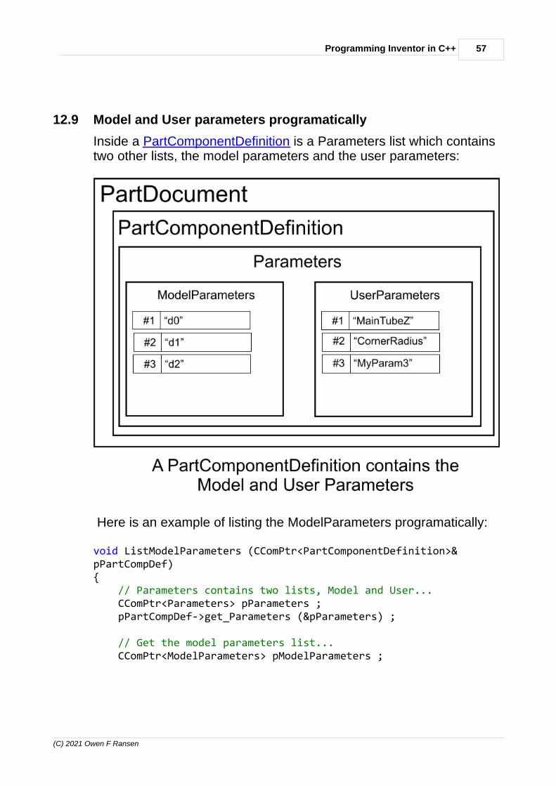
57Programming Inventor in C++
(C) 2021 Owen F Ransen
12.9 Model and User parameters programatically
Inside a PartComponentDefinition is a Parameters list which containstwo other lists, the model parameters and the user parameters:
Here is an example of listing the ModelParameters programatically:
void ListModelParameters (CComPtr<PartComponentDefinition>&pPartCompDef){ // Parameters contains two lists, Model and User... CComPtr<Parameters> pParameters ; pPartCompDef->get_Parameters (&pParameters) ;
// Get the model parameters list... CComPtr<ModelParameters> pModelParameters ;
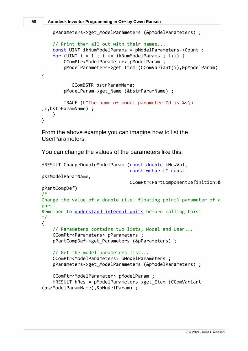
58 Autodesk Inventor Programming in C++ by Owen Ransen
(C) 2021 Owen F Ransen
pParameters->get_ModelParameters (&pModelParameters) ;
// Print them all out with their names... const UINT ikNumModelParams = pModelParameters->Count ; for (UINT i = 1 ; i <= ikNumModelParams ; i++) { CComPtr<ModelParameter> pModelParam ; pModelParameters->get_Item (CComVariant(i),&pModelParam);
CComBSTR bstrParamName; pModelParam->get_Name (&bstrParamName) ;
TRACE (L"The name of model parameter %d is %s\n",i,bstrParamName) ; }}
From the above example you can imagine how to list theUserParameters.
You can change the values of the parameters like this:
HRESULT ChangeDoubleModelParam (const double kNewVal, const wchar_t* constpszModelParamName, CComPtr<PartComponentDefinition>&pPartCompDef)/*Change the value of a double (i.e. floating point) parameter of apart.Remember to understand internal units before calling this!*/{ // Parameters contains two lists, Model and User... CComPtr<Parameters> pParameters ; pPartCompDef->get_Parameters (&pParameters) ;
// Get the model parameters list... CComPtr<ModelParameters> pModelParameters ; pParameters->get_ModelParameters (&pModelParameters) ;
CComPtr<ModelParameter> pModelParam ; HRESULT hRes = pModelParameters->get_Item (CComVariant(pszModelParamName),&pModelParam) ;
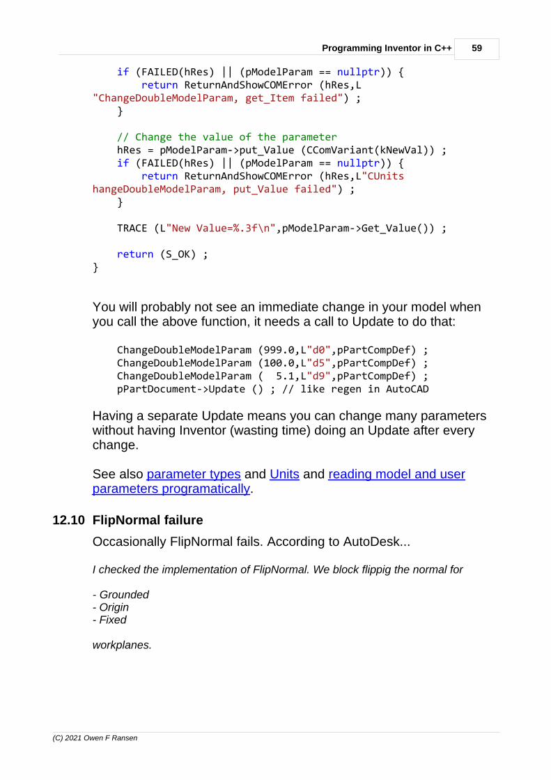
59Programming Inventor in C++
(C) 2021 Owen F Ransen
if (FAILED(hRes) || (pModelParam == nullptr)) { return ReturnAndShowCOMError (hRes,L"ChangeDoubleModelParam, get_Item failed") ; }
// Change the value of the parameter hRes = pModelParam->put_Value (CComVariant(kNewVal)) ; if (FAILED(hRes) || (pModelParam == nullptr)) { return ReturnAndShowCOMError (hRes,L"CUnitshangeDoubleModelParam, put_Value failed") ; }
TRACE (L"New Value=%.3f\n",pModelParam->Get_Value()) ;
return (S_OK) ;}
You will probably not see an immediate change in your model whenyou call the above function, it needs a call to Update to do that:
ChangeDoubleModelParam (999.0,L"d0",pPartCompDef) ; ChangeDoubleModelParam (100.0,L"d5",pPartCompDef) ; ChangeDoubleModelParam ( 5.1,L"d9",pPartCompDef) ; pPartDocument->Update () ; // like regen in AutoCAD
Having a separate Update means you can change many parameterswithout having Inventor (wasting time) doing an Update after everychange.
See also parameter types and Units and reading model and userparameters programatically.
12.10 FlipNormal failure
Occasionally FlipNormal fails. According to AutoDesk...
I checked the implementation of FlipNormal. We block flippig the normal for
- Grounded- Origin- Fixed
workplanes.

60 Autodesk Inventor Programming in C++ by Owen Ransen
(C) 2021 Owen F Ransen
Does this explain why you might see a failure there?
Thanks,
Gerald
Fixed workplanes may be a result of adaptive geometry.
12.11 Adaptive geometry
I don't know what it is used for, but you can recognise it like this:

61Programming Inventor in C++
(C) 2021 Owen F Ransen
12.12 Add a sketch to an assembly or part
You can use these two functions:
// Adds a sketch to one of the three standard workplanes in a partbool AddSketchToStdPartWorkplane (CComPtr<PlanarSketch>& pNewSketch, CComPtr<PartComponentDefinition>&pPartCompDef, const wchar_t* const pszNewSketchName, const UINT ikWorkPlaneNumber) // gikXIndex,gikYIndex, gikZIndex{

62 Autodesk Inventor Programming in C++ by Owen Ransen
(C) 2021 Owen F Ransen
if ((pszNewSketchName == nullptr) || (wcslen(pszNewSketchName) == 0)) { gLogger.Printf (ekErrMsg,L"ASTSPW, workplane name incorrect") ; return false; }
CComPtr<WorkPlane> pWorkPlane; bool bOk = GetStdWorkPlaneByIndex(pWorkPlane, ikWorkPlaneNumber,pPartCompDef); if (!bOk) { return false; }
// Get the list of sketches CComPtr<PlanarSketches> pSketchList ; HRESULT hRes = pPartCompDef->get_Sketches (&pSketchList); if (FAILED(hRes)) { ShowCOMError (hRes,L"ASTSPW, could not get planar sketches") ; return false; }
hRes = pSketchList->Add (_variant_t((IDispatch*)pWorkPlane),VARIANT_FALSE,&pNewSketch) ; if (FAILED(hRes)) { ShowCOMError (hRes,L"ASTSPW, could not get planar sketches") ; return false; }
pNewSketch->put_Name (CComBSTR (pszNewSketchName)) ;
return true;}
/*******************************************************************************************************/
bool AddSketchToStdAssemblyWorkplane(CComPtr<PlanarSketch>& pNewSketch, CComPtr<AssemblyComponentDefinition>&pAsmCompDef, const wchar_t* const pszNewSketchName, const UINT ikWorkPlaneNumber) //gikXIndex, gikYIndex, gikZIndex{ // Get the work plane from the list of work planes in the part... CComPtr<WorkPlane> pWorkPlane; HRESULT hRes =pAsmCompDef->WorkPlanes->get_Item(CComVariant(ikWorkPlaneNumber),&pWorkPlane); if (FAILED(hRes)) { ShowCOMError (hRes,L"ASTSAW but 'get' %d failed\n",ikWorkPlaneNumber); return false ; }
// Get the list of sketches

63Programming Inventor in C++
(C) 2021 Owen F Ransen
CComPtr<PlanarSketches> pSketchList ; hRes = pAsmCompDef->get_Sketches (&pSketchList); if (FAILED(hRes)) { ShowCOMError (hRes,L"ASTSAW, could not get planar sketches") ; return false; }
hRes = pSketchList->Add (_variant_t((IDispatch*)pWorkPlane),VARIANT_FALSE,&pNewSketch) ; if (FAILED(hRes)) { ShowCOMError (hRes,L"ASTSAW, could not get planar sketches") ; return false; }
pNewSketch->put_Name (CComBSTR (pszNewSketchName)) ;
return true;}
12.13 How to get the value of a user parameter
Here is some code to get the value of a user parameter in an Inventorpart:
double GetUserParameterValueByName (CComPtr<PartComponentDefinition>&pPartCompDef, const CString& kcsUserParamName){ // Parameters contains two lists, Model and User... CComPtr<Parameters> pParameters ; pPartCompDef->get_Parameters (&pParameters) ;
// Get the model parameters list... CComPtr<UserParameters> pUserParameters ; pParameters->get_UserParameters (&pUserParameters) ;
// Find the one we are looking for... const UINT ikNumUserParams = pUserParameters->Count ;
for (UINT i = 1 ; i <= ikNumUserParams ; i++) { CComPtr<UserParameter> pUserParam ; pUserParameters->get_Item (CComVariant(i),&pUserParam) ;
CComBSTR bstrParamName; pUserParam->get_Name (&bstrParamName) ;
if (kcsUserParamName.CompareNoCase(CString(bstrParamName)) == 0) { // Found it VARIANT ParamValue ;

64 Autodesk Inventor Programming in C++ by Owen Ransen
(C) 2021 Owen F Ransen
pUserParam->get_Value (&ParamValue) ; return ParamValue.dblVal; } }
// This is an error
return 0.0;}
And here is the very similar code for getting a model parameter value:
double GetModelParameterValueByName (CComPtr<PartComponentDefinition>&pPartCompDef, const CString& kcsModelParamName){ // Parameters contains two lists, Model and User... CComPtr<Parameters> pParameters ; pPartCompDef->get_Parameters (&pParameters) ;
// Get the model parameters list... CComPtr<ModelParameters> pModelParameters ; pParameters->get_ModelParameters (&pModelParameters) ;
// Find the one we are looking for... const UINT ikNumModelParams = pModelParameters->Count ; for (UINT i = 1 ; i <= ikNumModelParams ; i++) { CComPtr<ModelParameter> pModelParam ; pModelParameters->get_Item (CComVariant(i),&pModelParam) ;
CComBSTR bstrParamName; pModelParam->get_Name (&bstrParamName) ;
if (kcsModelParamName.CompareNoCase(CString(bstrParamName)) == 0) { // Found it VARIANT ParamValue ; pModelParam->get_Value (&ParamValue) ; return ParamValue.dblVal; } }
// This is an error
return 0.0;}
See also Model and User parameters programatically.

65Programming Inventor in C++
(C) 2021 Owen F Ransen
12.14 Getting the value of a custom iProperty
Here is a function which gets a custom iProperty value, returningfalse if the value does not exist in the document.
So it can be used to test for existence as well as getting the actualvalue.
// Returns true if the custom iProperty exists, with the value incsRetValue Needs a DOC not a PART or ASSEMBLY// Always returns a string in csRetValueboolean DocHasCustomiProperty(CComPtr<Document>& pInventorDoc,const CString& kcsiPropName, CString& csRetValue) { csRetValue = CString ("") ;
CComPtr <PropertySets> pPropSets; pInventorDoc->get_PropertySets(&pPropSets);
const long ikNumSets = pPropSets->Count;
// There are several sets of properties, loop over thesets... for (long iSet = 1; iSet <= ikNumSets; iSet++) { CComPtr<PropertySet> pPropSet; pPropSets->get_Item(CComVariant(iSet), &pPropSet);
CComBSTR bstrPropSetName; pPropSet->get_Name(&bstrPropSetName); CString csPropSetName(bstrPropSetName);
if (csPropSetName.CompareNoCase(L"Inventor User DefinedProperties") == 0) { // Loop over the properties of this property set... const long ikNumProps = pPropSet->Count;
for (long iProp = 1; iProp <= ikNumProps; iProp++) { CComPtr<Property> pThisProp; pPropSet->get_Item(CComVariant(iProp), &pThisProp);
_bstr_t bstrPropName = pThisProp->GetDisplayName();
const CString

66 Autodesk Inventor Programming in C++ by Owen Ransen
(C) 2021 Owen F Ransen
kcsThisPropName(bstrPropName.GetBSTR());
if (kcsThisPropName.CompareNoCase(kcsiPropName)== 0) { // We've found the property we are interestedin... // ...convert it into a string CComVariant varValue; pThisProp->get_Value(&varValue);
// Add more VT_... values for more detail... if (varValue.vt == VT_BSTR) { csRetValue = CString(varValue.bstrVal);
} else if (varValue.vt == VT_I4) { csRetValue.Format(L"%d",varValue.intVal);
} else if (varValue.vt == VT_R8) { csRetValue.Format(L"%.3f",varValue.dblVal);
} else { csRetValue.Format(L"(?vt=%d?)",varValue.vt); }
return true; } } } }
return false ;}
12.15 Add a part to an assembly
...or more properly how to add an occurrence of a part to anassembly. Here you go, and you specify the 3d position and optionallythe 3d angles too...
HRESULT AddPartToAssemblyAtPosition (CComPtr<AssemblyComponentDefinition>& pAsmCompDef, const CString& kcsFullPathPartName, const double kxPos,

67Programming Inventor in C++
(C) 2021 Owen F Ransen
const double kyPos, const double kzPos, CComPtr<ComponentOccurrence>& pPartOcc, CComQIPtr<PartComponentDefinition>& pPartCompDef, const double kxRotDegs /*=0.0*/, const double kyRotDegs /*=0.0*/, const double kzRotDegs /*=0.0*/) /*The positions are in the natural units of Inventor, usually cmWe return the occurence and its part component definition*/{ pPartOcc = nullptr ;
CComPtr<ComponentOccurrences> pOccurrencesList = nullptr; HRESULT hRes = pAsmCompDef->get_Occurrences (&pOccurrencesList) ; if (FAILED(hRes)) { return ReturnAndShowCOMError (hRes,L"AddPartToAssemblyAtPosition get_Occurrences failed") ; }
CComPtr<TransientGeometry> pTransGeom = GetTransGeomPtr () ; CComPtr<Matrix> pPosMatrix; pTransGeom->CreateMatrix(&pPosMatrix);
CComPtr<Vector> pVector; // Create a Vector to modify the Matrix pTransGeom->CreateVector(kxPos,kyPos,kzPos,&pVector);
// Make the matrix a "move to point" matrix... pPosMatrix->SetTranslation (pVector,VARIANT_TRUE) ;
CComPtr<Matrix> pPosRotMatrix ; pTransGeom->CreateMatrix(&pPosRotMatrix);
CComPtr<Vector> pZAxis ; hRes = pTransGeom->CreateVector (0,0,1,&pZAxis); if (FAILED(hRes)) { ShowCOMError (hRes,L"Could not create z axis vector") ; return false ; }
CComPtr<Point> pOrigin ; hRes = pTransGeom->CreatePoint (0,0,0,&pOrigin); const double kZRadsRot = RadsFromDegs(kzRotDegs); pPosRotMatrix->SetToRotation (kZRadsRot,pZAxis,pOrigin) ;
pPosRotMatrix->PreMultiplyBy(pPosMatrix);
hRes = pOccurrencesList->Add (CComBSTR(kcsFullPathPartName),pPosRotMatrix,&pPartOcc) ; if (FAILED(hRes)) {

68 Autodesk Inventor Programming in C++ by Owen Ransen
(C) 2021 Owen F Ransen
return ReturnAndShowCOMError (hRes,L"AddPartToAssemblyAtPosition Add failed") ; }
// Get the general component definition... CComQIPtr<ComponentDefinition> pCompDef ; hRes = pPartOcc->get_Definition (&pCompDef) ; if (FAILED(hRes)) { return ReturnAndShowCOMError (hRes,L"AddPartToAssemblyAtPosition could not get definition.") ; }
// Cast from the general sort of component definition to the specific PART component definition pPartCompDef = CComQIPtr<PartComponentDefinition>(pCompDef); if (pPartCompDef == nullptr) { gLogger.Printf (ekErrMsg,L"AddPartToAssemblyAtPosition could not cast to pPartCompDef.") ; return E_FAIL ; }
return S_OK ;}
12.16 Open an assembly part programatically
Here's a function to do it:
bool OpenAssembly (CComPtr<AssemblyComponentDefinition>& pAsmCompDef, //Output CComPtr<AssemblyDocument>& pAsmDoc, // Output const CString& kcsFullAsmFileName, // Input const bool kbOpenVisible/*=true*/) // Input{ CComBSTR strAssemblyFilename (kcsFullAsmFileName) ;
// Get the list of documents, we use this to oprn another CComPtr<Documents> pDocuments; HRESULT hRes = theApp.GetInvAppPtr()->get_Documents (&pDocuments) ; if (FAILED(hRes)) { ShowCOMError(hRes, L"get_Documents called from OpenAssembly"); return false; }
VARIANT_BOOL vbOpenVisible; if (kbOpenVisible) { vbOpenVisible = VARIANT_TRUE; } else { vbOpenVisible = VARIANT_FALSE; }
CComPtr<Document> pDoc = nullptr ;

69Programming Inventor in C++
(C) 2021 Owen F Ransen
hRes = pDocuments->Open (strAssemblyFilename, // what to open vbOpenVisible, &pDoc) ; if (FAILED(hRes)) { ShowCOMError (hRes,L"OA, could not open assembly, pDocuments->Open(%s)",kcsFullAsmFileName); return false ; }
// Try to cast from a general doc to an assembly pAsmDoc = pDoc; if (pAsmDoc == nullptr) { ShowCOMError (hRes,L"OA, failed to cast to AssemblyDocument"); return false ; }
hRes = pAsmDoc->get_ComponentDefinition(&pAsmCompDef); if (FAILED(hRes)) { ShowCOMError (hRes,L"OA, could not open assembly %s",kcsFullAsmFileName); return false ; }
return true;}
Note the kbOpenVisible. Another example of invisible opening:
CComPtr<Document> pDoc ;hRes = pDocuments->Open (strAssemblyFilename, // what to open VARIANT_FALSE, // open it invisible &pDoc) ; // result
Note that if you just want to interrogate the data of a part or assemblyopening it invisibly will be faster.
If you don't like that function...:
CComBSTR strAssemblyFilename ; strAssemblyFilename = L"C:\\George\\Best.iam" ;
CComPtr<Document> pDoc ; hRes = pDocuments->Open (strAssemblyFilename,VARIANT_TRUE,&pDoc) ; if (FAILED(hRes) || (pDoc == nullptr)) { ShowCOMError (hRes,L"OpenAssembly, Open failed "); return ; }

70 Autodesk Inventor Programming in C++ by Owen Ransen
(C) 2021 Owen F Ransen
// Try to cast from a general doc to an assembly CComQIPtr<AssemblyDocument> pAsmDoc (pDoc); if (pAsmDoc == nullptr) { ShowCOMError (hRes,L"Failed to cast to AssemblyDocument"); return ; }
// Now you can use pAsmDoc, the assembly document // ...
12.17 Landscape and Portrait orientation getting and setting
Programatically you can get and set the orientation of a drawingdocument like this:
CComPtr<Sheet> pSheet ; ... ... ...
PageOrientationTypeEnum Orientation; pSheet->get_Orientation(&Orientation);
pSheet->put_Orientation(kPortraitPageOrientation);
/* these are the other enum values: kDefaultPageOrientation kLandscapePageOrientation*/
The coordinate system within a sheet does not change, 0,0 bottomleft. See also adding a sheet to a drawing.

71Programming Inventor in C++
(C) 2021 Owen F Ransen
12.18 Adding a sheet to a drawing
Here is a graphical overview of Drawings Sheets and Views:
Note that when you first create a drawing you already have a singlesheet, so often there is no need to add another one.
Anyway, to add a Sheet to a drawing you must get hold of thedrawing object's Sheets list and call the Add method. Here is a

72 Autodesk Inventor Programming in C++ by Owen Ransen
(C) 2021 Owen F Ransen
fragment, error checking removed:
CComQIPtr<DrawingDocument> pDrawingDoc ; pDrawingDoc = ...
CComPtr<Sheets> pSheets = nullptr ; pDrawingDoc->get_Sheets(&pSheets) ;
CComVariant varReal (0.0) ; CComPtr<Sheet> pSheet = nullptr ; pSheets->Add (kA3DrawingSheetSize, kDefaultPageOrientation, L"View77", varReal, // width (not used in this case) varReal, // height (not used in this case) &pSheet) ;
The DrawingSheetSizeEnum Enumerator (first parameter in theabove call to Add) has many options, here a just a few:
kA3DrawingSheetSize 9996 A3 size (typically for metric units). kA4DrawingSheetSize 9997 A4 size (typically for metric units).kADrawingSheetSize 9987 A size (typically for inch units). kBDrawingSheetSize 9988 B size (typically for inch units).kCDrawingSheetSize 9989 C size (typically for inch units).kCustomDrawingSheetSize 9986 Custom size. Does (may) not fit one of the standard sizes.
If you use kCustomDrawingSheetSize then Width and Height must bespecified.
The orientation of the sheet (second parameter in the above call toAdd) will be one of these:
kDefaultPageOrientation 10241 Specifies the default setting. kLandscapePageOrientation 10242 Page is oriented as a Landscape.kPortraitPageOrientation 10243 Page is oriented as a Portrait.
You'll see the two drawings in a single sheet in the browser like this:

73Programming Inventor in C++
(C) 2021 Owen F Ransen
See also Landscape and Portrait orientation.
12.19 Compile/Link Errors and how to correct them
12.19.1 _WIN32_WINNT error
If you get this error:
"This file requires _WIN32_WINNT to be #defined at least to 0x0403.Value 0x0501 or higher is recommended."
You need to add this to your preprocessor defines:
_WIN32_WINNT=0x0501
in the preprocessor compilation tab of your Inventor project.

74 Autodesk Inventor Programming in C++ by Owen Ransen
(C) 2021 Owen F Ransen
12.19.2 error MSB3075: The command regsvr32 /s /c...
With registry free AddIns you probably don't need to know this anymore, but just in case:
regsvr32 needs admin rights to operate. It is called from within VisualStudio. So you must run Visual Studio "as the administrator" if youare creating old style plugins for Inventor.
It is not sufficient to be the administrator, you need to run as...
12.19.3 Error MK_E_UNAVAILABLE 0x800401e3
This has something to do with the ROT (Running Object Table) nothaving Inventor in it (yet).
Sometimes even though you have a running Inventor this code:
hRes = ::GetActiveObject (InvAppClsid, NULL, &pInvAppUnk); if (FAILED (hRes)) {
will fail with the error 0x800401e3
I've not been able to understand the underlying problem yet. But onething to check is that both processes are running at the same level,both non admin for example.
But see this as well.
This could be that you are running the compiler as administrator andInventor as normal user.

75Programming Inventor in C++
(C) 2021 Owen F Ransen
12.19.4 Include file paths
Here are two include paths you will have to add to get your projects compile:
C:\Users\Public\Documents\Autodesk\Inventor 2017\SDK\DeveloperTools\IncludeC:\Program Files\Autodesk\Inventor 2017\Bin\Bin32
Else you'll get a C1083 "cannot open include file" problem. Of courseyou may be using a different version of Inventor and the patha onyour computer may be slightly different.
InventorUtils.h is usually placed in the stdafx.h file for your project.You add the paths in the dialog shown below. (The string is very lngso the dialog does not show it, but basically you tack the twodirectories above onto the end of whatever is already there in theInclude Directories edit box, separated by semicolons.)
For 2015:

76 Autodesk Inventor Programming in C++ by Owen Ransen
(C) 2021 Owen F Ransen
12.19.5 CLSIDFromProgID error resolution
You have this usually:
CLSID InvAppClsid; HRESULT hRes = CLSIDFromProgID (L"Inventor.Application",&InvAppClsid); if (FAILED(hRes)) { pInvApp = nullptr ; return ReturnAndShowCOMError (hRes,L"ConnectToInventor,CLSIDFromProgID failed") ; }
Which may fail with this error:
ConnectToInventor, CLSIDFromProgID failedError = 800401f3WCode = 0000Meaning = Stringa dell'interfaccia non valida.
This could be that you are running the compiler as administrator andInventor as normal user.

77Programming Inventor in C++
(C) 2021 Owen F Ransen
12.19.6 C2064: term does not evaluate to a function taking 0 arguments
If you get this error:
1>c:\...\sources\book\testfunctions.cpp(51): error C2064: term does not evaluate to afunction taking 0 arguments
...it could well be that you are calling, for example, a member variableas if it is a function:
VARIANT_BOOL bIs = piPartCompDef->IsiPartFactory () ;
In other words you have used brackets () where they are not required.You should write this:
VARIANT_BOOL bIs = piPartCompDef->IsiPartFactory ;
Another example would be the oft used Count. The following is anerror because Count is not a function:
long iNumAssets = pAssEnum->Count() ;
Count is a member variable, this is the correct way of accessing it:
long iNumAssets = pAssEnum->Count ;
12.19.7 C2774 compile error
You'll get this if you try to modify a property which cannot be modified.For example:
pPartDoc->FullDocumentName = L"Whatever" ;
FullDocumentName of a Part cannot be changed.

78 Autodesk Inventor Programming in C++ by Owen Ransen
(C) 2021 Owen F Ransen
12.19.8 Failed to register
When you installl the Inventor addin making wizard for Visual Studioyou may well get this message:
In fact it may well have worked, click on Continue then go into VisualStudio to see if the Inventor plugin AddIn project wizard is there.
12.19.9 Four API methods warning when compiling for MFC
Yes, those four API methods have the same name with the methodswhich are introduced by Windows library. The clients need to userename to remove the warning.
And about the question that the client asks whether could change themethods name in Inventor type library, I am afraid not, because wehave rules that once a library is released to customer, we don't allowto update the method names, unless there is a special requirement,such as the method parameters needs be updated based on designor the method is totally useless. And about the four methods"DeleteFile", "CopyFile", "MoveFile" and "SetEnvironmentVariable",they are all old methods which exist for many Inventor releases. So Ithink they will not be renamed unless PD's permission.
These have existed since almost the beginning of the Inventor API. Ideally we would not have the name conflict but this isn't a big issueand we do not see it hasn't caused any big problems for the pastmany years.

79Programming Inventor in C++
(C) 2021 Owen F Ransen
12.20 Open an Inventor part programatically
This function opens an Inventor part, and returns the PartDocumentand the PartComponentDefinition, both of which are usually useful tothe caller.
HRESULT OpenPart (CComPtr<PartComponentDefinition>&pPartCompDef, // output CComPtr<PartDocument>& pPartDoc, // output const CString& csFullPartFileName, // input CComPtr<Application>& pInvApp) // input/*Opens a part in a separate Inventor document*/{ // Read in the correct file. CComPtr<Documents> pDocs = nullptr ; HRESULT hRes = pInvApp->get_Documents (&pDocs) ; if (FAILED(hRes) || (pDocs == nullptr)) { return ReturnAndShowCOMError (hRes,L"OpenPart,get_Documents failed "); }
CComPtr<Document> pDoc = nullptr ; hRes = pDocs->Open (CComBSTR(csFullPartFileName),VARIANT_TRUE,&pDoc) ; if (FAILED(hRes) || (pDoc == nullptr)) { return ReturnAndShowCOMError (hRes,L"OpenPart, Openfailed "); }
pPartDoc = pDoc ; if (pPartDoc == nullptr) { return ReturnAndShowCOMError (hRes,L"OpenPart, failed tocast to PartDocument"); }
// Get assembly component definition

80 Autodesk Inventor Programming in C++ by Owen Ransen
(C) 2021 Owen F Ransen
pPartCompDef = nullptr ; hRes = pPartDoc->get_ComponentDefinition(&pPartCompDef) ; if (FAILED(hRes) || (pPartCompDef == nullptr)){ return ReturnAndShowCOMError (hRes,L"OpenPartget_ComponentDefinition failed "); }
return (S_OK) ;}
12.21 PutFullFileName exception
It seems to me that if you do a PutFullFileName on an assembly thathas already been saved you'll get an exception.
This is because once set FullFileName cannot be altered after asave.
"The FullFileName property can only be set on a file if the file hasnever been saved. If a file has been saved, the FullFileName propertybecomes read-only. In order to perform the copy operation that youare talking about, you will need to do a file copy (using FileManager.CopyFile or Document.SaveAs), followed by FileDescriptor.ReplaceReference in order to fix up the references on the copiedfile.."
12.22 MessageBox vs MsgBox
MessageBox is an object used in iLogic:
MessageBox.Show ("Assembly " & invDocument.FullFileName & " has " & DocsInAsm.Count & " sub documents")
MsgBox is a function used in VBA.
MsgBox ("Questa funziona solo con disegni IDW")

81Programming Inventor in C++
(C) 2021 Owen F Ransen
12.23 InternalName vs DisplayName
Here's an example of an internal name and an external name of apart:
InternalName: {28494CA8-42AD-0898-8E49-DA9EB61E9E3F}DisplayName: 1234IRON.ipt
The InternalName is probably never any use to you, an add onprogrammer.
12.24 Add a circle to a sketch function
Here's a function for adding a circle to a sketch:
HRESULT AddCircleToSketch (CComPtr<PlanarSketch>& pSketch, const double xCenter, const double yCenter, const double kDiam, CComPtr<Application>& pInvApp) { CComPtr<TransientGeometry> pTransGeom ; GetTransGeomPtr (pTransGeom,pInvApp) ;
CComPtr<Point2d> pCenter; pTransGeom->CreatePoint2d(xCenter,yCenter,&pCenter);
HRESULT hRes =pSketch->SketchCircles->AddByCenterRadius(pCenter,kDiam/2.0); if (FAILED(hRes)) { return ReturnAndShowCOMError (hRes,L"AddCircleToSketchbut could not add by radius (Outer)\n"); }
return (S_OK) ;}
Note that this function uses the transient geometry object.
If you don't need that circle itself you can just ignore that lastparameter, like this:

82 Autodesk Inventor Programming in C++ by Owen Ransen
(C) 2021 Owen F Ransen
hRes =pSketch->SketchCircles->AddByCenterRadius(pCenter,kDiam/2.0);
...because it defaults to 0.
12.25 Standard WorkPlane getting
In this function gikXIndex means the plane at X=0, which is of coursethe YZ Plane. And so on.
HRESULT GetStdWorkPlaneByIndex (CComPtr<WorkPlane>& pWorkPlane, const UINT ikIndex, // gikXIndex, gikYIndex, gikZIndex CComPtr<PartComponentDefinition>& pPartCompDef) { if ((ikIndex < gikXIndex) || (ikIndex > gikZIndex)) { TRACE (L"GWPBI index out of range: %d\n",gikXIndex) ; return E_FAIL ; }
// Get the work plane from the list of work planes in the part... HRESULT hRes = pPartCompDef->WorkPlanes->get_Item(CComVariant(ikIndex), &pWorkPlane); if (FAILED(hRes) || (pWorkPlane == nullptr)) { ShowCOMError (hRes,L"GWPBI but 'get' %d failed\n",ikIndex); return E_FAIL ; }
return S_OK ;}
Here is how to use the function:
hRes = GetStdWorkPlaneByIndex (pFlangiaPlane, gikYIndex, // the plane at Y=0, XZ pFlangiaCompDef) ;

83Programming Inventor in C++
(C) 2021 Owen F Ransen
12.26 Creating folders in the browser programatically
Sometimes it is useful to have browser pane folders to hide detail.Here is how to create a folder programatically. You will need thename of the folder and an object collection of the occurrences to putinside the folder:
// Create a new folder so grouping together the object occurrences inpObjCollectionbool CreateNewPaneFolder (const CString& kcsFolderName, CComPtr<ObjectCollection>& pObjCollection){ CComPtr<Document> pActiveDoc; HRESULT hRes = theApp.GetInvAppPtr()->get_ActiveDocument(&pActiveDoc); if (FAILED(hRes)) { TRACE L"CNFP get_ActiveDocument failed"); return false; }
CComPtr<BrowserPanes> pPanes = nullptr; hRes = pActiveDoc->get_BrowserPanes (&pPanes) ; if (FAILED(hRes)) { TRACE (L"CNFP get_BrowserPanes failed"); return false; }
BrowserPaneObjectPtr pCctPane; hRes = pPanes->get_ActivePane (&pCctPane) ; if (FAILED(hRes)) { TRACE (L"CNPF get_ActivePane failed"); return false; }
// Do this so you can create object collection... CComPtr<TransientObjects> pTransObjs = GetTransientObjectsPtr() ;
CComPtr<ObjectCollection> pNodeCollection = nullptr ; hRes = pTransObjs->CreateObjectCollection (gkvarEmpty,&pNodeCollection) ; if (FAILED(hRes)) { TRACE (L"CNPF CreateObjectCollection for workaxes failed.") ; return false ; }
for (long i = 1; i <= pObjCollection->Count; i++) { CComPtr<BrowserNode> pThisBrowserNode; pCctPane->GetBrowserNodeFromObject(pObjCollection->GetItem(i),&pThisBrowserNode); pNodeCollection->Add(pThisBrowserNode); }
CComVariant cvNodeColl(pNodeCollection); CComBSTR bstrFolderName(kcsFolderName);

84 Autodesk Inventor Programming in C++ by Owen Ransen
(C) 2021 Owen F Ransen
hRes = pCctPane->AddBrowserFolder(bstrFolderName, cvNodeColl); if (FAILED(hRes)) { TRACE (L"CNPF AddBrowserFolder failed"); return false ; }
return true;}
Note that AddBrowserFolder will create a new folder, even if a folderof the same name already exists.
12.27 Getting the names of browser folders
Here is how to loop over browser folders and print out the name ofeach folder:
// Get the root of the pane of browser folders CComPtr<BrowserNode> pTopNode; pCctPane->get_TopNode(&pTopNode);
// Get the enumerator to loop over the browser folders... BrowserFoldersEnumeratorPtr SubFolders = pTopNode->GetBrowserFolders();
gLogger.Printf(ekLogMsg, L"Create new pane folder, %d already exist\n",SubFolders->Count);
// Loop over the browser folders... for (int f = 1; f <= SubFolders->Count; f++) {
// Get the folder... BrowserFolderPtr BrowserPtr = SubFolders->GetItem(f);
// Get its name and print it... CComBSTR cStr; BrowserPtr->get_Name(&cStr); CString csName(cStr); gLogger.Printf(ekLogMsg, L"Folder %03d is <%s>", f, csName); }
Enter topic text here.

85Programming Inventor in C++
(C) 2021 Owen F Ransen
12.28 How to set the BOM Reference property in a part occurrence
The reference property prevents the part occurring in a BOM or partslist.
CComPtr<ComponentOccurrence> pCctNodesOcc; CComQIPtr<PartComponentDefinition> pCctNodesDef ; hRes = AddPartToAssemblyAtPosition (pAssemblyCompDef, kcsNodesPartFullName, 0.0,0.0,0.0, // x y z position pCctNodesOcc, // return value pCctNodesDef) ; // return value if (FAILED(hRes)) { gLogger.Printf (ekErrMsg,"Bulb7 failed") ; return ; }
// This makes the occurrence a Reference which means it does not appear inthe Parts Only parts list pCctNodesOcc->put_Reference(VARIANT_TRUE);
12.29 Listing the contents of a model view BOM
Once you have an assembly comp def you need to get hold of theBOM and then the BOM views. There are usually three, you need tolook for the model view. Then you can list the contents:
// Find the BOM of this assembly CComPtr<BOM> pBOM; HRESULT hRes = pAsmCompDef->get_BOM(&pBOM); if (FAILED(hRes) || (pBOM == nullptr)) { ShowCOMError(hRes,L"ALUICBOM, Could not get BOM"); return ; }
// There are usually three types of view CComPtr<BOMViews> pBOMViews; hRes = pBOM->get_BOMViews(&pBOMViews); if (FAILED(hRes) || (pBOMViews == nullptr)) { ShowCOMError(hRes,L"ALUICBOM, Could not get BOMViews"); return ; }
long iNumBomViews; pBOMViews->get_Count(&iNumBomViews);
for (long bv = 1; bv <= iNumBomViews; bv++) { CComVariant varNum(bv); CComPtr<BOMView> pBomView; pBOMViews->get_Item(varNum, &pBomView);

86 Autodesk Inventor Programming in C++ by Owen Ransen
(C) 2021 Owen F Ransen
BOMViewTypeEnum eBVTYpe; pBomView->get_ViewType(&eBVTYpe);
if (eBVTYpe != kModelDataBOMViewType) { continue; // I'm only interested in the first tab, the model BOM }
gLogger.Printf(ekLogMsg, L"BOM Type %d == kModelDataBOMViewType",eBVTYpe);
CComPtr<BOMRowsEnumerator> BomRows; pBomView->get_BOMRows(&BomRows);
// Look at each row in the bom for (long iRow = 1; iRow <= BomRows->Count; iRow++) { CComPtr<BOMRow> ThisBomRow; BomRows->get_Item(iRow, &ThisBomRow);
// Of this row, what is the component? Usually there is onlyone... CComPtr<ComponentDefinitionsEnumerator> pDefinitionsEnum; ThisBomRow->get_ComponentDefinitions(&pDefinitionsEnum);
// ...assuming there is only one I get the first CComPtr<ComponentDefinition> pCompDef; pDefinitionsEnum->get_Item(1, &pCompDef) ;
// Get the definition of the part listed in this BOM row CComPtr<PartComponentDefinition> pPartCompDef; pPartCompDef = pCompDef; if (pPartCompDef == nullptr) { continue; }
CString csPartName = GetPartName(pPartCompDef);
... etc etc... } }
You may find this function useful:
// Returns the BOM view in pBomView and true if all went wellbool GetModelDataBOMView(CComPtr<BOMView>& pBomView, // return value CComPtr<AssemblyComponentDefinition>& pAsmCompDef){ // Find the BOM of this assembly CComPtr<BOM> pBOM; HRESULT hRes = pAsmCompDef->get_BOM(&pBOM); if (FAILED(hRes) || (pBOM == nullptr)) { ShowCOMError(hRes,L"GMDBOMV, Could not get BOM"); return false ; }

87Programming Inventor in C++
(C) 2021 Owen F Ransen
// There are usually three types of view CComPtr<BOMViews> pBOMViews; hRes = pBOM->get_BOMViews(&pBOMViews); if (FAILED(hRes) || (pBOMViews == nullptr)) { ShowCOMError(hRes,L"GMDBOMV, Could not get BOMViews"); return false ; }
long iNumBomViews; pBOMViews->get_Count(&iNumBomViews);
gLogger.Printf(ekLogMsg, "There are %d BOM views", iNumBomViews);
for (long bv = 1; bv <= iNumBomViews; bv++) { CComVariant varNum(bv); pBOMViews->get_Item(varNum, &pBomView);
BOMViewTypeEnum eBVTYpe; pBomView->get_ViewType(&eBVTYpe);
if (eBVTYpe == kModelDataBOMViewType) { return true ; // Done! Finished! Found! } }
return false;
}/**********************************************************************************************/
12.30 Static quantity in a BOM
Sometimes you want to force the number in a static quantity in aBOM. Here's an example of how you can do this, as long as the partyou have inserted as the appropriate BOM unit.
void PutStaticQuantity(CComPtr<BOMRow>& pBomRow, const int ikUse){ CString csQuantity;
csQuantity.Format(L"%d",ikUse);
CComBSTR bstrNewTotalQuantity = csQuantity ;
// Do this *before* you do put_TotalQuantityOverridden HRESULT hRes = pBomRow->put_TotalQuantity(bstrNewTotalQuantity);
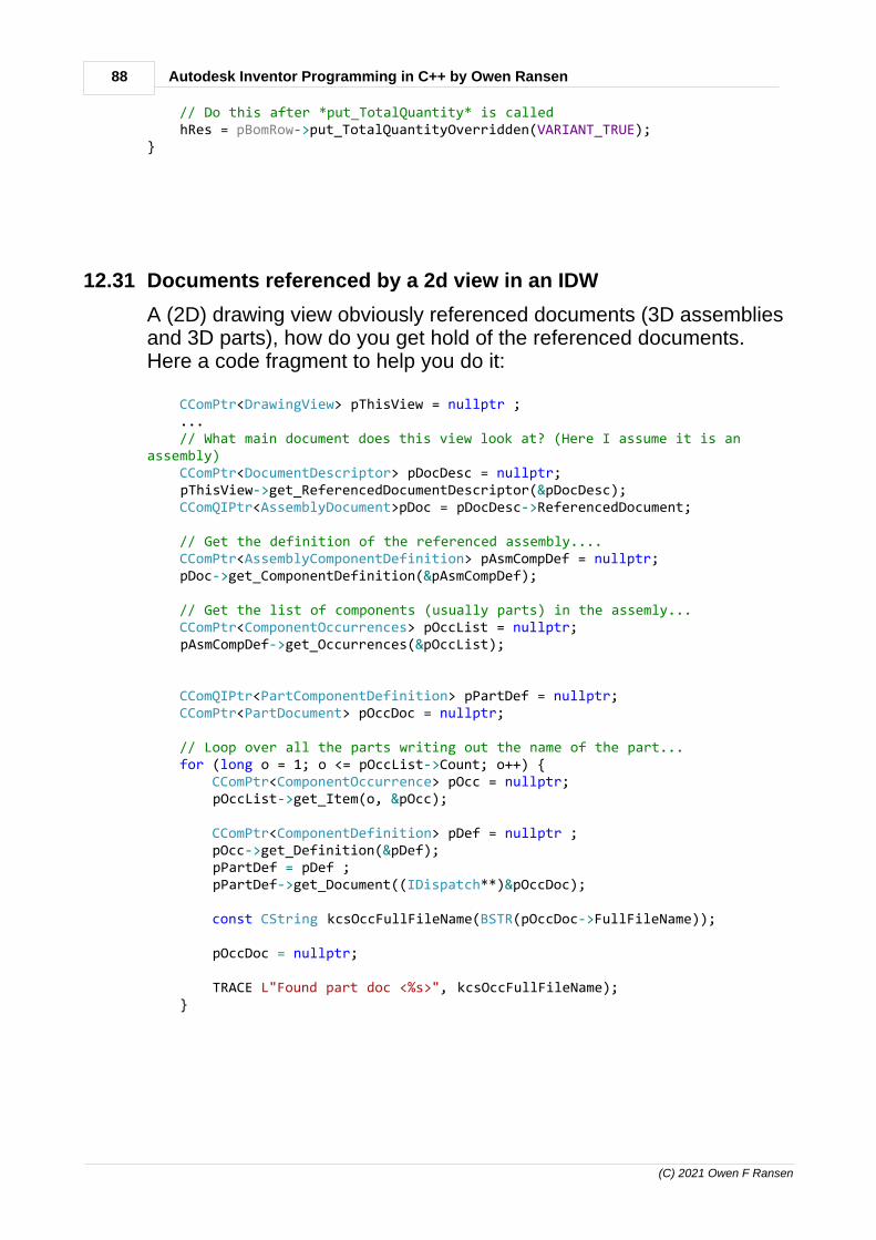
88 Autodesk Inventor Programming in C++ by Owen Ransen
(C) 2021 Owen F Ransen
// Do this after *put_TotalQuantity* is called hRes = pBomRow->put_TotalQuantityOverridden(VARIANT_TRUE);}
12.31 Documents referenced by a 2d view in an IDW
A (2D) drawing view obviously referenced documents (3D assembliesand 3D parts), how do you get hold of the referenced documents.Here a code fragment to help you do it:
CComPtr<DrawingView> pThisView = nullptr ; ... // What main document does this view look at? (Here I assume it is anassembly) CComPtr<DocumentDescriptor> pDocDesc = nullptr; pThisView->get_ReferencedDocumentDescriptor(&pDocDesc); CComQIPtr<AssemblyDocument>pDoc = pDocDesc->ReferencedDocument;
// Get the definition of the referenced assembly.... CComPtr<AssemblyComponentDefinition> pAsmCompDef = nullptr; pDoc->get_ComponentDefinition(&pAsmCompDef);
// Get the list of components (usually parts) in the assemly... CComPtr<ComponentOccurrences> pOccList = nullptr; pAsmCompDef->get_Occurrences(&pOccList);
CComQIPtr<PartComponentDefinition> pPartDef = nullptr; CComPtr<PartDocument> pOccDoc = nullptr;
// Loop over all the parts writing out the name of the part... for (long o = 1; o <= pOccList->Count; o++) { CComPtr<ComponentOccurrence> pOcc = nullptr; pOccList->get_Item(o, &pOcc);
CComPtr<ComponentDefinition> pDef = nullptr ; pOcc->get_Definition(&pDef); pPartDef = pDef ; pPartDef->get_Document((IDispatch**)&pOccDoc);
const CString kcsOccFullFileName(BSTR(pOccDoc->FullFileName));
pOccDoc = nullptr;
TRACE L"Found part doc <%s>", kcsOccFullFileName); }
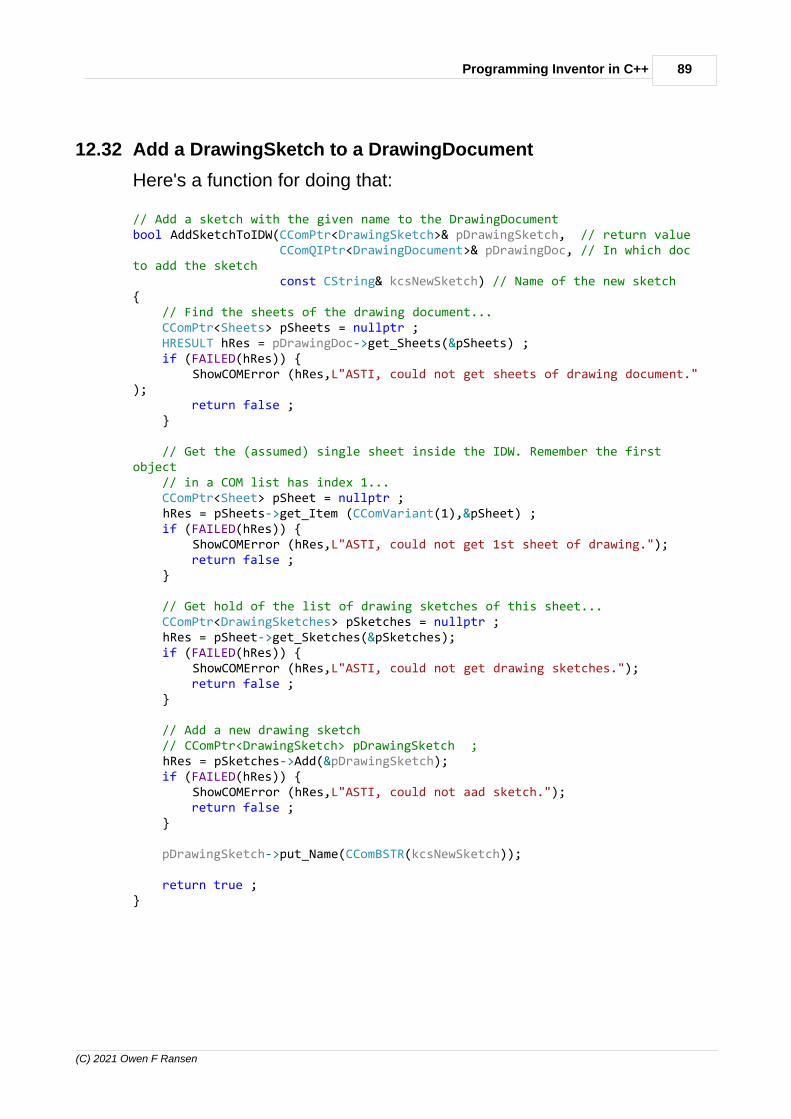
89Programming Inventor in C++
(C) 2021 Owen F Ransen
12.32 Add a DrawingSketch to a DrawingDocument
Here's a function for doing that:
// Add a sketch with the given name to the DrawingDocumentbool AddSketchToIDW(CComPtr<DrawingSketch>& pDrawingSketch, // return value CComQIPtr<DrawingDocument>& pDrawingDoc, // In which docto add the sketch const CString& kcsNewSketch) // Name of the new sketch{ // Find the sheets of the drawing document... CComPtr<Sheets> pSheets = nullptr ; HRESULT hRes = pDrawingDoc->get_Sheets(&pSheets) ; if (FAILED(hRes)) { ShowCOMError (hRes,L"ASTI, could not get sheets of drawing document."); return false ; }
// Get the (assumed) single sheet inside the IDW. Remember the firstobject // in a COM list has index 1... CComPtr<Sheet> pSheet = nullptr ; hRes = pSheets->get_Item (CComVariant(1),&pSheet) ; if (FAILED(hRes)) { ShowCOMError (hRes,L"ASTI, could not get 1st sheet of drawing."); return false ; }
// Get hold of the list of drawing sketches of this sheet... CComPtr<DrawingSketches> pSketches = nullptr ; hRes = pSheet->get_Sketches(&pSketches); if (FAILED(hRes)) { ShowCOMError (hRes,L"ASTI, could not get drawing sketches."); return false ; }
// Add a new drawing sketch // CComPtr<DrawingSketch> pDrawingSketch ; hRes = pSketches->Add(&pDrawingSketch); if (FAILED(hRes)) { ShowCOMError (hRes,L"ASTI, could not aad sketch."); return false ; }
pDrawingSketch->put_Name(CComBSTR(kcsNewSketch));
return true ;}
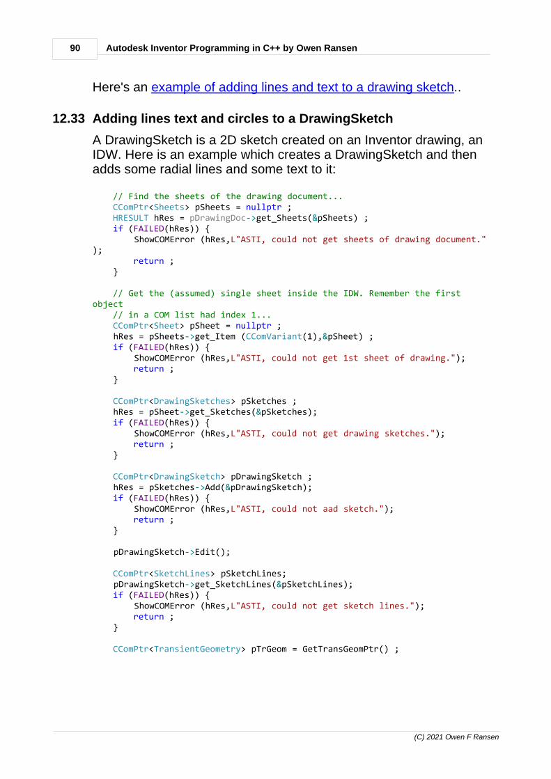
90 Autodesk Inventor Programming in C++ by Owen Ransen
(C) 2021 Owen F Ransen
Here's an example of adding lines and text to a drawing sketch..
12.33 Adding lines text and circles to a DrawingSketch
A DrawingSketch is a 2D sketch created on an Inventor drawing, anIDW. Here is an example which creates a DrawingSketch and thenadds some radial lines and some text to it:
// Find the sheets of the drawing document... CComPtr<Sheets> pSheets = nullptr ; HRESULT hRes = pDrawingDoc->get_Sheets(&pSheets) ; if (FAILED(hRes)) { ShowCOMError (hRes,L"ASTI, could not get sheets of drawing document."); return ; }
// Get the (assumed) single sheet inside the IDW. Remember the firstobject // in a COM list had index 1... CComPtr<Sheet> pSheet = nullptr ; hRes = pSheets->get_Item (CComVariant(1),&pSheet) ; if (FAILED(hRes)) { ShowCOMError (hRes,L"ASTI, could not get 1st sheet of drawing."); return ; }
CComPtr<DrawingSketches> pSketches ; hRes = pSheet->get_Sketches(&pSketches); if (FAILED(hRes)) { ShowCOMError (hRes,L"ASTI, could not get drawing sketches."); return ; }
CComPtr<DrawingSketch> pDrawingSketch ; hRes = pSketches->Add(&pDrawingSketch); if (FAILED(hRes)) { ShowCOMError (hRes,L"ASTI, could not aad sketch."); return ; }
pDrawingSketch->Edit();
CComPtr<SketchLines> pSketchLines; pDrawingSketch->get_SketchLines(&pSketchLines); if (FAILED(hRes)) { ShowCOMError (hRes,L"ASTI, could not get sketch lines."); return ; }
CComPtr<TransientGeometry> pTrGeom = GetTransGeomPtr() ;

91Programming Inventor in C++
(C) 2021 Owen F Ransen
for (int iDegs = 0; iDegs < 360; iDegs+=15) { CComPtr<Point2d> pStartPoint; pTrGeom->CreatePoint2d(0.0,0.0,&pStartPoint);
const double x = 100 * cos(RadsFromDegs(iDegs)); const double y = 100 * sin(RadsFromDegs(iDegs));
CComPtr<Point2d> pEndPoint; pTrGeom->CreatePoint2d(x,y,&pEndPoint);
pSketchLines->AddByTwoPoints((IDispatch*)pStartPoint,(IDispatch*)pEndPoint); }
CComPtr<Point2d> pTextPos,pDimPos1,pDimPos2; hRes = pTrGeom->CreatePoint2d(1.0,3.0,&pTextPos);
CComBSTR TestText(L"Hello"); CComVariant StyleName(L"Note Text (ISO)");
hRes = pDrawingSketch->TextBoxes->AddFitted(pTextPos, TestText,StyleName); if (FAILED(hRes)) { ShowCOMError (hRes,L"ASTI, AddFitted failed."); return ; }
pDrawingSketch->ExitEdit(); // Close the sketch editing
You'll get this, note the origin and that it is not clipped.

92 Autodesk Inventor Programming in C++ by Owen Ransen
(C) 2021 Owen F Ransen
The first part of the above code can be encapsulated as shown here.
12.34 Constrain a sketch point to a coordinate
This function can be used to add sketch points in defined xy positionsin a 2d sketch:

93Programming Inventor in C++
(C) 2021 Owen F Ransen
Note that AddTwoPointDistance uses the "initial" positions of the points towork out the distance and thus fix them with a dimension constraint.
// Given a sketch and a horizontal and vertical position this function addstwo // points, one at the origin of the sketch and the other constrained to theposition// in the parametersvoid AddConstrainedPointWRTOrigin(CComPtr<PlanarSketch>& pNewSketch,

94 Autodesk Inventor Programming in C++ by Owen Ransen
(C) 2021 Owen F Ransen
const double kxmmPos, const double kymmPos){ CComPtr<TransientGeometry> pTrGeom = GetTransGeomPtr();
// This will be a point fixed (grounded) at the origin... CComPtr<Point2d> pOrigin2d; pTrGeom->CreatePoint2d(0.0,0.0,&pOrigin2d); CComPtr<SketchPoint> pSketchOrigin; HRESULT hr = pNewSketch->SketchPoints->Add(pOrigin2d, VARIANT_FALSE,&pSketchOrigin);
CComPtr<GeometricConstraints> pGeoCons; hr = pNewSketch->get_GeometricConstraints(&pGeoCons);
// Fix the sketch point... CComQIPtr<SketchEntity> pSkEnt(pSketchOrigin); hr = pGeoCons->AddGround (pSkEnt); // !!!IMPORTANT!!! to make the originfixed
// Sketches work in cm so convert to cm from mm.... const double kcmxPos = kxmmPos / 10.0; const double kcmyPos = kymmPos / 10.0;
// The new point will be added to the sketch and constrained... CComPtr<Point2d> pNewPoint2d; pTrGeom->CreatePoint2d(kcmxPos,kcmyPos,&pNewPoint2d); CComPtr<SketchPoint> pNewSketchPointA ; hr = pNewSketch->SketchPoints->Add(pNewPoint2d, VARIANT_FALSE,&pNewSketchPointA); if (FAILED(hr)) { gLogger.Printf(ekErrMsg, L"Could not add sketch point"); return; }
// Work out a good point for the text of the dimension double xText = kcmxPos * 0.9; double yText = kcmyPos / 2.0; CComPtr<Point2d> pVTextPoint; pTrGeom->CreatePoint2d(xText,yText,&pVTextPoint);
hr = pNewSketch->DimensionConstraints->AddTwoPointDistance(pSketchOrigin, pNewSketchPointA, DimensionOrientationEnum::kVerticalDim, pVTextPoint, VARIANT_FALSE); if (FAILED(hr)) { ShowCOMError(hr, L"Could not add constraint AddTwoPointDistancevertical"); return; }
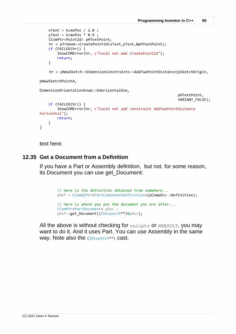
95Programming Inventor in C++
(C) 2021 Owen F Ransen
xText = kcmxPos / 2.0 ; yText = kcmxPos * 0.9 ; CComPtr<Point2d> pHTextPoint; hr = pTrGeom->CreatePoint2d(xText,yText,&pHTextPoint); if (FAILED(hr)) { ShowCOMError(hr, L"Could not add CreatePoint2d"); return; }
hr = pNewSketch->DimensionConstraints->AddTwoPointDistance(pSketchOrigin, pNewSketchPointA, DimensionOrientationEnum::kHorizontalDim, pHTextPoint, VARIANT_FALSE); if (FAILED(hr)) { ShowCOMError(hr, L"Could not add constraint AddTwoPointDistancehorizontal"); return; }}
text here.
12.35 Get a Document from a Definition
If you have a Part or Assembly definition, but not, for some reason,its Document you can use get_Document:
// Here is the definition obtained from somwhere... pDef = CComQIPtr<PartComponentDefinition>(pCompOcc->Definition); // Here is where you put the document you are after... CComPtr<PartDocument> pDoc ; pDef->get_Document((IDispatch**)&pDoc);
All the above is without checking for nullptr or HRESULT, you maywant to do it. And it uses Part. You can use Assembly in the sameway. Note also the (IDispatch**) cast.

96 Autodesk Inventor Programming in C++ by Owen Ransen
(C) 2021 Owen F Ransen
12.36 CreateSafeStringArray and CreateSafeDoubleArray
This is useful in various parts of COM programming:
// Call SafeArrayDestroy after you've finished with the arraySAFEARRAY* CreateSafeStringArray(long nElements, TCHAR *elements[]){ SAFEARRAYBOUND saBound[1];
saBound[0].cElements = nElements; saBound[0].lLbound = 0;
SAFEARRAY *pSA = SafeArrayCreate(VT_BSTR, 1, saBound);
if (pSA == NULL) { return NULL; }
for (int ix = 0; ix < nElements; ix++) { BSTR pData = SysAllocString(elements[ix]);
long rgIndicies[1];
rgIndicies[0] = saBound[0].lLbound + ix;
HRESULT hr = SafeArrayPutElement(pSA, rgIndicies, pData); }
return pSA;}
For example in adding tables into sheets.
For doubles use:
// After use call SafeArrayDestroySAFEARRAY* CreateSafeDoubleArray(long nElements, double* pElements){ SAFEARRAYBOUND rgsabound[1]; rgsabound[0].lLbound = 0; // index starts at 0 rgsabound[0].cElements = nElements; // number of elements
SAFEARRAY FAR* psa = SafeArrayCreate(VT_R8, 1, rgsabound); if (psa == NULL) { return 0; }
HRESULT hr = SafeArrayLock(psa);
for (int i = 0 ; i < nElements ; i++) { LONG rgIndex = i ;

97Programming Inventor in C++
(C) 2021 Owen F Ransen
double d = pElements[i]; hr = SafeArrayPutElement(psa, &rgIndex, &d); }
hr = SafeArrayUnlock(psa);
return psa;}
Here's an example.
12.37 Listing 2d points in a sketch
To get hold of the coordinates of 2d points in a 2d sketch look at thisexample:
gLogger.Printf(ekLogMsg, L"There are %d points in the sketch", pNewSketch->SketchPoints->Count); for (long p = 1; p <= pNewSketch->SketchPoints->Count; p++) { CComPtr<SketchPoint> pTempSketchPoint; pNewSketch->SketchPoints->get_Item(p,&pTempSketchPoint); CComPtr<Point2d> pCoords; pTempSketchPoint->get_Geometry(&pCoords); gLogger.Printf(ekLogMsg, L"Point %3d is %.2f %.2f",p, pCoords->GetX(),pCoords->GetY()); }
12.38 gkVarEmpty
This is used in various calls where you want an empty parameter:
const CComVariant gkvarEmpty ; // Used in various COM calls here
12.39 Add an iMate (based on a point) into an assembly
Here is a function to do it:
bool AddMateiMateAtAsmWorkPoint(const CString& kcsiMateName, CComPtr<AssemblyComponentDefinition>pAsmCompDef, const CString& kcsWorkPointName)

98 Autodesk Inventor Programming in C++ by Owen Ransen
(C) 2021 Owen F Ransen
{ CComPtr<iMateDefinitions> piMateDefinitions = nullptr ; HRESULT hRes = pAsmCompDef->get_iMateDefinitions(&piMateDefinitions); if (FAILED(hRes)) { TRACE ("AMMAAWP: Failed to get iMate definitions"); return false ; }
CComPtr<WorkPoint> pWorkPoint; const bool kbWpOk = GetWorkPointByName(pWorkPoint, kcsWorkPointName,pAsmCompDef); if (!kbWpOk) { TRACE ("AMMAAWP: Failed to get work point called <%s>",kcsWorkPointName); return false; }
// Zero offset CComVariant varOffset = CComVariant(0.0);
CComPtr<MateiMateDefinition> pMateiMateDef; hRes = piMateDefinitions->AddMateiMateDefinition(pWorkPoint, varOffset, kNoInference, gkvarEmpty, CComBSTR(kcsiMateName), gkvarEmpty, &pMateiMateDef); if (FAILED(hRes)) { TRACE (L"AMMAAWP:Failed to add iMate definition at work point.",kcsWorkPointName); return false; }
return true;}
Here is some example code which also opens the assembly...
CComPtr<AssemblyComponentDefinition> pAsmCompDef; CComPtr<AssemblyDocument> pAsmDoc; const CString kcsFullAsmFileName(L"C:\\TEST.IAM") ;
const bool kbOpenedOk = OpenAssembly(pAsmCompDef,pAsmDoc,kcsFullAsmFileName) ; if (!kbOpenedOk) { TRACE("Failed to open"); return; }
CComPtr<iMateDefinitions> piMateDefinitions = nullptr ; HRESULT hRes = pAsmCompDef->get_iMateDefinitions(&piMateDefinitions); if (FAILED(hRes)) {

99Programming Inventor in C++
(C) 2021 Owen F Ransen
TRACE("Failed to get imate definitions"); return; }
CComPtr<WorkPoint> pWorkPoint; const bool kbWpOk = GetWorkPointByName(pWorkPoint, L"ZeroPoint",pAsmCompDef); if (!kbWpOk) { TRACE("Could not find work point"); return; }
CComVariant varOffset = CComVariant(0.0);
CComPtr<MateiMateDefinition> pMateiMateDef; hRes = piMateDefinitions->AddMateiMateDefinition(pWorkPoint, varOffset, kNoInference, gkvarEmpty, CComBSTR("Pippo"), gkvarEmpty, &pMateiMateDef); if (FAILED(hRes)) { TRACE("Failed to add imate definition."); }
pAsmDoc->Close(VARIANT_FALSE);
See what I mean?
12.40 Part Lists programatically
Here you get an existing Part List and add a row to it:
// There can be many part lists in a single sheet, get hold of thelist of lists... CComPtr<PartsLists> pPartsLists; hRes = pSheet->get_PartsLists(&pPartsLists);
// Make a 2d point to specify the top left corner of the partslist... CComPtr<TransientGeometry> pTransGeom = GetTransGeomPtr () ; CComPtr<Point2d> pListPos; // Create a 2d point
// Place top left of part list in the center of the sheet... pTrGeom->CreatePoint2d(SheetWidth/2.0,SheetWidth/2.0,&pListPos);
// To create a part list you add it to the list of part lists.... CComPtr<PartsList> MyPartList; CComVariant varNumNum(kNumericNumbering); hRes = pPartsLists->Add(pBaseView1, pListPos, kFirstLevelComponents,varNumNum, 1, VARIANT_FALSE, &MyPartList);

100 Autodesk Inventor Programming in C++ by Owen Ransen
(C) 2021 Owen F Ransen
// A part list is in essence a set of rows... PartsListRowsPtr pRows = MyPartList->GetPartsListRows(); long iNumRows = pRows->Count;
// Add a new row. // This new row will have the same number of columns as existing rows CComPtr<PartsListRow> pNewRow; hRes = pRows->Add(iNumRows, // Relative to which existing row weinsert the new one? VARIANT_FALSE, // FALSE means insert after theexsiting roe &pNewRow); // Returned new row long iNumCols; pNewRow->get_Count(&iNumCols); if (iNumCols >= 4) { // Test adding text into col 3 // Col1 is id, 2 is quantity, they have default values 3 and 4 youfill out CComPtr<PartsListCell> pCell; CComVariant ColNum(3); pNewRow->get_Item(ColNum, &pCell); CComBSTR Hello(L"Hello you"); pCell->put_Value(Hello); }
So you have to get hold of the cell and then modify it.
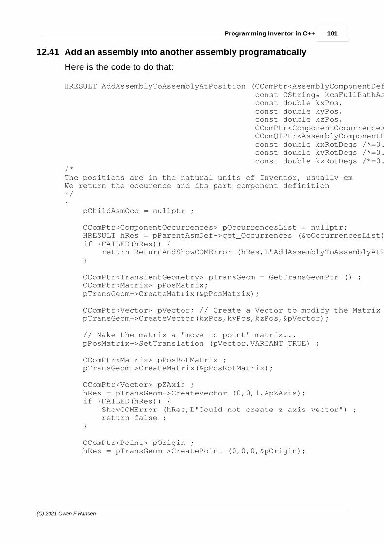
101Programming Inventor in C++
(C) 2021 Owen F Ransen
12.41 Add an assembly into another assembly programatically
Here is the code to do that:
HRESULT AddAssemblyToAssemblyAtPosition (CComPtr<AssemblyComponentDefinition>& pParentAsmDef, const CString& kcsFullPathAsmName, const double kxPos, const double kyPos, const double kzPos, CComPtr<ComponentOccurrence>& pChildAsmOcc, CComQIPtr<AssemblyComponentDefinition>& pChildAsmDef, const double kxRotDegs /*=0.0*/, const double kyRotDegs /*=0.0*/, const double kzRotDegs /*=0.0*/) /*The positions are in the natural units of Inventor, usually cmWe return the occurence and its part component definition*/{ pChildAsmOcc = nullptr ;
CComPtr<ComponentOccurrences> pOccurrencesList = nullptr; HRESULT hRes = pParentAsmDef->get_Occurrences (&pOccurrencesList) ; if (FAILED(hRes)) { return ReturnAndShowCOMError (hRes,L"AddAssemblyToAssemblyAtPosition get_Occurrences failed") ; }
CComPtr<TransientGeometry> pTransGeom = GetTransGeomPtr () ; CComPtr<Matrix> pPosMatrix; pTransGeom->CreateMatrix(&pPosMatrix);
CComPtr<Vector> pVector; // Create a Vector to modify the Matrix pTransGeom->CreateVector(kxPos,kyPos,kzPos,&pVector);
// Make the matrix a "move to point" matrix... pPosMatrix->SetTranslation (pVector,VARIANT_TRUE) ;
CComPtr<Matrix> pPosRotMatrix ; pTransGeom->CreateMatrix(&pPosRotMatrix);
CComPtr<Vector> pZAxis ; hRes = pTransGeom->CreateVector (0,0,1,&pZAxis); if (FAILED(hRes)) { ShowCOMError (hRes,L"Could not create z axis vector") ; return false ; }
CComPtr<Point> pOrigin ; hRes = pTransGeom->CreatePoint (0,0,0,&pOrigin);

102 Autodesk Inventor Programming in C++ by Owen Ransen
(C) 2021 Owen F Ransen
const double kZRadsRot = RadsFromDegs(kzRotDegs); pPosRotMatrix->SetToRotation (kZRadsRot,pZAxis,pOrigin) ;
pPosRotMatrix->PreMultiplyBy(pPosMatrix);
hRes = pOccurrencesList->Add (CComBSTR(kcsFullPathAsmName),pPosRotMatrix,&pChildAsmOcc) ; if (FAILED(hRes)) { return ReturnAndShowCOMError (hRes,L"AddAssemblyToAssemblyAtPosition Add failed") ; }
// Get the general component definition... CComQIPtr<ComponentDefinition> pCompDef ; hRes = pChildAsmOcc->get_Definition (&pCompDef) ; if (FAILED(hRes)) { return ReturnAndShowCOMError (hRes,L"AddAssemblyToAssemblyAtPosition could not get child definition.") ; }
// Cast from the general sort of component definition to the specific assembly component definition pChildAsmDef = CComQIPtr<AssemblyComponentDefinition>(pCompDef); if (pChildAsmDef == nullptr) { gLogger.Printf (ekErrMsg,L"AddAssemblyToAssemblyAtPosition(%s) could not cast to pChildAsmDef.") ; return E_FAIL ; }
return S_OK ;}
Enter topic text here.
12.42 Hide a sketch in a part
You can yse this function:
void HidePartSketchByName (CComPtr<PartComponentDefinition>& pPartCompDef,const wchar_t* const pszName){ // Get the list of sketches... CComPtr<PlanarSketches> pSketchesList ; HRESULT hRes = pPartCompDef->get_Sketches(&pSketchesList) ; if (FAILED(hRes)) { ShowCOMError(hRes,L"HPSBN (%s) get_Features failed",pszName); return ; }
CComPtr<PlanarSketch> pSketch ; hRes = pSketchesList->get_Item (CComVariant(pszName),&pSketch) ;

103Programming Inventor in C++
(C) 2021 Owen F Ransen
if (FAILED(hRes)) { gLogger.Printf(ekLogMsg, L"HPSBN (%s) get_Item failed, sketch hasalready been deleted maybe", pszName); return ; }
pSketch->put_Visible (VARIANT_FALSE) ;}
12.43 Range BBox of a PartsList
Notice that you declare the Box2d but don't must not make it withpTrGeom->CreateBox2d(&BBoxOfLists);. In other words get_RangeBox expectsa null input and he hands you back the created box.
// Find out the size of the bounding box CComPtr<Box2d> BBoxOfLists; // Inits to nullptr MyPartsList->get_RangeBox(&BBoxOfLists);
gLogger.Printf(ekLogMsg, L"Bbox = %.2f %.2f %.2f %.2f ", BBoxOfLists->GetMinPoint()->GetX(), BBoxOfLists->GetMinPoint()->GetY(), BBoxOfLists->GetMaxPoint()->GetX(), BBoxOfLists->GetMaxPoint()->GetY());
12.44 Add a unitless user parameter into an assembly
Here's a function to do that:
// Adds a unitless user parameter and its value into an assembly... void AddUserUlParamToAssembly(CComPtr<AssemblyComponentDefinition>&pAssemblyCompDef, const CString& kcsParamName, const double kParamValue){ // Parameters contains two lists, Model and User... CComPtr<Parameters> pParameters ; pAssemblyCompDef->get_Parameters (&pParameters) ;
// Get the model parameters list... CComPtr<UserParameters> pUserParameters ; pParameters->get_UserParameters (&pUserParameters) ;
CComVariant varValue(kParamValue); CComVariant varUnits(L"ul");
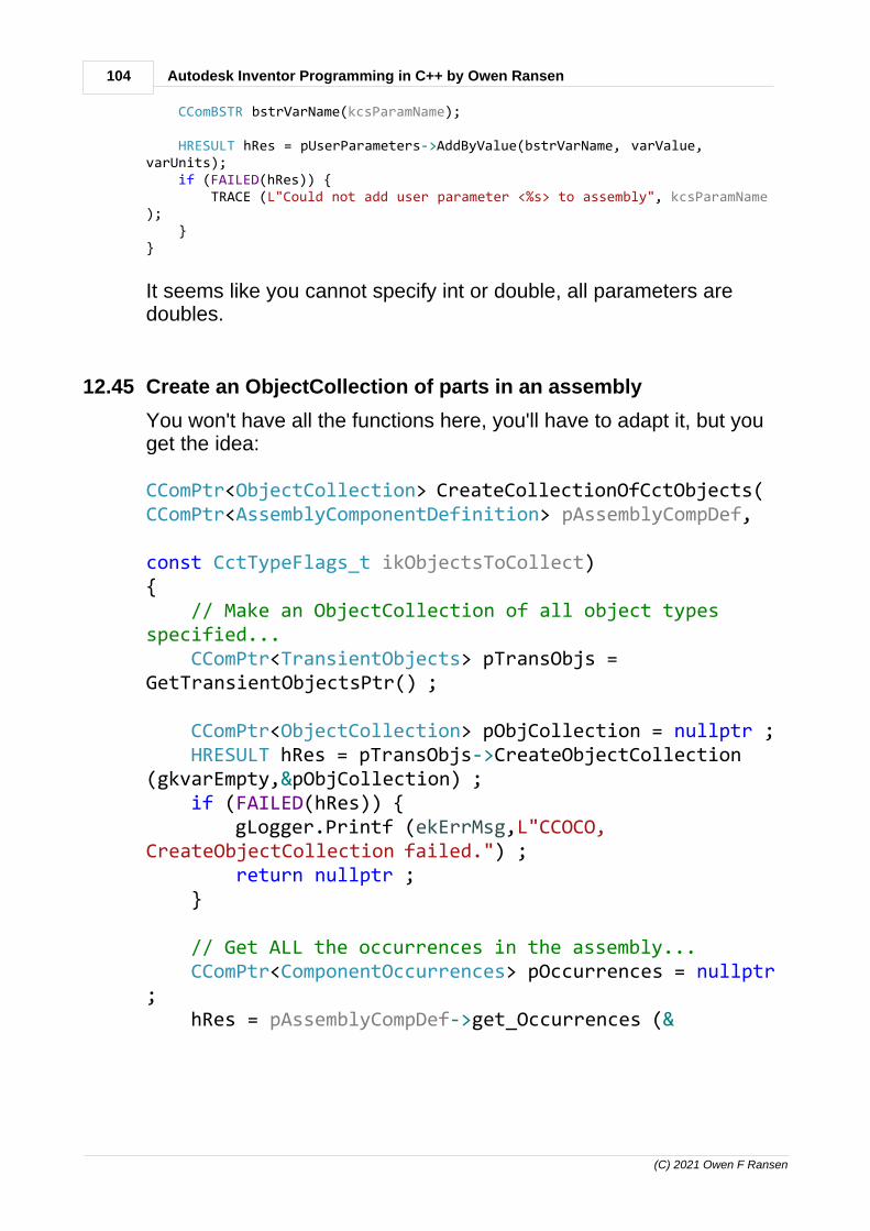
104 Autodesk Inventor Programming in C++ by Owen Ransen
(C) 2021 Owen F Ransen
CComBSTR bstrVarName(kcsParamName);
HRESULT hRes = pUserParameters->AddByValue(bstrVarName, varValue,varUnits); if (FAILED(hRes)) { TRACE (L"Could not add user parameter <%s> to assembly", kcsParamName); }}
It seems like you cannot specify int or double, all parameters aredoubles.
12.45 Create an ObjectCollection of parts in an assembly
You won't have all the functions here, you'll have to adapt it, but youget the idea:
CComPtr<ObjectCollection> CreateCollectionOfCctObjects(CComPtr<AssemblyComponentDefinition> pAssemblyCompDef, const CctTypeFlags_t ikObjectsToCollect){ // Make an ObjectCollection of all object typesspecified... CComPtr<TransientObjects> pTransObjs =GetTransientObjectsPtr() ;
CComPtr<ObjectCollection> pObjCollection = nullptr ; HRESULT hRes = pTransObjs->CreateObjectCollection(gkvarEmpty,&pObjCollection) ; if (FAILED(hRes)) { gLogger.Printf (ekErrMsg,L"CCOCO,CreateObjectCollection failed.") ; return nullptr ; }
// Get ALL the occurrences in the assembly... CComPtr<ComponentOccurrences> pOccurrences = nullptr; hRes = pAssemblyCompDef->get_Occurrences (&

105Programming Inventor in C++
(C) 2021 Owen F Ransen
pOccurrences) ; if (FAILED(hRes)) { gLogger.Printf (ekErrMsg,L"CCOCO,get_Occurrences failed.") ; return nullptr ; }
// Collect together only the occurrences we areinterested in... for (int i = 1; i <= pOccurrences->Count; i++) { CComPtr<ComponentOccurrence> pThisCompOcc =nullptr ; hRes = pOccurrences->get_Item(i, &pThisCompOcc);
_bstr_t DisplayName = pThisCompOcc->Get_DisplayName(); CString kcsDisplayName = CString(DisplayName.GetBSTR());
const CString kcsSapCode = kcsDisplayName.Left(NUM_SAP_CHARS);
const bool kbObjToActOn = SapCodeIsA(kcsSapCode, ikObjectsToCollect) ; if (kbObjToActOn) { pObjCollection->Add(pThisCompOcc); } }
return pObjCollection;}
Can be used to create an ObjectCollection of ParticipatingOccurrences.

106 Autodesk Inventor Programming in C++ by Owen Ransen
(C) 2021 Owen F Ransen
12.46 Delete a feature in a part
It is a bit delicate if other features depend on the feature you aretrying to delete.
void DeletePartFeatureByName(CComPtr<PartComponentDefinition>& pPartCompDef,const wchar_t* const pszName){ // Get the list of features... CComPtr<PartFeatures> pFeaturesList = nullptr ; HRESULT hRes = pPartCompDef->get_Features(&pFeaturesList) ; if (FAILED(hRes)) { ShowCOMError(hRes,L"DPFBN get_Features failed"); return ; }
CComPtr<PartFeature> pFeature = nullptr ; hRes = pFeaturesList->get_Item (CComVariant(pszName),&pFeature) ; if (FAILED(hRes)) { ShowCOMError(hRes,L"DPFBN get_Item(%s) failed",pszName); return ; }
hRes = pFeature->Delete(VARIANT_FALSE,VARIANT_FALSE,VARIANT_FALSE); if (FAILED(hRes)) { ShowCOMError(hRes,L"DPFBN Delete(%s) failed",pszName); }}
12.47 Loop over part occurences in an assembly
Here's an example, which also shows the use of _b_str_t andDisplayName and the filename of the part:
CComPtr<ComponentOccurrences> pOccurrences; hRes = pAssemblyCompDef->get_Occurrences (&pOccurrences) ;
// Note the i starts at 1, NET counting for (int i = 1; i <= pOccurrences->Count; i++) { CComPtr<ComponentOccurrence> pThisCompOcc ; hRes = pOccurrences->get_Item(i, &pThisCompOcc);
_bstr_t DisplayName = pThisCompOcc->Get_DisplayName(); CString csDisplayName = CString (DisplayName.GetBSTR());
CComPtr<DocumentDescriptor> pDocDesc ; pThisCompOcc->get_ReferencedDocumentDescriptor(&pDocDesc) ; CComBSTR bstrFullDocName ;

107Programming Inventor in C++
(C) 2021 Owen F Ransen
pDocDesc->get_FullDocumentName (&bstrFullDocName) ; gLogger.Printf(ekLogMsg, L"Occ <%s> Disp=<%s>",CString(bstrFullDocName), csDisplayName); }
The DisplayName is what appears in the tree list of the assembly, bythe way. The output in the display name also includes the number ofthe part inserted, after the ":"
Occurrence <C:\Owen\DirA\Curve_Rame_12\30091328.ipt> Display=<30091328:17>Occurrence <C:\Owen\DirA\Forcelle_Rame_12_Rigato\30093874.ipt>Display=<30093874:22>Occurrence <C:\Owen\DirA\Curve_Rame_12\30091327.ipt> Display=<30091327:18>Occurrence <C:\Owen\DirA\Forcelle_Rame_12_Rigato\30093882.ipt>Display=<30093882:23>

108 Autodesk Inventor Programming in C++ by Owen Ransen
(C) 2021 Owen F Ransen
12.48 Add a rectangle to a sketch
Here's a function to add a rectangle to a sketch:
bool AddRectToSketch (CComPtr<PlanarSketch>& pSketch, const double kxMin, const double kyMin, const double kxMax, const double kyMax) { // Get the transient geometry object. We'll use this to create pure geometric points CComPtr<TransientGeometry> pTrGeom = GetTransGeomPtr() ; CComPtr<Point2d> pMinPt; // Pure geometric point HRESULT hRes = pTrGeom->CreatePoint2d(kxMin,kyMin,&pMinPt); CComPtr<Point2d> pMaxPt; // Pure geometric point hRes = pTrGeom->CreatePoint2d(kxMax,kyMax,&pMaxPt);
// Create sketch points from above points // Get list of SketchPoints, points existing in a sketch CComPtr<SketchPoints> pSkPoints;
hRes = pSketch->get_SketchPoints(&pSkPoints);
// Create a SketchPoint from a geometric point CComPtr<SketchPoint> pSpt1; hRes = pSkPoints->Add(pMinPt, // geometrical point VARIANT_FALSE, // not a hole center &pSpt1); // resulting SketchPoint
CComPtr<SketchPoint> pSpt2; hRes = pSkPoints->Add(pMaxPt,VARIANT_FALSE,&pSpt2); CComPtr<SketchEntitiesEnumerator> pRectangleLines;
// Get SketchLines CComPtr<SketchLines> pSkLines; hRes = pSketch->get_SketchLines(&pSkLines);
// Creat a rectangle from two points hRes = pSkLines->AddAsTwoPointRectangle(_variant_t((IDispatch *)pSpt1), _variant_t((IDispatch *)pSpt2), &pRectangleLines);
return SUCCEEDED(hRes) ;}

109Programming Inventor in C++
(C) 2021 Owen F Ransen
12.49 Rectangular cut with extrusion
Here is what I use, complete with optional participating occurrencesObjectCollection:
bool ExtrudeSketchInAsm (const wchar_t* const pszExtrusionName, // name ofcreated feature const double kHeight, const wchar_t* const pszSketchName, // whichsketch to extrude const PartFeatureOperationEnum eOperation, // how toextrude const PartFeatureExtentDirectionEnum eDirection, CComPtr<AssemblyComponentDefinition>& pAsmCompDef, CComPtr<ObjectCollection> pParticipatingObjects /* =nullptr*/)/*Given a height and a sketch name the sketch is extruded to the given height.The resultant feature is placed inside pAsmCompDef, and is calledpszExtrusionNameeOperation tells us whether to cut a hole or create a solid object etc.eDirection tells us which direction to make the extrusion.If pParticipatingObjects is nullptr all occurrences in the assembly areaffected.If pParticipatingObjects is a list of occurrences ony thos occurrences areaffected.*/{ gLogger.Printf (ekLogMsg,L"ESIA extrusion called %s, height %.2fmm,sketch=%s\n", pszExtrusionName,kHeight,pszSketchName) ;
// Get the sketch in the part by name... CComPtr<PlanarSketch> pSketch; HRESULT hRes = pAsmCompDef->Sketches->get_Item(CComVariant(pszSketchName),&pSketch); if (FAILED(hRes)) { ShowCOMError (hRes,L"ESIA, but could not get sketch by name: <%s>\n",pszSketchName); return false ; } CComPtr<Profile> pProfile ; // This is the return value of the call toAddForSolid // and will be used when we extrude. CComVariant pSegs; // not used CComVariant pReserve; // not used hRes = pSketch->Profiles->AddForSolid(VARIANT_TRUE,pSegs,pReserve,&pProfile); if (FAILED(hRes)) { ShowCOMError (hRes,L"ESIA, but could not AddForSolid for pProfile\n");

110 Autodesk Inventor Programming in C++ by Owen Ransen
(C) 2021 Owen F Ransen
return false ; }
// Features are 3D objects. Get the list of them so we can add to thatlist... CComPtr<Features> pListOfFeatures=nullptr; hRes = pAsmCompDef->get_Features(&pListOfFeatures); if (FAILED(hRes)) { ShowCOMError (hRes,L"ESIA, but could not get_Features\n"); return false ; }
// Get the list of *extruded* features... CComPtr<ExtrudeFeatures> pListOfExtrusions; hRes = pListOfFeatures->get_ExtrudeFeatures(&pListOfExtrusions); if (FAILED(hRes)) { ShowCOMError (hRes,L"ESIA, but could not get_ExtrudeFeatures\n"); return false ; }
// Now at last we can use the pProfile to create a new extrusion, addingit to the list // of extruded features. This is where we use the eOperation parameter CComPtr<ExtrudeDefinition> pExtrudeDef; hRes = pListOfExtrusions->CreateExtrudeDefinition(pProfile,eOperation,&pExtrudeDef); if (FAILED(hRes)) { ShowCOMError (hRes,L"ESIA, but could not CreateExtrudeDefinition\n"); return false ; }
// Specify the distance and direction of the extrustion... pExtrudeDef->SetDistanceExtent(_variant_t(kHeight),eDirection);
if (pParticipatingObjects != nullptr) { hRes = pExtrudeDef->put_AffectedOccurrences(pParticipatingObjects); if (FAILED(hRes)) { ShowCOMError (hRes,L"ESIA, but could not put_AffectedOccurrencesfor <%s>\n",pszExtrusionName); return false ; } }
// Add the extrusion. CComPtr<ExtrudeFeature> pExtrude = nullptr ; hRes = pListOfExtrusions->Add (pExtrudeDef,&pExtrude); if (FAILED(hRes)) { ShowCOMError (hRes,L"ESIA, but could not Add ExtrudeDefinition for<%s>\n" L"***LISTEN*** This can happen if the extrusion does notchange the model.",pszExtrusionName); return false ; }

111Programming Inventor in C++
(C) 2021 Owen F Ransen
pExtrude->put_Name (CComBSTR (pszExtrusionName)) ;
return true ;}
12.50 WorkAxis constraints
To constrain two axes together programatically you can use thisfunction:
bool AddMateConstraintOfTwoWorkAxisProxies (CComPtr<AssemblyComponentDefinition>& pAsmCompDef, CComPtr<WorkAxisProxy>& pWAProxyA, CComPtr<WorkAxisProxy>& pWAProxyB, const double kRadiusMm /*=0.0*/) { // Get the list of constraints of the assembly so you can add a new one CComPtr<AssemblyConstraints> pConstraintList = nullptr ; HRESULT hRes = pAsmCompDef->get_Constraints(&pConstraintList) ; if (FAILED(hRes) || (pConstraintList == nullptr)) { ShowCOMError (hRes,L"AddMateConstraintOfTwoWorkAxisProxies could notget constraints.") ; return false ; }
// The offset in a axis constraint is a radius about which the axes // can rotate. Having a non zero one means a bit more flexiblity. CComVariant varOffset(kRadiusMm/10.0); // in cm
CComPtr<MateConstraint> pMateConstraint = nullptr ; hRes = pConstraintList->AddMateConstraint(pWAProxyA, pWAProxyB, varOffset, kNoInference, kNoInference, gkvarEmpty, gkvarEmpty, &pMateConstraint); if ((FAILED(hRes) || (pMateConstraint == nullptr))) { ShowCOMError (hRes,L"AddMateConstraintOfTwoWorkAxisProxies failed") ; return false ; }
return true ;}
Explanation of kRadiusMm here.

112 Autodesk Inventor Programming in C++ by Owen Ransen
(C) 2021 Owen F Ransen
12.51 Getting hold of the standard workpoint called "Center Point"
Here's an example of getting it and using it:
// Get the point in the manicotto CComPtr<WorkPoint> pWorkPointInMani ; hRes = GetWorkPointByName (pWorkPointInMani,L"Center Point",pManicottoCompDef) ;
AddMateConstraintOfTwoPoints (pAssemblyCompDef, pTuboOcc, pWorkPointInColl, pManicottoOcc, pWorkPointInMani) ;
I also call it an origin point or a zero point.
12.52 Add a WorkPoint into an assembly programatically
Here's how to do it, but note that the point added is totallyunconstrained:
CComPtr<WorkPoints> pWorkPointsList ; hRes = pAssemblyCompDef->get_WorkPoints (&pWorkPointsList) ;
CComPtr<Point> pPt; // Create a 3d point hRes = GetTransGeomPtr()->CreatePoint(kStart[XI],kStart[YI],kStart[ZI],&pPt);
hRes = pWorkPointsList->AddFixed (pPt,FALSE) ;
There's no error checking in the above code.
To do it manually you need to create a point which is the intersectionof 3 planes (x y z). The planes can be offset of course so you are ableto put the plane anywhere in 3D space.
Here is code which illustrates putting it at the start of an axis andsetting its name:
// Get the geometry of the axis.. LinePtr pLine = pNodeWAZProxy->GetLine() ; PointPtr pProxyOrigin = pLine->RootPoint ; UnitVectorPtr pDir = pLine->Direction ;
// You can get hold of the double values like this... TRACE("pos = %.3f, %.3f, %.3f, dir = %.3f, %.3f, %.3f,\n", pProxyOrigin->GetX(),pProxyOrigin->GetY(),pProxyOrigin->GetZ(), pDir->GetX(), pDir->GetY(), pDir->GetZ());
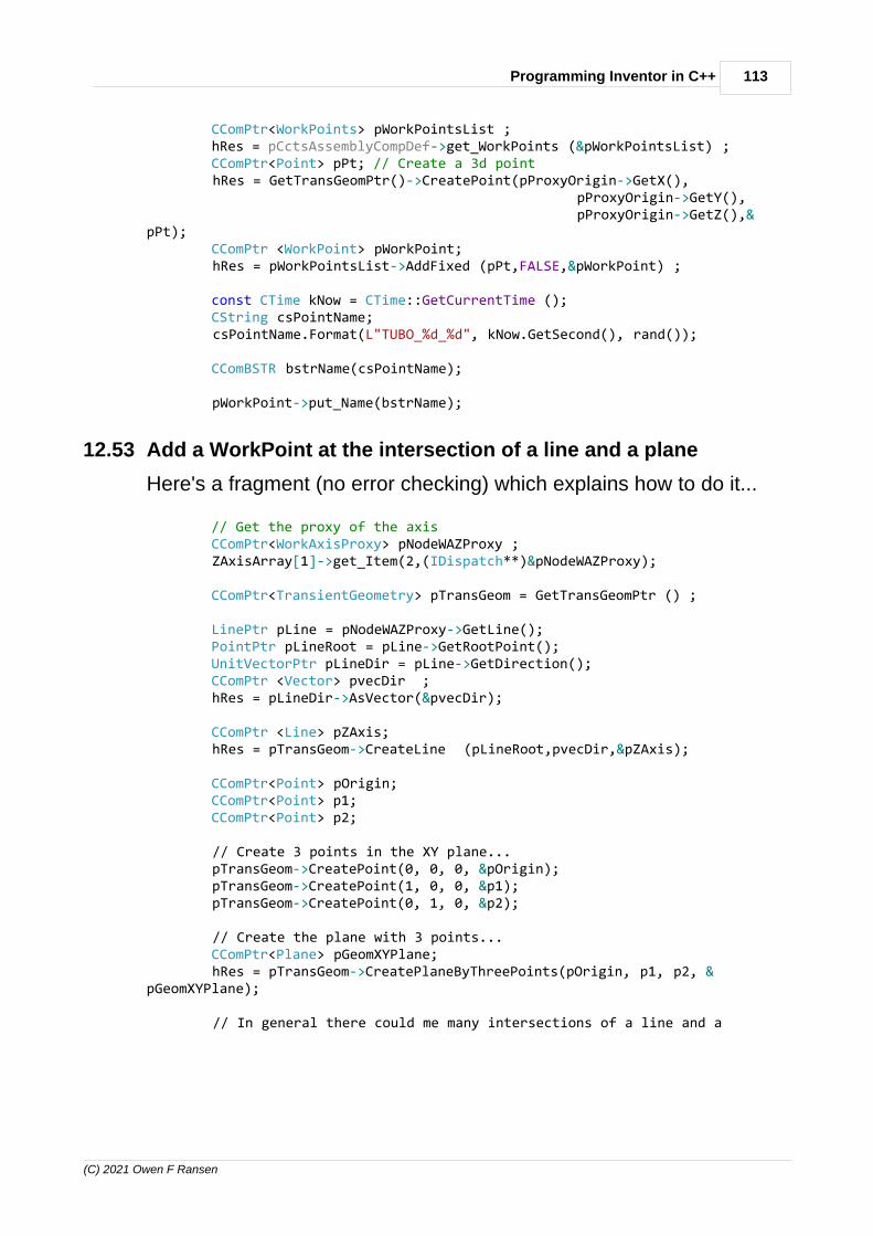
113Programming Inventor in C++
(C) 2021 Owen F Ransen
CComPtr<WorkPoints> pWorkPointsList ; hRes = pCctsAssemblyCompDef->get_WorkPoints (&pWorkPointsList) ; CComPtr<Point> pPt; // Create a 3d point hRes = GetTransGeomPtr()->CreatePoint(pProxyOrigin->GetX(), pProxyOrigin->GetY(), pProxyOrigin->GetZ(),&pPt); CComPtr <WorkPoint> pWorkPoint; hRes = pWorkPointsList->AddFixed (pPt,FALSE,&pWorkPoint) ;
const CTime kNow = CTime::GetCurrentTime (); CString csPointName; csPointName.Format(L"TUBO_%d_%d", kNow.GetSecond(), rand());
CComBSTR bstrName(csPointName);
pWorkPoint->put_Name(bstrName);
12.53 Add a WorkPoint at the intersection of a line and a plane
Here's a fragment (no error checking) which explains how to do it...
// Get the proxy of the axis CComPtr<WorkAxisProxy> pNodeWAZProxy ; ZAxisArray[1]->get_Item(2,(IDispatch**)&pNodeWAZProxy);
CComPtr<TransientGeometry> pTransGeom = GetTransGeomPtr () ;
LinePtr pLine = pNodeWAZProxy->GetLine(); PointPtr pLineRoot = pLine->GetRootPoint(); UnitVectorPtr pLineDir = pLine->GetDirection(); CComPtr <Vector> pvecDir ; hRes = pLineDir->AsVector(&pvecDir);
CComPtr <Line> pZAxis; hRes = pTransGeom->CreateLine (pLineRoot,pvecDir,&pZAxis);
CComPtr<Point> pOrigin; CComPtr<Point> p1; CComPtr<Point> p2;
// Create 3 points in the XY plane... pTransGeom->CreatePoint(0, 0, 0, &pOrigin); pTransGeom->CreatePoint(1, 0, 0, &p1); pTransGeom->CreatePoint(0, 1, 0, &p2);
// Create the plane with 3 points... CComPtr<Plane> pGeomXYPlane; hRes = pTransGeom->CreatePlaneByThreePoints(pOrigin, p1, p2, &pGeomXYPlane);
// In general there could me many intersections of a line and a

114 Autodesk Inventor Programming in C++ by Owen Ransen
(C) 2021 Owen F Ransen
surfaces, // With a plane we expeect pObjEnum to contain a single object CComPtr <ObjectsEnumerator> pObjEnum; hRes = pTransGeom->CurveSurfaceIntersection(pZAxis, pGeomXYPlane,0.1, &pObjEnum);
TRACE ("There are %d intersections...\n",pObjEnum->Count);
if (pObjEnum->Count < 1) { gLogger.Printf(ekErrMsg, "No intersections found..."); return; }
CComPtr <Point> pIntersectionPoint; hRes = pObjEnum->get_Item(1,(IDispatch**)&pIntersectionPoint);
TRACE("Intersection at %.2f %.2f %.2f \n", pIntersectionPoint->GetX(), pIntersectionPoint->GetY(), pIntersectionPoint->GetZ());
CComPtr<WorkPoints> pWorkPoints; hRes = pAssemblyCompDef->get_WorkPoints(&pWorkPoints);
CComPtr <WorkPoint> pInterWorkPoint; pWorkPoints->AddFixed (pIntersectionPoint,FALSE,&pInterWorkPoint);
CComBSTR bstrPointName("ZeroPoint"); hRes = pInterWorkPoint->put_Name(bstrPointName);
12.54 Add grounded WorkAxis in an assembly
There are limits to how you can add work axes in assemblies (andpresumably also work points and work planes). In general they haveto be done using AddFixed.
Here's an example:
CComQIPtr<AssemblyDocument> pAssemblyDoc; CComPtr<AssemblyComponentDefinition> pAssemblyCompDef;
CComPtr<TransientGeometry> pTransGeom = GetTransGeomPtr();
CComPtr<Application>pApp = theApp.GetInvAppPtr();
CreateNewAssembly(pAssemblyDoc, pAssemblyCompDef,strTemplateFile);

115Programming Inventor in C++
(C) 2021 Owen F Ransen
CComPtr<WorkAxes> pAsmWorkAxes; pAssemblyCompDef->get_WorkAxes(&pAsmWorkAxes);
for (int ix = 0; ix < 3; ix++) { double x = ix * 3; for (int iy = 0; iy < 3; iy++) { double y = iy * 3; CComPtr<UnitVector> pUnitVec; pTransGeom->CreateUnitVector(0, 0, 1.0, &pUnitVec);
CComPtr<Point> pPoint; pTransGeom->CreatePoint(x, y, 0.0, &pPoint);
CComPtr<WorkAxis> pNewAxis; pAsmWorkAxes->AddFixed(pPoint, pUnitVec,VARIANT_FALSE,&pNewAxis); pNewAxis->put_Grounded(VARIANT_TRUE); } }
Here is an example which starts off with a WorkAxisProxy and adds aWorkAxis in that position.
CComPtr<TransientGeometry> pTransGeom = GetTransGeomPtr () ;
LinePtr pLine = pNodeWAZProxy->GetLine(); PointPtr pLineRoot = pLine->GetRootPoint(); UnitVectorPtr pLineDir = pLine->GetDirection(); CComPtr <Vector> pvecDir ; HRESULT hRes = pLineDir->AsVector(&pvecDir); if (FAILED(hRes)) { gLogger.Printf(ekErrMsg, "AWAART: Could not get AsVector"); return false ; }
CComPtr<WorkAxes> pWorkAxes; hRes =pCctsAsmCompDef->get_WorkAxes(&pWorkAxes); if (FAILED(hRes)) { gLogger.Printf(ekErrMsg, "AWAATR: Could not get workaxes"); return false ; }

116 Autodesk Inventor Programming in C++ by Owen Ransen
(C) 2021 Owen F Ransen
CComPtr<WorkAxis> pNewWorkAxis; pWorkAxes->AddFixed (pLineRoot,pLineDir,VARIANT_FALSE,&pNewWorkAxis) ; if (FAILED(hRes)) { ShowCOMError (hRes,L"AWAATR: AddFixed (%s) failed",kcsAxisName.GetString ()); return false ; }
CComBSTR bstrAxisName(kcsAxisName); hRes = pNewWorkAxis->put_Name(bstrAxisName); if (FAILED(hRes)) { gLogger.Printf(ekErrMsg,L"AWAATR: put_Name (%s) failed",LPWSTR(bstrAxisName)); return false ; }
Here is an example in VB:
Public Sub AssemblyWorkAxis() Dim asmDoc As AssemblyDocument Set asmDoc = ThisApplication.ActiveDocument Dim asmDef As AssemblyComponentDefinition Set asmDef = asmDoc.ComponentDefinition Dim tg As TransientGeometry Set tg = ThisApplication.TransientGeometry Dim wa As WorkAxis Set wa = asmDef.WorkAxes.AddFixed(tg.CreatePoint(0, 0, 0), _ tg.CreateUnitVector(1, 1,1)) wa.Grounded = TrueEnd Sub

117Programming Inventor in C++
(C) 2021 Owen F Ransen
12.55 List iMates in an assembly
Here's something which will list iMates in an assembly:
CComPtr<AssemblyComponentDefinition> pAsmCompDef; CComPtr<AssemblyDocument> pAsmDoc; const CString kcsFullAsmFileName(L"C:\\docs\TestAssembly.Iam") ;
const bool kbOpenedOk = OpenAssembly(pAsmCompDef,pAsmDoc,kcsFullAsmFileName) ; if (!kbOpenedOk) { TRACE("Failed to open"); return; }
CComPtr<iMateDefinitions> piMateDefinitions = nullptr ; HRESULT hRes = pAsmCompDef->get_iMateDefinitions(&piMateDefinitions); if (FAILED(hRes)) { TRACE("Failed to get imate definitions"); return; }
TRACE ("There are %d imate definitions\n",piMateDefinitions->GetCount());
for (int i = 1; i <= piMateDefinitions->GetCount(); i++) { CComPtr<iMateDefinition> piMateDef; piMateDefinitions->get_Item(i, &piMateDef);
_bstr_t bstrName = piMateDef->GetName(); CString csName1((wchar_t*)bstrName);
CComPtr<iMateDefinition> piMateDef2; piMateDef->get_ReferencedEntity(&piMateDef2);
TRACE(L"%d %s\n", i, csName1);
if (piMateDef2 != nullptr) { bstrName = piMateDef2->GetName(); CString csName2((wchar_t*)bstrName); TRACE(L" Referenced entity name = %s\n",csName2); }
CComPtr<ReferenceComponent> pRefComp; piMateDef->get_ReferenceComponent(&pRefComp); if (pRefComp != nullptr) { TRACE (L" Refernced component = %s\n",pRefComp->Name) ; }
const ObjectTypeEnum eObjType = piMateDef->GetType();
TRACE(L" Obj type is %d <%s>\n", eObjType, GetObjTypeDesc(eObjType)); }
pAsmDoc->Close(VARIANT_TRUE);

118 Autodesk Inventor Programming in C++ by Owen Ransen
(C) 2021 Owen F Ransen
12.56 Filename of referenced doc
The FullDocumentName seems to be the filename. Here's anexample
CComPtr<ComponentOccurrence> pThisCompOcc ;hRes = pOccurrencesList->get_Item(1, &pThisCompOcc);
if (FAILED(hRes) || (pThisCompOcc == nullptr)){ ShowCOMError(hRes,L"GetComponentOccurrenceByName, get_Item failed "); return ; }
// Now find out the part which this is a view of... CComPtr<DocumentDescriptor> pDocDesc ; pThisCompOcc->get_ReferencedDocumentDescriptor (&pDocDesc) ;
CComBSTR bstrFullDocName ; pDocDesc->get_FullDocumentName (&bstrFullDocName) ;
WalertBoxW (L"Referenced doc = %s",bstrFullDocName) ;
12.57 Referenced Document of a View
When you have a view you can get hold of the object the view islooking at. The object is called the referenced document, for exampleif it is a part:

119Programming Inventor in C++
(C) 2021 Owen F Ransen
Getting the referenced document can be useful for getting retrieveable dimensions.
Here is an example code fragment (with no error checking):

120 Autodesk Inventor Programming in C++ by Owen Ransen
(C) 2021 Owen F Ransen
// Now find out the part which this is a view of... CComPtr<DocumentDescriptor> pDocDesc ; pThisView->get_ReferencedDocumentDescriptor (&pDocDesc) ;
// Still finding out the part which this is a view of... CComPtr<Document> pReffedDoc ; pDocDesc->get_ReferencedDocument ((IDispatch**)&pReffedDoc) ;
if (kPartDocumentObject != pReffedDoc->DocumentType) { WalertBoxW (L"The referenced document is not a part") ; return ; }
// Convert the general referenced doc into a part doc... CComQIPtr<PartDocument> pPartDoc = pReffedDoc ;
So pPartDoc is the document which the view refers to.
12.58 put_Name, how to use it
If you have the name a wchar_t it seems that you must convert ot toa CComBSTR like this
CComBSTR bstrName = CString (pszSketchName) ; pNewSketch->put_Name (bstrName) ;
If you just use the wchar_t it does not seem to work.
12.59 Retrievable Dimensions
Retrievable dimensions are dimensions in the part (and maybe theassembly) which can be placed in the view. In the GUI you open anIDW, go into the Annotate ribbon and click on the Retrieve icon:

121Programming Inventor in C++
(C) 2021 Owen F Ransen
If you have two visible versions of the same dimension in differentviews (on the same sheet) only one view will get the dimension.
Programatically you use the functions GetRetrievableDimensions andRetrieveDimensions.
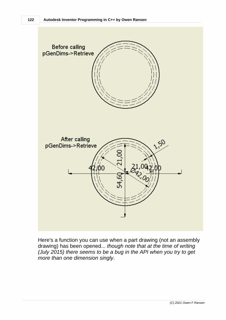
122 Autodesk Inventor Programming in C++ by Owen Ransen
(C) 2021 Owen F Ransen
Here's a function you can use when a part drawing (not an assemblydrawing) has been opened... though note that at the time of writing(July 2015) there seems to be a bug in the API when you try to getmore than one dimension singly.

123Programming Inventor in C++
(C) 2021 Owen F Ransen
void GetRetDimsOfPart (){ CComPtr<Application> pInvApp = theApp.GetInvAppPtr () ;
// Get all the documents which are open in Inventor... CComPtr<Documents> pDocuments; HRESULT hRes = pInvApp->get_Documents (&pDocuments) ;
if (FAILED(hRes) || (pDocuments == nullptr)) { TRACE (L"GetRetDimsOfPart, could not get docs") ; return ; }
// Find the first IDW document... const UINT ikNumDocs = pDocuments->Count ; if (ikNumDocs == 0) { TRACE (L"There should be at least one IDW documentopen\n" L"There are no documents open."); return ; }
// This will be non null after the for loop if an IDW drawingdocument is found CComQIPtr<DrawingDocument> pIDWDoc ; // Is null at the moment
for (UINT iDoc = 1 ; iDoc <= ikNumDocs ; iDoc) { CComPtr<Document> pDoc ; hRes = pDocuments->get_Item (1,&pDoc) ; if (FAILED(hRes) || (pDoc == nullptr)) { TRACE (L"GetRetDimsOfPart, could not get doc%d",iDoc) ; return ; }
// Try to convert from general doc to IDW drawing doc pIDWDoc = pDoc ; if (pIDWDoc != nullptr) { // The conversion worked so this is an IDW document,our first... TRACE (L"Doc %d is an IDW",iDoc) ; break ; } }
if (pIDWDoc == nullptr) { TRACE (L"Could not find an IDW") ; return ; }
// Find the sheets of the drawing document...
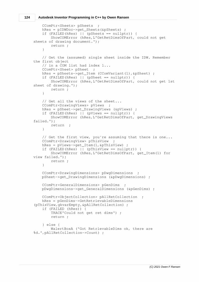
124 Autodesk Inventor Programming in C++ by Owen Ransen
(C) 2021 Owen F Ransen
CComPtr<Sheets> pSheets ; hRes = pIDWDoc->get_Sheets(&pSheets) ; if (FAILED(hRes) || (pSheets == nullptr)) { ShowCOMError (hRes,L"GetRetDimsOfPart, could not getsheets of drawing document."); return ; }
// Get the (assumed) single sheet inside the IDW. Rememberthe first object // in a COM list had index 1... CComPtr<Sheet> pSheet ; hRes = pSheets->get_Item (CComVariant(1),&pSheet) ; if (FAILED(hRes) || (pSheet == nullptr)) { ShowCOMError (hRes,L"GetRetDimsOfPart, could not get 1stsheet of drawing."); return ; }
// Get all the views of the sheet... CComPtr<DrawingViews> pViews ; hRes = pSheet->get_DrawingViews (&pViews) ; if (FAILED(hRes) || (pViews == nullptr)) { ShowCOMError (hRes,L"GetRetDimsOfPart, get_DrawingViewsfailed."); return ; }
// Get the first view, you're assuming that there is one... CComPtr<DrawingView> pThisView ; hRes = pViews->get_Item(1,&pThisView) ; if (FAILED(hRes) || (pThisView == nullptr)) { ShowCOMError (hRes,L"GetRetDimsOfPart, get_Item(1) forview failed."); return ; }
CComPtr<DrawingDimensions> pDwgDimensions ; pSheet->get_DrawingDimensions (&pDwgDimensions) ;
CComPtr<GeneralDimensions> pGenDims ; pDwgDimensions->get_GeneralDimensions (&pGenDims) ;
CComPtr<ObjectCollection> pAllRetCollection ; hRes = pGenDims->GetRetrievableDimensions(pThisView,gkvarEmpty,&pAllRetCollection) ; if (FAILED (hRes)) { TRACE"Could not get ret dims") ; return ;
} else { WalertBoxA ("Got RetrievableDims ok, there are%d.",pAllRetCollection->Count) ;

125Programming Inventor in C++
(C) 2021 Owen F Ransen
}
const long ikNumRetDims = pAllRetCollection->Count ;
// Change this to 0 or 1#define ALL_DIMENSIONS 0
#if ALL_DIMENSIONS /* * Make the dimensions actually appear in the IDW drawingdocument */ CComPtr<GeneralDimensionsEnumerator> pGenDimsEnum1; hRes = pGenDims->Retrieve(pThisView, CComVariant(pAllRetCollection),//This tells it to get all dimensions gkvarEmpty, &pGenDimsEnum1);#else
// Do this so you can create object collections... CComPtr<TransientObjects> pTransObjs =GetTransientObjectsPtr() ;
// Create an initially empty object collection... CComPtr<ObjectCollection> pJustOneDim ; hRes = pTransObjs->CreateObjectCollection(gkvarEmpty,&pJustOneDim) ;
// Get only the first dimension from the retrievabledimensions... IDispatchPtr pFirstDim; hRes = pAllRetCollection->get_Item(_variant_t(1),&pFirstDim);
// Add it into the collection of "just one dimension"... pJustOneDim->Add (pFirstDim) ;
// Add the single dimension into the drawing... CComPtr<GeneralDimensionsEnumerator> pGenDimsEnum1; hRes = pGenDims->Retrieve(pThisView, CComVariant(pJustOneDim), // Thistell it to get just the first dimension &pGenDimsEnum1);
#endif}
Listing the DimensionConstraints...

126 Autodesk Inventor Programming in C++ by Owen Ransen
(C) 2021 Owen F Ransen
12.60 DrawingDimensions vs GeneralDimensions
The lists they give are often the same. DrawingDimensions is at ahigher level than GeneralDimensions, and GeneralDimensions letsyou get hold of the RetrievableDimensions.
// This will get all the dimensions currently visible in the sheet as wellas giving // you a way of getting the general dimensions and hence the retrievabledimensions... CComPtr<DrawingDimensions> pDimensions = nullptr ; hRes = pSheet->get_DrawingDimensions (&pDimensions) ;
// The general dimensions gives you a way of getting at the retrievabledimensions.... CComPtr<GeneralDimensions> pGenDimensions = nullptr ; hRes = pDimensions->get_GeneralDimensions (&pGenDimensions) ;
// NOW you can get the retrievable dimensions CComPtr<ObjectCollection> pObjColl; hRes = pGenDimensions->GetRetrievableDimensions(pThisView, CComVariant(),&pObjColl);
Both GeneralDimensions and DrawingDimensions will also list thedimension objects in the sheet:
for (long i = 1; i <= pGenDimensions->Count; i++) { CComPtr<GeneralDimension> pGenDim; pGenDimensions->get_Item(i, &pGenDim);
CComPtr <DimensionText> pDimText; pGenDim->get_Text(&pDimText);
CComBSTR DimText; pDimText->get_Text(&DimText);
gLogger.Printf(ekLogMsg, L"GeneralDimension Type is <%d> <%s> Text is<%s>", pGenDim->Type, GetObjTypeDesc(pGenDim->Type), CString(DimText));

127Programming Inventor in C++
(C) 2021 Owen F Ransen
}
for (long i = 1; i <= pDimensions->Count; i++) { CComPtr<DrawingDimension> pDwgDim; pDimensions->get_Item(i, &pDwgDim);
double ModelValue; pDwgDim->get_ModelValue(&ModelValue);
CComPtr <DimensionText> pDimText; pDwgDim->get_Text(&pDimText);
CComBSTR DimText; pDimText->get_Text(&DimText);
gLogger.Printf(ekLogMsg, L"DrawingDim Type is <%d> <%s> Text is <%s>ModelValue=%.2f", pDwgDim->Type, GetObjTypeDesc(pDwgDim->Type), CString(DimText),ModelValue); }
Model value is the actual number of the value, whereas the Text iswhat appears in the drawing.
12.61 Negative Dimensions
Dimensions can only be positive, so if you want a negative dimension(as a way of positioning a hole to the left or right of another feature forexample) you need to put a point at one extreme and then use a UserParameter. This example should make it clear:

128 Autodesk Inventor Programming in C++ by Owen Ransen
(C) 2021 Owen F Ransen
When R1Scosta is 0 the circle is on the Z axis.
12.62 Show a dimension programatically
This function will try to show a list of dimensions, when eachdimension is based on a parameter.
And the definition is this (no error checking):
void ShowNamedRetDimsInView (const CString& kcsViewName, const CStringList& kcsParamNames, CComQIPtr<DrawingDocument>& pIDWDoc){ // Find the sheets of the drawing document... CComPtr<Sheets> pSheets = nullptr ; HRESULT hRes = pIDWDoc->get_Sheets(&pSheets) ;
// Get the (assumed) single sheet inside the IDW. Remember the firstobject // in a COM list had index 1...

129Programming Inventor in C++
(C) 2021 Owen F Ransen
CComPtr<Sheet> pSheet = nullptr ; hRes = pSheets->get_Item (CComVariant(1),&pSheet) ;
CComPtr<DrawingView> pThisView = nullptr ; const bool kbViewOk = FindDrawingViewInSheetByName (pThisView,pSheet,kcsViewName) ; if (!kbViewOk) { gLogger.Printf (ekErrMsg, L"SNRDIV2, could not find view <%s>.", kcsViewName); return ; }
CComPtr<DrawingDimensions> pDimensions = nullptr ; hRes = pSheet->get_DrawingDimensions (&pDimensions) ;
// The general dimensions gives you a way of getting at the retrievabledimensions.... CComPtr<GeneralDimensions> pGenDimensions = nullptr ; hRes = pDimensions->get_GeneralDimensions (&pGenDimensions) ;
// The Arrange function requires an object collection of dimensions toarrange... CComPtr<TransientObjects> pTransientObjects = GetTransientObjectsPtr() ; CComPtr<ObjectCollection> pObjCollection = nullptr ; hRes = pTransientObjects->CreateObjectCollection (gkvarEmpty,&pObjCollection) ; if (FAILED(hRes)) { ShowCOMError (hRes,L"CreateObjectCollection failed "); return; }
// Retrieve *all* retrievable dimensions. This will make all thedimensions appear in the drawing... CComPtr<GeneralDimensionsEnumerator> pGenDimsEnum; hRes = pGenDimensions->Retrieve(pThisView, CComVariant(), &pGenDimsEnum);
long nTotalDims=0; hRes = pGenDimsEnum->get_Count(&nTotalDims);
// Go over all the dimensions, erasing those not in my list... for(int nDim = 1; nDim <= nTotalDims; nDim++) { CComPtr<GeneralDimension> pGenDim; hRes = pGenDimsEnum->get_Item(_variant_t(nDim), &pGenDim);
CComPtr <DimensionText> pDimText; pGenDim->get_Text(&pDimText);
CComBSTR DimText; pDimText->get_Text(&DimText);
CComBSTR paramName; IDispatchPtr pGenDimIDisp;

130 Autodesk Inventor Programming in C++ by Owen Ransen
(C) 2021 Owen F Ransen
hRes = pGenDim->get_RetrievedFrom(&pGenDimIDisp);
CComQIPtr<FeatureDimension> pFeatureDim = CComQIPtr<FeatureDimension>(pGenDimIDisp); if(pFeatureDim != NULL) { CComPtr<Parameter> pParam; hRes = pFeatureDim->get_Parameter(&pParam); hRes = pParam->get_Name(¶mName); }
CComQIPtr<DimensionConstraint> pDimConstraint = CComQIPtr<DimensionConstraint>(pGenDimIDisp); if(pDimConstraint != NULL) { CComPtr<Parameter> pParam; hRes = pDimConstraint->get_Parameter(&pParam); hRes = pParam->get_Name(¶mName); }
CComQIPtr<FeatureDimensionProxy> pFeatureDimProxy = CComQIPtr<FeatureDimensionProxy>(pGenDimIDisp); if(pFeatureDimProxy != NULL) { CComPtr<Parameter> pParam; hRes = pFeatureDimProxy->get_Parameter(&pParam); hRes = pParam->get_Name(¶mName); }
/* * We will delete this dimension if it is NOT in the list * of dimensions we want. */ bool bDelete = true ; for (INT_PTR iParam = 0 ; iParam < kcsParamNames.GetCount ();iParam++) { const POSITION Pos = kcsParamNames.FindIndex (iParam) ; const CString kcsListed = kcsParamNames.GetAt (Pos) ; if (wcscmp (kcsListed.GetString(),paramName) == 0) { // This parameter, paramName, is in the list, so I don'tdelete it bDelete = false ; break ; } }
if (bDelete) { // This parameter is not one we want to retain... pGenDim->Delete();
} else { // Add to the collection of dimensions to be arranged later... pObjCollection->Add(pGenDim); }

131Programming Inventor in C++
(C) 2021 Owen F Ransen
}
if (pObjCollection->Count > 0) { pDimensions->Arrange(pObjCollection); }}
You can call the function in this way:
CStringList csNames; csNames.AddHead(L"d147"); // This corresponds to the length of thecollettore csNames.AddHead(L"Extra"); csNames.AddHead(L"Diameter7"); ShowNamedRetDimsInView (L"Front",csNames,pDrawingDoc) ;
12.63 Dimensions in a drawing sheet
Here's how to count the number of dimensions in a drawings sheet:
CComPtr<DrawingViews> pViews = nullptr ; hRes = pSheet->get_DrawingViews (&pViews) ;
{ CComPtr<DrawingDimensions> pDimensions = nullptr ; hRes = pSheet->get_DrawingDimensions (&pDimensions) ; if (FAILED(hRes)) { ShowCOMError (hRes,L"pSheet->get_DrawingDimensionsfailed "); }
long lNumDims; hRes = pDimensions->get_Count(&lNumDims); if (FAILED(hRes)) { ShowCOMError (hRes,L"pDimensions->get_Count failed "); }
WalertBoxA ("This has %d dimensions",lNumDims) ; }
See also retrievable dimensions.

132 Autodesk Inventor Programming in C++ by Owen Ransen
(C) 2021 Owen F Ransen
12.64 Plane object, getting its geometry
Here is how to get it from a proxy inside an assembly, but you canuse a similar function for a real WorkPlane.
// This will get you the point and the normal which define the workplanevoid GetWorkPlaneProxyData(CVec& vecRoot, CVec& vecNormal, CComPtr<WorkPlaneProxy>& pWorkPlaneProxy){ double RootCoords[3]; SAFEARRAY* pRootArray = CreateSafeDoubleArray(3, RootCoords) ;
double NormalCoords[3]; SAFEARRAY* pNormArray = CreateSafeDoubleArray(3, NormalCoords) ;
pWorkPlaneProxy->Plane->GetPlaneData(&pRootArray,&pNormArray);
for (LONG i = XI ; i <= ZI; i++) { LONG rgIndex = i; double Root = 0; SafeArrayGetElement(pRootArray, &rgIndex, &Root); vecRoot.SetVal(i, Root);
double Norm = 0; SafeArrayGetElement(pNormArray, &rgIndex, &Norm); vecNormal.SetVal(i, Norm); }
SafeArrayDestroy(pRootArray); SafeArrayDestroy(pNormArray);}

133Programming Inventor in C++
(C) 2021 Owen F Ransen
12.65 Open a part from a view
Here is a fragment to show you how:
CComPtr<DocumentDescriptor> pDocDesc ; pView->get_ReferencedDocumentDescriptor (&pDocDesc) ;
// Still finding out the part which this is a view of... CComPtr<Document> pReffedDoc ; pDocDesc->get_ReferencedDocument ((IDispatch**)&pReffedDoc) ;
if (kAssemblyDocumentObject != pReffedDoc->DocumentType) { WalertBoxW (L"The referenced document is not an assemblu part") ; return ; }
// Convert the general referenced doc into a part doc... CComQIPtr<AssemblyDocument> pAsmDoc = pReffedDoc ;
// Get assembly component definition CComPtr<AssemblyComponentDefinition> pAssemblyCompDef ; hRes = pAsmDoc->get_ComponentDefinition(&pAssemblyCompDef); if (FAILED(hRes) || (pAssemblyCompDef == nullptr)){ ShowCOMError(hRes,L"GetComponentOccurrenceByName, get_ComponentDefinition failed "); return ; }
CComPtr<ComponentOccurrences> pOccurrencesList=nullptr; hRes = pAssemblyCompDef->get_Occurrences (&pOccurrencesList) ; if (FAILED(hRes) || (pOccurrencesList==nullptr)) { ShowCOMError (hRes,L"get_Occurrences failed") ; return ; }
CComPtr<ComponentOccurrence> pThisCompOcc ;hRes = pOccurrencesList->get_Item(1, &pThisCompOcc);
if (FAILED(hRes) || (pThisCompOcc == nullptr)){ ShowCOMError(hRes,L"GetComponentOccurrenceByName, get_Item failed "); return ; }
// Now find out the part which this is a view of... CComPtr<DocumentDescriptor> pDocDesc2 ; pThisCompOcc->get_ReferencedDocumentDescriptor (&pDocDesc2) ;
CComBSTR bstrFullDocName ; pDocDesc2->get_FullDocumentName (&bstrFullDocName) ;

134 Autodesk Inventor Programming in C++ by Owen Ransen
(C) 2021 Owen F Ransen
WalertBoxW (L"Referenced doc = %s",bstrFullDocName) ;
CComPtr<PartComponentDefinition> pPartCompDef ; CComPtr<PartDocument> pPartDoc ; CComPtr<Application> pInvApp = theApp.GetInvAppPtr () ;
hRes = OpenPart (pPartCompDef, pPartDoc, CString(bstrFullDocName), pInvApp) ;
.
12.66 getType and ObjectTypeEnum
You can use GetType (or get_Type()) to see what sort of object youhave.
For example:
CComPtr<ModelParameter> pModelParam ; ... other stuff
// Two ways of getting the object type... TRACE (L"pModelParam->GetType()=%d\n",pModelParam->GetType());
ObjectTypeEnum ObjType ; pModelParam->get_Type (&ObjType) ;
TRACE (L"pModelParam->get_Type()=%d\n",ObjType) ;
If you have initialised pModelParam properly it will return 50348544 (kModelParameterObject).
Other common values are:
kComponentOccurrenceObject = 67113776, kAssemblyDocumentObject = 12291 kPartComponentDefinitionObject = 83886592, kFeaturePatternElementObject = 83923968, kObjectCollectionObject = 2130706443, kWorkPlaneObject = 83887616, kWorkPointObject = 83893504, kWorkPointProxyObject = 83893664,

135Programming Inventor in C++
(C) 2021 Owen F Ransen
kTwoPointDistanceDimConstraintProxyObject = 83905904 kDiameterDimConstraintProxyObject = 83906672
This example shows that get_Type will give you a high leveldescription, it does not tell you which sort of model parameter it is(double, count, etc). For that you need the ParameterTypeEnum.
The full set of values can be found in rxinventor.tlh, which will besomewhere like:
C:\Users\Public\Documents\Autodesk\Inventor 2017\SDK\DeveloperTools\Samples\VC++\AddIns\SimpleAddIn\x64\Debug\rxinventor.tlh
or in the API help file.
You may find this function useful, adding more cases as youneed/find them:
CString GetObjTypeDesc (const ObjectTypeEnum eObjType)/*Returns a string version of the object type.*/{ switch (eObjType) { case kWorkAxisObject: return CString ("kWorkAxisObject") ;
case kWorkPointObject: return CString ("kWorkPointObject") ;
case kWorkPlaneObject: return CString ("kWorkPlaneObject") ;
case kTwoPointDistanceDimConstraintProxyObject: return CString ("kTwoPointDistanceDimConstraintProxyObject") ;
case kDiameterDimConstraintProxyObject: return CString ("kDiameterDimConstraintProxyObject") ;
case kTwoLineAngleDimConstraintProxyObject: return CString ("kTwoLineAngleDimConstraintProxyObject") ;
case kTangentDistanceDimConstraintProxyObject: return CString ("kTangentDistanceDimConstraintProxyObject") ;
case kOffsetDimConstraintProxyObject: return CString ("kOffsetDimConstraintProxyObject") ;
case kRadiusDimConstraintProxyObject: return CString ("kRadiusDimConstraintProxyObject") ;

136 Autodesk Inventor Programming in C++ by Owen Ransen
(C) 2021 Owen F Ransen
case kDrawingViewObject: return CString ("kDrawingViewObject") ;
case kMateiMateDefinitionObject: return CString ("kMateiMateDefinitionObject") ;
case kiMateDefinitionObject : return CString("kiMateDefinitionObject");
case kAngleiMateDefinitionObject: return CString("");
case kFlushiMateDefinitionObject: return CString("kFlushiMateDefinitionObject");
case kInsertiMateDefinitionObject: return CString("kInsertiMateDefinitionObject");
case kTangentiMateDefinitionObject: return CString("kTangentiMateDefinitionObject");
case kCompositeiMateDefinitionObject: return CString("kCompositeiMateDefinitionObject");
case kRotateRotateiMateDefinitionObject: return CString("kRotateRotateiMateDefinitionObject");
case kRotateTranslateiMateDefinitionObject: return CString("kRotateTranslateiMateDefinitionObject");
case kiMateResultsObject: return CString("kiMateResultsObject");
case kiMateResultObject: return CString("kiMateResultObject");
case kLinearGeneralDimensionObject: return CString("kLinearGeneralDimensionObject"); case kDiameterGeneralDimensionObject: return CString("kDiameterGeneralDimensionObject");
default: { CString csUnknown ; csUnknown.Format (L"Unknown ObjTypeEnum %d",eObjType) ; return csUnknown ; } }}

137Programming Inventor in C++
(C) 2021 Owen F Ransen
12.67 Listing types of dimensions in a view
This code fragment shows you how to get hold of theDimensionConstraints:
CComPtr<ObjectCollection> pAllRetCollection ; hRes = pGenDims->GetRetrievableDimensions(pThisView,gkvarEmpty,&pAllRetCollection) ; if (FAILED (hRes)) { TRACE"Could not get ret dims") ; return ;
} else { WalertBoxA ("Got RetrievableDims ok, there are%d.",pAllRetCollection->Count) ; }
const long ikNumRetDims = pAllRetCollection->Count ;
for (long iDim = 1 ; iDim <= ikNumRetDims ; iDim++) { IDispatchPtr pNthDim; hRes = pAllRetCollection->get_Item(_variant_t(iDim),&pNthDim);
CComPtr<DimensionConstraint> pDimConstraint ; hRes = pNthDim->QueryInterface(__uuidof(DimensionConstraint), (void **)&pDimConstraint);
if (FAILED (hRes)) { TRACE (L"Could not query interface of dim %d of%d\n",iDim,ikNumRetDims) ;
} else { ObjectTypeEnum eType = pDimConstraint->GetType() ; TRACE (L" dim %d is a %d %s\n",iDim,eType,GetObjTypeDesc(eType)) ; CComPtr<Parameter> pThisParam ; hRes = pDimConstraint->get_Parameter (&pThisParam) ; if (FAILED (hRes)) { TRACE (L"Could not get parameter of dim %d of%d\n",iDim,ikNumRetDims) ;
} else { CComBSTR bstrParamName ; pThisParam->get_Name (&bstrParamName) ; TRACE (L"Param of dim %d is%s\n",iDim,bstrParamName) ; }

138 Autodesk Inventor Programming in C++ by Owen Ransen
(C) 2021 Owen F Ransen
}
pNthDim = nullptr ; // free the IDispatch pointer }
It also shows you how to get an item as an IDispatchPtr and turn itinto a DimensionConstraint (for example), and how to get the name ofthe parameter which controls the dimension.
12.68 Getting the version of Inventor programatically
Here is the code to do it:
CComPtr<Application> pInvApp = ...
CComBSTR bstrVersion ; pInvApp->SoftwareVersion->get_DisplayName (&bstrVersion) ; TRACE (L"Software version DisplayName is <%s>\n",bstrVersion) ;
pInvApp->SoftwareVersion->get_DisplayVersion (&bstrVersion) ; TRACE (L"Software version DisplayVersion is <%s>\n",bstrVersion) ;
And the output in your debug window will look something like this:
Software version DisplayName is <2013 (Build 170138000, 138)>Software version DisplayVersion is <2013>
Apart from DisplayName and DisplayVersion there are other functionslike get_Major and get_Minor. For example:
long iMajorVer ; pInvApp->SoftwareVersion->get_Major (&iMajorVer) ;
long iMinorVer ; pInvApp->SoftwareVersion->get_Minor (&iMinorVer) ;
TRACE (L"Software version Major=%d, Minor=%d\n",iMajorVer,iMinorVer) ;
with this result:
Software version Major=17, Minor=0

139Programming Inventor in C++
(C) 2021 Owen F Ransen
But I don't find numbers as helpful as the display strings.
12.69 QueryInterface and Release Etc
If possible use CComQIPtr. If you insist you can read the following...
There is some confusion in this question's answers about whatQueryInterface actually does. It simply retrieves pointers to thesupported interfaces on an object and increments the reference counton that object. It doesn't create a new object for each interface that itimplements.
For example if you have an object which implements 2 interfaces,then the call would simply cast that object as each of the interfaceand increment a variable which is used as the reference count.
QueryInterface allows the caller to retrieve references to differentinterfaces the component implements. It is similar to dynamic_cast<>in C++. Specifically, it is used to obtain a pointer to another interface,given a GUID that uniquely identifies that interface (commonly knownas an interface ID, or IID). If the COM object does not implement thatinterface, an E_NOINTERFACE error is returned instead.
COM object gives you some pointers to certain functions that you cancall to manipulate the object.
COM object is basically a C++ class. A C++ class is just a struct thatalways starts with a pointer to its VTable (an array of functionpointers). And the first three pointers in the VTable will always benamed QueryInterface, AddRef, and Release. What additionalfunctions may be in its VTable, and what the name of their pointersare, depends upon what type of object it is.
This is another important rule of COM. If you get hold of a COMobject created by someone else, you must call its Release functionwhen you're done with it.
CComQIPtr is a CComPtr with a QueryInterface inside it, apparently.

140 Autodesk Inventor Programming in C++ by Owen Ransen
(C) 2021 Owen F Ransen
12.70 CComQIPtr is better than QueryInterface
Instead of doing a QueryInterface where you have to worry aboutRelease etc., you can sometimes use a CComQIPtr, like this:
CComQIPtr<DimensionConstraint> pDimConstraint ; // It is null now (cannot be initialised to NULL) for (long iDim = 1 ; iDim <= ikNumRetDims ; iDim++) {
TRACE (L"Looking at dim %d of %d\n",iDim,ikNumRetDims) ;
// Look at the nth dimension in the collection... IDispatchPtr pNthDim; hRes = pAllRetCollection->get_Item(_variant_t(iDim), &pNthDim); if (FAILED (hRes)) { ShowCOMError (hRes,L"ShowNamedRetDimInView Could not get_Item %d",iDim) ; return ; }
pDimConstraint = pNthDim ; // This can be tested for NULL
if (pDimConstraint != NULL) { // We have a DimensionConstraint, what is the name of the model parameter?
CComPtr/CComQIPtr perform automatic reference counting for you (forexample, they call Release on the interface attached to them, whenthe smart-pointer variable goes out of scope).
And CComQIPtr is null when you first create it. See comment on firstline of the code above.
12.71 How to get iPart factory parent from child member
In C++ follow this example:
// This will give you"C:\Users\Owen\Documents\Inventor\Tubi_Rame_12-7_Liscio_Sp0,75.IPT" wchar_t* pszFullName = LPWSTR (pTroncCompDef->iPartMember->ReferencedDocumentDescriptor->FullDocumentName); if (pszFullName == nullptr) { return false; }
// Now get "Tubi_Rame_12-7_Liscio_Sp0,75.IPT"

141Programming Inventor in C++
(C) 2021 Owen F Ransen
CString csIPartFileName(pszFullName); StripPath(csIPartFileName);
// Now load with "Tubi_Rame_12-7_Liscio_Sp0,75.IPT" LoadTronchettiFile(csIPartFileName);
if (csIPartFileName.GetLength() < NUM_SAP_CHARS) { return false; }
// Get the member name "30089191.IPT" const CString kcsPartName = GetPartName(pTroncCompDef);
// Remove the IPT to get "30089191" const CString kcsTroncSapCode = kcsPartName.Mid(0, NUM_SAP_CHARS);
// Use "30089191" to find the details return GetTroncDetailsByCode(Details,kcsTroncSapCode);
In VB it would be like this:
Public Sub main()
Dim a As Application Set a = ThisApplication
Dim b As PartDocument Set b = a.ActiveDocument
a.Documents.Open (b.ComponentDefinition.iPartMember.ReferencedDocumentDescriptor.FullDocumentName)
End Sub
I need to translate this into C++.
12.72 Counting the number of documents open in Inventor
Get a pointer to the Inventor application, then use this code:
// Get the list of Documents CComPtr<Documents> pDocs; HRESULT hr = pInvApp->get_Documents(&pDocs); if (FAILED(hr)) { return ReturnAndShowCOMError (hr,L"CreateNewPartDoc, get document list failed\n") ; } const long ikNumDocs = pDocs->GetCount() ; TRACE (L"There are %d documents open in Inventor\n",ikNumDocs) ;

142 Autodesk Inventor Programming in C++ by Owen Ransen
(C) 2021 Owen F Ransen
Here is a function which encloses the above code:
size_t GetNumDocummentsOpenInInventor(){ CComPtr<Application> pInvApp = theApp.GetInvAppPtr() ; if (pInvApp == nullptr) { return 0 ; }
// Get the list of documents... CComPtr<Documents> pDocs ; HRESULT hRes = pInvApp->get_Documents (&pDocs) ; if (FAILED(hRes) || (pDocs == nullptr)) { ShowCOMError(hRes,L"GNDOII,get_Documents failed "); return 0 ; }
return pDocs->Count ;}
You can loop over the open dopcuments in Inventor like this:
// Get the pointer to the Inventor application... CComPtr<Application> pInvApp = ...
CComPtr<Documents> pDocs ; HRESULT hRes = pInvApp->get_Documents (&pDocs) ; if (FAILED(hRes) || (pDocs == nullptr)) { TRACE (L"RunTest,get_Documents failed "); return ; }
const long ikNumDocs = pDocs->GetCount() ;
TRACE ("There are %d documents open\n",ikNumDocs) ;
for (int iDoc = 1 ; iDoc <= ikNumDocs ; iDoc++) { CComPtr<Document> pDocument; hRes = pDocs->get_Item(iDoc,&pDocument) ; if (FAILED(hRes) || (pDocument == nullptr)) { TRACE (L"Could not get document number %d",iDoc); return ; } TRACE ("Got document %d of type %d %s\n", iDoc,

143Programming Inventor in C++
(C) 2021 Owen F Ransen
pDocument->DocumentType, GetInventorDocTypeDesc(pDocument->DocumentType)); }
You'll get a listing in the debug window something like this:
Got document 1 of type 12291 Assembly DocumentGot document 2 of type 12290 Part DocumentGot document 3 of type 12290 Part DocumentGot document 4 of type 12290 Part DocumentGot document 5 of type 12290 Part DocumentGot document 6 of type 12290 Part DocumentGot document 7 of type 12290 Part DocumentGot document 8 of type 12290 Part DocumentGot document 9 of type 12292 Drawing DocumentGot document 10 of type 12290 Part Document
12.73 CustomTables in Sheets and Drawings
This example C++ code shows how to create a custom table in anIDW Inventor drawing:
void CreateExampleTable (CComPtr<Sheet>& pSheet){ wchar_t* ColNames[128] = {L"Column One",L"Column Two",L"Column Three"};
// These contents are after the title row and the header row const int ikNumCols = 3 ; const int ikNumRows = 5 ; // 7 with header and column titles
SAFEARRAY* pstrColumns = CreateSafeStringArray(ikNumCols, ColNames);
CComPtr<CustomTables> pCustomTables ; pSheet->get_CustomTables (&pCustomTables) ;
// This is top left of the table. Sheet origin is bottom left. // In Europe this coordinate system is usually cm in a sheet CComPtr<Point2d> ptTable; // Create a 2d point GetTransGeomPtr()->CreatePoint2d(10.0,10.0,&ptTable);
CComVariant varEmpty ; CComPtr<CustomTable> pCustomTable ; pCustomTables->Add (CComBSTR(L"HOLES"),ptTable,ikNumCols,ikNumRows,&pstrColumns, varEmpty, // the contents will be added later

144 Autodesk Inventor Programming in C++ by Owen Ransen
(C) 2021 Owen F Ransen
varEmpty, // use the default widths varEmpty, // use the default heights varEmpty, // no more info &pCustomTable) ; // table returned
/* * Here we add contents by using put_Value in every cell */ for (UINT iRow = 1 ; iRow <= ikNumRows ; iRow++) { // Get the row where we want to add data... CComPtr<Row> pRow ; pCustomTable->Rows->get_Item (long(iRow),&pRow) ; for (UINT iCol = 1 ; iCol <= ikNumCols ; iCol++) { // Get the column of the row where we want to add data... CComPtr<Cell> pCell ; pRow->get_Item (CComVariant(iCol),&pCell) ;
// Demo example text... wchar_t szCellContents[_MAX_PATH] ; swprintf_s (szCellContents,L"R%d C%d",iRow,iCol) ;
// Put the data in the cell... pCell->put_Value (CComBSTR (szCellContents)) ; } }
SafeArrayDestroy (pstrColumns) ;}
The resulting table looks like this:
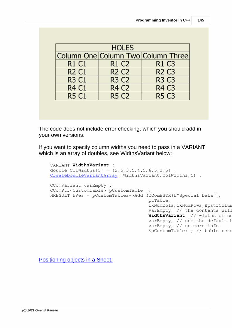
145Programming Inventor in C++
(C) 2021 Owen F Ransen
The code does not include error checking, which you should add inyour own versions.
If you want to specify column widths you need to pass in a VARIANTwhich is an array of doubles, see WidthsVariant below:
VARIANT WidthsVariant ; double ColWidths[5] = {2.5,3.5,4.5,6.5,2.5} ; CreateDoubleVariantArray (WidthsVariant,ColWidths,5) ;
CComVariant varEmpty ; CComPtr<CustomTable> pCustomTable ; HRESULT hRes = pCustomTables->Add (CComBSTR(L"Special Data"), ptTable, ikNumCols,ikNumRows,&pstrColumns, varEmpty, // the contents will be added later WidthsVariant, // widths of columns varEmpty, // use the default heights varEmpty, // no more info &pCustomTable) ; // table returned
Positioning objects in a Sheet.

146 Autodesk Inventor Programming in C++ by Owen Ransen
(C) 2021 Owen F Ransen
12.74 Positioning objects in a Sheet.
When you position text and tables in a sheet the origin of the sheet isbottom left. Tables are positioned by their top left corner, presumablyto let the rows grow downwards without having to redefine theposition.
As far as I can tell when metric, centimeters are used. Orientation ofthe sheet.
12.75 New line within table cells
To add a new line within a cell of a custom table you should use \r\n.
for (UINT i = 0 ; i <= iSoFar ; i++) {
147Programming Inventor in C++
(C) 2021 Owen F Ransen
CString csPasso ; csPasso.Format (L"%dx%d\r\n",Counts[i], int(RoundNumber(Passi[i],0))) ;
if (i != iSoFar) { // Separator needed.... csPasso += CString ("-") ; }
csPassi += csPasso ; }
12.76 CreateDoubleVariantArray
This function is useful for creating VARIANTs which specify thewidths of the columns in a CustomTable...
void CreateDoubleVariantArray (VARIANT& v, const double* constpValues, const UINT ikNumValues)/*Some functions, like adding a custom table into a sheet, requireVARIANTs which arearrays of doubles. This function, given an array of doublesinitialises the variant v.*/{ v.vt = VT_ARRAY | VT_R8; SAFEARRAYBOUND sab[1]; sab[0].lLbound = 0; sab[0].cElements = ikNumValues ; v.parray = SafeArrayCreate(VT_R8, 1, sab);
// Fill with some values... for(int i=0; i<ikNumValues; i++) { long indices[] = {i}; SafeArrayPutElement(v.parray, indices, (void*)&(pValues[i])); }}

148 Autodesk Inventor Programming in C++ by Owen Ransen
(C) 2021 Owen F Ransen
12.77 Create a drawing file (IDW or DWG)
This code (with error checking omitted) creates a new empty drawingfile:
// Get the pointer to the Inventor application... CComPtr<Application> pInvApp = ...
// Get IDW drawing template file CComBSTR strTemplateFilename; CComPtr<FileManager> pFileManager ; HRESULT hRes = pInvApp->get_FileManager(&pFileManager); hRes = pFileManager->GetTemplateFile(kDrawingDocumentObject, // i.e. an IDW or DWG kDefaultSystemOfMeasure, kDefault_DraftingStandard, CComVariant(), // Empty and unused &strTemplateFilename);
CComPtr<Documents> pDocuments; pInvApp->get_Documents (&pDocuments) ;
// create a new drawing from the standard template CComPtr<Document> pDocument ; hRes = pDocuments->Add (kDrawingDocumentObject, strTemplateFilename, VARIANT_TRUE, // Create Visible &pDocument);
// Convert from the "general document" type into the "drawing document" type... CComQIPtr<DrawingDocument> pDrawingDoc ; pDrawingDoc = pDocument ;
When you do copy/paste of this code for other document types,remember to change the enumerator of the types in both calls.
Also note that the document you create will already have one sheet init, you normally do not need to add any more. It is more likely that youwant to add views to the sheet.
See also creating an assembly.

149Programming Inventor in C++
(C) 2021 Owen F Ransen
12.78 How to add views to a drawing sheet (Inventor API)
If you have a new or exisiting drawing it is likely that you want to addviews of the 3D object into the sheet. Here is a commentedcode fragment which shows you to do it (error checking removed).Note also that we open the assembly invisibly so the user does nothave to wait for the display of the assembly.
// Choose the IDW drawing template file CComBSTR strTemplateFilename; strTemplateFilename = L"C:\\Users\\Public\\Documents\\Autodesk\\Inventor 2014\\Templates\\Ransen.idw" ;
// Get the list of documents so we can add a new one to it (an IDW) CComPtr<Documents> pDocuments; pInvApp->get_Documents (&pDocuments) ;
// create a new IDW drawing from the selected template CComPtr<Document> pDocument ; HRESULT hRes = pDocuments->Add(kDrawingDocumentObject, strTemplateFilename, VARIANT_TRUE, // true = create the document visible &pDocument);
// Convert from the "general document" type into the "drawing document" type... CComQIPtr<DrawingDocument> pDrawingDoc ; pDrawingDoc = pDocument ;
// Get the sheets in the drawing document. Since this IDW has only just been // created there will be a single sheet CComPtr<Sheets> pSheets ; hRes = pDrawingDoc->get_Sheets(&pSheets) ;
// Get the single sheet inside the IDW. Remember the first object // in a COM list had index 1... CComPtr<Sheet> pSheet ; hRes = pSheets->get_Item (CComVariant(1),&pSheet) ;
// Just for fun, get some data about the sheet... double SheetHeight,SheetWidth ; CComBSTR bstrSheetName ; pSheet->get_Name (&bstrSheetName) ; pSheet->get_Width(&SheetWidth) ; pSheet->get_Height(&SheetHeight) ;
TRACE (L"The first sheet is called <%s> and is %.1f %.1f\n", bstrSheetName,SheetWidth,SheetHeight) ;
// Now, we are going to add 2 views to the sheet, so get the list of views

150 Autodesk Inventor Programming in C++ by Owen Ransen
(C) 2021 Owen F Ransen
// Since this is a new drawing there will be no views yet, but we need // the list to add a view... CComPtr<DrawingViews> pViews ; hRes = pSheet->get_DrawingViews (&pViews) ;
// Create two points (using the transient geometry machine) which will // position the views in the sheet... CComPtr<TransientGeometry> pTrGeom = GetTransGeomPtr(); CComPtr<Point2d> pPt1; CComPtr<Point2d> pPt2; pTrGeom->CreatePoint2d(10.0,10.0,&pPt1); pTrGeom->CreatePoint2d(10.0,30.0,&pPt2);
// Set the view scales that we need. const double kViewScale1 = 0.25 ; const double kViewScale2 = 0.125 ;
// Now get hold of the assembly which we want to show in the view // (We'll open it invisibly) CComBSTR strAssemblyFilename ; strAssemblyFilename = L"C:\\CollMakeV2\\Coll_IPT_IAM\\new test.iam" ;
CComPtr<Document> pDoc ; hRes = pDocuments->Open (strAssemblyFilename, // what to open VARIANT_FALSE, // open it invisible &pDoc) ; // result
// The 6th parameter of AddBaseView requires a proper BSTR type object // else you'll get out of memory errors CComBSTR bstrModelViewName1 = CString (L"PLUTO") ; CComBSTR bstrModelViewName2 = CString (L"NEPTUNE") ;
// Now create our two views, first the base view on which all the others are based... CComVariant varEmpty ; CComPtr<DrawingView> pBaseView1 ; pViews->AddBaseView (pDoc, // what to show pPt1, // center of view kViewScale1, // size, scale, of view kBottomViewOrientation, // from where to view the doc kHiddenLineDrawingViewStyle, // DrawingViewStyleEnum bstrModel, // must be a BSTR varEmpty,varEmpty, // unused in this case &pBaseView1) ; // the created view
CComPtr<DrawingView> pBaseView2 ; pViews->AddBaseView (pDoc, pPt2, kViewScale2, kRightViewOrientation,

151Programming Inventor in C++
(C) 2021 Owen F Ransen
kShadedDrawingViewStyle, // DrawingViewStyleEnum bstrModelViewName2, varEmpty,varEmpty, &pBaseView2) ;
pDoc->Close (VARIANT_TRUE) ; // VARIANT_TRUE = close skipping save, obviously
See here for projected views.
As far as the "where are we looking from" option, these are the mostcommon:
kBottomViewOrientationkBackViewOrientationkCurrentViewOrientationkFrontViewOrientationkLeftViewOrientationkRightViewOrientationkTopViewOrientation

152 Autodesk Inventor Programming in C++ by Owen Ransen
(C) 2021 Owen F Ransen
These correspond in the user interface, to the view cube:
12.79 Names of views programatically
Although AddBaseView has a name parameter, it is not clear to mewhat it means. In fact it never changes the name of the view, to dothat you need to follow this code fragment:
{ CComPtr<DrawingView> pBaseView1 ...
... CComBSTR bstrViewName ; pBaseView1->get_Name (&bstrViewName) ; TRACE (L"Base view name was = <%s>\n",bstrViewName) ;
bstrViewName = L"SideView" ; pBaseView1->put_Name (bstrViewName) ;
pBaseView1->get_Name (&bstrViewName) ; TRACE (L"Base view name now = <%s>\n",bstrViewName) ; }
So just use put_Name to change the name of the view.

153Programming Inventor in C++
(C) 2021 Owen F Ransen
12.80 Creating projected views from base views
This page shows how to put in two base views. If you want to create aprojected view from the first base view, the last part of the codebecomes:
// Now create our two views, a base and a projected view CComVariant varEmpty ; CComPtr<Point2d> pPt1; pTrGeom->CreatePoint2d(10.0,10.0,&pPt1);
// The base view... CComPtr<DrawingView> pBaseView1 ; pViews->AddBaseView (pDoc, // what to show pPt1, // corner of view kViewScale1, // size, scale, of view kBottomViewOrientation, // from where to view the doc kHiddenLineDrawingViewStyle, // DrawingViewStyleEnum L"10-10", // name of created view varEmpty,varEmpty, // unused in this case &pBaseView1) ; // the created view
// In this case we create a projected view which has the base view as // the parent and which is to the right of the parent. Inventor itself will // sort out the projection. (compare pPt1 and pPt2) CComPtr<Point2d> pPt2; pTrGeom->CreatePoint2d(15.0,10.0,&pPt2); CComPtr<DrawingView> pProjectedView ; pViews->AddProjectedView (pBaseView1, // parent view pPt2, // center of projected view kHiddenLineDrawingViewStyle, varEmpty, // empty, so same scale as parent &pProjectedView) ; // resulting projected view
Here is a BaseView and a ProjectedView:

154 Autodesk Inventor Programming in C++ by Owen Ransen
(C) 2021 Owen F Ransen
12.81 Drawing View Styles
With AddProjectedView and AddBaseView you can use theseenumerators (DrawingViewStyleEnum):
kFromBaseDrawingViewStyle = use the base view settingskHiddenLineRemovedDrawingViewStyle = hide hidden lineskHiddenLineDrawingViewStyle = show hiddenl lineskShadedDrawingViewStyle = shaded, no hidden lines visiblekShadedHiddenLineDrawingViewStyle = shaded, show hidden lines
155Programming Inventor in C++
(C) 2021 Owen F Ransen
12.82 Close function for Parts and Assemblies
When you have created a Part or Assembly you may want to close itwith or without saving it. You will Close the assembly or partdocument, for example:
pAssemblyDoc->Close(VARIANT_TRUE) ;
The boolean (and remember to use VARIANT_TRUE orVARIANT_FALSE) tells Inventor whether the part should be savedbefore closing. For example:
pPartDoc->Close(VARIANT_TRUE) ; // "SkipSave" , no saving ,just close the document
pPartDoc->Close(VARIANT_FALSE) ; // Don't "SkipSave", save, andmaybe prompt // the user before closing thedocument
Also note that you can avoid any file saving dialogs by using the"silent" operation. For example:
pInvApp->SilentOperation = VARIANT_TRUE ; // don't show anydialogs, save with default names
// Not you can only do this if the file has not already beensaved pAssemblyDoc->put_FullFileName(CComBSTR(m_csAssemblyFullFileName)) ; // set the name
pAssemblyDoc->Save () ; // do the actual save
pAssemblyDoc->Close(VARIANT_TRUE) ; // close without saving(again)
Remember to switch off SilentOperation at the end of your functions.
12.83 GetInventorDocTypeDesc
Here is a function which will show you a description of the documenttype using the document type enumerator:
typedef struct {

156 Autodesk Inventor Programming in C++ by Owen Ransen
(C) 2021 Owen F Ransen
DocumentTypeEnum eEnum ; const char* const pszDesc ;} DocDesc_t;
const DocDesc_t kDocDescs [] = { {kAssemblyDocumentObject, "Assembly Document"}, {kDesignElementDocumentObject, "Design Element Document"}, {kDrawingDocumentObject, "Drawing Document"}, {kForeignModelDocumentObject, "Foreign Model Document"}, {kNoDocument, "No Document"}, {kPartDocumentObject, "Part Document"}, {kPresentationDocumentObject, "Presentation Document"}, {kSATFileDocumentObject, "SAT File Document"}, {kUnknownDocumentObject, "Unknown Document"}} ;
static const UINT ikNumDocTypeDescs = sizeof (kDocDescs)/sizeof(kDocDescs[0]) ;
const char* const GetInventorDocTypeDesc(const DocumentTypeEnum eDocTypeEnum) { for (UINT i = 0 ; i < ikNumDocTypeDescs ; i++) { if (kDocDescs[i].eEnum == eDocTypeEnum) { return kDocDescs[i].pszDesc ; } }
// This is an error, I handle it recursively... return GetInventorDocTypeDesc(kUnknownDocumentObject) ;}
12.84 Getting the current document of Inventor
It can be done like this:
CComPtr<Application> pApplication;hr = pInvAppUnk->QueryInterface (__uuidof(Application), (void **) &m_pApplication);if (FAILED(hr)) return hr;
CComPtr<Document> pDoc;
hr=pApplication->get_ActiveDocument(&pDoc);
get_ActiveDocument will put NULL in pDoc if there is no documentopen. You have to check that.
You can find out what sort of document it is by looking at the type, forexample:
157Programming Inventor in C++
(C) 2021 Owen F Ransen
if (pDoc->DocumentType==kDrawingDocumentObject)...
by looking at DocumentType. You can use this function to get adescription of the document type
Valid enumerators are:
kAssemblyDocumentObject 12291 Assembly Document. kDesignElementDocumentObject 12294 Design Element Document. kDrawingDocumentObject 12292 Drawing Document. kForeignModelDocumentObject 12295 Foreign Model Document. kNoDocument 12297 No Document. kPartDocumentObject 12290 Part Document. kPresentationDocumentObject 12293 Presentation Document. kSATFileDocumentObject 12296 SAT File Document. kUnknownDocumentObject 12289 Unknown Document.
Apart from looking at the pDoc->DocumentType you can also try to castthe doc into the doc type you are looking for:
// Get the component definition for the document if its a part or assembly.// Return an error for all other document types.CComQIPtr<ComponentDefinition> pCompDef;if (CComQIPtr<PartDocument> pPartDoc = pDoc) // try to cast{ TRACE("This is a part\n"); CComPtr<PartComponentDefinition> pPartCompDef; Result = pPartDoc->get_ComponentDefinition(&pPartCompDef); ...and so on...
} else if (CComQIPtr<AssemblyDocument> pAssemblyDoc = pDoc) { // try to cast TRACE("This is an assembly\n"); CComPtr<AssemblyComponentDefinition> pAssemblyCompDef; Result = pAssemblyDoc->get_ComponentDefinition(&pAssemblyCompDef); ...and so on...
}
There is another way of getting the part document:
// convert generic document to partdocumentCComPtr<PartDocument> pPartDocument;hr = pDocument->QueryInterface(DIID_PartDocument,(void**)&pPartDocument);if (FAILED(hr))

158 Autodesk Inventor Programming in C++ by Owen Ransen
(C) 2021 Owen F Ransen
return ReturnAndShowCOMError (hr,L" get part document failed ") ;
// Now you can use pPartDocument...
12.85 HRESULT codes
Return codes from Inventor COM function calls are the normal COMcodes.
· Codes greater than or equal to 0 indicate success. · Codes less than 0 indicate failure.· You can use S_OK (defined as 0) to return you own HRESULT
success code.· S_FALSE is also a success return code (S_ = success). It could be
a simple question you asked COM, and does not fail.· You can use E_FAIL to return failure from your functions (E_=error)· You can also use E_INVALIDARG to return failure from your
function (again E_=error)
These four macros are defined for you in WinError.h:
#define SUCCEEDED(hr) (((HRESULT)(hr)) >= 0)#define FAILED(hr) (((HRESULT)(hr)) < 0)
#define S_OK ((HRESULT)0L)#define S_FALSE ((HRESULT)1L)
You can sometimes get the text interpretation of the error by using _com_error in something like this:
HRESULT hRes = pInvApp->get_ActiveDocument(&pDoc); if (FAILED(hRes)) { TRACE("Get Active Document Failed"); TRACE(_com_error(hRes).ErrorMessage(),MB_ICONSTOP);

159Programming Inventor in C++
(C) 2021 Owen F Ransen
return ; }
You can also use ShowCOMError
Or you can use:
TRACE("SetupDiGetDeviceInstanceId(): %s), _com_error(GetLastError()).ErrorMessage());
Some example codes (from one of the many Windows headers):
// Catastrophic failure//#define E_UNEXPECTED _HRESULT_TYPEDEF_(0x8000FFFFL)#if defined(_WIN32) && !defined(_MAC)
// Not implemented#define E_NOTIMPL _HRESULT_TYPEDEF_(0x80004001L)
// Ran out of memory#define E_OUTOFMEMORY _HRESULT_TYPEDEF_(0x8007000EL)
// One or more arguments are invalid#define E_INVALIDARG _HRESULT_TYPEDEF_(0x80070057L)
// No such interface supported#define E_NOINTERFACE _HRESULT_TYPEDEF_(0x80004002L)
// Invalid pointer#define E_POINTER _HRESULT_TYPEDEF_(0x80004003L)
// Invalid handle#define E_HANDLE _HRESULT_TYPEDEF_(0x80070006L)
// Operation aborted#define E_ABORT _HRESULT_TYPEDEF_(0x80004004L)

160 Autodesk Inventor Programming in C++ by Owen Ransen
(C) 2021 Owen F Ransen
// Unspecified error#define E_FAIL _HRESULT_TYPEDEF_(0x80004005L)
// General access denied error#define E_ACCESSDENIED _HRESULT_TYPEDEF_(0x80070005L)
See also this page for the error manager.
12.86 Add a mate constraint with two planes programatically
Here is a function which constrains two occurrences by mating twoWorkPlanes in the occurrences. It maybe has more error checkingthan normal, but it helps debug stuff sometimes. Note also that ithandles the proxies, so the caller of the function does not need toworry about those:
// Given two occurrences which contain workplanes to be mated together// this function creates a Mate constraint between thembool AddMateConstraintOfTwoPlanes (CComPtr<AssemblyComponentDefinition>&pAsmCompDef, CComPtr<ComponentOccurrence>& pOccA, CComPtr<WorkPlane>& pWorkPlaneA, CComPtr<ComponentOccurrence>& pOccB, CComPtr<WorkPlane>& pWorkPlaneB, const double kOffsetMm/*=0.0*/){ if ((pWorkPlaneA == nullptr) || (pWorkPlaneB == nullptr)) { gLogger.Printf(ekErrMsg, L"Errore: (pWorkPlaneA == nullptr) ||(pWorkPlaneB == nullptr)"); return false;
} else if ((pOccA == nullptr) || (pOccB == nullptr)) { gLogger.Printf(ekErrMsg, L"Errore: (pOccA == nullptr) || (pOccB ==nullptr)"); return false; }
CComPtr<WorkPlaneProxy> pWPProxyA ; HRESULT hRes = pOccA->CreateGeometryProxy (pWorkPlaneA,(IDispatch**)&pWPProxyA) ; if (FAILED(hRes)) { const CString kcsWorkPlaneName = GetWorkPlaneName(pWorkPlaneA); const CString kcsOccName = GetOccurrenceName(pOccA);

161Programming Inventor in C++
(C) 2021 Owen F Ransen
ShowCOMError (hRes,L"AMCOTP could not get pWPProxyA, plane=<%s>occurrence=<%s>.",kcsWorkPlaneName,kcsOccName) ; return false ; }
CComPtr<WorkPlaneProxy> pWPProxyB ; pOccB->CreateGeometryProxy (pWorkPlaneB,(IDispatch**)&pWPProxyB) ; if (FAILED(hRes)) { ShowCOMError (hRes,L"AMCOTP could not get pWPProxyB.") ; return false ; }
// Get the list of constraints of the assembly so you can add a new one CComPtr<AssemblyConstraints> pConstraintList ; hRes = pAsmCompDef->get_Constraints(&pConstraintList) ; if (FAILED(hRes)) { ShowCOMError (hRes,L"AMCOTP could not get constraints.") ; return false ; }
CComVariant varOffset(kOffsetMm/10.0); // Inventor wants cm CComPtr<MateConstraint> pMateConstraint = nullptr ; hRes = pConstraintList->AddMateConstraint(pWPProxyA, pWPProxyB, varOffset, kNoInference, kNoInference, gkvarEmpty, gkvarEmpty, &pMateConstraint); if (FAILED(hRes)) { ShowCOMError (hRes,L"AddMateConstraint failed") ; return false ; }
return true ;}
Note that we use proxies, which give the position of the planes in thecoordinate system of the assembly. I assume here that the twooccurrences have been taken from theAssemblyComponentDefinition.
Another thing to note (and maybe change with FlipNormal) whenmating WorkPlanes is the normal. Depending on the part this couldflip or rotate your part by 180 degrees.

162 Autodesk Inventor Programming in C++ by Owen Ransen
(C) 2021 Owen F Ransen
12.87 GetGeometryProxy
Here you go:
CComPtr<WorkPoint> pTuboOrig ; GetPartWorkPointByIndex(pTuboOrig,1,pTubeCompDef) ;
gLogger.Printf (ekLogMsg,L"TuboOrig è a %6.3f %6.3f %6.3f",pTuboOrig->Point->X,pTuboOrig->Point->Y,pTuboOrig->Point->Z) ;
CComPtr<WorkPointProxy> pTuboOrigInIam ; hRes = pTuboOcc->CreateGeometryProxy(pTuboOrig, (IDispatch**)&pTuboOrigInIam) ; if (FAILED(hRes)) { gLogger.Printf (ekErrMsg,L"CCollettore::AIT origine tubo") ; return false ; }
gLogger.Printf (ekLogMsg,L"Tubo è a %6.3f %6.3f %6.3f",pTuboOrigInIam->Point->X,pTuboOrigInIam->Point->Y,pTuboOrigInIam->Point->Z) ;
You get the first workpoint in the part, which is always 0,0,0 in thepart, and convert it to a proxy in the assembly workspace.
You will crash your program if you invert the order of the parameters,

163Programming Inventor in C++
(C) 2021 Owen F Ransen
idiot.
Here is a function do do that:
// Returns the position (in cm) of a part occurence within an assemblyCVec GetPartPositionInIamCm(CComPtr<ComponentOccurrence>& pOcc, CComQIPtr<PartComponentDefinition>& pCompDef){ CComPtr<WorkPoint> pOrigin ; GetPartWorkPointByIndex (pOrigin,1,pCompDef) ; CComPtr<WorkPointProxy> pOriginInAsm ; HRESULT hRes = pOcc->CreateGeometryProxy(pOrigin, (IDispatch**)&pOriginInAsm ) ; if (FAILED(hRes)) { gLogger.Printf (ekErrMsg,L"GPPIICproxy creation failed") ; return gkZeroVec ; }
CVec kvecOrigin (pOriginInAsm->Point->X,pOriginInAsm->Point->Y,pOriginInAsm->Point->Z) ;
return kvecOrigin ;}
CreateGeometryProxy may fail if the two inputs are not sensible. Forexample...
CComPtr<WorkPlaneProxy> pWPProxyA ; HRESULT hRes = pOccB->CreateGeometryProxy (pWorkPlaneA,(IDispatch**)&pWPProxyA) ;
...if pWorkPlaneA is in one part and pOccB references a different partyou'll get a 80004005 error in hRes.
See also this page.
12.88 Proxies, why and what?
When you have an part or workplane, for example, you can get thecoordinates of its points in the coordinate system of that part orworkplane. But what about when the part is an occurrence in anassembly. How can you get the coordinates of that part in theassembly? You use proxies. The same goes for other objects, here isan example with workplanes.
In a constraint for example there are two proxies called EntityOne and
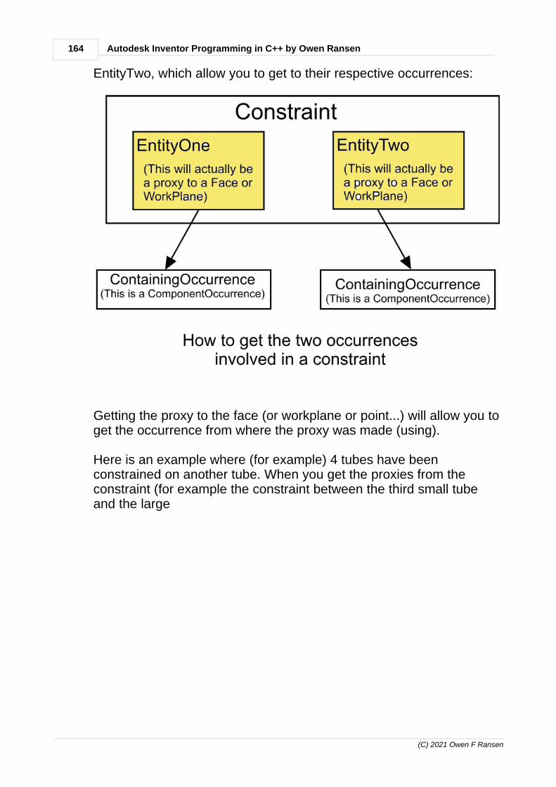
164 Autodesk Inventor Programming in C++ by Owen Ransen
(C) 2021 Owen F Ransen
EntityTwo, which allow you to get to their respective occurrences:
Getting the proxy to the face (or workplane or point...) will allow you toget the occurrence from where the proxy was made (using).
Here is an example where (for example) 4 tubes have beenconstrained on another tube. When you get the proxies from theconstraint (for example the constraint between the third small tubeand the large

165Programming Inventor in C++
(C) 2021 Owen F Ransen
Here is another example, with workplane proxies inside an assembly:

166 Autodesk Inventor Programming in C++ by Owen Ransen
(C) 2021 Owen F Ransen
12.89 ErrorManager, errors and warnings, ShowCOMError andReturnAndShowCOMError
In InvSuppLib the file InvErrorHandling.cpp contains the errorhandling functions I use.
An example of an error message would be if you tried to create acircle in a sketch with negative diameter. You'll not get a nice "badradius" message from COM, just an "invalid parameter" message.
Have a look at the code for ShowCOMError. Not only does it give youdialog with the the text of the error code, but sometimes it gives youan extra hint about what caused the error. I add those hints as, dayby day, I understand them. You can do the same.
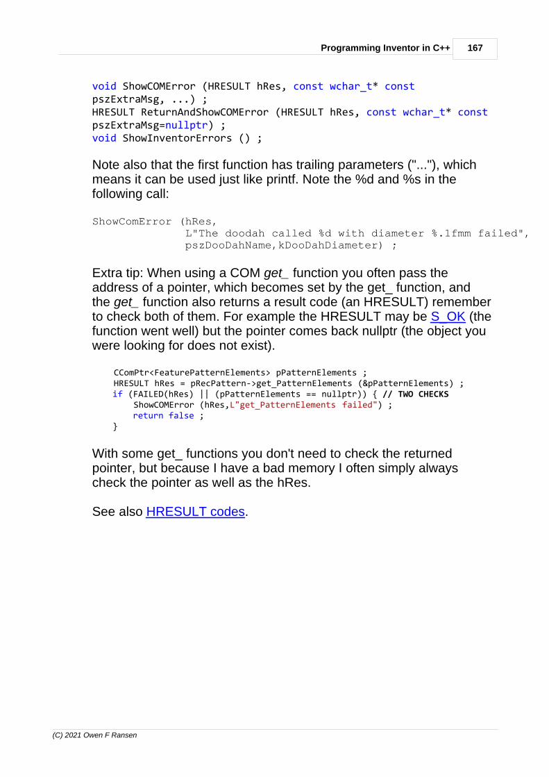
167Programming Inventor in C++
(C) 2021 Owen F Ransen
void ShowCOMError (HRESULT hRes, const wchar_t* constpszExtraMsg, ...) ;HRESULT ReturnAndShowCOMError (HRESULT hRes, const wchar_t* constpszExtraMsg=nullptr) ;void ShowInventorErrors () ;
Note also that the first function has trailing parameters ("..."), whichmeans it can be used just like printf. Note the %d and %s in thefollowing call:
ShowComError (hRes, L"The doodah called %d with diameter %.1fmm failed", pszDooDahName,kDooDahDiameter) ;
Extra tip: When using a COM get_ function you often pass theaddress of a pointer, which becomes set by the get_ function, andthe get_ function also returns a result code (an HRESULT) rememberto check both of them. For example the HRESULT may be S_OK (thefunction went well) but the pointer comes back nullptr (the object youwere looking for does not exist).
CComPtr<FeaturePatternElements> pPatternElements ; HRESULT hRes = pRecPattern->get_PatternElements (&pPatternElements) ; if (FAILED(hRes) || (pPatternElements == nullptr)) { // TWO CHECKS ShowCOMError (hRes,L"get_PatternElements failed") ; return false ; }
With some get_ functions you don't need to check the returnedpointer, but because I have a bad memory I often simply alwayscheck the pointer as well as the hRes.
See also HRESULT codes.

168 Autodesk Inventor Programming in C++ by Owen Ransen
(C) 2021 Owen F Ransen
12.90 Looping over views in sheets
This function will find a named view in a sheet of an IDW:
bool FindDrawingViewInSheetByName (CComPtr<DrawingView>& pView, CComPtr<Sheet>& pSheet, const wchar_t* const pszName) { if ((pSheet == nullptr) || (pszName == nullptr) || (wcslen(pszName) == 0)) { TRACE (L"FindDrawingViewInSheetByName, Bad inputparameters") ; return false ; }
CComPtr<DrawingViews> pViews ; HRESULT hRes = pSheet->get_DrawingViews (&pViews) ; if (FAILED(hRes) || (pViews == nullptr)) { ShowCOMError (hRes,L"FindDrawingViewInSheetByName,get_DrawingViews failed."); return false ; } const long ikNumViews = pViews->GetCount() ; for (long iView = 1 ; iView <= ikNumViews ; iView++) { CComPtr<DrawingView> pThisView ; hRes = pViews->get_Item (iView,&pThisView) ; if (FAILED(hRes) || (pThisView == nullptr)) { ShowCOMError (hRes,L"FindDrawingViewInSheetByName,get_Item(%d) failed.",iView); return false ; }
CComBSTR bstrViewName ; pThisView->get_Name (&bstrViewName) ;
TRACE ("Found a view called %s\n",bstrViewName) ;
if (wcscmp(CString(bstrViewName),pszName) == 0) { pView = pThisView ; return true ; } }
return false ;}
So you can find a named view inside a sheet..

169Programming Inventor in C++
(C) 2021 Owen F Ransen
12.91 Listing and checking constraints
This function goes over the constraints in an assembly checking thata given named constraint does not already exist:
bool ConstraintNameAlreadyExists (const CString& csNameToCheck, CComPtr<AssemblyComponentDefinition>& pAsmCompDef){ // Get the list of constraints of the assembly CComPtr<AssemblyConstraints> pConstraintList = nullptr ; HRESULT hRes = pAsmCompDef->get_Constraints(&pConstraintList); if (FAILED(hRes) || (pConstraintList == nullptr)) { ShowCOMError (hRes,L"ConstraintNameAlreadyExists couldnot get constraints.") ; return true ; // pretend it exists hopefully to stopfurther processing }
const long ikNumConstraints = pConstraintList->GetCount() ; for (int iConstraint = 1 ; iConstraint <= ikNumConstraints ;iConstraint++) { CComPtr<AssemblyConstraint> pConstraint = nullptr ; hRes =pConstraintList->get_Item(CComVariant(iConstraint),&pConstraint); if (FAILED(hRes) || (pConstraint == nullptr)) { ShowCOMError (hRes,L"ConstraintNameAlreadyExistscould not get constraint %d.",iConstraint) ; return true ; // pretend it exists hopefully to stopfurther processing }
CComBSTR bstrConstraintName ; pConstraint->get_Name(&bstrConstraintName) ; TRACE (L"Checking constraint <%s>\n",bstrConstraintName); if(CString(bstrConstraintName).CompareNoCase(csNameToCheck) == 0) { // A constraint with the given name already exists return true ; } }

170 Autodesk Inventor Programming in C++ by Owen Ransen
(C) 2021 Owen F Ransen
// If we get here then there are no constraints with the samename as csNameToCheck return false ;}
By the way, when your assemblies get even a bit complex it willprobably help you to name the constraints you add, using put_Name.
12.92 Saving apparently disabled (SilentOperation)
If you ever enable SilentOperation in your program remember to re-enable it just before your program exits. i.e:
m_pInvApp->SilentOperation = VARIANT_FALSE ;
12.93 WorkAxes in Inventor programs
In a Part there are always three standard WorkAxes, the X Y and Zaxes. Here is the "Z Axis":
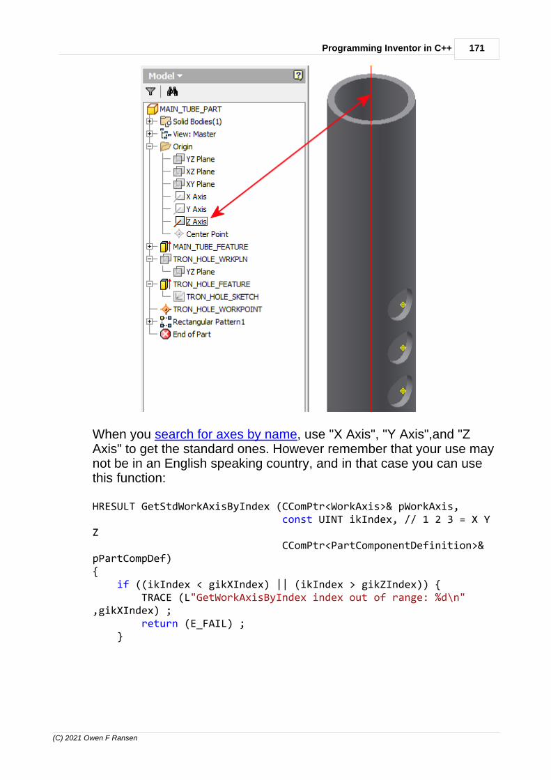
171Programming Inventor in C++
(C) 2021 Owen F Ransen
When you search for axes by name, use "X Axis", "Y Axis",and "ZAxis" to get the standard ones. However remember that your use maynot be in an English speaking country, and in that case you can usethis function:
HRESULT GetStdWorkAxisByIndex (CComPtr<WorkAxis>& pWorkAxis, const UINT ikIndex, // 1 2 3 = X YZ CComPtr<PartComponentDefinition>&pPartCompDef) { if ((ikIndex < gikXIndex) || (ikIndex > gikZIndex)) { TRACE (L"GetWorkAxisByIndex index out of range: %d\n",gikXIndex) ; return (E_FAIL) ; }

172 Autodesk Inventor Programming in C++ by Owen Ransen
(C) 2021 Owen F Ransen
// Get the axis in the part by name... HRESULT hRes =pPartCompDef->WorkAxes->get_Item(CComVariant(ikIndex),&pWorkAxis); if (FAILED(hRes) || (pWorkAxis == nullptr)) { ShowCOMError (hRes,L"GetWorkAxisByIndex but 'get'failed\n"); return (E_FAIL) ; }
return (S_OK) ;}
Like many things WorkAxes are inside PartComponentDefinition, andyou can get hold of them like this:
CComPtr<PartComponentDefinition>& pPartCompDef ; ... pPartCompDef->WorkAxes->get_Item(CComVariant(pszWorkAxisName), &pWorkAxis);
Note that the plural of Axis is Axes, not Axiss!
12.94 Wrapping COM and C++
If you write a console EXE in C++ you should follow this high levelstructure:
int _tmain(int argc, _TCHAR* argv[]){
HRESULT Result = CoInitialize (NULL); // Start COM...
if (SUCCEEDED(Result))Result = YourInventorProgram();
CoUninitialize(); // ...end COM
return 0;}

173Programming Inventor in C++
(C) 2021 Owen F Ransen
In this way the smart pointers and COM objects will be constructedand destroyed properly, as long as you keep them on the stack (i.e.local to some function).
If you had a global variable like the error manager outside ofYourInventorProgram you would need to be able to handle it explictly,and you'd probably get errors when you program closes down(because the global pointer will be handled after CoUnitialize hasbeen called, and COM is no longer active).
12.95 Units when programming Inventor
Whatever units the user chooses to use (Inches or mm or feet or cmetc) internally Inventor only uses one of each type.
For example, even if the user sets inches as the linear unit, intenallyInventor uses Centimeters anyway. And you, as a programmer shoulduse Centimeters too.
This has implications for parameters, for example.
If you change an angular parameter, for example, remember to use

174 Autodesk Inventor Programming in C++ by Owen Ransen
(C) 2021 Owen F Ransen
radians, even though the user will see degrees.
12.96 Exporting Paramenters
To make model and user parameters visibile at a higher level than thepart in which they are contained use the iPart author to place them inthe pane on the left:
.
12.97 Placing objects in space Vector and Matrix
When you add an occurrence of a part you can specify the placementusing Vector and Matrix. The example below places the part at20,2,2:
// Need some transient geometry to add in a part... CComPtr<TransientGeometry> pTransGeom;

175Programming Inventor in C++
(C) 2021 Owen F Ransen
hr = pInvApp->get_TransientGeometry(&pTransGeom);
CComPtr<Matrix> pMatrix; // Defaults to 0,0,0 position hr = pTransGeom->CreateMatrix(&pMatrix);
CComPtr<Vector> pVector; // Create a Vector to modify the Matrix hr = pTransGeom->CreateVector(20,2,2,&pVector); pMatrix->SetTranslation (pVector,VARIANT_TRUE) ; CComPtr<ComponentOccurrence> pOcc2; hr = pOccs->Add(csFileName,pMatrix,&pOcc2) ;
The TransientGeometry pTransGeom object is an object whichcreates Vector and Matrix etc. It is a machine for making theseabstract objects.
Also note that the second parameter of SetTranslation is set toVARIANT_TRUE. That means "Yes, reset any rotation components inthe matrix". If you've only just created the matrix as in the aboveexample, there will be no rotation components inside the matrix, but Igenerally do the call with VARIANT_TRUE.
You can rotate and move an occurrence of a part like this:
CComPtr<TransientGeometry> pGeom = GetTransGeomPtr () ; pGeom->CreateMatrix(&pFinalMatrix); // First rotate ... CComPtr<Vector> pZAxis = nullptr; pGeom->CreateVector(0, 0, 1, &pZAxis);
CComPtr<Point> pOrigin = nullptr; pGeom->CreatePoint(0, 0, 0, &pOrigin); pFinalMatrix->SetToRotation(kRadians, pZAxis, pOrigin);
// Then shift .... CComPtr<Matrix> pTransMatrix; pGeom->CreateMatrix(&pTransMatrix); CComPtr<Vector> pTransVector; // Create a Vector to modify the Matrix pGeom->CreateVector(50.0,0.0,0.0,&pTransVector); pTransMatrix->SetTranslation (pTransVector,VARIANT_TRUE) ;
pFinalMatrix->PostMultiplyBy(pTransMatrix);

176 Autodesk Inventor Programming in C++ by Owen Ransen
(C) 2021 Owen F Ransen
12.98 ObjectCollections in the Inventor API (transient objectcollections)
Object collections can be used to make a list of already existingobjects. This list can then be used by your program to do repeatedoperations on those objects. Although the objects already exist theymay be in hard to get places, or in the wrong order to what you want.Or maybe the objects you want are a sub set of the all the objects inyour part or assembly.
Anyway, you need to get hold of the transient objects pointer from theInventor application:
CComPtr<Application> pInvApp ... ; CComPtr<TransientObjects> pTransientObjects ; pInvApp->get_TransientObjects (&pTransientObjects) ;
Or, if basing your programs on the book sources, you can use GetTransGeomPtr().
The TransientObjects pointor is the thing which allows you to createobject collections. Here is how to create an initially empty one:
CComPtr<ObjectCollection> pObjCollection = nullptr ; pTransientObjects->CreateObjectCollection(varEmpty,&pObjCollection) ;
Simply use the Add function to add objects to the collection. Here isan example of adding a WorkPlaneProxy to an object collection:
CComPtr<WorkPlaneProxy> pWPProxy = nullptr ; pTuboOcc->CreateGeometryProxy (pWP,(IDispatch**)&pWPProxy) ; pObjCollection->Add (pWPProxy) ;
Once you have created the list of objects you can get hold of them bypassing the index to the get_Item function:

177Programming Inventor in C++
(C) 2021 Owen F Ransen
CComPtr<WorkPlaneProxy> pHoleWPProxy = nullptr ; int iTroncNum = ..something starting a 1, 1 is the firstobject.... pObjCollection->get_Item(iTroncNum,(IDispatch**)&pHoleWPProxy) ;
I've removed all error checking from the fragments above.
12.99 Creating a new Part Document
Here's a function for doing it:
HRESULT CreateNewPartDoc(CComPtr<PartDocument>& pPartDoc, const wchar_t* const pszPartName)/*Given a name a new part document is created in Inventor with thatname.*/{ CComPtr<Application> pInventorApp = theApp.GetInvAppPtr() ;
CComVariant pSubDocType;CComBSTR sTemplate;HRESULT hr = pInventorApp->GetTemplateFile
(kPartDocumentObject, // We are creating a PartDocument kMetricSystemOfMeasure, // mm kDefault_DraftingStandard, pSubDocType, &sTemplate);
if (hr != S_OK) {return hr;
}
CComPtr<Document> pDoc; hr = pInventorApp->Documents->Add (kPartDocumentObject, sTemplate, VARIANT_TRUE, &pDoc); if (hr != S_OK) { return hr; }

178 Autodesk Inventor Programming in C++ by Owen Ransen
(C) 2021 Owen F Ransen
pPartDoc = CComQIPtr<PartDocument>(pDoc);
if ((pszPartName != nullptr) && (wcslen (pszPartName) > 0)) { BSTR bstrName ; pDoc->get_DisplayName (&bstrName) ; TRACE (L"\nFull document name was %s\n",bstrName) ;
pPartDoc->DisplayName = pszPartName ;
pDoc->get_DisplayName (&bstrName) ; TRACE (L"\nFull document name now is %s\n",bstrName) ;
::SysFreeString (bstrName) ; }
return hr;}
Which can be called like this:
CComPtr<PartDocument> pPartDocument ; HRESULT hRes = CreateNewPartDoc (pPartDocument,L"MAIN_TUBE"); if (FAILED(hRes)) { return ReturnAndShowCOMError (hRes,L"CreateMainTube,CreateNewPart failed") ; }
12.100How to extrude a sketch programatically
Here is a function which takes five parameters and creates a 3Dextruded feature in the part. The feature could be a hole, as well asnormal solid objects....

179Programming Inventor in C++
(C) 2021 Owen F Ransen
HRESULT ExtrudeSketch (const wchar_t* const pszExtrusionName, // name of created feature const double kHeightMm, const wchar_t* const pszSketchName, // which sketch to extrude const PartFeatureOperationEnumeOperation, // how to extrude const PartFeatureExtentDirectionEnumeDirection, CComPtr<PartComponentDefinition>&pPartCompDef)/*Given a height and a sketch name the sketch is extruded to thegiven height.

180 Autodesk Inventor Programming in C++ by Owen Ransen
(C) 2021 Owen F Ransen
The resultant feaure is placed inside pPartCompDef, and is calledpszExtrusionNameeOperation tells us whether to cut a hole or create a solidobject etc.eDirection tells us which direction to make the extrusion.*/{ // Get the sketch in the part by name... CComPtr<PlanarSketch> pSketch; HRESULT hRes =pPartCompDef->Sketches->get_Item(CComVariant(pszSketchName),&pSketch); if (FAILED(hRes) || (pSketch == nullptr)) { return ReturnAndShowCOMError (hRes,L"ExtrudeSketch butcould not get sketch by name\n"); } CComPtr<Profile> pProfile ; // This is the return value ofthe call to AddForSolid // and will be used when weextrude. CComVariant pSegs; // not used CComVariant pReserve; // not used hRes =pSketch->Profiles->AddForSolid(VARIANT_TRUE,pSegs,pReserve,&pProfile); if (FAILED(hRes) || (pProfile == nullptr)) { return ReturnAndShowCOMError (hRes,L"ExtrudeSketch butcould not AddForSolid for pProfile\n"); }
// Features are 3D objects. Get the list of them so we canadd to that list... CComPtr<PartFeatures> pListOfFeatures; hRes = pPartCompDef->get_Features(&pListOfFeatures); if (FAILED(hRes) || (pListOfFeatures == nullptr)) { return ReturnAndShowCOMError (hRes,L"ExtrudeSketch butcould not get_Features\n"); }
// Get the list of *extruded* features... CComPtr<ExtrudeFeatures> pListOfExtrusions; hRes =pListOfFeatures->get_ExtrudeFeatures(&pListOfExtrusions); if (FAILED(hRes) || (pListOfExtrusions == nullptr)) {

181Programming Inventor in C++
(C) 2021 Owen F Ransen
return ReturnAndShowCOMError (hRes,L"ExtrudeSketch butcould not get_ExtrudeFeatures\n"); }
// Now at last we can use the pProfile to create a newextrusion, adding it to the list // of extruded features. This is where we use the eOperationparameter CComPtr<ExtrudeDefinition> pExtrudeDef; hRes =pListOfExtrusions->CreateExtrudeDefinition(pProfile,eOperation,&pExtrudeDef); if (FAILED(hRes) || (pExtrudeDef == nullptr)) { return ReturnAndShowCOMError (hRes,L"ExtrudeSketch butcould not CreateExtrudeDefinition\n"); }
// Specify the distance and direction of the extrustion... // This function needs it in cm, so convert from mm to cm pExtrudeDef->SetDistanceExtent(_variant_t(kHeightMm/10.0),eDirection);
// Add the extrusion. CComPtr<ExtrudeFeature> pExtrude; hRes = pListOfExtrusions->Add (pExtrudeDef,&pExtrude); if (FAILED(hRes) || (pExtrude == nullptr)) { return ReturnAndShowCOMError (hRes,L"ExtrudeSketch butcould Add ExtrudeDefinition\n"); }
pExtrude->put_Name (CComBSTR (pszExtrusionName)) ;
return (hRes) ;}
Here are the possible values for the two enumerators used above:

182 Autodesk Inventor Programming in C++ by Owen Ransen
(C) 2021 Owen F Ransen
PartFeatureExtentDirectionEnumEnumerator ValueDescriptionkNegativeExtentDirection
20994
Extension in the negativedirection.
kPositiveExtentDirection
20993
Extension in the positivedirection
kSymmetricExtentDirection
20995
Extension in positive ANDnegative direction.
PartFeatureOperationEnumEnumerator Value DescriptionkCutOperation 2048
2Cut operation. (i.e. make ahole)
kIntersectOperation 20483
Intersect operation.
kJoinOperation 20481
Join operation.
kNewBodyOperation
20485
New Body operation.
kSurfaceOperation20484
Surface operation.
This image has used kCutOperation and kSymmetricExtentDirectionaround a center plane of a cylinder, the sketch contained a singlecircle:
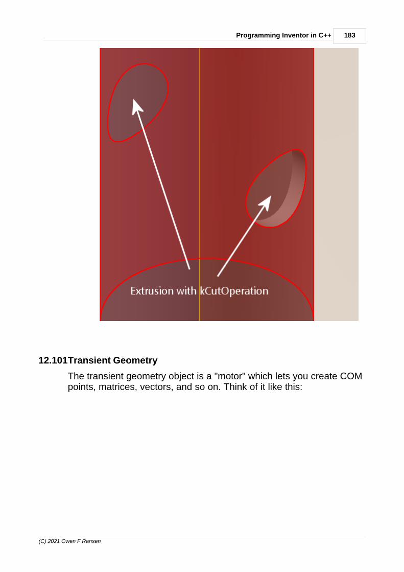
183Programming Inventor in C++
(C) 2021 Owen F Ransen
12.101Transient Geometry
The transient geometry object is a "motor" which lets you create COMpoints, matrices, vectors, and so on. Think of it like this:
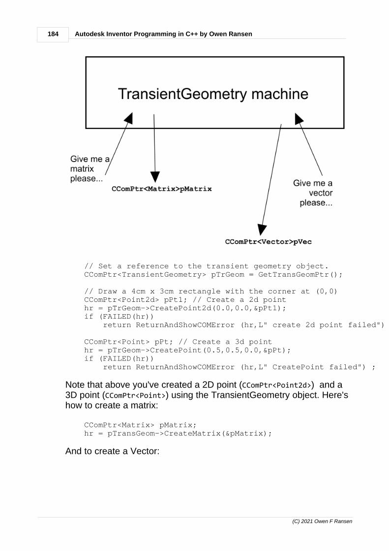
184 Autodesk Inventor Programming in C++ by Owen Ransen
(C) 2021 Owen F Ransen
// Set a reference to the transient geometry object. CComPtr<TransientGeometry> pTrGeom = GetTransGeomPtr();
// Draw a 4cm x 3cm rectangle with the corner at (0,0) CComPtr<Point2d> pPt1; // Create a 2d point hr = pTrGeom->CreatePoint2d(0.0,0.0,&pPt1); if (FAILED(hr)) return ReturnAndShowCOMError (hr,L" create 2d point failed") ;
CComPtr<Point> pPt; // Create a 3d point hr = pTrGeom->CreatePoint(0.5,0.5,0.0,&pPt); if (FAILED(hr)) return ReturnAndShowCOMError (hr,L" CreatePoint failed") ;
Note that above you've created a 2D point (CComPtr<Point2d>) and a3D point (CComPtr<Point>) using the TransientGeometry object. Here'show to create a matrix:
CComPtr<Matrix> pMatrix; hr = pTransGeom->CreateMatrix(&pMatrix);
And to create a Vector:

185Programming Inventor in C++
(C) 2021 Owen F Ransen
CComPtr<Vector> pVector; hr = pTransGeom->CreateVector(20,2,2,&pVector);
Note that these are "abstract geometrical" objects, not "concrete"CAD objects.
Note also that CComPtr will be initialised to nullptr automatically.
12.102Changing the application visibility
To set and get the visibility of Inventor:
// Obtain the 'Visible' property of the active application VARIANT_BOOL bVisible; Result = pInvApp->get_Visible(&bVisible); if (FAILED(Result)) return Result;
if (bVisible != VARIANT_TRUE){
pInvApp->Visible = VARIANT_TRUE ; }
...though you may well still see a tiny icon of Inventor at the top left ofyour screen.
12.103A matrix to rotate an object
When you insert a part in an assembly you can specify the initialposition and rotation. You do this by providing a matrix to the AddiPartMember call. Here is an example of how to create a matrixwhich will rotate the part around the Z axis by 180 degrees:
CComPtr<TransientGeometry> pTransGeom = GetTransGeomPtr () ; CComPtr<Matrix> pPosMatrix; pTransGeom->CreateMatrix(&pPosMatrix); // Defaults to origin
CComPtr<Vector> pZAxis = nullptr ; pTransGeom->CreateVector (0,0,1,&pZAxis);

186 Autodesk Inventor Programming in C++ by Owen Ransen
(C) 2021 Owen F Ransen
CComPtr<Point> pOrigin = nullptr ; pTransGeom->CreatePoint (0,0,0,&pOrigin);
pPosMatrix->SetToRotation (TwoPi,pZAxis,pOrigin) ;
...and when you call AddiPartMember you use the matrix like this:
pOccurrencesList->AddiPartMember (bstrFileName,pPosMatrix,_variant_t(bstrMemberName),&pOccurrence) ;
Note that SetToRotation requires radians, not degrees.
These two diagrams show the result of using a X-Axis rotation matrixwhen calling AddiPartMember:

187Programming Inventor in C++
(C) 2021 Owen F Ransen
Here is a code fragment which creates the matrix which does that:
CComPtr<Matrix> pRotXMatrix; pTransGeom->CreateMatrix(&pRotXMatrix); CComPtr<Vector> pXAxis = nullptr ; pTransGeom->CreateVector (0,1,0,&pXAxis); pRotXMatrix->SetToRotation (gkPi,pXAxis,pOrigin) ;
If you are using two planes in a constraint you can also sometimesuse FlipNormal to rotate the inserted object 180°
12.104Proxies, WorkAxes, Vectors and Points
Here is an example of getting the data about a work axis in part whichhas been inserted into an assembly:
CComPtr<Line> pAxisLine = nullptr ; p1stHoleWorkAxisProxy->get_Line (&pAxisLine) ;

188 Autodesk Inventor Programming in C++ by Owen Ransen
(C) 2021 Owen F Ransen
CComPtr<Point> pRootPoint ; pAxisLine->get_RootPoint (&pRootPoint) ; CComPtr<UnitVector> pAxisDir ; pAxisLine->get_Direction (&pAxisDir) ;
Now you can use that axis to form a rotation matrix:
CComPtr<Vector> pAxisVector = nullptr ; pTransGeom->CreateVector(pAxisDir->X,pAxisDir->Y,pAxisDir->Y,&pAxisVector) ;
pRotMatrix->SetToRotation (gkPi,pAxisVector,pRootPoint) ;
12.105WorkFeatures and iParts
If you have a workplane in a table based iPart (or even custom iPart)for that workplane to be visible in when inserted in an assembly (i.e.when it is an occurrence in an assembly) then you need to include itusing the iPart author.
If you don't do that you'll get a com error 80070057.
Here is the sequence:
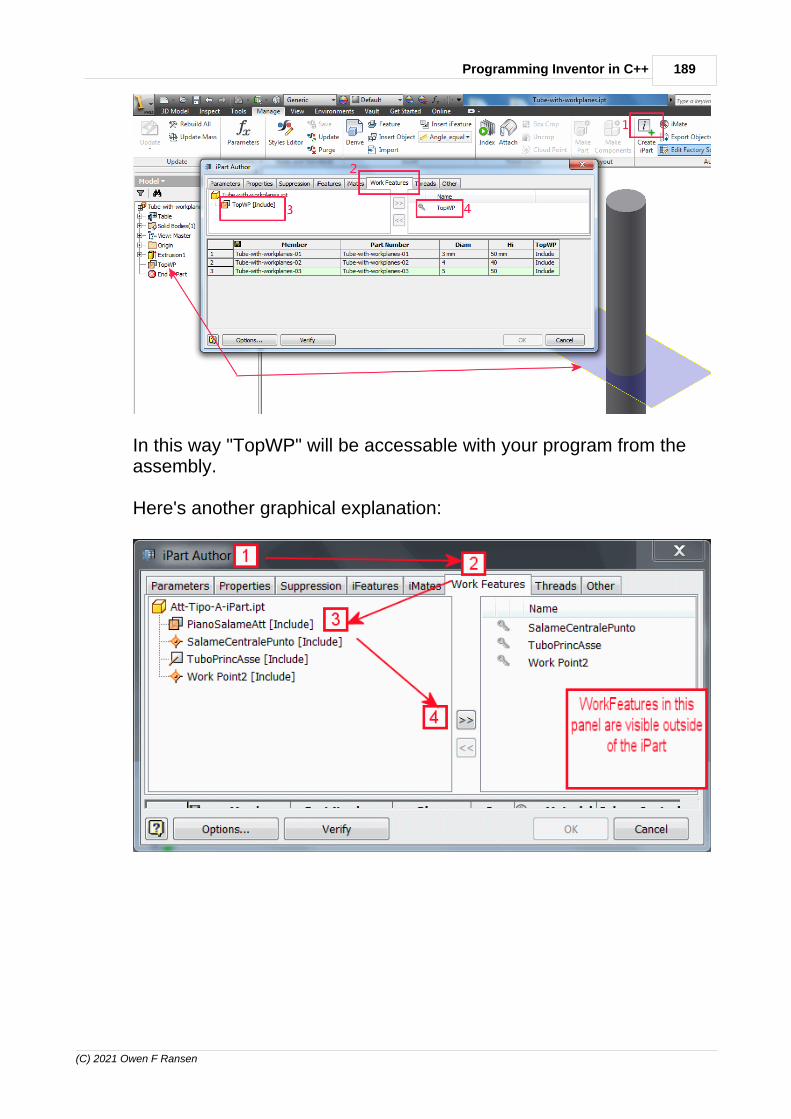
189Programming Inventor in C++
(C) 2021 Owen F Ransen
In this way "TopWP" will be accessable with your program from theassembly.
Here's another graphical explanation:

190 Autodesk Inventor Programming in C++ by Owen Ransen
(C) 2021 Owen F Ransen
12.106What are PatternElements?
The FeaturePatternElements are the actual "copies" within a pattern,apart from the first one which is considered special.
Here's how you can list them
for (int i = 1; i <= pPatternElements->Count; i++) { CComPtr <FeaturePatternElement> pEle = nullptr ; hRes = pPatternElements->get_Item (i,&pEle) ; if (FAILED(hRes)) { ShowCOMError (hRes,L"EWTPFP, get_Item (%d) failed",ikNumber) ; return false ; }
gLogger.Printf(ekLogMsg,L"Element %d is a <%s>",i,GetObjTypeDesc(pEle->GetType())); }

191Programming Inventor in C++
(C) 2021 Owen F Ransen
12.107Listing the contents of Patterns
The parent objects of a Pattern are the objects selected to berepeated in the pattern. They could also be called source objects...
Here are a couple of functions illustrating how to get details frompatterns:
// Write out details of any rectangular patterns in this assemblyvoid ListRectPatterns(CComPtr<AssemblyComponentDefinition>& pAsmCompDef){ gLogger.Printf(ekLogMsg, L"LRP starting..."); CComPtr<OccurrencePatterns> pOccPatterns; pOccPatterns = pAsmCompDef->GetOccurrencePatterns(); if (pOccPatterns == nullptr) { gLogger.Printf(ekLogMsg, L"LRP no patterns..."); return ; }
for (int p = 1; p <= pOccPatterns->Count; p++) { gLogger.Printf(ekLogMsg, L"LRP pattern %d...",p); CComPtr<OccurrencePattern> pPattern; CComVariant varp(p); HRESULT hRes = pOccPatterns->get_Item(varp, &pPattern); if (FAILED(hRes) || (pPattern == nullptr)) { gLogger.Printf(ekLogMsg, L"LRP could not get %d...",p);

192 Autodesk Inventor Programming in C++ by Owen Ransen
(C) 2021 Owen F Ransen
continue; }
CComQIPtr<RectangularOccurrencePattern> pRectPattern; pRectPattern = pPattern; if (pRectPattern == nullptr) { continue; }
// Getting hold of the row and column counts is a bit tricky... CComVariant varRowCount (pRectPattern->RowCount->GetValue()); CComVariant varColCount (pRectPattern->ColumnCount->GetValue());
// Name of the pattern const CString kcsPatternName (pRectPattern->Name.GetBSTR()); const UINT ikNumSubItems = int(varRowCount.dblVal *varColCount.dblVal);
gLogger.Printf (ekLogMsg,L"Rect Pattern <%s> has %.1f rows and %.1fcolumns, numsub items=%d", kcsPatternName,varRowCount.dblVal,varColCount.dblVal,ikNumSubItems);
// Parent components are the objects which are the source objects ofthe array. CComPtr<ObjectCollection> pParentComponents; hRes = pRectPattern->get_ParentComponents(&pParentComponents); if (FAILED(hRes) || (pParentComponents == nullptr)) { gLogger.Printf(ekLogMsg, L"Could not get parent objects"); continue; }
// Now list the parent objects gLogger.Printf(ekLogMsg, L"LRP pattern %d has %d parent objects...",p,pParentComponents->Count);
for (int o = 1; o <= pParentComponents->Count ; o++) { CComQIPtr <ComponentOccurrence> pOcc; hRes = pParentComponents->get_Item (o,(IDispatch**)&pOcc); if (FAILED(hRes) || (pOcc == nullptr)) { gLogger.Printf(ekLogMsg, L"Skipping sources object %d %d", p,o); continue; }
_bstr_t DisplayName = pOcc->Get_DisplayName(); CString kcsDisplayName = CString (DisplayName.GetBSTR());
gLogger.Printf(ekLogMsg, L"Pattern %03d parent occurrence %03d is<%s>", p, o, kcsDisplayName); } }}

193Programming Inventor in C++
(C) 2021 Owen F Ransen
/*****************************************************************************************/
// List the features of any rectangular patterns in this partvoid ListRectPatternFeatures (CComPtr<PartComponentDefinition>& pPartCompDef){ HRESULT hRes ;
// Get the list of features... CComPtr<PartFeatures> pFeaturesList ; pPartCompDef->get_Features(&pFeaturesList) ;
// Get the list of rectangular features, we will add to this list.... CComPtr<RectangularPatternFeatures> pRectPatList ; pFeaturesList->get_RectangularPatternFeatures (&pRectPatList) ;
const long ikNumRecFeats = pRectPatList->GetCount() ;
for (int iRect = 1 ; iRect <= ikNumRecFeats ; iRect++) {
CComPtr <RectangularPatternFeature> pRectPatFeat ; hRes = pRectPatList->get_Item (CComVariant(iRect),&pRectPatFeat) ;
if (FAILED(hRes)) { ShowCOMError (hRes,L"ListRectangularPatternComponents, could notget rectangular pattern") ; return ; }
BSTR bstrName = pRectPatFeat->GetName () ;
CComPtr<Parameter> XCountParam ; pRectPatFeat->get_XCount (&XCountParam) ; /*const int ikXCount = XCountParam->GetValue () ;
TRACE (L"Component %d is called %s, and the x count is %d",iRect,bstrName,ikXCount) ;*/
CComPtr<FeaturePatternElements> pFeaturePatternElements ; pRectPatFeat->get_PatternElements (&pFeaturePatternElements) ;
const int ikNumElements = pFeaturePatternElements->GetCount() ; TRACE (L", this has %d FeaturePatternElements\n",ikNumElements) ;
for (int iElem = 1 ; iElem < ikNumElements ; iElem++) { CComPtr<FeaturePatternElement> pFeaturePatternElement ; pFeaturePatternElements->get_Item (iElem,&pFeaturePatternElement); }
::SysFreeString(bstrName); }}

194 Autodesk Inventor Programming in C++ by Owen Ransen
(C) 2021 Owen F Ransen
12.108Pattern counts
Once you get hold of a rectangular pattern you can count rows andcolumns as follows...
// Getting hold of the row and column counts is a bit tricky... CComVariant varRowCount (pRectPattern->RowCount->GetValue()); CComVariant varColCount (pRectPattern->ColumnCount->GetValue());
// Getting hold of the pattern name... const CString kcsPatternName (pRectPattern->Name.GetBSTR()); const UINT ikNumSubItems = int(varRowCount.dblVal *varColCount.dblVal);
gLogger.Printf (ekLogMsg,L"Rect Pattern <%s> has %.1f rows and %.1fcolumns, numsub items=%d", kcsPatternName,varRowCount.dblVal,varColCount.dblVal,ikNumSubItems);
Oddly enough the counts are double values, which is why we use .dblVal in the above code.
The code also illustrates getting hold of the pattern's name.
Patterns can have a count of 1.
12.109What sort of WorkFeature is this?
Unfortunately WorkPoint WorkAxis and WorkPlane objects do nothave a common parent. If you get a pointer to one of these thingsfrom an ObjectsCollection you have to work a bit harder than normalto get their type. Here is an example, assuming you already have anObjectsEnumerator and want to get hold of the iObj th item:
CComPtr<ObjectsEnumerator> pObjs = ... ; int iObj = ... ... CComPtr<WorkPlane> pWPlane = nullptr ; CComPtr<WorkPoint> pWPoint = nullptr ; CComPtr<WorkAxis> pWAxis = nullptr ; pObjs->get_Item (iObj,(IDispatch**)&pWPlane) ; pObjs->get_Item (iObj,(IDispatch**)&pWPoint) ;

195Programming Inventor in C++
(C) 2021 Owen F Ransen
pObjs->get_Item (iObj,(IDispatch**)&pWAxis) ; if ((pWPlane != nullptr) && (pWPlane->GetType() ==kWorkPlaneObject)) { // pWPlane is a valid workplane } else if ((pWPoint != nullptr) && (pWPoint->GetType() ==kWorkPointObject)) { // pWPoint is a valid workpoint
} else if ((pWAxis != nullptr) && (pWAxis->GetType() ==kWorkAxisObject)) { // pWAxis is a valid axis
} else { // This is probably an error }
.
12.110IDispatch
You often need to cast pointers to objects into IDispatch* orIDispatch** when calling functions in the Inventor C++ COM API.Here are some examples, showing how to cast from various Inventorpointers to an IDispatch* :
Add a sketch based on a workplane:
CComPtr<WorkPlane> pWorkPlane ; hRes = pSketches->Add (_variant_t((IDispatch*)pWorkPlane), VARIANT_FALSE, &pNewSketch);
Add a workplane based on an existing workplane:
CComPtr<WorkPlane> pWorkPlane... ; CComPtr<WorkPlane> pOffsetWorkPlane ; hRes = pWorkPlanesList->AddByPlaneAndOffset (_variant_t((IDispatch*)pWorkPlane),// "starting" plane CComVariant(kTubeDiam/2.0), // how much to offset VARIANT_FALSE, // Construction?

196 Autodesk Inventor Programming in C++ by Owen Ransen
(C) 2021 Owen F Ransen
&pOffsetWorkPlane) ; // Return value of this call
Add a workpoint based on a sketchpoint:
CComPtr<SketchPoint> pSketchPoint... ; CComPtr<WorkPoint> pWorkPoint ; hRes = pWorkPointsList->AddByPoint (_variant_t((IDispatch*)pSketchPoint),VARIANT_FALSE,&pWorkPoint) ; if (FAILED(hRes) || (pWorkPoint == nullptr)) { return ReturnAndShowCOMError (hRes,L"AddWorkPointAtSketchPoint, Add workpoint failed") ; }
Create a proxy geometry from an occurrence and a workplane:
CComPtr<WorkPlaneProxy> pWPProxyA ; pOccurrence->CreateGeometryProxy (pWorkPlaneA,(IDispatch**)&pWPProxyA) ;
12.111AddByPlaneAndOffset example
Here is an example of creating an offset workplane from a standardworkplane, then setting it's name and making it visible in theassembly in which it exists:
CComPtr<WorkPlanes> pWorkPlanesList; hRes = pPartCompDef->get_WorkPlanes(&pWorkPlanesList);
CComPtr<WorkPlane> pCorpoCollXYWorkPlane; GetStdWorkPlaneByIndex(pCorpoCollXYWorkPlane, gikXYPlaneIndex,pPartCompDef);
CComPtr<WorkPlane> pOffsetWorkPlane;
const double kcmOffsetIn = 5.50; // 55mm
hRes = pWorkPlanesList->AddByPlaneAndOffset(pCorpoCollXYWorkPlane, //"starting" plane CComVariant (55.0), //how much to offset VARIANT_FALSE, //

197Programming Inventor in C++
(C) 2021 Owen F Ransen
Construction? &pOffsetWorkPlane); //Return value of this call if (SUCCEEDED(hRes)) { // Set the name so it is easily found by other parts of theprogram... pOffsetWorkPlane->Name = L"TuboIntBase";
// Export the feature so it is accessible in assemblies... pOffsetWorkPlane->Exported = VARIANT_TRUE; }
12.112Interrogating rectangular patterns
Here is a rectangular pattern inside an assembly:
If you have a PartComponentDefinition which contains a

198 Autodesk Inventor Programming in C++ by Owen Ransen
(C) 2021 Owen F Ransen
RectangularPatternFeature use this fragment of code to find out basicdata:
CComPtr<PartFeatures> pFeatures ; hRes = pBlockCompDef->get_Features (&pFeatures) ;
CComPtr<RectangularPatternFeatures> pRectPatList ; hRes = pFeatures->get_RectangularPatternFeatures (&pRectPatList) ;
// Pretend we know that we want the first rectangular pattern... CComPtr <RectangularPatternFeature> pRectPatFeat ; hRes = pRectPatList->get_Item (CComVariant(1),&pRectPatFeat) ;
CComPtr<Parameter> pXCountParam ; pRectPatFeat->get_XCount (&pXCountParam) ; int iXCount = 1 ; // note this initialization! if (pXCountParam != nullptr) { iXCount = pXCountParam->GetValue () ; // only if not nullptr! }
CComPtr<Parameter> pYCountParam ; pRectPatFeat->get_YCount (&pYCountParam) ; int iYCount = 1 ; // note this initialization! if (pYCountParam !=nullptr) { iYCount = pYCountParam->GetValue () ; // only if not nullptr! }
TRACE (L"The rectangular feature has %d by %d items\n",iXCount,iYCount) ;
Note the strangeness of the fact that there is no Y count if the patternis a linear array with , for example, 5 X items. That is why I set iYCount to 1 and change it only if pYCountParam is not nullptr.
Note also that you should check hRes, I've not done it for clarity here.
12.113Name of part in a component occurrence
Here is a function which will return the component occurrence (withinan assembly) of a given name.
HRESULT GetComponentOccurrenceByName (CComPtr<ComponentOccurrence>& pCompOccRet,

199Programming Inventor in C++
(C) 2021 Owen F Ransen
const wchar_t* constpszOccName, CComQIPtr<AssemblyDocument>pAssemblyDoc){ // Init for safety pCompOccRet = nullptr ;
// Get assembly component definition CComPtr<AssemblyComponentDefinition> pAssemblyCompDef = nullptr; HRESULT hRes =pAssemblyDoc->get_ComponentDefinition(&pAssemblyCompDef); if (FAILED(hRes) || (pAssemblyCompDef == nullptr)){ return ReturnAndShowCOMError(hRes,L"GetComponentOccurrenceByName, get_ComponentDefinition failed "); }
// Get the ComponentOccurrences collection for the assemblydocument CComPtr<ComponentOccurrences> pOccs; hRes = pAssemblyCompDef->get_Occurrences(&pOccs); if (FAILED(hRes) || (pOccs == nullptr)){ return ReturnAndShowCOMError (hRes,L"GetComponentOccurrenceByName, get_Occurrences failed "); }
long lNoOccs; hRes = pOccs->get_Count(&lNoOccs); if (FAILED(hRes)) { ReturnAndShowCOMError (hRes,L"GetComponentOccurrenceByName, get_Count failed "); }
TRACE (L"GetComponentOccurrenceByName, there are %doccurrences\n",lNoOccs);
//iterate through the current level of occurrencesfor (long lOccCount=1; lOccCount <= lNoOccs; ++lOccCount) {
CComPtr<ComponentOccurrence> pThisCompOcc = nullptr ; hRes = pOccs->get_Item(lOccCount, &pThisCompOcc); if (FAILED(hRes) || (pThisCompOcc == nullptr)){ ShowCOMError(hRes,L"GetComponentOccurrenceByName,

200 Autodesk Inventor Programming in C++ by Owen Ransen
(C) 2021 Owen F Ransen
get_Item failed "); return hRes ; }
CComPtr<ReferencedFileDescriptor> pRefFileDesc = nullptr; pThisCompOcc->get_ReferencedFileDescriptor(&pRefFileDesc) ; if (FAILED(hRes) || (pThisCompOcc == nullptr)){ ShowCOMError(hRes,L"GetComponentOccurrenceByName,get_ReferencedFileDescriptor failed "); return hRes ; } CComBSTR bstrDisplayName; // ::SysFreeString not requiredbecause CComBSTR, not BSTR hRes = pRefFileDesc->get_DisplayName (&bstrDisplayName) ; if (FAILED(hRes) || (pThisCompOcc == nullptr)){ ShowCOMError(hRes,L"GetComponentOccurrenceByName,get_DisplayName failed "); return hRes ;
} else {TRACE (L"Component occurrence %02d <%s>\n"
,lOccCount,bstrDisplayName); if (_wcsicmp(bstrDisplayName,pszOccName)==0) { pCompOccRet = pThisCompOcc ; } }
if (pCompOccRet != nullptr) { // We can get out return (S_OK) ; } }
TRACE (L"Could not find an occurrence called <%s>\n",pszOccName) ;
return (E_FAIL) ;}
Basically you get the name of the occurrence's part using theoccurrences ReferencedFileDescriptor .

201Programming Inventor in C++
(C) 2021 Owen F Ransen
12.114Add an occurrence to an assembly does not work
When you add an .ipt part to an .iam assembly you need to pass thecorrect sort of parameter to the Add function. For example this will notwork:
CComPtr<ComponentOccurrence> pCyl2Occ = nullptr;hRes = pOccurrencesList->Add (L"C:\\TEST\\Cyl2.ipt",pPosMatrix,&pCyl2Occ) ;
...but this will...
CComPtr<ComponentOccurrence> pCyl2Occ = nullptr;hRes = pOccurrencesList->Add (CComBSTR(L"C:\\TEST\\Cyl2.ipt"),pPosMatrix,&pCyl2Occ) ;
The difference is that the first call does not cast to CComBSTR, thesecond, working version, does.
12.115Listing constraints in an assembly programatically
Here is a code fragment showing how to list constraints and castEntityOne and EntityTwo into appropriate proxies. Graphically theconstraint and two proxies look like this:

202 Autodesk Inventor Programming in C++ by Owen Ransen
(C) 2021 Owen F Ransen
// Get the list of constraints of the assembly so you can adda new one CComPtr<AssemblyConstraints> pConstraintList = nullptr ; hRes = pAssemblyCompDef->get_Constraints(&pConstraintList) ; if (FAILED(hRes) || (pConstraintList == nullptr)) { TRACE (L"Could not get constraints.") ; return ; }
// List the two entities of each MateConstraint... for (int i = 1 ; i <= pConstraintList->Count ; i++) { CComPtr<AssemblyConstraint> pConstraint = nullptr ; pConstraintList->get_Item (CComVariant(i),&pConstraint) ; CComQIPtr<MateConstraint> pMate (pConstraint) ; if (nullptr != pMate) { // This is a mate constraing, show more data aboutit... IDispatchPtr pEnt1 = pMate->EntityOne ; IDispatchPtr pEnt2 = pMate->EntityTwo ; TRACE (L" Two parts are %p %p\n",pEnt1,pEnt2) ; CComQIPtr<FaceProxy> pFace1 =

203Programming Inventor in C++
(C) 2021 Owen F Ransen
CComQIPtr<FaceProxy>(pEnt1); CComQIPtr<WorkPlaneProxy> pWP1 =CComQIPtr<WorkPlaneProxy>(pEnt1); if (pFace1 != nullptr) { TRACE (L" Ent1 is a face proxy...\n") ; } else if (pWP1 != nullptr) { TRACE (L" Ent1 is a workplane proxy...\n") ; CComPtr<ComponentOccurrence> pContOcc =pWP1->ContainingOccurrence ; if (pContOcc != nullptr) { CComPtr<ReferencedFileDescriptor> pFileDesc= nullptr ; pContOcc->get_ReferencedFileDescriptor(&pFileDesc) ; if (pFileDesc != nullptr) { CComBSTR bstrFullFileName ; pFileDesc->get_FullFileName(&bstrFullFileName) ; TRACE (L" Ent1 full file name is %s\n",bstrFullFileName) ; } }
} else { TRACE (L" Ent1 This is neither a face orworkplane proxy\n") ; } } }
12.116Listing members in an iPartFactory programatically
Here is how to list members of an iPartFactory, starting with thePartDocument:
// Open the standard part... CComPtr<PartComponentDefinition> pTroncPartCompDef = nullptr; CComPtr<PartDocument> pTroncPartDoc = nullptr ; HRESULT hRes = OpenPart(pTroncPartCompDef,pTroncPartDoc,gkcsTroncFactory,pInvApp) ;
// Check that it is an iPartFactory...

204 Autodesk Inventor Programming in C++ by Owen Ransen
(C) 2021 Owen F Ransen
if (pTroncPartCompDef->IsiPartFactory == VARIANT_FALSE) { gLogger.Printf (ekImmediateErrorMsg,L"%s non e' uniPartFactory",gkcsTroncFactory) ; // This is NOT an iPartFactory return ; }
/* * Get the iPartFactory from the component definition... */ CComPtr<iPartFactory> piPartFactory = nullptr ; hRes =pTroncPartCompDef->get_iPartFactory (&piPartFactory) ;
/* * Get the rows of the factory, each row corresponds to a"member"... */ CComPtr<iPartTableRows> piPartTableRows = nullptr ; piPartFactory->get_TableRows (&piPartTableRows) ;
/* * Loop over the members in the table, printing Member... */ for (int iRow = 1 ; iRow <= piPartTableRows->Count ; iRow++){ CComPtr<iPartTableRow> piPartRow ; piPartTableRows->get_Item (iRow,&piPartRow) ; const int ikNumColumns = piPartRow->GetCount() ; BSTR bstrMember = nullptr ; piPartRow->get_MemberName (&bstrMember) ; TRACE (L" Row %03d:%s has %d things\n",iRow,LPCSTR(bstrMember),ikNumColumns) ; for (int iCol = 1 ; iCol <= ikNumColumns ; iCol++) { CComPtr<iPartTableCell> piPartTableCell = nullptr ; piPartRow->get_Item(CComVariant(iCol),&piPartTableCell) ;
CComBSTR bstrCellString ; piPartTableCell->get_Value (&bstrCellString) ; TRACE (L" iRow %d iCol %d has value %s\n",iRow,iCol,LPWSTR(bstrCellString)) ; }

205Programming Inventor in C++
(C) 2021 Owen F Ransen
::SysFreeString (bstrMember) ; }
As usual there's not as much error checking in the source above asthere should be. That last inner loop could use a function like this:
wchar_t* GetStringFromiPartTableRowCell (wchar_t* const szCellContents, size_t ikBufferSize, const UINT ikCol, CComPtr<iPartTableRow> piPartRow) { if (int(ikCol) > piPartRow->GetCount()) { szCellContents[0] = char(0) ; return szCellContents ; }
CComPtr<iPartTableCell> piPartTableCell ; piPartRow->get_Item (CComVariant(ikCol),&piPartTableCell) ;
CComBSTR bstrCellString ; piPartTableCell->get_Value (&bstrCellString) ; wcscpy_s (szCellContents,ikBufferSize,LPWSTR(bstrCellString)) ; return szCellContents ;}
See also iPartMember. and
12.117PartComponentDefinition from an occurrence
If you have an occurrence of a part, you can get thePartComponentDefinition of that part by using the Definition memberand a cast as shown below:
CComQIPtr<PartComponentDefinition> pCompDef =CComQIPtr<PartComponentDefinition>(pTuboOcc->Definition);
You are casting from a ComponentDefinition to aPartComponentDefinition, note the use of CComQIPtr.
CComQIPtr<PartComponentDefinition> pCompDef =pTuboOcc->Definition;

206 Autodesk Inventor Programming in C++ by Owen Ransen
(C) 2021 Owen F Ransen
It may be that you do not need the cast. Check the result though
12.118AddiPartMember
You can add an iPart member (i.e. an instance of an iPart from theiPart's table) to an assembly by using the function AddiPartMember.The easiest type of call is when you know the index of the row of thetable, for example row 3 in the example below:
CComPtr<ComponentOccurrence> pPartOcc = nullptr;pOccurrencesList->AddiPartMember (CComBSTR("My_Factory.ipt"), //iPart factory file pPosMatrix, CComVariant(3), // Row of theiPart Factory Table, the "member" &pPartOcc) ;
You can also specify directly the member to insert using the Memberstring:
CComPtr<TransientGeometry> pTransGeom = ...CComPtr<Matrix> pPosMatrix;pTransGeom->CreateMatrix(&pPosMatrix); // Defaults to 0 0 0
CComPtr<ComponentOccurrence> pTroncOcc ;CComBSTR bstrTronchettiFile (L"C:\\TEST\\TEST_IPART.ipt") ;CComBSTR bstrMember (L"30086486") ; // the Member valuepOccurrencesList->AddiPartMember (bstrTronchettiFile,pPosMatrix,_variant_t(bstrMember),&pTroncOcc) ;
As a reminder, the Member column is the first in the iPart table:

207Programming Inventor in C++
(C) 2021 Owen F Ransen
See also iPartFactory, listing members, and rotating parts inassemblies.
12.119Getting the workplanes of a part occurrence in an assembly
What you need to do here is get the occurrence and then get the partcomponent definition of it. This requires a cast...
CComQIPtr<PartComponentDefinition> pPartCompDef =CComQIPtr<PartComponentDefinition>(pOcc->Definition);

208 Autodesk Inventor Programming in C++ by Owen Ransen
(C) 2021 Owen F Ransen
You need to be sure that the occurrence point to a part, get itsDefinition, then cast it from ComponentDefinition toPartComponentDefinition, as shown above. Now you can get theworkplanes from the pPartCompDef, for example:
CComPtr<WorkPlanes> pWorkPlaneList ; HRESULT hRes = pPartCompDef->get_WorkPlanes(&pWorkPlaneList);
12.120SubOccurrences
SubOccurrences of an assembly can be parts or assemblies. Givenan assembly this code fragment lists their names:
CComPtr<ComponentOccurrencesEnumerator> pCompOccsEnum = nullptr ; pAttOcc->get_SubOccurrences (&pCompOccsEnum) ; UINT iNumSubOccurrences = pCompOccsEnum->Count ; for (UINT i = 1 ; i <= iNumSubOccurrences ; i++) { TRACE (L"Occ%d = %s\n",pCompOccsEnum->Item [1]->Name ) ; }
12.121SaveAs function
Be careful with this function. It will accept a wchar_t but will not workunless the wchar_t is wrapped inside a CComBSTR type:
hRes = pPartDoc->SaveAs (CComBSTR(L"C:\\CHS_LHS_COLL\\This.ipt"),VARIANT_TRUE) ; if (FAILED(hRes)){ ShowCOMError(hRes,L"CCollettore::CreateCollectorMainTubePart, save failed."); return (false) ; }
That last parameter is:

209Programming Inventor in C++
(C) 2021 Owen F Ransen
· VARIANT_TRUE - any existing file will be overwritten· VARIANT_FALSE - an existing file will not be overwritten and the
function will fail.
Here is another example with an assembly document:
CComQIPtr<AssemblyDocument> pAssemblyDoc ; ...init pAssemblyDoc ... CString csFullAssemblyName (L"C:\\YOUR_TEST\\Test_Assembly.iam") ; pAssemblyDoc->SaveAs(CComBSTR(csFullAssemblyName),VARIANT_TRUE) ;
Gotcha: SaveAs will save to a copy and not change the name of thedocument. So inside your program you'll still have the original. If youwant operate on the copy you'll have to read it in again.
If you want to save the current in memory document with a differentname you can do something like this:
// In this case we just change the name and save it without closing... CComBSTR bstrFullFileName(m_csAssemblyFullFileName); // Convert fromCString to BSTR pAssemblyDoc->PutFullFileName(bstrFullFileName.m_str); // Set the name(full file name ofthe document) pAssemblyDoc->Save(); // Save it with the new name
See also Save. After the first save FullFileName is read only.
12.122Save programatically
The Save function can be used like this:
CComQIPtr<AssemblyDocument> pAssemblyDoc ; ...init pAssemblyDoc ... CString csFullAssemblyName(L"C:\\TEST_DIR\\Test_Assembly.iam") ;
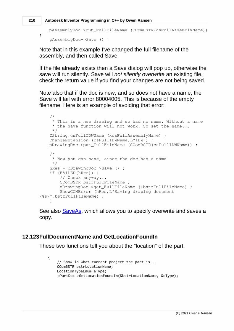
210 Autodesk Inventor Programming in C++ by Owen Ransen
(C) 2021 Owen F Ransen
pAssemblyDoc->put_FullFileName (CComBSTR(csFullAssemblyName)); pAssemblyDoc->Save () ;
Note that in this example I've changed the full filename of theassembly, and then called Save.
If the file already exists then a Save dialog will pop up, otherwise thesave will run silently. Save will not silently overwrite an existing file,check the return value if you find your changes are not being saved.
Note also that if the doc is new, and so does not have a name, theSave will fail with error 80004005. This is because of the emptyfilename. Here is an example of avoiding that error:
/* * This is a new drawing and so had no name. Without a name * the Save function will not work. So set the name... */ CString csFullIDWName (kcsFullAssemblyName) ; ChangeExtension (csFullIDWName,L"IDW") ; pDrawingDoc->put_FullFileName (CComBSTR(csFullIDWName)) ;
/* * Now you can save, since the doc has a name */ hRes = pDrawingDoc->Save () ; if (FAILED(hRes)) { // Check anyway... CComBSTR bstrFullFileName ; pDrawingDoc->get_FullFileName (&bstrFullFileName) ; ShowCOMError (hRes,L"Saving drawing document<%s>",bstrFullFileName) ; }
See also SaveAs, which allows you to specify overwrite and saves acopy.
12.123FullDocumentName and GetLocationFoundIn
These two functions tell you about the "location" of the part.
{ // Show in what current project the part is... CComBSTR bstrLocationName; LocationTypeEnum eType; pPartDoc->GetLocationFoundIn(&bstrLocationName, &eType);

211Programming Inventor in C++
(C) 2021 Owen F Ransen
TRACE (L"GetLocationFoundIn Location = <%s>, enum = %d",bstrLocationName, eType); // For example: <WorkSpace>, enum = 45057, read from the project file,I think }
{ // Show the simple full file path of the part... _bstr_t fdn = pPartDoc->GetFullDocumentName (); TRACE (L"FullDocumentName = <%s>",LPCWSTR (fdn));"C:\\WillyWonker\\Chocolate.ipt" }
12.124Close function, Inventor API
Here's an example of using the Close function on a PartDocument.Imagine we have opened and modified and existing file. Next we SaveAs to create a copy of our original part, then we Close theoriginal without saving:
// VARIANT_TRUE = Overwrite hRes = pPartDoc->SaveAs (CComBSTR(csPartFullFileName),VARIANT_TRUE) ;
// VARIANT_TRUE means skip save and don't show any dialogs hRes = pPartDoc->Close(VARIANT_TRUE) ;
Notice the comment just before the call to Close. We've alreadysaved the part with SaveAs, and we just want to close the document,and we don't want any further saving (or dialogs) to come up. HenceVARIANT_TRUE (which means SkipSave) is used.
12.125Making workfeatures of a part invisible in the assembly
Work features which are exported are in a table based iPart are oftenvisible in the assembly into which the part is placed. It seems to bethe default action.
To make these work features invisible in the assembly you need touse a function like this:
// pOcc is the occurrence of a part in an assembly. This function which switchon or off// the visibility of a workplane of the part in the assembly. It does notaffect the// visibility in the part file.void SetWorkPlaneVisibility(CComPtr<ComponentOccurrence>& pOcc, const CString&

212 Autodesk Inventor Programming in C++ by Owen Ransen
(C) 2021 Owen F Ransen
kcsWorkPlaneName, const bool kbVisible){ CComPtr<ComponentDefinition> pDef = nullptr; HRESULT hRes = pOcc->get_Definition(&pDef); if (FAILED(hRes)) { ShowCOMError(hRes, L"SWPV could not get definition %s",kcsWorkPlaneName); return; }
CComQIPtr<PartComponentDefinition> pPartCompDef = pDef;
CComPtr<WorkPlane> pWorkPlane=nullptr ; hRes = pPartCompDef->WorkPlanes->get_Item(CComVariant (kcsWorkPlaneName),&pWorkPlane); if (FAILED(hRes)) { ShowCOMError(hRes, L"SWPV, could not get workplane called %s",kcsWorkPlaneName); return; }
// Get the proxy which is how the part is instantiated in the assembly CComPtr<WorkPlaneProxy> pWPProxy ; hRes = pOcc->CreateGeometryProxy (pWorkPlane,(IDispatch**)&pWPProxy) ; if (FAILED(hRes)) { ShowCOMError(hRes, L"Could not get proxy of %s",kcsWorkPlaneName); return; }
if (kbVisible) { hRes = pWPProxy->put_Visible(VARIANT_TRUE);
} else { hRes = pWPProxy->put_Visible(VARIANT_FALSE); }
if (FAILED(hRes)) { ShowCOMError(hRes, L"Could not get set proxy visibility of %s",kcsWorkPlaneName); }}
/********************************************************************************************************/

213Programming Inventor in C++
(C) 2021 Owen F Ransen
12.126Visibility programatically in Inventor
Here is an example of how to set the visibility of a workpoint
CComPtr<WorkPoint> pWorkPoint = nullptr ; GetWorkPointByName (pWorkPoint,csPointName,pPartCompDef); if (bMakeVisible)) { pWorkPoint->put_Visible (VARIANT_TRUE) ;
} else { pWorkPoint->put_Visible (VARIANT_FALSE) ; }
12.127AddCustomiPartMember details and tips
Look at this call:
pOccs->AddCustomiPartMember(strFactoryFile, // This is thesource file of the object to create pMatrix, // This is where toplace the created custom iPart strFullFileName, // This is theresulting file of the created object varEmpty, // Usually unusedwith custom iParts, hence varEmpty. oleSafeArray, // Parameters, incolumn order &pCyl1Occ) ;
varEmpty will be something like this:
CComVariant varEmpty ;
The creation of oleSafeArray is explained here. However rememberthat the values must be in column order, for example:
BSTR strParams[] =

214 Autodesk Inventor Programming in C++ by Owen Ransen
(C) 2021 Owen F Ransen
{ CString("35 mm").AllocSysString(), // Diameter CString("1.5 mm").AllocSysString(), // Thickness CString("350 mm").AllocSysString(), // Length CString("10").AllocSysString(), // R1Angle CString("20").AllocSysString(), // R2Angle }; const int ikNumParams = sizeof(strParams)/sizeof(strParams[0]) ;
COleSafeArray oleSafeArray; oleSafeArray.CreateOneDim(VT_BSTR, ikNumParams, strParams);
The call may fail for one of these reasons:1. The columns you have specified don't make solid sense, an outer
diameter smaller than an inner diameter for example.2. The factory file (first parameter) does not exist.
The two filenames can be created like this:
CComBSTR strFactoryFile(L"C:\\CHS_LHS_COLL\\Tube-Custom.ipt"); CComBSTR strFullFileName(L"C:\\CHS_LHS_COLL\\Tube_999.ipt") ;
12.128Add in the occurrence of a custom iPart into an assembly
The most difficult part of adding a custom iPart into an assembly isunderstanding how to specify the parameters.
The first step is to get hold of the list of occurrences so you can add anew occurrence to the list.
Then you create a matrix and a vector to specify the position (and anyrotations etc.) of the object.
Then you create a list of parameters in column order of the iPart.When you use the iPart Author you'll see the custom parameters inpurple. Use that order. These parameters have to be created in aCOleSafeArray.

215Programming Inventor in C++
(C) 2021 Owen F Ransen
Now you are ready to call AddCustomiPartMember with the objects youcreated in the previous steps.
Here is a fragment which assumes you already have anAssemblyComponentDefinition:
CComPtr<ComponentOccurrences> pOccs; hRes = pAssemblyCompDef->get_Occurrences(&pOccs);
// This is the name of the iPart factory, from which customiParts will be created... CComBSTR strFactoryFile(L"C:\\TEST\\CustomCylinder.ipt") ; // Get hold of the transient geometry pointer to create thematrix which says // where to place the custom iPart... CComPtr<TransientGeometry> pTransGeom = GetTransGeomPtr() ; CComPtr<Matrix> pMatrix; // Defaults to 0,0,0 position pTransGeom->CreateMatrix(&pMatrix); CComPtr<Vector> pVector; // Create a Vector to modify theMatrix pTransGeom->CreateVector(2,2,0,&pVector); hRes = pMatrix->SetTranslation (pVector,VARIANT_TRUE) ;
// This is the name of the output file, the iPart createdfrom the factory file... CComBSTR strFullFileName(L"C:\\CHS_LHS_COLL\\CUSTOMCYL2.ipt"); CComVariant varEmpty ; // Nothing because we are notselecting a row
// We are not selecting a row but we are changing parameters.Here is how // we specify those parameters...#define NUM_PARAMS 2 BSTR strBSTR[NUM_PARAMS] = { CString("20 cm").AllocSysString(), CString("10 cm").AllocSysString(), };
COleSafeArray oleSafeArray; oleSafeArray.CreateOneDim(VT_BSTR, NUM_PARAMS, strBSTR);

216 Autodesk Inventor Programming in C++ by Owen Ransen
(C) 2021 Owen F Ransen
CComPtr<ComponentOccurrence> pCyl1Occ; pOccs->AddCustomiPartMember(strFactoryFile,pMatrix,strFullFileName,varEmpty,oleSafeArray,&pCyl1Occ) ;
I've not yet found out how to create the parameter list when not usingMFC. COleSafeArray is an MFC object.
See also AddCustomiPartMember details and tips.
12.129Occurrences and component definitions
An occurrence is like an XREF insert in AutoCAD. Occurrences exist,for example, inside assemblies. It is an instance of a part. Thediagram below shows that an assembly has inside it anAssemblyComponentDefinition, and inside that is a list of occurrences(among ther things):
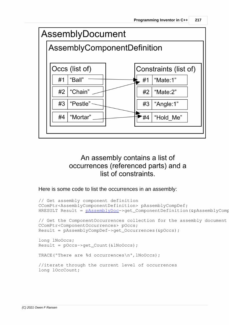
217Programming Inventor in C++
(C) 2021 Owen F Ransen
Here is some code to list the occurrences in an assembly:
// Get assembly component definitionCComPtr<AssemblyComponentDefinition> pAssemblyCompDef;HRESULT Result = pAssemblyDoc->get_ComponentDefinition(&pAssemblyCompDef);
// Get the ComponentOccurrences collection for the assembly documentCComPtr<ComponentOccurrences> pOccs;Result = pAssemblyCompDef->get_Occurrences(&pOccs);
long lNoOccs; Result = pOccs->get_Count(&lNoOccs);
TRACE("There are %d occurrences\n",lNoOccs);
//iterate through the current level of occurrenceslong lOccCount;

218 Autodesk Inventor Programming in C++ by Owen Ransen
(C) 2021 Owen F Ransen
for (lOccCount=1; lOccCount <= lNoOccs; ++lOccCount) {
// Get the nth occurrence... CComPtr<ComponentOccurrence> pCompOcc; Result = pOccs->get_Item(lOccCount, & pCompOcc);
//get the display name from the component occurrence CComBSTR bstrDisplayName; Result = pCompOcc->get_Name(&bstrDisplayName); TRACE("Component occurrence %02d <%s>\n",lOccCount,bstrDisplayName); // See if there are any other occurrences below the current one... CComPtr<ComponentOccurrencesEnumerator> pEnumOccurrences; Result = pCompOcc->get_SubOccurrences(&pEnumOccurrences); if (SUCCEEDED(Result) && (pEnumOccurrences->Count > 0)) { TRACE(" has %d sub occurrences\n",pEnumOccurrences->Count) ; }}
I've not placed any error checking in the previous code.
How to get the name of an occurrence.
12.130How to get the parameters of an assembly
If you have an assembly with parameters you can get hold of theparameters programatically like this:
CComPtr <AssemblyComponentDefinition> pAssCompDef ; pAssemblyDoc->get_ComponentDefinition (&pAssCompDef) ;
CComPtr <Parameters> pParams ; pAssCompDef->get_Parameters (&pParams) ;
const long ikNumParams = pParams->Count ;
TRACE (L"There are %d params in %s\n",ikNumParams,pszOccName);
for (int i = 1 ; i <= ikNumParams ; i++) { CComPtr <Parameter> pParam ;

219Programming Inventor in C++
(C) 2021 Owen F Ransen
pParams->get_Item (CComVariant(i),&pParam) ;
VARIANT VarValue ; pParam->get_Value (&VarValue) ; VarValue.dblVal ;
CComBSTR bstrParamName ; pParam->get_Name (&bstrParamName) ; TRACE (L" param %d is called %s and has a value of %.3f=\n",i,bstrParamName,VarValue.dblVal ) ; }
Notice how the parameter data is picked up inside the for loop.
If you have a part occurrence inside an assembly and want to get theparameters of that part a occurrence you can use this:
CComPtr<ComponentDefinition> pCompDef = nullptr ; hRes = pCompOcc->get_Definition (&pCompDef) ; if (FAILED(hRes) || (pCompDef == nullptr)){ return ReturnAndShowCOMError(hRes,L"ShowComponentOccurrenceParameters, get_Definition failed."); }
TRACE (L"The type of this occurrence is %d, def is %d\n",pCompOcc->GetType(),pCompDef->GetType()) ;
CComPtr<Parameters> pParams; CComQIPtr<PartComponentDefinition> pPartCompDef =pCompOcc->Definition; if (!pPartCompDef) { return (E_FAIL) ; }
if (pPartCompDef->IsiPartFactory) { TRACE (L"Is an ipart factory\n") ; }
// It is a part component definition, so we can get the // parameters of the part definition pParams = pPartCompDef->Parameters;
const long ikNumParams = pParams->Count ;

220 Autodesk Inventor Programming in C++ by Owen Ransen
(C) 2021 Owen F Ransen
TRACE (L"There are %d params in %s\n",ikNumParams,pszOccName);
for (int i = 1 ; i <= ikNumParams ; i++) { CComPtr <Parameter> pParam ; pParams->get_Item (CComVariant(i),&pParam) ;
VARIANT VarValue ; pParam->get_Value (&VarValue) ; CComBSTR bstrParamName ; pParam->get_Name (&bstrParamName) ; TRACE (L" param %d is called %s and has a value of %.3f=\n",i,bstrParamName,VarValue.dblVal ) ; }
12.131get_Item and Item, what sort of parameter?
When I need to get an item from a list, I generally use get_Item,because it crashes less, Item will throw an exception.
Here, the last two lines of code do the same thing:
CComPtr<UserParameter> pUserParam ; pUserParameters->get_Item (CComVariant(i),&pUserParam) ; pUserParam = pUserParameters->Item [i] ;
And what about the parameters? Generally it is an index, andgenerally that index starts at 1 (not 0) as the first item.
for (UINT i = 1 ; i <= ikNumModelParams ; i++) { CComPtr<ModelParameter> pModelParam ; pModelParameters->get_Item (CComVariant(i),&pModelParam);
Sometimes, if the item in the list has a text name, you can use thename in the call to get_Item. For example:
const wchar_t* const pszUserParamName = ... ... CComPtr<UserParameter> pUserParam = nullptr ; pUserParameters->get_Item(CComVariant(pszUserParamName),&pUserParam) ;

221Programming Inventor in C++
(C) 2021 Owen F Ransen
Horses for courses.
12.132Suppression and Unsuppression of features
To suppress and unsuppress features in a part simply use thefeature's suppression boolean:
pFeature->put_Suppressed(true) ;
(Suppression of parts in an assembly has a different use).
Here is a function which will suppress a named part in aPartComponentDefinition:
void SetSuppressPartFeatureByName(CComPtr<PartComponentDefinition>& pPartCompDef, const wchar_t* const pszName, const bool bSuppress) { TRACE (L"SetSuppressPartFeatureByName %s, %d\n",pszName,bSuppress) ;
// Get the list of features... CComPtr<PartFeatures> pFeaturesList ; HRESULT hRes = pPartCompDef->get_Features(&pFeaturesList) ; if (FAILED(hRes) || (pFeaturesList == nullptr)) { ShowCOMError(hRes,L"SetSuppressPartFeatureByNameget_Features failed"); return ; }
const long ikNumFeats = pFeaturesList->GetCount() ;
TRACE (L" There are %d pattern features\n",ikNumFeats) ;
bool bDone = false ;
for (long iFeat = 1 ; iFeat <= ikNumFeats ; iFeat++) { CComPtr<PartFeature> pFeature ; hRes = pFeaturesList->get_Item(CComVariant(iFeat),&pFeature) ; if (FAILED(hRes) || (pFeature == nullptr)) { ShowCOMError(hRes,L"SetSuppressPartFeatureByNameget_Item failed");
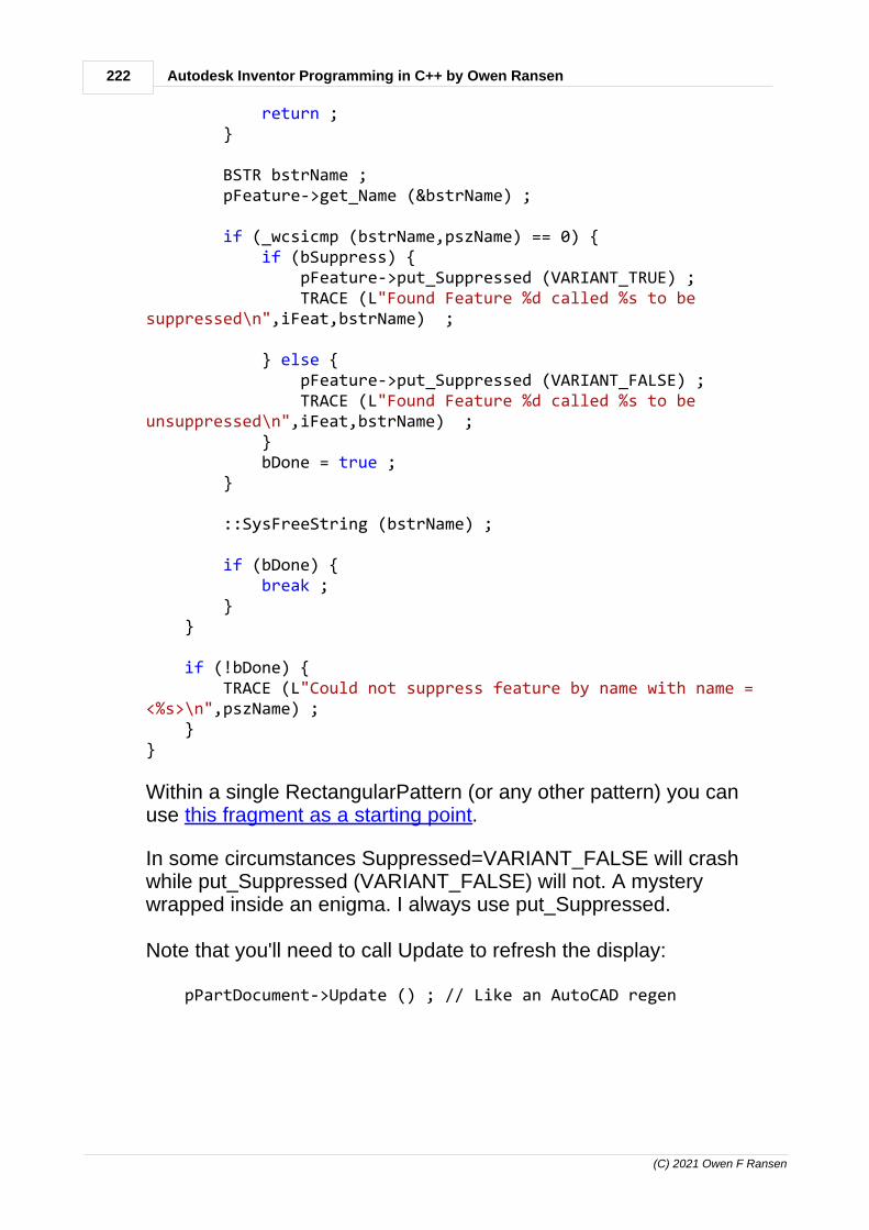
222 Autodesk Inventor Programming in C++ by Owen Ransen
(C) 2021 Owen F Ransen
return ; }
BSTR bstrName ; pFeature->get_Name (&bstrName) ;
if (_wcsicmp (bstrName,pszName) == 0) { if (bSuppress) { pFeature->put_Suppressed (VARIANT_TRUE) ; TRACE (L"Found Feature %d called %s to besuppressed\n",iFeat,bstrName) ;
} else { pFeature->put_Suppressed (VARIANT_FALSE) ; TRACE (L"Found Feature %d called %s to beunsuppressed\n",iFeat,bstrName) ; } bDone = true ; }
::SysFreeString (bstrName) ;
if (bDone) { break ; } }
if (!bDone) { TRACE (L"Could not suppress feature by name with name =<%s>\n",pszName) ; }}
Within a single RectangularPattern (or any other pattern) you canuse this fragment as a starting point.
In some circumstances Suppressed=VARIANT_FALSE will crashwhile put_Suppressed (VARIANT_FALSE) will not. A mysterywrapped inside an enigma. I always use put_Suppressed.
Note that you'll need to call Update to refresh the display:
pPartDocument->Update () ; // Like an AutoCAD regen

223Programming Inventor in C++
(C) 2021 Owen F Ransen
You cannot suppress all types of objects. You cannot, for example,suppress workpoints.
12.133Compute and Suppress from an iPart table programatically
Here's how I read a Compute/Suppress setting from an iPart table:
// Get the "Suppress" or "Compute" value from the table// returns true if Suppressedbool GetSuppressedFromiPartTableRowCell (const UINT ikCol, CComPtr<iPartTableRow> piPartRow) { wchar_t szValue[_MAX_PATH] ; GetStringFromiPartTableRowCell (szValue,_countof(szValue),ikCol,piPartRow) ;
// Since Suppress = Sopprimi and Compute = Calcola this // compare will work in both English and Italian return (szValue[0] == L'S') ;}
12.134Skipping missing components programatically
When looping over occurrences you must skip any missingcomponents, and you do it like this:
for (lOccCount=1; lOccCount <= lNoOccs; ++lOccCount){ // Get the nth occurrence... CComPtr<ComponentOccurrence> pCompOcc; hRes = pOccs->get_Item(lOccCount, &pCompOcc); if (FAILED(hRes)) { gLogger.Printf(ekErrMsg, L"Could not get acomponent in the attacco"); return false; }
if (VARIANT_TRUE == pCompOcc->ReferencedDocumentDescriptor->ReferenceMissing) {

224 Autodesk Inventor Programming in C++ by Owen Ransen
(C) 2021 Owen F Ransen
// Maybe a missing and skipped component... continue ; }
.
12.135How to open a document programatically
Here is some example code illustrating how to open a document file:
CComPtr<Documents> pDocs = nullptr ; HRESULT hRes = pInvApp->get_Documents (&pDocs) ; if (FAILED(hRes) || (pDocs == nullptr)) { ShowCOMError(hRes,L"RunTest,get_Documents failed "); return ; }
CComPtr<Document> pDoc; hRes = pDocs->Open (CComBSTR(L"C:\\PARTS\\MyPart.Ipt"),VARIANT_TRUE,&pDoc) ; if (FAILED(hRes) || (pDocs == nullptr)) { ShowCOMError(hRes,L"RunTest, Open failed "); return ; }
...
12.136Function calls in Autodesk Inventor C++ programming
Every COM C++ Inventor API method comes in 2 "flavors": 1. low level methods: that take output param as input and return
HRESULT, for example hRes = get_Item (Index,&Pointer).2. high level methods: that return the result directly and throw
exceptions, for example Pointer = GetItem (Index)
A concrete example of the difference is the visibility of workaxes:
// This "low level" version will not crash and you can lookat the success or not via hRes hRes = pWorkAxis->put_Visible (vbVisib) ; if (FAILED(hRes)) { // Show some error message if you want

225Programming Inventor in C++
(C) 2021 Owen F Ransen
}
// This "high level" version will throw and exception andcrash if something is wrong pWorkAxis->Visible = vbVisib ;
There are other functions which are high and low distinguished bywhether or not they have Method... in front of the name, high levelmethods are usually prefixed "Method".
Some examples :
HRESULT hRes = pWorkPlanesList->get_Item(CComVariant(1),&pWorkPlane) ; // low level version WorkPlanePtr pWorkPlane = pWorkPlanesList->GetItem(CComVariant(1)) ; // high level version
...and...
HRESULT hRes = pConstraintList->AddAngleConstraint(...etc...,&pAngConstraint) ; // low level version AngleConstraintPtr pAngConstraint =pConstraintList->MethodAddAngleConstraint(...etc...) ; // highlevel version
Note that with "low level" versions you often pass the address of apointer which is the "return value" of the function.
12.137Names of objects inside sketches
You cannot name objects inside sketches (sketch points and linesetc) though you can give them IDs and Attributes.
12.138COM pointers when programming AutoDesk Inventor
Here I'm paraphrasing Adam Nagy who helped me understand thisstuff.
When using COM objects like the ones provided by the Inventor COMAPI, then you have to take care of releasing the references to theobjects you retrieved. This is what CComPtr is helping you with,

226 Autodesk Inventor Programming in C++ by Owen Ransen
(C) 2021 Owen F Ransen
which is a smart-pointer and provides auto release of objects: when aCComPtr object variable goes out of scope then its destructor will becalled and there it will release the COM object it is referencing, i.e. itwill decrease the reference counter on that COM object.
Here are a couple of examples to help explain when you have toexplicitly release the object or how to reorganize your code to releasethe COM objects in time: all objects need to be released beforeCoUninitialize() is called.
If your CComPtr is declared inside a function (local variable) then itwill only be destructed - just like any other local variables - when thefunction returns, and that's when it will release the reference to theCOM object. In case of this sample function the pointer is releasedtoo late because of that:
int _tmain(int argc, TCHAR* argv[], TCHAR* envp[]){ HRESULT Result = NOERROR;
::CoInitialize(NULL);
// Access Inventor CLSID InvAppClsid; Result = CLSIDFromProgID (L"Inventor.Application", &InvAppClsid); if (FAILED(Result)) return Result;
CComPtr<IUnknown> pInvAppUnk; Result = ::GetActiveObject (InvAppClsid, NULL, &pInvAppUnk); if (FAILED (Result)) TRACE("Could not get the active Inventor instance\n");
if (FAILED(Result)) return Result;
CComPtr<Application> pInvApp; Result = pInvAppUnk->QueryInterface(__uuidof(Application), (void **) &pInvApp); if (FAILED(Result)) return Result;
::CoUninitialize();
return 0;
} // << pInvApp is only destructed now, i.e. it's only releasing the // Inventor Application object reference now, which is too late, // since CoUninitialize has already been called

227Programming Inventor in C++
(C) 2021 Owen F Ransen
One easy solution to this would be to place the code part that isinteracting with the COM objects into a separate function, so that thelocal variables will be release by the time we get to CoUninitialize():
int accessInventor(){ HRESULT Result = NOERROR;
// Access Inventor CLSID InvAppClsid; Result = CLSIDFromProgID (L"Inventor.Application", &InvAppClsid); if (FAILED(Result)) return Result;
CComPtr<IUnknown> pInvAppUnk; Result = ::GetActiveObject (InvAppClsid, NULL, &pInvAppUnk); if (FAILED (Result)) TRACE("Could not get the active Inventor instance\n"); if (FAILED(Result)) return Result;
CComPtr<Application> pInvApp; Result = pInvAppUnk->QueryInterface(__uuidof(Application), (void **) &pInvApp); if (FAILED(Result)) return Result;
return Result;}
int _tmain(int argc, TCHAR* argv[], TCHAR* envp[]){ HRESULT Result = NOERROR;
::CoInitialize(NULL);
// Access Inventor accessInventor();
// Once this function returned all its local objects have
// been destructed, and so the COM objects have also been released
::CoUninitialize();
return 0;}
Another simple solution is to create a local scope around the localvariables that ends before CoUninitialize():

228 Autodesk Inventor Programming in C++ by Owen Ransen
(C) 2021 Owen F Ransen
int _tmain(int argc, TCHAR* argv[], TCHAR* envp[]){ HRESULT Result = NOERROR;
::CoInitialize(NULL);
// Access Inventor inside a local scope created by the curly braces { CLSID InvAppClsid; Result = CLSIDFromProgID (L"Inventor.Application", &InvAppClsid); if (FAILED(Result)) return Result;
CComPtr<IUnknown> pInvAppUnk; Result = ::GetActiveObject (InvAppClsid, NULL, &pInvAppUnk); if (FAILED (Result)) TRACE(_"Could not get the active Inventor instance\n"); if (FAILED(Result)) return Result;
CComPtr<Application> pInvApp; Result = pInvAppUnk->QueryInterface(__uuidof(Application), (void **) &pInvApp);
if (FAILED(Result)) return Result;
} // << Now all the local variables have been destructed, // and so the COM objects have been released
::CoUninitialize();
return 0;}
When CComPtr is declared as a global variable then it will only bedestructed at the very end, even after the main function of theapplication has returned:
// This will only be destructed after _tmain() returned// which is too late, because by that time CoUninitialize()// has been called. So we'll have to release the COM object// it is referencing by setting it to NULL before calling// CoUninitialize()
CComPtr<Application> pInvApp;
int _tmain(int argc, TCHAR* argv[], TCHAR* envp[]){ HRESULT Result = NOERROR;

229Programming Inventor in C++
(C) 2021 Owen F Ransen
::CoInitialize(NULL);
// Access Inventor { CLSID InvAppClsid; Result = CLSIDFromProgID (L"Inventor.Application", &InvAppClsid); if (FAILED(Result)) return Result;
CComPtr<IUnknown> pInvAppUnk; Result = ::GetActiveObject (InvAppClsid, NULL, &pInvAppUnk); if (FAILED (Result)) TRACE("Could not get the active Inventor instance\n");
if (FAILED(Result)) return Result;
// In this case pInvApp is a global variable // declared outside the function Result = pInvAppUnk->QueryInterface(__uuidof(Application), (void **) &pInvApp); if (FAILED(Result)) return Result; }
// Release the referenced COM object by setting the CComPtr // object to NULL pInvApp = NULL;
::CoUninitialize();
return 0;}
See what I mean?
12.139VARIANT_BOOL
VARIANT_BOOL is a type currently defined as a short:
/* 0 == FALSE, -1 == TRUE */typedef short VARIANT_BOOL;
#define VARIANT_TRUE ((VARIANT_BOOL)-1)#define VARIANT_FALSE ((VARIANT_BOOL)0)
Here is an example

230 Autodesk Inventor Programming in C++ by Owen Ransen
(C) 2021 Owen F Ransen
if (VARIANT_TRUE == pCompOcc->ReferencedDocumentDescriptor->ReferenceMissing) { // Maybe a missing and skipped component... continue ; }
Here is an example:
VARIANT_BOOL bSuppressed =pFeaturePatternElement->GetSuppressed () ;
TRACE (L"Element %d suppressed = %d\n",iElem,bSuppressed) ;
In this case bSuppressed will show either -1 (true) or 0 (false).
You can use the predefined macros VARIANT_TRUE andVARIANT_FALSE as values.
Since VARIANT_FALSE is 0 you can use them in ifs like this:
if (p->InventorFunction()) { ...do something...}
12.140ParameterPtr and get_XCount
Some Inventor API COM functions take a ParameterPtr, even to getsimple integers, like the count in a RectangularPattern. Here is how todeclare and use the parameter pointer in those cases:
//CComPtr<Parameter> iXCount ; // this works too ParameterPtr iXCount ; pRectPattern->get_XCount (&iXCount) ;
So you can use CComPtr<Parameter> or ParameterPtr. Here is anexample of getting an integer value:
CComPtr<Parameter> XCountParam ;

231Programming Inventor in C++
(C) 2021 Owen F Ransen
pRectPatFeat->get_XCount (&XCountParam) ; const int ikXCount = XCountParam->GetValue () ;
TRACE (L"Component %d is called %s, and the x count is%d\n",iRect,bstrName,ikXCount) ;
So you need to use GetValue().
Note that you have to look at the pointers because if there is no ycount it is assumed to be 1. I assume. The following code will printout the x and y counts of a rectangular array.
CComPtr<Parameter> pXCountParam ; pRangoPattern->get_XCount (&pXCountParam) ; int iXCount = 1 ; // Init to 1 is important if (pXCountParam != nullptr) { iXCount = pXCountParam->GetValue () ; } CComPtr<Parameter> pYCountParam ; pRangoPattern->get_YCount (&pYCountParam) ; int iYCount = 1 ; // Init to 1 is important if (pYCountParam != nullptr) { iYCount = pYCountParam->GetValue () ; }
gLogger.Printf(ekLogMsg, L"Rect X count = %d Y count = %d",iXCount,iYCount);
12.141Gettings objects by name
When you create complex parts and assemblies it is best to namethem with other than the default names. That way you can get hold ofthem in your program without having to remember indices into a get_Item array, or having to remember that WorkPoint1 is the point atthe end of the tube or that WorkPlane3 is in the center of the cube.
(Note that for international programs you may prefer to use indices,because the standard objects created by Inventor change the names.For example "X Axis" in English is "Asse X" in Italian.)

232 Autodesk Inventor Programming in C++ by Owen Ransen
(C) 2021 Owen F Ransen
Here are some functions for getting hold of named objects:
bool GetSketchInPartByName (CComPtr<PlanarSketch>& pSketch, // return value ifsketch found const wchar_t* const pszSketchName, CComPtr<PartComponentDefinition>& pPartCompDef, const bool kbShowErr /*=true*/) { // Get the sketch in the part by name... HRESULT hRes = pPartCompDef->Sketches->get_Item(CComVariant(pszSketchName), &pSketch); if (FAILED(hRes)) { if (kbShowErr) { ShowCOMError (hRes,L"GetSketchByName(%s) but could not 'get'sketch\n",pszSketchName); } return false ;
} else { return true ; }}
HRESULT GetWorkPlaneByName (CComPtr<WorkPlane>& pWorkPlane, const wchar_t* constpszWorkPlaneName, CComPtr<PartComponentDefinition>&pPartCompDef) { // Get the sketch in the part by name... HRESULT hRes =pPartCompDef->WorkPlanes->get_Item(CComVariant(pszWorkPlaneName),&pWorkPlane); if (FAILED(hRes) || (pWorkPlane == nullptr)) { ShowCOMError (hRes,L"GetWorkPlaneByName but 'get'failed\n"); return (E_FAIL) ; }
return (S_OK) ;}
HRESULT GetWorkAxisByName (CComPtr<WorkAxis>& pWorkAxis, const wchar_t* const pszWorkAxisName, CComPtr<PartComponentDefinition>&pPartCompDef) {

233Programming Inventor in C++
(C) 2021 Owen F Ransen
// Get the sketch in the part by name... HRESULT hRes =pPartCompDef->WorkAxes->get_Item(CComVariant(pszWorkAxisName),&pWorkAxis); if (FAILED(hRes) || (pWorkAxis == nullptr)) { ShowCOMError (hRes,L"GetWorkAxisByName but 'get'failed\n"); return (E_FAIL) ; }
return (S_OK) ;}
You can imagine what GetWorkPointByName will look like.
Since these functions report errors you could ignore their returnvalues if you want, if there is an error you'll see it.
12.142How to get the RectangularPatterns in aPartComponentDefinition
What you need to remember is that a RectangularPattern is a feature,so you need to get the features of a part in order to get anyrectanguar patterns inside that part.
Here is a function which lists the names of rectangular patterns insidethe part parameter passed to it:
void ListRectangularPatternFeatures(CComPtr<PartComponentDefinition>& pPartCompDef){ // Get the list of features... CComPtr<PartFeatures> pFeaturesList ; pPartCompDef->get_Features(&pFeaturesList) ;
// Get the list of rectangular features, we will add to thislist.... CComPtr<RectangularPatternFeatures> pRectPatList ; pFeaturesList->get_RectangularPatternFeatures (&pRectPatList);
const long ikNumRecFeats = pRectPatList->GetCount() ;

234 Autodesk Inventor Programming in C++ by Owen Ransen
(C) 2021 Owen F Ransen
TRACE (L"There are %d rectangular pattern features\n",ikNumRecFeats) ;
for (int iRect = 1 ; iRect <= ikNumRecFeats ; iRect++) {
CComPtr <RectangularPatternFeature> pRectPatFeat ; pRectPatList->get_Item (CComVariant(iRect),&pRectPatFeat);
BSTR bstrName = pRectPatFeat->GetName () ;
TRACE (L"Component %d is called %s\n",iRect,bstrName) ;
::SysFreeString(bstrName); }}
Error checking has been removed for brevity and clarity, but, asalways, you should check the return values of the various InventorAPI functions.
How to add a RectangularPattern to a PartComponentDefinition.
12.143ResultFeatures
ResultFeatures, when got from Patterns, are workplanes, workpoints,worksurfaces which are created when the Pattern is created.
CComPtr <ObjectsEnumerator> pObjectsEnumerator ; pFeaturePatternElement->get_ResultFeatures (&pObjectsEnumerator) ; const int ikNumObj = pObjectsEnumerator->GetCount () ;
ResultFeatures are the result of creating a pattern with somefeatures. You often use them for getting proxies of the features.Result Features are of the type ObjectsEnumerator, a list of objects.

235Programming Inventor in C++
(C) 2021 Owen F Ransen
Graphically:
Here is a fragment which gets
12.144ObjectsEnumerator, a list of objects
The ObjectsEnumerator can be thought of a list of objects, from aselection set for example, or from resulting features in a pattern.
12.145Parameter types
Apart from Model parameters and User parameters each parameteralso has a type ParameterTypeEnum which specifies who and why aparameter was created.
Here is how to get the information:
ParameterTypeEnum eParamType ; pModelParam->get_ParameterType (&eParamType) ; TRACE (L"The ParameterTypeEnum is %d\n",eParamType) ;
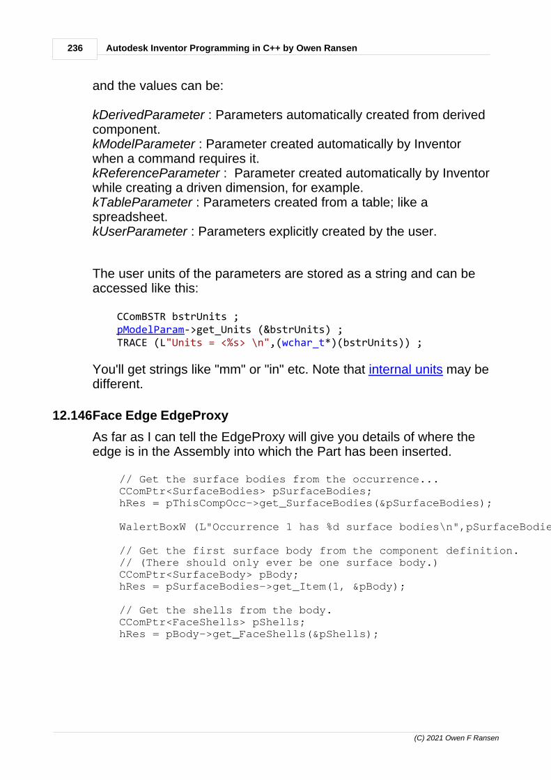
236 Autodesk Inventor Programming in C++ by Owen Ransen
(C) 2021 Owen F Ransen
and the values can be:
kDerivedParameter : Parameters automatically created from derivedcomponent. kModelParameter : Parameter created automatically by Inventorwhen a command requires it. kReferenceParameter : Parameter created automatically by Inventorwhile creating a driven dimension, for example. kTableParameter : Parameters created from a table; like aspreadsheet. kUserParameter : Parameters explicitly created by the user.
The user units of the parameters are stored as a string and can beaccessed like this:
CComBSTR bstrUnits ; pModelParam->get_Units (&bstrUnits) ; TRACE (L"Units = <%s> \n",(wchar_t*)(bstrUnits)) ;
You'll get strings like "mm" or "in" etc. Note that internal units may bedifferent.
12.146Face Edge EdgeProxy
As far as I can tell the EdgeProxy will give you details of where theedge is in the Assembly into which the Part has been inserted.
// Get the surface bodies from the occurrence... CComPtr<SurfaceBodies> pSurfaceBodies; hRes = pThisCompOcc->get_SurfaceBodies(&pSurfaceBodies);
WalertBoxW (L"Occurrence 1 has %d surface bodies\n",pSurfaceBodies->Count);
// Get the first surface body from the component definition. // (There should only ever be one surface body.) CComPtr<SurfaceBody> pBody; hRes = pSurfaceBodies->get_Item(1, &pBody);
// Get the shells from the body. CComPtr<FaceShells> pShells; hRes = pBody->get_FaceShells(&pShells);
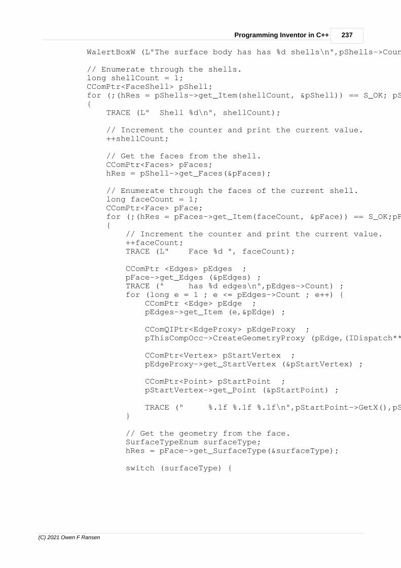
237Programming Inventor in C++
(C) 2021 Owen F Ransen
WalertBoxW (L"The surface body has has %d shells\n",pShells->Count) ;
// Enumerate through the shells. long shellCount = 1; CComPtr<FaceShell> pShell; for (;(hRes = pShells->get_Item(shellCount, &pShell)) == S_OK; pShell.Release()) { TRACE (L" Shell %d\n", shellCount);
// Increment the counter and print the current value. ++shellCount;
// Get the faces from the shell. CComPtr<Faces> pFaces; hRes = pShell->get_Faces(&pFaces);
// Enumerate through the faces of the current shell. long faceCount = 1; CComPtr<Face> pFace; for (;(hRes = pFaces->get_Item(faceCount, &pFace)) == S_OK;pFace.Release()) { // Increment the counter and print the current value. ++faceCount; TRACE (L" Face %d ", faceCount);
CComPtr <Edges> pEdges ; pFace->get_Edges (&pEdges) ; TRACE (" has %d edges\n",pEdges->Count) ; for (long e = 1 ; e <= pEdges->Count ; e++) { CComPtr <Edge> pEdge ; pEdges->get_Item (e,&pEdge) ;
CComQIPtr<EdgeProxy> pEdgeProxy ; pThisCompOcc->CreateGeometryProxy (pEdge,(IDispatch**)&pEdgeProxy) ;
CComPtr<Vertex> pStartVertex ; pEdgeProxy->get_StartVertex (&pStartVertex) ;
CComPtr<Point> pStartPoint ; pStartVertex->get_Point (&pStartPoint) ;
TRACE (" %.1f %.1f %.1f\n",pStartPoint->GetX(),pStartPoint->GetY(),pStartPoint->GetZ()) ; }
// Get the geometry from the face. SurfaceTypeEnum surfaceType; hRes = pFace->get_SurfaceType(&surfaceType);
switch (surfaceType) {

238 Autodesk Inventor Programming in C++ by Owen Ransen
(C) 2021 Owen F Ransen
default : TRACE (L" Unrecognised surface type:%d\n",surfaceType); break ;
case kCylinderSurface : TRACE (L" Cylindrical surface\n"); break ;
case kTorusSurface : TRACE (L" Cylindrical surface\n"); break ;
case kPlaneSurface : TRACE (L" Plane surface\n"); break ; } } }
12.147Attributes
An "Attribute" is extra data added to an Inventor object. You, theprogrammer, can store non graphical data in an object's attributes.
If you have ever programmed AutoCAD you could compare attributesin Inventor with Xdata in AutoCAD.
AutoDesk supplies a program called Attribute Helper which you canuse to add attributes into objects. For example into the faces of apart.
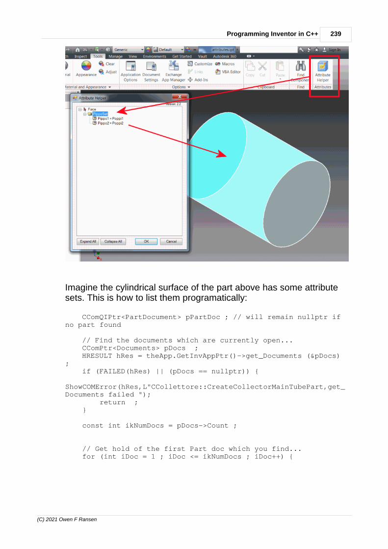
239Programming Inventor in C++
(C) 2021 Owen F Ransen
Imagine the cylindrical surface of the part above has some attributesets. This is how to list them programatically:
CComQIPtr<PartDocument> pPartDoc ; // will remain nullptr ifno part found
// Find the documents which are currently open... CComPtr<Documents> pDocs ; HRESULT hRes = theApp.GetInvAppPtr()->get_Documents (&pDocs); if (FAILED(hRes) || (pDocs == nullptr)) { ShowCOMError(hRes,L"CCollettore::CreateCollectorMainTubePart,get_Documents failed "); return ; }
const int ikNumDocs = pDocs->Count ;
// Get hold of the first Part doc which you find... for (int iDoc = 1 ; iDoc <= ikNumDocs ; iDoc++) {
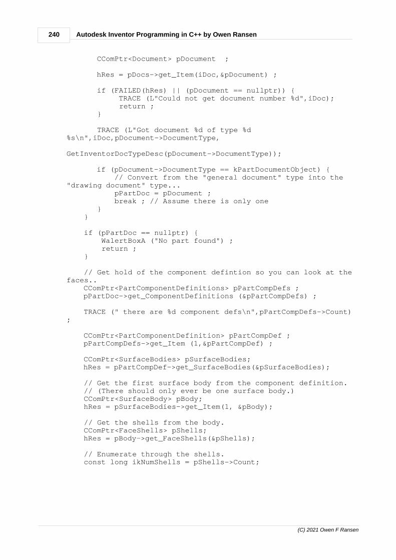
240 Autodesk Inventor Programming in C++ by Owen Ransen
(C) 2021 Owen F Ransen
CComPtr<Document> pDocument ;
hRes = pDocs->get_Item(iDoc,&pDocument) ;
if (FAILED(hRes) || (pDocument == nullptr)) { TRACE (L"Could not get document number %d",iDoc); return ; }
TRACE (L"Got document %d of type %d%s\n",iDoc,pDocument->DocumentType, GetInventorDocTypeDesc(pDocument->DocumentType)); if (pDocument->DocumentType == kPartDocumentObject) { // Convert from the "general document" type into the"drawing document" type... pPartDoc = pDocument ; break ; // Assume there is only one } }
if (pPartDoc == nullptr) { WalertBoxA ("No part found") ; return ; }
// Get hold of the component defintion so you can look at thefaces.. CComPtr<PartComponentDefinitions> pPartCompDefs ; pPartDoc->get_ComponentDefinitions (&pPartCompDefs) ;
TRACE (" there are %d component defs\n",pPartCompDefs->Count);
CComPtr<PartComponentDefinition> pPartCompDef ; pPartCompDefs->get_Item (1,&pPartCompDef) ;
CComPtr<SurfaceBodies> pSurfaceBodies; hRes = pPartCompDef->get_SurfaceBodies(&pSurfaceBodies);
// Get the first surface body from the component definition. // (There should only ever be one surface body.) CComPtr<SurfaceBody> pBody; hRes = pSurfaceBodies->get_Item(1, &pBody);
// Get the shells from the body. CComPtr<FaceShells> pShells; hRes = pBody->get_FaceShells(&pShells);
// Enumerate through the shells. const long ikNumShells = pShells->Count;

241Programming Inventor in C++
(C) 2021 Owen F Ransen
for (long iShell = 1 ; iShell <= ikNumShells ; iShell++) { CComPtr<FaceShell> pShell; hRes = pShells->get_Item(iShell, &pShell);
TRACE (L" Shell %d\n", iShell); // Get the faces from the shell. CComPtr<Faces> pFaces; hRes = pShell->get_Faces(&pFaces);
// Enumerate through the faces of the current shell. const long ikNumFaces = pFaces->Count; for (long iFace = 1 ; iFace <= ikNumFaces ; iFace++) { CComPtr<Face> pFace; hRes = pFaces->get_Item(iFace, &pFace) ;
CComPtr <Edges> pEdges ; pFace->get_Edges (&pEdges) ;
CComPtr<AttributeSets> pFaceAttSets ; pFace->get_AttributeSets (&pFaceAttSets) ; TRACE ("Face %d has %d attributesets\n",iFace,pFaceAttSets->Count) ; // This face has at least one attribute set... if (pFaceAttSets->Count > 0) {
// Get the first attribute set... CComPtr<AttributeSet> pFaceAttSet ; pFaceAttSets->get_Item(CComVariant(1),&pFaceAttSet) ;
if (pFaceAttSet != nullptr) {
// Get the first attribute... CComPtr<Attribute> pFaceAtt ; pFaceAttSet->get_Item(CComVariant(1),&pFaceAtt) ;
// Show the user what is inside theattribute... if (pFaceAtt != nullptr) { CComBSTR cbstrName ; pFaceAtt->get_Name (&cbstrName) ;
// Get the value. Use a CComVariantbecause there are strings // and number variants... CComVariant varValue ; pFaceAtt->get_Value (&varValue) ;
// Here we assume it is a string... WalertBoxW (L"Name = <%s> Value =

242 Autodesk Inventor Programming in C++ by Owen Ransen
(C) 2021 Owen F Ransen
<%s>",cbstrName,varValue.bstrVal) ; } } } } }
12.148CreateExtrudeDefinition
This function does not actually create an extrusion, it should bepaired with Add to do that. Here is an example (error checkingremoved):
// Now at last we can use the pProfile to create a newextrusion, adding it to the list // of extruded features CComPtr<ExtrudeDefinition> pExtrudeDef; hRes = pListOfExtrusions->CreateExtrudeDefinition(pProfile,kJoinOperation,&pExtrudeDef);
pExtrudeDef->SetDistanceExtent(_variant_t(kHeight),kPositiveExtentDirection );
CComPtr<ExtrudeFeature> pExtrude; hRes = pListOfExtrusions->Add (pExtrudeDef);
What you need to remember is that an ExtrudeDefinition is not anextrusion feature.
12.149Inserting an extrusion in a Part
You need to have a part .ipt document open for the following functionto work, and that .ipt must have a sketch called Sketch1 alreadyexisting inside it. I've tested it with an empty Sketch1.
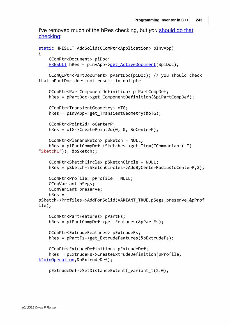
243Programming Inventor in C++
(C) 2021 Owen F Ransen
I've removed much of the hRes checking, but you should do thatchecking:
static HRESULT AddSolid(CComPtr<Application> pInvApp){ CComPtr<Document> piDoc; HRESULT hRes = pInvApp->get_ActiveDocument(&piDoc);
CComQIPtr<PartDocument> pPartDoc(piDoc); // you should checkthat pPartDoc does not result in nullptr
CComPtr<PartComponentDefinition> piPartCompDef; hRes = pPartDoc->get_ComponentDefinition(&piPartCompDef); CComPtr<TransientGeometry> oTG; hRes = pInvApp->get_TransientGeometry(&oTG);
CComPtr<Point2d> oCenterP; hRes = oTG->CreatePoint2d(0, 0, &oCenterP);
CComPtr<PlanarSketch> pSketch = NULL; hRes = piPartCompDef->Sketches->get_Item(CComVariant(_T("Sketch1")), &pSketch);
CComPtr<SketchCircle> pSketchCircle = NULL; hRes = pSketch->SketchCircles->AddByCenterRadius(oCenterP,2);
CComPtr<Profile> pProfile = NULL; CComVariant pSegs; CComVariant preserve; hRes =pSketch->Profiles->AddForSolid(VARIANT_TRUE,pSegs,preserve,&pProfile);
CComPtr<PartFeatures> pPartFs; hRes = piPartCompDef->get_Features(&pPartFs);
CComPtr<ExtrudeFeatures> pExtrudeFs; hRes = pPartFs->get_ExtrudeFeatures(&pExtrudeFs);
CComPtr<ExtrudeDefinition> pExtrudeDef; hRes = pExtrudeFs->CreateExtrudeDefinition(pProfile,kJoinOperation,&pExtrudeDef);
pExtrudeDef->SetDistanceExtent(_variant_t(2.0),

244 Autodesk Inventor Programming in C++ by Owen Ransen
(C) 2021 Owen F Ransen
kPositiveExtentDirection);
CComPtr<ExtrudeFeature> pExtrude; hRes = pExtrudeFs->Add (pExtrudeDef); if (FAILED(hRes)) { TRACE ("AddSolid but could Add ExtrudeDefinition\n"); return hRes ; }
TRACE ("AddSolid finished, extrusion added ok.\n");
return hRes;}
Good luck young man.
12.150Optional parameters and empty COM values
In VB and VBA there are sometimes optional parameters. And oftenthe only help available for functions in Inventor is the VB version, youhave to guess the parameters of the C++ version from the VBversion.
When there are optional parameters in C++ which you don't want touse you will probably have to pass an empty COM type value. A goodexample is GetTemplateFile:
hr = pFileManager->GetTemplateFile (kAssemblyDocumentObject, //type of file kDefaultSystemOfMeasure, kDefault_DraftingStandard, CComVariant(), // Optional inVB, GUID for Weld and SheetMetal &strTemplateFilename); //return value
That fourth parameter is an empty variant because we do not use it inthis instance. In the VB description of the same function it is anoptional parameter.
See also function call methods.

245Programming Inventor in C++
(C) 2021 Owen F Ransen
12.151Points and CenterPoints
The difference between these two sorts of points is that CenterPointsare displayed as center points:
Programatically the difference is here:
CComPtr<SketchPoint> pInventorPt; pSketch->SketchPoints->Add(pThePoint,VARIANT_TRUE,&pInventorPt);
That VARIANT_TRUE says "show as center point". Otherwise youshould use VARIANT_FALSE.
You can get the setting for this in two ways:
VARIANT_BOOL bHoleCenter ; pInventorPt->get_HoleCenter (&bHoleCenter) ; // first method
bHoleCenter = pInventorPt->HoleCenter ; // second method

246 Autodesk Inventor Programming in C++ by Owen Ransen
(C) 2021 Owen F Ransen
12.152GetTemplateFile
The template file is how an new empty file of a new object will looklike. It is what is used when you create a new file, and contains thingslike units etc. When you do a new part or a new assembly Inventoruses a template file to create your empty file.
You can get hold of template files for various types of documents likethis:
CComBSTR strTemplateFilename; CComPtr<FileManager> pFileManager;HRESULT hr = pInvApp->get_FileManager(&pFileManager);
hr = pFileManager->GetTemplateFile (kAssemblyDocumentObject, //type of file DocumentTypeEnum kDefaultSystemOfMeasure, kDefault_DraftingStandard, CComVariant(), // GUID forWeldment and SheetMetal &strTemplateFilename); //return value
In the above call the strTemplateFilename would come backcontaining something like this:
C:\Users\Public\Documents\Autodesk\Inventor 2013\Templates\Standard.iam
Some common values in the first parameter (a DocumentTypeEnum) of GetTemplateFile are:
kPartDocumentObject kAssemblyDocumentObject kDrawingDocumentObject
The second parameter sets the measurement units (mm or inches). Itcan be

247Programming Inventor in C++
(C) 2021 Owen F Ransen
Enumerator Value
Description
kDefaultSystemOfMeasure
8961
Installed, default system inuse for this user.
kEnglishSystemOfMeasure
8963
English system of measure(inches etc.)
kMetricSystemOfMeasure
8962
Metric system of measure(mm etc.).
Note that GetTemplateFile can have an empty 4th parameter in thiscase because we are not dealing with Weldment or SheetMetal. Inthose two cases the fourth parameter will be a GUID which furtheridentifies the sort of standard to be used.
Of course if you know and want to use a specific template file you cansimply do this:
strTemplateFilename = L"C:\\Users\\Public\\Documents\\Autodesk\\Inventor 2017\\Templates\\LuVe\\RanStd.idw" ;
without calling GetTemplateFile, and use the string in a call like this:
// create a new assembly document using an existing template file CComPtr<Document> pDocument=nullptr; hRes = pDocuments->Add(kAssemblyDocumentObject, strTemplateFilename,VARIANT_TRUE, &pDocument); if (FAILED(hRes)) { return ReturnAndShowCOMError (hRes,L"Could not make new assemblydocument"); }
12.153Add a (planar) sketch to a workplane programatically
Here is a function which will add a new sketch to a named workplanein a PartComponentDefinition:
HRESULT AddSketchToWorkplane (CComPtr<PartComponentDefinition>&pPartCompDef, const wchar_t* constpszNewSketchName, const wchar_t* const

248 Autodesk Inventor Programming in C++ by Owen Ransen
(C) 2021 Owen F Ransen
pszOldWorkPlaneName) { // Get the workplanes list CComPtr<WorkPlanes> pWorkPlaneList ; HRESULT hRes = pPartCompDef->get_WorkPlanes(&pWorkPlaneList); if (FAILED(hRes) || (pWorkPlaneList == nullptr)) { return ReturnAndShowCOMError (hRes,L"AddSketchToWorkplane, could not get workplane list") ; }
// Get the workplane to which we will add the sketch... CComPtr<WorkPlane> pWorkPlane ; hRes = pWorkPlaneList->get_Item(CComVariant(pszOldWorkPlaneName), &pWorkPlane); if (FAILED(hRes) || (pWorkPlaneList == nullptr)) { return ReturnAndShowCOMError (hRes,L"AddSketchToWorkplane, could find specific workplane") ; }
// Get the list of sketches CComPtr<PlanarSketches> pSketchList ; hRes = pPartCompDef->get_Sketches (&pSketchList); if (FAILED(hRes) || (pSketchList == nullptr)) { return ReturnAndShowCOMError (hRes,L"AddSketchToWorkplane, could not get planar sketches") ; } // Create a new sketch inside the list of sketches CComPtr<PlanarSketch> pNewSketch ; // return value offollowing call... hRes = pSketchList->Add (_variant_t((IDispatch *)pWorkPlane), VARIANT_FALSE, // Ignored when basedon a workplane &pNewSketch) ; if (FAILED(hRes) || (pNewSketch == nullptr)) { return ReturnAndShowCOMError (hRes,L"AddSketchToWorkplane, could not get planar sketches") ; }
pNewSketch->put_Name (CComBSTR (pszNewSketchName)) ;
return (S_OK) ;}
See also this page.

249Programming Inventor in C++
(C) 2021 Owen F Ransen
12.154Component Definition
A part component definition is contained inside a part document. Thecomponent definition contains the nitty gritty of the actual objects youwant to manipulate and add to. Often there are lists of components,like sketches, features, workplanes etc:
To get the PartComponentDefiniton from a PartDocument use this:
CComPtr<PartDocument> pPartDocument ; ... init pPartDocument in some way...
// Get the component definition inside the PartDoc... CComPtr<PartComponentDefinition> pPartCompDef; hRes = pPartDocument->get_ComponentDefinition(&pPartCompDef); if (FAILED(hRes) || (pPartCompDef == nullptr)) { return ReturnAndShowCOMError (hRes,L"get_ComponentDefinition failed") ;

250 Autodesk Inventor Programming in C++ by Owen Ransen
(C) 2021 Owen F Ransen
}
An AssemblyDocument and an AssemblyDocumentDefinition has thesame sort of structure. Here you can see just two of the many listsinside an AssemblyDocument:
There are other lists inside an AssemblyComponentDefinition. Here isan example of getting the AssemblyComponentDefinition and theconstraints list inside it:
// Init this in some way...... CComQIPtr<AssemblyDocument> pAssemblyDoc = pDoc ;
// Get assembly component definition

251Programming Inventor in C++
(C) 2021 Owen F Ransen
CComPtr<AssemblyComponentDefinition> pAssemblyCompDef; hRes =pAssemblyDoc->get_ComponentDefinition(&pAssemblyCompDef);
CComPtr<AssemblyConstraints> pConstraintList; hRes = pAssemblyCompDef->get_Constraints(&pConstraintList) ;
12.155Adding a workplane to a Part programatically
You need to get the list of workplanes and add to that. Here are thestandard workplanes which are contained in all parts:
As an example here I add a workplane which is offset from the YZPlane by 2.3. Here is what we will do graphicaly:
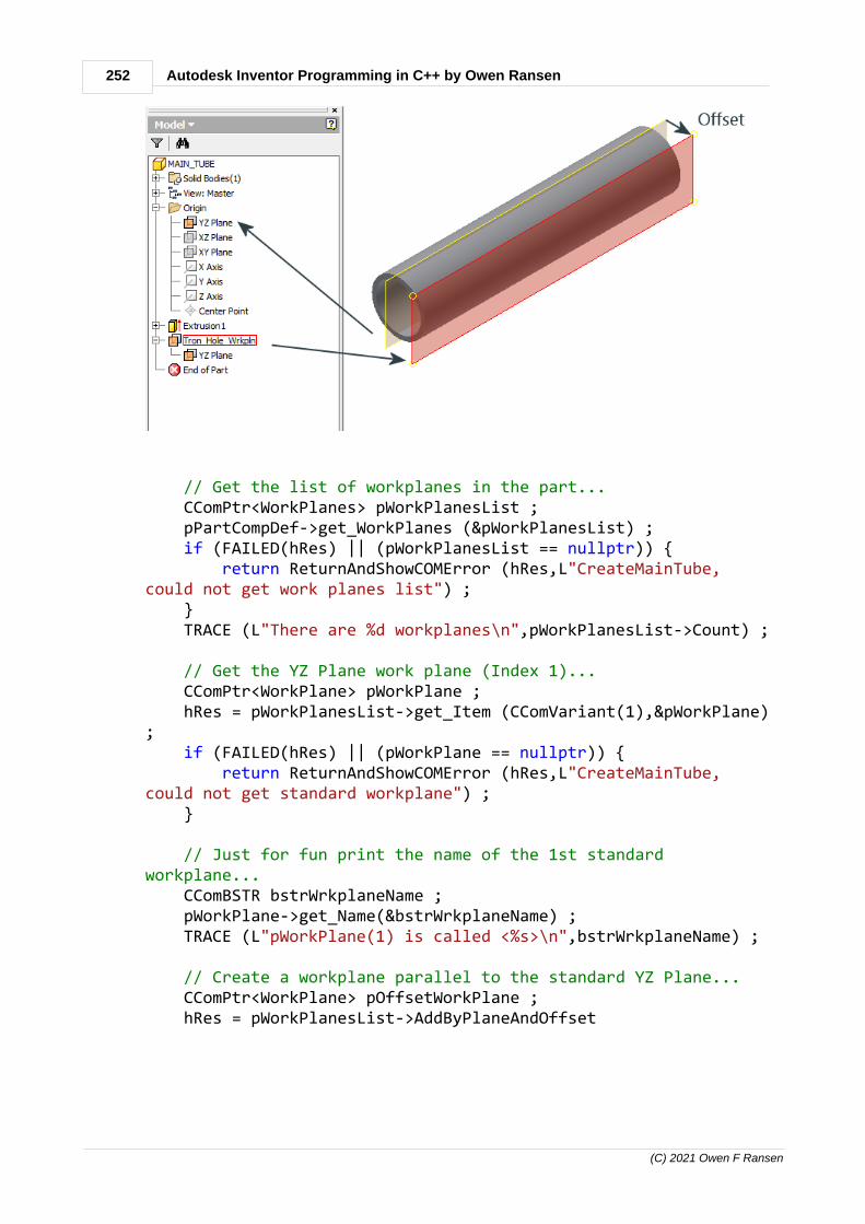
252 Autodesk Inventor Programming in C++ by Owen Ransen
(C) 2021 Owen F Ransen
// Get the list of workplanes in the part... CComPtr<WorkPlanes> pWorkPlanesList ; pPartCompDef->get_WorkPlanes (&pWorkPlanesList) ; if (FAILED(hRes) || (pWorkPlanesList == nullptr)) { return ReturnAndShowCOMError (hRes,L"CreateMainTube,could not get work planes list") ; } TRACE (L"There are %d workplanes\n",pWorkPlanesList->Count) ;
// Get the YZ Plane work plane (Index 1)... CComPtr<WorkPlane> pWorkPlane ; hRes = pWorkPlanesList->get_Item (CComVariant(1),&pWorkPlane); if (FAILED(hRes) || (pWorkPlane == nullptr)) { return ReturnAndShowCOMError (hRes,L"CreateMainTube,could not get standard workplane") ; }
// Just for fun print the name of the 1st standardworkplane... CComBSTR bstrWrkplaneName ; pWorkPlane->get_Name(&bstrWrkplaneName) ; TRACE (L"pWorkPlane(1) is called <%s>\n",bstrWrkplaneName) ; // Create a workplane parallel to the standard YZ Plane... CComPtr<WorkPlane> pOffsetWorkPlane ; hRes = pWorkPlanesList->AddByPlaneAndOffset
253Programming Inventor in C++
(C) 2021 Owen F Ransen
(_variant_t((IDispatch *)pWorkPlane), // "starting" plane CComVariant(2.3), // how much to offset VARIANT_FALSE, // See note below &pOffsetWorkPlane) ; // Return value if (FAILED(hRes) || (pOffsetWorkPlane == nullptr)) { return ReturnAndShowCOMError (hRes,L"CreateMainTube,could not add workplane with offset") ; } // For fun, again, get the name of the new workplane... hRes = pOffsetWorkPlane->get_Name (&bstrWrkplaneName) ; if (FAILED(hRes)) { return ReturnAndShowCOMError (hRes,L"CreateMainTube,could not get name of offset workplane") ; } TRACE (L"Offset WorkPlane was called <%s>\n",bstrWrkplaneName) ;
// Change the name of the workplane... pOffsetWorkPlane->put_Name (CComBSTR (L"Parallel_Smith")) ;
Note: This line in the call to AddByPlaneAndOffset...
VARIANT_FALSE, // See note below
...basically sets whether the plane is visible to the user. Theparameter is called Construction and if true then is just for theprogram to construct things and will not be visible to the user.
12.156Set the visibility of all workplanes in a part
Here is how to set all the WorkPlanes in a part to be visible orinvisible:
void SetVisibilityOfAllWorkPlanes (CComPtr<PartComponentDefinition>& pPartCompDef, const bool kbVisibility){

254 Autodesk Inventor Programming in C++ by Owen Ransen
(C) 2021 Owen F Ransen
// Get the list of workplanes in the part... CComPtr<WorkPlanes> pWorkPlanesList ; HRESULT hRes = pPartCompDef->get_WorkPlanes (&pWorkPlanesList) ; if (FAILED(hRes) || (pWorkPlanesList == nullptr)) { ShowCOMError (hRes,L"SetVisibilityOfAllWorkPlanes, could not get work planes list") ; return ; }
TRACE (L"There are %d workplanes\n",pWorkPlanesList->Count) ;
const UINT ikNumWorkPlanes = pWorkPlanesList->Count ;
VARIANT_BOOL vbVisib = kbVisibility ? VARIANT_TRUE : VARIANT_FALSE ;
for (UINT i = 1 ; i <= ikNumWorkPlanes ; i++) { CComPtr<WorkPlane> pWorkPlane ; hRes = pWorkPlanesList->get_Item(CComVariant(i),&pWorkPlane) ; if (FAILED(hRes) || (pWorkPlane == nullptr)) { ShowCOMError (hRes,L"SetVisibilityOfAllWorkPlanes, could not get item %d",i) ; return ; } pWorkPlane->Visible = vbVisib ; }}
You can write similar functions for WorkPoints and WorkAxes.
12.157Listing the names of axes in a part
Here's an example of how to do it:
for (int i = 1 ; i <= pPartCompDef->WorkAxes->Count ; i++) { CComPtr<WorkAxis> pWorkAxis ; HRESULT hRes = pPartCompDef->WorkAxes->get_Item (CComVariant(i),&pWorkAxis) ; if (FAILED(hRes)) { gLogger.Printf (ekLogMsg,L"Could not get axis number %d\n",i); } else { gLogger.Printf (ekLogMsg,L"Got axis %d, name = <%s> ",i,LPCWSTR(pWorkAxis->Name)) ; } }
Note the LPCWSTR cast.

255Programming Inventor in C++
(C) 2021 Owen F Ransen
12.158get_ActiveDocument
The active document can be one of many types. Here is an examplecall:
CComPtr<Document> pDoc;
HRESULT hRes=pApplication->get_ActiveDocument(&pDoc);
get_ActiveDocument will put NULL in pDoc if there is no documentopen. You have to check that as well as hRes:
CComPtr<Document> pDoc;HRESULT hRes = pInvApp->get_ActiveDocument(&pDoc);if (FAILED(hRes) || (pDoc == nullptr)) { ShowCOMError(hRes,L"Get Active Document Failed"); return ;}
12.159Get and Set the name of an Inventor document
You can get and set the document display name...

256 Autodesk Inventor Programming in C++ by Owen Ransen
(C) 2021 Owen F Ransen
...like this:
pPartDoc = CComQIPtr<PartDocument>(pDoc);
BSTR bstrName ; pDoc->get_DisplayName (&bstrName) ; TRACE (L"\nFull document name was %s\n",bstrName) ;
pPartDoc->DisplayName = L"George" ;
pDoc->get_DisplayName (&bstrName) ; TRACE (L"\nFull document name now is %s\n",bstrName) ;
The above also illustrates how to get a part document pointer from adocument pointer.

257Programming Inventor in C++
(C) 2021 Owen F Ransen
12.160The .AddIn file
What is the .AddIn file? The .AddIn file is an XML format file whichtells Inventor various things about your program. Inventor knowswhere to look for .AddIn files and so can pick up information aboutyour AddIn. Open an example .AddIn file to get familiar with itscontents, you'll be able to find one here:
C:\ProgramData\Autodesk\Inventor 2013\Addins
or in a directory similar.
<?xml version="1.0" encoding="utf-8"?><Addin Type="Standard"> <!--Created for Autodesk Inventor Version 17.0--> <ClassId>{213C79E5-0949-4CD8-93EA-77058D01BC48}</ClassId> <ClientId>{213C79E5-0949-4CD8-93EA-77058D01BC48}</ClientId> <DisplayName>Ch1AddInAddInServer</DisplayName> <Description>Description of Chapter 1</Description> <Assembly>C:\Users\Owen\Documents\MyAutoDeskStuff\Ch1AddIn.dll</Assembly> <LoadOnStartUp>1</LoadOnStartUp> <UserUnloadable>1</UserUnloadable> <Hidden>0</Hidden> <SupportedSoftwareVersionGreaterThan>16..</SupportedSoftwareVersionGreaterThan> <DataVersion>1</DataVersion> <UserInterfaceVersion>1</UserInterfaceVersion> </Addin>
Here are the most imports parts of an .AddIn file:
ClassId and ClientId which are simply unique identifiers to make sureInventor does not confuse your AddIn with other AddIns. DisplayName and Description are strings which will appear in theAddIn manager. (You can find the AddIn manager under the Toolstab, Options panel of the Inventor ribbon.) DisplayName appears inthe main list, and Description appears at the bottom of the dialogwhen you click on the name in the main list.
The Assembly is the path to the DLL which contains your AddIn, andso it is this entry which tells Inventor where to find your program. Ifyour DLL is in Inventor's bin directory you can simply list the name ofthe AddIn without the full path, for example: <Assembly>ScrewMaker.dll</Assembly>

258 Autodesk Inventor Programming in C++ by Owen Ransen
(C) 2021 Owen F Ransen
The UserUnloadable element specifies whether the user can unloadthe AddIn. Assumed to be true if this value is not specified (i.e. usercan unload the add-in). Value can be 0 or 1.
The optional Hidden element defines whether the AddIn is visible inthe AddIn Manager or not. A value of 1 indicates that it is hidden,although the end-user can still right-click within the AddIn Managerand choose "Show hidden members" to display all AddIns. Thedefault value is 0, i.e. not hidden.
The UserInterfaceVersion is explained here.
12.161Adding a flush constraint programatically
A flush constraint means two planes are aligned on the same plane.So this means that you must get hold of the two planes to make themflush. Imagine two boxes, you could select a face from each box tobecome flush.
Here is an example of adding a flush constraint withAddFlushConstraint. AddFlushConstraint requires WorkPlanes orplanar objects like faces. The example below uses faces (planar

259Programming Inventor in C++
(C) 2021 Owen F Ransen
objects).
When you call this function you'll need two parts (with one box ineach part) in the Inventor assembly document for this to work.
static void DoFlushConstraint (CComPtr<Application>& pInvApp){ TRACE (L"DoFlushConstraint starting\n"); CComPtr<Document> pDoc; HRESULT hRes = pInvApp->get_ActiveDocument(&pDoc); if (FAILED(hRes) || (pDoc == nullptr)) { ShowCOMError(hRes,L"Get Active Document Failed"); return ; } TRACE (L"A document is open, is it an assemply document?\n");
CComQIPtr<AssemblyDocument> pAsmDoc(pDoc); CComPtr<AssemblyComponentDefinition> pAssemblyCompDef; hRes = pAsmDoc->get_ComponentDefinition(&pAssemblyCompDef); if (FAILED(hRes) || (pAssemblyCompDef == nullptr)) { TRACE (L"Maybe this is not an assembly document?\n"); return ; }
TRACE (L"Getting occurrences, each occurrese is like an instance of a part\n");
CComPtr<ComponentOccurrences> pOccs; hRes = pAssemblyCompDef->get_Occurrences(&pOccs); long iNumOccs ; hRes = pOccs->get_Count(&iNumOccs);
if (iNumOccs != 2) { TRACE (L"This program needs exactly 2 occurrences in the assembly to work, but the doc has %d\n",iNumOccs); return ; }
// Get the list of constraints of the assembly so you can add a new one CComPtr<AssemblyConstraints> pConstraintList; hRes = pAssemblyCompDef->get_Constraints(&pConstraintList) ; if (FAILED(hRes) || (pConstraintList== nullptr)) { TRACE (L"Could not get the constraints of the assembly\n"); return ; }
TRACE (L"The assembly has %d existing constraints\n",pConstraintList->Count) ;

260 Autodesk Inventor Programming in C++ by Owen Ransen
(C) 2021 Owen F Ransen
CComPtr<Face> pFace1,pFace2; pAssemblyCompDef->Occurrences->Item[1]->SurfaceBodies->Item[1]->Faces->get_Item (1,&pFace1) ; pAssemblyCompDef->Occurrences->Item[2]->SurfaceBodies->Item[1]->Faces->get_Item (1,&pFace2) ;
if ((pFace1 == nullptr) || (pFace2 == nullptr)) { TRACE (L"Could not get two faces\n"); return ; }
CComVariant varEmpty, varReal(0.0);
// add the constraint CComPtr<FlushConstraint> pFC; hRes = pConstraintList->AddFlushConstraint(pFace1, pFace2, varReal, varEmpty, varEmpty,&pFC); if (FAILED(hRes)) { ShowCOMError (hRes,L"Could not add flush constraint\n"); return ; }
TRACE (L"Added constraint\n");}
Other sorts of constraints are available too.
12.162Adding a flush constraint using workplanes
Here is an example, which shows that you must use geometricalproxies, assuming you have a CComQIPtr<AssemblyDocument>pAsmDoc to start off with.
/* * Get the assembly definition which contains the actual"stuff"... */ CComPtr<AssemblyComponentDefinition> pAssemblyCompDef = nullptr ; hRes = pAsmDoc->get_ComponentDefinition(&pAssemblyCompDef);
/* * Get the list of occurrences so that you can add twocyliders to it... */ CComPtr<ComponentOccurrences> pOccurrencesList=nullptr; hRes = pAssemblyCompDef->get_Occurrences (&pOccurrencesList)

261Programming Inventor in C++
(C) 2021 Owen F Ransen
;
/* * Create some geometries to place the parts in space... */ CComPtr<TransientGeometry> pTransGeom = nullptr ; pInvApp->get_TransientGeometry(&pTransGeom); CComPtr<Matrix> pPosMatrix = nullptr ; hRes = pTransGeom->CreateMatrix(&pPosMatrix); // Defaults to0 0 0
CComPtr<ComponentOccurrence> pCyl1Occ = nullptr; hRes = pOccurrencesList->Add (CComBSTR(L"C:\\TEST\\Cyl1.ipt"),pPosMatrix,&pCyl1Occ) ;
CComQIPtr<PartComponentDefinition> pCyl1CompDef =CComQIPtr<PartComponentDefinition>(pCyl1Occ->Definition); CComPtr<WorkPlane> pWorkPlane1=nullptr ; hRes = pCyl1CompDef->WorkPlanes->get_Item(CComVariant(L"XYPlane"),&pWorkPlane1);
CComPtr<WorkPlaneProxy> pWPProxy1 ; pCyl1Occ->CreateGeometryProxy(pWorkPlane1,(IDispatch**)&pWPProxy1) ;
CComPtr<ComponentOccurrence> pCyl2Occ = nullptr; hRes = pOccurrencesList->Add (CComBSTR(L"C:\\TEST\\Cyl2.ipt"),pPosMatrix,&pCyl2Occ) ; CComQIPtr<PartComponentDefinition> pCyl2CompDef =CComQIPtr<PartComponentDefinition>(pCyl2Occ->Definition); CComPtr<WorkPlane> pWorkPlane2 ; hRes = pCyl2CompDef->WorkPlanes->get_Item(CComVariant(L"YZPlane"),&pWorkPlane2); CComPtr<WorkPlaneProxy> pWPProxy2 ; pCyl2Occ->CreateGeometryProxy(pWorkPlane2,(IDispatch**)&pWPProxy2) ;
// Get the list of constraints of the assembly so you can adda new one CComPtr<AssemblyConstraints> pConstraintList = nullptr ; hRes = pAssemblyCompDef->get_Constraints(&pConstraintList) ;
CComVariant varEmpty, varReal(0.0); CComPtr<FlushConstraint> pFC = nullptr ; hRes = pConstraintList->AddFlushConstraint

262 Autodesk Inventor Programming in C++ by Owen Ransen
(C) 2021 Owen F Ransen
(pWPProxy1,pWPProxy2, varEmpty,varEmpty, varEmpty,&pFC);
12.163Constraints and parts from a programmer's point of view
Inside an AssemblyDocument (or rather an AssemblyComponentDefinition) Occurrences and Constraints can beimagined like this:
You can see that occurrences of parts are "constrained" together byconstraints. "Ball" and "Chain" are constrained by the constraintnumber 1, called "Mate:1"

263Programming Inventor in C++
(C) 2021 Owen F Ransen
You can also see that constraint number 4 has a user selected name,"Hold_Me".
When you are programming it might be good to name yourconstraints so that you can easily pick the one you are looking for,rather than having to remember the indices or the standard names.
12.164Loading your DLL
Addins are loaded at the startup of Inventor.
Once you have your Inventor AddIn DLL you need to show it toInventor so it can be loaded. You do this by creating an .AddIn file. Ifyou use the wizard that will be done for you. The .addin file needs tobe placed in one or more of several directories.
One example place is here:
%ALLUSERSPROFILE%\Autodesk\Inventor 2013\Addins
Note that the above path will resolve down to something like this:
C:\ProgramData\Autodesk\Inventor 2013\Addins
Also note that maybe you are using a different version of Inventor, sothe 2013 becaomes 2014 for example.
Anyway, since the .AddIn file has a path to your DLL, Inventor scansthe known directories and examines the .AddIn files it finds. Hence itreads the <Assembly> part of the .AddIn file, and knows where topick up the file.

264 Autodesk Inventor Programming in C++ by Owen Ransen
(C) 2021 Owen F Ransen
12.165Sketches in an Inventor Part
This diagram shows you how sketches are contained inside a part:
They are inside a list which is itself inside a component definition.Programatically here is how to get a sketch by name:
// Get the component definition inside the PartDoc... CComPtr<PartComponentDefinition> pPartCompDef; hRes = pPartDoc->get_ComponentDefinition(&pPartCompDef);
// Get the sketch in the part by name... CComPtr<PlanarSketch> pSketch = NULL; hRes = pPartCompDef->Sketches->get_Item(CComVariant(L"MAIN_TUBE_CIRCS"), &pSketch); if (FAILED(hRes)) { ShowCOMError (hRes,L"AddSolid but could not 'get'sketch\n"); return (false) ; }

265Programming Inventor in C++
(C) 2021 Owen F Ransen
You can get hold of sketches by index (starting from #1)
CComPtr<PlanarSketch> pSketch ; // Get the first sketch in the part hRes = pPartCompDef->Sketches->get_Item(CComVariant(1),&pSketch);
Of course both these sketch getting methods require that the namedsketch you are looking for, or the index, are present in the Sketcheslist of the Inventor Part.
12.166Default workplanes and default sketches programatically
Every part has 3 default workplanes.
You can add sketches to them programatically using this function:
// Adds a sketch to one of the three standard workplanes in a partbool AddSketchToStdWorkplane (CComPtr<PlanarSketch>& pNewSketch, CComPtr<PartComponentDefinition>& pPartCompDef, const wchar_t* const pszNewSketchName, const UINT ikWorkPlaneNumber) // gikXIndex,gikYIndex, gikZIndex{ if ((pszNewSketchName == nullptr) || (wcslen(pszNewSketchName) == 0)) { gLogger.Printf (ekErrMsg,L"ASTSWP, workplane name incorrect") ;

266 Autodesk Inventor Programming in C++ by Owen Ransen
(C) 2021 Owen F Ransen
return false; }
CComPtr<WorkPlane> pWorkPlane; bool bOk = GetStdWorkPlaneByIndex(pWorkPlane, ikWorkPlaneNumber,pPartCompDef); if (!bOk) { return false; }
// Get the list of sketches CComPtr<PlanarSketches> pSketchList ; HRESULT hRes = pPartCompDef->get_Sketches (&pSketchList); if (FAILED(hRes)) { ShowCOMError (hRes,L"AddSketchToWorkplane, could not get planarsketches") ; return false; }
hRes = pSketchList->Add (_variant_t((IDispatch *)pWorkPlane),VARIANT_FALSE,&pNewSketch) ; if (FAILED(hRes)) { ShowCOMError (hRes,L"AddSketchToWorkplane, could not get planarsketches") ; return false; }
pNewSketch->put_Name (CComBSTR (pszNewSketchName)) ;
return true;}
The last part of the code above shows you how to get the name of asketch using get_Name. The following diagram shows the indices toget the standard workplanes:

267Programming Inventor in C++
(C) 2021 Owen F Ransen
You can also use: gikXIndex, gikYIndex, gikZIndex
This code...
// Create a part CComPtr<PartDocument> pPartDoc; bool bOk = CreateNewPart(GetInvAppPtr(),pPartDoc,L"Test"); if (!bOk) { return; }
CComPtr<PartComponentDefinition> pPartDef; HRESULT hRes = pPartDoc->get_ComponentDefinition(&pPartDef); if (FAILED(hRes) || (pPartDef==nullptr)) { return; }
for (UINT i = gikXIndex; i <= gikZIndex; i++) { // Add a sketch CString kcsSketchName; kcsSketchName.Format(L"Sketch%d", i); CComPtr<PlanarSketch> pNewSketch; AddSketchToStdWorkplane(pNewSketch, pPartDef, kcsSketchName, i); AddCircleToSketch(pNewSketch, i * 1, i * 2, i * 3); }
...creates these three sketches...

268 Autodesk Inventor Programming in C++ by Owen Ransen
(C) 2021 Owen F Ransen
See also this page.
12.167Add a work point at a sketch point
Here's a function to place a workpoint in space at the same positionas a point in a sketch. This is what we want to do:
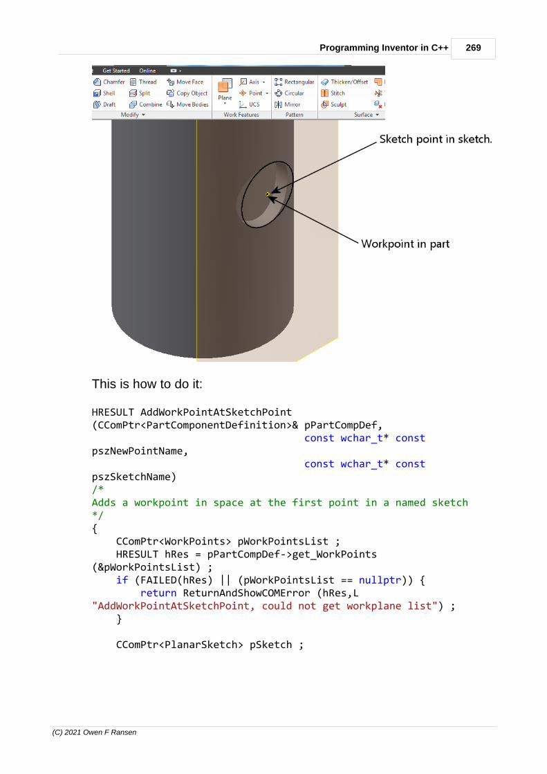
269Programming Inventor in C++
(C) 2021 Owen F Ransen
This is how to do it:
HRESULT AddWorkPointAtSketchPoint(CComPtr<PartComponentDefinition>& pPartCompDef, const wchar_t* constpszNewPointName, const wchar_t* constpszSketchName) /*Adds a workpoint in space at the first point in a named sketch*/{ CComPtr<WorkPoints> pWorkPointsList ; HRESULT hRes = pPartCompDef->get_WorkPoints(&pWorkPointsList) ; if (FAILED(hRes) || (pWorkPointsList == nullptr)) { return ReturnAndShowCOMError (hRes,L"AddWorkPointAtSketchPoint, could not get workplane list") ; }
CComPtr<PlanarSketch> pSketch ;

270 Autodesk Inventor Programming in C++ by Owen Ransen
(C) 2021 Owen F Ransen
hRes = GetSketchByName (pSketch,pszSketchName,pPartCompDef) ; if (FAILED(hRes) || (pSketch == nullptr)) { return ReturnAndShowCOMError (hRes,L"AddWorkPointAtSketchPoint, could not get sketch") ; }
CComPtr<SketchPoints> pSkPoints; pSketch->get_SketchPoints (&pSkPoints) ; long iNumPoints ; hRes = pSkPoints->get_Count (&iNumPoints) ; if (FAILED(hRes) || (iNumPoints < 1)) { return ReturnAndShowCOMError (hRes,L"AddWorkPointAtSketchPoint, not enough points in sketc") ; }
CComPtr<SketchPoint> pSketchPoint ; hRes = pSkPoints->get_Item (1,&pSketchPoint) ; if (FAILED(hRes) || (pSketchPoint == nullptr)) { return ReturnAndShowCOMError (hRes,L"AddWorkPointAtSketchPoint, get sketch point failed") ; }
CComPtr<WorkPoint> pWorkPoint ; hRes = pWorkPointsList->AddByPoint (_variant_t((IDispatch*)pSketchPoint),VARIANT_FALSE,&pWorkPoint) ; if (FAILED(hRes) || (pWorkPoint == nullptr)) { return ReturnAndShowCOMError (hRes,L"AddWorkPointAtSketchPoint, Add workpoint failed") ; }
pWorkPoint->put_Name (CComBSTR (pszNewPointName)) ;
return (hRes) ;}
This function assumes that there is at least 1 points in the sketch, andtakes the first. The function also takes a name for the workpointbecause I find that giving signifigant names to objects in Inventor makes them easier to find.

271Programming Inventor in C++
(C) 2021 Owen F Ransen
12.168Getting and setting the sketch name (as well as other objects)
Here is how to get and set the sketch (and other objects) name:
CComPtr<PlanarSketch> pSketch; ... CComBSTR bstrSketchName ; pSketch->get_Name (&bstrSketchName) ; //Get the sketch name ... pSketch->put_Name (CComBSTR(L"Tube_Base")) ; // Set the name
Many many objects in the Inventor API have names, like workplanesand parts etc. You can usually interrogate and change the nameswith the methods shown above.
12.169PatternSpacingTypeEnum
Constants identifying the pattern spacing type, used in, patterns(arrays) of objects.
Name Value Description
kDefault 33537Occurrences separated by specified
distance.
kFitted 33538All occurrences fitted within specified
distance.kFitToPathLe
ngth33539 All occurrences fitted within path length.
12.170PatternOrientationEnum
PatternOrientationEnum, Constants identifying the pattern orientationmethod.
Name Value Description
kAdjustToDirection1 33794Orientation of occurrences adjustedto direction 1.

272 Autodesk Inventor Programming in C++ by Owen Ransen
(C) 2021 Owen F Ransen
kAdjustToDirection2 33795Orientation of occurrences adjustedto direction 2.
kIdentical 33793All occurrences are orientedidentically.
12.171Occurences as Xrefs
If you are familiar with Xrefs in AutoCAD then you can imagine thatan occurrence can be considered as a sort of xref.
As Xiaodong Liang of Autodesk said:
"I think this is a good comparison. The Inventor assembly containsthe occurrence information (file, path, transformation etc) only. Itdoes not contain the geometry of the occurrence. When the assemblyis opened, it tries to resolve the occurrence, after that, read thegeometries and display them in the assembly context with thetransformation defined with the occurrence. The occurrence isactually a proxy of the original document. If the original file cannot befound, Inventor will ask the user to resolve. So it may be OK to saysome behaviors are similar to Xref."
12.172VT_I4
VT_I4 – 32-Bit signed long value (positive 2147483647 to negative2147483648 )
12.173rgs file for Inventor AddIns, what is it?
***WARNING***: The old plugin wizard may create this file for you,but it is no longer required for modern registry free AddIns.
12.174BSTR OLECHAR wchar_t
BSTR is normally defined as an OLECHAR* and is normally a pointerto a wide string.
So this is valid:
CComBSTR bstrSketchName ;

273Programming Inventor in C++
(C) 2021 Owen F Ransen
pSketch->get_Name (&bstrSketchName) ; TRACE (L"The name of the sketch just made is %s\n",bstrSketchName) ;
Remember that with TRACE the format specifier requires L toindicate wide char string types (wchar_t). See here for anotherexample.
CComBSTR is a class which encapsulates BSTR:
class CComBSTR{public:
BSTR m_str;......
Here's an example of going from CComBSTR to CString:
BSTR bstrThisUserParamName ; pUserParam->get_Name(&bstrThisUserParamName); const CString kcsThisParamName(bstrThisUserParamName);
So use CComBSTR instead of BSTR whenever you can, since BSTRrequires more explicit memory handling, a call to ::SysFreeString afteruse for example:
BSTR DisplayName; HRESULT hr = pSketch->get_Name(&DisplayName); ... do things... ::SysFreeString(DisplayName);
As an aside I doubt that anyone is still using ASCII, almost allInventor programmers are using UNICODE. For that reason I nolonger use the _T macro, which was used to conditionally compile forboth ASCII and UNICODE.
You of course have to check what type of string a given function isrequesting. In case of calling Inventor API functions the strings arerequired as BSTR (sometimes wrapped in a VARIANT) which you canget in multiple ways. All of them can create it from wchar_t:SysAllocString, CComBSTR, _bstr_t

274 Autodesk Inventor Programming in C++ by Owen Ransen
(C) 2021 Owen F Ransen
Here is how to get a CString from a _bstr_t.
_bstr_t FullName (pPartCompDef->iPartMember->GetReferencedFile()->GetFullFileName()); const CString kcsFulName((wchar_t*)FullName);
12.175AddForSolid
AddForSolid creates a profile inside a sketch which can be used forextrusion (for example).
CComPtr<Profile> pProfile = NULL;CComVariant pSegs;CComVariant pReserve;pSketch->Profiles->AddForSolid (VARIANT_TRUE, // combine allelements into one "path" pSegs, // path segments,may well not be used pReserve, // not used, butparameter requitred &pProfile); // returnedcombined profile
The VARIANT_TRUE means combine all the elements in the sketchinto one path.
pSegs may well not be used.
In the above case pProfile is the return data from AddForSolid.pProfile could be used later in the function like this:
CComPtr<ExtrudeDefinition> pExtrudeDef;hRes =pExtrudeFs->CreateExtrudeDefinition(pProfile,PartFeatureOperationEnum::kJoinOperation,&pExtrudeDef);

275Programming Inventor in C++
(C) 2021 Owen F Ransen
Next...
12.176VBA, VB.NET, C# or C++
VBA is only recommended for small macros.
VB can create quite large programs, as can C#.
C++ can be used to create EXE files which interact with Inventor from"outside" Inventor.
C++ can be used to create DLLs which run "inside" Inventor and addcommands to the program and icons in the "Ribbon".
12.177Profiles in sketches programatically
A profile is something like a circle, which is contained inside a sketch.
You can get the list of profiles in a sketch like this:
// Get Profiles CComPtr<Profiles> pSkProfiles; hr = pSketch->get_Profiles(&pSkProfiles) ;
12.178Creating an Assembly
HRESULT CreateNewAssembly (CComQIPtr<AssemblyDocument>& pAssemblyDoc, CComPtr<AssemblyComponentDefinition>&pAssemblyCompDef, const CString& kcsTemplateFile)/*Create a new assembly and return the document and assembly componentdefinition.AssemblyComponentDefinition is a list of parts and constraints.*/{ CComPtr<Documents> pDocuments=nullptr; HRESULT hRes = pInvApp->get_Documents (&pDocuments) ; if (FAILED(hRes)) { return ReturnAndShowCOMError (hRes,L"CreateNewAssembly, could not getdocuments");

276 Autodesk Inventor Programming in C++ by Owen Ransen
(C) 2021 Owen F Ransen
}
CComBSTR strTemplateFilename(kcsTemplateFile);
// create a new assembly document using the template passed to us CComPtr<Document> pDocument=nullptr; hRes = pDocuments->Add(kAssemblyDocumentObject, strTemplateFilename,VARIANT_TRUE, &pDocument); if (FAILED(hRes)) { return ReturnAndShowCOMError (hRes,L"CreateNewAssembly, Could not makenew assembly document"); }
// Try to cast to an assembly document, this should not ever fail... pAssemblyDoc = pDocument ;
// Get hold of the assembly component definition too... pAssemblyCompDef = nullptr ; hRes = pAssemblyDoc->get_ComponentDefinition(&pAssemblyCompDef); if (FAILED(hRes)) { return ReturnAndShowCOMError (hRes,L"CreateNewAssembly, Could not gethold of assembly component definition"); }
//theApp.PrintfLedMessage (RGB(255,255,155),CCT_DLG,L"Assieme OK...") ;
return S_OK ;}
Here is another example of how to do it in C++
static void CreateAssembly (const CComPtr<Application>& pInvApp) { CComPtr<Documents> pDocuments; pInvApp->get_Documents (&pDocuments) ;
CComBSTR strTemplateFilename; // Get assembly document template CComPtr<FileManager> pFileManager; HRESULT hr = pInvApp->get_FileManager(&pFileManager); if (FAILED(hr)) { TRACE (_"Could not get file manager\n"); return ; }
hr = pFileManager->GetTemplateFile(kAssemblyDocumentObject, kDefaultSystemOfMeasure, kDefault_DraftingStandard, CComVariant(), &strTemplateFilename); if (FAILED(hr)) { TRACE ("Could not get template file\n"); return ;

277Programming Inventor in C++
(C) 2021 Owen F Ransen
}
TRACE ("Template file is:\n%s\n",strTemplateFilename);
// create a new assembly document from a standard template CComPtr<Document> pDocument; hr = pDocuments->Add(kAssemblyDocumentObject, strTemplateFilename, VARIANT_TRUE, &pDocument); if (FAILED(hr)) { TRACE ("Could not create new assembly document\n"); return ; }
CComPtr<TransientGeometry> pTransGeom; hr = pInvApp->get_TransientGeometry(&pTransGeom); if (FAILED(hr)) { TRACE ("Could not get transient geometry\n"); return ; }
CComPtr<Matrix> pMatrix; hr = pTransGeom->CreateMatrix(&pMatrix); if (FAILED(hr)) { TRACE ("Could not create matrix\n"); return ; }
CComBSTR csFileName = L"c:\\temp\\cylinder.ipt" ;
// Try to cast to the document to an assembly document CComQIPtr<AssemblyDocument> pAssemblyDoc = pDocument ; if (!pAssemblyDoc) { TRACE ("Could not get assembly doc\n"); return ; }
// Get assembly component definition CComPtr<AssemblyComponentDefinition> pAssemblyCompDef; hr = pAssemblyDoc->get_ComponentDefinition(&pAssemblyCompDef); if (FAILED(hr)) { TRACE ("Could not get assembly component definition\n"); return ; }
// Get the ComponentOccurrences collection for the assembly document CComPtr<ComponentOccurrences> pOccs; hr = pAssemblyCompDef->get_Occurrences(&pOccs); if (FAILED(hr)) { TRACE ("Could not get assembly occurrences\n"); return ;

278 Autodesk Inventor Programming in C++ by Owen Ransen
(C) 2021 Owen F Ransen
}
CComPtr<ComponentOccurrence> pOcc1; hr = pOccs->Add(csFileName,pMatrix,&pOcc1) ; if (FAILED(hr)) { TRACE ("Could not add assembly occurrence 1\n"); return ; }
CComPtr<Vector> pVector; hr = pTransGeom->CreateVector(20,2,2,&pVector); if (FAILED(hr)) { TRACE ("Could not create vector\n"); return ; } pMatrix->SetTranslation (pVector,VARIANT_TRUE) ; CComPtr<ComponentOccurrence> pOcc2; hr = pOccs->Add(csFileName,pMatrix,&pOcc2) ; if (FAILED(hr)) { TRACE ("Could not add assembly occurrence 2\n"); return ; }
CComPtr<Face> pCylFace1 = GetCylinderSurface (pOcc1) ; CComPtr<Face> pCylFace2 = GetCylinderSurface (pOcc2) ;
TRACE ("pCylFace1 = %p pCylFace2 = %p\n",pCylFace1,pCylFace2);}
Of course if you know and want to use a specific template file you cansimply do this:
strTemplateFilename = L"C:\\Users\\Public\\Documents\\Autodesk\\Inventor 2013\\Templates\\LuVe\\RanStd.iam" ;
without calling GetTemplateFile .
See also creating a drawing, DWG IDW.
12.179Getting the project file location and other options programatically
You can use this fragment:
CComPtr<FileLocations> pFileLocations;Result = pInvApp->get_FileLocations(&pFileLocations);if (SUCCEEDED(Result))

279Programming Inventor in C++
(C) 2021 Owen F Ransen
{CComBSTR bstrFileLocationsFile;Result =
pFileLocations->get_FileLocationsFile(&bstrFileLocationsFile);if (SUCCEEDED(Result))
TRACE(L"Active Project File: %ls \n",bstrFileLocationsFile);
}
and something like this:
static HRESULT GetInventorInformation(CComPtr<Application>&pInvApp){ // Display some information about Inventor
TRACE("\nInventor Information: \n");
CComBSTR bstrCaption;HRESULT Result = pInvApp->get_Caption(&bstrCaption);if (SUCCEEDED(Result))
TRACE(L"Caption: %ls \n", bstrCaption);
CComBSTR bstrLanguage;Result = pInvApp->get_LanguageName(&bstrLanguage);if (SUCCEEDED(Result))
TRACE(L"Language: %ls \n", bstrLanguage);
CComBSTR bstrUserName;Result = pInvApp->get_UserName(&bstrUserName);if (SUCCEEDED(Result))
TRACE(L"User Name: %ls \n", bstrUserName);
CComPtr<SoftwareVersion> pSoftwareVersion;Result = pInvApp->get_SoftwareVersion(&pSoftwareVersion);if (SUCCEEDED(Result)){
CComBSTR bstrSoftVerDispName;Result =
pSoftwareVersion->get_DisplayName(&bstrSoftVerDispName);if (SUCCEEDED(Result))
TRACE(L"Software Version: %ls \n",bstrSoftVerDispName);
}
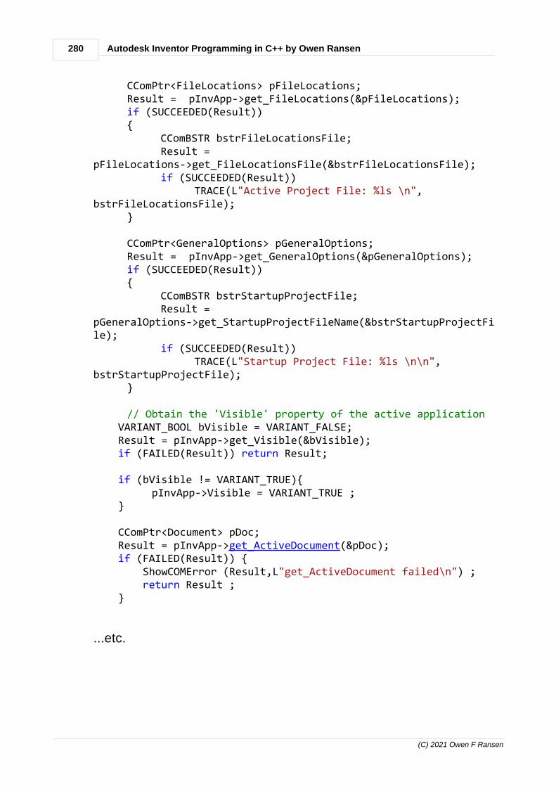
280 Autodesk Inventor Programming in C++ by Owen Ransen
(C) 2021 Owen F Ransen
CComPtr<FileLocations> pFileLocations;Result = pInvApp->get_FileLocations(&pFileLocations);if (SUCCEEDED(Result)){
CComBSTR bstrFileLocationsFile;Result =
pFileLocations->get_FileLocationsFile(&bstrFileLocationsFile);if (SUCCEEDED(Result))
TRACE(L"Active Project File: %ls \n",bstrFileLocationsFile);
}
CComPtr<GeneralOptions> pGeneralOptions;Result = pInvApp->get_GeneralOptions(&pGeneralOptions);if (SUCCEEDED(Result)){
CComBSTR bstrStartupProjectFile;Result =
pGeneralOptions->get_StartupProjectFileName(&bstrStartupProjectFile);
if (SUCCEEDED(Result))TRACE(L"Startup Project File: %ls \n\n",
bstrStartupProjectFile);}
// Obtain the 'Visible' property of the active application VARIANT_BOOL bVisible = VARIANT_FALSE; Result = pInvApp->get_Visible(&bVisible); if (FAILED(Result)) return Result;
if (bVisible != VARIANT_TRUE){
pInvApp->Visible = VARIANT_TRUE ; }
CComPtr<Document> pDoc; Result = pInvApp->get_ActiveDocument(&pDoc); if (FAILED(Result)) { ShowCOMError (Result,L"get_ActiveDocument failed\n") ; return Result ; }
...etc.

281Programming Inventor in C++
(C) 2021 Owen F Ransen
12.180regsvr32
This information is only useful if you are making old style AddIns.New Registry Free AddIns don't require the use of regsvr32.
Required for when you make AddIns. Two examples:
regsvr32 shmedia.dll (for registering a file)
regsvr32 /u shmedia.dll (for unregistering a file)
Note that the full path of the .dll may be used to ensure that you areregistering the correct dll.
The def file is required because it is used to export the functionsDllRegisterServer and DllUnregisterServer. Here's an example:
; SimpleAddIn.def : Declares the module parameters.
LIBRARY "SimpleAddIn.DLL"
EXPORTSDllCanUnloadNow PRIVATEDllGetClassObject PRIVATEDllRegisterServer PRIVATEDllUnregisterServer PRIVATE
DllCanUnloadNow is a function inside your code which Inventor callsto see if it can unload the DLL to free up memory.
12.181What and where is the AddIn manager?
You can get hold of it here:

282 Autodesk Inventor Programming in C++ by Owen Ransen
(C) 2021 Owen F Ransen
But also from the Windows Start Menu->Programs->Autodesk->Inventor->Tools. Just look for the "+" icon.
In your .AddIn file you can put a description of the addin which willappear in the manager:
You can also see the DisplayName from the .AddIn file in the main listof the manager. In this case it is InventorAddIn5AddInServer.
12.182RxInventor.tlb
A tlb file is a type-library and it contains a description of one or more aCOM components.
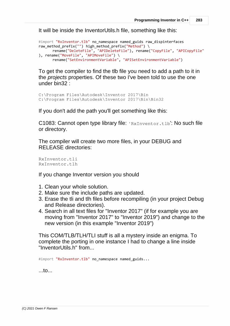
283Programming Inventor in C++
(C) 2021 Owen F Ransen
It will be inside the InventorUtils.h file, something like this:
#import "RxInventor.tlb" no_namespace named_guids raw_dispinterfacesraw_method_prefix("") high_method_prefix("Method") \
rename("DeleteFile", "APIDeleteFile"), rename("CopyFile", "APICopyFile"), rename("MoveFile", "APIMoveFile") \
rename("SetEnvironmentVariable", "APISetEnvironmentVariable")
To get the compiler to find the tlb file you need to add a path to it inthe projects properties. Of these two I've been told to use the oneunder bin32 :
C:\Program Files\Autodesk\Inventor 2017\BinC:\Program Files\Autodesk\Inventor 2017\Bin\Bin32
If you don't add the path you'll get something like this:
C1083: Cannot open type library file: 'RxInventor.tlb': No such fileor directory.
The compiler will create two more files, in your DEBUG andRELEASE directories:
RxInventor.tliRxInventor.tlh
If you change Inventor version you should
1. Clean your whole solution.2. Make sure the include paths are updated.3. Erase the tli and tlh files before recompiling (in your project Debug
and Release directories).4. Search in all text files for "Inventor 2017" (if for example you are
moving from "Inventor 2017" to "Inventor 2019") and change to thenew version (in this example "Inventor 2019")
This COM/TLB/TLH/TLI stuff is all a mystery inside an enigma. Tocomplete the porting in one instance I had to change a line inside"InventorUtils.h" from...
#import "RxInventor.tlb" no_namespace named_guids...
...to...

284 Autodesk Inventor Programming in C++ by Owen Ransen
(C) 2021 Owen F Ransen
#import "C:\Program Files\Autodesk\Inventor 2019\Bin\RxInventor.tlb"no_namespace named_guids...
...else the compiler could not find the file.
12.183Adding a rectangle to a sketch programatically
We create a rectangle in a 2D sketch by specifying 2 points. You getthe points from transient geometry object, but they need to be used tocreate the two SketchPoint things.
// Get the transient geometry object. We'll use this tocreate pure geometric points CComPtr<TransientGeometry> pTrGeom; pTrGeom = pApp->TransientGeometry;
// Draw a 4cm x 3cm rectangle with the corner at (0,0) CComPtr<Point2d> pPt1; // Pure geometric point hr = pTrGeom->CreatePoint2d(0.0,0.0,&pPt1); if (FAILED(hr)) return ReturnAndShowCOMError (hr,L" create 2d pointfailed") ;
CComPtr<Point2d> pPt2; // Pure geometric point hr = pTrGeom->CreatePoint2d(4.0,3.0,&pPt2); if (FAILED(hr)) return ReturnAndShowCOMError (hr,L" create 2d pointfailed") ;
// Create sketch points from above points // Get list of SketchPoints, points existing in a sketch

285Programming Inventor in C++
(C) 2021 Owen F Ransen
CComPtr<SketchPoints> pSkPoints; hr = pSketch->get_SketchPoints(&pSkPoints); if (FAILED(hr)) return ReturnAndShowCOMError (hr,L" get sketch point listfailed") ;
// Create a SketchPoint from a geometric point CComPtr<SketchPoint> pSpt1; hr = pSkPoints->Add(pPt1, // geometrical point VARIANT_FALSE, // not a hole center &pSpt1); // resulting SketchPoint if (FAILED(hr)) return ReturnAndShowCOMError (hr,L" add point to sketchfailed") ;
CComPtr<SketchPoint> pSpt2; hr = pSkPoints->Add(pPt2,VARIANT_FALSE,&pSpt2); if (FAILED(hr)) return ReturnAndShowCOMError (hr,L" add point to sketchfailed") ;
CComPtr<SketchEntitiesEnumerator> pRectangleLines;
// Get SketchLines CComPtr<SketchLines> pSkLines; hr = pSketch->get_SketchLines(&pSkLines); if (FAILED(hr)) return ReturnAndShowCOMError (hr,L" get lines listfailed") ;
TRACE (L"There are currently %d lines in the sketch\n",pSkLines->Count) ;
// Creat a rectangle from two points hr = pSkLines->AddAsTwoPointRectangle(_variant_t((IDispatch*)pSpt1), _variant_t((IDispatch*)pSpt2), &pRectangleLines);

286 Autodesk Inventor Programming in C++ by Owen Ransen
(C) 2021 Owen F Ransen
12.184get_ and Get ?
What is the difference between the functions like these:
// High syntax version Get... ComponentOccurrencesPtr pActOccs=ActDef->GetOccurrences() ; // I suggest you avoid using this version
// Raw syntax version get_... CComPtr<ComponentOccurrences> pOccs; pAssemblyCompDef->get_Occurrences(&pOccs); // I suggest you use this version
GetProperty and MethodMethName(): is called “high” method syntax get_property and MethodName(): is the “raw” syntax.
The first one returns a value and can throw exceptions. The secondone returns an error code and take the return value as in/out param.This is usually the suggested way to use the API, reason is that yourprogram is less likely to crash in case you are not handlingexceptions.
The returned property value itself is of course identical using one orthe other syntax.
Using the second method also means that you generally do not haveto worry about Releasing smart pointers and other COM arcania...
See also VARIANT and CComVariant.
12.185UserInterfaceVersion
UserInterfaceVersion is an entry in an .AddIn file.
It is used by Inventor to know when it should regenerate the GUI ofyour .AddIn. As you develop your AddIn's GUI this number should beincremeted so that Inventor knows to recreate that part of the ribbon.
It should be a positive integer. Here's an example:
<UserInterfaceVersion>1</UserInterfaceVersion>
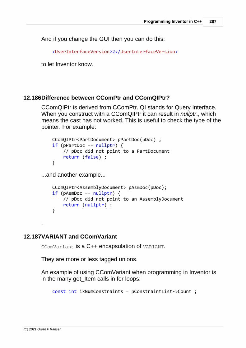
287Programming Inventor in C++
(C) 2021 Owen F Ransen
And if you change the GUI then you can do this:
<UserInterfaceVersion>2</UserInterfaceVersion>
to let Inventor know.
12.186Difference between CComPtr and CComQIPtr?
CComQIPtr is derived from CComPtr. QI stands for Query Interface.When you construct with a CComQIPtr it can result in nullptr., whichmeans the cast has not worked. This is useful to check the type of thepointer. For example:
CComQIPtr<PartDocument> pPartDoc(pDoc) ; if (pPartDoc == nullptr) { // pDoc did not point to a PartDocument return (false) ; }
...and another example...
CComQIPtr<AssemblyDocument> pAsmDoc(pDoc); if (pAsmDoc == nullptr) { // pDoc did not point to an AssemblyDocument return (nullptr) ; }
.
12.187VARIANT and CComVariant
CComVariant is a C++ encapsulation of VARIANT.
They are more or less tagged unions.
An example of using CComVariant when programming in Inventor isin the many get_Item calls in for loops:
const int ikNumConstraints = pConstraintList->Count ;
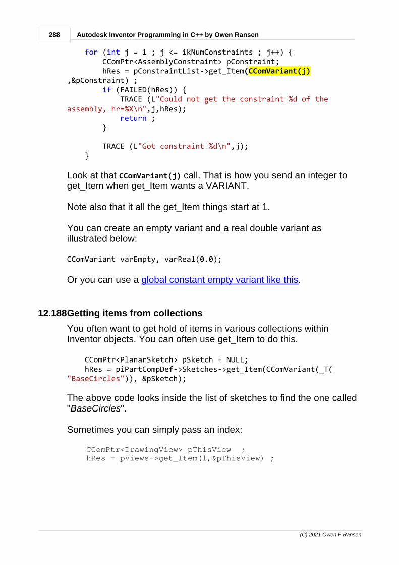
288 Autodesk Inventor Programming in C++ by Owen Ransen
(C) 2021 Owen F Ransen
for (int j = 1 ; j <= ikNumConstraints ; j++) { CComPtr<AssemblyConstraint> pConstraint; hRes = pConstraintList->get_Item(CComVariant(j),&pConstraint) ; if (FAILED(hRes)) { TRACE (L"Could not get the constraint %d of theassembly, hr=%X\n",j,hRes); return ; }
TRACE (L"Got constraint %d\n",j); }
Look at that CComVariant(j) call. That is how you send an integer toget_Item when get_Item wants a VARIANT.
Note also that it all the get_Item things start at 1.
You can create an empty variant and a real double variant asillustrated below:
CComVariant varEmpty, varReal(0.0);
Or you can use a global constant empty variant like this.
12.188Getting items from collections
You often want to get hold of items in various collections withinInventor objects. You can often use get_Item to do this.
CComPtr<PlanarSketch> pSketch = NULL; hRes = piPartCompDef->Sketches->get_Item(CComVariant(_T("BaseCircles")), &pSketch);
The above code looks inside the list of sketches to find the one called"BaseCircles".
Sometimes you can simply pass an index:
CComPtr<DrawingView> pThisView ; hRes = pViews->get_Item(1,&pThisView) ;

289Programming Inventor in C++
(C) 2021 Owen F Ransen
Another way of getting an item from a collection uses get_Item withan cast index:
for (int j = 1 ; j <= ikNumConstraints ; j++) { CComPtr<AssemblyConstraint> pConstraint; pConstraintList->get_Item(CComVariant(j),&pConstraint) ; TRACE ("Got constraint %d\n"),j);}
In the example above the index is passed as a CComVariant, CComVariant(j).
Here are some other ways of using get_Item:
get_Item(COleVariant(CGID)...
get_Item(CComVariant(j),... // i is an integer
get_Item(_variant_t(3L, VT_I4),... // 3 as a VT_I4
When using integer indices they always start from 1 (not 0).
12.189Assembly.Document Assembly
Here's how to get it...
CComPtr<Document> pDoc;HRESULT Result = pInvApp->get_ActiveDocument(&pDoc);if ((FAILED(iRes) || (pDoc == NULL)) { TRACE ("No document is open"); return Result ;}
// Try to cast the if (CComQIPtr<AssemblyDocument> pAssemblyDoc = pDoc){ TRACE ("This is an assembly\n");}
...basically you check to see if the cast (in red) returns somethingother than nullptr.

290 Autodesk Inventor Programming in C++ by Owen Ransen
(C) 2021 Owen F Ransen
12.19064bit vs 32bit
You should use 64 bit compilation when doing an AddIn for 64 bitInventor.
But you can use 32 or 64 bit when doing an external exe which willcommunicate with 64 bit Inventor.
12.191Client Graphics
Client Graphics are graphics which appear in drawings or on objectswhich a programmer can add via the API. There is a C++ example ofthis in the samples.
12.192Hierarchy of objects
The hierarchy is like this:
AssemblyAssemblyComponentDefinition
AssemblyConstraints...ComponentOccurencesList
ComponentOccurenceSurfaceBodiesList
SurfaceBodyFacesList
Face (Planar, Cylinder,Spheric...)
EdgeLoop (Line, Arc,Curve, Spline...)

291Programming Inventor in C++
(C) 2021 Owen F Ransen
12.193Getting or running an Inventor Instance
This code runs Inventor if it is not already running:
CLSID InvAppClsid; HRESULT Result = CLSIDFromProgID (L"Inventor.Application", &InvAppClsid); if (FAILED(Result)) return Result;
// See if Inventor is already running... CComPtr<IUnknown> pInvAppUnk; Result = ::GetActiveObject (InvAppClsid, NULL, &pInvAppUnk); if (FAILED (Result)) { // Inventor is not already running, so try to start it... TRACE (L"Could not get hold of an active Inventor , will start a new session\n"); Result = CoCreateInstance (InvAppClsid, NULL, CLSCTX_LOCAL_SERVER, __uuidof(IUnknown), (void **) &pInvAppUnk); if (FAILED (Result)){ TRACE (L"*** Failed to create a new Inventor application ***\n"); return Result; } }
CComPtr<Application> pInvApp; Result = pInvAppUnk->QueryInterface (__uuidof(Application), (void **) &pInvApp); if (FAILED(Result)) return Result;
After that you can carry on an interact with Inventor with pInvApp.
How to correct it if CLSIDFromProgID fails.
12.194Add a part to an assembly programatically
Here is a function for creating a new assembly:
// Create a new assembly and return the document and assemblycomponent definition.// AssemblyComponentDefinition is a list of parts andconstraints.bool CreateNewAssembly (CComQIPtr<AssemblyDocument>& pAssemblyDoc, CComPtr<AssemblyComponentDefinition>&pAssemblyCompDef,

292 Autodesk Inventor Programming in C++ by Owen Ransen
(C) 2021 Owen F Ransen
const CString& kcsTemplateFile){ CComPtr<Documents> pDocuments=nullptr; HRESULT hRes = pInvApp->get_Documents (&pDocuments) ; if (FAILED(hRes)) { ShowCOMError(ekErrMsg,hRes,L"CreateNewAssembly, could notget documents"); return false ; }
CComBSTR strTemplateFilename(kcsTemplateFile);
// create a new assembly document from a standard template CComPtr<Document> pDocument=nullptr; hRes = pDocuments->Add(kAssemblyDocumentObject,strTemplateFilename, VARIANT_TRUE, &pDocument); if (FAILED(hRes)) { gLogger.Printf(ekLogMsg, L"Errore in CreateNewAssemplytemplate = <%s>", kcsTemplateFile.GetString()); ShowCOMError(ekErrMsg,hRes,L"CreateNewAssembly, Could notmake new assembly document"); return false ; }
// Try to cast to an assembly document, this should not everfail... pAssemblyDoc = pDocument ;
// Get hold of the assembly component definition too... pAssemblyCompDef = nullptr ; hRes = pAssemblyDoc->get_ComponentDefinition(&pAssemblyCompDef); if (FAILED(hRes)) { ShowCOMError(ekErrMsg,hRes,L"CreateNewAssembly, Could notget hold of assembly component definition"); return false ; }
return true ;}
And here is how the above function is used:
CComQIPtr<AssemblyDocument> pAssemblyDoc ; CComPtr<AssemblyComponentDefinition> pAssemblyCompDef;

293Programming Inventor in C++
(C) 2021 Owen F Ransen
const bool kbAsmOk = CreateNewAssembly(pAssemblyDoc,pAssemblyCompDef,theApp.GetLuveIAMTemplate()) ; if (!kbAsmOk) { theApp.PrintfLedMessage (RGB(255,0,0),CCT_DLG,L"Erroredurante creazione IAM...") ; return false; }
Here is the code to do this and add a part, with no error checking:
static void CreateAssembly (const CComPtr<Application>& pInvApp) { // Get the list of documents currently in Inventor... CComPtr<Documents> pDocuments; pInvApp->get_Documents (&pDocuments) ;
// Get assembly document template, what is used as a default for .iam files // To do that you need to get the file manager CComPtr<FileManager> pFileManager; HRESULT hr = pInvApp->get_FileManager(&pFileManager);
// So get hold of the user's default template file... CComBSTR strTemplateFilename; hr = pFileManager->GetTemplateFile(kAssemblyDocumentObject, kDefaultSystemOfMeasure, kDefault_DraftingStandard, CComVariant(), &strTemplateFilename);
// Create a new assembly document from a standard template CComPtr<Document> pDocument; // This is a return value from the following call hr = pDocuments->Add(kAssemblyDocumentObject, strTemplateFilename, VARIANT_TRUE, &pDocument);
// New need some transient geometry to add in a part... CComPtr<TransientGeometry> pTransGeom; hr = pInvApp->get_TransientGeometry(&pTransGeom);
// Create a matrix CComPtr<Matrix> pMatrix; hr = pTransGeom->CreateMatrix(&pMatrix);
// This part must exist, because we are going to add an occurrence (instance) of it // to the assemply document CComBSTR csFileName = L"c:\\temp\\cylinder.ipt" ;
// Convert pDocument (returned by the call to Add previously) into an assembly document CComQIPtr<AssemblyDocument> pAssemblyDoc = pDocument ;

294 Autodesk Inventor Programming in C++ by Owen Ransen
(C) 2021 Owen F Ransen
// Get the assembly component definition CComPtr<AssemblyComponentDefinition> pAssemblyCompDef; hr = pAssemblyDoc->get_ComponentDefinition(&pAssemblyCompDef);
// Get the ComponentOccurrences collection for the assembly document CComPtr<ComponentOccurrences> pOccs; hr = pAssemblyCompDef->get_Occurrences(&pOccs);
// Now we can add an occurrence (instance) of cylinder.ipt into the assembly... CComPtr<ComponentOccurrence> pOcc1; hr = pOccs->Add(csFileName,pMatrix,&pOcc1) ;}
It is long winded but clear.
12.195Coordinates of a WorkAxis
Once you have the proxy of a work axis you can get details (in centimeters cm) like this
CComPtr<WorkAxisProxy> pWAProxy ; pTuboOcc->CreateGeometryProxy (pWAxis,(IDispatch**)&pWAProxy) ;
// Get the geometry of the axis.. LinePtr pLine = pWAProxy->GetLine() ; UnitVectorPtr pDir = pLine->Direction ;
// You can get hold of the double values like this... TRACE ("direction %.3f, %.3f, %.3f,\n",pDir->GetX(),pDir->GetY(),pDir->GetZ())
Here is another example when you have a collection of workaxes...
for (int i = 1 ; i <= pWAProxyCollection->Count ; i++) { CComPtr<WorkAxisProxy> pWAProxy; pWAProxyCollection->get_Item(i,(IDispatch**)&pWAProxy) ;
LinePtr pLine = pWAProxy->GetLine() ; UnitVectorPtr pProxyDir = pLine->Direction ; PointPtr pProxyOrigin = pLine->RootPoint ;
gLogger.Printf (ekLogMsg,"%2d origin = %.1fcm %.1fcm %.1fcm direction %.3f, %.3f, %.3f,\n", i, pProxyOrigin->X,pProxyOrigin->Y,pProxyOrigin->Z, pProxyDir->GetX(),pProxyDir->GetY(),pProxyDir->GetZ()) ; }
See also this.

295Programming Inventor in C++
(C) 2021 Owen F Ransen
12.196Invisibilize components in a collection
Here's an example of making a collection of work axes invisible. Usethe Visible attribute:
void InvisibilizeWorkAxes (CComPtr<ObjectCollection> pWACollection) { for (int i = 1 ; i <= pWACollection->Count ; i++) { CComPtr<WorkAxisProxy> pProxy ; pWACollection->get_Item (i,(IDispatch**)&pProxy) ; pProxy->Visible = VARIANT_FALSE ; // or VARIANT_TRUE }}
12.197Delete a WorkAxis
Here's some code which I have used
{ csAxisName.Format (L"WAZR%d",iRango) ; CComPtr<WorkAxis> pZWorkAxis ; HRESULT hRes = GetWorkAxisByName (pZWorkAxis,csAxisName,pNodesDef) ; if (FAILED(hRes) || (pZWorkAxis == nullptr)) { TRACE (L"DUR, could not get z axis to delete, R%d",iRango) ; return ; } pZWorkAxis->Delete(VARIANT_TRUE) ; // the parameter means "retain dependents" }
You can use the Delete function on other object types.
12.198Add a plane by offset from another plane
Note that in theory these two functions work, but currenty in Inventor2015, you cannot add planes programatically inside assemblies. Forthat use the function at the very end of this page.
static bool CreateSketchOffsetFromXYPlane (CComPtr<PlanarSketch>&pNewSketch, // The sketch created, output CComPtr<WorkPlanes>pWorkPlanes, // Where the sketch added

296 Autodesk Inventor Programming in C++ by Owen Ransen
(C) 2021 Owen F Ransen
CComPtr<PlanarSketches> pSketches, // The list to we add sketch const double kOffset, // How far to offset const wchar_t* constpszSketchName) // Name of the newsketch{ // Get hold of one of the WorkPlanes. Valid indices are 1L 2L3L for standard workplanes CComPtr<WorkPlane> pXYWorkPlane ; HRESULT hRes = pWorkPlanes->get_Item(_variant_t(3L,VT_I4),&pXYWorkPlane); if (FAILED(hRes) || (pXYWorkPlane == nullptr)) { ShowCOMError (hRes,L"CXYPOS, get_Item (workplane)failed") ; return false ; }
// Create a workplane parallel to the standard XY Plane... CComPtr<WorkPlane> pOffsetWorkPlane ; hRes = pWorkPlanes->AddByPlaneAndOffset(_variant_t((IDispatch *)pXYWorkPlane), // "starting" plane CComVariant(kOffset), // how much to offset VARIANT_TRUE, // Construction &pOffsetWorkPlane) ;// Return value
if (FAILED(hRes) || (pOffsetWorkPlane == nullptr)) { ShowCOMError (hRes,L"CXYPOS, could not add workplane withoffset, pOffsetWorkPlane=%p",pOffsetWorkPlane) ; return false ; }
// Now actually create a sketch and get a pointer to it inone go... hRes = pSketches->Add (_variant_t((IDispatch*)pOffsetWorkPlane), VARIANT_FALSE, &pNewSketch); if (FAILED(hRes)) { ShowCOMError (hRes,L"CXYPOS, AddSketch failed") ; return false ; }
pNewSketch->put_Name (CComBSTR (pszSketchName)) ;
CComBSTR bstrSketchName ; pNewSketch->get_Name (&bstrSketchName) ;
TRACE (L"The sketch is now called %s\n",bstrSketchName) ;

297Programming Inventor in C++
(C) 2021 Owen F Ransen
return true ;}
/**************************************************************************************************/
bool CreateSketchOffsetFromXYPlaneInPart(CComPtr<PartComponentDefinition>& pPartComponentDefinition, //where the sketch will be added CComPtr<PlanarSketch>&pNewSketch, // The sketch created, an output const double kOffset, const wchar_t* constpszSketchName) // Name of the newly created sketch{ // Get PlanarSketches, the list of sketches CComPtr<PlanarSketches> pSketches ; HRESULT hRes =pPartComponentDefinition->get_Sketches(&pSketches); if (FAILED(hRes) || (pSketches == nullptr)) { ShowCOMError (hRes,L"CreateXYPlaneSketch, get_Sketchesfailed") ; return false ; }
// Get standard default WorkPlanes, probably 3 only initiallyin the list CComPtr<WorkPlanes> pWorkPlanes ; hRes =pPartComponentDefinition->get_WorkPlanes(&pWorkPlanes); if (FAILED(hRes) || (pWorkPlanes == nullptr)) { ShowCOMError (hRes,L"CreateXYPlaneSketch, get_WorkPlanesfailed") ; return false ; }
bool bOk = CreateSketchOffsetFromXYPlane (pNewSketch, //The sketch created, an output pWorkPlanes, //Where the sketch will be added pSketches, //List to which we must add the sketch kOffset, //How far to offset pszSketchName) ; // Name of the newly created sketch
return bOk ;}
/*************************************************************************************************/

298 Autodesk Inventor Programming in C++ by Owen Ransen
(C) 2021 Owen F Ransen
bool CreateSketchOffsetFromXYPlaneInAsm(CComPtr<AssemblyComponentDefinition>& pAsmCompDef, // where thesketch will be added CComPtr<PlanarSketch>&pNewSketch, // The sketch created, an output const double kOffset, const wchar_t* constpszSketchName) // Name of the newly created sketch{ // Get PlanarSketches, the list of sketches CComPtr<PlanarSketches> pSketches ; HRESULT hRes = pAsmCompDef->get_Sketches(&pSketches); if (FAILED(hRes) || (pSketches == nullptr)) { ShowCOMError (hRes,L"CXYPOSIA, get_Sketches failed") ; return false ; }
// Get standard default WorkPlanes, probably 3 only initiallyin the list CComPtr<WorkPlanes> pWorkPlanes ; hRes = pAsmCompDef->get_WorkPlanes(&pWorkPlanes); if (FAILED(hRes) || (pWorkPlanes == nullptr)) { ShowCOMError (hRes,L"CXYPOSIA, get_WorkPlanes failed") ; return false ; }
bool bOk = CreateSketchOffsetFromXYPlane (pNewSketch, //The sketch created, an output pWorkPlanes, //Where the sketch will be added pSketches, //list to which we must add the sketch kOffset, //How far to offset pszSketchName) ; // Name of the newly created sketch
return bOk ;}
/*************************************************************************************************/
Here is a function which will work in assemblies:
bool CreateSketchOffsetFromXYPlaneInAsm (CComPtr<AssemblyComponentDefinition>& pAsmCompDef, // where the sketch will be added CComPtr<PlanarSketch>& pNewSketch, // The sketch created, an output const double kOffsetMm, const wchar_t* const pszSketchName) // Name of the newly created sketch{ // Get PlanarSketches, the list of sketches CComPtr<PlanarSketches> pSketches ;

299Programming Inventor in C++
(C) 2021 Owen F Ransen
HRESULT hRes = pAsmCompDef->get_Sketches(&pSketches); if (FAILED(hRes) || (pSketches == nullptr)) { ShowCOMError (hRes,L"CXYPOSIA, get_Sketches failed") ; return false ; }
// Get standard default WorkPlanes, probably 3 only initially in the list CComPtr<WorkPlanes> pWorkPlanes ; hRes = pAsmCompDef->get_WorkPlanes(&pWorkPlanes); if (FAILED(hRes) || (pWorkPlanes == nullptr)) { ShowCOMError (hRes,L"CXYPOSIA, get_WorkPlanes failed") ; return false ; }
// Get hold of one of the WorkPlanes. Valid indices are 1L 2L 3L for standard workplanes CComPtr<WorkPlane> pXYWorkPlane ; hRes = pWorkPlanes->get_Item(_variant_t(3L, VT_I4),&pXYWorkPlane); if (FAILED(hRes) || (pXYWorkPlane == nullptr)) { ShowCOMError (hRes,L"CXYPOSIA, get_Item (workplane) failed") ; return false ; }
CComPtr<TransientGeometry> pTransGeom = GetTransGeomPtr () ; CComPtr<Point> pOrigin ; hRes = pTransGeom->CreatePoint (0,0,0,&pOrigin);
CComPtr<UnitVector> UnitXVector ; pTransGeom->CreateUnitVector (1.0,0,0,&UnitXVector) ;
CComPtr<UnitVector> UnitYVector ; pTransGeom->CreateUnitVector (0.0,1.0,0,&UnitYVector) ;
// Internally Inventor always uses cm, so convert... const double kOffsetInCm = kOffsetMm/10.0 ; pOrigin->PutZ (kOffsetInCm) ; CComPtr<WorkPlane> pOffsetWorkPlane ; hRes = pWorkPlanes->AddFixed(pOrigin,UnitXVector,UnitYVector,VARIANT_FALSE,&pOffsetWorkPlane) ; if (pOffsetWorkPlane == nullptr) { TRACE (L"CXYPOSIA, Could not AddFixed") ; return false ; }
// Now actually create a sketch and get a pointer to it in one go... hRes = pSketches->Add (_variant_t((IDispatch *)pOffsetWorkPlane), VARIANT_FALSE, &pNewSketch); if (FAILED(hRes)) { ShowCOMError (hRes,L"CXYPOSIA, AddSketch failed") ; return false ; }
pNewSketch->put_Name (BSTR(pszSketchName)) ;

300 Autodesk Inventor Programming in C++ by Owen Ransen
(C) 2021 Owen F Ransen
return true ;}
12.199Getting hold of the surfaces and faces of a solid object
You can start with an occurrence, then drill down to the data you areinterested in:
1. Start with an occurrence.2. Get the surface body(ies) of the occurrence. There should only
ever be 13. Get the list of shells from the (single) surface body.4. For every shell in the list get the Faces.5. For every Face you can find out what it is.
Here are the sort of surfaces that you can find:
kCylinderSurface kPlaneSurfacekConeSurfacekSphereSurfacekTorusSurfacekBSplineSurface
In the end a cylinder is composed of a single shell which is composedof two plane surfaces and a cylindrical surface.
And here is a code fragment illustrating the process:
// Get the surface bodies from the occurrence...CComPtr<SurfaceBodies> pSurfaceBodies;hr = pOcc1->get_SurfaceBodies(&pSurfaceBodies);
TRACE (L"Occurrence 1 has %d surface bodies\n",pSurfaceBodies->Count);
// Get the first surface body from the component definition.// (There should only ever be one surface body.)CComPtr<SurfaceBody> pBody;hr = pSurfaceBodies->get_Item(1, &pBody);

301Programming Inventor in C++
(C) 2021 Owen F Ransen
// Get the shells from the body.CComPtr<FaceShells> pShells;hr = pBody->get_FaceShells(&pShells);
TRACE ("The surface body has has %d shells\n",pShells->Count) ;
// Enumerate through the shells.long shellCount = 1;CComPtr<FaceShell> pShell;for (;(hr = pShells->get_Item(shellCount, &pShell)) == S_OK; pShell.Release()){ TRACE (L" Shell %d\n", shellCount);
// Increment the counter and print the current value. ++shellCount;
// Get the faces from the shell. CComPtr<Faces> pFaces; hr = pShell->get_Faces(&pFaces);
// Enumerate through the faces of the current shell. long faceCount = 1; CComPtr<Face> pFace; for (;(hr = pFaces->get_Item(faceCount, &pFace)) == S_OK;pFace.Release()) { // Increment the counter and print the current value. ++faceCount; TRACE (L" Face %d ", faceCount);
// Get the geometry from the face. SurfaceTypeEnum surfaceType; hr = pFace->get_SurfaceType(&surfaceType);
switch (surfaceType) { default : TRACE (L" Unrecognised surface type:%d\n",surfaceType); break ;
case kCylinderSurface : TRACE (L" Cylindrical surface\n"); break ;
case kPlaneSurface : TRACE (L" Plane surface\n"); break ; } }}

302 Autodesk Inventor Programming in C++ by Owen Ransen
(C) 2021 Owen F Ransen
12.200Adding an AngleConstraint
Here's what I use:
bool AddAngleConstraintOfTwoWorkAxisProxies (CComPtr<AssemblyComponentDefinition>& pAsmCompDef, CComPtr<WorkAxisProxy>& pWAProxyA, CComPtr<WorkAxisProxy>& pWAProxyB, const double kRadsAngle) { // Get the list of constraints of the assembly so you can add a new one CComPtr<AssemblyConstraints> pConstraintList ; HRESULT hRes = pAsmCompDef->get_Constraints(&pConstraintList) ; if (FAILED(hRes) || (pConstraintList == nullptr)) { ShowCOMError (hRes,L"AddAngleConstraintOfTwoWorkAxisProxies could not get constraints.") ; return false ; }
CComVariant varReal(kRadsAngle); CComPtr<AngleConstraint> pAngleConstraint ; hRes = pConstraintList->AddAngleConstraint(pWAProxyA, pWAProxyB, varReal, kDirectedSolution, gkvarEmpty, gkvarEmpty, gkvarEmpty, &pAngleConstraint); if ((FAILED(hRes) || (pAngleConstraint == nullptr))) { ShowCOMError (hRes,L"AngleConstraint failed") ; return false ; }
return true ;}
12.201Creating a 64 bit plugin using the Wizard
1. Select new project and select Autodesk Inventor AddIn.2. Follow all the defaults til you get an empty 32 bit project3. Go to Configuration Manager Release/Debug combo in the tool bar
and select New4. Then in the dialogh which comes up select, under the Active
solution Platforms select New5. Choose x64 in the litlle dialog which pops up6. Now the first project in the list will default to WIN32, change it to
x647. Build it

303Programming Inventor in C++
(C) 2021 Owen F Ransen
You may well get 2 warnings and 1 error. The error could MSB3073,be that it cannot copy the .addin file into the Inventor addins directory,This is usually because the .addins directory in the makefile does notcontain the string 2013. For example this is wrong:
"C:\ProgramData\Autodesk\Inventor Addins\"
It should be:
"C:\ProgramData\Autodesk\Inventor 2013\Addins"
So you'll have to change that in the command line of the post buildevent step.
12.202Purging Material Assets
If you use the code on this page you may get a list where partdocuments seem to have two materials:
1 material asset type 99073 has display name <Copper - Satin>fixed name <Metal-022> and category name <Metal>2 material asset type 99073 has display name <Default> fixed name<InvGen-071> and category name <Miscellaneous>3 material asset type 99074 has display name <Copper> fixed name<MaterialInv_013> and category name <Metal>4 material asset type 99074 has display name <Generic> fixed name<MaterialInv_072> and category name <Misc>
In the above example you have, for the same part, two 99073 linesand two 99074 lines. You can get rid of these by purging the materialsin the part:

304 Autodesk Inventor Programming in C++ by Owen Ransen
(C) 2021 Owen F Ransen
12.203View orientations
The various orientation enumerator values (in ViewOrientationTypeEnum) correspond directly to the cube iconwhich shows the view orientation.
For example:
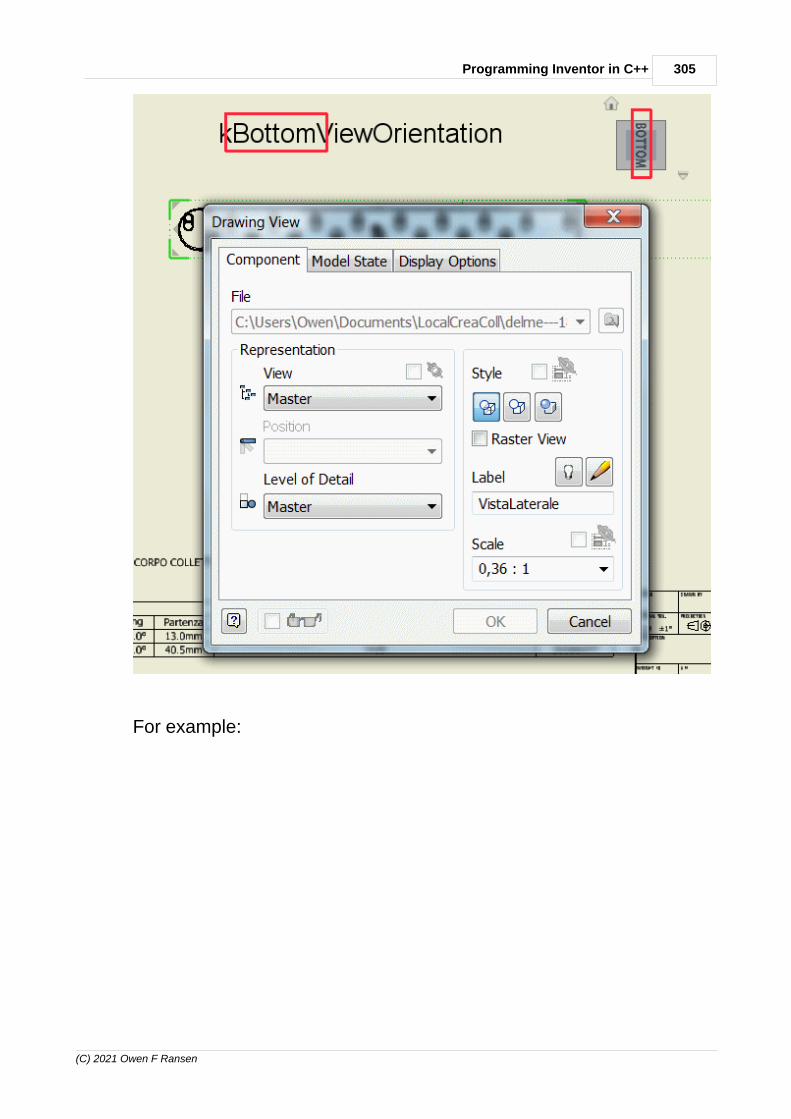
305Programming Inventor in C++
(C) 2021 Owen F Ransen
For example:
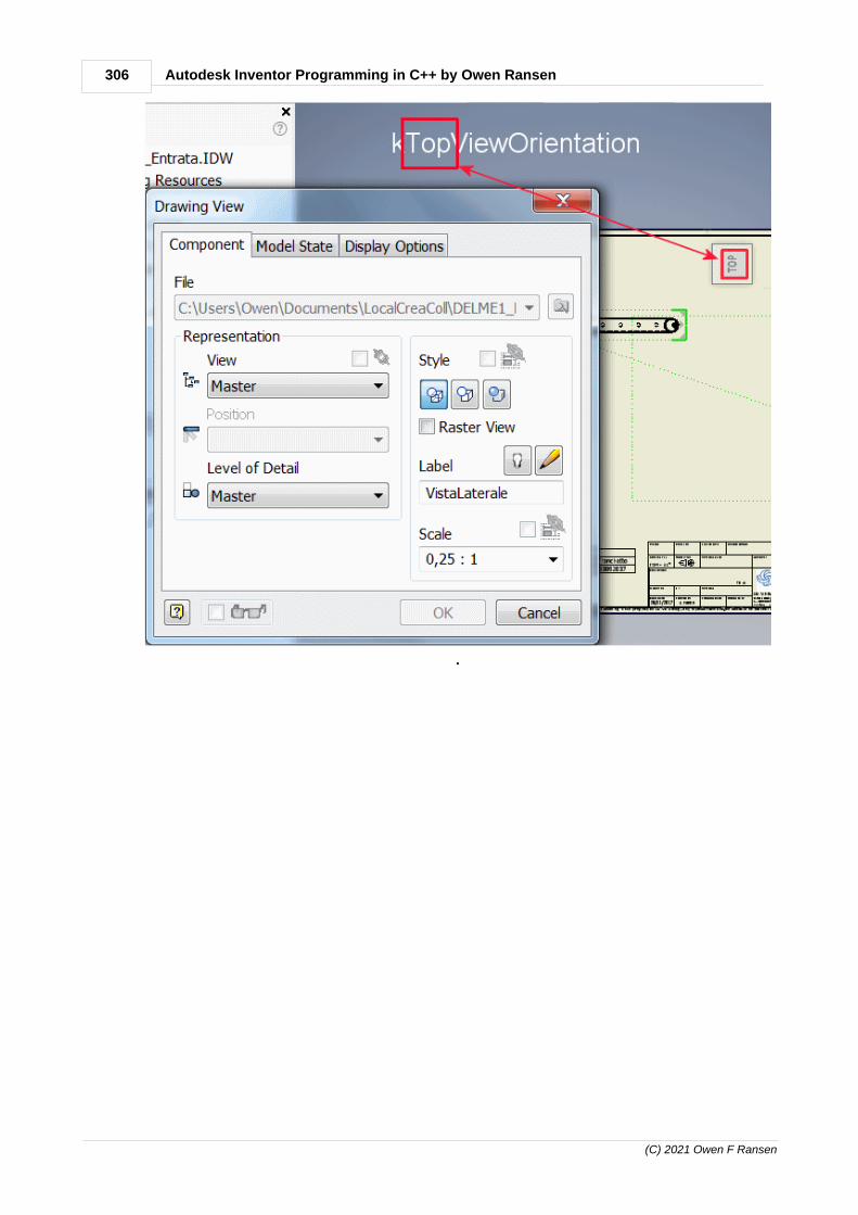
306 Autodesk Inventor Programming in C++ by Owen Ransen
(C) 2021 Owen F Ransen
.

307Programming Inventor in C++
(C) 2021 Owen F Ransen
12.204Functions for project files .IPT
Here's a function which will get the currect active project file:
CString GetActiveDesignProject (){ CComPtr<DesignProjectManager> pManager; theApp.GetInvAppPtr()->get_DesignProjectManager (&pManager) ;
CComPtr<DesignProject> pDesignProject ; pManager->get_ActiveDesignProject (&pDesignProject) ;
BSTR bstrDesignProjectName ; pDesignProject->get_FullFileName (&bstrDesignProjectName) ;
return CString (bstrDesignProjectName) ;}
Notice that it also illustrates converting from a BSTR to a CString.
Here's a function (with lots of internal checks) for setting the currentactive project:
void SetActiveProject(const CString& kcsFullProjName){ // Check to make sure a document isn't open. if (GetNumDocummentsOpenInInventor() > 0) { TRACE (L"SAP but some documents are still open\n") ; return ; }
if (!FileExists (kcsFullProjName)) { TRACE (L"SAP %s but file does not exist",kcsFullProjName) ; return ; }
CComPtr<DesignProjectManager> pManager; HRESULT hRes =theApp.GetInvAppPtr()->get_DesignProjectManager (&pManager) ; if (FAILED(hRes)) { TRACE (L"SAP %s get_DesignProjectManager failed",kcsFullProjName) ; return ; }
// Get the list of all projects... CComPtr<DesignProjects> pProjectList ; hRes = pManager->get_DesignProjects (&pProjectList) ; if (FAILED(hRes)) { TRACE (L"SAP %s get_DesignProjects failed",kcsFullProjName) ;

308 Autodesk Inventor Programming in C++ by Owen Ransen
(C) 2021 Owen F Ransen
return ; }
// This assumes that the project file exists... CComPtr<DesignProject> pDesignProject ; CComBSTR bstrFullProjectName (kcsFullProjName) ; hRes = pProjectList->get_ItemByName (bstrFullProjectName,&pDesignProject) ; if (FAILED(hRes)) { TRACE (L"SAP %s get_ItemByName failed",kcsFullProjName) ; return ; }
// Make the project the active one... hRes = pDesignProject->Activate (FALSE) ; if (FAILED(hRes)) { TRACE (L"SAP %s Activate failed",kcsFullProjName) ; return ; }
// Check that the change has actually happened... if (GetActiveDesignProject().CompareNoCase(kcsFullProjName) != 0) { TRACE (L"SAP tried to activate <%s>\n" L"but active project is still <%s>", kcsFullProjName, GetActiveDesignProject()) ; }}
The above also shows to how get a CComBSTR from a CString.

309Programming Inventor in C++
(C) 2021 Owen F Ransen
12.205Listing RevolveFeatures of a part programatically
Here's a code fragment to do that:
{ gLogger.Printf (ekLogMsg,L"Object has %d features",pTroncCompDef->Features->Count) ; CComPtr<RevolveFeatures> pRevFeats = pTroncCompDef->Features->RevolveFeatures ; gLogger.Printf (ekLogMsg,L"Tronchetto has %d revolved features",pRevFeats->Count) ; for (long f = 1; f <= pRevFeats->Count; f++) { CComPtr<RevolveFeature> pFeat ; pRevFeats->get_Item (CComVariant(f),&pFeat) ; CComQIPtr<WorkAxis> pAxis = pFeat->GetAxisEntity() ; LinePtr pLine = pAxis->GetLine() ; gLogger.Printf (ekLogMsg," Origin = %.2f %.2f %.2f ",pLine->RootPoint->X,pLine->RootPoint->Y,pLine->RootPoint->Z) ; } }
Enter topic text here.
12.206Create a rectangular pattern of parts programatically
Here is an example. Remember that occurrences are "links to parts"inside an assembly:
bool CreateYArrayOfParts (CComPtr<ComponentOccurrences> pOccurrencesList, // The occurrences in the assembly CComPtr<AssemblyComponentDefinition> pCctsAssemblyCompDef, // def of the assembly CComPtr<ComponentOccurrence> pObjOcc, const double kDeltaYMm, const UINT ikCount) { CComPtr<OccurrencePatterns> pOccPatterns ; pOccPatterns = pCctsAssemblyCompDef->GetOccurrencePatterns(); if (pOccPatterns == nullptr) { gLogger.Printf(ekErrMsg, "GetOccurrencePatterns failed"); return false; }
CComPtr<TransientObjects> pTransientObjects = GetTransientObjectsPtr() ;
CComVariant varObjEnumerator; CComPtr<ObjectCollection> pObjectCollection; HRESULT hRes = pTransientObjects->CreateObjectCollection(varObjEnumerator, &pObjectCollection); if (FAILED(hRes)) { gLogger.Printf(ekErrMsg, "CreateObjectCollection failed"); return false; }
// Add the part which is the basis to the pattern... hRes = pObjectCollection->Add (pObjOcc) ; if (FAILED(hRes)) { gLogger.Printf(ekErrMsg, "Add to ObjectCollection failed"); return false;

310 Autodesk Inventor Programming in C++ by Owen Ransen
(C) 2021 Owen F Ransen
}
// Get hold of the y axis... CComPtr<WorkAxis> pYWorkAxis ; GetAsmWorkAxisByName (pYWorkAxis,L"Y Axis",pCctsAssemblyCompDef) ; if (FAILED(hRes)) { gLogger.Printf(ekErrMsg, "Could not get assembly y axis"); return false; }
pOccPatterns->AddRectangularPattern(pObjectCollection, _variant_t((IDispatch *)pYWorkAxis), VARIANT_FALSE, CComVariant(kDeltaYMm/10.0), //ColumnOffset As Variant, CComVariant(ikCount), // ColumnCount As Variant, CComVariant(), // [RowEntity] As Variant, VARIANT_TRUE, // [RowEntityNaturalDirection] As Boolean, CComVariant(0.0),// [RowOffset] As Variant, CComVariant(1)); // [RowCount] As Variant)
return (hRes == S_OK) ;}
You could make it more general.
See also suppression of occurrences in a pattern.
12.207Suppression and Unsuppression of elements in a pattern
Read about general suppression programatically first, if you have'talready.
Within a single RectangularPattern (or any other pattern) you can usethis fragment as a starting point for suppressing individual featureswithin a pattern. Note that the first element in a pattern cannot besuppressed.
CComPtr<Parameter> XCountParam ; pRectPatFeat->get_XCount (&XCountParam) ; const int ikXCount = XCountParam->GetValue () ;
TRACE (L"Component %d is called %s, and the x count is %d",iRect,bstrName,ikXCount) ;
CComPtr<FeaturePatternElements> pFeaturePatternElements ; pRectPatFeat->get_PatternElements(&pFeaturePatternElements) ;
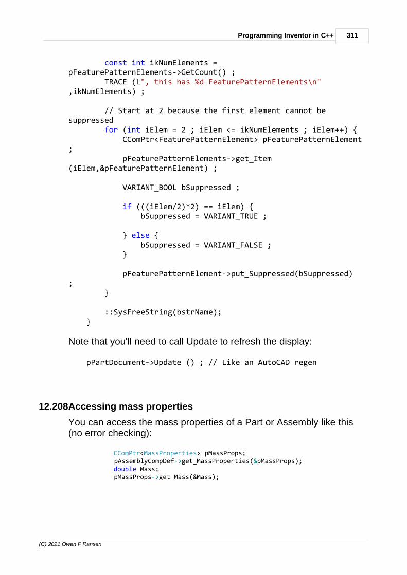
311Programming Inventor in C++
(C) 2021 Owen F Ransen
const int ikNumElements =pFeaturePatternElements->GetCount() ; TRACE (L", this has %d FeaturePatternElements\n",ikNumElements) ;
// Start at 2 because the first element cannot besuppressed for (int iElem = 2 ; iElem <= ikNumElements ; iElem++) { CComPtr<FeaturePatternElement> pFeaturePatternElement; pFeaturePatternElements->get_Item(iElem,&pFeaturePatternElement) ;
VARIANT_BOOL bSuppressed ;
if (((iElem/2)*2) == iElem) { bSuppressed = VARIANT_TRUE ;
} else { bSuppressed = VARIANT_FALSE ; }
pFeaturePatternElement->put_Suppressed(bSuppressed); }
::SysFreeString(bstrName); }
Note that you'll need to call Update to refresh the display:
pPartDocument->Update () ; // Like an AutoCAD regen
12.208Accessing mass properties
You can access the mass properties of a Part or Assembly like this(no error checking):
CComPtr<MassProperties> pMassProps; pAssemblyCompDef->get_MassProperties(&pMassProps); double Mass; pMassProps->get_Mass(&Mass);

312 Autodesk Inventor Programming in C++ by Owen Ransen
(C) 2021 Owen F Ransen
gLogger.Printf(ekLogMsg, L"Mass = %.3f", Mass);
12.209Is Excel installed on your computer?
Here's a function which will tell you if Excel is installed on yourcomputer. You need Excel if you use Inventor tabular iParts.
bool ExcelIsPresent ()/*This looks very simply to see if Excel is installed*/{ CLSID ExcelClsid; HRESULT hRes = CLSIDFromProgID (L"Excel.Application", &ExcelClsid); if (FAILED(hRes)) { return false ;
} else { return true ; }}
12.210ConnectToInventor
This function establishes a connection from your program to theInventor application and API:
bool ConnectToInventor () { CLSID InvAppClsid; HRESULT hRes = CLSIDFromProgID (L"Inventor.Application", &InvAppClsid); if (FAILED(hRes)) { pInvApp = nullptr ; ShowCOMError (hRes,L"ConnectToInventor, CLSIDFromProgID failed, adminvs normal user conflict?") ; return false; }
// See if Inventor is already running... CComPtr<IUnknown>pInvAppUnk = nullptr ; hRes = ::GetActiveObject (InvAppClsid, NULL, &pInvAppUnk); if (FAILED (hRes)) { // Inventor is not already running, so try to start it... const int ikAnswer = YesNoBoxW (L"Inventor non sta girando, lolancio?") ; if (ikAnswer == IDNO) { return false ; }
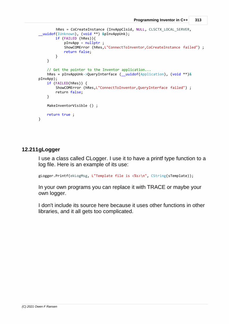
313Programming Inventor in C++
(C) 2021 Owen F Ransen
hRes = CoCreateInstance (InvAppClsid, NULL, CLSCTX_LOCAL_SERVER,__uuidof(IUnknown), (void **) &pInvAppUnk); if (FAILED (hRes)){ pInvApp = nullptr ; ShowCOMError (hRes,L"ConnectToInventor,CoCreateInstance failed") ; return false; } }
// Get the pointer to the Inventor application... hRes = pInvAppUnk->QueryInterface (__uuidof(Application), (void **)&pInvApp); if (FAILED(hRes)) { ShowCOMError (hRes,L"ConnectToInventor,QueryInterface failed") ; return false; }
MakeInventorVisible () ;
return true ;}
12.211gLogger
I use a class called CLogger. I use it to have a printf type function to alog file. Here is an example of its use:
gLogger.Printf(ekLogMsg, L"Template file is <%s>\n", CString(sTemplate));
In your own programs you can replace it with TRACE or maybe yourown logger.
I don't include its source here because it uses other functions in otherlibraries, and it all gets too complicated.

314 Autodesk Inventor Programming in C++ by Owen Ransen
(C) 2021 Owen F Ransen
12.212iProperties programatically
12.212.1iProperties overview
iProperties are values which are stored within the Inventor document.So they are not stored within the part or assembly, but in thedocument which contains that part or assembly:
You can see iProperties by
1. Right clicking on the file (an .IPT or .IAM) and choosing iPropertiesfrom the context menu which pops up.
2. Opening the file inside Inventor and using the File menu.

315Programming Inventor in C++
(C) 2021 Owen F Ransen
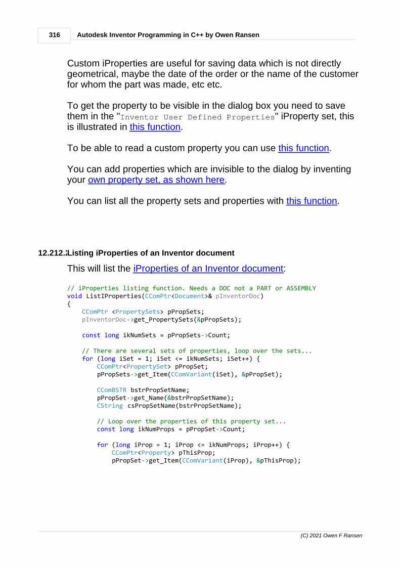
316 Autodesk Inventor Programming in C++ by Owen Ransen
(C) 2021 Owen F Ransen
Custom iProperties are useful for saving data which is not directlygeometrical, maybe the date of the order or the name of the customerfor whom the part was made, etc etc.
To get the property to be visible in the dialog box you need to savethem in the "Inventor User Defined Properties" iProperty set, thisis illustrated in this function.
To be able to read a custom property you can use this function.
You can add properties which are invisible to the dialog by inventingyour own property set, as shown here.
You can list all the property sets and properties with this function.
12.212.2Listing iProperties of an Inventor document
This will list the iProperties of an Inventor document:
// iProperties listing function. Needs a DOC not a PART or ASSEMBLYvoid ListIProperties(CComPtr<Document>& pInventorDoc){ CComPtr <PropertySets> pPropSets; pInventorDoc->get_PropertySets(&pPropSets);
const long ikNumSets = pPropSets->Count;
// There are several sets of properties, loop over the sets... for (long iSet = 1; iSet <= ikNumSets; iSet++) { CComPtr<PropertySet> pPropSet; pPropSets->get_Item(CComVariant(iSet), &pPropSet);
CComBSTR bstrPropSetName; pPropSet->get_Name(&bstrPropSetName); CString csPropSetName(bstrPropSetName);
// Loop over the properties of this property set... const long ikNumProps = pPropSet->Count;
for (long iProp = 1; iProp <= ikNumProps; iProp++) { CComPtr<Property> pThisProp; pPropSet->get_Item(CComVariant(iProp), &pThisProp);

317Programming Inventor in C++
(C) 2021 Owen F Ransen
_bstr_t bstrPropName = pThisProp->GetDisplayName();
CString csPropName(bstrPropName.GetBSTR());
CComVariant varValue; pThisProp->get_Value(&varValue);
// Add more VT_... values for more detail... CString csValue; if (varValue.vt == VT_BSTR) { csValue = CString(varValue.bstrVal);
} else if (varValue.vt == VT_I4) { csValue.Format(L"%d", varValue.intVal);
} else { csValue.Format(L"vt=%d", varValue.vt); }
gLogger.Printf(ekLogMsg, L"<%s> %03d %s value=%s", csPropSetName,iProp, csPropName, csValue); } }}
You can check for different values of varValue.vt to see different typesof properties.
You'll get an output something like this:
<Design Tracking Properties> 044 FlatPatternExtentsWidth value=vt=5<Design Tracking Properties> 045 FlatPatternExtentsLength value=vt=5<Design Tracking Properties> 046 FlatPatternExtentsArea value=vt=5<Design Tracking Properties> 047 SheetMetalRule value=<Design Tracking Properties> 048 LastUpdatedWith value=2017(Build 210142000, 142)<Design Tracking Properties> 049 SheetMetalWidth value=<Design Tracking Properties> 050 SheetMetalLength value=<Design Tracking Properties> 051 SheetMetalArea value=<Design Tracking Properties> 053 Appearance value=Copper - Satin<Design Tracking Properties> 054 Flat Pattern Defer Update value=vt=11<Inventor User Defined Properties> 001 TC_THICK value=<Inventor User Defined Properties> 002 TC_Testing Pressure value=vt=5<Inventor User Defined Properties> 003 TC_TO_APPROVER value=<Inventor User Defined Properties> 004 TC_CHANGE_NUMBER value=<Inventor User Defined Properties> 005 TC_CHANGE_REASON value=

318 Autodesk Inventor Programming in C++ by Owen Ransen
(C) 2021 Owen F Ransen
<Inventor User Defined Properties> 006 TC_CUST_MAT_CODE value=<Inventor User Defined Properties> 007 TC_DATE_CREAT value=19/12/2017<Inventor User Defined Properties> 008 TC_DATE_DRAWN value=23/05/2018<Inventor User Defined Properties> 009 TC_CUST_DWG_NO value=<Inventor User Defined Properties> 010 TC_CUSTOMERS value=<Inventor User Defined Properties> 011 TC_NOTE value=<Inventor User Defined Properties> 012 TC_ORDNO value=<Inventor User Defined Properties> 013 TC_MATERIAL value=<Inventor User Defined Properties> 014 TC_UOM value=<Inventor User Defined Properties> 015 TC_TO_APPROVAL_DATE value=
12.212.3iProperties, add a custom value programatically
If you want to add an iProperty into the visible custom properties...

319Programming Inventor in C++
(C) 2021 Owen F Ransen

320 Autodesk Inventor Programming in C++ by Owen Ransen
(C) 2021 Owen F Ransen
...use this function:
void AddCustomProperty(CComPtr<Document>& pInventorDoc, const CString& kcsPropName, const CString& kcsPropValue){ CComPtr <PropertySets> pPropSets; pInventorDoc->get_PropertySets(&pPropSets);
CComVariant varPropSetName(L"Inventor User Defined Properties"); CComPtr<PropertySet> pPropSet; HRESULT hRes = pPropSets->get_Item(varPropSetName,&pPropSet); if (FAILED(hRes) || (pPropSet == nullptr)) { ShowCOMError(hRes, L"Could not find custom property set"); return; }
CComPtr<Property> pProperty; CComVariant varPropName(kcsPropName) ; CComVariant varPropVal(kcsPropValue); CComVariant varPropId; pPropSet->Add(varPropVal, varPropName, varPropId, &pProperty);}
Here is an example of use:
CComQIPtr<Document> pDoc = pAssemblyDoc ; // upcast to Document AddCustomProperty(pDoc,gkcsInOutPropName,csInOut);
12.212.4iProperties, create a new property set
This function will create a new property set and optionally add in thefirst value of that property set:
void AddPropertySet(CComPtr<Document>& pInventorDoc, const CString& kcsNewPropSetName, const wchar_t* const pszFirstPropName /*= nullptr*/, const wchar_t* const pszFirstPropValue /*= nullptr*/){ CComPtr <PropertySets> pPropSets; pInventorDoc->get_PropertySets(&pPropSets);
CComPtr<PropertySet> pNewPropSet; CComVariant varInternalName; pPropSets->Add(CComBSTR(kcsNewPropSetName), varInternalName, &pNewPropSet);
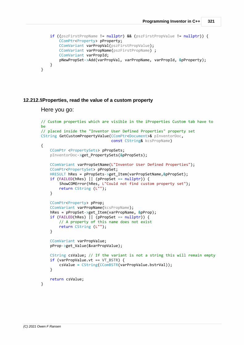
321Programming Inventor in C++
(C) 2021 Owen F Ransen
if ((pszFirstPropName != nullptr) && (pszFirstPropValue != nullptr)) { CComPtr<Property> pProperty; CComVariant varPropVal(pszFirstPropValue); CComVariant varPropName(pszFirstPropName) ; CComVariant varPropId; pNewPropSet->Add(varPropVal, varPropName, varPropId, &pProperty); }}
12.212.5iProperties, read the value of a custom property
Here you go:
// Custom properties which are visible in the iProperties Custom tab have tobe// placed inside the "Inventor User Defined Properties" property setCString GetCustomPropertyValue(CComPtr<Document>& pInventorDoc, const CString& kcsPropName){ CComPtr <PropertySets> pPropSets; pInventorDoc->get_PropertySets(&pPropSets);
CComVariant varPropSetName(L"Inventor User Defined Properties"); CComPtr<PropertySet> pPropSet; HRESULT hRes = pPropSets->get_Item(varPropSetName,&pPropSet); if (FAILED(hRes) || (pPropSet == nullptr)) { ShowCOMError(hRes, L"Could not find custom property set"); return CString (L""); }
CComPtr<Property> pProp; CComVariant varPropName(kcsPropName); hRes = pPropSet->get_Item(varPropName, &pProp); if (FAILED(hRes) || (pPropSet == nullptr)) { // A property of this name does not exist return CString (L""); }
CComVariant varPropValue; pProp->get_Value(&varPropValue);
CString csValue; // If the variant is not a string this will remain empty if (varPropValue.vt == VT_BSTR) { csValue = CString(CComBSTR(varPropValue.bstrVal)); }
return csValue;}
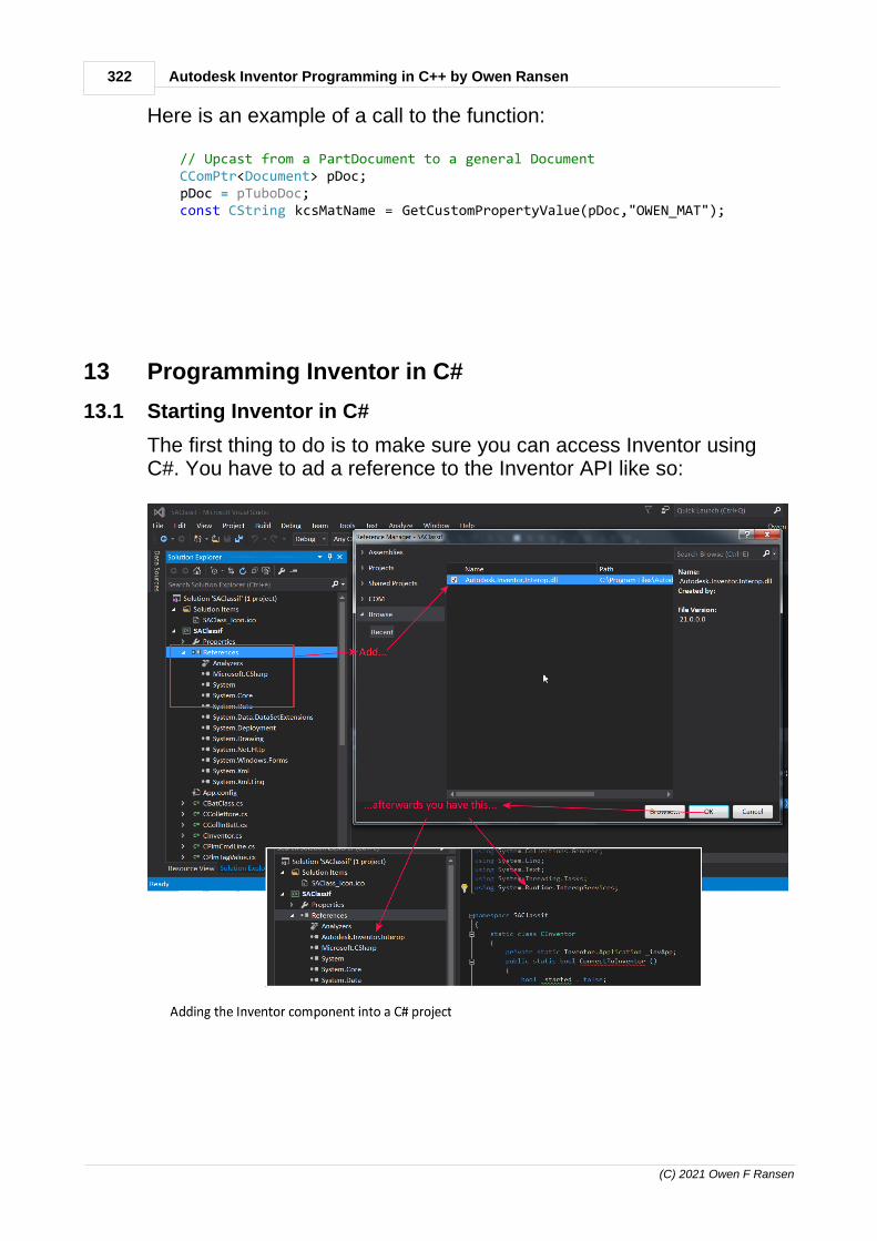
322 Autodesk Inventor Programming in C++ by Owen Ransen
(C) 2021 Owen F Ransen
Here is an example of a call to the function:
// Upcast from a PartDocument to a general Document CComPtr<Document> pDoc; pDoc = pTuboDoc; const CString kcsMatName = GetCustomPropertyValue(pDoc,"OWEN_MAT");
13 Programming Inventor in C#
13.1 Starting Inventor in C#
The first thing to do is to make sure you can access Inventor usingC#. You have to ad a reference to the Inventor API like so:

323Programming Inventor in C#
(C) 2021 Owen F Ransen
Note that you need to choose the .NET Framework, elseGetActiveObject will not be found in Marshal:
In VS2019 the sequence is this:

324 Autodesk Inventor Programming in C++ by Owen Ransen
(C) 2021 Owen F Ransen
Then you can use the following code to get you going...
// CInventor starts up and closes down Inventor// 2019-07-02 : Started.
using System;using System.Collections.Generic;using System.Linq;using System.Text;using System.Threading.Tasks;using System.Runtime.InteropServices;using System.Windows.Forms;using System.Diagnostics;
namespace SAClassif{ static class CInventor { private static Inventor.Application m_Inventor; private static bool m_bWasAlreadyRunning = false;
public static bool ConnectToInventor () { Debug.WriteLine("Connecting to inventor..."); try { // See if Inventor is already running...

325Programming Inventor in C#
(C) 2021 Owen F Ransen
m_Inventor = (Inventor.Application)Marshal.GetActiveObject("Inventor.Application"); m_bWasAlreadyRunning = true; Debug.WriteLine("Inventor already running..."); } catch (Exception ex1) { Debug.WriteLine("Not running, will start it..."); m_bWasAlreadyRunning = false; try { Type invAppType = Type.GetTypeFromProgID("Inventor.Application"); m_Inventor = (Inventor.Application)System.Activator.CreateInstance(invAppType); m_Inventor.Visible = true; Debug.WriteLine("Started Inventor"); } catch (Exception ex2) { MessageBox.Show(ex2.ToString()); MessageBox.Show("Unable to start Inventor"); return false; } }
return m_Inventor != null; }
public static void DisconnectFromInventor() { if (m_Inventor == null) { return; }
if (m_bWasAlreadyRunning) { // I did not start Inventro so I shoulkd not close it... return; }
// Inventor was not running, you started it so you should shut itdown m_Inventor.Quit(); m_Inventor = null; } }}

326 Autodesk Inventor Programming in C++ by Owen Ransen
(C) 2021 Owen F Ransen
13.2 MSB3277: Found conflicts between different versions
You may get this sort of error if you change compiler. What youshould do is remove the reference from the project:
Then add a reference, browsing to the file Autodesk.Inventor.Interop.dll.

327Programming Inventor in C#
(C) 2021 Owen F Ransen
The whole horrible message is this:
warning MSB3277: Found conflicts between different versions of "Autodesk.Inventor.Interop" that could not be resolved.warning MSB3277: There was a conflict between "Autodesk.Inventor.Interop, Version=23.0.0.0, Culture=neutral, PublicKeyToken=d84147f8b4276564" and "Autodesk.Inventor.Interop, Version=23.2.0.0, Culture=neutral, PublicKeyToken=d84147f8b4276564".warning MSB3277: "Autodesk.Inventor.Interop, Version=23.0.0.0, Culture=neutral, PublicKeyToken=d84147f8b4276564" was chosen because it was primary and "Autodesk.Inventor.Interop, Version=23.2.0.0, Culture=neutral, PublicKeyToken=d84147f8b4276564" was not.warning MSB3277: References which depend on "Autodesk.Inventor.Interop, Version=23.0.0.0, Culture=neutral, PublicKeyToken=d84147f8b4276564" [C:\Program Files\Autodesk\Inventor 2019\Bin\Public Assemblies\Autodesk.Inventor.Interop.dll].warning MSB3277: C:\Program Files\Autodesk\Inventor 2019\Bin\Public Assemblies\Autodesk.Inventor.Interop.dllwarning MSB3277: Project file item includes which caused reference "C:\Program Files\Autodesk\Inventor 2019\Bin\Public Assemblies\Autodesk.Inventor.Interop.dll".warning MSB3277: Autodesk.Inventor.Interop, Version=23.0.0.0, Culture=neutral, PublicKeyToken=d84147f8b4276564, processorArchitecture=MSILwarning MSB3277: References which depend on "Autodesk.Inventor.Interop, Version=23.2.0.0, Culture=neutral, PublicKeyToken=d84147f8b4276564" [C:\WINDOWS\Microsoft.Net\assembly\GAC_MSIL\Autodesk.Inventor.Interop\v4.0_23.2.0.0__d84147f8b4276564\Autodesk.Inventor.Interop.dll].warning MSB3277: C:\Program Files\Autodesk\Inventor 2019\Bin\Autodesk.iLogic.Automation.dllwarning MSB3277: Project file item includes which caused reference "C:\Program Files\Autodesk\Inventor 2019\Bin\Autodesk.iLogic.Automation.dll".warning MSB3277: Autodesk.iLogic.Automationwarning MSB3277: C:\Program Files\Autodesk\Inventor 2019\Bin\Autodesk.iLogic.Interfaces.dllwarning MSB3277: Project file item includes which caused reference "C:\Program Files\Autodesk\Inventor 2019\Bin\Autodesk.iLogic.Interfaces.dll".warning MSB3277: Autodesk.iLogic.Automationwarning MSB3277: C:\Program Files\Autodesk\Inventor 2019\Bin\Autodesk.iLogic.Types.dllwarning MSB3277: Project file item includes which caused reference "C:\Program Files\Autodesk\Inventor 2019\Bin\Autodesk.iLogic.Types.dll".warning MSB3277: Autodesk.iLogic.Automation
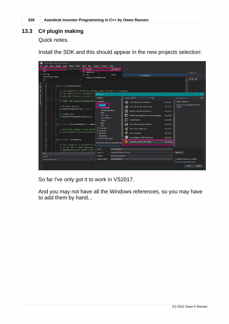
328 Autodesk Inventor Programming in C++ by Owen Ransen
(C) 2021 Owen F Ransen
13.3 C# plugin making
Quick notes.
Install the SDK and this should appear in the new projects selection:
So far I've only got it to work in VS2017.
And you may not have all the Windows references, so you may haveto add them by hand...

329Programming Inventor in C#
(C) 2021 Owen F Ransen
...alternatively add a form and the IDE should bring in the requiredreferences.
You will get some sources which look like this:
using System;using System.Runtime.InteropServices;using System.Windows.Forms;using Inventor;using Microsoft.Win32;
namespace InventorAddIn1{ /// <summary> /// This is the primary AddIn Server class thatimplements the ApplicationAddInServer interface /// that all Inventor AddIns are required toimplement. The communication between Inventor and /// the AddIn is via the methods on this interface. /// </summary> [GuidAttribute("bc7a9e92-f455-431d-9378-c791092de1cc")]
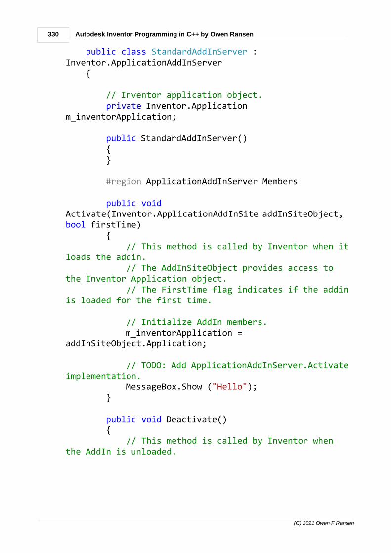
330 Autodesk Inventor Programming in C++ by Owen Ransen
(C) 2021 Owen F Ransen
public class StandardAddInServer :Inventor.ApplicationAddInServer {
// Inventor application object. private Inventor.Applicationm_inventorApplication;
public StandardAddInServer() { }
#region ApplicationAddInServer Members
public voidActivate(Inventor.ApplicationAddInSite addInSiteObject, bool firstTime) { // This method is called by Inventor when itloads the addin. // The AddInSiteObject provides access tothe Inventor Application object. // The FirstTime flag indicates if the addinis loaded for the first time.
// Initialize AddIn members. m_inventorApplication =addInSiteObject.Application;
// TODO: Add ApplicationAddInServer.Activateimplementation. MessageBox.Show ("Hello"); }
public void Deactivate() { // This method is called by Inventor whenthe AddIn is unloaded.

331Programming Inventor in C#
(C) 2021 Owen F Ransen
// The AddIn will be unloaded eithermanually by the user or // when the Inventor session is terminated
// TODO: AddApplicationAddInServer.Deactivate implementation
// Release objects. m_inventorApplication = null;
GC.Collect(); GC.WaitForPendingFinalizers(); }
public void ExecuteCommand(int commandID) { // Note:this method is now obsolete, youshould use the // ControlDefinition functionality forimplementing commands. }
public object Automation { // This property is provided to allow theAddIn to expose an API // of its own to other programs. Typically,this would be done by // implementing the AddIn's API interface ina class and returning // that class object through this property.
get { // TODO: AddApplicationAddInServer.Automation getter implementation return null; }

332 Autodesk Inventor Programming in C++ by Owen Ransen
(C) 2021 Owen F Ransen
}
#endregion
}}
.
.
13.4 C# plugins, adding a button and a command
I've found that I can use the VS 2017 Inventor Plugin Maker wizardand then simply move all the sources over to VS 2019. I haven'tfound a VS2019 compatible wizard.
Many thanks to Jelte de Jong for getting me going on this subject.
I add the "Sample" panel to the "Tools" tab of the "Assembly" ribbon:
Here is the full code of a C# program which adds in a command,copiously commented.
// Adding a button and a command into an Inventor ribbon// 2021-10-18 : Started

333Programming Inventor in C#
(C) 2021 Owen F Ransen
using System;using System.Drawing;using System.Runtime.InteropServices;using System.Windows.Forms;using Inventor;using Microsoft.Win32;
namespace InventorAddIn1{ /// <summary> /// This is the primary AddIn Server class thatimplements the ApplicationAddInServer interface /// that all Inventor AddIns are required toimplement. The communication between Inventor and /// the AddIn is via the methods on this interface. /// </summary> [GuidAttribute("bc7a9e92-f455-431d-9378-c791092de1cc")] public class StandardAddInServer :Inventor.ApplicationAddInServer {
// Inventor application object... private Inventor.Applicationm_inventorApplication;
// The button I will add in... private ButtonDefinition m_sampleButton = null;
public StandardAddInServer() { }
// Inventor will call this if it finds a (this)DLL in the appropriate place, for example //C:\Users\ofr\AppData\Roaming\Autodesk\ApplicationPlugins\InventorAddIn1\InventorAddIn1.dll

334 Autodesk Inventor Programming in C++ by Owen Ransen
(C) 2021 Owen F Ransen
// We are passed Inventor application which memust hold and cherish... public voidActivate(Inventor.ApplicationAddInSite addInSiteObject, bool firstTime) {
// This method is called by Inventor when itloads the addin. // The AddInSiteObject provides access tothe Inventor Application object. // The FirstTime flag indicates if the addinis loaded for the first time. m_inventorApplication =addInSiteObject.Application;
// I use try-catch because Inventor swallowsthe exceptions silently and does not // warn you or the user that anything hasgone wrong. The catch will give you a clue // if something does go wrong... try { // This was me checking thatm_inventorApplication is initialized properly MessageBox.Show("locale=" +m_inventorApplication.Locale.ToString()) ; var cmdMgr =m_inventorApplication.CommandManager;
// Create the button (without icons,icons appear to be tricky)... m_sampleButton =cmdMgr.ControlDefinitions.AddButtonDefinition("Command1", // Display name "Command 1", // Internal name

335Programming Inventor in C#
(C) 2021 Owen F Ransen
CommandTypesEnum.kQueryOnlyCmdType, // No changes, justlooking Guid.NewGuid().ToString(), //Invent an id for this command "Command 1 description", "Command 1 Tooltip"); // showswhen mouse hovers
m_sampleButton.OnExecute +=ButtonDef_OnExecute; // Tell the button what it shoulddo when clicked, see function below
#if false // If you want show the name of eachribbon.... foreach (Ribbon r inm_inventorApplication.UserInterfaceManager.Ribbons) { MessageBox.Show(r.InternalName); }#endif
// Which of these Ribbons (lines) youchoose depends on whether you plug in handles Parts orAssemblies... // Ribbon TheRibbon =m_inventorApplication.UserInterfaceManager.Ribbons["Part"]; // command active when a part doc is active is open Ribbon TheRibbon =m_inventorApplication.UserInterfaceManager.Ribbons["Assembly"]; // command active when an assembly doc isactive
#if false

336 Autodesk Inventor Programming in C++ by Owen Ransen
(C) 2021 Owen F Ransen
// If you want show the name of each tabin the ribbon.... foreach (RibbonTab t inpartRibbon.RibbonTabs) { MessageBox.Show(t.InternalName); }#endif
RibbonTab toolsTab =TheRibbon.RibbonTabs["id_TabTools"]; // tools is presentin both parts and assemblies // MessageBox.Show ("tools tab internalname = " + toolsTab.InternalName); RibbonPanel customPanel =toolsTab.RibbonPanels.Add("Sample", "MysSample",Guid.NewGuid().ToString()); // MessageBox.Show("Custom panelinternal name = " + customPanel.InternalName);
customPanel.CommandControls.AddButton(m_sampleButton); } catch (Exception Err) { MessageBox.Show("Error " + Err.Message); }
MessageBox.Show ("Plugin loaded"); }
// This is the function you added to the buttona few lines above private void ButtonDef_OnExecute(NameValueMapContext) { // This is a test of calling a standard

337Programming Inventor in C#
(C) 2021 Owen F Ransen
Inventor command... m_inventorApplication.CommandManager.ControlDefinitions["AppZoomallCmd"].Execute();
// This is my simple test of something Ido... MessageBox.Show("My Command Called"); }
public void Deactivate() { // This method is called by Inventor whenthe AddIn is unloaded. // The AddIn will be unloaded eithermanually by the user or // when the Inventor session is terminated
// TODO: AddApplicationAddInServer.Deactivate implementation
// Release objects. m_inventorApplication = null;
GC.Collect(); GC.WaitForPendingFinalizers(); }
public void ExecuteCommand(int commandID) { // Note:this method is now obsolete, youshould use the // ControlDefinition functionality forimplementing commands. }
public object Automation {

338 Autodesk Inventor Programming in C++ by Owen Ransen
(C) 2021 Owen F Ransen
// This property is provided to allow theAddIn to expose an API // of its own to other programs. Typically,this would be done by // implementing the AddIn's API interface ina class and returning // that class object through this property.
get { // TODO: AddApplicationAddInServer.Automation getter implementation return null; } } }}
13.5 Button Definition
See this page also, it has a full implementation.
A button definition has two functions:
1. It is a definition of the aspect, look of the button2. It has an OnExecute member which lets you react to a user clicking
on the button
Note that a button definition is not a button, that will be explainedlater.
Icons of a button are optional, and can be of two sizes Normal sizeicons are 16 pixels wide by 16 pixels high. Large icons are 32 pixelswide by 32 pixels high. If an icon of a different size is provided,Inventor will scale it to fit.
A good place to actually add an instance of a button is in the Activate

339Programming Inventor in C#
(C) 2021 Owen F Ransen
member of your addin. Read and understand the comments here:
public void Activate(Inventor.ApplicationAddInSiteaddInSiteObject, bool firstTime) { // This method is called by Inventor when it loadsthe addin. // The AddInSiteObject provides access to theInventor Application object. // The FirstTime flag indicates if the addin isloaded for the first time.
// Initialize AddIn members. m_inventorApplication = addInSiteObject.Application;
// Control definitions are definitons of things likebuttons and menus... ControlDefinitions controlDefs =m_inventorApplication.CommandManager.ControlDefinitions;
// Create a *definition* of a button, what it lookslike mainly... m_buttonDefinition = controlDefs.AddButtonDefinition("Owen's Button", "invrSampleCommand", Inventor.CommandTypesEnum.kShapeEditCmdType, "{786675cb-d781-4f02-bfaa-02c4fda0ba61}", "Owens Desc", "Owens Tooltip") ; m_buttonDefinition.Enabled = true;
// Now we have to *place* the button somewhere. // This is a lot of drilling down...
// Get the object which handles the user interface... UserInterfaceManager userInterfaceManager; userInterfaceManager =m_inventorApplication.UserInterfaceManager; // Get the list of ribbons... Inventor.Ribbons ribbons;

340 Autodesk Inventor Programming in C++ by Owen Ransen
(C) 2021 Owen F Ransen
ribbons = userInterfaceManager.Ribbons;
// Get the "Part" ribbon, a list of tabs active whenediting a part... Inventor.Ribbon partRibbon; partRibbon = ribbons["Part"];
// Get the tabs associated with part ribbon RibbonTabs ribbonTabs; ribbonTabs = partRibbon.RibbonTabs;
// In particular get the "tools" tab... RibbonTab partSketchRibbonTab; partSketchRibbonTab = ribbonTabs["id_TabTools"]; // Inside the "Tools" tab there are many panels... RibbonPanels ribbonPanels; ribbonPanels = partSketchRibbonTab.RibbonPanels;
// Get the measurepent panel... RibbonPanel ribbonPanel; ribbonPanel = ribbonPanels["id_PanelP_ToolsMeasure"];
// Finally we can add the button... ribbonPanel.CommandControls.AddButton(m_buttonDefinition); }
The Gui heirachy is illustrated here:

341Programming Inventor in C#
(C) 2021 Owen F Ransen
13.6 C# plugin removal
To remove an add in it looks like you need to remove the subdirectory which contains it, for example:
C:\Users\ofr\AppData\Roaming\Autodesk\ApplicationPlugins\InventorAddIn1
It'll look something like this:

342 Autodesk Inventor Programming in C++ by Owen Ransen
(C) 2021 Owen F Ransen
13.7 C# message box
You can either use the standard windows one:
public voidActivate(Inventor.ApplicationAddInSite addInSiteObject, bool firstTime) { // This method is called by Inventor when itloads the addin. // The AddInSiteObject provides access tothe Inventor Application object. // The FirstTime flag indicates if the addinis loaded for the first time.
// Initialize AddIn members. m_inventorApplication =addInSiteObject.Application;
// TODO: Add ApplicationAddInServer.Activateimplementation. MessageBox.Show ("Hello"); }
or the Inventor one:
You can use build-in "message box" inventorApp.CommandManager.PromptMessage(...), but its usage is little bit obscure. See APIreference for more information.
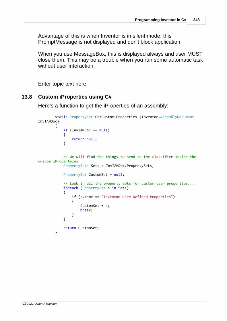
343Programming Inventor in C#
(C) 2021 Owen F Ransen
Advantage of this is when Inventor is in silent mode, thisPromptMessage is not displayed and don't block application.
When you use MessageBox, this is displayed always and user MUSTclose them. This may be a trouble when you run some automatic taskwithout user interaction.
Enter topic text here.
13.8 Custom iProperties using C#
Here's a function to get the iProperties of an assembly:
static PropertySet GetCustomiProperties (Inventor.AssemblyDocumentInvIAMDoc) { if (InvIAMDoc == null) { return null; }
// We will find the things to send to the classifier inside thecustom iPropertyies PropertySets Sets = InvIAMDoc.PropertySets;
PropertySet CustomSet = null;
// Look in all the property sets for custom user properties... foreach (PropertySet s in Sets) { if (s.Name == "Inventor User Defined Properties") { CustomSet = s; break; } }
return CustomSet; }

344 Autodesk Inventor Programming in C++ by Owen Ransen
(C) 2021 Owen F Ransen
13.9 Open an Inventor file using C#
You can use Open or OpenWithOptions. Here's how to do it withOpenWithOptions:
NameValueMap Options = m_Inventor.TransientObjects.CreateNameValueMap () ; // Some example options.... Options.Add("SkipAllUnresolvedFiles", true); Options.Add("DesignViewRepresentation", "View1"); Options.Add("DeferUpdates", true);
AssemblyDocument IamDoc = (AssemblyDocument)m_Inventor.Documents.OpenWithOptions(sFullDocName,Options,true);
The last true means Open Visible.
The DeferUpdates in interesting. If you turn defer updates on,Inventor blocks all kinds of editability, to the in-memory data. But thefile itself stays as is, so that is what I use for read-only processing,where I only want to read from the file, and not modify it.
13.10 ItemByName for Document
The syntax is as follows:
Document Doc = (Document)m_Inventor.Documents.ItemByName(sFullDocName) ;
You need that cast to (Document).
13.11 Get user parameters using C#
Here's how to do it:
// Returns the string value of the user parameter namedin the input static string GetUserParam (Inventor.AssemblyDocument
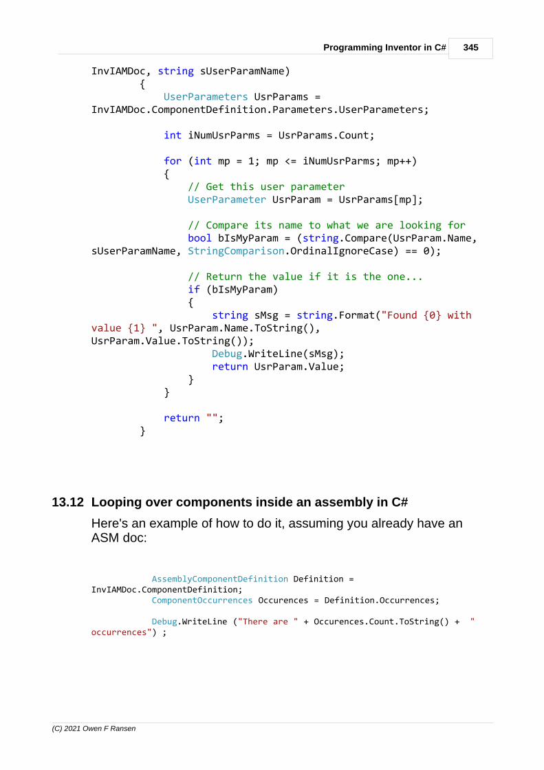
345Programming Inventor in C#
(C) 2021 Owen F Ransen
InvIAMDoc, string sUserParamName) { UserParameters UsrParams =InvIAMDoc.ComponentDefinition.Parameters.UserParameters;
int iNumUsrParms = UsrParams.Count;
for (int mp = 1; mp <= iNumUsrParms; mp++) { // Get this user parameter UserParameter UsrParam = UsrParams[mp];
// Compare its name to what we are looking for bool bIsMyParam = (string.Compare(UsrParam.Name,sUserParamName, StringComparison.OrdinalIgnoreCase) == 0);
// Return the value if it is the one... if (bIsMyParam) { string sMsg = string.Format("Found {0} withvalue {1} ", UsrParam.Name.ToString(),UsrParam.Value.ToString()); Debug.WriteLine(sMsg); return UsrParam.Value; } }
return ""; }
13.12 Looping over components inside an assembly in C#
Here's an example of how to do it, assuming you already have anASM doc:
AssemblyComponentDefinition Definition =InvIAMDoc.ComponentDefinition; ComponentOccurrences Occurences = Definition.Occurrences;
Debug.WriteLine ("There are " + Occurences.Count.ToString() + "occurrences") ;

346 Autodesk Inventor Programming in C++ by Owen Ransen
(C) 2021 Owen F Ransen
foreach (ComponentOccurrence ThisOcc in Occurences) { ComponentDefinition ThisDef = ThisOcc.Definition; Debug.WriteLine("Found something "); if (ThisDef.Type == ObjectTypeEnum.kAssemblyComponentDefinitionObject) { AssemblyComponentDefinition AsmDef = (AssemblyComponentDefinition)ThisDef; Material Mat = AsmDef.DefaultMaterial; AssemblyDocument AsmDoc = AsmDef.Document; Debug.WriteLine("Found an assembly of " + Mat.Name + " " +AsmDoc.FullDocumentName); } if (ThisDef.Type == ObjectTypeEnum.kPartComponentDefinitionObject) { PartComponentDefinition PartDef = (PartComponentDefinition)ThisDef; PartDocument PartDoc = PartDef.Document; Debug.WriteLine("Found an part " + PartDef.Material.Name+ " " + PartDoc.FullDocumentName) ; } }

347Programming Inventor in C#
(C) 2021 Owen F Ransen
13.13 GetActiveObject does not exist in Marshal
This may happen to you if you have not used the correct framework.
Other project types may not have the correct Marshall function.
13.14 Calling iLogic from C#
Remember to have Autodesk.iLogic.Automation.dll as a reference...

348 Autodesk Inventor Programming in C++ by Owen Ransen
(C) 2021 Owen F Ransen
Here is an example, the dynamic keyword is important apparently:
using System;using System.Windows.Forms;using Inventor;
namespace OInventor{ public partial class Form1 : Form { static Inventor.Application m_Inventor; // static Inventor.ApplicationAddIn m_AddIn;
public Form1() { InitializeComponent(); }
private void Form1_Load(object sender, EventArgs e) { m_Inventor = (Inventor.Application)System.Runtime.InteropServices.Marshal.GetActiveObject("Inventor.Application");
int iNumDocs = m_Inventor.Documents.Count; MessageBox.Show("There are " + iNumDocs.ToString() + " documents");
string iLogicAddinGuid = "{3BDD8D79-2179-4B11-8A5A-257B1C0263AC}";
Inventor.ApplicationAddIn addin = null;
try { // try to get iLogic addin addin = m_Inventor.ApplicationAddIns.get_ItemById(iLogicAddinGuid); } catch {

349Programming Inventor in C#
(C) 2021 Owen F Ransen
return; }
if (addin != null) { // activate the addin if (!addin.Activated) addin.Activate();
dynamic _iLogicAutomation1 = addin.Automation;
Document oCurrentDoc1 = m_Inventor.ActiveDocument;
_iLogicAutomation1.RunRule(oCurrentDoc1, "Pippo"); } } }}
Note that you have to have included the Autodesk.iLogic.Automationreference in your product references:

350 Autodesk Inventor Programming in C++ by Owen Ransen
(C) 2021 Owen F Ransen

351Programming Inventor in C#
(C) 2021 Owen F Ransen
13.15 Listing iLogic rules using C#
Remember to have Autodesk.iLogic.Automation.dll as a reference...
This works:
string iLogicAddinGuid ="{3BDD8D79-2179-4B11-8A5A-257B1C0263AC}"; Inventor.ApplicationAddIn addin = null; try { addin =m_Inventor.ApplicationAddIns.get_ItemById(iLogicAddinGuid); } catch { MessageBox.Show("Could not get iLogicobject"); }
if (addin != null) { if (!addin.Activated) {
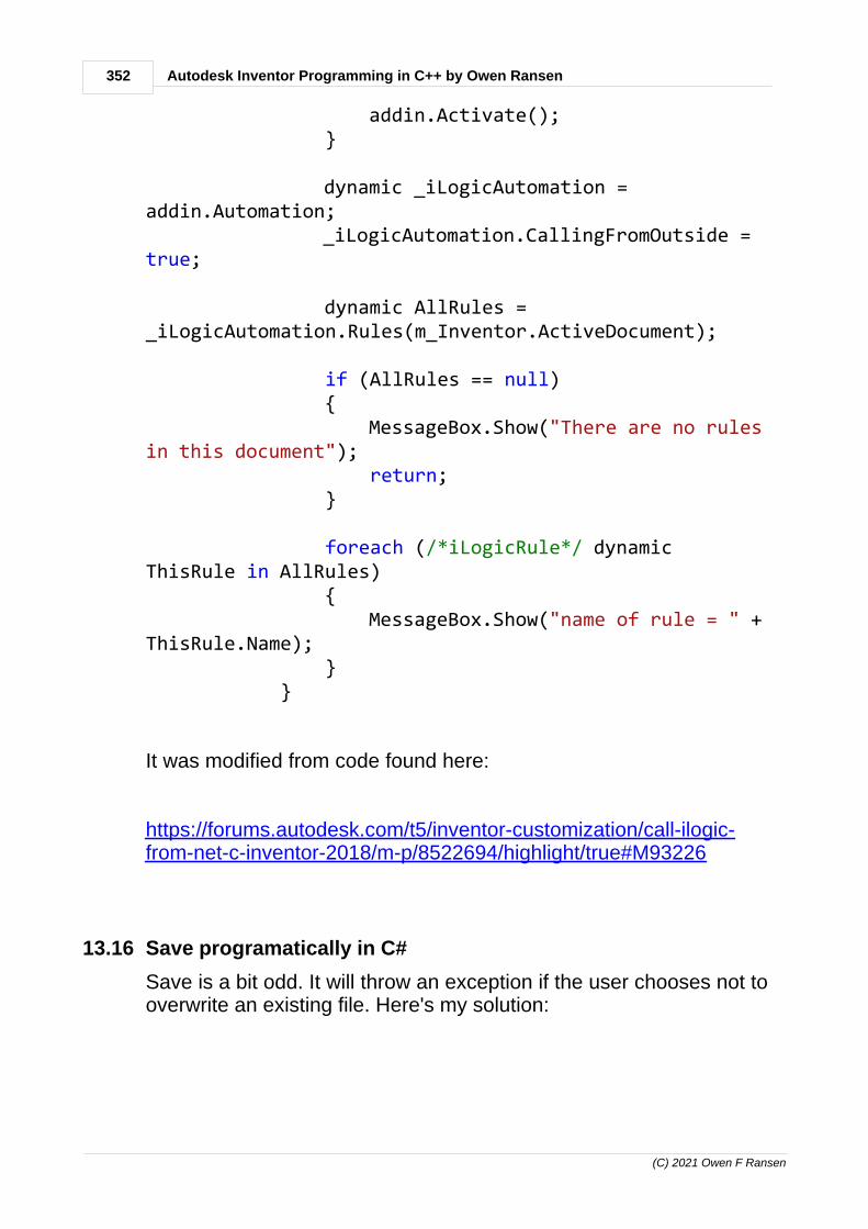
352 Autodesk Inventor Programming in C++ by Owen Ransen
(C) 2021 Owen F Ransen
addin.Activate(); }
dynamic _iLogicAutomation =addin.Automation; _iLogicAutomation.CallingFromOutside = true;
dynamic AllRules =_iLogicAutomation.Rules(m_Inventor.ActiveDocument);
if (AllRules == null) { MessageBox.Show("There are no rulesin this document"); return; }
foreach (/*iLogicRule*/ dynamicThisRule in AllRules) { MessageBox.Show("name of rule = " +ThisRule.Name); } }
It was modified from code found here:
https://forums.autodesk.com/t5/inventor-customization/call-ilogic-from-net-c-inventor-2018/m-p/8522694/highlight/true#M93226
13.16 Save programatically in C#
Save is a bit odd. It will throw an exception if the user chooses not tooverwrite an existing file. Here's my solution:

353Programming Inventor in C#
(C) 2021 Owen F Ransen
string sFullFileName = CInvSettings.sPlmCacheDir +m_Spec.sBatCode + ".IAM";if (System.IO.File.Exists (sFullFileName)){ // I need to delete the file if it already exists elseAsmDoc.Save will throw an exception // if the user says no to ovewrite. DialogResult Res = MessageBox.Show(m_Spec.sBatCode + "esiste, sovrascrivere?", "Sovrascrivere?",MessageBoxButtons.YesNo); if (Res == DialogResult.Yes) { // Stop Save() from thowing an exception System.IO.File.Delete(sFullFileName); } else { Cursor.Current = Cursors.Default; return; }}
AsmDoc.FullFileName = sFullFileName;AsmDoc.Save();
13.17 "Member not found" error in C# add-in
As mentioned in other blog posts (e.g. here and here) as well, usingEmbed Interop Types = True with the Inventor interop assembly doesnot work well.
Apart from some events not firing, you might not find all the propertieseither. E.g. in the case of a Parameter object, when doing this:
var unitType = param.get_Units();
I get this error:
{"Member not found. (Exception from HRESULT: 0x80020003(DISP_E_MEMBERNOTFOUND))"}
So just set Embed Interop Types to False:

354 Autodesk Inventor Programming in C++ by Owen Ransen
(C) 2021 Owen F Ransen
EmbedInteoropTypes
Just for completeness' sake (though the above solution should solvethe problem), there could be another way as well to avoid this error.You could declare a dynamic variable for the parameter (in order touse late-binding) and access the property through that:
dynamic p = param;var unitType = p.Units;
- Adam

355Programming Inventor in C#
(C) 2021 Owen F Ransen
13.18 Browser panes in C#
Aech document has its own browser panes (panels):
Inventor.BrowserPanes Panes =m_Inventor.ActiveDocument.BrowserPanes;
foreach (Inventor.BrowserPane ThisPane in Panes) { MessageBox.Show("Pane internal name: <" +ThisPane.InternalName + "> = <" + ThisPane.Name + ">"); }
MessageBox.Show(m_Inventor.LanguageName + " " +m_Inventor.LanguageCode.ToString());
13.19 Assembly document or part document?
You can try casting with the As keyword to find out what sort ofdocument you have:
Inventor.AssemblyDocument AsmDoc = m_Inventor.ActiveDocument as Inventor.AssemblyDocument;if (AsmDoc != null){
MessageBox.Show("This is an assembly");}else {
Inventor.PartDocument PartDoc = m_Inventor.ActiveDocument as Inventor.PartDocument;if (PartDoc != null){
MessageBox.Show("This is a part");}else {
MessageBox.Show("This is something else");}
}

356 Autodesk Inventor Programming in C++ by Owen Ransen
(C) 2021 Owen F Ransen
13.20 Listing parameters in an assembly, C#
Here is the code, note the foreach loop.
private void ListParameters_Click(object sender,EventArgs e) { Inventor.AssemblyDocument AsmDoc =m_Inventor.ActiveDocument as Inventor.AssemblyDocument; if (AsmDoc == null) { MessageBox.Show("This is not an assembly"); return; }
UserParameters UsrParams =AsmDoc.ComponentDefinition.Parameters.UserParameters; foreach (UserParameter UserParam in UsrParams) { string sMsg = string.Format("Found {0} with value{1} ", UserParam.Name.ToString(), UserParam.Value.ToString()); MessageBox.Show(sMsg); } }
The above works for user parameters, here is the loop for modelparameters:
ModelParameters ModParams =AsmDoc.ComponentDefinition.Parameters.ModelParameters; foreach (ModelParameter ModParam in ModParams) { string sMsg = string.Format("Found model param{0} with value {1} ", ModParam.Name.ToString(),ModParam.Value.ToString()); MessageBox.Show(sMsg); }

357Programming Inventor in C#
(C) 2021 Owen F Ransen
13.21 Getting the value of a parameter in a part
Here you go:
public static double GetPartMmParam (PartComponentDefinition PartDef, ParamType_e eParamType, string sParamName) { if (PartDef == null) { AutoBatSupp.Log.WriteLn(CLog.Type_e.ekErr,"SetAsmParam null AsmDef (" + sParamName + ")" + eParamType.ToString()); return 0.0 ; } if (!PartCompDefHasParam(PartDef, eParamType, sParamName)) { AutoBatSupp.Log.WriteLn(CLog.Type_e.ekErr,"Assembly does not have parameter <" + sParamName + ">, " + eParamType.ToString()); return 0.0; }
// This will become a User or Model Parameter Parameter Param = null;
if (eParamType == ParamType_e.ekModel) { ModelParameters ModelParams = PartDef.Parameters.ModelParameters; ModelParameter ThisParam = ModelParams[sParamName]; Param = (Parameter)ThisParam; } else if (eParamType == ParamType_e.ekUser) { UserParameters ModelParams = PartDef.Parameters.UserParameters; UserParameter ThisParam = ModelParams[sParamName]; Param = (Parameter)ThisParam; }
return (double)Param.Value * 10.0; }
13.22 Value of a Param
Though it is odd you may have to cast a Parameter Param.Value toget hold of its double value. look at the last line of this:
if (eParamType == ParamType_e.ekModel) {

358 Autodesk Inventor Programming in C++ by Owen Ransen
(C) 2021 Owen F Ransen
ModelParameters ModelParams = PartDef.Parameters.ModelParameters; ModelParameter ThisParam = ModelParams[sParamName]; Param = (Parameter)ThisParam; } else if (eParamType == ParamType_e.ekUser) { UserParameters ModelParams = PartDef.Parameters.UserParameters; UserParameter ThisParam = ModelParams[sParamName]; Param = (Parameter)ThisParam; }
return (double)Param.Value * 10.0;
13.23 Getting the GUI language of Inventor
This works:
MessageBox.Show(m_Inventor.LanguageName + " " + m_Inventor.LanguageCode.ToString());
Here is an example of LanguageName: "English" andLanguageCode: "en-US"
13.24 Changing parameters with C#
Here is an example of changing model parameters of a part:
private void ChangeCyl_Click(object sender,EventArgs e) { Inventor.PartDocument PartDoc =m_Inventor.ActiveDocument as Inventor.PartDocument; if (PartDoc == null) { MessageBox.Show("This is not a part"); return; }

359Programming Inventor in C#
(C) 2021 Owen F Ransen
ModelParameters ModParams =PartDoc.ComponentDefinition.Parameters.ModelParameters; foreach (ModelParameter ModParam inModParams) { if (ModParam.Name == "Diametro") { ModParam.Value = 111.0; // .Value isin cm .Expression would be in mm } else if (ModParam.Name == "Altezza") { ModParam.Value = 55.0; // .Value isin cm .Expression would be in mm } }
PartDoc.Update(); }
Note also the comment about .Value and .Expression, as well as thecall to update the part. See also get_Units.
I have this set of functions for changing parameters:
public enum ParamType_e { ekModel, ekUser, };
public static void SetAsmParam(Inventor.AssemblyComponentDefinition AsmDef, ParamType_e eParamType, string sParamName, doubleNewVal) { if (AsmDef == null) {
360 Autodesk Inventor Programming in C++ by Owen Ransen
(C) 2021 Owen F Ransen
MessageBox.Show("SetAsmParam null AsmDef (" +sParamName + ")" + eParamType.ToString ()); return; } if (!AsmCompDefHasParam(AsmDef,eParamType,sParamName)) { MessageBox.Show("Assembly does not have parameter<" + sParamName + ">, " + eParamType.ToString()); return; }
// This will become a User or Model Parameter Parameter Param = null;
if (eParamType == ParamType_e.ekModel) { ModelParameters ModelParams =AsmDef.Parameters.ModelParameters; ModelParameter ThisParam =ModelParams[sParamName]; if (ThisParam == null) { MessageBox.Show("Cannot find assembly modelparam: " + sParamName); return; } Param = (Parameter)ThisParam; } else if (eParamType == ParamType_e.ekUser) { UserParameters ModelParams =AsmDef.Parameters.UserParameters; UserParameter ThisParam =ModelParams[sParamName]; if (ThisParam == null) { MessageBox.Show("Cannot find assembly userparam: " + sParamName); return; } Param = (Parameter)ThisParam; }
if (Param != null)

361Programming Inventor in C#
(C) 2021 Owen F Ransen
{ Param.Value = NewVal; MessageBox.Show(Param.get_Units()); } }
public static voidSetAsmUlParam(Inventor.AssemblyComponentDefinition AsmDef, ParamType_e eParamType, string sParamName,double NewVal) { SetAsmParam(AsmDef, eParamType, sParamName, NewVal); }
public static voidSetAsmMmParam(Inventor.AssemblyComponentDefinition AsmDef, ParamType_e eParamType, string sParamName,double mmUserParamNewVal) { // Note the division by 10 because of cm native uintsin Inventor SI SetAsmParam(AsmDef, eParamType, sParamName,mmUserParamNewVal / 10.0); }
13.25 get_Units crashes
If you have a parameter then you may not be able to use get_Units(C# version of the VBA Units function). Your C# call to get_Units willcrash if you have not set Embed Interop _Types to true:

362 Autodesk Inventor Programming in C++ by Owen Ransen
(C) 2021 Owen F Ransen
The crash will look like this:
This can Enter topic text here.

363Programming Inventor in C#
(C) 2021 Owen F Ransen
13.26 Listing holes in a face of folded metal
Here is a face with a hole in it, actually a cut:
If you have that part open you can run this:
public static void Test () { PartDocument PartDoc; try { PartDoc = (PartDocument)m_Inventor.ActiveDocument asPartDocument; if (PartDoc == null) { MessageBox.Show("This is not a part document"); return; } } catch { MessageBox.Show ("not a part doc"); return; }
PartComponentDefinition PartDef = PartDoc.ComponentDefinition; PartFeatures FeatsList = PartDef.Features;
foreach (PartFeature ThisFeature in FeatsList) { if (ThisFeature.Type == ObjectTypeEnum.kCutFeatureObject) {

364 Autodesk Inventor Programming in C++ by Owen Ransen
(C) 2021 Owen F Ransen
CutFeature CutFeature = (CutFeature)ThisFeature; ProfilePath TheProfile = CutFeature.Definition.Profile[1]; ProfileEntity Ent = TheProfile[1];
Debug.WriteLine ("Profile ent " + Ent.ToString() + " " +Ent.CurveType.ToString());
if (Ent.CurveType == Curve2dTypeEnum.kCircleCurve2d) { Circle2d Circle = (Circle2d)Ent.Curve; Debug.WriteLine("It is a circle of radius " +Circle.Radius.ToString()); } } else if (ThisFeature.Type ==ObjectTypeEnum.kFaceFeatureObject) { FaceFeature FaceFeat = (FaceFeature)ThisFeature; MessageBox.Show("FaceFeature " + FaceFeat.ToString() + "name<" + FaceFeat.Name + "> has " + FaceFeat.Faces.Count.ToString() + " faces");
//Faces FacesList = FaceFeat.Faces; //FaceFeat.Definition.
//foreach (Face ThisFace in FacesList) //{ // Face.Edges;
//}
} else { MessageBox.Show("This feature is a " +ThisFeature.Type.ToString()); } } }
And you will get this output in the debug window of the IDE:
Profile ent System.__ComObject kCircleCurve2d
It is a circle of radius 0,15.
See also this.

365Programming Inventor in C#
(C) 2021 Owen F Ransen
13.27 Listing holes in a face of folded metal VB
This code was the starting point for this.
// Set a reference to the sheet metal document. // This assumes a part document is active. Dim oPartDoc As PartDocument Set oPartDoc = ThisApplication.ActiveDocument // Make sure the document is a sheet metal document. if (oPartDoc.SubType == "{9C464203-9BAE-11D3-8BAD-0060B0CE6BB4}")
{ MessageBox.Show ("A sheet metal document must be open.") return } // Get the sheet metal component definition. Because this is a partdocument whose // sub type is sheet metal, the document will return aSheetMetalComponentDefinition // instead of a PartComponentDefinition. Dim oSheetMetalCompDef As SheetMetalComponentDefinition Set oSheetMetalCompDef = oPartDoc.ComponentDefinition // Iterate through the features looking specifically for sheet metalfeatures. Dim oFeature As PartFeature For Each oFeature In oSheetMetalCompDef.Features switch (oFeature.Type) { Case kFaceFeatureObject Dim oFaceFeature As FaceFeature Set oFaceFeature = oFeature Debug.WriteLine ( "Face Feature: " + oFaceFeature.Name); Debug.WriteLine ( " Adaptive: " + oFaceFeature.Adaptive); Debug.WriteLine ( " Face Count: " + oFaceFeature.Faces.Count) ; Debug.WriteLine ( " HealthStatus: " + oFaceFeature.

366 Autodesk Inventor Programming in C++ by Owen Ransen
(C) 2021 Owen F Ransen
HealthStatus) ; Debug.WriteLine ( " RangeBox: (" + Format(oFaceFeature.RangeBox.MinPoint.X, "0.00000") + ", " + Format(oFaceFeature.RangeBox.MinPoint.Y, "0.00000") + ", " + Format(oFaceFeature.RangeBox.MinPoint.Z, "0.00000") + ")-(" + Format(oFaceFeature.RangeBox.MaxPoint.X, "0.00000") + ", " + Format(oFaceFeature.RangeBox.MaxPoint.Y, "0.00000") + ", " + Format(oFaceFeature.RangeBox.MaxPoint.Z, "0.00000") + ")" ) ; Debug.WriteLine ( " Suppressed: " + oFaceFeature.Suppressed ;
break ;
Case kContourFlangeFeatureObject Dim oContourFlangeFeature As ContourFlangeFeature Set oContourFlangeFeature = oFeature Debug.WriteLine ( "Contour Flange Feature: " +oContourFlangeFeature.Name) ; Debug.WriteLine ( " Adaptive: " + oContourFlangeFeature.Adaptive) ; Debug.WriteLine ( " Face Count: " +oContourFlangeFeature.Faces.Count) ; Debug.WriteLine ( " HealthStatus: " +oContourFlangeFeature.HealthStatus) ; Debug.WriteLine ( " RangeBox: (" + Format(oFaceFeature.RangeBox.MinPoint.X, "0.00000") + ", " + Format(oFaceFeature.RangeBox.MinPoint.Y, "0.00000") + ", " + Format(oFaceFeature.RangeBox.MinPoint.Z, "0.00000") + ")-(" + Format(oFaceFeature.RangeBox.MaxPoint.X, "0.00000") + ", " + Format(oFaceFeature.RangeBox.MaxPoint.Y, "0.00000") + ", " + Format(oFaceFeature.RangeBox.MaxPoint.Z, "0.00000") + ")") ;

367Programming Inventor in C#
(C) 2021 Owen F Ransen
Debug.WriteLine ( " Suppressed: " +oContourFlangeFeature.Suppressed ;
break ;
Case kCutFeatureObject Dim oCutFeature As CutFeature Set oCutFeature = oFeature Debug.WriteLine ( "Cut Feature: " + oCutFeature.Name) ; Debug.WriteLine ( " Adaptive: " + oCutFeature.Adaptive) ; Debug.WriteLine ( " Face Count: " + oCutFeature.Faces.Count) ; Debug.WriteLine ( " HealthStatus: " + oCutFeature.HealthStatus) ; Debug.WriteLine ( " RangeBox: (" + Format(oFaceFeature.RangeBox.MinPoint.X, "0.00000") + ", " + Format(oFaceFeature.RangeBox.MinPoint.Y, "0.00000") + ", " + Format(oFaceFeature.RangeBox.MinPoint.Z, "0.00000") + ")-(" + Format(oFaceFeature.RangeBox.MaxPoint.X, "0.00000") + ", " + Format(oFaceFeature.RangeBox.MaxPoint.Y, "0.00000") + ", " + Format(oFaceFeature.RangeBox.MaxPoint.Z, "0.00000") + ")") ; Debug.WriteLine ( " Suppressed: " + oCutFeature.Suppressed
break ;
Case kFlangeFeatureObject Dim oFlangeFeature As FlangeFeature Set oFlangeFeature = oFeature Debug.WriteLine ( "Flange Feature: " + oFlangeFeature.Name Debug.WriteLine ( " Adaptive: " + oFlangeFeature.Adaptive Debug.WriteLine ( " Face Count: " + oFlangeFeature.Faces.Count Debug.WriteLine ( " HealthStatus: " + oFlangeFeature.HealthStatus

368 Autodesk Inventor Programming in C++ by Owen Ransen
(C) 2021 Owen F Ransen
Debug.WriteLine ( " RangeBox: (" + Format(oFaceFeature.RangeBox.MinPoint.X, "0.00000") + ", " + Format(oFaceFeature.RangeBox.MinPoint.Y, "0.00000") + ", " + Format(oFaceFeature.RangeBox.MinPoint.Z, "0.00000") + ")-(" + Format(oFaceFeature.RangeBox.MaxPoint.X, "0.00000") + ", " + Format(oFaceFeature.RangeBox.MaxPoint.Y, "0.00000") + ", " + Format(oFaceFeature.RangeBox.MaxPoint.Z, "0.00000") + ")" Debug.WriteLine ( " Suppressed: " + oFlangeFeature.Suppressed
break ;
Case kHemFeatureObject Dim oHemFeature As HemFeature Set oHemFeature = oFeature Debug.WriteLine ( "Hem Feature: " + oHemFeature.Name Debug.WriteLine ( " Adaptive: " + oHemFeature.Adaptive Debug.WriteLine ( " Face Count: " + oHemFeature.Faces.Count Debug.WriteLine ( " HealthStatus: " + oHemFeature.HealthStatus Debug.WriteLine ( " RangeBox: (" + Format(oFaceFeature.RangeBox.MinPoint.X, "0.00000") + ", " + Format(oFaceFeature.RangeBox.MinPoint.Y, "0.00000") + ", " + Format(oFaceFeature.RangeBox.MinPoint.Z, "0.00000") + ")-(" + Format(oFaceFeature.RangeBox.MaxPoint.X, "0.00000") + ", " + Format(oFaceFeature.RangeBox.MaxPoint.Y, "0.00000") + ", " + Format(oFaceFeature.RangeBox.MaxPoint.Z, "0.00000") + ")" Debug.WriteLine ( " Suppressed: " + oHemFeature.Suppressed
break ;
369Programming Inventor in C#
(C) 2021 Owen F Ransen
Case kFoldFeatureObject Dim oFoldFeature As FoldFeature Set oFoldFeature = oFeature Debug.WriteLine ( "Fold Feature: " + oFoldFeature.Name Debug.WriteLine ( " Adaptive: " + oFoldFeature.Adaptive Debug.WriteLine ( " Face Count: " + oFoldFeature.Faces.Count Debug.WriteLine ( " HealthStatus: " + oFoldFeature.HealthStatus Debug.WriteLine ( " RangeBox: (" + Format(oFaceFeature.RangeBox.MinPoint.X, "0.00000") + ", " + Format(oFaceFeature.RangeBox.MinPoint.Y, "0.00000") + ", " + Format(oFaceFeature.RangeBox.MinPoint.Z, "0.00000") + ")-(" + Format(oFaceFeature.RangeBox.MaxPoint.X, "0.00000") + ", " + Format(oFaceFeature.RangeBox.MaxPoint.Y, "0.00000") + ", " + Format(oFaceFeature.RangeBox.MaxPoint.Z, "0.00000") + ")" Debug.WriteLine ( " Suppressed: " + oFoldFeature.Suppressed
break ;
Case kCornerFeatureObject Dim oCornerFeature As CornerFeature Set oCornerFeature = oFeature Debug.WriteLine ( "Corner Seam Feature: " +oCornerFeature.Name Debug.WriteLine ( " Adaptive: " + oCornerFeature.Adaptive Debug.WriteLine ( " Face Count: " + oCornerFeature.Faces.Count Debug.WriteLine ( " HealthStatus: " + oCornerFeature.HealthStatus Debug.WriteLine ( " RangeBox: (" + Format(oFaceFeature.RangeBox.MinPoint.X, "0.00000") + ", " + Format(oFaceFeature.RangeBox.MinPoint.

370 Autodesk Inventor Programming in C++ by Owen Ransen
(C) 2021 Owen F Ransen
Y, "0.00000") + ", " + Format(oFaceFeature.RangeBox.MinPoint.Z, "0.00000") + ")-(" + Format(oFaceFeature.RangeBox.MaxPoint.X, "0.00000") + ", " + Format(oFaceFeature.RangeBox.MaxPoint.Y, "0.00000") + ", " + Format(oFaceFeature.RangeBox.MaxPoint.Z, "0.00000") + ")" Debug.WriteLine ( " Suppressed: " + oCornerFeature.Suppressed
break ;
Case kBendFeatureObject Dim oBendFeature As BendFeature Set oBendFeature = oFeature Debug.WriteLine ( "Bend Feature: " + oBendFeature.Name Debug.WriteLine ( " Adaptive: " + oBendFeature.Adaptive Debug.WriteLine ( " Face Count: " + oBendFeature.Faces.Count Debug.WriteLine ( " HealthStatus: " + oBendFeature.HealthStatus Debug.WriteLine ( " RangeBox: (" + Format(oFaceFeature.RangeBox.MinPoint.X, "0.00000") + ", " + Format(oFaceFeature.RangeBox.MinPoint.Y, "0.00000") + ", " + Format(oFaceFeature.RangeBox.MinPoint.Z, "0.00000") + ")-(" + Format(oFaceFeature.RangeBox.MaxPoint.X, "0.00000") + ", " + Format(oFaceFeature.RangeBox.MaxPoint.Y, "0.00000") + ", " + Format(oFaceFeature.RangeBox.MaxPoint.Z, "0.00000") + ")" Debug.WriteLine ( " Suppressed: " + oBendFeature.Suppressed
break ;
Case kCornerRoundFeatureObject Dim oCornerRoundFeature As CornerRoundFeature

371Programming Inventor in C#
(C) 2021 Owen F Ransen
Set oCornerRoundFeature = oFeature Debug.WriteLine ( "Corner Round Feature: " +oCornerRoundFeature.Name Debug.WriteLine ( " Adaptive: " + oCornerRoundFeature.Adaptive Debug.WriteLine ( " Face Count: " +oCornerRoundFeature.Faces.Count Debug.WriteLine ( " HealthStatus: " +oCornerRoundFeature.HealthStatus Debug.WriteLine ( " RangeBox: (" + Format(oFaceFeature.RangeBox.MinPoint.X, "0.00000") + ", " + Format(oFaceFeature.RangeBox.MinPoint.Y, "0.00000") + ", " + Format(oFaceFeature.RangeBox.MinPoint.Z, "0.00000") + ")-(" + Format(oFaceFeature.RangeBox.MaxPoint.X, "0.00000") + ", " + Format(oFaceFeature.RangeBox.MaxPoint.Y, "0.00000") + ", " + Format(oFaceFeature.RangeBox.MaxPoint.Z, "0.00000") + ")" Debug.WriteLine ( " Suppressed: " +oCornerRoundFeature.Suppressed
break ;
Case kCornerChamferFeatureObject Dim oCornerChamferFeature As CornerChamferFeature Set oCornerChamferFeature = oFeature Debug.WriteLine ( "Corner Chamfer Feature: " +oCornerChamferFeature.Name Debug.WriteLine ( " Adaptive: " +oCornerChamferFeature.Adaptive Debug.WriteLine ( " Face Count: " +oCornerChamferFeature.Faces.Count Debug.WriteLine ( " HealthStatus: " +oCornerChamferFeature.HealthStatus Debug.WriteLine ( " RangeBox: (" + Format(oFaceFeature.RangeBox.MinPoint.X, "0.00000") + ", " + Format(oFaceFeature.RangeBox.MinPoint.Y, "0.00000") + ", " +

372 Autodesk Inventor Programming in C++ by Owen Ransen
(C) 2021 Owen F Ransen
Format(oFaceFeature.RangeBox.MinPoint.Z, "0.00000") + ")-(" + Format(oFaceFeature.RangeBox.MaxPoint.X, "0.00000") + ", " + Format(oFaceFeature.RangeBox.MaxPoint.Y, "0.00000") + ", " + Format(oFaceFeature.RangeBox.MaxPoint.Z, "0.00000") + ")" Debug.WriteLine ( " Suppressed: " +oCornerChamferFeature.Suppressed
break ;
Case kPunchToolFeatureObject Dim oPunchToolFeature As PunchToolFeature Set oPunchToolFeature = oFeature Debug.WriteLine ( "Punch Tool Feature: " +oPunchToolFeature.Name Debug.WriteLine ( " Adaptive: " + oPunchToolFeature.Adaptive Debug.WriteLine ( " Face Count: " + oPunchToolFeature.Faces.Count Debug.WriteLine ( " HealthStatus: " + oPunchToolFeature.HealthStatus Debug.WriteLine ( " RangeBox: (" + Format(oFaceFeature.RangeBox.MinPoint.X, "0.00000") + ", " + Format(oFaceFeature.RangeBox.MinPoint.Y, "0.00000") + ", " + Format(oFaceFeature.RangeBox.MinPoint.Z, "0.00000") + ")-(" + Format(oFaceFeature.RangeBox.MaxPoint.X, "0.00000") + ", " + Format(oFaceFeature.RangeBox.MaxPoint.Y, "0.00000") + ", " + Format(oFaceFeature.RangeBox.MaxPoint.Z, "0.00000") + ")" Debug.WriteLine ( " Suppressed: " + oPunchToolFeature.Suppressed
break ;
Case Else

373Programming Inventor in C#
(C) 2021 Owen F Ransen
Debug.WriteLine ( "Non Sheetmetal Feature: " + oFeature.Name Debug.WriteLine ( " Adaptive: " + oFeature.Adaptive Debug.WriteLine ( " Face Count: " + oFeature.Faces.Count Debug.WriteLine ( " HealthStatus: " + oFeature.HealthStatus Debug.WriteLine ( " RangeBox: (" + Format(oFaceFeature.RangeBox.MinPoint.X, "0.00000") + ", " + Format(oFaceFeature.RangeBox.MinPoint.Y, "0.00000") + ", " + Format(oFaceFeature.RangeBox.MinPoint.Z, "0.00000") + ")-(" + Format(oFaceFeature.RangeBox.MaxPoint.X, "0.00000") + ", " + Format(oFaceFeature.RangeBox.MaxPoint.Y, "0.00000") + ", " + Format(oFaceFeature.RangeBox.MaxPoint.Z, "0.00000") + ")" Debug.WriteLine ( " Suppressed: " + oFeature.Suppressed
break ;
} NextEnd Sub
13.28 Direction of a workaxis
Yes, axes have a direction. I personally don't know of a way to viewthat orientation outside of viewing those arrows while making aconstraint - maybe somebody else does.

374 Autodesk Inventor Programming in C++ by Owen Ransen
(C) 2021 Owen F Ransen
In the API, you can drill down and get the direction of the axis as avector. (workaxis.line.direction)
See also this.
13.29 HoleFeature HoleFeatureProxy C#
To find the position of a hole which is in a part which is in anassembly you must get hold of the hole feauture's proxy.
The proxy will give you the position of the hole in assemblycoordinates.
This function adds a fixed axis based on the position of a hole:
public static void AddFixedTest (){
if (!CurrentDocIsAssembly()){
MessageBox.Show("Not an assembly");

375Programming Inventor in C#
(C) 2021 Owen F Ransen
return;}
AssemblyDocument AsmDoc = m_Inventor.ActiveDocument as AssemblyDocument;AssemblyComponentDefinition AsmDef = AsmDoc.ComponentDefinition;ComponentOccurrences OccList = AsmDoc.ComponentDefinition.Occurrences;
ComponentOccurrence SpallaOcc = null;
// Find a component we know to contain "Hole7"foreach (ComponentOccurrence ThisOcc in OccList){
Debug.WriteLine("Found " + ThisOcc.Name);
// Get "30084896" only (not "30084896:2") by stripping off all the trailing characters....string sCode = ThisOcc.Name.Substring(0, 8);if (sCode == "30084896"){
SpallaOcc = ThisOcc;break;
}}
if (SpallaOcc == null){
MessageBox.Show("Spalla not found");return;
}
// The definition contains the list of holes...PartComponentDefinition SpallaDef = (PartComponentDefinition)SpallaOcc.Definition;
Debug.WriteLine("The spalla has " + SpallaDef.Features.HoleFeatures.Count + " hole features");
// Get it directly and hope it is thereHoleFeature Hole7 = SpallaDef.Features.HoleFeatures["Hole7"] ;
// CreateGeometryProxy needs an Object parameterObject Hole7ProxyObj = null;
// Create the proxy of the hole...SpallaOcc.CreateGeometryProxy(Hole7, out Hole7ProxyObj);
// Having created the general proxy cast it to a HoleFeatureProxy...HoleFeatureProxy Hole7Proxy = (HoleFeatureProxy)Hole7ProxyObj;
Debug.WriteLine ("Hole7 has " + Hole7Proxy.Faces.Count.ToString() + " faces");

376 Autodesk Inventor Programming in C++ by Owen Ransen
(C) 2021 Owen F Ransen
foreach (Face ThisHoleFace in Hole7Proxy.Faces){
if (ThisHoleFace.SurfaceType == SurfaceTypeEnum.kCylinderSurface){
Cylinder faceCyl = (Cylinder)ThisHoleFace.Geometry;StringBuilder sb = new StringBuilder("Cylinder In FaceFeature:" + "\r\n");Point centerPt = faceCyl.BasePoint;UnitVector axisVector = faceCyl.AxisVector;sb.Append("Center Point: X = " + Math.Round(centerPt.X, 4) + " Y = " + Math.Round(centerPt.Y, 4) + " Z = " + Math.Round(centerPt.Z, 4) + "\r\n");sb.Append("Axis: X = " + Math.Round(axisVector.X, 4) + " Y = " + Math.Round(axisVector.Y, 4) + " Z = " + Math.Round(axisVector.Z, 4));
Debug.WriteLine(sb.ToString());
AsmDef.WorkAxes.AddFixed(centerPt, axisVector);}
}}
This also illustrates getting a workaxis from a hole feature by uinsgthefaces of the hole.
There is a problem, being fixed the axis will not move if you move thepart.
13.30 Items in lists by string
Here are 2 different ways of doing the same thing, i.e. getting aHoleFeature by its text name:
// Get it directly and hope it is there HoleFeature Hole7 = SpallaDef.Features.HoleFeatures["Hole7"] ;
or
// Look for it, Hole7 remains null if not found HoleFeature Hole7 = null; foreach (HoleFeature ThisHole in

377Programming Inventor in C#
(C) 2021 Owen F Ransen
SpallaDef.Features.HoleFeatures) { if (ThisHole.Name == "Hole7") { Hole7 = ThisHole; break; } } if (Hole7 == null) { return; }
13.31 Constrain work axes C#
Here is how to constrain two work axes of two parts within anassembly
public static void WorkAxisMateTest() { if (!CurrentDocIsAssembly()) { MessageBox.Show("Non è un assieme"); return; } AssemblyDocument AsmDoc = m_Inventor.ActiveDocument asAssemblyDocument; AssemblyComponentDefinition AsmDef = AsmDoc.ComponentDefinition;
ComponentOccurrences OccsList = AsmDef.Occurrences; ComponentOccurrence SpallaOcc= null, FinPackOcc=null;
foreach (ComponentOccurrence Occ in OccsList) { string sComponentName = Occ._DisplayName.Substring(0, 8);
if ("30084897" == sComponentName) { SpallaOcc = Occ; }
if ("30095817" == sComponentName) { FinPackOcc = Occ; } }
378 Autodesk Inventor Programming in C++ by Owen Ransen
(C) 2021 Owen F Ransen
if ((SpallaOcc == null) || (FinPackOcc == null)) { MessageBox.Show("Manca spalla e o finpack"); return; }
try { PartComponentDefinition SpallaCompDef =(PartComponentDefinition)SpallaOcc.Definition; PartComponentDefinition FinPackCompDef =(PartComponentDefinition)FinPackOcc.Definition;
WorkAxis WASpalla = SpallaCompDef.WorkAxes["AsseAltoSinistra"]; WorkAxis WAFinPack = FinPackCompDef.WorkAxes["AsseAltoSinistra"];
// CreateGeometryProxy needs an Object parameter Object SpallaAxisProxyObj = null; Object FinPackAxisProxyObj = null;
// Create the proxies ... SpallaOcc.CreateGeometryProxy(WASpalla, outSpallaAxisProxyObj); FinPackOcc.CreateGeometryProxy(WAFinPack, outFinPackAxisProxyObj);
WorkAxisProxy WASpallaProxy =(WorkAxisProxy)SpallaAxisProxyObj; WorkAxisProxy WAFinPackProxy =(WorkAxisProxy)FinPackAxisProxyObj;
AsmDef.Constraints.AddMateConstraint(WASpallaProxy,WAFinPackProxy,0.0);
} catch (Exception Ex) { MessageBox.Show("Non sono risucito a fare il vincolo tra assi" + Ex.Message); } }
text here.

379Programming Inventor in C#
(C) 2021 Owen F Ransen
13.32 Constrain work things of a part to the work things of thecontaining assembly
You can do it, but remember that you do not need a proxy at theassembly level. You need a proxy for the part because it can movearound inside the assembly, but the assembly is, of course, fixed.
// A constraint between object B and a workplane in an assembly WorkPlaneA = m_AsmDef.WorkPlanes[m_iAsmObj]; // m_iAsmObj will be 1 2 or 3 probably
ComponentDefinition GenDefB = m_OccB.Definition; if (GenDefB.Type == ObjectTypeEnum.kAssemblyComponentDefinitionObject) { AssemblyComponentDefinition AsmDefB = (AssemblyComponentDefinition)m_OccB.Definition; WorkPlaneB = AsmDefB.WorkPlanes[m_iWorkObjB]; } else { // Assume a Part PartComponentDefinition PartDefB = (PartComponentDefinition)m_OccB.Definition; WorkPlaneB = PartDefB.WorkPlanes[m_iWorkObjB]; }
// CreateGeometryProxy needs an Object parameter object ProxyObjB = null; m_OccB.CreateGeometryProxy(WorkPlaneB, out ProxyObjB); WorkPlaneProxy WorkAxisBProxy = (WorkPlaneProxy)ProxyObjB;
if (m_eCostraintType == Type_e.eMate) { MateConstraint NewCons = null; // Here I use the workplane directly, in the asm, so no need for a proxy NewCons = m_AsmDef.Constraints.AddMateConstraint(WorkPlaneA, WorkAxisBProxy, 0.0); if (m_mmMaxOffset > 0.0) { NewCons.ConstraintLimits.MaximumEnabled = true; NewCons.ConstraintLimits.Maximum.Value = m_mmMaxOffset / 10.0; // Set as cm not mm } NewCons.Name = sName; } else { FlushConstraint NewCons; // Here I use the workplane directly, in the asm, so no need for a proxy NewCons = m_AsmDef.Constraints.AddFlushConstraint(WorkPlaneA, WorkAxisBProxy, 0.0); if (m_mmMaxOffset > 0.0) { NewCons.ConstraintLimits.MaximumEnabled = true;

380 Autodesk Inventor Programming in C++ by Owen Ransen
(C) 2021 Owen F Ransen
NewCons.ConstraintLimits.Maximum.Value = m_mmMaxOffset / 10.0; // Set as cm not mm } NewCons.Name = sName; }
If you see what I mean.
13.33 Bounding box of a part
Here is how to do it, make sure you use the ref keyword in the callthough:
PartDocument EndPlateDoc =CInvHelp.OpenPart(sEndPlateFullFileName, out PartDef);
Box BBox = PartDef.RangeBox;
double[] Mins = new double[3]; double[] Maxes = new double[3]; BBox.GetBoxData(ref Mins, ref Maxes);
for (int i = 0; i < 3; i++) { Debug.Write(Mins[i].ToString()); Debug.Write(" , "); Debug.Write(Maxes[i].ToString()); Debug.Write(" , "); }
These will be in native units, so normally cm.
13.34 Matrix Vector and SetTranslation, C#
Here is an example of how to use them:
// Create the default matrix... Matrix PosMat = TransGeom.CreateMatrix(); Vector DistribPos = TransGeom.CreateVector();
Point Origin = TransGeom.CreatePoint(0, 0, 0); Vector VectorAxis = TransGeom.CreateVector(1, 0, 0); PosMat.SetToRotation(-Math.PI/2.0, VectorAxis,Origin);

381Programming Inventor in C#
(C) 2021 Owen F Ransen
DistribPos.X = -20.0; // front view verticalpositioning, may change DistribPos.Y = 15.0; // how far from the spalla mainplane, may change DistribPos.Z = -mmEndPlateWidth/10.0; // positionnear center of double battery PosMat.SetTranslation(DistribPos);
Remember that SetTranslation will want cm, not mm.
13.35 WorkPlane orientation in C#
Here is some code which gets the a named WorkPlane in a part:
string sEndPlateFullFileName =GetPartFullFileName(sEndPlateCode); PartComponentDefinition PartDef = null; PartDocument EndPlateDoc =CInvHelp.OpenPart(sEndPlateFullFileName, out PartDef);
WorkPlane EndPlatePlane = PartDef.WorkPlanes["EndPlatePlane"];
// Point WPOrigin = null ; UnitVector XAxis = null; UnitVector YAxis = null;
EndPlatePlane.GetPosition(out _, out XAxis, outYAxis);
string sXaxis = string.Format("XAxis {0:0.0} {1:0.0}{2:0.0}", XAxis.X, XAxis.Y, XAxis.Z); Debug.WriteLine(sXaxis);
string sYaxis = string.Format("YAxis {0:0.0} {1:0.0}{2:0.0}", YAxis.X, YAxis.Y, YAxis.Z); Debug.WriteLine(sYaxis);

382 Autodesk Inventor Programming in C++ by Owen Ransen
(C) 2021 Owen F Ransen
And here are two examples of what those two vectors mean:

383Programming Inventor in C#
(C) 2021 Owen F Ransen
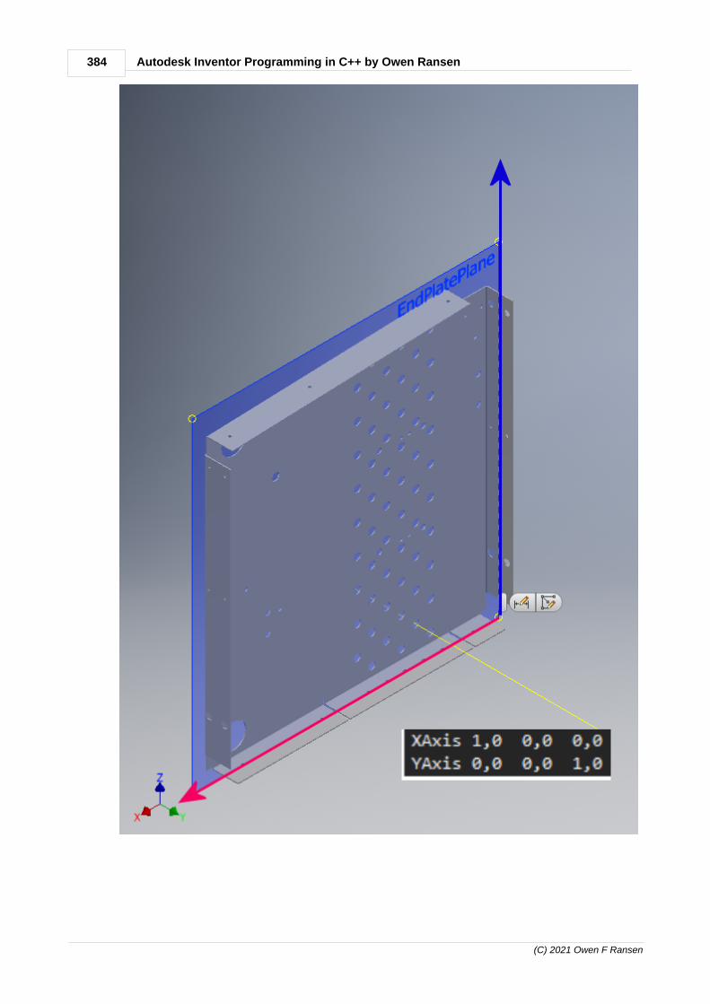
384 Autodesk Inventor Programming in C++ by Owen Ransen
(C) 2021 Owen F Ransen

385Programming Inventor in C#
(C) 2021 Owen F Ransen
13.36 Standard WorkAxes in C#
Here is some code to help you along:
//base work axes
WorkAxis XAxis = oAssyDef.WorkAxes[1];
WorkAxis YAxis = oAssyDef.WorkAxes[2];
WorkAxis ZAxis = oAssyDef.WorkAxes[3];
But you would be better to define something like this:
// These help to get at workplanes WorkPlanes[]
public const int ikYZPlaneNum = 1;
public const int ikXZPlaneNum = 2;
public const int ikXYPlaneNum = 3;
// These help to get at workaxes WorkAxes[]
public const int ikXAxisNum = 1;
public const int ikYAxisNum = 2;
public const int ikZAxisNum = 3;
13.37 Constrain a part to an assembly level work axis
Here's how to create a workaxis at assembly level and constrain it toa hole.
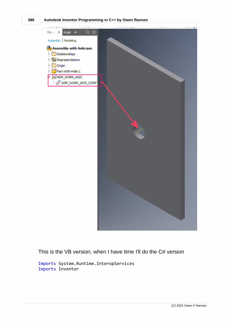
386 Autodesk Inventor Programming in C++ by Owen Ransen
(C) 2021 Owen F Ransen
This is the VB version, when I have time I'll do the C# version
Imports System.Runtime.InteropServicesImports Inventor

387Programming Inventor in C#
(C) 2021 Owen F Ransen
Class MainWindow ' For this to work you need a part open in the assembly andthe part needs to have a t least one hole in it Private Sub Button_Click(sender As Object, e AsRoutedEventArgs)
Dim ThisApp As Inventor.Application Dim oCylGeom As Cylinder Dim oWAxis As WorkAxis
' To get this you need .NET framework, not just .NET ThisApp = Marshal.GetActiveObject("Inventor.application")
If ThisApp.ActiveDocumentType <>DocumentTypeEnum.kAssemblyDocumentObject Then MsgBox("An Assembly Document must be active for thisto work. Exiting.", vbOKOnly + vbCritical, "WRONG DOCUMENT TYPE") Exit Sub End If
Dim oADoc As AssemblyDocument = ThisApp.ActiveDocument Dim oADef As AssemblyComponentDefinition =oADoc.ComponentDefinition Dim oComp As ComponentOccurrence =oADef.Occurrences.Item(1) Dim oPDoc As PartDocument = oComp.Definition.Document Dim oPDef As PartComponentDefinition =oPDoc.ComponentDefinition If oPDef.Features.HoleFeatures.Count = 0 Then MsgBox("No holes") Exit Sub End If
Dim oHole As HoleFeature =oPDef.Features.HoleFeatures.Item(1)
'oHole.HoleCenterPoints 'could likely use these too Dim oCylFace As Face = oHole.SideFaces.Item(1) If oCylFace.SurfaceType =SurfaceTypeEnum.kCylinderSurface Then Dim oCylFaceProxy As FaceProxy = Nothing oComp.CreateGeometryProxy(oCylFace, oCylFaceProxy)

388 Autodesk Inventor Programming in C++ by Owen Ransen
(C) 2021 Owen F Ransen
oCylGeom = oCylFaceProxy.Geometry Dim oPoint As Inventor.Point = oCylGeom.BasePoint Dim oAxis As UnitVector = oCylGeom.AxisVector oWAxis = oADef.WorkAxes.AddFixed(oPoint, oAxis, False) oWAxis.Name = "ASM_WORK_AXIS"
Dim oMConst1 As MateConstraint =oADef.Constraints.AddMateConstraint2(oWAxis, oCylFaceProxy, 0,InferredTypeEnum.kInferredLine, InferredTypeEnum.kInferredLine,MateConstraintSolutionTypeEnum.kAlignedSolutionType) oMConst1.Name = "ASM_WORK_AXIS_CONSTRAINT"
Else MsgBox("Hole's first side face was not a Cylinder.Exiting.", , "") Exit Sub End If
End SubEnd Class
So that workaxis is at assembly level but constrainted to a hole in apart. You can constrain further things to that workaxis...

389Programming Inventor in C#
(C) 2021 Owen F Ransen
13.38 Create an assembly document C#
This code creates a new assembly and sets the measurement unitsto be mm
public static AssemblyDocument CreateNewAssembly() { try { // Get the list of documents currentlyopen inventor Documents DocList =m_Inventor.Documents;
FileManager FileMan =

390 Autodesk Inventor Programming in C++ by Owen Ransen
(C) 2021 Owen F Ransen
m_Inventor.FileManager;
string sTemplateFile =FileMan.GetTemplateFile(DocumentTypeEnum.kAssemblyDocumentObject, SystemOfMeasureEnum.kMetricSystemOfMeasure); //Make sure metric units
// Create the doc and get hold of it... AssemblyDocument NewAsmDoc =(AssemblyDocument)DocList.Add(DocumentTypeEnum.kAssemblyDocumentObject); NewAsmDoc.UnitsOfMeasure.LengthUnits =UnitsTypeEnum.kMillimeterLengthUnits; // make sure mmunits
return NewAsmDoc; }
catch (Exception Ex) { MessageBox.Show("Create new assemblyfailed, " + Ex.Message); return null; } }

391Programming Inventor in C#
(C) 2021 Owen F Ransen
Enter topic text here.

392 Autodesk Inventor Programming in C++ by Owen Ransen
(C) 2021 Owen F Ransen
13.39 Listing the profiles of a face in C#
Look at this sheet metal:
Although it could be shown as a single face it is in fact 2 faces. Itprobably depends on how t was constructed. Anyway this code willlist the two profiles (if they are made of LineSegment2d:
public static void Test2 () { PartDocument PartDoc; try {

393Programming Inventor in C#
(C) 2021 Owen F Ransen
PartDoc = (PartDocument)m_Inventor.ActiveDocument as PartDocument; if (PartDoc == null) { MessageBox.Show("This is not a part document"); return; } } catch { MessageBox.Show ("not a part doc"); return; }
PartComponentDefinition PartDef = PartDoc.ComponentDefinition; PartFeatures FeatsList = PartDef.Features;
foreach (PartFeature ThisFeature in FeatsList) { if (ThisFeature.Type == ObjectTypeEnum.kCutFeatureObject) { CutFeature CutFeature = (CutFeature)ThisFeature; ProfilePath TheProfile = CutFeature.Definition.Profile[1]; ProfileEntity Ent = TheProfile[1];
Debug.WriteLine ("Profile ent " + Ent.ToString() + " " + Ent.CurveType.ToString());
if (Ent.CurveType == Curve2dTypeEnum.kCircleCurve2d) { Circle2d Circle = (Circle2d)Ent.Curve; Debug.WriteLine(" ...is a circle of radius " + Circle.Radius.ToString()); } } else if (ThisFeature.Type == ObjectTypeEnum.kFaceFeatureObject) { FaceFeature FaceFeat = (FaceFeature)ThisFeature; Debug.WriteLine("FaceFeature <" + FaceFeat.Name + "> has " + FaceFeat.Faces.Count.ToString() + " faces");
Debug.WriteLine(" the profile has " + FaceFeat.Definition.Profile.Count.ToString() + " objects");
foreach (ProfilePath ThisPath in FaceFeat.Definition.Profile) { Debug.WriteLine(" this path the profile has " + ThisPath.Count.ToString() + " entities");
foreach (ProfileEntity ThisEnt in ThisPath) { if (ThisEnt.CurveType == Curve2dTypeEnum.kLineSegmentCurve2d) { LineSegment2d Line2d = (LineSegment2d)ThisEnt.Curve;

394 Autodesk Inventor Programming in C++ by Owen Ransen
(C) 2021 Owen F Ransen
string sX0 = string.Format("{0,8:0.00}", Line2d.StartPoint.X); string sY0 = string.Format("{0,8:0.00}", Line2d.StartPoint.Y); string sX1 = string.Format("{0,8:0.00}", Line2d.EndPoint.X); string sY1 = string.Format("{0,8:0.00}", Line2d.EndPoint.Y);
Debug.WriteLine(" LinSeg, X:" + sX0 + " Y:" + sY0 + " --> X:" + sX1 + " Y:" + sY1); } } }
// Un false this to see even more detail#if false Faces FacesList = FaceFeat.Faces; // Face BiggestFace = null;
foreach (Face ThisFace in FacesList) { Debug.WriteLine(" this face has vertices: " + ThisFace.Vertices.Count.ToString() + " (feature: " + FaceFeat.Name + ")");
foreach (Vertex v in ThisFace.Vertices) { Point p = v.Point; Debug.WriteLine(" " + p.X.ToString() + " " + p.Y.ToString() + " " + p.Z.ToString()); } }#endif } else { Debug.WriteLine("This feature is a " + ThisFeature.Type.ToString()); } } }
And the output will look like this:
FaceFeature <Face1> has 3 faces the profile has 1 objects this path the profile has 4 entities LinSeg, X: 0,00 Y: 0,00 --> X: -53,30 Y: 0,00 LinSeg, X: -53,30 Y: 0,00 --> X: -53,30 Y: -53,00 LinSeg, X: -53,30 Y: -53,00 --> X: 0,00 Y: -53,00 LinSeg, X: 0,00 Y: -53,00 --> X: 0,00 Y: 0,00FaceFeature <Face3> has 1 faces the profile has 1 objects this path the profile has 4 entities LinSeg, X: 8,05 Y: 0,00 --> X: 8,05 Y: -3,50 LinSeg, X: 8,05 Y: -3,50 --> X: 52,90 Y: -1,90

395Programming Inventor in C#
(C) 2021 Owen F Ransen
LinSeg, X: 52,90 Y: -1,90 --> X: 52,90 Y: 0,00 LinSeg, X: 52,90 Y: 0,00 --> X: 8,05 Y: 0,00
...and shows that there are two FaceFeatures.
13.40 List all planes in a part, C#
There are always the first three planes which can be accessed by a 1based index. Other user work planes are added from 4 onwards:
In code you can access all the planes in a part like this:

396 Autodesk Inventor Programming in C++ by Owen Ransen
(C) 2021 Owen F Ransen
PartDocument PartDoc;try{
PartDoc = (PartDocument)m_Inventor.ActiveDocument as PartDocument;if (PartDoc == null){
MessageBox.Show("This is not a part document");return;
}}catch{
MessageBox.Show("not a part doc");return;
}
PartComponentDefinition PartDef = PartDoc.ComponentDefinition;WorkPlanes WPList = PartDef.WorkPlanes;
int iPlaneNumber = 1;foreach (WorkPlane ThisPlane in WPList){
Debug.WriteLine("ThisPlane is called <" + ThisPlane.Name + "> Plane number = " + iPlaneNumber.ToString());WorkPlane Plane1 = WPList[iPlaneNumber];Debug.WriteLine("Plane <" + Plane1.Name + "> number = " + iPlaneNumber.ToString());iPlaneNumber++;
}
This will give you output like this:
ThisPlane is called <YZ Plane> Plane number = 1Plane <YZ Plane> number = 1ThisPlane is called <XZ Plane> Plane number = 2Plane <XZ Plane> number = 2ThisPlane is called <XY Plane> Plane number = 3Plane <XY Plane> number = 3ThisPlane is called <PianoSpalla> Plane number = 4Plane <PianoSpalla> number = 4
Notice that 4th plane, the first user plane.
You could use something like this:
// These help to get at workplanes WorkPlanes[]
public const int ikYZPlaneNum = 1;
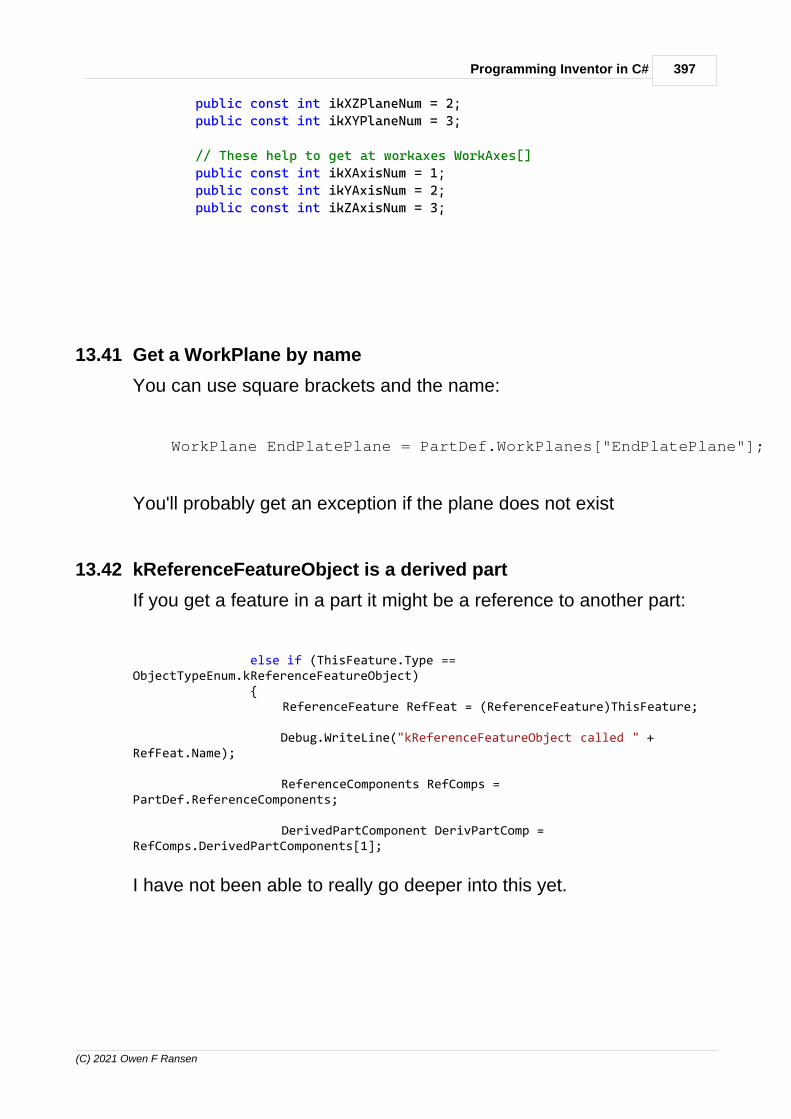
397Programming Inventor in C#
(C) 2021 Owen F Ransen
public const int ikXZPlaneNum = 2;
public const int ikXYPlaneNum = 3;
// These help to get at workaxes WorkAxes[]
public const int ikXAxisNum = 1;
public const int ikYAxisNum = 2;
public const int ikZAxisNum = 3;
13.41 Get a WorkPlane by name
You can use square brackets and the name:
WorkPlane EndPlatePlane = PartDef.WorkPlanes["EndPlatePlane"];
You'll probably get an exception if the plane does not exist
13.42 kReferenceFeatureObject is a derived part
If you get a feature in a part it might be a reference to another part:
else if (ThisFeature.Type ==ObjectTypeEnum.kReferenceFeatureObject) { ReferenceFeature RefFeat = (ReferenceFeature)ThisFeature;
Debug.WriteLine("kReferenceFeatureObject called " +RefFeat.Name);
ReferenceComponents RefComps =PartDef.ReferenceComponents;
DerivedPartComponent DerivPartComp =RefComps.DerivedPartComponents[1];
I have not been able to really go deeper into this yet.
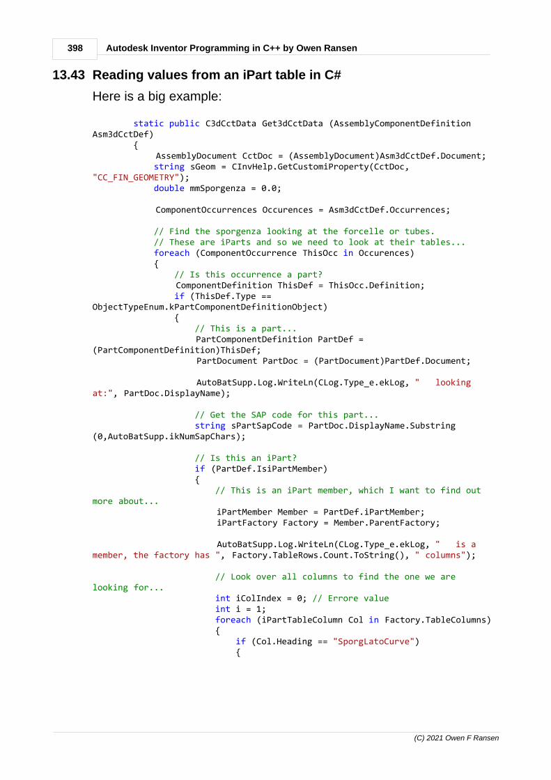
398 Autodesk Inventor Programming in C++ by Owen Ransen
(C) 2021 Owen F Ransen
13.43 Reading values from an iPart table in C#
Here is a big example:
static public C3dCctData Get3dCctData (AssemblyComponentDefinitionAsm3dCctDef) { AssemblyDocument CctDoc = (AssemblyDocument)Asm3dCctDef.Document; string sGeom = CInvHelp.GetCustomiProperty(CctDoc,"CC_FIN_GEOMETRY"); double mmSporgenza = 0.0; ComponentOccurrences Occurences = Asm3dCctDef.Occurrences;
// Find the sporgenza looking at the forcelle or tubes. // These are iParts and so we need to look at their tables... foreach (ComponentOccurrence ThisOcc in Occurences) { // Is this occurrence a part? ComponentDefinition ThisDef = ThisOcc.Definition; if (ThisDef.Type ==ObjectTypeEnum.kPartComponentDefinitionObject) { // This is a part... PartComponentDefinition PartDef =(PartComponentDefinition)ThisDef; PartDocument PartDoc = (PartDocument)PartDef.Document;
AutoBatSupp.Log.WriteLn(CLog.Type_e.ekLog, " lookingat:", PartDoc.DisplayName);
// Get the SAP code for this part... string sPartSapCode = PartDoc.DisplayName.Substring(0,AutoBatSupp.ikNumSapChars);
// Is this an iPart? if (PartDef.IsiPartMember) { // This is an iPart member, which I want to find outmore about... iPartMember Member = PartDef.iPartMember; iPartFactory Factory = Member.ParentFactory;
AutoBatSupp.Log.WriteLn(CLog.Type_e.ekLog, " is amember, the factory has ", Factory.TableRows.Count.ToString(), " columns");
// Look over all columns to find the one we arelooking for... int iColIndex = 0; // Errore value int i = 1; foreach (iPartTableColumn Col in Factory.TableColumns) { if (Col.Heading == "SporgLatoCurve") {

399Programming Inventor in C#
(C) 2021 Owen F Ransen
iColIndex = i; break; } i++; }
if (iColIndex > 0) { // So, we know in which *column* to get thesporgenza from
// Loop over all the rows to find the one whichcorresponds to our part iPartTableRows Rows = Factory.TableRows; foreach (iPartTableRow Row in Rows) { iPartTableCell SapCodeCell = Row[1]; string sThisSapCode = SapCodeCell.Value; if (sThisSapCode == sPartSapCode) { iPartTableCell SporgenzaCell =Row[iColIndex]; string sCellValue =AutoBatSupp.GetCleanNumberString(SporgenzaCell.Value); // Convert from "20,00mm" to "20.00" AutoBatSupp.Log.WriteLn(CLog.Type_e.ekLog, " cell is ", sCellValue); if (!double.TryParse(sCellValue,NumberStyles.Number, CultureInfo.InvariantCulture, out mmSporgenza)) { AutoBatSupp.Log.WriteLn(CLog.Type_e.ekErr, " could not get sporgenza ",mmSporgenza.ToString(), " from ", sCellValue); } else { AutoBatSupp.Log.WriteLn(CLog.Type_e.ekLog, " sporgenza is ",mmSporgenza.ToString()); break; // finished. } } } } } } }
if (mmSporgenza == 0.0) { AutoBatSupp.Log.WriteLn(CLog.Type_e.ekErr, "Could not findsporgenza parameter"); }

400 Autodesk Inventor Programming in C++ by Owen Ransen
(C) 2021 Owen F Ransen
// Compose all the data into a single object C3dCctData CctData = new C3dCctData { m_sGeom = sGeom, m_mmSporgenza = mmSporgenza };
return CctData;
Enter topic text here.
14 Using Inventor manually
14.1 Parallel constraint, not coplanar
You can make planes be parallel but not coplanar by using the Limitstab...

401Using Inventor manually
(C) 2021 Owen F Ransen
You'll have to experiment with which limits work. If the objects aresmall you can use, for example, 1000mm in the Maximum.
See also software wise.
You can achieve the same result using angular constraints...
.
14.2 BOMs and Part Lists
14.2.1 BOM vs Parts List
BOM can be accessed from Assembly and Drawing while Parts List isa Drawing only table.
In general a BOM cannot be changed, it is based on the actualassembly and rows cannot be added. But for example counts can be

402 Autodesk Inventor Programming in C++ by Owen Ransen
(C) 2021 Owen F Ransen
changed by making them static.
In the parts list you can add rows.
14.2.2 Adding a flat parts list in a drawing
Add the BOM into the assembly. See here and here. In the BOMselect Parts Only.
Create the drawing with that assembly as the base view.
Go to Annotate tab Parts List icon. In the Parts List dialog select BOMView Parts Only item:
14.2.3 BOM Bill of materials
To find the settings of the BOM go into the document settings of theassembly or part and click on the BOM tab.
To get to the BOM itself:

403Using Inventor manually
(C) 2021 Owen F Ransen
The parts list is derived from the BOM, but is not the same thing. Itseems to be closer to the metal. I think you can't do much with theBOM, whereas the parts list is more flexible.
Components can be1. Normal2. Phantom, like screws nuts washers, ignored by the BOM but used
in the mass calculations.3. Referenced, these are not real components, but are present to
help the drawing construction. Ignored by BOM and masscalculations.
4. Purchased, the component is a single BOM line5. Inseperable, made of parts, but of parts which cannot be separated
from each other

404 Autodesk Inventor Programming in C++ by Owen Ransen
(C) 2021 Owen F Ransen
See also substitution.
14.2.4 Remove something from a Parts List
Double click on the parts list in the drawing, that will bring up the partslist dialog list box. Right click on the component, and turn of visibility.
14.2.5 Parts list modification
Add a parts list to a drawing IDW like this (save the drawing first):
Once you have added a parts list you can modify it, even substitutingsome columns for other columns, Parts List Column Substitution:

405Using Inventor manually
(C) 2021 Owen F Ransen
Note that the parts list is obtained from the BOM but is not the samething.
14.2.6 Parts Only (disabled) problem
If you get the BOM dialog with Parts Only (disabled) all you have todo is enable them using the magnifying glass:

406 Autodesk Inventor Programming in C++ by Owen Ransen
(C) 2021 Owen F Ransen
14.2.7 Virtual components
Virtual components are good for adding quantities of paint or solderor padding ext. They appear in the BOM. They can only be insertedinto an assembly, not into a part.
You create them like this:

407Using Inventor manually
(C) 2021 Owen F Ransen
They have that white cube icon in the assembly.
Now here is how you can set the component to hold data aboutweight (for example). Create a user parameter which contains thedata you need, then...

408 Autodesk Inventor Programming in C++ by Owen Ransen
(C) 2021 Owen F Ransen
Now the component will appear in the BOM like this:

409Using Inventor manually
(C) 2021 Owen F Ransen
If this does not work in your situation you can also try this technique.

410 Autodesk Inventor Programming in C++ by Owen Ransen
(C) 2021 Owen F Ransen
14.2.8 Parts List Style (Default)
You set it like this:
It is all a bit of a mystery inside an enigma:

411Using Inventor manually
(C) 2021 Owen F Ransen

412 Autodesk Inventor Programming in C++ by Owen Ransen
(C) 2021 Owen F Ransen
See and understand also this:
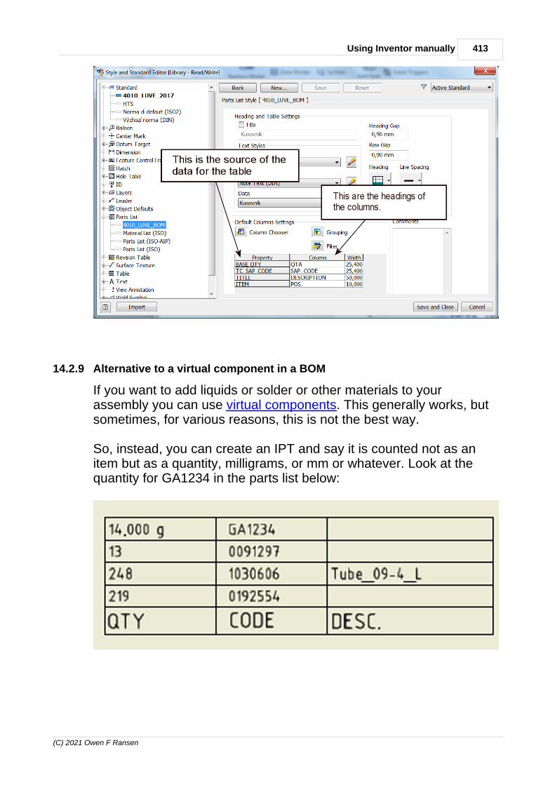
413Using Inventor manually
(C) 2021 Owen F Ransen
14.2.9 Alternative to a virtual component in a BOM
If you want to add liquids or solder or other materials to yourassembly you can use virtual components. This generally works, butsometimes, for various reasons, this is not the best way.
So, instead, you can create an IPT and say it is counted not as anitem but as a quantity, milligrams, or mm or whatever. Look at thequantity for GA1234 in the parts list below:

414 Autodesk Inventor Programming in C++ by Owen Ransen
(C) 2021 Owen F Ransen
It says the quantity is 14 grams. (The other quantities in the list aboveare counts of the number of IPTs in the assembly.)
Create the IPT which you want to contain your quantity and which youwant to appear in the BOM and Parts List. In the example belowGA1234.IPT has had its BOM settings set to grams:
The next step is to make that parts entry in the BOM "Static", whichmeans you can write whatever number you want in there, it is notcalculated:

415Using Inventor manually
(C) 2021 Owen F Ransen
Finally, if you want a parts list as well as a BOM, be sure to use QTYas one of the columns. As you design your parts list choose QTY asshown below:

416 Autodesk Inventor Programming in C++ by Owen Ransen
(C) 2021 Owen F Ransen
14.3 iParts
14.3.1 iParts general info
iParts work with parametric parts.
Steps to create an iPart, a tube for example:
1. Create a new part.2. In the sketch add a circle3. Add a dimension to the circle and in the tiny mm box type
Diameter=204. End the sketch and extrude it.5. In the edit box for the extrusion type Length=50.6. Finish the sketch7. Now you have two model parameters named as you want as
Length and Diameter (instead of the default L0 and D0).8. You also have a tube which is 20 by 509. Now go into the Manage tab and click on the Create iPart icon. (if
grey disabled trying saving the file) 10.Now you can create a table of different sized tubes. Each row of
the table is called a Member.

417Using Inventor manually
(C) 2021 Owen F Ransen
14.3.2 iPart - standard vs custom
A standard iPart has parameter values which must be selected from apredefined list. e.g. part code corresponds to a record in a table. Therecord contains the parameters like angle and length to specify theiPart for that code.
A custom iPart allows you to write whatever values you want, not justselecting one of several fixed values from a list.
In the SDK there are two examples of iParts, one custom onestandard, in this directory...
C:\Users\Public\Documents\Autodesk\Inventor 2013\SDK\DeveloperTools\Samples\Data_Files
...you should find CustomFactory.ipt and StandardFactory.ipt.
14.3.3 iPart author
To get to the iPart Author click on the Create iPart icon in the Managetab.
You must have Excel installed for iParts to work.
14.3.4 iPart Member and PartNumber
As far as I can tell there is some confusion here. It seems thatMember is the key index into the table, and maybe PartNumber is adescriptive field. This confusion/duplication/feature is due to history.
So when creating iParts make sure that Member has the code of the

418 Autodesk Inventor Programming in C++ by Owen Ransen
(C) 2021 Owen F Ransen
object you are creating, like 34120009.
Why is a new column needed? It is because sometimes memberscan have the same Part Number. PN is just a user book-keepingattribute. We need a column with unique values.
In summary, the Member column has to be there. The cell values canbe changed but they have to be unique. Please do not delete orrelocate the column.
The Member also gives the name to any temporary files created bythe iPart factory.
The iPart also generates "children" files, which represent each of themembers of your table. These are files that you normally don't haveto do much with, as they are controlled by the table in the Factorypart. The file names for these child parts are controlled by theMember name from the table - hence, when you change the membernames, their file names will change. This (not the name of the factorypart) is what the warning message was referring to.

419Using Inventor manually
(C) 2021 Owen F Ransen
14.3.5 Custom iParts
Create your part normally, for example a cylinder with Diameter andLength dimensions.

420 Autodesk Inventor Programming in C++ by Owen Ransen
(C) 2021 Owen F Ransen
Clicking on the Create iPart icon you'll get the iPart Author dialog,right click on the Diameter column and select Custom ParameterColumn:
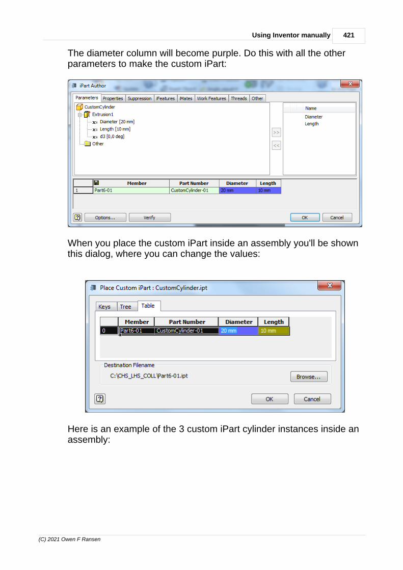
421Using Inventor manually
(C) 2021 Owen F Ransen
The diameter column will become purple. Do this with all the otherparameters to make the custom iPart:
When you place the custom iPart inside an assembly you'll be shownthis dialog, where you can change the values:
Here is an example of the 3 custom iPart cylinder instances inside anassembly:

422 Autodesk Inventor Programming in C++ by Owen Ransen
(C) 2021 Owen F Ransen
How to change parameters of an already created custom iPart.
14.3.6 Changing Custom Ipart Parameters
Once you have created a custom ipart you can change theparameters by Activating its table:

423Using Inventor manually
(C) 2021 Owen F Ransen
So here I'm changing the parameters of the"derived" object.
In the above screenshot the "source" object is Tubo-CHS-LHS-Custom.ipt
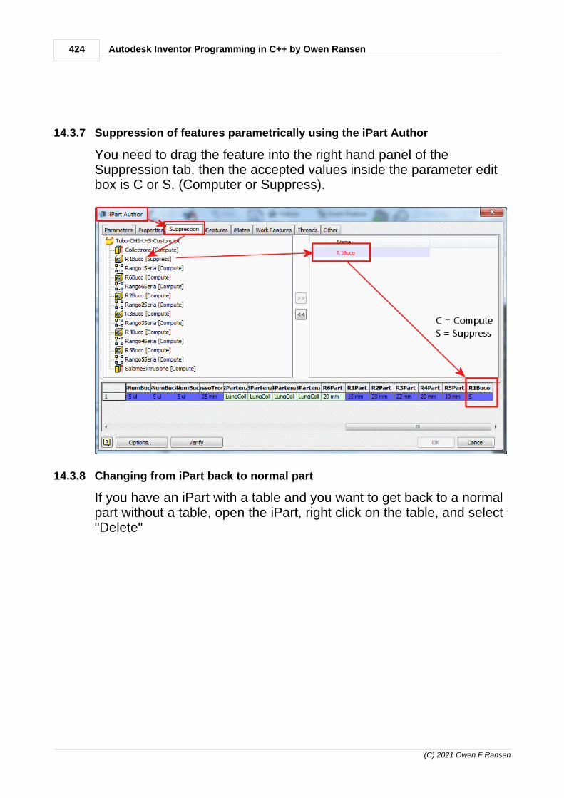
424 Autodesk Inventor Programming in C++ by Owen Ransen
(C) 2021 Owen F Ransen
14.3.7 Suppression of features parametrically using the iPart Author
You need to drag the feature into the right hand panel of theSuppression tab, then the accepted values inside the parameter editbox is C or S. (Computer or Suppress).
14.3.8 Changing from iPart back to normal part
If you have an iPart with a table and you want to get back to a normalpart without a table, open the iPart, right click on the table, and select"Delete"

425Using Inventor manually
(C) 2021 Owen F Ransen
1. You'll get a warning about turning the file back into a normal part. 2. Remember to set the parameters to those that you want before
removing the table.3. Do this on a copy of you want to keep the original tabulare iPart.
14.3.9 Custom column in an iPart table
Sometimes you want to add some text or a number into the iPart'stable which is not strictly connected to the geometry of the part. Youdo it like this:
· Open the table· Go to the Other tab· Click in the empty space· Insert the name of the extra column
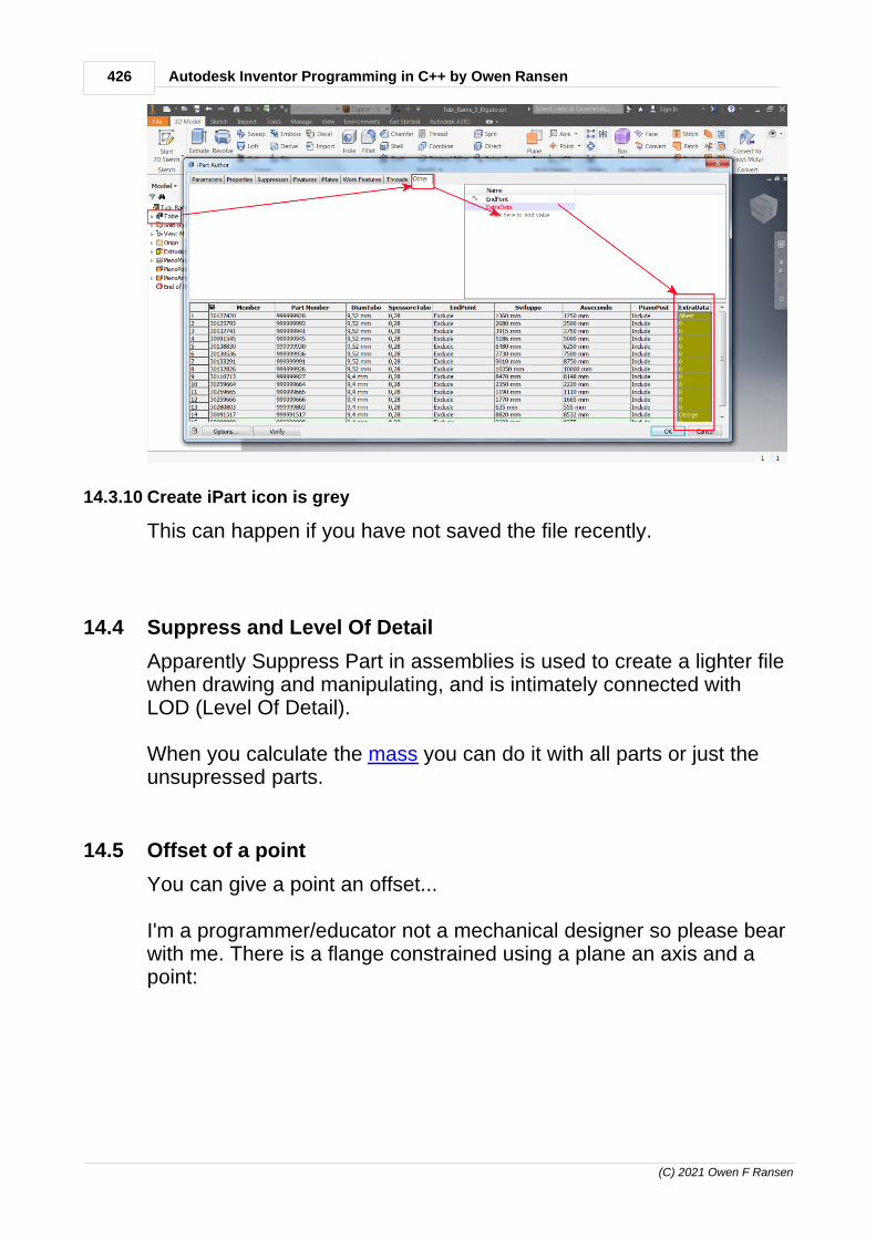
426 Autodesk Inventor Programming in C++ by Owen Ransen
(C) 2021 Owen F Ransen
14.3.10 Create iPart icon is grey
This can happen if you have not saved the file recently.
14.4 Suppress and Level Of Detail
Apparently Suppress Part in assemblies is used to create a lighter filewhen drawing and manipulating, and is intimately connected withLOD (Level Of Detail).
When you calculate the mass you can do it with all parts or just theunsupressed parts.
14.5 Offset of a point
You can give a point an offset...
I'm a programmer/educator not a mechanical designer so please bearwith me. There is a flange constrained using a plane an axis and apoint:

427Using Inventor manually
(C) 2021 Owen F Ransen
I'd like to be able to move the flanged tube in by 10mm. I can do thisby increasing the offset on the point-point constraint to 10mm. If I use-10 it does not go in the other direction. Presumably the absolutevalue of the number is taken.
But what tells Inventor in which direction the offset (in a point to pointconstraint) should go?.
This described mate combination has two possible solutions. Duringmate creation you can control the result using BiasPointOne andBiasPointTwo arguments. When the mates are already created, youcan move with the occurrence via API or iProperties dialog. If youmove the occurrence near to the second possible solution, afterupdate the occurrence will be move to the nearest solution (thesecond one in this case).Tags (0)
14.6 Pack And Go
Here's something which sort of works...
Copy all the pieces from the Pack And Go area into the Inventorcache directory. You will have to decide whether to overwrite thevarious bits and pieces.

428 Autodesk Inventor Programming in C++ by Owen Ransen
(C) 2021 Owen F Ransen
Most components are in the "Area di Lavoro" or the Englishequivalent:
In some cases the main component is in the same directory, as in theabove example, in other cases the main component is in a higherlevel directory:

429Using Inventor manually
(C) 2021 Owen F Ransen
Once in the usual Inventor directory make sure all components arenot read-only then pen them and save them while having your normalproject setup (i.e. not the Pack And Go project which the componentsarrived with).
14.7 WorkAxes at assembly level
When you add a work axis at assembly level what you actually do isconstrain it to some feature of a part.

430 Autodesk Inventor Programming in C++ by Owen Ransen
(C) 2021 Owen F Ransen
Programmatically you can AddFixed, and they stay in that place inspace, unattached to any part feature.
14.8 Insert constraint
The insert (perno foro) constraint lines up two cylindrical features byusing their axes and two planes.

431Using Inventor manually
(C) 2021 Owen F Ransen
Look...

432 Autodesk Inventor Programming in C++ by Owen Ransen
(C) 2021 Owen F Ransen
...aligned puts the cylinder exactly on the surface aligning the twoaxes:
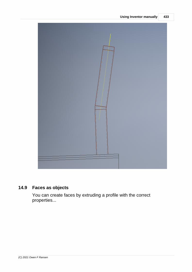
433Using Inventor manually
(C) 2021 Owen F Ransen
14.9 Faces as objects
You can create faces by extruding a profile with the correctproperties...

434 Autodesk Inventor Programming in C++ by Owen Ransen
(C) 2021 Owen F Ransen
14.10 Show hidden lines in a drawing manually
To show hidden lines in a 2D IDW drawing follow this:

435Using Inventor manually
(C) 2021 Owen F Ransen
14.11 Axis directions
It seems that it is better to use undirected axes constraint, eventhough each work axis does have a direction.

436 Autodesk Inventor Programming in C++ by Owen Ransen
(C) 2021 Owen F Ransen
So if you have a plane to plane constraint already in place you shouldchoose "undirected" axis constraint. I suppose it makes sensebecause who can tell which direction a hole or circular cut axis shouldgo...?
14.12 Creating folders in the browser manually
Select the objects in the browser and then context click and thenchoose "Add to New Folder"...

437Using Inventor manually
(C) 2021 Owen F Ransen
14.13 Construction lines in sketches
Construction lines help you create the profile to extrude, for example,but are not extruded themselves. You can flip lines from construction(dotted) to normal and back again using this icon:

438 Autodesk Inventor Programming in C++ by Owen Ransen
(C) 2021 Owen F Ransen
14.14 Formulas inside parameter settings
Here is an example which is the formula equivalent of this iLogic VBexample:

439Using Inventor manually
(C) 2021 Owen F Ransen
sign(RagColl - RagAtt) * sqrt(( RagColl * RagColl - RagAtt *RagAtt ) * sign(RagColl * RagColl - RagAtt * RagAtt))
It is very very important that the case is respected in the parameternames and the functions.
Here's how the thing would appear inside a part:
14.15 Explode a pattern
To make an object independent from its containing pattern right clickon the Element text odf the object, and choose "Independent".

440 Autodesk Inventor Programming in C++ by Owen Ransen
(C) 2021 Owen F Ransen
Once it is independent though all the constraints will be lost.
You can't remove the first object from a pattern, and you can't removean object from a pattern inside a pattern.
14.16 Assembly WorkPoints and Part WorkPoints
These are a bit different and so cannot be assumed to behave in thesame way. You cannot, in an assembly, create a WorkPoint from aSketchPoint. Autodesk says:
"Hi! Certainly, the behavior is not intuitive but there are technicalreasons behind it. Inventor assembly (except assembly features andweldment) is not history based like part. The advantage is to allowusers to structure the assembly and swap out components with ease.Work geometry is treated like a component. So, a workpoint or aworkplane or a workaxis is actually a component which can beconstrained to other geometry. Assembly level work geometry can be

441Using Inventor manually
(C) 2021 Owen F Ransen
adjusted by editing the constraint values. It is not like the workgeometry in a part as features.
However, assembly level sketch does have a sense of history likeassembly features. Allowing non-history based operation likeconstraining to act on history based object can lead to an unsolvablecycle. As a result, assembly level work geometry cannot beconstrained to an assembly sketch. There is room for improvementhere. At least, it should be made more apparent why this operation isblocked. I will work with project team to understand the behaviorbetter and see if the limitation can be removed."
The same presumably goes for WorkAxis and WorkPlane objects.
14.17 Erase pattern elements
It seems that you can suppress pattern elements, but not deletethem:

442 Autodesk Inventor Programming in C++ by Owen Ransen
(C) 2021 Owen F Ransen
14.18 Axis perpendicular to sketch point, how to
It is fairly easy, add the axes on a sketch point and parallel to (forexample) Z.
But remember that you may have to click on the Update icon if youchange some parameters:

443Using Inventor manually
(C) 2021 Owen F Ransen
Click on the Update icon...

444 Autodesk Inventor Programming in C++ by Owen Ransen
(C) 2021 Owen F Ransen

445Using Inventor manually
(C) 2021 Owen F Ransen
14.19 Delete a dimension manually
14.20 Mass Volume Calculation
In the brower, on the part or assembly root, right click and selectiProperties from the menu. Then click on the Physical tab. You mayhave to recalculate. And you may want with or without suppressedparts.
14.21 Add a WorkPlane in an Assembly
Here is a function to to it based on the existing standard workplanesof an assembly:
bool AddFixedWorkPlaneInAsm (CComPtr<AssemblyComponentDefinition>& pAsmCompDef, // where the plane will be added const int ikPlaneIdx, // Which ofthe standard planes to base the new one on const double kOffsetMm, // Offset, const wchar_t* const pszPlaneName)
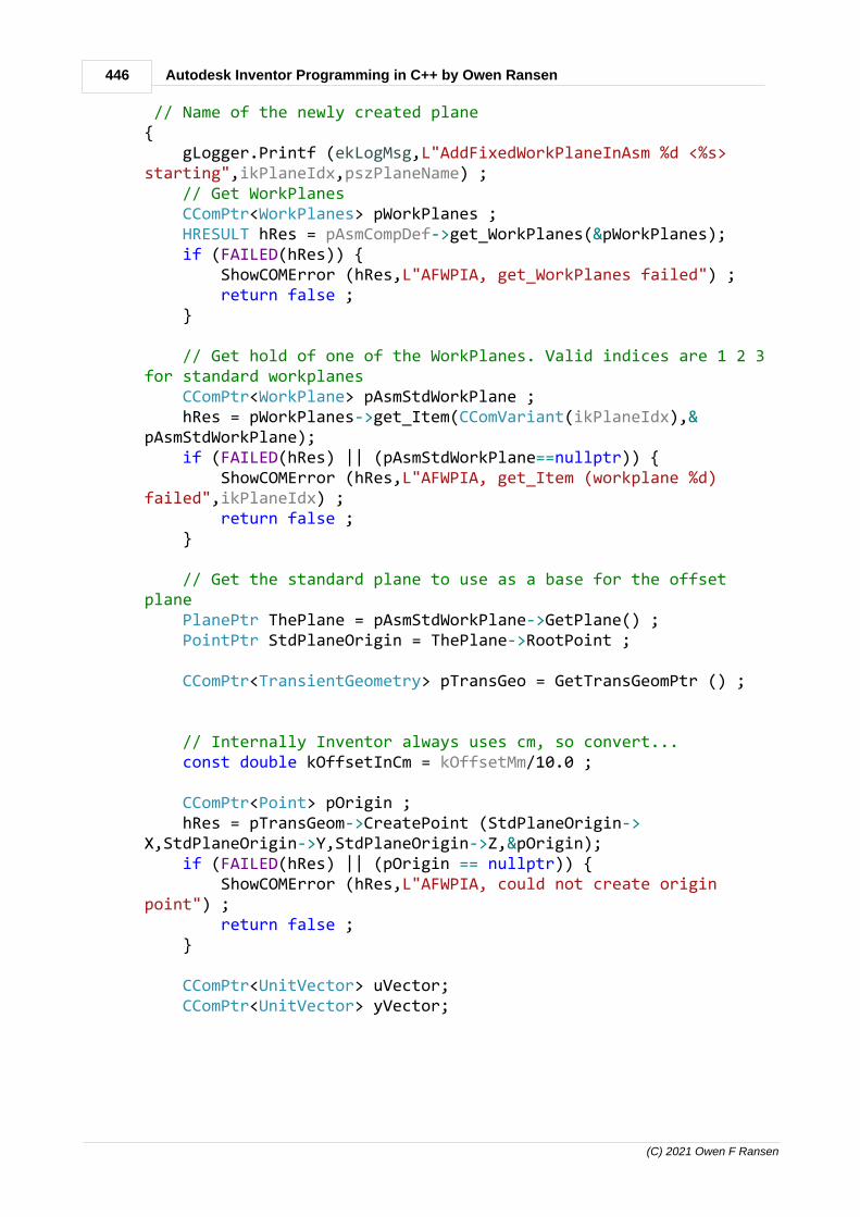
446 Autodesk Inventor Programming in C++ by Owen Ransen
(C) 2021 Owen F Ransen
// Name of the newly created plane{ gLogger.Printf (ekLogMsg,L"AddFixedWorkPlaneInAsm %d <%s>starting",ikPlaneIdx,pszPlaneName) ; // Get WorkPlanes CComPtr<WorkPlanes> pWorkPlanes ; HRESULT hRes = pAsmCompDef->get_WorkPlanes(&pWorkPlanes); if (FAILED(hRes)) { ShowCOMError (hRes,L"AFWPIA, get_WorkPlanes failed") ; return false ; }
// Get hold of one of the WorkPlanes. Valid indices are 1 2 3for standard workplanes CComPtr<WorkPlane> pAsmStdWorkPlane ; hRes = pWorkPlanes->get_Item(CComVariant(ikPlaneIdx),&pAsmStdWorkPlane); if (FAILED(hRes) || (pAsmStdWorkPlane==nullptr)) { ShowCOMError (hRes,L"AFWPIA, get_Item (workplane %d)failed",ikPlaneIdx) ; return false ; }
// Get the standard plane to use as a base for the offsetplane PlanePtr ThePlane = pAsmStdWorkPlane->GetPlane() ; PointPtr StdPlaneOrigin = ThePlane->RootPoint ;
CComPtr<TransientGeometry> pTransGeo = GetTransGeomPtr () ;
// Internally Inventor always uses cm, so convert... const double kOffsetInCm = kOffsetMm/10.0 ;
CComPtr<Point> pOrigin ; hRes = pTransGeom->CreatePoint (StdPlaneOrigin->X,StdPlaneOrigin->Y,StdPlaneOrigin->Z,&pOrigin); if (FAILED(hRes) || (pOrigin == nullptr)) { ShowCOMError (hRes,L"AFWPIA, could not create originpoint") ; return false ; }
CComPtr<UnitVector> uVector; CComPtr<UnitVector> yVector;
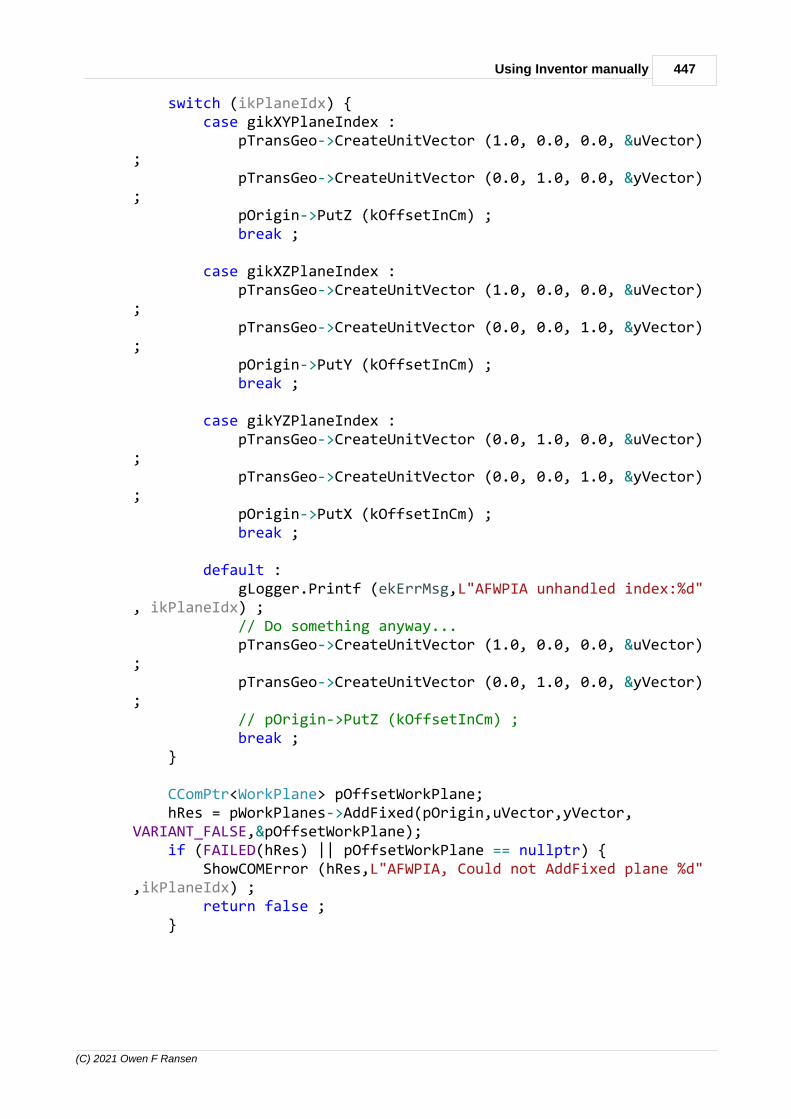
447Using Inventor manually
(C) 2021 Owen F Ransen
switch (ikPlaneIdx) { case gikXYPlaneIndex : pTransGeo->CreateUnitVector (1.0, 0.0, 0.0, &uVector); pTransGeo->CreateUnitVector (0.0, 1.0, 0.0, &yVector); pOrigin->PutZ (kOffsetInCm) ; break ;
case gikXZPlaneIndex : pTransGeo->CreateUnitVector (1.0, 0.0, 0.0, &uVector); pTransGeo->CreateUnitVector (0.0, 0.0, 1.0, &yVector); pOrigin->PutY (kOffsetInCm) ; break ;
case gikYZPlaneIndex : pTransGeo->CreateUnitVector (0.0, 1.0, 0.0, &uVector); pTransGeo->CreateUnitVector (0.0, 0.0, 1.0, &yVector); pOrigin->PutX (kOffsetInCm) ; break ;
default : gLogger.Printf (ekErrMsg,L"AFWPIA unhandled index:%d", ikPlaneIdx) ; // Do something anyway... pTransGeo->CreateUnitVector (1.0, 0.0, 0.0, &uVector); pTransGeo->CreateUnitVector (0.0, 1.0, 0.0, &yVector); // pOrigin->PutZ (kOffsetInCm) ; break ; }
CComPtr<WorkPlane> pOffsetWorkPlane; hRes = pWorkPlanes->AddFixed(pOrigin,uVector,yVector,VARIANT_FALSE,&pOffsetWorkPlane); if (FAILED(hRes) || pOffsetWorkPlane == nullptr) { ShowCOMError (hRes,L"AFWPIA, Could not AddFixed plane %d",ikPlaneIdx) ; return false ; }

448 Autodesk Inventor Programming in C++ by Owen Ransen
(C) 2021 Owen F Ransen
CComBSTR bstrName = CString (pszPlaneName) ; pOffsetWorkPlane->put_Name (bstrName) ;
gLogger.Printf (ekLogMsg,L"AddFixedWorkPlaneInAsm <%s> endingok",pszPlaneName) ;
return true ;}
Here's some other less flexible code:
HRESULT Result = NOERROR;
CLSID InvAppClsid; Result = CLSIDFromProgID (L"Inventor.Application", &InvAppClsid); if (FAILED(Result)) return;
CComPtr<IUnknown> pInvAppUnk; Result = ::GetActiveObject(InvAppClsid, NULL, &pInvAppUnk); if (FAILED(Result)) { _tprintf_s(_T("*** Could not get hold of an active Inventorapplication ***\n")); return ; }
CComPtr<Application> pInvApp; Result = pInvAppUnk->QueryInterface (__uuidof(Application), (void **)&pInvApp); if (FAILED(Result)) return ;
CComPtr<Document> oDoc; CComPtr<AssemblyDocument> pAssyDoc; Result = pInvApp->get_ActiveDocument(&oDoc); pAssyDoc = oDoc;
CComPtr<TransientGeometry> pTransGeo; Result = pInvApp->get_TransientGeometry(&pTransGeo);
CComPtr<Point> pt; Result = pTransGeo->CreatePoint(0, 0, -100,&pt);
CComPtr<UnitVector> xVector; Result = pTransGeo->CreateUnitVector(1,0, 0, &xVector);
CComPtr<UnitVector> yVector; Result = pTransGeo->CreateUnitVector(0, 1, 0, &yVector);

449Using Inventor manually
(C) 2021 Owen F Ransen
CComPtr<WorkPlane> wPlane;
Result = pAssyDoc->ComponentDefinition->WorkPlanes->AddFixed(pt,xVector,yVector, VARIANT_FALSE,&wPlane);
14.22 Add a feature to an existing pattern
You can add a feature to an existing pattern by simply editing it andwhen the dialog comes up (don't click in the dialog) hover the mouseover the feature you want to add (you'll see a + sign near the cursor).Then click on it.
NB: In the browser you must put the new features you want to add tothe pattern higher up than the pattern itself. The features you want toadd to the pattern must be considered to be created before thepattern itself.

450 Autodesk Inventor Programming in C++ by Owen Ransen
(C) 2021 Owen F Ransen
14.23 Add a point to the surface of a tube manually
The first step is to put a plane at the required height:
Put a sketch on that new plane, then project the geometry of the tubeonto the sketch. Draw a line and put a point at the intersection of thegeometry and the line.
14.24 General Note and text
You can add text to an Inventor document using the General Notefunction:

451Using Inventor manually
(C) 2021 Owen F Ransen
It looks like it always floats on the screen in a given quarter which youchoose.
14.25 Add an angular dimension
You select the Dimension icon and then select two lines.
The problem is that the standard axes are not considered lines, soyou have to add one manually before you can select it. Add a linealong the axis you want to use as the base for the angular dimension,in other words.

452 Autodesk Inventor Programming in C++ by Owen Ransen
(C) 2021 Owen F Ransen
14.26 Adding a Dimension in a sketch
The add dimension icons are in the constrain panel of the sketch tab.
For example...
Create a circle in Sketch mode and create a dimension in the Toolstab. Then click on the Parameters icon in the Manage tab. Now youcan change the name of the parameter from "d0" to, for example,"MainTubeDiam". So that parameter now controls the diameter of atube constructed on that sketch.
14.27 Application Options Settings
At empty startup go into the Tools tab and click on ApplicationOptions.
The files tab of this dialog lets you change various directories, likeyour default projects folder.
If you can't find an option in Application Options it is probably inDocument Settings (next to each other in the Tools ribbon). You canuse templates to make application wide document settings.
14.28 Backup options for Inventor files
This is an item in the project options. Select the project in the upperpane and select the Options branch in the lower pane.
The default setting for Old Versions To Keep is 1, keep one backup.You can set this to 2 3 4 or whatever.
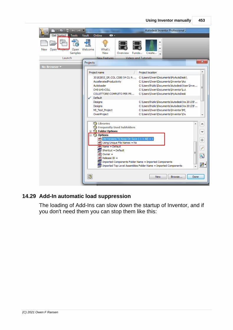
453Using Inventor manually
(C) 2021 Owen F Ransen
14.29 Add-In automatic load suppression
The loading of Add-Ins can slow down the startup of Inventor, and ifyou don't need them you can stop them like this:

454 Autodesk Inventor Programming in C++ by Owen Ransen
(C) 2021 Owen F Ransen
14.30 Strange material problem
If you get a single solid object which has different materials on it usethe Clear All Overides on its properties:

455Using Inventor manually
(C) 2021 Owen F Ransen
The solid above is copper outside and steel inside, I don't know why.But the clear all overrides solves the problem.
14.31 Browser is missing! Get it back!
Go to View tab, User Interface icon.
14.32 Change material / color of a solid
Select the object in the browser, and then use the material combo atthe top of the window:

456 Autodesk Inventor Programming in C++ by Owen Ransen
(C) 2021 Owen F Ransen
14.33 Change the offset elevation of a plane
Double click on the plane:

457Using Inventor manually
(C) 2021 Owen F Ransen
and you'll get the edit box.
14.34 Changing home view setting
Go to the view you want to be the home view then right click on thehome view icon, the examine the menu which pops up.
Front Top Right is the default visibility of the cube for home view.

458 Autodesk Inventor Programming in C++ by Owen Ransen
(C) 2021 Owen F Ransen
You can choose to set the current view as fit to view or fixed distance.
14.35 Changing manipulator snap
Use the Document Settings in the Tools tab. Then choose theModelling tab, 3D Snap Spacing edit box.
14.36 Changing the default units
Use the application options to change the default template file:
You can also change this in the document options:
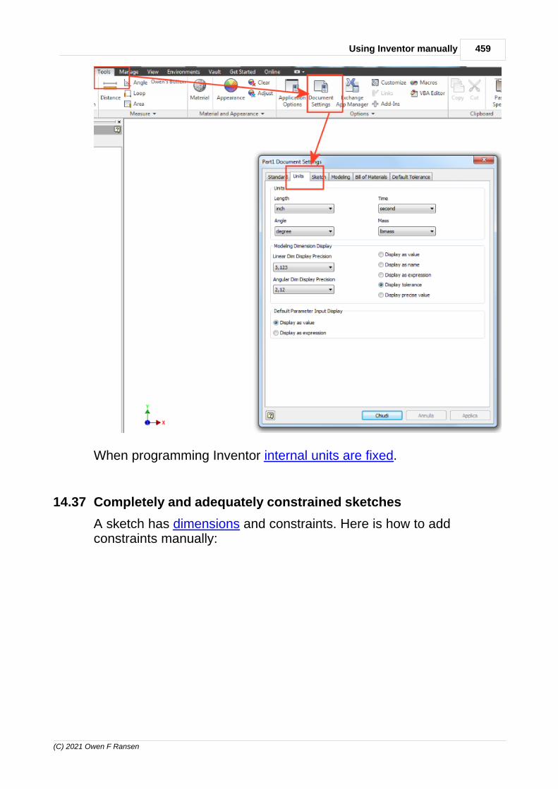
459Using Inventor manually
(C) 2021 Owen F Ransen
When programming Inventor internal units are fixed.
14.37 Completely and adequately constrained sketches
A sketch has dimensions and constraints. Here is how to addconstraints manually:
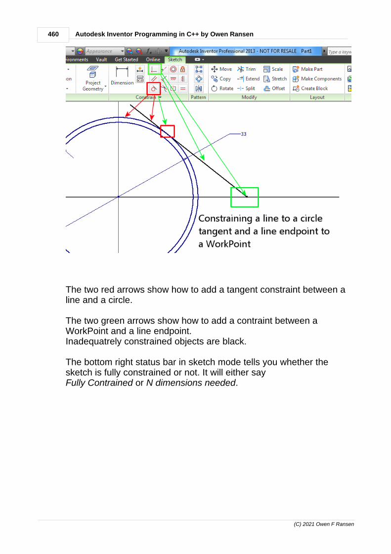
460 Autodesk Inventor Programming in C++ by Owen Ransen
(C) 2021 Owen F Ransen
The two red arrows show how to add a tangent constraint between aline and a circle.
The two green arrows show how to add a contraint between aWorkPoint and a line endpoint.Inadequatrely constrained objects are black.
The bottom right status bar in sketch mode tells you whether thesketch is fully constrained or not. It will either say Fully Contrained or N dimensions needed.

461Using Inventor manually
(C) 2021 Owen F Ransen
14.38 Constrain 2 pairs of axes
If you have a u-bend you have two axes in it, say AxisA and AxisB.These two axes have to be constrained to another two axes whichrepresent the tubes which the u-bend connects, say Axis1 and Axis2:
The problem is that although you can fix AxisA to be completelyconstrainged by Axis1, depending on the accuracy of the parts youmay not be able to constraing AxisB to Axis2. For example the inter-axis distance might be 25.0 on the u-bend but 25.06 between the twotubes.
You can get over this problem by changing the parameter in thesecond constraint. If you set it to 0.1mm, as shown above, it meansthat one of the axes rotates around the other with a radius of 0.1mm:
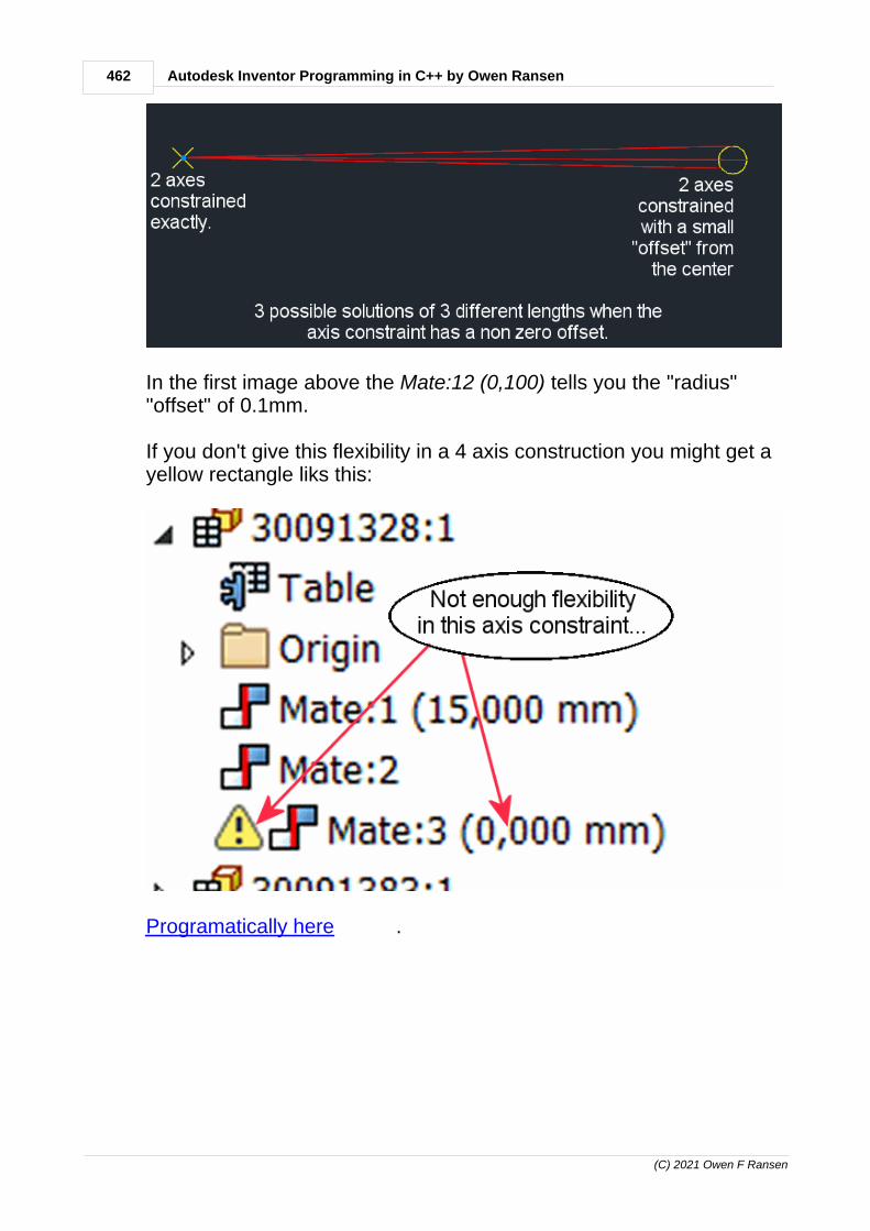
462 Autodesk Inventor Programming in C++ by Owen Ransen
(C) 2021 Owen F Ransen
In the first image above the Mate:12 (0,100) tells you the "radius""offset" of 0.1mm.
If you don't give this flexibility in a 4 axis construction you might get ayellow rectangle liks this:
Programatically here .

463Using Inventor manually
(C) 2021 Owen F Ransen
14.39 Constrain vertically and horizontally
Sometimes objects in sketches remain unconstrained (green objects)even though they are on axes. You need to constrain them probablyby the two constrain icons as shown below:
Here the green points are constrained with horizontal dimensions butnot vertically. The blue points are completely constrained.

464 Autodesk Inventor Programming in C++ by Owen Ransen
(C) 2021 Owen F Ransen
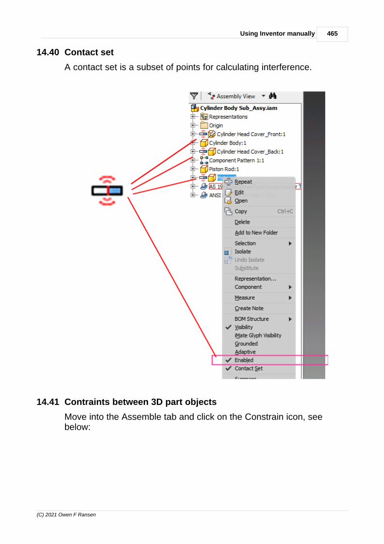
465Using Inventor manually
(C) 2021 Owen F Ransen
14.40 Contact set
A contact set is a subset of points for calculating interference.
14.41 Contraints between 3D part objects
Move into the Assemble tab and click on the Constrain icon, seebelow:

466 Autodesk Inventor Programming in C++ by Owen Ransen
(C) 2021 Owen F Ransen
The screenshot above also illustrates the fact that constraints canhave names, apart from Mate:1 etc. Note George and Mildred.
3D object based constraints are generally at the level of assembly,and constraints "connect" parts within the assembly.
Click here for constraints and parts from a programmers point of view.
14.42 Crash when creating a new drawing
You may get this message:
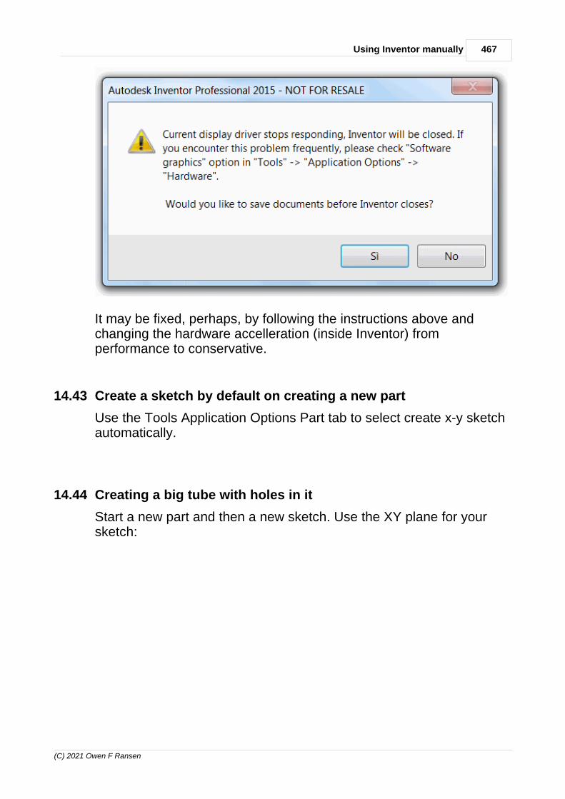
467Using Inventor manually
(C) 2021 Owen F Ransen
It may be fixed, perhaps, by following the instructions above andchanging the hardware accelleration (inside Inventor) fromperformance to conservative.
14.43 Create a sketch by default on creating a new part
Use the Tools Application Options Part tab to select create x-y sketchautomatically.
14.44 Creating a big tube with holes in it
Start a new part and then a new sketch. Use the XY plane for yoursketch:

468 Autodesk Inventor Programming in C++ by Owen Ransen
(C) 2021 Owen F Ransen
While in sketch mode draw two circles on it, then exit the sketch:

469Using Inventor manually
(C) 2021 Owen F Ransen
Now extrude, you may have to select the "profile" as being the areabetween the two circles:

470 Autodesk Inventor Programming in C++ by Owen Ransen
(C) 2021 Owen F Ransen
In the browser select the yz plane and create a new sketch there:

471Using Inventor manually
(C) 2021 Owen F Ransen
Like this:

472 Autodesk Inventor Programming in C++ by Owen Ransen
(C) 2021 Owen F Ransen
Now you have to put some points in the sketch which can be used ashole centers. To do this make sure that center point is highlighted likethis:

473Using Inventor manually
(C) 2021 Owen F Ransen
Now when you use the point command the points you make can beused as center points:
Putting 3 points in the yz sketch will look like this:

474 Autodesk Inventor Programming in C++ by Owen Ransen
(C) 2021 Owen F Ransen
Click on Finish Sketch, you'll return to the 3D part view. Now click onthe Hole icon and you'll get something like this:
14.45 Creating a drawing of an assembly or part
You need to have the assembly (or part) already open before you cancreate a drawing of it. And then, oddly enough, you have to create anew drawing using the file menu, and then specify the assembly.
1. Use the "file" new drawing command, you'll get a piece of paper onthe screen.
2. Right click on the paper and select "Base View"3. Choose various parameters:

475Using Inventor manually
(C) 2021 Owen F Ransen
You can also get the above dialog by right clicking on the view andselecting "edit".
14.46 Creating a workplane offset from another plane
Here is how to move a workplane, offsetting a workplane, use thismenu:

476 Autodesk Inventor Programming in C++ by Owen Ransen
(C) 2021 Owen F Ransen
And this sequence to specify the offset:
14.47 Customizing the menu
Use the tools tab customize icon.

477Using Inventor manually
(C) 2021 Owen F Ransen
14.48 Delete a parameter
Use the Parameters list dialog box and right click on the line of theparameter you want to delete.
Note that if the parameter is in use you'll not get a "Delete Parameter"menu item.
14.49 Deleting, removing a constraint
Right click on the constraint in the browser and choose "delete".
The delete key on your keyboard will not work for this operation, itseems.
14.50 Driven Dimensions and their Removal/Change
Driven dimensions are controlled by the geometry.
Turning a driven dimension into a normal dimension: Right click onthe dimension then if it is a driven dimension a small window willshow you a check box checked. Uncheck it.
Driven dimensions have brackets around them, like: (45,921)
Compare these with driving dimensions.
14.51 Editing a sketch flatly
Use the look at command (rectangle and arrow icon) and click on thesketch to get that sketch flat on the screen.
14.52 Editing Model Parameters and how they are displayed
Double click on a dimension in a sketch to change the value of thatdimension.
To see the name of the dimension change the document settings asfollows:

478 Autodesk Inventor Programming in C++ by Owen Ransen
(C) 2021 Owen F Ransen
Select Display As Expression in the radio buttons. Then you'll get"d0=45" rather than just "45". Not only but you can also change thename of the parameter, for example from "d0" to "DiamTube".
14.53 Enable and Disable parts and assemblies
If you right click in the browser a part you can Enable or not Enable it.When not enabled it goes green and cannot be selected.
14.54 Example of dimensions and parameters in a sketch
Two circles, to form a tube, later. Change the names from d1 and d2then add a thickness:

479Using Inventor manually
(C) 2021 Owen F Ransen
Now, to change InnerDiam into a driven dimension:

480 Autodesk Inventor Programming in C++ by Owen Ransen
(C) 2021 Owen F Ransen
And you'll get a tiny dialog where you can type in a formula:

481Using Inventor manually
(C) 2021 Owen F Ransen
Click on the green tick. You'll see the driven dimension:

482 Autodesk Inventor Programming in C++ by Owen Ransen
(C) 2021 Owen F Ransen
14.55 Extruding sketches with multiple concentric circles
If you add several concentric circles into an Inventor sketch, whenyou extrude the sketch, Inventor will need to know which areas youwant to extrude. Click inside the ones you want.

483Using Inventor manually
(C) 2021 Owen F Ransen
Three circles have been interpreted correctly when the extrusionhappened.
14.56 Extruding with widening angles
When you are extruding something you can use the tab key to switchbetween length minibar and angle minibar.

484 Autodesk Inventor Programming in C++ by Owen Ransen
(C) 2021 Owen F Ransen
14.57 File types
Inventor Standard Part File: *.ipt.: Used for storing general single ormulti-body components or part. For example a shaft, bolt, etc. Partfiles are the building blocks of any design. Collections of part filescome together to make an assembly. The Inventor standard part filecan be created easily by using the Standard (mm).ipt, Standard (in).ipt or Standard.ipt template on the New File dialog box.
Inventor sheetmetal part file: *.ipt. Used for creating parts (andiParts?) or components with constant and thin thicknesses. Mostsheet metal parts have thicknesses ranging from 1 mm to 6 mm. Youcan create sheet metal parts by using the Sheetmetal (mm).ipt,sheetmetal (in).ipt or sheetmetal.ipt template on the New File dialogbox.
Standard Assembly File: *.iam. It is used for storing assembly files.Collections of part files come together to make an assembly. Anassembly file is made of parts or components that are linked to eachother parametrically. All assemblies without weldments areaccommodated here. Inventor standard assembly files can be createdby using the Standard(mm).iam, Standard(in).iam or Standard.iamtemplate on the New File dialog box.
Inventor Weldment Assembly File: *.iam. This type of assembly fileis used for creating assemblies that require welding process forjoining one part or component to another. This file type can becreated by using the Weldment.iam template on the New File dialogbox
Inventor Drawing File: *.idw or *.dwg. The Inventor detail drawingfiles are used for creating design documentation. In a drawing file,one creates views (sectioned, detailed, orthographic, auxiliary, etc)accompanied with annotations, dimensions and Bill of Materials (BOM). There are two ways of creating drawing files in Inventor. Oneis with the *.idw file type and the other is with the *.dwg. The DWGformat is an industry standard and such files may be viewed withAutoCAD-based applications.
Inventor Presentation File: *.ipn *.ipt: Used for creating exploded

485Using Inventor manually
(C) 2021 Owen F Ransen
views of assemblies. These exploded parts could be animation tovisualize how the parts will be assembled Can be created by usingthe Standard(mm).ipn, Standard(in).ipt or Standard.ipn.
Inventor Project File: *.ipj : This is like the root of a large project.
Inventor iFeature file: .ide : A file for an iFeature..
14.58 FlipNormal and WorkPlane constraints
When you use WorkPlanes for constraints remember that they have anormal direction. The normals are the white arrows in the diagrambelow:
You can change the normal direction by choosing FlipNormal from theworkplane's context menu.

486 Autodesk Inventor Programming in C++ by Owen Ransen
(C) 2021 Owen F Ransen
If you see a red(dish) workplane you are looking at the front of it.If you see a blue(ish) workplane when you are looking at the back ofit.
14.59 Flush Mate And Axis Constraint Example
To put a tube inside a hole inside another tube you can make a flushcostraint with a workplane tangential to the cylindrical surface:
And the next step is to make the two axes coincident:

487Using Inventor manually
(C) 2021 Owen F Ransen
So two constraints.
14.60 Free Move and Free Rotate
These commands (right click on a part inside an assembly) allow youto move and rotate the part freely. But it is only temporary, maybe toallow you to see something better.
The move or rotation is not saved when you save the assembly. Afree move is a temporary "get out of the way" move.
14.61 fx: and parameters and formulas
If you add a dimension but set it not to a numeric value but to aparameter, then that dimension will be shown with an fx: in front of it.

488 Autodesk Inventor Programming in C++ by Owen Ransen
(C) 2021 Owen F Ransen
To get a sketch dimension to be a user parameter all you need to dois1. Create the user parameter. Use the big f icon under the manage
tab.2. When you create an object in sketch mode, instead of typing in a
number, type in the name of the user parameter.
These are called driving dimensions. Compare them to drivendimensions.
Difference between model parameters and user parameters.Model Parameters are created automatically when you create anobject, and are given automatic names, d0 for the diameter of the firstcircle you draw, for example. You can name model parameters on thefly, for example when you draw a circle, and then do a dimension of itinstead of typing 35, type InnerTube=35 directly. In that way whatwould have been d4 (for example) becomes InnerTube. Actually typethat into the tiny dimension edit box. It will then appear in the f dialog.
User Parameters are created by you to maybe drive dimensions, andmaybe be applied to more than one part of the sketch.
14.62 Get the browser pane back
Go into the view tab and click on the user interface icon near thecenter.
14.63 Getting into and out of sketches
To get into a sketch, in the browser on the left of the screen right clickon the node called, for example, "Sketch1" and choose Edit Sketch.
To get out of a sketch simply click on the green Finish Sketch icon attop right of the main tool bar.
It pops up also if you do a right click anywhere on the sketch.

489Using Inventor manually
(C) 2021 Owen F Ransen
14.64 Getting to the constrain icon in Inventor
You must be in assembly mode to see the constrain icon!
Doh!
14.65 Grounded Parts
An assembly is a collection of parts and by default the firstcomponent in an assembly file will be grounded. This means it cannotmove, and probably the other components will be offset relative to it.This assembly has two parts. The pushpin says which is groundedand cannot be should not be moved.
Here is another visual example:

490 Autodesk Inventor Programming in C++ by Owen Ransen
(C) 2021 Owen F Ransen
14.66 Holes in tubes
If you want a hole in a tube at an arbitrary angle it best to base thehole on a sketch.
The sketch will have a point at 0,0 and you select "Placement fromsketch" from the hole dialog.
The sketch must move around with the angle. To do this you need asketch in the plane parallel to the base of the tube:

491Using Inventor manually
(C) 2021 Owen F Ransen
That bright hole is what you attach the smaller sketch to:

492 Autodesk Inventor Programming in C++ by Owen Ransen
(C) 2021 Owen F Ransen
If you use some other method it may be that not all angles around thetube are respected.
14.67 How to change the background of the Inventor screen
Use Tools | Application Options | Colors tab.
14.68 How to make a hollow tube
1. Start a new part, clicking in the main window.2. Make a new sketch for this part.3. In the 2d commands draw a circle.4. Select Offset and so make another circle inside the first.5. After getting the two circles to the rights size clikc on Finish sketch6. You are now in the 3d Model tab7. Click on Extrude and click between the two circles so that the ring

493Using Inventor manually
(C) 2021 Owen F Ransen
becomes grey.
14.69 How to move a 3D object
Simply right click in the browser on the object you wwant to move:
You will get 3 axes which you can drag.

494 Autodesk Inventor Programming in C++ by Owen Ransen
(C) 2021 Owen F Ransen
14.70 Inches problem
Sometimes you create a new project and unless you are careful thefirst part you put in will be in inches. When you create the componentbe sure to select the Metric/Standard (mm).ipt template. You mayhave to hit the browse button in the dialog to do that.
Alternatively in the Project dialog Folder Options you can point thetemplate directly at:
Templates = C:\Users\Public\Documents\Autodesk\Inventor 2013\Templates\Metric\
14.71 Insert constraint
The insert constraint has an axis and a plane to match to another axisand another plane. Or rather two circles which together identifyeverything neccessary to insert a countersunk screw into acountersunk hole.
14.72 Inserting an inclined workplane
Here are the steps.
Make sure an axis is visible, like that Inventor will give you thepossibility to rotate it later:
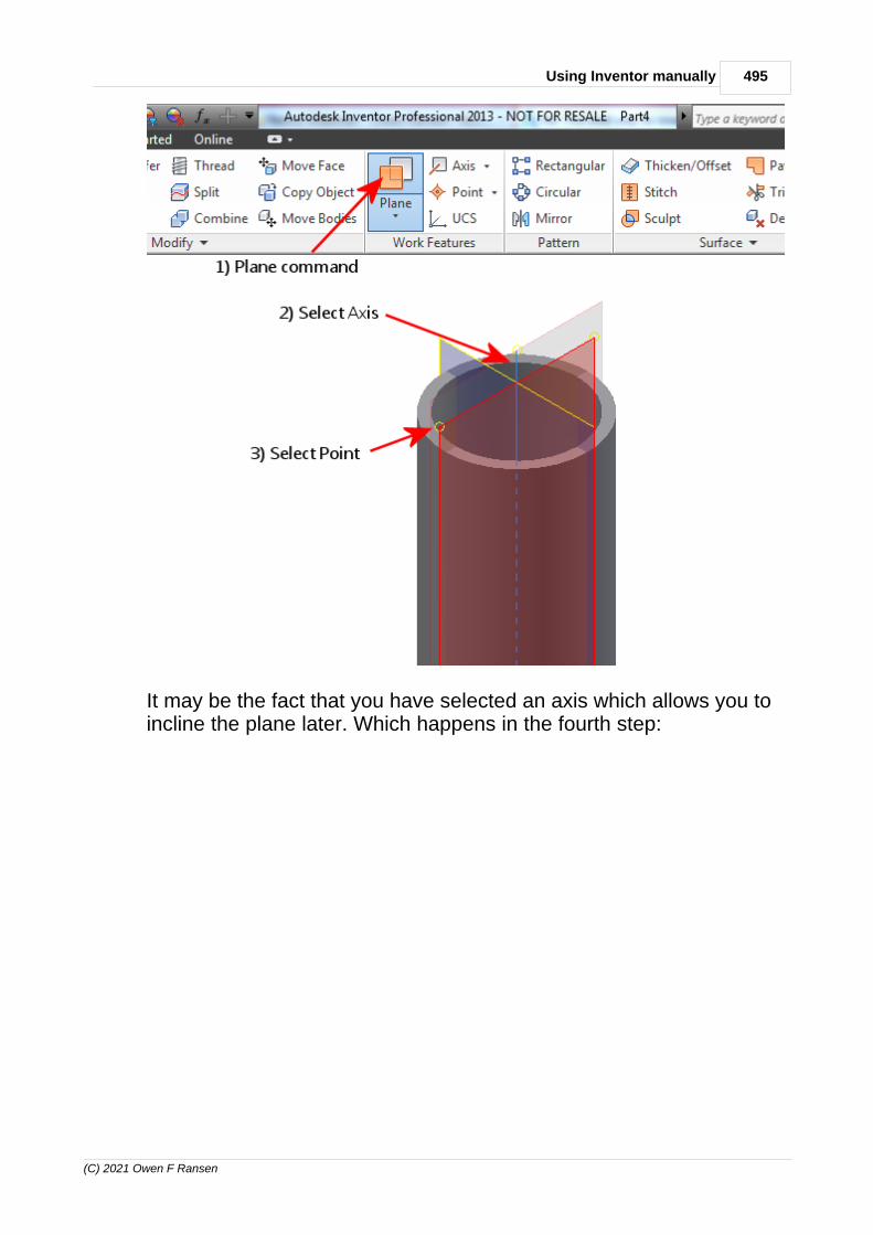
495Using Inventor manually
(C) 2021 Owen F Ransen
It may be the fact that you have selected an axis which allows you toincline the plane later. Which happens in the fourth step:

496 Autodesk Inventor Programming in C++ by Owen Ransen
(C) 2021 Owen F Ransen
14.73 Inventor Apprentice
Apprentice Server is basically a read-only subset of the Inventor APIunless you are doing some file manipulations - like savecopyas. It'snot a great subset either. I have not been able to use it much in myapps yet.
Inventor Apprentice is a freely available programming component thatcan be used by a program to read information from Inventor files. In afew cases, it is also possible to write information. A key part ofunderstanding how to use Apprentice is to understand what itscapabilities are, both what it can and cannot do. This class will look atthe functionality of Apprentice using several sample programs toillustrate its capabilities.

497Using Inventor manually
(C) 2021 Owen F Ransen
The simple way to think of Apprentice is that it's a smaller version ofAutodesk Inventor that does not have a user interface. Without a userinterface the only way to access its functionality is by using its API.Apprentice is actually an ActiveX component. It runs within theprocess space of the client that's using it. For example, if you write aVisual Basic program that displays information about the contents ofan assembly, Apprentice will be running within your VB program'sprocess space. Apprentice can be very efficient for certainapplications because it's smaller than the complete Autodesk Inventorapplication and because it runs in the same process as yourapplication.
The API exposed by Apprentice is a subset of the complete AutodeskInventor API. Apprentice provides access to file references, assemblystructure, B-Rep, geometry, attributes, render styles, and documentproperties. Access to the assembly structure, B-Rep, geometry, andrender styles is read-only.
14.74 Mate vs Flush constraints

498 Autodesk Inventor Programming in C++ by Owen Ransen
(C) 2021 Owen F Ransen
14.75 Mini tool bar autofade
Switch autofade on and off using the minitoolbar options, usually amenu near the red X button.
14.76 No visible unadaptive sketches
You might get this error message:
No visible unadaptive sketches
...if you make a sketch at assembly level rather than part level.
14.77 Pattern inside a sketch
You can make a pattern inside a sketch. Look at the red rectanglesbelow:
You need to create construction lines to specify the axes you need forthe rectangular pattern.

499Using Inventor manually
(C) 2021 Owen F Ransen
14.78 Patterns (arrays) of features
To create a rectangular array of features follow these steps whichshow how to create a linear array:
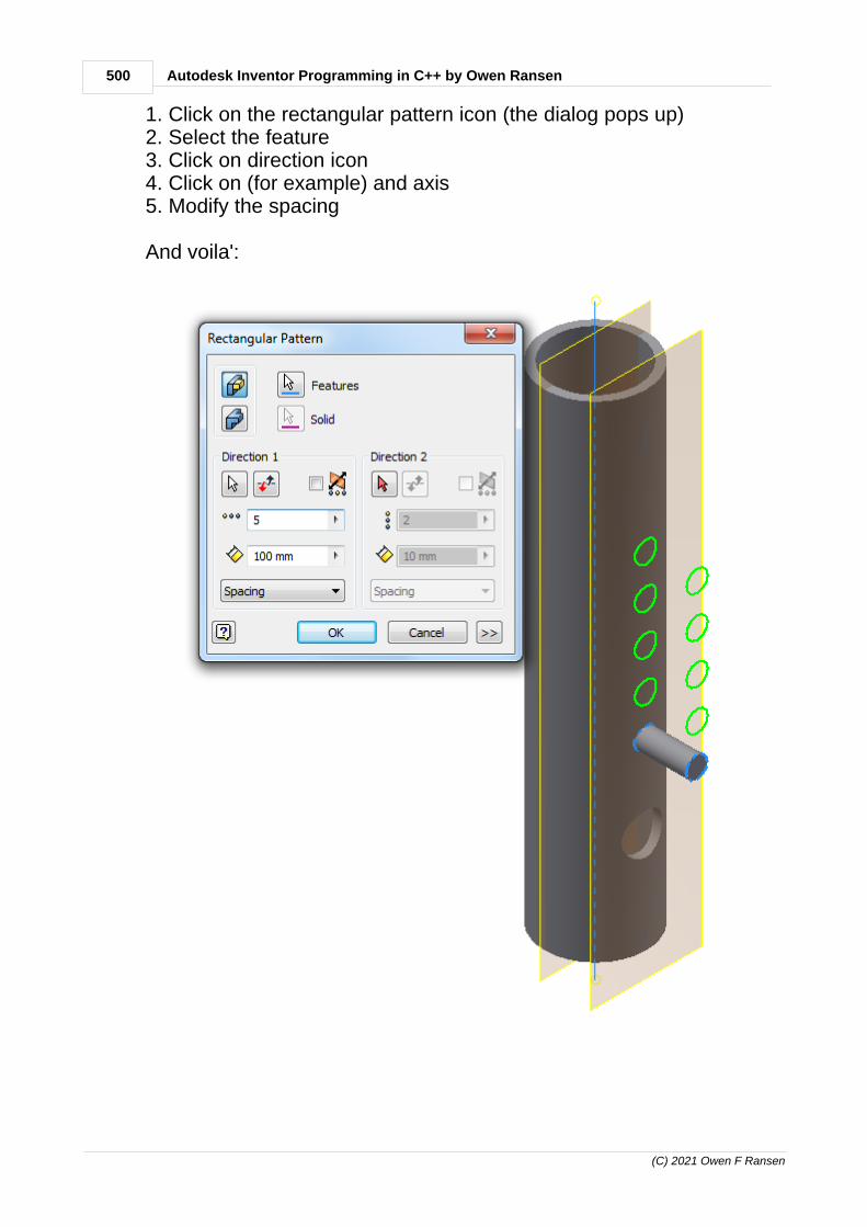
500 Autodesk Inventor Programming in C++ by Owen Ransen
(C) 2021 Owen F Ransen
1. Click on the rectangular pattern icon (the dialog pops up)2. Select the feature3. Click on direction icon4. Click on (for example) and axis5. Modify the spacing
And voila':

501Using Inventor manually
(C) 2021 Owen F Ransen
14.79 Plane on the surface of a tube at an angle
Create a sketch with a circle and a line. Add a point at theintersection of the circle and the line:
You may have to promote that sketch to see it at Part level.
Anyway, then use the WorkPlane at tangent to surface through point:
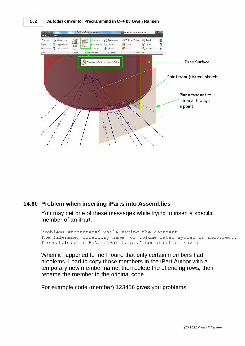
502 Autodesk Inventor Programming in C++ by Owen Ransen
(C) 2021 Owen F Ransen
14.80 Problem when inserting iParts into Assemblies
You may get one of these messages while trying to insert a specificmember of an iPart:
Problems encountered while saving the document.The filename, directory name, or volume label syntax is incorrect.The database in P:\...\Part1.ipt.* could not be saved
When it happened to me I found that only certain members hadproblems. I had to copy those members in the iPart Author with atemporary new member name, then delete the offending rows, thenrename the member to the original code.
For example code (member) 123456 gives you problems:

503Using Inventor manually
(C) 2021 Owen F Ransen
1. Create a new entry in the table, 123456N for example.2. Set the column values to be the same as 123456.3. Delete 123456, and rename 123456N into 123456. You'll be
warned that changing the member name will change the filename.Continue anyway.
14.81 Problems encountered while executing this command.
You may get this message if you are trying to do something in anAssembly when you should be doing it in a Part.
For example you will not be able to extrude from a sketch in anAssembly, but you will inside a part.
14.82 Problems with sketch extrusion and revsurf
There are many things which can go wrong. Remember to use thebutton for drawing construction geometry and for changing sketchgeometry to construction geometry:
I've found it easier not to use projected features, base your sketch onvariables and dimensions.
14.83 Project files
You should start all new projects with a project file, it'll have theextension .ipj.
Projects are a way of organizing many components, parts,
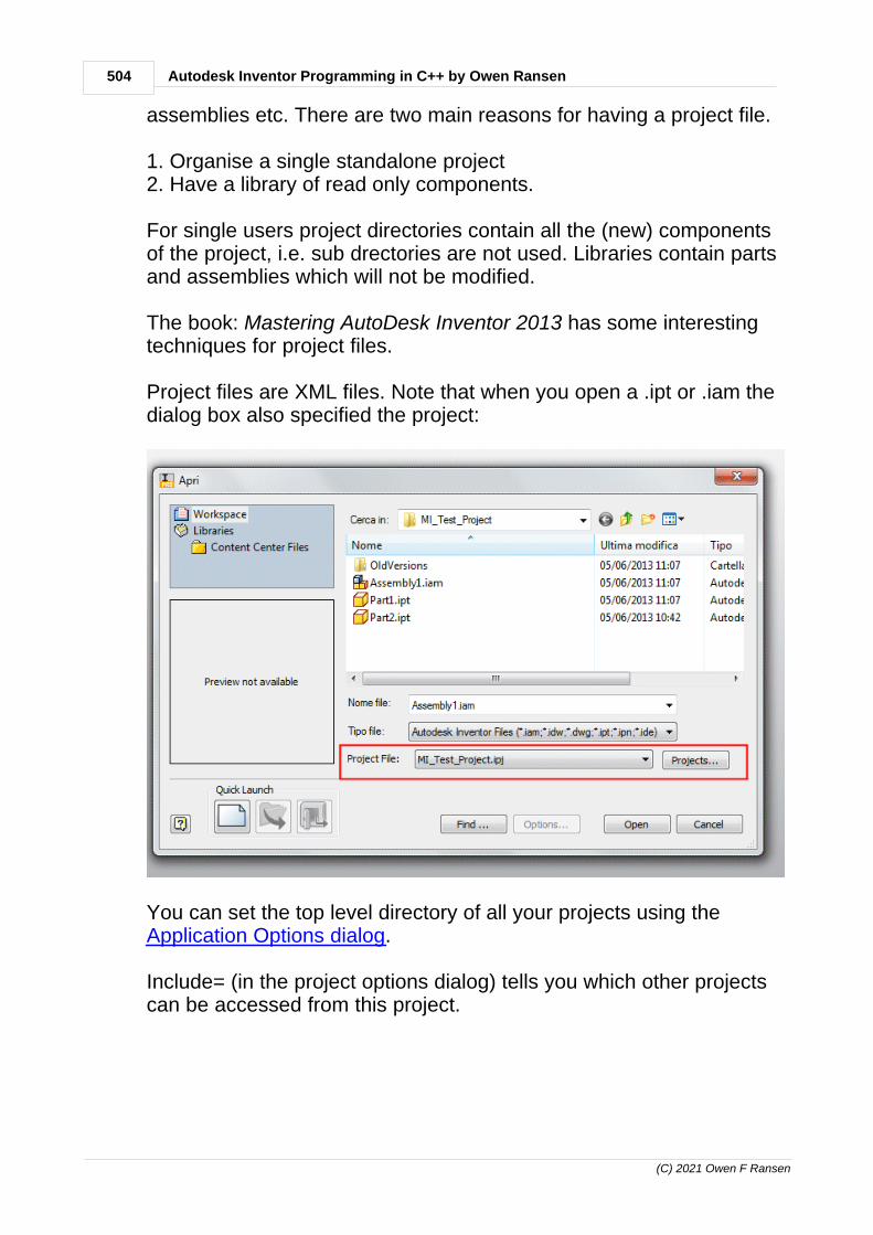
504 Autodesk Inventor Programming in C++ by Owen Ransen
(C) 2021 Owen F Ransen
assemblies etc. There are two main reasons for having a project file.
1. Organise a single standalone project2. Have a library of read only components.
For single users project directories contain all the (new) componentsof the project, i.e. sub drectories are not used. Libraries contain partsand assemblies which will not be modified.
The book: Mastering AutoDesk Inventor 2013 has some interestingtechniques for project files.
Project files are XML files. Note that when you open a .ipt or .iam thedialog box also specified the project:
You can set the top level directory of all your projects using the Application Options dialog.
Include= (in the project options dialog) tells you which other projectscan be accessed from this project.

505Using Inventor manually
(C) 2021 Owen F Ransen
14.84 Putting 2d dxf files in 3D assemblies, manually
You may want to put a 2D dxf file in a 3D position in an assembly:
To do this you must create a plane in the plane you want to DXF fileto appear, then add a sketch to that plane. Then, from AutoCAD copy(COPYCLIP) the entities of the DXF file and paste them into thesketch.
Precise locating has been beyond me so far, and even if the entitypasted is a block it gets changed into component lines and circles.
14.85 Removing material with the cut extrusion command
Here is the sequence:

506 Autodesk Inventor Programming in C++ by Owen Ransen
(C) 2021 Owen F Ransen
14.86 HealthStatusEnum
Here are two health status values which I've currently found:
kCannotComputeHealth 11783 Object cannot be evaluated.
kUpToDateHealth 11778 Object is up to date.
Here's a fragment of how it can be used, in this case with a RectangularPatternFeature...
const HealthStatusEnum eHealth = pRectPatFeature->GetHealthStatus(); gLogger.Printf(ekLogMsg, L"For pattern <%s> eHealth = %d",kcsPatternName, eHealth); if (eHealth == kCannotComputeHealth) { gLogger.Printf (ekErrMsg,L"Pattern health is bad %s\n",kcsPatternName) ; return E_FAIL ; }

507Using Inventor manually
(C) 2021 Owen F Ransen
There are a lot of values for HealthStatusEnum, and I'm not sure ofthe meaning of all of them.
14.87 Showing dimensions temporarily
In the browser right click the object (for example a feature) and select Show Dimensions. Select the same object to switch them off.
To remove the dimensions just click somewhere else in the browser.I'm not totally clear on all this at the moment.
14.88 Showing expressions in a sketch
In the sketch right click on the graphics screen and select
Dimension Display - > Expression
14.89 Sketch plane
The sketching plane is by default the XY plane and extrusions goalong the Z axis.
But you can change the default sketch plane, use the Tools tab,application options dialog, Part tab.
14.90 Sketches and Features
In general Sketches are 2D and features are 3D objects.
You have a basic solid feature created from a 2D sketch.

508 Autodesk Inventor Programming in C++ by Owen Ransen
(C) 2021 Owen F Ransen

509Using Inventor manually
(C) 2021 Owen F Ransen
14.91 Suppression and mirrored features
If you suppress a part, will its mirror be suppressed too? Butremember that suppression of parts is only for LOD applications,Level of detail.
Yes.
14.92 Templates and Template files
You will find the template files in this directory (or something similar)
C:\Users\Public\Documents\Autodesk\Inventor 2013\Templates
When you create a new file (a new assembly or part) the templatechoosing dialog...
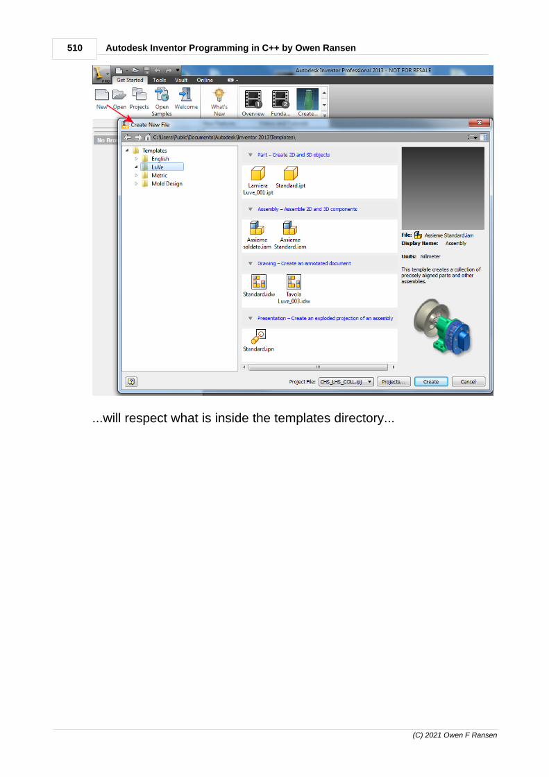
510 Autodesk Inventor Programming in C++ by Owen Ransen
(C) 2021 Owen F Ransen
...will respect what is inside the templates directory...

511Using Inventor manually
(C) 2021 Owen F Ransen
14.93 The Marking Menu
This is the menu which pops up when you right click in the graphicsarea.
You can use that to get to know where some commands are, so thatyou can use mouse gestures (drag with "other" button pressed) forvery quick access.

512 Autodesk Inventor Programming in C++ by Owen Ransen
(C) 2021 Owen F Ransen
14.94 Trim and Fillet
Fillet and Chamfer:
These commands exist in Inventor in the sketch tab. Select two lines(use the shift key for multiple selection) then click on the Fillet (orChamfer only one will be visible at the same time) icon in the toolbar.You can change the radius of the fillet by clicking on the numberwhich specifies the current size.
Chamfers also have a size and again you change change it by doubleclicking on the number.
Trim:

513Using Inventor manually
(C) 2021 Owen F Ransen
In Inventor trimming is easy Create a sketch with two overlappingrectangles, click on the Trim command (middle of the toolbar) andhover the mouse over the lines which intersect. Click to actually trim.
These are sometimes called placed features and should be done atthe end of a job, not at the beginning.
14.95 ul as a dimension
ul means unitless and you'll see it inside rectangular patternproperties as a count of the number of repititions.
14.96 Units, Inches, Mm
If you find yourself suddenly working in inches for some reason usethe Tools -> Application Settings dialog, -> Files tab -> ConfigureDefault Template.
Set it to ISO and mm.
14.97 Vault
Autodesk Vault locks down Inventor files for their protection.
There is a Vault icon in the Inventor toolbar.
14.98 View face command
The view face command lets you select a face in a 3D object andview it head on, from its normal type like.
14.99 Viewing Multiple Documents in Inventor
If you have more than one document or window open in Inventoryou'll see it in the tabs, as shown below:

514 Autodesk Inventor Programming in C++ by Owen Ransen
(C) 2021 Owen F Ransen
14.100Work Axis Thru Circular Hole
Do it like this:
Simples! No?
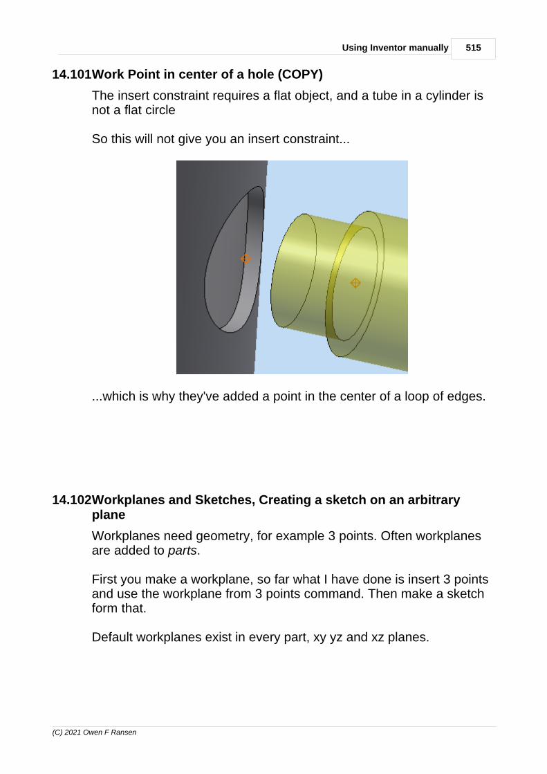
515Using Inventor manually
(C) 2021 Owen F Ransen
14.101Work Point in center of a hole (COPY)
The insert constraint requires a flat object, and a tube in a cylinder isnot a flat circle
So this will not give you an insert constraint...
...which is why they've added a point in the center of a loop of edges.
14.102Workplanes and Sketches, Creating a sketch on an arbitraryplane
Workplanes need geometry, for example 3 points. Often workplanesare added to parts.
First you make a workplane, so far what I have done is insert 3 pointsand use the workplane from 3 points command. Then make a sketchform that.
Default workplanes exist in every part, xy yz and xz planes.

516 Autodesk Inventor Programming in C++ by Owen Ransen
(C) 2021 Owen F Ransen
FYI in a program workplanes can be accessed like this:

517Using Inventor manually
(C) 2021 Owen F Ransen
14.103WorkPoint in center of a hole
If you want to place a work point in the center of a hole one option isto use the "Point In Center Of Loop Of Edges" function:
You'll have to select one of the two circles which forms the hole.
Autodesk forum also showed me this:

518 Autodesk Inventor Programming in C++ by Owen Ransen
(C) 2021 Owen F Ransen
See also center points and non.
14.104Yellow Dot Green Dot Constraints
When doing a sketch yellow snap nodes are not constraints, whereasgreen snap nodes are constraints.
A circle with a center snapped off the origin (becomes a yellow node),maybe on a axis, can be moved. These are called "soft snaps".
A circle with a center snapped on the origin (becomes a green node),cannot be moved. Snapped to green are called "hard snaps" becausethe object cannot be moved afterwards.
15 Acknowledgements
Thanks to, in alphabetical order (many, but not all, of these peoplework for AutoDesk):

519Acknowledgements
(C) 2021 Owen F Ransen
Vladimir AnanyevBrian Bolam
Carlos Manuel Carreiras Jonathan D. Kriek
Dave Hoder Bob Holland
Philippe LeefsmaXiaodong Liang
Adam NagyHerm Jan Otterman
Kean WalmsleyCaroline Ward
Chandra Shekar G Johnson Shiue
If I've left anybody out, my apologies and please let me know!

Autodesk Inventor Programming in C++ by Owen Ransen520
(C) 2021 Owen F Ransen
Index
- " -"Center Point" getting hold of it programatically 112
"ul" unitless parameters 103
- . -.addin 18, 263
.AddIn file directory 263
.AddIn file in Autodesk Inventor C++ Programming 257
.AddIn manager 281
.addins directory 302
.DEF file 281
.dwg 474
.dwg file types 484
.EXE file 18
.Expression vs .Value 358
.iam file types 484
.ide file types 484
.idw 474
.idw file types 484
.ipj 503
.ipj file types 484
.ipj programatically 278
.ipn file types 484
.ipt file types 484
.rgs file for Inventor AddIns, what is it? 272
.tlb 282
.tli 282
.Value vs .Expression 358
- : -::SysFreeString 272
- [ -[item] in C# lists 376
- \ -\n in a table 146
\r in a table 146
- _ -_b_str filename 106
_bstr_to CString 272
_com_error (Autodesk Inventor) 158
_T macro 272
_WIN32_WINNT=0x0501 in Inventor Programming 73
- 0 -0x80004005 AddByPlaneAndOffset not suppored inassemblies 295
0x800401e3 MK_E_UNAVAILABLE AutodeskInventor Programming 74
0x800401f3 CLSIDFromProgID failure 76
- 1 -1083 282
1083 in Inventor Programming 75
11778 Object is up to date health of pattern 506
11783 Object cannot be evaluated health of pattern 506
12291 134
- 2 -2064: term does not evaluate to a function taking 0arguments 77
2130706443 134
- - --2147467259 registration error in InventorProgramming 78
- 2 -2774 compile error in Inventor programming 77
2d and 3d points (abstract geomety) 183

Index 521
(C) 2021 Owen F Ransen
2d dxf files in 3D assemblies 505
2d points in a sketch, listing their coordinates 97
2d sketch 477
2d sketch solid feature 507
- 3 -3073 error 302
32 vs 64 in Autodesk Inventor Programming in C 302
3277: Found conflicts between different versions 326
3D snap spacing 458
- 4 -4278 Autodesk Inventor Programming 78
- 5 -50348544 is kModelParameterObject 134
- 6 -64 bit AddIn in Autodesk Inventor Programming inC++ 290
64bit vs 32bit in Autodesk Inventor Programming inC++ 290
67113776 134
- 8 -80004005 AddByPlaneAndOffset not suppored inassemblies 295
80004005 CreateGeometryProxy 162
80004005 error when saving Inventor documents 209
800401f3 CLSIDFromProgID failure 76
80070057 and WorkFeature visibility 188
83886592 134
83887616 134
83893504 134
83893664 134
83923968 134
- A -Access and connecting to Inventor 43
Acknowledgements 518
Activate function in plugin 342
active document 278
Active Document, Inventor programming in C++ 255
Active Inventor Document, how to get it 289
active project files programatically 307
ActiveDocument 156
Adaptive geometry 60
Add a circle to a sketch function 81
Add a column into an iPart table 425
Add a DrawingSketch to a DrawingDocument 89
Add a DrawingSketch to an IDW 90
Add a feature to an existing pattern 449
Add a line by two points 90
Add a mate constraint with two planesprogramatically, Autodesk Inventor Programming 160
Add a part to an assembly function 66
Add a part to an assembly programatically 291
Add a plane by offset from another plane 295
Add a point to the surface of a tube manually 450
add a rectangle to a sketch programatically 284
add a rule as a button in iLogic 40
add a sheet to a drawing 71
Add a sketch based on a workplane 195
Add a sketch offset from a plane 295
Add a sketch on a part's default workplaneprogramatically 265
add a sketch programatically 247
Add a sketch to an assembly or part 61
Add a unitless user parameter into an assembly 103
Add a work point at a sketch point 268
Add a workplane based on an existing workplane 195
add a workplane in an assembly programatically(AddFixed) 445
add a workplane programtically 251
Add a WorkPoint at the intersection of a line and aplane 113
Add a WorkPoint into an assembly manually 112
Add a WorkPoint into an assembly programatically 112

Autodesk Inventor Programming in C++ by Owen Ransen522
(C) 2021 Owen F Ransen
Add an angular dimension 451
Add an assembly into another assembly,programatically 101
add an extrusion to a part programatically 242
Add an iMate (based on a point) into an assembly 97
Add an occurrence of a part to an assembly 66
Add an occurrence to an assembly does not work 201
add assembly in anpther assembly, programatically 101
Add Form and iLogic 40
Add function calling (occurrences) 201
Add grounded WorkAxis in an assemblyprogramatically 114
add in C# member not found 353
Add in the occurrence of a custom iPart into anassembly 214
Add lines to a DrawingSketch 90
add named sketch to named workplaneprogramatically 247
add part to an assembly 66
add parts using iLogic 33
add rectangle to sketch 108
Add text to an Inventor document 450
Add to New Folder 436
Add views to an IDW 149
Add vs MethodAdd 224
AddAsTwoPointRectangle 284
AddBaseView 149
AddBrowserFolder 83
AddByCenterRadius 81
AddByCenterRadius example 242
AddByPlaneAndOffset 251
AddByPlaneAndOffset example 196
AddByPlaneAndOffset not suppored in assemblies 295
AddCircleToSketch 81
AddCustomiPartMember tips and hints and help 213
AddCustomiPartMember, how to use it in C++ 214
AddFixed 112
AddFixed axis in assembly based on a hole in a part 374
AddFlushConstraint 260
AddFlushConstraint in Autodesk Inventor C++Programming 258
AddFlushConstraintOfTwoPlanes with max distance 49
AddForSolid and profiles and AutoDesk InventorProgramming in C++ 274
AddForSolid example 242
AddGround and sketch origin 92
Add-In automatic load suppression 453
addin dll 263
AddIn file 257
addin loading 263
AddIn Manager 281
AddIn, Autodesk Inventor Programming in C++ 18
addin, C# 328
adding a button C# 338
Adding a Dimension in a sketch 452
Adding a flat parts list in a drawing 402
Adding an AngleConstraint 302
Addins in C# 347
AddiPartMember 206
AddiPartMember and rotation 185
AddLineByTwoPoints in a sketch 90
AddMateConstraint 160
AddMateConstraint2 at assembly level 385
AddMateConstraintOfTwoPlanes 160
AddMateiMateDefinition example 97
AddSketchToStdWorkplane 265
AddSketchToWorkplane Autodesk InventorProgramming in C++ 247
AddTwoPointDistance explanation 92
adequate constraint in sketch 459
administrator for regsvr32 in Inventor Programming 74
AffectedOccurrences in an extrusion 109
All occurrences are oriented identically. 271
All occurrences fitted within path length. 271
All occurrences fitted within specified distance. 271
Alternative to a virtual component in a BOM 413
Ananyev 518
angle (Inventor Programming) 173
angle, adding an angle constraint 302
AngleConstraint programatically 302
angular constraing programatically 302
angular constraints 400
angular dimension, how to add manually 451
angular units and Autodesk Inventor Programming 173
application invisible 185

Index 523
(C) 2021 Owen F Ransen
application options 507
Application Options Settings 452
application visible 185
Apprentice Server 496
array of double values as an array for Inventor 147
array of features 499
arrays (rectangular) in Autodesk InventorProgramming in C++ 233
Arrays in COM 96
Ascii 22
ASCIIand UNICODE 272
Assemblies - Hierarchy 290
assembly .iam file types 484
Assembly Close programatically 155
Assembly creation programatically 275
assembly document creation 291
assembly document opening (Inventor API) 68
assembly file types 484
Assembly in .AddIn file 257
assembly inside assembly, programatically 101
Assembly level workaxes 429
Assembly vs Part for work things 440
assembly workaxis and constraints 385
assembly workplanes, constrain to C# 379
Assembly WorkPoints and Part WorkPoints 440
Assembly WorkThings vs Part WorkThings 440
Assembly.Document get current one 289
AssemblyComponentDefinition 216
AssemblyComponentDefinition - Hierarchy 290
AssemblyComponentDefinition and componentoccurrences 198
AssemblyComponentDefinition C# 345
AssemblyComponentDefinition is a list of parts andconstraints 249
AssemblyDocument creation in C# 389
AssemblyDocument from general Document 291
AssemblyDocument or PartDocument C# 355
AssemblyDocument, get currenr document 289
Asset is null 47
asset lib access programatically 47, 52
asset looping 47, 52
asset purging in part documents 303
Asset Type 52
assets, material API 52
Attribute Sets in Inventor Programming 238
Attributes in Inventor programming in AutodeskInventor Programming in C++ 238
author of iParts 417
Autodesk Inventor COM API 22
AutoDesk Inventor functions 244
Autodesk Inventor Programming in C++ basicarchitecture of the source code 18
Autodesk Inventor Programming in C++ how to usethis book 17
Autodesk Inventor Programming Pattern Elements 190
Autodesk Inventor programming, COM and SmartPointers 22
Autodesk inventor version programatically in C++ 138
Autodesk.iLogic.Automation reference 347
Autodesk.Inventor.Interop version problems 326
autofade on and off 498
Axes (standard X Y Z( 170
Axis (X Y Z standard) 170
Axis And Flush Mate Constraint Example 486
axis constraint offset parameter 461
axis constraint parameter 461
axis constraint radius parameter 461
axis constraints 461, 486
axis direction 435
axis of a hole C# 374
Axis perpendicular to sketch point, how to 442
Axis Thru Circular Hole 514
- B -background of Inventor screen options 492
Backup files 452
Backup options for Inventor files 452
Base View 474
BaseView 149
BBox of a part in C# 380
BBox of a part occurrence in an assembly 49
BBox of a parts list 103
bias and point offset 426
biaspoint and point offset 426
Bill of materials 402
blue objects in a sketch 463
Bolam 518
BOM 402
BOM and substitution 404
BOM put_Reference 85
BOM quantity programatically 87

Autodesk Inventor Programming in C++ by Owen Ransen524
(C) 2021 Owen F Ransen
BOM row programatically 85
BOM Static part counts and quantities 413
BOM Static quantity in a programatically 87
BOM view parts only 405
BOM view type row programatically 85
BOM vs Parts List 401
BOM with virtual components 406
BOMRow 85
BOMRowsEnumerator 85
BOMViewTypeEnum 85
boolean values in COM 229
boolean VARIANT_BOOL 229
Bounding box of a part C# 380
Bounding box of a part occurrence in an assembly 49
bounding box of a parts list 103
Box2d and get_RangeBox 103
BoxPtr of a part in an assembly 49
Browser visibility 455
browser folder 436
Browser folder name getting 84
Browser is missing! Get it back! 455
browser pain on and off 488
Browser panes in C# 355
Browser, Folder, Pane programatically 83
Browset folders, looping over them 84
BSpline Surface 300
BSTR and ::SysFreeString 272
BSTR from CString 307
BSTR OLECHAR wchar_t 272
BSTR vs CComBSTR 272
button definition C# 338
button in C# 338
button, ribbon, tab C# 332
buttons and iLogic 40
buttons and rules in iLogic 40
Byname, items in lists C# 376
- C -C# 275
C# addin 328
C# and parameters 358
C# AssemblyComponentDefinition 345
C# calling iLogic 347
C# ComponentOccurrences 345
C# GUI adding a button 332
C# iLogic listing of the rules 351
C# Inventor references 322
C# Looping over components inside an assembly in 345
C# message box 342
C# NameValueMap 344
C# Open an Inventor file using 344
C# plugin making 328
C# plugins, adding a button and a command 332
C# running Inventor 322
C# TransientObjects 344
C++ 275
C++ from VBA 244
C1083 in Inventor Programming 75
C1083: Cannot open type library file: 'RxInventor.tlb':No such file or directory 282
C1189 error in Inventor Programming 73
C2064: term does not evaluate to a function taking 0arguments 77
C2774 compile error in Inventor programming 77
C4278 Autodesk Inventor Programming 78
Calling iLogic from C# 347
Camera and zoom 46
cannot add feature to existing pattern 449
Carreiras 518
carriage return inside table cells 146
cast from AssemblyDocument to Document 318
cast from Document to Part or Assembly 355
cast IDispatch** and get_Document 95
cast to get part document 156
cast to IDispatch**, in Autodesk InventorProgramming 195
Casting from a ComponentDefinition to aPartComponentDefinition. 205
casting using CComQIPtr example 51
category of material 47, 52
CComBSTR and wchar_t in the Autodesk InventorAPI 208
CComBSTR cast in Add function call 201
CComBSTR in AutoDesk Inventor Programming 201
CComBSTR vs BSTR in Inventor programming 272
CComPtr and how to release them in Inventorprogramming 225
CComPtr constructor 183
CComPtr is initialised to nullptr automatically 183

Index 525
(C) 2021 Owen F Ransen
CComPtr release memory by setting it to nullptr. 225
CComPtr vs CComQIPtr 287
CComPtr<Parameter> 230
CComPtr<Point> Autodesk Inventor Programming 183
CComPtr<Point2d> Autodesk Inventor Programming 183
CComQIPtr and QueryInterface 139
CComQIPtr and Release 140
CComQIPtr example of casting 51
CComQIPtr is better than QueryInterface 140
CComQIPtr vs CComPtr and AutoDesk InventorProgramming in C++ 287
CComStr and programming Autodesk's Inventor 272
CComVariant and VARIANT 287
CComVariant gkvarEmpty 97
cells in tables in IDW drawings 143
center point for hole 467
Center Point, getting hold of it programatically 112
CenterPoints and Points 245
centimeters C# 389
Chamfer 512
change a model or user parameter programatically 57
change dimensions in sketches using iLogic 33
change dimensions in sketches using VBA 33
change document filename when saving Inventordocuments 209
change filename of object in the Autodesk InventorAPI 209
Change material / color of a solid 455
change name of a sketch 120
change name of workplane programatically 251
change parameter name 477
change parameters in sketches using iLogic 33
change parameters in sketches using VBA 33
Change size of a hole 51
change the default units 458
Change the offset elevation of a plane 456
Changing from iPart back to normal part 424
Changing home view setting 457
Changing manipulator snap 458
Changing parameters with C# 358
Changing the application visibility in AutodeskInventor Programming 185
changing the name of a drivng dimension 452
circle, add to a sketch 81
Circle2d and ProfilePath and CutFeature C# 363
Circular Hole With Work Axis 514
ClassId in the .AddIn file 257
clear all overrides 454
Client Graphics and AutoDesk Inventor Programmingin C++ 290
ClientId in the .AddIn file 257
CLogger 313
Close (SkipSave) Inventor API 211
close a sketch edit with ExitEdit 90
Close and SaveAs Autodesk Inventor API C++ 211
Close function, Inventor API 211
Close of a part programatically 155
Close of an assembly programatically 155
Close with SkipSave 155
CLSIDFromProgID failure 76
CLSIDFromProgID for Excel 312
CLSIDFromProgID for Inventor 312
CLSIDFromProgID in Autodesk InventorProgramming in C++ 291
cm inches (Inventor Programming) 173
cm or mm in C# units 389
cm parameters 235
CoCreateInstance for Inventor 312
CoInitialize and AutoDesk Inventor Programming inC++ 172
COleSafeArray VARIANT arrays of strings 214
collections, getting items from them 288
color and material of a solid 455
colors of Inventor screen options 492
Column Chooser in a parts list 413
column substitution in BOMs and parts lists 404
ColumnCount is strange 194
COM and AutoDesk Inventor Programming 172
COM API and pointers and memory in AutodeskInventor Programming in C++ 225
COM arrays 96
COM DLL registering 281
Com error 80070057 188
COM errors in Autodesk Inventor 158
COM errors, and Autodesk Inventor Programming 166
COM Function calls in Autodesk Inventor C++programming 224
COM macros in Inventor C++ programming 158
COM ParameterPtr 230

Autodesk Inventor Programming in C++ by Owen Ransen526
(C) 2021 Owen F Ransen
COM points matrices vectors Autodesk InventorProgramming 183
COM return values 166
COM RxInventor 282
ComBSTR from CString 307
compiling with MFC dialog (for Autodesk Inventor) 78
complete constraint in sketch 459
Completely and adequately constrained sketches 459
component definition and occurrences 216
component definition of newly created assembly 291
Component definition, definition of, InventorProgramming in C++ 249
ComponentDefinition from an Occurrence 205
ComponentDefinition from Doc 249
ComponentOccurence - Hierarchy 290
ComponentOccurence and ReferencedFileDescriptor 198
ComponentOccurence crash 223
ComponentOccurence mssing component 223
ComponentOccurencesList - Hierarchy 290
ComponentOccurrenceByName 198
ComponentOccurrences when creating an assembly 275
ComponentOccurrences in C# 345
Compute and Suppress from an iPart tableprogramatically 223
Compute or Suppress in iPart tables 424
ComVariant, CComVariant 287
concentric circle extrusion 482
Cone Surface 300
Connecting to Inventor form your C++ Windowsprogram 312
ConnectToInventor with C# 322
ConnectToInventor, running Inventor programatically, Autodesk Inventor Programming in C++ 22
Consistent Materials 52
Constrain 2 pairs of axes 461
Constrain a part to an assembly level work axis 385
Constrain a sketch point to a coordinate 92
constrain command 465
Constrain icon in Inventor 489
Constrain vertically and horizontally in a sketch 463
Constrain work axes C# 377
Constrain work things of a part to the work things ofthe containing assembly C# 379
constraint (flush) in Autodesk Inventor C++Programming 258
constraint (Insert) does not work 515
Constraint deletion 477
constraint error GetWorkPlaneNameGetOccurrenceName 46
constraint example (Inventor programming) 287
Constraint removal 477
Constraint, EntityOne, EntityTwo 201
constraint, parallel but nor coplanar 400
constraint, programming 160
Constraints - Hierarchy in Autodesk InventorProgramming in C++ 290
Constraints and parts from a programmer's point ofview 262
constraints and proxies 201
constraints and proxies (planes) Autodesk InventorProgramming 160
constraints between parts in an assembly 207
constraints in an asselmbly, listing them 169
constraints in sketches 459
constraints, angular 400
constraints, WorkPlane and FlipNormal 485
construction geometry 503
Construction lines in sketches 437
construction plane 251
contact set 465
contacts for Inventor Programming in C++ 15
contacts for Programming Inventor in C++ 15
convert from a CString to a BSTR. 307
convert from Document to AssemblyDocument 291
convert from general to drawing document 148
convert from IDispatchPtr to something else, ifpossible 137
convert generic document to partdocument 265
convert iPart into normal part 424
coordinate system right hand or left hand 27
coordinates of 2d points in a sketch, SketchPoint 97
Coordinates of a WorkAxis 294
CopyFile warning, Autodesk Inventor Programming 78
CoUninitialize and AutoDesk Inventor Programmingin C++ 172
CoUninitialize() and COM pointers 225
Count error C2064 77

Index 527
(C) 2021 Owen F Ransen
Counting the number of documents open in Inventor 141
crash when inserting a drawing 466
create a 2d point 108
create a 2d point (transient geometry) 183
Create a 3d point 112
Create a 3d vector 183
create a drawing from a part or assembly 474
create a geometric object 114
create a hole extruding 178
create a Line 114
Create a matrix 174
create a new document 275
create a new part 177
create a Point 114
Create a proxy geometry from an occurrence and aworkplane 195
Create a rectangular pattern of parts programatically 309
Create a sketch by default on creating a new part 467
create a sketch programatically example 22
create a virtual component manually 406
Create an assembly and add a part to it 291
Create an assembly document C# 389
Create an ObjectCollection of parts in an assembly 104
Create assembly 291
Create Extruded Feature: problems encounteredwhile executing this command. 503
Create iPart 416, 417
Create iPart icon is disabled 426
Create iPart icon is grey 426
create new assembly document 291
CreateDoubleVariantArray, Autodesk Inventor C++COM API 147
CreateExtrudeDefinition 242
CreateExtrudeDefinition and AddForSolid 274
CreateExtrudeDefinition example 242
CreateGeometryProcy, how to use it 162
CreateGeometryProxy 80004005 162
CreateGeometryProxy C# 374
CreateGeometryProxy crash 162
CreateMatrix 291
CreateNewPartDoc Autodesk Inventor Programming 177
CreateObject("Inventor.Application") 43
CreateObjectCollection in the Inventor API 176
CreateOneDim VARIANT arrays of strings 214
CreatePoint in Autodesk Inventor Programming 183
CreatePoint2d 284
CreatePoint2D in Autodesk Inventor Programming 183
CreateSafeDoubleArray 96
CreateSafeDoubleArray example use 132
CreateSafeStringArray 96
CreateSketchOffsetFromXYPlaneInAsm 295
Creating a big tube with holes in it 467
Creating a new Part Document Autodesk InventorProgramming 177
Creating a workplane offset from another plane 475
Creating an Assembly programatically 275
Creating folders in the browser programatically 83
Creating projected views from base views using theInventor API 153
CSafeArray 96
CSafeArray and IDW and CustomTable 143
CSLID and AutoDesk Inventor Programming in C++ 291
CString 22
CString and ComBSTR 307
CString from CComBSTR 272
CString to _bstr_t 272
CString to BSTR conversion 307
current active project programatically 307
current display driver stops responding errormessage 466
Curve2dTypeEnum.kLineSegmentCurve2d C# profileof sheet metal 392
Custom column in an iPart table 425
custom iPart 417
custom ipart programatically 214
custom iParts programatically 213
Custom iParts, changing parameters 422
Custom iParts, how to make and use them 419
Custom iProperties using C# 343
custom iProperties VBA 44
custom iproperty create and update with VBA andiLogic 38
custom Level of Detail (LoD) 28
custom propery reading 321
custom table, multiple lines in cells 146
customize the menu 476
Autodesk Inventor Programming in C++ by Owen Ransen528
(C) 2021 Owen F Ransen
CustomTables in Sheets and Drawings 143
cut extrusion 505
CutFeature and ProfilePath C# 363
cuts in a face of folded metal C# 363
cutting objects using an extrusion, programatically 109
Cylinder Surface 300
- D -database blah blah .ipt could not be saved 502
DebugView and iLogic 31
Declaring variables in iLogic 39
DEF file 281
Default Parameter Input Display 477
default project templates 494
default projects folder 452
default sketch 467
default sketch plane 467
default template 513
default units (mm or inch) 458
default variant 287
default workplanes 515
Default workplanes and sketches programatically 265
Default.ivb VBA 35
DeferUpdates 344
Definition from an Occurrence 205
Definition from Doc 249
degrees and radians and Autodesk InventorProgramming 173
degrees and radians SetToRotation 185
Delete a dimension manually 445
Delete a feature in a part 106
delete a parameter 477
delete a plugin 341
delete a workaxis programatically 295
delete pattern elements 441
Delete something from a Parts List 404
delete suppressed compoents with iLogic 31
DeleteFile warning, Autodesk Inventor Programming 78
Deleting a constraint 477
Derived parts C# 397
DerivedPartComponent C# 397
Description in .AddIn file 281
Description in the .AddIn file 257
descriptions of objects 134
DesignProject 307
DesignProjectManager 307
DestroyInventorGlobals, 20
detail drawing file types 484
DeveloperTools.Msi 15
dialog, adding one to iLogic 40
Dialogs in iLofic 40
diameter as a driven dimension 478
diameter of hole changing 51
diameter parameter 459
Difference between CComPtr and CComQIPtr? 287
Difference between model parameters and userparameters 487
DIID_PartDocument 156
dimenions, who to delete them manually 445
dimension editing 477
dimension in a sketch 452
dimension ModelValue 126
dimension name getting 137
dimension selection to show programatically 128
dimension types 137
DimensionConstraint 140
dimensions as user parameters 487
dimensions in a drawing sheet 131
dimensions needed. 459
dimensions, dirven 477
Dimensions, Retrievable 120
Dimensions, Showing temporarily 507
DimensionText 126
direction of a work axis programatically 294
direction of a workaxis 435
Direction of a workaxis programatically 373
directory for tlb files 282
Disable and Enable parts and assemblies 478
disabled iPart 426
disabled Parts Only problem 405
disabling user save 170
DISP_E_MEMBERNOTFOUND C# crash 361
displaying expressions in a sketch 507
DisplayName 281
DisplayName and full file name of the part 106
DisplayName in Autodesk Inventor C++ Programming 255
DisplayName in the .AddIn file 257

Index 529
(C) 2021 Owen F Ransen
DisplayName of occurrences 46
DisplayName vs InternalName 81
DisplayName vs Name 52
DisplayName vs PartName 45
dll addin 263
DllCanUnloadNow 281
DllRegisterServer 281
DllUnregisterServer. 281
Document from a Definition 95
Document getting 156, 255
Document iProperties (te 316
document name getting and setting 255
Document opening in Autodesk InventorProgramming in C++ 224
document settings 452
document type in VBA 37
document types 156
document types in Inventor 155
DocumentDescriptor, referenced document 118
Documents in VBA 36
Documents opening 224
documents programatically 224
Documents referenced by a 2d view in an IDW 88
DocumentType 156
DocumentTypeEnum 246
DocumentTypeEnum.kAssemblyDocumentObjectVBA 37
dotted lines in sketches, construction 437
double array, as a VARIANT 147
double parameters (ParameterTypeEnum) 235
double variant 287
drawing dimensions 128
drawing object 156
drawing object, create a new one 148
drawing of assembly 474
drawing of part 474
drawing page sheet size 71
drawing sheet addition 71
drawing view styles 154
DrawingDimension 126
DrawingDimensions 131
DrawingDocument and DrawingSketch 89
DrawingDocument creation 148
drawings, views, sheets, Inventor C++ API 149
DrawingSheetSizeEnum 71
DrawingSketch creation and manipulation 90
DrawingSketch to a DrawingDocument 89
DrawingView and projected views 153
DrawingView names 152
DrawingView, referenced documents 88
DrawingViews and dimensions 120
DrawingViewStyleEnum 154
DrawingViewStyleEnum , Inventor API 149
DrawingViewStyleEnum AddBaseView 149
driven dimension diameter example 478
driven dimension removal 477
driven dimensions, what are they? 477
driving dimensions 487
dwg 474
dwg file types 484
dwg object 156
DWG, create a new one 148
dxf files in 3D assemblies 505
- E -E_ABORT Operation aborted (Autodesk Inventor) 158
E_ACCESSDENIED (Autodesk Inventor) 158
E_FAIL Unspecified error (Autodesk Inventor) 158
E_FAIL COM macro and Autodesk InventorProgramming 158
E_HANDLE invalid handle (Autodesk Inventor) 158
E_INVALIDARG (Autodesk Inventor) 158
E_NOINTERFACE (Autodesk Inventor) 158
E_NOTIMPL (Autodesk Inventor) 158
E_OUTOFMEMORY (Autodesk Inventor) 158
E_POINTER invalid pointer (Autodesk Inventor) 158
E_UNEXPECTED (Autodesk Inventor) 158
Each quantity in a BOM 413
EdgeProxy and occurrence 236
Edit a sketch 90
Edit an iLogic function 27
edit sketch 488
edit the offset of a workplane 456
Editing a sketch flatly 477
editing dimensions 477
Editing Model Parameters and how they aredisplayed 477
email address for Inventor Programming in C++ 15
email address for Programming Inventor in C++ 15
Embed Interop Types C# compiling Inventor 361

Autodesk Inventor Programming in C++ by Owen Ransen530
(C) 2021 Owen F Ransen
empty variant 97, 287
Enable and Disable parts and assemblies 478
enable contact set 465
enabling user save 170
EntityOne and EntityTwo in a constraint 201
enum in GetTemplateFile 246
enum values and rxinventor.tlh 134
enum values of ObjectTypeEnum 134
enumerator for sheet sizes, DrawingSheetSizeEnum 71
enumerators for extrusion 178
Erase a feature in a part 106
erase a parameter 477
erase a workaxis programatically 295
Erase pattern elements 441
Erase something from a Parts List 404
Error 3277: Found conflicts between differentversions 326
error 80004005 when saving Inventor documents 209
Error C1083 in Inventor Programming 75
error C2064: term does not evaluate to a functiontaking 0 arguments, Autodesk Inventor Programming 77
error MSB3075: The command "regsvr32 /s /c inInventor Programming 74
error strings and codes from COM in AutodeskInventor 158
error when compiling in Autodesk InventorProgramming 73, 74, 75, 77, 78
ErrorManager for Autodesk Inventor Programming 166
errors and reporting them and Autodesk InventorProgramming 166
errors in COM (Autodesk Inventor) 158
Example C++ code shows how to create aCustomTable in an IDW Inventor drawing 143
Excel and iLogic 33
Excel installed on your computer? 312
Excel, VBA and Inventor 38
ExcelIsPresent 312
exception in PutFullFileName 80
exception throwing in Autodesk InventorProgramming in C++ 224
EXE file, Autodesk Inventor Programming in C++ 18
exe, run one from iLogic 29
Exit the editing of a sketch with ExitEdit 90
explode a pattern 439
explode an array 439
Export a workfeature from a Part 196
export WorkFeatures from iParts into Assemblies 188
Exported in a part definition 196
expression display 507
Expression vs Value 358
expressions in a sketch 507
Extents of a part C# 380
extents of a part occurrence in an assembly 49
extrude programatically 242
extrude surfaces (not solids) 433
ExtrudeDefinition in Autodesk Inventor Programmingin C++ 242
extruding faces 433
extruding programatically 274
extruding programatically (AutoDesk InventorProgramming) 178
Extruding sketches with multiple concentric circles 482
Extruding with widening angles 483
extrusion angle 483
extrusion cutting 505
extrusion for cutting objects, programatically 109
extrusion of circles 482
extrusion problems 503
extrusion programatically (AutoDesk InventorProgramming) 178
extrusion to remove material 505
extrusions and profiles (Inventor Programming) 178
extrusions programatically in Autodesk InventorProgramming in C++ 242
extrusuion problems with sketch 503
- F -Face - Hierarchy 290
Face Edge EdgeProxy 236
face enumeration 300
face getting 300
Face Getting hold of the surfaces and faces of a solidobject 300
face normal viewing 513
face viewing along normal 513
FaceFeature listing in C# 392
faces and cylinders C# 374
faces as objects 433

Index 531
(C) 2021 Owen F Ransen
FaceShell Getting hold of the surfaces and faces of asolid object 300
FacesList - Hierarchy 290
factory from member programatically 140
Factory of an iPart in C# 398
factory, listing members 203
FactoryFile 213
FAIL return value for HRESULT codes (E_FAIL) 166
FAILED COM macro and Autodesk InventorProgramming 158
FALSE in VBA 229
FALSE VARIANT_BOOL 229
feature arrays 499
feature deletion 106
Feature deletion in a part 106
feature erasing 106
feature patterns 499
feature removing 106
Feature Suppression of features programatically 221
Feature.IsActive in iLogic 30
FeaturePatternElement getting 191
FeaturePatternElements 190, 221
FeaturePatternElements, suppression of 310
Features and Sketches 507
file exception while saving a file in C# 352
file locations programatically 278
File manager (Inventor programming) 246
file types 484
FileManager and AutoDesk Inventor Programming inC++ 291
filename in the Autodesk Inventor API 209
Filename of referenced doc 118
filename of the part 106
filename, directory name, or volume label syntax isincorrect. 502
Fillet and Trim 512
FindDrawingViewInSheetByName 168
finish sketch 488
fit to view 457
fixed origin in 2d sketches 92
fixed workplane 59
Flat parts list 402
flat sketch editing 477
FlipNormal and WorkPlane constraints 485
FlipNormal failure 59
floating point parameters (ParameterTypeEnum) 235
Flush constraint 258
Flush Mate And Axis Constraint Example 486
Flush vs Mate 497
folded metal cuts listing C# 363
folded metal holes listing C# 363
folded metal holes listing VB 365
folded model hole C# 363
folder in browser 436
Folder, Pane, Browser programatically 83
Folders browser panes 84
Folders in the browser programatically 83
foreach rule, C# 351
form, adding one to iLogic 40
forms and iLogic 40
formulas 487
formulas inside parameters 438
Found conflicts between different versions 326
Free Move 487
Free Rotate 487
full file name of a part 210
FullDocumentName 118
FullDocumentName changing 77
FullDocumentName to get parent of iPart member 140
FullDocumentrName 140
FullFileName exception 80
FullFileName in the Autodesk Inventor API 209
Fully Contrained sketches 459
Function calls in Autodesk Inventor C++programming 224
functions in AutoDesk Inventor 244
fx: 487
- G -general dimensions 128
General Note and text 450
GeneralDimension 126
geometric proxies in Autodesk Inventor C++Programming 260
geometry of a Plane object 132
Get a Document from a Definition 95
get a named object in Autodesk InventorProgramming in C++ 231
get a named workplane 247
Autodesk Inventor Programming in C++ by Owen Ransen532
(C) 2021 Owen F Ransen
get a view from a sheet 168
Get a WorkPlane by name C# 397
Get all the axes in a part 254
Get and Set the name of an Inventor document 255
Get by name C# 397
get document from definition 95
get list of sketches 247
get list of workplanes 247
get name of dimension 137
get name of parameter 137
get number of occurences 216
get occurrences of an assembly 198
Get or get_ differences 286
Get parameters using C# 344
Get PartComponentDefinition from an occurrence 205
get sketch by index 264
get sketch by name 264
Get the name of a part programatically 45
get the name of a sketch programatically 265
Get the part document from the document 156
Get user parameters using C# 344
get_ or Get differences and AutoDesk InventorProgramming in C++ 286
get_... function return values, and Autodesk InventorProgramming 166
get_ActiveDocument 156
get_ActiveDocument in Autodesk InventorProgramming in C++ 255
get_ActiveMaterial 52
get_BOM and BOM rows 85
get_ComponentDefinition and parameters 218
get_ComponentDefinition example 216
get_Constraints for a Mate constraint 160
get_Constraints from anAssemblyComponentDefinition 249
get_Count example 198
get_Count for documents 141
get_Count of dimensions 131
get_DisplayName 255
get_Document and IDispatch** cast 95
get_FileManager 291
get_FileManager for creating documents 148
get_FullDocumentName 118
get_Geometry 2d points in a sketch 97
get_item 300
get_Item and IDispatch**, in Autodesk InventorProgramming 195
get_Item by name 231
get_Item examples in Autodesk InventorProgramming in C++ 288
get_Item for views 288
get_Item for views in a sheet 168
get_item from collection and (IDispatch**) casting 294
get_Item in for loops 287
get_Item parameter type in AutoDesk InventorProgramming 220
get_Item to access objects in an Inventor object list 288
get_Item vs GetItem 224
get_Item vs Item in Autodesk Inventor Programming 220
get_Line from an object 187
get_MassProperties 311
get_Name and BSTR and CComBSTR 272
get_Name of occurence 216
get_Name of view 152
get_Occurrences example 216
get_Profiles 275
get_PropertySets 316
get_RangeBox and Box2d 103
get_ReferencedDocumentDescriptor 118
get_Sketches (Planar) 247
get_SketchPoints 284
get_SubOccurrences 208, 216
get_SurfaceBodies 238
get_SurfaceType 300
get_TransientObjects Autodesk InventorProgramming 176
get_Units crashes C# parameters 361
get_Value double example 63
get_Version 138
get_Workplanes 207, 247
get_XCount 230
get_XCount from a RectangularPatternFeature 197
get_YCount from a RectangularPatternFeature 197
get_YCount in Autodesk Inventor Programming inC++ 230
GetActiveObject does not exist in Marshal 347
GetActiveObject failure Autodesk InventorProgramming 74
GetComponentOccurrenceByName 198

Index 533
(C) 2021 Owen F Ransen
GetCount for documents 141
GetFullDocumentName of a part 210
GetInvAppPtr 20
GetInventorDocTypeDesc 155
GetItem vs get_Item 224
GetItemByName C# 344
GetLocationFoundIn 210
GetModelDataBOMView 85
GetNumDocummentsOpenInInventor 141
GetObject(, "Inventor.Application") 43
GetObjTypeDesc 134
GetOccurrenceName 46
GetPartName 45
GetPartPositionInIamCm position of an occurrence inan assembly 162
GetRetrievableDimensions and picking one of them 128
GetSketchByName 231
GetStdWorkAxisByIndex 170
GetStdWorkPlaneByIndex 82
GetTemplateFile (Inventor programming) 246
getting data about a RectangularPatternFeature 197
Getting hold of the standard workpoint called "CenterPoint" 112
Getting hold of the surfaces and faces of a solidobject 300
Getting into and out of sketches 488
Getting normal part back from iPart with table 424
getting objects by name 231
Getting or running an Inventor Instance 291
Getting the document in Autodesk Inventor C++Programming 156
getting the document type 156
Getting the names of browser folders 84
Getting the value of a parameter in a part C# 357
Getting the version of AutoDesk Inventorprogramatically 138
Getting the version of Inventor programatically 138
Getting the workplanes of a part occurrence in anassembly 207
Getting to the constrain icon in Inventor 489
GetTransGeomPtr 20
GetTransientObjectsPtr 20
getType and ObjectTypeEnum in Autodesk InventorProgramming 134
GetValue of a 197
GetValue() of a Parameter 230
GetWorkAxisByIndex 170
GetWorkAxisByName 231
GetWorkPlaneByName 231
GetWorkPlaneName 46
GetWorkPointByName 231
GetXCount of a rectangular array 230
GetYCount of a rectangular array 230
gkvarEmpty 97
Global or local VBA 35
global pointers for useful objects 20
Global shared variables in iLogic 39
gLogger 313
graphics crash 466
Green and Yellow Dot Constraints 518
green objects in a sketch 463
greyed out iPart 426
Ground and sketch origin 92
Grounded Parts 489
Grounded WorkAxis in an assembly, programatically 114
GUI 455
GUI language of Inventor C# 358
GUID for Sheetmetal and Weldment 246
- H -Headers of partslist 410
HealthStatusEnum 506
Hidden in the .AddIn file 257
hidden lines in an IDW 434
Hide a sketch in a part 102
Hierarchy of objects and AutoDesk InventorProgramming in C++ 290
Hoder 518
hole making from a center point 467
hole size changing 51
HoleCenter programatically 245
HoleDiameter 51
HoleFeature C# 376
HoleFeature HoleFeatureProxy C# 374
Holes in a face of folded metal C# 363
holes in a tube 467
Holes in tubes 490
holes, making them with extrusions 178
Holland 518
hollow tube making manually 492

Autodesk Inventor Programming in C++ by Owen Ransen534
(C) 2021 Owen F Ransen
home view setting customization 457
horizontal constraint in a sketch 463
How to add views to a drawing sheet (Inventor API) 149
How to change colors of the Inventor screen 492
How to change the background of the Inventor screen 492
how to count the number of occurences in anInventor part 258
how to extrude a sketch (Inventor Programming) 178
how to get the name of a component occurrence 198
How to get the parameters of an assembly 218
How to get the RectangularPatterns in aPartComponentDefinition 233
How to get the value of a user or model parameter inAutodesk Inventor C++ Programming 63
how to list constraints in an Inventor assemblyprogramatically 169
how to loop over the constraints in a part document 288
How to make a hollow tube manually 492
how to make an iPart 416
How to move a 3D object 493
How to set the BOM Reference property in a partoccurrence 85
How to start the contrain command 465
how to use get_Item to access objects in an Inventorobject array 288
how to use get_Item with a string name in AutodeskInventor Programming in C++ 288
how to use get_Item with an integer index 288
HRESULT codes in AutoDesk Inventor COMprogramming 158
HRESULT in high level and low level function calls 224
- I -i 489
iam file types 484
icon grounded 489
icon sizes 338
icons 338
icons, marking 511
ide file types 484
IDispatch** cast and get_Document 95
IDispatch, casting to, in Autodesk InventorProgramming 195
IDispatchPtr to DimensionConstraint conversion 137
idw 474
IDW and CustomTable 143
idw file types 484
IDW Views and Sheets programming 168
IDW, create a new one 148
iFeature file .ide file types 484
iLogic and buttons 40
iLogic and LOD 28
iLogic and parameters 39
iLogic and part parameters 30
iLogic and suppression of parts in assemblies 28
iLogic browser 27
iLogic dialog form modification 40
iLogic editing 27
iLogic forms 40
iLogic from C# 347
iLogic global shared variables in iLogic 39
iLogic iProperties 34
iLogic LOD : Setting the Level of Detail with iLogic 28
iLogic MessageBox 80
iLogic quote characters 29
iLogic reference to add to C# project 351
iLogic rules listed from C# 351
iLogic rules, when are they triggered? 41
iLogic running an exe 29
iLogic shared global variables in iLogic 39
iLogic suppression of features in a part 30
iLogic to add parts to an assembly 33
iLogic to change dimensions in sketches 33
iLogic to change parameters 33
iLogic to delete suppressed components 31
iLogic Trace and DebugView 31
iLogic variable declaration 39
iLogic which reads from an Excel file 33
iLogic, adding a new form 40
iMate, add into an assembly based on a workpoint. 97
iMateDefinitions 117
iMates in an assembly and how to list them 117
inch and mm 458
inches , but I want mm 494
inches feet (Inventor Programming) 173
Index 535
(C) 2021 Owen F Ransen
Inches, millimeters, units 513
inclined workplane creation 494
include files in Inventor Programming 75
include SafeArrayUtil.h 143
including WorkFeatures for iparts 188
independent object from pattern 439
indices of planes in a part, C# 395
indices of standard planes in a part C# 395
InitInstance MFC 18
Inseperable, BOM 402
Insert constraint 494
Insert constraint (Perno Foro) 430
Insert constraint does not worl 515
insert, Autodesk Inventor Programming in C++ 216
Inserting an inclined workplane 494
inside Inventor, running a C# plugin 328
Installing the SDK 15
integer variant 287
intellisense 75
intellisense not working 282
interference 465
internal name of material 47, 52
internal units of Autodesk Inventor Programming 173
InternalName vs DisplayName 81
Interrogating rectangular patterns in AutodeskInventor Programming 197
intersection between line and plane to get aWorkPoint 113
Invalid parameters in COM call, and AutodeskInventor Programming 166
Inventor Apprentice 496
Inventor CLSIDFromProgID 312
Inventor COM error reporting 166
Inventor document types 155
Inventor documents programatically 224
Inventor errors and reporting them 166
Inventor from inside Access VBA 43
Inventor part opening programatically API 79
Inventor Programming in C++ introduction 15
Inventor Project Wizard 78
Inventor Projects 503
Inventor references C# 322
Inventor User Defined Properties 38, 314
Inventor VBA and Excel 38
Inventor warnings 166
Inventor.Application 291
Inventor.Application VBA 43
Inventor.AssemblyDocument orInventor.PartDocument C# 355
Inventor.exe instance 291
Inventor.PartDocument orInventor.AssemblyDocument C# 355
InventorUtils.h and stdafx.h 75
InvErrorHandling.cpp 166
Invisibility of a part's WorkPlane in an assembly 211
Invisibilize components in a collection 295
invisible 478
invisible and visible work features 211
invisible Inventor app 185
invisible opening of parts and assemblies 149
Invisible sketch 102
invisibly open and assembly 68
iPart - standard vs custom 417
iPart author 417
iPart author parameter visibility 174
iPart Author to make custom iParts 419
iPart Author, suppression of features 424
iPart creation 416
iPart factory parent from child member 140
iPart file types 484
iPart insertion problems 502
iPart Member 416
iPart Member and PartNumber 417
iPart table programatically Compute and Suppress 223
iPart table value reading C# 398
iPart table, add a custom column 425
iPart tables suppression of features 424
iPart to normal part conversion 424
iPartFactory listing the members 203
iPartMember programming 206
iParts (custom, how to make and use them) 419
iParts and Assemblies and WorkFeatures 188
iParts and WorkFeatures 188
iParts and WorkPlane, WorkPoint, WorkAxis 188
iParts general info 416
iPartTableCell and iPartTableRow 203
iPartTableRow and iPartTableCell 203
ipj 503
ipj file types 484
ipn file types 484

Autodesk Inventor Programming in C++ by Owen Ransen536
(C) 2021 Owen F Ransen
iProperties and iLogic 34
iProperties of an Inventor DOC using C# 343
iProperties of an Inventor document 316
iProperties overview 314
iProperties using C# 343
iProperties VBA 44
iProperties, add a custom value programatically 318
iProperties, create a new property set 320
iProperties, read the value of a custom property 321
iProperty existence, C++ 65
iProperty sets in iLogic and VBA 38
iProperty value getting C++ 65
ipt file types 484
Is Nothing example 43
IsActive feature in iLogic 30
IsPatternElement and iLogic 31
Italian Compute and Suppress (Calcola e Sopprimi) 223
Item by name example C# 397
Item parameter type 220
Item vs get_Item in Autodesk Inventor Programming 220
ItemByName C# 344
Items in lists by string C# 376
- J -Jelte de Jong 332
- K -kA3DrawingSheetSize drawing page sheet size 71
kA4DrawingSheetSize drawing page sheet size 71
kAdjustToDirection1 271
kAdjustToDirection2 271
kADrawingSheetSize drawing page sheet size 71
kArbitraryViewOrientation = 10763, 304
kAssemblyDocumentObject 134, 156, 246, 275
kAssemblyDocumentObject VBA 37
kBackViewOrientation 149
kBackViewOrientation = 10756, 304
kBDrawingSheetSize drawing page sheet size 71
kBottomViewOrientation 149
kBottomViewOrientation = 10757, 304
kBottomViewOrientation in sheets 149
kBSplineSurface 300
kCannotComputeHealth 11783 Object cannot beevaluated. 506
kCDrawingSheetSize drawing page sheet size 71
kCircleCurve2d in a Profile C# 363
kComponentOccurrenceObject in Autodesk InventorProgramming 134
kConeSurface 300
kCurrentViewOrientation 149
kCustomDrawingSheetSize drawing page sheet size 71
kCylinderSurface 300
kDefaultPageOrientation 70
kDefaultPageOrientation drawing page orientation 71
kDefaultSystemOfMeasure 246
kDerivedParameter : Parameters automaticallycreated from derived component. 235
kDesignElementDocumentObject 156
kDrawingDocumentObject 246
kDrawingDocumentObject creating one 148
kEnglishSystemOfMeasure 246
kFeaturePatternElementObject 134, 190
kFitted pattern spacing 271
kFitToPathLength pattern spacing 271
kForeignModelDocumentObject 156
kFrontViewOrientation 149
kFrontViewOrientation = 10764, 304
kg mass Inventor Programming 173
kHiddenLineDrawingViewStyle 154
kHiddenLineDrawingViewStyle, , Inventor API 149
kHiddenLineRemovedDrawingViewStyle 154
kIdentical 271
kIsoBottomLeftViewOrientation = 10762, 304
kIsoBottomRightViewOrientation = 10761, 304
kIsoTopLeftViewOrientation = 10760, 304
kIsoTopRightViewOrientation = 10759, 304
kLandscapePageOrientation 70
kLandscapePageOrientation drawing page orientation 71
kLeftViewOrientation 149
kLeftViewOrientation = 10758, 304
kLineSegmentCurve2d C# 392
kMetricSystemOfMeasure 246
kModelParameter : Parameter created automaticallyby Inventor when a command requires it. 235
kModelParameterObject 134

Index 537
(C) 2021 Owen F Ransen
kObjectCollectionObject 134
kPartComponentDefinitionObject 134
kPartDocumentObject 156, 246
kPlaneSurface 300
kPortraitPageOrientation 70
kPortraitPageOrientation drawing page orientation 71
kPresentationDocumentObject 156
kReferenceFeatureObject is a derived part C# 397
kReferenceParameter : Parameter createdautomatically by Inventor while creating a drivendimension, for example. 235
Kriek 518
kRightViewOrientation 149
kRightViewOrientation = 10755, 304
kRightViewOrientation in sheets 149
kSATFileDocumentObject 156
kShadedDrawingViewStyle, Inventor API 149
kSphereSurface 300
kTableParameter : Parameters created from a table;like a spreadsheet. 235
kTopViewOrientation 149
kTopViewOrientation = 10754, 304
kTorusSurface 300
kUnknownDocumentObject 156
kUpToDateHealth 11778 Object is up to date. 506
kUserParameter : Parameters explicitly created bythe user. 235
kWorkAxisObject 194
kWorkPlaneObject 134, 194
kWorkPointObject 134, 194
kWorkPointProxyObject 134
- L -Landscape and Portrait orientation getting and setting 70
language of Inventor interface C# 358
LanguageCode C# 358
LanguageName C# 358
Leefsma 518
length (Inventor Programming) 173
LengthUnits C# mm or cm 389
Level of detail and suppress 426
Liang 518
library of components 503
Line create a geometric object 114
Line, getting from an object 187
LinePtr 294
LinePtr getting example 309
Lines, Adding lines text and circles to aDrawingSketch 90
linetypes in sketches 437
List (filtered) of parts in an assembly 104
List all planes in a part, C# 395
list all rules in an Inventor document using C# 351
List iMates in an assembly 117
list occurences inside an assembly 216
list of constraints 288
list of constraints in an assembly programatically 169
list of Inventor objects and get_Item 288
list of objects, ObjectCollection 176
List of objects, ObjectsEnumerator 235
list of workplanes 251
Listing 2d points in a sketch 97
Listing constraints in an assembly programatically 201
Listing cuts in a face of folded metal C# 363
Listing documents open in Inventor with VBA 36
Listing holes in a face of folded metal C# 363
Listing holes in a face of folded metal VB 365
Listing iProperties of an Inventor document 316
Listing members in an iPartFactory programatically 203
Listing parameters in an assembly, C# 356
Listing RevolveFeatures of a part programatically 309
Listing the names of axes in a part 254
Listing the profiles of a face in C# 392
Listing types of dimensions in a view 137
load AddIn suppression 453
loading the addin DLL in Autodesk Inventor C++Programming 263
Local or global VBA 35
LOD and iLogic 28
LOD Level Of Detail 426
Logger, gLogger 313
look at command 477
loop of edges 515, 517
loop over assets 47, 52
loop over materials 47, 52
Loop over occurrences in an assembly in C# 345
loop over open documents 141

Autodesk Inventor Programming in C++ by Owen Ransen538
(C) 2021 Owen F Ransen
Loop over part occurrences in an assembly 106
loop over views in a sheet 168
Looping over browser folders 84
Looping over components inside an assembly in C# 345
looping over parts in an assembly 104
LPCWSTR and BStr in Names of features 254
- M -maetrial name 47, 52
Major version 138
make a hole extruding 178
making a tube with holes in it 467
making an iPart 416
manipulator snap 458
manual dimension deletion 445
marking menu 476, 511
Marshal.GetActiveObject does not exist 347
mass kg (Inventor Programming) 173
mass properties programatically 311
Mass Volume Calculation 445
Mate constraint with two planes programatically 160
Mate vs Flush 497
material and color of a solid 455
material asset purging 303
material category 47, 52
material display name 47, 52
material error 454
material internal name 47, 52
material looping 47, 52
material problem, strange 454
materials and assets 52
materials API 52
materials editor 52
Matrix and Vector 174
matrix for rotation 185
matrix in Autodesk Inventor Programming in C++ 291
matrix point vector in Autodesk InventorProgramming 183
Matrix Vector and SetTranslation, C# 380
measurement units 246
Member and PartNumber in iParts 417
member name of an iPartFactory programatically 203
Member not found error in C# add-in 353
member of an iPart in C# 398
member to parent getting 140
menu customization 476
menu, marking 511
message box, C# 342
MessageBox vs MsgBox in iLogic and VBA 80
metal concrete wood 47, 52
MethodAdd vs Add 224
MFC compiling for Autodesk Inventor Programming 78
MFC InitInstance 18
millimieters C# 389
minibar autofade option 498
Minor version 138
mirrored parts suppressed 509
MK_E_UNAVAILABLE 0x800401e3 AutodeskInventor Programming 74
mm and inch 458
mm cm (Inventor Programming) 173
mm instead of inches 494
mm or cm in C# units 389
mm parameters in Autodesk Inventor Programmingin C++ 235
Mm, Units, Inches 513
Model and User parameters programatically inAutodesk Inventor Programming in C++ 57
model data BOM view 85
Model Parameter Change 477
Model Parameter Display 477
model parameter setting with C# 358
Model Parameter Type 134
model parameters 416
model parameters vs user parameters. 487
model parameters, getting the value programatically 63
ModelParameters in C# 356
ModelValue of a dimension 126
mouse gestures 511
Move a 3D object 493
MoveFile warning, Autodesk Inventor Programming 78
moving a workplane 475
MSB3073 error 302
MSB3075 in Inventor Programming 74
MSB3277: Found conflicts between different versions 326

Index 539
(C) 2021 Owen F Ransen
MsgBox vs MessageBox in VBA and iLogic 80
multi user 513
Multiple Document Viewing in Inventor 513
multiple lines within table cells 146
- N -Nagy 518
Name an assembly 208
Name of a part programatically 45
Name of a plane in a part definition 196
name of a sketch changing 120
Name of a WorkPoint, how to set it 112
name of an Inventor sketch programatically 271
name of an occurrence 198
name of an occurunce 46
Name of document, getting and setting 255
name of DrawingView 152
name of occurrence 118, 216
name of PartComponentDefinition 45
name of view 152
Name vs DisplayName 52
Name, DisplayName vs InternalName 81
Name, InternalName vs DisplayName 81
Name, set the name of a WorkFeature example 196
named objects, getting them 231
names and sketch objects 225
names of features, Name 254
Names of objects inside sketches in AutodeskInventor Programming in C++ 225
names of parameters which control dimensions 137
NameValueMap C# 344
naming model parameters 487
Negative Dimensions 127
new assembly and new document (creation of) 275
new browser folder 436
new document and new assembly (creation of) 275
new drawing document 148
new DWG document 148
new features and old patterns 449
new IDW document 148
New line within table cells 146
new Part programatically 177
new views in a sheet 149
no inference 97
No visible unadaptive sketches 498
non coplanar parallel constraint 400
normal face viewing 513
normal of a plane 160
Normal of a Plane object programatically 132
Normal, BOM 402
Nothing VBA example 43
null pAsset 47
NULL return values , and Autodesk InventorProgramming 166
NULL VARIANT 97
number of documents open in Inventor (C++) 141
- O -object descripion getting function 134
Object Hierarchy 290
object types 134
ObjectCollection Autodesk Inventor Programming 176
ObjectCollection creation (parts in an assembly) 104
ObjectCollections in the Inventor API 176
ObjectsEnumerator and Patterns 234
ObjectsEnumerator use example 113
ObjectsEnumerator, a list of objects in AutodeskInventor Programming in C++ 235
ObjectTypeEnum and getType 134
Occurences, Autodesk Inventor Programming in C++ 216
occurences, how to get the programmatically 198
occurrence adding 201
Occurrence and EdgeProxy 236
occurrence name 118
occurrence name getting 46
OccurrencePatterns inside Assemblies 309
occurrences and component definitions 216
occurrences and iPart members 206
occurrences and PartComponentDefinition of them 205
Occurrences as Xrefs 272
occurrences assemblies custom ipartsprogramatically 214
occurrences, sub, in Autodesk Inventor C++programming 208
occurrences, workplanes, parts, assemblies 207
offset from plane command 475
Autodesk Inventor Programming in C++ by Owen Ransen540
(C) 2021 Owen F Ransen
offset of a plane 456
offset plane and sketch 295
Offsetting a workplane 475
Old Versions To Keep 452
OldVersions directory of backups 452
OLECHAR BSTR wchar_t 272
OnExecute of a button 338
open a document programatically 224
open a part from a view 133
Open an assembly programatically 68
Open an Inventor assembly programatically 68
Open an Inventor file using C# 344
Open an Inventor part programatically 79
open invisible 149
OpenAssembly function 68
OpenPart API for Inventor 79
OpenWithOptions 344
Optional parameters and empty COM values inAutodesk Inventor Programming in C++ 244
options programatically 278
Options Settings 452
options, sketch plane, part tab 507
Orientation of a sheet on a page 71
orientation of a WorkPlane in C# 381
Orientation of occurrences adjusted to direction 1. 271
Orientation of occurrences adjusted to direction 2. 271
Orientation of patterns 271
orientation of the sheet 70
orientations of a view in a drawing 304
origin of a work axis programatically 294
Origin point 112
Other column in iPart tables 425
Otterman 518
out of memory errors in call to AddBaseView 149
Override a total quanitity in a BOM. 87
overrides, materials, clear them 454
overwite exising file exception C# 352
overwriting existing Inventor files with SaveAs in theAutodesk Inventor API 208
- P -Pack And Go, getting individual components from it. 427
PageOrientationTypeEnum 70
Pane, Browser, Folder programatically 83
panes in C# 355
Parallel constraint, not coplanar 400
Parallel planes constraints programatically 49
Parallel planes programatically 49
parallel workplanes 251, 475
Param.Value casting in C# 357
parameter adding 478
parameter adding programatically 103
parameter deletion 477
parameter diameter 459
parameter erasure 477
parameter export from a part 174
Parameter getting in C# 344
parameter getting programatically 218
parameter getting using C# 356
parameter in a part C# 357
parameter name changing 477
parameter of axis constraint 461
parameter setting with C# 358
Parameter Type 134
parameter types (ParameterTypeEnum) in AutodeskInventor Programming in C++ 235
Parameter units 235
parameter visibility at a higher level 174
ParameterPtr in COM for Inventor 230
parameters 487
parameters and C# 358
parameters and iLogic 30
parameters API 218
parameters for driven dimensions 478
parameters in a custom iPart programatically 214
Parameters in Inventor programatically 57
parameters invalid in COM call, and AutodeskInventor Programming 166
parameters with formulas 438
parameters, model and user, how to get themporgramatically 63
Parent objects of patterns 191
parent of an iPart member 140
part .ipt file types 484
Part Close programatically 155
Part containing sketches in Autodesk Inventor C++Programming 264
Part Document creation 177
part document from the document 156
Part document opening API 79

Index 541
(C) 2021 Owen F Ransen
part document pointer from a document pointer. 255
part files file types 484
Part Lists programatically 99
Part Name programatically 45
Part occurrences in an assembly, how to loop overthem 106
part parameters and iLogic 30
part position 174
Part vs Assembly for work things 440
part workfeatures in an assembly 211
PartComponentDefinition and occurrences 205
PartComponentDefinition and PartDocument openthe file 79
PartComponentDefinition and RectangularPatterns 233
PartComponentDefinition and Sketches 264
PartComponentDefinition from an occurrence 205
PartComponentDefinition getting 22
PartComponentDefinition name 45
PartComponentDefinition, get its document 95
PartDefinition from Doc 249
PartDocument and PartComponentDefinition 249,264
PartDocument and PartComponentDefinition openthe file 79
PartDocument creation programatically 177
PartDocument from PartComponentDefinition 95
PartDocument or AssemblyDocument C# 355
PartFeatureExtentDirectionEnum 178
PartFeatureOperationEnum 178
Participating occurrences 109
PartList programatically 99
PartList Style (Default) 410
PartNumber and Member in iParts 417
Parts and Constraints from a programmer's point ofview in Autodesk Inventor C++ Programming 262
parts and views, open a part from a view 133
Parts in an assembly object collection 104
Parts list 402, 404
parts list bounding box 103
Parts List Column Order 410
Parts List Style (Default) 410
Parts List vs BOM 401
Parts List, remove an item 404
Parts Only (disabled) problem 405
parts only BOM view 405
Parts Only Parts List 402
Partslist vs BOM 401
PartsListCell programatically 99
PartsListRow programatically 99
PartsLists programatically 99
pAsset is null 47
path for tlb files 282
path length pattern spacing 271
path to RxInventor.tlb 282
pattern (how ro add a feature to an existing pattern) 449
Pattern count = 1 ? 194
Pattern Counts are strange 194
pattern element deletion 441
Pattern element suppression, first element in apattern cannot be suppressed 310
Pattern Feature Suppression of featuresprogramatically 310
Pattern inside a sketch 498
pattern making 499
Pattern name 194
pattern of features 499
pattern of parts programatically 309
pattern spacing Occurrences separated by specifieddistance. 271
pattern spacing kDefault 271
pattern, explosion 439
pattern, remove object from one. 439
PatternElements 221
PatternElements and iLogic 31
PatternElements in the Inventor API 190
PatternElements, suppression of 310
PatternOrientationEnum, Constants identifying thepattern orientation method. 271
Patterns, contents of programatically 191
pDocuments->Add 149
Perno Foro (Insert) constraint 430
Phantom, BOM. 402
placed features 512
Placing a work axis 514
placing parts in space 174
PlanarSketch 178
PlanarSketch (adding to workplane) 247
Plane adding by offset from an existing plane 295
plane by offset from another plane 295
Plane object programatically getting its geometry 132

Autodesk Inventor Programming in C++ by Owen Ransen542
(C) 2021 Owen F Ransen
Plane on the surface of a tube at an angle 501
plane position editing 456
Plane Surface 300
planes in a part, C# 395
plugin Activate function 342
Plug-in automatic load suppression 453
plugin in C# 328
plugin manager, removal of a plug in 341
plugin removal 341
point 2d 3d in Autodesk Inventor Programming 183
point adding to tube manually. 450
Point create a geometric object 114
point display 245
Point in center of a hole 517
point offset 426
point vector matrix in Autodesk InventorProgramming 183
Point2d Transient Geometry 183
Point3d Transient Geometry 183
Points and CenterPoints in Autodesk InventorProgramming in C++ 245
points in a sketch programatically 284
points in a sketch, listing their coordinates 97
Portrait and Landscape orientation getting and setting 70
Position a 3D object 493
position of a part in space 174
position of a table in a sheet. 146
position of an occurrence in an assembly,GetPartPositionInIamCm 162
position of part in assembly, C++ 162
position of text in a sheet 146
Positioning objects in a Sheet. 146
post build event step 302
printf BSTR 272
problems encountered while executing thiscommand. 503
Problems encountered while saving the document. 502
Problems with sketch extrusion and revsurf 503
Profile and kCircleCurve2d C# 363
Profile example (extrusion) 242
profile of two circles 467
profile, what is it? 275
ProfilePath and CutFeature C# 363
profiles and AddForSolid 274
profiles and extrusions (Inventor Programming) 178
profiles and sketches 275
programatically add a rectangle to a sketch 284
programatically occurrences assemblies customiparts 214
Programming Autodesk Inventor in C++ to add acircle to a sketch 22
Programming Inventor in C++ introduction 15
Project file 503
project file file types 484
project file programatically 278
project file workspace 210
project files programatically 307
project template default setting 494
projected views and base views 153
Properties, adding 320
Property sets in iLogic and VBA 38
Property sets of an Inventor document 316
PropertySet, new 320
proxies (geomeatrical) 260
proxies and constraints (planes) Autodesk InventorProgramming 160
proxies in constraints 201
Proxies, why and what? in Autodesk InventorProgramming 163
Proxy in Autodesk Inventor Programming 163
Proxy in C# 374
proxy of an assembly workplane in an assembly 379
Purchased, BOM 402
purge assets 303
purge material assets 303
push pin grounded 489
put assembly inside another assembly,programatically 101
put_AffectedOccurrences 109
put_FullFileName example in the Autodesk InventorAPI, Save function 209
put_Name 112
put_Name and CString 120
put_Name and wchar_t problems 120
put_Name of view 152
put_Name, how to use it 120
put_Reference 85
put_Suppressed 221
put_Suppressed in patterns 310

Index 543
(C) 2021 Owen F Ransen
put_Visible 213
put_Visible for sketches 102
PutFullFileName exception 80
Putting 2d dxf files in 3D assemblies 505
- Q -QI QueryInterface 139
QTY in BOMs and partslists 413
quantity in a BOM programatically 87
QueryInterface and Release Etc 139
QueryInterface example 137
QueryInterface(DIID_PartDocument 156
quotes in VB strings 29
- R -radians and degrees and Autodesk InventorProgramming 173
radians and degrees SetToRotation 185
radius in a workaxis constraint 111
radius of hole, how to change 51
RangeBox of a parts list 103
Reading values from an iPart table in C# 398
ReadOnly opening 344
rectangle in sketch and AutoDesk InventorProgramming in C++ 284
rectangle, add it to a sketch 108
rectangles in sketches programatically 108
rectangular pattern 499
rectangular pattern in sketch 498
Rectangular pattern name and counts 194
Rectangular pattern of parts programatically 309
rectangular patterns 233
RectangularArray GetXCount 230
RectangularPattern contents programatically 191
RectangularPattern HealthStatusEnum 506
RectangularPatternFeature, getting data about one 197
RectangularPatterns and PartComponentDefinition 233
red and blue workplane sides 485
redefine the components of an existing pattern 449
Reference property of a part occurrence 85
ReferenceComponent 117
ReferenceComponents C# 397
referenced doc filename 118
Referenced Document of a View 118
referenced documents in a DrawingView 88
Referenced, BOM 402
ReferencedDocumentDescriptor 118
ReferencedDocumentDescriptor to get parent 140
ReferencedFileDescriptor 46
ReferencedFileDescriptor and ComponentOccurence 198
ReferencedFileDescriptor and name of a part 45
ReferenceMissing in a component occurrence 223
regen = Update 221
registering COM DLL 281
registration of Visual Studio Inventor Wizard failure 78
Registry Free AddIns 272, 281
Registry Free AddIns in Inventor Programming 74
regsvr32 281
regsvr32 in Inventor Programming 74
remove a C# plugin from the plugin manager 341
Remove a feature in a part 106
remove a workaxis programatically 295
remove an element from a pattern 439
Remove something from a Parts List 404
Remove table from an iPart 424
Removing a constraint 477
removing a driven dimension 477
Removing material with the cut extrusion command 505
rename warning, Autodesk Inventor Programming 78
ResultFeatures and Patterns in Autodesk InventorProgramming in C++ 234
ResultFeatures and workplanes, workpoints,worksurfaces 234
retrievable dimension showing 128
Retrievable Dimensions 120
return codes from COM (Autodesk Inventor) 158
ReturnAndShowCOMError 166
revolution problems with sketch 503
RevolveFeature listing C++ 309
rgs file for Inventor AddIns, what is it? 272
Right hand coordinate system in Inventor 27
ROT Running Object Table Autodesk InventorProgramming 74
rotate an object inserted as an occurrence in anassembly 185
rotate and translate an iPart 174

Autodesk Inventor Programming in C++ by Owen Ransen544
(C) 2021 Owen F Ransen
rotate around the Z Axis 185
rotation around the X axis in Inventor programming 185
rotation around the Z axis in Inventor programming 185
rotation of objects programatically in AutoDeskInventor 185
rotation with FlipNormal (constraints) 160
RowCount is strange 194
rules and buttons in iLogic 40
rules of iLogic from C# 347
rules, iLogic, and C# 351
Run Inventor from C# 322
Run Inventor from VBA 43
running Inventor 291
RunRule from C# 347
RxInventor.tlb and AutoDesk Inventor Programmingin C++ 282
RxInventor.tlb path in Autodesk InventorProgramming in C++ 282
RxInventor.tlh 282
rxinventor.tlh and enum values 134
RxInventor.tli 282
- S -S_FALSE com success macro and AutodeskInventor Programming 158
S_OK and S_FALSE, and Autodesk InventorProgramming 166
S_OK com success macro and Autodesk InventorProgramming 158
SAFEARRAY and doubles 96
SAFEARRAY and strings 96
SAFEARRAY with CustomTables 143
SafeArrayDestroy 96
SafeArrayUtil.h include 143
Samples (UserTools.msi) 15
save not working 170
Save programatically in C# 352
Save programatically in the Autodesk Inventor API 209
SaveAs and Close Autodesk Inventor API C++ 211
SaveAs gotcha 208
SaveAs programatically in the Autodesk Inventor API 208
SaveCopyAs 208
saving apparently disabled 170
Saving without dialogs 155
scale of view drawing 474
SDK Installing 15
set document filename when saving Inventordocuments 209
set name of an assembly 208
set name of an IPT or assembly FullFileName 80
Set the visibility of all workplanes in a part 253
set_Name (you mean put_Name) 112
SetDistanceExtent for extrusions 178
SetEnvironmentVariable warning, Autodesk InventorProgramming 78
setting the visibility if Inventor 185
settings of the document 452
Settings Options 452
SetToRotation 185
SetTranslation 174
SetTranslation (pVector,VARIANT_TRUE) 174
SetTranslation, C#, in cm 380
SetWorkPlaneVisibility 211
Shared global variables in iLogic 39
Sheet and dimensions 120
Sheet coordinate system 146
Sheet Metal C# 363
Sheet Metal GUID 246
sheet metal profile C# 392
Sheet Metal VB 365
Sheet orientation 70
Sheet View Orientations 304
Sheet View Referenced Document 118
sheets, views, drawings, Inventor C++ API 149
Sheets.Add 71
Shekar 518
shell getting 300
Shiue 518
Show a dimension programatically 128
Show hidden lines in a drawing manually 434
ShowCOMError and Autodesk Inventor Programming 166
Showing dimensions temporarily 507
showing expressions in a sketch 507
sign inside parameter formulas 438
sign of dimenions 127
SilentOperation 170
SilentOperation and save dialogs 155
single user 513
Index 545
(C) 2021 Owen F Ransen
sketch a rectangle programatically 108
sketch and part 264
Sketch by name 231
Sketch constraints 518
sketch edit 488
sketch expressions 507
sketch extrusion (Inventor Programming) 178
sketch finish 488
sketch geom to construction geom 503
sketch name getting 271
sketch name programatically 265
sketch name setting 271
sketch offset from a plane 295
Sketch offset from plane (in assemblies) 295
sketch origin constrain and AddGround 92
sketch patterns 498
sketch plane 507
sketch plane default 467
sketch plane from 3 points 515
sketch, add a circle to it 81
Sketch, Add a DrawingSketch to a DrawingDocument 89
sketch, add to assembly or part 61
sketch, exiting 488
sketch, getting into 488
Sketch, hiding it 102
SketchCircle, adding a circle to a sketch 81
SketchCircles in Autodesk Inventor C++Programming 81
Sketches and Features in Inventor 507
sketches and names 225
sketches and parts 264
sketches and profiles 275
sketches and workplanes programatically 265
Sketches in an Inventor Part 264
sketches on standard planes 265
sketches programatically 242
SketchPoint coordinate getting 97
SketchPoint in Autodesk Inventor Programming inC++ 284
Skipping missing components programatically 223
SkipSave when Close in Inventor API 211
SkipSave when closing a document 155
smart pointers, COM and Autodesk Inventorprogramming 22
snap changing for 3D dragging 458
snap spacing 3D 458
snaps hard and soft 518
solid feature 2d sketch 507
solid material and color 455
Sphere Surface 300
SQRT inside parameter forumlas 438
square bracket item in C# lists 376
standard iPart 417
standard planes and sketches 265
standard planes in a part C# 395
standard units in Inventor 173
standard work axis 170
Standard WorkAxes in C# 385
Standard WorkPlane getting 82
Startup Add-In automatic load suppression 453
Static BOM quantity 413
Static quantity in a BOM programatically 87
std workpoint "Center Point" getting hold of itprogramatically 112
stdafx.h and InventorUtils.h Autodesk InventorProgramming 75
stop addin load 453
Strange material problem 454
strings in Inventor and OLE and COM 272
strTemplateFile 246
Styles 410
SubOccurrences 216
SubOccurrences in the Autodesk Inventor C++ API 208
substitution in parts lists 404
suppress a feature in an iPart table 424
Suppress and Compute and from an iPart tableprogramatically 223
suppress feature 221
suppress feature in a pattern in Autodesk InventorProgramming in C++ 310
Suppress or Compute in iPart tables 424
Suppress parts 426
Suppressed boolean API 221
suppressed components deletion with iLogic 31
suppressed parts and mirrors thereof 509
suppression of features in a part using iLogic 30
Suppression of features in patterns programatically inAutodesk Inventor C++ Programming 310
Suppression of features parametrically using the iPartAuthor 424
Suppression of features programatically in AutodeskInventor Programming 221

Autodesk Inventor Programming in C++ by Owen Ransen546
(C) 2021 Owen F Ransen
Suppression of parts in assemblies iLogic 28
surface bodies 300
surface enumeration and AutoDesk InventorProgramming in C++ 300
surface extrusions 433
SurfaceBodies and EdgeProxies 236
SurfaceBodiesList - Hierarchy 290
SurfaceBody - Hierarchy 290
SurfaceTypeEnum in Autodesk InventorProgramming in C++ 300
switch on the browser pane 488
SysFreeString 272
- T -table cells with multiple lines 146
table editing of custom iparts 422
table iparts 424
table of an iPart readnig them 398
table suppression of iPart featues 424
table, add a custom column in an iPart table 425
Tables in Sheets and Drawings 143
tangent to surface through point 501
temperature (Inventor Programming) 173
template file in Autodesk Inventor Programming inC++ 246
template files 509
TemplateFile 291
text in an Inventor document 450
text tables in IDW files 143
The database blah blah .ipt could not be saved 502
The filename, directory name, or volume label syntaxis incorrect. 502
The hierarchy is like this: 290
throw exceptions 224
time (Inventor Programming) 173
tips and tricks for Autodesk Inventor programming inC++ 25
tlb 282
TLB RxInventor 282
tlh 282
TLH RxInventor 282
TLI RxInventor 282
Torus Surface 300
total quantity in BOM row 87
TotalQuantityOverridden 87
Trace in iLogic 31
Trace.WriteLine 31
transient geometry 291
transient geometry and AutoDesk InventorProgramming in C++ 174
Transient geometry and geometrical proxies 260
transient geometry points and SketchPoint 284
TransientGeometry 174
TransientGeometry Autodesk Inventor Programming 183
TransientObjects in the Inventor API 176
translation 174
tricks and tips for Autodesk Inventor programming inC++ 25
triggering iLogic rules 41
Trim and Fillet 512
TRUE in VBA 229
TRUE VARIANT_BOOL 229
tube hollow manually 492
Tubes with holes 490
type library 282
type of objects 134
types of dimension 137
types of parameters (ParameterTypeEnum) 235
- U -ul as a dimension 513
unadaptive sketches 498
UNICODE and ASCII 272
UNICODE, Autodesk Inventor Programming in C++ 22
UNICODE, wchar_t and programming Inventor 272
unitless 513
unitless parameters programatically, "ul" 103
units 458
units (internal) 173
Units does not exist in C# parameters 361
units in a sheet coordinate system 146
units in a template file 246
units of parameters 235
units when programming Autodesk Inventor 173
units, inches or mm programatically 246
Units, Inches, Mm 513
UnitsOfMeasure C# 389
UnitVector, getting an axis 187
Unsupress parts 426
upcast from AssemblyDocument to Document 318

Index 547
(C) 2021 Owen F Ransen
Update a Part after a parameter change 57
Update custom iproperty with VBA and iLogic 38
Updating a part or assembly C# 358
User and Model parameters programatically 57
user defined type not defined error and Excel 38
User Interface 455
user parameter setting with C# 358
user parameters and virtual components 406
user parameters as dimensions 487
User parameters in C# 344
user parameters, getting the value programatically 63, 223
UserInterfaceVersion in .AddIn files for Inventor 286
UserParameters and ModelParameters 57
UserParameters in C# 356
- V -Value casting in C#, parameters 357
value of a custom iProperty C++ 65
value of a parameter in a part C# 357
Value vs Expression 358
variables in iLogic 39
variant (default) 287
variant (empty) 287
VARIANT and CComVariant and AutoDesk InventorProgramming in C++ 287
VARIANT arrays of strings 214
VARIANT empty 97
VARIANT which is an array of doubles 143
VARIANT, an array of double values for Inventor 147
VARIANT_BOOL Autodesk Inventor Programming inC++ 229
VARIANT_FALSE 229
VARIANT_TRUE 229
Vault 513
VB.NET 275
VBA 275
VBA and iLogic Update custom iproperty 38
VBA custom iProperties 44
VBA Default.ivb 35
VBA document type 37
VBADocumentTypeEnum.kAssemblyDocumentObject 37
VBA Excel and Inventor 38
VBA Inventor from inside Access 43
VBA Inventor.Application 43
VBA iProperties 44
VBA kAssemblyDocumentObject 37
VBA listing documents 36
VBA local or global project 35
VBA MsgBox 80
VBA Run Inventor 43
VBA running an exe 29
VBA to C++ 244
VBA to change dimensions in sketches 33
VBA to change parametes 33
Vector and Matrix 174
Vector and SetTranslation, C# 380
Version of Inventor, getting it programatically 138
vertical constraint in a sketch 463
View and zoom 46
view assembly as a drawing 474
View Cube 304
view face 513
view face normal 513
view from a sheet 168
view names 152
View orientation, Inventor API 149
View orientations 304
View Referenced Document 118
view scale 474
View scale, Inventor API 149
view style 154
View, what documents is it looking at... 88
Viewing 2d dxf files in 3D assemblies 505
Viewing Multiple Documents in Inventor 513
ViewOrientationTypeEnum 304
ViewOrientationTypeEnum of views in sheets 149
views and parts, open a part from a view 133
Views Sheets Drawings programatically 168
views, base 149
views, sheets, drawings, Inventor C++ API 149
Virtual component alternative in a BOM 413
virtual components and user parameters 406
virtual components in a BOM 406
Virtual components, how to 406
visibility 478
Visibility of a part's WorkPlane in an assembly 211
Visibility of all workplanes in a part 253
Autodesk Inventor Programming in C++ by Owen Ransen548
(C) 2021 Owen F Ransen
Visibility programatically 213
Visibilize components in a collection 295
visible and invisible work features 211
visible Inventor app 185
Visible programatically 295
Visible sketch hiding 102
Volume Mass Calculation 445
VT_I4 COM data type and AutoDesk InventorProgramming in C++ 272
- W -Walmsley 518
Ward 518
wchar_t 22
wchar_t and CComBSTR in the Autodesk InventorAPI 208
wchar_t, UNICODE and programming Inventor 272
Weight properties programatically 311
weld file file types 484
weldment file .iam file types 484
Weldment GUID 246
what are PatternElements in the Inventor API? 190
What sort of WorkFeature is this in AutodeskInventor Programming? 194
When do iLogic rules run? 41
where .AddIn files are placed 263
where sketches are stored in an Inventor Part 264
why my objects blue 463
why my objects still green 463
wide char 272
WinError.h and Autodesk Inventor 158
Wizard 15, 302
Wizard failed to register 78
wood concrete metal 47, 52
Work Axis Thru Circular Hole 514
WorkAxes (Standard) in C# 385
WorkAxes at assembly level 429
WorkAxes listing names of 254
WorkAxes programatically 170
WorkAxis collection 170
workaxis constraint margin 111
workaxis constraints 111
Workaxis constraints C# 377
workaxis deletion 295
workaxis direction 294, 435
workaxis direction programatically 373
workaxis from a hole C# 374
workAxis in an assembly 385
WorkAxis in an assembly programatically 114
WorkAxis index C# 385
WorkAxis perpendicular to sketch point, how to 442
WorkAxis programatically Autodesk InventorProgramming in C++ 170
workaxis removal 295
workaxis visibility 253
WorkAxis, grounded programatically, in an assembly 114
WorkAxisProxy collection 294
WorkAxisProxy coordinates 294
WorkAxisProxy geometry 294
WorkAxisProxy Line 294
WorkFeatures and iParts in Autodesk InventorProgramming 188
WorkFeatures, what type is this one? ( in AutodeskInventor Programming) 194
WorkPlane and FlipNormal and constraints 485
workplane and sketch 515
WorkPlane by name C# 397
workplane from 3 points 515
workplane in an assembly programatically (AddFixed) 445
workplane inclination 494
workplane indices (standard) Inventor programming 265
workplane offset 475
workplane offset editing 456
workplane on surface of tube at an angle 501
WorkPlane orientation in C# 381
workplane positioning 475
workplane visibility 253
workplane, adding programatically, Inventor. 251
WorkPlane, getting the 3 standard ones, a functionfor 82
workplane, name of ,getting 46
WorkPlane, WorkPoint, WorkAxis and iParts 188
WorkPlaneProxy in Autodesk Inventor Programming 163
workplanes (default) 515
Workplanes and sketches programatically 265
workplanes in parallel 475
workplanes, parts, assemblies, occurrences,programatically 207

Index 549
(C) 2021 Owen F Ransen
workpoint "Center Point" getting hold of itprogramatically 112
WorkPoint at intersection between plane and line 113
WorkPoint by name 231
workpoint creation in Autodesk Inventor C++Programming 268
workpoint from sketch point 268
WorkPoint in center of a hole 517
WorkPoint into an assembly manually 112
WorkPoint into an assembly programatically 112
workpoint making 268
WorkPoint name settings 112
workpoint visibility 213, 253
WorkPoint WorkPlane WorkAxis, which is it? 194
Workspace project file 210
WorkThing by name C# 397
WorkThings in assemblies (cf parts) 440
WorlkPlane by name 231
wprintf BSTR 272
WriteLine and Trace and iLogic 31
- X -X Axis programatically 231
X Axis programatically by index 170
x64 302
XAxis of a workplane C# 381
XCount and YCount of patterns 197
XCount of a rectangular array 230
XData in Inventor programming in Autodesk InventorProgramming in C++ 238
Xrefs as Occurences and AutoDesk InventorProgramming in C++ 272
xy plane 467
XYPlane gikXIndex 265
XYPlane gikZIndex 265
XZPlane gikYIndex, 265
- Y -Y Axis programatically 231
Y Axis programatically by index 170
YAxis of a workplane C# 381
YCount of a rectangular array 230
Yellow Dot Green Dot Constraints 518
yellow rectange in an axis constraint 461
yz plane 467
YZ Plane in Autodesk Inventor C++ Programming 251
- Z -Z Axis programatically 231
Z Axis programatically by index 170
Z Axis rotation 185
Zero point 112
Zoom 46