ATP ForeFlight & Chart Training Supplement - Amazon S3
64
ForeFlight & Chart Training Supplement ATPFlightSchool.com Revised 2021-08-18
-
Upload
khangminh22 -
Category
Documents
-
view
0 -
download
0
Transcript of ATP ForeFlight & Chart Training Supplement - Amazon S3
ForeFlight & ChartTraining Supplement
ATPFlightSchool.com Revised 2021-08-18

Copyright © 2021 Airline Transport Professionals.No part of this publication may be reproduced, stored in a retrieval system, or transmitted, in any form or by any means electronic, mechanical or otherwise, without the prior written permission of Airline Transport Professionals.
To view recent changes to this supplement, visit: atpflightschool.com/changes/supp-foreflight
Introduction
ATP's Foreflight & Chart Training Supplement is an introduction to the Federal Aviation Administration’s (FAA) aeronautical charts and publications. It is useful to new pilots as a learning aid, and to experienced pilots as a quick reference guide.
The FAA publishes charts for Visual Flight Rules (VFR) and Instrument Flight Rules (IFR) air navigation including training, planning, departures, enroute, approaches, and airport diagrams.
The FAA Aeronautical Information Manual (AIM) Pilot/Controller Glossary defines in detail all terms and abbreviations used throughout this publication. Unless otherwise indicated, miles are nautical miles (NM), altitudes indicate feet above Mean Sea Level (MSL), and times used are Coordinated Universal Time (UTC).
The information in this supplement is highly condensed and serves as a good quick reference for training purposes, but it is not a substitute for the Aeronautical Chart Users' Guide, the FAA's official publication concerning chart symbology. The Aeronautical Chart Users' Guide may be found online via the FAA's website or in the Documents catalog in ForeFlight Mobile.
Thank you for giving ATP an opportunity to serve you.

Contents
VFR Aeronautical Chart Symbols......1Airport Symbols............................................1Airport Data Grouping ..................................2Radio Aids to Navigation ..............................3Airspace Information ....................................5Navigational & Procedural Information ......10Culture ........................................................13Hydrography ..............................................16Relief ..........................................................18Airspace Classification ...............................19Sample Information Tables ....................... 22
IFR Aeronautical Chart Symbols .... 23Airports ......................................................23Radio Aids to Navigation ............................25Airspace Information ..................................27Navigational & Procedural Information ......32Culture ........................................................32Hydrography ..............................................32Topography ................................................32
U.S. Terminal Procedures Publication Symbols .............................................. 33
Standard Terminal Arrival (STAR) & Departure Procedure (DP) Charts .............33Approach Lighting System .........................35Airport Diagram/Sketch ..............................39Instrument Approach Procedures Planview ..................................41Instrument Approach Procedures Profile View ............................ 44Circling Approach Obstacle Protected Airspace.....................................45Is A Procedure Turn Required? ..................47
Other Useful Information ............... 48Alternate Requirements ............................ 48Alternate Minimums .................................. 48Runway Lights ........................................... 50Runway Lights ............................................51Options for Obtaining/ Cancelling IFR Clearances ......................... 52ForeFlight Resources .................................53Taxiway Markings/Signs ............................ 54
Revised 2021-08-18

VFR Aeronautical Chart Symbols • 1
SECTION 1
VFR Aeronautical Chart Symbols
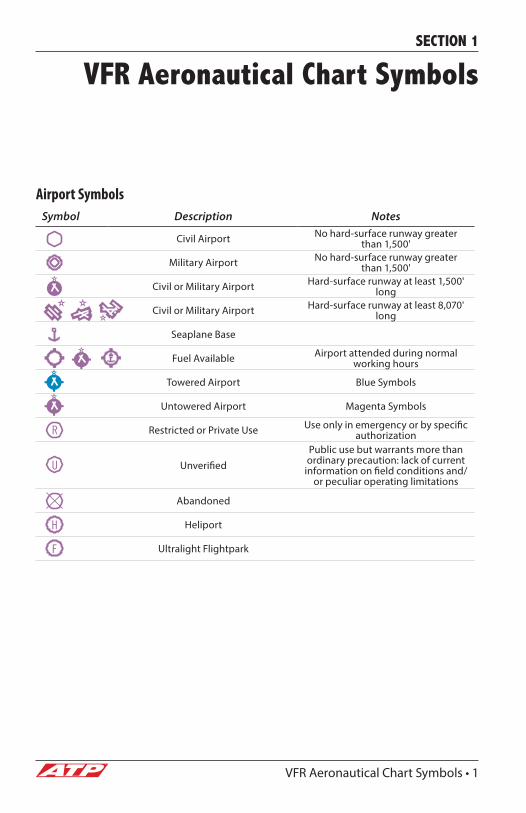
Airport SymbolsSymbol Description Notes
Civil Airport No hard-surface runway greater than 1,500'
Military Airport No hard-surface runway greater than 1,500'
Civil or Military Airport Hard-surface runway at least 1,500' long
Civil or Military Airport Hard-surface runway at least 8,070' long
Seaplane Base
Fuel Available Airport attended during normal working hours
Towered Airport Blue Symbols
Untowered Airport Magenta Symbols
Restricted or Private Use Use only in emergency or by specific authorization
UnverifiedPublic use but warrants more than ordinary precaution: lack of current
information on field conditions and/or peculiar operating limitations
Abandoned
Heliport
Ultralight Flightpark
2 • VFR Aeronautical Chart Symbols
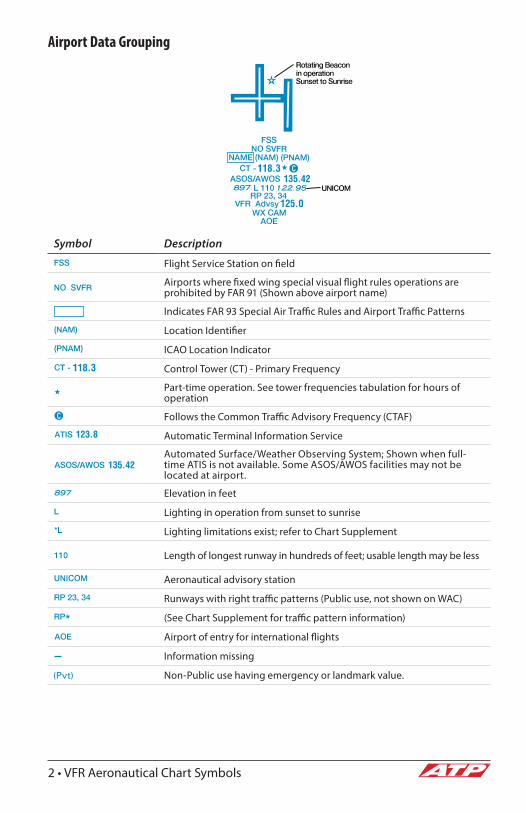
Airport Data Grouping
Symbol Description
Flight Service Station on field
Airports where fixed wing special visual flight rules operations are prohibited by FAR 91 (Shown above airport name)
Indicates FAR 93 Special Air Traffic Rules and Airport Traffic Patterns
Location Identifier
ICAO Location Indicator
Control Tower (CT) - Primary Frequency
Part-time operation. See tower frequencies tabulation for hours of operation
Follows the Common Traffic Advisory Frequency (CTAF)
Automatic Terminal Information Service
Automated Surface/Weather Observing System; Shown when full-time ATIS is not available. Some ASOS/AWOS facilities may not be located at airport.
Elevation in feet
Lighting in operation from sunset to sunrise
Lighting limitations exist; refer to Chart Supplement
Length of longest runway in hundreds of feet; usable length may be less
Aeronautical advisory station
Runways with right traffic patterns (Public use, not shown on WAC)
(See Chart Supplement for traffic pattern information)
Airport of entry for international flights
Information missing
Non-Public use having emergency or landmark value.(Pvt)

VFR Aeronautical Chart Symbols • 3
Radio Aids to Navigation
VHF Omni-Directional Radio (VOR) Range
VOR
VORTAC
When an NDB NAVAID shares the same name and Morse Code as the VOR NAVAID the frequency can be collocated inside the same box to conserve space.
VOR-DME
Non-Directional Radio Beacon (NDB)
NDB-DME
Other Radio Transmitters
(frequency and type of transmission marked on sectional chart)
4 • VFR Aeronautical Chart Symbols
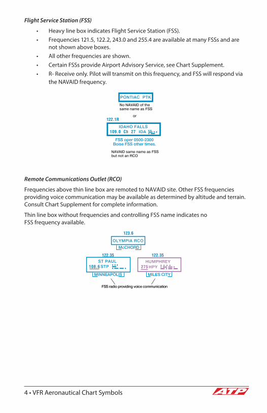
Flight Service Station (FSS)
• Heavy line box indicates Flight Service Station (FSS).• Frequencies 121.5, 122.2, 243.0 and 255.4 are available at many FSSs and are
not shown above boxes.• All other frequencies are shown.• Certain FSSs provide Airport Advisory Service, see Chart Supplement.• R- Receive only. Pilot will transmit on this frequency, and FSS will respond via
the NAVAID frequency.
Remote Communications Outlet (RCO)
Frequencies above thin line box are remoted to NAVAID site. Other FSS frequencies providing voice communication may be available as determined by altitude and terrain. Consult Chart Supplement for complete information.
Thin line box without frequencies and controlling FSS name indicates no FSS frequency available.
VFR Aeronautical Chart Symbols • 5
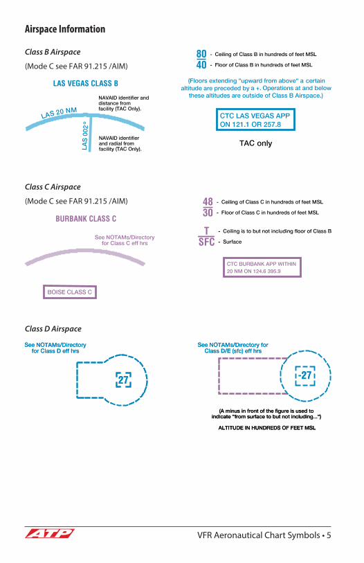
Airspace Information
Class B Airspace
(Mode C see FAR 91.215 /AIM)
Class C Airspace
(Mode C see FAR 91.215 /AIM)
Class D Airspace
6 • VFR Aeronautical Chart Symbols
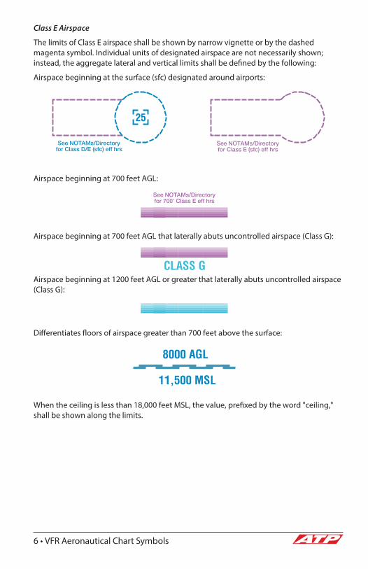
Class E Airspace
The limits of Class E airspace shall be shown by narrow vignette or by the dashed magenta symbol. Individual units of designated airspace are not necessarily shown; instead, the aggregate lateral and vertical limits shall be defined by the following:
Airspace beginning at the surface (sfc) designated around airports:
Airspace beginning at 700 feet AGL:
Airspace beginning at 700 feet AGL that laterally abuts uncontrolled airspace (Class G):
Airspace beginning at 1200 feet AGL or greater that laterally abuts uncontrolled airspace (Class G):
Differentiates floors of airspace greater than 700 feet above the surface:
When the ceiling is less than 18,000 feet MSL, the value, prefixed by the word "ceiling," shall be shown along the limits.
VFR Aeronautical Chart Symbols • 7
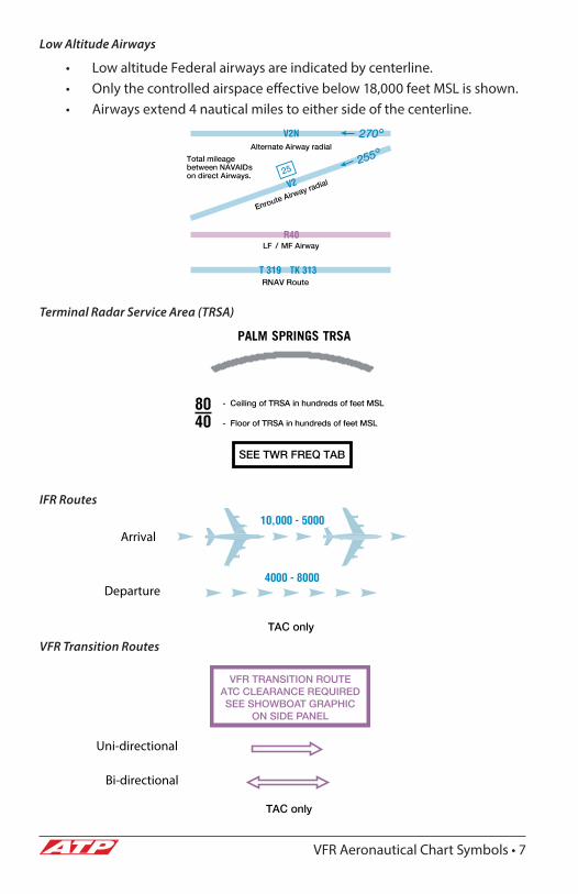
Low Altitude Airways
• Low altitude Federal airways are indicated by centerline.• Only the controlled airspace effective below 18,000 feet MSL is shown.• Airways extend 4 nautical miles to either side of the centerline.
Terminal Radar Service Area (TRSA)
IFR Routes
VFR Transition Routes
Arrival
Departure
VFR TRANSITION ROUTEATC CLEARANCE REQUIREDSEE SHOWBOAT GRAPHIC
ON SIDE PANEL
Uni-directional
Bi-directional

8 • VFR Aeronautical Chart Symbols
Special Use Airspace
• Only the airspace effective below 18,000 feet MSL is shown.• The type of area shall be spelled out in large areas if space permits.
Military Training Routes (MTR)
Special Military Activity Routes (SMAR)
Boxed notes shown adjacent to route.
Special Air Traffic Rules / Airport Paterns (FAR 93)
Appropriate boxed note as required shown adjacent to area.
Mode C Veil (FAR 91.215)
Appropriate notes as required may be shown.
Miscellaneous Airspace Areas
Parachute Jumping Area w/
Frequency
Ultralight ActivityGlider Operating Area
Hang Glider Activity
Unmanned Aircraft Activity
VFR Aeronautical Chart Symbols • 9
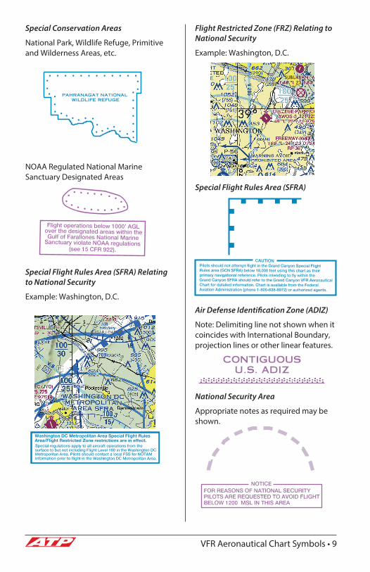
Special Conservation Areas
National Park, Wildlife Refuge, Primitive and Wilderness Areas, etc.
NOAA Regulated National Marine Sanctuary Designated Areas
Special Flight Rules Area (SFRA) Relating to National Security
Example: Washington, D.C.
Flight Restricted Zone (FRZ) Relating to National Security
Example: Washington, D.C.
Special Flight Rules Area (SFRA)
Air Defense Identification Zone (ADIZ)
Note: Delimiting line not shown when it coincides with International Boundary, projection lines or other linear features.
National Security Area
Appropriate notes as required may be shown.

10 • VFR Aeronautical Chart Symbols
Navigational & Procedural Information
Isogonic Line & Value
Isogonic lines and values shall be based on the five year epoch magnetic variation model.
Intersections
• Named intersections used as reporting points.• Arrows are directed toward facilities which establish intersection.
VFR Checkpoints
Underline indicates proper name of VFR Checkpoint.
VFR Aeronautical Chart Symbols • 11
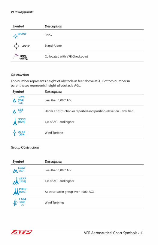
VFR Waypoints
Symbol Description
RNAV
Stand-Alone
Collocated with VFR Checkpoint
Obstruction
Top number represents height of obstacle in feet above MSL. Bottom number in parentheses represents height of obstacle AGL.
Symbol Description
Less than 1,000' AGL
Under Construction or reported and position/elevation unverified
1,000' AGL and higher
Wind Turbine
Group Obstruction
Symbol Description
Less than 1,000' AGL
1,000' AGL and higher
At least two in group over 1,000' AGL
Wind Turbines
12 • VFR Aeronautical Chart Symbols
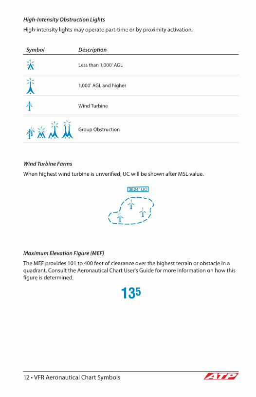
High-Intensity Obstruction Lights
High-intensity lights may operate part-time or by proximity activation.
Symbol Description
Less than 1,000' AGL
1,000' AGL and higher
Wind Turbine
Group Obstruction
Wind Turbine Farms
When highest wind turbine is unverified, UC will be shown after MSL value.
Maximum Elevation Figure (MEF)
The MEF provides 101 to 400 feet of clearance over the highest terrain or obstacle in a quadrant. Consult the Aeronautical Chart User's Guide for more information on how this figure is determined.

VFR Aeronautical Chart Symbols • 13
Culture
Railroads
Symbol Description
Single Track
Double Track
Roads
Symbol Description
Dual-Lane Divided Highway Category 1
Primary Category 2
Secondary Category 2
Trails
Symbol Description
Category 3
Road Markers
Symbol Description
Interstate Route No.
U.S. Route No.
Air Marked Identification Label
Road Names
Roads Under Construction

14 • VFR Aeronautical Chart Symbols
Bridges & Viaducts
Tunnels-Road & Railroad
Populated Places
Symbol Description
Large Cities Category 1
Cities and Large Towns Category 2
Towns and Villages Category 3
Boundaries
Symbol Description
International
State or Province
Convention or Mandate Line
Date Line
Railroad Road
Mines or Quarries Power Transmission & Telecommunication Lines
Time Zones

VFR Aeronautical Chart Symbols • 15
Symbol Description
Pipeline
Dams
Passable Locks
Small Locks
Outdoor Theater
Wells - Other than water
Race Tracks
Lookout Towers
Coast Guard Station
Miscellaneous Cultural Features
Symbol Description
Stadium
Fort
Cemetery
Tanks
Symbol Description
Water
Oil
Gas
618 (Elevation Base of Tower)

16 • VFR Aeronautical Chart Symbols
Hydrography
Symbol Description
Open Water
Inland Water
Open/Inland Water
Perennial Stream
Non-Perennial Stream
Lakes
Symbol Description Notes
Perennial Number indicates elevation.
Non-Perennial (dry, intermittent, etc.) Illustration includes small perennial lake
Miscellaneous Hydrographic Features
Symbol Description
Aqueducts
Falls
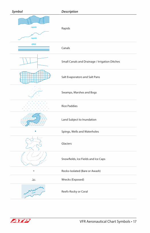
VFR Aeronautical Chart Symbols • 17
Symbol Description
Rapids
Canals
Small Canals and Drainage / Irrigation Ditches
Salt Evaporators and Salt Pans
Swamps, Marshes and Bogs
Rice Paddies
Land Subject to Inundation
Spings, Wells and Waterholes
Glaciers
Snowfields, Ice Fields and Ice Caps
Rocks-Isolated (Bare or Awash)
Wrecks (Exposed)
Reefs-Rocky or Coral
18 • VFR Aeronautical Chart Symbols
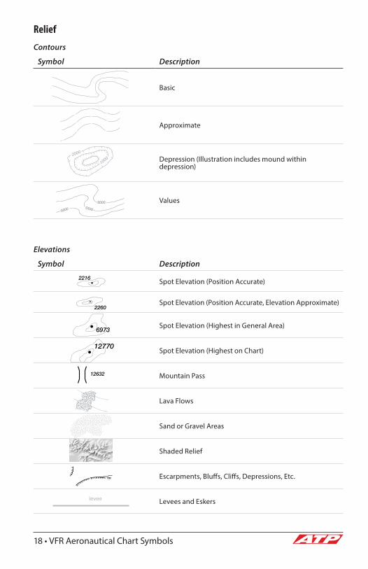
Relief
Contours
Symbol Description
Basic
Approximate
Depression (Illustration includes mound within depression)
Values
Elevations
Symbol Description
Spot Elevation (Position Accurate)
Spot Elevation (Position Accurate, Elevation Approximate)
Spot Elevation (Highest in General Area)
Spot Elevation (Highest on Chart)
Mountain Pass
Lava Flows
Sand or Gravel Areas
Shaded Relief
Escarpments, Bluffs, Cliffs, Depressions, Etc.
Levees and Eskers
2000
1000
12632
VFR Aeronautical Chart Symbols • 19
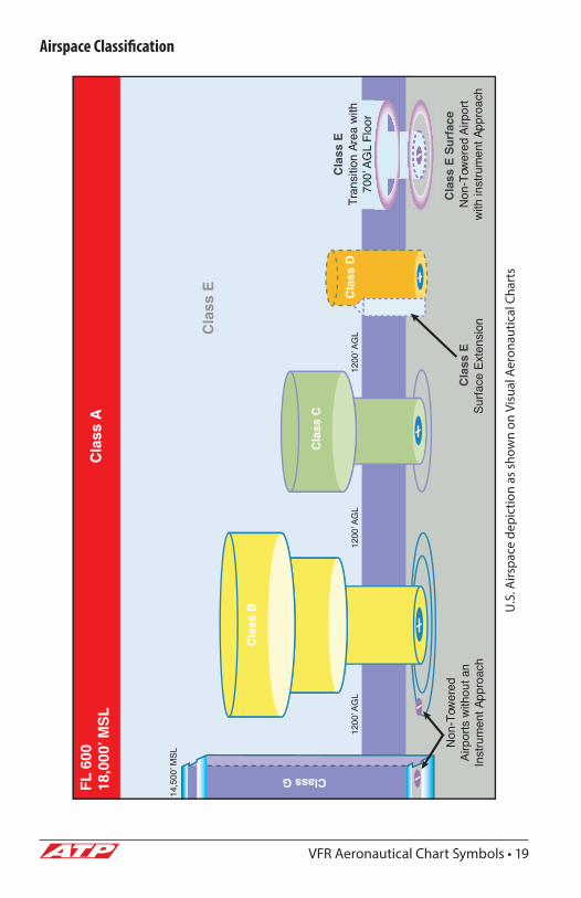
Airspace Classification
U.S
. Airs
pace
dep
ictio
n as
sho
wn
on V
isua
l Aer
onau
tical
Cha
rts
1200
ʼ AG
L
FL 6
0018
,000
ʼ MSL
Cla
ss A
Cla
ss E
Cla
ss E
Cla
ss E
Cla
ss E
Sur
face
Cla
ss D
Cla
ss C
Cla
ss B
Class G
Tran
sitio
n Ar
ea w
ith70
0ʼ A
GL
Floo
r
Non
-Tow
ered
Airp
ort
with
inst
rum
ent A
ppro
ach
Non
-Tow
ered
Airp
orts
with
out a
nIn
stru
men
t App
roac
hSu
rface
Ext
ensi
on
14,5
00ʼ M
SL
1200
ʼ AG
L12
00ʼ A
GL

20 • VFR Aeronautical Chart Symbols
AIRSPACE CLASS A CLASS B CLASS C CLASS D CLASS E CLASS GEntry Requirements ATC clearance ATC clearance ATC clearance for IFR
All require radio contact
ATC clearance for IFR All require radio contact
ATC clearance for IFR All IFR require radio contact
None
Minimum Pilot Instrument Rating
Private or Student
restrictions apply.
Two-Way Radio Communications
Yes Yes Yes Yesplan*
Not required*
Special VFR Allowed
No Yes Yes Yes Yes N/A
VFR Visibility Minimum
N/A 3 statute miles 3 statute miles 3 statute miles Below 10,000’ MSL3 statute miles
At or above 10,000’ MSL
5 statute miles
Below 1200’ AGL (regardless of MSL)
Day1 statute mile
Night3 statute miles
Above 1200’ AGL & below 10,000’ MSL
Day1 statute mile
Night3 statute miles
Above 1200’ AGL & at or Above 10,000’ MSL
5 statute miles
VFR Minimum Distance From Clouds
N/A Clear of Clouds 500’ below 1000’ above 2000’ horizontally
500’ below 1000’ above 2000’ horizontally
Below 10,000’ MSL500’ below 1000’ above 2000’ horizontally
At or above 10,000’ MSL
1000’ below 1000’ above 1 mile horizontally
Below 1200’ AGL (regardless of MSL)
DayClear of Clouds
Night500’ below1000’ above2000’ horizontally
Above 1200’ AGL & below 10,000’ MSL
Day500’ below1000’ above2000’ horizontally
Night500’ below1000’ above2000’ horizontally
Above 1200’ AGL & at or above 10,000’ MSL
1000’ below1000’ above1 mile horizontally
VFR Aircraft Separation
N/A All IFR Aircraft Runway Operations None None
Yes Yes Yes Workload permitting Workload permitting Workload permitting
Airport Application N/A RadarInstrumentApproachesWeatherControl TowerHigh Density
RadarInstrumentApproachesWeatherControl Tower
InstrumentApproachesWeatherControl Tower
InstrumentApproachesWeather
Control Tower
Speed Restrictions N/A 250 KIAS below 10000’ MSL
250 KIAS below 10,000’ MSL and 200 KIAS below 2500’ AGL within 4nm of the primary airport
250 KIAS below 10,000’ MSL and 200 KIAS below 2500’ AGL within 4nm of the primary airport
N/A N/A
Differs from ICAO No ICAO does not have speed restriction
ICAO does not have speed restrictionICAO requires ATC clearance
ICAO requires ATC clearance
No ICAO requires 3 statute miles visibility
VFR Aeronautical Chart Symbols • 21
*Unless a temporary tower is present
AIRSPACE CLASS A CLASS B CLASS C CLASS D CLASS E CLASS GEntry Requirements ATC clearance ATC clearance ATC clearance for IFR
All require radio contact
ATC clearance for IFR All require radio contact
ATC clearance for IFR All IFR require radio contact
None
Minimum Pilot Instrument Rating
Private or Student
restrictions apply.
Two-Way Radio Communications
Yes Yes Yes Yesplan*
Not required*
Special VFR Allowed
No Yes Yes Yes Yes N/A
VFR Visibility Minimum
N/A 3 statute miles 3 statute miles 3 statute miles Below 10,000’ MSL3 statute miles
At or above 10,000’ MSL
5 statute miles
Below 1200’ AGL (regardless of MSL)
Day1 statute mile
Night3 statute miles
Above 1200’ AGL & below 10,000’ MSL
Day1 statute mile
Night3 statute miles
Above 1200’ AGL & at or Above 10,000’ MSL
5 statute miles
VFR Minimum Distance From Clouds
N/A Clear of Clouds 500’ below 1000’ above 2000’ horizontally
500’ below 1000’ above 2000’ horizontally
Below 10,000’ MSL500’ below 1000’ above 2000’ horizontally
At or above 10,000’ MSL
1000’ below 1000’ above 1 mile horizontally
Below 1200’ AGL (regardless of MSL)
DayClear of Clouds
Night500’ below1000’ above2000’ horizontally
Above 1200’ AGL & below 10,000’ MSL
Day500’ below1000’ above2000’ horizontally
Night500’ below1000’ above2000’ horizontally
Above 1200’ AGL & at or above 10,000’ MSL
1000’ below1000’ above1 mile horizontally
VFR Aircraft Separation
N/A All IFR Aircraft Runway Operations None None
Yes Yes Yes Workload permitting Workload permitting Workload permitting
Airport Application N/A RadarInstrumentApproachesWeatherControl TowerHigh Density
RadarInstrumentApproachesWeatherControl Tower
InstrumentApproachesWeatherControl Tower
InstrumentApproachesWeather
Control Tower
Speed Restrictions N/A 250 KIAS below 10000’ MSL
250 KIAS below 10,000’ MSL and 200 KIAS below 2500’ AGL within 4nm of the primary airport
250 KIAS below 10,000’ MSL and 200 KIAS below 2500’ AGL within 4nm of the primary airport
N/A N/A
Differs from ICAO No ICAO does not have speed restriction
ICAO does not have speed restrictionICAO requires ATC clearance
ICAO requires ATC clearance
No ICAO requires 3 statute miles visibility
22 • VFR Aeronautical Chart Symbols
Sample Information Tables
(Tower frequencies, SUA info, etc.)
{ {
{{
{
{
NOT FOR NAVIGATION
NNNNNNONONO
NNNNNNNTIOIOIOOO
GANAVIG
OT FOROOOORORRRR NR NFFTT FF
NF
NNNNNO
IFR Aeronautical Chart Symbols • 23
SECTION 2
IFR Aeronautical Chart Symbols
ATP Students and Instructors are required to use Jeppesen Charts in training and checking. Please refer to the Introduction to Jeppesen Navigation Charts for Jeppesen chart information. The following section in this manual is provided as a reference to FAA IFR Chart symbology which is utilized on Foreflight charts and Airmen Knowledge Tests.
Airports
Airport Data
Facilities in blue or green have an approved IAP and/or Radar Minima published in either the FAA Terminal Procedures Publications or the DoD FLIPs (military instrument procedures). Those in blue have an IAP and/or Radar Minima published at least in the High Altitude DoD FLIPs. Facilities in brown do not have a published IAP or Radar Minima.
• All IAP Airports are shown on the Low Altitude Charts.• Non-IAP Airports shown on the U.S. Low Altitude Charts have a
minimum hard surface runway of 3,000'.• Associated city names for public airports are shown above or
preceding the airport name. If airport name and city name are the same, only the airport name is shown. City names for military and private airports are not shown.
• The airport identifier in parentheses follows the airport name or "Pvt."• Airport symbol may be offset for enroute navigational aids.• "Pvt" - Private Use
24 • IFR Aeronautical Chart Symbols
Airport Symbols
Symbol Description
Civil
Civil and Military
Military
Seaplane - Civil
Heliport
Airport Data
• Airport elevation given in feet above or below mean sea level• Pvt - Private use, not available to general public.• A solid line box enclosing the airport name indicates FAR 93 Special
Requirements - see Chart Supplement• "NO SVFR" above the airport name indicates FAR 91 fixed-wing special
VFR flight is prohibited.
• C or D following the airport identifier indicates Class C or Class D Airspace.
• Airport symbol may be offset for enroute navigational aids.• Associated city names for public airports are shown above or preceding
the airport name. If airport name and city name are the same, only the airport name is shown. The airport identifier in parentheses follows the airport name. City names for military and private airports are not shown.
• Airport Ident ICAO Location Indicator shown outside contiguous U.S. Inside contiguous U.S., add K to beginning of airport code to obtain ICAO identifier.
IFR Aeronautical Chart Symbols • 25
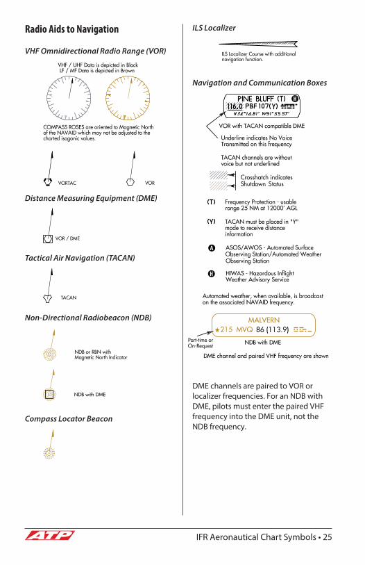
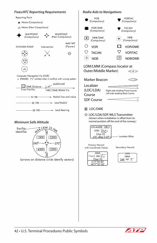
Radio Aids to Navigation
VHF Omnidirectional Radio Range (VOR)
Distance Measuring Equipment (DME)
Tactical Air Navigation (TACAN)
Non-Directional Radiobeacon (NDB)
Compass Locator Beacon
ILS Localizer
Navigation and Communication Boxes
DME channels are paired to VOR or localizer frequencies. For an NDB with DME, pilots must enter the paired VHF frequency into the DME unit, not the NDB frequency.
26 • IFR Aeronautical Chart Symbols
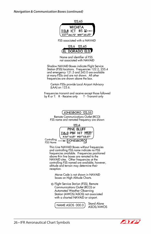
Navigation & Communication Boxes (continued)
IFR Aeronautical Chart Symbols • 27
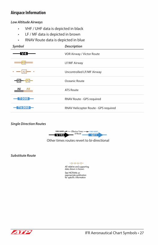
Airspace Information
Low Altitude Airways
• VHF / UHF data is depicted in black• LF / MF data is depicted in brown• RNAV Route data is depicted in blue
Symbol Description
VOR Airway / Victor Route
LF/MF Airway
Uncontrolled LF/MF Airway
Oceanic Route
ATS Route
RNAV Route - GPS required
RNAV Helicopter Route - GPS required
Single Direction Routes
Substitute Route
V 1931000-0600Z
Q111300-0600Z
Other times routes revert to bi-directional
28 • IFR Aeronautical Chart Symbols
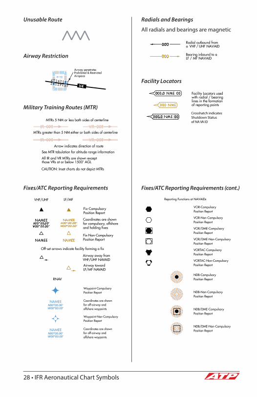
Unusable Route
Airway Restriction
Military Training Routes (MTR)
Fixes/ATC Reporting Requirements
Radials and Bearings
All radials and bearings are magnetic
Facility Locators
Fixes/ATC Reporting Requirements (cont.)
V4
IFR Aeronautical Chart Symbols • 29
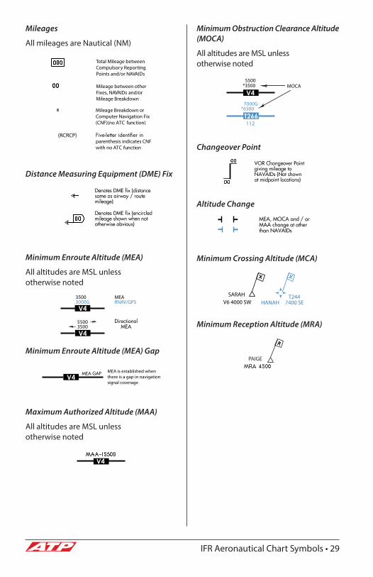
Mileages
All mileages are Nautical (NM)
Distance Measuring Equipment (DME) Fix
Minimum Enroute Altitude (MEA)
All altitudes are MSL unless otherwise noted
Minimum Enroute Altitude (MEA) Gap
Maximum Authorized Altitude (MAA)
All altitudes are MSL unless otherwise noted
Minimum Obstruction Clearance Altitude (MOCA)
All altitudes are MSL unless otherwise noted
Changeover Point
Altitude Change
Minimum Crossing Altitude (MCA)
Minimum Reception Altitude (MRA)
V4
T266
V4
V4
V4
30 • IFR Aeronautical Chart Symbols
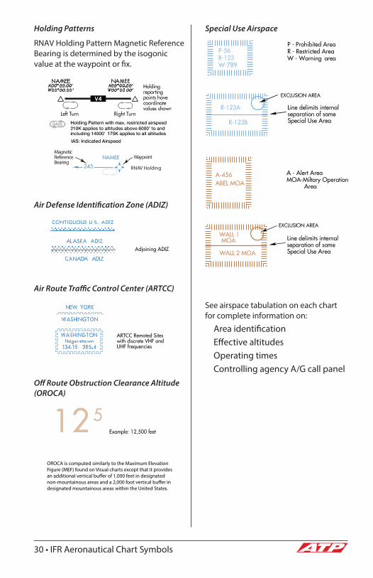
Holding Patterns
RNAV Holding Pattern Magnetic Reference Bearing is determined by the isogonic value at the waypoint or fix.
Air Defense Identification Zone (ADIZ)
Air Route Traffic Control Center (ARTCC)
Off Route Obstruction Clearance Altitude (OROCA)
Special Use Airspace
See airspace tabulation on each chart for complete information on:
Area identificationEffective altitudesOperating timesControlling agency A/G call panel
V4
IFR Aeronautical Chart Symbols • 31
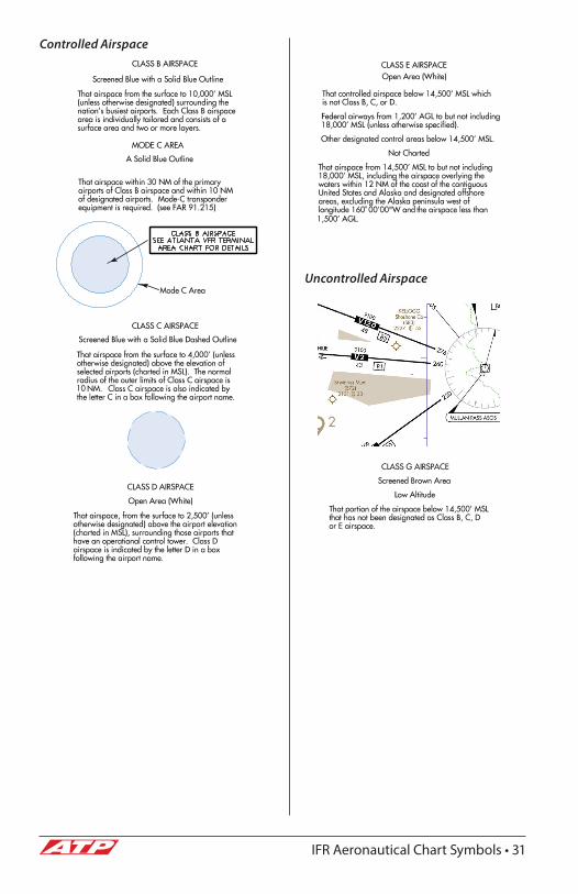
Controlled Airspace
Uncontrolled Airspace
32 • IFR Aeronautical Chart Symbols
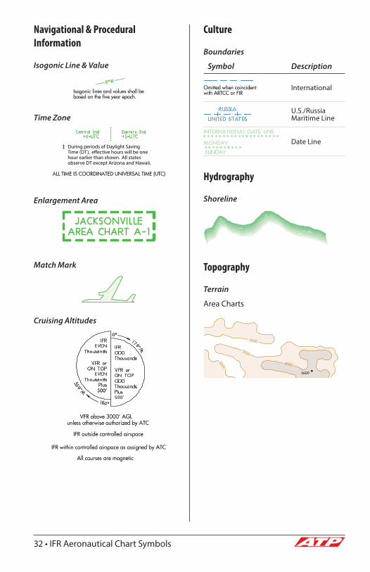
Navigational & Procedural Information
Isogonic Line & Value
Time Zone
Enlargement Area
Match Mark
Cruising Altitudes
Culture
Boundaries
Symbol Description
International
U.S./Russia Maritime Line
Date Line
Hydrography
Shoreline
Topography
Terrain
Area Charts

U.S. Terminal Procedures Public Symbols • 33
SECTION 3
U.S. Terminal Procedures Publication Symbols
Standard Terminal Arrival (STAR) & Departure Procedure (DP) Charts

34 • U.S. Terminal Procedures Public Symbols
U.S. Terminal Procedures Public Symbols • 35
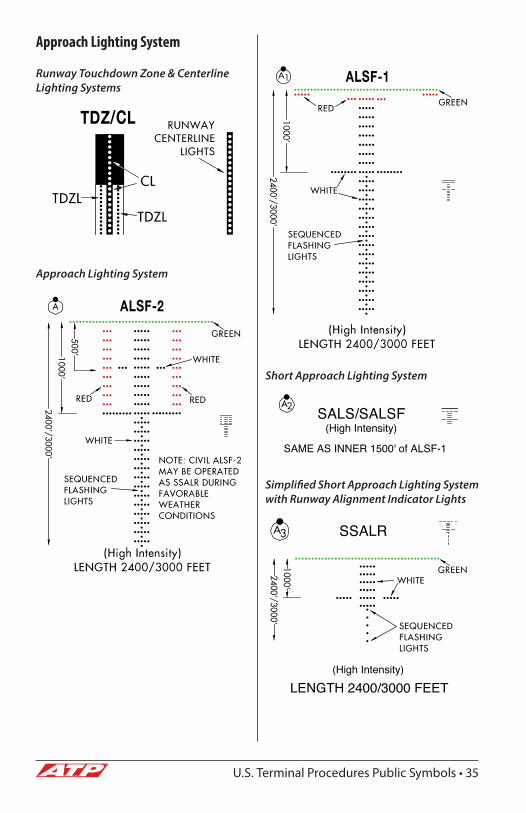
Approach Lighting System
Runway Touchdown Zone & Centerline Lighting Systems
Approach Lighting System
Short Approach Lighting System
Simplified Short Approach Lighting System with Runway Alignment Indicator Lights
SALS/SALSF(High Intensity)
SAME AS INNER 1500' of ALSF-1
(High Intensity)
LENGTH 2400/3000 FEET
SSALR
36 • U.S. Terminal Procedures Public Symbols
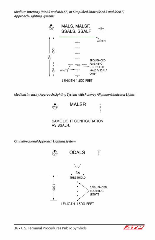
Medium Intensity (MALS and MALSF) or Simplified Short (SSALS and SSALF) Approach Lighting Systems
Medium Intensity Approach Lighting System with Runway Alignment Indicator Lights
Omnidirectional Approach Lighting System
MALS, MALSF, SSALS, SSALF
MALSR
SAME LIGHT CONFIGURATION AS SSALR.
ODALS
U.S. Terminal Procedures Public Symbols • 37
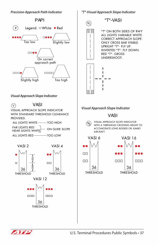
Precision Approach Path Indicator
Visual Approach Slope Indicator
"T"-Visual Approach Slope Indicator
Visual Approach Slope IndicatorVASI
"T"-VASI
VASI
PAPI
38 • U.S. Terminal Procedures Public Symbols
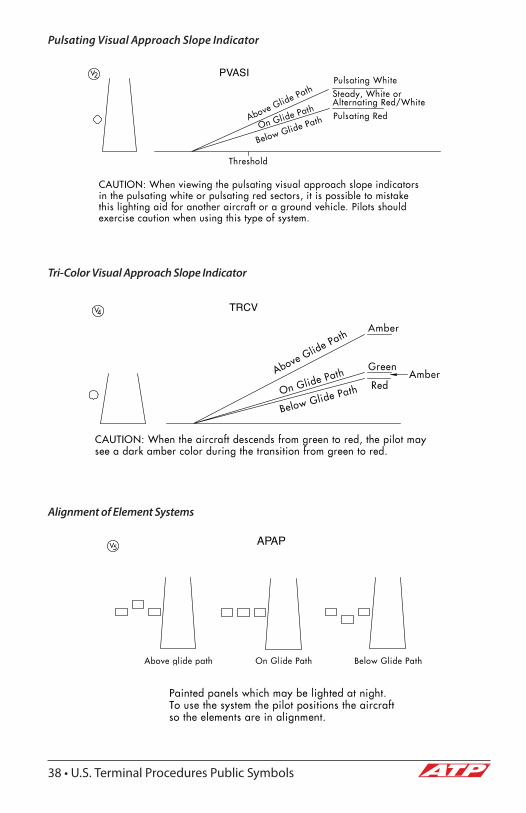
Pulsating Visual Approach Slope Indicator
Tri-Color Visual Approach Slope Indicator
Alignment of Element Systems
PVASI
TRCV
APAP

U.S. Terminal Procedures Public Symbols • 39
Airport Diagram/Sketch
Reference Features
Symbol Description
Buildings
24-Hour Self-Serve Fuel (See Chart Supplement for more information on available fuel)
Tanks
Obstruction
Airport Beacon
Runway Radar Reflectors
Hot Spot
Control Tower (If rotating beacon located on tower, beacon symbol is used and labeled "TWR")
Helicopter Alighting Areas
Negative Symbols used to identify Copter Procedures landing point
Runway Threshold elevation
Runway TDZ elevation
Runway Slope (measured to midpoint on runways 8000' or longer)
A symbol is shown to indicate runway declared distance information available, see appropriate Chart Supplement for distance information.
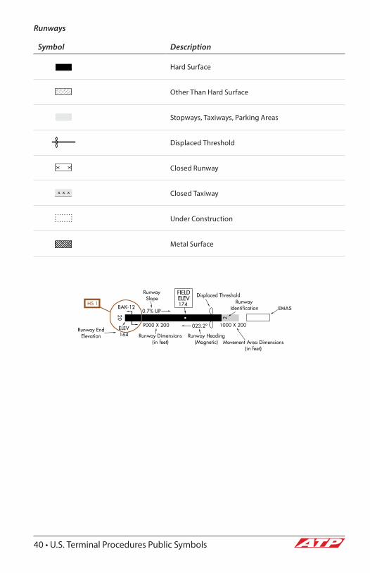
40 • U.S. Terminal Procedures Public Symbols
Runways
Symbol Description
Hard Surface
Other Than Hard Surface
Stopways, Taxiways, Parking Areas
Displaced Threshold
Closed Runway
Closed Taxiway
Under Construction
Metal Surface

U.S. Terminal Procedures Public Symbols • 41
Instrument Approach Procedures Planview
Terminal Routes
Symbol Description
Procedure Track
Missed Approach
Visual Flight Path
Procedure Turn (Type degree and point of turn optional)
Holding Patterns
• Limits will only be specified when they deviate from the standard.• Holding pattern with max. restricted airspeed:
• (175k) applies to all altitudes.• (210k) applies to altitudes above 6,000' to and including 14,000'
• DME fixes may be shown.• Arrival Holding Pattern altitude restrictions will be indicated when they
deviate from the adjacent leg.
42 • U.S. Terminal Procedures Public Symbols
Fixes/ATC Reporting Requirements
Minimum Safe Altitude
Radio Aids to Navigations
U.S. Terminal Procedures Public Symbols • 43
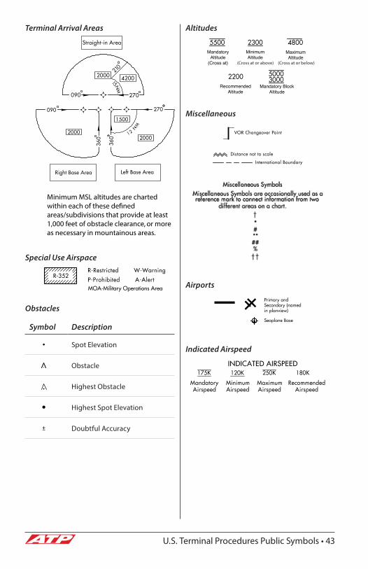
Terminal Arrival Areas
Special Use Airspace
Obstacles
Symbol Description
Spot Elevation
Obstacle
Highest Obstacle
Highest Spot Elevation
Doubtful Accuracy
Altitudes
Miscellaneous
Airports
Indicated Airspeed
MandatoryAltitude
(Cross at)
MinimumAltitude
MaximumAltitude
RecommendedAltitude
Mandatory BlockAltitude
(Cross at or above) (Cross at or below)
44 • U.S. Terminal Procedures Public Symbols
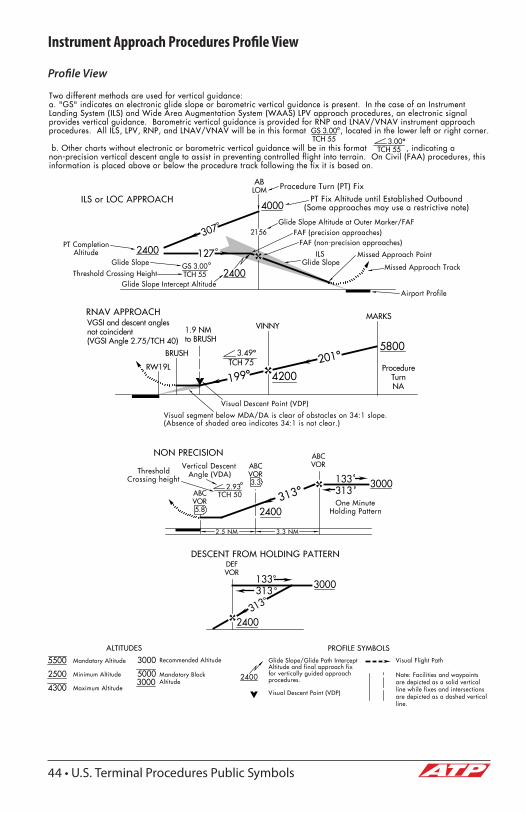
Instrument Approach Procedures Profile View
Profile View
U.S. Terminal Procedures Public Symbols • 45
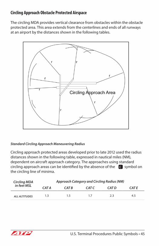
Circling Approach Obstacle Protected Airspace
The circling MDA provides vertical clearance from obstacles within the obstacle protected area. This area extends from the centerlines and ends of all runways at an airport by the distances shown in the following tables.
Standard Circling Approach Maneuvering Radius
Circling approach protected areas developed prior to late 2012 used the radius distances shown in the following table, expressed in nautical miles (NM), dependent on aircraft approach category. The approaches using standard circling approach areas can be identified by the absence of the c symbol on the circling line of minima.
Circling MDA in feet MSL
Approach Category and Circling Radius (NM)
CAT A CAT B CAT C CAT D CAT E
ALL ALTITUDES 1.3 1.5 1.7 2.3 4.5
46 • U.S. Terminal Procedures Public Symbols
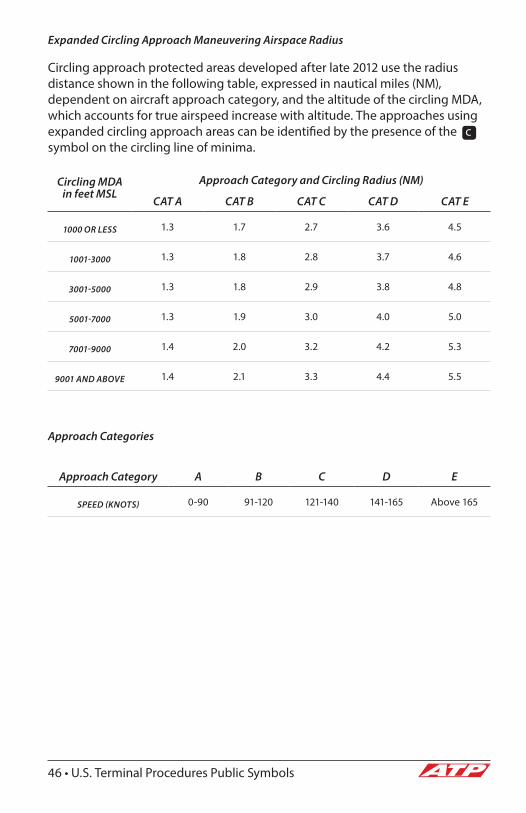
Expanded Circling Approach Maneuvering Airspace Radius
Circling approach protected areas developed after late 2012 use the radius distance shown in the following table, expressed in nautical miles (NM), dependent on aircraft approach category, and the altitude of the circling MDA, which accounts for true airspeed increase with altitude. The approaches using expanded circling approach areas can be identified by the presence of the c symbol on the circling line of minima.
Circling MDA in feet MSL
Approach Category and Circling Radius (NM)
CAT A CAT B CAT C CAT D CAT E
1000 OR LESS 1.3 1.7 2.7 3.6 4.5
1001-3000 1.3 1.8 2.8 3.7 4.6
3001-5000 1.3 1.8 2.9 3.8 4.8
5001-7000 1.3 1.9 3.0 4.0 5.0
7001-9000 1.4 2.0 3.2 4.2 5.3
9001 AND ABOVE 1.4 2.1 3.3 4.4 5.5
Approach Categories
Approach Category A B C D E
SPEED (KNOTS) 0-90 91-120 121-140 141-165 Above 165
U.S. Terminal Procedures Public Symbols • 47
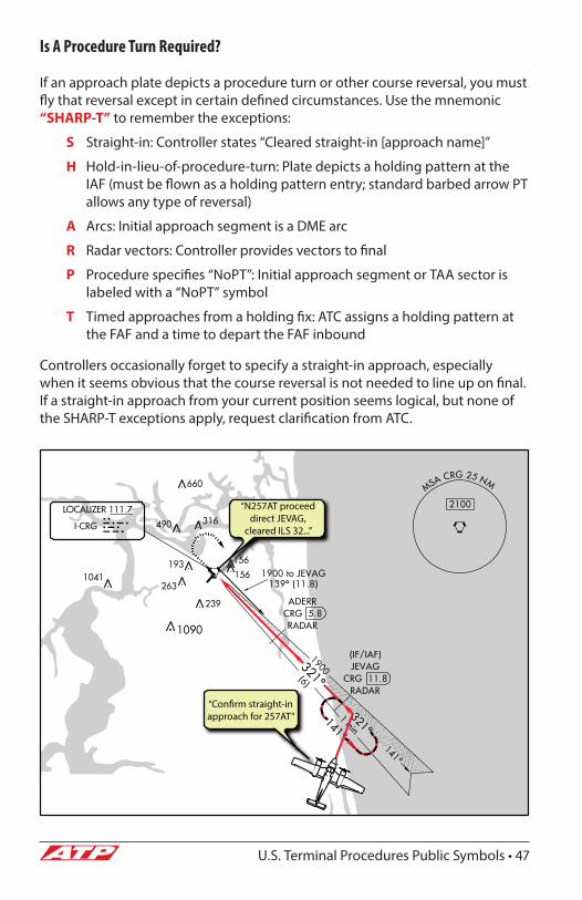
Is A Procedure Turn Required?
If an approach plate depicts a procedure turn or other course reversal, you must fly that reversal except in certain defined circumstances. Use the mnemonic “SHARP-T” to remember the exceptions:
S Straight-in: Controller states “Cleared straight-in [approach name]”
H Hold-in-lieu-of-procedure-turn: Plate depicts a holding pattern at the IAF (must be flown as a holding pattern entry; standard barbed arrow PT allows any type of reversal)
A Arcs: Initial approach segment is a DME arc
R Radar vectors: Controller provides vectors to final
P Procedure specifies “NoPT”: Initial approach segment or TAA sector is labeled with a “NoPT” symbol
T Timed approaches from a holding fix: ATC assigns a holding pattern at the FAF and a time to depart the FAF inbound
Controllers occasionally forget to specify a straight-in approach, especially when it seems obvious that the course reversal is not needed to line up on final. If a straight-in approach from your current position seems logical, but none of the SHARP-T exceptions apply, request clarification from ATC.
“N257AT proceed direct JEVAG,
cleared ILS 32...”
“Con�rm straight-in approach for 257AT”
48 • Other Useful Information
SECTION 4
Other Useful Information
IFR Alternates: 14 CFR 91.169Alternate Requirements
When filing an IFR flight plan, you must designate an alternate in two situations:
1. The destination airport does not have an instrument approach procedure (IAP).
2. Weather conditions at the destination are expected to violate the "1-2-3 Rule":
1 From 1 hour before to 1 hour after ETA...
2 Ceilings must be at least 2,000' AGL, and...
3 Visibility must be at least 3 statute miles.
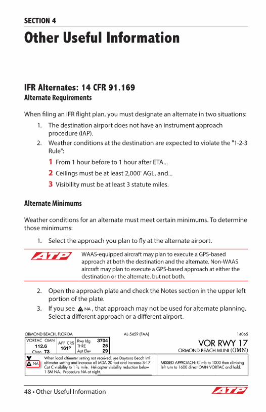
Alternate Minimums
Weather conditions for an alternate must meet certain minimums. To determine those minimums:
1. Select the approach you plan to fly at the alternate airport.
WAAS-equipped aircraft may plan to execute a GPS-based approach at both the destination and the alternate. Non-WAAS aircraft may plan to execute a GPS-based approach at either the destination or the alternate, but not both.
2. Open the approach plate and check the Notes section in the upper left portion of the plate.
3. If you see , that approach may not be used for alternate planning. Select a different approach or a different airport.
Other Useful Information • 49
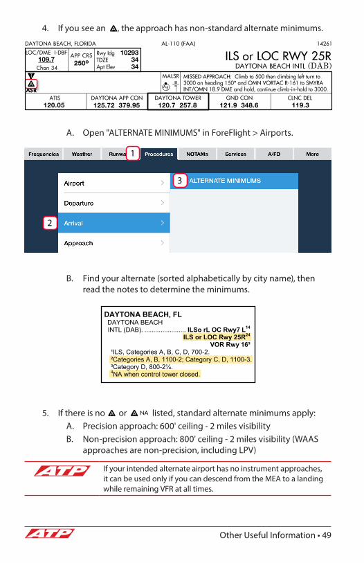
4. If you see an , the approach has non-standard alternate minimums.
A. Open "ALTERNATE MINIMUMS" in ForeFlight > Airports.
B. Find your alternate (sorted alphabetically by city name), then read the notes to determine the minimums.
5. If there is no or listed, standard alternate minimums apply:A. Precision approach: 600' ceiling - 2 miles visibilityB. Non-precision approach: 800' ceiling - 2 miles visibility (WAAS
approaches are non-precision, including LPV)
If your intended alternate airport has no instrument approaches, it can be used only if you can descend from the MEA to a landing while remaining VFR at all times.
DAYTONA BEACH, FL DAYTONA BEACH INTL (DAB). ....................... ILSo rL OC Rwy7 L14
ILS or LOC Rwy 25R24
VOR Rwy S, Categories A, B, C, D, 700-2.
Categories A, B, 1100-2; Category C, D, 1100-3. y D, 800-2 .
4NA when control tower closed.
1
2
3
50 • Other Useful Information
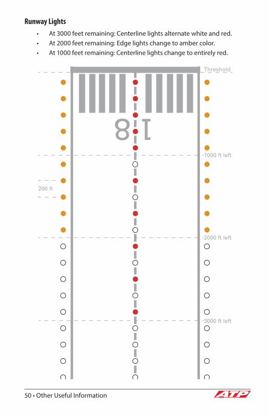
Runway Lights• At 3000 feet remaining: Centerline lights alternate white and red.• At 2000 feet remaining: Edge lights change to amber color.• At 1000 feet remaining: Centerline lights change to entirely red.
3000 ft left
2000 ft left
1000 ft left
Threshold
200 ft

Other Useful Information • 51
Runway Markings• Touchdown zone markings every 500 feet from 500 to 3000 feet.• Aiming point markings at 1000 feet.• Shorter runways may not have full set of markings.
1000 ft
1500 ft
2000 ft
2500 ft
3000 ft
500 ft
ThresholdMarkings
Touchdown Zone
Markings
Touchdown Zone
Markings
Aiming Point
Marking

52 • Other Useful Information
Options for Obtaining/Cancelling IFR Clearances
Consult the Chart Supplement to determine which of the following options to use for clearance delivery and/or cancellation:
1. Ground control or clearance delivery frequency2. Approach/departure control frequency3. Remote Communications Outlet (RCO) frequency4. Ground Communications Outlet (GCO) frequency (key the microphone
4 times to open a telephone connection to the local ATC facility, or 6 times to call an FSS briefer)
5. Call 888-766-8267, the national clearance delivery number6. Call 800-WX-BRIEF
For safety, always obtain and cancel IFR clearances on the ground. Do not depart with the intention of obtaining an IFR clearance airborne, and do not cancel IFR while airborne prior to landing.
Other Useful Information • 53
ForeFlight Resources
Up-to-date copies of the official FAA publications on which this supplement is based can be found in ForeFlight Mobile. Use the following procedure to download the relevant documents:
1. Open ForeFlight Mobile.2. Tap the “Documents” button at the bottom center of the screen.3. Tap the “Catalog” button in the upper right corner of the screen.4. A popup window will open. Select “FAA” from the list at left.5. Select the documents you would like to download. Recommended
documents include:A. Digital Terminal Procedures SupplementalB. A/FD Supplemental (9 available; select the appropriate one(s) for
your route or region)C. Aeronautical Chart User’s GuideD. IFR Low LegendE. TAC LegendF. VFR Chart Legend
54 • Other Useful Information
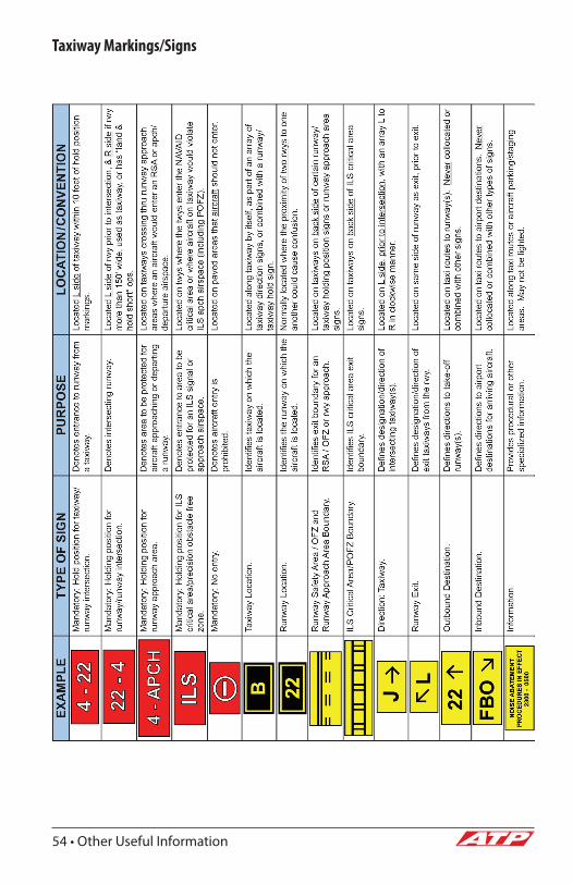
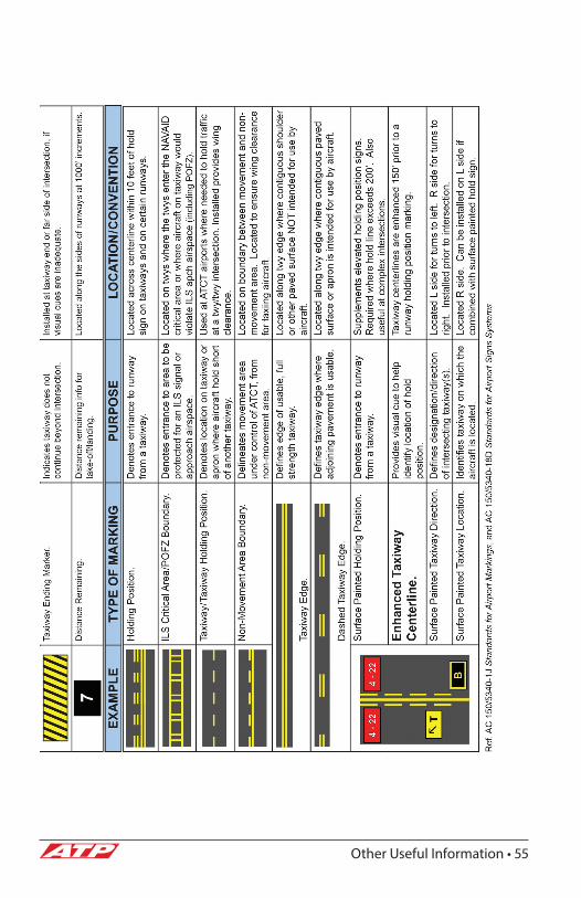
Taxiway Markings/Signs
Other Useful Information • 55


ATPFlightSchool.comP.O. BOX 1784 • Ponte Vedra Beach, FL 32004-1784
(904) 595-7950 • Fax: (904) 273-2164