Atomic-scale imaging and the effect of yttrium on the fracture toughness of silicon carbide ceramics
7
Atomic-scale imaging and the effect of yttrium on the fracture toughness of silicon carbide ceramics A.M. Kueck a,b , Q.M. Ramasse c , L.C. De Jonghe a,b , R.O. Ritchie a,b, * a Department of Materials Science & Engineering, University of California, Berkeley, CA 94720, USA b Materials Sciences Division, Lawrence Berkeley National Laboratory, Berkeley, CA 94720, USA c National Center for Electron Microscopy, Lawrence Berkeley National Laboratory, Berkeley, CA 94720, USA Received 6 January 2010; accepted 22 January 2010 Available online 17 February 2010 Abstract In SiC sintered with Al, B and C additions (ABC–SiC), the presence of Y in the Al–Si–O–C grain-boundary phase leads to less frequent crack deflection and lower toughness. When Y is absent from the grain-boundary phase and remains in the triple pockets, crack deflection is restored, and higher toughness results from grain-bridging mechanisms. The observations are consistent with elastic mod- ulus changes in the intergranular phase, which depend on their yttria and silica content, and indicate that these can play an important role in determining crack deflection. While high-toughness ceramics such as ABC–SiC and Si 3 N 4 rely on sintering additives forming crack-deflecting intergranular films, the present case is a striking example where the presence of a segregant in the grain boundary pro- motes transgranular fracture by raising the modulus of the nanoscale intergranular grain-boundary film. Ó 2010 Acta Materialia Inc. Published by Elsevier Ltd. All rights reserved. Keywords: Ceramics; Silicon carbide; Yttrium dopants; Fracture toughness 1. Introduction Rare-earth (RE) additives are commonly used as sintering aids in the processing of silicon carbide and silicon nitride structural ceramics. Much work has focused on the role of these additives, in particular on ionic size and its influence on mechanical properties such as strength, toughness and creep resistance. It is widely reported that the fracture tough- ness of SiC and Si 3 N 4 increases with increasing RE ionic radius of the additives [1–3], an effect which the present authors believe can be understood by the change in the stiff- ness of the grain-boundary phase due to the presence of the RE ions [4]. However, with additions of yttrium, which is of intermediate ionic size, the mechanism is less clear. Studies show that SiC and Si 3 N 4 with Y additives can fail by trans- granular fracture [1], intergranular fracture [5–7] or both [2,8,9]. The nature of the fracture mode is critical to the mechanical properties of the ceramic. Intergranular fracture can lead to crack-tip shielding by (interlocking) grain bridg- ing, 1 which promotes rising resistance-curve (R-curve) behavior and high fracture toughness (approaching, or even exceeding, 10 MPa m 1/2 ); with transgranular (cleavage) frac- ture, there is no such crack bridging or rising R-curves, and the fracture toughness is invariably low (typically 2–3 MPa m 1/2 ). Low toughness and the lack of a rising R-curve causes low damage tolerance and can also lead to lower strength [11]. Previous results with Y-containing SiC suggest that Y itself plays a critical role in determining the fracture mode, and hence the fracture toughness, of the material. 1359-6454/$36.00 Ó 2010 Acta Materialia Inc. Published by Elsevier Ltd. All rights reserved. doi:10.1016/j.actamat.2010.01.031 * Corresponding author. Address: Department of Materials Science & Engineering, University of California, Berkeley, CA 94720, USA. Tel.: +1 510 486 5798; fax: +1 510 643 7294. E-mail address: [email protected] (R.O. Ritchie). 1 Grain bridging is an extrinsic toughening mechanism [10] which enhances the toughness by operating in the wake of the crack tip to “shield” the crack tip from the full (applied) driving force. The crack bridges then carry loads that would otherwise be used to propagate the crack further, thereby increasing the measured fracture toughness. www.elsevier.com/locate/actamat Available online at www.sciencedirect.com Acta Materialia 58 (2010) 2999–3005
-
Upload
independent -
Category
Documents
-
view
3 -
download
0
Transcript of Atomic-scale imaging and the effect of yttrium on the fracture toughness of silicon carbide ceramics
Atomic-scale imaging and the effect of yttrium on the fracturetoughness of silicon carbide ceramics
A.M. Kueck a,b, Q.M. Ramasse c, L.C. De Jonghe a,b, R.O. Ritchie a,b,*
aDepartment of Materials Science & Engineering, University of California, Berkeley, CA 94720, USAbMaterials Sciences Division, Lawrence Berkeley National Laboratory, Berkeley, CA 94720, USA
cNational Center for Electron Microscopy, Lawrence Berkeley National Laboratory, Berkeley, CA 94720, USA
Received 6 January 2010; accepted 22 January 2010Available online 17 February 2010
Abstract
In SiC sintered with Al, B and C additions (ABC–SiC), the presence of Y in the Al–Si–O–C grain-boundary phase leads to lessfrequent crack deflection and lower toughness. When Y is absent from the grain-boundary phase and remains in the triple pockets, crackdeflection is restored, and higher toughness results from grain-bridging mechanisms. The observations are consistent with elastic mod-ulus changes in the intergranular phase, which depend on their yttria and silica content, and indicate that these can play an importantrole in determining crack deflection. While high-toughness ceramics such as ABC–SiC and Si3N4 rely on sintering additives formingcrack-deflecting intergranular films, the present case is a striking example where the presence of a segregant in the grain boundary pro-motes transgranular fracture by raising the modulus of the nanoscale intergranular grain-boundary film.� 2010 Acta Materialia Inc. Published by Elsevier Ltd. All rights reserved.
Keywords: Ceramics; Silicon carbide; Yttrium dopants; Fracture toughness
1. Introduction
Rare-earth (RE) additives are commonly used as sinteringaids in the processing of silicon carbide and silicon nitridestructural ceramics. Much work has focused on the role ofthese additives, in particular on ionic size and its influenceon mechanical properties such as strength, toughness andcreep resistance. It is widely reported that the fracture tough-ness of SiC and Si3N4 increases with increasing RE ionicradius of the additives [1–3], an effect which the presentauthors believe can be understood by the change in the stiff-ness of the grain-boundary phase due to the presence of theRE ions [4]. However, with additions of yttrium, which is ofintermediate ionic size, the mechanism is less clear. Studiesshow that SiC and Si3N4 with Y additives can fail by trans-granular fracture [1], intergranular fracture [5–7] or both
[2,8,9]. The nature of the fracture mode is critical to themechanical properties of the ceramic. Intergranular fracturecan lead to crack-tip shielding by (interlocking) grain bridg-ing,1 which promotes rising resistance-curve (R-curve)behavior and high fracture toughness (approaching, or evenexceeding, 10 MPa m1/2); with transgranular (cleavage) frac-ture, there is no such crack bridging or rising R-curves, andthe fracture toughness is invariably low (typically�2–3 MPa m1/2). Low toughness and the lack of a risingR-curve causes low damage tolerance and can also lead tolower strength [11]. Previous results with Y-containing SiCsuggest that Y itself plays a critical role in determining thefracture mode, and hence the fracture toughness, of thematerial.
1359-6454/$36.00 � 2010 Acta Materialia Inc. Published by Elsevier Ltd. All rights reserved.
doi:10.1016/j.actamat.2010.01.031
* Corresponding author. Address: Department of Materials Science& Engineering, University of California, Berkeley, CA 94720, USA.Tel.: +1 510 486 5798; fax: +1 510 643 7294.
E-mail address: [email protected] (R.O. Ritchie).
1 Grain bridging is an extrinsic toughening mechanism [10] whichenhances the toughness by operating in the wake of the crack tip to“shield” the crack tip from the full (applied) driving force. The crackbridges then carry loads that would otherwise be used to propagate thecrack further, thereby increasing the measured fracture toughness.
www.elsevier.com/locate/actamat
Available online at www.sciencedirect.com
Acta Materialia 58 (2010) 2999–3005
Difficulties in imaging yttrium with Z-contrast scanningtransmission electron microscopy (STEM) or collectingyttriumelectron energy loss spectroscopy (EELS) signals havehindered the development of a reliable means of characteriz-ing the grain-boundary phase with high (i.e., atomic) spatialresolution [8,12,13]. While it is generally agreed that thepresence of specific sintering additives governs the nature ofthis phase, which in turn dictates whether fracture occurs byhigh-toughness intergranular or low-toughness transgranularcracking, the exact cause of this transition for Y-containingsilicon carbide (and nitride) has not been determined.
Here, atomic-resolution transmission electron micros-copy (TEM) is used to examine two similar compositionsof yttrium-doped silicon carbides which exhibit either inter-granular or transgranular fracture. It is demonstrated thatit is the atomic-scale presence (or absence) of Y within thehigh-silica grain-boundary phase that directly correlateswith the marked differences in macro-scale fracture tough-ness of these ceramics.
2. Experimental procedures
2.1. Sample processing
SiC powders were prepared with 0.5 or 0.7 at.%Y; acetatesalts of yttriumwere dissolved inmethanol and added to sub-micrometerb-SiCpowder (Betarundum,gradeUltrafine, IBI-DEN, Japan), with amean particle size of 0.27 lm, 3 wt.%Almetal, 0.6 wt.% B and 6 wt.% carbon source. The Al powder(H-3, Valimet, Stockton, CA) had an average size of 3 lm; theboron powder (Alfa Aesar) had a particle size of <5 lm. Thecarbonwas added as polyvinylbutyral, which yielded�33%Cby weight upon pyrolysis. The powder slurry was ultrasoni-cally agitated, stir-dried, and sieved through a 200-meshscreen. Discs of the mixed powders 38 mm in diameter werepre-formed at ambient temperature in a steel die, before beinghot-pressed in a graphite die. Hot pressing was conducted at1900 �C with 50 MPa applied pressure under flowing argonat 1 atm, with heating and cooling rates of 10 �C min�1.Hot-pressed rounds were ground to remove �0.5 mm fromeach surface. The resulting 0.5 at.% Y- and 0.7 at.% Y-con-taining SiC ceramics are referred to throughout this paperas Y0.5 and Y0.7, respectively.
2.2. Fracture testing
To examine the fracture properties, Vickers micro-indentations with a 10 kg load on a polished surface ofthe ceramics were used to generate cracks, which were thenexamined in the scanning electron microscope (JEOL JSM-6340F SEM) to discern the overall crack path. At least 12cracks in each specimen were observed in the microscope tocharacterize the fracture behavior. Additionally, indenta-tion toughness was measured from these indents. Tenindents and �30 cracks were used for each measurement.
The fracture toughness was further estimated using thecontrolled-flaw method, where indentations on the tensile
surface of beams provide the initial flaws which lead tofracture. Five unindented beams were tested in four-pointbend, inner span 10 mm and outer span 25 mm, with a dis-placement rate of 0.05 mm min�1, along with four beamswith indentations. Three indentations were placed withinthe inner span on the tensile surface, spaced 2 mm apart.Critical flaw sizes were estimated to be �100 lm, basedon the original crack length and confirmed by observationof the post-mortem fracture surfaces. Fracture toughnessvalues were calculated from the strength of the indentedbeams based on the method of Cao et al. [14,15].
As SiC is intended to be a high-temperature material,further fracture tests were carried out at 1200 �C. Crack-growth resistance curves (R-curves) were generated usingcompact-tension DC(T) specimens. Cracks were initiatedat room temperature from razor micronotches with a rootradius of �10 lm and grown to �5–10 lm before high tem-perature testing. Crack lengths were measured in situ bythe DC potential-drop method described in Refs. [16,17],and corrected by observing the final crack size after testcompletion. Tests were conducted in a graphite resistancefurnace under flowing Ar at �1 atm at a displacement rateof 0.05 mm min�1.
2.3. TEM and spectroscopy
Togain information on the crack path at atomistic dimen-sions, specifically on how cracks interact with the grainboundaries and the boundary phases, a new technique ofindenting TEM foils was used [4]. The method is based onthe procedure of Sun et al. [18] to estimate the interfacialtoughness of glassy phases in ceramics from the elastic mis-match across the interface. TEM foils were prepared frommaterial at least 1 mm from the edge of the specimen. Stablecracks were produced to allow observation the compositionof the crack faces. Cracks in the TEM foils were introducedvia indentation, which was performed before final milling ona 200-lm-thick section; an array of 10 � 10 micro-indents(50 g load with a cube-corner indenter) was produced on apolished surface. Mechanical thinning and ion milling pro-ceeded from the opposite side to preserve the cracks. Theirpropagation paths as they impinged on grain boundarieswere then specifically examined.
A Philips CM200/FEG transmission electron micro-scope with energy dispersive spectroscopy (EDS), operat-ing in the STEM mode with a 1-nm spot size, wasemployed to analyze the chemistry of the fracture surfaces.High-resolution high-angle annular dark field (HAADF orZ-contrast) images of uncracked grain boundaries werealso obtained using an aberration-corrected VG HB501STEM with a spot size of 0.1 nm [19].
3. Results
The two SiC ceramics studied had different Y contents,denoted Y0.5 and Y0.7 for Y doping levels of 0.5 and0.7 at.%, respectively, but otherwise had similar composi-
3000 A.M. Kueck et al. / Acta Materialia 58 (2010) 2999–3005
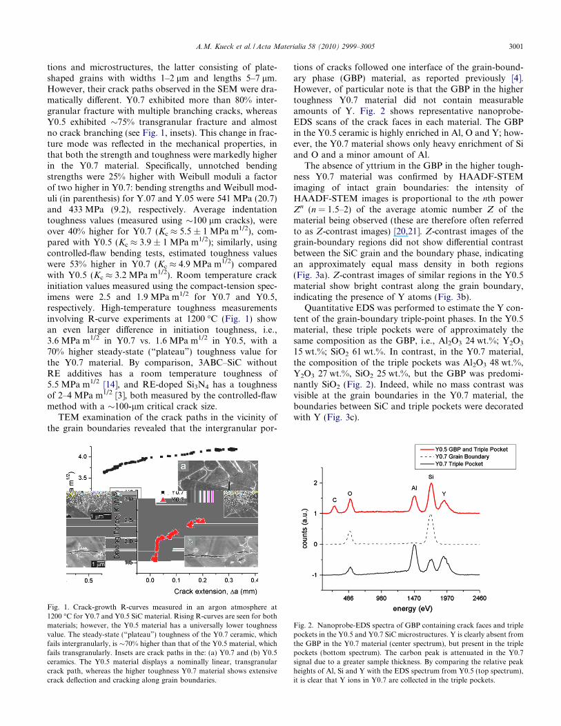
tions and microstructures, the latter consisting of plate-shaped grains with widths 1–2 lm and lengths 5–7 lm.However, their crack paths observed in the SEM were dra-matically different. Y0.7 exhibited more than 80% inter-granular fracture with multiple branching cracks, whereasY0.5 exhibited �75% transgranular fracture and almostno crack branching (see Fig. 1, insets). This change in frac-ture mode was reflected in the mechanical properties, inthat both the strength and toughness were markedly higherin the Y0.7 material. Specifically, unnotched bendingstrengths were 25% higher with Weibull moduli a factorof two higher in Y0.7: bending strengths and Weibull mod-uli (in parenthesis) for Y.07 and Y.05 were 541 MPa (20.7)and 433 MPa (9.2), respectively. Average indentationtoughness values (measured using �100 lm cracks), wereover 40% higher for Y0.7 (Kc � 5.5 ± 1 MPa m1/2), com-pared with Y0.5 (Kc � 3.9 ± 1 MPa m1/2); similarly, usingcontrolled-flaw bending tests, estimated toughness valueswere 53% higher in Y0.7 (Kc � 4.9 MPa m1/2) comparedwith Y0.5 (Kc � 3.2 MPa m1/2). Room temperature crackinitiation values measured using the compact-tension spec-imens were 2.5 and 1.9 MPa m1/2 for Y0.7 and Y0.5,respectively. High-temperature toughness measurementsinvolving R-curve experiments at 1200 �C (Fig. 1) showan even larger difference in initiation toughness, i.e.,3.6 MPa m1/2 in Y0.7 vs. 1.6 MPa m1/2 in Y0.5, with a70% higher steady-state (“plateau”) toughness value forthe Y0.7 material. By comparison, 3ABC–SiC withoutRE additives has a room temperature toughness of5.5 MPa m1/2 [14], and RE-doped Si3N4 has a toughnessof 2–4 MPa m1/2 [3], both measured by the controlled-flawmethod with a �100-lm critical crack size.
TEM examination of the crack paths in the vicinity ofthe grain boundaries revealed that the intergranular por-
tions of cracks followed one interface of the grain-bound-ary phase (GBP) material, as reported previously [4].However, of particular note is that the GBP in the highertoughness Y0.7 material did not contain measurableamounts of Y. Fig. 2 shows representative nanoprobe-EDS scans of the crack faces in each material. The GBPin the Y0.5 ceramic is highly enriched in Al, O and Y; how-ever, the Y0.7 material shows only heavy enrichment of Siand O and a minor amount of Al.
The absence of yttrium in the GBP in the higher tough-ness Y0.7 material was confirmed by HAADF-STEMimaging of intact grain boundaries: the intensity ofHAADF-STEM images is proportional to the nth powerZn (n = 1.5–2) of the average atomic number Z of thematerial being observed (these are therefore often referredto as Z-contrast images) [20,21]. Z-contrast images of thegrain-boundary regions did not show differential contrastbetween the SiC grain and the boundary phase, indicatingan approximately equal mass density in both regions(Fig. 3a). Z-contrast images of similar regions in the Y0.5material show bright contrast along the grain boundary,indicating the presence of Y atoms (Fig. 3b).
Quantitative EDS was performed to estimate the Y con-tent of the grain-boundary triple-point phases. In the Y0.5material, these triple pockets were of approximately thesame composition as the GBP, i.e., Al2O3 24 wt.%; Y2O3
15 wt.%; SiO2 61 wt.%. In contrast, in the Y0.7 material,the composition of the triple pockets was Al2O3 48 wt.%,Y2O3 27 wt.%, SiO2 25 wt.%, but the GBP was predomi-nantly SiO2 (Fig. 2). Indeed, while no mass contrast wasvisible at the grain boundaries in the Y0.7 material, theboundaries between SiC and triple pockets were decoratedwith Y (Fig. 3c).
Fig. 1. Crack-growth R-curves measured in an argon atmosphere at1200 �C for Y0.7 and Y0.5 SiC material. Rising R-curves are seen for bothmaterials; however, the Y0.5 material has a universally lower toughnessvalue. The steady-state (“plateau”) toughness of the Y0.7 ceramic, whichfails intergranularly, is �70% higher than that of the Y0.5 material, whichfails transgranularly. Insets are crack paths in the: (a) Y0.7 and (b) Y0.5ceramics. The Y0.5 material displays a nominally linear, transgranularcrack path, whereas the higher toughness Y0.7 material shows extensivecrack deflection and cracking along grain boundaries.
Fig. 2. Nanoprobe-EDS spectra of GBP containing crack faces and triplepockets in the Y0.5 and Y0.7 SiC microstructures. Y is clearly absent fromthe GBP in the Y0.7 material (center spectrum), but present in the triplepockets (bottom spectrum). The carbon peak is attenuated in the Y0.7signal due to a greater sample thickness. By comparing the relative peakheights of Al, Si and Y with the EDS spectrum from Y0.5 (top spectrum),it is clear that Y ions in Y0.7 are collected in the triple pockets.
A.M. Kueck et al. / Acta Materialia 58 (2010) 2999–3005 3001

4. Discussion
Although extensive studies [1–3,5–9,12,13,22–25] havebeen performed on the effect of yttrium additions on thestructure and properties of SiC and Si3N4 ceramics,2 diffi-culties in detecting Y and its location, by either EELS orZ-contrast imaging, have obscured its precise role. High-toughness microstructures in these materials rely on twoconditions: a microstructure of interlocking elongatedgrains and the deflection of cracks around these grains(to achieve an intergranular fracture mode and effectivetoughening from grain bridging). RE additions have beenshown to lead to the formation of glassy GBP, and to affectgrain shape greatly, with concurrent variations in tough-ness across the RE series. What has not been discussed inas much detail is the role of these RE additives in control-ling crack deflection at the grain boundary, which repre-sents the vital step in the development of an intergranular
fracture. Here, one sees that, given a nearly identical micro-structure by using a single RE additive, the actual locationof the Y ions within the microstructure at the atomic scaleappears to be the key feature in determining the crack path,which in turn governs the fracture toughness at the macro-scale, evidence that microstructural control and the simplepresence of an intergranular film are not solely sufficient toproduce increased toughness.
Previous studies have shown that small changes in Ycomposition can influence the fracture behavior [2,8,9],although no clear explanation has been proposed. Further-more, the final location of the Y dopants—within the GBPor solely in triple pockets and second phases—is sensitiveto processing conditions, including the Y2O3:Al2O3:SiO2
ratios and heat treatment. For example, it has been shownthat the crystallization of YAG-type materials in triplepockets will remove Y from the GBP, leaving only Al, Siand O [13,22], although no previous correlation with frac-ture behavior had been made.
Computational studies by Painter et al. [23] corroboratethese observations of varying segregation behavior. Y hasbeen calculated to have approximately equal affinity forsegregation to the grain surface (and therefore the grainboundary) or to collect in the triple pockets. This further
Fig. 3. Z-contrast STEM images of grain boundaries in: (a) Y0.7 and (b) Y0.5 silicon carbide materials. Color is tied to intensity and therefore mass; solidblue columns represent high mass Y ions. For the Y0.7 material in (a), no contrast is seen between the SiC grain and the GBP, indicating the absence of Yin the boundary phase. For the Y0.5 material in (b), bright contrast in the boundary phase indicates the presence of Y ions. (c) Z-contrast STEM image ofa boundary between SiC (right) and a crystalline triple pocket (left) in the Y0.7 SiC material. The bright layer at the edge of the triple pocket is on average40% brighter than the SiC lattice, indicating that it contains Y ions. The overview image on the bottom right shows the relative locations of images (a) and(c); the bright region at the left is a triple pocket.
2 While the Si3N4 field is rich in research on the nature of oxynitrideglasses, similar research on the effects of RE doping is not available onoxycarbide glasses relevant to SiC. It is expected though that trends inphysical properties such as elastic modulus in RE-doped SiAlON glasses/grain-boundary films will be similar in RE-SiAlOC glasses.
3002 A.M. Kueck et al. / Acta Materialia 58 (2010) 2999–3005
suggests that minor changes in processing, including tem-perature, pressure and chemistry, could stimulate a partic-ular segregation behavior.
For the present Y-doped SiC, to understand why GBPsdeficient in Y (in Y0.7) generate deflected cracks at grainboundaries and intergranular fracture, whereas the pres-ence of Y in the GBP (in Y0.5) does not, one needs toexamine the relative stiffness of these phases and how thisaffects crack deflection at the boundaries. Quantitativeinformation, either experimental or computational, onthe moduli of the GBP compositions observed here, how-ever, is not available. An estimate of the moduli was madeusing a simple rule of mixtures based on the moduli of thecomponent oxides.3 While such an estimate is far fromquantitative, together with trends in other glass systems[24–33], it nevertheless may provide a reasonable “bestguess” for estimating the modulus mismatch across theinterface, which can be characterized by the first Dundurs’parameter; for the SiC/GBP combination, this is defined interms of their respective moduli ESiC and EGBP asa = (ESiC � EGBP)/(ESiC + EGBP). The estimated Young’smoduli and resulting a values are listed in Table 1.
Images of cracks at grain boundaries, generated bymicro-hardness indents in the TEM foils, are shown in Fig. 1; theobjective here is to determine whether impinging cracks pen-etrate the boundary, as seen inY0.5, or deflect along the SiC/GBP interface, as seen in Y0.7 (Fig. 4). The tendency of acrack to penetrate through, or deflect along the GBP, maybe considered in the context of the relative toughness of theSiC/GPB interface compared with that of the GBP, GInt/GGBP,
4 together with the magnitude of the modulus mis-match a across the boundary, using the He and Hutchinsonlinear-elastic mechanics description of a crack impingingupon an elastic dissimilar material interface (Fig. 5) [4,34].Depending upon the values of these parameters, incidentcracks will either arrest and/or deflect along the interface(region I in Fig. 4) or penetrate it (region II). A major factorin determining the GBP modulus is the Y2O3/SiO2 ratio.There is a significant difference in this ratio for the GBP, asis evident from the compositions superimposed on theY2O3–SiO2–Al2O3 ternary diagram (Fig. 6) [35], for Y0.5and Y0.7. It should be noted that the alumina/yttria ratiosof the triple pocket phases donot varymuch for the two com-positions examined, and that their alumina/yttria ratio aftersintering is lower than expected on the basis of starting one.This is undoubtedly due to aluminum and alumina loss dur-ing the processing of alumina-containing SiC, which is awell-known phenomenon.
Crack deflection at the grain boundaries is essential forintergranular fracture to occur; without such a fracturemode crack-bridging mechanisms cannot develop, and the
absence of such (extrinsic) toughnesswill not result in a risingR-curve and produce a minimal fracture toughness compa-rable with its intrinsic value, i.e., �2–3 MPa m1/2 or less.The coupled observations of a change in the fracturemode—from intergranular to transgranular—with the inclu-sion of Y in the GBP shows that the increased modulus ofsuch a Y-containing lower silica GBP (in Y0.5), comparedwith the Y-free, higher silica GBP (in Y0.7), can alter thepath of a crack impinging on a boundary enough to changeboth the fracture behavior and the measured fracture tough-ness. Specifically, in Y0.5 material, the presence of Y ions inthe boundary together with the lower SiO2 content of theGBP leads to a stiffer GBP and hence to conditions wherean incident crack will penetrate the SiC/GBP interface(Fig. 5), leading to transgranular fracture, no grain bridging,and corresponding poor toughness.With the absence of seg-regated Y in the boundaries and the higher SiO2 content ofthe GBP in the Y0.7 material, the impinging crack will bedeflected along the SiC/GPB interface as a result of the low-ered modulus (i.e., higher a) of the GBP that it attempts toenter. The consequent deflection along the boundary leadsto intergranular fracture, which in turn gives rise to grainbridging and superior fracture toughness (Fig. 5).
It is likely that processing conditions, particularly the(difficult to control) oxygen content and the sintering/heattreatment schedule, dictate the segregation behavior of Y-containing ABC–SiC, and therefore its fracture properties.While similar processing variables studied using this ABC–SiC system do not change the segregation behavior of REions such as La and Yb, the segregation of Y ions to theGBP is sensitive to both composition and thermal history.
For the low Y2O3/SiO2 ratio GBP (Y0.7), a higherboundary stiffness should be expected from a simple esti-mate based on component moduli, as well from relatedwork [23–28]. The low stiffness of the Y-free boundaryphase can enhance crack deflection and increase toughnessby changing the mechanical properties of the GBP [4]. TheGBP of the Y0.7 material is primarily a silica-rich material,which should further decrease the stiffness of the boundaryphase: for a SiO2–SiC boundary, the value of Dundurs’parameter a would be �0.73, and crack deflection wouldbe preferred even if the interfacial toughness approachedthat of the boundary phase itself. For this SiC ceramicdoped with Y, crack-initiation fracture toughness valuescan be increased by up to 125% and R-curve plateau tough-ness values by 70% as a result of the separation of Y out ofGBP or its interface. Additionally, it has been shown that
Table 1Measurements of the compositions of GBP and estimates of elasticmodulus and first Dundurs’ parameter for Y0.5 and Y0.7, compared withSiC.
Sample GBP composition Y2O3;Al2O3; SiO2 (wt.%)
Estimatedmodulus, E(GPa)
Dundurs’parameter a
Y0.5 15; 24; 61 115 0.59Y0.7 Mainly SiO2 186 0.73SiC 450
3 http://www.ceramics.nist.gov/srd/summary/emodox00.htm4 Gi refers to the fracture toughness for phase “i” expressed in terms of
the critical value of the strain-energy release rate. It is related to the (modeI) toughness expressed in terms of the stress intensity K by the expression:G = K2/E, where E is Young’s modulus.
A.M. Kueck et al. / Acta Materialia 58 (2010) 2999–3005 3003
the crystalline Y-rich triple pockets that result from theremoval of Y from the GBP can serve as anchors during
high-temperature loading, decreasing grain-boundary slid-ing and improving creep resistance [13].
It is important to note that the action of the Y dopant isnot to enhance toughness by “embrittling” the boundaryphase, nor to reduce boundary failure by “strengthening”the boundary. The most significant effect is the increasein elastic modulus, which is separate from both the tough-ness and the strength of the phase. The change in modulus,compared with the fixed modulus of the SiC matrix, thenalters crack deflection mechanics, as shown in Fig. 5.
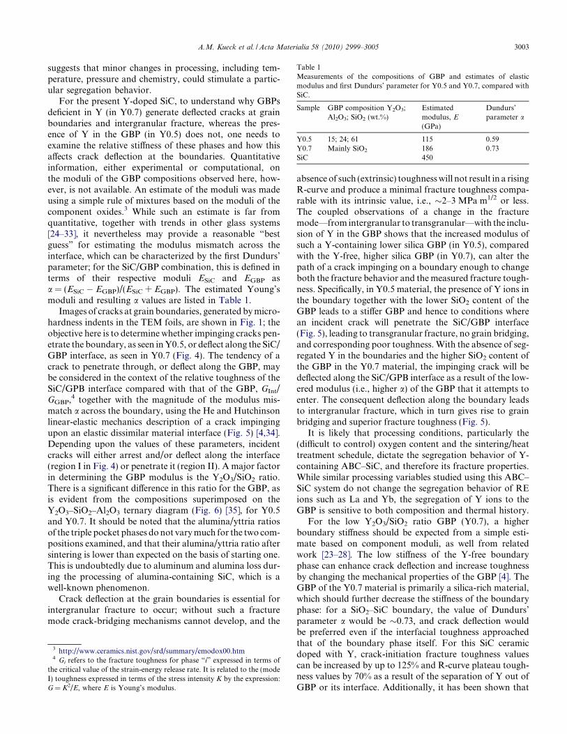
Fig. 4. Schematic representation of micro-indention-produced cracks in the TEM foils impinging on a SiC grain boundary containing a grain-boundaryphase (GBP) interaction. High toughness in the ceramic requires an intergranular fracture to generate toughening by grain bridging. This is only achievedwhen incidents crack deflect at the boundary, rather than penetrate it. This occurs in the Y0.7 material, but not in the Y0.5 material, by a process of“delamination” cracking at the first SiC/GBP interface.
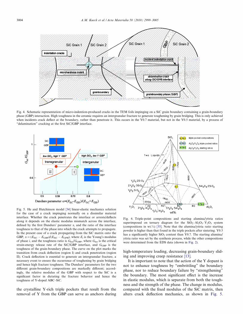
Fig. 5. He and Hutchinson model [34] linear-elastic mechanics solutionfor the case of a crack impinging normally on a dissimilar materialinterface. Whether the crack penetrates the interface or arrests/deflectsalong it depends on the elastic modulus mismatch across the interface,defined by the first Dundurs’ parameter a, and the ratio of the interfacetoughness to that of the phase into which the crack attempts to propagate.In the present case of a crack propagating from the SiC matrix onto theGBP, a = (ESiC � EGBP)/(ESiC � EGPB), where Ei is the Young’s modulusof phase i, and the toughness ratio is GInt/GGBP, where GInt is the criticalstrain-energy release rate of the SiC/GBP interface, and GGBP is thetoughness of the grain-boundary phase. The curve on the plot marks thetransition from crack deflection (region I) and crack penetration (regionII). Crack deflection is essential to generate an intergranular fracture, anecessary event to ensure the occurrence of toughening by grain bridgingand hence high fracture toughness. The Dundurs’ parameters for the twodifferent grain-boundary compositions are markedly different; accord-ingly, the relative modulus of the GBP with respect to the SiC is asignificant factor in dictating the fracture behavior and hence thetoughness of Y-doped ABC–SiC.
Fig. 6. Triple-point compositions and starting alumina/yttria ratiossuperimposed on ternary diagram for the SiO2–Al2O3–Y2O3 system(compositions in wt.%) [35]. Note that the alumina/yttria ratio startingpowder is higher than that found in the triple pockets after sintering. Y0.5has a significantly higher SiO2 content than Y0.7. The starting alumina/yttria ratio was set by the synthesis process, while the other compositionswere determined from the EDS data (shown in Fig. 2).
3004 A.M. Kueck et al. / Acta Materialia 58 (2010) 2999–3005
Knowledge of the effects of sintering additives on themechanical properties of the GBP, most importantly elasticmodulus, can therefore drive the selection of dopants toachieve the desired fracture behavior.
5. Conclusions
With SiC doped with Y as an additive, processingvariables such as yttrium and oxygen content andthermal history determine whether yttrium ions segregateto the GBP or are retained in the boundary triple pock-ets. This segregation behavior is primarily responsible forcontrolling the macroscopic fracture behavior through itsinfluence on the elastic modulus of the GBP whichcontrols whether incident cracks deflect or not at theSiC/GBP interface; such deflection leads to intergranu-lar fracture, grain bridging and superior fracturetoughness.
1. The presence of Y ions within the GBP in the SiC dopedwith 0.5 at.% Y correlates with a decreased SiO2 contentin the GPB which increases its stiffness; this decreasesthe likelihood of crack deflection at the boundary phaseinterface with the matrix due to the lower elastic mis-match across this interface. Such deflection is necessaryfor failure by intergranular cracking, which in turn isresponsible for the primary toughening mechanism ofgrain bridging.
2. The lower stiffness of the GBP in the 0.7 at.% Y ceramicfrom the absence of Y in the boundaries and the higherSiO2 content in the GBP, significantly increases theprobability of such deflection, consistent with its muchhigher toughness.
3. While an elongated grain morphology is a necessaryingredient for toughened ceramics, intergranular frac-ture must be operative in order to utilize such beneficialmicrostructures to achieve high toughness. It is nowclear that to develop Y-doped silicon carbide ceramicswith reliably high toughness, the precise atomic locationof the Y ions and the SiO2 content must be understoodand controlled.
Acknowledgements
This work was supported by the Director, Office of Sci-ence, Office of Basic Energy Sciences, Materials Sciencesand Engineering Division, of the US Department ofEnergy under Contract No. DE-AC02-05CH11231. Partof this work was carried out using the facilities at the Na-tional Center for Electron Microscopy, which is sup-ported at the Lawrence Berkeley National Laboratoryby the Department of Energy under the same contractnumber.
References
[1] Zhou Y, Hirao K, Toriyama M, Yamauchi Y, Kanzaki S. J AmCeram Soc 2001;84:1642–4.
[2] Satet RL, Hoffmann MJ, Cannon RM. Mater Sci Eng A2006;422:66–76.
[3] Becher PF, Painter GS, Shibata N, Waters SB, Lin H-T. J Am CeramSoc 2008;91:2328–36.
[4] Kueck AM, Kim DK, Ramasse QM, De Jonghe LC, Ritchie RO.Nano Lett 2008;8:2935–9.
[5] Zhan G-D, Xie R-J, Mitomo M, Kim Y-W. J Am Ceram Soc2001;84:945–50.
[6] Rixecker G, Biswas K, Rosinus A, Sharma S, Wiedmann I, AldingerFJ. J Eur Ceram Soc 2002;22:2669–75.
[7] Gu H, Chen H, Guo L. Mater Sci Eng A 2008;491:177–81.[8] Winkelman GB, Dwyer C, Marsh C, Hudson TS, Nguyen-Manh D,
Doblinger M, et al. Mater Sci Eng A 2006;422:77–84.[9] Kim J-Y, Kim Y-W, Mitomo M, Zhan G-D, Lee J-G. J Am Ceram
Soc 1999;82:441–4.[10] Ritchie RO. Int J Fract 1999;100:55–83.[11] Kruzic JJ, Sadat RL, Hoffmann MJ, Cannon RM, Ritchie RO. J Am
Ceram Soc 2008;91:1986–94.[12] Ziegler A, Kisielowski C, Hoffmann MJ, Ritchie RO. J Am Ceram
Soc 2003;86:1777–85.[13] Gu H, Nagano T, Zhan G-D, Mitomo M, Wakai F. J Am Ceram Soc
2003;86:1753–60.[14] Cao JJ, MoberlyChan WJ, De Jonghe LC, Gilbert CJ, Ritchie RO. J
Am Ceram Soc 1996;79:461–9.[15] Gilbert CJ, Cao J, MoberlyChan WJ, DeJonghe LC, Ritchie RO.
Acta Mater 1996;44:3199–214.[16] Gilbert CJ, McNaney JM, Dauskardt RH, Ritchie RO. J Test Eval
1994;22:117–20.[17] Chen D, Gilbert CJ, Ritchie RO. J Test Eval 2000;28:236–41.[18] Sun EY, Becher PF, Hsueh C-H, Painter GS, Waters SB, Hwang SL,
et al. Acta Mater 1999;47:2777–85.[19] Krivanek OL, Dellby N, Lupini AR. Ultramicroscopy 1999;78:1–11.[20] Hartel P, Rose H, Dinges C. Ultramicroscopy 1996;63:93–114.[21] Jesson D, Pennycook SJ. Proc Roy Soc (London) 1995;A449:273–93.[22] Zhan G-D, Ikuhara Y, Mitomo M, Xie R-J, Sakuma T, Mukherjee
AK. J Am Ceram Soc 2002;85:430–6.[23] Painter GS, Becher PF, Shelton WA, Satet RL, Hoffmann MJ. Phys
Rev B 2004;70:144108.[24] Chen J, Ouyang L, Rulis P, Misra A, Ching WY. Phys Rev Lett
2005;95:256103.[25] Ching WY, Chen J, Rulis P, Ouyang L, Misra A. J Mater Sci
2006;41:5061–7.[26] Lemercier H, Rouxel T, Fargeot D, Besson J-L, Piriou B. J Non-
Cryst Solids 1996;201:128–45.[27] Rouxel T, Huger M, Besson JL. J Mater Sci 1992;27:279–84.[28] Marchi J, Morais DS, Schneider J, Bressiani JC, Bressiani AHA. J
Non-Cryst Solids 2005;351:863–8.[29] Rouxel T. J Am Ceram Soc 2007;90:3019–39.[30] Moysan C, Riedel R, Harshe R, Rouxel T, Augereau F. J Eur Ceram
Soc 2007;27:397–403.[31] Walter S, Soraru GD, Brequel H, Enzo S. J Eur Ceram Soc
2002;22:2389–400.[32] Pantano CG, Singh AK, Zhang H. J Sol-Gel Sci Technol
1999;14:7–25.[33] Homeny J, Nelson GG, Paulik SW, Risbud SH. J Am Ceram Soc
1987;70:C114–6.[34] He M-Y, Hutchinson JW. Int J Solids Struct 1989;25:1053–67.[35] Bondar IA, Galakhov FYa. Izv Akad Nauk SSSR, Ser Khim
1963;7:1325 [reported as Fig. 2586 in Levin E, Robertins C,McMurdie H, editors. Phase diagrams for ceramists. Columbus(OH): American Ceramic Society; 1969].
A.M. Kueck et al. / Acta Materialia 58 (2010) 2999–3005 3005