ARL-500 - Wittur
137
ARL-500 LIFT CONTROL SYSTEM Programming Manual
-
Upload
khangminh22 -
Category
Documents
-
view
1 -
download
0
Transcript of ARL-500 - Wittur

ARL-500 LIFT CONTROL SYSTEM
Programming Manual

www.arkel.com.tr
ARKEL 2011 ARL-500
2
The information held in this manual may be modified without notice and ARKEL will not be responsible for changes that may occur in the future. No part of this manual can be reproduced, for any reason, in any form or by any means (including recording and photocopying) without the written consent of ARKEL. Before the control panel installation, wiring, commissioning and inspection, read this instruction manual carefully. Keep the manual in a safe place and available to engineering and installation personnel during the control panel functioning period. ARKEL is not responsible for those mistakes that may be found in this manual and for the damages that they may cause.
Publisher ARKEL Elektrik Elektronik Ticaret Ltd. Şti.
Şerifali Mah. Bayraktar Bulvarı Sehit Sk. No:32 Umraniye Istanbul TURKIYE
TEL: (+90 216) 540 03 10 – 11 - 12
Fax: (+90 216) 540 03 09
E-mail : [email protected]
www.arkel.com.tr
Date of document 2011
Document version V1.9
Hardware version V2.1A
Software version V20R109

www.arkel.com.tr
ARKEL 2011 ARL-500
3
TABLE OF CONTENTS
1. GENERAL ....................................................................................................................................6
1.1. APPLICABLE STANDARDS ................................................................................................................................... 6
1.2. ELECTROMAGNETIC COMPATIBILITY (EMC) ........................................................................................... 6
1.3. MANUAL DESCRIPTION ....................................................................................................................................... 7
1.3.1. This manual describes ..................................................................................................................................... 7 1.3.2. Symbols used in this manual .......................................................................................................................... 7
2. INTRODUCTION .......................................................................................................................8
3. PROGRAMMING INTERFACE .................................................................................................9
4. KEYPAD FUNCTIONS ACCORDING TO SCREEN ............................................................. 10
5. ARL-500 DISPLAY SCREEN ..................................................................................................... 13
5.1. STARTUP SCREEN .................................................................................................................................................. 13
5.2. MAIN SCREEN ......................................................................................................................................................... 14
5.3. INPUT STATUS SCREENS .................................................................................................................................... 17
5.3.1. ARL-500 FIXED INPUTS SCREEN ....................................................................................................... 17 5.3.2. ARL-500 PROGRAMMABLE INPUTS SCREENS ............................................................................ 18 5.3.3. REVKON PROGRAMMABLE INPUTS SCREENS ......................................................................... 18 5.3.4. KABKON PROGRAMMABLE INPUTS SCREENS ......................................................................... 19
5.4. OUTPUT STATUS SCREENS ............................................................................................................................... 20
5.4.1. ARL-500 FIXED RELAY OUTPUTS SCREEN .................................................................................. 20 5.4.2. ARL-500 PROGRAMMABLE RELAYS SCREENS ............................................................................ 20 5.4.3. ARL-500 PROGRAMMABLE TRANSISTORS SCREENS............................................................... 21 5.4.4. REVKON PROGRAMMABLE RELAYS SCREEN ........................................................................... 21
5.5. CANBUS STATUS SCREENS .................................................................................................................................. 22
5.5.1. The status of car communication ............................................................................................................... 22 5.5.2. The status of landing communication ........................................................................................................ 23
5.6. GROUP STATUS SCREEN .................................................................................................................................... 24
5.7. ERROR STATUS SCREEN ..................................................................................................................................... 25
5.8. V-T (VELOCİTY-TİME) TRAVEL CURVE SCREEN .......................................................................................... 26
5.9. ADRİVE / UNİDRİVE SP INVERTER SCREEN .................................................................................................. 26
5.10. CAR COMMAND ENTRY SCREEN ................................................................................................................. 27
5.11. MANUAL DRIVE SCREEN ................................................................................................................................. 28
5.12. SERVICE OPTIONS SCREENS ......................................................................................................................... 29
6. MENU SETTINGS .................................................................................................................... 31
6.1. ENTERING MENU ................................................................................................................................................. 31
6.2. MENU TREE .............................................................................................................................................................. 32
6.3. MENU PARAMETERS ............................................................................................................................................ 39
6.3.1. System Settings ............................................................................................................................................... 39 6.3.2 Door Settings ................................................................................................................................................... 42
6.3.2.1. Door Type Settings ................................................................................................................................................... 42
6.3.2.2. Set Door Timings ...................................................................................................................................................... 43 6.3.3. Call Responding Settings .............................................................................................................................. 45 6.3.4. Display Settings .............................................................................................................................................. 46

www.arkel.com.tr
ARKEL 2011 ARL-500
4
6.3.4.1. Floor Texts ................................................................................................................................................................. 46
6.3.4.2. Dot Matrix Settings ................................................................................................................................................... 47 6.3.5. Error Logs ....................................................................................................................................................... 49 6.3.6. Programmable Inputs .................................................................................................................................... 50
6.3.6.1. ARL-500 inputs ......................................................................................................................................................... 50
6.3.6.2. REVKON inputs ...................................................................................................................................................... 51
6.3.6.3. KABKON inputs ...................................................................................................................................................... 52
6.3.6.4. KK-x inputs ................................................................................................................................................................ 53
6.3.6.5. List of Input Functions ............................................................................................................................................ 54 6.3.7. Programmable Outputs ................................................................................................................................ 63
6.3.7.1. ARL-500 Transistors ................................................................................................................................................ 63
6.3.7.2. ARL-500 Relays ......................................................................................................................................................... 64
6.3.7.3. REVKON Relays ...................................................................................................................................................... 65
6.3.7.4. KK-x Outputs ............................................................................................................................................................ 65
6.3.7.5. List of Output Functions ......................................................................................................................................... 66 6.3.8. Encoder Settings ............................................................................................................................................ 70
6.3.8.1. Floor Level Fine Tuning .......................................................................................................................................... 70
6.3.8.2. Travel distances ......................................................................................................................................................... 70
6.3.8.3. Hardware configuration ........................................................................................................................................... 71
6.3.8.4. Learn shaft .................................................................................................................................................................. 71 6.3.9. Hydraulic Lift Settings .................................................................................................................................. 72 6.3.10. Group Settings ............................................................................................................................................. 73 6.3.11. Parking Settings ............................................................................................................................................ 74 6.3.12. Time and Date Settings .............................................................................................................................. 75
6.3.12.1. System date and time .............................................................................................................................................. 75
6.3.12.2. Next maintenance date........................................................................................................................................... 75 6.3.13. Motor Protection Settings .......................................................................................................................... 76 6.3.14. Sound Settings .............................................................................................................................................. 77 6.3.15. Rescue settings ............................................................................................................................................. 78 6.3.16. Language ....................................................................................................................................................... 80 6.3.17. Counters ........................................................................................................................................................ 80 6.3.18. Change Password ......................................................................................................................................... 81 6.3.19. Emergency Settings ..................................................................................................................................... 82 6.3.20. Headroom/Pit protection .......................................................................................................................... 83 6.3.21. Return to Factory Settings ......................................................................................................................... 84
7. TECHNICAL DATA .................................................................................................................. 85
7.1. ARL-500 MAIN CONTROLLER ........................................................................................................................... 85
7.1.1. ARL-500 Technical Data .............................................................................................................................. 86 7.1.2. ARL-500 TERMINALS & PIN ASSIGNMENT ................................................................................... 87 7.1.3. LEDs on ARL-500 Main controller ........................................................................................................... 89 7.1.4. JUMPERs on ARL-500 main controller ................................................................................................... 92
7.1.4.1. Assigning the supply voltage of encoder in incremental positioning ............................................................. 92
7.1.4.2. Activating the battery source of real time clock .................................................................................................. 92 7.1.5. LCD CONTRAST trimpot on ARL-500 controller ............................................................................... 92
7.2. REVKON CAR TOP CONTROLLER ......................................................................................................................... 93
7.2.1. REVKON Technical Data ........................................................................................................................... 94 7.2.2. REVKON TERMINALS & PIN ASSIGNMENT ................................................................................ 95 7.2.3. LEDs on REVKON Car Top Controller ................................................................................................. 98
7.3. KABKON CAR PANEL MODULE ......................................................................................................................... 100
7.3.1. KABKON Technical Data ........................................................................................................................ 101 7.3.2. KABKON TERMINALS & PIN ASSIGNMENT ............................................................................. 102 7.3.3. LEDs on KABKON Car command cotrol module .............................................................................. 104

www.arkel.com.tr
ARKEL 2011 ARL-500
5
7.3.4. Trimpot on KABKON module ................................................................................................................ 104 7.3.5. DIP-SWITCHES on KABKON module ............................................................................................... 105
7.4. CALL/INDICATOR MODULES ................................................................................................................................. 106
7.4.1. LCD240X128A Indicator Module ............................................................................................................ 106
7.4.1.1. LCD240X128A Technical Data ........................................................................................................................... 107 7.4.2. KKLCD-A/KKLCD-B/KKLCD-C Call/Indicator modules ............................................................ 108
7.4.2.1. KKLCD-A/KKLCD-B/KKLCD-C Technical Data ..................................................................................... 109
7.4.2.2. KKLCD-A/KKLCD-B/KKLCD-C Pin Assignments .................................................................................. 111 7.4.3. KK3X3057 Dot-matrix Call/Indicator modules ................................................................................... 113
7.4.3.1. KK3X3057 Technical Data ................................................................................................................................... 114
7.4.3.2. KK3X3057 Pin Assignments ................................................................................................................................ 115
7.4.3.3. KK3X3057 Floor Adjustment .............................................................................................................................. 116 7.4.4 KK2X3057 Dot-matrix Call/Indicator modules .................................................................................... 117
7.4.4.1. KK2X3057 Technical Data ................................................................................................................................... 118
7.4.4.2. KK2X3057 Pin Assignments ................................................................................................................................ 119
7.4.4.3. KK2X3057 Floor Adjustment .............................................................................................................................. 120 7.4.5. KKBT Non-indicator Call Module .......................................................................................................... 121
7.4.5.1. KKBT Technical Data ........................................................................................................................................... 122
7.4.5.2. KKBT Pin Assignments ........................................................................................................................................ 123 7.4.5.3 Floor Setting With Dipswitches On KKBT ......................................................................................... 124
8. ARL-500 DISPLAY MESSAGES ............................................................................................... 125
8.1. STATUS MESSAGES............................................................................................................................................. 125
8.2. ERROR MESSAGES .............................................................................................................................................. 132

www.arkel.com.tr
ARKEL 2011 ARL-500
6
1. GENERAL
1.1. APPLICABLE STANDARDS
The ARL-500 Lift Controller complies with: Lift Directive 95/16/EC
- European standards EN 81-1, EN 81-2
1.2. ELECTROMAGNETIC COMPATIBILITY (EMC)
The ARL-500 Lift Controller and its components comply with the standards according to Directives of electro magnetic compatibility 2004/108/EC
- EN 55011 Issue 2007 - EN 61000-6-4 Issue 2007 - EN 61000-6-2 Issue 2005
www.arkel.com.tr
ARKEL 2011 ARL-500
7
1.3. MANUAL DESCRIPTION
Please read this manual carefully before installing the ARL-500 Lift Controller System. This manual will help you during installation of the ARL-500 controller and its components. In case of any problems, users are advised to contact manufacturer without any delay giving details of the problem.
1.3.1. This manual describes
- the user interface of ARL-500
- the screens of the ARL-500
- the menu settings of the ARL-500 controller
- the technical information of ARL-500 controller and its components
- the terminals and plugs of ARL-500 controller and its components
- the display messages of the ARL-500
- the error messages of the ARL-500
1.3.2. Symbols used in this manual
+ Press keys together
► The default setting of parameter
Important points
Warning messages indicate that failure to take a specified action could result in harm to the system

www.arkel.com.tr
ARKEL 2011 ARL-500
8
2. INTRODUCTION
ARL-500 system, that we present you, our valued customers, under the “Advanced Solution” heading, is a completely plug-and-run elevator electronics and control system. ARL-500 is universal. With just a few parameter changes; it can be used for rope traction or hydraulic elevators, with two-speed or VVVF, up to 48 stops, and for groups of up to 8 elevators. ARL-500 is customizable. Freely programmable inputs and outputs located on the main board, car boards and landing boards enable you to adjust your settings according to your needs. With its special plug-in cables and connectors, it facilitates the commissioning process. You‟ll get surprised how easily and quickly you will install the complete system. The ARL-500 main board has most of the functions needed for any elevator system. Mains supply phase protection, motor temperature monitoring, door-bridging safety relays for door pre-opening and hydraulic re-leveling, dual-door support adjustable for each floor are all on board of ARL-500. Car and shaft connections are made easily with sockets. Also, inside-car and car-top board connections are made with ready-made, socketed cables. Spare terminals add to the flexibility of the system. One of the most powerful features of ARL-500 is its large graphic LCD display and its user-friendly interface that you will get used to in no time. Instead of using 2 or 4 line text displays that are usually too small and simple, we‟ve made use of graphics LCD technology to maximize ease-of-use and legibility of the menu and status screens. The HS500 hand terminal which can be connected to the system from any point on the CANbus (in the cabin, on the cabin or on landings), in a way, enables you to carry the controller board in your pocket. We are doing our best to improve the quality of our products. You, our worthy customers, are our biggest support in our studies. Thank you for purchasing ARL-500. ARKEL

www.arkel.com.tr
ARKEL 2011 ARL-500
9
3. PROGRAMMING INTERFACE The user interface of ARL-500 lift controller system consists of 128x64 pixel resolution graphic LCD, keypads, LEDs, jumpers and trimpots.
GRAPHIC LCD ARL-500 Controller has 128x64 pixel resolution illuminated blue graphic LC-Display.
KEYPAD
The ARL-500 controller is operated by using 6-key keypad. These keys have different functions in different displays. But in general, ESC is used to exit current menu. Enter is used to enter a menu and confirm any input. UP and DOWN arrows are used to move in menu lists and change value of a parameter. LEFT and RIGHT arrows are used to move left and right while changing the value of parameter.

www.arkel.com.tr
ARKEL 2011 ARL-500
10
4. KEYPAD FUNCTIONS ACCORDING TO SCREEN The ARL-500 controller is operated by using 6-key keypad. The functions of keys according to screen are described in the tables below:
Key functions in the main screen
or To previous/next monitoring screens
Open service options screen
Open manual command screen
Open main menu
Back to main screen
+ Open manual motion screen
Key functions in the main menu
or To previous/next submenu
To next menu item Increase value
To previous menu item Decrease value
Select submenu/menu item
Exit submenu/menu item
Key functions in the manual motion screen
Inspection drive Up
Inspection drive Down
Back to main screen
Key functions in the car command entry screen
Change car command number
Set in/reset car command to a number
Back to main screen

www.arkel.com.tr
ARKEL 2011 ARL-500
11
Key functions in the display settings submenu
or Move cursor left / right
or To next/previous floor name Increase/decrease value
Select menu item/arrange
Exit submenu/menu item
Key functions in the error logs submenu
To next error log Scroll help message one line up
To previous error log Scroll help message one line down
Exit submenu
Key functions in the system date and time setting submenu
or Move cursor left / right
or To next / previous menu item Increase / decrease value
Select menu item / set
Exit submenu / menu item
Key functions in the change password submenu
or Move cursor left / right
or Increase / decrease value
Select menu item / change
Exit submenu / menu item

www.arkel.com.tr
ARKEL 2011 ARL-500
12
Key functions in the door type settings submenu
or Select door A / door B
or To next/previous floor name Change door type
Activate door type item / set
Exit submenu / menu item
Key functions in the parking settings submenu
or Move cursor left / right
or To next / previous menu item Increase / decrease value
Select menu item / set
Exit submenu / menu item

www.arkel.com.tr
ARKEL 2011 ARL-500
13
5. ARL-500 DISPLAY SCREEN
The user interface of the ARL-500 controller is descripted below. The display of the ARL-500 controller is explained as required for installation and operating. ARL-500 Controller‟s display screen consists of:
5.1. STARTUP SCREEN
“VER”: Software Version for ARL-500 Controller
“SERI NO”: The serial number for ARL-500 Controller
After switching on, ARL-500 displays the startup screen. Meanings of the items in these screens are explained below.
Car Command
Entry Screen
Status Screens
(Diagnostics)
Service Options
Screen
Menu
Main
Screen
Startup
Screen
Manual Motion
Screen
+
Status Screens
(Diagnostics)

www.arkel.com.tr
ARKEL 2011 ARL-500
14
5.2. MAIN SCREEN ARL-500 controller‟s main screen summarizes the lift operation and the status of the lift system within separated windows. Messages, aliases, symbols and signs used in main menu are descripted below.
ARL-500 controller‟s main screen shows max. 30 stop numbers per one screen. 2 main screens are used to show car position, car commands and landing calls for systems more than 30 stops. The second part of main screen shows stop numbers from 31 to 48. These screens are switched automatically according to car position and by pressing LEFT/RIGHT keys.
Car positioning signals ● Car distance in cm with encoder positioning. ● ML1 and ML2 signals with ML1-ML2 counter. ● M1 and 142 signals with M1 counter.
Limit switches 818: Up limit switch 817: Down limit switch
Safety circuit 140: Landing door locks & car door contact(s) 130: Landing door contacts 120: Stop circuit
Status message
Current floor name
Current direction
Collective direction
Stop numbers line
Car position
Down landing call from 6th stop Up landing call from 10th stop
Door signals LB: Light Barrier DC: Door Close DO: Door Open
Signals of Door А
Signals of Door B
Status of Door А
Status of Door B
Car calls line
Landing calls line (Up and Down calls)

www.arkel.com.tr
ARKEL 2011 ARL-500
15
Status Message It displays status of the lift system and diagnostic messages.
Sample messages “Ready”, "Loading-Unloading", "Waiting for lock”
Current Floor Name
It displays the code on car/floor indicator for the current landing that is defined by user.
Sample code 01, b1, #5
Current Direction It displays the current direction of travel.
↑ Up direction
↓ Down direction
Collection Direction It displays the direction of collection.
▲ Up direction
▼ Down direction
Signal state It is using for showing the status of the signal
● Active
• Inactive
Safety Circuit It displays the status of safety circuit.
120 Stop circuit
130 Landing door contacts
140 Landing door locks & car door contact(s)
Limit switches It displays the status of up/down limit switches.
817 Down limit switch
818 Up limit switch
Door Signals It displays the status of door operation signals.
LB Light barrier signal
DC Door close signal
DO Door open signal
Door Status It displays the status of the car door.
Door is opening and door is open.
Door is closing.
Door is closed.
Door is locked.
Door is disabled in the “Debug tools” screen.

www.arkel.com.tr
ARKEL 2011 ARL-500
16
Stop Numbers Line
It displays the stop numbers that is defined by “Number of Stops” parameter on “System settings” menu.
Values 1−48
Car Commands This row displays car commands. One character is used for each floor. Leftmost character of row shows the calls for bottom floor. As moving right, stop number increases.
▪ No car command.
+ Car command to this floor.
Up/Down Hall Calls
This row displays landing calls. One character is used for each floor. Leftmost character of row shows the calls for bottom floor. As moving right, stop number increases.
▪ No hall call.
Up hall call from the floor.
Down hall call from the floor.
Car Position
The column displays current car position and servicing collective manner. In a floor 1 or 2 of call symbols can appear together means car and hall calls for same floor. Most left position of column shows bottom floor. As moving right, stop number increases. When lift services calls the call symbols for relevant floor is terminated.
Sample view
Positioning signals
It displays current position signals of the the system according to the counter system: Standart M1 counter: ML1 and 142 signals Special JF counter: ML1 and 142 signals ML1-ML2 counter: ML1 and ML2 signals Encoder counter: It displays current position of the car relative to leveled position of lowest landing in cm.
Sample value “2588cm”
“ML1 ● ML2 •”

www.arkel.com.tr
ARKEL 2011 ARL-500
17
5.3. INPUT STATUS SCREENS
5.3.1. ARL-500 FIXED INPUTS SCREEN
You cannot redefine or change the terminal of the following inputs: ML1, ML2, 817, 818, 870, 120, 130, 140A, 140B, 869, L1, L2, L3
Fixed Inputs Max. voltage
ML1 1st door zone magnetic switch input 24VDC
ML2 2nd door zone magnetic switch input 24VDC
817 Down limit switch input (Mechanical or bi-stable magnetic switch)
24VDC
818 Up limit switch input (Mechanical or bi-stable magnetic switch) 24VDC
120 Stop circuit monitoring input 230VAC
130 Landing door contacts monitoring input 230VAC
140A Landing door locks & car door contact(s) monitoring input (This input works same with the input 130 for full automatic doors)
230VAC
140B Landing door locks & car door contact(s) monitoring input for hydraulic systems during emergency lowering or AKUS-SD emergency system (This input works same with the input 130 for full automatic doors)
24VDC!!!
L1 L1 phase 380 VAC
L2 L2 phase 380 VAC
L3 L3 phase 380 VAC
869 Car top recall hand terminal 24 VDC
870 Control panel recall hand terminal 24 VDC
PHASE L1, L2, L3 phase monitoring
SEQ Phase sequence
In this screen some fixed inputs are monitored. The inputs which have „●‟ (Closed) on the right hand side are active at the moment which have „.‟ (Open) on the right hand side are inactive.

www.arkel.com.tr
ARKEL 2011 ARL-500
18
5.3.2. ARL-500 PROGRAMMABLE INPUTS SCREENS (4 Screens, PI1to PI14 programmable inputs)
5.3.3. REVKON PROGRAMMABLE INPUTS SCREENS (2 Screens, PI21to PI26 programmable inputs)
6 programmable inputs of car top controller are coded from PI21 to P126. All of the inputs in the system are summarized in two screens 1.6 to 1.7. UP and DOWN keys are used to switch to the previous/next screen.
All programmable inputs can be programmed by the user according to the needs of the system. Any input can be selected from the available inputs in the list of “REVKON inputs” menu.
In this screen all of the programmable inputs of ARL-500 controller are monitored. The inputs which have „●‟ (Closed) on the left hand side are active at the moment which have „.‟ (Open) on the left hand side are inactive. The inputs which are not defined are monitored as “undefined”. 14 programmable inputs of main controller are coded from PI1 to PI14. All of the inputs in the system are summarized in four screens 1.2 to 1.5. UP and DOWN keys are used to switch to the previous/next screen.
All programmable inputs can be programmed by the user according to the needs of the system. Any input can be selected from the available inputs in the list of “ARL500 inputs” menu.
In this screen all of the programmable inputs of REVKON (Car top controller) are monitored. The inputs which have „●‟ (Closed) on the left hand side are active at the moment which have „.‟ (Open) on the left hand side are inactive. The inputs which are not defined are monitored as “undefined”.

www.arkel.com.tr
ARKEL 2011 ARL-500
19
5.3.4. KABKON PROGRAMMABLE INPUTS SCREENS (4 Screens, PI31-PI33 of each KABKON)
In this screen all of the programmable inputs of KABKON (Car panel module) are monitored. The inputs which have „●‟ (Closed) on the left hand side are active at the moment which have „.‟ (Open) on the left hand side are inactive. The inputs which are not defined are monitored as “undefined”. 3 programmable inputs of each car panel module are coded from PI31 to PI33. All of the inputs in the system are summarized in 4 screens 1.8 to 1.11. UP and DOWN keys are used to switch to the previous/next screen.
In these screens, 12 rows of inputs (PI31-PI33 of
each KABKON) are listed. The inputs are listed
according to the KABKON code (Door side setting
and KABKON number). The door side setting can
be „A‟ or „B‟. „B‟ is used for the second entrance. In
a car operating panel 2nd KABKON is used for
systems more than 24 stops to increase the number
of stops up to 48. The 1st KABKON‟s number is 1
and the 2nd KABKON‟s number is 2.
All programmable inputs can be programmed by the user according to the needs of the system. Any input can be selected from the available inputs in the list of “KABKON inputs” menu.

www.arkel.com.tr
ARKEL 2011 ARL-500
20
5.4. OUTPUT STATUS SCREENS
5.4.1. ARL-500 FIXED RELAY OUTPUTS SCREEN
7 relays of ARL-500 controler are constant in the system. You cannot redefine or change the following relay output terminals: RU1, RU2, 11, RH1, RH2, RP, RSD, RF of ARL-500 controller. The functions of these relays are described in the following table.
The functions of ARL-500 fixed relays according to drive type
Relay Traction-Rope
Hydraulic Two Speed VVVF
RU1 Down Direction Contactor Down Direction Contactor VC : Slow-Down Valve
RU2 Up Direction Contactor Up Direction Contactor VA : Slow-Up Valve
RH1 High Speed Contactor High Speed Contactor VD : Fast-Down Valve
RH2 High Speed Contactor High Speed Contactor VB : Fast-Up Valve
RP - Main Contactors Up Contactor
RSD - - Star- Delta Contactors
RF Low Speed Contactor Low Speed Contactor Emergency Valve
5.4.2. ARL-500 PROGRAMMABLE RELAYS SCREENS (2 Screens, PR1to PR8 programmable relays)
All programmable relays can be programmed by the user according to the needs of the system. Any output can be selected from the available outputs in the list of “ARL500 relays” menu.
In this screen all of the fixed relays of ARL-500 main board are monitored. The outputs which have „●‟ (Closed) on the right hand side are active at the moment which have „.‟ (Open) on the right hand side are not active.
In this screen, all of the programmable relays of ARL-500 controller are monitored. The outputs which have „●‟ (Closed) on the left hand side are active at the moment which have „.‟ (Open) on the left hand side are inactive. The inputs which are not defined are monitored as “undefined”. 8 programmable relays are coded from PR1 to PR8. All of the relays in the system are summarized in two screens 2,2 to 2,3. UP and DOWN keys are used to switch to the previous/next screen.

www.arkel.com.tr
ARKEL 2011 ARL-500
21
5.4.3. ARL-500 PROGRAMMABLE TRANSISTORS SCREENS (2 Screens, PT1-PT6)
All programmable transistors can be programmed by the user according to the needs of the system. Any output can be selected from the available outputs in the list of “ARL500 transistors” menu.
5.4.4. REVKON PROGRAMMABLE RELAYS SCREEN (1 Screen, PR21-PR23)
3 programmable relays of REVKON coded from PR21 to PR23 are summarized in this screen.
All programmable relays can be programmed by the user according to the needs of the system. Any output can be selected from the available outputs in the list of “REVKON relays” menu.
In this screen all of the programmable transistors of ARL-500 controller are monitored.. The outputs which have „●‟ (Closed) on the left hand side are active at the moment which have „.‟ (Open) on the left hand side are inactive. The inputs which are not defined are monitored as “undefined”. 6 programmable transistors are coded from PT1 to PT6. All of the transistors in the system are summarized in two screens 2.4 to 2.5. UP and DOWN keys are used to switch to the previous/next screen.
In this screen all of the programmable relays of REVKON car top controller are monitored. The outputs which have „●‟ (Closed) on the left hand side are active at the moment which have „.‟ (Open) on the left hand side are inactive. The inputs which are not defined are monitored as “undefined”.

www.arkel.com.tr
ARKEL 2011 ARL-500
22
5.5. CANbus STATUS SCREENS (3 Screens, KKs & KABKONs & REVKON)
5.5.1. The status of car communication
The communication status of KABKONs (car panel controller) and REVKON (car top controller) are summarized in the bottom right corner of both 3 screens.
The REVKON texts which has „+‟ sign on the right side shows that there is a communication at the moment which has „-‟ sign shows that there is no communication.
The car panel module KABKON‟s number can be 1 or 2. 1st module KABKON1 is used
for 1-24 car commands and second one KABKON2 is used for 25-48 car commands.
The first digit next to KABKON (1/2) shows the communication of car operating panel at
door side A and the 2nd digit shows the communication of car operating panel at door side B.
„A‟ means communication with KABKON side A is established
„B„means communication with KABKON side B is established
„-„means no communication
„AB‟ sign may have two different meanings. First one is, there is one KABKON configured
as “AB” and serves to each entrance. Second one is, there are 2 different KABKONs for
two door entrances.
In this screen the serial communication of the lift bus wiring (CANbus) using the plug-in cables between the landing call/indicator panels (KK-x), car operating panels (KABKON), inspection box (REVKON) and the main controller (ARL-500) are monitored. ARL-500 Lift Control System communicates with car and landing units through serial data communication using two separated CANbus line. CAN1 for landing units and CAN2 for car units. CANbus serial communication status of the system is summarized in three screens 3.1 to 3.3. UP and DOWN keys are used to switch to the previous/next screen. The floor/door side settings of the car and landing units are described in the “INSTALLATION & OPERATION MANUAL”.

www.arkel.com.tr
ARKEL 2011 ARL-500
23
5.5.2. The status of landing communication
The communication status of KKs (landing panel controllers, KK-1 to KK-48) up to 48 floors is summarized in 3 screens 3.1 to 3.3.
The first digit next to KK-x shows the communication of landing panel at door side A and
the 2nd digit shows the communication of landing panel at door side B.
„A‟ means connection of landing panel side A is made
„B„means connection of landing panel side B is made
„-„means no connection
„AB„means there is one LOP and serves to each entrance or there are 2 LOPS and 2
entrances.

www.arkel.com.tr
ARKEL 2011 ARL-500
24
5.6. GROUP STATUS SCREEN
Member ID of Controller
The own ID of ARL-500 Controller in elevator group. It ID shows inside the parenthesis.
(A), (B), (C), (D), (E), (F), (G) or (H)
Active Calls The accepted calls of the elavator. The first part of call shows the floor number of call and the second part shows the door side.
2A: Call from door side A of 2nd floor 4B: Call from door side B of 4th floor 3AB: Call from door side A or/and door side B of 3th floor.
Current Direction It displays the current direction of travel.
↑ Up direction
↓ Down direction
Current Stop Number It displays the current stop number of elevator.
Values 1-48
Elevator status
The woking status of elevator.
O Overload
F Fullload
V Car priority
X Out of sevice
Find the “4.Group status” screen on ARL-500 display by pressing LEFT/RIGHT key. In this s screen the status of group operation are monitored. 8 elevators in group are summarized in 8 separated screens which are coded from „A‟ to „H‟. Below the meaning of numbers and signs used in the screen is described.
Elev
ator statu
s

www.arkel.com.tr
ARKEL 2011 ARL-500
25
5.7. ERROR STATUS SCREEN
In this screen the active error message of lift system is monitored. This screen is one of the status screens that give information about lift system and can be switched to the previous/next screen. Besides, when an error occurs the current screen is left and an error status screen is displayed where the information about the error is given.
If an error is handled lift goes into error mode, the error message and lift status mode message is displayed. The error mode depends on the error type. The error type designates error events that might still allow the lift controller to continue running, to go out of service or to be blocked.
When case is removed that causes the error while controller is out of service, controller directly attempt to retry with a time delay. If the error status is terminated after the retry delay time has expired, controller goes into normal operation mode and the last screen is restored. Otherwise it stays out of service.
The number of retries and the retry delay time depends on the error level. Controller can be blocked by the error after the maximum number of retries that is allowed. It is the only way to run lift again after it is blocked is controller reset.

www.arkel.com.tr
ARKEL 2011 ARL-500
26
5.8. V-T (Velocity-Time) TRAVEL CURVE SCREEN
The travel settings adjusted by the parameters of ARL-500 and the frequency inverter are monitored with a V-T (Velocity-Time) travel curve graph. By the help of the travel curve screen you can observe the travelling of elevator system. The acceleration and deccelaration of the elevator and the slowing & stopping distance of the elevator can be adjusted by the help this screen.
5.9. ADrive / Unidrive SP INVERTER SCREEN
By the help of this screen operating ADrive with HS500 hand terminal is very convenient and user friendly. Not only does it allow you to adjust settings and parameters of the inverter from the control cabinet but also directly from the car and from the landings using the HS500 hand terminal. The only work to do is connecting the cable and no more setting is needed to operate the inverter from the HS500 hand terminal.
In this screen the active travel curve of lift system is monitored. This screen is available only with incremental positioning and will not appear with other settings of positioning systems. This screen is one of the status screens that give information about lift system and can be switched to the previous/next screen.
In this screen the display of ADrive or Unidrive SP is monitored. These inverters can be operated with this screen by ARL-500 keypad (also HS500 hand terminal). This screen is available only with ADrive and Unidrive SP with a special connection. This screen will not appear with other systems.

www.arkel.com.tr
ARKEL 2011 ARL-500
27
5.10. CAR COMMAND ENTRY SCREEN
It is possible to give car command by using keypad when lift is not in inspection/recall mode. DOWN button is used to enter this screen at status screen (not in menu). 48 buttons represent the stops. The numbers of buttons which are filled with numbers designate the number of stops that is defined by the parameter on “System settings” menu. More than these stops are displayed as empty button. The functions of the keypad in this screen are shown below: In this screen Pressing ENTER will enable a parameter to change. A blinking cursor will appear. Setting can be made by arrow keys within a range limited by a number of stops. Pressing ENTER will give a call order to the chosen landing or reset the given call.
, , , : selection of call entries
: giving/cancelling a call
: Returning to status screen

www.arkel.com.tr
ARKEL 2011 ARL-500
28
5.11. MANUAL DRIVE SCREEN
This screen is used to get the lift into a manual motion mode by using keypad. The entire car and the landing calls are canceled. The out of service information is sent to all landing and car indicators. LEFT + RIGHT (pressing simultaneously) keys together are used to enter this screen on any status screen and ESC button is used to exit. In this mode lift can only be operated by means of UP/DOWN buttons on the keypad. UP button gives up direction command and DOWN button gives down direction command. When the inspection mode is activated at car or re-call operation is activated at control cabinet this mode will be ineffective.

www.arkel.com.tr
ARKEL 2011 ARL-500
29
5.12. SERVICE OPTIONS SCREENS
Disable doors This function is used during installation, maintenance or servicing. When this function is activated, car calls are allowed but landing calls are not allowed. Car command entry from controller board is also possible.
Options Yes: Doors disabled No: Doors enabled
Run as simplex
The lift controller needs to be taken out of the group during installation, maintenance and servicing or repair of lift systems. Lift is no more a member of a group when it is seperated from group and it works alone. Car calls are still serviced. Its landing modules still accepts calls, but they are not assigned to other lifts.
Options Yes: Seperated from the group No: Within the group
Contrast A fine-tune adjustment for LCD contrast can be adjusted by using this function. ↑ and ↓ buttons are used to increase/decrease LCD contrast. The value of LCD contrast is shown by a number of lines in a row. Number of these lines will increase/decrease by increasing/decreasing contrast.
Button beep This function is used to turn on/off the keypad pressing sound.
Options Yes: Button beep is ON No: Button beep is OFF
Reset system This function is used to reset the main controller. It is used especially with HS500 hand terminal to reset system during remote operation away from control panel.
In this screen the service options of ARL-500 lift control system is monitored. The functions of service options are described below.

www.arkel.com.tr
ARKEL 2011 ARL-500
30
Test mode This is a test mode function for testing the wiring of car operating panel and landing call panels.
Off The test mode is OFF.
Buttons COP (Car operating panel) test:
When this option is activated, the LEDs in the car panel will blink successively. The order of these blinking LEDs will be the same as the numbering on the KABKON module. Thus, you can check if the buttons are connected correctly.
If you hold down any of the buttons, you can see that button will start to blink faster. Experience this with every car command button and see if there is a mistake in the connections.
LOP (Landing Operating Panel) test:
When this option is activated, the up/down LEDs of the LOPs will start to blink. Thus, you can check the button connections.
If you hold down any of the buttons, you can see that button will start to blink faster. Thus, you can check if the call button is working properly or not.
Random-10 ARL-500 will give 10 commands consecutively.
Random-100 ARL-500 will give 100 commands consecutively.
Random-500 ARL-500 will give 500 commands consecutively.
Random always ARL-500 will give random commands continuously.

www.arkel.com.tr
ARKEL 2011 ARL-500
31
6. MENU SETTINGS All settings for lift controller are stored in main menu parameters. Menu parameters are classified into several groups to make it easy for users.
6.1. ENTERING MENU
The ARL-500 is password protected to prevent unauthorised manipulation of control parameters and endangerment of persons or impairment of the lift system resulting from unauthorised access. User password has six digits. The default setting for the password is “000000”. It is highly recommended to change it to an individual one having entered lift parameters first.
Pressing ENTER on main screen takes user to the password screen. Blinking cursor at the beginning of a numbers means a change mode.
LEFT/RIGHT buttons are used to move cursor left / right and UP/DOWN buttons are used to increase / decrease value. ENTER should be pressed to access into main menu.
The correct password enables access to the parameters menu. An invalid value or pushing EXIT returns to the main screen.

www.arkel.com.tr
ARKEL 2011 ARL-500
32
6.2. MENU TREE
The ARL-500 main menu is displayed as a menu tree divided into submenus and menu items.
System Settings
Door Settings
Call Responding Settings
Display Settings
Error Logs
Programmable Inputs
Programmable Outputs
Shaft Learning
Group Settings
Parking Settings
Time and Date Settings
Motor Protection Settings
Sound Settings
Language
Change Password
Return to Factory Settings
Rescue Settings
Counters
Hydraulic lift settings
PLC Module
Emergency settings
Headroom/Pit protection

www.arkel.com.tr
ARKEL 2011 ARL-500
33
System Settings Drive Type
Position sensing
Limiters in inspection mode (817-818)
Number of floors
Cabin lamp turn-off delay
Maximum time of travel at high speed
Maximum time of travel at low speed
Brake released/closed checkback
Operating mode
When 120 is OFF
Sleep mode time
Contactor drop delay after stopping
Resetting speed
Door Settings Door type settings
Door timing settings
Same setting for all floors
Individual settings for floors
Time to wait on floor
Max. Time to wait for door close
Retries for closing doors
Delay to reclose after photocell
Photocell will be disabled after
Time to exclude from group
Manual door close waiting time
Door close buton delay
Door preopening
130 debounce delay
140 debounce delay
First time door open delay
First time door close delay
Collection style Call responding settings
Accept calls only in a single direction
Avoid fake car calls checking lightbarrier
Maximum car calls allowed at one time
Cancelling car commands
Wait on the floor

www.arkel.com.tr
ARKEL 2011 ARL-500
34
Display Settings Floor texts
Dot-matrix settings Arrow type
Arrow scroll speed
Text scroll speed
Text scroll direction
Out-of-serv. text
Overload text
Inspection text
Door open text
Gray&Binary offset
Show travel arrows
Show collection arrows
Error logs View error logs
Delete error logs
Programmable inputs ARL-500 inputs Input (PI-1)
Input (PI-2)
Input (PI-3)
Input (PI-4)
Input (PI-5)
Input (PI-6)
Input (PI-7)
Input (PI-8)
Input (PI-9)
Input (PI-10)
Input (PI-11)
Input (PI-12)
Input (PI-13)
Input (PI-14)
REVKON inputs Input (PI-21)
Input (PI-22)
Input (PI-23)
Input (PI-24)
Input (PI-25)
Input (PI-26)
Input (PI-27)
www.arkel.com.tr
ARKEL 2011 ARL-500
35
KABKON-A1 inputs Input (PI31-A1)
Input (PI32-A1)
Input (PI33-A1)
KABKON-B1 inputs Input (PI31-B1)
Input (PI32-B1)
Input (PI33-B1)
KABKON-A2 inputs Input (PI31-A2)
Input (PI32-A2)
Input (PI33-A2)
KABKON-B2 inputs Input (PI31-B2)
Input (PI32-B2)
Input (PI33-B2) KK-x inputs
Programmable outputs ARL-500 transistors Transistor(PT1)
Transistor(PT2)
Transistor(PT3)
Transistor(PT4)
Transistor(PT5)
Transistor(PT6)
ARL-500 relays Relay(PR1)
Relay(PR2)
Relay(PR3)
Relay(PR4)
Relay(PR5)
Relay(PR6)
Relay(PR7)
Relay(PR8)
KK-x outputs
REVKON
relays Relay(PR21)
Relay(PR22)
Relay(PR23)

www.arkel.com.tr
ARKEL 2011 ARL-500
36
Encoder settings Floor level-fine tuning
Travel distances Slowing distance in high speed
Slowing distance in medium speed
Slowing distance in low speed
Flag length Hardware configuration
Position of 817
Overspeed alert limit
Learn shaft
Hydraulic lift settings Hydraulic valve open delay
Hydraulic pump motor star-delta time
Relevelling
Relevelling treshold
PAWL device
PAWL device release maximum delay
PAWL device lock maximum delay
PAWL device delay before release
Group settings Controller ID
Bottom missing floors
Top missing floors
Parking settings Parking delay
Parking time and parking floor settings
Time and date settings System date and time
Next maintenance date
Motor protection settings R-S-T checking
Motor temparature checking
www.arkel.com.tr
ARKEL 2011 ARL-500
37
Sound settings Car gong
Hall gongs
Gong type
Hall button sounds
Car button sounds
Emergency alarm
Rescue settings Rescue method
Speed limiter
Time to wait on brake
Time to wait with breake release
Delay to start rescue
Maximum time to rescue
Daily UPS check
Speed limit on rescue
PLC Module Program
Timer settings Timer number
ON delay
OFF delay
Time unit
Inputs PLC Input-1
PLC Input-2
PLC Input-3
PLC Input-4 Language
Counters Stops on floors
Reset counters
Change password

www.arkel.com.tr
ARKEL 2011 ARL-500
38
Emergency settings Primary fire exit
Secondary fire exit
Panic exit floor
Headroom/Pit protection Headroom protection system
Cartop protection lightbarrier
Return to factory settings

www.arkel.com.tr
ARKEL 2011 ARL-500
39
6.3. MENU PARAMETERS
6.3.1. System Settings
These are the most important and necessary parameters for lift to function properly.
Drive Type Lift Drive type used. Can be selected from a list with all common drive types.
Dual-speed For 2-speed systems
VVVF Type-A For ADrive, Unidrive SP and ZetaDYN 3BF frequency inverters. The speed signals are applied together. ADrive VVVF Inveter activates the higher speed in a case of more than one speed inputs applied. If the speed control inputs are driven by relays high speed and low speed signal should be applied together. Otherwise because of the relay delays, wrong speed inputs may be perceived at speed changes. Espacially for distance controlled stops it is important that there must be no delays at speed transitions.
VVVF Type-B Reserved
VVVF Type-C Reserved
Hydraulic For Hydraulic systems
Position sensing Type of car position sensing.
Standard M1 counter For two speed systems
Special JF counter For VVVF systems with no door bridging
ML1-ML2 counter For VVVF and Hydraulic systems with door bridging
Encoder For systems using incremental encoder car positioning (This must be selected for MRL Systems)
Number of floors Number of stops in lift system.
2 - 48 floors
Limiters in inspection mode (817-818)
This parameter defines the limiters working type in inspection or recall operation mode.
► Stop immediately Car stops immediately after reaching bottom & top limit switches
Stop car at floor level
Continue until to the floor level. Set this parameter to “Stop car at floor level” for systems with AKUS-SD evacuation unit.
Do not stop at limits!
Car do not stop at limits until the bottom or top limit switches interrupts the elevator. This function must only be used for testing the limit switches and must be used carefully!
www.arkel.com.tr
ARKEL 2011 ARL-500
40
Car lamp turn-off delay
Automatic deactivation of the car light after each drive at the end of the set time.
0 – 99 seconds ►6 seconds
Maximum time of travel in high speed
Maximum time allowed totravel with high speed without changing the current floor number. When this timer overflows then an error is generated and the system is blocked.
5 – 45 seconds ►20 seconds
Maximum time of travel in low speed
Maximum time allowed toreach the floor level after passing to low speed. When this timer overflows then an error is generated and the system is blocked.
5 – 45 seconds ►15 seconds
Brake released/closed checkback
The checkback signal control of the brake micro-switches for gearless motors. For activating this feature, “(BRC) Brake checkback” function must be assigned to a programmable input of ARL-500 controller.
► Disabled Disables brake checkback control (For asynchronous motors)
Enabled Enables brake checkback control (For synchronous motors)
Operating mode Lift operation mode.
Normal operation Normal operation mode.
►Inspection only
Controller can only be opeated in inspection mode or recall mode and can not be operated in normal mode. The controller is set to “Inspection only” mode in the default factory settings for safety startup installation. When ARL-500 controller is switched on, it checks the bottom limit switch (817) to correct its position counter. If the inspection or recall control is activated before this correction drive, the system can only be operated in “Inspection only”.
When 120 is OFF Shows the operating status of the elevator when 120 is off
►Resume after 120 is ON
Elevator starts to operate normally when 120 switch turns on.
Block the elevator Immediately blocks the elevator.

www.arkel.com.tr
ARKEL 2011 ARL-500
41
Sleep mode time If no call is received from the floors or from the car, to save electricity the elevator starts to run in sleep mode.
►Never The elevator never runs in sleep mode.
On cabin-light off The elevator runs in sleep mode when the cabin light turns off.
After X minutes (X: 1, 3, 5, 10, 20, 30, 40, 50, 60)
The elevator runs in sleep mode after X minutes. (X: between 1 and 60 minutes)
Resetting speed
When the system is resetted, the car cabin moves downwards in its high speed until the 817 limiter is cut. Sometimes the heights of the floors are short in some buildings and with high speed the elevator can not stop on the exact floor level. This function is used to prevent these kinds of states.
►High speed (V3) The cabin moves in high speed until the 817 limiter is cut.
Middle speed (V2) The cabin moves in middle speed until the 817 limiter is cut.
Contactor delay
The timing to keep the main contactor switch-on until the driver finishes running and drops the mechanical brake contactor (for only VVVF systems). The main contactors must drop after the mechanical brake contactor drops when the lift stops at floor level. If these contactors drop at the same time, it means the contactors drop while motor is still running. So this parameter‟s value must be increased. It is efficient that the main contactors drop 0.5 second after the mechanical brake contactor drops. It is possible to increase this delay time but in this case opening door is delayed too much.
0-3000 ms With timing After this time is exceeded the main contactors will be dropped.
With feedback
With driver‟s feedback signal. Assign a programmable input to “25: (DRUN) Driver is during run” as a feedback signal input. The high signal (+24V) means driver is running and when the low signal (0V) is activated then the main contactors will be dropped.
www.arkel.com.tr
ARKEL 2011 ARL-500
42
6.3.2 Door Settings
This section is designed for selection of active doors at each floor and the door time setting.
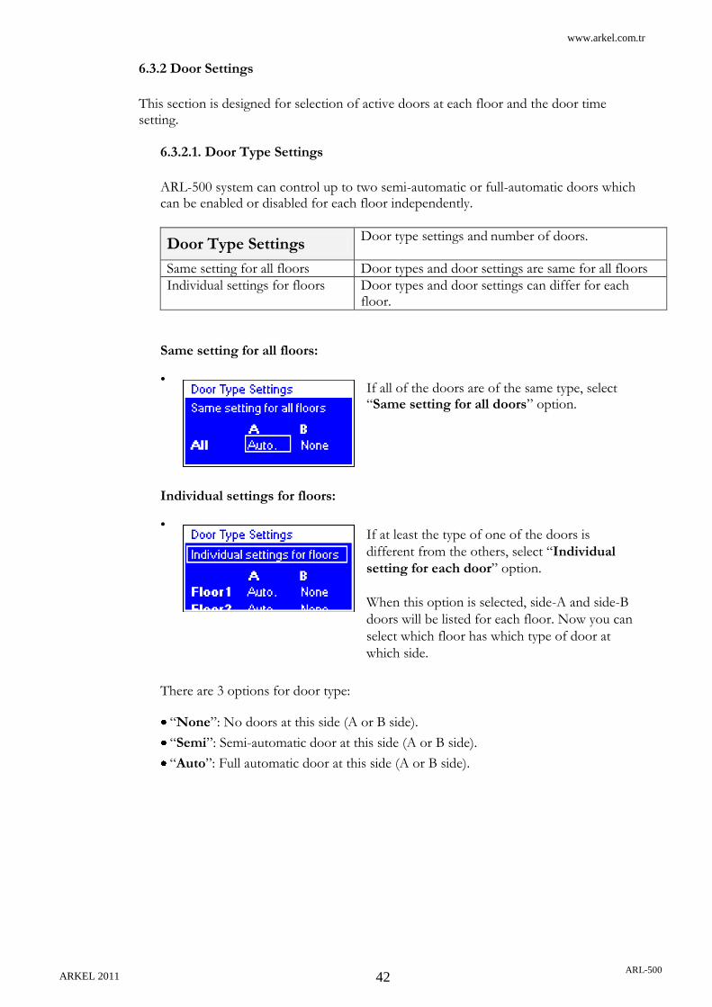
6.3.2.1. Door Type Settings
ARL-500 system can control up to two semi-automatic or full-automatic doors which can be enabled or disabled for each floor independently.
Door Type Settings Door type settings and number of doors.
Same setting for all floors Door types and door settings are same for all floors
Individual settings for floors Door types and door settings can differ for each floor.
Same setting for all floors:
•
Individual settings for floors:
•
There are 3 options for door type:
“None”: No doors at this side (A or B side).
“Semi”: Semi-automatic door at this side (A or B side).
“Auto”: Full automatic door at this side (A or B side).
If all of the doors are of the same type, select “Same setting for all doors” option.
If at least the type of one of the doors is
different from the others, select “Individual
setting for each door” option.
When this option is selected, side-A and side-B
doors will be listed for each floor. Now you can
select which floor has which type of door at
which side.

www.arkel.com.tr
ARKEL 2011 ARL-500
43
6.3.2.2. Set Door Timings
Time to wait on floor
The time period for the car to wait before departing for the next call in collective systems.
5 – 99 seconds ►5 seconds
Max. time to wait for door close
This parameter stores the delay for closing the car door after a forced closing. After the number of consecutive door failures that set in “Retries for closing doors”, an error is generated and the system goes to out of service.
1 – 30 seconds ►5 seconds
Retries for closing doors
Opening time of the car door before closing again after a lock fail.
0 – 10 times ►5 seconds
Delay to reclose after photocell
This parameter stores the delay for closing the car door after a photocell interruption.
2 – 99 seconds ►5 seconds
Photocell will be disabled after
This parameter stores the waiting time period for controller to disable the photocell interruption and try to reclose the door at low speed. If trying to close is not succeeded, controller retries closing that is controlled by the parameters: “Max. time to wait for door close” and “Retries for closing doors”.
10 – 99 seconds ►5 seconds
Time to exclude from group
This parameter stores the waiting time period for controller to exclude from group operation when door is open.
10 – 99 seconds ►20 seconds
Manual door close waiting time
This parameter stores the waiting time period for the manual door to be closed. This parameter is controlled by checking close (terminal 130). When this timer overflows then an error is generated and the system goes to out of service.
10 – 300 seconds ►20 seconds

www.arkel.com.tr
ARKEL 2011 ARL-500
44
Door close button delay
This parameter stores the delay time to ignore the door close button function. This timer starts counting when door starts opening and at the end of this delay time controller operates door close button.
0 – 20 seconds ►2 seconds
Door pre-opening
Enable approaching with car and landing doors open. The safety monitoring is integrated into the ARL-500 main board and enables car movements in the door zone with open car and landing doors. Re-levelling function for hydraulic systems does not depend on this parameter. Re-levelling is standart.
On
Doors are opened when the car entered the door zone of the target floor with a low speed. This operation is allowed only by using the special door bridging circuit ARL-500 control board. ML1 and ML2 additional magnetic switches must be employed to get information about the door zone. The wiring and associated parameters are explained on the electrical diagrams of ARL-500 controller.
►Off Door pre-opening is inactivated and the magnetic switches ML1 & ML2 are not required. Doors are opened after motor has been stopped and brake has been released.

www.arkel.com.tr
ARKEL 2011 ARL-500
45
6.3.3. Call Responding Settings
This section is designed to call responding and anti nuisance settings.
Collection style Collection type of lift system
Single direction, single button
Landing call is connected to Up socket for up collective systems and to Down socket for down collective systems on landing call modules. Landing calls are collective in a direction according to button connection.
Both directions, single button
Landing up or down calls are connected to Up or Down socket on landing call modules. Landing calls are collective in both directions
Two buttons Landing up calls are connected to Up socket and landing down calls are connected to Down socket on landing call modules. Up landing calls are collective in up direction and down landing calls are collective in up direction.
Accept calls only in a single direction
Landing calls in both directions (up and down) will be cleared. This parameter helps avoid unnecessary drives caused by “double calls” from one passenger when using a two button control. Only activate when using a two buttons control.
Yes – No ►No
Avoid fake car calls checking lightbarrier
All car calls will be cleared if the photocell does not trigger for the set number of stops. This parameter helps prevent unnecessary drives caused by car calls.
Disabled Function is disabled.
Cancel all at 2 – 5 fake calls
Controller cancels all car calls after detecting fake calls as this parameter determines.
Maximum car calls allowed at one time
Maximum permitted number of car calls acknowledged at a time. This parameter helps prevent unnecessary drives caused by car calls. A reasonable number is the specified maximum number of passengers.
1 – 32 calls ►5
Cancelling car commands
Allowing to cancel car command by pressing to the same buton for twice.
Allowed This function is enabled
Not allowed This function is disabled

www.arkel.com.tr
ARKEL 2011 ARL-500
46
6.3.4. Display Settings
This section is designed to make display settings.
6.3.4.1. Floor Texts
A two-digit floor text can be set in a list of characters for each floor. This name is used by ARL-500 display and by all car/landing position indicators.
List of characters using in ARL-500 for floor name texts
Digits 0,1,…,9
Small letters a,b,…,z
Capital letter A,B,…,Z
Dot .
Hyphen -
Plus sign +
Asterisk *
Number sign #
Dollar sign $
Space
Arrange Function The easy way is using “Arrange” function during this setting. By the way the floor names can be put in order easily by the controller from the selected floor to the last floor. For example:
Set “Floor1” to “B2”
Set “Floor2” to “B1”
Set “Floor3” to “0” and then activate the “Arrange” function.
The new settings will be in this order: “B2”, “B1”, “0”, “1”, “2”…
User defined floor names can be entered in this screen. Floor numbers and the equivalent floor names are diplayed in a list. The floor name can be set separately for each defined floor.

www.arkel.com.tr
ARKEL 2011 ARL-500
47
6.3.4.2. Dot Matrix Settings
This section is used to make dot-matrix display settings.
Arrow type The arrow type of travel direction on the dot-matrix display indicators
►Arrow type 1
Arrow type 2
Arrow type 3
Arrow type 4
Arrow scroll speed
The scroll speed of travel direction arrow (moving vertically) for dot-matrix display indicators.
No scroll The direction arrow scroll is disabled
Very slow The speed options of direction arrow scroll
Slow
►Normal
Fast
Very fast
Text scroll speed
The scroll speed of floor text (moving vertically) for dot-matrix display indicators.
No scroll The floor text scroll is disabled
Very slow The speed options of floor text scroll
Slow
►Normal
Fast
Very fast
Text scroll direction
The scroll direction of floor text (moving vertically) for dot-matrix display indicators if the “Text scroll speed” parameter is not disabled.
►Normal According to travel direction.
Inverse Inversed of travel direction.
Out of service text
The user defined “Out of service” message. When the system goes out of service this message is displayed at dot-matrix indicators. This message can be changed by using the keypad and selecting the letters one by one.
►”Out of Service” Only “Out of service” will appear in display
“Out of Service Floor:#1” When the system is out of service and the car is at floor 1, the message in display will appear like: “Out of service Floor:#1”
“Out of Service Error:#2” When the system is out of service and it is because of the error no: 2, the message in display will appear like: “Out of service Error:#1”

www.arkel.com.tr
ARKEL 2011 ARL-500
48
Overload text
The user defined “Over load” message. This message is only available for dot matrix indicator used in car operating panel when the over-load signal is activated. This message can be changed by using the keypad and selecting the letters one by one.
►”Overload”
Inspection text
The user defined “Inspection text” message. This option is designed to give a specific information to passengers instead of “Out of service” message. When the Inspection mode is activated from inspection hand terminal or the Recall mode is activated from recall hand terminal or the Manual drive is activated from ARL-500 keypad, this message is displayed at dot matrix indicators. This message can be changed by using the keypad and selecting the letters one by one.
►”Under maintenance”
Door open text
The user defined “Door open text” message. This option is designed to give a specific information to passengers instead of “Out of service” message in order to give a chance for solving this problem. When the elevator goes out of service because of the errors “Door can not close” and “Manual door open error”, this message is displayed at dot-matrix indicators. This message can be changed by using the keypad and selecting the letters one by one.
►”Door is open”
Gray&binary offset
When ARL-500 Gray&Binary kod outputs are used, the value which is set in this parameter is added to elevators.
0 If “0” is selected, when the elevator is on the ground floor its gray&binary output becomes “00000”.
1 If “1” is selected, when the elevator is on the ground floor its gray&binary output becomes “00000”. When the elevators display value is 1 lower than its real floor, this parameter must be selected.

www.arkel.com.tr
ARKEL 2011 ARL-500
49
Show travel arrows This function makes 7x10 dot matrix displays show travel arrows.
Yes Show travel arrows
►No Do not show travel arrows
Show collection arrows
This function makes 7x10 dot matrix displays show collection arrows.
Yes Show collection arrows
►No Do not show collection arrows
6.3.5. Error Logs
The Total errors: The number of total errors had occurred and stored in the memory.
View error logs: This submenu is used to call up the error logs screen.
Delete error logs: This item is used to clear the error list stored.
ARL-500 controller saves up to 200 error messages. If required to optimise the configuration of the control, these messages can be retrieved at any time. These messages can be called up on the user interface of the ARL-500 or via HS500 hand terminal.
In “Error logs” screen the number of the error activated, the
number of floor at error occured, date and time of the error as
well as the message code and message text are summarized.
The last error occured is shown at first line in the error list. The sample screen left side is described in detail below.
#1 The number of error is 1. It is the last error loccured. D:8 The fault has occured on the 8th floor. 04.03.1990 16:29 Date and time of the error (112) Error message code Power supply voltage too low Error message in text

www.arkel.com.tr
ARKEL 2011 ARL-500
50
6.3.6. Programmable Inputs
ARL-500 controller is available with 14 programmable inputs whose functions can be selected by the user. Additionally, there are 6 programmable inputs on the REVKON board, 3 programmable inputs on each KABKON board and 1 programmable input on each KK-x board that can be assigned functions by the user.
6.3.6.1. ARL-500 inputs
•
Programmable inputs are shown on ARL-500 menu display as described below. “0: <undefined>” means no function is assigned to the input.
ARL-500 programmable inputs are listed in the table below:
Input Function number
(Function alias)
Function description #
Factory setting
PI1 - 0 - Undefined
PI2 - 0 - Undefined
PI3 - 0 - Undefined
PI4 - 0 - Undefined
PI5 - 0 - Undefined
PI6 DEP 17 DEP Earthquake input
PI7 YAN 18 YAN Fire sensor input
PI8 KRC 11 KRC Contactor check-back
PI9 503 16 503 Recall up
PI10 502 15 502 Recall down
PI11 870 14 870 Recall switch
PI12 869 13 869 Inspection switch
PI13 142 27 142 Positioning signal
PI14 141 26 141 Positioning signal
There are 4 programmable input sections:
“ARL-500 inputs”: for PI1-PI14 inputs on ARL-
500 main controller.
“REVKON inputs”: for PI21-PI26 inputs on
REVKON car top controller.
“KABKON inputs ”: for PI31-PI33 inputs on
each KABKON car panel module.
“KK-x inputs”: for inputs on each KK-X landing
call/indicator module.
In this menu, 14 rows of inputs (PI1-PI14) are listed.
Function number (Function alias) Function description
11: (PI-8) Contactor check-back

www.arkel.com.tr
ARKEL 2011 ARL-500
51
6.3.6.2. REVKON inputs
•
REVKON inputs are shown on ARL-500 menu display as described below. “0: <undefined>” means no function is assigned to the input.
REVKON programmable inputs are listed in the table below:
Input Function number (Function alias) Function description
PI21 24 805 Full load
PI22 23 804 Overload
PI23 1 FSL-A Door-A photocell
PI24 6 FSL-B Door-B photocell
PI25 0 - Undefined
PI26 0 - Undefined
In this menu, 6 rows of inputs (P21-PI26) are
listed.
Function number (Function alias) Function description
24: (805) Full load

www.arkel.com.tr
ARKEL 2011 ARL-500
52
6.3.6.3. KABKON inputs
•
KABKON programmable input code used in ARL-500 display is described below:
KABKON programmable inputs are listed in the table below:
Input Function number
(Function alias) Function description
PI31-A1 0 - Undefined
PI32-A1 0 - Undefined
PI33-A1 0 - Undefined
PI31-A2 0 - Undefined
PI32-A2 0 - Undefined
PI33-A2 0 - Undefined
PI31-B1 0 - Undefined
PI32-B1 0 - Undefined
PI33-B1 0 - Undefined
PI31-B2 0 - Undefined
PI32-B2 0 - Undefined
PI33-B2 0 - Undefined
In this menu, 12 rows of inputs (PI31-PI33 of each
KABKON) are listed. The inputs are listed according to
the KABKON input code and the door side setting.
The car panel module KABKON‟s number can be 1 or 2.
The second KABKON is used for systems more than 24
stops to increase the number of stops up to 48. Door side
setting can be „A‟ or „B‟. „B‟ is used for the second
entrance.
Input Door side KABKON number
PI31- A 1

www.arkel.com.tr
ARKEL 2011 ARL-500
53
6.3.6.4. KK-x inputs
•
KK-x programmable input code shown in the upper row is described below:
KK-x programmable input function shown in the bottom row is described below:
Function number
(Function alias) Function description
0 - Undefined
In this menu, each KK output is shown by two
rows. The upper row shows the KK output
code and bottom row shows the assigned
function.
The KK landing number can be set from 1 to
48. Door side setting can be „A‟ or „B‟ („B‟ is
used for the second entrance).
KK module - Landing number / Door side
KK - 1 A

www.arkel.com.tr
ARKEL 2011 ARL-500
54
6.3.6.5. List of Input Functions
The following table contains all functions that can be assigned to the programmable input terminals. The active state of the function depends on the type of function either +24V or GND. The programmable inputs are high active and detect a signal when 100 (+24V DC) is applied.
# (Short name)
Name Function Note
0 - <undefined> No function
1 FSL-A (FSL-A) Photocell-A Door side A photocell sensor.
Active high (+24V)
2 DTS-A Close button-A Door side A close button. Active high (+24V)
3 K20-A Open button-A Door side A open button. Active high (+24V)
4 K16-A Open limit-A Door side A open limit switch. If limit switches on the cabin are working properly, this function must be assigned to door limit inputs.
Active low (0V)
5 K19-A Close limit-A Door side A close limit switch. Active low (0V)
6 FSL-B Photocell-B Door side B photocell sensor. Active high (+24V)
7 DTS-B Close button-B Door side B close button. Active high (+24V)
8 K20-B Open button-B Door side B open button.
Active high (+24V)
9 K16-B Open limit-B Door side B open limit switch.
Active low (0Vdc)
10 K19-B Close limit-B Door side B close limit switch.
Active low (0V)
11 KRC Contactor check-back Check-back signal of main contactors. The contactor pick-up signal is activated when low (0V) signal is detected from the input terminal. Because normally close contacts of main contactors with serial connection are used for this signal and 24V supply voltage is used.
12 ITA Fireman key Fireman key If the elevator is in the fire evacuation mode phase-1, a high signal from this input terminal activates fire evacuation mode phase-2.
Active high (+24V)
13 869 Inspection key Inspection operating switch Inspection operation is activated when low (0V) signal is detected from the input terminal. In normal operating mode high (24V) signal must be applied to the terminal.
Active low (0V)
14 870 Recall key Recall operating switch Recall operation is activated when low (0V) signal is detected from the input terminal. In normal operating mode high (24V) signal must be applied to the terminal.
Active low (0V)
15 502 Recall down Recall operation DOWN
Active high (+24V)

www.arkel.com.tr
ARKEL 2011 ARL-500
55
16 503 Recall up Recall operation UP
Active high (+24V)
17 DEP Earthquake detector Earthquake detector When an earthquake occurs, the earthquake sensor in the building activates earthquake detector input. By the activation of this input, lift system cancels all landing calls and make cabin stop at the nearest floor with doors open. Even after the input signal is inactivated, system must be resetted to work properly again.
Active high (+24V)
18 YAN Fire detector Fire detector When this input is activated; - All car landing calls are cancelled and no
more calls are received - The speaker on the COP starts emitting
an alarm - The doors are closed immediately and
the car starts to travel towards the designated fire exit floor.
- On arrival to the fire exit floor, the doors are opened and they stay open.
Active high (+24V)
19 VAT Vatman key Car priority key When this input is activated; - All calls from floors are cancelled. - System allows only the calls from inside
the car and from ARL-500 controller. - If the car lands to any floor and if there
is no any other call, the doors are opened and they stay open on that floor.
Thus the elevator is only controlled by authorized person.
Active high (+24V)
20 PAN Panic input Panic input When this input is activated - System cancels all landing calls and starts
emitting an alarm. - The car starts to travel towards the
designated “panic exit” floor. - After landing to designated floor, system
opens the doors and cancels emitting the alarm.
- System deactivates the “panic input” signal and starts to operate in normal mode.
Active high (+24V)
21 - <undefined> -
22 FANB Fan on/off Switching the fan on/off
Active high (+24V)
23 804 Over-load Over-load In case of load exceeding the rated capacity, this input becomes active. The door keeps open on the landing floor until the loading is reduced within rated value.
Active high (+24V)

www.arkel.com.tr
ARKEL 2011 ARL-500
56
24 805 Full-load Full-load In case of load is equal to full-load rated capacity, the elevator operates in normal mode but does not accept any calls given from floors, system saves the calls and when the elevator unloads and the signal becomes deactivated, than the calls from floors are accepted successively.
Active high (+24V)
25 DRUN Driver running Driver is running feed-back The feed-back signal comes from the driver. This input is used to keep the main contactors switch-on until the driver finishes running and drops the mechanical brake contactor. The high signal (+24V) means driver is running and when the low signal (0V) is detected then the main contactors will be dropped.
for VVVF systems
26 141 Positioning signal Positioning signal.
Active high (+24V)
27 142 Positioning signal Positioning signal Active high (+24V)
28 DRDY Driver ready Driver is ready to run The feed-back signal comes from the driver. The high signal (+24V) means driver is ready to run and the low signal (0V) means driver in error mode.
for VVVF systems
29 RESC Emergency rescue Emergency rescue operation Emergency rescue operation is activated when a high (24V) signal is applied to the input terminal.
for emergency evacuation unit
30 TDO Test door open Door open for door testing
Active high (+24V)
31 TDC Test door close Door close for door testing
Active high (+24V)
32 CCC Cancel car commands Cancels all car commands
Active high (+24V)
33 CFA Cancel fire alarm If the elevator system is in the fire evacuation mode, it returns to normal operation mode when a high (24V) signal is applied to the input terminal.
Active high (+24V)
34 SPR Shaft protection The shaft protection contacts input Elevator is blocked when a high (24V) signal is applied to this input terminal.
35 K16N-A Open limit (not)-A Same function with open limit switch (K16A) but this input is high activated.
Active high (+24V)
36 K19N-A Close limit (not)-A Same function with close limit switch (K19A) but this input is high activated.
Active high (+24V)
37 K16N-B Open limit (not)-B Same function with open limit switch (K16B) but this input is high activated.
Active high (+24V)
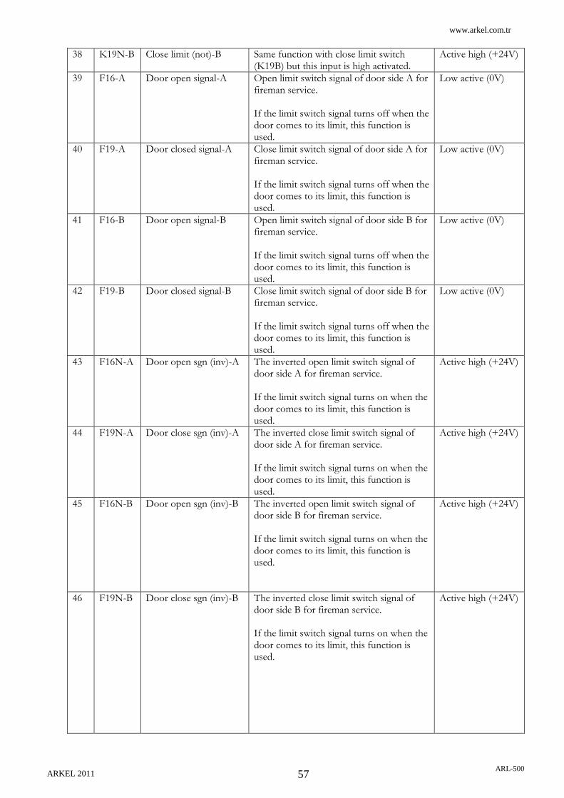
www.arkel.com.tr
ARKEL 2011 ARL-500
57
38 K19N-B Close limit (not)-B Same function with close limit switch (K19B) but this input is high activated.
Active high (+24V)
39 F16-A Door open signal-A Open limit switch signal of door side A for fireman service. If the limit switch signal turns off when the door comes to its limit, this function is used.
Low active (0V)
40 F19-A Door closed signal-A Close limit switch signal of door side A for fireman service. If the limit switch signal turns off when the door comes to its limit, this function is used.
Low active (0V)
41 F16-B Door open signal-B Open limit switch signal of door side B for fireman service. If the limit switch signal turns off when the door comes to its limit, this function is used.
Low active (0V)
42 F19-B Door closed signal-B Close limit switch signal of door side B for fireman service. If the limit switch signal turns off when the door comes to its limit, this function is used.
Low active (0V)
43 F16N-A Door open sgn (inv)-A The inverted open limit switch signal of door side A for fireman service. If the limit switch signal turns on when the door comes to its limit, this function is used.
Active high (+24V)
44 F19N-A Door close sgn (inv)-A The inverted close limit switch signal of door side A for fireman service. If the limit switch signal turns on when the door comes to its limit, this function is used.
Active high (+24V)
45 F16N-B Door open sgn (inv)-B The inverted open limit switch signal of door side B for fireman service. If the limit switch signal turns on when the door comes to its limit, this function is used.
Active high (+24V)
46 F19N-B Door close sgn (inv)-B The inverted close limit switch signal of door side B for fireman service. If the limit switch signal turns on when the door comes to its limit, this function is used.
Active high (+24V)

www.arkel.com.tr
ARKEL 2011 ARL-500
58
47 819 Mid-spd bottom limit Forced downward deceleration magnetic switch for middle speed. It is used together with the bottom correction switch (817) for high speed VVVF systems where the required deceleration distance is more than the floor to floor distance. The 817 signal forcibly turns off the high speed signal and the 819 signal turns off the middle speed signal. The magnet installation for 819 switch must be made to the bottom floor where the speed signal must be changed from middle speed to low speed.
Low active (0V)
48 820 Mid-spd top limit Forced upward deceleration magnetic switch for middle speed. It is used together with the top correction switch (818) for high speed VVVF systems where the required deceleration distance is more than the floor to floor distance. The 818 signal forcibly turns off the high speed signal and the 820 signal turns off the middle speed signal. The magnet installation for 820 switch must be made to the top floor where the speed signal must be changed from middle speed to low speed.
Low active (0V)
49 SPZ SPZ Zero-speed If the direction signals for the inverter (CT Unidrive SP) must not be interrupted until the elevator stops, this function is used. The zero-speed signal (stop signal) which comes from the inverter is connected to a programmable input to where this function is assigned to. When this signal is not used, the ARL-500 controller turns off the speed signals and the direction signals together. The high signal (+24V) means the driver is running and the low signal (0V) means the driver stops.

www.arkel.com.tr
ARKEL 2011 ARL-500
59
50 JP1 Bridge-1 A virtual input which can be assigned to a programmable output with the same function of a programmable input. The same function must be assigned to the programmable output. So that any programmable input of the elevator system can be bridged to any programmable output virtually by the ARL-500 controller.
51 JP2 Bridge-2 A virtual input 2
52 JP3 Bridge-3 A virtual input 3
53 JP4 Bridge-4 A virtual input 4
54 JP5 Bridge-5 A virtual input 5
55 JP6 Bridge-6 A virtual input 6
56 JP7 Bridge-7 A virtual input 7
57 JP8 Bridge-8 A virtual input 8
58 JP9 Bridge-9 A virtual input 9
59 JP10 Bridge-10 A virtual input 10
60 JP11 Bridge-11 A virtual input 11
61 JP12 Bridge-12 A virtual input 12
62 JP13 Bridge-13 A virtual input 13
63 JP14 Bridge-14 A virtual input 14
64 JP15 Bridge-15 A virtual input 15
65 JP16 Bridge-16 A virtual input 16
66 BRC Brake checkback The checkback control for brakes with synchronous motors. This function is used if the brake checkback signal is connected to ARL-500 mainboard and the brake checkbeck is control by ARL-500. If the control is made by the inverter this input is not used.
67 MEM Manual evac. mode This function is used with MRL systems for activating a manual operation which is used for emergency evacuation and testing of the elevator system (Encoder car positioning is required). Evacuation operation is activated when a high (24V) signal is applied to the input terminal and ARL-500 controller‟s display switched to a special evacuation secreen. In this screen the following signals are showed:
- the travel speed - over-speed warning (> 0.63 m/s) - current floor - direction arrow - floor level indicator

www.arkel.com.tr
ARKEL 2011 ARL-500
60
68 XER External error This function is used to give an external trip to ARL-500 controller. ARL-500 controller gives an error when a high (+24V) signal is detected from the input terminal. This error makes the elevator goes to out of service. When the high signal turns off, controller returns to normal operation.
69 XBL External blocking This function is used to give an external blocking command to ARL-500 controller. ARL-500 controller blocks the elevator when a high (+24V) signal is detected from the input terminal. Elevator will not operate until the controller is reset.
70 EVD Evacuation direction The evacuation direction information comes from inverter for easy way of car movement. ARL-500 controller uses this easy direction for evacuation.
71 KKN Pawl locked checkback When the pawl device is locked and car is ready to move, this input will be activated.
72 SKN Pawl released checkback
When the car lands on the floor and releases the pawl device, this input will be activated.
73 YAN2 Secondary fire detector If the fire occurs in designated fire exit floor for YAN input, YAN2 input becomes active and with cancelling all landing calls cabin moves to designated floor for YAN2.
74 HPD Headroom protection down switch
If headroom protection system parameter is used, headroom protection down switch must be active to make elevator operate in normal mode. If the switch is not active while a call is received, the elevator will block itself and will not operate until it is resetted.
75 HPU Headroom protection up switch
If headroom protection system parameter is used, when headroom protection up switch is activated, the system operates in only inspection mode, if the switch becomes passive after a while, the system resumes operating in normal mode.
76 CLC Cartop light barrier checkback
If cartop protection light barrier checkback system is used this input checks if the light barrier on the cabin is working properly. This input must be connected to cartop light barrier test (CLB) output.
77 RES Reset system System resets itself

www.arkel.com.tr
ARKEL 2011 ARL-500
61
78 TTR Travel timer reset This signal must be used in situations when the travel time exceeds 45 seconds (the maximum travel time that EN-81 allows). When this input toggles (goes ON or OFF) the travel counter will reset. For example if you set "max time for high speed travel" to 30 seconds and if this signal toggles every 20 seconds, you will never get error messages, because counter will be set to zero in every 20 seconds. where to take the reset signal; 1) You can put a single magnet and a magnetic switch on speed regulator. So you will get a reset signal at every revolution of speed governor. 2) You can put magnets on shaft and a magnetic switch on car. The distance between each magnet must be enough close (20 – 40 meter can be ok) to reset counter before it trips.
79 - <undefined> -
80 EC1A Urgent call-1A Urgent call to floor 1 door A Either the car is moving or waiting on a floor, if any urgent call input is activated the system erases all landing calls and obeys this call.
81 EC2A Urgent call-2A Urgent call to floor 2 door A
… … … … …
127 EC48A Urgent call-48A Urgent call to floor 48 door A
128 EC1B Urgent call-1B Urgent call to floor 1 door B
129 EC2B Urgent call-2B Urgent call to floor 2 door B
… … … … …
175 EC48B Urgent call-48B Urgent call to floor 48 door B
176 - <undefined> -
177 - <undefined> -
178 - <undefined> -
179 - <undefined> -
180 PPS1 Pit protection switch-1 Pit protection switch-1 This function is used in the buildings where elevator pits are short for the purposes of security to access elevator pit. If the car is not in the specified floor while the input is not active, the elevator blocks itself.
Active high
181 PPS2 Pit protection switch-2 Pit protection switch-2 Active high
182 PPS3 Pit protection switch-3 Pit protection switch-3 Active high
183 PPS4 Pit protection switch-4 Pit protection switch-4 Active high
184 PPS5 Pit protection switch-5 Pit protection switch-5 Active high
185 PPS6 Pit protection switch-6 Pit protection switch-6 Active high
186 PLI1 PLC In-1 PLC Input 1 Active high
187 PLI2 PLC In-2 PLC Input 2 Active high
188 PLI3 PLC In-3 PLC Input 3 Active high
189 PLI4 PLC In-4 PLC Input 4 Active high
190 PLI5 PLC In-5 PLC Input 5 Active high

www.arkel.com.tr
ARKEL 2011 ARL-500
62
191 PLI6 PLC In-6 PLC Input 6 Active high
192 PLI7 PLC In-7 PLC Input 7 Active high
193 PLI8 PLC In-8 PLC Input 8 Active high
194 PLI9 PLC In-9 PLC Input 9 Active high
195 PLI10 PLC In-10 PLC Input 10 Active high
196 PLI11 PLC In-11 PLC Input 11 Active high
197 PLI12 PLC In-12 PLC Input 12 Active high
198 PLI13 PLC In-13 PLC Input 13 Active high
199 PLI14 PLC In-14 PLC Input 14 Active high
200 PLI15 PLC In-15 PLC Input 15 Active high
201 PLI16 PLC In-16 PLC Input 16 Active high

www.arkel.com.tr
ARKEL 2011 ARL-500
63
6.3.7. Programmable Outputs
ARL–500 main controller is available with 8 functionally programmable relay outputs (PR1-PR8) and 6 functionally programmable transistor outputs (PT1-PT6). Additionally, there are 3 functionally programmable relay outputs (PR21-PR26) on the REVKON car top controller and 1 programmable output on each KK-x landing call/indicator module.
6.3.7.1. ARL-500 Transistors
•
Programmable transistor outputs are shown on ARL-500 menu display as described below. “0: <undefined>” means no function is assigned to the output.
The factory defaults of ARL-500 programmable transistors are listed in the table below:
Output Function number
(Function alias)
Function description Note #
Factory setting
PT1 - 0 - undefined -
PT2 - 0 - undefined -
PT3 - 0 - undefined -
PT4 - 0 - undefined -
PT5 - 0 - undefined -
PT6 - 0 - undefined -
There are 4 sections under this submenu:
“ARL-500 relays”: for PR1-PR8 relay outputs on
ARL-500 main controller.
“ARL-500 transistors”: for PT1-PT6 transistor
outputs on ARL-500 main controller.
“REVKON relays”: for PR21-PR23 relay outputs
on REVKON car top controller.
“KK-x outputs”: for outputs on each KK-x
landing call/indicator module.
In this menu, 6 rows of outputs (PT1-PT6) are
listed.
Function number (Function alias) Function description
2: (K3-A) Door-A close output

www.arkel.com.tr
ARKEL 2011 ARL-500
64
6.3.7.2. ARL-500 Relays
•
Programmable outputs are shown on ARL-500 menu display as described below. “0: <undefined>” means no function is assigned to the output.
ARL-500 programmable relays are listed in the table below:
Output
Function number
(Function alias)
Function description Note #
Factory setting
PR1 A-K3 2 K3-A Door-A close output
PR2 A-K5 1 K5-A Door-A open output
PR3 B-K3 5 K3-B Door-B close output Dual automatic door
PR4 B-K5 4 K5-B Door-B open output
PR5 L 7 LIR
Door lock magnet Semi automatic door
PR6 - 0 - undefined
PR7 Re 26 RRY
Inspection speed relay VVVF systems
PR8 - 0 - undefined
In this menu, 8 rows of outputs (PR1-PR8) are
listed.
Function number (Function alias) Function description
2: (K3-A) Door-A close output
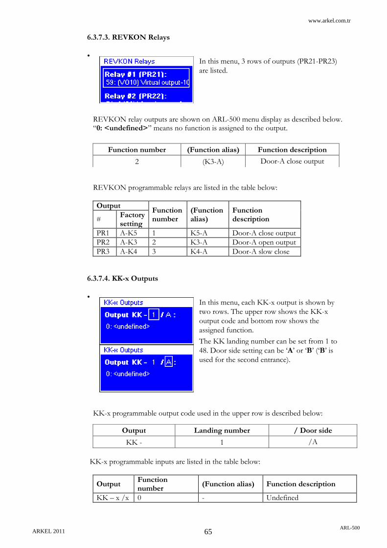
www.arkel.com.tr
ARKEL 2011 ARL-500
65
6.3.7.3. REVKON Relays
•
REVKON relay outputs are shown on ARL-500 menu display as described below. “0: <undefined>” means no function is assigned to the output.
REVKON programmable relays are listed in the table below:
Output Function number
(Function alias)
Function description #
Factory setting
PR1 A-K5 1 K5-A Door-A close output
PR2 A-K3 2 K3-A Door-A open output
PR3 A-K4 3 K4-A Door-A slow close
6.3.7.4. KK-x Outputs
•
KK-x programmable output code used in the upper row is described below:
KK-x programmable inputs are listed in the table below:
Output Function number
(Function alias) Function description
KK – x /x 0 - Undefined
In this menu, 3 rows of outputs (PR21-PR23)
are listed.
Function number (Function alias) Function description
2 (K3-A) Door-A close output
In this menu, each KK-x output is shown by
two rows. The upper row shows the KK-x
output code and bottom row shows the
assigned function.
The KK landing number can be set from 1 to
48. Door side setting can be „A‟ or „B‟ („B‟ is
used for the second entrance).
Output Landing number / Door side
KK - 1 /A

www.arkel.com.tr
ARKEL 2011 ARL-500
66
6.3.7.5. List of Output Functions
# Short name
Name Function Note
0 - <undefined> -
1 K5-A Door-A open output ON for opening door-A
2 K3-A Door-A close output ON for closing door-A
3 K4-A Door-A slow close ON for closing door-A slowly after photocell timeout
4 K5-B Door-B open output ON for opening door-B
5 K3-B Door-B close output ON for closing door-B
6 K4-B Door-B slow close ON for closing door-B slowly after photocell timeout
7 LIR Door lock magnet ON for unlocking semi-automatic doors.
8 31 Down arrow ON when car is travelling down
9 32 Up arrow ON when car is travelling up
10 41 Down collecting ON when colllection direction is “down”
11 42 Up collecting ON when collection direction is “up”
12 02 Out of service ON when lift is out of service or is in inspection/callback mode
13 DD Ding-Dong ON and OFF briefly when opening doors at floor level
14 12 Car lamp ON for turning on the car lamp
15 RU1 Down relay Depends on “Drive-Type” Motion relays
16 RU2 Up relay
17 RH1 Fast speed relay-1
18 RH2 Fast speed relay-2
19 RF Slow speed relay
21 RP Main contactor ON while car is in motion
22 RSD Star / Delta OFF: hydraulic pump drive star ON: hydraulic pump drive delta
For hydraulic lifts only
24 805 Full load ON when full load input (805) is on
25 804 Overload ON when 804 overload input is on and the lift is on floor level
26 RRY Inspection speed relay
ON when car is moving on inspection speed
27 ED2 Encoder up ON when encoder is counting upwards
28 ED1 Encoder down ON when encoder is counting downwards
29 ED12 Encoder moving ON when encoder is counting up or down
30 BC0 Binary code Floor number binary code bit-0
31 BC1 Binary code Floor number binary code bit-1
www.arkel.com.tr
ARKEL 2011 ARL-500
67
32 BC2 Binary code Floor number binary code bit-2
33 BC3 Binary code Floor number binary code bit-3
34 BC4 Binary code Floor number binary code bit-4
35 GC0 Gray code Gray code bit-0
36 GC1 Gray code Gray code bit-1
37 GC2 Gray code Gray code bit-2
38 GC3 Gray code Gray code bit-3
39 GC4 Gray code Gray code bit-4
40 KAK UPS active ON when the evacuation signal is activated. If the inverter is supplied with dc low voltage (with battery pack), this output is used to enable the evacuation supply from battery.
41 FLR Floor level ON when car is at rest on floor level
42 RBR Release brake on rescue
ON when brakes are released during manual evacuation mode.
For MRL systems.
43 SAK Mains active Mains active output. ON when mains power is active. Mains power is controller by the inputs on ARL-500 controller (L1, L2, L3, N).
44 UPT UPT Test Supply of UPS phase input is connected over a UPS test relay‟s contact. This function controls this relay. The input line of UPS is switched off for once in a day and the elevator is operated by UPS supply. The system is blocked if an error occurs during this UPS test drive.
For MRL systems.
45 DRS Driver reset When CT Unidrive SP inverter goes into an error mode, an external reset signal must be applied to make the inverter runs in normal operation mode. DRS function is used to reset the inverter during an error.
For CT Unidrive SP Inverter
46 DRZ Door zone Door safe zone signal. This signal is ON when the car is in door unlocking zone either the car stops or runs. (ML1 and ML2 signals are both ON) DRZ function is used as floor level indicator not FLR (Floor level) function.

www.arkel.com.tr
ARKEL 2011 ARL-500
68
47 INS Inspection mode Signal that shows the lift is in inspection mode
48 PWD Pawl device coil Pawl device coil output
49 SLP Sleep mode Sleep mode activation. This output is used when electricity saving is desired in the building.
50 JP1 Bridge-1 A virtual input which can be assigned to a programmable output with the same function of a programmable input. The same function must be assigned to the programmable output. So that any programmable input of the elevator system can be bridged to any programmable output virtually by the ARL-500 controller.
51 JP2 Bridge-2 A virtual output-2
52 JP3 Bridge-3 A virtual output-3
53 JP4 Bridge-4 A virtual output-4
54 JP5 Bridge-5 A virtual output-5
55 JP6 Bridge-6 A virtual output-6
56 JP7 Bridge-7 A virtual output-7
57 JP8 Bridge-8 A virtual output-8
58 JP9 Bridge-9 A virtual output-9
59 JP10 Bridge-10 A virtual output-10
60 JP11 Bridge-11 A virtual output-11
61 JP12 Bridge-12 A virtual output-12
62 JP13 Bridge-13 A virtual output-13
63 JP14 Bridge-14 A virtual output-14
64 JP15 Bridge-15 A virtual output-15
65 JP16 Bridge-16 A virtual output-16
66 CLB Cartop protection lightbarrier test
If the photocell is cut (for lift systems that have photocells on cartop) for any reason whatsoever, with blocking itself, elevator operates only in inspection mode. This function is used to check if the photocells are working properly whenever the car stops.
67…70 - <undefined>
71 PLO1 PLC Out-1 PLC output 1
72 PLO2 PLC Out-2 PLC output 2
73 PLO3 PLC Out-3 PLC output 3
74 PLO4 PLC Out-4 PLC output 4
75 O120 120 input state 120 input state signal
76 O130 130 input state 130 input state signal
77 O140 140 input state 140 input state signal
78 OML1 ML1 input state ML1 input state signal
79 OML2 ML2 input state ML2 input state signal
80 P817 817 input state 817 input state signal
81 O818 818 input state 818 input state signal
82 OSA Overspeed alert Overspeed alert limit signal
83 PLO5 PLC Out-5 PLC output 5

www.arkel.com.tr
ARKEL 2011 ARL-500
69
84 PLO6 PLC Out-6 PLC output 6
85 PLO7 PLC Out-7 PLC output 7
86 PLO8 PLC Out-8 PLC output 8
87…99 - <undefined> -
100…147 401…448 Car call – x ON when a car call from floor-x is waiting
148 - <undefined> -
149 - <undefined> -
150…197 201…248 Down call – x ON when a down direction landing call from floor-x is waiting
198 - <undefined>
199 - <undefined>
200…246 301…347 Up call - x ON when an up direction landing call from floor-x is waiting
247 FL1 Level mod 8-1 The car is on floor 1 Active high
248 FL2 Level mod 8-2 The car is on floor 2 Active high
249 FL3 Level mod 8-3 The car is on floor 3 Active high
250 FL4 Level mod 8-4 The car is on floor 4 Active high
251 FL5 Level mod 8-5 The car is on floor 5 Active high
252 FL6 Level mod 8-6 The car is on floor 6 Active high
253 FL7 Level mod 8-7 The car is on floor 7 Active high
254 FL8 Level mod 8-8 The car is on floor 8 Active high

www.arkel.com.tr
ARKEL 2011 ARL-500
70
6.3.8. Encoder Settings
This section is used to make encoder settings when incremental encoder positioning is used. If the parameter “System settings > Car position sensing” is not set to “Encoder counter”, entering this submenu is not allowed. If you are using an incremental encoder for car positioning, a shaft-learning run must be performed before going in to normal operation.
6.3.8.1. Floor Level Fine Tuning
This section is used to make the floor level-tuning after the shaft learning process. The elevator must be able to travel between floors with slight levelling errors. By the help of this section all floors are approached with in-car calls and the stopping precision is measured. Detailed information about shaft learning can be obtained in the section “Floor tuning of floor levels” in the Installation & Operation Manual.
6.3.8.2. Travel distances
This section is used to set travel distance parameters before going on to the floor-level fine tuning process. These parameters must be compatible with the settings of your motor driver.
Slowing distance in high speed
This parameter indicates the position where the slow-down command will
be sent to the motor driver. This parameter must be compatible with the
settings of your motor driver.
Set this parameter “Slowing distance in high speed” 10-15cm more then
the ADrive parameter “1.8 Deceleration distance”. Because of the delay
time of slow-down command received by ADrive. For example if ADrive
parameter “1.8. Deceleration distance” is set to 170cm, set this parameter
to 180cm.
20 – 999 cm ►170 cm
Slowing distance in medium speed
This parameter indicates the position where the slow-down command will be sent to the motor driver while travelling in medium speed. It is used for elevators which are necessary to start running in medium speed. For example if there is a building that has a low floor (alçak kat) the travel distance may not be suitable for high speed. Thus the elevator starts running in medium speed and with the help of this parameter it starts slowing down.
10 – 999 cm ►100 cm
Slowing distance in low speed
This parameter indicates the position where the stop command will be sent to the
driver. This parameter must be compatible with the settings of your motor
driver.
Set this parameter “Slowing distance in low speed” same as the ADrive
parameter “1.9 Stopping distance”. For example if ADrive parameter “1.9
Deceleration distance” is set to 20cm, set this parameter to 20cm.
0 – 200 mm ►60 mm

www.arkel.com.tr
ARKEL 2011 ARL-500
71
Min. high-speed start distance
The minumum travel distance required to start running with high speed.
This parameter is used for inverters which do not make automatic short
floor correction.
Controller decides the starting speed if it is high speed or middle speed
according to this distance. If the travel distance is less than this value
controller starts running with middle speed otherwise starts running with
high speed.
1 – 500 cm ►50 cm
6.3.8.3. Hardware configuration This section is used to set the hardware configuration of encoder positioning.
Flag length
The length of door zonebar magnets mounted for SML1-SML2 door zone magnetic switches. The default value is 40 cm and it can only be changed when the length of bar magnets is changed. If this value is changed after a shaft-learning drive, a new shaft-learning run must be required. Because during the shaft-learning run, ARL-500 will determine the relation between pulse-count and centimeters by using this “flag length” information.
10 – 50 cm ►40 cm
Position of 817 The position of SKSR1 (817 signal) bottom correction switch. The deceleration distance depends on the speed of elevator
► Between 1st & 2nd floors
It is used for systems where the required deceleration distance is less than a floor to floor distance. 817 bottom correction switches is installed between 1st and 2nd floors.
Between 2nd & 3rd floors
It is used for high speed systems where the required deceleration distance is more than a floor to floor distance. 817 bottom correction switches is installed between 2nd and 3rd floors. For high speed systems 819-820 decelaration switches of middle speed are used together with 817-818 decelaration switches of high speed.
Overspeed alert limit
For any reason whatsover, if the elevator starts to run in overspeed, it continues to operate in normal mode but system rings the alarm.
0.5 – 5 m/s ►1 m/s
6.3.8.4. Learn shaft
This section is used to perfome the shaft learning drive for incremental encoder positioning.
Detailed information about shaft learning can be obtained in the section “Shaft Learning with incremental encoder positioning” in the Installation & Operation Manual.

www.arkel.com.tr
ARKEL 2011 ARL-500
72
6.3.9. Hydraulic Lift Settings This section is used to performe the basic settings only for hydraulic lift systems.
Hydraulic valve open delay
This parameter determines the delay time for main contactor to drop after a stop command.
0,1 – 3 seconds ►0,2 seconds
Feedback controlled With this function, the hydraulic valves start to run automatically when the motor is ready to operate.
Hydraulic pump motor star-delta time
This parameter determines the switching time of the motor from star connection to delta connection in startup
0,1 – 3 seconds ►0,3 seconds
Relevelling With this parameter, after the car lands to a floor, system relevells the cars position with referencing that floor.
►On: Off:
Relevelling is on. Relevelling is off.
Relevelling threshold
Relevelling threshold parameter is only available with the systems that use encoder. Relevelling occurs according to the position of the encoder. After landing to any floor if the car moves more than the value entered in this parameter, system starts relevelling.
1 – 15 cm ►3 cm
PAWL device release maximum delay
This function controls if the pawl device is released or not. If the pawl device is not released it means that it is stuck between the car and the shaft. The system tries to recover the fault by moving the car upwads about 10 cm.
0,1 – 5 seconds ►5 seconds
PAWL device lock maximum delay
Time passed after the pawl is released until the pawl is locked.
0,1 – 5 seconds ►5 seconds
PAWL device delay before release
Time passed after the car lands to a floor until the pawl device is released.
0,1 – 5 saniye ►1 seconds
PAWL device After landing to a floor pawl device is a device that prevents the car slide downwards.
Yes: ►No:
PAWL device exists. There is no PAWL device.

www.arkel.com.tr
ARKEL 2011 ARL-500
73
6.3.10. Group Settings
After connection of control panels in the elevator group only to do is setting each controller as A,B,C,…,H on ARL-500 menu. Each controller must have a different group ID.
Controller ID The controller ID used by each controller in group operation. Controller ID must be adjusted differently within each controller. Single lifts are always set to lift A.
A-H ►A
Detailed information can be obtained in the Installation & Operation Manual.
Bottom missing floors
This parameter is only used for group operation. When each elevator has different number of stops in group operation this parameter is used to adjust the “Number of floors” to the same value for each elevator in group. For example, there is a dublex system with 10 stops but elevator A does not serve to the bottom floor. The “Number of floors” parameter must be set to 10 at each elevator and “Bottom missing floors” parameter must be set to 1.
0 – 47 floors
Top missing floors
This parameter is only used for group operation. When each elevator has different number of stops in group operation this parameter is used to adjust the “Number of floors” to the same value for each elevator in group. For example, there is a dublex system with 10 stops but elevator A does not serve to the top floor. The “Number of floors” parameter must be set to 10 at each elevator and “Top missing floors” parameter must be set to 1.
0 – 47 floors

www.arkel.com.tr
ARKEL 2011 ARL-500
74
6.3.11. Parking Settings
This section is used to set the parking drive characteristics of the lift system.
Parking delay
Waiting period before starting the park drive. Parking drive can be deactivated by entering the value “0”. When the lift has no calls in the time set in this parameter then it moves to the parking floor and waits with open doors.
0 – 60 minutes ►0 min
Parking Stop
Because there is no active call and parking delay is exceeded the controller sends the car to a programmed parking floor.
The parking scheduler for time zones is described in the table below:
Code Setting range Description
Start 00:00 to 23:59 Starting time of the time zone
End 00:00 to 23:59 Ending time of the time zone
Floor 0 to top floor Parking floor
The maximum waiting period between the starting time and the ending time can not be longer than a day. Below some example timing configurations are described:
Start End Waiting period
08:00 10:00 2 hours (begin at 08:00 and end at 10:00)
17:00 00:00 7 hours (begin at 17:00 and end at 00:00)
14:00 12:00 22 hours (begin at 14:00 and end at 12:00 the next day)
Other time zones This floor is activated as parking floor for the other times that is not defined in the 5 time zones.
0 – 48 ►0
The ARL-500 controller has a scheduler that enables time dependent park drive programs. Each day can de divided in 5 time zones. The time zones are listed in rows. Different park drive programs can be set for each of these time zones by the help of this screen.

www.arkel.com.tr
ARKEL 2011 ARL-500
75
6.3.12. Time and Date Settings
This section is used to adjust time and date setting and the make the maintenance configuration.
6.3.12.1. System date and time
6.3.12.2. Next maintenance date
This section is used to set the maintenance date and the controller‟s behaviour after the maintenance date is exceeded.
Next maintenance date
The next maintenance date. At the end of this date elevator behaves as set in the parameter “after maintenance date”. This setting must be checked during each maintenance and set to a new maintenance date if necessary.
After maintenance date
The controller‟s behaviour after the maintenance date is exceeded.
►Normal operation No action, even a warning message. Elevator runs as normal.
Warn only Only gives a warning message but elevator runs as normal.
Block lift Lift is blocked and it stops operating.
The date and the time of the ARL-500 controller. These settings must be checked during each service and adjusted if necessary. If the time is not set correctly, the time information of the error storage are useless. LEFT/RIGHT buttons are used to move cursor left/right and UP/DOWN buttons are used to increase/decrease value. “Set” item should be activated to change the current setting.

www.arkel.com.tr
ARKEL 2011 ARL-500
76
6.3.13. Motor Protection Settings
This section is used to make the phase and motor protection settings. ARL-500 controller is available with integrated phase and motor protection circuits.
R-S-T checking Enables the phase loss and phase sequence checking.
►Enabled Disabled
When this parameter is set to “enable”, the terminals L1, L2, L3, and N on ARL-500 controller must be connected properly.
Motor temperature checking
Enables the motor temperature checking. When motor temperature is exceeded if the cabin is; - Resting, system blocks itself and goes into out of service mode. - Moving, system cancels all landing calls, stops on the closest floor available and goes into out of service mode.
►Enabled Disabled
When this parameter is set to “enable”, the terminals T1, T2 at ARL-500 controller must be connected properly.

www.arkel.com.tr
ARKEL 2011 ARL-500
77
6.3.14. Sound Settings
Car gong Enables the car gong sound when the car reaches to the target floor.
►On Off
Hall gongs Enables the landing gong sound when the car reaches to that landing floor.
►On Off
Gong Type The sound type of car and landing gongs after reaching the target floor.
►Single sound Ding sound
Double sound Ding-dong sound
Up single, down double sound
Ding sound for up direction travel and ding dong sound for down direction travel
Up double, down single sound
Ding dong sound for up direction travel and ding sound for down direction travel.
Hall button sounds
Enables the sound for landing call button when pressed.
►On Off
Car button sounds
Enables the sound for landing call buttons when pressed.
►On Off
Emergency alarm Enables the sound for car call buttons when pressed.
On ►Off

www.arkel.com.tr
ARKEL 2011 ARL-500
78
6.3.15. Rescue settings
In this submenu, the settings for evacuation operation (when mains power off) are adjusted.
Rescue method The evacuation type of elevator.
No rescue No rescue device.
External (AKUS) ARKEL AKUS-SD evacuation unit is used (for only asynchrous drives).
By releasing brake Evacuation operation with brake releasing method (for only synchrous drives).
Zetadyn Evacuation operation by ZetaDYN inverter with UPS supply.
Unidrive SP Evacuation operation by Unidrive SP driver with low voltage dc supply.
Hydraulic Emergency lowering with two pieces of battery supply with hydraulic systems.
ADrive Evacuation operation by ADrive inverter with back-up power.
Speed limiter This parameter is only active when “By releasing brake” method is selected for “Rescue method”. It determines the type of brake releasing.
Periodic The time setting for braking and brake releasing is controlled periodicaly. “Time to wait on brake” and “Time to wait with brake released” parameters are used for this setting.
On encoder speed The time setting for releasing-acting of brakes is controlled by speed signals measured by encoder. “Speed limit on rescue” parameter is used for this setting.
Time to wait on brake
This parameter is only active when “By releasing brake” method is selected for “Rescue method”. It determines the period of brake acting.
2 - 9 seconds
Time to wait with brake released
This parameter is only active when “By releasing brake” method is selected for “Rescue method”. It determines the period of brake releasing.
This parameter also limits the maximum time of releasing brakes. Even if the measured speed by encoder does not exceed the allowed speed when “On encoder speed” method is selected for “Speed limiter”, brakes will act after this time expires.
1 - 120 seconds
Delay to start rescue
The waiting time for staring the evacuation operation after mains power off. For example if there is a generator which takes 5 sec to source mains power, set this parameter to 8-10 seconds. So when the mains power fail controller waits for generator for 10 seconds and then if there is still no power or something wrong with generator controller starts after this 10 seconds.
5 - 60 seconds

www.arkel.com.tr
ARKEL 2011 ARL-500
79
Maximum time to rescue
The maximum evacuation time for the evacuation opeation if controlled by ARL-500 controller. When no floor level signal is detected in this period during evacuation, controller interrupts the evacuation. This parameter must be set to a maximum time of floor to floor travel.
20 - 300 seconds
Daily UPS check
The daily UPS control. The input line of UPS is switched off for once in a day and the elevator is operated by UPS supply. The system is blocked if an error occurs during this UPS test drive.
On ►Off
Speed limit on rescue
This parameter is only available when “By releasing brake” method is selected for “Rescue method” and when “On encoder speed” method is selected for “Speed limiter”. The time setting for releasing-acting of brakes is controlled by speed signals measured by encoder. The speed of the car is monitored, and when the speed becomes too high (>0.63 m/s) the brakes act automatically.
5 - 40 seconds

www.arkel.com.tr
ARKEL 2011 ARL-500
80
6.3.16. Language
This section is used to set the of graphic LCD and ARL-500 menu language.
Language
The language of graphic LCD and ARL-500 menus. These languages are served in two packs. 5 languages are only available with each pack.
- Language Pack 1 (LP1) - Language Pack 2 (LP2)
►Turkish Turkish LP1, LP2
English English LP1, LP2
Nederlands Dutch LP1
Русский язык Russian LP1
Swenska Swedish LP1
Français French LP2
Polska Polish LP2
Italiano Italian LP2
6.3.17. Counters
This section is used for monitoring the travel counters of elevator.
Total number of travels
The total number of travels which starts counting with a first run. This counter can not be reset.
Stops on floors
The number of stops for each floor. This counter can be reset. The start of counting date and the time are showed in display. When the counter is reset, also this date and time renewed.
Reset counters
This function is used to reset the “Stops on floors” counters.

www.arkel.com.tr
ARKEL 2011 ARL-500
81
6.3.18. Change Password This section is used to set the password asked when entering the ARL-500 menu.
User password has six digits. The default setting for the password is “000000” and you probably used this password to enter the menu. It is highly recommended to change it to an individual one before setting the lift parameters. LEFT/RIGHT buttons are used to move cursor left / right and UP/DOWN buttons are used to increase / decrease value. “Change” item should be activated to change the current password. As a last note; when exiting the menu, do not forget the new password.

www.arkel.com.tr
ARKEL 2011 ARL-500
82
6.3.19. Emergency Settings In this submenu, the fire emergency evacuation and panic evacuation settings are adjusted.
Primary fire exit Elevators primary fire exit floor. When Fire detector (YAN) input is activated; - All car landing calls are cancelled and no more
calls are received - The speaker on the COP starts emitting an
alarm - The doors are closed immediately and the car
starts to travel towards the designated primary fire exit floor.
On arrival to the primary fire exit floor, the doors are opened and they stay open until the system is resetted
1 – 48 ►1. Floor
Secondary fire exit Elevators secondary fire exit floor. If the fire occurs in designated primary fire exit floor for YAN input, secondary fire detector (YAN2) input becomes active and with cancelling all landing calls cabin moves to designated floor for YAN2; - All car landing calls are cancelled and no more
calls are received - The speaker on the COP starts emitting an
alarm - The doors are closed immediately and the car
starts to travel towards the designated secondary fire exit floor.
On arrival to the secondary fire exit floor, the doors are opened and they stay open until the system is resetted
1 – 48 ►1. Floor
Panic exit floor Elevators panic exit floor. When panic input (PAN) is activated; - System cancels all landing calls and starts
emitting an alarm. - The car starts to travel towards the designated
“panic exit” floor. - After landing to designated floor, system opens
the doors and cancels emitting the alarm. Lastly, system deactivates the “panic input” signal and starts to operate in normal mode.
1 – 48 ►1. Floor

www.arkel.com.tr
ARKEL 2011 ARL-500
83
6.3.20. Headroom/Pit protection
In this submenu, headroom/pit protection settings are adjusted.
Headroom protection system
Safety system for lifts with limited or no safety space in the headroom. If the required safety space in the headroom is not available, due to the shaft dimensions, a foldable rod with two limit switches, fitted on the car roof may be used to fullfill the safety requirements. - When the foldable rod is in horizontal position,
system operates in normal mode. - When the foldable rod is in vertical position,
system operates in only inspection mode. Two limit switches indicates the position of the rod. One limit switch indicates the full upright position and the other limit switch indicates the full horizontal position of the rod.
Enabled ►Disabled
Cartop protection lightbarrier
The purpose of the lightbarrier is to detect Access to the car roof and the lift control system has to disable normal operation, but allow inspection operation If the lightbarrier is broken or if the supervision of the lightbarrier fails. The lightbarrier is fitted on the car roof, in such a manner, that it can detect the area on the car roof that can be used to gain Access to the car roof. The function of the lightbarrier is supervised from ARL-500 after every stop in normal operation. To supervise the lightbarrier the built-in test function is activated/deactivated and the output of the lightbarrier has to activate/deactivate due to this.
Enabled ►Disabled
Pit protection switches
The purpose of the limit switch(es) is to detect any access to the shaft pit. On six landing doors, that can be used to gain access to the shaft pit, a limit switch is fitted. The switches are connected to ARL-500 to detect if a switch is opened. The switch breaks when the corresponding landing door is opened. If a limit switch is broken and the car in not at that floor ARL-500 makes elevator operate only in inspection mode. The system has to be resetted to operate in normal mode again.
Enabled ►Disabled

www.arkel.com.tr
ARKEL 2011 ARL-500
84
6.3.21. Return to Factory Settings
If you want to set all parameters to the values set just after production then you can use this section. It clears all the parameters entered by the user and set them to factory defaults.

www.arkel.com.tr
ARKEL 2011 ARL-500
85
7. TECHNICAL DATA
7.1. ARL-500 MAIN CONTROLLER
1 Drive relays (not programmable) 2 Programmable relays (can be programmed from ARL-500 menu) 3 Programmable outputs (can be programmed from ARL-500 menu) 4 Programmable inputs (can ben programmed from ARL-500 menu) 5 Door bridging safety circuit 6 CPU module 7 128x64 Graphic LCD display 8 6-key keypad module 9 Real time clock circuit, clock battery and jumpers 10 LCD contrast adjustment trimpot 11 Jumpers for encoder voltage setting 12 MCU programming socket
1
2
3
4
5 6
7
8
9
10
11
12

www.arkel.com.tr
ARKEL 2011 ARL-500
86
7.1.1. ARL-500 Technical Data
Description Value
Dimensions Length × width × height (mm)
260 × 200 × 35
Working temperature ±0 - +60 °C
Degree of protection IP20
Supply voltage 24 VDC ± 5 VDC
Power consumption 400mA
Control inputs 24 VDC
Control outputs Excess load and short-circuit proof
Safety circuit voltage Max. 230VAC
ARL-500 Dimensional Drawing
A = 259mm B = 251mm C = 191mm D = 199mm E = 4mm
ARL-500

www.arkel.com.tr
ARKEL 2011 ARL-500
87
7.1.2. ARL-500 TERMINALS & PIN ASSIGNMENT
ARL-500 ►X1 : Drive Operation Terminals (Not programmable) Two Speed VVVF Hydraulic
RU1 Down Direction Contactor Down Direction Contactor VC : Slow-Down Valve
RU2 Up Direction Contactor Up Direction Contactor VA : Slow-Up Valve
11 Contactors Supply Common Contactors Supply Common Valves Supply Common
RH1 High Speed Contactor High Speed Contactor VD : Fast-Down Valve
RH2 High Speed Contactor High Speed Contactor VB : Fast-Up Valve
RP1 - Main Contactors Supply Common Up Contactor
Supply Common
RP2 - Main Contactors Supply Output Up Contactor
RS - - Star Contactor
RSD - - Star- Delta Contactors Supply Common
RD - - Delta Contactor
RF1 Low Speed Contactor Supply Common
Low Speed Contactor Supply Common
Emergency Valve Supply Common
RF2 Low Speed Contactor Low Speed Contactor Emergency Valve
ARL-500 ►X2 : Safety Chain Monitoring Terminals 10A Safety Chain Supply Ground Input
120 Stop Circuit Monitoring Input
130 Landing Door Contacts Monitoring Input
140A Landing Door Lock Contacts Monitoring Input (Electric Lift: 220Vac)
140B Landing Door Lock Contacts Monitoring Input (Hydraulic Lift: Evacuation Operation, 12-24Vdc)
10B Common of Main Contactors Output
ARL-500 ►X3 : Programmable Relay Terminals Factory Defaults R1A Programmable Relay 1 NO Output
A
K3 Door A Close Signal
R2A Programmable Relay 2 NO Output K5 Door A Open Signal
R12 Programmable Relays 1-2 Common K15 Door A Signals Common
R3A Programmable Relay 3 NO Output
B
K3 Door B Close Signal
R4A Programmable Relay 4 NO Output K5 Door B Open Signal
R34 Programmable Relays 3-4 Common K15 Door B Signals Common
R5A Programmable Relay 5 NO Output
R5 Programmable Relay 5 Common
R6A Programmable Relay 6 NO Output
R6 Programmable Relay 6 Common
R7A Programmable Relay 7 NO Output
R7K Programmable Relay 7 NC Output
R7 Programmable Relay 7 Common
R8A Programmable Relay 8 NO Output
R8K Programmable Relay 8 NC Output
R8 Programmable Relay 8 Common
ARL-500 ►X4 : Door Bridging Terminals SF1 Door Bridging Relay Contact Common
SF2 Door Bridging Relay Contact Output ML1 Door Zone Magnetic Switch 1 Input
ML2 Door Zone Magnetic Switch 2 Input

www.arkel.com.tr
ARKEL 2011 ARL-500
88
ARL-500 ►X5 : Motor Protection & Phase Failure Terminals
T1- T2 Panel Thermostat & Motor Thermistor & Brake Resistor Thermostat (VVVF) & Oil Thermostat (Hydraulic)
N Neutral
L1,L2,L3 Main Phase
ARL-500 ►X6 : Signal Circuit Supply Terminals 100 Signal Circuit Supply Input (+24VDC)
1000 Signal Circuit Ground (0V)
ARL-500 ►X7 : Encoder & Group Operation Terminals SA-SB Group Operation Communication
ARL-500 ►X8 : RS-232 serial communication interface
ARL-500 ►X9 : CANbus Terminals CAN1L – CAN1H Shaft CANbus terminals
CAN2L – CAN2H Car CANbus terminals
ARL-500 ►X10 : Programmable Transistor Terminals PT1 – PT6 Programmable Transistor Outputs
ARL-500 ►X11 : Signal Input Terminals Limit Switch Terminals 817 Down Limit Switch (Mechanical or Bi-Stable Magnetic Switch )
818 Up Limit Switch (Mechanical or Bi-Stable Magnetic Switch )
Programmable Input Terminals Factory Defaults PI1 Programmable Input 1 - -
PI2 Programmable Input 2 - -
PI3 Programmable Input 3 - -
PI4 Programmable Input 4 - -
PI5 Programmable Input 5 - -
PI6 Programmable Input 6 DEP Earthquake Sensor Contact
PI7 Programmable Input 7 YAN Fire Alarm Switch
PI8 Programmable Input 8 KRC Contactors Feed-back
PI9 Programmable Input 9 503 Recall Up
PI10 Programmable Input 10 502 Recall Down
PI11 Programmable Input 11 870 Recall Operation
PI12 Programmable Input 12 869 Inspection Operation
PI13 Programmable Input 13 142 Down Stop & Deceleration Magnetic Switch Input
PI14 Programmable Input 14 141 Up Stop & Deceleration Magnetic Switch Input
ARL-500 ►X12 : Encoder Terminals B- Encoder B- Phase Pulse
B Encoder B Phase Pulse
A Encoder A Phase Pulse
A- Encoder A- Phase Pulse
ARL-500 ►XP: MCU programming socket

www.arkel.com.tr
ARKEL 2011 ARL-500
89
7.1.3. LEDs on ARL-500 Main controller
Status & Power LEDs
LED Color Status Reason
CPU Green
Flashing slowly The processor is working correctly.
Flashing rapidly One or more errors have been occured.
Off Fault in the processor. The processor is not working correctly.
5V Green
On Power on.
Off
Power off.
5V power supply of the processor is not working correctly. The hardware of the ARL-500 ontroller is faulty.
100 Green
On Power on.
Off
Power off.
24V power supply of ARL-500 controller is not working correctly.
IO Green
On Power on.
Off
Power off.
5V power supply of I/O peri-pherals is not working correctly. The hardware of the ARL-500 ontroller is faulty.

www.arkel.com.tr
ARKEL 2011 ARL-500
90
LEDs of input terminals
LED Color State Description
817 Yellow Off Bottom limit switch SKSR1 interrupted
818 Yellow Off Top limit switch SKSR2 interrupted
PI1 Green On Programmable Input 1 activated
PI2 Green On Programmable Input 2 activated
PI3 Green On Programmable Input 3 activated
PI4 Yellow On Programmable Input 4 activated
PI5 Yellow On Programmable Input 5 activated
PI6 Yellow On Programmable Input 6 activated
PI7 Green On Programmable Input 7 activated
PI8 Green On Programmable Input 8 activated
PI9 Green On Programmable Input 9 activated
PI10 Red On Programmable Input 10 activated
PI11 Red On Programmable Input 11 activated
PI12 Yellow On Programmable Input 12 activated
PI13 Green On Programmable Input 13 activated
PI14 Green On Programmable Input 14 activated
LEDs of drive relays
LED Color State Description
RU1 Red On Drive relay RU1 activated
RU2 Red On Drive relay RU2 activated
RH1 Red On Drive relay RH1 activated
RH2 Red On Drive relay RH2 activated
RP Red On Drive relay RP activated
RSD Red On Drive relay RSD activated
RF Red On Drive relay RF activated
LEDs of programmable relays
LED Color State Description
PR1 Red On Programmable relay 1 activated
PR2 Red On Programmable relay 2 activated
PR3 Red On Programmable relay 3 activated
PR4 Red On Programmable relay 4 activated
PR5 Red On Programmable relay 5 activated
PR6 Red On Programmable relay 6 activated
PR7 Red On Programmable relay 7 activated
PR8 Red On Programmable relay 8 activated

www.arkel.com.tr
ARKEL 2011 ARL-500
91
LEDs of programmable transistor outputs
LED Color State Description
PT1 Green On Programmable transistor output 1 activated
PT2 Green On Programmable transistor output 2 activated
PT3 Green On Programmable transistor output 3 activated
PT4 Green On Programmable transistor output 4 activated
PT5 Green On Programmable transistor output 5 activated
PT6 Green On Programmable transistor output 6 activated
LEDs of safety circuit monitoring
LED Color State Description
120 Green On Stop circuit closed
130 Green On Landing door contacts closed
140A Green On
Safety circuit closed (220VAC) (Landing door locks and car door contacts closed)
140B Green On
Safety circuit closed (12VDC) (for Hydraulic lifts in case of emergency lowering)
LEDs of door bridging circuit
LED Color State Description
SR1 Red On Door bridging safety relay SR1 activated
SR2 Red On Door bridging safety relay SR2 activated
SR3 Red On Door bridging safety relay SR3 activated
RBE Red On Door bridging enable relay RBE activated
ML1 Green On Door zone magnetic switch SML1 closed
ML2 Green On Door zone magnetic switch SML2 closed
LEDs of encoder inputs
LED Color State Description
A Green On Encoder signal phase A activated
B Green On Encoder signal phase B activated

www.arkel.com.tr
ARKEL 2011 ARL-500
92
7.1.4. JUMPERs on ARL-500 main controller
7.1.4.1. Assigning the supply voltage of encoder in incremental positioning With incremental positioning, encoder supply voltages are assigned by using the encoder jumpers on ARL-500 controller. Two jumpers are used for each setting. 12V jumpers are delivered plugged at its rest position. It must be set according to the encoder supply voltage before operating ARL-500 controller.
Setting Encoder supply voltage 5V
jumpers 12V
jumpers 24V
jumpers
5V 5V DC Plugged Open Open
12V 12V – 15V DC Open Plugged Open
24V 24V – 30V DC Open Open Plugged
7.1.4.2. Activating the battery source of real time clock This jumper activates the battery source for the real time clock. This jumper is delivered plugged into OFF pins at its rest position. It must be plugged into ON pins before ARL-500 is operated in order to prevent the battery from discharging.
7.1.5. LCD CONTRAST trimpot on ARL-500 controller
Contrast trimpot is located on center of the board and up side of LCD. LCD contrast is finely increased by turning trimpot anti-clockwise and is decreased by turning trimpot clockwise.
Setting Real time clock operation mode Pins jumper plugged to
Battery OFF Real time clock is NOT available when ARL-500 has no power.
OFF ( pins 1-2)
Battery ON Real time clock is running when ARL-500 has no power until the battery is fully drained.
ON ( pins 2-3)

www.arkel.com.tr
ARKEL 2011 ARL-500
93
7.2. REVKON Car Top Controller
1 Programmable relays (can be programmed from ARL-500 menu)
2 Programmable inputs(can be programmed from ARL-500 menu)
3 Emergency light relay
4 Car fan relay
5 Car light relay
6 Programming socket
7 Battery fuse
8 Car light fuse
9 Inspection hand terminal sockets
10 KABKON connection socket
11 Car CANbus connection sockets
1
2
3 4 5
6
7 8
9
10
11

www.arkel.com.tr
ARKEL 2011 ARL-500
94
7.2.1. REVKON Technical Data
Description Value
Dimensions Length × width × height (mm)
220 × 170 × 27
Working temperature ±0 - +60 °C
Supply voltage 24 VDC ± 5 VDC
Power consumption 300mA, 8W @ 24VDC
Control inputs 24 VDC
Control outputs Excess load and short-circuit proof
Programmable relay contacts 3A 250V AC / 3A 30VDC
Car lamp power consumption Max. 2A, 500W @ 220VAC
Car fan power consumption Max. 2A, 500W @ 220 VAC
Emergency light output Max. 500 mA @ 12Vdc Approximately 2 hours duration with 1.3 Ah battery
Gong output 0.5W/8 Ohm speaker
REVKON Dimensional Drawing
A = 212mm B = 254mm C = 162mm D = 172mm E = 111mm F = 118mm
G = 68mm H = 50mm I = 37mm
J = 34mm K = 5mm L = 4mm
REVKON

www.arkel.com.tr
ARKEL 2011 ARL-500
95
7.2.2. REVKON TERMINALS & PIN ASSIGNMENT
REVKON ►XF1 : Car Safety Chain Terminals
118
119A
119B
120
135
140
To KBK-9 ►XF1 plug via trailing cable.
REVKON ►XF2 : Car Low Voltage Terminals
869
ML
1
ML
2
141
142
817
818
100
1000
CA
N1L
CA
N1H
1000
TL
F1
TL
F2
+12
AL
YK
1
YL
1
To KBK-7 ►XF2 plug via trailing cable.
REVKON ►XF3 : Car High Voltage Terminals
PE
1
NF
3
3S
YH
3
YH
2
YH
1
YH
6
YH
7
YH
8
YH
9
To KBK-7 ►XF3 plug via trailing cable.
REVKON ► XSC : Car Safety Chain Terminals Contact No
LIM1-LIM2 Limit Switch Car SS14
PK1-PK2 Safety Gear SS15
(Inspection Emergency Stop : SS16 )
STP1- STP2 Emergency Stop Car SS17
HK1-HK2 Slack Rope Car SS18
KC1-KC2 Car Hatch SS19
KA1-KA2 Car Door A SS20
KB1-KB2 Car Door B SS21
REVKON ► XHT2-A : Recall Hand Terminal Connector (5-pin)
REVKON ► XHT2-B : Recall Hand Terminal Connector (5-pin)
REVKON ►XKON : KABKON Connector (10-pin)
REVKON ►X-CB1 : Inspection Box CANbus Socket (4-pin)
REVKON ►X-CB2 : Inspection Box CANbus Socket (4-pin)
REVKON ►X21 : Alarm Horn Terminals
HOP+ Alarm Horn + Terminal
HOP- Alarm Horn – Terminal

www.arkel.com.tr
ARKEL 2011 ARL-500
96
REVKON ►X22 : Programmable Input Terminals Factory Defaults
PI21 Programmable Input 21 Over-load Contact
PI22 Programmable Input 22 Full-load Contact
PI23 Programmable Input 23 Door A Photocell Sensor Contact
PI24 Programmable Input 24 Door B Photocell Sensor Contact
PI25 Programmable Input 25
PI26 Programmable Input 26 100 Supply Voltage (+24Vdc)
1000 Supply Voltage (0Vdc)
REVKON ►X23 : Programmable Relay Terminals Factory Defaults
PR23A Programmable Relay 23 NO Output Door A Slow-Close Signal Output
PR23 Programmable Relays 23 Common Door A Slow-Close Signal Common
PR22A Programmable Relay 22 NO Output Door A Close Signal Output
PR21A Programmable Relay 21 NO Output Door A Open Signal Output
PR2122 Programmable Relays 21-22 Common Door A Open/Close Signals Common
REVKON ►X24 : Fan & Car Light Terminals
AA+ Emergency Light Supply
1000 Emergency Light Ground
BAT+ Battery + (+12VDC)
1000 Battery – (0Vdc)
100 Supply Voltage (+24Vdc)
REVKON ►X25 : Fan & Car Light Terminals
FAN Fan Supply (220 VAC)
NF Fan Neutral
NF Car Light Neutral
2 Car Light Supply (220 VAC)
REVKON ►X26 : Car Low Voltage Terminals
YL1 Auxiliary Low Voltage Terminals
YL2 (YK1) Intercom Button
YK1
YL3 (AL) Inspection Alarm Button
REVKON ►X27 : Car High Voltage Terminals
PE Earth 1 Car Supply NF Car Neutral
YH5(3) Car shaft lighting phase
YH4(3S) Car shaft lighting contact YH3
Auxiliary High Voltage Terminals
YH2
YH1
YH6
YH7
YH8
YH9

www.arkel.com.tr
ARKEL 2011 ARL-500
97
REVKON ► XMS : Shaft Information Terminals
ML1 Door Zone Magnetic Switch-1 ML2 Door Zone Magnetic Switch-2 141 Down Stop & Deceleration Magnetic Switch
(Not used with encoder positioning) 142 Up Stop & Deceleration Magnetic Switch 817 Down Limit Switch Input 818 Up Limit Switch Input MLO The common supply voltage for signals ML1, ML2, 141 and 142. If 100
(+24Vdc) is present MLO puts out 24Vdc. If not MLO puts out 12Vdc from the battery voltage in inspection box.
100 Supply Voltage (+24Vdc) 1000 Supply Voltage (0Vdc)

www.arkel.com.tr
ARKEL 2011 ARL-500
98
7.2.3. LEDs on REVKON Car Top Controller
Status & Power LEDs
LED Color Status Reason
CPU Green
Flashing slowly REVKON CANbus communication is faulty.
Flashing rapidly REVKON CANbus communication is working correctly.
Off Fault in the processor. The processor is not working correctly.
5V Green
On Power on.
Off
Power off.
5V power supply of the processor is not working correctly. The hardware of the REVKON is faulty.
100 Green
On Power on.
Off
Power off.
+24V power supply of REVKON is not working correctly.
LEDs of magnetic switch terminals
LED Color State Description
ML1 Yellow On Door zone magnetic switch SML1 closed
ML2 Yellow On Door zone magnetic switch SML2 closed
141 Yellow On Down stop & deceleration magnetic switch S141 closed
142 Yellow On Up stop & deceleration magnetic switch S142 closed
817 Yellow Off Bottom limit switch SKSR1 interrupted
818 Yellow Off Top limit switch SKSR2 interrupted
LEDs of programmable input terminals
LED Color State Description
PI21 Yellow On Programmable Input 21 activated
PI22 Yellow On Programmable Input 22 activated
PI23 Yellow On Programmable Input 23 activated
PI24 Yellow On Programmable Input 24 activated
PI25 Yellow On Programmable Input 25 activated
PI26 Yellow On Programmable Input 26 activated

www.arkel.com.tr
ARKEL 2011 ARL-500
99
LEDs of programmable relays
LED Color State Description
PR21 Red On Programmable relay 1 activated
PR22 Red On Programmable relay 2 activated
PR23 Red On Programmable relay 3 activated
LEDs of car relays
LED Color State Description
RAA Red On Car emergency light switched on
RFAN Red On Car fan switched on
RKL Red On Car light switched on

www.arkel.com.tr
ARKEL 2011 ARL-500
100
7.3. KABKON Car Panel Module
1 PI31…PI33: Free programmable inputs
2 PT31: Free programmable transistor output
3 AL BUT: Extra terminals for Alarm button connection
4 AL: Connection socket for Alarm button
5 AA+: Extra terminal for Emergency light connection
6 AA: Connection socket for Emergency light
7 YK1, TLF2, TLF1, +12, 0: Intercom connection terminals
8 HOP: Speaker connection socket
9 VOL: Trimpot for volume adjustment of speaker
10 VAT: Car priority (Vatman) socket
11 AC: Door open button socket
12 KAPA: Door close button socket
13 FAN: Car fan button socket
14 Dipswitches: For floor & door settings
15 1, 2, …, 24: Car call buttons connection
16 X-CB1: Small size CANbus socket for car position indicator (LCD or Dot-matris display)
connection
17 X-CB2: 2 pcs. big size CANbus socket for 2nd KABKON connection or HS500 hand
terminal connection
18 XKON: REVKON connection socket
8
13
1
4 3
6
9
10
7
5
11
2
AL
A
A 12
14
15
16
17
18

www.arkel.com.tr
ARKEL 2011 ARL-500
101
7.3.1. KABKON Technical Data
Description Value
Dimensions Length × width × height (mm)
97 × 148 × 15
Working temperature ±0 - +60 °C
Supply voltage 24 VDC ± 5 Vdc
Control inputs 24 VDC
Control outputs Excess load and short-circuit proof
Power consumption Board
40 mA, 1W @ 24VDC (without button power consumption)
Buttons 15 mA, 0,4W, 24VDC (for each button)
Emergency lighting output Max. 500 mA load @ 12Vdc Approximately 2 hours duration with 1.3 Ah battery.
Gong output 0,5W/8Ohm speaker
KABKON Dimensional Drawing
A = 88mm B = 96mm C = 139mm D = 147mm E = 4mm

www.arkel.com.tr
ARKEL 2011 ARL-500
102
7.3.2. KABKON TERMINALS & PIN ASSIGNMENT
KABKON ► XCB : Car Command Buttons & Indicators Sockets (3-pin)
1 - 24
100* BUT –C & LED+ Call Buttons and Led supply (+24V)
L-C1 Indicator Output (0VDC) LED – output (0 VDC)
S-C1 BUT - NO Button Input (High active)
KABKON ►XKON : REVKON Connector (10-pin)
KABKON ►X-CB1 : Car Operating Panel CANbus Socket (4-pin)
KABKON ►X-CB2 : Car Operating Panel CANbus Socket (4-pin)
KABKON ►X-CB2 : Car Operating Panel CANbus Socket (4-pin)
KABKON ►X31 : Programmable Input Terminals
PI31 Programmable Input 31
PI32 Programmable Input 32
PI33 Programmable Input 33
100 Supply Voltage (+24VDC)
KABKON ►X33 : Alarm Button & Emergency Light Terminals
ALBUT Alarm Button
1000 Alarm Button Ground
AA+ Emergency Light Supply (+12VDC)
1000 Emergency Light Ground (0VDC)
1000 Supply Voltage Ground (0VDC)
100 Supply Voltage (+24VDC)
KABKON ►XINT : Intercom Terminals
YK1 Intercom Button (Intercom receiver A terminal)
0 Intercom Supply Voltage Ground (0VDC, Intercom B terminal)
TLF2 Intercom C terminal
TLF1 Intercom D terminal
+12 Intercom Supply (+12VDC, Intercom panel board A terminal)
KABKON ► AC : Door Open Button & Indicator Socket (3-pin)
100* Door Open Button & Indicator Supply Voltage (+24VDC)
L-AC Indicator Output (0VDC)
S-AC Button Input (High active)
KABKON ► KAPA : Door Close Button & Indicator Socket (3-pin)
100* Door Close Button & Indicator Supply Voltage (+24VDC)
L-KAPA Indicator Output (0VDC)
S-KAPA Button Input (High active)
KABKON ► VAT : Car Priority Switch Socket (3-pin)
100* Car Priority Switch & Indicator Supply Voltage (+24VDC)
L-VAT Indicator Output (0VDC)
S-VAT Button Input (High active)
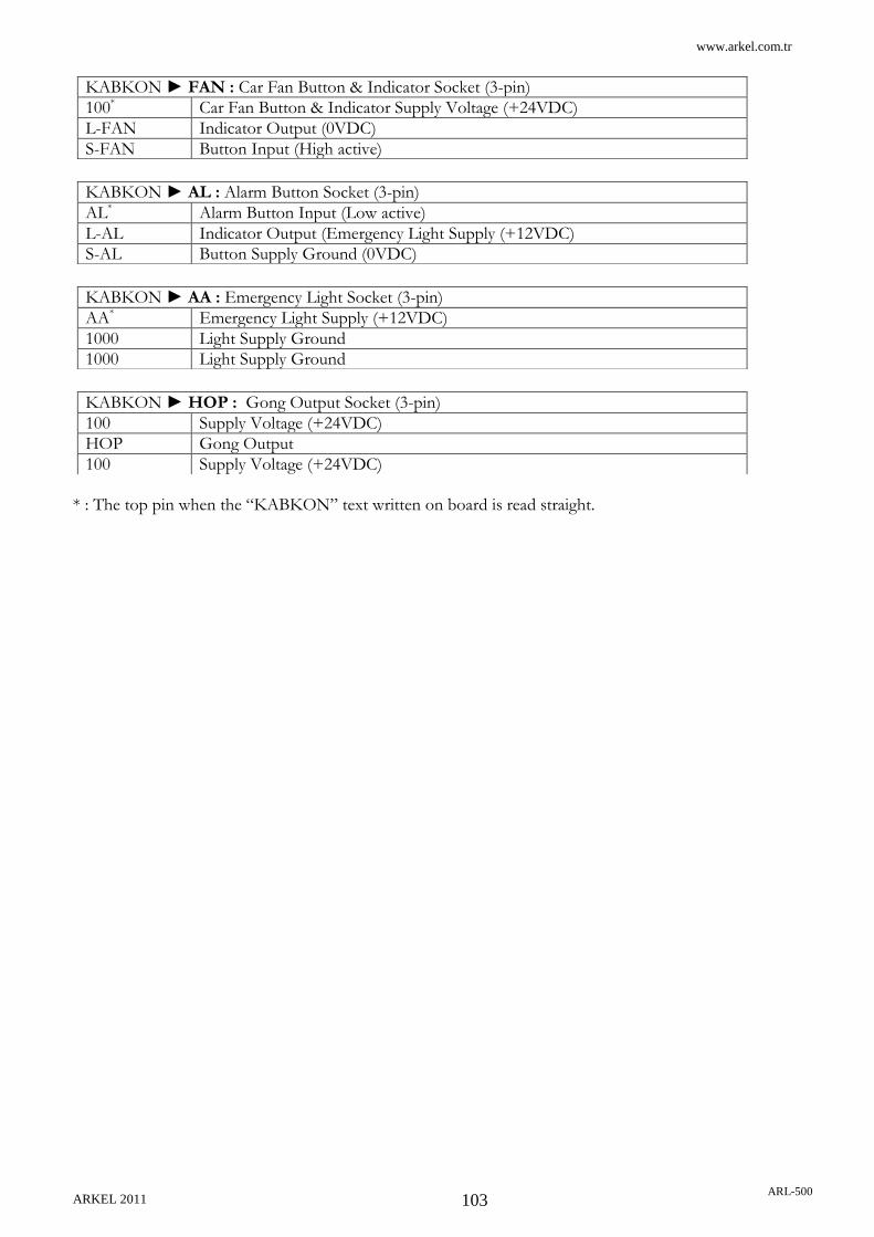
www.arkel.com.tr
ARKEL 2011 ARL-500
103
* : The top pin when the “KABKON” text written on board is read straight.
KABKON ► FAN : Car Fan Button & Indicator Socket (3-pin)
100* Car Fan Button & Indicator Supply Voltage (+24VDC)
L-FAN Indicator Output (0VDC)
S-FAN Button Input (High active)
KABKON ► AL : Alarm Button Socket (3-pin)
AL* Alarm Button Input (Low active)
L-AL Indicator Output (Emergency Light Supply (+12VDC)
S-AL Button Supply Ground (0VDC)
KABKON ► AA : Emergency Light Socket (3-pin)
AA* Emergency Light Supply (+12VDC)
1000 Light Supply Ground
1000 Light Supply Ground
KABKON ► HOP : Gong Output Socket (3-pin)
100 Supply Voltage (+24VDC)
HOP Gong Output
100 Supply Voltage (+24VDC)

www.arkel.com.tr
ARKEL 2011 ARL-500
104
7.3.3. LEDs on KABKON Car command cotrol module
7.3.4. Trimpot on KABKON module
Trimpot on KABKON module is used for adjusting volume of gongs in car operating panel. Gong volume is finely increased by turning trimpot anti-clockwise and is decreased by turning trimpot clockwise.
LED Color Status Reason
CPU Green
Flashing slowly KABKON CANbus communication is faulty.
Flashing rapidly KABKON CANbus communication is working correctly.
Off Fault in the processor. The processor is not working correctly.
5V Green
On Power on.
Off
Power off.
5V power supply of the processor is not working correctly. The hardware of the KABKON is faulty.
100 Green
On Power on.
Off
Power off.
24V power supply of KABKON is not working correctly.

www.arkel.com.tr
ARKEL 2011 ARL-500
105
7.3.5. DIP-SWITCHES on KABKON module
4-switch dipswitches at the backside of the KABKON board are used for door selecting
and number of commands selecting. The 1st switch is used for selecting number of
commands less/more than 24, the 2nd and 3rd switches are used for door selection and
the 4th switch is reserved.
The settings for number of car commands are described below: The settings for door side selection are described below:
or
This panel commands both door-A and door-B.
This panel commands door-A.
This panel commands door-B.
Set for car commands between 1 and 24
(KABKON board with this setting is showed as “KABKON1” on ARL-500
display)
Set for car commands between 25 and 48
(KABKON board with this setting is showed as “KABKON2” on ARL-500
display)
Number of commands selection
Door side selection
Reserved

www.arkel.com.tr
ARKEL 2011 ARL-500
106
7.4. Call/Indicator Modules
7.4.1. LCD240X128A Indicator Module
1 CANbus connection sockets (big size)
2 CANbus connection socket (small size)
3 PC connection socket for programming
4 LCD contrast adjustment setting
5 4-key keypad
6 Buzzer for button sounds
7 PC programming socket
8 Memory chip
1
2
3 4
5
6
7
8
LCD240X128A

www.arkel.com.tr
ARKEL 2011 ARL-500
107
7.4.1.1. LCD240X128A Technical Data
Description Value
Dimensions Length × width × height (mm)
160 × 125 × 28
Pixel resolution 240 x 128 pixels
Background light White LED
Working temperature ±0 - +60 °C
Supply Voltage 24 VDC ± 5 VDC
Power consumption 50mA 1.2W @ 24VDC
LCD240X128A Dimensional Drawing
A = 151.5mm B = 136.2mm C = 102mm D = 117.6mm E = 125mm F = 110mm G = 51mm H = 64mm
I = 114mm
J = 15mm K = 23mm L = 68.1mm M = 144mm N = 159.1mm P = 4mm
LCD240X128A

www.arkel.com.tr
ARKEL 2011 ARL-500
108
7.4.2. KKLCD-A/KKLCD-B/KKLCD-C Call/Indicator modules
1 Down direction led connection socket
2 Up direction led connection socket
3 Gong connection socket
4 Programmable input output connection socket
5 CANbus connection socket
6 2-key keypad
7 Gong volume setting.
8 PC programming socket
9 MCU programming socket
8
1 2 3 4 5
6
7
9
KKLCD-A
KKLCD-B
KKLCD-C

www.arkel.com.tr
ARKEL 2011 ARL-500
109
7.4.2.1. KKLCD-A/KKLCD-B/KKLCD-C Technical Data
KKLCD-A Dimensional Drawing
Description Value
Dimensions Length × width × height (mm)
KKLCD-A 113 × 84 × 20
KKLCD-B 92 × 68 × 24
KKLCD-C 98 × 84 × 23
Pixel resolution 128 x 64 pixels
Background light White LED
Working temperature ±0 - +60 °C
Power supply 24 VDC ± 5 VDC
Power consumption
Board 40mA, 1W @ 24VDC (without gong and buttons)
Button-led 15mA, 0.4W @ 24VDC (for each button)
Gong 0.5W/8Ohm speaker
Programmable output Max. 100mA. 2.5W @ 24VDC
A = 84mm B = 113mm C = 93mm D = 56.5mm E = 40mm F = 72mm G = 20.7mm H = 21.5mm
J = 4mm K = 13mm L = 19mm P = 7mm R = 3mm
KKLCD-A

www.arkel.com.tr
ARKEL 2011 ARL-500
110
KKLCD-B Dimensional Drawing
KKLCD-C Dimensional Drawing
A = 24mm B = 72mm C = 27mm D = 22mm E = 31.3mm F = 58.5mm G = 16.5mm H = 18.3mm I = 4mm
J = 7mm K = 3mm
A = 78mm B = 70mm C = 42mm D = 44mm E = 62mm F = 19.5mm G = 18mm H = 19mm
J = 13mm K = 7mm L = 3mm M = 4mm
KKLCD-B
KKLCD-C

www.arkel.com.tr
ARKEL 2011 ARL-500
111
7.4.2.2. KKLCD-A/KKLCD-B/KKLCD-C Pin Assignments
* : The leftmost pin behind KKLCD-X (socket writing must be on the top side of the card).
UP Call Button-LED Socket (3-pins)
BUT-COM * LED+
Call button and LED supply (+24V)
LED- LED- output (0 VDC)
BUT-NO Button input (High active)
DOWN Call Button-LED Socket (3-pins)
BUT-COM * LED+
Call button and LED supply (+24V)
LED- LED- Output (0 VDC)
BUT-NO Button Input (High active)
P-IO Programmable input-output socket (3-pins)
100 * Call button and LED supply (+24V)
P-O Programmable Output (0 VDC)
P-I Programmable Input (High active)
Gong Socket (3-pins)
100 * Gong Supply (+24V)
HOP Gong Output
100 Gong supply (+24V)
X-CB1 Car CANbus Socket (4-pins)
100 * +24VDC Supply
1000 GND (Ground)
CANL First CANbus terminal
CANH Second CANbus terminal
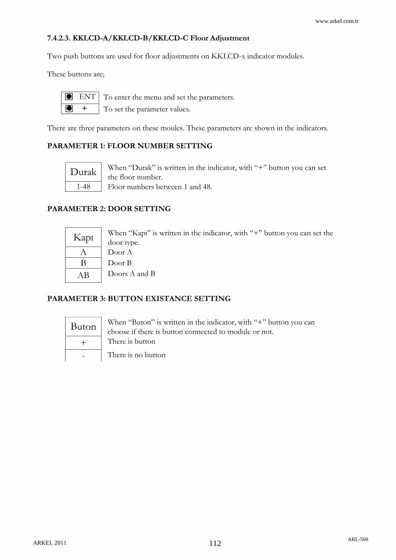
www.arkel.com.tr
ARKEL 2011 ARL-500
112
7.4.2.3. KKLCD-A/KKLCD-B/KKLCD-C Floor Adjustment Two push buttons are used for floor adjustments on KKLCD-x indicator modules. These buttons are;
There are three parameters on these moules. These parameters are shown in the indicators. PARAMETER 1: FLOOR NUMBER SETTING PARAMETER 2: DOOR SETTING PARAMETER 3: BUTTON EXISTANCE SETTING
ENT To enter the menu and set the parameters.
+ To set the parameter values.
Durak When “Durak” is written in the indicator, with “+” button you can set
the floor number.
1-48 Floor numbers between 1 and 48.
Kapı When “Kapı” is written in the indicator, with “+” button you can set the
door type.
A Door A
B Door B
AB Doors A and B
Buton When “Buton” is written in the indicator, with “+” button you can
choose if there is button connected to module or not.
+ There is button
- There is no button

www.arkel.com.tr
ARKEL 2011 ARL-500
113
7.4.3. KK3X3057 Dot-matrix Call/Indicator modules
1 Down direction button connection socket
2 Up direction button connection socket
3 Speaker connection socket
4 Programmable input-output connection socket
5 CANbus connection socket (small size)
6 CANbus connection socket (big size)
7 2-key keypad
8 Gong volume setting
9 MCU programming socket
1 2 3 4
5
8
7
9
6

www.arkel.com.tr
ARKEL 2011 ARL-500
114
7.4.3.1. KK3X3057 Technical Data
KK3X3057 Dimensional Drawing
Description Value
Dimensions Length × width × height (mm)
114 x 60 x 18
Number of Dot-matrix 3
Dot-matrix type 30 mm, 5 x 7 dots
LED colour Red
Working temperature ±0 - +60 °C
Power supply 24 VDC ± 5 VDC
Power consumption
Board 40mA, 1W @ 24VDC (without gong and buttons)
Button-led 15mA, 0.4W @ 24VDC (for each button)
Gong 0.5W/8Ohm speaker
Programmable output Max. 100mA, 2.5W @ 24VDC
A = 60mm B = 54mm C = 109mm D = 114mm E = 45.7mm F = 38mm H = 22.8mm
J = 17mm K = 15mm L = 18.5mm M = 7mm P = 7mm R = 4mm S = 3mm
KK3X3057

www.arkel.com.tr
ARKEL 2011 ARL-500
115
7.4.3.2. KK3X3057 Pin Assignments
* : The leftmost pin behind KK3X3057 (socket writing must be on the top side of the card).
UP Call Button-LED Socket (3-pins)
BUT-COM * LED+
Call button and LED supply (+24V)
LED- LED- output (0 VDC)
BUT-NO Button input (High active)
DOWN Call Button-LED Socket (3-pins)
BUT-COM * LED+
Call button and LED supply (+24V)
LED- LED- Output (0 VDC)
BUT-NO Button Input (High active)
P-IO Programmable input-output socket (3-pins)
100 * Call button and LED supply (+24V)
P-O Programmable Output (0 VDC)
P-I Programmable Input (High active)
Gong Socket (3-pins)
100 * Gong Supply (+24V)
HOP Gong Output
100 Gong supply (+24V)
X-CB1 Car CANbus Socket (4-pins)
100 * +24VDC Supply
1000 GND (Ground)
CANL First CANbus terminal
CANH Second CANbus terminal

www.arkel.com.tr
ARKEL 2011 ARL-500
116
7.4.3.3. KK3X3057 Floor Adjustment
Two push buttons are used for floor adjustments on KK3X3057 indicator modules. These buttons are;
There are three parameters on these cards. These parameters are shown in the indicators. PARAMETER 1: FLOOR NUMBER SETTING PARAMETER 2: DOOR SETTING PARAMETER 3: BUTTON EXISTANCE SETTING
ENT To enter the menu and set the parameters.
+ To set the parameter values.
D When “D” is written in the indicator, with “+” button you can set the
floor number.
1-48 Floor numbers between 1 and 48.
K When “K” is written in the indicator, with “+” button you can set the
door type.
A Door A
B Door B
AB Door A and B
B When “B” is written in the indicator, with “+” button you can choose if
there is button connected to module or not.
+ There is button
- There is no button

www.arkel.com.tr
ARKEL 2011 ARL-500
117
7.4.4 KK2X3057 Dot-matrix Call/Indicator modules
1 Down direction button connection socket
2 Up direction button connection socket
3 Speaker connection socket
4 Programmable input-output connection socket
5 CANbus connection socket
6 2-key keypad
7 Gong volume setting
8 MCU programming socket
1 2 3 4
5
6
7
8

www.arkel.com.tr
ARKEL 2011 ARL-500
118
7.4.4.1. KK2X3057 Technical Data
KK2X3057 Dimensional Drawing
Description Value
Dimensions Length × width × height (mm)
64 x 73 x 18
Number of Dot-matrix 3
Dot-matrix type 30 mm, 5 x 7 dots
LED colour Red
Working temperature ±0 - +60 °C
Power supply 24 VDC ± 5 VDC
Power consumption
Board 30mA, 0.8W @ 24VDC (without gong and buttons)
Button-led 15mA, 0.4W @ 24VDC (for each button)
Gong 0.5W/8Ohm speaker
Programmable output Max. 100mA, 2.5W @ 24VDC
A = 49mm B = 73mm C = 58mm D = 64mm E = 45.7mm F = 38mm G = 14mm H = 13mm
J = 12mm K = 4mm L = 3mm
KK2X3057

www.arkel.com.tr
ARKEL 2011 ARL-500
119
7.4.4.2. KK2X3057 Pin Assignments
* : The leftmost pin behind KK2X3057 (socket writing must be on the top side of the card).
UP Call Button-LED Socket (3-pins)
BUT-COM * LED+
Call button and LED supply (+24V)
LED- LED- output (0 VDC)
BUT-NO Button input (High active)
DOWN Call Button-LED Socket (3-pins)
BUT-COM * LED+
Call button and LED supply (+24V)
LED- LED- Output (0 VDC)
BUT-NO Button Input (High active)
P-IO Programmable input-output socket (3-pins)
100 * Call button and LED supply (+24V)
P-O Programmable Output (0 VDC)
P-I Programmable Input (High active)
Gong Socket (3-pins)
100 * Gong Supply (+24V)
HOP Gong Output
100 Gong supply (+24V)
X-CB1 Car CANbus Socket (4-pins)
100 * +24VDC Supply
1000 GND (Ground)
CANL First CANbus terminal
CANH Second CANbus terminal

www.arkel.com.tr
ARKEL 2011 ARL-500
120
7.4.4.3. KK2X3057 Floor Adjustment
Two push buttons are used for floor adjustments on KK2X3057 indicator modules. These buttons are;
There are three parameters on these cards. These parameters are shown in the indicators. PARAMETER 1: FLOOR NUMBER SETTING PARAMETER 2: DOOR SETTING PARAMETER 3: BUTTON EXISTANCE SETTING
ENT To enter the menu and set the parameters.
+ To set the parameter values.
D If “D” is written in the indicator, with “+” button you can set the floor
number.
1-48 Floor numbers between 1 and 48.
K If “K” is written in the indicator, with “+” button you can set the door
type.
A Door A
B Door B
AB Door A and B
B When “B” is written in the indicator, with “+” button you can choose if
there is button connected to module or not.
+ There is button
- There is no button
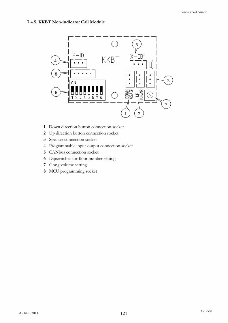
www.arkel.com.tr
ARKEL 2011 ARL-500
121
7.4.5. KKBT Non-indicator Call Module
1 Down direction button connection socket
2 Up direction button connection socket
3 Speaker connection socket
4 Programmable input-output connection socket
5 CANbus connection socket
6 Dipswitches for floor number setting
7 Gong volume setting
8 MCU programming socket
1 2
3
4
5
6
7
8

www.arkel.com.tr
ARKEL 2011 ARL-500
122
7.4.5.1. KKBT Technical Data
KKBT Dimensional Drawing
Description Value
Dimensions Length × width × height (mm)
52 x 41 x 18
Working temperature ±0 - +60 °C
Power supply 24 VDC ± 5 VDC
Power consumption
Board 15mA, 0.4W @ 24VDC (without gong and buttons)
Button-led 15mA, 0.4W @ 24VDC (for each button)
Gong 0.5W/8Ohm speaker
Programmable output Max. 100mA, 2.5W @ 24VDC
A = 33mm B = 41mm C = 26mm D = 52mm E = 4mm F = 3mm
KKBT

www.arkel.com.tr
ARKEL 2011 ARL-500
123
7.4.5.2. KKBT Pin Assignments
* : The rightmost pin behind KK2X3057 (socket writing must be on the top side of the card).
UP Call Button-LED Socket (3-pins)
BUT-COM * LED+
Call button and LED supply (+24V)
LED- LED- output (0 VDC)
BUT-NO Button input (High active)
DOWN Call Button-LED Socket (3-pins)
BUT-COM * LED+
Call button and LED supply (+24V)
LED- LED- Output (0 VDC)
BUT-NO Button Input (High active)
P-IO Programmable input-output socket (3-pins)
100 * Call button and LED supply (+24V)
P-O Programmable Output (0 VDC)
P-I Programmable Input (High active)
Gong Socket (3-pins)
100 * Gong Supply (+24V)
HOP Gong Output
100 Gong supply (+24V)
X-CB1 Car CANbus Socket (4-pins)
100 * +24VDC Supply
1000 GND (Ground)
CANL First CANbus terminal
CANH Second CANbus terminal

www.arkel.com.tr
ARKEL 2011 ARL-500
124
7.4.5.3 Floor Setting With Dipswitches On KKBT
In call-panels; KKBT, 8-switch dipswitches at the backside of the board is used. The first
two switches are for door selecting, the other 6 are for floor selection.
The procedure of floor selection switches is explained below:
Floor number is coded in binary code. The most-right switch has the least value. The value
of switch which is ON is added to floor number. The value of switch which is OFF is 0
(zero). Floor number is selected by the sum of ON switches value + 1.
For door selection switches, use the table below:
or
This panel commands both door-A and door-B
This panel commands door-A
This panel commands door-B
For this example floor number 28 is coded.
0 + 16 + 8 + 0 + 2 + 1 + 1 = 28
This landing call panel is indicated as “KK-28”
on ARL-500 display.
Floor number selection
Door A, B or AB selection
Switch value
Switch number

www.arkel.com.tr
ARKEL 2011 ARL-500
125
8. ARL-500 DISPLAY MESSAGES
8.1. STATUS MESSAGES
The current status of elevator during the operations of controller is shown on ARL-500 display with the information on the top of display we called status message. The status messages are listed in the following table.
Status Message Description Reason
Ready
ARL-500 controller is ready to run Controller is in normal mode and no active call acknowledged
Loading-Unloading
Elevator is loading or unloading passengers
Car door is opened at the floor and waiting for passengers to load/unload.
Preopening doors
Doors are opening as the car approaches to a landing This message is given if door pre-
opening function is enabled. When the car reaches the door zone while approaching to the target floor, doors are pre-opened.
Waiting for lock
Door lock is waiting After a call acknowledged, the car door is closed and the door lock is waiting in order to run.
Fast downward travel
Car is running downward at fast speed The controller activated high speed drive during downward travel.
Fast upward travel
Car is running upward at fast speed
The controller activated high speed drive during upward travel.
Slow downward travel
Car is running downward at slow speed The controller activated low speed drive during downward travel.
Slow upward travel
Car is running upward at slow speed The controller activated low speed drive during upward travel.

www.arkel.com.tr
ARKEL 2011 ARL-500
126
Status Message Description Reason
Out of service
Elevator is out of service An error was handled and lift gone into out of service mode. Because you have changed the error status screen by using keypad, controller shows this status message on main screen. The error message and the lift status message are showed in error status screen.
Hydraulic leveling (up)
Relevelling up with car and shaft doors open. This message is given if hydraulic
leveling function is enabled. Because of down direction movements of car during loading (or oil leaking) relevelling is required with car and landing doors open.
Hydraulic leveling (down)
Relevelling down with car and shaft doors open. This message is given if hydraulic
leveling function is enabled. Because of up direction movements of car during unloading relevelling is required with car and landing doors open.
Shaft learning is needed
Shaft learning has not yet been carried out Shaft learning is needed before going in to normal operation mode when incremental encoder positioning is used.
Resetting position sensors...
Car is running to the bottom floor in order to reset position sensors. When ARL-500 controller is
switched on or rebooted, it checks the bottom limit switch (817) to correct its position counter.
Earthquake evac.
Earthquake evacuation mode is activated. The earthquake sensor input (terminal DEP) on the ARL-500 controller is active.
Fire evacuation
Fire evacuation mode is activated. The fireman input (terminal YAN) on the ARL-500 controller is active.

www.arkel.com.tr
ARKEL 2011 ARL-500
127
Status Message Description Reason
Stop circuit off
Stop circuit (terminal between 110 and 120) is interrupted. Interruption of the stop circuit
before terminal 119. The stop circuit contacts between terminal 110 and 120 interrupted the safety circuit. All safety circuit inputs of ARL-500 controller are idle.
- Emergency stop switch may be operated on the remote control unit in normal mode (not Inspection or Recall).
- Unused safety contacts are not bridged on KBK-9 control panel connection boards and REVKON car top controller.
- Travelling cable may be damaged.
Parking...
Parking drive is activated. Because there is no active call and parking delay has exceeded, the controller sends the car to a programmed parking floor.
Inspection mode only
Controller can only be opeated in inspection mode or recall mode and can not be operated in normal mode.
The parameter “System Settings > Operating mode” is set to “Inspection only” in ARL-500 menu. The controller is set to “Inspection only” mode in the default factory settings for safety startup installation. This parameter should be set to “Normal operation” during normal operation.
When ARL-500 controller is switched on or rebooted, it checks the bottom limit switch (817) to correct its position counter. If the inspection or recall control is activated before this correction drive, the system can be operated only in “Inspection only”.
Door is unlocked
Door is unlocked. Waiting door lock beginning of startup drive in order to reset position sensors after ARL-500 controller has switched on. If door is locked controller performs this drive or else can not start to driving and waits until door is locked (terminal 140 is activated)

www.arkel.com.tr
ARKEL 2011 ARL-500
128
Status Message Description Reason
Overload
The overload input is active. The overload input on the REVKON is activated (on a programmable input assigned as overload 804 function)
Inspection
The inspection control is active. The inspection switch on the inspection hand terminal is turned to INSPECTION. Terminal
Inspection: 817 off
The bottom limit switch (SKSR1) is activated in inspection mode. Car is at the bottom floor and the
bottom limit switch is activated in inspection mode. The behaviour of controller is determined by the parameter “System settings > Limiters in inspection mode” either "Stop car immediately” or “Stop car at floor level” in the ARL-500 menu.
Inspection: 818 off
The top limit switch (SKSR2) is activated in inspection mode.
Car is at the top floor and the top limit switch is activated in inspection mode.
Inspection: Door unlocked
Door is unlocked in inspection mode. Waiting door lock beginning of inspection drive. After door lock controller performs this drive or else can not start to driving and waits until door is locked (terminal 140 is activated)
Inspection: Stop pressed
The emergency stop switch at inspection hand terminal is interrupted during inspection operation.
- The safety circuit is interrupted by the activation of the emergency stop switch during inspection UP or DOWN driving.
- The stop circuit contacts between terminal 110 and 120 interrupted the safety circuit during inspection drive.
Recall Operation
The recall control is active. The recall switch on the recall hand terminal is turned to INSPECTION.
Recall: 817 off
The bottom limit switch (SKSR1) is activated in recall mode.
Car is at the bottom floor and the bottom limit switch is activated in recall mode.
Recall: 818 off
The top limit switch (SKSR2) is activated in recall mode.
Car is at the top floor and the top limit switch is activated in recall mode.

www.arkel.com.tr
ARKEL 2011 ARL-500
129
Status Message Description Reason
Recall: Door unlocked
Door is unlocked in inspection mode. Waiting door lock beginning of recall drive. After door lock, controller performs this drive or else can not start to driving and waits until door is locked (terminal 140 is activated)
Recall: Stop pressed
An emergency stop switch at recall hand terminal is interrupted during recall operation.
-The safety circuit is interrupted by the activation of the emergency stop switch during inspection UP or DOWN driving.
- The stop circuit contacts between terminal 110 and 120 interrupted the safety circuit during inspection drive.
Inspection(*)
The manual control by keypad is active. LEFT + RIGHT keys on the ARL-500 keypad are pressed together are lift goes into manual control mode from keypad.
Inspection(*): 817 off
The bottom limit switch (SKSR1) is activated in manual control mode.
Car is at the bottom floor and the bottom limit switch is activated in manual control mode.
Inspection(*): 818 off
The top limit switch (SKSR2) is activated in manual control mode.
Car is at the top floor and the top limit switch is activated in manual control mode.
Inspection(*): Door unlocked
Door is unlocked in inspection mode. Waiting door lock beginning of manual control drive. After door lock, controller performs this drive or else can not start to driving and waits until door is locked (terminal 140 is activated)
Inspection(*): Stop pressed
An emergency stop switch at recall hand terminal is interrupted during recall operation.
- The safety circuit is interrupted by the activation of the emergency stop switch during manual control UP or DOWN driving.
- The stop circuit contacts between terminal 110 and 120 interrupted the safety circuit during manual cotrol drive.
Downward travel with middle-speed
Car is running downward at middle speed When there are short floors in the building, the car runs downward in middle speed on the way to the short floor.
Upward travel with middle speed
Car is running upward at middle speed When there are short floors in the building, the car runs upward in middle speed on the way to the short floor.

www.arkel.com.tr
ARKEL 2011 ARL-500
130
Status Message Description Reason
Car command entry Entering call commands to the system.
Any car call can be entered in this window.
X seconds to retry Time remaining for the system to operate in normal mode.
For some errors, the system tries to re-operate after this time is passed.
Lift blocked!!! The elevator is blocked. The elevator is blocked by the
reason of the error(s).
Door is open The door is open The status message when the car
lands to a floor and opens the door(s).
Door is unlocked The door is unlocked The status message when the
door lock(es) are open.
Fire alert (Phase – 1)
Fire alert signal. When in normal operation mode, an active signal on the programmable input “18:(YAN)Fire detector” causes the controller to go into Fire Emergency Phase-1 mode.
Firemen operation (Phase – 2)
When in Fire Emergency Phase-1, activation of the programmable input “12: (ITA) Fireman key” causes the controller to go into this mode.
See “ARL500 Fire emergency operations” for detailed information.
Inspection: Door is open The elevator is in inspection mode and the door is open
Recall: Door is open The doors are open during recall operation
Preparing for evacuation The elevator is preparing for evacuation
When the electricity is gone in the building, the system prepares elevator to evacuate.
Evacuation The elevator is evacuating
Evacuation ended. The evacuation has ended. System has ended the evacuation
and the car has landed on the floor.
Unjamming PAWL device.
The system is unjamming the PAWL device.
For any reason if the PAWL device is jammed, system runs the car upwards to unjam the PAWL device.
Waiting for PAWL release... The system is waiting for PAWL device release.
After landing to a floor, the PAWL device must be released to make cabin move.
Inspection(*): Door is open
The system is operating in inspection mode via the buttons on ARL 500, and the door is open.
Ready (inside door-zone) The system is ready for any command entry and inside door zone.
Cabin is ready for any command entry.
Ready (outside door-zone)
The system is ready for any command entry and outside door zone.
Cabin is ready for any command entry.
Status Message Description Reason

www.arkel.com.tr
ARKEL 2011 ARL-500
131
PAWL failed. Stopping… Because of the PAWL device error, the elevator stops.
The lift stops
Sleeping… The elevator operates in stand by mode.
The system operates in sleep mode for saving electricity until a call is received.
Waking up… The system is starting to operate in normal mode.
The system is starting to operate in normal mode after sleeping.
PTC error. Moving to bottom.
Only in hydraulic systems, because of the PTC error, the cabin moves to the bottom floor.
The hydraulic system is overheated and the car moves to the bottom floor.
PTC error. There is a PTC error The motor temperature is
overheated.
Safety circuit must be complete during shaft learning!
To make the system learn the shaft, safety circuits must be complete.
To operate in normal mode, at very first the system must learn the shaft and to learn the shaft the safet circuit must be complete.

www.arkel.com.tr
ARKEL 2011 ARL-500
132
8.2. ERROR MESSAGES
The current error of the elevator system is shown in error status screen on ARL-500 display we called error message. ARL-500 controller saves these error messages listed in the following table.
Error Message Description Reason
Max. time of fast travel expired
The maximum time allowed to travel at high speed without changing the current floor number is exceeded.
- Check motor drive - Check the function of floor counters - Increase the parameter Maximum time of travel in high speed
Max. time of slow travel expired
The maximum time allowed to travel at low speed without changing the current floor number is exceeded.
- Check motor drive - Check the function of floor counters - Increase the parameter Maximum time of travel in low speed
Door can not close
Error during closing of doors. The car door contact does not close even after attempts set by the parameter “Retries for closing doors”
- The car door is blocked mechanically or electrically. - Check operation of door relays on ARL-500 or REVKON. - Check operation of door operator - Check door contacts - Check connection of termimnal 140 at ARL-500
Bottom limit(817) sensed while moving up
Bottom limit switch (817) is interrupted while moving up except bottom floor
-Check bottom limit switch SKSR1 mechanically or electrically. -Check bottom limit switch input 817 on ARL-500 and REVKON.
Top limit(818) sensed while moving down
Top limit switch (818) is interrupted while moving down except top floor
-Check limit switch SKSR2 mechanically or electrically. -Check top limit switch input 817 on ARL-500 and REVKON.
Top and bottom limits sensed at the same time
Bottom limit switch (817) and top limit switch (818) are interrupted simultaneously
-Check limit switches SKSR1 and SKSR2 mechanically or electrically. -Check limit switch inputs 817 and 818 on ARL-500 and REVKON.

www.arkel.com.tr
ARKEL 2011 ARL-500
133
Error Message Description Reason
Contactor could not pick
The contactor pick-up protection has triggered. KRC contactor checkback signal is not OFF. Terminal KRC must not be supplied with 24V when the system is in operation.
-Check connection of terminal KRC on ARL-500 -Check connection of contactors supply -Check the NC contacts of contactors used in KRC circuit.
Contactor could not drop
The contactor drop-out protection has triggered. KRC contactor checkback is not ON. Terminal KRC must be supplied with 24V when the system is at rest.
-Check connection of terminal KRC on ARL-500 -Check connection of contactors supply -Check the NC contacts of contactors used in KRC circuit.
RST phase error RST phase turn error
-Check the connection of L1, L2, L3,N terminals on ARL-500 - Change any two phase of L1, L2, L3 terminals on ARL-500
Manual door open error
The manual door can not be closed in the time set by manual door close waiting time parameter. Timer is started counting after a call is accepted.
-Manual door remains open - Check shaft doors mechanically - Check door contacts. - Check the connection of terminal 130 on ARL-500
Short-circuit on prog.transistors
An overload or short circuit conditions at programmable transistors PT1-PT6. The outputs of PT1-PT6 terminals are short-circuit protected. The load current must not be more than the maximum load current.
-Check connections of terminals PT1-PT6 - Check the power consumption of active load
Motor temperature too high or PTC not connected
Temperature monitoring of the drive on T1-T2 terminals of ARL-500 has triggered. The voltage of terminal T1 is 24VDC. Terminal T2 must be supplied with 24V when there is no error in system.
-Check the connection of terminals T1-T2 - Motor overheated. Monitoring via input of motor thermistor terminals T1-T2. - The thermostat in the control panel has triggered - The thermostat in the brake resistor has triggered (for VVVF systems) - The oil thermostat has triggered (for hydraulic systems)
Group ID conflict. Change group id
There are lifts in group has an identical group ID.
Change the group ID of lifts set same using “Group settings > Controller ID” parameter. Each lift must have different group ID.

www.arkel.com.tr
ARKEL 2011 ARL-500
134
Error Message Description Reason
130 or 140 signal was cut off during motion
The safety citcuit door contact terminals (from terminals 120 to 140) have been interrupted while the car was moving.
- Check doors mechanically - Check door contacts - Check door lock contacts - Check the connection of terminal 130 and 140 on ARL-500
Earthquake detected
Earthquake detected. Terminal DEP of ARL-500 (programmable input) is supplied with 24V when an earthquake detected in system.
- An Earthquake occured - Check the connection of terminal DEP on ARL-500
Fire detected
Fire detected. Terminal YAN of ARL-500 (programmable input) is supplied with 24V when a fire detected in system.
- A fire occured - Check the connection of terminal YAN on ARL-500
Power supply voltage too low
The 24V supply of the ARL-500 board (100-1000) is below the permitted range of 24V - 20%.
Check power supply and wiring
Driver error or DRDY input not connected
A motor driver error occured or DF driver ready input is not connected properly. DF input is low active. The programmable input terminal assigned to DRDY (driver ready) function must be supplied with 24V when there is no error in system. This input also must be assigned and its terminal must be bridged to 100 (+24V) when no error output of motor driver.
-Motor driver has given an error. Check motor driver display and error diagnosis -Check the connection of DF terminal of ARL-500 -Check the function of DF programmable input using the status screens of programmable inputs
Encoder fault No movement of the car could be determined during the drive.
The encoder position does not change during the drive. - Check signals of the encoder by observing encoder LEDs on the ARL-500 controller. - The encoder is faulty. - No electric connection to encoder. - The drive does not move.
ML1-ML2 turned on simultaneously. Short-circuit?
SML1 & SML2 door zone switched turned on simultaneously.
SML1-SML2 magnetic switches are installed in the same bracket and SML2 (door zone-2) magnetic switch must be on top of SML1 (door zone-1). So they can not be switched on simultaneously. - Check the connection of terminals ML1 & ML2. - Short-circuit at ML1 & ML2 signals.

www.arkel.com.tr
ARKEL 2011 ARL-500
135
Error Message Description Reason
Wrong checkback in door bridging
A faulty check-back signal has detected during door bridging and the door bridging process was cancelled.
Internal hardware error
Parameters corrupt. (Flash CRC error)
Error during transferring data from/to processor
This error may also be caused by a firmware update. If the new version of the firmware has some parameters that the old version did not have, this error message will be shown. To clear the error: 1. Enter the parameter menu 2. Change any parameter (for example, increase car-light delay by 1 seconds) 3. Save the parameters when exiting the menu 4. Power off and power on. The error will be cleared.
Parameters unreadable. (Flash CRC error)
Error during reading parameters Internal hardware error
Maintenance date passed
Maintenance date has been expired set by “Date and Time Settings > Next maintenance date” parameter.
Maintenance date has been expired set by “Date and Time Settings > Next maintenance date” parameter.
Encoder counting in the wrong direction
The elevator is not moving in the desired direction.
The encoder terminals may be connected incorrect. Exchange the terminal inputs and maket he system learn the shaft again.
ML1-ML2 turned on simultaneously. Short-circuit?
ML1 and ML2 switches are activated simultaneously.
Check the connections of ML1 and ML2
Group ID conflict. Change group ID.
Group ID conflict in group operation.
Check the “group settings” in the main menu and change the controller ID parameter if there are any conflicts.

www.arkel.com.tr
ARKEL 2011 ARL-500
136
Error Message Description Reason
Rescue failed
If Control Techniques or Zetadyn drivers are used when the mains power is gone if “maximum rescue time” has passed, this error message will be displayed.
Accumulator used for rescuing operation or UPS might be discharged.
UPS shut-down during test
When Control Techniques or Zetadyn drivers are used, the system checks if the UPS is working properly by operating the elevator with only UPS supply. This function can be changed from “Rescue settings>Daily UPS check”
-UPS might be discharged -Check UPS connections -Check if your UPS has enough power to rescue the system.
Headroom protection rod\switch faulty
This error is triggered when headroom protection down switch (HPD) and headroom protection up switch (HPU) are activated simultaneously.
Check your HPD and HPU connections. If this function is not used in your system, disable the function from “Headroom/Pit protection>Headroom protection system”.
Headroom protection rod/position unknown
This error is triggered when headroom protection down switch (HPD) and headroom protection up switch (HPU) are passive at the same time.
Check your HPD and HPU connections. If this function is not used in your system, disable this feature from “Headroom/Pit protection>Headroom protection system”.
Cartop protection light-barrier faulty
This error is triggered when “Cartop lightbarrier checkback” (CLC) input is stil off after 2 seconds altough “Cartop protection lightbarrier test” (CLB) output was activated.
Ligt barrier might be broken down. If this function isnot used in your system, disable this feature from “Headroom/Pit protection>Cartop protection lightbarrier”.
Cartop protection lightbarrier interrupted. Inspection only!
This error is triggered when “Cartop lightbarrier checkback “ (CLC) input is active outside the lightbarrier monitoring period. The system operates only in inspection mode.
Check the connections of CLC input and CLB output. If this function isnot used in your system, disable this feature from “Headroom/Pit protection>Cartop protection lightbarrier”.
Pit protection switch did not open.
This error is triggered when A door assigned to one of the PPSx inputs was commanded to open but the same input was still active after 4 seconds.
Check assigned PPSx input connections on ARL-500. If this function is not used in your system, change the door parameter to “none” from “Headroom/Pit protection>PPSx: 1. floor/None”
Pit protection switch was opened.
This error is triggered when a PPSx input is assigned to a floor and the PPSx input is OFF and the car is not at the assigned floor.
Check assigned PPSx input connections on ARL-500. If this function is not used in your system, change the door parameter to “none” from “Headroom/Pit protection>PPSx: 1. floor/None”

www.arkel.com.tr
ARKEL 2011 ARL-500
137
ARKEL Elektrik Elektronik Ticaret Ltd. Şti.
Şerifali Mah. Bayraktar Bulvarı Şehit Sok. No:32 Umraniye Istanbul TURKIYE
Tel: (+90 216) 540 03 10 - 11 -12
Fax: (+90 216) 540 03 09
E-mail : [email protected]
www.arkel.com.tr