AquaEco A Smart Fish Tank - Department of ECE UCF - University ...
147
AquaEco A Smart Fish Tank Group #9 Department of Electrical Engineering and Computer Science University of Central Florida Dr. Lei Wei Matthew Klein - Computer Engineering Evan Kurnia - Electrical Engineering Edward Richards - Electrical Engineering Lisandro Osorio - Computer Engineering i
-
Upload
khangminh22 -
Category
Documents
-
view
2 -
download
0
Transcript of AquaEco A Smart Fish Tank - Department of ECE UCF - University ...

AquaEco
A Smart Fish Tank Group #9
Department of Electrical Engineering and Computer Science University of Central Florida
Dr. Lei Wei
Matthew Klein - Computer Engineering Evan Kurnia - Electrical Engineering
Edward Richards - Electrical Engineering Lisandro Osorio - Computer Engineering
i

Table of contents
1. Executive summary 1
2. Project Description 3 2.1 Project motivation and goals 4 2.2 Objectives 6 2.3 Project Milestones 8 2.4 Requirements Specifications 9 2.5 Overview Block Diagram 13 2.6 House of Quality Analysis 15
3. Research and Definition 17 3.1 Existing Similar Projects and Products 17 3.2 Relevant Technologies 21
3.2.1 Wireless Communications 21 3.2.2 Serial Communication 28
3.3 Strategic Components and Part Selections 35 3.3.1 Lighting considerations 36 3.3.2 Sensor considerations 38 3.3.2.1 PH sensor 41 3.3.2.2 Temperature sensor 42 3.3.2.3 Turbidity sensor 43 3.3.3 Fish feeder 44 3.3.4 Complete housing 46 3.3.5 Computing Unit 47
3.3.5.1 Development boards 48 3.3.5.2 MSP-EXP430G2ET 48 3.3.5.3 Arduino Uno 48 3.3.5.4 Raspberry Pi Zero 50 3.3.5.5 Custom Printed Circuit Board 50 3.3.5.6 PIC32 Microcontroller 52 3.3.5.7 Attiny1617 53 3.3.5.8 Atmega328P 53 3.3.5.9 Processing unit selection 54
3.3.6 Auxiliary Hardware Components 56
ii

3.5 Parts Selection Summary: 57
4. Related Standards and Realistic Design Constraints 60
4.1.1 Related Standards and Impact on Design 61 4.2 External Design Constraints 62
4.2.1 Economic Constraints 62 4.2.2 Time Constraints 63 4.2.3 Environmental Constraints 64 4.2.4 Social and Political Constraints 64 4.2.5 Ethical, Health, and Safety Constraints 65 4.2.6 Manufacturability Constraint 65 4.2.7 Sustainability Constraints 66
5. Product hardware 67 5.1 Initial Design Architectures and Related Diagrams 67 5.2 PCB Design Programs 70
5.2.1 EAGLE 71 5.2.2 DipTrace 72 5.2.3 KiCAD 72 5.2.4 PCB Design Program Selection 73
5.3 Power system considerations 73 5.4 Interfacing between sensors and microcontroller 96 5.5 PCB Design 99
6. Software design 107 6.1 Design choice 108 6.2 Development environment 109 6.3 Client App Environment Selection 111 6.4 Embedded software 112 6.5 Interface of application 119
7. Component Testing and Readings 123
7.1 Prototype board selection 123 7.2 Breadboard Testing 124 7.3 Software Testing 130
iii
8. Project Operation 131
9. Project Summary and Conclusions 133
10.Administration 134
10.1 Project Timeline 135 10.2 Budget 136
Appendix
Appendix A References 137 Appendix B image use 138
iiii

1.Executive summary There is a need for automated solutions with everyday machines and everyday activities. Of these the market for pet products is rapidly increasing as people want to find solutions that will increase productivity in the household. An aquarium is a staple in many households and often is the beginning of a person's pet care experience or for those who have small living spaces yet want the pet experience . Even experienced aquarium owners have a need for an automated solution that will monitor the aquarium’s overall health. We aim to provide a solution intended to prolong fish lives and save maintenance time.
There are many different ways to care for and monitor an aquarium. A person can use a variety of sensors available in their local shop to monitor the amount of Ph, temperature and other characteristics. All these different sensors give a better understanding of the aquarium's overall health and are very popular for those who want to know how their fish tank is behaving. There is an overarching problem however, with so many products found in the fish section of a pet supermarket, people are often overwhelmed with the many different brands and solutions that companies have provided. From fish feeders, to sensors, to testing kits, filters, and pumps, the average person will have a hard time deciding what to buy. Our main goal was to develop a device that provides information about a user’s current aquarium, including sensors and an automatic fish feeder. Lighting, feeding and monitoring were our core aims in this solution. Our solution titled AquaEco has features that reduce the labor and supervision required of the consumer as much as possible. AquaEco stands for Aquarium Ecosystem and aims to give people a kit that is designed for first time aquarium users in mind. A kit is a great way for a household to begin their first steps into owning a full aquarium. An aquarium is a great way for people to learn responsibility by owning a pet that is low maintenance yet can still provide a household with an enjoyable and memorable experience if done correctly. Fish can live many years and can be a staple part in a household if taken care of properly. The issue arises when fish are subjected to bad water conditions. First time owners of an aquarium, might not be able to know when to change the water or know if it is currently safe for fish. This lack of knowledge can often lead to many first time fish owners’ fish dying easily. In turn, these people are far less likely to try and keep fish again. If they don’t know how to properly take care of their fish and they find it challenging to keep up with the various aspects of raising fish, they will be disappointed and less likely to try again. This is not a desirable situation. Our solution, the AquaEco, is a kit that is designed to provide first time aquarium owners or even those used to owning fish with a set of tools to make owning a fish tank easier and less stressful. Automatic lighting is synced to a clock to allow the tank’s lights to turn on and turn off at the same time every day, mimicking the natural cycle of night and day. The user is able to control what time the lights turn on and off, and if they wish to adjust these times. Next is the automatic fish feeder, which is also able to be controlled via the
1

android application. Like the lighting, the user is also able to specify what time the feeder should release food each day. Lastly the device provides three sensors that monitor the aquarium: pH and temperature. The last installed sensor, the turbidity sensor, is able to alert the user if the water is either clean, murky, or dark. The readings are monitored via the android application, and the user is able to be notified when aspects of the tank environment are not up to par. These features allow the end user to control and monitor their smart aquarium from anywhere in the world, and at any time, relieving the need for them to be physically present for feeding and lighting. This can be useful in many situations, such as when a user must be away from their home for a few days, or cannot be home at the time when they would normally feed their fish. The application is the bridge between all these components and the user. With our society’s increasing dependency on technology to lessen the load of organizing our daily life, we feel that a solution such as our own should be very useful to a decent audience. We also understand that with so many people owning smartphones that a solution like this is necessary to differentiate us from the many products available out there.
2

2.0 Project Description In the following sections, our final design will be explained along with the components and reasonings for including them. Our main kit consists of three sections: an automatic fish feeder, lighting system and a combination of sensors . Ultimately, the end user is easily able to set this system up with an application and the application is easy to use.
The automatic fish feeder consists of a motor and a connection to our main controller where it is controlled via the application. It is enclosed fully and the user can pour food into the top and then the user will choose when to dispense the food.
The next component is the LED lighting that is also connected in such a way that the user is able to control the LED via the application tool. The application is able to provide the user with ways to limit lighting to turn off the lights when going to bed, or provide needed lighting to fish without having every light on in the house. Lastly, the user has access to sensor readings consisting of a ph sensor and temperature readings. The ph reading provides the users a way to make sure the water is not too acidic for the fish. The turbidity sensor gives the capability of measuring how dirty the water is and when is the correct time to change the water in the aquarium. Lastly, measuring temperature is important as different fish have different temperature needs. Our app also alerts the user if the temperature is incorrect for the fish that they have put in the aquarium. The hardware components all connect to our phone application. This application consists of an easy to use UI that gives the user important information that comes from the sensors and from an inbuilt aquarium helper. The helper provides valuable first time aquarium user information ranging from proper fish temperature requirements, and a way to see if fish are compatible with each other. This information is stored locally as to always let the user have access to the information. The application gives rich notifications by providing notifications based on thresholds set by the application. The custom aquarium builder in the app provides these thresholds by checking the needed parameters with the fish. This entire system is easy to set up and can create a strong first time experience and also provides those already used to creating aquariums capabilities to enhance and lessen the work needed every day.
3

2.1 Project motivation and goals
The pet industry throughout the world is huge and rapidly growing. New pet owners have a large task at hand when beginning pet ownership. Choosing the right companion is essential for those just tipping their foot into being a pet owner. Of the many pets available including dogs,cats,rabbits, and reptiles there are also fish! Found at every general pet store and even large supermarkets. markets. Fish are accessible to anyone willing to try. There are many reasons why someone might begin their pet ownership with a fish. First, fish are able to teach many different skills to individuals including responsibility and compassion. Fish are one of the most common pets in many households due not only because of large availability but because of the small initial investment and space requirements needed. Aquariums are able to be environments that are displayed in our households with various plants and colorful fish. Our motivation for creating AquaEco began at the research level. We researched the benefits that aquariums and owning fish had over other pet options and found that one key reason was the lower cost and also the less space the aquarium took up. While other pets like dogs require large cages and lots of room in the house and backyard fish are self encapsulated where they live in one environment set up by the user. Fish however, still require work and attention. It is widely known that owning a fish and therefore an aquarium can be an easy transition for those just beginning to start in owning a pet. There are many different ways to create and style an aquarium and also thousands of different species of fish ranging from saltwater to freshwater fish. There are often many people who believe that these fish can live in small spaces like bowls or even small 3 gallon tanks with nothing but water. However, this is far from the truth and fish just like many different species of pets all have seperate needs and wants that must be fulfilled to be long living and healthy.
The experience of owning a fish begins with the aquarium where many options will be found at the pet market. Aquariums can vary in terms of gallons, shape, and extra design. The issue with an upcoming fish owner is the fact that with so many options scattered throughout many different isles at the pet store that one will inevitably become confused and not know which tank might be the best for the particular household. People then begin to question whether or not owning a fish might be too complicated or might not work out as easily as they had hoped. While there might be tons of workers in the store, they might lack the knowledge necessary to explain the many differences between the hundreds of fish species that they have for sale. This is where AquaEco began its initial design and concept. By beginning with an application that provides this necessary information to the everyday individual, we aim to make not only the buying experience easier and more manageable but also provide the first time buyer with a hardware that makes owning the fish tank for many years a breeze.
AquaEco is both an application and a hardware monitoring system. The heart of the system lies in the monitoring and maintenance of the tank once assembled. While we
4
found that individuals had issues at the start, many current fish owners and previous fish owners had the issue of actually maintaining a healthy living space for their pet fish. After the sale is made at the pet market, and someone walks home with a pet fish in one bag and an aquarium in the other, it is now up to the user to decide how to take care of their newly found friend. This can be challenging for many first time owners as the fish tank has to be designed in such a way for the specific fish involved. Problems might arise if the fish tank is the incorrect pH level or temperature for the fish, and depending on the time of day lighting might be required. All these factors can prove confusing for the average aquarium owner. AquaEco’s main motivation for its hardware monitoring aspect is to make it much easier for any aquarium owner to monitor these key aspects and automate the fish feeding aspects of the fish tank for those owners that are not available at all times.
Aqua echo had two main goals, one was to provide an application that showed information related to the sensors, remote control the fish feeder, and provide a hub that supplied a variety of information relating to various fish types, aquariums and general guidance for time fish pet owners. There is a plethora of information already out there via the internet but with so many websites and so many questions to ask we feel that providing a hub where one can see step by step what to buy if for example they want to purchase a goldfish is essential during this era of information spreading. Physical stores where one tends to purchase the fish have limited information on fish, and with so many different species,plants, accessories, food and more there is clearly a need for this application. Our goal was to make sure that this information is available in a clean fashion that is easy to understand. This information enriches the user with all they need to build a tank successfully, and with our hardware solution also maintain it. This application also displays information related to the hardware sensors. The end goal was to have available options of giving users notifications for thresholds that are set up by the user or by a preset given. There is also the goal of having the fish feeder change its intervals in this application. The second goal of our project was to provide a cohesive hardware solution that can take care of monitoring and allow the user to feed and change the lighting in the tank. The main reason for this goal was to make it easier for the end user to monitor the aquarium while also providing help in maintaining the fish tank. A fish tank must have its water changed every so often when certain thresholds are reached, for example Ph is very important in sustaining a healthy aquarium. The automatic fish feeder is able to help those individuals who often do not have time to feed their fish at the necessary intervals or while traveling, as it's very hard to have an entire aquarium left to another individual. This goal is ultimately to unite these components onto one device that communicates directly to the application. The hardware was chosen to last a long time while being as cost effective as possible.
5

2.2 Objectives Aside from the project goals, which are focused on stating how the end product should function, there are also objectives that have been established to state what kind of knowledge and experience the team members should obtain from creating this project.
One of the prominent aspects of this project is working in a team. In a real-life industry environment for engineering, it is expected for an individual to be capable of communicating ideas, updating others of their progress, and being able to adapt to various stages of the project by working off the progress of others as well. By allowing students to collaborate on a high-management task, this gives us guidance and preparation for future engineering workplaces.
This leads into another objective; as with any team, roles and responsibilities have to be divided up. Especially in a dynamic assignment such as this, where changing situations and new problems can appear at any time, learning how to manage and allot tasks also becomes a critical objective along with teamwork. Not only should the responsibilities be divided up as evenly as possible to allow contribution from all members, but the strengths and weaknesses of the people must also be taken into consideration to allow the team to produce the best result as possible.
Continuing to look at characteristics required for this project, being able to brainstorm ideas is another notable objective. Naturally, since the product being designed and the method in which to create it doesn’t have strict guidelines, it is up to the team members to formulate plans and ideas. This comes with having the ability to discern what ideas are possible by taking into account various factors, such as the materials and technology available, any limitations, and potentially, the needs or desires of either a real or hypothetical client. Being an open-ended project, team members also must not allow a single possible solution to be our only focus just because it is the most obvious one; many other better alternatives or methods of accomplishing a task or feature may end up being ignored otherwise.
Documentation comprises another objective. In engineering, recording the plans, steps, progress, and other details about a project is not just for the benefit for others, but for that of the team as well. For outside parties, the documentation serves as an insightful explanation for the methods of the producers and the various properties of the product. In a professional scenario, it is necessary for people who have not worked on the project to be able to understand everything about it through the information provided by the team, especially if they’re clientele who are investing into the item. For the team, it allows each person to keep track of what actions are being taken and what still needs to be done. Following the discussion about communication earlier, there may be some information that is not equally understood among the team members, and in collaborations where certain individuals may not be working on the same components or task, progress must be carefully recorded to ensure that stages of the development are meeting deadlines.
6

While documentation has been done by the team members from previous assignments, this project serves as excellent practice for logging in-depth information and a plan of action which will be required for the engineering field.
Further into the stages of engineering projects is research. For this project, areas of research include materials, standards, and constraints. For materials, it is necessary to be knowledgeable about what is available, and many aspects must be evaluated, narrowed down, and balanced to deliver a feasible and practical product. The availability and function of various materials, for instance, might affect the decision of how a solution is implemented. Furthermore, adding a certain feature to an invention nearly always means that another feature has to be diminished or excluded. For example, implementing more components onto a product may make it more versatile, but it creates additional cost and weight, which would be unwanted if the invention is meant to be affordable or portable. In this project, gathering the research for a complex and lengthy process while being able to recognize what features should be included entails another objective.
Another notable stage that an objective is derived from is the testing and revision phase of the project. Even through meticulous planning, not all projects may work as intended with the first iteration, and determining the source of problems and undergoing testing again for a project is to be expected and prepared for. Members of the project had to allot enough time for this stage, and understand how the aquarium and all of its parts function, analyzing what problems are occurring and making the respective adjustments, and carefully ensuring that the output of the new iteration is operating as intended is a skillset that we utilized and can apply to future developments.
The development of the aquarium ties into the next goal of learning to create a product without pre-given specifications or in-depth instructions. While most other school assignments normally have a favored procedure and output to be considered correct, one of the main attributes of this project that distinguishes it from the rest is that the students are given much more freedom to select their topic, course of action, methodology, deadlines, and final result. Having to plan and execute these steps in an organized and timely manner is part of what makes this project challenging, and gives an accurate experience to the engineering field. To make innovative productions and designs, engineers cannot expect to rely on following the same procedure and designs as previous attempts; creative thinking and experimentation can lead to new, more efficient alternatives and inventions.
Overall, the aquarium served to fulfill one last objective - to be able to develop and create a project that will give practical engineering experience. The previous steps and objectives are all connected by a common goal of using the process of making the aquarium to enhance engineering skills that will prove valuable when working in the industry. From communication, to brainstorming, and to product-related steps, it can be seen that development of this nature requires an individual to be adept at a wide range of skills that may not overlap with each other, but all contribute to a project as a whole.
7

2.3 Project Milestones Due to our plan to incorporate both software and hardware components into our project we have divided this into the sub sections shown below, table 3 shows the timeline that we are reaching for. Show below are how we were able to meet this timeline and the goals we have set in regards to the broader scope.
Documentation
● To create the first draft document of a large scaled project consisting of project overview, choice of materials, and a discussion of design.
● Document all steps taken and meet weekly to discuss further topics ● Finish the final document which is the continuation of the draft.
Hardware
● Learn about the various ways to connect the sensors and allow communication between a controller and software level
● Understand the necessary components that will be needed for an individual sensor. Some might require amplifiers.
● Build and assemble a unique solution that is both easy to set up and looks like a finished product.
● Test and provide a final and finished aquarium. Software
● Learn the various languages and libraries that will be used in generating the application.
● Create an application that will interface with all the components in the hardware level.
● Application is to have a well designed interface such that information is easily accessible.
8
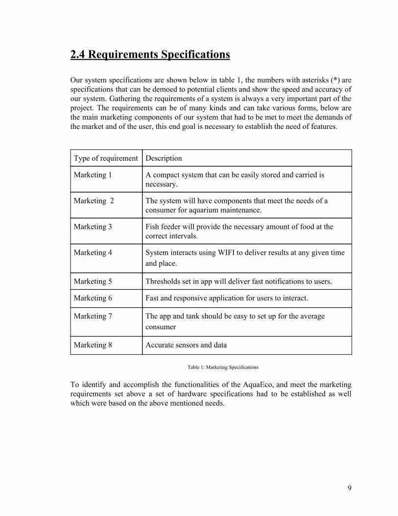
2.4 Requirements Specifications Our system specifications are shown below in table 1, the numbers with asterisks (*) are specifications that can be demoed to potential clients and show the speed and accuracy of our system. Gathering the requirements of a system is always a very important part of the project. The requirements can be of many kinds and can take various forms, below are the main marketing components of our system that had to be met to meet the demands of the market and of the user, this end goal is necessary to establish the need of features.
Type of requirement Description
Marketing 1 A compact system that can be easily stored and carried is necessary.
Marketing 2 The system will have components that meet the needs of a consumer for aquarium maintenance.
Marketing 3 Fish feeder will provide the necessary amount of food at the correct intervals.
Marketing 4 System interacts using WIFI to deliver results at any given time and place.
Marketing 5 Thresholds set in app will deliver fast notifications to users.
Marketing 6 Fast and responsive application for users to interact.
Marketing 7 The app and tank should be easy to set up for the average consumer
Marketing 8 Accurate sensors and data
Table 1: Marketing Specifications
To identify and accomplish the functionalities of the AquaEco, and meet the marketing requirements set above a set of hardware specifications had to be established as well which were based on the above mentioned needs.
9

Below is our hardware specifications to meet demand:
Specification type
Description
Hardware 1 The system’s dimensions should not exceed 10’’11.5’’ 6’’
Hardware 2 PH sensor should read ph levels between: 7.6 and 8.4
Hardware 3 Thermometer should measure up at least within a range of 50-100 degrees Fahrenheit
Hardware 4 Turbidity sensor should measure up to at least 100 NTU.
Hardware 5 The fish feeder should have an operating speed of at least .12 seconds with a stall torque of at least 17.5oz /in.
Hardware 6 The fish feeder will handle depositing food at least 1 time per 30 minutes.
Hardware 7 The microcontroller should use the Wireless LAN 802.11b/g standard to communicate to a server
Hardware 8 Ph sensor, tubidity, and temperature sensors should be accurate to within 7 percent.
Table 2: Hardware Specifications Our software specifications are also as follows:
Specification type Description
Software 1 Alerts should be received when thresholds set through the app are reached within 1 minute.
Software 2 Application should not have loading screens exceeding 2 seconds
Software 3 Set up time should not exceed 10 minutes
Software 4 Easy to use GUI that will display information to users
Table 3: Software Specifications
10

Taking these marketing requirements we then mapped them to their appropriate hardware and or software component and explained the reasoning behind the choice of including the hardware requirement.
● Compactable, easily storable, and easily carryable: ○ Dimensions of the product should not exceed 8” x 5” x 6”
One of most common and desirable characteristics of products from a consumer perspective is for the design to be as compact as possible, for ease of use and greater potential for storage. Limiting the dimensions of the aquarium system would provide these benefits in the case of the customer needing to move their aquarium, and would also allow for an easier setup that would be able to fit into more sizes of aquariums.
● Containing components that meet the needs of a customer for aquarium maintenance
○ pH Sensor ■ Should read pH levels between 7.6 and 8.4
○ Thermometer ■ should measure up at least within a range of 50-100 degrees
Fahrenheit ○ Turbidity Sensor
■ Should sense up to at least 100 NTU Naturally, the condition of the water is a primary concern of the aquariums, and directly affects the health of the fish. While maintaining the proper pH, temperature, and turbidity levels of the water is crucial, it can be difficult for the owner to distinguish these qualities without equipment. Including the sensors within the aquarium system would alleviate the workload off of the customer by providing them information on three of the most vital attributes of the water so that they would not have to periodically test it themselves. Using an Android app, the user is able to remotely monitor these sensor values, and will be informed if any action is necessary.
● Fish feeder that dispenses food at correct intervals ○ Operating speed of at least 0.12 seconds ○ Stall torque of at least 17.5 oz./in. ○ Adjustable interval time up to one activation per 30 minutes
Another task that must be done when taking care of fish is feeding them. This fish food dispenser is programmable through an application to set a specific period of time that the feeder will count down before activating. When the timer goes off, fish food from a holder will be deposited into the tank, dispensing at a steady rate until the preset amount that the owner inputs beforehand is dropped. The device having the specifications above ensures that the intended amount of food is given consistently, also reducing the time owners would have to tend to the aquarium, or allowing them to take extended trips away from their home or business.
11
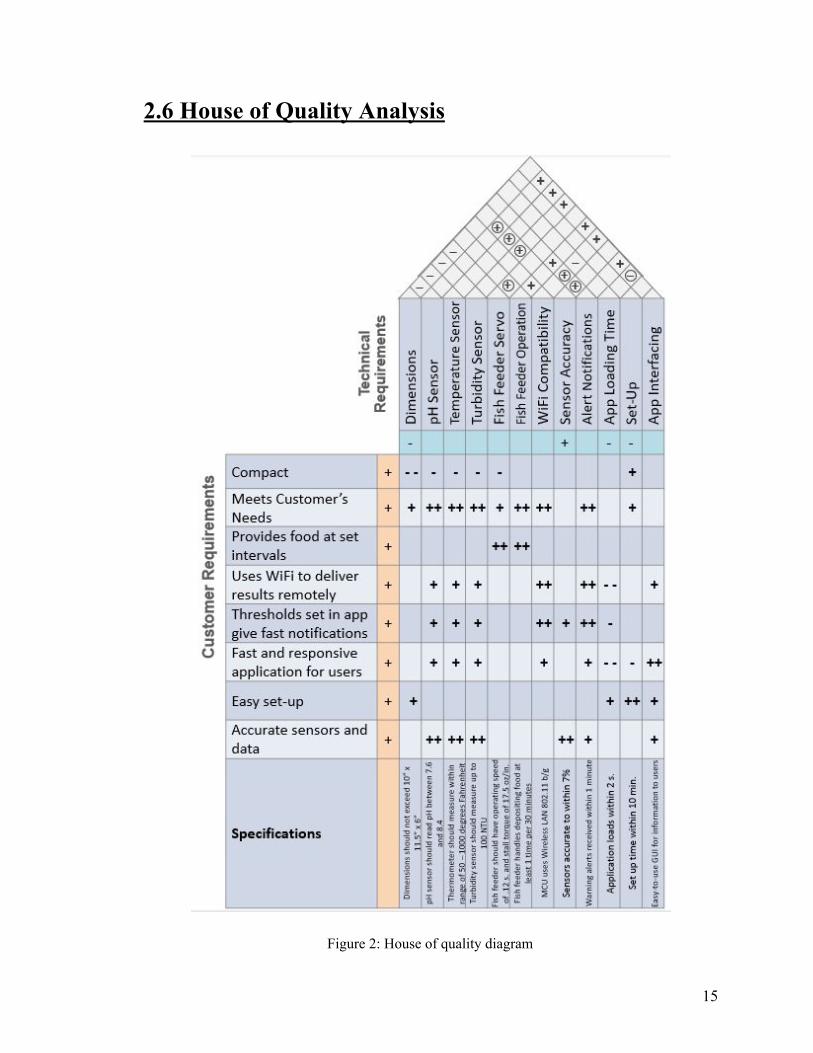
● Wi-Fi interactivity that allows the system to deliver real-time results anywhere
○ Microcontroller uses the Wireless LAN 802.11b/g standard for server communication
When the user is far away from the AquaEco, they may want to check on the
conditions of the aquarium or change settings of the devices within the system. Wi-Fi compatibility gives the owner freedom to easily control and monitor the product without having to manually interact with each interface of the devices. This is accomplished by setting up the device to connect to the user’s home Wi-Fi network. Then, the Android app is able to ping the tank (which acts as a server of sorts) from anywhere in the world, and the tank must respond with information about the status of the tank.
● Notifications through an app that will alert the user if conditions of the aquarium fall short of or exceed set thresholds
○ Alerts will warn the user within a minute if conditions are irregular With the idea of wanting to give aquarium owners the ability to manage the tank remotely, notifications with the AquaEco app will help ease the worry of owners of being away from the aquarium for too long. The application will alert the user if certain conditions detected by the system devices are below or beyond the levels set by the user via the app as well, which would prompt and allow them to remotely set changes to correct the problem with. The notifications will be sent within a minute of irregular conditions to give users fast monitoring without having to open up the app, and will allow users to take action as soon as possible.
● Fast and responsive application for users to interact
○ The application will not have loading screens exceeding 2 seconds The application is the method in which the user can receive notifications and change settings of the AquaEco through. To increase user-friendliness and utility, current trends and demands for other applications were be researched and considered when developing. Since long-distance controllability is a main feature of this product, it is important to prevent or mitigate any frustrations that may arise when dealing with the AquaEco application and discourage the user from utilizing it. Loading screens of 2 seconds or less were implemented into the app to give quick responsiveness and ensure that the customer will not have to wait and spend excessive time interacting with it.
● Easy setup for the app and tank ○ Average setup time should not exceed 10 minutes
By giving the AquaEco a fast average setup time, this widens the range of potential customers since it doesn’t require a lot of specialized knowledge or skills to get it working. Having an easy setup also benefits the previously mentioned feature of compact size, which allows the AquaEco to be set up in various dimensions of fish tanks. The
12

modern popularity of app compatibility and control means that to make the project stand out from the other products, quick setup should be a significant selling point.
● Fast and responsive application for users to interact. ○ Easy to use GUI that will display information to users
One of the most important aspects of an application in the current day and age is the GUI or graphical user interface. This is the main screen that the user uses to interact with and can make or break the experience of the application with the user. One of our biggest aspects is usability. With easy to use buttons and non-complicated interface we aimed to provide readings in a clean manner that will make sense to the user while also giving options like reading temperatures in different units or showing information about various fish that might be in the tank.
● Accurate data and sensors ○ Sensors should be accurate to within 7%
Giving as accurate information as possible is a necessity when caring for the wellbeing of fish, especially for aquariums where sensitive conditions and environments are . To provide as stable and healthy conditions as possible, notify the user of considerable changes in qualities of water when needed, and allow the system to make correct adjustments with its devices, the sensors of the system should always be within an accuracy range of 7% to that of the set parameters.
2.5 Overview Block Diagram As shown below we aim to have a system that meets these needs in terms of communication and interfacing. From the power supply we supply power to the main components including the sensor and feeder, and from the microcontroller we supply the information via data transfer services like tcp and http. This diagram's main purpose is to showcase the different roles the user has in the overall system structure, we note the differences but note that these might change as people try to learn new things or want to deviate from their typical structure. This high level image also shows how we have met the marketing requirements as the design of the system correlates to the above mentioned specifications.
13

Figure 1: Overview block diagram
14
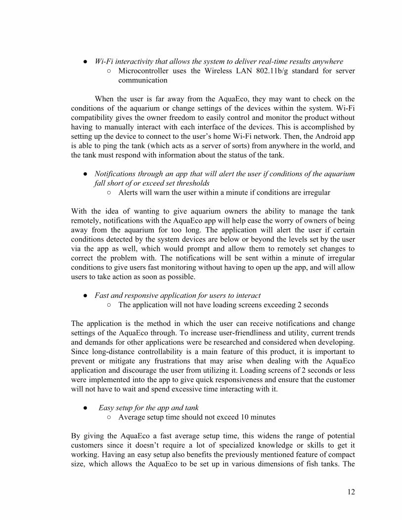
2.6 House of Quality Analysis
Figure 2: House of quality diagram
15

Figure 3: Explanations for house of quality symbols
The House of Quality diagram outlines the relationships and correlations between the many quantitative and qualitative considerations necessitated by the customer and technical requirements, including features that are directed towards providing benefits to potential customers and requirements that are the main concerns of the project from a production viewpoint. By looking at the table, it can be seen how the different characteristics interconnect and affect each other. This visual exists to outline how meeting certain needs in one area can affect our ability to meet needs in other areas. In addition, it serves as a way to demonstrate our goals and priorities to potential customers. The most important aspects for the customer are probably Remote Access, Ease of Use, and Low Maintenance.
16

3.0 Research and Definition With many different products pre existing in the market already, we needed to make sure that with the select components we have chosen, that we are able to stand out for many of those already pre existing. First however, we had to make sure our product met not only the needs but the goals we had set out to accomplish at the start. These include providing automotive hardware, and incorporating sensors that can be monitored through the application. The reason for the choosing of the type of sensors and which hardware solutions to add are going to be explained in the following sections.
3.1 Existing Similar Projects and Products Many products exist which share certain components our projects design however, these products fail to incorporate all the components needed for a completely smart system.
● Seneye device:
The seneye device aims to alert the user on the current state of their aquarium. The device’s staple technology is its ability to communicate information from various sensors to the user via cloud technology. The device boasts the ability to conveniently display information on the tank to the user in real time. Also gives the user the ability to view the systems data in graph form. System test for not only pH but ammonia content. The system offers users the ability to add different add-ons to the system. The system comes equipped with all the lights necessary to provide the tank with enough light to be healthy. Not only does the system come equipped with lights but it comes with a spectral analyzer to see in real time how the light is truly affecting the fish tank. The Seneye system includes a water level test which can also alert the user if the water level drops or raises above the set level of the user. The AquaEco system aims to accomplish the task of alerting the owner of the system whenever it escapes the user set parameters.Both systems staple technology is the ability to alert the owner of the system by wifi. We found that the addition of an ammonia sensor would not be cost effective for our system and not worth including in the design.
● Fishbit:
The Fishbit device is an app based sensor system which allows the user to view different characteristics of the fishtank through the use of sensors and a phone based application. Real time pH and salinity monitoring makes the system ideal for saltwater environments. The Fishbit device is not tank based; it is a somewhat small probe which the user drops into the fish tank. The device also comes equipped with multiple outlet sockets which can also be controlled by a mobile device. The fishbit device takes an interesting approach on alerting the user of the conditions of the tank however, this approach causes clear faults in the design of the device which causes loss of functionality. While the fishbit device accomplishes many of the same goals as the
17

AquaEco system the overall design causes the fishbit device to fall short. The device does not specify the size of the required fish tank and does not include the option to specify the size of the user's aquarium. This device fits into the aquarium so wifi connectivity will be weak because water absorbs all waves near 2.4 GHz in frequency. The device also fails to mention the possibility of water damage to the system. The main components of the system fit in the aquarium but still the system needs to be plugged in. Clearly this input power setup is not only unideal for the system but completely dangerous to anyone who would purchase the system.
● Bluenero
Bluenero seeks to accomplish the same alert system as the previous project. However, Bluenero attacks the problem head on in a realistic manner. Incorporating a pH and turbidity sensor and well as establishing a cloud network to share information with the user of the application. The problem with Bluenero is its completely unrealistic price. The current price for a single Bluenero is around $25,000.00 USD. Obviously this price is not worth the time that the aquarium saves. The biggest difference between Bluenero and AquaEco is clearly the price difference.
There is no known product which simultaneously implements all the tasks set out by our product design. While there may be multiple products which accomplish individual tasks, there is not a system which combines all the different functions including having both automation control and monitoring systems. Since our product does not have a comparable system currently available, our system will be compared to products which complete individual tasks similar to individual functions of our system. The different products total efficiencies and cost will be compared to the functionality and cost of our systems individual functions. These products can be seen in the following section.
Individual products functioning independently:
Fish Mate F14 Aquarium Fish Feeder:
● Each refill feeds fish up to 14 individual times ● Low energy usage (1-year+ off 2 AA battery) ● Other models have option of outlet power ● More expensive models alert owner when unit is out of food ● Keeps fish food dry ● Cost: 30.00$ ● Tanks up to 150 liters ● Weight: 6.6 ounces ● Dimensions: 4.7 x 5.5 x 1.5 inches
Aqua Culture Aquarium, 10 gallon
● High-strength silicone
18

● High quality material ● Inexpensive price ● 2.2 pounds when empty ● 85.6 pounds when completely full of water ● Cost $24.00
OCEANIC SYSTEMS INC. All Glass Aquarium AAG10021 Tank
● Expensive ● Weights 22 pounds when empty ● Weighs 188.8 pounds when full of water ● Dimensions: 30.2 x 12.5 x 12.8 inches ● Cost $105.00
FREESEA 1.4 Gallon Betta Aquarium Fish Tank with LED Light and Filter Pump
● Equipped with led lights ● Complete filtration system ● Only freshwater tank ● 5V USB power ● Very small ● Light weight
HDE Automatic Fish Feeder for Fish Tank Aquarium [WIFI Enabled, Programmable Timer]
● Works with any aquarium ● Powered by Micro USB Cable and AC wall plug ● Allows for feeding while out of the house ● Cost $23.00 ● Allows for irregular feeding schedules. ● Completely programmable when wifi is unavailable
5V Relay
● 5V trigger voltage ● Tolako 5v Relay Module for Arduino ● 5V - 12 V control signal of the TTL ● Control DC / AC signal ● Weight: 0.8 ounces ● Dimensions: 3 x 1.8 x 0.2 inches ● Brand name: TOLAKO
HM Digital PH-80 HydroTester Series pH Aquarium Meter with Thermometer:
● Dimensions: 2 x 1.5 x 8 inches ● Weights: 1.9 ounces ● Type: saltwater/freshwater ● Measures water pH levels from 0 to 14
19

● Auto-off function helps preserve battery life ● Accuracy: +/- 0.2 pH; Temperature accuracy is +/-2% ● Power: 3 x 1.5V button cell batteries ● Price $40.00
6 in 1 Water Quality Tester Monitor pH Meter Aquarium Water Meter for PH / Temperature / EC / CF / PPM / TDS XIN
● Inexpensive price of $52.00 ● Long shipping time ● Easy calibration ● Single charge can last over 10 hours ● FCC certified ● Over 6 different functions ● Checks temperature up to 122F
OBS300 Turbidity Sensor:
● Height: 13.1 cm (5.15 in.) ● Width: 2.5 cm (0.98 in.) ● Weight: 181.4 g (0.4 lb) ● Accuracy: 2% of reading or 0.5 NTU ● Operating range: 0° to 40°C ● Concentration accuracy: 2% of reading or 1 mg/l ● Total cost $95.00
HDE LCD Digital Aquarium Thermometer:
● Dimensions: 2.5 x 1.5 x 0.5 inches ● Weight: 0.5 lbs. ● Type: Saltwater/Freshwater ● Up-to-the-minute accurate temperature readings within 0.1 degree in both
Fahrenheit and Celsius ● Total cost $10.00
MINGER LED Strip Lights, 16.4ft RGB
● 16 multicolored options ● Colors and speed automatically and periodically ● Non-waterproof ● Safe material ● Not microcontroller controllable ● 150 premium 5050 SMD Leds ● Affordable ● Total cost: $17.00
20

Koval LED Aquarium Light:
● Dimensions: 36 x 5 x 0.75 inches ● 156 bright LEDs with 5 colors, full spectrum LEDs ● Weight: 2.07 pounds ● Type: saltwater/freshwater ● Full-spectrum array combines white, blue, pink, red and green LEDs ● LED lighting lasts 50,000 operational hours ● Features nighttime effect ● Multiple sizes ● Non-battery powered ● Cost $65.00
Tetra Correct Ph 7.0 Tablets for Aquarium Water: ● 100% effective in determining waters pH balance ● Requires no machinery but must be done in person ● Extremely cost effective ● Requires knowledge of product to use ● Lasts 8 months per $2.50 box
Although a combination of all these products would provide the same overall result as our system, it is clear that this combination is not cost effective and very unlikely to be able to compete with a completely synchronized microcontroller system. Along with the previous disadvantages, the combination of products listed above will not be able to be adjusted or controlled by wifi enable devices.
3.2 Relevant Technologies In researching information for creating the AquaEco Fish Tank we found that there are many important technologies which are relevant to our plans and ultimate design. Many of these technologies have important impacts on our options for how different requirements and goals for the project must be met. Additionally, a number of these technologies fill similar roles, and as such they must be compared for the purposes of determining which fit our needs best.
3.2.1 Wireless Communications Many embedded systems have great need for access to wireless communications, and the AquaEco is no exception. As an Internet of Things related product, AquaEco naturally requires the ability to communicate wirelessly with our Android app. There are 2 main communications technologies that we have considered for our needs - Wi-Fi and Bluetooth.
21
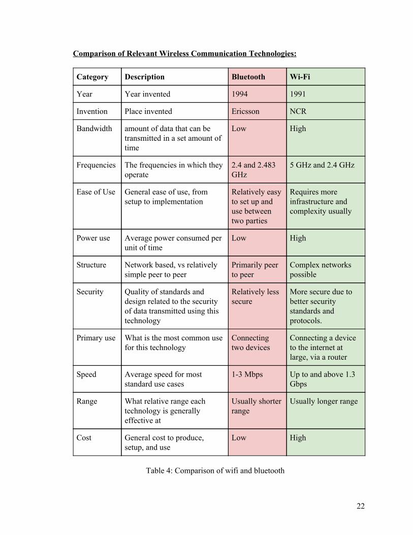
Comparison of Relevant Wireless Communication Technologies:
Category Description Bluetooth Wi-Fi
Year Year invented 1994 1991
Invention Place invented Ericsson NCR
Bandwidth amount of data that can be transmitted in a set amount of time
Low High
Frequencies The frequencies in which they operate
2.4 and 2.483 GHz
5 GHz and 2.4 GHz
Ease of Use General ease of use, from setup to implementation
Relatively easy to set up and use between two parties
Requires more infrastructure and complexity usually
Power use Average power consumed per unit of time
Low High
Structure Network based, vs relatively simple peer to peer
Primarily peer to peer
Complex networks possible
Security Quality of standards and design related to the security of data transmitted using this technology
Relatively less secure
More secure due to better security standards and protocols.
Primary use What is the most common use for this technology
Connecting two devices
Connecting a device to the internet at large, via a router
Speed Average speed for most standard use cases
1-3 Mbps Up to and above 1.3 Gbps
Range What relative range each technology is generally effective at
Usually shorter range
Usually longer range
Cost General cost to produce, setup, and use
Low High
Table 4: Comparison of wifi and bluetooth
22

Why do we need wireless communications for our project? One of the most important requirements of the AquaEco Fish Tank is that it should be able to communicate with our Android app in order to report the status of the tank and give the user control over the tank’s functions. For this to be possible, we must incorporate some kind of wireless communication technology into our system. Additionally, this should be possible from anywhere in the world, not just near the device. On the following page is a table comparing our two most relevant wireless communications technologies. Bluetooth Bluetooth is a wireless communications technology that was originally designed to function as a wireless alternative to RS-232 cables. Previously, the IEEE upkept a standard for Bluetooth as IEEE 802.15.1, but this standard is no longer maintained. Today, Bluetooth is managed by the Bluetooth Special Interest Group (SIG). The Bluetooth SIG, which has over 35,000 companies as members, manages the current standards and specifications for Bluetooth. Bluetooth exists primarily as a means to connect two devices wirelessly in order to transmit data, though the standard is designed to allow up to 8 devices to connect in a small, localized “piconet.” Originally, it was envisioned for use in wireless headphones. However, since then many other uses have come about. Bluetooth today is used in devices like printers, mice, data storage devices, and many other things.
Bluetooth is designed for low power consumption, and has short range using relatively low-cost transceiver microchips. The frequencies used by Bluetooth devices are between 2.4 GHz and 2.483 GHz, with guard bands on the top and bottom 3.5 MHz and 2 MHz, respectively. These frequencies are part of the Industrial, Scientific, and Medical (ISM) frequency bands, which are designated as being immune to the requirements of FCC licensing. Additionally, because of the high frequencies used, Bluetooth does not require line of sight for successful operation. However, the device must be within a relatively close range (typically from 1 to 10 meters, for most devices), and attenuation due to walls and reflections can often lower the effective range.
For our purposes, the main difference between Bluetooth and Wi-Fi is that Bluetooth is not designed to operate using a centralized access point to organize communications, like Wi-Fi. Instead, Bluetooth is designed to operate primarily in a master and slave communication architecture. What this means is that one device is designated as the primary device in control of operation, and communications are generally restricted to being between these two devices, and at short range. The concept can be visualized with the following figure:
23

Figure 4: Bluetooth Communication network example
In this example, a laptop computer serves as a master, which communicates using Bluetooth with the printer (which is a slave) and the camera (which is a slave) individually. The printer and camera are not connected to each other. Instead, any communications that they may need to perform is organized and managed by the master device, the laptop. In this sense, this example forms a simple piconet, which is defined as an ad hoc network that links wireless devices using Bluetooth protocols. According to these protocols, a master should be able to support up to 8 concurrent connections to other devices. However, not all Bluetooth devices conform to this protocol, depending on circumstances and design. For these reasons, Bluetooth is well suited for making short distance and short term connections between relatively few devices, where transmission speed is not the highest priority. However, it is not well suited to projects requiring long distance communication. For this reason, Bluetooth would not be the best choice for the AquaEdu. This is because one of the biggest requirements for the project is that the user must be able to check the status of their tank from anywhere connected to the Internet. Therefore, the tank must be able to connect to the internet at large, and then communicate with the Android app. Bluetooth is not designed for connecting to the end user’s Local Area Network (LAN), which is most commonly built on Wi-Fi technology, for the purposes of communicating with the Internet. Requiring the user to be near enough to the tank for them to be in Bluetooth communications range ruins the whole point.
24

Wi-Fi The more relevant technology for our needs is Wi-Fi. Wi-Fi is based on the IEEE 802.11 standards family, and is generally used for Local Area Networking (LAN). It serves as the primary and most common form of wireless communication for the purpose of connecting to the Internet for the average household or enterprise environment. The term Wi-Fi is a trademark of the Wi-Fi Alliance, which is a nonprofit organization composed of more than 375 companies that certifies the conformity of Wi-Fi products for interoperability and to ensure compliance with IEEE 802.11. Wi-Fi was originally coined as a pun on hi-fi (high fidelity), which was a term used to describe high quality audio. However, Wi-Fi was never intended to be a shortening in and of itself, despite instances of it being referred to as Wireless Fidelity. The majority of modern computing devices that are designed with the intention of connecting to the internet do so with at least some amount of Wi-Fi capability.
Wi-Fi, like Bluetooth, has a relatively short range. There are two frequencies used
for Wi-Fi: 2.4 GHz and 5 GHz.
2.4 GHz
● Works at a longer effective range than 5GHz. This is because lower frequency signals are better at penetrating solid objects and walls than higher frequency signals.
● Lower frequency means a generally slower transmission rate for data compared with higher frequencies.
● In the United States, only 11 channels are legally usable. ● Generally, there is more interference when using the 2.4 GHz bands, because
more devices use this band. 5 GHz
● Has a lower effective range than 2.4 GHz because higher frequencies are worse at penetrating walls and solid objects.
● Can provide a generally faster transmission rate compared to lower frequencies. ● Can have a potentially very large number of channels, or few wide channels.
Channel planning is more complex. ● The 5GHz bands have generally less interference because less devices use them.
They may also have larger bandwidth, depending on channel planning.
These frequencies are both part of the Industrial, Scientific, and Medical (ISM) frequency bands, which are designated as being immune to the requirements of FCC licensing. Also like Bluetooth, because of the high frequencies used, Wi-Fi does not require line of sight for successful operation. However, the device must be within a relatively close range (typically from 1 to 10 meters, for most devices) to the access point or other device, and attenuation due to walls and reflections can often lower the effective range. Compared to
25

Bluetooth, Wi-Fi almost always has a much faster speed for transferring data between two devices.
In function, Wi-Fi shares many similarities with Ethernet, its wired analog, which is defined under the IEEE 802.3 standard. The most common use for the Wi-Fi protocols is for the purpose of connecting multiple devices together in a LAN communications architecture, usually as a means to ultimately connect to the Internet. Unlike Bluetooth, Wi-Fi is not designed to primarily use a master-slave architecture. Instead, Wi-Fi is most commonly used in the context of a LAN, or some other large and complex network. In this setup, a single access point (also called the Router) serves as the hub for communication between devices on the network and acts as the gateway for data travelling out of the network to the internet at large. The following figure demonstrates this concept:
Figure 5: Communication between router and components
26

In this example, the Router is connected to the internet by an outgoing connection to the user’s ISP. Each node in the network, such as a laptop, desktop, smartphone, or tablet, communicates with the router using the Wi-Fi communication protocols. Then, the router routes the transmitted data to its destination, whether that’s another device on the network or a device located external to the network, on the internet at large.
Because of this, WiFi is most commonly used for long term networks connecting a much larger number of potential devices than Bluetooth can manage, while usually also allowing a connection to the rest of the internet for a wireless device. Since most Wi-Fi connections use an access point, this makes them more expensive and more complex to set up than simple Bluetooth. Wi-Fi’s general usage of connecting a device wirelessly to a local Router, and from there communicating with the internet at large, is the main reason for why we chose to use it in the AquaEco project. The main need for wireless communications for this project is that the microcontroller in the tank must be able to connect to the app from anywhere connected to the Internet, so that it can provide status information and receive commands. This is performed by having the device connect to the user’s home network. However, one roadblock in this manner is that in order to connect to a network, a device must first have the network’s SSID and password. Since every network is different in this regard, the user must have a way to provide the tank with the necessary credentials to access the network. Luckily, Wi-Fi also has methods by which a device can act like a Router and create an ad hoc network for another device to connect to, solely for the purpose of direct communication between the two devices. This is what is used by the app to set up the tank. With this system, the end user is able to find out the status of their tank from anywhere that they have an Internet connection.
27
3.2.2 Serial Communication
The vast majority of embedded systems require some form of serial communication. From retrieving sensor readings to writing to user output devices, from reading data from user input devices to communicating with external hardware, many systems must use some form of serial communication to achieve their needs and to facilitate work utilizing multiple components that function independently. Other protocols exist besides serial protocols. These are called Parallel Protocols. Unlike serial protocols, which rapidly transmit data one bit at a time across a wire, parallel protocols have eight, sixteen, or even thirty-two wires, sometimes with additional control wires, to transmit many bits at once. Parallel protocols are much simpler to implement and result in a much faster data transfer rate than serial communications. However, their main downside is that, by definition, they require multiple pins in parallel to be effective. Unfortunately, one major limitation of embedded processors is their lack of large numbers of ports. Therefore, while parallel communications protocols would be simpler and faster, they are impractical for embedded systems environments such as our project.
Over the years, many serial communication protocols have been developed for numerous purposes. Two of the most well known protocols are the Universal Serial Bus (USB) and 802.3 (Ethernet). For our purposes there are 4 serial communication protocols that could be relevant to our project: SPI, UART, I2C, and Dallas Semiconductor’s 1-Wire. Following is a tabular comparison of each protocol. The following pages show a tabular comparison of each of these 4 protocols.
Why do we need Serial Communications?
Our system has multiple sensors and a wifi chip connected to it. These all communicate with our controller in a number of different ways. Analog sensors require an Analog to Digital Converter (ADC), which then communicates sensor readings to the microcontroller via a serial communication protocol. Our Wi-Fi chip handles all of our Wireless communication needs, but in order to communicate with the chip, our solution needs to utilize a serial communication protocol, depending on which protocol the chip is designed to use. Therefore it is wise to research each protocol, to help inform our decision as to which chip to use.
28

Serial Communication Protocols:
Category Description UART I2C SPI 1-Wire
Year invented Year invented 1960 1982 1970 <1998
Invented by Invented by whom
Gordon Bell Phillips Motorola Dallas
Complexity Overall general complexity
Simple Easy for chaining devices
More complex with more devices
Simple
Duplexity Half Duplex, Full Duplex, or Simplex
Full Duplex Half Duplex
Full Duplex
Half Duplex
Asynchronous No clock, stream uses start and stop signals
True False False True
Synchronous Clock is used to synchronize transmission
False True True False
Speed Speed for transmitting data
Slow Faster than UART
Fastest Slowest
Multiple Masters
Multiple masters can control one slave
False True False True for some use cases
Multiple Slaves
Multiple slaves can be controlled by one master
False True True True for some use cases
Error Checking
Has error checking protocols
True True False False
Table 5: Serial communication overview
29

Category Description UART I2C SPI 1-Wire
Number of Wires
Wire count 1 2 4+ 1
Max Throughput
Bits/Second that can be transmitted using highest standard speed
Up to 92160 bps, depends on Baud rate
3200000 bps
Up to 60000000 bps
16300 bps
Addressing Slaves must each be given unique addresses
False True False False
Packeted Data is transmitted in a packet or message format with headers and metadata
False True False False
Table 6: Serial communication overview
UART:
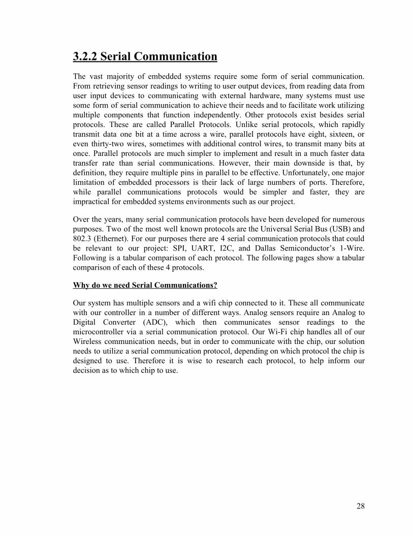
UART stands for Universal Asynchronous Receiver/Transmitter. A UART is a computer hardware device that handles asynchronous data transmission between devices usually as part of an Integrated Circuit (IC). It is most commonly used for serial communications between a computer and a peripheral device, though sometimes between other connected devices. Most microcontrollers use some form of UART technology. If a given microcontroller does not have a UART built in they are also available as their own IC. There are two sides to a UART. One side is a bus with typically eight data lines and one or more control pins which connect directly to the source and/or destination of data. The other side has two data lines: RX (receiving line) and TX (transmitting line). When sending, a UART takes the data coming from the bus and creates sync and parity bits for error checking, and then transmits that data across the TX line one bit at a time. When receiving, a UART samples data on its RX line and checks for errors, before translating the data back into the original data, which is then propagated onto its bus. The speed at which bits are set on the sender’s TX line and then sampled on the receiver’s RX line is called the Baud rate, which is a measure of the number of bits transmitted per second. A Baud rate of 9600 corresponds to 9600 bits sent and sampled per second. The communication between two UARTs looks similar to the figure below.
30
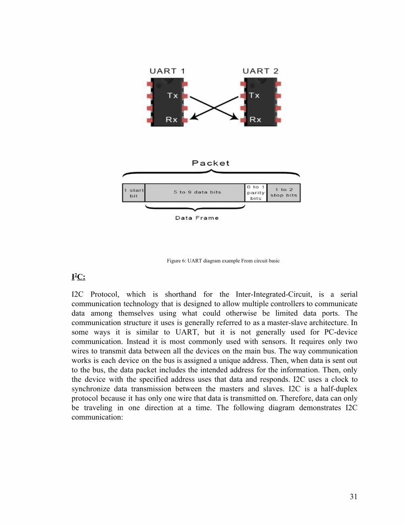
Figure 6: UART diagram example From circuit basic
I2C:
I2C Protocol, which is shorthand for the Inter-Integrated-Circuit, is a serial communication technology that is designed to allow multiple controllers to communicate data among themselves using what could otherwise be limited data ports. The communication structure it uses is generally referred to as a master-slave architecture. In some ways it is similar to UART, but it is not generally used for PC-device communication. Instead it is most commonly used with sensors. It requires only two wires to transmit data between all the devices on the main bus. The way communication works is each device on the bus is assigned a unique address. Then, when data is sent out to the bus, the data packet includes the intended address for the information. Then, only the device with the specified address uses that data and responds. I2C uses a clock to synchronize data transmission between the masters and slaves. I2C is a half-duplex protocol because it has only one wire that data is transmitted on. Therefore, data can only be traveling in one direction at a time. The following diagram demonstrates I2C communication:
31
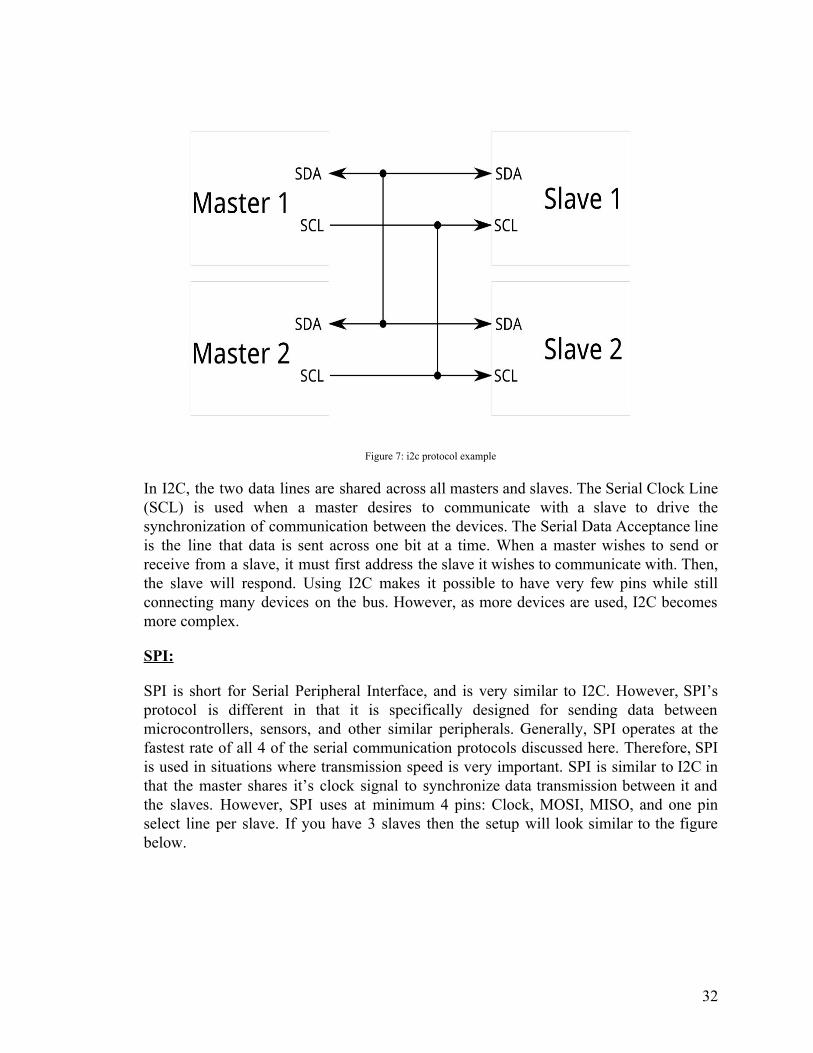
Figure 7: i2c protocol example
In I2C, the two data lines are shared across all masters and slaves. The Serial Clock Line (SCL) is used when a master desires to communicate with a slave to drive the synchronization of communication between the devices. The Serial Data Acceptance line is the line that data is sent across one bit at a time. When a master wishes to send or receive from a slave, it must first address the slave it wishes to communicate with. Then, the slave will respond. Using I2C makes it possible to have very few pins while still connecting many devices on the bus. However, as more devices are used, I2C becomes more complex.
SPI:
SPI is short for Serial Peripheral Interface, and is very similar to I2C. However, SPI’s protocol is different in that it is specifically designed for sending data between microcontrollers, sensors, and other similar peripherals. Generally, SPI operates at the fastest rate of all 4 of the serial communication protocols discussed here. Therefore, SPI is used in situations where transmission speed is very important. SPI is similar to I2C in that the master shares it’s clock signal to synchronize data transmission between it and the slaves. However, SPI uses at minimum 4 pins: Clock, MOSI, MISO, and one pin select line per slave. If you have 3 slaves then the setup will look similar to the figure below.
32

Figure 8: SPI Layout - Wikipedia
SCLK is the clock signal generated by the master, which is shared among all slaves. MOSI is short for Master Out Slave In, which is a monodirectional line used to send data out from master to slaves bit by bit using the clock. MISO is short for Master In Slave Out, and is a monodirectional line used to send data in from slaves to master bit by bit using the clock. Both are shared between all slaves. SS1, SS2, and SS3 are control signals used to select which device the master wishes to communicate with. When one of these slave select signals is high, that slave is considered “on,” and will use and respond to data. In this way, SPI is considered Full-Duplex, because data can be sent and received at the same time. Unlike I2C, there is no addressing system. To select a slave device, the master must simply set the corresponding pin to high. Because of this, the protocol to implement SPI is much simpler than UART and I2C, and because of the synchronization, much faster than UART in particular. However, the downside is that SPI uses more pins than UART and I2C.
1-Wire:
1-Wire, is a serial data communications protocol designed to use only one wire to communicate between a master and a slave. Designed by Dallas Semiconductor some time during or before 1998, 1-Wire provides low-speed data and power over a conductive surface. It’s most typical uses are for weather devices, thermometers, and very small ID oriented electronics. One thing 1-wire is particularly distinguishable for is its ability to use only 2 lines total - one for data and one for ground. Many 1-wire devices utilize a capacitor to store charge while data is high in order to power the device. Similar to I2C, 1-wire uses device addressing. Each 1-wire device is permanently assigned a 64 bit address, which means there are 264 possible device addresses. When the master wishes to communicate with a particular device, it can send an addressing command. Then, only the desired device will respond. The following diagram shows the protocol used to send data.
33
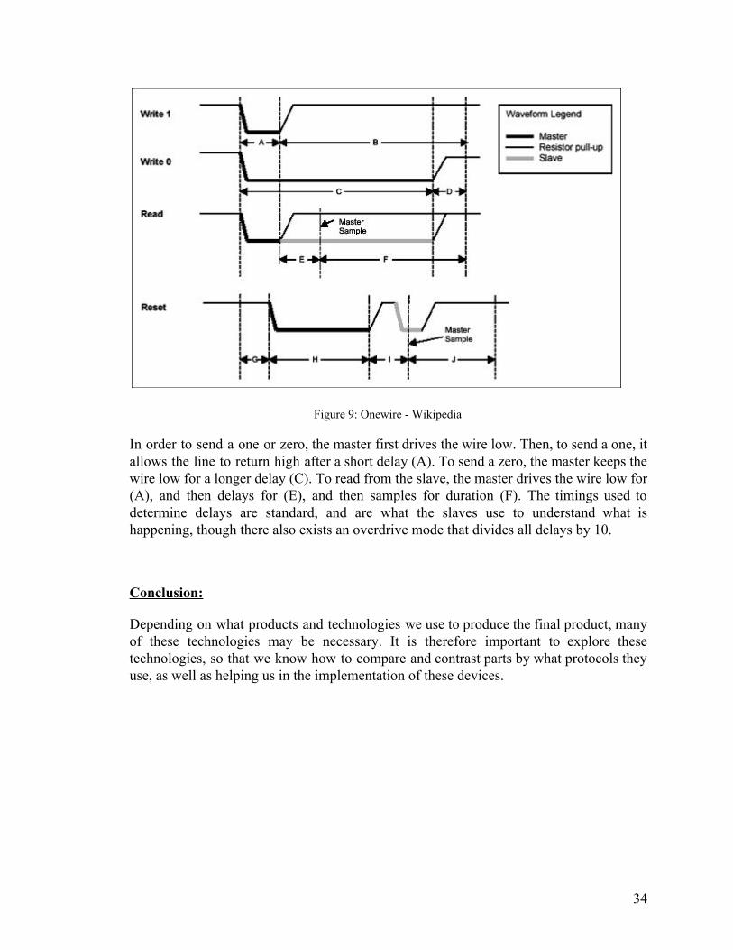
Figure 9: Onewire - Wikipedia
In order to send a one or zero, the master first drives the wire low. Then, to send a one, it allows the line to return high after a short delay (A). To send a zero, the master keeps the wire low for a longer delay (C). To read from the slave, the master drives the wire low for (A), and then delays for (E), and then samples for duration (F). The timings used to determine delays are standard, and are what the slaves use to understand what is happening, though there also exists an overdrive mode that divides all delays by 10.
Conclusion:
Depending on what products and technologies we use to produce the final product, many of these technologies may be necessary. It is therefore important to explore these technologies, so that we know how to compare and contrast parts by what protocols they use, as well as helping us in the implementation of these devices.
34

3.3 Strategic Components and Hardware Selections AquaEco began as a system or solution to the issue of helping those first time fish pet owners and even current owners navigate their aquarium and have fish live much longer than usual. Media portrays fish owning as a simple, easy task, and pet fish as one of the ideal beginning pets. Unlike other pets like reptiles, fish are often neglected due to the misinformation spread throughout various media. Ranging from circuses giving goldfish away in small plastic bags with no other information to having fish being sold in food supermarkets. Fish are animals just like any other pet and have needs and specific requirements to live a long life. It is because of this that we wanted to have certain components in our final design. We began research by investigating what some of the initial purchases were and looked into how we could improve these using software and electronic movement.
An ideal aquarium has many components however only one is only necessary: water. The rest can be thought of additions that help the fish live much longer. Of these investigated we found that an air pump, water filter, lighting, and fish feeder were the most common. We made note of the fact that a water filter would almost always be on, filtering much of the waste the fish are producing and other dangerous chemicals found in the water. These filters cannot be improved to a substantial amount by incorporating a microprocessor, therefore we choose not to include it in our system. Likewise similar to the filter a typical air pump adds much needed oxygen to the overall aquarium system and therefore is power efficient enough to be left running at all times. Water pumps are similar to the air pumps in that they provide needed water circulation, these as well can be left on the entire time. Because a microprocessor does not add functionality to these components, we decided to incorporate only the fish feeder, as we could add custom intervals set by an application. Lighting was the next big common purchase with a fish tank and although there are a lot of different lighting that can be used and can be run at all times, it is important to note that lighting a fish tank should only be done when the fish need the extra light. Explained later, light is important to fish in precise amounts. Therefore, we added lighting to our system as we felt giving the user the ability to control when the light will be on and off and being able to do it wireless is a great addition and improves usability. We also decided to add a variety of sensors in our end system. We felt with so many new owners lacking the necessary knowledge in water chemistry and water parameters, it was crucial that either with the app or with physical sensors that we show user information that is important in the health of the fish and the characteristics of the water environment. After all, water is the most affecting component of a fish tank.
Our end hardware solution consists of sensors, lighting and the automatic fish feeder. Each component had to be chosen carefully taking into account the final design and compatibility with each other. There were many choices made based on different factors ranging from price, to reliability, to key components relating to performance. Our hardware components include the fish feeder, lighting and sensor devices, which are all hooked onto one controller bringing together these components.
35

3.3.1 Lighting considerations We began our hardware components with lighting. The main purpose of incorporating lighting into our hardware solution is because it is a very important part of an aquarium that many people might not be aware of. There are many benefits that lighting has for not only fish but for the environment it is set up in.
In terms of benefits we begin with the fish benefits. Fish are very much like any other pet in the household. They require good living conditions to live long and be healthy. These living conditions can take the form of having a well sized tank, good ph levels, and of course for certain fish, lighting. In fact goldfish have even been shown to lose their color if no proper lighting is installed. There is however a limit, and having light on for the entire day can be problematic. Fish rely on this light to fuel themselves and often will begin to act slow without this. For environmental benefits having a lighting system in the aquarium is a great way to showcase the aquarium and provide a nice aesthetic to the room. Also, because fish need light it is often a better idea to have lighting as leaving lights on in the living room will cost more money.
There are many different types of lighting that can be placed in an aquarium. To begin, there are incandescent, fluorescent, and LED bulbs which are the most common. Each has unique traits with unique pros and cons. These bulbs all serve to provide adequate lighting to the fish.
Incandescent light bulbs are the typical lighting you find at home, these fit in typical light fixtures, and other lamps. While these are the most common light you can find there are also a lot of downsides to this type of light application in an aquarium. It is true that one can simply use a lamp with this bulb to light their aquarium at a cheap price but there are drawbacks depending on the needs of the fish. For starters, this lightbulb produces a lot of heat meaning temperature regulation will be a lot harder in an aquarium like this. The extra heat also means that this light bulb will draw a lot more power than usual, incorporating this into our components would have meant that we would need a better power solution to handle this. This would have then incurred extra design and cost onto our final solution.
The next type of common lighting is fluorescent which is one of the most common used lighting throughout the aquarium industry. They are usually more expensive than Incandescent light bulbs in both the initial setup and subsequent bulbs. The benefits arise with overall power consumption because it is much less than the typical Incandescent which means the average user will end up saving more in energy cost as time continues. There are many more benefits as well, because of less power draw the bulbs are also much colder which means the temperature of the aquarium would not be constantly changing and warming up. It is much easier to make an aquarium hot and keep it controlled than it is to try and make it colder. There are plenty of water heaters available that are both more controlling and better for keeping a stable temperature over the
36

warmth the Incandescent bulbs would provide. These bulbs tend to also last much longer than incandescent light bulbs meaning less maintenance required in the long run.
Lastly the last type of common lighting we researched were LEDs, which were our ultimate final choice to use. LED lighting has become more common recently as people are realizing the benefits that they provide in many scenarios. Even in more commercial applications they are being used more and more frequently. The benefits of LED include being very compact due to the fact that it is in fact not a bulb but a diode, cheap in cost, and long lasting. This means that the LED provided the benefit that we were looking for which was providing lighting that can be controlled with an application to both light up the tank for aesthetic reasons and for providing species of fish with a light source. It is important to note that one of the biggest reasons to choose LED lighting came from the fact of its compatibility with our final hardware solution. By draining minimal power and being addressable it was much easier to work with in our final schematic and design. There are many other factors that lighting could provide an aquarium including enhancing plant growth however those solutions were not looked at.
After choosing the type of light source the final step was choosing which brand and the final part selection of the LED. LEDs come in many different forms and each have their own benefits and cons. In our case we were in search of a low cost option that was both addressable and waterproof as we were lighting our aquarium where water might splash onto the lights. We decided to find a light that exactly hit this criteria. The key aspect was addressable which guaranteed that the lights were able to be programmed using our mcu. Our final option was the alitove ws2811 Rgb lights. These are 5 volt and with easy to use addressability, would have made it easier to implement into our system. Another benefit to this model is the unique 3 connections per led that are available for each including vcc data and gnd which would have allowed us to test at an individual level. This could have been helpful in testing purposes or for different layouts for small or large tanks. We chose an already made solution for the led as it was much more cost effective than building our own led strip, with much of the system being cohesive within the application the integrated ws2811 ic chip meant that interfacing it with our processor was seamless. The choice of whether to make it permanent or not was also debated as the end hardware solution was to incorporate these elements and make sure they work together. Since LED lights are a point of failure in our system, having replacements available was important to our end goal of stability.
We summarize the findings below where we notice the highlighted final choice given the reasons we explained above. One important thing to note is the final mode is the wsb2811 lights, these are very similar to the wsb812 led light fixture.
37

Part Advantages Disadvantages
Lighting
Incandescent ● Common ● Inexpensive
● Produces a lot of unnecessary heat
● Energy inefficient
Fluorescent ● Energy-inefficient ● Produces little heat ● Longer lifespan
● Higher upfront cost with bulbs
LED ● Compact ● Energy-efficient ● Very long-lasting
● Higher upfront cost with bulbs
Table 7: Lighting selection
3.3.2 Sensor considerations AquaEco hardware solution began with the consideration of monitoring the aquarium. What precisely this meant came at a later time where we researched the many different sensors available on the market and the importance they had on the overall aquarium health. For first time users, there was a plethora of information available ranging from water temperature to amount of algae in a system. Ultimately we chose a system that consisted of carefully chosen sensors that talked to the application and provided a variety of information to the user in real time. These sensors had been picked as to help the first time user manage their fish, while also providing those long time users the option to show these three fields.
Owning an aquarium is a great deal of work if a pet owner's main goal is to have healthy long living fish. Fish have lots of needs that one might not think about. The worst part is when buying a fish at the market these extra needs are often overlooked. AquaEco wants to make sure that first time users understand basic necessities of fish by providing them with sensors that help just that. Maintaining an aquarium relies on a lot of water knowledge; just like how dogs that have thick furs would not live well in environments that are very hot, every fish is different and every fish relies on a specific set of rules so that they are able to live long lives. There are many differences in all water. Even bottled water has all been filtered differently and therefore has different chemical compounds. Chemical makeup of all water can vary from state to state, country to country and even within the same pump systems.
Fish are very sensitive animals and will react quickly to changes in their environment. Fish can become stressed, stop swimming, stop eating, or worse die if their living conditions are not suitable for them. Just like any other pet, fish require space, food, and clean water. While space and food are easy to explain to a first time pet owner one of the
38

hardest to explain has to deal with the environment the fish is in. An aquarium will be where the fish will live its entire life so it's important to make sure that it's to the highest standards. We knew that the average consumer would have a hard time during the purchase of the fish as many tend to believe that fish can live in small bowls of water just like the cartoons showed them as kids. This is far from the truth and with thousands of species of fish it becomes even harder for people to understand the effect water has on their animal friends. Fish can be either freshwater or saltwater based. Even within these subsets each fish has unique properties, just like in their natural environment no ocean or body of water is truly identical, and becomes apparent when an individual is trying to build a system. One cannot simply mix species of fish together that might not be compatible water wise. A freshwater fish will die in salt water and a salt water fish will die in freshwater. Knowing that water and its components are crucial to the survivability of the fish we narrowed down what we believed would be the most appropriate sensors for this monitoring system.
We began by first looking at every sensor available for acquiring data related to the system. We began by looking at pH levels within an aquarium which is crucially important to fish. Fresh water fish cannot live in unsustainable conditions including water that has chlorine or is too acidic or basic. pH levels refer to a scale that measures how acidic or basic a water is and is an important factor in keeping fish. This scale ranges from 1-14 where 1 is water that is the most acidic and 14 is water that is basic. In short for aquariums we only needed to make sure that this water did not go over the needed ph for the fish. This is because this scale is logarithmic and a slight movement from 7-8 means exponential growth in ph levels. These increased or decreased levels can be dangerous for the fish and cause death. Liquid pH sensors were both cheap and easy to integrate into our chosen Atmega328P. This meant that we could implement a ph monitoring system.
The next quality we looked at was ammonia. Ammonia is a combination of nitrogen and hydrogen and is classified as a colorless gas. Ammonia can exist in aquariums and is toxic to fish if exceeding 2 parts per million. Fish naturally produce ammonia via their waste and can be controlled if proper filtering and water cycles are made. It is important to note that although there are sensors available, due to complex nature and accuracy standards there does not exist a solution that measures ammonia in water that is electronic and can stay submerged in water constantly. To do an ammonia test one must use a testing solution and strips to properly measure. Because of this set back and because ammonia can naturally be controlled by lowering ph levels we instead chose to implement tips to control ammonia via the wiki section in our application rather than build a complex non feasible solution to testing for this.
The next water condition we looked at was Nitrite. Nitrite is a result of bacteria in the water of converting the ammonia we mentioned earlier. Nitrite is also harmful to fish but can be controlled with cycles and making sure ammonia levels are balanced. Fish can react badly to high levels of nitrite and exhibit behaviors like gasping for air at the surface. Unfortunately like ammonia there exists no sensor that automatically detects for
39

the presence of nitrite that can be submerged in water constantly. Nitrite is usually tested using a testing kit solution that will turn water a certain color to demonstrate the levels detected. Instead of creating a solution that might become cumbersome for the average user to use and set up we instead rely on the application giving advice based on fish behavior.
Nitrate is the next water parameter we researched and much like nitrite is a bi product of ammonia in the tank. Fish waste is the main factor that increases nitrate levels. A reading of less than 20 ppm is necessary to ensure healthy fish. There exist filters that can help with Nitrate, and Nitrite but just like the latter the only accurate way to measure it is to use a testing strip. Due to this constraint we decided that ultimately we would not be looking at ammonia,nitrite, and nitrate in our monitoring system at the hardware level but making sure the end user knows about these harmful chemical compounds and how to limit them.
The next monitor we looked at was an important parameter in the system. Rather than chemicals, we looked at temperature due to a variety of reasons. The temperature in the fish tank is extremely important to the overall fish health; too much heat will increase production of ammonia in the system which is deadly to the fish in large quantities. Apart from this, fish themselves have temperature thresholds which is the temperature they are able to handle without being sick or increasing their oxygen intake. There are many solutions available that incorporate a constant waterproof temperature device so we decided to include this metric in our end hardware solution.
Lastly, we thought about how we could monitor overall clarity in the water known as turbidity. Fish need clean water that is not cloudy or green. Either of these types of water could have a negative impact on fish health. Cloudy water is a sign that bacteria is growing in the system at a rapid pace and green cloudy water is a sign of too much algae. A Turbidity sensor comes into play by measuring the amount of light refractions occuring at a given time. We decided to include this metric as sensors are low in cost and be implemented to become waterproof and submerged.
40

Part Justification
Sensors
pH ● Cheap and easy implementation ● Small changes in pH number can mean a drastic difference in
pH level
Ammonia, Nitrite, and Nitrate
● Can be controlled through filtering, water changes, and reducing pH
● No electronic and constantly submersible implementation
Temperature ● Too much heat can increase ammonia production ● Waterproof implementation available
Turbidity ● Turbidity signals excessive bacterial or algae growth ● Low-cost, electronic, and waterproof
Table 8: Selections and justifications for sensors
3.3.2.1 PH sensor The first sensor in our system was chosen as a ph sensor. Every fish requires a range of ph to live comfortably in its water. This ph level varies from fish to fish and will be important in supplying this information within our application. Ultimately we wanted this sensor to supply data to the application where the user can choose to be notified when the thresholds that do not match their fish are hit. Then the application is able to provide hints and tips on how to combat this problem. There were many components to choosing the correct ph sensor in our system. The ph sensor we are aiming for had to be cost effective, last a long time, be compatible with the atmega cpu we were using. This led to many different options available on the market that fit all those needs. We will now be discussing these options.
The first option we looked at for a ph sensor came from a chinese distributor, and was named the liquid pho-14. This ph sensor contained both the analog sensor and board that can interface with the atmega328p processor. This is important as this meant this analog sensor had a premade processing board where it could interface with our main pcb. This made the overall cost reduce. This probe and interfacing board works well in most environments but with low quality components and very little reviews, we chose to instead increase cost but have a more reliable sensor and solution. This led us to our next option which was the Gravity: Analog pH Sensor. This sensor and board combination had all the necessary readings we were looking for including reading pH from all 14 levels and having less than 1 minute reading time.This sensor reads pH levels within +-.1 pH
41

which is incredibly important as mentioned earlier. Because pH readings are exponential a slight change can have a big effect. It was important that sensors are both accurate and reliable. It can also operate at the temperatures most tanks will also operate at. This was a highly rated sensor that can operate staying submerged for a long time due its much more highly tested components. We believed that this sensor would work well with our plan in delivering accurate ph results to the end user. The board combination was implemented onto our final pcb design for easy plug and play.
pH Sensors
Liquid Pho-14 ● Built-in analog sensor and board
● Can interface with the PCB
● Low-quality parts ● Little user reviews;
indeterminable reliability
Gravity: Analog pH Sensor
● < 1 min. reading time ● Measures within ±0.1
pH ● Operates well in
standard aquarium conditions
● Cost ● Requires need of sensor analog
conversion board
Table 9: pH sensor selection
3.3.2.2 Temperature sensor The next sensor that was to be incorporated into our system was the temperature sensor. Much like the pH sensor discussed earlier, this temperature sensor’s main goal was to provide valuable information to the user's fish. AquaEco aimed to provide an easy-to-use interface that would read the temperature and give advice if the temperature reached thresholds that were not within the limits for your fish. We began our search for a good temperature sensor by thinking about the needs of our system. Since this sensor would be submerged in water, it must have been waterproof and fully encapsulated and the sensor must be accurate. The sensor must also have been able to interface with the Atmega328P. This is because since the readings are shown to the user, it is constantly polled and displaying results. We looked at a variety of sensors ranging from different price points. Because of the waterproof restriction, this limited our sensor search quite a bit. The first sensors we looked at were from companies such as Vktech and Hilitchi. These temperature sensors had the voltage we needed which were 3.0 V ~ 5 V, but lacked support and information available online. Ultimately we decided to choose the sensor which had the most support and it led to the choosing of the DS18B20 waterproof sensor. This sensor was very cost effective and provided everything we needed. This included being waterproof, usable with the power supply, high accuracy, and a wide range that allowed us to measure any temperature needed for a tank. Apart from the sensor, there are interfaces which translate the readings into proper data that can be read by our
42

Atmega328P, and thus we chose to use the Gravity:Terminal Sensor Adapter V2.0. This design is used in our final PCB to read this temperature sensor.
Part Advantages Disadvantages
Temperature sensor
Vktech ● Proper voltage ● Inexpensive ● Accuracy
● Lacks documentation
DS18B20 ● Accurate ● Included interface ● Has proper
documentation and support
● Higher upfront cost
Table 10: Temperature sensor selection
3.3.2.3 Turbidity sensor
The last sensor we chose to incorporate into our application is known as the turbidity sensor. This sensor is important for allowing our application to know when to alert the user to a water change. Oftentimes, the pet owner does not know when to change the water, or have it cycled. This information can be presented to the user when the water reaches a threshold of turbidity which measures the clarity of the liquid.
The requirements of the turbidity sensor for AquaEcho were the facts that it needed to be waterproof, and it needed to operate within our power rails which are 5 volt in the case of the sensor. Another requirement was the fast response which would be rated at a response time of 500ms. When researching various sensors, most reached the minimum requirements we had. Because of this the only difference between brands of sensors were shipping speed, location and price. We went with the Gravity: Analog Turbidity Sensor; not only did it meet our requirements but it also was available to ship and was priced at a low cost level even for smaller batch purchases. This sensor ultimately came with an analog to digital interface board as well compatible with the Atmega328P, we incorporated the design of this board onto our final pcb design as to reduce the amount of loose wires. This sensor’s reading was converted from their analog components into digital readings where we were able to convert the results to the application the user can set up.
43

3.3.3 Fish feeder When originally creating AquaEco we wanted to incorporate features that will help people that might not be available at all times. We understand that a huge majority of people travel for work and cannot leave pets at home alone, for those individuals we wanted to make sure that they can in fact still have a pet at home. With the fish feeder implementation our goal was to make sure that people can set fish feeding schedules even away from home and can monitor when the food is running low based on estimations. The concept of a fish feeder is not new and can be found in many different pet stores for many travelers, however we felt that it was harder to find a fish feeder than is as integrated into a system as this. We intended to have the fish feeder be fully controlled via an application where the user would be able to set the intervals in which to feed the fish. This means that to design this fish feeder there were components involved including the housing, the motor and overall setup in the tank.
A fish feeder needs to supply enough food for the specific fish involved. This was solved by making the motor open and closing an opening in the housing. The amount of time it takes to leave it open was how we were able to control the amount of food supplied for the fish. If the user just has one small goldfish then we would want to give the goldfish a small amount of food. If the user wants to give more than the motor would do multiple rotations dispensing food.
To dispense the food we needed a motor, and we had multiple options available to us. To begin, we needed a motor that was both small but powerful enough to not break under the weight of the fish food. This motor was to be small due to the size of our fish feeder. Because our overall system was to be installed in a small 5 gallon tank we went with a small fish feeder. There were small motors available that had options including high torque and high speed of up to 15000 rpm and there were also smaller servo motors that might not have the speed but were much cheaper and could interface with the arduino easily. The servo motor made the most sense in our scenario, due to its unique shape and size it was easy to design an enclosure that would fit with it. On top of this we did not require the rpm the other motors had. We needed a motor that had lower mobility to allow more food to pass through, the other motors would have been too fast for this operation.
As for the housing and main design materials there were a couple options we researched. First was wood, where we could create a custom wood enclosure to house the motor and drill holes on the bottom where the servo would use a plastic shield to move food in and out. Wood is inexpensive, reliable, and easy to fabricate. However the labor involved in creating a final product might have been arduous and tools like sealants must be used to combat against water splash that might come from the fish.
44
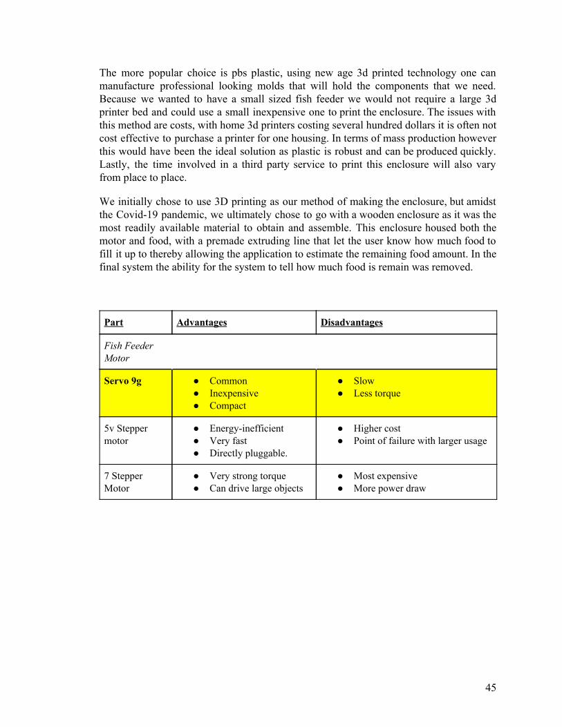
The more popular choice is pbs plastic, using new age 3d printed technology one can manufacture professional looking molds that will hold the components that we need. Because we wanted to have a small sized fish feeder we would not require a large 3d printer bed and could use a small inexpensive one to print the enclosure. The issues with this method are costs, with home 3d printers costing several hundred dollars it is often not cost effective to purchase a printer for one housing. In terms of mass production however this would have been the ideal solution as plastic is robust and can be produced quickly. Lastly, the time involved in a third party service to print this enclosure will also vary from place to place.
We initially chose to use 3D printing as our method of making the enclosure, but amidst the Covid-19 pandemic, we ultimately chose to go with a wooden enclosure as it was the most readily available material to obtain and assemble. This enclosure housed both the motor and food, with a premade extruding line that let the user know how much food to fill it up to thereby allowing the application to estimate the remaining food amount. In the final system the ability for the system to tell how much food is remain was removed.
Part Advantages Disadvantages
Fish Feeder Motor
Servo 9g ● Common ● Inexpensive ● Compact
● Slow ● Less torque
5v Stepper motor
● Energy-inefficient ● Very fast ● Directly pluggable.
● Higher cost ● Point of failure with larger usage
7 Stepper Motor
● Very strong torque ● Can drive large objects
● Most expensive ● More power draw
45

Fish Feeder Casing
Wood ● Inexpensive ● Sturdy ● Easily available
● May require other materials and tools to be resistant to water
● May require a lot of effort to construct into a final product
PBS Plastic ● Would not need a large or expensive printer for the case
● Robust ● Easy and quick to
construct
● Cost from either buying a 3D printer or hiring a third-party company to produce
● Time for a third-party company to deliver the product may change with different companies
Table 11: Fish feeder motor and housing selection
3.3.4 Complete housing
There were many ways to incorporate the aforementioned components, which could range from designing a fish tank in itself to have integrated side panels which can house the sensors, to having a 3d printed entire top case housing everything, however, with many off the shelf solutions doing just this, we wanted to go a different route and have an ecosystem rather one single aquarium. Because of this our end product sat on a pre existing tank, and can be form fitting to any gallon size. We chose a 5 gallon tank for the prototype, as it is small and can be form fitting. Alongside this the fish feeder was a good size in small to fit this tank. The reason for being form fitting to all aquariums is ease of use for customers. By not incorporating the tank in our final build we were able to appeal to a wider array of audiences. To those who are currently owners but want to enrich themselves in the monitoring and automation features they would have the ability to do so, besides this, having a one size tank can not benefit the many different species of fish available as some require more space than others. Another reason for this end decision was the fact that aquariums are an extension of many households. They can come in many different shapes and sizes along with different designs and cabinets. This way all those individuals who have a more out of the ordinary tank could still use this system. Ultimately, the part on these three components were all attributed to many different factors and research done in the current aquarium market along with other options we could have pursued.
46
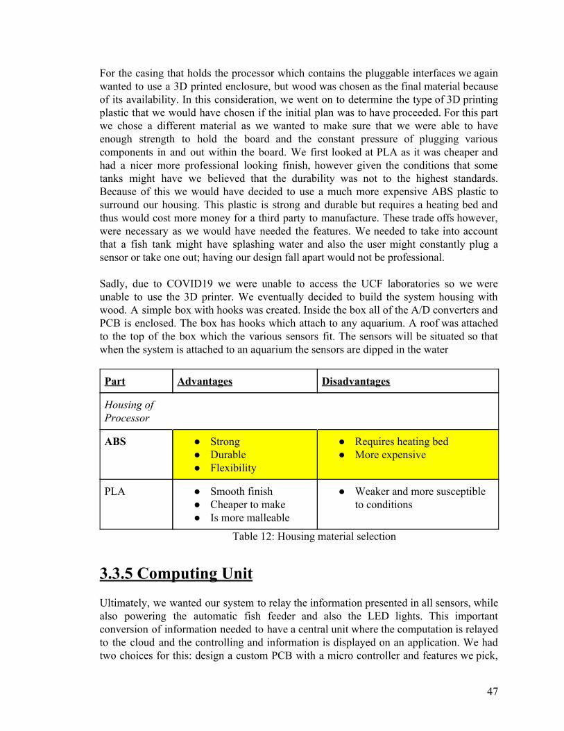
For the casing that holds the processor which contains the pluggable interfaces we again wanted to use a 3D printed enclosure, but wood was chosen as the final material because of its availability. In this consideration, we went on to determine the type of 3D printing plastic that we would have chosen if the initial plan was to have proceeded. For this part we chose a different material as we wanted to make sure that we were able to have enough strength to hold the board and the constant pressure of plugging various components in and out within the board. We first looked at PLA as it was cheaper and had a nicer more professional looking finish, however given the conditions that some tanks might have we believed that the durability was not to the highest standards. Because of this we would have decided to use a much more expensive ABS plastic to surround our housing. This plastic is strong and durable but requires a heating bed and thus would cost more money for a third party to manufacture. These trade offs however, were necessary as we would have needed the features. We needed to take into account that a fish tank might have splashing water and also the user might constantly plug a sensor or take one out; having our design fall apart would not be professional. Sadly, due to COVID19 we were unable to access the UCF laboratories so we were unable to use the 3D printer. We eventually decided to build the system housing with wood. A simple box with hooks was created. Inside the box all of the A/D converters and PCB is enclosed. The box has hooks which attach to any aquarium. A roof was attached to the top of the box which the various sensors fit. The sensors will be situated so that when the system is attached to an aquarium the sensors are dipped in the water
Part Advantages Disadvantages
Housing of Processor
ABS ● Strong ● Durable ● Flexibility
● Requires heating bed ● More expensive
PLA ● Smooth finish ● Cheaper to make ● Is more malleable
● Weaker and more susceptible to conditions
Table 12: Housing material selection
3.3.5 Computing Unit Ultimately, we wanted our system to relay the information presented in all sensors, while also powering the automatic fish feeder and also the LED lights. This important conversion of information needed to have a central unit where the computation is relayed to the cloud and the controlling and information is displayed on an application. We had two choices for this: design a custom PCB with a micro controller and features we pick,
47

or pick from a variety of development boards on the market. We discuss these options below:
3.3.5.1 Development boards A Microprocessor development board is a printed circuit board that is premade by a third party company. These companies take a micro controller and add features to the board. These features range from taking in USB power, to having pins that interface with lcd and other sensors. These boards have many different designs and are available in many different settings. The main advantage of a development board is the extensive resources available and easy to flash and code for the board. Because a lot of these boards are open source, people can develop and build upon the initial design.
3.3.5.2 MSP-EXP430G2ET The first development board we took a look at was the MSP-EXP430G2ET. This development board is manufactured by Texas instruments. This board incorporates the msp 430 microcontroller and has many features that worked well with our end goal. This board houses the MSP430 microcontroller which is a low cost, ultra low power microcontroller featuring 1 Mhz clock at its highest power draw. This development board has a lot of features that would have made it a great addition to a project of this nature. It features on board emulation which when combined with its native IDE (Integrated development environment) allows for very rich debugging. It also features 3.3 v and 5v rail which give us a lot of compatibility with our components. Another rich feature that the MSP430 development board has is compatibility with Texas Instrument’s Boosterpack plugin modules. These modules are compatible via the pin out of the board and give extra functionality like a capacitive touch screen, microphones, and IR receivers. These are native to the board and are easily programmable. The development board features native led and buttons for rapid testing and development use as well. The MSP430 was a great low cost board, however there are many downsides. To begin with, even though the board has features like booster pack compatibility, since we used our own hardware level sensors and analog to digital converter these features would have ended up costing space on the board that would not have been used. Also because the MSP430 is less popular in the development scene, there are less open source and resources available.
3.3.5.3 Arduino Uno Moving onto the next potential development board, the Arduino Uno is a simple Microprocessor development board that is utilized in many personal projects, and is one
48

of the most common boards in the world. Developed by Arduino.cc, it is very straightforward and is a general all-purpose board that is suitable for many applications. Since the main aspect of the Arduino Uno is that it is all-purpose, it has a decent range of specs with it. It operates at 5 V with a maximum input voltage of 6-20 volts, which means that it can supply the power for the devices of the AquaEco connected to it. With EEPROM, RAM, and flash memory, it is also capable of storing data and being programmable, which can make automation possible. The development board also has 14 digital I/O pins, where 6 are capable of giving a pulse width modulation output, which would have been extremely useful for some devices of the system such as the fish food feeder and the lighting. The fish food feeder of the AquaEco works with a rotating servo to dispense a set amount of fish food, which is programmed through a phone application by the user. A PMW output pin would have allowed the user to either slow or speed up the rotation of the servo to control how much food is dropped. For the lighting of the aquarium, it consists of an LED strip. Some fish require varying amounts of light, and their circadian rhythms, behavior, and health can be affected if too much or too little is given to them. PMW would have allowed for the lights of the strip to be dimmable instead of being completely turned on or off and would have given the users the freedom to set the level appropriate for the species of fish they own. This would have been helpful in situations where the external light from outside sources, like sunlight or the lighting of the room may add too much intensity going into the fish tank.
Six analog input pins are available for use in the Arduino Uno as well. This was especially necessary for the sensors of the product where obtaining an accurate reading is vital to maintaining the health of the fish. With the digital I/O pins, PMW pins, and analog input pins, this would have provided the right connections for the devices of the system while still having more to spare for any extra component that might have been added.
Advantages of the Arduino Uno however are its low cost. Since it is meant to be a beginner-friendly and low-investment microcontroller, it is inexpensive, which would have been beneficial for lowering production price of the AquaEco and providing an easily obtainable development board in the case that a replacement was needed during the development phase. To also promote beginner use, it is a robust board, which would have made it durable for when the AquaEco needed to be moved around during tank maintenance or subjected to force, as mentioned before. The Arduino’s disadvantages come in the form of the predefined specification sheet. On a whole, the Arduino Uno uses a ATmega328 and therefore has a lower overall clock speed than that of other typical micro controllers and flash memory of other development board utilizing different microcontrollers like the PIC32s, but depending on how fast the system of the AquaEco needed to be and whether programmability with the controller was needed, those specs may have been acceptable. Furthermore, the Arduino One is not
49

specifically meant for low power consumption, which can be costly in the long run with energy compared due to specifically designed boards utilizing more power efficient processors.
3.3.5.4 Raspberry Pi Zero Similar to the Arduino Uno, the Raspberry Pi Zero is another board that is common and beginner-friendly. However, unlike the previous two options, the Raspberry Pi Zero is actually a single-board computer, giving it more functionality and features than the previous two. As a single-board computer, it has much more processing and memory with a 1 GHz single-core CPU and 512 MB of RAM, and specializes in being compatible with various USB functionality and peripherals, which can possibly affect design choices through alternate or additional components if chosen. It also has one SPI bus for data communication to devices, and is compatible with a Wi-Fi module to work in tandem with the app functionality. For pins, it has general purpose input/output (GPIO), which can distinguish between an input and output signal and change behavior accordingly during use. This would have allowed for the connection of a variable amount of input signals for sensors or output signals for other devices for the system. However, GPIO marks a significant disadvantage of using a Raspberry Pi as a microcontroller. With GPIO, the pins only operate on a binary digital signal, both incoming and outgoing. Unlike with the WPM pins on the Arduino, the speed of the fish feeder and the intensity of the LED light system would not have been able to be adjusted beyond turning them on or off. But most importantly, not being able to receive an analog input meant that data from the sensors of the AquaEco will not work correctly, which is a serious impediment to the project. On top of that, the GPIO connections are supplied with 3.3 V, so connection to a higher voltage would cause damage to them and would have needed to be regulated as such. Lastly, single-board computer functionality could have opened up some possible functionalities and designs for the aquarium, but they ultimately ended up having little to no use in the scope of this project.
3.3.5.5 Custom Printed Circuit Board The central processing component of the AquaEco system is the most critical component of the entire system, and is in control in which all the other devices are connected through and data and information is transferred. As such, choosing the right micro controller and components to incorporate onto a PCB for the project was especially crucial to ensure that it supports all the functionalities that are available in the aquarium. We thus looked into custom-creating a PCB and incorporating a micro controller along with components that are needed. PCBs have many advantages over normal circuitry,
50

which includes being small and compact. If traditional wiring was utilized to connect all of the components for the AquaEco, it would have led to a complicated and bulky connection between each of the parts, which would have directly conflicted with our goals of making the product fit within a certain dimension, have a quick setup time, and be easy for the average person to use. For the developers, this also benefited them by avoiding confusing wiring that would be hard to troubleshoot faulty parts or connections, and instead provided an easily readable and relatively low-cost option that is not as susceptible to wire noise. There are a few nuances with selecting a PCB manufacturer and maker and comes with a lot of risk. To find which type of PCB ass needed, we needed to look at the kind of qualities that would make it desirable for both the market and for the producers. Since it is the most complex of the components for the average user, ensuring that it required little attention and maintenance was a necessity. If it had an error, it could have potentially affected the entire system, and when maintaining the health of the fish is the primary concern, it needed to operate reliably, accurately, and with a quick response time to prevent any irregularities that would have gone unnoticed. It was also expected for the system to be kept running constantly, since keeping the fish healthy is a constant task. With this, some important characteristics for the PCB were determined: it had to have a long operating lifespan, be durable, and utilize as little power as possible along with its components while still being able to support the current and voltage that they needed. The system must be able to continue running for multiple years; not just as a typical desired market feature, but also because the lifespan of fish can also vary up to many years too. Purchasers would be aware of this and would desire systems that would last a long time to avoid having to buy a replacement repeatedly. Durability leads into this because the system could risk damage. Especially for cases such as parts of the system having to be moved during water changes or tank cleanings, where components might be dropped or have to withstand bumps and other physical force, situations like these had to be accounted for so that the PCB would resist premature breaking. For the power consumption of the AquaEco, naturally, a user would have desired for the system to minimize energy usage to save money, which would add up if the operating time of the aquarium is targeted to be multiple years continously. Excessive energy expenditure would also have wasted electricity and caused the PCB and the devices to wear down more quickly, affecting the operating time of the system too.
A custom PCB begins with the most important selection - the microcontroller. The microcontroller is in charge of all the computation involved in the system and is also in charge of managing the resources as it contains the ram and storage. These are what are programmed to run the code needed on the machine. We discuss three popular micro controller options below.
51

3.3.5.6 PIC32 Microcontroller The first option that will be discussed will be the PIC32MX microcontroller line. With the AquaEco containing many devices that must react quickly to change, display or relay the data quickly, and respond to changes in configuration and parameters, a fast microcontroller would have been ideal. Based on MIPS architecture, this solution manufactured by Microchip Technology would have provided fast operations and allowed the devices of the aquarium to respond quickly to changes. Peripheral Interface Controllers, PICs, are notable for being able to execute a large number of instructions within a short time, and have considerable processing power and flash memory. While the processing power has its obvious advantage, having sufficient flash memory and being able to execute from RAM gives the option of setting and changing programs for automation of fish tank processes, if it was desired. Flash memory being non-volatile would also mean that data can be stored within the microcontroller for a long time, which would have coincided with wanting the operation lifespan of the aquarium’s controller to be long. The microcontroller would also need to have had enough connections to the components in the AquaEco. The PIC32MX microcontrollers offer various methods of communication to other devices through SPI, I2S, UART, and I2C. An analog-to-digital is also included, which would have helped with reading the measurements from the sensors of the system. There are also options of adding features such as touch-sensing, if an interface for controlling the microcontroller and devices connected to it were necessary, and with the I2S compatibility, audio could have been added as well to provide a possible feedback to the user for either alerts or responsiveness when interacting with the AquaEco. The PIC32s also fulfilled other requirements for the AquaEco. While having connectivity options through things such as USB, bluetooth, and ethernet, which could have also led to more design choices if the development team wished, it is compatible for Wi-Fi through modules, which would have given us the connection for the application and remote accessibility that was planned. Additionally, the PIC32MX line offers a model that can operate on low power consumption and can include low-power sleep modes, at the cost of lower processing power than the other models. Having low power consumption would have met the benefit of having a long lifespan without wasting a lot of energy, and the sleep mode could have opened up an interesting design choice for the aquarium. If the monitoring of the fish tank was to be set to periodic timings, then the system could be converted to sleep mode and utilize even less power by being on standby. When the AquaEco would need to monitor the water again or is being configured, then the system could fully activate again
52

and perform its action. While this might have not be useful depending on if constant monitoring is needed or if the system isn’t responsive to drastic changes in the aquarium conditions while in sleep-mode, it did allow an interesting and potential money-saving and high efficiency option if problems could have been worked around or if the processing speed of the other models were not necessary.
3.3.5.7 Attiny1617 The attiny1617 micro controller is part of the AVR development board and is used as the processor for the low cost designs. The benefits of this microcontroller are that they are very low cost for the performance. The micro controller stands at 20 MHZ for high accuracy readings and 32 khz for low end tasks. While the speeds are very comfortable for a micro controller of this price point, the power efficiency is also very good. This microcontroller features three in built timers which is plenty for the fish feeder to have been wired to this. The next timer could have been used for the led, while polling could have been used for the sensors. There are also separate modules for UART, SPI and TWI for compatibility for many external sources. There are two accessible interrupt levels with 22 external interrupts which with proper configuration means that all our hardware would have been able to be managed with this microcontroller. The downside to this microcontroller is development. With the available software, the in-built developing tools in the micro controller are not as polished or as good as other options in the given price point. There is also a noted issue that the microcontroller begins to not give its best performance with given voltages.
3.3.5.8 Atmega328P Another consideration for potential controllers of the PCB was utilizing the Atmega328P processor. Most similar to the PIC microcontrollers out of all of these comparisons, this microcontroller also runs based on RISC architecture for fast execution and boasts low power consumption through active operation and six types of sleep modes, which would increase the efficiency of the AquaEco especially over a long period of time. It contains alternative methods for connectivity to devices through USART, SPI, and I2C as well, and has flash memory, EEPROM, and SRAM for data storage and programmability. One major difference between the two is that the Atmega328P supports ISP through an SPI interface, which allows the microcontroller to be reprogrammed while already installed inside of a system instead of having to be taken out to be programmed before installing it again. This allows for a much easier process for sending data into the microcontroller without needing to dismantle the system. On the other hand, the PIC32MX line offers a greater range of models of similar functionality but varying
53

specifications, which may be of greater use depending on the kind of project that is being built. The biggest advantage of the Atmega328p has to be with documentation and support found all over the web. Because this processor is found in many Arduino and other similar development boards, there is open source code available that taps into the many features this processor has. This board has been tested to work with a variety of modules and other devices, this means that development time is much shorter than with any other microcontroller. These chips are easily flashed and have the ability to run code that is used with arduino products.
3.3.5.9 Processing unit selection There are many advantages to having a full development board. Because the development boards have plenty of peripheral support and documentation online, it is easy to make a product that will utilize a given development board and have it work. The Raspberry Pi zero was a great board that was both inexpensive and had a great amount of features that we used like wifi. However, it had some downsides like running a full operating system which was too much in terms of exceeding needs. One must note both minimum and maximum requirements when it comes to the board that our system uses. Next, the arduino uno was also inexpensive, had a large, fast documentation and support online, and every sensor and motors worked well with the system and could be programmed directly. However much like the raspberry pi it had other features that would not be used. Lastly, the MSP430 ultimately was discarded as a choice due to its poor compatibility with many of our components and lack of development support. The choice of using a development board was then discarded and the movement towards a custom PCB was decided. A custom PCB handles specialized projects much better than a development board. This is because a custom PCB can be created with the end goal being to make a cohesive solution that can have the average user set it up and turn it on themselves. Development boards would have a number of features that would go unused in projects. Also there are many separate external components like resistors and converters that must be added. The dimensions of the project would have increased and the complexity would as well. This makes the end product not have polish. However, having a micro controller and a custom PCB allowed us to have freedom in the exact components that will be used. The microcontroller choices were between the PIC32MX, Attiny1617 and the Atmega328P. All three similar MCUs were with great specifications that would be good choices to act as the microcontroller for the AquaEco. These micro controllers supported the voltages and had pins needed to be wired to the converters that we used. However, the Atmega328P was chosen over the PIC32MX and Attiny1617 for two main reasons. While the option to select different models and specifications with the PIC32MX family
54

was an enticing incentive, the Atmega328P having ISP compatibility to allow programming while inside the system would have reduced the amount of disassembly and reinstallation that would have to be done during development and on the user’s side. Moreover, there is a large amount of community support for the Atmega. While working on this project, it was a significant advantage to be able to easily find references and information about the microcontroller online, and lent a great hand in troubleshooting, wiring, and overall development. This final choice was made in part to hit the end goal of creating a solution that was easy for users to use, with direct connections with the sensors and the board, the user would have easy access to connect and disconnect sensors, and if some broke or needed replacement this could have also been done. Below is our pcb part selection with the bold selection being the final selection.
PCB
PIC32 ● Fast processing ● Relatively large memory ● Many model types available ● Many methods of connection ● Low power usage
Arduino Uno ● All-purpose ● Digital, pulse width modulation, and analog I/O pins ● Inexpensive ● Robust ● Lower clock speed and memory ● Moderate operating power for long-term use
Msp-Exp 430G2ET
● All-purpose ● BoosterPack expansion ● Inexpensive ● External support ● Moderate operating power for long-term use
Raspberry Pi Zero
● Single-board computer ● Relatively high processing and memory ● Compatible with USB and peripherals ● SPI bus and Wi-Fi module compatibility
55

● General purpose input/output pins ● Binary digital signal only
Atmega328P ● Fast processing ● Different types of memory for programmability ● Low power consumption ● Supports ISP through an SPI interface ● High community support
Attiny1617 ● Fast processing ● Low power consumption ● Three 16-bit timers ● Supports ISP, SPI,UART interface
Table 13: Final processing unit selection
3.3.6 Auxiliary Hardware Components WI-FI Modules One of the most important aspects of our final solution was the connectivity involved between all components. Compatibility between components was selected carefully such that all devices were able to be controlled via a microcontroller. However, other auxiliary hardware components were also needed to fully create the solution. The wifi-module is at the core of our communication link, this module had to be selected to meet the needs and wants of our systems. Compatibility is a big factor for this sensor. After choosing the microcontroller Atmega328p we worked towards finding a module that was compatible. The first module we took a look at was a combination of an ethernet adapter called the ENC28J60 and combining it with a seperate wifi router like the TL-WR702N. This combination would have required an ethernet connection through the module and have the wifi router act in client mode. This would give us the communication benefits as this wifi router could connect to a home network and transmit data through the network. This set of components would be costly and hard to set up for the user. In this age there is less reliance on having an open router ethernet port and is rare to see for IoT devices. Another downside to ethernet connection is proximity to the tank. Because our final device was enclosed this means that this box consists of the processing unit and modules, the user
56

would have had to connect a cable from the box to another place housing the router. Therefore we chose not to go this router due to cost and a reliance on user set up. The next module we looked at was the CC3000 module which incorporates 802.11b/g capabilities to our final pcb design. This wass compatible with our micro controller and could have run on 3 or 5 volts depending on which design we chose. It runs in SPI mode and can transmit data rapidly. Another feature is security. It has access to WPA and WPA2 modes which mean it could have been secure when transmitting the sensor data. The interface can also support both TCP and UDP protocols which means broader compatibility. The biggest issue is price, this module is very costly in comparison to the next option we looked at. The final module we researched was the ESP8266. This module can be found for under 4 dollars through manufacturers and has become a recent pioneer in Iot applications. Its low cost makes it easy to incorporate it into many applications. It features 802.11 b/g/n giving it a slight edge in connectivity to the CC3000 and also has access to TCP and UDP modes while running on the TTL serial interface. It also has the same security features as the CC3000 module. The downsides include having less reliable components. However, this does not mean it has a larger failure rate. We ultimately chose this module to use as it had the features we wanted while also being extremely low in cost. 3.5 Parts Selection Summary: We ultimately chose these parts based on the aforementioned reasons and comparisons with other competing parts. For those sensors that are available from a variety of different vendors, we chose those based on both supply and cost along with shipping speed. There is often a slight difference depending on whether the part will come from China or inland in the US. The parts located in China were low in cost but have a much longer shipping time. We took this into account when choosing a suitable vendor. Below is our final component sheet.
● Gravity: Analog pH Sensor / Meter Pro Kit:
57

● Waterproof DS18B20 Digital Temperature Sensor
● The Gravity: Analog Turbidity Sensor For Arduino:
● ALITOVE WS2812B Individually Addressable LED Strip Light 5050 RGB
58

● SG90 Micro Servo motor:
● 3D-Printed Housing
● ESP8266:
59

● Atmega328P:
● SunFounder 2 Channel DC 5V Relay Module with Optocoupler Low Level Trigger Expansion Board for Arduino
4.0 Related Standards and Realistic design constraints When creating a product, there is often a plethora of discussion prior to development, research and manufacturing of said final product. The amount of pre-questioning is essential in any new creation. This pre-questioning will seek to answer questions relating to constraints and standards. Realistic constraints are well needed to make sure that the manufacturing of the end product is very similar to that of the initial concept and design. Time and time again you see many concept products not hit the prototype phase due to failure of restricting these realistic constraints which can range from cost to scheduling. We had to also take into consideration standards as a means of establishing technicality of the different components in a system. One must realize that there are laws, and other restrictions in place that would limit both part selection and design, of which can impact the final concept creation. We now look at these constraints and standards used to dictate our end goals.
60

4.1.1 Related Standards and Impact on Design During the development process, we had to take into account the standards that can apply and affect the choices or methods of design that are chosen. To develop and deliver a product that is acceptable compared to that of similar current technology, a list of related standards to this project had been compiled. Many of these directly affected design decisions for how our project ultimately functioned, and served as references for safe and effective design.
● IEC 60335-2-55
The IEC 60335-2-55 standard relates to a safety standard for the use of electrical appliances for aquarium and electrical pond uses where the rated voltage does not exceed 250 V. Since this applied to the multiple devices that are contained within the AquaEco, the designs of each component were carefully evaluated and tested to ensure the customer’s safety and avoid any electrical shock hazards. Electrical and wire regulations, resistances, and other hazards were taken into account.
● IEC 60598-2-11 This standard encompasses safety regulations for aquarium luminaires with light sources that do not utilize power supply that exceeds 1000 V, which applied to the LED lighting system that is included in the system. Due to most lighting systems being attached to the top side of the aquarium, this means that they are near the water of the tank, which can pose an especially great risk when it needs to be moved often when doing actions such as changing water. This standard is meant to prevent electrical shocks from dropping electrical components into the water and lower the risk of harm from other electrical accidents. This affected the design of the LED system by requiring countermeasures to prevent any parts of the LED system from touching the water and neutralize risks in the case that they do.
● IEEE 8802-11
This standard deals with the Wi-Fi standard that the AquaEco operates with. 802.11 is the most common wireless connectivity standard and defines a medium access control and physical layers for local connection in an area. Since the microcontroller for the AquaEco utilizes Wi-Fi to send signals and work with the phone application, it was important to adhere to this standard to ensure stable and consistent connection and data transfer remotely.
61

4.2 External Design Constraints For this project we had to consider many constraints relating to our design. These aspects, such as economic constraints, time constraints, environmental constraints, social constraints, political constraints, ethical constraints, health constraints, safety constraints, manufacturability constraints, and sustainability constraints were all considered, as they had the potential to determine how much we could put into different aspects of the project.
4.2.1 Economic Constraints
The main economic constraint we had to deal with when considering what features, parts, and ideas we might incorporate into our design was the cost. While some of the components of potential designs are relatively inexpensive, others are not. For example, we considered designing a salt water based fish tank system. However, after further research, we determined that this would not be practical, primarily due to the cost of acquiring a salinity sensor which would have cost approximately $120 for just one. Add to this the fact that we had to order at least 2 of every part we need, in case one malfunctioned, was faulty, broke, or even if we simply made a mistake, and that was $240 for just a salinity sensor. Therefore, we scrapped the idea to make a saltwater tank, as it did not seem reasonable to design an automated fish aquarium that used salt water without including a salinity sensor. This type of design choice was made solely due to the cost involved. Additional choices for what parts to use and what features to add also depended on our cost of production. The budget of this project was agreed upon between the team at the start, so it was ideal for the costs of the materials and work to stay within a limit, including any additional costs that may have arisen during production that had not been foreseen. Another important cost constraint was the amount of components that could have been added to the overall system. The sensors chosen were not inexpensive, therefore careful consideration had to be taken when choosing which characteristics of the water we wanted to focus on. At least the baseline characteristics of a healthy tank should have been monitored. The sensors for nitrate and nitrite can cost over 500$. While these sensors are an important part of creating an environment in which fish therive, they were too expensive to consider for this project. Although inexpensive sensors for nitrite exist, the sensor's design proves that they would not suit well underwater for large periods of time, as well as becoming a potentially dangerous component for the fish in the aquarium. Not only were all these previous reasons enough to avoid adding these inexpensive sensors to the system but another reason was that these inexpensive components could have possibly opened up the possibility of complete system destruction. These are the kinds of economic constraints that affected our design
62

4.2.2 Time Constraints Time was another major constraint that we must consider when designing the AquaEco. As can be seen in section 2.3 Project Milestones and section 2.4 Project Timeline, we had deadlines and milestones to meet in regards to the project. The amount of time we had to invest into the project is limited. Our project must have been completed by the end of the summer 2020 semester. In order for us to meet this requirement, proper time management and planning for the group as a whole was critical to our success. We had to follow the schedule listed in Project Timeline in order to stay on track and finish everything on time.
The small yet numerous potential time constraints that were developed while creating a system were almost endless and could be difficult to pin-point. Some obvious time constraints which have nothing to do with the developer’s timeliness in creating the system was shipping time. Beyond the individual components having to be ordered and shipped from all over the world the biggest time consumer was the time it takes to receive a PCB. Unlike other components the PCB must be created to exactly fit the designer’s specifications. This means that the system had to go through a lengthy creation process before it is even ready to be shipped to the designer. Another problem is that the manufacturers of custom PCB boards are in China. This distance proved to be a potentially large problem when considering shipping time. Typically, it takes up to a week for a PCB to be manufactured and over 20 business days to be shipped internationally. Combined the total time for a PCB board to be created and shipped can be over a month. Considering the deadline of the project, a month to receive 1 component of the system could have been a very large constraint and one not to be taken lightly. Another constraint that was considered when designing a PCB board was that it is a set circuit. This means that the major components of the PCB board cannot be manipulated without destroying the board. While it was possible to add components, relocating was impossible. If the ordered PCB was faulty due to manufacturer error or designer error the potential time loss was massive. It could have potentially taken over a month to fix the error which would leave the development of the project in a stand still. This standstill in total time would have lasted over 2 months which was a legitimate portion of the project’s total allotted time. Therefore, it was imperative for developers to design the circuitry of the system before any other part of the system was developed.
Another less crucial but still important time constraint to consider was the potential of component failure because of water. While the time it took to receive the different mechanical components of the fish tank are much lower than that of the PCB board, they were still considerable. When creating the physical system many of these components had to be placed and mounted. When deciding the placement of these components they were very exposed to the surrounding environments. The environment always includes a large container of water so it was not unlikely that a component might be destroyed due to water damage. If destroyed it would have caused over a week of potential down time before the replacement component was received. Overall meaning that the project would have been on hold for potentially 2 different weeks. Unlike the PCB the different
63

components also had the constraint that there were multiple different components which were all exposed during the placement of those components, allowing the possibility for the destruction of multiple components over a large period. A possible solution to alleviate the stress of a last minute destruction of a component was to order multiple components at first and return the unused components once the system is complete.
4.2.3 Environmental Constraints There were two main considerations for the impact of environmental constraints on the design of AquaEco: enclosure material and power consumption. For our project, we originally planned to use additive manufacturing, in the form of 3D printing, to fabricate the enclosure for our pcb, wifi chip, motors, and other electronics. Additionally, our system was to be, in a sense, always be turned on, and would therefore always be using some amount of power. Modern 3D printing has many benefits and some drawbacks from traditional plastics fabrication. For example, because 3D printing functions by using heat and lasers to create the desired object, it can potentially be much more energy consumptive than standard subtractive processing, where material is grinded away from a piece of material to shape it into the desired form. And since many places still use fossil fuels as their primary source of household and industrial electricity, this can potentially have a noteworthy environmental impact. However, since 3D printing only uses the energy to add material in the first place, whereas subtractive manufacturing must spend time and energy removing material, the difference in energy consumption may ultimately have been negligible. One positive aspect of using a 3D printed enclosure was that 3D printed materials are usually made out of thermoplastic, which is usually recyclable. So in the very long run, at least that part of the AquaEco could have been recyclable. If we used PLA, which is sourced from corn, it would have had an even lower environmental impact.
4.2.4 Social and Political Constraints Our project was not significantly affected by any standard social or political constraints. An automated fish tank does not generally have any political implications. However, it is worth mentioning the social impact of automatic devices at large, such as this. For example, the main purpose that people generally keep pets is as a form of companionship, and to have something to take care of. In using a completely automatic fish aquarium, a large part of why people keep pets like fish may be lost. This, however, is a much more philosophically oriented discussion that was frankly out of the scope of this project and document.
64
4.2.5 Ethical, Health, and Safety Constraints In designing the AquaEco, we had to make sure to carefully consider the ethical, health, and safety aspects of our design. There were many reasons for this. First, our tank must have been safe for all members of a common household. Large fish tanks should not pose a danger to small children, as they should be placed out of their reach in the first place. Even so, we had to take care to design our project in such a way that it had as little chance as possible of causing problems. For example, our tank uses electricity in a location very near to water. This could have been dangerous if not handled appropriately. Therefore, the enclosure was to be properly sealed and insulated. A number of the standards listed in section 4.1.1 Related Standards and their Impact on Design was to be specifically considered when designing the AquaEco. In addition to not being dangerous for the user, we had to also consider the ethical implications of automatic fish management. Our design and implementation had to very reliably take care of the needs of the user’s fish, and accurately report important information relating to the tank’s status and needs to the user. It would have been unethical to create a product designed to keep a fish alive that fails to do so when needed, when a user is relying on it. Therefore, care had to be taken that all systems function properly at all times.
4.2.6 Manufacturability Constraints When considering the AquaEco from a manufacturing perspective, there were some constraints that would have affected the process. Although there were no plans to reproduce and distribute the aquarium system outside of this project, some of the points brought up in this section will act as a hypothetical outline.
One point that would have affected manufacturability was the components themselves. For this project, certain components of the aquarium were premade and were sourced from other companies. As a result, once the desired components are decided on, they had to be ordered from each supplier, which would have taken time to arrive and be tested for any potential flaws. Additionally, although having a product built from parts from other manufacturers was acceptable for this project, if the team desired to sell AquaEco commercially, components would have to be made from scratch, or deals would have to be made with the original manufacturers that sanction supply and selling in order to avoid legal issues.
Another was adhering to any standards. In this project, the standards that are listed were the ones that affected the development and design process, and the final result was based on them to meet the requirements that they list. Considering again a hypothetical business, constant and thorough research would have to be done to see if there are any new or applicable standards missing or updated from the design of the AquaEco. Alongside this, purchasing the standards was costly in comparison to the budget of the project, so more money would have to be readily available or investable by the team
65

members to have supported this. Furthermore, once the standards are obtained, the design of the product would have to be researched for, readjusted, retested, and reproduced again, which would be a tremendous effort and time sink. This can be linked into another difficulty with manufacturing - the lack of a large workforce. For this project, the amount of work was planned and allotted to be proportional to that of four individuals, and the development for a prototype was spread over the course of about half a year. The amount of tasks that each person could feasibly complete within a certain time frame limited when certain stages and deadlines could have been accomplished for the project. If manufacturing on a large scale were to be done, then either a partnership with a larger manufacturing firm that will agree to produce our product would have to be made, or additional members would have to be hired by the original team and significant restructuring of personnel and tasks would have to be done. While the AquaEco team of four people was a sufficient workforce with an adequate development period to produce a proof-of-concept for the Senior Design classes, in an industry, there were far too few workers and too slow progress at the time.
4.2.7 Sustainability Constraints For sustainability constraints, the main one that needed to be addressed in this project was electricity. Since the system was going to be active constantly, it would have been beneficial for the customer and environment for the system to utilize as little power as possible. This constraint had affected the choice of components for the AquaEco since the amount of operating power each device uses had to be considered, and excessive components had to be evaluated and removed as much as possible to reduce the electricity consumption of the system. To save energy, special considerations had to be made when designing every different component of the system. An ideal way to minimize energy usage was to minimize the amount of components that were used in the system. To do this the system had to be developed to be as basic as possible while still being very high functioning. Another important way that a system can become more sustainable was to have different components of the system turn off when they were idle. The system contains multiple sensors that needed power to take readings, however the different sensors did not have to be on all the time. The sensors could have taken readings once or if not twice a day, and still present the user of the system with functional data which monitors their aquarium's health. To do this the system would have had to be designed to have a controller to turn on and off the different sensor components. By completing this task the aquarium system would have improved greatly in sustainability. Another way the AquaEco system hoped to increase its sustainability was by implementing a low energy but highly effective lighting system. The lighting system
66

could use massive amounts of energy to accomplish the goal of heating and lighting portions of the aquarium. Fortunately different lighting methods have been developed which greatly reduce the environmental effect of lights. By employing these methods the overall sustainability concerns of the system would have been greatly improved.
5.0 Product hardware The end goal of our hardware components had been to be able to properly send the needed information to the mcu, which in turn would then take this information and supply it to a client which would be able to then relay the information back to an application that grabs the data in real time. There were many different ways to ultimately achieve this goal, including how the sensors themselves are wired to the main controller and whether or not we should have had them on the same bus setup. For various reasons including disruptions we chose to instead have every sensor behave separately. Our system also had these sensors send this analog information to the main central processing unit or CPU for short. The cpu however was not able to understand this analog information, and therefore because we decided to instead go for a pcb printed design instead of an all in one micro controller we had to also incorporate these converters onto our main board. Lastly our final setup with the processing unit and application involved the user of the WI-FI standard. This allowed the user to access readings and be able to control aspects of the system even when not at home, which was very important in our design and goal philosophy. Without this remote connection, there would have been much less for those traveling or those who have busy schedules. Our final design tried to incorporate all these elements, while also making sure goals and motivations were met. Design constraints and standards led the design component and ultimately had a strong influence on our end result. 5.1 Initial Design Architectures and Related Diagrams Our final system consisted of three components including lighting, sensors and the fish feeder. These components are all fed into the pcb consisting of the processor that handles all the raw data coming from these sensors. Below is a picture of the end to end connection between all components in our system. It is important to note that these components can be disconnected and still work on their own. For example, if the pH sensor is no longer reading accurately or fails, the entire system will not power down and stop working as they will be on seperate communication buses.The fish feeder and led lights can connect directly with pins located on the processor, while the sensors needed an adapter between the end of the sensors and the input of the processing unit. The turbidity sensor has an end that consists of gnd, vcc, and data terminals. For the ph sensor we had a BNC connector that was the end hardware that we had to account for when building the microcontroller. Lastly, the temperature sensor terminates in gnd, vcc, and
67

data. This connection again needed to be implemented for the analog to digital conversion to take place. These wired to the pcb and connected to a power supply. The end goal was to have this system be modular enough for components to be able to work separately.
Figure 10: Overall initial design connections
The main setup of our system relied on a custom built PCB that incorporated analog to digital converter adapters that all our sensors had. The heart of the pcb was the Atmega microcontroller which could be flashed easily to house the needed code for our project. This microcontroller was able to read the analog inputs after conversion takes place. There is a lot of documentation available online. This code made sure that the values being read and converted were able to be understood. For example, converting from a voltage to a reading of turbidity for the end user. From here our pcb also dealt with supplying the correct voltage and power to all the components we had. This device was to be connected directly to the wall outlet so we needed a way to limit the voltage onto the cpu. Here was our proposed initial design of our pcb:
68
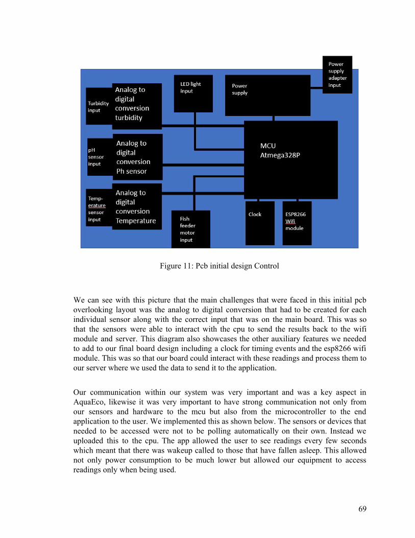
Figure 11: Pcb initial design Control
We can see with this picture that the main challenges that were faced in this initial pcb overlooking layout was the analog to digital conversion that had to be created for each individual sensor along with the correct input that was on the main board. This was so that the sensors were able to interact with the cpu to send the results back to the wifi module and server. This diagram also showcases the other auxiliary features we needed to add to our final board design including a clock for timing events and the esp8266 wifi module. This was so that our board could interact with these readings and process them to our server where we used the data to send it to the application.
Our communication within our system was very important and was a key aspect in AquaEco, likewise it was very important to have strong communication not only from our sensors and hardware to the mcu but also from the microcontroller to the end application to the user. We implemented this as shown below. The sensors or devices that needed to be accessed were not to be polling automatically on their own. Instead we uploaded this to the cpu. The app allowed the user to see readings every few seconds which meant that there was wakeup called to those that have fallen asleep. This allowed not only power consumption to be much lower but allowed our equipment to access readings only when being used.
69

5.2 PCB Design Programs A PCB needed to be designed specifically for this project to be able to get the proper functionalities needed to control the devices of the system. Properties such as delivering the right voltage and current to the devices, making connections to the microcontroller, and how power will be supplied to the PCB, among other things, needed to be decided and mapped out, not just only for ordering the right parts, but also to act as a guide for how connections through the PCB should have been made. To design the PCB that was needed, design software was utilized, and various possible choices were reviewed and compared so that one could be selected for this project. Some of the programs that were available to the team to use are EAGLE, DipTrace, and KiCAD.
Before the comparison, a few features that were ideal will be discussed. For the program, having an understandable and intuitive interface was preferred. This allows for an easier process of putting together the parts and figuring out where certain functions in the program could be done, and it also allows for a better demonstration of the development process if the circuit schematic for the PCB could be easily understood and analyzed by other people besides the development team. Also, on the user side, the more easily navigable and controllable the program is to work with, the easier it would be to implement objects or processes that are needed when constructing the schematic. Especially in this case, where designing possible prototypes of the PCB may have had to have been repeated, reducing the number of steps taken to complete an action would have saved a considerable amount of time.
Another feature that was worth looking out for was the number of libraries that the program came with. With libraries, the user could search for and add premade symbols and device schematics to their schematic design without having to create their own from scratch, which would save time when making the circuitry. Having various parts listed inside the library is a great benefit as well, since on top of giving the user an extensive list of the components that are available, which helps in the design process by giving the user ideas on what components may be good to add to a certain project, the library also contains detailed information on the components such as the manufacturer, price, datasheet, description, availability, and other similar aspects. This information would have been highly useful in referencing how the part works and would have made locating and shopping for parts easier. It was also possible to download libraries online and install it into the computer, but having to avoid taking unnecessary additional steps and having a large amount of material to work with immediately was advantageous.
Being able to build a bill of materials was one more feature that would have been beneficial to have. When constructing the circuitry, being able to compile together the parts that would have needed to be ordered to produce the PCB would have been useful to keep track of cost, availability of a component, the manufacturer of the component, and how much was needed. In other words, the bill of materials would have served as a guide as to the materials needed to construct the product and would have made managing
70

them easier. It would be more difficult to have to research the model of a component and its availability and price individually, outside of the program. By having a built-in bill of materials generator within the PCB design program, this would have saved time with research through having a neatly structured list that would entail exactly what was still needed.
5.2.1 EAGLE Keeping these features into mind, the first program that will be examined is EAGLE. EAGLE is a simple PCB design program that has a lot of community and online support, which would have been extremely helpful for troubleshooting any problems that may have arisne during development and gathering information about PCB design. Along with the standard features like the schematic editor and PCB editor, it also has forward and backward annotation, which means that if an adjustment is made in either the editor or PCB view, it will update the other window to include the change, which would have been helpful when constantly making small changes to the circuitry to test the output. It also comes with additional wiring features such as automatic wire routing. The more components there on the PCB board, the more complicated and intertwining the routing becomes as some connections are forced to cross over each other or take long paths to avoid intersecting through other connections. Routing the PCB by hand was always an option, but having the feature for auto-routing might have been able to make more efficient connections between terminals and suggest pathways that might have been otherwise unrecognized by the user if the number of connections became too much.
Adding onto these, EAGLE also has a large library already available on it, containing a large list of components that could be added, their model, the manufacturer, the price, and other specifications of the components. With this, having to search online for libraries with a necessary component and having to manually install it into EAGLE could have most likely been avoided, and the team would have been able to choose from a wide selection of components that EAGLE already has data on and could have provided. Alongside this, a bill of materials generator is available within the program, which utilizes the data mentioned before and creates an easy list to reference for obtaining the parts for the PCB.
Considering the price for obtaining the software, EAGLE has a free version available to students and hobbyists, but there are limitations placed onto the program such as only having two schematic sheets available and having a smaller board creation area, which could have hindered this project if larger-scale designing was needed. However, there is a premium version of EAGLE available for a price based on a monthly subscription, if it was desired, which would have more features and functions open to the user. And while it is a good basic program for PCB designing, it does not carry as many functions and detail as some of the higher-end programs, although some of the more complex programs might have been costly and have unnecessary functions, thus being unneeded for this project.
71

5.2.2 DipTrace Similar to EAGLE, DipTrace also is a fairly simple PCB design program with a decent number of features. One notable feature is that it has a clear and easy-to-navigate UI layout. As stated earlier, while this may seem like a small aspect, making the program for PCB designing easy to figure out how to toggle different functions, know how to access workspaces and manage them, and accomplish certain tasks in as minimal steps possible adds up over the design process and leads to significant cuts in time wasted. Also similar to EAGLE, it has its own components library available, where you can access components of varying specifications, models, and manufacturers. Creating a custom symbol or schematic and saving it to the library for later use is also available too. It also comes with the standard schematic and PCB editor, as well as sharing more features like EAGLE such as the backward and forward annotation and the auto-routing function. DipTrace also offers a free version with limited functionality, such as a lower amount of pins and only 2 signal layers, and versions for a price that would give more pins, signal layers, and functionality. While the freeware is sufficient for a small project, creating the PCB for the AquaEco might have required more resources than this provided, and a version of DipTrace with higher functionality might have been necessary. In this case, DipTrace also offers paid versions of their program, but unlike EAGLE, it is based on a one-time payment license rather than a subscription, with the cost increasing to buy the license for better editions of their program. If the lesser editions of DipTrace were sufficient, it might have been more cost-effective to buy it instead of EAGLE, if the PCB design process of this project extended for multiple months. If the unlimited functionality of a PCB design program was needed for a short period of time, then it might have beem more worthwhile to purchase EAGLE instead of DipTrace.
5.2.3 KiCAD For the last consideration of the PCB design programs, KiCAD is also a beginner to intermediate level PCB design tool with a relatively simple UI, once again sharing similarities with the other two programs in terms of tools and features. The most notable difference between KiCAD and the other two is through the layout of the program itself. KiCAD is split into separate parts, including the project manager, the PCB layout, and the schematic capture. This means that while the other programs contained their tools within themselves, there are some tools of KiCAD that are separate from each other and thus require actions like manually exporting netlists from the schematic capture editor and importing it into the PCB layout. However, it is a completely free and open source program, maintained by volunteers and contributors, which allows the program to have a lot of community support and updates. Being entirely freeware also means that there are no limitations to the functionality of the program. Unlike the other two programs, where having full access to the features requires
72

buying a paid version of the program, if we decided to forgo this cost, KiCAD would have been available in its entirety. Along with this, it is also supported by an extensive components library which is also managed by the KiCAD community, allowing users to find many components to implement in the schematics.
5.2.4 PCB Design Program Selection
In summary, many features that were relevant to this project were offered by all of the programs. With the features that were mentioned previously, they all shared other similar functionalities that were not discussed earlier, such as having built in design rule checking and electrical rule checking, both of which help to check for errors in connecting the components of the PCB together and allow the user to identify and repair problems quickly. One of the main differences between the programs was their prices. EAGLE offered a flat subscription-based payment for their full-access program, DipTrace offered a single payment license purchase which increased in cost for different editions of their program, and KiCAD is an entirely free open-source program. Although DipTrace seemed promising with their features, ultimately, the cost of purchasing the license for it, especially since it is currently undetermined how much functionality from DipTrace will be needed to create the AquaEco PCB, was considered to be too much for the project. This left EAGLE and KiCAD as the main considerations. However, EAGLE was the final choice for the PCB design program. Although KiCAD would have been an excellent second option for this project, KiCAD being split into multiple parts as opposed to EAGLE having all of its tools contained within one program was a deciding factor. Additionally, although both have online and community support, EAGLE is one of the most widely utilized programs for many PCB projects and has a larger amount of support than KiCAD. Due to online and community support being a huge benefit for being able to research information about the program or any problems that might have been encountered, this point was crucial for deciding.
5.3 Power system considerations ● Power systems:
The power system was designed to fit the requirements of the different components. To accomplish a system which functioned correctly different values of the components had to be identified to make sure the component could work with the power system. These values that needed to be identified included:
● Power Requirements:
73

➢ Peak Power (max-power the component consumes) ➢ Sustained Power (power needed to keep component functioning) ➢ Turn-off Power
● Voltage Rails: ➢ 3.3 and 5 volt rails: typically needed to transmit data to and from
microcontroller
The majority of the supplied power went to the inductive loads such as the lights while the microcontroller control lines used TTL logic levels which are typically 5V. The LED lights are typically 2-3Volts an LED, however we used a 5V volt LED strip. The wifi communication device was 3.3-5 volts so the input delivered the needed power directly. The voltage input needed to be converted from AC to DC so a AC to DC converter was used to supply the system with power.
● AC/DC Conversion:
Fortunately AC to DC conversion has come a long way in recent years. Originally a large and bulky 120VAC/12VAC transformer was used to convert AC to DC. Obviously this method of conversion would not have been ideal because of the size and cost. An ideal method of conversion would have been a transformer connected to a rectifier and then a voltage regulator. The full wave rectifier would be an ideal method of rectification. A diagram of the transformer rectifier circuit can be seen below.
Figure 12: Full wave rectifier and transformer circuit
Originally, the LM7805 voltage regulator was selected to be used to smooth out the 5 volt output voltage from the full wave rectifier and transformer circuit, but however, the component was found to not have been needed in the final implementation of the project.
Figure 13: LM7805 Voltage from datasheet
74

The LM7812 was planned to have been used to smooth out 12 volt input from other devices in the system, but 5 volt devices were the only components utilized in the final design of the AquaEco . The PWM controller could have been used to change the voltage to fit the other components of the system.
Figure 14: PWM controller datasheet
The fact that our system is water based drew some concern for possible destruction of the system due to water damage. Certain steps were planned to be taken to avoid a possible collapse of the system due to water damage. A GFCI was initially planned to be installed in the circuit to solve this problem. A GFCI shuts off power to the whole system if a ground-fault occurs. A GFCI could have shut off the whole system 1/40 of a second if the fault occurs. An external GFCI with a relay could have been used with the system to accomplish this. Using the GFCI in conjunction with the microprocessor would have allowed the user the capability to turn off the entire system from the application. However, this addition was left out of the final product.
Figure 15: GFCI controlled by microcontroller
● Microcontroller Relay:
While the GFCI could have been externally added, this feature left open the opportunity for the owner of the system to break or misplace the GFCI. The system without the GFCI completely opened the opportunity for the complete destruction of the system. This potential architecture would not have been ideal for our current design. The GFCI would have been integrated into the system so the user would not need to worry about making a mistake. An architecture which hoped to overcome this problem was to include a relay
75

connected to a GFCI. That GFCI will have been further connected to a regular outlet. Due to the GFCI design being removed from the final design of the AquaEco, this idea was also removed. However, we discuss the idea of it as a possibility if the GFCI was implemented into the final design of the AquaEco.
The relay involved 2 fixed contacts: one is typically open while the other is closed. When not energized the normal contact is closed while the other is on. When the coil becomes energized it causes the normal contact to open allowing the power to be on. A diagram of the relays coil and contacts can be seen below in figure 5. The relay would have been directly connected to the microprocessor and the GFCI. The voltage supply from the microprocessor would have been 5 volts; enough energy to turn on the relay and allow power. This not only included the GFCI as a part of the system - not an external piece of the system - but it would have given the user the ability to turn off the entire system from a distance. This feature would have allowed the user the ability to completely turn off the system if there was anything wrong with their aquarium.
The user would have been able to monitor their tank's environment via the application. If the application reported major problems with the tank the user would have the ability to turn off their tank. A major problem that would have been possible was loss of power. With this feature the owner of the AquaEco system would have been able to turn back on their aquarium so no valuable time is lost. This feature was beneficial for control over the aquarium's environment.
As mentioned previously, the microcontroller relay was eventually omitted from the final design due to problems with reliability and found that using a simple capacitor circuit the same goal can be accomplished more reliably. As well, in the final design it was decided to just use an external GFCI instead of a microcontroller GFCI due to concerns of the need of a microcontroller GFCI. It did not seem completely necessary so it was omitted. However, an external GFCI was used instead.
Figure 16: Magnetic example relay
● LED Microcontroller Light
76

The LED microcontroller light is essentially a combination of different but similar diodes whose biasing is controlled by a microcontroller. When a diode receives a forward bias it turns on and when it receives a reverse bias it turns off. The different colors have different biasing voltages which can be used to choose which diodes turn on and off. The resistance is chosen so the needed voltage is achieved when the microcontroller is supplying voltage to the LED light. Using this knowledge the LED strip was designed so that certain low voltages would cause certain lights to be turned on while others stay off. These designs were then programmed into the LED strip which could be directly controlled by MCU. The LED strip was connected to the MCU using TTL lines which allowed communication between the strip and MCU. This provided the user to be able to adjust the tank's light settings through the phone application. Different possible lighting configurations can be seen below. These different LED on configurations were coded directly on to the application so the user could easily set the desired lighting configuration to best suit their aquariums needs
● Powering the Micro Controlled LED Light
The ALITOVE WS2812B Individually Addressable LED Strip Light 5050 RGB lights required a 5 volt input voltage so the 5volt rails which will be discussed in the powering the processor section. The lights have two different inputs, one for power and one for data. The data line is supplied from the processor. The 5 volts form the input cannot exceed 6 volts so the voltage regulator that was created originally for the processor could also have been used for the light's input voltage. The lights are waterproof but this did not mean their input was free from destruction due to the water. Therefore, it was important to take special precautions when supplying power to the ALITOVE WS2812B Individually Addressable LED Strip Light 5050 RGB. For this reason, a separate but identical 5 volt voltage regulator which was discussed in the supplying the processor power section would have been replicated and applied to this input. The added advantage is that the ALITOVE WS2812B LED strip lights would have almost directly connected to the GFCI instead of the processor. So if anything were to go wrong with the system due to water damage, it would have most likely left the processor intact. In the final design, the lights were not directly connected to the GFCI because an external GFCI was used instead of an integrated GFCI.
77

Figure 17: Suggested lighting control setting for fish
● pH balance sensor:
Sustaining the correct pH balance was an imperative part of maintaining appropriate conditions for saltwater fish to thrive. A user having the ability to observe their aquariums pH balance in real time allows users a simple easy way to check the quality of their fish tank without all the hassle. The selection of the correct probe was essential for the correct functionality of the system. Many different factors came into play when choosing a correct sensor however, cost and size were definitely the leading concern. In salt water, the pH is 9-10 and voltage is around 775mV. The sensor Gravity: Analog pH Sensor / Meter Pro was chosen because it fit all of the requirements previously listed. The pH sensor was always supplied power because the user of the system had the option to quickly check the pH balance from the app. The pH balance sensor needed a meter to read the information it transmitted. The balance connected directly with the pH meter via BNC connector. The pH balance sensor was powered by the BNC cable so it was imperative for the pH meter to be correctly supplied with power. This component needed 5 volts of power to be supplied to it which had to be carried over from the mcu. The mcu was in charge of supplying the necessary voltage across all these components.
● Powering the pH balance sensor
The Gravity: Analog pH Sensor / Meter Pro has a minimum input power of 5 volts. A 5 volt regulation system was planned already for the system processor, which would have been used to supply power to the Gravity: Analog pH Sensor / Meter Pro, however, the 5 V of the power source was found to be sufficient for powering it. The Gravity: Analog pH Sensor / Meter Pro did not specify a input current so the output current from the processor was used to supply current. Fortunately the pH sensor was available with the pH meter attached so the power needed to power the sensor was identical to the pH balance sensor. The advantage was clearly the integration of the sensor to the system. The
78

sensor went in the aquarium so a completely coherent system allowed for the longevity of the system from possible damage due to water.
● pH Meter:
In conjunction with a pH diode a pH meter with a BNC input needed to be used to fully accomplish read from the sensor. The pH meter was used for testing water conditions found in both freshwater and saltwater. Due to this, it was important that our system was able to read values properly from the analog sensor to through our meter. Features such as response time and size were very important when choosing a pH meter. Choosing a meter with a response time under .1 seconds was imperative to have a smooth functioning application. Gravity:Analog pH sensor meter was chosen because of its high level of functionality while still being in line with the previous important characteristics. The pH meter then used TTL lines to communicate sensor information back to the microcontroller. Just like the sensor the pH meter had to always receive its functioning level of power so that the sensor data could always be observed by the user.
● Turbidity Sensor:
Turbidity is the quality of the clearness of the water. This is obviously an extremely important characteristic of the quality of a well maintained saltwater fish tank. Water can become unclear due to a multitude of things such as algae, micro bubbles and many more life threatening problems. Especially in saltwater tanks a certain level of cleanliness must be maintained for fish to have the highest quality of life. The sensor works by measuring the amount of light scattering in a sample of water which can get difficult to differentiate certain water clarities. However for saltwater, which has a high level of clarity, it would not be a problem for the sensor to tell when the water gets unclean. Fortunately these types of sensors are used in most commercial washing machines so the price can be quite low. The sensors were used to measure the tank's water for a turbidity of 0-10 NTU, anything exceeding 10 NTU would be life threatening for saltwater fish. A sensor which could be used with a microcontroller was imperative so The Gravity: Analog Turbidity Sensor was chosen because of its low-cost and size. Just like the pH sensor the turbidity sensor needed to be on or recording data at all times. The information was sent to the communication device via TTL line which is then transmitted to the app.
● Powering the Turbidity Sensor:
The Gravity: Analog Turbidity Sensor has a 5 volt operating current which is similar to the systems processor. The problem is that the voltage regulators chosen for the processor outputted a current of 3amps. The problem with this is that the The Gravity: Analog Turbidity Sensor needs a operating current of around 40mA at a maximum. So it was felt that the current must be dropped while still maintaining a 5 volt input. In order to do this a current regulator needed to be used and configured to be able to drop the current down to the sensor's maximum current. Eventually after testing, it was found that the current
79

regulator was not needed to prove the appropriate current to the turbidity sensor so it was left out of the final design.
Fortunately there are many different current regulators on the market today. These different current regulators are important because many of them while being similar have distinct characteristics which make them ideal for different situations. The configuration of the current regulator was extremely important in making the regulator fit the needed characteristics of the system. The regulator also needed other electrical components to function correctly. Two low capacitance capacitors were needed to smooth out the input of the regulator along with resistors which helped dial in the output and input before it was regulated. The typical configuration of a current regulator can be seen below.
Figure 18: Current regulator configuration
The resistance value of R1 controls the value of the output current. If a 3amp current is inputted a resistance value of at least 15ohm would be needed to drop the current to below a .4amp value. Now that the configuration was decided; picking the correct current regulator was imperative to have a correctly functioning system.
There are many different current regulators on the market today. Of all of the regulators availability is the most important factor. If a product is not available it can not be ordered therefore it can not be used in the overall system. So only considered regulators which have a high availability. The other important feature of only focusing on products with a high availability was that if the chosen product does not function the way it is designed to function another previously discussed regulator can be chosen.
The LM317 by MircoControllerPros LLC was first examined. This regulator allows for input voltages above 1.2 volts and can supply an output voltage of 1.2volts to 37 volts. Clearly this input voltage tolerance would work with our 5 volt input voltage to the regulator which it would maintain. The regulator allows an output current up to 1.5amps. Of course 1.5amps is much greater than the .4amps that this sensor requires so it was
80

possible to find another regulator with a lower tolerance if it supplied better features. Although the output of 1.5amps was high, it would still function correctly so this regulator could still be considered as a viable option to the system. The important detail to remember when configuring this current regulator was that the regulator was originally created to be a voltage regulator. Since the regulator was somewhat being used in a different way than its original design function a special configuration needed to be considered. The previous figure is an example of a configuration that would work correctly with the LM317 by MicroControllers Professionals.
Next, the LM340T-12-ND by Texas Instruments was considered. The main feature that immediately stands out about this product is its complete availability. On Texas Instruments website with over 1,500 regulators listed as available. Unfortunately this regulator has a fixed voltage output of 12 volts. Which did not make this regulator a possibility for the current regulator to the Gravity: Analog Turbidity Sensor. Other limitations about this regulator was the output current which is fixed to 1.5amp. Although all these characteristics do not require all this regulator to be considered for this sensor, it was important to keep in mind that other sensors and components of the system also needed certain input currents. A higher load component might be able to use this regulator to just change the input current from the original power input which is 12 volts. This function of this regulator made it a potential component of other parts of the system but not the Gravity: Analog Turbidity Sensor.
The last current regulator we considered was the LT1086CT-5#PBF. The availability on this regulator was extremely high with one website having over 1500 currently in stock. Thankfully this regulator has a fixed output voltage of 5 volts. This fixed output makes this regulator ideal for the Gravity: Analog Turbidity Sensor. Upon further investigation it was found that the current output is fixed at 1.5amps. Obviously this limitation will cause this regulator to be discarded as an option of the sensor regulator. Just as the previous regulator this did not completely throw this regulator off the table. With this regulator it would have been possible to maintain a constant voltage while changing the current of drop the voltage and change the current. Although this is a highly available regulator with important features the LT1086CT-5#PBF was not a viable option for regulating current to the Gravity: Analog Turbidity Sensor.
Another interesting current regulator was the LM317LM/NOPB-ND. This current regulator was created by Texas Instruments. This manufacturer was actually a positive attribute because many other products used in the AquaEco system had also been created by Texas Instruments. With an extremely high availability this product seemed perfect for use in the system. The manufacturer offers a discounted price when ordered in bulk however, this regulator may only have one fit in the entire system so there really was no need to order this product in bulk. The individual price of one of these regulators is $0.83 which was obviously extremely affordable. This regulator allows an input voltage of up to 40volts. Which was not exactly ideal. If the voltage was able to rise to 40 volts it would be supported by this regulator and the sensor would break. The problem with this was the sensor is clearly much more expensive then the current regulator. Ideally if the
81
voltage was to spike the regulator would be destroyed while the sensor is unaffected. The stand out feature of this current regulator was that it allows a output current as low as 1mAmp. This was a big advantage because it allows the input current to the sensor to be regulated to be lower than the maximum .4amps input. This lower input current allowed the configuration of the sensor to be perfectly dialed in to minimize unnecessary loss and protect the sensor from possible destruction. At the time this may have seemed like a deciding factor when choosing this regulator but it was important to keep in mind that the sensor for this regulator was also being protected as one of the most expensive components of the whole system.
After comparing all the different options for regulating the current to the Gravity: Analog Turbidity Sensor it was clear that the LM317 by MircoControllerPros LLC was the correct choice. Of all the different options the LM317 by MircoControllerPros LLC was the only regulator which maintained the 5volt input voltage which dropped the current below .4amps. After comparing many different regulators there were actually less options for the exact situation the system needed than expected. Thankfully, the LM317 by MircoControllerPros LLC was highly available and the cost can be reduced when purchased in bulk. The manufacturer's website does not offer this product in bulk like other sites. Since the system will most likely not need more than 5 LM317 by MircoControllerPros LLC regulators the product was purchased for its individual price of $.80 each.
After testing different regulators it was eventually found that the LM1117 regulator worked the best for the AquaEco system. The system was tested without the use of the current regulator and it was found that the components did not need further current regulators so it was omitted from the final design and just a voltage regulator was needed. The LM1117 regulator was eventually the regulator which was used in the final build of the AquaEco system.
● Fish Feeder:
Something as simple as a food feeder can seem useless but when it comes to a truly optimized fish tank this is just a more of a reason it was seamlessly integrated into the system of our design. The feeder is controlled by the microcontroller so that it can be adjusted by the systems user to set up certain feeding schedules. The feeder is just a simple rotating motor which moves a simple multi-sectional puck with a hole in the bottom so the food is moved into the hole. The SG90 Micro Servo motor was chosen and the power to that motor will be controlled by the microcontroller. A housing for the fish feeder motor was constructed which was simply made out of wood. The fish feeder was made with one large compartment for the food and a top where it can be easily refilled. The application allows the user to set notifications based on how many times the food dispenser has run. If the user has filled up to a certain line then our prediction will be accurate. Trial and error were needed to find the best input voltage for the motor. The standard SG90 Micro Servo motor was chosen because it fits these needed features. The motor also runs at the required voltage ranging from 4.8V. Thankfully simple rotating motors are very inexpensive so testing with different input signals was simple. The feeder
82

was placed above the aquarium water so the food can easily fall into the water. The fish feeder was eventually made with wood and metal. Using a sliding block in a metal sleeve the design was completed.
● Fish Feeder: Choosing the correct power
Finding the correct power to supply to the SG90 Micro Servo motor was difficult when the housing for the fish feeder had not been created yet. Even with this limitation it was still possible to find a somewhat reasonable value to begin testing to dial in the correct power. The operating speed of the motor when supplied with a 4.8 input voltage was 0.15 Sec/60 Degrees. At this speed the motor can lift up to 25 ounces which was much more than our potential housing would weigh. Dividing this value by the desired speed gave us the gear. Once we had the required torque this could be divided by the previously found gear. This gave the required starting torque for the motor. Using these calculations the exact SG90 Micro Servo motor was chosen. Another important aspect to focus on is the weight of the housing. Since the housing will be wood new limitations had to be observed. The light weight of the housing which would actually cause the speed to increase as well as the torque. This would have not been ideal for the small and precise rotation of the feeder. The closer the housing can weigh to approximately 25 ounces the slower the motor will rotate. Unfortunately due to COVID-19 we were unable to access the 3D-Design lab printer so the fish feed was made out of wood and metal. By cutting and sanding wood the same idea as described above was recreated.
● Wi-fi Communication:
Selecting the correct wifi communication device was an extremely important part of having a truly functioning system. When choosing the device, considerations were made such as: the communication device must be able to transmit multiple sensor information to the cloud in real time. The device had to also be able to take information for the cloud and transmit it to the microprocessor of the system. Size, cost and feedback time were the most important characteristics to keep in mind when choosing the correct wifi communication device.The Red Bear Duo originally stood out as the clear choice as a communication device but the devices’s lack of a proper software and similar cost to other potential communication devices brought our attention to other devices. The ESP8266 communication device was chosen because it fits all of the design requirement constraints. The device requires a 3.3 volt DC input however this input was constant so its power source will need to be constant. Fortunately the ESP8266 chip works as a part of the microcontroller which was also continuously on. The ESP8266 was in charge of transmitting data from the pH sensor, turbidity sensor, and the temperature probe to the user application as well as back to the microcontroller. The information was then transmitted back to the microprocessor from the ESP8266.
● Powering the ESP8266
This component brings a new need for a specific voltage and current. The ESP8266 requires an input current between 2.5 and 3.3 volts as well as a 80mAmp input current.
83

Choosing the correct voltage regulator was necessary for the correct function of this component. Since the ESP8266 was placed on the processor it was near the 5 volt rails which have been created by a separate voltage regulator. This gave two different options when choosing a voltage regulator. The simpler option seemed to drop the 5volt processor input to a 3.3 voltage separate from the processor input. The other option would be to drop the 12 volt system input voltage down to 3.3 volts. If the 3.3 voltage was not possible the voltage can also be dropped within the range of 2.5 to 3.3 volts. However, it was prefered that the voltage is dropped down to 3.3 volts because many of the other processors which were discussed in the parts selection section have an input voltage of 3.3 volts. This allowed for the 3.3 volts rails to be potentially used to power more and one component if the processor needed to be replaced with one of the lesser options discussed. Of course it would have been ideal not to switch the processor at any point but if it was necessary at least a new voltage regulator would not have to be obtained along with a new processor. After some research it was discovered that the ESP8266 can come already attached to the desired processor. The 3.3 voltage rail was still necessary because the processor still needed to be replaced so it was a possible configuration for the processor which included the ESP8266. Since the ESP8266 was attached to the processor the power supply was ignored.
● Processor:
The Processor was the backbone of the whole system. Therefore choosing the right processor was an extremely challenging task, to complete this task many different characteristics were considered in depth. Probably the most important feature was making sure the processor was fast enough to transmit all the other essential data to the user in a realistic amount of time. The processor had to be strong enough to be able to transmit enough power to the different elements of the circuit. Characteristics such as size, and cost were less important but still needed to be considered. At first the Atmega328 seemed like an easy choice but after further research it was discovered that a product existed that functioned the same but used less energy than the Atmega328p. The Atmega328P was selected because it fits all of the design constraints. This microcontroller uses a DC input of 5 volts and since the microcontroller was always on it can be directly supplied from the AC/DC converter. The processor directly controls the lights, GFCI and fish feeder. To control the GFCI the processor directly supplies the relay with 5 volts, along with controlling the on and off of the relay. The process also supports and maintains a cloud using the ESP8266.
● Supplying power to the processor:
When supplying power to the microprocessor 3 ways were considered: wall outlet, batteries and a computer USB port. Since our processor was the backbone to our system which runs off a wall outlet this seemed like the obvious choice however this choice came with constraints which needed to be considered. Typically microprocessors run off 5volts of DC electricity, this characteristic would have made batteries an easy option. However the overall system needed to be considered. The AquaEco system continuously
84
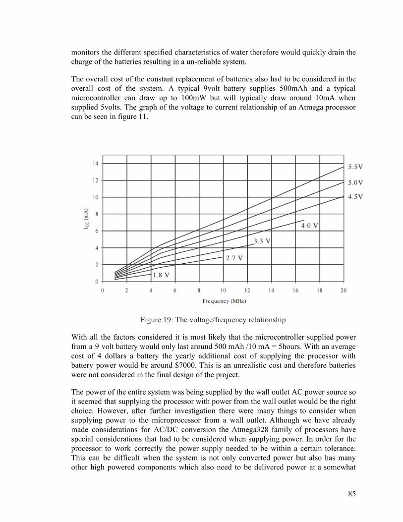
monitors the different specified characteristics of water therefore would quickly drain the charge of the batteries resulting in a un-reliable system.
The overall cost of the constant replacement of batteries also had to be considered in the overall cost of the system. A typical 9volt battery supplies 500mAh and a typical microcontroller can draw up to 100mW but will typically draw around 10mA when supplied 5volts. The graph of the voltage to current relationship of an Atmega processor can be seen in figure 11.
Figure 19: The voltage/frequency relationship
With all the factors considered it is most likely that the microcontroller supplied power from a 9 volt battery would only last around 500 mAh /10 mA = 5hours. With an average cost of 4 dollars a battery the yearly additional cost of supplying the processor with battery power would be around $7000. This is an unrealistic cost and therefore batteries were not considered in the final design of the project.
The power of the entire system was being supplied by the wall outlet AC power source so it seemed that supplying the processor with power from the wall outlet would be the right choice. However, after further investigation there were many things to consider when supplying power to the microprocessor from a wall outlet. Although we have already made considerations for AC/DC conversion the Atmega328 family of processors have special considerations that had to be considered when supplying power. In order for the processor to work correctly the power supply needed to be within a certain tolerance. This can be difficult when the system is not only converted power but also has many other high powered components which also need to be delivered power at a somewhat
85
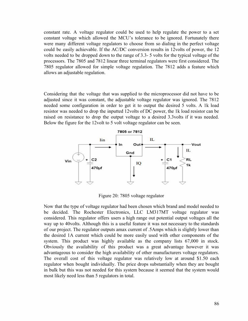
constant rate. A voltage regulator could be used to help regulate the power to a set constant voltage which allowed the MCU’s tolerance to be ignored. Fortunately there were many different voltage regulators to choose from so dialing in the perfect voltage could be easily achievable. If the AC/DC conversion results in 12volts of power, the 12 volts needed to be dropped down to the range of 3.3- 5 volts for the typical voltage of the processors. The 7805 and 7812 linear three terminal regulators were first considered. The 7805 regulator allowed for simple voltage regulation. The 7812 adds a feature which allows an adjustable regulation.
Considering that the voltage that was supplied to the microprocessor did not have to be adjusted since it was constant, the adjustable voltage regulator was ignored. The 7812 needed some configuration in order to get it to output the desired 5 volts. A 1k load resistor was needed to drop the inputted 12volts of DC power, the 1k load resistor can be raised on resistance to drop the output voltage to a desired 3.3volts if it was needed. Below the figure for the 12volt to 5 volt voltage regulator can be seen.
Figure 20: 7805 voltage regulator
Now that the type of voltage regulator had been chosen which brand and model needed to be decided. The Rochester Electronics, LLC LM317MT voltage regulator was considered. This regulator offers users a high range out potential output voltages all the way up to 40volts. Although this is a useful feature it was not necessary to the standards of our project. The regulator outputs amax current of .5Amps which is slightly lower than the desired 1A current which could be more easily used with other components of the system. This product was highly available as the company lists 67,000 in stock. Obviously the availability of this product was a great advantage however it was advantageous to consider the high availability of other manufacturers voltage regulators. The overall cost of this voltage regulator was relatively low at around $1.50 each regulator when bought individually. The price drops substantially when they are bought in bulk but this was not needed for this system because it seemed that the system would most likely need less than 5 regulators in total.
86

The next consideration was the LM350T/NOPB manufactured by Texas Instruments; this voltage regulator boasts high ratings and a low cost. This regulator can output voltages between the ranges of 1.2 V to 33 V while outputting a current of 3amps. The output current is high but this is easier to convert to lower currents so this seems like an advantage versus the previous .5amp output current of the Rochester Electronics voltage regulator. The input voltage minimus is fortunately 4.2 volts so this regulator works perfectly with our systems constraints. When purchased in bulk the regulator drops substantially in price but is still a reasonable price when bought individually. Since we will only be needing a few regulators for this project the individual price will only be considered. When purchased individually the Texas Instruments voltage regulator cost $1.81. This is more expensive than the previous regulator but 30 cents is something that can be ignored when trying to make a more functional system.
Next the MC7812ACTG regulator was considered. This product is manufactured by digi-key for a cheap $0.35. The website does not list how many regulators they have available but they do list multiple sites which have availability. This regulator takes 12 volts as an input and drops it down to 5 volts. Although the fixed voltage value of 5 volts was exactly what the processor was looking for it was not ideal because it would have become a problem if the processor needed to be changed to a processor with an input voltage of a different value. The regulator also has an output current of 2.2 amps. This output current was not ideal because it was much higher than the required output current. However it doesn't mean this current could not be manipulated to fit the requirements of the processor.
Lastly the NTE960 voltage regulator was considered. This regulator offered many of the features that the other regulators offered however the output is fixed on this regulator. Typically this would be ideal because of the easy set up and configuration. However since time is a factor in the completion of this system the limitations of having a fixed output did not seem to be ideal for the AquaEco system at the time. The processor of the system or many other components might have had to be changed through the development of the project. If the output voltage of the regulator was fixed and the new components needed a different voltage such as 3.3 the fixed regulator would not have been ideal. If a component was changed a whole new voltage regulator would have to be ordered and then configured to the new system. However, with the other 2 previous voltage regulators they were not fixed so all that would need to be replaced is the load resistor. With a simple calculation the load resistor could be replaced and the new correct output voltage could be achieved. The availability of this regulator was unfortunately much lower than the previous other 2 models with the website listing only 84 available for purchase. The price of this product also drops dramatically when purchased in bulk but this product is not offered in a high volume so these numbers could not be considered. Focusing on only the individual price of the regulator they would cost $1.55 which was considerable to the other 2 previous models of regulator. The fixed output value made this regulator a last possible option for our system leaving the other 2 models a viable option to the AquaEco system.
87

The Texas Instruments LM350T/NOPB voltage regulator was eventually chosen over the Rochester Electronics, LLC LM317MT voltage regulator. Many factors went into this decision but ultimately the output current of the LM350T was the deciding factor. Both regulators have similar output voltages and input voltages range as well low costs and availability. With all these similarities it only took one characteristic to make this decision clear.
Figure 21: TPS563249 regulator
Eventually the TPS563249 17-V, 3-A, Constant 1.4-MHz Synchronous Step-Down Voltage Regulator was considered because of its high functionality and large range of accepted inputs. This regulator allows designers a multitude of options such as the ability to select a set voltage output by configuring the regulator as necessary. This regulator allows input voltages to range from 4.5 volts all the way to 17 volts, obviously our 12-volt input would be within this range of voltages. A brief block overview of the regulator can be seen in figure-12.
Although this ability possessed by this regulator would have allowed it to be used in multiple situations through the creation of this system, we only considered it for converting 12 volts of DC power to 5volts and 0.2amps of DC Voltage and Current respectively. These output values had been selected to match the output values of the processor for seamless integration. The voltage rail was specifically designed to fit the needs of the processor since the processor was the most important component of the whole system. If the processor is not getting enough power from the electrical inputs it could cause a cascade of incorrect data being sent to the user or even worse an entire system failure.
88

Figure 22: TPS563249 voltage regulator
After careful consideration the TPS563249 17-V, 3-A, Constant 1.4-MHz Synchronous Step-Down Voltage Regulator was chosen to be used in creating the voltage rails to directly supply the processor with power. The TPS563249 needed to first be configured to provide the correct outputs according to the expected DC input. The schematic of the design of the 12 volt to 5 volt can be seen in figure – 13. The different components all share an integral part of creating the correct voltage output and current. The Cin is the input capacitor which was added to eliminate ripple current. The problem with ripple current was that it creates more unnecessary loss in the overall system. This capacitor eliminates the ripple current so the input to the TPS563249 17-V, 3-A, Constant 1.4-MHz Synchronous Step-Down Voltage Regulator can work with an input that is higher than 17 volts. This capacitor also allows the circuit to dissipate extra power than may be supplied to the circuit. This allows the entire circuit to be completely protected from random surges of power. The combination of these to helpful characteristics clearly makes the addition of this capacitor a necessary step of the creation of this regulator. Similarly, the Cout capacitor was added to the output of the circuit. This capacitor provides identical support as the Cin capacitor, so its addition supports the output of the system. L Ipp or the peak to peak current on the inductor was created to dissipate power that is coming out of the regulator. The Peak-to-peak inductor ripple current is approximately 1.35-Amps. The power output of the circuit was 100mW with an efficiency of 24.6%. By adjusting the resistor values the exact specifications can be achieved. The chosen resistor values are 73.2kOhm and 10kOhm by attaching the 73.2kOhm resistor with the inductor the output voltage of 5 volts was achieved. This arrangement of components also provided an output current of 0.2-Amps. The overall start up time of the circuit was found to be 1.57mS. Graphs of the start up time can be seen in figure-14.
89

Figure 23: Startup Voltage
These graphs provide the effectiveness of the system over a period maintaining both sought after values. By simply connecting the processor the voltage output and Iout points in the circuit the process received the correct voltage and current that the processor needed to function effectively. While the regulators adjustable output might have seemed like a positive feature at first glance it proved to bring up some concerns considering reliability. As shown in figure 3 the circuit quickly reaches a maximum voltage but what happens once the circuit reaches steady state. Since the supply voltage of the whole circuit has already been transformed down to be a functional 12 volt DC voltage, the input to the circuit is already proven as a functional and set input. Using the supplied voltage input of 12 volts it can be seen in figure 15 that the ripple voltage is still in effect however the fluctuation was so minor it could be still seen as a functioning voltage regulator circuit. The total voltage peak to peak value is a very small 14.30-mVolts. The average frequency of the whole circuit at steady state was 1381.00 kHz.
Figure 24: Steady state voltage
After much consideration the best option for supplying power to the different components of the system seems to be to create a different voltage rail for each different component of the system. Originally cascading the 12 volt to 5 volt regulator with a 5 to 3.3 volt
90

regulator and connecting components to their respective voltage seemed to be an easy solution.
After creating the circuits in simulation software, the current proved to be a possible problem. The simplest solution to this problem would be to create an individual rail to supply each component with exactly their respective power requirements. The creation of the 12 to 5 volt rail was discussed in the previous section. Now, the 12 volt to 3.3 rail will be discussed in the section below.
To accomplish the task of dropping 12 volts to 3.3 volts while also dropping the current down to .5- amps the TPS6217x 28-V, 0.5-A Step-Down Converter was used as the key element in the schematic. The TPS6217 converter allowed any voltage input from the ranges of 4.75 volts all the way up to 28 volts. While this range of inputs was not necessary it did allow support for random voltage surges, so the component didn’t break.
Figure 25: TPS6217 converter
The problem with the ability to accept multiple ranges of input was that the input must be perfect in order to have a correctly functioning system. Fortunately, the input process of the system had already been discussed in previous sections so the 12 volt input voltage with minimal ripple effects could already be expected. Although it was not completely ideal this circuit outputs a .5amp current which could have been manipulated later to become the needed values of whichever 3.3 volt component was being connected. The Cin capacitor had been set to 2.2 uF to smooth out an input ripple voltage or eliminated an input noise. While being very basic this capacitor was an integral part of the system because it made sure the converter could do it to the best of its ability by having a completely clear input. The ILpp was found to be a low 248.02mA and the current was later manipulated by the resistors shown in the circuit above to give a output current of 20mA. This was used to power the low voltage elements of the system. Current simulation software’s don’t provide support for the TPS6217 converter, so it was difficult to deduce the correct configuration to provide enough current to the components if more than one component was to be connected to the output of this converter circuit. At the time it seemed like the provided schematics of different electrical elements will most likely have to be changed to provide the different connected components with the correct power for maximum functionality.
If the rail system needed to supply power to more than one part of the system it was possible to power those components with different power rail systems. While this
91

approach may be the simplest there were still major obstacles which needed to be addressed. While the input voltage could easily be transferred to all the connected regulators and converters the current would be split 5 different ways resulting in a huge drop of current supplied from the input. The answer to this problem was the op amp voltage follower. By applying an op-amp voltage follower to each of the 5 voltage we were able to raise the current to a desired value while maintaining a voltage gain of 1. This method required much testing in order to make a truly coherent system. However, using the resources available it was easily possible to design a current booster which could be applied to the different rails. The design of this current booster can be seen below in figure 6.
Figure 26: Rail system converter
It was also possible to add a similar 5 volt to 5-volt current booster or 3.3 volt to 3.3 volt current booster circuit to the output of the different regulation rails. While this approach would result in a functional system, multiple different circuits would have had to been developed with different electrical components to achieve this objective. This was not completely practical because it would have required a large amount of circuit design along with the possibility of having a faulty booster. By using the same booster to control current for each different voltage rail of the system the chances of having a faulty circuit are reduced to one circuit instead of multiple different circuits. The positive aspect of using the same circuit as a current booster was that if a reorder was needed the problem could be fixed on all levels. The amount of time that was needed to reorder different circuits versus one circuit was the exact same. The combination of the regulation circuit with the current booster would have provided the different components with the power that their respective components needed to function.
We decided to not use a 12 volt input to our system. So the following section is eventually omitted from the final design. It should also be noted that the relay component
92

was also changed to a capacitor circuit which can be seen in more detail in the later sections.
Starting with an AC to DC converter, the converter is designed to have a 12-volt voltage output and a 1-amp current output. The output current is then split to be supplied to the different components of the system. Using a current booster, the current is set back to its original value while the voltage remains unchanged. The output of the current booster is then cascaded with its respective voltage regulator to make the output ideal for powering its component. This allows the system to have voltage rails to supply power to different components such as the relay circuit.
The different regulators will work for the voltage rails to supply voltage to different elements outside of the main board but are vplex to add to the main board. To accomplish the voltage regulation on the board different voltage regulators are used. After much consideration the 7805L regulator is used to drop a 12 volt input to a 5 volt output. The main reason for the decision in this regulator is that it is very simple to design. The 7805L regulator has a fixed output of 5 volts, which is exactly the desired voltage to operate the LED lighting system. The other regulator that is used on the main board is the LM2596T. The purpose of this regulator is its simplistic design and ease of operation. The regulator must be used with the 7805L so that the voltage can be dropped down from 5 volts to 3.3 volts.
The design for the relay system can be observed below in figure 6. The relay switch is activated by the output current from the Atmega328. When the output from the Atmega328 is in an off state the diode makes the relay move into its non common NC state. The non common state delivers the ground voltage to the light load of the circuit. When the Atmega328 delivers voltage the 2N2222 NPN transistor passes a small current through to the diode.
Figure 27: Relay
93

When the diode is in the on position current is strong enough to switch the position of the relay. The position on the relay is changed from non-common to common. In this position the relay is conducting and it allows the 12 voltage to pass through to the rest of the circuit. The 12 volt comes from the original 12 volt made from the AC/DC conversion. This 12 volt input is then regulated down to 5 volts where it is then the idea voltage to supply power to the lights. The combination of the diode and transistor allows for a minor amount of voltage to be added from the Atmega328. This allows for adjustability if different light would like to be later changed. All that needs to be changed to have the voltage from the AC/DC terminal with a regulator which can be easily created on Webench. The ability to easily switch the regulator's voltage can potentially save months of time since multiple PCBs can be ordered instead of switching the entire PCB board. The relayed 12 volts are then regulated down to 5 volts. To regulate the relay voltage a voltage regulator is used. Since the regulators which have been developed on Webench are very complex, a simple regulator is used. The LM7805L regulator is used. Capacitors are connected to the input and output of the regulator in order to take away the potentially overwhelming voltage which could stress the lights or whatever load is attached to the circuit.
94
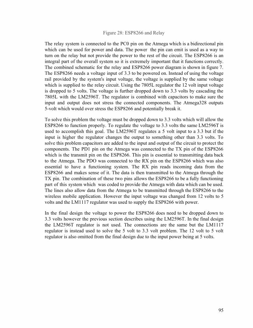
Figure 28: ESP8266 and Relay
The relay system is connected to the PC0 pin on the Atmega which is a bidirectional pin which can be used for power and data. The power the pin can emit is used as a way to turn on the relay but not provide the power to the rest of the circuit. The ESP8266 is an integral part of the overall system so it is extremely important that it functions correctly. The combined schematic for the relay and ESP8266 power diagram is shown in figure 7. The ESP8266 needs a voltage input of 3.3 to be powered on. Instead of using the voltage rail provided by the system's input voltage, the voltage is supplied by the same voltage which is supplied to the relay circuit. Using the 7805L regulator the 12 volt input voltage is dropped to 5 volts. The voltage is further dropped down to 3.3 volts by cascading the 7805L with the LM2596T. The regulator is combined with capacitors to make sure the input and output does not stress the connected components. The Atmega328 outputs 5-volt which would over stress the ESP8266 and potentially break it.
To solve this problem the voltage must be dropped down to 3.3 volts which will allow the ESP8266 to function properly. To regulate the voltage to 3.3 volts the same LM2596T is used to accomplish this goal. The LM2596T regulates a 5 volt input to a 3.3 but if the input is higher the regulator changes the output to something other than 3.3 volts. To solve this problem capacitors are added to the input and output of the circuit to protect the components. The PD1 pin on the Atmega was connected to the TX pin of the ESP8266 which is the transmit pin on the ESP8266. This pin is essential to transmitting data back to the Atmega. The PDO was connected to the RX pin on the ESP8266 which was also essential to have a functioning system. The RX pin reads incoming data from the ESP8266 and makes sense of it. The data is then transmitted to the Atmega through the TX pin. The combination of these two pins allows the ESP8266 to be a fully functioning part of this system which was coded to provide the Atmega with data which can be used. The lines also allow data from the Atmega to be transmitted through the ESP8266 to the wireless mobile application. However the input voltage was changed from 12 volts to 5 volts and the LM1117 regulator was used to supply the ESP8266 with power.
In the final design the voltage to power the ESP8266 does need to be dropped down to 3.3 volts however the previous section describes using the LM2596T. In the final design the LM2596T regulator is not used. The connections are the same but the LM1117 regulator is instead used to solve the 5 volt to 3.3 volt problem. The 12 volt to 5 volt regulator is also omitted from the final design due to the input power being at 5 volts.
95

5.4 Interfacing between sensors and microcontroller PH sensor One of the most important aspects of our end projects was the communication between the sensors in the system and the application. These sensors delivered their information to the main controller and we took this information and sent it over using WIFI and the main application. We begin with the sensors used, we start with the PH sensor, we use the Gravity: Analog pH Sensor. This PH sensor has a BNC connector at the end and transmits analog data. Because analog data cannot be read natively it was instead converted. This sensor transmits voltages from 0v to 5v and therefore it was mapped to PH levels between 0 and 14. There were external libraries available to decode the data through the serial interface however there must still be a way to take this analog data and convert it digitally. The analog to digital board of this device is as shown:
Figure 29: Analog to digital converter schematic for the PH sensor.
Requested image from DFrobot.com
This analog to digital converter relays this information and decodes it digitally. This decoder was used on our custom PCB to relay the information on the PH meter that was constantly being read. This was decoded using the DFRobot_PH Library which gives us built-in methods to read the inputs of this device. The inputs were then on a scale
96

between 0ph and 14ph the data was sent and received by an external API that converted the data to the application. The received data was then seen on an android app. Temperature Sensor The temperature sensor is the next device. We chose to use the Waterproof DS18B20 Digital Temperature Sensor. This sensor has only one wire that transmits data back and forth from the sensor to the PCB, and has two other wires for ground and power. While the data wire was sufficient for supplying power to the sensor, the VDD wire was also connected which allowed this circuit to provide parasitic power to it. With the analog to digital board of this device, although the temperature sensor sends out a digital signal, the ADC provides a location for a pull-up resistor to be connected with the sensor so that the sensor can receive a signal from the microcontroller. It also allowed the sensor to be connected to the microcontroller without having to solder a connection, which allowed for the sensor to be detached and replaced if needed.
Figure 30: Analog to digital converter schematic for the temperature sensor
Requested image from DFrobot.com
97

Turbidity Sensor The turbidity sensor is the final sensor device. The sensor that was chosen was the Gravity: Analog Turbidity Sensor. This sensor has an analog to digital converter attached to it. By changing the position of a signal mode switch on the ADC, it changes the type of data that the sensor sends out. Three wires were attached to the analog to digital converter. One is for the ground, the other is for the power, and the other is for data. When the converter is switched to analog mode, the data wire needed to be connected to an analog pin of the microcontroller, and to give off a signal from 0 - 4.5 V for the reading. When the converter was switched to digital mode, the data wire instead needed to be connected to a digital pin of the microcontroller, and it gave off either a low signal voltage or a high signal voltage of 5 V once the sensor detected a certain level of turbidity. The level in which the high signal is given was able to be adjusted through a potentiometer that was attached to the ADC.
Figure 31: Schematic for the turbidity sensor Requested image from DFrobot.com
98

5.5 PCB Design
Figure 32: Schematic for the first PCB
99

Figure 33: Board view for the first PCB
The first prototype for the PCB of the AquaEco is shown above. When designing the PCB, there were many different considerations and design choices that were made which ultimately affected the layout of it.
To start off, one aspect that had to be decided was what would be mounted permanently onto the board. By having certain components mounted on the board either by using screws to fix it into place or connecting them through headers, it helped to make the design more compact for the user and reduced some of the wire that would be needed to connect the components to the PCB. Especially since some of the features the aquarium have to benefit the consumers are: user-friendliness and compactness. Thus minimizing the amount of space and number of components that may be subject to wear or damage was beneficial.
On the other hand, we thought that having a specific area for a component to be mounted may cause problems when testing the components and design for the AquaEco. If a device needed to be soldered onto the PCB in order for a connection to be made, it would be harder to move it as needed in the case that an alternate connection has to be made or
100

the component would be better wired somewhere else, which would have a higher chance of happening as the at the time the prototype stage for the project continued. Additionally, by soldering the components, it may have limited the reach that the components for the system would have since parts like the ADCs of the sensors would have to be fixed. Another specification for the AquaEco was that it would have to be able to fit into fish tanks of varying sizes for easy installation into any tank the owners may have already, so limiting the flexibility of the system in this way was detrimental as well. Leaving the components unmounted to the board but connected through wires would have led to a larger system but would also have given a much greater potential reach and better control over placement of the devices. Furthermore, since some devices of the overall system may be more sensitive to heat, we found that by keeping them away from direct contact with the circuit board that the possible damage to them was reduced.
As a result, the benefits of keeping most of the components of the system unmounted was preferred over mounting them directly on the board. The decision then moved on to whether the components to be connected to the PCB should be attached using holes or surface mounts. Through holes are holes that are drilled through the PCB which can then be used as points for connection, while surface mounting keeps the connection points on the surface of the board. Although both methods hold similar purposes, they each have advantages and disadvantages. For through holes, they are more robust than surface mounts. Since the connections go through the board entirely, it is stronger in cases where components may have to be reattached and removed again constantly and can handle power and heat better than the surface mounts. However, the holes and pads of the through holes can take up more space than surface mounts, and there is a higher production cost when drilling through the board. For surface mounts, they are smaller than through holes, which can allow for more connections of components in the case that the PCB needs many parts to be attached to it. Since they remain on the surface, they also do not require drilling through the circuit board, which means that boards that favor surface mounting are overall cheaper and faster to manufacture. However, the cons are thus that they are less robust connections compared to through holes.
Through holes were ultimately chosen as the preferred method for producing this prototype of the PCB. Although the board did end up more costly, having the connection points more durable was eventually found to be helpful when testing the board, since issues did arise where the power going through a connection was found to be higher than expected, also components had to be moved and reconnected repeatedly. Due to the earlier choice of keeping most of the components of the AquaEco system separate and not attached directly to the board, the con of the through holes being larger than the surface mounts would be mitigated since large or many components would not have to
101
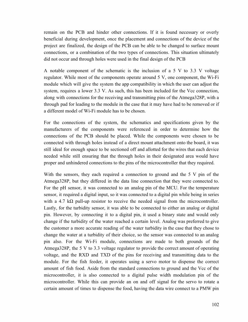
remain on the PCB and hinder other connections. If it is found necessary or overly beneficial during development, once the placement and connections of the device of the project are finalized, the design of the PCB can be able to be changed to surface mount connections, or a combination of the two types of connections. This situation ultimately did not occur and through holes were used in the final design of the PCB
A notable component of the schematic is the inclusion of a 5 V to 3.3 V voltage regulator. While most of the components operate around 5 V, one component, the Wi-Fi module which will give the system the app compatibility in which the user can adjust the system, requires a lower 3.3 V. As such, this has been included for the Vcc connection, along with connections for the receiving and transmitting pins of the Atmega328P, with a through pad for leading to the module in the case that it may have had to be removed or if a different model of Wi-Fi module has to be chosen.
For the connections of the system, the schematics and specifications given by the manufacturers of the components were referenced in order to determine how the connections of the PCB should be placed. While the components were chosen to be connected with through holes instead of a direct mount attachment onto the board, it was still ideal for enough space to be sectioned off and allotted for the wires that each device needed while still ensuring that the through holes in their designated area would have proper and unhindered connections to the pins of the microcontroller that they required.
With the sensors, they each required a connection to ground and the 5 V pin of the Atmega328P, but they differed in the data line connection that they were connected to. For the pH sensor, it was connected to an analog pin of the MCU. For the temperature sensor, it required a digital input, so it was connected to a digital pin while being in series with a 4.7 kΩ pull-up resistor to receive the needed signal from the microcontroller. Lastly, for the turbidity sensor, it was able to be connected to either an analog or digital pin. However, by connecting it to a digital pin, it used a binary state and would only change if the turbidity of the water reached a certain level. Analog was preferred to give the customer a more accurate reading of the water turbidity in the case that they chose to change the water at a turbidity of their choice, so the sensor was connected to an analog pin also. For the Wi-Fi module, connections are made to both grounds of the Atmega328P, the 5 V to 3.3 voltage regulator to provide the correct amount of operating voltage, and the RXD and TXD of the pins for receiving and transmitting data to the module. For the fish feeder, it operates using a servo motor to dispense the correct amount of fish food. Aside from the standard connections to ground and the Vcc of the microcontroller, it is also connected to a digital pulse width modulation pin of the microcontroller. While this can provide an on and off signal for the servo to rotate a certain amount of times to dispense the food, having the data wire connect to a PMW pin
102

also gave the servo the ability to have variable speeds for the turning of the fish feeder is desired.
For the LED, it was found that a direct connection to the power supply of the system instead of the Vcc pin of the microcontroller was necessary. Due to the LED strip requiring a large amount of current which draws too much power from the microcontroller and would result in a dim light, it needed to be wired directly from the power supply like the microcontroller. Along with this, a 1000 μF capacitor is connected to the voltage line and ground, and a 470 Ω resistor is connected in series with the data line leading to a digital PMW pin of the microcontroller. When the LED strip is turned on it can cause a drastic drop in voltage and current, which can damage the circuit or LEDs over time. The capacitor and resistor are included to counteract this whenever the LED strip is activated. A PMW pin is also utilized again due to allowing the signal of the data line to be variable, which in turn allows the brightness of the LED strip to be controlled through the AquaEco app by the owner. This is especially important for giving the fish in the aquarium the proper amount of light, where it would be necessary to either lower or raise the intensity based on the amount of light that may be already present or absent from within the room the aquarium is placed in.
103

Figure 34: Main schematic for the second PCB, not including the first voltage regulator
104

Figure 35: Schematic for second PCB of the first voltage regulator
105

Figure 36: Board view for the second PCB
After testing the first design of the PCB, it was found that adjustments had to be taken to the PCB’s design. However, most of the design from the first prototype was used as a basis for the second, and the second was the design that was used successfully for the final implementation. One change included adding a 16 MHz crystal oscillator to the two crystal pins of the ATmega, with 20 pF capacitors connecting each pin to ground. It was initially believed that the internal 8 MHz oscillator of the ATmega would have been used to provide the clock signal that would have been needed for this project. However, using the internal clock would have been less accurate than the external oscillator and would have provided a slower clock speed, both characteristics which would have been detrimental for the AquaEco which relies on timing-based devices to maintain the aquarium and sends a large amount of commands to the microcontroller. For the voltage regulator outputs, additional through holes were added. While the initial design featured two through holes to provide 3.3 V to the WiFi module, four were put on each voltage regulator to power the 3.3V, EN, RST, and IO0 pins of the module. Another change was removing the resistor that was in series with the temperature sensor data line connecting to the digital pin of the ATmega. While it was believed to have been necessary for the first design to act as a pull-up resistor, during testing, it was found that a direct connection from the adapter of the temperature sensor to the microcontroller was sufficient for the sensor to work.
106

The last and most significant change along with the second PCB was the addition of a different second 5 V to 3.3 V voltage regulator. During testing of the first iteration of the PCB, although the design of the first voltage regulator was to take an input of 5 V and convert it to a 3.3 V output, the output of the first voltage regulator only delivered around a 2.4 V when the devices of the AquaEco were connected in the system, which was not enough to power the ESP8266 consistently. To deliver the necessary voltage to the module, a second voltage regulator, the LD1117, was implemented onto the board. This was a low-drop voltage regulator that could take an input of between 4.3 V and 15 V and reduce the output to a fixed 3.3 V. A 100 µF capacitor was attached from the input of the second regulator to ground, and a 1000 µF capacitor was attached from the output to ground. These capacitors helped to stabilize the signal coming from the LD1117. Furthermore, four through holes were also added to the output of the second regulator to provide connection points to power the pins of the ESP8266. This second regulator was to power the 3.3V pin of the WiFi module while the first voltage regulator was kept onto the board to provide power to the other IO pins on the module, but during testing, it was found that the output of the LD1117 alone was sufficient to power the WiFi module.
6.0 Software Design Our solution has 3 software components: The software running on the Atmega controller, the software running on the ESP wifi module, and the software running on our Android app. The following pages show their respective flow diagrams. We considered another potential architecture involving a remote server and a database, to handle logins and to handle all data, but determined that such a design would add unnecessary complexity. The three components generally handle three separate aspects of the project. The Atmega controller on the PCB handles interactions with the sensors, lights, and feeders; The ESP WiFi module handles all networked communications; and the App handles user input and reporting. One of the core concepts of AquaEco deals with the software implementation that will bring together the components relating on the hardware level and bring them to the world of IoT (Internet of things). We accomplished this through creating an android application This was vitally important for the success of our project and gave our solution the edge over other competing products available. As such we needed to have decisions done at a software level that was be based on the hardware described above. Ultimately our goal was to relay the information the above sensors supply along with control the lighting and the fish feeder. Our hardware part selection was done on a level so that software communication was easier and more feasible.
107

6.1 Design choice AquaEco’s goals are to create an application for the many users that will be using the service. An application is a way that a normal day-to-day user will be able to communicate with their aquarium. On a basic level we were looking for a solution so that every aquarium is individually connected to an application based on a user created account. We decided over creating an application based on the fact that it would be easy to use for an individual. There are however, many other ways to implement the rallying of information over the internet.
Web application
The basics of a web application come from going into a webpage similar to that of “www.website.com”. A url is provided to a user and from there the web application can do a variety of different tasks. A web application best benefits include a wide variety of support. Web pages can be accessed on a variety of different devices and are only limited by availability of internet connection. Web pages are built using Javascript, html, and often css. Recently, there has been a large increase in web applications. With the aforementioned languages and tools, building a web application is now easier than ever with progressive scaling. Scaling refers to the size of the page itself. In past years web applications were often thought of as dependent on large screens to show the information. However, things have changed and now with particular designed choices a user can design a webpage that will have fields and images that become smaller as the screen size decreases. Downsides to building a web application include having a less cohesive experience. Users are unable to receive notifications directly onto their device and users must visit the webpage every time to access information. There is often also a performance hit with building a web application.
Mobile application
The next form of relaying information onto a user was to build a unique mobile application. A mobile application is found in either the Apple app store or Android play store. There are also other markets where an application is available. However, these two are the most prevalent and popular in today's market. This application store is home to native phone applications. These applications range from games to weather and news. Phone applications differ in web applications in the sense that they gain their own icon on the device and communicate using the device hardware through a layer. This cohesiveness brings about other benefits like improved performance, more user interface features, and notification support.
One of our main goals of AquaEco was to enrich the user with notifications that will help them in monitoring their aquarium. These notifications can range from notifying them of unsafe pH levels, temperature levels and also remind them that either lighting was left on or the fish need to be fed. These notifications are vital and were easier to provide to the user if done via a phone application.
108

The mobile application differs depending on what phone and marketplace it was built for. Unlike a web application which is available for every platform as long as a user has an internet browser, a phone application is only available for the platform it was built for. An app from the Apple app store is only compatible with applications available on its platform. This means android users are unable to access this app. The developers must choose to create an application on one platform or choose every platform and have a higher more costly development. Along with this, it is also more time consuming.
Because of rich notifications, we decided to use a mobile application to incorporate the monitoring and controlling hardware of our system. However, due to time constraints and costly development measures we decided to create an application for the android play store. Creating an application for the android play store is cheaper and is more available to more users, as the user base of android is much larger. Plans to create an Apple app store application can be created down the line to expand the user base. A phone application will also have a better user interface and with a large JAVA library set available will be much easier to create said application.
Aspect Choice Pros Cons
Type of application Web Cross platform, development support
Less support, less integration with device
Type of application
Mobile Integration with device, better user interface, easier to use
Costly, Different code bases for different device
Table 14: Type of application selection
6.2 Development environment Our software implementation began at an environment level. Choosing what software to use to create the android application was important as it laid the groundwork for what features our application used. There are some options available for android app development that will be discussed. These tools are known as IDE or an integrated development environment. These environments are used for making it much easier to code and develop. These environments have extra features like debugging and simulating devices. Due to the nature of an application being built for a mobile device, an IDE is
109

very recommended as it has strong simulating capabilities used for previewing the application on an on screen device.
Android studio
Android studio is one of the most popular choices for developing android applications. Because google themselves create the ide and also create android, it has strong cohesive backing between developing applications and adding it to the play store. It contains features such as simulation, resource manager, Layout Captures, and version control. Our goal was to develop a basic application that can interface over wifi to talk to our microcontroller and wifi chip. This IDE provided the features needed to do so.
Unreal Engine
Unreal engine is another IDE that can build android applications easier than using note software. Unreal engine is used in applications that are rich in visuals and graphics. It is often used to create large scaled games and provides features such as cross compatibility, built in asset, real time rendering and a strong graphical user interface. However, this engine was much more complex than was necessary for our uses.
IntelliJ IDEA
IntelliJ IDEA is a cross platform IDE used for mobile development across many different platforms including ios and android, it is similar to android studio and contains a strong backing in third party plugins that can make development easier for large scale projects. It also features an intelligent coding engine that will provide quick fixes for the code base.
Eclipse
Eclipse is a very popular Java ide that has been used for many years and has proven to be stable and commercially viable. Eclipse allows third party plugins and due to this has android plugins available. The android plugin known as android development tools uses much of the same api features that android studio has but unfortunately this plugin is no longer getting major updates.
Our final choice of IDE is android studio due to its unique feature set that makes creating basic text applications easily. The in built emulation tool also allows for rapid testing. While the other IDE have features that are used in the industry, our application does not use 3D assets and does not need to be cross platform. There are also many resources available for android studio if any development questions are to be had.
Language
Java is a programming language that is object oriented based. Due its strong support in android studio is recommended as the choice for android app development. Java has
110

extensive support in many external libraries for android app development. These external libraries make coding applications faster and with stronger support should bugs and other abnormalities arise. One of the biggest reasons to also use Java when developing android applications is due to the fact that android is built on java itself, having a 1 to 1 cohesive connection between libraries and the internal system is useful in terms of speed and compatibility. Additionally, Java’s support for simple UI design means much of the design process for producing the app UI will be rendered much easier. There are other languages like C++ that are compatible with Android studio, but this language is used on android more commonly for game building. In terms of our project, we will use Java.
6.3 Client App Environment Selection
Aspect Choice Pros Cons
Integrated development environment
Android studio
● Strong backing ● Support ● Emulation
● Needs lots of resources
● Can be slow with many plugins
Integrated development environment
Unreal engine
● Strong 3d components,
● Cross platform
● Lacks android specific integration
Integrated development environment
IntelliJ IDEA
● Third party plugin Cross platform
● Lacks integration with android
Integrated development environment
Eclipse ● Cross platform Support
● Outdated, ● Less
updates and stability
Language Java ● Object oriented ● Cross platform
● Resource intensive
Language C++ ● Extensive 3d application support
● Fast
● Lacks integration with android studio
Table 15: Final language selection
111

6.4 Embedded software The Atmega328P Controller The software on the Atmega microcontroller, which is mounted on the PCB, was written in C++ in the Arduino IDE. It serves three primary purposes. The first purpose of this software is to read sensor data from the sensors when the ESP WiFi module has requested sensor data across its serial communications port, and to then send this data back to the WiFi Module. This is the main way that the tank is able to measure and send the sensor data eventually to the app, and ultimately for the user to read. The second purpose of the software running on the Atmega controller was to control the feeding of the fish. The fish are fed a certain number of times a day, at certain times, which will be determined by the user. Therefore, the software must maintain a clock and timer system that determines if and when it is time to feed the fish. When the right amount of time has passed, the feeder will be activated and the food will be dispensed. Using the internal clock, the software maintains a somewhat inaccurate clock to know what time of day it is. Additionally, the Atmega occasionally is given an updated time of day by the ESP module, which occurs every time the user requests sensor data. This time reset is used to correct the errors in what time the Atmega thinks it is vs what time it actually is, errors which would otherwise accumulate over time and potentially lead to a somewhat substantial difference in time. Besides the fish feeding time, the Atmega also keeps track of the time to turn the lights on and off. The LED colors are also adjustable. This is the third purpose of this software - to control, power, and toggle the lights. Occasionally the user may desire to change the lights color, lights out time, lights on time, fish feeding time, or fish feeding frequency. This data is then supplied to the Atmega by the ESP, which is then used to update the Atmega’s time listings for when these actions should occur. The logic for the Atmega’s software can be summarized by the UML diagram at the end of this section, as well as the following process:
1. Read data from ESP and use accordingly. If this is a new feeding time or lights time, then set those new values. If this is a request for sensor measurements, then measure the data and respond.
2. Compare current time to the fish feeding times. If it's time to feed the fish, then feed the fish.
3. Compare current time to the lights on and lights off time. If it's time to toggle the lights, then toggle the lights.
4. Repeat.
112

The ESP8266 Controller The software on the ESP8266 microcontroller was written in C++, and was also written in the Arduino IDE, using an addon designed to allow developers to program the ESP8266 in the same environment. By default, the ESP8266 chip comes with a firmware that could in theory fulfill our needs inherently. It uses AT commands to allow a master microcontroller (in our case the Atmega) to send commands to it over UART in plaintext. These commands can be used to list available networks, connect to networks, set up the chip as an Access Point, and everything else we might need. However, we decided that it would be most efficient to flash our own custom firmware to the chip instead, using the Arduino IDE. There are many libraries we can use to streamline exactly what we want the device to do that can make our job easier, without having to use AT commands. Additionally, we found a library called WiFiManager that makes the initial setup of the device to a local user network much easier. This library could only be used in conjunction with flashing the device with our own firmware, which served as the final nail in the coffin in the decision of writing it ourselves. The software we wrote for the ESP8266 therefore had one primary purpose - to serve as the middleman between the Atmega controller, which handles sensors, lights, and food, and the App, located on the same network or anywhere on the internet. Its main goal was to be to facilitate the passing of user requests and their responses from the user to the Atmega, and vice versa. The first thing the Atmega does when it receives power is that it uses the WiFiManager library to set up an ad-hoc WiFi network for the user to connect to locally with their device. This directs them to an HTML page that provides them with fields to enter their home WiFi network’s SSID and Password, as well as a password for connecting to the device from then on. The module then shuts down the access point and attempts to connect to the user’s home network using these credentials. If this is unsuccessful, then it reopens the ad-hoc network and wait for the user to try again. There are two ways that the information can be sent from the ESP-8266 to the end user. The first way is to continuously broadcast a udp packet identifying itself on the network and then sleep for a moment until it receives a response from an App on the same network acknowledging it. This is known as a basic discovery protocol. Once the App knows what IP the module has been assigned, it is then able to communicate with it using TCP sockets. From this point on, the module will sit in a loop waiting until it receives a TCP connection request. Once an instance of the app connects in this manner, the module will receive a packet from the user describing the action needed - a new feeding time, a new lights time, a new lights color, or a request for the status of the tank (sensor readings). If the password set by the user in the initial setup is supplied in the request packet, then the ESP will then send this data to the Atmega controller across the serial port. If the packet was a request for sensor data, then the ESP will wait until the Atmega responds with the sensor data, which it will then send back to the App over the TCP
113

connection. Then the ESP will terminate the TCP connection, and will again wait for incoming new connections. The logic for this ESP8266’s protocol can be summarized by the UML diagram at the end of this section, as well as the following process:
1. Perform initial setup using WiFiManager and an ad-hoc network 2. Wait for requests from the app, and relay them to the Atmega controller 3. If the request was for sensor readings, then respond to the app with the relevant
data 4. Return to step 2.
The next way we could broadcast the data from ESP-8266 is to use an external server and api solution. In this scenario which we will describe below, the ESP-8266 will only use an external library known as ESP8266HTTPClient along with Arduino_JSON to send GET and POST requests to a server. It is constantly making a get request to the external server and the database will be in charge of issuing needed changes that the esp will pick up. In this scenario we move the processing to the server side. This will increase speed and require much less processing on the ESP8266 side. The UML diagram for this communication is also shown at the end of the section. The process is as follows:
1. Perform initial setup using WiFiManager and an ad-hoc network. 2. Issue a GET request to receive new data relating to Feeder and lighting controls
from the server. 3. If needed send the necessary data via serial to the atmega. 4. Issue POST request to send new sensor readings to the database. 5. Return to step 2.
Originally we had selected the first way, unfortunately due to the speed and the unreliability along with poor scalability and longer development times we decided to use the second method and below have explained the new changes and selections regarding the use of the second option. The Host The host that was used is known as Heroku, one of the reasons we chose this host was due to the cheap cost and reliability. It also supported the languages and structure we needed. Heroku was our choice due to these reasons. The Database
114

We decided to use MYSQL along with ClearDB to host our database that housed our data. ClearDB is an extension available in heroku that enables us to host a mysql server instance. Specifically MySql server 5.5. We chose MySql due to the schema that we needed. A relational database was needed over a non relational model. The schema consisted of one main linking table that had the identify code of every AquaEco device. This identifier code was the Mac Wifi address of every device. Since every device has a unique id and because it was easy to extract from the ESP8266, we decided to use this to distinguish every AquaEco device. Next we had 3 tables that housed the turbidity sensor voltages, the temperature in fahrenheit and the pH levels that were returned from the atmega. These tables have a foreign key linked to the identify code of every AquaEco. Next we had two tables for lighting and feeding. These tables control the LED and the Fish feeder. The led table consists of columns for fromTime and toTime along with 2 flags that enable the ESP8266 to know whether or not it is to tell the atmega to turn on the lights or turn off the lights. This is the field that the application will modify to do so. These tables are also linked with the device unique id. Lastly, we have a table where we link every AquaEco device to an android phone. This is to allow multiple android phones to control multiple AquaEco devices. The API For the API we used the PHP language along with heroku to host our application. The API served two purposes. First, it was to offload the expensive query costs regarding direct connection with a database and second, because it enabled a cohesive interaction between android and the ESP8266. Both the ESP8266 and the android phone would use the same API to send data using POST and receive data using GET. This made writing code for both platforms at the same time much easier. Our api feature prepared statements to avoid injection and used the identify code of each AquaEco to properly store the correct data and information to the correct AquaEco device. The API was done in PHP due to the extensive documentation relating with PHP and MYSQL. PHP features native MYSQL support which made development time much faster. The Android App The software comprising the Android app is written in Java using Android Studio. This application serves as the user’s primary means of interacting with the fish tank. Our original plan had the android app check for a UDP broadcast on the network from the ESP8266. Then the app would receive a UDP broadcast and extracts the IP from it. After that, and every time the app is opened thereafter, the app would initiate a TCP connection with the IP address of the tank to issue a request for sensor data. The new changes would have been sent as a packet directly to the ESP chip. The logic is shown below as the diagram. However, due to the complexity in development along with other issues regarding this implementation we decided to change the interaction between the Android application and ESP chip. The details will be explained below.
115

First, the new android application uses the OKHTTP3 external library to make a connection to our external server. The external library makes GET and POST requests very easy and straightforward. The GET requests will obtain information from the database regarding the current status of the sensor readings. The POST requests will insert data regarding to and from time, feed times, and whether the user wants to turn on the LED lights or fish feeder. After these requests are done, the data is retrieved asynchronously. This allows the application to still function while the data is being retrieved. All of this occurs fairly rapidly, therefore the user sees no major delay. The corresponding UML diagram for the android app server implementation is on the next few pages. Figure 37: Atmega328P’s UML Diagram
116

Figure 38: ESP8266’s UML Diagram
117

Figure 39: Android App’s UML Diagram
118

119

6.5 Interface of application
● AquaEco Application
● AquaEco Homepage:
The AquaEco homepage displays all of the features of the entire system in an easy to read, simple to use, convenient application. The application is constantly updated by the many sensors of the system allowing the user real time knowledge of the current status of the system. By using the processors wifi capabilities information can be delivered to the application wherever the user of the application is located. The user is able to see the temperature, pH and most importantly get a real time status of the water for the system. This water droplet can change color from blue to brown to dark brown indicating to the user that the water is clear, murky, or dark as shown above. The user is also given access to the setup screen. This module at the top allows the user the option to set up a new device or choose a pre existing saved one that was linked to the device.
120
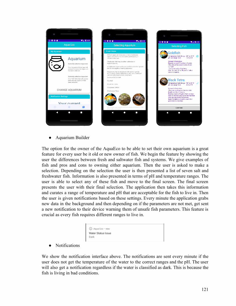
● Aquarium Builder The option for the owner of the AquaEco to be able to set their own aquarium is a great feature for every user be it old or new owner of fish. We begin the feature by showing the user the differences between fresh and saltwater fish and systems. We give examples of fish and pros and cons to owning either aquarium. Then the user is asked to make a selection. Depending on the selection the user is then presented a list of seven salt and freshwater fish. Information is also presented in terms of pH and temperature ranges. The user is able to select any of these fish and move to the final screen. The final screen presents the user with their final selection. The application then takes this information and curates a range of temperature and pH that are acceptable for the fish to live in. Then the user is given notifications based on these settings. Every minute the application grabs new data in the background and then depending on if the parameters are not met, get sent a new notification to their device warning them of unsafe fish parameters. This feature is crucial as every fish requires different ranges to live in.
● Notifications
We show the notification interface above. The notifications are sent every minute if the user does not get the temperature of the water to the correct ranges and the pH. The user will also get a notification regardless if the water is classified as dark. This is because the fish is living in bad conditions.
121

● LED Settings Menu
Another exciting feature presented in the settings portion of the main menu is the LED control menu. This feature allows users to make major changes to the environment of their aquarium anywhere in the world as long as WiFi is available. The LED control has a simple on/off button as well as a control for timing of the LED. The user is able to control all aspects of light that their aquarium will receive through this settings menu. This menu is an integral part of the AquaEco system because it allows users to have real time control of their system which the other components will monitor. The combination of the LEDs and sensors gives the user the ability to make educated decisions when making changes to the LED settings. Over time the system's user will be able to dial in their prefered settings for an optimal environment with minimal maintenance. We also provide the user with timings for the LED. This enables the user with a UI to select a time range to have the LED turn on and then off. This is crucial for users that are traveling as the lighting will work regardless with an internet connection or not.
122
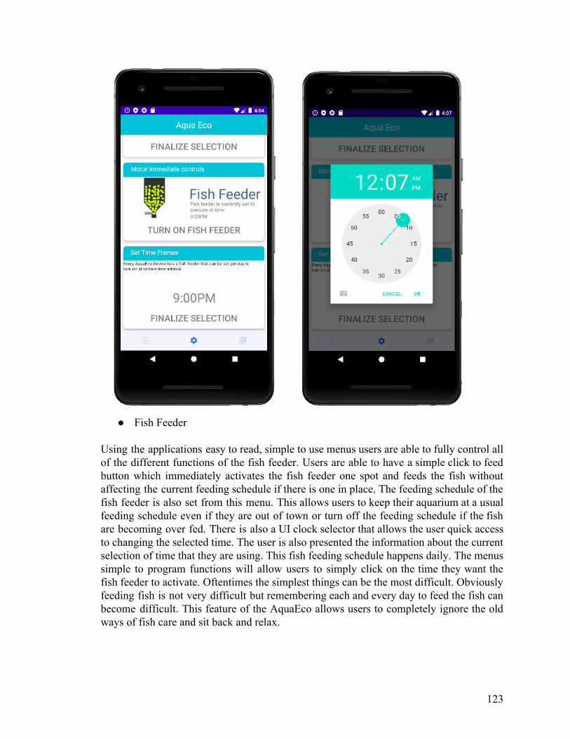
● Fish Feeder
Using the applications easy to read, simple to use menus users are able to fully control all of the different functions of the fish feeder. Users are able to have a simple click to feed button which immediately activates the fish feeder one spot and feeds the fish without affecting the current feeding schedule if there is one in place. The feeding schedule of the fish feeder is also set from this menu. This allows users to keep their aquarium at a usual feeding schedule even if they are out of town or turn off the feeding schedule if the fish are becoming over fed. There is also a UI clock selector that allows the user quick access to changing the selected time. The user is also presented the information about the current selection of time that they are using. This fish feeding schedule happens daily. The menus simple to program functions will allow users to simply click on the time they want the fish feeder to activate. Oftentimes the simplest things can be the most difficult. Obviously feeding fish is not very difficult but remembering each and every day to feed the fish can become difficult. This feature of the AquaEco allows users to completely ignore the old ways of fish care and sit back and relax.
123
7.0 Component Testing and Readings A very important aspect of any engineering design in the testing phase and testing of the component. Our project features a lot of sensors and external components that all had to be tested. We choose to use a prototype board and breadboard to test the hardware aspect of our design. For software we tested the functionality of our API by using POSTMAN to issue our POST and GET requests.
7.1 Prototype board selection Of the selected components discussed earlier many read results differently and interface within the chip as well in different ways. The temperature sensor DS18B20 reads information through a one wire bus and is able to interact with the digital pins of the ATMEGA cpu, the turbidity sensor uses analog to interface with the main cpu. Therefore, much testing was needed to understand results and understand the interfaces for connecting to the ATMEGA cpu. One way to accomplish this was to use a prototype board. There are many different prototype boards available to purchase and all have various features that set them apart from the other boards. In particular we wanted to make sure that the testing we did is for the same cpu that we used in our PCB, this was to make sure that compatibility was met and that the cpu was able to handle the inputs of the sensors. We looked at mainly one specific type of board. The Arduino family of boards is home to three popular models including the Arduino Nano, Arduino Uno, and Arduino Pro, of which can come equipped with the ATMEGA328 or the ATMEGA168 depending on the version. These prototype boards have components and voltage railings that allow us to effectively test the PCB without needing extra DEBUG ports. The main difference between the Arduino nano and the Arduino Uno is the size and form factor. The uno is much smaller in size and features a mini usb for charging and supplying power. The Uno is bigger and uses not only a usb port but has an in built power regulator on the board itself, the larger size brings more compatibility to various accessories like being able to mount a prototype shield on top. The Arduino pro has the same components the mini has but features a FTDI board, there are also feature i2c connections on the grid pins if needed. With this information in hand we decided to test our components with the Arduino Uno for its large size and compatibility with various accessories that we used like the prototype shield.
124

Table 16: Prototype board selection
Part Pros Cons
Arduino Nano Form factor Size Firmware compatibility
Less compatible with accessories
Arduino Uno Larger pool of compatible accessories Power regulator built in
Bigger size
Arduino Pro FTFI programming Form factor
No usb input Bigger learning curve
7.2 Breadboard testing Before testing began we laid out the components that needed to be tested, this included all the sensors, the motor and the led strip. These components did not need to connect to each at the same time, but for space purposes showcased them in the diagram below as such. They all utilize the same 5volt railing. In our final design we used a direct 5 volt 3 amp connector. While the arduino uno is unable to provide the same current, after calculations we noted that the combined current peak draw would not exceed that of 700 mA again, meaning that the arduino uno would be a direct testing translation . Of importance is the types of inputs used on the board itself. We handle analog inputs, digital and powered digital inputs all on the board. This is another reason why the atmega processor was selected. Many other processors at this price point do not offer the amount of expandability we needed to hook all sensors together. This means that we are able to house our one chip solution that can interface via the plug and play into these pin inputs. For testing purposes we use the power of the USB bus located on the chip itself, and also a 9v battery along with dc jack adapter for allowing the device to be moved from place to place to test various functionality like the waterproof nature of the temperature sensor, turbidity with different liquids and the pH readings. No other components were used besides those mentioned below and shown in the schematic. The led is shown as single to save on space likewise the temperature and turbidity sensors are given tags as they can be mistaken for other components. In some cases like reading the temperatures or turbidity we decided to view results via a i2c chip LCD display. This was mostly done for live results to test the capabilities of constant polling on the chip and its processing power, for other components like the leds and the pH tester these were read via the arduino ide serial interface as explained below. Also below are our findings and remarks for each part.
125

Figure 40: Board layout for testing purposes
Arduino development tools and libraries used
To test our components we decided to flash the arduino uno using the native arduino 1.8.11 tool kit available to download for free. This free IDE is the most popular choice of easy flashing given these chipsets. In fact, this one of the main reasons why we selected our processing unit as an ATMEGA chip that is flashed properly can only utilize all the extensive libraries and feature sets that this IDE offers. There are a couple of downsides like low debugging options in comparison to tools like code composer studio found in the MIPS chipsets but client debugging can also be done. Extensive library support is one of the main reasons to use this IDE. Libraries are a way to have third parties or open source developers write code that can be reused when method calls are implemented. For example, a library can contain code that will read input from an analog source and interpret the voltage findings into numbers that we can understand. Since we decided to test each individual part separately every sketch or program was written separately and did not communicate at this time together. This was done because of quicker development time as at this moment our focus lied with making sure the parts functioned. The cohesive nature of our final product is detailed later. Some of the libraries we used included DallasTemperature.h which has methods that take in a one wire interface and convert the returned voltage into a temperature reading in celcius format. We can take a neatly converted number and display it to an lcd or use serial print to interface with the inbuilt serial monitoring system monitoring system built into the software. Since the arduino ide supports this serial interface we do not need external libraries to accomplish this. This is one way to debug on the client rather than have the ide run the debugging for
126

us. Another library used was OneWire.h which is a good library that is specific for our DS18B20 temperature sensor, which means that the methods built in like request temperature can return the proper number, this number number can be sent to the Dallastemperature library to convert the results properly. Like mentioned earlier, we used an i2c LCD component to display the results of the temperature and the turbidity sensors. To accomplish this we used the library LiquidCrystal_I2C.h which simplifies the connection of the display which can be simplified to simple calls that initiate the backlight and push output to the display. For the next sensor the turbidity sensor we do not use any library and instead compute the read voltage. For the servo motor we used the library FastLED.h which gives us many methods that can make the leds a certain color or certain pattern easily. This is accomplished through palettes which are defined sequences of colors and patterns. For the servo motor we used the library Servo.h which allows custom methods that interface with the digital powered pins of the board. We get access to methods that simplify speed and angle trajectory. Similar to the turbidity sensor, for the ph sensor we do not use a library and instead interpret the values via mathematical means.
Temperature sensor DS18B20
With our final sensor selection being based on a variety of reasons, there were many benefits to having an external temperature sensor that is based on the one wire bus. This bus meant that connection to our prototype board was straight forward. The sensor interfaces via the digital input on the board, the other two wires read and black are for vcc and for gnd. One important thing to be aware of is that we used a pull up resistor of 4.7k ohms so that we guaranteed a high state for this temperature sensor.
This temperature sensor can operate on 5V which we can supply via the 5v output found on the board. With these components the sensor operates through Arduino via the library DallasTemperature which is a third party library available to download via the internet. This library was explained earlier but is the main reason we have rapid development times.The readings are done in Celsius and through conversion can be turned into Fahrenheit readings. We used an i2c based lcd to showcase results. These results were compared with a laser temperature reading and were found to be accurate. This temperature sensor is able to work in water which is the main goal ultimately, as it will stay inside the fish tank for monitoring.
127

Figure 41: User testing for temperature sensor example Figure 42: board schematic for temperature sensor
Here we can see how we interfaced with the board, Another aspect of the temperature reader is the fact that it can be completely submerged in water meaning more accurate readings. For the right side image with the board we note the digital pin input (yellow) and the black to vcc (5v) and gnd.
DF robot Turbidity sensor
The turbidity sensor supplied by DF robot works by measuring how much light is able to transmit within a medium. It operates on the same 5volts that the temperature sensor did as well. This sensor releases values from 0 to 4.5 volts and works by taking this voltage and converting to a complementary NTU value which can go from 0 to 3000. These voltages and NTU levels correspond via the equation NTU = -11204x^2 + 5742.3x -4352.9 which is derived from taking the voltage of 4.2 volts as the baseline 0 NTU and having the minimum 2.5 volts correspond to 3000. To properly read the values from the device we will use an A to D converter also supplied by DF ROBOT. This sensor allows the conversion from the incoming analog input into a digital signal for devices that cannot handle the analog inputs. With our CPU and prototype board however we can read analog videos via the analog port and choose the analog option on the board for this example. We still need the board however as the sensor produces very noisy voltage readings without the many regulators found on the board itself. To test that our sensor is reading accurately and will supply our tank with the necessary output: that is we want to notify the user when their tank is getting cloudy or too dirty, we decided to use the sensor and read the NTU of two water dishes, that is clear water which read 4.20 volts which was correct and a darker more clouded water brown in color that had its NTU level raised, we can see with the images that these results are indicative of the sensor working as intended.
128

Figure 43: Dirtier water 999 NTU/3.9 V Figure 44: Clear water reading of 0 NTU/4.2 V
Figure 45: Schematic connection for turbidity sensor
We can see from the schematic the analog connection (green wire) that was used in comparison to the digital readings that our temperature sensor used. This is due in part to how our sensor sends data over. The red wire was connected to Vcc (5 volts) and the black to ground.
Gravity: Analog pH Sensor
The last sensor we tested and decided to use in our tank was the pH sensor. The ph sensor operates via an analog signal much like the turbidity sensor, also like that sensor a separate board is used to reduce noise and convert the bnc input into three outputs. VCC,
129

gnd, and the analog signal itself that is routed to the analog input reading found in the Arduino prototype board. The board also regulates the voltage incoming so that we can operate in 3.3 or 5v ranges. The pH sensor works in measuring the hydrogen ion concentration index also known as pH which is found finding the voltage difference between solutions and the base that was measured. Calibration is an important step in making sure that the proper readings are being displayed due to this. We can do this to the sensor by Using the library supplied to properly convert the voltages into a proper pH reading. The supplied DfRobot_ph.h arduino library has a built in calibration process that helps calibrate the sensor and supply the values to the output. This sensor is wired up to the same 5 V that we also used in the past sensors. After calibration we confirmed that we were able to read the values properly in comparison to a market base pH kit.
Figure 46: Ph reading of dasani water Figure 47: Schematic of ph sensor into arduino board
In the schematic above we see the green wire is connected to the analog input of the board with red connected to 5v Vcc and black connected to ground. In this scenario we can
Reading pH level sensor pH level strips
Dasani Drinking Water 5.51 5.63
Coca cola 2.52 2.57
Table 17: pH reading comparisons
130

WSB2812B LED
One of the more troubling aspects of our system were the LEDS, this was because of the power draw needed for each single individual led, with more than 15 LEDS the power draw was too much for the arduinos current supply. Therefore for testing we used the same as our final amount which was 4. The use of the PixelLight library allowed us to display the leds at a pulsating pattern. We use only one digital pin for sending the data to the addressable leds. The other two wires are used for voltage and ground. Just like the rest of our components we are using the 5v header found on the arduino uno.
Servo 9G motor
The motor that is in charge of powering our fish feeder is the servo 9g motor. This motor is small and compact which is used in our small fish tank feeding one fish. To connect the motor we used the powered digital inputs the arduino housed and connected it to the 5V railing found on the board and then to ground, using the libraries we were able to get the servo motor to rotate including changing its speed via the delay function.
7.3 Software Testing API
To test the api we used a software called postman. Which allows us to send GET and POST requests to our external server and receive the data in the form JSON. The tool allowed us to test the api calls made for both our ESP and Android device. We simply supplied the URL necessary and received the data. All the calls made worked, and supplied the correct data in JSON. In our ESP code and Android application we parsed the data correctly to extract the needed information.
Android application
To test the android application we used android studio’s built in debugging tools. The IDE features an emulation mode that allows us to run the code in a simulation device. This can include things like a 5 inch pixel or a 9 inch nexus 9 tablet. The built in debugging allows us to debug in real time with a real device or the simulated device. This testing allowed us to properly test the notification features, the images, and the hd scaling that we used. To enable USB debugging on an actual android device we enable it through the settings of the android phone. Android has many versions and android studio also allows us to select the android version to run. On our final device- the Nvidia shield tablet was the device we used to test our application. This was a seven inch tablet that is 1080p resolution. This meant that we had to make sure our application looked good on a larger device screen. This took several tries but the android studio ide really helped with speed and coding times.
131

8.0 Project Operation The AquaEco device incorporates both hardware and software components. The user must set up the application to connect to the AquaEco device. The user must also correctly set up the AquEco device itself. Initial Setup For AquaEco device To set up the hardware device and begin using AquaEco the user must first mount the device to a fish tank. We recommend a fish tank that is at least ten gallons large as the device is wide and square. Then the user must connect the 5v charger into the dc plug found on the bottom of the AquaEco. This turns on the system. The LED light will turn on at first setup. Connecting to Wi-fi To establish a wifi connection from the AquaEco to your router the user must use a device like an IPHONE or ANDROID device. The user first navigates to the wifi networks and finds the network titled “Fish tank setup”. Once the user connects to this device the phone prompts to the user to finish setup. The user opens the website page and is directed to select a wifi network for the device to connect to. This is important. On initial setup the user must select the same home network that the android phone or iphone were originally using. Connecting to the device To link the AquaEco device to the android phone, first the user must open the application and navigate to the home screen. The user selects “add new device”. The user is given a list of nearby AquaEco devices that are on the same network as the user. Sometimes this screen will be blank. Please wait up to two minutes and re press the button. After the user confirms the selection of the AquaEco device the user is now linked. Now, the user can connect and view the sensor readings along with control the LED and fish feeder on any network including their own mobile device. Using the application The user must use the application to view the data presented from the AquaEco device, failure to do so means the user is unable to view the data or control the components of the device as there is no screen on the device itself. The user is given two readings pH and temperature. The readings are within 2-3 percent error of actual readings. The user is also given a water status reading. This can read “clear”, “murky”, or “dark”. If the user notices dark, the water must be changed. If the user notices murky or dark but the water is clear, please clean the sensor in the middle as there is dirt or debris between the sensor blocking or making readings not accurate. The application is also able to control the LED
132
and the fish feeder. If the user wants to activate the fish feeder and Led immediately they are able to select the immediate control part of the app to dispense and activate the LED. The user is also able to select a schedule to turn on and off the LED. This happens once a day and resets at the start of the day. If the user wants to run a second schedule on the saem day the user must change the time on the device and then unplug and replug the device. The user is also able to do this with the fish feeder. This happens also once a day. The user is able to select a time in 12 hour time through the application. Currently 24 hr is not supported. If the user has issues with the ranges not working the user is prompted to restart the device. Setting notifications The user is able to set up custom notifications by setting up the aquarium through the application. The user must select the type of aquarium they are currently using or will use. The user will then select the fish that are in the aquarium. This data is located locally on the users device. No internet is needed to set up the aquarium or view the data. Once the fish is selected then the user is able to view the safe parameters for the fish. Goldfish for example, require temperatures from 68 to 74 F. Once the user selects the aquarium the user is now enrolled to receive notifications every minute if these parameters are not met. Common issues If the user's device is being sent too many notifications the user on Android 10 can choose to mute the notifications and have them not be sent. The fish feeder on occasion might not dispense food. Please check to make sure that the feeder is not clogged up. This can happen if the fish food is too large. To fix this issue one must open the top case and find the white container. Please make sure that the container is free of food. Next the user should pat the food down so that it is inserted to make a good seal on the feeder. The leds might no longer adhere correctly to the device, the user must replace the glue that is found on the LED. We recommend waterproof adhesive.
If the application is not responding please restart the device. If the device loses connection to the internet router from a disconnection or change in password, the user must reconnect the device. To do so, please navigate to the settings and select the AquaEco device again shown as “Fish Tank Setup”. The user must then select the new network or reselect the old network.
133

9.0 Project Summary and Conclusions The Aqua Eco: A Smart Aquarium gives the user the ability to experience all the joys of owning an aquarium while avoiding the headache that might arise by any solutions already on the market. By creating a wireless sensor network the Aqua Eco provides the user with the ability to detect any potentially dangerous environmental changes long before they become life threatening to the user's aquatic life. The system also allows for environmental controls such as LEDS which can help aid in creating the best environment for aquatic life. Lastly the system includes a fish feeder which can be scheduled so the average pet owner does not have to worry if they forget to feed their fish. With all these features combined the Aqua Eco: A Smart Aquarium revitalizes the excitement of aquatic pet ownership and brings the hobby into the 21st century. This project allowed us as a group to gain valuable skills both used in the industry and for many individual projects. These skills included team dynamics and collaboration without much in person contact; managing responsibility and and task assignment with optimal skill utilization; brainstorming, critical thinking, and practical problem solving in a real application environment; developing proper documentation techniques; researching relevant information to successfully make informed design decisions; managing a nontrivial communications structure across multiple devices; and following a well developed plan to its logical conclusion in a practical manner. These skills are used in various industries. AquaEco Also allowed us to learn how to work together in a group setting. By allowing us to work together over a seven month period we were able to learn to share ideas and share knowledge over certain skills. AquaEco could have had improvements for example, we could have gathered PCB components earlier for organization and testing, not rush PCB fabrication times, redesigned enclosure to be smaller with a more lightweight material, redesigned fish feeder to deposit less food more accurately, and made the communications structure more efficient. However, this is the nature of a project, as there will always be improvements to add in the end version. AquaEco, however, did meet its goals, which were to provide an application that showed information related to the sensors and provide a hub that supplied a variety of information relating to various fish types, aquariums and general guidance for time fish pet owners, and to provide a cohesive hardware solution that can take care of monitoring and allow the user to feed and change the lighting in the tank. In this respect, we consider the project a success.
134

10.0 Administration Given the large scale of a project with many components like AquaEco, there are many tasks that were taken care of and divided within the team members that highlighted their strengths and allowed for learning to take place within their respected fields. The project combined elements of electrical design and power management along with PCB component design. Also, the project had strong software and embedded programming components. The group is divided evenly between two electrical engineers and two computer engineers. The tasks were allocated so that each member experienced a new aspect along with a familiar component. As follows are the key roles for the project.
1. Evan Kurnia a. Created PCB board which supplied power to all sensors b. Supplied different communication devices with power
2. Eddie Richards
a. Created housing for all the components. b. Created PCB board which supplies power to the different components
3. Matthew Klein
a. Microcontroller programming, including interfacing with the various sensors and controlling the functions of the tank.
b. The tank’s side of communications with the app
4. Lisandro Osorio a. Ui design and API interface for the application. b. Microcontroller interface to application c. Designed a way for data from microcontrollers to reach the application
wireless, without needing bluetooth connection for improved distances. These tasks were allotted through a timeline as shown below, this timeline houses the important time frame that was needed to finish the task and split the workload evenly. Time management is of utmost importance and we followed a calendar along with notifications for each user to meet and give status updates on the components they were working with. Each member had to make sure to meet the needed deadlines or receive help from other members if problems were presented or they had issues in a certain field or area.
135

10.1 Project Timeline Due to the many different factors involved in such large scaled projects, we decided to implement a schedule where we can hit milestones to ensure that we had the right pace needed to finish. Milestones Due date
Choose the final idea 1/15/2020 - 1/18/2020
Divide and conquer V1 Document 1/18/2020 - 2/1/2020
Begin researching the connections between all components and begin drafting layout
2/2/2020-2/10/2020
Revise document and finish V2 of Divide and conquer based on recommendations from the meeting.
2/2/2020 - 2/14/2020
Continue with research and begin creating schematics for the layout of the board. Team is to start learning skills that might be necessary for the rest of the project.
2/14/2020 - 3/20/2020
Start of the initial draft for the final documentation. This will be split into sections for individual team members to focus on.
2/20/2020 - 3/20/2020
Begin ordering the necessary parts needed for initial prototype stage
3/20/2020-4/10/2020
Start testing parts received to make sure all components are working as intended.
4/10/2020 - 4/20/2020
Have assignment on their sections and bring together the final document
3/20/2020-4/21/2020
Begin prototyping 4/22/2020- 06/01/2020
Start testing the current solution 06/01-2020-07/01/2020
Revise solution 07/01/2020-07/10/2020
Final additions/Final testing 07/10/2020-07/20/2020
Table 18: Milestones and timeline of the project
136

10.2 Budget Our budget for the smart fish tank is shown below. This budget does not include shipping.
Device to purchase
Device description
Price Per unit Amount Total cost
5 Gallon fish tank
Used to hold all the necessary components
25.00 1 25.00
Analog Ph tester
Measuring the ph level
56.90 1 56.90
Turbidity tester Testing water transparency
9.90 2 19.80
Fish feeder and its components (Motor, power supply, casing)
Custom made solution made from pvc
28.50 1 28.50
Arduino,MCU and Slave components
Programming of all components
267.74 1 267.74
Enclosure (wood)
For holding the various components
50.00 1 50.00
Temperature reader
For measuring the temperature in the tank
3.45 4 13.80
LED strip Lighting 15.88 1 15.88
TOTAL 477.42
Table 19: Budget of the project
137

Appendix A References Ph sensor: https://www.clemson.edu/extension/food/canning/canning-tips/44what-is-ph.html https://wiki.dfrobot.com/PH_meter_SKU__SEN0161_ https://www.sensorland.com/HowPage037.html https://www.e-tinkers.com/2019/11/measure-ph-with-a-low-cost-arduino-ph-sensor-board/ Housing: https://www.simplify3d.com/support/materials-guide/ https://all3dp.com/1/3d-printer-filament-types-3d-printing-3d-filament/ Turbidity sensor: https://www.usgs.gov/special-topic/water-science-school/science/turbidity-and-water?qt-science_center_objects=0# https://wiki.dfrobot.com/Turbidity_sensor_SKU__SEN0189 Leds: https://www.stouchlighting.com/blog/light-comparison-led-lighting-vs-incandescent-lighting https://learn.adafruit.com/adafruit-io-basics-neopixel-controller/circuit-wiring Temperature sensor: https://www.ametherm.com/blog/thermistors/temperature-sensor-types https://wiki.dfrobot.com/Waterproof_DS18B20_Digital_Temperature_Sensor__SKU_DFR0198_ https://image.dfrobot.com/image/data/DFR0198/DS18B20.pdf Power: http://www.ti.com/design-resources/design-tools-simulation/webench-power-designer.html https://www.tempoautomation.com/blog/the-key-fundamentals-of-power-supply-design-for-circuit-boards/ Arduino: https://thepihut.com/blogs/raspberry-pi-tutorials/how-do-i-power-my-arduino https://www.arduino.cc/en/Guide/HomePage https://www.arduino.cc/en/reference/libraries Software system: https://www.cs.rpi.edu/~moorthy/Courses/os98/Pgms/socket.html https://randomnerdtutorials.com/wifimanager-with-esp8266-autoconnect-custom-parameter-and-manage-your-ssid-and-password/
138
https://www.tempoautomation.com/blog/the-key-fundamentals-of-power-supply-design-for-circuit-boards/

https://developer.android.com/studio https://randomnerdtutorials.com/flashing-nodemcu-firmware-on-the-esp8266-using-windows/ https://randomnerdtutorials.com/sending-data-from-an-arduino-to-the-esp8266-via-serial/ General information https://www.thesprucepets.com/routine-aquarium-maintenance-1381084 https://www.petco.com/content/petco/PetcoStore/en_US/pet-services/resource-center/new-pet/eight-tips-to-keep-your-freshwater-fish-happy-and-healthy.html
Appendix B image use Notice COVID-19: Of note due to COVID-19 unfortunately many sites had very limited skeleton crews and responded very late to emails or did not respond at all. Various phone calls were made and all were met with due to large demand messages. This section is to be updated once the emails are sent back following this incident. Images tagged with wikipedia are being used with the wikipedia common license which allows usage of the images within this setting: See: https://commons.wikimedia.org/wiki/Main_Page
Requested and no response
139

DF Robot:
Requested and responded:
140

Requested and responded:
Requested and no response CS.OC:
141

Requested and no response: Elktrons:
Requested and no response: :
Requested and no response:
142

Requested and no response:
Requested and no response:
143