april 1939 - World Radio History
80
Proceedings AR) of the I RE APRIL 1939 VOLUME 27 NUMBER 4. Automatic selectivity control responsive to interference Harbor and coastal service Vogad for radiotelephony Harbor and coastal ship equipment Remotely controlled receiver Norfolk harbor and coastal installation Transient response of v -f amplifiers Ionosphere characteristics Institute of Radio Engineers
-
Upload
khangminh22 -
Category
Documents
-
view
0 -
download
0
Transcript of april 1939 - World Radio History

ProceedingsAR) of the I RE
APRIL 1939VOLUME 27 NUMBER 4.
Automatic selectivity controlresponsive to interference
Harbor and coastal serviceVogad for radiotelephonyHarbor and coastal ship equipmentRemotely controlled receiverNorfolk harbor and coastal
installation
Transient response of v -f amplifiersIonosphere characteristics
Institute of Radio Engineers

Joint Meeting With American Section, International Scientific Radio Union
Washington, D. C., April 28 and 29, 1939
New York Meeting-Engineering Societies Building May 3
33 West 39th Street, New York, N. Y.
National Convention
San Francisco, California, June 27-30, 1939
Fourteenth Annual Convention
New York, N. Y., September 20-23, 1929
SECTION MEETINGS
CLEVELAND LOS ANGELES PITTSBURGHApril 27 April 18 April 18
DETROIT PHILADELPHIA WASHINGTONApril 21 May 4 April 10
SECTIONS
ATLANTA-Chairman, Ben Akerman; Secretary, J. G. Preston, 230 Ansley St., Decatur, Ga.BOSTON-Chairman, H. W. Lamson; Secretary, E. B. Dallin, 64 Oakland Ave., Arlington, Mass.BUFFALO-NIAGARA-Chairman, H. C. Tittle; Secretary, E. C. Waud, 235 Huntington Ave., Buffalo, N. Y.CHICAGO-Chairman, V. J. Andrew; Secretary, G. I. Martin, RCA Institutes, 1154 Merchandise Mart, Chicago, Ill.CINCINNATI-Chairman, H. J. Tyzzer; Secretary, J. M. McDonald, Crosley Radio Corp., 1329 Arlington, Cincinnati, Ohio.CLEVELAND-Chairman, S. E. Leonard; Secretary, Hollie C. Williams, Rm. 1932, 750 Huron Rd., Cleveland, Ohio.CONNECTICUT VALLEY-Chairman, E. R. Sanders; Secretary, W. R. G. Baker, General Electric Co., Bridgeport, Conn.DETROIT-Chairman, L. C. Smeby; Secretary, R. J. Schaefer, 9753 N. Martindale, Detroit, Mich.EMPORIUM-Chairman, R. K. McClintock; Secretary, D. R. Kiser, Hygrade Sylvania Corp., Emporium, Penna.INDIANAPOLIS-Chairman, C. F. Wolcott; Secretary, B. V. K. French, P. R. Mallory & Co., E. Washington, St., Indianapolis, Ind.LOS ANGELES-Chairman, F. G. Albin; Secretary, M. T. Smith, General Radio Co., Seward & Romaine Sts., Hollywood, CalifMONTREAL-Chairman, Sydney Sillitoe; Secretary, R. E. Hammond, 1261 Shearer St., Montreal, Que.NEW ORLEANS-Chairman, G. H. Pierce; Secretary, D. W. Bowman, 8327 Sycamore St., New Orleans, La.PHILADELPHIA-Chairman, H. J. Schrader; Secertary, R. L. Snyder, 103 Franklin Rd., Glassboro, N. J.PITTSBURGH-Chairman, W. P. Place; Secretary, R. E. Stark, 90 Pilgrim Rd., Rosslyn Farms, Carnegie, Penna.PORTLAND-Chairman, H. C. Singleton; Secretary, E. R. Meissner, United Radio Supply, Inc., 203 S. W. Ninth Ave., Portland, Ore.ROCHESTER-Chairman, H. J. Klumb; Secretary, H. C. Sheve, Stromberg-Carlson Telephone Manufacturing Co., Rochester, N. Y.SAN FRANCISCO-Chairman, F. E. Terman; Secretary, L. J. Black, 243 -30th St., Oakland, Calif.SEATTLE-Chairman, R. 0. Bach; Secretary, Karl Ellerbeck, Pacific Telephone and Telegraph Co., 612 Northern Life Tower, Seattle,
Wash.TORONTO-Chairman, R. C. Poulter; Secretary, N. Potter, Canadian National Carbon Co., Ltd., 805 Davenport Rd., Toronto,
Ont.WASHINGTON-Chairman, Gerald C. Gross; Secretary, M. H. Biser, Capitol Radio Engineering Institute, Riggs Bank Bldg.,
Washington, D. C.

BOARD OF DIRECTORS
!.aymond A. Heising, President:der 0. Pedersen. Vice PresidentMelville Eastham, Treasureriarold P. Westman, Secretary
Harold H. BeverageRalph Bown
Frederick W. CunninghamAlfred N. GoldsmithVirgil M. GrahamOscar B. HansonAlan Hazeltine
Lawrence C. F. HoyleC. M. Jansky, Jr.
Ira J. KaarFrederick B. Llewellyn
Albert F. MurrayHaraden Pratt
Browder J. ThompsonHubert M. Turner
Arthur F. Van Dyck
BOARD OF EDITORS
Alfred N. Goldsmith, ChairmanRalph R. BatcherPhilip S. Carter
Frederick W. GroverJ. Warren Horton
Greenleaf W. PickardBenjamin E. Shackelford
Karl S. Van DykeHarold P. Westman, ex officio
Lynde P. WheelerLaurens E. Whittemore
William Wilson
PAPERS COMMITTEEWilliam Wilson, Chairman
Herman A. AffelEdmond Bruce
Howard A. ChinnJames K. Clapp
Tunis A. M. CravenPaul 0. FarnhamEnoch B. Ferrell
Elmer L. HallLoren F. Jones
Frederick B. LlewellynDc Loss K. MartinHarry R. MimnoAlbert F. Murray
Harold 0. PetersonRalph K. Potter
Hubert M. TurnerPaul T. Weeks
Harold A. WheelerWilliam C. White
Irving Wolff
Helen M. Stote, Assistant EditorJohn D. Crawford,
Advertising Manager
Proceedingsof the R E
Published Monthly by
The Institute of Radio Engineers, Inc.
VOLUME 27 pri 1939 NUMBER 4
Receiver with Automatic Selectivity Control Responsiveto Interference John F. Farrington 239
Radiotelephone System for Harbor and Coastal ServicesC N. Anderson and H. M. Pruden 245
A Vogad for Radiotelephone CircuitsS B. Wright, S. Doba, and A. C. Dickieson 254
Ship Equipment for Harbor and Coastal RadiotelephoneService R. S. Bair 258
Remotely Controlled Receiver for RadiotelephoneSystems H. B. Fischer 264
Coastal and Harbor Ship Radiotelephone Service fromNorfolk, Virginia W. M. Swingle and Austin Bailey 270
Transient Response of Multistage Video -FrequencyAmplifiers A V. Bedford and G. L. Fredendall 277
Characteristics of the Ionosphere at Washington, D. C.,February, 1939 T R. Gilliland, S. S. Kirby, and N. Smith 285
Institute News and Radio Notes 287
Board of Directors 287
I.R.E.-U.R.S.I. Meeting 287
Sections 288
Membership 293
Committee Persopnel-1939 294
Institute Representatives on Other Bodies 295
Books 295
"National Physical Laboratory, Collected Re-searches, Volume 24, Standards" 295
"National Physical Laboratory, Abstracts ofPapers, 1937" 295
"World Radio Convention, Complete Proceed-ings" 295
"Fundamental Electronics and Vacuum Tubes,"by A. L. Albert K. S. Van Dyke 296
"Principles of Electricity and Electromagnet-ism," by G. P. Harnwell K. S. Van Dyke 296
"Educational Broadcasting, 1937." K. S. Van Dyke 296
"Radio Troubleshooter's Handbook," by A. A.
Ghirardi J F. Farrington 297
"Einftihrung in die Vierpoltheorie cler elektrischen Nachrichten-technik," by R. Feldtkeller Hans von R. Jaffe 297
"I3ollettino del Centro Volpi di Elettrologia,"... . L. P. Wheeler 297
Contributors 298
Entered as second-class matter October 26, 1927, at the post office at Menasha, Wisconsin, under the Act of Feb-ruary 28, 1925, embodied in Paragraph 4, Section 412 of the Postal Laws and Regulations. Publication office, 450Ahnafp Street, Menasha, Wisconsin. Subscription, $10.00 per year; foreign, $11.00.

THE INSTITUTEThe Institute of Radio Engineers serves those interested in radio and allied electrical -communication
fields through the presentation and publication of technical material. In 1913 the first issue of the PROCEED-INGS appeared; it has been published uninterruptedly since then. Over 1500 technical papers have beenIncluded in its pages and portray a currently written history of developments in both theory and practice.
STANDARDSIn addition to the publication of submitted papers, many thousands of man-hours have been devoted
to the preparation of standards useful to engineers. These comprise the general fields of terminology, graphi-cal and literal symbols, and methods of testing and rating apparatus. Members receive a copy of each report.A list of the current issues of these reports follows:
Standards on Electroacoustics, 1938Standards on Electronics, 1938Standards on Radio Receivers, 1938Standards on Radio Transmitters and Antennas, 1938.
MEETINGSMeetings at which technical papers are presented are held in the twenty-one cities in the United Statesand Canada listed on the inside front cover of this issue. A number of special meetings are held annually and
include one in Washington, D. C., in co-operation with the American Section of the International ScientificRadio Union (U.R.S.I.) in April, which is devoted to the general problems of wave propagation and measure-ment technique, the Rochester Fall Meeting in co-operation with the Radio Manufacturers Association inNovember, which is devoted chiefly to the problems of broadcast -receiver design, and the Annual Conven-tion, the location and date of which is not fixed.
MEMBERSHIPMembership has grown from a few dozen in 1912 to more than five thousand. Practically every countryin the world in which radio engineers may be found is represented in our membership roster. Approximately
a quarter of the membership is located outside of the United States. There are several grades of mem-bership, depending on the qualifications of the applicant. Dues range between $3.00 per year for Studentsand $10.00 per year for Members. PROCEEDINGS are sent to each member without further payment.
PROCEEDINGSThe contents of each paper published in the PROCEEDINGS are the responsibility of the author and arenot binding on the Institute or its members. Material appearing in the PROCEEDINGS may be reprinted or ab-stracted in other publications on the express condition that specific reference shall be made to its originalappearance in the PROCEEDINGS. Illustrations of any variety may not be reproduced, however, without specificpermission from the Institute.Papers submitted to the Institute for publication shall be regarded as no longer confidential. They willbe examined by the Papers Committee and Board of Editors to determine their suitability for publication.Suggestions on the mechanical form in which manuscripts should be prepared may be obtained from theSecretary.
SUBSCRIPTIONSAnnual subscription rates for the United States of America, its possessions, and Canada, $10.00; tocollege and public libraries when ordering direct, $5.00. Other countries, $1.00 additional.
The Institute of Radio Engineers, Inc.Harold P. Westman, Secretary
33o West 42nd StreetNew York, N.Y.
Copyright, 1939, by The Institute of Radio Engineers, Inc.

Receiver with Automatic Selectivity ControlResponsive to Interference*
JOHN F. FARRINGTONt, FELLOW, I.R.E.
Summary-The selectivity requirements of a broadcast receiverthat must be met in order for it to perform satisfactorily under serviceconditions are discussed. A superheterodyne receiver is described thathas its selectivity controlled automatically to meet these requirements.It has intermediate -frequency selectors in which vacuum tubes areused to adjust the coupling between tuned circuits to effect adjustmentof the selectivity. The tubes are controlled by signal -derived potentialsso that the band width increases in accordance with the strength ofthe desired signal and decreases in response to undesired signals onadjacent channels. As a result, the selectivity and the fidelity of thereceiver are maintained at optimum under all conditions of signalstrength and interference.
INTRODUCTION
0UR broadcast stations transmit programs thatinclude frequencies up to 8000 cycles. To re-produce these programs, a receiver must have
broad selective circuits and a high-fidelity audio -fre-quency system. Most of the receivers on the marketare designed primarily for reception through inter-ference; therefore, they have sharp selector circuits.Users of such receivers never realize the benefits ofthe high-fidelity broadcasts. What the listener reallyshould have is a receiver with adjustable selectivityso that he can receive properly the high-fidelity pro-grams from local stations or receive to best advan-tage the weak stations.
But the problem is more complicated than this ap-parently, for adjustable selectivity receivers havebeen on the market for some time and yet they havenot had a great appeal. It develops that interferenceand background noise determine the optimum rela-tions between selectivity and the strength of ..thedesired signals. The user of an adjustable selectivityreceiver cannot be expected to know these optimumrelations or to appreciate their importance. Conse-quently he cannot be expected to adjust his receivercorrectly. The receiver he needs must be engineeredso that it does the job properly for him.
The special problems involved in designing such aset will be discussed. A receiver that has its selectivitycontrolled automatically to best advantage by thestrength of the desired signal and by the relation be-tween the strengths of the desired and interferingsignals will be described.
SPECIAL. REQUIREMENTS OF RECEIVER
To obtain the full benefits and entertainment valuefrom wide -frequency -range broadcasts, it is necessary
* Decimal classification: R361.2 XR4.30. Original manuscriptreceived by the Institute, July 12, 1938. Presented before I.R.E.Convention, New York, N. Y., June 16, 1938.
f llazeltine Service Corporation, Bayside, L. I., N. Y.
April, 1939
to use a receiver that accepts the full range of modu-lation side -band frequencies without appreciable dis-crimination and handles satisfactorily the corre-sponding wide range of audio frequencies. There is afurther requirement that the strength of the desiredradio signal shall be well above the level of adjacent -channel interfering signals and of noise originating in
the receiver and external thereto. When receptionconditions are not favorable as regards interferenceand noise, the receiver band width must be reducedin order that signals may be received to best advan-tage.
8
ILO 100 80 60 40 20
Signal Input in Db. below 1 Volt
Fig. 1-Optimum receiver band width versus signal strength.
0
Before a receiver can be designed to provide theseselectivity adjustments automatically, the optimumrelations between receiver band width and signalstrength must be known. To determine these, testswere made using an adjustable selectivity receiver.
Set noise of the hiss type, produced by tubes andcircuits, was found to be a definite limitation. Thecurve of Fig. 1 shows the relation between the re-ceiver band width and desired signal strength thatgives a fair compromise between fidelity of reproduc-tion and tolerable noise background of this character.However, a receiver that is adjusted in this mannerwill have somewhat greater background noise forweak signals than for strong signals.
When receiving in the presence of electrical dis-turbances originating external to the set, stronger de-sired -signal levels than those indicated by the curveare required for the various degrees of receiver band-width expansion, depending on the character andmagnitude of the disturbances.
An interfering signal on a channel immediately ad-jacent to the desired signal also necessitates limitingthe receiver band width in order to avoid cross talk
Proceedings of the I.R.E. 239

240 Proceedings of the I .R.E. /1 pril
and monkey chatter. Tests indicate that when theinterfering signal strength is equal to the desired sig-nal strength, the band width of the receiver shouldnot exceed approximately 7000 cycles, that is, +3500cycles. This figure was determined by listening to in-terfering transmitters that were not overmodulated
0
-40
-50-12 -8 -4 0 +4
456 fcc+8 +12
Fig. 2-Response characteristics of the intermediate-frequency selector of the test receiver.
to the point of producing spurious side -band fre-quencies. If the interfering carrier is several timesstronger than the desired signal, the receiver bandwidth should be reduced to a minimum.
The band -width figures given in the preceding dis-cussion were obtained with a superheterodyne re-ceiver having a fairly broad radio -frequency selectorand an audio -frequency amplifier and loud speakerthat handled efficiently frequencies out to 8000 cy-cles. The chief selectivity resided in the intermediate -
frequency selector system. Its band width was con-tinuously adjustable between limits of +1600 cyclesand +8500 cycles by a manual control. Typical re-sponse characteristics of this selector are shown inFig. 2. The band widths were measured at frequen-cies at which the output was one half the mid -bandfrequency response. The sensitivity of this receiverwas about 2 microvolts and the noise about 0.5 mi-crovolt at the minimum band -width adjustment of± 1600 cycles.
DESIGN OF RECEIVER
With these performance requirements as a guide, asuperheterodyne receiver was produced that had thespecial features shown in the circuit diagram of Fig.3. To simplify the explanation, the various specialcircuits are shown as independent of one another.Modifications that reduce the number of tubes areindicated later.
The signal circuit of the receiver includes a tunable
radio -frequency selector -amplifier and frequencychanger, a two -stage adjustable band -width inter-mediate -frequency amplifier, and a high-fidelity au-dio -frequency amplifier and associated sound repro-ducer. With the exception of the intermediate -fre-quency selector -amplifier, these components are ofconventional design except that they handle effi-ciently modulation frequencies up to 8000 cycles.
Adjustable Band- Width SelectorThe chief selectivity of the receiver resides in the
adjustable band -width intermediate -frequency se-lector units. There are two of these and they are sub-stantially identical. Each selector includes a pair ofresonant circuits (p), tuned to the intermediate fre-quency of 455 kilocycles. These are coupled by twovacuum tubes, the intermediate -frequency amplifiertube that operates in the direction of travel of thesignal through the receiver and the band -width con-trol tube that operates to feed back energy from theoutput tuned circuit to the input tuned circuit of theamplifier tube. The coils that couple the feed -backtube to the selective circuits are poled so that thefeedback is degenerative at the resonant frequencyof the circuits and becomes regenerative as the fre-quency departs either way from the resonant fre-quency.
The between the selective circuits thatis effective in determining the band width of the se -
Tunable R -FSelector -Amp
endFreq. Changer
CO
0
AVC
ASC Selector -Amplifier
:pp111121
Seasitiy4Control
CaatulTub,
Et 54- ziKu.
PAmp
:
controlTube
flptoctorP 2P
lardi
JOw Contraction Rica
F- AF. Amplifierand
Loud Speaker
S.W.Expansion
Bias
411
AKO-
ASP belay
ASC Contrarian
Fig. 3-Receiver Ix ith automatic selectivitycontrol responsive to interference.
lector is proportional to the mean of the mutual con-ductances of the two tubes. Therefore, the transmis-sion -frequency band of the selector can be regulatedautomatically by controlling the mutual conduct-ances of these tubes with signal -derived bias poten-tials. This will be treated later.
In the absence of signal input to the receiver, theamplifier tube has a fixed normal -bias potential thatproduces its rated mutual conductance and the con-

1939 Farrington: Automatic Selectivity Control 241
trot tube has a fixed bias potential that reduces itsmutual conductance substantially to zero. With thesepotentials on the tubes, the selector has a minimumband width determined by the power factors of thetwo tuned circuits, and the stage gain is a maximum.A positive control potential applied to the grid of thecontrol tube will increase its mutual conductance sothat it functions to broaden the band width of theselector and to reduce the gain through the stage,thus effecting both selectivity control and gain con-trol. The algebraic sum of the grid potentials appliedto the control tube should never be less than therated negative potential.
The response characteristics of a single -stage se-lector as a function of the mutual conductance of thecontrol tube are given in Fig. 4. The characteristicsbecome double -peaked because of degenerative ac-tion produced by the control tube at the resonantfrequency of the tuned circuits and regenerative ac-tion at the off -resonant frequencies. The gain is re-duced by increasing the mutual conductance of thecontrol tube, just as though the tuned circuits weredetuned symmetrically.
To secure flat -top expansion characteristics in theselector system, a third tuned circuit (2p) is includedas part of each stage. This tuned circuit has twice thepower factor of the other two selective circuits. It iscoupled loosely to one of the sharper circuits to avoidwidening unduly the over-all selectivity. The result-ing response characteristics of a three -circuit selectorare shown in Fig. 5.
When the selector is operated in the expandedband -width condition by the application of a positivecontrol potential to the control tube, the band widthmay be contracted by impressing a negative controlpotential on the amplifier tube to reduce its mutualconductance. Contraction of the band width in thismanner does not affect materially the gain at theresonant frequency of the selector unless the bandwidth is reduced below the condition correspondingto optimum coupling, when gain reduction becomesquite pronounced.
The two automatic -selectivity -control stages areconnected in cascade by coupling the output tunedcircuit of the first stage to the input tuned circuit ofthe second stage, using less than optimum couplingto avoid unnecessary widening of the selectivitycharacteristics.
Band -Width Control Circuits
Control of the adjustable intermediate -frequencyselector -amplifier system to achieve the desired re-ceiver operation is effected by the several control cir-cuits shown in the diagram of Fig. 3.
For controlling the receiver band width in accord-ance with the strength of the desired signal, the au-tomatic -selectivity -control diode is used to developa signal -derived positive potential for actuating thecontrol tubes. To insure band expansion in accord-ance with the curve of Fig. 1, adequate gain from theantenna to this diode must be provided. To preventappreciable expansion of the band width for signalsstronger than 5 or 10 millivolts, it is necessary tolimit the amplitude of the intermediate-frequencycarrier wave developed by the frequency converterand applied to the intermediate -frequency system.The first automatic volume control operating on theradio -frequency amplifier and on the frequency con -
40
.2:13 0
CD 20
450
10
Response Characteristics of on A5C Selector-Amplifier Stage
40-a
acliwRelativerd
9.340\
0-15 -10 -5 0 +5 +10
Relative
+le
Frequency - Kc
4150
0(D 20
r.. __
T.,cc 10
0-i5 -10 -5 0 +5 +10 +IS
Re ative Frequency- Kc.
0
Relativeliachwar
gm
Fig. 4 --Using two p circuits Fig. 5-Including 2p corn -only. pensating circuit.
verter tubes accomplishes this. The gain between theantenna and the first automatic volume control diodeis adjusted so that the control is effective only forsignals greater than 1 millivolt.
Contraction of the receiver band width in the pres-ence of a strong interfering signal on a channel ad-jacent to the desired signal wave is effected by the10 -kilocycle contraction control. A negative controlpotential developed by the 10 -kilocycle diode is ap-plied to one or more of the amplifier tubes of the in-termediate -frequency selector system. This poten-tial is derived from the 10 -kilocycle wave that is pro-duced by the signal detector when the interfering anddesired carrier waves are both present. The 10 -kilo-cycle wave is selected from the audio -frequency out-put by circuits sharply resonant to this frequency.The control potential thus is substantially unaffectedby side -band signal components associated with thedesired carrier wave, so spurious operation does notoccur when high -frequency modulation componentsof large amplitude are present. The take -off point forthe 10 -kilocycle wave precedes the audio -frequencyvolume control in order that the action will not beaffected by volume -level adjustments. A reasonableamount of gain at 10 kilocycles is provided so that

242 Proceedings of the I.R.E.
the control will operate even when the intermediate -frequency selector system is contracted sufficientlyto provide considerable attenuation of the adjacent -
channel interfering carrier wave.Additional band -width contraction by an interfer-
ing signal also is obtained from the first automaticvolume control when the selective circuits associatedwith it are made broad enough to accept the ad-
- --.....-,-.
_^-_
i-t-t-1,-1-I-Cunt SIg_Inpui- 1 -120 Ob
-110-100
4 - a 05 -806 -707
-6089 -40
-20 ,
10, I 1 0 1-
--'_7...--_,_
- "-----
_- - _ -
-
_
- --
-- 12
i z 0 4 Saes
30
t 1
Modulation Frequency in Cycles
Fig. 6-Over-all electric fidelity versus signal strength.
jacent-channel carrier wave. The potential producedby the interfering carrier wave reduces the gain ofthe radio -frequency amplifier and frequency con-verter at the desired -signal frequency and thus causesthe signal level to fall at the automatic -selectivity -
control diode, thereby contracting the band width.To meet conditions where external noise levels are
appreciable and necessitate delaying band expansionuntil the desired -signal level is greater than that re-quired in the presence of set noise alone, additionalcontrols are required. Two methods of accomplishingthe desired results are shown in the receiver diagram.
The sensitivity control delays the band expansionby a definite amount. This control takes the form of amanually adjustable negative bias potential that isapplied to the grids of the radio -frequency amplifierand frequency -changer tubes. Alternatively a posi-tive potential may be applied in the cathode circuitsof these tubes. By increasing the bias potential thesensitivity of the receiver is reduced so that strongersignals are required to produce a given intermediate -
frequency output from the frequency changer, andconsequently the expansion of the intermediate -fre-quency selector system is delayed. When externalnoise is consistently present, this form of controlmeets service conditions since it is futile to attemptto use a highly sensitive receiver in a noisy location.
In locations where noise is intermittent, the userof the receiver may forget to cut out the sensitivitycontrol when the noise is not present, and thus failto hear acceptable weak signals. To meet this condi-tion a signal -derived negative bias potential may beobtained from the automatic -selectivity -control de-lay diode and applied to the radio -frequency ampli-fier and frequency changer to delay the expansion.The amount of delay may be regulated by the po-
April
tentiomcter to suit particular conditions. This ar-rangement leaves the sensitivity of the receiverunaffected, since the bias is nil when the signals areweak.
OVER-ALL PERFORMANCE CHARACTERISTICS
Interesting performance characteristics of this re-ceiver are shown in the following figures by curvesbased on over-all electrical fidelity measurementsthat are indicative of the performance of the auto-matic -selectivity -control system in regulating the re-ceiver band width.
Electrical Fidelity CurvesFig. 6 shows over-all electrical fidelity curves ob-
tained at various levels of desired -signal strength; thesensitivity controls being inoperative and interferingsignals being nil. It will be observed that the fidelityimproves gradually with increasing signal strengthuntil nearly the maximum is reached at approximate-ly 3000 microvolts input, and that for signals abovethis level the fidelity remains substantially constant.Since in this receiver the frequency characteristic ofthe audio -frequency system was flat beyond 8000cycles, the fidelity curves show substantially the per-formance of the adjustable -band -width selector sys-tem.
Effect of Interfering SignalIn Fig. 7 are curves showing the band width and
the fidelity of the receiver as affected by an interfer-a
Kc
Ccia
4
07g' 2
-oiZ
0120
6
- -2 5 r
100 80 60 40 20 0
Interfering -Signal Input in DLL Below 1 Volt
Fig. 7-Effect of adjacent -channel interferingsignal on the contracting band width.
Curve Desired -signal inputDecibels below 1 volt
1 802 603 404 205 0
Solid curves10 -kilocycle automatic selectivity control and first auto-
matic volume control operating.Dash curves
10 -kilocycle automatic selectivity control not in use.ing signal on an adjacent channel. The ordinates ofthese curves are the fidelity as -determined by thefrequency at which the audio -frequency output isone half the 400 -cycle output. Also they are one half

1939 Farrington: Automatic Selectivity Control 243
of the receiver band width as measured at half theresonant -frequency response. Each curve has as afixed parameter the strength of the desired signal,and as the variable the strength of an interfering sig-nal 10 kilocycles removed from the desired signal.
The solid -line curves are with the 10 -kilocycle andfirst automatic volume controls operating. When theinterfering signal is weak the band width of the re-ceiver is unaffected by the interference. The terminalpoints of the several curves for the various levels ofdesired -signal strength indicate the normal bandwidth of the receiver in the absence of interference.As the interfering -signal strength increases the bandwidth of the receiver is reduced. When the interfer-ing -signal strength is equal to the desired signalstrength, the receiver band width is cut to approxi-mately +3500 cycles. This meets the performancerequirements determined by the preliminary investi-gation. Further increase in the interfering signal re-duces the band width still more until it reaches theminimum value of about +1600 cycles, which is thelimit of contraction procurable in this receiver. Thisperformance is deemed satisfactory.
The dotted curves in the figure show the action ofthe first automatic volume control alone. The con-traction produced by the interfering signal is muchless pronounced and does not meet sufficiently wellthe requirements as previously outlined.
The importance of the 10 -kilocycle control is ap-parent.
Effect of Band -Expansion Delay Controls
The action obtained with the band -expansion de-lay controls is illustrated by the curves of Fig. Theordinates are the same as in Fig. 7.
Curve A shows the normal performance withoutthe controls. It approaches quite closely the preferredcharacteristic determined from the preliminary ex-periments with the manually controlled adjustable -selectivity receiver.
Curves B and C respectively show the effect of thesensitivity control and of the automatic selectivitydelay control. The sensitivity control delays the bandexpansion by a definite amount throughout the entirerange of desired -signal strength. The automatic selec-tivity delay control retards the expansion in a some-what less desirable manner. The effect at low signallevels is not as good and the band widths obtainedfor strong signals are limited unnecessarily.
Both controls have advantages and disadvantages.They provide for a wide variety of reception condi-tions. Probably only one control is necessary to meetmost operating requirements.
Tuning CharacteristicsIn tuning the receiver to a steady strong signal an
effect somewhat like automatic -frequency -controlaction is obtained. As the receiver is brought near thedesired signal, the adjustable -selectivity circuits op-erate to expand the receiver band width toward thesignal with the result that over a reasonable tuningrange the signal is heard clearly.
When receiving fading signals it is important thatthe set be tuned properly to the desired signal in or-der that distortion of the audio -frequency signal willnot be produced by the carrier falling on the side ofthe selectivity characteristic as the band width con-tracts with the fading signal. On this account eitherautomatic frequency control or a selective tuning in-dicator is a desirable element in the receiver.
4- 8
Kc.
6C
*Z-= 4
-74
tZ
A
110
A- Normal
B-Sen3itivity Control
C-ASC Delay Control
100 80 60 40 20 0
Signal Input In Db Below_ 1 Volt
Fig. 8-Effect of controls for delaying expansion.
When tuning the receiver in the presence of ad-jacent -channel interfering signals, the 10 -kilocycleband -contraction control is a definite tuning aid inthat it serves to reduce the receiver output when theset is tuned between stations. This action takes placebecause between stations the 10 -kilocycle beat noteis greatest and consequently it produces a substantialcontraction of the band width of the intermediate -frequency selectors and a marked reduction of thegain through them.
DESIGN SIMPLIFICATIONS
It is practicable to build a receiver having the de-sired special operating characteristics without em-ploying as many tubes for the adjustable -selectivityselectors and their control circuits as were shown inthe diagram of Fig. 3.
For example, the two control tubes used in the in-termediate -frequency selectors can be triodes con-tained in one envelope. A 6N7 tube is satisfactory forthis purpose. It is even possible to build an adjustable -band -width selector using only the intermediate -fre-quency amplifier tube, although the selector then issomewhat critical to adjust initially.
A 6B8 tube can be used simultaneously as the firstautomatic - vol ume - con trol intermediate -frequency

244 Proceedings of the I.R.E.
amplifier and rectifier and as the 10 -kilocycle ampli-fier and rectifier without trouble.
Other savings in tube complement can be effectedby taking the intermediate -frequency energy for theautomatic -selectivity -control diode and for the auto-matic -selectivity -control delay diode from the outputof the intermediate -frequency system.
If the automatic -selectivity delay control is not used,this saves a diode.
Such simplifications have been carried out suc-cessfully in practice.
ACKNOWLEDGMENT
The circuit for procuring adjustable selectivitycontrol by feedback and the 10 -kilocycle beat -noteinterference control were suggested by my associate,Mr. H. A. Wheeler. It is desired also to acknowledgethe valuable assistance of Messrs. W. B. Wilkensand R. B. Brunn in the experimental work.
Bibliography(1) K. A. Chittick, British Patent No. 445,030; September
30, 1933; also U. S. Patent No. 2,094,231; September 28, 1937.(Multiple automatic volume control individual to different stagesof the receiver.)
(2) H. D. Ellis, British Patent No. 442,685; October 11, 1934.(Feedback through backward tube, giving symmetrical double -peak resonance curve.)
(3) "G. E. Model M-125," Service, vol. 3, pp. 422-425;November, (1934). (Double automatic volume control.)
(4) A. W. Martin, British Patent No. 448,716; January 23,1935. (Automatic tone control responsive to adjacent -channelcarrier, ±9 kilocycles.)
(5) N. R. Bligh and E. N. Smyth, British Patent No. 451,227;January 31, 1935. (Automatic selectivity control responsive toadjacent -channel carrier, ±9 kilocycles.)
(6) British Patent No. 450,081; April 13, 1935. (Automaticselectivity control responsive to adjacent -channel carrier, ±9kilocycles, or to beat note of audio frequency above 6 kilocycles.)
(7) H. A. Wheeler and J. K. Johnson, "High fidelity receiverswith expanding selectors," PROC. I.R.E., vol. 23, pp. 594-609;June, (1935). (Expansion of band width by variation of couplingbetween two p circuits, and leveling by a 2p third circuit.)
(8) British Patent No. 470,373; January 22, 1936. (Automaticselectivity control responsive to carrier beat note of high audiofrequency.)
(9) L. F. Curtis, U. S. Patent No. 2,033,330; March 10, 1936.(Automatic selectivity control by feedback through backwardtube, giving symmetrical double -peak resonance curve.)
(10) H. F. Mayer, "Automatic selectivity control," Electron-ics, vol. 9, pp. 32-34; December, (1936). (Automatic selectivitycontrol by feedback through backward tube, giving symmetricaldouble -peak resonance curve.)
(11) Ho-Shou Loh, "On single and coupled circuits havingconstant response band characteristics," PROC. I.R.E., vol. 26,pp. 469-474; April, (1938). (More data on two coupled p circuitsand one 2p circuit.)
(12) L. A. Moxon, British Patent No. 462,832; September 18,1935. (Automatic selectivity control responsive to adjacent -channel carrier beat note of 9 kilocycles.)
(13) J. F. Farrington. British Patent No. 479,991; June 12,1936. (Automatic selectivity control responsive to adjacent -channel carriers, +10 kilocycles.)
(14) H. M. Lewis, British Patent No. 483,602; March 21,1936. (Feedback through backward tube, giving symmetricaldouble -peak resonance curve.)
(15) H. A. Wheeler, British Patent No. 484,137; July 21, 1936.(Feedback through backward tube, giving symmetrical double -peak resonance curve.)

Radiotelephone System for Harbor andCoastal Services*
C. N. ANDERSON -I-, FELLOW, I.R.E., AND H. M. PRUD EN t, NONMEMBER, I.R.E.
Summary-Radiotelephone service with harbor and coastal vesselsis now being given through coastal stations in the vicinities of sevenlarge harbors on the Atlantic and Pacific coasts with additional sta-tions planned. The system is designed to be as simple as possiblefrom both the technical and operating standpoints on both ship andshore.
Recent developments in the shore -station design eliminates allmanipulations of the controls by the technical operator. This is madepossible principally because of crystal -controlled frequencies on shoreand ship, a "vogad" which keeps the transmitting volume of the shoresubscriber constant, and a "codan" incorporated in the shore radioreceiver which will operate on signal carrier but is highly discrimina-tory against noise. A signaling system permits the traffic operator tocall in an individual boat by dialing the assigned code which rings abell on the particular boat called. The ship calls the shore station byturning on the transmitter. The radio signal operates the codan inthe shore receiver which in turn lights a signal lamp in the trafficswitchboard.
Gradually the system has been taking on more and more the as-pects of the wire telephone system.
SOON after radiotelephone service for trans-oceanic ships was inaugurated1,2 in December,1929, steps were taken to establish a supple-
mental service for harbor craft and coastal vessels.In 1933, radio representatives of the United Statesand Canadian governments agreed to a tentativeplan for frequency and location of stations tovide service for the Atlantic, Pacific, Gulf, and GreatLakes. This plan called for United States stations
,SEATTLE- --STORIA
SAN FRANCISCO
9105 ANGELES
*".7 'GALVESTON,
ESTATOWLLILESO 500
NEWORLEANS h
BOSTON
NEW YORKOCEAN GA'
FORKED RN
NORFOLK
CHARLESTON
Fig. 1 --System of radiotelephone shore stations forUnited States coastal service.
located near the harbors of Boston, New York, Nor-folk, Charleston, Miami, St. Petersburg, New Or-
* Decimal classification: 8510. Original manuscript receivedby the Institute, June 10, 1938. Presented, Convention,New York, N. Y., June 18, 1938.
f Bell Telephone Laboratories, Inc., New York, N. Y.W. Wilson and L. Espenschied, "Radiotelephone service to
ships at sea," Bell Sys. Tech. Jour., vol. 9, pp. 407 428; July,(1930).
2 C. N. Anderson and 1. E. Lattimer, "Operation of a ship -shore radiotelephone system," PRoc. I. It. E., vol. 20, pp. 407-433; March, (1932).
leans, Galveston, Los Angeles, San Francisco, As-toria, and Seattle. Fig. 1 shows the estimated serviceranges of stations so located, taking into considera-tion the smaller ranges of the southern stations be-cause of increased radio noise. The solid lines indi-
0.L
TRAFFICSWIM
WIRE WIRETERMINAL LINES
00014
SNORE RADIOSTATIONS
2550 KG
2130! AC
SIGNALING50.CGT011
DELL
CA .1. ON+1104 LIKup/(VOICL PV104 PUTIO/0
SHIP STATION
Fig. 2-General system schematic for harbor andcoastal radiotelephone service.
cate the Bell System stations now in service, namely,Boston, New York (two stations), Norfolk, Miami,Los Angeles, San Francisco, and Seattle.
Service to harbor and coastal vessels presents cer-tain unique requirements which the system has beendesigned to meet. In the first place, the service isprincipally local with relatively few vessels venturingmore than two or three hundred miles from shore sothat the service area of any one station can be re-stricted. Second, the bulk of the potential service iswith small vessels with limited space and personnel.Furthermore this type of vessel requires that theservice be inexpensive. All of these requirementspointed to one main consideration: to make the sys-tem as simple as possible from both the technical andoperating standpoints on both ship and shore.
The system for any one station (Fig. 2) consists,in general, of a shore radio transmitter, one or moreshore radio receivers, wire lines extending back to atelephone toll office, the control and combiningequipment, and the traffic switchboard for connect-ing the radio circuit to the wire telephone network.The ship stations consist, in general, of a radio trans-mitter, a radio receiver, a handset, possibly a smallcontrol unit and, in some cases, a selective -signalingselector. In many respects, the operation of the sys-tem appears to the subscribers quite similar to theland telephone system. The shore subscriber is gen-erally unaware that he is speaking over a specialcircuit. With some ship equipments, a bell rings
April, 1939 Proceedings of the 245

246 Proceedings of the I.R.E.
when the ship subscriber is wanted on the phone andlifting his handset off the hook puts his equipmentin operation.
This paper discusses some of the fundamental tech-nical considerations involved in the system designand the steps leading up to improved equipmentrequiring minimum manipulation on the part of thetechnical operator.
e
7
6
Z3
2
E.- I
1
........."
INVERSEDISTANCE
-VALUES
OVERLANDOVERSEA
WAT ER
., , .. -. .-- -- --IV LV .0 V
DISTANCE -MILESe
Fig. 3-Comparison of overland and overwater radio transmis-sion, Green Harbor, Massachusetts. Frequency, 2590 kilo-cycles, radiated power, 200 watts.
FREQUENCY CONSIDERATIONS
One of the earliest considerations in planning theharbor and coastal service was that of frequencies tobe employed. As early as 1926, the Bell TelephoneLaboratories made a rather elaborate survey of NewYork Harbor on various frequencies from 1500 to12,000 kilocycles. By 1930, however, the utility ofvarious frequencies for various types of services wasfairly well established and indicated that for thelimited ranges required, the most satisfactory fre-quencies lay between two and three megacycles.Ground -wave transmission on these frequencies pro-vides reasonably reliable transmission over entiresalt -water paths out to about three hundred miles.Also, daytime noise is lower in this frequency rangethan on either higher or lower frequencies. Thepresent plan of the Federal Communications Com-mission provides for ten 8 -kilocycle ship -to -shorechannels between 2108 and 2208 kilocycles and tenshore -to -ship channels between 2504 and 2600 kilo-cycles. In addition, a ship -to -ship communicationchannel is provided on 2738 kilocycles.
One ship -to -shore channel frequency and oneshore -to -ship frequency is assigned to each shorestation and such vessels as work more than one shorestation have to change their transmitting and receiv-ing frequencies. This is no particular disadvantageas far as equipment for those vessels is concerned aspresent sets provide a multifrequency arrangement.However, the limiting factor in expediting service isthe shore station. With the shore channel frequencies
A pril
fixed, the waste of time incurred in shifting fre-quencies is eliminated, the shore radio transmitteris simpler, only one receiving frequency need bemonitored on shore which is especially importantwhen a plurality of shore receivers are used, and theradio equipments on shore and ship are always linedup without any question as to frequency. In addition,interference from other stations is avoided, advan-tage can be taken of geographical spacing to avoidinterference between stations on adjacent channelfrequencies, and ship -to -ship calls can be handledthrough the shore station with the latter acting asa repeater.
TRANSMISSION CONSIDERATIONS
The transmission range on a given frequency isprimarily dependent on three factors, namely, typeof transmission path, radio noise conditions, and theradiated transmitter power. Some idea of the effectof the type of path upon radio transmission may behad from Fig. 3, showing the signal fields obtainedfrom a single vertical antenna at the Boston stationat Green Harbor, Massachusetts, for overwater andoverland paths. The attenuation over sea waterdiffers from the inverse -distance values by only 0.06decibel per mile whereas the fields, even for the firstmile of overland transmission, are attenuated 9 or 10
Fig. 4-Radiotelephone shore station at Seattle, Washington.
decibels. At 10 miles, the difference between over-land and overwater fields is nearly 40 decibels, aratio of 100 to 1. Beyond 40 or 50 miles, sky -wavetransmission tends to raise the overland field some-what, thereby decreasing the differential. It is evi-dent that the shore stations should be located so asto avoid land in the transmission paths, particularlynear the radio terminals. Consequently, all the shoreradio stations, both transmitting and receiving, are

1939 Anderson and Pruden: Harbor and Coastal Radiotelephone System 247
located at or near the water's edge. This is illustratedby the Seattle, Washington, station shown in Fig. 4.
Radio noise may be classed as natural, commonlycalled static or atmospherics, and industrial. Fig. 5shows the diurnal variation in static in terms of thesignal field required for a commercial circuit. In thedaytime, signal fields of only one or two microvoltsper meter (0-6 decibels above 1 microvolt per meter)may be satisfactory for commercial circuits whereasat night, fields of 30 decibels above 1 microvolt permeter or more may be necessary. Although staticcannot be avoided, much can be done to avoid in-dustrial noise. In order not to penalize service undulyor limit the service range during the daytime whenstatic is low, the receiving location should be as freefrom industrial noise as possible. For rural sectionsthis is not difficult, but inasmuch as an importantpart of the service area is usually a busy harbor, theradio stations must often be located in an urbansection. At all the stations, noise surveys were madebefore final selection to insure satisfactory daytimeservice with fields at least as low as 15 decibelsabove 1 microvolt per meter. In most cases, condi-tions are materially better than that.
A 50 -watt boat set radiating 10 watts will give afield of 15 decibels above 1 microvolt per meter at adistance entirely over sea water of about 300 miles.For a 15 -watt set radiating 1 watt, this distance isreduced to about 200 miles and for a 400 -watt trans-mitter radiating 200 watts, the distance is increasedto 450 miles. These figures give the order of daytimeover -sea -water ranges which might be expected andare fairly reliably attained. At certain times of day,particularly in the early evening when the signal skywave has materially increased and before the noisehas reached its maximum, these ranges may occa-sionally be doubled or even tripled. On the otherhand, when land constitutes a substantial portion ofthe transmission path, the transmission range maybe reduced to the order of 10 miles for the 15 -wattset and to 50 miles for the 400 -watt set.
SHIP -STATION REQUIREMENTS
As explained previously there are three importantconsiderations regarding this service from the stand-point of the large bulk of the potential users whichaffect the ship -set design, namely, range, availablespace aboard ship, and simplicity of operation.
With coastal stations 300 to 500 miles apart, a300 -mile range for the ship set for coastal serviceshould be sufficient in most cases. This means a 50 -watt set with a reasonably good antenna. For short-range harbor service, lower powers such as 15 wattsOr less may be adequate, particularly in view of the
possibility of remotely controlled receiving stationsas will be explained later.
Fortunately, the space available varies roughly asthe range requirements. That is, the vessels whichtravel the greater distances are usually the largerones. Vessels requiring 50 -watt sets therefore gener-ally have a little more room available than do vesselswhich can get along with 15 -watt sets. However, inany case, most of the vessels are small and space ofany kind is usually at a premium. In general, there-fore, the sets should be as small as possible and de-signed so that they may be mounted in out-of-the-way corners or lockers.
/2 2 4A M
6 8 10 12
NOON
4 0 8
P.M
10 12
Fig. 5-Diurnal variation in noise in terms of signal field requiredfor commercial circuit. Frequency, 2500 kilocycles, ForkedRiver, N. J., October, 1931.
In order that the ship's personnel be able tooperate the equipment, it must be simple to operateand be sufficiently reliable so as not to require anymaintenance attention while the vessel is away fromthe home port, which may be several weeks. For thesake of simplicity, the operational controls consistgenerally of a switch for turning the equipment onor off, a volume control, a simple method for shiftingfrequencies when necessary, and a handset pushbutton to be pressed when talking. In some cases thispush button is unnecessary as speech itself is used toswitch the antenna to the radio transmitter and tocontrol the transmitting carrier. The transmitter isin operation only when the handset is removed fromits cradle. In order to avoid the necessity for theship's personnel to monitor the shore station con-tinuously, selective signaling is available at mostshore stations whereby the shore -station trafficoperator can dial any individual vessel suitablyequipped and ring a bell on the boat.
For coastwise vessels, it is necessary to changeboth transmitting and receiving frequencies as thevessel proceeds from the service area of one shorestation to that of another. In general, this need notbe a quick change. An additional frequency require-ment for the boat: sets involves the use of a frequency

248 Proceedings of the I.R.E.
for direct boat -to -boat calls, namely, 2738 kilocycles.Arrangements for such calls may be made throughthe shore station or direct between ships on a sched-ule basis. It should be possible to make a reasonablyquick shift to the boat -to -boat frequency, preferablywith automatic restoration to the shore -station fre-quency upon the completion of the call.
RECEIVERBAY
RADIORECEIVER
MONITORINGRECEIVER BATTERYSUPPLY CONTROL
CONTROL BAY
}BATTERY SUPPLYFUSES AND LAMPS
}LINE TERMINATINGVODAS AND BATTERYSUPPLY COILS, ETC
VODASRELAYS
AMPLIFIERMODIFIED
TEST OSCILLATORAND ORDER WIRETELEPHONE SET
} VOLUME INDICATOR
}TRANSMITTING ANDRECEIVING VOLUMEAND TRANSMITTINGAND RECEIVINGAMPLIFIER DETEC-TOR SENSITIVITIES
RECEIVINGAMPLIFIERDETECTOR
TRANSMITTINGAMPLIFIERDETECTOR
Fig. 6-Early design of radio receiver and control terminal forharbor radiotelephone station.
No provision need be made for the boats monitor-ing on a distress frequency. Arrangements are madeat each shore station for distress calls to be routeddirectly to the local life-saving agency, usually theUnited States Coast Guard, and the system put attheir disposal for the duration of the emergency.
SHORE -STATION EQUIPMENT CONSIDERATIONS
Prior to the consideration of radiotelephone servicefor small vessels, the shore radio system consisted ofseparate radio transmitting and receiving stationsand a control terminal with personnel at all threepoints. It was apparent that the expense of threestations was too great to enable service to be givenat a rate low enough to attract any business. One ofthe early requirements was, therefore, to combinethe three units of the terminal with one attendantto make such receiver, transmitting volume, andsensitivity adjustments on each call as were necessary
April
and to maintain the apparatus in good operatingcondition. The only other person required for theoperation of the shore terminal was the traffic oper-ator. Fig. 6 shows the technical operating positionfor such a terminal.
In order to simplify operation still further, thenext step was to eliminate all manipulations of thereceiver and the control terminal. Eliminating thereceiver controls would permit the radio receiver tobe located at some remote point and materiallysimplify the receiver location problem. Fortunately,the frequency from the boat transmitters to shorewas fixed and usually crystal -controlled. The shorereceivers could, therefore, also be crystal -controlled,thereby making any tuning adjustment unnecessary.Automatic -volume -control circuits had been devel-oped to a point where volume adjustments were notrequired. In receivers equipped with automatic vol-ume control, the receiver gain varies inversely as thestrength of the signal. With no signal, as when theship's transmitting carrier is off, the gain is maximumand noise is amplified accordingly. To prevent thesebursts of noise from disturbing the shore subscriberor from falsely operating the switching relays, a relayoperated from the automatic -volume -control circuitof the receiver was used to cut off the receiver outputexcept when a transmitting carrier was present. Thisdevice is called a "codan" from the initial letters ofthe words "carrier -operated device anti -noise." Thesensitivity of the device was adjusted just below theoperating point on noise. If noise were constantthroughout the day and seasons, one such adjustmentwould suffice. However, if the sensitivity is adjustedfor high nighttime noise, and higher signal fields too,incidentally, the codan would not operate on theweak daytime fields although, because of the lowdaytime noise, these fields would be satisfactory forservice. The design of an unattended receiver, par-ticularly with regard to a codan which would notoperate on noise with the receiver at full sensitivity,was one of the major problems of the development.
A receiver capable of unattended operation is alsothe solution to another problem, namely, the ex-tension of the service area for low -powered ship sets.For example, in New York harbor, the service areafrom 15 -watt boat sets with a single receiving site,Staten Island, extends from below about 60th Streetin the Hudson and East rivers to, say, Sandy Hook.The shore transmitting range is, however, consider-ably greater. With receivers at Perth Amboy, White -stone Point, and near Port Jefferson, the servicerange of a 15 -watt set has been increased to includenot only New York Harbor, but nearly all of LongIsland Sound as well. Putting it another way, the

1939 Anderson and Pruden: Harbor and Coastal Radiotelephone System 249
use of three additional shore receiving stations hasmeant a material increase in the number of potentialusers of the service as a low -powered set will now beadequate for many boat owners who could not affordthe higher -powered and more expensive boat sets.
With the necessity of shore -station receiver adjust-ments eliminated, the only other technical operatingcontrol of importance is the control of the speechvolume from the shore subscriber. Various talkersand various land lines result in a wide variation inspeech volumes delivered to the control terminal.These volumes must all be adjusted to modulate theradio transmitter adequately and avoid overloadingwith its accompanying spurious radiation. A devicewhich would compensate for these variations inspeech volume would relieve the technical operatorof a tedious job and permit him to attend to his otherduties without interruption at each call. Such a de-vice is the vogad, voice -operated gain-adjustingdevice.
With routine operation of controls by a technicalattendant unnecessary, with means provided forselectively signaling a particular boat or group of
boats, with automatic switching controls, alarms,and signals, the system has gradually been taking onmore and more the aspects of the wire telephonesystem.
Radio Transmitting StationThe shore radio transmitting station consists of the
radio transmitter, rectifier, antenna radiating sys-tem, transmitting -line amplifier, and miscellaneouscontrol equipment. In some cases a gas-engine -
driven alternator is used for emergency power supply.The transmitter is a 400 -watt Western Electric No.
9C radio transmitter. A photograph of this trans-mitter together with its associated rectifier and an-tenna tuning unit as installed at New York is shownin Fig. 7.
Either a current -fed or a voltage -fed antenna' maybe used. A current -fed antenna may consist of a 60 -to 100 -foot vertical conductor with or without ahorizontal top, suspended from one or more poles ortowers. An antenna tuning unit is used for couplingthe 500 -ohm transmitter output to the low-imped-ance antenna. Buried ground systems may or maynot be used depending on soil conditions. Often thestations are located on a salt -water marsh or so closeto sea water that an extensive ground system is notessential. Our experience with voltage -fed antennasfor this frequency range is limited to the installationat Norfolk. A standard steel 80 -foot flagpole is fed
' J. F. Morrison and P. H. Smith, "The Shunt -Excited An-tenna," PROC. I.R.E., vol. 25, pp. 673-696; June, (1937).
by means of a single -wire transmission line connectedto the pole about 20 feet above the ground. Such anantenna is particularly suitable from the appearancestandpoint when it is desired to locate the trans-mitting station in a residential section.
The transmitter can be turned on or off eitherlocally or remotely. Provision is also made for per-mitting the transmitter to operate in a "stand-by"condition with reduced filament current and no platevoltage. This permits the transmitter to be operatedwith full power without the 30 -second delay involvedin starting from the completely "off" condition.
RECTIFIER FORMANSMITTER
=,u14.,Ly RADIOTRAN5-ACTTER
ANTENNA DISCONNECT
ANTENNASWITCH 101.TONING uNFT /43N
Fig. 7-Radiotelephone transmitting station forharbor and coastal service.
Radio Receiving Station
The radio receiving station in its simplest formconsists simply of a radio receiver and antenna withtelephone and power connections. An emergencypower supply and a test oscillator may be added.
The fact that the radio receiver may be operatedunattended permits the entire equipment to beplaced in a housing and mounted on a pole as isshown in Fig. 8. This not only reduces the expense ofthe receiving site and building but also simplifies theproblem of locating receivers at advantageous points.
The receiver is a Western Electric No. 23A radioreceiver and has been described elsewhere.' It maybe operated on either alternating- or direct -currentsupplies and its outstanding feature is the codanwhich does not operate on noise and permits the re-ceiver to be operated over a wide range of noise con-ditions without readjustment.
The test oscillator, mounted above the receiver, iscrystal -controlled at the frequency of the incomingcarrier. The output may be modulated with 1000
' H. 13. Fischer, "Remotely controlled receiver for radiotele-phone systems," PROC. I.R.E., this issue, pp. 264-269.

250 Proceedings of the I.R.E. April
cycles. The purpose of this oscillator is threefold;namely, (a) for testing whether the receiver is oper-ating properly (output, tone -modulated); (b) fortesting the frequency deviation of the incoming sig-nal (unmodulated output), and (c) for signaling backto the control point when emergency power is beingused and when regular power is restored (tone -modulated output)
Fig. 8-Unattended radiotelephone receiving stationfor harbor and coastal service.
The emergency power supply consists of a 120 -
ampere -hour storage battery, kept charged by atrickle charger, which supplies filament currents andoperates a dynamotor for the 200 -volt plate supply.This supply can handle the load for about eighthours.
CONTROL TERMINAL
The control terminal of a radiotelephone systemconnects the two -wire line from the switchboard tothe circuits associated with the input of the trans-mitter and output of the receiver.
This terminal performs the following functions:
1. Prevents reradiation of received speech andnoise on normal calls.
2. Regulates volume of transmitted speech to ob-tain full modulation of the transmitter.
3. Provides for selective calling of ships.4. Signals traffic operator for incoming calls from
ships.5. Provides for turning the transmitter on or off.6. Provides for turning on the receiver test oscil-
lator, either for testing receiver operation or shiptransmitting frequency.
7. Provides transmitter power alarms and monitoring means for determining transmitter frequencyand approximate modulation and radiation.
8. Provides for connecting the receiving and trans-
mitting circuits together to permit the shore stationto act as a repeater for ship -to -ship calls using theship -shore frequencies.
In its simplest form the control terminal mightconsist of a hybrid coil for combining the trans-mission circuits and limiting reradiation of receivedvoice currents. In practice, however, such a controlterminal would be unsatisfactory because it wouldnot permit adjustment of the transmitting gain overa sufficient range without causing excessive reradia-tion of received speech and noise.
The earlier type of harbor telephone terminal em-ploys the circuit arrangement shown in Fig. 9. Thisterminal is shown in the photograph Fig. 6 and em-ploys a somewhat simplified version of the voice -
operated device used on the long transoceanic cir-cuits.' This type of terminal requires the constantattention of a technical operator during calls tooperate the controls. Since the most important con-trol is that for maintaining transmitting volume,schemes for using automatic devices have been con-sidered for use with this type of terminal, but theproblem has been somewhat complicated by the ne-cessity for making an opposite adjustment of thereceiving volume control when the local subscriber'svoice is weak or the radio noise is high.
Recent improvements in the codan, a carrier -operated device, have enabled us to design an en-tirely new type of control terminal. The circuitschematic of this new type of terminal is shown inFig. 10. In designing this terminal, it was assumedthat practically all ships will use controlled -carrier
TRANSMITTINGVOLUME
SWITCH-BOARDJACK I
HYBRIDCOIL
AMPLIFIER
RECEIVINGVOLUME
TRANSMITTINGSENSITIVITY
RECEIVINGSENSITIVITY
AMPLIFIERRECTIFIER--.RECEIVING
RELAY
\e_AMPUFIERRECTIFIER
RADIOTRANSMITTER
1TRANSMITTER -DISABLINGRELAY
RECEIVERDISABLINGRELAY
6- RADIORECEIVER
y1
Fig. 9-Schematic of early type of control terminal, voice -controlswitching, manual volume and sensitivity adjustments.
systems that radiate carrier only while talking. Thisterminal is intended to operate without manipulationof controls during each call. It consists mainly of aswitching relay and a voice -operated gain -adjustingdevice called a vogad. The subscriber is normallyconnected through the gain-adjusting device to the
6 S. B. Wright, "The vodas," Elec. Eng., vol. 56, pp. 1012-1017; August, (1937); and Bell Sys. Tech. Jour., vol. 16, pp. 456-474; October, (1937).

1939 Anderson and Pruden: Harbor and Coastal Radiotelephone System 251
input of the radio transmitter. The switching relay,controlled by means of a simplex circuit from thecodan in the radio receiver, transfers the subscriberto the receiving circuit whenever the ship subscriberspeaks. There is no direct relation between the per-missible transmission gains or losses on the two sidesof the circuit so that the requirements for the vogador voice -operated gain-adjusting device are some-what simpler than for the earlier type of terminal.
The vogadc operates to maintain a fairly constantoutput volume over a wide range of input volumes.It will handle input volumes between +10 and -35decibels to give a nearly constant output of 2 decibelsabove reference speech volume.
The traffic operator must be provided with meansfor selecting any one of a number of radio receivers.This is done by providing a separate switchboardjack for each of the receivers, each jack operating aconnecting relay to associate a receiver and its direct -current control circuit with the switching relay.
The plate and filament powers of the radio trans-mitter can be controlled separately by relays oper-ated by direct current over the conductors of thetransmission circuit. These control circuits are oper-ated either manually by keys on the control terminalor automatically through the connecting relay as thetraffic operator makes connection to any of theswitchboard jacks.
The controls required between the radio receiverand the control terminal are the control of the
CV:CO SIGNALINGOSCILLATOR
SWITCHINGRELAY
TELEPHONESWITCH-BOARD
I
2
VOGAD
FILAMENTSWITCH
4
AMPLIFIER -.--
SIGNALING RELAY
EQUALIZER
Ic:zt.,t;,c,Tx?
RELAY
EOUALIZERf
".CIONIIECTINGRELAY N0.2
PLATEPOWER
RADIO
lIi,IFILAwMEERN1r
RADIORECEIVER
NO .1
CODAN
RADIORECEIVER
t10.2
CODAN
Fig. 10-Schematic of iattr type of control terminal, carrier -control switching, automatic control of speech volume.
switching relay by the receiver codan, the controlof the two test oscillators, and the control of therelays associated with the emergency power alarm.All these controls are accomplished by an arrange-ment of polar relays. The codan relay in the receiveroperates the switching relay in the terminal by send-
s. H. Wright, S. Doha, and A. C. Dicldeson, "A vogad forradiotelephone service," l'itoc. this issue, pp. 254-257.
ing direct current over both conductors of the trans-mission circuit in the same direction. Relays in thereceiver for controlling testing oscillators are con-trolled by making currents flow over the conductorsin opposite directions. Relays associated with theemergency power alarm are controlled by operatingand releasing the oscillator relays in certain se-quences.
OSCILLATORS
RADIORANS
BAND PASSFILTERS
RECTIFIERS
TELEPHONE BELLDIAL
Fig. 11-Schematic of selective signaling system.
SELECTOR
Signaling from ships to the shore station is accom-plished through the carrier -operated devices in theradio receivers. A ship station calls the shore by ra-diating carrier current. The carrier current from theship's transmitter operates the codan in the receiverto pass a signal over the simplex circuit to the controlterminal. When the control terminal is idle the cir-cuits are arranged so that these signals operate relaysto light lamps at the switchboard and turn on thelocal transmitter. The operator extinguishes theswitchboard lamps by answering the call.
Signaling from the shore to the ships is providedby means of a selective signaling system operated onsignals radiated from the shore transmitter. Fig. 11shows the operating plan of this system. On the shoretwo oscillators are provided, one delivering 600 -cyclecurrent and the other 1500 -cycle current. A telephonedial is arranged to connect these oscillators alter-nately to the transmitting circuit in accordance withpreassigned codes. For each impulse from the dial, asingle change in tone is produced.
On each ship the radio receiver is connected to theinput of two band filters. The outputs of the twoband filters are connected through rectifiers to op-posing windings on a polar relay. This arrangementof band filters and balanced relay windings makes thedevice comparatively insensitive to radio noise sincemost types of radio noise produce approximatelyequal currents in the two relay windings. The con-tacts of the relay are connected to a condenser, thewindings of a selector, and a source of direct current.When a signaling tone is received the polar relaycloses one of its contacts and each change in fre-quency of the incoming audio -frequency signal moves

252 Proceedings of the I.R.E.
the armature from one contact to the other. The con-denser in series with the selector winding is chargedor discharged on alternate dial pulses. Each chargeor discharge of the condenser through its windingscauses a code wheel in the selector to advance onestep. A series of holes located around the circumfer-ence of the code wheel have pins inserted in accord-ance with the particular code number for eachparticular selector. If the successive groups of im-pulses correspond to the pin locations, the code wheel
TEST OSCILLATOR
MONITORING RECEIVERAND LOUD SPEAKER
}SIGNALING OSCILLATOR
}SWITCHING ANDCONTROL CIRCUITS
SPACE FOR CONTROLCIRCUITS FOR
ADDITIONAL RECEIVERS
RECEIVING AMPLIFIER
} VOGAD
Fig. 12-New type of control terminal for harbor andcoastal radiotelephone service.
will be held at the end of each group and eventuallystepped up to the last pin, which closes the local bellcircuit. The code wheel will drop back to its initialposition at the end of a code group if a pin is not lo-cated in the hole corresponding to the code groupdialed. One pulse will return the code wheel to itsinitial position from any pin.
One feature of the terminal not shown is the use ofthe shore station as a repeater for handling calls be-tween ships. This is done by substituting a resistancenetwork for the switching relay. A second jack at theswitchboard for each radio receiver operates the con-necting relays in the usual manner and also operatesa relay to make this substitution. When the resist-ance network is used, received speech is reradiated,and the transmission circuit still appears at theswitchboard.
Keys are provided on the terminal so that a tech-nical operator can perform manually any of the func-tions controlled from the switchboard, such as oper-
April
ate the receiver connecting relays, turn on thetransmitter, and operate the selective signaling sys-tem. In addition to these functions, the technical op-erator can monitor on the radio circuit and controlthe receiver test oscillators.
A photograph of this terminal is shown in Fig. 12.
TRAFFIC SWITCHBOARD
The equipment at the switchboard for the radiocircuit consists of two jacks, a line lamp, and a busysignal for each reciever, a lamp, a key, and a dial forsignaling.
The transmission circuit is multiplied to all of thejacks, which differ only in the control functions theyperform when connection is made to them. The twojacks associated with each receiver are called line andby-pass jacks. The line jacks are used for handlingall calls between the shore and ships with controlledcarrier. The by-pass jacks are used for handling callsbetween two ships and between the shore and shipsradiating continuous carrier.
SYSTEM OPERATION
The operation of the system can be summarizedby referring to Fig. 10 and following the sequence ofthe operations involved in setting up a circuit fromand to a ship.
When a circuit is set up from a ship the handset isremoved from its hanger and the ship transmitter isput in operation. The ship's transmitting carrier op-erates the codan circuit on one or more of the shorereceivers. This places ground on the codan controlcircuit to operate the signaling relay and light theassociated lamps on the switchboard. The signalingrelay also connects the battery to the transmittercontrol circuit and puts the transmitter in operation.A switchboard cord circuit is then connected to theline jack associated with a lighted signal lamp. Thisconnects battery to the sleeve of the jack, energizingthe associated connecting relay to keep the trans-mitter in operation and to connect the desired re-ceiver to the receiving amplifier. During the conver-sation the codan circuit operates the switching relay.
In setting up a circuit to a ship, the dial key is op-erated to connect the signaling oscillator to the trans-mitting circuit and to start the radio transmitter. Assoon as the carrier from the transmitter is receivedon the monitoring receiver at the terminal, a lamp islighted at the traffic position. The ship's assignedcode is then dialed which results in the ringing of thebell on that particular ship. When the ship answers,the carrier from the ship transmitter operates thecodan of the shore receiver and a signal lamp on theswitchboard is lighted. The dial key is then released

1939 Anderson and Pruden: Harbor and Coastal Radiotelephone System 253
and a cord circuit connected to the proper jack. Theprocedure is then the same as previously explainedfor setting up a call from the ship.
When the shore station is communicating with aship not equipped for carrier control, the "by-pass"jack instead of the line jack must be used to preventthe ship's carrier holding the switching relay in thereceiving position. On such calls, received speech isreradiated by the transmitter.
When a circuit is set up between ships, the callingship must ask the shore switchboard to dial the othership. A cord must be left connected to a by-pass jackto keep the transmitter in operation and keep a re-ceiver connected to the transmitter.
If the two ships are not within range of the samereceiver, a cord must be kept in each of the by-passjacks to keep the two receivers in operation.
Additional Bibliography
R. S. Bair, "Ship equipment for harbor and coastal service,"PRoc. I.R.E., this issue, pp. 258-263.
E. B. Hansen, "Ship -to -shore radio in Puget Sound area,"Elec. Eng., vol. 54, pp. 828-831; August, (1935).
F. A. Gifford and R. B. Meader, "Marine Radiotelephoneservice," Corn, and Broad. Eng., vol. 2, pp. 9-11, 15; October,(1935); digest in Bell Sys. Tech. Jour., vol. 14, pp. 702-707; Oc-tober, (1935).
W. M. Swingle and Austin Bailey, "Coastal and harbor shipradiotelephone service from Norfolk, Virginia," Ploc. I.R.E.,this issue, pp. 270-276.

Vogad for Radiotelephone Circuits'S. 13. NVIZ1(1-1T,1. ASSOCIATE mEmitER, I.R.E., S. 1)013A,.1- NoNmEmBER,
AND A. C. DI CK.IES(.)Nt, NoNMEMBER, I.E. E.
Summary- Commercial radiotelephone cmutections must gen-erally be accessible to any telephone in an extensive wire system.Speech signals delivered to the radio terminals for transmission todistant points vary widely in amplitude due to the characteristics ofthe wire circuits and individual voices. To provide the best marginagainst atmospheric noise, it is 'usually the practice to equalize thiswide range of speech amplitudes and thus drive the radiotelephonetransmitter at its full capacity.
Many, devices have been proposed to adjust automatically thegain in a circuit to equalize speech volumes. The difficulties of provid-ing a device which will respond properly over a wide range to thecomplex qualities of a speech signal have only recently been overcometo a satisfactory degree.
The voice -operated gain -adjusting device, or "vogad," describedin this paper is a practical design based upon more than a year'sexperience with one of the most promising devices made available byearlier development effort. A trial installation of this latest vogad isnow under way at Norfolk in connection with a new radiotelephonesystem for harbor and coastal service.
' N commercial radiotelephone connections, at-mospheric noise often limits transmission. Sinceradio transmitter power capacity is relatively
large and expensive, it is generally economical to con-trol the speech signals so that the transmitter will be
zo
25
35
10 20 10 40 50 60 0 BOPER CENT CORAL TO OR LESS TRAM VOLVME SHOWN
00 100
Fig. 1-Distribution of input volumes.
fully loaded whether the talker's voice waves arestrong or weak. Thus the effect of the noise is held toa minimum for a given transmitter power rating.
The vogad is a device that transforms varying in-put speech volumes' into an essentially constant out-put that will load the radio transmitter to its maxi-mum efficiency, without overloading on peaks. Thisaction it performs automatically, improving the per-formance of unattended radio systems and removingan irksome, routine manual adjustment from attend-ed systems. The word "vogad" is formed from theinitial letters of the words "voice -operated gain -ad-justing device."
* Decimal classification: 1(412. Original manuscript receivedby the Institute, May 21, 1938. Presented before Conven-tion, New York, N. Y., June 18, 1938.
t Bell Telephone Laboratories, Inc., New York, N. Y.I Volume is that measure of the intensity of electrical speech
waves that is read on instruments called "volume indicators."
254
VOLUMES SUPP LI ED HY TELEPHONECON V ER SA TI ON S
The sound energy that the telephone transmitsconsists of complicated waves made up of tones ofdifferent pitch and amplitude. The local lines andtrunks connecting telephone subscribers to the tollswitchboard have little effect in changing the funda-mental characteristics of these waves. However, be-cause of wire -line losses, the waves received at the tollswitchboard are always weaker than those transmit-ted by the telephone. Furthermore, their strengthvaries with the method of using the telephone, loud-ness of talking, battery supply, and transmitter effi-ciency. The subscriber may be talking over a long-distance c;rcuit from a distant city, in which case anynet loss in the toll connection further attenuates thewaves. Fig. 1 shows that the spread of speech vol-umes as measured at the transmitting toll switch-board by a volume indicator is nearly 10,000:1 inpower ratio (40 decibels) for talkers connected to thecircuit by a local -exchange plant in the same area.Similar data indicate that when calls are made fromdistant points the range is about the same but theaverage volume is even lower. Furthermore, thecurve in Fig. 1 gives only one reading for each callwhich corresponds to the average volume for thatcall. Data on a limited number of such calls indicatethat variations in volume during a call which amountto 5 decibels higher than average and 10 decibelslower than average are not uncommon.
FUNCTION OF A VOGAD
In the vogad the functions of manual control ofamplification with the aid of a volume indicator havebeen followed as closely as an electrical substitute formanual operation would allow. Thus, when speech ispresent, the vogad rarely assumes either a maximumor a minimum gain but takes the value required togive the correct output. Also, when no speech is ap-plied to the vogad it does not adjust but remains atthe gain existing when the speech ceases. In addition,while a subscriber at the distant end of the circuit istalking, the gain remains where it was set by the lastoutgoing speech. The time actions are so designedthat the vogad does most of its adjusting on thestrong parts of speech corresponding to the maximumdeflections of the volume indicator. Frequency dis-crimination is included in its control circuit to assist
Proceedings of the.1 prrl, 1939

Wright, Doba, and Dickieson: Vogad for Radiotelephone Circuits 255
it in distinguishing between fluctuations which arespeech and those which might be due to noise.
Thus, it is evident that the problem of designing avogad is inherently more difficult than that of morefamiliar types of gain control, such as those operatedby a single pilot frequency (carrier automatic volumecontrol) and devices which limit overloading througha relatively small range.
FUNCTIONAL PARTS
The various functional parts of the device dealtwith in this paper are outlined below and comparedwith the corresponding functions in manual opera-tion.
1. Variorepeater. A variable -gain device, the gainof which is adjusted by the several control circuits.Corresponds to the technical operator's gain -control
knob.2. Integrator. This circuit weighs and sums the
impulses from the control circuits, determining howmuch and in what direction gain is to be changed.Corresponds to the operator's judgment in changingthe setting of the gain -control knob.
3. Gain increaser. This circuit responds to inputsignals above a given threshold which is determinedby the requirement that the device should not op-erate on noise from telephone circuits. Since the peaksof the weakest talkers are usually well above thislimit, the gain increaser tends to increase the vario-repeater gain whenever speech is present. Corres-ponds to the operator's judgment in differentiatingbetween speech and noise.
4. Gain -increase disabler. This responds to outputvoltages above a given value to prevent the gain in-creaser from operating.
5. Gain decreaser. This circuit operates so as toreduce the gain whenever the output exceeds a crit-ical value. The actions of these last two circuits cor-respond to the visual response of the operator to thevolume -indicator reading.
STEPS IN DEVELOPMENT
In the development of a successful vogad severalproblems had to be solved. The first of these was asuitable variorepeater. In early development an at-tempt was made to use mechanical devices for con-trolling the gain. Two types of these mechanicalvogads were set up, the first using relays to insertvarious values of loss, and the second using a motor -driven potentiometer.
The relay type of vogad consisted of a group ofamplifier detectors operating a bank of relays. Theoperation was essentially that of inserting fixedamounts of loss if given values of input voltage wereexceeded. This vogad was the first successful one
built, but was not entirely satisfactory due to theabruptness with which the losses were inserted andthe finite stepping of loss which made small stepscumbersome and expensive.
The second type of vogad constructed utilized amotor -driven potentiometer as the variable -gain ele-ment, and had control circuits similar to presentvogads. Although the problems due to the previouscircuits were overcome, other difficulties were intro-duced. These included the slowness of operation ofthe potentiometer and troubles in the sliding con-tact.
The next vogads in the line of development used
vacuum tubes for the variorepeaters with Mechanicalrelays used only in some of the control circuits. Thevariorepeater consisted of a push-pull stage of 3 -ele-
ment low -p vacuum tubes in which the gain was con-trolled by means of a varying grid bias. This bias wasfurnished by the charge on a condenser circuit of
sufficiently high insulation resistance so that thecharge and hence the gain could be held constantover comparatively long times when no change wasrequired.
The gain increaser consisted of an amplifier-de-tector operating a relay which connected a low -re-sistance shunt across the gain -control condenser. Thegain -increase disabler consisted of an amplifier -de-tector operating another relay which interrupted thedischarge path provided by the gain increaser. Thegain decreaser consisted of a biased rectifier whichcharged the control condenser to reduce the gain.
The disadvantages of this circuit may be summedup as follows. Because of the availability of 3 -elementtubes only, the input voltage to the variorepeater andhence the range controlled with a single stage waslimited. The use of mechanical relays in the leakagepath of the gain -control condenser made quite diffi-cult the maintenance of the necessary high -insulationresistances to ground.
DESIGN OF PRESENT VOGAD
In the latest type of vogad, Fig. 2, the use ofmodern variable -p. tubes in combination with copper -oxide varistors for the variorepeater has expandedthe permissible input -voltage range so that a widerrange of input volumes can be controlled with aneconomy of vacuum tubes. The use of argon -filledcold -cathode tubes in place of mechanical relays hasalso helped improve the device in reducing main-tenance and in eliminating leakage paths.
VA R I °REPEATER
The variorepeater includes a one -stage push-pullamplifier using variable-µ pen tode tubes, whose gridbias is supplied by the integrator, and whose gain and

250PR","0/1.1iffs 0/ 1.k.I.. pril
cat It od( current both are reduced as };rid bias mademore inalive. Supplementing this is ,1 copper -oxidevaristor circuit, whose loss depends on the cathodecurrent of the variahle-.;ain stage. "Ilw circuit is ar-ranged so that high cathode current causes a hiasim;voltage to be applied to the varistor in the tioncon-
Alf IC
- -
- - -
A!
GliATORVOLTS -
HO-W:1 I
3
Wi
I .1.,
GAIN INCREASER
C
A
__-V
40VOLTS
GITC
1770VOLTS
--4
Fig. 2-Simplified schematic diagram of a vogad.
ducting direction. As the cathode current approacheszero, the bias on the varistor is set by a voltage di-vider across a 24 -volt battery and is in the conduct-ing direction. In this way, the impedance of thevaristor bridged across the transmission circuit fol-lows the cathode current, extending the range of gainchange, and affecting the sensitivity of the gain in-creaser as described Lelow.
The fixed -gain amplifiers before and after the var-iorepeater are used to fit the range of input volumesto the working range of the variable portion, and toset the output to the value desired for the radiotransmit ter.
GAIN INcREAsER
The gain increaser comprises a two -stage amplifiertuned to near the middle of the voice -frequencyband, acting through two cold -cathode gas tubes tocharge the integrator circuit positive with respect toground. When speech of sufficient amplitude is pres-ent, part is rectified by the copper -oxide unit (1)),and operates relay (A ). This closes the circuit throughgas tube (RI) and a 40 -volt aiding bias. \\lien thesum of the alternating -current potential and the 40 -
volt bias exceeds about 71) volts, gas tube (RI) lw-
cuirto;-; crifidirc ling, pruduciIIga v ()It ow applied to };asmin' (R2) \V hell !his v ()Hag(' rises ;dim' almut 70volts,};as tube (R2) breaks down, and currentcharges the integrator in the pr -;it ire direction, thusItising the gain of the variorepeater.
Witch t high volume is "PPhi'd In the input, thegain increaser tends to operate a greater proportionof the time than for a low volume. "This would tendto give a higher output for ;t high -input volume thanfor a low input. "Iso counteract this condition, thegain increaser is connected across the bridged varis-tor in the variorepeater circuit. As a result, when thegain of the variorepeater is high (low input volume),the loss through the varistor is low, and the imped-ance across which the gain increaser is connected ishigh. Consequently, a given input power is more (4-fective in operating 11w gain increaser when the vario-repeater gain is high (low volume) than when it islow (high volume).
Relay (.1) is made rather slow operating, so that aclick or brief spurt of noise either does not operate itor else causes a momentary closure of the contactsafter the click has passed on. This prevents operationof the gas tubes, which would cause a false gain set-ting. Relatively sustained speech currents, however,operate the relay after a delay of about the length ofa short syllable, which does not materially affect thegain -increase action.
GAIN-INcREAsE DisABLER
The gain -increase disabler is a rectifier connectedto the output of the variorepeater. When speech ex-ceeding a certain amplitude is present, part is rectifiedand the resultant negative bias is applied to the gridof the first amplifier tube of the gain increaser. Thisdesensitizes and for sufficient inputs disables it, andbecause of the slow discharge rate of condenser (C)and resistance (1), no subsequent gain increase ispossible for a period of about one-half second.
GAIN DE('REAsER
The gain decreaser is a cold -cathode gas -tube rec-tifier connected at the same point as the gain -increasedisabler but somewhat less sensitive. When the speechamplitude exceeds a predetermined value, currentflows through gas tube (GI)), charging the integratorin the negath-c direction to reduce the gain of thevariorepeater. It is desired that the amount of de-crease in gain caused by a particular speech outputvoltage should be independent of the previous gain ofthe variorepeater. 11owever, since the voltage due tothe charge already stored in the integrator opposesthe voltage from the gain decreaser, the decrease incharge caused by a given small increase in output is

1939 Wright, Doba, and Dichieson: Vogad for Radiotelephone Circuits 257
smaller for low gains than for high gains. In additionthe relationship of gain versus grid bias for the vario-repeater is curved so that the decrease of gain causedby a given increase in negative grid voltage is smallerfor low gains than for high gains. Because of thesetwo effects, it is necessary to make a given small in-
crease in output relatively more effective in decreas-ing the gain as the gain becomes smaller. The processof shaping the characteristic to produce these changesis carried out by tube (GDC). Its plate current flowsthrough resistance (5) determining the direct -currentbias on gas tube (GD). The grid potential of tube(GDC) is the drop across resistances (2) and (3),caused by the plate current of the variorepeaterstage. When the gain is high, the negative grid po-tential on tube (GDC) is high, and the aiding direct -current biasing voltage on gas tube (GD) is low.Therefore, the amount by which the charge on thecondenser is reduced by a given increase in outputvoltage is less for this condition than for the condi-tion when variorepeater gain is low. The 40 -kilocycleoscillator is used only as a source of ungrounded po-tential that would otherwise have to be supplied byan ungrounded dry -cell battery or other means.
INTEGRATOR
The integrator comprises the two condensers (L)and (II), the resistance (4) and the limiter tube(Lull). Condenser (L) is about 1/10 the capacitanceof (II), and is separated from it to a certain extent byresistance (4). The gain decreaser is connected to (L),so that if a speech peak operates the (GD) tube, con-denser (L) charges rapidly reducing the gain andlimiting the output peak. If the peak is of short dura-tion, the total charge stored in the integrator will besmall, and subsequently condenser (L) will dischargeinto condenser (II). By this means, peak limiting canbe made fast acting, without giving undue weight toa short peak in setting the gain. This is an actionwhose rapidity cannot be matched manually.
The limiter tube is used to prevent the grid bias ofthe variorepeater tubes from becoming very positivewhich would cause excessive gain reduction, and dis-rupt the control functions.
CONCLUSIONS
As shown on Fig. 3, the vogad automatically re-duces an applied volume range of about 40 decibelsto a range in which 90 per cent of the outputs arewithin ±3 decibels as read on a volume indicator. Italso operates on high peaks of short duration to pre -
$0
z
'g 5
-io0i0 20 30 40 50 CO 70 00 00 100
PER CENT EQUAL TO OR LESS THAN VOLUME SHOWN
Fig. 3-Distribution of output volumes.
vent overloading of the radio transmitter. The trans-mission -frequency characteristic is flat within ± 1decibel from 200 to 6000 cycles at all gains. All un-wanted modulation products are at least 30 decibelsdown from wanted components, except while it isoperating to reduce gain on high inputs, which oc-curs for short and relatively infrequent periods.
ACKNOWLEDGMENT
The accomplishments dealt with in this paper aredue to the concerted efforts of a large number ofworkers in the Bell System. Particular thanks aredue to the operating personnel of the transatlanticradiotelephone control terminals in New York.
Added in Proof: Since this paper was prepared,vogads have been placed in commercial service in asimilar system at Miami, Florida, and in the trans-atlantic radiotelephone service at New York, N. Y.

Ship Equipment for Harbor and CoastalRadiotelephone Service*
R. S. BAIRt, MEMBER I. R F
Summary-The ultimate objective in the design of radiotelephoneapparatus for use on ships is to provide equipment which is as con-venient and simple to operate as the telephone at home. To a consider-able degree this has been accomplished in the new 15- and 50 -wattship sets that have recently been designed for use on harbor craft andcoastwise vessels.
The requirements for sets of this type are discussed and the newequipment is described in this paper.
HEN radiotelephone service was first inau-gurated for the benefit of harbor craft,yachts, and commercial vessels operating in
coastal waters, the boat equipments used were com-posed largely of apparatus developed for aviation andother mobile applications. On the whole, these equip-ments have performed satisfactorily and have servedto demonstrate the practicability of a marine tele-phone service for these smaller boats. Installations ona wide range of sizes and types of boats have, how-ever, clearly indicated a number of desirable changesin the equipment to simplify the installation and op-eration, to provide increased reliability, and to re-duce greatly the cost of maintenance and operation.
It is the purpose of this paper to discuss the ap-paratus requirements found desirable for differenttypes of boat installations and to describe two marineradio equipments especially designed for this service.
The ideal equipment would be one which wouldfunction like the ordinary house telephone with a bellfor calling and nothing but a handset to be concernedwith while conversing. However, the radio equipmentrequires a source of power to operate it, an antenna,and reasonable installation conditions. For boatswishing telephone service through more than one har-bor station or wishing to talk directly to other boats,it is also necessary to have controls for selecting thecorresponding frequency channels. These factorsmust be carefully considered in determining the ap-paratus requirements for different applications.
Provision for this service on a two -frequency basishas been made by reserving frequencies between 2100and 2200 kilocyclesfor transmission from boats and be-tween 2500 and 2600 kilocycles for transmission fromharbor stations. A pair of frequencies is assigned foruse at each shore station. Other frequency assign-ments that may be used by these boats are the boat -
to -boat frequency (2738 kilocycles) and the Coast* Decimal classification: R510. Original manuscript received
by the Institute June 22, 1938. Presented before I.R.E. Conven-tion, New York, N. Y., June 18, 1938.
I Bell Telephone Laboratories, Inc., New York, N. Y.
258
Guard emergency frequency (2670 kilocycles). Boatequipments should, therefore, be capable of trans-mitting on frequencies from 2100 to 2800 kilocyclesand receiving on frequencies from 2500 to 2800 kilo-cycles.
For boats operating entirely in one harbor a singlepair of frequencies is all that is required but suchboats will usually wish to be able to talk on the boat -to -boat channel and may wish also to call the CoastGuard in emergencies. Equipment for this serviceshould therefore be arranged for operation on at leastthree and perhaps four channels in order that suchboats plying between two adjacent harbors such asNew York and Boston may be able to operate ineither harbor. Coastwise vessels require separate fre-quencies for each harbor station they pass in thecourse of their travels. The engineering plan of theFederal Communications Commission makes provi-sion for nine frequencies for radiotelephone commun-ication with shore stations from boats in coastal wa-ters. This is, of course, exclusive of the Great Lakes.A single ship would seldom have need for all of theseand therefore eight channels in addition to the boat-to -boat channel and the Coast Guard channel aremade available in the equipment under discussion.
In the interest of reliable telephone communicationand simplicity of operation both transmitter and re-ceiver should have crystal frequency control. Accu-rate frequency control of the transmitter is necessaryto insure proper reception at the harbor station andit is also required by government regulation to pre-vent interference to other services. In order to be sureof receiving incoming calls the ship's receiver must beaccurately tuned to the desired shore -station fre-quency while that station is inoperative. The use of asuperheterodyne receiver with a crystal -controlledoscillator is the only satisfactory solution that hasbeen found for this type of operation. Crystal controlis particularly necessary where selective signaling isemployed.
Experience with the early equipments, togetherwith a considerable amount of data collected fromtransmission characteristics in various harbors, hasindicated that 15 watts of carrier power supplied toan antenna which may be erected on the ordinarysmall harbor craft such as tugs and motor launchesshould give adequate coverage for local service in a
Proceedings of the I.R.E.April, 1939

Bair: Ship Equipment for Harbor Coastal Service 259
harbor. Large yachts and commercial coastwise ves-sels operating at much greater distances naturally re-quire more power for adequate coverage. With thelarger antennas possible on these boats satisfactorycoverage should be provided with 50 watts of carrier
power.The receiver required for coastwise ships should be
sensitive enough to make circuit noise the limitingcondition of operation and selective enough to avoidinterference from other marine and coastal radioservices. It must also have a good automatic gaincontrol in order to simplify the control of the equip-ment and to avoid missing calls as the boat movesaway from the shore station. For harbor boats therequirements can be somewhat lower because of theincreased signal levels encountered. Characteristicsbelieved to be satisfactory for these services are pre-sented later for the equipment under discussion.
Selective signaling has been in use on boats forseveral years and has been found very desirable. Itprovides a positive means of receiving calls withoutany of the discomfort of listening to all of the trans-missions from the shore station.
Because of the great variety of sizes and models ofboats using these equipments, the antennas must varywidely in size and efficiency and a single antennamust be used in most cases for transmission and re-ception. These factors make it necessary to provideflexible antenna tuning adjustments and to arrangefor switching the antenna between transmitter andreceiver during the course of a conversation.
The change from send to receive is sometimes ac-complished by a switch on the transmitter which isoperated by the person using the equipment. Operat-ing the circuit in this way is usually very unsatisfac-tory because it requires the use of both hands, one tohold the handset while the other operates the switch,and it also requires the presence of the operator di-rectly at the transmitter.
A better arrangement which has been in use forseveral years is to control the circuit by means of apush button in the handset which operates relays toperform the functions of the send -receive switch.This is a simple operation to perform with the handthat holds the handset and permits of considerablefreedom on the part of the operator. This method ofswitching has been found quite satisfactory on smallboats where only a few people operate the equipment.however, when the service is used by a large numberof people at irregular intervals the use of the pushbutton is found irksome and frequently results in un-satisfactory operation.
For the larger boats and yachts, therefore, it is
preferable to perform this switching operation by
means of relays operated by speech currents. In thisway the telephone conversation may be carried onmuch as it is with a standard telephone.
The only other controls required for the equipmentare switches to connect the power supply and channelor station selectors. The solution adopted for eachtype of equipment will be fully described later.
The primary power on boats which may be ex-pected to use this radiotelephone equipment is ob-tained from steam, Diesel, and gasoline engines. Ingeneral, the electrical power which supplies the radioequipment is obtained from batteries charged byauxiliary engine -generator sets. 120-volt direct -cur-rent supply is usually available on boats 75 feet inlength or greater, while smaller boats usually haveeither 32- or 12 -volt supplies. It is obviously im-practicable to manufacture, install, and service dif-ferent equipments for each supply voltage. Fortu-nately, a variety of standard motor-alternators pro-ducing 120 volts alternating current are available tooperate from each of these direct voltages. By usingthese machines the radio equipment can be uniformfor all applications in the same class of service andthe proper alternating and direct voltages for thevarious transmitter, receiver, and control -circuit
Fig. 1 -50 -watt marine radiotelephone equpiment No. 224A.
functions may readily be obtained by the use oftransformers and rectifiers. For most marine appli-cations the power supply must be used as economical-ly as possible because the electrical supply on smallboats is usually very limited. This consideration isespecially important- in the low -powered set for smallharbor craft and for the "stand-by" condition of bothsets where the receiver will be operated continuously.
Other important considerations are the installationand maintenance of the equipment. Space is alwaysat a premium on hoard ship especially on the smalleryachts and harbor craft. Fortunately, adequate serv-

260 Proceedings of the I.R.E. April
ice for these boats is provided by a low -powered setwhich can be constructed in a single small unit. Inthis service the equipment N1 dinarily be operatedin the pilothouse where a limit ed amount of bulkheadmounting space is usually available within reach ofthe pilot. In some cases it may be necessary to extendthe handset control for the convenience of the pilot.The high -power equipment for larger yachts andcoastwise vessels is considerably larger and cannotordinarily be installed at a desirable operating posi-tion. It must, therefore, be arranged for use with aremote -control unit, the main unit of the equipmentbeing installed against a companionway bulkhead, in
Fig. 2 -50 -watt set with front covers removed.
a closet, or under a bunk or seat. More than one re-mote -control position will frequently be required andshould be provided for.
Both equipments should be designed for ready ac-cessibility from the front in order that they may beinstalled flat against a bulkhead and serviced withoutdismounting. The apparatus should be built into asingle unit, if possible, in order to minimize installa-tion costs and troublesome interconnecting cables.Ordinary plug connectors frequently collect con-densed moisture and should be avoided whenever pos-sible. Terminal strips with soldered connections aremuch to be preferred for marine applications.
The 50 -watt equipment for large yachts and coast-wise vessels is shown in Figs. 1, 2, and 3. The mainunit is composed of a transmitter and a receivermounted together on a common frame which is se-cured flat against a bulkhead or on the floor with
pivot hinges on the top or either side and bracketbolts on the opposite side. This permits the unit as awhole to be swung out for access to the rear. Accessto the apparatus on the front where all I tikes and re-lays are located is obtained by removing the frontcovers. Doors in the front covers of the receiver andtransmitter provide ready access to the controls usedfor channel selection and frequency adjustment.
The transmitter at the top has a crystal selectorswitch, a knob for tuning the output circuit, and aplate -current meter for indicating the correct tuning.Microphone and receiver jacks are provided so theequipment may be operated locally, if desired, by the
Fig. 3-Rear view of SO-watt set with cover removed.
use of a handset equipped with suitable plugs. Thereceiver at the bottom has a crystal beating -oscillatorselector switch and a tuning control for the radio -fre-quency circuits. The indicating dials may be markedwith station identification for ready reference.
A choice of nine channels may be made from thisposition for use at one or more remote control unitssuch as those shown in Fig. 1. A tenth frequency maybe selected by relays operated by a momentary con-tact switch on the right side of the control unit whenthe handset is removed from the switchhook and thepower supply is turned on with the switch on the left.
As shown in Fig. 1 two control units are available,one for wall mounting and one for table use. Eachunit has a special panel mounting a power switch, aboat -to -boat frequency -selector switch, an indicatinglight which shows when the power is turned on, and avolume control for the receiver. The bell operated by

1939 Bair: Ship Equipnient for Harbor Coastal Service 261
the signaling selector in the radio receiver is mountedinside the control unit. Several of these control unitsmay be connected in parallel to provide telephoneservice from different parts of the boat. The motor -
ANT
screens by a push-pull audio -frequency power ampli-
fier using another pair of No. 339A pentode tubes.This amplifier is driven by a two-stage push-pullaudio -frequency amplifier using RCA 6L7 and 6N7
1.1
OSC.
+B
REAM . RE AMP.
2 STAGE VOLUMELIMITER AMPLIFIER MOD.
AVC
+B
I _LC
MOD
rf+B -C
Z1!,I.F. AMP
2 STAGES
+8 AVC
AUDIOTAMP
7115711
+6 -C
AU D.AMP
SELECTIVERINGER
-C
VOICE OPERATEDCARRIER CONTROL
TRANS POWER SUPPLY
I I ism)
OSC.
REC. POWER SUPPLY
Losa1 (Qui to o_oJ(oncrol
+B
TO FILCCT
CONTROL UNIT
RADIO TRANSMITTER RADIO RECEIVER
Fig. 4-Simplified schematic diagram of 50 -watt equipment.
alternator shown in Fig. 1 provides sufficient power at120 volts alternating current to supply the equipment.
A simplified schematic diagram of the entire equip-ment is shown in Fig. 4. The radio transmitter usesone Western Electric 350A tube as a crystal -con-trolled oscillator driving two Western Electric 339Apentode tubes in parallel to produce 50 watts of car-rier output power. The interstage circuit required noadjustment over the entire frequency range (2100 to2800 kilocycles) and the output circuit is tuned overa wide range of antenna characteristics by adjustinga single roller -type coil. After the set is installed andtuned to the boat's antenna it is seldom necessary tochange the antenna tuning adjustment since the shipstation frequencies, for use in coastal and harborservice, are all close enough together (2100 to 2200kilocycles) not to require retuning and the boat -to -boat frequency (2738 kilocycles) is selected from theremote control position and the tuning is automati-cally corrected by a relay which short-circuits a por-tion of the antenna -circuit inductance. The lastradio -frequency stage is modulated on plates and
110V50.60",
A C
tubes. The amplifier gain is automatically controlledto give substantially constant output over a 30 -deci-bel range by a gain -control circuit using a 61-16 diode
0
I-; 0
8 10
12
14
I';
I0
20
4 20
.41,11r - nn tin OW 0.001, %NAT Ir.
0
Fig. 5-Volume-limiter characteristic; 24Aradio transmitter.
rectifier tube. This characteristic, shown in Fig. 5,makes it unnecessary to have an adjustment for thespeech input to the transmitter.

262 Proceedings of the I.R.E. April
The transmitter is also equipped with a voice -con-trolled circuit using a 6C5 tube and relays to switchthe antenna from receiving to transmitting conditionand start the carrier within a few milliseconds afterthe speaker starts talking. The sensitivity of thiscircuit is peaked in the speech range to minimize falseoperations as shown in Fig. 6. The circuit is arranged
60
55
8,. 50
p,,o
cc 3
15.,:13.1 40
Jm1-0 35a_Z
100 000FREQUENCY IN CYCLES PER SECOND
0000
Eig. 6-Vodas sensitivity characteristic; 24A radio transmitter.
to be held in the transmitting condition for about twotenths of a second after the speaker stops in order toavoid unnecessary clipping between words and syl-lables.
The radio receiver used with this equipment is asuperheterodyne set using nine tubes in the following
0
10
20
30
0z
040
50
60
70
-30 -20 -10 0 10
BAND WIDTH IN KILOCYCLES20 30
Fig. 7-Selectivity characteristics; both receivers.
circuit arrangement: radio -frequency amplifier, firstdetector, crystal -controlled beating oscillator, twostages of intermediate -frequency amplification, acombined second detector and audio -frequency am-plifier, an automatic -volume -control tube, an audio -frequency output amplifier, and a rectifier tube.Three radio -frequency gang -tuned circuits, one
ahead of the first tube and two following it, provideadequate radio -frequency selectivity. The full tuningrange of these circuits is adjusted for 2450 to 2800kilocycles in order to broaden greatly the tuning ofthe circuits. A separate tuning condenser is providedfor each tuned circuit to care for the remotely select-ed boat -to -boat frequency. These condensers and theproper beating -oscillator crystal are connected intothe circuits by relays operated by the boat -to -boatswitch in the control unit.
The two -stage intermediate -frequency amplifieroperating at 385 kilocycles with the radio -frequencyselectivity described provides an over-all selectivityshown in Fig. 7. The automatic -gain -control circuitworking on the intermediate- and radio -frequencyamplifiers provides a sensitivity and volume -controlcharacteristic shown in Fig. 8.
a 35
,,c1 25
° 20
5226A EQUIPMENT
224A EQUIPMENT
10 ISO 1000 10,000INPUT IN MICROVOLTS
100000 1000000
Fig. 8-Automatic-volume-control characteristics;both receivers.
The entire equipment operates from a 120 -volt,60 -cycle supply with separate transformers and rec-tifiers for each unit. Approximately 150 volt-amperesare required in the stand-by condition, 350 volt-am-peres while receiving and ready to transmit, or 500volt-amperes while transmitting. The use of low -voltage rectifier tubes and filters for plate supply inthe transmitter was made possible by the new West-ern Electric No. 339A pentode tube which operatesfrom a 500 -volt supply.
The 15 -watt equipment for small yachts and har-bor craft is shown in Figs. 9 and 10. This equipmentis much simpler and smaller than the 50 -watt set.The transmitter and receiver are built together in thesame housing and use a common power -supply recti-fier. This unit is intended for bulkhead or tablemounting and for local control. It is equipped with aloud speaker for monitoring and does not contain aringer but may be used with a ringer mounted sepa-rately. The standard telephone switchhook and hand-set mounted on the left side of the set may readily beremoved and mounted in a more convenient locationto suit the particular installation. A push button inthe handset serves to transfer the power supply from

1939 Bair: Ship Equipment for Harbor Coastal Service 263
the receiver to the transmitter and at the same time circuit as the 50 -watt set but with one less interme-
to switch the antenna. diate-frequency stage and a simpler automatic -gain -
The schematic circuit of the complete equipment is
Fig. 9 -15 -watt marine radiotelephone equipment No. 226A. Fig. 10 -15 -watt set opened for inspection.
shown in Fig. 11. The transmitter uses two Western control circuit. Power supply for both transmitter
Electric 350A tubes, one as a crystal -controlled oscil- and receiver is obtained from the same rectifier using
lator and another as an output power amplifier, and a 5Z3 rectifier tube. The total power taken from a
OSC. R FAMP
1
ANT
ReCTPOWER
SUPPLY
OSC.
I.F. AMPI STAGE
110V 50-60...AC
DET. AVCAUD AMP
SELECTIVE,! RINGER 1
1' IF REQUIRED
Fig. 11-Simplified schematic diagram of 15 -watt equipment.
AUD AMP
E
two RCA 6L6 tubes in push-pull arrangement as an 120 -volt, 60 -cycle supply is 115 volt-amperes in theaudio -frequency amplifier to plate -modulate the last stand-by position for the receiver only or 250 volt -radio -frequency stage. The receiver uses the same amperes when the transmitter is operating.

Remotely Controlled Receiver forRadiotelephone Systems*H. B. FISCHER t, ASSOCIATE MEMBER, I. R. E.
Summary-New radio receiving eq uipmen t for shore station usedin ship -to -shore telephone circuits has been developed. This equip-ment is designed to operate on a remotely attended basis and may belocated a considerable distance from the telephone terminal equip-ment. The radio receiver forming a part of the equipment has a codancircuit which. operates reliably under high noise conditions and doesnot require adjustments to compensate for variations in the noiselevel. An emergency battery power -supply system is provided whichis automatically connected to the receiver when the primary alternat-ing -current power supply fails. Power failures are indicated at thetelephone central office. A test oscillator which is controlled from thetelephone central office is provided which may be used to check theoperation of the receiver or to measure the frequency deviations of theincoming signals. The various apparatus units are mounted in twoweatherproof cabinets which may be fastened to the same telephonepole which supports the receiving antenna.
INTRODUCTION
OR a number of years ship -to -shore telephonecircuits have been in successful operation andover this period of time numerous changes have
been made in the type of equipment used and in thegeneral operating procedure. At the present time, itis considered desirable to transmit the radio -fre-quency carrier from the ship transmitter only whenspeech is transmitted and to suppress the carrier inthe intervals between speech. This results in a savingof power, a reduction in interference, and also enablesswitching relays to be controlled by the carrier at theshore terminal.
Automatic volume control was provided on the re-ceivers originally used for this service to reduce theeffects of fading. When a set having automatic vol-ume control is used with cut -carrier operation a num-ber of problems arise which are not present in a sys-tem operating on a continuous -carrier basis. The gainof the receiver increases to its maximum value whenthe carrier is removed and, therefore, causes the setto amplify any received noise to such an extent asto be objectionable to a subscriber or to operate thecontrol relays and thus prevent operation of thetransmitter. To prevent this, a device known as acodan was developed and added to the receivers.This unit disconnects the receiver output wheneverno carrier is received and reconnects the receiveroutput to the telephone circuit whenever a carrier ispresent. This circuit improvement reduces the num-ber of false operations of control relays due to noiseduring intervals of no speech, and greatly improvesthe general operation of the circuit. The type of
* Decimal classification: R570 X R361.2. Original manuscriptreceived by the Institute, January 31, 1939. Presented beforeI.R.E. Convention, New York, N. Y., June 18, 1938.
t Bell Telephone Laboratories, Inc., New York, N. Y.
264
codan generally used consists of a direct -currentamplifier and a relay. The amplifier input is con-nected to the automatic -volume -control circuit ofthe receiver and its output is connected to the relaywhich disconnects the receiver from the circuit whenthe received signal falls below a predetermined value.Conversely, when the signal rises above this predeter-mined value the receiver output is reconnected to thecircuit. The operating sensitivity of the codan isusually adjusted by the technical operator so that thereceiver just fails to operate on noise. Since the noiselevel fluctuates over rather wide limits it is necessaryto readjust the codan sensitivity manually in orderto obtain optimum performance at all times.
NEW RECEIVING EQUIPMENT
In the interests of effecting additional improve-ments in service new shore -station receiving equip-ment for unattended operation has recently been de-veloped. This equipment not only embodies all of therecent developments in receiver circuit design, butalso takes advantage of improvements in the associa-ated apparatus units which permit simplifications inthe operation of the system. Modern transmittershave precise crystal control of the frequency and it
is no longer necessary to provide a continuously tun-able receiver and have an operator adjust it to thetransmitter frequency. The new receiver is arrangedfor crystal control of the beating oscillator, so manualtuning is eliminated.
A new codan circuit which operates over a widerange of noise levels without readjustment by a tech-nical operator eliminates the need for continuousmonitoring. Furthermore, an automatically con-nected emergency power supply insures operationeven when the primary alternating -current powersupply fails. These factors make it possible to oper-ate the receiver on an unattended basis and thereforeit may be installed at a remote point free from man-made interference where satisfactory operation willbe obtained with signals of lower intensity thanwould otherwise be possible.
This equipment known as the No. 223A radio re-ceiving equipment consists of the following com-ponents:
No. 23A radio receiverNo. 289A dynamotor panel
Proceedings of the I.R.E. April, 1939

Fischer: Remotely Controlled Receiver 265
No. 291A test oscillator panelNo. 292A control panelKS -10023 weatherproof cabinetKS -10024 weatherproof battery box
Fig. 1-KS-10023 weatherproof cabinet.
The No. 23A radio receiver is a fixed -frequencysuperheterodyne unit operating at any pretuned fre-quency in the range of 2 to 22 megacycles. It pro -
Fig. 2-KS-10023 weatherproof cabinet showing apparatus.
vides a high degree of sensitivity and selectivity, awide range of automatic volume control, and thefrequency stability of a crystal -controlled beatingoscillator. Its most noteworthy feature is the selec-
tive codan circuit which is an integral part of the re-ceiver. For local operation where the receiver unit islocated within a building no other facilities are re-quired but for remote installations a number of
Fig. 3-View of apparatus in cabinet with front dustcovers removed.
auxiliary panels may be used to provide the exacttype of service required.
Whenever the alternating -current power supply
Fig. 4-View of apparatus in cabinet with hinged rackrotated showing rear view.
fails, the equipment is automatically shifted to theemergency battery by relays in the No. 289A dyna-motor panel. These relays transfer the vacuum-tube
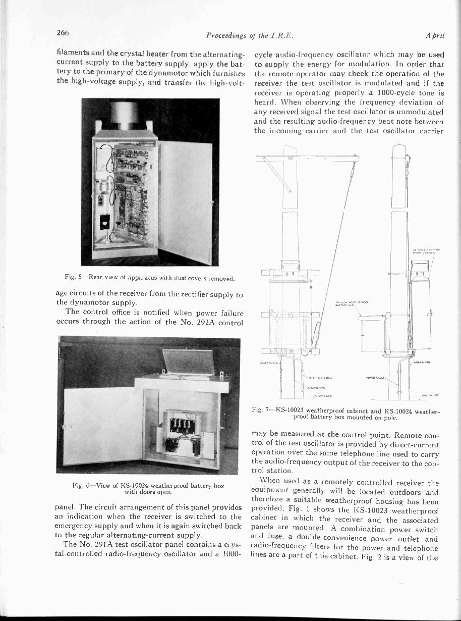
266 Proceedings of the I.R.E. April
filaments and the crystal heater from the alternating -
current supply to the battery supply, apply the bat-tery to the primary of the dynamotor which furnishesthe high -voltage supply, and transfer the high -volt -
Fig. 5-Rear view of apparatus with dust covers removed.
age circuits of the receiver from the rectifier supply tothe dynamotor supply.
The control office is notified when power failureoccurs through the action of the No. 292A control
Fig. 6-View of KS -10024 weatherproof battery boxwith doors open.
panel. The circuit arrangement of this panel providesan indication when the receiver is switched to theemergency supply and when it is again switched backto the regular alternating -current supply.
The No. 291A test oscillator panel contains a crys-tal -controlled radio -frequency oscillator and a 1000 -
cycle audio -frequency oscillator which may be usedto supply the energy for modulation. In order thatthe remote operator may check the operation of thereceiver the test oscillator is modulated and if thereceiver is operating properly a 1000 -cycle tone isheard. When observing the frequency deviation ofany received signal the test oscillator is unmodulatedand the resulting audio -frequency beat note betweenthe incoming carrier and the test oscillator carrier
PS -0024 WEATMCPPOVOrBATTERY SO,,
POwl, CAD-
ottoCrOt) weATHUI.MOOS WNW,
203
4,0,0 wne
GIOJNO Le4
Fig. 7-KS-10023 weatherproof cabinet and KS -10024 weather-proof battery box mounted on pole.
may be measured at the control point. Remote con-trol of the test oscillator is provided by direct -currentoperation over the same telephone line used to carrythe audio -frequency output of the receiver to the con-trol station.
When used as a remotely controlled receiver theequipment generally will be located outdoors andtherefore a suitable weatherproof housing has beenprovided. Fig. 1 shows the KS -10023 weatherproofcabinet in which the receiver and the associatedpanels are mounted. A combination power switchand fuse, a double -convenience power outlet andradio -frequency filters for the power and telephonelines are a part of this cabinet. Fig. 2 is a view of the

1939 Fischer: Renzotely Controlled Receiver 267
cabinet with the door open and in Fig. 3 the frontdust covers of the apparatus have been removed soas to show the front of the receiving equipment. Thevarious panels are mounted on a 19 -inch supportingframe similar to a short section of relay rack. Thisframe is fastened to the cabinet by hinged supportsso that the assembly may be swung out as shown inFig. 4, in order that the rear of the panels are acces-sible for servicing. Fig. 5 also shows the wiring sideof the panels with the rear dust covers removed.
The emergency battery is housed in the KS -10024weatherproof battery box which also contains a
controlled by the quartz crystal and for frequenciesabove about 7500 kilocycles the second triode sectionis used as a frequency multiplier.
The plate circuit of the first detector is coupled tothe first intermediate -frequency amplifier tube V4 bya double -tuned filter, and a similar filter couples thistube to the second intermediate -frequency amplifiertube V5. Another filter in the plate circuit of V5
feeds the full -wave series -type peak limiter tube V6,while the output of this tube energizes the last inter-mediate -frequency filter.
The diode section of the duplex -diode -triode tube
Vf
1r?,
A-I
-1
4
"11
Fig. 8-Simplified schematic of No. 23A radio receiver.
trickle charger to maintain the battery in a fullycharged condition. Fig. 6 shows a view of the batterybox with the cover open.
The No. 223A radiotelephone equipment will gen-erally be mounted on a telephone pole which alsosupports the receiving antenna, as shown on Fig. 7.This greatly simplifies the problem of making a satis-factory installation at a remote location.
CIRCUIT DESCRIPTION
A simplified schematic of the receiver is shown inFig. 8. Three preselector circuits are provided beforethe grid of the radio -frequency amplifier tube V1 inorder that a high degree of radio -frequency selectiv-ity may be obtained, if the requirements of any par-ticular installation make this necessary. The platecircuit of this tube is coupled to the first detector V2by two additional tuned circuits. The beating oscil-lator tube V3 is a double -triode tube. One section is
V7 is the speech -branch detector and is fed from thelast intermediate -frequency filter, while the triodesection of this tube is the first audio -frequency am-plifier. The detector and the direct -current amplifierfor the delayed, amplified automatic -volume -controlcircuit is also a duplex -diode -triode vacuum tube V8energized from the last intermediate -frequency filter.A level -control potentiometer is provided in the gridcircuit of the audio -frequency output tube V9.
The codan circuit of this receiver is energized fromthe final intermediate -frequency filter. Part of theintermediate -frequency output of this filter is fedto the control grid of the pentagrid converter tubeV10 and the control grid of the mixer tube V12. Theoscillator section of the pentagrid converter V10 iscrystal -controlled by a precise quartz crystal operat-ing at a frequency of 300 kilocycles, and consequentlythe 455 -kilocycle intermediate -frequency input tothis tube is modulated. The 755 -kilocycle modula-

268 Proceedings of the I.R.E. April
r-:1,
,
-1-
0
5
10
15
20
25
30
.! 35
z
40
P3 45
50
N-16 -12 -8 -4 0 4 8 12 IC 20
DEVIATION IN KILOCYCLES PER SECOND(FROM MIO8AND FREQUENCY OF 455 KC
Fig. 10-Intermediate-frequency characteristic ofNo. 23A radio receiver.
rr-
FTFE-:.=
,-1 -
L_
I'll Ili, 0.
11.7
Fig. 9-Interconnection diagram of No. 223A radiotelephone equipment.
tion product of the converter V10is selected by a filter and amplifiedby V11. Another filter feeds the755 -kilocycle component to themixer grid of V12. The intermedi-ate frequency of 455 kilocycles isalso fed to the control grid of 1712and therefore there is a 300 -kilo-cycle component in the plate circuitof the tube. When a signal is pre-sent in the intermediate -frequencyamplifier, this system of remodu-lation produces a new componenthaving a carrier frequency of 300kilocycles, with side bands corre-sponding to those associated withthe normal intermediate -frequencysignal.
The plate circuit of V12 energizestwo filter networks employinghighly selective quartz filters. Onefilter passes only a narrow band offrequencies corresponding to theincoming carrier, while the otherfilter eliminates this narrow bandbut passes a wider band corres-ponding to the normal band widthof the intermediate -frequency sys-tem. The outputs of these twofilters are rectified in the two dioderectifiers in V14. These outputsoperate two direct -current am-

1939 Fischer: Remotely Controlled Receiver 269
plifiers in the twin -triode tube V15 and the outputsof these amplifiers serve to operate differentially thepolarized relay which controls the audio -frequencyoutput of the receiver. During the intervals when nocarrier is being received very little energy passesthrough the narrow -band filter and the noise passingthrough the wide -band filter keeps the relay in theoperated position and short-circuits the audio-fre-quency output channel. When a carrier is received,
5,000,000
2,000,000
1,000,000
500,000
200,000
v) 100,000
0>2 50,000
S
z20,000
0
az
,0,000
5000
2000
1000
500
200
100-35 -30 -25 -20 -I5 -10 -5 0 5 10 15 20 25 30 35
FREQUENCY DEVIATIO I OF UNDESIRED SIGNAL IN KILOCYCLES PER SECOND
Fig. 11-Two-carrier radio -frequency -selectivity characteristicof No. 23A radio receiver. Desired signal, 1000 microvolts at2208 kilocycles. Interference from undesired signal, 20 deci-bels below, 30 per cent modulation, 400 cycles on desired signal.Undesired signal modulation, 30 per cent at 400 cycles.
the energy passing through the wide -band -filterchannel does not change appreciably, but that pass-ing through the narrow -filter channel is considerablyincreased, due to the presence of the carrier. Conse-quently, the relay is released and the audio -frequencychannel of the receiver is again energized.
Fig. 9 shows the interpanel wiring of the completeNo. 223A radiotelephone equipment as well as theschematic circuits of the various panels.
CHARACTERISTICS
A number of the more important operating char-acteristics of the receiver are shown in the variousillustrations. The intermediate -frequency selectivity
E 20
15
10
5
0
0
r:, 2
O
z
a. 6vt
10
100
5 10 50 100 1000 10,000 100,000 1,000,000INPUT IN MICROVOLTS
Fig. 12-Automatic-volume-control characteristicof No. 23A radio receiver.
200 300 400 500 1000 2000 3000FREQUENCY IN CYCLES PER SECOND
Fig. 13-Fidelity characteristic of No. 23A radio receiver.
5000
of the set is shown in Fig. 10, while a 2 -carrier radio -frequency -selectivity curve is shown in Fig. 11. Thiscurve shows the permissible value of an interfering
which will result in an outputlow the desired output. The automatic -volume -con-trol characteristic (Fig. 12) shows a variation ofabout 4 decibels in output for a variation in input of100 decibels. Consequently, a wide variation in signalinput has a negligible effect on the output level. Theaudio -frequency fidelity characteristic is shown inFig. 13. This characteristic represents a compromisebetween the wide pass -band which is desirable forhigh fidelity and the narrow band which is desirablefor minimum noise.
Actual operating experience in a trial installa-tion has shown that the performance of this receiveris highly satisfactory. In particular, the operation ofthe codan circuit is outstanding. No adjustment is re-quired under a wide variety of noise conditions andreliable codan operation is obtained from circuitswhich are too noisy for commercial service.

Coastal and Harbor Ship Radiotelephone Servicefrom Norfolk, Virginia*
W. M. SWINGLEt, NONMEMBER, AND AUSTIN BAILEYT, FELLOW, I.R.E.
Summary-This paper deals with the engineering and operationof a radiotelephone service for harbor and coastal vessels in theNorfolk area. The instrumentalities discussed in companion papersare employed for this purpose.
First, the need for such a service is developed from maritime dataconcerning the character of water transportation. Then radio -cover-age -survey results show that a radiotelephone station of only moderatePower can reach satisfactorily the commercially more important partsof this area. A discussion of the power radiated from antennas onthe smaller craft logically leads to the determination of suitable re-ceiver locations.
The paper contains a general description of the plant installedat the Virginia Beach radio transmitting station, the radio receivingstations, and the control -switchboard positions in Norfolk, togetherwith a discussion of the interconnection and interplay of these com-ponents to give service.
After telling of the facilities available for use by the switchboardoperator, the paper concludes with a tracing of the steps followed inhandling calls to or from vessels reached through the Norfolk marineoperator.
r ---i HE coastal and harbor radiotelephone station\VGB at Norfolk, Virginia, is the latest in aseries of stations being provided by the Bell Sys-
tem to make available a telephone service which per-mits the establishment of connections between anyland telephone station reached through the Bell Sys-tem and suitably equipped ships along the Atlantic,Gulf, and Pacific coasts. The Norfolk station, whichwas opened for public service on June 13, 1938, isof a type not previously employed. The engineeringand operation of this station is of special interest inthat it is the first station to use the new instrumen-talities discussed in the companion papers publishedin this issue of the PROCEEDINGS. The availability ofthis new equipment permits the construction of sta-tions requiring only a minimum amount of technicalattendance and whose operating costs, it is expected,will be much less than previously possible.
MARINE TRANSPORTATION IN THENORFOLK AREA
The Norfolk radio station is designed to serve shipsoperating in Hampton Roads, including its ports ofNorfolk and Newport News, in the lower ChesapeakeBay, and along the Atlantic coast from approxi-mately Cape May, New Jersey, to Cape Hatteras,North Carolina.
* Decimal classification: R510. Original manuscript receivedby the Institute, September 28, 1938. Presented before I.R.E.Convention, New York, N. Y., June 18, 1938.
t The Chesapeake and Potomac Telephone Company ofVirginia, Richmond, Va.
American Telephone and Telegraph Company, New York,N. Y.
270
Hampton Roads, formed by the junction of threerivers as they flow into the Chesapeake Bay near thepoint where the bay enters the ocean, provides aspacious ice -free harbor and is one of the majorocean gateways of the eastern seaboard. Eight trunk -line railroads have freight terminals on the harbor.Coal, hauled from the mines of Virginia and WestVirginia to water terminals in this area, constitutesthe major item of traffic of three of these railroads andHampton Roads is the largest coal port in the world.
The radiotelephone service provided by the Nor-folk station will be useful in dispatching the tugsused to tow lighters and car floats between the vari-ous railroad and ship terminals located on the har-bor. It will be valuable in operating passenger andautomobile ferries and freight -car floats over thelonger runs in the Hampton Roads area, such as theone -hour run between Norfolk and Newport Newsand the two- to three-hour run to the city of CapeCharles on of Virginia. Fishingboats operating along the coast and in the bay willbe able to maintain contact with, and receive in-structions and information from, their home offices.The ocean-going tugs engaged in towing coal to NewEngland points will find that the establishment ofthe Norfolk station, together with the existing NewYork and Boston stations, permits them to obtaina radio service suited to their needs.
Coastal and harbor radio service is also used byowners and guests aboard pleasure craft to maintaincontact with their homes and offices during cruises.The Norfolk station will serve not only the yachtswhose home ports are in the Norfolk area but alsoany suitably equipped yacht which may be within itsservice area, such as those passing along the coastbetween northern and southern waters.
While coastal and harbor radiotelephone serviceis intended especially for boats operating in a harborand its adjacent waters and for coastwise vesselsnot required by law to be equipped with radiotele-graph, the larger passenger vessels in the coastwiseservice may find it desirable to supplement theirradiotelegraph by making radiotelephone serviceavailable for the use of their passengers. The featureof direct two-way communication, as provided bythe radiotelephone service, will appeal to the pas-sengers of such boats.
Proceedings of the I.R.E. April, 1939

Swingle and Bailey: Coastal Harbor Service from Norfolk 271
SELECTION OF TRANSMITTER ANDRECEIVER LOCATIONS
As a preliminary to the establishment of a coastaland harbor station, two kinds of information, obtain-able from transmission tests, are needed. First, thecoverage of the shore transmitter must be tested to besure that a radio transmitter at any site tentativelyselected on the basis of experience' will adequatelyreach ships in the area to be served; and second,transmission tests must be made at several places todetermine strategic locations for radio receivers. BellTelephone Laboratories engineers made the radiotransmission tests for the Norfolk station using aportable transmitter operating on 2398 kilocyclestogether with a test car' equipped for field surveywork.
The geographical layout of the harbor and theadjoining coastal area, the service requirements ofthe prospective subscribers to the service, and theradio transmission characteristics at the frequenciesallocated to this service are controlling factors inselecting the location for the transmitting and re-ceiving equipment. Due consideration must also begiven to other factors, largely economic, such asavailability of land and proximity to existing powerand telephone lines. Because of the higher attenua-tion' of the radio path over land than over water andthe especially high attenuation of land adjacent tothe transmitter or receiver, satisfactory transmissionrange can be obtained with the low powers used inthis service only when the shore transmitter andreceiver are located so that the paths to the boats willbe over water in so far as practical.
As no location in the Norfolk area would permitan entirely overwater path, a transmitter loattionwas selected where the land would cause the mini-mum impairment. The transmitter location (Fig. 1)between Virginia Beach and Cape Henry providesan overwater path to boats on the ocean where thegreatest range is required. The path to boats onChesapeake Bay includes about a mile of land at thetransmitter end, but required coverage in this direc-tion is less than toward the ocean. The path to boatsin the Elizabeth River, where many of them dock,is almost entirely over land. However, the maximumdistance to be covered in this direction does not ex-ceed the limit for satisfactory overland transmission.
While a satisfactory transmitter location was se-lected, there is no single receiver location whichwould provide adequate coverage because of the
(2. N. Anderson, "Attenuation of overland radio transmis-sion in the frequency range 1.5 to 3.5 megacycles per second,"
1.1t.E., vol. 21, pp. 1447-1462; October, (1933).2 G. M. Ilafner, "A test car for marine radio telephone sur-
veys," 13d1 Lab. Rec., vol. 14, pp. 94-98; November, (1935).
lower powers used for the ship transmitters and thegenerally poorer antenna -installation conditions onboard ships. However, because of the lower cost ofreceiving stations, it is practicable to provide morethan one receiver, each located so as to obtain, in sofar as needed, an overwater path to the portions ofthe area served by it. Each shore receiver should belocated so as to avoid areas with high local noise.
Based upon the transmission and noise measure-ments made at several tentative locations, the initialreceiver of the Norfolk station was installed at the
f9 arro....i
_ _VIRGINIA _NORTH CAROLINA
z
w
0
0
z
Fig. 1-Norfolk harbor area and locations ofcoastal and harbor transmitter and receivers.
point shown in Fig. 1 near Ocean View. This re-ceiver is centrally located in the area to be servedand has an overwater path from ships in the bay,some land in the path from Hampton Roads, buthas a considerable amount of land in the path fromboats on much of the ocean.
The receiver is a development model of a new typeof receiver and as soon as commercial models becomeavailable, a second receiver will be installed at thepoint shown in Fig. 1 south of Virginia Beach so asto obtain the greatest possible ocean coverage. I t isexpected that the Ocean View receiver will ade-quately cover the Elizabeth River area, but shouldexperience indicate that the transmission loss is too

272 Proceedings of I/ic I.R.E. A Aril
REMOTE CONTROL OF TRANSMITTERAND RECEIVERS
While the einployment of more than a single re-ceiving- point has considerable advantage in makingthe service available to boats Operating in a largerarea, the telephone company must operate more re-ceivers and connect them all into a single controlpoint. The development of the new remote -control re-ceiver for coastal and harbor service, which has been
high, a third receiver located in the vicinity of theriver will be installed.
SERVICE AREA
The coverage area for the Virginia l3each trans-mitter is shown in the cross -hatched area in Fig. 2.Within this area a ship should be able to receive re-liably from the 400 -watt shore station during thedaytime. At night, the variability of noise and signal
ATLANT ICOCEAN
Fig. 2-Service areas of 400 -watt shore transmitter and 15- and 50 -watt ship transmitters.
field are so great that, while under adverse condi-tions, the reliable coverage is much less, nevertheless,valuable service is frequently given at distances faroutside the coverage area shown.
Ships using coastal and harbor radiotelephoneservice generally employ transmitters of 50 wattspower or less and space limitations on the smallercraft considerably reduce the antenna efficiency.Although the service area will depend in large meas-ure on the ship installation, some estimate can bemade of what might be expected with good installa-tions of 50 -watt and 15 -watt radiotelephone sets.With shore receivers near Ocean View and VirginiaBeach, the daytime service area for 50- and 15 -wattship transmitters is indicated on Fig. 2 as inside thesolid and dotted lines, respectively.
described in another paper,' has materially simplifiedthis problem. By use of this new receiver, it is pos-sible to extend the essential controls back to Norfolkover wire circuits and to concentrate receiver opera-tion at a single location.
The transmitter is likewise operated by remotecontrol over telephone circuits from Norfolk. Theseveral transmitter control features have been de-scribed in more detail in another paper.4
The remote control circuits from the transmitterand receiver are connected at the Norfolk centraloffice to control equipment located in the same room
3 H. B. Fischer, "Remotely controlled receiver for radiotele-phone systems," PRoc. I.R.E., this issue, pp. 264-269.
C. N. Anderson and I -I. M. Pruden, "A radiotelephonesystem for harbor and coastal service," Pitoc. I.R.E., this issue,pp. 245-253.

1939 Swingle and Bailey: Coastal Harbor Service from Norfolk 273
as the terminal and testing equipment associatedwith the long-distance telephone circuits. Afterpassing through the control equipment, the radiocircuit is terminated at the Norfolk long-distanceswitchboard. The location selected for the controlequipment is the logical one since it is the centralpoint in the network of telephone wires serving theNorfolk area, a skilled maintenance force is on dutyat all times, and the long-distance switchboard is inthe same building.
RADIO TRANSMITTING STATION
As the site of the transmitting station is in an areawhere the beginning of building development hasincreased the price of land, the land purchased wasas small as consistent with providing an adequateground system. Three lots, providing a plot 150 feetby 150 feet, were purchased about 1000 feet backfrom the ocean edge so as to obtain security frompossible storms and erosion. The ground system con-sists of 60 radial copper wires 0.165 of an inch indiameter buried in the sand at a depth of about 8inches. The ground system has an average radius of
Fig. 3-Transmitter building and 80 -footshunt -excited vertical radiator.
90 feet. The radial wires are brazed to a ring bus con-sisting of a 1/2 -inch copper tubing formed in a circleabout 7 feet in diameter around the base of theantenna.
The antenna (see Figs. 3 and 4) is a shunt -excited'6.1. F. Morrison and P. H. Smith, "The shunt -excited an-
tenna," PROC. I.R.E., vol. 25, pp. 673-696; June, (1937).
vertical radiator consisting of a commercial galva-nized steel self -supported flagpole, less the fittings forflying a flag, with 80 feet of pole above ground. Thepole is connected, near its base, to the ground systemby four lengths of copper tubing extending from thepole to the ring bus. The radiator is excited through
Fig. 4-Rear view of transmitter buildingand lower portion of radiator.
a lead from the transmitter connected to the poleabout 20 feet above the ground.
The shunt -excited radiator, as selected for thisstation, has essentially the same efficiency as a series -excited one of the same structural type, but is cheaperdue to the omission of insulating arrangements atthe base. It is estimated that its cost was little, ifany, more than for antennas of the same efficiencybut of different structural types, such as a flat -topantenna between wood poles or a vertical wire sus-pended from a wood pole, when all factors are con-sidered, including the more expensive arrangementsfor coupling a series antenna to the transmitterand the immunity of the shunt -type from lightningdamage. Moreover, as the transmitting station islocated in a developing residential area, it was verydesirable to use a shunt -excited flagpole for the an-tenna because of its better appearance.
The transmitter and associated equipment arehoused in a small tile -lined, reinforced -concretebuilding shown in Fig. 3. The building has two smallrooms, one room, 114 by 114 feet, is just large enoughto house the transmitter and rectifier, a work bench,and a spare -parts cabinet, and the other room, 7 by8 feet, is designed to house a proposed gasoline enginedriving a 5 -kilowatt 3 -phase alternator for use duringfailures of commercial power. A building of reinforcedconcrete is particularly suitable in this location be-

274 Proceedings of the I.R.E. April
cause of its stability against shifting of the sandaround the foundation and other effects of stormswhich may be severe in this area.
The radio transmitter employed at the VirginiaBeach transmitting station is a 400 -watt crystal -
controlled -type similar to those designed for use at
Fig. 5-Radio transmitter, rectifier,and auxiliary equipment.
aviation ground stations and is adjusted to feed theshunt -excited antenna at a frequency of 2538 kilo-cycles. The crystal control maintains this frequencyto a high degree of precision. The power supply forthe radio transmitter is obtained from a rectifierunit designed as a companion piece of equipment.These units, together with an auxiliary amplifierand certain wire terminating and control equipment,are installed in the transmitter building as shown inFig. 5.
Similar radio transmitter installations are alreadyin use at other Bell System coastal and harbor sta-tions.6.7 The modifications in the particular installa-tion at Virginia Beach are to care for the shunt -ex-cited antenna employed and to provide means to
6 E. B. Hansen, "Ship -to -shore radio in Puget Sound area,"Trans. A.I.E.E., vol. 54, pp. 828-831; August, (1935). Digest inBell Sys. Tech. Jour., vol. 14, pp.,708-712; October, (1935).
F. A. Gifford and R. B. Meader, "Marine radiotelephoneservice," Com. and Brdcst. Eng., pp. 9-11; October, (1935). Digestentitled "Marine radio telephone service for Boston harbor,"in Bell Sys. Tech. Jour., vol. 14, pp. 702-707; October, (1935).
control remotely a "stand-by" adjustment. In the"stand-by" condition, the filaments are operated atabout 80 per cent of their rated current and the platevoltage is removed from the equipment. When thetransmitter is required for service, it can be put "onthe air" in a few seconds. The switchboard operatorin Norfolk puts up a cord in the normal manner aswith any telephone call. This action energizes thecontrol circuits to the transmitting station whichoperate a relay to bring the filaments up to normalcurrent and apply the plate voltage. If, instead of be-ginning with the "stand-by" condition, the radiotransmitter had been shut down, about 30 secondswould have been required to get "on the air."
RADIO RECEIVERS
All of the equipment comprising a radio receiverinstallation is mounted on a single pole. The pole,as shown in Fig. 6, extends 50 feet above ground.
Fig. 6-Radio receiver installation.
The pole carries a vertical antenna wire, a box hous-ing the radio receiver and associated equipment(Fig. 7), a box housing a storage battery and chargerfor emergency use (Fig. 8), and a ground consistingof about 5 feet of wire fastened spiraled on the baseof the pole.
The radio receiving equipment is the remote -con-trolled receiver recently designed for coastal and

1939 Swingle and Bailey: Coastal Harbor Service from Norfolk 275
harbor service. The quartz -crystal control incorpo-rated in the receiver assures that it is at all timestuned to 2142 kilocycles, the transmitting frequencyof the boats served by the Norfolk system.
In case of failure of the commercial alternatingcurrent normally supplied the receiver, service iscontinued by an automatic change -over to the emer-gency power -supply equipment mounted on the pole.This equipment includes a trickle -charged 6 -voltstorage battery supplying filament power and alsodriving a dynamotor from which the higher direct -current potentials required are derived. A test oscil-
Fig. 7-Radio receiver and associated equipment.
lator, turned on by the change -over equipment,transmits a power -failure signal to the Norfolk officeso the maintenance forces may arrange for the res-toration of the commercial power and for replacingbatteries if the duration of the failure is likely toexceed the 8 -hour period during which the batterywill operate the receiver.
The test oscillator, which can be remotely con-trolled from the terminal, permits checking the fre-quency received from ships and provides a means forremotely testing the operation of the radio receiver.
CONTROL TERMINAL
Fig. 9 shows the control terminal installed in theNorfolk toll test room. In the upper portion of thebay is a radio receiver used to monitor the output ofthe Virginia Beach transmitter and a crystal -con -
Fig. 8-Emergency power supply for receiver.
trolled oscillator, by means of which the transmitterfrequency may be observed. The equipment in thecenter of the bay provides facilities for controlling
Fig. 9-Norfolk cunt rot tcrinilial.
and testing the operation of the transmitter and thetwo receivers and for interconnecting the one-wayradio transmitting and receiving circuits with thetwo-way telephone circuit to the switchboard In

276 Proceedings of the I.R.E.
the lower portion of the bay are two amplifiers, theone in the receiving branch having a fixed gain asthe volume level is held substantially constant bythe receiver automatic volume control, while the onein the transmitting branch is a yoga& (voice -oper-ated -gain -adjusting -device) whose gain varies withthe speech volume so as to keep the transmitter fullymodulated and, at the same time, avoiding over -modulation. The detailed functions and operation ofthe control terminal equipment are described else-where.'
The licensed radio operator responsible for theoperation of the system is stationed at this pointwhere he may check and control the operation of boththe transmitter and receiver, and may supervise and
Fig. 10-Marine position of Norfolklong-distance switchboard.
provide any assistance required by the traffic opera-tor at the switchboard. A transmitter cutoff key isprovided in the control terminal so that the licensedradio operator may turn, off the transmitter at anytime and, in doing so, prevent its being turned on bythe switchboard operator in accordance with theusual procedures described below.
PROCEDURE IN HANDLING CALLS
Calls through the radio station are handled by themarine operator at the position of the Norfolk long-distance switchboard shown in Fig. 10. The positionwas equipped for radio service by adding a key,lamp, and dial (the one mounted flush) to the right
S. B. Wright, S. Doba, and A. C. Dickieson, "A vogad forradiotelephone circuits," PROC. I.R.E., this issue, pp. 254-257.
of the usual key -shelf equipment and terminatingthe radio circuits on the jacks in the face of theboard. The dial and associated key are used to con-trol the pulses of 600- and 1500 -cycle tone trans-mitted to operate the signaling selectors on the boats.The lamp, whose operation is controlled by a relay inthe monitoring receiver of the control terminal, in-dicates to the operator whether or not the shoretransmitter is emitting carrier. In the face of theswitchboard, two jacks and a lamp are provided foreach receiver. The jack designated "line" is usedon calls between a ship and a land station, while thejack designated "by-pass," used on ship -to -shipcalls, is arranged so that the insertion of a plug con-nects the output of the receiver to the input of thetransmitter. Thus, on ship -to -ship calls, the Norfolkland station serves as a frequency changer by re -radiating at 2538 kilocycles (the ship receiving fre-quency) whatever is transmitted by a ship on 2142kilocycles.
The procedure of the traffic operators in handlingradio calls is generally similar to that used for ordi-nary long-distance calls. When a ship originates acall, the receipt of its carrier at the shore stationcauses a lamp to light over the jack associated withthe receiver on which the signal is being received andalso turns on the shore transmitter. The operatoranswers the call by inserting an ordinary switchboardcord in the jack and then extends the call, using theother end of the same cord circuit, to the called sta-tion over ordinary local or long-distance telephonecircuits as required. Calls originating on land arerouted to the Norfolk marine position where theoperator starts the transmitter by inserting a cordin one of the radio jacks and, when the key -shelflamp indicates that the carrier is on, she dials theassigned code of the called ship. The selective signal-ing equipment on the ship dialed rings a bell and theconnection is ready for use as soon as the call isanswered by lifting the handset on the boat. If theboat called is not equipped for selective signaling,the ringing key in the cord circuit is operated mo-mentarily to transmit over the radio the 1000 -cycletone interrupted 20 times a second which is used forringing on certain types of long-distance circuits.This serves as an attention signal and is reproducedin the waiting loud speakers of the boats not equippedfor selective signaling. The operator then announcesthe name of the called boat and the connection isready as soon as the called boat answers.

Transient Response of MultistageVideo -Frequency Amplifiers*
A. V. BEDFORD', ASSOCIATE AMBER, I.R.E., AND G. L. FREDENDALLt, ASSOCIATE MEMBER, I.R.E
Summary-The response to a Heaviside unit voltage is setforth as the most logical and relevant criterion of the fidelity of video -
frequency amplifiers.The part of the transient response that is governed by the high -
frequency amplitude and phase -delay characteristics of amplifiersmay be approximated closely by the steady-state response to a squarewave having a suitable period and thus may be expressed in a Fourierseries. Simplicity and rapidity of numerical calculation are the out-standing advantages of the steady-state formulation.
As an illustrative example of the method the transient responseof several multistage compensated resistance -coupled amplifiers arecomputed. Considerable data helpful in the design of amplifiers ofthis type are presented. It is concluded: (1) The wave -shape distortionof a Heaviside unit voltage is accumulative as the number of stagesis increased. (2) The value of the damping constant K= R.VL/ Cshould lie between 1.51 and 1.61. (3) The resonant frequencyf 0= I/ (271-V LC) determines the slope of the wave front of the transientresponse. R is load resistance; C is the total shunt capacitance; andL is the compensating inductance in series with R.
It is proposed that the oscillographic response of videofrequencyamplifiers and the associated transmission apparatus to a squarewave be considered as a part of performance tests of future televisionsystems.
NATURE OF THE PROBLEM
1N TELEVISION, intelligence is conveyed by thewave shape of voltage variations that originatein the television scanner. Such a signal is the
electrical equivalent of variations in the intensity ofillumination of the television subject along the scan-ning lines; and ideally the wave shapes of the varia-tions in intensity and the associated variations involtage should be the same. After much amplifica-tion, modulation of a carrier wave, and demodula-tion and more amplification in the receiver, the signalis translated back into variations in the intensity ofillumination along the scanning lines in the cathode-ray receiving tube.
Clearly, the prime requisite of a video -frequencyamplifier is the amplification of a signal, essentiallytransient in character, without appreciable modifica-tion of the intelligence borne by the signal; that is,
the wave shape must be preserved within limitsknown to be tolerable. Distortionless amplificationof transient voltages is obtained when the amplituderesponse and phase delay of the amplifier are inde-pendent of frequency from zero to infinite frequency.The essential video -frequency spectrum however islimited and extends from 60 cycles to at least 2.5megacycles for the present 441 -line interlaced scan-ning with a frame frequency of 30 cycles per second.Complete agreement on the upper limit of the spec-
* Decimal classification: R363.1. Original manuscript re-ceived by the Institute, September 8, 1938.
f RCA Manufacturing Company, Inc., Camden. N. J.
April, 1939
trum does not exist; values ranging from 2.5 to 4.25megacycles may be found in the literature. We knowthat amplifiers cannot and need not render distor-tionless amplification even over the video -frequencyspectrum. Specific tolerances therefore are very im-portant in design. The nature of the circuit elementsin video -frequency amplifiers permits 'a completedivision into low -frequency distortion and high -fre-quency distortion. We shall be concerned exclusivelywith the latter. Two criteria of high -frequency fidel-
ity are in use.The first concerns the sine -wave steady-state char-
acteristics. (a) The amplitude response shall be sub-stantially independent of frequency over the spec-trum. (b) Differences between the phase delays atintermediate frequencies and at the upper frequencylimit shall be small compared with the time requiredfor' the receiving aperture or spot to traverse a dis-tance equal to the scanning -line pitch.
The second and less common criterion concerns theto a Heaviside called
the transient response. Three points are made in sup-port of the unit voltage as a test signal. (1) An ampli-fier that responds properly to a unit voltage wiltamplify any video -frequency signal with acceptablefidelity. (2) If the response to a unit voltage is known,the response to any other transient signal may becalculated by the superposition theorem of opera-tional calculus. (3) The effect of a given transient -re-sponse wave upon the picture structure can be de-termined by inspection.
We believe that tolerances can best be set by adirect examination of the response to transient volt-ages and that the second criterion is well suited forthis purpose. The first criterion lacks directness andultimately the second must be used as a check be-cause the television video -frequency amplifier is fun-damentally an amplifier of transient voltages. In thisrespect transmission requirements for television dif-fer from those for sound.
A signal having the discontinouus character of aunit voltage is generated by a dimensionless scanningspot when scanning an infinitely sharp change in pic-ture shade. In reality the scanning spot has an ap-preciable diameter and changes in picture shades arenever infinitely sharp. As a consequence the mostabrupt unidirectional change in voltage that can be
Proceedings of the I.R.E. 277

278 Proceedings of the April
generated by a scanning spot in present televisionsystems occurs over an interval of about: 0.15 micro-second.
The existing literature treats only one or twostages and methods of calculating the transientresponse have not been particularly expeditious forextension to multistage amplifiers. This is at once ahandicap because the transmission characteristics ofthe entire television system (camera amplifier, studioamplifier, transmitter, and receiver) determine the fi-delity. The video -frequency signal may pass throughas many as forty stages of video -frequency amplifi-cation. A satisfactory method for obtaining the over-all response of a system must be readily adaptable
(A) (8)
Fig. 1(A) Compensated resistance -coupled amplifier.(B) Equivalent circuit for high frequencies.
to the data available. In most instances the circuitelements of an amplifier may be treated as lumpedconstants and the response calculated. In other in-stances, the circuit constants are distributed in sucha way that analysis in terms of lumped elements isnot feasible. In the later case it is usually practicableto measure steady-state amplitude and phase -delaycharacteristics of full or reduced -scale models. Theapplication of a completely satisfactory methodshould not require the services of a professionalmathematician. Simplicity and dependability arevery desirable.
We shall discuss briefly two classical methods forthe calculation of the response to a unit voltage, theoperational method and the Fourier integral formu-lation, and then develop in detail a preferred method.The compensated resistance -coupled amplifier hasbeen frequently used in television systems and there-fore will be used here as an example. Fig. 1(A) is aschematic diagram of connections. Fig. 1(B) is theequivalent circuit for high frequencies. The severalcomponents of distributed capacitance have beencombined in a single value C. The inductance isadded in order to maintain the response near theupper limit of the frequency spectrum at a higherlevel than possible in a simple resistance -coupledstage.
Using the conventional processes of operationalcalculus McLachlan' and others2 have derived corn -
1 N. W. McLachlan, "Reproduction of transients by a televi-sion amplifier," Phil. Mag., vol. 22, pp. 481-491; September,(1936).
plete formulas for the response of a single amplifierto a unit voltage. Reference to M cLachlan's paperis suggested for the details of the derivation whichyields the following- equation :
e(I) = g,111 -sin (Alt + 0)] (1)
in which
1
fo 27rvLC
K = 27rfoRC
= 27rfo /1/ 1A
4
AN/1 - K2T-10 = tan-'
K2/2 - 1
gin transconductance of the tube
R >> R ; C,>>C2i R >>1
C,0)
(Changes in the original notation have been madefor convenience.)
McLachlan mentions also the steps to be taken forobtaining the response of n stages but does not givethe explicit result. In any event the method of opera-tional calculus involves the use of specialized mathe-matical technique and entails a great amount of la-bor when there are several stages all identical or dif-ferent. Its application is restricted to cases in whichthe circuit configuration and elements are known.This excludes the practical case in which experiment-ally determined amplitude and phase characteristicsconstitute the only available data as a consequenceof distributed circuit constants.
The Fourier integral formulation provides an ex-pression for the response to a unit voltage involvingthe steady-state amplitude and phase characteristicsexplicitly; namely,
-11(0) (w) sin [cut - 0(w)]e(t)
2 7r(10.). (2)
H(w) and 0(w) are the amplitude and phase char-acteristics respectively and w is the angular fre-quency.
Although (2) is outwardly simple, its usefulness ismuch restricted in design work as the result of dif-ficulties in the integration of the infinite integral.Usually an analytical integration presents great dif-
2 O. Lurje, "Equalizing processes in wide -frequency rangeamplifiers," Tech. Phys. U.S.S.R., vol. 3, pp. 229-248; March,(1936).

1939 Bedford and Fredendall: Transient Response of V -F Amplifiers 279
ficulty even to a professional mathematician. Graphi-cal solution is unavoidably tedious on account of theoscillatory character of the integrand. After checkinga few points on the transient -response curves in Fig.11 by graphical integration of (2) we were convincedthat the method is impracticable when a numericalanswer is sought.
STEADY-STATE SQUARE -WAVE FORMULATION
Before proceeding further it is necessary to dis-tinguish between low -frequency and high -frequencydistortion. Fig. 2(A) is a sketch of a typical transientresponse of a multistage amplifier (not necessarily acompensated resistance -coupled amplifier.) The in-terval a -b over which the response is substantiallyzero is the effective time of transmission and doesnot represent distortion. During the interval b-c theresponse increases from zero to a steady value afterexecuting a damped oscillation (or an aperiodic varia-tion). The failure of the response to rise sharply to100 per cent, and remain there, is distortion. tb_cwill ordinarily be less than a half microsecond whichis to say that the response during the interval b -cis determined almost entirely by the amplitude andphase -delay characteristics in the upper region of thevideo -frequency spectrum. The capacitance of anamplifier for the reproduction of signals that cor-respond to the fine detail of a television subject ismeasured by the steepness of the wave front pro-vided that the amplitude of the damped oscillationis low. During the interval c -d there is a decline inresponse at a very slow rate which is governed by thelow -frequency characteristics of the amplifier, thatis, by coupling condensers, grid leaks, and plate -supply filters. This decline is too slow to be percep-tible on the time scale in Fig. 2(A). The complete re-sponse shown in Fig. 2(A) may be considered as thelimiting case of the response to a periodic squarewave as the period becomes infinite. That is, if thesquare wave has the form
1 2( 1
E(t) = - 27r-fd -- sin 67rfri2 3
1 - sin 107f,,i + 5 1' (3)
the response will he1 2
c(1) + limit. A1 sin 27rf(i - DI)2 1,--0 71-
+ A3 sin 671-f(i -
+ A5 sin l - D5) + . . . } . (4)
A and D are the steady-state amplitude responseand phase delay for the frequency n
It is clear from physical considerations that a sig-nificant calculation may be carried out using a finiteperiod. If the response during the interval a -c is
required, the period of the square wave is taken onlylong enough to permit the response to attain a sub-stantially constant enduring value (that is, 100 percent) before the beginning of the following half cycle.Hence in Fig. 2(B) the period is taken equal to 2 ta_c.
Usually the effective time delay ta_b is unimportantand only the response during the interval b -c is
required. In this instance a half period equal to tb_cis sufficiently long as illustrated in Fig. 2(C).
(A)(B)(C)
YQL.TA .c&
E'
C
TIME(A)
5 _s_civos_v6tr,_iil
TIME
SQUARE WAVE
b - C
(B)
TIME
(C)
Fig. 2Transient response of typical multistage amplifier.Response to a square wave; period =2ta_cResponse to a square wave; period = 2/b_e.
The simplicity of the steady-state formulation asa means of numerical computation may be greatlycompromised if a suitable choice of the period leadsto a slowly converging series. Fortunately, this is notthe case in the solutions presented below or in manyother practical problems that we have treated. Thelabor involved in a specific instance is minimizedwhen the duration of the transitory response isknown approximately. An estimate may be madeusually from inspection of the steady-state amplitudeand phase characteristics. The utility of the Fourierseries method can be demonstrated best by applica-tions. To this end we have calculated the responsesof a single -stage amplifier and several multistagecompensated amplifiers. The treatment covers theinterval a -c; no further consideration is given to,the response over the interval c-d.
TIIE TRANSIENT RESPONSE OF COMPENSATED'RESISTA NCE-COU PLED) AM P LI F I ERS
The amplitude and phase characteristics of a singlestage required for the series formulation are given bythe following formulas:
amplitude response =gm1-1-132/K2
(5)15 2 K 2 + 1) 2

280 Proceedings of the I.R.E.
0 1
phase delay-27rf 27f
(13/ K)(10--FB2- 1) (6)
in whichf= frequency0 = phase shift (0 is positive when the output
voltage lags the input voltage)B =No
K, fo, as defined for (1).
160
140
120
100
0801-
a.
z 60
z 4 00
Li 20cc
=mumIIIinami iiNam mum= ma I r -K...,.00......... pa 1
Namfin ..ditmu aK = 1.41
VIIIMMIIIIIM11-411111.1111Mla11111111111111afillettiM... MIMIMENIIIIMISPIIIrNNIMK 312 NMI1111111111111111 wombs. le mammailman I
f -APPL ED Fat_, ammism: INro_in7,..mom _ ....u......o......p.-....N...ro
WEIN IIIK=2Tifo C
MEMBEI11.1101111111 =MI 1111Mani 11111.111111111 =MOM111111111 11111111M111 1111111111111111111
0 I 1.0
(=f2rrilc)
Fig. 3-Amplitude characteristic of one -stage amplifier.
K 1.5 I
10
If f(K/fo) is taken as the independent variable in-stead of f, a family of universal response curves anda family of universal delay curves may be drawn inwhich K is a parameter; and the change in variablewill permit a rapid comparison of individual ampli-
0.16
IIIIIII"" lifil 1111111110.14
0.10
0.12 1111 :-C : *7112 Ill ikk 11111111
IIIIIIMITIAKIIMAIIIII0
0.04
0.02
0.06 bI'l kN
f -APP IED FR 0 E
f;o:
D PHA E D
L
I S
TT=2 foLRcC.
.49k iiiiii
ert
0.08
0.1 1.0 10
(=f2uRC)
Fig. 4-Phase-delay characteristic of one -stage amplifier.
fiers having equal gains at low frequencies but dif-ferent values of K. It will be shown later that K andfo are the essential circuit parameters. The conditionfor equal gains at low frequencies for different ampli-fiers characterized by K1, K2, K3, etc., is that theproduct Rgm shall be the same in all cases. That is,
Rigmi = R2gm2 R3grn3 etc. ,
Or
If
then
KI K2 K3g,1 = g,2 = g.3
foiCi 102C 2 f 03U 3
gmi gm2
C1 C2
K1
f()1
g
C3
K2 /C3
f02 f03
April
(7)
Hence at any given frequency the steady-state datacorresponding to K1, K2, K3, etc., may be read di-rectly from Figs. 3 and 4 in which the condition ofequal gain is automatically fulfilled when (7) holds.Inspection of these figures show that there is no
18
1416
>14-1
Z12L.
010
zw 80Ll0-
Z6 0
Llcr) 4 0z0.
L') 20cc
0
___K .. 1.00_
K - 1.41
NoK -1.51K -1.71-
____
_
K - 2.00 i1\K ... 3.12 sm._ LI
4
K = -. (L- a -,. \
I 1Pr -.-...--.,..__-
..---'''-P I i 1
t- I E IN SE SinK= 2rtfoRC
i/4-7IF
ris?_ --t27._,F-tz) 0.6 as IA
Fig. 5-Response of one -stage amplifier to a unit voltage.
value of K for which amplitude and phase -delaycharacteristics are simultaneously optimum. Amongthe curves in Figs. 3 and 4, that for K=1.71 exhibitsthe least dependence of phase delay on the fre-quency and that for K =1.51 (more exactly K=1.55),the least dependence of amplitude response on thefrequency.
Fig. 5 shows a family of curves of the response toa Heaviside unit voltage according to the rigorousequation (1). The family may be calculated easily bythe Fourier series method drawing the necessarydata from Figs. 3 and 4. The only step in the seriesdevelopment requiring judgment is the choice of afundamental period, or rather half period, that justexceeds the time required for the response to attaina steady value. If a longer period is used, the con-vergence of the series is less rapid but the calculatedresponse is not affected. If the period is too short,calculation reveals the misjudgment immediately byyielding a response curve that does not attain asteady value before the beginning of the next half

1939 Bedford and Fredendall: Transient Response of V -F Amplifiers 281
cycle. Fig. 5 is an aid in devising a guiding principlefor finding a suitable period. Consider the curve ofthe family corresponding to K=1.41. The responsedoes not vary more than ± 1 per cent from the
The agreement between e(t) computed from theseries (9) and e(t) computed from the rigorous equa-tion (1) is very good as shown in Table I. Near thediscontinuities in the response at t =--- 0 and t = 0.8K/fo
Uh IT V LTAGE
-IME DELAY
2 4
fc-
2 8 3 2
t= TIME
c =CUT
3 6
IN SECC NDfS
-CFT F REtDUE ICY
Fig. 6 -Response of idealized amplifier to a unit vo tage.
final value after the elapse of 0.8 K/fo second. Henceit is expected that the significant part of the response lfo
to a unit voltage which occurs within the interval 0to 0.8K/fo second will be approximated closely bythe response to a square wave that has a funda-mental period equal to 2 X 0.8K/fo or 2.26/fo seconds;namely,
1 2 foe(t) = - --{ A1 sin 27r (t D1)
2 7r 2.26
A3 fo
3 -sin 67r
2.26(t D3)
A5 fo
5 - sin 107r (t - D5) ±
2.26
If terms having amplitudes less than 0.01 arelected, the finite series expression becomes
(8)
neg-
1 2f fo= + 1.02 (27r t 0.358)
1.20)
1.46
e(t) - - , sin2 7r 2.26
fo+ 0.225 sin 67r -- t -
2.26
0.074 107r f° 1+ sin (2.26
0.036 ( f0147r 1.53 (9)+ sin 1
2.26fo
0.021 1.55+ sin (187r t2.26
fo+ 0.014 227r t( 1.56sin
2.26
+ 0.010 267E f° 1.56sin 1(2.26
TABLE I
e(l) from equation
(1) (9)
0.050.100.200.400.600.80
00.300.600.931.061.021.00
0.040.300.580.921.071.020.96
Slide -rule accuracy.
the series gives the poorest approximation. This is
expected according to the theory of Fourier series.Advance information was available in Fig. 5 for
selecting a suitable fundamental period, but in usefulapplications of the series method such a convenientguide will be lacking. In the absence of other data,the proper fundamental frequency may usually betaken equal to the frequency at which the steady-state amplitude and delay characteristics cease to besensibly independent of frequency. This is reasonablebecause distortion of the unit voltage input is causedby discrepancies in the characteristics. There arehowever exceptional cases in which this guide fails;one exception is the idealized amplifier. The ampli-tude and phase -delay characteristics of an idealizedamplifier are independent of frequency in the range0-f, and the amplitude characteristic is 0 for fre-quencies greater than L. This is one of the few in-stances in which the Fourier integral (2) leads to asimple expression. Thus if the amplitude response11(w) is set equal to 1 and the phase delay 0(w)/w toD, a constant independent of frequency, there results
1 2 r 21r1c(i-D) sin xc(1) = -2 -I- - J
(10)7r o
The definite integral is available in mathematical

282 Proceedings of the I.R.E. April
tables.3 Fig. 6 illustrates the response of the idealizedamplifier having an arbitrary value of phase delay Dequal to 20/24', seconds. Obviously the wave shapedoes not depend upon D.
A suitable period for a Fourier series developmentwould be chosen by trial. In general a period of in-sufficient length is detected immediately when thecalculated response fails to attain a steady valueduring a half cycle.
Equation (10) indicates that the idealized amplifierresponds before the unit voltage is applied. This dis-crepancy is a consequence of the physical incompati-bility of the assumptions regarding H(w) and 0(w).The idealized amplifier however is a good criterion
120
t -z. loo
cc 80
60
o 40a.
CC 20
0
K 1.6
16 STAGES
32 STAGES64 STAGES
16 STAG ES
32 STAGES
\= 2K
64 STAG
to
fifo (--farrRc)
Fig. 7-Amplitude characteristics of multistage amplifiers.
ES
= AP PLI
fti- Vt7c
ED
rtiFoRC
51
FR EC U NCY
0.1 10
of the optimum use of a given band width for theproduction of the maximum steepness of wave front.
TRANSIENT RESPONSE OF MULTISTAGE AMPLIFIERS
The simplicity and rapidity of calculation of thesteady-state response to a square wave are especiallyvaluable properties in the design of multistage ampli-fiers. A calculation of the stage -by -stage response ofa 16 -stage amplifier was laboriously made by re-peated application of the superposition theorem ofoperational calculus before the utility of the seriesmethod was recognized. The result shown in Fig. 10illustrates the accumulative distortion of a unit volt-age input, a progressive decrease in the slope of thewave front, and a progressive increase in the high -frequency damped oscillation, which is typical of cas-caded stages.
Fig. 11 is an extension of the Fourier series methodto 16-, 32-, and 64 -stage amplifiers. The required am-plitude response and phase -delay characteristicsshown in Figs. 7, 8, and 9 were derived from Figs. 3and 4 by raising the amplitude response of one stageto the nth power and multiplying the phase delay by
3 Jahnke-Emde, "Tables of Functions," Second revised edi-tion, p. 78. B. G. Teubner, Leipzig and Berlin, (1933).
n. All transient -response curves are plotted with thecorrect effective time delay, that is, the fundamentalperiods of the series expansions exceeded la-c.
5005 1 1011=1.10111I IIE EPIE111.111
700
tiE
+.g
0,00E1 101174111a 400z
2200 LINIIIIIMMIEr MAlil ...."1mu =prom! =Num
10 liallign raulillk111111111M1111°MENEM MIIIIIIM111111111111MIIIIII MII1111111111=111111111111
0.1 1.0
fr.% (=f. 27-iRC)
Fig. 8-Amplitude characteristics of multistage amplifiers.
10
Fourier series formed with shorter periods may ex-press adequately the response during the intervala -c as explained above. For example the response of
7
6
5
4°i 4O
2
0
Ili =1.61
K =1.51 64 STAGEA / K=1.4I
f = APPLIED FREQUENCYK=1.61 D =PHASE DELA' IN S: 3K =1.5i 32 TAGE ft) 21_K =1.41.. K =2 nro 4Ci
I1 j
-1.6iN
K
K =1.51 16 SK =1.41
10
fs% (--rarrac)
Fig. 9-Phase-delay characteristics of multistage amplifiers.
I0
a 64 -stage amplifier, K= 1.61, may have the followingseries expansion :
1
e(1) =2
-; 0.98 sin (27r16
t - 3.95)7r
+ 0.256 sin (67r -Jo t - 11.99)16
+ 0.08 sin 107r .1- I - 20. )916
)
+ 0.016 sin (147r -f° - 28.88)} .
16
The fundamental period 16/f0 is7equal to two timesthe reciprocal of the frequency at which the steady-state amplitude and phase -delay curves begin to de-

1939 Bedford and Fredendall: Transient Response of V -F Amplifiers 283
pend appreciably on the frequency as shown inFig. 11.
Equation (11) defines a response similar to that il-lustrated by Fig. 2 (C) and does not yield automati-cally the length of the effective time delay. If the
160
L1 140
J 120
z<
LT.
0L. 100
I -
zIJ 80cc
0.
z 60Lizo 40a.
1.1
20
with the fact that the intercept on the phase -delaycharacteristic in Fig. 9 is approximately equal to theeffective delay will define the delay explicitly. It isconceivable that this procedure may fail in specialcases.
16 ST AGE S
8 ST GE 5
4 STAGES
2 STAGE 5
U NITNPU
V 0
0
STAGE
LTAG
Ar
1.0
4d111ft. A I k
2.0
`411111111111100-
t = TIM E I
fo- 2rivEziK-2nf°CR
4 .5 EGO
= 1.4
NDS
30 40
Fig. 10-Response of multistage amplifiers to a unit voltage.
delay is required, steps justified by the following rea-soning will lead to the correct value. The squarewave shown in Fig. 2 (C) may be considered as thesuperposition of a series of positive unit voltages im-pressed at t= 0, -2tb,, -4tb_e, -6tb_e, etc., 2tb-c,
220
> 200
< - 180z11 160
O 140
FZ.
U 100
80
60
40
z
1.1
Z.)
120
0N 20LJLE
The character of the responses of the various 16 -stage amplifiers may be compared directly on thebasis of equal low -frequency gain as a result of thechoice of independent variable tfo/K; similarly in thecases of 32- and 64 -stage amplifiers. The essential
IT
NPI
IMMM. 1111111EPRIZEI INE111111K = 1.41 IMI mommosirdPencenniummourimomeznomm Eiallr EMI= MENEM
ENESII 411=111=1 IIIIEWAININI EIMMIElEINIEWINEloreimmum IINEMENEIMEEEEENEE1111111/1/1111EMIMMIESTIREMENIEFIENIEINIMENINIEE
L IEE11111/11,111E11110ENNINMELMINIIINIIIIIET IMARLIVIIIMMIMARMEMPIIF11.11-1313MM.MrAIMPrann.811WIMMMI.MOMITy amsP-7Amarhr tor our rpm= t.TIME IN SEC
1 7ANEW 1 All Ur A .111111 ElEr r° 2ndIWAMINIIINIWANNIII IV Adiffil=11.1 , .,,Tfoci N
1 2.41111111111MMENIII iiX., MI=
MEM 45 IMMIMMIMMIMMI. 1
111.... MIIIMIMM MM.Fig. 11-Response of multistage amplifiers to a unit voltage.
4tb_c, 6/f, -c, etc., and a series of negative unit voltagesimpressed at t equals -tb_c, -54,, etc.,
54,, etc. The associated transient func-tions will form the periodic response to the squarewave. It is evident that the apparent time delay plusan integral multiple of the period of the square waveis determinable from (11). This information together
character of the response is controlled by the parame-ters K and fo which may be specified independently.K determines the magnitude of the damped oscilla-tion and fo determines the steepness of the wavefront.
If the cathode-ray beam of a receiving tube ismodulated by the response of 32 stages, K =1..41., a

284 Proceedings of the I.R.E.
series of alternate light and dark striations will bedistinctly visible following the scanning of a verticalblack -to -white junction, as a result of the dampedoscillation in the signal. A definite standard of toler-able damped oscillation in the response of video -frequency amplifiers must treat (1) amplitude,(2) frequency, and (3) rate of decay. To set up astandard is not the purpose of this paper. However,observation of television pictures transmitted bymultistage video -frequency amplifiers with K=1.41has led to a general rejection of this value. Figs. 10and 11 ably support this rejection. We believe thatthe K factor should lie between 1.51 and 1.61.
The horizontal resolution of a television picture issubstantially proportional to the slope of the wavefront of the over-all response to a unit voltage. If aslope is specified, the resonant frequency fo may bedetermined by reference to the scale of abscissas inFigs. 10 and 11. For example, a 32 -stage amplifierK=1.51 has an effective linear rise from 0 to 100 percent response within about 0.8 unit on the axisof abscissas. Let this correspond arbitrarily to0.16 X10-6 second. Then
fo 0.16 X 10⁻⁶ X fo0 . 8 = t -=
K 1.51
fo = 7.5 X 10⁶ cycles.
EXPERIMENTAL DETERMINATION OF THETRANSIENT RESPONSE
The mathematical determination of the transientresponse may be obviated in the case of existing am-plifiers when a generator of a square -wave form and asuitable oscillograph are available. Thus the fidelityof a video -frequency amplifier can be determineddirectly from an oscillographic observation of the re-sponse to a square wave of suitable period by notingthe steepness of the wave front and the characterof the damped oscillation. Clearly, the analyticalmethod should give way to the experimental methodwhenever possible in order to avoid the labor in-volved in finding amplitude and phase -delay charac-teristics and the subsequent series solution of thetransient response.
If the amplitude and phase characteristics are re-
quired for the design of correcting networks, the ex-perimentally determined square -wave response maybe analyzed graphically by the well-known methodsof harmonic analysis.
CONCLUSIONS
The transient nature of the signals which televisionamplifiers are required to amplify suggests that themost logical and relevant criterion of the fidelity isthe response of the amplifier to a Heaviside unit volt-age. The survival of the older criterion based on thesteady-state characteristics of amplitude responseand phase delay is caused probably by the large ac-cumulation of knowledge of electric filters based alsoon these steady-state characteristics.
We have shown that the part of the response to aunit voltage that is governed by the high -frequencyamplitude and phase -delay characteristics of ampli-fiers may be approximated by the steady-state re-sponse to a square wave. Simplicity and rapidity ofnumerical calculation are the outstanding advantagesof the steady-state series formulation over themethod of operational calculus and the Fourier in-tegral formulation.
The series is formed by finding the steady-stateresponse to a square wave of voltage having a halfperiod that is longer than the time interval requiredfor the response to attain a steady value starting atthe time of the first appreciable response. Conver-gence of the series is most rapid when the shortestperiod satisfying the above condition is used. Trialcalculation will reveal the error in judgment when theperiod is too short.
A detailed analysis of the compensated resistance-
coupled amplifier yields the following conclusions:(1) The wave -shape distortion of a unit voltage isaccumulative as the number of stages is increased.(2) The value of the damping constant K should liebetween 1.51 and 1.61 in most cases. (3) The reso-nant frequency fo determines the slope of the wavefront of the transient response.
We propose that the oscillographic response ofvideo -frequency amplifiers and the associated equip-ment to a square wave be considered as a part of per-formance tests of future television systems.

Characteristics of the Ionosphere at Washington,D.C., February, 1939*
T. R. GILLILANDt, ASSOCIATE MEMBER, I. R. E., S. S. KIRBYt, ASSOCIATE MEMBER, I. R. E.,
AND N. SMITlit, NONMEMBER, I. R. E.
BATA on the critical frequencies and virtualheights of the ionosphere layers during Febru-ary are given in Fig. 1. Fig. 2. gives the
monthly average values of the maximum frequencieswhich could be used for radio sky -wave communica-
500
X 4000x 5 300-1< ZI- 200cc
z
6 8000
a 7000
4000
100
015000
14000
13000
12000
11000
10000
goo°
6000
5000
3000
2000
1000
0
FFz
1
E
FEB. 1939 1 I
1
I I 1 1- - AVERAGEFEB. 6
FOR UNDISTURBED DAYS1- ---- FEB. 25 II'
f; INt lj
utIAInec ..Z
..f'"...
NFz
',' 1
11) \ .E.Y..
fx/1
IF,
iNI
..04'4.t''''''44.7.---
° / If
J
2 4 , 6 8 10 12 14 16 18 20 22E S T
Fig. 1-Virtual heights and critical frequencies of the ionospherelayers, February, 1939. The solid-line graph is the undis-turbed average for February, 1939. The dashed -line anddotted -line graphs are for the ionosphere storm days of Febru-ary 6 and 25, respectively. The crosses represent the times onthese days when the critical frequencies were too poorly de-fined to measure.
tion by way of the regular layers. Fig. 3 gives thedistribution of the hourly values of F- and F2 -layercritical frequencies and maximum usable frequenciesabout the average for the month. Fig. 4 gives theexpected values of the maximum usable frequencies
* Decimal classification: R113.61. Original manuscript re-ceived by the Institute, March 11, 1939. These reports haveappeared monthly in the PROCEEDINGS starting in vol. 25, Sep-tember, (1937). See also vol. 25, pp. 823-840, July, (1937).Publication approved by the Director of the National Bureau ofStandards of the U. S. Department of Commerce.
f National Bureau of Standards, Washington, D. C.
40
36
32
28z
3 24
20-2
16
212
2 8
4
0
FEB. io 39
0 2 4 6 8 10 12 14 16 18 20 22 0
LOCAL TIME AT PLACE OF REFLECTION
Fig. 2-Maximum usable frequencies for sky -wave radio trans-mission; averages for February, 1939, for undisturbed days,for dependable transmission by the regular F and F2 layers.
1.4
1.3
1.2
I.0
0.9
0.8
0.7
0.6
0.50
1
1 FEB. 1939
11
....
DAY F2 ---> ....
,NIGHT F
AVERAGE-'..,
L,...,
I1
DISTURBED HOURS--'............
..%.
10 20 30 40 50 60 70
PERCENTAGE OF TIME
80 90 100
Fig. 3-Distribution of F and F2 critical frequencies and maxi-mum usable frequencies about monthly average. Abscissasshow percentage of time for which the ratio of the critical fre-quency to the undisturbed average exceeded the values givenby the ordinates. The graphs give data as follows: solid line,307 hours of observations on undisturbed nights between 1800and 0600 E.s.T.; dashed line, 105 hours on undisturbed daysbetween 0700 and 1700 E.s.T.; dotted line 64 of the 88 dis-turbed hours listed in Table I.
April, 1939 Proceedings of the I.R.E. 285

286 Proceedings of the I.R.E.
for transmission by way of the regular layers, aver-age for May, 1939. The ionosphere storms and suddenionosphere disturbances are listed in Tables I and II,respectively.
The severe ionosphere storm beginning on Febru-ary 24 at about 1200 E.S.T. was marked by an ini-
20
16
8
4
MWRMMEMMEm im NerrummWAMME21% 20.('ASIMERgatirmati=AMOM
OMERVERMORIMENONakII
OMMOMMINVtimmousaistiMs
IIPREDICTED
milMEMMEMEaragina.-211
iimiduIuuIummIWAMMOMMONMENba=r4M44
FOR MAY
11500
193911
- B.-Imiriti
I MI II
0 2 4LOCAL
6 8 10 12 14 16 18 20 22 G
TIME AT PLACE OF REFLECTION
Fig. 4 -Predicted maximum usable frequencies for sky -waveradio transmission May, 1939. Solid -line graphs representaverage values for undisturbed days for dependable transmis-sion by the regular ionosphere layers. The values shown willbe considerably exceeded during occasional irregular periodsby reflections from clouds of sporadic -E layer. For distancesof 1000, 1500, and 2000 kilometers the dotted and dashedportions of the graph represent predicted maximum usablefrequencies for F1- and Fs -layer transmission, respectively,when these are less than those determined by the E layer. Fordistances of 2500 and 3000 kilometers the dashed line repre-sents predicted maximum usable frequencies for Fs -layertransmission when these are less than those determined bythe F1 layer.
tial increase in F2 -layer ionization, followed by asevere turbulence similar to that reported for thestorm of May 11, 1938. The turbulence began atabout 1620 E.S.T. on February 24 and was accom-panied by poorly defined F -layer critical frequenciesall night.
Sporadic -E -layer reflections were observed at 6megacycles or above about 1 per cent of the time.
The effect of ionosphere storms on transmissionsat broadcast frequencies was described briefly in thereport of this series for May, 1938. Data obtainedsubsequently, and especially during February, 1939,confirm and extend the conclusions given there.During the initial stages of severe ionosphere stormsin the daytime the intensities of sky waves at broad-cast frequencies, reflected from a low (D) layer, roseto about three times normal. During storms ofmoderate or severe intensity at night, when thewaves were reflected by the E layer, the intensitiesfell to 0.3 to 0.02 of the normal values (usually to
TABLE IIONOSPHERE STORMS (APPROXIMATELY IN ORDER OF SEVERITY)
Date andhour E.S.T.
hp beforesunrise(km)
Mini-mum
fp beforesunrise
(kc)
Noonff't(kc)
Magneticcharacter! Iono-
spherechar-acter200-12
G.M.T.12-24
G.M.T.
Feb.24 (after 1200) - - - 0.9 1.9 1.825 292 3800 10,000 1.9 1.1 0.926 (until 0800) 312 3600 - 0.4 0.2 0.55 (after 1900) - - 0.1 0.7 0.36 284 4500 9,000 1.2 1.4 1.27 (until 0500) 298 4500 - 0.8 0.4 0.31 (after 1600) - - - 0.2 0.8 0.3
For comparison:Average for un-
disturbed days 288 4769 12,500 0.3 0.4 0.0
I American magnetic character figure, based on observations of seven ob-servatories.
2 An estimate of the severity of the ionosphere storm at Washington on anarbitrary scale of 0 to 2, the character 2 representing the most severe disturb-ance.
about 0.1 normal). The weak night sky -wave inten-sities persisted for four or five nights after other indi-cations of the storms had passed. Since there wasconsiderable time between storms in February therewere periods when the night sky -wave intensitiesconsistently had values which were normal duringthe sunspot minimum. It appears that weak average
TABLE IISUDDEN IONOSPHERE DISTURBANCES
Date1939
G.M.T.
Beginningof fade-out
Location ofEnd ; transmitter
Relativeintensity
at minimum'
Feb. 161 1854 1906 Ohio. Ontario, D. C. 0.05
1 Ratio of received field intensity during fade-out to average field intensitybefore and after; for station W8XAL, 6060 kilocycles, 650 kilometers distant.
night sky -wave intensities of broadcast transmissionsobserved during recent years have been due largelyto the greater prevalence of ionosphere storms ratherthan to other phenomena of the sunspot maximum.
Some recent papers have cast doubt on the validityof the calculations of maximum usable frequencies,1.2as shown in Fig. 2, by suggesting that the Lorentzpolarization term should be taken into account. Thecontinuous systematic high -frequency field -intensityrecording of oblique -incidence transmissions by theNational Bureau of Standards indicates that a cor-rection for the polarization term should not beapplied to such transmissions.
1 H. G. Booker and L. V. Berkner, Nature, vol. 141, p. 562,(1938).
2 D. R. Goddard, "Observations on sky -wave transmission onfrequencies above 40 megacycles," PROC. I.R.E., vol. 27, pp. 12-16; January, (1939).

TREASURE ISLAND
In San Francisco Bay, dominated by its 400 -foot Sun Tower, stands Treasure Island on which the San Francisco World's Fair is being held.
Berkeley and Alameda can be seen across the bay. From June 27 to 30, a national convention of the Institute will be held in San Francisco.The complete program will appear in the June issue of the Proceedings. Those interested in presenting papers should address Professor F. E.
Terman at Stanford University, San Francisco.
Institute News and Radio Notes
Board of DirectorsThe regular meeting of the Board of
Directors was held in the Institute officeon Wednesday, March 1, 1939. Those pres-ent were R. A. Heising, president; Mel-ville Eastham, treasurer; H. H. Beverage,Ralph Bown, F. W. Cunningham, AlfredN. Goldsmith, Virgil M. Graham, AlanHazeltine, L. C. F. Hoyle, C. M. Jansky,Jr., F. B. Llewellyn, Haraden Pratt, B. J.Thompson, H. M. Turner, A. F. Van Dyck,and H. P. Westman, secretary.
Thirty-three Associates, one Junior,and sixteen Students were admitted tomembership.
As a result of his nomination by theInstitute, Haraden Pratt was elected toserve as a member of the Board of Direc-tors of the American Standards Associa-tion for a three-year term starting January1, 1939.
The report of the Tellers Committee onthe ballots cast in the vote on amendingthe Institute Constitution was accepted.
Thirty-one per cent of the voting mem-bership cast ballots, which is greater thanthe minimum of twenty per cent requiredfor a successful Constitutional vote. Ofthe ballots cast, eighty-five per cent werein favor of all amendments proposed, two
A pril, 1939
per cent were against any changes in theConstitution, and thirteen per cent indi-cated objections to one or more specificsections of the proposed amendments.
As the Constitution requires thatamendments be adopted if seventy-fiveper cent of tge votes cast are in favor ofthe adoption, and as eighty-five per centof the votes cast were favorable, the pro-posed amendments were all approved.
The revised Constitution was adoptedas of March 1, 1939, and becomes effectiveon March 31, 1939.
Because all voting members of theInstitute received a copy of the proposedamendments with their ballots, it wasagreed that a new printing would not bemade until the Bylaws have been amendedby the Board of Directors to become con-sistent with the new Constitution.
Institute representatives on a com-mittee in charge of the revision of certainsections of the National Electrical Codereported on the undesirability of the in-clusion in that Code of articles permittingthe installation of conductors called"Covered Neutral Cables" and "Uninsu-lated Neutral Conductors." It is evidentthat the adoption of these types of wiringin homes will result in radio noise beingintroduced into receivers in a degree whichwill seriously affect their value to the user.
Proceedings of the I.R.E.
The committee was empowered to takeaction against the adoption of these newsections.
A report of a special committee con-sidering modification of the New YorkState law for the registration of profes-sional engineers was considered. Thecommittee was continued in force anddirected to supply additional data whichare felt necessary before a specific pro-gram can be adopted for further action.
I.R.E.-U. R. S. I. MeetingThe annual joint meeting of the Insti-
tute of Radio Engineers and the AmericanSection of the International ScientificRadio Union will be held in Washington,D. C., on Friday and Saturday, April 28and 29. The Friday meeting will be held atthe National Academy of Sciences, 2101Constitution Avenue, from 10:00 A.M. toapproximately 5:00 P.M. The Saturdaymeeting will probably be held at the sameplace, but from 9:00 A.M. to approximately11:00 A.M. The Ionosphere Conferencearranged by the Department of TerrestrialMagnetism, Carnegie Institution of Wash-ington, will be held at its building, 5241Broad Branch Road, N.W., beginning at11:30 A.M. on Saturday. All times areEastern Standard Time.
287

288 .Proceedings of the I.R.E. Al pri
The final program with abstracts will beavailable for distribution about. April 15.Correspondence should be addressed toS. S. Kirby, National Bureau of Standards,Washington, D. C. The papers will be pre-sented at the meeting in approximatelythe order listed in the tentative programbelow.
Tentative Program, April 28and 29, 1939
"Further investigations of n possible lunar effect onradio field intensities," by H. T. Stetson, Mas-sachusetts Institute of Technology.
"The impetus which aviation has given to the appli-cation of ultra -high frequencies," by \V. E.Jackson, Civil Aeronautics Authority.
"Trans -Atlantic reception of London television sig-nals." by D. R. Goddard, R.C.A. Communi-cations, Inc.
"An experimental investigation of the characteris-tics of certain types of noise," by K. G. Jansky,Bell Telephone Laboratories.
"Field -strength survey, 52.75 megacycles from Em-pire State Building," by G. S. Wickizer, R.C.A.Communications.
"New dielectric electric cable," by Professor Bril-louin, University of Paris.
"Comparison of long-distance broadcast transmis-sions over different paths," by S. S. Kirby andF. R. Gracely, National Bureau of Standards.
"A method for measuring the gain of transmittingantennas and certain phenomena affectingtransmission of high -frequency signals," byA. Alford, Mackay Radio and Telegraph Com-pany.
"Cathode-ray direction finder," by J. T. Henderson,National Research Council. (Ottawa. Canada.)
"Cathode-ray direction finding of atmospherics," byJ. T. Henderson, National Research Council.(Ottawa, Canada.)
"An inductive -output high -frequency power ampli-fier," by A. V. Haeff, R.C.A. ManufacturingCompany. (Harrison, N. J.)
"Tuned-grid-tuned-plate oscillator," by I. E.Mouromtseff, Westinghouse Electric and Man-ufacturing Company.
"Ionosphere disturbances, 1937-1938," by J. H.Dellinger, National Bureau of Standards.
"Exploration of the earth's outer atmosphere." byL. V. Berkner, Carnegie Institution of Wash-ington.
"Comparison of simultaneous ionosphere observa-tions at Washington, D. C., and Deal, N. J.,"by J. P. Schafer and W. M. Goodall, Bell Tele-phone Laboratories.
"The prediction of ionosphere characteristics andmaximum usable frequencies," by N. Smithand A. S. Taylor, National Bureau of Stand-ards.
"The reception of radio echoes from distant ion-ospheric irregularities," by J. A. Pierce andH. R. Mimno, Cruft Laboratory. HarvardUniversity.
"The measurement of ionosphere reflections at non -vertical incidence." by 0. Rydbeck, Cruft Lab-oratory, Harvard University.
SectionsAtlanta
P. H. Collins, who was one of thosepresent when Marconi received the firstwirless message transmitted across theAtlantic Ocean, was introduced, as a spe-cial guest, by the chairman. He gave adescription of the event and mentioned anumber of incidents which occurred duringthe experiment.
Ben Akerman, chief engineer of WGSTin Atlanta, then presented a paper on"Modern Broadcast Studios and Asso-ciated Equipment." The WGST studioswere installed in an existing buildingwhich presented many problems not metwhen special structures are designed forthe purpose. In discussing the acousticdesign of the rooms details of the slanting
nonparallel walls and windows and thesilencing of the air-conditioning lost:111a-t ion were emphasized.
The control system was described andits flexibility stressed. The various am-plifiers and their uses were covered. Therewas then described and demonstrated anew volume -level indicator of the typerecently developed for broadcast service.
The paper was closed with a demon-stration in which an old Edison record anda new vertically cut record were repro-duced through high -quality amplifiers todemonstrate the progress which has beenmade in program recording.
At the close of the paper an inspectiontour of the plant was made.
December 15, 1938-C. F. Daugherty,chairman, presiding.
The annual meeting of the section re-sulted in the election of Ben Akerman,chief engineer of WGST, to serve as chair-man; G. S. Turner, inspector -in -charge,Federal Communications Commission, asvice chairman; and J. G. Preston continu-ing to serve as secretary -treasurer.
Tracy Barnes, service engineer of theBrown Distributing Company, presenteda paper on "Low -Power Radio -FrequencyControl Devices."
After explaining the use of an induc-tion field for control purposes and the fac-tors affecting the choice of frequencies tobe used in such a system, the speaker dis-cussed in detail the Philco "mystery control." The remote -controldescribed and a partially dismantled unitdisplayed.
The pickup loop and control amplifierused in the receiver were discussed. Thethyratron control tube and "stepper as-sembly" which translates the impulsesreceived into receiver -control actions weredescribed. One of these switches was avail-able for inspection. The over-all perform-ance characteristics of the control systemwere outlined.
The speaker then described two Philcorecord players which employ radiatedfields for coupling to the receiver which isused for amplifying and reproducing pur-poses.
The Federal Communications Com-mission has established regulations on theuse of these low -power radio -frequencyradiating devices. These were read and adiscussion of them was given by G. S.Turner of the Commissions' staff.
January 19, 1939-C. F. Daugherty,chairman, presiding.
Buffalo -Niagara"Broadcast Facsimile" was discussed
by H. 4. Lavery, research engineer of theRCA Manufacturing Company (Camden).
The apparatus described draws 125lines per inch and employs a light spot inthe scanner approximately 0.003 by 0.008inch and a light flux of 0.06 lumen. Thereflected light is converted in a phototubeinto an electric current which is used to
modulate the radio transmit ter. The mod-ulation is arranged to give highest iuupli-I for the darkest area scanned.
In the receiver, the signal actuates abar which applies pressure to carbon paperill contact with the record paper. The areaof t he bar in contact with the paper is ap-proximately the same as t he size of thescanning spot at the transmitter. The pres-sure is adjusted so that the strongestmodulated signal gives a spot of maximumpressure on the bar.
February 8, 1939-11. C. Tittle, chair-man, presiding.
Chicago"General Properties of Mixer and Con-
verter Tubes" was the subject of a paperby Curtis Hammond, circuit engineer forthe Ren-Rad Tube and Lamp Corpora-tion.
The characteristics of various types ofmixer and composite converter tubes nowin general use were described and com-pared. Emphasis was placed on thoselittle -understood properties such as con-ductance loading as exhibited by signal in-put grids, space -charge capacitive couplingbetween various elements of compositeconverters, and normal conversion -gainvariations. It was pointed out that theinput conductance of signal grids may beeither positive or negative and factorsaffecting it were analyzed.
January 20, 1939-V. J. Andrew,chairman, presiding.
CincinnatiHarvey Fletcher, physical research
director of Bell Telephone Laboratories,presented a paper on "Auditory Patterns"before a joint meeting of the local sectionsof the Institute, the American Institute ofElectrical Engineers, Sigma Xi, and theEngineers Club of Dayton.
The construction and operation of thehuman ear were described. The perceptionof sound at various frequencies and powerlevels was demonstrated. Animated pic-tures, the voice mirror, and a large amountof other acoustical apparatus were demon-strated.
January 13, 1939-J. A. Noertker,chairman of the American Institute ofElectrical Engineers Section, presiding.
E. F. Nuezel, vice president of theTechnical and Scientific Societies Councilof Cincinnati, presided at the annualmeeting of the Council which was attendedby members of all technical and scientificsocieties of the city. J. D. Stewart, Mayorof Cincinnati, introduced the speaker, H.H. Clegg, assistant director of the FederalBureau of Investigation of the U. S. De-partment of Justice. A paper on "ScientificMethods of Crime Detection" was pre-sented.
The problem is to control approxi-mately 5,000,000 criminals whose activi-ties cost about $15,000,000,000 yearly and

1939Institute News and Radio Notes 289
who are responsible for a million and a halfmajor crimes annually. About thirty percent of all criminals arrested have previousrecords and about eighteen per cent areyounger than voting age.
Descriptions were then given of thefingerprint files, ultraviolet ray and fluoro-
scope equipment, and other useful aidssuch as moulage casts, files of tire treads,and files of water marks of the types usedon writing paper. The paper was closedwith descriptions of a number of interest-ing cases solved by the Bureau.
February 24, 1939.
ClevelandNew officers were elected as this was
the annual meeting. S. E. Leonard, chiefengineer of WTAM, was named chairman;R. L. Kline, of Winteradio, Inc., was de-signated vice chairman; and H. C. Wil-liams, of the Ohio Bell Telephone Com-pany, was elected secretary-treasurer.
Two papers were presented. The firstby E. L. Gove, technical supervisor ofWHK, was entitled "Finch FacsimileTransmission and Equipment," and thesecond, by R. A. Fox, of WHK, gave the"Results of a High -frequency Survey."
Mr. Gove contrasted point-to-pointfacsimile systems with a broadcast service.The necessity of simplifying the broadcastreceiver to operate with the pressing of abutton was stressed. Recent developmentsin ultra -high -frequency systems now pro-vide satisfactory automatic volume controland sufficient stability of tuning to permitthis type of operation.
An historical outline of methods usedin various facsimile systems was given andthe Finch system using a dry -paper re-corder and start -stop synchronization wasdescribed in detail. The advantages of thissynchronization method where areasserved by more than one power system areinvolved were discussed.
The Federal Communications Com-mission's requirements for the launchingof such a new public service were outlined.Receivers must be placed in the field on atrial basis and not more than ten per centmay be in the hands of technically trainedpersons. Quantitative data giving coverageof the transmitter must be presented andto obtain this, a survey of the Clevelandarea was made under the direction of R. A.Fox.
Mr. Fox presented data on the surveyof the transmission from W8XE on afrequency of 38.3 megacycles. A half -waveJ -type antenna mounted on top of theflagpole of Cleveland's Terminal Towerwas fed through a coaxial line from the 15 -watt transmitter located on the 44th floorof the building. The antenna was 850 feetabove Lake Erie and 776 feet from thesidewalk.
The receiver, employing a quarter -wave vertical antenna, was mounted in amobile unit and 354 spot measurementsmade to distances up to about 15 miles.
Measurements were spotted on a map andcontour lines drawn for 0.5 -millivolt steps.
A series of measurements were alsotaken over water. One such series showedthe signal fading at 35 miles which was thehorizon with respect to the transmittingantenna. Beyond this distance, the signalincreased until at the Perry Monument,which is 58.5 miles away, the intensitywas the same as at 17 miles. Refractioncaused by humidity variation was sug-gested as a partial explanation of this.
JESSE MARSDEN
Jesse Marsden (A'18, M'25) who hasserved as chief engineer of the InternationalResistance Company for several years, hasrecently been named vice president of thatorganization. He continues in his capacityas chief engineer.
It was pointed out that in reception,interference caused by automobiles ap-peared to be the most important factor.In areas with congested traffic, 3 to 5
millivolts per peter were required whilein suburban areas with low traffic 0.5millivolt was sufficient for satisfactoryservice. The contour map and variousfield -strength charts made with a record-ing device were shown.
A demonstration of facsimile broad-casting was given using receivers manufac-tured by the Crosley Radio Corporation.Receivers for both two -column and four -column pages were demonstrated. Mon-itoring receivers permitted rapid compari-son between the original, copy from areceiver fed directly from the scanningequipment, and copy from a receiveractuated by the transmitter at a fieldstrength equivalent to a distance of about12 miles.
January 26, 1939-G. H. Grostick,vice chairman, presiding.
Connecticut Valley"Principles and Methods in Television
Laboratory Technique" was the subject ofa paper by S. W. Seeley of the RCALicense Laboratory. It contained a de-
scription of various methods and measure-ments useful in television laboratory workand not normally encountered in otherradio practices. A description was givenof several of the major elements of tele-vision receivers together with the desiredoperating characteristics. Methods of de-termining these performance character-istics were outlined. A demonstration wasgiven of some of the measuring instrumentswhich had been found useful in this work.
June 23, 1938-D. E. Noble, chairman,presiding.
DetroitB. R. Curtis, research physicist at the
University of Michigan, presented a talkon the work on the cyclotron at the Uni-versity of Michigan. Dr. Curtis describedfirst the fundamental principles of thecyclotron which has been found useful inthe fields of chemistry, physics, medicine,and metallurgy. He then described brieflythe specific uses to which this particularcyclotron has been applied.
A list of various substances which canbe made radioactive by electronic bom-bardment in the cyclotron was given andpossible uses of these discussed.
The problems encountered in couplingthe radio -frequency oscillator to the cyclo-tron were explained. The tubes used in theoscillator were homemade and constructedto permit dismantling to replace ormodify elements. A sample tube was ondisplay.
Methods of sealing for vacuum in thecyclotron were described.
This was the annual meeting of thesection and L. C. Smeby of WXYZ wasnamed chairman; H. C. Seielstad of theDepartment of Commerce was designatedvice chairman; and R. J. Schaefer of theBriggs Manufacturing Company, secre-tary -treasurer.
December 16, 1938-E. H. Lee, chair-man, presiding.
"Applications of Standard Relays inElectronics" was the subject of a paper byR. H. Herrick, consulting engineer for theAutomatic Electric Company.
The history of the development of re-lays was first presented.
Fast -operating relays were first dis-cussed and design and manufacturingproblems were described. Such relays mayoperate and release in time intervals asshort as five milliseconds.
To retard the speed of operation, a low -resistance copper ring is placed at thearmature end of the core. The delay is afunction of the length of the copper ring.The ring operates as a short-circuited turnand a current is induced in it wheneverthe flux through the core is changed.
For telephone -dialing circuits, a relayis required which must operate rapidlybut release slowly. This is accomplishedby placing a copper ring or a slug at theend of the core opposite the armature.

290 Proceedings of the I.R.E.
There is sufficient flux leakage along thelength of the core to permit a fairly rapidincrease in flux at the armature end on theoperating cycle and the armature moveswith relatively small delay. When theoperating voltage is removed the inducedcurrents in the slug tend to maintain theflux in the core and the release cycle isslower.
Relays used with electronic tubes weredescribed. Major factors such as the num-ber of ampere turns required for stableoperation, the non -operate and operatecurrent limits, and the effect of the coilinductance on the operate and releasetimes.
A demonstration was presented of theoperation of various types of relays.
January 20, 1939-L. C. Smeby, chair-man, presiding.
EmporiumW. P. Mueller of the tube -application
department of the Hygrade SylvaniaCorporation, presented a discussion of thevarious component parts of a televisionreceiver. As a basis for the discussion heused the RMA television -signal standard.Special emphasis was placed upon therequirements of various types of circuitsused for test equipment.
February 21, 1939-Ray 1VIcClintock,chairman, presiding.
Los Angeles"Microphones for Sound Recording"
were discussed by F. L. Hopper, researchengineer for Electrical Research Products,Inc. It comprised the history of the de-velopment of microphones used in sound -recording work with the advantages andlimitations of each type being outlined. Alarge number of microphones were ondisplay to illustrate these developments.
A second paper on "Velocity Variationsin Sound -Picture Mechanics," was pre-sented by R. R. Scoville of the sameorganization. In it, he discussed and illus-trated the effects of velocity variationsand methods used to surmount them inrecording systems. Apparatus was demon-strated with artificially imposed velocityvariations in both percentage of modula-tion and percentage of frequency varia-tion. It was shown that under certain con-ditions minute variations become veryapparent. In properly designed equip-ment these variations may be caused bypoor adjustment or wear.
This was the annual meeting and F. G.Albin, of United Artists Studios, waselected chairman; A. C. Packard, ofColumbia Broadcasting System, wasnamed vice chairman; and M. T. Smith,of the General Radio Company, wasdesignated secretary -treasurer.
December 20, 1938-R. 0. Brooke,chairman, presiding.
L. C. Howard, electrical engineer of theInca Manufacturing Company, presented
a p.tper on "RecentDevelopments illAudio -Frequency Transformer Design." Itcovered many types of transformers usedin audio -frequency low -power amplifiers.Emphasis was placed on output trans-formers, class B amplifier transformers,and inpute transformers for class A opera-tion. Design formulas were presented andtheir use in the development of trans-formers demonstrated.
It was pointed out that developmentsduring the last few years of new alloyssuitable for cores and shielded cases havebeen of great significance in transformerdesign. A 90 -decibel reduction in externalhum may be obtained by using severalalternate layers of copper and high -permeability shielding.
Harry Kimball, sound engineer forMetro -Goldwyn -Mayer Studios, then pre-sented a paper on "Electrical Filters andEqualizers." He discussed briefly thedesign of the usual types of filters used inrecording work by the motion -picture in-dustry, giving details of the design ofequalizers to have predetermined fre-quency characteristics. Data were pre-sented from which it is possible to designan equalizer when only two points in theattenuation- characteristic and the char-acteristic impedance of the line are known.
January 17, 1939-F. G. Albin, chair-man, presiding.
Montreal"The Early Microphone and Recent
Research" was the subject of a paper byF. S. Goucher of Bell Telephone Labora-tories. In it Dr. Goucher traced the evolu-tion of the present telephone transmitterfrom its earliest beginnings in the crudeapparatus of Bell and Hughes, which didnot use carbon contact, to the presenttypes. Each of the early models was dem-onstrated by speaking into them and play-ing back the speech as recorded on a steeltape. The extreme sensitiveness of carboncontacts to pressure was strikingly dem-onstrated. A three-foot piece of rail, sup-ported on each end, had a single carboncontact arranged between its lower flangeand a fixed base. A battery caused a steadycurrent to flow through a milliammeter.This current could be seen to vary ap-preciably when one breathed on top of therail, the deformation being caused by theunequal expansion of the rail due to tem-perature differences. This movement wasstated to be of the order of 100 moleculesthickness.
J. R. Haynes assisted in the demon-strations.
February 9, 1939-S. Sillitoe, chair-man, presiding.
New OrleansDana Pratt of the RCA broadcast
engineering department (Camden), pre-sented a paper on "High -Efficiency, High -Power Amplifiers."
After a general description of high -efficiency amplifiers, the author discussedt he RCA type SOD transmitter specifically.As the meeting was held in the transmitterroom of Station WWL, the actual piecesof equipment could be pointed out duringthe discussion.
December 9, 1938-G. I I. Peirce, chair-man, presiding.
New York"Wave -Guide Radiators and Electro-
magnetic Horns" was the subject of ademonstration -lecture given by G. C.Southworth and A. P. King of the BellTelephone Laboratories.
This was a continuation of a similarlecture given a year previously on the useof wave guides as transmission lines. Aseries of experiments showed the char-acteristics of wave guides employed asradiators. The electromagnetic horn wasconsidered a special form of such a radi-ator. These horns may be used eithersingly or in arrays, to produce by di-rectivity effective power ratios of severalhundreds or possibly thousands. Thedirectional characteristics of such hornswere demonstrated. Most of the demon-strations employed frequencies of about3000 megacycles corresponding to wave-lengths shorter than ten centimeters.
February 1, 1939-President Heising,presiding.
PhiladelphiaTwo papers were presented. The first
was "A New Armstrong Frequency -
Modulation Receiver," by G. W. Fyler ofthe General Electric Company (Bridge-port), and the second on "FrequencyModulation Field Tests in the Schenec-tady -Albany Area," by I. R. Weir of theGeneral Electric Company (Schenectady).These papers were summarized in thereport of the January 19 meeting of theConnecticut Valley Section which appearsin the March PROCEEDINGS.
February 21, 1939-H. J. Schrader,chairman, presiding.
Pittsburgh"Ears and Eyes" was the subject of a
paper by R. P. Griffith of the Bell Tele-phone Company of Pennsylvania.
The construction of the ear was de-scribed. The frequencies and volume rangeover which the ear operated were out-lined. It was pointed out that at 230decibels above the minimum sound per-ceptible to the ear, the sound pressurewould be approximately 4000 pounds persquare inch and would result in death.The sensitivity of the average person'shearing decreases a fraction of a decibeleach year.
The eye was similarly considered and adetailed description of its structure pre-sented. Assuming that the maximum

1939 Institute News and Radio Notes 291
sensitivity of the eye permitted the lightof a candle at a distance of six miles to beperceptible and calling that zero level, themaximum stimulus was indicated as being110 decibels above that zero level. The sunwas rated at 130 decibels on the same scale.The 200 -inch telescope was computed togive a gain of 70 decibels in light intensity.
November 15, 1939-W. P. Place,chairman, presiding.
Homer Davies, of the WashingtonInstitute of Technology, presented a paperon "Radio Landing Beams." It included abrief but detailed history of the work in
this field by the National Bureau ofStandards up until the time the variousairlines and other interested organizationsbecame active in the field.
R. 0. Smith, of the PennsylvaniaCentral Airlines, then spoke on "Radio inAviation." In it he described the troublesof the early days in obtaining satisfactorycommunication with planes in flight andthe development of the present-day two-way systems. It was pointed out thatnormal operation requires notifying theCivil Aeronautics Authority in Washing-ton whenever a plane is a minute and ahalf overdue in contacting the groundradio station. Passenger planes flying overwater must contact a ground station or airfield at least every five minutes.
December 20, 1938-W. P. Place,chairman, presiding.
This meeting was held jointly with thePhysical Society of Pittsburgh and pre-sided over by G. R. Greenslade, chairmanof that organization.
A paper on "The Measurement ofElastic Constants of Single Crystals byMeans of Piezoelectric Oscillators," waspresented by Sidney Siegel, a Fellow atthe Westinghouse Electric and Manufac-turing Company research laboratory. Init, Dr. Siegel described his method ofarriving at Young's modulus of elasticityof single crystals of elements and com-pounds by means of piezoelectric oscil-lators generating supersonic waves whoselengths are comparable to the size of thecrystals under test. Former methods en-tailed use of considerably shorter wave-length vibrations.
There were then described methods ofcrystallizing metallic sodium in capillarytubes in vacuo and in obtaining resonant -frequency curves at various temperaturesand at zero pressure.
Numerous demonstrations of the elasticconstants of crystals have been made anda future research program of this naturewas outlined.
February 2, 1939.
"Characteristics of I fearing" were dis-cussed by S. F. Lyberger, chief engineer ofE. A. Myers Company. A description ofthe mechanism of the auditory system wasfirst present ed. The difference between the
threshold of feeling and of hearing was ex-plained. In a survey of about seventeenthousand ears, it was found that sixty-fiveper cent were normal; fourteen per centshowed a twenty -decibel loss; ten per cent,a fifty -decibel loss; eight per cent, a sixty-five decibel loss; and four per cent a lossbetween eighty-five and ninety decibels.Those showing losses of fifty decibels wereconsidered to be poor.
Hearing aids should be lightweight,not exceeding one pound, provide suffi-cient amplification over the frequencyrange in which the hearing is defective,and provide low cost of operation, usuallya quarter of a cent per hour or less. Com-plete units including the battery weighingas low as seven and one-half ounces weredisplayed.
Vacuum -tube -type amplifiers give lessdistortion than the carbon varieties andmuch fundamental work on portable unitsof this type is in progress. A set weighingtwo pounds has been produced.
Bone -conduction instruments requiremore power to operate and may give truertonal quality than others. Because of thevarious types of impairment, it is anengineering problem to fit a partially deafperson and give intelligent audition.
R. T. Gabler, of Carnegie Institute ofTechnology, presented a paper on "Con-stant -Resistance Networks and TheirDerivation." He discussed the design ofequalizers in sound systems to compensatefor various distortions of an electricalnature. Correction may be made of othertypes of distortion which may affect thecharacteristics of the system. Constant -resistance -type equalizers such as ladder,lattice, and bridge -T structures were de-scribed. The ladder type is used most.Various designs and formulas were given.The characteristic curve of an amplifyingsystem before and after corrective net-works had been installed were displayed.
February 2.1, 1939-W. P. Place, chair-man, presiding.
Portland3. W. Wallace, chief engineer of the
Puget Sound Broadcasting Company, pre-sented a paper on "Relay Broadcastingand Special Events."
February 9, 1939-11. C. Singleton,chairman, presiding.
I -I. Willis, chief research engineer ofthe Specry Gyroscope Company, spoke on"Developments in Aerial Navigation."
Dr. Willis outlined the numerous de-velopments in which his company hasbeen interested in the field of aerial naviga-tion, particularly where radio methodsand equipment arc used. Instrumentationwas discussed from the viewpoint of in-creased safety in air transportation andincluded descriptions of regular flightinstruments, the automatic pilot, theSpeery- RCA am.oniatic radio compass,
and the flight ray. Mention was madeof the Klystrom and Rhumbatron develop-ments at Stanford University and theirpossible application to the problem ofblind landing.
March 3, 1939-H. C. Singleton, chair-man, presiding.
RochesterAt a joint meeting with the local sec-
tion of the American Institute of ElectricalEngineers and the Rochester EngineeringSociety, J. 0. Perrine, of the AmericanTelephone and Telegraph Company, pre-sented his paper on "Waves, Words, andWires."
February 10, 1939.
San Francisco"Some Developments in Radio Pre -
selectors and Automatic Tuners," werediscussed by H. F. Elliott, consultingengineer for Motorola.
Various methods in push-button tuningwere described. He then discussed anddemonstrated a clock -controlled pre -selector which permitted programs to beselected for twenty-four hours in advance.Program changes were possible at fifteen -minute intervals which requires ninety-sixselector elements to cover the twenty -four-hour period.
January 18, 1939-F. E. Terman,chairman, presiding.
W. G. Wagener, of Heintz and Kauf-man, led a discussion of the "Reviewof Ultra -High -Frequency Vacuum -TubeProblems," by B. J. Thompson which waspublished in the October, 1938, issue of theRCA Review.
February 1, 1939-James Sharp, chair-man, Seminar Committee, presiding.
"Facsimile Broadcasting" was the sub-ject of a paper by Norman Webster, chiefengineer of the McClatchy BroadcastingCompany. RCA equipment was used inthe broadcast facsimile service which wasdescribed. The scanning machine was ofthe conventional rotating -drum type. Thescanning head traverses the length of thecopy at a speed which produces 125 linesper inch. The light source is focused onthe paper to a rectangular spot 0.008 inchby 0.003 inch. The reflected light actuatesa phototube which through an amplifierand modulator, amplitude -modulates a3200 -cycle carrier wave. This carrier andits side bands can be transmitted over astandard broadcast system. Carbon -paperrecording is used, the white recordingpaper and carbon paper being passed overa drum having a raised helical ridge on itssurface. This drum is rotated in synchro-nism with t he scanning drum. The received

292 Proceedings of the I.R.E. April
signals operate a printer bar which pinchesthe carbon paper against the record paperat a point where it intersects the raisedhelix.
A 345 -foot roll of white record paperand a 95 -foot roll of carbon paper permita month's operation on a ten -page -per -day schedule. Each page is 81- by 12 inchesand requires approximately twenty min-utes for transmission.
It is possible to reproduce half tonesas well as line drawings. At the presenttime, eight pages of condensed copy andcuts are being transmitted between mid-night and 3:10 A.M. from KFBK. inSacramento and KM J in Fresno, Cali-fornia.
February 15, 1939-F. E. Terman,chairman, presiding.
SeattleJ. R. Tolmie, an engineer of the Pacific
Telephone and Telegraph Company, pre-sented a paper on "Transmission ofColored Photographs."
Either wire or radio transmission ofcolored photographs may be accomplishedby transmitting three black -and -whiteprints. These prints are made from each ofthree negatives which have been exposedthrough color filters. Each received printcould be made on one of the special relieffilms used in preparing colored photo-graphs. The transmission system is thesame as is used now for black- and white-picture service.
At the transmitting end of the tele-photo system operated by the AmericanTelephone and Telegraph Company, a2400 -cycle pulsating light beam 0.01 inchsquare moves axially along a revolvingcylinder around which is fastened a photo-graph to be transmitted. The rate ofmotion is such as to give 100 lines per inch.The reflected light from a scanning beamactuates a phototube, the output of whichpasses through as 1200- to 2500 -cycle band-pass filter, a frequency equalizer, an ampli-fier, and onto the telephone line. At thereceiving end the signals are passedthrough another similar band-pass filter,rectified and passed through a 1200 -cyclelow-pass filter. The resulting signal afterfurther frequency equalization operates asingle -ribbon light valve which varies thewidth of a light beam similar to that at thetransmitter. This light beam moves syn-chronously along the axis of another re-volving drum carrying sensitized photo-graphic paper.
An electrical analogy of three -color-separation photography was presented. Analternator was substituted for the lightsource, electric waves for light waves,band-pass filters for the color filters, andband attenuators for the complementarycolor dyes.
P. M. Higgs, professor of physics at theUniversity of Washington, presented apaper on "The Production of Colored
Photographs by Three -Color Separation."He discussed the "wash -off relief" process,demonstrating each part of the processfollowing the printing of the relief films.The color -band response of each filter anddye was demonstrated by intercepting thespectrum reflected from a diffraction grat-ing onto a screen. In this process, eachof three negatives exposed respectivelythrough red, green, and blue filters, wasused to make a positive black -and -whiteprint on and through the back of a specialfilm having its emulsion suspended in ayellow light -attenuating gelatin.
Each film, which after developmentwill have its silver image varying in depthfrom the film support according to ex-posure, is run through processes in whichthe gelatin is hardened only where there ismetallic silver, the silver image is oxidizedto silver chloride, the silver salts are fixedout, and the film washed to remove thefixing solution. Each resulting matrixwhich now consists only of a film support-ing a clear gelatin of varying thickness isdyed a color complementary to that ofthe filter through which the respectivenegative was made, rinsed in dilute aceticacid, squeegeed in register onto a mor-danted gelatin -coated paper, placed underpressure, and separated after all the re-spective dye is transferred. The threeimages, blue-green, magenta, and yellow,respectively, superimposed in register onthe gelatin -coated paper, form the coloredphotograph.
February 17, 1939-T. M. Libby, act-ing chairman, presiding.
Toronto"Recent Developments in Radio Re-
ceiving Tubes" were discussed by R. M.Wise, chief radio engineer of the HygradeSylvania Corporation.
The development of battery -type re-ceiving tubes starting with the originaltungsten filament and progressing throughthe thoriated-tungsten to the oxide-coatedcathode was outlined. An oxide -coatedstraight -through filament for direct opera-tion from a single dry cell has been de-veloped. Because the filament is not of theV -type clearances of surrounding elementshave been reduced. An increase in micro-phonism has resulted but not sufficientlyserious to require a modification of design.
Curves were shown of the performanceof a single six-inch dry cell when supplyingcurrent to the filament of these new tubes.
A comparison of the transconductanceand interelectrode capacitance of the 1.4 -volt tubes compared with the previouslyused 2 -volt design showed the new tubesto be more effective even at their reducedfilament consumption. Improved loud-speaker design permits satisfactory per-formance in an ordinary -sized living roomwith only a 75-milliwatt-output tube.Manufacturing problems encountered in
the production of these tubes on a com-mercial scale were discussed.
The Loctal-type of tubes was de-scribed. A ring -seal arrangement permitsthe wires which form the airtight sealwith the glass envelope to act also as theterminal pins. A shielding method hasbeen developed for isolating the grid, thelead of which does not go to a top cap.
Samples of the various types of tubeswere available for inspection.
January 9, 1939-R. C. Poulter, chair-man, presiding.
F. S. Goucher of Bell Telephone Labo-ratories, presented a paper on "The Micro-phone and Research." In it Dr. Goucherpresented the same general material aswas given before the Montreal Section onFebruary 9. A report of this appears underthat section name in this issue.
This meeting was held jointly with thelocal section of the American Institute ofElectrical Engineers and the Bell Tele-phone Society.
February, 13, 1939-R. C. Poulter,chairman, presiding.
Washington"Applications for Ultra -High -Fre-
quency Transmitters for Relay BroadcastPurposes," was presented by D. 0. Hunter,studio engineer of the National Broad-casting Company.
He described various types of portabletransmitters including the "beer -mug,"pack set, and general utility types. Severaltypes of portable cue and relay programreceivers were also described. The paperwas concluded with a demonstration of the"beer -mug" transmitter. Various pieces ofequipment were available for inspection.
The second paper presented was by F.M. Ryan of the American Telephone andTelegraph Company, who spoke on "RadioEquipment for Telephone Communica-tions in Emergencies."
It included a recently developed port-able transmitter useful in re-establishingtelephone communication during emer-gencies. Details of the equipment andcircuits were given.
W. M. Swingle, transmission and out-side plant engineer for the Chesapeake andPotomac Telephone Company of Virginia,commented on a motion picture whichillustrated the procedure followed in start-ing up and operating the equipment.
The transmitter and receiver units withtheir associated controls and gasoline -
engine -driven power source were displayed.The paper was followed by the show-
ing of several sound films taken after theNew England hurricane disaster of lastFall.
The meeting was held jointly with thelocal section of the American Institute ofElectrical Engineers.
February 13, 1939-Gerald C. Gross,chairman, presiding.

1939Institute News and Radio Notes 293
MembershipThe following indicated admissions to
membership have been approved by theAdmissions Committee. Objections to anyof these should reach the Institute office bynot later than April 29, 1939.
Admission to Associate (A),Junior (J), and Student (S).
Adams, R. L., (S) 598 Williams St., AtTanta, Ga.
Ahrens, G. C., (A) 124 -03 --109th Ave.,South Ozone Park, L.I., N. Y.
Algor, M. M., (S) 120 Willow St., FairHaven, N. J.
Alward, P. B., (S) 407 W. South St., An-gola, Ind.
Ambos, C., (A) c/o John E. Fast & Co.,3123 N. Crawford Ave., Chicago,Ill.
Ankrum, P. D., (A) 3514 Lafayette St.,Fort Wayne, Ind.
Arnott, R. F., (A) 25 Glenwood Rd.,Upper Montclair, N. J.
Baba, A., (A) 4885 Glencairn Rd., Holly-wood, Calif.
Bergstrom, R. 0., (S) 2627 Ridge Rd.,Berkeley, Calif.
Bernard, W. B., (A) 307 Forest Ave.,Marietta, Ga.
Boisvert, P., (A) 17 W. St. Joseph Blvd.,Montreal, Que., Canada.
Bonadio, G. A., (A) 325 Winslow St.,Watertown,
Boyd, F. E., (S) 4030 Cold Spring La.,Baltimore, Md.
Brown, K. C., (A) 18 Caythorpe Rd.,Leeds 6, Yorks, England.
Brown, T. W., (S) 1328 Toledano St., NewOrleans, La.
Buck, D. G., (A) 43 Hagen Ave., NorthTonawanda, N. Y.
Chard, R. J., (S) Route 1, Box 309, Red-wood City, Calif.
Christensen, P. C., (A) 552 Hamilton Ave.,Palo Alto, Calif.
Clark, E. P., (A) U.S.S. Philadelphia, c/oPostmaster, New York, N. Y.
Clark, H. L., (A) Broadview Rd., WestRichfield, Ohio.
Clement, E. M., (S) 709 W. Maumee St.,Angola, Ind.
Collins, C. M., (S) 1144 E. Third South,Salt Lake City, Utah.
Corner, J. M., Jr., (A) 145 Columbia Dr.,Decatur, Ga.
Coughlin, D. E., (S) 765 -61st St., Oak-land, Calif.
Day, J. V., (A) 18 E. Elm St., Chicago, Ill.De Clercque, K. D., (J) 28213 Smith Rd.,
Inkster, Mich.Dunn, E. F., (A) 88 Ranson La., Welling,
Kent, England.Fachilla, M., (S) 404 N. Superior St., An-
gola, Ind.Fox, E. B., (S) 1211 Jefferson St., Oakland,
Calif.Fox, J., (S) 720 Riverside Dr., New York,
N. Y.
Frost, S. M., (S) 2315 Dwight Way, Berke-ley, Calif.
Fry, B. L., (S) 527 Bay St., Santa Monica,Calif.
Fryer, P. W. F., (A) 25 Dollis Hill La.,London N.W.2, England.
Gatti, W., (A) 1612 -42nd St., Brooklyn,N. Y.
Haines, J. W., (A) 3224 -16th St., N.W.,Washington, D. C.
Hall, L. L., (A) P. 0. Radio Branch, Ar-mour House, London E.C.1,Eng-land.
Hammond, J. W., (A) 4407 Marble HallRd., Baltimore, Md.
Hancock, J. R., (A) 375 Lincoln Pl.,Brooklyn, N. Y.
Hardenbergh, G. A., (S) 1301 E. CaliforniaSt., Pasadena, Calif.
Hardin, R. 0., (A) Oak Park Dr., Knox-ville, Tenn.
Hardland, L. S., (S) University Station,Grand Forks, N. D.
Harland, R., Jr., (S) 1021 W. Sixth St.,Moscow, Idaho.
Harris, W. A., (S) 1426 E. Fifth St., Tuc-son, Ariz.
Harvey, J. P., (A) 10 Manor Rd., Farn-borough, Hants., England.
Hayden, J. R., (A) 875 Michigan Ave.Columbus, Ohio.
Hayman, W. H., (S) 2411 Durant Ave.Berkeley, Calif.
Hiner, T. L., (A) Box 407, Pasadena, Tex.
Hollingsworth, G. L., (S) Crest Dr.,Eugene, Ore.
Holzman, R., (A) 4518 St. Clair Ave.Detroit, Mich.
Houston, P. E., (A) 27 N.W. 60th St.,Miami, Fla.
Ibuka, M., (A) Nippon Kon-on Co., Ltd.,564 4-chome, Kita-ShinagawaTokyo, Japan.
Ives, G. M., Jr., (A) 4221 Arthur Ave.Congress Park, Ill.
Jayavirsinhji, J. 13., (S) 27 Regent St.,London S.W.1, England.
Jones, 0. J., Jr., (S) 227 Maple Ave.Grafton, W. Va.
Julian, R. S., (S) International House,Berkeley, Calif.
Kato, T., (S) 1547 Parker St., Berkeley,Calif.
Kleinhofer, B., (S) Tennis Ave., Ambler, Pa.Konigsberg, S., (5) 3019 Deakin St.,
Berkeley, Calif.Larsen, M. J., (A) Michigan College of
Mining and Technology, Hough-ton, Mich.
Ledbetter, J. F., (A) USS Skipjack, c/oPostmaster, New York, N. Y.
Mac Donald, W. L., (S) 1799 Euclid Ave.,Berkeley, Calif.
Marshall, F. M., (A) Box 674, LangleyField, Va.
Martin, H. L., (A) Minocqua, Wis.McLaren, J. 11., (A) Tilncy St. Lawrence,
King's Lynn, Norfolk, England.Melton, E. L., (A) 1012-14 McGee St.,
Kansas City, Mo.Meyer, M. A., (S) 14 Centre St., Cam-
bridge, Mass.
Miller, J. W., (S) Johns Hopkins Univer-sity, Box 667, Baltimore, Md.
Miyake, Y., (S) 59 Sarvataricho Kanaga-waku, Yokohama, Japan.
Muchmore, R., (S) 2333 College Ave.,Berkeley, Calif.
Mueller, G. E., (S) 608 W. 11th St., Rolla,Mo.
Newcomb, B. R., (A) 231 Pondfield Rd.,Bronxville, N. Y.
O'Brien, R. S., (S) 2548 Cedar St., Berke-ley, Calif.
Oniki, B., (S) 465 W. Fifth North St., SaltLake City, Utah.
Ormontowicz, L. K., (A) Matejki 68,Torun, Poland,
Parker, J. D., (A) P.O. Radio Branch(WIA), Armour House, LondonE.C.1, England.
Parmelee, W. G., Jr., (S) WeatherfordHall, Corvallis, Ore.
Parry, W., (5) 1799 Euclid Ave., Berkeley,Calif.
Perkins, E. G., (A) 310 Cotton St., Green-wood, Miss.
Persons, C. B., (A) 4-B Hayes Ct., Su-perior, Wis.
Phillips, C. J., (A) Corning Glass Works,Corning, N. Y.
Pugsley, D. W., (A) 1766 E. Main St.,Bridgeport, Conn.
Quraishi, A. H., (A) Sanda Kalan, Lahore,Punjab, India.
Ramiah, Y. V., (A) All India Radio, Eg-more, Madras, South India.
Randles, W. C., (A) 2813 Clinton St., S.,St. Petersburg, Fla.
Rebold, J. I -I., (A) 516 Flatbush Ave.,Brooklyn, N. Y.
Reed, 0. W. B., Jr., (5) 7601 -16th St.,N.W., Washington, D. C.
Reichert, W. L., (S) 1335 Fifth Ave., SanFrancisco, Calif.
Robinson, R. A., (5) 4187 Denker Ave.,Los Angeles, Calif.
Roldan, A., (A) Ministerio de GuerraSecc. Radio, Bogota, Colombia.
Ross, K., (A) 63 Kingsley Ave., Rugby,England.
Rotkiewicz, W., (A) Grochowska 319 m.12, Warszawa 4, Poland.
Rudd,W., (A) 836 -11th Ave.,Sidney,Neb.Sambasivarao, S., (A) Veerabhadrapuram,
Rajahmundry, East GodavariDistrict, South India.
Schenck, R. L., (A) 5651 Hamilton Ave.,Cincinnati, Ohio.
Schmidt, W. C., (A) 31 Sunset Ave.,Newark, N. J.
Schneider, C. J., (S) Fleming House, 1301E. California St., Pasadena, Calif.
Sensiper, S., (S) M.I.T. Dormitories, Cam-bridge, Mass.
Seymour, A. P., (A) 14 Hever Rd., Eden -bridge, Kent, England.
Shelley, 0. D., (J) 3224 -16th St., N.W.,Washington, D. C.
Sherry, F. E., Jr., (A) R.F.D., Marshfield,Mass.
Simons, 13. H., (A) Bell Telephone Labs.,Inc., 180 Varick St., New York,N. Y.

294 Proceedings of the April
H. H. BeverageRalph BownMelville EasthamJ. F. FarringtonL. C. F. Horle
Spencer, F. L., (A) 20 Sunnydene Ave.,Ruislip, Middx., England.
Stearns, H. M., (S) General Delivery,Stanford University, Calif.
Stewart, E. C., (A) 28 Roxborough St., E.,Toronto, Ont., Canada.
Symonds, G. W., (A) 39 Wayne Pl., Nut-ley, N. J.
Tom, H., (A) 68 Mott St., New York,N.Y.
Vaksvik, A. J., (S) 721 S. Fourth St., GrandForks, N. D.
Von Bergen, C. A., (5)119 -14th St., Oak-land, Calif.
Wait, D. E., (S) 272 Amherst Ave., Berke-ley, Calif.
Ward, F. R., (A) 4929 Darrah St., Phila-delphia, Pa.
Warner, R. C., (S) 613 W. Pleasant St.,Angola, Ind.
Weiss, H. G., (S) M.I.T. Dormitory, Cam-bridge, Mass.
White, F. C., (A) 114 N.E. 78th St.,Miami, Fla.
Wiehr, J. A., (A) 144 Somerset St., Red-wood City, Calif.
Wiley, H. T., (A) Box 653, Paris, Tex.Winchell, R. W., (S) 612 N. Linden Dr.,
Beverly Hills, Calif.Wolfskill, J. M., (A) 357 W. 10th St.,
Erie, Pa.Wyeth, F. H., (A) 4901 Stenton Ave.,
Philadelphia, Pa.Yosida, K. (A) JOAK Tokyo 2nd Broad-
casting Station, Hatogaya-MachiSaitama-ken, Japan.
Zahl, H. A., (A) 320 Bath Ave., LongBranch, N. J.
Committee Personnel -1939
ADMISSIONS COMMITTEEF. W. Cunningham, Chairman
C. M. Jansky, Jr.C. E. ScholzJ. S. SmithH. M. TurnerA. F. Van Dyck
ANNUAL REVIEWA. F. Van Dyck,
E. K. CohanJ. H. Dellinger E.W. G. H. FinchD. E. Foster P.Keith Henney L.
COMMITTEEChairman
. S. KnowlesG. Ports
H. M. TurnerT. WeeksE. Whittemore
AWARDS COMMITTEEHaraden Pratt, Chairman
H. H. Beverage Melville EasthamRalph Bown H. M. Turner
BOARD OF EDITORSAlfred N. Goldsmith, Chairman
R. R. Batcher H. P. Westman, exP. S. Carter officioF. W. Grover L. P. WheelerB. E. Shackelford L. E. WhittemoreK. S. Van Dyke William Wilson
CONSTITUTION AND LAWSCOMMITTEE
II. M. Turner, ChairmanAustin Bailey C. E. ScholzRalph I3own B. J. ThompsonAlfred N. Goldsmith 11. R. Zeamans
FACSIMILE COMMITTEEW. G. H. Finch, Chairman
J. C. BarnesW. A. R. BrownJ. L. CallahanJ. V. L. Hogan
George LewisP. MertzJ. W. MilnorC. J. Young
MEMBERSHIP COMMITTEEC. E. Scholz, Chairman
Nathaniel Bishop A. F. MurrayE. L. Bowles L. G. PacentI. S. Coggeshall J. R. PoppeleE. D. Cook F. X. RettenmeyerF. W. Cunningham C. R. RoweH. F. Dart 13. SalzbergCoke Flannagan J. E. SmithH. C. Gawler F. E. TermanR. M. Heintz H. J. Vennes
J. S. Webb(Chairmen of Membership Committees
of Sections, ex officio)
NEW YORK PROGRAMCOMMITTEE
I. S. Coggeshall, ChairmanH. A. AffelAustin BaileyR. R. BealA. B. Chamberlain
J. F. FarringtonW. M. GoodallKeith HenneyG. T. Royden
NOMINATIONS COMMITTEEC. M. Jansky, Jr., Chairman
W. G. Cady Melville EasthamF. W. Cunningham B. J. Thompson
L. P. Wheeler
PAPERS COMMITTEEWilliam Wilson, Chairman
H. A. AffelEdmond BruceH. A. ChinnJ. K. ClappT. A. M. CravenP. 0. FarnhamE. B. FerrellE. L. HallL. F. Jones
W. C.
F. B. LlewellynDeL. K. MartinH. R. MimnoA. F. MurrayH. 0. PetersonR. K. PotterH. M. TurnerP. T. WeeksH. A. Wheeler
White
PUBLICITY COMMITTEE0. H. Caldwell R. C. PoulterMartin Codel F. X. Rettenmeyer
K. B. Warner
SECTIONS COMMITTEEE. D. Cook, Chairman
I. S. Coggeshall R. M. HeintzVirgii M. Graham J. H. Miller
C. E. Scholz(Chairmen of Sections, ex officio)
TELLERS COMMITTEEAustin Bailey, Chairman
H. F. Dart D. G. FinkH. P. Westman, ex officio
'TECHNICAL COMMITTEESELECTROACOUSTICS COMMITTEE'
11. S. Knowles, ChairmanL. B. Blaylock George NixonJ. T. L. Brown Benjamin OlneyR. P. Glover H. F. OlsenKnox Mcllwain L. J. Sivian
ELECTRONICS COMMITTEEP. T. Weeks, Chairman
L. B. Blaylock F. B. LlewellynR. S. 13urnap G. F. MetcalfE. L. Chaffee A. F. MurrayH. P. Corwith G. D. O'NeillK. C. DeWalt H. W. ParkerBen Kievit, Jr. B. J. ThompsonGeorge Lewis Balth. van der Pol
J. R. Wilson
RADIO RECEIVERS COMMITTEED. E. Foster, Chairman
E. H. ArmstrongC. R. BarhydtL. B. BlaylockR. I. ColeW. F. CotterL. F. CurtisHarry DiamondE. T. DickeyH. B. Fischer
Lincoln
C. J. FranksVirgil M. GrahamDavid GrimesD. E. HarnettR. S. HolmesD. D. IsraelH. 0. PetersonA. E. ThiessenH. J. Tyzzer
Walsh
STANDARDS COMMITTEEL. P. Wheeler, Chairman
W. R. G. BakerW. L. BarrowH. H. ButtnerJ. H. DellingerW. G. H. FinchD. E. FosterVirgil M. GrahamL. C. F. Horle
H. S. KnowlesR. M. MorrisE. G. PortsF. E. TermanA. E. ThiessenH. J. VennesP. T. WeeksWilliam Wilson
TELEVISION COMMITTEEE. K. Cohan, Chairman
R. R. BatcherA. B. DumontE. W. EngstromP. T. FarnsworthD. E. FosterP. C. GoldmarkT. T. Goldsmith, Jr.
A. G. JensenI. J. KaarGeorge LewisH. M. LewisA. F. MurrayR. E. Shelby
TRANSMITTERS AND ANTENNASCOMMITTEE
E. G. Ports, ChairmanRaymond Asserson W. E. JacksonL. B. Blaylock J. F. MorrisonW. W. Brown R. E. PooleHarry Diamond D. S. RauG. W. Fyler J. C. SchellengRaymond Guy P. E. Watson
J. E. Young
WAVE PROPAGATIONCOMMITTEE
J. H. Dellinger, ChairmanS. L. BaileyL. V. 13erknerC. R. BurrowsT. L. EckersleyW. A. Fitch
G. D. GillettH. R. MimnoK. A. NortonH. 0. PetersonBalth. van der Pol

1939 Institute News and Radio Notes 295
Institute Representatives on Other Bodies
A.[.E.E.-Subcommittee on Radio of the Committee on Applications to Marine Work T. E. NIVISON AND J. L. PRESTON
American Documentation InstituteC M. JANSKY, JR.
Committee on Applied PhysicsWILLIAM WILSON
Council of the American Association for the Advancement of Science
U.R.S.I. (International Scientific Radio Union) Executive CommitteeU. S. National Committee, Advisers on Electrical Measuring Instruments MELVILLE EASTHAM AND HAROLD OLESEN
U. S. National Committee, Advisers on SymbolsL E. WHITTEMORE AND J. W. HORTON
J C. JENSEN
Engineering Index National CommitteeMELVILLE EASTHAM
Joint Co-ordination Committee on Radio Reception of the N.E.L.A., N.E.M.A., and R.M.A C. E. BRIGHAM
Liaison Committee on Aeronautic Radio ResearchF M. RYAN (C. C. SHANGRAW, alternate)
National Advisory Council on Radio in EducationLLOYD ESPENSCHIED, ALFRED N. GOLDSMITH, C. W. HORN, L. M. HULL, AND R. H. MARRIOTT
New York City Advisory Board on Industrial EducationH. P. WESTMAN
Planning Committee, National Conference on Educational Broadcasting, American Council on EducationC M. JANSKY, JR., C. B. JOLLIFFE, AND E. L. NELSON
Radio Broadcasting Committee, American Engineering CouncilMELVILLE EASTHAM
C M. JANSKY, JR.
AMERICAN STANDARDS ASSOCIATION
Board of DirectorsHARADEN PRATT
Standards CouncilBoard of ExaminationElectrical Standards CommitteeSectional Committee on Acoustical Measurements and TerminologySectional Committee on Definitions of Electrical Terms
Subcommittee on Vacuum TubesSectional Committee on Electric and Magnetic Magnitudes and UnitsSectional Committee on Electrical Installations on Shipboard
I. F. BYRNES AND V. R. Russ
Sectional Committee on Electrical Measuring InstrumentsWILSON AULL
Sectional Committee on Graphical Symbols and Abbreviations for Use on Drawings
ALFRED N. GOLDSMITH (H. P. WESTMAN, alternate)H. P. WESTMAN
R H. MANSON (H. P. WESTMAN, alternate)E D. COOK AND IRVING WOLFF
HARADEN PRATTB E. SHACKELFORD
J H. DELLINGER
L E WHITTEMORE (H. P. WESTMAN, alternate)
Subcommittee on Communication SymbolsH M. TURNER
Sectional Committee on Letter Symbols and Abbreviations for Science and Engineering A. E. KENNELLY
Subcommittee on Letter Symbols for Radio UseH. M. TURNER
Sectional Committee on National Electrical Safety Code, Subcommittee on Article 810, Radio Broadcast Reception Equipment....E T. DICKEY (VIRGIL M. GRAHAM, alternate)
Sectional Committee on Preferred NumbersA F VAN DYCK
Sectional Committee on Radio ALFRED N. GOLDSMITH, HARADEN PRATT, AND L. E. WHITTEMORE
Sectional Committee on Radio -Electrical Co-ordination J V. L. HOGAN, C. M. JANSKY, JR., AND L. E. WHITTEMORE
Sectional Committee on Specifications for Dry Cells and BatteriesH M. TURNER
Sectional Committee on Standards for Drawings and Drafting Room PracticesL E. WHITTEMORE
Sectional Committee on Vacuum Tubes for Industrial PurposesB E. SHACKELFORD
Books
National Physical Laboratory,Collected Researches, Vol-ume 24, Standards.Published by His Majesty's Stationery
Office, York House, Kingsway, London,W.C.2, England. 450 pages, 9E inches by121 inches. Price £1 2s. 6d, net.
This is the last of the "Collected Re-searches" to be published; their place is tohe taken by collections of abstracts ofpapers published each year.
All of the ten papers relate mainly tofundamental standards and several havenot previously been published.
Fundamental measurements of thevolt, ampere, and ohm, of the capacitanceand power factor of a mica condenser, andthe measurement of high voltages, corn -vise the "electrical" contents of the book.
A paper on instrument pivots and jewelswould be of interest to those in the elec-trical instrument and meter field. The re-maining papers concern the comparison oftemperature scales and the relation be-tween fundamental standards of lengthand the wavelength of light.
National Physical Laboratory,Abstracts of Papers, 1937.Published by His Majesty's Stationery
Office, York House, Kingsway, London,W.C.2, England. 71 pages, 6 inches by 9rt;inches. Price ls. Od. net.
This is the second of a series of pam-phlets giving abstracts of all papers con-tributed by the National Physical Labora-tory to the scientific and technical press orissued as official publications. It covers allpapers published (luring 1937, the previousreport being for 1936.
The radio section abstracts twelvepapers, half of which are on wave propa-
gation studies, two on direction finding,two on vacuum tubes, and the other twoare on recording transient electrical phe-nomena and detecting insect larvae intimber.
Several of the papers under "Elec-tricity" would be of interest to radio en-gineers.
An authors' index and subject index areincluded.
Complete Proceedings of theWorld Radio Convention.Published by the Institution of Radio
Engineers, (Australia), Box 3120, GeneralPost Office, Sydney, N.S.W., Australia.About 600 pages, well illustrated, 81 inchesby 11 inches. Price 21/.
From April 4 to 14, 1938, the Institu-tion of Radio Engineers (Australia) helda World Radio Convention as part of thecelebration of the 150th anniversary of thefounding of that count ry. Over 50 papers

296 Proceedings of Me .R./!. April
were presented and these are published infull in this book. They include contribu-tions on acoustics, aerial systems, aircraftradio, broadcasting, communications, di-rection finding and navigation, measure-ments and instruments, receivers, tele-vision, valves, and wave propagation. Inaddition, information is given on the meet-ings themselves, the Institution of RadioEngineers (Australia) and its membership.
Fundamental Electronics andVacuum Tubes, by ArthurLemuel Albert.Published by the Macmillan Company,
New York, N. Y., 1938. 422 pages, 286figures, 6 inches by 9:1 inches. Price $4.50.
This is strictly an engineering text in-tended primarily for undergraduate use.The treatment is straightforward and con-cise, the arrangement clear and teachable.It is well illustrated, clearly designed forand built around its teaching objective.The author makes frequent use of italicsto emphasize the key word in the contextand of heavy type for technical terms.Frequent reference is made to the bibliog-raphies which occur at the end of eachchapter, where more general texts includ-ing those on radio engineering as well asmany original articles in the literature arelisted. In place of the commonly used listof problems at the end of a chapter thepresent text contains "Suggested Assign-ments." These are of the problem sort, butless definite, in that the data are incom-plete. In other words, the final concretesetting of the problem is left to the stu-dent. An especially commendable featurein the eyes of the reviewer is the author'scare in giving the source of data used inhis curves throughout the book, or the ref-erence from which figures are taken whenthis is the case. But one misprint is found.The reviewer regrets that in a number ofcases the phrasing used by the author is alittle loose and a somewhat different choiceof words would have been desirable foraccuracy and clarity.
K. S. VAN DYKEWesleyan University
Middletown, Conn.
Principles of Electricity andElectromagnetism, by Gay-lord P. Harnwell.Published by McGraw-Hill Book Com-
pany, New York, N.Y., 1938, 619 pages,384 figures. Price $5.00.
This is an excellently written book suchas many radio -physicists have probablyoften wished for-a treatise on classicalelectricity and magnetism-with a treat-ment of comparable grade of the newercommunication subjects and a considera-tion of the experimental behavior of ma-terials available.
The new textbook is of a grade com-parable to those of similar title now in usein advanced undergraduate and graduatecourses in American universities. It differsfrom the books most used at present inincluding much more experimental mate-rial while retaining all of the mathematicalanalysis. This makes the book of consider-ably greater size for the field covered.Also, much more of the material commonlythought of as pertaining to the electricalcommunication field has been includedthan has been done in other standard text-books on electricity and magnetism. Thusthere are chapters on thermionic vacuumtubes and vacuum -tube circuits, coupledcircuits, filters and lines, as well as themore classical theory. Particularly to benoted for those interested in the com-munication field are sections on electricnetworks, multielectrode tubes, wave fil-ters, class A, 13, and C amplifiers, nonlinearoscillator theory, and chapters on non -
ohmic circuit elements, chemical-, thermo-,and photoelectric effects and electricalconduction in gases.
In paying particular attention to theexperimental aspect of the subject, theauthor has collected much material on theelectrical and magnetic properties of mat-ter. A chapter entitled "The PhysicalCharacteristics of Dielectrics and Con-ductors" follows the first two chapters ofthe book which are devoted to a theoreticaldevelopment of electrostatics. In this thirdchapter the characteristics of many insu-lating materials are to be found includingmany of recent development and impor-tance. A later chapter on the magneticproperties of matter includes a sectioncorrelating the special ferromagnetic prop-erties of materials.
Vector notation is used throughout; abrief treatment of vector theory is givenin the Appendix; additional sections inthe Appendix treat other mathematicaltools, and the matter of units and stand-ards. The author boldly departs from thepresent conventional system of units so asto be in line with the new absolute systemadopted by the International Committeeof Weights and Measures for use afterJanuary 1, 1940, in place of the presentinternational system. Thus the readermust expect to find equations basedthroughout on the newton meter as equiv-alent to the joule rather than on dynesand centimeters. There is ample use ofwell -drawn figures and frequent referenceto other texts and to original papers. Excel-lent sets of problems follow each chapter.The volume is in itself a complete text-book of a grade most suited to the gradu-ate student in experimental physics.
The author's treatment is of the high-est standard throughout. The selection ofmaterial for inclusion, especially the em-phasis on the communication subjects andthe choice of the new units, makes thebook timely and, with its experimentalemphasis, an especially valuable reference.
The reviewer finds a very few errors,
perhaps insignificant in so large a work.On page 188, the title of the figure isprobably meant to be "Circuits UsingThermo -Electric Junctions," instead of"Circuits Visiting etc." On page 471, indefining different orientations of quartzresonators, the accepted designations ofX cut and V cut have been interchanged.On page 84 the author wrongly defines thepiezoelectric constant of quartz, which hestates to be the ratio of charge to mechani-cal force. This is true for certain specialcases, as in the longitudinal effect, a limi-tation which the author does not mention.The usual definition of polarization perunit stress is applicable to any piezoelec-tric effect. Dimensionally, coulombs pernewton is correct for this constant, but ingeneral the areas over which the coulomband newton will be distributed are not thesame.
K. S. VAN DYKEWesleyan University
Middletown, Coun.
Educational Broadcasting,1937.
Proceedings of the Second NationalConference on Educational Broadcasting.Held in Chicago, Illinois, on November 29,30, December 1, 1937. Edited by C. S.Marsh. Published, 1938, by the Univer-sity of Chicago Press, Chicago, Illinois.387 pages. Price $3.00.
This volume, appearing many monthsafter the conference was held of which it isa record, is still of interest, largely becauseof the continuing question of the desira-bility of control or regulation of broad-casting in America.
The principal objective of the confer-ence was "to provide a national forumwhere interests concerned with educationby radio could come together to exchangeideas and experiences." The general planfor the two and one-half days of its dura-tion included four general sessions withprepared addresses representing the in-dustry, the audience, and education. Therewere two afternoons of discussion sectionsand a banquet with speeches on the generaltopic.
The conference was attended by nearlyfive hundred registrants, with a broad na-tional representation-eleven college presi-dents and about two hundred other repre-sentatives largely interested in some phaseof education-about seventy-five fromother welfare, social, or national organiza-tions, fifty-five representatives of theradio industry, and scattered groups ofjournalists, publishers, editors, advertisers,and federal and state government officials.
The volume is not of primary directinterest to the radio engineer as such. Theadvanced state of his art and his technicalexcellence seem to be granted by all speak-ers. Nor does the volume particularlyconcern the artist who appears in radioprograms. His great success in entertain-

1939 Institute News and Radio Notes 297
ing and in holding interest and again histechnical excellence is granted. This is avolume which records the growing painsof the new public utility, the broadcastindustry, and the inevitable conflict be-tween the entrepreneurs who had theforesight to develop the industry and whobuilt their own system and others who nowfeel shut out of the necessarily closed
system.The speeches delivered in the four gen-
eral sessions and constituting the materialof the present volume were in generalcarefully prepared, sometimes very wittyand, to judge from the remarks of thechairmen, were in some cases delivered bypersons particularly well studied in the artof talking before a microphone. It was, ap-parently, the opinion of one spokesman forinformal lobby and dining room discus-sions that most of the prepared speecheswere largely favorable to this Americansystem and that the smoothness of theconference did not reflect a general satis-faction with the system as operated.
K. S. VAN DYKEWesleyan University
Middletown, Conn.
Radio Troubleshooter'sHand-book, by Alfred A. Ghirardi.Published 1939 by Radio and Techni-
cal Publishing Company, New York, NewYork. 518 pages, 134 illustrations, 9 inchesby 111 inches. Price $3.00.
This handbook, as its title implies, is
intended primarily to aid the radio service-man in quickly locating and remedyingfaults in broadcast receivers. There are 272
pages of "case histories" covering troublespersistently noted in the field in 3313models of home and auto receivers of 177
different makes. These case histories in-clude symptoms and remedies. The mate-rial is presented clearly and in a form well
suited for ready reference. Prepared in thesame manner are sections covering com-mon troubles in home and auto receivers,and a compilation of data as to the correctintermediate frequencies used in over15,000 models of superheterodyne re-ceivers. There is valuable material dealingwith the installation of auto receivers andthe elimination of ignition and other noisespeculiar to particular sets and cars. Theservicing of portable sound recorders and
intercommunicator systems also is covered.The various tubes used in broadcast re-ceivers are listed in several ways for readyreference and equivalent and substitutetubes are indicated. There is also a direc-tory of set, tube, and parts manufacturers;several short sections dealing with mathe-matical formulas and conversion tablesused in radio work; RMA symbols andcolor codes, etc.
The completeness of the servicing in-formation and the manner of its presenta-tion should make this volume of unusualvalue to the serviceman.
JOHN F. FARRINGTONHazeltine Service Corporation
Bayside, L.I., N.Y.
Einfiihrung in die Vierpol-theorie der elektrischenNachrichtentechnik, by R.Feldtkeller.Published in 1937 by S. Hirzel, Leipzig.
142 pages, 85 diagrams. Price 10 RM.
This booklet has been accorded highpraise in German periodicals. It gives in-deed a very lucid and systematic develop-ment of the general theory of four -terminalnetworks. The more advanced mathemat-ical tools needed, as conformal mappingand some fundamental properties of mat-rices, are explained in a neat and simpleway. All derivations are carried through indetail. Thus the author succeeds in remov-ing the veil of mystery which seems to haveobscured the laws of these electric quadri-poles to the not mathematically minded.
The book is divided into six chapters.Chapter I gives some fundamental rela-tions. Chapter II, the longest in the book,deals with linear symmetrical networks.Special stress is laid on the geometricalconstruction for input impedance fromterminal impedance by means of the vari-ous pairs of quadripole constants. In chap-ter III the results are specialized for non -dissipative networks. Chapter IV dealswith linear unsymmetrical quadripoles;this term is used for networks which areequivalent to a T network with unequalarms. In chapter V matrices of four ele-ments are introduced as the most generalmathematical expression for four ter-minals. Whereas all the preceding chaptersdeal with passive networks only, the
matrices can also represent networkswhich contain unilateral conductances,especially amplifying tubes in the linearrange of operation. The concluding chapterdevelops the matrices for a number of net-works with and without unilateral con-ductances by a very simple application ofmatrix algebra.
The volume does not give any numeri-cal examples or practical applications ofthe theory. These will doubtless be foundin a book on filter networks whose publica-tion has been announced for January,1939.1
Feldtkeller follows the recent trend ofGerman technical writers to introduce,wherever possible, Germanic words in-stead of the more international terms ofLatin and Greek origin. While this practicecertainly enhances the readability for theGerman student, it makes the going dif-ficult for the American reader even if he isequipped with a modern dictionary.
HANS VON R. JAFFEWesleyan University
Middletown, Conn.
1 R. Feldtkeller, Einf Uhrung in die Siebschal-tungstheorie der elektrischen Nachrichtentechnik.175 pp. Leipzig, 1939.
Bollettino del Centro Volpi diElettrologia.Published by the Volpi Center of
Electrology, Vendramin Palace, Venice,Italy. Price, English edition, 30 lira perannum.
This quarterly bulletin made its ap-pearance in the first quarter of 1938. Itis devoted to electrical technology, andeach issue contains papers dealing withvarious subjects in this field. The most im-portant feature of the bulletin, however, isits abstracting service. In each issue ap-proximately one hundred abstracts are soarranged that they may be cut to fit astandard 3- X5 -inch card file, with theItalian abstract on one side of the cardand its English translation on the other.The subject classification of each abstractis given in the Decimal classification thirdGerman edition, Library of Congressfifth edition, and the American Engineer-ing Index.
L. P. WHEELERFederal Communications Commission
Washington, D. C.

Contributors
CLIFFORD N. ANDERSON
AUSTIN BAILEY
R. S. BAIR
298
.ALDA V. BEDFORD
Clifford N. Anderson (A'19, F'34) wasborn at Scandinavia, Wisconsin, on Sep-tember 22, 1895. He received the Ph.B.degree from the University of Wisconsin in1919 and the M.S. degree in 1920. From1913 to 1917 Mr. Anderson was the super-vising principal of schools at Amery,Wisconsin, and from 1917 to 1918 heserved as an Ensign of Aircraft Radio inthe United States Naval Reserve Force.From 1919 to 1920 he was an instructor inengineering physics at the University ofWisconsin, and from 1920 to 1921 he wasin the standardizing laboratory of theGeneral Electric Company at Lynn, Mas-sachusetts. After spending the year 1921-1922 in Norway as a Fellow of the Ameri-can Scandinavian Foundation, he enteredthe Department of Development and Re-search of the American Telephone andTelegraph Company where he stayed until1934. Since then he has been with the BellTelephone Laboratories.
Austin Bailey (A'22, M'25, F'36) wasborn in Lawrence, Kansas, on June 9,1893. He received the A.B. degree fromthe University of Kansas in 1915 and thePh.D. degree from Cornell University in1920. In 1918 he was made a Second Lieu-tenant in the Signal Corps of the UnitedStates Army and worked on the develop-ment of new radio equipment. Upon com-pletion of his university work, followingthe war, he took a position as Superintend-ent of the Apparatus Division of theCorning Glass Works until the summer of1921 when he resigned to be Assistant Pro-fessor of Physics at the University ofKansas. In June of 1922 Dr. Bailey ac-cepted a position with the American Tele-phone and Telegraph Company, working
Proceedings of the I.R.E.
A. C. DICSIESON
on radio problems in the Department ofDevelopment and Research. In 1934 hewas transferred to Bell Telephone Labora-tories and in 1937 returned to the Ameri-can Telephone and Telegraph Company,department of operation and engineeringwhere he is continuing to work on radioservices. Dr. Bailey became a Member ofthe American Institute of Electrical En-gineers in 1937 and is a member of SigmaXi and Alpha Chi Sigma.
R. S. Bair (A'21, M'36) was born onMay 1, 1896, at Wetmore, Pennsyl-vania. He received the B.S. degree in elec-trical engineering from Cooper Union in1924. From 1916 to 1917 he was with theWestern Electric Company Model Shop,and from 1917 to 1919 in the research andinspection division of the Signal Corps ofthe United States Army. After the warMr. Bair was with the engineering depart-ment of the Western Electric Companyfrom 1919 to 1925, and since 1925 he hasbeen in the apparatus development depart-ment of Bell Telephone Laboratories. Heis a Member of the American Institute ofElectrical Engineers.
Alda V. Bedford (A'31) was born inWinters, Texas, on January 6, 1904. Hereceived the B.S. degree in electrical en-gineering from the University of Texas in1925. While at the University he spent onesummer with the Dallas Power and LightCompany, and during the latter part ofhis school term he was engaged as assistantin the physics department. In 1925 Mr.Bedford joined the General Electric Com-pany, starting in the general engineering
April

STEPHEN DOBA, JR.
department and later transferring to thetesting department and research labora-tories, working on sound recording by filmand disk, audio -frequency amplifiers, loudspeakers, sound printers for film, and tele-vision. While in Schenectady he obtainedthe M.S. degree in electrical engineeringfrom Union College. Since 1929 he hasbeen employed in the laboratories of theRCA Manufacturing Company, first ondisk sound recording and then on tele-vision.
44:
A. C. Dickieson was born at NewYork, New York, on August 16, 1905. Hewas with the Bell Telephone Laboratoriesfrom 1923 to 1929, the Fox -Case Corpora-tion from 1929 to 1930, and since 1930 hasbeen a member of the technical staff ofBell Telephone Laboratories.
Stephen Doba, Jr., was born May 27,1907, at New York, New York. Since 1926he has been a member of the technicalstaff of Bell Telephone Laboratories.
John F. Farrington (A'19, M'29, F'31)was born at New York, New York, in1895. From 1907 to 1915 he was a radioamateur and radio operator in the NavalAuxiliary Service. In 1916 Mr. Farringtonwas an honor student at the Bliss Elec-trical school. He was a member of the re-search department of the Western ElectricCompany and Bell Telephone Laborato-ries from 1916 to 1929 doing developmentwork on Government radio equipmentduring the war and contributing generallyto the development of the Bell Systemtrans -Atlantic and ship -to -shore radio -
JOHN F. FARRINGTON
phone services. From 1929 to 1931 he wasengineer -in -charge of the radio depart-ment of International CommunicationsLaboratories, and from 1932 to date hehas been an engineer with the HazeltineService Corporation. He is a Fellow of theRadio Club of America.
H. B. Fischer (A'25) was born in Wis-consin on June 26, 1902. He received theB.S. degree from the University of Wis-consin in 1924. From 1924 to 1925 Mr.Fischer was in the engineering departmentof the Western Electric Company, andsince 1925 he has been with Bell TelephoneLaboratories.
00
G. L. Fredendall (A'26) received thePh.D. degree from the University of Wis-consin. From 1931 to 1936 he was at theUniversity teaching electrical engineering,mathematics, and doing research work inmercury -arc phenomena. Since 1936 hehas been with the RCA ManufacturingCompany engaged in television research.
0.0
Harold M. Pruden was born November3, 1899, at Basking Ridge, New Jersey.He is a licensed engineer in New Yorkstate. In 1917 Mr. Pruden was a radiooperator with the Marconi Company, andfrom 1919 to 1925 he was in the engineer-ing department of the Western ElectricCompany. Since 1925 he has been with theBell Telephone Laboratories, engaged incircuit design of toll systems, includingradio switching and signaling systems.
1939 Institute News and Radio Notes
H. B. FISCHER
G. L. FREDENDALL
I i A R0LD M. PR UDEN
299

W. MORGAN SWINGLE
from Massachusetts Institute of Tech-nology in 1928. Since his graduation hehas been in the engineering departmentsof several of the telephone companies inthe Chesapeake and Potomac group.Since 1937 Mr. Swingle has been transmis-sion and outside plant engineer of theChesapeake and Potomac Telephone Com-pany. He is an Associate member of theAmerican Institute of Electrical Engineers.
+S. B. Wright (A'36) was born Novem-
ber 5, 1897, at Baltimore, Maryland. Hereceived the M.E. degree in electrical en-gineering from Cornell University in 1919.He was a student engineer with the Ameri-can Telephone and Telegraph Company in1919, and later in the year became a tele-phone engineer in the department of de-velopment and research where he remaineduntil 1934 when he took his present posi-tion as a member of the technical staff of
W. Morgan Swingle was born at Wash- Bell Telephone Laboratories. Mr. Wright For biographical sketches of T. R.ington, D. C., on June 1, 1904. He received is a member. of Tau Beta Pi and the Gilliland, S. S. Kirby and Newbern Smith,the &S. degree in electrical engineering American Institute of Electrical Engineers. see the PROCEEDINGS for January, 1939.
:.
300 Proceedings of the I.R.E.
S. B. WRIGHT

rfr f>44
'if4,174;.
WILL MAKE A CHAMPIONOF YOUR RECEIVER
ERIESILVER -MICA
TO get good performance out of a receiver, put
good performers in it. In the oscillator stages
of push-button tuned receivers, a sure way of
eliminating off -frequency tuning and wandering
caused by fixed condenser temperature changes
is to use ERIE SILVER -MICA CONDENSERS.
Because their temperature coefficient is only
.000025/°C or less, and their power factor and
humidity characteristics are excellent, these new
825 25 M M F
type condensers will definitely eliminate condenser
drift.
Performance can be further improved by using tol-
erances as close as I % or smaller. The unique con-
struction of ERIE SILVER -MICAS makes possible
their construction in these tolerances without pro-
hibitive cost.
Write today for samples and complete engineering
data.
ERIE RESISTOR CORPORATION,g-tieTORONTO, CANADA LONDON, ENGLAND PARIS, FRANCE-J.E.CANETTI CO.
MANUFACTURERS OF RESISTORS CONDENSERS MOLDED PLASTICSProceedings of the I. R. E. .11 til, /939

Commercial EngineeringDevelopments
These reports on engineeringdevelopments in the commercialfield have been prepared solely onthe basis of information receivedfrom the firms referred to in eachitem.
Sponsors of new developmentsare invited to submit descriptionson which future reports may bebased. To be of greatest useful-ness, these should summarize,with asTmuch detail as is practical,the novel engineering features ofthe design. Address: Editor, Pro-ceedings of the I.R.E., 330 West42nd Street, New York, New York
Equipment for AutomaticMeasurement of Audio -Frequency CircuitsAn automatic measuring assembly de-
veloped by the Columbia BroadcastingSystem* provides a means of undertakinga number of acoustic and audio -frequencymeasurements in a manner which, in manyrespects, is superior to the one the networkpreviously employed. f Although designedprincipally for acoustic measurements, itsmany applications to audio -frequencymeasurements makes the apparatus ofinterest to the radio engineer.
The automatic audio -frequency meas-uring assembly supplies test tones of anydesired audio frequency, at any normallyrequired level and impedance for both bal-anced or unbalanced circuits. A load cir-
* Columbia Broadcasting System, 485 MadisonAvenue, New York, New York.
'1" H. A. Chinn and Vir N. James, "Apparatusfor Acoustic and Audio -Measurements," Jour.Acous. Soc. Amer., Vol. 10, pp. 239-245; (1939).
Automatic audio -frequency measuring as-sembly developed by the Columbia Broad-
casting System.
cuit having all commonly encounteredvalues is also provided. A feature of thiscircuit is its ability to indicate power levelswithout the necessity of making correc-tions for the load impedance. An auto-matic high-speed power -level recorder isprovided to record audio -frequency equip-ment power -levels and, by means of a syn-chronous drive, supplies automatic re-sponse -frequency characteristic curves onwax -paper records.
Of special interest to the audio -facili-ties engineer is the transmission panel ofthis assembly which, when used in con-junction with the audio -frequency oscil-lator, provides:
(a) Generator source impedances of 30,200, 250, 500 and 600 ohms, obtain-able by operation of a rotary switch.
(b) Complete isolation, as regardsgrounds, between oscillator and cir-cuit under test. This feature, whichis found in no commercially avail-able transmission panel, permitsmeasurements of series mixer cir-cuits in addition to circuits whichare balanced or have one sidegrounded.
(c) Power level indicator for determina-tion of test -tone level.
(d) Attenuation, adjustable in 1 -decibelsteps for providing test -tones atknown levels from +10vu to - 80vu(numerically equal to number ofdecibels above a reference level of1 milliwatt).
(e) Switch for terminating both oscil-lator and circuit under test.
The "load" section of the transmissionpanel is normally connected to the outputof the equipment under test and provides:
(a) Load impedances of 7.5, 15, 30, 200,250, 500 and 600 ohms, 30 wattcapacity, obtainable by operation ofa rotary switch.
(b) Output power -level indicator withrange from - 12vu to +44 vu auto-matically corrected for circuit im-pedance.
The high-speed, power -level recordernormally bridges across the load imped-ance. A synchronous coupling between therecorder paper drive and the beat -fre-quency oscillator provides a means forsweeping the oscillator frequency through-out the audio -frequency range while therecorder scribes the transmission power-level on the wax paper. Such automaticresponse -frequency characteristics are ob-tained in 3, 15 or 150 seconds. The speedof operation of the recorder is 560 decibelsper second, and the maximum recordingrange is 75 decibels.
IconoscopesTechnical information, with tenative
ratings on operation and performance,have just become available* on two corn-
* RCA Manufacturing Company, Harrison,New Jersey.
The HANDIESTTESTER of all!
MODEL 666DEALER NET
$14.00
At a New Low Price
POCKET VOLT-OHM-MILLIAMMETER
A complete instrument for all A.C.-D.C. voltage, direct current and resist-ance analyses.
Model 666 has 3" Sq. Triplett improvedrectifier type instrument. A.C.-D.C.Voltage Scales read: 0-10-50-250-500-1000 at 1000 Ohms per volt. D.C. Milli-ampere scales read: 0-1-10-50-250. Ohmsscales read: Low 1/2-300; High 250,000.Resistance range can be increased byadding external 3 1/16"x 53/43' x VA". Black Molded Case andPanel. Newly improved Low Loss Selec-tor Switch. Complete with AlligatorClips, Battery and Test Leads ... DealerPrice, $14.00.
Also, a new high range tester-Model666-H. . . . Same as above but withranges: A.C. and D.C. volts 0-10-50-250-1000-5000 at 1000 Ohms per volt; D.C.M.A., 0-10-100-500; low ohms 0-300 (10ohms center scale) ; high ohms 0-250,000.Dealer Price, $14.50.
18 INSTRUMENT STYLES
CHOOSEOI FSETT
Round, SquareFan or Twin Cases
4" Modernistic SquareInstrument . . . A.C. orD.C. All Popular Ranges2" to 7".
MOST MODELS AVAILABLE WITH FRONT ORREAR ILLUMINATION.
Write for Catalog!
THE TRIPLETT ELECTRICAL INSTRUMENT CO.214 Harmon Ave., Bluffton, Ohio
17.111 NiZirPirechlint
ELECTRICAL INSTRUMENTSii April, 1939 Proceedings of the I. R. E.

Improve your service toclients and listeners .. .with this pace -setting
5 KW
Western Electric's 5KW Transmitterchanges prospects into clients-turnsdial -turners into regular listeners! Ithas "what it takes"- QUALITY!
And it's extremely economical tooperate. The Doherty Circuit increasesthe efficiency of the final amplifier stagefrom the usual 30% to over 60%, greatlyreducing primary power required.
Other outstanding features are:improved stabilized feed -back circuit;automatic line voltage regulators; cath-
ode ray oscillograph connections in allimportant circuits; engineered to permitincrease to 10 KW or 50 KW by addingstandard Western Electric apparatus.Get full details from Graybar.
"ASK YOURENGINEER" DISTRIBUTORS: Graybar Electric Co., Graybar
Building, New York. In Canada and Newfoundland:Northern Electric Co., Ltd. In other countries: Inter-national Standard Electric Corp.
Famous
DOHERTY CIRCUIT
increases amplifier
efficiency over
100%
Western ElectricProceedings of the I. k. E. April, 1939 IU

the New DAVEN Type No. 910VOLUME LEVEL INDICATOR
It is designed to indicate audio levels in broadcasting, sound recording and alliedfields where precise monitoring is important. The Type 910 unit is completely self-contained, requiring no batteries or external power supply. The indicator is sensitiveto low power levels, rugged and dependable.
The indicator used in this panel is the new WESTON Type 30 meter, the dynamiccharacteristics of which have been approved by BELL TELEPHONE LABORA-TORIES, N.B.C. and COLUMBIA Engineers. The indicator reads in percent volt-age and VU. The "VU" is defined as being numerically equal to the number of DBabove 1 mw. reference level into 600 ohms.
Two meter controls are provided, one a small decade with screw driver adjust-ment for zero level setting of the meter pointer; the other a constant impedance"T" type network for extending the range of the instrument in steps of 2 Db.
Because of the length of the meter scale, small differences in pointer indicationsare easily noticed. For this reason the screw driver type vernier is provided. AllV.I. meters can thus be adjusted to the same scale reading. This is particularly con-venient in complex installations where several V.I. meters must be read by oneoperator, or in coordinating the various meters at different points in a network.
SPECIFICATIONS* INPUT IMPEDANCE: 7500 ohms constant
on all steps of meter range switch except onthe 1 mw. calibration step.
* POWER LEVEL -RANGES: Standard 1
mw. at 600 ohms reference. See table below.
* FREQUENCY RANGE: Less than 0.2 Db.variation up to 10,000 cycles.
* SCALE READING: Meter calibrated -20to +3 VU and 0 to 100%. Type "A" Scale,for sound level work is marked in VU on theupper scale; Type "B" Scale for broadcast-ing work is marked in per cent on the uppersca e.
* INDICATING METER: Copper -oxide -typeadjusted for deliberate pointer action. Largeclearly marked scale.
* METER RANGE CONTROL: Heavy duty"T" network. Input impedance 7500 ohms;Output impedance 3900 ohms. Attenuationvariable in steps of 2 VU.
* METER ADJUSTMENT CONTROL: Min-iature step-by-step decade type unit. De-signed for fine adjustment of the zero levelreading over a range of ± 0.5 VU.
* MOUNTING: Standard relay rack mountingAluminum Panel 5,/4 x 19".
* FINISH: Black alumilite, dull satin finish;R.C.A. or W.E. gray.
Type No. Range Zero Level Scale Price
910-A I mw. + 4 to 40 VU off I mw. 600 Ohms A $65.00910-B I mw. + 4 t, 40 VU off I mw. 600 Ohms B 65.00910-C I mw. + 4 to 24 VU off I mw. 600 Ohms A 60.00910-13 I mw. + 4 to 24 VU off 1 mw. 600 Ohms B 60.00
The new "T" attenuatorillustrated at left is a 12 stepunit. Both the 12 and 20 stepattenuators are in stock forimmediate delivery.
Type T-994 Price $12.5012 step attenuator
Type TA -I000 Price $17.5020 step attenuator
Round dials supplied withabove attenuators.
Type 991 Price $2.50Rheostat for calibrating
meter
THE DAVEN COMPANY158 SUMMIT STREET NEWARK, NEW JERSEY
(Continued from page ii)
mercial television -pickup tubes of theiconoscope type.
One tube, the 1849, is intended pri-marily for pickup from motion -picturefilm, and it has been designed so that asudden change in the average illuminationof the mosaic does not cause the tube togenerate a spurious signal. Tests have
The electron gun in this iconoscope-type oftelevision pickup tube is located in the neckbeyond the left-hand edge of the photo-graph. The glass wall at the left is an opti-cally polished window through which the
image is focused on the mosaic
shown that, with a 25 -ampere high -inten-sity arc light -source, a camera shutterwhich is open 8 per cent of the time, ashutter frequency of 60 cycles per second,and a K-2 filter to reduce the effects ofchromatic abberation in the lens, a suit-able value of high -light illumination on themosaic is from 150 to 300 foot-candles.This value is an average for a completecycle of shutter rotation.
The other tube, the 1850, has been de-signed to have high sensitivity for directpickup at low levels of scene illumination.With incandescent -lamp illumination ofthe scene and with no "back -lighting" ofthe tube, tests have shown that from 5 to10 foot-candles is a satisfactory value ofhigh -light illumination on the mosaic.When "back -lighting" is used, lower levelsof mosaic illumination are suitable. The term "back -lighting" refers to theuse of a small amount of constant illumina-tion on the glass walls between the mosaicand the window, obtained by placing oneor two small lamps close to the bulb of the
MOSAIC
COLLECTOR
ELECTRONGUN
TO vi OCOAM PL IC t EP
LOAD PCSISTOP
Schematic diagram of the iconoscope andits video -circuit connections. Connectionsfor the electron gun are brought out to astandard 6 -pin base at the end.of the neck
IV April, 1939 Proceedings of the I. R. E.

Backed by a Great Plant .AEROVOX produc-tion once again is infull swing. The newplant, owned out-right by AERO-VOX, is four timeslarger than formerBrooklyn plant which
ranked among indus-try's largest. SoAEROVOX, betterthan ever before, canmeet your require-ments.
433,000 sq. ft. offloor space. 21/2
round trips throughjust one floor, andyou've walked afull mile!
SINCE the best condenser can be the poor-est condenser in use, if improperly ap-
plied, AEROVOX offers A.A.E.* service toradio -set, sound -system, electronic -equipmentand other manufacturers who cannot risk con-denser failures, yet seek reasonable economies.
Instead of merely selling condensers, AERO-VOX prefers to sell a satisfactory and eco-nomical condenser application. Over a centuryof total condenser -application experiences pos-sessed by AEROVOX sales engineers can bedrawn upon in assuring you of the lowest -costassembly consistent with a safe performance.
Submit Your Problem . .
Tell us the results you desire. Our engineers willcollaborate in evolving the best assembly consis-tent with economy. Be sure you have our catalogin your working library.
AEROVOX CORPORATIONNew Becilia4ci, Ala44.
Sales Offices in All Principal Cities
Proceedings of the I. R. E. April, 1939

Important in the scheme of the greatradio industry are those men who willstep forward to carry on the work wehave started today.
C. R. E. I. home -study and residencecourses in Practical Radio Engineer-ing afford every ambitious man theprivilege of preparing for a definitefuture in this rapidly expanding field.
The marked success of C. R. E. I.trained men in every branch of Radiois indicative of the type of men andtype of training we are proud to of-fer to this progressive industry. Todayour students and graduates hold re,sponsible positions in more than 275U. S. broadcasting stations . . . anachievement that proves our trainingis worthwhile.
The men who will carry on tomorrowmust be equipped with the ability to"know how, and why." Through theyears of our growth, our policy hasbeen directed toward training betterengineers for the future. Our recordto date, we believe, is in step withthat policy.
We should like very much to haveyou read a copy of our illustratedbooklet, "A Tested Plan for a Futurein Practical Radio Engineering." Weare also glad to send copies to mem-bers of your staff. Address your re-quest to the attention of Mr. E. H.Rietzke, President-no obligations, ofcourse.
E. H. RIETZKE, Pres.Dept. PR -4
3224 Sixteenth St., N.W.Washington,
D.C.
'4.1i:34:::,...k:etx:-
(Continued from page iv)
iconoscope in back of the mosaic on thesignal -plate side of the bulb. Casting lighton the glass walls in this manner is helpfulin reducing dark -spot signal and in im-proving picture contrast.
The principal parts of the tube-themosaic, signal plate, collector, and elec-tron gun-are shown in the photographand the drawing.
The mosaic consists of a large numberof photosensitive globules deposited on theface of a thin sheet of insulation. Theglobules are spaced a very small distanceapart on the sheet so as to be insulatedfrom each other. On the opposite face ofthe insulating sheet is a conductive film,the signal plate. Because the insulatingsheet is thin, there is considerable capacit-ance between the globules and the signalplate.
The collector is a conductive coating onthe inner surface of the tube wall whichcollects electrons emitted by the mosaic.
In operation, an image of a scene isfocused through the window in the bulbonto the mosaic by means of a lens soplaced that its axis is perpendicular to themosaic. A beam of electrons, provided bythe electron gun, is made to scan the im-age. As the beam moves over the image,there is generated at the signal plate avoltage whose magnitude at any instantdepends on the image brightness at thepoint where the beam is impinging at thatinstant. This voltage is the video -signalvoltage. t
Both the 1849 and the 1850 tubes areintended for use with an auxiliary electro-magnetic deflecting system. The deflectingfields are produced by a cylindrical yoke,carrying the two windings for vertical andhorizontal deflection and placed close tothe bulb on the neck of the tube.
Typical Operating Conditions
Heater 6.3 v0.6 a"
High -voltage electrode 1000 vCollector 1000 v
Focusing electrodeControl electrodeMosaic dimensionsConnections:
0.05-0.1gaa360 v
-24 v"41 X3-9/16 in."
Electron gun medium 6 -pin baseCollector & signal plate caps on glass
Approximate value.
T For further information on the development,application, and operating principles of the icono-scope, see the following:Harley lams, R. B. Janes, and W. H. Hickok, "The
brightness of outdoor scenes and its relation totelevision transmission." PRoc. I.R.E., vol. 25,pp. 1034-1047; August, (1937).
R. D. Kell, A. V. Bedford, and M. A. Trainer, "Anexperimental television system-The transmit-ter." PROC. I.R.E., vol. 22, pp. 1246-1265;November, (1934).
Maloff and Epstein, "Electron Optics in Televi-sion," McGraw-Hill Book Company, Inc.
S. W. Seeley and C. N. Kimball, "Analysis and de-sign of video amplifiers," RCA Rev., vol. 2, pp.171-183; October, (1937); Part II, RCA Rev.,vol. 3, pp. 290-308, January, (1939).
V. K. Zworykin, G. A. Morton, and L. E. Flory,"Theory and performance of the iconoscope,"PROC. I.R.E., vol. 25, pp. 1071-1092; August,(1937).
V. K. Zworykin, "Iconoscopes and kinescopes intelevision," RCA Rev., vol. 1. pp. 68-84; July,1936.
V. K. Zworykin. "The iconoscope-A modern ver-sion of the electric eye." PROC. I.R.E., vol. 22,pp. 16-32; January, (1934).
CRYSTALSHOLDERS
OVENSFOR BROADCAST SERVICE
Both the compactBC467 tempera-ture controlledvariable air -gap
mounting andthe low -driftBliley Crystalare approved bythe F.C.C. Correctdesign and pre-
cision manufac-ture assure fulldependability.
FOR GENERAL SERVICE
The VP4 steatiteadjustable pressureholder, completewith Bliley Crystal,is widely employedin general fre-quency control ap-plications through-out the range from240kc. to 7.5 mc.
FOR HIGH AND ULTRA -HIGH
FREQUENCIES
The M02 unit, forcrystal frequenciesfrom 7.5mc. to30mc., is designedto withstand the se-vere operating con-ditions encounteredin portable andmobile services.
FOR FREQUENCY STANDARDSPrecision frequencycontrol for primaryor secondary stand-ards is economicallyobtained with theSOC I 00 mounted100kc. bar. Thecrystal is rigidlyclamped betweenknife edges and isground to have atemperature coeffi-cient not exceeding3 cycles/mc./°C.Catalog G-10 containscomplete information.Write for your copy.
BLILEY ELECTRIC CO.UNION STATION BUILDING ERIE, PA.
yl April, 1939 Proceedings of the I. R. E.

IRE membership offers
many servicesto the radio engineer
Proceedings-An outstanding pub-
lication in the radio engineering field.
Over a quarter of a century of service
to the world in publishing important
radio engineering discoveries and de-
velopments, the PROCEEDINGS presents
exhaustive engineering data of use to
the specialist and general engineer. A
list of its authors is a "Who's Who"
of the leaders in radio science, re-
search, and engineering.
Standards-Since 1914 our standards
reports have stabilized
engineering language,
graphical presentations,
and clarified
mathematics,
and the test-
ing and rating of equipment. They are
always in the process of revision and
thus remain up to date.
Meetings-In twenty-two cities in the
United States and Canada, meetings of
the Institute and its sections are held
regularly. Scores of papers on prac-
tically every branch of the field are
presented and discussed. Several con-
vention meetings arc sponsored by the
Institute and add materially to its ef-
fectiveness in distributing data of
value to engineers.
The Institute of Radio EngineersIncorporated
330 West 42nd Street, New York, N.Y.
To the Board of DirectorsGentlemen :
I hereby make application for ASSOCIATE membership in the Instituteof Radio Engineers on the basis of my training and professional experiencegiven herewith, and refer to the sponsors named below who arc personallyfamiliar with my work.
I certify that the statements made in the record of my training and profes-sional experience are correct, and agree if elected, that I shall be governed by the
Constitution of the Institute as long as I continue a member. Furthermore I
agree to promote the objects of the Institute so far as shall be in my power.
(Sign with Pen)
(Address for mail)
(City and State)
(Date)
SPONSORS(Signatures not required here)
Mr.
Address
City and State
Mr.
Address
City and State
Mr.
Address
City and State
Proceedings of the I. R. E. April, 1939vii

Associate membership affiliatesyou with the Institute and brings youthe PROCEEDINGS each month as wellas notices of meetings held near you.
(Typewriting preferred in filling in this form) No.
RECORD OF TRAINING AND PROFESSIONALEXPERIENCE
Name(Give full name, last name first)
Present Occupation(Title and name of concern)
Business Address
Home Address
Place of Birth Date of Birth Age
Education
Degree(College) (Date received)
TRAINING AND PROFESSIONAL EXPERIENCE(Give dates and type of work, including details of present activities)
Record may be continued on other sheets of this size is space is insufficient.
Receipt Acknowledged Elected Notified
Requirements-For Associate mem-
bership, an applicant must be at leasttwenty-one years of age, of goodcharacter, and be interested in or con-nected with the study or application
of radio science or the radio arts.
Sponsors-Three sponsors who are
familiar with the work of the appli-cant must be named. Preferably these
should be Associates, Members, orFellows of the Institute. In caseswhere the applicant is so located asnot to be known to the required num-ber of member sponsors, the names of
responsible nonmember sponsors maybe given.
Dues-Dues for Associate member-ship are six dollars per year. The en-
trance fee for this grade is three dol-
lars and should accompany the appli-cation.
Other Grades-Those who are be-tween the ages of sixteen and twenty-
one may apply for Junior grade. Stu-
dent membership is available to full-
time students in engineering or science
courses in colleges granting degrees
as a result of four-year courses.Member grade is open to older en-
gineers with several years of experi-ence. Information on these gradesmay be obtained from the Institute.
viii April, 1939 Proceedings of the I. R. E.

Impossible at the Track-but not on The RIDER
VoltOhmystThat's the ratio of the resistancerange of the VoltOhmyst. Wideenough for engineering require-ments of today and tomorrow, de-signed for use on television, radioreceivers, transmitters, aircraftradio, power, sound, facsimile orother engineering work.
The Rider VoltOhmyst measures 0.05 to5000 volts d -c-0.1 ohm to 1,000,000,000ohms with a greater convenience thanany other existing instrument. As anexample, you can measure any d -c con-trol or operating voltage wherever it maybe without being concerned with thecircuit complications - with the signalpresent in the circuit. For, the RiderVoltOhmyst has one scale-one zero ad-justment. You just put the proper probeon the point to be measured and thescale shows the voltage or resistancewithout any adjustments as you changeranges.
Yes, the Rider VoltOhymst is accurate -3%, accuracy on the Ohmmeter, 2% onthe Voltmeter. And the input resistance ofthe Voltmeter is higher than all others -16,000,000 ohms up to 500 volts and 160,-000,000 ohms from 500 to 5000 volts. But-all specifications and complete descrip-tion are included in a booklet we shouldlike to mail you.
Write today for Booklet Giving Com-plete Information.
The New Elec-
tronic D -C Volt -
me te r- 0 h m -
meter With-out an Equal
a 105-130 Volts25-60 Cycles.
SERVICE INSTRUMENTS, INC.404 Fourth Avenue, New York City
Foreign Division -147 W. 45th Street, N. Y.,Cables-"Servicin"
Booklets, Catalogsand PamphletsThe following commercial literature has
been received by the Institute.
INDUCTANCE BRIDGES Aerovox Cor-poration, New Bedford, Massachusetts.October, 1938, "The Aerovox ResearchWorker," 3 pages, 8 tX 11 inches. Summaryof principal characteristics of the betterknown inductance bridges.
INSULATION Spaulding Fibre Com-pany, Inc., 310 Wheeler Street, Tonawanda,New York. Catalog, "1939 EngineeringData Book," 36 pages, 81 X 11 inches. Giv-ing application characteristics of vulcan-ized fibre, laminated phenolic materials,etc.
LOUD SPEAKERS ' Graybar ElectricCompany, 420 Lexington Avenue, NewYork, New York. Bulletin T1572, 7 pages,8 X 10 inches. Description of a new WesternElectric permanent -field speaker.
MONEL The International NickelCompany, Inc., 67 Wall Street, New York,New York. Bulletin T-5, 12 pages, 84X 11inches. "Engineering Properties of Monel."
NICKEL The International NickelCompany, Inc., 67 Wall Street, New York,New York. Bulletin T-15, 19 pages, 84X 11inches. "Engineering Properties of Nickel."
OSCILLOGRAPH Allen B. Du MontLaboratories, Inc., Passaic, New Jersey.February-March, "Oscillographer,"8 pages, 6X9} inches. Describes a newlaboratory -type cathode-ray oscillograph.
PERMANENT MAGNETS Crucible SteelCompany of America, Chrysler Building,New York, New York. Folder, 8iX11inches. Summary of specifications of Al-nico, an aluminum -nickel -cobalt perma-nent -magnet alloy.
PHASE MONITOR Graybar ElectricCompany' 420 Lexington, Avenue, NewYork, New York. Bulletin T1593, 8 pages,8 X 11 inches. A description of a "phasemonitor" for use in adjusting directionalbroadcast -antenna arrays.
POWER SUPPLY DESIGN AerovoxCorporation, New Bedford, Massachusetts.November-December, 1938, "Aerovox Re-search Worker," 8 pages, 8iX11 inches.Summary of graphical data to assist in thedesign of power -supply equipment forvacuum -tube circuits.
TUBE DATA (RCA) RCA Manufac-turing Company, Harrison, New Jersey.Application Note No. 102, 6 pages, 8i X 11inches. "On the 6SK7 as an I -F Amplifier."
TUBE DATA (RAYTHEON) RaytheonProduction Corporation, 55 Chapel Street,Newton, Massachusetts. Bulletin No. 53, 14pages, 8iX11 inches. "Noise in VacuumTubes and Associated Circuits" by J. R.Nelson. Presents the results of additionalwork on tube noise by the Raytheon organ-ization.
Announcing the new
TERMINAL
ProfessionalTRANSCRIPTION
Record Player!Completely por-table, operateson I10 voltsA.C. or D.C.
2 speed motor33 1/3 and 78
R.P.M.
The new Terminal Professional Tran-scription Record Player answers the de-mands of advertising agencies, broad-cast station executives and radio artists'representatives for a reasonably pricedrecord player capable of reproducingtranscription records with broadcast -likequality. We have, without exaggeration,utilized every modern electronic andmechanical development necessary tomake the TERMINAL ProfessionalRecord Player THE masterpiece inportable sound reproduction design. Itscompactness and light weight and extrafeatures makes this new unit a valuablecommercial aid to the radio industry.
Completely portable-weighs approximatelythirty lbs. Case is made of sturdy DuPontfabric, leather reinforced.
Plays anywhere-operates on both 110volts A.C. or D.C. current.
6 -tube amplifier. No resistance line cord is used.
Plays any size record up to 171/4 inches. 2 speed motor -33% and 78 R.P.M. Dual -cell wide -range crystal pick-up. High fidelity full-size loudspeaker. Provisions for microphone input-The unit
may also be used as a high quality pub-lic address system.
Extended tone range. Automatic electronic bass "booster." Speaker is mounted in infinite baffle for
utmost in fidelity. Speaker case is removable-for proper
horizontal and remote sound reproduction.25 feet of speaker cable is furnished.
Records, up to 171/t" size, can be car-ried in case.
Dual rectifier tubes are used for balancedefficiency on A.C. and D.C.
Essentially flat frequency response forbroadcast -quality reproduction.
6 watts output.This unit is priced at 8119.50, F.O.B. New York City.Accessories are optional, and include your choice ofthree crystal microphones-$25.00, list price; floorstand-$7.50, list price; desk stand -115.00, list price.
Complete descriptive literature will beforwarded on request.
TERAtiNAL2 STORES IN NEW YORK CITY
80 CORHANDT ST. 68 WEST 45th ST.CobI Addr..1
Proceedings of the I. R. E. April, 1939IX

INDEXENGINEERING
DIRECTORY
Consultants, Patent Attorneys,Laboratory Services
BRUNSON S. McCUTCHEN andCHARLES B. AIKENConsulting Engineers
Technical cooperation with Attorneys inconnection with patent litigation-De-sign and Development work-Audio andradio frequency measurements-Equip-ment studies-Receiver and transmitterproblems-A well equipped laboratory.75 West Street TelephoneNew York City WHitehall 4-7275
ALFRED CROSSLEYConsulting Engineer
Radio -engineering problems involvingreceiver design, iron -core investigations,and A- and B -battery substitutes
549 West Randolph Street, Chicago,Illinois; Telephone STAte 7444
Specialist in
AMPLIFIER DESIGNengineering and construction. Completefacilities for developing any type of indus-trial, commercial, or professional ampli-fier equipment, audio filters, transformers,reactors, power supplies, etc.
N. M. HAYNES17-19 West 20th Street TelephoneNew York, N.Y. Watkins 9-0916
Use this directory . . .
when you need consulting serv-
ices
when you are asked to suggest
the name of a specialist on an en-
gineering or patent problem
Consulting Engineers, Patent Attor-neys, Laboratory Services ... Applica-tions for card space in the EngineeringDirectory are invited. Complete datawill be sent on request to
PROCEEDINGS of the I.R.E.
330 West 42nd Street New York, N.Y.
COMMERCIAL ENGINEERINGDEVELOPMENTS ii
BOOKLETS, CATALOGS, & PAMPHLETS ix
POSITIONS OPEN
ENGINEERING DIRECTORY
DISPLAY ADVERTISERS
A
Aerovox Corporation
American Telephone & Telegraph Co... xi
B
Bliley Electric Company vi
C
Cornell-Dubilier Electric Corp. xii
D
Daven Company iv
E
Erie Resistor Corp.
G
General Radio Company Cover IV
R
RCA Manufacturing Co., Inc... Cover III
S
Service Instruments, Inc. ix
T
Terminal Radio Corp. ixTriplett Electrical Instrument Co. ....ii
POSITIONSOPEN
The following positions of interestto I.R.E. members have been re-ported as open on March 20. Makeyour application in writing and ad-dress it to
Box No.
PROCEEDINGS of the I.R.E.330 West 42nd Street, New York, N.Y.
Please be sure that the envelopecarries your name and address
TRANSMITTER DESIGNERSA reputable and long-establishedmanufacturer in the East wants ex-perienced transmitter engineers ca-pable of designing complete equip-ment from government specifica-tions. Permanent positions to rightmen. Engineering work on salary.Present staff knows of this opening.Box No. 193.
TELEVISIONINSTALLATION & SERVICE
An Eastern manufacturer of tele-vision receivers is organizing astaff for installation, service, andeducational sales work in GreaterNew York.Engineering graduates with prac-tical experience gained throughservice or amateur work preferred.Give full details of education andexperience. Present staff knows ofthis announcement. Box No. 194.
TRANSMITTER DEVELOPMENTGraduate engineer wanted for radiotransmitter development and designwork. Practical experience essential.State salary expected. Must beBritish subject. Location Canada.Box No. 195.
AttentionEmployers . . .
Announcements for "PositionsOpen" are accepted without chargefrom employers offering salariedemployment of engineering gradeto I.R.E. members. Please supplycomplete information and indicatewhich details should be treated asconfidential. Address: "PosmoNsOPEN," Institute of Radio Engi-neers, 330 West 42nd Street, NewYork, N.Y.
The Institute reserves the right to refuse anyannouncement without giving a reason for
the refusalWestern Electric Company iii
April, 1939 Proceedings of the I. R. E.

Big /Wake
. . . Little in CostFEW things give you so much con-
venience, happiness and security
-all rolled into one-as yourtelephone.
Telephone service is not onlyexceptionall), good-it's cheap.Nowhere in the world do people
get so much service and suchgood service at such low cost.
Experienced management,trained people and good equip-ment are three important reasons
for this fact.BELL TELEPHONE SYSTEM
YOU ARE CORDIALLY INVITED TO VISIT THE BELL SYSTEM EXHIBIT AT THE NEW YORK WORLD'S FAIR
Proceedings of the I. R. E. April, 1939xi

You'll find thatsame dependability inC-11) CapacitorsThe Overland Express has wings today-and more horse-power up front. A hundred years of delivering the mail hastaught Uncle Sam something about dependability.There is a great deal of talk in advertising about Dependability-of a company . . . of its products. Getting it is somethingelse. Cornell-Dubilier believes there is REAL significance in thefact that each year more engineers are taking the INITIALSC -D TO MEAN CAPACITOR DEPENDABILITY.For prompt, efficient service, engineering cooperation and com-plete satisfaction, call on Cornell-Dubilier for your capacitor re-quirements. Catalog No. 160 free on request to all accredited en-gineers.
MICA DYKANOL PAPER WET & DRY ELECTROLYTICS
Photo Courtesy American Airlines. Inc.
TYPE BR "BLUE BEAVER"ETCHED FOIL DRY ELECTROLYTICSThe Type BR series, developed in theCornell-Dubilier laboratories, is being util-ized extensively by leading manufacturersof receivers and amplifier equipment. Com-pact, scientifically designed and economical-ly priced, these capacitors are ideally suitedfor large quantity production applications.Available in a complete capacity range from200 to 450 volt ratings. Supplied in singleand dual capacity combinations.PRODUCT OF THE WORLD'S LARGEST
MANUFACTURER OF CAPACITORS
CORNELL -DUMMERELECTRIC CORPORATIONMHZ Hamilton Boulevard, South Plainfield, New Jersey
Cable Address . "CORDU"
xi i April, 1939 Proceedings of the I. R. E.

RCA offers aComplete Line of
TELEVISIONTUBES
RCA KINESCOPES
WITH WHITE SCREEN
the 141 A-906-1'4io a 3'
K Cope availableat unusually
low
.,,,t. Provides low circuit cost becaiise of
us low voltage operation.Ilas conduc-
tive coating which minimizesdeflecting -
plate loadingand prevents
drifting of
the patternwith changes
in bias .. $15
TUE 11CA-1802-Pis a 5' Television
Kinescopehaving electrostatic
dflec-
tion. Provides excellent quality televi-
ion pictures. The deflection sensitivitv
is ouch that the beam may be deflected
across the entire screenwith no more
voltage than is requiredfor full defer
3' tube. Separate11-term bye foinals
are
provid fleetingnewMagnal
pinr
lion
dplate
.
each
$27.50
.....---__
The RCA 1804-P4is a cr
TelevisionKinescope
em-
ploying electro-magnetictie-
tection of the electron beam.
Can be operatedwith an anode
N. 2 voltage up to 7000 volts.
Providesrilliant picture with
excellentdefinition .. $60.00
CA-1803-P4is a 1rTele-
The Rvision Kinescope
employingnectro-magtic
deflectio then of
the electron beam. Likeele
1804-P4this tube can be oper-
ated with an anode No.2 voltage
to1,0but its large
Mize lend0s greyter brillianceand
detail to pictures-mae withuseit
especially suitableople. $75.00e for us
large groups of p
Goo m
T h eG is RCA .21'3...21.3.Nam:
-"ligh nv.t tYPe ofhait, et+umtier rirte reeti-suit use i" ga .erectify!devices topPl Y the high
vohn.,quire,/re.scope
by
e- death.Od 11°). tu&
$3.00
RCA RECTIFIERS
Jj
I
R CA E, 79haifit vacitum8fier
verecti:
for usetype
rectatothe (1-c
n'enr-8 of cattic -ray tubes.
$3.00
RCA R -F AM PL IFIam
ER SThe RCA-1832 and 1853 aremutualplifiers offering highconductance,
resuhingperbin surprisingly-
high gain and su-signal-to-noiseratio. Bothof these tubes have the grid con-nection at the base,thus elimi-nating grid cap and decreasingfeed -back at high frequencies.This feature also greatly im-
proves circuit stability. Thesetwo tubes are particularlywell
suited for televisionamplifierapplications.
. . $1.85 apiece
1124060
1ILtaten to due Afagic
Key. Seaways,2 to 3 P. At. E. S. T.. on NBC Blue Network
ra
FIRST IN METALFOREMOST IN GLASS
FINEST IN PERFORMANCE
RCA MANUFACTURING CO., INC., CAMDEN, N. J. A Service of the Radio Corporation of America

PARALLELCONDENSER
CAPACITANCE MULTIPLIER10 100
I I/WOO
CAPACITANCE NRIOOEMI TINA WILL 0.11141GENERAL RA010 CO
ailiria1WWL WW1 OSA
POWER f ACTONZERO AOAMIEWNE
POWER FACTOR
UNKNOWNCONDENSER
Bireet-Reading Sehering Bridgefor
Capacitance and Power Factor Measurements On* CONDENSERS* INSULATORS* CABLES* TRANSFORMER OILS* WAXES
THIS Capacitance Bridge is direct -readingin capacitance at audio frequencies with a
range of 100 p.1.11 to 1 p.f, and in power factor at1 kc from 0.002% to 6%. When the substitu-tion method is used its capacitance range is 0.1p.p.f to 1000 p.p.f with the internal standard andup to 1µf with an external standard.
When used as a direct -reading bridge it issuitable for measuring the capacitance andpower factor of 2 -terminal condensers.
* RUBBER* CERAMICS* GLASS* PAPER* ELECTRICAL MACHINERY
With its direct -reading feature this bridge isvery convenient for laboratory measurementsand production testing of condensers; determ-ing dielectric properties such as power factoror phase angle, dielectric constant, dielectricloss and the change of these properties withmoisture absorption; measurements of resist-ance of electrolytes and capacitance and powerfactor tests on insulators and insulator bush-ings.
TYPE 716-A CAPACITANCE BRIDGE $335.00
WRITE FOR BULLETIN 402 FOR COMPLETE DATA
GENERAL RADIO COMPANY, CAMBRIDGE, MASS.Branches in New York and Los Angeles