Application of the imaginary planes method to three-dimensional systems
11
In,./. Hu~~r.Wus, Trunsjrr. Vol. 33. No 12.~~. 1671~2681. IWU 0017-9310 9053.00+0.w Pnnted m Great Britain f I990 Perpmon Press pie Application of the imaginary planes method to three-dimensional systems A. CHARETTE,? A. LAROUCHEf and Y. S. KOCAEFE? ?Groupe de Recherche en Inginierie des Procedes et Systemes. Depdrtement des Sciences Appliquees. Universite du Quebec a Chicoutimi, 555, bout. de Wniversite, Chicoutimi (Quebec), Canada G7H 28 I ZAlcan International Ltd, 1955, boul. Mellon, P.O. Box 1750. Jonquiere (Quebec), Canada G7S 4K8 (Received 5 July 1989 and in/inal form 76 Junrmry 1990) Abstract-Three-dimensional (3-D) mathematical formulation of the imaginary planes method (IPM) for the calculation of radiative transfer in rectangular furnaces is presented. In this method, radiative transfer is modelled in terms of chain interaction from zone to zone as opposed to direct interaction in the classical zone method. A number of tests are carried out for gray and real gases as well as different enclosure geometries. The results compare well with those of the zone method. Moreover. considerable reduction in computer time (reduction factor up to 24) has been obtained with respect to the zone method. This feature will allow the IPM to be more easily incorporated into an overall simulation involving the equations of motion, combustion kinetics and transfer of heat and mass. 1. INTRODUCTION COMMERCIAL numerical codes (e.g. Phoenics. Fluent, Flotran, . . .) are becoming more and more popular among the industrial research divisions. These avail- able numerical tools are now used by researchers as the basis of large mathematical models which are made increasingly sophisticated in order to reflect the actual phenomena as closely as possible. However, the complexities of most industrial processes, together with long computation time requirement, still pre- clude a rigorous simulation of the phenomena involved. Affordable solutions are obtained only through simplified methods. This paper proposes a simplified method in radi- ation heat transfer which is the most important heat transfer mode in industrial furnaces. Radiative trans- fer has been extensively studied over the past three decades. The zone method [I] is known to be the most rigorous of all the 3-D numerical procedures. However, its implementation as part of an overall complex transient model is prohibitive owing to its considerable requirements in computation time. Nevertheless, it is worth mentioning that the accuracy of this technique has led recently some researchers to use it in conjunction with the solution of the Navier- Stokes equations for steady state cases [2, 31. The Monte Carlo method also gives an ‘exact’ solution, but its computation requirements are even higher than those of the zone method. and nowadays it is prac- tically confined to a role of reference to which approxi- mate methods are compared to test their validity. Another exact 3-D method is reported by Selcuk [4]. Her proposed method yields a rigorous solution for a box-shaped furnace enclosing a gray gas of uniform absorption coefficient subjected to non-uniform radia- tive energy source distribution. The results are intended to serve as standards for testing the accuracy of the predictions of approximate radiation models in isolation from the models of Row and combustion. The study is however restricted to black wall enclos- ures which limits the applicability of the method. The so-called flux methods (see for example ref. [j]). based on an assigned intensity variation over discrete sub- divisions of the 47~ sr solid angle, lead to a set of differential equations that integrate well with other finite-difference schemes such as those used in solving the Navier-Stokes equations. However. these methods are often over-simplified, especially for cases where the gases are clear and when the heat sink temperatures are low [2]. Lockwood and Shah [6] developed the discrete transfer method which is a combination of Monte Carlo, flux and zone methods. Some applications of this method to industrial pro- cesses have been reported in the literature [7, 81. Recently the method has been adapted to the wide band model for representing non-gray effects [9]. It requires an iterative procedure unless the walls are black. It assumes heat fluxes at the walls, solves the basic transfer equation for radiation beams emitted in predetermined directions and updates the heat fluxes until the convergence is obtained. The iterative nature of this method may result in large computation times for certain applications. Fiveland [lo] has adapted the discrete ordinate method (used extensively for solving the neutron transport equation) to the 3-D absorption and scattering of thermal radiative energy. The reported results compare well with those obtained by the zone method for an extinction coefficient of 1.0 m - ‘. However, since the basic principle of the method is similar to that of the flux methods (solving the radiative transfer equation for a set of discrete direc- 2671
-
Upload
independent -
Category
Documents
-
view
1 -
download
0
Transcript of Application of the imaginary planes method to three-dimensional systems
In,./. Hu~~r.Wus, Trunsjrr. Vol. 33. No 12.~~. 1671~2681. IWU 0017-9310 9053.00+0.w
Pnnted m Great Britain f I990 Perpmon Press pie
Application of the imaginary planes method to three-dimensional systems
A. CHARETTE,? A. LAROUCHEf and Y. S. KOCAEFE?
?Groupe de Recherche en Inginierie des Procedes et Systemes. Depdrtement des Sciences Appliquees. Universite du Quebec a Chicoutimi, 555, bout. de Wniversite, Chicoutimi (Quebec),
Canada G7H 28 I ZAlcan International Ltd, 1955, boul. Mellon, P.O. Box 1750. Jonquiere (Quebec),
Canada G7S 4K8
(Received 5 July 1989 and in/inal form 76 Junrmry 1990)
Abstract-Three-dimensional (3-D) mathematical formulation of the imaginary planes method (IPM) for the calculation of radiative transfer in rectangular furnaces is presented. In this method, radiative transfer is modelled in terms of chain interaction from zone to zone as opposed to direct interaction in the classical zone method. A number of tests are carried out for gray and real gases as well as different enclosure geometries. The results compare well with those of the zone method. Moreover. considerable reduction in computer time (reduction factor up to 24) has been obtained with respect to the zone method. This feature will allow the IPM to be more easily incorporated into an overall simulation involving the equations of
motion, combustion kinetics and transfer of heat and mass.
1. INTRODUCTION
COMMERCIAL numerical codes (e.g. Phoenics. Fluent, Flotran, . . .) are becoming more and more popular among the industrial research divisions. These avail- able numerical tools are now used by researchers as the basis of large mathematical models which are made increasingly sophisticated in order to reflect the actual phenomena as closely as possible. However, the complexities of most industrial processes, together with long computation time requirement, still pre- clude a rigorous simulation of the phenomena involved. Affordable solutions are obtained only through simplified methods.
This paper proposes a simplified method in radi- ation heat transfer which is the most important heat transfer mode in industrial furnaces. Radiative trans- fer has been extensively studied over the past three decades. The zone method [I] is known to be the most rigorous of all the 3-D numerical procedures. However, its implementation as part of an overall complex transient model is prohibitive owing to its considerable requirements in computation time. Nevertheless, it is worth mentioning that the accuracy of this technique has led recently some researchers to use it in conjunction with the solution of the Navier- Stokes equations for steady state cases [2, 31. The Monte Carlo method also gives an ‘exact’ solution, but its computation requirements are even higher than those of the zone method. and nowadays it is prac- tically confined to a role of reference to which approxi- mate methods are compared to test their validity. Another exact 3-D method is reported by Selcuk [4]. Her proposed method yields a rigorous solution for a box-shaped furnace enclosing a gray gas of uniform absorption coefficient subjected to non-uniform radia-
tive energy source distribution. The results are intended to serve as standards for testing the accuracy of the predictions of approximate radiation models in isolation from the models of Row and combustion. The study is however restricted to black wall enclos- ures which limits the applicability of the method. The so-called flux methods (see for example ref. [j]). based on an assigned intensity variation over discrete sub- divisions of the 47~ sr solid angle, lead to a set of differential equations that integrate well with other finite-difference schemes such as those used in solving the Navier-Stokes equations. However. these methods are often over-simplified, especially for cases where the gases are clear and when the heat sink temperatures are low [2]. Lockwood and Shah [6] developed the discrete transfer method which is a combination of Monte Carlo, flux and zone methods. Some applications of this method to industrial pro- cesses have been reported in the literature [7, 81. Recently the method has been adapted to the wide band model for representing non-gray effects [9]. It requires an iterative procedure unless the walls are black. It assumes heat fluxes at the walls, solves the basic transfer equation for radiation beams emitted in predetermined directions and updates the heat fluxes until the convergence is obtained. The iterative nature of this method may result in large computation times for certain applications. Fiveland [lo] has adapted the discrete ordinate method (used extensively for solving the neutron transport equation) to the 3-D absorption and scattering of thermal radiative energy. The reported results compare well with those obtained by the zone method for an extinction coefficient of 1.0 m - ‘. However, since the basic principle of the method is similar to that of the flux methods (solving the radiative transfer equation for a set of discrete direc-
2671

‘672 A. CHARETTE CI d.
NOMENCLATURE
A surfdce area [m ‘1 (I heat flux at an imaginary or real surface; (1,. u:, weighting factor for the nth gray gas (I~, for incident flux on surface k, qI,,
when radiation is emitted from a volume or a surface zone, respectively
for leaving flux, clx for net flux [W m ._ ‘1 T
&j term containing the reception factors temperature [K]
U overall heat transfer coefficient (equation (6))
BM matrix formed from equations (7)-(9) [W m-’ K-l].
C, heat capacity at constant pressure Greek symbols [J kg-’ K-‘1 & emissivity
CM vector formed from the right-hand side d Stefan-Boltzmann constant. of equations (7)-(9) 5.67x IO-* W m-‘K-‘.
0, term containing the emissive powers and the net heat flows (equation (6)) Subscripts
f;“l
black emissive power, aT4 [W m-*1 a ambient reception factor between surface j and g gas surface k i incident
ss, direct interchange area between a volume I’ (orj, k) identification of a zone (volume zone and an enclosing surface k or surface)
h convective heat transfer coefficient t1 rlth gray gas [W m-‘K-‘1 0 leaving
I, J, K identification of the subdiv.isions r reference along the .Y. _Y and I coordinates, I ’ . _. . . . .6 identification of the surfaces respectively enclosing a volume zone (see Fig. 1).
K gray gas absorption coefficient [m- ‘1 L total number of volume zoi;es ;long the Superscripts
s-axis C central volume zone IM total number of volume zones along the E east
y-axis H high ti mass flow rate [kg s- ‘1 i neighbouring volume zone N total number of gray gases. or total L low
number of volume zones along the Z- N north axis n 11th gray gas
Q net heat crossing an imaginary plane; S south subscripts I, 4’ and I for corresponding SW south-west (other combinations of H, L, coordinates [Wj E, W, N. S also possible)
QC heat generated by combustion p] W west.
tions within the 4n solid angle). it is not clear if the results would still be as reliable at lower extinction coefficients. The imaginary planes method [I l-131 is essentially a simplified zone method. No assumption is made concerning the variation of intensity over the solid angle. The exchange between a given gas zone and its immediate boundaries is calculated as in the zone method, however direct interaction with sur- rounding gas zones is prohibited. The method was originally developed for one-dimensional systems [I l] and then extended to two-dimensional cases [13]. It combines good accuracy and considerabty reduced computation time compared to the zone method. Since it requires an integral analysis for the calculation of radiation as opposed to the differential formulation used in the flux methods, the IPM is not directly compatible with the solution of the equations of motion and transfer of heat and mass. Nevertheless,
due to its low computation time. it has been used successfully for the modeling of a melter-holder fur- nace [ 141 by adopting separate grids for solving radi- ation and motion/combustion with a proper interface. Although the use of IPM implies added difficulties for its incorporation into the general solution framework, the benefits obtained in terms of accuracy and appli- cability to different types of furnaces outweigh such problems. This paper briefly describes the general for- mulation of the 3-D method in rectangular coor- dinates and presents a number of assessments for typi- cal industrial furnaces.
2. FUNDAMENTALS OF THE IMAGINARY
PLANES METHOD (IPM)
The IPM uses the same subdivision principle as that of the zone method, however the interaction between
Application of the imaginary planes method to thr~-dimensjona~ systems 2673
REAL SURFACES : 2,3,5
1~~~~~ SURFACES (RAt4ES) : f&,6
FIG. 1. Identification of the boundaries (by numbers) and of the immediate neighbours (by letters) of a given volume
zone C.
zones is more restricted. Two types of surfaces arc considered : surfaces on the enclosure walls referred to as real surfaces (not in the sense of radiatively selective surfaces) and ima~na~ pfanes separating the adjacent voiume zones, Figure I depicts these sur- faces and explains the identification of the boundaries (by numbers) and of the immediate neighbours (by letters) of a given volume zone C. According to the IPM, each volume zone has a direct view only of its own boundaries. However, the adjacent volume zones are linked through radiative heat fluxes crossing the imaginary planes, providing an indirect interaction between all the zones as opposed to the direct inter- action in the zone method. Figure 2 describes the linking procedure between the zones through the imaginary planes in three directions. The subscripts i and o stand for ‘incident’ and ‘leaving’, respectively, Q is the net heat ffow rate, and it will be defined by equation (3). The tinking principle between adjacent volume zones is that the incident flux on an imaginary plane coming from a given volume is equal to the leaving flux from the same plane directed towards the adjacent volume (that is the flux is continuous through the imaginary plane, e.g. & = $)_ The IPM allows the radiative transfer in each volume zone to be ex- pressed in terms of heat fluxes or temperatures of its six faces, which offers the considerable advantage that the interchange areas can now be calculated zone by zone inde~ndently. The linking procedure then takes care of the interdependence between zones in the enclosure. An abridged mathematical formulation is given below. Emphasis is put on the extension of the method to 3-D systems. Detailed derivations of the equations may be found in the previously pub~~sh~ work on this topic [it, 13, 17.
Irradiation q: of surface k of a given volume zone
Fw. 2. The coupling principfe of the IPM.
C is due to radiative heat received from gas C and from the six faces (real and imaginary) by which zone C is bounded
(1)
where & is the reception factor ~tw~n surface j and surface k according to the terminology first introduced by Hottel and Cohen [I], and $k is the direct inter- change area between the gas and surface k. If the surface is real, the above equation combined with a heat baaiance leads to
j= I
On the other hand, a heat balance performed on an imaginary surface (plane) gives the general equation (see Fig. 2)
CT2 = (q~*-q~)A~ (3
where, by convention, the net heat flow rate Qf is taken as positive in the inward direction within zone C and opposite to the coordinate directions. Replac- ing the incident fluxes qg in equation (3) with the leaving fluxes in the adjacent volume zones based on the linking procedure and rearranging kads to the following relations :
2674 A. CHARETE et QI
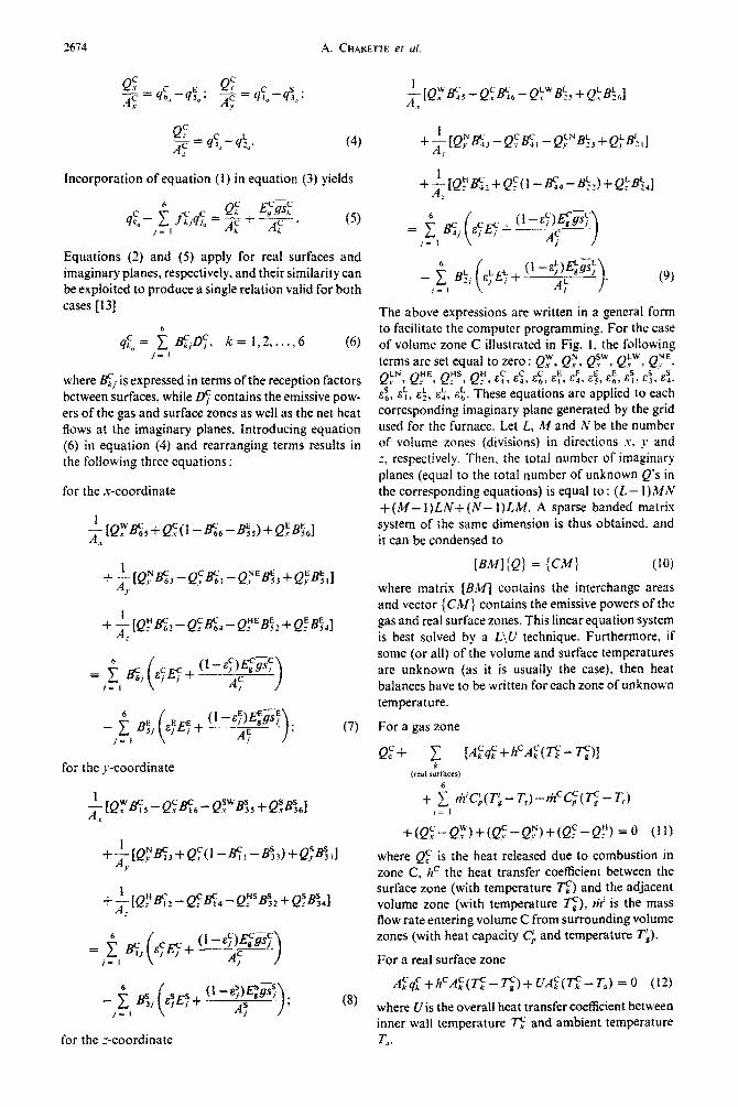
Incorporation of equation (1) in equation (3) yields
Equations (2) and (5) apply for real surfaces and imaginary planes, respectively. and their similarity can be exploited to produce a single relation valid for both cases [ 131
where gj is expressed in terms of the reception factors between surfaces, while Ds contains the emissive pow- ers of the gas and surface zones as well as the net heat Rows at the imaginary planes. Introducing equation (6) in equation (4) and rearranging terms results in the following three equations :
for the .r-coordinate
for the y-coordinate
(9)
The above expressions are written in a general form to facilitate the computer programming. For the case of volume zone C illustrated in Fig. 1. the following terms are set equal to zero : Qy, Qz, Qsw, Q:“_ Q-y”,
!$“;Q_~, F:‘, Q:, 6, 6 E:, E?,& E:, 6% ~7, ES, 8%
Q, E,, cZ, cd, E\. These equations are applied to each corresponding imaginary plane generated by the grid used for the furnace. Let L, M and N be the number of votume zones (divisions) in directions I, _r and * respectively. Then, the total number of imaginary ilanes (equal to the total number of unknown Q’s in the corresponding equations) is equal to : (L- I)NN +(M- I)LN+(N- I)LM. A sparse banded matrix system of the same dimension is thus obtained. and it can be condensed to
[BM](Q) = {CM) (10)
where matrix [B&f] contains the interchange areas and vector {CM) contains the emissive powers of the gas and real surface zones. This linear equation system is best solved by a L\U technique. Furthermore, if some (or all) of the volume and surface temperatures are unknown (as it is usually the case), then heat balances have to be written for each zone of unknown temperature.
For a gas zone
+(a:-Q$‘)+tQ:--Q.?)+(Q:-Q:) = 0 (11)
where QF is the heat released due to combustion in zone C, hC the heat transfer coefficient between the surface zone (with temperature c) and the adjacent volume zone (with temperature c), riz’ is the mass flow rate entering volume C from surrounding volume zones (with heat capacity CL and temperature Ti).
For a real surface zone
A~cl~+h=A~(~-~)fUA:(~--_T,) =o (12)
where U is the overall heat transfer coefficient between inner wall temperature c and ambient temperature
To. for the :-coordinate
It is seen from the above expressions that allowance is made for combustion, convection and arbitrary flow
pattern (the latter through the term
of equation (11)). The distribution of the combustion and flow patterns can be either prescribed or cal- culated by solving the combustion kinetics and Nav- ier-Stokes equations. Since the purpose of this work is to assess the IPM, these will be prescribed here. The solution of the problem is then obtained by an iterative procedure as follows: (1) an initial tem- perature field is assumed ; (2) the Q’s are computed by equation (10) ; (3) the q%‘s are found by equation (6); (4) the net fluxes at the walls are obtained by qc = (g -q~“)&/(l -Q) ; (5) the new temperature distribution is obtained by solving the non-linear equations (11) and (12) using the Newton-Raphson technique; (6) these temperatures are compared with the previous ones, and if the difference is less than a given tolerance, the solution has converged; if not, the procedure is repeated starting from step 2 until the convergence is obtained.
temperature. The second difficulty is apparent from the examination ofequation (13). It is seen that &(Tj, 7”J is to be evaluated on the basis of the tem~~tures of the six faces enclosing a given volume zone. These faces can be imaginary planes for which T; is imma- terial since radiation passing through them is of many different sources (gas and surface). There is no clear sohnion to this problem. Different suggestions have been made, among which : taking q equal to the geo- metric mean value of the gas temperatures on both sides of the plane [13], or using the closest solid tem- perature [17]. However, the authors feel that the full assessment of this point has not yet been made and, therefore, no general rule can be drawn for the moment. Thus, even though results from the IPM were found to compare well with those obtained from the zone method for real gases, at this stage the util- ization of IPM offers a safer basis for the case of a gray medium.
2.1. Extension to real gases To adapt the formulation to a real gas medium,
Hottel’s well-known weighted sum of gray gases for- mulation is used [ 151. The chosen technique is similar to that used in the zone method, except that the weighting coefficients are assigned to the direct inter- change areas rather than the total interchange areas. For example, in the presence of a real gas, equation (1) is rewritten as
where ai and n, are the weighting coefficients for the abso~ti~ty and the emissivity of the gas. The rest of the mathematical formulation is modified accord- ingly. However, two difficulties arise. First, the B values in equation (6) are now dependent on tem- perature and so is, as a consequence, the matrix [BM) in equation (10). Therefore, in calculating the iacob- ian for the solution of equations (11) and (12), the partial derivative of Q with respect to a given tem- perature T, is expressed as
N-l S - ‘, corresponding to typical values in the industrial
+ 1 a,(~‘)GY~ (13) operation. The gas medium is considered as gray with n- I an absorption coefficient of 0.175 m- ‘. Such a gas is
relatively transparent and is therefore a good medium for testing the validity of a simplified method such as the IPM. In principle, the IPM shouId give better resuits in dark gases since the formufation is based on partial interaction between zones. The chosen grid is 6 x 3 x 4 (x, I’, I), but this can be changed at will since the interchange areas are calculated by a Monte Carlo method which allows high Sexibiiity in the sizing of the grid. The results of the simulation are presented in Fig. 4 for the heat transferred to the liquid metal at J = 1 and 2 (part (a)), the temperature of the roof at the same location (part (b)) and the gas temperature averaged over the height of the furnace at J = 2 (part (cl). The IPM is compared with the zone method which is taken as the rigorous solution. It is seen that the results are in good agreement. The average computational errors are 4.4, 3.4 and 0.5% for parts (a), (b) and (cf, respectively. The computation times on a VAX-785 were 1099 and 74 s for the zone method
which makes the solution more difficult especially for 3-D cases. Owing to the relatively moderate vari- ation of the weighting factors a and (I’ with respect to tem~rature, the recommended procedure is to neglect the last partial differential in equation (14) and to re-evaluate fBM1 at each iteration with the undated r~ ~~ and the IPM respectively, giving a time ratio of 14.9.
Application of the imaginary planes method to three-dimensional systems 2675
3. RESULTS
To assess the IPM method, a series of tests were performed on different types of furnaces.
3.1. Test I The first geometry chosen is the one illustrated in
Fig. 1 which corresponds to a typical elongated com- bustion chamber of an aluminium melter/holder. This case is fully described in Table 1 and Fig. 3. The liquid metal that constitutes the bottom of the furnace is held constant at 1033 K and all the other surface and gas temperatures are unknown. The total heat release by combustion (natural gas) and the mass flow rate at the burner are respectively 4213 kW and 1.754 kg

2676 A. CHARETTE et a/.
Table I. Data used in test I for the elongated furnace
Model inputs Remarks and
numerical values
PRESCRIBED PATTERNS : Combustion Flow field
PHYSICAL PARAMETERS: Gas absorption coefficient K Direct interchange areas Refractory emissivity Charge (bottom) emissivity Nature of gas Size of the furnace (x, _v’. -_) Number of subdivisions (x, J, c) Overall heat transfer coefficient (from inside surface to environment) -charging side -side opposite to the charging doors -roof -burner face and opposite face Convective heat transfer coefficient -burner face and opposite face -other faces Composition of combustion gas (volume basis) Ambient temperature Temperature at burner inlet Charge temperature
see Fig. 3(a) see Fig. 3(b)
0.175 m-’ calculated by Monte Carlo
0.7 0.6
gray 10.75 x 3.75 x I.2 m
6x3x4
1.3 W m-’ K-’ 0.86 W m-’ K-’ 1.37 W rn-? K-’ 0.75 W m-’ K-’
SO W m-’ K- ’ 25 W m-‘ K-’
CO2 8.9. Hz0 17.7, O2 1.3, NJ 72.1%
298 K 333 K
1033 K
Y Y (a) W
FIG. 3. (a) Prescribed combustion distribution for Test I (kW); (b) prescribed flow field (kg s-l). The indicated values are relative to each subdivision along the :-axis (four subdivisions in this case) ; they must
thus be multiplied by 4 to obtain the total values for the furnace.
3.2. Test 2 The same example has been worked out based on
the real gas behaviour for which the molar ratio H,O/COr was taken equal to 2, characteristic of the combustion products of natural gas (the full com- position is given in Table 1). Results are shown in Fig. 5 for the parallelepiped gas portion J = K = 2. As explained previously, the solution is dependent on
the immaterial temperatures of the imaginary planes. Three cases have been tested here. In case I, all the imaginary planes were assigned the temperature of the liquid metal (1033 K); in cases 2 and 3, they were assigned, respectively, the average temperature of all the refractories enclosing the furnace and the average temperature of the real surface zones parallel and opposed on both sides to each imaginary plane. The

Application of the imaginary- planes method to three-dimensional systems 2677
temperature dependent weighting coefficients intro- duced in equation (13) were calculated according to the procedure suggested by Smith er uf. [IS]. Four
[ZG-q gray gases were considered, one being the clear gas with K = 0 m- ‘, It is apparent from Fig. 5 that the
l J:l best results are obtained for the first case, i.e. when the . Jr2
-lPM bottom surface temperature is used as the imaginary
__**.. w __-_ ZONE
plane temperature in the calculations (average pet- - METIC centage error : 1%). This surface has the lowest tem-
perature of all the surfaces of the enclosure and is by far the most absorbing. Unfortunately. at this stage, it cannot be stated positively that the most absorbing surface should be used in ail other systems. Never- theless. it can be pointed out that case I gives better results than when the imaginary planes are assigned mean temperatures of the gas zones on both sides of the planes as reported in ref. [13]. For this case, the computation times were 4744 and 413 s for the zone method and the PM, respectively (ratio = I 1.5).
3.3. Test 3
Jz2
To further test the method, the cross section of the furnace was changed to a square of 5 m x 5 m (still 10.75 m long), and the energy released by combustion and the total flow rate were doubled without changing however the relative distribution of these quantities.
123456 PoslTlCN I AUNG THE X AXIS
FIG. 4. Results for Test I (elongated furnace, gray gas with K=O.l75m-‘f:(a)heattotheliquidmetalatJ= land2; (b) roof temperature at the same locations: (c) gas tem- perature averaged over the height of the furnace at f = 2
Wf means that the two methods give similar results).
J J-2, Ks2
- IPM(easel) ------- I PM kase2) ---- IPMbzas.?3) -.- ZOM METlfm
1 2 3 4 5 6
FOSiTlON I ALONG THE X AXIS
FIG. 3. Results for Test 2 (elongated furnace, real gas). The arrows indicate the locations of the calculated values. Continuous lines between these points have no physical meaning, however they are used here in place of the bar
diagram (see Fig. 4) to avoid overloading the figure.
s_-_- -- Js2
1300 (b)
1000
/ -
J-2 900 ----
123456
FIG. 6. Results for Test 3 (5 x 5 x 10.75 m furnace. gray gas with K = 0.175 m-l). Parts (a) and (b) are for J = Z and
part (c) for J = K = 2.
‘678 A. CHARETTE er al.
E - 0.8
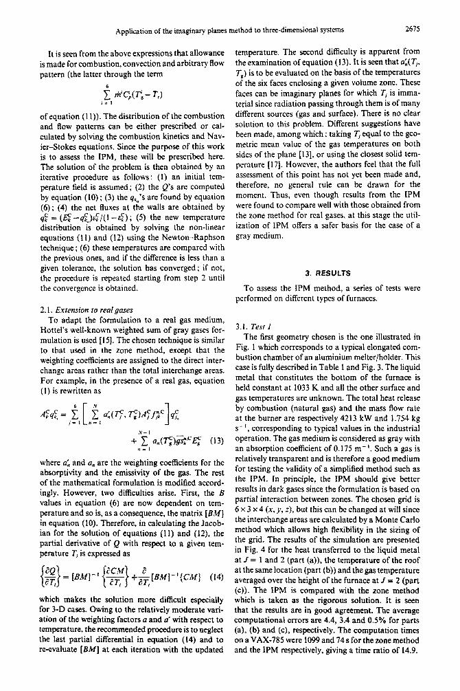
FIG. 7. Description of the enclosure used in Test 4.
The gas was taken as gray. The rest of the charac- teristics remained unchanged. This modified furnace is a more severe test for the IPM. The furnace is no longer of the elongated type, and the radiative transfer is important in every direction (in the previous case, the axial heat fluxes were small compared to the trans- versal ones). The results are given in Fig. 6 for the same variables as in Fig. 4. Note however that the gas temperatures are reported for J = K = 2 instead of values averaged over the height. It is seen that the discrepancies between the two methods are of the same order as the previous ones: the average errors are 4, 6.1 and 3.5% on the heat to the liquid metal, the roof temperature and the gas temperature, respec- tively. The computation time ratio between the two methods was the same as in Test I.
3.4. Test 4 The purpose of this last test is to evaluate the influ-
ence of the gas absorption coefficient K. The assess- ment is made for a case of pure radiation, all tem- peratures of the volume and surface zones being prescribed, which means that the solution of the non- linear set of equations of the type (11) and (12) is bypassed. Hence, the emphasis is put here on the basic principle of the IPM. Since the interaction between zones is established indirectly, it is logical to question the validity of the method at very low absorption coefficients, in which case the exchange between dis- tant zones also become important. The enclosure chosen is described in Fig. 7. It is a 1.5 x 1.5 x 3 m (x,
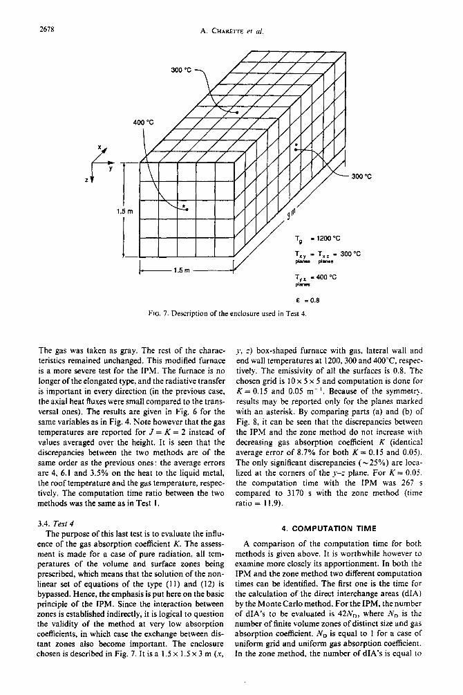
y, z) box-shaped furnace with gas, lateral wall and end wall temperatures at 1200,300 and 400°C respec- tively. The emissivity of all the surfaces is 0.8. The chosen grid is IO x 5 x 5 and computation is done for K = 0.15 and 0.05 m- ‘. Because of the symmetry. results may be reported only for the planes marked with an asterisk. By comparing parts (a) and (b) of Fig. 8, it can be seen that the discrepancies between the IPM and the zone method do not increase with decreasing gas absorption coefficient K (identical average error of 8.7% for both K = 0.15 and 0.05). The only significant discrepancies (-25%) are loca- lized at the corners of the Y-Z plane. For K = 0.05. the computation time with the IPM was 267 s compared to 3170 s with the zone method (time ratio = 11.9).
4. COMPUTATION TIME
A comparison of the computation time for both methods is given above. It is worthwhile however to examine more closely its apportionment. In both the IPM and the zone method two different computation times can be identified. The first one is the time for the calculation of the direct interchange areas (dIA) by the Monte Carlo method. For the IPM, the number of dIA’s to be evaluated is 42Nn, where ND is the number of finite volume zones of distinct size and gas absorption coefficient. ND is equal to 1 for a case of uniform grid and uniform gas absorption coefficient. In the zone method, the number of dIA’s is equal to
2679
(a) K = 0.15 I
(b) K ~0.05
FIG. 8. Comparison of the IPM and the zone method (Test 4) with K = 0.15 m- ’ (part (a)) and K = 0.05 m- ’ (part (b)). Results are reported for the net heat fluxes in kW m-*. Values in parentheses are
for the IPM.
42N’ where N is the total number of finite volumes in the domain regardless of the sizes of the volume zones and the gas absorption coefficient distribution. Hence, it can be inferred that the IPM reduces computation time considerably, especially for the case of uniform grid/uniform gas absorption coefficient. It must be pointed out however that this comparison is not perfect, since the zone method goes one step further by evaluating the total interchange areas which adds to the computation time (it increases considerably if the emissivities of the real surfaces are low). The second time is related to the calculation of radiative heat fluxes and to the procedure for the convergence of heat balances on the surface and volume zones,
the combination of which will be referred to as the iteration time. Since both methods use the Newton- Raphson algorithm for solving the heat balances, there is no significant difference in computation time in this regard. However, due to limited interaction of the IPM with the neighbouring zones, time used for obtaining the radiative heat fluxes is much less with this method.
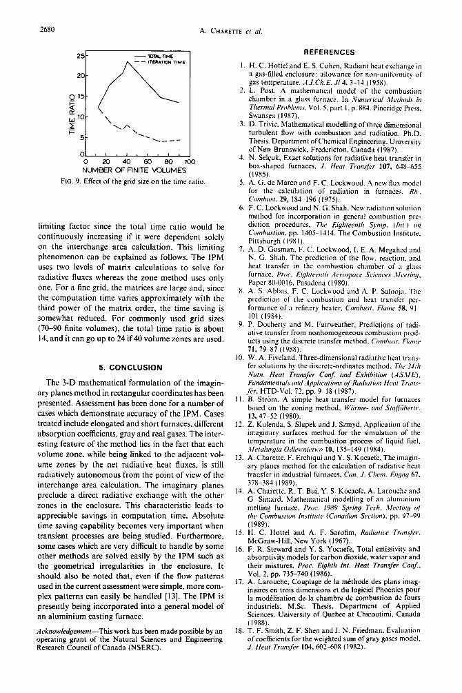
Figure 9 shows how the time ratio (defined as the ratio of the time required with the zone method to that with the IPM) varies with respect to the number of finite volumes on a VAX-785 for the case of a gray gas where all the zone temperatures are unknown. It can be seen from the figure that iteration time is the
2680 A. CHARETTE cl d.
NUMBER OF FINITE VOLUMES
FIG. 9. Effect of the grid size on the time ratio
limiting factor since the total time ratio would be continuously increasing if it were dependent solely on the interchange area calculation. This limiting phenomenon can be explained as follows. The IPM uses two levels of matrix calculations to solve for radiative fluxes whereas the zone method uses only one. For a fine grid, the matrices are large and, since the computation time varies approximately with the third power of the matrix order, the time saving is somewhat reduced. For commonly used grid sizes (70-90 finite volumes), the total time ratio is about 14, and it can go up to 24 if 40 volume zones are used.
5. CONCLUSION
The 3-D mathematical formulation of the imagin- ary planes method in rectangular coordinates has been presented. Assessment has been done for a number of cases which demonstrate accuracy of the IPM. Cases treated include elongated and short furnaces, different absorption coefficients, gray and real gases. The inter- esting feature of the method lies in the fact that each volume zone, while being linked to the adjacent vol- ume zones by the net radiative heat fluxes, is still radiatively autonomous from the point of view of the interchange area calculation. The imaginary planes preclude a direct radiative exchange with the other zones in the enclosure. This characteristic leads to appreciable savings in computation time. Absolute time saving capability becomes very important when transient processes are being studied. Furthermore, some cases which are very difficult to handle by some other methods are solved easily by the IPM such as the geometrical irregularities in the enclosure. It should also be noted that, even if the flow patterns used in the current assessment were simple, more com- plex patterns can easily be handled [l3]. The IPM is presently being incorporated into a general model of an aluminium casting furnace.
Acknolc(edgenrerrr-This work has been made possible by an operating grant of the Natural Sciences and Engineering Research Council of Canada (NSERC).
7.
S.
9.
IO
I I.
12.
13.
14.
15,
16.
17.
18.
REFERENCES
H. C. Hottel and E. S. Cohen. Radiant heat exchange in a gas-filled enclosure : allowance ior non-uniformity of gas temperature. .1.I.Ch.E. Jl4, 3-14 (1958). L. Post. A mathematical model of the combustion chamber in a glass fErnace. In iVunrrricrrl ,t/el/~otls in Thernlal Proh1enr.s. Vol. 5. part I, p. 884. Pineridge Press. Swansea (1987). D. Trivic, Mathematical modelling of three dimensional turbulent flow with combustion and rudiation, Ph.D. Thesis, Department ofchemical Engineering. University of New Brunswick, Fredericton. Canada (1987). N. Selcuk. Exact solutions for radiative heat transfer in box-shaped furnaces. J. Heut Trun.$v 107, 615-655 (1985). A. G. de Marco and F. C. Lockwood. A new tlux model for the calculation of radiation in furnaces. Rk.
Combust. 29. 184-196 (1975). F. C. Lockwood and N. G. Shah, New radiation solution method for incorporation in general combustion pre- diction procedures, Tl,e E$treennrh Synrp. (/)I/.) on Comhu.~tion. pp. 1405-1414. The Combustion Institute, Pittsburgh (19s I). A. D. Gosman. F. C. Lockwood, I. E. A. Megahed and N. G. Shah. The prediction of the flow. reaction. and heat transfer in the combustion chamber of ;I glass furnace, Proc. Eighteen/h A cvospacc Sciences .II~vring.
Paper 80-0016. Pasadena (19SO). A. S. Abbes. F. C. Lockwood and A. P. Salooja. The prediction of the combustion and heat transfer per- formance of a refinery heater, Con~hus!. Flon~c 58. 9 I IO1 (19S4). P. Docherty and M. Fairweather,’ Predictions of radi- ative transfer from nonhomogeneous combustion prod- ucts using the discrete transfer method. Conrhrrs~. f/umc 71, 79-87 (IYSS). W. A. Fiveland. Three-dimensional radiative heat tram- fer solutions by the discrete-ordinates method. Tlrc ‘d/h Nurn. Hear Transfer Conj and Exhibition (AS.WE). Fundamenruls und Applicuiions oJ’Rudiarion Hcor Truns-
fer, HTD-Vol. 72, pp. 9-18 (1987). B. Striim. A simple heat transfer modrl for furnaces based on the zoning method. Wiirnte- un(1 Slqfiii’herrr. 13,47-52 (1980). 2. Kolenda. S. Slupek and J. Szmyd. Application of the imaginary surfaces method for the simulation of the temperature in the combustion process of liquid fuel. .Iferahrruia Odhvnicmx 10. 135-149 (1984). A. Charette. F. Erchiqui and Y. S. Kocaefe;The imagin- ary planes method for the calculation of radiative heat transfer in industrial furnaces. Can. J. Chem. Dyng 67. 378-384 (1989). A. Charette. R. T. Bui. Y. S. Kocaefe, A. Larouche and G. Simard. Mathematical modelling of an aluminium melting furnace, Proc. 19X9 Spring Tech. ,Weering q/’ the Conrbu.sriun Instirure (Cunudian Secrion). pp. 97-99
(1989).
H. C. Hottel and A. F. Sarolim, Rudiuiice Trrrrrsfir.
McGraw-Hill, New York (1967). F. R. Steward and Y. S. Yocaefe, Total emissivity and absorptivity models for carbon dioxide. water vapor and their mixtures, Proc. Eighth Inr. Hear Transfer Con&
Vol. 2. pp. 735-740 (1986). A. Larouche. Couplage de la m&hode des plans imag- inaires en trois dimensions et du logiciel Phoenics pour la modelisation de la chambre de combustion de fours industriels, M.Sc. Thesis, Department of Applied Sciences. University of Quebec at Chicoutimi, Canada (1988). T. F. Smith. Z. F. Shen and J. N. Friedman, Evaluation of coefficients for the weighted sum of gray gases model. J. Heur 7rrmsyer 104, 602-605 ( 1982).
Application of the imaginary planes method to three-dimensional systems 268 1
LA METHODE DES PLANS IMAGINAIRES APPLIQUEE A DES SYSTEMES TRIDlMENSlONNELS
R&sum&-On prisente la formulation mathematique de la methode des plans imaginaires pour le calcul du transfert de chaleur radiatif dans des fournaises rectangulaires en trois dimensions. Cette mPthode simplifie le rayonnement en le reprisentant sous la forme d’une interaction en chaine d’une zone B I’autre con- trairement B une interaction directe de toutes les zones telle que pr&onis& par la mithode classique de zones. On a r&ah& certains tests pour la validation de la mPthode en faisant appel B des gaz gris et &Is ainsi qu’8 diffkrentes gtometries. Les rCsultats obtenus supportent bien la comparaison avec ceux de la methode de zones. De plus, les temps de calcul se sent rivilis considirablement reduits par rapport ;i ceux de la mkthode de zones (facteur de riduction atteignant 24). Cette derniere caractiristique permettra $ la methode des plans imaginaires d’etre plus facilement incorpor& dans une simulation globale impliquant Cgalement les iquations du mouvement. de la cinitique de combustion et du transfert de masse et de
chaleur.
ANWENDUNG DER METHODE DER IMAGINAREN EBENEN AUF DREIDIMENSIONALE SYSTEME
Zusammenfassung-Es wird eine dreidimensionale mathematische Formulierung der Methode der imag- inlren Ebenen (IPM) zur Berechnung des Strahlungsaustausches in rechteckigen dfen vorgestellt. Bei dieser Methode wild der Strahlungswlrmeaustausch als Kettenreaktion von Zone zu Zone modelliert. wohingegen beim klassischen Zonenverfahren eine direkte Wechselwirkung angenommen wird. Es wird eine Reihe von Versuchen mit grauen und realen Gasen sowie fiir unterschiedliche Hohiraumgeometrien durchgefiihrt. Die Ergebnisse stimmen gut mit denen des Zonenverfahrens i&rein. Das neue Verfahren erlaubt eine betrichtliche Verringerung der Rechenzeit (bis zum Faktor 24) im Vergleich zum Zonen- verfahren. Dies wird dem IPM-Verfahren leichten Eingang in Gesamtsimulationen verschaffen, hei denen die Bewegungsgleichungen, die Verbrennungskinetik und der Wgrme- und Stofftransport zu beriick-
sichtigen sind.
ITPWMEHEHHE METOW MHHMbIX I-IJIOCKOCrER K TPEXMEPHbIM CHCTEMAM
Am3~ums-IIpsieo~~~~cn TpcxMepHan MaTeMaTHgemax @opMyAHposra M~TOA~ ~mibfbm nnocrocre~ (lPM)ana pa@mapawarmomoro nepenoca B npos~oyro~b~bm~on~~. Bna~lto~~erone pauaa- unomihal uepetioc MOAU~~PY~T~~K uentsn4 B3aSiMOAe&TB~CM OT 30mu x 30se B o-rnnwe OT npnhtoro B3aEbfOAefiCTBHII B KJlaCCHPeCKOM U)HBAbHOM MeTOAe. BbmonneH p3UX 3KCIlepHMeHTOB AJIx cepor0 A peaAbHor ra3o~,aTa~~egnnpa3~1~mbm reoMeTpd nonocm.~oJrynck~o xopomeecorAacHecpe3yd?a- TaTaMR 30HaRbHOrO MeTOAa. &me TOTO, 3Ha'IHTeAbiiO (B 24 pt.@ CoxpauteHo MB-oe 62PeMX UO cpaBHeHHI0 c 301iaAb~bc~ MCroAoM.~O ~IO~BOAET 6oAee nelllo HcnOAb30BaTb MC7011 IPM B o6rUC.Cr MOAeJUipoBaHSiH, BxJllO'SaKNAeM~aBHeHHn AB=ewx, KHHCTEKH cropaexn,aTanteTeMO- H bmccone-
peeoca.