"Application for Certificate of Compliance for the Traveller ...
433
Westinghouse Electric Company, LLC Columbia Fuel Fabrication Plant Columbia, SC Application for Certificate of Compliance for the Traveller PWR Fuel Shipping Package NRC Certificate of Compliance USA/9297/AF-96 Docket 71-9297 Initial Submittal: March 2004
-
Upload
khangminh22 -
Category
Documents
-
view
0 -
download
0
Transcript of "Application for Certificate of Compliance for the Traveller ...

Westinghouse Electric Company, LLC
Columbia Fuel Fabrication Plant
Columbia, SC
Application for Certificate of Compliance for the
Traveller PWR Fuel Shipping Package
NRC Certificate of Compliance
USA/9297/AF-96
Docket 71-9297
Initial Submittal: March 2004

Docket 71-9297
Traveller Safety Analysis Report Rev. 0, 3/2004
6437-TOC-rev0.doc
TABLE OF CONTENTS
1 GENERAL INFORMATION.......................................................................................................1-1
2 STRUCTURAL EVALUATION .................................................................................................2-1
3 THERMAL EVALUATION ........................................................................................................3-1
4 CONTAINMENT .........................................................................................................................4-1
5 SHIELDING EVALUATION ......................................................................................................5-1
6 CRITICALITY EVALUATION ..................................................................................................6-1
7 PACKAGE OPERATIONS..........................................................................................................7-1
8 ACCEPTANCE TESTS AND MAINTENANCE PROGRAM...................................................8-1


Docket 71-9297
Traveller Safety Analysis Report Rev. 0, 3/2004
6437-1rev0.doc i
TABLE OF CONTENTS
1 GENERAL INFORMATION.......................................................................................................1-1 1.1 INTRODUCTION ...........................................................................................................1-1 1.2 PACKAGE DESCRIPTION............................................................................................1-1
1.2.1 Packaging ........................................................................................................1-1 1.2.1.1 Package Types.................................................................................1-1 1.2.1.2 Outerpack ........................................................................................1-2 1.2.1.3 Clamshell.........................................................................................1-4 1.2.1.4 Rod Container .................................................................................1-6
1.2.2 Containment System........................................................................................1-7 1.2.3 Contents...........................................................................................................1-7
1.2.3.1 Traveller ..........................................................................................1-7 1.2.4 Operational Features........................................................................................1-7
1.3 GENERAL REQUIREMENTS FOR ALL PACKAGES ...............................................1-7 1.3.1 Minimum Package Size ...................................................................................1-7 1.3.2 Tamper-Indicating Feature ..............................................................................1-7
1.4 APPENDICES .................................................................................................................1-8 1.4.1 Package Drawings ...........................................................................................1-8

Docket 71-9297
Traveller Safety Analysis Report Rev. 0, 3/2004
6437-1rev0.doc ii
LIST OF FIGURES
Figure 1-1 Outerpack Closed Position (left) and Opened Position (right) ........................................1-3
Figure 1-2 Outerpack Cross-Section View (typical) .........................................................................1-3
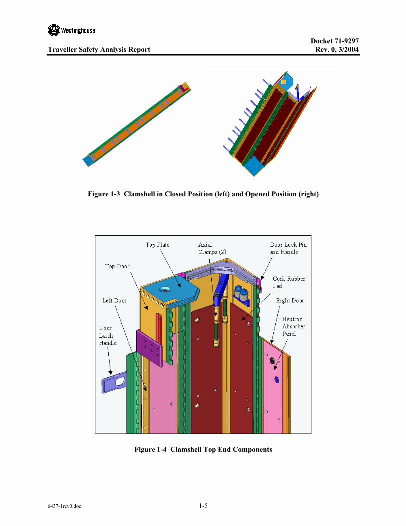
Figure 1-3 Clamshell in Closed Position (left) and Opened Position (right).....................................1-5
Figure 1-4 Clamshell Top End Components .....................................................................................1-5
Figure 1-5 Clamshell Latch Locked Position (left) and Open Position (right)..................................1-6
Figure 1-6 Rod Pipe (left) and Rod Box (right) ................................................................................1-6

Docket 71-9297
Traveller Safety Analysis Report Rev. 0, 3/2004
6437-1rev0.doc 1-1
1 GENERAL INFORMATION
1.1 INTRODUCTION
The Traveller™ (Patent Pending)1 is a new shipping package designed to transport non-irradiated uranium fuel assemblies or rods with enrichments up to 5.0 weight percent. It will carry several types of PWR fuel assemblies as well as either BWR- or PWR rods. This is described further in Section 6. The proposed Criticality Safety Index (CSI) for the Traveller is 0.7 when transporting fuel assemblies and 0.0 when transporting loose rods. The following sections describe the package design and testing program in detail. Drawings are presented in Section 1.4.1.
1.2 PACKAGE DESCRIPTION
1.2.1 Packaging
The Traveller package is designed to carry one (1) fuel assembly or one (1) container for loose rods. It is made up of three basic components: 1) an Outerpack, 2) a Clamshell, and 3) a Fuel Assembly or Rod Container. The Outerpack and Clamshell are connected together with a suspension system that reduces the forces applied to the fuel assembly during transport. The Rod Container is secured inside the Clamshell during transport of loose rods.
1.2.1.1 Package Types
There are two types of packagings in the Traveller family.
1.2.1.1.1 Traveller Standard (Traveller STD)
• Gross Weight = 4,500 pounds (2041 kg)
• Tare Weight = 2850 pounds (1293 kg)
• Outer Dimensions = 197.0" length x 27.0" width x 39.3" height (5004 mm x 688 mm x 998 mm)
1 Traveller is a Westinghouse trademark.

Docket 71-9297
Traveller Safety Analysis Report Rev. 0, 3/2004
6437-1rev0.doc 1-2
1.2.1.1.2 Traveller XL
• Gross Weight = 5,100 pounds (2313 kg)
• Tare Weight = 3155 pounds (1431 kg)
• Outer Dimensions = 226.1" length x 27.1" width and 39.3" height (5740 mm x 688 mm x 998 mm)
1.2.1.2 Outerpack
The Outerpack is a structural component that serves as the primary impact and thermal protection for the Fuel Assembly. It also provides for lifting, stacking, and tie down during transportation. The Outerpack is a long tubular design consisting of a top and bottom half as shown in Figure 1-1. Each half consists of a stainless steel outer shell, a layer of rigid polyurethane foam, and an inner stainless steel shell. The stainless steel provides structural strength and acts as a protective covering to the foam. A typical cross-section showing key elements of the package is depicted in Figure 1-2.
At each end of the package are thick impact limiters consisting of two sections of foam at different densities sandwiched between three layers of sheet metal. The impact limiters are integral parts of the Outerpack and reduce damage to the fuel assembly during an end, or high-angle drop.
The foam is a rigid, closed cell polyurethane that is an excellent impact absorber and thermal insulator and has well defined characteristics that make it ideal for this application. The steel-foam-steel “sandwich” is the primary fire protection, and is described in more detail in Section 3.
The inside of the Outerpack is lined with blocks of Ultra High Molecular Weight (UHMW) polyethylene. The polyethylene has a dual purpose. It provides a conformal cavity for the Clamshell and fuel assembly to fall into during low-angle drops. It is also a significant component used for criticality safety. Further discussion is presented in Chapter 6, Criticality Evaluation, of this document.

Docket 71-9297
Traveller Safety Analysis Report Rev. 0, 3/2004
6437-1rev0.doc 1-3
Figure 1-1 Outerpack Closed Position (left) and Opened Position (right)
Figure 1-2 Outerpack Cross-Section View (typical)

Docket 71-9297
Traveller Safety Analysis Report Rev. 0, 3/2004
6437-1rev0.doc 1-4
1.2.1.3 Clamshell
The Clamshell is a structural component consisting of a lower aluminum “v” extrusion, two aluminum door extrusions, and a small top access door. Piano type hinges (continuous hinges) connect each door to the “v” extrusion. The doors are then held closed with a latch mechanism and eleven quarter-turn bolts (9 for the Traveller STD). At the bottom nozzle end, a base plate is bolted to the “v” extrusion. At the top nozzle end, the top plate and small v-shaped door are bolted together. These form the top door which is hinged at one side to allow it to swing open, leaving access to the top nozzle from above. The top door is secured with a short hinge pin which is inserted along the length of the top door. The Clamshell assembly is shown closed, and opened in Figure 1-3. A more detailed schematic showing key Clamshell components of the top end is depicted in Figure 1-4.
The quarter-turn Clamshell fasterners are shown in Figure 1-5. By rotating the nut plus or minus 90 degrees opens or closes the latch. Spring- loaded plungers on both sides of the nuts positively restrain each nut during shipping and handling, and precludes inadvertent opening of the latch.
The Fuel Assembly or Rod Tube is secured inside the Clamshell at three locations down the length. At the top end, two jackscrews with neoprene pads clamp the fuel assembly axially against the bottom plate. Adjustable spring-loaded pads are positioned at any axial location between end locations to secure the fuel assembly along its length. These pads will be located at mid-grid locations.
The “v” extrusion is lined with a cork rubber pad to cushion the contents and prevent damage during normal handling and transport conditions. The bottom plate is similarly lined with cork rubber.
Neutron absorber plates are installed in each leg of the “v” extrusion and in each of the doors. The absorber is a borated aluminum plate inserted in pocket in each extrusion and attached with screws. The plates are solely for neutron absorption and do not provide any structural support. More details are described in Section 6, Criticality Evaluation and Section 8, Acceptance Tests and Maintenance Program.
The purpose of the Clamshell is to protect the contents during routine handling and in the event of an accident. During routine handling, the Clamshell doors are closed immediately after the contents are loaded. This provides a physical barrier to debris or accidental damage. During accident conditions, the Clamshell provides a physical barrier to rod bowing, lattice expansion, and loss of rods. It also provides neutron absorption.
Docket 71-9297
Traveller Safety Analysis Report Rev. 0, 3/2004
6437-1rev0.doc 1-5
Figure 1-3 Clamshell in Closed Position (left) and Opened Position (right)
Figure 1-4 Clamshell Top End Components

Docket 71-9297
Traveller Safety Analysis Report Rev. 0, 3/2004
6437-1rev0.doc 1-6
Figure 1-5 Clamshell Latch Locked Position (left) and Open Position (right)
1.2.1.4 Rod Container
The Traveller is designed to carry loose rods using either of two types of rod containers: a rod box or rod pipe. Both can be seen in Figure 1-6. The rod box is an ASTM, Type 304 stainless steel container of rectangular cross section with stiffening ribs located approximately every 23.6 inches (600 mm) along its length. It is secured by fastening a removable top cover to the container body using socket head cap screws. The rod pipe consists of a 5" (12.7 cm) or a 6" (15.2 cm) standard 304 stainless steel, Schedule 40 pipe. The pipes are secured with a 0.44 inch (11.18 mm) flange and Type 304 stainless steel hardware on each end.
Figure 1-6 Rod Pipe (left) and Rod Box (right)

Docket 71-9297
Traveller Safety Analysis Report Rev. 0, 3/2004
6437-1rev0.doc 1-7
1.2.2 Containment System
The Containment System is described in both IAEA Regulations for the Safe Transport of Radioactive Material, Safety Standard Series No. TS-R-1 (213) and the Code of Federal Regulations, Title 10, Part 71.4 as, “the assembly of components of the packaging intended to retain the radioactive material during transport.” The Containment System for the Traveller is the fuel rod. Containment is described in greater detail in Section 6.
1.2.3 Contents
1.2.3.1 Traveller
Identification and Enrichment of Special Nuclear Material (SNM) – The SNM is unirradiated uranium enriched up to 5 weight % in the isotope U235, U234 and U236 quantities will be such that their activity will not exceed established A2 limits.
Form of SNM – The SNM is in the form of non-dispersible pellets inside the cladding to form fuel rods.
1.2.4 Operational Features
Fork lift pockets and tubular legs are attached to the bottom Outerpack. Stacking brackets, which double as lift points, are attached to the top Outerpack and are located in eight (8) locations. The package must be uprighted onto one end for loading and unloading. Two lifting points are attached to the top nozzle end of the top Outerpack.
1.3 GENERAL REQUIREMENTS FOR ALL PACKAGES
1.3.1 Minimum Package Size
The smallest overall dimension of the Traveller packages is outer shell diameter, approximately 25 inches (64 cm). This dimension is greater than the minimum dimension of 4-inches specified in 10 CFR §71.43(a), TS-R-1 (634). Therefore, the requirements of 10 CFR §71.43(a), TS-R-1 (634) are satisfied by the Traveller packages.
1.3.2 Tamper-Indicating Feature
Two (2) tamper indicating seals (wire/lead security seal) are attached between the upper and lower Outerpack halves to provide visual evidence that the closure was not tampered. Thus, the requirements of 10 CFR §71.43(b), TS-R-1 (635) are satisfied.
The Traveller series of packages cannot be opened inadvertently. Positive closure of the Traveller packages is provided by high strength ¾-inch hex head screws. Thus, the requirements of 10 CFR §71.43(c), TS-R-1 (639) are satisfied.
Docket 71-9297
Traveller Safety Analysis Report Rev. 0, 3/2004
6437-1rev0.doc 1-8
1.4 APPENDICES
1.4.1 Package Drawings

Docket 71-9297
Traveller Safety Analysis Report Rev. 0, 3/2004
6437-2rev0.doc i
TABLE OF CONTENTS
2 STRUCTURAL EVALUATION .................................................................................................2-1 2.1 DESCRIPTION OF STRUCTURAL DESIGN...............................................................2-1
2.1.1 Discussion........................................................................................................2-1 2.1.2 Design Criteria.................................................................................................2-3
2.1.2.1 Basic Design Criteria ......................................................................2-3 2.1.2.2 Miscellaneous Structural Failure Modes.........................................2-3
2.1.3 Weights and Centers of Gravity ......................................................................2-4 2.1.4 Identification of Codes and Standards for Package Design.............................2-4
2.2 MATERIALS...................................................................................................................2-5 2.2.1 Material Properties and Specifications ............................................................2-5 2.2.2 Chemical, Galvanic, or Other Reactions .........................................................2-5 2.2.3 Effects of Radiation on Materials....................................................................2-5
2.3 FABRICATION AND EXAMINATION........................................................................2-7 2.3.1 Fabrication.......................................................................................................2-7 2.3.2 Examination.....................................................................................................2-7
2.4 LIFTING AND TIE-DOWN STANDARDS FOR ALL PACKAGES...........................2-8 2.4.1 Lifting Devices ................................................................................................2-8
2.5 GENERAL CONSIDERATIONS ...................................................................................2-9 2.5.1 Evaluation by Test ...........................................................................................2-9 2.5.2 Evaluation by Analysis..................................................................................2-11
2.6 NORMAL CONDITIONS OF TRANSPORT ..............................................................2-12 2.6.1 Heat................................................................................................................2-12
2.6.1.1 Summary of Pressures and Temperatures .....................................2-12 2.6.1.2 Differential Thermal Expansion....................................................2-12 2.6.1.3 Stress Calculations ........................................................................2-12 2.6.1.4 Comparison with Allowable Stresses............................................2-13
2.6.2 Cold ...............................................................................................................2-13 2.6.3 Reduced External Pressure ............................................................................2-13 2.6.4 Increased External Pressure...........................................................................2-13 2.6.5 Vibration........................................................................................................2-13 2.6.6 Water Spray ...................................................................................................2-14 2.6.7 Free Drop.......................................................................................................2-14 2.6.8 Corner Drop...................................................................................................2-15 2.6.9 Compression – Stacking Test ........................................................................2-15 2.6.10 Penetration.....................................................................................................2-15
2.7 HYPOTHETICAL ACCIDENT CONDITIONS...........................................................2-16 2.7.1 Free Drop.......................................................................................................2-23
2.7.1.1 Technical Basis for the Free Drop Tests .......................................2-23 2.7.1.2 Test Sequence for the Selected Tests ............................................2-24 2.7.1.3 Summary of Results from the Free Drop Tests.............................2-24
Docket 71-9297
Traveller Safety Analysis Report Rev. 0, 3/2004
6437-2rev0.doc ii
TABLE OF CONTENTS (cont.)
2.7.2 Crush..............................................................................................................2-24 2.7.3 Puncture.........................................................................................................2-25
2.7.3.1 Technical Basis for the Puncture Drop Tests ................................2-25 2.7.3.2 Summary of Results from the Puncture Drop Tests......................2-26
2.7.4 Thermal..........................................................................................................2-26 2.7.4.1 Summary of Pressures and Temperatures .....................................2-27 2.7.4.2 Differential Thermal Expansion....................................................2-27 2.7.4.3 Stress Calculations ........................................................................2-27 2.7.4.4 Comparison with Allowable Stresses............................................2-27
2.7.5 Immersion – Fissile Material.........................................................................2-27 2.7.6 Immersion – All Packages.............................................................................2-28 2.7.7 Summary of Damage .....................................................................................2-28
2.8 ACCIDENT CONDITIONS FOR AIR TRANSPORT OF PLUTONIUM ..................2-29 2.9 ACCIDENT CONDITIONS FOR FISSILE MATERIAL FOR
AIR TRANSPORT ........................................................................................................2-30 2.10 SPECIAL FORM...........................................................................................................2-31 2.11 FUEL RODS..................................................................................................................2-32 2.12 APPENDIX....................................................................................................................2-33
2.12.1 CONTAINER WEIGHTS AND CENTERS OF GRAVITY........................2-34 2.12.1.1 Container Weights.........................................................................2-34 2.12.1.2 Centers of Gravity .........................................................................2-34
2.12.2 MECHANICAL DESIGN CALCULATIONS FOR THE TRAVELLER XL SHIPPING PACKAGE...................................................2-36 2.12.2.1 Analysis Results and Conclusions.................................................2-38 2.12.2.2 Calculations...................................................................................2-40
2.12.3 DROP ANALYSIS FOR THE TRAVELLER XL SHIPPING PACKAGE ....................................................................................................2-67 2.12.3.1 Analysis Results ............................................................................2-67 2.12.3.2 Predicted Performance of the Traveller Qualification
Test Unit........................................................................................2-68 2.12.3.3 Comparison of Test Results and Predictions...............................2-116 2.12.3.4 Discussion of Major Assumptions ..............................................2-128 2.12.3.5 Calculations.................................................................................2-129 2.12.3.6 Model Imput................................................................................2-135 2.12.3.7 Evaluations, Analysis and Detailed Calculations........................2-142 2.12.3.8 Accelerometer Test Setup ...........................................................2-143 2.12.3.9 Bolt Factor of Safety Calculation................................................2-144
2.12.4 TRAVELLER DROP TESTS RESULTS ...................................................2-148 2.12.4.1 Prototype Test Unit Drop Tests...................................................2-148 2.12.4.2 Qualification Test Unit Drop Tests .............................................2-167 2.12.4.3 Conclusions .................................................................................2-192

Docket 71-9297
Traveller Safety Analysis Report Rev. 0, 3/2004
6437-2rev0.doc iii
LIST OF TABLES
Table 2-1 Summary of Traveller STD and Traveller XL Design Weights ......................................2-4
Table 2-2 Safety-Related Materials Used in the Traveller Packages ...............................................2-6
Table 2-3 Summary of Regulatory Requirements............................................................................2-9
Table 2-4 Summary of Traveller Mechanical Analysis .................................................................2-11
Table 2-5 Summary of the Development of the Traveller .............................................................2-17
Table 2-6 Summary of Traveller STD and Traveller XL Design Weights ....................................2-34
Table 2-7 Summary of Regulatory Requirements for Mechanical Analysis .................................2-38
Table 2-8 Summary of Traveller Mechanical Analysis .................................................................2-39
Table 2-9 Summary of Traveller STD and Traveller XL Design Weights ....................................2-40
Table 2-10 Top Outerpack Latch Bolt Minimum Factors of Safety (FS) for 9m Side Dropped .........................................................................................................................2-77
Table 2-11 Top Outerpack Hinge Bolt Minimum Factors of Safety (FS) for 9m Side Drop ..........2-78
Table 2-12 Clamshell Keeper Bolt Minimum Factors of Safety for 9m Side Drop.........................2-80
Table 2-13 Clamshell Bottom Plate Bolt Minimum Factor of Safety for 9m Side Drops ...............2-81
Table 2-14 Clamshell Grooved Top Plate Bolt Minimum Factors of Safety for 9m Side Drops..............................................................................................................................2-82
Table 2-15 Clamshell Lipped Top Plate Bolt Minimum Factors of Safety for 9m Side Drops..............................................................................................................................2-83
Table 2-16 Top Outerpack Latch Bolt Minimum Factors of Safety for 9m CB-Forward of Corner Drops .............................................................................................................2-93
Table 2-17 Top Outerpack Hinge Bolt Minimum Factors of Safety for 9m CB Forward of Corner Drops .............................................................................................................2-93
Table 2-18 Clamshell Keeper Bolt Minimum Factors of Safety for 9m CG-Forward-of- Corner Drops..................................................................................................................2-94
Table 2-19 Clamshell Bottom Plate bolt Minimum Factors of Safety for 9m CG-Forward- of-Corner Drops.............................................................................................................2-95
Table 2-20 Clamshell Grooved Top Plate Bolt Minimum Factors of Safety for 9m CG-Forward-of-Corner Drops .......................................................................................2-95
Table 2-21 Clamshell Lipped Top Plate Bolt Minimum Factors of Safety for 9m CG-Forward-of-Corner Drops .......................................................................................2-96
Table 2-22 Prototype Tests Used to Compare with Analysis.........................................................2-117

Docket 71-9297
Traveller Safety Analysis Report Rev. 0, 3/2004
6437-2rev0.doc iv
LIST OF TABLES (cont.)
Table 2-23 Comparison of Predicted and Actual Deformations for Test 1-1 ................................2-121
Table 2-24 Initial Velocities 9 Meter Drop and 1 Meter Pin Puncture Analyses...........................2-136
Table 2-25 Summary of Elastic Properties.....................................................................................2-142
Table 2-26 Bolt Strength Summary ...............................................................................................2-145
Table 2-27 Strengths of Various Classifications of Bolts [14].......................................................2-146
Table 2-28 Bolt Strength Ratio ......................................................................................................2-147
Table 2-29 Series 1 As-Tested Drop Conditions............................................................................2-150
Table 2-30 Measured Decelerations in Prototype Test 1.1 ............................................................2-156
Table 2-31 Measured Accelerations in Test 1.2.............................................................................2-158
Table 2-32 Prototype Test Series 2 ................................................................................................2-159
Table 2-33 Traveller Prototype Drop Tests Performed in Test Series 3 ........................................2-165
Table 2-34 QTU-1 Measured Weight ............................................................................................2-167
Table 2-35 QTU-1 Drop Test Orientations ....................................................................................2-168
Table 2-36 Key Dimensions of QTU-1 Fuel Assembly Before Testing ........................................2-173
Table 2-37 QTU-1 Fuel Assembly Grid Envelope After Testing ..................................................2-174
Table 2-38 QTU-1 Fuel Rod Pitch Data After Testing ..................................................................2-175
Table 2-39 QTU Series 2 As-Tested Drop Conditions ..................................................................2-175
Table 2-40 QTU-2 Weights............................................................................................................2-176
Table 2-41 Key Dimensions of QTU-2 Fuel Assembly Before Testing ........................................2-181
Table 2-42 QTU-2 Fuel Assembly Grid Envelope After Testing ..................................................2-182
Table 2-43 QTU-2 Fuel Rod Pitch Data After Testing ..................................................................2-183
Table 2-44 Test Weights ................................................................................................................2-185
Table 2-45 CTU Drop Test Orientations........................................................................................2-186
Table 2-46 Fuel Assembly Key Dimension Before Drop Test ......................................................2-196
Table 2-47 CTU Fuel Assembly Grid Envelop Dimensions After Testing ...................................2-197
Table 2-48 CTU Fuel Assembly Rod Envelope Data After Testing..............................................2-198
Table 2-49 CTU Fuel Assembly Rod Envelope After Testing ......................................................2-199
Table 2-50 CTU Fuel Rod Gap and Pitch Inspection After Testing ..............................................2-200

Docket 71-9297
Traveller Safety Analysis Report Rev. 0, 3/2004
6437-2rev0.doc v
LIST OF FIGURES
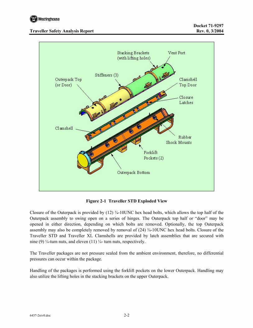
Figure 2-1 Traveller STD Exploded View ........................................................................................2-2
Figure 2-2 Traveller XL and Traveller STD Dimensions and Center of Gravity (Note: End View is Common to both Models) .............................................................2-35
Figure 2-3 Westinghouse Fresh Fuel Shipping Package , the Traveller XL ...................................2-36
Figure 2-4 Internal View of the Traveller Shipping Package..........................................................2-37
Figure 2-5 Traveller Lifting Configurations....................................................................................2-43
Figure 2-6 Lifting Hole Force Detail...............................................................................................2-44
Figure 2-7 Lifting Bracket Fabrication Detail .................................................................................2-45
Figure 2-8 Hole Tear-out Model and Mohr’s Circle Stress State....................................................2-46
Figure 2-9 Weld Geometry at Swing Bolt Block ............................................................................2-48
Figure 2-10 Forklift Handling Model and Assumed Cross Section ..................................................2-49
Figure 2-11 Typical Temperature Dependent Tensile Properties for Tempered 6000 Series Al ......2-52
Figure 2-12 Temperature Dependent Tensile Properties for 304 SS.................................................2-53
Figure 2-13 Temperature Dependent Crush Strength for 10 PCF Polyurethane Foam.....................2-54
Figure 2-14 Temperature Dependent Crush Strength for 20 PCF Polyurethane Foam.....................2-54
Figure 2-15 Temperature Dependent Crush Strength for 6 PCF Polyurethane Foam.......................2-55
Figure 2-16 Temperature Dependent Crush Strength for Traveller Foam at 10% Strain..................2-55
Figure 2-17 Compression/Stacking Requirement Analysis Model ...................................................2-58
Figure 2-18 Stacking Force Model on Stacking Bracket...................................................................2-59
Figure 2-19 Outerpack Section Compression Model ........................................................................2-60
Figure 2-20 Leg Support Section Compression Model .....................................................................2-63
Figure 2-21 Traveller Stiffeners, Legs, and Forklift Pockets ............................................................2-69
Figure 2-22 Results of Prototype Drop Test......................................................................................2-70
Figure 2-23 Side Drop Orientation....................................................................................................2-70
Figure 2-24 Low Angle Drop Orientation .........................................................................................2-71
Figure 2-25 Damage from Prototype Low Angle Drop (Test 1.1) ....................................................2-71
Figure 2-26 Horizontal Drop Orientations ........................................................................................2-72
Figure 2-27 Predicted Energy and Work for 9m Horizontal Drop Onto Outerpack Hinges .............2-73

Docket 71-9297
Traveller Safety Analysis Report Rev. 0, 3/2004
6437-2rev0.doc vi
LIST OF FIGURES (cont.)
Figure 2-28 Predicted Energy and Work Histories for a 9m Horizontal Drop Onto the Outerpack Hinges ..........................................................................................................2-73
Figure 2-29 Predicted Rigid Wall Force Histories for 9m Horizontal Drops Onto the Outerpack Latches and Hinges ......................................................................................2-74
Figure 2-30 De-coupled Impacts for 9 m Horizontal Side Drop .......................................................2-75
Figure 2-31 Bolts on Prototype Outerpack........................................................................................2-76
Figure 2-32 Bolt Labels for Right Outerpack....................................................................................2-77
Figure 2-33 Bolt Labels for Left Outerpack ......................................................................................2-79
Figure 2-34 Clamshell Closure Latches and Keeper Bolts................................................................2-79
Figure 2-35 Clamshell Keeper Bolt Labels .......................................................................................2-80
Figure 2-36 Clamshell Top and Bottom End Plates ..........................................................................2-81
Figure 2-37 Clamshell Bottom Plate Bolt Labels..............................................................................2-82
Figure 2-38 Clamshell Top Plate Bolt Labels ...................................................................................2-83
Figure 2-39 Clamshell Doors ............................................................................................................2-84
Figure 2-40 Clamshell Response during Side Drop ..........................................................................2-85
Figure 2-41 Clamshell Doors at Bottom Plate...................................................................................2-85
Figure 2-42 Predicted Response of Clamshell Bottom Plate and Doors During 9m Horizontal Drop onto Outerpack Latches................................................................2-86
Figure 2-43 Top Nozzle Analysis Drop Orientation .........................................................................2-87
Figure 2-44 Location of Impact.........................................................................................................2-87
Figure 2-45 Damage to Outerpack During Angled Drop onto Top Nozzle End of Package ............2-88
Figure 2-46 Predicted Deformation of Outerpack Top Nozzle Impact Limiter ................................2-88
Figure 2-47 Predicted Pin Puncture Orientation after a CG-Forward-of-Corner Test ......................2-89
Figure 2-48 Outerpack Top Separation vs. Drop Angle....................................................................2-90
Figure 2-49 Predicted Energy and Work Histories for 9 m CG over Corner Drop onto the Top Nozzle End at Various Angles .................................................................2-91
Figure 2-50 Predicted Rigid Wall Forces ..........................................................................................2-92
Figure 2-51 Clamshell Top Plate Geometry......................................................................................2-96
Figure 2-52 Traveller Drop Orientations Analyzed For Maximum Fuel Assembly Damage ...........2-97

Docket 71-9297
Traveller Safety Analysis Report Rev. 0, 3/2004
6437-2rev0.doc vii
LIST OF FIGURES (cont.)
Figure 2-53 Predicted Energy and Work Histories for a 9m Vertical Drop Onto the Top Nozzle End of the Package.....................................................................................2-99
Figure 2-54 Predicted Energy and Work Histories for a 9m Vertical Drop Onto the Bottom Nozzle End of the Package ...............................................................................2-99
Figure 2-55 Predicted Rigid Wall Histories for 9m Vertical Drops onto the Bottom (QU-1) and Top (QU-8B) Ends of the Package..............................................2-100
Figure 2-56 Predicted Force Between Clamshell and Impact Limiter for 9m Vertical Drops ........2-101
Figure 2-57 Predicted Fuel Assembly Accelerations for 9m Vertical Drops ..................................2-102
Figure 2-58 Impact Between Clamshell and Bottom Impact Limiter for Vertical Drop onto Bottom End of Package .......................................................................................2-102
Figure 2-59 First Impact Between Clamshell and Top Impact Limiter for Vertical Drop onto Top End of Package.............................................................................................2-103
Figure 2-60 Second Impact Between Clamshell and Top Impact Limiter for Vertical Drop onto Top End of Package.............................................................................................2-103
Figure 2-61 Third Impact Between Clamshell and Top Impact Limiter for Vertical Drop onto Top End of Package.............................................................................................2-104
Figure 2-62 Predicted Temperature and Foam Density Effect on Outerpack/Drop Pad Interface Forces (9m CG-Forward-of-Corner with 18° Rotation Drop onto the Top End of the Package)........................................................................................2-105
Figure 2-63 Predicted Temperature and Foam Density Effect on Outerpack/Drop Pad Interface Forces (9m CG-Forward-of-Corner with 18° Rotation Drop onto the Top End of the Package)........................................................................................2-105
Figure 2-64 Predicted Energy and Work Histories at Various Temperatures .................................2-107
Figure 2-65 Pin Drop Orientations ..................................................................................................2-108
Figure 2-66 Predicted Outerpack/Pin Interference Forces (1m Drop onto 15mm Diameter Steel Pin)......................................................................................................................2-108
Figure 2-67 Predicted Fuel Assembly Accelerations (1m Drop onto 15mm Diameter Steel Pin)......................................................................................................................2-109
Figure 2-68 Pin Drop onto Outerpack Hinges.................................................................................2-109
Figure 2-69 Predicted Outerpack/Pin Interface Forces (1m Drop onto 15mm Diameter Steel Pin)......................................................................................................................2-110
Figure 2-70 Predicted Fuel Assembly Accelerations (1m Drop onto 15mm Diameter Steel Pin)......................................................................................................................2-110

Docket 71-9297
Traveller Safety Analysis Report Rev. 0, 3/2004
6437-2rev0.doc viii
LIST OF FIGURES (cont.)
Figure 2-71 Predicted Energy and Work Histories for a 1 m Horizontal Pin Drop (Pin Underneath the Package CG) ...............................................................................2-111
Figure 2-72 Predicted Energy and Work Histories for a 1 m Tilted Pin Drop (20° Tilt With TN End Down ......................................................................................2-112
Figure 2-73 Predicted Energy and Work Histories for a 1 m Horizontal Pin Drop (Pin Hitting Hinge at Package CG)..............................................................................2-112
Figure 2-74 Comparison of Predicted Maximum Pin Indentions....................................................2-113
Figure 2-75 Predicted Outerpack/Pin Interface Forces (1 m Drop onto 15 mm Diameter Steel Pin After 9m Drop) .............................................................................................2-114
Figure 2-76 Predicted Fuel Assembly Accelerations (1 m Drop onto 15mm Diameter Steel Pin after 9 m Drop) .............................................................................................2-115
Figure 2-77 Predicted Energy and Work Histories (1 m Drop onto 15 mm Diameter Steel Pin after 9 m Drop) .............................................................................................2-116
Figure 2-78 Prototype Drop Tests Used To Benchmark Analysis ..................................................2-117
Figure 2-79 Prototype Unit 1 Drop Test..........................................................................................2-118
Figure 2-80 Comparison of Test 1.1 with Analytical Results .........................................................2-119
Figure 2-81 Comparison of Test 1.1 with Analytical Results .........................................................2-120
Figure 2-82 Deformations at End of Package..................................................................................2-122
Figure 2-83 Internal Deformations at Inside Outerpack..................................................................2-123
Figure 2-84 Outerpack Deformations at Bottom Nozzle End of Package.......................................2-124
Figure 2-85 Pin Puncture Deformations..........................................................................................2-124
Figure 2-86 Dimensions of Pin Puncture Deformations..................................................................2-124
Figure 2-87 Outerpack Predicted Deformations of Pin Drop..........................................................2-125
Figure 2-88 Predicted and Measured Y Accelerations ....................................................................2-126
Figure 2-89 Three Axis Measured Accelerations............................................................................2-126
Figure 2-90 Predicted and Measured Y Accelerations ....................................................................2-127
Figure 2-91 Predicted and Measured Y Accelerations ....................................................................2-127
Figure 2-92 Measured Primary and Secondary Accelerations ........................................................2-128
Figure 2-93 FEA Model Input Files ................................................................................................2-130
Figure 2-94 Outerpack Mesh in Prototype Model...........................................................................2-131

Docket 71-9297
Traveller Safety Analysis Report Rev. 0, 3/2004
6437-2rev0.doc ix
LIST OF FIGURES (cont.)
Figure 2-95 Impact Limiter in Prototype Unit Model .....................................................................2-131
Figure 2-96 Clamshell Mesh in Qualification Unit Model..............................................................2-132
Figure 2-97 Fuel Assembly in Both Prototype and Qualification Unit Models ..............................2-132
Figure 2-98 Outerpack Hinge Model...............................................................................................2-133
Figure 2-99 FEA Input Files............................................................................................................2-134
Figure 2-100 Outerpack Mesh in Qualification Unit Model .............................................................2-134
Figure 2-101 Impact Limiter Mesh in Qualification Unit Model......................................................2-135
Figure 2-102 Clamshell Mesh in Qualification Unit Model..............................................................2-135
Figure 2-103 Package Drop Angle ....................................................................................................2-137
Figure 2-104 Gravity Load Profile ....................................................................................................2-138
Figure 2-105 Stress Strain Data for LAST-A_FOAM ......................................................................2-139
Figure 2-106 Stress- Strain Curves for 304 Stainless Steel ...............................................................2-140
Figure 2-107 Temperature Effects on Tensile Properties of Annealed Stainless Steel .....................2-140
Figure 2-108 Stress-Strain Characteristics of Aluminum in Clamshell ............................................2-141
Figure 2-109 Temperature Effects on Tensile Properties of Aluminum in Clamshell ......................2-141
Figure 2-110 Accelerometer Locations on Prototype Unit 1.............................................................2-144
Figure 2-111 Traveller Prototype Internal View ...............................................................................2-149
Figure 2-112 Traveller Prototype External View ..............................................................................2-150
Figure 2-113 Drop Orientations for Prototype Test Series 1.............................................................2-151
Figure 2-114 Traveller Prototype Exterior After Test 1.1.................................................................2-152
Figure 2-115 Traveller Prototype Interior After Test 1.1 ..................................................................2-153
Figure 2-116 Traveller Prototype Exterior After Test 1.2.................................................................2-154
Figure 2-117 Traveller Prototype Interior After Test 1.2 ..................................................................2-155
Figure 2-118 Clamshell Accelerometer Trace for Prototype Test 1.1...............................................2-156
Figure 2-119 Outerpack Accelerometer Trace for Prototype Test 1.1 ..............................................2-157
Figure 2-120 Clamshell Accelerometer Trace for Prototype Test 1.2...............................................2-157
Figure 2-121 Traveller Prototype After Test 1.3 ...............................................................................2-159
Figure 2-122 Drop Orientations for Traveller Prototype Test Series 2 .............................................2-160
Docket 71-9297
Traveller Safety Analysis Report Rev. 0, 3/2004
6437-2rev0.doc x
LIST OF FIGURES (cont.)
Figure 2-123 Traveller Prototype After Test 2.1 ...............................................................................2-161
Figure 2-124 Traveller Prototype After Test 2.2 ...............................................................................2-162
Figure 2-125 Traveller Prototype After Test 2.3 ...............................................................................2-163
Figure 2-126 Traveller Prototype Interior After Test Series 2 ..........................................................2-164
Figure 2-127 Traveller Prototype After Test Series 3 .......................................................................2-166
Figure 2-128 Traveller Prototype Clamshell and Bottom Impact Limiter After Test Series 3 .........2-166
Figure 2-129 Drop Orientation for QTU Test Series 1......................................................................2-168
Figure 2-130 QTU-1 Outerpack After Test 1.1 .................................................................................2-169
Figure 2-131 QTU-1 Outerpack After Test 1.2 .................................................................................2-170
Figure 2-132 QTU-1 Outerpack After Test 1.3 .................................................................................2-170
Figure 2-133 QTU-1 Fuel Assembly After Drop and Burn Tests .....................................................2-171
Figure 2-134 Measurements Made on QTU Fuel Assemblies Before and After Drop Tests............2-172
Figure 2-135 QTU Test Series 2 Drop Orientaitons..........................................................................2-177
Figure 2-136 QTU Outerpack After Test 2.1 ....................................................................................2-178
Figure 2-137 QTU Outerpack After Test 2.2 ....................................................................................2-178
Figure 2-138 QTU Outerpack After Test 2.3 ....................................................................................2-179
Figure 2-139 QTU-2 Clamshell and Fuel Assembly After Drop Tests.............................................2-180
Figure 2-140 Traveller CTU Test Article Internal View...................................................................2-184
Figure 2-141 Traveller CTU External View......................................................................................2-185
Figure 2-142 CTU Drop Test Orientations........................................................................................2-186
Figure 2-143 Top Nozzle End Outerpack Impact Damage ...............................................................2-187
Figure 2-144 CTU Outerpack Stiffener After Test 1.........................................................................2-188
Figure 2-145 CTU Outerpack After Test 2........................................................................................2-188
Figure 2-146 Bottom Nozzle End Cap Stiffener Damage From Test 2.............................................2-189
Figure 2-147 Hinge Separation at Bottom Nozzle End From Test 2.................................................2-189
Figure 2-148 CTU Outerpack After Test 3........................................................................................2-190
Figure 2-149 CTU Clamshell After Drop and Fire Tests ..................................................................2-191
Figure 2-150 Outerpack Lid Moderator After Testing ......................................................................2-191

Docket 71-9297
Traveller Safety Analysis Report Rev. 0, 3/2004
6437-2rev0.doc xi
LIST OF FIGURES (cont.)
Figure 2-151 Fuel assembly Damage Sketch and Pre-test Assembly ...............................................2-193
Figure 2-152 CTU Fuel Assembly After Testing ..............................................................................2-194
Figure 2-153 CTU Fuel Assembly Top End After Testing ...............................................................2-194
Figure 2-154 Cracked Rod From CTU Fuel Assembly.....................................................................2-195
Figure 2-155 Cracked Rod Locations on CTU Fuel Assembly.........................................................2-195


Docket 71-9297
Traveller Safety Analysis Report Rev. 0, 3/2004
6437-2rev0.doc 2-1
2 STRUCTURAL EVALUATION
This section presents the structural design criteria, weights, mechanical properties of material, and structural evaluations which demonstrate that the Traveller series of packages meet all applicable structural criteria for transportation as defined in 10 CFR 711 and TS-R-12.
2.1 DESCRIPTION OF STRUCTURAL DESIGN
The structural evaluation of the standard length Traveller (Traveller STD) and the longer length Traveller (Traveller XL) packages are performed with various tests and computer simulation using finite element analysis. The results of the computer simulations and testing are provided in the following sections. Supporting analyses and analyses of not-tested structural aspects are also provided.
The Traveller shipping package consists of two major fabricated components: 1) an Outerpack assembly, and 2) a Clamshell assembly. The Outerpack consists of a stainless steel outer shell for structural strength, a layer of rigid polyurethane foam for thermal and impact protection, and a stainless steel inner shell for structural strength. Polyethylene blocks are affixed to the inner shell of the Outerpack for criticality safety. See Section 6, Criticality Evaluation, for full criticality safety description. The Clamshell consists of an aluminum container to structurally enclose the contents. Neutron absorber panels are affixed to the inner faces of the Clamshell. Rubber shock mounts separate and isolate the Clamshell from the Outerpack assembly. See Figure 2-1 for an exploded view of the Traveller STD package.
2.1.1 Discussion
The designs of the Traveller STD and Traveller XL unirradiated fuel shipping packages are the same except for length (and therefore weight). Details of the packages, including dimensions, and materials can be found in Section 1, General Information. Both packages consist of an Outerpack, and a Clamshell. Positive closure of the Outerpack is accomplished by means of high strength stainless steel bolts. The number of bolts is the same for the XL and STD designs, thus the loading per bolt is lower for the STD design. Both are below the bolt’s ultimate strength. The Clamshell is closed using ¼-turn nuts which lock latches on the doors of the assembly.
The Outerpack bolts and the Clamshell closure mechanisms have been subjected to the drop conditions of 10 CFR 71 and TS-R-1 without failure. Therefore, these designs are more than adequate to withstand the loads experienced during normal conditions of transport.
1 Title 10, Code of Federal Regulations, Part 71 (10 CFR 71), Packaging and Transportation of Radioactive Material, January 1, 2004 Edition.
2 TS-R-1 1996 Edition (Revised), Regulations for the Safe Transport of Radioactive Material.
Docket 71-9297
Traveller Safety Analysis Report Rev. 0, 3/2004
6437-2rev0.doc 2-2
Figure 2-1 Traveller STD Exploded View
Closure of the Outerpack is provided by (12) ¾-10UNC hex head bolts, which allows the top half of the Outerpack assembly to swing open on a series of hinges. The Outerpack top half or “door” may be opened in either direction, depending on which bolts are removed. Optionally, the top Outerpack assembly may also be completely removed by removal of (24) ¾-10UNC hex head bolts. Closure of the Traveller STD and Traveller XL Clamshells are provided by latch assemblies that are secured with nine (9) ¼-turn nuts, and eleven (11) ¼- turn nuts, respectively.
The Traveller packages are not pressure sealed from the ambient environment, therefore, no differential pressures can occur within the package.
Handling of the packages is performed using the forklift pockets on the lower Outerpack. Handling may also utilize the lifting holes in the stacking brackets on the upper Outerpack.
Docket 71-9297
Traveller Safety Analysis Report Rev. 0, 3/2004
6437-2rev0.doc 2-3
Standard fabrication methods are utilized to fabricate the Traveller series of packages. Visual weld examinations are performed on all welds of the Traveller packages in accordance with AWS D1.6. and ASME Section III, Subsection NF-5360, for stainless steel and aluminum respectively.
2.1.2 Design Criteria
2.1.2.1 Basic Design Criteria
Evidence of performance for the Traveller XL package is achieved by (1) empirical evaluations using full-scale packages and (2) large-strain capable Finite Element Analysis (FEA). The Traveller XL is bounding due to its increased weight and length when compared to Traveller STD. The criteria that was used for impact evaluation is a demonstration that the containment and confinement systems maintain integrity throughout Normal Conditions of Transport (NCT) and Hypothetical Accident Condition (HAC) certification testing. That is, it is necessary to demonstrate that there is no release of material, no loss of moderator or neutron absorber, no decrease in Outerpack geometry, and no increase in Clamshell geometry. The as-found condition of the package (packaging and contents) is the baseline configuration for the criticality safety evaluation that can be found in Chapter 6, Criticality Evaluation.
A detailed discussion related to Traveller XL design criteria, can be found in Appendix 2.12.2, Mechanical Design Calculations for the Traveller XL Shipping Package.
2.1.2.2 Miscellaneous Structural Failure Modes
2.1.2.2.1 Brittle Fracture
The primary structural materials of the Traveller packages are austenitic stainless steel (ASTM A240 Type 304 SS) and 6000 Series aluminum (extruded components 6005-T5, all else 6061-T6). These materials do not undergo a ductile-to-brittle transition in the temperature range of interest [i.e., down to -40°F (-40°C)], and thus do not require evaluation for brittle fracture.
2.1.2.2.2 Fatigue
Because the shells of the Outerpack are constructed of ductile stainless steel and they are formed into a very stiff body with low resulting stresses, no structural failures of the Outerpack due to fatigue will occur. Because the Clamshell is structurally isolated from the Outerpack through the rubber shock mounts, no Clamshell fatigue will occur. The Clamshell is, for practical purposes, decoupled from the Outerpack through the rubber shock mounts. These rubber shock mounts also provide excellent damping to the Clamshell.
2.1.2.2.3 Buckling
For normal condition and hypothetical accident conditions, the Clamshell which structurally encloses the fuel, will not buckle due to free or puncture drops. This behavior has been demonstrated via full-scale testing of the bounding Traveller XL package.
Docket 71-9297
Traveller Safety Analysis Report Rev. 0, 3/2004
6437-2rev0.doc 2-4
2.1.3 Weights and Centers of Gravity
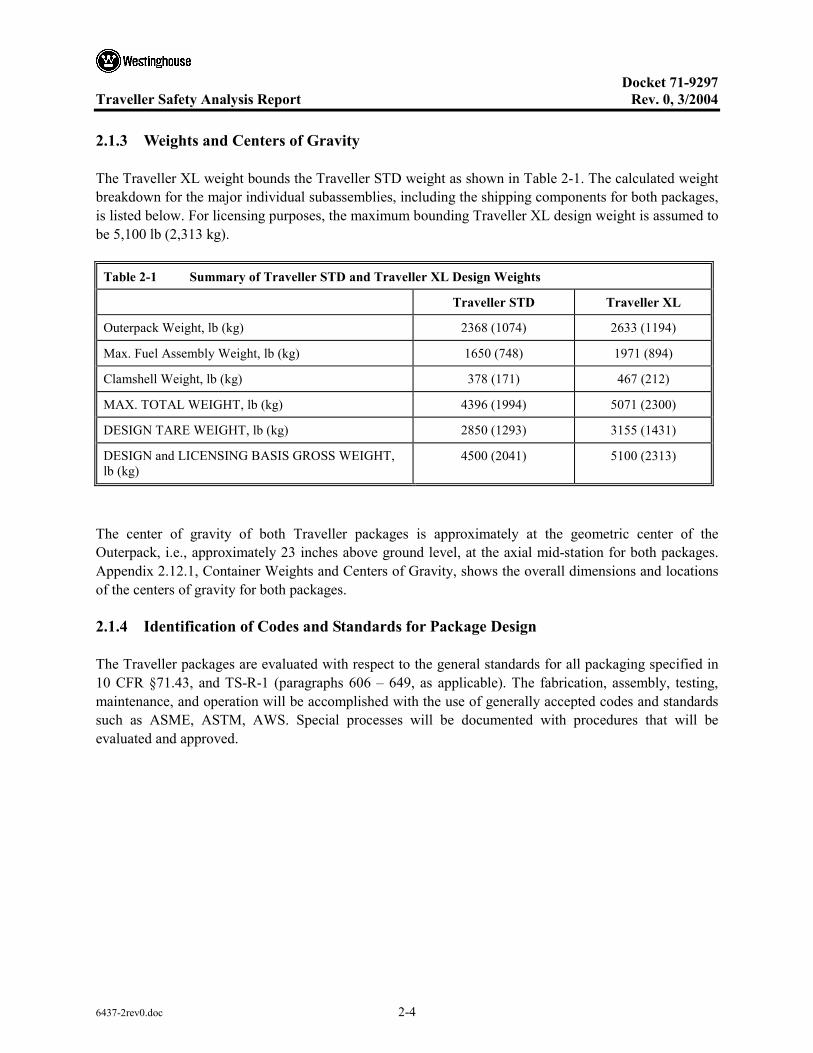
The Traveller XL weight bounds the Traveller STD weight as shown in Table 2-1. The calculated weight breakdown for the major individual subassemblies, including the shipping components for both packages, is listed below. For licensing purposes, the maximum bounding Traveller XL design weight is assumed to be 5,100 lb (2,313 kg).
Table 2-1 Summary of Traveller STD and Traveller XL Design Weights
Traveller STD Traveller XL
Outerpack Weight, lb (kg) 2368 (1074) 2633 (1194)
Max. Fuel Assembly Weight, lb (kg) 1650 (748) 1971 (894)
Clamshell Weight, lb (kg) 378 (171) 467 (212)
MAX. TOTAL WEIGHT, lb (kg) 4396 (1994) 5071 (2300)
DESIGN TARE WEIGHT, lb (kg) 2850 (1293) 3155 (1431)
DESIGN and LICENSING BASIS GROSS WEIGHT, lb (kg)
4500 (2041) 5100 (2313)
The center of gravity of both Traveller packages is approximately at the geometric center of the Outerpack, i.e., approximately 23 inches above ground level, at the axial mid-station for both packages. Appendix 2.12.1, Container Weights and Centers of Gravity, shows the overall dimensions and locations of the centers of gravity for both packages.
2.1.4 Identification of Codes and Standards for Package Design
The Traveller packages are evaluated with respect to the general standards for all packaging specified in 10 CFR §71.43, and TS-R-1 (paragraphs 606 – 649, as applicable). The fabrication, assembly, testing, maintenance, and operation will be accomplished with the use of generally accepted codes and standards such as ASME, ASTM, AWS. Special processes will be documented with procedures that will be evaluated and approved.

Docket 71-9297
Traveller Safety Analysis Report Rev. 0, 3/2004
6437-2rev0.doc 2-5
2.2 MATERIALS
2.2.1 Material Properties and Specifications
Mechanical properties for the materials used for the structural components of the Traveller packages are provided in this section. Temperature-dependent material properties for structural components are primarily obtained from Section II, Part D, of the ASME Boiler and Pressure Vessel (B&PV) Code. The analytic evaluation of the Traveller packages is via computer simulation (ANSYS/LS-DYNA®), only the material properties specific to the analysis portion and computer simulation portion of the evaluation are given. Table 2-2 lists the materials used in the Traveller packages and summarized key properties and specifications. More detailed material properties can be found in Appendix 2.12.2, Mechanical Design Calculations for the Traveller XL Shipping Package Traveller XL, and Appendix 2.12.3, Drop Analysis for the Traveller XL Shipping Package.
All materials used in the fabrication of the Certification Test Unit (CTU) meet 10 CFR 71 and TS-R-1 requirements. However, simulated neutron absorber plates were affixed to the inner faces of the Clamshell. These were fabricated from 1100-T0 aluminum (“dead soft” aluminum). These component plates did not contain boron, and were used to simulate the mechanical and thermal properties of borated aluminum material. The 1100-T0 aluminum was used due to its low mechanical properties. In production units, the actual borated aluminum plates will have insignificant differences in the material properties compared to the material used in the prototypes and CTU package.
2.2.2 Chemical, Galvanic, or Other Reactions
The Traveller series of packages are fabricated from ASTM A240 Type 304 stainless steel, 6000-series aluminum, borated 1100-series aluminum, polyurethane foam, and polyethylene sheeting. The stainless steel Outerpack does not have significant chemical or galvanic reactions with the interfacing components, air, or water.
The aluminum Clamshell is physically isolated, and environmentally protected, by the Outerpack and therefore will have negligible chemical or galvanic reactions with the interfacing components, air, or water. In addition, the Type 304 stainless steel fasteners which attach various Clamshell components represent a very small area ratio (cathode-to-anode ratio), which will render the reaction insignificant. Therefore, the requirements of 10 CFR §71.43(d), TS-R-1 (613) are met.
The Outerpack hinge bolts are zinc plated for the purpose of improving galling resistance which can be a significant problem when stainless steel fasteners are inserted in stainless steel threaded holes. The plating is not required for chemical or galvanic protection.
2.2.3 Effects of Radiation on Materials
There are no materials used in the Traveller packages which will be adversely affected by radiation under normal handling and transport conditions.

Docket 71-9297
Traveller Safety Analysis Report Rev. 0, 3/2004
6437-2rev0.doc 2-6
Table 2-2 Safety-Related Materials Used in the Traveller Packages
Material Critical Properties Reference
Specifications/Codes Comments
304 Stainless Steel UTS: 75 ksi (517 MPa)
YLD: 30 ksi (206 MPa)
τallow: 18 ksi (124 MPa)
E: 29.4 E6 psi (203 GPa)
ASTM A240
ASTM A276
Fully annealed material and not subject to brittle fracture.
6005-T6 Aluminum UTS: 38 ksi (262 MPa)
YLD: 35 ksi (241 MPa)
τallow: 21 ksi (145 MPa)
E: 10 E6 psi (69 GPa)
ASTM B221
ASTM B209
Reference standard UNS A96005
6061-T6 Aluminum UTS: 45 ksi (310 MPa)
YLD: 40 ksi (276 MPa)
τallow: 24 ksi (165 MPa)
E: 10 E6 psi (69 GPa)
ASTM B221
ASTM B209
Reference standard UNS A96061
Polyurethane Closed Cell Foam
Densities: 6 ± 1 pcf (0.096 ± 0.016 gm/cm3), 10 ± 1 pcf (0.16 ± 0.016 gm/cm3), 20 ± 2 pcf (0.32 ± 0.016 gm/cm3)
Crush Strengths: See Appendix 2.12.2
Westinghouse Specification PDSHIP02
ASTM D1621-94
ASTM D1622-93
ASTM D2842
Burn Characteristics verified by ASTM F-501, with exceptions noted in PDSHIP02.
UHMW Polyethylene Specific Gravity: > 0.93
Molecular Wt: >3 million
ASTM D4020 N/A
Borated Aluminum Plate or Borated Aluminum Laminate Composite
Minimum areal densities: Borated Al Plate: 0.018 g/cm2
Borated Al Composite: 0.024 g/cm2
Westinghouse Specification PDSHIP04
ASTM C750
ASTM E748
The minimum areal densities are defined for the finished plate or laminate final thickness of 0.125″ ± 0.006″ (3.175 mm ± 0.153 mm).
No structural credit is taken for the neutron poison plates.
Ceramic Insulation (Paper and Felt)
Max. use temp: >1800°F (982°C)
Conductivity: < 1.2 Btu-in/hr-ft2 @ 500°F, (0.173 W/m-K @ 260°C)
N/A The paper thickness is 0.0625″ (1.59 mm), and the blanket thickness is 0.25″ (6.35 mm)
Docket 71-9297
Traveller Safety Analysis Report Rev. 0, 3/2004
6437-2rev0.doc 2-7
2.3 FABRICATION AND EXAMINATION
2.3.1 Fabrication
The Traveller packages (XL and STD) are manufactured using standard fabrication techniques. No exotic materials or processes are required. Safety related items which are needed for criticality safety purposes have specific manufacturing specifications which clearly delineate all necessary codes, standards, and specifications required to meet design intent. All fabrication specifications are listed on the engineering drawings.
The fabrication processes of the Traveller include basic processes such as cutting, rolling, bending, machining, welding, and bolting. All welding is performed in accordance with ASME Section IX.
The manufacturing flow of the Traveller units includes fixturing of the inner and outer shells of the upper and lower Outerpack assemblies. Individual closure components are then aligned and welded in place. Sub-assemblies such as the forklift pockets, leg structures and stacking brackets are assembled in a parallel manner and appended to the main assemblies at appropriate times. Upon welding closure of the assemblies, the upper and lower Outerpack assemblies are secured together and poured with polyurethane foam material. Pouring of this material is tightly controlled through the foam manufacturing specification.
When the Traveller is filled with foam, it is ready for final assembly and installation of the Clamshell which has followed a parallel fabrication process. One difference for the Clamshell is that the faces are manufactured extrusions as opposed to “off-the-shelf” material. The extrusions are fabricated to industry standard specifications. Upon integration of the Clamshell to the Outerpack, final assembly and light grit blasting conclude the manufacturing process.
2.3.2 Examination
Manufacture of the Traveller XL and Traveller STD packages shall be performed in accordance with strict Quality Assurance (QA) requirements. Included in the manufacture of the packages are examinations to verify that each package is being built to the required specifications. These examinations include the following:
1. Receipt inspections whereby the received components are visually inspected for workmanship, overall part quality, dimensional compliance, and material certification compliance.
2. All welds (which shall be performed by qualified welders/processes) shall be visually examined by a qualified inspector in accordance with AWS D1.6 and ASME Section III, Subsection NF-5360, for stainless steel and aluminum respectively..
3. Examinations which evaluate form, fit, and function shall be performed on each package to verify its operability and assess its overall quality.
Docket 71-9297
Traveller Safety Analysis Report Rev. 0, 3/2004
6437-2rev0.doc 2-8
2.4 LIFTING AND TIE-DOWN STANDARDS FOR ALL PACKAGES
2.4.1 Lifting Devices
The lifting criteria is governed by 10 CFR §71.45(a) and TS-R-1 (607). 10 CFR §71.45(a) states that any lifting attachment that is a structural part of the package must be designed with a minimum safety factor of three against yielding when used to lift the package in its intended manner. In addition, it must be designed so that failure of any lifting device under excessive load would not impair the ability of the package to meet other requirements of 10 CFR 71. The following calculations are based on the features of the Traveller XL package which bounds the Traveller STD for these requirements. Lifting and tie-down are described in detail in Appendix 2.12.2, Mechanical Design Calculations for the Traveller XL Shipping Package.
Docket 71-9297
Traveller Safety Analysis Report Rev. 0, 3/2004
6437-2rev0.doc 2-9
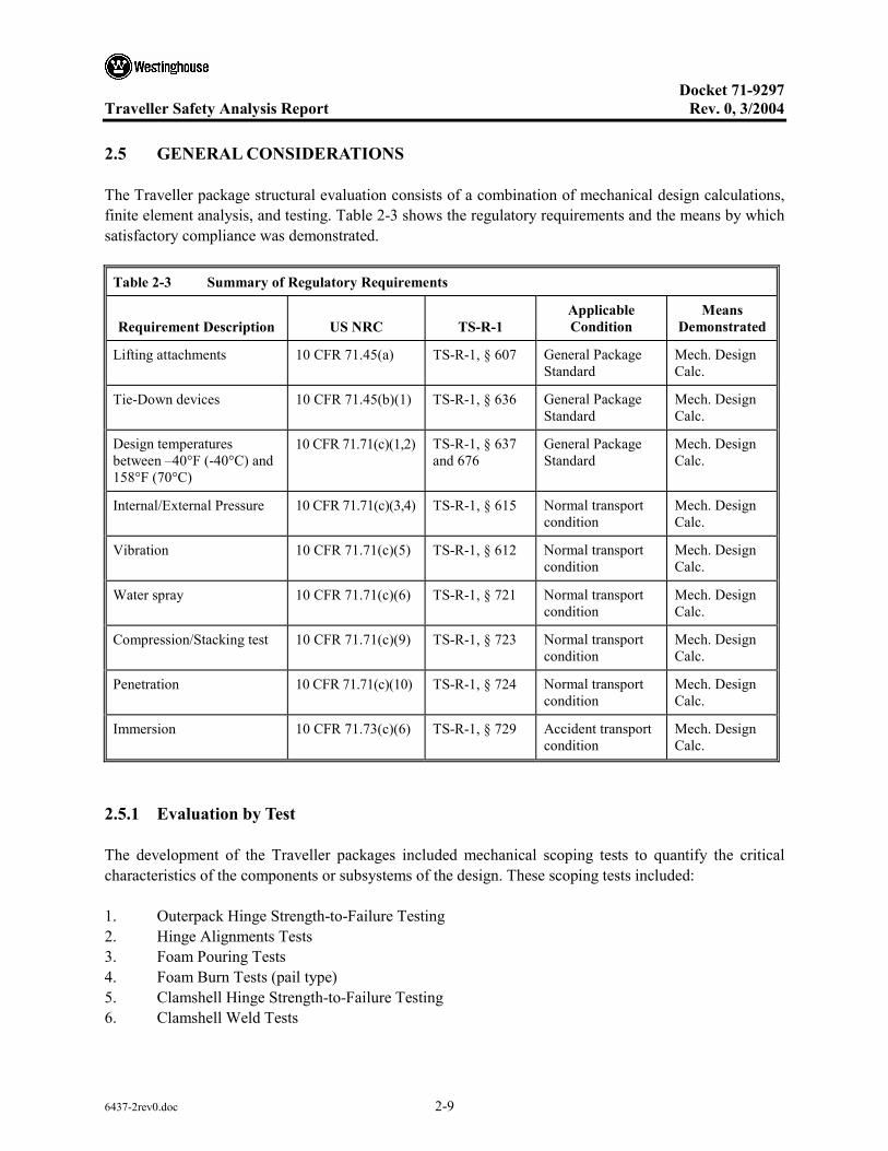
2.5 GENERAL CONSIDERATIONS
The Traveller package structural evaluation consists of a combination of mechanical design calculations, finite element analysis, and testing. Table 2-3 shows the regulatory requirements and the means by which satisfactory compliance was demonstrated.
Table 2-3 Summary of Regulatory Requirements
Requirement Description US NRC TS-R-1 Applicable Condition
Means Demonstrated
Lifting attachments 10 CFR 71.45(a) TS-R-1, § 607 General Package Standard
Mech. Design Calc.
Tie-Down devices 10 CFR 71.45(b)(1) TS-R-1, § 636 General Package Standard
Mech. Design Calc.
Design temperatures between –40°F (-40°C) and 158°F (70°C)
10 CFR 71.71(c)(1,2) TS-R-1, § 637 and 676
General Package Standard
Mech. Design Calc.
Internal/External Pressure 10 CFR 71.71(c)(3,4) TS-R-1, § 615 Normal transport condition
Mech. Design Calc.
Vibration 10 CFR 71.71(c)(5) TS-R-1, § 612 Normal transport condition
Mech. Design Calc.
Water spray 10 CFR 71.71(c)(6) TS-R-1, § 721 Normal transport condition
Mech. Design Calc.
Compression/Stacking test 10 CFR 71.71(c)(9) TS-R-1, § 723 Normal transport condition
Mech. Design Calc.
Penetration 10 CFR 71.71(c)(10) TS-R-1, § 724 Normal transport condition
Mech. Design Calc.
Immersion 10 CFR 71.73(c)(6) TS-R-1, § 729 Accident transport condition
Mech. Design Calc.
2.5.1 Evaluation by Test
The development of the Traveller packages included mechanical scoping tests to quantify the critical characteristics of the components or subsystems of the design. These scoping tests included:
1. Outerpack Hinge Strength-to-Failure Testing 2. Hinge Alignments Tests 3. Foam Pouring Tests 4. Foam Burn Tests (pail type) 5. Clamshell Hinge Strength-to-Failure Testing 6. Clamshell Weld Tests

Docket 71-9297
Traveller Safety Analysis Report Rev. 0, 3/2004
6437-2rev0.doc 2-10
7. Clamshell impact tests 8. Impact limiter testing including “pillow” impact testing
The scoping tests provided designers with performance data. However, proof of performance in the Traveller package was obtained through full-scale testing. As such, these tests were not required to be performed in accordance with full QA standard. However, all full-scale Traveller XL packages were fabricated and tested under all QA requirements.
The development of the Traveller consisted of essentially three (3) full-scale test campaigns. These campaigns consisted of what are called the Prototype units (2), the Qualification Test Units (QTU) (2), and finally the Certification Test Units (CTU) (1). In general, these packages are very similar. The overall configuration of the Outerpack and Clamshell remain essentially identical throughout the design evolution. With each test campaign, the design was modified to increase structural or thermal margin, or to reduce excess design margin when appropriate. The significant design changes from Prototype to CTU were:
1. The reduction in Outerpack shell thicknesses from 11 gage (0.120″, 0.30 cm) to 12 gage (0.105″, 0.27 cm),
2. The adjusting of polyurethane foam densities (first a lowering of density for structural reasons, then an increase for improve thermal performance),
3. The addition of a thin stainless steel covering of the moderator blocks,
4. The replacement of short individual Outerpack hinges with a continuous Outerpack hinge,
5. A redesign of the Clamshell head attachment configuration, and finally,
6. A reduction in the number and size of the Outerpack hinge bolts.
The purpose of the computer simulation was to assist in evaluating these minor changes and predict performance of the modified packages. The computer simulation was also used to show the impact of initial test conditions (temperature of package) and manufacturing variability (foam density tolerances, skin thickness variations, etc.). These factors showed negligible effects on the overall performance of the packages. Details can be found in Appendix 2.12.3, Drop Analysis for the Traveller XL Shipping Package.
A summary of the development and testing of the Traveller XL full-scale test packages is described in Table 2-5, and the detailed results of each test are described in Appendix 2.12.4, Traveller Drop Test Results.

Docket 71-9297
Traveller Safety Analysis Report Rev. 0, 3/2004
6437-2rev0.doc 2-11
2.5.2 Evaluation by Analysis
Analysis consisted of mechanical design calculations and finite element analysis. Mechanical design calculations are described in detail in Appendix 2.12.2. Finite element analysis, utilizing LS-DYNA software, is described in detail in Appendix 2.12.3.
Table 2-4 gives a summary of the regulatory requirements that are demonstrated through mechanical design calculations.
Table 2-4 Summary of Traveller Mechanical Analysis
Requirement Description
Allowable Design Value(s) or Acceptance Criteria Calculated Value Acceptable
Lifting attachments Tensile Stress: σactual < σy (30 ksi)
Shear Stress: τactual < τy (18 ksi)
Weld shear Stress: τactual < τweld (12 ksi)
Hoist Screw Shear Stress: τactual < τallow (60 ksi)
Hole tear: τ = 5.1 ksi< 18 ksi
Weld: τ = 9.5 ksi< 12 ksi (Alt. 8.1 ksi< 12 ksi)
Hoist: τ = 49.4 ksi< 60 ksi
Yes, for all
Tie-Down devices Tensile Stress: σactual < σy (30 ksi) No tie down systems on package
Yes
Design temperatures between –40°F (-40°C) and 158°F (70°C)
No brittle fracture
No impact from Differential Thermal Expansion (DTE)
No Impact Yes
Internal/External Pressure
Tensile Stress: σactual < σy (30 ksi) No stress developed Yes
Vibration No impact on structural performance fnatOP > fnat TRANS
No impact, 41 Hz > 3.7-8 Hz Yes
Water spray No impact on structural performance No impact Yes
Compression/Stacking test
Weld shear Stress: τactual < τweld (12 ksi)
Critical Buckling, F < Pcr
4.0 ksi < 12 ksi
Outerpack; 25.5 ksi < 78.6 ksi
Leg Support; 3.2 ksi < 26.9 ksi
Yes, for all
Penetration No perforation of outer skin Bounded by 1.0m HAC pin-puncture; No perforation of outer skin.
Yes
Immersion Tensile Stress: σactual < σy (30 ksi) No stress developed Yes

Docket 71-9297
Traveller Safety Analysis Report Rev. 0, 3/2004
6437-2rev0.doc 2-12
2.6 NORMAL CONDITIONS OF TRANSPORT
2.6.1 Heat
The thermal evaluation for the heat test is described and reported in Section 3, Thermal Evaluation.
2.6.1.1 Summary of Pressures and Temperatures
There is no pressure seal in the Traveller series of packages. Therefore, there is no pressure build up within the package. Maximum temperature for the following sections were evaluated to 158°F (70°C) and minimum temperatures to -40°F (-40°C).
2.6.1.2 Differential Thermal Expansion
The effects differential thermal expansion for the Traveller series of packages is negligible due to the design of the package. The most significant differential is between the aluminum Clamshell and the fuel assembly, and is less than 0.25 inches. The differential thermal expansion is accommodated by rubber-cork spacers between the Clamshell and fuel assembly.
Ultra-high Molecular Weight (UHMW) polyethylene does have a significantly higher coefficient of thermal expansion (CTE) when compared to Type 304 stainless steel. For this reason, the moderator panels are segmented along their lengths to accommodate the differential thermal expansion between the polyethylene and the inner stainless steel shells of the Outerpack. Additionally, oversized holes in the polyethylene panel are used to accommodate the effects of both temperature extremes.
See Appendix 2.12.2, Mechanical Design Calculations for the Traveller XL Shipping Package, for detailed differential thermal expansion calculations.
2.6.1.3 Stress Calculations
The Traveller packages are fabricated from relatively thin sheet metal parts which are not subject to thermal gradients generated from the interior of the package. The packages are also not sealed to the environment, therefore pressure stress is negated. The most significant stress potential occurs from the differential expansion rates of the bolted polyethylene moderator panels to the inner steel shells of the Outerpack. This potential stress is also negated by design, whereby the panels are made in sections and the bolt clearances and gaps between panels are adequately sized to allow unrestrained growth and contraction.
Successful testing of full scale Traveller XL packages indicates that the stresses associated with differential thermal expansion of the various packaging components are negligible.

Docket 71-9297
Traveller Safety Analysis Report Rev. 0, 3/2004
6437-2rev0.doc 2-13
2.6.1.4 Comparison with Allowable Stresses
As discussed in Section 2.6.1.3, Stress Calculations, further evaluation of stresses associated with differential thermal expansion for the various Traveller package components is not required.
2.6.2 Cold
The materials used in construction of the Traveller packages are not degraded by cold at -40°C (-40°F). Stainless steel and aluminum exhibit no brittle fracture at these temperatures. Therefore, the requirements of 10 CFR §71.71(c)(2) and TS-R-1 (618) are satisfied.
2.6.3 Reduced External Pressure
Since the Traveller series of packages are not sealed against pressure, there can not be any significant differential pressure. However, calculations presented in Appendix 2.12.2, Mechanical Design Calculations for the Traveller XL Shipping Package, demonstrates that the package could withstand the differential pressure described in 10 CFR §71.71(c)(3) if the containers were sealed.
2.6.4 Increased External Pressure
Since the Traveller series of packages are not sealed against pressure, there can not be any significant differential pressure. However, information presented in Appendix 2.12.2, Mechanical Design Calculations for the Traveller XL Shipping Package, demonstrates that the package could withstand the differential pressure described in 10 CFR §71.71(c)(4) if the packages were sealed.
2.6.5 Vibration
The package must be evaluated to consider the effects of normal vibration on the design performance. The isolation system is designed to dampen normally induced vibrations from transport, and is not fundamental to the safe operation of the package. However, the Outerpack must maintain its structural integrity during transport to maintain a safe transport condition as specified in 10 CFR §71.71(5), TS-R-1 (612). Typical attachment to a transport conveyance for the Traveller packages includes nylon straps or chain mounted both over the package and on the gusset tray connected to the support legs pointed inboard. The loading configuration can be modeled as a simply supported beam. Furthermore, the Outerpack is conservatively modeled considering only the outer shell at the first mode of vibration. The typical natural frequency range for transportation vehicles, fnat TRANS, is 3.7-8 Hz. The natural frequency of the Outerpack can be determined from:
mlEIgafnatOP /)( 3=
where a=1.57 (primary mode coefficient assuming hinge-hinge end conditions for additional conservatism), E=29.4E6 psi, I=634 in4, m=2633 pounds, g = 386.4 in/s2 and l=158 in (distance from gusset tray to gusset tray). Substituting values:
Docket 71-9297
Traveller Safety Analysis Report Rev. 0, 3/2004
6437-2rev0.doc 2-14
2633/])158()4.386)(634)(64.29[(57.1 3EfnatOP = 1/s (Hz)
69357.1=natOPf Hz
41=natOPf Hz
Since the natural frequency of the Outerpack is greater than the natural frequency typical of a transportation vehicle, resonance of the Outerpack is not expected and normally induced vibrations will not preclude the package from performing its design function.
The rubber shock mounts effectively isolate and dampen loads and vibrations to the Clamshell and its contents. No resonant vibration conditions which could fatigue the Clamshell shall occur during normal conditions of transport.
2.6.6 Water Spray
The materials of construction utilized for the Traveller packages are such that the water spray test identified in 10 CFR §71.71(c)(6), TS-R-1 (721), will have negligible effect on the package. Further, the Traveller Outerpack is cylindrical, and is specifically shaped to negate water collection. Since the Outerpack shell is fabricated from ASTM A240 Type 304 SS, the water spray will not impact the structural integrity of the package.
2.6.7 Free Drop
Since the gross weight of the bounding Traveller XL package is approximately 5,000 kg (11,000 lb), a 1.2 m (4 feet) free drop is conservatively required per 10 CFR §71.71(c)(7), TS-R-1 (722). As discussed in Appendix 2.12.4, Traveller Drop Test Results, 1.2 m drops were performed on the Traveller CTU as an initial condition for subsequent Hypothetical Accident Condition (HAC) tests.
The Traveller packages are well protected during drop testing. In particular, the leg structure including fork lift structure, stacking structure, and upper Outerpack stiffener I-beam structure, all protect the Traveller during impact. Traveller CTU free drop testing and analytical and engineering evaluations indicated that this testing have negligible impact on the integrity of the package. However, the orientation selected for the free drop testing was a low angle slap-down, approximately 10 degrees, with the package inverted. The basis for selection of this orientation was that this orientation offered the greatest opportunity to stress the welded joints at the ends of the package. Detailed descriptions of the test results are given in Appendix 2.12.4, Traveller Drop Test Results. Examinations following the prototypic and CTU testing proved the ability of the Traveller packaging to maintain its structural and criticality control integrity. Therefore, the requirements of 10 CFR §71.71(c)(7) are satisfied.
Docket 71-9297
Traveller Safety Analysis Report Rev. 0, 3/2004
6437-2rev0.doc 2-15
2.6.8 Corner Drop
The corner drop test does not apply, since the gross weight of the package exceeds 100 pounds (50 kg), as specified in 10 CFR §71.71(c)(8) or 100 kg (221 lb) as specified in TS-R-1 (722).
2.6.9 Compression – Stacking Test
The compressive load requirement of 10 CFR §71.71(c)(9), TS-R-1 (723) is satisfied by the Traveller packages. Details of the analysis can be found in Appendix 2.12.2, Mechanical Design Calculations for the Traveller XL Shipping Package.
2.6.10 Penetration
The 1 m (40 inch) drop of a 1 ¼-inch (3.2 cm) diameter, 6 kg (13 pound), hemispherical end steel rod, as specified in 10 CFR §71.71(c)(10), TS-R-1 (724), is of negligible consequence to the Traveller series of packages. This conclusion is due to the fact that the Traveller packages are designed to minimize the consequences associated with the much more limiting case of a 1 m (40 inch) drop of the entire package onto a puncture rod, as discussed I Section 2.7.3, Puncture. The 12-gauge (2.7 mm) minimum thickness of the outer shell of the Outerpack is not damaged by the penetration event. Therefore, the requirements of 10 CFR §71.71(c)(10), TS-R-1 (724), are satisfied.

Docket 71-9297
Traveller Safety Analysis Report Rev. 0, 3/2004
6437-2rev0.doc 2-16
2.7 HYPOTHETICAL ACCIDENT CONDITIONS
When subjected to the hypothetical accident conditions as specified in 10 CFR §71.73, the Traveller package meets the performance requirements specified in Subpart E of 10 CFR 71, and TS-R-1 (726-737 as applicable). This conclusion is demonstrated in the following subsections, where the most severe accident condition is addressed and the package is shown to meet the applicable design criteria. The method of demonstration is through both computer analysis and by testing. The loads specified in 10 CFR §71.73 are applied sequentially, per Regulatory Guides 7.8 and 7.9 (draft).
The Traveller XL Certification Test Unit (CTU) test results are summarized in Section 2.7.7, Summary of Damage, with details provided in Appendix 2.12.4, Traveller Drop Test Results. Additional full-scale test results conducted prior to the certification tests are also included in Appendix 2.12.4. These tests describe the improvements to the Traveller XL design, substantiate the basis for the most severe hypothetical accident condition, and were used to validate the computer simulations.
Because so much work was involved in developing the Traveller XL shipping package, the following table summarizes its development from the first prototype through the Certification Test Unit, or CTU. As can be seen, satisfying the thermal test requirements proved more difficult than expected. However, the culmination of the development effort has yielded a shipping package that has been thoroughly tested and meets the requirements of both 10 CFR 71 and TS-R-1.

Docket 71-9297
Traveller Safety Analysis Report Rev. 0, 3/2004
6437-2rev0.doc 2-17
Table 2-5 Summary of the Development of the Traveller
Traveller XL Test Sequence(s) Structural Performance Fire/Thermal Performance
Prototype-1
Drop testing: Jan 27-28, 2003
Burn Testing: Feb 28, 2003
Objective: FEA validation
- 9 m low angle slap down (14.5 degrees)
- 9 m high angle (71 degrees)
- 1 m pin puncture (through CG, low angle)
- 35 minute pool fire burn test.
- Outerpack – Satisfied requirements. Minor, local damage only.
- Clamshell – Satisfied requirements for 9 m low angle test. Failed requirements for 9 m high angle test. Satisfied 1 m pin puncture test.
Outerpack failed to prevent ignition of polyethylene sheets in one location.
Clamshell temperature away from interior combustion satisfied fire requirements.
Comments:
The Traveller XL Prototype-1 demonstrated robust structural performance, except for the Clamshell head(s) attachment which was not adequate. The most probable root cause of ignition of polyethylene sheeting was polyurethane foam combustion products entering the inside of the Outerpack as a result of holes drilled into inner Outerpack shell for thermocouples. No seals were used in the Outerpack for conservatism.
Fire testing failed to prevent ignition of the combustible materials in the Outerpack. However, the components not adjacent to the internal fire remained well within thermal limitations, thus, demonstrating that the Outerpack had sufficient thermal resistance to external heat flow into package.
Design Changes as a Result of Testing:
Additional bolts were added to secure the top Clamshell head for Prototype-2 testing (see below).
The package was subjected to the applicable tests for Normal and Hypothetical Accident conditions as described below. Following this series, the package was modified again to assess the robustness of the design. The center Outerpack hinge bolts were removed (1 of 3 bolts) from each hinge section. The number of locking pins on the Clamshell latches was also reduced, from 18 to 12.
Prototype-2
Drop Testing: Jan 30, 2004
Burn Testing: N/A
- 1.2 m low angle slapdown (20 degrees)
- 1 m pin puncture (through CG, low angle)
- 9 m high angle (72 degrees)
Bolts and locking pins removed (described above)
- 9 m end drop (bottom end down)
- 9 m horizontal (feet down)
- 9 m horizontal (side down)
- Outerpack – Satisfied requirements for all 9 m drops and pin puncture tests. Minor, local damage only.
- Clamshell – Satisfied requirements for first 9 m drop. Bottom head separated in second 9 m drop (bottom end drop) because the fuel assembly was not properly seated against bottom Clamshell head as a result of prior drop. No other significant damage.
- Prototype 2 was not subjected to HAC fire testing.

Docket 71-9297
Traveller Safety Analysis Report Rev. 0, 3/2004
6437-2rev0.doc 2-18
Table 2-5 Summary of the Development of the Traveller (cont.)
Traveller XL Test Sequence(s) Structural Performance Fire/Thermal Performance
Comments:
The performance of the Prototypes (1 & 2) associated with the first testing campaign clearly demonstrated the robustness of the Overpack and Clamshell (except for the Clamshell head attachments). In all, six (6) drops were performed on 2 full-scale prototypes from 9 m. The Outerpack retained its overall integrity and functionality. Most importantly, all design features important to criticality safety performed as intended. Moderator blocks and simulated borated aluminum plates remained intact and attached to their respective structural components.
Design Changes as a Result of Testing:
Based on the robust structural performance of the Prototype units, several design changes were made to the Traveller XL for subsequent testing in the second test campaign. The Traveller units fabricated for the second campaign were called the Qualification Test Units, or QTUs. A total of two units were fabricated and tested. The significant changes to the QTUs were as follows:
1. The Outerpack stainless steel shells were reduced from 11 gauge (0.1196 in., 3.04 mm) to 12 gauge (0.1046 in., 2.66 mm). This change was made primarily to lower weight and reduce excessive structural margin.
2. The hinge bolts were reduced in both number and size, from ten 7/8″ (2.22 cm) diameter bolts to ten ¾″ (1.91 cm) bolts. This change was made to reduce excessive design margin.
3. A total of 2 seal materials were added to the design to act as: 1) an environmental seal, and 2) to minimize hot gases from entering the Outerpack seams.
4. The Outerpack leg structure, circumferential stiffeners, stacking brackets, and forklift pocket structures were changed. These changes were made for simplified manufacturing purposes and to reduce excessive design margin.
5. The polyurethane foam density of the center section of the package was reduced from 11 pcf to 10 pcf. The axial limiter foam sections of the package were also reduced from 16 pcf to 14 pcf. This change was made to lower the impact deceleration, and therefore loads experienced by the Clamshell.
6. The Clamshell extrusions were made thicker, from a nominal 0.375″ (0.95 cm) to 0.438″ (1.11 cm). This change was made primarily to eliminate welding of the heads to the extrusions. Bolted connections were utilized to attach the heads.
7. The welded simulated poison plates were redesigned for a bolted connection. This change was made to reduce the distortion of the aluminum Clamshell extrusions due to welding.
8. The Clamshell door locking latches were redesigned for quarter-turn nuts. This change was made for manufacturing and aesthetic purposes.
9. The Clamshell axial restraint system for restraint of the fuel assembly was redesigned. This change was made to simplify the fuel handling.

Docket 71-9297
Traveller Safety Analysis Report Rev. 0, 3/2004
6437-2rev0.doc 2-19
Table 2-5 Summary of the Development of the Traveller (cont.)
Traveller XL Test Sequence(s) Structural Performance Fire/Thermal Performance
QTU-1 Drop Testing: Sep 11, 2003
Burn Testing: Sep 15, 2003
- 1.2 m low angle slapdown (10 degree)
- 9 m high angle (72 degrees)
- 1 m pin-puncture (83 degrees at bottom end)
- 37 minute pool-fire burn test.
- Outerpack – Satisfied requirements for both drops and pin puncture tests. Minor, local damage only.
- Clamshell – Satisfied requirements for both drops and pin puncture tests.
Failed to prevent ignition of the polyethylene sheeting inside the Outerpack. Temperatures inside the Outerpack exceeded design limits. The package was extinguished approximately 1 hour after the conclusion of the pool fire testing.
Comments: The Traveller XL QTU-1 demonstrated robust structural performance. No Outerpack bolts failed. The Outerpack did not separate, and the pin puncture did not perforate the inner or outer shells nor did it effect the Clamshell in any detrimental way.
One hour after the pool fire, the package burning was extinguished. Upon inspection of the QTU-1 unit, it was determined that excessive distortion of the Outerpack shells between the hinges, allowed sufficient hot gases to ignite the polyethylene sheeting on the top half of the Outerpack. The burnt polyethylene sheeting was directly in line with the gaps in between the hinges. The burnt zones (4) were located only on the upper half of the Outerpack. This is most likely due to the flanges on the mating Outerpack halves which preferentially directs incoming gases to the upper portion of the Outerpack.
Design Changes as a Result of Testing: Based on unsuccessful fire testing of the QTU-1 unit, the QTU-2 unit was modified for improved thermal performance. Since the QTU-2 had already been drop tested in accordance with 10 CFR 71, and TS-R-1 requirements, only minor modifications were deemed acceptable. Only changes considered for the QTU-2 were ones that would not have affected the drop characteristics and performance. The changes made to the QTU-2 unit subsequent to drop testing are listed as follows:
1. The 10 short Outerpack hinge sections were removed and replaced with 8 (four per side) long hinge sections that butted together forming a continuous hinge covering essentially all of the Outerpack mating seams.
2. The polyethylene moderator sheeting (both top and bottom sections) was covered with 26 gage stainless steel sheet metal. This sheet material was welded to the inner shells of the Outerpack along the sides of the covers, the ends (both top and bottom) were sealed with adhesive. The coverings therefore, were not completely welded closed.
QTU-2 Drop Testing: Sep 11, 2003
Burn Testing: Oct 20, 2003
- 1.2 m low angle slapdown (10 degrees)
- 9 m end drop (bottom end down)
- 1 m pin puncture (22 degrees through CG)
- 32 minute pool-fire burn test.
- Outerpack – Satisfied requirements for both drops and pin puncture tests. Minor, local damage only.
- Clamshell – Satisfied requirements for both drop tests and thermal tests. No failures were noted in any structure, or fasteners. The maximum temperature of the Clamshell and its contents never exceeded design limits
- Failed to prevent ignition of the polyethylene sheeting inside the Outerpack. However, the maximum temperature of the Clamshell and contents remained below 200°C. The package was extinguished approximately 7 hours after the conclusion of the pool fire testing.

Docket 71-9297
Traveller Safety Analysis Report Rev. 0, 3/2004
6437-2rev0.doc 2-20
Table 2-5 Summary of the Development of the Traveller (cont.)
Traveller XL Test Sequence(s) Structural Performance Fire/Thermal Performance
Comments:
The Traveller XL QTU-2 demonstrated robust structural performance. No Outerpack bolts failed. The Outerpack did not separate, and the pin puncture did not perforate the inner or outer shells nor did it effect the Clamshell in any detrimental way.
Seven hours after the pool fire, the package burning was extinguished. During this seven hour period there was continuous low level smoldering. Upon inspection of the QTU-2 unit, it was determined that ignition occurred at the bottom end of the package. This was most likely caused by distortion of the Outerpack halves in the area of the bottom end where the impact limiter warped away from the top Outerpack half during the fire. The continuous hinge sections also did not cover the last 3 inches of the Outerpack seams on both sides of the package, which may have allowed additional hot gases to enter the package. The hot gas ingress occurred at a location were there was exposed polyurethane foam (the inner axial limiter foam) due to the thin stainless steel limiter cover being punched out by the Clamshell. This was an expected consequence of the bottom end drop.
The long sheet metal covers which were welded along their sides but applied adhesive at the ends did not perform as anticipated. The covers distorted during the testing and opened the adhesive joint. This allowed the polyethylene moderator to ignite. The areas around the shock mounts also were not covered with sheet metal thus exposing the moderator to the conditions inside the Outerpack. These exposed areas showed signs of burning in post-test examinations.
The QTU-2 test demonstrated that the polyethylene sheeting must be completely welded, or “canned”, by sheet metal to prevent ignition. However, this test was further evidence that the “bulk” heating of the inside of the Outerpack was acceptable, even with burning occurring within the Outerpack. This is a result of the fact that there is insufficient oxygen to support large amounts of burning. It was estimated that over the 7.5 hours of total burning, only about 10-15% of the moderator material was consumed.
Design Changes as a Result of Testing:
Based on the structural success of the QTU units and the thermal failures of the units, several changes were made to the design. These changes are listed below:
1. The 26 gage moderator sheet metal covers were redesigned so that the polyethylene was completely encapsulated by sheet metal. This mandated the use of sheet metal “cones” around each shock mount. Additionally, thin ceramic insulating material was incorporated between the moderator sheet and the metal covers, around the cones, and over a length of 30 inches at both the top and bottom ends. The ceramic “paper” is nominally 0.06 inches (0.15 cm) in thickness. Ceramic felt was also incorporated to fill the voids under the shock mount cones and at the ends of the moderator sheets.
2. The thin sheet metal impact limiter cover which were design to be punched out by high angle Clamshell impacts were redesigned to have thicker (0.25″, 0.64 cm) puncture-resistant plates. These “pillows” were separate structures that were tested in a separate series of mechanical and thermal tests prior to CTU testing. The purpose of the pillows was to prevent polyurethane foam from becoming exposed to the inside of the outerpack, even in end drops. The pillow also incorporated a thick (0.25″, 0.64 cm) plate at its base to act as a heat capacitor for incoming heat during the fire testing. Finally, the void space between the pillow and the outer sections of the impact limiters was filled with ceramic felt and paper to further reduce the heat load to the pillows and the internal contents of the Outerpack.
3. The foam density within the inner section of the impact limiters, or pillows, was reduced from 7 pcf to 6 pcf to allow more crushing of the foam. This change was made to lower the impact forces on the Clamshell and its contents.
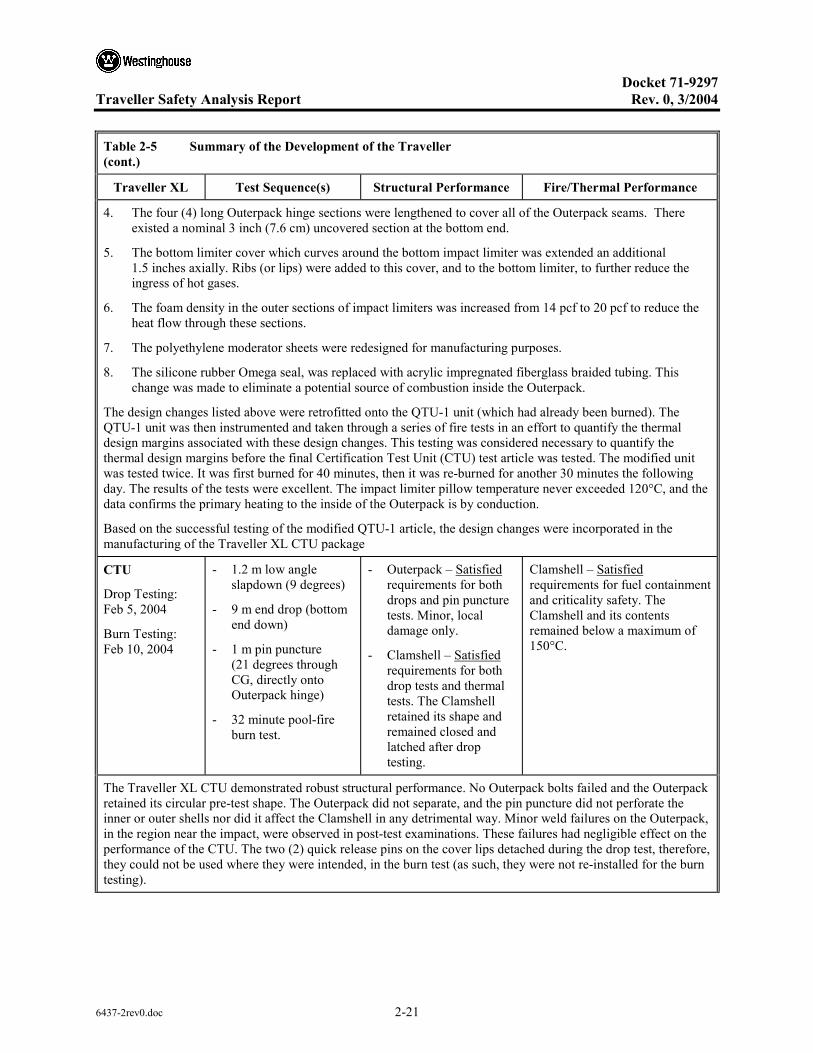
Docket 71-9297
Traveller Safety Analysis Report Rev. 0, 3/2004
6437-2rev0.doc 2-21
Table 2-5 Summary of the Development of the Traveller (cont.)
Traveller XL Test Sequence(s) Structural Performance Fire/Thermal Performance
4. The four (4) long Outerpack hinge sections were lengthened to cover all of the Outerpack seams. There existed a nominal 3 inch (7.6 cm) uncovered section at the bottom end.
5. The bottom limiter cover which curves around the bottom impact limiter was extended an additional 1.5 inches axially. Ribs (or lips) were added to this cover, and to the bottom limiter, to further reduce the ingress of hot gases.
6. The foam density in the outer sections of impact limiters was increased from 14 pcf to 20 pcf to reduce the heat flow through these sections.
7. The polyethylene moderator sheets were redesigned for manufacturing purposes.
8. The silicone rubber Omega seal, was replaced with acrylic impregnated fiberglass braided tubing. This change was made to eliminate a potential source of combustion inside the Outerpack.
The design changes listed above were retrofitted onto the QTU-1 unit (which had already been burned). The QTU-1 unit was then instrumented and taken through a series of fire tests in an effort to quantify the thermal design margins associated with these design changes. This testing was considered necessary to quantify the thermal design margins before the final Certification Test Unit (CTU) test article was tested. The modified unit was tested twice. It was first burned for 40 minutes, then it was re-burned for another 30 minutes the following day. The results of the tests were excellent. The impact limiter pillow temperature never exceeded 120°C, and the data confirms the primary heating to the inside of the Outerpack is by conduction.
Based on the successful testing of the modified QTU-1 article, the design changes were incorporated in the manufacturing of the Traveller XL CTU package
CTU
Drop Testing: Feb 5, 2004
Burn Testing: Feb 10, 2004
- 1.2 m low angle slapdown (9 degrees)
- 9 m end drop (bottom end down)
- 1 m pin puncture (21 degrees through CG, directly onto Outerpack hinge)
- 32 minute pool-fire burn test.
- Outerpack – Satisfied requirements for both drops and pin puncture tests. Minor, local damage only.
- Clamshell – Satisfied requirements for both drop tests and thermal tests. The Clamshell retained its shape and remained closed and latched after drop testing.
Clamshell – Satisfied requirements for fuel containment and criticality safety. The Clamshell and its contents remained below a maximum of 150°C.
The Traveller XL CTU demonstrated robust structural performance. No Outerpack bolts failed and the Outerpack retained its circular pre-test shape. The Outerpack did not separate, and the pin puncture did not perforate the inner or outer shells nor did it affect the Clamshell in any detrimental way. Minor weld failures on the Outerpack, in the region near the impact, were observed in post-test examinations. These failures had negligible effect on the performance of the CTU. The two (2) quick release pins on the cover lips detached during the drop test, therefore, they could not be used where they were intended, in the burn test (as such, they were not re-installed for the burn testing).
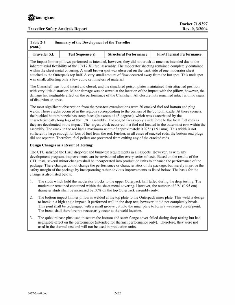
Docket 71-9297
Traveller Safety Analysis Report Rev. 0, 3/2004
6437-2rev0.doc 2-22
Table 2-5 Summary of the Development of the Traveller (cont.)
Traveller XL Test Sequence(s) Structural Performance Fire/Thermal Performance
The impact limiter pillows performed as intended, however, they did not crush as much as intended due to the inherent axial flexibility of the 17x17 XL fuel assembly. The moderator sheeting remained completely contained within the sheet metal covering. A small brown spot was observed on the back side of one moderator sheet attached to the Outerpack top half. A very small amount of flow occurred away from the hot spot. This melt spot was small, affecting only a few cubic centimeters of material.
The Clamshell was found intact and closed, and the simulated poison plates maintained their attached position with very little distortion. Minor damage was observed at the location of the impact with the pillow, however, the damage had negligible effect on the performance of the Clamshell. All closure nuts remained intact with no signs of distortion or stress.
The most significant observation from the post-test examinations were 20 cracked fuel rod bottom end plug welds. These cracks occurred in the regions corresponding to the corners of the bottom nozzle. At these corners, the buckled bottom nozzle has steep faces (in excess of 45 degrees), which was exacerbated by the characteristically long legs of the 17XL assembly. The angled faces apply a side force to the local fuel rods as they are decelerated in the impact. The largest crack occurred in a fuel rod located in the outermost row within the assembly. The crack in the rod had a maximum width of approximately 0.075″ (1.91 mm). This width is not sufficiently large enough for loss of fuel from the rod. Further, in all cases of cracked rods, the bottom end plugs did not separate. Therefore, fuel pellets are prevented from exiting any of the cracked rods.
Design Changes as a Result of Testing:
The CTU satisfied the HAC drop-test and burn-test requirements in all aspects. However, as with any development program, improvements can be envisioned after every series of tests. Based on the results of the CTU tests, several minor changes shall be incorporated into production units to enhance the performance of the package. There changes do not change the performance or characteristics of the package, but merely improve the safety margin of the package by incorporating rather obvious improvements as listed below. The basis for the change is also listed below:
1. The studs which hold the moderator blocks to the upper Outerpack half failed during the drop testing. The moderator remained contained within the sheet metal covering. However, the number of 3/8″ (0.95 cm) diameter studs shall be increased by 50% on the top Outerpack assembly only.
2. The bottom impact limiter pillow is welded at the top plate to the Outerpack inner plate. This weld is design to break in a high angle impact. It performed well in the drop test, however, it did not completely break. This joint shall be redesigned with a small groove cut into the inner plate to form a weakened break point. The break shall therefore not necessarily occur at the weld location.
3. The quick release pins used to secure the bottom end seam flange cover failed during drop testing but had negligible effect on the performance (intended for thermal performance only). Therefore, they were not used in the thermal test and will not be used in production units.

Docket 71-9297
Traveller Safety Analysis Report Rev. 0, 3/2004
6437-2rev0.doc 2-23
2.7.1 Free Drop
Subpart F of 10 CFR 71, TS-R-1 (727) requires that a 9-meter (30 foot) free drop be considered for the Traveller series of packages. The free drop is to occur onto a flat, essentially unyielding, horizontal surface, and the package is to strike the surface in an orientation for which the maximum damage is expected. The free drop is addressed by test, in which the most severe orientation is used. The free drop precedes both the puncture and fire tests. The ability of the Traveller packages to adequately withstand this specified drop condition is demonstrated via drop testing of the full-scale Traveller XL Certification Test Unit (CTU). The Traveller XL variant bounds the shorter and lighter Traveller STD design.
2.7.1.1 Technical Basis for the Free Drop Tests
To properly select a worst case package orientation for the 9 m (30 feet) free drop event, the foremost item that could potentially compromise the criticality control integrity of the Traveller series of packages must be clearly identified.
The criticality control integrity may be compromised by four methods: 1) excessive movement of the fuel rods such that they form a critical geometry, 2) damage/destruction of the borated aluminum and polyethylene sheeting, 3) degradation of the borated aluminum/polyethylene sheeting and/or 4) other structural damage that could affect the nuclear reactivity of an array of packages.
For the above considerations, testing and FEA predictive methodology must include orientations that affect the Clamshell geometry and integrity. Throughout the development of the Traveller XL, minor design changes were made to optimize the structural and thermal performance of the package.
A total of nine (9) 30 foot (9 m) free drops were performed using full-scale prototypes at a variety of orientations to determine the most severe orientation and to assist in benchmarking the computer simulation model. Based on these tests, and the predictions of the analytic analyses, it was determined that the most severe 9 m free drop orientation was a bottom-end down drop due to; 1) the relatively high deceleration, 2) the greatest opportunity for lattice expansion of the fuel, and 3) the greatest opportunity for fire damage as a result of the subsequent pool-fire thermal testing.
The bottom-down end drop causes the greatest damage to the axial impact limiters, or “pillows.” These pillows were incorporated as a re-design from QTU-2 testing whereby the Clamshell punched through the plate covering the inner section of the axial impact limiter. This exposed foam later burned within the interior of the Outerpack and ignited the moderator panels. The concept of a puncture plate was redesigned to incorporate a “puncture resistant” plate. The inner foam limiter was therefore protected by the puncture resistant plate (1/4″ thk, 0.64 cm), and was enclosed by a spun metal “can” welded to the plate to completely seal the pillow assembly. CTU test results confirmed that no polyurethane foam was exposed as a result of the bottom-down end impact.
The long bottom nozzle “legs” associated with the Westinghouse 17x17 XL fuel assembly are considered the most severe because they allow considerable strain of the bottom nozzle (particularly the flow plate,
Docket 71-9297
Traveller Safety Analysis Report Rev. 0, 3/2004
6437-2rev0.doc 2-24
or adapter plate) during a bottom-down end drop. The bowed adapter plate offers the greatest opportunity to damage fuel rods during the impact.
The top-down end drop produces significantly lower deceleration due to buckling of the axial clamp bolts. As these buckle, considerable energy is absorbed, thus lower the buckling of the top nozzle. By comparison, the bottom-down end drop is more severe.
2.7.1.2 Test Sequence for the Selected Tests
Based on the above discussions, the Traveller XL CTU was tested for one specific, HAC 9 m (30 foot) free drop conditions: 1) End drop onto the bottom of the container. This single “worst case” 9 m drop is required. Numerous 9 m drops using full-scale prototypes were tested prior to CTU testing to determine the most severe orientation. The specific conditions for all full-scale prototype and CTU tests are summarized in Table 2-2 above.
2.7.1.3 Summary of Results from the Free Drop Tests
Successful HAC free drop testing of the Traveller XL CTU certification unit indicates that the various structural features are adequately designed to withstand the 9 m (30 foot) free drop event. The most important result of the testing program was the demonstrated ability of the bounding Traveller XL package to maintain its criticality safety integrity.
Significant results of the free drop tests, including the thermal test, are as follows:
1. There was no breach or distortion of the Clamshell aluminum container. 2. There was no evidence of melting or material degradation on the polyethylene sheeting. 3. The Outerpack remained closed and structurally intact. 4. A small number of rods (20) were cracked during drop testing (only seen in bottom-end drops). 5. Rod damage has been at the end of the rods only. No damage anywhere else. 6. None of the end plugs have separated from the rods. 7. No pellet material is lost from the cracked rods.
Further details of the free drop test results are provided in Appendix 2.12.4, Traveller Drop Test Results.
2.7.2 Crush
The crush test specified in 10 CFR §71.73(c)(2), TS-R-1 (727) is required only when the specimen has mass not greater than 500 kg (1,100 pounds), an overall density not greater than 1,000 kg/m3 (62.4 lb/ft3), and radioactive contents greater than 1,000 A2, not as special form. The gross weights of the Traveller packages are greater than 500 kg (1,100 pounds). Therefore, the dynamic crush test of 10 CFR §71.73(c)(2), TS-R-1 (727) is not applicable to the Traveller series of packages.

Docket 71-9297
Traveller Safety Analysis Report Rev. 0, 3/2004
6437-2rev0.doc 2-25
2.7.3 Puncture
Subpart F of 10 CFR 71 requires performing a puncture test in accordance with the requirements of 10 CFR §71.71(c)(3), TS-R-1 (727). The puncture test involves a 1 m (40 inch) drop onto the upper end of a solid, vertical, cylindrical, mild steel bar mounting on an essentially unyielding, horizontal surface. The bar must be 15 cm (6 inches) in diameter, with the top surface horizontal and its edge rounded to a radius of not more than 6 mm (1/4 inch). The minimum length of the bar is to be 20 cm (8 inches). The ability of the bounding Traveller XL packages to adequately withstand this specified drop condition is demonstrated via testing of numerous full-scale Traveller XL prototypes and the Certification Test Unit (CTU).
2.7.3.1 Technical Basis for the Puncture Drop Tests
To properly select a worst case package orientation for the puncture drop test, items that could potentially compromise criticality integrity of the Traveller package must be clearly identified. For the Traveller XL package design, the foremost item to be addressed is the integrity of the Clamshell and the neutron moderation and absorption materials (i.e., borated aluminum and polyethylene sheeting).
The integrity of the Clamshell and the criticality control features may be compromised by two methods: 1) breach of the Clamshell boundary, and 2) degradation of the neutron moderation/control materials due to fire.
For the above reasons, testing must consider orientations that attack the Outerpack closure assembly, which may result in an excessive opening into the interior for subsequent fire event, and/or the Clamshell which contains the fuel assembly. Based on prototype testing and computer simulations of the pin puncture event, the pin puncture has insufficient energy to cause significant damage to the Outerpack hinge closure system nor to the Clamshell (including components within the Clamshell).
The greatest possibility of cumulative damage to the package occurs when the pin puncture is located in within the area of impact of the 9m drop. These locations further attack the welded joints adjacent to the crushed area between the Outerpack outer shell and the end cap. Many pin puncture locations were tested in prototype testing, and all had insignificant impact on the structural and thermal performance of the package. See Table 2-2 above, and Appendix 2.12.4, Traveller Drop Test Results, for more information regarding pin puncture testing.
Based on the above discussion, the Traveller XL CTU was specifically evaluated at a “new” location. The pin puncture was located such that the pin impacted directly on an Outerpack hinge at a low impact angle. This test had not previously been performed, and it was desired to test the hinge’s ability to take a pin impact and still perform its important function of thermally protecting the seam between Outerpack bottom and top assemblies. Section 3 describes how the hinge protects the seam in more detail.
Docket 71-9297
Traveller Safety Analysis Report Rev. 0, 3/2004
6437-2rev0.doc 2-26
2.7.3.2 Summary of Results from the Puncture Drop Tests
Successful HAC puncture drop testing of the CTU indicates that the various Traveller XL packaging features are adequately designed to withstand the HAC puncture drop event. The most important result of the testing program was the demonstrated ability of the bounding Traveller XL to maintain its structural integrity. Significant results of the puncture drop testing are as follows:
1. Minor damage to the Outerpack and Outerpack hinge
2. No affect on the structural or thermal performance of the package.
3. There was no evidence of separation of the Outerpack seam which would allow hot gases to enter the Outerpack.
4. No evidence of movement occurred that would have significantly affected the geometry or structural integrity of the Clamshell.
5. There was no evidence of loss of contents from the Clamshell due to the puncture events.
6. There was no evidence of deterioration of the polyethylene sheeting in the subsequent fire event.
7. There was no evidence of deterioration of the borated-aluminum sheeting (simulated) in the subsequent fire event.
Further details of the puncture drop test results are provided in Appendix 2.12.4, Traveller Drop Test Results.
2.7.4 Thermal
Subpart F of 10 CFR 71, TS-R-1 requires performing a thermal test in accordance with the requirements of 10 CFR §71.71(c)(4), TS-R-1 (728). To demonstrate the performance capabilities of the Traveller packaging when subjected to the HAC thermal test specified in 10 CFR §71.71(c)(4), TS-R-1 (727), a full-scale CTU was burned in a fully engulfing pool fire. The test unit was subjected to a 9 m (30 foot) free drop, and a 1.2 m (4 foot) puncture drop, prior to being burned, as discussed above. Further details of the thermal performance of the Traveller XL CTU are provided in Section 3, Thermal Evaluation.
Type K thermocouples were installed on the exterior surface of the packaging (each side, top, and bottom) to monitor the package’s temperature during the test. In addition, passive, non-reversible temperature indicating labels were installed on the Clamshell, fuel assembly, and inner surfaces of the Outerpack.
The CTU was exposed to a minimum 800ºC (1,475ºF), 30-minute pool fire. As discussed in Appendix 2.12.4, Traveller Drop Test Results, the package was orientated such that the Outerpack was on its side. This orientation offered the greatest opportunity for formation of a chimney and thus result in maximum combustion of the Outerpack foam and degradation of the polyethylene sheeting.

Docket 71-9297
Traveller Safety Analysis Report Rev. 0, 3/2004
6437-2rev0.doc 2-27
Following the minimum 30-minute fire, the CTU was allowed to cool naturally in air, without any active cooling systems.
2.7.4.1 Summary of Pressures and Temperatures
The accident case pressure is assumed to be 0 psig since the Outerpack and Clamshell are not sealed.
The peak temperatures for the Clamshell, as recorded by five (5) temperature indicating strips, was 104ºC (217ºF). No loss of material was observed in the polyethylene material.
2.7.4.2 Differential Thermal Expansion
Fire testing of a full-scale Traveller XL package indicates that the stresses associated with differential thermal expansion of the various components are negligible.
2.7.4.3 Stress Calculations
Successful fire testing of a full-scale Traveller XL CTU package, as well as prior tested prototypes, indicates that the stresses associated with differential thermal expansion of the various packaging components are negligible.
2.7.4.4 Comparison with Allowable Stresses
As discussed in Section 2.7.4.3, Stress Calculations, further evaluation of stresses associated with differential thermal expansion for the various Traveller package components is not required.
Successful HAC thermal testing of the CTU indicates that the various Traveller packaging design features are adequately designed to withstand the HAC thermal test event. The most significant result of the testing program was the demonstrated ability of the Traveller XL CTU to maintain its criticality control integrity, as demonstrated by post-test inspection of; the moderator and poison materials, the remaining polyurethane foam, and the integrity of the Clamshell.
Further details of the thermal test results are provided in Appendix 2.12.4, Traveller Drop Tests Results and Section 3, Thermal Evaluation.
2.7.5 Immersion – Fissile Material
Subpart F of 10 CFR 71 requires performing an immersion test for fissile material packages in accordance with the requirements of 10 CFR §71.73(c)(6), TS-R-1 (733). Because of the seal configuration (see Section 1, General Information), the Traveller STD and Traveller XL packages are not leak-tight under external overpressure. Under the immersion test, water will fill all internal void space. Because of the pressure equalization, the packaging structure is therefore not subjected to loading during these tests.
Docket 71-9297
Traveller Safety Analysis Report Rev. 0, 3/2004
6437-2rev0.doc 2-28
2.7.6 Immersion – All Packages
Subpart F of 10 CFR 71 requires performing an immersion test for fissile material packages in accordance with the requirements of 10 CFR §71.73(c)(6), TS-R-1 (729). Because of the seal configuration (see Section 1, General Information), the Traveller STD and Traveller XL series of packages are not leak-tight under external overpressure. Under the immersion test, water will fill all voids. Because of the pressure equalization, the packaging structure is therefore not subjected to loading during these tests.
As the package model criticality study assumes the worst-case flooding scenario, the Traveller XL CTU is exempted from this water immersion test.
2.7.7 Summary of Damage
As discussed in the previous sections, the cumulative damaging effects of the free drops, puncture drop, and thermal tests were satisfactorily withstood by the Traveller XL CTU. Subsequent examinations of the CTU confirmed that integrity of the criticality control components was maintained throughout the test series. The geometry of the Clamshell remained essentially unchanged from the pretest condition. In addition, the Fuel Assembly was well protected and experienced damage that was within acceptance criteria. Therefore, the requirements of 10 CFR §71.73, TS-R-1 (726-729) have been adequately satisfied.

Docket 71-9297
Traveller Safety Analysis Report Rev. 0, 3/2004
6437-2rev0.doc 2-29
2.8 ACCIDENT CONDITIONS FOR AIR TRANSPORT OF PLUTONIUM
Not applicable.

Docket 71-9297
Traveller Safety Analysis Report Rev. 0, 3/2004
6437-2rev0.doc 2-30
2.9 ACCIDENT CONDITIONS FOR FISSILE MATERIAL FOR AIR TRANSPORT
Application to be made at a later date.
Docket 71-9297
Traveller Safety Analysis Report Rev. 0, 3/2004
6437-2rev0.doc 2-31
2.10 SPECIAL FORM
The contents of the Traveller series of packages do not classify as special form material.

Docket 71-9297
Traveller Safety Analysis Report Rev. 0, 3/2004
6437-2rev0.doc 2-32
2.11 FUEL RODS
In the Traveller XL and STD packages, the fuel rods within the package provide containment for the nuclear fuel. This containment was successfully demonstrated in 3 full-scale test campaigns comprising a total of nine (9) 30 foot free drops, and the corresponding 1.3 meter free-drops and pin puncture tests. These tests resulted in 100% containment of the fuel pellets within rod of every fuel assembly.
For all 9-meter drop test orientations except for the bottom-down end drop (long axis of package aligned with the gravity vector), every fuel rod survived with no damage except slight to moderate buckling of the cladding. Rod pressure test sampling was routinely performed on these fuel assemblies. Except for the bottom-down end drop, all of the rods sampled remained intact and pressurized. All rods visually appeared in excellent condition.
A total of two (2) full-scale Traveller XL packages (QTU-2 and CTU) were tested in a bottom-down end drop orientation. Both of these fuel assemblies (dummy Westinghouse 17x17 XLs) experienced a small percentage of rods with cracked welds in the location of the bottom end plug. In the worst case assembly (CTU), post-test inspection of the fuel assembly indicated that approximately 7.5% of the fuel rods were visibly cracked at the end plug weld zone. The average magnitude of the crack widths measured approximately 0.030 inches (0.76 mm) encompassing about one-half of a rod diameter. This minor cracking is considered insignificant since fuel pellets of diameter 0.374 inches (9.50 mm) are approximately 12.5 times larger than the average visible crack widths. A crack width of 0.075 inches (1.91 mm) was the largest observed. This width is not sufficient for fuel pellets to escape. Therefore, the containment system satisfies its requirement of containing loss of fuel.
Due to the nature of the bottom-down end impact, the fuel rod array is tightly packed and forced into the bottom nozzle. As the bottom nozzle buckles, the rods located nearest the corners of the adapter plate experience a side loading due to the deformed shape of the plate. This moment is sufficient to crack the weld, however, it is clearly not sufficient to completely break off the bottom end plug since the array of rods is so tightly packed. No complete separation of the bottom end plug was observed in any fuel rods for both fuel assemblies. Therefore, the fuel pellets are safely contained within each fuel rod. Further details can be found in Appendix 2.12.4, Traveller Drop Tests Results
Docket 71-9297
Traveller Safety Analysis Report Rev. 0, 3/2004
6437-2rev0.doc 2-33
2.12 APPENDIX
2.12.1 Container Weights and Centers of Gravity
2.12.2 Mechanical Design Calculations for the Traveller XL Shipping Package
2.12.3 Drop Analysis for the Traveller XL Shipping Package
2.12.4 Traveller Drop Tests Results

Docket 71-9297
Traveller Safety Analysis Report Rev. 0, 3/2004
6437-2rev0.doc 2-34
2.12.1 CONTAINER WEIGHTS AND CENTERS OF GRAVITY
2.12.1.1 Container Weights
This section provides the Traveller XL and Traveller STD estimated weight breakdown and centers of gravity for each package.
Table 2-6 Summary of Traveller STD and Traveller XL Design Weights
Traveller STD Traveller XL
Outerpack Weight, lb (kg) 2368 (1074) 2633 (1194)
Max. Fuel Assembly Weight, lb (kg) 1650 (748) 1971 (894)
Clamshell Weight, lb (kg) 378 (171) 467 (212)
MAX. TOTAL WEIGHT, lb (kg) 4396 (1994) 5071 (2300)
DESIGN TARE WEIGHT, lb (kg) 2850 (1293) 3155 (1431)
DESIGN and LICENSING BASIS GROSS WEIGHT, lb (kg)
4500 (2041) 5100 (2313)
2.12.1.2 Centers of Gravity
This section provides the location of the center of gravity for empty Traveller XL and Traveller STD packages.

Docket 71-9297
Traveller Safety Analysis Report Rev. 0, 3/2004
6437-2rev0.doc 2-35
Figure 2-2 Traveller XL and Traveller STD Dimensions and Center of Gravity (Note: End View is Common to both Models)
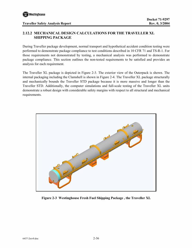
Docket 71-9297
Traveller Safety Analysis Report Rev. 0, 3/2004
6437-2rev0.doc 2-36
2.12.2 MECHANICAL DESIGN CALCULATIONS FOR THE TRAVELLER XL SHIPPING PACKAGE
During Traveller package development, normal transport and hypothetical accident condition testing were performed to demonstrate package compliance to test conditions described in 10 CFR 71 and TS-R-1. For those requirements not demonstrated by testing, a mechanical analysis was performed to demonstrate package compliance. This section outlines the non-tested requirements to be satisfied and provides an analysis for each requirement.
The Traveller XL package is depicted in Figure 2-3. The exterior view of the Outerpack is shown. The internal packaging including the Clamshell is shown in Figure 2-4. The Traveller XL package structurally and mechanically bounds the Traveller STD package because it is more massive and longer than the Traveller STD. Additionally, the computer simulations and full-scale testing of the Traveller XL units demonstrate a robust design with considerable safety margins with respect to all structural and mechanical requirements.
Figure 2-3 Westinghouse Fresh Fuel Shipping Package , the Traveller XL

Docket 71-9297
Traveller Safety Analysis Report Rev. 0, 3/2004
6437-2rev0.doc 2-37
Figure 2-4 Internal View of the Traveller Shipping Package
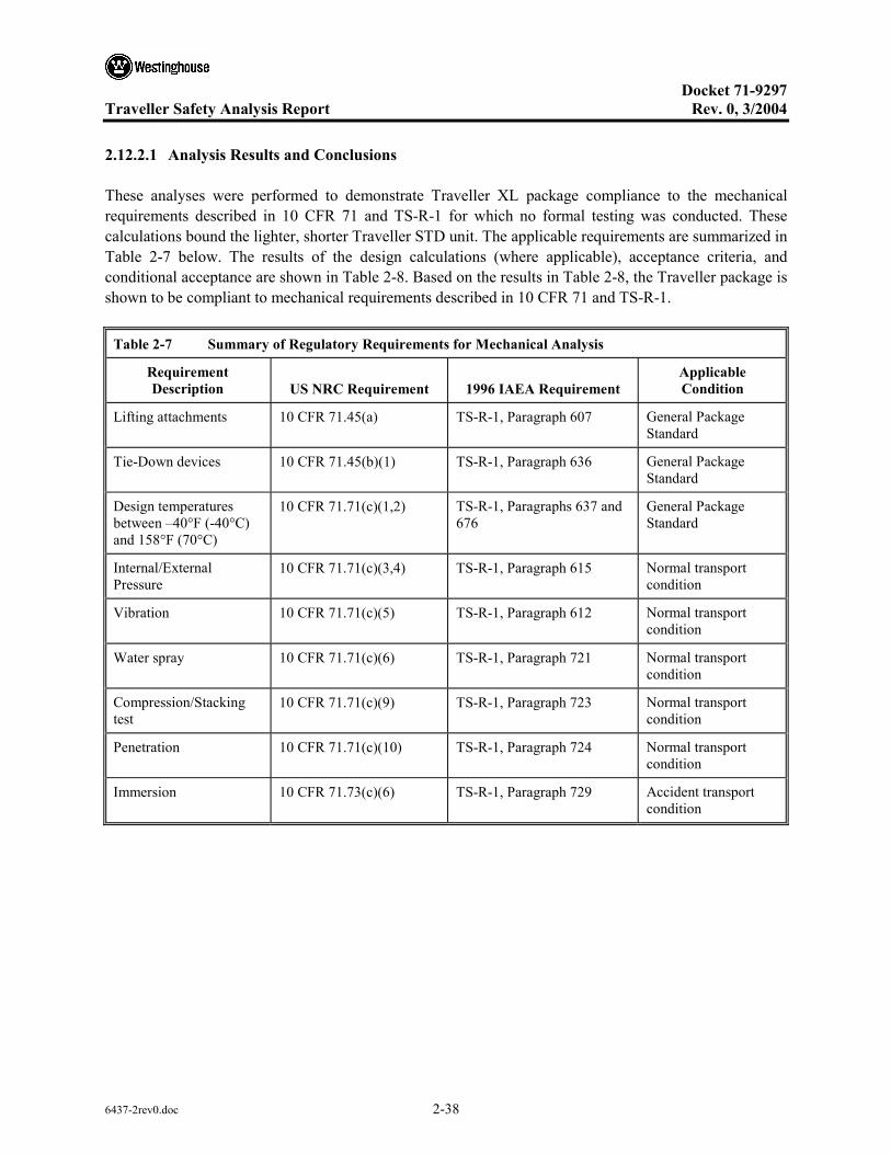
Docket 71-9297
Traveller Safety Analysis Report Rev. 0, 3/2004
6437-2rev0.doc 2-38
2.12.2.1 Analysis Results and Conclusions
These analyses were performed to demonstrate Traveller XL package compliance to the mechanical requirements described in 10 CFR 71 and TS-R-1 for which no formal testing was conducted. These calculations bound the lighter, shorter Traveller STD unit. The applicable requirements are summarized in Table 2-7 below. The results of the design calculations (where applicable), acceptance criteria, and conditional acceptance are shown in Table 2-8. Based on the results in Table 2-8, the Traveller package is shown to be compliant to mechanical requirements described in 10 CFR 71 and TS-R-1.
Table 2-7 Summary of Regulatory Requirements for Mechanical Analysis
Requirement Description US NRC Requirement 1996 IAEA Requirement
Applicable Condition
Lifting attachments 10 CFR 71.45(a) TS-R-1, Paragraph 607 General Package Standard
Tie-Down devices 10 CFR 71.45(b)(1) TS-R-1, Paragraph 636 General Package Standard
Design temperatures between –40°F (-40°C) and 158°F (70°C)
10 CFR 71.71(c)(1,2) TS-R-1, Paragraphs 637 and 676
General Package Standard
Internal/External Pressure
10 CFR 71.71(c)(3,4) TS-R-1, Paragraph 615 Normal transport condition
Vibration 10 CFR 71.71(c)(5) TS-R-1, Paragraph 612 Normal transport condition
Water spray 10 CFR 71.71(c)(6) TS-R-1, Paragraph 721 Normal transport condition
Compression/Stacking test
10 CFR 71.71(c)(9) TS-R-1, Paragraph 723 Normal transport condition
Penetration 10 CFR 71.71(c)(10) TS-R-1, Paragraph 724 Normal transport condition
Immersion 10 CFR 71.73(c)(6) TS-R-1, Paragraph 729 Accident transport condition

Docket 71-9297
Traveller Safety Analysis Report Rev. 0, 3/2004
6437-2rev0.doc 2-39
Table 2-8 Summary of Traveller Mechanical Analysis
Requirement Description
Allowable Design Value(s) or Acceptance Criteria Calculated Value Acceptable
Lifting attachments Tensile Yield Stress, σy < 30 ksi Shear Yield Stress, τy < 18 ksi Weld shear Yield Stress, τy < 12 ksi Hoist Screw Shear Stress, τ < 60 ksi
Hole tear: τ = 5.1 ksi< 18 ksi
Weld: τ = 9.5 ksi< 12 ksi (Alt. 8.1 ksi< 12 ksi)
Hoist: τ = 49.4 ksi< 60 ksi
Yes, for all
Tie-Down devices Tensile Yield Stress, σy < 30 ksi No tie down systems on package Yes
Design temperatures between –40°F (-40°C) and 158°F (70°C)
No brittle fracture No impact from Differential Thermal Expansion (DTE)
No Impact Yes
Internal/External Pressure
Compressive Yield Stress, σy < 30 ksi
No stress developed Yes
Vibration No impact on structural performance fnatOP > fnat TRANS
No impact,
41 Hz > 3.7-8 Hz
Yes
Water spray No impact on structural performance No impact Yes
Compression/Stacking test
Weld shear Yield Stress, τy < 12 ksi
Critical Buckling, F < Pcr
4.0 ksi < 12 ksi
Outerpack; 25.5 ksi < 78.6 ksi
Leg Support; 3.2 ksi < 26.9 ksi
Yes, for all
Penetration No perforation of outer skin Bounded by 1.0m HAC pin-puncture; No perforation of outer skin.
Yes
Immersion Compressive Yield Stress, σy < 30 ksi
No stress developed Yes
Assumptions
The calculations to determine the maximum Outerpack allowable stresses for yield, shear, and weld shear are based on the properties of ASTM A240 Type 304 Stainless Steel. It is further assumed that the weld consumable possess greater mechanical properties than that of the base metal. Hence, the mechanical properties of the base metal will be employed for weld stress analysis. The reference drawings included in this analysis represent the Certification Test Unit (CTU) Traveller XL, which was fabricated for the drop and fire tests.

Docket 71-9297
Traveller Safety Analysis Report Rev. 0, 3/2004
6437-2rev0.doc 2-40
Acceptance Criteria
The Traveller package was structurally evaluated to demonstrate compliance to the conditions described in Table 2-7. The package’s Outerpack structure is composed of ASTM A240 Type 304 Stainless steel. The mechanical properties are of listed below:
• Tensile strength, Minimum: 75 ksi • Yield strength, Minimum: 30 ksi
For mechanical analysis where tensile, shear, or weld shear stresses were determined, the acceptance criteria was as follows:
• Maximum allowable tensile yield stress, σy = 30 ksi • Maximum allowable shear stress, τmax = .6σy = 18 ksi • Maximum allowable weld shear stress, τweld = .4σy = 12 ksi
The material constant Young’s Modulus for 304 Stainless steel is:
64.29 EE = psi
2.12.2.2 Calculations
Nine mechanical conditions were evaluated for Traveller package. These conditions are outlined in Table 2-7. Standard engineering methods were used for these calculations.
2.12.2.2.1 Input
The design loads were determined according to the criteria described in 10 CFR 71 and TS-R-1, 1996 where appropriate. The Traveller XL package weight bounds the Traveller STD design as shown in Table 2-9. The total weights for each Traveller design include shipping components where applicable.
Table 2-9 Summary of Traveller STD and Traveller XL Design Weights
Traveller STD Traveller XL
Outerpack Weight, lb (kg) 2368 (1074) 2633 (1194)
Max. Fuel Assembly Weight, lb (kg) 1650 (748) 1945 (882)
Clamshell Weight, lb (kg) 378 (171) 467 (212)
MAX. TOTAL WEIGHT, lb (kg) 4396 (1994) 5071 (2300)
DESIGN TARE WEIGHT, lb (kg) 2850 (1293) 3155 (1431)
DESIGN and LICENSING BASIS GROSS WEIGHT, lb (kg)
4500 (2041) 5100 (2313)

Docket 71-9297
Traveller Safety Analysis Report Rev. 0, 3/2004
6437-2rev0.doc 2-41
Lifting – The lifting criteria is governed by 10 CFR 71.45(a) and TS-R-1, Paragraph 607. 10 CFR 71.45(a) states that any lifting attachment that is a structural part of the package must be designed with a minimum safety factor of three against yielding when used to lift the package in its intended manner. In addition, it must be designed so that failure of any lifting device under excessive load would not impair the ability of the package to meet other requirements of 10 CFR 71. The applied load to the package lifting attachments is then:
23 −= Tl WF
)5100(3=lF lb
300,15=lF lb
Tie-Downs – The tie-down requirements are described in 10 CFR 71.45(b) and TS-R-1, Paragraph 636. 10 CFR 71.45 states that a system of tie-downs that is a structural part of the package must be capable of withstanding, without generating stress in excess of its yield strength, a static force applied to the center of gravity having the following components:
• Vertical: 2 g • Axial: 10 g • Transverse: 5 g
Thus, the applied tie-down loads for the Traveller are:
• Vertical: 10,200 lb • Axial: 51,000 lb • Transverse: 25,500 lb
Design Temperatures between -40°F (-40°C) and 158°F (70°C) – The package must account for temperatures ranging from -40°F (-40°C) to 158°F (70°C) per TS-R-1 (637), and from -40°F (-40°C) to 100°F (38°C) per 10 CFR 71.71(c)(1,2). Thus, the bounding temperature range to consider for package design is -40°F (-40°C) to 158°F (70°C). The analysis of the Traveller package will consider the effects of temperature on thermally induced stress.
Internal/External Pressure – The package must account for the effects of external pressure conditions. The effects of reduced and increased external pressure are described in 10 CFR 71.71(c)(3,4) and TS-R-1 (615). The reduced external pressure is 25 kPa (3.5 psi) absolute, and the increased external pressure is 140 kPa (20 psi) as stated in 10 CFR 71.45.
Water Spray – A water spray test is required for the Traveller package to consider the effects of excessive rainfall on the structural integrity of the package. The water spray test is described by 10 CFR 71.71(c)(6) and TS-R-1 (721). The water spray test is to simulate a rainfall rate of approximately 5 cm/hr (2 in/hr) for at least one hour.
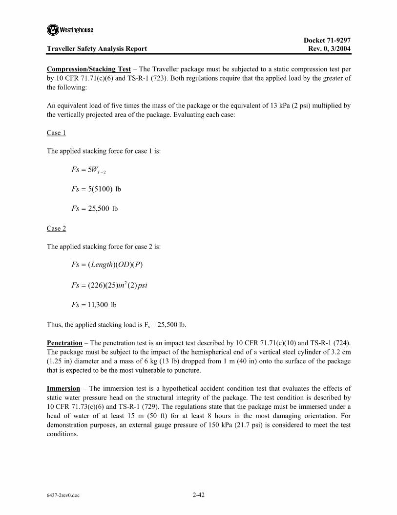
Docket 71-9297
Traveller Safety Analysis Report Rev. 0, 3/2004
6437-2rev0.doc 2-42
Compression/Stacking Test – The Traveller package must be subjected to a static compression test per by 10 CFR 71.71(c)(6) and TS-R-1 (723). Both regulations require that the applied load by the greater of the following:
An equivalent load of five times the mass of the package or the equivalent of 13 kPa (2 psi) multiplied by the vertically projected area of the package. Evaluating each case:
Case 1
The applied stacking force for case 1 is:
25 −= TWFs
)5100(5=Fs lb
500,25=Fs lb
Case 2
The applied stacking force for case 2 is:
))()(( PODLengthFs =
psiinFs )2()25)(226( 2=
300,11=Fs lb
Thus, the applied stacking load is Fs = 25,500 lb.
Penetration – The penetration test is an impact test described by 10 CFR 71.71(c)(10) and TS-R-1 (724). The package must be subject to the impact of the hemispherical end of a vertical steel cylinder of 3.2 cm (1.25 in) diameter and a mass of 6 kg (13 lb) dropped from 1 m (40 in) onto the surface of the package that is expected to be the most vulnerable to puncture.
Immersion – The immersion test is a hypothetical accident condition test that evaluates the effects of static water pressure head on the structural integrity of the package. The test condition is described by 10 CFR 71.73(c)(6) and TS-R-1 (729). The regulations state that the package must be immersed under a head of water of at least 15 m (50 ft) for at least 8 hours in the most damaging orientation. For demonstration purposes, an external gauge pressure of 150 kPa (21.7 psi) is considered to meet the test conditions.

Docket 71-9297
Traveller Safety Analysis Report Rev. 0, 3/2004
6437-2rev0.doc 2-43
2.12.2.2.2 Lifting
Four Point Lift – The Traveller package is crane lifted using a 4-point lift with attachment points located on the stacking bracket. Figure 2-5 shows a sample package with the lifting configurations. The assumed sling angle is 30°. The applied load, Fl = 15,300 lb.
Figure 2-5 Traveller Lifting Configurations
Based on the lifting configuration, the applied load transferred to each lifting hole, F, is:
30sin4lF
F =
5.4300,15
=F lb
650,7=F lb/hole
The applied forces and resultant components for a single lifting hole are shown in Figure 2-6.
30º
F1
F1

Docket 71-9297
Traveller Safety Analysis Report Rev. 0, 3/2004
6437-2rev0.doc 2-44
Figure 2-6 Lifting Hole Force Detail
The resulting force components are then:
)30(cosFFx =
)866.0(7650=xF lb
625,6=xF lb, and
)30(sinFFy =
)50.0(7650=Fy lb
825,3=Fy lb
The lifting bracket consists of ASTM A276 SS plate with an attached lifting eye. The lifting eye is 0.25″ thick ASTM A276 SS plate and is reinforced with a 0.25″ plate doubler. A lifting bracket detail is shown in Figure 2-7.
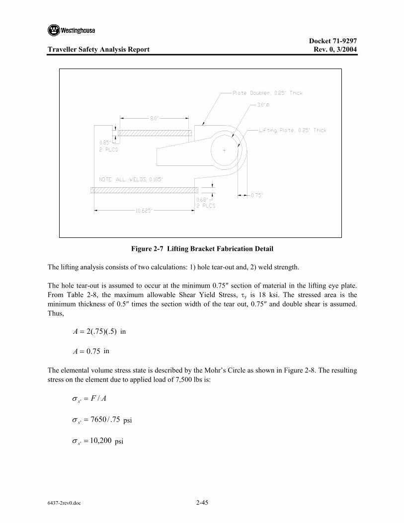
Docket 71-9297
Traveller Safety Analysis Report Rev. 0, 3/2004
6437-2rev0.doc 2-45
Figure 2-7 Lifting Bracket Fabrication Detail
The lifting analysis consists of two calculations: 1) hole tear-out and, 2) weld strength.
The hole tear-out is assumed to occur at the minimum 0.75″ section of material in the lifting eye plate. From Table 2-8, the maximum allowable Shear Yield Stress, τy is 18 ksi. The stressed area is the minimum thickness of 0.5″ times the section width of the tear out, 0.75″ and double shear is assumed. Thus,
)5)(.75(.2=A in
75.0=A in
The elemental volume stress state is described by the Mohr’s Circle as shown in Figure 2-8. The resulting stress on the element due to applied load of 7,500 lbs is:
AFx /' =σ
75./7650' =xσ psi
200,10' =xσ psi

Docket 71-9297
Traveller Safety Analysis Report Rev. 0, 3/2004
6437-2rev0.doc 2-46
The maximum shear stress on the element is then:
2''
2''
max 2)(
yxyx τ
σστ +
−=
22
max 02
)0200,10(+
−
=τ
100,5max =τ psi
Shear tear-out of the hole is not expected since 100,5max =τ psi < 000,18=allowxτ psi.
Figure 2-8 Hole Tear-out Model and Mohr’s Circle Stress State
The weld attaching the lift plates to the Outerpack shell are required to demonstrate that they are adequate to preclude local weld yielding. The analysis assumes that half of the total welds bear the lifting load. The
weld shear stress is found by AF
weld =τ , where F is the applied vertical or horizontal load and A is the weld area. The assumed weld area is:
45sinhlA = , where l is (.5)(21.69″) = 10.85″ from Figure 2-6, and h is the weld thickness, 0.105″.
(σx’,τx’y’)
σx’ = -10,200 psi
τmax = 5,100 psi
(σy’,τx’y’)
τ
σ
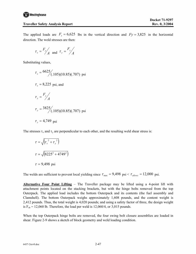
Docket 71-9297
Traveller Safety Analysis Report Rev. 0, 3/2004
6437-2rev0.doc 2-47
The applied loads are 625,6=xF lbs in the vertical direction and 825,3=Fy in the horizontal direction. The weld stresses are then:
AFx
x =τ and AFy
y =τ
Substituting values,
)707)(.85.10)(105(.6625=xτ psi
225,8=xτ psi, and
AFy
y =τ
)707)(.85.10)(105(.3825=yτ psi
749,4=yτ psi
The stresses τx and τy are perpendicular to each other, and the resulting weld shear stress is:
( )22yx τττ +=
( )22 47498225 +=τ
498,9=τ psi
The welds are sufficient to prevent local yielding since 498,9max =τ psi < 000,12=allowxτ psi.
Alternative Four Point Lifting – The Traveller package may be lifted using a 4-point lift with attachment points located on the stacking brackets, but with the hinge bolts removed from the top Outerpack. The applied load includes the bottom Outerpack and its contents (the fuel assembly and Clamshell). The bottom Outerpack weighs approximately 1,608 pounds, and the content weight is 2,412 pounds. Thus, the total weight is 4,020 pounds; and using a safety factor of three, the design weight is Fsb = 12,060 lb. Therefore, the load per weld is 12,060/4, or 3,015 pounds.
When the top Outerpack hinge bolts are removed, the four swing bolt closure assemblies are loaded in shear. Figure 2-9 shows a sketch of block geometry and weld loading condition.

Docket 71-9297
Traveller Safety Analysis Report Rev. 0, 3/2004
6437-2rev0.doc 2-48
Figure 2-9 Weld Geometry at Swing Bolt Block
The weld shear stress is found by AFsb
sb =τ , where Fsb is the applied load and A is the weld area.
45sinhlA = , where l is (2)(.5)+(2)(2) = 5.00″ from Figure 2-9, and h is the weld thickness, 0.105″.
The applied load per weld is 015,3=sbF lbs. The weld stresses are then:
AFsb
sb =τ
)707)(.0.5)(105(.3015=sbτ psi
122,8=sbτ psi,
The welds are sufficient to prevent local yielding since 122,8=sbτ psi < 000,12=allowxτ psi.
Forklift Analysis – During package lift by a forklift, only the center portion of the package is supported by the forklift. Consequently, the package is subject to a bending load due to the unsupported weight of the package. The Traveller XL package is conservatively modeled as a cantilever beam with the length equal to half of the overall length (Lf = 112.5 in), and the design lifting load distributed over the length of the package (Figure 2-10). The outer shell is the only assumed structure of the package carrying the bending load.
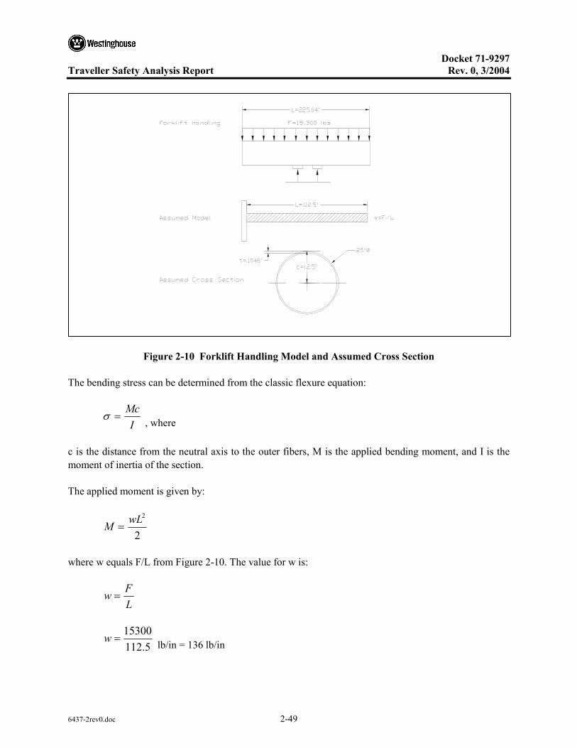
Docket 71-9297
Traveller Safety Analysis Report Rev. 0, 3/2004
6437-2rev0.doc 2-49
Figure 2-10 Forklift Handling Model and Assumed Cross Section
The bending stress can be determined from the classic flexure equation:
IMc
=σ , where
c is the distance from the neutral axis to the outer fibers, M is the applied bending moment, and I is the moment of inertia of the section.
The applied moment is given by:
2
2wLM =
where w equals F/L from Figure 2-10. The value for w is:
LFw =
5.11215300
=w lb/in = 136 lb/in

Docket 71-9297
Traveller Safety Analysis Report Rev. 0, 3/2004
6437-2rev0.doc 2-50
Thus,
2)5.112)(136( 2
=M in-lb
625,860=M in-lb
The moment of inertia for the shell, I, is calculated as follows:
)(4
44io RRI −=
π
where Ro=12.5″ and Ri=(12.5-.1046)″, Ri=12.395″.
Thus,
)395.125.12(4
44 −=πI in4
634=I in4
The bending stress is then:
634)5.12)(625,860(
=σ psi
968,16=σ psi
Forklift loading is not expected to impact the package since 968,16=σ psi < 000,30=yieldσ psi. As previously noted, the model conservatively assumes the outer shell and the actual Outerpack sandwich structure is would provide even greater margin against bending.
Hoist Ring Analysis – During package lift for fuel loading and unloading, the package is hoisted using the two hoist rings attached to the top end of the Outerpack. The hoist rings attach to the Outerpack using two 3/8-16 UNC socket head cap screws per hoist ring into a welded nut. The four screws are subject to shear loading, combined shear and axial loading, and axial loading. The screws are fabricated to a minimum yield strength of 100,000 psi. The load per bolt is the design lifting load of 15,500 pounds distributed by the four bolts. Thus, the load per bolt is 3,825 pounds. The allowable axial stress is the yield stress of 100,000 psi and the allowable shear stress is 0.6Sy, or 60,000 psi. The stressed area is 0.0775 in2. The applied stress is then:
AF=τ

Docket 71-9297
Traveller Safety Analysis Report Rev. 0, 3/2004
6437-2rev0.doc 2-51
0775.3825=τ psi
355,49=τ psi, which is less than the allowable shear stress of 60,000 psi as well as the axial allowable stress of 100,000 psi and is acceptable.
When the package is vertical, the coupling nut will be subject to a shear load. The nut is 3/8-16 (P=1/16=0.0625) and the material is 18-8 stainless steel. The tolerance gap is 0.0057 inches. The allowable shear stress is 18,000 psi.
The stressed area of the internal thread is found by:
ntDA isπ= where Ds is the minimum major diameter 0.3595 inches, ti is the internal thread thickness (7/8P-2*gap = .0432 inches), and n is the number of stressed threads 16*(21/64) = 5.25.
)25.5)(0432.0)(3595.0(π=A in2
256.0=A in2
The shear stress is then:
AF=τ
256.3825=τ psi
941,14=τ psi, which is less than the allowable material shear stress of 18,000 and is acceptable.
2.12.2.2.3 Tie-Down Analysis
The Traveller packages are secured to the transport conveyance by means of strapping across the top of the package(s) and placing a chain inboard from the welded plate at the package legs. Since there are no structural devices designed for tie-down, a tie-down analysis is not required.
2.12.2.2.4 Design Temperature Analysis –40°F (-40°C) and 158°F (70°C)
The materials of construction of the Traveller Outerpack include ASTM A240 Type 304 Stainless Steel for the shells and low density, closed cell polyurethane impact limiter/thermal insulator (10pcf along the axis as well as 7 and 20 pcf at the end caps). The Clamshell is comprised of ASTM B209/B221 Type 6005-T5 Aluminum. As demonstrated in the below sections, the package is suitable for transport operations over the required design temperature range.

Docket 71-9297
Traveller Safety Analysis Report Rev. 0, 3/2004
6437-2rev0.doc 2-52
Brittle Fracture – Aluminum alloys, including 6005-T5 Aluminum, do not exhibit a ductile-to-brittle temperature transition; consequently, neither ASTM nor ASME specifications require low temperature Charpy or Izod tests of aluminum alloys. Thus, brittle fracture of the aluminum components is not expected. Austenitic steels such as 304 Stainless Steel have a Face Centered Cubic (FCC) structure and consequently exhibit a ductile-to-brittle transition at cryogenic temperatures near -297°F (-183°C). Thus, brittle fracture of the stainless steel components is not expected.
Mechanical Properties For Design Temperature Range – The range of tensile and yield strength of 6005 series Aluminum over the design temperature range will not preclude the package from performing its intended design function. Figure 2-11 provides the temperature dependent yield and tensile strengths typical for a 6000-series aluminum up to approximately 212°F (100°C). Furthermore, the recommended operating temperature of aluminum alloys for structural applications is up to a temperature of 400°F (204°C), which is well below the maximum design temperature of 158°F (70°C).
The range of tensile and yield strength of 304 stainless steel over the design temperature range will not preclude the package from performing it intended design function. Figure 2-12 provides the temperature dependent yield and tensile strengths for 304 SS up to approximately 194°F (90°C).
Temperature Dependent Tensile Properties Tempered 6000 Series Al
0
10
20
30
40
50
60
-80 -60 -40 -20 0 20 40 60 80 100 120Temperature, C
Stre
ngth
, ksi
TensileStrength
YieldStrength
Figure 2-11 Typical Temperature Dependent Tensile Properties for Tempered 6000 Series Al
Docket 71-9297
Traveller Safety Analysis Report Rev. 0, 3/2004
6437-2rev0.doc 2-53
Temperature Dependent Tensile Properties 304 Stainless Steel
020406080
100120140160180
-80 -60 -40 -20 0 20 40 60 80 100Temperature, C
Stre
ngth
, ksi
TensileStrength
YieldStrength
Figure 2-12 Temperature Dependent Tensile Properties for 304 SS
Temperature Evaluation of Foam – The foam is used as a crushable impact limiter and a special thermal insulator. This section only considers the mechanical properties since the thermal functions are evaluated in Section 3, Thermal Evaluation. The foam exhibits a general increase in compressive strength as temperature decreases. Figures 2-13, 14 and 15 show the compressive strength for the 10 pcf (pound per cubic foot), 20 pcf, and 6 pcf foam as a function of temperature, respectively. Of interest is the area under each temperature curve from 0-60% strain (the recommended energy absorption operation range of the foam). For each foam density, the temperature range considered does not significantly impact the energy absorption characteristics. Also, Figures 2-15 show that the compressive strength difference between –29°C and 24°C are relatively similar indicating at -40°C the behavior of the foam will not significantly change. Figure 2-16 provides the temperature dependent strength of each foam density at 10% strain from -54°C to 82°C. The curves show essentially a linear increase in crush strength as temperature decreases. Therefore, the impact properties of the foam are acceptable for use in the temperature range from -40°F (-40°C) to 158°F (70°C).
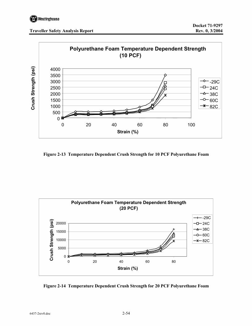
Docket 71-9297
Traveller Safety Analysis Report Rev. 0, 3/2004
6437-2rev0.doc 2-54
Figure 2-13 Temperature Dependent Crush Strength for 10 PCF Polyurethane Foam
Polyurethane Foam Temperature Dependent Strength(20 PCF)
0
5000
10000
15000
20000
0 20 40 60 80
Strain (%)
Cru
sh S
tren
gth
(psi
) -29C24C38C60C82C
Figure 2-14 Temperature Dependent Crush Strength for 20 PCF Polyurethane Foam
Polyurethane Foam Temperature Dependent Strength(10 PCF)
0 500
1000 1500 2000 2500 3000 3500 4000
0 20 40 60 80 100 Strain (%)
Cru
sh S
tren
gth
(psi
)
-29C24C38C60C82C

Docket 71-9297
Traveller Safety Analysis Report Rev. 0, 3/2004
6437-2rev0.doc 2-55
Polyurethane Foam Temperature Dependent Strength(6 PCF)
0100200300400500600700800
0 20 40 60 80
Strain (%)
Cru
sh S
tren
gth
(psi
) -29C24C38C60C82C
Figure 2-15 Temperature Dependent Crush Strength for 6 PCF Polyurethane Foam
Temperature Dependent Foam Crush Strength (10%strain)
0200400600800
100012001400160018002000
-60 -30 0 30 60 90Temperature (C)
Cru
sh S
tren
gth
(psi
)
FR-3710FR-3720FR-3706
Figure 2-16 Temperature Dependent Crush Strength for Traveller Foam at 10% Strain

Docket 71-9297
Traveller Safety Analysis Report Rev. 0, 3/2004
6437-2rev0.doc 2-56
Differential Thermal Expansion – Differential thermal expansion (DTE) is expected to only impact the fuel assembly and Clamshell interface. The Outerpack is not under physical constraints and can accommodate thermal growth. Differential thermal expansion between the foam and the stainless steel shells of the Outerpack is easily accommodated by the elastic properties (low modulus value) of the foam.
However, the Ultra-high Molecular Weight (UHMW) polyethylene does have a significantly higher coefficient of thermal expansion (CTE) when compared to 304 stainless steel. For this reason, the moderator panels are segmented along their lengths to accommodate the differential thermal expansion between the polyethylene and the inner stainless steel shells of the Outerpack. Holes in the polyethylene segments are used to attached the panels to the inner Outerpack shells using threaded studs. These studs must not be loaded by the individual panel differential thermal expansion, or contraction. For this reason, each hole drilled into the polyethylene panel is significantly large to preclude thermally induced stresses in the bolt studs. The following calculation addresses this case.
The greatest bolt-to-bolt axial span occurs in the top moderator panels, and is 17 inches (43.2 cm). The average UHMW CTE value is 90 in/in-F. The greatest temperature change occurs from room temperature to -40°F (-40°C). Therefore the shrinkage of the panel is:
oLTL )(∆=∆ α , where ∆L is the total contraction, Lo is the original bolt spacing (the largest in a panel), ∆T is the temperature change (assumed to be 70°F to -40°F), and α is the coefficient of thermal expansion.
Solving this equation yields a total contraction of 0.168 inches (0.43 cm). Therefore, a total radial clearance of greater than 0.168 must be made around the 2 bolts. Each bolt must have a clearance of 0.168/2, or 0.084 inches (0.21 cm). The actual hole diameters in all the moderator panels are 5/8 inches, 0.625″ (1.59 cm), which gives a radial clearance of 0.094 inches (0.24 cm) using the 7/16” (1.11 cm) diameter bolt studs. This clearance is greater than required, therefore differential thermal expansion between the polyethylene panels and the inner shell bolting studs will not stress the studs
Analyzing the DTE between the fuel assembly and the Clamshell is evaluated assuming fuel loading is performed at 70°F (21°C) and shipped to a cold environment of -40°F (-40°C) since the aluminum will tend to contract more than the fuel assembly. The thermal growth is found by the familiar equation:
oLTL )(∆=∆ α , where ∆L is the total growth, Lo CS is the original length of the Clamshell (202 inches), Lo FA is the original length of the fuel assembly (188.86 inches, per drawing 1453E86), ∆T is the temperature change (110°F), and α is the coefficient of thermal expansion.
For Aluminum, α = 13 µin/in-°F. For Zircalloy, α = 2.79 µin/in-°F.
Docket 71-9297
Traveller Safety Analysis Report Rev. 0, 3/2004
6437-2rev0.doc 2-57
The differential thermal growth between the Clamshell and the fuel assembly is then:
DTE = { CSoLTL )(∆=∆ α Al }- { FAoLTL )(∆=∆ α Zirlo}
= {13e-6x110x202} inches- {2.79e-6x110x188.86} inches
= 0.29-0.058 inches
Thus,
DTE =0.23 inches (the fuel assembly grows 0.23 inches relative to the Clamshell).
The combined thickness of the base cork rubber and axial clamp cork rubber is 0.50 inches and can accommodate the growth due to differential thermal expansion. Thus, DTE is not a concern. Since the total differential growth associated with the XL Clamshell is greater than the STD Clamshell, it is the bounding calculation.
2.12.2.2.4.1 Internal/External Pressure
The Traveller package utilized acrylic coated fiberglass seals for thermal protection and to preclude dust and other contaminants from entering the package. These seals are not continuous, and do not form an airtight pressure boundary. The package does not maintain a boundary between pressure gradients and is not designed to be pressurized during transport. Thus, internal/external reduced pressure will not impact the structural integrity of the package.
2.12.2.2.4.2 Vibration
The package must be evaluated to consider the effects of normal vibration on the design performance. The isolation system is designed to dampen normally induced vibrations from transport, and is not fundamental to the safe operation of the package. However, the Outerpack must maintain its structural integrity during transport to maintain a safe transport condition. Typical package attachment to a transport conveyance for the Traveller includes nylon straps or chain mounted both over the package and on the gusset tray connected to the support legs pointed inboard. The loading configuration can be modeled as a simply supported beam. Furthermore, the Outerpack is conservatively modeled considering only the outer shell at the first mode of vibration. The typical natural frequency range for transportation vehicles, fnat TRANS, is 3.7-8 Hz . The natural frequency of the Outerpack can be determined from.
mlEIgafnatOP /)( 3=
where a=1.57 (primary mode coefficient assuming hinge-hinge end conditions for additional conservatism), E=29.4E6 psi, I=634 in4, m=2633 pounds, g = 386.4 in/s2 and l=158 in (distance from gusset tray to gusset tray). Substituting values:
2633/])158()4.386)(634)(64.29[(57.1 3EfnatOP = 1/s (Hz)

Docket 71-9297
Traveller Safety Analysis Report Rev. 0, 3/2004
6437-2rev0.doc 2-58
69357.1=natOPf Hz
41=natOPf Hz
Since the natural frequency of the Outerpack is greater than the natural frequency typical of a transportation vehicle, resonance of the Outerpack is not expected and normally induced vibrations will not preclude the package from performing its design function.
2.12.2.2.5 Water Spray
The Traveller Outerpack is cylindrical, and shaped so that water will not be collected. Since the shell is fabricated of 304 SS, the water spray will not impact the structural integrity of the package.
2.12.2.2.6 Compression/Stacking test
The Traveller package must demonstrate elastic stability for a 5 g static load. No credit is taken for the circumferential stiffeners or the forklift support tubes. The analysis assumes the stacking load is uniformly distributed over the four outermost stacking brackets on the Outerpack. Figure 2-17 depicts the shell compression/stacking model.
F = 6,375# F = 6,375#
F = 6,375# F = 6,375#
Figure 2-17 Compression/Stacking Requirement Analysis Model
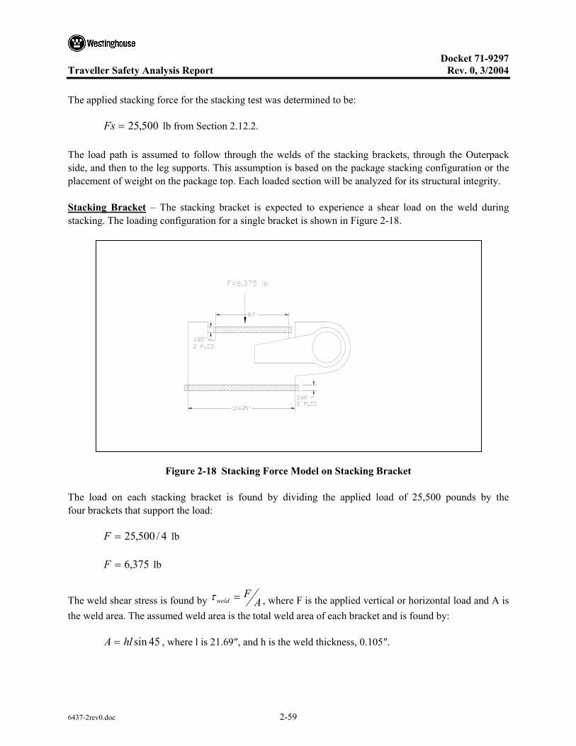
Docket 71-9297
Traveller Safety Analysis Report Rev. 0, 3/2004
6437-2rev0.doc 2-59
The applied stacking force for the stacking test was determined to be:
500,25=Fs lb from Section 2.12.2.
The load path is assumed to follow through the welds of the stacking brackets, through the Outerpack side, and then to the leg supports. This assumption is based on the package stacking configuration or the placement of weight on the package top. Each loaded section will be analyzed for its structural integrity.
Stacking Bracket – The stacking bracket is expected to experience a shear load on the weld during stacking. The loading configuration for a single bracket is shown in Figure 2-18.
Figure 2-18 Stacking Force Model on Stacking Bracket
The load on each stacking bracket is found by dividing the applied load of 25,500 pounds by the four brackets that support the load:
4/500,25=F lb
375,6=F lb
The weld shear stress is found by AF
weld =τ , where F is the applied vertical or horizontal load and A is the weld area. The assumed weld area is the total weld area of each bracket and is found by:
45sinhlA = , where l is 21.69″, and h is the weld thickness, 0.105″.

Docket 71-9297
Traveller Safety Analysis Report Rev. 0, 3/2004
6437-2rev0.doc 2-60
The weld stress is then:
AF=τ
Substituting values,
)707)(.69.21)(105(.6375=τ psi
959,3=τ psi, which is less the allowable weld shear stress of 12 ksi.
2.12.2.2.6.1 Outerpack Section
The stacking bracket is expected to experience a compressive load through the package side cross section during stacking as the force follows the projected load path The loading configuration and model for the Outerpack section is shown in Figure 2-19.
Figure 2-19 Outerpack Section Compression Model
The evaluation first examined the slenderness ratio of this section to determine if buckling is applicable. The model conservatively assumed no structural credit for the foam. In addition, the model assumed the force path section is from the base of the stacking bracket to the top of the support leg. The cross section consisted of a rectangular section of dimensions 9.50″ x 3.209″ with a wall thickness of 0.1046″. The

Docket 71-9297
Traveller Safety Analysis Report Rev. 0, 3/2004
6437-2rev0.doc 2-61
critical buckling load will be calculated and compared to the actual load to determine elastic stability of the Outerpack section.
The slenderness ratio, SR, can be expressed as:
klSR /=
where l is the effective length, 9.50 inches, and the radius of gyration, k, is:
AIk =
For the Outerpack section, the moment of inertia, I, and the cross section area, A are:
( ) 12/33iilwwlI −= in4
{ } { }( ) 12/29.90.350.9209.3 33 −=I in4
8.28=I in4
iilwwlA −= in2
{ } { }( )29.90.350.9209.3 −=A in2
62.2=A in2
Thus, the value for k is:
62.28.28=k in
32.3=k in
The corresponding slenderness ratio is then:
32.3/50.9=SR in/in
86.2=SR

Docket 71-9297
Traveller Safety Analysis Report Rev. 0, 3/2004
6437-2rev0.doc 2-62
The limiting slenderness ratios for columns are as follows:
Long Columns
( )y
CEkl
σπ 2
1
2=
where the end condition C is conservatively assumed to be unity, E is Young’s Modulus, and σy is the tensile yield stress.
Substituting values:
( )30000
)64.29(2 2
1
Ekl π
=
( ) 1391=k
l
Short Columns
( )I
Alkl
2
2
2282.
π=
Substituting values:
( )8.28
)50.9(62.2282. 2
2
2 π=k
l
( ) 257.2=k
l
Thus, .257< 2.86 (SR) < 139 and the Outerpack section is considered an intermediate column. The critical load for this column is given by:
)12
(2
CEklAP y
ycr
−=πσ
σ
)64.29
132.350.9
23000030000(62.2
2
EPcr
−=
π
583,78=crP lb

Docket 71-9297
Traveller Safety Analysis Report Rev. 0, 3/2004
6437-2rev0.doc 2-63
Since the actual load of 25,500 pounds is less than the critical buckling load of 78,583 pounds, the Outerpack section is considered stable during compression from stacking.
2.12.2.2.6.2 Leg Support
The leg support is expected to experience a compressive load through the straight top cross section during stacking as the force follows the projected load path The loading configuration and model for the leg support section is shown in Figure 2-20. There are eight (8) leg sections of 2″x2″x.120″ 304 SS tubing of approximately 10″ length, The expected load for each leg section is 25,500/8 pounds, or 3,188 pounds.
Figure 2-20 Leg Support Section Compression Model
The evaluation will first consider the slenderness ratio of this section to determine if buckling is applicable. The critical buckling load will be calculated and compared to the actual load to determine elastic stability of the leg support section.
The slenderness ratio, SR, is:
klSR /=
where l is the effective length, 10.0 inches, and the radius of gyration, k, is:
AIk =
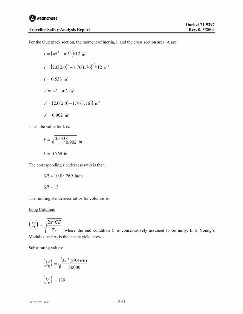
Docket 71-9297
Traveller Safety Analysis Report Rev. 0, 3/2004
6437-2rev0.doc 2-64
For the Outerpack section, the moment of inertia, I, and the cross section area, A are:
( ) 12/33iilwwlI −= in4
{ } { }( ) 12/76.176.10.20.2 33 −=I in4
533.0=I in4
iilwwlA −= in2
{ } { }( )76.176.10.20.2 −=A in2
902.0=A in2
Thus, the value for k is:
902.0533.0=k in
769.0=k in
The corresponding slenderness ratio is then:
769./0.10=SR in/in
13=SR
The limiting slenderness ratios for columns is:
Long Columns
( )y
CEkl
σπ 2
1
2=
where the end condition C is conservatively assumed to be unity, E is Young’s Modulus, and σy is the tensile yield stress.
Substituting values:
( )30000
)64.29(2 2
1
Ekl π
=
( ) 1391=k
l

Docket 71-9297
Traveller Safety Analysis Report Rev. 0, 3/2004
6437-2rev0.doc 2-65
Short Columns
( )I
Alkl
2
2
2282.
π=
Substituting values:
( )534.0
)0.10(902.0282. 2
2
2 π=k
l
( ) 16.12=k
l
Thus, 1.16< 13 (SR) < 139 and the leg support section is considered an intermediate column. The critical load for this column is:
)112
(2
CEkAP y
ycr
−=πσ
σ
)64.29
177.00.10
23000030000(902.0
2
EPcr
−=
π
942,26=crP lb
Since the actual load of 3,188 pounds is less than the critical buckling load of 26,942 pounds, the leg support section is considered stable during compression from stacking.
2.12.2.2.7 Penetration
The penetration test can be characterized as a localized impact event on the outer skin of the Outerpack. The energy imparted onto the outer skin is equal to the potential energy of the falling pin:
mghPE = , where the mass of the pin is 13 lb and the drop height is 40 inches. To obtain correct units of energy, the gravitational constant gc must be used in the energy equation. Thus,
2.32)2.32)(40)(13(
=npenetratioPE in-lb (ft*s2)/ft*s2
520=npenetratioPE in-lb.

Docket 71-9297
Traveller Safety Analysis Report Rev. 0, 3/2004
6437-2rev0.doc 2-66
By comparison, the energy locally imparted to the outer skin from the pin-puncture drop test is determined from the dropped package mass and the drop height. The mass of the package is 5,100 lb, and the drop height is 40 inches. Thus,
mhgmghPE
cpin ==
)40)(5100(=pinPE in-lb.
000,204=pinPE in-lb.
Pin puncture drop tests have demonstrated that the outer skin was not perforated as a result of impact onto the pin. Since the impact energy of the pin puncture drop test is approximately 400 times greater than that of the pin penetration, the pin puncture drop test bounds the pin penetration. Thus, the pin penetration impact is not expected to result in any significant structural damage to the Outerpack.
2.12.2.2.8 Immersion Analysis
The Traveller package uses acrylic fiberglass seals for thermal protection and to preclude dust and other contaminants from entering the package. The seals are not continuous around the perimeter of the package and do not form a pressure boundary. In the event of water submersion, the inner portion of the package will fill with water creating equal hydrostatic pressure on the Outerpack and Clamshell surfaces. This condition would not result in a stress gradient through the Outerpack or Clamshell. Thus, immersion will not impact the structural integrity of the package.

Docket 71-9297
Traveller Safety Analysis Report Rev. 0, 3/2004
6437-2rev0.doc 2-67
2.12.3 DROP ANALYSIS FOR THE TRAVELLER XL SHIPPING PACKAGE
Two finite element models were developed for the Traveller XL package undergoing the prescribed regulatory drop tests. The first model reflected the prototype configuration used for initial exploratory (“scoping”) tests conducted in January 2003. The second model reflected the Qualification Test Units tested in September 2003 that included modifications based on the prototype test results. These models were used to develop a crash-worthy design, minimizing structural cost and weight, determining the “worst-case” drop orientations.
The objectives of this effort are:
• To validate the techniques used in these models by documenting the conservative agreement found between predictions and results of the prototype drop tests; and,
• To determine the appropriate number of drop tests and their orientation(s) needed for the qualification drop tests. By regulation, the shipping package must be dropped at orientations that are most damaging to the fuel assembly and to the shipping package.
Due to mesh density limitations, the actual stress and strain predictions can not be considered highly accurate. Rather, the relative deformations, decelerations and energy absorption between drop orientations should be considered. Also, this model can not predict the deformation of the fuel assembly rods. These limitations apply to both the prototype and qualification unit models.
2.12.3.1 Analysis Results
The Traveller XL shipping package complies with 10 CFR 71 and TS-R-1 requirements, respectively for all drop orientations. Test orientations which are most challenging are a 9 meter vertical drop with the bottom end of the package hitting first as shown in Figure 2-52A and a 9 meter CG-forward-of-corner drop onto the TN end of package with an 18° forward rotation, Figures 2-44 and Figure 2-45. The former has the greatest potential to damage the fuel assembly and the latter is most damaging to the shipping package itself. Successful drop tests in these two orientations are adequate demonstration that the Traveller XL design meets/exceeds the HAC drop test requirements.
The Traveller XL shipping package will survive the HAC drop tests in any orientation with few or no closure bolt failures. Horizontal side drops onto the hinges or latches, Figures 26A and B, result in the highest hinge/latch bolt loads. The analyses indicate ten ¾-10 stainless steel bolts/side are sufficient to ensure the Outerpack remains closed during such drops. The miminum predicted factor of safety for the Outerpack latch and hinge bolts is 1.12.
Damage to the Traveller XL shipping package from the HAC drop tests is predicted to be minor and primarily involves localized deformations in the region of impact. Both the Outerpack and Clamshell structures remain intact and closed. Fuel assembly damage is confined to the top or bottom region depending on drop orientation. This damage primarily involves localized buckling and deformation of the nozzles.

Docket 71-9297
Traveller Safety Analysis Report Rev. 0, 3/2004
6437-2rev0.doc 2-68
Temperature and foam density have a minor effect on drop performance of the Traveller XL package. For the orientation predicted most damaging to the Outerpack, a package with nominal foam density and dropped at “normal temperature” (75°F) experiences 8.5 and 13.7% higher loads than, respectively, one containing low density foam and dropped at 160°F or one containing high density foam and dropped at -40°F, Figure 2-62. Fuel assemblies in packages containing the highest allowable density foam and dropped at the lowest temperature extreme will experience accelerations that are very similar to those in packages with lowest allowable density foam and dropped at the highest temperature extreme, Figure 2-63. However, the accelerations at these extremes are only 5% greater than for a package dropped at 75°F containing nominal density foam.
A maximim indentation of 67 mm is predicted for the 1 m pin puncture test when the package is impacted from underneath, Figure 2-65A, and dropped horizontally with its CG directly above the pin. The steel outer skin should not be ruptured during this test. Overall, the 1 m pin puncture test is a relatively benign test for the Traveller XL package.
In some drop orientations, the moderator blocks lining the inside walls of the upper and lower Outerpack assemblies prevent the Clamshell from radically changing shape as might otherwise occur.
An accurate and conservative methodology for predicting HAC impact performance of the Traveller XL shipping package was developed. The LS-DYNA finite element code was used to develop drop and pin puncture models of the prototype and qualification units. In comparisons against test, a model of the prototype unit, at worst, correlated to within 27% for displacements. Predicted accelerations matched measured traces well. However, due to a limitation on mesh density, predicted stresses and strains should be interpreted in a comparative manner. This limitation applies to the models of both the prototype and qualification units.
2.12.3.2 Predicted Performance of the Traveller Qualification Test Unit
2.12.3.2.1 Most Damaging Drop Orientations
A primary objective of this study was to determine the worst case drop orientation(s) for the HAC drop tests. This requirement is to drop test the shipping package in orientations that most damage: a) the shipping package, and b) the fuel assembly. It was quickly realized that the most damaging orientation for the shipping package, would not necessarily be the same for the fuel assembly. Based on the robust performance of the Traveller XL drop units during testing, orientations that were most severe to the fuel assembly became more significant.
Determination of the worst case orientation for the shipping package was facilitated by the Traveller XL computer analysis and results of the prototype tests. Many orientations can be eliminated from consideration due to inherent design features of the Traveller. For example, the circumferential stiffeners on the upper Outerpack, and the legs/forklift pocket structure, Figure 2-21, greatly reduce the crushing of the Outerpack since they crush prior to impact of the main body of the Outerpack. Drop orientations where one or the other of these structures directly contacts the drop pad, Outerpack damage is reduced in

Docket 71-9297
Traveller Safety Analysis Report Rev. 0, 3/2004
6437-2rev0.doc 2-69
comparison to orientations where these features are not impacted. This is because the energy absorbed in crushing these features cannot be absorbed by the Outerpack.
Forktruck lift pockets
Legs On Lower Overpack
Circumferential StiffenersOn Upper Overpack
Figure 2-21 Traveller Stiffeners, Legs, and Forklift Pockets
Test results supported this hypothesis. Indeed, in the two available tests of relevance, these features absorbed almost all the energy and very little damage was incurred by the Outerpack. For example, Prototype-1, Test 1.1 was a low angle slap down test resulting in extensive crushing of the upper Outerpack stiffeners, Figure 2-22. Aside from this crushing, very little Outerpack damage was incurred. Prototype-2, Test 3.2 was the second example. In this test, the Outerpack was dropped horizontally onto its legs from 9 m. This resulted in significant crushing of the Outerpack legs and feet, Figure 2-22B, and the forklift supports, not shown. However, the Outerpack was otherwise not significantly damaged.
Legs on Lower Outerpack Forklift Pockets
Circumferential Stiffeners on Upper Overpack
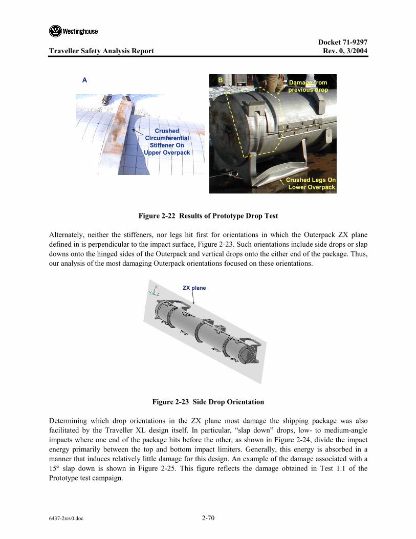
Docket 71-9297
Traveller Safety Analysis Report Rev. 0, 3/2004
6437-2rev0.doc 2-70
Crushed Circumferential
Stiffener On Upper Overpack
Crushed Legs On Lower Overpack
BA Damage from previous drop
Figure 2-22 Results of Prototype Drop Test
Alternately, neither the stiffeners, nor legs hit first for orientations in which the Outerpack ZX plane defined in is perpendicular to the impact surface, Figure 2-23. Such orientations include side drops or slap downs onto the hinged sides of the Outerpack and vertical drops onto the either end of the package. Thus, our analysis of the most damaging Outerpack orientations focused on these orientations.
ZX plane
Figure 2-23 Side Drop Orientation
Determining which drop orientations in the ZX plane most damage the shipping package was also facilitated by the Traveller XL design itself. In particular, “slap down” drops, low- to medium-angle impacts where one end of the package hits before the other, as shown in Figure 2-24, divide the impact energy primarily between the top and bottom impact limiters. Generally, this energy is absorbed in a manner that induces relatively little damage for this design. An example of the damage associated with a 15° slap down is shown in Figure 2-25. This figure reflects the damage obtained in Test 1.1 of the Prototype test campaign.
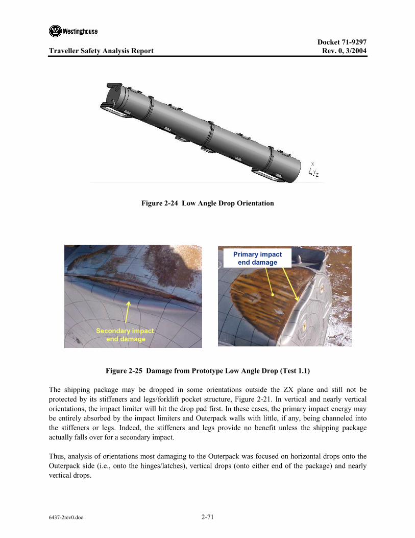
Docket 71-9297
Traveller Safety Analysis Report Rev. 0, 3/2004
6437-2rev0.doc 2-71
Figure 2-24 Low Angle Drop Orientation
Secondary impact end damage
Primary impact end damage
Figure 2-25 Damage from Prototype Low Angle Drop (Test 1.1)
The shipping package may be dropped in some orientations outside the ZX plane and still not be protected by its stiffeners and legs/forklift pocket structure, Figure 2-21. In vertical and nearly vertical orientations, the impact limiter will hit the drop pad first. In these cases, the primary impact energy may be entirely absorbed by the impact limiters and Outerpack walls with little, if any, being channeled into the stiffeners or legs. Indeed, the stiffeners and legs provide no benefit unless the shipping package actually falls over for a secondary impact.
Thus, analysis of orientations most damaging to the Outerpack was focused on horizontal drops onto the Outerpack side (i.e., onto the hinges/latches), vertical drops (onto either end of the package) and nearly vertical drops.
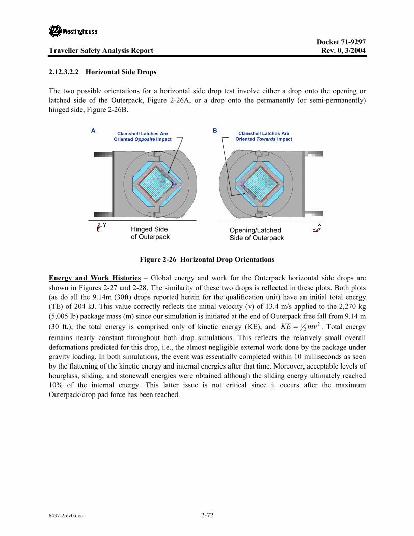
Docket 71-9297
Traveller Safety Analysis Report Rev. 0, 3/2004
6437-2rev0.doc 2-72
2.12.3.2.2 Horizontal Side Drops
The two possible orientations for a horizontal side drop test involve either a drop onto the opening or latched side of the Outerpack, Figure 2-26A, or a drop onto the permanently (or semi-permanently) hinged side, Figure 2-26B.
Opening/Latched Side of Overpack
Hinged Side of Overpack
Clamshell Latches Are Oriented Opposite Impact
Clamshell Latches Are Oriented Towards Impact
A B
Figure 2-26 Horizontal Drop Orientations
Energy and Work Histories – Global energy and work for the Outerpack horizontal side drops are shown in Figures 2-27 and 2-28. The similarity of these two drops is reflected in these plots. Both plots (as do all the 9.14m (30ft) drops reported herein for the qualification unit) have an initial total energy (TE) of 204 kJ. This value correctly reflects the initial velocity (v) of 13.4 m/s applied to the 2,270 kg (5,005 lb) package mass (m) since our simulation is initiated at the end of Outerpack free fall from 9.14 m (30 ft.); the total energy is comprised only of kinetic energy (KE), and 2
21 mvKE = . Total energy
remains nearly constant throughout both drop simulations. This reflects the relatively small overall deformations predicted for this drop, i.e., the almost negligible external work done by the package under gravity loading. In both simulations, the event was essentially completed within 10 milliseconds as seen by the flattening of the kinetic energy and internal energies after that time. Moreover, acceptable levels of hourglass, sliding, and stonewall energies were obtained although the sliding energy ultimately reached 10% of the internal energy. This latter issue is not critical since it occurs after the maximum Outerpack/drop pad force has been reached.
Hinged Side of Outerpack
Opening/Latched Side of Outerpack

Docket 71-9297
Traveller Safety Analysis Report Rev. 0, 3/2004
6437-2rev0.doc 2-73
p g ( )
Figure 2-27 Predicted Energy and Work for 9m Horizontal Drop Onto Outerpack Hinges
Figure 2-28 Predicted Energy and Work Histories for a 9m Horizontal Drop Onto the Outerpack Hinges

Docket 71-9297
Traveller Safety Analysis Report Rev. 0, 3/2004
6437-2rev0.doc 2-74
Rigid Wall Forces – Neglecting the very soft shock mounts that tie them together, the Traveller XL shipping package consists of an essentially de-coupled Outerpack and Clamshell/fuel pair. Indeed, the predicted drop scenario consists of the Outerpack crushing onto the pad while the Clamshell/fuel assembly continues falling until it hits the inner surfaces of the Outerpack. Then the Outerpack, Clamshell, and fuel assembly crush further onto the pad. This scenario is reflected in the rigid wall force history shown in Figure 2-29.
14.8 MN
10.1 MN
Figure 2-29 Predicted Rigid Wall Force Histories for 9m Horizontal Drops Onto the Outerpack Latches and Hinges
In Figure 2-30A, the initial impact between the Outerpack and pad is seen in the first 4 milliseconds, peaking at approximately 1.5 milliseconds for the drop onto hinge (run QU_15) and 2.0 milliseconds for the drop onto latches (run QU_5). This disparity is attributed to slight errors in the model geometrical definition (rather than to any actual non-symmetry within the design itself). Further, we postulate resolution of this disparity would lower the predicted forces for the drop onto Outerpack latch simulation (run QU_5) and increase those for the simulated drop onto the Outerpack hinges (run QU_15). However, we choose not to resolve this difference but simply used the QU_5 predictions as a bounding and conservative case. At approximately 4.0 milliseconds, the force between the Outerpack and drop pad has decreased and it appears the Outerpack might soon rebound. However, the Clamshell/fuel assembly then contacts the inner surface of the Outerpack and drives it into back into the drop pad, Figure 2-30B.

Docket 71-9297
Traveller Safety Analysis Report Rev. 0, 3/2004
6437-2rev0.doc 2-75
B.
A.
First Impact is between Drop Pad and OP
Second Impact involves CS driving OP into Drop Pad
Figure 2-30 De-coupled Impacts for 9 m Horizontal Side Drop
The forces between the Outerpack and drop pad during the first portion of a horizontal side drop are the highest predicted forces for any orientations analyzed. However, these forces are so high because the deformations (i.e., cushioning) are small. Thus, despite the high forces, the package (Outerpack and Clamshell) should be relatively undamaged provided its components remain closed. For the Outerpack, this requires that the majority of the Outerpack latch/hinge bolts do not fail. In the case of the Clamshell, the latch bolts, the top and bottom end plate bolts, and, as will be described, the lipped/groove interfaces between the Clamshell end plates themselves (top end) and between the Clamshell doors and plate (bottom end) must not be comprised. During Prototype testing the robustness of these features was confirmed, as no Outerpack bolts failed, and the Clamshell latches remained closed.
Note that the Clamshell cross-sectional shape is predicted to stay essentially unchanged during the horizontal side drops, Figure 2-30. This is due in large part to the moderator blocks which form a “cradle” for the Clamshell. These moderator blocks prevent the Clamshell from radically changing shape as might otherwise happen since three of the Clamshell edges are either hinged or latched. This is an important structural benefit of the conformal shape of the interior of the Outerpack.
Outerpack Hinge Bolts – The Outerpack hinges are secured to the Outerpack with Type 304 stainless steel bolts, Figure 2-31. The bolts securing the bottom flange of the hinge (or latch) to the lower Outerpack are not removed during normal operation. Thus, the number of bolts used in this area is not critical from a user/operation standpoint. However, the bolts securing the top half of the latch to the upper Outerpack must be removed whenever the package is opened. Thus, the desire is to minimize the number

Docket 71-9297
Traveller Safety Analysis Report Rev. 0, 3/2004
6437-2rev0.doc 2-76
of these bolts while still insuring the package is not compromised during HAC drop tests. As such, the development of the Traveller XL design started with three 7/8" diameter (2.2 cm) for each hinge segment. A total of five (5) hinge segments per Outerpack side were utilized. The second Prototype unit therefore was tested with only 2 of 3 bolts in each hinge section (10 per side) to verify that design margins were present in the design.
Based on the successful testing of 10 bolts per side, evaluations were initiated to determine if smaller ¾" diameter (1.91 cm) bolts had sufficient strength to sustain impact loads. These were shown to be acceptable. The QTU-1 and QTU-2 units were dropped with ten ¾" (1.91 cm) bolts on each side.
Two ¾-10 SS bolts secure the top portion of the hinge/latch to the upper overpack (larger diameter bolts are shown)
Four 5/8-11 SS bolts secure the bottom portion of the hinge/latch to the lower overpack
Provision for a third bolt in the top hinge/latch flange
Figure 2-31 Bolts on Prototype Outerpack
Prototype-2, Test 3.3 was a side drop in which two 7/8-9 stainless steel bolts were used to secure the top portion of the hinge to the upper Outerpack and four 5/8-11 stainless steel bolts were used to secure the bottom hinge flange to the lower Outerpack. In this test, no bolts were broken. Our analyses indicate two ¾-10 stainless steel bolts/latch and hinge are sufficient to insure the Outerpack remains closed during the 9m side drop. This is seen by reviewing the predicted safety factors of the top latch bolts when the package is dropped on its latching side, Figure 2-26B. As shown in Table 2-10, the minimum factor-of-safety (FS) for the top Outerpack latch bolts was 2.15 based on the bolt minimum tensile (125 ksi). This minimum was calculated for a latch bolt when the Outerpack was dropped onto its latched side, Figure 2-26B.
Four 5/8-11 SS bolts secure the bottom portion of the hinge/latch to the lower outerpack

Docket 71-9297
Traveller Safety Analysis Report Rev. 0, 3/2004
6437-2rev0.doc 2-77
Table 2-10 Top Outerpack Latch Bolt Minimum Factors of Safety (FS) for 9m Side Dropped
FS/Time ID
(Figure 2-32) Dropped On OP Latches
(Figure 2-30B) Dropped On OP Hinges
(Figure 2-30A)
B917 2.22/0.0082 s 2.20/0.0077 s
B921 2.15/0.0065 s 2.21/0.0065 s
B923 2.16/0.0065 s 2.17/0.0065 s
B927 2.20/0.0062 s 2.18/0.0065 s
B929 2.19/0.0057 s 2.19/0.0062 s
B933 2.19/0.0067 s 2.20/0.0077 s
B935 2.20/0.0067 s 2.16/0.0065 s
B939 2.18/0.0065 s 2.18/0.0065 s
B941 2.21/0.0085 s 2.23/0.008 s
B945 2.32/0.0045 s 2.43/0.0045 s
Figure 2-32 Bolt Labels for Right Outerpack
Hinge bolt FS for horizontal 9m side drops on the latched and hinged side of the Outerpack are shown in Table 2-10. If the shipping package were exactly symmetrical, FS for the hinge bolts calculated for a drop on the Outerpack hinges would correspond with those for the latch bolts when the package was dropped onto the latches, etc. However, this was not the case as can be seen by comparing the results shown in Table 2-10 with those in Table 2-11. This small irregularity is primarily attributed to slight errors in the model geometrical definition and to a lesser extent on actual non-symmetry within the design itself. The analysis indicates little likelihood of compromising the Outerpack closure during a 9m side drop.
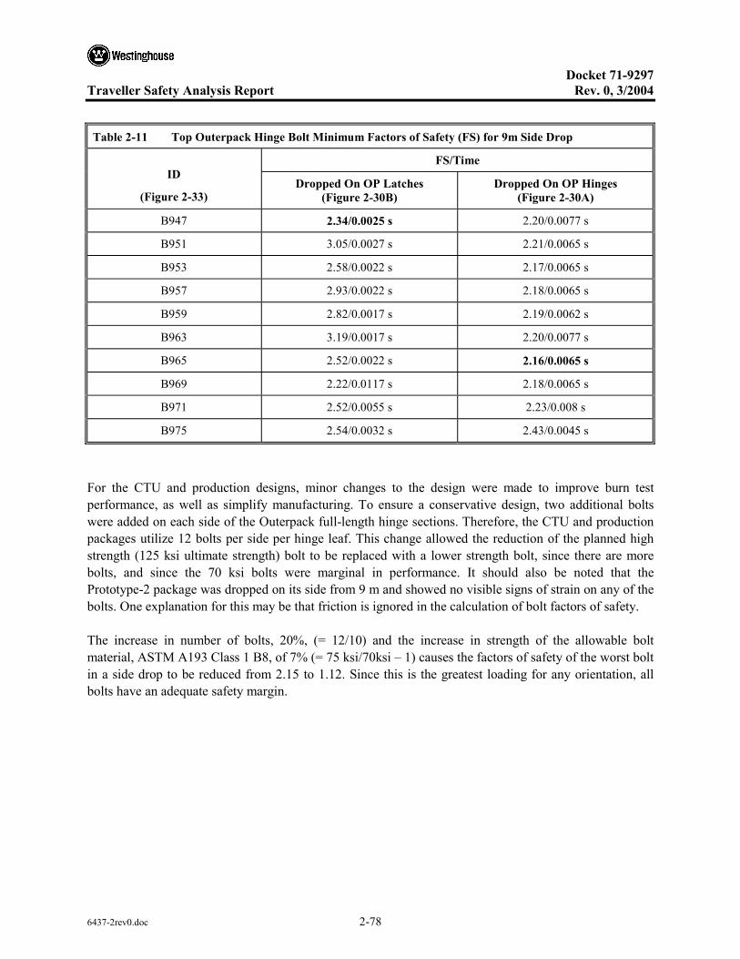
Docket 71-9297
Traveller Safety Analysis Report Rev. 0, 3/2004
6437-2rev0.doc 2-78
Table 2-11 Top Outerpack Hinge Bolt Minimum Factors of Safety (FS) for 9m Side Drop
FS/Time ID
(Figure 2-33) Dropped On OP Latches
(Figure 2-30B) Dropped On OP Hinges
(Figure 2-30A)
B947 2.34/0.0025 s 2.20/0.0077 s
B951 3.05/0.0027 s 2.21/0.0065 s
B953 2.58/0.0022 s 2.17/0.0065 s
B957 2.93/0.0022 s 2.18/0.0065 s
B959 2.82/0.0017 s 2.19/0.0062 s
B963 3.19/0.0017 s 2.20/0.0077 s
B965 2.52/0.0022 s 2.16/0.0065 s
B969 2.22/0.0117 s 2.18/0.0065 s
B971 2.52/0.0055 s 2.23/0.008 s
B975 2.54/0.0032 s 2.43/0.0045 s
For the CTU and production designs, minor changes to the design were made to improve burn test performance, as well as simplify manufacturing. To ensure a conservative design, two additional bolts were added on each side of the Outerpack full-length hinge sections. Therefore, the CTU and production packages utilize 12 bolts per side per hinge leaf. This change allowed the reduction of the planned high strength (125 ksi ultimate strength) bolt to be replaced with a lower strength bolt, since there are more bolts, and since the 70 ksi bolts were marginal in performance. It should also be noted that the Prototype-2 package was dropped on its side from 9 m and showed no visible signs of strain on any of the bolts. One explanation for this may be that friction is ignored in the calculation of bolt factors of safety.
The increase in number of bolts, 20%, (= 12/10) and the increase in strength of the allowable bolt material, ASTM A193 Class 1 B8, of 7% (= 75 ksi/70ksi – 1) causes the factors of safety of the worst bolt in a side drop to be reduced from 2.15 to 1.12. Since this is the greatest loading for any orientation, all bolts have an adequate safety margin.

Docket 71-9297
Traveller Safety Analysis Report Rev. 0, 3/2004
6437-2rev0.doc 2-79
Figure 2-33 Bolt Labels for Left Outerpack
Clamshell Keeper Bolts – The inner Clamshell is restrained during shipment by eleven (11) quarter-turn latches as shown in Figure 2-34. This design was incorporated after Prototype testing, primarily for improved handling characteristics. One half of the latch, the latch handle, is welded to the one Clamshell door hinge. The portion of the latches which is physically turned to allow opening and closing is attached to the opposite door is called the “keeper.” Each keeper is attached to the Clamshell door with ½-13 stainless steel bolts.
Factors-of-safety for the Clamshell keeper bolts are shown in Table 2-12. The analyses indicate that these bolts are unlikely to fail during side drops onto either the Outerpack latches or Outerpack hinges. Further, the modeling of the fuel assembly as a rigid structure likely makes little difference to these predictions since the fuel rods would not be expected to buckle in this drop orientation.
Figure 2-34 Clamshell Closure Latches and Keeper Bolts

Docket 71-9297
Traveller Safety Analysis Report Rev. 0, 3/2004
6437-2rev0.doc 2-80
Table 2-12 Clamshell Keeper Bolt Minimum Factors of Safety for 9m Side Drop
FS/Time ID
(Figure 2-35) Dropped On OP Latches
(Figure 2-30B) Dropped On OP Hinges
(Figure 2-30A)
B6271277 2.10/0.0067 s 1.72/0.006 s
B6271278 2.15/0.007 s 1.72/0.0085 s
B6271279 3.17/0.0062 s 3.36/0.0075 s
B6271280 2.12/0.0072 s 4.40/0.01 s
B6271281 2.90/0.008 s 4.03/0.0092 s
B6271282 2.50/0.0082 s 2.48/0.0067 s
B6271283 3.70/0.0055 s 2.16/0.0067 s
B6271284 2.56/0.007 s 1.84/0.0062 s
B6271285 1.93/0.0072 s 2.64/0.008 s
B6271286 2.62/0.0072 s 3.00/0.0082 s
B6271287 1.94/0.0075 s 2.29/0.0082 s
Figure 2-35 Clamshell Keeper Bolt Labels
Clamshell Top and Bottom Plate Bolts – In addition to the Clamshell latch bolts, there are thirty ½-13 stainless steel bolts securing the Clamshell top and bottom end plates. The twenty bolts securing the top end plate are distributed five per side as shown in Figure 2-36A. These bolts are not removed during normal operation and are permanently adhered to the plates. The ten bolts securing the bottom end plate are distributed equally to the two walls of the Clamshell V-shaped bottom extrusion as shown in Figure 2-36B. These bolts are also permanently adhered.
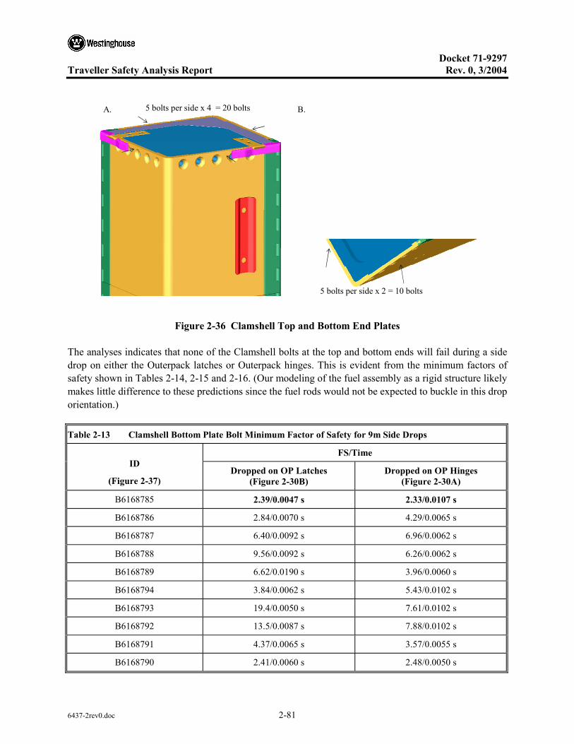
Docket 71-9297
Traveller Safety Analysis Report Rev. 0, 3/2004
6437-2rev0.doc 2-81
B.
5 bolts per side x 2 = 10 bolts
A. 5 bolts per side x 4 = 20 bolts
Figure 2-36 Clamshell Top and Bottom End Plates
The analyses indicates that none of the Clamshell bolts at the top and bottom ends will fail during a side drop on either the Outerpack latches or Outerpack hinges. This is evident from the minimum factors of safety shown in Tables 2-14, 2-15 and 2-16. (Our modeling of the fuel assembly as a rigid structure likely makes little difference to these predictions since the fuel rods would not be expected to buckle in this drop orientation.)
Table 2-13 Clamshell Bottom Plate Bolt Minimum Factor of Safety for 9m Side Drops
FS/Time ID
(Figure 2-37) Dropped on OP Latches
(Figure 2-30B) Dropped on OP Hinges
(Figure 2-30A)
B6168785 2.39/0.0047 s 2.33/0.0107 s
B6168786 2.84/0.0070 s 4.29/0.0065 s
B6168787 6.40/0.0092 s 6.96/0.0062 s
B6168788 9.56/0.0092 s 6.26/0.0062 s
B6168789 6.62/0.0190 s 3.96/0.0060 s
B6168794 3.84/0.0062 s 5.43/0.0102 s
B6168793 19.4/0.0050 s 7.61/0.0102 s
B6168792 13.5/0.0087 s 7.88/0.0102 s
B6168791 4.37/0.0065 s 3.57/0.0055 s
B6168790 2.41/0.0060 s 2.48/0.0050 s
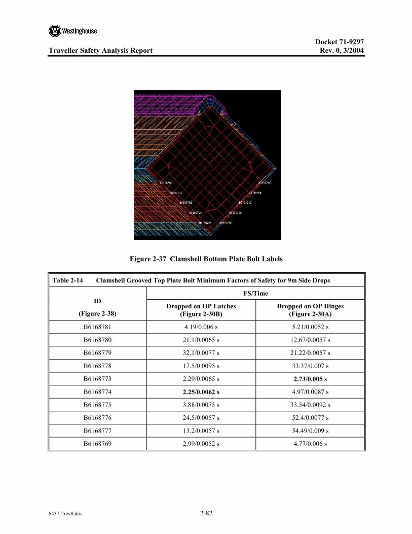
Docket 71-9297
Traveller Safety Analysis Report Rev. 0, 3/2004
6437-2rev0.doc 2-82
Figure 2-37 Clamshell Bottom Plate Bolt Labels
Table 2-14 Clamshell Grooved Top Plate Bolt Minimum Factors of Safety for 9m Side Drops
FS/Time ID
(Figure 2-38) Dropped on OP Latches
(Figure 2-30B) Dropped on OP Hinges
(Figure 2-30A)
B6168781 4.19/0.006 s 5.21/0.0052 s
B6168780 21.1/0.0065 s 12.67/0.0057 s
B6168779 32.1/0.0077 s 21.22/0.0057 s
B6168778 17.5/0.0095 s 33.37/0.007 s
B6168773 2.29/0.0065 s 2.73/0.005 s
B6168774 2.25/0.0062 s 4.97/0.0087 s
B6168775 3.88/0.0075 s 33.54/0.0092 s
B6168776 24.5/0.0057 s 52.4/0.0077 s
B6168777 13.2/0.0057 s 54.49/0.009 s
B6168769 2.99/0.0052 s 4.77/0.006 s
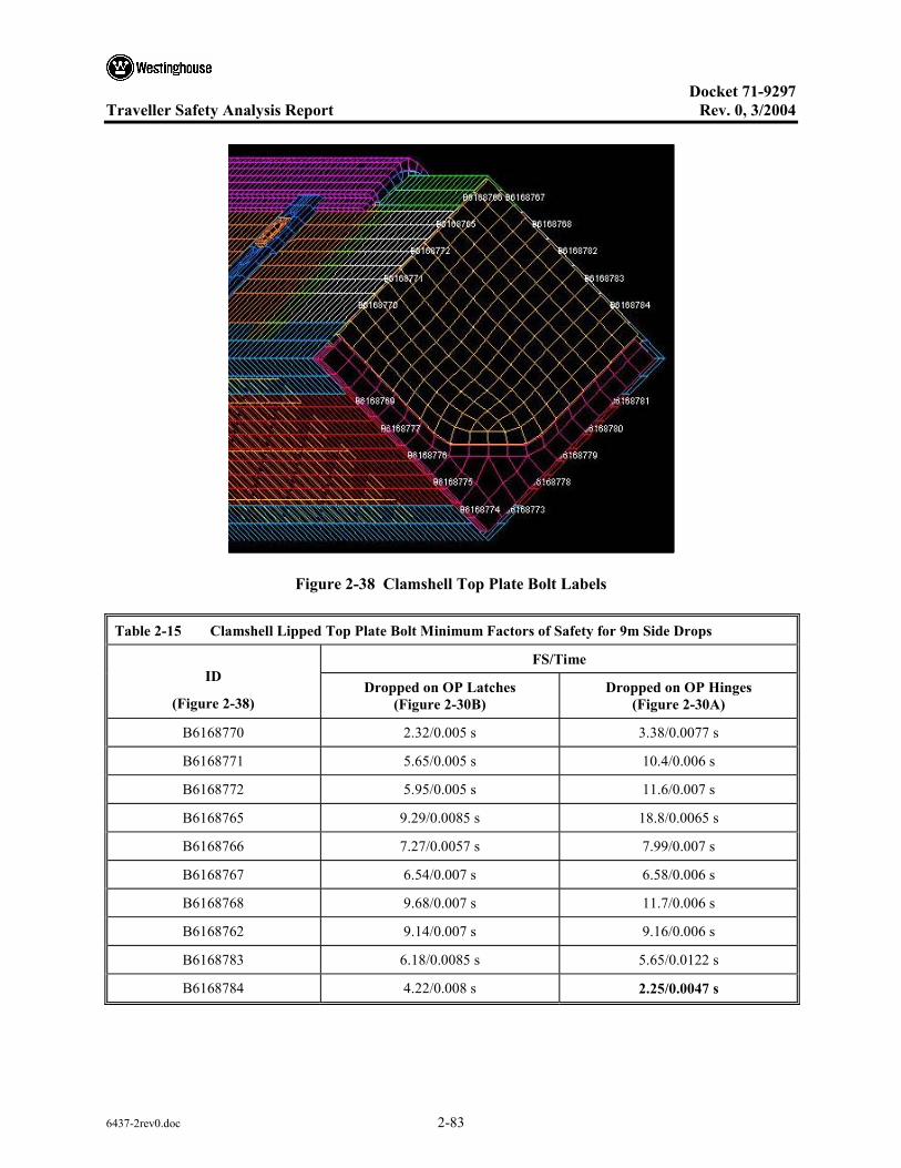
Docket 71-9297
Traveller Safety Analysis Report Rev. 0, 3/2004
6437-2rev0.doc 2-83
Figure 2-38 Clamshell Top Plate Bolt Labels
Table 2-15 Clamshell Lipped Top Plate Bolt Minimum Factors of Safety for 9m Side Drops
FS/Time ID
(Figure 2-38) Dropped on OP Latches
(Figure 2-30B) Dropped on OP Hinges
(Figure 2-30A)
B6168770 2.32/0.005 s 3.38/0.0077 s
B6168771 5.65/0.005 s 10.4/0.006 s
B6168772 5.95/0.005 s 11.6/0.007 s
B6168765 9.29/0.0085 s 18.8/0.0065 s
B6168766 7.27/0.0057 s 7.99/0.007 s
B6168767 6.54/0.007 s 6.58/0.006 s
B6168768 9.68/0.007 s 11.7/0.006 s
B6168762 9.14/0.007 s 9.16/0.006 s
B6168783 6.18/0.0085 s 5.65/0.0122 s
B6168784 4.22/0.008 s 2.25/0.0047 s
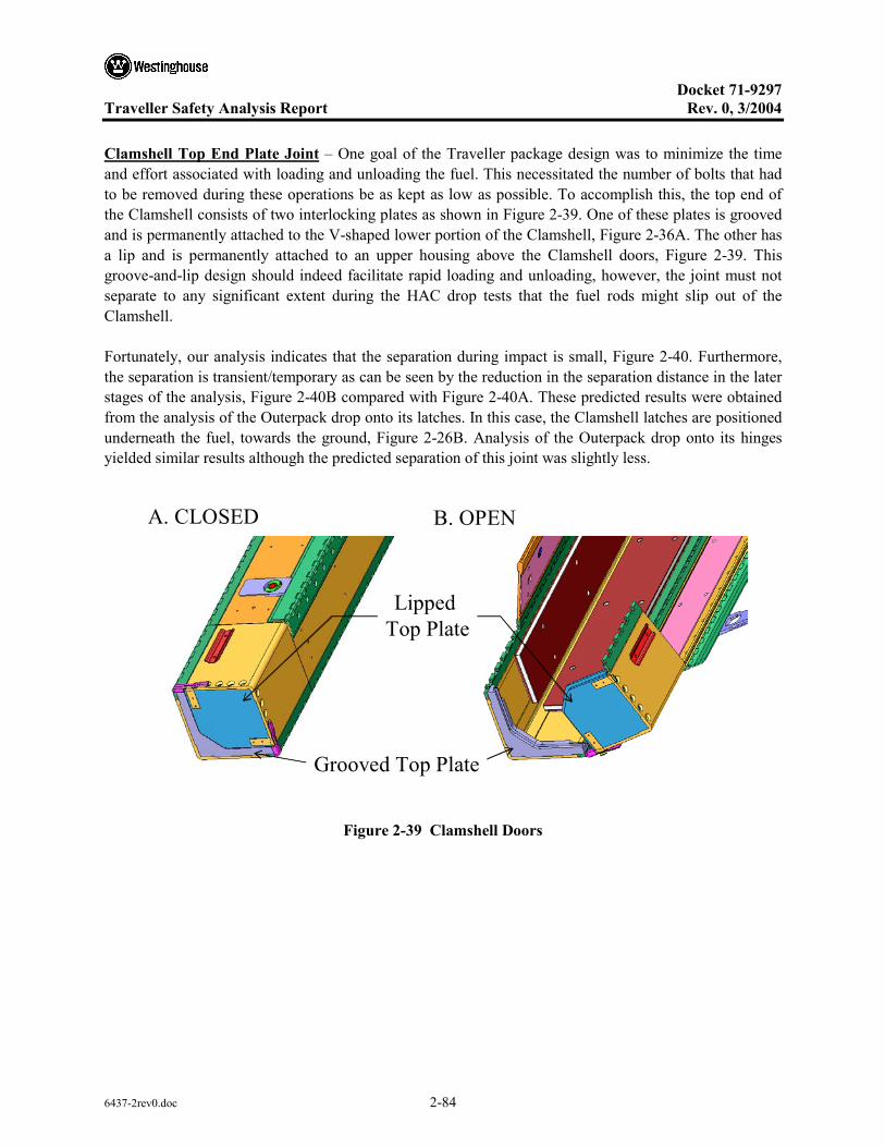
Docket 71-9297
Traveller Safety Analysis Report Rev. 0, 3/2004
6437-2rev0.doc 2-84
Clamshell Top End Plate Joint – One goal of the Traveller package design was to minimize the time and effort associated with loading and unloading the fuel. This necessitated the number of bolts that had to be removed during these operations be as kept as low as possible. To accomplish this, the top end of the Clamshell consists of two interlocking plates as shown in Figure 2-39. One of these plates is grooved and is permanently attached to the V-shaped lower portion of the Clamshell, Figure 2-36A. The other has a lip and is permanently attached to an upper housing above the Clamshell doors, Figure 2-39. This groove-and-lip design should indeed facilitate rapid loading and unloading, however, the joint must not separate to any significant extent during the HAC drop tests that the fuel rods might slip out of the Clamshell.
Fortunately, our analysis indicates that the separation during impact is small, Figure 2-40. Furthermore, the separation is transient/temporary as can be seen by the reduction in the separation distance in the later stages of the analysis, Figure 2-40B compared with Figure 2-40A. These predicted results were obtained from the analysis of the Outerpack drop onto its latches. In this case, the Clamshell latches are positioned underneath the fuel, towards the ground, Figure 2-26B. Analysis of the Outerpack drop onto its hinges yielded similar results although the predicted separation of this joint was slightly less.
B. OPENA. CLOSED
Grooved Top Plate
Lipped Top Plate
Figure 2-39 Clamshell Doors
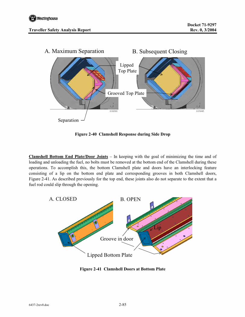
Docket 71-9297
Traveller Safety Analysis Report Rev. 0, 3/2004
6437-2rev0.doc 2-85
B. Subsequent ClosingA. Maximum Separation
Grooved Top Plate
Lipped Top Plate
Separation
Figure 2-40 Clamshell Response during Side Drop
Clamshell Bottom End Plate/Door Joints – In keeping with the goal of minimizing the time and of loading and unloading the fuel, no bolts must be removed at the bottom end of the Clamshell during these operations. To accomplish this, the bottom Clamshell plate and doors have an interlocking feature consisting of a lip on the bottom end plate and corresponding grooves in both Clamshell doors, Figure 2-41. As described previously for the top end, these joints also do not separate to the extent that a fuel rod could slip through the opening.
B. OPENA. CLOSED
Lip
Groove in door
Lipped Bottom Plate
Figure 2-41 Clamshell Doors at Bottom Plate

Docket 71-9297
Traveller Safety Analysis Report Rev. 0, 3/2004
6437-2rev0.doc 2-86
A small separation of one of these joint during impact is predicted, Figure 2-42. Because the separation is at the upper joint is small, it is not possible that a fuel rod could slip through this joint. Furthermore, the other joint is predicted to remain closed and the bottom end plate should remain intact. These predicted results were obtained from the analysis of the Outerpack drop onto its latches. In this case, the Clamshell latches are positioned underneath the fuel, towards the ground, Figure 2-26B. As with the joint at the top Clamshell plate, the predicted separation of this joint was slightly less for a drop onto the Outerpack hinges.
B. 19.4 millisecondsA. 11 milliseconds
Lip onBottom Plate
SeparationGrooved
Doors Separation
Figure 2-42 Predicted Response of Clamshell Bottom Plate and Doors During 9m Horizontal Drop onto Outerpack Latches
2.12.3.2.3 “CG-over-Corner” and “CG-forward-of-Corner” Drops onto Top Nozzle End of Package
As indicated in Figure 2-43, almost vertical orientations may result in the package center of gravity (CG) being positioned directly above the impacting corner of the package. When this occurs, the drop is designated as a “CG-over-corner” impact. In a CG-over-corner impact, the shipping package will initially continue translating in the direction of impact without rotating. However, deformation of the impacted corner may eventually result in the package tilting and falling over.
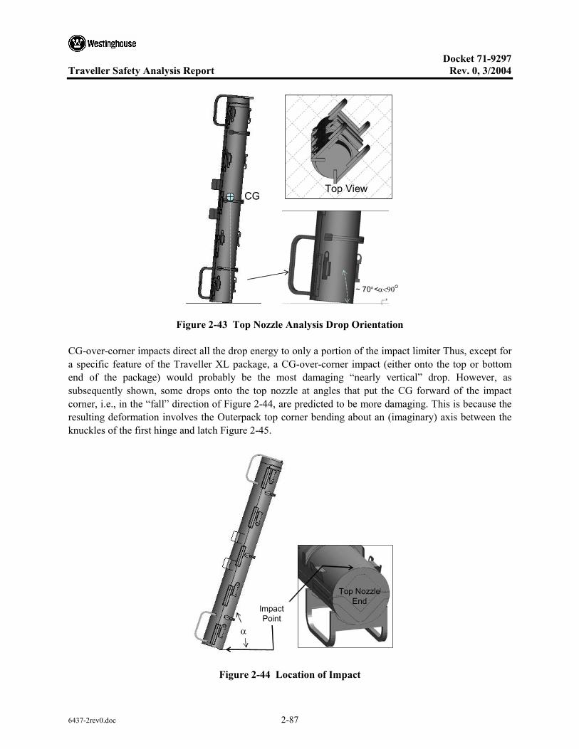
Docket 71-9297
Traveller Safety Analysis Report Rev. 0, 3/2004
6437-2rev0.doc 2-87
Top ViewCG
~ 70°<α<90°
Figure 2-43 Top Nozzle Analysis Drop Orientation
CG-over-corner impacts direct all the drop energy to only a portion of the impact limiter Thus, except for a specific feature of the Traveller XL package, a CG-over-corner impact (either onto the top or bottom end of the package) would probably be the most damaging “nearly vertical” drop. However, as subsequently shown, some drops onto the top nozzle at angles that put the CG forward of the impact corner, i.e., in the “fall” direction of Figure 2-44, are predicted to be more damaging. This is because the resulting deformation involves the Outerpack top corner bending about an (imaginary) axis between the knuckles of the first hinge and latch Figure 2-45.
Top Nozzle End
Impact Point
α
Figure 2-44 Location of Impact

Docket 71-9297
Traveller Safety Analysis Report Rev. 0, 3/2004
6437-2rev0.doc 2-88
Pivot Axis
FallDirection
Note: the package is shown falling in a “forward” direction.
Figure 2-45 Damage to Outerpack During Angled Drop onto Top Nozzle End of Package
The most damaging drop orientation for the Outerpack is a top nozzle down, CG-forward-of-corner configuration having an 18° rotation (α=72°), see Figure 2-44. With smaller rotations, the detrimental opening of the Outerpack seam is predicted to be less despite a greater amount of energy being absorbed by the impact limiter. This is because portions of both the upper and lower Outerpack assemblies contact the drop pad and this significantly reduces their relative motion. With larger rotations, Outerpack seam opening is also predicted to be less. This is because the pivot axis moves well in front of the hinge knuckles in Figures 2-45 and 2-46.
Pivot Axis
FallDirection
Note: the package is shown falling in a “forward” direction.
Figure 2-46 Predicted Deformation of Outerpack Top Nozzle Impact Limiter
For the subsequent 1 meter pin puncture drop, the premise is that this is the worst possible additional damage for the Outerpack seam to be further opened. Thus, the most damaging pin puncture orientation following a CG-forward-of-corner test is clearly one where the damaged face of the Outerpack is
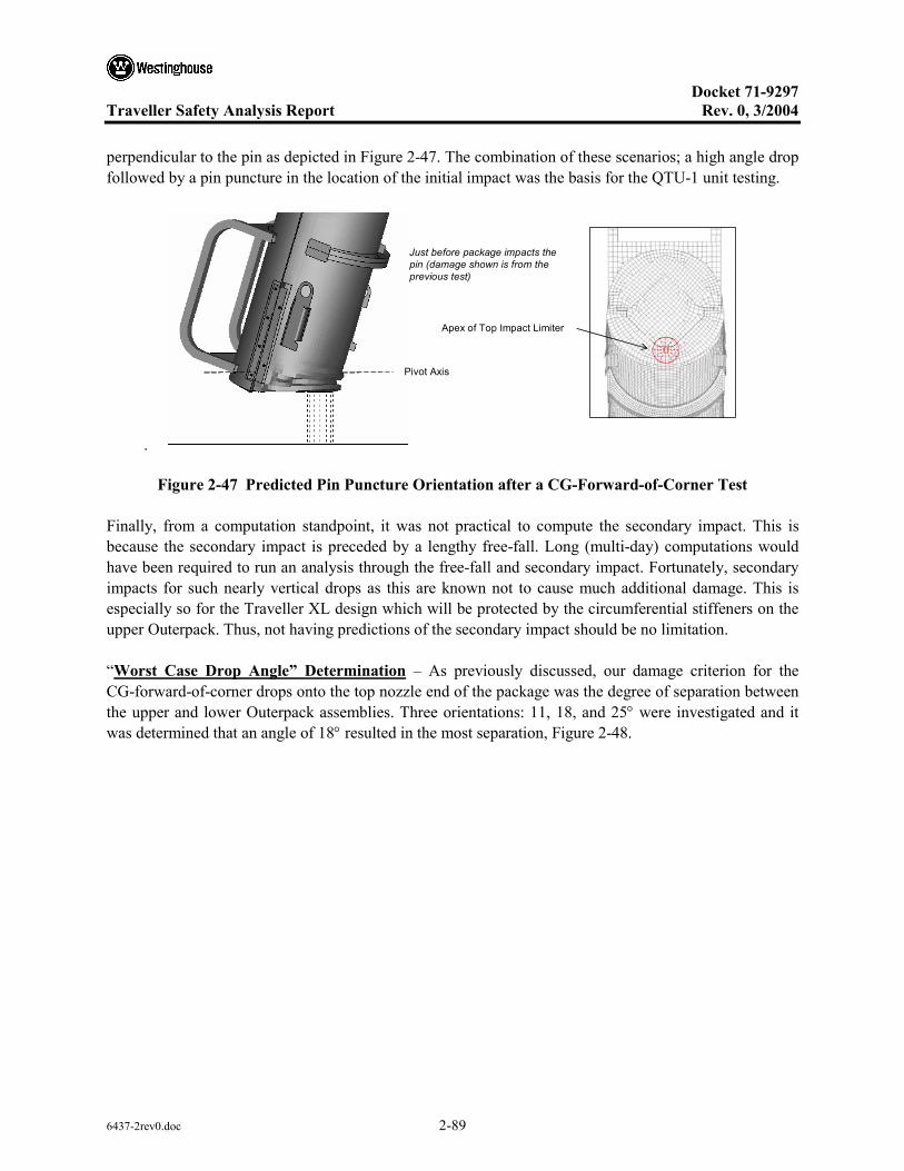
Docket 71-9297
Traveller Safety Analysis Report Rev. 0, 3/2004
6437-2rev0.doc 2-89
perpendicular to the pin as depicted in Figure 2-47. The combination of these scenarios; a high angle drop followed by a pin puncture in the location of the initial impact was the basis for the QTU-1 unit testing.
.
Pivot Axis
Just before package impacts the pin (damage shown is from the previous test)
Apex of Top Impact Limiter
Figure 2-47 Predicted Pin Puncture Orientation after a CG-Forward-of-Corner Test
Finally, from a computation standpoint, it was not practical to compute the secondary impact. This is because the secondary impact is preceded by a lengthy free-fall. Long (multi-day) computations would have been required to run an analysis through the free-fall and secondary impact. Fortunately, secondary impacts for such nearly vertical drops as this are known not to cause much additional damage. This is especially so for the Traveller XL design which will be protected by the circumferential stiffeners on the upper Outerpack. Thus, not having predictions of the secondary impact should be no limitation.
“Worst Case Drop Angle” Determination – As previously discussed, our damage criterion for the CG-forward-of-corner drops onto the top nozzle end of the package was the degree of separation between the upper and lower Outerpack assemblies. Three orientations: 11, 18, and 25° were investigated and it was determined that an angle of 18° resulted in the most separation, Figure 2-48.

Docket 71-9297
Traveller Safety Analysis Report Rev. 0, 3/2004
6437-2rev0.doc 2-90
D16 mm - 11°
20 mm - 18°18 mm - 25°
D213 mm - 11°20 mm - 18°16 mm - 25°
0
5
10
15
20
25
10 15 20 25
Rotation Angle [°]
Dim
ensi
on D
1 [m
m]
0
5
10
15
20
25
10 15 20 25
Rotation Angle [°]
Dim
ensi
on D
2 [m
m]
Note: These results do not include the effects of the 1 m pin puncture drop. Figure 2-48 Outerpack Top Separation vs. Drop Angle
Energy and Work Histories – Predicted global energy and work histories for the primary impact of three CG-forward-of-corner drops onto the top nozzle end of the package are shown in Figure 2-49. These plots were obtained for forward rotations of 11, 18, and 25°, respectively. As before, the initial total energy (TE) of 204 kJ and increases slightly during the run in concert with the external work due to gravity. In each of these plots, the internal energy (IE) and kinetic energy (KE) traces become flat between 50-60 milliseconds into the impact event. This indicates completion of the primary impact and initiation of rollover. (Rollover and secondary impact were not numerically investigated as previously justified.) Note as drop rotation angle decreases, the internal energy absorbed by the Outerpack is predicted to increase. However, as explained earlier, this should not result in the largest Outerpack seam opening. Finally, hourglass, sliding and stonewall energies are low in each plot. This indicates overall numerically sound analyses. However, late in the analysis, hourglass energy does reach 4.1% of the total energy. While this is a low percentage, the hourglass error is concentrated in the XL pins (PID 10764) and the Clamshell cushioning pads (PIDS 2003 and 2013) in the vicinity of impact. An investigation of this error which involved using fully integrated elements found the energy previously dissipated as hourglass deformation was now (correctly) forced into the bottom impact limiter. This had only a marginal effect on the predicted force in the primary impact of Figure 2-50 and Figure 2-62. However, it did reduce predicted FA accelerations by about 17% (from the 47.3 g’s shown in Figure 2-63 to 39.3 g’s.). This latter effect was not significant enough to change any conclusions within the report.

Docket 71-9297
Traveller Safety Analysis Report Rev. 0, 3/2004
6437-2rev0.doc 2-91
5.7 kJ
173 kJ
Rotated 11° (Run QU-39)
26 kJ
153 kJ
Rotated 18° (Run QU-29)
48.6 kJ
140 kJ
Rotated 25° (Run QU-49)
Figure 2-49 Predicted Energy and Work Histories for 9 m CG-over-Corner Drop onto the Top Nozzle End at Various Angles

Docket 71-9297
Traveller Safety Analysis Report Rev. 0, 3/2004
6437-2rev0.doc 2-92
Rigid Wall Forces – The predicted rigid wall force histories are shown in Figure 2-50 for CG-forward-of-corner drops on to the top end of the package rotated 11, 18, and 25°. These plots show only the primary impact (since the secondary impact due to fall-over was not calculated). The primary impact is divided into two separate events. From impact onset to approximately 25 milliseconds, the Outerpack impacts the drop pad while the Clamshell is still in free-fall. (This is due to the de-coupling between Outerpack and Clamshell previously discussed in section 2.1.1.1.1.) Secondly, the Clamshell hits the inner surfaces of the Outerpack and drives it back into the drop pad from approximately 25 milliseconds into the impact until about 70 milliseconds. Figure 2-50 shows the highest predicted loads for the Outerpack in these three orientations will be encountered at an 11° rotation. This agrees with the previous prediction that as drop rotation angle decreases, the internal energy absorbed by the Outerpack increases.
p g ( )
Figure 2-50 Predicted Rigid Wall Forces
As previously stated, the primary concern with CG-forward-of-corner drops onto the top nozzle end of the package is whether or not the thermal integrity needed to protect against the 30 min burn test will be compromised. It was shown that the deformation most likely to induce such damage is greatest when the Traveller XL package is rotated approx. 18° forward from a vertical orientation Figure 2-48. The main concern with the higher loads sustained and additional energy absorbed by the Outerpack at smaller rotation angles is if this jeopardized the Outerpack bolts. This issue is addressed in the following section.
Outerpack Hinge/Latch Bolts – The analysis indicates there is little likelihood of the Outerpack latch and hinge top bolts failing during a 9m CG-forward-of-corner drop onto the top end of the package. This is evident from the relatively high predicted factors of safety for these bolts, Tables 2-16 and 2-17.

Docket 71-9297
Traveller Safety Analysis Report Rev. 0, 3/2004
6437-2rev0.doc 2-93
Table 2-16 Top Outerpack Latch Bolt Minimum Factors of Safety for 9m CB-Forward of Corner Drops
FS/Time ID
(Figure 32) 11° Forward Rotation 18° Forward Rotation 25° Forward Rotation
B917 3.80/0.0143 s 7.57/0.0102 s 5.08/0.0105 s
B921 3.94/0.014 s 6.89/0.0247 s 6.19/0.0102 s
B923 3.10/0.0225 s 2.63/0.0245 s 3.87/0.0245 s
B927 3.28/0.0227 s 2.70/0.0247 s 4.04/0.0262 s
B929 2.61/0.012 s 2.29/0.0112 s 2.36/0.0147 s
B933 2.45/0.0065 s 2.25/0.0112 s 2.38/0.0147 s
B935 2.22/0.0117 s 2.22/0.0072 s 2.22/0.008 s
B939 2.22/0.0117 s 2.22/0.0072 s 2.22/0.0075 s
B941 2.23/0.0032 s 2.23/0.0052 s 2.23/0.0057 s
B945 2.22/0.0057 s 2.23/0.0077 s 2.23/0.0097 s
Table 2-17 Top Outerpack Hinge Bolt Minimum Factors of Safety for 9m CB Forward of Corner Drops
FS/Time ID
(Figure 33) 11° Forward Rotation 18° Forward Rotation 25° Forward Rotation
B947 3.59/0.014 s 6.37/0.0337 s 5.13/0.0105 s
B951 3.73/0.014 s 7.49/0.0232 s 6.17/0.0135 s
B953 2.95/0.0225 s 3.04/0.0245 s 4.19/0.0322 s
B957 3.19/0.0225 s 3.26/0.0245 s 4.30/0.0322 s
B959 2.65/0.0065 s 2.32/0.0115 s 2.34/0.0147 s
B963 2.51/0.0065 s 2.27/0.011 s 2.40/0.0122 s
B965 2.21/0.0062 s 2.21/0.0243 s 2.21/0.0077 s
B969 2.22/0.006 s 2.21/0.0235 s 2.23/0.0072 s
B971 2.20/0.006 s 2.20/0.0095 s 2.20/0.0110 s
B975 2.22/0.0055 s 2.23/0.0072 s 2.23/0.0077 s
It should also be noted that the latch and hinge bolts nearest impact were predicted to have the smallest (although still very adequate) safety factors. This is logical.

Docket 71-9297
Traveller Safety Analysis Report Rev. 0, 3/2004
6437-2rev0.doc 2-94
Clamshell Keeper Bolts – Our analysis indicates there is little likelihood of the Clamshell keeper bolts failing during a 9m CG-forward-of-corner drop onto the top nozzle end of the package. This is evident from the relatively high predicted factors of safety for these bolts, Table 2-18.
Table 2-18 Clamshell Keeper Bolt Minimum Factors of Safety for 9m CG-Forward-of-Corner Drops
FS/Time ID
(Figure 35) 11° Forward Rotation 18° Forward Rotation 25° Forward Rotation
B6271277 5.86/0.0255 s 8.71/0.038 s 10.86/0.0237 s
B6271278 5.75/0.027 s 4.79/0.0285 s 4.43/0.0277 s
B6271279 22.6/0.029 s 8.46/0.0287 s 6.63/0.0237 s
B6271280 17.4/0.0258 s 10.89/0.026 s 3.29/0.0225 s
B6271281 13.38/0.023 s 12.31/0.0522 s 7.96/0.024 s
B6271282 19.48/0.0455 s 8.13/0.0375 s 8.85/0.0282 s
B6271283 16.85/0.0207 s 5.41/0.0332 s 5.78/0.0258 s
B6271284 33.54/0.0285 s 8.89/0.0392 s 7.3/0.0252 s
B6271285 17.56/0.0405 s 11.32/0.0132 s 11.69/0.0197 s
B6271286 14.73/0.016 s 9.67/0.0415 s 8.09/0.024 s
It should be noted that the keeper bolt nearest impact was predicted to have the smallest (although still very adequate) safety factor.
Clamshell Top and Bottom Plate Bolts – The analyses indicate that none of the Clamshell bolts at the top and bottom ends will fail during a 9m CG-forward-of-corner drop onto the top nozzle end of the package. This is evident from the minimum factors of safety shown in Tables 2-19, 2-20 and 2-21. (The modeling of the fuel assembly as a rigid structure likely makes little difference to these predictions since the fuel rods would not be expected to buckle in this drop orientation.)
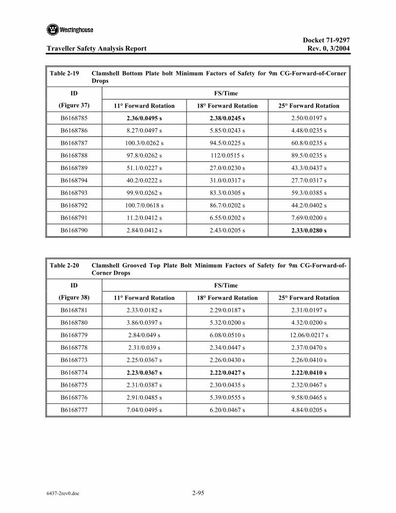
Docket 71-9297
Traveller Safety Analysis Report Rev. 0, 3/2004
6437-2rev0.doc 2-95
Table 2-19 Clamshell Bottom Plate bolt Minimum Factors of Safety for 9m CG-Forward-of-Corner
Drops
FS/Time ID
(Figure 37) 11° Forward Rotation 18° Forward Rotation 25° Forward Rotation
B6168785 2.36/0.0495 s 2.38/0.0245 s 2.50/0.0197 s
B6168786 8.27/0.0497 s 5.85/0.0243 s 4.48/0.0235 s
B6168787 100.3/0.0262 s 94.5/0.0225 s 60.8/0.0235 s
B6168788 97.8/0.0262 s 112/0.0515 s 89.5/0.0235 s
B6168789 51.1/0.0227 s 27.0/0.0230 s 43.3/0.0437 s
B6168794 40.2/0.0222 s 31.0/0.0317 s 27.7/0.0317 s
B6168793 99.9/0.0262 s 83.3/0.0305 s 59.3/0.0385 s
B6168792 100.7/0.0618 s 86.7/0.0202 s 44.2/0.0402 s
B6168791 11.2/0.0412 s 6.55/0.0202 s 7.69/0.0200 s
B6168790 2.84/0.0412 s 2.43/0.0205 s 2.33/0.0280 s
Table 2-20 Clamshell Grooved Top Plate Bolt Minimum Factors of Safety for 9m CG-Forward-of-
Corner Drops
FS/Time ID
(Figure 38) 11° Forward Rotation 18° Forward Rotation 25° Forward Rotation
B6168781 2.33/0.0182 s 2.29/0.0187 s 2.31/0.0197 s
B6168780 3.86/0.0397 s 5.32/0.0200 s 4.32/0.0200 s
B6168779 2.84/0.049 s 6.08/0.0510 s 12.06/0.0217 s
B6168778 2.31/0.039 s 2.34/0.0447 s 2.37/0.0470 s
B6168773 2.25/0.0367 s 2.26/0.0430 s 2.26/0.0410 s
B6168774 2.23/0.0367 s 2.22/0.0427 s 2.22/0.0410 s
B6168775 2.31/0.0387 s 2.30/0.0435 s 2.32/0.0467 s
B6168776 2.91/0.0485 s 5.39/0.0555 s 9.58/0.0465 s
B6168777 7.04/0.0495 s 6.20/0.0467 s 4.84/0.0205 s

Docket 71-9297
Traveller Safety Analysis Report Rev. 0, 3/2004
6437-2rev0.doc 2-96
Table 2-21 Clamshell Lipped Top Plate Bolt Minimum Factors of Safety for 9m CG-Forward-of-
Corner Drops
FS/Time ID
(Figure 38) 11° Forward Rotation 18° Forward Rotation 25° Forward Rotation
B6168770 1.76/0.0165 s 1.81/0.0180 s 1.77/0.0195 s
B6168771 1.79/0.0207 s 1.77/0.0177 s 1.75/0.0197 s
B6168772 1.78/0.0360 s 1.76/0.0477 s 1.80/0.0117 s
B6168765 1.76/0.0350 s 1.76/0.0170 s 1.73/0.0135 s
B6168766 1.77/0.0125 s 1.77/0.0150 s 1.72/0.0125 s
B6168767 1.78/0.0200 s 1.75/0.0150 s 1.72/0.0127 s
B6168768 1.77/0.0362 s 1.76/0.0152 s 1.76/0.0277 s
B6168762 1.76/0.0362 s 1.77/0.0510 s 1.76/0.0187 s
B6168783 1.77/0.0192 s 1.77/0.0155 s 1.77/0.0202 s
Clamshell Top End Plate Joint – The analyses indicate the Clamshell top end plate joint (Figure 2-39) will separate slightly, but not come completely apart during CG-forward-of-corner impacts. In particular, the lip on the top plate is predicted to remain within the groove in the V-shaped top plate along both edges but slip completely out in the middle. This is shown in Figure 2-51 for the CG-forward-of-corner drop rotated 11°. It should be noted that this separation is predicted to be permanent, not transient. It should also be noted that predicted deformations were similar but lesser for CG-forward-of-corner drops rotated 18° and 25°. However, in these latter two orientations, the lip on the top plate is predicted to remain within the groove in the V-shaped top plate along its entire length. This extent of deformation was not observed in full-scale testing of Traveller XL prototypes and is therefore conservative.
Complete separation at 11° rotation(Minimal overlap at 18° and 25°)
Grooved Top Plate
Lipped Top Plate
Overlap
A
A
OverlapSection A-A
Figure 2-51 Clamshell Top Plate Geometry
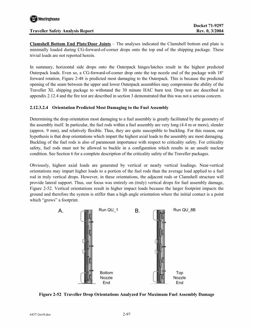
Docket 71-9297
Traveller Safety Analysis Report Rev. 0, 3/2004
6437-2rev0.doc 2-97
Clamshell Bottom End Plate/Door Joints – The analyses indicated the Clamshell bottom end plate is minimally loaded during CG-forward-of-corner drops onto the top end of the shipping package. These trivial loads are not reported herein.
In summary, horizontal side drops onto the Outerpack hinges/latches result in the highest predicted Outerpack loads. Even so, a CG-forward-of-corner drop onto the top nozzle end of the package with 18° forward rotation, Figure 2-48 is predicted most damaging to the Outerpack. This is because the predicted opening of the seam between the upper and lower Outerpack assemblies may compromise the ability of the Traveller XL shipping package to withstand the 30 minute HAC burn test. Drop test are described in appendix 2.12.4 and the fire test are described in section 3 demonstrated that this was not a serious concern.
2.12.3.2.4 Orientation Predicted Most Damaging to the Fuel Assembly
Determining the drop orientation most damaging to a fuel assembly is greatly facilitated by the geometry of the assembly itself. In particular, the fuel rods within a fuel assembly are very long (4.4 m or more), slender (approx. 9 mm), and relatively flexible. Thus, they are quite susceptible to buckling. For this reason, our hypothesis is that drop orientations which impart the highest axial loads to the assembly are most damaging. Buckling of the fuel rods is also of paramount importance with respect to criticality safety. For criticality safety, fuel rods must not be allowed to buckle in a configuration which results in an unsafe nuclear condition. See Section 6 for a complete description of the criticality safety of the Traveller packages.
Obviously, highest axial loads are generated by vertical or nearly vertical loadings. Near-vertical orientations may impart higher loads to a portion of the fuel rods than the average load applied to a fuel rod in truly vertical drops. However, in these orientations, the adjacent rods or Clamshell structure will provide lateral support. Thus, our focus was entirely on (truly) vertical drops for fuel assembly damage, Figure 2-52. Vertical orientations result in higher impact loads because the larger footprint impacts the ground and therefore the system is stiffer than a high angle orientation where the initial contact is a point which “grows” a footprint.
Run QU_1
Bottom Nozzle
End
Run QU_8BA. B.
TopNozzle
End
Figure 2-52 Traveller Drop Orientations Analyzed For Maximum Fuel Assembly Damage
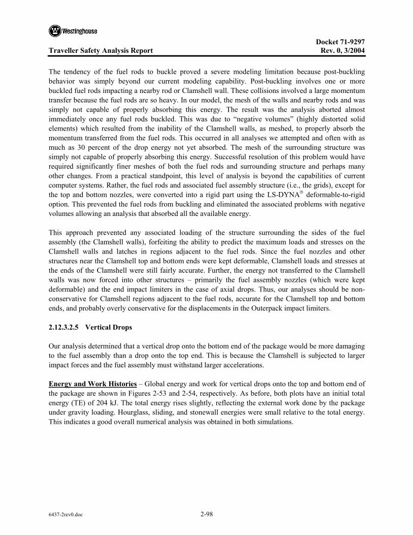
Docket 71-9297
Traveller Safety Analysis Report Rev. 0, 3/2004
6437-2rev0.doc 2-98
The tendency of the fuel rods to buckle proved a severe modeling limitation because post-buckling behavior was simply beyond our current modeling capability. Post-buckling involves one or more buckled fuel rods impacting a nearby rod or Clamshell wall. These collisions involved a large momentum transfer because the fuel rods are so heavy. In our model, the mesh of the walls and nearby rods and was simply not capable of properly absorbing this energy. The result was the analysis aborted almost immediately once any fuel rods buckled. This was due to “negative volumes” (highly distorted solid elements) which resulted from the inability of the Clamshell walls, as meshed, to properly absorb the momentum transferred from the fuel rods. This occurred in all analyses we attempted and often with as much as 30 percent of the drop energy not yet absorbed. The mesh of the surrounding structure was simply not capable of properly absorbing this energy. Successful resolution of this problem would have required significantly finer meshes of both the fuel rods and surrounding structure and perhaps many other changes. From a practical standpoint, this level of analysis is beyond the capabilities of current computer systems. Rather, the fuel rods and associated fuel assembly structure (i.e., the grids), except for the top and bottom nozzles, were converted into a rigid part using the LS-DYNA deformable-to-rigid option. This prevented the fuel rods from buckling and eliminated the associated problems with negative volumes allowing an analysis that absorbed all the available energy.
This approach prevented any associated loading of the structure surrounding the sides of the fuel assembly (the Clamshell walls), forfeiting the ability to predict the maximum loads and stresses on the Clamshell walls and latches in regions adjacent to the fuel rods. Since the fuel nozzles and other structures near the Clamshell top and bottom ends were kept deformable, Clamshell loads and stresses at the ends of the Clamshell were still fairly accurate. Further, the energy not transferred to the Clamshell walls was now forced into other structures – primarily the fuel assembly nozzles (which were kept deformable) and the end impact limiters in the case of axial drops. Thus, our analyses should be non-conservative for Clamshell regions adjacent to the fuel rods, accurate for the Clamshell top and bottom ends, and probably overly conservative for the displacements in the Outerpack impact limiters.
2.12.3.2.5 Vertical Drops
Our analysis determined that a vertical drop onto the bottom end of the package would be more damaging to the fuel assembly than a drop onto the top end. This is because the Clamshell is subjected to larger impact forces and the fuel assembly must withstand larger accelerations.
Energy and Work Histories – Global energy and work for vertical drops onto the top and bottom end of the package are shown in Figures 2-53 and 2-54, respectively. As before, both plots have an initial total energy (TE) of 204 kJ. The total energy rises slightly, reflecting the external work done by the package under gravity loading. Hourglass, sliding, and stonewall energies were small relative to the total energy. This indicates a good overall numerical analysis was obtained in both simulations.

Docket 71-9297
Traveller Safety Analysis Report Rev. 0, 3/2004
6437-2rev0.doc 2-99
Figure 2-53 Predicted Energy and Work Histories for a 9m Vertical Drop Onto the Top Nozzle End of the Package
g ( )
Figure 2-54 Predicted Energy and Work Histories for a 9m Vertical Drop Onto the Bottom Nozzle End of the Package
Rigid Wall Forces – Predicted force histories between Outerpack and drop pad are shown in Figure 2-50 for top and bottom end vertical drops. The near de-coupling of the Clamshell and Outerpack is clearly evident in both simulations. In the drop onto the bottom end of the package, the initial impact between

Docket 71-9297
Traveller Safety Analysis Report Rev. 0, 3/2004
6437-2rev0.doc 2-100
Outerpack and drop pad has a 12 milliseconds (approx.) duration. The Clamshell is not involved in this impact as it is still in free-fall (neglecting the small forces of the shock mounts.) At approximately 15 milliseconds into the simulation, the Clamshell contacts the inner surface of the bottom impact limiter and pushes it back into the drop pad. The Clamshell and Outerpack impact further into the drop pad while the fuel assembly is now essentially decoupled from the Clamshell and still in free-fall. As the Outerpack and Clamshell begin to re-bound (at ~25 milliseconds into the simulation) the fuel assembly impacts the Clamshell and all three components (Outerpack, Clamshell and fuel assembly) crash back into the drop pad. The shipping package begins to rebound at approximately 31 milliseconds into the simulation and has left the drop pad after 45 milliseconds. A similar scenario is evident for the vertical drop onto the top nozzle end of the package.
Referring to Figure 2-55, it is noted that the predicted maximum Outerpack load for the top end drop is more than 2X that for the bottom end drop (5.1 versus 2.5 MN, respectively). This shows the higher cushioning capability of the bottom impact limiter design. Further, this indicates that bolts in the Outerpack hinges and latches in the vicinity of impact will be loaded more significantly in a vertical drop onto the top end of the package. Finally, the predicted 5.1 MN load on the Outerpack for a vertical top end drop is still 2-3X less than that predicted for horizontal side drops, Figure 2-29.
5.1E06 N
2.5E06 N
Orientation:
Figure 2-55 Predicted Rigid Wall Histories for 9m Vertical Drops onto the Bottom (QU-1) and Top (QU-8B) Ends of the Package
Clamshell Loads and Accelerations – The force between Clamshell and impact limiter was determined for vertical drops by specifying contacts between the CS top and bottom plates and the innermost impact limiter covers. For drops onto the top end of the package, this required defining contacts between the two CS top plates (the grooved and the lipped plate) and the innermost plate of the top impact limiter and summing the predicted forces. This technique was only used for vertical drops because these are the only

Docket 71-9297
Traveller Safety Analysis Report Rev. 0, 3/2004
6437-2rev0.doc 2-101
drop orientations in which the Clamshell impacts into only one surface. (The vertical load developed by extension of the shock mounts is negligible and was ignored.)
Results are shown in Figure 2-56 (for the primary impact only as previously explained.) Note that the force is zero until almost 9 milliseconds into the drop simulation (which starts right before the Outerpack hits the drop pad. This is the time it takes the Clamshell to fall through the approximate 120 mm sway space separating the Clamshell and inner and the top and bottom impact limiters.
Figure 2-56 Predicted Force Between Clamshell and Impact Limiter for 9m Vertical Drops
Note also in Figure 2-56 that drops onto the bottom end of the package are more severe for the Clamshell than those onto the top end. Indeed, predicted CS loads for vertical drops onto the top and bottom end of the package are, respectively, 605 and 843 kN. These loads resulted in higher accelerations for the fuel assembly (FA) as well. As shown in Figure 2-57, predicted FA accelerations are 102 and 126 g’s, respectively, for drops onto the bottom and top ends of the package.
The predicted sequence for a drop onto the bottom nozzle end of the package is shown in Figure 2-58. Impact between the Clamshell and inside covering of the bottom impact limiter occurs at approximately 13 milliseconds into the simulation; the maximum load between CS and bottom impact limiter is predicted to occur at approx. 33 milliseconds; and, the Clamshell is in full rebound by 40 milliseconds. Note the predicted crushing of the bottom nozzle legs shown in Figure 2-58.
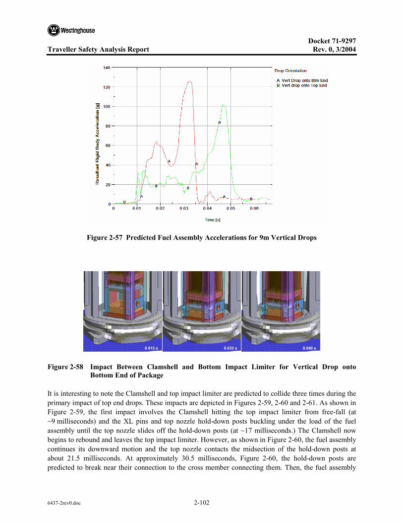
Docket 71-9297
Traveller Safety Analysis Report Rev. 0, 3/2004
6437-2rev0.doc 2-102
Figure 2-57 Predicted Fuel Assembly Accelerations for 9m Vertical Drops
0.013 s 0.033 s 0.040 s
Figure 2-58 Impact Between Clamshell and Bottom Impact Limiter for Vertical Drop onto Bottom End of Package
It is interesting to note the Clamshell and top impact limiter are predicted to collide three times during the primary impact of top end drops. These impacts are depicted in Figures 2-59, 2-60 and 2-61. As shown in Figure 2-59, the first impact involves the Clamshell hitting the top impact limiter from free-fall (at ~9 milliseconds) and the XL pins and top nozzle hold-down posts buckling under the load of the fuel assembly until the top nozzle slides off the hold-down posts (at ~17 milliseconds.) The Clamshell now begins to rebound and leaves the top impact limiter. However, as shown in Figure 2-60, the fuel assembly continues its downward motion and the top nozzle contacts the midsection of the hold-down posts at about 21.5 milliseconds. At approximately 30.5 milliseconds, Figure 2-60, the hold-down posts are predicted to break near their connection to the cross member connecting them. Then, the fuel assembly

Docket 71-9297
Traveller Safety Analysis Report Rev. 0, 3/2004
6437-2rev0.doc 2-103
pushes the Clamshell back into the top impact limiter. This momentarily removes the fuel assembly loading from the Clamshell and it no longer is pushed into the Outerpack. However, the FA continues falling and the top nozzle begins pushing into the cross member at approximately 33.5 milliseconds. The FA continues its downward fall until motion is arrested at approximately 53 milliseconds, Figure 2-41.
p p g ( )
0.009 s 0.013 s 0.017 s
Figure 2-59 First Impact Between Clamshell and Top Impact Limiter for Vertical Drop onto Top End of Package
0.0215 s 0.0255 s 0.0305 s
Figure 2-60 Second Impact Between Clamshell and Top Impact Limiter for Vertical Drop onto Top End of Package

Docket 71-9297
Traveller Safety Analysis Report Rev. 0, 3/2004
6437-2rev0.doc 2-104
0.0335 s 0.047 s 0.053 s
Figure 2-61 Third Impact Between Clamshell and Top Impact Limiter for Vertical Drop onto Top End of Package
From the results shown in this section, we conclude that a CG-forward-of-corner drop onto the top nozzle end of the package with an 18° forward rotation, Figures 2-44 and 2-45 is most damaging to the Outerpack. Further, as also shown, we conclude that the drop most damaging to a fuel assembly is a vertical one onto the bottom nozzle end of the package, Figure 2-52A. Thus, successful drop tests in these two orientations are an adequate demonstration that the Traveller XL design meets/exceeds the HAC drop test requirements.
2.12.3.2.6 Temperature and Foam Density Effects
The Traveller XL package must be capable of passing the HAC drop tests at any temperature within the range -40 to 160°F. Furthermore, foam crush strength is also directly related to foam density. The drop orientation previously determined most damaging to the Outerpack was selected to study the effect of temperature and density (the 9 meter CG-forward-of-corner drops onto the TN end of package with an 18° forward rotation, Figure 2-64). Our finding is that a Traveller XL package with nominal foam density and at “normal temperature” (75°F) experiences slightly higher Outerpack loads when dropped in this orientation compared with packages containing low density foam and dropped at 160°F or containing high density foam and dropped at -40°F, see Figure 2-82. In particular, the predicted maximum Outerpack load for the 75°F temperature/nominal density scenario is 1.69 MN. This is 8.5% more than the maximum load predicted for the -40°F/high density scenario and 13.7% more than that for the 160°F/low density scenario. Our analyses also indicates fuel assemblies in packages containing the highest allowable density foam and dropped at the lowest temperature extreme will experience accelerations that are very similar to those in packages with lowest allowable density foam and dropped at the highest temperature extreme, see Figure 2-83. However, the accelerations at these extremes are only 5% greater than for a package dropped at 75°F containing nominal density foam. Thus, temperature and foam density have a minor effect on drop performance of the Traveller XL package.

Docket 71-9297
Traveller Safety Analysis Report Rev. 0, 3/2004
6437-2rev0.doc 2-105
1.49E06 N (160 F / LOW)
1.69E06 N (75 F/ NOMINAL)
E06 N (-40 F / HIGH)
Figure 2-62 Predicted Temperature and Foam Density Effect on Outerpack/Drop Pad Interface Forces (9m CG-Forward-of-Corner with 18° Rotation Drop onto the Top End of the Package)
49.3 g(160F / LOW)47.3 g (75F / NOMINAL)
49.6 g (-40 F / HIGH)
Figure 2-63 Predicted Temperature and Foam Density Effect on Outerpack/Drop Pad Interface Forces (9m CG-Forward-of-Corner with 18° Rotation Drop onto the Top End of the Package)

Docket 71-9297
Traveller Safety Analysis Report Rev. 0, 3/2004
6437-2rev0.doc 2-106
Energy and Work Histories – The predicted global energy and work histories for the package at 75°F containing nominal density foam was previously shown in Figure 2-29 (18° rotation.) This information is repeated in Figure 2-44 along with the corresponding results for a package dropped at 160°F with low density foam and at -40°F and high density foam. Although not discernable from these graphs, the initial total energies were slightly different for the three runs. In particular, the initial energy for the 160°F/low foam density run was 202 kJ, 204 kJ for the 75°F/nominal foam density run, and 205 kJ for the -40°F/high foam density run. These slight differences were obviously a result of the slight differences in predicted weight. Hourglass, sliding, and stonewall energies were small relative to the total energy. This indicates good overall numerical analyses.
2.12.3.2.7 Pin Puncture
In addition to the 9m drops, the package must survive a “pin puncture” test. The pin puncture test involves dropping the shipping package onto a flat-headed (15 cm diameter with 6 mm chamfer all around) steel pin from a 1 m height. The orientation of the package and location of pin impact must be chosen to achieve the greatest damage to the package.
The pin damage investigation consisted of two approaches. First, the pin drop was analyzed, based on maximum impact forces imparted to the Outerpack. Then, the cumulative damage that a pin drop could cause following a 9 m drop was studied. The latter study was naturally based on the 9 m drop predicted to cause the most Outerpack damage.
Maximum Loads – Our analysis indicates the shipping package will be subjected to the higher loads when dropped in a horizontal orientation, Figure 2-65A, compared to an inclined one Figure 2-65B. For example, when the package is tilted 20° (with the top nozzle end of the package towards the ground), our analysis predicts the maximum impact load is 561 kN. This is 10% less than the 624 kN load predicted for a fully horizontal drop Figure 2-66.

Docket 71-9297
Traveller Safety Analysis Report Rev. 0, 3/2004
6437-2rev0.doc 2-107
9m CG forward of Corner Drops with 18 Rotation onto the Top Nozzle End of Package
160 °F / LOW Density (Run QU-29_hot_b)
75 °F / Nominal Density (Run QU-29)
-40 °F / High Density (Run QU_29_cold_b)
Figure 2-64 Predicted Energy and Work Histories at Various Temperatures

Docket 71-9297
Traveller Safety Analysis Report Rev. 0, 3/2004
6437-2rev0.doc 2-108
A. Horizontal B. Inclined
Figure 2-65 Pin Drop Orientations
A comparison of predicted fuel assembly accelerations is shown in Figure 2-67. Note the fuel assembly is predicted to experience approximately 9% higher accelerations in a fully horizontal pin drop than one inclined at 20 degrees.
624kN
561 kN
Figure 2-66 Predicted Outerpack/Pin Interference Forces (1m Drop onto 15mm Diameter Steel Pin)
Thus, a fully horizontal pin puncture drop produces higher Outerpack loads and fuel assembly accelerations than inclined pin puncture drops.

Docket 71-9297
Traveller Safety Analysis Report Rev. 0, 3/2004
6437-2rev0.doc 2-109
Orientation:
43.2 g39.8 g
Figure 2-67 Predicted Fuel Assembly Accelerations (1m Drop onto 15mm Diameter Steel Pin)
Worst Horizontal Pin Drop – Two axial rotations were compared when studying the horizontal pin puncture drops. These were the previously described orientation in which the pin impacts the shipping package from underneath, Figure 2-65A, and one where the pin impacts the Outerpack hinges, Figure 2-68. In both cases, the pin was positioned directly under the package CG.
Figure 2-68 Pin Drop onto Outerpack Hinges
Interestingly, predicted Outerpack loads were practically the same for a horizontal pin puncture to the underneath side of the Outerpack and a pin impact directly to a hinge, Figure 2-69. However, there was less cushioning for the fuel assembly in the latter drop. This is evident from the predicted fuel assembly accelerations of 43.2 g’s for the impact to the underneath region of the Outerpack and 82.1 g’s for the hinge impact, Figure 2-70.

Docket 71-9297
Traveller Safety Analysis Report Rev. 0, 3/2004
6437-2rev0.doc 2-110
In fact, all of these pin puncture orientations were tested using full-scale Traveller XL units. In all cases, the pin puncture tests were passed without any puncturing of the outer skins of the units, nor any detrimental effects to the Clamshell/fuel assembly, or criticality safety aspects of the package.
624kN627 kN Horizontal - Underneath ImpactHorizontal - Hinge Impact
Figure 2-69 Predicted Outerpack/Pin Interface Forces (1m Drop onto 15mm Diameter Steel Pin)
43.2 g
82.1 g
Figure 2-70 Predicted Fuel Assembly Accelerations (1m Drop onto 15mm Diameter Steel Pin)

Docket 71-9297
Traveller Safety Analysis Report Rev. 0, 3/2004
6437-2rev0.doc 2-111
Energy and Work Histories – Global energy and work for the 1 m pin puncture drops discussed above are shown in Figures 2-71, 2-72 and 2-73. These plots have an initial total energy (TE) of 22.3 kJ. This value correctly reflects the initial velocity (v) of 4.43 m/s applied to the 2,270 kg package mass (m) since our pin puncture simulations are initiated at the end of Outerpack free fall from 1 m; the total energy is comprised only of kinetic energy (KE), and 2
21 mvKE = . Total energy rises about 8% in these drop
simulations. This reflects the work done by the package under gravity loading, i.e., the bending of the shipping package around the pin. Depending on drop orientation, the event was completed within 4 to 5 milliseconds as seen by the flattening of the kinetic energy and internal energies after that time. Moreover, acceptable levels of hourglass, sliding, and stonewall energies were obtained. This indicates a good overall numerical analysis was obtained in each simulation.
g ( )
Figure 2-71 Predicted Energy and Work Histories for a 1 m Horizontal Pin Drop (Pin Underneath the Package CG)
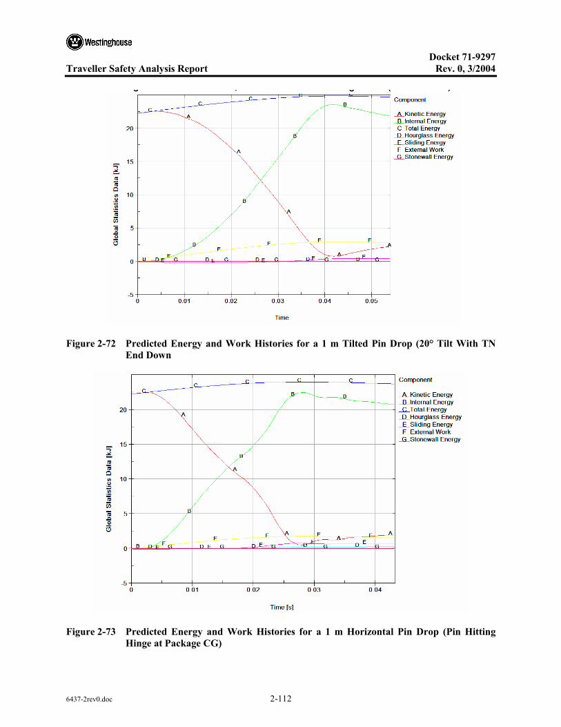
Docket 71-9297
Traveller Safety Analysis Report Rev. 0, 3/2004
6437-2rev0.doc 2-112
g , g ( )
Figure 2-72 Predicted Energy and Work Histories for a 1 m Tilted Pin Drop (20° Tilt With TN End Down
Figure 2-73 Predicted Energy and Work Histories for a 1 m Horizontal Pin Drop (Pin Hitting Hinge at Package CG)
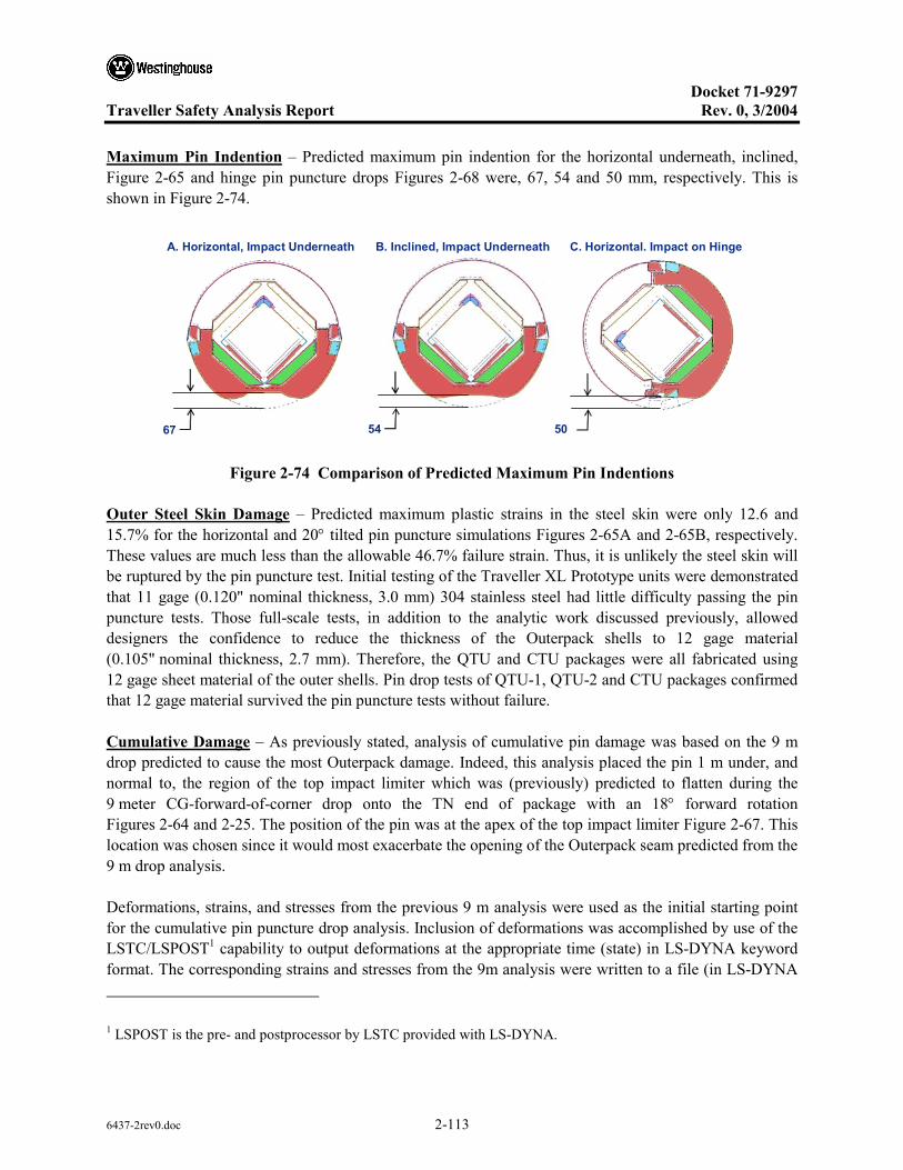
Docket 71-9297
Traveller Safety Analysis Report Rev. 0, 3/2004
6437-2rev0.doc 2-113
Maximum Pin Indention – Predicted maximum pin indention for the horizontal underneath, inclined, Figure 2-65 and hinge pin puncture drops Figures 2-68 were, 67, 54 and 50 mm, respectively. This is shown in Figure 2-74.
A. Horizontal, Impact Underneath
67
B. Inclined, Impact Underneath
54
C. Horizontal. Impact on Hinge
50
Figure 2-74 Comparison of Predicted Maximum Pin Indentions
Outer Steel Skin Damage – Predicted maximum plastic strains in the steel skin were only 12.6 and 15.7% for the horizontal and 20° tilted pin puncture simulations Figures 2-65A and 2-65B, respectively. These values are much less than the allowable 46.7% failure strain. Thus, it is unlikely the steel skin will be ruptured by the pin puncture test. Initial testing of the Traveller XL Prototype units were demonstrated that 11 gage (0.120" nominal thickness, 3.0 mm) 304 stainless steel had little difficulty passing the pin puncture tests. Those full-scale tests, in addition to the analytic work discussed previously, allowed designers the confidence to reduce the thickness of the Outerpack shells to 12 gage material (0.105" nominal thickness, 2.7 mm). Therefore, the QTU and CTU packages were all fabricated using 12 gage sheet material of the outer shells. Pin drop tests of QTU-1, QTU-2 and CTU packages confirmed that 12 gage material survived the pin puncture tests without failure.
Cumulative Damage – As previously stated, analysis of cumulative pin damage was based on the 9 m drop predicted to cause the most Outerpack damage. Indeed, this analysis placed the pin 1 m under, and normal to, the region of the top impact limiter which was (previously) predicted to flatten during the 9 meter CG-forward-of-corner drop onto the TN end of package with an 18° forward rotation Figures 2-64 and 2-25. The position of the pin was at the apex of the top impact limiter Figure 2-67. This location was chosen since it would most exacerbate the opening of the Outerpack seam predicted from the 9 m drop analysis.
Deformations, strains, and stresses from the previous 9 m analysis were used as the initial starting point for the cumulative pin puncture drop analysis. Inclusion of deformations was accomplished by use of the LSTC/LSPOST1 capability to output deformations at the appropriate time (state) in LS-DYNA keyword format. The corresponding strains and stresses from the 9m analysis were written to a file (in LS-DYNA
1 LSPOST is the pre- and postprocessor by LSTC provided with LS-DYNA.
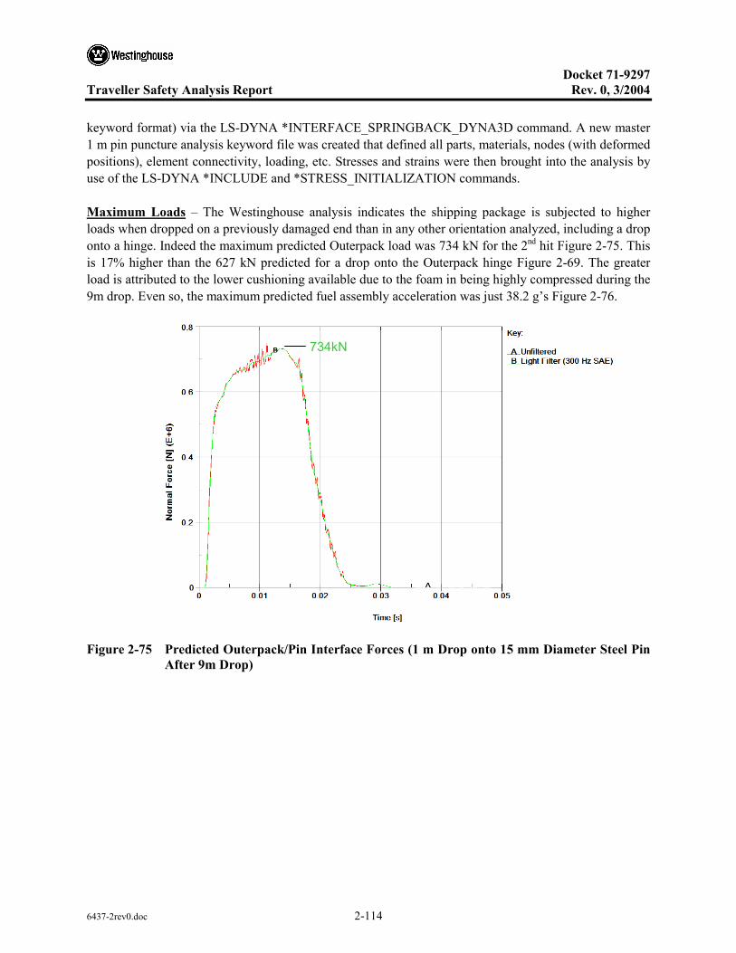
Docket 71-9297
Traveller Safety Analysis Report Rev. 0, 3/2004
6437-2rev0.doc 2-114
keyword format) via the LS-DYNA *INTERFACE_SPRINGBACK_DYNA3D command. A new master 1 m pin puncture analysis keyword file was created that defined all parts, materials, nodes (with deformed positions), element connectivity, loading, etc. Stresses and strains were then brought into the analysis by use of the LS-DYNA *INCLUDE and *STRESS_INITIALIZATION commands.
Maximum Loads – The Westinghouse analysis indicates the shipping package is subjected to higher loads when dropped on a previously damaged end than in any other orientation analyzed, including a drop onto a hinge. Indeed the maximum predicted Outerpack load was 734 kN for the 2nd hit Figure 2-75. This is 17% higher than the 627 kN predicted for a drop onto the Outerpack hinge Figure 2-69. The greater load is attributed to the lower cushioning available due to the foam in being highly compressed during the 9m drop. Even so, the maximum predicted fuel assembly acceleration was just 38.2 g’s Figure 2-76.
734kN
Figure 2-75 Predicted Outerpack/Pin Interface Forces (1 m Drop onto 15 mm Diameter Steel Pin After 9m Drop)

Docket 71-9297
Traveller Safety Analysis Report Rev. 0, 3/2004
6437-2rev0.doc 2-115
38.2 g
Figure 2-76 Predicted Fuel Assembly Accelerations (1 m Drop onto 15mm Diameter Steel Pin after 9 m Drop)
Additional Damage – As previously discussed, our primary concern for this sequence of drops (a 9 m CG-forward-of-corner drop onto the top nozzle end of the package followed by the 1 m pin puncture) was the extent of Outerpack seam opening Figure 2-28. Our measures of Outerpack seam opening, D1 and D2 (see Figure 2-48), would increase from 20 to 22.9 mm and from 20 to 22.2 mm, respectively.
Energy and Work Histories – Predicted global energy and work for the 1 m pin puncture drop following a 9 m CG-forward-of-corner drop onto the top nozzle end of the package is shown in Figure 2-77. The sliding energy in this plot is related to the initial penetration between the crushed impact limiter foam and outer steel skins. It is not necessarily an error. Moreover, the predicted increase in damage due to the pin puncture test simply does not warrant further investigation of this issue.
Pin Puncture Summary – Our analyses indicate the Traveller XL package is very capable of withstanding the 1 m pin puncture test. Indeed, it was determined that the likelihood of rupturing the outer steel skin is very low. Thus, the 1 m pin puncture test is a relatively benign test for the Traveller XL package. These conclusions were confirmed by the prototype test results as subsequently discussed.
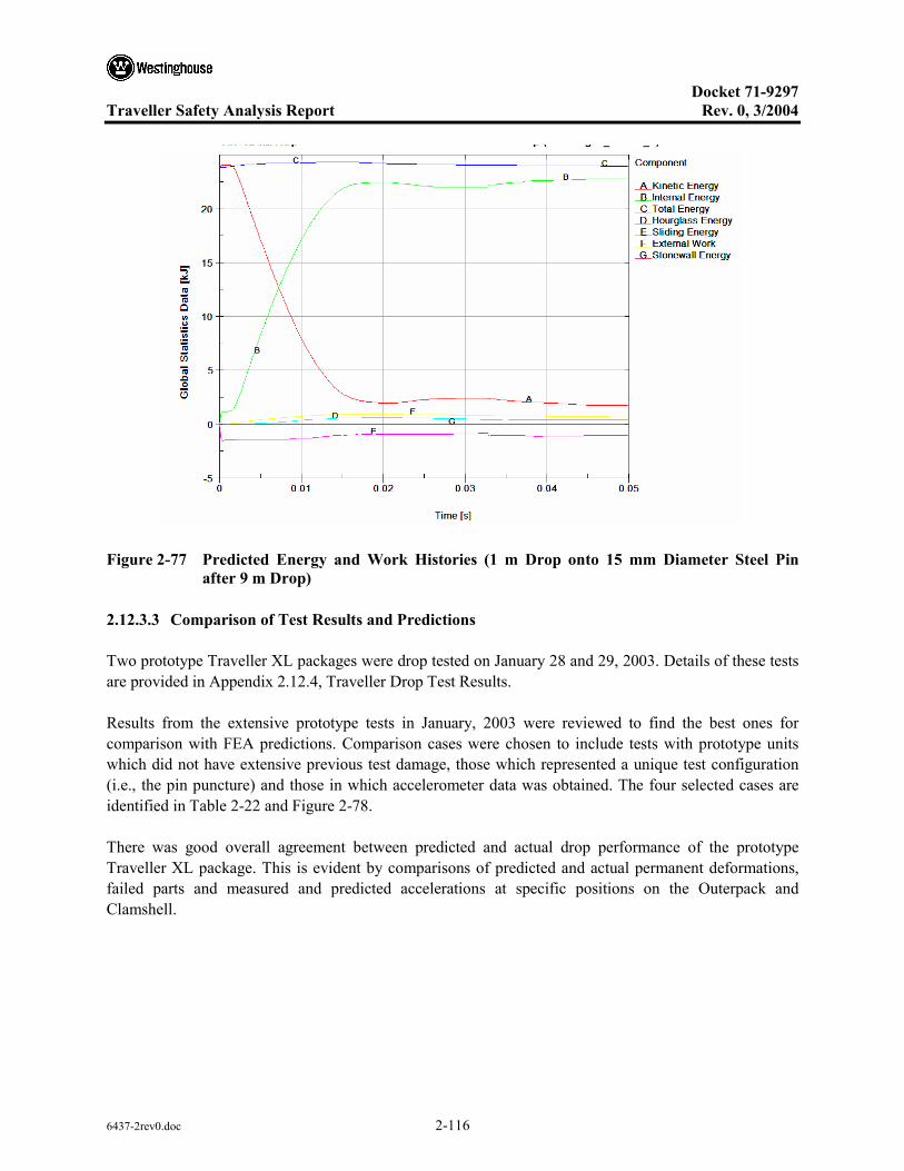
Docket 71-9297
Traveller Safety Analysis Report Rev. 0, 3/2004
6437-2rev0.doc 2-116
p p ( g _ _ )
Figure 2-77 Predicted Energy and Work Histories (1 m Drop onto 15 mm Diameter Steel Pin after 9 m Drop)
2.12.3.3 Comparison of Test Results and Predictions
Two prototype Traveller XL packages were drop tested on January 28 and 29, 2003. Details of these tests are provided in Appendix 2.12.4, Traveller Drop Test Results.
Results from the extensive prototype tests in January, 2003 were reviewed to find the best ones for comparison with FEA predictions. Comparison cases were chosen to include tests with prototype units which did not have extensive previous test damage, those which represented a unique test configuration (i.e., the pin puncture) and those in which accelerometer data was obtained. The four selected cases are identified in Table 2-22 and Figure 2-78.
There was good overall agreement between predicted and actual drop performance of the prototype Traveller XL package. This is evident by comparisons of predicted and actual permanent deformations, failed parts and measured and predicted accelerations at specific positions on the Outerpack and Clamshell.

Docket 71-9297
Traveller Safety Analysis Report Rev. 0, 3/2004
6437-2rev0.doc 2-117
Table 2-22 Prototype Tests Used to Compare with Analysis
Test ID (corresponds to [6]) Analysis ID
Drop Height [m] Θx Θz Comment
1.1, 9 m Low Angle C1-25 9.1 14.5° 180° T/N primary impact on OP top
1.2, 9 m CG-over-corner C1-31 9.1 -71° 90° B/N primary impact on OP hinge
2.2, 1 m Pin-puncture Punc2-2nh 1.04 20° 135° CG (Axial) on OP topside, T/N end down
2.3, 9 m CG-over-corner C1-29 9.1 108° 0° T/N primary impact on OP top
Test 1-1(Run C1-25)
Test 2-3(Run C1-29)
Top Nozzle End
Top Nozzle End
Z
20°
Bottom Nozzle End
135°
1 m
Test 2-2(Run Punc2-2nh)
Top Nozzle End
Z
14.5°
Bottom Nozzle End
180°
Bottom Nozzle
End
Test 1-2 (Run C1-31)
Bottom Nozzle End
Top Nozzle
End
Figure 2-78 Prototype Drop Tests Used To Benchmark Analysis

Docket 71-9297
Traveller Safety Analysis Report Rev. 0, 3/2004
6437-2rev0.doc 2-118
2.12.3.3.1 Prototype Unit-1 Test 1.1
Prototype Unit-1, Test 1.1 was chosen for the first comparison. As indicated in Table 2-22 and Figure 2-78, this was an inclined drop from 9.1 meters onto the upper Outerpack (the unit was rotated 175° about its long axis and inclined 14.5° with the end of the package nearest the top of the fuel assembly hitting first.1 Four frames taken from a video recording of test 1.1 are shown in Figure 2-79. These frames show the test sequence was comprised of the initial impact on the top nozzle end of the package (frame 1), rollover (frames 2 and 3), and a secondary impact to the bottom nozzle end of the package (frame 4).
1 2
3 4
Figure 2-79 Prototype Unit 1 Drop Test
Deformations – As reported in, test 1.1 produced noticeable permanent deformations in several locations of the Outerpack and no significant permanent deformations in the Clamshell. Outerpack permanent deformations were primarily at the ends of the package.
1 This will be referred to as the “top nozzle end” of the package. Likewise, the end of the package nearest the bottom of the fuel assembly will be called the “bottom nozzle end.”

Docket 71-9297
Traveller Safety Analysis Report Rev. 0, 3/2004
6437-2rev0.doc 2-119
An overall sense of the correspondence between predicted and actual Outerpack permanent deformations may be obtained by reviewing Figures 2-80 through 2-87. Quantitative comparison between predicted and documented measurements is given in Table 2-23.
(c) Deformation of the Upper Overpack Stiffeners
(a) Overpack Deformation at TN End of the Package
Actual Simulation
Actual Simulation
Actual Simulation
(b) Overpack Deformation at the BN End of the Package
Top Nozzle End
Lw
WL
C
C
Figure 2-80 Comparison of Test 1.1 with Analytical Results
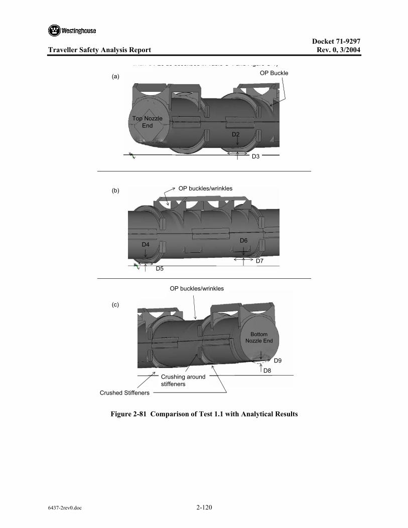
Docket 71-9297
Traveller Safety Analysis Report Rev. 0, 3/2004
6437-2rev0.doc 2-120
Top Nozzle End
(Run C1 25 as described in Table C 1 and Figure C 1)OP Buckle
D2
OP buckles/wrinkles
D9
Crushed Stiffeners
Crushing around stiffeners
Bottom Nozzle End
OP buckles/wrinkles
(a)
(b)
(c)
D4D6
D3
D5D7
D8
Figure 2-81 Comparison of Test 1.1 with Analytical Results
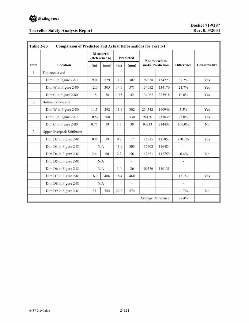
Docket 71-9297
Traveller Safety Analysis Report Rev. 0, 3/2004
6437-2rev0.doc 2-121
Table 2-23 Comparison of Predicted and Actual Deformations for Test 1-1
Measured (Reference 6) Predicted
Item Location (in) (mm) (in) (mm) Nodes used to
make Prediction Difference Conservative
1 Top nozzle end
Dim L in Figure 2-80 9.0 229 11.9 302 192658 134223 32.2% Yes
Dim W in Figure 2-80 12.0 305 14.6 371 134052 134170 21.7% Yes
Dim C in Figure 2-80 1.5 38 1.65 42 134062 223918 10.0% Yes
2 Bottom nozzle end
Dim W in Figure 2-80 11.5 292 11.9 302 214342 190946 3.5% Yes
Dim L in Figure 2-80 10.57 268 13.0 330 94120 213639 23.0% Yes
Dim C in Figure 2-80 0.75 19 1.5 38 93833 214433 100.0% No
3 Upper Overpack Stiffeners
Dim D2 in Figure 2-81 0.8 19 0.7 17 115715 115853 -10.7% Yes
Dim D3 in Figure 2-81 N/A 11.9 303 115702 116484 -
Dim D4 in Figure 2-81 2.4 60 2.2 56 112621 112759 -6.4% No
Dim D5 in Figure 2-81 N/A - -
Dim D6 in Figure 2-81 N/A 1.0 26 109526 110131 -
Dim D7 in Figure 2-81 16.0 406 18.4 468 15.1% Yes
Dim D8 in Figure 2-81 N/A - -
Dim D9 in Figure 2-81 23 584 22.6 574 -1.7% No
Average Difference: 22.4%
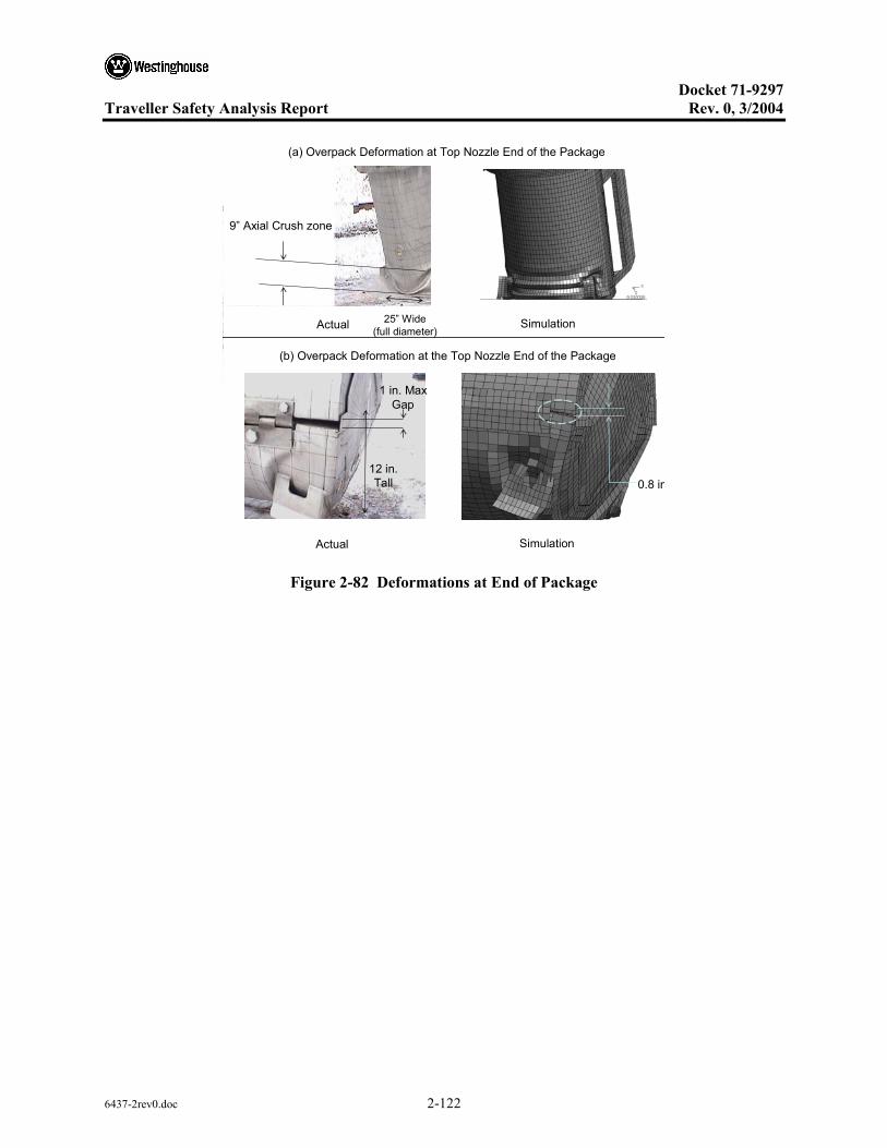
Docket 71-9297
Traveller Safety Analysis Report Rev. 0, 3/2004
6437-2rev0.doc 2-122
(a) Overpack Deformation at Top Nozzle End of the Package
Actual Simulation
Actual Simulation
(b) Overpack Deformation at the Top Nozzle End of the Package
9” Axial Crush zone
25” Wide (full diameter)
1 in. Max Gap
12 in. Tall 0.8 in
Figure 2-82 Deformations at End of Package

Docket 71-9297
Traveller Safety Analysis Report Rev. 0, 3/2004
6437-2rev0.doc 2-123
(a) FA Displacement at Bottom Nozzle End of the Package
Actual Simulation
Actual Simulation
(b) Deformation at the Top Nozzle End of the Package
Spacer and fuel moved 3-3/8 in.No fuel damage at Bottom Nozzle.
Figure 2-83 Internal Deformations at Inside Outerpack

Docket 71-9297
Traveller Safety Analysis Report Rev. 0, 3/2004
6437-2rev0.doc 2-124
Actual Simulation
22 in. Tall
3 in. Crush
8 in. Tear
10 in. Wide
Figure 2-84 Outerpack Deformations at Bottom Nozzle End of Package
Figure 2-85 Pin Puncture Deformations
14 in. [356 mm] Wide
2 in [51 mm]Deep
10 in. [254 mm] Tall
( g )
Figure 2-86 Dimensions of Pin Puncture Deformations

Docket 71-9297
Traveller Safety Analysis Report Rev. 0, 3/2004
6437-2rev0.doc 2-125
A
A
Node 138904
3.8 [97.9]
16.1 [409]
18.5 [469]
The undeformed configuration shown in Red was based on deformed positions of Nodes 134236, 220381 and 94784.
Section A-A
Figure 2-87 Outerpack Predicted Deformations of Pin Drop
2.12.3.3.2 Accelerations
Vertical accelerations (Y-direction) measured during test 1.1 are compared with the FE-based predictions in Figures 2-88 through 2-92. Agreement was good. Indeed, discrepancies between the two could easily be attributed to the inherent error associated with obtaining such data.
For the Outerpack, both measured and predicted traces contained two peaks, Figure 2-88. These corresponded to the two impacts associated with this test as illustrated in Figure 2-78. (Note: the larger acceleration with the secondary impact should not be interpreted as meaning larger forces were associated with the second impact. Rather, the larger magnitude simply reflects that the accelerometer was much nearer the secondary impact end.) While there were two visible peaks, the measured response was very small for the primary impact. For the secondary impact, the predicted acceleration was 1270 g’s. This was in accordance with the measured peak acceleration which indicated accelerations were greater than 950 g’s.
For unknown reasons, the accelerometers on both the Clamshell top and bottom plates gave erroneous readings late into the drop. This is clearly evident from accelerometer data in Appendix 2.12.4 that the accelerometers “saturate” for over 0.025 seconds and provide no meaningful response afterwards. Thus, only the first 0.05 seconds of the Clamshell data was compared in this report. For the accelerometer on the Clamshell top plate, measured and predicted accelerations corresponding to the first impact (at time 0.01 seconds in Figure 2-90) were 555 g’s. This was also in accordance with measurements which indicated a peak acceleration greater than 525 g’s was experienced. As shown in Figure 2-91, peak accelerations of 205 g’s were measured on the Clamshell bottom plate. The corresponding predicted acceleration is also shown. Note the peak predicted acceleration was 155 g’s.

Docket 71-9297
Traveller Safety Analysis Report Rev. 0, 3/2004
6437-2rev0.doc 2-126
Overpack Bottom End
-1500.00
-1250.00
-1000.00
-750.00
-500.00
-250.00
0.00
250.00
500.00
0.00 0.01 0.02 0.03 0.04 0.05 0.06 0.07 0.08 0.09 0.10
Time [secs]
Y A
ccel
erat
ion
[g]
PredictedMeasured
>945 g
1300 g
Figure 2-88 Predicted and Measured Y Accelerations
Primary Impact
Accelerometer at B/N endSlap-Down
X - Lateral g-forceY - Axial g-forceZ - Vertical g-force
Figure 2-89 Three Axis Measured Accelerations
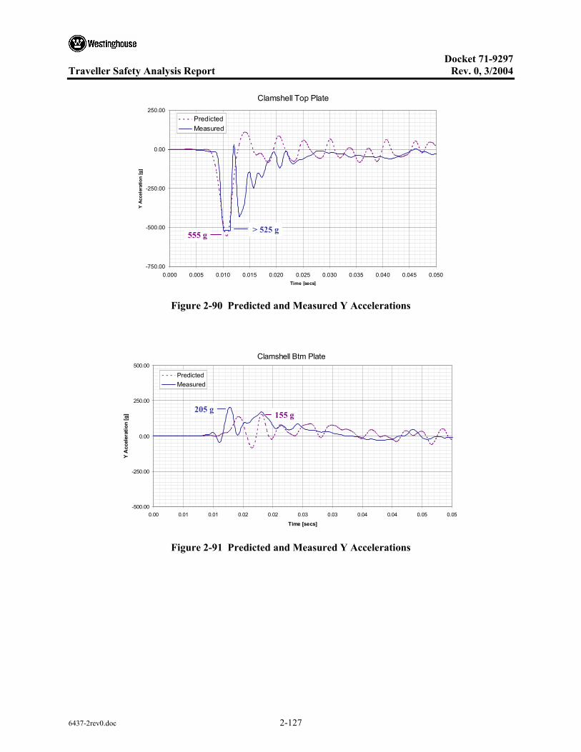
Docket 71-9297
Traveller Safety Analysis Report Rev. 0, 3/2004
6437-2rev0.doc 2-127
Clamshell Top Plate
-750.00
-500.00
-250.00
0.00
250.00
0.000 0.005 0.010 0.015 0.020 0.025 0.030 0.035 0.040 0.045 0.050Time [secs]
Y Ac
cele
ratio
n [g
]
PredictedMeasured
> 525 g555 g
Figure 2-90 Predicted and Measured Y Accelerations
Clamshell Btm Plate
-500.00
-250.00
0.00
250.00
500.00
0.00 0.01 0.01 0.02 0.02 0.03 0.03 0.04 0.04 0.05 0.05
Time [secs]
Y A
ccel
erat
ion
[g]
PredictedMeasured
205 g155 g
Figure 2-91 Predicted and Measured Y Accelerations
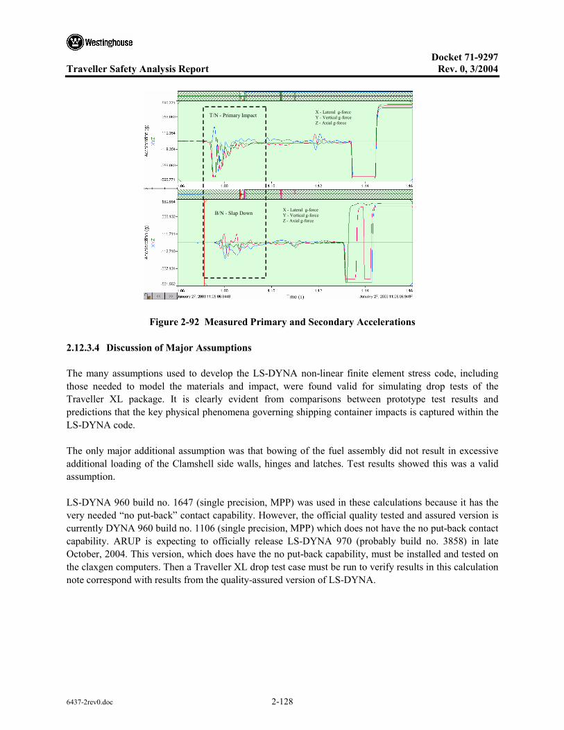
Docket 71-9297
Traveller Safety Analysis Report Rev. 0, 3/2004
6437-2rev0.doc 2-128
T/N - Primary Impact X - Lateral g-forceY - Vertical g-forceZ - Axial g-force
B/N - Slap Down X - Lateral g-forceY - Vertical g-forceZ - Axial g-force
Figure 2-92 Measured Primary and Secondary Accelerations
2.12.3.4 Discussion of Major Assumptions
The many assumptions used to develop the LS-DYNA non-linear finite element stress code, including those needed to model the materials and impact, were found valid for simulating drop tests of the Traveller XL package. It is clearly evident from comparisons between prototype test results and predictions that the key physical phenomena governing shipping container impacts is captured within the LS-DYNA code.
The only major additional assumption was that bowing of the fuel assembly did not result in excessive additional loading of the Clamshell side walls, hinges and latches. Test results showed this was a valid assumption.
LS-DYNA 960 build no. 1647 (single precision, MPP) was used in these calculations because it has the very needed “no put-back” contact capability. However, the official quality tested and assured version is currently DYNA 960 build no. 1106 (single precision, MPP) which does not have the no put-back contact capability. ARUP is expecting to officially release LS-DYNA 970 (probably build no. 3858) in late October, 2004. This version, which does have the no put-back capability, must be installed and tested on the claxgen computers. Then a Traveller XL drop test case must be run to verify results in this calculation note correspond with results from the quality-assured version of LS-DYNA.
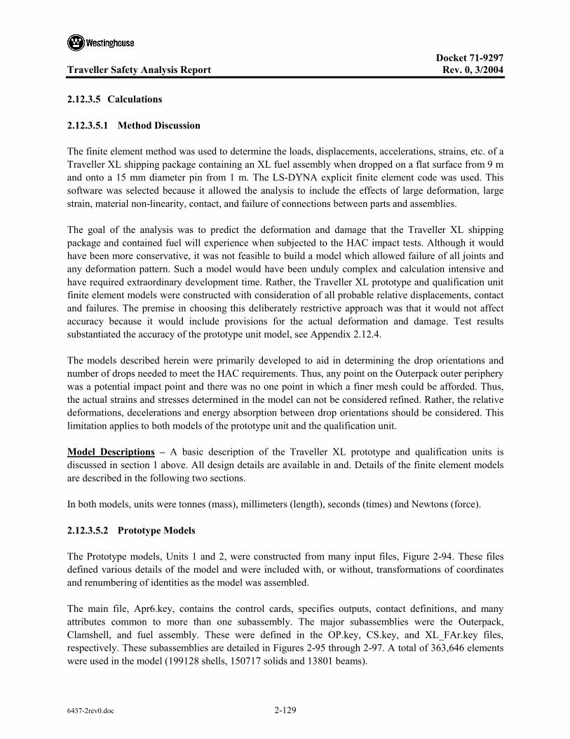
Docket 71-9297
Traveller Safety Analysis Report Rev. 0, 3/2004
6437-2rev0.doc 2-129
2.12.3.5 Calculations
2.12.3.5.1 Method Discussion
The finite element method was used to determine the loads, displacements, accelerations, strains, etc. of a Traveller XL shipping package containing an XL fuel assembly when dropped on a flat surface from 9 m and onto a 15 mm diameter pin from 1 m. The LS-DYNA explicit finite element code was used. This software was selected because it allowed the analysis to include the effects of large deformation, large strain, material non-linearity, contact, and failure of connections between parts and assemblies.
The goal of the analysis was to predict the deformation and damage that the Traveller XL shipping package and contained fuel will experience when subjected to the HAC impact tests. Although it would have been more conservative, it was not feasible to build a model which allowed failure of all joints and any deformation pattern. Such a model would have been unduly complex and calculation intensive and have required extraordinary development time. Rather, the Traveller XL prototype and qualification unit finite element models were constructed with consideration of all probable relative displacements, contact and failures. The premise in choosing this deliberately restrictive approach was that it would not affect accuracy because it would include provisions for the actual deformation and damage. Test results substantiated the accuracy of the prototype unit model, see Appendix 2.12.4.
The models described herein were primarily developed to aid in determining the drop orientations and number of drops needed to meet the HAC requirements. Thus, any point on the Outerpack outer periphery was a potential impact point and there was no one point in which a finer mesh could be afforded. Thus, the actual strains and stresses determined in the model can not be considered refined. Rather, the relative deformations, decelerations and energy absorption between drop orientations should be considered. This limitation applies to both models of the prototype unit and the qualification unit.
Model Descriptions – A basic description of the Traveller XL prototype and qualification units is discussed in section 1 above. All design details are available in and. Details of the finite element models are described in the following two sections.
In both models, units were tonnes (mass), millimeters (length), seconds (times) and Newtons (force).
2.12.3.5.2 Prototype Models
The Prototype models, Units 1 and 2, were constructed from many input files, Figure 2-94. These files defined various details of the model and were included with, or without, transformations of coordinates and renumbering of identities as the model was assembled.
The main file, Apr6.key, contains the control cards, specifies outputs, contact definitions, and many attributes common to more than one subassembly. The major subassemblies were the Outerpack, Clamshell, and fuel assembly. These were defined in the OP.key, CS.key, and XL_FAr.key files, respectively. These subassemblies are detailed in Figures 2-95 through 2-97. A total of 363,646 elements were used in the model (199128 shells, 150717 solids and 13801 beams).

Docket 71-9297
Traveller Safety Analysis Report Rev. 0, 3/2004
6437-2rev0.doc 2-130
Figure 2-93 FEA Model Input Files
The orientation for each run was defined in individual load case files. Obviously, only one load case file and one material file was invoked per run.
The Clamshell Figure 2-96 is mounted to the Outerpack, Figure 2-94 with 22 rubber shock mounts. These shock mounts were modeled as discrete elements (springs). The stiffness of these elements was 92.7 N/mm in the global X direction, 135.4 N/mm in the global Y direction and 42.3 N/mm in the global Z direction. These values were obtained through tests. These details are included in the ‘ShockMounts.key’ file.
Predicted model weight for the Prototype units was 2.39 tonnes (5258 lbs). This matched the Prototype unit’s 5065 lb. average weight within 3.8%.

Docket 71-9297
Traveller Safety Analysis Report Rev. 0, 3/2004
6437-2rev0.doc 2-131
Figure 2-94 Outerpack Mesh in Prototype Model
p yp
11 pcf foam
Figure 2-95 Impact Limiter in Prototype Unit Model

Docket 71-9297
Traveller Safety Analysis Report Rev. 0, 3/2004
6437-2rev0.doc 2-132
Clamshell Mesh in Qualification Unit Model
Bottom End Top End
Figure 2-96 Clamshell Mesh in Qualification Unit Model
Figure 2-97 Fuel Assembly in Both Prototype and Qualification Unit Models
The Outerpack hinge details are shown in Figure 2-98. There were three bolts in the upper hinge plate in the Prototype models and only two for the Qualification unit models (shown). The bolts were modeled as spotweld beams. The spotweld beams and hinge plate shared nodes. The spotweld beam node at the hinge block was tied with LS-DYNA’s NODAL_RIGID_BODIES. It should be noted that the manner of modeling the bolts allows for compression loading of the bolt, whereas in reality compression loads are not typically carried in bolted joints. However, in the horizontal side impact drops, the bolt heads themselves may impact the drop pad and compressive bolt loads are expected. Thus, our bolt model should be accurate in instances where compressive loads are developed and conservative elsewhere. The hinge pin was simulated using the LS-DYNA REVOLUTE_JOINT feature.

Docket 71-9297
Traveller Safety Analysis Report Rev. 0, 3/2004
6437-2rev0.doc 2-133
OP Hinge Model
Qualification unit had two bolts in upper hinge block and the prototype unit had three. Both models had four bolts in bottom hinge block.
Bolts
Two Revolute Joints(5 places)
Figure 2-98 Outerpack Hinge Model
2.12.3.5.3 Qualification Unit Models (QTUs)
As with the Prototype units, the QTUs were constructed from many input files, see Figure 2-99. These files defined various details of the model and were included with, or without, transformations of coordinates and renumbering of identities as the model was assembled.
The main file, Aug19.key, contains the control cards, specifies outputs, contact definitions, and many attributes common to more than one subassembly. The major subassemblies were the Outerpack, Clamshell, and fuel assembly. These were defined in the OPs.key, CS_06_26sl6.key, and FA_remesh_FRslip.key files, respectively. The Outerpack and Clamshell subassemblies are detailed in Figures 2-101, 2-102 and 2-103 (The fuel assembly model was very similar to the one depicted previously in Figure 2-97. A total of 361,333 elements were used in the model (185985 shells, 157031 solids and 18317 beams).
The orientation for each run was defined in individual load case files. Likewise, the material property date was defined in three files which represented three different temperatures and foam densities. Obviously, only one load case file and one material file was invoked per run.
The Clamshell, Figure 2-102 is mounted to the Outerpack, Figure 2-100, with 14 rubber shock mounts. These shock mounts were modeled as discrete elements (springs). Outerpack hinge details were described in the previous section, see Figure 2-98.
Predicted model weight was 2.27 tonnes (4994 lbs). This matched the qualification unit’s 4786 lb. average weight within 4.4%.

Docket 71-9297
Traveller Safety Analysis Report Rev. 0, 3/2004
6437-2rev0.doc 2-134
Figure 2-99 FEA Input Files
Figure 2-100 Outerpack Mesh in Qualification Unit Model
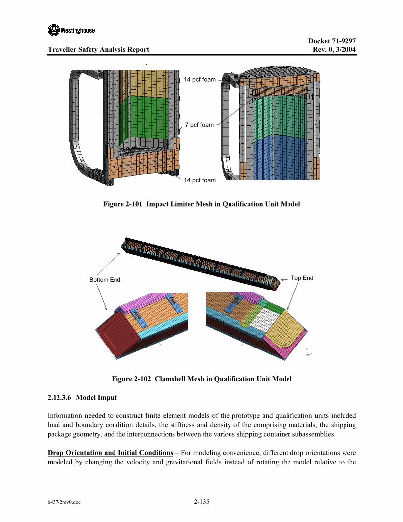
Docket 71-9297
Traveller Safety Analysis Report Rev. 0, 3/2004
6437-2rev0.doc 2-135
p
7 pcf foam
14 pcf foam
14 pcf foam
Figure 2-101 Impact Limiter Mesh in Qualification Unit Model
Bottom End Top End
Figure 2-102 Clamshell Mesh in Qualification Unit Model
2.12.3.6 Model Imput
Information needed to construct finite element models of the prototype and qualification units included load and boundary condition details, the stiffness and density of the comprising materials, the shipping package geometry, and the interconnections between the various shipping container subassemblies.
Drop Orientation and Initial Conditions – For modeling convenience, different drop orientations were modeled by changing the velocity and gravitational fields instead of rotating the model relative to the

Docket 71-9297
Traveller Safety Analysis Report Rev. 0, 3/2004
6437-2rev0.doc 2-136
model global axes. Loadings were therefore specific to each drop orientation. Further, each analysis was initiated just prior to impact with the shipping package positioned just above the impact surface, having an initial velocity based on drop height (9.14 m for the free drops and 1 m for the pin puncture), and undergoing earth’s gravitational pull. This analysis approach minimized computation effort since only minimal calculations of the shipping package during free-fall were needed. The required calculations were as follows.
2.12.3.6.1 Initial Velocity Magnitude (Speed)
The velocity, V, of any object having fallen for a drop height, h, in a constant gravitational field, g, is:
ghV 2=
Thus, using 9810 mm/s as the value of g, the calculated magnitude of the initial velocities (speed) for the 9 meter free drop and 1 meter pin puncture tests were as shown in Table 2-24.
Table 2-24 Initial Velocities 9 Meter Drop and 1 Meter Pin Puncture Analyses
Test Drop Height [m] Initial Velocity (Speed) [mm/s]
9 m drop
Prototype model 9.0 13288
Qualification model 9.14 (30 ft) 13389
Pin Puncture
Prototype & Qualification models 1.0 4429
Velocity and Gravitational Fields – In general, a complete description of the position and orientation of an object in 3-dimensional space requires three coordinates and three direction cosines. However, for these drop tests, specification of only two direction cosines is sufficient. This is because both the drop pad and impact pin may be modeled as two-dimensional rigid walls or surfaces. In other words, these items have no distinct feature with respect to the shipping package that requires specification of the angle θy in Figure 2-103. Thus, only the angles θx and θZ are needed to define the velocity and gravitational fields.

Docket 71-9297
Traveller Safety Analysis Report Rev. 0, 3/2004
6437-2rev0.doc 2-137
xθ
Zθ
yθ
Y
Z
Figure 2-103 Package Drop Angle
Using the angles θx and θZ shown in Figure 2-69, the velocity and gravitational fields are, respectively,
0
0
Tv A V = −
and
0
0
Ta A g =
where
cos sin 0cos sin cos cos sinsin sin sin cos cos
z z
x z z x x
x z x z x
Aθ θ
θ θ θ θ θθ θ θ θ θ
= ⋅ ⋅ − ⋅ ⋅
The normal to the plane of impact (drop pad surface or pin face) is given by
01
0
Tn A = −
The initial velocity field was implemented into the finite element model with the *INITIAL_VELOCITY command in LS-DYNA. The gravity field was applied using the *LOAD_BODY_GENERALIZED

Docket 71-9297
Traveller Safety Analysis Report Rev. 0, 3/2004
6437-2rev0.doc 2-138
command. Finally, the impact plane was defined using the *RIGIDWALL_PLANAR or *RIGIDWALL_GEOMETRIC_CYLINDER commands. This approach allowed the drop orientation to be changed without altering the model coordinates. It should be noted that the gravity load was applied as a ramped load as shown in Figure 2-70. This was done as a precaution to minimize any numerical oscillations. However, this was probably unnecessary – applying the full gravity load at time zero would most likely produced equivalent results.
y
0
2500
5000
7500
10000
12500
0 0.02 0.04 0.06 0.08Time [s]
Acc
eler
atio
n [m
m/s
2]
Figure 2-104 Gravity Load Profile
2.12.3.6.2 Material Properties
The crush strength of the polyurethane foam used in the Traveller XL package (LAST-A-FOAM from General Plastics Manufacturing Company) is strongly influenced by temperature. For example, the perpendicular-to-rise dynamic crush strength of 10 pcf foam at 40% strain is approximately 940 psi at -40°F, 550 psi at 75°F, and just 338 psi at 160°F. Furthermore, foam crush strength is also directly related to foam density. Per the foam procurement specification, density is held within ±1 pcf for the 7 and 10 pcf foam and ±10% for the 14 pcf foam. Both effects were included in our analyses. This was accomplished by specifying the foam crush strength at highest temperature (160°F) and lowest density (nominal density minus 1 pcf or 10%) and at lowest temperature (-40°F) and highest density (nominal density plus 1 pcf or 10%). Foam stress-strain curves used in the qualification unit analysis are shown in Figure 2-105. These were obtained from General Plastics data except that; 1) the curves were extended past General Plastics’ recommend maximum strain limit to fully compressed (100% strain) using linear regressions of the last three known points, and 2) the two most crushable foams (6 pcf @160°F and 7 pcf @75°F) were made to follow the 8 pcf @ -40°F curves at strains above 50%, Figure 2-105). The latter adjustment was needed to prevent the foam elements from inverting under the high strains (i.e., this prevented “negative volumes”).
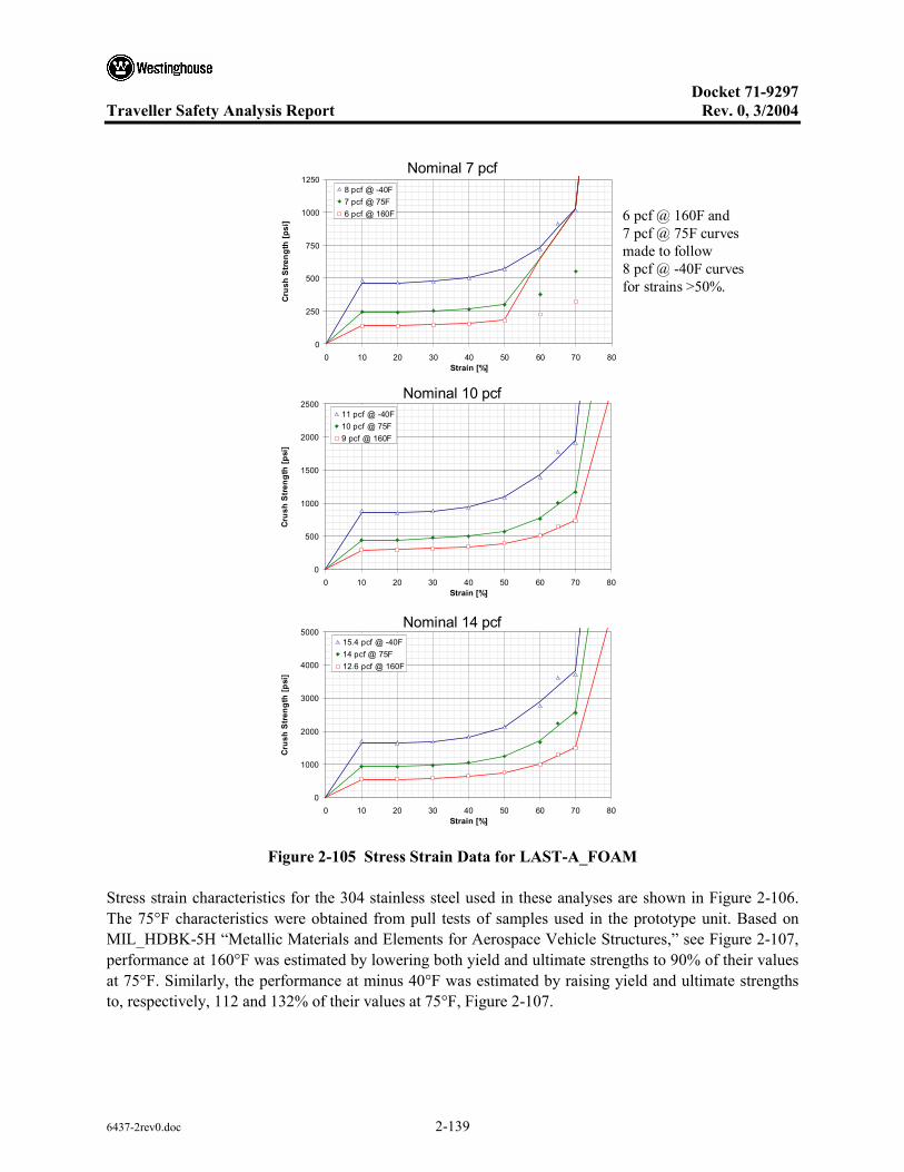
Docket 71-9297
Traveller Safety Analysis Report Rev. 0, 3/2004
6437-2rev0.doc 2-139
0
500
1000
1500
2000
2500
0 10 20 30 40 50 60 70 80Strain [%]
Cru
sh S
tren
gth
[psi
]
11 pcf @ -40F10 pcf @ 75F9 pcf @ 160F
Nominal 7 pcf
Nominal 14 pcf
Nominal 10 pcf
0
1000
2000
3000
4000
5000
0 10 20 30 40 50 60 70 80Strain [%]
Cru
sh S
tren
gth
[psi
]
15.4 pcf @ -40F14 pcf @ 75F12.6 pcf @ 160F
0
250
500
750
1000
1250
0 10 20 30 40 50 60 70 80Strain [%]
Cru
sh S
tren
gth
[psi
]
8 pcf @ -40F7 pcf @ 75F6 pcf @ 160F 6 pcf @ 160F and
7 pcf @ 75F curves made to follow 8 pcf @ -40F curves for strains >50%.
Figure 2-105 Stress Strain Data for LAST-A_FOAM
Stress strain characteristics for the 304 stainless steel used in these analyses are shown in Figure 2-106. The 75°F characteristics were obtained from pull tests of samples used in the prototype unit. Based on MIL_HDBK-5H “Metallic Materials and Elements for Aerospace Vehicle Structures,” see Figure 2-107, performance at 160°F was estimated by lowering both yield and ultimate strengths to 90% of their values at 75°F. Similarly, the performance at minus 40°F was estimated by raising yield and ultimate strengths to, respectively, 112 and 132% of their values at 75°F, Figure 2-107.

Docket 71-9297
Traveller Safety Analysis Report Rev. 0, 3/2004
6437-2rev0.doc 2-140
g p
0
500
1000
1500
2000
2500
0.0 0.1 0.2 0.3 0.4 0.5 0.6
Strain [mm/mm]
Stre
ss [M
Pa]
Estimate for -40 F75 F [9]Estimate for 160 F
Figure 2-106 Stress- Strain Curves for 304 Stainless Steel
Yield Strength
90
112
[16]
Ultimate Strength
90
132
[16]
Figure 2-107 Temperature Effects on Tensile Properties of Annealed Stainless Steel
Estimated stress strain characteristics for the 6005-T5 aluminum used in these analyses are shown in Figure 2-108. The 75°F characteristics are typical of those for 6061-T6 used in the aerospace and automotive industries.1 The 6005-T5 properties are similar based on their similar yield and ultimate strength and elongation. Because there was no available temperature dependent data, the curves for -40°F and 160°F were estimated based on the temperature dependence of aluminum alloy 6061T6. This was judged acceptable because alloy 6061-T6 is very similar to 6005-T5. However, for conservatism, we
1 This data is not published. However, a similar curve is available from ALCAN.
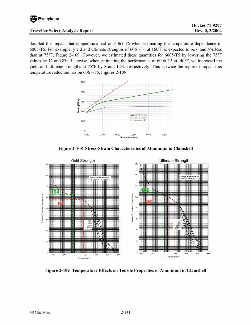
Docket 71-9297
Traveller Safety Analysis Report Rev. 0, 3/2004
6437-2rev0.doc 2-141
doubled the impact that temperature had on 6061-T6 when estimating the temperature dependence of 6005-T5. For example, yield and ultimate strengths of 6061-T6 at 160°F is expected to be 6 and 4% less than at 75°F, Figure 2-109. However, we estimated these quantities for 6005-T5 by lowering the 75°F values by 12 and 8%. Likewise, when estimating the performance of 6006-T5 at -40°F, we increased the yield and ultimate strengths at 75°F by 8 and 12%, respectively. This is twice the reported impact this temperature reduction has on 6061-T6, Figures 2-109.
0
100
200
300
400
500
0.00 0.10 0.20 0.30 0.40 0.50Strain [mm/mm]
Stre
ss [M
Pa]
'TYPICAL' for 75 FEstimate for 160 FEstimate for -40F
Figure 2-108 Stress-Strain Characteristics of Aluminum in Clamshell
Yield Strength
94
104
Ultimate Strength
96
106
Figure 2-109 Temperature Effects on Tensile Properties of Aluminum in Clamshell
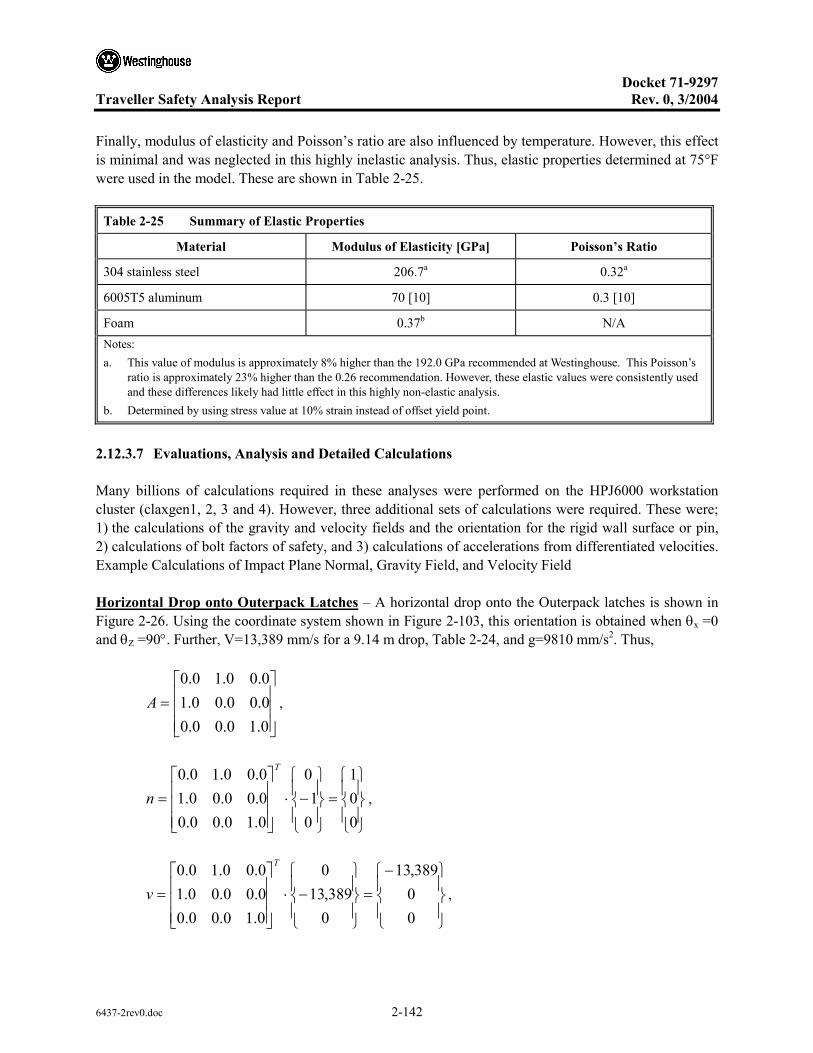
Docket 71-9297
Traveller Safety Analysis Report Rev. 0, 3/2004
6437-2rev0.doc 2-142
Finally, modulus of elasticity and Poisson’s ratio are also influenced by temperature. However, this effect is minimal and was neglected in this highly inelastic analysis. Thus, elastic properties determined at 75°F were used in the model. These are shown in Table 2-25.
Table 2-25 Summary of Elastic Properties
Material Modulus of Elasticity [GPa] Poisson’s Ratio
304 stainless steel 206.7a 0.32a
6005T5 aluminum 70 [10] 0.3 [10]
Foam 0.37b N/A Notes: a. This value of modulus is approximately 8% higher than the 192.0 GPa recommended at Westinghouse. This Poisson’s
ratio is approximately 23% higher than the 0.26 recommendation. However, these elastic values were consistently used and these differences likely had little effect in this highly non-elastic analysis.
b. Determined by using stress value at 10% strain instead of offset yield point.
2.12.3.7 Evaluations, Analysis and Detailed Calculations
Many billions of calculations required in these analyses were performed on the HPJ6000 workstation cluster (claxgen1, 2, 3 and 4). However, three additional sets of calculations were required. These were; 1) the calculations of the gravity and velocity fields and the orientation for the rigid wall surface or pin, 2) calculations of bolt factors of safety, and 3) calculations of accelerations from differentiated velocities. Example Calculations of Impact Plane Normal, Gravity Field, and Velocity Field
Horizontal Drop onto Outerpack Latches – A horizontal drop onto the Outerpack latches is shown in Figure 2-26. Using the coordinate system shown in Figure 2-103, this orientation is obtained when θx =0 and θZ =90°. Further, V=13,389 mm/s for a 9.14 m drop, Table 2-24, and g=9810 mm/s2. Thus,
=
0.10.00.00.00.00.10.00.10.0
A ,
=
−⋅
=
001
01
0
0.10.00.00.00.00.10.00.10.0 T
n ,
−=
−⋅
=
00389,13
0389,13
0
0.10.00.00.00.00.10.00.10.0 T
v ,

Docket 71-9297
Traveller Safety Analysis Report Rev. 0, 3/2004
6437-2rev0.doc 2-143
and
=
⋅
=
00810,9
0810,90
0.10.00.00.00.00.10.00.10.0 T
g .
Example Calculation of Bolt Factor of Safety – The equation below is utilized to calculate bolt factor of safety. For example, suppose a Clamshell bolt is subjected to an axial force of 5,134 lbf and shear forces of 925 and 3380 lbf. A factor of safety is calculated by first calculating the “Actual” (load) using these values of load, Table 2-26.
5175.0040,6380,3
040,6925
070,12134,5
___222
222
=
+
+
=
+
+
=
ultFSF
ultFSF
ultFNFActual zshearyshearaxial
.
This value must be divided into the “Allowable” which is 1.0. Thus, the factor of safety for the bolt in this example is 1.93. (These loads correspond to those predicted for the Clamshell keeper bolt which is third down from the top end of the Clamshell during a horizontal side drop onto the latches at time 0.0072s. The calculated value for factor of safety corresponds to that shown in Table 2-11.
Description of Acceleration Calculations – Predicted accelerations, as shown in Figures 2-88 through 2-92, were obtained by differentiating predicted nodal velocities sampled at a frequency of 4 KHz and applying a “light” (SAE 180 Hz) filter. This technique was used because the finite-difference technique used in LS-DYNA yields very noisy accelerations. These nodal accelerations are indeed accurate in an average sense, but not in an absolute value. The differentiated velocity technique allowed the true trend in accelerations to be discerned. The calculations were accomplished with the LS-POST program.
2.12.3.8 Accelerometer Test Setup
Prior to testing, piezoelectric accelerometers were mounted on the Outerpack and Clamshells of both test prototypes. The intent was to measure the accelerations at a few critical points so that the forces involved in the drops would be better known and so that the FEA results could be validated.
Three accelerometers were positioned on the Prototype Unit-1 Test series 1, Figure 2-110. One accelerometer was on the Clamshell top plate and thus was near the initial impact end. The other two were positioned on the secondary impact end at the Clamshell bottom plate and bottom impact limiter. Further details of this instrumentation are available in Appendix 2.12.4.
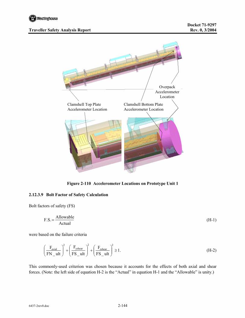
Docket 71-9297
Traveller Safety Analysis Report Rev. 0, 3/2004
6437-2rev0.doc 2-144
Overpack Accelerometer
Location
Clamshell Bottom Plate Accelerometer Location
Clamshell Top Plate Accelerometer Location
Figure 2-110 Accelerometer Locations on Prototype Unit 1
2.12.3.9 Bolt Factor of Safety Calculation
Bolt factors of safety (FS)
Actual
AllowableF.S.= (H-1)
were based on the failure criteria
.1ult_FS
Fult_FS
Fult_FN
F2
zshear2
yshear2
axial ≥
+
+
(H-2)
This commonly-used criterion was chosen because it accounts for the effects of both axial and shear forces. (Note: the left side of equation H-2 is the “Actual” in equation H-1 and the “Allowable” is unity.)
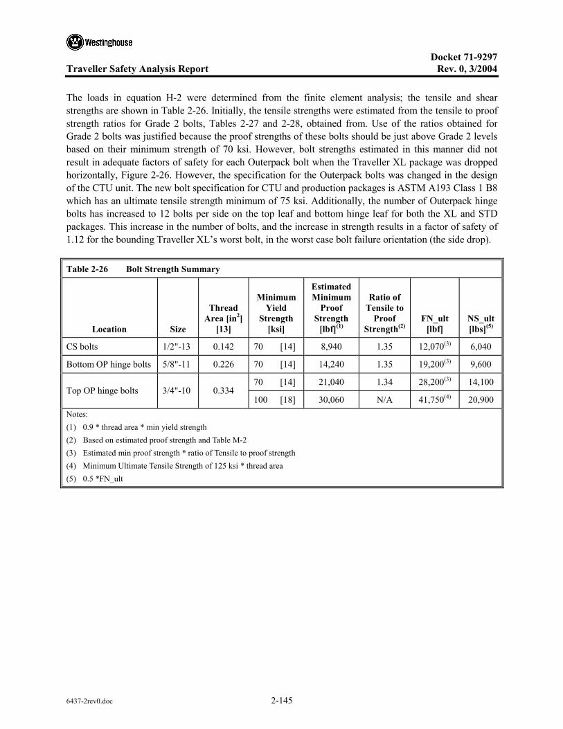
Docket 71-9297
Traveller Safety Analysis Report Rev. 0, 3/2004
6437-2rev0.doc 2-145
The loads in equation H-2 were determined from the finite element analysis; the tensile and shear strengths are shown in Table 2-26. Initially, the tensile strengths were estimated from the tensile to proof strength ratios for Grade 2 bolts, Tables 2-27 and 2-28, obtained from. Use of the ratios obtained for Grade 2 bolts was justified because the proof strengths of these bolts should be just above Grade 2 levels based on their minimum strength of 70 ksi. However, bolt strengths estimated in this manner did not result in adequate factors of safety for each Outerpack bolt when the Traveller XL package was dropped horizontally, Figure 2-26. However, the specification for the Outerpack bolts was changed in the design of the CTU unit. The new bolt specification for CTU and production packages is ASTM A193 Class 1 B8 which has an ultimate tensile strength minimum of 75 ksi. Additionally, the number of Outerpack hinge bolts has increased to 12 bolts per side on the top leaf and bottom hinge leaf for both the XL and STD packages. This increase in the number of bolts, and the increase in strength results in a factor of safety of 1.12 for the bounding Traveller XL’s worst bolt, in the worst case bolt failure orientation (the side drop).
Table 2-26 Bolt Strength Summary
Location Size
Thread Area [in2]
[13]
Minimum Yield
Strength [ksi]
Estimated Minimum
Proof Strength
[lbf](1)
Ratio of Tensile to
Proof Strength(2)
FN_ult [lbf]
NS_ult [lbs](5)
CS bolts 1/2"-13 0.142 70 [14] 8,940 1.35 12,070(3) 6,040
Bottom OP hinge bolts 5/8"-11 0.226 70 [14] 14,240 1.35 19,200(3) 9,600
70 [14] 21,040 1.34 28,200(3) 14,100 Top OP hinge bolts 3/4"-10 0.334
100 [18] 30,060 N/A 41,750(4) 20,900 Notes: (1) 0.9 * thread area * min yield strength (2) Based on estimated proof strength and Table M-2 (3) Estimated min proof strength * ratio of Tensile to proof strength (4) Minimum Ultimate Tensile Strength of 125 ksi * thread area (5) 0.5 *FN_ult
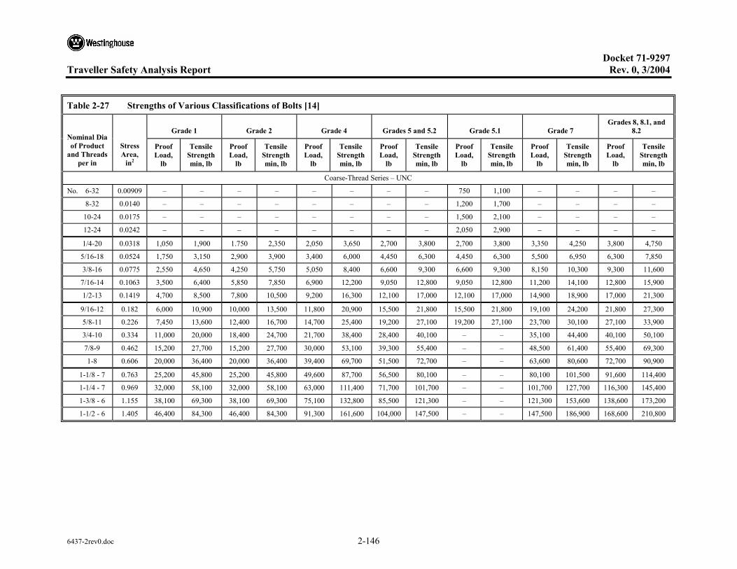
Docket 71-9297 Traveller Safety Analysis Report Rev. 0, 3/2004
6437-2rev0.doc 2-146
Table 2-27 Strengths of Various Classifications of Bolts [14]
Grade 1 Grade 2 Grade 4 Grades 5 and 5.2 Grade 5.1 Grade 7 Grades 8, 8.1, and
8.2 Nominal Dia of Product
and Threads per in
Stress Area,
in2
Proof Load,
lb
Tensile Strength min, lb
Proof Load,
lb
Tensile Strength min, lb
Proof Load,
lb
Tensile Strength min, lb
Proof Load,
lb
Tensile Strength min, lb
Proof Load,
lb
Tensile Strength min, lb
Proof Load,
lb
Tensile Strength min, lb
Proof Load,
lb
Tensile Strength min, lb
Coarse-Thread Series – UNC
No. 6-32 0.00909 – – – – – – – – 750 1,100 – – – –
8-32 0.0140 – – – – – – – – 1,200 1,700 – – – –
10-24 0.0175 – – – – – – – – 1,500 2,100 – – – –
12-24 0.0242 – – – – – – – – 2,050 2,900 – – – –
1/4-20 0.0318 1,050 1,900 1.750 2,350 2,050 3,650 2,700 3,800 2,700 3,800 3,350 4,250 3,800 4,750
5/16-18 0.0524 1,750 3,150 2,900 3,900 3,400 6,000 4,450 6,300 4,450 6,300 5,500 6,950 6,300 7,850
3/8-16 0.0775 2,550 4,650 4,250 5,750 5,050 8,400 6,600 9,300 6,600 9,300 8,150 10,300 9,300 11,600
7/16-14 0.1063 3,500 6,400 5,850 7,850 6,900 12,200 9,050 12,800 9,050 12,800 11,200 14,100 12,800 15,900
1/2-13 0.1419 4,700 8,500 7,800 10,500 9,200 16,300 12,100 17,000 12,100 17,000 14,900 18,900 17,000 21,300
9/16-12 0.182 6,000 10,900 10,000 13,500 11,800 20,900 15,500 21,800 15,500 21,800 19,100 24,200 21,800 27,300
5/8-11 0.226 7,450 13,600 12,400 16,700 14,700 25,400 19,200 27,100 19,200 27,100 23,700 30,100 27,100 33,900
3/4-10 0.334 11,000 20,000 18,400 24,700 21,700 38,400 28,400 40,100 – – 35,100 44,400 40,100 50,100
7/8-9 0.462 15,200 27,700 15,200 27,700 30,000 53,100 39,300 55,400 – – 48,500 61,400 55,400 69,300
1-8 0.606 20,000 36,400 20,000 36,400 39,400 69,700 51,500 72,700 – – 63,600 80,600 72,700 90,900
1-1/8 - 7 0.763 25,200 45,800 25,200 45,800 49,600 87,700 56,500 80,100 – – 80,100 101,500 91,600 114,400
1-1/4 - 7 0.969 32,000 58,100 32,000 58,100 63,000 111,400 71,700 101,700 – – 101,700 127,700 116,300 145,400
1-3/8 - 6 1.155 38,100 69,300 38,100 69,300 75,100 132,800 85,500 121,300 – – 121,300 153,600 138,600 173,200
1-1/2 - 6 1.405 46,400 84,300 46,400 84,300 91,300 161,600 104,000 147,500 – – 147,500 186,900 168,600 210,800
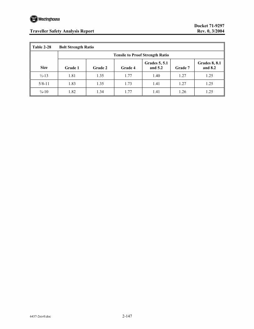
Docket 71-9297
Traveller Safety Analysis Report Rev. 0, 3/2004
6437-2rev0.doc 2-147
Table 2-28 Bolt Strength Ratio
Tensile to Proof Strength Ratio
Size Grade 1 Grade 2 Grade 4 Grades 5, 5.1
and 5.2 Grade 7 Grades 8, 8.1
and 8.2
½-13 1.81 1.35 1.77 1.40 1.27 1.25
5/8-11 1.83 1.35 1.73 1.41 1.27 1.25
¾-10 1.82 1.34 1.77 1.41 1.26 1.25
Docket 71-9297
Traveller Safety Analysis Report Rev. 0, 3/2004
6437-2rev0.doc 2-148
2.12.4 TRAVELLER DROP TESTS RESULTS
Three series of full scale drop tests have been performed on the Traveller package to evaluate the performance of the design. This appendix will summarize structural performance of the Traveller during these tests. The objectives, test articles, results and lessons learned will be described. The three series were:
• Prototype Tests • Qualification Tests • Certification Tests
2.12.4.1 Prototype Test Unit Drop Tests
Testing was conducted at Columbiana High Tech Company (CHT) in Columbiana, Ohio during the week of January 27-30, 2003 (Ref. 3).
An as-built Traveller package prototype is shown in Figures 2-111 and 2-112. Figure 2-111 shows the internal packaging including the 17x71 XL fuel assembly, Clamshell, and moderator blocks. Figure 2-112 shows the closed Outerpack. The prototype packages employed 11 pcf foam along the axial section of the package and 16 pcf foam in the endcaps. Furthermore, the Outerpack consisted of 11 gage inner and outer skin. Each package also contained 22 shock mounts to connect the Clamshell to the Outerpack.
Test Series 1 – Test series 1 was conducted on January 27th through 28th and included two 9 meter drop tests plus a pin-puncture test. The package’s test weight was 5072 pounds. Drop orientations are shown in Figure 2-113 and Table 2-29.
The Outerpack retained its basic circular pre-test shape except for localized plastic deformation from the 9 meter drop tests and the pin-puncture test. One bolt on the lower Outerpack hinge failed after completion of the last 9 meter drop test. The Outerpack did not separate after any impacts, and the pin did not perforate the inner or outer shell. The internal damage was minimal. The fuel assembly’s envelope decreased from 8.418" nominal to 8.25" maximum after the first 9 meter drop test, and reduced further to 8.13" maximum after second 9 meter drop test. Fuel rod gaps globally decreased (the fuel envelope decreased), but local expansion was noted between a few rods with a maximum measured gap of .188" for the first 9 meter drop test and .625" maximum measured gap for second 9 meter drop test (compared to the nominal gap of .122"). The polyethylene moderator blocks and aluminum neutron “poison plates” maintained position. The Clamshell doors remained closed, but the top and bottom heads were separated from the Clamshell. The separation was caused by the fuel assembly deceleration forces reacting against the clamshell end plate. The bearing force of the bolts (a shear effect on the top head plate) from impact was sufficient to fail the material in the bolt slots for both head pieces. The fuel inspection indicated that no fuel rods had ruptured, and that the axial position of fuel rods maintained location between bottom and top nozzle. The failure the clamshell endplates was due to the bolt slots being modified as a result of warping of the clamshell during fabrication.
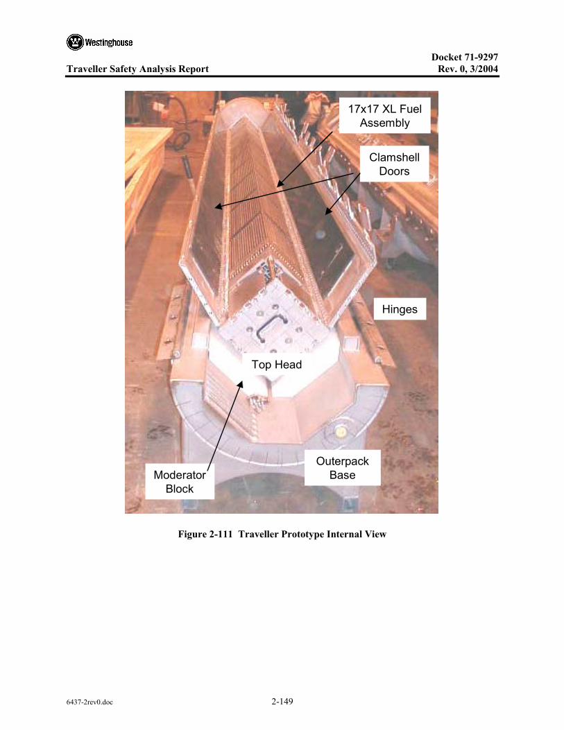
Docket 71-9297
Traveller Safety Analysis Report Rev. 0, 3/2004
6437-2rev0.doc 2-149
17x17 XL Fuel Assembly
Clamshell Doors
Top Head
Moderator Block
Outerpack Base
Hinges
17x17 XL Fuel Assembly
Clamshell Doors
Top Head
Moderator Block
Outerpack Base
Hinges
Figure 2-111 Traveller Prototype Internal View

Docket 71-9297
Traveller Safety Analysis Report Rev. 0, 3/2004
6437-2rev0.doc 2-150
Circumferential Stiffeners
End Cap
Stacking Bracket
Foaming Plug
Hinge
Figure 2-112 Traveller Prototype External View
Table 2-29 Series 1 As-Tested Drop Conditions
Test Sequence Test Pitch Attitude
Test Roll Attitude Impact Location
1.1) 9 m Low Angle
1.2) 9 m CG-over-corner
1.3) 1 m Pin-puncture
14.5°
71°
20°
180°
90°
180°
T/N primary impact on OP top
B/N primary impact on OP hinge
Center of Gravity (Axial) on OP top, T/N end down
Test 1.1 – The Outerpack retained its basic circular pre-test shape except for localized plastic deformation from the 9 meter drop test. Impact zones from the drop test were localized at the nozzle impact locations on the package ends. The Outerpack did not separate after the impact, and no bolt failures on the Outerpack hinge were noted. The top nozzle damage zone consisted of local crush approximately 12" wide, 9" axially and a maximum crush of approximately 1.5". The circumferential stiffeners were crushed (Figure 2-114) and inhibited global crushing on the Outerpack. The bottom nozzle damage zone consisted of local crush approximately 11.5" wide, a maximum crush of approximately 3/4", and axially from the package end to the edge of the stiffening ring. The internal damage was minimal as shown in Figures 2-113 and 2-114. The polyethylene moderator blocks and aluminum neutron “poison plates”
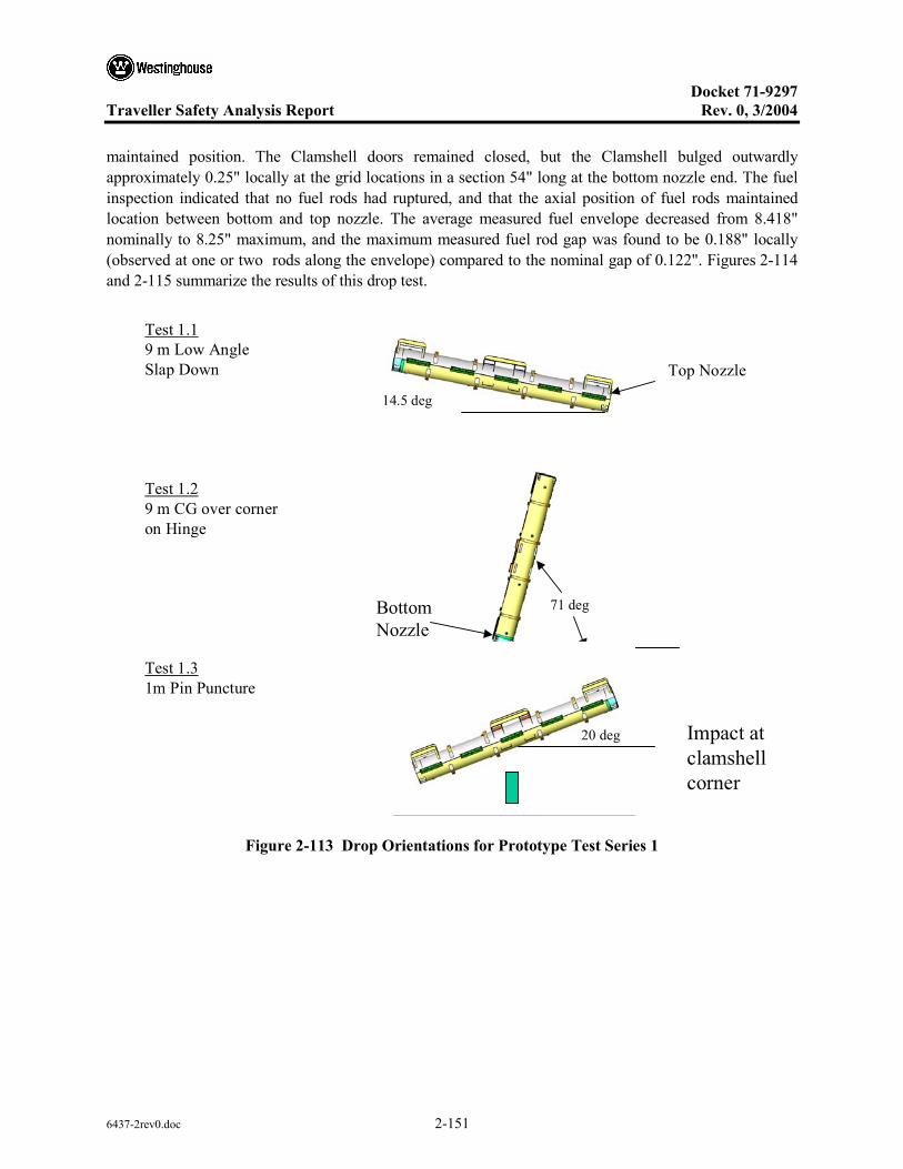
Docket 71-9297
Traveller Safety Analysis Report Rev. 0, 3/2004
6437-2rev0.doc 2-151
maintained position. The Clamshell doors remained closed, but the Clamshell bulged outwardly approximately 0.25" locally at the grid locations in a section 54" long at the bottom nozzle end. The fuel inspection indicated that no fuel rods had ruptured, and that the axial position of fuel rods maintained location between bottom and top nozzle. The average measured fuel envelope decreased from 8.418" nominally to 8.25" maximum, and the maximum measured fuel rod gap was found to be 0.188" locally (observed at one or two rods along the envelope) compared to the nominal gap of 0.122". Figures 2-114 and 2-115 summarize the results of this drop test.
Test 1.19 m Low AngleSlap Down
Test 1.29 m CG over corneron Hinge
Test 1.31m Pin Puncture
14.5 deg
Top Nozzle
71 degBottomNozzle
20 deg Impact atclamshellcorner
Figure 2-113 Drop Orientations for Prototype Test Series 1
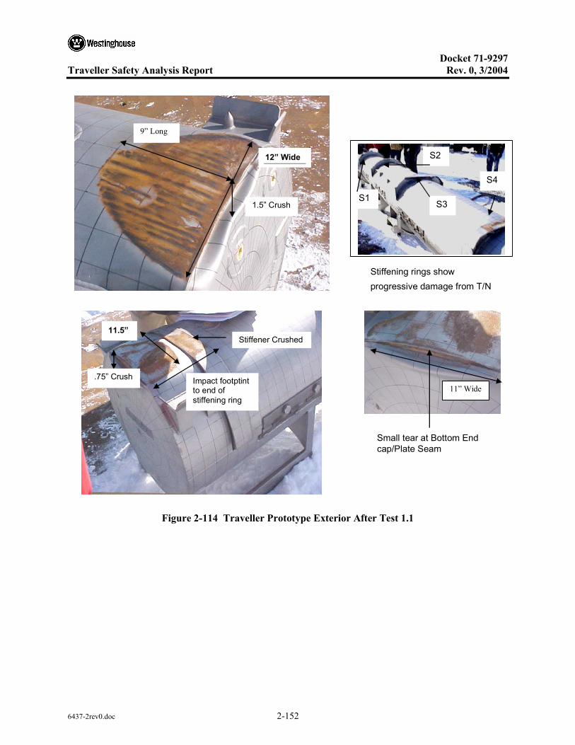
Docket 71-9297
Traveller Safety Analysis Report Rev. 0, 3/2004
6437-2rev0.doc 2-152
9” Long
1.5” Crush
12” Wide
Small tear at Bottom End cap/Plate Seam
11” Wide
Stiffener Crushed
Impact footptint to end of stiffening ring
11.5”
.75” Crush
Stiffening rings show progressive damage from T/N
S4
S3 S1
S2
Figure 2-114 Traveller Prototype Exterior After Test 1.1

Docket 71-9297
Traveller Safety Analysis Report Rev. 0, 3/2004
6437-2rev0.doc 2-153
T/N Close-up: No Significant Damage to Top head or Moderator Blocks.
F/A Damage Notes: 1.Grids 2,4,5,6,8 welds broke 2. 12 B/N plug screws sheared
No Significant Fuel Assembly Damage
About ¼” Local Bulge at Grid Locations (Section 54” Long)
Clamshell Intact
Figure 2-115 Traveller Prototype Interior After Test 1.1
Test 1.2 – The Outerpack retained its basic circular pre-test shape except for localized plastic deformation from the 9 meter drop test. Impact zones from the drop test were localized at the nozzle impact locations on the package ends. The Outerpack did not separate after the impact. One bolt failure on the Outerpack lower hinge, top nozzle end was noted. The bottom nozzle damage zone consisted of local crush approximately 10" wide, 22" tall and a maximum crush of approximately 3". The impact encompassed the stacking bracket which caused local buckling at the top/bottom Outerpack joint. A small ripple occurred in the Outerpack at this location. In addition, a tear in the Outerpack end cap measuring 8" wide resulted from the impact The top nozzle damage zone consisted of local crush approximately 6" wide, 13" long and a maximum crush of approximately 1/4". The relatively small amount of crushing is attributed the stacking bracket impacting the Outerpack in a normal direction and spreading the load more uniformly along the Outerpack length. The internal damage was more substantial than the previous drop test. The polyethylene moderator blocks and aluminum neutron“poison plates” maintained position. The Clamshell doors remained closed, but the top and bottom head pieces separated from the Clamshell. The separation

Docket 71-9297
Traveller Safety Analysis Report Rev. 0, 3/2004
6437-2rev0.doc 2-154
was caused by material shear-out as the top head connector bolts beared against the bolt slots. The bearing force of the bolts (a shear effect on the top head plate) from impact was of sufficient load to fail the material in the bolt slots for both head pieces. The fuel inspection indicated that no fuel rods had ruptured, and that the position of fuel rods maintained axial location between bottom and top nozzle. The maximum measured fuel envelope compressed from 8.25" after test 1.1 to 8.13", and the maximum measured fuel rod gap increased from 0.188" to 0.625" locally (observed at one or two rods along the envelope). The fuel rod gap expansion was also localized to Grids P, 1, 2, 3, and 4. In addition, Grid 2 failed by means of the weld joint tearing on the grid corner. External and internal results are summarized in Figures 2-116 and 2-117.
22” Tall
3” Crush
Local Buckling from stacking bracket impact
8” Tear
10” Wide
Sheared Bolt (1)
6” Wide
13” Long
.25” Crush
Figure 2-116 Traveller Prototype Exterior After Test 1.2
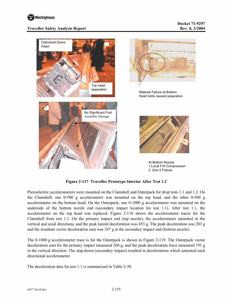
Docket 71-9297
Traveller Safety Analysis Report Rev. 0, 3/2004
6437-2rev0.doc 2-155
Material Failure at Bottom Head bolts caused separation
Clamshell Doors Intact
Top head separation
At Bottom Nozzle: 1.Local F/A Compression 2. Grid 2 Failure
No Significant Fuel Assembly Damage
Figure 2-117 Traveller Prototype Interior After Test 1.2
Piezoelectric accelerometers were mounted on the Clamshell and Outerpack for drop tests 1.1 and 1.2. On the Clamshell, one 0-500 g accelerometer was mounted on the top head, and the other 0-500 g accelerometer on the bottom head. On the Outerpack, one 0-1000 g accelerometer was mounted on the underside of the bottom nozzle end (secondary impact location for test 1.1). After test 1.1, the accelerometer on the top head was replaced. Figure 2-118 shows the accelerometer traces for the Clamshell from test 1.1. On the primary impact end (top nozzle), the accelerometer saturated in the vertical and axial directions, and the peak lateral deceleration was 453 g. The peak deceleration was 203 g and the resultant vector deceleration sum was 247 g at the secondary impact end (bottom nozzle).
The 0-1000 g accelerometer trace is for the Outerpack is shown in Figure 2-119. The Outerpack vector deceleration sum for the primary impact measured 204 g, and the peak deceleration force measured 191 g in the vertical direction. The slap-down (secondary impact) resulted in decelerations which saturated each directional accelerometer.
The deceleration data for test 1.1 is summarized in Table 2-30.

Docket 71-9297
Traveller Safety Analysis Report Rev. 0, 3/2004
6437-2rev0.doc 2-156
Table 2-30 Measured Decelerations in Prototype Test 1.1
Measured Deceleration Force, g
Accelerometer Position Vertical Lateral Axial Vector Sum
Clamshell T/N end >500 435 >500 N/A
Clamshell B/N end 118 203 78 247
Outerpack – Primary Impact 191 59 42 204
Outerpack – Slap Down >1000 >1000 >1000 N/A
T/N - Primary ImpactX - Lateral g-forceY - Vertical g-forceZ - Axial g-force
B/N - Slap Down X - Lateral g-forceY - Vertical g-forceZ - Axial g-force
Figure 2-118 Clamshell Accelerometer Trace for Prototype Test 1.1
The top head accelerometer was replaced prior to test 1.2. Due to damaged instrumentation, no data was recorded for the bottom head or the Outerpack. The primary impact occurred on the bottom nozzle end. The top head accelerometer measured the deceleration trace of the primary impact as shown in Figure 2-119. The vector deceleration sum of the primary impact measured 417 g, and the peak deceleration force measured 260 g in the axial direction. The deceleration data for test 1.2 is summarized in Table 2-31.

Docket 71-9297
Traveller Safety Analysis Report Rev. 0, 3/2004
6437-2rev0.doc 2-157
Primary Impact
Accelerometer at B/N end Slap-Down
X - Lateral g-forceY - Axial g-forceZ - Vertical g-force
Figure 2-119 Outerpack Accelerometer Trace for Prototype Test 1.1
Figure 2-120 Clamshell Accelerometer Trace for Prototype Test 1.2

Docket 71-9297
Traveller Safety Analysis Report Rev. 0, 3/2004
6437-2rev0.doc 2-158
Table 2-31 Measured Accelerations in Test 1.2
Measured Deceleration Force, g
Accelerometer Position Vertical Lateral Axial Vector Sum
Clamshell T/N end 230 232 260 417
Clamshell B/N end No data No data No data N/A
Outerpack – Primary Impact No data No data No data N/A
Outerpack – Slap Down No data No data No data N/A
Test 1.3 – The 1-meter pin puncture test resulted in little damage to the package. The outer skin of the Outerpack was locally punched approximately 1.63" and the width of the impact was approximately 10.5" as shown in Figure 2-121. The impact did not perforate the outer skin. The subsequent inspection of the inner side of the Outerpack top indicated that a small dent approximately 7/16" to 1/2" and 15" wide resulted from the pin puncture test. The moderator blocks were not impacted by the pin test.
Test Series 2 – Test series 2 was conducted on January 30th and included a 1.2-meter Normal accident condition free drop, a 1-meter pin-puncture test, and a 9-meter free drop test. The package’s test weight was 5057 pounds.
The cumulative external damage from the regulatory drop test sequence was localized to plastic deformation at the impact zones. There was no significant changes in the Outerpack geometry, and no bolt failures were noted. Upon an internal inspection, the pin did not perforate the inner or outer shell. The internal damage was minimal. The fuel assembly’s envelope decreased from 8.418" nominal to 8.25" maximum. Fuel rod gaps globally decreased (the fuel envelope decreased), but local expansion was noted between a few rods with a maximum measured gap of .188" compared to the nominal gap of .122". The polyethylene moderator blocks and aluminum neutron “poison plates” maintained position. The Clamshell doors remained closed, and the modified top head and bottom heads maintained position. A subsequent fuel inspection indicated that no fuel rods had ruptured, and that the axial position of fuel rods maintained location between bottom and top nozzle.

Docket 71-9297
Traveller Safety Analysis Report Rev. 0, 3/2004
6437-2rev0.doc 2-159
10.5” Wide
1.63” Deep
No damage to inner outerpack base. The top inner outerpack (not pictured) incurred a small dent approximately 7/16”-1/2” deep and 15” wide.
Figure 2-121 Traveller Prototype After Test 1.3
Table 2-32 Prototype Test Series 2
Test Sequence Test Pitch Attitude
Test Roll Attitude Impact Location
2.1) 1.2-m NAC drop
2.2) 1-m Pin-puncture
2.3) 9-m CG-over-corner
20°
20°
72°
180°
135°
180°
B/N primary impact on OP top
CG (Axial) on OP topside, T/N end down
T/N primary impact on OP top

Docket 71-9297
Traveller Safety Analysis Report Rev. 0, 3/2004
6437-2rev0.doc 2-160
Test 2.11.2 m Low AngleSlap Down
Test 2.21m Pin Puncture
Test 2.39 m CG over corneron Top
20 deg
BottomNozzle
20 deg
Impact atflat ofclamshell
72 deg
Top Nozzle
Figure 2-122 Drop Orientations for Traveller Prototype Test Series 2
Test 2.1 – The 1.2 meter normal condition drop test resulted in minimal damage to the Outerpack. The impact created an impact zone at the bottom end 9" wide, 2.5" in axial length, and crushed the Outerpack .75" as shown in Figure 2-123. Two stiffeners near the Outerpack center crushed approximately .75" over a width of 6". The energy absorption of the circumferential stiffeners precluded damage to the secondary impact end (top nozzle).
Test 2.2 – The second test of this drop sequence was a 1-meter pin drop on the package side, Figure 2-122. The 1-meter pin puncture test resulted in little damage to the package. The outer skin of the Outerpack was locally punched in approximately 2"as shown in Figure 2-124. The impact punch zone was 10" tall and the width of the impact was approximately 14". The impact did not perforate the outer skin.
Test 2.3 – The 9-meter drop test resulted in local damage to the primary impact region (top nozzle end). The secondary impact region was in the vicinity of the impact region of the 1.2-meter free drop and did not result in additional damage. From Figure 2-125, the damage zone was approximately 25" wide, 12" tall, and produced a crush zone approximately 9" axially. Due to the impact attitude, the Outerpack top tended to shear relative to the Outerpack bottom. A gap approximately 1" resulted from the impact, but did not comprise the Outerpack closure. No bolt failures were noted.

Docket 71-9297
Traveller Safety Analysis Report Rev. 0, 3/2004
6437-2rev0.doc 2-161
In general, the test sequence resulted in minimal Clamshell and fuel damage. The top nozzle end of the Clamshell was slightly bowed in a localized region at the top nozzle end (Figure 2-126), but did not result in fuel expansion. The modified top and bottom head pieces remained intact, and no shock mount failures were noted. The fuel inspection indicated that the assembly had moved axially toward the top nozzle 3-3/8" as a result of the spacer movement. There was no significant fuel damage at the bottom nozzle. Also the top nozzle region of the fuel assembly incurred some local damage. The guide pins buckled. Four (4) fuel rods moved axially (maximum of 1"), but did not extend beyond the neutron poison plates. The fuel inspection also indicated that no fuel rods had ruptured. The fuel rod gap measurements indicated the maximum measured fuel rod gap increased from 0.122" nominally to 0.188" locally (observed at one or two rods along the envelope). The measured fuel envelope compressed from 8.418" nominally to 8.25" maximum. The moderator blocks did not move from their original position even though two studs were sheared off. The pin-puncture test produced a 24" long by 5/8" deep dent on the inner Outerpack surface.
9” Wide
0.75 ” Crush
The axial damage zone is approximately 2.5”. No damage at T/N end.
Stiffeners crushed about .75” and also dented OP about .75”. Crush width 6”.
Figure 2-123 Traveller Prototype After Test 2.1

Docket 71-9297
Traveller Safety Analysis Report Rev. 0, 3/2004
6437-2rev0.doc 2-162
Impact very near CG based on double bounce on pin.
14” Wide
2” Deep 10” Tall
Figure 2-124 Traveller Prototype After Test 2.2

Docket 71-9297
Traveller Safety Analysis Report Rev. 0, 3/2004
6437-2rev0.doc 2-163
9” Axial Crush zone
25” Wide (full diameter)
1” Max Gap
12” Tall
No additional damage was incurred at the bottom nozzle.
Figure 2-125 Traveller Prototype After Test 2.3

Docket 71-9297
Traveller Safety Analysis Report Rev. 0, 3/2004
6437-2rev0.doc 2-164
The modified top and bottom head maintained position.
The clamshell remained closed and 3 pins failed. The T/N end bowed out about 3/16” over a 12” length.
Spacer and fuel moved 3-3/8”. No fuel damage at Bottom Nozzle.
Rod moved axially 1” maximum, but within absorber plate region.
Figure 2-126 Traveller Prototype Interior After Test Series 2
Test Series 3 – Test Series 3 consisted of three 9-meter drop tests conducted to evaluate design features of the Outerpack after modifications to the Clamshell and Outerpack. The test sequence and measured drop attitudes are summarized in Table 2-33. The test series employed was Prototype 2 that had been used for test Series 2. The purpose of this test series was to evaluate design features and evaluate design margin. External damage assessments were performed following each supplementary drop test, and a general internal assessment was conducted after the completion of test 3.3. However, the inspections for this test series were not intended for use in nuclear criticality safety analysis. Prior to test 3.1, the following modifications were made to the package:
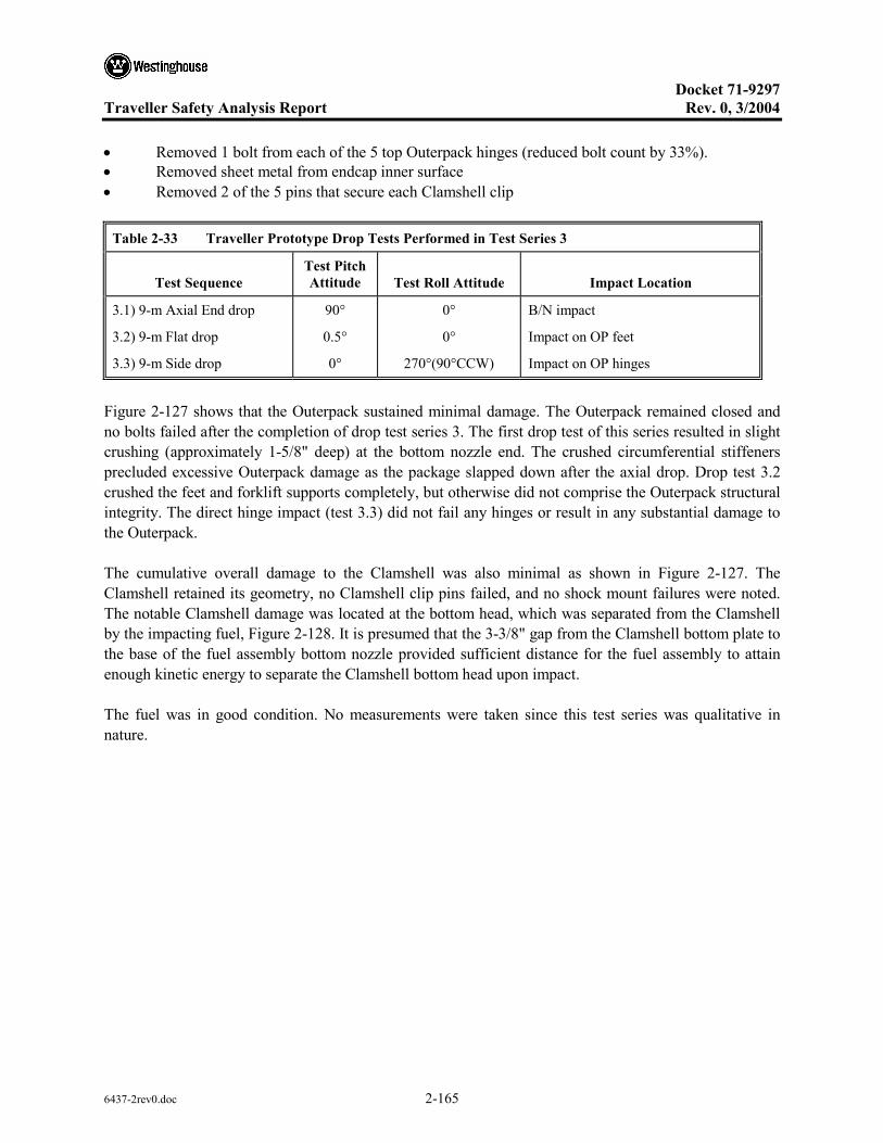
Docket 71-9297
Traveller Safety Analysis Report Rev. 0, 3/2004
6437-2rev0.doc 2-165
• Removed 1 bolt from each of the 5 top Outerpack hinges (reduced bolt count by 33%). • Removed sheet metal from endcap inner surface • Removed 2 of the 5 pins that secure each Clamshell clip
Table 2-33 Traveller Prototype Drop Tests Performed in Test Series 3
Test Sequence Test Pitch Attitude Test Roll Attitude Impact Location
3.1) 9-m Axial End drop
3.2) 9-m Flat drop
3.3) 9-m Side drop
90°
0.5°
0°
0°
0°
270°(90°CCW)
B/N impact
Impact on OP feet
Impact on OP hinges
Figure 2-127 shows that the Outerpack sustained minimal damage. The Outerpack remained closed and no bolts failed after the completion of drop test series 3. The first drop test of this series resulted in slight crushing (approximately 1-5/8" deep) at the bottom nozzle end. The crushed circumferential stiffeners precluded excessive Outerpack damage as the package slapped down after the axial drop. Drop test 3.2 crushed the feet and forklift supports completely, but otherwise did not comprise the Outerpack structural integrity. The direct hinge impact (test 3.3) did not fail any hinges or result in any substantial damage to the Outerpack.
The cumulative overall damage to the Clamshell was also minimal as shown in Figure 2-127. The Clamshell retained its geometry, no Clamshell clip pins failed, and no shock mount failures were noted. The notable Clamshell damage was located at the bottom head, which was separated from the Clamshell by the impacting fuel, Figure 2-128. It is presumed that the 3-3/8" gap from the Clamshell bottom plate to the base of the fuel assembly bottom nozzle provided sufficient distance for the fuel assembly to attain enough kinetic energy to separate the Clamshell bottom head upon impact.
The fuel was in good condition. No measurements were taken since this test series was qualitative in nature.

Docket 71-9297
Traveller Safety Analysis Report Rev. 0, 3/2004
6437-2rev0.doc 2-166
Figure 2-127 Traveller Prototype After Test Series 3
Figure 2-128 Traveller Prototype Clamshell and Bottom Impact Limiter After Test Series 3
Minor design modifications were recommended for the Traveller package based on this testing. The top and bottom heads required additional bolting to preclude Clamshell separation. The number of Clamshell clip retaining pins (and clips) could be reduced. It was found that sufficient design margin against material failure existed allowing the Outerpack gage metal can be reduced slightly in thickness. In addition, the number of Outerpack bolts can be reduced on the top hinge by at least 1/3.

Docket 71-9297
Traveller Safety Analysis Report Rev. 0, 3/2004
6437-2rev0.doc 2-167
2.12.4.2 Qualification Test Unit Drop Tests
The following section delineates the second of three (3) full-scale testing campaigns of the Traveller development program. This campaign utilized two units called Quality Test Units, or QTU-1 and 2. A total of two (2) QTUs were built and tested, with minor changes to improve burn performance incorporated into the second QTU article.
2.12.4.2.1 QTU Test Series 1
Test series 1 was conducted on the afternoon of September 11 and included a 50 inch (1.27 m) slap down, a 33.3 feet (10.15 m) center of gravity-over-corner free drop test, and a 42 inch (1.07 m) pin-puncture test. The package’s test weight was 4793 pounds (Table 2-34). The internal inspection of the fuel assembly was conducted after completion of the fire test on September 16, 2003.
Table 2-34 QTU-1 Measured Weight
Test Weights Nominal Actual
Weight of Outerpack (Empty): 3033 lb 3032 lb
Weight of Clamshell (Empty): 425 lb 400 lb
Weight of package (Empty) : 3477 lb 3432 lb
Total package test weight: 5422 lb 4793 lb
Test series 1 was conducted on the afternoon of September 11 and included a 50.75 inch (1.29 m) slap down, a 33.3 feet (10.15 m) free drop test, and a 42 inch (1.07 m) pin-puncture test. QTU1 pre-test data and observations are shown in Form 1A. The test sequence and measured drop attitudes are summarized in Table 2-35 and shown in Figure 2-129. A fuel damage assessment was conducted after the completion of the hypothetical fire condition test conducted on September 16, 2003 at the South Carolina Fire Academy near Columbia, SC.
The Outerpack retained its basic circular pre-test shape except for localized plastic deformation at the top nozzle end accumulated from the drop test series. No bolts failed on the Outerpack after completion of the drop test series. The Outerpack did not separate after any impacts, and the pin did not perforate the inner or outer shell. The most notable Outerpack damage was the resulting joint tear of approximately 1-1/8" at the Outerpack corner located at the top, left hinge side. The fuel assembly damage was minimal. At the top nozzle portion, the fuel assembly locally expanded from 8.375" nominal to 8.625" maximum over a length of approximately 2-3". The fuel rod gaps were globally unchanged but local expansion was noted between one rod near Grid 10 with a maximum measured gap of 0.250". The resulting measured maximum local pitch was 0.625 inches. Three rods were found to be in contact with each other while the remaining rods were nominally positioned. Intermediate grids 2-7 were buckled locally, but the fuel rod envelope was unchanged. The bottom nozzle portion of the fuel assembly was slightly compressed from 8.375" nominally to 8.250" measured. Based on the condition of the fuel assembly, the Clamshell was

Docket 71-9297
Traveller Safety Analysis Report Rev. 0, 3/2004
6437-2rev0.doc 2-168
concluded to have performed successfully. The fuel inspection also indicated that no fuel rods had visibly ruptured, and that the axial position of fuel rods maintained location between bottom and top nozzle.
Table 2-35 QTU-1 Drop Test Orientations
Test Article ID F/A
Type Test Sequence Test Pitch Attitude
Test Roll Attitude Design Feature Tested
17x17 XL
P1.1) 1.2 m, NAC, Low angle1
10° 180° Operations of hinges/doors
P1.2) 9 m CG-over-Corner1
108° 90° OP hinge shear, CS latches QTU1
P1.3) 1 m Pin-puncture1
83° 90° Joint Integrity – Fire test
Test 1.150-3/4 inch Low AngleSlap Down
Test 1.233feet ,4 inch CG overCorner Free Drop
Test 1.342 inch Pin Puncture
10 degTop Nozzle
Impact attop,hinge sidedamaged joint
83 deg
Top Nozzle
108 deg
Figure 2-129 Drop Orientation for QTU Test Series 1

Docket 71-9297
Traveller Safety Analysis Report Rev. 0, 3/2004
6437-2rev0.doc 2-169
Test 1.1 – The 50.75 inches (1.29 m) drop onto the Outerpack lid was performed first. As shown in Figure 2-130, this drop resulted in a small indention in the outer skin of the Outerpack.
6” long
10” wide
Figure 2-130 QTU-1 Outerpack After Test 1.1
Test 1.2 – The 33.3-foot free drop resulted in localized damage to the top nozzle end region. One of the hoist rings was sheared off as a result of the impact, Figure 2-131. The impact opened a small tear at the top and bottom Outerpack seam (also in circled region). The entire 25" diameter face of the top nozzle end was dented approximately 3-1/2". The stiffeners were also dented across their tops, but were intact. Two welds located at the bottom nozzle end stiffener were broken, but this did not compromise the stiffener position.
Test 1.3 – The pin puncture test was located in the top left (hinge) side of the Outerpack top nozzle end. The objective of the test was attempt to increase the Outerpack separation incurred by the previous 33.3-ft drop. Additional tearing of the joint was noted which resulted in measured tear of approximately 1-1/8". The indention resulting from the pin puncture was approximately 1-1/2" deep (Figure 2-132).

Docket 71-9297
Traveller Safety Analysis Report Rev. 0, 3/2004
6437-2rev0.doc 2-170
Hoist ring sheared off
Tear at overpack joint
25” wide face indented
3-1/2” deep
Figure 2-131 QTU-1 Outerpack After Test 1.2
6” pin impact location
Additional tearing at OP seam
1-1/8” tear
Figure 2-132 QTU-1 Outerpack After Test 1.3

Docket 71-9297
Traveller Safety Analysis Report Rev. 0, 3/2004
6437-2rev0.doc 2-171
QTU-1 was not opened until after the fire test. The Clamshell and fuel assembly were examined for damage at that time. The fuel assembly of QTU-1 was essentially undamaged, Figure 2-133. The most damage occurred at the top nozzle section where an area of approximately 2-3" in length increased from 8.375" nominal to 8.625". Grid 10 was torn, and all other grids were buckled but intact. The nozzles were essentially undamaged. The impact resulted in buckling of the core line-up pins attached to the top nozzle. The fuel rods appeared visibly undamaged.
The fuel assembly in QTU-1 was measured before the test and after the burn test at locations shown in Figure 2-134. Table 2-36 provides the pretest dimensions. Tables 2-37 and 2-38 provide the post test dimensions.
Grid 10 slightly torn
Fuel rod envelope unchanged.
Essentially undamaged fuel assembly.
Figure 2-133 QTU-1 Fuel Assembly After Drop and Burn Tests

Docket 71-9297
Traveller Safety Analysis Report Rev. 0, 3/2004
6437-2rev0.doc 2-172
Figure 2-134 Measurements Made on QTU Fuel Assemblies Before and After Drop Tests

Docket 71-9297
Traveller Safety Analysis Report Rev. 0, 3/2004
6437-2rev0.doc 2-173
Table 2-36 Key Dimensions of QTU-1 Fuel Assembly Before Testing
Fuel Assembly ID: 503007, B/N # 02-6703
F/A Location Fuel Envelope (inches) Gap (inches) Pitch (inches)
B/N – Grid 1 1 – 8.330
2 – 8.455
3 – 8.250
4 – 8.446
8.375 Meas. Nominal*
L – 0.122
R – 0.123
0.125 Meas. Nominal*
L – 0.497
R – 0.498
0.500 Meas. Nominal*
Grid 1 – Grid 2 1 – 8.338
2 – 8.418
3 – 8.326
4 – 8.415
8.375 Meas. Nominal*
L – 0.124
R – 0.124
0.125 Meas. Nominal*
L – 0.499
R – 0.499
0.500 Meas. Nominal*
Grid 2 – Grid 3 8.375 Meas. Nominal* L – 0.123
R – 0.120
0.125 Meas. Nominal*
L – 0.498
R – 0.495
0.500 Meas. Nominal*
Grid 3 – Grid 4 8.375 Meas. Nominal* 0.125 Meas. Nominal* 0.500 Meas. Nominal*
Grid 4 – Grid 5 8.375 Meas. Nominal* 0.125 Meas. Nominal* 0.500 Meas. Nominal*
Grid 5 – Grid 6 8.375 Meas. Nominal* 0.125 Meas. Nominal* 0.500 Meas. Nominal*
Grid 6 – Grid 7 8.375 Meas. Nominal* 0.125 Meas. Nominal* 0.500 Meas. Nominal*
Grid 8 –- Grid 9 8.375 Meas. Nominal* 0.125 Meas. Nominal* 0.500 Meas. Nominal*
Grid 9 – Grid 10 8.375 Meas. Nominal* 0.125 Meas. Nominal* 0.500 Meas. Nominal*
Grid 10 – T/N 8.375 Meas.Nominal* 0.125 Meas. Nominal* 0.500 Meas. Nominal*
Note: * Measured nominal values were measured to nearest 1/8".

Docket 71-9297
Traveller Safety Analysis Report Rev. 0, 3/2004
6437-2rev0.doc 2-174
Table 2-37 QTU-1 Fuel Assembly Grid Envelope After Testing
Fuel Assembly Envelope Inspection Table
Envelope Dimension, Inches
Location Left Side, LS Right Side, RS Maximum Fuel Rod Gap from
Form 1F (Nominal Gap = 0.122")
Between B/N and Grid 1 8.125 8.250 0.250
Between Grids 1 and 2 8.125 8.000 0.250
Between Grids 2 and 3 8.000 8.250 0.188
Between Grids 3 and 4 8.375 8.375 0.125
Between Grids 4 and 5 8.375 8.375 0.125
Between Grids 5 and 6 8.375 8.375 0.188
Between Grids 6 and 7 8.375 8.375 0.188
Between Grids 7 and 8 8.375 8.375 0.188
Between Grids 8 and 9 8.375 8.375 0.188
Between Grids 9 and 10 8.375 8.500 0.250
Between Grid 10 and T/N 8.500 8.625 0.250
MAXIMUM VALUE 8.500 8.625 0.250
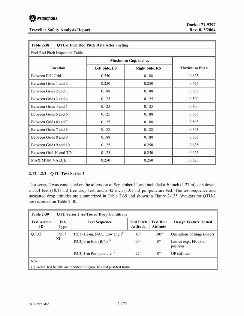
Docket 71-9297
Traveller Safety Analysis Report Rev. 0, 3/2004
6437-2rev0.doc 2-175
Table 2-38 QTU-1 Fuel Rod Pitch Data After Testing
Fuel Rod Pitch Inspection Table
Maximum Gap, inches
Location Left Side, LS Right Side, RS Maximum Pitch
Between B/N Grid 1 0.250 0.188 0.625
Between Grids 1 and 2 0.250 0.250 0.625
Between Grids 2 and 3 0.188 0.188 0.563
Between Grids 3 and 4 0.125 0.125 0.500
Between Grids 4 and 5 0.125 0.125 0.500
Between Grids 5 and 6 0.125 0.188 0.563
Between Grids 6 and 7 0.125 0.188 0.563
Between Grids 7 and 8 0.188 0.188 0.563
Between Grids 8 and 9 0.188 0.188 0.563
Between Grids 9 and 10 0.125 0.250 0.625
Between Grid 10 and T/N 0.125 0.250 0.625
MAXIMUM VALUE 0.250 0.250 0.625
2.12.4.2.2 QTU Test Series 2
Test series 2 was conducted on the afternoon of September 11 and included a 50 inch (1.27 m) slap down, a 33.4 feet (10.18 m) free drop test, and a 42 inch (1.07 m) pin-puncture test. The test sequence and measured drop attitudes are summarized in Table 2-39 and shown in Figure 2-135. Weights for QTU-2 are recorded on Table 2-40.
Table 2-39 QTU Series 2 As-Tested Drop Conditions
Test Article ID
F/A Type
Test Sequence Test Pitch Attitude
Test Roll Attitude
Design Feature Tested
P2.1) 1.2-m, NAC, Low angle(1) 10° 180° Operations of hinges/doors
P2.2) 9-m End (B/N)(1) 90° 0° Lattice exp., FR axial position
QTU2 17x17 XL
P2.3) 1-m Pin-puncture(1) 22° 0° OP stiffness
Note: (1) Actual test heights are reported in Figure 163 and post-test forms.

Docket 71-9297
Traveller Safety Analysis Report Rev. 0, 3/2004
6437-2rev0.doc 2-176
Table 2-40 QTU-2 Weights
Test Weights Nominal Actual
Weight of Outerpack (Empty): 3033 lb 2611 lb
Weight of Clamshell (Empty): 425 lb 400 lb
Weight of package (Empty) : 3477 lb 3011 lb
Total package test weight: 5422 lb 4778 lb
The Outerpack retained its basic circular pre-test shape except for localized plastic deformation accumulated from the 1.2 meter and 33.4 foot (10.18m) drop test. Damage zones from the drop test were localized to impact locations on the package end. The Outerpack did not separate after the impact, and no bolt failures on the Outerpack hinges were noted. From Figure 2-136, the 1.2 meter free drop resulted in a local crush zone at the top nozzle end measuring approximately 9-1/2" wide, 6" long axially and 7/8" deep. The Outerpack damage from the 33.4 foot drop, Figure 2-136 consisted of local crumple zone approximately 7" long maximum as demonstrated by the buckled Outerpack at the bottom nozzle end. A small weld tear was noted on each side of the Outerpack where the leg stand is connected to the end cap. The pin puncture damage was isolated to the impact point located at the package center-of-gravity. From As shown in Figure 2-138, pin puncture damage zone was an indented oval of measured dimensions 9" long by 6" wide and 2-7/8" deep.
The Clamshell was essentially undamaged from the drop test series, Figure 2-138. No change in the Clamshell grid markings were noted indicating that the Clamshell had not bulged outward (nor compressed). The polyethylene moderator blocks and aluminum neutron “poison plates” maintained position. The fuel assembly was found to be within the confines of the Clamshell and intact. The impact resulted in a slight ovalizing of the fuel assembly at the bottom nozzle region. Figure 2-139 shows the approximate angle of ovality is 118° at Grid 1 location. Localized expansion from 8.375" nominal to 8.625" was measured over a length of approximately 12" (30.48cm). The maximum fuel rod gap measured was 0.722 inches resulting in a maximum measured fuel rod pitch of 1.097 inches. The top nozzle portion of the tested fuel assembly was essentially undamaged. The axial position of fuel rods maintained location between bottom and top nozzles.

Docket 71-9297
Traveller Safety Analysis Report Rev. 0, 3/2004
6437-2rev0.doc 2-177
Test 2.150 inch Low AngleSlap Down
Test 2333 feet, 5 inch Endon Bottom Nozzle
Test 2.442-1/2 inch Pin Puncture
10 degTop Nozzle
90 deg
Impact atclamshellbase
22 deg
Bottom Nozzle
Figure 2-135 QTU Test Series 2 Drop Orientaitons

Docket 71-9297
Traveller Safety Analysis Report Rev. 0, 3/2004
6437-2rev0.doc 2-178
6” long
9-1/2” wide
7/8” deep
Figure 2-136 QTU Outerpack After Test 2.1
Figure 2-137 QTU Outerpack After Test 2.2

Docket 71-9297
Traveller Safety Analysis Report Rev. 0, 3/2004
6437-2rev0.doc 2-179
9” long
6” wide
2-7/8” deep
Figure 2-138 QTU Outerpack After Test 2.3
The fuel assembly in QTU-1 was measured before the test and after the burn test at locations shown in Figure 2-134 above. Table 2-41 provides the pretest dimensions. Tables 2-42 and 2-43 provide the post test dimensions.
The post-test inspections concluded that the tested configuration of the Traveller Outerpacks and Clamshells were acceptable. Furthermore, the tests concluded that Test Series 1 imparted the most damage to the Outerpack, and Test Series 2 imparted the most damage to the fuel assembly. Also, testing demonstrated that the Traveller Outerpack is suitable for transport with two top Outerpack bolts per hinge. The post-test geometry of the fuel assemblies for both test series was also acceptable.
In summary, testing demonstrated the Traveller package is suitable for compliance to normal and hypothetical mechanical drop test conditions described in 10 CFR 71 and TS-R-1.

Docket 71-9297
Traveller Safety Analysis Report Rev. 0, 3/2004
6437-2rev0.doc 2-180
Undamaged clamshell
118°
12” length of expanded area Relatively undamaged at Top Nozzle region
Bent rodlet
Figure 2-139 QTU-2 Clamshell and Fuel Assembly After Drop Tests

Docket 71-9297
Traveller Safety Analysis Report Rev. 0, 3/2004
6437-2rev0.doc 2-181
Table 2-41 Key Dimensions of QTU-2 Fuel Assembly Before Testing
Fuel Assembly ID: 503005, B/N # 97-2480Y
F/A Location Fuel Envelope (inches) Gap (inches) Pitch (inches)
B/N – Grid 1 1 – 8.356
2 – 8.463
3 – 8.329
4 – 8.430
8.375 Meas. Nominal*
L – 0.124
R – 0.123
0.125 Meas. Nominal*
L – 0.499
R – 0.498
0.500 Meas. Nominal*
Grid 1 – Grid 2 1 – 8.325
2 – 8.415
3 – 8.319
4 – 8.420
8.375 Meas. Nominal*
L – 0.121
R – 0.123
0.125 Meas. Nominal*
L – 0.496
R – 0.498
0.500 Meas. Nominal*
Grid 2 – Grid 3 1 – 8.333
2 – 8.410
3 – 8.329
4 – 8.411
8.375 Meas. Nominal*
L – 0.121
R – 0.123
0.125 Meas. Nominal*
L – 0.496
R – 0.498
0.500 Meas. Nominal*
Grid 3 – Grid 4 1 – 8.311
2 – 8.435
3 – 8.310
4 – 8.24
8.375 Meas. Nominal*
L – 0.124
R – 0.123
0.125 Meas. Nominal*
L – 0.499
R – 0.498
0.500 Meas. Nominal*
Grid 4 – Grid 5 8.375 Meas. Nominal* 0.125 Meas. Nominal* 0.500 Meas. Nominal*
Grid 5 – Grid 6 8.375 Meas. Nominal* 0.125 Meas. Nominal* 0.500 Meas. Nominal*
Grid 6 – Grid 7 8.375 Meas. Nominal* 0.125 Meas. Nominal* 0.500 Meas. Nominal*
Grid 8 – Grid 9 8.375 Meas. Nominal* 0.125 Meas. Nominal* 0.500 Meas. Nominal*
Grid 9 – Grid 10 8.375 Meas. Nominal* 0.125 Meas. Nominal* 0.500 Meas. Nominal*
Grid 10 – T/N 8.375 Meas. Nominal* 0.125 Meas. Nominal* 0.500 Meas. Nominal*
Note: * Measured nominal values were measured to nearest 1/8".
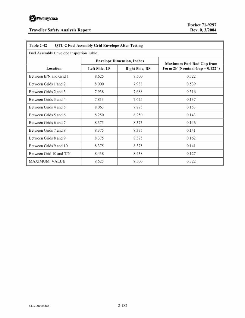
Docket 71-9297
Traveller Safety Analysis Report Rev. 0, 3/2004
6437-2rev0.doc 2-182
Table 2-42 QTU-2 Fuel Assembly Grid Envelope After Testing
Fuel Assembly Envelope Inspection Table
Envelope Dimension, Inches
Location Left Side, LS Right Side, RS Maximum Fuel Rod Gap from
Form 2F (Nominal Gap = 0.122")
Between B/N and Grid 1 8.625 8.500 0.722
Between Grids 1 and 2 8.000 7.938 0.539
Between Grids 2 and 3 7.938 7.688 0.316
Between Grids 3 and 4 7.813 7.625 0.137
Between Grids 4 and 5 8.063 7.875 0.153
Between Grids 5 and 6 8.250 8.250 0.143
Between Grids 6 and 7 8.375 8.375 0.146
Between Grids 7 and 8 8.375 8.375 0.141
Between Grids 8 and 9 8.375 8.375 0.162
Between Grids 9 and 10 8.375 8.375 0.141
Between Grid 10 and T/N 8.438 8.438 0.127
MAXIMUM VALUE 8.625 8.500 0.722

Docket 71-9297
Traveller Safety Analysis Report Rev. 0, 3/2004
6437-2rev0.doc 2-183
Table 2-43 QTU-2 Fuel Rod Pitch Data After Testing
Fuel Rod Pitch Inspection Table
Maximum Gap, inches
Location Left Side, LS Right Side, RS Maximum Pitch, inches
Between B/N and Grid 1 0.722 0.501 1.097
Between Grids 1 and 2 0.539 0.501 0.914
Between Grids 2 and 3 0.250 0.316 0.691
Between Grids 3 and 4 0.137 0.125 0.512
Between Grids 4 and 5 0.153 0.132 0.528
Between Grids 5 and 6 0.142 0.143 0.518
Between Grids 6 and 7 0.145 0.146 0.521
Between Grids 7 and 8 0.141 0.138 0.516
Between Grids 8 and 9 0.162 0.122 0.537
Between Grids 9 and 10 0.139 0.141 0.516
Between Grid 10 and T/N 0.127 0.123 0.502
MAXIMUM VALUE 0.722 0.501 1.097
2.12.4.2.3 Certification Test Unit Drop Tests
A Traveller XL package was fabricated by Columbiana High Tech to serve as the certification test unit (CTU), Figures 2-140 and 2-141 and Table 2-44. This unit was subjected to a regulatory drop test performed February 5, 2004 in Columbiana, Ohio. The test included a 50 inch (1.27 m) slap down, a 32.8 feet (10.0 m) free drop test impacting the bottom nozzle, and a 42 inch (1.07 m) pin-puncture test, Figure 2-142 and Table 2-45. The CTU package was thermally saturated for approximately 15 hours prior to testing at a temperature of about 17ºF (-8.3ºC). At the time of testing the temperature was approximately 24ºF (-4.4ºC). The package’s test weight was 4863 pounds.
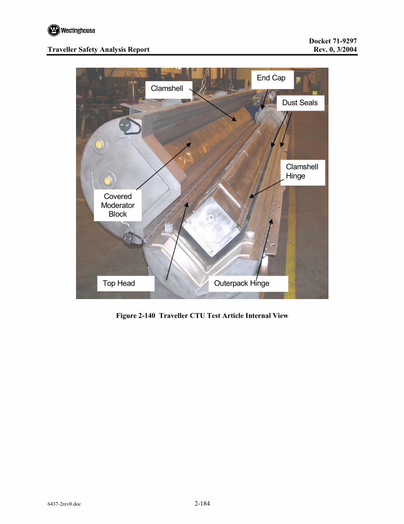
Docket 71-9297
Traveller Safety Analysis Report Rev. 0, 3/2004
6437-2rev0.doc 2-184
Clamshell Hinge
Covered Moderator
Block
Dust Seals
Clamshell
Outerpack Hinge Top Head
End Cap
Figure 2-140 Traveller CTU Test Article Internal View
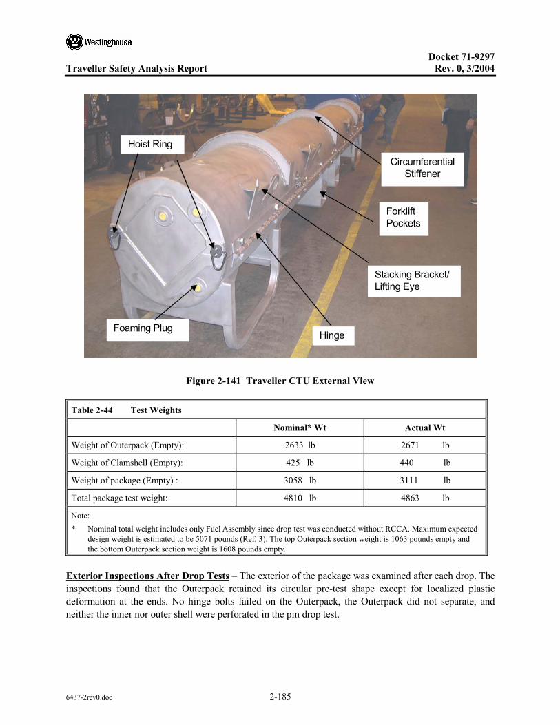
Docket 71-9297
Traveller Safety Analysis Report Rev. 0, 3/2004
6437-2rev0.doc 2-185
CircumferentialStiffener
Stacking Bracket/ Lifting Eye
Foaming Plug Hinge
Hoist Ring
Forklift Pockets
Figure 2-141 Traveller CTU External View
Table 2-44 Test Weights
Nominal* Wt Actual Wt
Weight of Outerpack (Empty): 2633 lb 2671 lb
Weight of Clamshell (Empty): 425 lb 440 lb
Weight of package (Empty) : 3058 lb 3111 lb
Total package test weight: 4810 lb 4863 lb
Note: * Nominal total weight includes only Fuel Assembly since drop test was conducted without RCCA. Maximum expected
design weight is estimated to be 5071 pounds (Ref. 3). The top Outerpack section weight is 1063 pounds empty and the bottom Outerpack section weight is 1608 pounds empty.
Exterior Inspections After Drop Tests – The exterior of the package was examined after each drop. The inspections found that the Outerpack retained its circular pre-test shape except for localized plastic deformation at the ends. No hinge bolts failed on the Outerpack, the Outerpack did not separate, and neither the inner nor outer shell were perforated in the pin drop test.

Docket 71-9297
Traveller Safety Analysis Report Rev. 0, 3/2004
6437-2rev0.doc 2-186
Test 1.150 inch Low AngleSlap Down
Test 1.232 feet, 10 inch EndDrop on B/N
Test 1.342 inch Pin Puncture
9 deg
Top Nozzle
90 degBottomNozzle
Top Nozzle
21 deg
Figure 2-142 CTU Drop Test Orientations
Table 2-45 CTU Drop Test Orientations
Test ArticleID F/A Type Test Sequence
Test Pitch
Attitude Test Roll Attitude Design Feature Tested
CTU
17x17 XL P1.1) 1.2-m, NCT, Low angle1
P1.2) 9-m End Drop1
P1.3) 1-m Pin-puncture1
9°
90°
21°
180°
0°
90°
Operations of hinges/doors
Lattice exp., FR axial position
Hinge structural integrity
Test 1 – The 1.2 meter drop test resulted in a localized dent at the top nozzle end, and near the bottom nozzle end, the stiffener was dented over a length of about 8". Figures 2-143 and 2-144 shows the damage observed. The normal condition drop produced only local damage to the impact area. The depth of the crush was minimal.
Test 2 – The 9m (32.8-foot) free drop resulted in localized damage to the bottom nozzle end region. The two bottom nozzle stiffener keeper pins were detached as a result of the impact. The impact created a circumferential ripple located at 9" (bottom Outerpack) and 12" (top Outerpack) from the package bottom end. The ripple resulted in a 1/2" crumple impact, which effectively shortened that section of the package slightly. Two stitch welds located inside the bottom nozzle end stiffener were broken, but this did not
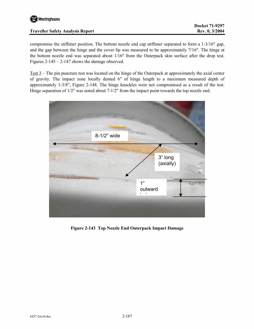
Docket 71-9297
Traveller Safety Analysis Report Rev. 0, 3/2004
6437-2rev0.doc 2-187
compromise the stiffener position. The bottom nozzle end cap stiffener separated to form a 1-3/16" gap, and the gap between the hinge and the cover lip was measured to be approximately 7/16". The hinge at the bottom nozzle end was separated about 1/16" from the Outerpack skin surface after the drop test. Figures 2-145 – 2-147 shows the damage observed.
Test 3 – The pin puncture test was located on the hinge of the Outerpack at approximately the axial center of gravity. The impact zone locally dented 6" of hinge length to a maximum measured depth of approximately 1-3/8", Figure 2-148. The hinge knuckles were not compromised as a result of the test. Hinge separation of 1/2" was noted about 7-1/2" from the impact point towards the top nozzle end.
8-1/2” wide
1” outward b l
3” long (axially)
Figure 2-143 Top Nozzle End Outerpack Impact Damage

Docket 71-9297
Traveller Safety Analysis Report Rev. 0, 3/2004
6437-2rev0.doc 2-188
Secondary impact damage at bottom nozzle end. The stiffener welds were not damaged.
8”
Figure 2-144 CTU Outerpack Stiffener After Test 1
Detached pins
1/2” Crumple
9”
2 broken welds inside lip (not visible)
12”
Figure 2-145 CTU Outerpack After Test 2
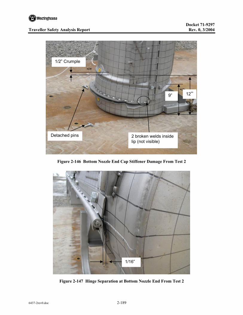
Docket 71-9297
Traveller Safety Analysis Report Rev. 0, 3/2004
6437-2rev0.doc 2-189
Detached pins
1/2” Crumple
9”
2 broken welds inside lip (not visible)
12”
Figure 2-146 Bottom Nozzle End Cap Stiffener Damage From Test 2
1/16”
Figure 2-147 Hinge Separation at Bottom Nozzle End From Test 2

Docket 71-9297
Traveller Safety Analysis Report Rev. 0, 3/2004
6437-2rev0.doc 2-190
1-3/8” deep
6” long
Figure 2-148 CTU Outerpack After Test 3
Interior Inspection Results – The CTU was sent to the South Carolina Fire Academy for the burn test immediately after the drop tests were completed. The package was not opened until the following week, approximately five hours after the fire test was completed. In general, the drop test and fire test resulted in minor damage to the Traveller internal structural components. The Clamshell was found intact and closed, Figure 2-149, and the simulated poison plates maintained position. At the bottom Clamshell plate, a 2-1/2" and a 2-3/4" piece of end lip sheared off. The measured gap was less than 1/16" and in the axial direction. The axial location of the fuel rods maintained position between the bottom and top nozzle. Finally, the moderator blocks were found to be intact and essentially undamaged after the completion of the drop and fire test. The moderator stud bolts on the top Outerpack were found sheared off, but the moderator cover maintained the moderator position. The stainless steel moderator cover was removed and the polyethylene moderator was examined. As shown in Figure 2-150, the moderator was intact and essentially undamaged.
Figure 2-151 provides the damage sketch overlaying the pre-tested fuel assembly for comparative purposes. For the 20" span from the bottom nozzle to Grid 2 of the fuel assembly, the fuel rod envelope expanded from 8-3/8" average nominal to 9-3/16". The grid envelope expanded from 8-7/16" nominal to 8-5/8" over the same 20" axial distance. The maximum measured fuel rod pitch in this region increased from 0.496" nominal to 0.990". This was caused by a single bent rod which was bent outward
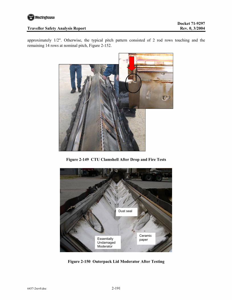
Docket 71-9297
Traveller Safety Analysis Report Rev. 0, 3/2004
6437-2rev0.doc 2-191
approximately 1/2". Otherwise, the typical pitch pattern consisted of 2 rod rows touching and the remaining 14 rows at nominal pitch, Figure 2-152.
Figure 2-149 CTU Clamshell After Drop and Fire Tests
Dust seal
Ceramicpaper Essentially
Undamaged Moderator
Figure 2-150 Outerpack Lid Moderator After Testing

Docket 71-9297
Traveller Safety Analysis Report Rev. 0, 3/2004
6437-2rev0.doc 2-192
For a length of 10" above Grid 2, the fuel rod envelope compressed from 8-3/8" nominal to 8-1/4". This slight compression is due to the single top rod slightly compressed inward. Above this 10" region, the single rod bent outward about 1/2" for a length of approximately 25".
For the 25" length from between Grids 2 and 3 and up to Grid 4, the single rod resulted in a measured envelope of 8-7/8", but the remaining envelope of 16 rows was slightly compressed (about 1/16"). The maximum pitch caused by the single rod was 0.740" compared to 0.496" nominal. Otherwise, the average pitch was nominal.
For the remainder of the fuel assembly from Grid 4 to the top nozzle, the fuel rod envelope compressed about 0.15" and the grid envelope compressed about 1/4". The average pitch decreased from 0.496" to 0.459" in this region.
Grid 1 was severely buckled, and the ovality was measured to be 120º for a length of about 20", Figure 2-153. Grids 2 and 3 were broken at the top corner, but otherwise intact. Grids 4-10 were relatively undamaged. The fuel inspection also indicated that 7.5% (20 of 265 rods) were cracked at the end plug locations (Figure 2-154). The average crack width measured was approximately 0.030" (30 mils) and the average length was 50% of the rod diameter. The cracked rods were located at the four corners, indicating the vertical impact created symmetrical impact forces to be transmitted through the bottom nozzle and fuel rods (Figure 2-155).
The fuel assembly in QTU-1 was measured before the test and after the burn test at locations shown in Figure 2-134 above. Table 2-46 provides the pretest dimensions. Tables 2-47 through 2-50 provide the post test dimensions.
2.12.4.3 Conclusions
Three series of drop tests were performed during the development and certification of the Traveller shipping package. This included two prototype units, two qualification test units and one certification test unit. Design improvements were made at each step based on the results of the drop tests and subsequent fire tests. The drop test series included a regulatory normal free drop of 1.2 meters, a 9-meter end drop onto the bottom nozzle, and a 1-meter pin-puncture test on the hinge. Minor structural Outerpack damage indicated that the Traveller Outerpack design satisfied the hypothetical accident condition defined in 10 CFR 71 and TS-R-1. Furthermore, the Clamshell was found to meet the acceptance criteria of the test by maintaining closure and its pre-test shape. The post-test geometry of the fuel assembly was determined to meet the acceptance criteria since only local expansion was noted in the lower 20" of the bottom nozzle region and the cracked rod gaps were all measured less than a pellet diameter.
In summary, testing demonstrated the Traveller package is suitable for compliance to normal and hypothetical mechanical drop test conditions described in 10 CFR 71 and TS-R-1.

Docket 71-9297
Traveller Safety Analysis Report Rev. 0, 3/2004
6437-2rev0.doc 2-193
21.2738.375Nominal FA
24.139.5Clamshell
Grid #1
Grid #2
Grid #3
Grid #4
19.88”
(50.5)
38.5”
(97.79) 25” section: Single Rod - 8.875” (22.543 cm)
Remaining Env. - 8.3125” (21.114 cm)
10” section: Envelope - 8.25” (20.955 cm)
BN to grid #2: Envelope - 9.19” (23.34 cm)
Grid #4 to TN: Envelope - 8.225” (20.892 cm)
Grid #1 : 120 degrees
4.07”
(10.3)
Figure 2-151 Fuel assembly Damage Sketch and Pre-test Assembly

Docket 71-9297
Traveller Safety Analysis Report Rev. 0, 3/2004
6437-2rev0.doc 2-194
Rod envelope slightly compressed from Grid 4 to T/N.
Relatively little damage from Grid 4 to T/N.
Figure 2-152 CTU Fuel Assembly After Testing
120º
Expanded region 20” long. Average rod envelope 9-3/16”.
Single rod expanded to clamshell inner surface. Other rods slightly compressed.
Figure 2-153 CTU Fuel Assembly Top End After Testing

Docket 71-9297
Traveller Safety Analysis Report Rev. 0, 3/2004
6437-2rev0.doc 2-195
Figure 2-154 Cracked Rod From CTU Fuel Assembly
Figure 2-155 Cracked Rod Locations on CTU Fuel Assembly
The cracks occurred at the end plug weld zone for all cracked rods.

Docket 71-9297
Traveller Safety Analysis Report Rev. 0, 3/2004
6437-2rev0.doc 2-196
Table 2-46 Fuel Assembly Key Dimension Before Drop Test
Fuel Assembly ID: T/N # LM1F2N
F/A Location Fuel Envelope (inches) Gap (inches) Pitch (inches)
B/N – Grid 1 1: 8-3/8 2: 8-7/16 3: 8-3/8 4: 8-7/16
L – 0.123 R – 0.121
L – 0.498 R – 0.495
Grid 1- Grid 2 1: 8-3/8 2: 8-7/16 3: 8-3/8 4: 8-7/16
L – 0.123 R – 0.124
L – 0.497 R – 0.499
Grid 2- Grid 3 1: 8-3/8 2: 8-7/16 3: 8-3/8 4: 8-7/16
L – 0.121 R – 0.121
L – 0.495 R – 0.495
Grid 3- Grid 4 1: 8-3/8 2: 8-7/16 3: 8-3/8 4: 8-7/16
L – 0.123 R – 0.123
L – 0.497 R – 0.498
Grid 4- Grid 5 Rods: 8-3/8 Grids: 8-7/16
0.121 0.495
Grid 5- Grid 6 Rods: 8-3/8 Grids: 8-7/16
0.123 0.498
Grid 6- Grid 7 Rods: 8-3/8 Grids: 8-7/16
0.122 0.497
Grid 7- Grid 8 Rods: 8-3/8 Grids: 8-7/16
0.123 0.497
Grid 8- Grid 9 Rods: 8-3/8 Grids: 8-7/16
0.123 0.498
Grid 9- Grid 10 Rods: 8-3/8 Grids: 8-7/16
0.121 0.495
Grid 10 – T/N Rods: 8-3/8 Grids: 8-7/16
0.122 0.497
AVERAGE Rods: 8-3/8 Grids: 8-7/16:
0.122 0.497
Note: * Measured fractional values were measured to nearest 1/16". Measured decimal values were measured to the nearest 0.001".

Docket 71-9297
Traveller Safety Analysis Report Rev. 0, 3/2004
6437-2rev0.doc 2-197
Table 2-47 CTU Fuel Assembly Grid Envelop Dimensions After Testing
Measured Grid Envelope Dimension, Inches
Location Left Side, LS Right Side, RS
Grid 1 9-0 8-3/4
Grid 2 8-7/16 8-3/8
Grid 3 9-1/2 9-1/2
Grid 4 8-1/8 8-1/4
Grid 5 8-1/8 8-1/4
Grid 6 8-1/4 8-1/4
Grid 7 8-1/8 8-3/16
Grid 8 8-5/16 8-3/16
Grid 9 8-5/16 7-7/8
Grid 10 8-3/8 8-1/2
MAXIMUM VALUE 9-1/2 9-1/2

Docket 71-9297
Traveller Safety Analysis Report Rev. 0, 3/2004
6437-2rev0.doc 2-198
Table 2-48 CTU Fuel Assembly Rod Envelope Data After Testing
Fuel Assembly Rod Envelope Inspection Table
Measured Envelope Dimension, In.
Location Left Side, LS Right Side, RS
Calculated Maximum Fuel Rod Pitch from Form 1G
(Nominal Pitch = 0.496")
Between B/N and Grid 1 9-0 8-3/4 0.566
Between Grids 1 and 2 8-5/16 (1) 8-5/16 (1) 0.990
Between Grids 2 and 3 8-1/2 8.-0 0.740
Between Grids 3 and 4 8-7/16 8-1/2 0.715
Between Grids 4 and 5 8-3/16 8-3/16 0.472
Between Grids 5 and 6 8-3/16 8-3/8 0.578
Between Grids 6 and 7 8-1/16 8-1/16 0.550
Between Grids 7 and 8 8-3/8 8-3/16 0.541
Between Grids 8 and 9 8-0 7-13/16 0.483
Between Grids 9 and 10 8-3/8 8-1/2 0.498
Between Grid 10 and T/N 8-3/8 8-0 0.497
MAXIMUM VALUE 9-0 8-3/4 0.990
Note: (1) A single rod was measured to the inner Clamshell surface (9-1/2"). See Figure 2-153.
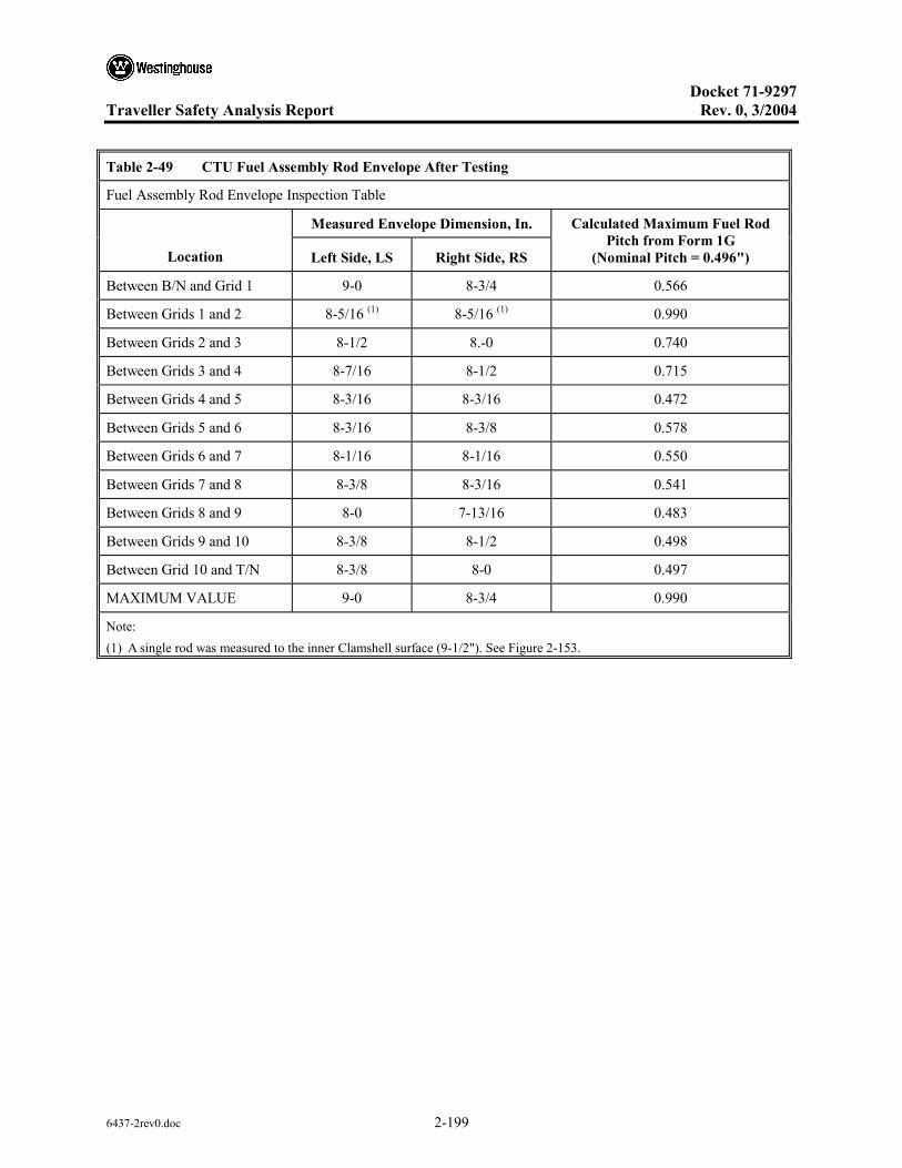
Docket 71-9297
Traveller Safety Analysis Report Rev. 0, 3/2004
6437-2rev0.doc 2-199
Table 2-49 CTU Fuel Assembly Rod Envelope After Testing
Fuel Assembly Rod Envelope Inspection Table
Measured Envelope Dimension, In.
Location Left Side, LS Right Side, RS
Calculated Maximum Fuel Rod Pitch from Form 1G
(Nominal Pitch = 0.496")
Between B/N and Grid 1 9-0 8-3/4 0.566
Between Grids 1 and 2 8-5/16 (1) 8-5/16 (1) 0.990
Between Grids 2 and 3 8-1/2 8.-0 0.740
Between Grids 3 and 4 8-7/16 8-1/2 0.715
Between Grids 4 and 5 8-3/16 8-3/16 0.472
Between Grids 5 and 6 8-3/16 8-3/8 0.578
Between Grids 6 and 7 8-1/16 8-1/16 0.550
Between Grids 7 and 8 8-3/8 8-3/16 0.541
Between Grids 8 and 9 8-0 7-13/16 0.483
Between Grids 9 and 10 8-3/8 8-1/2 0.498
Between Grid 10 and T/N 8-3/8 8-0 0.497
MAXIMUM VALUE 9-0 8-3/4 0.990
Note: (1) A single rod was measured to the inner Clamshell surface (9-1/2"). See Figure 2-153.
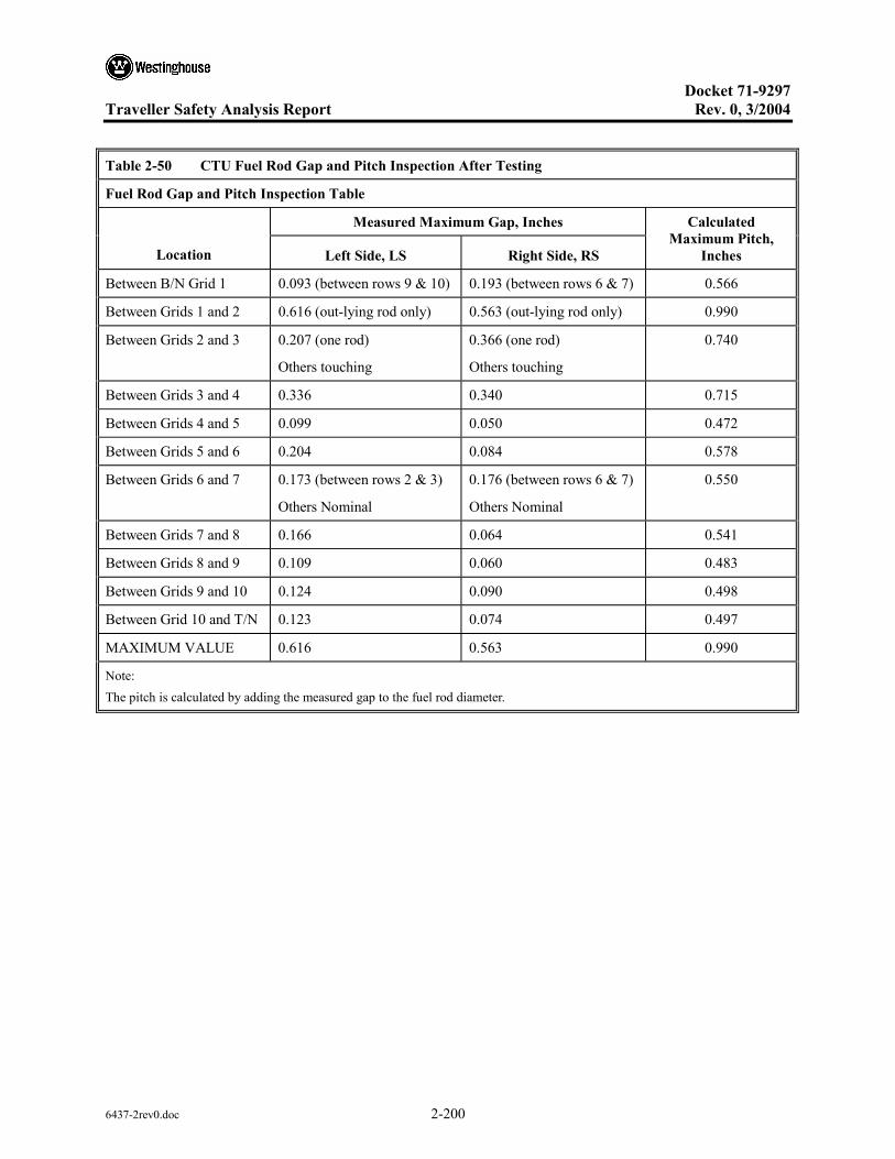
Docket 71-9297
Traveller Safety Analysis Report Rev. 0, 3/2004
6437-2rev0.doc 2-200
Table 2-50 CTU Fuel Rod Gap and Pitch Inspection After Testing
Fuel Rod Gap and Pitch Inspection Table
Measured Maximum Gap, Inches
Location Left Side, LS Right Side, RS
Calculated Maximum Pitch,
Inches
Between B/N Grid 1 0.093 (between rows 9 & 10) 0.193 (between rows 6 & 7) 0.566
Between Grids 1 and 2 0.616 (out-lying rod only) 0.563 (out-lying rod only) 0.990
Between Grids 2 and 3 0.207 (one rod)
Others touching
0.366 (one rod)
Others touching
0.740
Between Grids 3 and 4 0.336 0.340 0.715
Between Grids 4 and 5 0.099 0.050 0.472
Between Grids 5 and 6 0.204 0.084 0.578
Between Grids 6 and 7 0.173 (between rows 2 & 3)
Others Nominal
0.176 (between rows 6 & 7)
Others Nominal
0.550
Between Grids 7 and 8 0.166 0.064 0.541
Between Grids 8 and 9 0.109 0.060 0.483
Between Grids 9 and 10 0.124 0.090 0.498
Between Grid 10 and T/N 0.123 0.074 0.497
MAXIMUM VALUE 0.616 0.563 0.990
Note: The pitch is calculated by adding the measured gap to the fuel rod diameter.
Docket 71-9297
Traveller Safety Analysis Report Rev. 0, 3/2004
6437-3rev0.doc i
TABLE OF CONTENTS
3 THERMAL EVALUATION ........................................................................................................3-1 3.1 DESCRIPTION OF THERMAL DESIGN .....................................................................3-1
3.1.1 Design Features ...............................................................................................3-1 3.1.2 Contents Decay Heat .......................................................................................3-2 3.1.3 Summary Tables of Temperatures...................................................................3-2 3.1.4 Summary Tables of Maximum Pressures ........................................................3-3
3.2 MATERIALS PROPERTIES AND COMPONENT SPECIFICATIONS ......................3-3 3.2.1 Materials Properties.........................................................................................3-3 3.2.2 Component Specifications...............................................................................3-4
3.3 GENERAL CONSIDERATIONS ...................................................................................3-5 3.3.1 Evaluation by Analysis....................................................................................3-5 3.3.2 Evaluation by Test ...........................................................................................3-7
3.3.2.1 Seam Burn Test ...............................................................................3-7 3.3.2.2 Impact Limiter Burn Test ................................................................3-8
3.3.3 Margins of Safety ..........................................................................................3-10 3.4 THERMAL EVALUATION UNDER NORMAL CONDITIONS OF
TRANSPORT+..............................................................................................................3-10 3.5 THERMAL EVALUATION UNDER HYPOTHETICAL ACCIDENT
CONDITIONS ...............................................................................................................3-10 3.5.1 Initial Conditions ...........................................................................................3-13 3.5.2 Fire Test Conditions ......................................................................................3-13 3.5.3 Maximum Temperatures and Pressures.........................................................3-13 3.5.4 Accident Conditions for Fissile Material Packages for Air Transport ..........3-14
3.6 APPENDICES ...............................................................................................................3-15 3.6.1 TRAVELLER THERMAL ANALYSIS.......................................................3-16 3.6.2 TRAVELLER SEAM BURN TESTS...........................................................3-19
3.6.2.1 Test Results ...................................................................................3-21 3.6.2.2 Conclusions ...................................................................................3-25
3.6.3 TRAVELLER IMPACT LIMITER BURN TESTS......................................3-26 3.6.3.1 First Impact Limiter Burn (December 15) ....................................3-27 3.6.3.2 Second Impact Limiter Burn (December 16) ................................3-31 3.6.3.3 Test Conclusions ...........................................................................3-33
3.6.4 TRAVELLER CERTIFICATION TEST UNIT BURN TEST .....................3-35 3.6.4.1 Test Procedures and Results..........................................................3-40

Docket 71-9297
Traveller Safety Analysis Report Rev. 0, 3/2004
6437-3rev0.doc ii
LIST OF TABLES
Table 3-1 Summary Table of Temperatures for Traveller Materials ...............................................3-2
Table 3-2 Room Temperature Properties of Key Traveller Materials .............................................3-4
Table 3-3 Room Temperature Properties of Key Fuel Assembly Materials ....................................3-4
Table 3-4 Temperature Dependent Thermal Conductivity Used to Model Polyurethane Foam ..............................................................................................................................3-17
Table 3-5 Optical Thermometer Data Sheet (West Side, Degrees C) ............................................3-45
Table 3-6 Optical Thermometer Data Sheet (East Side, Degrees C) .............................................3-46
Table 3-7 Wind Data Sheet ............................................................................................................3-47

Docket 71-9297
Traveller Safety Analysis Report Rev. 0, 3/2004
6437-3rev0.doc iii
LIST OF FIGURES
Figure 3-1 Calculated Radial Temperature Distribution for 30 Minute Fire (800°C).......................3-6
Figure 3-2 Calculated Radial Temperature Distribution for 30 Minute Fire (1000°C).....................3-6
Figure 3-3 Seam Burn Test................................................................................................................3-8
Figure 3-4 December 15, Impact Limiter Burn Test .........................................................................3-9
Figure 3-5 Pool Fire Test Facility....................................................................................................3-11
Figure 3-6 Traveller CTU During Pool Fire Test ............................................................................3-12
Figure 3-7 Thermocouple Locations Measuring Fire Temperature During CTU Burn Test...........3-12
Figure 3-8 Temperature Strip Condition After CTU Burn Test ......................................................3-14
Figure 3-9 Approach Used to Generate Analytical Model Geometry .............................................3-16
Figure 3-10 Seam Burn Test Orientation...........................................................................................3-20
Figure 3-11 Package Exterior Wrapped with Ceramic Fiber Insulation ...........................................3-20
Figure 3-12 Measured Temperatures During Second Burn of the Control Section ..........................3-21
Figure 3-13 Interior Temperature Measurements During Test of Continuous Hinge Section ..........3-23
Figure 3-14 Interior Temperature Measures After Test of Continuous Hinge Section .....................3-23
Figure 3-15 Interior Temperature Measurements During Test of Covered Moderator Section ........3-24
Figure 3-16 Gaps in Outerpack Bottom Seam at Covered Moderator Test Section..........................3-25
Figure 3-17 Thermocouple Locations in Impact Limiter ..................................................................3-26
Figure 3-18 Thermocouple Locations in Outerpack Interior.............................................................3-27
Figure 3-19 December 15, Impact Limiter Burn Test .......................................................................3-28
Figure 3-20 Impact Limiter Pillow Temperatures .............................................................................3-29
Figure 3-21 Internal Outerpack Skin Temperatures (December 15 Burn) ........................................3-29
Figure 3-22 Flame Temperatures Measured by Optical Pyrometers.................................................3-30
Figure 3-23 Outerpack Internals after December 15 Burn Test ........................................................3-30
Figure 3-24 Kaowool Layers on Outerpack Bottom Impact Limiter ................................................3-31
Figure 3-25 December 16 Impact Limiter Burn ................................................................................3-32
Figure 3-26 Internal Outerpack Skin Temperatures (December 16 Burn) ........................................3-32
Figure 3-27 Impact Limiter Pillow Temperatures (December 16 Burn) ...........................................3-33
Figure 3-28 Traveller CTU Burn Test ...............................................................................................3-36
Docket 71-9297
Traveller Safety Analysis Report Rev. 0, 3/2004
6437-3rev0.doc iv
LIST OF FIGURES (cont.)
Figure 3-29 Thermocouple Locations on CTU Burn Test.................................................................3-36
Figure 3-30 Polyurethane Char in Outerpack Seam After Burn Test................................................3-37
Figure 3-31 Brown Polyurethane Residue Inside Outerpack After Burn Test ..................................3-37
Figure 3-32 Test Stand for Fire Test .................................................................................................3-39
Figure 3-33 Test Setup with Steel Diffuser Plates.............................................................................3-39
Figure 3-34 Test Article Under Tent to Maintain Temperature Overnight .......................................3-40
Figure 3-35 Overnight Temperatures on East Side of Test Article ...................................................3-41
Figure 3-36 Overnight Temperatures on West Side of Test Article..................................................3-41
Figure 3-37 Fire Temperatures Measured at the Corners of the Pool ...............................................3-42
Figure 3-38 Data from Direction Flame Thermometers (DFTs) .......................................................3-43
Figure 3-39 Skin Temperature Data from East Side of CTU ............................................................3-43
Figure 3-40 Skin Temperature Data from West Side of CTU...........................................................3-44
Figure 3-41 Fire Temperature Data from East Side of CTU .............................................................3-44
Figure 3-42 Fire Temperature Data from West Side of CTU............................................................3-45
Figure 3-43 Location of Possible Combustion of Moderator ............................................................3-48
Figure 3-44 Localized Melt Spot in Lid Moderator Block................................................................3-48
Figure 3-45 Location and Indicated Temperatures of Temperature Strip Sets..................................3-49
Figure 3-46 Temperature Strip Set After Fire Test ...........................................................................3-49
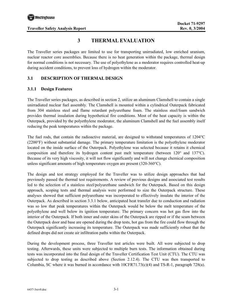
Docket 71-9297
Traveller Safety Analysis Report Rev. 0, 3/2004
6437-3rev0.doc 3-1
3 THERMAL EVALUATION
The Traveller series packages are limited to use for transporting unirradiated, low enriched uranium, nuclear reactor core assemblies. Because there is no heat generation within the package, thermal design for normal conditions is not necessary. The use of polyethylene as a moderator requires controlled heat-up during accident conditions, to prevent loss of hydrogen within the moderator.
3.1 DESCRIPTION OF THERMAL DESIGN
3.1.1 Design Features
The Traveller series packages, as described in section 2, utilize an aluminum Clamshell to contain a single unirradiated nuclear fuel assembly. The Clamshell is mounted within a cylindrical Outerpack fabricated from 304 stainless steel and flame retardant polyurethane foam. The stainless steel/foam sandwich provides thermal insulation during hypothetical fire conditions. Most of the heat capacity is within the Outerpack, provided by the polyethylene moderator, the aluminum Clamshell and the fuel assembly itself reducing the peak temperatures within the package.
The fuel rods, that contain the radioactive material, are designed to withstand temperatures of 1204°C (2200°F) without substantial damage. The primary temperature limitation is the polyethylene moderator located on the inside surface of the Outerpack. Polyethylene was selected because it retains it chemical composition and therefore its hydrogen content past melt temperature (between 120° and 137°C). Because of its very high viscosity, it will not flow significantly and will not change chemical composition unless significant amounts of high temperature oxygen are present (320-360°C).
The design and test strategy employed for the Traveller was to utilize design approaches that had previously passed the thermal test requirements. A review of previous designs and associated test results led to the selection of a stainless steel/polyurethane sandwich for the Outerpack. Based on this design approach, scoping tests and thermal analysis were performed to size the Outerpack structure. These analyses showed that sufficient polyurethane was incorporated to effectively insulate the interior of the Outerpack. As described in section 3.3.1 below, anticipated heat transfer due to conduction and radiation was so low that peak temperatures within the Outerpack would be below the melt temperature of the polyethylene and well below its ignition temperature. The primary concern was hot gas flow into the interior of the Outerpack. If both inner and outer skins of the Outerpack are ripped or if the seam between the Outerpack door and base are opened during the drop tests, hot gas from the fire could flow through the Outerpack significantly increasing its temperature. The Outerpack was made sufficiently robust that the defined drops did not create air infiltration paths within the Outerpack.
During the development process, three Traveller test articles were built. All were subjected to drop testing. Afterwards, these units were subjected to multiple burn tests. The information obtained during tests was incorporated into the final design of the Traveller Certification Test Unit (CTU). The CTU was subjected to drop testing as described above (Section 2.12.4). The CTU was then transported to Columbia, SC where it was burned in accordance with 10CFR71.73(c)(4) and TS-R-1, paragraph 728(a).
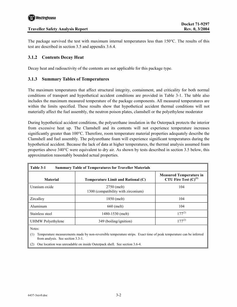
Docket 71-9297
Traveller Safety Analysis Report Rev. 0, 3/2004
6437-3rev0.doc 3-2
The package survived the test with maximum internal temperatures less than 150°C. The results of this test are described in section 3.5 and appendix 3.6.4.
3.1.2 Contents Decay Heat
Decay heat and radioactivity of the contents are not applicable for this package type.
3.1.3 Summary Tables of Temperatures
The maximum temperatures that affect structural integrity, containment, and criticality for both normal conditions of transport and hypothetical accident conditions are provided in Table 3-1. The table also includes the maximum measured temperature of the package components. All measured temperatures are within the limits specified. These results show that hypothetical accident thermal conditions will not materially affect the fuel assembly, the neutron poison plates, clamshell or the polyethylene moderator
During hypothetical accident conditions, the polyurethane insulation in the Outerpack protects the interior from excessive heat up. The Clamshell and its contents will not experience temperature increases significantly greater than 100°C. Therefore, room temperature material properties adequately describe the Clamshell and fuel assembly. The polyurethane foam will experience significant temperatures during the hypothetical accident. Because the lack of data at higher temperatures, the thermal analysis assumed foam properties above 340°C were equivalent to dry air. As shown by tests described in section 3.5 below, this approximation reasonably bounded actual properties.
Table 3-1 Summary Table of Temperatures for Traveller Materials
Material Temperature Limit and Rational (C) Measured Temperature in
CTU Fire Test (C)(1)
Uranium oxide 2750 (melt) 1300 (compatibility with zirconium)
104
Zircalloy 1850 (melt) 104
Aluminum 660 (melt) 104
Stainless steel 1480-1530 (melt) 177(2)
UHMW Polyethylene 349 (boiling/ignition) 177(2)
Notes: (1) Temperature measurements made by non-reversible temperature strips. Exact time of peak temperature can be inferred
from analysis. See section 3.3-1. (2) One location was unreadable on inside Outerpack shell. See section 3.6-4.
Docket 71-9297
Traveller Safety Analysis Report Rev. 0, 3/2004
6437-3rev0.doc 3-3
3.1.4 Summary Tables of Maximum Pressures
The Traveller Outerpack surrounds the Clamshell and fuel assembly. It has two rubberized fiberglass seals to prevent rain and spray from entering the package. The seals are not continuous, however, to avoid producing an air-tight seal. The Traveller Clamshell is not air tight and cannot maintain a different pressure than the air surrounding it. The double wall Traveller Outerpack also incorporates acetate seal plugs that melt in the event of a fire allowing decomposition products from the polyurethane insulate to vent to the outside air. Therefore, the Traveller interior pressure will always maintain itself in approximate equilibrium with external air pressure.
3.2 MATERIALS PROPERTIES AND COMPONENT SPECIFICATIONS
3.2.1 Materials Properties
The Traveller package series is fabricated primarily from four materials: 304 stainless steel, 6005 aluminum, Ultra-High Molecular Weight (UHMW) polyethylene, and flame retardant polyurethane foam. The Outerpack is fabricated from stainless steel and the polyurethane foam. The interior Clamshell holding the fuel assembly is fabricated from aluminum. The polyethylene is used as a neutron moderator and is located on the inside walls of the Outerpack, between the Outerpack and Clamshell. The important room temperature material properties are provided in Table 3-2.
The melt temperature of the polyurethane foam is not provided because it is a thermoset material that decomposes before melting. The urethane foam selected for use will be a fire retardant foam that, when heated above 204.4°C, produces an intumenscent char that seals voids and continues to provide insulation. This process is endothermic and produces gasses that must be vented. Vent plugs are placed along the length of the package to provide this venting. All Outerpack components containing polyurethane foam will have at least one vent plug.
The fuel assembly significantly affects the response of the overall package during a hypothetical fire. Because the fuel assembly may account for as much as 40% of the total package weight, the thermal capacity of the fuel assembly has a significant effect interior temperature. Key materials for the 17x17 XL fuel assembly to be shipped in the Traveller XL package is shown in Table 3-3.

Docket 71-9297
Traveller Safety Analysis Report Rev. 0, 3/2004
6437-3rev0.doc 3-4
Table 3-2 Room Temperature Properties of Key Traveller Materials
Material Density Melt Temp Conductivity Specific Heat
304 Stainless Steel 8.3 g/cc .29 lb/in3
1400-1455°C 2550-2650°F
16.3 W/m-K 9.4 BTU/hr-ft-F
0.5 J/g-°C 0.12 BTU/lb-°F
6005 Aluminum 2.8 g/cc .098 lb/in3
582-652°C 1080-1210°F
182 W/m-K 104 BTU/hr-ft-F
0.96 J/g-°C 0.23 BTU/lb-°F
UHMW polyethylene .932-.945 g/cc .0337 - .0341 lb/in3
125-138°C 257-280°F
0.42 W/m-K .24 BTU/hr-ft-F
2.2 J/g-°C 0.526 BTU/lb-°F
Polyurethane Foam 166 g/cc .0058 lb/in3
NA 0.041 W/m-K .023 BTU/hr-ft-F
1.15 J/g-°C 0.275 BTU/lb-°F
Table 3-3 Room Temperature Properties of Key Fuel Assembly Materials
Material Mass in FA Melt Temp Conductivity Specific Heat
304 Stainless Steel 22 kg 49 lb
1400-1455°C 2550-2650°F
16.3 W/m-K 9.4 BTU/hr-ft-F
0.5 J/g-°C 0.12 BTU/lb-°F
Inconel 2.7 kg 6 lb
1354-1413°C 2470-2580°F
14.9 W/m-K 8.6 BTU/hr-ft-F
0.44 J/g-°C 0.106 BTU/lb-°F
Zircalloy 4 150 kg 330 lb
1850°C 3360°F
21.5 W/m-K 12.4 BTU/hr-ft-F
0.285 J/g-°C 0.0681 BTU/lb-°F
Uranium dioxide 608.3 kg 1341 lb
2750°C 4982°F
5.86 W/m-K 3.39 BTU/hr-ft-F
0.237 J/g-°C 0.0565 BTU/lb-°F
3.2.2 Component Specifications
Stainless steel and aluminum materials are procured to ASTM A24 304 SS and ASTM B209/B221 respectively. Welding is performed in accordance with ASME Section IX and inspected per AWS D1.6. The polyurethane foam is poured in accordance with approved procedures and specifications.

Docket 71-9297
Traveller Safety Analysis Report Rev. 0, 3/2004
6437-3rev0.doc 3-5
3.3 GENERAL CONSIDERATIONS
Thermal evaluations of the Traveller were performed by analysis and actual test. The Traveller package utilizes a double wall, insulated, Outerpack to protect an interior box (Clamshell) containing a fuel assembly and blocks of polyethylene moderator. Because of the large length to diameter ratio (8.8), heat transport in most of the package is primarily radial. The thermal analysis performed examined this heat transport path. The seam burn tests, examined radial heat flow with prototypical gas infiltration through the Outerpack seams. The impact limiter burn tests, examined and measured the heat transport through the ends of the package. The final QTU burn test combined all of the possible heat transport mechanism and demonstrated the suitability of the design.
3.3.1 Evaluation by Analysis
The thermal modal of the Traveller package was created to examine the response to the hypothetical fire accident conditions described in 10 CFR 71 and IAEA Regulations for the Safe Transport of Radioactive Material, Section VII-728. This analysis was performed to bound the anticipated response and was done by analyzing the response of the package at 800°C external conditions with a fire emissivity of 0.9 and a package emissivity of 0.8 as defined by 10CFR71.73. The analysis was also performed assuming an average fire temperature of 1000°C anticipated during an actual burn test. The analytical burn model did not include potential damage to the Outerpack because:
• Minimum damage was anticipated after drop test
• The anticipated minor damage would not have a significant impact of global performance
• The combined uncertainty of the package damage combined with uncertainty in modeling gas flow patterns around the package made a detailed thermal analysis undesirable.
The analysis results show that the outer skin of the package quickly rises to thermal equilibrium with the fire. The internal components heat up more slowly due to the insulation capability of the polyurethane foam between the inner and outer shell of the Outerpack. Fuel and Clamshell temperatures increase by approximately 50°C and are well within acceptable levels, see Figure 3-1 and Figure 3-2. This analysis is described in greater detail in appendix 3.6.1.
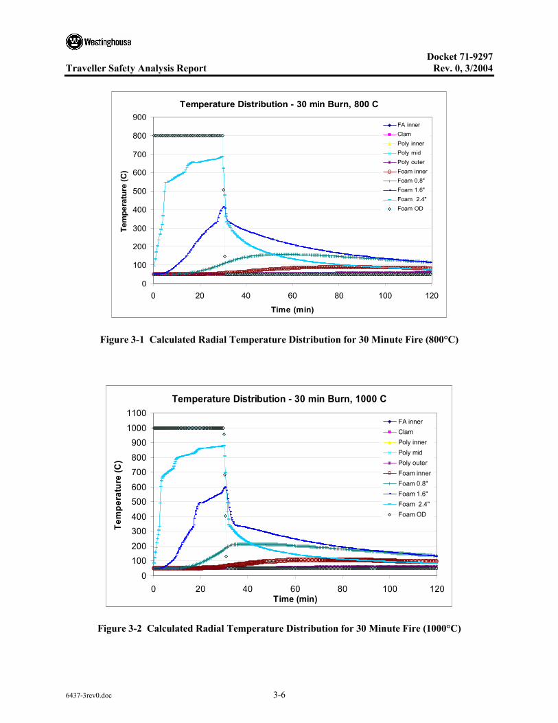
Docket 71-9297
Traveller Safety Analysis Report Rev. 0, 3/2004
6437-3rev0.doc 3-6
Temperature Distribution - 30 min Burn, 800 C
0
100
200
300
400
500
600
700
800
900
0 20 40 60 80 100 120
Time (min)
Tem
pera
ture
(C)
FA innerClamPoly innerPoly midPoly outerFoam innerFoam 0.8"Foam 1.6"Foam 2.4"Foam OD
Figure 3-1 Calculated Radial Temperature Distribution for 30 Minute Fire (800°C)
Temperature Distribution - 30 min Burn, 1000 C
0
100200
300400
500600
700800
9001000
1100
0 20 40 60 80 100 120Time (min)
Tem
pera
ture
(C)
FA innerClamPoly innerPoly midPoly outerFoam innerFoam 0.8"Foam 1.6"Foam 2.4"Foam OD
Figure 3-2 Calculated Radial Temperature Distribution for 30 Minute Fire (1000°C)
Docket 71-9297
Traveller Safety Analysis Report Rev. 0, 3/2004
6437-3rev0.doc 3-7
3.3.2 Evaluation by Test
Traveller performance under hypothetical accident conditions specified in 10CFR71.73 (c) and IAEA Regulations for the Safe Transport of Radioactive Material, Section VII-728 was initially calculated using the SCALE 4.4 thermal analysis code. The performance was subsequently demonstrated in a series of partial burn tests exposing selective portions of a full-scale package to pool fire conditions exceeding the hypothetical accident conditions. Finally, a full scale package was subjected to a full scale, fully engulfing, pool fire exceeding hypothetical accident conditions.
Two separate partial burn tests were performed to verify the final Traveller design. The first was the seam burn test. This test was designed to simulate the flow of hot gas through the Outerpack seams at the hinged joint between the Outerpack base and the Outerpack door and to measure the resulting heat transfer. The second, was the impact limiter burn test. This test subjected the end of a Traveller package to pool fire conditions to measure heat transfer at the package ends. These partial burn tests were then followed by a burn test of the qualification test article. This test, which followed the regulatory drop tests, completely immersed the full scale test unit in a pool fire for more than 30 minutes in flames significantly hotter than 800°C.
3.3.2.1 Seam Burn Test
The seam burn tests were designed to measure performance of different design approaches of protecting polyethylene moderator from excessive heat during the hypothetical fire conditions. Previous burn tests had revealed a tendency for package structures to deform in pool fires potentially allowing hot gasses to enter the package. The tests, performed in a previously burned package with large gaps left between the upper and lower Outerpack to allow hot gases to enter the package. One section, used as a control, had no protection for interior structures. The second section covered the Outerpack seam with stainless steel hinges to model a design with essentially continuous hinges. The third section used 26 gage stainless steel to cover the moderator blocks. The steel cover sheet was stitch welded in place, leaving gaps for combustion air to enter. The test approach is described in appendix 3.6.2
The first burn was of the control section. During the 30 minute burn, internal temperatures rose within the test section throughout the test due to the gap deliberately left in the seam between Outerpack base and lid Peak internal temperatures over 500°C were observed, Figure 3-3.
The second test burn was of the section protected with essentially continuous hinge material. This section had a similar gap between the Outerpack base and lid, but gas flow through the package was minimized by the hinge sections. This burn lasted for 35 minutes with internal temperatures rising to 75°C (from an initial temperature of 35°C). After the burn was completed, interior temperatures continued to rise, peaking after 30 minutes at approximately 100°C.
The third test section was burned for 35 minutes as well. The internal temperatures measured show temperatures rose at a much higher rate than in the second test. This was expected because of the large gapes in the Outerpack seam (varying between 0.5 and 1.5 inches at the bottom seam). One thermocouple showed temperature at the bottom moderator blocks rose above 350°C within 25 minutes after the start of

Docket 71-9297
Traveller Safety Analysis Report Rev. 0, 3/2004
6437-3rev0.doc 3-8
the burn. After the pool fire was extinguished, some smoke was observed at the top Outerpack seam. This corresponded with a high temperature measurement on the moderator surface. Later examination showed that a small section of moderator burned for a limited period of time.
The seam burn tests showed that, where the Outerpack seam was covered by a hinge, that hot gas ingestion was virtually eliminated. Peak internal temperatures were approximately 100°C. With gaps in the Outerpack seams, peak internal temperatures exceeded the 350°C, the ignition temperature of polyethylene. Covering the moderator with stainless reduced the heat up rate, even with larger seam gaps, but moderator combustion took place near gaps in the stainless steel cover sheet. The tests showed that the best approach to prevent moderator combustion is to incorporate continuous hinge sections to prevent hot gas ingestion. The tests also showed that, to prevent combustion of moderator, assuming higher temperatures are experienced within the package, the stainless steel cover must be welded closed to prevent significant amounts of oxygen from reaching the polyethylene.
Figure 3-3 Seam Burn Test
3.3.2.2 Impact Limiter Burn Test
The seam burn tests described above examined the performance of the center portion of the package. The impact limiter burn test examined the thermal performance of the bottom end of the Traveller package. Both burns engulfed the bottom impact limiter and approximately 1.2 meters (four feet) of the package beyond the bottom impact limiter. Thermocouples were mounted at 16 locations inside and outside the
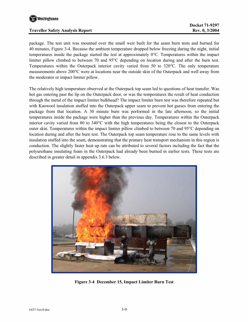
Docket 71-9297
Traveller Safety Analysis Report Rev. 0, 3/2004
6437-3rev0.doc 3-9
package. The test unit was mounted over the small weir built for the seam burn tests and burned for 40 minutes, Figure 3-4. Because the ambient temperature dropped below freezing during the night, initial temperatures inside the package started the test at approximately 0°C. Temperatures within the impact limiter pillow climbed to between 70 and 95°C depending on location during and after the burn test. Temperatures within the Outerpack interior cavity varied from 50 to 320°C. The only temperature measurements above 200°C were at locations near the outside skin of the Outerpack and well away from the moderator or impact limiter pillow.
The relatively high temperature observed at the Outerpack top seam led to questions of heat transfer. Was hot gas entering past the lip on the Outerpack door, or was the temperatures the result of heat conduction through the metal of the impact limiter bulkhead? The impact limiter burn test was therefore repeated but with Kaowool insulation stuffed into the Outerpack upper seam to prevent hot gasses from entering the package from that location. A 30 minute burn was performed in the late afternoon, so the initial temperatures inside the package were higher than the previous day. Temperatures within the Outerpack interior cavity varied from 80 to 340°C with the high temperatures being the closest to the Outerpack outer skin. Temperatures within the impact limiter pillow climbed to between 70 and 95°C depending on location during and after the burn test. The Outerpack top seam temperature rose to the same levels with insulation stuffed into the seam, demonstrating that the primary heat transport mechanism in this region is conduction. The slightly faster heat up rate can be attributed to several factors including the fact that the polyurethane insulating foam in the Outerpack had already been burned in earlier tests. These tests are described in greater detail in appendix 3.6.3 below.
Figure 3-4 December 15, Impact Limiter Burn Test

Docket 71-9297
Traveller Safety Analysis Report Rev. 0, 3/2004
6437-3rev0.doc 3-10
3.3.3 Margins of Safety
The Traveller protects its contents with a polyurethane insulated, double walled, stainless steel Outerpack. This Outerpack provides sufficient insulation to prevent significant heat conduction and maintain low interior temperatures during a hypothetical fire accident. The Outerpack also incorporates design features that prevent convective heat transfer. The tests described in 3.3.2 above, identified features (continuous hinge lengths and a large lip over the bottom seam) that prevent hot gases from entering the Outerpack seams. The results of these tests, as described in sections 3.5.2 and appendices 3.6.3 and 3.6.4 show that internal temperatures remain low when the Outerpack seams are adequately protected. These features were incorporated into the CTU test article and the production design. When the CTU was tested, significant margins of safety were observed as illustrated by Table 3-1 above. The most temperature sensitive component, the polyethylene moderator blocks, have an additional level of protection. The blocks are sealed by stainless steel cover sheets and are insulated at the ends. In the event that local conditions exceed the combustion temperature of the polyethylene, the moderator is protected by an insulating air gap (and refractory fiber insulation at the ends). Additionally, the moderator is isolated from oxygen preventing significant combustion.
3.4 THERMAL EVALUATION UNDER NORMAL CONDITIONS OF TRANSPORT+
The package will only be used to ship non-irradiated nuclear fuel. Without an internal heat source, package temperatures will not significantly exceed ambient temperatures. All materials used within the Traveller package retain their desired properties over the entire range of possible ambient temperatures. The package is not hermetically sealed allowing interior pressure to adjust with changes in elevation and allowing expansion/contraction of internal air during temperature changes. Therefore, no thermal evaluation is needed for normal conditions of transport.
3.5 THERMAL EVALUATION UNDER HYPOTHETICAL ACCIDENT CONDITIONS
The primary verification of the Traveller’s performance in a hypothetical accident was demonstrated in the burn test of a full-scale package loaded with a simulated fuel assembly. This unit was identified as the certification test unit (CTU). According to 10 CFR71.73 “Thermal. Exposure of the specimen fully engulfed, except for a simple support system, in a hydrocarbon fuel/air fire of sufficient extent, and in sufficiently quiescent ambient conditions, to provide an average emissivity coefficient of at least 0.9, with an average flame temperature of at least 800ºC (1475ºF) for a period of 30 minutes, or any other thermal test that provides the equivalent total heat input to the package and which provides a time averaged environmental temperature of 800ºC. The fuel source must extend horizontally at least 1 m (40 in), but may not extend more than 3 m (10 ft), beyond any external surface of the specimen, and the specimen must be positioned 1 m (40 in) above the surface of the fuel source. For purposes of calculation, the surface absorptivity coefficient must be either that value which the package may be expected to possess if exposed to the fire specified or 0.8, whichever is greater; and the convective coefficient must be that value which may be demonstrated to exist if the package were exposed to the fire specified. Artificial cooling may not be applied after cessation of external heat input, and any combustion of materials of construction, must be allowed to proceed until it terminates naturally.” (The IAEA Regulations for the Safe Transport of Radioactive Material, Section VII-728 have similar specifications.)
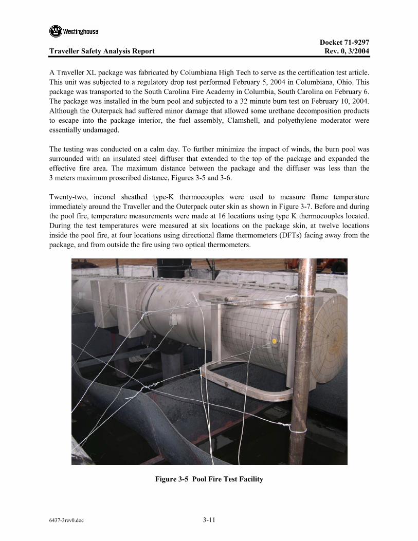
Docket 71-9297
Traveller Safety Analysis Report Rev. 0, 3/2004
6437-3rev0.doc 3-11
A Traveller XL package was fabricated by Columbiana High Tech to serve as the certification test article. This unit was subjected to a regulatory drop test performed February 5, 2004 in Columbiana, Ohio. This package was transported to the South Carolina Fire Academy in Columbia, South Carolina on February 6. The package was installed in the burn pool and subjected to a 32 minute burn test on February 10, 2004. Although the Outerpack had suffered minor damage that allowed some urethane decomposition products to escape into the package interior, the fuel assembly, Clamshell, and polyethylene moderator were essentially undamaged.
The testing was conducted on a calm day. To further minimize the impact of winds, the burn pool was surrounded with an insulated steel diffuser that extended to the top of the package and expanded the effective fire area. The maximum distance between the package and the diffuser was less than the 3 meters maximum proscribed distance, Figures 3-5 and 3-6.
Twenty-two, inconel sheathed type-K thermocouples were used to measure flame temperature immediately around the Traveller and the Outerpack outer skin as shown in Figure 3-7. Before and during the pool fire, temperature measurements were made at 16 locations using type K thermocouples located. During the test temperatures were measured at six locations on the package skin, at twelve locations inside the pool fire, at four locations using directional flame thermometers (DFTs) facing away from the package, and from outside the fire using two optical thermometers.
Figure 3-5 Pool Fire Test Facility

Docket 71-9297
Traveller Safety Analysis Report Rev. 0, 3/2004
6437-3rev0.doc 3-12
Figure 3-6 Traveller CTU During Pool Fire Test
Figure 3-7 Thermocouple Locations Measuring Fire Temperature During CTU Burn Test
20 in
51 in above pool
100 in
20 in
60 in
36 in
TCs attached 8” from end of package
NW upper and lower TCs
Directional Flame Thermometer (6)
20 in
51 in above pool
100 in
20 in
60 in
36 in
20 in
51 in above pool
100 in
20 in
60 in
36 in
TCs attached 8″ from end of package
NW upper and lower TCs
Directional Flame Thermometer (6)
N E
Docket 71-9297
Traveller Safety Analysis Report Rev. 0, 3/2004
6437-3rev0.doc 3-13
3.5.1 Initial Conditions
The package was covered with a canvas tent approximately 16 hours before the burn test. Two 44 kWth (150,000 BTU/hr) kerosene heaters were used, alternately, to maintain air temperature within the tent to above 37°C. The heaters were secured and the tent removed approximately 75 minutes before the beginning of the fire test. Air temperature around the package at this time averaged at 50°C (122°F). The air temperature and outside surface temperature dropped to approximately 5°C (41°F). Additional information can be found in appendix 3.6-4.
3.5.2 Fire Test Conditions
The CTU burn test was performed on a cool, calm, lightly overcast morning. The test article was located on stand in a water pool. Fuel was pumped into manifolds under the surface of the pool to provide an even distribution of fuel for the pool fire. Approximately one minute after the fuel on the surface of the pool was ignited, the test article was completely engulfed. The fuel system continued to pump fuel into the fire until 32 minutes after the pool was lit. The pool fire was extinguished approximately one minute later. Fire temperatures were measured using four directional flame thermometers (DFTs) and 12 thermocouples suspended in the fire 0.9 m (3 feet) from the surface of the package. The 30 minute average temperatures measured by the DFTs were 833°C (1531°F). The 39 minute average temperature measured by the thermocouples suspended in the fire was 859°C (1578°F). Two, hand-held, optical thermometers that measured flame temperature from outside the pool supplemented these measurements. The average readings made with these thermometers was 958°C (1757°F).
3.5.3 Maximum Temperatures and Pressures
Temperatures were measured on the CTU Outerpack outer skin using six type K thermocouples, attached by screws. These thermocouples were located as shown in Figure 3-7 above. The 30 minute average temperature measured by these thermocouples was 904°C (1659°F). Temperatures inside the CTU Outerpack were measured using 13 sets of non-reversible temperature strips. One set on the inner stainless steel skin covering the Outerpack lid moderator was unreadable. All of the remaining temperature strips on the Outerpack lid recorded temperatures of 177°C (351°F) or below. Temperatures on the inside surface of the top and bottom impact limiters were 116 (241°F) and 149°C (300°F) respectively. Temperatures inside the Clamshell were below 104°C (219°F). An example of the temperature strip sets attached to the Outerpack lid moderator cover sheets is shown in Figure 3-8.

Docket 71-9297
Traveller Safety Analysis Report Rev. 0, 3/2004
6437-3rev0.doc 3-14
Figure 3-8 Temperature Strip Condition After CTU Burn Test
The Traveller package design is a non-pressurized and cannot retain internal pressure. The seals used around the Outerpack door are designed to keep dust, dirt and spray from getting inside the Outerpack and to minimize the amount of high temperature gases reaching the Clamshell during a hypothetical fire. The seals are discontinuous to prevent internal pressurization during the hypothetical fire and during normal variations in temperature and atmospheric pressure. The polyurethane foam space between the inner and outer shells of the Outerpack is also protected from pressurization through the use of vent plugs. Every internal foam compartment within the Outerpack is protected by at least one acetate vent plug that will melt in the event of a fire and allow the internal spaces to vent. As a result, no significant increase in pressure was observed during the testing, nor is anticipated in any hypothetical accident condition.
The Traveller design surrounds the fuel assembly and polyethylene moderator with an insulated outer package. As a result, the outer surface of the package quickly reaches equilibrium with the fire while the interior remains cool. This is indicated by analysis and by the burn tests described above. The peak temperature measured on the Clamshell and the moderator covers were consistent between the seam burn test, the impact limiter burn test and the CTU burn test. All temperatures remained below 177°C and most locations remained below 100°C. No significant thermal damage was observed in the fuel assembly, Clamshell or moderator blocks after the fire test. Moderator blocks were weighed before and after the fire test. No measurable reduction in mass was found.
3.5.4 Accident Conditions for Fissile Material Packages for Air Transport
Application will be made for air transport at a later date.
Docket 71-9297
Traveller Safety Analysis Report Rev. 0, 3/2004
6437-3rev0.doc 3-15
3.6 APPENDICES
The following appendices are included to provide amplifying information on material contained elsewhere in section 3.
• 3.6.1: Traveller Thermal Analysis • 3.6.2: Traveller Seam Burn Tests • 3.6.3: Traveller Impact Limiter Burn Tests • 3.6.4: Traveller Certification Test Unit (CTU) Burn Test

Docket 71-9297
Traveller Safety Analysis Report Rev. 0, 3/2004
6437-3rev0.doc 3-16
3.6.1 TRAVELLER THERMAL ANALYSIS
A simplified computer model was developed using the HEATING7.2 code distributed by Oak Ridge National Laboratory as a part of SCALE 4.4. The model was built in cylindrical coordinates using the simplified geometry shown in Figure 3-9. This simplification was possible because:
• Primary temperature variations occur in the Outerpack foam that is cylindrical on the outside • Simplifying interior foam surface by making it cylindrical is conservative • The large length to diameter ratio (8.9:1) minimize end effects • The ends have twice the thickness of polyurethane foam as the sides further reducing end effects
25” OD18.5”
10.375”
Stainless skin0.1046” thick
Upper Moderator1.25” thick
24.895” OD 18.5” dia
Smeared clamshell/FA11.71” dia
15.39” ID
Traveller-2 Cross section
Relevant Portion of Cross Section
Geometry Used in Analysis
Lower Moderator1.86” thick
25” OD18.5”
10.375”
Stainless skin0.1046” thick
Upper Moderator1.25” thick
24.895” OD 18.5” dia
Smeared clamshell/FA11.71” dia
15.39” ID
24.895” OD 18.5” dia
Smeared clamshell/FA11.71” dia
15.39” ID
Traveller-2 Cross section
Relevant Portion of Cross Section
Geometry Used in Analysis
Lower Moderator1.86” thick
Figure 3-9 Approach Used to Generate Analytical Model Geometry
Three material regions were used in the analysis: Polyurethane foam with an average density of 10 lb/ft3, Polyethylene, and a smeared mixture representing the mid-section of the Clamshell and fuel assembly.
The Clamshell and fuel assembly region was modeled as a heat sink representing a 17x17 XL fuel assembly within the 9.50 inch (24.13 cm) inside dimension aluminum Clamshell. Because the end effects were to be ignored in this model, the fuel assembly nozzles and the Clamshell end plates were not included in this calculation. This resulting in the following material ratios:
• Aluminum Clamshell – 359.7 lb (163.2 kg) with a specific heat of 0.23 BTU/lb-°F (0.96 J/g-°C), 104 BTU/hr-ft-F
• Uranium Dioxide – 1341 lb (608.3 kg) with a specific heat of 0.0565 BTU/lb-°F (0.237 J/g-°C)
• Zircalloy 4 – 330 lb (149.7 kg) with a specific heat of 0.0681 BTU/lb-°F (0.285 J/g-°C)

Docket 71-9297
Traveller Safety Analysis Report Rev. 0, 3/2004
6437-3rev0.doc 3-17
The Traveller XL Clamshell is 202.0 inches (513.1 cm) long. The heat sink region weighs 2031 lb (921.1 kg), has an average specific heat of 0.891 BTU/lb-°F (0.373 J/g-°C) and a smeared density of 0.0934 lb/in3 (2.58 gm/cc).
A volumetric average conductivity was generated for the Clamshell and fuel assembly region by calculating a volume smeared conductivity by using the ratio of conductivity to volume for each material.
• Aluminum Clamshell – 3560 in3 (58,300 cc) with a conductivity of 104 BTU/hr-ft-F (182 W/m-K) • Uranium Dioxide – 3380 in3 (54,500 cc) with a conductivity of 3.39 BTU/hr-ft-F (5.86 W/m-K) • Zircalloy 4 – 1400 in3 (23,000 cc) with a conductivity of 12.4 BTU/hr-ft-(21.5 W/m-K)
Total volume used in the Clamshell/fuel assembly region is 21,700 in3 (356,000 cc). This results in a smeared conductivity of 18.3 BTU/hr-ft-F (32.1 W/m-K). This approximation is valid only because the heat input rate is very low allowing the region to be almost isothermal, even with low conductivities.
The Traveller XL Outerpack contains approximately 426 lb (193 kg) of UHMW polyethylene with specific heat of 0.526 BTU/lb-°F (2.2 J/g-°C) and a conductivity of 24 BTU/hr-ft-°F (0.42 W/m-°C). The total length of the moderator within the Outerpack is approximately 206 inches (523 cm). For the geometry defined for the model, this results in a smeared polyethylene density of 0.0249 lb/in3 (0.689 g/cc) which is 74% of predicted minimum density. The polyethylene acts as a heat sink and an insulation of primary heat sink.
The polyurethane foam room-temperature properties are given in Table 3-5. The properties change significantly, however, as the foam temperature increases resulting in pyrolization which occurs between 600 and 650°F (316 and 343°C). After charring, the material has the general appearance of very low density carbon foam. For the analytical model, the room temperature specific heat and conductivity were used up to 600F. Above 650°F, the temperature dependent conductivity of air was used instead. Between 600 and 650°F, foam specific heat is assumed to drop to zero.
Table 3-4 Temperature Dependent Thermal Conductivity Used to Model Polyurethane Foam
Temperature (F)
Conductivity (BTU/hr-ft-F)
Conductivity (W/m-K)
100 .0230 .0398
600 .0230 .0398
650 .0249 .0431
700 .0268 .0464
800 .0286 .0495
1000 .0319 .0552
1500 .0400 .0692
2000 .0502 0.0869
Docket 71-9297
Traveller Safety Analysis Report Rev. 0, 3/2004
6437-3rev0.doc 3-18
The surface emissivity of the foam was set at 0.8. The first analysis performed modeled a 30 minute fire with flame temperature of 800°C. This analysis, Figure 3-1, showed significant temperature variation through the thickness of the polyurethane foam. Peak temperatures on the inside surface of the foam reached 100°C approximately 80 minutes after the beginning of the fire (50 minutes after the fire was put out).
Because the planned fire test facility burns at a higher temperature, the same analysis was performed assuming a 1000°C fire temperature. As shown in Figure 3-3, peak temperature within the polyethylene (at the interface between the polyurethane foam and the polyethylene) was calculated to reach 106°C. This is below the 125 – 138°C melt temperature of the polyethylene and well below the temperature that the melted polyethylene viscosity is low enough to flow easily.

Docket 71-9297
Traveller Safety Analysis Report Rev. 0, 3/2004
6437-3rev0.doc 3-19
3.6.2 TRAVELLER SEAM BURN TESTS
This test examined two methods of protecting the polyethylene to prevent combustion and/or significant melting. One was the use of continuous hinges to seal the gap at the seam and the second was to cover the moderator with stainless steel sheet to prevent combustion. A third test section was also created to act as the test control. This section did not have any additional protection for the moderator.
The test was performed as series of three burns, heating the reference or control section, the section with additional hinge to model a package with continuous hinges, and the section with stainless covering over the moderator respectively. The first burn lasted 30 minutes. The two subsequent burns lasting for 35 minutes. A small pool fire (approximately 30 x 80 inches) was be created under the region of the package to be tested, Figure 3-10. Each region was approximately 57 cm (22.4 inches) across separated from the adjacent test region by 61 cm (24 inches) of refractory insulation. This insulation was stuffed between the Clamshell and the moderator to prevent air flow from the section being tested to other test regions within the prototype package. The test regions were selected based having intact moderator left from previous tests. The test section with stainless steel cover over the moderator was selected based on the minimum distortion of the inner Outerpack shell and moderator blocks. The outside of the package was insulated on the bottom and sides using at least 2.5 cm (one inch) of refractory fiber insulation. This insulation will extend at least 1.2 m (48 inches) from each end of the test region, Figure 3-11.
Six thermocouples were attached in each test section. Two were screwed to the moderator bottom edge nearest the seam, one was screwed to the moderator/Outerpack where the two moderator blocks meet, one was screwed to the moderator block near the top seam, one was screwed to the Clamshell J-clip, and one was run through the bottom seam to hang approximately four inches below the package in the flames. Thermocouple connections and Teflon coated wires were routed out of the package at each end.
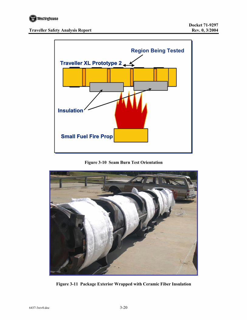
Docket 71-9297
Traveller Safety Analysis Report Rev. 0, 3/2004
6437-3rev0.doc 3-20
Region Being Tested
Traveller XL Prototype 2
Small Fuel Fire Prop
Insulation
Region Being Tested
Traveller XL Prototype 2
Small Fuel Fire Prop
Insulation
Traveller XL Prototype 2
Small Fuel Fire Prop
Insulation
Figure 3-10 Seam Burn Test Orientation
Figure 3-11 Package Exterior Wrapped with Ceramic Fiber Insulation
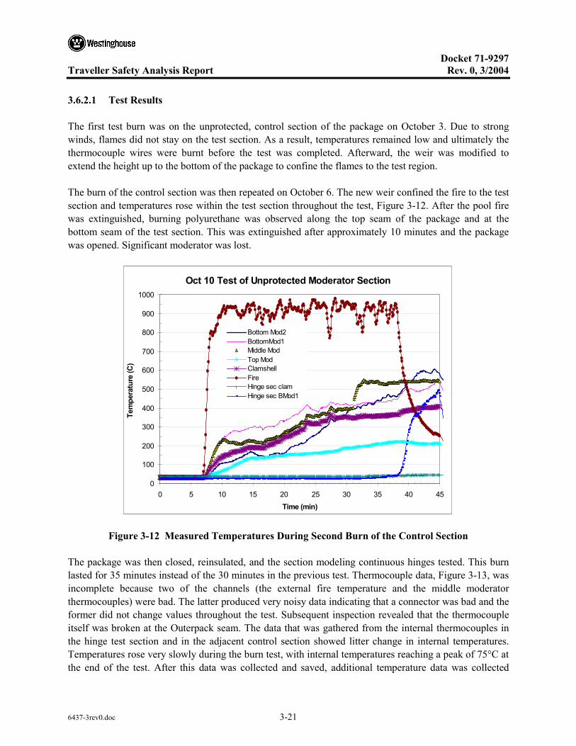
Docket 71-9297
Traveller Safety Analysis Report Rev. 0, 3/2004
6437-3rev0.doc 3-21
3.6.2.1 Test Results
The first test burn was on the unprotected, control section of the package on October 3. Due to strong winds, flames did not stay on the test section. As a result, temperatures remained low and ultimately the thermocouple wires were burnt before the test was completed. Afterward, the weir was modified to extend the height up to the bottom of the package to confine the flames to the test region.
The burn of the control section was then repeated on October 6. The new weir confined the fire to the test section and temperatures rose within the test section throughout the test, Figure 3-12. After the pool fire was extinguished, burning polyurethane was observed along the top seam of the package and at the bottom seam of the test section. This was extinguished after approximately 10 minutes and the package was opened. Significant moderator was lost.
Oct 10 Test of Unprotected Moderator Section
0
100
200
300
400
500
600
700
800
900
1000
0 5 10 15 20 25 30 35 40 45Time (min)
Tem
pera
ture
(C)
Bottom Mod2BottomMod1Middle ModTop ModClamshellFireHinge sec clamHinge sec BMod1
Figure 3-12 Measured Temperatures During Second Burn of the Control Section
The package was then closed, reinsulated, and the section modeling continuous hinges tested. This burn lasted for 35 minutes instead of the 30 minutes in the previous test. Thermocouple data, Figure 3-13, was incomplete because two of the channels (the external fire temperature and the middle moderator thermocouples) were bad. The latter produced very noisy data indicating that a connector was bad and the former did not change values throughout the test. Subsequent inspection revealed that the thermocouple itself was broken at the Outerpack seam. The data that was gathered from the internal thermocouples in the hinge test section and in the adjacent control section showed litter change in internal temperatures. Temperatures rose very slowly during the burn test, with internal temperatures reaching a peak of 75°C at the end of the test. After this data was collected and saved, additional temperature data was collected
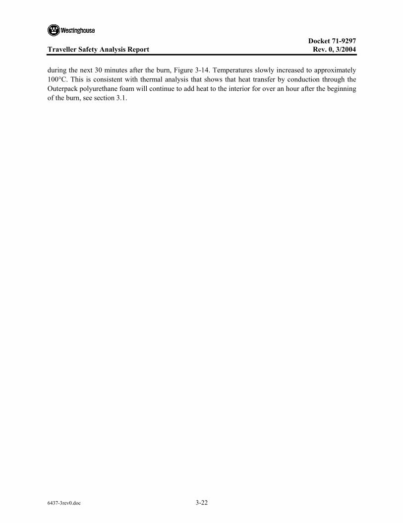
Docket 71-9297
Traveller Safety Analysis Report Rev. 0, 3/2004
6437-3rev0.doc 3-22
during the next 30 minutes after the burn, Figure 3-14. Temperatures slowly increased to approximately 100°C. This is consistent with thermal analysis that shows that heat transfer by conduction through the Outerpack polyurethane foam will continue to add heat to the interior for over an hour after the beginning of the burn, see section 3.1.

Docket 71-9297
Traveller Safety Analysis Report Rev. 0, 3/2004
6437-3rev0.doc 3-23
Interior Temperature In Continuous Hinge Section
20
30
40
50
60
70
80
90
100
0 5 10 15 20 25 30 35 40 45 50
Time (min)
Tem
pera
ture
(C)
Bottom Mod1Bottom Mod2ClamshellTop ModeratorUnprotected Middle ModUnprotected Clam
Fire started
Fire Stopped
Figure 3-13 Interior Temperature Measurements During Test of Continuous Hinge Section
Figure 3-14 Interior Temperature Measures After Test of Continuous Hinge Section
Continuous Hinge Interior Cooldown
30
40
50
60
70
80
90
100
50 55 60 65 70 75
Time (min)
Tem
pera
ture
(C)
Hinge BMod1Hinge B Mod2Hinge ClamHinge Top ModBare Md ModBare Clam

Docket 71-9297
Traveller Safety Analysis Report Rev. 0, 3/2004
6437-3rev0.doc 3-24
The package was then moved on the test stand and positioned with the third test section, the covered moderator, over the burn weir. This section was burned for 35 minutes as well. The internal temperatures measured, Figure 3-15, show temperatures rose at a much higher rate than in the second test. This was expected because of the large gapes in the Outerpack seam (varying between 0.5 and 1.5 inches at the bottom seam), Figure 3-16. One thermocouple showed temperature at the bottom moderator blocks rose to above 350°C within 25 minutes after the start of the burn. After the pool fire was extinguished, some smoke was observed at the top Outerpack seam. This corresponded with an eventual rise in moderator temperature at one location after the external fire had been extinguished. After approximately 15 minutes, the package was cooled by water spray and removed from the burn pool. When opened, there was not initial sign of damage. After the stainless steel covering the moderator was removed, however, it was confirmed that small amounts of the moderator had burned.
Temperatures From Covered Moderator Section
0
100
200
300
400
500
600
700
800
900
1000
1100
20 30 40 50 60 70 80Time (min)
Tem
pera
ture
(C)
FireBot Mod1Bot Mod2Clamshell
Moderator reaches ignition temperature
Package cooled by water spray
Temperatures From Covered Moderator Section
0
100
200
300
400
500
600
700
800
900
1000
1100
20 30 40 50 60 70 80Time (min)
Tem
pera
ture
(C)
FireBot Mod1Bot Mod2Clamshell
Moderator reaches ignition temperature
Package cooled by water spray
Figure 3-15 Interior Temperature Measurements During Test of Covered Moderator Section

Docket 71-9297
Traveller Safety Analysis Report Rev. 0, 3/2004
6437-3rev0.doc 3-25
Figure 3-16 Gaps in Outerpack Bottom Seam at Covered Moderator Test Section
3.6.2.2 Conclusions
Tests showed that, where the Outerpack seam was covered by a hinge, that hot gas ingestion was virtually eliminated. Peak internal temperatures were approximately 100°C. With gaps in the Outerpack seams, peak internal temperatures exceeded the 350°C ignition temperature of polyethylene. Covering the moderator with stainless did appear to reduce heatup rate, even with larger seam gaps, but moderator combustion took place anyway. The tests showed that the best approach to prevent moderator combustion is to incorporate continuous hinge sections to prevent hot gas ingestion during the burn test.

Docket 71-9297
Traveller Safety Analysis Report Rev. 0, 3/2004
6437-3rev0.doc 3-26
3.6.3 TRAVELLER IMPACT LIMITER BURN TESTS
A Traveller package was subjected to two burn tests after being tested in a full series of regulatory drops. This test series focused on the heat transfer characteristics of the bottom end of the package. This end in referred to as the bottom impact limiter. The top and bottom impact limiters are divided into two regions with high (20 lb/ft3) density foam in the outer regions and low density foam (6 lb/ft3) pillows inside. The foam pillow is eparately encased in stainless steel with a 0.64 cm (0.25 inch) impact plate to minimize the chance of exposing the foam. Each pillow also has a 0.64 cm (0.25 inch) thick plate out the outer end as a heat sink to reduce peak temperatures in a fire. The foam pillow is also separated from the inside end of the outer impact limiter foam with approximately 0.32 cm (0.125 inches) of refractor insulation.
During both tests, the package was instrumented with 16, inconel sheathed, type K thermocouples (Omega part numbers XCIB-K-4-2-10 and XCIB-K-2-3-10). Seven thermocouples were mounted on or around the impact limiter pillow, one midway through the outer impact limiter foam, and one on the outer impact limiter skin, Figure 3-17. The remaining seven thermocouples were mounted inside the Outerpack. The location of the thermocouples is shown in Figure 3-18.
Outer Foam
FoamPillow
Foam exposed at four locations
Impact limiter skin
Impact limiter foam
Top hat (pillow side)
Pillow hot side
Pillow cold side
Pillow 12 o’clock
Pillow 3 o’clock
Pillow 9 o’clock
Pillow 6 o’clock
Outer Foam
FoamPillow
Foam exposed at four locations
Impact limiter skin
Impact limiter foam
Top hat (pillow side)
Pillow hot side
Pillow cold side
Pillow 12 o’clock
Pillow 3 o’clock
Pillow 9 o’clock
Pillow 6 o’clock
Pillow 12 o’clock
Pillow 3 o’clock
Pillow 9 o’clock
Pillow 6 o’clock
Figure 3-17 Thermocouple Locations in Impact Limiter

Docket 71-9297
Traveller Safety Analysis Report Rev. 0, 3/2004
6437-3rev0.doc 3-27
Figure 3-18 Thermocouple Locations in Outerpack Interior
The thermocouples were connected to thermocouple wire extensions using standard Type K plugs connecting the thermocouples to 20 gage type K extension wire. The 16 thermocouple cables were connected to two data acquisition systems. One system used an Omega OM-CP-OCTTEMP 8-channel data logger. This unit was set in operation before the test using a laptop computer and stored data from each channel at a rate of 12 samples per minute. After the test was completed, the data was download to the same laptop computer. The second system used an 8-channel Omega INET-100 external A/D box connected to an INET-230 PC-Card controller with a INET 311-2 power supply. This recorded data directly into the laptop computer allowing these channels to be monitored during the test.
Additional data was taken on external temperatures using two OMEGA OS523 handheld optical thermometers during the December 15 test. These units were used to measure flame temperatures and outside package skin temperature after the pool fire was extinguished.
A previously drop tested unit was modified to incorporate these changes in the bottom impact limiter and was subjected to two burns, one on December 15, and the second on December 16. Both burns engulfed the bottom impact limiter and approximately 3 feet of the package above the bottom impact limiter. Thermocouples were mounted at 16 locations inside and outside the package. Data from eight of the thermocouples were recorded by a laptop PC based Instrunet system that allowed data to be monitored in real time. The other eight channels were recorded using a battery powered Omega data logger.
3.6.3.1 First Impact Limiter Burn (December 15)
The test unit was mounted over the small weir built for the seam burn tests and burned for 40 minutes, Figure 3-19. Because the ambient temperature dropped below freezing during the night, initial

Docket 71-9297
Traveller Safety Analysis Report Rev. 0, 3/2004
6437-3rev0.doc 3-28
temperatures inside the package started the test at approximately 0°C. Temperatures within the impact limiter pillow climbed to between 70 and 95°C depending on location during and after the burn test, Figure 3-20. Temperatures within the Outerpack interior cavity varied from 50 to 320°C, Figure 3-21.
Figure 3-19 December 15, Impact Limiter Burn Test

Docket 71-9297
Traveller Safety Analysis Report Rev. 0, 3/2004
6437-3rev0.doc 3-29
Pillow Temperatures
0
20
40
60
80
100
9:30 9:40 9:50 10:00 10:10 10:20 10:30 10:40 10:50 11:00 11:10 11:20Time
Tem
pera
ture
(C)
Pillow 12o'clockPillow 3 o'clockPillow 6 o'clockPillow 9 o'lockPillow Cold Side
Burn
Figure 3-20 Impact Limiter Pillow Temperatures
Overpack Internal Temperatures
0
50
100
150
200
250
300
350
400
20 40 60 80 100 120
Time (min)
Tem
pera
ture
(C)
Left lower moderatorOP top seamLid Left ModeratorLower OP Left LedgeLower OP left Side
Burn
Figure 3-21 Internal Outerpack Skin Temperatures (December 15 Burn)

Docket 71-9297
Traveller Safety Analysis Report Rev. 0, 3/2004
6437-3rev0.doc 3-30
During this test, external temperatures were measured with two optical thermometers. Readings were taken every five minutes, Figure 3-22. After the test was completed, the Outerpack was opened. Other than a thin layer of soot lining the inside surfaces, there was no noticeable change in the Outerpack or Clamshell, Figure 3-23.
Optical Thermometer Readings
0
200
400
600
800
1000
1200
1400
0 10 20 30 40Time (min)
Tem
pera
ture
(C)
Unit 1 (C )Unit 2 (C )
Figure 3-22 Flame Temperatures Measured by Optical Pyrometers
Figure 3-23 Outerpack Internals after December 15 Burn Test

Docket 71-9297
Traveller Safety Analysis Report Rev. 0, 3/2004
6437-3rev0.doc 3-31
3.6.3.2 Second Impact Limiter Burn (December 16)
The relatively high temperature observed at the Outerpack top seam led to questions of heat transfer. Was hot gas entering past the lip on the Outerpack door, or was the temperatures the result of heat conduction through the metal of the impact limiter bulkhead. The impact limiter burn test was therefore repeated but with Kaowool insulation stuffed into the Outerpack upper seam to prevent hot gasses from entering the package from that location, Figure 3-24. This burn lasted for 30 minutes, Figure 3-25. This test was performed in the late afternoon, so the initial temperatures inside the package were higher than the previous day. Temperatures within the Outerpack interior cavity varied from 80 to 340°C, Figure 3-26. Temperatures within the impact limiter pillow climbed to between 70 and 95°C depending on location during and after the burn test, Figure 3-27. The Outerpack top seam temperature rose to the same levels with insulation stuffed into the seam, demonstrating that the primary heat transport mechanism in this region is conduction.
Figure 3-24 Kaowool Layers on Outerpack Bottom Impact Limiter
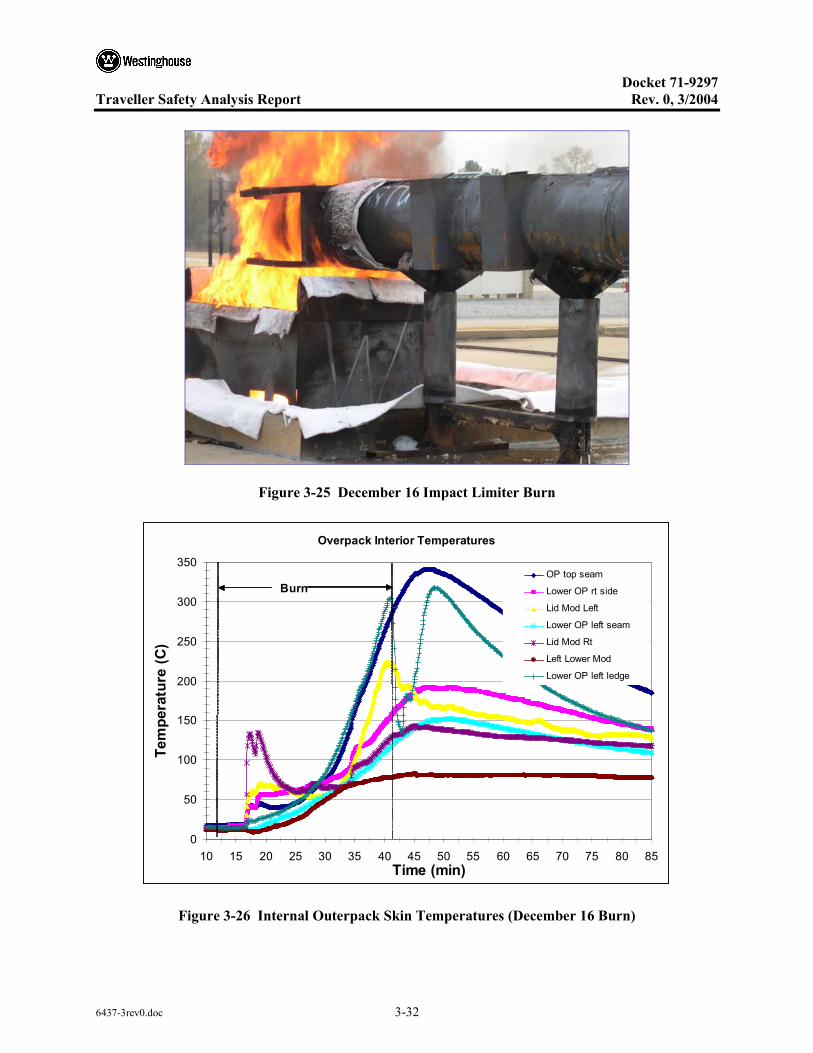
Docket 71-9297
Traveller Safety Analysis Report Rev. 0, 3/2004
6437-3rev0.doc 3-32
Figure 3-25 December 16 Impact Limiter Burn
Overpack Interior Temperatures
0
50
100
150
200
250
300
350
10 15 20 25 30 35 40 45 50 55 60 65 70 75 80 85Time (min)
Tem
pera
ture
(C)
OP top seam
Lower OP rt side
Lid Mod Left
Lower OP left seam
Lid Mod Rt
Left Lower Mod
Lower OP left ledge
Burn
Figure 3-26 Internal Outerpack Skin Temperatures (December 16 Burn)

Docket 71-9297
Traveller Safety Analysis Report Rev. 0, 3/2004
6437-3rev0.doc 3-33
Pillow Temperatures
0
20
40
60
80
100
120
140
20 30 40 50 60 70 80 90 100Time (min)
Tem
pera
ture
(C)
Pillow 6 o'clockPillow 9 o'clockPillow 12 o'clockPillow cold sideTop hat
Burn
Figure 3-27 Impact Limiter Pillow Temperatures (December 16 Burn)
3.6.3.3 Test Conclusions
The purpose of the December 16 test was to repeat the previous day’s test ensuring that hot gases did not flow around the Outerpack lid bottom lip. The heat up rate of the Outerpack top seam was slightly higher during the second burn than the first. Three factors may explain the higher temperatures during the second test.
• Foam in the impact limiter was charred during the first test resulting in higher heat transfer during the second test.
• The kaowool used to fill the bottom seam prevented the lid from closing as tightly as in the first test. This may have allow small amounts of combustion gas from the pool to enter the package
• During the first 5-6 minutes of the burn, fuel was sprayed directly on the outer skin of the package.
The test demonstrated that the revised impact limiter design will not overheat during a regulatory burn test. Even if the initial temperature is raised by 50°C, final temperature of the impact limiter pillow is anticipate to be less than 150°C. The test also demonstrated that very little gas is entering the Outerpack through the side or top seams. The interior skin is heating up however, due to conduction through metal parts of the Outerpack and through the polyurethane foam. The impact limiter tests results are

Docket 71-9297
Traveller Safety Analysis Report Rev. 0, 3/2004
6437-3rev0.doc 3-34
conservative because the foam in the cylindrical section of the package was not replaced and, therefore, did not provide the insulation that a unburnt package would have.
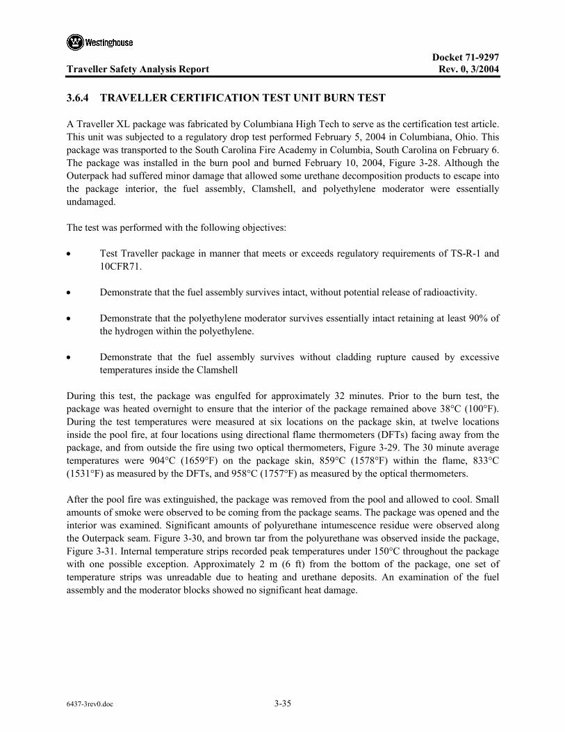
Docket 71-9297
Traveller Safety Analysis Report Rev. 0, 3/2004
6437-3rev0.doc 3-35
3.6.4 TRAVELLER CERTIFICATION TEST UNIT BURN TEST
A Traveller XL package was fabricated by Columbiana High Tech to serve as the certification test article. This unit was subjected to a regulatory drop test performed February 5, 2004 in Columbiana, Ohio. This package was transported to the South Carolina Fire Academy in Columbia, South Carolina on February 6. The package was installed in the burn pool and burned February 10, 2004, Figure 3-28. Although the Outerpack had suffered minor damage that allowed some urethane decomposition products to escape into the package interior, the fuel assembly, Clamshell, and polyethylene moderator were essentially undamaged.
The test was performed with the following objectives:
• Test Traveller package in manner that meets or exceeds regulatory requirements of TS-R-1 and 10CFR71.
• Demonstrate that the fuel assembly survives intact, without potential release of radioactivity.
• Demonstrate that the polyethylene moderator survives essentially intact retaining at least 90% of the hydrogen within the polyethylene.
• Demonstrate that the fuel assembly survives without cladding rupture caused by excessive temperatures inside the Clamshell
During this test, the package was engulfed for approximately 32 minutes. Prior to the burn test, the package was heated overnight to ensure that the interior of the package remained above 38°C (100°F). During the test temperatures were measured at six locations on the package skin, at twelve locations inside the pool fire, at four locations using directional flame thermometers (DFTs) facing away from the package, and from outside the fire using two optical thermometers, Figure 3-29. The 30 minute average temperatures were 904°C (1659°F) on the package skin, 859°C (1578°F) within the flame, 833°C (1531°F) as measured by the DFTs, and 958°C (1757°F) as measured by the optical thermometers.
After the pool fire was extinguished, the package was removed from the pool and allowed to cool. Small amounts of smoke were observed to be coming from the package seams. The package was opened and the interior was examined. Significant amounts of polyurethane intumescence residue were observed along the Outerpack seam. Figure 3-30, and brown tar from the polyurethane was observed inside the package, Figure 3-31. Internal temperature strips recorded peak temperatures under 150°C throughout the package with one possible exception. Approximately 2 m (6 ft) from the bottom of the package, one set of temperature strips was unreadable due to heating and urethane deposits. An examination of the fuel assembly and the moderator blocks showed no significant heat damage.
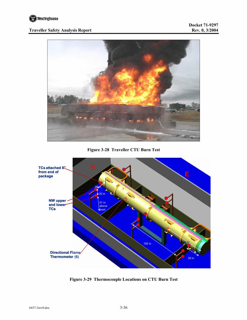
Docket 71-9297
Traveller Safety Analysis Report Rev. 0, 3/2004
6437-3rev0.doc 3-36
Figure 3-28 Traveller CTU Burn Test
Figure 3-29 Thermocouple Locations on CTU Burn Test
20 in
51 in above pool
100 in
20 in
60 in
36 in
TCs attached 8” from end of package
NW upper and lower TCs
Directional Flame Thermometer (6)
20 in
51 in above pool
100 in
20 in
60 in
36 in
20 in
51 in above pool
100 in
20 in
60 in
36 in
TCs attached 8” from end of package
NW upper and lower TCs
Directional Flame Thermometer (6)
N E
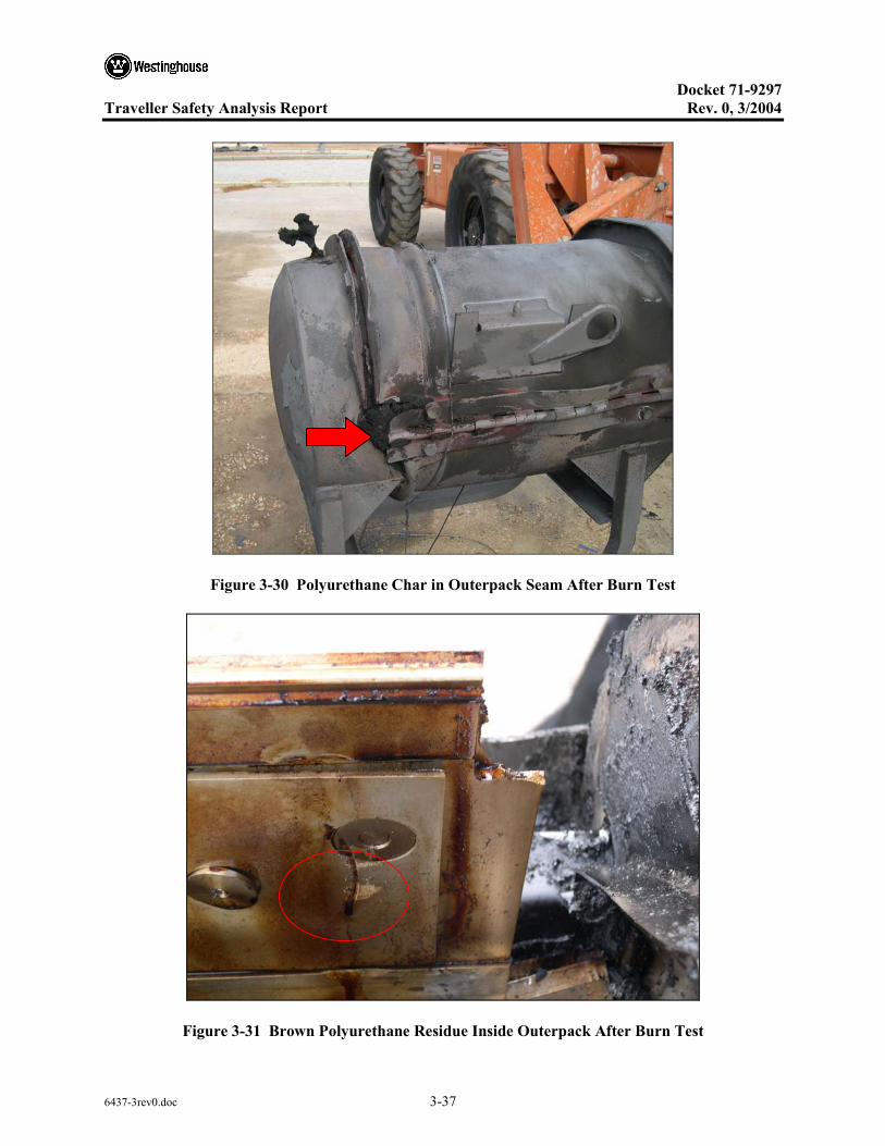
Docket 71-9297
Traveller Safety Analysis Report Rev. 0, 3/2004
6437-3rev0.doc 3-37
Figure 3-30 Polyurethane Char in Outerpack Seam After Burn Test
Figure 3-31 Brown Polyurethane Residue Inside Outerpack After Burn Test

Docket 71-9297
Traveller Safety Analysis Report Rev. 0, 3/2004
6437-3rev0.doc 3-38
The following test equipment was used to conduct the burn test:
• Video cameras (4)
• Digital camera
• Omega type K thermocouples with Inconel overbraided 10' leads to measure skin temperature and flame temperature depending on location (XCIB-K-4-2-10 with screw attachment ends and XCIB-K-3-2-10 with air hoods)
• Omega OM-CP-OCTTEMP data loggers (2)
• Omega USB recorder Data Acquisition Modules with weather tight electronics box
• Laptop computer
• Hand held optical pyrometer with adjustable emissivity setting (s)
• Adhesive temperature measurement strips (TL-E-170, TL-E-250, TL-E-330)
• Edmund Scientific Propeller Wind Anometer
The package rested on a steel support structure placed in a burn pool, Figure 3-32. The burn pool was limited by a water cooled weir and the fuel was evenly distributed throughout the pool. The pool was also surrounded by a steel diffuser, Figure 3-33. The top of the diffuser was approximately 1.6 m (5.4 ft) above the top of the pool surface, the height of the top of the test article.
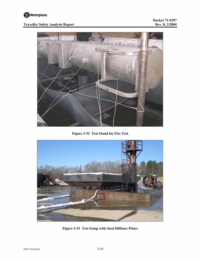
Docket 71-9297
Traveller Safety Analysis Report Rev. 0, 3/2004
6437-3rev0.doc 3-39
Figure 3-32 Test Stand for Fire Test
Figure 3-33 Test Setup with Steel Diffuser Plates
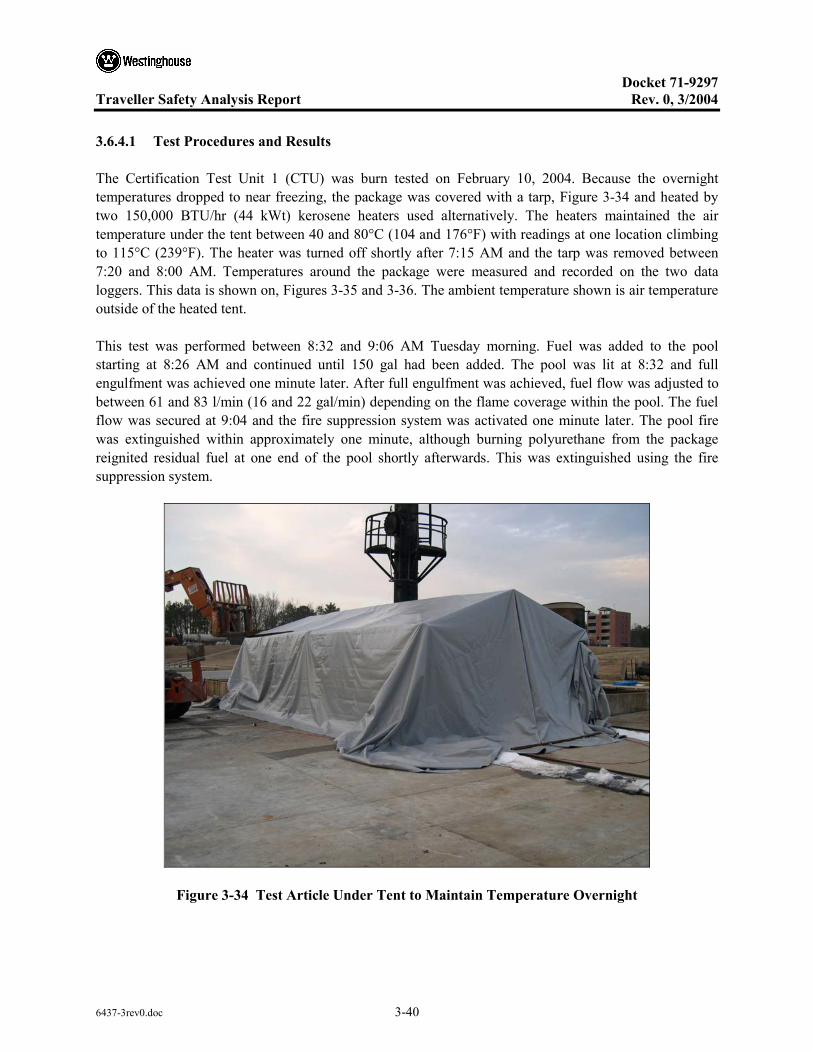
Docket 71-9297
Traveller Safety Analysis Report Rev. 0, 3/2004
6437-3rev0.doc 3-40
3.6.4.1 Test Procedures and Results
The Certification Test Unit 1 (CTU) was burn tested on February 10, 2004. Because the overnight temperatures dropped to near freezing, the package was covered with a tarp, Figure 3-34 and heated by two 150,000 BTU/hr (44 kWt) kerosene heaters used alternatively. The heaters maintained the air temperature under the tent between 40 and 80°C (104 and 176°F) with readings at one location climbing to 115°C (239°F). The heater was turned off shortly after 7:15 AM and the tarp was removed between 7:20 and 8:00 AM. Temperatures around the package were measured and recorded on the two data loggers. This data is shown on, Figures 3-35 and 3-36. The ambient temperature shown is air temperature outside of the heated tent.
This test was performed between 8:32 and 9:06 AM Tuesday morning. Fuel was added to the pool starting at 8:26 AM and continued until 150 gal had been added. The pool was lit at 8:32 and full engulfment was achieved one minute later. After full engulfment was achieved, fuel flow was adjusted to between 61 and 83 l/min (16 and 22 gal/min) depending on the flame coverage within the pool. The fuel flow was secured at 9:04 and the fire suppression system was activated one minute later. The pool fire was extinguished within approximately one minute, although burning polyurethane from the package reignited residual fuel at one end of the pool shortly afterwards. This was extinguished using the fire suppression system.
Figure 3-34 Test Article Under Tent to Maintain Temperature Overnight

Docket 71-9297
Traveller Safety Analysis Report Rev. 0, 3/2004
6437-3rev0.doc 3-41
Overnight Temperature on East Side Of Package
0
10
20
30
40
50
60
70
80
90
100
14:24 16:48 19:12 21:36 0:00 2:24 4:48 7:12 9:36Time
Tem
pera
ture
s (C
)
Ambient Temperature (°C) NE Upper flame
E Upper Flame E Lower Flame
SE Upper Flame NE Skin
E Skin SE Skin
Figure 3-35 Overnight Temperatures on East Side of Test Article
West Side Temperature Data
0
20
40
60
80
100
120
14:24 16:48 19:12 21:36 0:00 2:24 4:48 7:12 9:36
Time
Tem
pera
ture
(C)
Ambient Temperature (°C)NW Upper flameW Upper FlameW Lower FlameSW Upper FlameNW SkinW SkinSW Skin
Figure 3-36 Overnight Temperatures on West Side of Test Article

Docket 71-9297
Traveller Safety Analysis Report Rev. 0, 3/2004
6437-3rev0.doc 3-42
During the fire test, data recorded by the instrument system was monitored in real time. This data included the following thermocouples:
• NE lower flame temperature (same height as center of test article) • NE DFT • SE DFT • SE lower flame temperature • NW lower flame temperature • NW DFT • SW DFT • SW lower flame temperature
The data from the thermocouples within the fire is shown in, Figure 3-37. The data from the DFTs is shown in Figure 3-38.
Two data loggers were used to record a total of 14 channels of data. One data logger recorded temperatures on the east side of the CTU other, the west side of the CTU. Figures 3-39 and 3-40 show the skin temperature data collected on the east and west sides of the CTU. Figures 3-41 and 3-42 show data collected from the remaining thermocouples in the fire on the east and west sides respectively.
Monitored Burn Test Temperature Data
0
200
400
600
800
1,000
1,200
-10 0 10 20 30 40 50Time (min)
Tem
pera
ture
(C)
NE Lower flameSE Lower flameNW Lower flameSW Lower flame
Figure 3-37 Fire Temperatures Measured at the Corners of the Pool
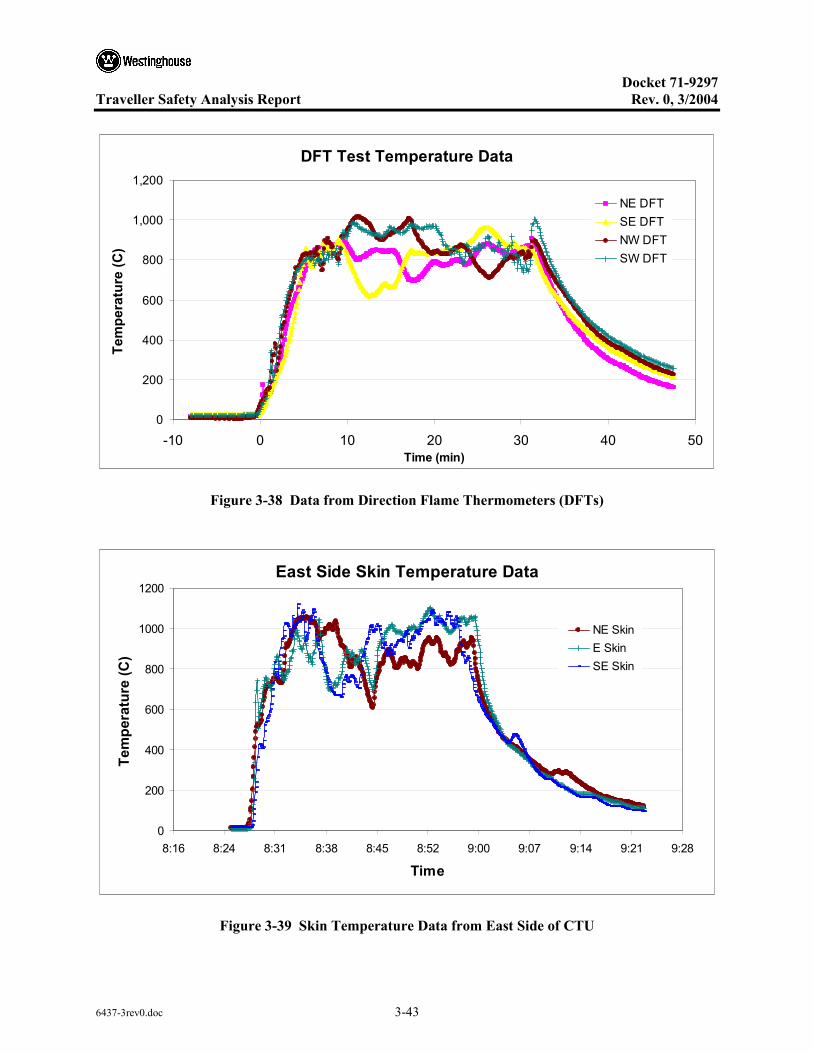
Docket 71-9297
Traveller Safety Analysis Report Rev. 0, 3/2004
6437-3rev0.doc 3-43
DFT Test Temperature Data
0
200
400
600
800
1,000
1,200
-10 0 10 20 30 40 50Time (min)
Tem
pera
ture
(C)
NE DFTSE DFTNW DFTSW DFT
Figure 3-38 Data from Direction Flame Thermometers (DFTs)
East Side Skin Temperature Data
0
200
400
600
800
1000
1200
8:16 8:24 8:31 8:38 8:45 8:52 9:00 9:07 9:14 9:21 9:28
Time
Tem
pera
ture
(C)
NE SkinE SkinSE Skin
Figure 3-39 Skin Temperature Data from East Side of CTU
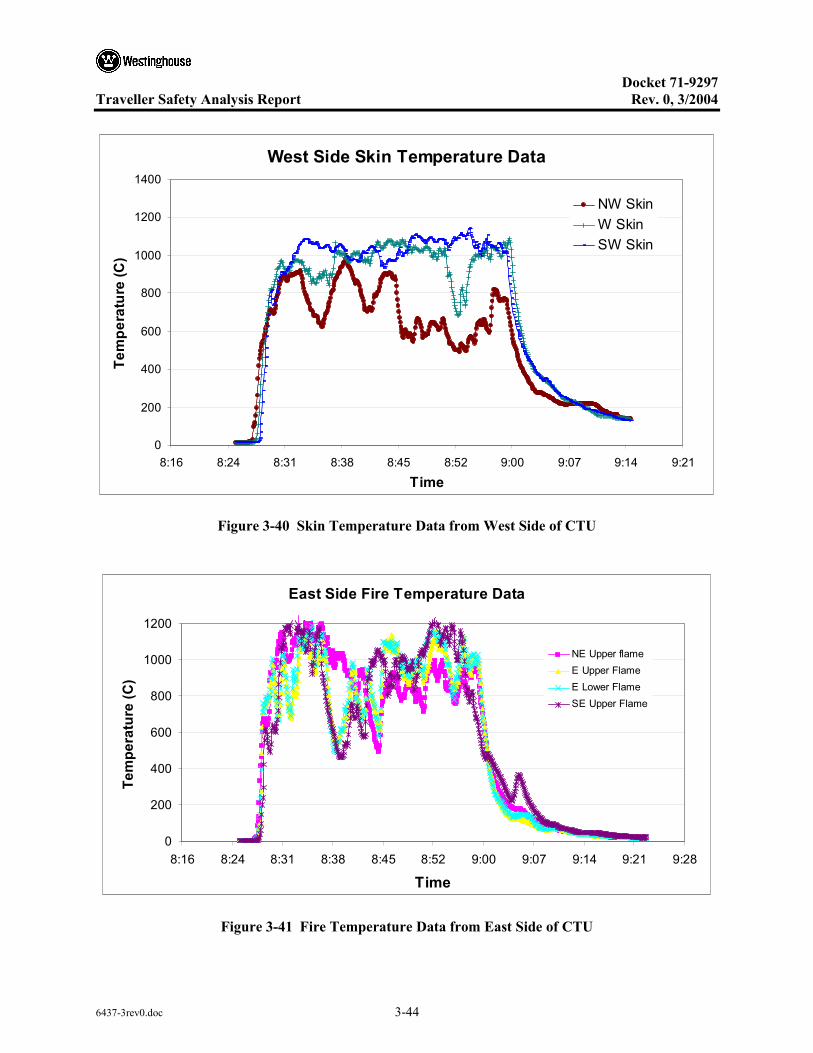
Docket 71-9297
Traveller Safety Analysis Report Rev. 0, 3/2004
6437-3rev0.doc 3-44
West Side Skin Temperature Data
0
200
400
600
800
1000
1200
1400
8:16 8:24 8:31 8:38 8:45 8:52 9:00 9:07 9:14 9:21
Time
Tem
pera
ture
(C)
NW SkinW SkinSW Skin
Figure 3-40 Skin Temperature Data from West Side of CTU
East Side Fire Temperature Data
0
200
400
600
800
1000
1200
8:16 8:24 8:31 8:38 8:45 8:52 9:00 9:07 9:14 9:21 9:28
Time
Tem
pera
ture
(C)
NE Upper flameE Upper FlameE Lower FlameSE Upper Flame
Figure 3-41 Fire Temperature Data from East Side of CTU

Docket 71-9297
Traveller Safety Analysis Report Rev. 0, 3/2004
6437-3rev0.doc 3-45
West Side Fire Temperature Data
0
200
400
600
800
1000
1200
8:16 8:24 8:31 8:38 8:45 8:52 9:00 9:07 9:14 9:21Time
Tem
pera
ture
(C)
NW Upper flameW Upper FlameW Lower FlameSW Upper Flame
Figure 3-42 Fire Temperature Data from West Side of CTU
Temperature data was also collected using two portable, single wavelength optical thermometers. One was located on a raised platform on the west side of the package. The second was located on the east side of the package. Temperature data was recorded by hand. This data is shown in Tables 3-5 and 3-6.
Table 3-5 Optical Thermometer Data Sheet (West Side, Degrees C)
Time After Pool Fire Ignition
Temperature (North End)
Temperature (Middle)
Temperature (South End)
0 minutes 922 944 874
5 minutes 1047 973 1025
10 minutes 1002 1092 993
15 minutes 937 847 987
20 minutes 1177 982 942
25 minutes 1062 1073 1058
30 minutes 898 1162 968
35 minutes 525 460 484
40 minutes 318 362 294

Docket 71-9297
Traveller Safety Analysis Report Rev. 0, 3/2004
6437-3rev0.doc 3-46
Table 3-6 Optical Thermometer Data Sheet (East Side, Degrees C)
Time After Pool Fire Ignition
Temperature (North End)
Temperature (Middle)
Temperature (South End)
0 minutes 800 1000 936
5 minutes 978 1062 837
10 minutes 1037 948 932
15 minutes 842 996 835
20 minutes 590 1120 978
25 minutes 552 969 1048
30 minutes 1098 740 980
35 minutes
40 minutes
Wind speed measurements were made before, during and after the burn test. Average wind speed during the test was 0.9 miles per hour (0.4 m/s). Peak wind speed measured during the test was 2.2 miles per hour (1.0 m/s). The data was recorded by had at five minute intervals. This data is shown in Table 3-7.
An examination of the moderator blocks after the burn test revealed no significant damage. One small portion of moderator at the bottom end of the package showed signs of combustion, Figure 3-43. The very localized nature of the burn marks (on both the moderator and the refractory felt that covered the moderator) indicates that this was probably caused during the fabrication process. The stainless steel cover sheets are welded into place after the moderator blocks are bolted in and covered with insulation. It appears that the welding torch was applied to the steel immediately moderator causing a small amount of damage. A brown spot was observed on the back side of one moderator block attached to the Outerpack lid. The polyethylene at this location appears to have been heated to melt temperature, Figure 3-44. A very small amount of flow occurred away from the hot spot. This melt spot was small, affecting only a few cubic centimeters of material.

Docket 71-9297
Traveller Safety Analysis Report Rev. 0, 3/2004
6437-3rev0.doc 3-47
Table 3-7 Wind Data Sheet
Time Wind Speed
(mph) Wind Direction Temperature
F
8:05 1.7 E 42
8:10 2.0 NE -
8:15 1.7 E -
8:20 2.0 E 42
8:25 0.8 E -
8:30 0.8 E 42
8:35 0.8 E -
8:40 0.6 E 42
8:45 1.3 E -
8:50 2.2 N 42
8:55 0 - -
9:00 1.5 N -
9:05 0 - 43
9:10 1.3 W -
9:20 1.7 SW 43
9:30 1.3 SW 44
Wind data was taken every five minutes starting approximately 15 minutes before the burn until 30 minutes after the burn was completed.

Docket 71-9297
Traveller Safety Analysis Report Rev. 0, 3/2004
6437-3rev0.doc 3-48
Figure 3-43 Location of Possible Combustion of Moderator
Figure 3-44 Localized Melt Spot in Lid Moderator Block

Docket 71-9297
Traveller Safety Analysis Report Rev. 0, 3/2004
6437-3rev0.doc 3-49
Twelve sets of non-reversable temperature strips were attached to the CTU. Two were placed on the inside faces of the impact limiters (one at each end), six were placed on the stainless steel covering the moderator in the Outerpack lid, and five were attached to the inside doors of the Clamshell. Except for on set that was unreadable after the test, the peak indicated temperature was 177°C. Locations of the temperature strip sets are shown in Figure 3-45. Readings on one of the Outerpack lid temperature strip sets is shown in Figure 3-46.
116 C(inside Face)
116 C
160 C
177 C
Unreadable
143 C
<77 C
77 C
104 C
104 C
88 C
116 C(inside Face)
116 C
160 C
177 C
Unreadable
143 C
<77 C
77 C
104 C
104 C
88 C
116 C(inside Face)
116 C
160 C
177 C
Unreadable
143 C
<77 C
77 C
104 C
104 C
88 C
Figure 3-45 Location and Indicated Temperatures of Temperature Strip Sets
Figure 3-46 Temperature Strip Set After Fire Test

Docket 71-9297
Traveller Safety Analysis Report Rev. 0, 3/2004
6437-4rev0.doc i
TABLE OF CONTENTS
4 CONTAINMENT .........................................................................................................................4-1 4.1 DESCRIPTION OF THE CONTAINMENT SYSTEM..................................................4-1
4.1.1 Containment Boundary....................................................................................4-1 4.2 GENERAL CONSIDERATIONS ...................................................................................4-1
4.2.1 Type A Fissile Packages..................................................................................4-1

Docket 71-9297
Traveller Safety Analysis Report Rev. 0, 3/2004
6437-4rev0.doc 4-1
4 CONTAINMENT
4.1 DESCRIPTION OF THE CONTAINMENT SYSTEM
4.1.1 Containment Boundary
The Traveller package is limited to transporting unirradiated, low enriched uranium, nuclear fuel assemblies and rods. The radioactive material, bound in sintered pellets having very limited solubility, has minimal propensity to suspend in air. These pellets are sealed in fuel tubes to form the fuel rods portion of each assembly.
Containment System is described in both TSR-1 (§213) and 10CFR71.4 as, “the assembly of components of the packaging intended to retain the radioactive material during transport.” The Containment System for the Traveller consists of the fuel rods.
4.2 GENERAL CONSIDERATIONS
4.2.1 Type A Fissile Packages
For type A fissile packages, no loss or dispersal of radioactive material is permitted under normal conditions of transport as specified in 10CFR71.43(f). It has been demonstrated from repeated normal drop scenarios that there is no loss of fissile material from the rods, and therefore no dispersal. Therefore, the containment system remains intact.


Docket 71-9297
Traveller Safety Analysis Report Rev. 0, 3/2004
6437-5rev0.doc i
TABLE OF CONTENTS
5 SHIELDING EVALUATION ......................................................................................................5-1

Docket 71-9297
Traveller Safety Analysis Report Rev. 0, 3/2004
6437-5rev0.doc 5-1
5 SHIELDING EVALUATION
Due to the nature of the radioactive material to be transported in the Traveller, gamma radiation is not emitted. In addition, neutron radiation is not emitted because the contents remains in a subcritical configuration. Therefore, the surface dose rate of the Traveller will be less than 2mSv/h (200 mrem/h) at any point on the external surface of the package.


Docket 71-9297
Traveller Safety Analysis Report Rev. 0, 3/2004
6437-6rev0.doc i
TABLE OF CONTENTS
6 CRITICALITY .............................................................................................................................6-1 6.1 DESCRIPTION OF CRITICALITY DESIGN................................................................6-3
6.1.1 Design Features ...............................................................................................6-3 6.1.1.1 Containment System .......................................................................6-3 6.1.1.2 Confinement System .......................................................................6-4 6.1.1.3 Flux Traps .......................................................................................6-5 6.1.1.4 Neutron-Absorbing Materials .........................................................6-6 6.1.1.5 Neutron-Moderating Materials........................................................6-7 6.1.1.6 Floodable Void Spaces....................................................................6-7 6.1.1.7 Array Spacing Significant Components ..........................................6-9
6.1.2 Summary Tables of Criticality Evaluation ......................................................6-9 6.1.3 Criticality Safety Index (CSI)........................................................................6-11
6.1.3.1 PWR Fuel Transport Index ...........................................................6-11 6.1.3.2 Rod Container Transport Index.....................................................6-11
6.2 FISSILE MATERIAL CONTENTS..............................................................................6-12 6.2.1 PWR Fuel Assemblies ...................................................................................6-12 6.2.2 PWR and BWR Rods ....................................................................................6-13
6.3 GENERAL CONSIDERATIONS .................................................................................6-15 6.3.1 Model Configuration .....................................................................................6-15
6.3.1.1 Contents Models............................................................................6-15 6.3.1.2 Packaging Model...........................................................................6-17
6.3.2 Material Properties ........................................................................................6-19 6.3.2.1 Package to Model Comparison .....................................................6-22
6.3.3 Computer Codes and Cross-Section Libraries...............................................6-23 6.3.4 Demonstration of Maximum Reactivity ........................................................6-24
6.3.4.1 Evaluation Strategy .......................................................................6-24 6.3.4.2 Establish Baseline Case for Packaging
(Routine Condition of Transport)..................................................6-24 6.3.4.3 Identify Most Reactive Fuel Assembly Type (Contents) ..............6-26 6.3.4.4 Determine Most Reactive Flooding Configurations
(Flooding Case) .............................................................................6-26 6.3.4.5 Include Conservative Assumptions for Material Properties..........6-27 6.3.4.6 Determine the Normal Condition of Transport .............................6-27 6.3.4.7 As-found Condition After Testing ................................................6-29 6.3.4.8 Determine the License-basis Case (HAC Case)............................6-30 6.3.4.9 Analyze Different Hypothetical Conditions
(Sensitivity Studies) ......................................................................6-30 6.4 SINGLE PACKAGE EVALUATION ..........................................................................6-32
6.4.1 Configuration for Fuel Assemblies................................................................6-32 6.4.1.1 Configuration Under Normal Conditions of Transport .................6-32 6.4.1.2 Configuration Under Hypothetical Accident Conditions ..............6-32

Docket 71-9297
Traveller Safety Analysis Report Rev. 0, 3/2004
6437-6rev0.doc ii
TABLE OF CONTENTS (cont.)
6.4.2 Results for Fuel Assemblies ..........................................................................6-33 6.4.3 Configuration for Rod Containers .................................................................6-35
6.5 EVALUATION OF PACKAGE ARRAYS UNDER NORMAL CONDITIONS OF TRANSPORT..........................................................................................................6-36 6.5.1 Configuration for Fuel Assemblies................................................................6-36 6.5.2 Results for Fuel Assemblies ..........................................................................6-36
6.6 PACKAGE ARRAYS UNDER HYPOTHETICAL ACCIDENT CONDITIONS ...............................................................................................................6-37 6.6.1 Configuration for Fuel Assemblies................................................................6-37 6.6.2 Results for Fuel Assemblies ..........................................................................6-37 6.6.3 Results for Rod Containers............................................................................6-39
6.7 SENSITIVITY STUDIES..............................................................................................6-40 6.7.1 Flooding.........................................................................................................6-40
6.7.1.1 Pin-Cladding Gap Flooding ..........................................................6-40 6.7.1.2 Most Reactive For Individual Package – Fully Flooded...............6-40 6.7.1.3 Most Reactive For Package Array – Preferential Flooding...........6-40 6.7.1.4 Partial Flooding.............................................................................6-41 6.7.1.5 Partial Density Interspersed Moderation.......................................6-43
6.7.2 Lattice Expansion ..........................................................................................6-43 6.7.2.1 Non-uniform Lattice Expansion....................................................6-44
6.7.3 Annular Pellets ..............................................................................................6-45 6.7.4 Axially Displaced Rods.................................................................................6-45 6.7.5 Polyurethane Foam Moderating Effect..........................................................6-46 6.7.6 Shock Mount Moderating Effect ...................................................................6-47 6.7.7 Polyethylene Density.....................................................................................6-47 6.7.8 Reduction of Boron Content in Neutron Absorber........................................6-47 6.7.9 Elimination of Structural Stainless Steel .......................................................6-48 6.7.10 Zirconium Reduction.....................................................................................6-48
6.8 FISSILE MATERIAL PACKAGES FOR AIR TRANSPORT.....................................6-49 6.9 BENCHMARK EVALUATIONS.................................................................................6-50
6.9.1 Applicability of Benchmark Experiments .....................................................6-50 6.9.2 Bias Determination........................................................................................6-51
6.10 APPENDICES ...............................................................................................................6-52 6.10.1 PWR FUEL ASSEMBLY PARAMETERS..................................................6-53 6.10.2 FUEL ASSEMBLY COMPARISON............................................................6-57 6.10.3 17X17OFA-XL MODEL ..............................................................................6-60
6.10.3.1 Introduction ...................................................................................6-60 6.10.3.2 Fuel Assembly Model ...................................................................6-60 6.10.3.3 Fuel Rod Arrays ............................................................................6-61 6.10.3.4 Fuel Rod Cell ................................................................................6-61

Docket 71-9297
Traveller Safety Analysis Report Rev. 0, 3/2004
6437-6rev0.doc iii
TABLE OF CONTENTS (cont.)
6.10.4 TRAVELLER PACKAGING MODEL ........................................................6-63 6.10.4.1 Introduction ...................................................................................6-63 6.10.4.2 Outerpack Model...........................................................................6-63 6.10.4.3 Clamshell Model ...........................................................................6-66
6.10.5 SINGLE PACKAGE EVALUATION CALCULATIONS...........................6-69 6.10.6 PACKAGE ARRAY EVALUATION CALCULATIONS...........................6-83 6.10.7 ROD CONTAINER CALCULATIONS .....................................................6-104
6.10.7.1 Introduction .................................................................................6-104 6.10.8 CALCULATIONS FOR SENSITIVITY STUDIES ...................................6-108
6.10.8.1 Partial Density Interspersed Moderation.....................................6-108 6.10.8.2 Boron Content Sensitivity Study.................................................6-115
6.10.9 BENCHMARK CRITICAL EXPERIMENTS............................................6-116

Docket 71-9297
Traveller Safety Analysis Report Rev. 0, 3/2004
6437-6rev0.doc iv
LIST OF TABLES
Table 6-1 Summary Table for Traveller STD with PWR Fuel Assembly .....................................6-10
Table 6-2 Summary Table for Traveller XL with PWR Fuel Assembly .......................................6-10
Table 6-3 Summary Table for Traveller XL with the Rod Box and Rod Pipe...............................6-10
Table 6-4 Uranium Isotope Distribution ........................................................................................6-12
Table 6-5 Fuel Rod Parameters......................................................................................................6-14
Table 6-6 17OFA-XL Parameters ..................................................................................................6-16
Table 6-7 Fuel Rod Model Dimension Ranges ..............................................................................6-17
Table 6-8 Sample Input Showing Material Properties ...................................................................6-19
Table 6-9 Material Descriptions.....................................................................................................6-20
Table 6-10 Material Compositions...................................................................................................6-21
Table 6-11 Material Specifications for Outerpack ...........................................................................6-22
Table 6-12 Material Specifications for Clamshell ...........................................................................6-23
Table 6-13 Material Specifications for Contents .............................................................................6-23
Table 6-14 Most Reactive Flooding Cases for Traveller .................................................................6-27
Table 6-15 Parameters for the different Traveller Conditions .........................................................6-31
Table 6-16 Most Reactive Configuration for a Single Package in Isolation....................................6-33
Table 6-17 Routine and Normal Conditions of Transport for Package Array .................................6-36
Table 6-18 Hypothetical Accident Condition Results for a Package Array.....................................6-37
Table 6-19 Hypothetical Accident Condition Results for Rod Container........................................6-39
Table 6-20 Parameters for 14x14 Fuel Assemblies..........................................................................6-55
Table 6-21 Parameters for 15x15 Fuel Assemblies..........................................................................6-55
Table 6-22 Parameters for 16x16 Fuel Assemblies..........................................................................6-56
Table 6-23 Parameters for 17x17 and 18x18 Fuel Assemblies........................................................6-56
Table 6-24 17X17 and 18X18 Fuel Assemblies ..............................................................................6-58
Table 6-25 Single Package Calculations for Traveller STD and XL – Normal Conditions ............6-69
Table 6-26 Single Package Calculations for Traveller STD – HAC................................................6-69
Table 6-27 Single Package Calculations for Traveller XL – HAC..................................................6-70
Table 6-28 Input Deck for Traveller STD Single Package ..............................................................6-71

Docket 71-9297
Traveller Safety Analysis Report Rev. 0, 3/2004
6437-6rev0.doc v
LIST OF TABLES (cont.)
Table 6-29 Input Deck for Traveller XL Single Package ................................................................6-77
Table 6-30 Package Array Calculations for Traveller STD and XL – Normal Conditions .............6-83
Table 6-31 Package Array Calculations for Traveller STD – HAC.................................................6-84
Table 6-32 Package Array Calculations for Traveller XL – HAC...................................................6-85
Table 6-33 Input Deck for Traveller STD Package Array – HAC...................................................6-86
Table 6-34 Input Deck for Traveller XL Package Array – HAC.....................................................6-92
Table 6-35 Input Deck for Traveller XL Package Array – HAC.....................................................6-98
Table 6-37 Partial Density Interspersed Moderation Results for Traveller STD...........................6-108
Table 6-38 Input Deck for Traveller STD Package Array .............................................................6-109
Table 6-39 Boron Sensitivity Results.............................................................................................6-115
Table 6-40 Summary of Available LWR Critical Experiments .....................................................6-116
Table 6-41 Critical Benchmark Experiment Classification............................................................6-118
Table 6-42 Summary Comparison of Benchmark Critical Experiment Properties to Traveller...................................................................................................................6-119

Docket 71-9297
Traveller Safety Analysis Report Rev. 0, 3/2004
6437-6rev0.doc vi
LIST OF FIGURES
Figure 6-1 Traveller Exploded View.................................................................................................6-3
Figure 6-2 Traveller Confinement System ........................................................................................6-4
Figure 6-3 Seven Package Array Showing the Flux Trap System ....................................................6-5
Figure 6-4 Floodable Void Spaces ....................................................................................................6-8
Figure 6-5 Regression Curves of keff Versus Fuel Assembly Envelope over Range of Interest .......................................................................................................................6-13
Figure 6-6 Solid Works Model and Keno3D Rendering of Traveller .............................................6-18
Figure 6-7 Outerpack Model Showing Material..............................................................................6-18
Figure 6-8 Criticality Evaluation Strategy.......................................................................................6-25
Figure 6-9 Individual HAC Curves for Traveller STD and Traveller XL.......................................6-34
Figure 6-10 Package Array HAC Curves for Traveller STD and Traveller XL................................6-38
Figure 6-11 Partial Flooding Scenario #1..........................................................................................6-42
Figure 6-12 Partial Flooding Scenario #2..........................................................................................6-42
Figure 6-13 Interspersed Moderation Density Curve ........................................................................6-43
Figure 6-14 Symmetric and Asymmetric Non-uniform Distribution ................................................6-44
Figure 6-15 Non-uniform Expansion keff Plot ...................................................................................6-45
Figure 6-16 Axial Slice Showing 92 Displaced Rods .......................................................................6-46
Figure 6-17 Effect of Varying Polyethylene Density ........................................................................6-47
Figure 6-18 Sensitivity Study of Boron Content for Traveller STD Package Array.........................6-48
Figure 6-19 Upper Safety Limits (USLs) for 55 LWR Fuel Critical Experiments ...........................6-51
Figure 6-20 Cross Section for 18x18 and 17x17 Assemblies............................................................6-54
Figure 6-21 Cross Sections for 16x16 Assemblies............................................................................6-54
Figure 6-22 Cross Sections for 15x15 and 14x14 Assemblies ..........................................................6-54
Figure 6-23 keff Curves vs Fuel Envelope Over Range of Interest ....................................................6-57
Figure 6-24 Input Deck for 17x17 OFA............................................................................................6-59
Figure 6-25 Sample Input Lines for Traveller Fuel Assembly..........................................................6-60
Figure 6-26 Keno 3d Image of Fuel Assembly .................................................................................6-60
Figure 6-27 Sample Input Lines for Fuel Rod Cells..........................................................................6-61
Docket 71-9297
Traveller Safety Analysis Report Rev. 0, 3/2004
6437-6rev0.doc vii
LIST OF FIGURES (cont.)
Figure 6-28 Fuel Rod Cell .................................................................................................................6-62
Figure 6-29 Sample Input for Traveller Outerpack ...........................................................................6-64
Figure 6-30 Keno 3d Line Schematic of Outerpack Cuboids............................................................6-65
Figure 6-31 Keno 3d Drawing of Outerpack Showing Media...........................................................6-65
Figure 6-32 Keno 3d Images of Outerpack .......................................................................................6-66
Figure 6-33 Sample input lines for Clamshell ...................................................................................6-67
Figure 6-34 Clamshell .......................................................................................................................6-68
Figure 6-35 Rod Pipe – keff vs. Pellet Pitch for Individual Package................................................6-105
Figure 6-36 Rod Pipe – keff vs. Pellet Diameter for Individual Package .........................................6-105
Figure 6-37 Rod Pipe – keff vs. Pellet/Diameter Ratio for Individual Package ...............................6-106
Figure 6-38 Rod Box – keff vs. Pellet Pitch for Package Array .......................................................6-106
Figure 6-39 Rod Box in Traveller XL.............................................................................................6-107
Figure 6-40 Rod Pipe in Traveller XL.............................................................................................6-107

Docket 71-9297
Traveller Safety Analysis Report Rev. 0, 3/2004
6437-6rev0.doc 6-1
6 CRITICALITY
The following analyses demonstrate that the Traveller complies fully with the requirements of 10CFR71.551 and §71.59 and TS-R-12. The nuclear criticality safety requirements for Type A fissile packages are satisfied for a single package and array configurations under normal conditions of transport and hypothetical accident conditions. A comprehensive description of the Traveller packaging is provided in Section 1. This section provides a description of the package (i.e., packaging and contents) that is sufficient for understanding the features of the Traveller that maintain criticality safety.
Specifically, this criticality evaluation presents the following information3:
1. Description of the contents and packaging, including maximum and minimum mass of materials, maximum 235U enrichment, physical parameters, type, form, and composition.
2. Description of the calculational models, including sketches with dimensions and materials, pointing out the differences between the models and actual package design, with explanation of how the differences affect the calculations.
3. Justification for the credit assumed for the fixed neutron absorber content, including reference to the acceptance tests that are implemented which verify the presence and uniformity of the absorber.
4. Justification for assuming 90% credit for fixed moderating material.
5. Description of the most reactive content loading and the most reactive configuration of the contents, the packaging, and the package array in the criticality evaluation.
6. Description of the codes and cross-section data used, together with references that provide complete information.
7. Discussion of software capabilities and limitations of importance to the criticality safety evaluations.
1 Title 10, Code of Federal Regulations, Part 71 (10CFR71), Packaging and Transportation of Radioactive Material, edition effective Oct 2004.
2 TS-R-1 1996 (Revised), Regulations for the Safe Transport of Radioactive Material.
3 NUREG/CR-5661, Recommendations for Preparing the Criticality Safety Evaluation of Transport Packages.
Docket 71-9297
Traveller Safety Analysis Report Rev. 0, 3/2004
6437-6rev0.doc 6-2
8. Description of validation procedures to justify the bias and uncertainties associated with the calculational method, including use of the administrative subcritical margin of 0.05 delta k to set an upper safety limit (USL) of 0.94.
9. Demonstration that the effective neutron multiplication factor (keff) calculated in the safety analysis is less than the USL after consideration of appropriate bias and uncertainties for the following.
a. A single package with optimum moderation within the containment (i.e., confinement) system, close water reflection, and the most reactive packaging and content configuration consistent with the effects of either normal conditions of transport or hypothetical accident conditions, whichever is more reactive.
b. An array of 5N undamaged packages (packages subject to normal conditions of transport) with nothing between the packages and close water reflection of the array.
c. An array of 2N damaged packages (packages subject to hypothetical accident conditions) if each package were subjected to the tests specified in §71.73, with optimum interspersed moderation and close water reflection of the array.
10. Calculation of the Criticality Safety Index (CSI) based on the value of N determined in the array analyses.
11. Description of the Traveller’s Confinement System.

Docket 71-9297
Traveller Safety Analysis Report Rev. 0, 3/2004
6437-6rev0.doc 6-3
6.1 DESCRIPTION OF CRITICALITY DESIGN
6.1.1 Design Features
This section describes the design features of the Traveller that are important for criticality. The Traveller shipping package carries either a single PWR fuel assembly or a single rod container that holds either PWR or BWR rods. The Traveller is divided into two major systems, Outerpack and Clamshell. The Outerpack consists of a polyurethane foam material sandwiched between concentric stainless steel shells. The Outerpack is a split-shell design with the two halves hinged together. Neutron-moderating high-density polyethylene blocks are affixed to the upper and lower halves of the Outerpack.
The Clamshell is a rectangular aluminum box that completely encloses the contents. It is rotated 45° and mounted in the Outerpack with rubber shock mounts. Neutron absorber panels are slotted into the inner face of each Clamshell side. The Clamshell is designed such that it retains its original dimensions when subjected to the HAC tests. See Figure 6-1 for an exploded view of the Traveller.
Overpack Lower Half
Overpack Top Half
Clamshell
Fuel Assembly
Figure 6-1 Traveller Exploded View
6.1.1.1 Containment System
The Containment System is described in both TSR-1 (§213) and 10CFR71.4 as, “the assembly of components of the packaging intended to retain the radioactive material during transport.” The

Docket 71-9297
Traveller Safety Analysis Report Rev. 0, 3/2004
6437-6rev0.doc 6-4
Containment System for the Traveller consists of the fuel rods, regardless of whether the Traveller is carrying a fuel assembly or rods in a rod container.
6.1.1.2 Confinement System
The Confinement System is defined in TS-R-1 (§209) as “the assembly of fissile material and packaging components specified by the designer and agreed to by the competent authority as intended to preserve criticality safety.” Note that TS-G-1.11 further describes the confinement system as “that part of a package necessary to maintain the fissile material in the configuration that was assumed in the criticality safety assessment for an individual package.” NUREG 16092 recommends that the analysis include a discussion of the “structural components that maintain the fissile material or neutron poisons in a fixed position within the package or in a fixed position relative to each other.” These structural components are intended to maintain criticality safety of the package. These structural components of the packaging actually comprise part of the Confinement System.
The Confinement System for the Traveller consists of those assembly and packaging components that preserve criticality safety of a single package in isolation. Hence, it consists of the fuel rods, the fuel assembly (or rod container), and the Clamshell assembly, including the neutron absorber panels. The Confinement System is shown in Figure 6-2.
Figure 6-2 Traveller Confinement System
1 IAEA TS-G-1.1, Advisory Material for the IAEA Regulations for the Safe Transport of Radioactive Material.
2 NUREG 1609, Standard Review Plan for Transportation Packages for Radioactive Material.

Docket 71-9297
Traveller Safety Analysis Report Rev. 0, 3/2004
6437-6rev0.doc 6-5
6.1.1.3 Flux Traps
The Traveller package features a unique flux trap system, which does not require an accident condition (i.e., flooding) in order to function. The system was designed to ensure an acceptable subcritical margin for the unlikely but most conservative flooding scenario, described later in this section. The flux trap system consists of neutron absorber panels in the Clamshell immediately adjacent to the contents, and high-density polyethylene (UHMW) blocks affixed to the inside of the Outerpack. Neutrons escaping from one fuel assembly would pass through two moderator blocks prior to passing through the absorber of the neighboring package.
Any flooding outside the Clamshell enhances the performance of the flux trap. The UHMW blocks ensure that there will be neutron moderation, and therefore, flux trap operation, in those array configurations where the contents are moderated inside the Clamshell but where there is no flooding in void spaces outside the Clamshell or between the packages. The flux trap components are further described below. Figure 6-3 shows the flux traps in a seven-package triangular-pitch array of Traveller packages.
Figure 6-3 Seven Package Array Showing the Flux Trap System

Docket 71-9297
Traveller Safety Analysis Report Rev. 0, 3/2004
6437-6rev0.doc 6-6
6.1.1.4 Neutron-Absorbing Materials
Neutron absorbing materials are present in the Traveller in two forms: materials of construction and neutron poisons.
6.1.1.4.1 Materials of Construction
Materials of construction include those materials normally present, namely the stainless steel in the Outerpack, the fuel assembly skeleton, and the top nozzle. It also includes the burnable absorbers in the fuel. The evaluation takes credit for approximately 60% of the stainless steel in the inner and outer shells of the Outerpack. See Table 6-11. No credit is taken for the neutron absorbing properties of the fuel assembly skeleton or top nozzle, with the exception of the zirconium thimble tube material. In the criticality model the volumes occupied by skeleton and top nozzle are modeled as water. Water is assumed to increase reactivity more than steel by providing more neutron reflection or moderation than the steel. Finally, the evaluation does not consider the presence of any integral or burnable absorbers.
6.1.1.4.2 Neutron Poisons
Neutron poison has been added to the Traveller specifically to limit reactivity during hypothetical accident conditions. The neutron poison in the Traveller could be in one of two forms: borated-aluminum or BORAL® panels in the Clamshell. These panels are permanently fixed.
6.1.1.4.3 Borated Aluminum
Boron that is intentionally added to aluminum for the purpose of absorbing neutrons is 2.3 wt% of 1100 borated aluminum alloy. The boron is enriched in 10B to abundance greater than 95 weight percent. The boron is distributed homogeneously through the borated aluminum. Section 8 describes the QA program for ensuring acceptable boron content.
The evaluation takes credit for 90% of the boron content, modeling the boron at 2.0 wt%. This equates to an areal density of 0.016 g/cm2 B10. Section 8 provides technical justification for extending the range of credit from 75% to 90%. Section 6.7.8 discusses the effect of varying the boron content on system reactivity.
6.1.1.4.4 BORAL
BORAL is a thermal neutron poison material composed of boron carbide and 1100 alloy aluminum. Boron carbide is a compound having a high boron content in a physically stable and chemically inert form. The 1100 alloy aluminum is a light-weight metal with high tensile strength which is protected from corrosion by a highly resistant oxide form. The two materials, boron carbide and aluminum, are chemically compatible and ideally suited for long-term use. BORAL has been licensed by the NRC for use in numerous BWR and PWR spend fuel storage racks and has been used in international reactor installations. Manufacturing QA (i.e., neutronics or chemical testing) ensures that the minimum areal densities are achieved.

Docket 71-9297
Traveller Safety Analysis Report Rev. 0, 3/2004
6437-6rev0.doc 6-7
The BORAL sheets measure 0.125 inches (0.3175 cm) thick, including cladding and core. The nominal thickness of the cladding and core are as follows: Cladding (0.0179 inches/0.0455 cm), Core (0.0892 inches/0.2266 cm), Cladding (0.0179 inches/0.0455 cm). The maximum areal density loading for B10 that corresponds to this thickness is 0.0250 g/cm2, which equates to a B4C loading of 36.5%. This analysis assumes 75% credit for areal density, which equates to 0.01875 g/cm2.
6.1.1.5 Neutron-Moderating Materials
Neutron-moderating materials in the Traveller include the polyurethane foam in the Outerpack, the shock mounts, and the high-density polyethylene (UHMW) blocks.
6.1.1.5.1 Polyurethane Foam
Results from the formal thermal test and the numerous scoping burn tests that were conducted indicate that an unpredictable amount of the polyurethane foam burns away. Therefore, no credit is taken for the foam under accident conditions. Rather, the foam is modeled as a void in the criticality analysis, which is the most conservative option. It is possible that the void space could be backfilled with water if the package were immersed but this possibility is not considered in the analysis.
6.1.1.5.2 Shock Mounts
Testing indicates that the shock mounts remain intact and hold the Clamshell in place. However, their contribution as a moderator is insignificant and therefore, they are modeled as full density water in the single package cases and as void spaces in the array cases.
6.1.1.5.3 High-density Polyethylene
High-density polyethylene (UHMW) “poly” is attached to the inside of the upper and lower sections of the Outerpack. The poly configuration is identical for both the Traveller and Traveller XL Outerpacks. The thickness is 1.25 in. [3.18 cm] in the upper section and 1.75 in [4.445 cm] in the lower section. The HPDE is a fixed moderator that together with the fixed neutron absorber installed in the Clamshell forms the flux trap system, which is discussed in Section 6.1.1.3. The UHMW density is 0.92 g/cc. The analysis assumes 90% density, or 0.828 g/cc. Section 6.7.7 discusses the effect of varying the HPDE density on system reactivity.
6.1.1.6 Floodable Void Spaces
The Traveller, including packaging and contents, contains six floodable regions. These regions have been modeled in various flooding combinations, including flooding with partial density water, in order to determine the most conservative accident configuration. The floodable regions are shown in Figure 6-4. (Note that region 1, the pin-gap, is shown in Figure 6-28). Flooding is addressed in Section 6.7.1. The region numbers below correspond to the numbers used in the criticality input decks.

Docket 71-9297
Traveller Safety Analysis Report Rev. 0, 3/2004
6437-6rev0.doc 6-8
Region 6: Outside the outerpack
Region 5: Polyurethane foam region
Region 4: Outerpack cavity region
Region 3: Clamshell region
Region 2: Fuel assembly region
Figure 6-4 Floodable Void Spaces
6.1.1.6.1 Region 1 – Pellet-Cladding Gap (Pin Gap)
The pellet-cladding gap, or pin gap, is the floodable space inside the cladding. It was seen from the testing that some fuel rods may crack. Therefore, it is assumed that all rods have fully flooded pin gaps. The pin-gap is shown in Figure 6-28.
6.1.1.6.2 Region 2 – Fuel Assembly Region
The fuel assembly region is the floodable space in the fuel assembly envelope. It is modeled fully flooded in all configurations. Sensitivity studies were conducted with this area partially flooded to evaluate the effects of differential flooding.
6.1.1.6.3 Region 3 – Clamshell Region
The Clamshell region is the floodable space outside the fuel assembly region and inside the Clamshell. It is modeled both flooded and dry to determine which configuration is most conservative for single package or array. Sensitivity studies were conducted with the Clamshell partially full to evaluate the partial flooding scenario.
6.1.1.6.4 Region 4 – Outerpack Cavity Region
The Outerpack cavity region is the floodable space outside the Clamshell and inside the Outerpack. It was modeled both flooded and dry to determine which configuration is most conservative for single package or array configurations. Sensitivity studies were conducted with the Outerpack cavity region partially full to evaluate the partial flooding scenario.

Docket 71-9297
Traveller Safety Analysis Report Rev. 0, 3/2004
6437-6rev0.doc 6-9
6.1.1.6.5 Region 5 – Polyurethane Foam Region
The polyurethane foam region is the floodable space that is formed when the polyurethane foam burns away. As mentioned above, since it is difficult to predict how much foam will actually burn away, the entire foam region is modeled as a void for the normal condition and hypothetical accident condition, which is the most conservative configuration. For the routine condition the foam region is modeled as foam.
6.1.1.6.6 Region 6 – Outside Outerpack Region
This is the volume outside the Outerpack. It has been modeled both flooded and dry to determine which configuration is most conservative for single package and array.
6.1.1.7 Array Spacing Significant Components
The single component that affects the physical separation of the fissile material contents in package arrays is the Outerpack. The Outerpack outer radius is 12.50 inches ± 1.0 inch (317.50 mm ±25.40 mm). It is a cylindrical annular shell split along the longitudinal axis to form two separate halves. The inner and outer shells are fabricated from 12-gauge [0.104 in. 0.264 cm)] stainless steel sheet, and the space between the shells is filled with polyurethane foam. The foam has a nominal 3.0 in. (7.62 cm) radial thickness and axial thickness of approximately 8.0 in. (20.32 cm). The foam material limits impact forces on the fuel assembly and insulates the fuel assembly from heat generated by a fire. Circumferential stiffeners mounted outside provide significant impact protection to the Outerpack diameter. The Outerpack diameter is not reduced at all following hypothetical accident tests.
6.1.2 Summary Tables of Criticality Evaluation
Table 6-1 and Table 6-2 below give the most conservative results, rounded to three decimal places, for the Traveller and Traveller XL when carrying a PWR fuel assembly. The tables give results for single package and array configurations for both normal and hypothetical accident conditions of transport. Table 6-3 gives conservative results for the two types of rod containers, namely the Rod Box and Rod Pipe.

Docket 71-9297
Traveller Safety Analysis Report Rev. 0, 3/2004
6437-6rev0.doc 6-10
Table 6-1 Summary Table for Traveller STD with PWR Fuel Assembly
Traveller STD Keff
Single Package in Isolation
Normal 0.185
HAC 0.867
Package Array
Normal 0.296
HAC 0.891
Table 6-2 Summary Table for Traveller XL with PWR Fuel Assembly
Traveller XL Keff
Single Package in Isolation
Normal 0.194
HAC 0.905
Package Array
Normal 0.263
HAC 0.932
Table 6-3 Summary Table for Traveller XL with the Rod Box and Rod Pipe
Keff
Single Package in Isolation
Rod Box 0.730
Rod Pipe 0.780
Package Array
Rod Box 0.730
Rod Pipe 0.780

Docket 71-9297
Traveller Safety Analysis Report Rev. 0, 3/2004
6437-6rev0.doc 6-11
6.1.3 Criticality Safety Index (CSI)
6.1.3.1 PWR Fuel Transport Index
The Criticality Safety Index when transporting PWR fuel assemblies is calculated as follows:
2 * N = Array Size Array Size = 150 N= 150/2 → 75 Therefore, CSI = 50/75 → 0.7
6.1.3.2 Rod Container Transport Index
The Criticality Safety Index when transporting rods in either rod container is calculated as follows:
2 * N = Array Size Array Size = infinite N= infinity/2 → infinity Therefore, CSI = 50/infinity → 0.0

Docket 71-9297
Traveller Safety Analysis Report Rev. 0, 3/2004
6437-6rev0.doc 6-12
6.2 FISSILE MATERIAL CONTENTS
The package will be used to carry heterogeneous uranium compounds in the form of fuel rods. These rods will transported either as PWR fuel assemblies or as loose PWR or BWR fuel rods in a rod container. The uranium enrichment shall not be greater than 5.0 wt% 235U. The uranium isotopic distribution considered in the models in this criticality safety analysis is shown in Table 6-4.
Table 6-4 Uranium Isotope Distribution
Isotope Modeled Wt% 235U 5.0 238U 95.0
6.2.1 PWR Fuel Assemblies
The fuel assembly types to be transported in the Traveller belong to the 14x14, 15x15, 16x16, 17x17, 17x17, and 18x18 families. Different fuel assembly products in each family may have names not included in this application, but the parameters important to criticality are described in Appendix 6.10.1. The Traveller XL will carry all fuel assembly types while the Traveller will carry the 12-ft. long assemblies.
Calculations were performed to determine which fuel assembly would be the most reactive. Appendix 6.10.2 provides more detail. The analysis compares keff versus fuel assembly envelope when expanding a 100 cm length of the assembly from nominal to 14 inches (35.56 cm). Figure 6-23 shows the results over the entire range. Figure 6-5 shows regression curve fits over the range of interest, that is, up to 9.6 inches/24.384 cm.

Docket 71-9297
Traveller Safety Analysis Report Rev. 0, 3/2004
6437-6rev0.doc 6-13
This analysis indicates that the 17x17OFA is the most reactive fuel assembly over the range of interest. However, the difference between the 17x17STD and the 17x17OFA is less significant at the top end of the range (9.6 inches/24.384 cm). The 17x17OFA is the most reactive contents and fuel assembly to use in all calculations.
Figure 6-5 Regression Curves of keff Versus Fuel Assembly Envelope over Range of Interest
6.2.2 PWR and BWR Rods
The Traveller will carry loose rods in rod containers. Table 6-5 below gives the nominal parameter ranges for the fuel rods. Analysis for the rod container was based solely on pellet diameter and pellet pitch. Therefore, there is no restrictions on the non-fuel components of the rods. Fuel rods that satisfy the criteria of Table 6-5 may be transported. This applies to PWR and BWR fuel rods.

Docket 71-9297
Traveller Safety Analysis Report Rev. 0, 3/2004
6437-6rev0.doc 6-14
Table 6-5 Fuel Rod Parameters
Parameter Limit
Enrichment ≤ 5.0 wt% 235U
Pellet diameter 0.20 – 0.60 inches/0.508 – 1.524 cm
Minimum stack length No restriction
Maximum stack length Rod container length
Cladding Zirconium alloy
Integral absorber No restriction
Wrapping or sleeving No restriction
Minimum number per container No restriction
Maximum number per container No restriction
Non-fissile components in rod container No restriction
Docket 71-9297
Traveller Safety Analysis Report Rev. 0, 3/2004
6437-6rev0.doc 6-15
6.3 GENERAL CONSIDERATIONS
The models developed for these calculations are not exact representations of the package, but they do explicitly include all of the physical features that are important to criticality safety. Modeling approximations will be shown to be either conservative or neutral with respect to the criticality safety case. This section describes the packaging and the contents models.
6.3.1 Model Configuration
Geometry input dimensions are taken directly from design drawings and are derived by stacking dimensions from design drawings or calculated using geometric relationships and dimensions shown on design drawings. Longitudinal dimensions in the model are oriented along the z-axis, and latitudinal dimensions are oriented in the x-y plane. The origin of the individual package unit is near the bottom of the package along the z-axis and at the center of the package in the x-y plane. The positive direction is from bottom to top of the package along the z-axis, the positive direction is from left to right along the x-axis when viewed from the top of the package and the positive direction is from lower to upper along the y-axis.
6.3.1.1 Contents Models
The contents models used in support of this analysis include the PWR fuel assembly model, the BWR fuel rod model, and two rod container models, namely the Rod Pipe and Rod Box.
6.3.1.1.1 PWR Fuel Assembly Model: 17OFA-XL
Section 6.2.1 established that the 17x17OFA would be the fuel assembly used in all calculations. In order to incorporate the maximum fuel assembly length, the 17x17STD-XL, an imaginary fuel assembly, the 17OFA-XL, was modeled in the calculations. The 17OFA-XL model is described in detail in Appendix 6.10.4. It basically consists of concentric cuboids to model the top nozzle assembly, skeleton, and fuel regions. The fuel assembly origin is at the bottom left hand corner of the fuel assembly lower nozzle. The fuel assembly is placed inside the fuel confinement with no translation of the origin. Table 6-6 shows the parameters of the 17OFA-XL and how they compare to the 17x17OFA and 17x17STD.

Docket 71-9297
Traveller Safety Analysis Report Rev. 0, 3/2004
6437-6rev0.doc 6-16
Table 6-6 17OFA-XL Parameters
Fuel Assembly Type W-STD/XL W-OFA W-OFA/XL
Nominal Pellet Diameter 0.3225 (8.192)
0.3088 (7.843)
0.3088 (7.843)
Annular Pellet Inner Diameter 0.155 (3.937)
0.155 (3.937)
0.155 (3.937)
Nominal Clad Thickness 0.0225 (0.572)
0.0225 (0.572)
0.0225 (0.572)
Clad Material Zirconium alloy Zirconium alloy Zirconium alloy
Nominal Clad Outer Diameter 0.374 (9.499)
0.360 (9.144)
0.360 (9.144)
Maximum Stack Length 169 (4292.6)
145 (3683)
169 (4292.6)
Nominal Assembly Envelope 8.418 (213.817)
8.418 (213.817)
8.418 (213.817)
Kg’s 235U Assembly 28 22 28
Nominal Lattice Pitch 0.496 (12.598)
0.496 (12.598)
0.496 (12.598)
GT Diameter 0.482 (12.243)
0.474 (12.040)
0.474 (12.040)
GT Thickness 0.016 (0.406)
0.016 (0.406)
0.016 (0.406)
GT Material ZIRC ZIRC ZIRC
IT Diameter 0.482 (12.243)
0.474 (12.040)
0.474 (12.040)
IT Thickness 0.016 (0.406)
0.016 (0.406)
0.016 (0.406)
IT Material ZIRC ZIRC ZIRC
6.3.1.1.2 Fuel Rod Model
The fuel rods for the rod containers are conservatively modeled in order to bound all PWR and BWR fuel rods that will be transported. The rods are modeled as pellet stacks with no consideration given to cladding or other non-fuel characteristics or properties. The rod container analysis consists of evaluating arrays of pellet stacks inside each container type (Rod Box and Rod Pipe), varying the pellet diameter and pitch to determine the optimum configuration. Pellet diameters range from 0.20 inches to 0.60 inches [0.508 cm to 1.524 cm] at 0.05 inch increments. Pellet pitch ranged from close-packed to 4.0 cm in order to find the optimum water-to-fuel ratios for each pellet diameter.
Docket 71-9297
Traveller Safety Analysis Report Rev. 0, 3/2004
6437-6rev0.doc 6-17
No credit is taken for integral burnable absorbers. 100% theoretical density is assumed. Parameters are given in Table 6-7. There are no restrictions with respect to the type of neutron absorbers that may be included in the fuel design.
Table 6-7 Fuel Rod Model Dimension Ranges
Element (cm) (inch)
Pellet Radius 0.254 - 0.762 0.10 – 0.30
Pellet Diameter 0.508 - 1.524 0.20 – 0.60
Full Length Rod 448.3862 176.53
6.3.1.1.3 Rod Box Model
The Rod Box is described in Section 1. It is modeled as a simple cuboid with dimensions 13.0x13.5x 450 cm (5.12x5.31x177 inches), which equates to the outside dimension of the actual box. The box material is not modeled. The Rod Box is positioned at the bottom of the Clamshell.
6.3.1.1.4 Rod Pipe Model
The Rod Pipe is described in Section 1. It is modeled as a simple cylinder with diameter 6.625 inches/16.8275 cm, which equates the nominal outside dimension of a 6.0 inch diameter stainless steel pipe. It is sealed at both ends. No internal padding or cushioning is modeled. Nor is it modeled with any flanges or fittings that enable it to seat inside the Clamshell. It’s length is 177 inches/450 cm. The Rod Pipe is positioned at the bottom of the Clamshell.
6.3.1.2 Packaging Model
6.3.1.2.1 Outerpack Model
Both the Traveller and Traveller XL have the same Outerpack, and so the same Outerpack model is used for both. The Outerpack model geometry is described in greater detail in Appendix 6.10.5. It consists of concentric cylinders to model the outer shell and intersecting cuboids rotated appropriately to model the inner shell and fixed moderator. The shock mount (unit 12) is a cylinder placed inside the Outerpack as a hole. Twenty-six holes are positioned along the lower half of the inner shell to represent the shock mounts. The shock mounts are included because their placement displaces fixed moderator and the shock mount material is itself a moderator that could have an effect on keff. Actual Outerpack dimensions are found on the license drawings. Figure 6-7 shows an end-on view of the Outerpack.
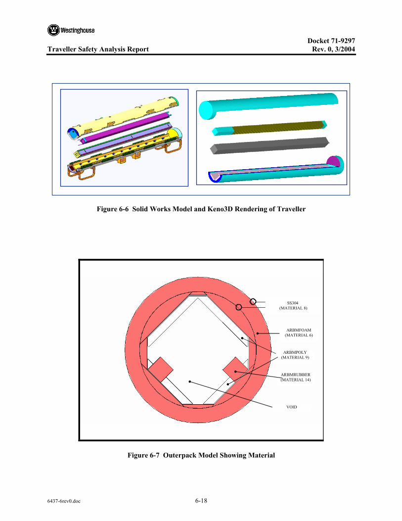
Docket 71-9297
Traveller Safety Analysis Report Rev. 0, 3/2004
6437-6rev0.doc 6-18
Figure 6-6 Solid Works Model and Keno3D Rendering of Traveller
ARBMPOLY (MATERIAL 9)
VOID
ARBMFOAM (MATERIAL 6)
SS304
(MATERIAL 8)
ARBMRUBBER (MATERIAL 14)
Figure 6-7 Outerpack Model Showing Material
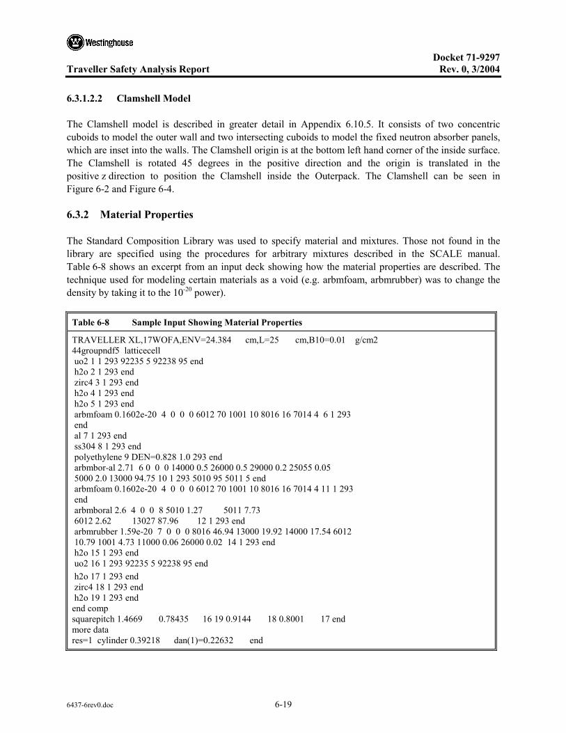
Docket 71-9297
Traveller Safety Analysis Report Rev. 0, 3/2004
6437-6rev0.doc 6-19
6.3.1.2.2 Clamshell Model
The Clamshell model is described in greater detail in Appendix 6.10.5. It consists of two concentric cuboids to model the outer wall and two intersecting cuboids to model the fixed neutron absorber panels, which are inset into the walls. The Clamshell origin is at the bottom left hand corner of the inside surface. The Clamshell is rotated 45 degrees in the positive direction and the origin is translated in the positive z direction to position the Clamshell inside the Outerpack. The Clamshell can be seen in Figure 6-2 and Figure 6-4.
6.3.2 Material Properties
The Standard Composition Library was used to specify material and mixtures. Those not found in the library are specified using the procedures for arbitrary mixtures described in the SCALE manual. Table 6-8 shows an excerpt from an input deck showing how the material properties are described. The technique used for modeling certain materials as a void (e.g. arbmfoam, arbmrubber) was to change the density by taking it to the 10-20 power).
Table 6-8 Sample Input Showing Material Properties
TRAVELLER XL,17WOFA,ENV=24.384 cm,L=25 cm,B10=0.01 g/cm2 44groupndf5 latticecell uo2 1 1 293 92235 5 92238 95 end h2o 2 1 293 end zirc4 3 1 293 end h2o 4 1 293 end h2o 5 1 293 end arbmfoam 0.1602e-20 4 0 0 0 6012 70 1001 10 8016 16 7014 4 6 1 293 end al 7 1 293 end ss304 8 1 293 end polyethylene 9 DEN=0.828 1.0 293 end arbmbor-al 2.71 6 0 0 0 14000 0.5 26000 0.5 29000 0.2 25055 0.05 5000 2.0 13000 94.75 10 1 293 5010 95 5011 5 end arbmfoam 0.1602e-20 4 0 0 0 6012 70 1001 10 8016 16 7014 4 11 1 293 end arbmboral 2.6 4 0 0 8 5010 1.27 5011 7.73 6012 2.62 13027 87.96 12 1 293 end arbmrubber 1.59e-20 7 0 0 0 8016 46.94 13000 19.92 14000 17.54 6012 10.79 1001 4.73 11000 0.06 26000 0.02 14 1 293 end h2o 15 1 293 end uo2 16 1 293 92235 5 92238 95 end h2o 17 1 293 end zirc4 18 1 293 end h2o 19 1 293 end end comp squarepitch 1.4669 0.78435 16 19 0.9144 18 0.8001 17 end more data res=1 cylinder 0.39218 dan(1)=0.22632 end
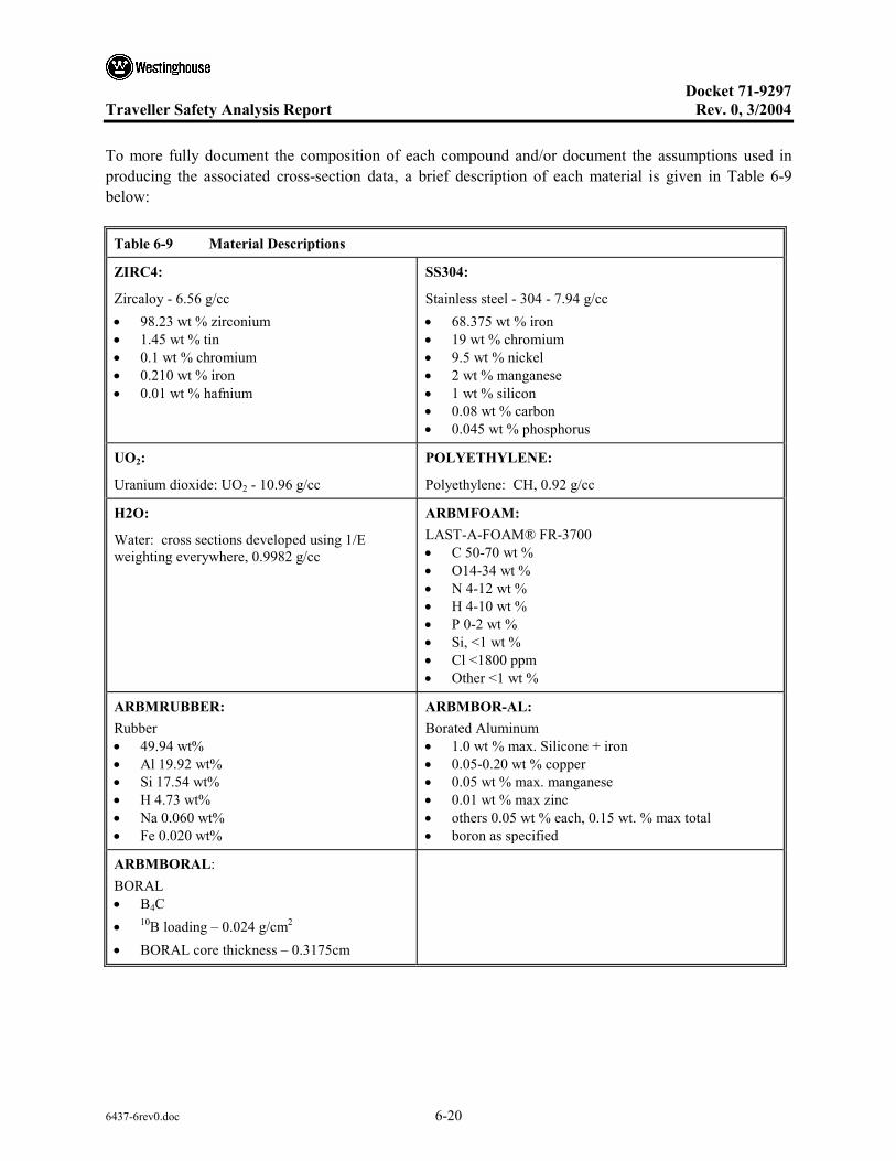
Docket 71-9297
Traveller Safety Analysis Report Rev. 0, 3/2004
6437-6rev0.doc 6-20
To more fully document the composition of each compound and/or document the assumptions used in producing the associated cross-section data, a brief description of each material is given in Table 6-9 below:
Table 6-9 Material Descriptions
ZIRC4:
Zircaloy - 6.56 g/cc • 98.23 wt % zirconium • 1.45 wt % tin • 0.1 wt % chromium • 0.210 wt % iron • 0.01 wt % hafnium
SS304:
Stainless steel - 304 - 7.94 g/cc • 68.375 wt % iron • 19 wt % chromium • 9.5 wt % nickel • 2 wt % manganese • 1 wt % silicon • 0.08 wt % carbon • 0.045 wt % phosphorus
UO2:
Uranium dioxide: UO2 - 10.96 g/cc
POLYETHYLENE:
Polyethylene: CH, 0.92 g/cc
H2O:
Water: cross sections developed using 1/E weighting everywhere, 0.9982 g/cc
ARBMFOAM: LAST-A-FOAM® FR-3700 • C 50-70 wt % • O14-34 wt % • N 4-12 wt % • H 4-10 wt % • P 0-2 wt % • Si, <1 wt % • Cl <1800 ppm • Other <1 wt %
ARBMRUBBER: Rubber • 49.94 wt% • Al 19.92 wt% • Si 17.54 wt% • H 4.73 wt% • Na 0.060 wt% • Fe 0.020 wt%
ARBMBOR-AL: Borated Aluminum • 1.0 wt % max. Silicone + iron • 0.05-0.20 wt % copper • 0.05 wt % max. manganese • 0.01 wt % max zinc • others 0.05 wt % each, 0.15 wt. % max total • boron as specified
ARBMBORAL: BORAL • B4C • 10B loading – 0.024 g/cm2 • BORAL core thickness – 0.3175cm

Docket 71-9297
Traveller Safety Analysis Report Rev. 0, 3/2004
6437-6rev0.doc 6-21
Multiple sets of iron, nickel, and chromium nuclides are available in the Standard Composition Library (FESS, NISS, CRSS). These sets correspond to different weighting functions used in generating the multigroup cross sections. For the 44- and 238-group libraries generated from ENDF/B-V data, there are two special weighting functions. One special weighting function corresponds to 1/E σt (E), where σt (E) is the total cross section of stainless steel 304. In the other special weighting, σt (E) is the cross section for the referenced nuclide.
Table 6-10 Material Compositions
Compound Density (g/cm3) Elt.
Atomic density
(atoms/b-cm) Compound Density (g/cm3) Elt.
Atomic density
(atoms/b-cm)
Uranium dioxide 10.9600 U-235 1.23767E-03 Aluminum 2.7020 AL 6.03066E-02 U-238 2.32186E-02 Stainless steel 7.9400 C 3.18772E-04 O 4.89126E-02 SI 1.70252E-03 Water 0.9982 O 3.33846E-02 P 6.94680E-05 H 6.67692E-02 CRSS 1.74726E-02 Zirc 4 6.5600 ZR 4.25413E-02 MN 1.74071E-03 SN-112 4.68065E-06 FESS 5.85446E-02 SN-114 3.13652E-06 NISS 7.74020E-03 SN-115 1.73715E-06 Polyethylene 0.9200 C 3.95300E-22 SN-116 7.01133E-05 H 7.90600E-22 SN-117 3.70592E-05 Borated aluminum 2.7100 FE 1.46119E-04 SN-118 1.16872E-04 AL-27 5.17753E-02 SN-119 4.14021E-05 SI 4.06761E-04 SN-120 1.57260E-04 MN 2.37649E-04 SN-122 2.23417E-05 CU 2.56823E-05 SN-124 2.79391E-05 MG 5.37171E-04 FE 1.48557E-04 TI 1.70430E-03 CR 7.59779E-05 B-10 6.19361E-03 HF 2.21333E-06 B-11 2.96476E-04 Foam 11 PCF 0.1602 O 9.65313E-04 Silicone Rubber 1.5900 O 2.81077E-02 H 9.57279E-03 H 4.49402E-02 C 5.62769E-03 Fe 3.42922E-06 N 2.75581E-04 C 8.60970E-03 BORAL 2.5891 B-10 1.98595E-03 Al 7.06913E-03 B-11 1.09937E-02 Si 5.97996E-03 C 3.41857E-03 Na 2.49902E-05 AL-27 5.10432E-02

Docket 71-9297
Traveller Safety Analysis Report Rev. 0, 3/2004
6437-6rev0.doc 6-22
6.3.2.1 Package to Model Comparison
A comparison of the mass of materials in the package model to the actual package provides an overall assessment of differences in geometry and material composition. The mass of the materials in the package model is calculated using the volume option in KENO-VI that calculates volumes of each material using the random method. The model volume is multiplied by the material density to obtain the model mass for each material. There are some materials in the actual package that are not included in the package model. Tables 6-11 through Table 6-13 compares the model mass quantities to the actual.
The actual mass of materials is obtained from design drawings for the package. A small quantity of plastic in the Outerpack vent plugs and steel in the shock mount bolts are not included. Also, there is stainless steel structure in the Outerpack that is not included in the model. Approximately 320 kg (700 lb.) of stainless steel are in the components of the package that were not included in the model. The cork rubber used as spacer material in the Clamshell, and the stainless steel in the Clamshell hinge pins are not included in the model.
Table 6-11 Material Specifications for Outerpack
Material No. Material Density Model Mass Actual Mass
8 ASTM A240 type 304 SS
7.94 g/cm3 [494.38 lb/ft3]
485.32 kg [1069.96 lb.]
804.47 kg [1772.86 lb.]
6, 11 Foam 0.1602 g/cm3 [11 lb/ft3]
156.14 kg [344.23 lb.]
142.26 kg [313.64 lb.]
14 Rubber 1.70 g/cm3 [0.106 lb/ft3]
14.02 kg [30 lb.]
6.99 kg [15.40 lb.]
9 Polyethylene 0.92 g/cm3 [57.43 lb/ft3]
204.56 kg [450.95 lb.]
185.25 kg [408.41 lb.]
Plastic g/cm3 [0.0361 lb/in3]
0 0.10 kg [0.22 kg]
Steel g/cm3 [0.291 lb/in3]
0 8.54 kg [18.83 kg]
15 Water 0 .9982 g/cm3 [62.31 lb/ft3]
Variable Variable

Docket 71-9297
Traveller Safety Analysis Report Rev. 0, 3/2004
6437-6rev0.doc 6-23
Table 6-12 Material Specifications for Clamshell
Material No. Material Density Model mass Actual mass
7 6061 Aluminum g/cm3 164.98
161.48 kg [355.99 lb.]
162.42 kg [358.17 lb.]
10 1100 Borated aluminum
2.6558 g/cm3 169.16
25.60 kg [56.43 lb.]
25.17 kg [55.48 lb.]
Cork/natural rubber [0.0201 lb/in3] 0 9.05 kg [19.95 lb.]
Stainless steel 0 3.72 kg [7.44 lb.]
None of the stainless steel in the bottom and top nozzle is included in the fuel assembly. The uranium dioxide actual mass is less than the model mass because theoretical density is used in the model, but actual density is 96.5 percent the theoretical density. The zirconium mass is less in the model because the spacer grids are not included. Neither the model mass nor the actual mass for the contents includes the mass of the fuel rod bottom and top end plugs, plenum spring. Also, the skeleton stainless steel lock tube and top nozzle insert mass are not included in the comparison.
Table 6-13 Material Specifications for Contents
Material No. Material Density Model mass Actual mass
1 Uranium dioxide 10.96 g/cm3 [494.38 lb/ft3]
574.97 kg [1267.59 lb.]
559.97 kg [1234.51 lb.]
2, 4 Water 0 .9982 g/cm3 [62.31 lb/ft3]
Variable Variable
3 Zircaloy 6.56 g/cm3 [409.48 lb/ft3]
126.44 kg [278.75 lb.]
147.54 kg [325.28 lb.]
Stainless steel 7.94 g/cm3 [795.63 lb/ft3]
0 kg [0 lb.]
17.00 kg [37.49 lb.]
Inconel 0 kg [0 lb.]
2.60 kg [5.73 lb.]
6.3.3 Computer Codes and Cross-Section Libraries
The 44-group ENDF/B-V library has been developed for use in the analysis of fresh and spent fuel and radioactive waste systems. The library was initially released in version 4.3 of SCALE. Collapsed from the finegroup 238-group ENDF/B-V cross-section library, this broad-group library contains all nuclides (more than 300) from the ENDF/B-V data files. Broad-group boundaries were chosen as a subset of the parent 238-group ENDF/B-V boundaries, emphasizing the key spectral aspects of a typical LWR fuel

Docket 71-9297
Traveller Safety Analysis Report Rev. 0, 3/2004
6437-6rev0.doc 6-24
package. Specifically, the broad-group structure was designed to accommodate the following features: two windows (where the cross section drops significantly at a particular energy, allowing neutrons at that energy to pass through the material) in the oxygen cross-section spectrum; a window in the cross section of iron; the Maxwellian peak in the thermal range; and the 0.3-eV resonance in 239Pu (which, due to its low energy, cannot be properly modeled via the SCALE Nordheim Integral Treatment module NITAWL-II). The resulting boundaries represent 22 fast and 22 thermal energy groups; the full-group structure is compared with that of the 238-group library. The finegroup 238-group ENDF/B-V cross sections were collapsed into this broad-group structure using a fuel-cell spectrum calculated based on a 17 × 17 Westinghouse pressurized-water reactor (PWR) assembly. Thus, the 44-group library performs well for LWR lattices, but not as well for other types of systems. The 44-group ENDF/B-V library has been tested against its parent library, using a set of 33 benchmark problems in order to demonstrate that the collapsed set was an acceptable representation of 238-group ENDF/B-V, except for intermediate-energy systems.
6.3.4 Demonstration of Maximum Reactivity
This section demonstrates the most reactive configuration of each case presented in sections 6.4, 6.5, and 6.6. Assumptions and approximations are identified and justified. The optimum combinations of internal and interspersed moderation for the different cases are also explained.
6.3.4.1 Evaluation Strategy
It is important first to understand that significant distinctions exist between the routine transport configuration, the normal condition of transport case, the as-found configuration, the license-basis (hypothetical accident condition) case, and the sensitivity study configurations. The Traveller CTU was tested in accordance with U.S. and IAEA regulatory requirements. Mechanical design calculations, finite element analysis calculations, actual drop test data, reasoned engineering analysis, and sound engineering judgment were used to determine worst-case orientations for the mechanical and thermal tests. This is explained in Section 2. The as-found condition of the package represents the most damaging configuration following actual testing. Therefore, it follows that the as-found package configuration combined with the worst-case flooding configuration, conservative material assumptions, and conservative fuel assembly assumptions should form the hypothetical accident condition case (license-basis case) of this safety analysis. (The worst-case flooding condition must be assumed because the Traveller was not actually subjected to an immersion test).
The evaluation strategy used to arrive at the license-basis case is presented below. A flow chart showing the criticality evaluation strategy is given in Figure 6-8.
6.3.4.2 Establish Baseline Case for Packaging (Routine Condition of Transport)
The first task was to establish the baseline case for the packaging. The baseline case in actuality is routine condition of transport. See Table 6-15.

Docket 71-9297
Traveller Safety Analysis Report Rev. 0, 3/2004
6437-6rev0.doc 6-25
The Outerpack model dimensions for the Traveller and Traveller XL are identical and remain the same for all three conditions of transport. The Outerpack outer diameter is 25.0 inches (63.5 cm). This diameter does not change throughout the testing. The circumferential stiffeners absorb the impact forces of the 9-meter drop, leaving the packaging diameter unchanged. The lower section polyethylene blocks measure 1.75 inches (4.445 cm). The upper section poly blocks measure 1.25 (3.175) inches. The conditions that vary in the Outerpack model are the condition of the floodable void spaces and the material densities. These items are discussed in the respective sections below.
Figure 6-8 Criticality Evaluation Strategy
The internal dimension of the Traveller XL Clamshell measures 9.50±0.05 inches (24.13±127 cm), making the maximum dimension 9.55 inches (24.257 cm). The bottom faces of the Clamshell are lined with 0.188 inch (0.476 cm) thick cork. The cork lining therefore reduces the effective Clamshell dimension to 9.36 inches (23.78 cm). The Traveller XL Clamshell for the routine case is conservatively modeled at 9.60-inches (23.384 cm), neglecting the presence of the cork liner and the manufacturing tolerance. This is a difference of 0.24 inches (0.61 cm).
Likewise, the Clamshell dimension for the Traveller is 9.00± 0.05 inches (22.86±0.127 cm). The effective volume of the Clamshell with the cork lining in place is 8.86 inches (22.51 cm). However, the Traveller Clamshell is conservatively modeled at 9.1 inches (23.114 cm).
Most Reactive Fuel
Most Reactive Flooding Scenario
Include Conservative Material Assumptions
• > 100 cm lattice expansion • Non-uniform lattice distribution • Axially displaced rods • Eliminate stainless steel • Absorber sensitivity • Moderator sensitivity • Include cork liner in Clamshell
Normal Condition of transport
As-found condition after testing
License-basis case
Routine condition (baseline case)

Docket 71-9297
Traveller Safety Analysis Report Rev. 0, 3/2004
6437-6rev0.doc 6-26
For the routine case the polyurethane foam is modeled as foam at 100% density. The moderator blocks are likewise modeled at 100% density (0.92 g/cc). The rubber shock mounts are modeled as natural rubber at 100% density (1.59 g/cc).
The boron content in the neutron absorber plate is 2.3 wt% boron, with 10B abundance enriched greater than 95%. It is modeled at 2.0 wt% boron, which equates to an areal density of 16 mg/cm2.
All floodable void spaces of the Outerpack are modeled dry for the routine configuration. The package is close reflected by 20 cm water.
The fuel assembly is modeled undamaged. That is, there is no expansion of the lattice pitch and the pin-gap is dry. Nominal cladding thickness is used.
6.3.4.3 Identify Most Reactive Fuel Assembly Type (Contents)
The next task was to establish the most reactive fuel assembly type. This involved performing a parametric comparison of all PWR fuel assemblies to be transported in the Traveller. The analysis is further described in section 6.2.1 and appendix 6.10.2. The following assumptions and conservatisms were included:
• Assumed 100% TD • Assumed flooded pin-gap • Ignored dishing, chamfering of pellets • Ignored burnable poisons (Gd, Erbia, Boron)
6.3.4.4 Determine Most Reactive Flooding Configurations (Flooding Case)
The flooding case takes the baseline case with the most reactive fuel assembly and analyzes for the most reactive flooding scenario for a single package a package array. This was done by modeling the floodable void spaces, see Section 6.1.1.6, in different combinations to determine the combination that produces the highest keff. Included in the combinations were those that replicate total water immersion (full density water) or burial in snow (low density water). For each flooding scenario, the Traveller was modeled assuming fuel envelope expansion from 0-cm to full fuel assembly length. The flooding scenarios are discussed in section 6.7.1. The most reactive flooding configuration for a single package is described in section 6.4.1.2. The most reactive flooding configuration for a package array configuration is described in section 6.6.1. The most reactive flooding cases for the individual package and package array cases are summarized in Table 6-14.
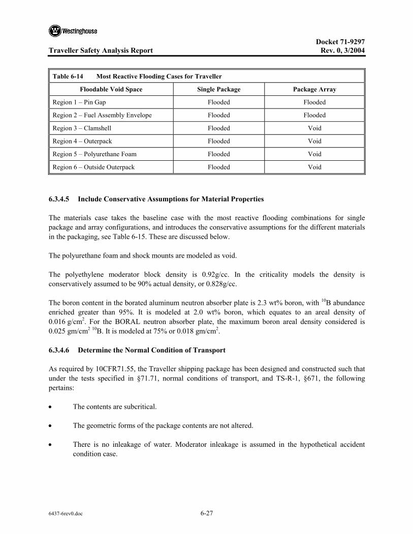
Docket 71-9297
Traveller Safety Analysis Report Rev. 0, 3/2004
6437-6rev0.doc 6-27
Table 6-14 Most Reactive Flooding Cases for Traveller
Floodable Void Space Single Package Package Array
Region 1 – Pin Gap Flooded Flooded
Region 2 – Fuel Assembly Envelope Flooded Flooded
Region 3 – Clamshell Flooded Void
Region 4 – Outerpack Flooded Void
Region 5 – Polyurethane Foam Flooded Void
Region 6 – Outside Outerpack Flooded Void
6.3.4.5 Include Conservative Assumptions for Material Properties
The materials case takes the baseline case with the most reactive flooding combinations for single package and array configurations, and introduces the conservative assumptions for the different materials in the packaging, see Table 6-15. These are discussed below.
The polyurethane foam and shock mounts are modeled as void.
The polyethylene moderator block density is 0.92g/cc. In the criticality models the density is conservatively assumed to be 90% actual density, or 0.828g/cc.
The boron content in the borated aluminum neutron absorber plate is 2.3 wt% boron, with 10B abundance enriched greater than 95%. It is modeled at 2.0 wt% boron, which equates to an areal density of 0.016 g/cm2. For the BORAL neutron absorber plate, the maximum boron areal density considered is 0.025 gm/cm2 10B. It is modeled at 75% or 0.018 gm/cm2.
6.3.4.6 Determine the Normal Condition of Transport
As required by 10CFR71.55, the Traveller shipping package has been designed and constructed such that under the tests specified in §71.71, normal conditions of transport, and TS-R-1, §671, the following pertains:
• The contents are subcritical.
• The geometric forms of the package contents are not altered.
• There is no inleakage of water. Moderator inleakage is assumed in the hypothetical accident condition case.

Docket 71-9297
Traveller Safety Analysis Report Rev. 0, 3/2004
6437-6rev0.doc 6-28
• There was no reduction in effectiveness of the packaging, namely:
– There was no reduction in the total effective volume of the packaging on which nuclear safety is assessed. Because there was no reduction in volume following the hypothetical accident condition testing, it follows that there is none during normal conditions of transport.
– There was no reduction in the effective spacing between the fissile contents and the outer surface of the packaging. Test results given later report that the Clamshell held the contents in place.
– There were no breeches in the Outerpack. Hence, there is no occurrence of an aperture in the outer surface of the packaging large enough to allow the entry of a 10 cm (4 in) cube.
• The loss of efficiency of built-in neutron absorbers is addressed. The calculations assume less than 100% 10B for the neutron absorber.
• The loss of efficiency of built-in moderators is addressed. The calculations assume 90% actual moderator density.
• The rearrangement of the contents within the package is addressed. There was no loss of contents from the package.
• There was no reduction of space within the package.
• There was no reduction of spacing between packages.
• The effect of temperature changes is addressed below.
The Traveller model under normal conditions of transport differs slightly from the routine configuration.
Outerpack dimensions are the same. The Clamshell is modeled the same as the routine condition. The fuel assembly is modeled the same as the routine condition.
The polyurethane foam and shock mounts are modeled as void. These are conservative assumptions because neither is really altered under normal conditions of transport. The moderator blocks are modeled at 90% density.
The neutron absorber is modeled the same as for the routine condition. All floodable void spaces of the Outerpack are modeled dry. The package is close reflected by 20 cm water.
The fuel assembly is modeled the same as for the routine condition.
Docket 71-9297
Traveller Safety Analysis Report Rev. 0, 3/2004
6437-6rev0.doc 6-29
6.3.4.7 As-found Condition After Testing
The as-found case reports the actual condition of the Traveller XL package following the regulatory testing, excluding the immersion test. It is important that the as-found condition be noted, so comparison can be made between it and the more conservative license-basis condition. The as-found condition includes an assessment of the fuel assembly, see Table 6-15.
The Outerpack diameter was unchanged. A good portion, but not all, of the polyurethane foam had burned away. The moderator blocks were in place and not damaged. All shock mounts were in place, holding the Clamshell. The cork liner was in place.
The bottom nozzle end drop is believed to be the worst-case drop orientation for the fuel assembly because it directly challenges the criticality safety of the package in ways that other drop angles do not. The bottom nozzle impact has been shown to produce the most severe localized damage to the bottom end of the fuel assembly. Further, it is the angle most likely to produce lattice expansion.
As can be seen from above, the as-found condition of the fuel assembly showed 20 cracked rods. Due to the nature of the end impact, the fuel rod array is tightly packed and forced into the bottom nozzle. As the bottom nozzle buckles, the rods located nearest the corners of the adapter plate experience a side loading due to the deforming movement of the plate. This momentum is sufficient to crack the weld but not to break off the bottom end plug because the rods are so tightly packed.
The average magnitude of the crack-widths was 0.03 inches (0.76 mm). The largest crack encompassed about ½ a rod diameter, meaning that none of the end plugs was completely broken off. This cracking is considered insignificant since a 17OFA fuel pellet diameter is 10 times larger than the visible crack widths. Furthermore, localized inward buckling of the rods at the end plug weld zone would tend to reduce the inner diameter of the fuel rod bottom end and preclude the pellet stack from axial movement.
As stated above, the end drop is most likely to produce fuel lattice expansion. In the several prototype and qualification tests conducted prior to the certification test unit testing, (see section 2), it was found that all drop angles other than the end drop compress the fuel assembly lattice. Only the end drop resulted in lattice expansion.
At no point did the lattice pitch expand to fill the 9.5 inches (24.13 cm) Clamshell. From the bottom nozzle to the first grid, a 4.0 inch (10.16 cm) span, the fuel envelope measured 9.0 inches (22.86 cm) on one side and 8.75 inches (22.1 cm) on the other. Between grids #1 and #2, about 20 inches (50 cm), the fuel envelope measured 8.32 inches (21.13 cm) on both sides. Between grids #2 and #3, also 20 inches (50 cm), the fuel envelope measured 8.5 inches (21.59 cm) and 8.0 inches (20.32 cm). Between grids #3 and #4 the envelope measured 8.5 inches (21.59 cm) and 8.44 inches (21.44 cm). For the rest of the assembly, the envelope measured no greater than 8.375 inches (21.27 cm). Close examination of the rod arrangement showed that throughout the assembly there was a combination of compressed, nominal, and slightly expanded rod pitches. Several rows of rods were actually touching, some were at nominal pitch, and one or two rods had larger pitch.
Docket 71-9297
Traveller Safety Analysis Report Rev. 0, 3/2004
6437-6rev0.doc 6-30
Therefore, confinement held because the fissile material remained in the fuel rods and the fuel rods remained inside the Clamshell. Neutron absorber and neutron moderator material remained in place.
6.3.4.8 Determine the License-basis Case (HAC Case)
The HAC case combines the as-found condition with the most reactive flooding configuration of section 6.3.4.4, and adds the conservative material assumptions of section 6.3.4.5, and conservative assumptions for the fuel assembly, which are described in this section.
The HAC case conservatively models the fuel assembly so that it bounds the as-found condition. The HAC model assumes lattice pitch expansion to 9.1in (23.114 cm) for the Traveller and 9.6 inches (23.384 cm) for the Traveller XL. The lattice expansion is uniformly distributed and extends 100 cm of fuel length.
6.3.4.9 Analyze Different Hypothetical Conditions (Sensitivity Studies)
The hypothetical cases start from the license-basis case and include different assumptions to determine effect on system keff.
• Cork liner in place on bottom faces (0.188 inches/0.476 cm) • Lattice pitch expansion for full length of fuel assembly • Non-uniform distribution in lattice expansion • Axially displaced rods • Absorber material variations • Moderator material variations
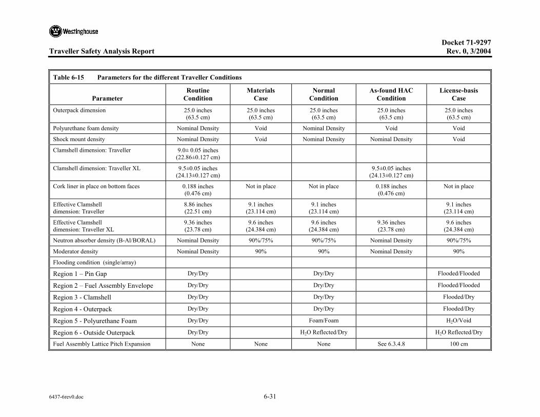
Docket 71-9297 Traveller Safety Analysis Report Rev. 0, 3/2004
6437-6rev0.doc 6-31
Table 6-15 Parameters for the different Traveller Conditions
Parameter Routine
Condition Materials
Case Normal
Condition As-found HAC
Condition License-basis
Case
Outerpack dimension 25.0 inches (63.5 cm)
25.0 inches (63.5 cm)
25.0 inches (63.5 cm)
25.0 inches (63.5 cm)
25.0 inches (63.5 cm)
Polyurethane foam density Nominal Density Void Nominal Density Void Void
Shock mount density Nominal Density Void Nominal Density Nominal Density Void
Clamshell dimension: Traveller 9.0± 0.05 inches (22.86±0.127 cm)
Clamshell dimension: Traveller XL 9.5±0.05 inches (24.13±0.127 cm)
9.5±0.05 inches (24.13±0.127 cm)
Cork liner in place on bottom faces 0.188 inches (0.476 cm)
Not in place Not in place 0.188 inches (0.476 cm)
Not in place
Effective Clamshell dimension: Traveller
8.86 inches (22.51 cm)
9.1 inches (23.114 cm)
9.1 inches (23.114 cm)
9.1 inches (23.114 cm)
Effective Clamshell dimension: Traveller XL
9.36 inches (23.78 cm)
9.6 inches (24.384 cm)
9.6 inches (24.384 cm)
9.36 inches (23.78 cm)
9.6 inches (24.384 cm)
Neutron absorber density (B-Al/BORAL) Nominal Density 90%/75% 90%/75% Nominal Density 90%/75%
Moderator density Nominal Density 90% 90% Nominal Density 90%
Flooding condition (single/array)
Region 1 – Pin Gap Dry/Dry Dry/Dry Flooded/Flooded
Region 2 – Fuel Assembly Envelope Dry/Dry Dry/Dry Flooded/Flooded
Region 3 - Clamshell Dry/Dry Dry/Dry Flooded/Dry
Region 4 - Outerpack Dry/Dry Dry/Dry Flooded/Dry
Region 5 - Polyurethane Foam Dry/Dry Foam/Foam H2O/Void
Region 6 - Outside Outerpack Dry/Dry H2O Reflected/Dry H2O Reflected/Dry
Fuel Assembly Lattice Pitch Expansion None None None See 6.3.4.8 100 cm

Docket 71-9297
Traveller Safety Analysis Report Rev. 0, 3/2004
6437-6rev0.doc 6-32
6.4 SINGLE PACKAGE EVALUATION
Calculations were performed to determine the most reactive configuration for a single package in isolation under routine, normal, and hypothetical accident conditions of transport. The configurations are described below. The corresponding data are tabulated in Table 6-15. These descriptions hold for the Traveller and Traveller XL. Discussion for the rod containers is also included.
6.4.1 Configuration for Fuel Assemblies
6.4.1.1 Configuration Under Normal Conditions of Transport
Paragraphs 71.55 of 10CFR and 679 of TS-R-1 require that the contents be subcritical under normal conditions of transport. TS-R-1 indicates that when it can be demonstrated that the confinement system remains within the packaging following the prescribed tests, close reflection of the package by at least 20-cm water may be assumed. Since this is the case for the Traveller, the individual package evaluation includes the close-reflection around the Outerpack.
The remaining parameters for the hypothetical accident condition for the Traveller are described in section 6.3.4.6 and shown in Table 6-15.
6.4.1.2 Configuration Under Hypothetical Accident Conditions
The hypothetical accident condition requires that the most reactive flooding configuration be considered. It is generally true that the most reactive configuration for an individual package would be the one in which the neutrons are moderated as close to the fuel as possible and reflected back into the fuel assembly region. They should not be allowed to escape or to reach the neutron poison where they would be absorbed.
Calculations have shown that this is the case for the Traveller. Therefore, all floodable void spaces in the package except the foam region (region #5) are modeled as fully flooded, and the package is close reflected by 20-cm full density water. The foam region is modeled as a void. Although it might seem that flooding the foam region would be most conservative, this concern is nullified in that the entire package is fully reflected by 20-cm water. Hence the neutrons pass freely through the foam region and are directed back toward the fuel assembly by full reflection.
The remaining parameters for the hypothetical accident condition for the Traveller are described in section 6.3.4.8 and shown in Table 6-15.
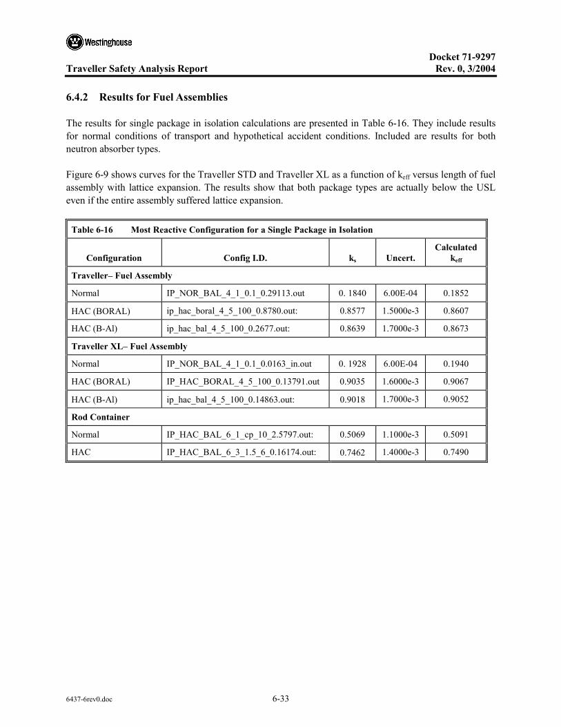
Docket 71-9297
Traveller Safety Analysis Report Rev. 0, 3/2004
6437-6rev0.doc 6-33
6.4.2 Results for Fuel Assemblies
The results for single package in isolation calculations are presented in Table 6-16. They include results for normal conditions of transport and hypothetical accident conditions. Included are results for both neutron absorber types.
Figure 6-9 shows curves for the Traveller STD and Traveller XL as a function of keff versus length of fuel assembly with lattice expansion. The results show that both package types are actually below the USL even if the entire assembly suffered lattice expansion.
Table 6-16 Most Reactive Configuration for a Single Package in Isolation
Configuration Config I.D. ks Uncert. Calculated
keff
Traveller– Fuel Assembly
Normal IP_NOR_BAL_4_1_0.1_0.29113.out 0. 1840 6.00E-04 0.1852
HAC (BORAL) ip_hac_boral_4_5_100_0.8780.out: 0.8577 1.5000e-3 0.8607
HAC (B-Al) ip_hac_bal_4_5_100_0.2677.out: 0.8639 1.7000e-3 0.8673
Traveller XL– Fuel Assembly
Normal IP_NOR_BAL_4_1_0.1_0.0163_in.out 0. 1928 6.00E-04 0.1940
HAC (BORAL) IP_HAC_BORAL_4_5_100_0.13791.out 0.9035 1.6000e-3 0.9067
HAC (B-Al) ip_hac_bal_4_5_100_0.14863.out: 0.9018 1.7000e-3 0.9052
Rod Container
Normal IP_HAC_BAL_6_1_cp_10_2.5797.out: 0.5069 1.1000e-3 0.5091
HAC IP_HAC_BAL_6_3_1.5_6_0.16174.out: 0.7462 1.4000e-3 0.7490

Docket 71-9297
Traveller Safety Analysis Report Rev. 0, 3/2004
6437-6rev0.doc 6-34
Figure 6-9 Individual HAC Curves for Traveller STD and Traveller XL

Docket 71-9297
Traveller Safety Analysis Report Rev. 0, 3/2004
6437-6rev0.doc 6-35
6.4.3 Configuration for Rod Containers
The discussion on the rod container is found in appendix 6.10.8.

Docket 71-9297
Traveller Safety Analysis Report Rev. 0, 3/2004
6437-6rev0.doc 6-36
6.5 EVALUATION OF PACKAGE ARRAYS UNDER NORMAL CONDITIONS OF TRANSPORT
6.5.1 Configuration for Fuel Assemblies
The package model for the normal condition of transport is described in section 6.3.4.6. In this analysis it was modeled in an infinite array.
6.5.2 Results for Fuel Assemblies
Table 6-17 Routine and Normal Conditions of Transport for Package Array
Configuration Config I.D. ks Uncert. Calculated
keff
Traveller– Fuel Assembly
Package Array – Infinite
Normal PA_NOR_BAL_4_1_0.1_0.27789.out 0. 2945 8.00E-04 0.2961
Traveller XL– Fuel Assembly
Package Array – Infinite
Normal PA_NOR_BAL_4_1_0.1_0.335.out 0.2613 8.00E-04 0.2629

Docket 71-9297
Traveller Safety Analysis Report Rev. 0, 3/2004
6437-6rev0.doc 6-37
6.6 PACKAGE ARRAYS UNDER HYPOTHETICAL ACCIDENT CONDITIONS
6.6.1 Configuration for Fuel Assemblies
The most reactive configuration for a package array, in contrast to the individual case, is the one that allows maximum thermal neutron interaction between packages. Section 6.7.1 discusses this in detail. This model assumes a flooding configuration that maximizes neutron interaction. Region 1 (pin-gap) and region 2 (fuel assembly) are flooded to maximize reactivity inside the fuel assembly. Region 3 (Clamshell) is modeled as a void to increase the probability that neutrons escaping the fuel assembly envelope will pass through the neutron poison. The remaining floodable void spaces (region 4 – Outerpack cavity; region 5 – foam; region 6 – outside Outerpack) are modeled as a void to allow maximum interaction between packages in the array.
The configuration of the Outerpack, Clamshell, and contents for the hypothetical accident condition for the Traveller are described in section 6.3.4.8 and shown in Table 6-18. Figure 6-10 shows curves for the Traveller STD and Traveller XL in a fixed package array as a function of keff versus length of fuel assembly with lattice expansion. The results show that the Traveller STD would be below the USL even if the entire assembly suffered lattice expansion.
6.6.2 Results for Fuel Assemblies
Table 6-18 Hypothetical Accident Condition Results for a Package Array
Configuration Config I.D. ks Uncert. Calculated
keff
Traveller
HAC (BORAL-0.0188g/cm2 10B)
PA_HAC_BORAL_4_5_100_0.22193.out 0.8869 1.60E-03 0.8901
HAC (B-Al – 0.0163g/cm2 10B)
PA_HAC_BAL_4_5_100_0.28238.out 0.8881 1.50E-03 0.8911
Traveller XL
HAC (BORAL-0.0188g/cm2 10B)
PA_HAC_BORAL_4_5_100_0.6261.out 0.9253 0.0017 0.9287
HAC (B-Al – 0.0163g/cm2 10B)
PA_HAC_BAL_4_5_100_0.11152.out 0.9286 0.0016 0.9318
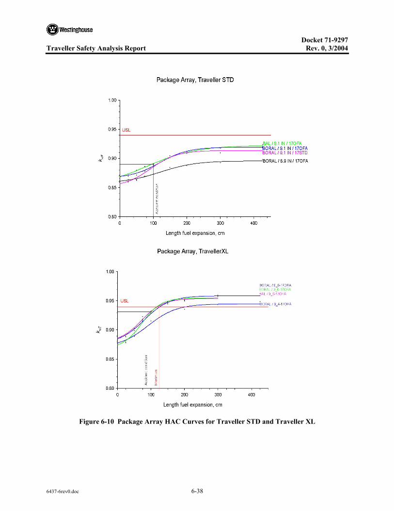
Docket 71-9297
Traveller Safety Analysis Report Rev. 0, 3/2004
6437-6rev0.doc 6-38
Figure 6-10 Package Array HAC Curves for Traveller STD and Traveller XL

Docket 71-9297
Traveller Safety Analysis Report Rev. 0, 3/2004
6437-6rev0.doc 6-39
6.6.3 Results for Rod Containers
The discussion on the rod container results is found in appendix 6.10.8.
Table 6-19 Hypothetical Accident Condition Results for Rod Container
Configuration Config I.D. ks Uncert. Calculated
keff
Rod Box Not reported
Rod Pipe PA_HAC_BAL_6_5_2.0_8_1.21593.out 0.6784 1.50E-03 0.6814
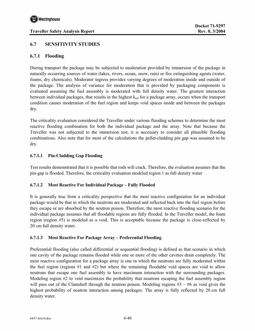
Docket 71-9297
Traveller Safety Analysis Report Rev. 0, 3/2004
6437-6rev0.doc 6-40
6.7 SENSITIVITY STUDIES
6.7.1 Flooding
During transport the package may be subjected to moderation provided by immersion of the package in naturally occurring sources of water (lakes, rivers, ocean, snow, rain) or fire extinguishing agents (water, foams, dry chemicals). Moderator ingress provides varying degrees of moderation inside and outside of the package. The analysis of variance for moderation that is provided by packaging components is evaluated assuming the fuel assembly is moderated with full density water. The greatest interaction between individual packages, that results in the highest keff for a package array, occurs when the transport condition causes moderation of the fuel region and keeps void spaces inside and between the packages dry.
The criticality evaluation considered the Traveller under various flooding schemes to determine the most reactive flooding combination for both the individual package and the array. Note that because the Traveller was not subjected to the immersion test, it is necessary to consider all plausible flooding combinations. Also note that for most of the calculations the pellet-cladding pin gap was assumed to be dry.
6.7.1.1 Pin-Cladding Gap Flooding
Test results demonstrated that it is possible that rods will crack. Therefore, the evaluation assumes that the pin-gap is flooded. Therefore, the criticality evaluation modeled region 1 as full density water
6.7.1.2 Most Reactive For Individual Package – Fully Flooded
It is generally true from a criticality perspective that the most reactive configuration for an individual package would be that in which the neutrons are moderated and reflected back into the fuel region before they escape or are absorbed by the neutron poison. Therefore, the most reactive flooding scenario for the individual package assumes that all floodable regions are fully flooded. In the Traveller model, the foam region (region #5) is modeled as a void. This is acceptable because the package is close-reflected by 20 cm full density water.
6.7.1.3 Most Reactive For Package Array – Preferential Flooding
Preferential flooding (also called differential or sequential flooding) is defined as that scenario in which one cavity of the package remains flooded while one or more of the other cavities drain completely. The most reactive configuration for a package array is one in which the neutrons are fully moderated within the fuel region (regions #1 and #2) but where the remaining floodable void spaces are void to allow neutrons that escape one fuel assembly to have maximum interaction with the surrounding packages. Modeling region #2 to void maximizes the probability that neutrons escaping the fuel assembly region will pass out of the Clamshell through the neutron poison. Modeling regions #3 – #6 as void gives the highest probability of neutron interaction among packages. The array is fully reflected by 20 cm full density water.
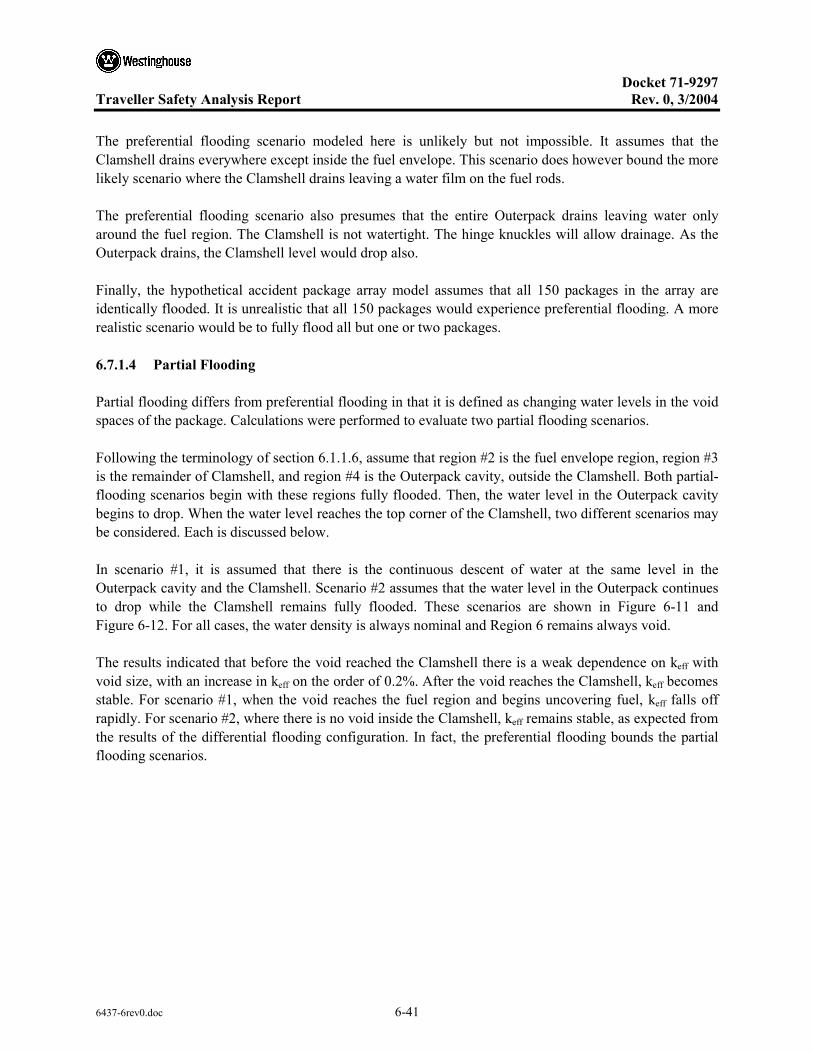
Docket 71-9297
Traveller Safety Analysis Report Rev. 0, 3/2004
6437-6rev0.doc 6-41
The preferential flooding scenario modeled here is unlikely but not impossible. It assumes that the Clamshell drains everywhere except inside the fuel envelope. This scenario does however bound the more likely scenario where the Clamshell drains leaving a water film on the fuel rods.
The preferential flooding scenario also presumes that the entire Outerpack drains leaving water only around the fuel region. The Clamshell is not watertight. The hinge knuckles will allow drainage. As the Outerpack drains, the Clamshell level would drop also.
Finally, the hypothetical accident package array model assumes that all 150 packages in the array are identically flooded. It is unrealistic that all 150 packages would experience preferential flooding. A more realistic scenario would be to fully flood all but one or two packages.
6.7.1.4 Partial Flooding
Partial flooding differs from preferential flooding in that it is defined as changing water levels in the void spaces of the package. Calculations were performed to evaluate two partial flooding scenarios.
Following the terminology of section 6.1.1.6, assume that region #2 is the fuel envelope region, region #3 is the remainder of Clamshell, and region #4 is the Outerpack cavity, outside the Clamshell. Both partial-flooding scenarios begin with these regions fully flooded. Then, the water level in the Outerpack cavity begins to drop. When the water level reaches the top corner of the Clamshell, two different scenarios may be considered. Each is discussed below.
In scenario #1, it is assumed that there is the continuous descent of water at the same level in the Outerpack cavity and the Clamshell. Scenario #2 assumes that the water level in the Outerpack continues to drop while the Clamshell remains fully flooded. These scenarios are shown in Figure 6-11 and Figure 6-12. For all cases, the water density is always nominal and Region 6 remains always void.
The results indicated that before the void reached the Clamshell there is a weak dependence on keff with void size, with an increase in keff on the order of 0.2%. After the void reaches the Clamshell, keff becomes stable. For scenario #1, when the void reaches the fuel region and begins uncovering fuel, keff falls off rapidly. For scenario #2, where there is no void inside the Clamshell, keff remains stable, as expected from the results of the differential flooding configuration. In fact, the preferential flooding bounds the partial flooding scenarios.
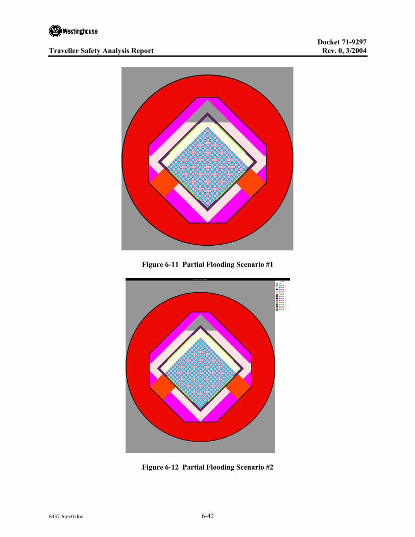
Docket 71-9297
Traveller Safety Analysis Report Rev. 0, 3/2004
6437-6rev0.doc 6-42
Figure 6-11 Partial Flooding Scenario #1
Figure 6-12 Partial Flooding Scenario #2

Docket 71-9297
Traveller Safety Analysis Report Rev. 0, 3/2004
6437-6rev0.doc 6-43
6.7.1.5 Partial Density Interspersed Moderation
Spacing maintains void regions between the packages where environmental factors (snow, rain, ice, and immersion) may provide moderation. Also, materials of construction may scatter or moderate neutrons. The spacing is assumed to be no less than 25 inches provided by the nominal diameter of the Outerpack outer shell. Figure 6-13 shows that the package is overmoderated with respect to interspersed moderation for fuel lattice expansion along a partial length with 2 wt. % Boron where the number of packages in the array is 150.
Figure 6-13 Interspersed Moderation Density Curve
6.7.2 Lattice Expansion
From calculations done in support of the Traveller package licensing effort, and from other literature available, it is clear that the factor that has the greatest effect on keff for a moderated system is lattice pitch expansion. Expanding the lattice pitch of undermoderated fuel assemblies increases the water-fuel ratio. Keff will increase until the water-fuel ratio reaches optimum
This evaluation considered the effect of lattice expansion for all accident configurations. The fuel lattice was expanded to the Clamshell (9.6 inches in Traveller XL and 9.1 inches for Traveller) in incremental lengths of 25 cm, 50 cm, 75 cm, 100 cm, 150 cm, 200 cm, 300 cm, and full length (426 cm). It must be noted that analyzing these scenarios does not imply that full-length expansion becomes the license-basis case. Figure 6-14 shows keff versus length of expanded section for the Traveller.
It has been seen from numerous 9-meter drops at different drop angles that any horizontal or shallow angle drop will compress the fuel assembly envelope rather than expand it. Similarly, center-of-gravity drops on the end will cause local crumpling on the end but will not expand the lattice pitch.

Docket 71-9297
Traveller Safety Analysis Report Rev. 0, 3/2004
6437-6rev0.doc 6-44
Results from a bottom nozzle end drop shows fuel rod lattice pitch expansion at the bottom 20 inches (50 cm). The expansion was not uniformly distributed. There was a combination of rods touching or at compressed pitch, rods at nominal pitch, and rods with expanded pitch.
6.7.2.1 Non-uniform Lattice Expansion
Non-uniform lattice expansion is defined as a fuel envelope with rods at different pitches, such as was found in the tested fuel assemblies. There will be some rods touching, some compressed, some at nominal pitch, and some at expanded pitch. An analysis was performed to determine how non-uniform lattice expansion compared to uniform expansion.
Asymmetric
Symmetric
Figure 6-14 Symmetric and Asymmetric Non-uniform Distribution
The analysis assumed a fixed number of rods, namely 289 in a 17x17 array. It then looked at four types of expansion/compression combinations, which can be seen in Figure 6-14. The combinations included compressed rods around the edge of the assembly or in a cluster, in both a symmetric and asymmetric arrangement. The small grid in the figure represents the nominal or close pack rods, and the large grid

Docket 71-9297
Traveller Safety Analysis Report Rev. 0, 3/2004
6437-6rev0.doc 6-45
represents the remaining rods expanded to the space available for expansion within the confinement of the Clamshell 9.5 inch by 9.5 inch cross section. There are no thimble tubes. These configurations are confined to 100 cm of fuel length.
The graph in Figure 6-15 shows two curves: keff as a function of the number of rods in the expansion zone {x} and the remaining rods {289-x} either at (1) nominal pitch or (2) close packed. The area between the curves is expected to bound all the rod rearrangements possible within the confinement of the Clamshell. The results show that any compaction of the lattice suppresses the reactivity increase due to rod expansion up until the expansion includes about 100 rods (~1/3 of the assembly). The results also show the importance of the confinement dimension in limiting the possible rearrangements without rods leaving the confines of the Clamshell. These results support the assumption that the most reactive rearrangement is uniform expansion.
Figure 6-15 Non-uniform Expansion keff Plot
6.7.3 Annular Pellets
Analysis has determined that annular pellets in the fuel assembly do not increase keff. Therefore, the fuel assemblies and rods that are allowed to be carried in the Traveller may container annular pellets.
6.7.4 Axially Displaced Rods
Several axial rod displacement configurations have been analyzed. The models assumed that the rod is displaced until it reaches the top of the Clamshell, so the effect is evaluated at its maximum value. Results showed that a reactivity peak occurs for 56 displaced rods. Nevertheless, the effect on keff is quite small,

Docket 71-9297
Traveller Safety Analysis Report Rev. 0, 3/2004
6437-6rev0.doc 6-46
≈0.001 ∆keff, on the same order as the Monte Carlo uncertainty. Because of this, no statistically significant effect has been found and the displaced rods need not be considered in the criticality analysis of the Traveller. Figure 6-16 shows the model with 92 axially displaced rods.
Figure 6-16 Axial Slice Showing 92 Displaced Rods
6.7.5 Polyurethane Foam Moderating Effect
Foam is used as both a thermal insulator and impact absorbing material in the Outerpack. The hydrogen content in the polyurethane foam moderates neutrons outside the confinement system boundary of the individual package. Change to the foam composition can significantly affect the interaction between packages in an array. The polyurethane foam starts to burn when the temperature exceeds 600°F (315°C) leaving a low-density char residual material.
Calculations were run to determine the effect of removing the foam from the package. Results showed that eliminating the foam results in an increase in keff of 0.025.
Docket 71-9297
Traveller Safety Analysis Report Rev. 0, 3/2004
6437-6rev0.doc 6-47
6.7.6 Shock Mount Moderating Effect
There is a significant amount of natural rubber used in the shock mounts that attach the Clamshell to the Outerpack. The shock mounts are partially embedded in the holes in polyethylene moderator blocks. Eliminating the shock mounts resulted in no significant change in keff. Any reduction in moderation provided by the shock mounts is masked by the presence of large amount of hydrogen in the polyethylene moderator blocks.
6.7.7 Polyethylene Density
Moderator blocks provide moderation control by maintaining a fixed amount of moderation between the contents in the individual packages. The polyethylene moderator blocks provide moderation that in combination with a neutron poison effectively reduces the interaction between packages. The fixed moderator and a neutron poison are arranged to function as a neutron flux trap.
keff
Polyethylene density0.69 0.92
0.936883
0.91505
0.91
0.915
0.92
0.925
0.93
0.935
0.94
Figure 6-17 Effect of Varying Polyethylene Density
The polyethylene was evaluated at densities equating to 100% (ρ = 0.92 gm/cc), 90% (ρ = 0.83 gm/cc), and 75% (ρ = 0.69 gm/cm3) nominal density to determine effect. Figure 6-17 shows the relative results. It was determined that, for 4.5 wt% boron loading, reducing polyethylene density by 10% increased keff approximately 1%, and reducing density to 75% increases keff approximately 2%. It was noted that the effect of reducing the polyethylene density of the 1.25 inch thick moderator blocks is not strongly dependent on the neutron poison content.
6.7.8 Reduction of Boron Content in Neutron Absorber
The analysis included a sensitivity study of boron content in the neutron absorber. The sensitivity to 10B areal density is evaluated for a package array with 100 cm fuel lattice expansion. Figure 6-18 shows keff versus 10B content for the Borated aluminum and BORAL products. The 10B effectiveness does not diminish significantly until the areal density decreases to approximately 0.010 gm/cm2. As can be seen in
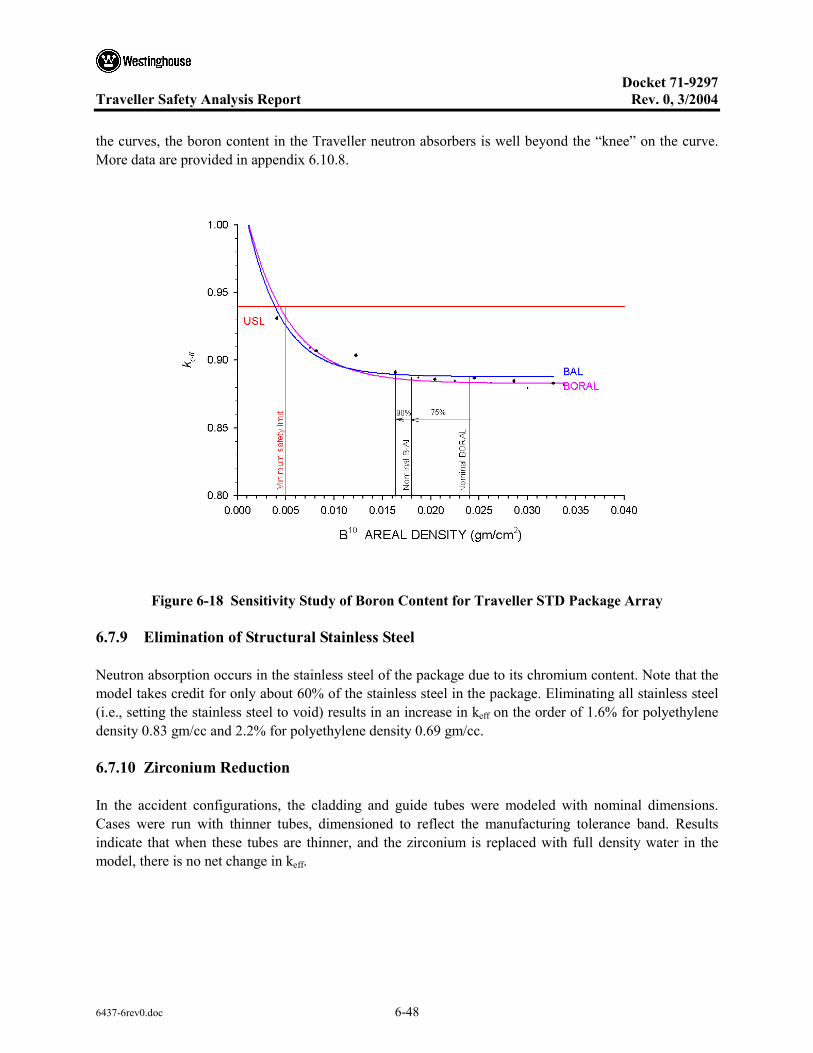
Docket 71-9297
Traveller Safety Analysis Report Rev. 0, 3/2004
6437-6rev0.doc 6-48
the curves, the boron content in the Traveller neutron absorbers is well beyond the “knee” on the curve. More data are provided in appendix 6.10.8.
Figure 6-18 Sensitivity Study of Boron Content for Traveller STD Package Array
6.7.9 Elimination of Structural Stainless Steel
Neutron absorption occurs in the stainless steel of the package due to its chromium content. Note that the model takes credit for only about 60% of the stainless steel in the package. Eliminating all stainless steel (i.e., setting the stainless steel to void) results in an increase in keff on the order of 1.6% for polyethylene density 0.83 gm/cc and 2.2% for polyethylene density 0.69 gm/cc.
6.7.10 Zirconium Reduction
In the accident configurations, the cladding and guide tubes were modeled with nominal dimensions. Cases were run with thinner tubes, dimensioned to reflect the manufacturing tolerance band. Results indicate that when these tubes are thinner, and the zirconium is replaced with full density water in the model, there is no net change in keff.

Docket 71-9297
Traveller Safety Analysis Report Rev. 0, 3/2004
6437-6rev0.doc 6-49
6.8 FISSILE MATERIAL PACKAGES FOR AIR TRANSPORT
Application for air transport for the Traveller will be made at a later date.

Docket 71-9297
Traveller Safety Analysis Report Rev. 0, 3/2004
6437-6rev0.doc 6-50
6.9 BENCHMARK EVALUATIONS
The computer code used for these criticality calculations has been benchmarked against applicable criticality experiments.
6.9.1 Applicability of Benchmark Experiments
There are approximately 180 experiments that are applicable to transport.1 Of these, 55 were selected based on their structural, material, poison, geometry, and spectral similarities to the Traveller. Table 6-39 in appendix 6.10.10 gives a summary of available LWR critical experiments and indicates how many of each type were selected. The selected experiments were grouped into four classifications: Simple Lattice, Separator Plate, Flux Trap, and Water Hole experiments. Table 6-40 shows the breakdown of the experiments into the four classifications. In general, there were 15 Simple Lattice experiments, 26 Separator Plate experiments, 8 Flux Trap experiments, and 6 Water Hole experiments.
In determining which experiments were not applicable, criteria were established by which experiments would be rejected. These criteria include:
• No separator plates made of hafnium, copper, cadmium, zirconium, or depleted uranium (include only separator plates made of stainless steel, aluminum or boron),
• No thick wall lead, steel, or uranium reflector material,
• No hexagonal fuel rod lattices,
• No burnable poison rods (Ag-In-Cd rods, B4C rods, UO2-Gd2O3 rods)
• No soluble boron
The 55 experiments were analyzed for their applicability to the Traveller package. Table 6-25 shows a summary comparison of the benchmark critical experiment properties to the Traveller package. The range of properties for the critical experiment includes range of values for the Traveller package.
In addition, a qualitative evaluation of the neutron event probabilities is also done to compare the importance of the contents and packaging materials relative to neutron absorption. Comparing the absorption probabilities for the critical experiments and package indicates that the importance of neutron absorption is similar between the critical experiments and package model.
1 NUREG/CR-6361 (ORNL/TM-13211): Criticality Benchmark Guide for Light-Water-Reactor Fuel in Transportation and Storage Packages.

Docket 71-9297
Traveller Safety Analysis Report Rev. 0, 3/2004
6437-6rev0.doc 6-51
The input decks for the 55 experiments were run locally using Keno V.a. The results compared favorably to published results. The input decks were then converted to Keno-VI using the C5TOC6 utility program and run again. These results were used to determine the USL for the Traveller calculations.
The analysis concluded that no single group of critical benchmark experiments (simple lattice, separator plate, flux trap, or water hole) contains all the characteristics of the Traveller shipping package. However, the four groups each represent different aspects of the package model that are important to understanding the bias associated with the package modeling. The simple lattice and water hole experiments represent the fuel region modeling (i.e., fuel enrichment, lattice pitch, water-to-fuel ratio), and the separator plate and flux trap experiments represent additional characteristics of the package modeling (i.e., moderator, neutron absorbers).
6.9.2 Bias Determination
As can be seen in Figure 6-19, results indicate that a USL of 0.94 is acceptable including an administrative margin , ∆km = 0.05, and a bias of negative 0.01 (β + ∆β = -0.01). The administrative margin is acceptable because for all grouping of experiments the minimum subcritical margin is positive, USL2-USL1≥ 0. The largest statistical bias (USL-2) is associated with the flux trap group. The application of the statistically based subcritical margin indicates the administrative margin is adequate by a margin of at least 0.015 (USL-2 minus USL-1) even for groups were there is a limited number of data points (i.e., flux trap, water hole). Therefore, the bias determination is made by including all 55 experiments in the USLSTAT calculation.
Figure 6-19 Upper Safety Limits (USLs) for 55 LWR Fuel Critical Experiments

Docket 71-9297
Traveller Safety Analysis Report Rev. 0, 3/2004
6437-6rev0.doc 6-52
6.10 APPENDICES
The following appendices are included to provide amplifying information on material contained elsewhere in section 6.
6.10.1: PWR Fuel Assembly Parameters 6.10.2: Fuel Assembly Comparison 6.10.3: 17OFA-XL Model 6.10.4: Traveller Packaging Model 6.10.5: Single Package Evaluation Calculations 6.10.6: Package Array Evaluation Calculations 6.10.7: Rod Container Calculations 6.10.8: Calculations for Sensitivity Studies 6.10.9: Benchmark Critical Experiments

Docket 71-9297
Traveller Safety Analysis Report Rev. 0, 3/2004
6437-6rev0.doc 6-53
6.10.1 PWR FUEL ASSEMBLY PARAMETERS
The following tables and figures provide the fuel assembly parameters important to criticality safety for the 14x14, 15x15, 16x16, 17x17, and 18x18 fuel types to be transported in the Traveller. Fuel assemblies with other product names, but which satisfy the parameters found in this section may be transported in the Traveller. Fuel assembly designs with cross sections different than found in Figures 6-20 through 6-22 may be transported in the Traveller if shown to be bounded by the 17x17OFA fuel assembly.

Docket 71-9297
Traveller Safety Analysis Report Rev. 0, 3/2004
6437-6rev0.doc 6-54
18ATOM 17OFA/STD/XL
Figure 6-20 Cross Section for 18x18 and 17x17 Assemblies
16STD/ATOM/NGF 16CE
Figure 6-21 Cross Sections for 16x16 Assemblies
14STD/OFA 15STD/OFA/BW 14CE-1/CE-2
Figure 6-22 Cross Sections for 15x15 and 14x14 Assemblies

Docket 71-9297
Traveller Safety Analysis Report Rev. 0, 3/2004
6437-6rev0.doc 6-55
Table 6-20 Parameters for 14x14 Fuel Assemblies
Fuel Assembly Description 14 X 14 14 X 14 14 X 14
Fuel Assembly Type W-STD W-OFA CE-1/CE-2
Rods per assembly 179 179 176
Minimum No. Non-Fuel Rods 17 17 20
Nominal Pellet Diameter 0.3659 0.3444 0.3765/0.3805
Nominal Clad Outer Diameter 0.4220 0.4000 0.4400
Nominal Clad Thickness 0.0243 0.0243 0.0280/0.0260
Clad Material Zirconium alloy Zirconium alloy Zirconium alloy
Nominal Assembly Envelope 7.756 7.756 8.110
Nominal Lattice Pitch 0.5560 0.5560 0.5800
G 235U/cm length (nominal/100%TD) 56.9/58.7 50.4/52.0 60.5/62.4
Fuel Rod Arrangement Fig 6-22 Fig 6-22 Fig 6-22
Table 6-21 Parameters for 15x15 Fuel Assemblies
Fuel Assembly Description 15 X 15 15 X 15
Fuel Assembly Type STD/OFA B&W
Rods per Assembly 205 205
Minimum No. Non-Fuel Rods 20 20
Nominal Pellet Diameter 0.3659 0.3659
Nominal Clad Outer Diameter 0.4220 0.4220
Nominal Clad Thickness 0.0243 0.0243
Clad Material Zirconium alloy Zirconium alloy
Nominal Assembly Envelope 8.418 8.528
Nominal Lattice Pitch 0.5630 0.5680
G 235U/cm length (nominal/modeled) 65.2/67.2 65.2/67.2
Fuel Rod Arrangement Fig 6-22 Fig 6-22

Docket 71-9297
Traveller Safety Analysis Report Rev. 0, 3/2004
6437-6rev0.doc 6-56
Table 6-22 Parameters for 16x16 Fuel Assemblies
Fuel Assembly Description 16 X 16 16 X 16 16 X 16 16 X 16
Fuel Assembly Type W-STD CE NGF ATOM
Rods per Assembly 235 236 235 235
Minimum No. Non-Fuel Rods 21 20 21 21
Nominal Pellet Diameter 0.3225 0.3250 0.3088 0.3590
Nominal Clad Outer Diameter 0.3740 0.3820 0.3600 0.4232
Nominal Clad Thickness 0.0225 0.0250 0.0225 0.0285
Clad Material Zirconium alloy Zirconium alloy Zirconium alloy Zirconium alloy
Nominal Assembly Envelope 7.763 8.122 7.763 9.0354
Nominal Lattice Pitch 0.4850 0.5060 0.4850 0.5630
G 235U/cm length (nominal/modeled) 58.0/59.8 59.2/61.0 53.2/54.8 71.9/74.1
Fuel Rod Arrangement Figure 6-21 Figure 6-21 Figure 6-21 Figure 6-21
Table 6-23 Parameters for 17x17 and 18x18 Fuel Assemblies
Fuel Assembly Description 17 X 17 17 X 17 18 X 18
Fuel Assembly Type W-STD/XL W-OFA ATOM
Rods per Assembly 264 264 300
Minimum No. Non-Fuel Rods 25 25 24
Nominal Pellet Diameter 0.3225 0.3088 0.3169
Nominal Clad Outer Diameter 0.3740 0.3600 0.3740
Nominal Clad Thickness 0.0225 0.0225 0.0252
Clad Material Zirconium alloy Zirconium alloy Zirconium alloy
Nominal Assembly Envelope 8.418 8.418 9.031
Nominal Lattice Pitch 0.4960 0.4960 0.500
G 235U/cm length (nominal/modeled) 65.2/67.2 59.8/61.6 71.5/73.7
Fuel Rod Arrangement Figure 6-20 Figure 6-20 Figure 6-20

Docket 71-9297
Traveller Safety Analysis Report Rev. 0, 3/2004
6437-6rev0.doc 6-57
6.10.2 FUEL ASSEMBLY COMPARISON
The fuel assembly comparison study compares keff versus fuel assembly envelope when expanding a 100 cm length of each fuel assembly from nominal to 14 inches (35.56 cm). Figure 6-23 shows the keff versus fuel envelope over the entire range in order to ascertain the optimum envelope size for each. Tables 6-24 shows results for the 17x17 and 18x18 assemblies. Figure 6-24 shows a sample input deck.
Figure 6-23 keff Curves vs Fuel Envelope Over Range of Interest
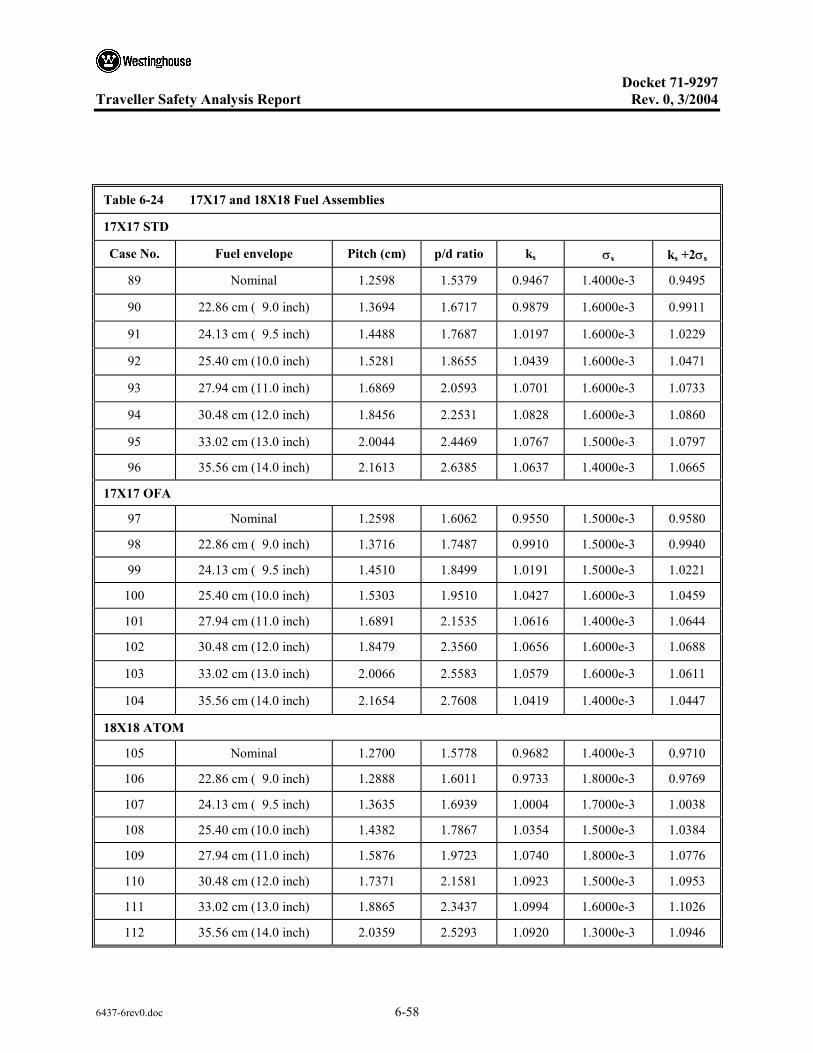
Docket 71-9297
Traveller Safety Analysis Report Rev. 0, 3/2004
6437-6rev0.doc 6-58
Table 6-24 17X17 and 18X18 Fuel Assemblies
17X17 STD
Case No. Fuel envelope Pitch (cm) p/d ratio ks σs ks +2σs
89 Nominal 1.2598 1.5379 0.9467 1.4000e-3 0.9495
90 22.86 cm ( 9.0 inch) 1.3694 1.6717 0.9879 1.6000e-3 0.9911
91 24.13 cm ( 9.5 inch) 1.4488 1.7687 1.0197 1.6000e-3 1.0229
92 25.40 cm (10.0 inch) 1.5281 1.8655 1.0439 1.6000e-3 1.0471
93 27.94 cm (11.0 inch) 1.6869 2.0593 1.0701 1.6000e-3 1.0733
94 30.48 cm (12.0 inch) 1.8456 2.2531 1.0828 1.6000e-3 1.0860
95 33.02 cm (13.0 inch) 2.0044 2.4469 1.0767 1.5000e-3 1.0797
96 35.56 cm (14.0 inch) 2.1613 2.6385 1.0637 1.4000e-3 1.0665
17X17 OFA
97 Nominal 1.2598 1.6062 0.9550 1.5000e-3 0.9580
98 22.86 cm ( 9.0 inch) 1.3716 1.7487 0.9910 1.5000e-3 0.9940
99 24.13 cm ( 9.5 inch) 1.4510 1.8499 1.0191 1.5000e-3 1.0221
100 25.40 cm (10.0 inch) 1.5303 1.9510 1.0427 1.6000e-3 1.0459
101 27.94 cm (11.0 inch) 1.6891 2.1535 1.0616 1.4000e-3 1.0644
102 30.48 cm (12.0 inch) 1.8479 2.3560 1.0656 1.6000e-3 1.0688
103 33.02 cm (13.0 inch) 2.0066 2.5583 1.0579 1.6000e-3 1.0611
104 35.56 cm (14.0 inch) 2.1654 2.7608 1.0419 1.4000e-3 1.0447
18X18 ATOM
105 Nominal 1.2700 1.5778 0.9682 1.4000e-3 0.9710
106 22.86 cm ( 9.0 inch) 1.2888 1.6011 0.9733 1.8000e-3 0.9769
107 24.13 cm ( 9.5 inch) 1.3635 1.6939 1.0004 1.7000e-3 1.0038
108 25.40 cm (10.0 inch) 1.4382 1.7867 1.0354 1.5000e-3 1.0384
109 27.94 cm (11.0 inch) 1.5876 1.9723 1.0740 1.8000e-3 1.0776
110 30.48 cm (12.0 inch) 1.7371 2.1581 1.0923 1.5000e-3 1.0953
111 33.02 cm (13.0 inch) 1.8865 2.3437 1.0994 1.6000e-3 1.1026
112 35.56 cm (14.0 inch) 2.0359 2.5293 1.0920 1.3000e-3 1.0946
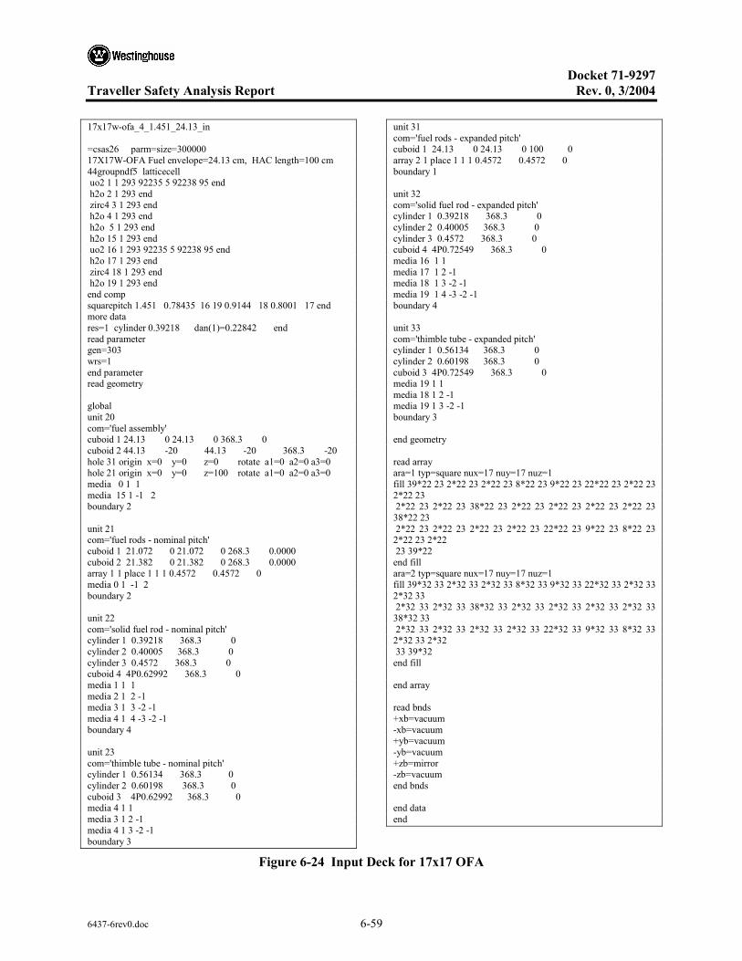
Docket 71-9297
Traveller Safety Analysis Report Rev. 0, 3/2004
6437-6rev0.doc 6-59
17x17w-ofa_4_1.451_24.13_in =csas26 parm=size=300000 17X17W-OFA Fuel envelope=24.13 cm, HAC length=100 cm 44groupndf5 latticecell uo2 1 1 293 92235 5 92238 95 end h2o 2 1 293 end zirc4 3 1 293 end h2o 4 1 293 end h2o 5 1 293 end h2o 15 1 293 end uo2 16 1 293 92235 5 92238 95 end h2o 17 1 293 end zirc4 18 1 293 end h2o 19 1 293 end end comp squarepitch 1.451 0.78435 16 19 0.9144 18 0.8001 17 end more data res=1 cylinder 0.39218 dan(1)=0.22842 end read parameter gen=303 wrs=1 end parameter read geometry global unit 20 com='fuel assembly' cuboid 1 24.13 0 24.13 0 368.3 0 cuboid 2 44.13 -20 44.13 -20 368.3 -20 hole 31 origin x=0 y=0 z=0 rotate a1=0 a2=0 a3=0 hole 21 origin x=0 y=0 z=100 rotate a1=0 a2=0 a3=0 media 0 1 1 media 15 1 -1 2 boundary 2 unit 21 com='fuel rods - nominal pitch' cuboid 1 21.072 0 21.072 0 268.3 0.0000 cuboid 2 21.382 0 21.382 0 268.3 0.0000 array 1 1 place 1 1 1 0.4572 0.4572 0 media 0 1 -1 2 boundary 2 unit 22 com='solid fuel rod - nominal pitch' cylinder 1 0.39218 368.3 0 cylinder 2 0.40005 368.3 0 cylinder 3 0.4572 368.3 0 cuboid 4 4P0.62992 368.3 0 media 1 1 1 media 2 1 2 -1 media 3 1 3 -2 -1 media 4 1 4 -3 -2 -1 boundary 4 unit 23 com='thimble tube - nominal pitch' cylinder 1 0.56134 368.3 0 cylinder 2 0.60198 368.3 0 cuboid 3 4P0.62992 368.3 0 media 4 1 1 media 3 1 2 -1 media 4 1 3 -2 -1 boundary 3
unit 31 com='fuel rods - expanded pitch' cuboid 1 24.13 0 24.13 0 100 0 array 2 1 place 1 1 1 0.4572 0.4572 0 boundary 1 unit 32 com='solid fuel rod - expanded pitch' cylinder 1 0.39218 368.3 0 cylinder 2 0.40005 368.3 0 cylinder 3 0.4572 368.3 0 cuboid 4 4P0.72549 368.3 0 media 16 1 1 media 17 1 2 -1 media 18 1 3 -2 -1 media 19 1 4 -3 -2 -1 boundary 4 unit 33 com='thimble tube - expanded pitch' cylinder 1 0.56134 368.3 0 cylinder 2 0.60198 368.3 0 cuboid 3 4P0.72549 368.3 0 media 19 1 1 media 18 1 2 -1 media 19 1 3 -2 -1 boundary 3 end geometry read array ara=1 typ=square nux=17 nuy=17 nuz=1 fill 39*22 23 2*22 23 2*22 23 8*22 23 9*22 23 22*22 23 2*22 23 2*22 23 2*22 23 2*22 23 38*22 23 2*22 23 2*22 23 2*22 23 2*22 23 38*22 23 2*22 23 2*22 23 2*22 23 2*22 23 22*22 23 9*22 23 8*22 23 2*22 23 2*22 23 39*22 end fill ara=2 typ=square nux=17 nuy=17 nuz=1 fill 39*32 33 2*32 33 2*32 33 8*32 33 9*32 33 22*32 33 2*32 33 2*32 33 2*32 33 2*32 33 38*32 33 2*32 33 2*32 33 2*32 33 2*32 33 38*32 33 2*32 33 2*32 33 2*32 33 2*32 33 22*32 33 9*32 33 8*32 33 2*32 33 2*32 33 39*32 end fill end array read bnds +xb=vacuum -xb=vacuum +yb=vacuum -yb=vacuum +zb=mirror -zb=vacuum end bnds end data end
Figure 6-24 Input Deck for 17x17 OFA

Docket 71-9297
Traveller Safety Analysis Report Rev. 0, 3/2004
6437-6rev0.doc 6-60
6.10.3 17X17OFA-XL MODEL
6.10.3.1 Introduction
The same general fuel assembly input deck is used for the several Traveller and Traveller XL criticality calculations. The primary differences are the length and the extent to which the lattice pitch expands in the expanded section. The fuel is expanded to 9.1 inches in the Traveller and 9.6 inches in the Traveller XL.
6.10.3.2 Fuel Assembly Model
The fuel assembly is typically designated as unit 20 in the input decks. Figure 6-25 shows a sample of the unit 20 input lines for the Traveller. Fuel assembly input consists of concentric cuboids to model the top nozzle assembly, skeleton and fuel regions. The fuel assembly origin is at the bottom left hand corner of the fuel assembly lower nozzle. Units #21 (nominal pitch fuel rod array), #31 (expanded pitch fuel rod array), and #40 (top nozzle assembly) are dropped into unit #20 as hole #21 and hole #31. Figure 6-26 shows the different parts that make up unit #20.
Figure 6-25 Sample Input Lines for Traveller Fuel Assembly
Figure 6-26 Keno 3d Image of Fuel Assembly
unit 20 com='fuel assembly' cuboid 1 21.4122 0 21.4122 0 0 -14.0208 cuboid 2 23.1140 0 23.1140 0 504.1392 -14.0208 hole 31 origin x=0 y=0 z= 0. rotate a1=0 a2=0 a3=0 hole 21 origin x=0 y=0 z=100.0000 rotate a1=0 a2=0 a3=0 hole 40 origin x=0 y=0 z=426.7200 rotate a1=0 a2=0 a3=0 media 15 1 1 media 0 1 -1 2 boundary 2

Docket 71-9297
Traveller Safety Analysis Report Rev. 0, 3/2004
6437-6rev0.doc 6-61
6.10.3.3 Fuel Rod Arrays
Units #21 and #31 are the fuel rod arrays. The arrays are identical except that cuboid #4 is sized according to the nominal pitch (unit #21) or expanded pitch (unit #31).
Unit #21 is made up of nominal pitch fuel rods (unit #22) and thimble tubes (unit #23). Unit #31 similarly is made up of expanded pitch fuel rods (unit #32) and thimble tubes (unit #33). Sample input deck lines for these units are found in Figure 6-27.
Figure 6-27 Sample Input Lines for Fuel Rod Cells
6.10.3.4 Fuel Rod Cell
Fuel rod cells (units #22 and #32) are modeled as concentric cylinders for the pellet, gap, and cladding. The cells are bounded by a cuboid whose dimension is determined by lattice pitch. Thimble tubes (units #23 and 33) are similarly structured. Sample input lines for the rod cell units are shown in Figure 6-27. A fuel cell is shown in Figure 6-28.
unit 21 com='fuel rods - nominal pitch' cuboid 1 21.4166 0 21.4166 0 326.7200 0.0000array 2 1 place 1 1 1 0.6299 0.6299 0 boundary 1 unit 22 com='solid fuel rod - nominal pitch' cylinder 1 0.3922 448.3862 0 cylinder 2 0.4 448.3862 0 cylinder 3 0.4572 448.3862 0 cuboid 4 0.6299 -0.6299 0.6299 -0.6299 448.3862 0media 1 1 1 media 2 1 2 -1 media 3 1 3 -2 -1 media 4 1 4 -3 -2 -1 boundary 4 unit 23 com='thimble tube - nominal pitch' cylinder 1 0.5613 448.3862 0 cylinder 2 0.6020 448.3862 0 cuboid 3 0.6299 -0.6299 0.6299 -0.6299 448.3862 0media 4 1 1 media 3 1 2 -1 media 4 1 3 -2 -1 boundary 3
unit 31 com='fuel rods - expanded pitch' cuboid 1 23.1140 0 23.1140 0 100.0000 0 array 3 1 place 1 1 1 0.4572 0.4572 0 boundary 1 unit 32 com='solid fuel rod - expanded pitch' cylinder 1 0.3922 448.3862 0 cylinder 2 0.4 448.3862 0 cylinder 3 0.4572 448.3862 0 cuboid 4 0.6937 -0.6937 0.6937 -0.6937 448.3862 0media 16 1 1 media 17 1 2 -1 media 18 1 3 -2 -1 media 19 1 4 -3 -2 -1 boundary 4 unit 33 com='thimble tube - expanded pitch' cylinder 1 0.5613 448.3862 0 cylinder 2 0.6020 448.3862 0 cuboid 3 0.6937 -0.6937 0.6937 -0.6937 448.3862 0 media 19 1 1 media 18 1 2 -1 media 19 1 3 -2 -1 boundary 3

Docket 71-9297
Traveller Safety Analysis Report Rev. 0, 3/2004
6437-6rev0.doc 6-62
FUEL PELLET UO2 (MATERIAL 1)
CLAD-PELLET GAP (VOID)
CLAD ZIRC4 (MATERIAL 3)
MODERATOR H2O (MATERIAL 4)
Figure 6-28 Fuel Rod Cell

Docket 71-9297
Traveller Safety Analysis Report Rev. 0, 3/2004
6437-6rev0.doc 6-63
6.10.4 TRAVELLER PACKAGING MODEL
6.10.4.1 Introduction
The same general Outerpack input deck has been used for the several Traveller and Traveller XL criticality calculations. The primary differences are dimensions of different materials. For example, the thickness of the moderator block in the Outerpacks differ. For the Traveller the moderator blocks upper and lower are 1.25 inches. For the Traveller XL, the upper moderator block is 1.25 inches and the lower block is 1.75 inches. Also, for the Clamshell, the face-to-face dimensions are different between the Traveller (9.1 inches) and Traveller XL (9.6 inches).
6.10.4.2 Outerpack Model
The Outerpack is typically designated as unit 10 in the input decks. Figure 6-29 shows a sample of the unit 10 input lines for the Traveller. Figure 6-30 is a Keno 3d rendering that shows the placement of the first six cuboids in the Outerpack model. The intersecting cuboids define the inner shell and fixed moderator.
• Cuboid #1, rotated 45 degrees, defines the inner edge of the moderator block.
• Cuboid #2, not rotated, defines the side limits of the moderator blocks.
• Cuboid #3, rotated, defines the shell side of the moderator block. The thickness of the moderator block is determined by taking the difference between cuboids #3 and #1 for the respective coordinates.
• Cuboid #4, rotated, defines the thickness of the inner stainless steel shell of the Outerpack. The thickness of the steel is determined by taking the difference between cuboids #4 and #3, and cuboids #6 and #5, for the respective coordinates.
• Cuboid #5, not rotated, defines the upper and lower limits of the moderator blocks.
• Cuboid #6, not rotated, defines the steel thickness.
Concentric cylinders #9 through #14 define the foam regions and the outer steel shell. The shock mount (unit 12) is a cylinder placed in the Outerpack as a hole. Twenty-six holes are positioned along the lower half of the inner shell to represent the shock mounts. The shock mounts are included because their placement displaces fixed moderator and the shock mount material is itself a moderator that could have an effect on keff.
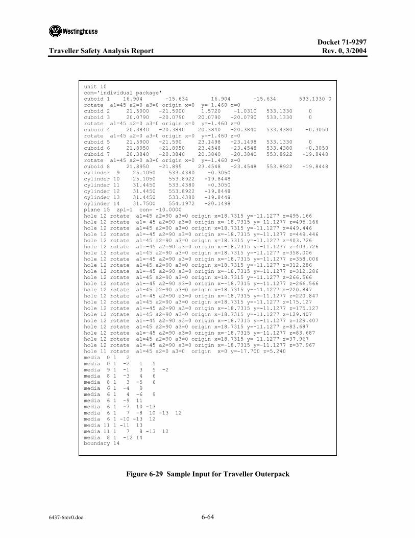
Docket 71-9297
Traveller Safety Analysis Report Rev. 0, 3/2004
6437-6rev0.doc 6-64
Figure 6-29 Sample Input for Traveller Outerpack
unit 10 com='individual package' cuboid 1 16.904 -15.634 16.904 -15.634 533.1330 0 rotate a1=45 a2=0 a3=0 origin x=0 y=-1.460 z=0 cuboid 2 21.5900 -21.5900 1.5720 -1.0310 533.1330 0 cuboid 3 20.0790 -20.0790 20.0790 -20.0790 533.1330 0 rotate a1=45 a2=0 a3=0 origin x=0 y=-1.460 z=0 cuboid 4 20.3840 -20.3840 20.3840 -20.3840 533.4380 -0.3050 rotate a1=45 a2=0 a3=0 origin x=0 y=-1.460 z=0 cuboid 5 21.5900 -21.590 23.1498 -23.1498 533.1330 0 cuboid 6 21.8950 -21.8950 23.4548 -23.4548 533.4380 -0.3050 cuboid 7 20.3840 -20.3840 20.3840 -20.3840 553.8922 -19.8448 rotate a1=45 a2=0 a3=0 origin x=0 y=-1.460 z=0 cuboid 8 21.8950 -21.895 23.4548 -23.4548 553.8922 -19.8448 cylinder 9 25.1050 533.4380 -0.3050 cylinder 10 25.1050 553.8922 -19.8448 cylinder 11 31.4450 533.4380 -0.3050 cylinder 12 31.4450 553.8922 -19.8448 cylinder 13 31.4450 533.4380 -19.8448 cylinder 14 31.7500 554.1972 -20.1498 plane 15 zpl=1 con= -10.0000 hole 12 rotate a1=45 a2=90 a3=0 origin x=18.7315 y=-11.1277 z=495.166 hole 12 rotate a1=-45 a2=90 a3=0 origin x=-18.7315 y=-11.1277 z=495.166 hole 12 rotate a1=45 a2=90 a3=0 origin x=18.7315 y=-11.1277 z=449.446 hole 12 rotate a1=-45 a2=90 a3=0 origin x=-18.7315 y=-11.1277 z=449.446 hole 12 rotate a1=45 a2=90 a3=0 origin x=18.7315 y=-11.1277 z=403.726 hole 12 rotate a1=-45 a2=90 a3=0 origin x=-18.7315 y=-11.1277 z=403.726 hole 12 rotate a1=45 a2=90 a3=0 origin x=18.7315 y=-11.1277 z=358.006 hole 12 rotate a1=-45 a2=90 a3=0 origin x=-18.7315 y=-11.1277 z=358.006 hole 12 rotate a1=45 a2=90 a3=0 origin x=18.7315 y=-11.1277 z=312.286 hole 12 rotate a1=-45 a2=90 a3=0 origin x=-18.7315 y=-11.1277 z=312.286 hole 12 rotate a1=45 a2=90 a3=0 origin x=18.7315 y=-11.1277 z=266.566 hole 12 rotate a1=-45 a2=90 a3=0 origin x=-18.7315 y=-11.1277 z=266.566 hole 12 rotate a1=45 a2=90 a3=0 origin x=18.7315 y=-11.1277 z=220.847 hole 12 rotate a1=-45 a2=90 a3=0 origin x=-18.7315 y=-11.1277 z=220.847 hole 12 rotate a1=45 a2=90 a3=0 origin x=18.7315 y=-11.1277 z=175.127 hole 12 rotate a1=-45 a2=90 a3=0 origin x=-18.7315 y=-11.1277 z=175.127 hole 12 rotate a1=45 a2=90 a3=0 origin x=18.7315 y=-11.1277 z=129.407 hole 12 rotate a1=-45 a2=90 a3=0 origin x=-18.7315 y=-11.1277 z=129.407 hole 12 rotate a1=45 a2=90 a3=0 origin x=18.7315 y=-11.1277 z=83.687 hole 12 rotate a1=-45 a2=90 a3=0 origin x=-18.7315 y=-11.1277 z=83.687 hole 12 rotate a1=45 a2=90 a3=0 origin x=18.7315 y=-11.1277 z=37.967 hole 12 rotate a1=-45 a2=90 a3=0 origin x=-18.7315 y=-11.1277 z=37.967 hole 11 rotate a1=45 a2=0 a3=0 origin x=0 y=-17.700 z=5.240 media 0 1 2 media 0 1 -2 1 5 media 9 1 -1 3 5 -2 media 8 1 -3 4 6 media 8 1 3 -5 6 media 6 1 -4 9 media 6 1 4 -6 9 media 6 1 -9 11 media 6 1 -7 10 -13 media 6 1 7 -8 10 -13 12 media 6 1 -10 -13 12 media 11 1 -11 13 media 11 1 7 8 -13 12 media 8 1 -12 14 boundary 14

Docket 71-9297
Traveller Safety Analysis Report Rev. 0, 3/2004
6437-6rev0.doc 6-65
Cuboid #1
Cuboid #2
Cuboid #3
Cuboid #4
Cuboid #5
Cuboid #6
Figure 6-30 Keno 3d Line Schematic of Outerpack Cuboids
Media 8 – Stainless steel
Media 9 – Moderator
Media 6 & 11 – foam
Figure 6-31 Keno 3d Drawing of Outerpack Showing Media

Docket 71-9297
Traveller Safety Analysis Report Rev. 0, 3/2004
6437-6rev0.doc 6-66
Figure 6-32 Keno 3d Images of Outerpack
6.10.4.3 Clamshell Model
The same general Clamshell input deck has been used for the several Traveller and Traveller XL criticality calculations. The obvious difference is the face-to-face dimension of the Traveller and Traveller XL.
The Clamshell is typically designated as unit 11 in the input decks. Figure 6-33 shows a sample of the unit 11 input lines for the Clamshell. Figure 6-34 is a schematic drawing of the Clamshell model.
• Cuboid #1 defines the inner edge of the Clamshell. The face-to-face dimension of the Clamshell is simply this measurement.
• Cuboid #2 defines outer edge of the aluminum Clamshell.
• Cuboid #3 defines the inner cladding dimension of the top and bottom neutron absorber. Cladding thickness is calculated by taking the difference of the ±y dimensions between cuboid #3 and cuboid #1.
• Cuboid #4 defines the core of the top and bottom neutron absorber. Core thickness is calculated by taking the difference of the ±y dimensions between cuboid #4 and cuboid #3.
• Cuboid #5 defines the outer cladding dimension of the top and bottom neutron absorber. Cladding thickness is calculated by taking the difference of the ±y dimensions between cuboid #5 and cuboid #4.
• Cuboid #6 defines the inner cladding dimension of the side neutron absorber sections. Cladding thickness is calculated by taking the difference of the ±x dimensions between cuboid #6 and cuboid #1.

Docket 71-9297
Traveller Safety Analysis Report Rev. 0, 3/2004
6437-6rev0.doc 6-67
• Cuboid #7 defines the core of the side neutron absorber sections. Core thickness is calculated by taking the difference of the ±x dimensions between cuboid #7 and cuboid #6.
• Cuboid #8 defines the outer cladding dimension of the side neutron absorber sections. Cladding thickness is calculated by taking the difference of the ±x dimensions between cuboid #8 and cuboid #7
Figure 6-33 Sample input lines for Clamshell
unit 11 com='fuel assembly confinement system' cuboid 1 24.384 0 24.384 0 520.7000 2.5400 cuboid 2 25.337 -0.9525 25.337 -0.9525 523.2400 0.0000 cuboid 3 19.812 4.572 24.429 -0.04545 520.7000 2.5400 cuboid 4 19.812 4.572 24.656 -0.27205 520.7000 2.5400 cuboid 5 19.812 4.572 24.702 -0.3175 520.7000 2.5400 cuboid 6 24.429 -0.04545 19.812 4.572 520.7000 2.5400 cuboid 7 24.656 -0.27205 19.812 4.572 520.7000 2.5400 cuboid 8 24.702 -0.3175 19.812 4.572 520.7000 2.5400 hole 20 origin x=0 y=0 z=16.5600 rotate a1=0 a2=0 a3=0 media 15 1 1 media 7 1 -1 2 -5 -8 media 7 1 -1 3 media 12 1 -3 4 media 7 1 -4 5 media 7 1 -1 6 media 12 1 -6 7 media 7 1 -7 8 boundary 2

Docket 71-9297
Traveller Safety Analysis Report Rev. 0, 3/2004
6437-6rev0.doc 6-68
Cuboid #1: h2o Cuboid #2: Al
Cuboid #5: Al Cuboid #4: BORAL Cuboid #3: Al
Cuboid #6: Al Cuboid #7: BORAL Cuboid #8: Al
Figure 6-34 Clamshell

Docket 71-9297
Traveller Safety Analysis Report Rev. 0, 3/2004
6437-6rev0.doc 6-69
6.10.5 SINGLE PACKAGE EVALUATION CALCULATIONS
Results for the single package in isolation calculations are presented below. Table 6-25 shows the results for normal conditions. Tables 6-32 and 6-33 show results for hypothetical accident conditions for the Traveller STD and Traveller XL, respectively. Table 6-28 shows the input deck used in calculating the Traveller STD single package with borated aluminum as the absorber assuming 100 cm length expanded lattice, results #ip_hac_bal_4_5_100_0.2677.out in Table 6-25. Table 6-29 shows a similar input deck for the Traveller XL calculations, results #ip_hac_bal_4_5_100_0.14863.out in Table 6-26.
Table 6-25 Single Package Calculations for Traveller STD and XL – Normal Conditions
Package File name ks σks ks+2×σks
Traveller STD IP_NOR_BAL_4_1_0.1_0.29113.out 0. 1840 6.00E-04 0.1852
Traveller XL IP_NOR_BAL_4_1_0.1_0.0163_in.out 0. 1928 6.00E-04 0.1940
Table 6-26 Single Package Calculations for Traveller STD – HAC
INDIVIDUAL PACKAGE – IP_HAC_BAL (0.0163 g/cm2 B10)
Length of Exp.(cm) ks σks ks+2×σks
ip_hac_bal_4_1_0.1_0.1837.out: 0.0000 0.8331 1.8000e-3 0.8367
ip_hac_bal_4_2_25_0.2064.out: 25.0000 0.8350 1.7000e-3 0.8384
ip_hac_bal_4_3_50_0.2263.out: 50.0000 0.8403 1.6000e-3 0.8435
ip_hac_bal_4_4_75_0.2469.out: 75.0000 0.8518 1.7000e-3 0.8552
ip_hac_bal_4_5_100_0.2677.out: 100.0000 0.8639 1.7000e-3 0.8673
ip_hac_bal_4_6_150_0.2883.out: 150.0000 0.8710 1.8000e-3 0.8746
ip_hac_bal_4_7_200_0.3078.out: 200.0000 0.8731 1.4000e-3 0.8759
ip_hac_bal_4_8_300_0.3284.out: 300.0000 0.8744 1.6000e-3 0.8776
ip_hac_bal_4_9_426_0.3481.out: 426.0000 0.8738 1.7000e-3 0.8772
INDIVIDUAL PACKAGE – IP_HAC_BORAL (0.0188 g/cm2 B10)
Length of Exp.(cm) ks σks ks+2×σks
ip_hac_boral_4_1_0.1_0.7987.out: 0.0000 0.8368 1.6000e-3 0.8400
ip_hac_boral_4_2_25_0.8181.out: 25.0000 0.8366 1.7000e-3 0.8400
ip_hac_boral_4_3_50_0.8381.out: 50.0000 0.8401 1.5000e-3 0.8431
ip_hac_boral_4_4_75_0.8577.out: 75.0000 0.8563 1.5000e-3 0.8593
ip_hac_boral_4_5_100_0.8780.out: 100.0000 0.8577 1.5000e-3 0.8607
ip_hac_boral_4_6_150_0.8977.out: 150.0000 0.8646 1.7000e-3 0.8680
ip_hac_boral_4_7_200_0.9178.out: 200.0000 0.8701 1.6000e-3 0.8733
ip_hac_boral_4_8_300_0.9372.out: 300.0000 0.8738 1.5000e-3 0.8768
ip_hac_boral_4_9_426_0.9601.out: 426.0000 0.8749 1.8000e-3 0.8785

Docket 71-9297
Traveller Safety Analysis Report Rev. 0, 3/2004
6437-6rev0.doc 6-70
Table 6-27 Single Package Calculations for Traveller XL – HAC
INDIVIDUAL PACKAGE – IP_HAC_BAL (0.0163 g/cm2 B10)
Length of Exp.(cm) ks σks ks+2×σks
ip_hac_bal_4_1_0.1_0.15788.out: 0.0000 0.8575 1.6000e-3 0.8607
ip_hac_bal_4_2_25_0.16449.out: 25.0000 0.8547 1.6000e-3 0.8579
ip_hac_bal_4_3_50_0.16720.out: 50.0000 0.8785 1.7000e-3 0.8819
ip_hac_bal_4_4_75_0.17050.out: 75.0000 0.8929 1.8000e-3 0.8965
ip_hac_bal_4_5_100_0.14863.out: 100.0000 0.9018 1.7000e-3 0.9052
ip_hac_bal_4_6_150_0.17252.out: 150.0000 0.9064 1.5000e-3 0.9094
ip_hac_bal_4_7_200_0.17967.out: 200.0000 0.9119 1.6000e-3 0.9151
ip_hac_bal_4_8_300_0.18183.out: 300.0000 0.9134 1.7000e-3 0.9168
ip_hac_bal_4_9_426_0.18444.out: 426.0000 0.9154 1.5000e-3 0.9184
INDIVIDUAL PACKAGE – IP_HAC_BORAL (0.0188 g/cm2 B10)
Length of Exp.(cm) ks σks ks+2×σks
ip_hac_boral_4_1_0.1_0.24798.out: 0.0000 0.8544 1.5000e-3 0.8574
25.0000
ip_hac_boral_4_3_50_0.28498.out: 50.0000 0.8775 2.0000e-3 0.8815
IP_HAC_BORAL_4_4_75_0.14352.out 75.0000 0.8929 1.6000e-3 0.8961
IP_HAC_BORAL_4_5_100_0.13791.out 100.0000 0.9035 1.6000e-3 0.9067
ip_hac_boral_4_6_150_0.29141.out: 150.0000 0.9077 1.6000e-3 0.9109
ip_hac_boral_4_7_200_0.29813.out: 200.0000 0.9128 1.7000e-3 0.9162
ip_hac_boral_4_8_300_0.2811.out: 300.0000 0.9130 1.6000e-3 0.9162
ip_hac_boral_4_9_426_0.3842.out: 426.0000 0.9148 1.5000e-3 0.9178
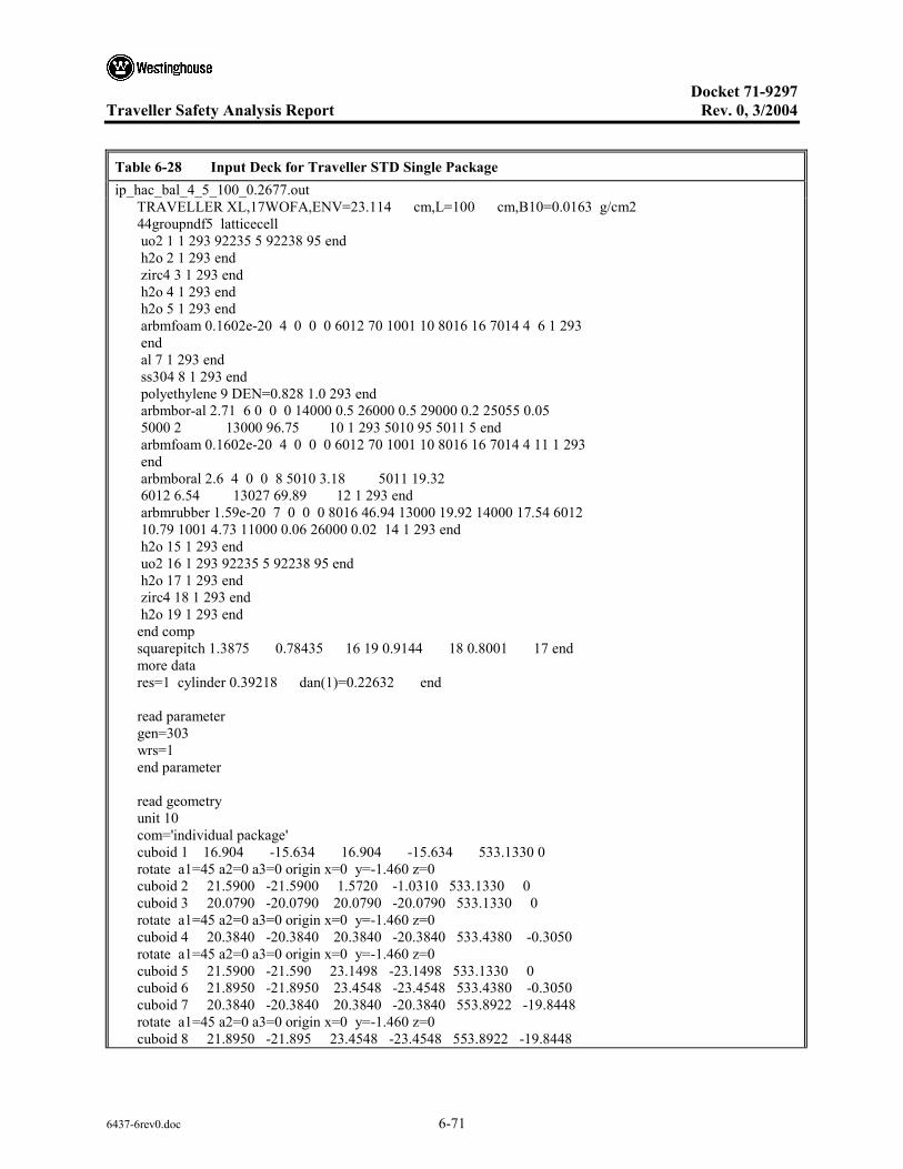
Docket 71-9297
Traveller Safety Analysis Report Rev. 0, 3/2004
6437-6rev0.doc 6-71
Table 6-28 Input Deck for Traveller STD Single Package ip_hac_bal_4_5_100_0.2677.out TRAVELLER XL,17WOFA,ENV=23.114 cm,L=100 cm,B10=0.0163 g/cm2 44groupndf5 latticecell uo2 1 1 293 92235 5 92238 95 end h2o 2 1 293 end zirc4 3 1 293 end h2o 4 1 293 end h2o 5 1 293 end arbmfoam 0.1602e-20 4 0 0 0 6012 70 1001 10 8016 16 7014 4 6 1 293 end al 7 1 293 end ss304 8 1 293 end polyethylene 9 DEN=0.828 1.0 293 end arbmbor-al 2.71 6 0 0 0 14000 0.5 26000 0.5 29000 0.2 25055 0.05 5000 2 13000 96.75 10 1 293 5010 95 5011 5 end arbmfoam 0.1602e-20 4 0 0 0 6012 70 1001 10 8016 16 7014 4 11 1 293 end arbmboral 2.6 4 0 0 8 5010 3.18 5011 19.32 6012 6.54 13027 69.89 12 1 293 end arbmrubber 1.59e-20 7 0 0 0 8016 46.94 13000 19.92 14000 17.54 6012 10.79 1001 4.73 11000 0.06 26000 0.02 14 1 293 end h2o 15 1 293 end uo2 16 1 293 92235 5 92238 95 end h2o 17 1 293 end zirc4 18 1 293 end h2o 19 1 293 end end comp squarepitch 1.3875 0.78435 16 19 0.9144 18 0.8001 17 end more data res=1 cylinder 0.39218 dan(1)=0.22632 end read parameter gen=303 wrs=1 end parameter read geometry unit 10 com='individual package' cuboid 1 16.904 -15.634 16.904 -15.634 533.1330 0 rotate a1=45 a2=0 a3=0 origin x=0 y=-1.460 z=0 cuboid 2 21.5900 -21.5900 1.5720 -1.0310 533.1330 0 cuboid 3 20.0790 -20.0790 20.0790 -20.0790 533.1330 0 rotate a1=45 a2=0 a3=0 origin x=0 y=-1.460 z=0 cuboid 4 20.3840 -20.3840 20.3840 -20.3840 533.4380 -0.3050 rotate a1=45 a2=0 a3=0 origin x=0 y=-1.460 z=0 cuboid 5 21.5900 -21.590 23.1498 -23.1498 533.1330 0 cuboid 6 21.8950 -21.8950 23.4548 -23.4548 533.4380 -0.3050 cuboid 7 20.3840 -20.3840 20.3840 -20.3840 553.8922 -19.8448 rotate a1=45 a2=0 a3=0 origin x=0 y=-1.460 z=0 cuboid 8 21.8950 -21.895 23.4548 -23.4548 553.8922 -19.8448

Docket 71-9297
Traveller Safety Analysis Report Rev. 0, 3/2004
6437-6rev0.doc 6-72
Table 6-28 Input Deck for Traveller STD Single Package (cont.) ip_hac_bal_4_5_100_0.2677.out cylinder 9 25.1050 533.4380 -0.3050 cylinder 10 25.1050 553.8922 -19.8448 cylinder 11 31.4450 533.4380 -0.3050 cylinder 12 31.4450 553.8922 -19.8448 cylinder 13 31.4450 533.4380 -19.8448 cylinder 14 31.7500 554.1972 -20.1498 plane 15 zpl=1 con= -10.0000 hole 12 rotate a1=45 a2=90 a3=0 origin x=18.7315 y=-11.1277 z=495.166 hole 12 rotate a1=-45 a2=90 a3=0 origin x=-18.7315 y=-11.1277 z=495.166 hole 12 rotate a1=45 a2=90 a3=0 origin x=18.7315 y=-11.1277 z=449.446 hole 12 rotate a1=-45 a2=90 a3=0 origin x=-18.7315 y=-11.1277 z=449.446 hole 12 rotate a1=45 a2=90 a3=0 origin x=18.7315 y=-11.1277 z=403.726 hole 12 rotate a1=-45 a2=90 a3=0 origin x=-18.7315 y=-11.1277 z=403.726 hole 12 rotate a1=45 a2=90 a3=0 origin x=18.7315 y=-11.1277 z=358.006 hole 12 rotate a1=-45 a2=90 a3=0 origin x=-18.7315 y=-11.1277 z=358.006 hole 12 rotate a1=45 a2=90 a3=0 origin x=18.7315 y=-11.1277 z=312.286 hole 12 rotate a1=-45 a2=90 a3=0 origin x=-18.7315 y=-11.1277 z=312.286 hole 12 rotate a1=45 a2=90 a3=0 origin x=18.7315 y=-11.1277 z=266.566 hole 12 rotate a1=-45 a2=90 a3=0 origin x=-18.7315 y=-11.1277 z=266.566 hole 12 rotate a1=45 a2=90 a3=0 origin x=18.7315 y=-11.1277 z=220.847 hole 12 rotate a1=-45 a2=90 a3=0 origin x=-18.7315 y=-11.1277 z=220.847 hole 12 rotate a1=45 a2=90 a3=0 origin x=18.7315 y=-11.1277 z=175.127 hole 12 rotate a1=-45 a2=90 a3=0 origin x=-18.7315 y=-11.1277 z=175.127 hole 12 rotate a1=45 a2=90 a3=0 origin x=18.7315 y=-11.1277 z=129.407 hole 12 rotate a1=-45 a2=90 a3=0 origin x=-18.7315 y=-11.1277 z=129.407 hole 12 rotate a1=45 a2=90 a3=0 origin x=18.7315 y=-11.1277 z=83.687 hole 12 rotate a1=-45 a2=90 a3=0 origin x=-18.7315 y=-11.1277 z=83.687 hole 12 rotate a1=45 a2=90 a3=0 origin x=18.7315 y=-11.1277 z=37.967 hole 12 rotate a1=-45 a2=90 a3=0 origin x=-18.7315 y=-11.1277 z=37.967 hole 11 rotate a1=45 a2=0 a3=0 origin x=0 y=-17.700 z=5.240 media 15 1 2 media 15 1 -2 1 5 media 9 1 -1 3 5 -2 media 8 1 -3 4 6 media 8 1 3 -5 6 media 15 1 -4 9 media 15 1 4 -6 9 media 15 1 -9 11 media 15 1 -7 10 -13 media 15 1 7 -8 10 -13 12 media 15 1 -10 -13 12 media 11 1 -11 13 media 11 1 7 8 -13 12 media 8 1 -12 14 boundary 14 unit 11 com='fuel assembly confinement system' cuboid 1 23.114 0 23.114 0 520.7000 2.5400 cuboid 2 24.067 -0.9525 24.067 -0.9525

Docket 71-9297
Traveller Safety Analysis Report Rev. 0, 3/2004
6437-6rev0.doc 6-73
Table 6-28 Input Deck for Traveller STD Single Package (cont.) ip_hac_bal_4_5_100_0.2677.out 523.2400 0.0000 cuboid 3 19.177 3.937 23.159 -0.04545 520.7000 2.5400 cuboid 4 19.177 3.937 23.386 -0.27205 520.7000 2.5400 cuboid 5 19.177 3.937 23.432 -0.3175 520.7000 2.5400 cuboid 6 23.159 -0.04545 19.177 3.937 520.7000 2.5400 cuboid 7 23.386 -0.27205 19.177 3.937 520.7000 2.5400 cuboid 8 23.432 -0.3175 19.177 3.937 520.7000 2.5400 hole 20 origin x=0 y=0 z=16.5600 rotate a1=0 a2=0 a3=0 media 15 1 1 media 7 1 -1 2 -5 -8 media 10 1 -1 3 media 10 1 -3 4 media 10 1 -4 5 media 10 1 -1 6 media 10 1 -6 7 media 10 1 -7 8 boundary 2 unit 12 com='shock mount' cylinder 1 3.962 0 -7.62 media 15 1 1 boundary 1 unit 20 com='fuel assembly' cuboid 1 21.072 0 21.072 0 0 -14.0208 cuboid 2 23.114 0 23.114 0 504.1392 -14.0208 hole 31 origin x=0 y=0 z=0 rotate a1=0 a2=0 a3=0 hole 21 origin x=0 y=0 z=100 rotate a1=0 a2=0 a3=0 hole 40 origin x=0 y=0 z=426.72 rotate a1=0 a2=0 a3=0 media 15 1 1 media 15 1 -1 2 boundary 2 unit 21 com='fuel rods - nominal pitch' cuboid 1 21.072 0 21.072 0 326.72 0.0000 array 2 1 place 1 1 1 0.4572 0.4572 0 boundary 1 unit 22 com='solid fuel rod - nominal pitch' cylinder 1 0.39218 426.72 0
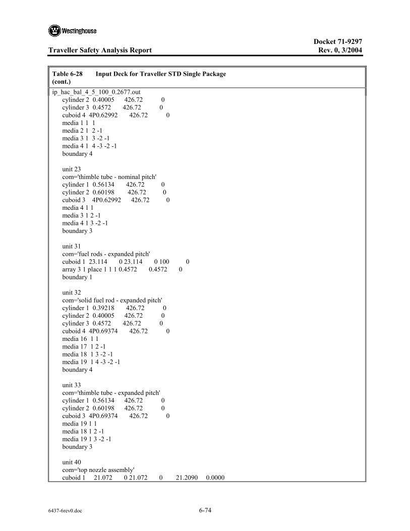
Docket 71-9297
Traveller Safety Analysis Report Rev. 0, 3/2004
6437-6rev0.doc 6-74
Table 6-28 Input Deck for Traveller STD Single Package (cont.) ip_hac_bal_4_5_100_0.2677.out cylinder 2 0.40005 426.72 0 cylinder 3 0.4572 426.72 0 cuboid 4 4P0.62992 426.72 0 media 1 1 1 media 2 1 2 -1 media 3 1 3 -2 -1 media 4 1 4 -3 -2 -1 boundary 4 unit 23 com='thimble tube - nominal pitch' cylinder 1 0.56134 426.72 0 cylinder 2 0.60198 426.72 0 cuboid 3 4P0.62992 426.72 0 media 4 1 1 media 3 1 2 -1 media 4 1 3 -2 -1 boundary 3 unit 31 com='fuel rods - expanded pitch' cuboid 1 23.114 0 23.114 0 100 0 array 3 1 place 1 1 1 0.4572 0.4572 0 boundary 1 unit 32 com='solid fuel rod - expanded pitch' cylinder 1 0.39218 426.72 0 cylinder 2 0.40005 426.72 0 cylinder 3 0.4572 426.72 0 cuboid 4 4P0.69374 426.72 0 media 16 1 1 media 17 1 2 -1 media 18 1 3 -2 -1 media 19 1 4 -3 -2 -1 boundary 4 unit 33 com='thimble tube - expanded pitch' cylinder 1 0.56134 426.72 0 cylinder 2 0.60198 426.72 0 cuboid 3 4P0.69374 426.72 0 media 19 1 1 media 18 1 2 -1 media 19 1 3 -2 -1 boundary 3 unit 40 com='top nozzle assembly' cuboid 1 21.072 0 21.072 0 21.2090 0.0000
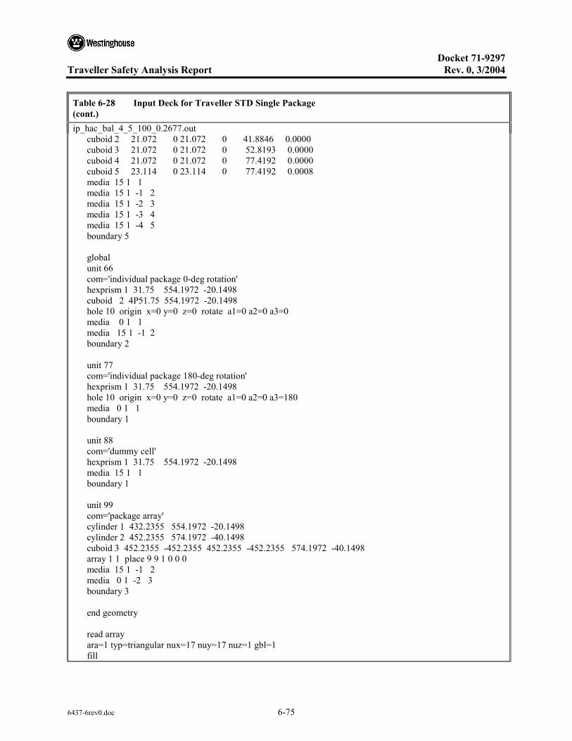
Docket 71-9297
Traveller Safety Analysis Report Rev. 0, 3/2004
6437-6rev0.doc 6-75
Table 6-28 Input Deck for Traveller STD Single Package (cont.) ip_hac_bal_4_5_100_0.2677.out cuboid 2 21.072 0 21.072 0 41.8846 0.0000 cuboid 3 21.072 0 21.072 0 52.8193 0.0000 cuboid 4 21.072 0 21.072 0 77.4192 0.0000 cuboid 5 23.114 0 23.114 0 77.4192 0.0008 media 15 1 1 media 15 1 -1 2 media 15 1 -2 3 media 15 1 -3 4 media 15 1 -4 5 boundary 5 global unit 66 com='individual package 0-deg rotation' hexprism 1 31.75 554.1972 -20.1498 cuboid 2 4P51.75 554.1972 -20.1498 hole 10 origin x=0 y=0 z=0 rotate a1=0 a2=0 a3=0 media 0 1 1 media 15 1 -1 2 boundary 2 unit 77 com='individual package 180-deg rotation' hexprism 1 31.75 554.1972 -20.1498 hole 10 origin x=0 y=0 z=0 rotate a1=0 a2=0 a3=180 media 0 1 1 boundary 1 unit 88 com='dummy cell' hexprism 1 31.75 554.1972 -20.1498 media 15 1 1 boundary 1 unit 99 com='package array' cylinder 1 432.2355 554.1972 -20.1498 cylinder 2 452.2355 574.1972 -40.1498 cuboid 3 452.2355 -452.2355 452.2355 -452.2355 574.1972 -40.1498 array 1 1 place 9 9 1 0 0 0 media 15 1 -1 2 media 0 1 -2 3 boundary 3 end geometry read array ara=1 typ=triangular nux=17 nuy=17 nuz=1 gbl=1 fill
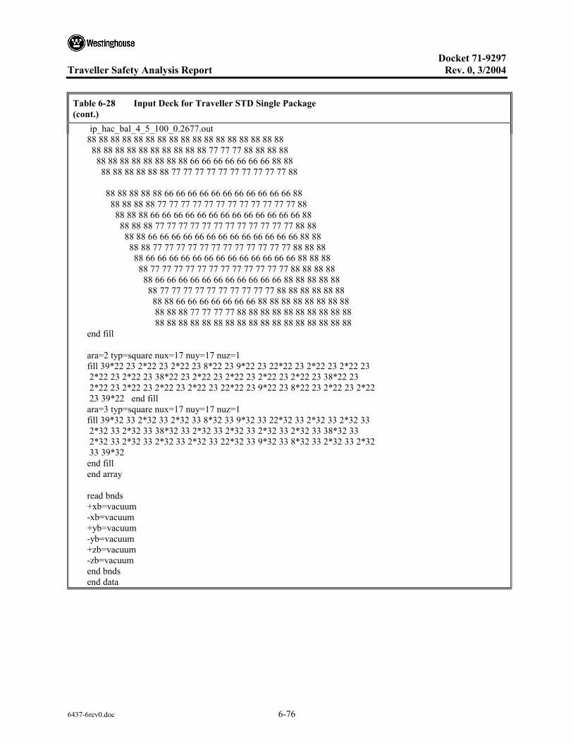
Docket 71-9297
Traveller Safety Analysis Report Rev. 0, 3/2004
6437-6rev0.doc 6-76
Table 6-28 Input Deck for Traveller STD Single Package (cont.) ip_hac_bal_4_5_100_0.2677.out 88 88 88 88 88 88 88 88 88 88 88 88 88 88 88 88 88 88 88 88 88 88 88 88 88 88 88 77 77 77 88 88 88 88 88 88 88 88 88 88 88 88 66 66 66 66 66 66 66 88 88 88 88 88 88 88 88 77 77 77 77 77 77 77 77 77 77 88 88 88 88 88 88 66 66 66 66 66 66 66 66 66 66 66 88 88 88 88 88 77 77 77 77 77 77 77 77 77 77 77 77 88 88 88 88 66 66 66 66 66 66 66 66 66 66 66 66 66 88 88 88 88 77 77 77 77 77 77 77 77 77 77 77 77 88 88 88 88 66 66 66 66 66 66 66 66 66 66 66 66 66 88 88 88 88 77 77 77 77 77 77 77 77 77 77 77 77 88 88 88 88 66 66 66 66 66 66 66 66 66 66 66 66 66 88 88 88 88 77 77 77 77 77 77 77 77 77 77 77 77 88 88 88 88 88 66 66 66 66 66 66 66 66 66 66 66 88 88 88 88 88 88 77 77 77 77 77 77 77 77 77 77 88 88 88 88 88 88 88 88 66 66 66 66 66 66 66 88 88 88 88 88 88 88 88 88 88 88 77 77 77 77 88 88 88 88 88 88 88 88 88 88 88 88 88 88 88 88 88 88 88 88 88 88 88 88 88 88 88 end fill ara=2 typ=square nux=17 nuy=17 nuz=1 fill 39*22 23 2*22 23 2*22 23 8*22 23 9*22 23 22*22 23 2*22 23 2*22 23 2*22 23 2*22 23 38*22 23 2*22 23 2*22 23 2*22 23 2*22 23 38*22 23 2*22 23 2*22 23 2*22 23 2*22 23 22*22 23 9*22 23 8*22 23 2*22 23 2*22 23 39*22 end fill ara=3 typ=square nux=17 nuy=17 nuz=1 fill 39*32 33 2*32 33 2*32 33 8*32 33 9*32 33 22*32 33 2*32 33 2*32 33 2*32 33 2*32 33 38*32 33 2*32 33 2*32 33 2*32 33 2*32 33 38*32 33 2*32 33 2*32 33 2*32 33 2*32 33 22*32 33 9*32 33 8*32 33 2*32 33 2*32 33 39*32 end fill end array read bnds +xb=vacuum -xb=vacuum +yb=vacuum -yb=vacuum +zb=vacuum -zb=vacuum end bnds end data

Docket 71-9297
Traveller Safety Analysis Report Rev. 0, 3/2004
6437-6rev0.doc 6-77
Table 6-29 Input Deck for Traveller XL Single Package ip_hac_bal_4_5_100_0.14863.out: TRAVELLER XL,17WOFA,ENV=24.384 cm,L=100 cm,B10=0.0163 g/cm2 44groupndf5 latticecell uo2 1 1 293 92235 5 92238 95 end h2o 2 1 293 end zirc4 3 1 293 end h2o 4 1 293 end h2o 5 1 293 end arbmfoam 0.1602e-20 4 0 0 0 6012 70 1001 10 8016 16 7014 4 6 1 293 end al 7 1 293 end ss304 8 1 293 end polyethylene 9 DEN=0.828 1.0 293 end arbmbor-al 2.71 6 0 0 0 14000 0.5 26000 0.5 29000 0.2 25055 0.05 5000 2 13000 96.75 10 1 293 5010 95 5011 5 end arbmfoam 0.1602e-20 4 0 0 0 6012 70 1001 10 8016 16 7014 4 11 1 293 end arbmboral 2.6 4 0 0 8 5010 3.18 5011 19.32 6012 6.54 13027 69.89 12 1 293 end arbmrubber 1.59e-20 7 0 0 0 8016 46.94 13000 19.92 14000 17.54 6012 10.79 1001 4.73 11000 0.06 26000 0.02 14 1 293 end h2o 15 1 293 end uo2 16 1 293 92235 5 92238 95 end h2o 17 1 293 end zirc4 18 1 293 end h2o 19 1 293 end end comp squarepitch 1.4669 0.78435 16 19 0.9144 18 0.8001 17 end more data res=1 cylinder 0.39218 dan(1)=0.22632 end read parameter gen=303 wrs=1 end parameter read geometry unit 10 com='individual package' cuboid 1 16.904 -15.634 16.904 -15.634 533.1330 0 rotate a1=45 a2=0 a3=0 origin x=0 y=-1.460 z=0 cuboid 2 21.5900 -21.5900 1.5720 -1.0310 533.1330 0 cuboid 3 20.0790 -20.0790 20.0790 -20.0790 533.1330 0 rotate a1=45 a2=0 a3=0 origin x=0 y=-1.460 z=0 cuboid 4 20.3840 -20.3840 20.3840 -20.3840 533.4380 -0.3050 rotate a1=45 a2=0 a3=0 origin x=0 y=-1.460 z=0 cuboid 5 21.5900 -21.590 23.1498 -23.1498 533.1330 0 cuboid 6 21.8950 -21.8950 23.4548 -23.4548 533.4380 -0.3050 cuboid 7 20.3840 -20.3840 20.3840 -20.3840 553.8922 -19.8448 rotate a1=45 a2=0 a3=0 origin x=0 y=-1.460 z=0 cuboid 8 21.8950 -21.895 23.4548 -23.4548 553.8922 -19.8448

Docket 71-9297
Traveller Safety Analysis Report Rev. 0, 3/2004
6437-6rev0.doc 6-78
Table 6-29 Input Deck for Traveller XL Single Package (cont.) ip_hac_bal_4_5_100_0.14863.out: cylinder 9 25.1050 533.4380 -0.3050 cylinder 10 25.1050 553.8922 -19.8448 cylinder 11 31.4450 533.4380 -0.3050 cylinder 12 31.4450 553.8922 -19.8448 cylinder 13 31.4450 533.4380 -19.8448 cylinder 14 31.7500 554.1972 -20.1498 plane 15 zpl=1 con= -10.0000 hole 12 rotate a1=45 a2=90 a3=0 origin x=18.7315 y=-11.1277 z=495.166 hole 12 rotate a1=-45 a2=90 a3=0 origin x=-18.7315 y=-11.1277 z=495.166 hole 12 rotate a1=45 a2=90 a3=0 origin x=18.7315 y=-11.1277 z=449.446 hole 12 rotate a1=-45 a2=90 a3=0 origin x=-18.7315 y=-11.1277 z=449.446 hole 12 rotate a1=45 a2=90 a3=0 origin x=18.7315 y=-11.1277 z=403.726 hole 12 rotate a1=-45 a2=90 a3=0 origin x=-18.7315 y=-11.1277 z=403.726 hole 12 rotate a1=45 a2=90 a3=0 origin x=18.7315 y=-11.1277 z=358.006 hole 12 rotate a1=-45 a2=90 a3=0 origin x=-18.7315 y=-11.1277 z=358.006 hole 12 rotate a1=45 a2=90 a3=0 origin x=18.7315 y=-11.1277 z=312.286 hole 12 rotate a1=-45 a2=90 a3=0 origin x=-18.7315 y=-11.1277 z=312.286 hole 12 rotate a1=45 a2=90 a3=0 origin x=18.7315 y=-11.1277 z=266.566 hole 12 rotate a1=-45 a2=90 a3=0 origin x=-18.7315 y=-11.1277 z=266.566 hole 12 rotate a1=45 a2=90 a3=0 origin x=18.7315 y=-11.1277 z=220.847 hole 12 rotate a1=-45 a2=90 a3=0 origin x=-18.7315 y=-11.1277 z=220.847 hole 12 rotate a1=45 a2=90 a3=0 origin x=18.7315 y=-11.1277 z=175.127 hole 12 rotate a1=-45 a2=90 a3=0 origin x=-18.7315 y=-11.1277 z=175.127 hole 12 rotate a1=45 a2=90 a3=0 origin x=18.7315 y=-11.1277 z=129.407 hole 12 rotate a1=-45 a2=90 a3=0 origin x=-18.7315 y=-11.1277 z=129.407 hole 12 rotate a1=45 a2=90 a3=0 origin x=18.7315 y=-11.1277 z=83.687 hole 12 rotate a1=-45 a2=90 a3=0 origin x=-18.7315 y=-11.1277 z=83.687 hole 12 rotate a1=45 a2=90 a3=0 origin x=18.7315 y=-11.1277 z=37.967 hole 12 rotate a1=-45 a2=90 a3=0 origin x=-18.7315 y=-11.1277 z=37.967 hole 11 rotate a1=45 a2=0 a3=0 origin x=0 y=-17.700 z=5.240 media 15 1 2 media 15 1 -2 1 5 media 9 1 -1 3 5 -2 media 8 1 -3 4 6 media 8 1 3 -5 6 media 15 1 -4 9 media 15 1 4 -6 9 media 15 1 -9 11 media 15 1 -7 10 -13 media 15 1 7 -8 10 -13 12 media 15 1 -10 -13 12 media 11 1 -11 13 media 11 1 7 8 -13 12 media 8 1 -12 14 boundary 14 unit 11 com='fuel assembly confinement system' cuboid 1 24.384 0 24.384 0 520.7000 2.5400 cuboid 2 25.337 -0.9525 25.337 -0.9525

Docket 71-9297
Traveller Safety Analysis Report Rev. 0, 3/2004
6437-6rev0.doc 6-79
Table 6-29 Input Deck for Traveller XL Single Package (cont.) ip_hac_bal_4_5_100_0.14863.out: 523.2400 0.0000 cuboid 3 19.812 4.572 24.429 -0.04545 520.7000 2.5400 cuboid 4 19.812 4.572 24.656 -0.27205 520.7000 2.5400 cuboid 5 19.812 4.572 24.702 -0.3175 520.7000 2.5400 cuboid 6 24.429 -0.04545 19.812 4.572 520.7000 2.5400 cuboid 7 24.656 -0.27205 19.812 4.572 520.7000 2.5400 cuboid 8 24.702 -0.3175 19.812 4.572 520.7000 2.5400 hole 20 origin x=0 y=0 z=16.5600 rotate a1=0 a2=0 a3=0 media 15 1 1 media 7 1 -1 2 -5 -8 media 10 1 -1 3 media 10 1 -3 4 media 10 1 -4 5 media 10 1 -1 6 media 10 1 -6 7 media 10 1 -7 8 boundary 2 unit 12 com='shock mount' cylinder 1 3.962 0 -7.62 media 15 1 1 boundary 1 unit 20 com='fuel assembly' cuboid 1 21.072 0 21.072 0 0 -14.0208 cuboid 2 24.384 0 24.384 0 504.1392 -14.0208 hole 31 origin x=0 y=0 z=0 rotate a1=0 a2=0 a3=0 hole 21 origin x=0 y=0 z=100 rotate a1=0 a2=0 a3=0 hole 40 origin x=0 y=0 z=426.72 rotate a1=0 a2=0 a3=0 media 15 1 1 media 15 1 -1 2 boundary 2 unit 21 com='fuel rods - nominal pitch' cuboid 1 21.072 0 21.072 0 326.72 0.0000 array 2 1 place 1 1 1 0.4572 0.4572 0 boundary 1 unit 22 com='solid fuel rod - nominal pitch' cylinder 1 0.39218 426.72 0 cylinder 2 0.40005 426.72 0

Docket 71-9297
Traveller Safety Analysis Report Rev. 0, 3/2004
6437-6rev0.doc 6-80
Table 6-29 Input Deck for Traveller XL Single Package (cont.) ip_hac_bal_4_5_100_0.14863.out: cylinder 3 0.4572 426.72 0 cuboid 4 4P0.62992 426.72 0 media 1 1 1 media 2 1 2 -1 media 3 1 3 -2 -1 media 4 1 4 -3 -2 -1 boundary 4 unit 23 com='thimble tube - nominal pitch' cylinder 1 0.56134 426.72 0 cylinder 2 0.60198 426.72 0 cuboid 3 4P0.62992 426.72 0 media 4 1 1 media 3 1 2 -1 media 4 1 3 -2 -1 boundary 3 unit 31 com='fuel rods - expanded pitch' cuboid 1 24.384 0 24.384 0 100 0 array 3 1 place 1 1 1 0.4572 0.4572 0 boundary 1 unit 32 com='solid fuel rod - expanded pitch' cylinder 1 0.39218 426.72 0 cylinder 2 0.40005 426.72 0 cylinder 3 0.4572 426.72 0 cuboid 4 4P0.73342 426.72 0 media 16 1 1 media 17 1 2 -1 media 18 1 3 -2 -1 media 19 1 4 -3 -2 -1 boundary 4 unit 33 com='thimble tube - expanded pitch' cylinder 1 0.56134 426.72 0 cylinder 2 0.60198 426.72 0 cuboid 3 4P0.73342 426.72 0 media 19 1 1 media 18 1 2 -1 media 19 1 3 -2 -1 boundary 3 unit 40 com='top nozzle assembly' cuboid 1 21.072 0 21.072 0 21.2090 0.0000 cuboid 2 21.072 0 21.072 0 41.8846 0.0000

Docket 71-9297
Traveller Safety Analysis Report Rev. 0, 3/2004
6437-6rev0.doc 6-81
Table 6-29 Input Deck for Traveller XL Single Package (cont.) ip_hac_bal_4_5_100_0.14863.out: cuboid 3 21.072 0 21.072 0 52.8193 0.0000 cuboid 4 21.072 0 21.072 0 77.4192 0.0000 cuboid 5 24.384 0 24.384 0 77.4192 0.0008 media 15 1 1 media 15 1 -1 2 media 15 1 -2 3 media 15 1 -3 4 media 15 1 -4 5 boundary 5 global unit 66 com='individual package 0-deg rotation' hexprism 1 31.75 554.1972 -20.1498 cuboid 2 4P51.75 554.1972 -20.1498 hole 10 origin x=0 y=0 z=0 rotate a1=0 a2=0 a3=0 media 0 1 1 media 15 1 -1 2 boundary 2 unit 77 com='individual package 180-deg rotation' hexprism 1 31.75 554.1972 -20.1498 hole 10 origin x=0 y=0 z=0 rotate a1=0 a2=0 a3=180 media 0 1 1 boundary 1 unit 88 com='dummy cell' hexprism 1 31.75 554.1972 -20.1498 media 15 1 1 boundary 1 unit 99 com='package array' cylinder 1 432.2355 554.1972 -20.1498 cylinder 2 452.2355 574.1972 -40.1498 cuboid 3 452.2355 -452.2355 452.2355 -452.2355 574.1972 -40.1498 array 1 1 place 9 9 1 0 0 0 media 15 1 -1 2 media 0 1 -2 3 boundary 3 end geometry read array ara=1 typ=triangular nux=17 nuy=17 nuz=1 gbl=1 fill

Docket 71-9297
Traveller Safety Analysis Report Rev. 0, 3/2004
6437-6rev0.doc 6-82
Table 6-29 Input Deck for Traveller XL Single Package (cont.) ip_hac_bal_4_5_100_0.14863.out: 88 88 88 88 88 88 88 88 88 88 88 88 88 88 88 88 88 88 88 88 88 88 88 88 88 88 88 77 77 77 88 88 88 88 88 88 88 88 88 88 88 88 66 66 66 66 66 66 66 88 88 88 88 88 88 88 88 77 77 77 77 77 77 77 77 77 77 88 88 88 88 88 88 66 66 66 66 66 66 66 66 66 66 66 88 88 88 88 88 77 77 77 77 77 77 77 77 77 77 77 77 88 88 88 88 66 66 66 66 66 66 66 66 66 66 66 66 66 88 88 88 88 77 77 77 77 77 77 77 77 77 77 77 77 88 88 88 88 66 66 66 66 66 66 66 66 66 66 66 66 66 88 88 88 88 77 77 77 77 77 77 77 77 77 77 77 77 88 88 88 88 66 66 66 66 66 66 66 66 66 66 66 66 66 88 88 88 88 77 77 77 77 77 77 77 77 77 77 77 77 88 88 88 88 88 66 66 66 66 66 66 66 66 66 66 66 88 88 88 88 88 88 77 77 77 77 77 77 77 77 77 77 88 88 88 88 88 88 88 88 66 66 66 66 66 66 66 88 88 88 88 88 88 88 88 88 88 88 77 77 77 77 88 88 88 88 88 88 88 88 88 88 88 88 88 88 88 88 88 88 88 88 88 88 88 88 88 88 88 end fill ara=2 typ=square nux=17 nuy=17 nuz=1 fill 39*22 23 2*22 23 2*22 23 8*22 23 9*22 23 22*22 23 2*22 23 2*22 23 2*22 23 2*22 23 38*22 23 2*22 23 2*22 23 2*22 23 2*22 23 38*22 23 2*22 23 2*22 23 2*22 23 2*22 23 22*22 23 9*22 23 8*22 23 2*22 23 2*22 23 39*22 end fill ara=3 typ=square nux=17 nuy=17 nuz=1 fill 39*32 33 2*32 33 2*32 33 8*32 33 9*32 33 22*32 33 2*32 33 2*32 33 2*32 33 2*32 33 38*32 33 2*32 33 2*32 33 2*32 33 2*32 33 38*32 33 2*32 33 2*32 33 2*32 33 2*32 33 22*32 33 9*32 33 8*32 33 2*32 33 2*32 33 39*32 end fill end array read bnds +xb=vacuum -xb=vacuum +yb=vacuum -yb=vacuum +zb=vacuum -zb=vacuum end bnds end data

Docket 71-9297
Traveller Safety Analysis Report Rev. 0, 3/2004
6437-6rev0.doc 6-83
6.10.6 PACKAGE ARRAY EVALUATION CALCULATIONS
Results for the package array calculations are presented below. Table 6-30 shows the results for normal conditions. Tables 6-37 and 6-38 show results for hypothetical accident conditions for the Traveller STD and Traveller XL, respectively. Table 6-33 shows the input deck used in calculating the Traveller STD single package with borated aluminum as the absorber assuming 100 cm length expanded lattice, identified as # Pa_hac_bal_4_5_100_0.28238.out in Table 6-30. Table 6-34 shows a similar input deck for the Traveller XL calculations, identified as # Pa_hac_bal_4_5_100_0.11152.out: n Table 6-32. finally, Table 6-35 shows results for the Traveller XL with the BORAL absorber, identified as # Pa_hac_boral_4_5_100_0.6261.out in Table 38.
Table 6-30 Package Array Calculations for Traveller STD and XL – Normal Conditions
Package File name ks σks ks+2×σks
Traveller STD PA_NOR_BAL_4_1_0.1_0.27789.out 0. 2945 8.00E-04 0.2961
Traveller XL PA_NOR_BAL_4_1_0.1_0.335.out 0.2613 8.00E-04 0.2629
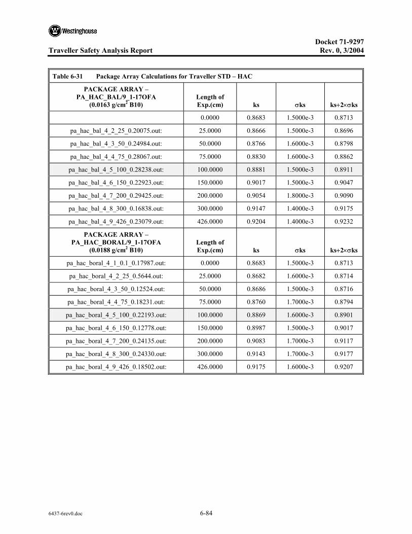
Docket 71-9297
Traveller Safety Analysis Report Rev. 0, 3/2004
6437-6rev0.doc 6-84
Table 6-31 Package Array Calculations for Traveller STD – HAC
PACKAGE ARRAY – PA_HAC_BAL/9_1-17OFA
(0.0163 g/cm2 B10) Length of Exp.(cm) ks σks ks+2×σks
0.0000 0.8683 1.5000e-3 0.8713
pa_hac_bal_4_2_25_0.20075.out: 25.0000 0.8666 1.5000e-3 0.8696
pa_hac_bal_4_3_50_0.24984.out: 50.0000 0.8766 1.6000e-3 0.8798
pa_hac_bal_4_4_75_0.28067.out: 75.0000 0.8830 1.6000e-3 0.8862
pa_hac_bal_4_5_100_0.28238.out: 100.0000 0.8881 1.5000e-3 0.8911
pa_hac_bal_4_6_150_0.22923.out: 150.0000 0.9017 1.5000e-3 0.9047
pa_hac_bal_4_7_200_0.29425.out: 200.0000 0.9054 1.8000e-3 0.9090
pa_hac_bal_4_8_300_0.16838.out: 300.0000 0.9147 1.4000e-3 0.9175
pa_hac_bal_4_9_426_0.23079.out: 426.0000 0.9204 1.4000e-3 0.9232
PACKAGE ARRAY – PA_HAC_BORAL/9_1-17OFA
(0.0188 g/cm2 B10) Length of Exp.(cm) ks σks ks+2×σks
pa_hac_boral_4_1_0.1_0.17987.out: 0.0000 0.8683 1.5000e-3 0.8713
pa_hac_boral_4_2_25_0.5644.out: 25.0000 0.8682 1.6000e-3 0.8714
pa_hac_boral_4_3_50_0.12524.out: 50.0000 0.8686 1.5000e-3 0.8716
pa_hac_boral_4_4_75_0.18231.out: 75.0000 0.8760 1.7000e-3 0.8794
pa_hac_boral_4_5_100_0.22193.out: 100.0000 0.8869 1.6000e-3 0.8901
pa_hac_boral_4_6_150_0.12778.out: 150.0000 0.8987 1.5000e-3 0.9017
pa_hac_boral_4_7_200_0.24135.out: 200.0000 0.9083 1.7000e-3 0.9117
pa_hac_boral_4_8_300_0.24330.out: 300.0000 0.9143 1.7000e-3 0.9177
pa_hac_boral_4_9_426_0.18502.out: 426.0000 0.9175 1.6000e-3 0.9207
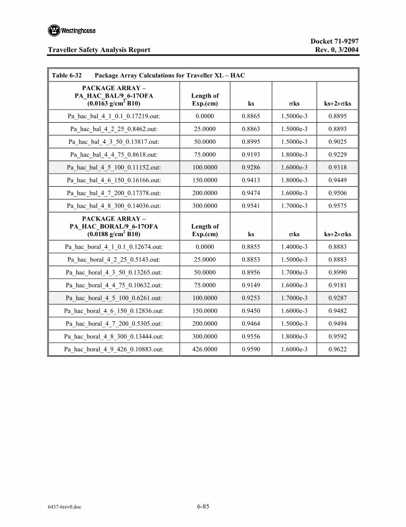
Docket 71-9297
Traveller Safety Analysis Report Rev. 0, 3/2004
6437-6rev0.doc 6-85
Table 6-32 Package Array Calculations for Traveller XL – HAC
PACKAGE ARRAY – PA_HAC_BAL/9_6-17OFA
(0.0163 g/cm2 B10) Length of Exp.(cm) ks σks ks+2×σks
Pa_hac_bal_4_1_0.1_0.17219.out: 0.0000 0.8865 1.5000e-3 0.8895
Pa_hac_bal_4_2_25_0.8462.out: 25.0000 0.8863 1.5000e-3 0.8893
Pa_hac_bal_4_3_50_0.13817.out: 50.0000 0.8995 1.5000e-3 0.9025
Pa_hac_bal_4_4_75_0.8618.out: 75.0000 0.9193 1.8000e-3 0.9229
Pa_hac_bal_4_5_100_0.11152.out: 100.0000 0.9286 1.6000e-3 0.9318
Pa_hac_bal_4_6_150_0.16166.out: 150.0000 0.9413 1.8000e-3 0.9449
Pa_hac_bal_4_7_200_0.17378.out: 200.0000 0.9474 1.6000e-3 0.9506
Pa_hac_bal_4_8_300_0.14036.out: 300.0000 0.9541 1.7000e-3 0.9575
PACKAGE ARRAY – PA_HAC_BORAL/9_6-17OFA
(0.0188 g/cm2 B10) Length of Exp.(cm) ks σks ks+2×σks
Pa_hac_boral_4_1_0.1_0.12674.out: 0.0000 0.8855 1.4000e-3 0.8883
Pa_hac_boral_4_2_25_0.5143.out: 25.0000 0.8853 1.5000e-3 0.8883
Pa_hac_boral_4_3_50_0.13265.out: 50.0000 0.8956 1.7000e-3 0.8990
Pa_hac_boral_4_4_75_0.10632.out: 75.0000 0.9149 1.6000e-3 0.9181
Pa_hac_boral_4_5_100_0.6261.out: 100.0000 0.9253 1.7000e-3 0.9287
Pa_hac_boral_4_6_150_0.12836.out: 150.0000 0.9450 1.6000e-3 0.9482
Pa_hac_boral_4_7_200_0.5305.out: 200.0000 0.9464 1.5000e-3 0.9494
Pa_hac_boral_4_8_300_0.13444.out: 300.0000 0.9556 1.8000e-3 0.9592
Pa_hac_boral_4_9_426_0.10883.out: 426.0000 0.9590 1.6000e-3 0.9622

Docket 71-9297
Traveller Safety Analysis Report Rev. 0, 3/2004
6437-6rev0.doc 6-86
Table 6-33 Input Deck for Traveller STD Package Array – HAC pa_hac_bal_4_5_100_0.28238.out: TRAVELLER XL,17WOFA,ENV=23.114 cm,L=100 cm,B10=0.0163 g/cm2 44groupndf5 latticecell uo2 1 1 293 92235 5 92238 95 end h2o 2 1 293 end zirc4 3 1 293 end h2o 4 1 293 end h2o 5 1 293 end arbmfoam 0.1602e-20 4 0 0 0 6012 70 1001 10 8016 16 7014 4 6 1 293 end al 7 1 293 end ss304 8 1 293 end polyethylene 9 DEN=0.828 1.0 293 end arbmbor-al 2.71 6 0 0 0 14000 0.5 26000 0.5 29000 0.2 25055 0.05 5000 2 13000 96.75 10 1 293 5010 95 5011 5 end arbmfoam 0.1602e-20 4 0 0 0 6012 70 1001 10 8016 16 7014 4 11 1 293 end arbmboral 2.6 4 0 0 8 5010 3.18 5011 19.32 6012 6.54 13027 69.89 12 1 293 end arbmrubber 1.59e-20 7 0 0 0 8016 46.94 13000 19.92 14000 17.54 6012 10.79 1001 4.73 11000 0.06 26000 0.02 14 1 293 end h2o 15 1 293 end uo2 16 1 293 92235 5 92238 95 end h2o 17 1 293 end zirc4 18 1 293 end h2o 19 1 293 end end comp squarepitch 1.3875 0.78435 16 19 0.9144 18 0.8001 17 end more data res=1 cylinder 0.39218 dan(1)=0.22632 end read parameter gen=303 wrs=1 end parameter read geometry unit 10 com='individual package' cuboid 1 16.904 -15.634 16.904 -15.634 533.1330 0 rotate a1=45 a2=0 a3=0 origin x=0 y=-1.460 z=0 cuboid 2 21.5900 -21.5900 1.5720 -1.0310 533.1330 0 cuboid 3 20.0790 -20.0790 20.0790 -20.0790 533.1330 0 rotate a1=45 a2=0 a3=0 origin x=0 y=-1.460 z=0 cuboid 4 20.3840 -20.3840 20.3840 -20.3840 533.4380 -0.3050 rotate a1=45 a2=0 a3=0 origin x=0 y=-1.460 z=0 cuboid 5 21.5900 -21.590 23.1498 -23.1498 533.1330 0 cuboid 6 21.8950 -21.8950 23.4548 -23.4548 533.4380 -0.3050 cuboid 7 20.3840 -20.3840 20.3840 -20.3840 553.8922 -19.8448 rotate a1=45 a2=0 a3=0 origin x=0 y=-1.460 z=0 cuboid 8 21.8950 -21.895 23.4548 -23.4548 553.8922 -19.8448
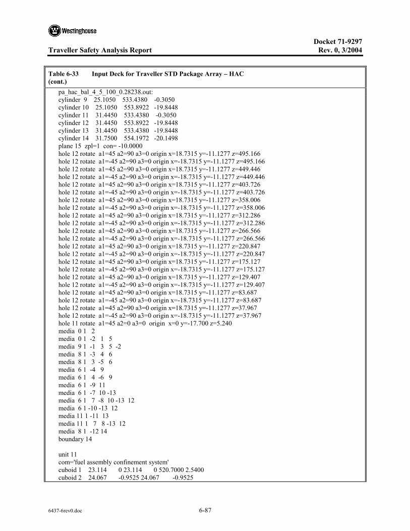
Docket 71-9297
Traveller Safety Analysis Report Rev. 0, 3/2004
6437-6rev0.doc 6-87
Table 6-33 Input Deck for Traveller STD Package Array – HAC (cont.) pa_hac_bal_4_5_100_0.28238.out: cylinder 9 25.1050 533.4380 -0.3050 cylinder 10 25.1050 553.8922 -19.8448 cylinder 11 31.4450 533.4380 -0.3050 cylinder 12 31.4450 553.8922 -19.8448 cylinder 13 31.4450 533.4380 -19.8448 cylinder 14 31.7500 554.1972 -20.1498 plane 15 zpl=1 con= -10.0000 hole 12 rotate a1=45 a2=90 a3=0 origin x=18.7315 y=-11.1277 z=495.166 hole 12 rotate a1=-45 a2=90 a3=0 origin x=-18.7315 y=-11.1277 z=495.166 hole 12 rotate a1=45 a2=90 a3=0 origin x=18.7315 y=-11.1277 z=449.446 hole 12 rotate a1=-45 a2=90 a3=0 origin x=-18.7315 y=-11.1277 z=449.446 hole 12 rotate a1=45 a2=90 a3=0 origin x=18.7315 y=-11.1277 z=403.726 hole 12 rotate a1=-45 a2=90 a3=0 origin x=-18.7315 y=-11.1277 z=403.726 hole 12 rotate a1=45 a2=90 a3=0 origin x=18.7315 y=-11.1277 z=358.006 hole 12 rotate a1=-45 a2=90 a3=0 origin x=-18.7315 y=-11.1277 z=358.006 hole 12 rotate a1=45 a2=90 a3=0 origin x=18.7315 y=-11.1277 z=312.286 hole 12 rotate a1=-45 a2=90 a3=0 origin x=-18.7315 y=-11.1277 z=312.286 hole 12 rotate a1=45 a2=90 a3=0 origin x=18.7315 y=-11.1277 z=266.566 hole 12 rotate a1=-45 a2=90 a3=0 origin x=-18.7315 y=-11.1277 z=266.566 hole 12 rotate a1=45 a2=90 a3=0 origin x=18.7315 y=-11.1277 z=220.847 hole 12 rotate a1=-45 a2=90 a3=0 origin x=-18.7315 y=-11.1277 z=220.847 hole 12 rotate a1=45 a2=90 a3=0 origin x=18.7315 y=-11.1277 z=175.127 hole 12 rotate a1=-45 a2=90 a3=0 origin x=-18.7315 y=-11.1277 z=175.127 hole 12 rotate a1=45 a2=90 a3=0 origin x=18.7315 y=-11.1277 z=129.407 hole 12 rotate a1=-45 a2=90 a3=0 origin x=-18.7315 y=-11.1277 z=129.407 hole 12 rotate a1=45 a2=90 a3=0 origin x=18.7315 y=-11.1277 z=83.687 hole 12 rotate a1=-45 a2=90 a3=0 origin x=-18.7315 y=-11.1277 z=83.687 hole 12 rotate a1=45 a2=90 a3=0 origin x=18.7315 y=-11.1277 z=37.967 hole 12 rotate a1=-45 a2=90 a3=0 origin x=-18.7315 y=-11.1277 z=37.967 hole 11 rotate a1=45 a2=0 a3=0 origin x=0 y=-17.700 z=5.240 media 0 1 2 media 0 1 -2 1 5 media 9 1 -1 3 5 -2 media 8 1 -3 4 6 media 8 1 3 -5 6 media 6 1 -4 9 media 6 1 4 -6 9 media 6 1 -9 11 media 6 1 -7 10 -13 media 6 1 7 -8 10 -13 12 media 6 1 -10 -13 12 media 11 1 -11 13 media 11 1 7 8 -13 12 media 8 1 -12 14 boundary 14 unit 11 com='fuel assembly confinement system' cuboid 1 23.114 0 23.114 0 520.7000 2.5400 cuboid 2 24.067 -0.9525 24.067 -0.9525

Docket 71-9297
Traveller Safety Analysis Report Rev. 0, 3/2004
6437-6rev0.doc 6-88
Table 6-33 Input Deck for Traveller STD Package Array – HAC (cont.) pa_hac_bal_4_5_100_0.28238.out: 523.2400 0.0000 cuboid 3 19.177 3.937 23.159 -0.04545 520.7000 2.5400 cuboid 4 19.177 3.937 23.386 -0.27205 520.7000 2.5400 cuboid 5 19.177 3.937 23.432 -0.3175 520.7000 2.5400 cuboid 6 23.159 -0.04545 19.177 3.937 520.7000 2.5400 cuboid 7 23.386 -0.27205 19.177 3.937 520.7000 2.5400 cuboid 8 23.432 -0.3175 19.177 3.937 520.7000 2.5400 hole 20 origin x=0 y=0 z=16.5600 rotate a1=0 a2=0 a3=0 media 15 1 1 media 7 1 -1 2 -5 -8 media 10 1 -1 3 media 10 1 -3 4 media 10 1 -4 5 media 10 1 -1 6 media 10 1 -6 7 media 10 1 -7 8 boundary 2 unit 12 com='shock mount' cylinder 1 3.962 0 -7.62 media 15 1 1 boundary 1 unit 20 com='fuel assembly' cuboid 1 21.072 0 21.072 0 0 -14.0208 cuboid 2 23.114 0 23.114 0 504.1392 -14.0208 hole 31 origin x=0 y=0 z=0 rotate a1=0 a2=0 a3=0 hole 21 origin x=0 y=0 z=100 rotate a1=0 a2=0 a3=0 hole 40 origin x=0 y=0 z=426.72 rotate a1=0 a2=0 a3=0 media 15 1 1 media 15 1 -1 2 boundary 2 unit 21 com='fuel rods - nominal pitch' cuboid 1 21.072 0 21.072 0 326.72 0.0000 array 2 1 place 1 1 1 0.4572 0.4572 0 boundary 1 unit 22 com='solid fuel rod - nominal pitch' cylinder 1 0.39218 426.72 0

Docket 71-9297
Traveller Safety Analysis Report Rev. 0, 3/2004
6437-6rev0.doc 6-89
Table 6-33 Input Deck for Traveller STD Package Array – HAC (cont.) pa_hac_bal_4_5_100_0.28238.out: cylinder 2 0.40005 426.72 0 cylinder 3 0.4572 426.72 0 cuboid 4 4P0.62992 426.72 0 media 1 1 1 media 2 1 2 -1 media 3 1 3 -2 -1 media 4 1 4 -3 -2 -1 boundary 4 unit 23 com='thimble tube - nominal pitch' cylinder 1 0.56134 426.72 0 cylinder 2 0.60198 426.72 0 cuboid 3 4P0.62992 426.72 0 media 4 1 1 media 3 1 2 -1 media 4 1 3 -2 -1 boundary 3 unit 31 com='fuel rods - expanded pitch' cuboid 1 23.114 0 23.114 0 100 0 array 3 1 place 1 1 1 0.4572 0.4572 0 boundary 1 unit 32 com='solid fuel rod - expanded pitch' cylinder 1 0.39218 426.72 0 cylinder 2 0.40005 426.72 0 cylinder 3 0.4572 426.72 0 cuboid 4 4P0.69374 426.72 0 media 16 1 1 media 17 1 2 -1 media 18 1 3 -2 -1 media 19 1 4 -3 -2 -1 boundary 4 unit 33 com='thimble tube - expanded pitch' cylinder 1 0.56134 426.72 0 cylinder 2 0.60198 426.72 0 cuboid 3 4P0.69374 426.72 0 media 19 1 1 media 18 1 2 -1 media 19 1 3 -2 -1 boundary 3 unit 40 com='top nozzle assembly' cuboid 1 21.072 0 21.072 0 21.2090 0.0000
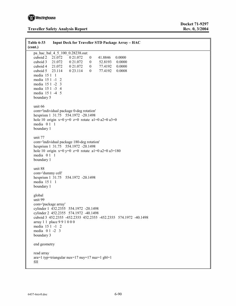
Docket 71-9297
Traveller Safety Analysis Report Rev. 0, 3/2004
6437-6rev0.doc 6-90
Table 6-33 Input Deck for Traveller STD Package Array – HAC (cont.) pa_hac_bal_4_5_100_0.28238.out: cuboid 2 21.072 0 21.072 0 41.8846 0.0000 cuboid 3 21.072 0 21.072 0 52.8193 0.0000 cuboid 4 21.072 0 21.072 0 77.4192 0.0000 cuboid 5 23.114 0 23.114 0 77.4192 0.0008 media 15 1 1 media 15 1 -1 2 media 15 1 -2 3 media 15 1 -3 4 media 15 1 -4 5 boundary 5 unit 66 com='individual package 0-deg rotation' hexprism 1 31.75 554.1972 -20.1498 hole 10 origin x=0 y=0 z=0 rotate a1=0 a2=0 a3=0 media 0 1 1 boundary 1 unit 77 com='individual package 180-deg rotation' hexprism 1 31.75 554.1972 -20.1498 hole 10 origin x=0 y=0 z=0 rotate a1=0 a2=0 a3=180 media 0 1 1 boundary 1 unit 88 com='dummy cell' hexprism 1 31.75 554.1972 -20.1498 media 15 1 1 boundary 1 global unit 99 com='package array' cylinder 1 432.2355 554.1972 -20.1498 cylinder 2 452.2355 574.1972 -40.1498 cuboid 3 452.2355 -452.2355 452.2355 -452.2355 574.1972 -40.1498 array 1 1 place 9 9 1 0 0 0 media 15 1 -1 2 media 0 1 -2 3 boundary 3 end geometry read array ara=1 typ=triangular nux=17 nuy=17 nuz=1 gbl=1 fill

Docket 71-9297
Traveller Safety Analysis Report Rev. 0, 3/2004
6437-6rev0.doc 6-91
Table 6-33 Input Deck for Traveller STD Package Array – HAC (cont.) pa_hac_bal_4_5_100_0.28238.out: 88 88 88 88 88 88 88 88 88 88 88 88 88 88 88 88 88 88 88 88 88 88 88 88 88 88 88 77 77 77 88 88 88 88 88 88 88 88 88 88 88 88 66 66 66 66 66 66 66 88 88 88 88 88 88 88 88 77 77 77 77 77 77 77 77 77 77 88 88 88 88 88 88 66 66 66 66 66 66 66 66 66 66 66 88 88 88 88 88 77 77 77 77 77 77 77 77 77 77 77 77 88 88 88 88 66 66 66 66 66 66 66 66 66 66 66 66 66 88 88 88 88 77 77 77 77 77 77 77 77 77 77 77 77 88 88 88 88 66 66 66 66 66 66 66 66 66 66 66 66 66 88 88 88 88 77 77 77 77 77 77 77 77 77 77 77 77 88 88 88 88 66 66 66 66 66 66 66 66 66 66 66 66 66 88 88 88 88 77 77 77 77 77 77 77 77 77 77 77 77 88 88 88 88 88 66 66 66 66 66 66 66 66 66 66 66 88 88 88 88 88 88 77 77 77 77 77 77 77 77 77 77 88 88 88 88 88 88 88 88 66 66 66 66 66 66 66 88 88 88 88 88 88 88 88 88 88 88 77 77 77 77 88 88 88 88 88 88 88 88 88 88 88 88 88 88 88 88 88 88 88 88 88 88 88 88 88 88 88 end fill ara=2 typ=square nux=17 nuy=17 nuz=1 fill 39*22 23 2*22 23 2*22 23 8*22 23 9*22 23 22*22 23 2*22 23 2*22 23 2*22 23 2*22 23 38*22 23 2*22 23 2*22 23 2*22 23 2*22 23 38*22 23 2*22 23 2*22 23 2*22 23 2*22 23 22*22 23 9*22 23 8*22 23 2*22 23 2*22 23 39*22 end fill ara=3 typ=square nux=17 nuy=17 nuz=1 fill 39*32 33 2*32 33 2*32 33 8*32 33 9*32 33 22*32 33 2*32 33 2*32 33 2*32 33 2*32 33 38*32 33 2*32 33 2*32 33 2*32 33 2*32 33 38*32 33 2*32 33 2*32 33 2*32 33 2*32 33 22*32 33 9*32 33 8*32 33 2*32 33 2*32 33 39*32 end fill end array read bnds +xb=vacuum -xb=vacuum +yb=vacuum -yb=vacuum +zb=vacuum -zb=vacuum end bnds end data

Docket 71-9297
Traveller Safety Analysis Report Rev. 0, 3/2004
6437-6rev0.doc 6-92
Table 6-34 Input Deck for Traveller XL Package Array – HAC Pa_hac_bal_4_5_100_0.11152.out: TRAVELLER XL,17WOFA,ENV=24.384 cm,L=100 cm,B10=0.0163 g/cm2 44groupndf5 latticecell uo2 1 1 293 92235 5 92238 95 end h2o 2 1 293 end zirc4 3 1 293 end h2o 4 1 293 end h2o 5 1 293 end arbmfoam 0.1602e-20 4 0 0 0 6012 70 1001 10 8016 16 7014 4 6 1 293 end al 7 1 293 end ss304 8 1 293 end polyethylene 9 DEN=0.828 1.0 293 end arbmbor-al 2.71 6 0 0 0 14000 0.5 26000 0.5 29000 0.2 25055 0.05 5000 2 13000 96.75 10 1 293 5010 95 5011 5 end arbmfoam 0.1602e-20 4 0 0 0 6012 70 1001 10 8016 16 7014 4 11 1 293 end arbmboral 2.6 4 0 0 8 5010 3.18 5011 19.32 6012 6.54 13027 69.89 12 1 293 end arbmrubber 1.59e-20 7 0 0 0 8016 46.94 13000 19.92 14000 17.54 6012 10.79 1001 4.73 11000 0.06 26000 0.02 14 1 293 end h2o 15 1 293 end uo2 16 1 293 92235 5 92238 95 end h2o 17 1 293 end zirc4 18 1 293 end h2o 19 1 293 end end comp squarepitch 1.4669 0.78435 16 19 0.9144 18 0.8001 17 end more data res=1 cylinder 0.39218 dan(1)=0.22632 end read parameter gen=303 wrs=1 end parameter read geometry unit 10 com='individual package' cuboid 1 16.904 -15.634 16.904 -15.634 533.1330 0 rotate a1=45 a2=0 a3=0 origin x=0 y=-1.460 z=0 cuboid 2 21.5900 -21.5900 1.5720 -1.0310 533.1330 0 cuboid 3 20.0790 -20.0790 20.0790 -20.0790 533.1330 0 rotate a1=45 a2=0 a3=0 origin x=0 y=-1.460 z=0 cuboid 4 20.3840 -20.3840 20.3840 -20.3840 533.4380 -0.3050 rotate a1=45 a2=0 a3=0 origin x=0 y=-1.460 z=0 cuboid 5 21.5900 -21.590 23.1498 -23.1498 533.1330 0 cuboid 6 21.8950 -21.8950 23.4548 -23.4548 533.4380 -0.3050 cuboid 7 20.3840 -20.3840 20.3840 -20.3840 553.8922 -19.8448 rotate a1=45 a2=0 a3=0 origin x=0 y=-1.460 z=0 cuboid 8 21.8950 -21.895 23.4548 -23.4548 553.8922 -19.8448

Docket 71-9297
Traveller Safety Analysis Report Rev. 0, 3/2004
6437-6rev0.doc 6-93
Table 6-34 Input Deck for Traveller XL Package Array – HAC (cont.) Pa_hac_bal_4_5_100_0.11152.out: cylinder 9 25.1050 533.4380 -0.3050 cylinder 10 25.1050 553.8922 -19.8448 cylinder 11 31.4450 533.4380 -0.3050 cylinder 12 31.4450 553.8922 -19.8448 cylinder 13 31.4450 533.4380 -19.8448 cylinder 14 31.7500 554.1972 -20.1498 plane 15 zpl=1 con= -10.0000 hole 12 rotate a1=45 a2=90 a3=0 origin x=18.7315 y=-11.1277 z=495.166 hole 12 rotate a1=-45 a2=90 a3=0 origin x=-18.7315 y=-11.1277 z=495.166 hole 12 rotate a1=45 a2=90 a3=0 origin x=18.7315 y=-11.1277 z=449.446 hole 12 rotate a1=-45 a2=90 a3=0 origin x=-18.7315 y=-11.1277 z=449.446 hole 12 rotate a1=45 a2=90 a3=0 origin x=18.7315 y=-11.1277 z=403.726 hole 12 rotate a1=-45 a2=90 a3=0 origin x=-18.7315 y=-11.1277 z=403.726 hole 12 rotate a1=45 a2=90 a3=0 origin x=18.7315 y=-11.1277 z=358.006 hole 12 rotate a1=-45 a2=90 a3=0 origin x=-18.7315 y=-11.1277 z=358.006 hole 12 rotate a1=45 a2=90 a3=0 origin x=18.7315 y=-11.1277 z=312.286 hole 12 rotate a1=-45 a2=90 a3=0 origin x=-18.7315 y=-11.1277 z=312.286 hole 12 rotate a1=45 a2=90 a3=0 origin x=18.7315 y=-11.1277 z=266.566 hole 12 rotate a1=-45 a2=90 a3=0 origin x=-18.7315 y=-11.1277 z=266.566 hole 12 rotate a1=45 a2=90 a3=0 origin x=18.7315 y=-11.1277 z=220.847 hole 12 rotate a1=-45 a2=90 a3=0 origin x=-18.7315 y=-11.1277 z=220.847 hole 12 rotate a1=45 a2=90 a3=0 origin x=18.7315 y=-11.1277 z=175.127 hole 12 rotate a1=-45 a2=90 a3=0 origin x=-18.7315 y=-11.1277 z=175.127 hole 12 rotate a1=45 a2=90 a3=0 origin x=18.7315 y=-11.1277 z=129.407 hole 12 rotate a1=-45 a2=90 a3=0 origin x=-18.7315 y=-11.1277 z=129.407 hole 12 rotate a1=45 a2=90 a3=0 origin x=18.7315 y=-11.1277 z=83.687 hole 12 rotate a1=-45 a2=90 a3=0 origin x=-18.7315 y=-11.1277 z=83.687 hole 12 rotate a1=45 a2=90 a3=0 origin x=18.7315 y=-11.1277 z=37.967 hole 12 rotate a1=-45 a2=90 a3=0 origin x=-18.7315 y=-11.1277 z=37.967 hole 11 rotate a1=45 a2=0 a3=0 origin x=0 y=-17.700 z=5.240 media 0 1 2 media 0 1 -2 1 5 media 9 1 -1 3 5 -2 media 8 1 -3 4 6 media 8 1 3 -5 6 media 6 1 -4 9 media 6 1 4 -6 9 media 6 1 -9 11 media 6 1 -7 10 -13 media 6 1 7 -8 10 -13 12 media 6 1 -10 -13 12 media 11 1 -11 13 media 11 1 7 8 -13 12 media 8 1 -12 14 boundary 14 unit 11 com='fuel assembly confinement system' cuboid 1 24.384 0 24.384 0 520.7000 2.5400 cuboid 2 25.337 -0.9525 25.337 -0.9525

Docket 71-9297
Traveller Safety Analysis Report Rev. 0, 3/2004
6437-6rev0.doc 6-94
Table 6-34 Input Deck for Traveller XL Package Array – HAC (cont.) Pa_hac_bal_4_5_100_0.11152.out: 523.2400 0.0000 cuboid 3 19.812 4.572 24.429 -0.04545 520.7000 2.5400 cuboid 4 19.812 4.572 24.656 -0.27205 520.7000 2.5400 cuboid 5 19.812 4.572 24.702 -0.3175 520.7000 2.5400 cuboid 6 24.429 -0.04545 19.812 4.572 520.7000 2.5400 cuboid 7 24.656 -0.27205 19.812 4.572 520.7000 2.5400 cuboid 8 24.702 -0.3175 19.812 4.572 520.7000 2.5400 hole 20 origin x=0 y=0 z=16.5600 rotate a1=0 a2=0 a3=0 media 15 1 1 media 7 1 -1 2 -5 -8 media 10 1 -1 3 media 10 1 -3 4 media 10 1 -4 5 media 10 1 -1 6 media 10 1 -6 7 media 10 1 -7 8 boundary 2 unit 12 com='shock mount' cylinder 1 3.962 0 -7.62 media 15 1 1 boundary 1 unit 20 com='fuel assembly' cuboid 1 21.072 0 21.072 0 0 -14.0208 cuboid 2 24.384 0 24.384 0 504.1392 -14.0208 hole 31 origin x=0 y=0 z=0 rotate a1=0 a2=0 a3=0 hole 21 origin x=0 y=0 z=100 rotate a1=0 a2=0 a3=0 hole 40 origin x=0 y=0 z=426.72 rotate a1=0 a2=0 a3=0 media 15 1 1 media 15 1 -1 2 boundary 2 unit 21 com='fuel rods - nominal pitch' cuboid 1 21.072 0 21.072 0 326.72 0.0000 array 2 1 place 1 1 1 0.4572 0.4572 0 boundary 1 unit 22 com='solid fuel rod - nominal pitch' cylinder 1 0.39218 426.72 0

Docket 71-9297
Traveller Safety Analysis Report Rev. 0, 3/2004
6437-6rev0.doc 6-95
Table 6-34 Input Deck for Traveller XL Package Array – HAC (cont.) Pa_hac_bal_4_5_100_0.11152.out: cylinder 2 0.40005 426.72 0 cylinder 3 0.4572 426.72 0 cuboid 4 4P0.62992 426.72 0 media 1 1 1 media 2 1 2 -1 media 3 1 3 -2 -1 media 4 1 4 -3 -2 -1 boundary 4 unit 23 com='thimble tube - nominal pitch' cylinder 1 0.56134 426.72 0 cylinder 2 0.60198 426.72 0 cuboid 3 4P0.62992 426.72 0 media 4 1 1 media 3 1 2 -1 media 4 1 3 -2 -1 boundary 3 unit 31 com='fuel rods - expanded pitch' cuboid 1 24.384 0 24.384 0 100 0 array 3 1 place 1 1 1 0.4572 0.4572 0 boundary 1 unit 32 com='solid fuel rod - expanded pitch' cylinder 1 0.39218 426.72 0 cylinder 2 0.40005 426.72 0 cylinder 3 0.4572 426.72 0 cuboid 4 4P0.73342 426.72 0 media 16 1 1 media 17 1 2 -1 media 18 1 3 -2 -1 media 19 1 4 -3 -2 -1 boundary 4 unit 33 com='thimble tube - expanded pitch' cylinder 1 0.56134 426.72 0 cylinder 2 0.60198 426.72 0 cuboid 3 4P0.73342 426.72 0 media 19 1 1 media 18 1 2 -1 media 19 1 3 -2 -1 boundary 3 unit 40 com='top nozzle assembly' cuboid 1 21.072 0 21.072 0 21.2090 0.0000

Docket 71-9297
Traveller Safety Analysis Report Rev. 0, 3/2004
6437-6rev0.doc 6-96
Table 6-34 Input Deck for Traveller XL Package Array – HAC (cont.) Pa_hac_bal_4_5_100_0.11152.out: cuboid 2 21.072 0 21.072 0 41.8846 0.0000 cuboid 3 21.072 0 21.072 0 52.8193 0.0000 cuboid 4 21.072 0 21.072 0 77.4192 0.0000 cuboid 5 24.384 0 24.384 0 77.4192 0.0008 media 15 1 1 media 15 1 -1 2 media 15 1 -2 3 media 15 1 -3 4 media 15 1 -4 5 boundary 5 unit 66 com='individual package 0-deg rotation' hexprism 1 31.75 554.1972 -20.1498 hole 10 origin x=0 y=0 z=0 rotate a1=0 a2=0 a3=0 media 0 1 1 boundary 1 unit 77 com='individual package 180-deg rotation' hexprism 1 31.75 554.1972 -20.1498 hole 10 origin x=0 y=0 z=0 rotate a1=0 a2=0 a3=180 media 0 1 1 boundary 1 unit 88 com='dummy cell' hexprism 1 31.75 554.1972 -20.1498 media 15 1 1 boundary 1 global unit 99 com='package array' cylinder 1 432.2355 554.1972 -20.1498 cylinder 2 452.2355 574.1972 -40.1498 cuboid 3 452.2355 -452.2355 452.2355 -452.2355 574.1972 -40.1498 array 1 1 place 9 9 1 0 0 0 media 15 1 -1 2 media 0 1 -2 3 boundary 3 end geometry read array ara=1 typ=triangular nux=17 nuy=17 nuz=1 gbl=1 fill

Docket 71-9297
Traveller Safety Analysis Report Rev. 0, 3/2004
6437-6rev0.doc 6-97
Table 6-34 Input Deck for Traveller XL Package Array – HAC (cont.) Pa_hac_bal_4_5_100_0.11152.out: 88 88 88 88 88 88 88 88 88 88 88 88 88 88 88 88 88 88 88 88 88 88 88 88 88 88 88 77 77 77 88 88 88 88 88 88 88 88 88 88 88 88 66 66 66 66 66 66 66 88 88 88 88 88 88 88 88 77 77 77 77 77 77 77 77 77 77 88 88 88 88 88 88 66 66 66 66 66 66 66 66 66 66 66 88 88 88 88 88 77 77 77 77 77 77 77 77 77 77 77 77 88 88 88 88 66 66 66 66 66 66 66 66 66 66 66 66 66 88 88 88 88 77 77 77 77 77 77 77 77 77 77 77 77 88 88 88 88 66 66 66 66 66 66 66 66 66 66 66 66 66 88 88 88 88 77 77 77 77 77 77 77 77 77 77 77 77 88 88 88 88 66 66 66 66 66 66 66 66 66 66 66 66 66 88 88 88 88 77 77 77 77 77 77 77 77 77 77 77 77 88 88 88 88 88 66 66 66 66 66 66 66 66 66 66 66 88 88 88 88 88 88 77 77 77 77 77 77 77 77 77 77 88 88 88 88 88 88 88 88 66 66 66 66 66 66 66 88 88 88 88 88 88 88 88 88 88 88 77 77 77 77 88 88 88 88 88 88 88 88 88 88 88 88 88 88 88 88 88 88 88 88 88 88 88 88 88 88 88 end fill ara=2 typ=square nux=17 nuy=17 nuz=1 fill 39*22 23 2*22 23 2*22 23 8*22 23 9*22 23 22*22 23 2*22 23 2*22 23 2*22 23 2*22 23 38*22 23 2*22 23 2*22 23 2*22 23 2*22 23 38*22 23 2*22 23 2*22 23 2*22 23 2*22 23 22*22 23 9*22 23 8*22 23 2*22 23 2*22 23 39*22 end fill ara=3 typ=square nux=17 nuy=17 nuz=1 fill 39*32 33 2*32 33 2*32 33 8*32 33 9*32 33 22*32 33 2*32 33 2*32 33 2*32 33 2*32 33 38*32 33 2*32 33 2*32 33 2*32 33 2*32 33 38*32 33 2*32 33 2*32 33 2*32 33 2*32 33 22*32 33 9*32 33 8*32 33 2*32 33 2*32 33 39*32 end fill end array read bnds +xb=vacuum -xb=vacuum +yb=vacuum -yb=vacuum +zb=vacuum -zb=vacuum end bnds end data
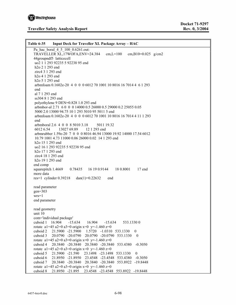
Docket 71-9297
Traveller Safety Analysis Report Rev. 0, 3/2004
6437-6rev0.doc 6-98
Table 6-35 Input Deck for Traveller XL Package Array – HAC Pa_hac_boral_4_5_100_0.6261.out: TRAVELLER XL,17WOFA,ENV=24.384 cm,L=100 cm,B10=0.025 g/cm2 44groupndf5 latticecell uo2 1 1 293 92235 5 92238 95 end h2o 2 1 293 end zirc4 3 1 293 end h2o 4 1 293 end h2o 5 1 293 end arbmfoam 0.1602e-20 4 0 0 0 6012 70 1001 10 8016 16 7014 4 6 1 293 end al 7 1 293 end ss304 8 1 293 end polyethylene 9 DEN=0.828 1.0 293 end arbmbor-al 2.71 6 0 0 0 14000 0.5 26000 0.5 29000 0.2 25055 0.05 5000 2.0 13000 94.75 10 1 293 5010 95 5011 5 end arbmfoam 0.1602e-20 4 0 0 0 6012 70 1001 10 8016 16 7014 4 11 1 293 end arbmboral 2.6 4 0 0 8 5010 3.18 5011 19.32 6012 6.54 13027 69.89 12 1 293 end arbmrubber 1.59e-20 7 0 0 0 8016 46.94 13000 19.92 14000 17.54 6012 10.79 1001 4.73 11000 0.06 26000 0.02 14 1 293 end h2o 15 1 293 end uo2 16 1 293 92235 5 92238 95 end h2o 17 1 293 end zirc4 18 1 293 end h2o 19 1 293 end end comp squarepitch 1.4669 0.78435 16 19 0.9144 18 0.8001 17 end more data res=1 cylinder 0.39218 dan(1)=0.22632 end read parameter gen=303 wrs=1 end parameter read geometry unit 10 com='individual package' cuboid 1 16.904 -15.634 16.904 -15.634 533.1330 0 rotate a1=45 a2=0 a3=0 origin x=0 y=-1.460 z=0 cuboid 2 21.5900 -21.5900 1.5720 -1.0310 533.1330 0 cuboid 3 20.0790 -20.0790 20.0790 -20.0790 533.1330 0 rotate a1=45 a2=0 a3=0 origin x=0 y=-1.460 z=0 cuboid 4 20.3840 -20.3840 20.3840 -20.3840 533.4380 -0.3050 rotate a1=45 a2=0 a3=0 origin x=0 y=-1.460 z=0 cuboid 5 21.5900 -21.590 23.1498 -23.1498 533.1330 0 cuboid 6 21.8950 -21.8950 23.4548 -23.4548 533.4380 -0.3050 cuboid 7 20.3840 -20.3840 20.3840 -20.3840 553.8922 -19.8448 rotate a1=45 a2=0 a3=0 origin x=0 y=-1.460 z=0 cuboid 8 21.8950 -21.895 23.4548 -23.4548 553.8922 -19.8448

Docket 71-9297
Traveller Safety Analysis Report Rev. 0, 3/2004
6437-6rev0.doc 6-99
Table 6-35 Input Deck for Traveller XL Package Array – HAC (cont.) Pa_hac_boral_4_5_100_0.6261.out: cylinder 9 25.1050 533.4380 -0.3050 cylinder 10 25.1050 553.8922 -19.8448 cylinder 11 31.4450 533.4380 -0.3050 cylinder 12 31.4450 553.8922 -19.8448 cylinder 13 31.4450 533.4380 -19.8448 cylinder 14 31.7500 554.1972 -20.1498 plane 15 zpl=1 con= -10.0000 hole 12 rotate a1=45 a2=90 a3=0 origin x=18.7315 y=-11.1277 z=495.166 hole 12 rotate a1=-45 a2=90 a3=0 origin x=-18.7315 y=-11.1277 z=495.166 hole 12 rotate a1=45 a2=90 a3=0 origin x=18.7315 y=-11.1277 z=449.446 hole 12 rotate a1=-45 a2=90 a3=0 origin x=-18.7315 y=-11.1277 z=449.446 hole 12 rotate a1=45 a2=90 a3=0 origin x=18.7315 y=-11.1277 z=403.726 hole 12 rotate a1=-45 a2=90 a3=0 origin x=-18.7315 y=-11.1277 z=403.726 hole 12 rotate a1=45 a2=90 a3=0 origin x=18.7315 y=-11.1277 z=358.006 hole 12 rotate a1=-45 a2=90 a3=0 origin x=-18.7315 y=-11.1277 z=358.006 hole 12 rotate a1=45 a2=90 a3=0 origin x=18.7315 y=-11.1277 z=312.286 hole 12 rotate a1=-45 a2=90 a3=0 origin x=-18.7315 y=-11.1277 z=312.286 hole 12 rotate a1=45 a2=90 a3=0 origin x=18.7315 y=-11.1277 z=266.566 hole 12 rotate a1=-45 a2=90 a3=0 origin x=-18.7315 y=-11.1277 z=266.566 hole 12 rotate a1=45 a2=90 a3=0 origin x=18.7315 y=-11.1277 z=220.847 hole 12 rotate a1=-45 a2=90 a3=0 origin x=-18.7315 y=-11.1277 z=220.847 hole 12 rotate a1=45 a2=90 a3=0 origin x=18.7315 y=-11.1277 z=175.127 hole 12 rotate a1=-45 a2=90 a3=0 origin x=-18.7315 y=-11.1277 z=175.127 hole 12 rotate a1=45 a2=90 a3=0 origin x=18.7315 y=-11.1277 z=129.407 hole 12 rotate a1=-45 a2=90 a3=0 origin x=-18.7315 y=-11.1277 z=129.407 hole 12 rotate a1=45 a2=90 a3=0 origin x=18.7315 y=-11.1277 z=83.687 hole 12 rotate a1=-45 a2=90 a3=0 origin x=-18.7315 y=-11.1277 z=83.687 hole 12 rotate a1=45 a2=90 a3=0 origin x=18.7315 y=-11.1277 z=37.967 hole 12 rotate a1=-45 a2=90 a3=0 origin x=-18.7315 y=-11.1277 z=37.967 hole 11 rotate a1=45 a2=0 a3=0 origin x=0 y=-17.700 z=5.240 media 0 1 2 media 0 1 -2 1 5 media 9 1 -1 3 5 -2 media 8 1 -3 4 6 media 8 1 3 -5 6 media 6 1 -4 9 media 6 1 4 -6 9 media 6 1 -9 11 media 6 1 -7 10 -13 media 6 1 7 -8 10 -13 12 media 6 1 -10 -13 12 media 11 1 -11 13 media 11 1 7 8 -13 12 media 8 1 -12 14 boundary 14 unit 11 com='fuel assembly confinement system' cuboid 1 24.384 0 24.384 0 520.7000 2.5400 cuboid 2 25.337 -0.9525 25.337 -0.9525
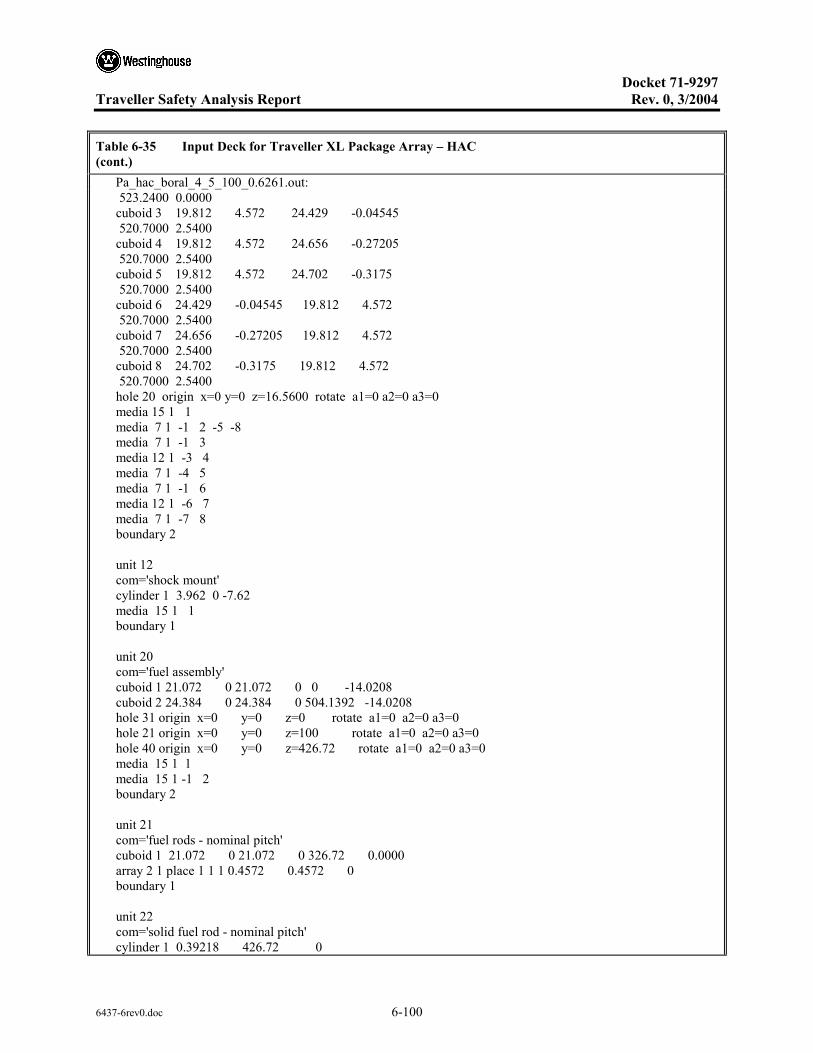
Docket 71-9297
Traveller Safety Analysis Report Rev. 0, 3/2004
6437-6rev0.doc 6-100
Table 6-35 Input Deck for Traveller XL Package Array – HAC (cont.) Pa_hac_boral_4_5_100_0.6261.out: 523.2400 0.0000 cuboid 3 19.812 4.572 24.429 -0.04545 520.7000 2.5400 cuboid 4 19.812 4.572 24.656 -0.27205 520.7000 2.5400 cuboid 5 19.812 4.572 24.702 -0.3175 520.7000 2.5400 cuboid 6 24.429 -0.04545 19.812 4.572 520.7000 2.5400 cuboid 7 24.656 -0.27205 19.812 4.572 520.7000 2.5400 cuboid 8 24.702 -0.3175 19.812 4.572 520.7000 2.5400 hole 20 origin x=0 y=0 z=16.5600 rotate a1=0 a2=0 a3=0 media 15 1 1 media 7 1 -1 2 -5 -8 media 7 1 -1 3 media 12 1 -3 4 media 7 1 -4 5 media 7 1 -1 6 media 12 1 -6 7 media 7 1 -7 8 boundary 2 unit 12 com='shock mount' cylinder 1 3.962 0 -7.62 media 15 1 1 boundary 1 unit 20 com='fuel assembly' cuboid 1 21.072 0 21.072 0 0 -14.0208 cuboid 2 24.384 0 24.384 0 504.1392 -14.0208 hole 31 origin x=0 y=0 z=0 rotate a1=0 a2=0 a3=0 hole 21 origin x=0 y=0 z=100 rotate a1=0 a2=0 a3=0 hole 40 origin x=0 y=0 z=426.72 rotate a1=0 a2=0 a3=0 media 15 1 1 media 15 1 -1 2 boundary 2 unit 21 com='fuel rods - nominal pitch' cuboid 1 21.072 0 21.072 0 326.72 0.0000 array 2 1 place 1 1 1 0.4572 0.4572 0 boundary 1 unit 22 com='solid fuel rod - nominal pitch' cylinder 1 0.39218 426.72 0

Docket 71-9297
Traveller Safety Analysis Report Rev. 0, 3/2004
6437-6rev0.doc 6-101
Table 6-35 Input Deck for Traveller XL Package Array – HAC (cont.) Pa_hac_boral_4_5_100_0.6261.out: cylinder 2 0.40005 426.72 0 cylinder 3 0.4572 426.72 0 cuboid 4 4P0.62992 426.72 0 media 1 1 1 media 2 1 2 -1 media 3 1 3 -2 -1 media 4 1 4 -3 -2 -1 boundary 4 unit 23 com='thimble tube - nominal pitch' cylinder 1 0.56134 426.72 0 cylinder 2 0.60198 426.72 0 cuboid 3 4P0.62992 426.72 0 media 4 1 1 media 3 1 2 -1 media 4 1 3 -2 -1 boundary 3 unit 31 com='fuel rods - expanded pitch' cuboid 1 24.384 0 24.384 0 100 0 array 3 1 place 1 1 1 0.4572 0.4572 0 boundary 1 unit 32 com='solid fuel rod - expanded pitch' cylinder 1 0.39218 426.72 0 cylinder 2 0.40005 426.72 0 cylinder 3 0.4572 426.72 0 cuboid 4 4P0.73342 426.72 0 media 16 1 1 media 17 1 2 -1 media 18 1 3 -2 -1 media 19 1 4 -3 -2 -1 boundary 4 unit 33 com='thimble tube - expanded pitch' cylinder 1 0.56134 426.72 0 cylinder 2 0.60198 426.72 0 cuboid 3 4P0.73342 426.72 0 media 19 1 1 media 18 1 2 -1 media 19 1 3 -2 -1 boundary 3 unit 40 com='top nozzle assembly' cuboid 1 21.072 0 21.072 0 21.2090 0.0000

Docket 71-9297
Traveller Safety Analysis Report Rev. 0, 3/2004
6437-6rev0.doc 6-102
Table 6-35 Input Deck for Traveller XL Package Array – HAC (cont.) Pa_hac_boral_4_5_100_0.6261.out: cuboid 2 21.072 0 21.072 0 41.8846 0.0000 cuboid 3 21.072 0 21.072 0 52.8193 0.0000 cuboid 4 21.072 0 21.072 0 77.4192 0.0000 cuboid 5 24.384 0 24.384 0 77.4192 0.0008 media 15 1 1 media 15 1 -1 2 media 15 1 -2 3 media 15 1 -3 4 media 15 1 -4 5 boundary 5 unit 66 com='individual package 0-deg rotation' hexprism 1 31.75 554.1972 -20.1498 hole 10 origin x=0 y=0 z=0 rotate a1=0 a2=0 a3=0 media 0 1 1 boundary 1 unit 77 com='individual package 180-deg rotation' hexprism 1 31.75 554.1972 -20.1498 hole 10 origin x=0 y=0 z=0 rotate a1=0 a2=0 a3=180 media 0 1 1 boundary 1 unit 88 com='dummy cell' hexprism 1 31.75 554.1972 -20.1498 media 15 1 1 boundary 1 global unit 99 com='package array' cylinder 1 432.2355 554.1972 -20.1498 cylinder 2 452.2355 574.1972 -40.1498 cuboid 3 452.2355 -452.2355 452.2355 -452.2355 574.1972 -40.1498 array 1 1 place 9 9 1 0 0 0 media 15 1 -1 2 media 0 1 -2 3 boundary 3 end geometry read array ara=1 typ=triangular nux=17 nuy=17 nuz=1 gbl=1 fill

Docket 71-9297
Traveller Safety Analysis Report Rev. 0, 3/2004
6437-6rev0.doc 6-103
Table 6-35 Input Deck for Traveller XL Package Array – HAC (cont.) Pa_hac_boral_4_5_100_0.6261.out: 88 88 88 88 88 88 88 88 88 88 88 88 88 88 88 88 88 88 88 88 88 88 88 88 88 88 88 77 77 77 88 88 88 88 88 88 88 88 88 88 88 88 66 66 66 66 66 66 66 88 88 88 88 88 88 88 88 77 77 77 77 77 77 77 77 77 77 88 88 88 88 88 88 66 66 66 66 66 66 66 66 66 66 66 88 88 88 88 88 77 77 77 77 77 77 77 77 77 77 77 77 88 88 88 88 66 66 66 66 66 66 66 66 66 66 66 66 66 88 88 88 88 77 77 77 77 77 77 77 77 77 77 77 77 88 88 88 88 66 66 66 66 66 66 66 66 66 66 66 66 66 88 88 88 88 77 77 77 77 77 77 77 77 77 77 77 77 88 88 88 88 66 66 66 66 66 66 66 66 66 66 66 66 66 88 88 88 88 77 77 77 77 77 77 77 77 77 77 77 77 88 88 88 88 88 66 66 66 66 66 66 66 66 66 66 66 88 88 88 88 88 88 77 77 77 77 77 77 77 77 77 77 88 88 88 88 88 88 88 88 66 66 66 66 66 66 66 88 88 88 88 88 88 88 88 88 88 88 77 77 77 77 88 88 88 88 88 88 88 88 88 88 88 88 88 88 88 88 88 88 88 88 88 88 88 88 88 88 88 end fill ara=2 typ=square nux=17 nuy=17 nuz=1 fill 39*22 23 2*22 23 2*22 23 8*22 23 9*22 23 22*22 23 2*22 23 2*22 23 2*22 23 2*22 23 38*22 23 2*22 23 2*22 23 2*22 23 2*22 23 38*22 23 2*22 23 2*22 23 2*22 23 2*22 23 22*22 23 9*22 23 8*22 23 2*22 23 2*22 23 39*22 end fill ara=3 typ=square nux=17 nuy=17 nuz=1 fill 39*32 33 2*32 33 2*32 33 8*32 33 9*32 33 22*32 33 2*32 33 2*32 33 2*32 33 2*32 33 38*32 33 2*32 33 2*32 33 2*32 33 2*32 33 38*32 33 2*32 33 2*32 33 2*32 33 2*32 33 22*32 33 9*32 33 8*32 33 2*32 33 2*32 33 39*32 end fill end array read bnds +xb=vacuum -xb=vacuum +yb=vacuum -yb=vacuum +zb=vacuum -zb=vacuum end bnds end data

Docket 71-9297
Traveller Safety Analysis Report Rev. 0, 3/2004
6437-6rev0.doc 6-104
6.10.7 ROD CONTAINER CALCULATIONS
6.10.7.1 Introduction
The calculations involved two separate analyses, one for the Rod Pipe, and another for the Rod Box. The approach was the same for both. Each was modeled inside the Traveller XL and calculations were made using the hypothetical accident conditions for individual package and package array cases. As was mentioned earlier, the analyses consisted of modeling pellet stacks inside the container and varying the pitch to determine the optimum pellet pitch-to-diameter ratio. This series of calculations was repeated for pellets varying in diameter from 0.20-0.60 inches/0.508 -1.524 cm.
Plots were made to show keff versus pellet pitch for the different pellet diameters, and keff versus pellet diameter for the different pitches. A third plot was made that shows keff versus pitch/diameter ratio.
Both rod container types are geometry limiting with respect to criticality. Calculated keff results were found to be < 0.80 for all cases. Results indicated that the rod pipe was the bounding container, and that the individual case was more reactive than the package array case. Figures 6-35 through 6-37 pertain to the Rod Pipe. Figure 6-35 shows keff versus pitch for the individual package. Figure 6-36 shows keff versus diameter for the individual package. Figure 6-37 shows keff versus pitch/diameter ratio for the individual package. It can be seen that the optimum ratio occurs at about 2.0.
Figure 6-38 shows keff versus pitch for the rod box individual package for comparison purposes. It was found that the optimum pitch/diameter ratio for the rod box was also about 2.0.
Figures 6-39 and 6-40 show renderings of the Rod Pipe and Rod Box models in the package.
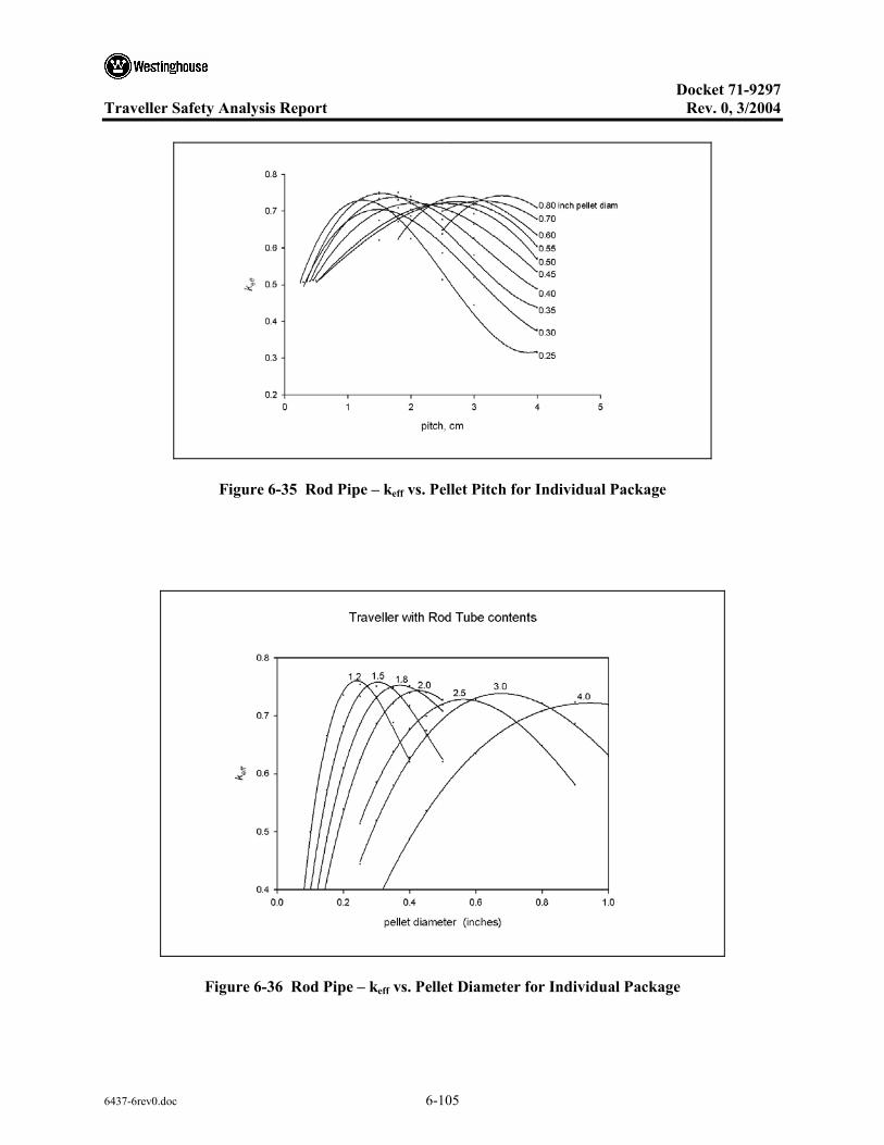
Docket 71-9297
Traveller Safety Analysis Report Rev. 0, 3/2004
6437-6rev0.doc 6-105
Figure 6-35 Rod Pipe – keff vs. Pellet Pitch for Individual Package
Figure 6-36 Rod Pipe – keff vs. Pellet Diameter for Individual Package
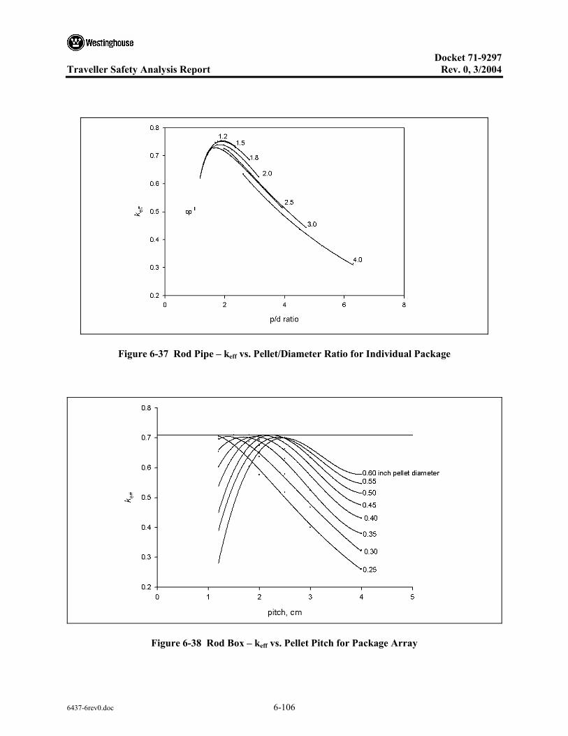
Docket 71-9297
Traveller Safety Analysis Report Rev. 0, 3/2004
6437-6rev0.doc 6-106
Figure 6-37 Rod Pipe – keff vs. Pellet/Diameter Ratio for Individual Package
Figure 6-38 Rod Box – keff vs. Pellet Pitch for Package Array

Docket 71-9297
Traveller Safety Analysis Report Rev. 0, 3/2004
6437-6rev0.doc 6-107
Figure 6-39 Rod Box in Traveller XL
Figure 6-40 Rod Pipe in Traveller XL

Docket 71-9297
Traveller Safety Analysis Report Rev. 0, 3/2004
6437-6rev0.doc 6-108
6.10.8 CALCULATIONS FOR SENSITIVITY STUDIES
6.10.8.1 Partial Density Interspersed Moderation
The data below reports the results of one of the interspersed moderation studies. The Traveller STD package accident condition model was run with different moderation densities. Table 6-37 shows the output for the graph in section 6.7.1.5. Table 6-38 shows the input deck for the 20g/cc case, identified as # pa_hac_boral_4_5_100_0.025_5_0.23880.out in Table 6-37.
Table 6-37 Partial Density Interspersed Moderation Results for Traveller STD
PACKAGE ARRAY– PA_ACCIDENT_INTERSPERSED MODERATION
Intespersed Water Density
(g/cc) ks σks ks+2×σks
pa_hac_boral_4_5_100_0.24880.out: 0.0000 0.8869 1.6000e-3 0.8901
pa_hac_boral_4_5_100_0.025_2_0.2818.out: 0.0100 0.8886 1.6000e-3 0.8918
pa_hac_boral_4_5_100_0.025_3_0.16542.out: 0.0500 0.8851 1.5000e-3 0.8881
pa_hac_boral_4_5_100_0.025_4_0.27394.out: 0.1000 0.8839 1.6000e-3 0.8871
pa_hac_boral_4_5_100_0.025_5_0.23880.out: 0.2000 0.8824 1.4000e-3 0.8852
pa_hac_boral_4_5_100_0.025_6_0.27551.out: 0.3000 0.8801 1.4000e-3 0.8829
pa_hac_boral_4_5_100_0.025_7_0.23955.out: 0.4000 0.8765 1.6000e-3 0.8797
pa_hac_boral_4_5_100_0.025_8_0.16733.out: 0.6000 0.8728 1.4000e-3 0.8756
pa_hac_boral_4_5_100_0.025_9_0.24111.out: 0.8000 0.8634 1.6000e-3 0.8666
pa_hac_boral_4_5_100_0.16944.out: 1.0000 0.8640 1.6000e-3 0.8672
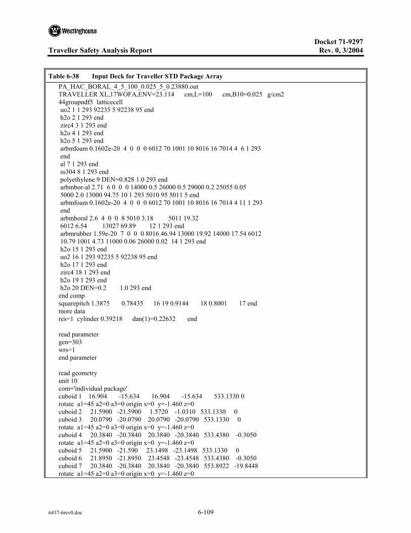
Docket 71-9297
Traveller Safety Analysis Report Rev. 0, 3/2004
6437-6rev0.doc 6-109
Table 6-38 Input Deck for Traveller STD Package Array PA_HAC_BORAL_4_5_100_0.025_5_0.23880.out TRAVELLER XL,17WOFA,ENV=23.114 cm,L=100 cm,B10=0.025 g/cm2 44groupndf5 latticecell uo2 1 1 293 92235 5 92238 95 end h2o 2 1 293 end zirc4 3 1 293 end h2o 4 1 293 end h2o 5 1 293 end arbmfoam 0.1602e-20 4 0 0 0 6012 70 1001 10 8016 16 7014 4 6 1 293 end al 7 1 293 end ss304 8 1 293 end polyethylene 9 DEN=0.828 1.0 293 end arbmbor-al 2.71 6 0 0 0 14000 0.5 26000 0.5 29000 0.2 25055 0.05 5000 2.0 13000 94.75 10 1 293 5010 95 5011 5 end arbmfoam 0.1602e-20 4 0 0 0 6012 70 1001 10 8016 16 7014 4 11 1 293 end arbmboral 2.6 4 0 0 8 5010 3.18 5011 19.32 6012 6.54 13027 69.89 12 1 293 end arbmrubber 1.59e-20 7 0 0 0 8016 46.94 13000 19.92 14000 17.54 6012 10.79 1001 4.73 11000 0.06 26000 0.02 14 1 293 end h2o 15 1 293 end uo2 16 1 293 92235 5 92238 95 end h2o 17 1 293 end zirc4 18 1 293 end h2o 19 1 293 end h2o 20 DEN=0.2 1.0 293 end end comp squarepitch 1.3875 0.78435 16 19 0.9144 18 0.8001 17 end more data res=1 cylinder 0.39218 dan(1)=0.22632 end read parameter gen=303 wrs=1 end parameter read geometry unit 10 com='individual package' cuboid 1 16.904 -15.634 16.904 -15.634 533.1330 0 rotate a1=45 a2=0 a3=0 origin x=0 y=-1.460 z=0 cuboid 2 21.5900 -21.5900 1.5720 -1.0310 533.1330 0 cuboid 3 20.0790 -20.0790 20.0790 -20.0790 533.1330 0 rotate a1=45 a2=0 a3=0 origin x=0 y=-1.460 z=0 cuboid 4 20.3840 -20.3840 20.3840 -20.3840 533.4380 -0.3050 rotate a1=45 a2=0 a3=0 origin x=0 y=-1.460 z=0 cuboid 5 21.5900 -21.590 23.1498 -23.1498 533.1330 0 cuboid 6 21.8950 -21.8950 23.4548 -23.4548 533.4380 -0.3050 cuboid 7 20.3840 -20.3840 20.3840 -20.3840 553.8922 -19.8448 rotate a1=45 a2=0 a3=0 origin x=0 y=-1.460 z=0

Docket 71-9297
Traveller Safety Analysis Report Rev. 0, 3/2004
6437-6rev0.doc 6-110
Table 6-38 Input Deck for Traveller STD Package Array (cont.) PA_HAC_BORAL_4_5_100_0.025_5_0.23880.out cuboid 8 21.8950 -21.895 23.4548 -23.4548 553.8922 -19.8448 cylinder 9 25.1050 533.4380 -0.3050 cylinder 10 25.1050 553.8922 -19.8448 cylinder 11 31.4450 533.4380 -0.3050 cylinder 12 31.4450 553.8922 -19.8448 cylinder 13 31.4450 533.4380 -19.8448 cylinder 14 31.7500 554.1972 -20.1498 plane 15 zpl=1 con= -10.0000 hole 12 rotate a1=45 a2=90 a3=0 origin x=18.7315 y=-11.1277 z=495.166 hole 12 rotate a1=-45 a2=90 a3=0 origin x=-18.7315 y=-11.1277 z=495.166 hole 12 rotate a1=45 a2=90 a3=0 origin x=18.7315 y=-11.1277 z=449.446 hole 12 rotate a1=-45 a2=90 a3=0 origin x=-18.7315 y=-11.1277 z=449.446 hole 12 rotate a1=45 a2=90 a3=0 origin x=18.7315 y=-11.1277 z=403.726 hole 12 rotate a1=-45 a2=90 a3=0 origin x=-18.7315 y=-11.1277 z=403.726 hole 12 rotate a1=45 a2=90 a3=0 origin x=18.7315 y=-11.1277 z=358.006 hole 12 rotate a1=-45 a2=90 a3=0 origin x=-18.7315 y=-11.1277 z=358.006 hole 12 rotate a1=45 a2=90 a3=0 origin x=18.7315 y=-11.1277 z=312.286 hole 12 rotate a1=-45 a2=90 a3=0 origin x=-18.7315 y=-11.1277 z=312.286 hole 12 rotate a1=45 a2=90 a3=0 origin x=18.7315 y=-11.1277 z=266.566 hole 12 rotate a1=-45 a2=90 a3=0 origin x=-18.7315 y=-11.1277 z=266.566 hole 12 rotate a1=45 a2=90 a3=0 origin x=18.7315 y=-11.1277 z=220.847 hole 12 rotate a1=-45 a2=90 a3=0 origin x=-18.7315 y=-11.1277 z=220.847 hole 12 rotate a1=45 a2=90 a3=0 origin x=18.7315 y=-11.1277 z=175.127 hole 12 rotate a1=-45 a2=90 a3=0 origin x=-18.7315 y=-11.1277 z=175.127 hole 12 rotate a1=45 a2=90 a3=0 origin x=18.7315 y=-11.1277 z=129.407 hole 12 rotate a1=-45 a2=90 a3=0 origin x=-18.7315 y=-11.1277 z=129.407 hole 12 rotate a1=45 a2=90 a3=0 origin x=18.7315 y=-11.1277 z=83.687 hole 12 rotate a1=-45 a2=90 a3=0 origin x=-18.7315 y=-11.1277 z=83.687 hole 12 rotate a1=45 a2=90 a3=0 origin x=18.7315 y=-11.1277 z=37.967 hole 12 rotate a1=-45 a2=90 a3=0 origin x=-18.7315 y=-11.1277 z=37.967 hole 11 rotate a1=45 a2=0 a3=0 origin x=0 y=-17.700 z=5.240 media 0 1 2 media 0 1 -2 1 5 media 9 1 -1 3 5 -2 media 8 1 -3 4 6 media 8 1 3 -5 6 media 6 1 -4 9 media 6 1 4 -6 9 media 6 1 -9 11 media 6 1 -7 10 -13 media 6 1 7 -8 10 -13 12 media 6 1 -10 -13 12 media 11 1 -11 13 media 11 1 7 8 -13 12 media 8 1 -12 14 boundary 14 unit 11 com='fuel assembly confinement system'
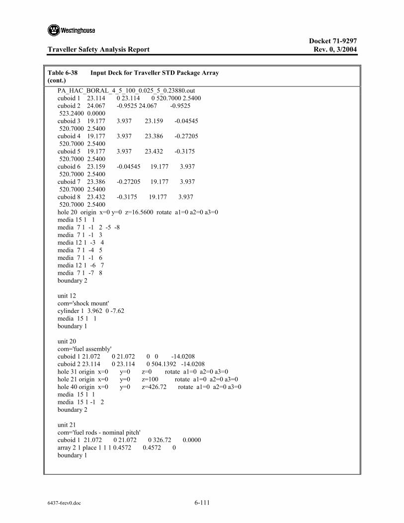
Docket 71-9297
Traveller Safety Analysis Report Rev. 0, 3/2004
6437-6rev0.doc 6-111
Table 6-38 Input Deck for Traveller STD Package Array (cont.) PA_HAC_BORAL_4_5_100_0.025_5_0.23880.out cuboid 1 23.114 0 23.114 0 520.7000 2.5400 cuboid 2 24.067 -0.9525 24.067 -0.9525 523.2400 0.0000 cuboid 3 19.177 3.937 23.159 -0.04545 520.7000 2.5400 cuboid 4 19.177 3.937 23.386 -0.27205 520.7000 2.5400 cuboid 5 19.177 3.937 23.432 -0.3175 520.7000 2.5400 cuboid 6 23.159 -0.04545 19.177 3.937 520.7000 2.5400 cuboid 7 23.386 -0.27205 19.177 3.937 520.7000 2.5400 cuboid 8 23.432 -0.3175 19.177 3.937 520.7000 2.5400 hole 20 origin x=0 y=0 z=16.5600 rotate a1=0 a2=0 a3=0 media 15 1 1 media 7 1 -1 2 -5 -8 media 7 1 -1 3 media 12 1 -3 4 media 7 1 -4 5 media 7 1 -1 6 media 12 1 -6 7 media 7 1 -7 8 boundary 2 unit 12 com='shock mount' cylinder 1 3.962 0 -7.62 media 15 1 1 boundary 1 unit 20 com='fuel assembly' cuboid 1 21.072 0 21.072 0 0 -14.0208 cuboid 2 23.114 0 23.114 0 504.1392 -14.0208 hole 31 origin x=0 y=0 z=0 rotate a1=0 a2=0 a3=0 hole 21 origin x=0 y=0 z=100 rotate a1=0 a2=0 a3=0 hole 40 origin x=0 y=0 z=426.72 rotate a1=0 a2=0 a3=0 media 15 1 1 media 15 1 -1 2 boundary 2 unit 21 com='fuel rods - nominal pitch' cuboid 1 21.072 0 21.072 0 326.72 0.0000 array 2 1 place 1 1 1 0.4572 0.4572 0 boundary 1

Docket 71-9297
Traveller Safety Analysis Report Rev. 0, 3/2004
6437-6rev0.doc 6-112
Table 6-38 Input Deck for Traveller STD Package Array (cont.) PA_HAC_BORAL_4_5_100_0.025_5_0.23880.out unit 22 com='solid fuel rod - nominal pitch' cylinder 1 0.39218 426.72 0 cylinder 2 0.40005 426.72 0 cylinder 3 0.4572 426.72 0 cuboid 4 4P0.62992 426.72 0 media 1 1 1 media 2 1 2 -1 media 3 1 3 -2 -1 media 4 1 4 -3 -2 -1 boundary 4 unit 23 com='thimble tube - nominal pitch' cylinder 1 0.56134 426.72 0 cylinder 2 0.60198 426.72 0 cuboid 3 4P0.62992 426.72 0 media 4 1 1 media 3 1 2 -1 media 4 1 3 -2 -1 boundary 3 unit 31 com='fuel rods - expanded pitch' cuboid 1 23.114 0 23.114 0 100 0 array 3 1 place 1 1 1 0.4572 0.4572 0 boundary 1 unit 32 com='solid fuel rod - expanded pitch' cylinder 1 0.39218 426.72 0 cylinder 2 0.40005 426.72 0 cylinder 3 0.4572 426.72 0 cuboid 4 4P0.69374 426.72 0 media 16 1 1 media 17 1 2 -1 media 18 1 3 -2 -1 media 19 1 4 -3 -2 -1 boundary 4 unit 33 com='thimble tube - expanded pitch' cylinder 1 0.56134 426.72 0 cylinder 2 0.60198 426.72 0 cuboid 3 4P0.69374 426.72 0 media 19 1 1 media 18 1 2 -1 media 19 1 3 -2 -1 boundary 3

Docket 71-9297
Traveller Safety Analysis Report Rev. 0, 3/2004
6437-6rev0.doc 6-113
Table 6-38 Input Deck for Traveller STD Package Array (cont.) PA_HAC_BORAL_4_5_100_0.025_5_0.23880.out unit 40 com='top nozzle assembly' cuboid 1 21.072 0 21.072 0 21.2090 0.0000 cuboid 2 21.072 0 21.072 0 41.8846 0.0000 cuboid 3 21.072 0 21.072 0 52.8193 0.0000 cuboid 4 21.072 0 21.072 0 77.4192 0.0000 cuboid 5 23.114 0 23.114 0 77.4192 0.0008 media 15 1 1 media 15 1 -1 2 media 15 1 -2 3 media 15 1 -3 4 media 15 1 -4 5 boundary 5 unit 66 com='individual package 0-deg rotation' hexprism 1 31.75 554.1972 -20.1498 hole 10 origin x=0 y=0 z=0 rotate a1=0 a2=0 a3=0 media 20 1 1 boundary 1 unit 77 com='individual package 180-deg rotation' hexprism 1 31.75 554.1972 -20.1498 hole 10 origin x=0 y=0 z=0 rotate a1=0 a2=0 a3=180 media 20 1 1 boundary 1 unit 88 com='dummy cell' hexprism 1 31.75 554.1972 -20.1498 media 15 1 1 boundary 1 global unit 99 com='package array' cylinder 1 432.2355 554.1972 -20.1498 cylinder 2 452.2355 574.1972 -40.1498 cuboid 3 452.2355 -452.2355 452.2355 -452.2355 574.1972 -40.1498 array 1 1 place 9 9 1 0 0 0 media 15 1 -1 2 media 0 1 -2 3 boundary 3 end geometry read array ara=1 typ=triangular nux=17 nuy=17 nuz=1 gbl=1 fill

Docket 71-9297
Traveller Safety Analysis Report Rev. 0, 3/2004
6437-6rev0.doc 6-114
Table 6-38 Input Deck for Traveller STD Package Array (cont.) PA_HAC_BORAL_4_5_100_0.025_5_0.23880.out 88 88 88 88 88 88 88 88 88 88 88 88 88 88 88 88 88 88 88 88 88 88 88 88 88 88 88 77 77 77 88 88 88 88 88 88 88 88 88 88 88 88 66 66 66 66 66 66 66 88 88 88 88 88 88 88 88 77 77 77 77 77 77 77 77 77 77 88 88 88 88 88 88 66 66 66 66 66 66 66 66 66 66 66 88 88 88 88 88 77 77 77 77 77 77 77 77 77 77 77 77 88 88 88 88 66 66 66 66 66 66 66 66 66 66 66 66 66 88 88 88 88 77 77 77 77 77 77 77 77 77 77 77 77 88 88 88 88 66 66 66 66 66 66 66 66 66 66 66 66 66 88 88 88 88 77 77 77 77 77 77 77 77 77 77 77 77 88 88 88 88 66 66 66 66 66 66 66 66 66 66 66 66 66 88 88 88 88 77 77 77 77 77 77 77 77 77 77 77 77 88 88 88 88 88 66 66 66 66 66 66 66 66 66 66 66 88 88 88 88 88 88 77 77 77 77 77 77 77 77 77 77 88 88 88 88 88 88 88 88 66 66 66 66 66 66 66 88 88 88 88 88 88 88 88 88 88 88 77 77 77 77 88 88 88 88 88 88 88 88 88 88 88 88 88 88 88 88 88 88 88 88 88 88 88 88 88 88 88 end fill ara=2 typ=square nux=17 nuy=17 nuz=1 fill 39*22 23 2*22 23 2*22 23 8*22 23 9*22 23 22*22 23 2*22 23 2*22 23 2*22 23 2*22 23 38*22 23 2*22 23 2*22 23 2*22 23 2*22 23 38*22 23 2*22 23 2*22 23 2*22 23 2*22 23 22*22 23 9*22 23 8*22 23 2*22 23 2*22 23 39*22 end fill ara=3 typ=square nux=17 nuy=17 nuz=1 fill 39*32 33 2*32 33 2*32 33 8*32 33 9*32 33 22*32 33 2*32 33 2*32 33 2*32 33 2*32 33 38*32 33 2*32 33 2*32 33 2*32 33 2*32 33 38*32 33 2*32 33 2*32 33 2*32 33 2*32 33 22*32 33 9*32 33 8*32 33 2*32 33 2*32 33 39*32 end fill end array read bnds +xb=vacuum -xb=vacuum +yb=vacuum -yb=vacuum +zb=vacuum -zb=vacuum end bnds end data

Docket 71-9297
Traveller Safety Analysis Report Rev. 0, 3/2004
6437-6rev0.doc 6-115
6.10.8.2 Boron Content Sensitivity Study
Both the Traveller STD and Traveller XL were evaluated for their sensitivity to varying the boron content in the absorber. Table 6-39 below gives the output data that was used to derive the figure in Section 6.7.8.
Table 6-39 Boron Sensitivity Results
PACKAGE ARRAY – PA_HAC_BAL/9_1-17OFA
10B Areal Density, g/cm2 ks σks ks+2×σks
pa_hac_bal_1_5_100_0.24657.out: 4.0870e-3 0.9275 1.8000e-3 0.9311
pa_hac_bal_2_5_100_0.14033.out: 8.1740e-3 0.9038 1.6000e-3 0.9070
pa_hac_bal_3_5_100_0.26235.out: 0.0123 0.9006 1.6000e-3 0.9038
pa_hac_bal_4_5_100_0.28238.out: 0.0163 0.8881 1.5000e-3 0.8911
pa_hac_bal_5_5_100_0.29127.out: 0.0204 0.8823 1.8000e-3 0.8859
pa_hac_bal_6_5_100_0.29327.out: 0.0245 0.8835 1.7000e-3 0.8869
pa_hac_bal_7_5_100_0.23938.out: 0.0286 0.8813 1.7000e-3 0.8847
pa_hac_bal_8_5_100_0.17482.out: 0.0327 0.8792 1.9000e-3 0.8830
PACKAGE ARRAY – PA_HAC_BORAL/9_1-17OFA
10B Areal Density, g/cm2 ks σks ks+2×σks
0.0000 1.0368 1.5000e-3 1.0428
pa_hac_boral_1_5_100_0.23519.out: 7.5000e-3 0.9092 1.6000e-3 0.9154
0.0113
pa_hac_boral_3_5_100_0.21685.out: 0.0150 0.8900 1.7000e-3 0.8964
pa_hac_boral_4_5_100_0.22193.out: 0.0188 0.8869 1.6000e-3 0.8931
pa_hac_boral_5_5_100_0.22719.out: 0.0225 0.8849 2.4000e-3 0.8927
pa_hac_boral_6_5_100_0.13028.out: 0.0263 0.8834 1.7000e-3 0.8898
pa_hac_boral_7_5_100_0.24629.out: 0.0300 0.8795 1.6000e-3 0.8857
pa_hac_boral_8_5_100_0.24828.out: 0.0338 0.8817 1.6000e-3 0.8879

Docket 71-9297
Traveller Safety Analysis Report Rev. 0, 3/2004
6437-6rev0.doc 6-116
6.10.9 BENCHMARK CRITICAL EXPERIMENTS
Table 6-40 Summary of Available LWR Critical Experiments
Report
No. of available
experiments
No. of selected
experiments Description of criticality experiments
ANS Transactions, Vol. 33, p.362 (Ref. 5)
25 9/9 4.74 wt % 235U UO2 fuel rods in square lattices of 1.35 cm pitch; fuel 235 clusters separated by air, polystyrene, polyethylene, or water; fuel clusters submersed in aqueous NaNO3 solution
BAW-1484 (Ref. 6) 37 1/10 2.46 wt % 235U UO2 fuel rods in square lattices of 1.636 cm pitch; the spacing between 3 × 3 array of LWR-type fuel assemblies is filled with water and B4C pins, stainless steel sheets, or borated stainless steel sheets; lattices with borated moderator
EPRI-NP-196 (Ref. 7) 6 3/6 2.35 wt % 235U UO2 fuel rods in square lattices of 1.562, 1.905, 235 and 2.210 cm pitch; lattices with borated moderator
NS&E, Vol. 71 (Ref. 8) 26 3/6 4.74 wt % 235U UO2 fuel rods in square lattices of 1.26 cm, 1.60 cm, 2.10 cm, and 2.52 cm pitch; triangular and triangular with pseudo-cylindrical shape lattices of 1.35, 1.72, and 2.26 cm pitch; irregular hexagonal lattices of 1.35 cm pitch; lattices with water holes
PNL-2438 (Ref. 9) 48 4/6 2.35 wt % 235U UO2 fuel rods in square lattices of 2.032 cm pitch; Cd, Al, Cu, stainless steel, borated stainless steel, Boral, and Zircaloy separator plates between assemblies
PNL-2827 (Ref. 10) 23 1/9 2.35 and 4.31 wt % 235U UO2 fuel rods in square lattices of 2.032, 235 and 2.540 cm pitch; reflecting walls of Pb or depleted uranium
PNL-3314 (Ref. 11) 142 18/27 2.35 and 4.31 wt % 235U UO2 fuel rods in square lattices of 1.684 and 1.892 cm pitch; stainless steel, borated stainless steel, Cd, Al, Cu, Boral, Boroflex, and Zircaloy separator plates between assemblies; lattices with water holes and voids
PNL-3926 (Ref. 12) 22 2/14 2.35 and 4.31 wt % 235U UO2 fuel rods in square lattices of 1.684, 235 and 1.892 cm pitch; reflecting walls of Pb or depleted uranium
WCAP-3269 (Ref. 15) 157 3/9 2.7, 3.7, and 5.7 wt % 235U UO2 fuel rods in square lattices of 1.029, 1.105, and 1.422 cm pitch; lattices with Ag-In-Cd absorber rods, water holes, void tubes

Docket 71-9297
Traveller Safety Analysis Report Rev. 0, 3/2004
6437-6rev0.doc 6-117
Table 6-40 Summary of Available LWR Critical Experiments (cont.)
Report
No. of available
experiments
No. of selected
experiments Description of criticality experiments
WCAP-3385 (Ref. 16) 3 2/2 5.74 wt % 235U UO2 fuel rods in square lattices of 1.321, 1.422, and 2.012 cm pitch
BAW-1645 (Ref. 17) 21 2/8 2.46 wt % 235U UO2 fuel rods in close-packed triangular lattices of 1.209 cm pitch, close-packed square lattices of 1.209 cm pitch, and square lattices of 1.410 cm pitch
PNL-6205 (Ref. 20) 19 1/1 4.31 wt % 235U UO2 fuel rods in square lattices of 1.891 cm pitch; Boral flux traps
PNL-7167 (Ref. 21) 9 4/4 4.31 wt % 235U UO2 fuel rods in square lattices of 1.891 cm pitch; Boral flux traps containing voids filled with Al plates, Al rods, or UO2 fuel rods.

Docket 71-9297
Traveller Safety Analysis Report Rev. 0, 3/2004
6437-6rev0.doc 6-118
Table 6-41 Critical Benchmark Experiment Classification
Critical Benchmark Experiment Groups
Report Simple lattice Separator plate Flux trap Water hole
ANS Transactions, Vol. 33, p. 362
ANS33SLG (8) ANS33AL1 (1) ANS33AL2 (2) ANS33AL3 (3)
ANS33EB1 (4) ANS33EB2 (5) ANS33EP1 (6) ANS33EP2 (7) ANS33STY(9)
BAW-1484 BW1484SL (24) EPRI-NP-196 EPRU65 (45)
EPRU75 (47) EPRU87 (44)
NS&E, Vol. 71, p. 154
NS&E71SQ (54) NS&E71W1 (55) NS&E71W2 (56)
PNL-2438 P2438SLG (60) P2438AL (57) P2438BA (58) P2438SS (61)
PNL-2615 P2615AL (63) P2615BA (64) P2615SS (68)
PNL-2827 P2827SLG (74) PNL-3314 P3314SLG (96) P3314AL (79)
P3314BA (80) P3314BC (81) P3314BF1 (82) P3314BF2 (83) P3314BS1 (84) P3314BS2 (85) P3314BS3 (86) P3314BS4 (87) P3314SS1 (97) P3314SS2 (98) P3314SS3 (99) P3314SS4 (100) P3314SS5 (101) P3314SS6 (102)
P3314W1 (103) P3314W2 (104)
PNL-3926 P3926SL1 (138) P3926SL2 (139)
PNL-6205 P62FT231 (154) PNL-7167 P71F214R (158) P71F14F3 (155)
P71 F14V3 (156) P71 F14V53 (157)
WCAP-3269 W3269SL1 (168) W3269SL2 (169)
W3269W1 (170) W3269W2 (171)
WCAP-3385 W3385SL1 (172) W3385SL2 (173)
Total 15 26 8 6

Docket 71-9297 Traveller Safety Analysis Report Rev. 0, 3/2004
6437-6rev0.doc 6-119
Table 6-42 Summary Comparison of Benchmark Critical Experiment Properties to Traveller
Critical Benchmark Experiments
All Simple lattice Separator Flux Trap Water Hole Traveller Package
Number of cases 55 15 26 8 6 19
Properties of Lattice
Water-to-fuel volume ratio 1.196-5.067 1.196-5.067 1.6-3.883 1.6-2.302 1.495-1.932 2.21-3.49
Hydrogen-to-fissile ratio 97.6-504.2 97.6-504.2 105-398. 105-138.4 98.3-218.6 120.5-190.4
Lattice pitch 1.26-2.540 1.26-2.21 1.35-2.54 1.35-1.891 1.26-1.892 1.26-1.467
Dancoff factor 0.03889-0.3772 0.05727-0.3772 0.03889-0.20179 0.17388-0.20096 0.17284-0.25719 0.13137-0.22632
Water hole/No. pins 0.051-0.152 NA NA NA 0.051-0.152 0.095
Properties of UO2 fuel rods
Outside diameter, cm 0.86-1.4147 0.86-1.206 0.94-1.4147 0.94-1.4147 0.94-1.4147 0.9144
Wall thickness, cm 0.038-0.081 0.038-0.081 0.06-0.0762 0.06-0.0762 0.038-0.0795 0.05715
Wall material Al Zircaloy-4 304SS
Al Zircaloy-4 304SS
Al Al Zircaloy-4 304SS Zircaloy-4
Pellet diameter, cm 0.7544-1.2649 0.7544-1.2649 0.79-1.2649 0.79-1.2649 0.79-1.2649 0.7844
Total fuel length, cm 97.155-156.44 97.155-156.44 97.155-156.44 97.155-156.44 97.155-156.44 426.72
Active fuel length, cm 90.0-153.44 90.0-153.44 90.0-153.44 90.0-153.44 90.0-153.44 426.72
Enrichment, 235U/U wt% 2.35-5.74 2.35-5.74 2.35-4.74 4.31-4.74 2.35-5.70 5.00
Fuel density, g/cm3 9.20-10.412 9.20-10.412 9.20-10.412 10.38-10.412 9.20-10.412 10.96
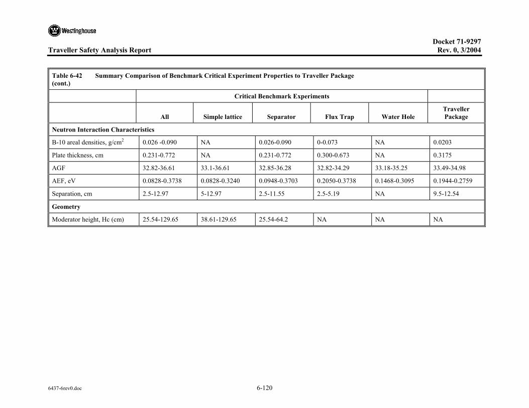
Docket 71-9297 Traveller Safety Analysis Report Rev. 0, 3/2004
6437-6rev0.doc 6-120
Table 6-42 Summary Comparison of Benchmark Critical Experiment Properties to Traveller Package (cont.)
Critical Benchmark Experiments
All Simple lattice Separator Flux Trap Water Hole Traveller Package
Neutron Interaction Characteristics
B-10 areal densities, g/cm2 0.026 -0.090 NA 0.026-0.090 0-0.073 NA 0.0203
Plate thickness, cm 0.231-0.772 NA 0.231-0.772 0.300-0.673 NA 0.3175
AGF 32.82-36.61 33.1-36.61 32.85-36.28 32.82-34.29 33.18-35.25 33.49-34.98
AEF, eV 0.0828-0.3738 0.0828-0.3240 0.0948-0.3703 0.2050-0.3738 0.1468-0.3095 0.1944-0.2759
Separation, cm 2.5-12.97 5-12.97 2.5-11.55 2.5-5.19 NA 9.5-12.54
Geometry
Moderator height, Hc (cm) 25.54-129.65 38.61-129.65 25.54-64.2 NA NA NA

Docket 71-9297
Traveller Safety Analysis Report Rev. 0, 3/2004
6437-7rev0.doc i
TABLE OF CONTENTS
7 PACKAGE OPERATIONS..........................................................................................................7-1 7.1 PACKAGE LOADING ...................................................................................................7-1
7.1.1 Preparation for Loading...................................................................................7-1 7.1.1.1 Receive Shipping Package ..............................................................7-1 7.1.1.2 Clean Shipping Package..................................................................7-1 7.1.1.3 Refurbish Shipping Package ...........................................................7-1 7.1.1.4 Configure Package for Fuel Assembly Loading .............................7-1 7.1.1.5 Inspection ........................................................................................7-1
7.1.2 Loading Contents.............................................................................................7-2 7.1.2.1 Inspection ........................................................................................7-2 7.1.2.2 Close Shipping Package ..................................................................7-2 7.1.2.3 Inspection ........................................................................................7-2
7.1.3 Preparation for Transport.................................................................................7-2 7.1.3.1 Truck Loading of Shipping Packages .............................................7-2 7.1.3.2 Regulatory .......................................................................................7-3 7.1.3.3 Inspection ........................................................................................7-3
7.2 PACKAGE UNLOADING..............................................................................................7-3 7.2.1 Receipt of Package from Carrier .....................................................................7-3 7.2.2 Removal of Contents .......................................................................................7-3
7.3 PREPARATION OF EMPTY PACKAGE FOR TRANSPORT ....................................7-4

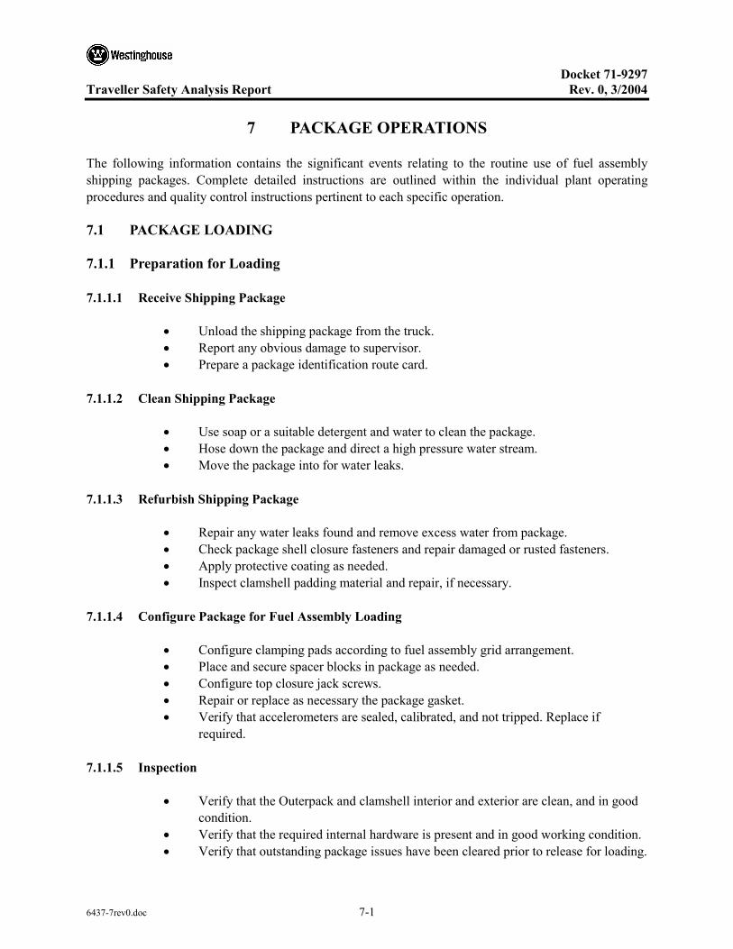
Docket 71-9297
Traveller Safety Analysis Report Rev. 0, 3/2004
6437-7rev0.doc 7-1
7 PACKAGE OPERATIONS
The following information contains the significant events relating to the routine use of fuel assembly shipping packages. Complete detailed instructions are outlined within the individual plant operating procedures and quality control instructions pertinent to each specific operation.
7.1 PACKAGE LOADING
7.1.1 Preparation for Loading
7.1.1.1 Receive Shipping Package
• Unload the shipping package from the truck. • Report any obvious damage to supervisor. • Prepare a package identification route card.
7.1.1.2 Clean Shipping Package
• Use soap or a suitable detergent and water to clean the package. • Hose down the package and direct a high pressure water stream. • Move the package into for water leaks.
7.1.1.3 Refurbish Shipping Package
• Repair any water leaks found and remove excess water from package. • Check package shell closure fasteners and repair damaged or rusted fasteners. • Apply protective coating as needed. • Inspect clamshell padding material and repair, if necessary.
7.1.1.4 Configure Package for Fuel Assembly Loading
• Configure clamping pads according to fuel assembly grid arrangement. • Place and secure spacer blocks in package as needed. • Configure top closure jack screws. • Repair or replace as necessary the package gasket. • Verify that accelerometers are sealed, calibrated, and not tripped. Replace if
required.
7.1.1.5 Inspection
• Verify that the Outerpack and clamshell interior and exterior are clean, and in good condition.
• Verify that the required internal hardware is present and in good working condition. • Verify that outstanding package issues have been cleared prior to release for loading.

Docket 71-9297
Traveller Safety Analysis Report Rev. 0, 3/2004
6437-7rev0.doc 7-2
7.1.2 Loading Contents
• Raise shipping package to vertical position and secure in Traveller specific tooling. • Open shipping package door and secure. • Open top head. • Open clamshell doors. • Place the fuel assembly in the support frame. • Close the clamshell doors and J clip closure. • Secure the doors. • Close and secure top closure assemblies. • Check all fasteners for correct configuration.
7.1.2.1 Inspection
• Verify that the fuel assemblies and core components have been released and the proper component is being shipped with the assembly.
• Verify that the fuel assemblies are properly oriented in the package. • Verify the number of shock mounts is correct and accelerometers are sealed,
calibrated and not tripped. • Verify general cleanliness and absence of debris on package internals, fuel
assembly, package shell lower subassembly prior to closing the package. • Verify placement and integrity of shipping package gasket.
7.1.2.2 Close Shipping Package
• Verify that the cover flange is free of debris and close overpack door. • Tighten package closure fasteners to secure cover. • Install one approved tamper proof security seal on each end of the package.
7.1.2.3 Inspection
• Verify that the package lid is properly seated and all closure bolts are present. • Verify that the required decals, license plates, labels, stencil markings, etc. are
present and legible.
7.1.3 Preparation for Transport
7.1.3.1 Truck Loading of Shipping Packages
• Place shipping package on trailer equipped to permit chaining down of package. • Center and place package lengthwise on trailer. • Secure packages to trailer bed with stops. • Chain packages to trailer using “come along” tighteners and chains of 3/8 inch
minimum diameter.
Docket 71-9297
Traveller Safety Analysis Report Rev. 0, 3/2004
6437-7rev0.doc 7-3
7.1.3.2 Regulatory
• Conduct direct alpha surveys on both the packages and the accessible areas of the flatbed.
• Perform the removable alpha and beta-gamma external smear surveys on both the packages and the accessible areas of the flatbed. If any single alpha measurement exceeds 220 dpm/100 cm2 or beta-gamma measurement exceeds 2200 dpm/100 cm2, notify Regulatory Engineering for instructions on decontamination.
7.1.3.3 Inspection
• Verify that packages are properly stacked and secured. • Verify that required Health Physics, Radioactive and any other placards or labels
have been properly placed. • Verify that two tamper proof security seals have been properly placed on each
package.
7.2 PACKAGE UNLOADING
7.2.1 Receipt of Package from Carrier
• Perform an external inspection of the unopened package and record any significant observations.
• Verify that two tamper proof security seals have been properly placed on each package.
7.2.2 Removal of Contents
• Raise shipping package to vertical position and secure in Traveller specific tooling. • Open shipping package door and secure. • Open top head. • Open clamshell doors. • Remove the fuel assembly from the support frame. • Close the clamshell doors and J clip closure. • Secure the doors. • Close and secure top closure assemblies. • Check all fasteners for correct configuration.

Docket 71-9297
Traveller Safety Analysis Report Rev. 0, 3/2004
6437-7rev0.doc 7-4
7.3 PREPARATION OF EMPTY PACKAGE FOR TRANSPORT
• Verify the package is empty of contents. • Verify radiation levels do not exceed prescribed limits. • Verify nonfixed radioactive surface contamination does not exceed prescribed
limits. • Verify the package does not contain more than 15 grams of uranium-235. • Verify the packaging is in unimpaired condition and is securely closed. • Verify the internal contamination does not exceed 100 times prescribed limits. • Remove any previously applied labels affixed for fuel shipments. • Affix an “Empty” label.

Docket 71-9297
Traveller Safety Analysis Report Rev. 0, 3/2004
6437-8rev0.doc i
TABLE OF CONTENTS
8 ACCEPTANCE TESTS AND MAINTENANCE PROGRAM...................................................8-1 8.1 ACCEPTANCE TESTS ..................................................................................................8-1
8.1.1 Visual Inspections and Measurements ............................................................8-1 8.1.2 Weld Examinations .........................................................................................8-1 8.1.3 Structural and Presssure Tests .........................................................................8-1 8.1.4 Leak Tests........................................................................................................8-1 8.1.5 Component and Material Tests........................................................................8-1
8.1.5.1 Polyurethane Foam..........................................................................8-1 8.1.5.2 Neutron Poison Plates .....................................................................8-5 8.1.5.3 Polyethylene Sheeting.....................................................................8-7
8.1.6 Shielding Tests ................................................................................................8-7 8.1.7 Thermal Tests ..................................................................................................8-8
8.2 MAINTENANCE PROGRAM .......................................................................................8-8 8.2.1 Structural and Pressure Tests...........................................................................8-8 8.2.2 Leak Tests........................................................................................................8-8 8.2.3 Component and Material Tests........................................................................8-8
8.2.3.1 Fasteners..........................................................................................8-8 8.2.3.2 Braided Fiberglass Sleaving............................................................8-8
8.2.4 Thermal............................................................................................................8-8 8.2.5 Neutronic Confirmation...................................................................................8-8


Docket 71-9297
Traveller Safety Analysis Report Rev. 0, 3/2004
6437-8rev0.doc 8-1
8 ACCEPTANCE TESTS AND MAINTENANCE PROGRAM
8.1 ACCEPTANCE TESTS
Per the requirements of 10 CFR §71.85(c)1, this section discusses the inspections and acceptance tests to be performed prior to first use of the Traveller package. Complete detailed instructions are outlined within the individual plant operating procedures and quality control instructions pertinent to each specific operation.
8.1.1 Visual Inspections and Measurements
All Traveller packaging materials of construction and welds shall be examined in accordance with the requirements delineated in Table 2-2 of Section 2.
8.1.2 Weld Examinations
All Traveller welds shall be examined to verify conformance with all applicable codes, and standards and noted on each drawing.
8.1.3 Structural and Presssure Tests
The Traveller packaging does not contain any structural or lifting/tiedown devices that require testing. There is also no pressure testing requirement.
8.1.4 Leak Tests
The Traveller packaging does not have any requirements for leak testing.
8.1.5 Component and Material Tests
8.1.5.1 Polyurethane Foam
The Traveller packaging utilizes a closed-cell, polyurethane foam and must certified to meet the requirements and acceptance criteria for installation, inspection, and testing as defined in this section.
The finished foam product shall be greater than 85% closed cell polyurethane plastic foam of the self-extinguishing variety of the density specified. The closed cell configuration will ensure that the foam will not be susceptible to significant water absorption.

Docket 71-9297
Traveller Safety Analysis Report Rev. 0, 3/2004
6437-8rev0.doc 8-2
8.1.5.1.1 Density
Rigid polyurethane foam shall have a density per the following table:
Part Lb/ft3
End Caps 20.0 +/- 2.0
Package body 10.0 +/- 1.0
Inner Limiter 6.0 +/- 1.0
Density shall be determined in accordance with ASTM D-1622 with the following exceptions:
a) A minimum of one specimen per pour shall be taken, distributed regularly throughout the batch.
b) Conditioning shall be 70°F to 80°F and 40% – 60% relative humidity for 12 hours minimum.
c) Test conditions shall be 70°F to 80°F and 30% – 70% relative humidity.
d) Length, width and thickness measurements shall be made with a 6-inch digital or dial caliper.
e) Measurements shall be made and reported to the nearest 0.001 inches.
f) Density shall be reported in pounds per cubic foot and no correction made for the (negligible) buoyant effect of air.
g) The standard deviation of the three density determinations need not be calculated or reported.
8.1.5.1.2 Mechanical Properties
Exhibited foam compressive strength for 10% strain parallel to foam rise shall be determined in accordance with ASTM D-1621, with the exceptions noted below, and shall fall within the following range of values:
Part Density Min Max
End 20.0 +/- 2.0 888 psi 1332 psi
Body 10.0 +/- 1.0 262 psi 393 psi
Inner 6.0 +/- 1.0 132 psi 198 psi
Docket 71-9297
Traveller Safety Analysis Report Rev. 0, 3/2004
6437-8rev0.doc 8-3
a) Specimen shall be right rectangular prisms 1.0+/-0.1 inches thick x 2.0+/-0.1 inches x 2.0+/-0.1 inches with the 1.0+/-0.1 inch dimension parallel to the direction of foam rise.
b) A specimen from each batch shall be tested.
c) Conditioning shall be 70°F to 80°F and 40% – 60% relative humidity for 12 hours minimum.
d) Test conditions shall be 70°F to 80°F and 30% – 70% relative humidity.
e) Length, width and thickness measurements shall be made with a 6-inch digital or dial caliper.
f) Measurements shall be made and reported to the nearest 0.001 inches.
g) Strain rate shall be 0.1 +/- 0.05 in/in – min.
h) Only actual values (not averages or standard deviations) need be reported.
8.1.5.1.3 Flame Retardant Characteristics
Flame retardant characteristics shall be qualified by demonstrating compliance with the following requirements. The requirements shall be demonstrated by flame testing described in FAA Powerplant Engineering Report No. 3A. Additional certification testing to validate the flame-retardant characteristics shall also be performed in accordance with ASTM F-501-93. The test described in b) below is not applicable to the 6 pcf foam.
a) Foam shall not be capable of sustaining a flame for a period greater than five (5) minutes, following the removal of the heat source and after being exposed to temperatures up to 1,500°F. A heat source with a flame temperature of at least 1,500°F is applied until the foam is ignited. The heat source is removed after ignition of the foam and the time until self-extinguishment of the flame (absence of flame) will be monitored and compared against the 5-minute acceptance criteria.
b) Prepare a representative sample of the foam material and test in accordance with the following:
1) Cut two pieces of sheet metal (16 gauge maximum/25 gauge minimum) to a size sufficient to cover a 10 inch diameter test sample.
2) Attach a thermocouple at the approximate center of one side of each piece of sheet metal.
3) Prepare a representative sample of the foam material inside a 10-inch inner diameter by 6-inch long steel cylinder. Foam to fill the entire length of the cylinder and the full 10-inch diameter.
Docket 71-9297
Traveller Safety Analysis Report Rev. 0, 3/2004
6437-8rev0.doc 8-4
4) Sandwich the sample between the two pieces of sheet metal, with the thermocouples in contact with the foam.
5) Expose one end of the foam sample (sheet metal) to a heat source. Apply enough heat to cause the indicated thermocouple temperature to increase from ambient temperature to 1,475°F minimum on the exposed side.
6) Hold the sample at a minimum of 1,475°F for a minimum period of thirty (30) minutes.
Acceptance criteria shall be as follows:
During the period that heat is applied, the thermocouple on the non-exposed end of the sample shall not exceed 180°F. The thermocouple on the back side (away from the flame) shall be isolated from the sheet metal to prevent heat from radiating from the metal instead of traversing the foam core. The thermocouple can be isolated using a piece of Nomex cloth or approved equivalent.
8.1.5.1.4 Thermal Properties
The foam shall exhibit the following thermal characteristics for the 6 pcf, 10 pcf and 20 pcf nominal density pours, minimum of three specimens per qualification:
a) Thermal Conductivity
0.18 to 0.55 BTU-in/hr-ft2-°F
b) Specific Heat
0.275 to 0.535 BTU/hr-°F
8.1.5.1.5 Water Absorption
The average water absorption by the foam observed by testing using ASTM D-2842, with the following exceptions, shall not be more than 5% by volume. The construction of the Traveller will further ensure that in actual operation, significantly lower water absorption rate would be observed.
a) Length, width and thickness measurements shall be made with a digital or dial caliper.
b) Measurements shall be made and reported to the nearest 0.001 inches.
c) A single specimen of the qualifying material shall be molded to the density range as stated in the density chart above.
d) The specimen shall consist of a single 3.0 inches x 6.0 inches x 6.0 inches (tolerance on dimension is 0.5 inches) block of foam.

Docket 71-9297
Traveller Safety Analysis Report Rev. 0, 3/2004
6437-8rev0.doc 8-5
e) No correction shall be made for cut or open cells in the specimen’s volume calculations.
8.1.5.1.6 Chemical Composition
The chemical composition of the foam shall be as follows:
C – 50 – 70% O – 14 – 34% N – 4 – 12% H – 4 – 10% P – 0 – 2% Si – < 1% Cl – < 1800 PPM Leachable Chlorides < 1 PPM Other < 1%
The foam will be a rigid polyether polyurethane formed as reaction product of the primary chemicals: polyphenylene, polymethylene, polyisocyanate (polymeric isocyanate) and polyoxypropylene glycols (polyether polyols). These materials react to produce a rigid, polyether, polyurethane foam. The foam will not contain halogen containing flame retardant or trichloromonoflouromethane (Freon 11).
8.1.5.2 Neutron Poison Plates
Neutron poison plates are installed along the four faces of the Clamshell to meet the requirements specified in Section 6 of this document. The Traveller packaging has two options for this material.
a) Borated Aluminum – Boron precipitates in the form of AlB2 and TiB2 are contained within the matrix of 1100 series aluminum alloy.
b) Boral – a hot-rolled composite aluminum sheet consisting of a core of uniformly distributed boron carbide and aluminum particles which is enclosed within layers of pure aluminum forming a solid barrier against the environment.
The plates are used to ensure subcriticality during transportation as a neutron poison and are not relied upon for the conductivity or mechanical properties. The service conditions are not so severe as to promote significant alterations of these plates. Therefore, durability of these neutron absorbing materials is regarded to meet or exceed the service requirements of this application.
8.1.5.2.1 Boron-10 Areal Density
The poison plate minimum B10 areal densities for the final thickness of 0.125 +/-0.006 inch are as follows:
Docket 71-9297
Traveller Safety Analysis Report Rev. 0, 3/2004
6437-8rev0.doc 8-6
a) Borated Aluminum – The poison plates shall possess a minimum B10 areal density of 0.018 gm/cm2.
b) Boral – The poison plates shall possess a minimum B10 areal density of 0.024 gm/cm2.
8.1.5.2.2 Mechanical Tests
The poison plates perform a neutronic function in the Traveller packages. Thus, no mechanical testing is required.
8.1.5.2.3 Neutronics Testing
Tests involving neutron attenuation are of two types: luminance and transmittance.
a) Neutron Radiograph testing shall be performed for each selected sample with a luminance test or approved equivalent to verify the uniformity of the Boron-10 distribution in the sheet at thermal neutron energies. Inspection results shall be recorded using the appropriate data recording method by the testing facility.
b) Neutron Transmittance testing shall be performed at thermal neutron energies per approved test method to verify the minimum required B10 concentration per sheet. Test coupons are considered acceptable when the transmittance data indicates a B10 areal density equal to or greater than the values stated in Section 8.1.4.2.1. Statistical data on transmissivity may be coupled with luminescence test data to demonstrate uniformity of the boron material.
8.1.5.2.4 Chemical Testing
Chemical testing may be employed as an acceptable substitute to the neutronics testing defined in Section 8.1.4.2.3 to verify the minimum areal density of B10 is present in the poison plate. Prior to B10 verification by chemical testing, the process shall be demonstrated to be equivalent to the testing described in Section 8.1.4.2.3 with respect to B10 uniformity and isotopic composition. Test coupons are considered acceptable when the calculated B10 areal density is equal to or greater than the values stated in Section 8.1.4.2.1.
8.1.5.2.5 Visual Inspection
The finished plate shall be free of visual cracks, blisters, pores, or foreign inclusions.
8.1.5.2.6 Tests
a) Lot Definition – A lot shall consist of all plate of the same nominal size, condition and finish that is produced from the same heat, processed in the same manner, and presented for inspection at the same time.

Docket 71-9297
Traveller Safety Analysis Report Rev. 0, 3/2004
6437-8rev0.doc 8-7
b) Heat Definition – A heat shall consist of the total molten metal output from a single heating in a batch melting process or the total metal output from essentially a single heating in a continuous melting operation and targeted at a fixed metal chemistry at the furnace spout.
c) Sampling Rates and Test Methods – The frequency of testing shall be as shown below. All samples shall be randomly selected from and representative of the lot from which they are taken.
Requirement Number of
Tests Per Lot Test Method
Aluminum Alloy Composition 1 per Heat ASTM B209 and Approved Procedure
Neutron Radiograph 100%(1) Approved Procedure
Neutron Transmittance for B-10 Areal Density 100%(1) Approved Procedure
Chemical Testing 100%(2) Approved Procedure
Note: (1) For every lot, initial sampling of coupons for neutron transmission measurements and radiograph/radioscopy shall be
100%, which shall be considered normal sampling. Rejection of a given coupon shall result in rejection of any contiguous plate(s). Reduced sampling (50%) may be introduced based upon acceptance of all coupons in the first 25% of the lot. The approved process specification as described in Section 8.1.4.2.3 shall reflect the use of reduced sampling, as applicable. A rejection during reduced inspection will require a return to 100% inspection of the lot.
(2) For every lot, initial sampling of coupons for chemical testing shall be 100%, which shall be considered normal sampling. Rejection of a given coupon shall result in rejection of any contiguous plate(s). Reduced sampling of the lot to 95/95 confidence sampling is acceptable based upon acceptance of all coupons in the first 25% of the lot. The approved process specification as described in Section 8.1.4.2.4 shall reflect the use of reduced sampling, as applicable. A rejection during reduced inspection will require a return to 100% inspection of the lot.
8.1.5.3 Polyethylene Sheeting
This section establishes the requirements and acceptance criteria for inspection and testing of Ultra High Molecular Weight (UHMW) Polyethylene sheeting utilized within the Traveller packaging.
8.1.5.3.1 Polyethylene Composition
The supplier shall certify that the polyethylene is Ultra High Molecular Weight (UHMW).
8.1.6 Shielding Tests
The Traveller package does not contain any biological shielding.

Docket 71-9297
Traveller Safety Analysis Report Rev. 0, 3/2004
6437-8rev0.doc 8-8
8.1.7 Thermal Tests
The material properties utilized in Chapter 3, Thermal Evaluation, are consistently conservative for the Normal Conditions of Transport (NCT) thermal analysis performed. The Hypothetical Accident Condition (HAC) fire certification testing of the Traveller package (see Section 2.12.4, Certification Tests) served to verify material performance in the HAC thermal environment. As such, with the exception of the tests required for specific packaging components, as discussed in Section 8.1.4, Component Tests, specific acceptance tests for material thermal properties are not required or performed.
8.2 MAINTENANCE PROGRAM
This section describes the maintenance program used to ensure continued performance of the Traveller package.
8.2.1 Structural and Pressure Tests
The Traveller packaging does not contain any structural or lifting/tiedown devices that require testing. There is also no pressure testing requirement.
8.2.2 Leak Tests
The Traveller packaging does not have any requirements for leak testing.
8.2.3 Component and Material Tests
8.2.3.1 Fasteners
All threaded components shall be inspected prior to each use for deformed or stripped threads. Damaged components shall be repaired or replaced prior to further use.
8.2.3.2 Braided Fiberglass Sleaving
Prior to each use, visual inspection of the braided fiberglass sleaving shall be performed for tears, damage, or deterioration. Unacceptable sleaving shall be replaced.
8.2.4 Thermal
No thermal tests are necessary to ensure continued performance of the Traveller packaging.
8.2.5 Neutronic Confirmation
On a periodic basis (not to exceed five years), packages will be inspected to verify the poison plate configuration complies with the drawing requirements. Quality Control Instructions and Mechanical Operating Procedures will define the specific inspection requirements. In accordance with established
Docket 71-9297
Traveller Safety Analysis Report Rev. 0, 3/2004
6437-8rev0.doc 8-9
company procedures, a visual inspection will be conducted of the visible side of the neutron absorber plates. Personnel will visually verify that the plates are present and in good condition. These plates will be repaired or replaced if defects are found. Documentation relating to these inspections, repairs, part replacements, etc. will be produced and subsequently maintained via the existing plant records program.