
Appendix - GWP Consultants
129
APPENDIX A REPORT BY THE TECHNICAL ASSESSOR Final Assessor's report7Mar07.doc Appendix A Report on geological, hydrogeological and cavern stability issues relevant to the consideration of the application by Canatxx Gas Storage Limited to develop and operate gas storage caverns at Preesall, Lancashire File Ref: APP/Q2371/A/05/1183799, & APP/HSC/05/07 By Ruth Allington BSc MSc MBA FIMMM CEng FGS CGeol MAE QDR
-
Upload
khangminh22 -
Category
Documents
-
view
3 -
download
0
Transcript of Appendix - GWP Consultants

APPENDIX A REPORT BY THE TECHNICAL ASSESSOR
Final Assessor's report7Mar07.doc Appendix A
Report on geological, hydrogeological and cavern stability issues relevant to the consideration of the application by Canatxx Gas Storage Limited to develop and operate gas storage caverns at Preesall, Lancashire File Ref: APP/Q2371/A/05/1183799, & APP/HSC/05/07
By Ruth Allington BSc MSc MBA FIMMM CEng FGS CGeol MAE QDR


APPENDIX A REPORT BY THE TECHNICAL ASSESSOR
Final Assessor's report7Mar07.doc Appendix A, contents
Page i
CONTENTS
1. INTRODUCTION.......................................................................................................1 Terms of reference and scope of report......................................................................1 Geological, hydrogeological and mining setting.........................................................2 Properties of the salt and overlying materials............................................................3 Proposed storage technology.......................................................................................3 Evidence referred to in the preparation of this report ..............................................4
2. COMMON GROUND BETWEEN THE PARTIES..................................................6 Geological, hydrogeological and mining setting.........................................................6
Geology...................................................................................................................6 Hydrogeology ....................................................................................................7 Mining history and setting..................................................................................7
Properties of the salt and overlying materials.........................................................8 Proposed storage technology ..................................................................................8
3. GEOLOGICAL, HYDROGEOLOGICAL AND MINING SETTING OF THE SITE ...........................................................................................................10 Appellant’s case on geology, hydrogeology and former brine and salt mining ......10
Geological sequence and structure .......................................................................10 i. Geological information sources .................................................................10 ii. Geological investigations undertaken for the appellant ..............................11 iii. Geological sequence ..................................................................................13 Strata above the halite .....................................................................................13 Preesall Halite .................................................................................................14 Strata below the halite .....................................................................................15 iv. Geological structure ..................................................................................16 v. Thicknesses of principal units ....................................................................18 vi. Seismic hazard...........................................................................................20 vii. Reliability and level of precision of the geological model ...........................20
Hydrogeological setting of the Site .......................................................................23 i. Wet rockhead.............................................................................................23 ii. Aquifers .....................................................................................................23
Location and condition of old mine workings ......................................................24 i. Decommissioned brine wells ......................................................................25 ii. Old salt mine workings ..............................................................................25
Relevant elements of the case on geology, mining and hydrogeology for Lancashire County Council ......................................................................................25
Geological sequence and structure .......................................................................26 i. Geological sequence ..................................................................................26 ii. Thicknesses of principal units ....................................................................26 iii. Geological structure ..................................................................................27 iv. Reliability and level of precision of the geological model ...........................28
Hydrogeological setting of the Site .......................................................................29 i. Wet rockhead.............................................................................................29 ii. Aquifers .....................................................................................................31
Location and condition of old mine workings ......................................................32 i. Decommissioned brine wells ......................................................................32 ii. Old salt mine workings ..............................................................................32

APPENDIX A REPORT BY THE TECHNICAL ASSESSOR
Appendix A, contents Final Assessor's report7Mar07.doc
Page ii
Relevant elements of the case on geology, hydrogeology and mining for the Protect Wyre Group..................................................................................................32
Geological sequence and structure .......................................................................32 i. Geological sequence ..................................................................................33 ii. Thicknesses of principal units.....................................................................33 iii. Geological structure ..................................................................................33 iv. Reliability and level of precision of the geological model ...........................34
Hydrogeological setting of the Site .......................................................................35 i. Wet rockhead .............................................................................................35 ii. Aquifers .....................................................................................................35 iii. Flooded mine workings and former brine wells ..........................................35
Location and condition of old mine workings.......................................................36 Relevant elements of the case for the Jackson family on geology, hydrogeology and mining .................................................................................................................36
Geological sequence and structure .......................................................................37 Reliability and level of precision of the geological model .................................37
Hydrogeological setting of the site........................................................................38 Location and condition of old mine workings.......................................................38
i. Decommissioned brine wells ......................................................................38 ii. Old salt mine workings...............................................................................40
4. PROPERTIES OF THE SALT AND OVERLYING MATERIALS.......................41 Appellant’s case on the properties of the salt and overlying materials ...................41
Mechanical and physical properties of the salt at Preesall ...................................41 i. Salt thickness .............................................................................................41 ii. Salt strength and creep behaviour ..............................................................42 iii. Thickness and number of non-salt layers and their effect on strength,
proportion of insoluble material in the brine and washing characteristics............................................................................................42
iv. Depth to salt roof and implications for maximum and minimum operating pressures....................................................................................44
v. Permeability of salt and associated mudstone layers ..................................44 Comparison of the properties of Preesall salt with properties of salt within which storage caverns have been established successfully or have been permitted elsewhere. .............................................................................................44
i. Salt thickness .............................................................................................44 ii. Thickness, number and nature of non-salt layers within the halite bed .......45 iii. Strata dips and presence of faulting ...........................................................45 iv. Depth to salt roof .......................................................................................45 v. Permeability of salt and associated mudstone layers ..................................46
Extrapolation of physical and mechanical properties of the salt measured at Arm Hill................................................................................................................46
i. Strength .....................................................................................................46 ii. Thickness and number of non-salt layers....................................................46
Properties of the materials overlying the salt........................................................47 i. Sequence....................................................................................................47 ii. Thickness ...................................................................................................47 iii. Permeability...............................................................................................47 iv. Overburden stresses...................................................................................47
Relevant elements of LCC’s case on the properties of the salt and overlying materials ....................................................................................................................48

APPENDIX A REPORT BY THE TECHNICAL ASSESSOR
Final Assessor's report7Mar07.doc Appendix A, contents
Page iii
Mechanical and physical properties of the salt at Preesall ...................................48 i. Salt thickness .............................................................................................48 ii. Salt strength...............................................................................................48 iii. Thickness and number of non-salt layers and their effect on strength,
proportion of insoluble material in the brine and washing characteristics ...........................................................................................49
iv. Depth to salt roof and implications for maximum operating pressures .......49 Comparison of the properties of Preesall salt with properties of salt within which storage caverns have been established successfully or have been permitted elsewhere ..............................................................................................49
i. Thickness, number and nature of non-salt layers within the halite bed .......49 ii. Strata dips and presence of faulting ...........................................................49
Extrapolation of physical and mechanical properties measured at Arm Hill .......49 i. Thickness and number of non-salt layers....................................................49
Properties of the materials overlying the salt........................................................50 i. Thickness ...................................................................................................50 ii. Permeability ..............................................................................................50 iii. Overburden stresses...................................................................................50
Relevant elements of PWG’s case on the properties of the salt and overlying materials ....................................................................................................................50 Relevant elements of Mr and Mrs Jackson’s case on the properties of the salt and overlying materials.............................................................................................50
5. PROPOSED STORAGE TECHNOLOGY..............................................................51 Appellant’s case on proposed storage technology....................................................51
Design criteria for the proposed salt caverns........................................................51 i. Significance of depth and thickness of overburden .....................................52 ii. Maximum and minimum operating pressure in the caverns ........................53 iii. Roof and floor salt thicknesses ...................................................................54 iv. Minimum spacing necessary between adjacent caverns, and between
caverns and faults, old mine workings etc ..................................................56 v. Cavern shapes ...........................................................................................56 vi. Factors influencing the operating volume and gas storage capacity of
the caverns.................................................................................................57 Construction and commissioning of the caverns ..................................................62
i. Sequence of events during the construction phase ......................................62 ii. Testing and commissioning ........................................................................64
Decommissioning of the caverns ..........................................................................65 Subsidence............................................................................................................67
i. Risk and effects of surface subsidence due to creep closure of caverns .......67 ii. Risk and effects of subsidence resulting from roof failure (collapse of
one or more cavern roofs)..........................................................................68 Risk of gas migration from the caverns or associated pipework and facilities......69
i. Potential pathways for gas migration within the salt ..................................69 ii. Potential pathways for gas migration within the overburden strata............69
Number of caverns that could be formed at this site and the total storage capacity.................................................................................................................69
Relevant elements of LCC’s case on proposed storage technology .........................69 Design criteria for the proposed salt caverns........................................................69
i. Minimum spacing necessary between adjacent caverns, and between caverns and faults, old mine workings etc ..................................................69

APPENDIX A REPORT BY THE TECHNICAL ASSESSOR
Appendix A, contents Final Assessor's report7Mar07.doc
Page iv
ii. Cavern shapes............................................................................................70 Decommissioning of the caverns ..........................................................................71 Surface subsidence ...............................................................................................71 Risk of gas migration from the caverns or associated pipework and facilities......73 Number of caverns that could be formed at this site and the total storage capacity .................................................................................................................73
Relevant elements of PWG’s case on proposed storage technology ........................73 Relevant elements of Mr and Mrs Jackson’s case on proposed storage technology ..................................................................................................................77
6. SUMMARY AND DISCUSSION .............................................................................79 Geological, hydrogeological and mining setting.......................................................79
What is the geological sequence and structure in and around the application site?.......................................................................................................................79
i. What are the information sources relating to geology and what is their reliability? .................................................................................................79
ii. What is the sequence of strata in the application site?................................80 iii. What is the geological structure in the application site?.............................81 iv. What level of confidence at the overall site and individual cavern scale
can be ascribed to the geological model?...................................................81 v. Is the level of confidence in the geological setting adequate for a
consideration of the issues which I have been asked to consider?...............82 What is the limit of the area of wet rockhead?......................................................83
i. What are the information sources relating to wet rockhead and what is their reliability? .........................................................................................83
ii. Does the area of wet rockhead extend to the west of the former brine wells and other old mine workings? ...........................................................84
iii. What are the potential mechanisms for an expansion of wet rockhead?......84 iv. Is the area of wet rockhead expanding and/or is it likely to expand in
the future?..................................................................................................84 What is the location and condition of old mine workings including decommissioned salt caverns? ..............................................................................85
i. How has the location, geometry and condition of former mine workings been established?........................................................................85
ii. How are the former mine workings monitored?..........................................85 iii. How secure are the former caverns and mine workings and what are
the implications, if any, for the appellant’s scheme?...................................85 Taken overall, is the information provided on the geological, hydrogeological and mining setting sufficient or sufficiently detailed at this stage?....................................................................................................................86
Properties of the salt and overlying materials..........................................................87 What are the mechanical and physical properties of the salt at Preesall? ............87
i. Thickness? .................................................................................................87 ii. Strength? ...................................................................................................88 iii. Thickness and number of non-salt layers and their effect on salt
strength/proportion of insolubles?..............................................................88 iv. Depth to salt roof? .....................................................................................88
Are the properties of the Preesall salt and its geological setting consistent with properties of salt within which gas storage caverns have been established successfully, or have been permitted elsewhere?................................89

APPENDIX A REPORT BY THE TECHNICAL ASSESSOR
Final Assessor's report7Mar07.doc Appendix A, contents
Page v
Can the physical and mechanical properties measured in the single cored borehole at Preesall be extrapolated with confidence to the rest of the deposit?.................................................................................................................92
i. Sequence?..................................................................................................92 ii. Strength? ...................................................................................................92 iii. Thickness and number of non-salt layers?..................................................92
What are the properties of the materials overlying the salt?.................................92 i. Sequence?..................................................................................................92 ii. Thickness? .................................................................................................93 iii. Permeability? ............................................................................................93
Taken overall, is the information provided on the properties of salt and overlying materials sufficient or sufficiently detailed at this stage? .....................93
i. Information relating to the nature of the materials themselves ...................93 ii. Information relating to the suitability of the indicated cavern sites.............94
Proposed storage technology.....................................................................................94 What are the design criteria for the proposed salt caverns? .................................94
i. What is the significance of depth and thickness of overburden?..................94 ii. What is the maximum and minimum operating pressure in the
caverns? ....................................................................................................94 iii. What thickness of salt must exist in the roof and floor of the caverns?........95 iv. What spacing is necessary between adjacent caverns, and between
caverns and faults, old mine workings etc? ................................................95 vi. What shape will the caverns be? ................................................................96 vii. What determines the operating volume of the caverns? ..............................96
How will the caverns be constructed and commissioned? ....................................98 i. What is the sequence of events during the construction phase? ..................98 ii. What are the procedures for testing and commissioning caverns?..............99
How will the caverns be decommissioned? ...........................................................99 How much closure of the caverns is expected to take place due to creep?............99 What mechanisms of subsidence are relevant at this site? .................................100
i. How much generalised or ‘trough’ subsidence is expected to occur as a result of cavern closure? .......................................................................100
ii. What subsurface effects could result from cavern closure due to creep?...102 iii. How big would crown holes be if they occurred? .....................................102
Is there a risk of gas migration from the caverns or associated pipework and facilities? ............................................................................................................102 How many caverns could be formed at this site and what would be the total volume and tonnage of storage capacity?...........................................................103 Taken overall, is the information provided on the proposed storage technology sufficient or sufficiently detailed at this stage? ................................104
7. CONSIDERATION OF OVER-ARCHING QUESTION IN PARAGRAPH 1.5 ...................................................................................................105 Gas storage technology............................................................................................105 Ground conditions, and their interaction with gas storage technology.................105
The depth of the halite below the surface ...........................................................105 Availability of sufficient intact salt strata suitable for the construction of caverns................................................................................................................106 The influence of shape and insoluble residues on the capacity of the caverns themselves...........................................................................................................107 Protection of surface and sub-surface infrastructure.........................................108

APPENDIX A REPORT BY THE TECHNICAL ASSESSOR
Appendix A, contents Final Assessor's report7Mar07.doc
Page vi
8. OVERALL CONCLUSIONS .................................................................................109 The suitability of the Preesall Salt for the proposed storage technology...............109 The mechanisms and potential for gas migration and the extent and nature of related impacts ........................................................................................................110 The mechanisms and potential for subsidence and the extent and nature of related impacts ........................................................................................................110
ANNEX AR1 Assessor’s assessment of proportion of insoluble materials described in
the core description of the Arm Hill #1 borehole.
ANNEX AR2 Comparison between key features of the permitted scheme at Byley and the proposed scheme at Preesall
ANNEX AR3 Assessor’s analysis of the scale of crown hole collapses that could occur as a result of roof failure

APPENDIX A REPORT BY THE TECHNICAL ASSESSOR
Final Assessor's report7Mar07.doc Appendix A,
Page 1 of 112
Report on geological, hydrogeological and cavern stability issues relevant to the consideration of the application by Canatxx Gas Storage Limited to develop and operate gas storage caverns at Preesall, Lancashire File Ref: APP/Q2371/A/05/1183799, & APP/HSC/05/07
By Ruth Allington BSc MSc MBA FIMMM CEng FGS CGeol MAE QDR
1. INTRODUCTION
Terms of reference and scope of report
1.1 I was appointed Technical Assessor to the Canatxx Gas Storage Inquiry by letter dated 30th September 2005. The general terms of my appointment were to attend the inquiry on the opening day and the days allocated for hearing Block 2 evidence (i.e. evidence relating to geology/storage technology, mining history etc) and to provide the Inspector with a report following the inquiry.
1.2 My status, function and overall terms of reference as Assessor to this inquiry are set out in the following excerpt from Appendix A to my appointment letter:
‘An Assessor is a specialist adviser, usually legal, scientific or technical, selected to assist the Inspector by hearing, testing and weighing evidence of a specialised nature that may be outside the normal experience of the Inspector but which may have an important bearing on the issues to be decided. ……….The Assessor’s task is to evaluate the specialist evidence within his/her field that is presented at the inquiry and so far as possible to indicate the weight which it should, in his/her opinion, be given by the Inspector in coming to his/her conclusions’ (A Note for Assessors and Inspectors).
1.3 The Inspector provided the following note in advance of my appointment setting out the issues which he anticipated would be material to my involvement in this inquiry:
‘The issues in relation to gas storage on which I would seek the views of an assessor revolve around the competence of the geological formation here to satisfactorily contain/keep in place, the gas once injected into the solution caverns. The appellant company are of the view that the permeability, stress state and fracture gradients of the overlying marls and the target salt deposits, as tested by specialist geophysics laboratories (I believe in America), lead to the conclusion that there is no potential for gas migration. Those conclusions need to be tested. In view of the proximity of the urban area of Fleetwood, and the only partly-rural nature of the area to the east of the Wyre Estuary, this risk will be an important material consideration in the report of the inquiry.’ (Note for assessor received by email on 16th August 2005)
1.4 On the basis of the Block 2 evidence submitted to the Inquiry by the parties (on or before 14th October 2005 and during Block 2 of the Inquiry itself), the scope of my assistance to the Inspector has become clearer. In order to assist the Inspector with his consideration of the Block 2 evidence, three specific issues have been identified for my particular attention in discussion with him:
• the suitability of the Preesall Salt Field for the proposed storage technology • the mechanisms and potential for gas migration and the extent and nature of related
impacts; and • the mechanisms and potential for subsidence and the extent and nature of related impacts.

APPENDIX A REPORT BY THE TECHNICAL ASSESSOR
Appendix A, Final Assessor's report7Mar07.doc
Page 2 of 112
1.5 Taken together, these issues may be framed as the following over-arching question: ‘Are there any reasonable circumstances relating to ground conditions, the proposed gas storage technology or the interaction between the two which could place in doubt the successful implementation of the proposed development’?
1.6 In my report, the geological, hydrogeological and mining setting of the Preesall Salt Field, the properties of the salt itself, and the proposed storage technology, form the three main topic areas for the reporting of the cases presented at the inquiry (Sections 3, 4, and 5 deal with these in turn). Section 2 sets out the common ground that exists between the appellant, Lancashire County Council and Wyre Borough Council, in these topic areas, as expressed in the draft Statement of Common Ground partly agreed by them in the course of the inquiry [CD28]. Within each of my main topic areas, I have framed a number of general and subsidiary questions relevant to advising the Inspector on the key issues listed in paragraph 1.4 above:
Geological, hydrogeological and mining setting
1.7 The proposed development involves the formation of voids in the Preesall Salt at depth. Accordingly, an understanding of the geological, hydrogeological and mining setting (i.e. the way in which the salt occurs in the ground and its relationship with the overlying strata, the surface, groundwater and existing solution caverns and other mine workings) is vital to assessing the suitability of the site to accommodate the proposed development. Specifically I have addressed the following questions:
• What is the geological sequence and structure in and around the application site? - What are the information sources relating to geology and what is their reliability? - What is the sequence of strata in the application site? - What is the geological structure in the application site? - What level of confidence at the overall site and individual cavern scale can be
ascribed to the geological model? - Is the level of confidence in the geological setting adequate for a consideration of the
issues which I have been asked to consider?
• What is the limit of the area of wet rockhead? - What are the information sources relating to wet rockhead and what is their
reliability? - Does the area of wet rockhead extend to the west of the former brine wells and other
old mine workings? - What are the potential mechanisms for an expansion of wet rockhead? - Is the area of wet rockhead expanding and/or is it likely to expand in the future?
• What is the location and condition of old mine workings including decommissioned salt caverns? - How has the location, geometry and condition of former mine workings been
established? - How are the former mine workings monitored? - How secure are the former mine workings and what are the implications, if any, for
the appellant’s scheme?
• Taken overall, is the information provided on the geological, hydrogeological and mining setting sufficient or sufficiently detailed at this stage?

APPENDIX A REPORT BY THE TECHNICAL ASSESSOR
Final Assessor's report7Mar07.doc Appendix A,
Page 3 of 112
Properties of the salt and overlying materials
1.8 The mechanical and physical properties of the salt need to be known in order to design the caverns themselves and as input data to model their behaviour over time. Questions I have addressed in this regard are:
• What are the mechanical and physical properties of the salt at Preesall?
- Salt thickness? - Salt strength? - Thickness and number of non-salt layers and their effect on salt strength/proportion
of insolubles? - Depth to salt roof?
• Are the properties of the Preesall salt and its geological setting consistent with properties of salt within which gas storage caverns have been established successfully, or have been permitted elsewhere?
• Can the physical and mechanical properties measured in the single cored borehole at Preesall be extrapolated with confidence to the rest of the deposit?
- Sequence? - Strength? - Thickness and number of non-salt layers?
• What are the properties of the materials overlying the salt? - Sequence? - Thickness? - Permeability?
• Taken overall, is the information provided on the properties of salt and overlying materials sufficient or sufficiently detailed at this stage? - Information relating to the nature of the materials themselves? - Information relating to the suitability of the indicated cavern sites?
Proposed storage technology
1.9 Construction of the proposed storage technology depends upon the characteristics of the salt in which it is proposed to form the gas storage caverns. An understanding of the technology and the way in which it will interact with the ground is essential to establishing whether or not the site is suitable for the proposed development.
• What are the design criteria for the proposed salt caverns?
- What is the significance of depth and thickness of overburden? - What is the maximum and minimum safe operating pressure in the caverns? - What thickness of salt must exist in the roof and floor of the caverns? - What spacing is necessary between adjacent caverns, and between caverns and
faults, old mine workings etc? - What shape will the caverns be? - What determines the operating volume of the caverns?
• How will the caverns be constructed and commissioned?

APPENDIX A REPORT BY THE TECHNICAL ASSESSOR
Appendix A, Final Assessor's report7Mar07.doc
Page 4 of 112
- What is the sequence of events during the construction phase? - What are the procedures for testing and commissioning caverns?
• How will the caverns be decommissioned?
• How much closure of the caverns is expected to take place due to creep?
• What mechanisms of subsidence are relevant at this site?
- How much generalised or ‘trough’ subsidence is expected to occur as a result of cavern closure?
- What subsurface effects could result from cavern closure due to creep? - How big would crown holes be if they occurred?
• Is there a risk of gas migration from the caverns or associated pipework and facilities?
• How many caverns could be formed at this site and what would be the total volume of storage capacity?
• Taken overall, is the information provided on the proposed storage technology sufficient or sufficiently detailed at this stage?
1.10 I have used these questions as sub-headings in the sections of the report setting out the cases of the parties to the inquiry relating to each of the main topic areas, which I set out in Sections 2 to 5 below. In Section 6 I discuss the cases summarised in Sections 2 to 5 and provide my opinion on each of the supplementary questions listed above. Sections 7 and 8 provide, respectively, my advice to the Inspector on the issues and questions posed in paragraphs 1.5 and 1.4.
Evidence referred to in the preparation of this report
1.11 I was provided with all of the Block 2 evidence submitted by the principal parties as soon as it became available (mid October 2005 with a significant amount of supplementary information in the course of the inquiry) and most of the application documents and plans (insofar as they were relevant to the scope of my appointment). I also have copies of: all opening and closing submissions; submissions relating to conditions; statements of interested persons; and the statement of common ground. I maintained a longhand note throughout my attendance at the inquiry, to which I have also made reference in the course of preparing this report.
1.12 I attended the Inquiry on Day 1 (11th October 2005), throughout the Block 2 evidence1, on 2nd and 3rd March 2006 to hear statements from interested persons, on 16th and 17th March 2006 for the conditions sessions and on 2nd – 5th May 2006 for closing submissions. I attended the second day of the Inspector’s accompanied site visit (17th May 2006) during which we visited the parts of the site relevant to Block 2 (i.e. land east of the River Wyre). The Inspector and I also made an unaccompanied site visit on 15th March 2006, during which we viewed the site from the section of the Wyre Way from Knott End to just north of the caravan sites at the Heads. In addition to accompanied and unaccompanied visits to the site and surroundings, the Inspector and I made a brief unaccompanied visit on Thursday 18th May 2006 to the Byley site to observe the drilling rig in situ.
1 13th-16th December 2005, 10th – 13th January 2006, and 31st January – 3rd February 2006

APPENDIX A REPORT BY THE TECHNICAL ASSESSOR
Final Assessor's report7Mar07.doc Appendix A,
Page 5 of 112
1.13 All documents referred to in the preparation of this report are included in the list at the end of the Inspector’s report. These documents are identified in the text of my report by means of their inquiry reference numbers in square brackets following the relevant reference or in boldface in the course of the narrative.

APPENDIX A REPORT BY THE TECHNICAL ASSESSOR
Appendix A, Final Assessor's report7Mar07.doc
Page 6 of 112
2. COMMON GROUND BETWEEN THE PARTIES
2.1 Lancashire County Council (LCC), Wyre Borough Council (WBC) and the appellant submitted a draft Statement of Common Ground (SoCG) on 30th January 2006 [CD28]. Although this was not signed, the parties indicated that sections relevant to the Block 2 evidence were fully agreed. In this section, I have reproduced paragraphs from the draft SoCG to illustrate where the parties were able to agree that common ground exists in relation to the matters that I consider in this report. Whilst WBC was a party to the Statement of Common Ground, it did not bring forward its own case on the Block 2 issues, and therefore the sections reproduced below amount to common ground agreed between the appellant and LCC only. Neither Protect Wyre Group (PWG) nor the Jackson family were parties to the SoCG.
Geological, hydrogeological and mining setting
Geology
2.2 Common ground on geology is set out in sections 10 and 11 of the SoCG:
10 AVAILABILITY OF GEOLOGICAL INFORMATION
10.1 The 3D geological model generated by British Geological Survey ("BGS") in 2005 is based upon reprocessed seismic reflection data and BGS’s interpretation of borehole data they hold from the Preesall area, including ICI wells.
10.2 Canatxx themselves do not have records of any ICI boreholes or wells other than a schedule of tops and bottoms of salt prepared by ICI (which BGS also have).
10.3 BGS have drillers and/or lithological logs of some (not all) of the ICI wells
10.4 The ICI schedule shows that in some of the boreholes, the base of the salt was not reached (it appears that once ICI reached a predetermined thickness of salt they drilled no further).
10.5 The information in the ICI schedule was re-cast by Tom Eyermann in his report and he appears to have made some assumptions about the position of the salt base. There are other slight differences from the ICI schedule. Of the two datasets, the ICI schedule appears to be the most reliable summary of borehole data, outwith the 2005 reappraisal by BGS.
10.6 BGS have re-evaluated the dataset and confirmed or defined the top and base Preesall Halite in records held by BGS.
10.7 BGS have no lithological records of BW130 (other than top and thickness of salt taken from the ICI schedule). BGS hold no data for BW135 other than its location.
10.8 BGS have a record of borehole E27 (west of Wyre) showing top of salt at 173m bgl and terminal depth of 207m bgl. The salt is interpreted as part of the Preesall Salt, as suggested by the tie between the seismic data (GASGCE-86-DV371) and boreholes E27 and The Heads 1.
10.9 BGS had understood that the ICI borehole records, having been used in the Daran (1996) and Jenyon (1997) work and again (apparently) in the interpretation of the IELP2 lines (where borehole information is annotated on the depth converted line), had been released for public access. However, the BGS web-site shows the information as confidential and this still appears to be the case. BGS can provide copies of the borehole records to Atkins (with the agreement of the owner of the data), together with the ICI spreadsheet of borehole data they were supplied with and which went towards the compilation of Table 3 in the BGS 2005 report.
10.10 BGS assumed that its use of the available seismic reflection data meant that it was in the public domain – this is not necessarily correct. The full Jenyon report and Daran information have not been made available to LCC or Atkins.
10.11 Reprocessed versions of 4 seismic lines (Canatxx F and Canatxx G [Jenyon work]; GasGCE-86-DV371 [Daran work]; and IELP-99-25 were supplied to John Arthur on 21st October 2005.

APPENDIX A REPORT BY THE TECHNICAL ASSESSOR
Final Assessor's report7Mar07.doc Appendix A,
Page 7 of 112
11 GEOLOGY
11.1 There is general agreement on BGS’s overall interpretation of the geological structure, borehole and seismic interpretations and halite depths, and the resultant 3D geological model at this stage. Further work and data acquisition will inevitably lead to refinement of the model.
11.2 The structure of the area is now interpreted to be essentially a graben with the down-east Burn Naze Fault forming the western limit of the Preesall Saltfield. The eastern limit is defined by the Preesall Fault.
11.3 The course of the Burn Naze Fault to the west of Hackensall Hall has been further investigated by BGS. It is now thought likely that borehole E1 intersects the Burn Naze Fault in this area. This is based on the thickness of 81 m of Preesall Halite proved in borehole E1, which is significantly less than the 241 m proved by Arm Hill No. 1 Borehole, circa 875 m to the south-south-east of borehole E1.
11.4 A number of NW-SE trending intra-grabenal faults are associated with the Burn Naze Fault.
11.5 The exact positions of some of these intra-grabenal faults may be refined during future investigations.
11.6 Further analysis by BGS of seismic line IELP-99-25 and information from boreholes E2, B6 and Arm Hill 1 indicates another NW-SE trending down-east intra-grabenal fault, with an approximate 50m throw, running to the west of the Arm Hill borehole. The possibility of a fault in this region was noted in the BGS 2005 report.
11.7 The intra-grabenal faults identified cut through the full thickness of the Preesall Halite but evidence for their presence within the salt may be obscured because over geological time the salt may have annealed and sealed. Consequently they may not now be an identifiable entity within the Preesall Halite except where they displace non-salt beds.
11.8 Movement on the identified faults is likely to have been 10s of millions of years ago and they are not seen as active and thus a significant seismic hazard to the proposed development.
11.9 As described in the BGS 2005 report, the gamma ray log from the Arm Hill #1 Borehole shows a number of high gamma ray peaks, which arise due to mudstone [non-halite] beds within the Preesall Halite. The gamma log response from The Heads Borehole shows a very similar character to that of Arm Hill No. 1 Borehole. This indicates that a well-developed stratigraphy within the Preesall Halite can be correlated between the two boreholes.
11.10 There is less information concerning the area of approximately 1000m (north to south) between Arm Hill and the northern part of The Heads, where further faulting could be identified in the future. However, seismic line IELP-99-25, on which a fault has been identified on the western end and mapped to the west of ICI B6, runs eastwards from B6 through the Arm Hill #1 Borehole locality. The seismic display presented does not indicate faulting to the east of the mapped fault, between the Arm Hill and Coat Walls Farm boreholes.
11.11 BGS consider the mudstones above and below the Preesall Salt to have similar lithologies but do not know whether their mechanical properties are sufficiently similar to allow testing of the upper mudstone to be representative of the lower mudstone as well.
11.12 Future work might therefore usefully further define the nature and structure of the rocks above and below the salt.
11.13 Non-salt rocks are unlikely to have the same self-sealing properties as the salt but in mixed sequences salt can occupy and seal fractures in non-salt rocks.
Hydrogeology
2.3 Hydrogeology is referred to in the SoCG at paragraph 13.1:
13.1 Canatxx accepts that caverns should be located away from wet rockhead.
Mining history and setting
2 Assessor’s note: “IELP lines” are seismic survey lines acquired and processed by IMC Geophysics for Independent Energy Lancashire Plains (IELP) in 1999 [CGS/3/2, appendix 2, paragraph 4.1.4].

APPENDIX A REPORT BY THE TECHNICAL ASSESSOR
Appendix A, Final Assessor's report7Mar07.doc
Page 8 of 112
2.4 Common ground relating to the mining history and setting is set out in the SoCG at paragraphs 2.1-2.3:
2.1 The Preesall Salt Field has a long history of previous brine workings evident since Roman times. Until 1994, the site was solution mined for use as a source of chemical feedstock for chlorine production by ICI. There remains evidence of former abstraction wellheads and brine-filled depressions throughout the site where abstraction activities have taken place within the salt deposits inland to the east of the river.
2.2 The historic solution-mining has led to some instances of collapse within the wider area. Para 10.31 of Lancashire Minerals and Waste Local Plan acknowledges that “although the method of extraction used has long been established as safe and unlikely to cause subsidence, the presence of a void under the surface does have a physiological impact.” It goes on to say that “ the Mineral planning authority will therefore need to be satisfied that the provisions made for the protection of existing development in or adjacent to the development area, and for the long term safety of the cavities created are adequate”.
2.3 The majority of historic mineral workings planning applications relating to the appeal site have been for brine pumping and the extraction of salt – the latest permission being approved in 1998; and for exploratory borehole operations approved in 1972, 1998 and 2001. Planning permission was also granted in 1972 for the storage of brine sludge in a sealed salt cavity adjoining a borehole site at the junction of Highgate Lane and Brown’s Lane (Application No: 2/6/8141) with three supplementary applications in 1975, 1978 and 1990 for the continuation of brine sludge disposal approved under the 1972 permission. The areas previously used by ICI for solution mining are located to the east of the proposed development which would create new caverns
Properties of the salt and overlying materials
2.5 The properties of the salt are referred to in Section 14 of the Statement of Common Ground as follows:
14 ROCK MECHANICS
14.1 The permeability of salt is very low.
14.2 It is intended to carry out further tests for the permeability, strength and creep behaviour of the salt and mudstone for the final design of the caverns.
2.6 The properties of the overlying materials are not referred to specifically in the SoCG except in paragraph 11.11, which is included in the section quoted in paragraph 2.2 above
Proposed storage technology
2.7 Common ground relating to cavern design is set out at section 12 of the SoCG and, in relation to cavern pressure, at section 15:
12 CAVERN DESIGN
12.1 The design for each cavern will need to be site-specific, based on detailed local geology, further material testing, rock mechanical calculations and experience. Canatxx will need to undertake a programme of further investigative work as part of its cavern design process. This information will also be required to support Canatxx's submissions to the HSE3, as part of the COMAH4 process.
12.2 Cavern locations should be a minimum of 3 cavern radii away from major faults (such as the Burn Naze and Preesall faults) and other similar geological features, with actual locations determined on the basis of geological and geotechnical criteria.
12.3 A testing schedule proposed by Professor Rokahr would, subject to agreement of details with Dr Passaris, form an acceptable programme of further investigative work and, if appropriate, could be considered as a series of agreed conditions, should planning permission be granted.
12.4 Testing would need to apply to mudstones above, within and below the salt as well as the salt itself.
3 Assessor’s note: HSE = Health and Safety Executive. 4 Assessor’s note: COMAH – Control of Major Accident Hazards

APPENDIX A REPORT BY THE TECHNICAL ASSESSOR
Final Assessor's report7Mar07.doc Appendix A,
Page 9 of 112
12.5 The final cavern design should reflect:
(a) That the thickness of the remaining salt between cavern roof and the mudstone above the salt should be at least the maximum radius of the cavern
(b) Between the cavern floor and the mudstone below, a salt layer of 20% of the maximum cavern radius should be maintained
(c) A pillar of at least 3 times maximum cavern radius should be maintained between caverns
(d) The distance to existing ICI caverns and other similar man-made features should be at least 4 times the maximum cavern radius
15 CAVERN PRESSURE
15.1 Maximum and minimum operating pressures have to be related to cavern depths – there cannot be a single maximum pressure.
15.2 The maximum pressures shown on drawing C.3600.0300003 Rev 2 were solely to give HSE an indication of the likely pressures in above-ground plant. They were based on a generic criterion of 0.8psi/foot (18.5kPa/m) for indicative purposes. Actual maximum pressures for individual caverns would not be on a generic basis: they would be based on specific material testing, in-situ stress tests, rock mechanical testing and experience.

APPENDIX A REPORT BY THE TECHNICAL ASSESSOR
Appendix A, Final Assessor's report7Mar07.doc
Page 10 of 112
3. GEOLOGICAL, HYDROGEOLOGICAL AND MINING SETTING OF THE SITE
3.1 The geological, hydrogeological and mining settings of the site are described briefly below. This section of the report is based on information in the appellant’s evidence and submitted documents, especially (but not exclusively) the evidence of Dr. Evans [CGS/3/1 to CGS/3/11]. Whilst most of the information set out in this section of the report is not in dispute between the parties, as set out or referred to in the draft Statement of Common Ground [CD28], evidence was given by those opposing the development in relation to its adequacy to support both the proposals made and the assurances given in the Planning Application and the appellant’s evidence to the inquiry. Following the summary based on the appellant’s evidence, I have included sections summarising, in turn, the cases of other principal parties on geology, hydrogeology and mining, where these differ from or seek to qualify the appellant’s evidence.
3.2 The Inspector has described the site and surroundings at Section 3 of his report, and the proposed development is described in Section 6. The Inspector’s general descriptions of the geology and proposed gas storage technology are based on the more detailed descriptions in Sections 3 and 5 below.
Appellant’s case on geology, hydrogeology and former brine and salt mining
3.3 The appellant’s case on geology, hydrogeology and former brine and salt mining was primarily covered by Dr D. J. Evans in proofs and supplementary material numbered CGS/3/1 to CGS/3/11, and also in appendices to the evidence of Mr N. Heitman [CGS/4/3].
Geological sequence and structure
i. Geological information sources
3.4 The following is a summary of the main sources of information relating to the geological sequence and structure relied upon by the appellant and its experts in the preparation of its application and evidence to this inquiry. For a full list of geological references and other geological information sources, see CGS/3/1, Appendix 25.
(a) Wilson, A.A. & Evans, W.B. 1990. Geology of the country around Blackpool. Memoir of the British Geological Survey, Sheet 66 (England and Wales.). HMSO, London.6
(b) Daran Petroleum, 1996. Fleetwood Project – salt cavern gas storage for British Gas Hydrocarbon Resources Limited. Daran Petroleum Consultants Limited, Berkshire. 14pp. [CD51, CD51a-d]
(c) Jenyon, M.K. 1997. The Preesall Salt Basin: a provisional report for Canatxx Energy Ventures. 17pp [CD50, and CD26, pages 19-36]
(d) Ratigan, J.L. 2005. Core logging, well logging, well testing Canatxx exploratory wells at Fleetwood, United Kingdom. Topical Report PB-0104, 22pp plus Appendices. [CGS/4/3 Appendix 1 and CD7, Appendix 3]
5 The geology of the Preesall Saltfield area (D.J. Evans et al 2005), especially section 12: Main report references, and Appendix 1 (Data supplied to BGS by Canatxx/Mott MacDonald), and Appendix 2 (Table of BGS borehole numbers relative to ICI well numbering (for use with Figures 6-11)).
6 Pages 19-24 reproduced as inquiry document CD57 and pages 69 and 70 included in PWG/1/4/c

APPENDIX A REPORT BY THE TECHNICAL ASSESSOR
Final Assessor's report7Mar07.doc Appendix A,
Page 11 of 112
(e) Eyerman, T. 2005. Geology of the Preesall Salt Field. Report to Canatxx Gas Storage Limited. 20pp. [CD26 pages 37-44]
(f) ICI drilling reports [CD52]
(g) Further drilling reports obtained in the course of the inquiry by LCC as a result of their application to BGS for environmental information [LCC/1/6a7]
3.5 In addition, Dr Evans and colleagues from BGS were provided with raw seismic and geophysical data upon which earlier reports had been based for re-interpretation.
ii. Geological investigations undertaken for the appellant
3.6 The appellant undertook or commissioned the following investigations and analysis relating to geology:
• A geophysical survey in 1997 carried out by IMC Geophysics Limited under the direction of Dr M. K. Jenyon, consultant geologist and reported in the report The Preesall Salt Basin. A provisional report for Canatxx Energy Ventures Limited [CD50, CD26, pages 19-36].
• Drilling of two exploratory wells at Arm Hill (December 2003 – February 2004) and The Heads (February – March 2004) and related core description, sampling, testing and in situ permeability and stress testing (Arm Hill only) and geophysical logging (both boreholes). The locations of these exploratory wells are shown on a number of plans which show geological information and indicative cavern locations prepared by or for the appellant as part of its further information submitted after the application and in evidence to the inquiry, (e.g. Figure 1-1 of the Geology Report included with the Supplementary Environmental Information [CD7, Appendix 3] and the three plans at CD47b). The descriptive and geophysical logging, sampling, testing and analysis arising from this borehole programme is reported in Proposed natural gas storage facility, Preesall Salt Field, Lancashire – Supplementary Environmental Information, 20th April 2005 [CD7, Section 11 and Appendix 3] and in Mr Heitman’s evidence [CGS/4/3, Appendix 1].
• Reassessment by the British Geological Survey (BGS) of all available borehole, down hole geophysical and seismic survey information to create an updated geological model. This assessment included consideration of all the information listed at paragraph 3.4 above as well as the results of the exploratory drilling. The revised geological interpretation is reported in detail in BGS internal report CR/05/183N, which was commissioned by Canatxx Gas Storage Limited: The geology of the Preesall Saltfield area, 5th October 2005 [CGS/3/2, Appendix 2 & CGS/0/6, Appendix 1].
3.7 The appellant considers that the work programme at Preesall “is the most extensive program of preconstruction evaluation ever undertaken on a proposal for a salt cavern gas storage facility” [CGS/2/2, paragraph 3.2.2.1].
3.8 The revised geological interpretation reported in the BGS report of October 2005 [CGS/3/2, Appendix 2 & CGS/0/6, Appendix 1] is the basis of the agreements reached in the
7 Information upon which Dr Raybould’s supplementary note LCC/1/6 was based and from which borehole records in LCC/1/7 were abstracted. Inquiry number allocated after the inquiry.

APPENDIX A REPORT BY THE TECHNICAL ASSESSOR
Appendix A, Final Assessor's report7Mar07.doc
Page 12 of 112
draft SoCG [CD28] and the evidence given to the inquiry as to geology and the suitability of the site for the establishment of gas storage caverns at the indicated locations. It supersedes (or incorporates) descriptions and interpretations included in the reports by Jenyon [CD50, and CD26, pages 19-36], Daran Consultants [CD51, CD51a-d], and Eyerman [CD26 pages 37-44] and included in the application documents and the supplementary environmental information [CD7]. The main conclusions of the BGS report, as set out in the summary (pages v-vi), are reproduced in paragraph 3.9 below:
3.9 Extract from CGS/3/2, Appendix 2 & CGS/0/6, Appendix 1, pp v-vi
The main conclusions are as follows:
1. That the existing published BGS model for the Preesall Salt, published in 1975 (and later added to by Wilson & Evans, 1990), prior to the currently available seismic reflection data, requires modification. Originally shown as being preserved in the Preesall Syncline, the saltfield is now seen as preserved in a fault bounded (downfaulted) graben, the controlling faults to which are the Preesall Fault zone in the east and the Burn Naze Fault in the west.
2. Borehole data are, naturally, concentrated in the area of the former ICI brinefield. In the area of the proposed site, borehole data are fewer and more scattered, but now include two recent wells (one cored through the salt interval) drilled by Canatxx in 2004. These data are also augmented by 14 kms of seismic reflection data in the region of interest.
3. When compared with those borehole data held by BGS and to which reference could be made, inconsistencies and discrepancies regarding the borehole information, including borehole heights (ground level), terminal depths (TD) and the depths or and/or thickness of the Preesall Halite exist in the Canatxx/ICI database as supplied to BGS.
4. The supplied borehole database implies many of the ICI wells reached TD in the Preesall Halite. However, this study would suggest that many (perhaps most?) penetrated through the halite and reached terminal depth (TD) in the underlying Thornton Mudstones.
5. The inconsistencies and differences in interpretation in some of the boreholes might be expected in a large dataset, parts of which date back to the early 1870s. BGS has, therefore, reappraised the available borehole information, providing a consistent interpretation of all the lithologies encountered in the boreholes.
6. The present seismic interpretation follows on from previous studies in the area (Daran Petroleum, 1996; Jenyon, 1997). These earlier studies used seismic reflection data originally acquired in the mid-late 1980’s and 1990’s, and which were reprocessed during 1996. Jenyon (1997) also had access to three Canatxx lines acquired during 1997. The quality of these data was variable, but their interpretation led to a series of maps of the Preesall Halite, showing a number of generally down-west faults running NE-SW across areas of the proposed site.
7. These seismic reflection data were again reprocessed during this study. Data quality has been improved, and these data now begin to reveal the structure of the halite in the area of the proposed site, augmenting the available borehole data and providing a better understanding of structure and distribution of the Preesall Halite.
8. From these seismic reflection data, it is thought the Preesall Halite thickens to the west within the Preesall Graben, and, along with the enclosing Triassic mudstones, is affected by smaller subsidiary down-east and down-west faults.
9. The faults are mapped trending NNW across the southern parts of the area of interest (notably between BNG Northing 445000 and 446000). The faults appear to be in the main down-east normal faults that cut both the top and the base of the halite. The halite is thinned by faulting across this zone.
10. It is estimated that depths to top Preesall Halite in the west of the study area, adjacent to the down-east Burn Naze normal fault vary from around 168 m below Ordnance Datum (OD) in the ICI-E27 borehole towards the southern end of the area (west of Canatxx’s The Heads borehole), to perhaps less than 150 m below OD between BNG Northings 445000 and 446000, and then deepening to around 360 m below OD in the area to the SW of the ICI-B6 and Canatxx Arm Hill boreholes.
11. The seismic reflection data indicate that the base of the Preesall Halite may deepen to around 700 m below OD (thereby thicknening to circa 550 m), between BNG Northings 445000 and 446000. However, due to the relative paucity of borehole data in the area of interest, thickness and depth estimates must be viewed as not tightly constrained. Additional information will help refine the depth conversion and accuracy of subsurface mapping and hence the model of the Preesall Halite.

APPENDIX A REPORT BY THE TECHNICAL ASSESSOR
Final Assessor's report7Mar07.doc Appendix A,
Page 13 of 112
12. This study indicates that the seismic reflection technique, providing the data are carefully acquired and processed, provides valuable subsurface information and aids the geological characterisation of the Preessall saltfield area.
13. Borehole geophysical logs (notably Gamma ray) from the 2004 Canatxx Arm Hill and The Heads boreholes show log characters/motifs that can be correlated between boreholes. The logs indicate that thin mudstones (or series of thin mudstones and halite beds) within the main halite are developed and can be recognised across the proposed area. They indicate that such logs in the future could be used to successfully characterise the Preesall Halite in this region.
14. Although the Preesall site is in an area which is dominated by geological structures that could be considered as liable to reactivation, observed seismicity in the recent geological past on these structures has been low. Perhaps only the 17 March 1843 earthquake was responsible for a magnitude 5.0 ML event. The likelihood of any fault reactivation near the site causing a direct rupture hazard is thus considered extremely small. The larger UK earthquakes have depths considerably in excess of their rupture dimensions. From historical records, the maximum observed intensity at site is just below the damage threshold.
15. For these reasons, a full probabilistic seismic hazard assessment (PSHA) at the Preesall site has not been undertaken. Seismic hazard at the site is seen as being dominated by the effects of large (in UK terms) earthquakes at distances of tens of kilometres, which have the potential to cause ground motion at site. The hazard at site is thus considered average for the UK.
iii. Geological sequence
3.10 The area around Preesall is underlain by Triassic rocks of the Mercia Mudstone Group. The general geological succession and nomenclature of the strata in the area is as follows [based on Table 2, pages 8 and 38 of CGS3/2, Appendix 2]:
Current nomenclature Former nomenclature (Wilson & Evans, 1990)
Breckells Mudstone Member Breckells Mudstones
Kirkham Mudstone Member
Coat Walls Mudstone Preesall Halite Thornton Mudstone
Kirkham Mudstones
Coat Walls Mudstones Preesall Halite Thornton Mudstone
Singleton Mudstone Member Singleton Mudstones
Mercia Mudstone Group
Sidmouth Mudstone Formation
Hambleton Mudstone Member Hambleton Mudstones
TR
IASS
IC
Sherwood Sandstone Group Sherwood Sandstone Group
3.11 The following descriptions of the strata underlying the application site are taken from CGS/3/2 Appendix 2 & CGS/0/6 Appendix 1, Section 3.2.
3.12 The Preesall Halite is part of the Kirkham Mudstone Member. Above the Kirkham Mudstone Member is the Breckells Mudstone and the Singleton and Hambleton Mudstone Members are beneath it. These mudstones together make up the Mercia Mudstone Group in this area. The Sherwood Sandstone Group underlies the Mercia Mudstone Group.
Strata above the halite
3.13 Superficial deposits comprising glacial and post-glacial sequences blanket the entire western Fylde area and are variable in thickness, exceeding 60m in the Blackpool area. Paragraph 3.2.2.1 of CGS/3/2, Appendix 2 & CGS/0/6, Appendix 1, describes the deposits in the site area as “till, consisting of stiff reddish brown clay with pebbles of sandstone, limestone and igneous rocks with irregular, beds and lenses of sand and gravel. The Till, which is up to

APPENDIX A REPORT BY THE TECHNICAL ASSESSOR
Appendix A, Final Assessor's report7Mar07.doc
Page 14 of 112
40m thick, forms an irregular, undulating surface that in places is moulded into drumlins. ……..the larger drumlins are about 500m long, 200m wide and rise to circa 20m above Ordnance Datum (O.D.) and trend at 150° to 170°.” Figure 13a in CGS/3/3 is a 3D view of the Preesall Saltfield showing the Drift (glacial superficial materials), and the top and base of Preesall Halite surfaces viewed looking to the north east. This diagram does not include any dimensions and does not provide any additional information regarding the thickness or variability of the superficial deposits.
3.14 Immediately overlying the Preesall Halite is the Coat Walls Mudstone, which is up to 122m thick. The Coat Walls Mudstone is a series of structureless, reddish brown mudstones interbedded with laminated, reddish brown and greenish grey mudstones and siltstones. Sporadic thin bands of mudstone with halite crystals also occur, particularly in the lower sequences. The Breckells Mudstone Member overlies the Coat Walls Mudstone and comprises three distinct lithologies that may reach a total thickness of 144m. They are dominantly reddish brown structureless mudstones with scattered greenish grey bands. The upper division, where present, often comprises largely brecciated (fragmented) mudstones, resulting from dissolution of thin halite beds.
Preesall Halite
3.15 The Preesall Halite is described in CGS/3/2, Appendix 2 & CGS/0/6, Appendix 1, paragraph 3.2.1.3 as being a “succession of halite (rock salt) ranging in thickness from 79m to over 280m, with thin partings of reddish brown and greenish grey mudstones. Based on the correlation of mudstone partings, Wilson and Evans (1990) 8 divided the Preesall Halite into beds (in ascending order, A, B and C). These partings reach a maximum thickness of 2.1m between beds B and C and were thought to be persistent, although they accounted for probably less than 5% of the Preesall Halite. The areas of halite mining were confined to beds A and C. …. The basis of the original subdivision is not entirely clear and it has not been possible during this study to verify or apply this scheme, or produce correlations with other ICI boreholes (due to their not having gamma logs available).”
3.16 “The Preesall Halite is the lateral equivalent of the Northwich Halite in the Cheshire Basin …. which is the target for cavern development at Byley” [CGS/3/1, paragraph 5.31]
3.17 Figure 1-4 of CGS/4/3 shows the gamma log of the cored interval of the Arm Hill borehole superimposed on a graphic representation of the descriptive log. In total, 10 non-salt layers (described as mudstone, mudstone and salt, salt and mudstone, anhydrite and ‘mix’) are identified within the salt on this diagram. Figure 5 to the BGS report [CGS/3/2, Appendix 2 & CGS/0/6, Appendix 19] shows an inferred correlation between the Arm Hill and Heads boreholes of internal beds based upon increased gamma values. Higher gamma values relate to mudstone (with or without thin anhydrite beds). The diagram in Figure 5 shows five bands of high gamma values inferred to indicate mudstone and/or anhydrite bands that can be correlated between the boreholes. CGS/3/7 is an expansion of the correlation diagram included in the BGS report at Figure 5. This diagram includes gamma logs for boreholes 112, 114, 116, 119, 121, 123 and P1 and infers eight horizons within the Preesall Salt that have high clay contents and can be correlated between boreholes. The detailed descriptive log of the Arm Hill core at
8 Pages 19-24 reproduced as inquiry document CD57 and pages 69 and 70 included in PWG/1/4/c 9 Figures can be found bound into the volume after appendix 7 to the report

APPENDIX A REPORT BY THE TECHNICAL ASSESSOR
Final Assessor's report7Mar07.doc Appendix A,
Page 15 of 112
CGS/4/3 Appendix 1, Table 1 identifies the thickness and nature of non salt beds within the sequence.
3.18 Analysis of the core shows “that the Preesall salts are free of potassium salts and have an insoluble content of approximately 3% according to the core report and laboratory chemical analysis. As a result, many of the insoluble inclusions can be easily manipulated using today’s washing techniques. These enable insoluble inclusions to be deposited at the base of the cavern rather than bringing them to the surface.” [CGS/4/2 paragraph 4.2.2] In reply to LCC’s challenge to this figure [LCC/2/4 paragraph 12], Dr Heitmann confirmed his view that “the core sample contained between 3% and 8% insolubles” [CGS/4/5 page 710]. In answer to PWG’s cross examination, the same percentages were quoted, and Dr Heitmann conceded that the range 3-8% included only insoluble materials incorporated within the salt, and that mudstone and other non-salt materials occurring in distinct layers within the sequence would be additional to this [Heitmann XX, PWG].
3.19 Dr Evans in his supplementary proof notes that “the lithological log of Arm Hill would suggest that mudstone and/or anhydrite beds and stringers comprise up to 11% by volume of the halite.” [CGS/3/5, paragraph 2.26]. Later in the same document he notes: “The lithological log of the Arm Hill #1 Borehole indicates that the Preesall Halite contains between 11% and 15% mudstone (plus or minus anhydrite), by volume, dependant upon how many of the very thinnest stringers of mudstone are included in the calculation. Most of the mudstones are present as thin beds, with the thickest intercalations of mudstones and halite seen in the Arm Hill core occurring over three main intervals. The first between 552.8m and 559.34m contains a series of mudstone, anhydrite, halite and mudstone beds 1.25m, 0.85m, 4.25m and 0.5m thick respectively. Similar prominent zones are found between 420m and 425m, and 452.35 and 457.4m and relate to varying mixes of thin halite and (thinner) mudstone bed” [CGS/3/5, paragraph 2.27].
3.20 In summary, the appellant’s case is that 3-8% of non-salt material is expected to be present within the salt itself, with a further 11-15% of the halite sequence comprising mudstone (and/or anhydrite) beds or stringers.
Strata below the halite
3.21 The strata immediately below the halite are known as the Thornton Mudstone and comprise reddish brown and greyish green interlaminated mudstones with thin halite beds near the top and base [CGS/3/2, Appendix 2 & CGS/0/6, Appendix 1, paragraph 3.2.1.3]. The cored section of the Arm Hill Borehole extended approximately 3m below what was inferred to be the base of the Preesall Halite and into what was inferred to be the Thornton Mudstones. The thickness of the Thornton Mudstone is not given in CGS/3/2, Appendix 2 & CGS/0/6, Appendix 1, paragraph 3.2.1.3 where it is described. Beneath the base of the Thornton Mudstone (i.e. the base of the Kirkham Mudstone Member), are the Singleton and Hambleton Mudstone Members, with thicknesses of up to 311m and c 37m respectively. The Hambleton Mudstone Member is underlain by Sherwood Sandstone.
10 Paragraph headed “Paragraph 12”

APPENDIX A REPORT BY THE TECHNICAL ASSESSOR
Appendix A, Final Assessor's report7Mar07.doc
Page 16 of 112
iv. Geological structure
3.22 Based on the re-interpretation of seismic data as described in the BGS report [CGS/3/2, Appendix 2 & CGS/0/6, Appendix 1, section 4.2], a new model for the structure of the Preesall Halite was developed by Dr Evans and his colleagues at the BGS. The previous model (and that upon which the application documents were based) assumed that the structure was a syncline, bounded to the east by the Preesall Fault but without major faulting to the west beneath the River Wyre [as illustrated in CD7, Figure 10]. The pre-study state of understanding of the structure of this area is shown on Figures 5 and 6 attached to Dr Evans’ evidence in chief [CGS/3/3]. This work was done between submission of the planning application and this planning appeal (Dr Evans was instructed by Canatxx on 24th August 2005 [CGS/3/1 paragraph 2.5]), and superseded the geological model described in the memoir11.
3.23 The BGS team undertook a detailed checking and validation exercise on the information supplied to them by Canatxx and held by them as ‘public domain’ information12 to establish levels at the top and bottom of the halite. During the review and validation exercise, inconsistencies were found between individual borehole records and tabulated data with which BGS had been provided. Of the 745 boreholes that exist in the Fylde area, 190 were relevant to the BGS modelling because they intersected (and therefore proved the depth to) the top and/or base of the halite bed. [CGS/3/1, paragraphs 4.4-4.6].
3.24 The new interpretation is summarised as follows: “The Preesall Halite would …. appear to have been deposited in an asymmetrical, westerly tilted graben that produced thickening into a down-east fault (the Burn Naze Fault) in the west” [final paragraph of CGS/3/2, Appendix 2 & CGS/0/6, Appendix 1, Section 4.2.2.3 and CD28, Section 11]. The first report to identify the structure as a graben and not a syncline was that by Daran in 1996 [CD51, CD51a-d]. This interpretation was reflected in the later reports by Jenyon [CD50, and CD26, pages 19-36] and Eyerman [CD26 pages 37-44], but not in the application documents originally submitted by Canatxx. The glossary to Dr Evans’ proof of evidence [CGS/3/1, page 28] includes a diagram illustrating what is meant by an asymmetrical westerly tilted graben. As shown on this diagram, the zone between the boundary faults in a graben such as this is characterised by faults developed parallel or sub-parallel to the boundary faults. Where these are parallel to and on the same side of the graben as the main basin controlling normal fault, they are known as ‘synthetic faults’ and where on the other side, they are known as ‘antithetic faults’. At Preesall, the main basin controlling fault is the down-west Preesall Fault. The Burn Naze Fault is the easternmost and largest of the inferred antithetic faults.
3.25 I reproduce below a sketch that I made in my notes to explain to the Inspector the difference between a graben and a syncline.
11 Wilson, A.A. & Evans, W.B. 1990. Geology of the country around Blackpool. Memoir of the British Geological Survey, Sheet 66 (England and Wales.). HMSO, London [Pages 19-24 reproduced as inquiry document CD57 and pages 69 and 70 included in PWG/1/4/c].
12 At paragraph 4.6 of CGS/3/1, the following statement is made: “Borehole records used within the study are available for consultation from the National Geoscience Records Centre at BGS, Keyworth”. In the course of the Inquiry it became clear that the borehole records made available by the appellant in CD52 were incomplete and that a large number of the borehole records held by the BGS, and upon which Dr Evans and his colleagues had relied, were held on a confidential basis by BGS. Therefore they were not within the public domain as assumed. Accordingly, LCC made an application to BGS for disclosure of environmental data and the balance of ICI well and borehole records were disclosed in January 2006 [LCC/1/6a]

APPENDIX A REPORT BY THE TECHNICAL ASSESSOR
Final Assessor's report7Mar07.doc Appendix A,
Page 17 of 112
3.26 Sketches from Assessor’s notes illustrating the key features of a syncline and a graben
3.27 There is a non-technical explanation of faulting and the features to which it gives rise in Section 3 of CGS/3/1. Section 3 of CGS/3/1 makes the following points about faulting in general and faulting of halite in particular:
• Faults in general may be barriers to fluid flow or may act as conduits [paragraph 3.7] • Faulting may be seen that affect only the top or the base of the halite or there may be
faults identified in the overlying strata, that appear to be unconnected to faulting beneath the halite. Other faults identified in the seismic lines in this study affect both top and base of the halite and appear to be related. Therefore it appears that some faults in this area passed through the salt [paragraphs 3.10-3.12]
• Following propagation and displacement on a fault in halite, the rock salt, being viscoplastic, will over geological time undergo crystal plastic deformation and creep under normal geostatic pressures. The salt will effectively self-heal (anneal) and ‘repair’ any areas of fault damage. Therefore, if a fault is seen on a seismic section currently connecting through the salt, this may only be indicative of a former fault plane, across which any damage to the salt may, over geological time, have subsequently been repaired by the viscoplastic flow [paragraphs 3.14-3.15]
3.28 The revised geological model (as amended during the course of the Inquiry) is depicted at a scale of 1:10,000 on the three plans comprising CD47b:
• Drawing No. 1 (revision 8, 1st January 2006): Master Plan – Completed Scheme. Salt Top Contour;
• Drawing No. 2 (revision 8, 1st January 2006): Master Plan – Completed Scheme. Salt Bottom Contour;
• Drawing No. 3 (revision 8, 1st January 2006): Master Plan – Completed Scheme. Salt Thickness Isopachyte.
3.29 The halite is inferred to thicken to the west and its depth is inferred to increase from south to north [CGS/3/1 paragraphs 8.18 and 8.19, and CD47b].
BH
BH
BH
BH
BH BH
Fault
Fault Fault
Fault
Syncline – downfold in the strata forming a basin.
Graben – strata dislocated by faulting to form a basin
In each case, the boreholes (BH) shown would give the same thickness and depth data for the stratum depicted even though the structural settings are entirely different

APPENDIX A REPORT BY THE TECHNICAL ASSESSOR
Appendix A, Final Assessor's report7Mar07.doc
Page 18 of 112
3.30 The Daran report indicated that faulting of a smaller scale than the major faults defining the western and eastern limits of the graben was likely to occur in the current area of interest [CGS/3/1, paragraph 6.5]. Therefore one of the primary objectives (of the BGS modelling and reporting) was to try to assess the level of faulting in the Triassic rocks”. Reprocessing of seismic lines (and re-interpretation of available borehole information in the area of interest) was carried out in an attempt to improve data quality and provide better imaging and therefore understanding of the pattern of faulting [CGS/3/1 paragraph 6.6 & 6.7].
3.31 To the west of the existing ICI caverns, in the area where the new caverns are proposed, the pattern of faulting shown on CD47b has been derived by interpretation of seismic lines supplemented by Canatxx and ICI borehole information where available. It has been necessary to interpolate between the seismic lines and it “should be noted that fault positions shown on the various maps will be further constrained as more data becomes available” [CGS/3/10, page 1].
3.32 In the area where the ICI brinefield was developed (generally east of the sea wall), the pattern of faulting shown on the plans accompanying the Daran report [CD51b] has been used in the new model without significant modification as there was no point in re-interpreting the data for the current model outside the relevant area [CGS/3/1, paragraph 8.5]. In this area, the density of drilling is very high [CD47b] and faults with displacements of only 5m have been interpreted by the Daran work.
3.33 The conclusions drawn in relation to faulting were that: “Within the Preesall Graben, the Triassic rocks are affected by smaller subsidiary down-east and down-west faults. These faults generally displace the top and base of the halite and thus moved post depositionally. Thickening of the halite into some of these smaller faults within the graben also indicates they moved syndepositionally. However, faulting of the overlying mudstones by the same faults also indicates some post depositional faulting on most of the faults” [CGS/3/2, Appendix 2 & CGS/0/6, Appendix 1, page 28].
3.34 “Between Northing 446000 and seismic line IELP-99-25 the effects of faulting appear much reduced, such that by the IELP seismic line the Kirkham Mudstone Member (including the Preesall Halite) appears to lie on the western limb of a shallow anticline, dipping towards the Burn Naze Fault. Only minor down-east faulting is apparent in the crestal area of the fold structure.” [CGS/3/1, paragraph 8.15].
v. Thicknesses of principal units
3.35 The thicknesses of the principal units vary considerably, primarily as a result of variations in dip and faulting. Indicative ranges of thicknesses of mudstone and superficial materials overlying the Preesall Halite and the halite itself are given at paragraphs 3.13 to 3.15 above. The most up to date interpretation of the depth to the top of the salt (i.e. the thickness of the overburden, comprising mudstone and superficial materials) and thickness of the halite in the application area is shown on Drawing Nos. 1 and 3 respectively in CD47b.
3.36 The depths to roof level and floor level for each indicative cavern location shown on CD47b, based on the geological model, are tabulated at Appendix 1 of CGS/4/413. For convenience, I reproduce that table at paragraph 3.39 below, with the addition of four further columns indicating the inferred depths to the top of the salt, to the bottom of the salt and, by
13 This table supersedes Table 1 of CGS/4/2, page 41

APPENDIX A REPORT BY THE TECHNICAL ASSESSOR
Final Assessor's report7Mar07.doc Appendix A,
Page 19 of 112
subtraction, the appellant’s case as to thicknesses of non-salt overburden (mudstone plus superficial materials) and salt at each indicative cavern location shown on CD47b. The depth to the top of the salt has been estimated by subtracting a salt head of 50m [note to Appendix 1 of CGS/4/4 and CGS/8/1, paragraph 5.4] from the depth to cavern roof level. The depth to the base of the salt has been estimated by adding 10m [note to Appendix 1 of CGS/4/4 and CGS/8/1, paragraph 5.5] to the cavern floor depth.
3.37 From the table, it is apparent that the thickness of salt at indicated cavern locations is inferred to vary between a minimum of 117m (cavern 9) and a maximum of 329m (cavern 17), with an average of 202m. The inferred thickness of mudstone and superficial materials overlying the salt varies between a minimum of 192m (cavern 20) and a maximum of 412m (cavern 26), with an average of 319m. The appellant has not produced any analysis of the maximum, minimum and average thicknesses of superficial materials.
3.38 I believe that the table in Appendix 1 of CGS/4/4 (reproduced at paragraph 3.39 below) pre-dates the final geological model presented to the Inquiry, and therefore that the depths and thicknesses tabulated may require some amendment to tally with the geological models as represented on Drawing Nos. 1 – 3 in CD47b.
3.39 Table summarising the appellant’s case as to thicknesses of overburden and halite
Provisional Cavern Volumes
Cavern Number
Depth to Roof Level
(m)
Depth to Floor Level
(m)Cavern
Height (m)Total Cavity Volume (m³)
���������
����������
��
���������
���������
���� ��
����������
�����������
�����������
��
����������
�����������
������� ��
1 412 533 121 950,300 �� !"� �� #$#
2 394 503 109 856,100 �"" !#� �"" #�%
3 450 568 118 926,800 "&& !'$ "&& #'$
4 411 565 154 1,209,500 ��# !'! ��# #"
5 359 503 144 1,131,000 �&% !#� �&% &"
67 425 539 114 895,400 �'! !"% �'! #'"
8 416 494 78 612,600 ��� !&" ��� #�$
9 317 374 57 447,700 �' �$" �' ##'
10 408 520 112 879,600 �!$ !�& �!$ #'
11 367 451 84 659,700 �#' "�# �#' #""
12 334 423 89 699,000 $" "�� $" #"%
1314 384 492 108 848,200 ��" !& ��" #�$
15 332 597 265 2,081,300 $ �&' $ � !
16 353 528 175 1,374,400 �&� !�$ �&� �!
17 297 566 269 2,112,700 "' !'� "' � %
18 297 560 263 2,065,600 "' !'& "' � �
19 267 450 183 1,437,300 #' "�& #' "�
20 242 381 139 1,091,700 #% �%# #% #%%
21 to 2425 450 575 125 981,700 "&& !$! "&& #$!
26 462 596 134 1,052,400 "# �&� "# #%"
22,313,000 ��� ��� ���
Notes: � ��� ���
Cavern volume is based on notional: 100 m diameter �� � ��� ���
50 m of roof salt ����� � ��� ���
10 m of floor salt
CGS/4/4, Appendix 1 (�������������������������)�(�������
Total anticipated Cavity Volume (m³)
Cavern relocated and re-numbered
Cavern relocated and re-numbered
Caverns excluded from calculation

APPENDIX A REPORT BY THE TECHNICAL ASSESSOR
Appendix A, Final Assessor's report7Mar07.doc
Page 20 of 112
3.40 The Arm Hill exploratory well was cored between 349.60m below ground level and 610.60m below ground level and proved Preesall Halite 244m thick at depths between 366m and 610m [CGS/4/3, Appendix 1, paragraph 1.2.2, page 1-3]. The geophysical logging for The Heads borehole indicated top of salt at a depth of c 229m and base of salt at c 432m, giving a total thickness of 203m [scaled from CGS/3/2, Appendix 2 & CGS/0/6, Appendix 1, Figure 5].
vi. Seismic hazard
3.41 Seismic hazard is considered in Section 7 of CGS/3/1 and in Appendix 5 to CGS/3/2, Appendix 2 & CGS/0/6, Appendix 1. The area is of low seismicity even by UK standards, and the likelihood of any fault reactivation near the site causing a direct rock rupture is extremely small. Such an event has never happened anywhere in the UK since Quaternary times (up to 1.8 million years ago), as the larger UK earthquakes have depths considerably in excess of their rupture dimensions. Seismic events in the area have not been of sufficient intensity or magnitude to cause damage to surface structures; the maximum observed intensity in historical times is 5 EMS, which is just below the damage threshold [CGS/3/1, paragraph 7.2-7.4].
vii. Reliability and level of precision of the geological model
3.42 The instructions received by BGS on 24th August 2005 were to: “provide the best fit model from the current database that shows the general structure, subsurface character and distribution of the Preesall Halite”. The objective of the work was to “contribute to the other proofs of evidence to be submitted on behalf of Canatxx Gas Storage Limited for the Public Inquiry” [CGS/3/1, paragraphs 2.5 and 2.6]
3.43 In his written evidence, Dr Evans includes the following statement in CGS/3/1 paragraph 6.9: “As a result of the present work, an updated 3D structural model of the Preesall Saltfield has been constructed based on mapping the top and base of the Preesall Halite (Figs 11, 12, & 13). This allows a practical means of assessing the subsurface form and distribution of the Preesall Halite and should provide the basis for any future investigations and plans”. At paragraph 2.10, he observes that “It is felt that the new 3D model represents significant progress. However, given the data distribution across the proposed area of development, this work can only represent a working model. As more subsurface information becomes available, it will be possible to further refine the model and confirm the subsurface form and the existence of any structures affecting the halite.” During his evidence in chief, in answer to the question “What confidence do you have in the model?”, Dr Evans responded “I believe that it is a good representation of the geology. It’s not a site investigation”. At paragraph 2.9 of CGS/3/1 Dr Evans notes that “the report is NOT an assessment of engineering issues or the technology of Underground Gas Storage (UGS) and the suitability of the Preesall Halite hereabouts for gas storage. Canatxx is separately advised by other experts on these issues.”
3.44 Details of the model, the confidence that could reasonably be placed in it, and its accuracy and precision were further explored with Dr Evans in oral evidence, supported by several supplementary proofs and notes submitted in the course of the inquiry [CGS/3/5 to CGS/3/11] in response to critical comment in evidence presented by other experts and parties [LCC/1/4, LCC/1/5, LCC/1/6, LCC/1/7, LCC/2/4, LCC/2/5, LCC/2/6, ]. In addition to further narrative evidence, the plans illustrating the modelled top and bottom of salt and its thickness were revised and reissued twice during the course of the inquiry [CD47, CD47a, CD47b].

APPENDIX A REPORT BY THE TECHNICAL ASSESSOR
Final Assessor's report7Mar07.doc Appendix A,
Page 21 of 112
3.45 Although the drawings in CD47b state that their scale is 1:5,000, they are actually reproduced at a scale of 1:10,000. Earlier versions of the drawings (now superseded by CD47b) were plotted at 1:5,000 at my request to make them easier to read and to allow witnesses and interested parties to measure dimensions. Dr Evans declined to produce CD47b at a scale larger than 1:10,000 and arranged for the following note to be added to the bottom of each of these drawings: “BGS Report No. CR/05/183N. Evans, D.J., Hough, E., Terrington, R., Crofts, R.G., & Williams, G. 2005. The geology of the Preesall Saltfield area. Geological data compiled, interpreted and verified by the British Geological Survey; the nominal scale for this data is 1:10,000. The geological surfaces are modelled by BGS and tied to the nominal scale. The use of this geological data at other scales does not imply a change in the data from the nominal scale 1:10,000.” In answer to my questions following his cross examination, Dr Evans told me that BGS would not release (and he would be uneasy about releasing) contour plots depicting the new structural model at a scale larger than 1:10,000 or with closer contour intervals, as this would imply a spurious accuracy to the model, which is essentially a refinement and reinterpretation of the published 1:10,000 scale mapping. In CGS/3/10, the appropriateness of the choice of 100m contour intervals is explained as follows: “Contoured maps at 100m intervals are fit for scale and purpose relative to the stage of the investigations for which the work was conducted. Maps and resultant halite thicknesses, should be viewed with this in mind and take into account the distribution of data across the study area with the associated confidence levels in mapping that these distributions imply.”
3.46 There are two areas of uncertainty relating to the model that were discussed at length during the inquiry. These are uncertainty relating to the actual levels of the top and bottom of the salt and uncertainty relating to the location and displacement of faults.
3.47 Uncertainty relating to the level of the top and bottom of the salt arises both because of the uncertainties inherent in the depth conversion of the seismic data, and because of the need to extrapolate where there are no boreholes or seismic lines. Dr Evans provided a sketch map in CGS/3/10 illustrating “the estimated range in depth values of depth converted seismic picks identified as top and base halite (from synthetic seismograms generated from the sonic logs of Arm Hill and The Heads boreholes)”. On this sketch map, ranges of uncertainty relating to depths are given along each of the seismic lines as summarised in the table at paragraph 3.48 below.
3.48 Table based on sketch map on page 4 of CGS/3/10
Seismic line Range of depth values
Western end, near Arm Hill Borehole Top halite: ±5m Base halite: ±5m IELP-99-25
Eastern end, near Coat Walls Farm Borehole Top halite: ±5m Base halite: ±20m
Western c 42.5% of the line Top halite: ±20m Base halite: ±40-50m
Middle c 28.75% of the line Top halite: ±20m Base halite: ±25-35m
Can 97-G
Eastern c 28.75% of the line (near ICI boreholes 130, 129 and 112)
Top halite: ±5m Base halite: ±5m
Western c 43% of the line Top halite: ±20m Base halite: ±40-50m
Middle c 28.5% of the line Top halite: ±20m Base halite: ±25-35m
Can 97-F
Eastern c 28.5% of the line (near ICI borehole 134) Top halite: ±5m Base halite: ±5m

APPENDIX A REPORT BY THE TECHNICAL ASSESSOR
Appendix A, Final Assessor's report7Mar07.doc
Page 22 of 112
Seismic line Range of depth values
Western end near ICI borehole E27 Top halite: ±5m Base halite: ±25m
Central portion between E27 and The Heads BH Top halite: ±20m Base halite: ±25m
GASCE-86-DV371
Near The Heads borehole Top halite: ±5m Base halite: ±5m
3.49 The sketch plan includes the following note adjacent to the Burn Naze Fault: “Depths for top and base halite poorly constrained. Surfaces based upon regional dips established from the east and from north to south and interpretations of western ends of seismic lines.” In relation to the apparent reduced effects of faulting between Northing 446000 and seismic line IELP-99-25 (see paragraph 3.34 above), any other faulting that might be present and intersect the seismic line is below seismic resolution and the amount of vertical displacement of the beds cannot therefore be resolved. “This would typically apply to faults with displacements of less than 20m, but depends on the acquisition and processing parameters” (of the seismic data) [CGS/3/1, paragraph 8.16]. This matter is further discussed in CGS/3/6, paragraphs 2.22 and 2.27. Following re-processing of the available seismic lines, good quality data are now available to allow interpretation of the subsurface geology. Based on the dominant frequencies associated with the strata above and beneath the halite (as derived from sonic logs of the Arm Hill and Heads boreholes and creation of synthetic seismograms), the theoretical vertical resolution in these beds equates to between 8 and 20m. This is likely to represent the threshold for the amount of throw (displacement) that can be recognised on faults from the seismic data. “In some circumstances, faults with smaller throws might be recognised on seismic data as ‘dead zones’ arising from the disturbance of beds in the vicinity of the fault but offsets are unlikely to be seen” [CGS/3/6, paragraph 2.22].
3.50 Although borehole data are sparse in the area where it is proposed to locate storage caverns, the availability of the newly reprocessed seismic reflection data “effectively providing a line of closely spaced boreholes, assists the appraisal of the distribution and extent of the Preesall Halite” [CGS/3/1, paragraph 8.7]. This is because the creation of synthetic seismograms from the Arm Hill and Heads boreholes calibrates the seismic reflection data with the stratigraphy encountered in the boreholes (provides “ground truth”). “Seismic reflection data will never give the primary lithological proof that chippings or borehole core provide. They do, however, provide continuous stratigraphical and structural data along their length that is not provided by borehole provings. Seismic reflection data can, through seismic inversion techniques, be used to indirectly obtain such information as potential rock types and rock properties of the sequences from which the reflections arose. Therefore, seismic reflection data can provide extremely useful (and accurate) depth and thickness information on rock intervals/units along their length. This is important stratigraphic information on an equal with that derived from many of the old brine wells in this study area, which were themselves only able to offer rudimentary stratigraphic detail” [CGS/3/10, paragraphs 2.8-2.12].
3.51 The further work undertaken by the BGS for the appellant has improved the company’s understanding of the site and “suggests that some of the cavern locations shown in the illustrative layout may be less suitable for cavern development and other areas may be more suitable for cavern development. …. This confirms Canatxx’s view that it would be wholly inappropriate to seek to fix the location of the caverns at this stage. Indeed, the precise design

APPENDIX A REPORT BY THE TECHNICAL ASSESSOR
Final Assessor's report7Mar07.doc Appendix A,
Page 23 of 112
and location of the caverns will have to reflect the further work which will need to be undertaken in order to satisfy the HSE and EA14 under the COMAH Regulations” [CGS/0/6, Appendix 2].
3.52 The scope of the site investigation envisaged by the appellant after a planning permission is granted is indicated by the following statement: “It would, in the company’s view, be irresponsible to commit to a precise layout of caverns which, as further information becomes available and as the essential data provided by the drilling, coring and washing processes become known, were shown to be unsafe or otherwise inappropriate”[CGS/0/6, Appendix 2].
Hydrogeological setting of the Site
i. Wet rockhead
3.53 “The Preesall Halite decreases in depth to the east until adjacent to the Preesall Fault, the salt is affected by circulating groundwaters. This leads to an area known as wet rockhead where the halite is dissolved and the overlying strata collapse into the void left by the dissolved salt. In the Preesall area salt dissolution has resulted in a belt of collapse breccias 400m – 600m wide, immediately west of the Preesall Fault (Wilson & Evans, 1990)” [CGS/3/1, paragraph 5.12]. The eroded zones known as wet rockhead generally extend 50-75m below the base of the drift, with collapsed Coats Walls Mudstones largely taking the place of the dissolved Preesall Halite. Historically, brine groundwater has been extracted from these zones in an operation known as ‘wild brining’ and this has exacerbated sub-erosion of the rock salt and induced collapse of the overlying formations, leading to localised ground subsidence. The area inferred to be characterised by wet rockhead conditions is shown on a map by Wilson & Evans, 1990 [Appendix 6 to CGS/3/2, Appendix 2 & CGS/0/6, Appendix 1].
3.54 “The area of proposed development lies to the west of the zone of wet rockhead …. Area as mapped by Wilson & Evans (1990)” but may “get close to the southeastern regions of the area of interest” [CGS/3/1, paragraph 5.13]. “The top of the halite rises to perhaps less than 150m below OD between BNG Northings 445000 and 446000, and may be up to 550m thick (Figs 8&9). Hereabouts the halite might be affected by wet rockhead conditions” [CGS/3/1, paragraph 8.19].
3.55 The appellant has not carried out or commissioned any studies to establish or confirm the extent of wet rockhead.
ii. Aquifers
3.56 Aquifers and their properties are described in Dr Evans’ evidence [CGS/3/1 & CGS/3/2, Appendix 2]. In the Supplementary Environmental Information there is a hydrogeological report at Appendix 2, referred to at section 10 of the Supplementary Environmental Information (SEI) main text [CD7, Section 10 and Appendix 2].
3.57 As noted in paragraph 3.21 above, the Sherwood Sandstone Group (SSG) underlies the Mercia Mudstone sequence at some considerable depth below the base of the Preesall Halite; the SSG subcrops beneath the superficial materials immediately to the east of the Preesall Fault. The SSG is a major aquifer of regional importance where it occurs at economically exploitable
14 Assessor’s note: EA = Environment Agency

APPENDIX A REPORT BY THE TECHNICAL ASSESSOR
Appendix A, Final Assessor's report7Mar07.doc
Page 24 of 112
depths. Within the application site (west of the Preesall Fault), it is deeply buried beneath the Mercia Mudstone Group. North-east of the application site (east of the Preesall Fault), the Sherwood Sandstone has historically been utilised as a water supply for the Preesall saltfield and other industrial applications. It is likely that groundwater flow in the SSG beneath the Mercia Mudstone within the graben is limited due to deep burial, and that connectivity between the SSG in the application area and the Fylde Aquifer east of the Preesall Fault is very limited [CGS/3/1, paragraphs 9.2-9.4].
3.58 In general the Mercia Mudstone Group is an aquitard (i.e. very low permeability) with very minor vertical or horizontal flows of groundwater. The salt deposits are also poorly permeable; in situ hydraulic testing for the proposed scheme indicated approximate rock mass hydraulic conductivities of 5x10⁻⁶ metres per day to 8x10⁻⁶ metres per day for the depth interval 200 to 355m below ground level and 1x10⁻⁶ to 3x10⁻⁶ metres per day for the interval 400m to 575m below ground level. Fracture tests conducted during the same investigation gave rise to an estimated fracture hydraulic conductivity of around 9x10⁻³ metres per day [CGS/3/1, paragraph 9.10].
3.59 Very little field data exists on the hydraulic properties of the drift, due to its very limited potential for supplying groundwater at economic yields. The bulk of the superficial deposits in the application site are Till or Boulder Clay, which is generally impermeable. The principal hydrogeological significance of Till is that it limits recharge and confines water within underlying formations (namely the SSG and Mercia Mudstone). Some groundwater has been recorded as occurring within Glacial Sand, although probably from areas closer to Blackpool as this unit is almost completely absent in the proposed area. Any saturated sand/gravel horizons that are present within the drift and in the application site will generally be confined from below at relatively shallow depths, either by less permeable Mercia Mudstone or by less permeable drift deposits [CGS/3/1, paragraphs 9.12-9.14].
3.60 The conclusions of the review of geological and hydrogeological information reported in the Supplementary Environmental Information, Appendix 2 are as follows [CD7, Section 10]:
The conceptual model consists of the caverns being below the active groundwater zone and therefore not hydraulically connected to the overlying aquifers. The process of creating of the voids is therefore unlikely to impact on the hydrogeological regime.
The voids will be tested to ensure that they are gas (and thus water) tight.
The solution mining process will not impinge on the mercuric sulphide repository.
The deep boreholes required to inject water will be cased and grouted in place to prevent the ingress of groundwater into the developing halite voids. The boreholes will therefore not provide pathways for groundwater and will not have an impact on the hydrogeological conditions. The grouting process does not have the potential to impact on the shallow groundwater and surface hydrology. A risk assessment will need to undertaken to address this issue.
There is the potential for the shallow trench and pipeline on the Fylde Peninsula to have localised impacts on the surface water and shallow groundwater regime.
The development of well head structures and access roads has the potential to have localised impacts on surface water features and shallow groundwater features.
The voids will eventually be decommissioned by infilling with water or an inert material. No long term impacts on the prevailing hydrogeological conditions are envisaged.
Location and condition of old mine workings
3.61 In October 2005, in response to the Regulation 19 request, Canatxx provided the following information in CGS/0/6, Appendix 2:

APPENDIX A REPORT BY THE TECHNICAL ASSESSOR
Final Assessor's report7Mar07.doc Appendix A,
Page 25 of 112
Canatxx has been aware of the existence of former workings in the Preesall saltfield since the company first became interested in developing the area in 1992. It has always been the company’s intention to ensure that the former workings would be avoided in developing the area. In order to do that the company has sought to establish where, within and close to the area of the company’s ownership, the former workings are located.
Records in respect of the former workings maintained by the former owner, ICI, of the site now owned by the company have been acquired with the site. These have been studied extensively by the company to establish a clear understanding of where the former workings are and what is their extent. The records have also been studied to see what can be learned from them which could be applied to developing the project.
In addition to studying the records, Canatxx has carried out sonar surveys of 14 of the caverns created by ICI nearest to the proposed new gas storage caverns. This has provided helpful information about the salt but has also defined clearly the location of the caverns. The location of the sonar surveyed caverns is shown on the attached plan. Canatxx therefore has good base data in respect of the location and extent of the former workings within the Canatxx ownership and development site.
Mott MacDonald have used the available data to create a three dimensional model of the saltfield so as to indicate where, in the subsurface, the former workings are located. In preparing this response to the Regulation 19 letter, Canatxx have had regard to this model.
i. Decommissioned brine wells
3.62 Sonar surveys were carried out on some of the existing brine caverns in September 2003; those chosen were closest to the western limit of the ICI brine field (and therefore closest to the proposed new cavern locations). The results of these surveys are included in CGS/4/3, Appendix 8. “BGS have produced a three dimensional model of the Preesall Halite which has been used by Mott MacDonald in producing a three dimensional representation of the location of the former workings in the vicinity of the site. This includes three dimensional sonar surveys of the former ICI caverns. See appendix 12” [CGS/4/2, paragraph 8.2.4 and CGS/4/3, Appendix 12].
3.63 The appellant considers that “there is sufficient detailed information available to the Inspector and the Secretary of State at this stage for them to be satisfied that it will be possible to develop the appeal site for underground gas storage without any impact on, or indeed from, the former brine workings in the locality” [CGS/0/6, Appendix 2].
ii. Old salt mine workings
3.64 The illustrative layout of caverns produced and submitted to LCC on 1st July 2005 [copy included in CGS/0/6, Appendix 2] “sought to indicate, on the basis of the then current state of knowledge of the site, how the proposed caverns might be located without impinging upon the former workings. See appendix 11” [CGS/4/2, paragraph 8.1.1 and CGS/4/3].
Relevant elements of the case on geology, mining and hydrogeology for Lancashire County Council
3.65 As noted in paragraph 3.1 above, there is much common ground between the parties concerning geology, mining and hydrogeology. Additional or opposing points made by Lancashire County Council (LCC) that are material to this section of my report are summarised below. For ease of cross referencing with the case for the appellant, I have retained the general subject headings used to summarise the appellant’s case, to the extent that they are covered in LCC’s case in this topic area.
3.66 The LCC evidence on geology was given by Dr Garth Raybould and Mr John Arthur [LCC/1/1-LCC/1/6a and LCC/4/1 and LCC/4/2]. Dr Raybould’s main proof of evidence [LCC/1/1 to LCC/1/3] was written before he had seen Dr Evans’ evidence (and before the

APPENDIX A REPORT BY THE TECHNICAL ASSESSOR
Appendix A, Final Assessor's report7Mar07.doc
Page 26 of 112
experts’ discussions that led to the preparation of the draft SoCG [CD28]. Dr Raybould’s supplementary evidence presented in LCC/1/4 effectively supersedes his main proof, to the extent that the Hyder report on Geology, Subsidence and Gas Migration [CGS/4/3, Appendix 5] and Dr Evans’ evidence [CGS/3/1 to CGS/3/4] had superseded or expanded information supporting the planning application and environmental statement. LCC’s case on geological matters (as it had evolved by the end of the inquiry) is summarised at section 2.2 of its closing submission [LCC/0/7].
Geological sequence and structure
i. Geological sequence
3.67 Dr Raybould did not challenge BGS’s description of the geological sequence in CGS/3/1 to CGS/3/4][paras 3.10 to 3.21 above], although he did draw attention to inconsistencies between the various reports and other information sources relating to the frequency and nature of non-salt materials within the Preesall Halite [LCC/1/1, paragraphs 4.16 to 4.25 and LCC/0/7, paragraph 2.2.12]. The importance of understanding the quantity and nature of non-salt materials in the sequence is explained at paragraph 4.16 of LCC/1/1: “An ideal salt formation for gas storage caverns is consistent or uniform throughout its depth, that is, without intervening partings or beds of other rocks. This is because the attributes of salt which make it suitable for hosting storage caverns are its extremely low permeability (or hydraulic conductivity) and the fact that, through a creep mechanism, it is self-sealing if fractures occur. The presence of other rocks adversely affects these qualities”. In this section of his evidence, Dr Raybould notes inconsistencies between the various reports and data sources (including Canatxx’s Arm Hill borehole), and that these give rise to uncertainty in relation to the lateral continuity of the non-salt beds or partings. The BGS memoir “confirms that the salt formation consists of up to six clearly defined salt beds interspersed with mudstone and marl beds and partings” but the Eyerman report indicates that “there are some (possibly many) non-salt units within the main salt beds, of unknown persistence and thickness” [LCC/1/1 paragraphs 4.17-4.18]. There is therefore uncertainty as to whether the Preesall Halite consists of clearly defined and laterally persistent salt beds interspersed with mudstone and marl beds or partings or whether these non-salt beds or partings are laterally discontinuous.
3.68 In his supplementary evidence, Dr Raybould makes the following additional observation: “I note that the BGS report highlights correlations between the mudstone bands of the Arm Hill borehole and those of the borehole at The Heads (page 9 and Figure 5). This suggests persistence of mudstone bands over relatively wide areas” [LCC/1/4, paragraph 3.15.]
3.69 “The BGS memoir (page 61) refers to lenticles (lenses) of anhydrite (calcium sulphate) up to 25cm thick within the salt, and the log of the Arm Hill core confirms that anhydrite is present at many points through the salt thickness”. Between 387.70m and 420.17m, it forms up to 40% of the core, and between 562.54m and 607.41m it forms up to 50% in some places and up to 30% in others [LCC/1/1, paragraph 4.22].
3.70 A conservative estimate of the overall percentage of insoluble impurities at Preesall is 15% [LCC/1/1, paragraph 2.5].
ii. Thicknesses of principal units
3.71 Paragraphs 4.9 to 4.15 of LCC/1/1 set out a number of inconsistencies in the information on salt thickness included with the information supplied in the planning application. In particular, inconsistencies are identified between borehole data tabulated in the Eyerman report

APPENDIX A REPORT BY THE TECHNICAL ASSESSOR
Final Assessor's report7Mar07.doc Appendix A,
Page 27 of 112
[CD26 pages 37-44] and isopach maps showing salt thickness (in the Eyerman report and on page 7 of the planning application document, now known to be based on a plan in the Jenyon report [CD50]). Many of these discrepancies were resolved in experts’ discussions which led to the draft SoCG [CD28, section 10], and in the course of the inquiry, as further information became available to LCC and Dr Evans made amendments to the geological model to address errors and omissions in the borehole information brought to his attention by witnesses for LCC, PWG and the Jackson family.
3.72 The three maps comprising CD/47b show the top of salt contours (Map 1), the base of salt contours (Map 2) and an isopach plan of salt thickness (Map 3; derived from Maps 1 and 2) depict the depths and thicknesses of salt and overburden that were generally agreed following this period of comment, discussion and amendment, although these final versions of CD/47b were not produced until after LCC witnesses had given evidence.
3.73 Despite agreement as to the general interpretation of the available information on the thicknesses of the principal units, LCC’s witnesses remained of the view that the coverage and reliability of the source data, particularly but not exclusively in the area between seismic lines IELP-99-25 and CAN97-G, is generally inadequate as a basis for assessing the feasibility and safety of the proposed caverns.
iii. Geological structure
3.74 The draft SoCG [CD28, paragraphs 11.1 and 11.2] includes the following agreed text relating to the geological structure: “There is general agreement on BGS’s overall interpretation of the geological structure, borehole and seismic interpretations and halite depths, and the resultant 3D geological model at this stage. Further work and data acquisition will inevitably lead to refinement of the model. The structure of the area is now interpreted to be essentially a graben with the down-east Burn Naze Fault forming the western limit of the Preesall Saltfield. The eastern limit is defined by the Preesall Fault”.
3.75 Dr Raybould included the following in his supplementary evidence: “The BGS report (summary, paragraph 7) notes that the reprocessed seismic data “begin” to reveal the structure of the Preesall Salt in the area of the proposed site. Dr Raybould agrees “that the information only begins to elucidate the structure of the area and does not establish it with certainty” [LCC/1/4, paragraph 3.1]. In cross examination, Dr Raybould said that, in general terms, this is the best fit with information currently available, but that this did not mean that he stepped away from the SoCG on these matters.
3.76 The ‘general agreement’ expressed in the SoCG was clarified by both Dr Raybould and Mr Arthur in cross examination when challenged as to how they could come to such an agreement and yet still be critical of the appellant and its advisers in relation to interpretation of the geological structure (notably the pattern and significance of faulting). Both witnesses responded that they did not criticise the BGS interpretation (which they agreed had been a reasonable interpretation of the available data), and that they agreed with the BGS’s assessment of its limitations both in terms of the extent of poorly controlled interpolation in areas not covered by any primary geological information and in relation to the resolution of the seismic data. However, both witnesses considered the model to be unsuitable as a basis for understanding the geology and structure at a level of detail suitable to allow cavern site selection and evaluation, given its inherent uncertainties and incompleteness, particularly in relation to the location and character of faults.

APPENDIX A REPORT BY THE TECHNICAL ASSESSOR
Appendix A, Final Assessor's report7Mar07.doc
Page 28 of 112
3.77 The footnote to Figure 24 in the BGS 2005 report [CGS/3/2, Appendix 2 & CGS/0/6, Appendix 1] reads “Reprocessed (2005) migrated (a) and filtered stacks (b) of Canatxx line D. Complex faulting apparent in central parts of the line, but line length and possibly direction do not permit reliable interpretation.” This is taken by LCC to support its view that, “where the model does not show faulting then it cannot be taken that absence of evidence means absence of faulting – it may be that absence of faulting is due to paucity of reliable data – in that instance that is evidence of complex faulting but the length of the line precluded proper interpretation at that stage” [LCC/0/7, paragraph 2.2.22].
3.78 “Putting the geological interpretation in a broader context, Dr Evans several times refers in his proof (paragraphs 5.14, 5.25, 5.31) to the Preesall salt as the lateral equivalent of the Northwich Halite in Cheshire, which is the host rock for the proposed Byley storage facility. It might well be that this theory is correct, but stratigraphic equivalence has no relevance to the suitability of a particular site for gas storage. The local structure and salt characteristics are the key factors. The geological setting at Preesall is quite different from that of Byley, most notably in the degree of faulting that has now been confirmed at Preesall, as discussed above. By contrast, the location of the Byley facility is in a well understood, relatively undisturbed block of flat lying salt, the nearest faults being approximately 1500m to the west and 4500m to the east (Beutal and Black, 2004, as referenced by Dr Evans; Byley Environmental Statement page 9-415)” [LCC/1/4, paragraph 3.16].
3.79 “The log of the Arm Hill borehole shows brecciated (fragmented) zones and slickensides (planes where adjacent rock bodies have slid across each other), both indicators of faulting” [LCC/1/1, paragraph 4.30].
iv. Reliability and level of precision of the geological model
3.80 LCC’s case on the reliability and level of precision of the geological model, particularly in relation to faulting, is summarised in the following paragraphs from the LCC closing submission [LCC/0/7]:
2.2.20 As for the evidence of faulting in and around the halite the unsatisfactory nature of the information before the inquiry is best demonstrated by Dr Evans conclusions about faulting around Arm Hill, and in particular the change in thickness between Arm Hill and B6 for which a series of explanations were posited on p21 of the 2005 report. However in the supplementary proof16 once the correct location of Arm Hill had been determined the difference became explicable and a fault was interpreted and located. Not only does that demonstrate the huge degree of caution that must be applied to this particular data set when matters as fundamental as borehole locations may be wrong17, but it demonstrates the limitations of interpretation of such a data set where Dr Evans was prepared to posit faulting of significance in a manner which was, with benefit of hindsight simply incorrect.
2.2.21 That can also be demonstrated by the ever evolving fault maps produced by Dr Evans which have changed through the inquiry as more information has come to hand. That is not to say that the process of interpretation should be criticised just because further work refines the model. Rather the extent of ‘refinements’ and the limited geographic (and geologic) extent of data means that those changes eloquently tell one that we are the start of the process of understanding this geology and nowhere near the end of it. Moreover the indications that we have to hand are that there is extensive faulting of a type to be expected of this type of geological structure.
2.2.22 What is important to note in relation to faulting is perhaps best illustrated by the footnote to figure 24 of the 2005 report – ie that where the model does not show faulting then it cannot be taken that absence of
15 The Byley ES was not an inquiry document at this inquiry and neither I nor the Inspector have seen it. 16 CGS 3/5 ¶1.7 17 A point most forcefully made by the Jacksons in relation to bore holes 108 and 109 and others.

APPENDIX A REPORT BY THE TECHNICAL ASSESSOR
Final Assessor's report7Mar07.doc Appendix A,
Page 29 of 112
evidence means absence of faulting – it may be that absence of faulting is due to paucity of reliable data – in that instance that is evidence of complex faulting but the length of the line precluded proper interpretation at that stage.
3.81 Mr Arthur commented on the geological model of the Preesall Saltfield as follows [LCC/4/1, section 8]:
8.1 The model has been developed with GSI3D which no doubt provides a useful 3D screen presentation (probably rotatable) but which produces almost unintelligible “3D” printed pictures (e.g. Figure 31) which do not add to the understanding of the structure or demonstrate the robustness, or otherwise, of the model.
8.2 The Mott MacDonald presentation of the model (figure A1.5 of Section 5 of the Hyder report), presumably utilising the same information, is somewhat clearer and shows the projected positions of the proposed caverns.
8.3 The model does not “reveal” that the “Preesall Halite is preserved within a downfaulted block”; it merely pictorially presents the data which has already been constrained by an interpretation.
8.4 As no north-south seismic lines are available within the graben the BGS statement “faulting just to the south of and along the same orientation of line IELP-99-25 cannot be ruled out at this stage” is of considerable significance.
8.5 Similarly it should be noted that BGS state “The top of the halite is very poorly controlled to the west of ICI-B6” emphasising the lack of knowledge regarding the position of the Burn Naze fault.
3.82 The conclusions reached by Mr Arthur in relation to the contribution and significance of the seismic re-interpretation carried out by BGS as part of the geological modelling are as follows [LCC/4/1, section 9]:
9.1 BGS have done their best with the seismic data set and explained why it has not been considered prudent to incorporate certain elements. The result is an exploration-type structural evaluation but does not meet the expectation of an engineering study of this nature. They have therefore, quite rightly, been cautious in their conclusions and indicated where further data would be of value.
9.2 I would emphasize that the four lines of useable data need to be presented at large vertical and horizontal scales (commensurate with the returned frequencies and data record intervals) to investigate the levels of the top and bottom of the halite.
9.3 It is quite clear, however, that the seismic coverage of the project area is inadequate, especially with regard to north-south linkage between existing lines. Should further seismic be planned, some further refinement in acquisition parameters could also be effected.
Hydrogeological setting of the Site
i. Wet rockhead
3.83 Wet rockhead “is essentially a laterally extensive collapse feature which provides a very open pathway for gas migration. Its full extent is unknown. The BGS memoir shows its conjectured extent in Figure 10 (page 21) but the text states that “in practice, the boundaries of the wet-rockhead cannot be plotted with precision” (page 19). In any case, because wet rockhead is a dynamic feature it must be constantly expanding as solution continues, and it is likely to be extending westward because that is the likely direction of groundwater movement. Branston (2003) (Appendix GR14) reviewed the hydrogeology of the salt field as part of an exercise to calibrate geophysical techniques for identifying caverns; he concluded that “the Preesall Salt Field is unlikely to stabilise and dissolution of the salt in and around the caverns will continue” (page 121)” [LCC/1/1, paragraph 7.15]. At the time that LCC/1/1 was written, Dr Raybould considered that there was a strong possibility that some of the proposed caverns will be within the existing wet rockhead area and that others will be affected by its expansion in due course. He also pointed out that the two caverns at the southern end of the storage area on the “Master Plan” submitted with the planning application were within the wet rockhead area plotted by the BGS and that a third was within a few metres. The indicative cavern locations to which he refers and some of those at the northern end of the proposed storage area were re-

APPENDIX A REPORT BY THE TECHNICAL ASSESSOR
Appendix A, Final Assessor's report7Mar07.doc
Page 30 of 112
positioned or withdrawn in later versions of the cavern layout drawing, the most recent of which is CD/75b.
3.84 Other evidence for the extent and effects of wet rockhead noted by Dr Raybould [LCC/1/1, paragraph 7.17] includes:
• a plan showing precise levelling points extending outside the brine well area right up to Preesall village, indicating that subsidence from wild brining was anticipated in these areas;
• evidence that some groups of caverns became connected by erosion at wet rockhead level;
• a 1920s report by Thompson suggesting that there are connections between the shafts of the old salt mine and various former brine wells;
• in order to increase salt production during the second World War, ICI undertook brine pumping from a borehole connected to the former salt mine, and this continued until the 1960s. “Removal of brine over this period cannot have been carried out without substantial damage, not only to the mineworkings but to wet rockhead, since it would cause the drawing in of unsaturated groundwater from a wide area and consequent further solution and settlement”; and
• core from the Arm Hill borehole indicated washing of the top 10m of salt by undersaturated groundwater, suggesting that “even if wet rockhead is not fully developed as a collapse zone in that area, the potential for solution and the existence of gas pathways is present’.
3.85 More details on the history of wild brining and the development of wet rockhead were given by PWG in their evidence, but their evidence was generally consistent with Dr Raybould’s.
3.86 Further indications of the extent of wet rockhead came from a witness statement of Mr Greg Robinson, who had been involved in the drilling of ICI borehole BW130. “He recalls that as the drilling rods were about to enter the salt bed, they suddenly dropped about 5m, indicating the presence of a cavity at that level”. The BGS report that core was lost in borehole E2, about 8m after entering the salt bed. “Both of these instances could be attributed to wet rockhead conditions” [LCC/1/4, paragraphs 4.12 and 4.13].
3.87 “The log of the Arm Hill borehole …. notes that “The top 10 metres of salt were slightly washed by undersaturated brine”. It is not clear whether this refers to an in-situ natural process; if so, it indicates an active zone of groundwater movement, but the hydrogeological implications for cavern development are not discussed by Hyder” in the hydrogeological report at CD7, Section 10 and Appendix 2 [LCC/1/4, paragraph 5.6].
3.88 LCC’s case on wet rockhead is summarised at paragraphs 2.2.23 and 2.2.24 of LCC’s closing submission [LCC/0/7]:
2.2.23 Canatxx’s case on this issue is simple – it accepts it as an issue to investigate further in the event that permission is granted. Indeed Dr Evans appears to admit of the possibility of it extending further to the west of where is had been previously assessed . Based upon his experience elsewhere in the UK Dr Raybould is much more cautious. In XX it was suggested that the Cheshire experience of wet rock head is at a much shallower depth than that evidenced in Preesall and therefore that the phenomenon is not comparable. By contrast the fact that the shallowness of the depth of halite for gas storage is unprecedented in the UK and Europe appears not to trouble Canatxx. Dr Raybould’s evidence was however compelling – it is not the depth that is important – if there is a route for the water then dissolution will occur. Indeed from at least one of the newly produced borehole logs there may be some suggestion of gaps which may be consistent with wet rockhead.

APPENDIX A REPORT BY THE TECHNICAL ASSESSOR
Final Assessor's report7Mar07.doc Appendix A,
Page 31 of 112
2.2.24 Again LCC’s case is spectacularly simple – the suitability of the strata for gas storage in principle depends upon the absence of credible pathways and for wet rockhead (especially where Dr Raybould’s experience of wet rockhead elsewhere is that its extent can change over time) there is an as yet imperfectly investigated and yet credible pathway. That should be properly investigated long before permission/consent is granted.
ii. Aquifers
3.89 Although the planning application was submitted in November 2004, the only hydrogeological information provided by the appellant was a short report dated April 2005. This report, which was included with the Supplementary Environmental Information [CD7 Appendix 2], was compiled within a restricted timescale, with a limited data set, and without reference to any site investigation. The scope of the geological study is broadly appropriate but fails to address any of the relevant items in adequate detail [LCC/1/1, paragraphs 5.1 and 5.2]. “The Environment Agency identified the need for a hydrogeological risk assessment which “should include a conceptual model and a method statement detailing the mediation requirements” (letter dated 17 January 2005). A conceptual model is one based on ideas rather than facts and is very much subject to change as facts emerge. It is not a basis for drawing conclusions on the suitability of a site for development” [LCC/1/1, paragraph 5.3]
3.90 The conclusions of the appellant’s hydrogeological study, as summarised at Section 10 of CD7 (see paragraph 3.60 above), were challenged by Dr Raybould for LCC [LCC/1/1, Section 5]. LCC’s case on the potential impacts of the proposal on groundwaters and the potential impact of groundwaters on the proposals is summarised as follows:
• Conceptual model. The theory behind the conceptual model is logical but unsupported by any factual data. Despite this lack of factual data, the conclusion is reached that the caverns “will be below the active groundwater zone, and thus the creation of the voids is unlikely to have an impact on the overlying aquifers” [LCC/1/4, paragraph 5.5].
• Connections to Sherwood Sandstone aquifer. The report in the supplementary environmental information [CD7, Appendix 2] concludes that the Sherwood Sandstone aquifer is unlikely to be affected by the proposals, being to the east of the Preesall Fault. “If this conclusion is based on an assumption that the fault acts as a barrier to groundwater movement, there is readily available evidence that this is incorrect” [LCC/1/4, paragraph 5.7]. The discovery of salt in groundwater in the Sherwood Sandstone to the east of the fault demonstrates groundwater movement across the fault from the salt field into the sandstone [LCC/1/4 paragraph 5.8].
• Shallow regime. The Hyder report highlights the potential for impacts on surface water features and shallow groundwater from pipelines, wellheads, buildings and access roads associated with the proposed development. “In view of this there is surprisingly little information in the report on the geology and hydrogeology of the shallow drift deposits” [LCC/1/4, paragraph 5.9]. Potential receptors should have been identified through a water features survey which the report recommends is done before construction, “but the identification of such impacts is the purpose of the environmental impact assessment at the planning stage”. Even without full information, it should have been possible to assess a “reasonable worst case scenario (such as a hypothetical water abstraction within a given distance of a pipeline), and to assess the risks and possible mitigation measures” [LCC/1/4, paragraph 5.11].

APPENDIX A REPORT BY THE TECHNICAL ASSESSOR
Appendix A, Final Assessor's report7Mar07.doc
Page 32 of 112
Location and condition of old mine workings
i. Decommissioned brine wells
3.91 “Sonar surveys were carried out on some of the existing caverns in September 2003 for the purpose of avoiding possible interactions with the proposed caverns. However, there appears to be some confusion over which of the caverns were surveyed”. Dr Raybould assumes that those for which information is given in Appendix 8 of CGS/4/3 form a complete record of those actually surveyed. “The original plotting of the surveyed caverns, on Drawing No. A.GSP.0600010rev4, includes caverns 110, 114, 117, and 122, which were not actually surveyed, and excludes caverns 128 and 133, which were”. The drawing of the cavern footprints in the Regulation 19 information, Appendix 2 [CGS/0/6] “had caverns 114 and 117 removed but incorrectly retained caverns 110 and 122 and excludes 128 and 133”. This suggests that “no serious assessment has been made of any possible effect of the existing caverns on the proposed development, including the effect on pipeline routes” [LCC/1/4, paragraph 4.10].
ii. Old salt mine workings
3.92 Athough it is claimed by the appellant that indicative cavern locations had been selected in order that they do not impinge on the former mining and brining operations, the submitted documents do not show the extent of the workings at the former Preesall salt mine. When the indicative locations for caverns shown on the “Master Plan” are superimposed on the mine working plans, it is clear that the western limit of the mine workings is within 50m of a proposed cavern. There is also anecdotal information that the mine workings may have extended further west of the limit shown on the available record plans [LCC/1/1, paragraphs 7.18-7.19 and LCC/1/3, Appendix GR1, Figure 7.3].18
Relevant elements of the case on geology, hydrogeology and mining for the Protect Wyre Group
3.93 As noted in paragraph 3.1 above, there is much common ground between the parties concerning geology, mining and hydrogeology, although PWG was not a party to the SoCG [CD28]. Additional or opposing points made by the Protect Wyre Group (PWG) that are material to this section of my report are summarised below. For ease of cross referencing with the case for the appellant, I have retained the general subject headings used to summarise the appellant’s case, to the extent that they are covered in PWG’s case in this topic area.
Geological sequence and structure
3.94 PWG’s case on the geological, hydrogeological and mining setting was presented by Mr Howard Phillips and is set out in the following documents:
18 The indicative cavern locations (to the south and east of Coat Walls Farm) which are shown close to the mine workings and former brine wells do not appear on CD/47b, the preparation of which post-dated Dr Raybould’s main proof of evidence.

APPENDIX A REPORT BY THE TECHNICAL ASSESSOR
Final Assessor's report7Mar07.doc Appendix A,
Page 33 of 112
Inquiry document number
Title of document PWG document reference19
PWG/1/4 Proof of evidence on geology. PWG/2/1 PWG/1/4a Additional proof of evidence on Geology (Figure 2/3/12) PWG/2/5 PWG/1/4b Proof of evidence on geology (Additional and revised
statements). All paragraph references refer to PWG 2/1 [PWG/1/4]
PWG/2/4
PWG/1/4c Proof of evidence on geology (References) PWG/2/2 PWG/1/4d Proof of evidence on geology (Figures) PWG/2/3 PWG/1/5 Proof of evidence on existing brinefield and mine
workings PWG/3/1
PWG/1/5a Proof of evidence on existing brinefield and mine workings (additional and revised statements). All paragraph references refer to PWG/3/1 [PWG/1/5].
PWG/3/5
PWG/1/5b Proof of evidence on existing brinefield and mine workings (References)
PWG/3/2
PWG/1/5c Proof of evidence on existing brinefield and mine workings (additional statement and photographs to be appended to PWG/3/2 [PWG/1/5b]).
PWG/3/6
PWG/1/5d Sections across the Preesall Fault Zone PWG/3/2/4 PWG/0/3 The impact of brine extraction and rock salt mining in
the Preesall salt field PWG/3/3
PWG/0/3a The impact of brine extraction and rock salt mining in the Preesall salt field (References)
PWG/3/4
PWG/0/3b1 to PWG/0/3b8
The impact of brine extraction and rock salt mining in the Preesall salt field (Figures)
PWG/3/5/1 to PWG/3/5/8
i. Geological sequence
3.95 No case was made by PWG relating to the geological sequence.
ii. Thicknesses of principal units
3.96 The thickness of salt is discussed in PWG/1/4, paragraphs 2.3.1 – 2.3.2.6 and additional comments are made in PWG/1/4b which was produced after the evidence had been exchanged. In PWG/1/4b and in the course of its cross examination of Dr Evans, PWG drew attention to a number of inconsistencies between isopachs shown on the various maps representing the geological model.
iii. Geological structure
3.97 The geological structure is discussed in PWG/1/4, paragraphs 2.3.5.1 to 2.3.5.8 and additional comments are made in PWG/1/4b, which was produced after the evidence had been
19 PWG witnesses developed their own numbering and cross referencing system before inquiry numbers were allocated. These references, although superseded, are included here for ease of cross referencing between PWG documents.

APPENDIX A REPORT BY THE TECHNICAL ASSESSOR
Appendix A, Final Assessor's report7Mar07.doc
Page 34 of 112
exchanged. “PWG does not disagree with the general model of the Preesall Salt Field which Evans presents. There is, however, a need for a much more detailed survey to be undertaken” [PWG/0/6, page 2220].
iv. Reliability and level of precision of the geological model
3.98 In closing, PWG summarised their case on the reliability and level of precision of the geological model:
[PWG/0/6, page 22]
Dr Jenyon in his study states “an idea of the number of such caverns and their location that might be developed must await further work in the form of 2 boreholes (one in this area and one in the west bank of the estuary) and the completion of the high resolution seismic programme originally proposed”.
[PWG/0/6, page 23]
Dr Jenyon in his study states “an idea of the number of such caverns and their locations that might be developed must await further work in the form of 2 boreholes (one in this area and one in the west bank of the estuary) and the completion of the high resolution seismic programme originally proposed.”
Why, one must ask, were his recommendations not carried out?
Despite the detail shown on the geological maps produced by the BGS, much of this is based on discrete smooth interpolation based on the GSI 3D software which uses the existing borehole logs and seismic data.
Dr Evans states (CGS 3/10) “that contoured maps at 100m intervals are fit for scale and purpose relative to the stage of the investigation for which the work was conducted”. In other words to produce contoured maps at less than 100m intervals would give a degree of accuracy which is not possible given the available data.
The report at this stage is too general and therefore totally inadequate to determine whether gas can be safely stored as proposed.
He shows that along the seismic lines the depth to the top and the base of the halite is accurate to within +/- 5m where the lines can be tied in to boreholes, but increases to as much as +/- 20m for the top and +/- 40-50 m for the base of the halite bed westwards under the Wyre Estuary where the halite thickens.
[PWG/0/6, page 24]
There are no north-south seismic lines which are needed to fix with some degree of certainty the top and base of the halite between the east- west seismic lines which have the degree of uncertainty as indicated above. In particular 4 areas can be identified as being uncertain.
1. The area north of IELP-99-25 which affects cavern locations 1, 2, 5, 9 (Canatxx numbering).
2. The area between IELP-99-25 and Can 97 G affecting caverns 3, 7, 10, 11, 26, 14
3. The area immediately to the east of the Burn Naze Fault (which is poorly constrained according to Evans) affecting cavern 26.
4. The area south of GASGCI-86-DV371 affecting caverns 21-24.
Despite the claims by Mr Heitmann that geological conditions make it highly unlikely that caverns 21-24 would be created in this location (in fact Mr Heitmann leaves these caverns out of his calculations of total cavern volume), nevertheless the well heads 21-24 are still part of the application.
Evans’ maps show the top of the halite in this locality to be at depths of between 90 and 180m and the halite bed to have a thickness of between 100 and 150m. He has not disagreed with the Memoir of Wilson and Evans “Towards the south of the salt field the unit thins and individual salt beds are increasingly split up by more and thicker bands of mudstones”.
By retaining well heads 21-24 in their proposals Canatxx portray a woeful lack of understanding of the geology which must call into question the whole scheme.
20 Page references to the PWG closing submissions [PWG/0/6] are to the hard copy which was provided to the inquiry double spaced. The electronic copy in pdf format takes up fewer pages as it is not double spaced.

APPENDIX A REPORT BY THE TECHNICAL ASSESSOR
Final Assessor's report7Mar07.doc Appendix A,
Page 35 of 112
Hydrogeological setting of the Site
i. Wet rockhead
3.99 PWG’s evidence on wet rockhead and its development and extent is included in document PWG/1/5, supported by PWG/0/3 (and PWG/0/3a and b). In closing, PWG’s case was summarised as follows:
[PWG/0/6, page 33]
The greatest concern of PWG is the extent of the wet rockhead across the proposed cavern area. Solution of the upper layers of the halite and the lower layers of the overlying mudstones produces a rock head void along which water could which renders the area liable to collapse or along which gas could migrate. In either case it makes the area totally unsuitable to the storage of gas.
The earliest phase of brine pumping in the area to the immediate west of Preesall Village has led to widespread collapse and the formation of flashes. This pumping created a flow of fresh water from the Sherwood Sandstone aquifer across the Preesall Fault in at least two localities.
[PWG/0/6, page 34]
Further to the south there are several groups of brine wells which have become connected at the rockhead leading to collapses such as at Aggleby’s and Height o’ th’ Hill. Many brine wells were until recently topped up to replace the brine that had moved into other locations and this demonstrates the probability of a flow of water and/or brine along the rock head.
There is evidence of the extent of the mine galleries until the mine was closed in 1930.
Wild brine pumping from the mine commenced in the Second World War and continued until the1960’s and this would have extended the wet rockhead westwards towards the estuary.
There are several reasons to show that this may be the case.
1. The area has been avoided by ICI for brine extraction.
2. The ground level used to be carefully monitored by ICI in the area west of the flashes.
3. The pipes at BW 43 sheared off at the rockhead and the well was abandoned.
4. On the south side are four areas where caverns have become interconnected. Collapse is expected at BW 50.
5. The Arm Hill bore describes the top 10m of halite as slightly washed by undersaturated brine. When the core was examined by Drs Raybould and Passaris they found that 70cm from the bore near the top of the halite was missing. This has not been satisfactorily explained.
[PWG/0/6, page 35]
6. Mr Robinson, in his testimony, raises serious concerns about the possibility of rock head void at BW 130 encountered during the drilling process. BW 130 was subsequently abandoned without brine being pumped.
ii. Aquifers
3.100 PWG did not put a case relating to aquifers except insofar as it was referred to in relation to its cases on wet rockhead and flooded mine workings and former brine wells. PWG’s interpretation of the relationship between the Sherwood Sandstone aquifer on the east of the Preesall Fault and the Preesall halite and overlying mudstones to the west is shown on Figure PWG/0/3b8.
iii. Flooded mine workings and former brine wells
3.101 See paragraph 3.99 above for PWG’s case on flooded mine workings and former brine wells in the context of the hydrogeological setting.

APPENDIX A REPORT BY THE TECHNICAL ASSESSOR
Appendix A, Final Assessor's report7Mar07.doc
Page 36 of 112
Location and condition of old mine workings
3.102 PWG presented detailed evidence on the former brine-field and salt mining and its history and geology [PWG/1/5 and PWG/0/3]. PWG’s case on the location and condition of old mine workings and the significance of this to the appellant’s proposal is summarised in the following extracts from its closing submission:
[PWG/0/6, page 35]
Canatxx claims that it has studied the ICI records extensively to establish a clear understanding of where the former workings are and what their extent is.
This they clearly have not done.
The Master Plan which Canatxx produced contains major inaccuracies.
The extent of the mine workings with the dissolution of the rock head caused by wild brine pumping has not been investigated.
Shafts S3 and S4 and brine wells 108 and 109 are wrongly located.
Brine wells 37A and 135 are not shown at all.
No consideration is given to the Preesall Fault or the water extraction boreholes in the Sherwood Sandstone to the east. Canatxx has made no effort to identify all the boreholes that are known to have been drilled in the area.
[PWG/0/6, page 36]
All that Canatxx has done is to sonar survey 14 of the caverns which were the most recent to be created. These caverns were operated using an air blanket system which prevented the cavity from developing upwards and on to the rockhead. It would be expected that they would be stable.
What Canatxx has not done, is to examine any of those caverns which were developed earlier without the air blanket. The evidence is that many of these caverns are continuing to grow and to merge together. Connection at the rockhead is leading to wholesale collapse.
There are another 119 caverns which must be looked at. Some of these are as close or closer to the proposed gas caverns as the few Canatxx has already surveyed, i.e. less than 200m.
During the Inquiry Canatxx announced that it did not propose to create caverns 6 and 13 which are closest to the old mine and Mr Humphries stated that this was in response to concerns raised by PWG.
That statement seems both very odd and very worrying.
What sort of company is it that does not carry out a comprehensive investigation but relies on a resident’s group such as PWG in order to make commercial decisions?
[PWG/0/6, page 37]
Canatxx does not know what size of area is likely to be affected by wet rockhead and collapse, a fact borne out by the decision to change the route of their access road at the last minute.
Canatxx has dismissed the Kansas State Regulations as a knee jerk reaction to the Hutchinson disaster which can only be seen as an arrogant disregard of the danger which arises from locating gas caverns close to old brine wells and mines.
Hutchinson showed what can happen and as a considered response the Kansas State Legislature and several other American states stipulate that no gas cavern shall be created with 2 miles of a solution mining operation or within 5 miles of a mine.
On these grounds, if for no others, this gas storage scheme should not be allowed to go ahead. The proximity of the brine wells and mine make it far too risky.
Relevant elements of the case for the Jackson family on geology, hydrogeology and mining
3.103 The Jacksons’ case on the geology, hydrogeology and mining is set out in relevant sections of the following proofs of evidence of D S Jackson: J/1/4, J/1/4a, J/1/5, J/1/5a, J/1/6, J/1/8 and J/1/9. In addition, reference is made to aspects of geological and mining setting in the Opening Statement [J/1/7] and Closing Submissions [J/1/16].

APPENDIX A REPORT BY THE TECHNICAL ASSESSOR
Final Assessor's report7Mar07.doc Appendix A,
Page 37 of 112
3.104 As noted in paragraph 3.1 above, there is much common ground between the parties concerning geology, mining and hydrogeology, although the Jackson family was not a party to the draft SoCG. Additional or opposing points made by members of the Jackson family that are material to this section of my report are summarised below. For ease of cross referencing with the case for the appellant, I have retained the general subject headings used to summarise the appellant’s case, to the extent that they are covered in the Jacksons’ case in this topic area.
Geological sequence and structure
Reliability and level of precision of the geological model
3.105 Mr Jackson’s evidence included a large number of specific points drawing attention to errors or omissions in the borehole and brine well data (mainly in relation to their locations) upon which the appellant’s geological modelling was based. These are summarised as in the following paragraphs from her closing submission [J/1/16]:
4.14 The information from the last ICI borehole at the Heads, BW135, indicates that the salt is not as thick or deep as Canatxx predict, similarly, B6, to the west of Armhill 1, also confirms this. Dr. Evans (CGS/3/6) comments; “the reduced thickness of halite in this vicinity may be explained by faulting”.
4.15 The appellant is still refusing to acknowledge the existence of BW135, despite photographs being produced which clearly indicate it’s position. Boring records and letters have been produced, but because they do not confirm the appellant’s assumptions, this evidence is being disregarded by Canatxx.
3.106 As tenants on the land, the Jacksons have personal knowledge of the operation and monitoring of the brine field stretching back over many years. Whilst many of the points made in relation to the inadequacies of the geological model as a result of these errors and omissions were picked up by the appellant in refinements to its geological modelling during the course of the inquiry (culminating in the plans produced as CD47b).
3.107 “The appellant’s plans rather than being based on thorough survey work of the development area, taking into account present, past and predicted future local conditions, appear to have been drawn and re-drawn repeatedly because of a lack of any real basic local knowledge” [J/1/4, paragraph 2.1.1].
3.108 Mrs Jackson summarised her family’s lack of confidence in the appellant’s geological information in closing [J/1/16] as follows:
1.1 Looking back to the 11th of October 2005, when this Inquiry commenced at the Marine Hall, a common thread has run through the whole proceedings. This has been the appellant's reluctance to provide information in a timely fashion. The lack of geological information, in particular, has been a cause for delay and only increased the serious doubts and concerns already being felt, in relation to the proposed development.
1.2 My own opinion is that this problem goes right back to the submission of the first planning application, I have always felt that the first step should have been to establish whether the geological conditions could accommodate the development, before proceeding to planning.
………..
4.1 No sound geological information has been submitted, in regard to the area chosen to accommodate the storage caverns, to prove, that the halite is capable of storing natural gas safely.
4.2 Geophysical logs of Arm Hill 1 and Heads 1 were supplied by Canatxx and used to generate a synthetic seismograph. Dr. David Evans of BGS admitted that synthetic seismographs are not “bomb proof.”
4.3 I was surprised that Dr. Evans was so keen to point out in his evidence, CGS3/1, that his report was not an assessment of underground gas storage technology or the suitability of the Preesall halite for gas storage, as he had made reference to Preesall in his written evidence to the House of Lords select committee in 2004, The Case for Underground Gas Storage(J/1/14).
………….

APPENDIX A REPORT BY THE TECHNICAL ASSESSOR
Appendix A, Final Assessor's report7Mar07.doc
Page 38 of 112
4.17 Canatxx have produced no borehole data within the area of the proposed cavern development, to establish the depth, thickness or characteristics of the halite.
4.18 Professor Rokahr told us an inadequate number of test samples had been used from the core samples of Arm Hill1 borehole. Also no information has been obtained or given in regard to the overburden.
4.19 We were also told that further information would be required from a series of test bores, within the cavern development area and a seismic line, north to south, would have furthered knowledge of the geology of the area.
Hydrogeological setting of the site
3.109 “A hydrogeological assessment should be produced based on data obtained, a desk top survey is inadequate” [J/1/4, paragraph 4.1.7].
Location and condition of old mine workings
i. Decommissioned brine wells
3.110 The history of solution mining and information on the condition of certain of the former ICI brine wells is set out in Section 5.5 of J/1/4. Subsidence incidents are separately reported in Section 5.4.
3.111 At the end of Section 5.5, the following paragraphs summarise the Jacksons’ view of the appellant’s investigations and knowledge of the brine field:
5.5.20 The appellants grasp of the layout of the former brine field is tenuous and in some cases totally inaccurate. On Drawing No. A. GSP 0600010 rev 4, two brine wells are shown 600m south of their true position and an area of subsidence is shown at a distance of 1600m from its true position.
5.5.21 On the same drawing brine wells which the appellant claims to have been sonar surveyed are depicted, not all these wells have been sonar surveyed. In a letter to Joan Humble MP, dated March 2nd 2004 Dennis Volter of Canatxx states 5. “Existing workings within the Preesall Salt Field are well documented and we have carried out sonar surveys to define their precise size and location.”
Appendix Block 2, 40. letter from Dennis Volter to Joan Humble MP, dated March 2 2004.
5.5.22 No complete survey has been undertaken. A survey was proposed by “NPL Estates” for “safety reasons” of 22 wells in the vicinity of the river bank during November 2003. The survey took place between 9/11/03 and 18/11/03. Results were incomplete. Wells 110, 114, 122, 127 and 128 were unable to be surveyed due to blockages and other related problems. Some wells had built up a lot of pressure which needed to be released slowly.
3.112 I have tabulated below the detailed information given on the history and condition of the former brine wells, by way of a summary.
Brine well
Marl roof
Subsidence (collapse) and expected collapse
Broken or blocked pipes
Notes
BW21 1930 BW23 1891 BW28 & 29
1901
BW31 ���� BW32 ���� BW43 ���� BW44 ���� BW48 1965 BW50 ���� Subs considered imminent BW52 1974 13 extra panels
in fence 2005 “Agglebys” subsidence (still expanding)

APPENDIX A REPORT BY THE TECHNICAL ASSESSOR
Final Assessor's report7Mar07.doc Appendix A,
Page 39 of 112
Brine well
Marl roof
Subsidence (collapse) and expected collapse
Broken or blocked pipes
Notes
BW53 1974 in fence 2005 Well head included in Agglebys subsidence
BW54 1923 BW59 ���� BW62 ���� Explosives used to blow off trapped pipes due to roof slides.
Plugged and then drilled out. Dipping and hooking but no sonar survey.
BW63 ���� BW64 ���� Subs considered imminent BW65 ���� BW69 ���� BW70 ���� BW73 ���� BW74 ���� BW76 ���� BW81 ���� BW83 ���� BW84 ���� BW87 ���� BW88 1994
BW89 ���� Subs considered imminent BW97 Subs considered imminent BW93 ���� BW94 ���� BW97 ���� BW98 ���� BW101 1970 – brine bubbled up in next field, approx 300m away.
101 production subsequently stopped. BW105 ���� 3” pipes not lifted, trapped due to roof slide. Pipes broken
15m down during efforts to dislodge them. BW106 Outside pipe failed in 1980s releasing all compressed air.
BW110 ���� Could not be surveyed in 2003 due to blockages and related problems.
BW112 Linked to BW126
BW114 ���� BW122 ���� BW124 In 1994 gushed for 3hrs before being capped (6 months after
decommissioning) – occurred 3 months after depressurisation and 2 hours after lifting pipes.
BW127 ���� BW128 ���� BW129 Lost air during development and has a vertical chimney in it.
No explanation – unexplained 3.113 “The cavities vary in size and can extend to 110 metres in diameter and 100 metres in height. Not all cavities centre under the wellhead and irregular shapes occur” [J/1/4, paragraph 5.5.8].
3.114 “Each cavity is unique and has its own history, for instance some wells were prone to trap pipes, due to movements in the salt rock, others suffered blockages” [J/1/4, paragraph 5.5.9].

APPENDIX A REPORT BY THE TECHNICAL ASSESSOR
Appendix A, Final Assessor's report7Mar07.doc
Page 40 of 112
ii. Old salt mine workings
3.115 “In 1883 the Fleetwood Salt Company was formed and six years later they bought 22 acres of Burn Naze salt marsh and re-claimed if for construction of a salt works” [J/1/4, paragraph 5.3.2].
3.116 “In 1893 mining of the rock salt commenced. Two levels of mines were created, one at a depth of 450ft and a second in 1904, the lower mine being at a depth of 900ft below the surface. The salt was taken to the surface in tubs” [J/1/4, paragraph 5.3.4].
3.117 “Solution mining was being carried out concurrently with the conventional rock salt mining. Frederick Thompson, of the well known Cheshire salt mining family, helped develop the principles of modern solution mining at Preesall. Preesall was at the forefront of research into the application of controlled brine pumping” [J/1/4, paragraph 5.3.7].
3.118 “Unfortunately both “dry” mines extended into the area covered by natural brine. Water seepage occurred, by 1923 it became obvious that the problem could not be controlled. The mines became flooded and were closed in 1930. I.C.I. took over the United Alkali Company shortly before the closure of the mines” [J/1/4, paragraph 5.3.8].

APPENDIX A REPORT BY THE TECHNICAL ASSESSOR
Final Assessor's report7Mar07.doc Appendix A,
Page 41 of 112
4. PROPERTIES OF THE SALT AND OVERLYING MATERIALS
Appellant’s case on the properties of the salt and overlying materials
4.1 The appellant’s case on the properties of the salt and overlying materials is set out in the various reports and documents appended to Mr Heitmann’s evidence [CGS/4/3, Solution Mining Process – Appendices], specifically Appendix 1: Core logging, well logging, well testing, and laboratory testing, Canatxx exploratory wells at Fleetwood, United Kingdom. Report dated April 2005, by Joe L. Ratigan of PB Energy Storage Services Inc, Houston. (Topical report PB-0104). I list below the full contents of Appendix 1 (which actually comprises a set of reports by several authors and organisations; the same material was also produced by the appellant in April 2005 as Appendix 3 to the Supplementary Environmental Information [CD7].
Documents included in Appendix 1 of CGS/4/3 Part 1.0 Executive summary Part 2.0 Description of field activities Part 3.0 Core Logging A memorandum dated 22nd February 2005 from T. J. Eyermann to N. A. Heitmann: Core
description of Arm Hill Log (comprises a covering memorandum, a detailed descriptive borehole core log for Arm Hill No. 1 well (Table 1) and photographs of the core).
Part 4.0 Wellbore logging Records of geophysical logging, included on a CD (well logging undertaken by Schlumberger) Part 5.0 In situ stress and permeability measurements Report by MeSy GmbH of Bochum, Germany: Hydraulic tests and hydraulic fracturing stress
measurements in borehole Arm Hill No. 1, Fleetwood Gas Storage Project, Lancashire, U.K., 16th April 2005 (authors: Professor Dr. F. Rummel, Dipl.-Geophys. U. Weber and Dipl.-Geophys. G. Klee).
Part 6.0 Laboratory core testing Report by RESPEC consulting and services, Rapid City, South Dakota (Topical Report RSI-1798
Revision 1): Mechanical properties testing and mineralogical analyses of Preesall Salt and mudstone from the Arm Hill No. 1 Borehole, United Kingdom. April 2005 (author: Rodger D. Arnold)
4.2 None of the authors of the various reports included in Appendix 1 of CGS/4/3 were called as witnesses or were present at the inquiry. Mr Heitmann referred questions of detail on the geology (parts 3.0 and 4.0) to Dr Evans and questions relating to the laboratory and in situ testing of the core to Professor Rokahr [Heitmann XX, LCC].
4.3 The summary and conclusions to the Executive summary of the Appendix 1 report are as follows [Section 1.4, CGS/4/3, Appendix 1]:
Canatxx has performed a comprehensive on-site investigation of the Preesall salt deposit at Fleetwood that has included two exploratory wells, in situ testing in the wells, and comprehensive laboratory testing of the salt and nonsalt core recovered from the Arm Hill No. 1 well.
The rock properties and in situ conditions determined in the exploratory test well campaign will be used in geomechanical models to design the proposed natural gas storage caverns.
Mechanical and physical properties of the salt at Preesall
i. Salt thickness
4.4 The appellant’s case as to the thickness of salt at each of its indicative cavern locations is summarised in the table at paragraph 3.39 above, and its case as to the reliability and precision of those estimates is summarised at paragraphs 3.42 to 3.52 above.

APPENDIX A REPORT BY THE TECHNICAL ASSESSOR
Appendix A, Final Assessor's report7Mar07.doc
Page 42 of 112
ii. Salt strength and creep behaviour
4.5 The results of core sampling and testing and of in situ testing on the salt and mudstone rock-mass are reported in the report by Ratigan dated April 2005 (incorporating core logging report by Eyerman at Section 3.0, in situ stress and permeability measurements report by MeSy at Section 5.0, and a laboratory core testing report by RESPEC at Section 6.0) [CD7, Appendix 3 and CGS/4/3, Appendix 1]. The tests undertaken by RESPEC of Rapid City South Dakota on rock salt cores from the Arm Hill No. 1 Borehole demonstrate that, in terms of strength as well as creep behaviour, the Preesall salt is of medium rock salt quality [CGS/8/2, paragraph 11]. Professor Rokhar confirmed in cross examination that the salt strength test results from the Arm Hill cores confirm that the Preesall Salt has physical and mechanical properties within the normal ranges he has seen in halite within which gas storage caverns have been established. He stressed that significantly more testing would be needed, together with cavern-specific geological modelling, before geomechanical modelling could commence. Whilst useful to have such testing at this stage, it was not sufficient for detailed design purposes (and could not anyway be used in isolation from a robust geological model (thickness, depth, faulting, etc)). No testing had been done on the mudstone and other non-salt layers within the halite bed, and no back-analysis had been carried out by the appellant on the existing brine caverns.
4.6 “As shown in figure 1 the creep rates for Preesall salt measured by RESPEC are within the range of values from the IUB database. In order to correctly compare the values the Preesall salt creep rates have been transferred from the testing temperature of 20°C to 50°C, which is the basis of the IUB database” [CGS/8/1, paragraph 4.4].
4.7 The Preesall salt is said by Professor Rokahr, on the basis of the test results so far available, to be within normal ranges of strength and creep behaviour for the salt bodies that he has worked with (and by reference to accepted databases). Various detailed technical questions were put to Professor Rokahr on the quality and interpretation of the testing that has been done on the Arm Hill core (and discussions were held with Dr Passaris). Some of these were resolved (in cross examination, supplementary proofs and meetings between the experts during the inquiry), and there was general agreement between the two experts that the strength information so far available is helpful as a ‘head start’ to the detailed design phase, but is not sufficient to allow such design to proceed, even at Arm Hill. Given this, detailed reporting of the cases relating to the data and its interpretation is not relevant in this report and has not been attempted.
iii. Thickness and number of non-salt layers and their effect on strength, proportion of insoluble material in the brine and washing characteristics
4.8 The appellant’s case as to the thickness and number of non-salt layers in the Preesall Halite is summarised at paragraph 3.18 above. In the summary of drilling, sampling and testing included at section 11 of the Supplementary Environmental Information [CD7], the following is stated: “A salt section suitable for gas storage cavern development with a thickness of well over 200 metres was encountered in the Arm Hill No. 1 well. Few insignificant nonsalt units were observed in the target cavern development interval of the salt bed”.
4.9 After Appendix F to the Respec report [Section 6.0 of Ratigan Report; CD7, Appendix 3] a memorandum dated 30th September 2004 from J Ratigan to R. D. Arnold is reproduced

APPENDIX A REPORT BY THE TECHNICAL ASSESSOR
Final Assessor's report7Mar07.doc Appendix A,
Page 43 of 112
describing the testing of nine samples for insolubility21. The following table is a reproduction of the table in that memorandum, to which I have added the descriptions of the strata from which the samples were taken, from Section 3.0, Table 1 of the report.
4.10 Excerpts from Table 1 from Ratigan Memorandum 30 September 2004 and Table 1 of Eyerman core logging report (section 3.0 of Ratigan report)
[Memo at the end of CD7, Appendix 3, Appendix F] [CD7, Appendix 3/CGS/4/3, Appendix 1, Section 3.0, Table 1] Interval Depths Test 1 Test 2 Rock Type Top (m)
Bottom (m)
Length (m) % Insoluble
Core description from Eyerman core logging report. (Depth ranges are ranges to which the descriptions refer)
salt 377.26 378.12 0.86 8.86 8.61 374.74-377.38: Clear to white salt. Salt crystal size under 2cm. Inclusions form banded pattern, chevrons as if nose of a structure has been cut. 377.38-378.50: Clear to reddish salt. Salt crystal size under 3cm. Mudstone and anhydrite inclusions increase from about 10% to 25% with depth.
mudstone 456.75 457.15 0.40 39.88 38.74 456.53-457.40: Grayish red mudstone. Massive. Monor salt as fracture filling and hopper crystals under 1.5cm.
mudstone 458.84 459.65 0.81 76.54 76.92 457.40-459.16: Grayish red and medium dark gray mudstone. Colors alternate in thin, poorly defined laninae. Red salt fills fractures. Laminae dip about 20°. Lower contact dips 70°. 459.16-461.69: Clear salt. Salt crystal size under 1cm. Zones of cleaner salt have crystals under 4cm. Numerous core breaks and joints dipping 35° from 460.5 to 462.0. Mudstone layers and stringers present 459.9 to 460.61.
salt 467.34 468.03 0.69 10.94 11.63 461.91-476.00: Clear salt. Salt crystal size under 1cm. Mottled due to dark inclusions. Minor blebs of mudstone and anhydrite. Cleaner salt has crystals up to 4cm. Above 470m, core breaks at either 20° or 65°, below 470m breaks at 35°, 20° or 0°. Mudstone stringers at 474.05 to 474.45 dipping 30° in large crystal salt. Some horizontal banding from 468.70 to 469.10 and 470.00 to 470.50. Clean pink salt from 470.80 to 472.44 ending on 1 to 1.5 cm thick mudstone parting dipping 30°.
mudstone22 491.94 492.10 0.16 3.43 3.98
salt 511.27 511.94 0.67 4.26 4.82
490.23-512.82: Clear salt. Salt crystal size under 1.5cm. Salt in cleaner zones up to 3.5cm. Zones of anhydrite prominent at 492.20 –492.35, 493.13-493.23, 494.49-494.57 (dipping 60°). 498.67-498.85 (dipping 20°), 508.42-508.64, 509.00-510.01, 513.28-513.82. Below 501m core breaks at 0°.
salt 514.23 514.99 0.76 3.16 3.33 512.82-526.95: Grayish red to pink salt. Salt crystal size under 2cm. Zones of mudstone and anhydrite blebs. Anhydrite about 15% at 513.8-514.2, 515.65-516.00, 521.86-523.86. Dark inclusions present banded appearance. Core breaks at 0°. 30° and 50°. Salt crystals below 515 under 4cm. Very large clean salt crystals 516.46-516.56.
salt 578.04 578.82 0.78 4.68 5.32
salt 585.90 586.66 0.76 1.02 0.98
562.54-588.06: Clear to pink salt. Salt crystals under 2.5cm. Grayish red mudstone common 562.54-563.52. Some medium dark gray siltstone below. Dirtier zones with mudstone and anhydrite 570.28-571.02, 578.30-579.35 (anhydritic at top, mudstone at bottom), 580.84-582.90 with mudstone and anhydrite making up about 30% of core with pieces up to 3cm x 6cm. Very clean salt 579.84-580.14 with crystals up to 5cm and 585.88 with crystal under 6cm. Core breaks at 0° and 20°.
4.11 Mr Heitmann and Professor Rokahr were both asked in cross examination about the significance of layers of mudstone and anhydrite on the strength of the halite and the washability of the caverns (especially shape control). In re-examination, Mr Heitmann referred to the lack of ledges and generally smooth walls depicted in the sonar surveys as evidence of the salt
21 It is not known whether this is part of Appendix F; it is bound between page F-4 of Appendix F and the CD of well logging data, which is Section 4.0 of the Ratigan report. This memorandum is not included in the copy of the same report which is included in CGS/4/3, Appendix 1, where Appendix F comprises only pages F-1 to F-4.
22 Sample description as mudstone is probably a typographical error since sample has apparently come from a salt unit 22.59m thick. Alternatively, depths are incorrect.

APPENDIX A REPORT BY THE TECHNICAL ASSESSOR
Appendix A, Final Assessor's report7Mar07.doc
Page 44 of 112
behaving as a homogeneous material in which the layers of non-salt material did not appear to cause washing irregularities or give rise to beams of harder material extending across the cavern that could eventually break and damage the drill string [Heitmann XX, LCC]. Professor Rokahr did not regard the frequency or thickness of mudstone and other non-salt beds within the halite bed as being unusual in his experience, although he did concede that they would need to be sampled more carefully in future investigations and tested to provide all necessary information for the geomechanical modelling that would be required to support the detailed design of caverns [Rokahr XX, LCC].
iv. Depth to salt roof and implications for maximum and minimum operating pressures
4.12 The appellant’s case as to the depth to the top of salt at the indicated cavern locations is summarised in the table at paragraph 3.39 above. In general, the deeper the cavern, the higher the maximum operating pressure can be, and the higher the minimum safe operating pressure must be (see paragraphs 5.8 and 5.9 below).
v. Permeability of salt and associated mudstone layers
4.13 For rock salt of medium quality without mudstone layers in a primary state of stress such as that at Preesall, a permeability of 10-20m² would be anticipated23. This is based on experience with testing salt beds both in situ and in the laboratory. Observation of the Preesall core, which does not exhibit any peculiarities, suggests that this would be a reasonable assumption for the Preesall Halite [CGS/8/1, paragraph 4.6].
4.14 The permeability of mudstone layers within the salt bed depends on their degree of saturation as well as their mineralogy. “Gas can only intrude into the mudstone layer if the water in the pore is displaced. This can only happen if the capillary force is exceeded. The capillary force increases with decreasing permeabilities. For the case at hand it can be assumed that the pores in the mudstone are filled with water and the permeability is low. Of course this assumption has to be proved by suitable tests [CGS/8/1, paragraph 4.7].
Comparison of the properties of Preesall salt with properties of salt within which storage caverns have been established successfully or have been permitted elsewhere.
i. Salt thickness
4.15 The diagram at CGS/3/8 illustrates the variation in thickness of halite in the main English salt basins. The information from this diagram is summarised in the table at paragraph 4.20 below.
23 Permeability or hydraulic conductivity would normally be expressed in m/s or m/day, this being the rate at which water may pass through a unit cross section of a porous medium under unit hydraulic gradient. Transmissivity is the product of the hydraulic conductivity and the saturated thickness of the aquifer and is commonly expressed in m²/s or m²/day. It is not clear whether the permeability stated in Professor Rokahr’s evidence is a hydraulic conductivity or a transmissivity and what unit of time is missing from the unit quoted incompletely as m².

APPENDIX A REPORT BY THE TECHNICAL ASSESSOR
Final Assessor's report7Mar07.doc Appendix A,
Page 45 of 112
ii. Thickness, number and nature of non-salt layers within the halite bed
4.16 The diagram produced by Dr Evans at CGS/3/8 is a comparative diagram showing the extent of halite deposits in England and providing gamma logs for each of the deposits. The spikes in the gamma logs indicate the thicknesses and frequencies of mudstone layers within the halite. The extent of halite is shown on each gamma log on the diagram in yellow. When introducing this diagram to the inquiry, Dr Evans noted that comparison between the gamma log for Arm Hill with those for the other salt formations shows generally fewer or thinner mudstone layers at Preesall than in halite found elsewhere in England.
4.17 Dr Evans made some specific comparisons with Byley in his supplementary evidence: “the lithological log of Arm Hill would suggest that mudstone and/or anhydrite beds and stringers comprise up to 11% by volume of the halite. In the South Cheshire (Byley) area, this figure is 24% by volume (Earp and Taylor, 1986)” [CGS/3/5, paragraph 2.26]. He goes on to say: “There are no mudstones (± anhydrite) or mudstone/halite interbeds at Preesall even remotely approaching the thickness of the ’30 foot marl’ present within the Northwich Halite in the Byley area (see Earp & Taylor, 1986). This ’30 foot marl’ is at the proposed levels of cavern development at Byley (see Beutal & Black, 2004), but was not apparently deemed an insurmountable problem or a major risk” [CGS/3/5, paragraph 2.28]. In cross examination, Dr Evans did concede in response to a question asked by Mr Tucker for LCC, that CGS/3/7 shows, by means of a yellow line, a non-salt bed 7-10m (23 – 32.8 feet) thick consistently present in the upper third of the Preesall Halite in the boreholes depicted on that diagram. Dr Evans also agreed that this is the 7m interval between depths 452.35m and 459.16m described in the Eyermann borehole log, and that the only salt found within this depth range occurs between 455.21m and 455.92m (0.71m) [CGS/4/3, Appendix 1, Section 3.0, Table 1].
iii. Strata dips and presence of faulting
4.18 No specific evidence was put forward by the appellant in relation to strata dips and the presence of faulting at other sites where underground gas storage has been permitted and/or is in operation.
iv. Depth to salt roof
4.19 The diagram presented as CGS/3/8 illustrates the range of depths to the top of the salt beds intersected in boreholes drilled in the principal English salt basins. These are as follows:
4.20 Table summarising depth and thickness information shown on CGS/3/8
Salt basin Borehole Estimated depth of top of salt below datum (to nearest 5m)
Estimated thickness of salt (to nearest 5m)
Reference datum24
Walney Island Biggar #1 205m (upper bed) 365m (lower bed)
30m (upper bed) 45m (lower bed)
RT
Silloth Silloth #1 195m 20m KB Lockton East Lockton East #1 865m 35m KB
Knutsford #1 0m 230m KB Cheshire Basin Elworth #125 520m (Northwich Halite) 215m KB
24 OD = Ordnance Datum, GL = ground level. The meaning of RT and KB is not known and was not explained, they are apparently well below ground level and may relate to major stratigraphic boundaries in the strata above the halite bed.

APPENDIX A REPORT BY THE TECHNICAL ASSESSOR
Appendix A, Final Assessor's report7Mar07.doc
Page 46 of 112
Salt basin Borehole Estimated depth of top of salt below datum (to nearest 5m)
Estimated thickness of salt (to nearest 5m)
Reference datum24
Prees #1 855m (Wilkesley Halite) 1355m (Northwich Halite)
335m (Wilkesley Halite) 180m (Northwich Halite)
OD
Staffs/Needwood Hanbury #1 130m 30m RT Marshwood #1 420m 105m KB Nettlecombe #1 810m 140m KB Chickerell #1 1295m 1640m RT Wessex Basin Winterborne Kingston #1
1950m 2130m KB
Preesall Arm Hill #1 365m 240m GL NOTE that datums “KB” and “RT” are apparently well below ground level.
4.21 Under cross examination by LCC, Professor Rokahr confirmed that, if permitted, the Preesall scheme would be the shallowest such scheme in Europe.
v. Permeability of salt and associated mudstone layers
4.22 Formation integrity testing has been carried out for the planned gas storage caverns at Byley. These have confirmed that the insoluble marl beds within the salt there can be considered to be gas tight because of their low permeability. “From the geological point of view the mudstone layers at Preesall are comparable with the marl layers at Byley” [CGS/8/1, paragraph 4.8].
Extrapolation of physical and mechanical properties of the salt measured at Arm Hill
i. Strength
4.23 Mr Heitmann was confident that Arm Hill #1 is representative of the whole deposit. When asked by Mr Tucker for LCC why he was so confident, he explained that the electrical logs can be correlated. It is normal to have a fully cored borehole (or well) and both to describe it and obtain an electric log. New wells then only require electric logs, which allow for correlation [Heitmann XX, LCC]. Professor Rokahr, when asked a similar question expressed a different opinion. He felt that, to assess whether the strength (and other properties) of the salt recovered from the Arm Hill #1 borehole could be extrapolated with confidence to the rest of the deposit, there would need to have been at least 3 cored boreholes in the salt and, from each, 50-70 cores would need to have been taken for testing [Rokahr, XX, LCC]. In Professor Rokahr’s evidence [CGS/8/1, paragraph 5.11], he provides a schedule of the types and numbers of laboratory and in situ tests that would, in his opinion, need to be carried out for the first wells to be drilled. He concedes that it may be possible to reduce the extent of the testing programme for subsequent wells if examination of the scatter of test results were to reveal that reliable extrapolation could be made from one cavern site to another.
ii. Thickness and number of non-salt layers
4.24 Comparison of the gamma logs of the Arm Hill and Heads boreholes [CGS/3/3, Figure 2] and comparison of these with gamma logs of various ICI boreholes [CGS/3/7] demonstrates that the thin mudstones and other non salt beds within the salt are laterally persistent and can be correlated from north to south in the area where caverns are proposed.
25 Closest borehole to the Byley site

APPENDIX A REPORT BY THE TECHNICAL ASSESSOR
Final Assessor's report7Mar07.doc Appendix A,
Page 47 of 112
Properties of the materials overlying the salt
i. Sequence
4.25 The mudstone sequence overlying the salt was not cored and has therefore not been described in detail. Mudstones are likely to be impermeable to gas, although this must be checked, whilst anhydrite and carbonate layers could be more permeable; they would need to be identified and assessed in detailed investigations of cavern sites [Rokahr, XX, LCC].
ii. Thickness
4.26 The total thickness of overburden at each indicated cavern site is summarised in the table at paragraph 3.39 above26.
iii. Permeability
4.27 No specific in situ or laboratory testing was carried out in the mudstones or superficial materials encountered in the Arm Hill #1 borehole. Professor Rokahr considered that the permeability of the mudstone overburden (and the superficial materials) would be very low, and pointed out that it is regarded as suitable for radioactive waste storage in some localities. He did not consider that increased permeability would be likely along bedding planes. The permeability of any anhydrite beds within the overburden strata may be greater than that for the mudstone but this would need to be checked by site specific testing [Rokahr XX, PWG].
iv. Overburden stresses
4.28 Overburden stresses can be estimated (assuming an in situ density for the mudstone, superficial materials and salt above the roof of the cavern). In cross examination (by PWG), Professor Rokahr estimated that the vertical component of overburden stress would be around 0.22bar/m. He emphasised that detailed design depends upon detailed knowledge of the stress distribution within the ground and that in situ measurements would be necessary as a basis for detailed geomechanical modelling at every cavern location.
4.29 The MeSy report [CGS/4/3, Appendix 1, tab 3] reported a vertical pressure gradient of 0.245 bar/m (see table 4.3 and figure 4.3 on pages 20 and 21) based on “hydro frac” and other in situ testing. This is as would be expected, given the measured density of the mudstone overburden of 2.5g/cm³. Professor Rokahr expressed reservations regarding some of these figures, notably the relationship between the horizontal and vertical stresses; this was discussed between Professor Rokahr and Mr Passaris for LCC and there was general agreement that the horizontal and vertical overburden stresses should be equal [Rokahr XX, LCC].
26 It should be noted that the table at CGS/4/4, Appendix 1 pre-dated the final version of the geological model, which was presented to the Inquiry as CD47b. Accordingly, the thicknesses of salt and depths to salt roof have now been superseded for some of the cavern locations by re-interpretation of the geology, although no further evidence was produced on cavern depths and volumes following production of CD47b.

APPENDIX A REPORT BY THE TECHNICAL ASSESSOR
Appendix A, Final Assessor's report7Mar07.doc
Page 48 of 112
Relevant elements of LCC’s case on the properties of the salt and overlying materials
4.30 LCC’s case on the properties of the salt and overlying materials was covered in evidence by Dr Passaris [LCC/2/1 to LCC/2/6] and was also covered in part by Dr Raybould [LCC/1/1 to LCC/1/7]. The following exchange summarises LCC’s case as to the approach taken by the appellant to establishing the properties of the salt and overlying materials [Passaris XX, CGS]:
Q: “You’re not arguing that gas caverns cannot be constructed in bedded salt?” A: “No, but it must be suitable. Suitability is not just of the salt but of the salt rock mass” Q: “The programme of investigation proposed by Professor Rokahr is directed towards
characterising the salt mass?” A: “No, only the salt itself, the characteristics of the rock mass are matters for specialist
geologists”
4.31 This was developed in re-examination:
Q: “What is the distinction between knowledge of salt and knowledge of the salt rock mass, please explain.”
A: “In the lab, I can measure pieces of salt etc. Mass is combination of material and all its discontinuities. An isotropic rock mass will behave significantly differently from one with large numbers of discontinuities. This is why Professor Rokahr sets such store on the importance of geological inputs. It is claimed that whatever cracks that have occurred will have healed, but the memory of the shear is there and apparently identical samples will give different results”.
4.32 Some of the detailed issues raised in Dr Passaris’ proof of evidence relating to the interpretation of MeSy and RESPEC testing and analysis had been discussed with Professor Rokahr in the course of the inquiry. Dr Passaris expressed great confidence both in Professor Rokahr and the design methodology that he advocates and in his ability to design stable caverns in suitable strata. These matters are not referred to in detail in this report; only those aspects of LCC’s case that differ materially from that put forward by the appellant (or where LCC’s witnesses wished to qualify aspects of the appellant’s case) are reported in detail.
Mechanical and physical properties of the salt at Preesall
i. Salt thickness
4.33 Whilst LCC generally accepts the BGS geological model, its witnesses did not accept that it provides a sufficiently reliable basis for assessment of the range of salt thicknesses likely to be encountered either at the indicated cavern locations or elsewhere within the site identified for cavern construction.
ii. Salt strength
4.34 Dr Passaris’ evidence on salt strength was that insufficient samples had been taken to be properly representative of the sequence sampled in the Arm Hill No. 1 borehole. “The key word here is “sufficient”. Canatxx do not satisfy this part of the British Standard because from the 609.47m of core that were recovered from the Arm Hill No. 1 borehole, only 0.82m of mudstone and 3.67m of rocksalt were used for rock mechanics laboratory tests. In other words less than 0.74% of the total length of the recovered core was tested. Consequently, the statement “Extensive in-situ and laboratory testing was undertaken…”, made by Mr Humphries in page

APPENDIX A REPORT BY THE TECHNICAL ASSESSOR
Final Assessor's report7Mar07.doc Appendix A,
Page 49 of 112
38 of his opening remarks for the Appellant with respect to the laboratory testing, is not accurate.” [LCC/2/4, page 1, paragraph 1].
iii. Thickness and number of non-salt layers and their effect on strength, proportion of insoluble material in the brine and washing characteristics
4.35 LCC’s estimate of the proportion of insoluble impurities (within the salt and in non-salt layers) is 15%, and this is said to be conservative (see paragraph 3.70 above). Dr Passaris observes that “in estimating the insoluble material that will result from the creation of a gas storage cavern one should not restrict the calculations to the results of the analysis of a number of salt cores, instead an account should be taken of the complete lithology of the borehole that corresponds to the geology of [a] cavern” [LCC/2/4, page 6, paragraph 12]. In addition to this general observation, Dr Passaris notes that the two samples taken in the Arm Hill No. 1 borehole indicating 3% insolubles were both from depths below 500m, whereas the samples more relevant to the depth range for the nearest cavern (cavern No.4) provide evidence of insoluble materials ranging between 17% and 24%.
iv. Depth to salt roof and implications for maximum operating pressures
4.36 Whilst LCC generally accepts the BGS geological model, its witnesses did not accept that it provides a sufficiently reliable basis for assessment of the range of depths to salt roof likely to be encountered either at the indicated cavern locations or elsewhere within the site identified for cavern construction.
Comparison of the properties of Preesall salt with properties of salt within which storage caverns have been established successfully or have been permitted elsewhere
i. Thickness, number and nature of non-salt layers within the halite bed
4.37 At Saltholme and Wilton brine fields the percentage of insoluble impurities in the salt is 14%. In the Bottom Bed salt at Holford it rises to 24% [LCC/1/1, paragraph 2.5].
4.38 In evidence in chief, Dr Raybould was asked about CGS/3/8 (see paragraph 4.16 above). He referred to Dr Evans’ evidence in chief relating to this diagram, in which he had commented that the diagram showed that mudstone beds are more prominent in the Northwich Halite than at Preesall. Dr Raybould commented “At Arm Hill we have a full core showing discrete mudstone bands. In Winsford Mine, you can see the full sequence. In fact, there are no distinct bands. Mud will be distributed through the salt there, except for the 30 Foot Marl”.
ii. Strata dips and presence of faulting
4.39 “The geological setting of Preesall is quite different from that of Byley, most notably in the degree of faulting that has now been confirmed at Preesall, as discussed above. By contrast, the location of the Byley facility is in a well understood, relatively undisturbed block of flat lying salt, the nearest faults being approximately 1500m to the west and 4500m to the east (Beutel and Black, 2004, as referenced by Dr Evans, Byley Environmental Statement page 9-4)” [LCC/1/4, paragraph 3.16].
Extrapolation of physical and mechanical properties measured at Arm Hill
i. Thickness and number of non-salt layers

APPENDIX A REPORT BY THE TECHNICAL ASSESSOR
Appendix A, Final Assessor's report7Mar07.doc
Page 50 of 112
4.40 LCC’s case as to the thickness and number of non-salt layers and whether they can be extrapolated is set out in paragraphs 3.67 and 3.68 above.
Properties of the materials overlying the salt
i. Thickness
4.41 No specific case on overburden thickness was put forward by LCC in addition to that set out at paragraphs 3.71 to 3.75 above.
ii. Permeability
4.42 No specific case on permeability of the mudstone overlying the salt was put by LCC except in relation to the general lack of information provided by the appellant and the inadequacies of the site investigation that had taken place.
iii. Overburden stresses
4.43 The MeSy results (see page 19 of the MeSy report in Appendix 1 of Mr Heitmann’s proof of evidence [CGS/4/3, part 5.0]) have shown that the Preesall salt is characterised by a mean gradient of 0.0260 MPa/m for the overburden marl formation [LCC/2/4, page 9, paragraph 20].
Relevant elements of PWG’s case on the properties of the salt and overlying materials
4.44 PWG did not put forward their own case on the properties of the salt and the overlying materials, although they did test the appellant’s case through cross examination of relevant witnesses.
Relevant elements of Mr and Mrs Jackson’s case on the properties of the salt and overlying materials
4.45 The Jacksons did not put forward a detailed case on the properties of the salt and the overlying materials, although they did test the appellant’s case through cross examination of relevant witnesses.

APPENDIX A REPORT BY THE TECHNICAL ASSESSOR
Final Assessor's report7Mar07.doc Appendix A,
Page 51 of 112
5. PROPOSED STORAGE TECHNOLOGY
Appellant’s case on proposed storage technology
5.1 The appellant’s case on the proposed storage technology is set out in the evidence of Professor Rokahr (design) [CGS/8/1 to CGS8/4] and Mr Heitmann (construction and commissioning) [CGS/4/1 to CGS/4/6]. Also relevant (to the operation of the proposed storage technology) is the evidence of Mr Petryk (control systems) [CGS/5/1 to CGS/5/3], Mr Harrison (risk) [CGS/7/1 to CGS/7/4] and Mr Tyldesley (safety) [CGS/6/1 to CGS/6/3a]. Cases relating to the operation of the proposed storage technology and the related aspects of control systems, safety and risk are covered in the Inspector’s report and, save for geotechnical risks and the risks associated with gas migration during operation, are not covered in my report.
Design criteria for the proposed salt caverns
5.2 A design methodology and set of criteria for salt cavern design are described at Section 3 of Professor Rokahr’s proof of evidence [CGS/8/1] The particular design criteria important for salt caverns are as follows:
• minimum thickness of the salt layer above the roof • depth of the cavern • geometrical shape • minimum and maximum operating pressures • minimum pillar dimensions with respect to adjacent caverns or to the boundary of the
salt rock formations or faults • volume convergence during operation
5.3 Overall, a tight surrounding rock salt mass and smooth, consistent cavern shapes are fundamental to successful design. [CGS/8/1, paragraphs 3.2.3 and 3.2.4].
5.4 In his oral evidence in chief, Professor Rokahr described the following sequence for detailed cavern design:
1. A geologist provides a detailed 3D model of the proposed site of the cavern. 2. The borehole/well is drilled through the centre of the cavern and selected cores are
taken from the overburden and salt strata for testing of strength, creep behaviour and gas tightness. In situ testing (e.g. permeability testing, in situ stress testing) is carried out in the well as it is drilled and after it is complete.
3. Analysis of the results is carried out and a 3D geomechanical computer model incorporating the geological (structural and stratigraphic) setting with the test results is created to allow simulation of deformation behaviour and refinement and testing of alternative designs.
5.5 Each cavern is an individual case and must be designed as such, also the design process is staged and iterative; with each item of information you improve confidence in the reliability of the geological model. One of the key objectives of design is to create around each cavern a ‘safety zone’. This safety zone is a zone beyond which the influences on in situ stresses in the ground of the construction and operation of the cavern are negligible. It must be contained entirely within the salt. “If you are just at the moment of final design, you need enough to calculate the safety zone around the cavern. Never do it without sufficient information. If I am not satisfied, I will not start the design”. Not all cavern designers use the safety zone concept,

APPENDIX A REPORT BY THE TECHNICAL ASSESSOR
Appendix A, Final Assessor's report7Mar07.doc
Page 52 of 112
for example, in the US, some engineers rely on compressive strength only and derive rules for spacings etc from that [Rokahr XX, LCC].
5.6 Professor Rokahr repeatedly stressed that his recommendations as to appropriate design criteria for the Preesall caverns (roof and floor thickness, cavern spacing, proximity to faults etc) were preliminary, as they were not based on the rigorous design process, including geomechanical modelling, described in his evidence. The information so far collected did not allow more than a preliminary view to be taken of the properties of the salt, based on available data and the application of expertise and experience. For each design criterion, Professor Rokahr considered it likely that detailed investigation, testing, analysis, modelling and design would give rise to a larger safety zone being specified; it is inconceivable that the safety zone for fully designed caverns would be smaller than indicated; “The recommendations given so far to Canatxx are minima. Canatxx must expect less, not more” [Rokahr XX, LCC (when recalled with respect to CGS/8/4)].
5.7 In response to my questions, both Professor Rokahr and Mr Heitmann agreed that the geological setting over the entire ‘footprint’ of every cavern and in three dimensions should be well understood so as to ensure, by design, that the situations depicted on ID/2 (reproduced below) would be avoided.
i. Significance of depth and thickness of overburden
5.8 The vertical pressure of the overburden (including salt head) above the cavern is the starting point in determining the maximum safe operating pressure and the minimum allowable internal pressure within the cavern. The stability of the cavern in various stress states is then determined by reference to the salt and overburden rock and rock mass properties, and having regard to the way in which the cavern will be operated (velocity of changes in internal pressure during operation).
5.9 Professor Rokahr estimated (subject to verification by a reliable programme of testing) that the vertical component of overburden stress would be around 0.22bar/m [Rokahr XX, PWG]. The MeSy report [CGS/4/3, Appendix 1 divider 3] indicates an overburden pressure
Steep dip leading to variable salt cover above cavern
Irregular upper salt surface leading to variable salt cover above cavern
Faulting close to a cavern
Sketches presented to witnesses by the Assessor ID/2

APPENDIX A REPORT BY THE TECHNICAL ASSESSOR
Final Assessor's report7Mar07.doc Appendix A,
Page 53 of 112
gradient of 2.45bar/m based on analysis of the results of hydrofrac testing and density measurements.
5.10 Professor Rokahr recommends maximum operating pressures not exceeding 83% of the vertical component of overburden stress and minimum internal pressures not lower than 30% (internal cavern pressure �0.18bar/m, �0.07bar/m) [CGS/8/1, paragraphs 5.9 and 5.10]. Given the wide variation in depths of the proposed caverns at their indicative locations, and the fact that each cavern must be designed individually to take account of its particular setting and the properties of the salt at that location [Rokahr XX, LCC], a similarly wide variation in allowable pressure ranges is anticipated (see paragraphs 5.11 to 5.14 below).
ii. Maximum and minimum operating pressure in the caverns
5.11 The minimum internal cavern pressure is that pressure necessary to guarantee the stability of the rock mass surrounding the cavern, taking account of the nature of pressure cycling within the cavern during operation. The minimum pressure is safe only for a restricted time span [CGS/8/1, paragraph 3.3.1]. On the basis of his experience and the data that has so far been obtained on salt strength and condition, Professor Rokahr recommends that this should not be less than 30% of the vertical component of the overburden pressure related to casing shoe depth [CGS/8/1, paragraph 5.10]. In cross examination, he stressed that the actual minimum internal cavern pressure would be determined on the basis of modelling and design, and was likely to be at or above 30%, but not less than this.
5.12 The maximum internal cavern pressure must be restricted to a value substantially below the pressure resulting from the overburden. As with the minimum internal cavern pressure, it is necessary to simulate cycles of internal cavern pressure between the minimum and maximum in order to establish that the design maximum will be safe in operation [CGS/8/1, paragraphs at 3.4]. “Normally the maximum internal cavern pressure for gas storage caverns is in the range … 75% to 85% of the vertical component of overburden pressure related to casing shoe depth”. At Preesall, 83% is considered appropriate [CGS/8/1, paragraph 5.9].
5.13 Drawing No. C.3600.0300003 Rev 2 (Hazardous Substance Application) [CD26a] shows maximum operating pressures for groups of wells based on ‘minimum riser lengths’ at those locations. Under cross examination by PWG, Mr Heitmann explained that the minimum riser length relates to the minimum depth of overburden within each zone. This plan was produced before Professor Rokahr made his recommendations as to maximum operating pressures and before Dr Evans had completed his geological modelling. The table at paragraph 5.17 below is an extension of the table at paragraph 3.39 above, including a calculation of the maximum operating pressure based on Professor Rokahr’s recommendation that it must not exceed 83% of the vertical component of overburden related to casing shoe depth (i.e. at the base of the salt head).
5.14 Professor Rokahr emphasised that 83% of vertical overburden pressure is the starting point for estimating maximum operating pressures; depth to cavern roof is not the only consideration. As with all of the design criteria indicated in his report, this parameter represented the best case; under no circumstances would a larger maximum operating pressure be permitted, but the detailed investigation, analysis and design might lead to a lower figure being recommended.
5.15 Professor Rokahr was asked whether he would expect the cavern to be designed so as to be stable at atmospheric pressure. He confirmed that he would expect that and explained that this is a requirement in Germany and, for deep caverns, they must be able to demonstrate that

APPENDIX A REPORT BY THE TECHNICAL ASSESSOR
Appendix A, Final Assessor's report7Mar07.doc
Page 54 of 112
they can be filled with water quickly. Sometimes this design requirement has an influence on spacing and roof thickness. The requirement would be that the cavern would be stable at atmospheric pressure for 3-4 months and that it can be filled safely with water. Professor Rokahr confirmed that, if there were to be a blow-out it would be necessary to take the pressure down to 1 atmosphere to remove the driving mechanism. He gave an example of a cavern with a volume of 500,000m³, where it took a month to remove the gas – during a blow-out it is impossible to fill the cavern [Rokahr XX, LCC].
iii. Roof and floor salt thicknesses
5.16 For a maximum cavern radius of 50m (as proposed by the appellant), the thickness of salt remaining between the cavern roof and the mudstone formation above the salt must be greater than the maximum radius of the cavern (i.e. ≥50m) [CGS/8/1, paragraph 5.4]. For the same cavern radius, the minimum thickness of salt that must remain between the deepest point in the cavern and the mudstone formation beneath should be 20% of the maximum radius of the cavern (i.e. ≥10m) [CGS/8/1, paragraph 5.5]. Mr Heitmann confirmed in oral evidence that references in his written evidence to different roof and floor salt thicknesses had been made before he had seen Professor Rokahr’s detailed recommendations, which supersede any figures that he quoted.

APPENDIX A REPORT BY THE TECHNICAL ASSESSOR
Final Assessor's report7Mar07.doc Appendix A,
Page 55 of 112
5.17 Table indicating the range of maximum operating pressures for caverns at the locations indicated by the appellant on CGS/4/4, Appendix 2 and CD47b.27
27 NOTE: The geological model upon which the table at Appendix 1 of CGS/4/4 is based was superseded by that depicted on CD47b, which was the final version presented to the inquiry, although the cavern numbering and indicative locations did not change. Accordingly, different cavern heights and depths in this table have been superseded in some cases by further changes to the geological model.
&* ���+�� #�
���
,�����-�.+��
��������
1 412 %&*� '!* '* '$ $�*#,
2 394 $�*' '#*% �*& '$ %&*&,
3 450 %%*& $ * %*' '$ '$*$,
4 411 %&*" '!*& '*# '$ $�*�,
5 359 '%*& �!*� �*' '$ %$*$,
67 425 %�*! ''*� $*# '$ $�*",
8 416 %#*! '�*& '*! '$ $!* ,
9 317 �%*' !'*% &*% !$*! $�*%,
10 408 $%*$ '"*! �*% '$ $�*%,
11 367 $&*' �'*& "* '$ %�*�,
12 334 '�*! �#*& *& !$*! '%*�,
1314 384 $"*! '&*# !*� '$ % *�,
15 332 '�*& �&*� #*% ' *� %%*",
16 353 ''*' �"*! �*� ' *� %�*!,
17 297 �!*� !"* #%*� ' *� ###*#,
18 297 �!*� !"* #%*� � %"*%,
19 267 !$*' "$*$ #'*� � #&!*!,
20 242 !�* ""* #�*& � ##�*!,
21 to 2425 450 %%*& $ * %*' '$ '$*$,
26 462 #&#*� $"*" �&*! '$ '�*',
/����0 #�
�
��
"�
(�������������������������)�(�����������������
���������1������)����������2�����
������������1�����!*%
������������1�����!*#&
Cavern relocated and re-numbered
Cavern relocated and re-numbered
Caverns excluded from calculation
3��������������)����������2������
�������������-�����������)��45
Information from original version of CGS/4/4,
Appendix 1(���������������
1���������������������0
&* �-��������������������������
6�-�����������������7��
���������
��-�����
��������1�
���������
$�,���
.+��
����������
���� ��
3���������
���������
����������
��
�����������
���������
���� �
Depth to Roof Level
(m)Cavern Number
��������
��������1�
���������
�&,���
.+��
����������
���� "�

APPENDIX A REPORT BY THE TECHNICAL ASSESSOR
Appendix A, Final Assessor's report7Mar07.doc
Page 56 of 112
iv. Minimum spacing necessary between adjacent caverns, and between caverns and faults, old mine workings etc
5.18 The following recommendations were given by Professor Rokahr in relation to minimum spacings between caverns and faults and other structures [CGS/8/1, paragraphs 5.6-5.8]:
5.6 Between adjacent caverns a sufficiently large pillar has to be provided. The minimum width should be greater than 3*maxrcav. For gas storage caverns at substantially greater depths (casing shoe depth deeper than 800m) for instance this measure is at about 5*maxrcav.
5.7 If geological studies reveal that in the Preesall formation faults can be expected the caverns should not be established in the immediate vicinity of these faults. The minimum distance between cavern wall and the fault should not be less than 3*maxrcav. This recommendation is valid with respect to the Burn Naze Fault. The distance to the intra-graben faults can be reduced if the gas tightness in these faults in the salt can be proven by further in situ tests.
5.8 The distance to the existing ICI caverns should be greater than 4*maxrcav. The distance can be reduced if the risk of collapsing of the ICI caverns is negligible.
5.19 There was extensive discussion throughout the inquiry (including the Conditions session) regarding the significance of faults (other than the Burn Naze Fault), and whether the spacings proposed by Professor Rokahr should apply to all the faults identified by the geological investigations to date. Section 8.9 of CGS/4/2 describes the faults indicated by the work of the BGS and modelled by Mott MacDonald as “what appear to be minor fault lines in certain areas of the salt body” [CGS/4/2, paragraph 8.9.1] and stated that “the detailed design work on each cavern will include an assessment of the position with regard to any indicated faulting. …. If that assessment indicates that the indicated faulting affects the salt body to the extent that a safe and efficient cavern cannot be created then no cavern will be created in that location. The data and the assessment made on them will be considered, in any event, in the COMAH process.” [CGS/4/2, paragraph 8.9.3]. “Where the assessment indicates that the indicated faulting is not such as to be prejudicial to the creation of a safe and efficient cavern, and subject as ever, to the COMAH process, drilling will be undertaken with a view to establishing whether there is a step in the salt body which is the result of a significant fault. During the drilling, the nitrogen blanket will be monitored (as explained earlier) and this will enable any loss of pressure to be detected. Loss of nitrogen pressure would be an indicator that gas tightness could not be assured. Sonar testing would also be undertaken to monitor the shape of a cavern as it is being washed. Any anomaly in the shape of the cavern would be investigated to establish whether it was due to a weakness in the salt body caused by a fault” [CGS/4/2, paragraph 8.9.4].
5.20 Notwithstanding the evidence from Mr Heitmann regarding the appellant’s proposals with respect to the further investigation of faults, Professor Rokahr expanded on the statement made in paragraph 5.7 of his proof of evidence during his cross examination: “Faults in salt should be tight and must be checked. I have advised Canatxx to “forget it” as so many boreholes would be needed. Anyway there will be more faults than the seismic shows up. The presence of these [unidentified] faults is taken into account in the definition of the safety zone” [Rokahr XX, LCC].
v. Cavern shapes
5.21 The shape of a gas storage cavern should be somewhere between a sphere and a cylinder, but the roof should, under no circumstances, be flat and horizontal [GCG/8/1, paragraph 5.2]. The roof should generally be shaped like a vault with a parabolic or elliptical curve. The floor of the cavern (the sump) would normally be in the shape of a cone, but the shape at the bottom of the operational volume depends upon the quantity and character of insoluble materials (and

APPENDIX A REPORT BY THE TECHNICAL ASSESSOR
Final Assessor's report7Mar07.doc Appendix A,
Page 57 of 112
associated brine) that have accumulated at the bottom of the cavern during the washing process. [Rokahr in response to Assessor’s questions].
5.22 There will be a chimney approximately 20m high between the casing shoe (the base of the cemented casing installed in the well linking the cavern to the surface) and the roof of the cavern. The sketch below is based on a sketch from my notes, which Professor Rokahr confirmed reflected the geometry of the situation at the cavern roof.
vi. Factors influencing the operating volume and gas storage capacity of the caverns
5.23 The operating volume of each gas storage cavern is the volume of the void created by solution mining less the volume taken up by insoluble materials and associated brine. Mr Heitmann included in his original proof of evidence a table of volumes illustrating how the indicative volume of 26,687,830m³ had been calculated and how it was distributed amongst caverns numbered 1 to 20 [CGS/4/2, Table 1]. The locations of caverns to which this table refers are shown on the map included in CGS/4/3, Appendix 11. The cavern locations shown on this plan are reproduced on plans attached to the subsidence reports included as Appendix 5 to CGS/4/3, and numbered. “The provisionally chosen cavern locations referred to above have been assessed relative to the geological model produced by the BGS. The model covers all of the provisional cavern locations and portrays them as 100m diameter cylinders. Using these data Mott MacDonald has represented the inter-spatial relationships of the caverns, the host salt layer (the Preesall Halite), the overlying mudstone layer (the Coats Walls Mudstones), any potential faulting, and nearby existing brine caverns” [CGS/4/2, paragraph 8.2.5].
5.24 “Based on the 20 notional caverns set out [in Table 1 of CGS/4/2] there is the potential to create up to 26,687,830m³ of cavern volume. The number and volume of caverns actually developed will provide storage for up to 1.2 million tonnes of gas” [CGS/4/2, paragraph 8.2.9]. The derivation of 1.2 million tonnes of gas from the 26.7Mm3 of cavern space was not explained in detail at the inquiry, but I have confirmed that this figure can be obtained by applying relevant information provided elsewhere in the appellant’s evidence as shown in the table at paragraph 5.25 below.
r
Without the “chimney” beneath the casing shoe, damage could be caused to the casing as stresses in the roof cause the salt to ‘grab’ the pipe, promoting strains which could damage the pipe.
r
c 20m
Top of salt
Casing
Chimney
Casing shoe
Vaulted cavern roof

APPENDIX A REPORT BY THE TECHNICAL ASSESSOR
Appendix A, Final Assessor's report7Mar07.doc
Page 58 of 112
5.25 Table illustrating how the appellant’s cavern volume calculation reported in CGS/4/2, Table 1 relates to a gas tonnage of 1.2 million tonnes.
The table of volumes in CGS/4/2 was based on minimum salt roof thicknesses of 25m and a notional salt floor thickness of not less than 7m [CGS/4/2]. This table was superseded in the course of the inquiry by the table at CGS/4/4, Appendix 1, from which a revised volume of cavern space from 20 caverns was given as 22,313,000m³. To create this table, the roof and floor salt thicknesses were revised to be consistent with Professor Rokahr’s recommendations and the depths and thicknesses of salt at each indicated cavern location were updated to reflect the latest geological information available at the time CGS/4/4 was prepared28 [CGS/4/2, paragraph 3.9]. The caverns identified by number on this drawing are at the locations shown on the map in CGS/4/4, Appendix 2 (same locations as those on CD47b). Although there are
28 NOTE: The geological model upon which CGS/4/4, Appendix 1 was based was an earlier version than that shown on the maps at CD47b, which was put before the inquiry after CGS/4/4 had been written and submitted.
Provisional Cavern Volumes
Cavern Numbe
r
Assumed Ground
Level (m BOD)
Roof Level
(m BOD)
Floor Level
(m BOD)
Cavern Height
(m)Total Cavity Volume (m³)
������������
�����������
���������� ��
8��������
�����������
������������
���� ����
6�-�����
����7�����
�������
���������
����
6�-�1���
�������
�������
������������
���������
6�-�1���
�����1�� %!,�
�����������
#!9:�� ��������
�������
1 5 415 524 109 856,084 "#& #& *!& $!*&$ ' *$� &*&!
2 5 305 553 248 1,947,787 �&& '!*&& � * ! # #* ! &*&%
3 5 426 606 180 1,413,717 " # #&!* ! $'*�� # �*!& &*&%
4 5 315 563 248 1,947,787 �#& ''*!& �"*�� # !* % &*&%
5 5 346 431 85 667,588 �"# $!* ! '&*'� "'* " &*&�
6 5 330 383 53 416,261 � ! $#* ! �'*"" $*&' &*&
7 5 335 583 248 1,947,787 ��& $ *!& �$*"$ #��*�' &*&%
8 5 265 463 198 1,555,088 �& �!*&& !�*%! $�*%& &*&�
9 5 300 362 62 486,947 %! '�*'! �#* # %*$# &*&
10 5 383 523 140 1,099,557 �'$ %"*!& '$*"" $�* " &*&�
11 5 343 455 112 879,646 ��$ $"*!& '&*#" �#*�% &*&"
12 5 309 397 88 691,150 �&" '�*&& ��*&$ "�*�& &*&�
13 5 255 308 53 416,261 !& � *!& !#*$$ #*!% &*&
14 5 359 495 136 1,068,142 �!" $$*!& '�*"� '$*"� &*&�
15 5 308 598 290 2,277,655 �&� '!*'! � *$' #"�* & &*#&
16 5 329 530 201 1,578,650 � " $#*&& �'* � #&�*#� &*&$
17 5 285 564 279 2,191,261 $& '&*&& !$*#& # '*�# &*&%
18 5 271 564 293 2,301,217 �� ��*!& !!* & # '*& &*&%
19 5 244 452 208 1,633,628 �% !%*'! "%*!% $#*& &*&�
20 5 217 384 167 1,311,615 # !�*&& "�*%% !'*'& &*&"
26,687,830 ����� ����
Notes: (����������0
.�������������������1������� &* ! ���+� ���� ��!���
6�-������������������������ $�, �������
#* ����1���;%!,�������������#!9:���������0
!%*$! ��������������������������
#<�%! ���<���������
#*&����1���;%!,�������������#!9:���������0
"%*$'! ��������������������������
#<"# ���
�����������
.+����������
(�������������������������)�(�������
*1. All parameters presented in the above Table are provisional estimates, and may be subject to change as a consequence of additional site investigations and design assessment for each cavern.
����
CGS/4/2, Table 1 (page 41)
Total anticipated Cavity Volume (m³)
*2. Total cavity volume is based on a cylindrical form of 100m diameter

APPENDIX A REPORT BY THE TECHNICAL ASSESSOR
Final Assessor's report7Mar07.doc Appendix A,
Page 59 of 112
20 caverns identified on CGS/4/4, Appendix 2, these are not all in the same locations as those those referred to on Table 1 of CGS/4/2 and shown on the map in CGS/4/3, Appendix 11.
5.26 The appellant did not provide an amended figure for the tonnage of gas that would equate with 22.3Mm3 of cavern space at the revised depths and volumes. In order to assist the Inspector to understand the full significance of the change in the appellant’s case represented by the change from the figures at CGS/4/2, Table to those at CGS/4/4, Appendix 1, I have prepared the table at paragraph 5.27 below illustrating that the revised tonnage would be of the order of 1.17 million tonnes.
5.27 Table illustrating the approximate tonnage of gas that could be stored in the appellant’s revised cavern volume calculation reported in CGS/4/4, Appendix 1.
Provisional Cavern Volumes
Cavern Number(1)
Depth to Roof
Level (m)
Depth to Floor Level (m)
Cavern Height
(m)Total Cavity Volume (m³)
������������
�����������
���������� ��
8��������
�����������
������������
���� ����
6�-�����
����7�����
�������
���������
����
6�-�1���
�������
�������
������������
���������
6�-�1���
�����1�� %!,�
�����������
#!9:�� ��������
�������
1 412 533 121 950,300 "# #&�*&& $!*"% $#* " &*&�
2 394 503 109 856,100 �%" %$*!& $#*'� �%*%% &*&!
3 450 568 118 926,800 "!& ## *!& %�*�$ $�*!" &*&�
4 411 565 154 1,209,500 "## #& *'! $!* $ #&�*#! &*&'
5 359 503 144 1,131,000 �!% $%*'! '"*"% $"* ! &*&�
67 425 539 114 895,400 " ! #&�* ! $$*#% '$*%� &*&�
8 416 494 78 612,600 "#� #&"*&& $�*� ! *$$ &*&"
9 317 374 57 447,700 �#' '%* ! �!*'$ %*"! &*&
10 408 520 112 879,600 "&$ #& *&& $"*�� '"*"' &*&!
11 367 451 84 659,700 ��' %#*'! '�*#! !&* " &*&"
12 334 423 89 699,000 ��" $�*!& �%*�# "$*"" &*&�
1314 384 492 108 848,200 �$" %�*&& '%*�$ �'*!$ &*&!
15 332 597 265 2,081,300 �� $�*&& �$*$% #"�*�$ &*#&
16 353 528 175 1,374,400 �!� $$* ! '�* ! #&&*�' &*&'
17 297 566 269 2,112,700 %' '"* ! �#*�� #�&* & &*&%
18 297 560 263 2,065,600 %' '"* ! �#*�� # '*�& &*&%
19 267 450 183 1,437,300 �' ��*'! !!*"& '%*�� &*&�
20 242 381 139 1,091,700 " �&*!& !&* !"*$ &*&"
21 to 2425 450 575 125 981,700 "!& ## *!& %�*�$ %#*�' &*&�
26 462 596 134 1,052,400 "� ##!*!& %!*$' #&&*$% &*&'
22,313,000 ����� ����
Notes: (����������0
100 m diameter .�������������������1������� &* ! ���+� ���� ��!���
50 m of roof salt 6�-������������������������ $�, �������
10 m of floor salt#* ����1���;%!,�������������#!9:���������0
!%*$! ��������������������������
#<�%! ���<���������
#*&����1���;%!,�������������#!9:���������0
"%*$'! ��������������������������
#<"# ���
CGS/4/4, Appendix 1
Total anticipated Cavity Volume (m³)
Cavern volume is based on notional: �����������
.+����������
(�������������������������)�(�������
����
(1) These cavern locations are not the same as those on CGS/4/2, Table 1
Cavern relocated and re-numbered
Cavern relocated and re-numbered
Caverns excluded from calculation

APPENDIX A REPORT BY THE TECHNICAL ASSESSOR
Appendix A, Final Assessor's report7Mar07.doc
Page 60 of 112
5.28 Professor Rokahr was asked in cross examination about the volumes in the table at Appendix 1 of CGS/4/4. He responded that, because the maximum diameter must stay below 100m, and the roof of each cavern must be vaulted, it would be impossible to wash caverns so as to clear out the whole of the cylindrical volumes indicated. He would anticipate that, within a cylindrical envelope the maximum achievable volume that could be created would be 70% of the cylinder volume. Professor Rokahr had not been involved in the volumetric estimates using cylinders reported in Mr Heitmann’s evidence [Rokahr XX, LCC]. Mr Heitmann also estimated 70% as an achievable percentage of the cylinder volume when asked about this in cross examination [Heitmann XX, PWG]. Applying the 70% to the volume of the caverns at the indicative locations to which CGS/4/4, Appendix 1 relates would give a reduced indicated volume of salt to be removed by solution mining of 15,619,100m³.
5.29 The subsidence reports included with CGS/4/3, Appendix 5 (appendices to Hyder report: Clarification of potential for gas migration and consequences of subsidence) both include tables of cavern volumes derived from indicative cavern heights. The cavern volumes shown on these tables are not calculated in the same way as in Mr Heitmann’s evidence; an allowance has apparently been made for departure of the cavern shape from a perfect cylinder. These tables are reproduced below with additional columns added by me indicating the relationship of the volumes quoted to cylinders.
5.30 Table 1 in Ratigan subsidence report with additional columns added by Assessor illustrating shapes assumed in subsidence modelling (nominal cavern height 100m).
Canatxx Gas Storage Caverns Modeled Using SALT_SUBSID
Well X (m) Y (m) Top (m)Bottom
(m) Volume (m³):���������1���
���������� ��
:)�������
������� �=�
���������
���7����
�)�������
����������
����������
������� �=�
>���������
������������
,����)�������
������
8����������
�������7����
�����������
����������
����������1���
�=�
Cavern 1 334,733 446,775 410 508 485,302 %$ '�%<�%& $"<�$$ ��*#, "% <$&'
Cavern 2 334,992 446,950 410 510 523,599 #&& '$!<�%$ �#<'%% ��*', ! �<!%%
Cavern 3 334,874 446,529 410 510 523,599 #&& '$!<�%$ �#<'%% ��*', ! �<!%%
Cavern 4 335,061 446,711 410 510 523,599 #&& '$!<�%$ �#<'%% ��*', ! �<!%%
Cavern 5 335,230 446,879 380 470 381,704 %& '&�<$!$ � !<#!" !"*&, �$#<'&"
Cavern 6 335,516 447,053 320 395 220,893 '! !$%<&"% ��$<#!� �'*!, &<$%�
Cavern 7 335,114 446,463 400 500 523,599 #&& '$!<�%$ �#<'%% ��*', ! �<!%%
Cavern 8 335,289 446,636 360 450 381,704 %& '&�<$!$ � !<#!" !"*&, �$#<'&"
Cavern 9 335,482 446,794 330 405 220,893 '! !$%<&"% ��$<#!� �'*!, &<$%�
Cavern 10 335,083 446,212 400 500 523,599 #&& '$!<�%$ �#<'%% ��*', ! �<!%%
Cavern 11 335,311 446,307 370 434 135,656 �" !& <�!! ���<%%% '*&, #�'< !$
Cavern 12 335,489 446,483 330 405 220,893 '! !$%<&"% ��$<#!� �'*!, &<$%�
Cavern 13 335,683 446,644 285 360 220,893 '! !$%<&"% ��$<#!� �'*!, &<$%�
Cavern 14 335,131 445,982 390 490 523,599 #&& '$!<�%$ �#<'%% ��*', ! �<!%%
Cavern 15 335,149 445,707 380 480 523,599 #&& '$!<�%$ �#<'%% ��*', ! �<!%%
Cavern 16 334,900 445,682 410 510 523,599 #&& '$!<�%$ �#<'%% ��*', ! �<!%%
Cavern 17 334,911 445,438 390 490 523,599 #&& '$!<�%$ �#<'%% ��*', ! �<!%%
Cavern 18 335,030 445,217 360 460 523,599 #&& '$!<�%$ �#<'%% ��*', ! �<!%%
Cavern 19 335,089 444,977 350 450 523,599 #&& '$!<�%$ �#<'%% ��*', ! �<!%%
Cavern 20 335,321 444,888 310 410 523,599 #&& '$!<�%$ �#<'%% ��*', ! �<!%%
Cavern 21 335,574 444,810 240 289 60,663 "% �$"<$"! � "<#$ #!*$, �#<�&#
Cavern 22 335,669 444,581 210 236 9,471 � &"< &" #%"<'�� "*�, %< &�
Cavern 23 335,420 444,599 230 313 294,009 $� �!#<$$& �!'<$'# "!*#, %%<�$'
Cavern 24 335,529 444,373 160 190 14,137 �& �!<�#% #<"$ �*&, #"<#�'
������������ $<%""<!!$
(�������������������������)�(�������
CGS/4/3, appendix 5, Table 1 of appendix 1 (Ratigan subsidence report)

APPENDIX A REPORT BY THE TECHNICAL ASSESSOR
Final Assessor's report7Mar07.doc Appendix A,
Page 61 of 112
5.31 Table 1 in Fuenkajorn subsidence report with additional columns added by Assessor illustrating shapes assumed in subsidence modelling (nominal cavern height 200m).
5.32 It would appear from this that the experts appointed by the appellant may have assumed in their analysis that caverns will be spherical where their height is less than or equal to 100m (the maximum allowable diameter). The assumption where the height is greater than 100m is less clear, although the Fuenkajorn caverns generally approximate to a cylinder of diameter 100m with spherical roof and floor.
5.33 “The geological data for Caverns 21, 22, 23 and 24 are not sufficiently detailed to allow notional cavern volumes to be indicated and so they have not been included in [Table 1]. During the project, further geological information will be gathered, by drilling and by seismic work, to establish the feasibility of caverns in these general locations” [CGS/4/2, paragraph 8.2.10]. Whilst it remained the appellant’s case in closing that the application was still for “up to 24” caverns, each with its own well head in the locations shown on the application plans [CGS/0/10, paragraphs 15, 16, and 17], Mr Heitmann conceded in cross examination that the construction of four caverns in the south of the area (near the compressor station) was unlikely to go ahead, the indications from the latest geological modelling being that the salt in this area is too thin and too shallow (Philips: “Do you intend to go back to the south area where the four caverns were withdrawn?” Heitmann: “No, probably not” [Heitmann XX, PWG]).
5.34 A further influence on the volume of a salt cavern available for gas storage is the quantity of insoluble materials that will remain in the cavern sump and the bulking factor of the insolubles in the bottom of the developing cavern [CGS/4/2, paragraphs 5.6.2 and 5.7.7]. The
Well X (m) Y (m) Top (m)Bottom
(m) Volume (m³):���������1���
���������� ��
:)�������
������� �=�
���������
���7����
�)�������
����������
����������
������� �=�
>���������
������������
,����)�������
������
8����������
�)���������
����������
���1���7������
��������������
��������� �=�
Cavern 1 334,733 446,775 410 608 1,271,016 #%$ #<!!!<&$$ $"<&' $#*', #< %�< $%
Cavern 2 334,992 446,950 410 610 1,309,313 && #<!'&<'%� �#<"$� $�*", #<�&$<%%'
Cavern 3 334,874 446,529 410 610 1,309,313 && #<!'&<'%� �#<"$� $�*", #<�&$<%%'
Cavern 4 335,061 446,711 410 610 1,309,313 && #<!'&<'%� �#<"$� $�*", #<�&$<%%'
Cavern 5 335,230 446,879 380 570 1,167,418 #%& #<"% < !' � "<$�% '$* , #< �&<"!'
Cavern 6 335,516 447,053 320 495 1,006,607 #'! #<�'"<""' ��'<$"& '�* , #<## <�"'
Cavern 7 335,114 446,463 400 600 1,309,313 && #<!'&<'%� �#<"$� $�*", #<�&$<%%'
Cavern 8 335,289 446,636 360 550 1,167,418 #%& #<"% < !' � "<$�% '$* , #< �&<"!'
Cavern 9 335,482 446,794 330 505 1,006,607 #'! #<�'"<""' ��'<$"& '�* , #<## <�"'
Cavern 10 335,083 446,212 400 600 1,309,313 && #<!'&<'%� �#<"$� $�*", #<�&$<%%'
Cavern 11 335,311 446,307 370 534 921,370 #�" #< $$<&!� ���<�$� '#*!, #<& �< !"
Cavern 12 335,489 446,483 330 505 1,006,607 #'! #<�'"<""' ��'<$"& '�* , #<## <�"'
Cavern 13 335,683 446,644 285 460 1,006,607 #'! #<�'"<""' ��'<$"& '�* , #<## <�"'
Cavern 14 335,131 445,982 390 590 1,309,313 && #<!'&<'%� �#<"$� $�*", #<�&$<%%'
Cavern 15 335,149 445,707 380 580 1,309,313 && #<!'&<'%� �#<"$� $�*", #<�&$<%%'
Cavern 16 334,900 445,682 410 610 1,309,313 && #<!'&<'%� �#<"$� $�*", #<�&$<%%'
Cavern 17 334,911 445,438 390 590 1,309,313 && #<!'&<'%� �#<"$� $�*", #<�&$<%%'
Cavern 18 335,030 445,217 360 560 1,309,313 && #<!'&<'%� �#<"$� $�*", #<�&$<%%'
Cavern 19 335,089 444,977 350 550 1,309,313 && #<!'&<'%� �#<"$� $�*", #<�&$<%%'
Cavern 20 335,321 444,888 310 510 1,309,313 && #<!'&<'%� �#<"$� $�*", #<�&$<%%'
Cavern 21 335,574 444,810 240 389 846,377 #"% #<#'&< "� � �<$�� ' *�, %&$<"""
Cavern 22 335,669 444,581 210 336 795,185 # � %$%<�& #%"<"#' $&*", ' '<$&
Cavern 23 335,420 444,599 230 413 1,079,723 #$� #<"�'< '% �!'<!!� '!*#, #<#'!<"'%
Cavern 24 335,529 444,373 160 290 799,851 #�& #<& #<&#$ #<#�' '$*�, '!%< #$
������������ $<!&%<%!�
(�������������������������)�(�������
CGS/4/3, appendix 5, Table 1 of appendix 3 (Fuenkajorn subsidence report)
Coordinates and depths of Canatxx Gas Storage Caverns usind in the SALT_SUBSID calculation. The nominal cavern height = 200m.

APPENDIX A REPORT BY THE TECHNICAL ASSESSOR
Appendix A, Final Assessor's report7Mar07.doc
Page 62 of 112
appellant’s case as to the proportion of the salt washed in the caverns that will be insoluble is set out at paragraphs 3.18 to 3.20 above; between 14% and 23% of the salt sequence washed is anticipated to be insoluble material. In answer to my questions, Mr Heitmann estimated that the bulking of insoluble materials (deposited in an unconsolidated state and with a high brine content) would be of the order of 50% [Heitmann, Assessor’s questions]. Of the insoluble materials washed, Mr Heitmann estimated that 95-98% will remain in the cavern sump.
5.35 In summary, it is the appellant’s case that between 21% and 34.5% of the washed cavern volume will be occupied by insoluble materials29.
Construction and commissioning of the caverns
i. Sequence of events during the construction phase
5.36 The drilling of a well and the construction of a cavern by solution mining is described in CGS/4/2 Section 5 and [CGS/4/3, Appendix 3]. An additional set of colour drawings was provided during the Inquiry and referred to in a presentation given by Mr Heitmann in his evidence in chief [CGS/4/6]. These additional drawings are similar in style and content to those at CGS/4/3, Appendix 3 but are more detailed, especially in the description of the solution mining process itself. The depths and thicknesses of salt and overburden depicted on the drawings at CGS/4/6 reflect the results of the Arm Hill #1 borehole. The sequence of events is summarised below, based on these documents and Mr Heitmann’s explanations during his evidence in chief:
1. Conductor casing is driven into the ground using a vibrating tool. The diameter of this casing is either 30” (oral evidence and Phase I drawing) or 22” according to the written evidence [CGS/4/2, paragraph 5.3.1]. The depth to which this casing will be driven depends on ground conditions but typically it will be to between 10 and 20m (presumed to be the base of the overburden, but this is not clear on the drawing or in the text). [CGS/4/6, diagram Phase I]
2. A pilot hole (diameter 27.5”) will be drilled to around 100m depth to accommodate the surface casing. The surface casing will have a diameter of either 18” (written evidence) or 26” (oral evidence and Phase III drawing) and will be cemented back to the surface so as to create an impermeable barrier between the casing and the surrounding material [CGS/4/6, diagram Phases II & III].
3. During Phase IV, the well itself will be drilled; if the target cavern location is offset from the drill pad, the hole will be drilled in a lazy “S” shaped configuration. In answer to PWG’s questions, Mr Heitmann explained that the section in the middle of the lazy “S” could be horizontal or angled at up to 45° - sharp curves would be avoided [Heitmann XX, PWG]. In answer to my questions, Mr Heitmann said that the minimum radius of curvature would be 50m and that the inclined drilling would give rise to offsets from the wellhead locations of not more than 500m [Heitmann, Assessor’s questions]. By the time the hole has penetrated 25 metres into the salt, it will be vertical. The hole will be geologged using the same technique as that use for the Arm Hill and Heads boreholes. “The results of this measurement are analysed and provide the required data for verifying the mechanical properties” [CGS/4/2
29 Min: 14% bulked by 50% = 21%, of which 95% would remain in the cavern = 19.95% remaining Max: 23% bulked by 50% = 34.5%, of which 98% would remain in the cavern = 33.81% remaining

APPENDIX A REPORT BY THE TECHNICAL ASSESSOR
Final Assessor's report7Mar07.doc Appendix A,
Page 63 of 112
paragraph 5.3.5]. When the well is complete, the casing will be cemented back to the surface [CGS/4/2 paragraph 5.3.5, and CGS/4/6, diagram Phase VII]
4. After the cement grout has cured, the borehole will be drilled vertically to total depth (i.e. the level at which production tubing will terminate). Further geologging will be carried out and tied back to the previous logging (see paragraph 3. above). In addition to geologging, core samples can be taken on a selective basis as the borehole is drilled through the salt [CGS/4/2, paragraphs 5.3.7 to 5.3.9 and CGS/4/6, diagram Phase VIII].
5. Inside the production casing (i.e. the casing that is installed through the overburden and 25m into the salt and cemented in place as described in paragraph 3 above), tubing will be installed through which washing water will be pumped (this is known as the ‘hanging string’ because it can be raised or lowered as required so that the position at which the wash water is pumped in can be adjusted) [CGS/4/2, paragraph 5.5.1 and CGS/4/6 Phase IX]. The hanging string has two components; an injection tube with a diameter of 177.8mm inside a larger tube with a diameter of 273.1mm.
6. Initially, sea water is pumped down the inner tube and brine is removed from the ground via the annulus between the two tubes [CGS/4/6, diagram ‘direct solution mining I’]. The sea water used for washing will be taken from the Fish dock and have a salinity of 3%30 [CGS/4/2, paragraph 5.7.2].
7. Once a sump has been created (into which insoluble materials will fall during the washing process), and sonar surveying has confirmed the shape of the cavern, the process will be reversed (i.e. sea water will be injected via the annulus between the two tubes of the hanging string and brine will be taken out through the inner tube). This ‘reverse injection’ method produces a higher brine specific gravity and more efficient daily cavern space creation [CGS/4/6, diagram ‘direct solution mining II’ and CGS/4/2, paragraph 5.5.4]. During the washing process, the absolute and relative positions of the injection and withdrawal tubings can be varied to alter the cavern dimensions [CGS/4/2, paragraph 5.7.6].
8. Throughout the direct solution mining process, a layer (‘blanket’) of nitrogen will be maintained between the developing roof of the cavern and the circulating water/brine. This nitrogen will be introduced via the annulus between the hanging string and the borehole wall in the salt. The presence of the nitrogen blanket will prevent sea water coming into contact with the roof of the cavern until such time as the lateral development of the void is complete to the desired distance and shape. The nitrogen blanket is raised by 3-4m at a time [CGS/4/6, diagrams ‘direct solution mining I to VI’].
9. Washing continues in this way, with intermittent sonar surveys to monitor cavern size and shape, and careful monitoring of the daily cavern storage capacity created each day based on the volume of brine withdrawn and the temperature corrected specific gravity of that brine [CGS/4/2, paragraphs 5.5.5 and 5.5.6]. The eventual operating capacity of the cavern will depend both on the height of the void created in the salt by washing and the amount of that void that is filled by insoluble materials (and the extent to which they bulk) [CGS/4/2, paragraphs 5.6.2 and 5.7.7].
30 The salinity of sea water and brine were referred to many times during the Inquiry and there was no dispute about the figures used (3% for sea water and up to 26% for saturated brine). It should be noted that these are concentrations by weight and not by volume (i.e. for sea water with a salinity of 3%, 3% of the weight of the sea water comprises sodium chloride). The volume of salt that can be dissolved in any given volume of sea water (to increase its salinity from 3% to 23-26% is around 11% of the volume of the water because salt is just over twice as dense as water.

APPENDIX A REPORT BY THE TECHNICAL ASSESSOR
Appendix A, Final Assessor's report7Mar07.doc
Page 64 of 112
10. When the desired size and shape of cavern is achieved, the outer tube is shortened to a position just below the roof of the cavern and the water flow is again reversed (i.e. sea water is pumped in through the central tube and out through the outer tube) [CGS/4/6, diagram Phase X]. The purpose of this step is not explained.
11. After the cavern has been washed to the design shape and volume the hanging string will be removed, the wellhead will be fitted to the top of the borehole and de-brining tubing will be installed as illustrated on CGS/4/3, Appendix 3, diagrams Phase XI to XIII. Following mechanical integrity testing (described in paragraph 5.39 below), gas will be injected down the annulus between the cemented production casing and the debrining tubing. Gas is introduced under pressure and used to purge the cavern of brine. After all the brine has been removed in this way from the cavern (except for that mixed with the insoluble materials remaining in the cavern sump), valves on the de-brining string will be closed to prevent gas from entering the brine stream. When the cavern is full of gas, the de-brining tubing will either be removed from (“snubbed out of” the well or cut off “shot off” just below the cavern roof [CGS/4/2, paragraph 6.4.1].
5.37 According to Mr Heitmann’s main proof [CGS/4/2, paragraph 5.8.1], throughout the period of solution mining (and de-brining), “brine returning to the surface during washing will be tested for salinity and the entrained insolubles will be dropped out into a pit in front of the brine booster pumps, so that insolubles are not transported through the disposal pipeline to the Irish Sea”. The application drawings showing the arrangements at the brine booster pumping station [CD75j, CD75l(r), CD75t(r), CD75u(r)] do not, in fact, show pits but an “above ground settling pipe array” comprising eleven pipes of diameter 1m mounted parallel to each other on 1m high supports, with inlet and outlet arrangements at either end. The operation and capacity of this facility is not explained in the appellant’s evidence, but Mr Heitmann confirmed both in his rebuttal proof of evidence [CGS/4/4] and in his oral evidence that pits or lagoons are not now proposed for the settlement of suspended solids from brine.
5.38 Appendix D to the Environmental Statement [CD4, Tab D, Marine dispersion modelling report] states as follows in section 1.1: “Over the operating life of the gas storage facility it will be necessary to carry out maintenance work on each cavern by re-washing to counteract the natural creep that occurs within salt caverns. It will be necessary to maintain the infrastructure for delivery of washing water and disposal of brine throughout the operating life of the gas storage facility, albeit the volume of brine will be minimal in comparison to that required during initial construction phase”. However, this was contradicted by Mr Heitmann in cross examination. In answer to the question: “Does salt creep and infilling affect the life of the facility?”, he responded “No, convergence for Preesall is relatively low. Aldbrough closure rate is 1% per year as they are at great depth. With a lifetime of 30 years, no rewashing is necessary. I don’t like rewashing because it involves putting strings back in the well etc and therefore greater risks” [Heitmann XX, PWG].
ii. Testing and commissioning
5.39 Two types of testing will be carried out on the well/cavern system:
• During the drilling of the wells, each casing is pressure tested after cementing, both before and after the cement is drilled out. This is to confirm that there is no fluid leakage behind the casing or to the surface. Sonar surveys are also carried out in the well [CGS/4/2 paragraph 6.1].

APPENDIX A REPORT BY THE TECHNICAL ASSESSOR
Final Assessor's report7Mar07.doc Appendix A,
Page 65 of 112
• After solution mining is complete and the well has been sonar tested, mechanical integrity testing will be performed in the cavern using nitrogen gas. Nitrogen is injected into the well between the production casing and the de-brining tubing until the gas/brine interface is several metres below the casing shoe (base of the production casing). The level of the nitrogen/brine interface is verified by the running of a density interface log, which detects the difference between nitrogen and brine. “After the interface has stabilised due to temperature/brine equalisation and pressure, the well is monitored for 24 hours and a new interface log is performed. If the interface has not moved upward, the well and cavern are certified as devoid of fluid leakage: that is, the well and cavern have mechanical integrity. If the interface has moved upward, a new test is required to certify the integrity of the system” [CGS/4/2, paragraph 6.2].
5.40 If a well/cavern does not pass the mechanical integrity test, the appellant will attempt to determine the reason for the failure and will not, under any circumstances, store gas in a leaky well or cavern system; until the HSE is satisfied with the integrity of a cavern it cannot be brought into gas storage use [CGS/4/2, paragraph 6.3].
5.41 “If a well or cavern fails to pass the requisite testing for natural gas storage service and cannot be used for that service, it will be properly decommissioned according to UK requirements” [CGS/4/2, paragraph 6.3.3].
Decommissioning of the caverns
5.42 Unless a cavern is to be filled with solid material, there are two approaches that may be adopted (or combinations) [Heitmann, examination in chief]:
• Fill the cavern with brine (a saturated salt solution), seal permanently and leave (with ongoing monitoring of surface subsidence).
• Fill the cavern with water (sea water or fresh water), install valves at the surface to allow occasional pressure relief or topping up and monitor both cavern convergence/pressure and surface subsidence.
5.43 In answer to Mrs Jackson, Mr Heitmann stated that the very best method in his opinion is to backfill a cavern with inert materials [Heitmann XX, Jackson].
5.44 The planning application states that: “at the end of the life of a cavern, it will be • Emptied of gas • Filled with brine • The borehole will be plugged with cement • The wellhead will be cut off 2m below surface level
Topsoil can then be spread with a view to returning the land to agricultural use” [CD1, paragraph 10.4]. This is the first of the two methods described by Mr Heitmann in oral evidence.
5.45 The relevant part of Mr Heitmann’s evidence was as follows in relation to decommissioning [CGS/4/2, section 11]:
11.1 Actions which will be taken on decommissioning
11.1.1 Purge gas

APPENDIX A REPORT BY THE TECHNICAL ASSESSOR
Appendix A, Final Assessor's report7Mar07.doc
Page 66 of 112
At the end of the life cycle, the action to purge gas from the cavern will include drawing the cavern pressure down to an acceptable pressure to permit snubbing into the caverns of a new sea water injection tubing. Snubbing enables the introduction of the sea water tubing whilst at the same time preventing the escape of the remaining low pressure gas. It is a process used widely in the gas industry and is carried out by specialist contractors.
11.1.2 Fill with seawater
A seawater injection tubing will be snubbed into the cavern bottom. The final storage gas will be displaced by injection of seawater into that seawater injection tubing.
11.1.3 Making the borehole safe
After all the gas has been removed and each cavern is again filled with seawater, in accordance with industry practice. A pressure gauge is installed to enable the pressure within the cavern to be monitored on an ongoing basis. Typically the pressure with a sea water filled cavern will increase slightly as a result of creep. Periodically, this pressure is released and the water which is displaced is collected and disposed of in a manner appropriate to its composition.
In addition to monitoring the pressure in the cavern, sonar tests are run to monitor the shape and size of the cavern to ensure that it remains in a safe condition. Both of these processes have been used successfully in respect of the caverns created by ICI in the area.
11.2 Surface
11.2.1 Valves measures
The well head valves will be similar to those which were installed on the former ICI caverns. Regular inspection will ensure that they are properly maintained. Due to the low pressure and the nature of the water held in the cavern this is considered to be a safe and appropriate arrangement, as has proved to be the case with former ICI caverns. It is not considered that there is a security risk in this arrangement and no security measures are therefore proposed.
11.2.2 The surface installations would be removed and the land restored in a suitable manner to be agreed with the local planning authority.
11.3 Monitoring and control
11.3.1 Measures for monitoring the safety of the decommissioned cavern on an ongoing basis include:
• Instrumentation
• Inspection on a programmed basis
5.46 This is the second alternative method and (through reference to it in the appellant’s closing submission [CGS/0/10]), would appear to supersede the proposal in the application.
5.47 I asked Mr Heitmann about the effect of adding sea water to a cavern. He told me that, as a result of the additional solution of salt, the volume of the cavern would increase by 10-15% [Heitmann, Assessor’s questions].
5.48 The appellant’s case on decommissioning as it emerged during the inquiry was summarised as follows in its closing submission [CGS/0/10]:
324. The cavern decommissioning process is described in section 11 of Mr Heitmann’s proof of evidence (CGS/4/2). In describing the decommissioning process Canatxx has attempted not to be too prescriptive as the first caverns are only likely to be decommissioned in some 35 years’ time. By that time there will have been considerable previous decommissioning experience at other sites in the UK and ‘best practice’ may have moved on from current procedures. Mr Heitmann made it very clear in his evidence that Canatxx would want to adopt ‘best practice’ at the time the caverns were decommissioned. To that end, Canatxx has agreed to a planning condition (draft Condition [36] of the Schedule of Conditions) that, within 3 months following the permanent cessation of gas storage within a cavern, a scheme and programme for the decommissioning of the cavern shall be submitted to the Mineral Planning Authority for approval in writing and that the approved scheme shall be implemented within one month from the date of approval. It needs to be noted that the cushion gas which will remain in each cavern prior to its being decommissioned will be worth many millions of pounds. The condition has quite deliberately been structured so that Canatxx will not be able to realise that valuable asset without complying with the scheme of decommissioning approved by the County Council.

APPENDIX A REPORT BY THE TECHNICAL ASSESSOR
Final Assessor's report7Mar07.doc Appendix A,
Page 67 of 112
5.49 The extent to which the method used would depart from that set out in Section 11 of CGS/4/2 was not explained.
Subsidence
i. Risk and effects of surface subsidence due to creep closure of caverns
5.50 The appellant’s case on surface subsidence resulting from creep and closure of the caverns is set out in Section 3 of the Hyder report in appendix 5 to Mr Heitmann’s evidence [CGS/4/3, appendix 5].
5.51 There are two reports appended to the Hyder report [CGS/4/3, appendix 5], one by Dr J Ratigan (Appendix 1 to the Hyder report), and one by Professor Fuenkajorn (Appendix 2 to the Hyder report). These reports used a computer program called SALT_SUBSID to model the surface subsidence that would occur over 24 caverns at the indicative locations shown on the drawing at Appendix 11 of CGS/4/331, each of diameter 100m and at range of depths derived from the three dimensional geological model prepared by Mott MacDonald using BGS geological interpretations32. The Ratigan report assumes a maximum cavern height of 100m, whilst the Fuenkajorn report assumes that the cavern height will be up to 200m (where the thickness of salt allows). Paragraphs 5.29 to 5.32 above describe the shapes that were apparently assumed for the caverns in each of these studies. The Hyder report [CGS/4/3, Appendix 5, section 3, page 6] reports the results of the subsidence modelling as follows:
Canatxx has commissioned, from specialist consultants in the field, work to predict the likely subsidence resulting from the proposed caverns. These consultants, Dr Joe Ratigan and Professor Kittitep Fuenkajorn, have used industry recognised modelling methods. The modelling work covers a range of possible cavern sizes and designs and shows that the average subsidence rate is between 0.2mm to 0.3mm per annum in respect of the cavern size considered in Dr Ratigan’s report and between 0.4mm to 0.8mm per year in respect of the larger caverns considered in Professor Fuenkajorn’s report. It should be borne in mind when considering these predicted figures that subsidence below 2mm per annum is not considered to be reliably measurable as it represents such a small value.
The results of the modelling will be taken into account when establishing the initial operating parameters for the caverns in the operational phase. They will assist in establishing minimum and maximum cavern pressures, flow rate and gas temperatures.
Careful monitoring of any subsidence which does occur will be undertaken and where appropriate adjustments can be made to the operating parameters.
……….
The maximum subsidence rate above the cavern field has been predicted to be 0.5mm per year by Dr Ratigan and 1.4mm per year by Professor Kittitep. This would occur in the centre of the northern part of the cavern field and would affect approximately 0.5 hectares of salt marsh. Over the remainder of the affected area, which on its Estuary side extends approximately midway between the mean high and low water marks subsidence is predicted to be 1.2mm per year and 0.1mm per year depending on the distance from the caverns.
The subsidence calculations can be verified independently using the data contained within the reports. It will be noted that the predicted subsidence rates are dependent upon a range of variables, including size of caverns.
……….
31 Drawing No. A.GSP.0600010 rev 5, issued June 30th 2005. The same locations without numbers were also shown on rev 3 of this drawing which was included with the Supplementary Environmental Information issued in April 2005
32 This modelling, and some of the cavern locations, was changed and superseded by the plans produced towards the end of the inquiry as CD47b.

APPENDIX A REPORT BY THE TECHNICAL ASSESSOR
Appendix A, Final Assessor's report7Mar07.doc
Page 68 of 112
….. In response to a request by English Nature, Dr Ratigan was asked to provide confidence levels to this prediction. His response was as follows:
“At the heart of the software predictions is the cavern closure rate – which comes from geomechanical finite element modelling. The finite element modelling relies upon laboratory determined salt and non-salt properties and estimates of eventual cavern shapes. The “two sigma” interval on this closure rate is probably something like ± 50%33.
If one knows the cavern closure rate accurately, the software SALT_SUBSID can be extremely accurate in predicting the distribution of vertical ground motions on the surface. I have performed software validations on this software at many actual storage cavern sites and believe the “two sigma” interval on subsidence predictions (given accurate cavern closure rates) is probably about ±15%.
So, the “two-sigma” confidence interval on the subsidence rates during gas storage services is probably something like ± 60%, which means I am confident to within about 65% that the maximum34 subsidence will be between about 0.2mm/year and 0.8mm/year”.
5.52 Professor Rokahr was familiar with SALT_SUBSID and explained that it is used quite widely for subsidence prediction in the cavern industry, but he had never personally used it (and it is not widely used in Europe). He had checked the input parameters used by the experts who had prepared the subsidence reports and thought they seemed reasonable. Professor Rokahr would model subsidence as part and parcel of his finite element or finite difference geomechanical modelling. Mr Heitmann was not personally familiar with the software and was not able to provide any details of comparisons between predictions using SALT_SUBSID and actual observations of subsidence [Assessor’s questions].
5.53 Mr Heitmann was asked about the effects on a gas well linking a well head to a cavern of subsidence strains within the overburden strata causing differential movement across a fault plane. He was not aware of damage having been caused to ‘lazy “S”’ well strings as a result of subsidence strains but he did say that, if large movements did occur, a pipe could rupture (“If the formation shifts, Mother Nature is stronger than any steel pipe”). He was confident that the bends in the pipe could be formed without causing weak points that could give rise to leakage [Heitmann XX, PWG].
ii. Risk and effects of subsidence resulting from roof failure (collapse of one or more cavern roofs)
5.54 Although roof failure, cavern collapse and the formation of crown holes was not addressed in the written evidence put forward as part of the appellant’s case, in answer to my questions, both Professor Rokahr and Mr Heitmann confirmed that, if a cavern roof were to fail at Preesall, given the relatively shallow depth and the proposed heights of the caverns, the void would be likely to migrate to the surface and form a crown hole. Given the proposed approach to design described by Professor Rokahr, the appellant’s case is that the risk of a roof collapse is extremely remote, providing the geological model is reliable (i.e. the situations depicted in ID2 (see paragraph 5.7 above) are anticipated and avoided through design).
33 Assessor’s note: It is not clear what is meant by the “two sigma interval”, nor the significance of this interval to the confidence that could be ascribed to the subsidence estimates; this was not explained at the inquiry. There was no opportunity to question Dr Ratigan and none of the appellant’s experts was fully familiar with his report or claimed expertise themselves in this area. The Greek letter “sigma” (�) is commonly used in statistics to denote standard deviation and, for a normal distribution, approximately 95% of values fall within a range 2 standard deviations either side of the mean.
34 This appears to be a typographical error – I believe the subsidence range quoted is the average and not the maximum predicted.

APPENDIX A REPORT BY THE TECHNICAL ASSESSOR
Final Assessor's report7Mar07.doc Appendix A,
Page 69 of 112
Risk of gas migration from the caverns or associated pipework and facilities
i. Potential pathways for gas migration within the salt
5.55 Professor Rokahr explained in cross examination that there is an infiltration zone that starts at the wall of the cavern and extends into the salt up to 4m. Within this zone, the salt has a higher permeability (perhaps 10-16 m/s) and gas may pass in and out as the pressure in the cavern changes. The safety zone (where gas tightness is assured) begins not at the wall of the cavern but at the outer edge of this infiltration zone [Rokahr XX, LCC]. Evidence relating to the permeability of the salt and its associated mudstone layers is summarised in paragraphs 4.13 and 4.14 above.
ii. Potential pathways for gas migration within the overburden strata
5.56 The appellant’s case on the potential for gas migration within the overburden strata is summarised in paragraph 4.27 above. No detailed investigation, testing or modelling has been carried out in the overburden strata.
Number of caverns that could be formed at this site and the total storage capacity
5.57 The appellant anticipates that, with further investigation, it will be possible to identify up to 24 suitable sites for the construction of gas storage caverns allowing the storage of up to 1.2million tonnes of natural gas, but emphasised that the locations and cavern heights indicated on CD47b are indicative only at this stage.
Relevant elements of LCC’s case on proposed storage technology
5.58 LCC’s case on the proposed storage technology is set out in Dr Passaris’ evidence [LCC/2/1 to LCC/2/6]. Evidence relevant to gas migration potential is included in Dr Raybould’s evidence. In general, Dr Passaris did not disagree with the approaches followed and recommended by Professor Rokahr or the solution mining proposals put forward by Mr Heitmann. I have drawn attention to significant points of disagreement below under each of the main headings used in summarising the appellant’s case.
Design criteria for the proposed salt caverns
i. Minimum spacing necessary between adjacent caverns, and between caverns and faults, old mine workings etc
5.59 Whilst the typical geometric arrangement of a gas storage cavern field is based on a minimum spacing of 2 cavern diameters between caverns, the exact spacing should be determined on the basis of numerical modelling (using either the finite difference or finite element method) [LCC/2/1, paragraph 3.17].
5.60 “From the details shown in the drawings [A.GSP.0600010 rev4] and [C.3600.0300003 rev2], provided by Canatxx Gas Storage Limited it appears that there is an intention of conforming, in principle, to the aforementioned rule of “two cavern diameters” spacing. However there has been no evidence that Canatxx Gas Storage Limited have conducted, as one would have expected at even a preliminary stage, any numerical analysis to determine the required safe spacing of the caverns (i.e. the exact geometry of the separating pillars) and as such the proposed geometric configuration of the storage caverns is considered as potentially inadequate and perhaps unsafe” [LCC/2/1, paragraph 3.18].

APPENDIX A REPORT BY THE TECHNICAL ASSESSOR
Appendix A, Final Assessor's report7Mar07.doc
Page 70 of 112
ii. Cavern shapes
5.61 Dr Passaris made the following observations relating to cavern geometry in LCC/2/1, paragraphs 3.12 to 3.14.
3.12 In rocksalt cavern design, rock mechanics factors cannot be examined in isolation since the geometrical details of the caverns are expected to influence the mechanical response of the geological formations enclosing the caverns.
3.13 Since the underground storage caverns are formed by solution mining, there is an unavoidable deviation from smooth regular geometric shapes. However the inelastic flow of rocksalt in regions of high stress concentrations tends to even out the effects of local irregularities in shape. There is usually some opportunity to optimise the shape and volume of the storage caverns within the limitations imposed by geology and the practicalities of solution mining. For storage caverns constructed at moderate depths, as indeed is the case in Preesall brinefield, there is probably little to choose between a variety of shapes, provided that adequate roof stability is assured. Nevertheless, Canatxx Gas Storage Limited failed to provide details concerning the shape and dimensions of the caverns they intend to develop in Preesall brinefield (other than a mention of the maximum diameter of 100m) and consequently no conclusions can be drawn as to the safe operation of the proposed underground gas storage scheme.
3.14 There is a clear indication that the total volume of the 24 proposed caverns is 6 million cubic metres based on the following reasoning:
• The original planning application form (18 Nov 04) states that the volume of mineral to be extracted is 10 million cubic metres.
• The subsequent Statement of Case (22 Aug 05), under “scheme modifications” states that the decision to construct 24 caverns “has the effect of reducing the overall gas storage capacity from up to 2 million tonnes to up to 1.2 million tonnes”.
• Clearly this implies that the volume of material to be extracted will be reduced to 60% of 10 million cubic metres i.e. 6 million cubic metres.
5.62 Dr Passaris noted in the paragraphs quoted above that the total volume of the 24 caverns proposed is apparently of the order of 6 million cubic metres based on the appellant’s information [LCC/2/1, paragraph 3.15], or 250,000m³ per cavern on average. He provided a graph [LCC/2/3, page 1] showing that, for a cavern of diameter 100m, its height would be between 70m and 85m depending on whether the roof is assumed to be flat or a hemispherical dome. This analysis assumed that the height of the conical sump required is included in the total height and that the sump depth (depth of the cone) will be 70% of the cavern’s radius [LCC/2/1, paragraph 3.15]. “Clearly this cannot be a realistic configuration whereby storage caverns are developed using only 28% to a maximum 34% of the available thickness of the salt formation (it is assumed that salt has an average thickness of 250m)” [LCC/2/1, paragraph 3.15]. “In the light of this analysis the information provided by Canatxx Gas Storage Limited, concerning the void capacity of the storage caverns, is questionable and as a result the cavern geometry might justifiably be regarded with some concern” [LCC/2/1, paragraph 3.16]. Assessor’s comment: I calculate that the volume of such a cavern would be of the order of 350,000m³. It appears therefore that Dr Passaris is saying that the volume of salt to be removed by solution mining of 6Mm3 in the appellant’s application (or even 10Mm3) is not credible because the caverns would be significantly smaller than those which could be created given the indicated average thickness of the halite.
5.63 Dr Passaris, in answer to my questions observed that caverns in salt domes tend to be long and slender, whilst those in bedded salt typically have the shape of a bell. The issue with lower pressure caverns is the diameter of unsupported roof span that is acceptable [Passaris, Assessor’s questions].

APPENDIX A REPORT BY THE TECHNICAL ASSESSOR
Final Assessor's report7Mar07.doc Appendix A,
Page 71 of 112
Decommissioning of the caverns
5.64 At paragraph 21 of LCC/2/4, Dr Passaris makes the following observation on paragraph 11.1.3, page 50 of Mr Heitmann’s evidence [CGS/3/2] (with respect to the decommissioning of the storage caverns), where it is stated that, after all the gas is removed, each cavern will be filled with sea water. “The sea water has a salinity content of 3% (see paragraph 4.5.2.4 in page 16 of Mr Grimes’s proof of evidence) and therefore will be capable of leaching the cavern walls in an uncontrollable manner. Furthermore, because saturated brine has a density higher than that of sea water, with time, more salt will be dissolved at the level of the cavern’s roof than at the level of the cavern’s bottom. Consequently, the original vault shaped roof of the cavern is expected to become flat, something that clearly raises significant concern over the long term stability of the decommissioned caverns. …… In addition, and with respect to the long term confinement of the brine in the caverns, it is expected that the vulnerability of the steel pipes to corrosion in a saline environment will eventually allow the brine to migrate into the superincumbent strata”. In cross examination, Dr Passaris said that the best method available is to fill the caverns with saturated brine (so as to avoid uncontrolled solution on introduction of sea water) and then to follow the technique advocated by the appellant (i.e. fitting a valve and undertaking regular monitoring) [Passaris XX, CGS].
5.65 Paragraph 6.3.3 of Mr Heitmann’s evidence [CGS/4/2] indicates that if a cavern fails to pass the requisite testing and cannot be commissioned, it will be properly decommissioned “according to UK requirements”. “Since no UK requirements for decommissioning exist, Canatxx ought to specify these requirements and must also clarify how they plan to implement them according to the type of failure that will be identified” [LCC/2/4, paragraph 16].
Surface subsidence
5.66 The creation of an opening the size of a storage cavern is bound to cause some movement at the surface. Whether or not this movement is significant in relation to the location of surface plant sensitive to differential settlement or ground strain will usually depend on the depth of the cavern and the type of overburden rock formations [LCC/2/1, paragraph 4.14].
5.67 If the bridging formation above the cavern (the strata in the roof) fail by buckling, shearing or excessive deflection, this will transfer the load to the overlying strata. The increased load on these layers causes them to sag into the cavern and may give rise to a trough subsidence at the surface. “Then, as the stress and deformation in these layers increase, a second mechanism, either simultaneous failure of the brittle material on a conical surface (plugging) or progressive failure of the brittle layers (stoping), contributes to the cavern failure. Plugging results in immediate sinkhole formation as the plug drops into the cavern. During stoping, blocks and fragments of failed material fall into the cavern, and the cavern migrates towards the surface” [LCC/2/1, paragraph 4.15].
5.68 “If the volume of the cavern is small or the cavern is deep, the blocks of failed material will fill the cavern and support the roof, arresting the migration. This may produce a sinkhole, but more likely the result is simply increased general subsidence or the formation of a trough. If, however, the cavern is large or relatively shallow, the blocks of failed material will not fill the cavern and the stoping may reach the surface, thus producing a sinkhole” [LCC/2/1, paragraph 4.16].
5.69 “Similar failure scenarios can occur if the failure is caused by weakening of the brittle argillaceous rock layers by penetration of brine. As the roof fails and falls away, higher layers are exposed to the brine, deteriorate and fail, exposing even higher layers. Deterioration of

APPENDIX A REPORT BY THE TECHNICAL ASSESSOR
Appendix A, Final Assessor's report7Mar07.doc
Page 72 of 112
strength in the presence of brine or water is common to many rocks, especially the argillaceous rocks overlying rocksalt formations” [LCC/2/1, paragraph 4.17].
5.70 In answer to my questions, Dr Passaris confirmed that the relationship between the depth and proposed height of the caverns at the indicated locations would give rise to crown holes (referred to in his evidence as sinkholes) at the surface. He also told me that the limits of ‘trough subsidence’ (generalised lowering of the ground surface without the formation of a ‘crater’) resulting from cavern closure would be anticipated to be beyond the limits of the cavern projected vertically to the surface. The same relationships would apply in this setting as are commonly accepted to apply in other forms of mining, in particular the angle of draw would be used to establish the limit of subsidence strains at the surface [Passaris, Assessor’s questions].
5.71 In his supplementary proof [LCC/2/4] Dr Passaris made reference to published information relating to a number of sites in Europe and North America where surface subsidence rates considerably in excess of those predicted by the appellant had been recorded (7mm/annum at Bernburg (Germany), 40mm/annum at Mont Belvieu (Texas), and 10mm/annum at Tersanne (France). The paper referred to is by Bérest and Brouard and is included in appendices to Dr Raybould’s evidence [in LCC/1/3, appendix GR17]. The depth of the Bernburg caverns is said in that paper to be 500-650m. At Tersanne, the depth is given as 1400m. Depth information is not provided for Mont Belvieu.
5.72 In response to the example given by Mr Heitmann of a measure to address subsidence that occurs in excess of predicted rates (namely to raise the minimum pressure in the cavern in question), Dr Passaris states that maintaining a high mean pressure does not necessarily prevent excessive closure and uses the example of the Tersanne caverns [LCC/2/4, paragraph 15].
5.73 I asked Dr Passaris for his views on the SALT_SUBSID software and, particularly as to whether it was appropriate to use it in this setting where width to height ratios of the proposed openings were generally less than 1; which is very different from the opening shown in Figure 1 to Dr Ratigan’s report [CGS/4/3, Appendix 5, Appendix 1]. He told me that the software is widely used and can give good results but that he would regard it as only helpful to give an ‘indication’ in this setting. He personally would have used 2D FLAC modelling at this stage. The software uses an elastic solution in time dependent materials but it is ‘clever’ enough inside the code to use an empirical solution to solve the problem elastically and then convert to time dependent behaviour. It relies on model parameters being reliable, especially the steady state cavern closure rate (Yss). There is no evidence in either of the 2 subsidence reports as to how they derive Yss from the data. A shortcoming of the program is that it is an over-simplification; a subsidence profile is calculated for each opening on a grid system and the resultant displacements may then be accumulated and contoured – no information is given as to the grid system [Passaris, Assessor’s questions].
5.74 The most significant strains due to closure of a cavern (without roof failure) will occur closest to the opening (i.e. at the casing shoe and in the lower part of the well casing). This has not been modelled by the appellant, even though the software SALT_SUBSID allows for such an analysis [Passaris XX, CGS and Assessor’s questions].
5.75 In examination in chief, Dr Passaris was asked whether any conclusions could be drawn from the ICI caverns in relation to the closure of the proposed caverns and the resultant subsidence. He replied that “they are not comparable sizes and they have always had a good support of ½ geostatic pressure from brine. The caverns proposed would have a pressure much

APPENDIX A REPORT BY THE TECHNICAL ASSESSOR
Final Assessor's report7Mar07.doc Appendix A,
Page 73 of 112
lower than geostatic pressure. Pressure in a brine cavern remains constant whilst with a gas cavern, it goes up and down [Passaris, evidence in chief].
Risk of gas migration from the caverns or associated pipework and facilities
5.76 In the opening submission for the appellant, reference is made to the fact that the impermeable viscoplastic properties of salt, inter alia, give confidence that gas will not escape from the caverns[CGS/0/4, paragraph 64]. Whilst Dr Passaris considers that this is accurate as far as it goes, he maintains that it “presents an incomplete picture since migration of gas, in the particular case of the Preesall gas caverns, will primarily be controlled by the existence of marl layers whose permeability has not yet been determined by Canatxx. Rather it has assumed it to be low. It is significant to notice that Professor Rokahr in page 10 of his statement …. clarifies that “of course this assumption has to be proved by suitable testing”, indicating that the assumption of the impermeability of marl has not yet been proven by appropriate testing. Furthermore, information published by SMRI in 2006 (page 6 of the paper by Bruno and Dusseault, 2002 [LCC/1/3, appendix GR24] concerning the influence of marl layers in thin bedded salt caverns, clarifies that “bedding plane slip may be induced in heterogeneous layers surrounding the cavern” and “bedding plane slip adjacent to caverns can lead to lateral gas migration” [LCC/2/4, paragraph 2].
5.77 The appellant claims that “there has never been an escape of natural gas to the surface from a salt cavern in Europe” [CGS/4/2, paragraph 3.6], but this gives a misleading impression. There has, in fact been a “serious leak of ethylene gas from a salt storage cavern in Bad Lauchstadt (southeast of the city of Halle in Germany) on 29 March 1988 [LCC/2/4, paragraph 7]. There is also evidence of gas escapes in the USA confirmed by annual statistics which give migration of gas from storage reservoirs as one of the reasons for discrepancies between reported injections and withdrawals during reporting periods [LCC/2/4, paragraph 8].
Number of caverns that could be formed at this site and the total storage capacity
5.78 Dr Passaris was asked, during his examination in chief whether, on the basis of the evidence before this inquiry, he could say how many caverns could be created at Preesall – he answered that he could not [Passaris, evidence in chief].
Relevant elements of PWG’s case on proposed storage technology
5.79 PWG’s case on the proposed storage technology concentrated mainly on safe operating pressures in the caverns and the capacity of the scheme, given the geological information available. These matters are covered in PWG/1/4 and PWG/1/4a-d and summarised in PWG’s closing submission [PWG/0/6]. The relevant section of the closing submission is reproduced below:
Page 2235
Canatxx submitted their application without any clear understanding of the geology. The BGS were not approached until August 2005 and it was only at the beginning of the Inquiry in October that Dr Evans’ report was presented.
The Report is based on the borehole information from BGS, ICI and Canatxx and 4 of the existing seismic surveys. No new seismic surveys or boreholes were undertaken by BGS. The report presents on the basis
35 Page references are to the hard copy of PWG/0/6; the electronic version provided has single spaced type and different page numbering.

APPENDIX A REPORT BY THE TECHNICAL ASSESSOR
Appendix A, Final Assessor's report7Mar07.doc
Page 74 of 112
of this evidence maps to show the configuration of the Preesall Salt Field. At no stage does it suggest that it is feasible to store gas at this location.
If it were presumed feasible to store gas here, you would have expected Canatxx to make full use of the fact – because they haven’t done so perhaps speaks for itself.
PWG does not disagree with the general model of the Preesall Salt Field which Evans presents. There is, however, a need for a much more detailed survey to be undertaken.
Dr Jenyon in his study states “an idea of the number of such caverns and their locations that might be developed must await further work in the form of 2 boreholes (one in this area and one in the west bank of the estuary) and the completion of the high resolution seismic programme originally proposed.”
Page 23
Why, one must ask, were his recommendations not carried out?
Despite the detail shown on the geological maps produced by the BGS, much of this is based on discrete smooth interpolation based on the GSI 3D software which uses the existing borehole logs and seismic data.
Dr Evans states (CGS 3/10) “that contoured maps at 100m intervals are fit for scale and purpose relative to the stage of the investigation for which the work was conducted”. In other words to produce contoured maps at less than 100m intervals would give a degree of accuracy which is not possible given the available data.
The report at this stage is too general and therefore totally inadequate to determine whether gas can be safely stored as proposed.
He shows that along the seismic lines the depth to the top and the base of the halite is accurate to within +/- 5m where the lines can be tied in to boreholes, but increases to as much as +/- 20m for the top and +/- 40-50 m for the base of the halite bed westwards under the Wyre Estuary where the halite thickens.
Page 24
There are no north-south seismic lines which are needed to fix with some degree of certainty the top and base of the halite between the east- west seismic lines which have the degree of uncertainty as indicated above. In particular 4 areas can be identified as being uncertain.
1. The area north of IELP-99-25 which affects cavern locations 1, 2, 5, 9 (Canatxx numbering).
2. The area between IELP-99-25 and Can 97 G affecting caverns 3, 7, 10, 11, 26, 14
3. The area immediately to the east of the Burn Naze Fault (which is poorly constrained according to Evans) affecting cavern 26.
4. The area south of GASGCI-86-DV371 affecting caverns 21-24.
Despite the claims by Mr Heitmann that geological conditions make it highly unlikely that caverns 21-24 would be created in this location (in fact Mr Heitmann leaves these caverns out of his calculations of total cavern volume), nevertheless the well heads 21-24 are still part of the application.
Evans’ maps show the top of the halite in this locality to be at depths of between 90 and 180m and the halite bed to have a thickness of between 100 and 150m. He has not disagreed with the Memoir of Wilson and Evans “Towards the south of the salt field the unit thins and individual salt beds are increasingly split up by more and thicker bands of mudstones”.
Page 25
By retaining well heads 21-24 in their proposals Canatxx portray a woeful lack of understanding of the geology which must call into question the whole scheme.
In his evidence Mr Heitmann stated that he had been working for Canatxx since late 2002, which is 12 months before the first application in November 2003. He is the Canatxx expert on design and construction of caverns. Therefore the obvious errors in his evidence highlight the fact that Canatxx do not have the necessary expertise to develop this facility.
In both applications the maximum amount of gas to be stored was given as 3 bcm (2 million tonnes). Yet in the JESS Report of May 2004 Canatxx proposed to store 5 bcm.
It was confirmed by the DTI that the JESS Reports were drawn up on the information supplied to the DTI by the various developers, yet Mr Heitmann says he had no knowledge of how the 5 bcm was arrived at.
Shouldn’t we at least expect some form of explanation from Canatxx as to how this figure was arrived at?
Shouldn’t a company purporting to be putting forward a scheme of national importance be willing to have their calculations scrutinised or are they above scrutiny?

APPENDIX A REPORT BY THE TECHNICAL ASSESSOR
Final Assessor's report7Mar07.doc Appendix A,
Page 75 of 112
Page 26
Is this part of the over promotion of the scheme that we spoke of earlier?
Equally, the we think that the DTI had a responsibility here, but they failed to at least make some form of validation before telling the nation and other developers that this is a possible volume of gas storage in this proposed area. In mitigation the DTI have told us that because the Canatxx project was seen as the lowest category, i.e. unlikely to proceed, the figures were treated as guestimates.
The question to be asked now is has Canatxx done enough investigative work at the site to raise their project profile within the DTI. We would suggest not.
In the SEI in May 2005, the amount of gas to be stored was reduced to 1.7 bcm, i.e. to 2/3rds of the amount in the application.
In evidence Mr Heitmann said that this was because some caverns which had been planned under Barnaby’s Sands had been relocated.
It is quite unbelievable that with the same number of caverns, this relocation could reduce the gas by 1.3 bcm.
Page 27
Canatxx was making wild guesses about the amount which could be stored and it still is, because it has clearly not done sufficient investigation into what is actually possible.
In the application Canatxx intended to excavate 10 mcm of salt from the caverns. This was reduced to 6 mcm in the SEI. Yet in Mr Heitmann’s evidence (CGS 4/4 Appendix 1) the total provisional cavern volume is given as 22.3 mcm.
To store 3 bcm of gas at 75 bar, then approximately 40 mcm of salt would have had to be excavated. Mr Heitmann admitted that he had got it wrong. How could he have got it so wrong? He is their expert.
Similarly he says in his evidence that the salt head i.e. the thickness of salt left above the caverns, is typically 10m. In his diagram of a gas cavern the salt head is shown as 25m. Yet in his appendices (CGS 4/3 Appendix 9), Professor Rokahr recommends that the salt head be greater than the maximum radius of the cavern i.e. over 50m.
Why is it only now that Canatxx is appearing to take note of what their experts, such as Professor Rokahr are saying? We have no guarantee that he will be listened to if Canatxx obtain planning approval so his recommendations must be viewed exactly as that – recommendations, not actions being taken.
Page 28
In CGS 4/4 Mr Heitmann has calculated the cavern height which is possible at each of 20 proposed locations (21-24 are omitted).
With reference to Dr Evans’ maps, PWG accepts that the thickness of salt at these locations is maybe sufficient to accommodate caverns of this height but then Mr Heitmann calculates the volume at each of the caverns as if it were a perfect cylinder.
He has got it wrong again. Professor Rokahr’s evidence refutes Mr Heitmann’s.
He has said in evidence that the volume of a cavern will only be on average 70% that of a true cylinder because of the dome shaped roof and the sump in the floor.
The mudstone layers within the salt and the insoluble material would collect in the sump and reduce the percentage further. The lithological analysis of the Arm Hill core shows that 15% of the halite core is composed of mudstone layers and thin stringers. The halite itself is not pure. Analysis of 4 halite samples from the Arm Hill core shows impurities ranging from 3 to 27%.
Thus PWG estimate that the real volume of a cavern is only 50% of that of a perfect cylinder is far more realistic.
At Byley for example, the caverns will only occupy 54% of the space of perfect cylinders.
Page 29
Mr Heitmann uses the figure for the cavern volume, i.e. 22.3 mcm, to calculate the amount of gas which could be stored, by multiplying volume by pressure, thus 22.3mcm x 75 bar gives 1672 mcm which is close to the 1700 mcm proposed.
But this ignores the varying thickness of overburden across the salt field and hence the varying maximum pressure at which the gas can be stored at each cavern.
Using the Evans’ data there would be 10 caverns with an MOP (maximum operating pressure) of less than 50 bar and 6 caverns of less than 40 bar.

APPENDIX A REPORT BY THE TECHNICAL ASSESSOR
Appendix A, Final Assessor's report7Mar07.doc
Page 76 of 112
It must be stressed that these would be the shallowest underground gas storage caverns in salt in the whole of Europe.
Mr Heitmann states in CGS 4/4 that the BGS model indicates that the minimum riser length as agreed with the HSE can be achieved. When his attention was drawn to cavern 19 as an example he admitted that the minimum riser length was not possible to achieve and that he was wrong.
PWG points out in its evidence that 13 of the 24 caverns do not have the necessary minimum riser length.
Page 30
All this contradiction of evidence brings into question Mr Heitmann’s claim that it is possible to store 1.7 bcm of gas.
PWG has presented evidence based on the Evans’ maps which demonstrates clearly that the maximum amount of gas which it is possible to store based solely on the thickness of the salt and the depth of the overburden is approximately 577 mcm.
Let us now examine the evidence concerning faulting.
Professor Rokahr (CGS 4/3 Appendix 9) states clearly that caverns should not be established in the immediate vicinity of faults. As part of the conditions Canatxx has accepted that no cavern should be created close to the Burn Naze Fault. This immediately brings into question the safety of cavern 26 and possibly other caverns since the line of the Fault remains to be fixed.
Other faults, the majority of which are lateral to the Burn Naze Fault, could also affect the integrity of many of the caverns.
Professor Rokahr in evidence stated that he would recommend that these secondary faults should be avoided.
Page 31
By reference to Dr Evans’ maps then caverns 2, 4, 7, 15, 17, 18, 19 and 20 are on or lie close to a fault. There are likely to be other faults which have not been detected by the limited seismic surveys carried out because they have a throw of less than 20m.
Thus some of the remaining caverns might prove not to be gas tight.
The information from BW 135 which Dr Evans did not take into consideration shows a marked discrepancy between the thickness of the halite as found in the bore which was 169m and the 330m thickness which is interpolated form Dr Evans’ map. This anomaly could be caused by faulting but it needs to be satisfactorily explained.
Professor Rokahr gives the minimum thickness of the salt wall between caverns as x3 the radius of the cavern i.e. 150m. Thus 250m has to be left between the centres of the caverns.
So why does Canatxx ignore this recommendation?
11 of the 24 caverns are shown closer than this 250 m minimum distance and will have to be relocated.
Canatxx has not shown how this can be done and what effect it might have on the number of caverns which could be accommodated.
Page 32
Looking at those caverns which lie away from the faults shown by Dr Evans, then the distances between caverns 11 and 12, 10 and 26 and 10 and 14 are insufficient.
Hyder has stated in their document Geology, Subsidence and Gas Migration (7th October 2005)
“in the event the further work undertaken on behalf of Canatxx by the BGS has improved the Company’s understanding of the site and suggests that some of the cavern locations shown in the illustrative layout may be less suitable for cavern development”.
We must not lose sight of the fact that Canatxx has been working on this project for about 13 years and we should also note that BGS have carefully avoided giving an opinion on suitability of this location but appear to have done so elsewhere!
If Canatxx believes that there is a need to change the location of the caverns and accordingly the well heads in response to the BGS report, then this application must be rejected.
5.80 As is indicated in the excerpt from the closing submissions reproduced above, PWG produced its own estimates of cavern capacity, and amended their estimates during the inquiry as further information became available to them. The most up to date version of their table is at PWG/1/4e, with hand corrections made during the inquiry following submission of CGS/3/10
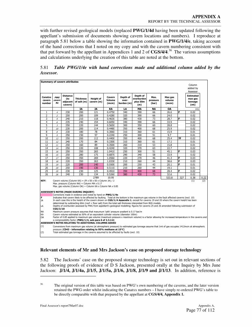
APPENDIX A REPORT BY THE TECHNICAL ASSESSOR
Final Assessor's report7Mar07.doc Appendix A,
Page 77 of 112
with further revised geological models (replaced PWG/1/4d having been updated following the appellant’s submission of documents showing cavern locations and numbers). I reproduce at paragraph 5.81 below a table showing the information contained in PWG/1/4/e, taking account of the hand corrections that I noted on my copy and with the cavern numbering consistent with that put forward by the appellant in Appendices 1 and 2 of CGS/4/4.36 The various assumptions and calculations underlying the creation of this table are noted at the bottom.
5.81 Table PWG/1/4e with hand corrections made and additional column added by the Assessor.
Relevant elements of Mr and Mrs Jackson’s case on proposed storage technology
5.82 The Jacksons’ case on the proposed storage technology is set out in relevant sections of the following proofs of evidence of D S Jackson, presented orally at the Inquiry by Mrs June Jackson: J/1/4, J/1/4a, J/1/5, J/1/5a, J/1/6, J/1/8, J/1/9 and J/1/13. In addition, reference is
36 The original version of this table was based on PWG’s own numbering of the caverns, and the later version retained the PWG order whilst indicating the Canatxx numbers – I have simply re-ordered PWG’s table to be directly comparable with that prepared by the appellant at CGS/4/4, Appendix 1.
�"##��� �$ %���� ����&"��'
:������
�������)�
(�������
(� )� *� +� �� ,� -� #"#
# " �& && # # &*"'!& �"& �%& �� �*� . &*&
!& && #&% &*" $& � & �%& �� "*& &*&
� % "& #& ##$ &*"��& �$& "�& '� $*' . &*&
" � �! "& #!" &*�&!& �"& �%& �� ��*% &*&
! � !& & #"" &*!�!& �&& �!& �& $*$ &*&
' #& �& && ##" &*""$& �!& "&& �$ !*% &*&
$ $ �& #$& '$ &*�&�& �#& ��& �# #!*% &*&#
% ! !& #!& !' &* "& !& �&& !# %*' &*&#
#& #� !& && ## &*""&& �!& "&& �$ !*" /. &*&
## # "& #'& $" &*��&& �#& ��& �# #'*# &*&#
# ## !& #�& $% &*�!&& �& �#& !� #!*$ &*&#
#" #" !& & #&$ &*" "& � & �'& �� *' &*&
#! #� !& �!& �! #*&"#& !& �&& !# "!*# . &*&�
#� #! !& $& #'! &*�$'& %& �"& !$ ��*% &*&
#' #' !& �!& �% #*&!�& & '& "� "#*� . &*&�
#$ #$ & �!& �� #*&��& #& �& "" �$*� . &*&�
#% #% & && #"& &*!!&& && !& "� &*# . &*&#
& & !& #%& #�& &*!##& #& �& "" #%*# &*&#
! ! �& �& # ! &*"%#& �!& "&& �$ $*" . &*&
� � "& �& #�" &*! �& �$& "�& '� � *� &*&
'$% #&*%! !��*$ � ' &*�$ &* *012 :������������� :������?(��@� ���-�!&�-�!&�-�:������A(��+� #� �
6�-*���������� :������/(��@�:������6(�-�&*#'
6�-*�1���������� :������.(��@�:������?(�-�:������/(�-�&*$!
���0��-�3� ,-�0� 4���0 �5�(,� (,65(�17
:���������������������������������������)���������89������
. >��������������������������)���������������)�������1*�������������������������������-�����1������������������������������������� �-��*�#&�
A(
B(
/( 6�-������������������������������������-�����C���C����������1�����������&*#'����+�
?( :��������������������������!&,�������D����������)�������������� ���������#&&��
.(
���0��-�3� ,-�0� �0+��(,� �- ���(�(-,�+ �-+5�,� ���0�
#�
� ����������������1��������1���������������������������������������)������� �-��*�#&�
:�����������������-�����1���������� ��������������������������������������1��������1��������������#�����1������������#"# �������������������
��������� ���� : $��#��� ����� �� �;< #��=�� �� �;>��
>���������������������������1�������������������7������������ �!!�?� �<��-����������������#%����� &�7�������������������1������������
������������)�����������1��&�� ����E����������������������������������������������������������5�������*������������������������������)��45��������������C��1����1�������������1F��1���������������� !����� ��������������7��1��������������
��������
G��������&*$!��������������-�����1���������� ��-��������������-���-����������������������������7��1���������������������������������������������
����������������)������� 89�����@ '"&:!��� � �$ ��������
0'�#���?
#�� �'
��� �
4#�7
������
%����
"#&��
89�
%����
,�
��!�= �$
����:
&"�?� 4#7
��!�= �$
����&"�?�
!�"' ;�#
4#7
����
!��''"��
4&��7
��� �'
���"#�
4#%#7
�'��%�
4��
�?A�%��
%����7
�=%B�''
�$ '��� 4#7
C� =� �$
%���� 4#7
�����
D��"#�
4#%#7

APPENDIX A REPORT BY THE TECHNICAL ASSESSOR
Appendix A, Final Assessor's report7Mar07.doc
Page 78 of 112
made to aspects of the proposed storage technology in the Opening Statement [J/1/7] and Closing Submissions [J/1/16]. Gas migration is also covered in the evidence of R S Jackson [J/3/1] and M J Jackson [J/2/1 and J/2/2].
5.83 The following excerpt from J/1/4 relate to the scope of the case presented by the Jackson family in relation to the proposed storage technology:
1.1.1 The development proposals are at a conceptual planning stage, the detailed surveys, methodology statements and detailed design statements required in relation to the proposed project, have not been supplied.
1.1.2 The appellant has failed to submit a decommissioning programme and a detailed site restoration plan or supply details of measures to be undertaken to mitigate long term subsidence.
1.1.3 The appellant’s E.I.A. Statement and Planning documents show an inadequate knowledge of the previous mining history of the area, contaminated land issues and natural and man-made features.
1.1.4 The appellant has failed to take into account the risk of gas migration and undertake a risk assessment as required to comply with EU case law.
5.84 Section 4 of J/1/4 sets out the Jacksons’ concerns regarding the lack of design information that had been submitted:
4.1.2 The appellant has submitted insufficient information to establish that the proposed design of the project is practical in this location and capable of carrying out its intended function.
4.1.3 A three dimensional representation showing the location and dimensions of the proposed caverns and their relationship to existing caverns should be produced.
4.1.4 A method statement should be produced for the design and construction of the caverns, both by conventional drilling methods and directional drilling techniques.
4.1.5 No details of the directional drilling methodology have been submitted or any detailed explanation as to why the caverns are now located at their current proposed position.
4.1.6 No records of geophysical surveys and analysis have been produced or up to date surface levelling data, showing settlement rates.
…
4.1.8 Full details of a de-commissioning programme have not been provided, or a site restoration programme, there is a lack of information on the measures which will be undertaken to mitigate long-term subsidence.
4.1.9 Although we, the general public, as lay persons, may not understand some of the technical detail produced in these types of reports, studies and surveys, we do need to be reassured that all the necessary studies and assessments have been undertaken and that they are comprehensive and reliable.

APPENDIX A REPORT BY THE TECHNICAL ASSESSOR
Final Assessor's report7Mar07.doc Appendix A,
Page 79 of 112
6. SUMMARY AND DISCUSSION
6.1 Based on the case summaries presented in Sections 3 to 5 above, in this section of the report, I address, in turn, each of the questions posed in paragraphs 1.7 to 1.9 above. In Section 7, I address the over-arching question posed in paragraph 1.5 above, and in Section 8 I provide the Inspector with my opinion on the key issues listed in my instructions.
Geological, hydrogeological and mining setting
What is the geological sequence and structure in and around the application site?
i. What are the information sources relating to geology and what is their reliability?
6.2 The raw information sources relating to geology comprises[para 3.4]:
• the published geological memoir by Wilson and Evans (1990); • a large number of borehole records (primarily covering the ICI brine-field, but some in
the area where it is proposed to establish storage caverns); • reports on the geological setting and structure by Daran Petroleum (1996), Jenyon (1997)
and Eyerman (2005); • seismic data for re-processing; and • records of the drilling and logging of two boreholes commissioned by Canatxx at Arm
Hill and The Heads (Ratigan, 2005).
6.3 This information (especially the seismic surveys and the borehole records) has been reviewed and investigated by Dr Evans and colleagues at the BGS to provide a detailed report that updates and supersedes the Wilson and Evans memoir [CGS/3/2, Appendix 2 & CGS/0/6, Appendix 1]. The BGS report puts forward a revised structural interpretation for the application site and this is depicted on the 1:10,000 scale maps numbered CD47b[paras 3.28 & 3.45].
6.4 The levels at the top and base of the salt in the area where caverns are proposed have been modelled with varying precision depending on proximity to data sources (boreholes and seismic lines) and the extent to which it has been possible to tie in and enhance the value of these data sources. In general, along the seismic lines, the actual levels at the top of the salt might be expected to differ from those in the model by between ±5m where there is a borehole close to the seismic line and ±20m for those sections of seismic lines where there are no boreholes to tie them in. At the base of the salt, the uncertainty relating to levels is generally greater, ranging from ±5m close to boreholes that penetrated the base of the salt to ±40-50m on those sections of the seismic lines where there are no boreholes, with intermediate ranges where there are boreholes on or close to the seismic lines that penetrated the top but not the bottom of the salt[para 3.48].
6.5 In the area west of the western limit of the ICI brine field and between seismic lines CAN97-G and IELP-99-25, there are neither seismic lines nor boreholes. In this area, which is just over 1km from north to south by just under 1km from west to east, levels are based on poorly constrained extrapolation; there are known points in the east, north and south, but no relevant data at all to the west. The position of the Burn Naze Fault (the western limit of the graben) is particularly poorly constrained as it was not crossed by the Canatxx or IELP seismic lines[para 3.49]. The uncertainty in this area is significantly greater than elsewhere in the model, but cannot be quantified; essentially this is a large area with no data and where a wide range of alternative interpretations (of thickness and level of salt and fault locations) are possible.

APPENDIX A REPORT BY THE TECHNICAL ASSESSOR
Appendix A, Final Assessor's report7Mar07.doc
Page 80 of 112
6.6 Faults with displacements of 20m or more can be identified with reasonable confidence from the available seismic data. On the IELP and Canatxx lines, faults with displacements between 8m and 10m can be identified, based on the velocities and synthetic seismograms derived from the Arm Hill and Heads boreholes. It may be possible to identify smaller faults than this on seismic lines, but this is not assured[para 3.49]. Between the seismic lines, the pattern, frequency, orientation, displacements and inclinations of faults is a matter of conjecture. In my view it is likely, given the interpretation of the overall structural setting as a graben, that further investigation will reveal more faults in the area between lines CAN97-G and IELP-99-25 where there is currently no data.
ii. What is the sequence of strata in the application site?
6.7 The sequence of strata at the application site is described in detail at paragraphs 3.10 to 3.21 above. In summary (on the appellant’s case), at the indicated cavern sites, it comprises between 192m and 412m of mudstone and superficial materials (which may be between 5.5 and 55m thick) overlying a bed of rock salt known as the Preesall Halite. The thickness of the Preesall Halite is estimated to vary between 117m and 329m[para 3.39, 6.51, and see also sketch at para 6.52].
6.8 Superficial materials. Apart from a general statement in the BGS report regarding the thickness of superficial materials reaching 60m in the Blackpool area [para 3.13], none of the parties has put forward any evidence regarding the thickness and nature of superficial materials. My own review of the borehole records provided on two CDs by BGS to LCC in response to their formal request for environmental information37 indicates that, for the boreholes where this information was recorded (65 of the 127 records on the CDs), the average thickness of superficial materials was 30.3m (maximum 54.9m in BH24 (SD34NE89) and minimum of 5.5m in BH125 (SD34NE133) [see Appendix 2 of the BGS report (CGS/3/2, Appendix 2 & CGS/0/6, Appendix 1) for BGS numbering and equivalent ICI numbering]. Many of these records only give depth to salt, sometimes referred to as ‘rockhead’38.
6.9 Bedrock overburden. The bedrock overburden to the salt comprises Coat Walls Mudstone overlain by the Breckells Mudstone Member. The Coat Walls Mudstone is a series of structureless, reddish brown mudstones interbedded with laminated, reddish brown and greenish grey mudstones and siltstones. Sporadic thin bands of mudstone with halite crystals also occur, particularly in the lower sequences. The Breckells Mudstone Member comprises dominantly reddish brown structureless mudstones with scattered greenish grey bands. The upper division, where present, often comprises largely brecciated mudstones, resulting from dissolution of thin halite beds. The Coat Walls Mudstone is said to be up to 122m thick and the Breckells Mudstone Member is said to be up to 144m thick[para 3.14]. Although both the Heads and Arm Hill boreholes drilled by Canatxx penetrated the mudstones overlying the halite, coring in the Arm Hill borehole and geophysical logging in both boreholes was carried out over only a very small part of the mudstone sequence. Based on the geological modelling, the total thickness of mudstone and superficial materials combined above the halite varies between 192m and 412m at the indicated cavern locations shown on CD47b[para 3.39, and see also sketch at para 6.52].
37 No inquiry number allocated. This information discussed in G Raybould’s note LCC/1/6 dated 2nd February 2006, and noted there as having been received by him on 24th January 2006.
38 Many of these borehole records are quite old; in modern use, the term ‘rockhead’ is used to describe the base of the superficial materials/top of bedrock.

APPENDIX A REPORT BY THE TECHNICAL ASSESSOR
Final Assessor's report7Mar07.doc Appendix A,
Page 81 of 112
6.10 Halite. The Preesall Halite is said in the BGS report to be a “succession of halite (rock salt) ranging in thickness from 79m to over 280m, with thin partings of reddish brown and greenish grey mudstones”[para 3.15]. Based on the geological model, the halite varies in thickness at the indicated cavern locations between 117m and 329m[para 3.39, and see also sketch at para 6.52]. It includes a number of non-salt beds comprising mudstone, anhydrite and various mixed materials. It appears, from the limited number of geologged boreholes, that these non-salt layers can be correlated based on synthetic seismograms and sonic logs of boreholes that were geologged[para 3.17].
6.11 Strata beneath the halite. There is over 300m of mudstone beneath the Kirkham Mudstone Member (including the Preesall Halite); these are known as the Singleton and Hambleton Mudstone Members. The Hambleton Mudstone Member is underlain by Sherwood Sandstone, which is a major aquifer[para 3.21].
iii. What is the geological structure in the application site?
6.12 The structural setting for the application area is agreed between the parties to be a westerly tilted graben bounded on the west by the down-east Burn Naze Fault and to the east by the down-west Preesall Fault. This supersedes the structural interpretation in the planning application, which assumed a synclinal structure. The sketch at paragraph 3.26 above (based on one I made in my notes to assist the Inspector during the inquiry) illustrates the difference between a simple graben structure and a simple syncline and indicates that, with limited data, either interpretation might be possible.
6.13 The Mercia Mudstone Group (within which the Preesall Halite occurs) is faulted against the Sherwood Sandstone Group on the eastern side of the graben. Between the two boundary faults, strata dips are generally to the west and there is inferred to be thickening of the halite from east to west. Both synthetic and antithetic faulting has been identified within the graben structure[paras 3.22 to 3.34].
6.14 Most of the faults that have been identified pass right through the halite bed, causing dislocation at the contacts with the mudstone at the top and the base[para 3.33]. There is general agreement that it is unlikely that there will be defined fault planes within the salt strata, given the property of salt to anneal (heal) fractures over geological time, although ‘healed’ fractures can be associated with planes of weakness within the salt. However, non-salt beds do not possess this property and the possibility of open fractures in these beds where they occur within the salt and are affected by faulting has been raised in relation to both strength and the potential for gas migration. The description of the Arm Hill salt core includes references to brecciated zones and slickensides, both taken by Dr Raybould as being indicative of faulting having affected the salt and potentially giving rise to gas migration pathways[para 3.79].
iv. What level of confidence at the overall site and individual cavern scale can be ascribed to the geological model?
6.15 I note the following statement in the draft SoCG: “There is general agreement on BGS’s overall interpretation of the geological structure, borehole and seismic interpretations and halite depths, and the resultant 3D geological model at this stage. Further work and data acquisition will inevitably lead to refinement of the model”[para 2.2 (SoCG para 11.11)]. I also note Dr Evans’ reluctance to present the data at a scale larger than 1:10,000 or to contour the top and bottom of the Preesall Halite at intervals of less than 100m[para 3.45], and, in addition, his evidence that the model and the work undertaken to produce it does not amount to a site investigation.

APPENDIX A REPORT BY THE TECHNICAL ASSESSOR
Appendix A, Final Assessor's report7Mar07.doc
Page 82 of 112
6.16 Whilst many details of the model were challenged in the course of the inquiry, some of the errors and inconsistencies were addressed by Dr Evans and his colleagues. CD47b appears to represent a consensus between the parties as to the best interpretation that could be achieved with the information available (as is reflected in the draft SoCG). I consider that a high level of confidence can be placed in the geological model at an overall site level with respect to setting the geological context of the site as summarised in paragraph 6.12 above. However, at an individual cavern level, for site selection or feasibility assessment, it can only provide imprecise estimates of the detailed topography of the top and bottom of salt surfaces or of the presence and nature of faults over the footprint of each cavern. Over large areas of the site, where cavern locations have been indicated, there is no information whatever about the location and nature of faults, and the way in which faults identified on adjacent seismic lines are linked together between those lines is open to alternative interpretations.
v. Is the level of confidence in the geological setting adequate for a consideration of the issues which I have been asked to consider?
6.17 As noted above, based on the evidence before the inquiry, I consider that the information sources and the geological model derived from them provide a reliable description of the general geological setting of the application site. However, there is a considerable amount of uncertainty inherent in the model, such that this model is not able to provide sufficiently reliable fault locations, salt levels and thicknesses to characterise proposed cavern locations or as a basis for conceptual design of caverns and a realistic estimate of the volume and tonnage of storage that could be created in this site. The model provides an excellent basis for the design of a site investigation (further seismic lines and boreholes to tie them in) directed towards identifying suitable blocks of un-faulted salt within which caverns might be located.
6.18 Despite the general agreement on the geological model between LCC and the appellant, and related general agreement as to its limitations and appropriate approaches to addressing these, there remains disagreement as to the level of detail and confidence in the model that is appropriate at the planning application stage. This has led to disagreement between the parties as to the further investigations that should have been carried out by the appellants and the information that should have been collected and analysed before the planning application was submitted.
6.19 I note that the appellant considers that its programme of preconstruction evaluation is the most extensive ever undertaken on a proposal for a salt cavern gas storage facility[para 3.7]. Witnesses for the appellant have sought to reinforce this point through comparisons with the geological evidence presented to the Byley inquiry, where caverns are to be created in salt strata that are stratigraphically equivalent to the Preesall Halite. LCC points out that, at the Byley inquiry, the geological evidence was not in dispute because the regional and local geological sequence and structure are both simpler and better understood than at Preesall[para 3.78]. The area within which caverns are to be constructed is described as ‘proved area without faults’[CD60], and all the proposed wells and caverns are within one fault block. LCC also points out that stratigraphic equivalence, of itself, does not imply or demonstrate that, if the geological setting at Byley is deemed suitable for the establishment of gas storage caverns, the Preesall Halite must also be suitable[para 3.78].
6.20 As is discussed elsewhere in this report, the primary constraints on the number, location, preliminary design of caverns and scheme capacity at this site are thickness; depth and inclination of the salt bed; and the location and nature of faults. At Preesall, all of these constraints are known to be highly variable as is demonstrated in the geological modelling that

APPENDIX A REPORT BY THE TECHNICAL ASSESSOR
Final Assessor's report7Mar07.doc Appendix A,
Page 83 of 112
has been completed to date. Given the fundamental importance of geological structure to this scheme, it is surprising that evaluation effort has not been more focused in these areas in the form of a site investigation. Such a site investigation would logically have been designed on the basis of the geological modelling. It would have been directed towards filling the large area of considerable uncertainty (‘hole’) that currently exists in the model between seismic lines IELP99-25 and CAN97-G, identifying the limits of un-faulted blocks of salt within which salt caverns of the diameter proposed could be created and, within those blocks, establishing the geometry of the top and bottom of the Preesall Halite with greater certainty than exists at present. Given the size of the site, such an investigation would probably involve at least two more seismic surveys, probably aligned north-east to south-west or north-west to south-east[para
3.81], and the drilling and geophysical logging of associated boreholes intersecting the top and bottom of the salt along those lines, providing the opportunity for accurate tie in of the data and improvement in its precision.
6.21 It is particularly surprising that the site investigation that has taken place (i.e. the drilling of boreholes at Arm Hill and The Heads) took place before the geological modelling upon which its design (in terms of number and locations of boreholes) would logically have been based. It is also surprising that the geological modelling was done after the planning application was submitted.
6.22 Whether or not the programme of pre-construction evaluation undertaken is unusually extensive for a project of this nature, I do not agree with the appellant that the geological investigation and analysis carried out is adequate to support a feasibility study for the proposal. Such a study would relate to the scale of the development and the location of the caverns, neither of which can be planned with any confidence using the currently available geological model. I do not agree with the appellant that the level of detail requested by LCC, the Planning Inspectorate and other parties is inappropriate at the planning application stage; the appropriate extent and complexity of preconstruction evaluation at any site will depend on the size and nature of the site, the nature of the proposals and the amount and quality of pre-existing geological knowledge. The appellant’s choice to focus most of its efforts on the drilling of two deep boreholes and testing of samples from one of them, rather than undertaking investigations to address the geological uncertainty described above, demonstrates that they have not appreciated the three dimensional constraints on their proposals of the geological setting and structure. This is further demonstrated by the emphasis placed upon drilling of wells and washing as important elements of investigations directed towards selecting final cavern locations [para3.52], rather than providing detailed design information at cavern locations that have already been selected.
What is the limit of the area of wet rockhead?
i. What are the information sources relating to wet rockhead and what is their reliability?
6.23 The main published information source relating to wet rockhead is the map in Wilson & Evans’ 1990 memoir, which is reproduced as an appendix to the BGS report[para 3.53]. PWG presented a comprehensive and well-researched case on the history of brine production and underground mining at the site, based on a range of contemporary reports, plans and other records[PWG/1/5 and PWG/0/3], which would form an excellent starting point for design of an investigation directed towards establishing the actual limits.

APPENDIX A REPORT BY THE TECHNICAL ASSESSOR
Appendix A, Final Assessor's report7Mar07.doc
Page 84 of 112
ii. Does the area of wet rockhead extend to the west of the former brine wells and other old mine workings?
6.24 There is no direct information relating to the actual extent of wet rockhead, and no site investigation has been done to confirm the western limit. The appellant relies on the area shown by Wilson and Evans in the published memoir and does not anticipate encountering wet rockhead deeper than 50-75m below the base of the drift[para 3.53], but the way in which Wilson and Evans established their limit is not known. PWG and LCC have identified information from drilling records and from an investigation and synthesis of the mining history of the ICI brine field and former underground salt mine that indicate that wet rockhead may be more extensive, and may be growing[paras 3.83 & 3.99] . All parties agree that caverns should not be formed in any location where there is wet rockhead. Accordingly, it is essential both that the western limit of wet rockhead is established with more certainty and that every cavern location is checked carefully to establish whether wet rockhead exists at that location. The establishment of a more accurate western limit for wet rockhead would be appropriate, in my view, at the planning application stage.
6.25 Detailed investigation at each and every cavern site to demonstrate that wet rockhead is not present may not be appropriate until after planning permission is granted (the COMAH stage), but it would be appropriate at this stage for the appellant to have described how it intends to undertake these investigations so that their impact may be assessed.
iii. What are the potential mechanisms for an expansion of wet rockhead?
6.26 The driving mechanism for expansion of wet rockhead would be the continued supply of fresh or weakly saline water (via the crown holes and lakes associated with collapsed mine workings or brine wells, or from the Sherwood Sandstone via the tunnels and other pathways that clearly exist beneath the brine-field). However, addition of fresh or weakly saline water, of itself, is not sufficient to promote expansion of wet rockhead. In order for expansion to occur, there would have to be an ‘outflow’ point in the system, providing for throughput of water with the capacity to dissolve salt.
6.27 If such an outflow were to exist down dip of sources of fresh or weakly saline water (i.e. to the west) of the existing brine field, then expansion of wet rockhead could occur (or could be occurring) in that direction.
iv. Is the area of wet rockhead expanding and/or is it likely to expand in the future?
6.28 It is not possible to say, from the information available, whether the area of wet rockhead is expanding or is likely to expand in the future. However, both PWG and LCC have put forward evidence relating to the man-induced expansion of wet rockhead as a result of uncontrolled wild brining and interconnections being created between adjacent brine caverns and between brine caverns and the collapsed mine workings[paras 3.83 & 3.99]. Some of these connections are described as having been created deliberately during the second World War to increase output[para 3.84]. LCC also considered that indications of solution at the top of the salt core from Arm Hill No. 1 borehole could reflect wet rockhead at that location[para 3.87].
6.29 The potential mechanisms and pathways for the introduction of fresh or weakly saline water at this site are overwhelmingly man-induced and new sources are likely to arise in the future if more ICI caverns collapse (as is regarded as likely)[para 3.102].

APPENDIX A REPORT BY THE TECHNICAL ASSESSOR
Final Assessor's report7Mar07.doc Appendix A,
Page 85 of 112
6.30 Site investigation and hydrogeological modelling will need to establish not only the current extent of wet rockhead but also make reliable predictions of its development (or ‘equilibrium state’ over the total life of the scheme (and beyond, after the caverns have been decommissioned).
What is the location and condition of old mine workings including decommissioned salt caverns?
i. How has the location, geometry and condition of former mine workings been established?
6.31 As part of its evaluation of the site, the appellant commissioned sonar surveys of some of the decommissioned solution mined salt caverns. The results of these surveys are shown in Appendix 8 to Mr Heitmann’s evidence[CGS/4/3, appendix 8] and the ‘footprints’ of the caverns surveyed are shown on the maps, CD47b. In general, sonar surveys were done for the caverns at the western limit of the ICI brine field; i.e. at the eastern edge of the area identified for the establishment of new caverns. However the appellant was not able to survey some of the caverns at the western limit of the brine field because it could not gain access via the well heads and pipe work[para 3.62]. Most of the wells shown on CD47b, but which have not been sonar surveyed, are associated with solution caverns although there are some (mostly those furthest to the south and west) that were not developed or not developed fully following the drilling of the well.
6.32 The appellant has not identified the former salt mine workings on its maps and figures and appears not to have considered the potential impacts on surface and sub-surface infrastructure associated with these former mine workings, or the brine caverns. PWG brought forward some detailed plans and narrative based upon their desk study exercise which indicates that the Appellant’s consideration of the mining setting of the site, both in relation to some of the proposed cavern sites and in relation to the surface infrastructure it proposes within the site, is incomplete and, in some cases, incorrect[para 3.102].
ii. How are the former mine workings monitored?
6.33 When the brine field was operational and, following its decommissioning, whilst in the ownership and control of ICI, regular surface levelling was carried out across the ICI brine field and the caverns were periodically ‘dipped and hooked’ to check on the condition of the cavern roofs. The appellant appears not to have continued with the precise levelling, although it has indicated that this will be continued. Whilst many years of precise levelling data must be available, none was made available to the inquiry (and it apparently had not been made available to the appellant either). The appellant had not undertaken any analysis or assessment of the stability and subsidence history of the former brine field. Mr and Mrs Jackson were able to describe past monitoring activities in some detail, having been involved both in ensuring access to the land and in assisting with the work.
iii. How secure are the former caverns and mine workings and what are the implications, if any, for the appellant’s scheme?
6.34 Several of the existing brine caverns have been identified as likely to collapse; these are generally those with thin or no salt in the roof, where the brine has been in contact with the overlying mudstone. Where collapse is predicted, these wells have been fenced off, including, for example, BW64 which is close to proposed pipeline routes.

APPENDIX A REPORT BY THE TECHNICAL ASSESSOR
Appendix A, Final Assessor's report7Mar07.doc
Page 86 of 112
6.35 Caverns that have collapsed have given rise to dramatic crown hole features, the edges of which continue to fall in, requiring periodic repositioning of the fencing. The Inspector and I were told on our site visit that the fencing around the crown hole arising from collapse of brine well BW-88 in 1994, is repositioned every year.
6.36 The brine in the caverns that were sonar surveyed has been confirmed to be under pressure, indicating that creep and closure has taken place and that the fluid in the caverns is keeping the caverns open. The continued security of these caverns depends upon the continuing integrity of the well string and valves at the well heads; i.e. on the continued confinement of the brine. Given that the appellant’s experts have indicated that observation of the ICI caverns and their long term behaviour in terms of deformation and subsidence will be important background data for the design of the new caverns, the lack of ongoing subsidence monitoring and absence of precise levelling results for the area is surprising. It is also surprising that no assessment or modelling of the likely impact of subsidence arising from closure or collapse of existing caverns on proposed surface pipework, roads and other infrastructure has so far been attempted.
Taken overall, is the information provided on the geological, hydrogeological and mining setting sufficient or sufficiently detailed at this stage?
6.37 I would have expected that the published BGS map and memoir, together with the collection, collation and analysis of all available site-specific information relating to current and former land-uses (brine wells and underground mining), ground conditions, and the mining and hydrogeological settings of the site would form the starting point for the design of a site investigation intended to support a feasibility study and/or mineral planning application for this project. This stage is commonly referred to as a ‘desk study’ and would be the framework within which more detailed site investigations would normally be designed and carried out.
6.38 The geological model and detailed report prepared by the BGS amount to a refinement of the published geological map at a scale of 1:10,000 and its associated memoir. Dr Evans was emphatic that the work that he and his colleagues undertook does not amount to a site investigation, that it is only fit for purpose at a scale of 1:10,000 with contour intervals of 100m, and that the model will benefit from further information, particularly in the area between seismic lines IELP-99-25 and CAN-97-G, where no drilling or seismic surveys have been carried out. I regard the geological work that has been undertaken as a high quality geological ‘desk study’, suitable as a basis for design of further site investigations but not for site selection and preliminary cavern design and determination of scheme capacity. The appellant has not included in its site evaluation any detailed consideration of the ground conditions in the ICI brine field area, where it proposes to establish significant surface infrastructure. PWG’s historical and local research provides an excellent example of what this element of the desk study could have contributed to project planning and identification of elements requiring further investigation or monitoring.
6.39 The objectives of a site investigation (designed on the basis of the desk study findings) would be to:
• provide sufficient additional information to reduce uncertainty to an acceptable level; • confirm or amend assumptions in the desk study model; • allow preliminary site selection (for both caverns and surface infrastructure); and • provide a basis for reliable estimation of scheme capacity (or a range of capacities) based
on conceptual and conservative design parameters.

APPENDIX A REPORT BY THE TECHNICAL ASSESSOR
Final Assessor's report7Mar07.doc Appendix A,
Page 87 of 112
6.40 The absence of such a site investigation at the planning application stage of this project underpins the very significant uncertainty regarding the number of caverns that can be established, their depths and dimensions and therefore the anticipated capacity of the scheme. It is impossible to say exactly what level of residual geological uncertainty is acceptable at the planning application stage, as this will, to some extent, be driven by the amount of commercial risk the developer is prepared to tolerate. However, the current level of uncertainty inherent in the geological model is such that the range of possible outcomes in terms of cavern numbers, locations and capacities is so wide that the scale and therefore the impact of the scheme in planning and environmental terms cannot be established.
6.41 Only when geologically suitable areas for cavern establishment have been identified in a site investigation as described above would it be appropriate for detailed investigation of the individual cavern sites to proceed and for sampling, testing and geomechanical modelling to commence. Detailed investigations would include the drilling of a single deep, cored borehole at each of the proposed cavern locations and the application of geophysical and/or supplementary probe drilling techniques to determine, in detail, the three dimensional geometry of the proposed location. In situ and laboratory testing would be carried out in the salt and overburden materials to provide input data and boundary conditions for the geomechanical modelling required to support cavern design. It is only this phase of investigation that is inappropriate before a planning permission is granted and the site comes under the COMAH regulatory regime.
6.42 From the Byley Inspector’s report and, particularly, the Byley Assessor’s report [CD53] as well as the Byley geological evidence presented at this inquiry[CD60] it is clear that the level of uncertainty in the geological setting at Byley was very low. Detailed geological and geomechanical studies of the salt at the proposed cavern locations are undoubtedly required at Byley as a basis for detailed cavern design and to support the COMAH process but there is no risk that such investigations would fundamentally alter the proposals in terms of the number and size of caverns. At Preesall, that is not the case.
6.43 Taken overall, I do not consider that the information provided by the appellant is sufficient nor is it sufficiently detailed to support the proposals in the planning application. I have reached this view against the background of the considerable uncertainty that exists relating to constraints that fundamentally affect the location of the caverns and the capacity of the scheme, namely the location of faults, the depth of the Preesall Halite and the thickness of the salt.
Properties of the salt and overlying materials
What are the mechanical and physical properties of the salt at Preesall?
i. Thickness?
6.44 The thickness of the Preesall Halite within the application site varies considerably. At the indicated cavern sites, the estimated thickness varies between 117m and 329m[para 3.39 and see
also sketch at para 6.52]. In general, the halite is inferred to be thickest at the western side of the southern section of the application site (between caverns 15 and 17 and the Burn Naze Fault)[CD47b].

APPENDIX A REPORT BY THE TECHNICAL ASSESSOR
Appendix A, Final Assessor's report7Mar07.doc
Page 88 of 112
ii. Strength?
6.45 There was general agreement between the cavern design experts that the amount of testing that had been undertaken on the Arm Hill #1 salt core was insufficient for the purposes of detailed geomechanical modelling and cavern design. However, there was also general agreement that the available data demonstrated that the strength and creep characteristics of the salt at Preesall are within the expected range for halite; Professor Rokahr described it as ‘medium quality’[para 4.13].
iii. Thickness and number of non-salt layers and their effect on salt strength/proportion of insolubles?
6.46 Non-salt (insoluble) materials within the Preesall Halite occur in two forms; discrete beds of mudstone, anhydrite or mixed materials and as non-salt materials entrained within the rock salt. In the evidence, the proportion of these materials was variously estimated by the appellant’s experts to account for less than 5% of the sequence or 3-8% including both non salt layers and insoluble materials incorporated within the salt layers. This estimate was later corrected under cross examination as being within the salt only[para 3.18], with beds and stringers of mudstone to be accounted for in addition. In his supplementary evidence, Dr Evans estimated 11%-15% for mudstone/anhydrite beds and stringers from the Arm Hill core report[para 3.20]. Thus the appellant’s total estimate of insoluble materials would be in the range 14-23%. LCC put forward 15% as a conservative estimate of the volume of insoluble material that could arise and need removing from or accommodating within the caverns, but this does not seem to be based on analysis of the core[para 3.70]. Given the discrepancy between the estimates made by the various experts, I have made my own assessment of the proportion of non-salt material in the sequence from the core description for the Arm Hill borehole [CGS/4/3, Appendix 1, Table 1]. Based on the descriptions in the core log, I estimate, from the Eyermann descriptions, that approximately 8% of the halite sequence cored at Arm Hill comprises non-salt layers. Based on the estimates in the descriptions of the individual beds, I estimate that insoluble material (mudstone etc) entrained within the salt makes up a further 10-12% of the sequence, giving an estimated total insoluble content for the sequence of 18-20%, which is broadly consistent with the appellant’s case as it emerged by the end of the inquiry. My assessment is set out in Annex AR1 to this report.
6.47 Based on the above, the appellant appears to me to have based its application on an under-estimate of the amount of insoluble material that will arise in the course of washing the halite sequence as it is represented in the Arm Hill borehole. This has implications both for the amount of insoluble material that will be pumped to the surface in suspension in the brine and need to be filtered or settled out (and hence the adequacy of the settling array shown and disposal arrangements) and for the proportion of the cavern volume that will be taken up by a sump at the bottom.
6.48 I agree with LCC that the only logical way to estimate the proportion of insolubles is to consider the whole sequence and to do this individually at each cavern location.
iv. Depth to salt roof?
6.49 The depth to the top of the halite bed within the application site varies considerably. At the indicated cavern sites, the estimated thickness of overburden varies between 192m and 412m, and comprises mudstone and superficial materials (which may be between 5.5 and 55m thick) [see sketch at para 6.52]. The depth to the top of each cavern will be at least 50m (one cavern radius) below the top of the halite. In general, the halite is inferred to be deepest at the western

APPENDIX A REPORT BY THE TECHNICAL ASSESSOR
Final Assessor's report7Mar07.doc Appendix A,
Page 89 of 112
side of the northern section of the application site (between caverns 25, 3, and 26 and the Burn Naze Fault)[CD47b].
Are the properties of the Preesall salt and its geological setting consistent with properties of salt within which gas storage caverns have been established successfully, or have been permitted elsewhere?
6.50 The inspector and I were provided with the Inspector’s and Assessor’s reports from the Byley inquiry [CD53]. Throughout the inquiry, comparisons were made between the geological setting and the amount of investigation and analysis that had been done at Byley and Preesall before planning applications were submitted. Some of these comparisons are included in the summaries in Sections 3 to 5 above. To assist me and the Inspector in considering the implications of the comparisons we were invited to make, I have used CD53 and the evidence presented to this inquiry to prepare the comparative table attached as Annex AR2 to this report.
6.51 It is clear from Annex AR2 that there are some fundamental differences between the permitted scheme at Byley and the proposed scheme at Preesall, in terms of the scale of the proposed facilities, the complexity of the geological setting and potential failure modes. The key differences are summarised below and in the sketch at paragraph 6.52 below39:
Preesall Byley
Number of caverns proposed
Up to 24 Up to 8
Total tonnage of salt to be removed to form caverns
Between 32 and 48.2 million tonnes (depending on shape assumed)
7.2 million tonnes
Range of depths to cavern roof 242-462m 630m Range of total salt thickness
117-329m 290m
Minimum thickness of intact salt above cavern roof
50m (or one cavern radius) 150m
Thickness of intact salt below cavern floor
10m 10m
Percentage of insoluble materials within the salt bed
14-23% by volume (in situ, before bulkage) 10% by volume (in situ before bulkage)
Range of proposed cavern dimensions
Max diameter: 100m Height: 57-269m H/W ratio 0.57-2.69
Max diameter: 84m Height: 100m H/W ratio 1.19
Ratio of bedrock overburden thickness to cavern height
1.03 (cavern 17) – 5.21 (cavern 9)
6.05
Range of safe operating pressures
Minimum: >30% of OB pressure (range estimated to be 16 bar in cavern 20 to 30.5 bar in cavern 26) Maximum: <83% of OB pressure (range estimated to be 44.2 bar in cavern 20 to 84.4 bar in cavern 26). Appellant says maximum will not exceed 78 bar.
Minimum: 35 bar Maximum: 105 bar (maximum estimated to be approximately 75% of vertical overburden pressure)
39 Although the proposed storage technology is not discussed in detail until later in section 6, I have included information relevant to the proposed caverns at this point for completeness.

APPENDIX A REPORT BY THE TECHNICAL ASSESSOR
Appendix A, Final Assessor's report7Mar07.doc
Page 90 of 112
Preesall Byley
Range of salt cavern volumes
Salt cavern volumes Min: 0.1-0.32mcm (cavern 9) Max: 1.37-1.48mcm (cavern 17) (range depends on shape assumed) Operating volumes 21-34% less due to retained insolubles (50% bulkage)
Salt cavern volumes 360,000m³ Operating volumes 300,000m³
Scheme capacity
9.8-12.3mcm of gas storage capacity in the 20 indicated caverns shown on CD47b
2.4mcm of gas storage capacity

APPENDIX A REPORT BY THE TECHNICAL ASSESSOR
Final Assessor's report7Mar07.doc Appendix A,
Page 91 of 112
6.52 Sketch illustrating key features of the permitted scheme at Byley and the proposed scheme at Preesall.
Superficial materials
Mercia Mudstone
Halite
Preesall Byley
0
-700
-200
-300
-400
-500
-600
-800
-100
0
-700
-200
-300
-400
-500
-600
-800
-100
Max cavern height 269m (Cavern 17)
117m (min estimated salt
thickness)
329m (max estimated salt
thickness – cavern 17) (PWG max
350m – caverns 15, 16 & 17)
100m (max cavern
diameter)
54.9m (max recorded depth to rockhead - BH24)
192m (PWG -200m) (min estimated depth to top salt – cavern 19) 412m (PWG – 380m)
(max estimated depth to top salt - cavern
26)
84m (max cavern
diameter)
100m (max cavern height)
Min cavern height 57m (Cavern 9)
Salt thickness approx 280m
Estimated thickness of superficial
materials 25m
m below ground level
Min thickness of salt in the roof: 150m (170m shown on
CD60)
5.5m (min recorded depth to rockhead - BH125)
455m - estimated thickness of Wych-Byley Mudstone formation
Note – shapes shown for the caverns are indicative only. A variety of shapes is possible. From the evidence at the inquiry, they could be spheres, ellipsoids, cylinders with parabolic or spherical roof and conical, flat or spherical floors, or ‘bell shapes’.
m below ground level

APPENDIX A REPORT BY THE TECHNICAL ASSESSOR
Appendix A, Final Assessor's report7Mar07.doc
Page 92 of 112
Can the physical and mechanical properties measured in the single cored borehole at Preesall be extrapolated with confidence to the rest of the deposit?
i. Sequence?
6.53 From the correlation of geophysical logs presented by Dr Evans[para 3.17], there are indications that the Arm Hill borehole may be representative of the Preesall Halite in terms of the stratigraphy of the salt bed itself. However, the thickness of halite indicated in the ICI wells in the correlation was around 50m less than that intersected in the new boreholes and this correlation does not provide any information about the thickness or nature of non-salt beds, since the only cored borehole in this group was the Arm Hill borehole. Further ‘ground truth’ in the form of additional fully cored boreholes would be needed to confirm such a correlation.
ii. Strength?
6.54 The current information on salt strength and in situ stress state cannot be extrapolated with confidence to the rest of the deposit. Professor Rokahr explained that, whilst the testing that has been done on the Arm Hill core gives a good ‘head start’ to the feasibility/design phase, if he had been designing an investigation at this site to obtain representative parameters for preliminary geomechanical modelling and design, he would have recommended drilling at least three cored boreholes and taken 50-70 core samples from each for testing.
iii. Thickness and number of non-salt layers?
6.55 Whilst the analysis that I carried out on the core description of the Arm Hill borehole[para
6.46] provides a reasonably reliable figure for the individual and total thicknesses, number and lithologies of non-salt strata at that location (assuming that the measurements and visual descriptions are reliable), the estimate of entrained insoluble material is far less certain, being based on a visual estimate of the proportion of mudstone entrained within the salt. The only way to obtain a reliable estimate for the proportion of non-salt material entrained within the salt is to take a continuous sample of the core, dissolve it and measure the insoluble residue. The appellant’s limited sampling is not a reliable or representative basis for an estimate of the proportion of insolubles that will arise in a cavern at or near Arm Hill; the whole thickness that will be intersected in the cavern would need to be sampled.
6.56 Only one fully cored borehole has been drilled and so it is impossible to say, at this stage, whether the thickness and number of non-salt layers, and the amount of insoluble material entrained in the salt as described in the Arm Hill borehole is typical of the Preesall Salt throughout the site area. As noted in paragraph 6.53 above, there are indications that it may be possible to correlate the principal non-salt bands in the halite between boreholes, this analysis cannot provide information about thicknesses and proportions without further ‘ground truth’ in the form of coring.
What are the properties of the materials overlying the salt?
i. Sequence?
6.57 Dr Evans in his report described the Mercia Mudstone strata overlying the salt in general terms[paras 3.10-3.14]. These strata have not been sampled, described and tested or geophysically logged in the two boreholes drilled by the appellant (which collected information primarily from

APPENDIX A REPORT BY THE TECHNICAL ASSESSOR
Final Assessor's report7Mar07.doc Appendix A,
Page 93 of 112
the halite). Whilst there are some descriptions of this material in the borehole and well records associated with the former brine field, these are not of a consistent quality or level of detail, neither do they cover the area within which it is proposed to establish gas storage caverns. It is therefore not possible to say in detail what the sequence of overburden strata is, beyond the fact that it is likely to be predominantly reddish brown mudstone possibly with some beds of sandstone, siltstone, gypsum or anhydrite.
ii. Thickness?
6.58 The thickness of the bedrock overburden strata varies according to the topography, the thickness of superficial materials and (to a greater extent) according to the depth at which the halite bed is present. The geological model provides estimates of total overburden thickness, but insufficient information is available to establish the likely thickness of superficial materials over the application site or thicknesses of individual beds of Mercia Mudstone strata that may have different properties from the mudstone itself (e.g. anhydrite, gypsum).
iii. Permeability?
6.59 No in situ or laboratory permeability tests have been done on the overburden strata. Whilst it is reasonable to assume that the permeability of the dominant material (mudstone) will be low, the presence of more permeable strata cannot be ruled out.
Taken overall, is the information provided on the properties of salt and overlying materials sufficient or sufficiently detailed at this stage?
6.60 The information provided by the appellant on the properties of the salt and the materials overlying the salt falls into two categories:
• information relating to the nature of materials themselves (strength, creep behaviour, density, proportion of insoluble materials etc); and
• information relating to the suitability of each of the indicated cavern sites, or any other cavern site that might be indicated in the future (thickness and depth of the salt, proximity to faults etc).
i. Information relating to the nature of the materials themselves
6.61 The appellant has drilled only one borehole at the site and, whilst it has recovered core from the salt strata, tested some of the salt cores and undertaken in situ testing in the borehole, it has not sampled or tested the overburden mudstones or superficial materials. The appellant’s own cavern design expert considers that the number of cores that were tested from the borehole was insufficient for the purpose of characterising the material for cavern design; a larger number of cores and a greater range of tests is needed for the confident prediction of material properties as input to the type of geomechanical modelling that will be needed for detailed design. Professor Rokahr and LCC’s experts all indicated that, even if the sampling and testing in the Arm Hill #1 borehole could be considered to be representative, it is not possible to extrapolate material properties from Arm Hill to other indicated cavern locations without further core drilling.
6.62 Whilst I agree with the experts who gave evidence on this subject that the currently available information about the material properties of the salt (and overburden) is insufficient for the purposes of detailed cavern design, I do not consider that the amount of information appropriate for detailed design is necessarily appropriate at the planning application stage. The

APPENDIX A REPORT BY THE TECHNICAL ASSESSOR
Appendix A, Final Assessor's report7Mar07.doc
Page 94 of 112
information is sufficient to allow Professor Rokahr to draw a general conclusion regarding the quality of the salt and its in situ stress regime and to set out some recommendations as to cavern dimensions and spacing. Detailed design based on geomechanical modelling is not required until the COMAH stage.
ii. Information relating to the suitability of the indicated cavern sites
6.63 As is set out in detail in Section 3 of this report (and summarised and discussed in the earlier part of this section), the uncertainties relating to the geological structure at this site are significant. This is acknowledged by the appellant’s experts, but the appellant asserts that further investigation is inappropriate at this time, but will be carried out once planning permission is granted, as essential background to the COMAH process. In my view, the effect of the level of uncertainty is that, for each indicated cavern location (or for any other location that might be chosen at the site), the fundamental constraints on cavern design (the thickness of the salt, its depth, and the proximity of a proposed cavern to faults) are, at best, uncertain and, in places, entirely unknown. This means that there is no reliable basis either for assessment of the indicated cavern locations or for identification of alternative locations. Accordingly, I do not consider that there is sufficient or sufficiently detailed information currently available in relation to the suitability of the indicated cavern sites or for selecting alternative sites.
Proposed storage technology
What are the design criteria for the proposed salt caverns?
i. What is the significance of depth and thickness of overburden?
6.64 All parties agreed that the vertical pressure of the overburden (including salt head) above the cavern is the starting point in determining the maximum safe operating pressure and the minimum allowable internal pressure within the cavern. The stability of the cavern in various stress states is then determined by reference to the salt and overburden rock and rock mass properties, and having regard to the way in which the cavern will be operated (particularly velocity of changes in internal pressure and pressure during operation).
6.65 Professor Rokahr recommended maximum operating pressures not exceeding 83% of the vertical component of overburden stress (which would have to be calculated based on a comprehensive testing regime) and minimum internal pressures not lower than 30% (internal cavern pressure �0.18bar/m, �0.07bar/m)[para 5.10]. Dr Passaris did not disagree with this recommendation. Based on their study of international norms, PWG considered that the maximum safe pressure should not exceed 0.17bar/m; i.e. broadly in agreement with Professor Rokahr.
6.66 From the geological modelling already carried out, there will certainly be a wide variation in depths of the proposed caverns at their indicative locations and therefore a similarly wide variation in maximum safe internal pressures. This underlines the importance of site specific geological modelling at each cavern location, since the depth to the roof determines the maximum safe pressure (and the minimum required to ensure stability).
ii. What is the maximum and minimum operating pressure in the caverns?
6.67 Professor Rokahr emphasised that 83% of the vertical overburden pressure is the starting point for estimating maximum operating pressures; depth to cavern roof is an important consideration but it is not the only consideration. As with all other design recommendations in

APPENDIX A REPORT BY THE TECHNICAL ASSESSOR
Final Assessor's report7Mar07.doc Appendix A,
Page 95 of 112
his report, this parameter represents the best case; under no circumstances would a larger maximum operating pressure be permitted, but the detailed investigation, analysis and design might lead to a lower figure being recommended.[para 5.14]. Using the appellant’s estimates of cavern depths and heights, I estimated maximum operating pressures for each of the 20 caverns for which the appellant has provided indicative locations, cavern depths and heights[para 5.17]. It is immediately apparent from this analysis that, with the exception of caverns 3, 25 and 26, none of the caverns now indicated by the appellant could operate safely at the maximum pressures shown on CD26a (Hazardous Substances Application plan). Thus, it appears that the assessments of risk based on this plan will tend to have been conservative since the actual gas pressures will, in most cases, be lower than indicated at the time that plan was drawn.
6.68 As noted above, the wide variation in cavern depth resulting from the geological setting gives rise to a wide variation in estimated maximum safe operating pressures. The maximum calculated is 84.4 bar (cavern 26) and the minimum is 44.2 bar (cavern 20).
iii. What thickness of salt must exist in the roof and floor of the caverns?
6.69 The appellant’s cavern design expert, Professor Rokahr has recommended that the thickness of salt that must be left in the cavern roof must be not less than the maximum cavern radius, and that the maximum cavern radius at this site should not exceed 50m. Between the cavern floor and the mudstone beneath, the minimum recommended salt thickness left in situ is 20% of the maximum cavern radius (for a cavern with maximum radius 50m, this will mean a thickness of floor salt of 10m[para 5.16].
6.70 Professor Rokahr emphasised that these recommendations were not based on detailed investigation, geological and geomechanical modelling and should be regarded as preliminary. However, he said that, under no circumstances would the thicknesses of roof and floor salt be reduced from these; they would be likely to increase as a result of detailed design.
iv. What spacing is necessary between adjacent caverns, and between caverns and faults, old mine workings etc?
6.71 Professor Rokahr, has provided the following recommendations as to minimum distances between existing and proposed salt caverns and faults[para 5.18]:
• Between adjacent proposed gas storage caverns: ........................... 3*maxrcav 40 (150m) • Between proposed gas storage caverns and faults: ............................... 3*maxrcav (150m) • Between proposed gas storage caverns and
existing ICI brine caverns:...................................................................4*maxrcav (200m)
6.72 Professor Rokahr emphasised that firm recommendations as to undisturbed salt that would have to be left in situ around caverns could not be made until detailed geomechanical modelling and design had been carried out to determine the size of the ‘safety zone’ required. The recommendations that he had made in his evidence were minima, and there was no prospect that they would be reduced – in fact he said that the appellant should expect less and not more[para 5.6]. In addition to distances from adjacent caverns, faults, and former brine wells and mine workings, inclined (lazy “S”) drilling should not give rise to an offset between a well head and a cavern of greater than 500m[para 5.36, point 3].
40 maxrcav = maximum cavern radius

APPENDIX A REPORT BY THE TECHNICAL ASSESSOR
Appendix A, Final Assessor's report7Mar07.doc
Page 96 of 112
6.73 There was much debate about the proximity of caverns to faults and whether Professor Rokahr’s recommended standoff distances applied to all faults or only major faults[para 5.19]. Whilst Professor Rokahr had indicated in his written evidence that his recommendation was valid for the Burn Naze Faults and not necessarily for the intra-graben faults, if they could be shown to be gas tight, he explained in cross examination that so many boreholes would need to be drilled to investigate all identified faults that the appellant should “forget it”. He also said that there would be small faults that would be missed by seismic surveys and that the design should take these into account in defining the safety zone[para 5.20].
6.74 His recommendation now amounts to “no cavern should be closer than three times the maximum cavern radius from faults that can be identified from seismic and other investigations and all caverns must be designed conservatively assuming that there are some faults that cannot be identified given the resolution of the seismic surveys”.
vi. What shape will the caverns be?
6.75 The appellant’s estimates of total cavern volume (i.e. the amount of salt that will be removed by solution mining) are based on the simplifying assumption that the caverns will be cylinders, each with a diameter of 100m and maximum height equal to the thickness of the salt bed minus the thickness of salt that must be left in the roof and floor. In the course of the inquiry, the experts for the appellant provided an estimate of 70%[para 5.28] as the proportion of the volume of a cylindrical ‘envelope’ that could be washed, given the need for a vaulted roof[para 5.21]. PWG used a figure of 50% as their estimate of the proportion of the volume of a cylindrical ‘envelope’ that would result from washing a properly designed cavern of an acceptable shape[para 5.81]. The subsidence reports by Ratigan and Fuenkajorn apply the following methodology to the estimation of cavern shape and volume[para 5.32]:
• Any cavern with maximum height less than or equal to 100m will be spherical, with a diameter equal to the maximum height achievable in that cavern location41; and
• Any cavern with a maximum height greater than 100m will be cylindrical, with a spherical roof and floor42
6.76 Clearly, as the relative proportions of cylindrical and spherical elements will depend on cavern height, applying this methodology to individual caverns will give a range of percentage shape reduction factors to apply to idealised cylinder volumes. This is illustrated in the table at paragraph 6.80 below.
vii. What determines the operating volume of the caverns?
6.77 The operating volume of each cavern depends not only on the shape of the cavity formed in the salt in the course of solution mining but also on the volume taken up in the base of the cavity by insoluble materials retained there[para 5.23].
41 Volume = 3
234
��
���
� hπ where h = maximum cavern height
42 Volume = ��
���
� 3
34
rπ + ( )( )1002 −hrπ , where r = maximum cavern radius (50m for this proposal)

APPENDIX A REPORT BY THE TECHNICAL ASSESSOR
Final Assessor's report7Mar07.doc Appendix A,
Page 97 of 112
6.78 All the experts agreed that the total anticipated cavity volume of 22.3Mm3 indicated by the appellant on its table in appendix 1 of CGS/4/4 is wholly unrealistic for two reasons. First, this volume has been calculated assuming that the caverns will be cylindrical. Second, no allowance has been made for insoluble materials that will fall to the bottom of the cavern during washing and remain there in the sump.
6.79 I have prepared the table at paragraph 6.80 below to illustrate the cavern volumes that would result from applying the Ratigan/Fuenkajorn estimation method[paras 5.30-5.31] and using the maximum cavern heights indicated by the appellant in appendix 1 of CGS/4/4. This indicates that individual salt cavern volumes are likely to be between 21.7% and 81.9% of perfectly cylindrical caverns, with an overall reduction to 66.3% of the most recent estimate of total volume indicated by the appellant (22.3Mm3).
6.80 Table showing Assessor’s estimate of volume of caverns and scheme capacity using Ratigan/Fuenkajorn shape assumptions
6.81 The table at paragraph 6.80 above indicates that the tonnage of gas storage capacity in the caverns would be 0.67Mt (some 56% of the 1.2Mt indicated in the application), if the whole of the washed volume is available for gas storage. In fact, some of the volume of each cavern will be occupied by insoluble materials that are washed out of the salt during cavern washing, 95-98% of which is expected to remain in the cavern sump in a saturated state[para 5.34. The volume of this material (after bulkage of 50%) has been estimated from the information included
Provisional Cavern Volumes
Cavern Number(1)
Depth to Roof
Level (m)
Depth to Floor Level (m)
Cavern Height
(m)Total Cavity Volume (m³)
2������������)�
�����������)��1�
2���1��+G�����H����
������������������
I�
2������������)�
����������,���
����������
�)�������������
������������
�����������
���������� ��
8��������
�����������
������������
���� ����
6�-�����
����7�����
�������
���������
����
6�-�1���
�������
�������
������������
���������
6�-�1��������1��
%!,������������
#!9:�� ��������
�������
1 412 533 121 950,300 !�$<#&! !%*$, "# %&*�" '!* � " *'" &*&�
2 394 503 109 856,100 "'�<$!' !!*", �%" $�*�$ '#*%" �"*&% &*&
3 450 568 118 926,800 !""<!"� !$*$, "!& %%*&& $ *#' ""*'! &*&�
4 411 565 154 1,209,500 $ '< $� �$*", "## %&*" '!*&! � *&% &*&"
5 359 503 144 1,131,000 '"$<'"� ��* , �!% '$*%$ �!*!! "%*&$ &*&�
67 425 539 114 895,400 !#�<# ' !'*�, " ! %�*!& ''*�# �%*$ &*&�
8 416 494 78 612,600 "$<"'! "&*�, "#� %#*! '!*%� #$*$' &*&#
9 317 374 57 447,700 %�<%�' #*', �#' �%*'" !'*$$ !*�# &*&&
10 408 520 112 879,600 "%'<"#% !�*�, "&$ $%*'� '"*!& �'*&� &*&�
11 367 451 84 659,700 �#&<��% "'*&, ��' $&*'" �'*&# &*$& &*&#
12 334 423 89 699,000 ��%<# # ! *$, ��" '�*"$ �&*%% *!# &*&
1314 384 492 108 848,200 "��<&&� !"*%, �$" $"*"$ '&*# � *�$ &*&
15 332 597 265 2,081,300 #<�%%<&'$ $#*�, �� '�*&" �&*� #&�*&& &*&'
16 353 528 175 1,374,400 %% < & ' * , �!� ''*�� �"*"� ��*%� &*&!
17 297 566 269 2,112,700 #<'�&<"%" $#*%, %' �!*�" !"* � %�*$! &*&'
18 297 560 263 2,065,600 #<�$�<�'& $#*!, %' �!*�" !"* � %#* % &*&�
19 267 450 183 1,437,300 #<&!!<&! '�*", �' !$*'" "$*'! !#*"" &*&"
20 242 381 139 1,091,700 '&%<"'� �!*&, " !�* " ""*#% �#*�! &*&
21 to 2425 450 575 125 981,700 !%%<! # �#*#, "!& %%*&& $ *#' "%* � &*&�
26 462 596 134 1,052,400 �'&< &� ��*', "� #&#*�" $"*�� !�*!" &*&"
22,313,000 ��@���@��� ����< 6�-�$#*%,<����� #*',� ����� ����
Notes: (����������0
100 m diameter .�������������������1������� &* ���+� ��B�=� EE 89�
50 m of roof salt 6�-������������������������ $�, �������
10 m of floor salt#* ����1���;%!,�������������#!9:���������0
!%*$! ��������������������������
#<�%! ���<���������
#*&����1���;%!,�������������#!9:���������0
"%*$'! ��������������������������
#<"# ���
Original version of CGS/4/4, Appendix 1
Total anticipated Cavity Volume (m³)
Cavern volume is based on notional: �����������
.+����������
(�������������������������)�(�������
����
(1) These cavern locations are not the same as those on CGS/4/2, Table 1
Cavern relocated and re-numbered
Cavern relocated and re-numbered
Caverns excluded from calculation
I���������7�����@��
7������J@#&&�
:)�������7����
������������������
�����7�����
�K#&&�

APPENDIX A REPORT BY THE TECHNICAL ASSESSOR
Appendix A, Final Assessor's report7Mar07.doc
Page 98 of 112
with the appellant’s evidence to represent between 21% and 34.5% of the total washed volume[para 5.35]. Using these figures, I estimate that the capacity of the scheme, if all 20 of the caverns can be constructed at the locations and with the heights indicated would be between 9.8 and 11.7Mm3, and that this would allow the storage of between 0.44 and 0.53Mt of gas if the estimated maximum allowable cavern pressures could be achieved in each cavern (see table at paragraph 6.82 below).
6.82 Table showing Assessor’s estimate of the capacity of the caverns after insolubles retained in the caverns are taken into account
How will the caverns be constructed and commissioned?
i. What is the sequence of events during the construction phase?
6.83 The sequence of events during the construction phase is described in paragraphs 5.36 to 5.38 above. Whilst this evidence was not challenged in relation to the formation of the caverns, there was some ambiguity regarding the arrangements for settlement and disposal of solids. Mr Heitmann’s evidence was that 3-8% of the washed volume of each cavern would comprise insoluble materials but this was at variance with the opinion of the appellant’s geological expert, Dr Evans, who estimated that, in addition to the 3-8% of insoluble materials that would be washed out the solid salt, a further 11-15% by volume of insoluble materials occurs as beds or
Cavern Number(1)
Total Cavity Volume (m³)
2������������)�
�����������)��1�
2���1��+G�����H����
������������������
I�
2��������������)�
�������1� #,���
����������������
�)�����������
2��������������)�
�������1��",���
����������������
�)�����������
������������
�����������
���������� ��
8��������
�����������
������������
���� ����
6�-�����
����7�����
�������
���������
����
6�-�1���
�������
�������
������������
���������
6�-�1��������1��
%!,������������
#!9:�� ��������
�������
6�-�1���
������� ����
���������������
���������
6�-�1���
�����1�� %!,�
�����������
#!9:�� ��������
�������
1 950,300 !�$<#&! ""$<$&� �'"<%"% "# %&*�" '!* � ��*'� &*& " $* # &*& &
2 856,100 "'�<$!' �'"<�"' �# <'"� �%" $�*�$ '#*%" �*%� &*&#% *!& &*&#�
3 926,800 !""<!"� "�&<#$% �!%<�%$ "!& %%*&& $ *#' �!*�! &*& ! %*!� &*& #
4 1,209,500 $ '< $� �!�<!!� !"�<&&% "## %&*" '!*&! "%*&! &*&�! "&*%$ &*& %
5 1,131,000 '"$<'"� !%#<!#& "%"<#'� �!% '$*%$ �!*!! �$*'$ &*& ' � *�% &*& �
67 895,400 !#�<# ' "&!<�'& ��$<��" " ! %�*!& ''*�# �#*"� &*& �* $ &*&#%
8 612,600 "$<"'! #%�< %! #��<%%� "#� %#*! '!*%� #"*%# &*&## # *"� &*&&%
9 447,700 %�<%�' '�<�&" ��<%%$ �#' �%*'" !'*$$ "*"� &*&&� �*'& &*&&�
10 879,600 "%'<"#% �% <%�# � $< %� "&$ $%*'� '"*!& %* $ &*& # "*"� &*&#'
11 659,700 �#&<��% "!<#�$ &"<$ " ��' $&*'" �'*&# #�*"� &*&# #�*'� &*&#&
12 699,000 ��%<# # %#<�&� "�<� & ��" '�*"$ �&*%% #'*'$ &*&#� #"*$� &*&##
1314 848,200 "��<&&� ��$<#" �&'<!� �$" $"*"$ '&*# !*$# &*&#$ #*!' &*&#!
15 2,081,300 #<�%%<&'$ #<�" < ' #<# #<�%# �� '�*&" �&*� $#*�' &*&!$ �'*%$ &*&"$
16 1,374,400 %% < & '$�<$!" �!"<$�! �!� ''*�� �"*"� !&*!� &*&�� " * # &*&�&
17 2,112,700 #<'�&<"%" #<��'<&%& #<#" <# � %' �!*�" !"* � '"*#" &*&! �#*%" &*&""
18 2,065,600 #<�$�<�'& #<� %<$� #<###<& " %' �!*�" !"* � ' *# &*&!# �&* ! &*&"�
19 1,437,300 #<&!!<&! $��<"%# �%�<��" �' !$*'" "$*'! "&*�" &*& % ��*%! &*& "
20 1,091,700 '&%<"'� !�&<"$� "�$< !" " !�* " ""*#% "*'' &*&#$ &*�% &*&#!
21 to 2425 981,700 !%%<! # "'�<� # �%!<�$" "!& %%*&& $ *#' �$*% &*& $ � *!# &*& �
26 1,052,400 �'&< &� ! %<"�� "" <��� "� #&#*�" $"*�� ""*�' &*&� �'*� &*& �
max 2,112,700 #<'�&<"%" #<��'<&%& #<#" <# � "� #&#*�" $"*�� $#*�' &*&!$ �'*%$ &*&"$
min 447,700 %�<%�' '�<�&" ��<%%$ " !�* " ""*#% "*"� &*&&� �*'& &*&&�
average 1,115,650 '"&<#'& !$"<'�" "$$<!# ��% $#*#! �'*�! �'*!� &*& ' �#*�$ &*&
22,313,000
��@���@���#F
4����< �$
�!!�����3'
���'�? $ "��7
��@���@���
4;���< �$
�!!�����3'
���'�? $ "��7
�@���@���
4����< �$
�!!�����3'
���'�? $ "��7
#, �", (����������0
.�������������������1������� &* ���+� ��B�=� EE 89�
6�-������������������������ $�, �������
#* ����1���;%!,�������������#!9:���������0
!%*$! ��������������������������
#<�%! ���<���������
#*&����1���;%!,�������������#!9:���������0
"%*$'! ��������������������������
#<"# ���
Provisional Cavern Volumes #,�����������
������ 4����< �$
�!!�����3' ?%���?
��� � �$ �����7
����
�����������
.+����������
��;��� 4����< �$
�!!�����3' ?%���?
��� � �$ �����7
�",�����������
(�������������������������)�(�������
Information from CGS/4/4, Appendix 1
I���������7�����@��
7������J@#&&�
:)�������7����
������������������
�����7�����
�K#&&�
Total anticipated
Cavity Volume
(m³)

APPENDIX A REPORT BY THE TECHNICAL ASSESSOR
Final Assessor's report7Mar07.doc Appendix A,
Page 99 of 112
lenses of mudstone or anhydrite within the salt[paras 3.19 and 3.20]. Although only 2-5% of the total insoluble materials are expected to be removed from the caverns with brine, this represents a significant increase in the amount of material that could arise at the settling arrays, and therefore a significant increase in the amount of material that will need to be disposed of.
ii. What are the procedures for testing and commissioning caverns?
6.84 The procedures for testing and commissioning caverns are described at paragraphs 5.39 to 5.41.
How will the caverns be decommissioned?
6.85 Three methods of decommissioning were considered at the inquiry:
• Backfill the cavern with inert solid material (PFA or similar). • Fill the cavern with brine (a saturated salt solution), seal permanently and leave (with
ongoing monitoring of surface subsidence). • Fill the cavern with water (sea water or fresh water), install valves at the surface to allow
occasional pressure relief or topping up and monitor both cavern convergence/pressure and surface subsidence.
6.86 Of these, the first was mentioned in passing by Mr Heitmann, and he felt that it would be the preferred method, but its feasibility was not explored. In my view, the volumes of material needed would preclude this method being a realistic proposition. Aside from the obvious problems of sourcing the huge volume of material that would be needed and transporting it to the site, its introduction to a cavern whilst displacing brine would not be straightforward.
6.87 The second method is that proposed in the planning application, and the third is that proposed in Mr Heitmann’s evidence.
6.88 Whilst saturated brine would be the preferred fluid to introduce (because no further salt solution could take place), this could not be supplied to the site other than by forming yet more solution caverns in the area or by importing saturated brine from elsewhere; sea water therefore appears to be the only realistic option. There was consensus that the introduction of sea water would give rise to a 10-15% increase in cavern volume[para 5.47], and Dr Passaris considered that there would be likely to be more solution at the top of a cavern than the bottom, thus potentially putting at risk the long term stability of the cavern roof[para 5.64]. This is clearly a matter that will require careful consideration during design and cavern creation. The design will need to allow for this additional solution on decommissioning, presumably further reducing the operating capacity of the gas storage caverns to introduce an appropriate safety margin.
How much closure of the caverns is expected to take place due to creep?
6.89 Mr Heitmann considered that, at the relatively shallow depths at Preesall, closure of caverns due to creep is likely to be significantly less than 1% per year (the rate at Aldbrough, where the caverns are at much greater depth). On the strength of this, he ruled out the need to rewash the caverns during their 30 year lifespan and observed that rewashing introduces greater risks[para 5.38]. Professor Rokahr was also of the opinion that creep rates would be very significantly less than 1%.

APPENDIX A REPORT BY THE TECHNICAL ASSESSOR
Appendix A, Final Assessor's report7Mar07.doc
Page 100 of 112
What mechanisms of subsidence are relevant at this site?
6.90 Two types of surface subsidence are relevant at this site[paras 5.66-5.69] :
• Generalised lowering of the ground surface above and around a cavern ‘footprint’ resulting from deformation of the cavern roof and downward movement of the overlying strata and the ground surface.
• Formation of craters known as crown holes (also referred to as ‘sink holes’) as a result of failure of a cavern roof and migration of the void upwards to the surface. There are several examples of such crown hole collapses in the ICI brinefield (e.g. collapsed brine well 88).
6.91 These two mechanisms are illustrated schematically in sketches that I prepared for the information of the Inspector, reproduced at paragraph 6.93 below. The appellant had considered only generalised subsidence before the inquiry, but all three cavern design and construction experts (Mr Heitmann and Professor Rokahr for the appellant and Dr Passaris for LCC) told me in answer to my questions that, given the relationship between the depth of the caverns and their height, a roof collapse, if it occurred, would result in the migration of a void to the ground surface and formation of a crown hole.
i. How much generalised or ‘trough’ subsidence is expected to occur as a result of cavern closure?
6.92 The appellant, using software known as SALT_SUBSID, has predicted very low rates of surface subsidence due to creep closure of the caverns[para 5.51]. There is some uncertainty about these predictions arising from the fact that the geometry, spacing, depth height and number of caverns assumed in the modelling do not reflect the most up to date geological modelling or cavern design recommendations. It is also apparent that the modelling is particularly sensitive to a key input variable (Yss, the cavern closure rate)[para 5.73], and this is not currently known given the preliminary nature of the geological modelling, site investigations and testing, and the fact that cavern locations and sizes are indicative only.

APPENDIX A REPORT BY THE TECHNICAL ASSESSOR
Final Assessor's report7Mar07.doc Appendix A,
Page 101 of 112
6.93 Schematic diagram illustrating the two mechanisms of subsidence relevant at Preesall

APPENDIX A REPORT BY THE TECHNICAL ASSESSOR
Appendix A, Final Assessor's report7Mar07.doc
Page 102 of 112
6.94 I agree with the cavern design experts that the amount of surface subsidence (and the magnitudes of tensile and compressive strains at the surface) cannot be predicted with any confidence at any location or set of locations until such time as geological and geomechanical models have been created and caverns have been designed.
ii. What subsurface effects could result from cavern closure due to creep?
6.95 The most significant strains due to closure of a cavern will occur closest to the opening at the roof of the cavern, and there is potential for damage to pipework close to the casing shoe, even without roof failure occurring[para 5.74]. Cavern roof designs incorporate an un-cased ‘chimney’ below the casing shoe to mitigate the potential adverse effects of high strains at and just above the cavern roof[para 5.22].
6.96 If subsidence strains within the overburden strata were to cause differential movement across faults, this has the potential to shear piping crossing such structures[para 5.53].
iii. How big would crown holes be if they occurred?
6.97 The Inspector has asked me to advise him as to approximately how large crown holes would be if they occurred as a result of roof collapse. I attach my analysis in Annex AR3, on which I have set out my assumptions. Initially a crown hole collapse will have approximately the same radius as the cavern from which it originates, but over time (as may be seen in several places over the ICI brine field) the area of collapse will expand beyond the limit of the cavern as the sides fall in to give ultimate slopes at the edge typically at 45° (although flatter under water). I estimate that the average radius of a crown hole resulting from collapse of caverns of the heights at the depths indicated by the appellant would be of the order of 92m, and would range between a minimum of 68m and a maximum of 123m. The depth of these features is also likely to vary; my estimate is that crown hole features could be between 18 and 73m deep. My assumptions are set out on the sketch at paragraph 6.93 above. This analysis is approximate only, based necessarily on a number of simplifying assumptions. It was undertaken to give the Inspector advice as to the potential scale of these features, if they were to occur.
Is there a risk of gas migration from the caverns or associated pipework and facilities?
6.98 Potential pathways for gas migration at Preesall that were identified at the inquiry are as follows:
• High permeability non-salt layers within the halite bed exposed in the walls of a cavern; • More permeable layers within the mudstone overburden through which the well string
will pass; • Collapsed or brecciated material at the top of the salt where wet rockhead is present
above a cavern; • Faults through salt that have not ‘healed’ and are intersected in a cavern wall; and • Faults through overburden strata through which gas pipes pass.
6.99 Whilst the geological investigation and modelling undertaken by the appellant provides some descriptive information on non-salt layers within the salt, there is insufficient information to assess whether such pathways exist at any of the indicated cavern locations or along the indicated alignments of the well strings that will link the caverns to the proposed well heads. Professor Rokahr has described how design of caverns will be directed towards defining a ‘safety zone’ around caverns, entirely within the salt layer. Unless such a safety zone can be demonstrated to exist and the caverns can be demonstrated to be gas tight, they will not be filled

APPENDIX A REPORT BY THE TECHNICAL ASSESSOR
Final Assessor's report7Mar07.doc Appendix A,
Page 103 of 112
with gas. On the strength of this, I agree with the appellant that gas migration from the caverns themselves is a very remote possibility. However, the situation regarding risks associated with the lazy “S” pipework passing through the overburden strata above the salt are entirely unknown.
How many caverns could be formed at this site and what would be the total volume and tonnage of storage capacity?
6.100 Applying the agreed minimum design standards to the geological model as it currently exists, I agree with the analysis of PWG [para 5.81, reference to page 31], that it would be impossible to fit as many as 20 (or 24) caverns into the available area, even if there were no further faulting present in the areas not covered by geophysical surveys. Reference to the plans produced as CD47b indicates that caverns 15, 17, 18, 19 and 20 in the southern part of the site and caverns 1, 2, 3, 4 and 7 in the north would be within 150m (3 times the maximum cavern radius) of the interpreted positions of faults in the existing geological model.
6.101 Table illustrating the Assessor’s estimate of the capacity of the scheme if proximity to faults is taken into account
Cavern Number(1)
Total Cavity Volume (m³)
2������������)�
�����������)��1�
2���1��+G�����H����
������������������
I�
2��������������)�
�������1� #,���
����������������
�)�����������
2��������������)�
�������1��",���
����������������
�)�����������
������������
�����������
���������� ��
8��������
�����������
������������
���� ����
6�-�����
����7�����
�������
���������
����
6�-�1���
�������
�������
������������
���������
6�-�1��������1��
%!,���������
���#!9:�� ��������
�������
6�-�1���
������� ����
���������������
���������
6�-�1���
�����1�� %!,�
�����������
#!9:�� ��������
�������
1 950,3002 856,1003 926,8004 1,209,5005 1,131,000 '"$<'"� !%#<!#& "%"<#'� �!% '$*%$ �!*!! �$*'$ &*& ' � *�% &*& �
67 895,4008 612,600 "$<"'! #%�< %! #��<%%� "#� %#*! '!*%� #"*%# &*&## # *"� &*&&%
9 447,700 %�<%�' '�<�&" ��<%%$ �#' �%*'" !'*$$ "*"� &*&&� �*'& &*&&�
10 879,600 "%'<"#% �% <%�# � $< %� "&$ $%*'� '"*!& %* $ &*& # "*"� &*&#'
11 659,700 �#&<��% "!<#�$ &"<$ " ��' $&*'" �'*&# #�*"� &*&# #�*'� &*&#&
12 699,000 ��%<# # %#<�&� "�<� & ��" '�*"$ �&*%% #'*'$ &*&#� #"*$� &*&##
1314 848,200 "��<&&� ��$<#" �&'<!� �$" $"*"$ '&*# !*$# &*&#$ #*!' &*&#!
15 2,081,30016 1,374,400 %% < & '$�<$!" �!"<$�! �!� ''*�� �"*"� !&*!� &*&�� " * # &*&�&
17 2,112,70018 2,065,60019 1,437,30020 1,091,700
21 to 2425 981,700 !%%<! # "'�<� # �%!<�$" "!& %%*&& $ *#' �$*% &*& $ � *!# &*&
26 1,052,400 �'&< &� ! %<"�� "" <��� "� #&#*�" $"*�� ""*�' &*&� �'*� &*&�
22,313,000
�@���@���#F
4����< �$
�!!�����3'
���'�? $ "��7
�@���@���
4����< �$
�!!�����3'
���'�? $ "��7
�@���@�;�
4����< �$
�!!�����3'
���'�? $ "��7
#, �", (����������0
.�������������������1������� &* ���+� ��B�=� EE 89�
6�-������������������������ $�, �������
#* ����1���;%!,�������������#!9:���������0
!%*$! ��������������������������
#<�%! ���<���������
#*&����1���;%!,�������������#!9:���������0
"%*$'! ��������������������������
#<"# ���
Total anticipated
Cavity Volume
(m³)
�����������
.+����������
:�������7������#!&�����������������������������������������7���������&
������ 4����< �$
�!!�����3' ?%���?
��� � �$ �����7
������ 4����< �$
�!!�����3' ?%���?
��� � �$ �����7
����
I���������7�����@��
7������J@#&&�
:)�������7����
������������������
�����7�����
�K#&&�
:�������7������#!&�����������������������������������������7���������&
:������7������#!&�����������������������������������������7���������&
:������7������#!&�����������������������������������������7���������&
Provisional Cavern Volumes #,����������� �",�����������
(�������������������������)�(�������
Information from CGS/4/4, Appendix 1

APPENDIX A REPORT BY THE TECHNICAL ASSESSOR
Appendix A, Final Assessor's report7Mar07.doc
Page 104 of 112
Taken overall, is the information provided on the proposed storage technology sufficient or sufficiently detailed at this stage?
6.102 The information provided on the proposed storage technology has had to be pieced together in the course of the inquiry since the appellant’s case was neither clear nor internally consistent before the inquiry. Nevertheless, I consider that the information now available on the proposed storage technology is sufficient at this stage to describe the scale and nature of the development envisaged, how it is proposed to create the storage caverns, what their dimensions and possible range of shapes might be, what proportion of the volume of each salt cavern will be taken up by insoluble materials and associated brine, and what minimum separation distances will be required between adjacent caverns and between caverns and faults or former brine workings.
6.103 There is not sufficient information available for any of the indicated cavern locations to create detailed designs for the caverns, and the appellant has repeatedly stressed that the cavern locations shown on its various plans are indicative only. I agree with the appellant that it is not necessary at this stage to have collected sufficient information to create detailed geological and geomechanical computer models of each proposed cavern location; this is a matter that is appropriate to the COMAH stage of the project, after planning permission is granted.
6.104 There is sufficient information available to demonstrate that, even if 20 caverns could be constructed with the heights indicated on the relevant plans and tables, the amount of storage capacity indicated in the application could not be achieved in any event. I estimate that only 44-52% of the total anticipated cavity volume of 22.3Mm3 could be achieved due to the combined effects of retention of insoluble materials in the cavern and reduction in size from the perfect cylinders assumed by the appellant[para 6.82].
6.105 Applying the various indicative ‘design rules’ that have been described by the appellant’s experts to the geological model as it currently exists clearly demonstrates that there is no realistic prospect of forming caverns at around half of the indicative locations because of their proximity to faults. If those caverns that are too close to faults are taken out of the scheme, I estimate that only 15-18% of the total anticipated cavity volume of 22.3Mm3 could be achieved[para 6.101]. I accept the appellant’s argument that, where indicative locations are unsuitable for cavern creation because of proximity to faults, the option exists (in theory at least) to identify alternative, more suitable, locations. However, since the wellhead locations are fixed, and given the density of faulting where it has been identified, the possibilities for relocation of caverns to more suitable locations are actually extremely limited. The appellant has failed to appreciate that the geological structure is a major constraint on cavern location and scheme capacity and has therefore significantly over-stated the amount of storage capacity that could be formed at this site.

APPENDIX A REPORT BY THE TECHNICAL ASSESSOR
Final Assessor's report7Mar07.doc Appendix A,
Page 105 of 112
7. CONSIDERATION OF OVER-ARCHING QUESTION IN PARAGRAPH 1.5
7.1 In paragraph 1.5 above, I posed the following over-arching question: ‘Are there any reasonable circumstances relating to ground conditions, the proposed gas storage technology or the interaction between the two which could place in doubt the successful implementation of the proposed development’? In this penultimate section of my report, I set out to answer this question.
Gas storage technology
7.2 The proposed gas storage technology described by the appellant is consistent with that installed elsewhere in the World and there is consensus between the experts for the appellant and those for LCC that the formation of stable caverns and their safe operation in suitable salt strata should not present any technical difficulties for competent designers and operators. There is also consensus that delivery of stable caverns and their safe operation and long term stability following decommissioning is critically dependent upon reliable data on geological sequence and structure and geomechanical properties. Assessment criteria for the suitability of salt strata for the formation of salt caverns include thickness of the salt bed, mechanical properties of the salt, geological structure (especially the presence of faults), character and thickness of overlying strata and hydrogeological conditions.
7.3 If planning permission were granted for the proposed development, the COMAH process would ensure that the design of caverns and their construction was carefully controlled and that no cavern could be put into operation unless or until it and its related infrastructure could be demonstrated to be safe and secure. Accordingly, subject to suitable salt strata existing at the site, I do not consider that there are any reasonable circumstances relating to the design, construction or operation of the proposed gas storage technology that place in doubt the proposed development.
Ground conditions, and their interaction with gas storage technology
7.4 I have described, in Section 6 of this report, the significant uncertainty that exists in relation to ground conditions and indicated what I believe to be the reasonable range of possibilities in relation to each relevant element of the ground conditions, based on the evidence presented at the inquiry. I have also outlined the further investigations that will be required as a basis for establishing the suitability of the site for the proposed development, for determining the scale of that development, and as background to the detailed design process.
7.5 I conclude that the following circumstances (relating to ground conditions and their suitability for the proposed gas storage caverns) place in doubt the successful implementation of the proposed development or fundamentally change its nature or scale.
The depth of the halite below the surface
7.6 The appellant’s primary case on suitability of the Preesall salt for this development is based on the relatively shallow depth of the halite. As recorded in CGS/0/10 (Canatxx closing submissions) and discussed in Section 6 above, it is said that the relatively shallow depth is an advantage over other, deeper schemes, in that it allows for lower pressure storage and faster cycle times in the facility. Whilst this may provide a commercial advantage and enhance the importance of the contribution that this scheme could make to national storage capacity, this needs to be weighed against a very significant disadvantage, relating to stability. All the relevant experts confirmed, in answer to my questions, that a roof collapse in a cavern of the

APPENDIX A REPORT BY THE TECHNICAL ASSESSOR
Appendix A, Final Assessor's report7Mar07.doc
Page 106 of 112
geometry indicated whilst under construction, during its operational phase or after decommissioning would lead to collapse at the surface and formation of a crown hole (similar to those that are present in the ICI brine field) rather than generalised surface lowering. The rigour of the COMAH process is such that I doubt that any cavern would receive the necessary authorisation for operational use if there were any actual or incipient roof failure following solution mining, and the first stage of the COMAH process would undoubtedly seek to ensure that the design of caverns was such that stable roofs would be formed. On this basis, such a catastrophic collapse of an operating cavern and associated escape of gas is extremely unlikely to occur. However, during the period of washing, before the COMAH process is invoked to assess the integrity of the pressure vessel itself and, later, on decommissioning, roof collapse would have a devastating effect.
7.7 As described above, there is no doubt that collapse of any of the caverns developed to the indicated heights at each of the indicated cavern locations (or, in fact, anywhere at the site) would give rise to a void migrating upwards to the ground surface. Such a collapse would form a crown hole (similar to those already present at the site), which would be very large indeed and would continue to develop and enlarge over many years. Within the anticipated limits of such collapses lie proposed wellheads for other caverns, existing structures (such as the sea wall and Hackensall Sewage Works), and areas designated as SSSIs (Arm Hill and the salt marshes). Whilst some of the existing ICI caverns are known to be at risk of collapse in the future, the appellant has undertaken no systematic investigation of their condition or risk assessment with respect to existing and proposed infrastructure. Some of the proposed infrastructure (pipelines and roads) has been sited within areas that could be affected by surface subsidence in the future.
7.8 The only way to design out the possibility of void migration to the surface would be to increase the depth of the caverns and/or to reduce their size so that material falling into them if the roof failed would fill the cavern, support the roof and arrest further migration. Given the limited thickness of salt available for the development, reduction in cavern size and increase in salt head thickness would inevitably reduce the capacity of the scheme.
Availability of sufficient intact salt strata suitable for the construction of caverns
7.9 The cavern design experts who gave evidence in the inquiry agreed that the selection of precise locations and sizes of the caverns (and therefore the number that could be constructed and their total capacity) would depend upon detailed and site specific site investigations and the development of robust and evidence based design parameters concerning, inter alia:
• Maximum safe cavern radius at each location (up to an absolute maximum of 50m); • maximum safe cavern pressure at each location (expressed as a percentage of overburden
pressure); • minimum thickness of salt to be left in each cavern roof (expressed as a multiple of
maximum cavern diameter); • minimum thickness of salt to be left in each cavern floor (expressed as a multiple of
maximum cavern diameter); • minimum stand-off from faults (expressed as a multiple of maximum cavern diameter);
and • minimum stand-off from old workings (expressed as a multiple of maximum cavern
diameter).
7.10 As recorded in CD72d (Condition 13), and summarised in section 5 above, the appellant and LCC were generally agreed on the minimum likely design parameters set out in the

APPENDIX A REPORT BY THE TECHNICAL ASSESSOR
Final Assessor's report7Mar07.doc Appendix A,
Page 107 of 112
evidence given by the appellant’s cavern design expert. The appellant’s cavern design expert stressed repeatedly that these were minimum design standards, and that it was probable that all or some of the safe stand-offs would be increased, and/or that maximum cavern radii and/or operating pressures would be reduced, based on the geological investigations, testing, modelling and analysis that would take place at the detailed design stage.
7.11 Applying the agreed minimum design standards to the geological model as it currently exists, I agree with the analysis of PWG, that it would be impossible to fit as many as 20 (or 24) caverns into the available area, even if there were no further faulting present in the areas not covered by geophysical surveys. Reference to the plans produced as CD47b indicates that caverns 15, 17, 18, 19, and 20 in the southern part of the site and caverns 1, 2, 3, 4 and 7 in the north would be within 150m (3 times the maximum cavern radius) of the interpreted positions of faults in the existing geological model. The remaining 10 caverns shown on these plans are within areas that have a much lower density of faulting but much greater uncertainty (having not been the subject of seismic or other investigation). I have estimated that the volume of the remaining caverns would be just under 5Mm3 , around 22% of the appellant’s revised volume figure in Mr Heitmann’s rebuttal evidence.
7.12 Given the reinterpretation of the geological structure (now assumed to be a graben and not a syncline) I agree with the LCC case that it is more likely than not that more faulting will be found in these areas when a more detailed investigation is carried out. I also agree with Professor Rokahr for the appellant that it would be prudent to avoid completely all known faults so as to avoid the extremely detailed and very costly investigation that would be necessary to investigate them fully enough. Therefore I conclude that it is likely that the number of caverns that could be formed at the site would be less than 10. This is a significant reduction from the maximum of 24 applied for or the 20 shown on the plans.
7.13 There is consensus that caverns should not be formed under any circumstances in areas of wet rockhead. However, no investigations have currently taken place with respect to the western extent of wet rockhead. LCC and PWG raised the possibility that wet rockhead may exist considerably to the west of the line postulated by the BGS in the local geological memoir; this is another issue that will require significant investigation and that could give rise to further limitations on the site area within which caverns can be formed in any event.
The influence of shape and insoluble residues on the capacity of the caverns themselves
7.14 In the written evidence before the inquiry, the appellant included estimates of cavern volume and capacity in tonnes of gas. These estimates were based on the simplifying assumption that the caverns would be cylindrical and the volumes were calculated on this basis. As described in Section 6 above, this is an over-simplification and it is apparent on the appellant’s evidence that the actual volume of each individual cavern when formed will be between 22% and 82% of the volume of a cylinder with the same radius (actual percentage depends on the height of the cavern). If it is assumed that caverns can safely be formed of the heights noted and at all 20 of the cavern locations indicated by the appellant in its most up to date evidence to the inquiry, I estimate that the overall scheme volume would be of the order of 66% of the volume calculated assuming perfect cylinders. If indicated cavern locations that are within 150m of faults indicated on CD47b are disregarded, the total volume of caverns created by solution mining would fall to just below 5Mm3; some 22.4% of the appellant’s most up to date estimate of 22.3Mm3.

APPENDIX A REPORT BY THE TECHNICAL ASSESSOR
Appendix A, Final Assessor's report7Mar07.doc
Page 108 of 112
7.15 A further reduction in volume will take place as a consequence of the space taken up in each cavern by insoluble material not removed in the course of solution mining. This insoluble material occurs both as layers and lenses of mudstone, anhydrite and other non-salt strata within the halite deposit and insoluble materials that are present within the halite. The cavern construction expert for the appellant estimated that 95-98% of the insoluble material in the sequence would remain in the caverns after solution mining to form them, but there was no agreement as to what percentage of the halite sequence would comprise insoluble materials.
7.16 Estimates of the proportion of cavern volume that will be taken up by insoluble materials left behind after solution mining varied considerably, and were all highly speculative, given the very limited sampling, testing and detailed geological logging of the halite sequence that had been carried out by the appellants. At this stage, it would be prudent, on a reasonable interpretation of the data produced to support the appellant’s evidence, to assume that 14-23% of cavern volume will be occupied by insoluble materials, some 95-98% of which will be retained within the cavern (in the sump). This material would be expected to bulk by around 50% when the associated brine in the cavern sump is taken into account. The gas storage capacity within each cavern would therefore be reduced by between 21% and 34% of the total void washed as a result of the retention of insoluble materials.
7.17 The combined effect of the ‘shape reduction’ (resulting from assuming spherical roofs and floors) and retention of insoluble materials, is such that a reasonable estimate of the gas storage capacity of 20 caverns at the indicative locations and with the heights now shown by the appellant is between 44% and 53% of the scheme volume based on perfect cylinders. Taken together with the fact that, based on the latest geological model, 10 of the 20 caverns are too close to faults to meet the appellant’s provisional design criteria, it would appear that the maximum volumetric capacity of the scheme will be between 15% and 18% of the capacity claimed in the revised table of cavern volumes put forward by the appellant during the inquiry (i.e. between 3.3Mm3 and 4Mm3). Taking the appellant’s estimates of cavern depths and assuming that maximum pressures will be 83% of vertical overburden pressure, I estimate that this volume of cavern space would accommodate between 0.17 and 0.20 million tonnes of gas (some 15-17% of the 1.2 million tonnes in the application).
Protection of surface and sub-surface infrastructure
7.18 Leaving aside the risk of cavern collapse, there is considerable uncertainty with respect to the amount of generalised subsidence that will occur as a result of convergence in the proposed caverns. Similarly, the potential effects on project infrastructure of continuing movement associated with the existing decommissioned caverns and collapsed old mine workings has neither been investigated nor assessed. There has been some predictive analysis of the amount of subsidence that will occur but, as discussed in Section 6, this cannot be regarded as anything other than preliminary, given the significant uncertainty regarding the ground conditions, the locations and geometries of the caverns and the geomechanical properties of the salt and overburden. Furthermore, the effect of subsidence strains on surface and sub-surface infrastructure has not been considered and is certainly not reflected in the appellant’s plans showing the layout of surface infrastructure, which would require amendment to ensure that no road, pipeline or other structure falls within the zone of influence of any existing or proposed cavern. Also of concern is the vulnerability to subsidence strain of the lazy “S” pipework forming the link between the caverns and the wellheads. Unless or until reliable subsidence calculations have been carried out (based on a reliable three dimensional geomechanical model), it is impossible to say what these strains may be and whether it is possible to design a ‘fail safe’ well string that would withstand them.

APPENDIX A REPORT BY THE TECHNICAL ASSESSOR
Final Assessor's report7Mar07.doc Appendix A,
Page 109 of 112
8. OVERALL CONCLUSIONS
8.1 I set out below my opinions on the three issues upon which I have been asked particularly to advise the Inspector:
The suitability of the Preesall Salt for the proposed storage technology
8.2 As discussed above, the Preesall Salt has not been demonstrated to be suitable for the proposed gas storage technology on a number of counts. Most of these have to do with the lack of information and the possibility that adverse geological or structural settings exist that have not so far been identified. It is simply not possible, based on the available geological information, to say whether the geological setting and geomechanical properties of the salt are suitable or not, and, if suitable, how many caverns with what capacity could be formed. A very extensive site investigation will be required to address this uncertainty, with associated modelling of the deposit and its overlying and surrounding strata at an appropriate level of detail before even the first steps can be taken with design; this will be costly and time consuming and there is no guarantee that the resultant cavern designs, the number and general locations of caverns or the layout of surface infrastructure would resemble the planning application before this inquiry. I note that site investigation activities of the scale required to create an adequately detailed geological model as a basis for site selection and to create detailed geological/geomechanical models at each cavern location (and along the line of its associated well string) may give rise to a range of environmental impacts, none of which have so far been identified or assessed.
8.3 There are two serious problems with the implementation of the development, however, which are already apparent and in respect of which no mitigation could be available through further investigation and modelling. Whilst these would not necessarily prevent the formation of caverns that could be stable before during and after operation, they would certainly have a significant effect on the capacity (and presumably therefore the commercial viability of the scheme):
8.3.1 The depth of the deposit is such that roof collapse would inevitably give rise to collapse at the surface unless the size of the caverns were to be significantly reduced, to the extent that it would be impossible for a void to migrate to the surface. If the caverns were to be designed to ensure that void migration to the surface and crown hole development could not occur, they would be very significantly smaller in terms of diameter and height than those indicated by the appellant, and therefore the total capacity of the scheme would bear no relationship to the indicative quantities given in the planning and hazardous substances applications and in the course of the planning inquiry.
8.3.2 The proposed development is for ‘up to 24 caverns’ to be constructed. The appellant’s latest drawings have indicated where 20 of these caverns might be sited and the appellant has expressed optimism that it will be possible to identify suitable sites for at least 20 caverns. This optimism appears to me to be misplaced. It would be impossible to apply to the currently available geological model the appellant’s minimum design parameters in terms of standoffs from faults and old workings so as to fit more than 10 caverns into the application site. Furthermore, there is significant uncertainty regarding the location and intensity of faulting in the areas that are, apparently, suitable on the basis of the current geological model, which has been acknowledged to be, at best, preliminary and

APPENDIX A REPORT BY THE TECHNICAL ASSESSOR
Appendix A, Final Assessor's report7Mar07.doc
Page 110 of 112
subject to confirmation and refinement. In my opinion, it is likely that more faults will be found and therefore that fewer than 10 cavern sites will be identified for detailed investigation and design.
The mechanisms and potential for gas migration and the extent and nature of related impacts
8.4 The appellant has advanced a case that no cavern will be commissioned unless, through the COMAH process, it can be demonstrated to be gas tight at the operating pressures proposed. In order to show this, the cavern designer would have to demonstrate that there was no possibility of movement of gas away from the cavern walls beyond the ‘infiltration zone’, which is estimated to be only a few metres thick, and certainly no possibility of movement beyond the limit of the ‘safety zone’. In my opinion, if a cavern design and testing successfully negotiates the COMAH process, the risk of gas migration from the cavern itself is likely to be very small indeed. Furthermore, although subject to verification through site investigation and modelling, the likelihood of pathways existing within the halite bed that could act as conduits for migrating gas that could link the caverns with receptors is, in my estimation, very low, providing Professor Rokahr’s recommendation of avoiding all known faults is implemented through adopting the design methodology that he describes.
8.5 The appellant has acknowledged that reported failures of underground gas storage installations leading to migration of gas have generally occurred as a result not of cavern failure but of failure of the well itself and/or associated valves above the top of the salt. The potential for gas migration and its consequences at receptors in or near the site as a result of a ruptured pipe passing through more permeable strata that may exist in the overburden (either subject to corrosion, subsidence strains, or the effects of collapse at an adjacent cavern) has not been addressed adequately or at all. It will be essential that a comprehensive risk assessment be carried out at each and every proposed cavern location to identify mechanisms for pipe failure and potential pathways for gas migration and to establish whether those pathways are linked to receptors. The basis of this will be a robust 3D model of the overburden strata (mudstones and superficial materials) from which the characteristics, depth and extent of more permeable beds within the sequence (and the limits of wet rockhead) can be established. It would not be acceptable to rely solely on seismic profiles and down-hole geophysical logging to develop such a model. Whilst these techniques may be helpful for extrapolating between investigation boreholes or pilot wells, coring and in situ permeability testing will be essential for ‘ground truth’. The presence of faults at Preesall is likely to require a significantly more extensive and costly investigation than would be necessary in flat lying strata, unless the overburden stratigraphy can be demonstrated to be consistent across the site, and more permeable layers have a verifiable and repeatable ‘signature’ in geologged boreholes.
The mechanisms and potential for subsidence and the extent and nature of related impacts
8.6 Two mechanisms of subsidence are relevant at the site: generalised lowering of the ground surface (and strains within the overburden strata) resulting from progressive closure of the caverns, and roof failure leading to catastrophic collapse and crown hole development at the ground surface.
8.7 Subsidence resulting from cavern closure. Although the appellant commissioned some predictive subsidence calculations, these are not based on the latest geological modelling and the cavern dimensions that appear to have been used in the two studies bear little relationship to the indicative shapes and sizes of caverns that were described during the course of the inquiry. The

APPENDIX A REPORT BY THE TECHNICAL ASSESSOR
Final Assessor's report7Mar07.doc Appendix A,
Page 111 of 112
confidence limits provided are unclear and were not explained at the inquiry. No assessment has been made of strains at the casing shoe (cavern roof) nor of the effects of surface and sub-surface strains within the overburden on inclined (lazy “S” shaped) drill strings (and associated concrete grouts), some of which may pass through faults. Professor Rokahr (cavern design expert for the appellant) would make subsidence predictions on the basis of his detailed geomechanical modelling, both in the course of cavern design and on completion of an actual cavern (taking account of its ‘as constructed’ shape). There is acknowledged to be insufficient information for detailed geomechanical modelling at any cavern location (even at Arm Hill, near the borehole that was drilled there), and therefore little reliance can reasonably be placed at this stage on the appellant’s predictive subsidence calculations.
8.8 Surface subsidence due to cavern closure will occur over the entire ‘footprint’ of an individual cavern projected vertically upwards to the surface, and beyond into a zone determined by the ‘angle of draw’. The ‘angle of draw’ is commonly held to be 35° to the vertical such that the width of the zone of influence outside the limits of the ‘footprint’ would be expected to be around 1.43m per m depth to the roof of the opening. Thus, for a cavern 350m deep, the zone within which subsidence could occur as a result of closure of that cavern would extend around 500m beyond the limit of the cavern projected vertically to the ground surface. Subsidence strains which occur are at a maximum above the centre of an opening and diminish to zero at the limit of the zone of influence. Maximum tensile stresses occur vertically above the limits of the underground opening.
8.9 Subsidence resulting from roof collapse. Both of the cavern design experts and the cavern construction expert who gave evidence to the inquiry confirmed that, if a cavern roof were to fail at any of the indicated cavern locations at Preesall, then the relationship between cavern height and depth is such that a void would migrate to the ground surface, forming a crown hole. Crown holes generally develop vertically above the underground opening from which they originate, but, over time, the edges erode back in an uncontrolled manner so as to create a ‘crater’ very much larger in diameter than the original cavern. There are several examples in the existing ICI brine field, which are still expanding more than ten years after the original collapse. Erosion and enlargement of crown hole collapses within the inter-tidal zone would be likely to be much more rapid than in the existing brine field as a result of the twice daily inundation by the tides. Despite the appellant’s experts being in no doubt that crown holes will occur if caverns fail, no assessment of the impact of such catastrophic failure has been made.
8.10 Avoiding the possibility of such collapses will depend on detailed and reliable geological modelling at each cavern site to eliminate the possibility that design roof salt thicknesses will be reduced by unforeseen changes in top of salt levels over the cavern footprint. In addition, the relationship between cavern height and depth should be such that it can be demonstrated beyond doubt that voids could not, under any circumstances, migrate to the surface (bedrock overburden thickness of at least six times cavern height).
8.11 Cavern roof collapses are, in my estimation, significantly less likely to occur after testing and commissioning of the caverns, than during washing. This is because, whilst the design of any cavern will need to be approved by the HSE, it is not until the cavern is formed and has been comprehensively monitored and tested that its suitability for use as a gas storage cavern can be established under the COMAH process; if the HSE is not satisfied, then the COMAH approvals will not be forthcoming, the cavern cannot be used for gas storage and must be made safe. It is therefore possible that unforeseen differences in the actual geological setting from those assumed in the approved design could lead to the creation of a cavern with an

APPENDIX A REPORT BY THE TECHNICAL ASSESSOR
Appendix A, Final Assessor's report7Mar07.doc
Page 112 of 112
unacceptably thin salt head or even a roof partially in mudstone. This leaves the developer (and the planning authority) with a cavern that is actually or potentially unstable, falling entirely outside the COMAH process (except inasmuch as its failure could affect surface infrastructure associated with the former brine field or caverns that have already been completed and commissioned). This scenario underlines the importance of robust and reliable geological modelling within the entire envelope and safety zone of a proposed cavern and in all the overlying strata. It will be particularly important to establish the precise topography of the upper and lower surfaces of the salt bed. Given the complexity of the geology at Preesall and the current indications that each cavern location will present a unique combination of depth and thickness, the investigations necessary to produce such models are likely to be extensive and opportunities for extrapolation very limited; geologging, coring of the salt and in situ testing of the lazy “S” well string will not be adequate for this purpose.
8.12 Monitoring. Monitoring of surface subsidence is acknowledged by all parties to be essential through precise levelling. To be meaningful, this monitoring should be established over all cavern footprints (and surrounding zones of influence of subsidence), with adequate control points established on ground not affected by proposed or former mining or cavern formation. However, the appellant has not brought forward any proposals as to how this will be achieved over the area of salt marsh beneath which caverns are to be sited. The appellant’s proposal to monitor subsidence at well head locations when the proposed caverns are offset from them as a result of inclined (lazy “S”) drilling could not provide meaningful data on cavern closure rates either for incorporation in future cavern designs or as a basis for the design and implementation of remedial measures.
8.13 Precise levelling over the former brine field to determine the rate and magnitude of subsidence of the brine filled caverns (if any) appears to have lapsed, and no evidence has been put forward of risk assessments having been carried out as to the acceptability of establishing access roads and pipelines across the former brine field. Given the history of catastrophic collapses in the area, evidence given that certain wells are expected to collapse at some point in the future, and the unpredictability of future developments of wet rockhead, it seems to be unwise to establish any such infrastructure across the footprint of any of the caverns in the former brine field, or within their zones of influence, unless careful monitoring, investigation and modelling can demonstrate that this is safe.
...................................................................................
RUTH ALLINGTON
BSc, MSc, MBA, FIMMM, CEng, FGS, CGeol, MAE, QDR FEBRUARY 2007

����������������������� �� ��������������������������������������������������������� ���������
��������������������������������� ����!������"��#$%&%'"�� ���(��"��������'�)*
!� �+���,�������
*
-�����+���,������
*
+���,�������.����
*
/�� ����������� 0*�
1!���.��������� *�11 2������.�!3 � ��������������� ����������������
���� ������������������� �� ������
����
�� � ��� ��� �������� ������������������������������
��� ��� � ��!� �������� �����������������"��"���
��� � � �� ���� ��������
� �� ��� ��� �������� #��������������������$���������������"����
��� ����� �� ��������
����� � � � ��� ��������
� � � � � �� ��������
� � � ��� �� �������� ������������������������������
� ��� �!�!! ���� ��������%���������������������!� ������!����&%����
�����������������!� ������!�!���
�!�!! ���� �� � �������� �����������������"��"���
���� �!! �� ��������
%�����������'������(������)��������������������
����������������� �������� *������������
%����������������������$$����������������
��� ���%�����������)��������� ��������
�� ��
�!! � �� ����������������+��)������������������������������ �!�
��� ���*� �! ���� ����
� !�� ���! !��� ���� %���������������� ��������������������*������������������$���
������"�����,���� �,�
%������������ �,���������������!�,���%������
$��$���������������������"����������������������
!�� !���� ��! ���� � � %������������������������$����������������������
��$���-����������,�����������������������
!���� !�� �� � �� �� � %��� �����������������������"��"�� (�������,����"��"�
!�� !��� ��� ��� ��� �������� �����)�����������.����������������� -���������,�����
!��� ! �� �� � ����� �� � %���
! �� ! ��� ���� ��� ���� �������� #����������������������������������� -���������,�����
! ��� !�� ���� ���� ��� %��� ������������������������������������$�� -����������,�����
!�� !�! �� ����� �� %���
!�! !!�� � ����� � %���
!!�� !���� ��� � �� ��� %����������������������������������������������
������"������,���� �,��������$��
%��������������,�������������!�,�����$����������
�����������������
!���� !��! ���! ���� ��!� %��� ��������������������������$���
!��! !���� �� ��� ���� �������� ����������������������������� -���������,�����
!���� �� �� ���� ��� %��� /����������������������"����&�"�������� ��
���,�"�������!����������� �0���1������
�������.�����������������������"��������������
�����������,�����������������������)���
�� ���! ���� ��� ���� �������� %��������������������� -���������,�����
���! ���! ��� ���� �� � �������������%��� �������������������������������$��
���! � �� �� ��� �� %������������$$�����������������������������
���������"��"�������� ���������!�
�� �������"��"��������������)���0��,1�����
�������,������������"��"�*�����,�������������
�������������������������������,�
� �� �!�!� ��� ���� �� � %�����������������222
2223�/��������$�������������������*�����
"�������������%������������"������������������
������$�����.���4����$5
�!�!� � ��! ��! ! � ����! %����222
($$��4�� �,�������������������������������
����������������������)����,������� ����
��� �������������� � �&�%����
����������"������������������
�!�!�.��� �6��� ������������$$��4�� ,�
�������������������04�555������1�
��� .��� 3���!��������$$��4�� ,�
���������0 )�4�6 �����1�
��� .���3�!!��������$$��4�� ,����������
0 4�7& �����1�
���.� � 3������������$$��4�� ,����������
0� �&85 �����1�
� � .� ��!3������������$$��4�� ,�����
�����0&�6&5������1�
� ��! � � �� � ���� �� � %��� %����������������������� -���������,����������
� � � � �� ���� �� � %��� ��������"���������������
� � � ��� �� ! ���� �� %��� ��������������������
� ��� ����� �� �!�� � %��� ("���������������������.��� �� �����������������.���������,����������
+�$���������$��$������ � �
(���4�(7��4��*����$�������������"�����������*�� 8� 8 ��!

����������������������� �� ��������������������������������������������������������� ���������
����� ��������������������������� ����!������"��#$%&%'"�� ���(��"��������'�)*
!� �+���,�������
*
-�����+���,������
*
+���,�������.����
*
/�� ����������� 0*�
1!���.��������� *�11 2������.�!3 � ��������������� ����������������
���� ������������������� �� ������
����
����� ��� � ����� � � �� � %���
�1�(���������"��"���� �.������
1�9����������"��������!� .������
1�(���������"���������������� ��������������
����������
1�:��;����������������.������(���������
"�������� �
�1��������������,��������� 1�� ����������,�
���������1�.�,��)������1 ��������,������������
��� � �!�!� ��� ���� ���� %��� <�����������;���������� ���������,���������
�!�!� ��� ��! ��� ��� %��� �,�����������������������
��� ���! ��! ��� �� %�����������������������������������$������
�"�����,�����������
���! �� � �� �� �� � %����������������<�����������������������������������������
��������� ��. �� �
�� ����������0���,�����1�����������������
"������
�� � ���� �� ! !�� ��� �������������$������������$$�������������������������
���������������!,������0���������������1
���� � � ��� ��� %����������������<�����������;�����������&��������������������
�������$��
� ��! ��! ��� ��� %���
����������������������"��������
����������&"��������������������$���������
����;����������$��������������"������� � �.
��!
�� ��"�������3��,�������("�)�*����������,�
�����������������������
��! �� ���� ���� ���� %��� �����"��;�����������
�� ��� ��� !� ��� �������������)���=�������������������������������������
�$$��� ���
��� � ��� ���� ���� %��� ������������������"������
22223�>���������������������� � �����
� ���+��������"������������������������
"����������
� ��� � ���� � %���
������������;�����������������������������
���������������������������������������
����������������$��
(�������,���������������������������,5�?����
��$��*��������������,���������
��� �� ��! ��� �� ��4 "����������������������������������&����
�� ��� � ���� �� %��� �����;������������(������������������ �,���������
��� �!! ��� ���� ��� %�������������������"��������(�������������������
���.���
(������.��,�����������8"�������$���� ,�����
���������
�!! �� ! ���� ����� ���� %��� =�����������
�� ! ���� ��! ���� ���� %���:��;�����������������"������&�"����������;�
��������������!���
���� � �� �� �!�� �!� %���
:��;�����������"��������(���������
������������.�� �����"��"��������������
��!��#�����������������������������������
�������������������
��,�"����������� ,���������������������,�
���������������������
� �� � ��! �� ��� ���� ��������
�����)�������������������������"�����������
������ ��.� � ���%��������������������� �� .
����
�� ����������,�������@��������������,����
����
� ��! �� ! ��� ��� ��� �������� �����)��$�����������������"�)��"�4� ���!�����������������,�����
�� ! ���! ���� ���� ��� %���������������� ���"������,������
���! ��� � ��� � � ��� ��������@�����������������������������������$��������� .
��*����.�������A����������$������,����������
��� � ���! ��� ��� ��� %��� ($$��4���,����;�����������
���! ���� ���� ����� ���� %���
���� � � � �� ��� ���� %���������������� %����&�"�����,
� � � � �� �� �� ��� �������� ��������������������� �
� �� � �� ���� ��� ���� ��������
� �� �!�� ���! �� ��� ���������������������������������������������$$���
��������
�!�� ���� ��! ��� ���� �������� 7������������������������
���� �� � �� �!� � %���������������������������������$����������� .
�� ��� �����������������������,���� ��������)���
�� � ���� �� ����� �� %���
���� ! ��� ���� ��� ����� %���
������������������;�������������������"��"�����
�������������������������������������������
���!���.!���%��������B������"�������
��!. ���*�!�.!�����<����������.������
���������$�������
9�����������,�����������������0�,1���"�/:9/C�
�����0��,1*������0��,1��������������
(���4�(7��4��*����$�������������"�����������*�� 8� 8 ��!

����������������������� �� ��������������������������������������������������������� ���������
�������������������������������� ����!������"��#$%&%'"�� ���(��"��������'�)*
!� �+���,�������
*
-�����+���,������
*
+���,�������.����
*
/�� ����������� 0*�
1!���.��������� *�11 2������.�!3 � ��������������� ����������������
���� ������������������� �� ������
����
! ��� ���� ���� �� �� � %���
:��;�����������*��������������������������;��
�$���� �,��<�����! ����������������������
����������$��������"����������������������
(������ �,����������������$�����������������
�����)�������������5�(������! .! � �0�����1�
�����,�������������"������������!�,������
���� ���� ��� ��� ���� ��������@����������������������������#�����������������
"����������������D����������������������
�����������,���������������������,���������������
����������
���� ����� �!� � �� �� %��� &����������������������� (�������,��������
����� ��� ��� ��� ���� �������� �������������������
��� �� �� ��� ���� ��� %���E������������������� � �.� ��*����.
�� *����.���!*��������(���������B�����6� � ��
�� �� � ��� ��� ���� � ��� %���E�������������������������������"��"���
(����������"������,���&�:��;������������
(�����������,������������ �!��������������,�
������������"��"�����������������
� ��� � ��� ����� � � ���!� %���
(���������B����� ��.����!��%����������� ����
(���������"��"��������������*�$��)�������
����.���� �
=��������������������+�;���������!�0���������1�
A�� ������������(����!,������������������"��"��
��������������
� ��� �� ��� ��� ��� �� %���
���������������������"�)���!� *������������
���������������"��������! ��(���������������
���
�� �������������������"�)����������"���������
!,�������� ���
�� ��� ����� �� � ��� ��� �������� 7������������������������
����� ����� ��� ���� ���� (�������� ��$��;������������������������$���
����� ����� � � !��� ��� %���
(���������$�������������������"��"������
�����������������������������������������������
������������������$���
(������ �,��������
����� ���� ���� ��� ���� ��������
���� � �� � � ���� ��� %��� :��;���������������"����
� �� ����� ��� ��� �� %���
������������������� ��.� �� &�����
����������"��������������������������������
����������B�����.��,���������0�$�������
�������1
!�,����������+�;�������������������
����� ����� ��� ���� �! %��� �������������������������
����� �� �� ��� � � ��� %���
�����������������������"��"����������������
:��;�����������������"�������� �.�,�
���������������! .���� *�����.������
�,�����"��"�����������������!������!�,�����
�� �� ��!�!� ���� ����� ���� %���
��!�!� ����� � !��� ���� %�����������������������������$������$�����,�
�������&
����� ���� ��� ��� ���� �������� �����,������������������
���� ��� �� ��� ��� �������� �������;�����������������������4���������
��� �
��� � � �� � ��� ���� �������� %���������������������
� � �!�� ���� ��� ��! %����������������������������;���$��"������,�
�����������������������"����!�,
�!�� ���! � ��� ���� ��������
���! ��� ���� ��� ��� �������� @��������������$��;�����
��� ��� � ��! ��� ��� �������� @��������������$��;�����
0�����������)���0�11
���$�������������"���
������������������
��D�����
0-��������������������
����;����0�11
?�����������"��������0 � �.� �!���1 ���� ��, �� ��� /���3�+�������������$���������$��$��������������"������������$��$������ �!���
��� � �������������
��� �����(��������
��� �����%����������������
��� ����������������������
�!�� ��0!���,�������������������1/����3 �2�3����$���������������)�������;���������������?����������$�������������������������"�������������������)�������$��$�����������"�������������*�"������������������$�����
�22�3�+���;��������������F�����������������������������$��$��������������*�������������)�������;�����
/�� ���������������������������9����� ��3�������:�����������*;�4)�'0����:�����5��)0���������������
���������3����������������������:���������������
(���4�(7��4��*����$�������������"�����������*�� 8� 8 ��!

������������������ ������� ��������������������������������������������� ������������������������������� ����������� � � ������������
� ������ ���!�"#$"%$"&�
��� � ������������������������ ���� ��������������������� �� ������ ��������'����������(�� ��������� !"����#�)� ������(��������� ��� ����� ��� ��
���� ������"���(�� ��� ��� �*+,&�-�
!"���$�)*+�%!�. ��������������!������ �-� ����������������������� �����%���������� ��������
��(�� �������������������� �
/������� ������������������
���(���� �������������������� ��������(�� ��
�� %����������(������������ ����������*� �����
��������������� �� �*+,&��)� ��*01$,$,!��� �����- ��/�����������������#$%����������������&�����)���%% &������ ��� ������� ��&"2�������������� �������������������������� ������, 3��$%������� ��� ������ ������������ $4�� ��5�� ������- �
'%���������������). ��������������!�*+�%!�
����� �- ��
�������������������������(�������� �,�� ��6�
����������� ���������������������������(����������� ���(��������(�� �(������������������� 37� &�����������(��������(�� �(��������������
+���������(�� ������ 8�������!�����#(��)������*���#���)*01$,$,!��� ������9��:0�� ��:0$�$,�������������"7,%"- ������� ������������������� ���
�6&- ��;������!�����������"��������������9����������)�"-�9�*01$3$�!������ ,�
���� ������ ����� ��� �����������������(+,�%��;������!�������������&"��������������)����������������� ������ �����*+6"!������- �
��������(�� ���������������� ��""�� ��%3"���������� ������������(�� ��)� �7� 6�����������-�
;(������� ���������� <��
1�������������������
'��� ������� �� ��������� ��������������������
��������������������=����������������������� ������ ���������� ��������������%�" ��;����������������������� ���� ��� �������(��������������������(�� ������������ ��'��� ��������������� ��������������������������� ������� � ��0� �������������� �� �>(� ����(��� ��<��?(��������� ������ ����������� ��6"�� ������������������@�*01$%$���� �����!�����% � ��
1��������������� ���������������� ������������������� �*+�����> (��� � ����. ������� �
����� ��������01����A**��- ���+,%+������������������, #�� ��=�,�)1+%,'>3#-�� ����
� ������� ��� ��=����)1+%,'>�%%- ��B� ����������� �����(��������������!������������������������C��������� ���8��������������������������������� ����������� �������������������� ����������� �������������
������ �8���������������� ��� ����������������������
� ����� ���� �!�����!����(������ ��1����� � ���� ���������� �
1���������������������������� ��������������
������������ �*+6"!�����������.����� ��+������������?������ �����(��@ �
�������������������������������������������������
�(��������������������������������������������������������(������� ���������������������� �� ��������(�������������������������!��� ������������������������(�� ��������������� �
;(������� ���������� <��B����� ����������
����������B����� �������������������,,�������)*01$%$������% � � ,-�� ��*����:�����B����� ��
�������������� �����=������������������ ���������������� ������� ��������������&��������*����
:�����B����� ���������������(���������������=����� ��/���������������� ���������� ���������������(���������(�� �
;(������� ������ ���):���7������B����� ��������� ����� ����#..��������� ��������������
������������ �� �*+6"!������ ��+������������?����� ������������ �����������@�
1����������� ����D�� ���������� �

������������������ ������� ��������������������������������������������� ������������������������������� ����������� � � ������������
� ������ ���!�"#$"%$"&�
��� � ������������������������ ���� ��������������������� �� ������ ������������� ����������� ��� ��
������ � 7����������������� ������������
��&��������� ��� ������� �����������������
��������,�� %�7,�# �6����������� ������������� ��������=�������������)*01$,$%��� �����!�/�����
�!�A**$"$&������ � �&�� ������ ����%"- ��:���� ������� ���(��!�� ����"2����������D�� �������������������C����� ��/���������������� �������� ���� ���� ��� ���������� ��!������ ���������������������������� � 7�����������������������������//0/.1 ���������������� ����)*01$%$�!������ �6- �
�/��������������������� ��� ��������=�������������
���� ���������,"2�������������������� ������������� ���� � 7���������������(���������(����������������� ������ �)����*01$,$%��� �����!�4�������7��� �������������������(������� �*01$,$%��� �����!�/������-��. �������� �������������������������� ��� ��� �������!� � 7��������������)� ��������-�����
�����������������������������%732�����������������D�� ��!���(� ��� ����������� �����������������
/#0�+1 �����(�����)��7%,2�� ������������������� ������"2-�
/,1��&�����- ���������%%�/,���&��� ��������2��������%��)*+�%!�����������������!���������, %3�7, %3� ��/��������������� ����������
�%"����������!����������������������� ��������������������������(�� �� �������(����������������)� ���������� ����� �-�� �������(�� ����9�� �������� ���������������� ��; �������� �������� ��� �������������������) ��� �������- �
�0��������������������������� �� �� ���� ����� ��9�
��������������������������� ����!������ ����� ����(���������������� ���� �������� ��������� �
/���������� ����� �� � 7����������������������������
�� ���������� ���������� ����� ��� ������� ��. ��� �����!������������!������������������� ���� ��
��������� ���������,"2����������(�� �� ��������D�� ������(���������������� ����� ����������� � 7������� �� ����� ����������� ��:������������������������D�� ������������ ���������� ���������������(����� ���� �������� ������������������������!���������� �������
���������� �������������)>(� ���������������� ���������������������������������� �� �����(�- �
/���� ������������� ����������� ��������
���������<������������ ����(�� ��������).,�-�)*01$3$�!������ ,-�����4���������<������������"2��������������������
)/,�-�)*01$3$�!������ �-�
���������<�����������/.,��)���� �� �*+6"�����&"-���������������������������������� ����������������� ������������ �������� ��������������� � �)*+�%!�����������������!�����, %&�- ���4���������E����������/,��)*+�%!�����������������!�
����, %&6-�
8����������� ������������������������ ����� ������������� ������ �������������� ��������������������������� ����������)� ��� ���������� �������������������� �- ��C1������F� ����� ������(�������������������������������������������������������� ���������E�������� ��������� ���������������� ������������������������ ������� �
�4��������������� ��������� �����!����������������
����� �������������������� ����������������������� �
�
B���� ���� ��������������� ���������������(�� ��
+�������):-<��3���/,,��)*01$3$������� %-��=������)=-<��8������.'��)��(�� �#-�4��(5��)��(�� ��&-��)*+,&�!�*01$,$,!��� ������� ���:0$�$,$�-��
������=$:<��(������9�,%.'����%(5�
+�������):-<��3���$#����=������)=-<��/,,��G*+�%!�. �������������������� %!����������������������, %6�H��������=$:<�/%/5��
:������ ��������������� ��=$:���������������������������� ����������������������������� � ������� ����(�� ������������(������� ����� ����� ���6���������"�� �������������������(�� ����(��=$:I��)� � ���������������� ����� ���� ���������� �����- �

������������������ ������� ��������������������������������������������� ������������������������������� ����������� � � �����%������
� ������ ���!�"#$"%$"&�
��� � ������������������������ ���� ��������������������� �� ������ ��������+���� ��������� ��������
��(�� ��� ��������!���������(�� ��� ��������� ���������
������� �� ��(���� �
������ ���(�� ��� ��������<�%�������J�/.,��
G*01$3$�!������ &H��
�������� ���(�� �<�%������
�J�/.,��G*01$3$�!������ 6H�������� ��������� �������� ����� �����������(�� �<��,������
�J��,,��G*01$3$�!������ 3H�
��
������ ���(�� ��� ��������<������������������
��(���������&�*��& ��*�(�� ������������� ���F� �����������+,,����������������(��������
G*+6"!������H�������� ���(�� �<��/5(��G*+�%!����������������������, %&"H�������� ��������� �������� ����� �����������(�� �<��'���������9����� ����� ��������� ��
����� ���(��������� �� ���� ����� ������:� ������B� ����(� ������� ��� ��������
�������� �� �G*+�%������, %&��� ��, %&�H�
����������������������������������� ������(��
�������!���� �� ���� ����������� (��������� �� ������� �������������*01��������������������������
�������������� ���� �������� ��!�� �� ���(� �!����������� �
1���������� 8������������� ����������������!��� �������
��������� ��+��(�����!�� � �/6.%+�)�" &K-���������� ����������(�� �'� �&!�/6/%��)%# 3K-�������������������� ����������(�� �'� ��6�����������������)������������*+$,&�!����- ��1�������� ����������)���� ������ ����� ���������������������������������� ���������� ���*�'#&70�� ��.>A�7##7��-���������������������������� � �/6#%.�)�� �K-���������� ����������(�� �'� �&!�/6+�)�3K-����� ��� ����������(�� ���"!��,!���!��6�� ���6�)��������
����*+$,&�!����-�
0� ��������� �7������������� �""����
)������� ��������������A**$�$,!���������% �6-�
>���������(��������� �������������������������������
�������������� ���������(��������� �������(�� ������� �!�� � <���
����������(������� ������ ����
�����(�� ��������
8����� �������������������������*��.%�/�
)��(�� �#-!������*��/%,+�)��(�� ��&-�)� �����%�� �����������LL����LL�� �����������������- ��'���������������������������������������������(�� ��� ������ �������� ��������������� ��� ������������������� ��� ����� ����������������� ������� �
>��������������(%,.������ ������������������
��(�� ������J�6"��)6%"7�����������������-�� ����(�� ��������J��""��'���������������������������������������������(�� ��� ������ �������� ��������������� ��� ������������������� ��� ����� ����������������� ������� �
*��� �������� �������������������������������
����������(�����������6�������������� � � �������������!�������(�� ����(������������(����������� ������� ��������������� �����������(��������������������������������������������������������� ������ ������ ���������������(�� ��3�� ��#�������I6������������ �� ������������������� ��� ����� ������������������������ �� �������� ������������������������������(�� � ����������(�� ����������� ����������������(����������� �����������������
����������� ������ ��
�""�
�
,
�"�%& ��
6� ��

������������������ ������� ��������������������������������������������� ������������������������������� ����������� � � �����,������
� ������ ���!�"#$"%$"&�
��� � ������������������������ ���� ��������������������� �� ������ ��������1���������� ����������� B� ��������� ���������<��8+,1��&���
- ��������"�����&��- 2* ��" ��* �������������������� ������ �G*01$3$�!������ �"H ��
����� ��" �����$��������(����������� � ������(������� ��������!��������(���� ��������� ����������������� �/(%.��� ��$%#�2� %��
B����������� ���������<��1��� �� �*+�6�������� ��2���.$%.�2� ��� �'$�2� �����������(�� ��� ��������������������������� �� �*01$,$%!��� ������ ��/����������������������� �� �*+�6������������(�� �������������������4��!������ ������(�������� �������������(����� ��������� ����
9$+1 ��&���- ��������"�����&��- 2* ��" ��* �������������������� ������ �G*01$3$�!������ #H ������� ��" �����$��������(����������� � ������(������� ��������!���(���
��������� ����������������� �##��� �$#�2� ���2����"� ��.%/'��&� "� �!����������������
��������������������������������&3����� �� ���(� ��)*+�6�- ����
4����������������(�� �!������������������� �
*+�6������������������������� ������������������� �������(�� �������� ������3%2��������������������
)������� ������ ���(������� ������ �����������01�������� ��� ��(������� ��������������� �����" �����$!������������� ����������(�������- ��
/�������������������� �*+�6��������������������������� ����� ��������������������� (��(���� ��
����������������������������������������������� ��������������������������������������������� ��
*+�6��������� ������������������(������� ���������������������� ������������������������������������������� ��
�:0$�$,$��� ���������������������������� �����������9��������(����������������������� �����" �&���$����� ������ ��� ���� ��������������������������� ��������������� ����/������(����� ����� �3�2��������������������������� ������?� ������������������� ���������������@�:�;�</<#)�"� ���%+%�%(H ���
B� ��������� ���������<��+.2� �)��� �� ��
� ���������������(�� �� ������� ������(� ������� ������� �������� �������(�� �����-�G*+�%!�
����������������!�����, %66H�����B����������� ���������<��/,.2� �)���������(��������������� ������������ ������(����
�������� ��� �������������� ������������������ ��������(�� -��G*+�%!�����������������!�����, %6&H��
�������������������������4�����(�� �����6%"������)�����������-!������������������� �����" �6&����$�)�����&�2�����(������� ��������!�������������������������" ������$- ��. �*01$3$�!������ #!����������(����� ����������������� ������&�2�7�3�2�� �!���������!����������������������������������� ������������ ��� ������������������������� �� �
B�������������������� ������������������������
������������������������� ������ ���������� ���� ������������(����������� � ����������� ��
������������ ������������������� ����� �������������� ������ ����������� ��������������������������� ��������������������������� ��4���������(�� ��������%!����� ���6!������������������� ������3%2������� ������ !��������������������� ������������������ �������������������� �� �*+�6� �

������������������ ������� ��������������������������������������������� ������������������������������� ����������� � � ������������
� ������ ���!�"#$"%$"&�
��� � ������������������������ ���� ��������������������� �� ������ ��������. ���������� ��������(�� �
������ ��(������
*�(����(������(������ ��������� ��=�����������
��(� �� �*+,&��� ��(����������D��(��� ������ �������(����� ������������� �*01$,$,�
�� ����� ������� ���(��(��������(����� ������������� ������� ���������������������� ������������������ ������ ����������������� �� ��4�� ��5�� �� �������������� ����������G������ =�� "� �"� �� �"��>>H�� ��������� �����������������"���(�� ��� ��������� �*+,&���������������66 %2�������� ����(����� �
�*� �������� ���������������������������� ����
(��������������������������&"2���������������������������������(�����������)�����(���������������-�MM������������ ��=���� ���� ��������(�� �(������&"2�������� ����<�� � ���� ,3���)*�(�� ��&-�� � � �" %����)*�(�� �#-�
� � �(��������� $4�� ��5�� <�
� � ���� %&���)*�(�� ��&-�� � � �" �"���)*�(�� �#-�
�. ���������� ����� ��� ����������������������7
%,2��������(��������������(�� ������������������ �� � ��G������ =�� "� �"� �� �"��>>��� ��������/H �
����� ���������������� ��������������
������ $4�� ��5�� �� �������� ��������� ��!������������� ����(�� �(�������������� �# 3���� ��
�� &�� ��1����� ����������� ���������(�� �!����� ����&"2������������������������� �� ����7%,2������ ���������� ����� ��� �������!������������� ����(�� �(�������������������� ��" %���� ���� %�� �
����3���(�� ������������������� ��� � �
�8����������(�������������������� �� � �<�
%6"!"""N ��/�������6�2��������(�������������� �����������������3,�� ����������"" ��'�����(�� �(�����)����������������������� ������� �!���(�� �������-<��%""!"""N!����� �����6 &2�������(���� �����(�����������9����������������� �� �(������ ������ ?����-��*���&�.#1 ��&�������� �
)*+�%!�������������������������������3 ��"-��
/������������(����(��������3���%6"!"""�N�)�%5����������@-�
/�������������(�� ������������������������������
��F������������������(�� ������������ �������(���������������� �����������(���� ��/���������
��(�� ���������� ���,2�������F�����������������������������������(�� ��/����������� ��(����(��������������)������������������������������������ �����������(�� �� ������������� ������������� �����������������������-�����#2��������(����(���������������� ��
�
1������� ������� ����������<��*+�%�� ��*+6"�)*+6"���������� �� ����������������� ����� ������������(�� �� ������������������ ����- �

������������������� ����������� ���������������������������������������������� ���� � ������ ���������
Provisional Cavern Volumes ����������� ������������������������ ��
Cavern Number
Depth to Roof Level
(m)
Depth to Floor Level
(m)Cavern
Height (m)Total Cavity Volume (m³)
���������
��������
��������
��������� �
��� �������
����� ����
���������
�����������
��������
���� �����
������
�����������
���������
��������������
���� �����
�����
���������������
���������
������� ������ �
���������
���������
������������ �
����������
����������� ��
���������� ��
���
1 412 533 121 950,300 !�" #$ %$ &% %
2 394 503 109 856,100 !" "% $% &
3 450 568 118 926,800 !$" "$ $$ &
4 411 565 154 1,209,500 �!#" &' (�' '$ "$
5 359 503 144 1,131,000 �! # && (�& '$ "$
67 425 539 114 895,400 !## "% $% &
8 416 494 78 612,600 #!�& (� � %� ��
9 317 374 57 447,700 #!�( & �& $& (&
10 408 520 112 879,600 !"$ "% $% &
11 367 451 84 659,700 "!( �$ "$ %% �%
12 334 423 89 699,000 !# % #% &( (
1314 384 492 108 848,200 ! % "% $% &
15 332 597 265 2,081,300 (!(& �( � (� %
16 353 528 175 1,374,400 (!'� (�� ("� (� #
17 297 566 269 2,112,700 (!� �� �" (� %
18 297 560 263 2,065,600 (!�# �(% � % (� %
19 267 450 183 1,437,300 (! # ("� ($� ((� $�
20 242 381 139 1,091,700 (!$� (�� (�� (�( #(
21 to 2425 450 575 125 981,700 !"" # % &% %
26 462 596 134 1,052,400 ! � $� &� '� "�
22,313,000 �������� ��� �� !�
Notes: ���� �"� �� #$ $
Cavern volume is based on notional: 100 m diameter ��%���&� $ ��%� �� ��
50 m of roof salt �'%�����(� �'���%� (� &�
10 m of floor salt
����� �������� ���������)���������CGS/4/4, Appendix 1
Total anticipated Cavity Volume (m³)
Cavern relocated and re-numbered
Cavern relocated and re-numbered
Caverns excluded from calculation
����)���������������������������%� ��)�'�����)�%����%�
���������� ���
�
��
"�
$�
&�
(��
(��
("�
� #� (�� (#� ��� �#�
*�����+�,�� �'�������������� ����������%� ��)�����������
������+),
����)�����������+�,�����������+�-�,�
� ������������������+),
��������������������� ��������������������� ������������ �����
������������������������������� ������ ������������������������������ ����������� �������
#*��(�
#*��(�
�����������
����)�����
������ ������������������������������� ������ ��������%�+�����������)� ��
����)������������,�������������������
-�� ���./
�(��0���� �)�����������������������1� �����������1�
�������������)�2��3������� �� �������������������4��
5����� �!��6�������� #*����������������4���� �
� ������������ ���������������������� ������� ��
������ ���7������)�2��3�������8��������.��
/�������9��������)������������� !��
�����������
����)�����
3��� �������� ����������7�����������
���)� �������������)��������� ������"#*��� ��
:�������
����������
.��� �������
��������������� �
�#%�7�$'��
;�������������������������
����������� ����������7
&�������������������
�����������������������)�����
��������������������������������
��������������������
�����(7;<$����
������
�
= ������� ������������������>��������
�������������������������������� ������
����)>�����������������������������
������?$��������������������������
4�����4������������ ����������� �����
��������������������������� ���������
����������!���@��������������������A$��
��������������>������� �����������
�����!��
83� �������������������0112�2 ������
"!($!��6��������$���������������������
��������4���� �� �������9
:����������� �����������
����������������
����� �� ������� �����
������������������ �
�����;� �������
��� �������� ��!
B����������������������
������� ���������)�������
(C(���������������� ����
������
�������������������� ��������)� ������
��������������������������������� �
������������������������� ������"#*�
�� �������������������
0����
0����
�
�
� �
6�������������� ������
������������) ����������
�������� ��������
D��� ���������� ������
���������������
������ �������
�� ��� ��)���������
��������� ���
� ����E !���>�0��� ������;��>�($<��<���%


![¨2¤!/P4(. !,]« - Kurtzman Carson Consultants LLC](https://static.fdokumen.com/doc/165x107/631e562b25add517740afee9/2p4-kurtzman-carson-consultants-llc.jpg)


![1¤]#v1!+ - Kurtzman Carson Consultants LLC](https://static.fdokumen.com/doc/165x107/633bb1444e0eba8d290dad24/1v1-kurtzman-carson-consultants-llc.jpg)


