Annual Report 2014-2015 small - Fraunhofer-Gesellschaft
121
PROFESSORSHIP OF PRODUCTION TECHNOLOGY AND PROFESSORSHIP OF JOINING TECHNOLOGY AT THE FACULTY OF MECHANICAL ENGINEERING AND SHIP TECHNOLOGY AT THE UNIVERSITY OF ROSTOCK FRAUNHOFER APPLICATION CENTRE LARGE STRUCTURES IN PRODUCTION TECHNOLOGY Annual Report 2014/2015
-
Upload
khangminh22 -
Category
Documents
-
view
4 -
download
0
Transcript of Annual Report 2014-2015 small - Fraunhofer-Gesellschaft

PROFESSORSHIP OF PRODUCTION TECHNOLOGY AND
PROFESSORSHIP OF JOINING TECHNOLOGY AT THE FACULTY
OF MECHANICAL ENGINEERING AND SHIP TECHNOLOGY AT
THE UNIVERSITY OF ROSTOCK
FRAUNHOFER
APPLICATION CENTRELARGE STRUCTURES IN PRODUCTION TECHNOLOGY
Annual Report 2014/2015

1
Contents
0 Preface 21 Introduction to the Facilities 32 Work Area: Production Technology 363 Work Area: Automation Technology 664 Work Area: Organisational Engineering 785 Work Area: Accredited Test Laboratory,
Monitoring and Certification Body 886 Work Area: Academic Programs Professorships
Production Technology (PT) and Joining Technology (JT) 947 Projects in Progress (2014-2018) 958 Committee Membership, Further Lectureships 2014 1039 Guest Lecturers and Guest Scientists 2014 10410 Scientific Events, Exhibitions 2014 10411 Publications, Articles, Presentations 2014 10512 Diploma Papers 2014 11013 Master Papers 2014 11014 Bachelor Papers 2014 115

2
0 Preface
• In 2014 a new Professorship of Joining Technology was established. Dr.-Ing. habil. K.-M. Henkel was appointed to this post in 11/2014. This ensures a further interlinking of the facilities of Fraunhofer and the University of Rostock.
• Currently there are 58 employees at Fraunhofer and 10 employees at the professorships of ProductionTechnology and Joining Technology. The target set for the implementation of an independent Fh institute bythe end of 2015 has almost been achieved.
• This year the implementation of a novel orbital welding unit for the production of pipe nodes, research work on facade structures, which was the subject of a television report, and the introduction of heavy lockbolts for joints placed under high dynamic stress are particulary emphasised. Still there is a real prospect to expand the facility in a 4th construction phase between 2016 and 2018 significantly.Prof. Dr.-Ing. M.-C. Wanner
Prof. Dr.-Ing. habil. K.-M. Henkel

33
1 Introduction to the Facilities
Fraunhofer Application Center for Large Structures in Production Technology
Professorship of Production Technology
Univ.-Prof. Dr.-Ing. Martin-Christoph Wanner
� +49(0)381 49682-10
� +49(0)381 49682-12E-mail: [email protected]
Professorship of Joining Technology
Univ.-Prof. Dr.-Ing. habil. Knuth-Michael Henkel
� +49(0)381 49682-30
� +49(0)381 49682-12
E-mail: [email protected]
Director:
Univ.-Prof. Dr.-Ing. Martin-Christoph Wanner
� +49(0)381 49682-10
� +49(0)381 49682-12E-mail: [email protected]
Deputy director
Univ.-Prof. Dr.-Ing. habil. Knuth-Michael Henkel
� +49(0)381 49682-30
� +49(0)381 49682-12
E-mail: [email protected]
Professorship of Production TechnologyProfessorship of Joining Technology
Albert-Einstein-Straße 218059 Rostock
http://www.hro.ipa.fraunhofer.de/de/Lehrstuhl_Fertigungstechnik.html
Albert-Einstein-Straße 3018059 Rostock
http://www.hro.ipa.fraunhofer.de
4
1.1 General
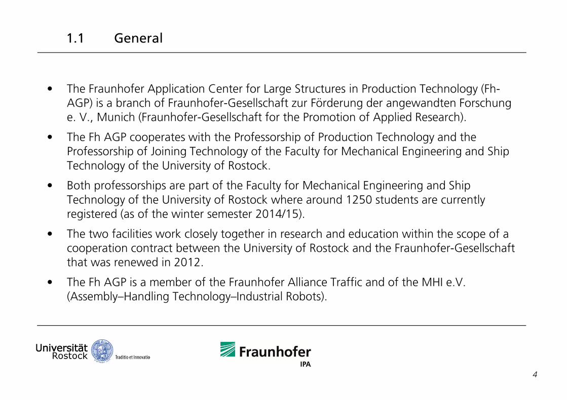
• The Fraunhofer Application Center for Large Structures in Production Technology (Fh-AGP) is a branch of Fraunhofer-Gesellschaft zur Förderung der angewandten Forschung e. V., Munich (Fraunhofer-Gesellschaft for the Promotion of Applied Research).
• The Fh AGP cooperates with the Professorship of Production Technology and theProfessorship of Joining Technology of the Faculty for Mechanical Engineering and ShipTechnology of the University of Rostock.
• Both professorships are part of the Faculty for Mechanical Engineering and ShipTechnology of the University of Rostock where around 1250 students are currently registered (as of the winter semester 2014/15).
• The two facilities work closely together in research and education within the scope of a cooperation contract between the University of Rostock and the Fraunhofer-Gesellschaft that was renewed in 2012.
• The Fh AGP is a member of the Fraunhofer Alliance Traffic and of the MHI e.V. (Assembly–Handling Technology–Industrial Robots).

5
1.2 Research areas
Research area Areas of focus Maritime industry, offshore
Structural steelwork, aircraft, automotive andrail vehicle construction,
wind energy
Regionalresearch
Measuring, sensor, robotic and control technology, measuring of geometric variables, image processing
Company concepts,cooperative networks, production organisationand logistics
Maritime industry, structural steelwork, etc.
ProductionTechnology
Automation Technology, Quality Technology
Company and ProductionOrganisation
ProductDevelopment, Testing Technology
Mechanical joining,welding, brazing, gluing,parting, forming,material testing

6
1.3 Organisation Chart
Institutional Administration
Univ.-Prof. Dr.-Ing. Martin-Christoph WannerUniv. Prof. Dr.-Ing. habil. Knuth-Michael Henkel (Deputy)
Development team Mechanical Joining Technology I
Development teamOrganisational Engineering
Workshop, Laboratories
Dipl.-Wirt. Ing. N. Fuchs Dipl.-Wirt. Ing. J. Sender Dipl.-Ing. (FH) K. Müller
Development teamAutomation Technology
M.Sc. M. Gründler
EducationUniversity of Rostock
Dr.-Ing. U. Kothe
Development teamTest Engineering
Dipl.-Wirt. Ing. N. Fuchs
Development team Sensor data processing
Dr.-Ing. A. Zych
Development team Welding Technology
Prof. Dr.-Ing. habil. K.-M. Henkel
Development team Large structures measurement
Dipl.-Ing. (FH) M. Geist
Development teamPrototypes
M.Sc. M. Gründler
Development team New Materials/Adhesive Bonding
Dipl.-Ing. N. Glück
Development team Mechanical Joining Technology II
Dr.-Ing. R. Glienke
Monitoring and Certification Body
Dr.-Ing. R. Glienke

7
"Fraunhofer lines"
� Application-oriented research which is of direct use to economy and of benefit tosociety
� 66 institutes and research institutions
� Around 24 000 employees
� Research volume: more than 2 billion Euro, of which around 1.7 billion Euro is in the area of research under contract
� Fraunhofer generates more than 70% in this area from work commissioned by industry and with research projects supported by public financing
� Around 30% is provided as basic financing by the Federal Government and the Federal States
1.4.1 The Fraunhofer-Gesellschaft in profile 2015

8
� Information and Communication Technology
� Life Sciences
� Light & Surfaces Microelectronics
Institutes in a similar area are organized into research associations and have a joint presence in the R&D market.
They take part in the corporate policy and also in the implementation offunction and financing models of the Fraunhofer-Gesellschaft.
� Production
� Material, components – MATERIALS
� Defence and Security Research VVS
1.4.2 Bundling of competences through the networking of Fraunhofer Institute associations

9
1.4.3 Locations of the Fraunhofer Gesellschaft
2015
Fraunhoferlocationsworldwide
1 Fraunhofer AGP locationAlbert-Einstein-Straße 30
3 Faculty of Mechanical Engineering and ShipTechnology
4 Town hall5 Main station6 University library9 Parkstraße10 Goetheplatz11 Südring12 Erich-Schlesinger-Str.14 Joachim-Jungius-Str.15 Albert-Einstein-Str.
1
Fraunhofer Application Center Rostock,Albert-Einstein-Straße 30
Fraunhoferresearch institutionsin Germany:
Institutes and facilities
Further locations

0
10
20
30
40
50
45 42
13
0
10
20
30
40
50
60
55
43
2
10
1.5 Development in Earnings of the facilities1.5.1 Third party funding and its percentage distribution
Earnings development 2005-2014
[%]
By branch 2014
By research area 2014[%]
Year
T€
Production Automation Organisational Engineering & Quality Engineering
Maritime Industry Steel / Aircraft Construction RegionalOffshore Vehicle and Rail Stock Research,
Construction Wind Energy Miscellaneous
0
1000
2000
3000
4000
5000
6000
2005 2006 2007 2008 2009 2010 2011 2012 2013 2014
946 10261278
1596 1794 17632065
3074
3885
4686
337 312
679
631556 557
602
437
694
502
IfF (Lehrstuhl
Fertigungstechnik)
Fh AGP

0%
5%
10%
15%
20%
25%
30%
35%
40%
45%
50%
48
127
4 3 58 7 6
11
1.5.2 Industry project volumes
Share of industry project volume(ave. 50.6% in the last 5 years)
Industry project volumes since 2005 to end 12/2014, by countries
48,6%55,4%
52,5%
53,7%
42,4%
0%
10%
20%
30%
40%
50%
60%
1 2 3 4 52010 2011 2012 2013 2014

12
1.6.1 Scientific Staff
Directors
Scientific StaffProf. Dr.-Ing. M.-C. WannerProfessorship of Production TechnologyHead of Fraunhofer Application Center
Tel. 0381 49682 -10
Mobile 0172 9587098, Fax 0381 49682-12
Prof. Dr.-Ing. habil. K.-M. Henkel
Professorship of Joining TechnologyDeputy Head of Fraunhofer Application Center, Tel. 0381 49682-30, Fax 0381 [email protected]
Secretariat, Administration
Mrs. Dipl.-Ing. (FH) G. Ehmke*
Extension -11; [email protected]
Mrs. LL.M. (FH) M. Gragert Extension -221; [email protected]
Mrs V. Ratsch Extension -15; [email protected]
• Dipl.-Wirt. Inf. M. Baier (IT, Organisation) Extension -57; [email protected]
• Dipl.-Ing. R. Banaschik (Welding Technology) Extension -143; [email protected]
• Dipl.-Ing. F. Beuß (Organisation) Extension -59; [email protected]
• Dipl.-Wirt. Ing. C. Blunk (Mech. Joining Technology)Extension -34; [email protected]
• M.Sc. O. Brätz (Welding Technology)Extension -231; [email protected]
• M.Eng. H. Brauns (Test Engineering)Extension -220; [email protected]
• M.Sc. M. Busch* (Mech. Joining Technology)Extension -147; [email protected]
• Dipl.-Ing. C. Denkert (Mech. Joining Technology)Extension -64; [email protected]
• Dr.-Ing. K.-J. Dittmann** (Technical Documentation) Extension -0; [email protected]
* Established post Uni Rostock ** Work contract with FhG

13
1.6.2 Scientific Staff
• Dipl.-Ing. S. Dryba (Automation Technology)Extension -45; [email protected]
• M.Sc. A. Ebert (Mech. Joining Technology)Extension -33; [email protected]
• M.Sc. M. Eggert (Organisation)Extension -145; [email protected]
• M.Sc. K. Ehrich (New Materials/Adhesive Bonding)Extension -21; [email protected]
• Mrs M.Sc. L. Fröck (New Materials/Adhesive Bonding)Extension -140; [email protected]
• M.Sc. P. Froitzheim (Mech. Joining Technology)Extension -228; [email protected]
• Dipl.-Wirt. Ing. N. Fuchs (Mech. Joining Technology)Extension -36; [email protected]
• Dipl.-Ing. (FH) M. Geist (Measuring Technology)Extension -48; [email protected]
• M.Sc. A. Gericke (Welding Technology)Extension -37; [email protected]
• Dipl.-Ing. F. Gierschner (Measuring Technology)Extension -47; [email protected]
• Dr.-Ing. R. Glienke (Mech. Joining Technology)Extension -40; [email protected]
• Dipl.-Ing. N. Glück (New Materials/Adhesive Bonding) Extension -39; [email protected]
• M.Sc. M. Gründler (Automation Technology)Extension -226; [email protected]
• M.Sc. T. Haberecht (Automation Technology)Extension -315; [email protected]
• Dipl.-Ing. A. Harmel* (Automation Technology)Extension -49; [email protected]
• M.Sc. M. Hauer* (Welding Technology)Extension -225; [email protected]
• Dipl.-Ing. R. Hein (Welding Technology)Extension -58; [email protected]
• Dipl.-Ing. H. Herholz (Automation Technology)Extension -142; [email protected]
• M.Sc. B. Illgen (Organisation)Extension -230; [email protected]
• Dipl.-Wirt. Ing. M. Irmer (New Materials/Adhesive Bonding) Extension -20; [email protected]
Scientific Staff* Established post Uni Rostock

• Mrs M.Sc. K. Nowak (Mech. Joining Technology)Tel -233; [email protected]
• M.Sc. S. Schmidt (New Materials) Extension -223; [email protected]
• Mrs. Dr. rer. pol. A.-K. Schröder (Organisation) Extension -229; [email protected]
• Dipl.-Ing. M . Schumann (New Materials)Extension -24; [email protected]
• M.Sc. M. Schwarz (Mech. Joining Technology) Extension -193; [email protected]
• Dipl.-Wirt. Ing. J. Sender (Organisation)Extension -55; [email protected]
• M.Sc. R. Staschko (Mech. Joining Technology) Extension -42; [email protected]
• Mrs. Dipl.-Ing. S. Wegener (Selected Research Topics)
Extension -13; [email protected]
• Dipl.-Ing. O. Wurst (Automation Technology) Extension -67; [email protected]
• Dr.-Ing. A. Zych (Automation Technology) Extension -43; [email protected]
• M.Sc. K. Jacobi (IT, Measuring Technology) Extension -192; [email protected]
• M.Sc. K. Jagusch (Organisation)Extension -51; [email protected]
• Dr.-Ing. F. Kaltofen (Selected Research Topics)Extension 314; [email protected]
• M.Sc. C. Klötzer (Automation Technology) Extension -54; [email protected]
• Mrs. M. Eng. L. Knaack (MeasuringTechnology)Extension -146; [email protected]
• Dr.-Ing. U. Kothe* (Education) Extension -50; [email protected]
• M.Sc. S. Lauer (Automation Technology) Extension -232; [email protected]
• Dipl.-Wirt. Ing. J. Meißner (Organisation) Extension -53; [email protected]
• Dipl.-Math. M. Meister (Measuring Technology)Extension -149; [email protected]
• M.Sc. T. Nehls (Mech. Joining Technology)Extension -65; [email protected]
Scientific Staff
1.6.3 Scientific Staff
14
* Established post Uni Rostock

1.6.4 Technical Staff
15
* Established post Uni Rostock
Technical Staff
• R. Arndt (Welding Technology)Extension -148; [email protected]
• D. Geber (IT) Extension -56; [email protected]
• A. Herhaus (Production Technology, Laboratory)
Extension -63; [email protected]
• Mrs G. Höffer (IT) Extension -141; [email protected]
• U. Jenner (Production Technology, Laboratory)Extension -191, mobile -62; [email protected]
• U. Klausz (Production Technology, Laboratory)Extension -191; [email protected]
• D. Krüger (Test Engineering) Extension -311, mobile -18; [email protected]
• R. Krupiza (Production Technology, Laboratory)Extension -194; [email protected]
• Dipl.-Ing. (FH) K. Müller* (Chief Laboratory Engineer)
Extension -60; [email protected]
Apprentices
• N. Ziegelmann
• D. Namyslo* (Welding Technology)Extension -73; [email protected]
• Dipl.-Ing. (FH) U. Pfletscher (Prototypes)Extension -44; [email protected]
• T. Vogel (Test Engineering)
Extension -234; [email protected]
• S. Wachtmann (Bonding Laboratory)Extension -25; [email protected]

16
1.6.5 Scientific Assistants I (Stand 5/15)
Scientific AssistantsFhG and University of Rostock
• J. Ahrndt MBST/AT
• L. Baumgart WI-ING/OT
• R. Bliesener MBST/FT
• A. Bolsmann WI-ING/OT
• R. Damerius ET/OT
• P. Diel MBST/FT
• A. Dierke MBST/AT
• F. Dix WI-ING/OT
• M. Dörre MBST/FT
• I. Drisga MBST/AT
• M.-T. Dube Lehramt/S
• D. Durain WI-ING/FT
• J. Gatzke MBST/FT
• A. Gerhards WI-ING/OT
• H. Gericke MBST/FT
• F. Hauschulz MBST/OT
• M. Hayn WI-ING/FT
• M. M. Heimann WI-ING/OT
• M. Heinrich WI-ING/OT
• H. Heise MBST/FT
• S. Heise WI-ING/OT
• F. Holleitner MBST/FT
• M. Hottendorf WI-ING/OT
• D. Humpert MBST/FT
• A. Jentsch MBST/AT
• O. Kappel MBST/FT
• R. Kelling MBST/FT
• M. Klohn WI-ING/AT
• F. Knöchelmann MBST/FT
• C. Köhn WI-ING/MT
Activities:AT = Automation TechnologyFT = Production TechnologyMT = Measuring TechnologyOT = Organisational TechnologyS = Others
Field:ET = Electrical EngineeringI = InformaticsMBST = Machine Eng./Ship TechnologyWI-ING = Industrial EngineeringWIWI = Business Science

17
Scientific AssistantsFhG and University of Rostock
1.6.6 Scientific Assistants II (Stand 5/15)
• L. Kolley WI-ING/OT
• M. König MBST/FT
• L. J. Kunz MBST/S
• T. Kureck MBST/AT
• D. Leingang MBST/FT
• H. Maaß WI-ING/AT
• M. Malagic MBST/FT
• T. Milbrandt MBST/AT
• K. Möller MBST/AT
• E. Mohs MBST/OT
• B. Perschnick MBST/FT
• A. Peters WIWI/S
• N. Richter DLM/S
• B. Ripsch WI-ING/FT
• T. Ritt I/MT
• F. Schmatz WI-ING/OT
• B. Schornstein MBST/FT
• L. M. Schulz MBST/FT
• R. Serduk MBST/FT
• P. Soehring WI-ING/OT
• R. Somodi WI-ING/OT
• N. Stepniak WIWI/FT
• U. Streckfuß MBST/MT
• G. Szczypek MBST/FT
• G. Treichel MBST/MT
• H. Völzer MBST/OT
• C. Weinrich WI-ING/OT
• S. Witting WI-ING/OT
• R. Wodars MBST/FT
• M. Zickermann MBST/FT
• J. Zimdahl MBST/S
Activities:AT = Automation TechnologyFT = Production TechnologyMT = Measuring TechnologyOT = Organisational TechnologyS = Others
Field:DLM = Management of ServicesET = Electrical EngineeringI = InformaticsMBST = Machine Eng./Ship TechnologyWI-ING = Industrial EngineeringWIWI = Business Science

18
1.7.1 Infrastructure (as of 6/15)
Fraunhofer office and laboratory building
Fraunhofer Laboratory
Special Facilities
2545 m2 useful area (offices, laboratories)
133 m2 useful area (offices)1060 m2 useful area (test workshop, laboratories)
Laboratories for:• Production Technology and machine tools• Automation and robotics• Production measurement technology, large
structures measurement
Laboratory and office building of the Fraunhofer Application Center, Albert-Einstein-Straße 30
• Test Engineering/CIT body• Welding Technology• Mechanical joining technology• Adhesive bonding technology
• Refrigeration engineering, conditioning chamber
• Virtual reality• Factory planning and
factory organisation
Professorship PT and JT University
92 m2 useful area (Südstadt production laboratory)268 m2 useful area (Warnemünde welding laboratory)

19
Machine tools
• DMG turning-milling centre LTX beta 1250 with opposed spindle and 16x star turret
• Deckel Maho 5-axis universal milling machine DMU 100 mono Block with 32 magazine slots
• Bridgeport 3-axis machining centre VMC 600-22
• Böhringer boring mill DUS 40 ti
• Flat grinder HFS 3063VC
• Pillar drilling machine Eppler UTM80 DIGI
• Tile saw, belt grinder
• Two hydraulic laboratory presses
Welding and cutting facilities
• Four-wire submerged arc welding unit Lincoln including peripherals
• Single-wire submerged arc hand welding unit Lincoln including peripherals
• Electrogas welding unit Mini Vertomatic NC/W (ESAB)
• Electrogas welding unit Hyundai SS-EGW DIGITAL-1W
• MIG/MAG high-power current source Lorch (Speed Puls, Speed Arc)
• Inverter power source for MAG tandem welding (Time Twin Digital – Fronius)
1.7.2 Selected large machines and software (as of 6/15)
• Plasma cutting device Kjellberg with power source Hi Focus plus 160i and hand plasma cutting unit CUTi 31
• Plasma parting device Kjellberg with inverter power source Trans Plus Synergic 4000 from Fronius integrated into robot system KUKA KR15
Software for calculation, simulation, design, production and signal analysis
• CAD (PROENGINEER, CATIA V5), CAM (EDGECAM)
• Electrical engineering (EPLAN)
• CAQ (3DCS Analyst, Geometric, CENIT)
• FEM (ANSYS Mechanical, LS DYNA, MSC.MARC, RSTAB)
• MKS (MSC.ADAMS)
• Modal analysis X-Modal III, SMART-Office-Analyser,
• Perception S/W Package Advanced (signal analysis)
• Production simulation (eM-Plant, eM-Workplace, Automatic Path Planner), DELMIA PCM (collaboration)
• Mobile 3D factory planning with visTable touch®
• 3-D-Studio MAX, Poly Trans, IPA planning table
• Tracking system for VR, Vis-table tough
• Editing of scatter plots (POLYWORKS)

20
1.7.3 Measuring technology and robotics (as of 6/15)
Measuring technology
• 3D coordinate measuring machine CRISTA-APEX C574, Mitutoyo
• Measuring arm (6 axes) CIMCORE 3000i
• Laser interferometer Renishaw ML 10
• Measuring device for modal analysis VTI
• Measuring data recording device GENESIS
• Transient recorder YOKOGAWA 16 channel
• Thermal imaging camera (FLIR-Systems)
• Infrared camera Vario CAM
Measuring of large dimensions• 3D laser scanner, Z+F Imager 5010, range < 150 m
• 3D laser scanner Faro Focus X130, range < 100 m
• 3D laser scanner, MENSI/TRIMBLE, GX, range < 200 m
• 3D laser scanner, MENSI/TRIMBLE, GS 25, range < 25 m
• 3D laser scanner, MINOLTA VL 9i
• Digitization system light stripe projection ATOS III, GOM
• Projection system Werklicht-Pro
• Leica laser tracker AT 901-B
• Photogrammetric measuring systems IMETRIC 610TP and AICON 3D-Studio
• Two 3D total stations SOKKIA MONMOS and SOKKIA NET 1200 (GLM)
Robots/manipulators
• Processing and handling robot KUKA KR 500 with tools and highly flexible work piece holder
• Welding robot KUKA KR15 including sensors and peripherals (MIG/MAG Fronius) in gantry configuration (Güdel/IMG), working area 4,000 x 4,200 x 1,500 mm
• Welding robot KUKA KR5-2 arc HW
• Bosch assembly robot SR8 with image processing system force/torque sensor, various grippers and gripper changing facilities
• Lightweight robot UR 10-1,8 LV with gripper
• Automated guided Vehicle Neobotix MPO-500
• Balancer Roosen (NL)
Mechanical assembly facilities / mounting tools
• Riveting/clinching units TOX riveting pliers type TZ up to 100 kN and ultrasound-based clinching unit up to 60 kN
• Mounting tool with process monitoring 5,000 Nm
• Torque test stand Schatz up to 50 Nm and up to 500 Nm
• Eckold force former KF170 60 kN
• Pneumohydraulic press Tox 130 kN

21
1.7.4 Testing technology (as of 6/15)
Test Engineering
• Servohydraulic test machine HB 1000 Zwick/ROELL
• Dynamic universal testing machine walter+bai LFV 63kN
• High-frequency pulsator ROELL HFP 5100 100 kN
• High-frequency pulsator POWER SWINGMOT 100kN (Sinco
Tec)
• Static testing machine Zwick Z400E 400 kN
• Tensile/compression force testing machine 50kN with temperature chamber
• Torque test stand Schatz 500Nm
• Imagic microscope system DM 600
• Reflected light stereo microscope OLYMPUS
• Helium leakage tester HLT 160/560
• Salt spray chambers and corrosion climate change tester (450 l and 1000 l), Weiss
• Conditioning cabinet 350 l (-70 °C to 180 °C, with humidity regulator)
• Rapid weathering device Q-Lab QUV/spray
• MHG grit-blasting unit SMG 25 S
• Atmospheric pressure plasma device Plasmatreat OPENAIR
• Precision cutting machine
• Hot bed press Opal 400
• Pendulum impact tester HIT 50P
• Pendulum impact tester PSd 450
• Hardness tester 432 SVD
• Ultrasound tester Krautkramer USN 60 and USIP 40
• Metal analysis unit SPECTROMAXx
• Layer thickness measuring device Leptoskop 2042
• Contact angle measurement device with tipping device, OCA 20
• Moisture generator Data Physics
• Tempering bath ST/Lauda
• Oxygen, nitrogen and hydrogen analyser
• Differential scanning calorimeter
• Rotation-type rheometer Thermo-Scientific Haakemars III
• Internal stress analyser Stresstech PRISM
• Dynamic Mechanical Analyser (DMSA)
• Sound level measuring device XL2-Akustik Analysator

22
1.8 Purchases of new large machines
• The investments in large machines grew considerably in 2014, with an increase in the investment rate (investment/costs of operation) of more than 23%.
• The main focus of the investment concerned a further expansion of test technology, with a static testing machine with temperature chamber, a high-frequency pulsator and a torque test stand.
• In prospect of the rapid developments in 3D measuring technology , investments in a projection system and in a fast 3D scanner waer necessary.
• These purchases were rounded down - in Welding Technology by an electrogas welding unit and an internal stress analyser - in Joining Technology by a new riveting/clinching unit - in New Materials by a dynamic mechanical analyser, in Robotics by a lightweight robot and a automated guided Vehicle and in Organisational Engineering by hardware and software for mobile 3D factory planning.

23
• Measurement of internal stress with the drilled hole method• Use of ESPI (Electronic Speckle Pattern Interferometry) makes the complicated and
time-consuming application of DMS unnecessary• Speckle patterns generated by laser radiation and the optical roughness of a
sample change and thus allow conclusions to be made concerning stresses• Determination of the internal stresses in almost all materials, including those
that are difficult to X-ray, such as titanium and plastics• Fully automatic configuration with software-controlled advance feed• Evaluation of tension depth profiles with selectable increments within a few minutes• Use with current drill diameters from 0.4 mm to 3.2 mm
allows reproducible depth profile production to within 2 mm• Variable speed of rotation of the drill unit with regulation for constant
holding and precision suspension for exact diameter determination• Little sample preparation (as a rule, only cleaning) prevents
falsification of measuring results
1.8.1 Internal stress analyser Stresstech PRISM
Technical data
Fields of use / applications
• Determination of the internal stress state in thermally sprayed and welded samples for correlation with the microstructureand functional properties
• Determination of internal stresses in small parts• Support when analysing instances of damage
Measuring setup to determine the state of internal stress in thermally sprayed samples. Analysis system consisting of a laser light source, lighting stand, camera
unit and electrical high-speed drilling machine
Level stress state (σx, σy, τxy) of a thermally sprayed sample as depth profile
σx
σy
τxy

24
1.8.2 Electrogas welding unit Hyundai SS-EGW DIGITAL-1W
Technical data/controller
Fields of use / applications
• Proven welding machine in asian shipbuilding and containerconstruction
• Test unit for the development of EG welding consumables and technology testing adapted to European production conditions
General description
SS-EGW DIGITAL-1W in shipbuilding
• Currently the most compact EG welding machine available, guidanceby means of a magnetic rail
• Primarily made of aluminium (weight of basic machine: 15 kg)• Allows single-layer welding of plates up to 30 mm thick in the uphill
welding position (PF) for seams from 0.5 approx. 30 m in length• Thyristor-controlled welding current source, max. 600 A and 50 V at 100 % ESD
• Automatic welding speed regulation with constantstick-out (∆I)
• Max. welding speed 15 m/h• Digital display for welding current and welding voltage• Water-cooled copper sliding shoe, root protection by
means of ceramic bath protection • Welding nozzle oscillation for plate thicknesses t > 20 mm
SS-EGW DIGITAL-1W mounted on magnetic rail
Macrosection EG weld seam, t = 18 mm

25
1.8.3 Static testing machine – tensile/compression forcetesting machine with temperature chamber Zwick Roell
• Static load 50 kN• Traversing speed 0.0005
up to 110 % of the test force up to(vmin to vNom) 600 mm/min
• Test area height 1325 mm• Temperature chamber -70 to 250° C
• Measured value transmission rate 500 Hz
• Precision class 1
• Automatic zero point correction
• VideoXtens Array: Visual field / resolution from 54 mm/0.27 µm to 515 mm/2.6 µm Simultaneous measurement of lengthways and transverse stretchingTwo-dimensional measurement with 2D point matrix
• Static tensile and compressive testing • Use of high test speed range without restrictions• Two test areas, flexible sample and test tool holding system• Use of the VideoXtens array in the temperature chamber, including in all temperature ranges
Fields of use / applications
Technical data
Measuring configuration

26
1.8.4 Dynamic test machine – high-frequency pulsator SINCOTEC
• Determination of breakage vibration load cycles and fatigue strength through classical Wöhler tests
• Software module for block program regulation
• Evaluation program for step tests or to determine Wöhler lines
• Not affected by transverse forces, suitable for asymmetric loadings
• Static load 100 kN
• Max. dyn. force amplitude ±50 kN
• Stroke 7 mm
• Max. sample length 1000 mm
• Free column passage 600 mm
• Test frequency 30to 120 Hz
• Precision 0.03 %
• Error bandwidth to nominal load ±0.05 %
• Analog inputs and outputs ± 10 V
Technical data
Measuring configuration
Fields of use / applications

27
1.8.5 Riveting/clinching unit TOX
• Pressing and nominal force 100 kN
• Total stroke 200 mm
• Max. piston speed 200 mm/s
• Machine, gripper No. TE-X
• Force sensor measuring range 5 % - 100 % of the nominal force
• Measuring precision (force) < ±1 % of the nominal force
• Force sensor sensitivity 0-10 VDC / ±20 mA
• Reproducibility < ±0.01 mm
• Joining process characterisation and process parameter variation during clinching and riveting
• Function-controlled programming of joining work flows by means of complex programs
• Electromechanical servo drive for exact monitoring and control of pressing and joining processes
• Available dies: Clinching (6 mm, 8 mm and 10 mm); solid rivets (4 mm and 5 mm); half-hollow rivets (3.3 and 5.3 mm)
Fields of use / applications
Measuring configuration
Technical data
282828
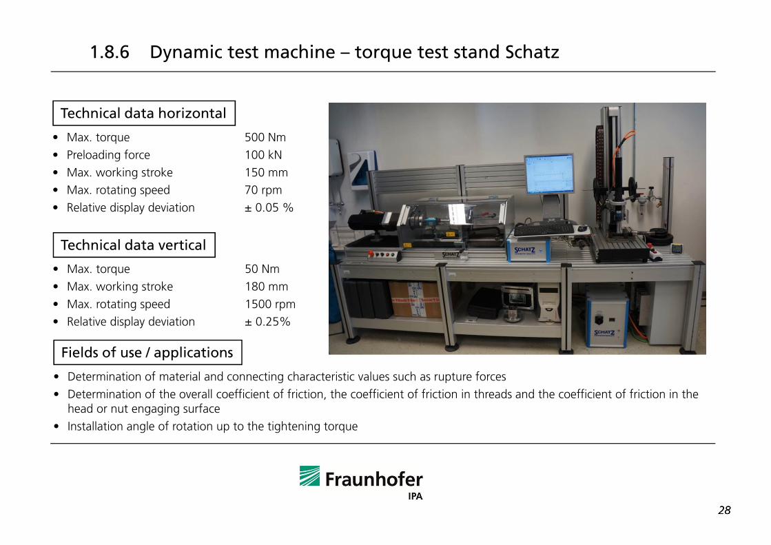
1.8.6 Dynamic test machine – torque test stand Schatz
• Determination of material and connecting characteristic values such as rupture forces
• Determination of the overall coefficient of friction, the coefficient of friction in threads and the coefficient of friction in the head or nut engaging surface
• Installation angle of rotation up to the tightening torque
• Max. torque 500 Nm
• Preloading force 100 kN
• Max. working stroke 150 mm
• Max. rotating speed 70 rpm
• Relative display deviation ± 0.05 %
• Max. torque 50 Nm
• Max. working stroke 180 mm
• Max. rotating speed 1500 rpm
• Relative display deviation ± 0.25%
Fields of use / applications
Technical data vertical
Technical data horizontal

29
1.8.7 Macroscope – Photo workstation
• Resolution 18 megapixels
• ISO sensitivity 100-12.000
• Automatic white balance via sensor
• Focusing via 9 AF cross-sensors
• Multi-focus exposures with infinite depth of field
• Live image view for optimal camera setting
• Image processing with, among other things, image superimposition for an exact illustration of fracture surfaces
29
• Sample documentation
• Subsequent measuring of samples and weld seams in the processing program with automatic calibration
Fields of use / applications
Picture management system Image Access
Digital SLR camera Canon EOS 700

30
1.8.8 Polymer analysis – Dynamic Mechanical Analyser (DMA)
Technical data
Fields of use / applications
Characterisation of the mechanical properties of polymer materials such as plastics, matrix resins of fibre composite parts, fibre composite samples or adhesives under the influence of temperature
Investigation of the following characteristic values and processes:• Storage/loss modules (G‘/G‘‘, E‘/E‘‘)• Non-linear stress deformation curves (σ, τ)• Retardation/Relaxation mode
Deformation modes:• 3-point bending, single/double arm bending• Tension• Compression/Penetration
Device Netzsch - DMA 242 CMeasuring principle Dynamic MechanicalCooling system Liquid / gaseous N2
Temperature range -170 to +600 °C
Heating rates 0.01 to 20 K/minSpecial configuration Separate purging gas connection
for the use of any desired gases
Determination of the mechanical glass transition temperature of an adhesive

31
1.8.9 Projection system Werklicht-Pro
Fields of use / applications
• Use in the internal fitting out of ships, e.g.:• Positioning of parts• Setting of pass-throughs• Collision checking
• Quality control • Application of labelling and patterns onto objects without
using gluing templates• Transfer of installation and assembly instructions to the real
object
Technical data
Projection range 60° (up to 80° with reduced precision)
Measuring distance approx. 6-8 m
Projection accuracy ± 0.5 mm in 4 m
Laser protection class 2M (visible green laser)
Laser line <1 mm in 4 m
Marking of the waterline and monitoring of hull openings
Projection system Werklicht-Pro
System configuration in use

32
1.8.10 Faro Focus X130 3D Scanner
Fields of use / applications
Technical data
Measuring range 0.6 m to 130 m
Measuring rates up to 976,000 points/second
Systematic distance error
± 2 mm
Built-in colour camera
Up to 70 megapixels
Laser protection class
1
Faro Focus X130 3D Scanner• Automation applications, e.g. online programming of robots
• Measuring of large technical structures with high precision, e.g.• Ship rumps and sections,• Wind turbine vanes and forms
• Documentation of historical buildings and facilities• Surveying of factory equipment and workshops
3D point cloud of the astronomical clock in the Sankt-
Marien-Kirche Rostock (Church of St. Mary)
Online programming on the basis of scanned data

33
1.8.11 Lightweight robot UR10 with adaptive 2-finger gripper
Technical data gripper
Fields of use / application
• Gripper opening 0-85mm• Gripping force 60 – 200 N• 3 gripping modes: Parallel, Encompassing, Inside
• Assembly and handling tasks• Mounting and placement of units• Quality Assurance• Collaborative work
Technical data UR 10
• 6-axis lightweight robot made of aluminium• Weight 28.9 kg• Load capacity 10 kg• Range 1300 mm• Reproducibility +/- 0.1 mm• Joint velocity approx. 150 °/s• Communication TCP/IP• Safety system in accordance with EN ISO 13849:2008 PL d and
EN ISO 10218-1:2011
Source: www.robotiq.com

34
1.8.12 Automated guided Vehicle Neobotix MPO-500
Manipulator
Fields of use / application
• UR10 lightweight robot can be integrated• Adaptive 2-finger gripper from robotIQ
• Autonomous logistics• Machine mounting and placement• Man-machine collaboration• Service robotics• Security Technology
Technical data
• Load capacity 30 kg (platform)10 kg (arm)
• Dimensions 986 x 692 x 409 (LxWxH)• Speed < 0.8 m/s• Rechargeable battery time up to 5 hours• Safety technology 2 x safety laser scanners
from Sick• Omnidirectional movements through Mecanum
wheels• Navigation with the aid of natural landmarks
GUI of the MPO-500Source: www.neobotix-roboter.de
Orientation without landmarksSource: www.neobotix-roboter.de
Use for autonomous intra-logistics at the Fraunhofer AGP

35
1.8.13 Mobile 3D factory planning with visTable touch®
Scope of functions
Fields of use / application
• Factory planning• Digital factory• Plant and layout planning• Material flow analysis• Optimisation of logistics processes • Scenario planning• Routing optimisation
• Mobile PC rack with 55“ display• Multi-touch capable
• Graphics PC with Nvidia Quadro graphics card
• Software for 2D and 3D factory planning
• 2D and 3D factory planning• 3D visualization of facilities and structures• Analysis and optimisation of material flows• Layout optimisation• Collision checking for facilities and structures• Open model library
Joint planning in 2D and 3D at Fraunhofer AGP
System

36
• Welding technology concerns itself, among other things, with the development of welding and cutting processes, investigations into welding arc behaviour and various alloying concepts for shipbuilding and large items of structural steelwork.
• The main focus of development in mechanical joining technology is on the qualification of processes, newjoining tools and automation solutions plus consulting services. Test Engineering and the Monitoring and Certification Body are located in this area.
• Adhesives, Fibre Composites and Surface Technology develops new production and joining processes for modern lightweight and mixed forms of construction, primarily large structures. A further emphasis is on the investigation of the efficacy and ageing of coatings under maritime environmental conditions.
2 Work Area: Production Technology

37
´12 - ´13Problem
Solution
Benefits
• In practice, deviations in the gap geometries of up to 10 mm are observed at butt joints.
• The MSG multi-pass welding methods employed can react to these with great manual effort, but are relatively slow and laborious.
• Lack of systematic welding technology investigations into electro-gas welding for European applications.
2.1 Single-sided electro-gas welding with discontinuities of plate thicknesses and butt joint geometries
ESAB Mini Vertomatic NC/W electro-gas welding machine
• Development of a reproducible EG single-sided welding process for irregular butt joint geometries
• Increased productivity with single-pass welding while reducing the errors associated with an automatic process
• Verification of process-relevant parameters
• Derivation of suitable measures for increasing the process reliability, productivity and joint quality
• Investigation of the influence of irregular gap widths and plate thicknesses on the mechanical and technological quality and vibration resistance
Electro-gas welding trials
Macrosection with hardness measurement of an electro-gas welded seam

38
Problem Solution
Benefits
2.2 Development of a cost-effective process variant of submerged-arc welding in transverse position (PC) on large plate thicknesses for application on offshore structures and in shipbuilding (SAW-transverse)
• Due to the design and production, welding in forced positions in shipbuilding and offshore structure construction is often unavoidable.
• Welding in transverse position is almost exclusively carried out by manual MSG welding.
• MSG transverse welding represents a bottleneck in the production chain due to the low deposition rates and significantly increases the lead times.
• Development of a cost-effective technology for one-sided submerged-arc welding in transverse position (PC)
• Design of a suitable and flexible head guidance technology for SAW systems
• Increased productivity through qualification of multi-wire processes in PC
• Influencing of the melt pool and increasing the deposition rates by controlling the time and amplitude balances
• Qualification of a suitable wire/powder combination for optimised melt pool support and with higher mechanical and technological properties
• Single-sided submerged-arc welding of plate thicknesses from 13 mm to 80 mm in PC
• Reduced lead times with improved weld seam quality
Macrosection SAW-PC welding in
the tandem-twin process
Tandem-twin-arc welding head arrangement for test welding in PC
SAW test stand for PC multi-wire welding
´12 - ´14

39
Solution
Benefits
• Erosion caused by cavitation, seawater corrosion and surface abrasion is frequently observed in the rudder and stern areas of high-speed ships.
• Countermeasures taken to date, such as polymer coating, make-up welding or sacrificial anodes are time-intensive or have only a limited effect.
• Docking and the repair of damaged area is necessaryafter 5 to 7 years, associated with high costs.
• Reduction of the erosion damage occurring results in an increase in the operating times and a reduction in the costs
• Approvals for technical implementation are applied for in cooperation with classification societies
2.3 Damage-resistant surface coatings of maritime structures: Example rudder - BESOMA
´12 - ´14Problem
Damage in the rudder area
Surfacecavitation
Intake edge cavitation
Extensive repair measures
Schematic diagram of cold gas spraying: Particle impact and coating build-up take place in solid state
Cold gas spray system at the HSU for application of large coating thicknesses
• Development of a technology for complete or partial cold gas spraying to reduce the damage
• Identification of suitable sprayable materials for the maritime sector with low porosity / oxidisation and high application rates

580 590 600 610 620
10- 5
10- 4
10- 3
10- 2
10- 1
100
101
102
103
104
105
Ca Ca Ca CaCaCaCaCaCa
Cu
MgMgMn Mn Mn
MnMnMn
NaNa
NaNa
K KK K
0,0
5,0x 10¹⁰
1,0x 10¹¹
1,5x 10¹¹
2,0x 10¹¹
2,5x 10¹¹
3,0x 10¹¹
λ [nm]
• An understanding of the process of submerged-arc welding as a widely used high-performance welding procedure in heavy steel structures is lacking due to the visual inaccessibility; this applies in particular to:
• Correlation of electrical signal characteristics with process events• Chemical-physical interactions over time between droplets - slag - welding arc
column, for example, the transfer efficiency of important alloying elements • Multi-rod versions with inverter-controlled current/voltage modulation
40
2.4 Increase in the process reliability of SAW, AC/AC procedure variations bymeans of optical analysis of the arc and the material transition in thecavity – ProUP
´15 - ´16Problem
Solution
Benefits
• Development of a methodology for real time welding arc diagnostics in submerged-arc welding with cinematographic high-speed photographs through a novel concept for tapping the cavity
• Correlation of the process events with the electrical signals and the welding results (mechanical technical properties; chemical composition) depending on the welding parameters
• Increase in the process reliability due to a greater understanding of the process
• Basic principles for quality assurance concepts through the correlation of the electrical signals with the welding results
• Compliance with the required chemical composition and reduction in overmatching
Control panel
Welding heads
Work sample
Liquid droplet depot at the rod
Slag transition in droplets
Test setup with high-speed camera in the foreground
View into the submerged arc cavity with 5000 fps shortly before short circuiting
Overview spectrum from the submerged arc cavity with intensities of existing elements

41
2.5 Development of a TIG-Twin process technology to increaseproductivity when welding aluminium structures
Problem
Solution
Benefits
• The melting performance in TIG procedures depends on the energy of the welding arc (current strength)
• High current strengths lead to excessive high arc pressures and hence to severe turbulence and uneven penetration profiles
• As a consequence, the danger of undercuts, seam and root failures increases
• Better flank/root formation, ability to bridge gaps, and energy coupling in aluminium joins
• Improvement in the mechanical technical quality values by up to 20%
• Lower thermal stress, higher productivity and less wear
• Better distribution of the arc pressure through two electrodes
• Optimisation of media guiding and arc modulation
• Implementation of various DC and AC characteristic curves for optimal arc management
Expansion of the process window Penetration profiles of TIG standard and TIG-Twin procedures (schematic)
´14 - ´16
Measurement of the arc pressure with single and twin electrodes for the same current

2.6 Experimental determination of the fatigue strength of shear-stressed lock bolt and blind rivet joints without component influence
42
´12 - ´14
Benefits
Problem
Solution
• Development of suitable test specimens for determining the fatigue strength under shear loading with/without load reversal
• Determination of component-independent fatigue lines and allocation to the catalogue of details on the basis of the FAT classes
• Analysis of the fracture image for characterisation of the failure mechanisms
• Due to the growing demands on the joining technologies, e.g. single-sided accessibility (blind rivets, blind rivet bolts) or durability of the clamping force (lock bolts), such joining elements are increasingly in demand.
• Joints with blind rivets and lock bolts can only be approximatively described under dynamic load in transverse direction and do not permit a reliable design and configuration. No data are available at present for the separate proof of the fatigue strength on the basis of modern dimensioning concepts.
• The proof of fatigue strength for the joint elements investigated can be carried out on the basis of the nominal strain concept.
Planned catalogue of details based on the FAT classes or EC3 (example)
Blind rivet joints subjected to vibrations in high-bay warehouses[Source: FAS FörderAnlagen Systeme GmbH]
Resulting fatigue lines for a blind rivet (dN = 6.4 mm, PÜ = 99%) with different load
conditions

43
Benefits
• Development of test conditions and criteria for single-shear test specimens
(to DIN EN 1090-2 Annex G, Test for determining the coefficient of static friction)• Determination of the sliding loads for different hole geometries, and hence the
determination of reduction factors for lock bolt joints in accordance with DIN EN 1993-1-8, Table 3.6
• The dimensioning of shear and tensile joints with lock bolts is currently being developed
(DVS/EFB Code of Practice 3435-2).• Lack of clarity concerning various production-relevant influences:
− Influence of different bolt hole geometries (slots)− Effect of punching and drilling of bolt holes on the fatigue strength of a
lock bolt joint
´12 - ´14
• Use of oversized holes and slots in slip-tight pretightened joints with validated reduction factors for the dimensioning value of the sliding resistance
• Compensation of manufacturing and assembly tolerances through the choice of suitable hole geometries, at the same time reduction in assembly costs
2.7 Conditions for a production and repair-oriented design of lock bolt joints while complying with the minimum load-bearing strength
Problem
Solution
Problem when using lock bolts in slots (with/without washer)
Test configuration for determining the sliding load to
DIN EN 1090-2
Excerpt from DIN EN 1993-1-8 (EC3) - Table 3.6 – Numerical values ks
Description ks
Screws in holes with a normal amount of play 1,0
Screws in oversize holes or in short slotted holes whose longitudinal axis runs tranversely to the direction of force
0,85
Screws in long slotted holes whose longitudinal axis runs tranversely to the direction of force
0,70
Screws in long slotted holes whose longitudinal axis runs parallel to the direction of force
0,63
Examples for the use of SRB connections in general automotive construction

Solution
Benefits
• High joining forces occur in the clinching process.• High joining forces limit the practical handling of the joining process and
limit the area of application to sheets with strengths Rm < 800 Mpa, elongation at fracture A80 > 14% and thicknesses ttot = 1.6-3.0 mm.
• Crack formation when joining high-strength steels of low ductility
• Reduction of the yield point of the materials to be joined by the− superimposition of the clinching process with power
ultrasound (PUS) (University of Rostock)− Heating of the joining point by a laser (Technical University of
Dresden)
• Better formability and reduction of the joining forces at the same time
• Extension of clinching to high-strength and less ductile materials
• Research into ultrasound superimposition when forming metals
• Indication of the potential and the limits of the technologies
´13 - ´14Problem
2.8 Laser and ultrasound-aided clinching of high-strength steel/aluminium composite joints
Ultrasound unit:Power rating: max. 1kWAmplitude: approx. 30µmFrequency: 20kHz
Hydraulic cylinder
PUS unit
4 column test stand
44Professorship of Production Technology
Professorship of Material Science

45
2.9 Simulation of the semi-hollow punch riveting process of FRP by multi-scale modelling
Institute for Solids Mechanics
Solution
Benefits
• No availability of joining procedures that do not require pre-punched holes, e.g. for component fixing, for glued mixed joints made of fibre-reinforced composites and metals
• Joining procedures that do not require pre-punched holes lead to damage and delamination in the fibre-reinforced plastics due to theforces in the installation process
• Effect of delamination and damage on the strength of the joint arenot known at the moment
• Multi-scale modelling of fibre-reinforced plastics to illustrate the inelastic material behaviour.
• Analysis of the damage process by means of experimental and numeric processes.
• Determination of the influencing parameters to reduce damage and delamination in fibre-reinforced plastics
• Procedure for the determination and dimensioning of joints without pre-punched holes for mixed forms of construction
´13 - ´14Problem
Numeric simulation of the semi-hollow punch riveting process
Hierarchical material structure and multi-scale modelling
Upsetting tests on semi-hollow punch rivets in experiments and simulations

46
Solution
Benefits
• The number of influencing factors on the lock bolt installation process is very large, as batch-dependent material and geometric properties, joint part flaws or other assembly irregularities affect the installation process.
• Current studies have not taken the influence of faults into consideration during the simulation of the lock bolt installation process
• The effects of a installation process fault on the load-bearing strength properties are unknown to date.
• Selective study of the effects of an installation process fault using numerical and experimental methods
• Derivation of the installation process curves and comparison with reference curves
• Categorisation of the process irregularities according to their influence• Sensitivity analysis with variable simulation models
• Reduction of the experimental effort involved in the definition of the installation process reference curves
• Identification of the process parameters with the greatest influence on the joint quality
• Extended process monitoring to determine the cause of the faults
´13 - ´15
Faultylock bolt joints
Simulation models
Problem
Generated envelope curve
2.10 Numerical and experimental investigation of irregularities in the installation process of lock bolt systems
2D
3D
Se
tzk
raft
Setzweg

47
Solution
Benefits
• According to the relevant guidelines, low-distortion shear joints in steel construction and rail vehicle engineering should be designed as non-slip prestressed joints.
• The basis for the dimensioning are the pretightening force and the coefficient of static friction µ at the contact surfaces.
• Measures to increase the coefficient of friction in order to achieve coefficients of static friction of µ ≥ 0.5 at the contact surfaces are either very expensive or do not provide sufficient protection against corrosion.
• A "prestressed hybrid joint" as a process combination with normally pretightened lock bolts (SRB) or blind rivet bolts (BB) with adhesive should contribute to increasing the service loads with adequate corrosion protection.
• Interdisciplinary progress in joining technology by increasing the bonding strength or the selective increase in the coefficient of friction through the combination of the lock bolt (blind rivet bolt) and bonding processes
• Development of an inter-company design and handling guideline for "prestressed hybrid joints" for the steel construction, wind turbine and rail-bound vehicle construction sectors of the heavy plate industry
´13 - ´15Problem
2.11 Prestressed hybrid joints with lock bolts and blind rivet bolts
0
20.000
40.000
60.000
0,0 4,0 8,0
Kra
ft [N
]
Verschiebung [mm]
Kraft-Verschiebungs-Diagramm
Probe 10
20.000
40.000
60.000
0,0 4,0 8,0
Kra
ft [N
]
Verschiebung [mm]
Kraft-Verschiebungs-Diagramm
Probe 50
20.000
40.000
60.000
0,0 4,0 8,0
Kra
ft [N
]
Verschiebung [mm]
Kraft-Verschiebungs-Diagramm
Probe 5
+ =
Elementary bonding Elementary lock bolt Lock bolt + adhesive
Lattice wind turbine tower [Source www.butzkies.de]
Necessary friction surface pretreatment

48
2.12 Stress limits forfunction element screwed joints
´13 - ´15
Function element after pull-through test
Segmentation of the fastening section
Solution
Benefits
• Function elements are inserted threaded elements that are insertedmechanically into the plate by stamping, riveting or pressing.
• The fastening section influences the screwed joint condition.• The fastening section is difficult to describe geometrically.• Small contact surfaces leads to local tension spikes and increased
surface pressure.
• Data collection of the fastening section by image recognition and transfer into a CAD model
• Transferability of the calculation for function element screwed joints within the meaning of VDI 2230
• Identification of excessive local stress in the area of the fastening section through numeric simulation
• Contribution to the DVS/EFB code of practice work for the reliable measurement of function element screwed joints
• Statements on the influence of the fastening section on the preloading force in cyclically and vibration-stressed function element screwed joints and small clamping lengths
Problem
Function element in FE simulation

49
Benefits
Problem
• Collection of data on the relevant types of corrosion and identification of the corrosion mechanisms acting on lock bolt joints
• Comparison of the degree of corrosiveness between outdoorweathering and in laboratory tests
• Joints which are made of lock bolts were made in a cold formingprocess
• For tribological reasons this requires other surface protection systems than do screws or bolts (hot dip galvanising is not possible).
• Guidelines/codes of practice for a suitable corrosion-resistant form of lock bolt joints are not available.
• The influences of high surface pressures during the forming process on the protection against corrosion are not determined.
• Until now there had been no systematic investigation of the corrosion system for lock bolts
• Knowledge of the corrosion mechanisms and corrosion rate oflockbolt systems at outdoor weathering and laboratory tests
• Statements on the corrosiveness of exposure at various geographical locations
2.13 Join connections of lock bolts under atmospheric stress
Solution
´14 - ´17
Lattice mast with lockbolts (above)
Outdoor weathering test (left)
Lock bolt systems with critical areasfor corrosion (left)
50
0 0.5 1 1.5 2 2.5 3 3.5 4 4.50
5
10
15
Setz
kra
ft [
kN
]
Setzweg [mm]
Berechnung Abbruchkriterium BNM-Setzprozess
0 0.5 1 1.5 2 2.5 3 3.5 4 4.50
5
10
15
Gra
die
nt
[kN
/mm
]
Prozesskurve
Polyfit
pos. Gradient > 5 kN/mm
Weggrenze
Gradient
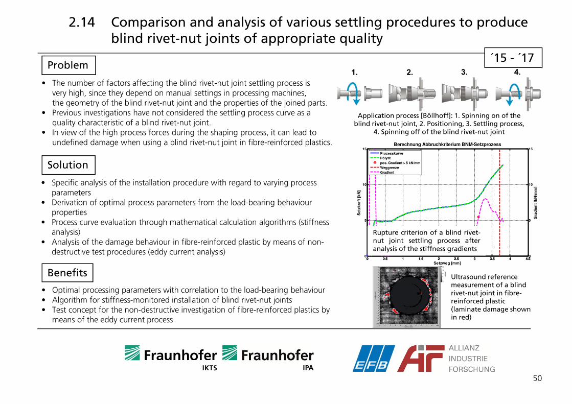
Solution
Benefits
• The number of factors affecting the blind rivet-nut joint settling process isvery high, since they depend on manual settings in processing machines, the geometry of the blind rivet-nut joint and the properties of the joined parts.
• Previous investigations have not considered the settling process curve as a quality characteristic of a blind rivet-nut joint.
• In view of the high process forces during the shaping process, it can lead to undefined damage when using a blind rivet-nut joint in fibre-reinforced plastics.
• Specific analysis of the installation procedure with regard to varying process parameters
• Derivation of optimal process parameters from the load-bearing behaviour properties
• Process curve evaluation through mathematical calculation algorithms (stiffness analysis)
• Analysis of the damage behaviour in fibre-reinforced plastic by means of non-destructive test procedures (eddy current analysis)
• Optimal processing parameters with correlation to the load-bearing behaviour• Algorithm for stiffness-monitored installation of blind rivet-nut joints• Test concept for the non-destructive investigation of fibre-reinforced plastics by
means of the eddy current process
´15 - ´17Problem
2.14 Comparison and analysis of various settling procedures to produceblind rivet-nut joints of appropriate quality
Application process [Böllhoff]: 1. Spinning on of the blind rivet-nut joint, 2. Positioning, 3. Settling process,
4. Spinning off of the blind rivet-nut joint
Ultrasound reference measurement of a blind rivet-nut joint in fibre-reinforced plastic (laminate damage shown in red)
Rupture criterion of a blind rivet-nut joint settling process afteranalysis of the stiffness gradients

51
2.15 Small clamping length relationships
Solution
Benefits
• Increasingly small clamping length-diameter relationships at frictional mechanical joints
• Uncertainty of the clamping force when using preloaded connecting elements with small clamping length-diameter relationships
• Measuring joints with small clamping length-diameter relationships is not possible at the moment
• Development and extension of the test criteria for sliding load tests• Experimental investigations of the effect of various parameters
(temperature, cutting ability, hole geometry) on the individual sliding load• Measurement of the preloading forces to describe the settling and creep
effects
• Use of suitable joints for assembly with small ��
�relationships
• Evaluation of the suitability of various preloaded connecting elements• Achievable loading capacities of frictional connections can be forecast
accurately
Problem
´15 - ´16

52
2.16 Measuring concept for structural blind rivet seams in structural steelwork and machine construction
´14 - ´16
Benefits
Problem
Solution
• Identification of technical and geometric factors influencing the load-bearing capacity of blind rivet joints
• Derivation of a suitable test methodology to determine the measurement characteristic values for blind rivet joints under transverse and tensile force loading
• Classification of the blind rivets on the basis of their load-bearing capacity• Drawing up of user specifications for the "Measurement of blind rivet
joints"
• There is a wide variety of blind rivets available due to a lack ofstandardisation
• Existing approaches to dimensioning frequently underestimate the load-bearing capacity of modern blind rivets, as a result they are less cost-effective
• In many application areas, such as in the construction of rail vehicles, the measured characteristic values must be verified by separate testing
• No uniform measuring concept for blind rivet joints that takes into consideration both static and dynamic loads
• Separate verification of load-bearing capacity for connecting element and joined parts
• Costs of testing avoided or reduced• Reduction in costs and increase in competitiveness
Use of blind rivet joint in various technical fields:Rail vehicle - cableway gondola - high bay warehouse (l to r)
Determination of the bearing resistance load-bearing capacity depending on the edge clearances

53
Benefits
Solution
• Investigation of the influence of the joints on the overall dynamic behaviour (identification of local indicators)
• Investigation of the behaviour of the wind turbine by overall dynamic simulation and metrological verification
• Development and verification of an optical measurement method for determining the vibration and deformation behaviour of the tower structure and of the rotor blades
• Inadequate consideration of the joints when designing lattice mast structures to date
• Highly complex dynamic behaviour of the wind turbines and hence the necessity to consider complex load situation during the design engineering
• Metrological verification is currently only possible using instruments and with great effort
´13 - ´15
2.17 Use of maintenance-free lattice masts for wind turbines with large hub heights
Problem
www.stieblich.de
Source: EFI Wind GmbH
Conceptual approach to the optical measurement of a wind turbine
• Cost reduction for the regular maintenance intervals of the wind turbine• Verification of the overall dynamic load calculation • Contact-free measurement method for fast and inexpensive
verification of the engineering design
Professorship of Technical Mechanics / Dynamics

54
Solution
Benefits
• Eccentric stress on joints in steelwork and machine construction lead to a combined bending and lengthways tensile loading of the connecting elements that are used (e.g. bolted joints at a tubular steel tower)
• Additional bending reduces the fatigue resistance of the connecting elements• Lockbolt system at as an alternative means of joining:
• Lack of knowledge of the load-carrying behaviour (lockbolt force function) and measurement of the eccentric stress
• Characterisation of the influence of eccentricity on lockbolt joints:• Formulation of the lockbolt force function• Determination of the resistance to vibration (stress concentration)
of lockbolt joints under eccentric strain• Comparison with bolted joints • Segment settling for lockbolt joints
• Increase in load-bearing capacity associated with cost savings through:• Reduction in the required nominal diameter• Reduction of the flange dimensions• Savings in manufacture and installation• No costs for maintenance and servicing
• Extension DIN EN 1993 and EFB/DVS code of practice 3435-2
´15 - ´17Problem
2.18 Increase in load-bearing capacity in eccentrically stressed jointsdue the use of lockbolt systems
Bolt force function SCHMIDT/NEUPER
Source: SEIDEL – Design of flanged connections
Modelling: Segment settling
Source: DIBt guideline for wind energy units (WEU)
Source: www.commons.media.de
Wind energy unit with tubular steel tower

55
2.19 Preloading force losses in preloaded bolted joints under fatigue stress
• With bolted connections it is vitally important that the preloading force that is applied to the joint remains there over the working life of the structure to ensure its load-bearing capacity or suitability for use.
• Preloading force losses ΔFp,C,tot from various causes must consequently be estimated realistically at the stage of dimensioning a connection.
• Scientific investigations of preloading losses in bolted joints under fatigue stress are not available.
Solution
Benefits
• Verification of the individual proportions of the preloading force losses as a result of settling and fatigue stresses for
• Various connecting elements• Various tightening procedures• Slip-resistant connection and tensile connection• Various forms of surface preparation
• Allows the design of low-maintenance/zero-maintenance joints• Optimal utilization of the remaining preloading force level
´15 - ´17Problem
Vorspannkraftabfall infolge selbsttätigen Lösens
LosdrehenLockern
Kriechen Setzen Total Partiell
Schraube, Mutter, verspannte Teile
Gewinde, Kopf-und Mutterauf-lageflächen, Trennfugen
Äußere Losdreh-momente
Relativ-bewegungenzwischen den Kontaktflächen
Atmen im Mutterngewin-de bei Axial-beanspruchung
∆Fp,C,ges = ∆Fp,C,Setzen + ∆Fp,C,Relaxation + ∆Fp,C,Querkontraktion + ∆Fp,C,Längszugkraft + ∆Fp,C,Losdrehen
Source: Mauer & Söhne GmbH

56
2.20 Increase the joining point stiffness through Z-pins in the mechanical
joining of fibre-reinforced plastics-metal hybrid structures – PLUGZ
Solution
Benefits
• When mechanically joining hybrid composite materials made of metal and fibre-reinforced plastics (FRP) with preloaded connectors, retardation processes are caused in the FRP
• Retardation causes a reduction in the preloading forces andthus endangers the suitability for use of the joint
• FRP hybrid joints are therefore given less preloading than metal joints and can thus only transfer lower forces
• Retardation processes are avoided and increased joint point stiffness
• Increase in the loads that can be transferred by FRP hybrid composite materials
• Increased use of mechanical hybrid joints and thereby increased and extended use of FRP in special forms of machine construction
´15 - ´16Problem
Application of Z-pin reinforcing plates in fibre-reinforced plastic composite materials
Measurement of preloading force loss in fibre-reinforced plastic hybrid composite materials and evaluation
• Development of a form of reinforcing for FRP materials through the point use of Z-pin plates at the join points
• Determination of suitable procedures for the production of reinforced FRP joint points and settling process parameters for mechanical joints
20
25
30
75
80
85
90
95
100
0,01 0,1 1 10 100Zeit [h]
Tem
pe
ratu
r [°
C]
Vo
rsp
an
nkra
ft r
ela
tiv i
n [
%]
Vergleich Vorspannkraftverlauf GFK [0,90]S mit und ohne Z-Pin
Kraft_relativ_oZPin
Kraft_relativ_mZPin
Temperatur
∆FV,rel = 10%

57
• The displacement criterion will be jointly revised to ensure that the testing can be done economically.
• Developing of tightening procedures for lockbolts, H360, DTIs and new innovative surface coatings
• Extension of the use of injection bolts as an economic alternative to non-slip pre-loaded joints
• Dimensioning rules are to be drawn up for the first time for non-rusting steels.• Further investigation of hot-dip galvanized structural steelwork constructions
• Non-slip joints are used in structures subjected to shear loads subject to stresses from vibration or load reversal (tensile/compressive vibration stress), for example, in wind energy units, bridges, cranes and radio masts.
Benefits
• The rules of DIN EN 1090-2, Annex G, for the determination of the friction coefficient cannot be clearly transferred for new types of coating systems and joints.
• In addition, the tests are very complex and the so-called displacement criterion to determine the slip load vary according to the test pieces.
´14 - ´16
2.21 Execution and reliability of slip resistant connections for steel structures using carbon steel and stainless steel - SIROCO RFCS - Project
Problem
Solution
Displacement time behaviour of non-slip pre-loaded joints in fatigue testing, creep testing and extended creep testing
Slip load testing in compliance with DIN EN 1090-2, Annex G for various surface pre-treatments in compliance with DIN EN 1090-2
No. 1: as rolled (Class D)No. 2: blasted with grit (Class A)No. 3: hot-dip galvanized No. 4: blasted and ASI-Zn-
coating (Class B)No. 5: grit-blasted and spray-
metallized (Class B)
Cp
Si
iF
F
,4 ⋅
=µ
n
µi
m
∑=µ
Slip factor as individual µi and mean value µm:
0,00
0,05
0,10
0,15
0,20
0,25
0,30
0,000001 0,00001 0,0001 0,001 0,01 0,1 1 10
dis
pla
cem
en
t δ
[mm
]
log time t [a]
Extended creep tests- at 70% FSm and 40% FSm -
displacement-log-time-curve 70% Fsmdisplacement-log-time-curve 40% Fsm

58
´15 - ´16
2.22 Extension of the general technical approval Z-14.4-591 for BobTail lockbolts of diameter M22 - M39
Lockbolt system BobTail M39 Alcoa Fastening Systems Ltd.
• Currently BobTail lockbolts with a bolt nominal diameters M12 – M20 and 1‘‘ (25.4 mm), are technical approved for the use in structural steelwork (as per DIN EN 1993-1-8/-9) and in the towers for wind energy units
• In view of current developments regarding alternative tower concepts for wind energy units, users are requesting lockbolts of larger diameters (up to M39).
• Among other things, these are suitable in view of their low variation when applying a high planned preloading force and their securing effect in view of their working principle, especially for structures that are subject to fatigue stress.
Benefits
• Drawing up testing and appraisal concepts• Carried out the required experimental investigations• Drawing up an appraisal and derivation of the stipulations for the draft
and measurement in accordance with DIN EN 1993-1-8/-9 and the DIBt guidelines for wind energy units
• Use of large diameter BobTail lockbolts in structural steelwork by extending the existing technical approval at the Deutsches Institut für Bautechnik (DIBt)
Problem
Solution

59
2.23 Adaptive, self-monitoring tool for the subsequent sheathing ofimpregnated fibre bundles - AdaptRo
´12 - ´13Problem
Solution
Benefits
• Determination of suitable sheathing parameters with the aid of a laboratory winding unit equipped with sensors
• Development of a tool for the subsequent sheathing of already laid impregnated fibre bundles with integrated sensors to monitor the impregnation (e.g. capacitative), monitoring of further critical production errors and an optical analysis and evaluation of the components that are produced
• The cable-laying procedure developed in the lattice truss-PFM project to produce integral fibre-composite load-bearing structures directly from fibre rovings and matrix resin exhibits specific disadvantages due to unbundled single rovings:• reduced compressive strength due to the risk of individual rovings buckling• lack of protection against mechanical outside forces (impacts, vandalisms, etc,)• truss geometry not defined and hence not reproducible
• necessity for laying multiple fibre cables at highly stressed areas entails a subsequent sheathing process
• Elaborate manual monitoring of the production process and a subsequent testing of the components that have been created is necessary
• Optimised mechanical component properties• Higher process reliability and reduced manual process monitoring through a
developed quality control system• Opening up of new markets through markedly increased surface quality
A cable laying and winding unit for component production with
defined process parameters developed at Fh AGP

60
´13 - ´15
Solution
Benefits
• Joints of pipework in ship construction are currently predominantly welded and in some cases mechanically produced.
• Mechanical socket systems are classified as non-maintenance-free and can therefore only
be used at accessible points; they also allow only limits compensation of large tolerances.• Use of welding methods results in destruction of the corrosion protection coatings of pipes
and in the environment due to the induced heat.• Confined spaces in the ship require welding in awkward positions which lead to higher
error rates and a correspondingly higher need for repairs.
• Development of a bonding method for joining of metallic pipework• Qualification of bonding processes suitable for the respective intended application• Development of an application variant for the joining operation (low heat,
production of maintenance-free joints, suitable for use in confined spaces, compensation of large tolerances) suitable for use under construction site conditions
2.24 Joining of metallic pipework in ship construction by bonding
Problem
Top left: TIG-soldered double socket, top right: welded pipe connection, bottom left: mechanical pipe coupling systems [www.teekaycouplings.de]
Construction possibilities for joining pipes by bonding [Steinhilper, Sauer]
• Low heat input, thus eliminating the restraightening work• Error rate reduced due to elimination of welding in awkward positions• Reduction of repair and refinishing work (grinding out of flaws and rewelding) • Time and cost-intensive installation of pipework in ships or offshore constructions
simplified

61
2.25 Development of carbon fibre-reinforced bridge systems with automatic production - E.B.a.F
´13 - ´15
Top view: Schematic of jointing of the roadway deck
Fügeverbindungen:
VerschraubungKlebung (orange)Umwicklung
CFK StabGFK Spant
Solution
Benefits
• Conventional bridge constructions using ferroconcrete required long construction times, they are sensitive to corrosion and have a high weight.
• Conventional bridges made of fibre-reinforced plastics (FRP) have a limited span (max. 50 m).
• Use of expensive semi-finished products (fabric, rovings) is required
• FRP bridges on the basis of structures made of carbon fibre-reinforced plastics produced by the cable-laying process
• Development of novel joining technologies for individual bridge segments (arch and roadway) and structural adaptations
• Use of cost-effective rovings as semi-finished products
• Insensitivity to corrosion means lower maintenance costs• High degree of prefabrication and weight reduction lead
to a reduction in transport costs and construction time• Longer spans are possible (> 50 m)• Working load increased by 20%
Problem
3-point bending test of an arch section for comparison of the bending progression under variable pre-loading forces
Arched bridge of cable-laying construction

62
2.26 Small wind energy unit that can be used worldwide - GEK-WEA
´13 - ´15Problem
Solution
Benefits
• Development and use of new rotor materials in connection with new manufacturing procedures
• Development, testing and use of components that are appropriate for the stresses encountered (bearings, shaft, hub, etc.)
• High demand for energy generation units with high availability in regions with a decentralized power supply (e.g. Central America)
• Area of application of small wind turbines as prototypes only in temperate climatic zones up to now
• Lack of knowledge of the climatic limits in use• Production of the rotors that are manufactured by hand is very time-
consuming and results in unsatisfactory process reliability
Heat and humidity climatic cycles to determine the output power and the micro-climate inside the generator
Prototype of a DELA rotor with an efficiency of approx. 40%
Production and testing of FRP rotor blade materials
Below the dew point at the surface of a component
• Use of small wind turbines that are more resistant to climatic and ambient conditions with high availability and longer calculable lifetime
• Increase in process reliability and component quality
• Guarantee of decentralised power supply in regions with weak infrastructure

63
´14 - ´16
Solution
Benefits
• Increasing demand in architecture for facades and roof covering with extreme shapes
• The three-dimensional direction-free shaping of thin metal sheets is technically complex
• High costs for reshaping dies lead to high production costs
• Construction of facades and roof elements with high levels of 3D shaping is possible
• Reduction of the production costs
2.27 Development of a flexible die – FLEXIFORM 1
Problem
Fully automatic contour machining in the milling
centre
• Investigation of alternative materials that can be shaped on the basis of thermoplastics through empirical tests andnumeric simulation
• Development of a shape-changing reshaping die
• Implementation of fully automated contour machining and dimensional compliance checking
Simulation of the thermal internal stresses in the semi-finished product in the heating process (left), temperature gradient upper and lower side (right)
Checking the geometrical dimensional compliance after recovery due to internal stresses, shaped semi-finished product 140°C vs. 20°C

64
• The resulting total weight leads to an increased draught of the river passenger boat.
• In combination with low water at dry times of the year the ability to pass throughcertain river sections is limited.
• This shortens the cruising season, which greatly reduces the usage time of the boats.
• In inland waterway passenger boats both the hull and the superstructure are produced in the form of conventional structural steelwork.
Solution
Benefits
• A reduction in the intrinsic weight of the boat leads to a reduction ofthe draught and hence to an extension of the touring season
• Reduction in fuel consumption leads to cost savings
• Reduction in exhaust emissions contributes to better environmental compatibility
2.28 Integral lightweight deck sections made of composites forinland waterway passenger boats – CompDeck
´15Problem
• Development of integral lightweight deck sections of fibre-based compound materials
• Verification of approval-related requirements (strength, stiffness, fire resistance, etc.)
FEM calculation of a deck section of conventional steel construction (load case: deck load 4 kN/m²)
River passenger boat Viking Gullveig with upper steel deck section
Source: Rolf Heinrich

65
2.29 Development of a holistic, established and environmentally-friendly form of protection for offshore wind energy units – OptiWind
Solution
Benefits
• Offshore wind energy units are exposed to harsh ambient conditions (wind, salt, wave action, etc.)
� The protection against corrosion must function optimally for
the planned operating time of at least 25 years• Interface problems, especially between the steel erector and the
coating applicator, frequently lead to subsequent damage in the protection against corrosion as a result of the standards and guidelines not being harmonised, and this leads to high costs
• Cost optimisation through a simplified and non-friction coating process and by avoiding subsequent damage to the protection against corrosion
´15 - ´18Problem
• Development and testing of complex test bodies to verify theeffect of steelwork geometries on the effectiveness of theprotection against corrosion
• Development of a guideline to harmonise the requirements for the application of coating systems
• Development of a tool to estimate the cost of measures for protection against corrosion depending on the production of the structural steelwork
Complex test specimens
Outsourcingstatus List/Sylt
© Fraunhofer IWES

66
3 Work Area: Automation Technology
• Automation/Sensor Technology focuses primarily on the development of automation solutions and their implementation as prototypes in industry, and in particular, novel robot concepts with intelligent sensor guidance.
• Quality Technology concentrates on the measuring of large structures. Here the main focus is on 3D geometry data acquisition, calculation and evaluation. There are very close linkage between Automation Technology and Organisational Technology via Reverse Engineering, the digitisation of production layouts and the tracker guidance of robots.

3.1 Parallel kinematics large robots IMG
´10 - ´14Problem
Solution
Benefits
• Currently industrial robots are only available up to a load capacity of around 1.5 tons.
• There is potential for the automation of heavierwork pieces and heavier tools.
• The performance limits of conventional robot kinematics have been largely reached.
• Large robot with a parallel kinematics basic design
• Low moving dead weights
• High load-bearing capacity with high mobility
• Low energy requirements
• Configuration either as a floor-mounted unit or linear gantry unit
• Availability of flexible automation technology for heavy loads with a long reach
• Opening up of new application areas for automation solutions
67

68
3.2 Drilling robot
Problem
Solution
Benefits
• The surface machining in the production of ship propellers is done by grinding. Propellers for large container ships have diameters up to 12 metres.
• The specifications for the machining of the cast propeller are provided by drilling the surface of the blank to the required final dimensions.
• This work is very time-consuming. The propeller has to be turned in a device for the machining of thepressure and suction sides.
• Drilling the holes by a large robot that is guided with extreme precision by a tracking system. The specifications for the drilling depth and orientation of the propeller surface are passed to the robot via the evaluation software of a 3D scanner.
• Reduced throughput times
• Increased quality
• Minimized production costs
´14 - ´15

69
• Adaptive welding facility for setting onto the pipe nozzle to be welded with various lengths and, for preference, large diameters (< 2.5 m)
• Double automated tandem welding process to reduce the throughput time and improve weld seam quality
• Sensor-controlled weld seam measurement for optimal welding position and torch alignment
3.3 Automated production of pipe nodes
´13 - ´15Problem
Solution
Benefits
• The joining of various pipe segments to make a pipe node is currently done by hand and is very time-consuming.
• Pipe node connections in the offshore sector are subject to high quality requirements regarding seam geometry and the inner structure and must be checked and tested several times during production.
• Welding work in awkward positions is almost unavoidable.
• Improvements in weld seam quality• Development of a consistently reproducible weld seam• Significant increase in productivity for a broad spectrum of pipe
nodes ranging up to very large sizes

70
3.4 Coastal erosion model Darßer Ort (Mecklenburg-Vorpommern)
´15
Problem
Solution
Benefits
• Drawing up a 3D volume model through mathematical calculation procedures and interactive data adaptation
• Height adjustment for easier comprehension
• Offline programming of the production task
• Production of an exhibition model with dimensions of1 m x 2 m, made of hard PU modelling foam
• Production of a 3D exhibition piece for the outdoor area of the Natureum Darßer Ort
• Data base: Handmade illustration and geographic measured data
• Creation of an "easily comprehensible" model of the retreat from the coastline of Darßer Ort with high recognition value on the basis of only a limited amount of measured data
Linked scatter plot of the geometric measured data
3D CAD model
Handmade illustration

7171
3.5 Sensor-based robot programming for the automated production of high orthogonal volume structures - SensPro (Inno profiles)
´13 - ´16
System components
Data processing sequence
Solution
Benefits
• Conventional robot programming for the production of volume structure as structural steelwork ischaracterised by the large amount of time required for small numbers produced and the necessity to make adjustments to the actual location of the components in production, hence is often very uneconomic.
• In the area of flat modules automated robot programming had already been turned into a reality on the basis of 3D sensor data of the components.
• In view of the great complexity of orthogonal volume structures and the high risk of collision between robot and component, the implementation of a sensor-based procedure for robot programming in the area of the production of volume structures represents a special challenge.
• Three-dimensional collection of the data of the components at the production unit
• Automatic processing of the sensor data to determine the parameters of the seams to be welded
• Conversion of the seam parameters into unit-specific robot programs with collision monitoring
• Adaptive modification of the robot programs to the actual components on the basis of data from an intelligent seam sensor
• Drawing up of a research profile in the area of sensor-based robot programming• Increasing the competitiveness of maritime companies through the use of innovative technology
Problem

72
3.6 Use of laser scanners in steel structure construction - ELASTA
Solution
Benefits
• High adjustment and modification work during the production of steel structures, such as sections
• Lack of testing possibilities for steel structures with respect to surface features
• Extensive tactile tests slow down the production process
• Using laser scanners for the measurements• Development of alignment and evaluation algorithms for
automated evaluation of the point clouds• Holistic testing of the steel structures, including surface
features
• Comprehensive, accelerated quality testing in steel structure construction
• Increased reproducibility and also higher process reliability• Possibility of process optimisation through digital documentation
of the measured parameters
Problem
´12 - ´14
Flatness testing of a section
Determination of installation dimensions, position of the
bearing points of a flap
Reference point orientation

73
3.7 Standard geometry-based model for the interior outfitting of megayachts - IMoScan
´13 - ´16
Solution
Benefits
Problem
• Deviations in the steel structure results in high levels of reworking and adaptation during interior outfitting.
• Determination of the necessary dimensions in interior outfitting is time-intensive, redundant and susceptible to errors.
• Different dimension references and lack of feedback of geometric information lead to increased effort.
• Central data acquisition using laser scanners • Development of methods for quick referencing in the ship's
coordinate system• Standard geometry-based automated dimension
generation on the basis of the CAD model• System for mobile dimension documentation
• Acquisition and digital preparation of actual production data • Establishment of a uniform data basis for interior outfitting• Acceleration of the recording, evaluation and documentation • Increased productivity in interior outfitting
Dimension generationin interior outfitting
Data base 3D point cloud
Superimposition of actual and nominal
data

74
Solution
Benefits
Problem
3.8 3D recording and monitoring of underwater large structures –DeepInspect (internal preliminary research of the FhG)
´15 - ´17
• Development of laser-based scanning systems for the underwater area
• Combination of sensor and evaluation unit for an automated inspection system
• Requirement-specific automation of the data evaluation
• Offshore units, dams and other underwater structures are currently mainly inspected visually and manually by the use of divers.
• When it comes to geometric monitoring and deformation analyses, regarding the state of the art in the underwater sector, the present sensors that work on a sonar basis are not adequate in view ofprecision, resolution, speed and data quality.
• Reliable and precise data collection for large underwater structures• Possibility of regular objective checking and monitoring in the offshore
area• Reduction of the effort and cost required for underwater inspections

75
Solution
Benefits
• Extremely high quality requirements for the visible painted areas of yachts in the above-water area
• Although there are already methods in use for the body filling work, they are not efficient enough; high cost of data acquisition
• Body filling simulation on the basis of scanned data is done by manual smoothing of the data. This is subjective and not sufficiently reproducible
• Significant speeding up of data acquisition through the use of cinematic scanning methods
• Development of algorithms for automated reproducible generation of visually straked surfaces with regard to all the relevant optimisation parameters
• Development of criteria to evaluate the quality of the generated surfaces froman optical point of view
• Speeding up of the coating process in yacht construction
• Use of body filling prediction also for complex areas for the prefabrication of components
• Qualitative evaluation of the body filling layer and the course of the contours
• Avoiding reworking and additional costs
Problem
3.9 Exact and rapid geometry determination and data evaluation of shipsurfaces for efficient coating processes – FINISH
[Go-3D,2012]
´15 - ´18

76
3.10 Developing Smart Technologies for Productivity Improvement of European Small and Medium Sized Shipyards - SMARTYards
• Knowledge transfer to increase the competitiveness of small and medium-sized shipyards in Europe
• Increase in productivity and efficiency in the production process of shipyards
• Small and medium-sized shipyards often have a competitive disadvantage compared to larger yards.
• The reasons for this are:• Limited financial options• Fewer specialists• Older shipyard equipment (cranes, halls, etc.)• Uneconomic production • Difficult access to information and cooperation networks
Solution
Benefits
Problem´13 - ´16
Technology areas of the SMARTYards project
Basic principles for the drawing up of the design catalogue in the field of forming
Basic principles for the drawing up of the design catalogue in the field of the monitoring of precision
• Optimisation of existing resources / areas with the aid of companies with leading edge technology
• Creation of design catalogues for selected technology ideas for knowledge transfer and the implementation of prototyping
• As one of the leading high-tech enterprises, Fh AGP supports the areas of geometric quality control, measuring technology in the forming process and production technology
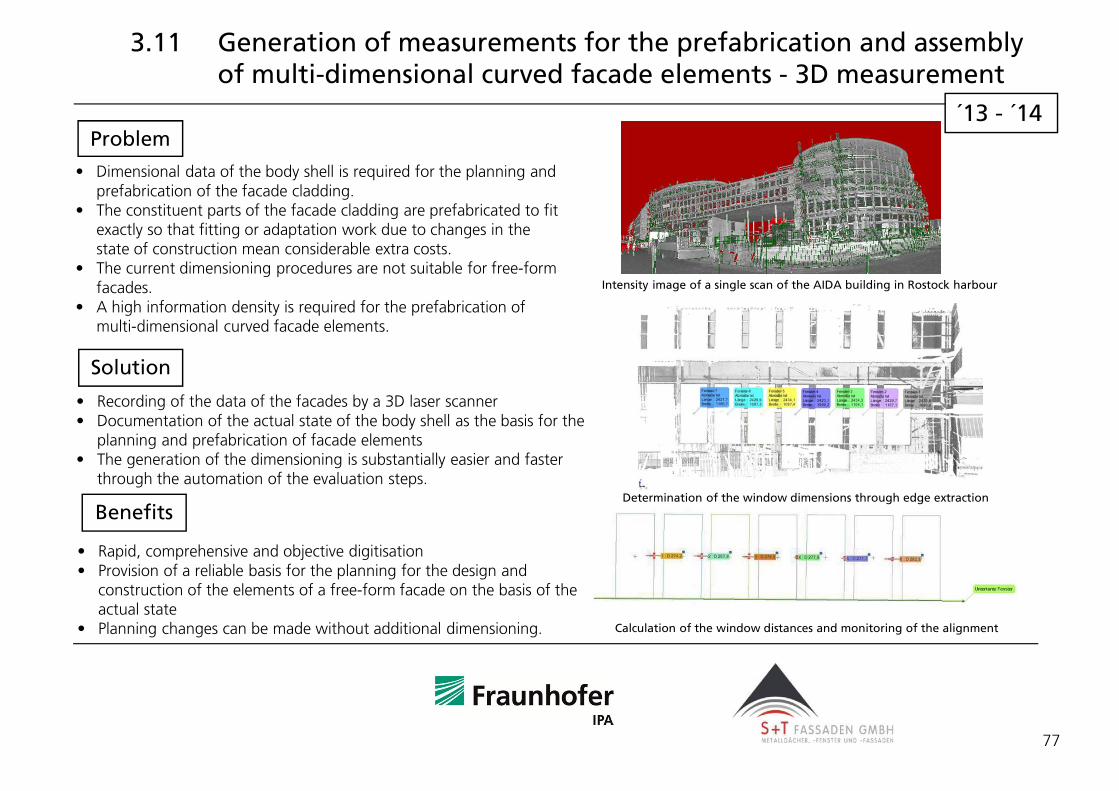
• Dimensional data of the body shell is required for the planning and prefabrication of the facade cladding.
• The constituent parts of the facade cladding are prefabricated to fit exactly so that fitting or adaptation work due to changes in the state of construction mean considerable extra costs.
• The current dimensioning procedures are not suitable for free-form facades.
• A high information density is required for the prefabrication of multi-dimensional curved facade elements.
77
3.11 Generation of measurements for the prefabrication and assembly of multi-dimensional curved facade elements - 3D measurement
Solution
Benefits
Problem
• Recording of the data of the facades by a 3D laser scanner• Documentation of the actual state of the body shell as the basis for the
planning and prefabrication of facade elements• The generation of the dimensioning is substantially easier and faster
through the automation of the evaluation steps.
• Rapid, comprehensive and objective digitisation• Provision of a reliable basis for the planning for the design and
construction of the elements of a free-form facade on the basis of the actual state
• Planning changes can be made without additional dimensioning.
´13 - ´14
Calculation of the window distances and monitoring of the alignment
Determination of the window dimensions through edge extraction
Intensity image of a single scan of the AIDA building in Rostock harbour

78
4 Work Area: Organisational Engineering
• Corporate and production organisation devises holistic solutions for the design of efficient and flexible production systems, primarily for large structures.
• The Research concentrates on the development of IT solutions for the planning and control of the production of complex unique items (Industry 4.0).
• In order to support the work force in production, and also against the background of the emerging demographic trend, special assistance systems are being developed to implement computer-supported and ergonomic work flows.

79
4.1 Development of a computer-aided system of spatial sensors for virtual commissioning of intelligent production plants - VirtualScan
´12 - ´14
Solution
Benefits
• Virtualisation of 3D sensors• Integration of the virtual 3D sensors into a simulation
environment for virtual commissioning• Development of automatic routines for the automatic
interpretation of the virtual measurement results• Establishment of a 3D sensor library
• Reduction in commissioning times• Early recognition of planning errors• Validation of the positioning and orientation
of the sensors during operation
• Due to the growing number of different variants and decreasing quantities, 3D measuring sensors are gaining in importance in production environments. At present, only sensors with binary input/output signals are used in the virtual commissioning of plants
• Lack of integration of 3D measuring sensors in the simulation environment
• Time-consuming commissioning by trial-&-error on the machine (high standstill times)
Problem

80
• Virtual layout planning and illustration of the flow of materials of the entire production process
• Development and optimisation of a workplace using ergonomics simulation with regard to the working time and ergonomic stress
4.2 Materials flow and layout study with tools from the digital factory
Solution
Benefits
Problem´13 - ´14
• Implementation of a production line for a novel heat exchanger• In advance, high investment costs must be covered through detailed
analyses.• Integration of the new production line into an existing production
hall
• Evaluation of the workplace concepts regarding assembly times and the stress placed on the workers
• An illustration of the flow of materials makes possible dynamic analyses of the production work flows with regard to utilisation rate, throughput time and production quantity
• Planning errors are avoided by securing production at an early stage in a simulation system
Analysis of the workplace
Layout planning and simulation of the flow of materials

Development of an ergonomic workplace systemfor large components
Unergonomic forms of working
81
ERGOTAB
Demographic trend
• Development of novel kinematic concepts for adaptive work tables to support the workers during the assembly process
• Creation of intelligent controls for the kinematics• Supporting information for the worker during the assembly process• Merging of sub-components into a new system for workplaces suitable for
older workers
4.3 Development of an intelligent work table for the assembly of large components - ERGOTAB
Solution
Benefits
Problem´13 - ´16
• The demographic change leads to an ageing workforce in manufacturing companies.
• Companies that need to assemble larger components manually have to take a higher average age into particular consideration since it isdifficult to avoid disadvantageous body postures during the assembly work.
• So far, workplace systems for large components only permit a limited degree of intelligent adaptivity. This leads to disadvantageous body postures and hence to unnecessary stress for the workers.
• Reduction of stress due to ergonomically correct forms of working by manipulation of the ErgoTab
• Full provision of information through virtual production instructions
Sou
rce:
Buc
k/S
chle
tzS
ourc
e: B
uck/
Sch
letz

82
4.4 Innovative recycling of ships
´14 - ´15
A ship recycling process that is suitable for the future
Problem
Solution • Creating technologies for partial automation of the disassembly processes in Ship building
• Creating process work flows and production structures for the efficient disassembly of ships
• Development of concepts for the integrated handling of hazardous substances and materials
• Processing and evaluation of the concepts with the aid of material flow simulation
• Reduction of the amount of stress placed on the workers in the ship recycling process and ensuring appropriate working conditions
• Implementation of a cost-efficient recycling process through the use of innovative technologies
Benefits
• Currently the staff of the ship recycling processes have to work under very bad conditions; the use of technology to support the staff is very rudimentary.
• There is no regulated procedure to deal with hazardous substances and materials.
• However, this sector will change greatly in the next few years in view of the guidelines of the IMO. Therefor suitable measures must beprepared.
Innovative technologies
Efficient work flows

83
Problem
Solution
4.5 Study on the development of ergonomic handling devices tochange batteries in AGVs
• Analysis and evaluation of the handling process with regard to ergonomic and organisational aspects
• Development of an adaptive ergonomic handling system for the specified overall geometric and environmental conditions to support the workers when changing the batteries
• The ergonomic handling system can avoid unfavourable body postures and reduced the amount of stress placed on the workers.
• The workers are spatially separated from the hazards when changing batteries (voltage bridges, escape of acid).
Benefits
AGV and battery box in the container terminal of
Hamburg harbour
• Currently the battery change in automatic guided vehicles (AGVs) is done exclusively manually.
• In view of the high battery weight and poor accessibility this produces unfavourable body postures and hence an increased amount of stress for the workers.
´14
Approach to solving the
problem: Development of a variable handling
system for theergonomically
favourablechanging of
batteries with a reduced load on
the workers

84
4.6 Development of a modular yacht generation –pilot study and joint project
´11 - ´14
Solution
Benefits
• Development of a modular yacht structure• Introduction of standardisation and identical part concepts• Production and assembly-orientated yacht construction• Development of construction methods for the modular yacht
structures
• Simple configuration of individual yachts thanks to a holistic modularisation concept
• Reduction in the number of different parts and standardisation of component interfaces
• Reduction in the system complexity and hence reduced lead times
• Increased process stability in assembly• Use of learning curve effects
• Large number of different components and materials with individually configured sailing yachts
• Long and widely fluctuating development and production processes• No standardisation across models• Lack of assembly suitability in the yacht construction
Problem
Source: http://www.hanseyachts.com

85
4.7 New generation of production control systems
Problem
Solution
• Development of a new generation of production control systems• Integration of additional target aspects into the planning
algorithms of production control systems taking the example of energy data
• Technical feasibility study to confirm the feasibility and for interface generation
• The efficient use of increasingly large amounts of data with high processing speeds (real time) in production industries
• Holistic optimisation of production processes• Use of the data and results within the scope of energy
management as defined by the EEC and in ISO 50001
Benefits
• The developments in the context of Industry 4.0 show that the mastering of the variety, quantity and speed of data flows represents a major challenge.
• Production control systems to date are not able to make use of the whole data that had been generated in production foroptimisation of the PPS.
Setup of an operating data acquisition structure for the collection of production and energy data in the test field at Fraunhofer AGP
Evaluation and planning of the energy requirements and the production work flows with regard to the production data
Datenverarbeitung und –bereitstellung
VorverarbeitungBigData
Algorithmen
Trend-
erkennung
Informations-
darstellung
Daten-
rückmeldung
´14 - ´15

86
4.8 Containerised hydraulic units
Solution
Benefits
• Design of suitable containerisation concepts• Development of a modular system• Interface definition and standardisation (Plug 'n' Play approach)
• Simple configuration of individual yachts thanks to a holistic modularisation concept
• Reduction in the number of different parts and standardisation of component interfaces
• Reduction in the system complexity and hence reduced lead times (use of learning curve effects)
• Location-independent options for use (harsh environments) • Ease of installation and maintenance
• Large number of different components and materials with individually configured hydraulic units
• Long and widely fluctuating development and production processes• No standardisation across models• Various requirements for the enclosure (transport, operation,
environmental influences, emissions)
Problem
Source: www.prinztechnik.de
Source: www.bosch-logistik.de
´14 - ´15

87
4.9 Simulation study on the robot painting unit for the 65.5 rotor blade at Nordex Energy GmbH
´15
Solution
Benefits
• Introduction of a new generation of rotor blades of type NR65.5• Automated painting unit at Nordex designed only for rotor blades of type
NR58.5• Verification of the feasibility for the new type of rotor blade with a length
of 65.5 m required (reachability, freedom from collisions, positioning)
Problem
• 3D simulation study to verify reachability and freedom from collisions• Determination of optimal positioning and alignment of the rotor blade
in the painting cell• Derivation of the required conversion measures (axis extensions, limit
switches, etc.)• Derivation of the required adaptations to the rotor blade holder
• Virtual determination of feasibility at an early stage• Basis of the decision for introduction of the NR65.5 and the conversion
measures to be implemented• Reduction of time and costs in the planning and commissioning process
Source: www.nordex-online.com

88
• In 2009 the test laboratory was accredited in compliance with DIN EN ISO/IEC 17025:2005 to meet the high quality requirements from research and business. The scope of testing is extended at regular intervals to meet the relevant requirements. The level of competence is confirmed by the deutsche Akkreditierungsstelle (DAkkS) [German Accreditation Body].
• The Fh AGP is recognised as a monitoring and certification body in accordance with the German LBauO M-V. The activities comprise, among others, the monitoring of production plants concerning the staffing and technical preconditions for correct production and testing of the conformity and certification of connecting elements for steel and lightweight construction.
5 Work Area: Accredited Test Laboratory, Monitoring and Certification Body

8989
5.1 Accredited test procedures
1) Mechanical-technological tests
Tensile and compressive test, vibration fatigue test• i.a. on complete and
machined-down connecting elements (right)
• i.a. connecting element "Bobtail" lock bolt M12 (far right)
• Testing of bonded joints - shear tensile test (left)
Notched barimpact test (right)
Vickers hardness test
Clamping force test
3-point bendingtest
• on plastic parts
(right)

90
5.2 Accredited test procedures
37
39
41
0 30 60 90 120 150 180 210
Ve
rsch
ieb
un
g δ
[µm
]
Prüfzeit t [min]
Kriechversuch
Probe 9
5 min
180 min
Testing of mechanically connected joints
0
75.000
150.000
0,00 0,05 0,10 0,15 0,20
Gle
itla
st F
Si[N
]
Verschiebung δ [mm]
Last-Verschiebungs-Diagramm
Probe 8 150 µm
Determination of the coefficient ofstatic friction of a non-slip joint
Testing of bonded joints and adhesivesTransverse force test
Manufacture
Caterpillar peeling test
Determination of the fracture toughness for metal materials
(according to Sander)

91
5.3 Accredited test procedures
2) Leak testing
Test setup for the determination of the dynamic characteristic values of elastic bearing elements of ships in various thrust directions
3) Corrosion testing
Salt spray and condensation units
Artificial weathering of coating systems
Upper pressure device without connection to side thrust plates
Side thrust plates to apply the thrust forces
Threaded rods to apply the axial thrust force
Installation baseplate with connection to lower positioner
Positioner to determine the axial and radial stiffness

92
5.4 Accredited test procedures
Testing of coating systems
Assessment of artificially weathered coating materials
4) Chemical–physical tests
Textile glass-reinforced plastics - determination of the textile glass and mineral glass content, calcination method
CFRP specimen before, during and after thermal calcining
Spark emission spectrometryof steel and iron materials
Determination of the chemical composition of metallic materials

5.5 Work as a Monitoring and Certification Body for joining elements in compliance with BRL and approval areas Z-14.1 and Z-14.4
93
Certification body
Monitoring body for outside monitoring
• Evaluation of the reports presented by the Monitoring Body and decision on the granting or retention of the compliance certificate
First monitoring
• First inspection and evaluation of the producing plant and the in-house production control system
Rule monitoring
• Regular inspection and evaluation of the producing plant and the in-house production control system
• Random checking of samples taken from the producing plant, the market or, in special cases, from a construction site
Special monitoring
Compliance mark [source: MÜZVO]
Non-regulated construction products in the construction field
• Monitoring body for outside monitoring and
• certification body
for construction products with a general technical approval (joining elements approval areas Z-14.1…, Z-14.4-…) in accordance with the Federal Land construction regulations
Area of application
´14 - to date

ManufacturingManufacturing
Selected ProductionMethods
Selected ProductionMethods
ProductionEquipmentProductionEquipment
WeldingTechnologyWeldingTechnology
WeldingConstructionWeldingConstruction
WeldingMetallurgyWeldingMetallurgy
ProductionManagementProductionManagement
QualityManagementQualityManagement
ProductionMeasurement Technology
ProductionMeasurement Technology
Technical DocumentationTechnical Documentation
Automation in Manufacturing and Assembly
Automation in Manufacturing and Assembly
ControlEngineeringControlEngineering
Robotics(with Prof. Woernle)Robotics(with Prof. Woernle)
94
Statistical figures:
6 Work Area: Academic Programs Professorships Production
Technology (PT) and Joining Technology (JT)
2014 2013 2012 2011 2010
Test cases 994 1333 1644 879 836
Diploma/master papers 46 60 34 20 20Bachelor papers 39 35 42 39 27KLR LS PE & JT 2.85 2.27 2.57 1.65 1.95
LabourSciencesLabourSciences
ManufacturingManufacturing WeldingWelding Automation inAutomation inQualityQualityOrganisationOrganisation
Marine Production EngineeringMarine Production Engineering
Management ofindustrial plantsManagement ofindustrial plants
KLR = key performance indicator of the MB&ST faculty

95
7 Projects in Progress (2014-2018)
As of 6/15
Serial No.
Project Theme Duration Customer / Project Manager
Production Engineering
1. Single-sided electro-gas welding with discontinuities of plate thicknesses and butt joint geometries
2012-2014 CMT/AiF
2. Development of a cost-effective process variant of submerged-arc welding in transverse position on large plate thicknesses for application on offshore structures and in shipbuild-ing
2012-2014 CMT/AViF
3. Experimental determination of the fatigue strength of shear-stressed lock bolt and blind rivet joints without component influence
2012-2014 EFB/AiF
4. Conditions for a production and repair-oriented design of lock bolt joints while complying with the minimum load-bearing strength
2012-2014 EFB/AiF
5. Damage-resistant surface coatings of maritime structures under typical operating and environmental conditions, taking the example of a rudder
2012-2014 CMT/AiF
6. High-strength foundation structures for the offshore industry 2012-2014 Joint project with EEW/TBI
7. Laser and ultrasonic-aided clinching of high-strength steel/aluminium composite joints 2013-2014 Joint project with University of Dresden/DFG-SFB 1640
8. Simulation of the semi-hollow punch riveting process of FRP by multi-scale modelling 2013-2014 EFB/AiF

96
9. Research and test campaign for use of self-piercing rivets in primary aircraft structure in terms of design, manufacturing and tooling
2013-2014 Airbus GmbH, Hamburg
Serial No.
Project Theme Duration Customer / Project Manager
10. Imperfections in the friction surfaces of BSS towers 2013-2014 Siemens AG, Denmark
11. Concept study for freight system-based transport system 2013-2014 ThyssenKrupp AG, Essen
12. Consulting and selection of suitable joining elements for use in non-slip joints 2013-2014 Nordex Energy GmbH, Rostock
13. Defined prestressed hybrid joints with lock bolt and blind rivet bolt 2013-2015 EFB/AiF
14. Numerical and experimental investigation of settling process irregularities with ring bolt systems
2013-2015 EFB/AiF
15. Load limits for FE investigations 2013-2015 EFB/AiF
16. Joining of pipework by bonding 2013-2015 CMT/AiF
17. Development of carbon fibre-reinforced bridge systems with automatic production 2013-2015 ZIM-Koop. with BaltiCo and HS Wismar
18. Development and qualification of a small wind turbine plant for regions with demanding climatic conditions
2013-2015 Joint project with Dethloff & Lange/TBI
19. Use of maintenance-free lattice masts for wind turbines with large hub heights 2013-2015 Joint project with Stieblich/TBI
20. Novel steel tube tower concepts for wind turbines with large hub heights 2013-2015 Joint project with e.n.o./TBI

97
21. Approval of Nord-Lock lock washers 2014 Nord-Lock, Radevormwald
Serial No.
Project Theme Duration Customer / Project Manager
22. Generation of a Wöhler curve to determine the influence of dynamic pulsating tensile loads on the electrical resistance
2014 Nordex Energy GmbH, Rostock
23. Mechanical properties and clamping forces of lock bolts 2014 Avdel, UK
24. Fatigue tests to extend the area of applicability of general technical approval z-14.4-406 2014 FAS Fördertechnik, Parkstein
25. Investigation of welded pipes made of corrosion-resistant steel 2014 Neptun Werft GmbH, Rostock
26. Determination of the ageing resistance and cold impact properties of cable sheathing 2014 NordicYards, Wismar
27. Screw-in tests with fastening screws 2014 Adolf Würth GmbH, Künzelsau
28. Roto PA 2014-2015 Emano Kunststofftechnik, Teterow
29. Feasibility study for development of a mobile disassembly cell for rotor blades 2014-2015 Hanseatic Rohr GmbH, Rostock
30. Feasibility study for the development of functionally integrated floors made of carbon fibre reinforced plastic
2014-2015 PMC, Rhena
31. Development of a test environment for the qualified investigation of hydrogen by means of an implant test
2014-2015 EEW, Rostock
32. Development of a bonding process for a rubber liner and qualification of the adhesive joint
2014-2015 Faber Industrie SPA, Udine

98
33. Determination of the structural behavior of Bobtail lockbolts with large diameter 2014-2015 Alcoa Huck, Telford
Serial No.
Project Theme Duration Customer / Project Manager
34. Feasibility study: Unique custom-made free-form interior elements made of coloured minerals
2014-2015 Eigenstetter, Rhena
35. Support for the development of a WIG twin process technology 2014-2016 MIKA, Stralsund
36. Requirements profile for blind rivet joints with carbon fibre 2014-2016 EFB/AiF
37. Measuring concept for structural blind rivet seams in structural steelwork and machine construction
2014-2016 EFB/AiF
38. Execution and feasibility of slip-resistant connections for steel structures using LS and SS 2014-2016 EC: Research Fund for Coal and Steel, Joint
Project
39. Development of a handheld tool for solid punch rivet installation, Part I and II 2014-2017 Airbus GmbH, Hamburg
40. Join connections of lockbolts under atmospheric stress 2014-2017 EFB/AiF
41. Feasibility study: Feasibility of integral lightweight construction sections made of composites for inland water way passenger boats
2015 tfc, Güstrow
42. Utilization of prestressed joining elements for thin clamping regions under suitable conditions for installation
2015-2016 EFB/AiF
43. Increase in the process reliability of SAW, AC/AC procedure variations by means of optical analysis of the arc and the material transition in the cavity
2015-2016 DVS FA-V3/AiF

99
44. Evaluation of bolted joints using the "TEREFLEX" concept for wind energy unit towers with large hub heights
2015-2016 ThyssenKrupp Steel, Europe
45. Experimental investigations to determine a general technical approval 2015-2016 Butzkies Windprojekt, Hamburg
Serial No.
Project Theme Duration Customer / Project Manager
46. Comparison and analysis of various setting procedures to produce blind rivet-nut joints of appropriate quality
2015-2017 EFB/AiF
47. Development of a joining process for a PET-Liner 2015-2016 Faber Industrie SPA, Udine
48. Technology study: Investigation of the effect of the filler metal on the basic material properties of A60 construction steel
2015-2016 Nordex, Rostock
49. Point-type laminate support by Z-pins to increase the joining point stiffness when using mechanical joining elements
2015-2016 EFB/AiF
50. Development of a concept for the recording of prestressing force losses in prestressed bolted connections under fatigue stress
2015-2017 FOSTA/AiF
51. Increase in load-bearing capacity in eccentrically stressed connections due the use of lockbolt systems
2015-2017 EFB/AiF
52. Material- and process-related optimization of cavitation erosion-resistant coatings on ship rudders by means of cold gas spraying
2015-2017 CMT/AiF
53. Development of a holistic, established and environmentally-friendly form of protection against corrosion for overall cost optimization through optimized and matched production sections for offshore wind energy units
2015-2018 BMWi/PTJ

100
Automation and quality testing
54. Parallel kinematics large robots, sub-project 2: Control and drive technology 2010-2014 Joint project with IMG GmbH/TBI
55. Use of laser scanners in construction of structural steelwork 2012-2014 CMT/AiF
Serial No.
Project Theme Duration Customer / Project Manager
56. 3D data recording for overlength decks 2013-2014 Lürssen, Vegesack
57. Technology study: Generation of measurements for the prefabrication and assembly of multi-dimensional curved façade elements
2013-2014 S + T Fassaden Technik, Ticino
58.
Technology and system development for the automatic production of pipe nodes. TP2: Orbital welding system
2013-2015 Joint project with IMG GmbH/TBI
59. Standard geometry-based model for the interior outfitting of mega-yachts (IMOScan 3D joint project)
2013-2016 Joint project with Lürssen, Dölker + Voges/PTJ
60. Low Cost Flexible Automation and Mechanisation in Small and Medium Shipyards (pro-ject SMARTYards)
2013-2016 EU joint project
61. Reverse engineering of a hull form (H445) 2014 Hanse Yachts, Greifswald
62. Development concept for a mobile drilling device 2014 Nordex AG, Rostock
63. Reverse engineering of a hull form 2014 HanseYachts AG, Greifswald
64. 3D testing of a reed master pattern 2015 Tamsen Maritim, Rostock

101
65. Technology study: Development of a system concept for the automated marking of ship propellers
2015-2016 MMG Waren
66. Study for the re-engineering of an automatic tank filling system 2015-2016 HHLA Hamburg
67. 3D recording and monitoring of underwater large structures 2015-2017 MAVO-FhG with IPM Freiburg
Serial No.
Project Theme Duration Customer / Project Manager
Organisational Engineering
68. Development of a system of virtual spatial sensors for virtual commissioning of intelligent production plants
2012-2014 Joint project with Icarus, Winsen and SMT, Syke-DLR/BMBF KMU-innovativ: IKT
69. Simulation study for the industrialization of HVH devices in the Webasto factory Neu-brandenburg
2013-2014 Webasto, Neubrandenburg
70. Development of an intelligent workbench suitable for older workers for the manual as-sembly of large components (ERGOTAB)
2013-2016 Joint project with REFA, MiniTec, Hobas and Selck/BMBF-PTJ
71. Simulation study for a shipyard planning project 2014 TKMS, Hamburg
72. Study on the development of ergonomic handling devices to change batteries in H-AGVs at SCA
2014 HHLA, Hamburg
73. Technology study: Innovative recycling of ships 2014-2015 IMG GmbH, Rostock
74. Analysis of dynamic floor deflection 2014-2015 Airbus GmbH, Hamburg

102
75. Technical feasibility study: Containerized hydraulic units 2014-2015 Prinz Hydraulik, Schwerin
76. Technical feasibility study for a new generation of production control systems 2014-2015 SEAR, Rostock
77. Basic investigation of new technologies to support installation, maintenance and training 2014-2015 Siemens AG, Erlangen
Serial No.
Project Theme Duration Customer / Project Manager
78. Technical feasibility study for the ergonomic control room 4.0 2014-2015 Koepke & Kassiske, Garz
79. Simulation study on the robot painting unit for the 65.5 rotor blade at Nordex Energy GmbH
2015 Icarus Consulting, Lüneburg
Prototypes
80. Development of a modular yacht generation 2011-2014 Hanse Yards, Greifswald/TBI
81. Inline quality assurance sensors for monitoring the component properties 2012-2014 TEDI, Schwerin/TBI
82. Development of a test facility for an industrial pizza oven 2014-2015 Dr. Oetker AG, Wittenburg
83. Creation of two prototypes for a strapping machine 2014-2015 Linder, Seevetal
84. Coast model Darß 2015 Deutsches Meeresmuseum [German Marine Mu-
seum], Stralsund
INNO PROFILE

103
85. Sensor-based robot programming for the automated production of high, orthogonal vol-ume structures
2013-2016 INNO PROFILE transfer: Joint project with IMG, Hensel Electronic and Nordic Yards/ BMBF-PTJ

103
8 Committee work, external lectures 2014
Work group of industrial Research Associations „Otto von Guericke“ Prof. Dr.-Eng. M.-C. Wanner – Expert Federal Ministry of Economy and Technology (BMWI) Prof. Dr.-Eng. M.-C. Wanner – Expert of the funding programme 'Innovative shipbuilding ensuring competitive jobs'
Center of Ship Technologies (CMT) Prof. Dr.-Eng. M.-C. Wanner – Member of the technical board
German Society for Quality Dr. A.-K. Schröder – Deputy of the district Rostock German Association of Welding and related Methods (DVS) Dr.-Eng. habil. K.-M. Henkel – Head of state association Mecklenburg-Vorpommern
Hanse Aerospace e. V., Hamburg Prof. Dr.-Eng. M.-C. Wanner – Member of the scientific board
Maritime Alliance Baltic Sea Region Prof. Dr.-Eng. M.-C. Wanner – Second Deputy of the board
REFA State Association Mecklenburg-Vorpommern Dipl.-Econ. Eng. J. Sender – Member of the board
Shipbuilding Technological Society (STG) Prof. Dr.-Eng. M.-C. Wanner – Head of the work group 'work organisation and production technology' and member of the technical-scientific board
Technical University Hamburg-Harburg (TU HH) Prof. Dr.-Eng. M.-C. Wanner – Lecturer of the discipline 'Essentials of production and assembly in shipbuilding'

104
Technology and Innovation Circle Economy/Science Mecklenburg-Vorpommern Prof. Dr.-Eng. M.-C. Wanner – Member Society of German Engineers (VDI) Prof. Dr.-Eng. M.-C. Wanner – Chairman of the work group 'Production technology'
9 Guest lectures, Guest scientists 2014
Dipl.-Econ. Eng. N. Fuchs, Fraunhofer AGP, Lecture Selected production methods – Joining technology Dipl.-Eng. (FH) M. Geist, Fraunhofer AGP, Tutorial Measure-assisted Production technology Dr.-Eng. R. Glienke, Fraunhofer AGP, Lecture Welding construction Dipl.-Eng. N. Glück, Fraunhofer AGP, Lecture Selected production methods – Adherence technology Dipl.-Phys. J. Hoffmann, SLV-MV Rostock, Lecture Selected production methods – Laser technology Prof. Dr.-Eng. K. Ortlieb, Dürr AG Stuttgart, Lecture Selected production methods – Lacquer technology Dipl.-Econ. Eng. J. Sender, Fraunhofer AGP, Lecture work sciences; Tutorial Shipbuilding technology 2 Dr.-Eng. B. Weidemann, TKMS Blohm+Voss, Lecture Automation in production and assembly – Information systems Dipl.-Eng. O. Wurst, Fraunhofer AGP, Lecture Control technology Dr.-Eng. A. Zych, University Rostock, externally funded, Tutorial Automation technology
10 Scientific events, fairs 2014
EFB- work group „Mechanical joining“ September, 1 2014, Rostock
Shipbuilding, Machinery and Technology SMM International Trade Fair Contribution, September, 9-12 2014, Hamburg
EuroBlech 2014 – International Sheet Metal Working Technology Exhibition Contribution, October, 21-25 2014, Hanover

105
11 Publications, Articles, Presentations 2014
11.1 Magazine Articles, Proceedings
Banaschik, R.; Herholz, H.; Henkel, K.-M.: Metallurgical impact on welding results of electrogas-welded butt joints via cold wire lead. In: DVS Congress 2014, Big Welding Technology Conference (DVS-reports vol. 306), Düsseldorf, DVS Media GmbH, ISBN 978-3-945023-03-7, pp. 268-274, 2014 Denkert, C.; Süße, D.: Load limit of function element screw joints. In: Conference report vol. 4. Joint colloquy of joint technologies 2014 'Joint research on mechanical joint technologies', Conference report T39, EFB Hanover, pp. 83-89, 2014 Denkert, C.; Süße, D.: Sheet metal thread racks − From insertion to failure. In: Conference report vol. 15. Roundtable "Simulating Manufacturing", Marburg, Simufact Engineering, ISBN 978-3-981381-43-6, pp. 1-10, 2014 Ebert, A.; Glienke, R.; Wanner, M.-C.: Recent requirements on mechanical jointing within steel and lightweight metal construction for solar and wind energy plants. In: DVS Congress 2014, Big Welding Technology Conference (DVS-reports vol. 306), Düsseldorf, DVS Media GmbH, ISBN 978-3-945023-03-7, pp. 210-220, 2014 Glienke, R.; Blunk, C.: Change within connection technology. The lock bolt within steel construction. In: German Engineer Journal (July-August), Hanover, Schiele and Schön, pp. 12-19, 2014 Glienke, R.; Stranghöner, N.; Schiborr, M.:

106
Procedure test of slip-resistant connections according to EN 1090-2. Contribution to EUROSTEEL 2014, 7th European Conference on Steel and Composite Structures, Napoli, pp. 12-19, 2014 Grewe, O.; Geist, M.: Reverse engineering of ship structures. In: HANSA International Maritime Journal (5), pp. 30-34, 2014 Irmer, M.; Momber, A.; Glück, N.: Evaluation of organic surface protection systems in arctic offshore use. In: Conference report of conference n. 13: Corrosion prevention within ship techonologies, Hamburg, DNV GL, GfKORR- Society of corrosion prevention, Society for shipbuilding technologies, ISBN 978-3-935406-53-6, pp. 5-20, 2014 Irmer, M.; Momber, A.; Glück, N.: Coating systems: properties amidst arctic conditions. In: Ship & Harbour (9), Hamburg, DVV Media Group GmbH, ISBN 0938-1643, pp. 180-185, 2014 Meißner, J.; Sender, J.; Schulz, J.-P.; König, A.: Virtual protection of optical 3D sensors. Selection and positioning of optical 3D-sensors in automated production plants. In: Productivity Management (2), Berlin, Gito mbH Verlag, ISSN 1868-8519, pp. 31-34, 2014 Momber, A.; Irmer, M.; Glück, N.: Offshore coatings for low-temperature applications. In: European Coatings Conference-Marine Coatings (March, 4-5 2014, Düsseldorf), Hanover, Vincentz Network GmbH & Co. KG, pp. 121-130, 2014 Schumann, M.; Büchler, D.; Fechner, M.: Development of strand-laying-CFRP bridge systems with automated manufacturing processes. In: CFK-Valley Stade Convention, pp. 50-55, 2014

107
Schröder, A.-K.; Nebl, T.; Mainzinger, C.: Theoretical foundations of efficiently organising production processes: using the example of combining organisational forms of component manufacture and internal transport. In: Journal of Industrial Engineering, Hindawi Publishing Corporation, pp. 1-27, 2014 Wanner, M.-C.; Glienke, R.; Busch, M.: Preloaded hybrid connections with lock bolts and blind rivet studs. In: Conference report T 39 – Joint research within mechanical joint technologies - 4. Joint colloquy of jointing technologies 2014, EFB Hanover 2014, pp. 41-50, ISBN 978-3-86776-448-3 Wanner, M.-C.; Glück, N.; Schumann, M.: Joining of large structures. Mixed building as a chance within adherence technologies. In: Adherence 'KLEBEN & DICHTEN' (7),Springer press, Wiesbaden, ISSN 1619-1919, pp. 16-20, 2014 Wanner, M.-C.; Glück, N.: Adherence of large structures. In: 14. Adherence technology colloquy – Joint research within adherence technology-Conference report, Frankfurt on the Main, Dechema, pp. 4-6, 2014 Wanner, M.-C.; Kothe, U.; Eggert, M.: Action plan for restructuring the technology of a medium-sized shipyard. In: Ship Science & Technology (7), Cartagena, COTECMAR, pp. 77-90, 2014 Weidemann B.; Sender, J.: Productivity index of space planning in plants. An approach to index based capacity planning of plant ressources using the example of ship industry. In: Journal of economic plant running ZFW (3), Munich, Carl Hanser press, pp.113-116, 2014

108
11.2 Presentations, Posters
Ehrich, K.: Alternative support material for independent LNG tank systems. GasTech, Seoul, South Korea, March 26 2014 Fuchs, N.; Nitschke, T.; Staschko, R.: Impact of mechanical joining on dynamic properties of compound building components within steel construction. Czech-German conference-problematics Stanzen-Prague, ISBN 978-80-87583-08-1, 2014 Glück, N.: From leaf tips to tower bottoms. The devil is in the detail. 33. Technology Night at the IHK Rostock and Rostock University, 2014 Momber, A.; Irmer, M.; Glück, N.: Requirements on high-performance coating systems under low-temperature offshore conditions. Windforce, Bremen, June 17-19 2014 Sender, J.: Modern work place design. Innovative technologies of ergonomic work place design, Forum Best Practice: Sustainable and healthy added value in Mecklenburg-Vorpommern, Wismar, September 4 2014 Wanner, M-C.: Developments within steel shipbuilding. Symposium on Prof. Dr.-Eng. Hans-Jürgen Warnecke's 80th anniversary, April 4 2014 Wanner, M.-C.: From research laboratories to implementation − Convenient solutions for companies. Industry Forum Long Night of Research, Rostock, May 17 2014

109
Wanner, M-C.: Wind energy plants − Towers for large nacelle hights. Wind Energy Network MV, Conference, Rostock, March 3 2014
11.3 Final Reports
Ebert, A.; Glienke, R.; Wanner, M.-C.: Terms of a repair suitable realisation of lock bolt joints in accordance with a minimum of load capacity. Final report AiF-Nr.16986 BR, 2014 Geist, M.; Knaack, L.; Gierschner, F.; Meister, M.: Usage of laser scanners within steel construction. Final report, IGF 17279 N, 2014 Henkel, K.-M.; Gericke, A.; Peters, A.; Sumpf, A.: Development of economic methods for transversal submerged arc-weding of thick sheets in usage for offshore structures and shipbulding. Final report, AVIF A 273, 2014 Wanner, M.-C.; Kothe, U.; Hein, R.; Geist, M.; Beuß, F.; Machens, M.: Alternative bracing systems to avoid side collision and ice compression − SideColl. Production of an alternative bracing system, PTJ final report, BMWi03SX309A, Rostock, 2014 Wanner, M.-C.; Gründler, M.; Dryba, S.: Control and drive of parallel kinematic large-robot. Final report, V220-630-08-TFMV-S-068; V220-630-08-TFMV-F-06, 2014

110
Zych, A.; Geist, M.; Fuchs, N.: Development of components for automated and production interegrated quality protection of pressure casted aluminium − KompAQT+. Final report, V-630-00008-2010/143 and 144, Rostock, 2014
12 Diploma Papers 2014
Fischer, Robert – Supervisor: Dipl.-eng. F. Beuß Development of an application programme for simplified completion of activity analysis via mobile technologies
13 Master Papers 2014
Study degree Master Machine Engineering
Albrecht, Christoph – Supervisor: Dipl.-eng. S. Dryba Development of a tear-off protection for belt driven roboter linear axis' Assaf, Shady – Supervisor: Dipl.-eng. R. Hein Optimisation of engineering planning and manufacturing algorithms with the helpf of an innovative floating offshore grounding Barth, Julia – Supervisor: Dipl.-Econ. Eng. J. Meißner Further development of a configurable passenger seat for increased cabine flexibility of an aircraft Bartsch, Christoph – Supervisor: Dipl.-eng. R. Hein Development of a high quality concept of processing aluminium and non-rusting steel by welding according to the norm Brätz, Oliver – Supervisor: Prof. Dr.-eng. habil. K.-M. Henkel Exploring the influence of vehicle steel's manipulation states on the mechanic-technological characteristics of semi-tubular rivet joints

111
Dammann, Gunnar – Supervisor: M.Sc. L. Fröck Inspection and optimisation of the tightness of web technical jointed pipelines Grönda, Erik – Supervisor: Dipl.-econ. Eng. J. Sender Development of a simulation environment in order to measure micro panel lines considering variable processing times Grundmann, Stefan – Supervisor: Dipl.-econ. Eng. M. Irmer Development of a qualification programme for thermic and electrographic carbon fibres as anti-icing system Heidtmann, André – Supervisor: Prof. Dr.-Eng. habil. K.-M. Henkel Development and evidence methods on the diffusible hydrogen content of multilayer submerged arc-welded seams Heise, Henrik – Supervisor: M.Sc. T. Nehls Determination and verification of placing process curves of blind rivet nuts' diverse manufacturing concepts with the help of numeric simulation Kendziora, Hannes – Supervisor: M.Sc. Econ.-Eng. Andreas Gericke Influence characterisation of molten bath excitation in metallurgy, mechanic-technological characteristics and energy balance at submerged arc welding Klink, Steffen – Supervisor: Dipl.-Econ. Eng. J. Sender Development of a simulation environment for tugger system planning Knespel, Maximilian – Supervisor: Dipl.-Econ. Eng. N. Fuchs Development of methods to explore vibro-acoustic transfer chracteristics of elastic elements Kobold, Philipp – Supervisor: M.Sc. L. Fröck Development and verification of a bonding for injected adhension to coat ship hulls Kowal, Daniel – Supervisor: M.Sc. Econ.-Eng. A. Ebert About the influence of overdimensional holes in anti-slip joints with lockbolts

112
Krohn, Matti – Supervisor: Prof. Dr.-Eng. habil. K.-M. Henkel Analysis of the temperature influence on cracking sensitivity of high temperature-resistant nickel-based alloys during laser cladding Krull, Felix – Supervisor: M.Sc. Econ.-Eng. K. Ehrich Development of a permanent prototype of fibreglass-reinforced support systems to determine pressure resistance and thermoconductivity Kuhlmey, Christoph – Supervisor: Dipl.-Econ. Eng. J. Sender Development of logistic planning options for the manufacturing process of side inflators Kurze, Dennis – Supervisor: M.Sc. L. Fröck Analysis of the adherence on coatings Ladewig, Willi – Supervisor: Dipl.-Eng. R. Banaschik Comparing analysis of autogenous cut firing rim textures of welding sutiable construction steel Lauer, Sascha – Supervisor: Dipl.-Eng. S. Dryba Development of a gripping device for taking as much as 2 tons heavy connecting pipes with a heavy load robot Madaus, Mario – Supervisor: Dipl.-Eng. A. Kacaras Optimisation of manufacturing processes for oblong wound FRP structural components with subsequent component inspection Meyer, Robert – Supervisor: Dipl.-Eng. S. Dryba Development of a closed reverse transformation in use for an 8 axis industrial robot consisting of a Cartesian system and a buckling arm robot Nowak, Karina – Supervisor: Dipl.-Econ. Eng. N. Fuchs Analysis of the influnce of damages at surface protection systems on corrosion features of lockbolt systems

113
Paa, Alexander – Supervisor: M.Sc. S. Schmidt Development of processing procedures and subsystem concepts for a portable unit to demount rotor blades using water jet cutting technology Rathert, Michael – Supervisor: Dipl.-Econ. Eng. M. Irmer Experimental analysis of the impact of artificially created climate on small wind energy plants Rowolt, Christian – Supervisor: Prof. Dr.-Eng. habil. K.-M. Henkel Laser and laser-hybrid-welding of thick walled aluminium structures for shipbuilding and facade building Schreiter, Thomas – Supervisor: Prof. Dr.-Eng. habil. K.-M. Henkel Process development for tractor based laser welding of hollow section sheets in use for bridge building Schümann, Marcus – Supervisor: M.Sc. Econ.-Eng. A. Ebert Experimental analysis of a lockbolt's preload force at different grip length rates Staschko, Robert – Supervisor: Dipl.-Econ. Eng. N. Fuchs Verification of numeric models describing dynamic properties of screwed constructions Streif, Tino – Supervisor: Prof. Dr.-Eng. habil. K.-M. Henkel Optimisation of active gas-shielded metal arc welding in use of deposition welding of wear-resistant layers Tscherpel, Sascha – Supervisor: Dr.-Eng. U. Kothe Analysis and systematisation of generative manufacturing processes – Elaboration of an evaluation for the use of selected methods Wittenbrink, Gerrit – Supervisor: Dipl.-Eng. N. Glück
Development of design standards of rubber bearings with artificial exterior parts in respect of reliable bracing within vehicles
Yan, Han – Supervisor: M.Sc. M. Hauer Modification of an improved cavitation properties analyser using different materials

114
Zachäus, Gregor – Supervisor: M.Sc. M. Hauer Laser powder cladding of stannic base alloys in use for composite plain bearings Zeglat, Ulli – Supervisor: Prof. Dr.-Eng. habil. K.-M. Henkel Analysing the reduction of electrode attrition properties of aluminium-aluminium and aluminium-steel spot welding joints Study degree Master Economic Engineering Donst, Christoph – Supervisor: Dipl.-Econ. Eng. J. Meißner Development of a concept for organising rework of wire rod flanges at the rolling mill ArcelorMittal Hamburg GmbH to aim ideal utilization of rework capacities Dörfel, Eric – Supervisor: Dipl.-Econ. Eng. C. Blunk Influence of component stability on load properties of blind rivet and screw joints according to Eurocode 3 Illgen, Benjamin – Supervisor: Dipl.-Econ. Eng. J. Sender Produktivity index based plant simulation using the example of shipbuilding Julius, Frank – Supervisor: Dipl.-Econ. Eng. J. Sender Increase of planning quality considering material and information flow using the example of offshore crane production Köllmann, Christoph – Supervisor: Dipl.-Econ. Eng. J. Sender Technological simulation of ship control technologies with the use of a ship type sensitive algorithm Kühl, Lennart – Supervisor: M.Sc. K. Jagusch Development and integration of digital assembly instructions in use at small and medium enterprises considering 'LEAN'-Management Niemann, Robert – Supervisor: M.Sc. Econ-Eng. Andreas Gericke Technological and economic analysis of high performance welding processes as well as further conditions for construction site assembly of onshore wind energy plants

115
Walter, Hagen – Supervisor: Dipl.-Econ. Eng. J. Meißner Levelling of an assembly line based on 'Lean'-Management in order to master small batch sizes and a high diversity of variants at Scansonic MI GmbH Winderlich, Adrian Paul – Supervisor: Dipl.-Eng. F. Beuß Conceptual development of an intelligent working table in use for employees at transformed assembly jobs
14 Bachelor Papers 2014
Study course Bachelor Mechanical Engineering
Gericke, Horst – Supervisor: Dipl.-Eng. Robert Hein Influence of ferric-aluminium-boric-alloys on mechanical-technologic characteristics of CuSi3-dissolved joints
Heyn, Amadeus Bogomil – Supervisor: Dipl.-Econ. Eng. J. Sender Analysis of wireless communication concepts of driverless transport systems within production
Holleitner, Felix – Supervisor: M.Sc. T. Nehls Material parameter detection for numeric simulation on real units
Humpert, Daniel – Supervisor: M.Sc. Econ.-Eng. K. Ehrich Analysis of frequency-dependent heat-generation within dynamic inspection of fibre-reinforced synthetics
Jandejsek, Daniel – Supervisor: Dipl.-Eng. N. Glück Verification of the interchanging stability of reinforced loop connections within unit trials
Kappel, Oliver – Supervisor: Dipl.-Eng. F. Heßeln Experimental analysis of adhensive attrition at clinching with ultrasonic assistance

116
Kappis, Lukas Vincent – Supervisor: M.Sc. S. Schmidt Experimental testing of methods producing rotor blades of small wind energy plants
Knöchelmann, Florian – Supervisor: Dipl.-Eng. C. Denkert Segmentation of CAD models to use mapping methods
Komorowski, Alex David – Supervisor: M.Sc. L. Fröck Development and testing of devices cutting fibre-reinforced rods to length
König, Moritz – Supervisor: M.Sc. Econ.-Eng. K. Ehrich Selection and qualification of a MS polymer sealant
Kureck, Tom – Supervisor: M.Sc. Wirt-Eng. Andreas Gericke Analysis of a combined influence of VWC on internal stress and mechanical-technological characteristics of submerged arc welded joints
Leingang, Daniel – Supervisor: M.Sc. Econ.-Eng. K. Ehrich Analysis of the shear strengh of fibreglass-reinforced epoxy resins in use for support material
Lindloff-Rühse, Jens – Supervisor: M.Sc. L. Fröck Testing the adherence of pipe sleeves under climate changing conditions
Loske, Cora – Supervisor: Dipl.-Econ. Eng. J. Meißner Integration of an optical 3D measuring sensor within the simulation Delmia V5
Malagic, Malik – Supervisor: Dipl.-Econ. Eng. N. Fuchs Analysing solid cut rivets of mixed joints from aluminium and composite fibre material with different rivet geometrics
Möller, Katharina – Supervisor: M.Sc. Econ.-Eng. K. Ehrich Procedual analysis in production of polyamide made from monomers

117
Pechmann, Alberecht – Supervisor: M.Sc. S. Schmidt Analysis of potentials reducing weight of a commercial flexible arm robot
Perlick, Toni – Supervisor: M.Sc. K. Jagusch Development of a data recording system using process visualization via 3D mounting instructions
Rami, Abou Said – Supervisor: Dr.-Eng. U. Kothe Development of a system comparing parametres within productivity (benchmarking) in ship repair
Sachse, Till – Supervisor: M.Sc. K. Jagusch Development of a controlling concept at 'the intelligent workingplace'
Schröder, Ingomar – Supervisor: M.Sc. S. Schmidt Development of a concept connecting a CFR robot arm
Serduk, Roman – Supervisor: Dipl.-Eng. A. Kacaras Procedural analysis of polymer production from monomers
Streckfuß, Ulrich – Supervisor: Dr.-Eng. U. Kothe Approaching the evaluation of manufacturing system's energy flexibility
Wegner, Hendrik – Supervisor: M.Sc. K. Jagusch Development of a quality management system within manual mounting with the help of optical systems
Werner, Hannes – Supervisor: Dipl.-Eng. A. Harmel Interpretation of a screw circle according to VDI2230 in comparison with an FE simulation
Zech, Aenne – Supervisor: Dr.-Eng. U. Kothe Properties of maritime vessels in shallow, icegoing water and resulting characteristics within ship body construction

118
Zickermann, Mirco – Supervisor: M.Sc. Econ.-Eng. A. Ebert Influence of punched and drilled holes on fatigue stability of hot-galvanized non-slip connections
Study course Bachelor Economic Engineering
Baudisch, Martin – Supervisor: M.Sc. T. Nehls Analysis of irregularities at the setting process of a selected lockbolt system
Becker, Alexander – Supervisor: Dipl.-Econ. Eng. J. Meißner Process analysis and construction of the montage of selected building units considering ergonomic, economic and technological aspects
Bolsmann, Alexander – Supervisor: M.Sc. K. Jagusch Conceptualization of a driving unit for working tables for the manual montage of large units
Gerhards, Alexander – Supervisor: Dipl.-Econ. Eng. J. Sender Detection of a productivity index within panel production
Haaker, Insa – Supervisor: M.Sc. Wirt-Eng. Andreas Gericke Market analysis and trend reports developing de facto heat-resistant jointing and separating methods
Junge, Susann – Supervisor: Dipl.-Econ. Eng. J. Meißner Analysis and systematization according to recent security technologies within human-robot-interaction in use for mobile robots
Lehmann, Nick – Supervisor: Dipl.-Eng. F. Beuß Analysing the profitability of human-robot-collaboration within mounting processes
Lück, Thomas – Supervisor: Dr. rer. pol. A.- K. Schröder Analysis and rationalization of an energy-oriented configuration planning
Portwich, Paul – Supervisor: Dipl.-Econ. Eng. J. Meißner Analysis and evaluation of the indoor tracking system Ubisense RTLS

119
Prior, Ninja – Supervisor: Dipl.-Econ. Eng. J. Meißner Systematization of industrial, optical 3D measuring sensors for developing a sensor library in the context of virtual 3D sensor protection
Scheidt, Maximilian – Supervisor: M.Sc. C. Klötzer Development of a flexible span and guiding device for areal grinding of welded ferric sections unto 600mm length to be based on pre-selected mobile grinding units
Somodi, Robert – Supervisor: Dipl.-Eng. F. Beuß Technical interpretation of fixing slots used for racks in the field of large structures
Theiß, Romy – Supervisor: Dipl.-Econ. Eng. J. Meißner Analysis and systematization according to recent security technologies within human-robot-interaction in use for stationary robots
Wagner, Felix – Supervisor: M.Sc. Econ.-Eng. M. Eggert Multiple machine operation within plant simulation
Winkels, Denise – Supervisor: Dipl.-Econ. Eng. J. Meißner Classification of modular service contracts for electric engines and converters used by Siemens AG in the field of product live management as well as developing a training concept to be used by the sales staff
Witting, Sergej – Supervisor: Dipl.-Econ. Eng. J. Meißner Simulation assisted offline programming of a UR10 light weight robot to be used at ship bodies
Zickermann, Mirco – Supervisor: M.Sc. Econ.-Eng. A. Ebert Influence of punched and drilled holes on fatigue stability of slip-resistant joints wit