anglo saxon beaded wires reconstruction and classification
24
The Reverse Engineering of Anglo-Saxon Beaded Wire _____________________________________ Dennis Riley ©Dennis Riley, 2011
-
Upload
independent -
Category
Documents
-
view
1 -
download
0
Transcript of anglo saxon beaded wires reconstruction and classification
The Reverse Engineering of Anglo-Saxon
Beaded Wire
_____________________________________
Dennis Riley
©Dennis Riley, 2011

Introduction and overview
One cannot view the fine precious metal work of the early Anglo-Saxons and not remain impressed with the quality of manufacture, in particular the production and use of beaded wire, these wires range from 0.5mm upwards and exhibit a range of design types that to the naked eye are difficult to see, were they accident or design?, the aim of this paper is to set out the principle beaded wire types and through a process of reverse engineering recreate these beaded wires, the author is hampered somewhat by the lack of good quality images available for investigation, this problem aside there is sufficient material available for investigation to determine the wire types and through experimenetation determine the likely production route.
What is obvious from the investigations carried out here is that the beading was carried out using machinery of some sort and that within any given wire strand there can be a variation in the type of wire produced, an early indicator that beading was carried out in small sections at a time and as the bead sections were reproduced the chance of error and defects multiply. The early work carried out by Tamla and Varkki1 in the theory of beaded wire manufacture has been an important starting point in the study of beaded wire production and the problems encountered by the Author in producing this report have been mirrored in their work also – a vindication of their theories, in some respects this paper adds to their work but here a difference in application of the theory takes it along a different but parallel route, also the important work carried out by Duczko2 in the production of a functional organarium and beading file adds to the picture on manufacturing techniques in northern Europe , the author here uses an adaptable beading file wheras Duczko uses a file of simple design – simple but not simplistic, the device required accurate manufacture and would produce beads of standard structure, the use of an adaptive beading file (variable plate technology) in the context of this paper represents a more complex device that is easier to use and capable of producing some of the design variants found. Various experiments using base metals have shown the limitations of these materials for beading to the extent that no good results are achievable, the precious metals; gold and silver due to their low hardness and high malleability do lend themselves to beading and once the techniques of the
1 Estonian journal of archaeology, 2009
2 The filigree and granulation work of the Viking period. Uppsala University
©Dennis Riley, 2011
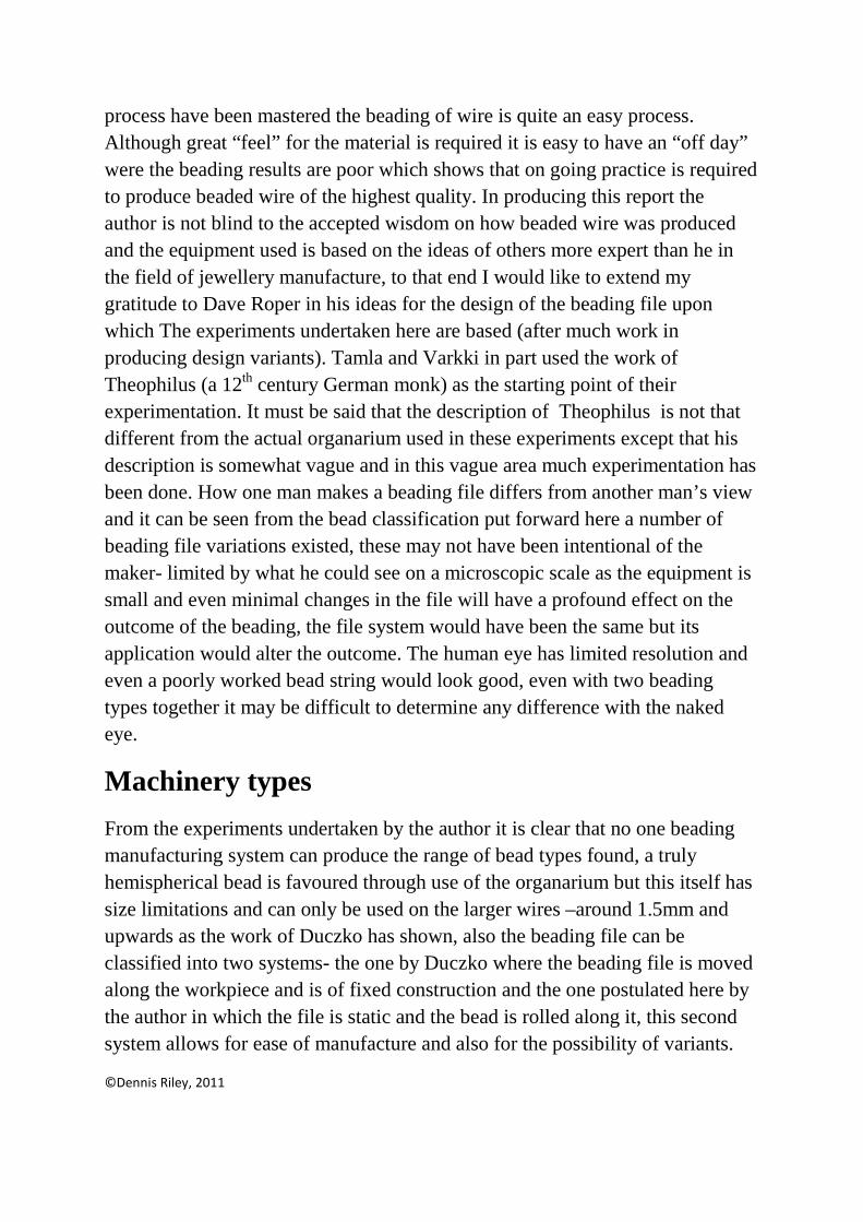
process have been mastered the beading of wire is quite an easy process. Although great “feel” for the material is required it is easy to have an “off day” were the beading results are poor which shows that on going practice is required to produce beaded wire of the highest quality. In producing this report the author is not blind to the accepted wisdom on how beaded wire was produced and the equipment used is based on the ideas of others more expert than he in the field of jewellery manufacture, to that end I would like to extend my gratitude to Dave Roper in his ideas for the design of the beading file upon which The experiments undertaken here are based (after much work in producing design variants). Tamla and Varkki in part used the work of Theophilus (a 12th century German monk) as the starting point of their experimentation. It must be said that the description of Theophilus is not that different from the actual organarium used in these experiments except that his description is somewhat vague and in this vague area much experimentation has been done. How one man makes a beading file differs from another man’s view and it can be seen from the bead classification put forward here a number of beading file variations existed, these may not have been intentional of the maker- limited by what he could see on a microscopic scale as the equipment is small and even minimal changes in the file will have a profound effect on the outcome of the beading, the file system would have been the same but its application would alter the outcome. The human eye has limited resolution and even a poorly worked bead string would look good, even with two beading types together it may be difficult to determine any difference with the naked eye.
Machinery types
From the experiments undertaken by the author it is clear that no one beading manufacturing system can produce the range of bead types found, a truly hemispherical bead is favoured through use of the organarium but this itself has size limitations and can only be used on the larger wires –around 1.5mm and upwards as the work of Duczko has shown, also the beading file can be classified into two systems- the one by Duczko where the beading file is moved along the workpiece and is of fixed construction and the one postulated here by the author in which the file is static and the bead is rolled along it, this second system allows for ease of manufacture and also for the possibility of variants.
©Dennis Riley, 2011
Here the point must be made that in the original manufacturing context it is unlikely that variant designs were aimed for, the variations found however reflect the type of beading file made by the user who would have had knowledge of the process but each set of beading plates would have been different and the extant beading finds represent the output of a number of individuals at different times producing beaded wires on different machines, as a consequence variants will and do exist, to this end and has been previously stated the smaller wire designs were manufactured using a beading file and the larger wires on an organarium.
Classification of Beaded Wires.
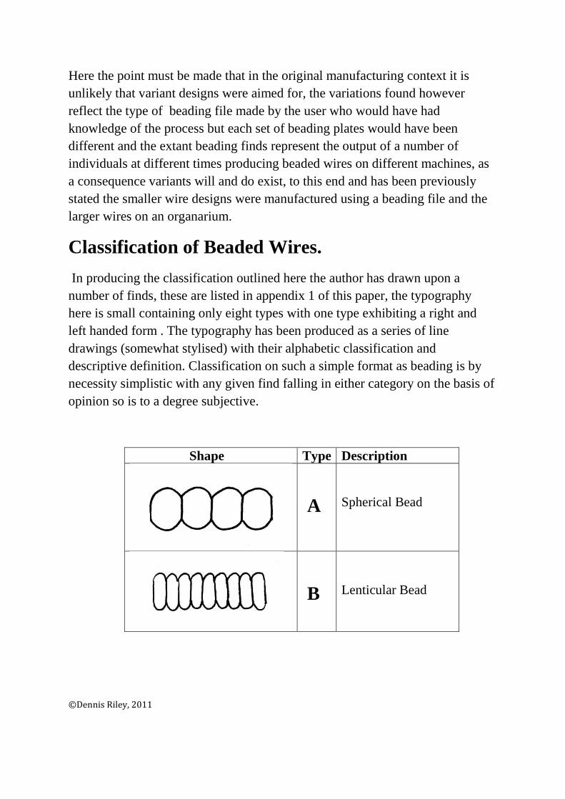
In producing the classification outlined here the author has drawn upon a number of finds, these are listed in appendix 1 of this paper, the typography here is small containing only eight types with one type exhibiting a right and left handed form . The typography has been produced as a series of line drawings (somewhat stylised) with their alphabetic classification and descriptive definition. Classification on such a simple format as beading is by necessity simplistic with any given find falling in either category on the basis of opinion so is to a degree subjective.
Shape Type Description
A
Spherical Bead
B
Lenticular Bead
©Dennis Riley, 2011

This typography is not large but all beading can be classified according to the above variants and with this as a starting point we can now begin the reproduction of Anglo-Saxon beaded wire forms. For the beading file The tooling required is two stage, the beading file (which will be discussed next) and the beading knife, the beading file produces (in theory) a finished beaded wire but under some circumstances the use of a beading knife can clarify or help re shape certain points on the wire, the beading knife has its limitations and can only be used successfully on the larger diameter wires (1.5mm range and upwards) as the knife (hereafter refered to as a fettling knife)
©Dennis Riley, 2011
C
Coffee Bean Bead
D Shallow Groove Bead
E Deep Groove Bead
F Conoid Bead
G Helical left Hand Bead
H Helical Right Hand Bead
Is too large and unwealdly for fine wires – also the user has difficulty in seeing what they are doing which usually destroys the bead work (as many failures have shown!)
The Beading File; theory and construction
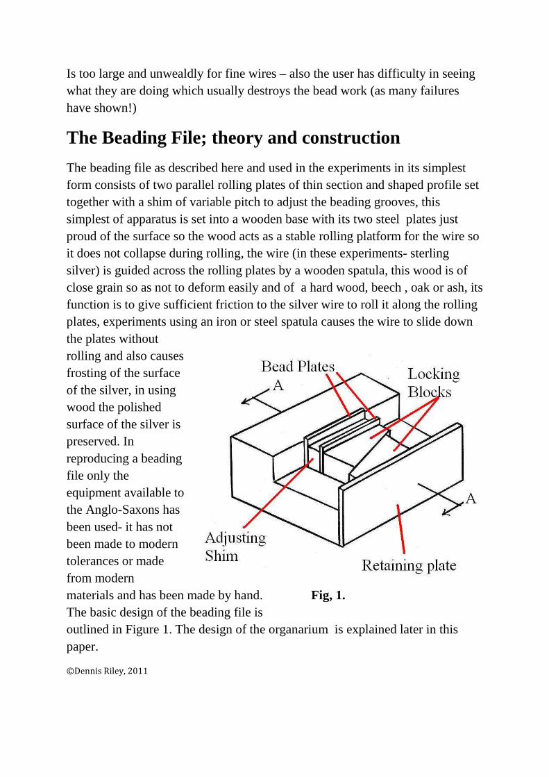
The beading file as described here and used in the experiments in its simplest form consists of two parallel rolling plates of thin section and shaped profile set together with a shim of variable pitch to adjust the beading grooves, this simplest of apparatus is set into a wooden base with its two steel plates just proud of the surface so the wood acts as a stable rolling platform for the wire so it does not collapse during rolling, the wire (in these experiments- sterling silver) is guided across the rolling plates by a wooden spatula, this wood is of close grain so as not to deform easily and of a hard wood, beech , oak or ash, its function is to give sufficient friction to the silver wire to roll it along the rolling plates, experiments using an iron or steel spatula causes the wire to slide down the plates without rolling and also causes frosting of the surface of the silver, in using wood the polished surface of the silver is preserved. In reproducing a beading file only the equipment available to the Anglo-Saxons has been used- it has not been made to modern tolerances or made from modern materials and has been made by hand. Fig, 1. The basic design of the beading file is outlined in Figure 1. The design of the organarium is explained later in this paper.
©Dennis Riley, 2011
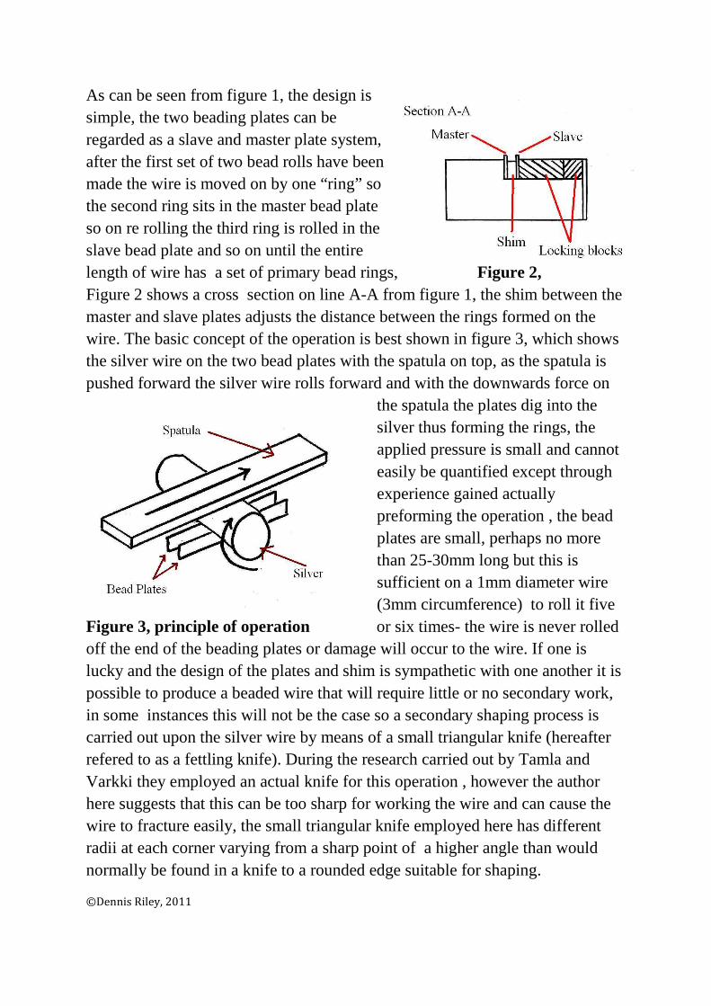
As can be seen from figure 1, the design is simple, the two beading plates can be regarded as a slave and master plate system, after the first set of two bead rolls have been made the wire is moved on by one “ring” so the second ring sits in the master bead plate so on re rolling the third ring is rolled in the slave bead plate and so on until the entire length of wire has a set of primary bead rings, Figure 2, Figure 2 shows a cross section on line A-A from figure 1, the shim between the master and slave plates adjusts the distance between the rings formed on the wire. The basic concept of the operation is best shown in figure 3, which shows the silver wire on the two bead plates with the spatula on top, as the spatula is pushed forward the silver wire rolls forward and with the downwards force on
the spatula the plates dig into the silver thus forming the rings, the applied pressure is small and cannot easily be quantified except through experience gained actually preforming the operation , the bead plates are small, perhaps no more than 25-30mm long but this is sufficient on a 1mm diameter wire (3mm circumference) to roll it five
Figure 3, principle of operation or six times- the wire is never rolled off the end of the beading plates or damage will occur to the wire. If one is lucky and the design of the plates and shim is sympathetic with one another it is possible to produce a beaded wire that will require little or no secondary work, in some instances this will not be the case so a secondary shaping process is carried out upon the silver wire by means of a small triangular knife (hereafter refered to as a fettling knife). During the research carried out by Tamla and Varkki they employed an actual knife for this operation , however the author here suggests that this can be too sharp for working the wire and can cause the wire to fracture easily, the small triangular knife employed here has different radii at each corner varying from a sharp point of a higher angle than would normally be found in a knife to a rounded edge suitable for shaping.
©Dennis Riley, 2011

Secondary shaping can have a dramatic effect upon the finished wire so care has to be observed in using the fettling knife as inappropriate use can destroy the work done by the beading file and has been said it is used only on large diameter wires were bead defects are more readily apparent , since most of these beaded wires can only be viewed under magnification small defects are not readily visible, either by the manufacturer or end user, in this respect small defects in manufacture are therefore of limited importance so long as the overall view of the beaded wire with the naked eye is pleasing. To understand problems that arise we require a little understanding of the mechanical metallurgy of the beading process.
Mechanical Metallurgy of the Beading process
The concept of beading is; by rolling, a groove is formed in the wire thereby giving the appearance of a continuous string of beads, when a groove is formed
in the wire, deformation of the wire occurs forcing out the metal displaced by the bead rollers, the only way it can do this is to form a metal “flash” either side of the groove, this flash is greater diameter than the diameter of the wire from which it is formed as can be seen from figure 4. When the bead plates are close together the two
Figure 4, flash flashes of the juxtaposed grooves forms a flash groove roughly of the same diameter of the original wire, the beaded wire in this condition requires further working, but as can be seen from a type C bead (coffee bean bead) this flash groove does not necessarily need to be totally erased during the finishing process, it could be argued that this is a manufacturing defect which in most cases it is, but some beaded wire has been constructed as to leave a small groove but we cannot say by accident or design. Once primary rolling has been done we are left with a beaded wire containing both flash and flash groove, the beaded wire therefore requires further working, this however is not always the case and in some instances the wire produced on the beading file is of sufficient quality and appearance to be used in this state.
The next stage in beading is to remove the beading flash and smooth out the primary worked wire into well formed hemispherical beads, this is the next
©Dennis Riley, 2011
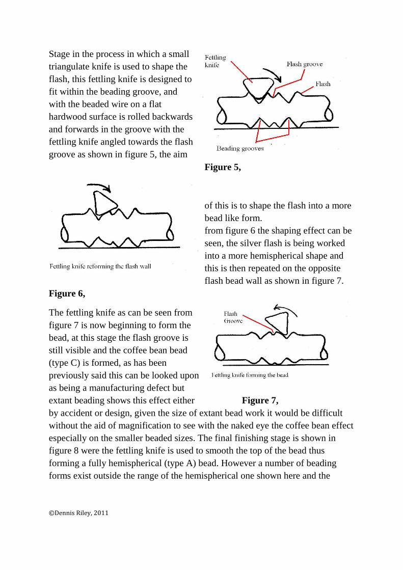
Stage in the process in which a small triangulate knife is used to shape the flash, this fettling knife is designed to fit within the beading groove, and with the beaded wire on a flat hardwood surface is rolled backwards and forwards in the groove with the fettling knife angled towards the flash groove as shown in figure 5, the aim
Figure 5,
of this is to shape the flash into a more bead like form. from figure 6 the shaping effect can be seen, the silver flash is being worked into a more hemispherical shape and this is then repeated on the opposite flash bead wall as shown in figure 7.
Figure 6,
The fettling knife as can be seen from figure 7 is now beginning to form the bead, at this stage the flash groove is still visible and the coffee bean bead (type C) is formed, as has been previously said this can be looked upon as being a manufacturing defect but extant beading shows this effect either Figure 7, by accident or design, given the size of extant bead work it would be difficult without the aid of magnification to see with the naked eye the coffee bean effect especially on the smaller beaded sizes. The final finishing stage is shown in figure 8 were the fettling knife is used to smooth the top of the bead thus forming a fully hemispherical (type A) bead. However a number of beading forms exist outside the range of the hemispherical one shown here and the
©Dennis Riley, 2011

manufacturing route used in the production of these beading types is best shown by experimentation . The production of helical wound beaded wire requires a variation on the beading file system outlined in figure 1
Figure 8, and consists of a beading plate set at 45o on a hardwood bed as shown in figure 9, a variation of the spatula is used- one of wider width than would be used in the beading file in which the silver wire is placed on the beading plate paralell with the spatula and is rolled forwards, in doing so it traverses along the bead plate producing a helical twist , dependent upon the design of the beading Figure 9, plate a fully formed helical wire can be made (type G).
Fettling Knife versus Organarium
As can be seen from the description given above the use of the fettling knife to produce rounded beads is a laborious process and it must be recognised that using the fettling knife to this extent would be unlikely in most circumstances, for this process the easier route is the use of the organarium which in theory would produce hemispherical type beads to a standard format, even so the possibility of some finishing with the fettling knife cannot be overlooked. The basic construction of the organarium is outlined in figure 10 below and in simple terms consists of two dies each of hemispherical design that when matched up produce a hemispherical cavity with an entry and exit way for the wire when closed, this device does require very well engineered parts as based on the description of theophilus and the application of it by Duczko, however the Author in this paper has taken a slightly different route in using tools and
©Dennis Riley, 2011
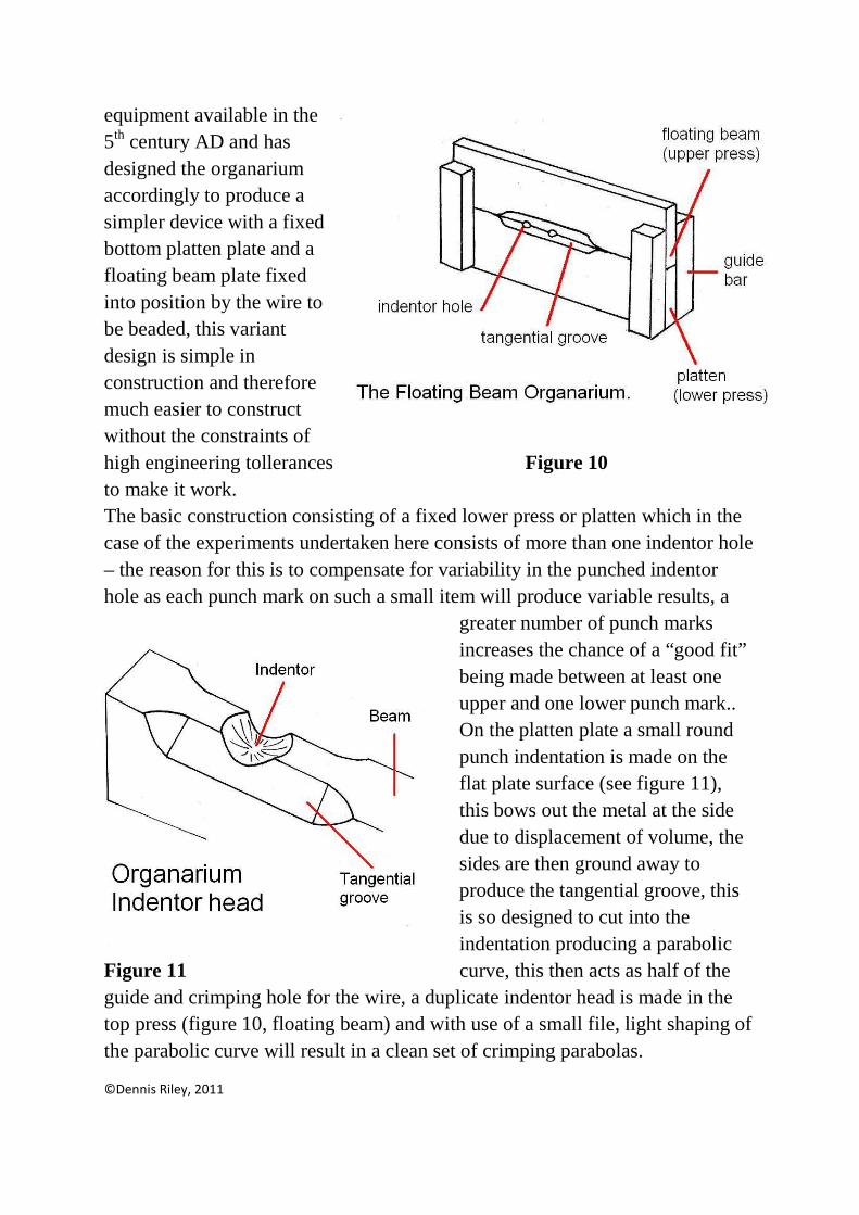
equipment available in the 5th century AD and has designed the organarium accordingly to produce a simpler device with a fixed bottom platten plate and a floating beam plate fixed into position by the wire to be beaded, this variant design is simple in construction and therefore much easier to construct without the constraints of high engineering tollerances Figure 10 to make it work. The basic construction consisting of a fixed lower press or platten which in the case of the experiments undertaken here consists of more than one indentor hole – the reason for this is to compensate for variability in the punched indentor hole as each punch mark on such a small item will produce variable results, a
greater number of punch marks increases the chance of a “good fit” being made between at least one upper and one lower punch mark.. On the platten plate a small round punch indentation is made on the flat plate surface (see figure 11), this bows out the metal at the side due to displacement of volume, the sides are then ground away to produce the tangential groove, this is so designed to cut into the indentation producing a parabolic
Figure 11 curve, this then acts as half of the guide and crimping hole for the wire, a duplicate indentor head is made in the top press (figure 10, floating beam) and with use of a small file, light shaping of the parabolic curve will result in a clean set of crimping parabolas.
©Dennis Riley, 2011

Use of the organarium is quite simple but does require practice and a light hand, the wire to be crimped is palced in the bottom groove with the floating beam located on top with both grooves located on the wire, the floating beam is lightly struck with a hammer (around the 200g weight) and the bead wire rotated after each strike, after a number of strikes a fully rounded bead is formed (see figure 12), once made the floating beam is lifted and the wire moved along until the groove in the wire is relocated in the groove on the opposite side of the press, the process is repeated again and so on until the bead is to the required length, in some cases the beading produced at this stage is fully formed and to an acceptable quality, however the fettling knife can be used to shape the bead if so wished, here another variation can be added in the use of a small stone shim or thin fragment to act as a micro fine hone, this is usefull in refining the groove surface of harder metals such as copper which tends to spall on crimping (see figure 12), this is employed by holding the shim stone and beading wire between thumb and fore finger and lightly rolling the beaded wire causing a filing effect on the groove smoothing out any unwanted asperities.
Lubrication of the Organarium
Figures 12 and 13 show the effect of lubrication on the beaded wire, with lubrication (figure 13) a much smoother wire is produced with what apears to be a smoother and more uniform bead, this may be due to the isostatic effects of the lubricationg oil acting as a hydraulic damper and also the reduction in friction as the crimp is made thus reducing mechanical tearing of the copper,
Figure 12; unlubricated copper beading produced in the organarium
©Dennis Riley, 2011

Figure 13, Lubricated copper beading produced in the organarium
And if viewed at a lower magnification (figure 14 below) the results are more apparent, However the real test in beading is the quality of reproductions using silver based alloys where the main thrust of this research lies.
Figure 14.
Reproduction of beaded wires- variant tooling
In the experiments the description of the process has been kept to a minimum, the explaination of theory (mechanical metallurgy of the beading process) is applicable in most instances to the work undrtaken here , as a further experiment a brass (copper /zinc alloy) wire fettling knife was employed to see what effects a softer metal has upon the process, there was however no discernable difference in the effect that either a steel or brass fettling knife had upon the beaded wire produced- the more important factor is the ammount of applied force used to manipulate the beaded wire with failiure occuring in all cases were excessive force was applied. It is interesting to note that most
©Dennis Riley, 2011
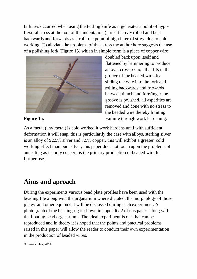
failiures occurred when using the fettling knife as it generates a point of hypo-flexural stress at the root of the indentation (it is effectivly rolled and bent backwards and forwards as it rolls)- a point of high internal stress due to cold working. To aleviate the problems of this stress the author here suggests the use of a polishing fork (Figure 15) which in simple form is a piece of copper wire
doubled back upon itself and flattened by hammering to produce an oval cross section that fits in the groove of the beaded wire, by sliding the wire into the fork and rolling backwards and forwards between thumb and forefinger the groove is polished, all asperities are removed and done with no stress to the beaded wire thereby limiting
Figure 15. Failiure through work hardening.
As a metal (any metal) is cold worked it work hardens until with sufficient deformation it will snap, this is particularily the case with alloys, sterling silver is an alloy of 92.5% silver and 7,5% copper, this will exhibit a greater cold working effect than pure silver, this paper does not touch upon the problems of annealing as its only concern is the primary production of beaded wire for further use.
Aims and aproach
During the experiments various bead plate profiles have been used with the beading file along with the organarium where dictated, the morphology of those plates and other equipment will be discussed during each experiment. A photograph of the beading rig is shown in appendix 2 of this paper along with the floating bead organarium . The ideal experiment is one that can be reproduced and in theory it is hoped that the points and practical problems raised in this paper will allow the reader to conduct their own experimentation in the production of beaded wires.
©Dennis Riley, 2011

Worked examples in beaded wire production
Type A, spherical bead
Various experiments have shown that the likely production route for properly formed Hemispherical beaded wires is through the use of the organarium, the experiment conducted here supports this hypothesis on the basis of the form of the spheroid and the groove formed. In this experiment a 2mm diameter sterling silver wire was placed in the organarium between the upper (floating beam )and lower platen set in the indentor groove , the wire was lubricated with light machine oil (in an Anglo-Saxon context animal fat is more than adequate for this task). With a light hammering action on the floating beam the wire was spun in its groove and after about 10 seconds and 4 revolutions or so the wire was removed and the bead inspected, once done it was placed back into the organarium with the nearside bead groove now set in the farside indentor groove and the process repeated until a series of beads were formed, once produced to the required length- in this experiment around 4cm ,it was removed from the organarium, cleaned of oil and placed in the polishing fork (figure 15) and rotated backwards and forwards until the rough crimped surface of the wire was polished smooth, this took about 5 seconds for each bead crimp, the results of this experiment are shown in figure 16 and 17 below, the same wire at different magnifications;
Figure 16 2mm beaded wire
Figure 17, 2mm beaded wire at a lower magnification.
©Dennis Riley, 2011
On the basis of the experiment undertaken here it is possible to manufacture around 12” (305mm) of beaded wire per hour.
Type B, Lenticular Bead
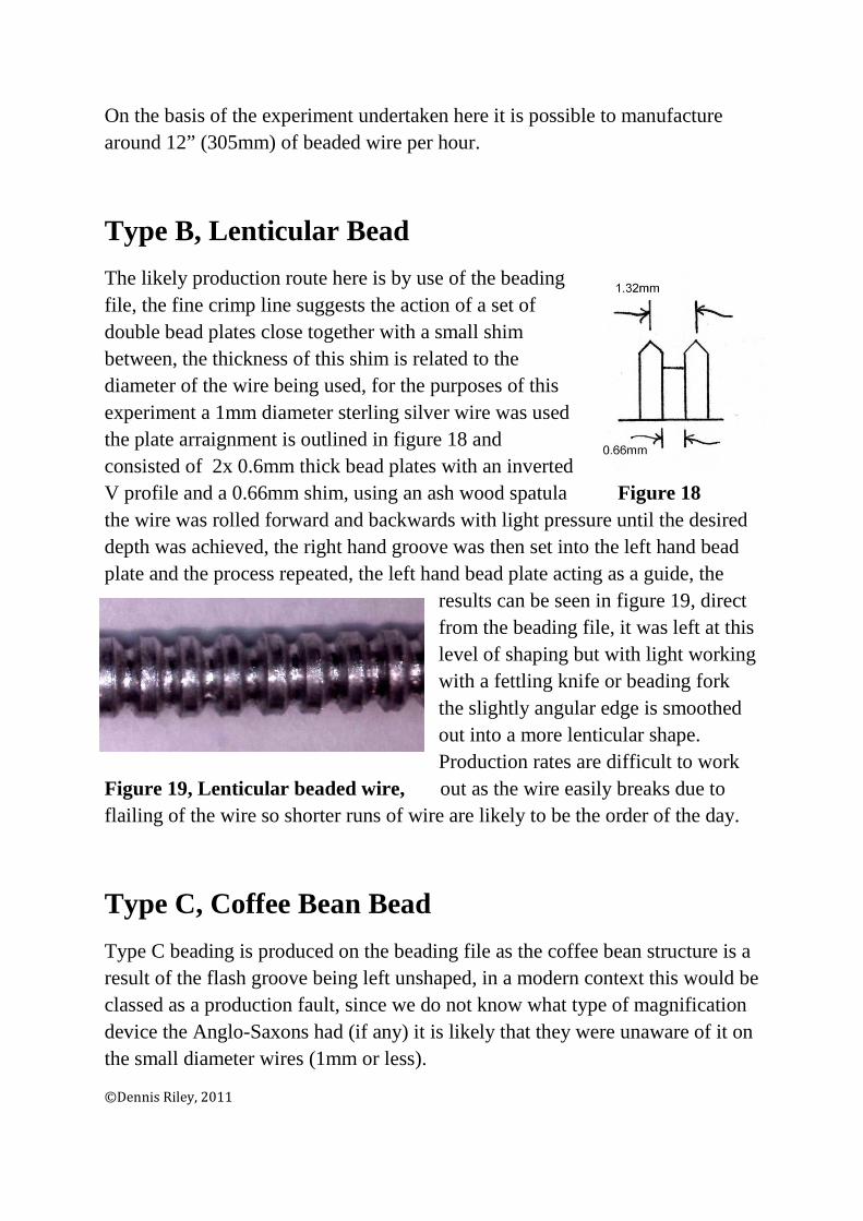
The likely production route here is by use of the beading file, the fine crimp line suggests the action of a set of double bead plates close together with a small shim between, the thickness of this shim is related to the diameter of the wire being used, for the purposes of this experiment a 1mm diameter sterling silver wire was used the plate arraignment is outlined in figure 18 and consisted of 2x 0.6mm thick bead plates with an inverted V profile and a 0.66mm shim, using an ash wood spatula Figure 18 the wire was rolled forward and backwards with light pressure until the desired depth was achieved, the right hand groove was then set into the left hand bead plate and the process repeated, the left hand bead plate acting as a guide, the
results can be seen in figure 19, direct from the beading file, it was left at this level of shaping but with light working with a fettling knife or beading fork the slightly angular edge is smoothed out into a more lenticular shape. Production rates are difficult to work
Figure 19, Lenticular beaded wire, out as the wire easily breaks due to flailing of the wire so shorter runs of wire are likely to be the order of the day.
Type C, Coffee Bean Bead
Type C beading is produced on the beading file as the coffee bean structure is a result of the flash groove being left unshaped, in a modern context this would be classed as a production fault, since we do not know what type of magnification device the Anglo-Saxons had (if any) it is likely that they were unaware of it on the small diameter wires (1mm or less).
©Dennis Riley, 2011

For this experiment a 1mm silver wire was used with the bead plates set together with an inverted V profile and no shim, the width between the tips of the V’s was 0.6mm (see figure 20), the wire was rolled in the conventional way (as bead type B). the product of this experiment is shown in figure 21 below, as can be seen (given the limits of optical photography) the groove has produced a flash butt that has risen up above the original diameter of the wire , since the mechanical Figure 20, constraints of the beading file process does not allow for the folding over of the flash butt to cover up the flash groove a structure not unlike a “Bean” is produced .
Figure 21, Coffee bean bead.
Type D, Shallow groove bead
Type D beaded wire is the simplest to produce, yet on smaller diameter wires (1mm and below) the end product is effective, in this experiment 2mm diameter
wire was used using a beading file (this type of beading would not be manufactured on an organarium) with a bead plate arraignment as used in type B wires (figure 18) the wire is lightly rolled producing a shallow V groove , the product of this method is
Figure 22, Shallow groove. Shown in Figure 22.
©Dennis Riley, 2011
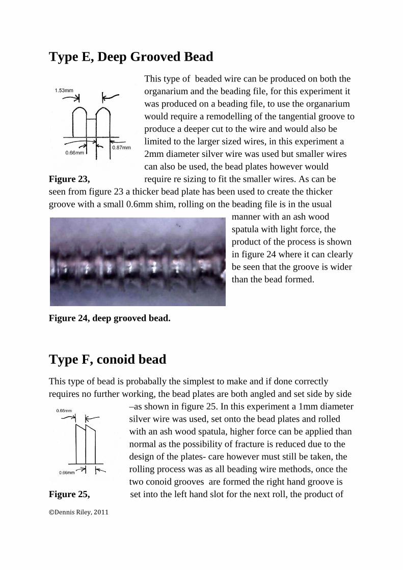
Type E, Deep Grooved Bead
This type of beaded wire can be produced on both the organarium and the beading file, for this experiment it was produced on a beading file, to use the organarium would require a remodelling of the tangential groove to produce a deeper cut to the wire and would also be limited to the larger sized wires, in this experiment a 2mm diameter silver wire was used but smaller wires can also be used, the bead plates however would
Figure 23, require re sizing to fit the smaller wires. As can be seen from figure 23 a thicker bead plate has been used to create the thicker groove with a small 0.6mm shim, rolling on the beading file is in the usual
manner with an ash wood spatula with light force, the product of the process is shown in figure 24 where it can clearly be seen that the groove is wider than the bead formed.
Figure 24, deep grooved bead.
Type F, conoid bead
This type of bead is probabally the simplest to make and if done correctly requires no further working, the bead plates are both angled and set side by side
–as shown in figure 25. In this experiment a 1mm diameter silver wire was used, set onto the bead plates and rolled with an ash wood spatula, higher force can be applied than normal as the possibility of fracture is reduced due to the design of the plates- care however must still be taken, the rolling process was as all beading wire methods, once the two conoid grooves are formed the right hand groove is
Figure 25, set into the left hand slot for the next roll, the product of
©Dennis Riley, 2011
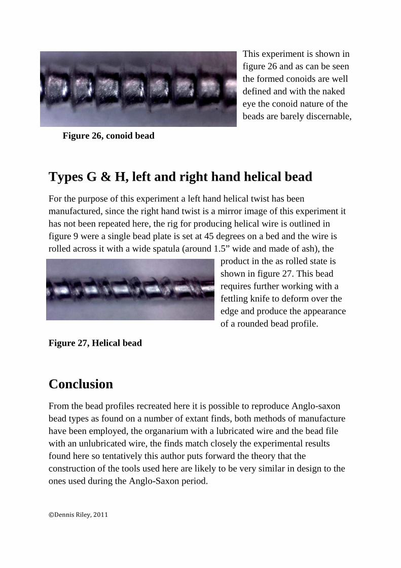
This experiment is shown in figure 26 and as can be seen the formed conoids are well defined and with the naked eye the conoid nature of the beads are barely discernable,
Figure 26, conoid bead
Types G & H, left and right hand helical bead
For the purpose of this experiment a left hand helical twist has been manufactured, since the right hand twist is a mirror image of this experiment it has not been repeated here, the rig for producing helical wire is outlined in figure 9 were a single bead plate is set at 45 degrees on a bed and the wire is rolled across it with a wide spatula (around 1.5” wide and made of ash), the
product in the as rolled state is shown in figure 27. This bead requires further working with a fettling knife to deform over the edge and produce the appearance of a rounded bead profile.
Figure 27, Helical bead
Conclusion
From the bead profiles recreated here it is possible to reproduce Anglo-saxon bead types as found on a number of extant finds, both methods of manufacture have been employed, the organarium with a lubricated wire and the bead file with an unlubricated wire, the finds match closely the experimental results found here so tentatively this author puts forward the theory that the construction of the tools used here are likely to be very similar in design to the ones used during the Anglo-Saxon period.
©Dennis Riley, 2011
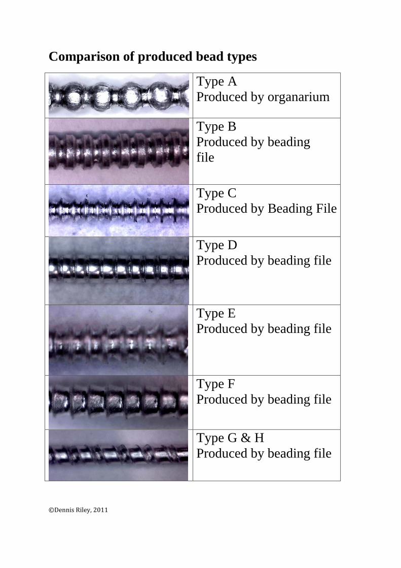
Comparison of produced bead types
Type A Produced by organarium
Type B Produced by beading file
Type C Produced by Beading File
Type D Produced by beading file
Type E Produced by beading file
Type F Produced by beading file
Type G & H Produced by beading file
©Dennis Riley, 2011

Appendix 1
Extant bead wire forms
This list is not extensive and only represents the varying bead forms found during the research for this paper, the bead classifications used here are based on the photographs reproduced in these publications (listed in the bibliography).
Norwich Southern bypass,
Grave 11,
Composite disc brooch with spherical, helical left & helical right forms.
Grave 18,
Gold & garnet pendant, containing spherical, coffee bean and wide groove.
Grave 28,
Gold openwork pendant containing shallow groove, conoid and spherical forms.
West Dereham Ring (isolated find)
Conoid, spherical and lenticular finds
©Dennis Riley, 2011

Gold ring, Now in the Ashmolean museum (no other information)
Lenticular and spherical forms.
Kenninghall, Norfolk 6th C (no further information)
Silver wrist clasp- hook and eye, lenticular bead.
Butlers Field, Lechlade, Anglo-Saxon cemetery.
Grave 84,
Gold disc pendant containing helical left and right handed forms
Grave 95,
Gold disc pendant, spherical beaded form
Grave 172,
Pendant with spherical beaded form
Grave 179,
Gold disc pendant with helical left and right handed form and Spherical beaded forms.
Appendix 2
Organarium and Bead file designs.
The designs shown here represent the final product of a number of experiments, it can be said that the author has discovered 100 ways how not to make beaded wire, the tools developed here (or more specifically “re discovered”) have been manufactured using period equipment and have been reconstructed using period materials (albeit in modern form), consequently the accuracy of the tools made here would reflect (in theory) the accuracy of the originals, the main function of a tool is to produce a product any aesthetic considerations are subordinate to this goal as many tool finds show.
©Dennis Riley, 2011

Organarium
Beading File
©Dennis Riley, 2011
Bibliography
Boyle, A. Jennings, B. Miles, D. & Palmer, S.; The Anglo-Saxon cemetery at Butler’s Field, Lechlade, Gloucestershire, Oxford, 1998.
Duczko, W.; Birka V,-The filigree and granulation work of the Viking period, Uppsala.
Mottram, S.; The west Dereham Ring. Reprinted from the Antiquaries Journal Vol LII, Part II, Oxford, 1972.
Penn, K.; Excavations on the Norwich Southern Bypass 1989-91 Part II. Norfolk Museums service report no 92, Dereham, 2000.
Tamla, U. Varkki, H.; Learning the technologies of making beaded wire. Estonian Journal of Archaeology (13.1, 36-52). Tallinn, 2009.
©Dennis Riley, 2011