Analysis preheat effect on thermal cycle and residual stress in a welded connection by FE simulation
7
Analysis preheat effect on thermal cycle and residual stress in a welded connection by FE simulation M.E. Aalami-Aleagha * , M. Foroutan, S. Feli, S. Nikabadi Department of Mechanical Engineering, Engineering Faculty, Razi University, Kermanshah 67149, Iran article info Article history: Received 14 May 2010 Received in revised form 3 December 2013 Accepted 11 December 2013 Keywords: Preheat temperature Finite-element simulation Thermal analysis ASME section IX abstract Preheat effect on thermal cycle and residual stress was studied by employing a 3D finite-element method. A circumferential multi-pass butt weld of pipes based on ASME section IX was investigated and the experiment for thermal cycle validation was carried out. A spherical heat source density with a Gaussian distribution was employed and by an appropriate coordinate system, the rotation of electrode around the pipe was modeled reasonably. Sequentially coupled, thermalemechanical analysis was applied using temperature-dependent thermo-mechanical behavior for material properties and the variation in peak temperature, cooling rate, and the axial residual stress due to the preheat effect were evaluated. The simulation results revealed that the pattern of final residual stress was influenced by the preheat temperature. However the thermal cycle experienced in the welding zone seems to be significantly affected by the preheat temperature. Ó 2013 Elsevier Ltd. All rights reserved. 1. Introduction Standards and Codes have specified disciplines for fabrication prequalified welded pipes and the details are given in Standard Welding Procedure Specifications (SWPS) [1e3]. Welding the pipes and pressure vessels regulations has presented in Section IX of ASME Standard [4]. A specified discipline in these regulations is an advice for preheating the welded parts, and the range of reasonable temperature for steel parts is suggested in ASME Section IX, Part QW, paragraph 406. Preheating should be applied; particularly where the ambient temperature of the welding process is low and/ or the size of welded parts become thick in order to provide appropriate metallurgical and mechanical properties in welded zones and prevent from unexpected brittle fracture in practice. The appropriate range of this effective preheat temperature docu- mented in the Codes are advised by experts and needs to be sup- ported by a scientific thermal analysis. Finite-element simulation can be used as a powerful tool for evaluation the appropriate range of this preheats temperature proposed in the Codes. In an arc welding finite-element simulation, thermal energy should be modeled by a specific heat density and is conducted in the weld zone based on heat transfer Fourier equation, where the boundary condition around the weld is introduced to the model. The temperature gradients should be obtained from this thermal analysis, particularly in a multi-pass weld. By the thermal history experienced in each part of the weld, cooling rate is estimated and the constitution of unwilling phases can be prevented. Residual stresses can also be deducted from this thermal analysis and by a sequentially structural analysis, this provides a potential for esti- mating the hardening of the weld zone, however the other parameter such as carbon equivalence in composition of steel alloy is also cooperated in estimating accurately the hardening of welded pipes [5e8]. Tailoring the proper preheats and inter-pass temperature can control reasonably the thermal history experienced in each point of the weld zone and this can be used to make a control on harden- ability of the steel pipes in a weld process. In addition to the preheat temperature, post weld heat treatment is also proposed in a SWPS, this can be used to provide an appropriate thermal cycle and a prequalified connection. These are proposed to alleviate the residual stress and improving the mechanical properties of welded pipes. In a SWPS, the types of variables are introduced and the ranking of their importance are classified, these are essential variables, supplementary variables, and non-essential variables. At ambient temperatures, according to the ASME standard, Section IX e part QW e article 2, a tolerance is specified to be allowed at reduction up to a 100 F down as an essential variable. However, the increase up to a similar quantity is categorized in the supplementary variables. This shows the change in thermal regime in a weld process is complicated and needs to be analyzed accurately. Tailoring a sound * Corresponding author. E-mail address: [email protected] (M.E. Aalami-Aleagha). Contents lists available at ScienceDirect International Journal of Pressure Vessels and Piping journal homepage: www.elsevier.com/locate/ijpvp 0308-0161/$ e see front matter Ó 2013 Elsevier Ltd. All rights reserved. http://dx.doi.org/10.1016/j.ijpvp.2013.12.003 International Journal of Pressure Vessels and Piping 114-115 (2014) 69e75
Transcript of Analysis preheat effect on thermal cycle and residual stress in a welded connection by FE simulation
lable at ScienceDirect
International Journal of Pressure Vessels and Piping 114-115 (2014) 69e75
Contents lists avai
International Journal of Pressure Vessels and Piping
journal homepage: www.elsevier .com/locate/ i jpvp
Analysis preheat effect on thermal cycle and residual stress in awelded connection by FE simulation
M.E. Aalami-Aleagha*, M. Foroutan, S. Feli, S. NikabadiDepartment of Mechanical Engineering, Engineering Faculty, Razi University, Kermanshah 67149, Iran
a r t i c l e i n f o
Article history:Received 14 May 2010Received in revised form3 December 2013Accepted 11 December 2013
Keywords:Preheat temperatureFinite-element simulationThermal analysisASME section IX
* Corresponding author.E-mail address: [email protected] (M
0308-0161/$ e see front matter � 2013 Elsevier Ltd.http://dx.doi.org/10.1016/j.ijpvp.2013.12.003
a b s t r a c t
Preheat effect on thermal cycle and residual stress was studied by employing a 3D finite-elementmethod. A circumferential multi-pass butt weld of pipes based on ASME section IX was investigated andthe experiment for thermal cycle validation was carried out. A spherical heat source density with aGaussian distribution was employed and by an appropriate coordinate system, the rotation of electrodearound the pipe was modeled reasonably. Sequentially coupled, thermalemechanical analysis wasapplied using temperature-dependent thermo-mechanical behavior for material properties and thevariation in peak temperature, cooling rate, and the axial residual stress due to the preheat effect wereevaluated.
The simulation results revealed that the pattern of final residual stress was influenced by the preheattemperature. However the thermal cycle experienced in the welding zone seems to be significantlyaffected by the preheat temperature.
� 2013 Elsevier Ltd. All rights reserved.
1. Introduction
Standards and Codes have specified disciplines for fabricationprequalified welded pipes and the details are given in StandardWelding Procedure Specifications (SWPS) [1e3]. Welding the pipesand pressure vessels regulations has presented in Section IX ofASME Standard [4]. A specified discipline in these regulations is anadvice for preheating the welded parts, and the range of reasonabletemperature for steel parts is suggested in ASME Section IX, PartQW, paragraph 406. Preheating should be applied; particularlywhere the ambient temperature of the welding process is low and/or the size of welded parts become thick in order to provideappropriate metallurgical and mechanical properties in weldedzones and prevent from unexpected brittle fracture in practice. Theappropriate range of this effective preheat temperature docu-mented in the Codes are advised by experts and needs to be sup-ported by a scientific thermal analysis. Finite-element simulationcan be used as a powerful tool for evaluation the appropriate rangeof this preheats temperature proposed in the Codes.
In an arc welding finite-element simulation, thermal energyshould be modeled by a specific heat density and is conducted inthe weld zone based on heat transfer Fourier equation, where theboundary condition around the weld is introduced to the model.
.E. Aalami-Aleagha).
All rights reserved.
The temperature gradients should be obtained from this thermalanalysis, particularly in a multi-pass weld. By the thermal historyexperienced in each part of the weld, cooling rate is estimated andthe constitution of unwilling phases can be prevented. Residualstresses can also be deducted from this thermal analysis and by asequentially structural analysis, this provides a potential for esti-mating the hardening of the weld zone, however the otherparameter such as carbon equivalence in composition of steel alloyis also cooperated in estimating accurately the hardening of weldedpipes [5e8].
Tailoring the proper preheats and inter-pass temperature cancontrol reasonably the thermal history experienced in each point ofthe weld zone and this can be used to make a control on harden-ability of the steel pipes in aweld process. In addition to the preheattemperature, post weld heat treatment is also proposed in a SWPS,this can be used to provide an appropriate thermal cycle and aprequalified connection. These are proposed to alleviate the residualstress and improving the mechanical properties of welded pipes.
In a SWPS, the types of variables are introduced and the rankingof their importance are classified, these are essential variables,supplementary variables, and non-essential variables. At ambienttemperatures, according to the ASME standard, Section IX e partQWe article 2, a tolerance is specified to be allowed at reduction upto a 100 �F down as an essential variable. However, the increase upto a similar quantity is categorized in the supplementary variables.This shows the change in thermal regime in a weld process iscomplicated and needs to be analyzed accurately. Tailoring a sound
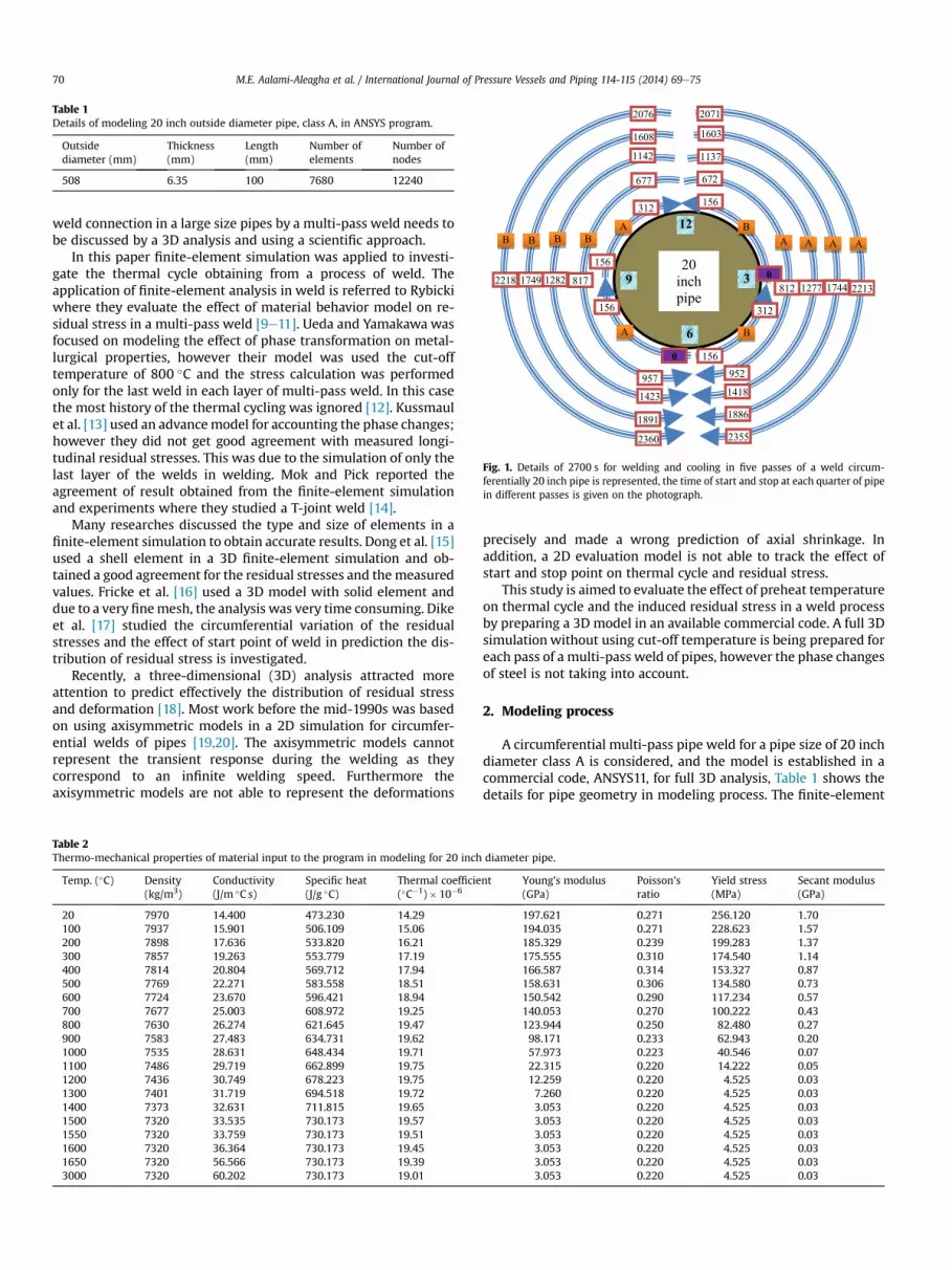
Table 1Details of modeling 20 inch outside diameter pipe, class A, in ANSYS program.
Outsidediameter (mm)
Thickness(mm)
Length(mm)
Number ofelements
Number ofnodes
508 6.35 100 7680 12240
B
0
156
B
156
312
A
156
A
0
156
9
12
3
6
A
672
952
312
B
957
677
A
1137
1418
B
1423
1142
A
1603
1886
B
1891
1608
A
2071
2355
B
2360
2076
1277 1744 22138121749 1282 8172218
20 inch pipe
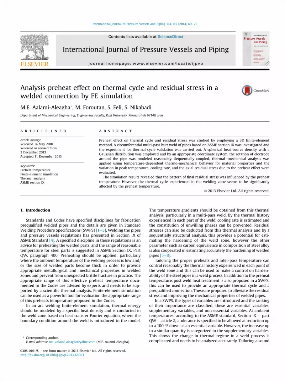
Fig. 1. Details of 2700 s for welding and cooling in five passes of a weld circum-ferentially 20 inch pipe is represented, the time of start and stop at each quarter of pipein different passes is given on the photograph.
M.E. Aalami-Aleagha et al. / International Journal of Pressure Vessels and Piping 114-115 (2014) 69e7570
weld connection in a large size pipes by a multi-pass weld needs tobe discussed by a 3D analysis and using a scientific approach.
In this paper finite-element simulation was applied to investi-gate the thermal cycle obtaining from a process of weld. Theapplication of finite-element analysis in weld is referred to Rybickiwhere they evaluate the effect of material behavior model on re-sidual stress in a multi-pass weld [9e11]. Ueda and Yamakawa wasfocused on modeling the effect of phase transformation on metal-lurgical properties, however their model was used the cut-offtemperature of 800 �C and the stress calculation was performedonly for the last weld in each layer of multi-pass weld. In this casethe most history of the thermal cycling was ignored [12]. Kussmaulet al. [13] used an advancemodel for accounting the phase changes;however they did not get good agreement with measured longi-tudinal residual stresses. This was due to the simulation of only thelast layer of the welds in welding. Mok and Pick reported theagreement of result obtained from the finite-element simulationand experiments where they studied a T-joint weld [14].
Many researches discussed the type and size of elements in afinite-element simulation to obtain accurate results. Dong et al. [15]used a shell element in a 3D finite-element simulation and ob-tained a good agreement for the residual stresses and themeasuredvalues. Fricke et al. [16] used a 3D model with solid element anddue to a very finemesh, the analysis was very time consuming. Dikeet al. [17] studied the circumferential variation of the residualstresses and the effect of start point of weld in prediction the dis-tribution of residual stress is investigated.
Recently, a three-dimensional (3D) analysis attracted moreattention to predict effectively the distribution of residual stressand deformation [18]. Most work before the mid-1990s was basedon using axisymmetric models in a 2D simulation for circumfer-ential welds of pipes [19,20]. The axisymmetric models cannotrepresent the transient response during the welding as theycorrespond to an infinite welding speed. Furthermore theaxisymmetric models are not able to represent the deformations
Table 2Thermo-mechanical properties of material input to the program in modeling for 20 inch
Temp. (�C) Density(kg/m3)
Conductivity(J/m �C s)
Specific heat(J/g �C)
Thermal coefficie(�C�1)� 10�6
20 7970 14.400 473.230 14.29100 7937 15.901 506.109 15.06200 7898 17.636 533.820 16.21300 7857 19.263 553.779 17.19400 7814 20.804 569.712 17.94500 7769 22.271 583.558 18.51600 7724 23.670 596.421 18.94700 7677 25.003 608.972 19.25800 7630 26.274 621.645 19.47900 7583 27.483 634.731 19.621000 7535 28.631 648.434 19.711100 7486 29.719 662.899 19.751200 7436 30.749 678.223 19.751300 7401 31.719 694.518 19.721400 7373 32.631 711.815 19.651500 7320 33.535 730.173 19.571550 7320 33.759 730.173 19.511600 7320 36.364 730.173 19.451650 7320 56.566 730.173 19.393000 7320 60.202 730.173 19.01
precisely and made a wrong prediction of axial shrinkage. Inaddition, a 2D evaluation model is not able to track the effect ofstart and stop point on thermal cycle and residual stress.
This study is aimed to evaluate the effect of preheat temperatureon thermal cycle and the induced residual stress in a weld processby preparing a 3D model in an available commercial code. A full 3Dsimulation without using cut-off temperature is being prepared foreach pass of a multi-pass weld of pipes, however the phase changesof steel is not taking into account.
2. Modeling process
A circumferential multi-pass pipe weld for a pipe size of 20 inchdiameter class A is considered, and the model is established in acommercial code, ANSYS11, for full 3D analysis, Table 1 shows thedetails for pipe geometry in modeling process. The finite-element
diameter pipe.
nt Young’s modulus(GPa)
Poisson’sratio
Yield stress(MPa)
Secant modulus(GPa)
197.621 0.271 256.120 1.70194.035 0.271 228.623 1.57185.329 0.239 199.283 1.37175.555 0.310 174.540 1.14166.587 0.314 153.327 0.87158.631 0.306 134.580 0.73150.542 0.290 117.234 0.57140.053 0.270 100.222 0.43123.944 0.250 82.480 0.2798.171 0.233 62.943 0.2057.973 0.223 40.546 0.0722.315 0.220 14.222 0.0512.259 0.220 4.525 0.037.260 0.220 4.525 0.033.053 0.220 4.525 0.033.053 0.220 4.525 0.033.053 0.220 4.525 0.033.053 0.220 4.525 0.033.053 0.220 4.525 0.033.053 0.220 4.525 0.03
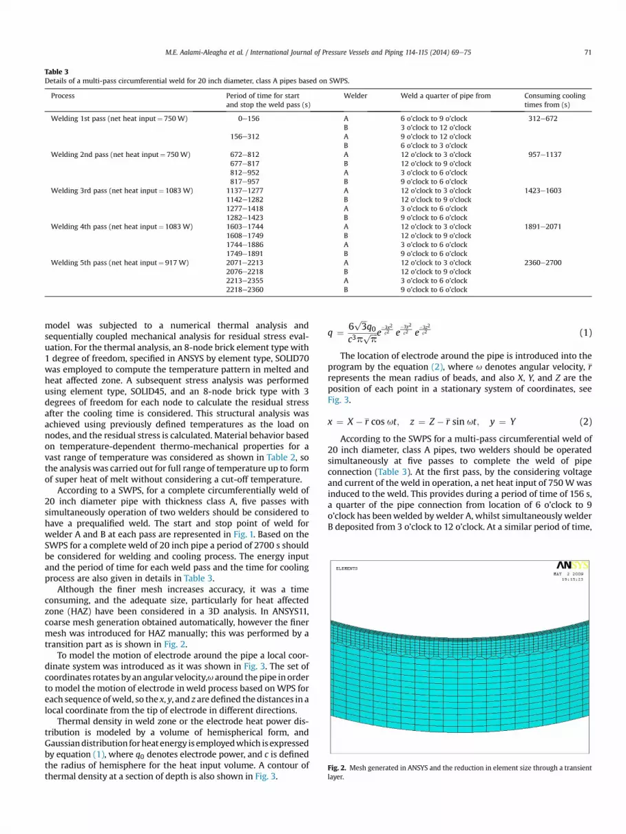
Table 3Details of a multi-pass circumferential weld for 20 inch diameter, class A pipes based on SWPS.
Process Period of time for startand stop the weld pass (s)
Welder Weld a quarter of pipe from Consuming coolingtimes from (s)
Welding 1st pass (net heat input¼ 750W) 0e156 A 6 o’clock to 9 o’clock 312e672B 3 o’clock to 12 o’clock
156e312 A 9 o’clock to 12 o’clockB 6 o’clock to 3 o’clock
Welding 2nd pass (net heat input¼ 750W) 672e812 A 12 o’clock to 3 o’clock 957e1137677e817 B 12 o’clock to 9 o’clock812e952 A 3 o’clock to 6 o’clock817e957 B 9 o’clock to 6 o’clock
Welding 3rd pass (net heat input¼ 1083 W) 1137e1277 A 12 o’clock to 3 o’clock 1423e16031142e1282 B 12 o’clock to 9 o’clock1277e1418 A 3 o’clock to 6 o’clock1282e1423 B 9 o’clock to 6 o’clock
Welding 4th pass (net heat input¼ 1083 W) 1603e1744 A 12 o’clock to 3 o’clock 1891e20711608e1749 B 12 o’clock to 9 o’clock1744e1886 A 3 o’clock to 6 o’clock1749e1891 B 9 o’clock to 6 o’clock
Welding 5th pass (net heat input¼ 917W) 2071e2213 A 12 o’clock to 3 o’clock 2360e27002076e2218 B 12 o’clock to 9 o’clock2213e2355 A 3 o’clock to 6 o’clock2218e2360 B 9 o’clock to 6 o’clock
Fig. 2. Mesh generated in ANSYS and the reduction in element size through a transientlayer.
M.E. Aalami-Aleagha et al. / International Journal of Pressure Vessels and Piping 114-115 (2014) 69e75 71
model was subjected to a numerical thermal analysis andsequentially coupled mechanical analysis for residual stress eval-uation. For the thermal analysis, an 8-node brick element type with1 degree of freedom, specified in ANSYS by element type, SOLID70was employed to compute the temperature pattern in melted andheat affected zone. A subsequent stress analysis was performedusing element type, SOLID45, and an 8-node brick type with 3degrees of freedom for each node to calculate the residual stressafter the cooling time is considered. This structural analysis wasachieved using previously defined temperatures as the load onnodes, and the residual stress is calculated. Material behavior basedon temperature-dependent thermo-mechanical properties for avast range of temperature was considered as shown in Table 2, sothe analysis was carried out for full range of temperature up to formof super heat of melt without considering a cut-off temperature.
According to a SWPS, for a complete circumferentially weld of20 inch diameter pipe with thickness class A, five passes withsimultaneously operation of two welders should be considered tohave a prequalified weld. The start and stop point of weld forwelder A and B at each pass are represented in Fig. 1. Based on theSWPS for a complete weld of 20 inch pipe a period of 2700 s shouldbe considered for welding and cooling process. The energy inputand the period of time for each weld pass and the time for coolingprocess are also given in details in Table 3.
Although the finer mesh increases accuracy, it was a timeconsuming, and the adequate size, particularly for heat affectedzone (HAZ) have been considered in a 3D analysis. In ANSYS11,coarse mesh generation obtained automatically, however the finermesh was introduced for HAZ manually; this was performed by atransition part as is shown in Fig. 2.
To model the motion of electrode around the pipe a local coor-dinate system was introduced as it was shown in Fig. 3. The set ofcoordinates rotates byan angular velocity,u around thepipe in orderto model the motion of electrode in weld process based on WPS foreach sequence ofweld, so the x, y, and z are defined the distances in alocal coordinate from the tip of electrode in different directions.
Thermal density in weld zone or the electrode heat power dis-tribution is modeled by a volume of hemispherical form, andGaussiandistribution forheatenergy is employedwhich isexpressedby equation (1), where q0 denotes electrode power, and c is definedthe radius of hemisphere for the heat input volume. A contour ofthermal density at a section of depth is also shown in Fig. 3.
q ¼ 6 3q0c3p
ffiffiffiffi
pp e
�3x2
c2 e�3y2
c2 e�3z2
c2 (1)
ffiffiffip
The location of electrode around the pipe is introduced into theprogram by the equation (2), where u denotes angular velocity, rrepresents the mean radius of beads, and also X, Y, and Z are theposition of each point in a stationary system of coordinates, seeFig. 3.
x ¼ X � r cos ut; z ¼ Z � r sin ut; y ¼ Y (2)
According to the SWPS for a multi-pass circumferential weld of20 inch diameter, class A pipes, two welders should be operatedsimultaneously at five passes to complete the weld of pipeconnection (Table 3). At the first pass, by the considering voltageand current of the weld in operation, a net heat input of 750 Wwasinduced to the weld. This provides during a period of time of 156 s,a quarter of the pipe connection from location of 6 o’clock to 9o’clock has beenwelded bywelder A, whilst simultaneously welderB deposited from 3 o’clock to 12 o’clock. At a similar period of time,
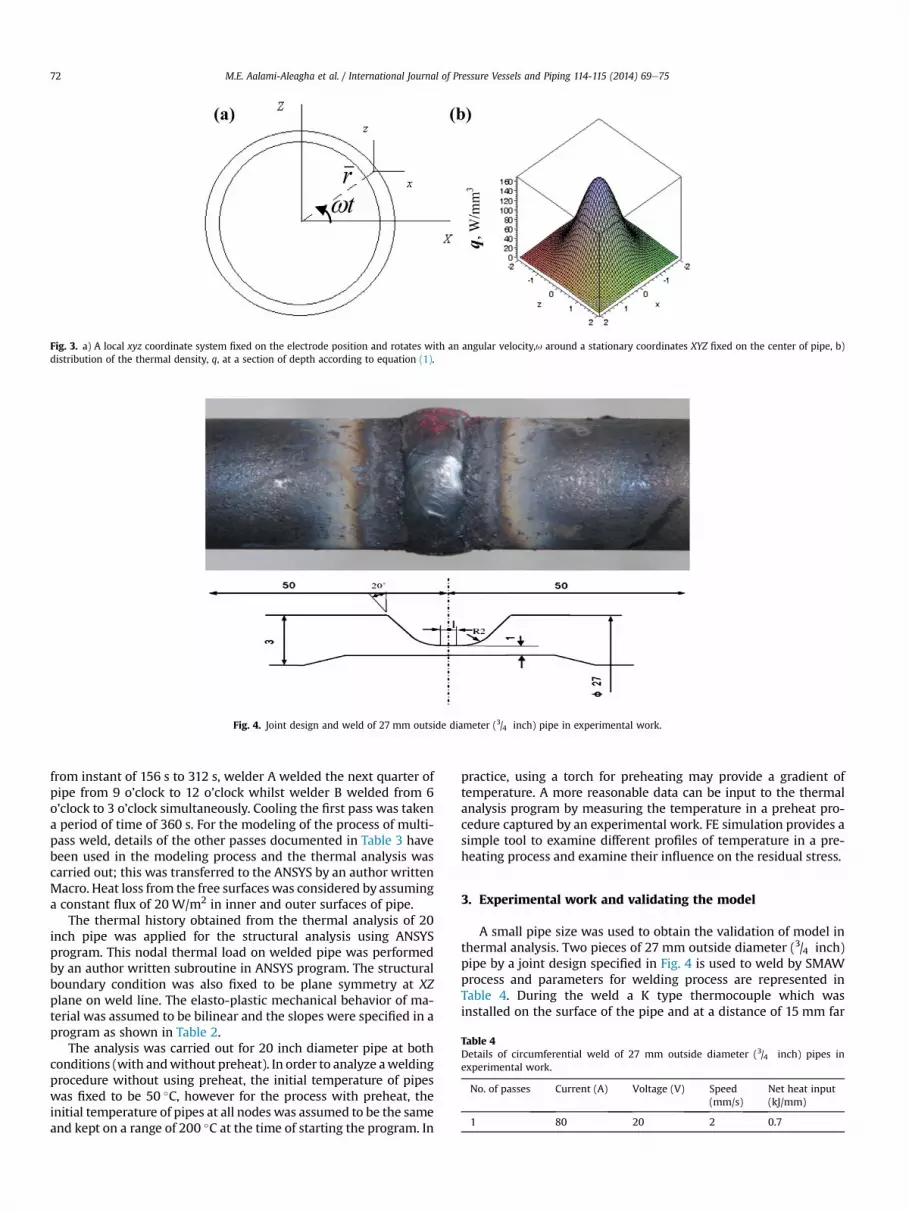
Fig. 3. a) A local xyz coordinate system fixed on the electrode position and rotates with an angular velocity,u around a stationary coordinates XYZ fixed on the center of pipe, b)distribution of the thermal density, q, at a section of depth according to equation (1).
Fig. 4. Joint design and weld of 27 mm outside diameter (3/4 inch) pipe in experimental work.
Table 4Details of circumferential weld of 27 mm outside diameter (3/4 inch) pipes inexperimental work.
No. of passes Current (A) Voltage (V) Speed(mm/s)
Net heat input(kJ/mm)
1 80 20 2 0.7
M.E. Aalami-Aleagha et al. / International Journal of Pressure Vessels and Piping 114-115 (2014) 69e7572
from instant of 156 s to 312 s, welder A welded the next quarter ofpipe from 9 o’clock to 12 o’clock whilst welder B welded from 6o’clock to 3 o’clock simultaneously. Cooling the first pass was takena period of time of 360 s. For the modeling of the process of multi-pass weld, details of the other passes documented in Table 3 havebeen used in the modeling process and the thermal analysis wascarried out; this was transferred to the ANSYS by an author writtenMacro. Heat loss from the free surfaces was considered by assuminga constant flux of 20 W/m2 in inner and outer surfaces of pipe.
The thermal history obtained from the thermal analysis of 20inch pipe was applied for the structural analysis using ANSYSprogram. This nodal thermal load on welded pipe was performedby an author written subroutine in ANSYS program. The structuralboundary condition was also fixed to be plane symmetry at XZplane on weld line. The elasto-plastic mechanical behavior of ma-terial was assumed to be bilinear and the slopes were specified in aprogram as shown in Table 2.
The analysis was carried out for 20 inch diameter pipe at bothconditions (with andwithout preheat). In order to analyze aweldingprocedure without using preheat, the initial temperature of pipeswas fixed to be 50 �C, however for the process with preheat, theinitial temperature of pipes at all nodes was assumed to be the sameand kept on a range of 200 �C at the time of starting the program. In
practice, using a torch for preheating may provide a gradient oftemperature. A more reasonable data can be input to the thermalanalysis program by measuring the temperature in a preheat pro-cedure captured by an experimental work. FE simulation provides asimple tool to examine different profiles of temperature in a pre-heating process and examine their influence on the residual stress.
3. Experimental work and validating the model
A small pipe size was used to obtain the validation of model inthermal analysis. Two pieces of 27 mm outside diameter (3/4 inch)pipe by a joint design specified in Fig. 4 is used to weld by SMAWprocess and parameters for welding process are represented inTable 4. During the weld a K type thermocouple which wasinstalled on the surface of the pipe and at a distance of 15 mm far

Fig. 5. Comparison the predicted result by FEA and the recorded temperature inexperimental work at a location of 15 mm far from the weld center line during thewelding process of 27 mm diameter pipe.
M.E. Aalami-Aleagha et al. / International Journal of Pressure Vessels and Piping 114-115 (2014) 69e75 73
from the center line of the weld was used to record precisely thetemperature. This has been carried out by an interface programprepared in MATLAB software to obtain the data for plotting thepattern of temperature against the time during the weld process.The results obtained experimentally and the data output fromrunning the finite-element program for input data of 27 mm
Fig. 6. Thermal analysis results at location 3 o’clock, 6 o’clock, 9 o’clock, and 12 o’clock, in a ca SWPS data, and presentation of a contour of temperature for pipe at the end time of sim
diameter pipe is compared. This shows a good agreement betweenthe experimental result and FE thermal analysis as shown in Fig. 5.
The result obtained for temperature history of nodes was usedto compare the pattern of inherent residual stress obtained fromFEA for different thermal loads.
4. FEA results for 20 inch diameter pipe weld and discussionthe preheat effect
The FE simulation results for thermal analysis, based on theSWPS of a 20 inch diameter pipe, are shown in Fig. 6. The profile ofchange in temperature against the time for positions underlying at3 o’clock, 6 o’clock, 9 o’clock, and 12 o’clock are represented in thisphotograph, respectively. The patterns show the transient tem-perature during the weld at the edge of pipe in axial direction. Inorder to investigate the motion of electrode based on the sequenceof weld documented in Fig. 1 in a position such as 12 o’clock, it isexpected to have the peaks on temperature profile for this positionat times of 156 s, 312 s, w672 s, w1137 s, w1603 s, and w2071 s,just when the electrode is passing this position by welder A or B.The sequence of weld and the position of electrode by welders forthe other points underlying at 3 o’clock, 6 o’clock, and 9 o’clock isalso revealed that FE thermal analysis results for the aroused peakson temperature profile are reasonable and has a good consistencybetween the SWPS and the obtained peaks for temperature.
Standard obligation confirmed that the inter-pass temperaturein multi-pass welds should be controlled in order to be not higherthan 220 �C. The obtained result from thermal analysis by consid-ering Fig. 6, is revealed that for the achieved weld, the inter-pass
ircumferential weld of 20 inch diameter pipe without preheat based on the sequence ofulation (2700 s after starting the weld).
0
200
400
600
800
1000
1200
1400
1600
4156
308
460
612
764
916
1065
1217
1368
1519
1671
1823
1975
2127
2279
2429
2581
Time, s
Tem
pera
ture
, ºC
(a)
1053.2 ºC
207.6ºC
1186.9ºC1509ºC
1244ºC795.9ºC
0
200
400
600
800
1000
1200
1400
1600
1800
4156
308
460
612
764
916
1065
1217
1368
1519
1671
1823
1975
2127
2279
2429
2581
Time, s
Tem
pera
ture
, ºC
(b)
1138.5 ºC
290.1ºC
1221.3ºC
800.5ºC
1252.4ºC1525.4ºC
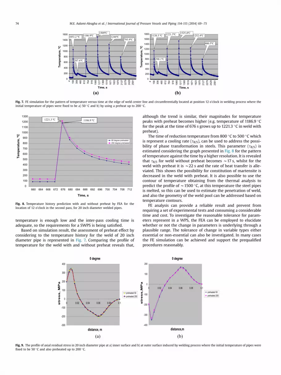
Fig. 7. FE simulation for the pattern of temperature versus time at the edge of weld center line and circumferentially located at position 12 o’clock in welding process where theinitial temperature of pipes were fixed to be a) 50 �C and b) by using a preheat up to 200 �C.
0
100
200
300
400
500
600
700
800
900
1000
1100
1200
1300
660 664 668 672 676 680 684 688 692 696 700 704 708 712
Time, s
Tem
pera
ture
, ºC
1221.3 ºC 1186.9 ºC
Fig. 8. Temperature history prediction with and without preheat by FEA for thelocation of 12 o’clock in the second pass, for 20 inch diameter welded pipes.
M.E. Aalami-Aleagha et al. / International Journal of Pressure Vessels and Piping 114-115 (2014) 69e7574
temperature is enough low and the inter-pass cooling time isadequate, so the requirements for a SWPS is being satisfied.
Based on simulation result, the assessment of preheat effect byconsidering to the temperature history for the weld of 20 inchdiameter pipe is represented in Fig. 7. Comparing the profile oftemperature for the weld with and without preheat reveals that,
0 degree
-300
-200
-100
0
100
200
300
400
0 0.02 0.04 0.06 0.08 0.1
distance, m
str
es
s,
MP
a
preheated 50preheated 200
(a)
Fig. 9. The profile of axial residual stress in 20 inch diameter pipe at a) inner surface and b) afixed to be 50 �C and also preheated up to 200 �C.
although the trend is similar, their magnitudes for temperaturepeaks with preheat becomes higher (e.g. temperature of 1186.9 �Cfor the peak at the time of 676 s grows up to 1221.3 �C inweld withpreheat).
The time of reduction temperature from 800 �C to 500 �C whichis represent a cooling rate (s8/5), can be used to address the possi-bility of phase transformation in steels. This parameter (s8/5) isestimated considering the graph presented in Fig. 8 for the patternof temperature against the time by a higher resolution. It is revealedthat s8/5 for weld without preheat becomes w17 s, whilst for theweld with preheat it is w22 s and the rate of heat transfer is alle-viated. This shows the possibility for constitution of martensite isdecreased in the weld with preheat. It is also possible to use thecontour of temperature obtaining from the thermal analysis topredict the profile of w1500 �C, at this temperature the steel pipesis melted, so this can be used to estimate the penetration of weld,and also the geometry of the weld pool can be addressed based ontemperature contours.
FE analysis can provide a reliable result and prevent fromrequiring a set of experimental tests and consuming a considerabletime and cost. To investigate the reasonable tolerance for param-eters represent in a WPS, the FEA can be employed to elucidatewhether or not the change in parameters is underlying through aplausible range. The tolerance of change in variable types eitheressential or non-essential can also be investigated. In many casesthe FE simulation can be achieved and support the prequalifiedprocedures reasonably.
0 degree
-400
-300
-200
-100
0
100
200
0 0.02 0.04 0.06 0.08 0.1
distance,m
str
es
s,M
Pa
preheated 50preheated 200
(b)
t outer surface induced by welding process where the initial temperature of pipes were

M.E. Aalami-Aleagha et al. / International Journal of Pressure Vessels and Piping 114-115 (2014) 69e75 75
The structural analysis has been achieved for prediction theaxial residual stress variation in 20 inch pipe in a circumferentialmulti-pass weld considering preheat effect. The result obtained forthe distribution of residual stress at the edge of weld is demon-strated in Fig. 9. The pattern shows, occurrence of a high tensionstress in inner surface of pipe, however severe compressive stressfor outer layer of pipe is predicted. Considering the pattern of re-sidual stress, it shows a decrease in severity for the points wherethey are far from the weld center line. This trend of stresses is re-ported by others during the experimental research [21,22].
FEA also reveals the effect of the increase in the initial temper-ature of weld or preheat effect on the axial residual stress, see Fig. 9.It reveals an increase in initial temperature up to the 150 �C has anegligible effect on the axial residual stress. Therefore in welding,preheat process has an inevitable effect on the thermal cycle but noserious effect is observed for the induced residual stress.
5. Conclusions
In this study a 3D finite-element computational analysis wasdeveloped to predict the preheat effect on the thermal cycle andinduced residual stress in a circumferential multi-pass weld of 20inch pipe based on a SWPS. In the proposed model, temperature-dependent material properties were used, a semispherical distri-bution for heat density is assumed, and the rotation of electrodearound the pipe is modeled appropriately. According to the simu-lation result the following conclusions have been drawn.
� The response from the FEmodel for the thermal cycle representsthe peaks for temperature follows reasonably the sequence ofweld considering the motion of electrode by the welders. Thepeaks for temperature at a position are aroused on times wherethe electrode is just leaving that position.
� The axial residual stress induced by the thermal cycle produceda field of high tensile stress and compressive stress near theweld center line at the inner and outer surfaces of piperespectively, this field of stress is being changed and the value ofstresses being dropped as the distances becomes far from theweld center line.
� Preheat process in the weld zone has a major effect on thethermal cycle experienced in each point and reduces the coolingrate, but it is not an apparent effect on the residual stressinduced by the temperature gradient of the weld source.
� Finite-element simulation can be used as a reliable method toinvestigate the effect of change in essential and non-essentialparameters documented in a WPS, and the variation and theplausible tolerances for variables can be evaluated by a simplermanner of modeling and run the computational programwithout employing hard practical trials by fabricating thesamples for testing.
Acknowledgments
The authors gratefully acknowledge the support received fromthe Razi University for this research work. Appreciations are alsodue to Iranian National Gas Corporation in Kermanshah city toprovide the funds for the research.
References
[1] ANSI/AWS B2.1-1-201-96. Standard welding procedure specification (WPS)for shielded metal arc welding of carbon steel (M-1/P-1/S-1, group 1 or 2) 1/8through 3/4 inch thick, E6010 (vertical uphill) followed by E7018 (verticaluphill) as-welded condition, primarily pipe applications. 550 N.W. LejeuneRoad, Miami, FL 33126: American Welding Society.
[2] ANSI/AWS B2.1-1-202-96. Standard welding procedure specification (WPS)for shielded metal arc welding of carbon steel (M-1/P-1/S-1, group 1 or 2) 1/8through 3/4 inch thick, E6010 (vertical downhill) followed by E7018 (verticaluphill) as-welded condition, primarily pipe applications. 550 N.W. LejeuneRoad, Miami, FL 33126: American Welding Society.
[3] ANSI/AWS B2.1-1-203-96. Standard welding procedure specification (WPS)for shielded metal arc welding of carbon steel (M-1/P-1/S-1, group 1 or 2) 1/8through 3/4 inch thick, E6010 (vertical uphill) as-welded condition, primarilypipe applications. 550 N.W. Lejeune Road, Miami, FL 33126: AmericanWelding Society.
[4] The American Society of Mechanical Engineers. Three Park Avenue, New York,NY 10016-5990; 1998.
[5] Murugan S, Rai SK, Kumar PV, Jayakumar T, Raj B, Bose MSC. Temperaturedistribution and residual stress due to multipass welding in type 304 stainlesssteel and low carbon steel weld pads. Int J Press Vessels Pip 2001;78:307e17.
[6] Tall L. Residual stresses in welded plates e a theoretical study. Weld J1964;43(1):10e23.
[7] Ueda Y, Yamakawa T. Thermal stress analysis of metals with temperaturedependent mechanical properties. In: Proceedings of the international con-ference on mechanical behavior of materials 1971. p. 10.
[8] Jiang W, Yahiaoui K, Hall FR. Finite element predictions of temperature dis-tributions in a multipass welded piping branch junction. ASME J Press VesselTechnol 2005;127:7e12.
[9] Rybicki EF, Schmueser DW, Stonesifer RB, Groom JJ, Mishler HW. A finiteelement model for residual stresses in girth-butt welded pipes. In: Numericalmodeling of manufacturing processes 1977. ASME winter annual meeting,held in Atlanta, Georgia.
[10] Rybicki EF, Schmueser DW, Stonesifer RB, Groom JJ, Mishler HW. A finite-element model for residual stresses and deflections in girth-butt weldedpipes. ASME J Press Vessel Technol 1978;100:256e62.
[11] Rybicki EF, Mcguire PA. The effects of induction heating conditions on con-trolling residual stresses in welded pipes. Trans ASME J Eng Mater Technol1982;104:267e73.
[12] Ueda Y, Yamakawa T. Analysis of thermal elastic-plastic stress and strainduring welding by finite element method. Trans Jpn Weld Res Inst 1971;2(2):90e100.
[13] Kussmaul K, Roos E, Guth W. A contribution to the numerical and experi-mental determination of residual stresses in welds. Nucl Eng 1989;112:337e48.
[14] Mok D, Pick R. Finite element study of residual stresses in a plate T-joint fa-tigue specimen. J Mech Eng Sci 1990;204(C2):127e34.
[15] Dong Y, Hong JK, Tsai CL, Dong P. Finite element modeling of residual stressesin austenitic stainless steel pipe girth welds. Weld J 1997;76(10):442e9.
[16] Fricke S, Keim E, Schmidt J. Numerical weld modeling, a method for calcu-lating weld-induced residual stresses. Nucl Eng Des 2001;206(2e3):139e50.
[17] Dike J, Ortega AR, Cadden CH, Rangaswamy P. Finite element modeling andvalidation of residual stresses in 304L girth welds. In: 5th International con-ference on trends in welding research. Pine Mountain, USA: ASM Interna-tional; 1998.
[18] Shan X, Davies CM, Wangsdan T, O’Dowd NP, Nikbin KM. Thermo-mechanicalmodeling of a single-bead-on-plate weld using the finite element method. IntJ Press Vessels Pip 2009;86:110e21.
[19] Ravichandran G, Raghupathy VP, Ganesan N, Krishnakumar R. Prediction ofaxis shift distortion during circumferential welding of thin pipes using thefinite element method. Weld J 1997, January:39e55.
[20] Brickstad B, Josefson L. A parametric study of residual stresses in multi-passbutt-welded stainless steel pipes. Int J Press Vessels Pip 1998;75:11e25.
[21] Malik AM, Qureshi EM, Dar NU, Khan I. Analysis of circumferentially arcwelded thin-walled cylinders to investigate the residual stress fields. ThinWalled Struct 2008. http://dx.doi.org/10.1016/j.tws.2008.03.011.
[22] Deng D, Murakawa H. Finite element analysis of temperature field, micro-structure and residual stress in multi-pass butt-welded 2.25Cre1Mo steelpipes. Comput Mater Sci 2008;43:681e95.