An investigation of the effect of work piece reinforcing ...
10
Journal of Mechanical Engineering Research Vol. 3.(1), pp. 15-24, January 2011 Available online at http://www.academicjournals.org/jmer ISSN 2141 - 2383 ©2011 Academic Journals Full Length Research Paper An investigation of the effect of work piece reinforcing percentage on the machinability of Al-SiC metal matrix composites N. Muthukrishnan 1 * and J. Paulo Davim 2 1 Department of Mechanical Engineering, Sri Venkateswara College of Engineering, Sriperumbudur-602105, Tamilnadu, India. 2 Department of Mechanical Engineering, University of Aveiro, Campus Santiago, 3810-193 Aveiro, Portugal. Accepted 21 September 2010 This paper presents the study of the tool wear mechanism in machining the metal matrix composites (MMC) and its dependence on the percentage of reinforcing with MMC. Aluminum alloy (A356 - SiC) silicon carbide metal matrix composite of two samples, were prepared in-house by using stir casting method. Samples having 10 and 20% silicon carbide particles (grain size ranging from 55 to 85 μm) by weight are fabricated in the form of cylindrical bars. Experiments were conducted in the medium duty lathe by using polycrystalline diamond (PCD) insert. Optimum parameters were obtained by analyzing the power consumed on an average surface roughness (Ra) of the machined component. By setting these optimum parameters at a constant machining condition, tool wear study was carried out for a time duration of 100 min. The result showed that the tool flank wears was maximum while machining 20% of the SiC reinforcing MMC when compared with 10% of the SiC reinforcing MMC. The result proved that the influence of SiC particles’ weight percentage was a dependent parameter on tool wear. The main mechanism of tool wear in machining Al-SiC MMC includes two-body abrasion and three-body abrasion. However, the tool wear images were captured by optical microscope and SEM, which supported the result. Key words: Machining, PCD, Al-SiC-MMC, different percentage of SiC reinforcing, power consumed, tool wear. INTRODUCTION Increasing quantities of Metal Matrix Composites (MMCs) are replacing the conventional materials in many applications, especially in the automobile and aerospace industries. The most popular types of MMCs are aluminum alloy reinforced with ceramic particles. These low cost composites provide higher strength, stiffness and fatigue resistance (Kennedy et al., 1997; Allision and Gole, 1993) with a minimal increase in density over the base alloy. Owing to the addition of reinforcing materials, which are normally harder and stiffer than the matrix, *Corresponding author. E-mail: [email protected] or [email protected]. Tel: +91-44-27152000. Fax: +91- 44 – 27162462. machining becomes significantly more difficult than in the case of conventional materials, as reported in the earlier publications (Allision and Gole, 1993). Two types of MMCs were studied: workpiece-1 is reinforced with 10% of the silicon carbide particles (SiC), and workpiece-2 is reinforced with 20% of the SiC. A typical microstructure of the material having 10% SiCp is shown in Figure 1. The chemical composition of the matrix material is shown in Table 1. Wang and Alan (1990) investigated the erosion behavior of SiC fibre-SiC matrix composites. They found that erosion rate was inversely prepositional to the density and hardness of the composite. It was reported that erosion rate was lesser at a higher temperature, due to the increased ductility of the composite. Cao et al. (1990) carried out an experimental investigation on the
-
Upload
khangminh22 -
Category
Documents
-
view
3 -
download
0
Transcript of An investigation of the effect of work piece reinforcing ...

Journal of Mechanical Engineering Research Vol. 3.(1), pp. 15-24, January 2011 Available online at http://www.academicjournals.org/jmer ISSN 2141 - 2383 ©2011 Academic Journals Full Length Research Paper
An investigation of the effect of work piece reinforcing percentage on the machinability of Al-SiC metal matrix
composites
N. Muthukrishnan1* and J. Paulo Davim2
1Department of Mechanical Engineering, Sri Venkateswara College of Engineering, Sriperumbudur-602105, Tamilnadu, India.
2Department of Mechanical Engineering, University of Aveiro, Campus Santiago, 3810-193 Aveiro, Portugal.
Accepted 21 September 2010
This paper presents the study of the tool wear mechanism in machining the metal matrix composites (MMC) and its dependence on the percentage of reinforcing with MMC. Aluminum alloy (A356 - SiC) silicon carbide metal matrix composite of two samples, were prepared in-house by using stir casting method. Samples having 10 and 20% silicon carbide particles (grain size ranging from 55 to 85 µµµµm) by weight are fabricated in the form of cylindrical bars. Experiments were conducted in the medium duty lathe by using polycrystalline diamond (PCD) insert. Optimum parameters were obtained by analyzing the power consumed on an average surface roughness (Ra) of the machined component. By setting these optimum parameters at a constant machining condition, tool wear study was carried out for a time duration of 100 min. The result showed that the tool flank wears was maximum while machining 20% of the SiC reinforcing MMC when compared with 10% of the SiC reinforcing MMC. The result proved that the influence of SiC particles’ weight percentage was a dependent parameter on tool wear. The main mechanism of tool wear in machining Al-SiC MMC includes two-body abrasion and three-body abrasion. However, the tool wear images were captured by optical microscope and SEM, which supported the result. Key words: Machining, PCD, Al-SiC-MMC, different percentage of SiC reinforcing, power consumed, tool wear.
INTRODUCTION Increasing quantities of Metal Matrix Composites (MMCs) are replacing the conventional materials in many applications, especially in the automobile and aerospace industries. The most popular types of MMCs are aluminum alloy reinforced with ceramic particles. These low cost composites provide higher strength, stiffness and fatigue resistance (Kennedy et al., 1997; Allision and Gole, 1993) with a minimal increase in density over the base alloy. Owing to the addition of reinforcing materials, which are normally harder and stiffer than the matrix, *Corresponding author. E-mail: [email protected] or [email protected]. Tel: +91-44-27152000. Fax: +91- 44 – 27162462.
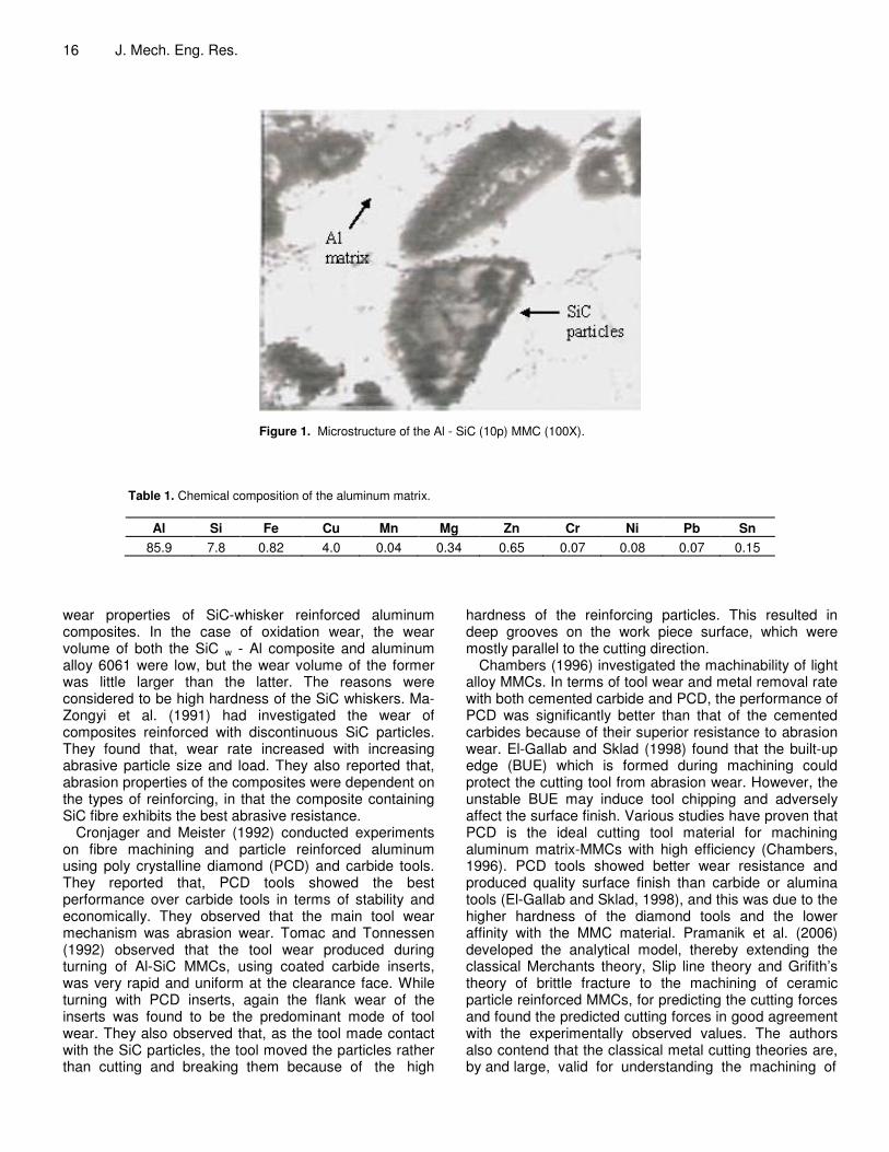
machining becomes significantly more difficult than in the case of conventional materials, as reported in the earlier publications (Allision and Gole, 1993). Two types of MMCs were studied: workpiece-1 is reinforced with 10% of the silicon carbide particles (SiC), and workpiece-2 is reinforced with 20% of the SiC. A typical microstructure of the material having 10% SiCp is shown in Figure 1. The chemical composition of the matrix material is shown in Table 1.
Wang and Alan (1990) investigated the erosion behavior of SiC fibre-SiC matrix composites. They found that erosion rate was inversely prepositional to the density and hardness of the composite. It was reported that erosion rate was lesser at a higher temperature, due to the increased ductility of the composite. Cao et al. (1990) carried out an experimental investigation on the
16 J. Mech. Eng. Res.
Figure 1. Microstructure of the Al - SiC (10p) MMC (100X).
Table 1. Chemical composition of the aluminum matrix.
Al Si Fe Cu Mn Mg Zn Cr Ni Pb Sn 85.9 7.8 0.82 4.0 0.04 0.34 0.65 0.07 0.08 0.07 0.15
wear properties of SiC-whisker reinforced aluminum composites. In the case of oxidation wear, the wear volume of both the SiC w - Al composite and aluminum alloy 6061 were low, but the wear volume of the former was little larger than the latter. The reasons were considered to be high hardness of the SiC whiskers. Ma-Zongyi et al. (1991) had investigated the wear of composites reinforced with discontinuous SiC particles. They found that, wear rate increased with increasing abrasive particle size and load. They also reported that, abrasion properties of the composites were dependent on the types of reinforcing, in that the composite containing SiC fibre exhibits the best abrasive resistance.
Cronjager and Meister (1992) conducted experiments on fibre machining and particle reinforced aluminum using poly crystalline diamond (PCD) and carbide tools. They reported that, PCD tools showed the best performance over carbide tools in terms of stability and economically. They observed that the main tool wear mechanism was abrasion wear. Tomac and Tonnessen (1992) observed that the tool wear produced during turning of Al-SiC MMCs, using coated carbide inserts, was very rapid and uniform at the clearance face. While turning with PCD inserts, again the flank wear of the inserts was found to be the predominant mode of tool wear. They also observed that, as the tool made contact with the SiC particles, the tool moved the particles rather than cutting and breaking them because of the high
hardness of the reinforcing particles. This resulted in deep grooves on the work piece surface, which were mostly parallel to the cutting direction.
Chambers (1996) investigated the machinability of light alloy MMCs. In terms of tool wear and metal removal rate with both cemented carbide and PCD, the performance of PCD was significantly better than that of the cemented carbides because of their superior resistance to abrasion wear. El-Gallab and Sklad (1998) found that the built-up edge (BUE) which is formed during machining could protect the cutting tool from abrasion wear. However, the unstable BUE may induce tool chipping and adversely affect the surface finish. Various studies have proven that PCD is the ideal cutting tool material for machining aluminum matrix-MMCs with high efficiency (Chambers, 1996). PCD tools showed better wear resistance and produced quality surface finish than carbide or alumina tools (El-Gallab and Sklad, 1998), and this was due to the higher hardness of the diamond tools and the lower affinity with the MMC material. Pramanik et al. (2006) developed the analytical model, thereby extending the classical Merchants theory, Slip line theory and Grifith’s theory of brittle fracture to the machining of ceramic particle reinforced MMCs, for predicting the cutting forces and found the predicted cutting forces in good agreement with the experimentally observed values. The authors also contend that the classical metal cutting theories are, by and large, valid for understanding the machining of
Muthukrishnan and Davim. 17
Table 2. Specification and characteristics of the cutting tool used.
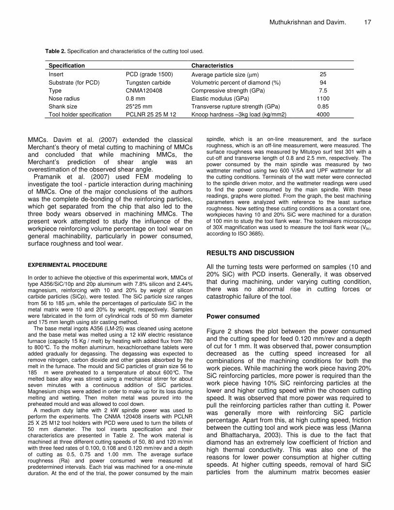
Specification Characteristics Insert PCD (grade 1500) Average particle size (µm) 25 Substrate (for PCD) Tungsten carbide Volumetric percent of diamond (%) 94 Type CNMA120408 Compressive strength (GPa) 7.5 Nose radius 0.8 mm Elastic modulus (GPa) 1100 Shank size 25*25 mm Transverse rupture strength (GPa) 0.85 Tool holder specification PCLNR 25 25 M 12 Knoop hardness –3kg load (kg/mm2) 4000
MMCs. Davim et al. (2007) extended the classical Merchant’s theory of metal cutting to machining of MMCs and concluded that while machining MMCs, the Merchant’s prediction of shear angle was an overestimation of the observed shear angle.
Pramanik et al. (2007) used FEM modeling to investigate the tool - particle interaction during machining of MMCs. One of the major conclusions of the authors was the complete de-bonding of the reinforcing particles, which get separated from the chip that also led to the three body wears observed in machining MMCs. The present work attempted to study the influence of the workpiece reinforcing volume percentage on tool wear on general machinability, particularly in power consumed, surface roughness and tool wear. EXPERIMENTAL PROCEDURE In order to achieve the objective of this experimental work, MMCs of type A356/SiC/10p and 20p aluminum with 7.8% silicon and 2.44% magnesium, reinforcing with 10 and 20% by weight of silicon carbide particles (SiCp), were tested. The SiC particle size ranges from 56 to 185 µm, while the percentages of particulate SiC in the metal matrix were 10 and 20% by weight, respectively. Samples were fabricated in the form of cylindrical rods of 50 mm diameter and 175 mm length using stir casting method.
The base metal ingots A356 (LM-25) was cleaned using acetone and the base metal was melted using a 12 kW electric resistance furnace (capacity 15 Kg / melt) by heating with added flux from 780 to 800°C. To the molten aluminum, hexachloroethane tablets were added gradually for degassing. The degassing was expected to remove nitrogen, carbon dioxide and other gases absorbed by the melt in the furnace. The mould and SiC particles of grain size 56 to 185 �m were preheated to a temperature of about 600°C. The melted base alloy was stirred using a mechanical stirrer for about seven minutes with a continuous addition of SiC particles. Magnesium chips were added in order to make up for its loss during melting and wetting. Then molten metal was poured into the preheated mould and was allowed to cool down.
A medium duty lathe with 2 kW spindle power was used to perform the experiments. The CNMA 120408 inserts with PCLNR 25 X 25 M12 tool holders with PCD were used to turn the billets of 50 mm diameter. The tool inserts specification and their characteristics are presented in Table 2. The work material is machined at three different cutting speeds of 50, 80 and 120 m/min with three feed rates of 0.100, 0.108 and 0.120 mm/rev and a depth of cutting as 0.5, 0.75 and 1.00 mm. The average surface roughness (Ra) and power consumed were measured at predetermined intervals. Each trial was machined for a one-minute duration. At the end of the trial, the power consumed by the main
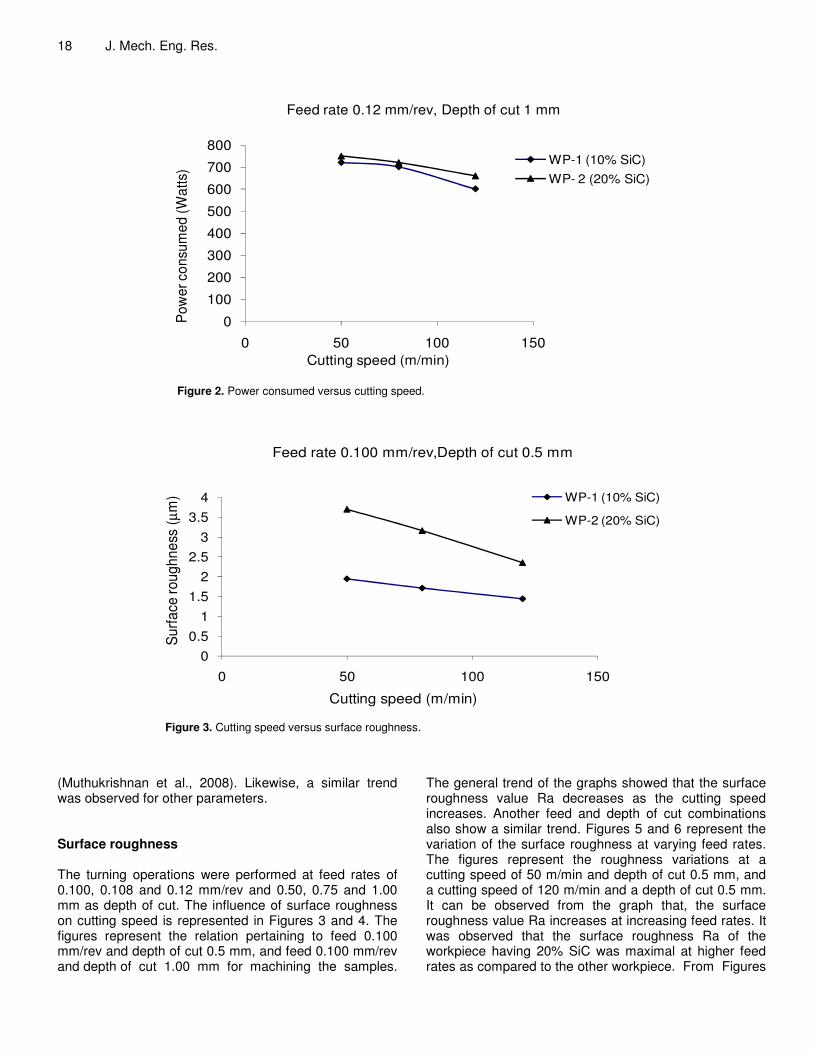
spindle, which is an on-line measurement, and the surface roughness, which is an off-line measurement, were measured. The surface roughness was measured by Mitutoyo surf test 301 with a cut-off and transverse length of 0.8 and 2.5 mm, respectively. The power consumed by the main spindle was measured by two wattmeter method using two 600 V/5A and UPF wattmeter for all the cutting conditions. Terminals of the watt meter were connected to the spindle driven motor, and the wattmeter readings were used to find the power consumed by the main spindle. With these readings, graphs were plotted. From the graph, the best machining parameters were analyzed with reference to the least surface roughness. Now setting these cutting conditions as a constant one, workpieces having 10 and 20% SiC were machined for a duration of 100 min to study the tool flank wear. The toolmakers microscope of 30X magnification was used to measure the tool flank wear (Vbc, according to ISO 3685). RESULTS AND DISCUSSION All the turning tests were performed on samples (10 and 20% SiC) with PCD inserts. Generally, it was observed that during machining, under varying cutting condition, there was no abnormal rise in cutting forces or catastrophic failure of the tool. Power consumed Figure 2 shows the plot between the power consumed and the cutting speed for feed 0.120 mm/rev and a depth of cut for 1 mm. It was observed that, power consumption decreased as the cutting speed increased for all combinations of the machining conditions for both the work pieces. While machining the work piece having 20% SiC reinforcing particles, more power is required than the work piece having 10% SiC reinforcing particles at the lower and higher cutting speed within the chosen cutting speed. It was observed that more power was required to pull the reinforcing particles rather than cutting it. Power was generally more with reinforcing SiC particle percentage. Apart from this, at high cutting speed, friction between the cutting tool and work piece was less (Manna and Bhattacharya, 2003). This is due to the fact that diamond has an extremely low coefficient of friction and high thermal conductivity. This was also one of the reasons for lower power consumption at higher cutting speeds. At higher cutting speeds, removal of hard SiC particles from the aluminum matrix becomes easier
18 J. Mech. Eng. Res.
0
100
200
300
400
500
600
700
800
0 50 100 150
Pow
er c
onsu
med
(Wat
ts)
Cutting speed (m/min)
Feed rate 0.12 mm/rev, Depth of cut 1 mm
WP-1 (10% SiC)WP- 2 (20% SiC)
Figure 2. Power consumed versus cutting speed.
00.5
11.5
22.5
33.5
4
0 50 100 150
Surfa
ce ro
ughn
ess
(µm
)
Cutting speed (m/min)
Feed rate 0.100 mm/rev,Depth of cut 0.5 mm
WP-1 (10% SiC)
WP-2 (20% SiC)
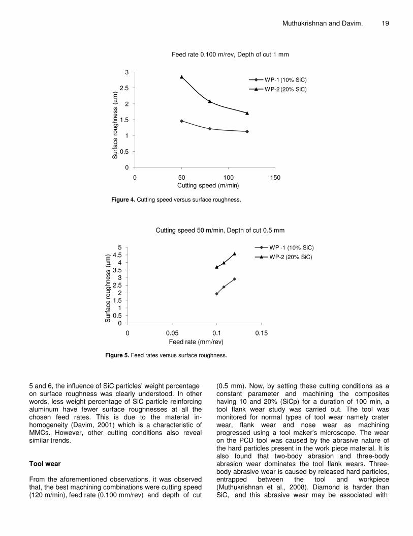
Figure 3. Cutting speed versus surface roughness.
(Muthukrishnan et al., 2008). Likewise, a similar trend was observed for other parameters. Surface roughness The turning operations were performed at feed rates of 0.100, 0.108 and 0.12 mm/rev and 0.50, 0.75 and 1.00 mm as depth of cut. The influence of surface roughness on cutting speed is represented in Figures 3 and 4. The figures represent the relation pertaining to feed 0.100 mm/rev and depth of cut 0.5 mm, and feed 0.100 mm/rev and depth of cut 1.00 mm for machining the samples.
The general trend of the graphs showed that the surface roughness value Ra decreases as the cutting speed increases. Another feed and depth of cut combinations also show a similar trend. Figures 5 and 6 represent the variation of the surface roughness at varying feed rates. The figures represent the roughness variations at a cutting speed of 50 m/min and depth of cut 0.5 mm, and a cutting speed of 120 m/min and a depth of cut 0.5 mm. It can be observed from the graph that, the surface roughness value Ra increases at increasing feed rates. It was observed that the surface roughness Ra of the workpiece having 20% SiC was maximal at higher feed rates as compared to the other workpiece. From Figures
Muthukrishnan and Davim. 19
0
0.5
1
1.5
2
2.5
3
0 50 100 150
Sur
face
rou
ghne
ss (
µm)
Cutting speed (m/min)
Feed rate 0.100 m/rev, Depth of cut 1 mm
WP-1 (10% SiC)
WP-2 (20% SiC)
Figure 4. Cutting speed versus surface roughness.
00.5
11.5
22.5
33.5
44.5
5
0 0.05 0.1 0.15
Sur
face
roug
hnes
s (µ
m)
Feed rate (mm/rev)
Cutting speed 50 m/min, Depth of cut 0.5 mm
WP -1 (10% SiC)
WP-2 (20% SiC)
Figure 5. Feed rates versus surface roughness.
5 and 6, the influence of SiC particles’ weight percentage on surface roughness was clearly understood. In other words, less weight percentage of SiC particle reinforcing aluminum have fewer surface roughnesses at all the chosen feed rates. This is due to the material in-homogeneity (Davim, 2001) which is a characteristic of MMCs. However, other cutting conditions also reveal similar trends. Tool wear From the aforementioned observations, it was observed that, the best machining combinations were cutting speed (120 m/min), feed rate (0.100 mm/rev) and depth of cut
(0.5 mm). Now, by setting these cutting conditions as a constant parameter and machining the composites having 10 and 20% (SiCp) for a duration of 100 min, a tool flank wear study was carried out. The tool was monitored for normal types of tool wear namely crater wear, flank wear and nose wear as machining progressed using a tool maker’s microscope. The wear on the PCD tool was caused by the abrasive nature of the hard particles present in the work piece material. It is also found that two-body abrasion and three-body abrasion wear dominates the tool flank wears. Three-body abrasive wear is caused by released hard particles, entrapped between the tool and workpiece (Muthukrishnan et al., 2008). Diamond is harder than SiC, and this abrasive wear may be associated with
20 J. Mech. Eng. Res.
0
0.5
1
1.5
2
2.5
3
3.5
0 0.05 0.1 0.15
Sur
face
roug
hnes
s (µ
m)
Feed rate (mm/rev)
Cutting speed 120 m/min, Depth of cut 0.5 mm
WP-1 (10%SiC)WP-2 (20% SiC)
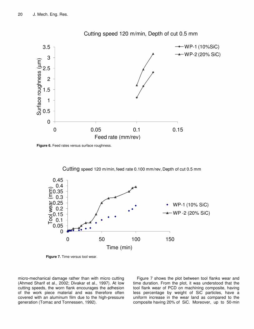
Figure 6. Feed rates versus surface roughness.
00.05
0.10.15
0.20.25
0.30.35
0.40.45
0 50 100 150
Tool
wea
r (m
m)
Time (min)
Cutting speed 120 m/min, feed rate 0.100 mm/rev, Depth of cut 0.5 mm
WP-1 (10% SiC)
WP -2 (20% SiC)
Figure 7. Time versus tool wear.
micro-mechanical damage rather than with micro cutting (Ahmed Sharif et al., 2002; Divakar et al., 1997). At low cutting speeds, the worn flank encourages the adhesion of the work piece material and was therefore often covered with an aluminum film due to the high-pressure generation (Tomac and Tonnessen, 1992).
Figure 7 shows the plot between tool flanks wear and time duration. From the plot, it was understood that the tool flank wear of PCD on machining composite, having less percentage by weight of SiC particles, have a uniform increase in the wear land as compared to the composite having 20% of SiC. Moreover, up to 50-min
Muthukrishnan and Davim. 21
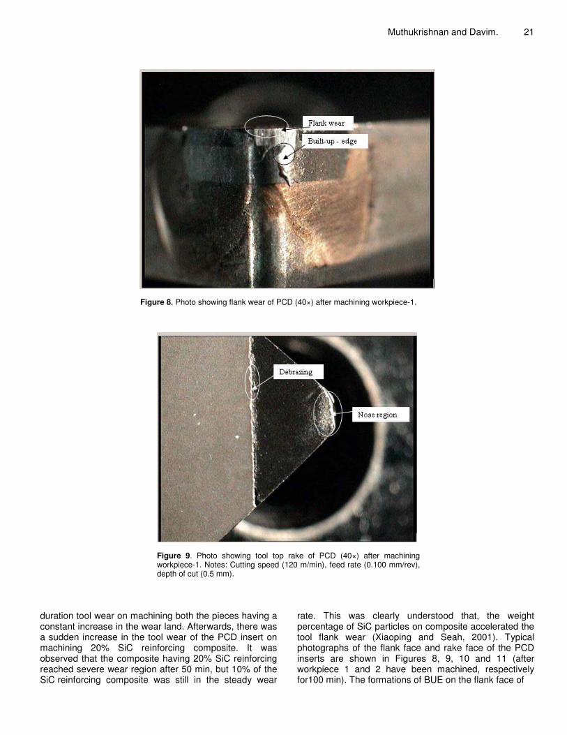
Figure 8. Photo showing flank wear of PCD (40×) after machining workpiece-1.
Figure 9. Photo showing tool top rake of PCD (40×) after machining workpiece-1. Notes: Cutting speed (120 m/min), feed rate (0.100 mm/rev), depth of cut (0.5 mm).
duration tool wear on machining both the pieces having a constant increase in the wear land. Afterwards, there was a sudden increase in the tool wear of the PCD insert on machining 20% SiC reinforcing composite. It was observed that the composite having 20% SiC reinforcing reached severe wear region after 50 min, but 10% of the SiC reinforcing composite was still in the steady wear
rate. This was clearly understood that, the weight percentage of SiC particles on composite accelerated the tool flank wear (Xiaoping and Seah, 2001). Typical photographs of the flank face and rake face of the PCD inserts are shown in Figures 8, 9, 10 and 11 (after workpiece 1 and 2 have been machined, respectively for100 min). The formations of BUE on the flank face of
22 J. Mech. Eng. Res.
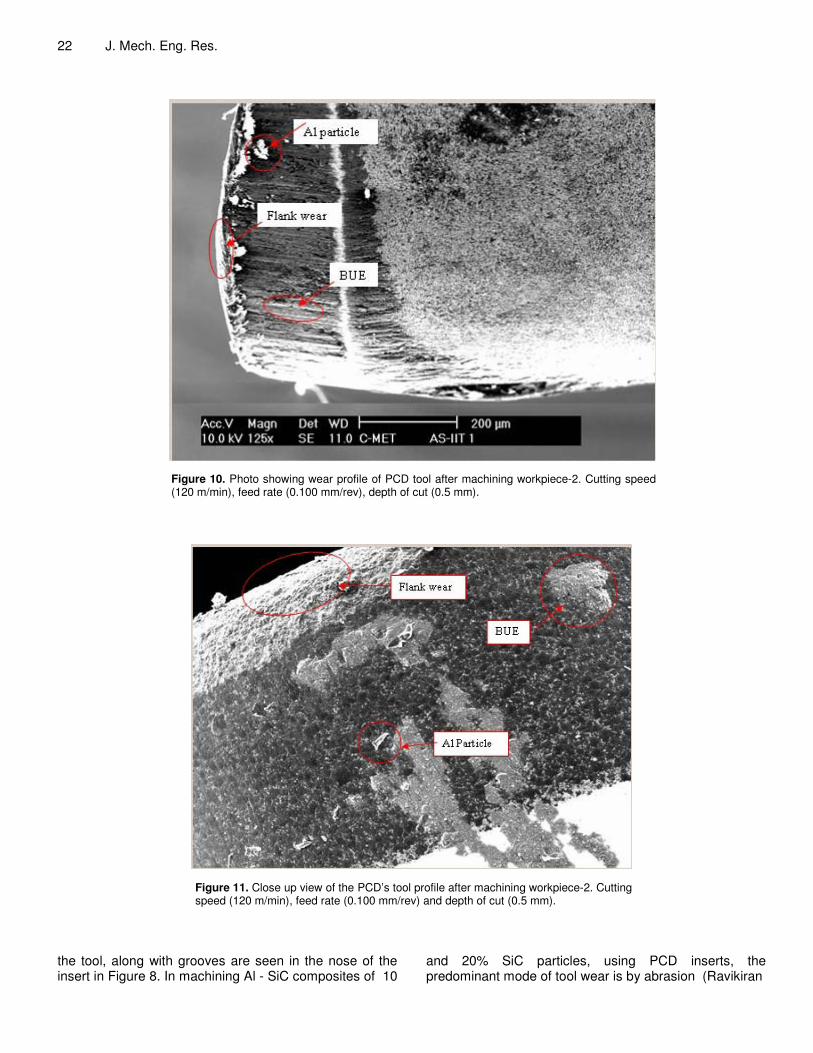
Figure 10. Photo showing wear profile of PCD tool after machining workpiece-2. Cutting speed (120 m/min), feed rate (0.100 mm/rev), depth of cut (0.5 mm).
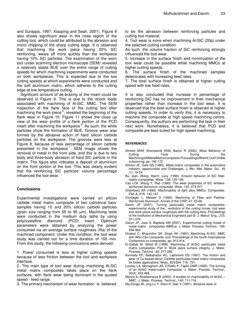
Figure 11. Close up view of the PCD’s tool profile after machining workpiece-2. Cutting speed (120 m/min), feed rate (0.100 mm/rev) and depth of cut (0.5 mm).
the tool, along with grooves are seen in the nose of the insert in Figure 8. In machining Al - SiC composites of 10
and 20% SiC particles, using PCD inserts, the predominant mode of tool wear is by abrasion (Ravikiran
and Surappa, 1997; Xiaoping and Seah, 2001). Figure 8 also shows significant wear in the nose region of the cutting tool, which could be attributed to the abrasion and micro chipping of the sharp cutting edge. It is observed that machining the work piece having 20% SiC reinforcing, wears off more quickly than the workpiece having 10% SiC particles. The examination of the worn tool under scanning electron microscope (SEM) revealed a relatively stable BUE over the entire range of cutting speeds for which machining experiments were conducted on both workpieces. This is expected due to the low cutting speeds at which experiments were conducted and the soft aluminum matrix, which adheres to the cutting edge at low temperature cutting.
Significant amount of de-brazing of the insert could be observed in Figure 9. This is due to the shock loads associated with machining of Al-SiC, MMC. The SEM inspection of the flank face of the cutting tool after machining the work piece-2, revealed the beginning of the flank wear in Figure 10. Figure 11 shows the close up view of the wear profile of a flank portion of the PCD insert after machining the workpiece-2. As such, the white particles show the formation of BUE. Groove wear was formed by the abrasive action of hard silicon carbide particles on the workpiece. The grooves were less at Figure 8, because of less percentage of silicon carbide presented in the workpiece-1. SEM image shows the removal of metal in the front side, and this is due to two body and three-body abrasion of hard SiC particle in the matrix. The figure also indicates a deposit of aluminium on the front portion of the tool. This was clearly evident that the reinforcing SiC particles’ volume percentage influenced the tool wear. Conclusions Experimental investigations were carried on silicon carbide metal matrix composite of two cylindrical bars’ samples having 10 and 20% silicon carbide particles (grain size ranging from 55 to 85 µm). Machining tests were conducted in the medium duty lathe by using polycrystalline diamond (PCD) insert. Optimum parameters were obtained by analyzing the power consumed via an average surface roughness (Ra) of the machined component. Under this condition, the tool wear study was carried out for a time duration of 100 min. From this study, the following conclusions were derived: 1. Power consumed is less at higher cutting speeds because of less friction between the tool and workpiece interface. 2. The main type of tool wear during machining Al-SiC metal matrix composites takes place on the flank surfaces, with flank wear being dominant in the quoted speed - feed range. 3. The primary mechanism of wear formation is believed
Muthukrishnan and Davim. 23 to be the abrasion between reinforcing particles and cutting tool material. 4. Tool wear is more when machining Al-SiC (20p) under the selected cutting condition. As such, the volume fraction of SiC reinforcing strongly influenced the tool wear. 5. Increase in the surface finish and minimization of the tool wear could be possible while machining MMCs at higher cutting speeds. 6. The surface finish of the machined samples deteriorates with increasing feed rates. 7. The best surface finish is obtained at higher cutting speed with low feed rates. It is also concluded that increase in percentage of reinforcing SiC has no improvement in their mechanical properties rather than increase in the tool wear. It is observed that the best surface finish is obtained at higher cutting speeds. In order to verify this, it is necessary to machine the composite at high speed machining centre. Consequently, the authors are performing the task in their next work. Nonetheless, it is believed that PCD and composite are best suited for high speed machining. REFERENCES Ahmed SKM, Shorowordi AKM, Bazlur R (2002). Wear Behavior of
Cutting Tools During the MachiningofAlMetalMatrixComposite.ProceedingsoftheInt.Conf.OnManufacturing, pp. 165-172.
Allision JE, Gole GS (1993). Metal-matrix composites in the automotive industry: opportunities and Challenges. J. Min. Met. Mater. Sci., 45 (1): 19-24.
Bu- qian, Wang, AlanV, Levy (1990). Erosion behavior of SiC fiber-matrix composites. Wear, 138: 125-136.
Cao LCK ,Wang Y, Rao (1990). The wear properties of SiC whisker-reinforced aluminium composite. Wear, 140: 273-277.
Chambers AR (1996). Machinability of light alloy MMCs. Composites. Part A, 27A: 143-147.
Cronjager L, Meister D (1992). Machining of Fiber and Particle-Reinforced Aluminum. Annals of the CIRP, 41: 63-66.
Davim JP (2001). Turning particulate metal matrix composites: experimental study of the evolution of the cutting forces, tool wear and work piece surface roughness with the cutting time. Proceedings of the Institution of Mechanical Engineers part B- J. Manuf. Eng., 215: 371-376.
Davim JP, Jose S, Baptista AM (2007). Experimental cutting model of metal matrix composites (MMCs). J. Mater. Process. Technol., 183: 358-362.
Divakar C, Bhaumikm SK, Singh AK (1997). Machining Al-SiC, MMC with Wbn-Cbn composite tool. Proceedings of the fourth International Conference on composites, pp. 913-914.
Ei-Gallab M, Sklad M (1998). Machining of Al/SiC particulate metal matrix composites. Part II: Work piece surface integrity. J. Mater. Process. Technol., 83: 277-285.
Kennedy FE, Balbahadur AC, Lashmore DS (1997). The friction and wear of Cu-based silicon Carbide particulate metal matrix composites for brake applications. Wear, 203/204: 715- 721.
Looney LA, Monagham JM, O’Reilly P, Taplin DMR (1992). The turning of an Al/SiC metal-matrix Composite. J. Mater. Process. Technol., 33(4): 453-468.
Manna A, Bhattacharya B (2003). A studies on machinability of Al/SiC – MMC. J. Mater. Process. Technol., 140: 711-716.
Ma-Zongyi BI, Jing Lu Y, Shen H, Gao Y (1991). Abrasive wear of

24 J. Mech. Eng. Res.
discontinuous SiC reinforced aluminium alloy composites. Wear, 148: 287-293.
Muthukrishnan N, Murugan M, Prahlada, Rao K (2008). An investigation on the machinability of Al- SiC metal matrix composites using pcd inserts. Int. J. Adv. Manuf. Technol., 38: 447-454.
Muthukrishnan, Murugan M, Prahlada, Rao K (2008). Machinability issues in turning of Al-Sic (10p) metal matrix composites. Int. J. Adv. Manuf. Technol., 39: 211-218.
Pramanik A, Zhang LC, Arsecularatne JA (2006). Prediction of cutting forces in machining of metal matrix composites. Int. J. Mach. Tools Manuf., 46: 1795-1803.
Pramanik A, Zhang LC, Arsecularatne JA (2007). An FEM investigation
into the behavior of metal matrix composites. Tool – particle interaction during orthogonal cutting. Int. J. Mach. Tools Manuf., Doi:
10.1016 / j.ijmachtools, 2006. 12.004. Ravikiran A, Surappa MK (1997). ‘Effect of sliding speed on wear
behavior of A356 Al 30 wt % SiCp MMC’, Wear, 206: 33-38. Tomac N, Tonnessen K (1992). Machinability of particulate aluminium
matrix composites. Ann. CIRP, 42(1): 55-58. Xiaoping LI, Seah WKH (2001). Tool wear acceleration in relation to
workpiece reinforcing percentage in cutting of metal matrix composites, Wear, 27: 161-171.