An implementation of a distributed artificial intelligence architecture to the integrated production...
14
This article appeared in a journal published by Elsevier. The attached copy is furnished to the author for internal non-commercial research and education use, including for instruction at the authors institution and sharing with colleagues. Other uses, including reproduction and distribution, or selling or licensing copies, or posting to personal, institutional or third party websites are prohibited. In most cases authors are permitted to post their version of the article (e.g. in Word or Tex form) to their personal website or institutional repository. Authors requiring further information regarding Elsevier’s archiving and manuscript policies are encouraged to visit: http://www.elsevier.com/copyright
-
Upload
independent -
Category
Documents
-
view
0 -
download
0
Transcript of An implementation of a distributed artificial intelligence architecture to the integrated production...

This article appeared in a journal published by Elsevier. The attachedcopy is furnished to the author for internal non-commercial researchand education use, including for instruction at the authors institution
and sharing with colleagues.
Other uses, including reproduction and distribution, or selling orlicensing copies, or posting to personal, institutional or third party
websites are prohibited.
In most cases authors are permitted to post their version of thearticle (e.g. in Word or Tex form) to their personal website orinstitutional repository. Authors requiring further information
regarding Elsevier’s archiving and manuscript policies areencouraged to visit:
http://www.elsevier.com/copyright

Author's personal copy
An implementation of a distributed artificial intelligence architecture to theintegrated production management
César Bravo a,*,1, José Aguilar Castro a, Luigi Saputelli b, Addison Ríos a,Joseph Aguilar-Martin c, Francklin Rivas d
aCEMISID, Universidad de los Andes. Mérida, VenezuelabHess Corporation, Houston, TX, USAcCTAE e Aerospace Research and Technology Center, Barcelona, Spaind LABSIULA, Universidad de los Andes, Mérida, Venezuela
a r t i c l e i n f o
Article history:Received 5 August 2011Accepted 30 August 2011
Keywords:Artificial intelligenceIndustrial architectureMulti-agents systemsOntology
a b s t r a c t
The oil production process is highly complex and requires the combination of several disciplines andtechnological tools for its management. System integration and the automation of the workflowsrequired to develop oil production operations are two main problems nowadays at the oil and gasproduction industry. This work approaches these problems through the implementation of distributedartificial intelligence architecture, designed for the automated production management. The architecturecomprises a standardized schema to access information sources, a production ontological framework andan intelligent workflow mechanism based on multi-agent systems and electronic institution. Ourarchitecture present several novelties: the incorporation of the semantic integration, the extension of theagents theory through the electronic institutions paradigm to solve the real-time decision problemstypical in the industry, the Holon-Agent hybrid model used to make more feasible its implementation,among others. An oil production management case study is presented in order to demonstrate theapplicability of the proposed architecture.
� 2011 Elsevier B.V. All rights reserved.
1. Introduction
As the technology improves, the automation systems thatcontrol the industrial processes have increased their complexity.The information has become in one of the key assets of the enter-prises. Each day there are more and more information require-ments at all enterprise areas (operations, management, marketing,etc.), looking for total visibility and control over their processes.
This work addressed the implementation of an IntegratedProduction Management Architecture (IPMA) (Bravo, 2010) to theoil production process. The objective of IPMA implementation is tocalculate, in an automatic way, the optimal production units’configuration, in order to maximize the oilfield profitability. Toaims this objective, a set of software adaptors are defined, in orderto gather the data from the databases, applications and any otherproduction process information sources. Also, oil productionontology is designed, with the concepts required to the informationinterchange between the oil production domain applications.
Finally, an implementation of an electronic institution is developed,in order to automate the oil production workflows.
Our architecture present several novelties: we propose a struc-tured mechanism to resolve the access to the information sourcesand develop a semantic based integration layer; also, we use anextension of the agents’ theory, called electronic institutions, tosolve the real-time decision problems; finally, we propose a Holon-Agent hybrid model for the implementation of the architecture.
This document is composed by 5 sections. In the second sectionsomebackgroundworks arediscussed in order to study thedifferentapproaches for integrated production management and establish-ing the bases for the proposed architecture; Section 3 presentsa detailed description of the proposed architecture; Section 4presents a case study of the application of the proposed architec-ture to a production management problem, through the design ofa virtual oil field; finally, Section 5 presents some conclusions.
2. Background
Industrial Process Automation and Integrated Production Manage-ment have been subject of study from the scientific and industrialcommunity for several years. In the 1970 decade begins a trend named
* Corresponding author. Tel.: þ52 1 5543656237.E-mail address: [email protected] (C. Bravo).
1 Now with Halliburton.
Contents lists available at SciVerse ScienceDirect
Journal of Natural Gas Science and Engineering
journal homepage: www.elsevier .com/locate/ jngse
1875-5100/$ e see front matter � 2011 Elsevier B.V. All rights reserved.doi:10.1016/j.jngse.2011.08.002
Journal of Natural Gas Science and Engineering 3 (2011) 735e747

Author's personal copy
“Enterprise Modeling”, which look for describe the processes (and theelement related to them) than happens in an enterprise. Since then,enterprisemodelsandstandardsbegin toappear, suchasCIMOSA(ENV40 003, 1990), for the representation of manufacturing processes, ISO/OSI (Zimmermann,1980) and PERA (Williams,1989)models, designedto model enterprise’s industrial automation infrastructure, and morerecently, PROSA model (Wyns, 1999), which presents the enterprisemodeling based on an holonic architecture.
Industrial automation architectures implemented in continuousproduction enterprises, follow the hierarchical pattern proposed inthe ISO/OSIpyramid.Nevertheless, recent researchanddevelopment(R&D) on Distributed Artificial Intelligence (DAI) and, specifically, inDistributed IntelligentControl (DIC) (PABADIS, 2002e2006; Jenningsand Bussmann, 2003; Bravo et al., 2005; Marik and Vrba, 2005),proposed collaborative architectures, inwhich theautonomyand theintelligence are implemented on field devices and application plat-forms, in order to reach flexible control strategies which could adaptto changes in theproduction environmentor in theproduction goals.
The evolution of the industrial automation models to distributedschemas has been allowed by the advance in InformationTechnology(IT). Current trends inEnterpriseApplicationPlatforms are directed toService Oriented Architectures (SOA), in which the enterprise appli-cations and systems are built by the composition or orchestration ofseveral well defined and re-usable “services”, reflecting the enter-prises business processes on the IT platform. In these architectures,the integrationand inter-operationbetweenapplicationsandsystemsis a key element. In the other hand, the field devices have increasedtheirprocessingcapabilities, allowingexecutingcomplexapplicationsover them, leveraging the distribution of the industrial IT platforms.
In the business processes definition area, there are also muchinterest in the R&D and industrial world. In R&D a set of frame-works and languages has been proposed, in order to establish theinformation and products flows within the enterprise. These area few relevant works in business processes definition for industrialinformation: ISA SP 88 (ISA, 1995) and SP 95 standards (ISA, 2000),B2MML (World Batch Forum, 2004) and PSLX (PSLX Consortium,2005). Also, in the IT environment, several techniques and stan-dards for business processes analysis (BPA) and business processesmodeling (BPM) have been proposed, most based on XML. Themostrelevant business process management languages are XPDL, BPELand RossetaNet (Litchicum, 2004). In the oil and gas industry someinteresting efforts had been developed for the generation ofontologies designed for the specialized application integration,such as WITSML (POSC, 2003e2006), PRODML (POSC, 2006), andthe Oil & Gas Ontology (OGO) (POSC, 2009).
In Integrated Production Management, there are several studiesdeveloped for the oil and gas industry, which proposed the inte-gration of all information systems in the enterprise, in order toobtain all the information related with the production process,from the static data (geological and petrophysical information) tothe real-time production information, in order to generate theoptimal reservoir exploitation plan (Satter and Thakur, 1994).Following this approach, several oil & gas production enterprisesare developing technological projects related with IntegratedReservoir Management (IRM). Some of the most relevant projectsare the High North Integrated Operations (POSC, 2009), developedby Statoil� and the Norway Scientific Research Council, the i-Field(Soma et al., 2008; Sankaran et al., 2010) the Smart Field developedby Shell� (Potters and Kapteijn, 2005) and the Field of the Future(Sisk et al., 2007) developed by BP�. These kinds of modelsapproach the automation as a mean for the production planningand operation, and not as an end in itself.
This work proposed an integrated architecture, which approachthe production management in a distributed and intelligent way,following the principles of the Integrated Reservoir Management.
3. Integrated Production Management Architecture (IPMA)
In this work the Integrated Production Management Architec-ture (IPMA) proposed in (Bravo, 2010) is used to approach the oilfield production management. This architecture consist of thetechnological tools required for information process acquisition,treatment and analysis and also for the business process anddecision making automation at continuous production industries.IPMA is composed by three layers. First layer is called “ConnectivityLayer”, in which the data acquisition, treatment and interpretationmechanism are defined. Second layer, called “Semantic Layer”,consist in an ontological framework that aims to assure effectiveinformation interchange between the applications that are used atthe production process. Finally the third layer, called “ManagementLayer”, is in charge of establishing enterprise workflows intelligentautomation mechanism. A scheme of IPMA is shown in Fig. 1.
3.1. Connectivity Layer
The Connectivity Layer provides required mechanisms to allowaccess to process state information, which is stored in severalinformation sources. The objective of this layer is to extract processinformation from data sources and expose it in a common schemewell known by all applications that belong to the Information
Fig. 1. Integration Production Management Architecture.
Fig. 2. Connectivity Layer implementation schema.
C. Bravo et al. / Journal of Natural Gas Science and Engineering 3 (2011) 735e747736
Author's personal copy
Technology (IT) enterprise platform. Since XML is considereda standard to the data interchange between applications at enter-prise environments, we will use this language to expose theinformation at the connectivity layer.
In the oil & gas industry there are several data sources withinformation about the production process state. Some of the mostimportant of this data sources are:
Production Databases: Information about the configurationand performance of the field facilities (wells, flow stations,plants, manifolds, etc.) is stored in these data sources. For eachfacility, information about its configuration (parts, type),potential and actual production, and product quality is stored.Generally, these data sources are managed using relationaldatabases, which use standard data access drivers (such asODBC or JDBC).Economic Information and Goals: This is the source of infor-mation about operational costs (OPEX), final product sell prices,and field production goals. Generally, this kind of information isstored in ERP systems, which provides it own data accessdrivers.Optimization systems: These are systems that calculatedifferent production scenarios, based on the field configuration
and production goals. The objective of these systems is tomaximize field profitability. Nowadays, these systems providethe possibility of building integrated surface/subsurface models,including wells models and surface net model (pipelines, flowstation, plants, manifolds, etc.). The access mechanisms to thesesystems are data access drivers provided by the manufacturer.
For each data source, it is necessary to build software adaptorsas web services. These web services will allow extracting therequired information and exposing it in XML format (see Bravo,2010). It the Fig. 2 the connectivity layer configuration is described.
3.2. Semantic Layer: Oil Production Ontology
The second layer of the proposed architecture is composed bythe tools which allow the semantic analysis of the informationobtained from the several applications and data sources of the ITplatform. This layer, named “Semantic Layer”, is an ontologicalframework in which all production process required concepts aredefined. This framework looks for establishing an unique languagefor the data interchange between the applications and data sourcesand guarantees reaching a global and integrated view of theproduction process state.
The ontological framework is composed by four elements:
� Meta-data� Data meta-model� General purpose concepts� Specific domain ontology.
3.2.1. Meta dataAs a primary element of the semantic layer, a general structure
for the concepts that belongs to the ontology was defined. Thisstructure describes the meta-information about every concept inthe ontology:
Access meta-data: describes the source of the information rep-resented by any concept in the ontology. This source can be theapplication that generates the information, the address of the file
Fig. 3. Meta model.
Fig. 4. Oil Well Production Unit concepts.
C. Bravo et al. / Journal of Natural Gas Science and Engineering 3 (2011) 735e747 737

Author's personal copy
which store the information, the IP direction of the server whichcontains the information or the location of the database (DB) whichstore it.
Creation meta-data: describes the information about theprocess, application or person who generates the information.
Specific information meta-data: is the information about thecontent of the concept described on the ontology.
Associate meta-data to every concept in the ontology will serveas a tool to optimize the searching of concepts in the semantic layer.
3.2.2. General purpose conceptsThis component group every general purpose concepts which
can be used on the semantic layer, regardless the kind of enterprisein which the architecture is implemented. The elements used asgeneral purpose concepts are taken from already defined ontol-ogies. This allows re-using well-defined and widely accepted
concepts in order to reduce the effort in the construction of thesemantic layer.
An example of general purpose concepts are the defined in theSemantic Web for Earth and Environmental Terminology (SWEET)ontologies, developed by NASA (Raskin, 2009). These ontologieshave a great collection of concepts related to the science andengineering, categorized in several domains. In this work, we usethe SWEET ontologies to complete the semantic layer definition.
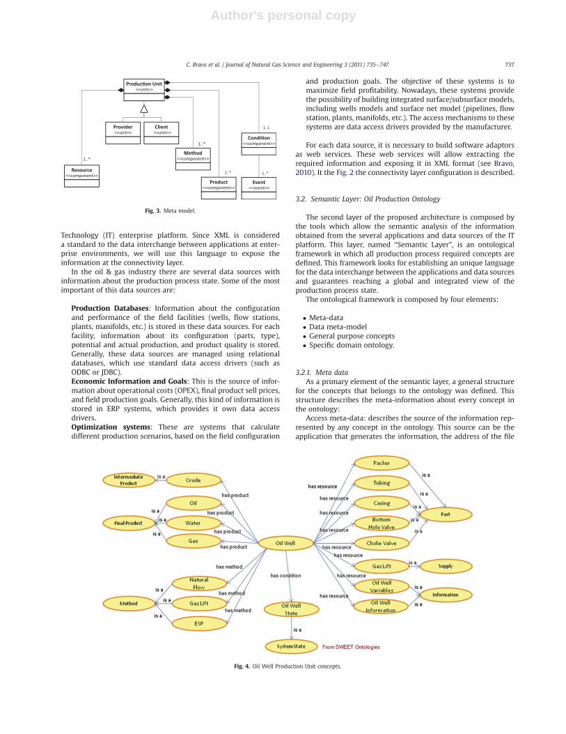
3.2.3. Meta-modelThe meta-model is a common structure used to describe each
one of the business objects in the Enterprise, over the IT platform.The meta-model has the Production Unit as a center. The produc-tion unit is the main element at a continuous production enter-prise. A production unit is any facility at the enterprise thatgenerates a product (intermediate or final), through the application
Fig. 5. Production Management Performative Structure.
C. Bravo et al. / Journal of Natural Gas Science and Engineering 3 (2011) 735e747738

Author's personal copy
of a method and by the use of a specific quantity of resources(energy, supplies, etc). The production unit aims to a productiongoal and attends to a set of constraints, which are established byenterprise’s upper levels. Also, the production unit generatesinformation about it state, for monitoring purposes. Finally, theproduction unit produces (in addition to the generated products)wastes which should be properlymanaged in order to minimize theenvironmental impact (Chacón, 2001).
The meta-model has as objective representing all productionunits through a generic schema. The meta-model is an adaptationof PROSA Model (Wyns, 1999), which represents the productionunit by three main elements: Products, Resources and Orders.Also, a reference of PRODML (POSC, 2006) is taken to complementthe data meta-model. As a result, a production model is obtained,which is composed by the following elements: Resources, Prod-ucts, Methods, Condition, Providers and Clients. The meta-modelaims to reduce the complexity of the ontological framework,making easier the implementation of the enterprise ontologythrough a generic structure for the concepts related with theproduction process. The meta-model concepts are exposed in theFig. 3 (Bravo, 2010).
The meta-model defines a common schema for the conceptsrelated to the production units of the enterprise. This schema isbased in the approach of the “holonic” architectures (Wyns, 1999),inwhich every production unit is composed by Products, Resourcesand Orders, and are named as “holons”. In this kind of architectures,all production units, from the simplest (e.g. an instrument) to themost complex (e.g. the whole enterprise) is represented asa “holon”, establishing a generic structure for the enterpriseelements representation.
In this work the concept of “holon” has been used, adapting it todefine a structure for the oil production units. Also, some conceptsused in PRODML schema, like events and condition, have beenadded to the meta-model. In this sense, the data meta-model iscomposed by the Production Unit as central element, which hasassociated “Resources” required to produce “Products”, and whichare provided by “Providers”. Also, a Production Unit has “Methods”which defines the procedures to develop the production process.The Production Unit delivers its products to “Clients” and hasa “Condition” which defines its state in every instant. In the nextfigure the structure of a production unit is described.
3.2.4. Specific domain conceptsEvery Enterprise has a set of specific concepts to describe its
production process. To represent these concepts within theontology the Specific Domain Concepts are defined. These conceptsare instances of the data meta-model, i.e., the structure of everyspecific domain concept must be the defined in the data meta-model.
Within the specific domain concepts must be defined theproduction units, resources, products, conditions and methods ofthe Enterprise.
Such this work is about an implementation of IPMA to the oilproduction process, in the semantic layer we will define the mostimportant concepts of the oil production domain. These conceptscomprise an ontology called “Oil Production Ontology”, which isbased in the proposal made in (Bravo, 2010).
The Oil Production Ontology is composed by the specific domainconcepts defined for the semantic layer, which are based on theDATA META-MODEL and use concepts from the general purposeontologies.
Following the approach presented in (Soma et al., 2008), thegeneral purpose concepts to use in the semantic layer will be theconcepts proposed in the Semantic Web for Earth and Environ-mental Terminology (SWEET) developed by the California Instituteof Technology Jet Propulsion Laboratory and the NASA (NASA,CalTech, 2009). These concepts will be the base to the Oil Produc-tion Ontology construction. The concepts of the SWEET Ontologyused to build the Oil Production Ontology are (see details at Bravo,2010): Temporal Entity, in which notions about time measure unitsare defined, System States, in which possible systems states aredefined, and Infrastructure, which defines concepts about facilitiesand equipments used in production environments.
The Oil Production Ontology has as central concepts the defi-nition of the production units that can be found in an oil field, suchas: oil well, flow station, manifold, plant; therefore the firstconcepts to define at the ontology are related with these produc-tion units.
The rest of the concepts of the ontology are defined around thedefinition of these production units. All concepts are structuredfollowing the DATA META-MODEL. In order to give an example ofthe structure for Oil Production Ontology concepts, Fig. 4 shownsome of the Oil Well Production Unit concepts.
Fig. 6. Oil Field MAS.
C. Bravo et al. / Journal of Natural Gas Science and Engineering 3 (2011) 735e747 739

Author's personal copy
3.3. Management layer: e-OilFieldInstitution
The management layer IPMA is based on an Electronic Institu-tion (EI), whichwill be called as e-OilFieldInstitution. This El has theobjective of automate the workflows involve in the oil productionprocess.
The purpose of oil production management is controlling theoperations to obtain the maximum economic recovery from thefield, base on data, information and knowledge. The productionmanagement process requires establishing objectives, defininga strategy, developing a plan, implementing and monitoring thatplan and evaluating the results (Saputelli et al., 2003). The e-Oil-FieldInstitution is defined to automate the productionmanagementworkflows which are executed to reach the oil field goals, usingelectronic institutions as a mean.
An EI is a specialization of multi-agent systems that aims toemulate the social institutions operation, in which actors haveautonomy but their behavior is regulated by a set of social rules thatguarantee reaching theobjectiveof the institution (Estevaetal., 2001;Noriega and Sierra, 2002; Sierra, 2004; García-Camino et al., 2005).
An EI is composed by a Dialogical Framework, which defines theroles that EI actors could develop and valid speech acts for thecommunication between them; an Performative Structure, whichdefines the set of scenes that could take place in the institution; anda set of Social Norms, which allow to regulate the behavior of theactors in the institution (Esteva et al., 2001). A detail description ofthe e-OilFieldInstitution components is presented bellow.
3.3.1. Dialogical FrameworkThe Dialogical Framework of an EI is defined as an ordered list of
elements or tuple:
DF ¼ (O;L;I;RI;RE;Rs)
Which is composed by the ontology (O) to use in the institution,the language (L) used to the communication between actors(agents), the valid speech acts or ilocutory particules (I), the rolesthat actors could develop, which are categorized as Internal Roles(RI) that regulate the institution, and External Roles (RE); andfinally, the relationship between roles (Rs).
For the architecture proposed in this work the DialogicalFramework components are:
O: OilProductionOntology (defined in previous sections);L: OWL (Ontology Web Language);I: {agree, failure, inform, inform-done, inform-results, promise,query, refuse, request, open, close}.RI: {Production Manager};RE: {Producer, Provider, Client, Optimizer, Maintenance};
The notion of role is fundamental on the EI’s specification. Rolesallow to abstract individuals (agents) involve in the activities of anEI. An agent has the obligation to adopt a role to belong to an EI.When an agent is developing a specific role, this should accomplishthe behavior pattern of this role. In consequence, all agents thatadopt the same role have the same rights, duties and opportunities.A role could be defined as a finite set of dialogical actions. Theobjective of these actions is representing the role capacities (Estevaet al., 2001).
In each scene, agents assume specific roles, which have definedbehaviors within the EI. This allows agents to develop tasks thataim to assure the EI well function and the accomplishment of the EIobjectives.
In the e-OilFieldInstitution the following roles are defined:
Production Manager: is the institution regulator. ProductionManager is responsible for the programming and supervision ofproduction execution. Also, Production Manager guarantees theaccomplishment of the production goal.Producer: a production process is executed by one or severalproduction units. Producer role is defined to control theseproduction units, managing the production rate and theresource consuming of each unit.Provider: a production unit requires several providers thatsupply the necessary resources to execute the productionprocess. To do that, a Provider role is defined within theinstitution.Client: production units have clients, which are the finalreceptors of the products generated for these units. Theproduction goal is established in order of the client
Fig. 7. Virtual oil field structure.
C. Bravo et al. / Journal of Natural Gas Science and Engineering 3 (2011) 735e747740

Author's personal copy
requirements. To represents these actors within the institution,a Client role is defined.Optimizer: the institution objective is to reach the productiongoal based on optimal criteria defined for each enterprise. Inorder to reach the optimal way to execute the productionprocess, an Optimizer role is defined. The Optimizer will executethe optimization models to define the institution productionprogram.Maintenance: this role will be in charge of developing main-tenance tasks for the production units of the institution.
Some of these roles are internal roles (Production Manager),which are the institution regulators, and the other ones are externalroles, which are developed by actors that participate in the insti-tution, but don’t have any regulatory function at it. Likewise,depending of the role type, this could be developed by one orseveral agents. In the e-OilFieldInstituion, the Production Managershould be developed by only one agent, such as it must be only oneinstitution regulator. The rest of the roles could be developed forseveral agents at the same time.
3.3.2. Performative structureThe performative structure of an electronic institution defines
the set of scenes and transitions in which dialogical activitiesbetween agents are developed. The main performative structure ofe-OilFieldInstitution is called “Production Management Performa-tive Structure (PMPS)”. The PMPS is defined as a tuple:
EPGP ¼�S; T; s0; sU; E; fL; fT; fOE ; C; ML; m
�
Where,S: set of scenes ¼ {Start (S), Production Programming (PP),
Production Execution (PE), End (E)}T: set of transitions ¼ {Programming Start (PS), Execution Start
(ES), New Programming Request (NPR), New Programming (NP),Production End (PE)}
s0: initial scene ¼ I;sU: final scene ¼ E;E: set of arcs ¼ EI U EO
On Fig. 5 the performative structure developed for themanagement layer is shown.
Scenes define the dialogical activities between agents throughinteraction protocols described as state machines. When theinteraction protocols are too complex, a scene could be described asa sub-performative structure, which has scenes and transitionsinside. The PMPS has four scenes:
Start: initial scene. In this scene all agents that participate at thee-OilFieldInstitution should enter.Production Program: in this scene the optimal productionscenario is calculated. This scene is described as a sub-performative structure that has the following scenes:
Start: Field Manager, Producer and Provider agents enter tothe production program performative structure.Information Search: in this scene Field Manager Agentgathers information about the state, requirements andcapacities of all producers, providers and clients, in order todesign the production program. This scene is described bya request interaction protocol (FIPA, 2005e2011).Production Quotes Calculation: in this scene the Field Opti-mizer Agent calculates the optimal production scenariobased on the information gathered by the Field ManagerAgent. Once individual production goals and energy quotesare calculated, Field Optimizer Agent informs to the FieldManager Agent the optimal scenario.End: agents leave the production program performativestructure.
Production Execution: in this scene the production program isexecuted, based on the optimal scenario calculated in theprevious scene. This scene is described as a sub-performativestructure that has four scenes:
Start: Field Manager, Producer, Provider, Client and Mainte-nance agents enter to the production execution performativestructure.Production: in this scene the Field Manager Agent gives tothe producer and provider agents the order of execute theproduction program. Once the production execution starts,Field Manager Agentmonitors the process in order to react incase of any abnormal situation occurs.Maintenance: in this scene Field Maintenance Agent receivesmaintenance request from producer and providers agentsthat come from Production with failure states. This scene isdescribed by a request interaction protocol.End: agents leave the production execution performativestructure.
In case of changes in the production goals or operational eventsoccurs, agents could return to the Production Program scene inorder to re-calculate the production scenario.
End: production execution final. All agents leave the e-OilFieldInstitution.
All agents’ interactions at the institution are regulated by theperformative structures, scenes and transitions described above. In
Fig. 8. Differential pressure per each well. Scenario 1.
C. Bravo et al. / Journal of Natural Gas Science and Engineering 3 (2011) 735e747 741

Author's personal copy
this sense, the enterprise workflows are represented by theseperformative structures, and automated by the agents’ activity inthe electronic institution. Each agent could have intelligent mech-anisms to act, also as reactivity, proactivity, mobility, socialbehavior and even autonomy, but it actions are bounded by theprotocols defined at the performative structures and by socialnorms (described in the next section), in order to guarantee thesuccess of the institution.
3.3.3. Social normsNorms allow imposing social linked rules to the agents, which
restrict them behavior in order to reach the institution objective. Inour case, norms will allow to reach a production program ina specific time, assigning optimal production quotes and resourcesquantities, processing maintenance task in an obligated way, andreacting to failures in a secure and planned way.
An example of norms defined for e-OilFieldInstitution is thenorm that regulates the time to access information from theprovider role. This norm is described as follow:
3.3.3.1. Access to provider information. With this norm a time limitis established to Provider deliver information about it state, whichis requested by the Production Manager at Information Searchscene. The norm has the following structure:
OBLIGED (utter (InformationSearch, ProviderIR, inform-results(?ES,Provider, ?FM, AssetManager, Information)) BEFORE tmax)
The norm meaning is:
Scene: Information SearchState: Provider Information GatheringIllocution (speech act): Inform ResultsSender: ProviderReceiver: Production ManagerContent: Provider State InformationObligation: to deliver the ilocution before a time “tmax” (where“tmax” is a customizable parameter)
Three additional norms were defined with the same structure ofthe norm described above (see Bravo, 2010). These norms weredesigned to establish time limits to the following tasks: accessinginformation from the Producer, calculation of the optimal produc-tion quotes, and executing production.
3.3.4. Oil field multi-agent systemIn order to accomplish the roles defined at the dialogical
framework, a set of oil production domain agents were designed.These agents are the components of a multi-agent system (MAS)called as “Oil Field MAS”.
Agents of the Oil Field MAS are categorized as Production UnitsAgents and Service Agents. Components of the Oil Field MAS areshown in Fig. 6.
3.3.4.1. Production unit agents. This kind of agents represents theproduction units that compose the oil field. These agents are incharge of the production units’ information management andcontrol. These agents can take the following roles in the institution:Producer, Provider and Client.
Production Unit Agents have a common structure that definestheir objectives, services, capacities, and restrictions. This struc-ture is based on the MASINA model presented at (Aguilar et al.,2008).
Each agent defined for a production unit has correspondencewith the definition of that production unit at the Oil ProductionOntology. In this sense, the agent attributes have correspondencewith the concepts defined at the ontology. The production unit’agents defined in the Oil Field MAS are listed below.
� Oil Well Agent: controls the oil wells operations at the field.This agent has a correspondence with the oil well conceptdefined in the Oil Production Ontology.
� Flow Station Agent: controls the flow stations operation at thefield. This agent has a correspondence with the flow stationconcept defined in the Oil Production Ontology.
Fig. 9. Interaction between agents Scenario 1.
C. Bravo et al. / Journal of Natural Gas Science and Engineering 3 (2011) 735e747742
Author's personal copy
� Energy Supplier Agent: controls the energy generationplants operation at the field. This agent has a correspon-dence with the plant concept defined in the Oil ProductionOntology.
3.3.4.2. Service agents. These agents provide services to the oil fieldproduction units. There are three types of service agents:
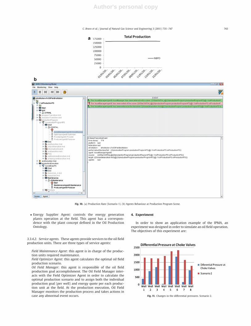
Field Maintenance Agent: this agent is in charge of the produc-tion units required maintenance.Field Optimizer Agent: this agent calculates the optimal oil fieldproduction scenario.Oil Field Manager: this agent is responsible of the oil fieldproduction goal accomplishment. The Oil Field Manager inter-acts with the Field Optimizer Agent in order to calculate theoptimal production scenario and to assign both the individualproduction goal (per well) and energy quote per each produc-tion unit at the field. At the production execution, Oil FieldManager monitors the production process and takes actions incase any abnormal event occurs.
4. Experiment
In order to show an application example of the IPMA, anexperimentwas designed in order to simulate an oil field operation.The objectives of this experiment are:
Fig. 11. Changes in the differential pressures. Scenario 2.
Fig. 10. (a) Production Rate (Scenario 1). (b) Agents Behaviour at Production Program Scene.
C. Bravo et al. / Journal of Natural Gas Science and Engineering 3 (2011) 735e747 743

Author's personal copy
� To demonstrate the well function of the IPMA through itimplementation to the oil production process optimizationproblem.
� To validate the reactive behavior of the electronic institutionimplemented at the management layer, when changes in theoperational conditions occurs.
� To validate the layers integration at the experiment execution.� To validate the well function of the ontology as communicationelement in the architecture.
A virtual oilfield, based on a commercial integrated productionmodel (IPM) and history matched data, was used to show thebenefits of the proposed approach. The process selected to run theexperiment was an oil field with the following configuration: 3reservoir, 8 oil wells, and 1 flow station (see Fig. 7).
In order to resolve the production optimization problem in anoil field with the schema presented above, we will make anapplication of IPMA.
The oil field optimization problem could be described as follow:
a
b
Fig. 12. Agents Interaction for Production Rate Adjustment (Scenario 2). Production Rate Adjustment (Scenario 2).
C. Bravo et al. / Journal of Natural Gas Science and Engineering 3 (2011) 735e747744

Author's personal copy
4.1. Objective function
Reach the production goal. The production goal is set at 159,000BPD.
Constraints:
� Maximum field production: 160,000 BPD� Maximum Production Well 1: 24,000 BPD� Maximum Production Well 2: 20,000 BPD� Maximum Production Well 3: 10,000 BPD� Maximum Production Well 4: 28,000 BPD� Maximum Production Well 5: 20,000 BPD� Maximum Production Well 6: 10,000 BPD� Maximum Production Well 7: 30,000 BPD� Maximum Production Well 8: 18,000 BPD� Numbers of Separators: 3� Separation Capacity per separator: 60,000 BPD
Experiment’s manipulated variables are the production goal andthe choke valves opening rate per each well.
A simulation for a field with the configuration described abovewas executed using a commercial simulator program, taking asinitial date 01/01/2010 and as final date 01/02/2010, having a day assample interval. Data gather for the simulator was stored in excelsheets, which served as data sources for the experiment. A set ofSW adaptors based on POI library (Apache, 2006) were used togather the data generated by the simulator.
EIDE suite (IIIA-CSIC, 2006e2009) was used to the ElectronicInstitution implementation. This suite is composed by tools that
allow designing, validating and executing an electronic institu-tion. The semantic layer is composed by a sub-set of conceptsdefined in the Oil Production Ontology, which are coding as Javaclasses.
At the management layer was implemented the e-Oil-FieldInstitution, composed by the Oil Field MAS with the followingconfiguration:
� 1 Oil Well Agent performing Producer role, which will controlthe eight oil Wells of the field.
� 1 Flow Station Agent performing Client role.� 1 Field Optimizer Agent performing Optimizer role.� 1 Field Maintenance Agent performing Maintenance role.
Fig. 13. Adjustment at differential pressure for Scenario 3.
c
Fig. 12. Agents Interaction (Scenario 3).
C. Bravo et al. / Journal of Natural Gas Science and Engineering 3 (2011) 735e747 745

Author's personal copy
� 1 Field Manager Agent performing Production Manager role.
IE’s agents were in charge of obtaining the asset stateinformation, from several data sources (specified in previoussections). Based on the asset state and on the productiongoals, the Field Manager Agent requests to the Field OptimizerAgent to calculate the system configuration at optimal condi-tions, establishing the production and energy quotes per eachwell. In order of the results obtained from the Field OptimizerAgent, the Field Manager Agent could decide to changethe asset configuration, through modifications of handledvariables.
4.2. Simulations and results
Three field situations (scenarios) were simulated through theIPMA:
1. The experiment begins with a production goal of 159,000 BPDto the field and a separation capacity of 50,000 BPD for eachseparator at the Flow Station.
2. Then, the production goal is modified to 120,000 BPD, in orderto observe the IPMA reaction to this event.
3. Finally, well 8 is stopped in order to generate a new scenario.
Scenario 1: Initial goal is reached by FieldManager Agent settingthe opening of the choke valves per each well (through Well Agentaction) at a certain percentage, which generates a set of differentialpressure rates for each well, as is shown in the Fig. 8.
The interaction between the agents is shown through theinteraction diagram described in Fig. 9.
Total production rate for this configuration is shown in Fig. 10.Scenario 2: At sample instant #15 (day 01/15/10), Field Manager
Agent receives an order to change the production goal to 120,000BPD. Field Manager Agent and Producer Agent move themselves tothe Production Program scene (see Fig. 11). At that scene a newproduction scenario is calculated, in order to reach the newproduction goal. Once Production Program scene is finished, theagents go the Execution Program scene, which will function withthe configuration defined for the new scenario.
The interaction between the agents in this new scenario isshown through the interaction diagram described in Fig. 12.
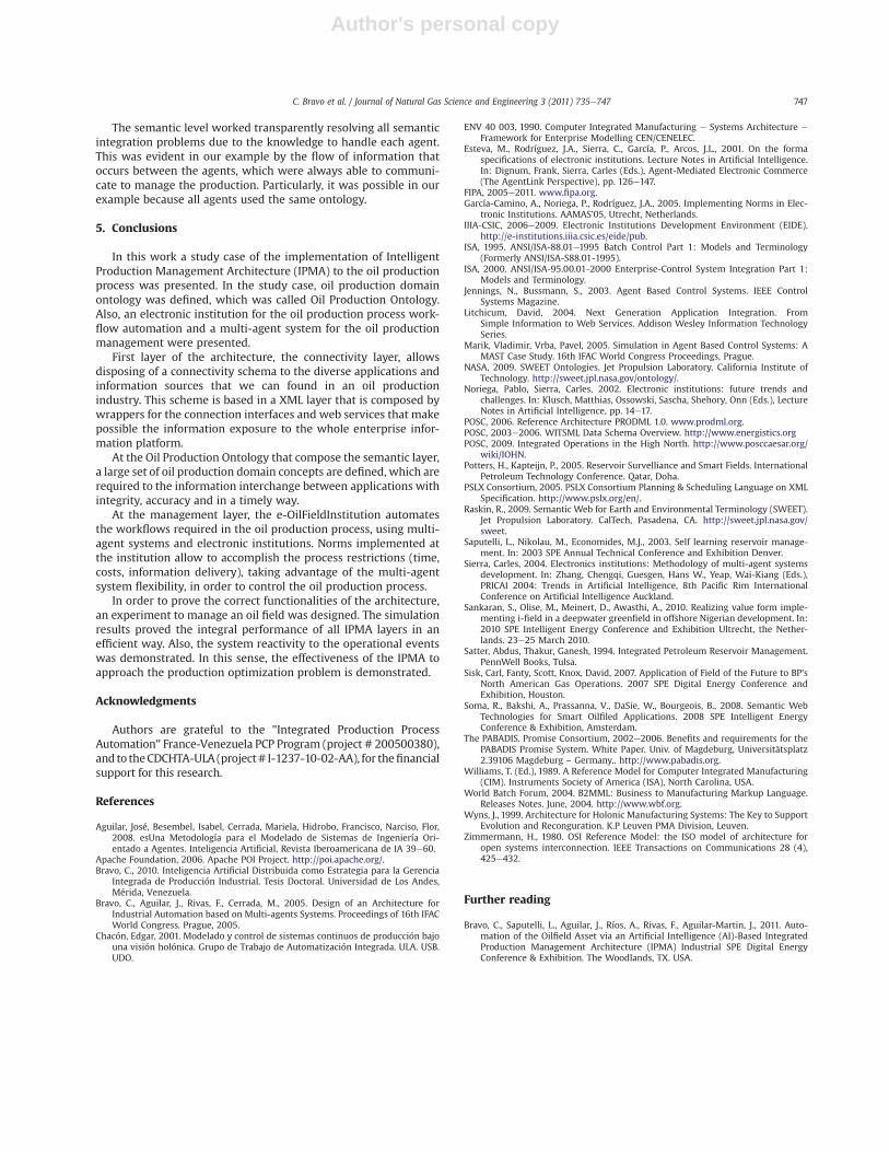
The new scenario set an adjustment for the opening of the oilwells choke valves (through Producer Agent), and in consequencean adjustment in the differential pressure per each well is gener-ated, as is show in the Fig. 13.
As is shown in the Fig. 11, increasing in the differential pressureat each choke valve are generated. This is the result of the changesin the valves opening rate. As a consequence, the production of thefield is changed to 120,000 BPD (see Fig. 14).
Scenario 3: At sample instant #25 (day 01/25/10), well 8 isstopped. A production re-programming is suited, in order to adjustthe production rates of the remaining wells to maintain theproduction of the field as close as possible of the production goal.
The interaction between the agents in this new scenario isshown through the interaction diagram described in Fig. 12.
In Fig.13 is shown the adjustment in the differential pressure foreach well. We can see the total loss of the pressure inwell 8 and thedecrease in the differential pressure for the wells 1, 2, 3, 5, 6, and 7,in order to compensate the production loss from well 8. To do thisa new Production Program is executed to re-define the productionscenario and then a new Production Execution scene starts with thenew configuration.
As we can see in Fig.14, as a consequence of the changesmade atthe field configuration by the IPMA e-OilFieldInstitution, theproduction rate is maintained at the production goal.
In Fig. 15 we can see how the rest of the wells compensate theproduction loss from well 8.
4.3. Analysis of results
As it was shown at the simulation and results section, theimplementation of IPMA was effective in accomplishing theobjectives for the experiment, which were maintaining theproduction goal under different production scenarios. The objectiveis reached using the three layers of the architecture.
When operational events occurred (change in the productiongoal and/or well 8 stopped), IPMA reacted effectively, doing thenecessary changes in the field configuration to reach the produc-tion goal. This behavior demonstrates the reactive capacity of thearchitecture.
State process data gathering and the monitoring of the processinformation in real time was possible thanks to the connectivitylayer, which allow accessing to the several information sourcesusing the software adaptors developed for this layer. Likewise, thesemantic layer was useful to guarantee the effective communica-tion between the agents during the process execution. The OilProduction Ontology provided the necessary concepts to theinformation interchanging at the production process. Finally, themanagement layer worked as an intelligent workflow automationtool, through the e-OilFieldInstitution implementation.
Fig. 15. Production per Well Scenario 3.
Fig. 14. Field Production Scenario 3.
C. Bravo et al. / Journal of Natural Gas Science and Engineering 3 (2011) 735e747746
Author's personal copy
The semantic level worked transparently resolving all semanticintegration problems due to the knowledge to handle each agent.This was evident in our example by the flow of information thatoccurs between the agents, which were always able to communi-cate to manage the production. Particularly, it was possible in ourexample because all agents used the same ontology.
5. Conclusions
In this work a study case of the implementation of IntelligentProduction Management Architecture (IPMA) to the oil productionprocess was presented. In the study case, oil production domainontology was defined, which was called Oil Production Ontology.Also, an electronic institution for the oil production process work-flow automation and a multi-agent system for the oil productionmanagement were presented.
First layer of the architecture, the connectivity layer, allowsdisposing of a connectivity schema to the diverse applications andinformation sources that we can found in an oil productionindustry. This scheme is based in a XML layer that is composed bywrappers for the connection interfaces and web services that makepossible the information exposure to the whole enterprise infor-mation platform.
At the Oil Production Ontology that compose the semantic layer,a large set of oil production domain concepts are defined, which arerequired to the information interchange between applications withintegrity, accuracy and in a timely way.
At the management layer, the e-OilFieldInstitution automatesthe workflows required in the oil production process, using multi-agent systems and electronic institutions. Norms implemented atthe institution allow to accomplish the process restrictions (time,costs, information delivery), taking advantage of the multi-agentsystem flexibility, in order to control the oil production process.
In order to prove the correct functionalities of the architecture,an experiment to manage an oil field was designed. The simulationresults proved the integral performance of all IPMA layers in anefficient way. Also, the system reactivity to the operational eventswas demonstrated. In this sense, the effectiveness of the IPMA toapproach the production optimization problem is demonstrated.
Acknowledgments
Authors are grateful to the "Integrated Production ProcessAutomation" France-Venezuela PCP Program (project # 200500380),and to theCDCHTA-ULA (project# I-1237-10-02-AA), for thefinancialsupport for this research.
References
Aguilar, José, Besembel, Isabel, Cerrada, Mariela, Hidrobo, Francisco, Narciso, Flor,2008. esUna Metodología para el Modelado de Sistemas de Ingeniería Ori-entado a Agentes. Inteligencia Artificial, Revista Iberoamericana de IA 39e60.
Apache Foundation, 2006. Apache POI Project. http://poi.apache.org/.Bravo, C., 2010. Inteligencia Artificial Distribuida como Estrategia para la Gerencia
Integrada de Producción Industrial. Tesis Doctoral. Universidad de Los Andes,Mérida, Venezuela.
Bravo, C., Aguilar, J., Rivas, F., Cerrada, M., 2005. Design of an Architecture forIndustrial Automation based on Multi-agents Systems. Proceedings of 16th IFACWorld Congress. Prague, 2005.
Chacón, Edgar, 2001. Modelado y control de sistemas continuos de producción bajouna visión holónica. Grupo de Trabajo de Automatización Integrada. ULA. USB.UDO.
ENV 40 003, 1990. Computer Integrated Manufacturing e Systems Architecture e
Framework for Enterprise Modelling CEN/CENELEC.Esteva, M., Rodríguez, J.A., Sierra, C., García, P., Arcos, J.L., 2001. On the forma
specifications of electronic institutions. Lecture Notes in Artificial Intelligence.In: Dignum, Frank, Sierra, Carles (Eds.), Agent-Mediated Electronic Commerce(The AgentLink Perspective), pp. 126e147.
FIPA, 2005e2011. www.fipa.org.García-Camino, A., Noriega, P., Rodríguez, J.A., 2005. Implementing Norms in Elec-
tronic Institutions. AAMAS’05, Utrecht, Netherlands.IIIA-CSIC, 2006e2009. Electronic Institutions Development Environment (EIDE).
http://e-institutions.iiia.csic.es/eide/pub.ISA, 1995. ANSI/ISA-88.01e1995 Batch Control Part 1: Models and Terminology
(Formerly ANSI/ISA-S88.01-1995).ISA, 2000. ANSI/ISA-95.00.01-2000 Enterprise-Control System Integration Part 1:
Models and Terminology.Jennings, N., Bussmann, S., 2003. Agent Based Control Systems. IEEE Control
Systems Magazine.Litchicum, David, 2004. Next Generation Application Integration. From
Simple Information to Web Services. Addison Wesley Information TechnologySeries.
Marik, Vladimir, Vrba, Pavel, 2005. Simulation in Agent Based Control Systems: AMAST Case Study. 16th IFAC World Congress Proceedings, Prague.
NASA, 2009. SWEET Ontologies. Jet Propulsion Laboratory. California Institute ofTechnology. http://sweet.jpl.nasa.gov/ontology/.
Noriega, Pablo, Sierra, Carles, 2002. Electronic institutions: future trends andchallenges. In: Klusch, Matthias, Ossowski, Sascha, Shehory, Onn (Eds.), LectureNotes in Artificial Intelligence, pp. 14e17.
POSC, 2006. Reference Architecture PRODML 1.0. www.prodml.org.POSC, 2003e2006. WITSML Data Schema Overview. http://www.energistics.orgPOSC, 2009. Integrated Operations in the High North. http://www.posccaesar.org/
wiki/IOHN.Potters, H., Kapteijn, P., 2005. Reservoir Survelliance and Smart Fields. International
Petroleum Technology Conference. Qatar, Doha.PSLX Consortium, 2005. PSLX Consortium Planning & Scheduling Language on XML
Specification. http://www.pslx.org/en/.Raskin, R., 2009. Semantic Web for Earth and Environmental Terminology (SWEET).
Jet Propulsion Laboratory. CalTech, Pasadena, CA. http://sweet.jpl.nasa.gov/sweet.
Saputelli, L., Nikolau, M., Economides, M.J., 2003. Self learning reservoir manage-ment. In: 2003 SPE Annual Technical Conference and Exhibition Denver.
Sierra, Carles, 2004. Electronics institutions: Methodology of multi-agent systemsdevelopment. In: Zhang, Chengqi, Guesgen, Hans W., Yeap, Wai-Kiang (Eds.),PRICAI 2004: Trends in Artificial Intelligence, 8th Pacific Rim InternationalConference on Artificial Intelligence Auckland.
Sankaran, S., Olise, M., Meinert, D., Awasthi, A., 2010. Realizing value form imple-menting i-field in a deepwater greenfield in offshore Nigerian development. In:2010 SPE Intelligent Energy Conference and Exhibition Ultrecht, the Nether-lands. 23e25 March 2010.
Satter, Abdus, Thakur, Ganesh, 1994. Integrated Petroleum Reservoir Management.PennWell Books, Tulsa.
Sisk, Carl, Fanty, Scott, Knox, David, 2007. Application of Field of the Future to BP'sNorth American Gas Operations. 2007 SPE Digital Energy Conference andExhibition, Houston.
Soma, R., Bakshi, A., Prassanna, V., DaSie, W., Bourgeois, B., 2008. Semantic WebTechnologies for Smart Oilfiled Applications. 2008 SPE Intelligent EnergyConference & Exhibition, Amsterdam.
The PABADIS. Promise Consortium, 2002e2006. Benefits and requirements for thePABADIS Promise System. White Paper. Univ. of Magdeburg, Universitätsplatz2.39106 Magdeburg – Germany.. http://www.pabadis.org.
Williams, T. (Ed.), 1989. A Reference Model for Computer Integrated Manufacturing(CIM). Instruments Society of America (ISA), North Carolina, USA.
World Batch Forum, 2004. B2MML: Business to Manufacturing Markup Language.Releases Notes. June, 2004. http://www.wbf.org.
Wyns, J., 1999. Architecture for Holonic Manufacturing Systems: The Key to SupportEvolution and Reconguration. K.P Leuven PMA Division, Leuven.
Zimmermann, H., 1980. OSI Reference Model: the ISO model of architecture foropen systems interconnection. IEEE Transactions on Communications 28 (4),425e432.
Further reading
Bravo, C., Saputelli, L., Aguilar, J., Ríos, A., Rivas, F., Aguilar-Martin, J., 2011. Auto-mation of the Oilfield Asset via an Artificial Intelligence (AI)-Based IntegratedProduction Management Architecture (IPMA) Industrial SPE Digital EnergyConference & Exhibition. The Woodlands, TX. USA.
C. Bravo et al. / Journal of Natural Gas Science and Engineering 3 (2011) 735e747 747