American.,(i Woodworker - Wood Tools
67
-
Upload
khangminh22 -
Category
Documents
-
view
1 -
download
0
Transcript of American.,(i Woodworker - Wood Tools

Doug
Text Box
WhereWeShare.com

American.,(i Woodworker
#140, February/March 2009
Features 36 Router Bit Caddy
Separate, sort and see your collection.
39 NEW! Build Your Skills Tambour Door Breadbox Flexible doors are now much easier to
make using a set of ingenious router bits.
49 Weekend Picture Frames Create extraordinary frames with
ordinary router bits.
54 Next-Generation Router Table Make more accurate cuts with a fiat,
solid-surface top.
62 NEW! American Masterworks Shaker Blanket Chest Having a top-notch dovetail jig'
really pays off.
72 Aged Cherry Finish Wipe on years of age in
a few easy steps.
74 Fast-and-Easy Drawer Boxes A unique router table, with two machines,
does the trick.

Departments 8 Workshop Tips
Store router bits on a router table, organize sandpa
per in an index-card box, build a turntable for finish
ing, add height-adjustment to sawhorses, make a jig
for marking dozens of dovetails, build a jig for plan
ing square edges, prevent your vise from racking,
burnish purpleheart to look like rosewood, and use
real parts to label part bins.
12 NEW! Thrifty Woodworker Recycle mop pads into vise faces, make a sandpaper
shoulder plane, rout dowels from square stock, store
glue in a soap bottle, hook up dust collection using a
pool noodle, and make jig knobs from bottle caps.
14 Well-Equipped Shop Infinity Lapped Miter Joint Router Bit Set,
Professional Coping Sled and 2-Piece 15° Shaker
Matched Rail and Stile Set; Betterley Stacc-Vac Router
Base; CMT Bowl and Tray Kit; Festool MFK 700 EQ
Trim Router Set and Kapex KS 120 Sliding Compound
Miter Saw; Freud Quadra-Cut router bits, Premier
Solid Carbide Bits and Double Grind Straight Bits;
Amana In-Tech Series Replaceable Knife Router Bits
and In-Groove Insert Engraving Bits, Makita Laminate
Trimmer, Veritas NX60 Premium and DX60 Block
Planes; and Micro Fence Micro Bit Kit.
20 Tool Nut The Carter Electric Plane helps revive an old Stanley
dome-top router.
22 My Shop A college student's first shop fills his parent's garage.
24 Tool Talk Porter-Cable's Omnijig Joinery System
An innovative jig makes routing dovetails a pleasure.
28 School News WoodLiNKS
An ambitious nonprofit connects woods hop
students to industry.
31 NEW! A Great American Woodworker Peter H. Wallace masters the art of
Windsor chairmaking.
82 Oops! A magnifying glass and a bright sun
melt a scroll saw.
4 www.AmericanWoodworker.com FEB R U A R Y I MAR C H20 0 9

M~!~LUMBER & SAVE MONEY
8 Sawmill Models
Available
A:m.erican~ Woodworker
EDITORIAL
Editorial Director Randy Johnson
Editor Tom Caspar
Associate Editor Tim Johnson
Contributing Editors Lonnie Bird John English Brad Holden Bruce Kieffer Alan Lacer Dave Munkittrick David Radtke
Office Administrator Shelly Jacobsen
ART & DESIGN
Creative Director Vern Johnson
Director of Photography Jason Zentner
Design Consultants Impress, Inc.
Category President/Publisher Carol Lasseter
Advertising Director Brian Ziff
Classified Advertising Manager Susan Tauster
Vice President/Production Derek W. Corson
Production Coordinator Michael J. Rueckwald
Ad Production Coordinator Kristin N. Beaudoin
Systems Engineer Denise Donnarumma
V.P. Consumer Marketing Dennis O'Brien
Circulation Steve Pippin Adrienne Roma Susan Sidler Dominic M. Taormina
Director E-Media Steve Singer
ADVERTISING SALES
1285 Corporate Center Drive, Suite 180, Eagan, MN 55121 Brian Ziff, [email protected]
office (860) 417-2275, cell (203) 509-0125, fax (B60) 41 7-2275 Classified Advertising Manager - Susan Tauster,
[email protected] office (630) 858-155B,cell (630) 336-0916, fax (630) 85B- 1510
NEW TRACK MEDIA LLC
Chief Executive Officer Stephen J. Kent Executive Vice President/CFO Mark F. Arnett
Vice President/Publishing Director Joel P. Toner
Issue #140. American Woodworke r®, ISSN 1074-9152, USPS 738-710 Published bimonth ly by Woodworking Media, LLC, 90 Sherman St., Cambridge, MA 02140. Periodicals postage paid at Boston, MA and additional mailing offices. Postmaster: Send change of address notice to American Woodworke~, P.O. Box 420235, Palm Coast, FL 32142-0235. Subscription rates: US. one-year, $24.98. Single-copy, $5.99. Canada one-year, $29.98. Single-copy $6.99 (U.s. Funds); GST # R1 2298861 1. Foreign surface one-year, $29.98 (U.s. Funds). u.s. newsstand distribution by Curtis Circulation Company, LLC, New Milford, NJ 07646. Canada Post Publications Mail Agreement Number 41525524. Canada Postmaster: Send address chang es to: American Woodworker, PO Box 456, Niagara Falls, ON UE 6V2. Send returns and address changes to American Woodworkere, P.O. Box 420235, Palm Coast, FL 32142-0235. Printed in USA. e 2008 New Track Media LLC. All rights reserved.
American Woodworlrer may share information about you with reputable companies in order forthem to offer you products and services of interest to you. If you would rather we not share information, please write to us at: American Woodworker,Customer Service Department, P.O. Box 420235, Palm Coast, FL 32142'()235.Please include a copy of your address label.
Subscribers: If the Post Office alerts us that your magazine is undeliverable, we have no further obligation unless we receive a corrected address within one year.
Comments & Suggestions Write to us at American Woodworker, 1285 Corporate
Center Drive,Suite 180, Eagan, MN 55121. (952) 948-5890,
fax (952) 948-5895, e-mail [email protected].
Subscriptions American Woodworker Subscriber Service Dept.
P.O. Box 420235, Palm Coast, FL 32142-0235, (800) 666-31 1 1, e-mail [email protected]
Back Issues Some are available for $6.99 each, plus shipping and handling. Order from the Reprint Center at www.americanwoodworker.com/backissue.

From the Editor's Deslt
In the Groove A ROUTER'S ABILITY to cut, shape, carve and drill makes it one of woodworking's most versatile tools. Its usefulness continues to expand, as evidenced by the large number of
new accessories, bits and jigs that come to market every year. And its popularity is underscored by manufacturers' ongoing efforts to improve the machine itself.
This issue of American
Woodworker is our 10th annual Router Special. There's never been a shortage of "new and improved" router items to write about, and this year is no exception. We've included several of our favorites in "Well
Equipped Shop" (see page 14), such as Freud's expanded line of QuadraCut bits, with patented up and down shear cutters that help eliminate
tearout and fuzz on even the toughest woods. We also cover Festool's new MFK 700 EQ trim router, Infinity's professional router table coping sled, CMT's bowl and tray bit set, and many more.
Porter-Cable's all-new Omnijig Joinery System is a major entry in this year's field of dovetail jigs (see page 24). We all aspire to mastering dovetail joints-either by hand or machine, because they add beauty and strength to any project. The "Shaker Blanket Chest" (see page 62)
turned out to be a perfect piece to put the new Omnijig through its
paces. Capable of routing through, half-blind, fixed and variably spaced dovetails, Porter-Cable went all out
to mClke this new Omnijig accurate and easy to use.
Making a tambour door is another woodworking technique that holds a similar attraction. If you've ever built a roll-top desk, you know
the sense of accomplishment that you feel after completing the tambour. Traditionally, tambour doors were created by gluing strips of
wood to a piece of canvas. But now you can complete the job with a router. Amana's ingenious new tambour door router bit set creates tambour sections that go together with interlocking joints, so you can skip the canvas and glue. Master woodworker Lonnie Bird shows us how it's done with his "Tambour-Door Breadbox" on page 39.
If you're looking for ways to improve your routing skills, learn a few new tricks or turn out some
nice small projects, see "Fast-andEasy Drawer Boxes" on page 74 and "Weekend Picture Frames" on page 49.
Of course, our Router Special issue wouldn't be complete with out
something for your router table. This time, it's the whole table! John English's "Next-Generation Roy,ter Table" incorporates a host of useful features, including a solid-surface tabletop (see page S4).John also
provides a bonus project with his "Router Bit Caddy" on page 36. Fill this one up with router bits and you'll really be "in the groove."
Keep the chips flying,
q~if9L-Randy Johnson
FEB R U A R Y I MAR C H20 09 · www.Am.ericanWoodworker.com 7

Workshop Tips
Router Bit Nest WATCHING AN EXPENSIVE router bit roll onto the floor is a heartbreaking experience. In the middle of a project, it can be a disaster. I drilled a few 1/2" and 1/4" holes in the edge of a piece of MDF and fastened it to
Clever Ideas From Our Readers
the back of my router table's fence. In this nest, I keep all the bits I'm using for a particular project at my fingertips without worrying about having them roll off the table.
-Serge Due/os
Finishing Turntable . .............................. . My finishing turntable is perfect for spraying large parts or projects. To make the device, I mounted five fixed 3-1/2" casters on a plywood panel. They're equally spaced in a 16" diameter circle. Fixed casters
won't pivot, so the project rotates around its center. I placed 3" blocks in front of the casters to keep them from getting clogged with finish.
-Mark Thiel
Terrific Tips Win Terrific Tools! We'll give you $100 for every original workshop tip we publish. We'll choose one Terrific Tip for each issue.
The Terrific Tip winner receives a 12" Leigh Super Jig with VRS (Vacuum and Router Support), a $239 value.
E-mail your t ip [email protected] orsend it toAmericanWoodworkerWorkshop Tips.1 285CorporateCenter Drive. Suite 180, Eagan, MN 55 121 . Submissions can't be returned and become our property upon acceptance and payment. We may edit submissions and use them in all print and elect ronic media.
8 www.AmericanWoodworker.com FEB R U A R Y I MAR C H 2 0 0 9

AdjustableHeight Table THERE'S NO SINGLE SURFACE in my shop that's the ideal height for every job. With my adjustable-height saWhorses, I can quickly set up an outfeed table, drawing table, or assembly table at different heights as the need arises.
My sawhorses are the folding, galvanized-metal kind, but any type will do. Cut 2x4's to fit on the sawhorse's top surfaces. Make a 3/4" wide x 3/4" deep groove down the center of each 2x4. Fine-tune the groove's width so that a 3/4" thick piece of plywood will fit snugly. Then, screw the 2x4s to the sawhorses. Cut 3/4" plywood inserts to raise or lower the tabletop to whatever height you need. -Craig Kortz
Pin Board Marking Jig . ....................... . My task: 28 kitchen drawers of different sizes, all with hand-cut dovetails. The thought of laying these out was overwhelming, so I designed a jig to simplify the process. To make the jig, carefully layout and cut a piece of 1/4" hardboard as if it were the pin board for the tallest drawer. Glue and nail the hardboard to a 3/4" plywood backer. Fasten a stop on each side.
Place an actual pin board into
\'~.m" ALUMINUM ANGLE
the jig with the outside face against the backer board and one side against either stop. Clamp the whole thing into a vise and use a chisel to mark the end grain, defining the pins. Scribe a depth line, and use a square to mark saw lines and cut the dovetails as usual. Since my drawer heights and my dovetail spacing were in 1/2" increments, the jig worked for all the drawers.
-Bob Edenhofer
Perfectly Square Edges Using a Planer I'VE HAD TROUBLE making square and smooth edges on face frame parts, but this planer j ig solved all my problems. It produces accurate and consistent results. For the jig's base, cut T-slots in a 3/4" x 11 " board that's a little bit longer than the planer's bed and extension tables. Use T-bolts and wing nuts to fasten two 1-1 /2" x 1-1 / 2" aluminum angles to the jig. Adjust the angles to fit tight around your board. Clamp the jig to the planer's bed, then feed your stock between the angles. Use smaller or larger angles for different widths of stock, being careful to ensure your planer knives come nowhere near the angles' top edges. -Doug/as MacKay
FEB R UA RY I MA RC H 2 009 www.AmericanWoodworker.com 9

Workshop Tips continued
No-Rack Vise A WORKPIECE ALWAYS SLIPS
when placed vertically in my vise, because the vise racks. To solve the problem, I made a vise spacer from a 1 "x 2"x 6" hardwood block, a 1/4" T-nut, a 1/4" x 4" bolt, and a couple pieces of 3/4" dia. dowel. I drilled a 4" hole in one end of the hardwood block and inserted the Tnut to accept the bolt. Next I drilled
two 3/4" holes in the bottom of the block to line up with the bench's
Quick 10 Parts Bin LIKE MOST PEOPLE, I keep lots of
different screws, bolts, nails, wasbers,
and other small parts in bins. Instead
of paper labels, I hot glue a sample of
the actual part on the outside of the
bin. It's much easier to locate what I
need by eye than by name. If I ever run out of parts, I can always remove
the one on the bin's front!
-Dave Dobrin
dog holes, and glued and screwed
two 3/4" dowels into them. To prevent racking, I clamp the
workpiece in the vise, then insert the spacer into two dog holes on the benchtop, on the opposite side of the vise from the workpiece. Next, I insert a bench dog into a hole in the vise. As I tighten the vise, I adjust the bolt in or out to keep the vise's front jaw parallel to the bench. This enables the vise to apply even pressure across the full width of the workpiece.
-Bill LaPrade
10 www.AmericanWoodworker.com FEB R U A RY I MA RCH 2009
Thrifty Woodworker Handy Tips for Saving Money
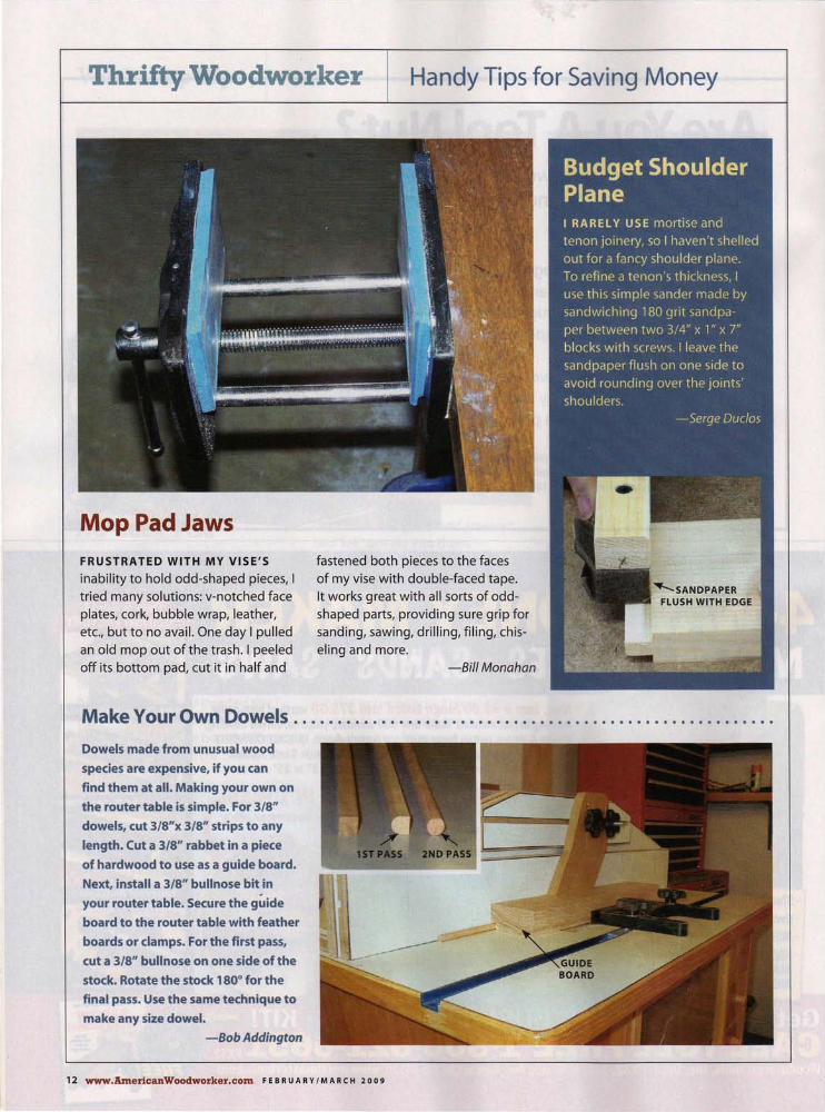
Mop Pad Jaws FRUSTRATED WITH MY VISE'S
inability to hold odd-shaped pieces, I . tried many solutions: v-notched face
plates, cork, bubble wrap, leather, etc., but to no avail. One day I pulled an old mop out of the trash. I peeled off its bottom pad, cut it in half and
fastened both pieces to the faces of my vise with double-faced tape. It works great with all sorts of oddshaped parts, providing sure grip for sanding, sawing, drilling, filing, chiselingand more.
-Bill Monahan
Make Your Own Dowels . ..................................................... .
Dowels made from unusual wood species are expensive, if you can
find them at all. Making your own on the router table is simple. For 3/S"
dowels, cut 3/S"x 3/S" strips to any length. Cut a 3/S" rabbet in a piece
of hardwood to use as a guide board. Next, install a 3/S" bullnose bit in your router table. Secure the guide board to the router table with feather boards or clamps. For the first pass,
cut a 3/S" bullnose on one side of the stock. Rotate the stock 1 SO· for the final pass. Use the same technique to make any size dowel.
-Bob Addington
12 www.Americ::anWoodworker.c::om FEBRUARY/MARCH 2009

Using Your Noodle
WHILE LOUNGING AT THE POOL
one afternoon, I had an inspiration. I "borrowed" one of my kids' floating pool noodles, cut it into sections and used the pieces as universal connectors for vacuum hoses and tool dust ports. (A noodle is only about three bucks, so I replaced it the next day).
A noodle has a 1" hole down the center, and jt's flexible and compressible. It's about 6' long so you can make lots of connectors from one noodle. That can save you a ton of money over buying plastic adaptors.
-Bob Enderle
Bottle Cap Jig Knobs ......................................................... . I'm always trying to use up scraps and stuff that would otherwise end up in the trash. My latest devices are jig knobs made with plastic bottle caps, which have a grippy surface on their edges. To make these knobs, all you need are plastic caps, 1/2" thick plywood, carriage bolts and epoxy.
First, cut plywood discs to fit in the caps using a hole saw. Next, counterbore the plywood disk with a Forstner bit large enough for the bolt's head. Then, drill a hole all the way through the disc and slide the bolt through. Finally, spread epoxy around the inside of the plastic cap, and place it on the disc/bolt assembly. Make sure you put epoxy in the counterbored area around the bolt's head.
-Serge Duclos
E-mail your tip to [email protected] or send it to American Woodworker,
Thrifty Woodworker, 1285 Corporate Center Drive, Suite 180, Eagan, MN 551 21. Submissions can't be
returned and become our property upon acceptance and payment. We may edit submissions and use them in all print and electronic media.
FEB R U A R Y I MAR C H20 0 9 www.AmericanWoodworker.com 13

The Well-Equipped Shop Our Pick of the Latest Tools
Strong Lapped Miter Joints
IT'S CHALLENGING to produce
strong, good-looking corner
joints, especially with thin ply
wood. Traditional 45° lock-miter
bits are finicky to set up and in
thin stock, the finger joints they
produce can be quite fragile.
Infinity Tools' new 2-piece lapped
miter router bit set produces
super-strong joints by creating
more surface area for gluing. The
bits are easy to set up, using the
instructions that are included, and
they produce perfect miter joints
every time. They're designed for
use with lumber and plywood
from 1/2" to 3/4" thick.
Source: Infinity Tools,
www.infinitytools.com. (877) 872-2487,
Lapped Miter Joint Router Bit Set, #55-
505, $109.
Coping Sled for Cabinet Doors WHEN USED on a router table with cope and stick (rail and stile) router bits, Infinity Tools' new Professional Coping Sled makes fast work of cabinet door joints. Stock up to 5-3/4" wide can be easily clamped on, and at over five pounds, the sled's sheer heft helps to absorb vibration and ensure precise cuts. A Lexan visor runs against the fence and keeps the sled's base away from the spinning bit. It also guards your hands and protects you from any debris. The sled's 3/8" thick aluminum base is tapped, so you can attach the optional 3/4" miter bar and run the sled in the table's miter slot. Source: Infinity Tools, www.infinitytools.com. (877) 872-248, Professional Coping Sled,
#COP-l 00, $150; Miter Bar, #COP-MB1, $20.
14 www.AmericanWoodworker.com FEB R U A R Y I MAR C H20 0 9

COLLET EXTENSION
Trim Router Also Goes Horizontal THE NEW MFK 700 TRIM ROUTER from Festool easily transforms from a vertical to a horizontal position in a few simple steps-no tools required. The horizontal position is ideal for routing edge trim flush with a top. The router's extra-deep base and handle offer plenty of support and make the router easier to control. You're much less likely to tip the MFK 700 in either orientation than any other similar router. The base has a fully integrated port for dust extraction. A detachable roller bearing allows you to make a flush cut using bits without bearings. Speed control electronics assure smooth starts and constant speed under load, a nice feature when it's time to rout tough woods like oak. The 6-amp, 4.2 lb. router comes with 1/4" and 8mm collets. Depth adjustments are accurate to 1/10 mm (about 1/256"). Source: Festool, www.festoolusa.com. (888)
337-8600, MFK 700 EO Trim Router Set, $510.
No More Splintered Edges FREUD'S NEW Quadra-Cut router bits produce routed profiles with little or no tear out or fuzz, even on cross-grain cuts. These unique, patented bits employ four cutting edges instead of two. The large profile cutters remove most of the stock with an upshear cut. Then a pair of downshear cutters makes the final cut to produce an ultra clean edge with no fuzz or splinters at the top surface.
Freud now offers 44 bits with this unique 4-cutter geometry. These profiles include roundover, ogee, beading, table edging, and more. All of the bits are coated with Perma-SHIELD permanent non-stick coating to reduce friction and resin adhesion. Source: Freud, www.freudtools.com. (800) 472-7307.
FEB R U A R Y I MAR C H20 0 9 www.AmericanWoodworker.com 15
The Well-Equipped Shop
Second Bevel= Longer Life FREUD IS problem-solving
again with a new design for
straight bits. Their Double
Grind bits have a unique sec
ondary bevel for better chip
clearance. The benefit: the bit
runs cooler, and that equals
longer life. Other features of
the bits are Freud's TiCo high
density carbide with titani
um, Tri-Metal brazing for a
stronger, more impact resist
ant bond of the carbide, and
a Perma-SHIELD non-stick
coating for further reducing friction.
Source: Freud, www.freudtools.com. (800) 427-
7307, Double Grind Straight Bits, $15 to $55.
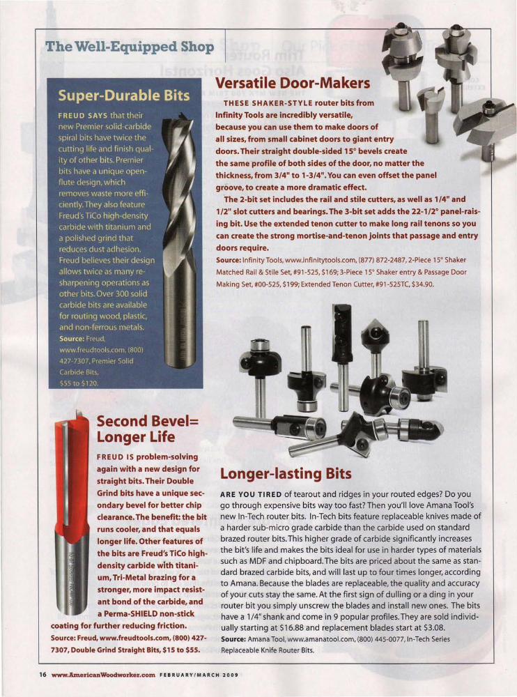
Versatile Door-Makers THESE SHAKER-STYLE router bits from
Infinity Tools are incredibly versatile,
because you can use them to make doors of
all sizes, from small cabinet doors to giant entry
doors. Their straight double-sided 15° bevels create
the same profile of both sides of the door, no matter the
thickness, from 3/4" to 1-3/4". You can even offset the panel
groove, to create a more dramatic effect.
The 2-bit set includes the rail and stile cutters, as well as 1/4" and
1/2" slot cutters and bearings. The 3-bit set adds the 22-1/2° panel-rais
ing bit. Use the extended tenon cutter to make long rail tenons so you
can create the strong mortise-and-tenon joints that passage and entry
doors require.
Source: Infinity Tools, www.infinitytools.com. (877) 872-2487,2-Piece 15° Shaker
Matched Rail & Stile Set, #91-525, $169; 3-Piece 15° Shaker entry & Passage Door
Making Set, #00-525, $199; Extended Tenon (utter, #91-525TC, $34.90.
Longer-lasting Bits ARE YOU TIRED oftearout and ridges in your routed edges? Do you go through expensive bits way too fast? Then you'll love Amana Tool's new In-Tech router bits. In-Tech bits feature replaceable knives made of a harder sub-micro grade carbide than the carbide used on standard brazed router bits. This higher grade of carbide significantly increases the bit's life and makes the bits ideal for use in harder types of materials such as MDF and chipboard. The bits are priced about the same as standard brazed carbide bits, and will last up to four times longer, according to Amana. Because the blades are replaceable, the quality and accuracy of your cuts stay the same. At the first sign of dulling or a ding in your router bit you simply unscrew the blades and install new ones. The bits have a 1/4" shank and come in 9 popular profiles. They are sold individually starting at $16.88 and replacement blades start at $3.08. Source: Amana Tool, www.amanatool.com. (800) 445-0077, In-Tech Series
Replaceable Knife Router Bits.
16 www.AmericanWoodworker.com FEB R U A R Y I MAR C H20 0 9

Extreme Block Planes TWO NEW LOW-ANGLE block planes from Veritas are beautiful marriages of fine art and sound engineering. Under each shiny, streamlined exterior lies a very serious tool-one that should please even the most demanding woodworker.
The NX60 (top) and DX60 (bottom) are Lee Valley's first offerings in a planned line of premium planes. Both are essentially the same: they have a 12° bed angle, an adjustable mouth, and a Norrisstyle mechanism that combines depth-ofcut and lateral adjustments. Both planes are equippped with extremely durable A2-steel blades with pre-lapped backs. All the adjusting hardware is stainless steel.
The difference between the two models is in their bodies. The NX60 is made from a corrosion-resistant material-nickel-resist ductile iron-while the DX60 is . made from regular ductile iron and has a die-cast lever cap. Extra mass is always good in a small plane, and both weigh a hefty 1-3/4 Ibs. Boy, do they feel good in your hands. Whenever you use one these babies, you're going for a real ride. Source: Lee Valley, www.leevalley.com (800)
871-8158, Veritas NX60 Premium Block Plane,
#05P70.11 , $279; Veritas DX60 Block Plane,
#05P70.01, $179.
Feature-Packed 1/4" Trim Router WHETHER YOU ' RE TRIMMING laminate, doing inlay work, or just mortising a hinge, Makita's new 1/4" laminate trimmer is up to the task. This tr immer offers a number of improvements that make it more powerful and easier to use. Rack and pinion depth adjustment allows precise control for setting bit height. The transparent base provides a clear view of your work. The 4-amp motor delivers 20% more power and 30,000 rpm. Ergonomic improvements include slim design, a soft rubber grip and a power cord that has been moved to the top, so it's out of the way. This new trimmer is almost 1-1/2" shorter than the previous model and it weights only 3.3 Ibs. lncluded with the router are template and trimmer guides, wrenches, a chip deflector, and a straight bit. Source: Makita Industrial Power Tools, makita
tools.com, (800) 462-5482, Makita Laminate Trimmer,
#3709, $108.
FEB R U A R Y I MAR C H20 0 9 www.AmericanWoodworker.com 17

The Well-Equipped Shop
A Slider to Love FESTOOL'S NEW Kapex KS 120 10" sliding compound miter saw is proof that great things come in small packages. For example, most sliding miter saws require a lot of space, up to 45" from back to front when the turntable is at 90°. This slider, by comparison, measures only 31 ",and it weighs only 471bs.
The KS 120's saw head slides on widely spaced rails, to minimize side-to-side play when the head is extended. Fully adjustable, dual lasers define the cut. According to Festool, dust extraction up to 91 % efficiency can be achieved.
The bevel adjustment mechanism is, in a word, superb. Simply release the lock and dial the control lever, which is perfectly located on the front of one extension rail. The adjustment is counter spring balanced, so the head tilts effortlessly in both directions and stays in position at any angle, even when it isn't locked. The bevel scales are super-sized and genuinely easy to read. Bevel capacity is 4]0 left and right. Miter capacities are
50° left and 60° right. The miter angle controllever/lockldetent override mechanism operates intuitively, and the pointer includes guides for accurately setting 112° positions.
Power is supplied by a 13 amp motor with variable speed control for cutting different materials, constant feedback to maintain blade speed under load, and soft-start technology to prevent wrist-wrenching blade jumps. Also included are a high-quality carbide blade, dual-height quickrelease adjustable fences, a quick-release hold-down clamp and an angletransferring device for on-site work. The KS 120 crosscuts boards up to 12" wide. Standard thickness capacity is 3-1/2", but the blade can also be repositioned to cut 4-3/4" wide boards on edge and miter 6-5/8" wide crown
moldings at 45°, when they're nested between the bed and the fence. Source: Festool, www.festoolusa.com. (888) 337-8600, Kapex KS 120 Sliding
Compound Miter Saw, #561 287, $1300.
18 www.AmericanWoodworker.com FEB R UA R Y /MA RC H 2009
Versatile System for Engraving AMANA'S IN-GROOVE Insert Engraving bits are designed for making signs, lettering, and engraving using a
CNC machine. They're engineered so you can quickly change inserts without removing the bit from the CNC, minimizing down time. There are 30 differ
ent insert knives that fit either a 1/4" shank tool body or a 1/2" shank tool body. The tool bodies are balanced to minimize vibration, and the industrialquality insert knives are very long last
ing and produce crisp, clean cuts, according to Amana. They're ideal for cutting laminated materials, veneers,
MDF, plastics, wood and
solid surface. Source: Amana Tool,
www.amanatool.com.
(800) 445-0077, 1/4" Tool
Body #RC-1075, $50; 1/2"
Tool Body #RC -1076, $50;
Inserts $22 ea.

Tool Nut Tools Our Readers Love
Dome-Top Discovery REMEMBER YOUR FIRST ROUTER?
I still have mine-a classic Stanley dome-top from the 1960s. (It's the one sitting on the bench, above). It was the only router we had in the shop I apprenticed in. I loved this machine, particularly the shaft-lock button located on top of the dome. When it wore out I thought the router was done for. There was no way to lock the shaft in order to replace a bit. A few years later, I found a similar router with an intact button, and a lot more history, sitting on a forlorn table at a flea market. One man's trash became my new treasure.
I had stumbled on a big, green, rusty box labeled "Carter Tools -Electric Plane." Inside was a wellused carpenter's dream-machine of
long ago: a handheld planer powered by a dome-topped router motor. Wouldn't you know, that motor was a dead ringer for my Stanley! Taking this prize home, I unscrewed the dome, removed the button, put it in my router, and was back in business.
Turns out the green box was toted around for years by a carpenter who worked in a hospital and primarily used the planer for fitting doors.
The planer is an exquisite piece of engineering. It has a fully adjustable fence, a helical cutter, and a front sole that adjusts up and down to regulate the depth of cut.
I've no idea how old the Carter Electric Plane is- maybe one of you can help me out here-but it has an illustrious pedigree. A fellow named Ray L. Carter is often credited with
20 www.AmericanWoodworker.com FEB R U A R Y I MAR C H20 0 9
having invented the router back in the early 19205. In the early 19305, his business, the R. L. Carter Co., was acquired by the Stanley Works, where it operated as the R. L. Carter division and made the Electric Plane. Stanley made dome-top routers for many years, but sold the line to Bosch in the 1980s. Compared to new routers, the most striking feature of these old Stanleys is their bodies; they're entirely aluminum and have gracefully aged to a beautiful pewter color.
Not long after my flea market find, I stumbled on another old Stanley dome-top (it's the router to the left of the planer), and added it to my growing collection. My original machine is still going strong, but I figured that someday I'd be looking for yet another button!
-Tom Caspar

My Shop Where Our Readers Live
My First Shop I'M A 20-YEAR-OLD college student at Oklahoma State University in Stillwater. My shop had its beginning a couple of years ago, when I was still living at home in Enid. My Mom said that I could park my pickup in the
garage, or have a little woodworking shop in the same space. A young tool nut, I had already acquired a pretty good collection of woodworking tools, so it was an easy choice. My truck would stay outside. Now, when the
weekends come, I head straight to my parent's house and my garage shop.
Ever since I was a child, I've been obsessed with building and fixing things. I've taught myself for the most part and I've learned from others. Last summer I got a job working for a cabinetmaker in Waukomis, OK. It was a great experience that added many new tech
niques to my woodworking skills. And with the extra money I made, I was able to buy a
My new tablesaw was Christmas gift
from my parents. I bought most of my
other tools with money earned from
woodworking projects.
22 www.AmericanWoodworker.com FEB R U A R Y I MAR C H20 0 9
My parent's one cardinal rule for allowing
me to use their garage for my shop is that
I always leave room for my mom's car.
new miter saw, router, router table, nail gun, planer and a bandsaw. 1 still keep in touch with the cabinetmaker-he gives me off-cuts that are a bother to him, but perfect for me.
Lately I've turned my garagebased hobby into a small business, doing woodworking projects mostly for neighbors and friends: bookcases, small cabinets, picture frames and such. After I graduate from college, my goal is to have my own shop, outfitted with more tools than I can count. My dream is to save enough money to buy the cabinetmaker's shop where I learned so much. But until then, I'll keep working in my "Mom-and-Pop" shop.
Tell Us About Your Shop
Jordan Riddle
Stillwater, OK
Send us photos of your shop, a layout
drawing and a description of what
makes your shop interesting. Tell us what
you make in it and what makes your
shop important to you. If "My Shop"fea
tures your shop, you'll receive S 1 00.
E-mail your entry to
myshop(dJamericanwooclworker,com
with digital photos attached. Or mail
your description with prints or digital
photos on a disc to My Shop,
American Woodworker, 1285
Corporate Center Drive, Suite 180,
Eagan, MN 55121. Please include your
phone number. Submissions cannot
be returned and become our property
on acceptance and payment. We may
edit submissions and use them in all
print and electronic media.

Tool Talk Buying Advice for Shop Gear
Porter-Cable's Omnijig Joinery System This innovative jig makes routing dovetails a pleasure.
By Bruce Kieffer
LOADED WITH user-friendly features and available in 16" and 24" models, Porter-Cable's new Omnijig Joinery System is a significantly updated version of the venerable P-C Omnijig (see Sources, page 27). The new 16" model is equipped with a
fixed-finger routing template that's dedicated to routing fixed-space halfblind dovetails-the type of dovetails typically found in production-made drawers. The 24" model is equipped with a routing template that has adjustable fingers. This template
24 www.AmerieanWoodworker.com FEB R U A R Y I MAR C H20 0 9
allows routing many different types of dovetails (right) . A smaller version of the adjustable-finger template is available as an accessory for the 16" Omnijig. Accessory kits and templates are available for both jigs to allow making miniature dovetails, sliding tapered dovetails and box joints.
A system that works Both new Omnijigs are thoughtfully designed to make dovetailing easier
The 24" Omnijig (left) creates all of the joints shown below. Half-blind dovetails are typically used for drawer fronts. Rabbeted half-blind dovetails create lipped drawer fronts, which hide the drawer opening. Through dovetails are often used decoratively on casework. On variably spaced joints, both the pin and tail widths can vary, and the spacing across the joint doesn't have to be symmetrical.
VARIABLY SPACED HALF-BLIND
FIXED SPACE HALF-BLIND
VARIABLY SPACED RABBETED HALF-BLIND
VARIABLY SPACED THROUGH

than ever. Setup revolves around a simple system of interchangeable parts that are color-coded by dovetail joint type (Photos 1 and 2). All you have to do is choose the type of joint you want to create and then follow the system.
The system tells you how to orient the routing template and which stops, bit and template guide to use. Instructional labels on the jig give you the sequence of cuts and
Interchangeable Parts
workpiece orientation . The stops position the routing template (Photo 3) . Onboard depth gauges help you set the router bit depth (Photo 4). Both the stops and depth gauges are adjustable. Dialing in these settings determines the joint's fit. Once you've got the stops and gauges set for a particular joint type and stock thickness, you can return to that setup later with minimum fuss.
TEMPLATE GUIDES
Color Coding
Notable features The heart of the 24" Omnijig is its adjustable finger template (Photo 5). Th is template is flipped or rotated, depending on the dovetailing operation, so it mounts on the jig four different ways. Changing from one orientation to another takes only seconds.
The template carries 13 adjustable finger pairs that guide the router. Each finger consists of left- and right-
The Omnijig Joinery System incorporates interchangeable stops, bits and template guides to produce different types of dovetail joints. Plug in the correct parts and you're ready to rout.
Each joint type is assigned a color and all the parts used to create that joint are marked. Follow the color-coded setup guide and onboard instructions and you can't go wrong.
Repeatable Setup Adjustable stops fine-tune the routing template's position, to dial in perfectly fitting joints. Once the stops are set, the template automatically returns to that setup for the next use.
Set-and-Save Bit Depth Gauges On board adjustable router bit depth gauges allow setting and saving numerous bit settings for different types of dovetails and different stock thicknesses.
FEB R U A R Y I MAR C H 2 0 0 9 www.AmedcanWoodwo:rker.com 2S

Tool Talk continued
hand parts. The fingers can be positioned and locked down anywhere on the template, or moved out of the way, to create the desired dovetail appearance and spacing. Locking the two-part fingers together creates the narrowest pins (1/2"). Separating the two parts widens the pins. The spacing between finger pairs determines the tail widths. Locking the fingers side by side creates joints with equally sized pins and tails.
The Omnijig's cam-action levers take the hassle out of mounting the workpieces (Photo 6). First, you set the initial pressure-enough to stabilize the workpiece for clamping. Install the workpiece and turn the large knobs at the ends of the clamping bar until the workpiece stays in place. Then lock it securely with the lever. It's a piece of cake.
The stabilizer bar that mounts directly in front of the routing template serves three functions. In addition to supporting the router and deflecting chips and sawdust to the floor or into the dust port accessory, it's a billboard for the onboard instructions (Photo 7).
Creating joints Variably spaced through dovetail joints are routed in two steps (see "Through Dovetails," page 27). The workpiece is always positioned vertically, with a horizontal backer board mounted directly behind, to prevent blowout. First, you rout tails in one board, using a dovetail bit. This board is called the tailboard, because of the tail-shaped sections the dovetail bit creates. To rout matching pins on the other board (the pinboard), you flip the routing template so the fingers' pointed ends will guide the cut. You also switch to a straight bit and the prescribed template guide.
Fixed-space half-blind dovetails (also called single-pass dovetails) are created with one setup (see "Half-
Adjustable Finger Routing Template Two-part fingers allow creating virtually any dovetail spacing. Their U-shaped ends are used to rout the tails; their pointed ends are used to rout the pins.
Effortless Clamping. Cam-action levers and coarsely machined bearing faces make it easy to clamp workpieces in position.
Router Support The stabilizer bar supports the outboard side of the router base, so the router won't tip forward during operation and gouge the workpiece. The bar also deflects chips down and provides dust collection when combined with the optional dust port.
26 www.AmericanWoodworker.com FEB R U A R Y I MAR C H20 0 9

Through Dovetails
For through dovetails, the first step is to rout tails on the end of one board, using the dovetail bit and the template guide prescribed by the system. A backer board prevents blowout.
Blind Dovetails," above, right}. The jig automatically offsets the boards and a stop bar limits the cut's depth. Routing creates a modified version of through dovetails on the vertical board and stopped blind dovetails on the other board. The vertical boards form the drawer sides; the horizontal boards form the drawer front and back. That means the boards must be oriented carefully-both mount inside-face out.
Living with the Omnijig The Omnijig comes with an excellent owner's manual and an informative DVD, and I was successfully routing dovetail joints within a short period of time. But as with any woodworking apparatus, I discovered that the Omnijig has its quirks.
As I expected, the factory settings for the stops and depth gauges were close, but they all had to be finetuned. Surprisingly, the 3/8" deep variable-spaced half-blind dovetails turned out to be closer to 5/16" deep, once everything was adjusted
The second step is to rout pins on the other board, which is mounted in the same position as the first board. Flip the routing template. switch to a straight bit, change the template guide, and go.
for a close fit-one minor consequence of using a system for multiple applications. (You raise or lower the bit to adjust the fit of half-blind dovetails, so their final depth is what you get; it may not be exactly what you want.) According to Porter-Cable, this variation is within tolerance, as the depths specified for half-blind dovetails are approximate.
I also discovered that it's important for the router base to be exactly centered on the collet (see Sources). If the base is off-center, the bit won't be centered in the templat~" guide, because the template guide mounts to the base. Misalignment can cause fit problems in the joint if you orient the router differently for successive passes or rotate it back and forth as you navigate around the fingers. Even with the base plate centered, it's good practice to always orient the router the same way for every pass.
Backer boards virtually eliminate blowout on the back side of the workpiece. I got the best results when I removed the backer after
Half-Blind Dovetails
To rout fixed-space half-blind dovetails, lock the fingers tightly together and position one board vertically and the other horizontally. Install the stop bar and rout both boards simultaneously.
routing each board and re-jointed it's edge, to remove the bit marks.
I'm a stickler for symmetry, so I like variably spaced dovetails that are uniformly spaced. I rip a length of scrap stock to match the spacing between dovetails that I want. I cut this strip into short pieces and insert one piece between each pair of fingers on the template. To uniformly widen the pins, I mill scrap to the desired thickness, cut it into pieces and insert those pieces on-edge between the two-part fingers.
SOURCES
• Porter-Cable, www.deltaportercable.com.
(888) 848-5175,24" Omnijig Joinery
System, #77240, $599; 24" Dust Shroud,
#77244, $45; 24" Half-Blind/Sliding
Dovetail Template, #77248, $119; 16"
Omnijig Joinery System, #55160, $429; 16"
Variable Finger Template, #55161 , $199;
16" Dust Shroud, #55164, $35.
• Woodcraft, www.woodcraft.com. (800)
225-1153, Router Base Plate with
Centering Pin, #144931, $25.99.
FEBRUARY I MARCH 2009 www.AmericanWoodworker.com 27

School News
WoodLINKS Linking Woodshop Students with the Wood Industry
By David Radtke
The Next Generation
"THESE DAYS, many students don't see a clear connection between high school and a career," says Mark Roberts, a teacher in Mesa, Arizona. That's why he and many other teachers across the country are volunteers for WoodLiNKS, a nonprofit organization that facilitates the building of programs between the wood industry and schools.
WoodLiNKS' goal is to establish a big-brother relationship among industry, schools and teachers, in order to provide encouragement
WoodLINKS programs bring students and industry representatives together,learnlng how to set up and use high-tech industrial machines is II core benefit for students. Here, Chris Dolbow demonstrates Installing a blade on an Altendorf sliding tablesaw,
and training for students, and to help them learn about career opportunities that are available in the wood industry. WoodLiNKS staff members and volunteers are dedicated to producing students who are qualified and certified for employment in the wood industry, as well as
for entry into wood-related post-secondary institutions.
Through WoodLiNKS, students receive special training right at their school, in conjunction with their existing woodshop classes. The teachers use detailed curriculum guidelines to prepare students for jobs in the wood
industry."Along with learning to use woodworking machines, the students also learn great people skills and teamwork," says Troy Spear, an instructor at Theodore Roosevelt High School in Kent,Ohio.
WoodLiNKS is currently involved in about eighteen states. Mark Smith, WoodLiNKS' national director, projects that about twenty new schools will join
These students show the results of a WoodLINKS class assignment the program that combined learning to read technical drawings with learning this year. to use an Industrial shapero
28 www.1UnericanWoodworker.com FEB R U A R Y I MAR C H20 0 9
How WoodLiNKS Works Wood industry companies contact WoodLiNKS to connect with a local high school or technical school, with the aim of providing new, skilled workers for their companies. History shows that for a WoodLiNKS program to work and thrive, it must be industry driven. But sometimes a teacher who wants to bring a sharper focus on career training at his or her school initiates the contact."There's another important ingredient for success," says Mark Roberts, a long-time advocate for WoodLlNKS."Each individual program needs an energetic and dedicated instructor."
The curriculum among member schools varies, depending on the focus of the local industry sponsors. Typical industries include cabinet shops, production furniture manufacturers, sheet goods and veneer producers, machine tool manufacturers and custom millwork shops.
WoodLiNKS charges a one-time fee to initiate a program. The fee is usually paid by the industry sponsor, but sometimes it is shared between school and sponsor. Donations from the wood industry and individuals also help fund the mission. A pro-
.'

gram such as this takes a concerted
effort from the school board, teachers
and community to be a success. A
new program usually takes two to
three years to get up and running,
and WoodLiNKS remains supportive
during the process.
Training for Teachers WoodLiNKS provides in-service tra in
ing for the teachers. This special train
ing consists of a minimum of 32
hours of instruction and exposure to
industry. It is taught in classes at the IWF (International Woodworking
Machinery & Furniture Supply Fair)
and AWFS (Association of
Woodworking & Furnishings
Suppliers) wood industry shows.
WoodLiNKS pays for transportation
and lodging for teachers who attend.
Troy Spear, who helped get the pro
gram started at his school, says, "The
shows are a real motivator for teach
ers, and the in-service classes are a
great way to stay in touch with the
industry. The contacts with other
teachers and industry representa
tives are invaluable."
Benefits for the students
Students profit beyond a curriculum
that prepares them for jobs in the
Brienna Larrick shows off a project she completed through a Wood LINKS program. She designed the piece with AutoCAO and cut out the shapes with a CNC router. After assembling the curved honeycomb structure, she used a vacuum press to glue on the face veneers.
wood industry. They have the advantage
of direct contact with
their industry sponsor and they get to know
industry representa
tives who visit the
school to guest-lec
ture on what's new in
the industry or
explain and demon
strate some of the lat
est machinery.
Students also
Students at East High School in Madison, Wisconsin display "got smarts?" buttons. Students who complete WoodLINKS courses earn certification recognized by the wood industry.
have the opportunity
to visit industry sites and observe
skilled workers and manufacturing
methods firsthand. Industry partner
ships provide opportunities for the
school to purchase some of the new
equipment to train students.
Internships and scholarships are
also available to the students
through this close relationship with the industry."Taking woodshop class
es exposed me to a different type of learning." says Brienna Larrick, a for
mer student at a WoodLiNKS mem
ber high schooL "1 found satisfaction
in producing something tangible,
that shows what I've learned. I also
have a greater appreciation of peo
ple who work in the wood industry."
Each student earns National
Industry Standard certification by
completing the specialized course
work at his or her school. This certifi
cation reflects mastering the skills
and knowledge for entry-level posi
tions, and is recognized by the wood
industry in the United States and
Canada. Earning certificatio~ is also a benefit for continuing on to a univer
sity or technical college, such as
Virginia Tech, where a wide variety of
studies and career paths are available
for students interested in wood sci
ence, packaging, adhesion chemistry
and forest products.
Benefits for Industry "As industry professionals, we enjoy
opportunities that allow us to work
and interact with students and thei r
teachers," says Chris Dolbow, product
manager for Altendorf sliding table
saws at Stiles Shop Solutions in
Grand Rapids, Michigan."Students
are the future of our industry and it's essential to expose them to the latest
technology and new manufacturing
concepts. Having better-educated
and technologically-aware students
will not only increase the industry's
pool of qualified employees for the
short term, but will also help our
industry grow for the future."
Starting a program If you work in the wood products
industry or are an interested teacher
or parent and would like to get more information about WoodLiNKS, visit
www.woodlinksusa.org or contact
Mark Smith, National Director
(217) 253-3239 or (217) 621 -4628
woodlinksusa@netcare-iLcom ~
Paul Winistorfer, president of WoodLiNKS, speaks at an in-service training meeting. Participating WoodLiNKS teachers complete special training in teaching methods and curriculum.
FEB R U A R Y I MAR C H20 0 9 www.AmericanWoodworker.com 29

A Great American Woodworker An Artisan's Life Story
PeterB. Wallace A carpenter turned chairmaker masters a classic American design. By Spike Carlsen
PETER WALLACE HAS A LOT in common with the Windsor chairs he crafts: They're solid, yet elegant; they welcome you with a sense of comfort and authenticity.
These enduring qualities didn't come easily. Before carving out a niche as one of the premier Windsor chairmakers in America, Wallace
New England writing armchair
labored 30 years as a carpenter. Realizing, at the tender young age of 55, that he was no longer enamored by the heavy lifting, he decided to shift gears. Though intending to open a millwork shop at his home in rural Pennsylvania, a series of events led him to the shop of a local Windsor chair builder where he spent a week as an apprentice. After building that first chair, he proceeded to build three more at his own shop, and it was then that he discovered he'd been bitten by the Windsor bug."The first year I lost money, the second year I broke even and the third year I actually turned a profit."
A dozen years later Wallace is still plying his craft. If you need evidence of his talents, chat with those at Colonial Williamsburg and the White House who have purchased his chairs. Or talk to the gentleman who commissioned
him to craft an exact replica of a Windsor chair he'd fallen in love"with at an antique show-but not with the $60,000 price tag.
One thing that sets Wallace apart from many of his colleagues is his meticulous attention to traditional details and design. He's spent entire days at Colonial Williamsburg and the Winterthur Museum-repositories of the finest Windsor chair collections in America-creating exact measured drawings. He's consulted with Nancy Evans, author of the definitive American Windsor Chairs. Of the 60-some pieces in his repertoire, all but one is based on originals. The one exception to his historic faithfulness is his unique "Nanny Rocker" (page 32). Half rocking chair, half cradle, the design is based on a piece of doll furniture made in the 1930s. "The traditional Windsors are so gor-
FEB R U A R V I MAR C H20 0 9 www.Americali.Woodworker.com 31

32 www.AmericanWoodworker.com FEB R U A R Y I MAR C H20 0 9
geous, it's hard to improve upon them," explains Wallace. "Plus I'm better at copying than designing."
And given the hundreds of different antique Windsor chairs from which to copy, how does Wallace differentiate the classic from the clumsy? "The qualities that make a Windsor superior are the crisp elegance of the turnings, the graceful line of the carved volutes and knuckles, the overall lightness and flawless proportions of each part to the whole," explains Wallace.
While Wallace uses power equipment for cutting parts to size and other mundane aspects of his craft-tasks where master furniture builders of yore would have used an apprentice-he relies on hand tools for the bulk of his work."I've tried various shortcuts and they just don't look right," explains Wallace."lf you want to build a period piece and do a historic reproduction it has to pretty much be handwork."
The process begins with crafting the seat, a task for which he uses many of the same tools used by wheelwrights (see The Scoop on Windsor Seats, p. 33). Next comes turning the legs on a modern lathe and fitting them into compound-angled holes. He turns the back and arm spindles with the help of a traditional English

FEB R U A R Y I MAR C H20 0 9 www.AmericanWoodworker.com 33

A Great American Woodworker
Wilmington,
Delaware side
chair, about
1780-1795
34 www.Amertoa.,Woodwo:rker.oom FEB R U A R Y I MAR C H20 0 9
continued
tool called a trapping plane, which is part turning tool and part hand plane. After fitting the arm and back spindles, he steam bends and shapes the curved backrest and arm components.
Wallace continues to use the traditional woods. Seats are
made of poplar, a wood that's dimensionally stable and readily available in thick, wide planks. He uses maple for legs because of its fine grain, hickory for the spindles because of its strength and ash for the curved parts because of its ease in bending. Since multiple types of wood are used, traditional Windsor chairs are frequently painted. But about 15% of
Wallace's Windsors remain natural wood. For these chairs, he selects woods of exemplary quality -the curly cherry or tiger maple he uses for the seat can cost $250 or more alone.
Most of his career, Wallace has built chairs on a commission basis. He averages about one chair per week, and the 6-month backlog in orders attests to his success. But he has new areas he'd like to explore-like building furniture
inspired by John Goddard and Job Townsend, of colonial Newport, Rhode Island. And while his pieces won't fetch the record $12.1 million one of their vintage pieces
brought at auction several years back, it will allow him to put his newly learned carving skills to work; skills learned
Three-legged bar stool

in classes taken from a master carver from Russia."I've had the wood for a highboy for 3 years, but just haven't been able to get to it." At 67, Wallace intends to get to it soon.
When asked what advice he'd give aspiring Windsor chair makers, Wallace responds,"lf you look at a Windsor with a single eye, it looks complicated. But if you look at the different elements one by one it becomes less daunting. You look at a leg and say 'yeah I could probably turn that' and then examine the seat and figure you could somehow do that. When you break it down element by element it becomes a lot more doable."
Wallace offers 1 -on-1 and 2-on-1 "mini-apprenticeships," which consist of 40 hours of hands-on experience over a five-day period."Every aspect of building a chair is demonstrated and explained and then the student is guided through the process, hands-on, from sculpting the seat on," explains Wallace."The class emphasizes watching, then doing- with me, right next to the student, giving ongoing guidance." At the end, students walk away with a completed chair that Wallace would normally sell for $950-a superb deal considering tuition is $1,000.
In the end, it's a process that requires skill, patience and persistence."1 make some of the bestWindsors in the country and I've worked very, very hard at it,"Waliace explains. "Some [woodworkers] complain that they've worked two hours on applying a finish and want to find a shortcut to cut their time. My wife will spend eight or 1 0 hours getting a finish on a chair. Making one of these is not a simple, weekend job. It takes a lot of effort and a lot of work." But one look at a Wallace chair will tell you it's worth it. A..
More of Peter H. Wallace's work can be seen at www.windsor-chairs.com. Spike Carlsen is author of A Splintered History of Wood: Belt Sander Races, Blind Woodworkers and Baseball Bats recently published by HarperCollins.
Amos Hagget-style rod-back side chair
FEB R U A R Y I MAR C H20 0 9 www.AmericanWoodworker.com 35

36 www.AmericanWoodworker.com FEBRUARY/MARCH 2009
By John English WITH JUST FIVE DIFFERENT PARTS
to make, this easy-to-build caddy accommodates bits with both 1/2" and 1/4" shafts. It can be customized to handle just about any collection. The caddy stands solidly on its wide base, stores easily on a shelf or in a cabinet, and is light enough to tote around the shop or take to a jobsite.

Cut Sliding Dovetails 1. Cut the sides and shelves to size.
Cut two 1/4" wide dadoes on the inside face of each side piece (Photo 1). Set up the routertable with a 1/2" dovetail bit, raise the bit 1/2" high, and enlarge the four dadoes, making sliding-dovetail sockets (Photo 2). Joint the edges of these pieces to remove any tear-out.
2. Use a scrap piece exactly the same thickness as the two shelves to set up the router table for cutting tails (Photo 3). Use the same dovetail bit and leave it at the same height. Adjust the fence so the dovetails are loose enough to slide in the sockets without using any force. Once you've achieved the correct fence setting, mill the tails on the real shelves. Glue and clamp the shelves to the sides.
Make Shelf Inserts 3. Cut the shelf inserts 5" extra
long, to avoid splitting their ends when you drill holes. On each insert, layout the holes according to your needs, staying at least 3" from each end. Use a sharp 17/32" bit for 1 /2" shafts and a 9/32" bit for 1/4" shafts. These oversize holes make it easier to remove or replace the router bits. Drill all the way through each insert.
4. Run the inserts through a planer or across a jointer to remove any tearout from the drilling. Trim the inserts to fit on the shelves. I left a 3/8" gap on each end for aesthetics.
Assemble the Caddy 5. Cut the handle to size and use a
1/4" roundover bit to ease all four edges. Stop the cut 3" from each end. Install the handle with glue and screws.
6. Cut the base to size and saw the corners. Rout a decorative profile along the top edge, then ease the edges with sandpaper. Center the carcass on the base and attach it with glue and screws.
7. Glue and clamp the inserts onto the base and shelves (Photo 4). Apply a finish, and load it up! b...
The caddy is held together with slidingdovetail joints. Start by cutting dadoes in the sides to remove most of the waste.
3 Using the same bit, make test cuts on a piece of scrap until it slides easily into the sockets. Then cut the real shelves.
Widen the dadoes into dovetail sockets using a router table. Steady the workpiece with a miter gauge.
Glue the inserts onto the shelves. This twopiece construction creates deep holes for the bits, so they won't tip over when you tote the caddy around.
HANDLE 3/4" x 1-1/2" x 15-3/8"
SIDE
1-5/8" #8 FH (TYP)
112" DEEP SOCKET
SHELF 3/4" x 4-3/4" x 16"
INSERT 3/4" x 4 -1/2" x 14-5/8"
OVERALL DIMENSIONS 1 S-3/4"H x S-3/4"W x 20"L
FE B R U A R Y I MAR C H20 0 9 www.AmericanWoodworker.com 37

Build Your Skills with Lonnie Bird
FEB R UA RY I MA RC H 2009 www.AmericanWoodworker.com 39

Tambour Router Bits Most tambour doors are held together by a cloth backing or are strung together with wires. Not this one. Working with Amana Tool, I developed a set of three router bits that create slats with interlocking joints that just slide together (see Sources, page 46).
Fig. A Exploded View
CUTTING LIST BREADBOX D'",,,n,'ons '05 ib H ,21-7';10 "II, 1~ 13'0 D
PART
A B C D E F G
NAME
Side Top " Base Front Back (plywood) Tambour slats Tambour end
QTY.. TH X W X L
_ -2 5/8" x 14-1/8" x 9-9/16" (a) 5/8" x 8-1/16" x 21-7/16" 5/8" x 14-13/16" x 21-1/8" 5/8" x 2-11/16" x 19" 1/4" x 9-5/16" x 19"
16 1/2" x 29/32" x 19-3/16" (b) 1/2" x 1-1/4" x 19-3/16"
(a) Make two sides from one 5/8" x 14-1 18"x 20" blank. (b) Make 8 pieces at 112" x 1-15/16" x 20", then rip these in halfto make 16 slats.
40 _.JlmericaJtWooclwodl:er.c:am FEB R U A R Y I MAR C H20 0 9
HERE'S A GREAT PROJECT to introduce you to the art of making a tambour door. I designed this breadbox as a road test for a set of tambour-making
router bits I recently developed. The project doesn't require a lot of wood or special skills-but you'll learn a lot about using your router table, because every joint is made with a router bit. Once you've mastered the technique, you can make larger tambour doors for a roll-top
desk, computer desk, entertainment center, or a kitchen appliance garage. Use your imagination!
Bits You'll Need To make the tambours, you'll need a set
of three bits: one to shape the faces of the slats, one to shape the sockets, and a
1/8" roundover bit for the edges of the end slat (see Sources, page 46). You'll also need a 1/2" flush trim bit, a 1/2" dovetail bit, 1/4",9/16" and 5/8" straight bits, and an ogee bit. In addition, you'll need a 3/4" o.d. template guide for your router.
Shape the Tambours Let's start with the fun part-routing the tambour slats (Photo 1). Make them extra-long for now and cut them to length after you assemble the case. The fit between the tambour's ball and socket is critical to making a joint that flexes
without binding. The width of the socket isn't adjustable, but you can adjust the width of the ball.
Here's the plan: install the socket bit in your router table and cut a socket in a scrap piece of wood using the proce
dure outlined in Photos 5 and 6. Keep this piece handy for checking your progress as you cut the balls.
Making the balls requires a series of four cuts. Install the bit so that its top is 1" above the router table. Adjust the fence for a shallow cut and make the
first pass (Photo 2). Flip the piece end-for-end and make
another pass (Photo 3). Repeat the process on the stock's opposite face. Make the same four cuts in each tam
bour piece. Next, reposition the fence to deepen
the cuts (Photo 4). This is the critical step
for fitting the balls into the socket. Your goal is to make the thickest part of the

The tambour slats are connected by ball and socket joints, which are made by a special set of router bits. You'll make the slats two at a time from one piece of wood.
First, make a shallow pass with the ball-cutting bit. Caution: Use a push stick and featherboard to keep your fingers out of harm's way.
Flip the piece end for end to make a second ball. Then turn the piece around to make two more balls on the other side.
Reset the fence to cut all four balls a little deeper. Cutting the ball to exact thickness is critical to making a joint that flexes properly.
ball about 1/64" shy of 1/4". Since this
can be difficult to measure, experiment
with some extra slat pieces and try them
out in your test socket. You'll have to rip
the test pieces in half in order to do this
(see Photo 7), so they won't be usable if
they don't fit. Once you've adjusted the
fence to the proper position, shape all of
the slat stock.
To cut the sockets, rip a 1/4" deep
groove on both edges of each piece of
stock to reduce the strain on the router
bit (Photo 5). Then mount the socket
bit in the router table and adjust its
height to 3/8". Position the fence so that
the socket is centered on the thickness
of the tambour stock. Set up a feather
board to keep the stock firmly against
the fence, then rout the sockets (Photo 6). Rout a socket on the tambour's end
piece (G). Rip each piece of tambour
stock down the middle to separate the slats (Photo 7). Finally, soften the sharp
outside edges of the tambour end with
a 1/8" roundover bit.
Mill Stock for the Case Begin building the case by gluing up
wood for the sides (A), top (B) and base
(C). Note that the grain of the sides runs
vertically (Fig. A). This provides strength
for the sliding dovetails that join the
sides to the top and ensures that season
al expansion and contraction in the top,
base, and sides occurs in the same direc
tion. Mill one piece of wood for both
sides (see Cutting List, page 40); you'll cut
it in half later. Plane this piece about
1/32" thicker than its final dimension.
Later on, use a hand plane or sander to
smooth the sides and fit them to the
grooves in the base.
Rip the top and base approximately
1 /2" wider than the finished dimensions.
If there's any blowout on the back edge
after routing dovetail sockets or
grooves, you'll be able to cut if off later.
Mill wood for the front (0). Leave this
piece 1" extra-long.
Mill wood for the tambour slats (F)
and end (G). Rip the slat stock wide
enough to make two tambours from
each piece (see Cutting List, page 40).
This provides an extra margin of safety
by adding mass and positioning your
hands further away from the bit when
you rout the pieces. Also, cut the slats
and end 1" extra-long. You'll trim them
to fit later on. Make a couple of extra
pieces for testing your setups.
Rout the Tambour Groove Make a template from 1/4" plywood to
guide your router (Fig. 0). The dimen
sions given here for the template
assume that you 'll use a 9/16" dia.
straight bit and a 3/4" o.d. template
guide. Use a compass to draw the groove's arc onto the plywood (Photo
FEBRUARY/MARCH 2009 _.11 .knl .... oJlliJJ.W;_ 41

Begin making the sockets by removing some of the waste on the tablesaw.
Finish the sockets on the router table.
/
1
8
Rip each blank down the middle, creating two tambour slats. Begin building the case by laying out a semi-circular template. This will guide your router in making the grooves that house the tambour door.
8). After drawing the arc, extend the layout line another 1 ". This extra inch provides you with a starting area for smoothly entering the cut. Bandsaw the template to the layout lines and fair the curve with sandpaper.
Next, apply double-faced woodturner's cloth tape to the template. (This tape adheres far better than ordinary carpet tape; see Sources, page 46). Position the template on the workpiece. Apply pressure to the template using a handscrew or deep-reach clamp to improve the tape's adhesion. Remove the clamp. _
Rout the tambour groove on one end (Photo 9). Rout counterclockwise around the template to ensure that the bushing stays in contact with the template. Remove the template and position it on the other end of the workpiece. Be careful, because a mistake here could really mess things up. Note
that you're making a left side and a right side; when you position the template the second time, measure from the same edge of the workpiece (the front) that you used before.
Shape the Ogee Curve The ogee is composed of two arcs; draw them on a 1/4" plywood template using a compass (Figure C). Bandsaw the curve, then lightly smooth the surface with sandpaper to remove the sawmarks.
Crosscut the sides to exact length. Trace the template onto the sides of the box. Bandsaw the sides, staying 1/16" away from the line. Secure the template to the workpiece with double-faced tape; remember to allow the template to overhang the stock exactly 1" at each end of the curve. Tape the template to the outside surface of the right side piece and the inside surface of the left side piece. Why? For the safest cut and
42 _.AmericaDWoodworJr.er.c:om FEB R U A R Y I MAR C H20 0 9
the best results, you should always push a router counter-clockwise around the outside edge of a workpiece, and go downhill with the grain. Putting the template on opposite sides follows this rule. Apply extra pressure to the tape with a clamp, remove the clamp, then flush trim the sides (Photo 10).
Rout the Sliding Dovetails Begin by mounting a 1/2" dovetail bit in the router table; adjust its height to 3/8" (Photo 11). You'll rout the top piece first, so position the fence exactly 1" from the center of the bit. Make certain that the fence is parallel to the miter gauge slot by taking a measurement at each end of the fence. Fasten a backer board to the miter gauge. Mark a pair of lines on the fence to indicate the stopping points (Photo 12). Also, mark the top piece 1" from the front edge to indicate where the sockets stop.

Fasten the template to one of the box's sides using double-faced tape. Put a template guide in your router and cut the goove.
The sides and top of the breadbox are joined with sliding dovetails. First, set up a dovetail bit to rout the sockets in the top.
TEMPLATE
Use another template and a flush-trim bit to shape the ogee curves on the breadbox's sides.
Using a scrap piece, mark the router table's fence to indicate where the bit stops cutting. The dovetail sockets are stopped at the front to hide the joints.
Cutting the right-hand socket is straightforward, but you must feed the left-hand socket from left to right. which is not the normal direction. Clamp the workpiece to the miter gauge to prevent the bit from pushing the stock away from the fence and spoiling the cut (Photo 13). Feed the workpiece until the layout line for the socket's stopping point aligns with the mark on the fence. If you cut the top extra-wide earlier, rip it to exact width.
Fig. B Interior of Side
Next, cut the tails on the top edge of the breadbox sides. This operation uses the same dovetail bit, but the stock is positioned on end and fed past the bit twice, once on each face. During setup, keep the fence and table openings as small as possible and position most of the bit inside the fence.
The depth of this cut determines the fit of the tail within the socket; a larger cut creates a narrower tail and vice-
L1 r-
3/8"
r- 1I2"
~ TAIL
1/4"
~------ ~l~u ------~
9/16" WIDE, 1/4" DEEP GROOVE
1/8" DEEP GROOVE FOR BACK
118" DEEP GROOVE FOR FRONT
FE 8 R U A R Y f MAR C H20 0 9 www.AmericanWoodworker.com 43

Rout the sockets, stopping the cut when a mark on the workpiece aligns with the pencil mark on the fence.
Rout the tails. Use a push block to hold the workpiece tight against the fence and to keep your fingers out of harm's way.
Assemble the top and sides temporarily. Center this assembly on the base in order to mark the location of stopped grooves that will receive the sides.
Using a bit that's the same width as the sides, make a test cut In a scrap piece to make sure the grooves are the correct distance from
the edge.
versa. Test the setup with a sample board before making the cut on the workpiece. The fit of the tail within the socket should be snug, but not tight. During assembly, the wood will swell slightly as glue is applied; if the tail is
too large, it will bind in the socket and make it difficult to assemble. Once you're satisfied with the setup, cut the tails (Photo 14).
Rout Grooves in the Base Rout a pair of shallow grooves in the base to accept the sides and back (Fig.
A). To stay hidden, the grooves start ~t the back edge of the base and stop before reaching the front edge. Although the sides are fastened to the base with screws from underneath, the grooves position the sides and keep them in alignment.
Mark the location of these grooves
directly from the top to ensure that they
are precisely positioned. First, dry-assem
ble the sides to the top. Then center the assembly on the base by measuring with a combination square (Photo 15). Take a
measurement at each end; if there is any difference, adjust the square, shift the assembly, and measure again.
Next, mount a 5/8" straight bit in the router table and adjust its height to 1/8". Position the fence, make a test cut in a scrap piece, and check the groove's
location (Photo 16). Move the fence if necessary, then rout the base using the same method of stopping the cuts as you used on the top. Square the front end of each groove with a chisel. Rip the
base to exact width.
Rout Grooves for the Front The front piece sits in shallow grooves in the sides. Use the same bit, set at the same height, as you used in the last
step. These grooves are also stopped;
44 _--W-Wila' u'" _ FEBRUARY/MARCH 2009
they begin at the top and end at t he tambour groove. Check their distance from the back edge of the side (Fig. B),
then set the fence to this distance. Rout the right side first. Mark the
right-hand side of the fence to indicate
where the cut stops. Mark the top to indicate how far you ought to push.
Rout the groove. The left side requires a different
method. Mark the left-hand side of the fence to indicate where the cut starts. Mark the workpiece to indicate where the cut should begin and clamp a stop block to the fence at the appropriate distance. Position the workpiece against
the stop block and plunge it onto the bit. Then feed the stock from right to left in the usual manner (Photo 17).
Shape the Top and Base Next, shape the decorative ogee profile
along the edges of the top and base.

LOCATION OF GROOVE
Cut a similar groove for the breadbox's front board. This side requries a plunge cut. Drop the workpiece onto the bit, then feed in the normal direction. Use a stop block to guide the plunge.
Rout the end grain first, then the long-grain. This method minimizes tearout at the corners.
Fig. C Ogee Curve layout Fig.D
Set up a bit to cut an ogee profile on the top and base.
Rout stopped grooves in the top and base for a plywood back. Rout similar grooves in the sides, cutting all the way through.
r Tambour Groove Template
5-25132"
J ALIGN WITH B?JTZM /
1"
6-15116"
-------~~~--=h,.,---':--== 7-3/16" ~ / ""':--==- ----- 14-118" --------r':.j
__ __:::~-? ______ L __ I 1"
I. 11-9/16" .1
Fig. E Rear View and Underside ofTop
SOCKET 112"
7"
1 L...f- 11
FEB R U A R Y I MAR C H20 0 9 _.JIme.ricaaWooclwoIl.el COllI 45

Drop the back into place,.then attach toe base with four screws, just to make sure everything fits OK.
Make sureth~ doorslictes without binding, then remove the base. ' Disassemble the door so you can finish its pieces separately.
Adjust the bit's height so that the
square portion of the bit is 1/16" above
the table (Photo 18). Adjust the fence
so that it's even with the bit's guide
bearing. Minimize the fence opening.
Rout the end grain first (Photo 19) and
finish with the long grain edges.
Rout Grooves for the Back The box's back (E) slides in a 1/4" wide
groove in the sides and is housed in a
groove in the base and top (Fig. A). All
the grooves are the same depth and dis
tance from the pieces' outside edges:
Rout the grooves all the way down the
sides. Rout stopped grooves in the top
and base (Photo 20).
Assemble the Breadbox Assemble the breadbox without glue to
take final measurements for the front,
back and tambour slats. Cut the slats
1/16" shorter than the distance between
the bottoms of the tambour grooves so
the tambour opens smoothly.
For the final assembly, position the
sides vertically with their back edges flat
on your workbench. Put glue on the
front board, install it in place, and clamp
the assembly together. Apply glue spar
ingly to the dovetails. Then slide on the
top, until the mating surfaces are flush
at the back (Photo 21). Assemble and
install the tambour slats (Photo 22).
Slide the back into position (Photo 23),
and attach the base with four screws
(Photo 24).
Before applying finish, remove the
base and disassemble the door so that
those parts can be finished separately.
Once the finish is dry, wax both tambour ends and the tambour groove.
Reassemble the box, but don't glue on
the base. D..
46 www.Americ:anWoodworker.c:om FEB R U A R Y I MAR C H20 0 9
SOURCES
• Amana Tool, www.amanatool.com. (800) 445-0077, Tambour set, #54314, $180; the set includes three bits that
may be purchased separately: Bit 1, #54310, $77; Bit 2, #54312, $76; Bit 3, #49498, $32. Ogee bit, #49202, $39.
• Craft Supplies,
www.woodturnersctalog.com. (800) 551-8876, Double Face Tape, #028-0100, $21/108 ft.
Lonnie Bird, long-time woodworker,
author and teacher, runs a school in
East Tennessee. You can find out more
about his school at www.lonniebird.com.

Create extraordinary frames
with ordinary router bits.
By Tim Johnson
HER E' S A FUN WAY to save money, be creative, make something use
ful, and use up scrap stock: make your own picture frames. You can start
from scratch and have finished frames in a day or less, and the only
tools you need are a tablesaw and a router table. The challenge is to
create unique profiles using the router bits you already have.
The frames and instructions that follow will get you started. You
probably don't have all the sanC bits (see photo, page SO), but that
doesn't matter. Just substitute and experiment. You'll find that a little
tinkering yields an amazing range of profiles. .-
Most frames are made using small stock, so be sure to work safely. / .
Always use guards, featherboards and push sticks. Never use stock less
than 12" long. Create profiles on long stock; then cut individual frame
" piece)from the profiled stock. Similarly, use wide stock to create thin
pieces; rout the profile, then cut !o 'fin~1 thickness. Rout large or deep
profiles in multiple passes, raisi'ng the bit or moving the fence in small
increments before each pass.

3/ 8" RABBET
Create unique frames by experimenting. All the frames shown here were made by combining tablesaw cuts
and profiles made with these common router bits.
112" COVE
1/2" ROUNDOVER
45° CHAMFER 1/4"
STRAIGHT
3/4" ROUND NOSE
3/8" ROUNDOVER
1/8" ROUNDOVER
1/2" STRAIGHT
1/2" ROUND 1/8" ROUND NOSE NOSE
50 www.AmericanWoodworker.com FEB R U A R Y I MAR C H20 0 9

FEB R U A R Y I MAR C H20 0 9 www.JlmerlcanWoodworker.com 51

52 www.Americ::anWoodworker.com FEB R U A R Y I MAR C H20 0 9

3
FEB R U A R Y I MAR C H20 0 9 www.AmericanWoodworker.com 53

FnIfUAlI"f,M,AIICH 2009

THIS ROUTER TABLE took thirty years to build. No kidding. I don't mean that it took me thirty years to actually make
it, but it took me that long to figure out how to do it right.
I've used a lot of router tables over those years, and all have come up short. I've been frustrated with complicated fence locks, panels tipping because the fence wasn't tall enough, insert plates that were finicky to level, small worktops that don't support a door or drawer, inadequate dust collection, bad lighting, and on top of all that, having to kneel on the floor to change the depth of cut.
After all those disappointments, I finally built a router table that solved all these problems.
Build The Case 1. Glue two pieces of hardwood to
create the four legs (A) . Plane all four faces of each leg, and then trim them to length. Using a dado set or a router equipped with a straight bit and a fence, mill a stopped groove in two adjacent faces of each back leg and one face of each front leg (Fig. A). These grooves receive the side and back panels. Note that the front legs are not grooved to receive the face frame. Square the end of each groove with a chisel.
2. Clamp the four legs together and locate the screw holes in each groove. On the drill press, use a 3/32" bit to drill pilot holes through the legs. Counterbore the exit holes for plugs, using a 3/8" Forstner bit.
3. Cut the sides (B) and the back panel (C). Screw and glue the two back legs to the panel. Screw and glue the side panels to the back legs, then attach the two front legs. Keep the panels flush with the tops of the legs. Glue plugs in the legs to cover the screw holes.
4. Mark the locations of the two divider panels (J) on the inside face of the back panel (Fig. A). Drill five equally-spaced pilot holes along the center of each location. Cut the divider panels to size, and then glue and screw them to the back panel using screws driven through pre-drilled, countersunk pilot holes. Clamp the panels in place as you drive the screws.
5. Make the side stiles (D) and the top and bottom rails (E and F) of the
FEB R U A R Y I MAR C H20 0 9 www . .l!.medcanWoodwo:rker.com 55
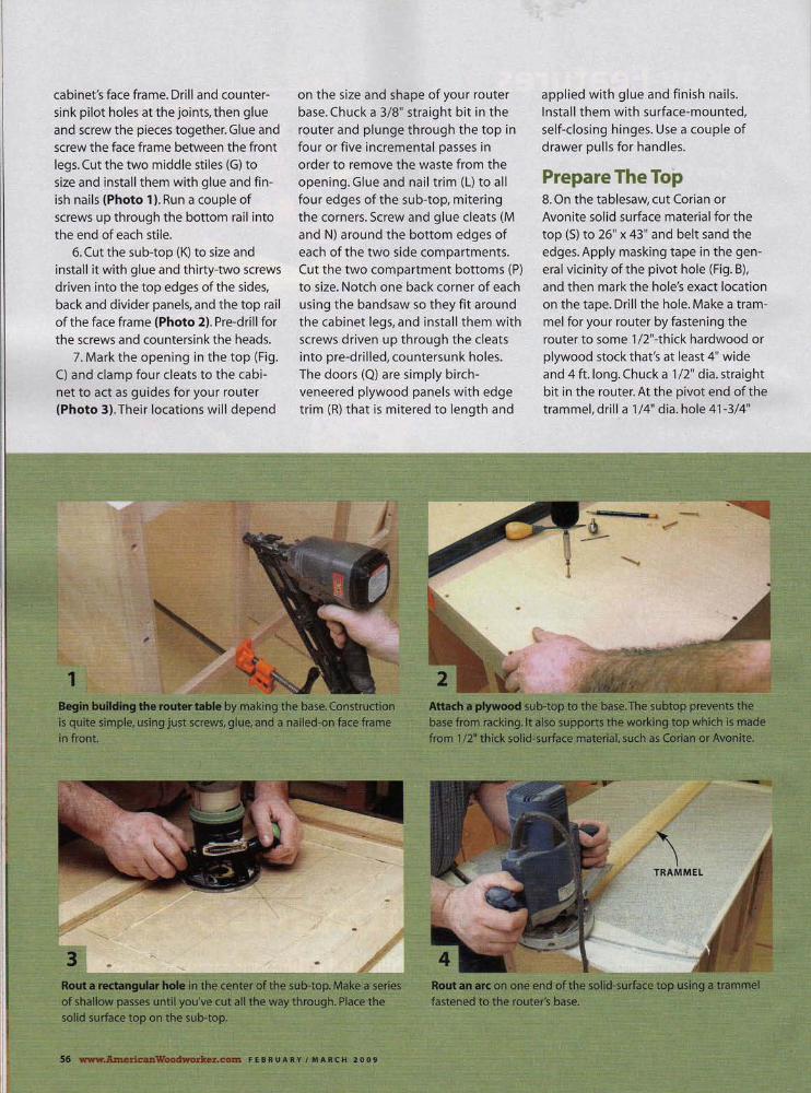
cabinet's face frame. Drill and countersink pilot holes at the joints, then glue and screw the pieces together. Glue and screw the face frame between the front legs. Cut the two middle stiles (G) to size and install them with glue and finish nails (Photo 1). Run a couple of screws up through the bottom rail into the end of each stile.
6. Cut the sub-top (K) to size and install it with glue and thirty-two screws driven into the top edges ofthe sides, back and divider panels, and the top rail of the face frame (Photo 2). Pre-drill for the screws and countersink the heads.
7. Mark the opening in the top (Fig. C) and clamp four cleats to the cabinet to act as guides for your router (Photo 3). Their locations will depend
1
on the size and shape of your router base. Chuck a 3/8" straight bit in the router and plunge through the top in four or five incremental passes in order to remove the waste from the opening. Glue and nail trim (L) to all four edges of the sub-top, mitering the corners. Screw and glue cleats (M and N) around the bottom edges of each of the two side compartments. Cut the two compartment bottoms (P) to size. Notch one back corner of each using the bandsaw so they fit around the cabinet legs, and install them with screws driven up through the cleats into pre-drilled, countersunk holes. The doors (0) are simply birchveneered plywood panels with edge trim (R) that is mitered to length and
applied with glue and finish nails. Install them with surface-mounted, self-closing hinges. Use a couple of drawer pulls for handles.
Prepare The Top 8. On the tablesaw, cut Corian or Avonite solid surface material for the top(S) to 26" x 43" and belt sand the edges. Apply masking tape in the general vicinity of the pivot hole (Fig. B). and then mark the hole's exact location on the tape. Drill the hole. Make a trammel for your router by fastening the router to some 1 /2"-thick hardwood or plywood stock that's at least 4" wide and 4 ft. long. Chuck a 1/2" dia. straight bit in the router. At the pivot end of the trammel, drill a 1/4" dia. hole 41-3/4"
Begin bulking the router table by making the base. Construction is quite simple, using just screws, glue, and a nailed-on face frame In front.
Attach a plywood sub-top to the base. The subtop prevents the base from racking. It also supports the: working top which is made from 1/2" thick solld-,surface material, such as Corian or Avonite.
Roma~.rho~einthe!~eltterm1~wb-rol). Makeasl~ies
m shallow passes until you've cut aU the Wil'V th.rnlloh. "'Ia,r~ 1'_
solid surface top on the sub-top.

from the center of the bit. Loosely
attach the end of the trammel to the
top with a 1/4" bolt, two washers and a
hand-tightened nut, and cut an arc
across the left end of the top in several
1/8" deep passes (Photo 4). Once
you've cut all the way through, gently
sand all the top's edges. 9. Place the top on the cabinet flush
with the back. The top's right edge
(where the pivot hole is located)
should overhang the cabinet by 2".
Temporarily clamp the top in place and
mark the cabinet's outline (Photo 5).
Also mark the large, rectangular hole in
the sub-top. Cut two stiles (T) and four
rails (U) for the support frame (Photo 6). The inner rails should line up with
the edges of the large hole in the sub-
top. Assemble the support f rame with
biscuits and glue and attach it to the
underside of the top with clear silicone
adhesive. Apply weight (a sandbag
works well) while the silicone cures. An
overnight cure is good, but it's better to
let it cure for a few days.
10. Connect the top and support
frame assembly to the cabinet with a continuous (piano) hinge. Use longer 1-
5/ 8" bugle screws in the center and one
near each end for strength.
The Top's Lift Support 11 . When raised, the top is locked in the
open position by a three-part mecha
nism: an arm with both top and bot
tom cleats (Photo 7). Make the top
cleat (V, Fig. D). Attach it to the inside
edge of the support frame's left-hand
rail , using two screws and glue.
12. Make the bottom cleat (W). Cut it
to size and then miter one end. Bore
three holes for carriage bolts. Epoxy a
bolt into the middle hole. Use a washer
and nut to pull the bolt tight while the
epoxy cures, and then locate the bot
tom cleat in the cabinet. Drill holes in
the partition for the other two bolts, and
install the cleat with washers and nuts. 13. Make the arm (X) and install it
with two plastic tri -knobs.
Mount the Router 14. With the top closed, drill a 3/4" dia.
hole where the center of the router will
be located (Fig. B). Lock the top in the
open position and use the hole to
Clamp the top to the base and trace all the way around the top's underside. Turn the top over.
Build a frame to fit inside the rectangle you drew. GlUe the frame to the top using silicone adhesive. Attach the top assembly to the case with a continuous hinge.
Build an ann to prop the top. This makes it much easier to change bits because there will be plenty of elbowroom around the router. Plus, you don't have to bend over.
DrIll a 3/4" ella. hole through the top, then remove the router's baseplate and mark the locations of its mounting holes onto the top. Drill the holes and lower the top.
FEBRUARY/MARCH200t _..Imerlcan~.~ 51

locate your router's baseplate on the underside (Photo 8). Mark and drill holes for mounting bolts using the baseplate as a pattern. Close the top and countersink the holes. Install the router base, minus the baseplate, with stove bolts, washers and nuts.
15. Take a look at your router bit collection and decide how large you would like the hole in the top to be. (At my woodworking school, I strongly recommend limiting router bits to 2" dia.) To enlarge the hole, begin by using a rabbeting bit with a guide bearing that is slightly smaller than the hole (Photo 9). Follow up with a bearing-guided pattern bit, and then use these bits in sequence until the hole is as large as you wish. Make a final pass with the rabbeting bit to leave a ledge that will support hardwood inserts (Photo 10).
Build The Fence 16. Cut the fence base (F1) to size and usea miter saw to trim the pivot end at an angle (Fig. H). Drill the pivot hole at the location indicated. Lay the fence base on the top and secure the pivoting end with a bolt, two washers and a nut that is just finger tight. Mark the opposite end (Photo 11), then cut the base 2" longer than the top, using the offcut from the top as a guide to make a curved end. Mark and cut the circular bit opening in the fence base, then pre-drill some screw holes for assembling the frame (Photo 12).
17. Cut the fence back wall (F2) to size and bandsaw the opening in it for a dust collection port (Fig. H). Align the back wall along the front edge of the base and attach it with glue and screws. Cut the front wall (F3) to size. Cut the sliding fences (F4 and F5) to size and mill one Tslot in each (Photo 13 and Fig.G).(lt helps to mill each groove with a 1/4" straight bit first, and finish the

Enlarge the opening by using a series of rabbeting bits and pattern bits. A rabbeting bit leaves a ledge around the hole making it perfect for fitting an insert.
Mark the length of the fence's bottom board. Cut the board 2" longer than the top.
CutT-siots in the fence's face pieces. This can't be done on a tablesaw, but you could borrow a friend's router table or use a handheld router and an edge guide.
Drill a hole through the fence for the clamping block'5T-bolt.
Make a set of wooden zero-clearance inserts to fit the hole. Drill variously sized holes in the inserts to fit your bits.
Drill pilot holes in the fence using a drill press. This ensures that all the pieces of the fence are square when they're assembled.
14 Make the fence's damping block. It contains aT-bolt that's trapped between two pieces of wood that are glued together. Attach a felt chair pad as a spacer.
Attach the damping block to the fence with a plastic knob. To adjust the distance from any router bit to the face of the fence, loosen the knob and pivot the fence back and forth.
FEBRUARY I MARCH 2009 www.~wooctworkel..com 59

Fig. A Exploded View
s
H4 L
~~
Fig. E Clamping Block
3/4" DIA. FELT CHAIR PAD H10
GRIP TAPE
~NOTCH 7/16" DEEP, ~:f~60VE
~"="";""'-=-=
• ~ 15/16" LONG
~H'4
H35'
Fig. B Frame and Top
I--r---.--r--
i+ h-1I2:'''': I I,
I , I ,
, , I ,
41:-1f,2" 14-1/8"
,-,,==-,===..!.===..=..r,J k-
20" 16"
~ Fig. C Sub-top
:-- -- ::r-==-:-=- :: ------; I II I , ;
: :: 9-5/8 11 : :
13-1/2"41 x :: : l: 19" :: : :: :: 3" : ::L..--- U-! ______ L _______ L _____ _
60 www.AmericanWoodworker.com FEB R U A R Y I MAR C H20 0 9
B
A
Fig. F Featherboard
FENDER WASHER
Fig. G End View of Fence
T-SLOT HAS F6 5/8" WIDE SLOT
AND 3/8" WIDE GROOVE
F7
F1 1-5/8" r-'-'----.J
Fig. H Top View of Fence

cut with the T-slot bit.) Cut the top
molding (F6) to size and plow aT-slot
in that, also. Glue and clamp the front
and back walls together. When the
glue has dried, trim the top molding
to length with a short 45° miter on
each end (that is, leave about 1/3 square and miter the rest), and then
attach it with glue and clamps. Cut
the four fence braces (F7) to size and
shape, and install each with glue and
screws. Drill four holes for the T-bolts
that lock the sliding fences in place.
18. Build the fence-clamping block
(Photo 14 and Fig. E). Nibble a small
dado on the bottom section (F9), and
install a T-bolt before gluing both
sections together (Photo 15). Attach
a self-adhesive felt chair pad to the
top of the lock, then add a little sand
paper or grip tape to the top of the
rabbet. Mark and drill a hole in the
fence base to align with the T-bolt,
and install the lock with a tri-knob
(Photo 16). Screw the dust port in
place behind the fence and you're
ready to add some handy accessories
(see page 58). n..
SOURCE
• Peachtree Woodworking Supply,
www.ptreeusa.com. (888) 512-9069, Right
Angle Dust Port, #386, $4.99; 12" x 12"
Dust Hood, #430, $6.99; Router Table
Power Switch, #1042, $24.99; Small Router
Bit Guard, #1 049, $5.99.
John English has been writing how-to
articles and books for more than fifteen
years. He and his wife, Meg, live in South
Dakota, where he teaches joinery and fur-
niture building at the Black Hills School of
Woodworking.
CUTTING LIST ROUTER TABLE Overall Dimension: 37·1/4"Hx43"Wx26"D
PART NAME QTY. MATERIAL DIMENSION
A Leg 4 Hardwood 1-1 /2" x 1-1/2" x 35-1 /4" B Cabinet side 2 Plywood 3/4" x 22" x 22" C Cabinet back Plywood 3/4" x 33-1/2" x 22" D Face frame outer stile 2 Hardwood 3/4" x 3/4" x 22" E Face frame top rail Hardwood 3/4" x 2-1 /2" x 31-1 /2" F Face frame bottom rai l Hardwood 3/4" x 1-1 /2' x 31-1 /2" G Face frame middle stile 2 Hardwood 3/4" x 1-1/4" x 18"
Divider Panel 2 Plywood 3/4" x 22" x 22" K Sub-top Plywood 3/4" x 23-1/2" x 35-1 /4" L Sub-top trim Hardwood 3/4" x 3/4" x 117-1 /2" (a) M Compartment long cleat 4 Hardwood 3/4" x 3/4" x 22" N Compartment short cleat 4 Hardwood 3/4" x 3/4" x 8-1/4" P Compartment bottom 2 Plywood 3/4" x 9-3/4" x 22" Q Cabinet door 2 Plywood 3/4" x 8-1 /2" x 18-1 /4" R Door trim Hardwood 1/4" x 3/4" x 111" (a) S Top 1 Solid Surface 1/2" x 26" x 43" (b) T Frame stile 2 Hardwood 3/4" x 3-1/4" x 36-3/4" U Frame rail 4 Hardwood 3/4" x 3-1 /4" x 18-1 /2" V Arm top cleat Hardwood 3/4" x 1-7/8" x 7" W Arm bottom cleat Hardwood 1-3/8" x 2-1/8" x 8" (c) X Arm 1 Hardwood 1/2" x 1-3/4" x 24-3/4" y Router table insert 3 Hardwood 1/4" thick, custom dia. Z Dust hood plate Plywood 3/4" x 13-1 /8" x 14" AA Dust hood plate trim Hardwood 1/4" x 3/4" x 13-1 /8" AB Dust hood cleats 2 Hardwood 3/4" x 3/4" x 14" AC Decorative plug 20 Hardwood 3/8" dia.
FENCE
Fl Base Hardwood 3/4" x 5-1 /4" x 45" (d) F2 Back wall Hardwood 3/4" x 8-1 /2" x 38" F3 Front wall Hardwood 3/4" x 5-3/4" x 38" F4 Sliding fence - right Hardwood 3/4" x 3-1/4" x 16-3/4" F5 Sliding fence - left Hardwood 3/4" x 3-1 /4" x 19-1 /4" F6 Top molding Hardwood 3/4" x 1-1 /2" x 38" F7 Brace 4 Hardwood 3/4" x 4" x 9-1 /4" F8 Clamp block top Hardwood 3/4" x 1-1 /2" x 3" F9 Clamp block bottom Hardwood 3/4" x 1-1 /2" x 3" FlO Lamp base Hardwood 3/4" x 1-1/2" x 4"
(a) Cut to length as needed (b) You may use Corian, Avonite or another synthetic countertop material (c) Make the cleat from 3 pieces of 3/4" x 1-3/8" stock. (d) Rough cut at 47" long, then cut to fit
HARDWARE
Hl Screw 176 1-S/8" Bugle H2 Cabinet hinge, pair 2 Overlay, surface mount H3 Cabinet pull 2 Knob H4 Continuous hinge 1-1 /2" x 36" H5 Machine bolt 1/4" x 2" H6 Carriage bolt 1 1/4"-20 x 2" H7 Carriage bolt 3 1/4"-20 x 3" H8 Washer 4 1/4" ID H9 Nut 3 1/4" nylon locking Hl0 Tri-knob 10 1/4"-20, plastic Hll Router mounting bolt 3 To fit, countersink stove H12 Stove bolt washer 3 Locking or spring washer H13 Stove bolt nut 3 To fit H14 T-bolt 8 1/4"-20 x 2-1/4" toilet bolts H15 Dust port To fit your hose
FEB R U A R Y I MAR C H20 0 9 www.AmericanWoodworker.com 61

Shaker Blanket Chest Having a top-notch
dovetail jig really pays off.
By Bruce Kieffer
I'VE ALWAYS WANTED TO BUILD a dovetailed blanket chest, but never got around to it. I couldn't see making all those joints by hand, and I hadn't found a design that I really liked. All that changed when I recently bought a new multipurpose dovetail jig and discovered a Shaker chest with beautiful proportions. No more excuses!
I found this chest in June Sprigg's Shaker Design, a classic work published in 1986. The picture was taken head-on, and that really helped me to make an accurate scale drawing of the piece. The original was built in 1848, in New Hampshire, using white pine painted red. I chose cherry instead. I also designed the case with web frames and center drawer guides, which the original builders wouldn't have used. Web frames make construction simpler, and the guides make it easier to open the drawers, particularly the extra-wide bottom one.
62 www.1!.mericanWoodworker.com FEB R U A R Y I MAR C H20 0 9

American Masterworks
FEB R U A R Y I MAR C H20 0 9 www.AmericanWoodworker.coJll 63

11
A Jig's Benefits Unless you opt for cutting dovetails by hand, building this chest requires a jig that can cut both through and halfblind dovetails. I used a Porter-Cable Omnijig (see Story on Omnijig, page 24), but you could also use a Leigh, Akeda, Chestmate, or a Router Boss. Handmade dovetails usually have small pins and large tails; you can create the same pleasing proportions with all these jigs.
This is a challenging project. If you've never routed dovetails before, this wouldn't be the place to start. But
Fig. A Exploded View
once you get the hang of it, it's not hard to make perfect joints, even in pieces as wide as the sides of this chest.
New Hinges I've built other chests before and always cringed when it came to supporting the lid. Soon after starting th is project, I found some fantastic Lid Stay Torsion Hinges that operate just like the hinges on a laptop computer (see Sources, page 70). You don't need an additional stay beca l,lse the lid won't slam shut. Torsion hinges com.e in different strengths. Build your lid first, weigh it,
64 www.AmericanWoodworker.com FEB R U A R Y I MAR C H20 0 9
and then use the manufacturer's formulas to determine which hinges you'll need.
Selecting the Wood After drawing up a rough cutting list, I went to my local lumberyard and hand-picked top-grade 10' long roughsawn boards. I knew I could get two of the chest's parts from each board, since many are about 4' long. I laid out all the boards in my shop and selected the best for the chest front (A 1), drawer faces (04 and 05), and the base's front (Cl) and sides (C3). 1 set aside the nextbest pieces for the chest sides (A2) and lid (El through E9). The least appealing boards went to make the chest back (A3).1 used one board for all the drawer faces and one board for the base, making the grain continuous across the two upper drawers and around three sides of the base. The time spent deciding the position of each board really pa id off. It made the finished piece look well balanced rather than haphazard.
Dovetail Strategy A jig can do a great job of cutting accurate dovetails, but it's only as good as the care you put into setting it up. The case's through dovetails are quite challenging, no question. Test your setups by routing glued-up scrap pieces that are the same width (22-1/4") and the same species as the chest itself. After routi ng, glue together a few joints to get a feel for what constitutes a good fit.Too tight is a disaster; too loose is ugly, and you'll need to fill the gaps with shims. Testing will also teach you where to apply the glue and how to clamp.
There's an age-old question about how far a dovetail joint'.s pins and tails should protrude at the outset, and building this chest caused me to rethink my approach. In the past, I've always let the ends extend a bit beyond each other so they could be sanded flush after the joint was assembled. There's one big complication: You need to make special clamping blocks to bridge each protruding pin or tail. That takes a lot of time, and often clamping requires two people-one just

Begin building the chest by gluing boards for the front, sides and
top. Clamp a pair of straight sticks across each end to hold the assem
bly flat. Put masking tape under the sticks so they won't adhere.
Rout tails on the sides. This j ig has adjustable fingers so that you
can vary the distance between the pins and tails. Clamp a stop
block at the end to avoid routing tails where the drawers go.
Rout pins on the front and back pieces. These boards are nearly 4'
long; you 'll need to raise the dovetail jig by placing it on a sturdy shop-made box.
Web frames separate the drawers and storage area inside the chest. Rout tongues on the web frame rails using a coping sled to
steady the workpiece.
to hold those darned blocks! A friend told me that he just made
everything flush to begin with and skipped the stepped blocks. I tried that method, and it worked great. I used a good crosscut blade to trim the ends of each board to make them very smooth. I set up the Omnijig so the dovetails were as flush to each other as I could get them. Before clamping, I wiped off all the glue squeeze-out so no glue would be forced into the end grain. I used pipe clamps with rubber pads to squeeze the joints home. The pads were soft enough to conform to any unevenness, but the clamps still applied adequate pressure. After the chest was assembled, a bit of belt sanding and orbital sanding was enough to make the dovetails perfectly flush .
Case and Web Frames 1. Mill boards for the front, sides and
back. Take the wood's thickness down in stages, over the course of a few days, to reduce any chance of warping. Cut biscuit slots in neighboring boards to help with alignment. Using tight-fitting biscuits, glue and clamp the boards, being very careful that the assembly stays flat (Photo 1). You can glue the parts in sections to make it easier to keep the boards flat.
2. Layout and rout the tails on the chest sides (Photo 2 and Fig. F) . I put blue tape between some of the fingers to indicate where I wasn't supposed to rout. I also used a stop block to make extra-sure that I didn't cut too many tails on the front ends.
3. Rout the pins on the chest's back and front (Photo 3). Routing one end of the front requires a spacer, because it's narrower than the sides. I registered each workpiece from a stop on the jig's left side. When I routed the left end of
the chest's front piece, I placed an 11-3/4" long spacer against the stop and put the workpiece next to it. This placed the workpiece's top edge 22-1 /4" over from the stop, the same width as a side.
4. Cut the web frame stiles and rails to size (B1 and B2). Using an adjustable tongue and groove router bit set (see Sources), rout grooves in the stiles and rails (Fig. C), then rout tongues on the rail ends (Photo 4). A good coping sled makes these end cuts very accurately (see Sources and Well-Equipped Shop, page 14). Make the web frame panels (B3) and rout rabbets on their edges to fit the stile and rail grooves. Assemble the web frames.
5. Layout and rout stopped grooves in the chest's back and sides to house the web frames (Photo 5 and Fig. F). The grooves are stopped in order to hide them at the chest's corners.
6. Dry-assemble the chest's front,
FEB R U A R Y I MAR C H20 0 9 www.A.mericanWoodworker.com 65

Rout stopped grooves in the back and sides to receive the web frames. Guide your plunge router with a straight board clamped to the workpiece.
Cut notches on the rear corners of the web frames to fit the stopped grooves. Make the long cuts first using a bandsaw, then finish the cuts by hand.
The chest's drawers run on center guides. Fasten the guides to the middle and lower web frames using 1/4" fiberboard spacers for precise alignment.
Begin assembling the chest. There are a lot of dovetails to glue, so it's best to start with a single corner. Use shop-made assembly squares to keep the pieces oriented 90° to each other.
sides and back. Measure inside to determine the exact lengths and widths of the web frames, then trim them to fit.
Cut notches on the back corners of the web frames (Photo 6, Fig. G). Make the divider (B4) and rout grooves for it in
the middle and upper web frames. 7. Make and attach the drawer
guides (B5) to the middle and lower web frames (Photo 7). Align the guides flush to the fronts of the web frames.
Assemble the Chest 8. This is a complicated assembly.
Dry-fit everything before you eventhink of gluing and figure out in advance how you will clamp the parts together. Use slow-set glue to make the work less frantic (see Sources) and get help from a friend. Start the assembly by gluing and clamping the left side to the back (Photo 8). Large L-shaped
assembly squares made from two or
three thicknesses of plywood are invaluable to ensure that the sides and back remain square to one another.
9. Glue and clamp the lower web fame to the assembly, then add the middle and upper web frames, one at a
time. Slide the divider (B4) in place (Photo 9). Put a small amount of glue on the front 1" of the divider edges prior to tapping the divider home.
1 O. The chest assembly gets really tricky from here. Take a deep breath, and glue and clamp the chest front to the assembly (Photo 10).
11. The last step of the chest assembly is definitely the scariest. Not that it's difficult, but the stakes are high. As I stood back and pondered how I would put on the right side to complete the case, I realized that if I goofed, and something didn't fit perfectly, I would have lost two weeks of work and about $1 ,000 in lumber! So I slowed down
66 _.AmerlcanWoodworker.com FEB R U A R Y I MAR C H20 0 9
and went through the steps of yet
another dry fit. It was a darn good thing I did. Somehow, even with all my careful preparation, the upper web frame was about 1/32" too long, preventing the chest's right side from
going home. I took a couple swipes with my hand plane over the end of the errant web frame, repeated the dry fit, and all was good. Make absolutely sure your side fits properly, then glue and clamp it in place.
12. Make, fit and glue the edgings (B6 through B8) to the web frame and
divider front edges. Sand the chest to at least 180 grit.
Make the Base 13. Cut the base parts (C1 through
C5) to size. Miter the front piece; also miter the front ends of the side pieces. Make sure the inside lengths of these pieces perfectly match the width and

Install the web frames, then slide in a divider to go between the drawers. Glue one web frame at a time, again using an assembly square to maintain a right angle.
Add the front. It sits on the upper web frame, but needs support to stay square. Apply a small amount of pressure in the middle using a crossbeam. When this dries, add the remaining end.
Fasten a template to the workpiece's back for pattern-routing the feet. Use a top-bearing pattern bit to cut with the grain on this end; flip the workpiece and use a bottom-bearing bit on the other end.
Fasten the base one piece at a time to the chest's bottom. This method guarantees a tight fit between the chest and the base's molding. Glue and tape the feet's mitered corners.
depth of the chest. Rout a cove-andbead profile on the top edges of the front and side pieces (see Sources).
14. Make a 3/4" thick template for shaping the curved foo~ (Fig.J). Use the template to draw the foot on the front and side pieces. Rough-tut the shapes using a bandsaw, staying 1/16" away from the line. Rout the feet (Photo 11). Use a straight template to pattern-rout the straight sections of these pieces. Use a chisel and file to square the inside corners between the curved and straight sections.
15. Cut the base back (C2). Cut biscuit grooves to join the back and side pieces. Make the base deats (C4 and C5) and drill holes for fastening them to the case. Sand the exposed surfaces of the base parts. Glue and damp the deats to the front and side pieces.
16. Align the front piece side to side. Screw it in place, without glue. Make
sure it's tight to the face of the bottom edging piece (87). Apply glue to the front's left-hand miter, place the left side piece in position, tape it to the front piece, then screw the left side in place (Photo 12). Glue the back piece to the side piece and fasten it to the chest. Glue the right-hand side piece last. Make corner blocks (C6) to reinforce the joints and glue thelTl in place.
Make the Drawers 17. The dimensions given for the
drawers allow for 1/16" spaces between the drawers and chest at the sides and top, and a 3/8" space behind the drawers when they are dosed. Cut the drawer parts (Dl through D5) to size. Make the drawer backs (D2 and D3) the same width as the sides for now.
18. Layout and drill the knob holes in the drawer faces (Fig. C). Round the edges of the drawer faces on the router
taqle, then rout or use the tablesaw to cut rabbets on the top and ends of these pieces. Note that there is no rabbet on the bottom of each drawer face (Fig. C).
19. Rout pins in the ends of the drawer faces and drawer backs (Photo 13, Fig. D). Check your dovetail jig's manual on how to make lipped joints, or see "Making Lipped Drawers with a Dovetail Jig", AW #84, December 2000, page 91. Then rout tails on the ends of the drawer sides (Photo 14).
20. Cut grooves for the bottoms (D7 and D8) in the drawer faces and drawer sides. Cut the drawer backs to their finished width. Cut a 5° bevel on the bottom edges of the drawer faces (Fig. C). This bevel prevents the bottom edges of the drawer faces from banging against the chest when the drawers are slid all the way in.
21. Make the drawer tracks (D6) and
FEB R U A R Y I MAR C H20 0 9 www.AmericanWoodworker.com 67
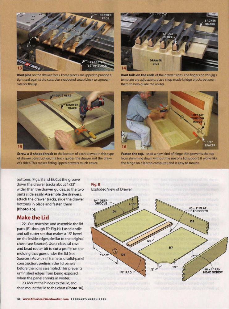
Rout pins on the drawer faces. These pieces are lipped to provide a
tight seal against the case. Use a rabbeted setup block to compen
sate for the lip.
Screw a U-shaped track to the bottom of each drawer. In this type
of drawer construction, the track guides the drawer, not the draw
er's sides. This makes fitting lipped drawers much easier.
Fig.B
DRAWER SIDE
Rout tails on the ends of the drawer sides. The fingers on this jig's
template are adjustable; place shop-made bridge blocks between
them to help guide the router.
Fasten the top. I used a new kind of hinge that prevents the top
from slamming down without the use of a lid support. It works like
the hinge on a laptop computer, and is easy to mount.
bottoms (Figs. B and E). Cut the groove down the drawer tracks about 1/ 32" wider than the drawer guides, so the two parts slide easily. Assemble the drawers, attach the drawer tracks, slide the drawer bottoms in place and fasten them (Photo 15).
Exploded View of Drawer
Make the Lid 22. Cut, machine, and assemble the lid
parts (E1 through E9, Fig. H). I used a stile and rail cutter set that makes a 15° bevel on the inside edges, similar to the original chest (see Sources). Use a classical cove
and bead router bit to cut a profile-on the molding that goes under the lid (see Sources). As with all frame and solid-panel
construction, prefinish the lid panels before the lid is assembled. This prevents unfinished edges from being exposed when the panel shrinks in winter.
23. Mount the hinges to the lid, and then mount the lid to the chest (Photo 16).
68 www.AmericanWoodworker.com FEB R U A R Y I MAR C H20 0 9

Fig. C Drawer Face Fig. D Drawer Details
* NOMINAL DIMENSIONS
5/1~ Ir END VIEW
DRAWER FACE PINS
Fig. F Chest Dovetails
Fig.E Drawer Track
Fig.G Web Frame Details
B1
1/4" r-~" r 1"
J -J 114"
BACK CORNER NOTCHES
t 2-7~
2-7/32"
2-7t 10-1/2"
2-7t ~ L ah"
t Ai
END VIEW PINBOARD
CHEST FRONT
The hallmark of classic dovetails: wide tails
and narrow pins.
FRONT VIEW TAILBOARDS CHEST SIDES
1t 1/4" {CENTER RAIL { EN~ RAIL
B3 t ~3 B2 h B3 <} -i:-I-__ B3_----'?L __ B2_----' 1/2"...IT 7/16"Tk-'--------+
PANEL TO RAIL JOINTS
{ FRONT STILE $ BAC:
1
STILE
I B:/16"~'-----'B:....:3----+<} -i:+-_-=-B.::....3_-, PANEL TO STILE JOINTS
Fig. H Cross Section of Lid
SIDE SECTION VIEW
i
T 4-15/16"
D1 1 ~ -!------J
D1
FRONT VIEW DRAWER SIDE TAILS
END VIEW DRAWER
BACK PINS
Fig.J Feet
END VIEW FRONT VIEW PINBOARD PIN BOARD
CHEST BACK CHEST BACK
r 2-1/8"
L f C1" ca8 ~ ;
1" xl" SQUARES
1-7/8"-+
::',> l,'"
i ,~ r/
", ,') h ' iV' f;"{ LI.2 L
l-s~=---'---''''''''-'"''''''"''''''''''''''l 6-1/4"
J J- L1-S/8"
FEB R U A R Y I MAR C H20 0 9 www.AmericanWoodworker.com 69

Clamp 1/8" thick spacers to the side of
the chest to position the lid. Note that
the back of the lid is flush with the back
of the chest. There should be a 1/8" gap
between the inside of the lid's front
molding and the case.
Finishing 24. Remove the lid and base, do any
remaining sanding, and apply a finish
(see Aged Cherry Finish, page 72). It
isn't necessary to finish the inside of
the chest or drawers, but I like to do it
to make a perfectly smooth surface
that fabric won't catch on. Plus, it helps
prevent the wood from imparting any
odors to clothing stored in the chest.
25. After assembly, wax the drawer
tracks, guides, d rawer side top and bot
tom edges, and web frame bearing sur
faces so the drawers operate smoothly.
Paraffin or canning wax works well. b...
SOURCES
• Porter Cable, www.deltaportercable.com. (888) 848-
5175,24" Omnijig Joinery System,
#77240, $600.
• Freud, www.freudtools.com. (800) 334-4107, Adjustable Tongue & Groove
Bit Set, #99-036, $70; Cove and Bead
Router Bit, #38-314, $42; Classical Cove
and Bead Router Bit, #38-524, $32.
• Infinity Cutting Tools, www.infinitytools.com. (877) 872-2487,
15° Matched Shaker Rail & Stile Set,
#91-505, $90; Professional Coping Sled,
#COP-l 00, $130.
• Woodworker's Supply, www.woodworker.com. (800) 645-9292,
1-1/4" Cherry Face Grain Knob, #938-
741, $5.49 apiece.
• Rockier, www.rockler.com. (800) 279-4441, Lid Stay Torsion Hinges, (use
online Torsion Calculator to determine
which hinges you'll need). about $20
per hinge;Titebond II Extend Slow-Set
Wood Glue, $7.39/pint.
Bruce Kieffer is a freelance woodworking author, technical illustrator, and custom furniture builder. You can see a collection of his work from the past 30 years on his website, www.kcfi .biz.
SHAKER BLANKET CHEST Overall Dimenslons:49-1/2"W x 29-1!4" T x 21'S/8"D
PART NAME QTY. MATERIAL TH X W X L
Chest
A1 Front Cherry 3/4" x 10-1/2" x 47-1/2"
A2 Side 2 Cherry 3/4" x 22-1/4" x 20-1/8"
A3 Back Cherry 3/4" x 22-1/4" x 47-1/2"
Web Frames
B1 Stile 6 Maple 3/4" x 3" x 46-1/2"
B2 Rail 9 Maple 3/4" x 3" x 13-3/4" (a)
B3 Panel 6 Poplar 1/2" x 13-518" x 19-5/8" (b)
B4 Divider Poplar 3/4" x 5-1/2" x 18-5/8"
B5 Drawer Guide 3 Maple 3/8" x 3/4" x 18-5/8"
B6 Mid Edging Cherry 3/4" x 3/4" x 46"
B7 Bottom Edging Cherry 3/4" xl" x 46"
B8 Divider Edging Cherry 3/4" xl" x 5"
Base
C1 Front Cherry 3/4" x 6-314" x 49"
C2 Back 1 Cherry 3/4" x 6-1/4" x 47-1/2"
C3 Side 2 Cherry 3/4" x 6-3/4" x 20-7/8"
C4 Cleat 1 Cherry 3/4" x 1-5/8" x 47-1/2"
C5 Cleat 2 Cherry 3/4" x 1-5/8" x 18-5/8"
C6 Corner Block 4 Cherry 3/4" x 3/4" x 4-5/8"
Drawers
D1 Side 6 Poplar 1/2"x4-15/16"x 18-3/4" (c)
D2 Back 2 Poplar 1/2" x 4-118" x 22-3/8" (d)
D3 Back Poplar 1/2" x 4-1/8" x 45-7/8" (d)
D4 Face 2 Cherry 3/4" x 5-114" x 23"
D5 Face Cherry 3/4" x 5-1/4" x 46-1/2"
D6 Drawer Track 3 Maple 3/4"x 1-1/2"x 18-3/4"
D7 Bottom 4 Poplar 1/2" x 18-3/4" xl 0-7/16"
D8 Bottom 2 Poplar 1/2" x 18-3/4" x 22-3/16"
lid
E1 Stile Cherry 3/4" x 3-3/4" x 48-1/2"
E2 Stile Cherry 3/4" x 3-1/4" x 48-1/2"
E3 Stile Cherry 3/4" x 4-9/16" x 40-7/8" (a)
E4 Rail 2 Cherry 3/4" x 4-1/4" x 14-9/16" (a)
E5 Panel 2 Cherry 7/16" x 5-5/16" x 40-3/4" (b)
E6 Trim Cherry 1/2" x 3/4" x 49-1/2"
E7 Trim 2 Cherry 1/2" x 3/4" x 21-1/8"
E8 Molding Cherry 5/8" x 13/16" x 49-3/8"
E9 Molding 2 Cherry 5/8" x 13/16" x 21-1/8"
Notes:
(a) Length based on 7/16" long rail end tongues. (b) Length and width based on 7/16" deep frame grooves.
(c) Actual length is determined by the height of the tail cut with your dovetail jig. Total length of drawer from rear of drawer face lip to rear of drawer is 19".
(d) Cut initially to 4-15/16" wide, rout dovetails, then cut to 4-1/8" wide.
70 www.AmericanWoodworker.com FEB R U A R Y I MAR C H20 0 9


Blend Color Mismatches Use the same method to blend cherry sapwood and heartwood, plywood and solid wood, and even color variations between boards. Begin by sealing the entire surface with one or two coats of Gel Topcoat. This step also shows the
SAPWOOD
1Iel''mp,o~t on all.
wood's natural color, so you can choose the most comp'lementary stain color: Candlelite gel stain is a great place to start. When the Topcoat has dried, apply Candlelite gel stain to the lightcolored sapwood only. Gel stain is per-
/
/'
feet for this job, because its thick, nodrip consistency makes it easy to control. When this first coat of stain has dried, apply a second coat of Candlelite gel stain over the entire surface. ~
FEB R U A R Y I MAR C H20 0 9 www.AmericanWoodworker.com 73

Fas -and-Easy rawer Boxes
I built a dedicated router table for quickly making lots of drawers. It has two routers: the left machine has a 1/4" straight bit, and the right mach ine has a 1/ 2" straight bit. Both bits stick up 1/4".
74 www.AmericanWoodworker.com FE B R UA RY 1M A RC H 2009
A unique router table, with
two machines, does the trick.
By Jeff Corns
MAKING DRAWERS can chew up a lot of time-unless you've got an efficient system. I've worked in several cabinetmaking shops where draw-ers are made fast. I've adopted their methods for my home shop, where I often make cabinets that require lots of drawers. But even if you don't need to work fast, this system works quite well.
As drawers go, this design is pretty simple. It's a classic four-piece drawer box, made from 1/2" Baltic birch. It's intended for utilitarian furniture, not showpieces. The box is dadoed, glued, and nailed together: joinery that's strong enough for a drawer that runs on slides. After the box is built, it receives an applied front, which is usually hardwood or edge-banded plywood.
Let's begin with a drawer-making station I built that saves a lot of set-up time (Photo 1).
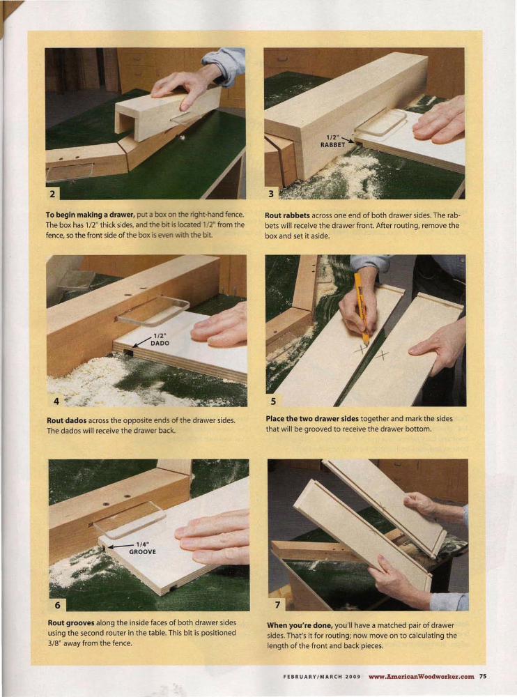
To begin making a drawer, put a box on the right-hand fence.
The box has 1/2" thick sides, and the bit is located 1 /2" from the
fence, so the front side of the box is even with the bit.
Rout dados across the opposite ends of t he drawer sides.
The dad os will receive the drawer back.
Rout grooves along the inside faces of both drawer sides using the second router in the table. This bit is positioned
3/8" away from the fence.
Rout rabbets across one end of both drawer sides. The rab
bets will receive the drawer front. After routing, remove the
box and set it aside.
Place the two drawer sides together and mark the sides
that will be grooved to receive the drawer bottom.
When you're done, you'll have a matched pair of drawer
sides. That's it for routing; now move on to calculating the
length of the front and back pieces.
FEB R U A RY I MARC H 2009 www.AmericanWoodworker.com 75

TWO DRAWER SIDES
Hold the two drawer sides back-to-back. Place a ruler across the two rabbets to directly calculate the front and back pieces' length. For example, the ruler reads 16-3/16" at right, the size of the finished drawer; at left, the ruler reads 15-11 /1 6" , the length to cut the front and back pieces. Rip the fronts the same width as the sides; rip the back piece 5/S" narrower than the sides.
Temporarily assemble the drawer. Make the bottom from 1/4" plywood. Rip it 1 / 32" narrower than the length of the front and back pieces. Crosscut it 1" extra-long . Slide in the bottom and mark its length to be flush with the back.
Assemble the drawer using glue and 1" long lS-gauge brads. Place the drawer parts upside down, to align their top edges. Start with the back corners.
76 www.AmericanWoodworker.com FEB R UA RY 1M A RC H 2009
Using a different router table, round over the top edges of the drawer parts using a 1/4" roundover bit. Flip each piece over and rout both sides.
Glue and nail the front. Then slide the bottom in almost all of the way, and turn the drawer over.

Run a bead of glue across the end of the drawer bottom, then push the bottom into the front groove. Turn the drawer over.
Add slides and mount the drawer in the cabinet. Attach the solid-wood front piece with double-faced tape, then open the drawer and fasten the front with screws from the inside. b..
To make sure the drawer is square, nest it inside two strips screwed to a large piece of plywood. Fasten the bottom using 1/4" crown staples, 3/4" long.
Add glue blocks around the bottom.
They're 3/8" square and 2" long. Just rub them in place; they don't need to be nailed. These blocks hold the drawer square and keep the bottom from rattling if it fits loose in the grooves.
FEBRUARY / MARCH 2009 www.AmericanWoodworker.com 77

----s\ Crazy Mistakes Woodworkers Make
Flaming Scroll Saw WHEN I WORK in my garage shop, I keep the garage door open to let the sunlight stream in. After working for several hours one fine afternoon, I caught a whiff of that acrid "electrical" smell. Something was burning! None of my tools were running or even plugged in, so I checked outside. Nothing. But as I reentered the shop, I noticed a wisp of smoke. I traced the smoke to its source and couldn't believe what had happened.
My scroll saw has a large magnifying lamp attached. The lens happened to be fixed at just the right angle to direct the sunlight at the saw's plastic housing. The laser-like beam had melted the housing and set it afi reo
My most recent shop purchases have been a new housing for the saw and a cover for the magnify-. I /" mg g ass. <'
-Bill Aurand
82 www.AmericanWoodworker.com FEB R U A R Y I MAR C H20 0 9
memorable "What was I thinking?"
blunders. You'll receive $100 for each
one we print. E-mail to:
or send to AW Oops!, American
Woodworker, 1285 Corporate
Center Drive, Suite180, Eagan, MN
55121. Submissions can't be
returned and become our property
upon acceptance and payment. We
may edit submissions and use them
in all print and electronic media.