Altivar 71 - NET
34
NHA33281 www.schneider-electric.com Altivar 71 Variable speed drives for synchronous and asynchronous motors Network braking units manual VW3A72101 ... 112 09/2015
-
Upload
khangminh22 -
Category
Documents
-
view
1 -
download
0
Transcript of Altivar 71 - NET

NH
A33
281
www.schneider-electric.com
Altivar 71Variable speed drivesfor synchronous and asynchronous motors
Network braking units manualVW3A72101 ... 112
09/2015

The information provided in this documentation contains general descriptions and/or technical characteristics of the performance of the products contained herein. This documentation is not intended as a substitute for and is not to be used for determining suitability or reliability of these products for specific user applications. It is the duty of any such user or integrator to perform the appropriate and complete risk analysis, evaluation and testing of the products with respect to the relevant specific application or use thereof. Neither Schneider Electric nor any of its affiliates or subsidiaries shall be responsible or liable for misuse of the information contained herein. If you have any suggestions for improvements or amendments or have found errors in this publication, please notify us.
No part of this document may be reproduced in any form or by any means, electronic or mechanical, including photocopying, without express written permission of Schneider Electric.
All pertinent state, regional, and local safety regulations must be observed when installing and using this product. For reasons of safety and to help ensure compliance with documented system data, only the manufacturer should perform repairs to components.
When devices are used for applications with technical safety requirements, the relevant instructions must be followed.
Failure to use Schneider Electric software or approved software with our hardware products may result in injury, harm, or improper operating results.
Failure to observe this information can result in injury or equipment damage.
© 2015 Schneider Electric. All rights reserved.

NHA33281 09/2015 3
Contents
Contents ____________________________________________________________________________________________________ 3Before you begin______________________________________________________________________________________________ 4Steps for setting up the Network braking unit________________________________________________________________________ 7Recommendations ____________________________________________________________________________________________ 8Checking the installation________________________________________________________________________________________ 9Technical Data ______________________________________________________________________________________________ 14Sizing _____________________________________________________________________________________________________ 16Dimensions and Mounting _____________________________________________________________________________________ 20Mounting and temperature conditions ____________________________________________________________________________ 22Connection diagrams, fuses and associated cables__________________________________________________________________ 23Grounding System ___________________________________________________________________________________________ 27Electromagnetic Compatibility __________________________________________________________________________________ 28Commissioning ______________________________________________________________________________________________ 30Diagnostic and Troubleshooting _________________________________________________________________________________ 31

Before you begin
Important Information
NOTICERead these instructions carefully, and look at the equipment to become familiar with the device before trying to install, operate, or maintain it. The following special messages may appear throughout this documentation or on the equipment to warn of potential hazards or to call attention to information that clarifies or simplifies a procedure.
PLEASE NOTEElectrical equipment should be installed, operated, serviced, and maintained only by qualified personnel. No responsibility is assumed by Schneider Electric for any consequences arising out of the use of this material.
A qualified person is one who has skills and knowledge related to the construction and operation of electrical equipment and its installation, and has received safety training to recognize and avoid the hazards involved.
Qualification Of PersonnelOnly appropriately trained persons who are familiar with and understand the contents of this manual and all other pertinent product documentation are authorized to work on and with this product. In addition, these persons must have received safety training to recognize and avoid hazards involved. These persons must have sufficient technical training, knowledge and experience and be able to foresee and detect potential hazards that may be caused by using the product, by changing the settings and by the mechanical, electrical and electronic equipment of the entire system in which the product is used. All persons working on and with the product must be fully familiar with all applicable standards, directives, and accident prevention regulations when performing such work.
4 NHA33281 09/2015

Before you begin
Intended UseThis product is a drive for three-phase synchronous and asynchronous motors and intended for industrial use according to thismanual.The product may only be used in compliance with all applicable safety regulations and directives, the specified requirementsand the technical data.Prior to using the product, you must perform a risk assessment in view of the planned application. Based onthe results, the appropriate safety measures must be implemented.Since the product is used as a component in an entire system,you must ensure the safety of persons by means of the design of this entire system (for example, machine design). Any use otherthan the use explicitly permitted is prohibited and can result in hazards. Electrical equipment should be installed, operated, serviced,and maintained only by qualified personnel.
Product Related InformationRead and understand these instructions before performing any procedure with this drive.
DANGERHAZARD OF ELECTRIC SHOCK, EXPLOSION OR ARC FLASH• Only appropriately trained persons who are familiar with and understand the contents of this manual and all other pertinent
product documentation and who have received safety training to recognize and avoid hazards involved are authorized to work on and with this drive system. Installation, adjustment, repair and maintenance must be performed by qualified personnel..
• The system integrator is responsible for compliance with all local and national electrical code requirements as well as all other applicable regulations with respect to grounding of all equipment.
• Many components of the product, including the printed circuit boards, operate with mains voltage. Do not touch. Use only electrically insulated tools.
• Do not touch unshielded components or terminals with voltage present.• Motors can generate voltage when the shaft is rotated. Prior to performing any type of work on the drive system, block the
motor shaft to prevent rotation.• AC voltage can couple voltage to unused conductors in the motor cable. Insulate both ends of unused conductors of the motor
cable• Do not short across the DC bus terminals or the DC bus capacitors or the braking resistor terminals.• Before performing work on the drive system:
- Disconnect all power, including external control power that may be present.- Place a Do Not Turn On label on all power switches.- Lock all power switches in the open position.- Wait 15 minutes to allow the DC bus capacitors to discharge. The DC bus LED is not an indicator of the absence of DC
bus voltage that can exceed 800 Vdc.- Measure the voltage on the DC bus between the DC bus terminals (PA/+, PC/–) using a properly rated voltmeter to verify
that the voltage is <42 Vdc- If the DC bus capacitors do not discharge properly, contact your local Schneider Electric representative. Do not repair or
operate the product.• Install and close all covers before applying voltage.Failure to follow these instructions will result in death or serious injury.
NHA33281 09/2015 5

Before you begin
Damaged products or accessories may cause electric shock or unanticipated equipment operation.
Contact your local Schneider Electric sales office if you detect any damage whatsoever.
(1) For USA: Additional information, refer to NEMA ICS 1.1 (latest edition), Safety Guidelines for the Application, Installation, and Maintenance of Solid-State Control and to NEMA ICS 7.1 (latest edition), Safety Standards for Construction and Guide for Selection, Installation and Operation of Adjustable-Speed Drive Systems.
WARNINGUNEXPECTED MOVEMENTDrive systems may perform unexpected movements because of incorrect wiring, incorrect settings, incorrect data or other errors.• Carefully install the wiring in accordance with the EMC requirements.• Do not operate the product with unknown or unsuitable settings or data.• Perform a comprehensive commissioning test.
Failure to follow these instructions can result in death, serious injury, or equipment damage.
DANGERELECTRIC SHOCK OR UNANTICIPATED EQUIPMENT OPERATIONDo not use damaged products or accessories.
Failure to follow these instructions will result in death or serious injury.
WARNINGLOSS OF CONTROL
• The designer of any control scheme must consider the potential failure modes of control paths and, for critical control functions, provide a means to achieve a safe state during and after a path failure. Examples of critical control functions are emergency stop, overtravel stop, power outage and restart.
• Separate or redundant control paths must be provided for critical control functions.• System control paths may include communication links. Consideration must be given to the implications of unanticipated
transmission delays or failures of the link.• Observe all accident prevention regulations and local safety guidelines (1).• Each implementation of the product must be individually and thoroughly tested for proper operation before being placed into
service.
Failure to follow these instructions can result in death, serious injury, or equipment damage.
NOTICEDESTRUCTION DUE TO INCORRECT MAINS VOLTAGEBefore switching on and configuring the product, verify that it is approved for the mains voltage
Failure to follow these instructions can result in equipment damage.
WARNINGHOT SURFACES
• Ensure that any contact with hot surfaces is avoided.• Do not allow flammable or heat-sensitive parts in the immediate vicinity of hot surfaces.• Verify that the heat dissipation is sufficient by performing a test run under maximum load conditions.
Failure to follow these instructions can result in death, serious injury, or equipment damage.
6 NHA33281 09/2015

Steps for setting up the Network braking unit
Steps 1 to 4 must be performed with the power off
b 1 Receive and inspect of the Network braking unit (see page 8)
v Check that the catalog number printed on the label is the same as that on the purchase order.
v Remove the Network braking unit from its packaging and check that it has not been damaged.
b 2 Verify the supply mains (see page 14)v Verify that the supply mains is compatible with the
voltage range of the Network braking unit
b 3 Install the Network braking unit (see page 22)v Mount the Network braking unit in accordance with
the instructions in this document
b 4 Wire the Network braking unit (see page 23)
v Connect the Network braking unit to the 3-phase supply (L1, L2, L3)
v Connect the Network braking unit to the drive DC bus
v Connect the control cable
NHA33281 09/2015 7

Recommendations
ReceiptVerify that the equipment catalog number printed on the label is the same as that on the delivery note corresponding to the purchase order. Open the packaging and check that the equipment has not been damaged in transit.
For more information, please contact your local representative.
Contact your local Schneider Electric sales office if you detect any damage whatsoever.
DANGERELECTRIC SHOCK OR UNANTICIPATED EQUIPMENT OPERATIONDo not use damaged products or accessories.
Failure to follow these instructions will result in death or serious injury.
8 NHA33281 09/2015

Checking the installation
Cable length of the DC busThe maximum inductance of the DC bus connecting output PA/+, PC/– on the drive to the Network braking unit must not exceed a set level,as this inductance results in an additional difference in potential on the DC bus when the IGBTs are open. To avoid an overload on thecomponents of the Network braking unit, this difference in potential must not exceed 100 Vdc. The maximum inductance can be calculatedusing this and other characteristics of the Network braking unit (value of the DC bus capacitors and absolute value of the grid current).
This inductance must be greater than or equal to the sum of the inductance of the DC bus on the drive and the inductance of the DC busconnection cables. The inductance of the DC bus on the drive must be taken into consideration. The inductance per unit of length of thecables generally used for the power supply is close to around of 0.6 µH/m.
The maximum length of the conductors LMAX is calculated according to the following information:• Values of the input capacities C• Maximum DC voltage edge permitted during motor generator operation (ΔUGL = 100 Vdc)• Maximum AC current level for the equipment î (=2*Irms)• Inductance per unit of length L'• Inductance of the coil LZKD of the DC bus
The equation below can be used to calculate Lmax:
Typical capacity of the DC connection inside the Network braking unit
Example:C = 200 μF, ΔUGL = 100 V, i = 271 A, a = 80 mm (3.15 in.), r = 8.5 mm (0.3 in.), μ0=1.257.10-6 H/m
For longer DC bus cables, additional capacitors have to be installed (Please contact your local representative).
Network braking unit Power DC capacity
VW3A7...
8 - 16 kW 20 μF
20 - 32 kW 40 μF
40 - 48 kW 100 μF
58 kW 220 μF
80 - 140 kW 440 μF
170 - 200 kW 660 μF
230 kW 880 μF
265 kW 1100 μF
300 - 345 kW 1320 μF
( )2
2ˆGL
MAX
C UL
I• Δ
=
( )2
2ˆGL ZKD
MAX
C U LLLI L
• Δ= −
′′•
NHA33281 09/2015 9
Checking the installation
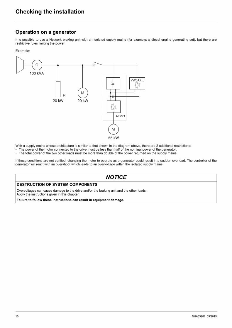
Operation on a generatorIt is possible to use a Network braking unit with an isolated supply mains (for example: a diesel engine generating set), but there arerestrictive rules limiting the power.
Example:
With a supply mains whose architecture is similar to that shown in the diagram above, there are 2 additional restrictions:• The power of the motor connected to the drive must be less than half of the nominal power of the generator.• The total power of the two other loads must be more than double of the power returned on the supply mains.
If these conditions are not verified, changing the motor to operate as a generator could result in a sudden overload. The controller of thegenerator will react with an overshoot which leads to an overvoltage within the isolated supply mains.
NOTICEDESTRUCTION OF SYSTEM COMPONENTSOvervoltages can cause damage to the drive and/or the braking unit and the other loads.Apply the instructions given in this chapter.
Failure to follow these instructions can result in equipment damage.
M
M
VW3A7...
R
ATV71
20 kW 20 kW
100 kVA
55 kW
G
10 NHA33281 09/2015
Checking the installation
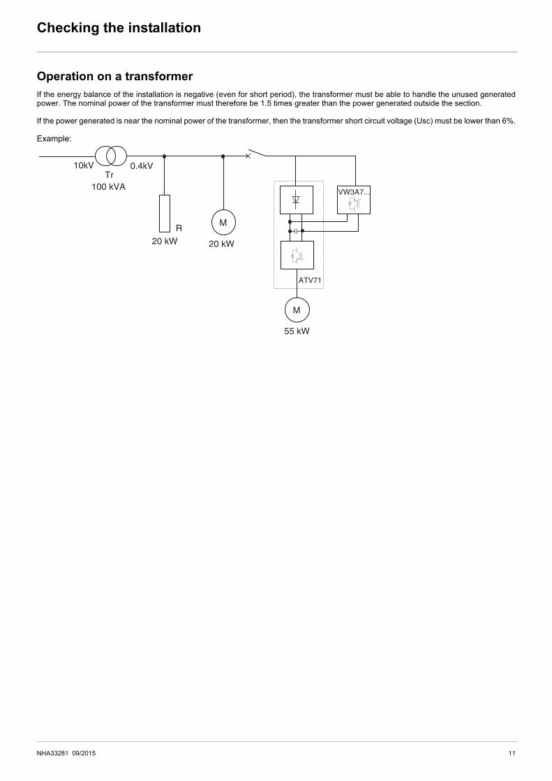
Operation on a transformerIf the energy balance of the installation is negative (even for short period), the transformer must be able to handle the unused generatedpower. The nominal power of the transformer must therefore be 1.5 times greater than the power generated outside the section.
If the power generated is near the nominal power of the transformer, then the transformer short circuit voltage (Usc) must be lower than 6%.
Example:
M
MR
Tr10kV 0.4kV
ATV71
VW3A7...100 kVA
20 kW
55 kW
20 kW
NHA33281 09/2015 11

Checking the installation
Position of the Line ChokeIf the drive is connected to an external line choke, then the Network braking unit must be connected according to the diagram below. If theNetwork braking unit is connected downstream of the line choke, then the inductance of the line choke prevents the Network braking unitfrom synchronizing on supply mains and thus generates overvoltages.
Example:
NOTICERISK OF DAMMAGE TO THE EQUIPMENTIf the drive is connected to an external line choke, connect the Network braking unit according to the diagram below.
Failure to follow these instructions can result in equipment damage.
M
ATV71
VW3A7...
12 NHA33281 09/2015
Checking the installation
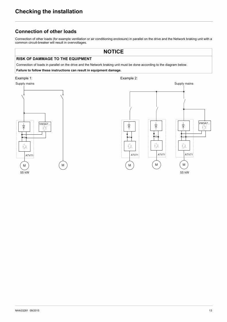
Connection of other loadsConnection of other loads (for example ventilation or air conditioning enclosure) in parallel on the drive and the Network braking unit with acommon circuit-breaker will result in overvoltages.
Example 1: Example 2:
NOTICERISK OF DAMMAGE TO THE EQUIPMENTConnection of loads in parallel on the drive and the Network braking unit must be done according to the diagram below.
Failure to follow these instructions can result in equipment damage.
M
ATV71
Supply mains Supply mains
M
VW3A7...
55 kW 55 kW
M
ATV71
M
ATV71
M
ATV71
VW3A7...
NHA33281 09/2015 13
Technical Data
General Data
Electrical Data
Connection characteristics
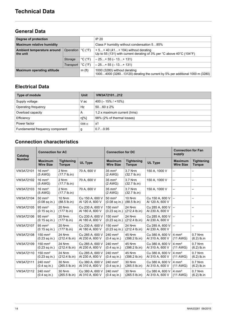
Degree of protection IP 20
Maximum relative humidity Class F humidity without condensation 5…85%
Ambient temperature around the unit
Operation °C (°F) + 5…+ 40 (41…+ 104) without deratingUp to 55 (131) with current derating of 3% per °C above 40°C (104°F)
Storage °C (°F) – 25…+ 55 (– 13…+ 131)
Transport °C (°F) – 25…+ 55 (– 13…+ 131)
Maximum operating altitude m (ft) 1000 (3280) without derating1000…4000 (3280...13120) derating the current by 5% per additional 1000 m (3280)
Type of module Unit VW3A72101...212
Supply voltage V ac 400 (– 15% / +10%)
Operating frequency Hz 50…60 ± 2%
Overload capacity A 1.2 x maximum current (Irms)
Efficiency ƞ[%] 98% (2% of thermal losses)
Power factor cos ϕ ±1
Fundamental frequency component g 0.7…0.95
CatalogNumber
Connection for AC Connection for DC Connection for Fan supply
Maximum Wire Size
Tightening Torque UL Type Maximum
Wire SizeTightening Torque UL Type Maximum
Wire SizeTightening Torque
VW3A72101 16 mm²(5 AWG)
2 N•m(17.7 lb.in)
70 A, 600 V 35 mm²(2 AWG)
3.7 N•m(32.7 lb.in)
150 A, 1000 V – –
VW3A72102 16 mm²(5 AWG)
2 N•m(17.7 lb.in)
70 A, 600 V 35 mm²(2 AWG)
3.7 N•m(32.7 lb.in)
150 A, 1000 V – –
VW3A72103 16 mm²(5 AWG)
2 N•m(17.7 lb.in)
70 A, 600 V 35 mm²(2 AWG)
3.7 N•m(32.7 lb.in)
150 A, 1000 V – –
VW3A72104 50 mm²(0.08 sq in.)
10 N•m(88.5 lb.in)
Cu 150 A, 600 VAl 120 A, 600 V
50 mm²(0.08 sq in.)
10 N•m(88.5 lb.in)
Cu 150 A, 600 VAl 120 A, 600 V
– –
VW3A72105 95 mm²(0.15 sq in.)
20 N•m(177 lb.in)
Cu 230 A, 600 VAl 180 A, 600 V
150 mm²(0.23 sq in.)
24 N•m(212.4 lb.in)
Cu 285 A, 600 VAl 230 A, 600 V
– –
VW3A72106 95 mm²(0.15 sq in.)
20 N•m(177 lb.in)
Cu 230 A, 600 VAl 180 A, 600 V
150 mm²(0.23 sq in.)
24 N•m(212.4 lb.in)
Cu 285 A, 600 VAl 230 A, 600 V
– –
VW3A72107 95 mm²(0.15 sq in.)
20 N•m(177 lb.in)
Cu 230 A, 600 VAl 180 A, 600 V
150 mm²(0.23 sq in.)
24 N•m(212.4 lb.in)
Cu 285 A, 600 VAl 230 A, 600 V
– –
VW3A72108 150 mm²(0.23 sq in.)
24 N•m(212.4 lb.in)
Cu 285 A, 600 VAl 230 A, 600 V
240 mm²(0.4 sq in.)
45 N•m(398.2 lb.in)
Cu 380 A, 600 VAl 310 A, 600 V
4 mm²(11 AWG)
0.7 N•m(6.2) lb.in
VW3A72109 150 mm²(0.23 sq in.)
24 N•m(212.4 lb.in)
Cu 285 A, 600 VAl 230 A, 600 V
240 mm²(0.4 sq in.)
45 N•m(398.2 lb.in)
Cu 380 A, 600 VAl 310 A, 600 V
4 mm²(11 AWG)
0.7 N•m(6.2) lb.in
VW3A72110 150 mm²(0.23 sq in.)
24 N•m(212.4 lb.in)
Cu 285 A, 600 VAl 230 A, 600 V
240 mm²(0.4 sq in.)
45 N•m(398.2 lb.in)
Cu 380 A, 600 VAl 310 A, 600 V
4 mm²(11 AWG)
0.7 N•m(6.2) lb.in
VW3A72111 240 mm²(0.4 sq in.)
30 N•m(265.5 lb.in)
Cu 380 A, 600 VAl 310 A, 600 V
240 mm²(0.4 sq in.)
30 N•m(265.5 lb.in)
Cu 380 A, 600 VAl 310 A, 600 V
4 mm²(11 AWG)
0.7 N•m(6.2) lb.in
VW3A72112 240 mm²(0.4 sq in.)
30 N•m(265.5 lb.in)
Cu 380 A, 600 VAl 310 A, 600 V
240 mm²(0.4 sq in.)
30 N•m(265.5 lb.in)
Cu 380 A, 600 VAl 310 A, 600 V
4 mm²(11 AWG)
0.7 N•m(6.2) lb.in
14 NHA33281 09/2015
Technical Data
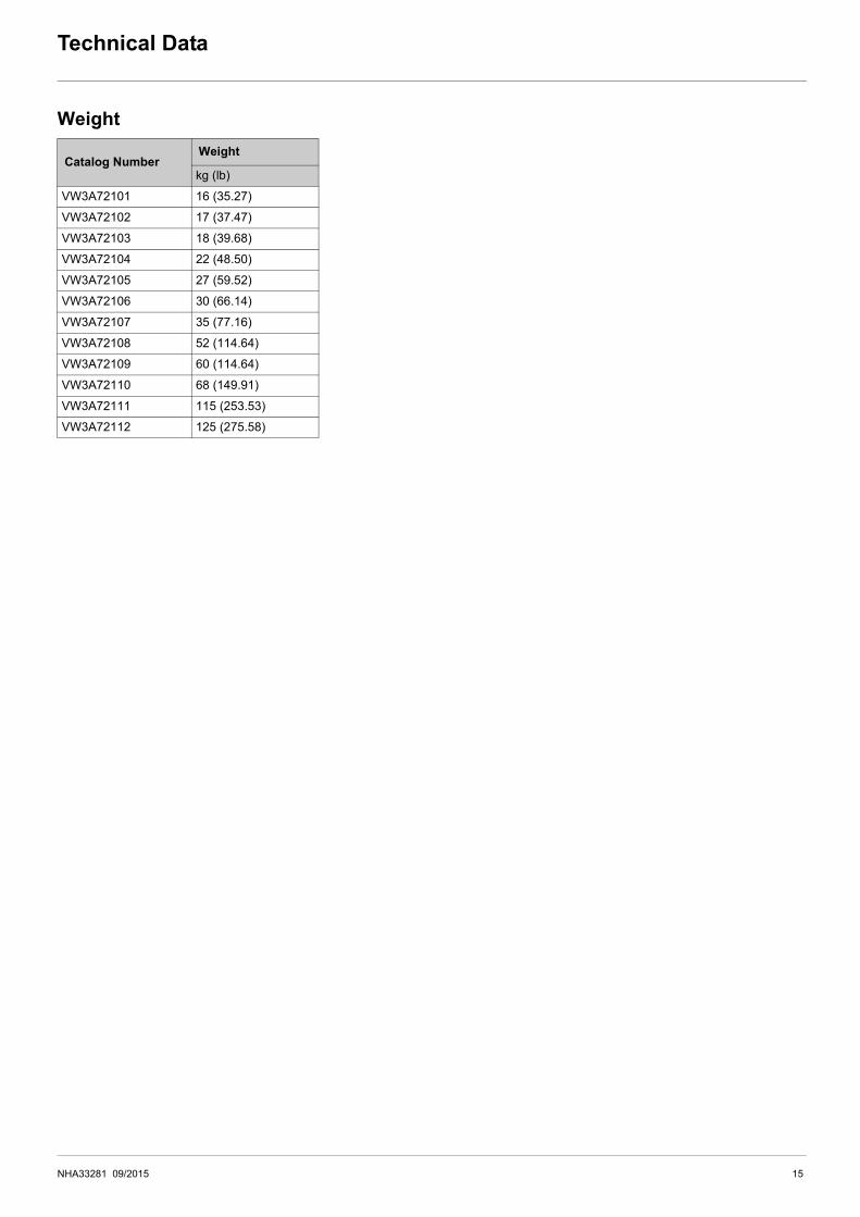
Weight
Catalog NumberWeight
kg (lb)
VW3A72101 16 (35.27)
VW3A72102 17 (37.47)
VW3A72103 18 (39.68)
VW3A72104 22 (48.50)
VW3A72105 27 (59.52)
VW3A72106 30 (66.14)
VW3A72107 35 (77.16)
VW3A72108 52 (114.64)
VW3A72109 60 (114.64)
VW3A72110 68 (149.91)
VW3A72111 115 (253.53)
VW3A72112 125 (275.58)
NHA33281 09/2015 15

Sizing
Network Braking Unit SizingThe selection of the Network braking unit depends on your application. Calculate the targeted braking power of your installation to selectthe right Network braking unit.
Braking Cycle Time Characteristics
CatalogNumber
MainsVoltage
BrakingPower
BrakingCurrent
Braking Cycle at 40°C (104°F)
Comment
MaximumBraking Time
MinimumNon BrakingTime
(Vac) (kW) (A) (s) (s)
VW3A72101 400 8 12 ∞ – Continuous braking power
400 9 13 400 180
400 10 14 300 180
400 11 16 3 – After 3 seconds, the Network braking unit will trigger an error (overcurrent)
VW3A72102 400 12 17 ∞ – Continuous braking power
400 13 19 400 180
400 14 20 300 180
400 16 23 3 – After 3 seconds, the Network braking unit will trigger an error (overcurrent)
VW3A72103 400 20 29 ∞ – Continuous braking power
400 22 32 400 180
400 24 35 300 180
400 26 37 3 – After 3 seconds, the Network braking unit will trigger an error (overcurrent)
%
s0
Braking time Braking timeNon braking time Non braking time
16 NHA33281 09/2015

Sizing
CatalogNumber
MainsVoltage
BrakingPower
BrakingCurrent
Braking Cycle at 40°C (104°F)
Comment
MaximumBraking Time
MinimumNon BrakingTime
(Vac) (kW) (A) (s) (s)
VW3A72104
400 19 27 ∞ – Continuous braking power
400 22 32 520 180
400 26 37 480 180
400 29 42 270 180
400 32 46 180 180
400 35 50 150 180
400 38 55 120 180
400 41 60 3 –After 3 seconds, the Network braking unit will trigger an error (overcurrent)
VW3A72105
400 29 42 ∞ – Continuous braking power
400 34 49 520 240
400 38 55 460 240
400 43 62 400 240
400 48 69 360 240
400 53 76 300 240
400 58 84 180 240
400 62 89 3 –After 3 seconds, the Network braking unit will trigger an error (overcurrent)
VW3A72106
400 48 69 ∞ - Continuous braking power
400 56 81 520 240
400 64 92 460 240
400 72 104 400 240
400 80 116 360 240
400 88 127 300 240
400 96 139 180 240
400 104 150 3 -After 3 seconds, the Network braking unit will trigger an error (overcurrent)
VW3A72107
400 57 82 ∞ - Continuous braking power
400 66 95 520 240
400 76 110 400 240
400 85 123 360 240
400 95 137 300 240
400 105 151 180 240
400 114 164 150 240
400 123 177 3 -After 3 seconds, the Network braking unit will trigger an error (overcurrent)
NHA33281 09/2015 17

Sizing
CatalogNumber
MainsVoltage
BrakingPower
BrakingCurrent
Braking Cycle at 40°C (104°F)
Comment
MaximumBraking Time
MinimumNon BrakingTime
(Vac) (kW) (A) (s) (s)
VW3A72108
400 84 121 ∞ – Continuous braking power
400 98 142 500 240
400 112 162 400 240
400 126 182 360 240
400 140 202 300 240
400 154 223 240 240
400 168 243 180 240
400 182 263 3 –After 3 seconds, the Network braking unit will trigger an error (overcurrent)
VW3A72109
400 91 132 ∞ – Continuous braking power
400 107 155 500 240
400 136 197 400 240
400 153 221 360 240
400 170 246 300 240
400 187 270 240 240
400 204 295 180 240
400 221 319 3 –After 3 seconds, the Network braking unit will trigger an error (overcurrent)
VW3A72110
400 120 173 ∞ – Continuous braking power
400 140 202 500 240
400 160 231 400 240
400 180 260 360 240
400 200 289 300 240
400 220 318 180 240
400 240 346 150 240
400 260 378 3 –After 3 seconds, the Network braking unit will trigger an error (overcurrent)
VW3A72111
400 133 192 ∞ – Continuous braking power
400 159 230 420 360
400 186 269 270 360
400 212 306 210 360
400 239 345 180 360
400 265 383 150 360
400 292 422 100 360
400 318 460 80 360
400 345 499 3 –After 3 seconds, the Network braking unit will trigger an error (overcurrent)
18 NHA33281 09/2015
Sizing
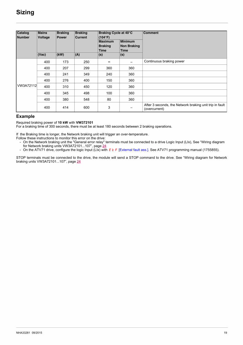
ExampleRequired braking power of 10 kW with VW372101For a braking time of 300 seconds, there must be at least 180 seconds between 2 braking operations.
If the Braking time is longer, the Network braking unit will trigger an over-temperature.Follow these instructions to monitor this error on the drive:
- On the Network braking unit the "General error relay" terminals must be connected to a drive Logic Input (LIx), See “Wiring diagram for Network braking units VW3A72101...107”, page 24
- On the ATV71 drive, configure the logic Input (LIx) with EtF [External fault ass.]. See ATV71 programming manual (1755855).
STOP terminals must be connected to the drive, the module will send a STOP command to the drive. See “Wiring diagram for Networkbraking units VW3A72101...107”, page 24
CatalogNumber
MainsVoltage
BrakingPower
BrakingCurrent
Braking Cycle at 40°C (104°F)
Comment
MaximumBraking Time
MinimumNon BrakingTime
(Vac) (kW) (A) (s) (s)
VW3A72112
400 173 250 ∞ – Continuous braking power
400 207 299 360 360
400 241 349 240 360
400 276 400 150 360
400 310 450 120 360
400 345 498 100 360
400 380 548 80 360
400 414 600 3 – After 3 seconds, the Network braking unit trip in fault (overcurrent)
NHA33281 09/2015 19

Dimensions and Mounting
VW3A72101 ... 107
VW3A72108 ... 111
VW3A72... Amm (in.)
Bmm (in.)
Cmm (in.)
Dmm (in.)
Emm (in.)
Fmm (in.)
Gmm (in.)
X1mm (in.)
X2mm (in.) 4 Ø
101... 103 409 (16.1) 240 (9.45) 240 (9.45) 211 (8.3) 365 (14.37) 340 (13.38) 384 (15.12) 150 (5.9) 70 (2.8) M6 x 20104 499 (19.64) 240 (9.45) 275 (10.83) 211 (8.3) 430 (16.92) 404 (15.9) 449 (17.67) 150 (5.9) 70 (2.8) M6 x 20
105 ... 107 568 (22.36) 255 (10) 315 (12.4) 226 (8.9) 530 (20.87) 504 (19.84) 549 (21.61) 150 (5.9) 70 (2.8) M6 x 20
VW3A72... Amm (in.)
Bmm (in.)
Cmm (in.)
Dmm (in.)
Emm (in.)
E’mm (in.)
Fmm (in.)
X1mm (in.)
X2mm (in.) Ø
108 ...110 763 (30.04) 273 (10.8) 305 (12) 254.4 (10) 490 (19.3) – 701.5 (27.62) 150 (5.9) 70 (2.8) 4 M6 x 20111 888 (85) 378 (14.9) 390 (15.34) 349.2 (13.75) 598 (23.54) 279 (11) 836 (33) 150 (5.9) 70 (2.8) 6 M8 x 20
G
AE F X2X2
X1
X1
CB
Ø D
A
B
D
C
F
EE
’
Ø
Ø
Ø
Ø
X2X2
X1
X1
20 NHA33281 09/2015

Dimensions and Mounting
VW3A72112
VW3A72... Amm (in.)
Bmm (in.)
Cmm (in.)
Dmm (in.)
Emm (in.)
E’mm (in.)
Fmm (in.)
X1mm (in.)
X2mm (in.) Ø
112 994 (39.13) 378 (14.9) 390 (15.34) 349.2 (13.75) 319 (12.56) 279 (11) 836 (33) 150 (5.9) 70 (2.8) 6 M8 x 20
C
AX2X2
X1
X1
D
B
F
EE
’Ø
Ø
NHA33281 09/2015 21

Mounting and temperature conditions
Required mounting positionThe Network braking unit has been designed to be mounted on a vertical wall only (+/– 15°). The unit can only be mounted on a smoothsurface without the use of any type of spacer. It must be mounted in this way to help correct circulation of the cooling air.
• Leave sufficient free space.- Leave a horizontal distance of at least 70 mm (2.8 in.) between the Network braking units and the other components, and between the
Network braking units and the enclosure walls.- Leave a vertical distance of at least 70 mm (2.8 in.) between the Network braking units and the other components, and between the
Network braking units and the enclosure walls.• Verify that there are no obstacles to the entry and exit of the cooling air. Leave a minimum distance of 15 cm (5.9 in.) at the air intake and
outlet apertures.• If the cooling air is polluted (dust, grease, corrosive gas) this may hamper some of the functions of the Network braking unit.
- Take appropriate measures, for example: Keep the cooling air separate, fit air filters, clean regularly.• Do not exceed the acceptable ambient temperature during use.
Dissipated thermal power = 3% of the maximum nominal power. Take into account this dissipated power if you install the Network Brakingunit in an Enclosure.The air temperature must not exceed 40°C (104°F) in the vicinity of the Network braking unit. The air inputs and air outputs at the top andbottom of the Network braking unit must not be covered by installation equipment such as cable ducts or other equipment.
The required air flow rate depends on the size of the Network braking unit (nominal power and nominal voltage).
Network braking unit Required air flow ratein m3/h (cu ft/h)
VW3A72101...104 200 (7063)
VW3A72105...107 350 (12360)
VW3A72108...110 450 (15892)
VW3A72111, 112 700 (24720)
22 NHA33281 09/2015

Connection diagrams, fuses and associated cables
Electrical power supplyBranch Circuit Protection (F4, F5, F6) Supply mains voltage: 400 Vac
Wiring
• All the connections must be as short as possible.• Shielded cables must be used in order to comply the EMC directives (in accordance with current standards such as EN 61800.3).• Connect the supply mains to terminals L1, L2 and L3 on the Network braking unit. Only a three-phase supply is permitted.• A defined phase sequence (indirect rotation of the field) must be followed when connecting the Network braking unit to the supply mains.
The Network braking unit has a phase sequence check. If the rotating field is incorrect, the LED "phase failure" is displayed. In this case, two phases connected to the Network braking unit must be inverted.
• Connect the ground of the power supply cables to the ground connection screw on the Network braking unit.• Wire the DC bus between the Drive and the Network braking unit.
Maximum CurrentIrms
ContinuousBraking Power
Fast-acting Semi-conductor Fuses AC uR
Catalog Number
a c a a
A A kW A V12 14 8 20 690 VW3A7210117 20 12 30 690 VW3A7210229 35 20 50 690 VW3A7210346 55 19 80 690 VW3A7210469 83 29 100 690 VW3A72105116 139 48 160 690 VW3A72106137 165 57 200 690 VW3A72107202 242 84 315 690 VW3A72108246 295 91 400 1100 VW3A72109290 348 120 500 1100 VW3A72110383 460 133 500 1100 VW3A72111500 600 173 630 1100 VW3A72112
WARNINGINSUFFICIENT PROTECTION AGAINST OVERCURRENTS• Properly rated overcurrent protective devices must be used.• Use the fuses specified in this manual.
Failure to follow these instructions can result in death, serious injury or equipment damage.
WARNINGSIGNAL AND DEVICE INTERFERENCESignal interference can cause unexpected responses of the device.• Install the wiring in accordance with the EMC requirements.• Verify compliance with the EMC requirements.
Failure to follow these instructions can result in death, serious injury or equipment damage.
DANGERHAZARD OF ELECTRIC SHOCK, EXPLOSION, OR ARC FLASH• The cable shield must be connected to Ground.• The shield must not come into contact with live parts
Failure to follow these instructions will result in death or serious injury.
NOTICEDESTRUCTION DUE TO INCORRECT WIRINGVerify the DC bus polarity connection.
Failure to follow these instructions can result in equipment damage.
NHA33281 09/2015 23

Connection diagrams, fuses and associated cables
Wiring diagram for Network braking units VW3A72101...107
(1) Optional additional EMC input filter, see the ATV71 Catalog on www.schneider-electric.com(2) Line reactor, use the fuses specified in the annex (S1B86981) provided with the drive.(3) For ATV71HC40N4 drives combined with a 400 kW (600 HP) motor and ATV71HC50N4, see the ATV71 Installation Manual (1755849).(4) Configuration of the LIx in external fault is necessary, see EtF [External fault ass.] on the ATV71 programming manual (1755855).
Components for use with the unit NOTE: for a complete list of references, see our “Motor starter solutions. Power control and protection components” specialist catalog).
Ref. Description
A1 ATV71 drive
A2 Network braking unit
F1, F2, F3 2 A fuse, 500 Vac, size: 5*30 mm
F4, F5, F6 For the fuses, refer to the reference tables on page 23
Q1 Residual current circuit breaker 300 mA.
A2
+ 2
4
PA/+PC/–
+–
U1
W1
V1
M 3
ATV 71Hppppp
Network braking unit
Q1
2 4 6
KM1
L1L2L3NPE
1 3 5
NC
S1
STOP RESET
NO
+ –
A1
2 4 6
1 3 5
21 43 87 1211
L1 L2 L3
F1
F2
F3
W/T
3
U/T
1
LIx
V/T
2
R/L
1
S/L
2
T/L
3
R1A
R1C
R1B
R2A
R2C
(1)
(2)
F6
F5
F4
(4)
(3) (3) (3)
24 NHA33281 09/2015
Connection diagrams, fuses and associated cables
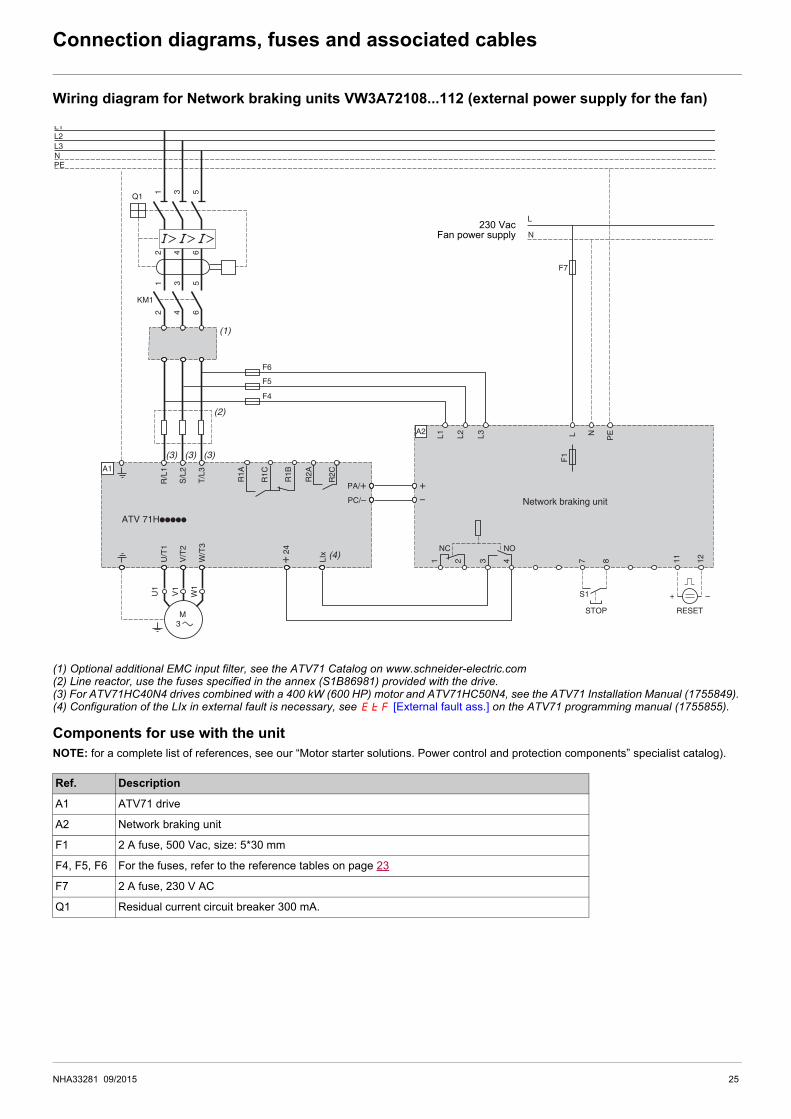
Wiring diagram for Network braking units VW3A72108...112 (external power supply for the fan)
(1) Optional additional EMC input filter, see the ATV71 Catalog on www.schneider-electric.com(2) Line reactor, use the fuses specified in the annex (S1B86981) provided with the drive.(3) For ATV71HC40N4 drives combined with a 400 kW (600 HP) motor and ATV71HC50N4, see the ATV71 Installation Manual (1755849).(4) Configuration of the LIx in external fault is necessary, see EtF [External fault ass.] on the ATV71 programming manual (1755855).
Components for use with the unit NOTE: for a complete list of references, see our “Motor starter solutions. Power control and protection components” specialist catalog).
Ref. Description
A1 ATV71 drive
A2 Network braking unit
F1 2 A fuse, 500 Vac, size: 5*30 mm
F4, F5, F6 For the fuses, refer to the reference tables on page 23
F7 2 A fuse, 230 V AC
Q1 Residual current circuit breaker 300 mA.
A2
+ 2
4
PA/+PC/–
+–
U1
W1
V1
M 3
ATV 71Hppppp
Network braking unit
Q1
2 4 6
KM1
L1L2L3NPE
1 3 5
NC NO
+ –
A1
2 4 6
1 3 5
21 43 87 1211
L1
F1
L2 L3 L
L
N
N
PE
W/T
3
U/T
1
LIx
V/T
2
R/L
1
S/L
2
T/L
3
R1A
R1C
R1B
R2A
R2C
(1)
(2)
F6
F5
F4
(4)
(3) (3) (3)
F7
S1
STOP RESET
230 VacFan power supply
NHA33281 09/2015 25
Connection diagrams, fuses and associated cables
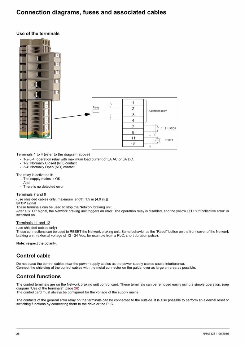
Use of the terminals
Terminals 1 to 4 (refer to the diagram above)- 1-2-3-4: operation relay with maximum load current of 5A AC or 3A DC.- 1-2: Normally Closed (NC) contact- 3-4: Normally Open (NO) contact
The relay is activated if:- The supply mains is OK
And- There is no detected error
Terminals 7 and 8(use shielded cables only, maximum length: 1.5 m (4.9 in.))STOP signalThese terminals can be used to stop the Network braking unit.After a STOP signal, the Network braking unit triggers an error. The operation relay is disabled, and the yellow LED "Off/collective error" isswitched on.
Terminals 11 and 12(use shielded cables only)These connections can be used to RESET the Network braking unit. Same behavior as the "Reset" button on the front cover of the Networkbraking unit. (external voltage of 12 - 24 Vdc, for example from a PLC, short duration pulse).
Note: respect the polarity.
Control cableDo not place the control cables near the power supply cables as the power supply cables cause interference.Connect the shielding of the control cables with the metal connector on the guide, over as large an area as possible.
Control functionsThe control terminals are on the Network braking unit control card. These terminals can be removed easily using a simple operation. (seediagram “Use of the terminals”, page 26)The control card must always be configured for the voltage of the supply mains.
The contacts of the general error relay on the terminals can be connected to the outside. It is also possible to perform an external reset orswitching functions by connecting them to the drive or the PLC.
1
2
3
4
7
8
11
12
+
Operation relayRelay
S1: STOP
RESET‒
26 NHA33281 09/2015
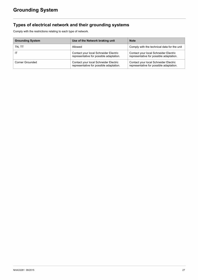
Grounding System
Types of electrical network and their grounding systemsComply with the restrictions relating to each type of network.
Grounding System Use of the Network braking unit Note
TN, TT Allowed Comply with the technical data for the unit
IT Contact your local Schneider Electric representative for possible adaptation.
Contact your local Schneider Electric representative for possible adaptation.
Corner Grounded Contact your local Schneider Electric representative for possible adaptation.
Contact your local Schneider Electric representative for possible adaptation.
NHA33281 09/2015 27

Electromagnetic Compatibility
EMC requirements for the control cabinet
Shielded cables
Cable Installation
Power Supply
EMC measures Objective
Use mounting plates with good electrical conductivity, connect large surface areas of metal parts, remove paint from contact areas.
Good conductivity due to large surface contact.
Ground the control cabinet, the control cabinet door and the mounting plate with ground straps or ground wires. The conductor cross section must be at least 10 mm2 (AWG 8).
Reduces emissions.
Fit switching devices such as power contactors, relays or solenoid valves with interference suppression units or arc suppressors (for example, diodes, varistors, RC circuits).
Reduces mutual interference.
Install power components and control components separately.
EMC measures Objective
Connect large surface areas of cable shields, use cable clamps and ground straps. Reduces emissions.
Use cable clamps to connect a large surface area of the shields of all shielded cables to the mounting plate at the control cabinet entry.
Ground shields of digital signal wires at both ends by connecting them to a large surface area or via conductive connector housings
Reduces interference affecting the signal wires, reduces emissions
Ground the shields of analog signal wires directly at the device (signal input); insulate the shield at the other cable end or ground it via a capacitor (for example, 10 nF, 100 V or higher.
Reduces ground loops due to low-frequency interference.
Use only shielded motor cables with copper braid and a coverage of at least 85%, ground a large surface area of the shield at both ends.
Diverts interference currents in a controlled way, reduces emissions.
EMC measures Objective
Do not route fieldbus cables and signal wires in a single cable duct together with lines with DC and AC voltages of more than 60 V. (Fieldbus cables, signal lines and analog lines may be in the same cable duct)Recommendation: Use separate cable ducts at least 20 cm apart.
Reduces mutual interference.
Keep cables as short as possible. Do not install unnecessary cable loops, use short cables from the central grounding point in the control cabinet to the external ground connection.
Reduces capacitive and inductive interference.
Use equipotential bonding conductors in the following cases: wide-area installations, different voltage supplies and installation across several buildings.
Reduces current in the cable shield, reduces emissions.
Use fine stranded equipotential bonding conductors. Diverts high-frequency interference currents
If motor and machine are not conductively connected, for example by an insulated flange or a connection without surface contact, you must ground the motor with a ground strap or a ground wire. The conductor cross section must be at least 10 mm2 (AWG 6).
Reduces emissions, increases immunity.
Use twisted pair for the DC supply.For digital and analog inputs use shielded twisted cables with a pitch of between 25...50 mm (1...2 in).
Reduces interference affecting the signal cables, reduces emissions.
EMC measures Objective
Operate product on mains with grounded neutral point. Enables effectiveness of mains filter.
Surge arrester if there is a risk of overvoltage. Reduces the risk of damage caused by overvoltage.
28 NHA33281 09/2015

Electromagnetic Compatibility
Additional measures for EMC improvementDepending on the application, the following measures can improve the EMC-dependent values:
NOTE: If using an additional input filter, it should be mounted as close as possible to the drive and the Network braking unit, connected directly to the supply mains via an unshielded cable, see wiring diagram page 23.
EMC measures Objective
Use mains reactors Reduces mains harmonics, prolongs product service life.
Use external mains filters Improves the EMC limit values.
Additional EMC measures, for example mounting in a closed control cabinet with 15 dB shielding attenuation of radiated interference
NHA33281 09/2015 29

Commissioning
Initial power-upStep 1: Switch the Supply mains on.
- The Network braking unit is ready to operate after approximately 1 s.
Step 2: Verify that the Network braking unit is ready to be used.- If the operation green LED only is ON, the Network braking unit is ready to be used.- If the other LEDs are also ON, as well as the green LED, the Network braking unit has detected an error. (see section “Diagnostic and
Troubleshooting”, page 31).
Step 3: Verify that the drive is ready to run.- Proceed in accordance with the drive manual.
Step 4: Verify braking sequences.- Realize tests of braking sequences with the drive, to verify that the Network braking unit operates properly.
Check List Before Switching OnMechanical InstallationVerify the mechanical installation of the entire drive system:
Electrical installationVerify the electrical connections and the cabling:
Covers And SealsVerify that all covers and seals of the control cabinet are properly installed to meet the required degree of protection.
NOTICEDESTRUCTION DUE TO INCORRECT WIRING• Before switching on and configuring the equipment, verify that it is properly wired.
Failure to follow these instructions can result in equipment damage.
Step Action
1 Does the installation meet the specified distance requirements?
2 Did you tighten all fastening screws with the specified tightening torque?
Step Action
1 Did you connect all protective ground conductors?
2 Do all fuses and circuit breaker have the correct rating; are the fuses of the specified type? (refer to the catalog and the Getting Started Annex available with the product).
3 Did you connect or insulate all wires at the cable ends?
4 Did you properly connect and install all cables and connectors?
5 Do all plug-in terminals colors and markings correspond to the colors and marking of the control block?
6 Did you properly connect the signal wires?
7 Are the required shield connections EMC-compliant?
8 Did you take all measures for EMC compliance?
30 NHA33281 09/2015
Diagnostic and Troubleshooting
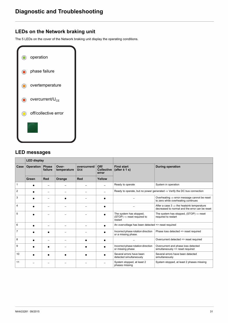
LEDs on the Network braking unitThe 5 LEDs on the cover of the Network braking unit display the operating conditions.
LED messagesLED display
Case Operation Phase failure
Over-temperature
overcurrent/UCE
Off/Collective error
First start (after ± 1 s)
During operation
Green Red Orange Red Yellow
1 p ‒ ‒ ‒ ‒ Ready to operate System in operation
2 p ‒ ‒ ‒ ‒ Ready to operate, but no power generated ⇒ Verify the DC bus connection
3 p ‒ p ‒ p ‒ Overheating ⇒ error message cannot be reset to zero while overheating continues
4 p ‒ ‒ ‒ p ‒ After a case 3 ⇒ the heatsink temperature decreased to normal and the error can be reset
5 p ‒ ‒ ‒ p The system has stopped, (STOP) ⇒ reset required to restart
The system has stopped, (STOP) ⇒ reset required to restart
6 p ‒ ‒ ‒ p An overvoltage has been detected => reset required
7 p p ‒ ‒ p Incorrect phase rotation direction or a missing phase.
Phase loss detected => reset required
8 p ‒ ‒ p p ‒ Overcurrent detected => reset required
9 p p ‒ p p Incorrect phase rotation direction or missing phase
Overcurrent and phase loss detected simultaneously => reset required
10 p p p p p Several errors have been detected simultaneously
Several errors have been detected simultaneously
11 ‒ ‒ ‒ ‒ ‒ System stopped, at least 2 phases missing
System stopped, at least 2 phases missing
off/collective error
operation
phase failure
overtemperature
overcurrent/UCE
NHA33281 09/2015 31

Diagnostic and Troubleshooting
STOPAs optional function, it is possible to wire a "STOP" switch, see diagram page 24 or 25.To restart the Network braking unit after a STOP command, push the RESET button.
Reset of the productThe cause of the detected error must be removed before resetting: • by pressing the RESET button,• or by turning the power OFF and then back ON.
Phase loss and undervoltage detectionPhase loss and undervoltage function monitors the 3 phases of the supply mains.In case of a phase loss or low voltage on one phase, the Network braking unit triggers an error on terminals 1,2,3,4 (relay) and the LED"phase failure".
Overvoltage DetectionThe Network braking unit will trigger an error if the mains voltage is higher than 460 Vac.
Overcurrent DetectionThe cause of periodic tripping on Overcurrent detection may be an overload, a fall in Mains voltage, an oscillating or defective drive, anoscillating input reference.
NOTICERISK OF DAMAGE TO THE EQUIPMENTDo not reset the product during the braking operation. The power semi-conductors might be exposed to increased stress, which can resultin accelerated aging.
Failure to follow these instructions can result in equipment damage.
32 NHA33281 09/2015

NHA33281 09/2015 33

NHA33281 09/2015
ATV71_Network_braking_units_manual_EN_NHA33281_03