
PUB DATE Different formats are used for organizing ... - ERIC
Upload
khangminh22Category
view
0download
0
University of Bath
PHD
Resource-Oriented Architecture based Scientific Workflow Modelling
Duan, Kewei
Award date:2016
Awarding institution:University of Bath
Link to publication
Alternative formatsIf you require this document in an alternative format, please contact:[email protected]
Copyright of this thesis rests with the author. Access is subject to the above licence, if given. If no licence is specified above,original content in this thesis is licensed under the terms of the Creative Commons Attribution-NonCommercial 4.0International (CC BY-NC-ND 4.0) Licence (https://creativecommons.org/licenses/by-nc-nd/4.0/). Any third-party copyrightmaterial present remains the property of its respective owner(s) and is licensed under its existing terms.
Take down policyIf you consider content within Bath's Research Portal to be in breach of UK law, please contact: [email protected] with the details.Your claim will be investigated and, where appropriate, the item will be removed from public view as soon as possible.
Download date: 30. Jun. 2022

Resource-Oriented Architecture basedScientific Workflow Modelling
submitted by
Kewei Duanfor the degree of Doctor of Philosophy
of the
University of BathDepartment of Computer Science
11/07/2016
COPYRIGHT
Attention is drawn to the fact that copyright of this thesis rests with its author. Thiscopy of the thesis has been supplied on the condition that anyone who consults it isunderstood to recognise that its copyright rests with its author and that no quotationfrom the thesis and no information derived from it may be published without the priorwritten consent of the author.
This thesis may be made available for consultation within the University Library andmay be photocopied or lent to other libraries for the purposes of consultation.
Signature of Author . . . . . . . . . . . . . . . . . . . . . . . . . . . . . . . . . . . . . . . . . . . . . . . . . . . . . . . . . . .
Kewei Duan


Abstract
This thesis studies the feasibility and methodology of applying state-of-the-art com-puter technology in scientific workflow modelling, within a collaborative environment.The collaborative environment also indicates that the people involved include non-computer scientists or engineers from other disciplines. The objective of this researchis to provide a systematic methodology based on a web environment for the purposeof lowering the barriers brought by the heterogeneous features of multi-institutions,multi-platforms and geographically distributed resources which are implied in the col-laborative environment of scientific workflow.
The central argument of this thesis is that applying novel design based on Resource-
Oriented Architecture (ROA) is able to enhance the efficiency of applications from the
perspective of data staging, service deployment and workflow enactment of scientific
workflow modelling in the context of a cooperative environment. Based on this genericsolution, the thesis aims to provide approaches and evidence to support the centralargument from two perspectives: (i) from the application perspective, as a user of sci-entific workflow, this thesis aims to validate the feasibility and discover the advantagesof applying a new web-based services workflow framework. (ii) from the developmentperspective, as a computer scientist, this thesis aims to fill the gap between new webservices technology and scientific workflow modelling by developing a new frame-work;
For the depiction and analysis side, this thesis reviews the relevant literature ofscientific workflow systems and MDO frameworks and provides the background in-formation about the web services technology and ROA that have been applied withinthis work. It further reviews the existing solutions on web services composition aswell as some relevant solutions about workflow, which also includes the reviews ofthe related works on declarative languages for REST web service composition andspeculative enactment of services. With the exploration on the literature gap of a sys-
2

tematic ROA based scientific workflow modelling framework, this thesis introducesa new architectural style by showing the potential to overcome the disadvantages in-herited from RPC-style. It also explores and researches the advantages that the newarchitectural style can bring. The reviews on the evolution of MDO frameworks rep-resents the demand from scientists that smart methodology should be adopted in thescientific workflow that bears the features of multi-institutions, multi-platforms andgeographically distributed resources.
For the design and implementation side, this thesis is driven by the motivation toenhance the performance of scientific workflow modelling and present the feasibilityof implementing ROA and RESTful web services in scientific workflows. Throughoutthe thesis, several approaches are introduced to present the contributions from bothdevelopment and application perspectives. They cover Data Management and Virtual-
ization, Service Management and Virtualization and Service Composition. The wholescientific workflow modelling framework is implemented based on the ROA Based
Distributed Data-flow Model, the Cloud Based Online Web Services Management Sys-
tem, the Declarative Services Composition Description and the Speculative Enactment
Engine. Related evaluations are included based on user experience experiments, modelsimulations and case studies.
Based on this research and corresponding implementation, this framework is ableto achieve the four following points:
• It proposes a data staging mechanism for ROA based distributed system thatutilises the features and follows the design constraints of RESTful web servicewithout introducing an extra layer of protocol. This mechanism can providebetter data staging performance by its distributed and asynchronous features.
• It proposes a SaaS based mechanism for REST web services deployment andmanagement. It simplifies the design and architecture based on ROA. Thus, itcan be integrated with existing WMSs simply through the HTTP/HTTPS proto-col. Additionally, it simplifies the process for non-specialist users to turn legacycode and programs into web services.
• It proposes a scientific workflow modelling framework based on virtualizationtechnology. The implementation of this framework can enhance the efficiencyof computing resources utilisation and increase the reproducibility of the com-puting environment for heterogenous scientific applications.
3

• It proposes a speculative services description to describe composite web ser-vices. Based on this description, an speculative enactment runtime is proposedas well to execute the composite web services. This speculative enactment run-time enables failure handling of composite web services. Also, these improvethe workflow execution performance in the scenario of web service failure.

Acknowledgements
First, I would like to thank my parents, grandparents and all my family members. Thejourney of seeking truth and knowledge is never easy. Their supports are always mystrongest backing in this journey. Also, I would like to give my special thanks to mywife Shirui Chai. As my constant companion, her encouragement gives me the forceto go forward.
I also would like to thank my supervisors Dr. Julian Padget and Dr. Alicia Kim ,who play the most important roles in my journey of seeking truth and knowledge as aPhD student. They give me great help and show me the directions.
Thanks to my internal examiner Dr Marina De Vos and external examiner ProfMaozhen Li. Thanks for the time they spend, their patience and the helpful advicesfrom them.
Bath is a beautiful city. My lovely friends made my life in Bath more colorful.Thank them.
I also spent half an year for an internship in NII Tokyo in my PhD study. In thisperiod, Prof. Ken Satoh, who was my supervisor, provided great helps not only to myresearches, but also to my life in Tokyo. Thanks to him and also to all the friends I metin that journey.
As the last thank, I would like to thank a special character, Mr Xiaopin Deng. Thisformer overseas student brought back college education in China. He advocated andgranted the basic state policies of Opening To The Outside World and Family Planning.Although, it is hard to say what results will those policies finally bring to us. Butwithout them, I will not be able write such a thesis in English, study in the UK andmeet all the people in this journey.
Finally, I want to say something to myself. I write a poem in the form of Ci withthe particular title (Cipai) of Ru Meng Lin:

6

Publications
Chapter 3, Chapter 6:
1. Duan, Kewei, Julian Padget, H. Alicia Kim, and Hiroshi Hosobe. ”Com-position of engineering web services with universal distributed data-flowsframework based on ROA.” In Proceedings of the Third International Work-
shop on RESTful Design, pp. 41-48. ACM, 2012.
Chapter 4, Chapter 6:
1. Duan, Kewei, YE Vincent Seowy, H. Alicia Kim, and Julian Padget. ”AResource-Oriented Architecture for MDO Framework.” In Proceedings of
8th AIAA Multidisciplinary Design Optimization Specialist Conference.2012.
2. Duan, Kewei, Julian Padget, and H. Alicia Kim. ”A Light-Weight Frame-work for Bridge-Building from Desktop to Cloud.” In Service-Oriented
ComputingICSOC 2013 Workshops, pp. 308-323. Springer InternationalPublishing, 2014.
7

Contents
1 Introduction 181.1 Motivation . . . . . . . . . . . . . . . . . . . . . . . . . . . . . . . . 21
1.1.1 A Computer Science Perspective . . . . . . . . . . . . . . . . 211.1.2 A Mechanical Engineering Perspective . . . . . . . . . . . . 23
1.2 Contributions . . . . . . . . . . . . . . . . . . . . . . . . . . . . . . 251.2.1 Data Management . . . . . . . . . . . . . . . . . . . . . . . 261.2.2 Service Management . . . . . . . . . . . . . . . . . . . . . . 261.2.3 Data and Service Virtualization . . . . . . . . . . . . . . . . 271.2.4 Service Composition . . . . . . . . . . . . . . . . . . . . . . 27
1.3 The Structure of the Thesis . . . . . . . . . . . . . . . . . . . . . . . 28
2 Literature Review 312.1 Web Services . . . . . . . . . . . . . . . . . . . . . . . . . . . . . . 31
2.1.1 Advantages and Disadvantages of SOAP . . . . . . . . . . . 322.1.2 REST Web Service . . . . . . . . . . . . . . . . . . . . . . . 352.1.3 A Comparison between SOA and ROA . . . . . . . . . . . . 37
2.2 The Implementation of Web Services and Workflow in EngineeringFramework . . . . . . . . . . . . . . . . . . . . . . . . . . . . . . . 39
2.3 Scientific Workflow System . . . . . . . . . . . . . . . . . . . . . . . 422.3.1 Data Staging . . . . . . . . . . . . . . . . . . . . . . . . . . 432.3.2 Service Deployment and Management . . . . . . . . . . . . . 442.3.3 Web Services Composition . . . . . . . . . . . . . . . . . . . 472.3.4 Workflow Description . . . . . . . . . . . . . . . . . . . . . 52
2.4 Summary . . . . . . . . . . . . . . . . . . . . . . . . . . . . . . . . 56
8

3 Datapool: A ROA Based Distributed Data-flow Model 583.1 Introduction . . . . . . . . . . . . . . . . . . . . . . . . . . . . . . . 583.2 Distributed Data-flow . . . . . . . . . . . . . . . . . . . . . . . . . . 59
3.2.1 Distributed Data Staging . . . . . . . . . . . . . . . . . . . . 593.2.2 Asynchronous Data Staging . . . . . . . . . . . . . . . . . . 61
3.3 The Implementation of Distributed Data-flow Model . . . . . . . . . 633.3.1 Datapool Service . . . . . . . . . . . . . . . . . . . . . . . . 643.3.2 User Interface . . . . . . . . . . . . . . . . . . . . . . . . . . 653.3.3 Usages and Technical Details . . . . . . . . . . . . . . . . . 663.3.4 Authentication and Authorization . . . . . . . . . . . . . . . 67
3.4 Evaluation . . . . . . . . . . . . . . . . . . . . . . . . . . . . . . . . 683.5 Summary . . . . . . . . . . . . . . . . . . . . . . . . . . . . . . . . 70
4 SaaS based Scientific Web Services Management 724.1 Introduction . . . . . . . . . . . . . . . . . . . . . . . . . . . . . . . 724.2 The Wrapping Technology for Applications . . . . . . . . . . . . . . 74
4.2.1 Local Application Wrapping Technology . . . . . . . . . . . 754.2.2 Online Application Wrapping Technology . . . . . . . . . . . 78
4.3 SaaS model based Web Service Deployment and Management Mech-anism . . . . . . . . . . . . . . . . . . . . . . . . . . . . . . . . . . 814.3.1 Service Deployment . . . . . . . . . . . . . . . . . . . . . . 814.3.2 Service Invocation and Execution . . . . . . . . . . . . . . . 824.3.3 GUI Based Interface . . . . . . . . . . . . . . . . . . . . . . 854.3.4 Implementation Details . . . . . . . . . . . . . . . . . . . . . 87
4.4 Evaluation . . . . . . . . . . . . . . . . . . . . . . . . . . . . . . . . 874.4.1 Experiment on Usefulness and Usability . . . . . . . . . . . . 874.4.2 Preliminary Case Study . . . . . . . . . . . . . . . . . . . . 89
4.5 Discussion . . . . . . . . . . . . . . . . . . . . . . . . . . . . . . . . 904.5.1 The Integration with Existing Workflow Management Systems
(WMSs) . . . . . . . . . . . . . . . . . . . . . . . . . . . . . 904.5.2 A Generic Interface for Building Hyper-workflow . . . . . . . 91
4.6 Summary . . . . . . . . . . . . . . . . . . . . . . . . . . . . . . . . 93
5 Virtualized Data and Services for Scientific Workflows 945.1 Introduction . . . . . . . . . . . . . . . . . . . . . . . . . . . . . . . 94
9

5.2 Scientific Workflow and Virtualization Technology . . . . . . . . . . 955.2.1 The Challenge of Scientific Workflows in the Cloud . . . . . 955.2.2 PaaS and Linux Container Virtualization . . . . . . . . . . . 985.2.3 Docker . . . . . . . . . . . . . . . . . . . . . . . . . . . . . 99
5.3 Container based Workflow Enactment . . . . . . . . . . . . . . . . . 1015.3.1 Architecture . . . . . . . . . . . . . . . . . . . . . . . . . . . 1015.3.2 Virtual Service Configuration File (Metadata) Schema . . . . 1055.3.3 Authentication and Authorization . . . . . . . . . . . . . . . 1085.3.4 The Execution Process of Virtualized Application in the Frame-
work . . . . . . . . . . . . . . . . . . . . . . . . . . . . . . 1095.4 Experiments and Results . . . . . . . . . . . . . . . . . . . . . . . . 111
5.4.1 Framework Implementation . . . . . . . . . . . . . . . . . . 1115.4.2 Experiment Design . . . . . . . . . . . . . . . . . . . . . . . 1125.4.3 Results . . . . . . . . . . . . . . . . . . . . . . . . . . . . . 114
5.5 Discussion . . . . . . . . . . . . . . . . . . . . . . . . . . . . . . . . 1175.5.1 The Suitable Solution for Scientific Workflow . . . . . . . . . 1175.5.2 The Impact of Adoption of Containerization . . . . . . . . . . 119
5.6 Summary . . . . . . . . . . . . . . . . . . . . . . . . . . . . . . . . 120
6 Declarative Services Composition Description and Speculative EnactmentEngine 1216.1 Introduction . . . . . . . . . . . . . . . . . . . . . . . . . . . . . . . 1216.2 Web Service Composition and Workflow Description . . . . . . . . . 1226.3 Declarative Description . . . . . . . . . . . . . . . . . . . . . . . . . 123
6.3.1 Declarative Description Solutions for REST . . . . . . . . . . 1246.3.2 Discussion on Declarative Description Languages . . . . . . . 128
6.4 Web Services Based on Speculative Computation . . . . . . . . . . . 1286.5 Design and Implementation of Speculative Service Description (SSD) 130
6.5.1 A Description Language for Stateless Web Services . . . . . . 1316.5.2 First-order Logic in SSD . . . . . . . . . . . . . . . . . . . . 1356.5.3 Ranking for Alternatives . . . . . . . . . . . . . . . . . . . . 136
6.6 A Runtime System for Speculative Enactment of Workflow . . . . . . 1396.6.1 System Architecture . . . . . . . . . . . . . . . . . . . . . . 1396.6.2 Speculative Execution on Parts of the Workflow . . . . . . . . 142
10

6.6.3 A Discussion on Time/Compute Resource Decisions . . . . . 1456.7 Evaluation . . . . . . . . . . . . . . . . . . . . . . . . . . . . . . . . 146
6.7.1 A Petri Net Model . . . . . . . . . . . . . . . . . . . . . . . 1466.7.2 A Implementation of the Speculative Enactment Runtime . . . 1516.7.3 The Simulation for Time/Compute Resource Decisions . . . . 154
6.8 Summary . . . . . . . . . . . . . . . . . . . . . . . . . . . . . . . . 157
7 Case Studies 1587.1 Optimization of the Wing Internal Stiffness Distribution . . . . . . . . 158
7.1.1 Scenario . . . . . . . . . . . . . . . . . . . . . . . . . . . . . 1587.1.2 Solution . . . . . . . . . . . . . . . . . . . . . . . . . . . . . 159
7.2 The Integration with local program based MDO frameworks . . . . . 1617.2.1 Scenario . . . . . . . . . . . . . . . . . . . . . . . . . . . . . 1617.2.2 Solution . . . . . . . . . . . . . . . . . . . . . . . . . . . . . 162
7.3 Image Processing Workflow . . . . . . . . . . . . . . . . . . . . . . 1647.3.1 Scenario . . . . . . . . . . . . . . . . . . . . . . . . . . . . . 1647.3.2 Solution . . . . . . . . . . . . . . . . . . . . . . . . . . . . . 165
7.4 Summary . . . . . . . . . . . . . . . . . . . . . . . . . . . . . . . . 166
8 Conclusion 1678.1 Contribution . . . . . . . . . . . . . . . . . . . . . . . . . . . . . . . 1678.2 Limitations . . . . . . . . . . . . . . . . . . . . . . . . . . . . . . . 170
8.2.1 The Overheads in Web Services based Scientific Workflow . . 1708.2.2 The Synchronized Connection based on HTTP . . . . . . . . 174
8.3 Future Works . . . . . . . . . . . . . . . . . . . . . . . . . . . . . . 175
A The Description of the Cancer Modelling Workflow 178A.1 Introduction . . . . . . . . . . . . . . . . . . . . . . . . . . . . . . . 178A.2 Epirubicin Pharmacokinetcs . . . . . . . . . . . . . . . . . . . . . . 178A.3 Epirubicin Pharmacodynamics . . . . . . . . . . . . . . . . . . . . . 180A.4 Breast Cancer Therapy: Epirubicin . . . . . . . . . . . . . . . . . . . 180
B The Core Prolog Code of the Enactment Engine 181
C The Template for Docker Configuration File 184
11

Bibliography 187
12

List of Figures
2-1 SOAP Web Services Architecture Stack [Booth et al., 2004] . . . . . 342-2 The structure of SOAP Envelop Mitra et al. [2003] . . . . . . . . . . 352-3 Workflow Reference Model - Components & Interfaces [Hollingsworth
and Hampshire, 1993] . . . . . . . . . . . . . . . . . . . . . . . . . . 53
3-1 Centralized Data-Flows in Web Services Composition . . . . . . . . . 603-2 Distributed Data-flows in Web Services Composition . . . . . . . . . 603-3 Comparison of two different data staging mechanisms . . . . . . . . . 623-4 The data dependency in a simple example of multiple steps of workflow 633-5 Comparison of 1000 continuous executions . . . . . . . . . . . . . . 693-6 Results of simple workflows work with both Centralized and Distributed
Data-flows . . . . . . . . . . . . . . . . . . . . . . . . . . . . . . . . 69
4-1 GFac Architecture [The Trustees of Indiana University, 2006] . . . . 774-2 Configuration files of application services . . . . . . . . . . . . . . . 824-3 UML Deployment Diagram of the Framework Deployment Example . 834-4 UML Sequence Diagram of the Execution of Workflow Example . . . 844-5 Windows of GUI tool . . . . . . . . . . . . . . . . . . . . . . . . . . 854-6 Local folder for service description . . . . . . . . . . . . . . . . . . . 864-7 The average time of deployment operations . . . . . . . . . . . . . . 884-8 The command for the cancer model workflow . . . . . . . . . . . . . 894-9 The GUI for the deployment of cancer hypermodel . . . . . . . . . . 904-10 The python script to execute the RESTful web service . . . . . . . . . 90
5-1 Data-flow between two host OSs . . . . . . . . . . . . . . . . . . . . 975-2 Data-flow between two guest OSs . . . . . . . . . . . . . . . . . . . 975-3 VM architecture[Docker, 2016] . . . . . . . . . . . . . . . . . . . . . 100
13

5-4 Docker architecture[Docker, 2016] . . . . . . . . . . . . . . . . . . . 1015-5 The Architecture of Multiple Framework Instances . . . . . . . . . . 1035-6 The Architecture of Containerized Framework . . . . . . . . . . . . . 1035-7 Activity diagram of virtualization director . . . . . . . . . . . . . . . 1105-8 Experiments Procedure . . . . . . . . . . . . . . . . . . . . . . . . . 1155-9 Copy Workflow . . . . . . . . . . . . . . . . . . . . . . . . . . . . . 1165-10 Pipe Workflow . . . . . . . . . . . . . . . . . . . . . . . . . . . . . 1165-11 Socket Workflow . . . . . . . . . . . . . . . . . . . . . . . . . . . . 1165-12 WS Localhost Workflow . . . . . . . . . . . . . . . . . . . . . . . . 1165-13 WS LAN Workflow . . . . . . . . . . . . . . . . . . . . . . . . . . . 1165-14 Container Localhost A Workflow . . . . . . . . . . . . . . . . . . . . 1165-15 Container Localhost D Workflow . . . . . . . . . . . . . . . . . . . . 1165-16 Container LAN D Workflow . . . . . . . . . . . . . . . . . . . . . . 116
6-1 The /jdoe/shelf/biology resource responds to a HTTP GET request byeventually invoking the pick biology book/1 predicate, which in turncalls pick books/3; the context is traversed until a proper definition forit is found in the resource. [Piancastelli and Omicini, 2008] . . . . . . 126
6-2 Modularization of SSD . . . . . . . . . . . . . . . . . . . . . . . . . 1316-3 Description resides in Execution Engine . . . . . . . . . . . . . . . . 1326-4 Description is Separated with Execution Engine . . . . . . . . . . . . 1326-5 The flow chart of runtime based on SSD without speculative enactment 1406-6 The flow chart of runtime based on SSD with speculative enactment . 1406-7 Speculative Execution of Parts of Workflow . . . . . . . . . . . . . . 1436-8 A Petri Net Model of Speculative Enactment Runtime . . . . . . . . 1476-9 An exemplar composite web service for the Petri net model . . . . . . 1496-10 The test composite web service . . . . . . . . . . . . . . . . . . . . . 1516-11 The ratio between the performance of execution modes . . . . . . . . 1536-12 Equation simulation workflow . . . . . . . . . . . . . . . . . . . . . 1556-13 Results of simulation . . . . . . . . . . . . . . . . . . . . . . . . . . 156
7-1 The MDO process built in Taverna based on REST web services . . . 1607-2 The wing topology . . . . . . . . . . . . . . . . . . . . . . . . . . . 1617-3 The description file for openMDAO MDF service . . . . . . . . . . . 1627-4 The description file for Dakota service . . . . . . . . . . . . . . . . . 163
14

7-5 The image processing workflow . . . . . . . . . . . . . . . . . . . . 1647-6 The description file for PovRay service . . . . . . . . . . . . . . . . . 1657-7 The description file for ImageMagick service . . . . . . . . . . . . . 165
8-1 Workflow execution time with different sleep time in three situations(Local workflow, Intranet workflow and Internet workflow) . . . . . . 171
8-2 Web service based workflow execution time normalised by the localexecution time . . . . . . . . . . . . . . . . . . . . . . . . . . . . . . 171
8-3 Experiment results of data communication . . . . . . . . . . . . . . . 173
A-1 Taverna workflow of cancer model . . . . . . . . . . . . . . . . . . . 179
15

List of Tables
2.1 Pros and Cons of SOAP and REST[Spies, 2008] . . . . . . . . . . . . 332.2 HTTP verbs . . . . . . . . . . . . . . . . . . . . . . . . . . . . . . . 37
3.1 URIs of Datapool Service . . . . . . . . . . . . . . . . . . . . . . . . 653.2 Secure URIs of Datapool Service . . . . . . . . . . . . . . . . . . . . 68
4.1 URIs of Datapool and Application Services . . . . . . . . . . . . . . 83
6.1 The URI templates for inference query . . . . . . . . . . . . . . . . . 1346.2 The Simulation Results of Petri Net Model . . . . . . . . . . . . . . . 1496.3 The simulation results of the composite web service in real runtime . . 1526.4 The three rounds results of simulation . . . . . . . . . . . . . . . . . 156
16

Listings
5.1 Virtual Service Configuration Schema . . . . . . . . . . . . . . . . . 1056.1 A ReLL Description Example[Brzezinski et al., 2012] . . . . . . . . . 1256.2 ROsWeL Entry Rules[Brzezinski et al., 2012] . . . . . . . . . . . . . 1266.3 ROsWel Invocation Rules[Brzezinski et al., 2012] . . . . . . . . . . . 1266.4 Segment of ROsWeL description example . . . . . . . . . . . . . . . 1336.5 Inference Rules in SSD . . . . . . . . . . . . . . . . . . . . . . . . . 1356.6 Relation Facts in SSD . . . . . . . . . . . . . . . . . . . . . . . . . . 1356.7 Detail of Web service Facts in SSD . . . . . . . . . . . . . . . . . . . 1356.8 Ranking example in Relation Facts . . . . . . . . . . . . . . . . . . . 1386.9 IfAlternative Function . . . . . . . . . . . . . . . . . . . . . . . . . . 154
17

Chapter 1
Introduction
Nowadays, in-silico experimentation plays an important role in scientific research toovercome physical limitation. With the growing of model complexity and developmentof cyberinfrastructure, more computing resources, both hardware and software fromheterogenous contexts are involved in a series of computational and data manipulationsteps for the experiments. The concept of scientific workflow is introduced to representthis series of steps as useful paradigm to describe, manage, and share complex scien-
tific analyses Singh and Vouk [1996]. The user and creator of scientific workflowsare usually not computer and software specialists. A general trend can be observedthat the cyberinfrastructure for scientific workflow is behind the development of thenew computer technology and the methodology/approaches based on the technology.The advantages brought by technology progress cannot be reflected in scientific re-searches, which heavily depends on in-silico experimentation. The forward-lookinginvestigation and research is necessary for the emergence of new infrastructure withbetter related features, such as performance, reusability, accessibility and so on. Thus,the questions of what out-dated cyberinfrastructure parts influence those features, whatand how technology and methodology can be adopted to resolve the issues need to beanswered.
This thesis studies the feasibility and methodology of applying state-of-the-artcomputer technology in scientific workflow modelling, within a collaborative researchenvironment. The object of study is workflow, which is a sequence of connected ac-tivities or operations that abstract and model real-world working as an activity. It hasemerged as a paradigm for representing and managing complex distributed scientificresources. The collaborative research environment is intended to indicate that the peo-
18

ple involved include non-computer scientists or engineers from other disciplines. Howto enhance the efficiency of both the applications and users in such an environmentdrives the general direction in this research. Nowadays, large-scale computations anddata analysis characterize much scientific research, meaning there is a need for newapproaches to the computation and management of distributed resources in what isalso a broader execution environment, namely the Internet. Given this background, thecomputational resources, such as servers and specialist software, can be establishedand maintained by multiple organizations at different institutions. The computationalresources can be developed by scientists or engineers with different knowledge back-grounds on multiple development platforms. Therefore, the objective of this researchis to provide a systematic methodology based on a web environment for the purposeof lowering the barriers brought by the heterogeneous features of multi-institution,multi-platform and geographically distributed resources which are implied in the col-laborative environment of scientific workflow.
This thesis will mainly study scientific workflow enactment under web environ-ment from several aspects: data transfer, service deployment, data and service virtu-alization and service composition. For this purpose, Resource-Oriented Architecture(ROA) is introduced to serve as the firm basis of the proposed scientific workflow mod-elling framework. A series of state-of-art technologies, such as REST web services,containerization and speculative computing are adapted in this ROA based frameworkto form the new feasible methodologies and approaches for scientific workflow en-actment. The central argument of this thesis is that, through the application of novel
designs based on ROA it is possible to enhance the efficiency of applications and users
in the context of a collaborative research environment from the perspective of data
staging, service deployment and workflow enactment of scientific workflow modelling.All the approaches will be proposed and examined from two perspectives: applicationperspective and user perspective. The goal is that the proposed approaches should notonly enhance the performance of scientific workflow enactment, but also it will reducethe difficulty of utilising the adopted technologies for user. Thus, (i) from applicationperspective, the ROA based framework is proposed to fill the gap between new tech-nology and scientific workflow modelling. This framework serves as the foundationto enhance the efficiency of applications. (ii) from user perspective, this thesis willvalidate the feasibility and discover the advantages of adopting new technologies inthis framework. This framework aims to help users to enhance their efficiency in the
19

collaborative research environment.From developer’s perspective, the efficiency will be enhanced by filling the gap
between a new web design pattern (ROA) and scientific workflow modelling by devel-oping new framework. The feasibility will be studied and reflected from two aspects:(i) A series of approaches designed and delivered based on a distributed dataflow ar-chitecture and an online service deployment system to enhance the data staging perfor-mance, simplifying the service deployment and management process, and (ii) A set ofmethods can be achieved to build a scientific workflow based on services composition,aiming to enhance the workflow enactment efficiency.
From user’s perspective, the efficiency will be enhanced to resolve the issues in col-laborative research environment by applying new web service technology in a work-flow framework. The feasibility will be studied and reflected from two aspects: (i) aframework that enables the integration of a variety of existing applications and codesbased on a generic solution, which in terms of intention also enables and enhances theperformance of transfers, storage, sharing of geographically distributed scientific data,and (ii) a framework that can simplify the manipulation of web services deploymentso that the barrier for non-specialist users can be lower for the purpose of sharing andintegration.
One of the important application domains that drives this thesis is MultidisciplinaryDesign Optimization (MDO). Multidisciplinary design optimization (MDO) is a fieldof research that studies the application of numerical optimization techniques to thedesign of engineering systems involving multiple disciplines or components[Martinsand Lambe, 2013]. MDO enables designers to incorporate all relevant disciplines inone design process. MDO have been applied in design processes, such as automobiledesign, naval architecture, electronics, architecture, computers, electricity distributionand so on. In this research field, the largest number of applications have been in thefield of aerospace engineering, such as aircraft and spacecraft design which are relatedto disciplines like aerodynamics, structural analysis, propulsion, control theory, andeconomics. The reason of selecting MDO as primary problem domain is that MDOembodies all the aforementioned characteristics of a collaborative research environ-ment. They are the heterogeneous features of multi-institution, multi-platform andgeographically distributed resources. To support the research on MDO, various MDOframeworks are developed. The benefits brought by the development are defined asto provide the capability to enable interdisciplinary interaction and communication
20

via the use of sophisticated computational procedures combined with state-of-the-artoptimization or design improvement techniques[Salas and Townsend, 1998]. In thisdevelopment trend, it is shown that the integration with new computer technologygradually also improves the efficiency of MDO framework. The improvement allowsthe framework to enact an automatic process for engineering computation in an moreeasy-to-use manner. Therefore, this research also follows this trend, and aims to pro-vide a scientific workflow framework that can be used for deployment, sharing andenactment of MDO workflow.
In summary, this thesis will study the new features of a newly proposed web-service based framework for scientific workflow modelling. New technologies, whichare popular in cyberinfrastructure nowadays, such as REST web service, containeriza-tion, speculative computing as well as new approaches like distributed dataflows, SaaSand PaaS based web service management are adopted. The pros and cons by adoptingthese technologies in scientific workflow modelling will be discussed and examinedbased on a series of experiments on workflow enactment performance and user experi-ence. MDO will serves as an representative and important application domain, whichembodies some typical application scenarios as the challenges for scientific workflow.
1.1 Motivation
This research has the feature of cross-discipline. On one hand, it requires computerscience knowledge to fill the gap between new web services technology and scientificworkflow modelling. On the other hand, it needs to investigate the problem domainfrom the point of view of the user of the scientific workflow modelling framework.Thus, considering the primary problem domain defined previously, the motivation ofthis research is mainly driven from two perspectives: computer science and mechanicalengineering.
1.1.1 A Computer Science Perspective
In recent years, a number of scientific workflow management systems (WMS) havebeen developed to support the creation of scientific workflow [Ludascher et al., 2006,Oinn et al., 2004, Taylor et al., 2007, Van Der Aalst and ter Hofstede, 2005]. Theyall possess the basic functions of workflow compositions, enactment and monitoring.
21

In these workflow management systems, there are common features that function toaccess distributed computing resources. The main driving force is that scientific work-flows require more computing power given their growing complexity. A key element inthe construction of workflows is the web service, which is defined by W3C as “a soft-ware system designed to support interoperable machine-to-machine interaction overa network”[Haas and Brown, 2004]. This interoperable machine-to-machine interac-tion over a network allows resources to be accessed in a geographically distributedcooperative environment.
To enable scientific reproducibility, result publication and sharing, nowadays, sci-entific workflow is often defined by co-operation and web services technology. How-ever, technically, there exist different web service styles and communication protocols,each with a set of methods built on a specific style and protocol – and being incom-patible with each other. For example, arbitrary web services, which are categorizedby W3C [W3C, 2004], include a series of web services styles including RPC (RemoteProcedure Call), CORBA (Common Object Request Broker Architecture), RMI (JavaRemote Method Invocation), SOAP (Simple Object Access Protocol). These are alsoknown as RPC-style web services. They all have different and incompatible com-munication protocols, which severely limit access to service components created bydifferent systems, and this restriction reduces the overall interoperability between sys-tems. Additionally, new users may have to learn heavyweight specifications in order touse systems effectively, which can increase the cost of introducing of new applicationtools. Based on this, there is also the risk that non-specialist users are locked insideone particular system because the complexity of each web service specification.
In the meantime, a relatively new class of web services emerged and gained itspopularity rapidly, namely REST-compliant web services [W3C, 2004]. The maindifference between REST (Representative State Transfer) and the RPC-style web ser-vices is the protocol employed between client and server. RPC-style requires eachapplication designer to define a new and arbitrary protocol comprising vocabulary ofnouns and verbs that is usually overlaid on the HTTP [Pautasso et al., 2008]. In con-trast, RESTful web services work directly with HTTP, so they have one less protocollayer, simplifying and making it easy to deploy and use web services, as well as reduc-ing the overall cost of computation and knowledge preparation. Pautasso and Wilde[2009] conclude that for the objective of designing IT architectures, REST is a betterchoice in the context of a co-operative environment in that it is intrinsically loosely
22

coupled because of its asynchronous communication nature, universal addressabilityand uniform interfaces. From the emerging of RESTful web services, many new publicweb services from large vendors, such as Google, Yahoo and Amazon, are now RESTbased. REST’s simplicity and being lightweight has brought significant changes tobusiness markets and has been broadly accepted.
A question is raised together with the emergence of a new service style, can sci-entific workflow modelling efficiency be enhanced further, by comparing with the ex-isting service styles, based on the features of new web services technology? The dataflow and control flow are the two important aspects of workflow[Russell et al., 2005].In practice, they represent the steps of date transfer (data staging) from one service toanother and a sequence of web services invocations. Also, the composition of thesesteps finally forms the executable workflow. The efficiency of these practical activ-ities are closely related to the web services styles that are applied and used to buildthe bricks in the scientific workflow modelling. From a computer science perspective,questions can be asked tangibly from bottom to top through three aspects: How toimprove data staging performance in the interaction of RESTful web services for ascientific workflow situation? How to provide a more convenient RESTful service de-
ployment/management mechanism with higher reusability? How to support RESTfulservices composition for the co-operation of web services in a scientific workflow?
1.1.2 A Mechanical Engineering Perspective
It is a common practise that optimization program for specific discipline is writtenby the expert on this discipline. For example, optimization program for aerodynam-ics will be written by an aerodynamics expert, structure optimization program will bewritten by a structure expert. They may come from different institute or even dif-ferent country. In a MDO method, these programs have to work together for oneoverall goal and the methods might be developed by people who work under differentorganisational standards, adopt different computer platforms and coding techniques.Moreover, all relevant experts and computing resources can be distributed around theworld. The features of being multi-institutional, multi-platform and geographicallydistributed set the backgrounds for designing MDO framework. Various computingtechnologies have been adopted in the design of MDO frameworks to overcome thesebarriers. In hindsight, it can be anticipated that more new computer technology can be
23

brought in to further lower the barriers based on the observation of MDO frameworkresearch history.
In the history of MDO framework research, the advances of computer hardwareand software is correlated with its development. In their review of the history of MDOframework research[Padula and Gillian, 2006], S. L. Padula and R. R. Gillian summa-rize that in the period 1984-1994, frameworks tended to be presented in monolithiccodes written in procedural languages such as FORTRAN and C. It was difficult forresearchers to embed their own code into the framework, which was formed by fixedanalysis codes. They also mention that in the following decade (1994-2004), a widervariety of framework architectures emerged, taking advantage of hardware and soft-ware developments. Web technology is adopted in MDO framework in the course ofdevelopment.
By considering the features of MDO and the close relationship between the de-velopment of MDO frameworks and computer technology, a number of ideas haveemerged. For example, the idea of modularity is raised by Padula and Gillian [2006]to isolate machine-dependent parts of code, to improve the readability and to expeditetesting. A similar idea is also proposed by Kodiyalam and Sobieszczanski-Sobieski[2001] as a requirement of a MDO framework, which is that the framework shouldprovide a quick and easy linking of analysis tools which serve as slaves to the MDOframework. In an earlier paper, Salas and Townsend [1998] discussing the require-ments of MDO framework development, the requirements for architectural design alsoinclude the opinions that a framework should be designed using object-oriented princi-ples to allow switching of analysis or optimization methods at run time. In this process,plenty of MDO frameworks proposed various solutions based on different computingtechnologies to build up a modularized architecture. Based on those frameworks, a ten-dency emerges for frameworks to evolve from monolithic codes to modularized com-ponents, from local programs to online services. Computer technology improvementsare closely correlated with the future development directions of MDO framework.
The adoption of web service technology can further support the concept of mod-ularization in the form of web service and parallel processing among services. Inthe realm of computer science research, for the purpose of supporting interpretablemachine-to-machine interaction mechanism through the Internet, web services havebeen an active research and standardization topic for several years now, reinforced bythe emergence of the concept of service-oriented architecture. Remote Procedure Call
24

(RPC) is an early style of web services. The remote invocation through the RPC proto-col allows programs to communicate over the network by means of special communi-cation protocols obviating the need for extra coding to account for network details andremote machines. Several analogues of RPC have arisen to provide more sophisticatedfeatures, such as the Common Object Request Broker Architecture (CORBA)[Corba,1995], Java Remote Method Invocation (RMI)[ORACLE, 2011] and Simple ObjectAccess Protocol (SOAP)[Box et al., 2000]. Systems built using these protocols aresometimes referred to as arbitrary web services[W3C, 2004] and they have been uti-lized in the MDO context.
This thesis is motivated, by the tendency that has been shown in the evolution ofMDO frameworks, to propose that the features of web services are particularly relevantfor MDO. The reason is that MDO requires a co-operative environment across multiplespecialist disciplines that not only can access and integrate geographically distributedresources, but also have the capacity to access existing knowledge that resides in legacycode and the latest software across a range of platforms. From user perspective, thereis another reason that it also needs to consider the users of MDO frameworks. Theyare non-computer scientists. Thus, a light-weighted and easy-to-access architecturewill be helpful on improving the use efficacy. In this case, REST web service hasthis potential that it is built based on broadly applied protocols (HTTP/HTTPS) andinterfaces (CRUD: create, read, update and delete).
1.2 Contributions
This thesis is driven by the motivation to enhance the efficiency of scientific workflowmodelling and present the feasibility of implementing ROA and RESTful web servicesin scientific workflows. Contributions are embodied in four problems this frameworkaims tentatively to solve. They are:
• Data management,
• Service management,
• Data and Service Virtualization
• Service composition.
25

Each of them will introduce related approaches to enhance the efficiency from bothapplication and user point of view. They are introduced in following sections.
1.2.1 Data Management
One key feature of scientific workflow is its dataflow driven nature and the large datatransfers between client and server can consume significant bandwidth. In this the-sis, reducing the redundant data transfer amount and enabling an asynchronous datatransfer style among multiple services are considered as the keys to enhance the datatransfer performance. On the other hand, from a computer science perspective, theproblem of staging data in workflows has received much attention over the last decade,with a variety of user-directed and automatic solutions. In order to provide an efficientarchitectural style for this Internet-based data transfer mechanism, this thesis proposesa data staging model. In this model data-flows are distributed to each pair of con-nected web services, without passing through clients, who act as central controllers.A RESTful web service, which is called Datapool, is designed to enable clients tostore, identify and manipulate data elements based on this model. By means of thisdistributed data transfer mechanism, the amount of data transferred from client-side toserver-side and vice-versa can be reduced, by storing data server-side and exposing itas a globally accessible resource. This work around this contribution is presented inChapter 3.
1.2.2 Service Management
From the perspective of mechanical engineering, there is an obvious gap between sci-entific applications and web services. The process to wrap and deploy from the formerto the latter is a barrier for users who may have limited computer knowledge of the rel-evant technology. Following on from the aforementioned issues, questions can also beraised about the configuration and management costs of a lightweight (RESTful) webservice. Hence, another contribution of this thesis is the combination of the data stag-ing mechanism with a simple service deployment mechanism, that is designed to allowapplications developed for the command-line to function as (RESTful) services with-out modification or (in some cases) without recompilation. Furthermore, this deploy-ment and management mechanism is built based on a Software-as-a-Service (SaaS)manner framework. All the data and application resources can be shared through net-
26

work by a distributed computing platform. This enables both a flexible and convenientservice deployment and migration process. Along with this mechanism, a desktopclient system is designed to further reduce the hurdle for non-specialist users. Thispart of work is mainly presented in Chapter 4.
1.2.3 Data and Service Virtualization
This thesis also presents an more advanced approach for data and service managementbased on containerization technology. This allows data and service to be virtualised.It can enhance the reproducibility and reusability of application/service. This partof work is built based on the works about data management (Chapter 3) and servicemanagement (Chapter 4). In those two parts of works, it is discovered that there arestill limits on the approaches proposed for data management as well as service man-agement. In general, there is bottleneck on data transfer and the reproducibility andreusability is still not ideal enough for non-specialists that there is space for furtherexploration. This part of work filled this space with a tangible solution that a ROAbased scientific workflow enactment framework is also built in Python. A series ex-periments are carried out to present the feasibility and the enhancement on data stagingand workflow enactment. This part of work is presented in Chapter 5
1.2.4 Service Composition
A scientific workflow is the combination of a series of data resources and services re-sources. How to construct them together to form an automatic process is yet anotherimportant issue that this thesis aims to resolve. Especially, in the case of ROA basedscientific workflow modelling, the question is how to further utilise its specific fea-tures to further improve the efficiency. Essentially, this is an issue that rests on servicediscovery, service description and service enactment. This thesis proposes two setsof methodologies that allow workflow to operate in both imperative and declarativemanners. Firstly, a complete set of methods will be presented to build a scientificworkflow based on the data and service management systems together with an existinggeneric Workflow Management System (WMS) that works in an imperative manner.Secondly, a RESTful services-based composite service system is presented based on aProlog based description language and a knowledge sharing mechanism. With the sup-port of the second solution, the workflow has the ability to deal with faults at run-time
27

and share its knowledge about the computing process. The two methodologies can beapplied in different working circumstances and will be discussed later in Section 6.1.This discussion also leads to the introduction of the declarative services compositionlanguage and speculative enactment engine. The evaluation of this work is carriedout in two parts: (i) A Petri net based model of the composite service mechanism isproposed for simulation. It aims to show the performance enhancement in variousscenarios. (ii) An implemented workflow enactment engine based on the Prolog de-scription language is presented. It aims to show the feasibility and the influence ofintroducing such a mechanism to workflow enactment. This part of work is presentedin Chapter 6.
1.3 The Structure of the Thesis
The remainder of the thesis is structured as follows:
Chapter One – IntroductionIn which this thesis states the central argument and the motivation. This chapteralso gives a brief introduction of the current literature and the contribution thiswork makes to the subject area.
Chapter Two – Literature ReviewIn which this thesis presents a comprehensive review of related scientific work-flow research, identifies gaps and observes trends. In particular, for the scientificworkflow this thesis focuses on the implementation of web services, workflowsystem architecture, other PaaS applications and identifying the trend of web ser-vices application. For the MDO framework this thesis focuses on the literaturegap in respect of the implementation of web technology and workflow togetherwith an introduction about the evolution of MDO frameworks.
Chapter Three – Datapool: A ROA Based Distributed Data-flow ModelIn which this thesis starts to build the basis for scientific workflow modelling,which is the dataflow. It is argued that the performance of data transfers in aweb-based workflow system can be enhanced by the distributive dataflow modelby comparing it with a centralized dataflow model. Users can use the Datapoolservice to easily access and manage the data collection resources, which are
28

supported by ROA. The enhancement is experimentally verified, and is put touse in a workflow application.
Chapter Four – SaaS based Scientific Web Services ManagementIn which this thesis further discusses the scientific workflow modelling on ser-vices management, which includes deployment, configuration and execution.The issue of application wrapping and service management are identified basedon the literature review, especially for non-specialist users. A SaaS Cloud systemis presented for users to deploy, configure and manage their local application-based web resources. It enables complicated services management jobs to beturned into a series of mouse-clicking operations. A series of service manage-ment examples are demonstrated in this chapter. The system also fits into thedistributive dataflow model.
Chpater Five – Virtualized Data and Services for Scientific Workflow Modelling
In which this thesis proposed a scientific workflow enactment framework basedon containerization technology. It further enhances the performance on datastaging and workflow enactment. It also enhance the reusability and repro-ducibility of application/service. This chapter starts with an introduction on thetechnology foundation and basic methodology. Then it elaborates the design ofthis framework. Following that, the chapter evaluates the framework with a se-ries experiments. This chapter also discusses the suitable solution for scientificworkflow in different scenarios as well as the impact of adoption of container-ization in scientific workflow modelling.
Chapter Six – Services Composition Language and Enactment EngineIn which this thesis introduces the methodologies for building a scientific work-flow based on the composition of Datapool services and application services.Firstly, an imperative method is introduced based on the application of an ex-isting generic workflow management system. Then, a declarative method is in-troduced, which includes a novel declarative description for composite servicesand an online description knowledge system. The advantage of this system andthe advantages and disadvantages of imperative and declarative methods are dis-cussed in detail in this chapter.
29

Chapter Seven – Case StudiesThis Chapter present several case studies. The first is the main study subjectMDO. The whole system demonstrates its ability to solve MDO problems bybuilding a web services composition based workflow. The implementation ofDatapool, online web service management system and service composition isshown step-by-step to deliver a complete image of the systematic methodol-ogy when solving the issues in scientific workflow modelling. Additionally, themethodology shows its capacity to work with other existing MDO frameworks.Furthermore, other exemplar applications are also demonstrated based on thismodelling system to show its extensibility.
Chapter Eight – ConclusionsThis chapter summarises the contributions of the thesis, and examines how thisseries of methodologies have developed to support the central argument forscientific workflow modelling. This thesis also discusses the inspiration for abroader scope and suggests possible avenues for the future development of thiswork.
30

Chapter 2
Literature Review
This chapter reviews literature on scientific workflow systems and MDO frameworksand provides some background information about web services technology, resource-oriented architecture (ROA), cloud computing and speculative computing, which havebeen applied within this work. This chapter first reviews and discusses the main tech-nology used in scientific workflow systems and web services, which serves as a basisand follows that is the review of MDO frameworks and scientific workflow system.Afterwards, this chapter presents a review of the literature on the use of web servicesin MDO frameworks. Following it this chapter reviews some key aspects of scientificworkflow systems which concern this research. These aforementioned two reviewsaims to present the gaps between two different areas in different development stages.In the reviews on scientific workflow systems, more detailed background knowledgeis reviewed from three aspects: data staging, service management and service com-position. In the review of service composition, one important technique for servicecomposition, workflow description, is also reviewed. The aim is to draw a clear pic-ture of what can be resolved by state-of-the-art approaches, by identifying the currentgaps in existing cases and how these can be resolved tangibly. The summary identifiesresearch trends and current literature gaps.
2.1 Web Services
For the purpose of exploring the implementation of ROA in scientific workflow, one es-sential step is to have a panoramic view of the state-of-the-art web services technology.As introduced in Section 1.1.1, W3C categorises web services in two ways: arbitrary
31

web services and REST-compliant web services. Nowadays, SOAP and RESTful webservices are the representative services of the two aforementioned classes that havebeen widely implemented. Briefly, they are described as:
• SOAP/WSDL based web Services (also known as “Big web services”) that pro-vide an arbitrary (i.e. developer defined) set of operations, and
• REST type web services, providing a uniform interface, that is considered more“web-friendly”. For example, an HTTP(S) REST web service will use someor all of the standard HTTP protocol operations: GET, POST, HEAD, PUT,DELETE
There are pros and cons to both of them as discussed by Spies [2008], which aresummarised in Table 2.1 for comparison and discussed in depth in the following sec-tions, leading on to a comparison between service-oriented and resource-oriented ar-chitecture.
2.1.1 Advantages and Disadvantages of SOAP
Simple Object Access Protocol (SOAP) is used to defined as a web service protocolusing XML technologies, an extensible messaging framework containing a messageconstruct that can be exchanged over a variety of underlying protocols. SOAP com-municates mainly based on HTTP, but can also communicate through FTP, SMTP, etc.Thus, SOAP supports communication in going around firewalls. SOAP contains threemain parts [Box et al., 2000] (i) an envelope that defines a framework for describingwhat is in a message and how to process it, (ii) a set of encoding rules for expressinginstances of application-defined datatypes, (iii) a convention for representing proce-dure calls and responses. SOAP is a W3C recommendation. W3C describes the setof interrelated technologies that can be utilised to construct and consume SOAP webservices, as illustrated in Figure 2-1.
SOAP Message
By observing the SOAP message framework, a better understanding of the characteris-tics of heavy-weight and extra payload can be acquired. A SOAP message is specified
32

SOAP REST
Pros
• Transfer over multipleprotocols, not only HTTP
• Designed to handle distributedcomputing environments bySOAP intermediary
• Has better support from otherstandards (WSDL, WS-*) andtooling from vendors
Cons
• Conceptually more difficult,more ”heavy-weight” thanREST
• More verbose, extra payload
• Harder to develop, requirestools and higher level ofknowledge preparation
Pros
• Simpler to develop thanSOAP
• Easier to learn, less relianceon tools
• No additional messaging layer
• Closer in design andphilosophy to the web
• Built-in error handling
Cons
• Transfer only through HTTP
• Point-to-point communicationmodel, no intermediary in themessage exchange
• Lack of standards support forsecurity, policy, reliablemessaging, etc., may requireextra development
Table 2.1: Pros and Cons of SOAP and REST[Spies, 2008]
as an XML information set whose comment, element, attribute, namespace and char-acter information items are able to be serialized as XML 1.0. It is defined in Box et al.[2000] as comprising:
SOAP Envelope The SOAP envelope element information item has: A local name
of Envelope; A namespace name of http://www.w3.org/2003/05/soapenvelope;Zero or multiple namespace-qualified attribute information items in its attributes
property; One or two element information items in its children property in thefollowing order: An optional Header element information item; A mandatoryBody element information item. Figure 2-2 shows the structure of the SOAPEnvelope.
33

Figure 2-1: SOAP Web Services Architecture Stack [Booth et al., 2004]
SOAP Header The SOAP header element information item provides a mechanismfor extending a SOAP message in a decentralised and modular way. The SOAPHeader element is optional. A SOAP Header serves as an extension mechanismto provide a way to exchange information in SOAP messages that is not an appli-cation payload. This information includes passing directives, that is contextualinformation related to the processing of the message. By this mechanism, SOAPmessage can be extended in an application-specific manner.
SOAP Body A SOAP body provides a mechanism for transmitting information toa SOAP receiver. The SOAP body is a mandatory element within the SOAPEnvelope. It includes the main information conveyed in a SOAP message that isclosest related to the functions the web service provides.
SOAP Fault A SOAP fault is used to carry error information within a SOAP message.To be recognised as carrying SOAP error information, a SOAP message must
contain a single SOAP Fault element information item as the only child elementinformation item of the SOAP Body.
34

Figure 2-2: The structure of SOAP Envelop Mitra et al. [2003]
2.1.2 REST Web Service
The term REST is now widely used to refer to REST-complaint web services. How-ever, when REST was originally coined by Fielding, it denoted an architectural style.The fundamental features of this architectural style are summarized clearly by Fielding[2000] as:
The Representational State Transfer (REST) style is an abstraction of
architectural elements within a distributed hypermedia system. The REST
ignores the details of component implementation and protocol syntax to fo-
cus on the roles of components, the constraints upon their interaction with
other components, and their interpretation of significant data elements. It
encompasses the fundamental constraints upon components, connectors,
and data that define the basis of the web architecture, and thus the essence
of its behaviour as a network-based application.
35

In the Chapter 5 of Fielding’s thesis [Fielding, 2000], he elaborates on the archi-tectural constraints of REST. They also form the basis for the guidelines of ResourceOriented Architecture which will be further discussed in Section 2.1.3. One basic con-straint is that REST is based on the principle of a client-server architecture. Client andserver are separated with their certain concerns. Clients only initiate requests basedon user state to services. Services only process requests and return responses based ondata stored without reference to user state. They communicate with each other througha uniform interface and this is the only matter of concern to both client and server. Bothrequest and response are built around the transfer of a representations of a resource.In REST, the representation of a resource means a document in a certain format thatcaptures the current or intended state of a resource. State transfer means that, whenclients send requests, they are ready to transit from current state to a new state. In therepresentation of application state returned by servers, there are also links in the formof URIs that can be chosen by the client to lead to a new state transition. With suchan client-server architecture, clients and servers have a separation of concerns. Thus,servers and clients may also be designed, developed and configured independently, aslong as the uniform interface between them is not altered.
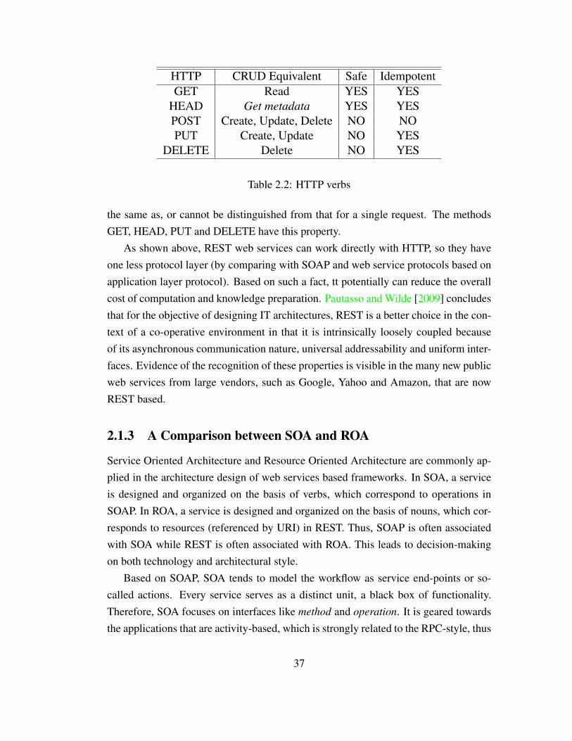
In HTTP(S)-based RESTful web services, the emphasis is on simple point-to-pointcommunication over HTTP(S). As designed by Fielding [2000], REST does not haveto be coupled with HTTP only, but in real implementations, only HTTP is applied.REST architectures that use the HTTP application protocol can be summed up as usingfive verbs (GET, HEAD, POST, PUT, and DELETE methods from HTTP 1.1) anda collection of nouns, which are the resources available on the network, referencedthrough Universal Resource Identifier (URI). The verbs have the following operationalequivalents, shown in Table 2.2. Here CRUD means Create, Read, Update and Delete.They are the the four basic functions of persistent storage, which normally used todescribe user interface conventions such as the verbs based interface for REST webservice.
In the REST uniform interface, which is based on the HTTP verbs, the conventionhas been established that the GET and HEAD methods should not have side effectsthat it should only take the action of retrieval as the operation READ in the CRUD.These are the so-called safe methods of HTTP[Fielding et al., 1999]. Methods thatonly take the action of read should be considered as ”safe”. Methods can also have theproperty of ”idempotence” that the side-effects of two or more identical requests are
36
HTTP CRUD Equivalent Safe IdempotentGET Read YES YES
HEAD Get metadata YES YESPOST Create, Update, Delete NO NOPUT Create, Update NO YES
DELETE Delete NO YES
Table 2.2: HTTP verbs
the same as, or cannot be distinguished from that for a single request. The methodsGET, HEAD, PUT and DELETE have this property.
As shown above, REST web services can work directly with HTTP, so they haveone less protocol layer (by comparing with SOAP and web service protocols based onapplication layer protocol). Based on such a fact, tt potentially can reduce the overallcost of computation and knowledge preparation. Pautasso and Wilde [2009] concludesthat for the objective of designing IT architectures, REST is a better choice in the con-text of a co-operative environment in that it is intrinsically loosely coupled becauseof its asynchronous communication nature, universal addressability and uniform inter-faces. Evidence of the recognition of these properties is visible in the many new publicweb services from large vendors, such as Google, Yahoo and Amazon, that are nowREST based.
2.1.3 A Comparison between SOA and ROA
Service Oriented Architecture and Resource Oriented Architecture are commonly ap-plied in the architecture design of web services based frameworks. In SOA, a serviceis designed and organized on the basis of verbs, which correspond to operations inSOAP. In ROA, a service is designed and organized on the basis of nouns, which cor-responds to resources (referenced by URI) in REST. Thus, SOAP is often associatedwith SOA while REST is often associated with ROA. This leads to decision-makingon both technology and architectural style.
Based on SOAP, SOA tends to model the workflow as service end-points or so-called actions. Every service serves as a distinct unit, a black box of functionality.Therefore, SOA focuses on interfaces like method and operation. It is geared towardsthe applications that are activity-based, which is strongly related to the RPC-style, thus
37

it can better model transaction-based business systems. Based on such an architecturaldesign, it also heavily depends on an extra layer of protocol for interface description.Thus, there is tight coupling between client and server because of object referencesemantics, object serialization and early binding to interfaces defined in the interfacedescription.
ROA, in contrast, is normally considered as a set of constraints or guidelines for theimplementation of REST-based web application. Other than the technical features dis-cussed in Section 2.1.2, ROA summarises the guidelines as four properties [Richardsonand Ruby, 2007]:
Addressibility Addressability means to expose the resources, applications or data,through URIs that can be located and accessed universally. In the prototypesystem that will be introduced in the following chapters, it means all related re-sources should be allocated appropriate URIs. In addition, it would be desirablethat the URI could self-explain the function and access method to some extent.For example, the URIs can be designed to include the type of the requestedresources in accordance with the W3C note on “cool URIs” Sauermann et al.[2011].
Statelessness Statelessness means that every HTTP request should be isolated fromany user session information associated with previous requests. The HTTP re-quest made by a user must contain all the information to fulfil this request. Theapplication state should be placed at the client side and the resource state at theserver side. Essentially, the application state is different for each user, such assome session information about individual visitors. The resource state is thesame for every user.
Connectedness RESTful web services usually present resources as hypermedia, whichmeans the resources not only contain data but also links to other resources. Thisis built on the addressability of all the resources. This feature can increase theextendibility of the system and save storage space in the case of multiple datainstances. Therefore, a web service is connected to the extent that you can putthe service in different stages just by following links and completing forms.
Uniform Interface Create, Read, Update and Delete (CRUD) are the four basic oper-ations on persistent storage. The HTTP uniform interface covers the four basic
38

operations by POST, PUT, GET and DELETE methods. For example, given aURI of a resource, every user knows that to retrieve the resource, a GET requestshould be sent to that URI.
Briefly, the language analogy is that the components in SOA serve as arbitraryverbs (actions) and in ROA serve as a series of nouns (resources). There are alsoverbs exposed by ROA, but they are constrained in that they are based on the uniforminterface. Furthermore, ROA as an approach aims to describe a SOA implementationthat follows the guidelines stated above. In other words, ROA is more particular in itsdependence on the technical architecture of the services, which is REST.
2.2 The Implementation of Web Services and Work-flow in Engineering Framework
A question, when employing network technology, is which of the many protocols andframeworks to choose, and indeed which will last. Others have faced the same ques-tion. For example, FIDO [Weston and Townsend, 1994] is proposed with functions thatoffer control over processes, monitoring of execution status and visualization of prob-lem data in a networked system of heterogeneous computers. Another early frame-work, DARWIN 1 and its successor DARWIN 2 [Walton et al., 2000], allows users toaccess data through web browsers. The data are dynamically generated by means ofCommon Gateway Interface (CGI) scripts and visualized with Java applets embeddedin the web pages. The common themes here are the integration of hardware plat-forms and remote process control and monitoring, but are intrinsically techno-centric,rather than problem-centric: resources can only be accessed by users through specificinterfaces, and frameworks are constructed based on a bespoke deployment and com-munication mechanism. These both limit the sharing of resources and seamless accessto substantial computing resources.
For the purpose of supporting an interoperable machine-to-machine interactionmechanism through the Internet, web services have been an active research and stan-dardisation topic for several years now, reinforced by the emergence of the concept ofthe service-oriented architecture (SOA). Remote Procedure Call (RPC) is an early styleof web services, still in limited existence albeit with disadvantages. The remote invo-cation through the RPC protocol allows programs to communicate over the network
39

by means of special communication protocols that obviate the need for extra codingto account for network details and remote machines. Several analogues of RPC havearisen to provide more sophisticated features, such as the Common Object RequestBroker Architecture (CORBA) [Corba, 1995], Java Remote Method Invocation (RMI)[ORACLE, 2011] and Simple Object Access Protocol (SOAP) [Box et al., 2000]. Sys-tems built using these protocols are sometimes referred to as arbitrary web services[W3C, 2004] and they have (all) been utilised in the MDO context.
For example, the ModelCenter software utilises RPC-style web services to deploylegacy programs remotely that are then accessible through a special applications pro-gram interface (API) via ModelCenter [Ng et al., 2003]. Analysis Server [PhoenixIntegration, 2001], a web services container, is used to publish web services and allowremote access from ModelCenter. ModelCenter and the Analysis Server together pro-vide a client/server environment for distributed resource access. In this environment,Quick-Wrap is the local tool used for automating command line programs and gen-erating services for Analysis Server. Based on this local tool solution, local machineadministrator permissions and relevant administration skills for software installationand web services deployment are mandatory.
The VADOR framework uses a similar client-server architecture but is mediated bya Java RMI package to provide remote access [Alzubbi et al., 2000]. In VADOR [Mah-davi, 2002], another wrapping mechanism is implemented. The CPU server, which isa JAVA server program, is designed to act as a wrapper and remotely execute the anal-ysis task. To run a task, the CPU server performs the following steps [Zhou et al.,2003]:
1. Locates the executable program, application, or script file;2. Builds a temporary directory;3. Transfers all input files to the temporary directory;4. Runs the program, application, or script file;5. Transfers the created output files;6. Cleans up and destroys the temporary directory.These are the typical and basic steps shared in the process of wrapping scientific
applications. CPU servers run the legacy scripts and programs locally. Although thisserver can only wrap the programs or scripts that already exist in the local machine,these steps still can be the guidelines for the design of web services based scientificapplication frameworks.
40

The Java RMI interface has been used in iSIGHT and Fiper [Sobolewski, 2002],which provide a web representation of the analysis and results accessible via a webbrowser. The Fiper framework utilises web-based components for the purpose ofremote execution. Analysis components are executed and monitored through a webbrowser which provides an open API and a Component Generator for the job of de-velopment of components. It offers a JAVA based mechanism to wrap applications. Inthis process, coding work of application provider is unavoidable.
In recent years, SOAP has gained wide acceptance as a web services protocol andLee et al. [2009] demonstrates a MDO framework based on SOAP. They deploy andexecute MDO methods using the Globus Toolkit [Foster and Kesselman, 1999], how-ever it is, as with ModelCenter, only accessible through a particular client. In this case,it is also accessible via a web browser.
The aforementioned existing MDO frameworks are typically implemented in a waythat services are mapped directly to language-specific function calls. Thus, the limita-tion on access to each of the RPC analogues arises. This means the services providedby a server can be accessed and executed only by specified clients. For example, aSOAP-based design optimization process [Crick et al., 2009] and the Soaplab tool[Senger et al., 2008b] have been used to deploy SOAP services. In that case, clienttools can only access the services based on integration with the Soaplab plug-in thathas particular library and protocol. Indeed, the interfaces of the RPC analogues (e.g.RMI and SOAP) have different and incompatible communication protocols which in-hibits access to service components created by different frameworks. This restrictionis inherent to arbitrary web services and reduces the overall interoperability betweensystems.
This tight coupling of components characteristic of SOAP can potentially increasethe costs of migrating from one client tool to another, or of introducing new applicationtools to existing frameworks that operate using bespoke protocols. The question thatnaturally arises then is whether there are any other service types that can resolve therestriction issue.
There are also some MDO frameworks supporting the extension of functions throughexternal code. For example, the MDO framework DAKOTA [Sandia National Labora-tories, 2010] simulation code can be deployed as components on networks of worksta-tions (NOWs) or desktop multiprocessors. It requires further coding work involvingscripts or programs as local components based on provided APIs.
41
2.3 Scientific Workflow System
With the development of computer technology, the trend can be observed that the net-work plays a more important role to support large-scale science research through ge-ographically distributed co-operation. The issue of enabling individual domain sci-entists to access large scale data collections and computing resources in this Inter-net environment has become key to defining research in e-Science [Deelman et al.,2009]. Large-scale computations and data analysis characterize much scientific re-search now, meaning there is a need for new approaches to emerge in order to supportcomputation and management of distributed resources in what is also a new execu-tion environment. Workflow is a sequence of connected activities or operations thatabstract and model as an activity. In business applications, it is defined as an orches-trated and repeatable pattern of business activity, enabled by the systematic organiza-tion of resources into processes that transform materials, provide services, or [email protected] [2009]. In the area of scientific computation, it hasemerged as a paradigm for representing and managing complex heterogeneous scien-tific resources. Scientific activities can also be systematically organized and processedin such a paradigm. For example, each of the data management and computationprocess can be abstracted and modeled as activities in workflow. This brings new chal-lenges in the context of e-Science research, such as application requirements, data andworkflow description, dynamic workflows, user steering and system level workflowmanagement [Gil et al., 2007].
As mentioned in Chapter 1, a number of workflow management systems (WMS)[Ludascher et al., 2006, Microsoft, 2011, Oinn et al., 2004, Taylor et al., 2007, TheYAWL Foundation, 2004] have been developed to provide the functions of work-flow composition, enactment and monitoring. As basic functions, users can use theseWMSs to build their workflow, execute the computation process and retrieve the out-puts from it. In this section, the review of WMSs will be presented through the threemain issues of this thesis, that we aim to study in scientific workflow modelling work-ing from bottom to top: data staging, web service management and service compo-sition. Based on this review, the adaptivity of each workflow management system ina cooperative environment can be discerned. Furthermore, this chapter aims to de-termine these WMSs’ advantages and disadvantages in respect of handling data man-agement, service deployment and service composition. These are the key points in
42

order to lower the barriers brought by the features of multiple institutions, multipleplatforms and geographically distributed resources that are central to the cooperativeenvironment of scientific workflow.
2.3.1 Data Staging
Conventionally, web service composition frameworks have centrally coordinated control-flows and data-flows, so the data associated with the execution process has to be stagedthrough a client-side management system. This data staging activity handles the dataprocessing activities, such as data I/O, on an intermediate storage area used in themiddle of the computational processes. The staged data in the area is used for theexecution of corresponding computing activity in the whole (workflow) process. Thecentralized data-flow approach can easily increase the level of data traffic and the sit-uation is exacerbated where large data sets are concerned[Alonso et al., 1997]. Ingeneral, centralised approaches are easily implemented and suit workflow applicationsin which large-scale data flow is not required. Taverna [Oinn et al., 2004] is a typicalWMS that implements centralised data staging.
Data staging and how to control it are not new problems. In 1997 [Alonso et al.,1997], adopted the idea of distributed dataflows in a service composition frameworkto improve data transfer performance, as did [Liu et al., 2005] some years later. Sim-ilar ideas are embodied in some distributed program execution engines, such as [Isardet al., 2007, Murray et al., 2011], to overcome bottlenecks in data transfers. Mean-while, several workflow management systems utilise a peer-to-peer style mechanismfor intermediate data movement Cao et al. [2003], Ludascher et al. [2006], Taylor et al.[2007]. Although there are differences in detail between the aforementioned solutions,there is one common aspect, namely the use of a private – by which is meant internal,or closed – mechanism (functions are exposed by a set of developer-defined specificinterfaces and operations) to handle data transfer.
In early research on peer-to-peer data staging solutions, a distributed data man-agement architecture for workflow management system was adopted in the distributedworkflow environment Exotica/FMQM [Alonso et al., 1997]. The motivation was tore-solve the problem of poor performance when data-flow is embedded with control-flow. The solution implemented only works on a local-area network (LAN), by meansof a set of loosely synchronized replicated databases. Several other workflow man-
43

agement systems have adopted such an architecture, but using more recent technology,namely Triana [Taylor et al., 2007] and Kepler [Ludascher et al., 2006], both of whichapply JXTA [Gong, 2001] – a peer-to-peer protocol – to allow services to exchangemessages. Both use an internal mechanism to identify resources in the network basedon a unique identifier. GridFlow [Cao et al., 2003] offers a slightly different solutionat the implementation level, utilising an agent-based resource management system,whose task it is to transfer between peers realized as agents. The Globus ReplicaLocation Service (RLS) [Chervenak et al., 2009], used in some Grid-based workflowmanagement systems for peer-to-peer data transfers, takes a similar approach, but withdifferent components, maintaining a simple registry that keeps track of where data re-sides in the Grid environment. RLS also has a web service incarnation, called WSRLS, which is based on the Web Services Resource Framework (WSRF). This workswith the WS-addressing specification to identify data at a messaging level. The com-mon feature in all of these data staging solutions, is either the use of an extra layer ofprivate protocols, above the Internet application layer protocols, or the introduction ofa potentially complicated (internal) system to achieve peer-to-peer data transfer.
2.3.2 Service Deployment and Management
For the purpose of considering service deployment and management in a co-operativeenvironment, one key point that should be emphasized is the high possibility that usersare non-specialists with limited knowledge and experience of relevant computer tech-nology. This determines whether the system provides a relatively simple architectureand interface for installation as well as manipulation for those non-specialists users.
Web Service Wrapping Tools
In (e-)science research, web services are commonly created for and invoked withinworkflows. Web service end-users can utilise workflow management systems to com-pose and execute them. Taverna [Oinn et al., 2004] is a popular platform for this pur-pose. It can invoke Soaplab [Senger et al., 2008b] and Opal [Krishnan et al., 2006] webservices through Taverna’s plugin mechanism. The Kepler workflow tool [Ludascheret al., 2006] can also invoke services created by these two application wrapper tools.However, both of these workflow tools need to develop extra plugins, using Soaplab’sand Opal’s programmatic APIs, in order to invoke web services seamlessly. Specific
44

APIs for each scientific application’s wrapping tool may place an extra barrier forworkflow engines to invoke corresponding web services. For example, both gRAVI[Chard et al., 2009], a WSRF web service wrapping tool and Generic Factory Service(GFac)[Kandaswamy et al., 2006], a web service wrapping tool, have three ways toinvoke services: Java Client API, web interface and command line. However, nei-ther wrapping tool provides a method for invocation from workflow engines directly.Therefore, a plugin mechanism is necessary to handle the interface between workflowand service. Thus, there always appear to be hurdles for non-specialists to deployscientific applications for use within workflows. Although Taverna and Kepler cansupport Soaplab and Opal services via plugins, because programmatic access to thoseservices needs specific APIs, this creates a restriction on the programming languages itis able to support. For instance, Soaplab2 supports Java and Perl whilst Opal supportsPython and Java.
Soaplab and Opal are widely used and build on the SOAP specification. In Soaplab,access to the underlying processes is provided by some generically named operationslike createJob, run, destroy, getSomeResults etc., but data is not sent to the serverthrough distinct SOAP endpoints. More precisely, each data object must be packedinto a Map data structure and sent by invoking the runAndWaitFor method. Thesetechnical details are handled by a mature plugin in Taverna and are transparent toworkflow management tool users. The Soaplab service in Taverna can expose severalinterfaces allowing users to extract each data item directly. Each output from a servicecan be directed to all the input ports for following services. However, this is also thereason why specific APIs must be included in order to invoke a Soaplab service, whichalso happens on the other SOAP-based tools. We also observe that Soaplab does nothave any security mechanisms to encrypt data and perform role-based access controlover users.
Opal, in contrast, uses a more ad-hoc solution to address the payload format issue.For example, in the Opal plugin for Taverna [University of Manchester, 2010], an ex-ample of an Opal web service is presented, which shows the response from the Opalservice as a string of comma-separated URLs of output files plus the content of thestandard output stream from the server-side application. Some regular expression ser-vices must be created by the user locally in order to select the necessary URL, whichwill be fed into the next Opal service as input. This would appear to raise the (user)cost of workflow creation and linking of web services based on Opal, requiring knowl-
45

edge of regular expressions, as well as the data returned being a URL pointing to thedata rather than the data itself. Although this RESTful-like feature allows the URL tobe used as the input URL for compatible web services [Ren et al., 2010], an incom-patible web service needs extra steps and data transfer to obtain and utilise the output.Compared to Soaplab, Opal does however provide a security mechanism for data en-cryption, authentication and authorization. It is based on the GSI security system,which uses the Secure Sockets Layer (SSL) for its mutual authentication protocol.
Cloud Based Web Services Deployment and Management
Cloud computing is commonly categorized into three service models [Mell and Grance,2011] known as {Infrastructure, Platform, Software} as a Service (IaaS, PaaS andSaaS, respectively), of which PaaS is the service model which provides consumerswith the capability to deploy consumer-created or acquired applications onto cloud in-frastructure, thus creating a service. One aim of this research is to provide ready accessto cloud services so that regular users can deploy their own applications as services,share them with others and utilise them in service workflows. This is done through theprovision of a platform (i.e. PaaS) that provides: (i) deployment services, and (ii) datastorage and transfer services.
PaaS cloud has been used to deploy science and engineering applications, in whichthe platform enables applications to appear as web services, creating a SaaS for pub-lic invocation. There are several generic PaaS platforms like Google’s APP Engine[Google, 2008] and Heroku [Lindenbaum et al., 2008], both of which provide themeans for users to deploy web applications on the providers’ public cloud infras-tructure. However, both work via programming language APIs. For the purpose ofdeploying an application into their infrastructures, users must either write applica-tions in specific languages or modify original code in those languages. Other potentialplatforms providing command-line interfaces are: (i) CloudFoundry [GoPivotal, Inc.,2011], which provides an open-source mechanism for application deployment. How-ever, it uses its own API, implemented for a range of popular languages for serviceinteraction, and (ii) Openshift [Red Hat, Inc., 2011], which only appears to provide aplatform for running applications using cloud resources, rather than actually deployingthem as services that others may use. This is a very rapidly evolving area in terms ofservice provision and what was true and current at the time of writing, may not hold forvery long. It is clear PaaS cloud is receiving much attention through the development
46
of experimental deployment stacks, but our focus aims as much as is feasible to stay onarchitectural issues that underpin the design and implementation of such frameworks.
The Generic Worker framework [Simmhan et al., 2010] has similar goals to ourframework: it provides a PaaS service based on Microsoft’s Azure Cloud platform andservices can be deployed by the client using command-line tools. They also adopta distributed data transfer mechanism for performance enhancement. However, theirservices are tightly connected to Azure service elements, such as Azure’s REST webservice API and the Azure blob store.
2.3.3 Web Services Composition
There are two main types of solutions for web services composition that have beendeveloped independently of one another. The first approach comes from the businessworld, which formalizes a series of XML-based standards as the specification for webservices, their flow composition and execution. It has primarily syntactic interfaces andtakes the view that web services work as remote procedure calls. The other approachstems from the Semantic Web community designed series of ontologies whose purposeis the explicit and precise declaration of the preconditions and effects of a web service.Thereby, a composition of web services can reason about web resources and plan flowby means of a goal-oriented inferencing.
Concretely, there are many web services flow specification languages like BPEL4WS[Khalaf et al., 2003] and WSCI [Arkin et al., 2002] that exemplify the first approach.Semantic Web community has widely discussed semantic annotations for a number ofyears, arriving at a solution in which preconditions and effects of services are explicitlydeclared in the Resource Description Format (RDF), based on the terms from widely-accepted ontologies. Not only those web services flow specification languages, butalso the description languages of workflow can provide approaches for web servicescomposition. On this basis, this section aims to give an overview on the existing tech-nologies for web services composition, as well as related technologies on workflowdescription.
Service Composition and WSDL
Web services, which are machine-readable, need an appropriately formatted descrip-tion of additional information on either their functions and/or the methods to interact
47

with them. WSDL specifies only the syntax of messages that enter or leave a singleSOAP service. In the composition of a group of SOAP services described by WSDL,the flow of message exchange between SOAP services must be described by a specifi-cation out of WSDL.
As aforementioned, in the business world, there are many web services flow spec-ification languages, but there is not an obvious common standards stack. Thus, eachorganisation is free to build up their own proprietary business protocols. There arelanguages, such as BPEL4WS and WSCI, both of which use WSDL as the interfacewith web services. The composition of the flow is typically constructed manually.Semantic annotations have been widely discussed in the Semantic Web communitywhere preconditions and effects of services are explicitly declared in the Resource De-scription Format (RDF) using terms from pre-agreed ontologies. There is also workon light-weight annotation of WSDL[Kopecky et al., 2007]. All those concrete imple-mentations are introduced and discussed in following text.BPEL4WS BPEL4WS (commonly also known as WS-BPEL or BPEL) is the de
facto standard for web services orchestration and business process modelling.BPEL4WS is an OASIS standard executable language for specifying actionswithin business processes with web services. Its primary proponents and sup-porters are Microsoft and IBM. It describes the control logic for web servicescoordination in a business process. The process is interpreted and executed bya BPEL [Curbera et al., 2003] engine. It includes a set of control structures likethose in imperative programming languages (if/else, repeat/until, while, etc.),but additionally it also offers parallel loops and XML processing.BPEL4WS uses SOAP-style web services as a base. This fact is embodied fromthree points: (i) Every BPEL4WS based composite service is exposed as a webservice using WSDL. For example, the public entry and exit points of the processare described in WSDL. (ii) A BPEL process communicates with external webservices through WSDL interfaces. (iii) The information in the BPEL process isdescribed by WSDL data types directly.
WSCI WSCI [Arkin et al., 2002] is a language for describing the sequence of webservice invocations. More precisely, it is a language for specifying the condi-tions under which a particular operation can be invoked. It is proposed by Sun,SAP, BEA,1 etc., and has been submitted to W3C as a technical note. In compar-
1Sun:https://www.oracle.com/sun/index.html, SAP:http://go.sap.com/index.html,
48
ison to BPEL4WS, BPEL4WS primarily focuses on the creation of executablebusiness processes in a centrally-controlled manner, while WSCI is concernedwith public message exchange between web services that in the context of a dis-tributed system. This is also the primary difference between an orchestrationlanguage and a choreography language. Similar to BPEL language, WSCI isalso XML-based. About the services grounding in WSCI, actions, which aretagged by <action>, represents a unit of work and would typically map to aWSDL defined service invocation. Thus, WSDL describes the entry points ofeach service, while WSCI describes the interactions between these services.WSCI does not concern itself with the creation of executable business process.So WSCI uses Business Process Management Language (BPML), a metalan-guage, to describe business processes. In other words, WSCI only defines theinteractions between services, and BPML defines the big image of the busi-ness processes. BPML provides similar process flow constructs and activities asBPEL.
SAWSDL Semantic Annotations for WSDL and XML Schema[Kopecky et al., 2007]was published as a technical recommendation of W3C in 2007. It describes theabstract functionalities and other semantic information of a service by defining aset of extension attributes for WSDL. It is not yet another language for represent-ing the semantic model, such as ontologies. On the contrary, the mechanisms ithas enable it to reference to the concepts from the semantic models, typicallydefined outside the WSDL document, from within WSDL and XML Schemacomponents by annotations. For example, it uses the the extension attributemodelReference to represent the URI link to the semantic model. To specify themappings between semantic data and XML, two other extension attributes, lift-
ingSchemaMapping and loweringSchemaMapping, are added to XML Schemaelement declarations and type definitions. In a nutshell, SAWSDL does not de-scribe the web services composition directly. It makes WSDL-based web ser-vices amenable to Semantic Web Services automation for the purpose of forminga composite web services (CWS).
BEA:http://www.oracle.com/us/corporate/acquisitions/bea/index.html
49

Web Services Composition in the Semantic Web
In semantic web, web resources are described or annotated by semantic marks that thewhole World Wide Web can be globally interlinked as an database of semantic data.There are large amounts of data spread across the web that is only readable to humans:the goal of semantic web is to process and share the knowledge implied in the data au-tomatically as machine-readable. The semantic web works as a representation of theknowledge, which is well-defined in a format that is machine-readable. Web Ontol-ogy Language for Services (OWL-S)[Martin et al., 2004] and Web Service ModelingOntology (WSMO)[De Bruijn et al., 2005a] are two prominent techniques used forservices composition in the domain of semantic web.OWL-S OWL-S, which was formerly called DAML-S, is a language based on OWL
(Web Ontology Language) used for describing semantic web service properties.The OWL-S ontology has three main parts: service profile, process model andgrounding. They have the following usages:
1. The service profile is used to describe what the service does. This partincludes the service name and description, limitations on applicability andquality of service, publisher and contact information. It mainly aims toprovide human-readable information about the web service.
2. The process model is used to describe how to perform the web service’sfunctions, which includes the sets of inputs, outputs, pre-conditions andeffects (IOPE) of the service execution.
3. The grounding specifies the details of how to interact with the web servicebased on web service protocols, which includes communication protocols,message formats, port numbers, etc.
The grounding part is filled with a description of the actual web service, forwhich WSDL is the commonly-used description language. OWL-S is mappedto WSDL through the following three aspects:
1. An OWL-S atomic process is grounded as a WSDL operation.
2. The I/O of an OWL-S atomic process are grounded as WSDL messages.
3. The I/O types of an OWL-S atomic process are grounded as WSDL abstracttypes.
50

Therefore, in practice, OWL-S has a high degree of coupling with SOAP. Basedon OWL-S and WSDL, it is possible to describe web services declaratively,which in turn enables the automatation of web services composition[Chapmanet al., 2007].
WSMO Besides OWL-S, there is another conceptual model used for describing thesemantic web services called the Web Services Modelling Onology (WSMO)[Feier et al., 2005]. WSMO has four main components:
Goals The client’s objectives when consulting a web Service.
Ontologies A formal semantic description of the information used by all other
components.
Mediators Connectors between components with mediation facilities. Provides
interoperability between different ontologies.
Web Services Semantic description of web Services. May include functional
(Capability) and usage (Interface) descriptions.
As presented in [Kopecky et al., 2005], WSMO is grounded to WSDL. The W3Cmember submission document [De Bruijn et al., 2005b] also shows that WSMOonly specifies the grounding in WSDL. Therefore, as with OWL-S, WSMO alsotargets the so-called ”Big” web services [Pautasso et al., 2008], which mainlyoperate under the paradigm of arbitrary web services [W3C, 2004] or RemoteProcedure Call (RPC). Both OWL-S and WSMO use Semantic Web elementssuch as ontologies that pre-date the concept of Linked Data or Connectedness inROA. Neither OWL-S or WSMO appear to have stood the test of time, in thatdespite extensive web search, it seems there is currently (2014) no substantialreal-world usage.
Discussion of Web Services Composition
In the past decade, great efforts have been expended on semantic web service models.They are not limited to those mentioned above[Akkiraju et al., 2005, Kopecky et al.,2007]. However, there is no substantial real-world usage of them. In this process, it canbe observed that there is a strong binding between SOAP+WSDL and semantic webservice models. One important reason is that SOAP became popular as a web serviceprotocol and has been widely implemented since it became a W3C recommendation in
51

2003. There is semantic annotation for REST web resources, called SA-REST[Shethet al., 2007], that supports semantic description in a /emphmashup, which is the webapplication hybrid to create a single new service from more than one source. However,its annotations are based on human-readable HTML or XHTML, which has limitedutility if the resources are machine-readable only web services. Thus, it is difficult toapply the languages in previous approaches to a new type of web service, namely theRESTful web service. The difficulties are reflected from the following two perspec-tives:
1. There is no binding from semantic web services languages to RESTful web ser-vices description. Semantic web services cannot be grounded to the RESTfulweb services in an straightforward way.
2. There are fundamental differences between SOAP and REST, in that SOAP isoperation-based and REST is resource-based. In the design of semantic web ser-vice models, it naturally follows this operation-based style. This design allowsthose semantic web serivce models to be adaptable to their grounding targets.This basic architectural difference means that the key concept of resource can-not be reflected in those models.
2.3.4 Workflow Description
Nowadays, scientific workflows are largely built based on distributed resources, whichrely heavily on the support of web services. Some of the Workflow Management Sys-tem (WMS) involve standard or proprietary workflow definition language that can sewweb services and other resources together into one workflow; nevertheless, the finalgoal is to enable the workflow enactment. This section investigates the existing solu-tions for workflow description and workflow enactment, especially focussing on theirimplementation in WMS. This section aims to bring the ideas from those solutions tobear on the design of a novel service composition language.
Two Major Phases for Workflows
The Workflow Management Coalition (WfMC)[Coalition, 1996] defines workflow asthe automation of a business process, in whole or part, during which documents, infor-mation or tasks are passed from one participant to another for action, according to a
52
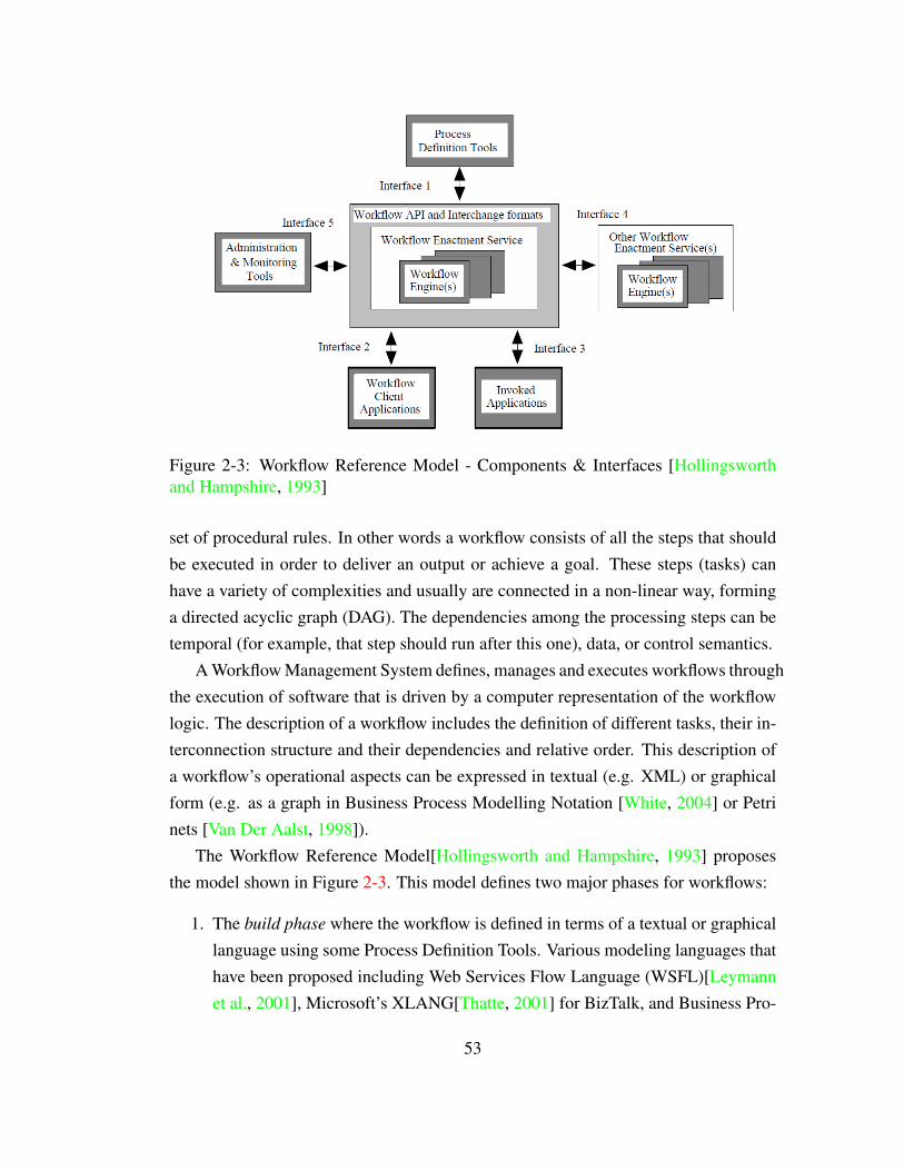
Figure 2-3: Workflow Reference Model - Components & Interfaces [Hollingsworthand Hampshire, 1993]
set of procedural rules. In other words a workflow consists of all the steps that shouldbe executed in order to deliver an output or achieve a goal. These steps (tasks) canhave a variety of complexities and usually are connected in a non-linear way, forminga directed acyclic graph (DAG). The dependencies among the processing steps can betemporal (for example, that step should run after this one), data, or control semantics.
A Workflow Management System defines, manages and executes workflows throughthe execution of software that is driven by a computer representation of the workflowlogic. The description of a workflow includes the definition of different tasks, their in-terconnection structure and their dependencies and relative order. This description ofa workflow’s operational aspects can be expressed in textual (e.g. XML) or graphicalform (e.g. as a graph in Business Process Modelling Notation [White, 2004] or Petrinets [Van Der Aalst, 1998]).
The Workflow Reference Model[Hollingsworth and Hampshire, 1993] proposesthe model shown in Figure 2-3. This model defines two major phases for workflows:
1. The build phase where the workflow is defined in terms of a textual or graphicallanguage using some Process Definition Tools. Various modeling languages thathave been proposed including Web Services Flow Language (WSFL)[Leymannet al., 2001], Microsoft’s XLANG[Thatte, 2001] for BizTalk, and Business Pro-
53

cess Execution Language for Web Services (BPEL4WS), which is the mergingof WSFL and XLANG for web services orchestration.
2. The run phase where the workflow is enacted according to its definition by aworkflow execution (enactment) component or a workflow engine. At this phase,the execution of some tasks may require the interaction with users or other soft-ware applications and tools.
Workflow Description Solutions for Workflow Management System (WMS)
This section surveys the workflow description solutions in some of the WMS that havebeen popular in recent years in the scientific user communities.Taverna SCUFL (Simple Conceptual Unified Flow Language) is the workflow lan-
guage used by Taverna 1.7.x. This language is essentially a data-flow-centriclanguage[Oinn et al., 2006], defining a graph of data interactions between dif-ferent services. It is based on IBM’s WSFL[Leymann et al., 2001] which is theone of the predecessors of BPEL, including support for specifying control-flowand data-flow. The SCUFL model contains a set of inputs, outputs, processors,data links and control links. The processor represents a logical service that is anindividual step within a workflow. It is specified in the design stage of workflow.
In Taverna 2.x, a new workflow language t2flow is adopted. It is a serializationformat that is very close to the Java object model. It contains various items thatare simply Java beans that serialized using XMLBeans. From the functionalpoint of view, it is similar to SCUFL. However, its drawback is being a serializa-tion format that can be difficult for third party software to operate on. In Taverna3.x, it will be replaced by SCUFL2 [Williams and Soiland-Reyes, 2012]. Its betarelease was in 2012. Now, Taverna 3.x is still not released and there is no clue ithas been involved in current version of Taverna. It mainly aims to overcome theproblem in the t2flow that its serialization format suffers from being very closeto the Java object model, and contains various items that are simply Java beansserialized using XMLBeans. As the t2flow format is very verbose, it can be dif-ficult to deal with for third party software. The workflow structure of SCUFL2is defined using an OWL ontology written by the Taverna developers.
Kepler Kepler adopts a non-standard workflow description language [Barker and Van Hemert,
54
2008] called Modeling Markup Language (MoML)[Lee and Neuendorffer, 2000].It is based on XML and specifies interconnections of parameterized, hierarchicalcomponents. Based on this language, the workflow in Kepler is a compositionof independent components (actors) that communicate with each other throughinterfaces called ports. Each actor is parameterized that it exhibits a concretebehaviour, which is specified at design time. The execution of a workflow iscontrolled by a director, which is the object that orchestrates the actors, initial-izing them and controlling their execution.
The ACGT Workflow Editor The ACGT Workflow Environment[Martin et al., 2011]supports BPEL as its standard workflow definition and enactment language.BPEL is introduced in more detail as an language for web services composi-tion in 2.3.3.
YAWL YAWL [Van Der Aalst and ter Hofstede, 2005] is a workflow system, basedon a modelling language. The language has the same name as the system, whichstands for “Yet Another Workflow Language”. The YAWL language design isbased on Petri nets with the aim of preserving their strengths for the specifica-tion of control-flow dependencies in workflows, with extensions that allows forstraightforward specification of workflow patterns[Van Der Aalst et al., 2003].The tasks specified in the workflow are associated with SOAP web services aredesign time. It is enacted through the Web Service Invoker Service in YAWLworkflow system[Adams and ter Hofstede, 2009].
There are also some WMS do not have an explicit workflow languages to supportthe design of workflow, such as Triana[Taylor et al., 2007]. The workflow in Trianais written based on XML, which is proprietary. Its workflow file is saved as plaintext without a postfix. Galaxy[Galaxy Team, 2008] saves its workflow in a proprietaryJSON-like format, which is named as ga.
Discussion on Workflow Description
Section 2.3.4 provides an overview of how workflow is orchestrated for the purpose ofworkflow enactment. The importance of a workflow description language is reflectedin both the two major phases and functions as a bridge between them. Considering thesituation that all the components described in a workflow are web services, then sucha workflow is in effect a composite web service (CWS). Therefore, based on the twomajor phases noted in 2.3.4, it can be further observed that, the following are important
55

aspects in the design of web services composition language:
1. a description language that can define the execution dependencies among webservices.
2. a runtime to support enactment of CWS derived from the description language.
2.4 Summary
Existing MDO frameworks provide different mechanisms for the job of applicationswrapping. Some can deploy analysis components as web services, others either donot provide a web-based component or utilise web pages rather than web services forcomponent invocation. A web page is more person-friendly, but lacks machine ac-cessibility. Meanwhile, all of these popularly adopted wrappers are executed locally,which need local installation processes, administrator permissions and most impor-tantly are without/lack remote accessibility. It is also significant that the web servicesadopted by them are RPC-style, so all the drawbacks of RPC-style are also inherited,which may incur extra hurdles to user experience and data staging.
A new architectural style, in REST, has emerged showing the potential to over-come the disadvantages inherited from the RPC-style. It is also worth exploring andresearching the advantages that the new architectural style can bring. The evolu-tion of MDO frameworks represents the demand from scientists that smart method-ology should be adopted in the scientific workflow that bears the features of multi-institutions, multi-platforms and geographically distributed resources.
The following chapters in this thesis aim to analyse those issues and propose the asystematic solution as a framework to be applied in the context of scientific workflow,based on ROA. From the perspectives of data staging, service management and ser-vice compostion, the improvements based on this framework will be reflected in thefollowing aspects:
1. The framework considers the deployment of web services in a broader context,assuming services will typically be composed. Consequently a data stagingmechanism is provided to assist in the effective enactment of composition ofservices. This is in direct contrast to the above tools, which do not consider datacommunication as part of their concern, and which can, in the worst case, resultin centralised data transfer, when deployed as web services.
56
2. The framework allow hot-plug style program uploading, deployment and systemdeployment. In contrast, some of the wrapping techniques, such as Soaplab andOpal, mentioned in this chapter require the wrapper to be installed on the serverand work as local tools on a server that needs to be set up and configured everytime a new service is deployed. The framework we propose also aims to pro-vide a desktop GUI tool for clients to deploy web services based on command-line programs. This avoids the need to learn and use the description languagesadopted in existing tools, as well as the overheads involved in authoring, debug-ging and maintaining such descriptions in parallel with the application.
3. Based on the new methodology for data staging and service management, thisframework will further explore the feasibility of introducing cloud computinginto this framework. It will further enable the ability of distributed computa-tion and resources with the supported of enhanced reusability and reproducibil-ity. This aims to overcome the technical hurdles and management complexity.These hurdles and complexity are brought by various legacy code, which requirespecific execution environments, such as heterogeneous operating systems andsoftware dependencies.
4. The framework also needs to address support for the construction and deploy-ment of composite services. A possible issue is the dependence on specific ser-vices, meaning there is a reliance on a service provided at a specific location,as against a specification of a service by, say, its profile (in OWL-S terminol-ogy), and the late binding identification of suitable available candidate servicesclose to enactment time. We propose and construct a mechanism that based onthe works in this thesis to support workflow description for RESTful web ser-vices based composite service, web service composition and composite serviceexecution.
57

Chapter 3
Datapool: A ROA Based DistributedData-flow Model
3.1 Introduction
The problem of staging data in workflows has received much attention over the lastdecade, with a variety of user-directed and automatic solutions. In Section 2.3.1, theexisting solutions and researches were introduced. A trend of distributed managementof data and separation of data-flow and control-flow emerges, which aims to resolvethe performance overhead when the two flows are embedded within each other. Thefirst challenge in the design for this ROA based WMS emerges as, how to design a datastaging mechanism that can utilise the light-weight feature of less layers of protocol,follow the constraints of ROA and also enable the data staging in a distributed mannerwith separation of data-flow and control-flow. This chapter addresses this challenge.The resulting data-flow model has following features:
1. The model is designed based on mature and widely applied technology. It doesnot use a private – by which we mean internal, or closed – mechanisms (func-tions are exposed by a set of developer defined specific interfaces and operations)to handle data transfer.
2. The model supports universal access through network to data objects, whichare viewed as online resources. By this, this mechanism enables the access toprovenance data.
58

3. The model provides a seamless interface for application services to access indi-vidual data objects or a collection of data objects.
4. In this model, data-flow is separated from control-flow to avoid central coordi-nation, which forms the basis for distributed data transfers.
5. It supports a distributed data staging mechanism. Data-flow can be distributedamong services without passing through a central controller.
6. It supports asynchronous data staging. Data transfers can be initiated asyn-chronously before the actual execution of a service when data comes from dif-ferent sources.
The rest of this chapter will first provide a detailed design of this model as wellas its comparative advantages in Section 3.2; then implementation of this model basedon ROA in Section 3.3; evaluation of performance is provided in Section 3.4; therewill be a summary in Section 3.5. Furthermore, there is a discussion of limitations inSection 8.2.1.
3.2 Distributed Data-flow
Inspired by the principle of distributed data transfer, this thesis presents a data-flowmodel for web services composition, which is able to alleviate the communicationbottleneck between client and server. There are two quite obvious remarks about data-flows among multiple services: (i) for a given service invocation, the data-flow rarelyinvolves the client or central controller, which means that data-flows can (normally)be distributed, and (ii) it is not uncommon that the necessary data objects (inputs)may come from different sources, suggesting that data transfers can be initiated asyn-chronously before the actual execution of a service. These constitute the two propertiesthat our data staging mechanism needs to satisfy.
3.2.1 Distributed Data Staging
Figures 3-1 and 3-2 illustrate the essential difference between a centralized and a dis-tributed mechanism for data transfer. Figure 3-1 shows that both control-flow anddata-flow are centrally coordinated for each web service invocation. There is a high
59

Figure 3-1: Centralized Data-Flows in Web Services Composition
Figure 3-2: Distributed Data-flows in Web Services Composition
risk that the client or central controller becomes a bottleneck for data communicationamong computation components. In Figure 3-2, the data-flows are distributed amongweb services directly rather than passing through a central controller, which also al-lows for the concurrent transfer of data objects from different resources. The I/O datacommunication carries out in network between each related web service. The clientcan also obtain the complete set of data objects from the network whenever it needs.
60

Hence, each service provider takes care of the task of data storage instead of the client.This comparison also illustrates the additional technical requirements on the dis-
tributed data staging mechanism. Two key functions are identified: (i) an universaladdressing system that allows each individual data object can be identified and ac-cessed in network, (ii) an server-side data management service that allows data objectto be stored, grouped and accessed based on that universal address system. Chapter 2showed that some other distributed data transfer system to achieve these two require-ments either through the use of an extra layer of private protocols, above the Internetapplication layer protocols, or the introduction of a potentially complicated (internal)system to achieve distributed data transfer. This thesis aims to present that an opensolution can be achieved by simpler web services based architecture like ROA and inwhich data objects can be addressed just by URIs. More design details are presentedin Section 3.3.
3.2.2 Asynchronous Data Staging
As aforementioned, it is common that necessary data objects come from differentsources. In a centralized way, control-flow and data-flow are centralized coordinatedthrough client. Therefore, the inputs from different sources for next service have to besynchronized at client in advance. In an arbitrary web service, it is common to havemultiple data objects compacted into one data object, such as XML, JSON file, whichnaturally makes the data staging among services working in a synchronous style. Onthe other hand, in REST-compliant web services, it is also common phenomenon thatmultiple data objects are compacted together into a data structure, which is either con-tains in URI or HTTP body data.
The comparison between asynchronous and synchronous data staging mechanismsare demonstrated in Figure 3-3, where there are three data objects from three differentweb services that need to be transferred to another service as inputs through threedifferent connections. We make the not entirely realistic assumption that in the twosituations, the same data object transfer takes the same time. Under synchronous datatransfer, because the data references are controlled through the client, data transfer onlystarts when the last service finishes and the next service invocation happens. However,in the asynchronous method, the transfers start asynchronously when each previousservice finishes. The transfers are not synchronized with the invocation of next service.
61

Figure 3-3: Comparison of two different data staging mechanisms
Data objects will be transferred in advance. From Figure 3-3, we can clearly see thatthe asynchronous method may be able to bring about an earlier completion of thewhole data transfer process.
The advantages of asynchronous data staging are mainly embodied in the enact-ment of workflow, such as multiple steps in sequence. This is shown in Figure 3-4by a simple workflow data staging example. In this example, there is a data depen-dency that Service 3 depends on both Service 1 and Service 2 directly. D2 is generatedafter Service 1’s execution. In synchronous data staging mechanism, D2 has to waitfor Service 2’s execution and is submitted to Service 3 together with D4. In asyn-chronous mechanism, D2 can be transferred to Service 3 in advance in spite of theexecution of Service 2. Obviously, with the increase of number of sequential steps inworkflow, there are higher possibility that the overhead on data staging can be savedby asynchronous mechanism.
62

Figure 3-4: The data dependency in a simple example of multiple steps of workflow
3.3 The Implementation of Distributed Data-flow Model
In order to implement the distributed data-flow model in this framework, there areseveral basic design requirements to be considered. First of all, the addressability ofdata objects. By following the design principles of ROA and the URI protocol, weare straightforwardly able to achieve the requirement of enabling data objects beingidentified and accessed universally on Internet. Secondly, it is also required for usersto be able to deploy services that can be joined up via this implementation, without theneed to take any special action or need to modify existing applications. Finally, it isalso a requirement that an appropriately authorized user should be able to manipulateonly their own data objects, in order both to secure a given workflow’s data, but alsoto avoid unintentional conflicts with other users.
63

3.3.1 Datapool Service
The Datapool service is the RESTful web service for I/O data items manipulation(uploading, retrieval, etc.). Datapools are components that used to connect data withapplication services, which implement the distributed data-flow model. Each Datapoolrepresents a collection of data items each with a unique URI. Each data item inside oneDatapool is allocated with unique URI to enable addressability as well.
There are two advantages to organising data in this way. First, because all the dataitems and data collections are directly allocated with URIs, they are all web resourcesthat can be re-accessed through HTTP at any time rather than merely a data streamin the form of an extra layer of XML or other structure. Furthermore, each data itemcan also be transferred and kept in their original textual or binary format. Second,in the execution of an application service, the URI of one Datapool that contains allthe input data is provided to the service. The application will pull the necessary dataautomatically from the provided local or remote Datapool. In this way, the interfacesare unified for different application services in the form of one URI, of which theDatapool URI is a constituent as a query string.
Distribution of data between services is greatly simplified through the use of URIs.Each Datapool service is collocated with application services in the same host as shownin Figure 3-2. Hence the basic function of the Datapool is to provide data storagefor association with a particular service, whereby data objects are uploaded into aparticular Datapool, such as during initialization, or are transferred from one Datapoolto another as a result of the control-flow. In each case, the object will be given a namederived from the Datapool’s URI.
Asynchronous data staging is also achieved by the existing of Datapool. We iden-tify that the essence of asynchronous data staging is the separation of control-flow anddata-flow. In our case, data-flows among services can be totally controlled throughDatapool service. Control-flow merely needs to pass through the application servicesthat associated with the Datapool service which is collocated in the same host. Eachdata object can be submitted to or retrieved from Datapool service independently fromcontrol-flow.
64

Methods URIsPUT http://. . . /datapool/{Datapool Instance Name}/{Data Object Name}PUT http://. . . /datapool/{Datapool Instance Name}?DO URI={Data Object URI}
Datapool GET http://. . . /datapool/{Datapool Instance Name}/{Data Object Name}Services GET http://. . . /datapool/{Datapool Instance Name}
DELETE http://. . . /datapool/{Datapool Instance Name}/{Data Object Name}DELETE http://. . . /datapool/{Datapool Instance Name}
Table 3.1: URIs of Datapool Service
3.3.2 User Interface
For the purpose of enabling data being transferred from client to Datapool or betweentwo Datapools, firstly, it exposes an interface for users to inject documents of any for-mat into the repository as either textual data or arbitrary binary data. Datapool serviceautomatically allocate URIs and organize them in the form of a collection of URIs.Secondly, clients can submit the URI of the data object to Datapool. Datapool willautomatically obtain and allocate a new URI to it. Afterwards, before the execution ofservice, client merely need to provide the URI of the corresponding local Datapool toweb service, which contains all the necessary inputs. Web services will automaticallyextract and consume the data it needs based on data object’s name. The whole interfaceis built based on the HTTP protocol to allow the uniform interface of ROA.
The services of Datapool are accessible through URIs as shown in Table 3.1. Userscan maintain several Datapool instances for different processes or for different stagesin one process, and only the owner of the Datapool instance can control the data objectsstored in it and decide who can access them, which provides a degree of security foruser data. Data resources in the Datapool instance have unique URIs so that differentusers cannot unintentionally conflict each other.
The HTTP methods - GET, PUT, DELETE - are used in these URIs to representcorresponding functions of the Datapool service. The Datapool service aims to pro-vide following functions: (i) create, update, retrieve, delete of Datapool instances,(ii) create, update, retrieve, delete of data object in Datapool instance. The number offunctions can be further reduced to simplify the method vocabulary. The update jobof Datapool instance actually equals the create, update and delete jobs of data objects.The create job of Datapool instance is automatically activated by the create job ofdata object in a new Datapool instance. There is no necessity to create an empty Dat-apool instance. Meanwhile, the create job of data object can share the same method ofupdate. The Datapool system can distinguish them by checking if the requested data
65

object is existing. Therefore, there are five jobs that needed to be achieved by the thoseURIs and the HTTP methods. (i) retrieve, delete of Datapool instance, (ii) update, re-
trieve, delete of data object in Datapool instance.The first two PUT methods in Table 3.1 are used for update job of data object.
First is used for uploading raw data directly. Second is used to upload from anotherDatapool by providing the URI of data object. The first GET method in Table 3.1 isused to retrieve the raw data of the data object. The second GET method is used toretrieve the list of the data object URIs in the retrieved Datapool instance. The lasttwo DELETE methods are used to delete the corresponding data object or the wholeDatapool instance.
3.3.3 Usages and Technical Details
Datapool Service Datapool service is deployed in each of the machine where appli-cations reside in. This Datapool service is always associated with the data stag-ing activities of the applications in the machine it is deployed. When there aremultiple machines, there will be same number of Datapool services deployedon those machines, one for each. Cross-machine data staging happens betweentwo Datapool services in two different machines. In Table 3.1, the URI prefixhttp://. . . /datapool/ represents Datapool Service. Datapool Service can containmultiple Datapool instance, where the data object are categorised based on theirusages and owners. At this level, only the system admin have the permission todo configuration and manipulation. In the OS file system of the Datapool ser-vice, their will be a designated folder to hold all the data instances as sub-folders.The path of the designated folder can be customised in the configuration file forthe Datapool service.
Datapool Instance Datapool instance is the data collection in Datapool service. Therecan be multiple Datapool instances in one Datapool instance. Each of the Dat-apool instances can have associated data owner or group. Only the owner orthe member in the group has the access to the data objects in the correspond-ing Datapool instance. Contrarily, one owner or one group can have multipleDatapool instances in one Datapool service for different usages. For exam-ple, Datapool instance X can be used only for Service X’s data staging ac-tivities and instance Y is only used for Service Y. In Table 3.1, the URI pre-
66

fix http://. . . /datapool/{Datapool Instance Name} represents the Datapool in-stance. Each of them can have it own unique name. As mentioned, each Dat-apool instance appears as sub-folder in the designated folder for Datapool Ser-vice in OS file system. Their folder name is the same as the Datapool Instance Name
appeared in the URI.
Data Object in Datapool Instance Data object is the real raw I/O data from appli-cations. Their accessibility is decided by the Datapool instance where they areput in. Only the Datapool instance owner or owner group can access the dataobjects. In the OS file system, they are saved in their raw formats in each ofthe corresponding Datapool instance sub-folder. When there is data staging ac-tivities happen between two Datapool instance in the same machine, the realbackground activity in the OS is just to change the original path of the file to letit points into the new Datapool instance sub-folder. If it is cross-machine datatransfer, the original data will be deleted, and a new file will be created in thenew sub-folder in the other machine OS. In Table 3.1, Data Object Name in onecomplete URI http://. . . /datapool/{Datapool Instance Name}/{Data Object Name}means the name of the Data object. It is also the file’s name in the Datapool in-stance’s sub-folder.
3.3.4 Authentication and Authorization
Authentication and authorization are key functions that should be applied to the Dat-apool system. One of the important reasons of applying ROA is that RESTful webservice enforces security based on the HTTP/HTTPS protocol. There is no necessityto implement an extra security layer for such purpose. Based on that, an authorizationsystem is implemented to enable a role-based control authorization. There are twoobvious benefits brought by it: firstly, developers do not need to design and embed anew security mechanism into the system, which can save developing time and reduceknowledge preparation; secondly, users also do not need to extra knowledge to getfamiliar with the security mechanism as well as do not need to install extra layer ofsoftware or plug-ins to use it, because of the wide application of the HTTP/HTTPSprotocol.
HTTPS is a communications protocol for secure communication over a computernetwork. It simply layers the HTTP protocol on top of the SSL/TLS protocol, thus
67
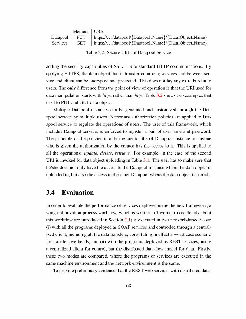
Methods URIsDatapool PUT https://. . . /datapool/{Datapool Name}/{Data Object Name}Services GET https://. . . /datapool/{Datapool Name}/{Data Object Name}
Table 3.2: Secure URIs of Datapool Service
adding the security capabilities of SSL/TLS to standard HTTP communications. Byapplying HTTPS, the data object that is transferred among services and between ser-vice and client can be encrypted and protected. This does not lay any extra burden tousers. The only difference from the point of view of operation is that the URI used fordata manipulation starts with https rather than http. Table 3.2 shows two examples thatused to PUT and GET data object.
Multiple Datapool instances can be generated and customized through the Dat-apool service by multiple users. Necessary authorization policies are applied to Dat-apool service to regulate the operations of users. The user of this framework, whichincludes Datapool service, is enforced to register a pair of username and password.The principle of the policies is only the creator the of Datapool instance or anyonewho is given the authorization by the creator has the access to it. This is applied toall the operations: update, delete, retrieve. For example, in the case of the secondURI is invoked for data object uploading in Table 3.1. The user has to make sure thathe/she does not only have the access to the Datapool instance where the data object isuploaded to, but also the access to the other Datapool where the data object is stored.
3.4 Evaluation
In order to evaluate the performance of services deployed using the new framework, awing optimization process workflow, which is written in Taverna, (more details aboutthis workflow are introduced in Section 7.1) is executed in two network-based ways:(i) with all the programs deployed as SOAP services and controlled through a central-ized client, including all the data transfers, constituting in effect a worst case scenariofor transfer overheads, and (ii) with the programs deployed as REST services, usinga centralized client for control, but the distributed data-flow model for data. Firstly,these two modes are compared, where the programs or services are executed in thesame machine environment and the network environment is the same.
To provide preliminary evidence that the REST web services with distributed data-
68

Figure 3-5: Comparison of 1000 continuous executions
Figure 3-6: Results of simple workflows work with both Centralized and DistributedData-flows
69
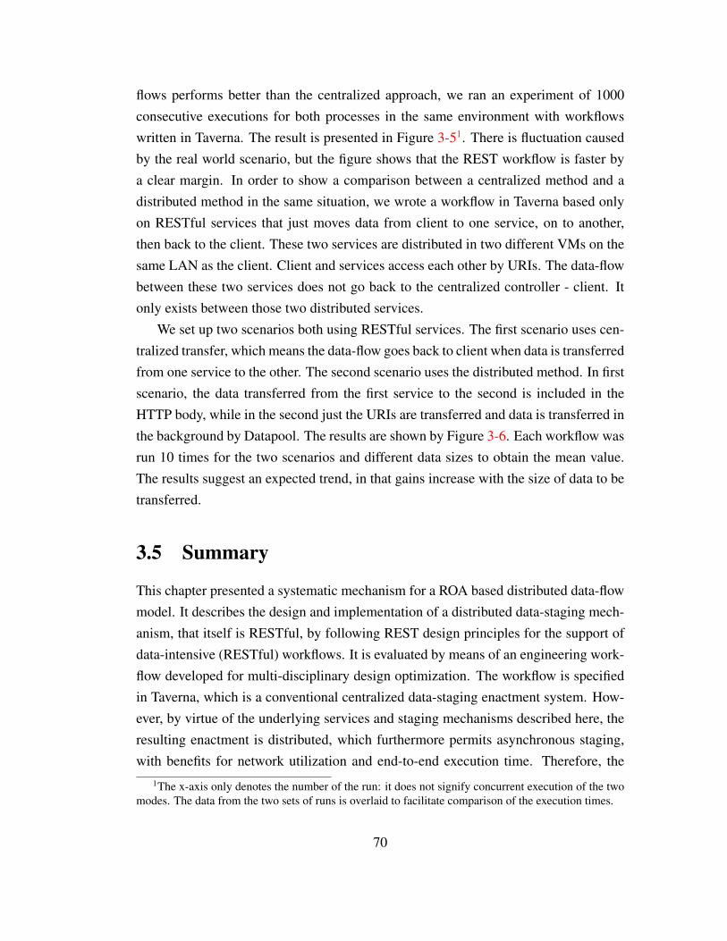
flows performs better than the centralized approach, we ran an experiment of 1000consecutive executions for both processes in the same environment with workflowswritten in Taverna. The result is presented in Figure 3-51. There is fluctuation causedby the real world scenario, but the figure shows that the REST workflow is faster bya clear margin. In order to show a comparison between a centralized method and adistributed method in the same situation, we wrote a workflow in Taverna based onlyon RESTful services that just moves data from client to one service, on to another,then back to the client. These two services are distributed in two different VMs on thesame LAN as the client. Client and services access each other by URIs. The data-flowbetween these two services does not go back to the centralized controller - client. Itonly exists between those two distributed services.
We set up two scenarios both using RESTful services. The first scenario uses cen-tralized transfer, which means the data-flow goes back to client when data is transferredfrom one service to the other. The second scenario uses the distributed method. In firstscenario, the data transferred from the first service to the second is included in theHTTP body, while in the second just the URIs are transferred and data is transferred inthe background by Datapool. The results are shown by Figure 3-6. Each workflow wasrun 10 times for the two scenarios and different data sizes to obtain the mean value.The results suggest an expected trend, in that gains increase with the size of data to betransferred.
3.5 Summary
This chapter presented a systematic mechanism for a ROA based distributed data-flowmodel. It describes the design and implementation of a distributed data-staging mech-anism, that itself is RESTful, by following REST design principles for the support ofdata-intensive (RESTful) workflows. It is evaluated by means of an engineering work-flow developed for multi-disciplinary design optimization. The workflow is specifiedin Taverna, which is a conventional centralized data-staging enactment system. How-ever, by virtue of the underlying services and staging mechanisms described here, theresulting enactment is distributed, which furthermore permits asynchronous staging,with benefits for network utilization and end-to-end execution time. Therefore, the
1The x-axis only denotes the number of the run: it does not signify concurrent execution of the twomodes. The data from the two sets of runs is overlaid to facilitate comparison of the execution times.
70

contributions of this work can be summarised as:
• It provides a data staging mechanism for ROA based distributed system that itutilises the features and follows the design constraints of RESTful web servicewithout introducing extra layer of protocol.
• This data staging mechanism has the ability to separate the data-flow and control-flow in workflow enactment. By having the asynchronous feature, it is also ableto further separate the data-flow based on the data source and data destination.Also, this mechanism can provide better data staging performance by its dis-tributed and asynchronous features.
71

Chapter 4
SaaS based Scientific Web ServicesManagement
4.1 Introduction
For at least the past decade, a significant trend in scientific research, which includessignificant amount of computation for the purposes of modelling, simulation, verifica-tion and evaluation, has been the increasing uptake of computational techniques (mod-elling) for in-silico experimentation. This trend trickles down from the grand chal-lenges that require capability computing to smaller-scale problems suited to capacitycomputing. Such virtual experiments also establish an opportunity for collaboration ata distance. At the same time, we believe the development of web service and cloudcomputing technology, is providing a potential platform to support these activities.This defines the general topic and issues we aim to study in this thesis. In Chapter 2, aseries of issues are identified on existing web service deployment toolkits. The prob-lem is the technical hurdles for users without specific and enough knowledge aboutweb services, workflow and other related mechanisms – in a word, ‘accessibility’.Specifically: (i) the heavy weight and diversity of infrastructures that inhibits share-ability and collaboration between services, (ii) the relatively complicated processesassociated with deployment and management of web services for non-disciplinary spe-cialists, and (iii) the relative technical difficulty in packaging the legacy software thatencapsulates key discipline knowledge for web-service environments.
The aforementioned hurdles are determined by the nature of the end-user-scientist
72
and the resources that need to be deployed in the cloud. Most scientists who havelimited knowledge of web services or cloud infrastructure may need to face the needto learn new programming languages or system administrative skills for the purpose tobuild scientific applications in the cloud or as web services. For example, an engineerpossibily has the skill to develop desktop applications based on Fortran or Matlab, butrarely has knowledge of or experience with web application development based onlanguages like Java or Python. On the other hand, with years of development, numer-ous legacy programs in which real domain-specific knowledge resides, may face thepredicament that a new round of coding and translating work is needed or they simplylose the ability to be re-developed because of the lack of source code, documents orlanguage support1.
Therefore, this chapter aims to propose a web services management frameworkthat makes differences from following aspects:
1. A Software-as-a-Service (SaaS) cloud model is applied to provide the functionof service deployment as web services, which allows a hot-plug style of programuploading and deployment. The existing methods for service deployment as-sume the programs or the libraries to support the service have been pre-installedon the server. They work as local tools on a server that needs to be set up andconfigured by system administrators every time a new service is deployed.
2. The deployment of web services is considered for a certain demand, which as-sumes services will be composed as one web service. Consequently, a datastaging mechanism - Datapool, which was proposed in Chapter 3 is provided toassist the composition of services. The web service management mechanism inthis chapter will inherit the interfaces and be able to communicate with Datapoolwithout further configuration from users. The existing tools do not consider theease of use for service composition. Data staging among services have to be or-chestrated by a third-party application through a centrally controlled data stagingspace, which may result in the extra data traffic mentioned in Chapter 3.
3. A desktop GUI tool is provided for clients to deploy web services based oncommand-line programs. This avoids the need to learn and use the descrip-tion languages adopted in these tools (such as “Ajax Command Definition” in
1In the worst case, only a binary of the program may exist, which happens to be executable due tobackwards hardware compatibility.
73

Soaplab, “serviceMap” in GFac and “Metadata” in Opal), as well as the over-heads involved in authoring, debugging and maintaining such descriptions inparallel with the applicaiton.
To be compatible and consistent with the Datapool service adopted, the proposedweb service management framework adopts REST web services. At the same time,because this framework is also based on REST/ROA, it also inherently has the benefitsof flexibility, simplicity as well as the easy-to-use feature for non-specialist users asdiscussed in Chapter 2. Furthermore, this framework lowers the barriers by provid-ing a set of GUI based client tools and a set of REST web services which serve asboth portal for service deployment and service execution by following the SaaS ser-vice model[Mell and Grance, 2011]. The framework is able to deploy legacy codeand command-line programs as RESTful services, which can support a wide rangeof languages and tools, such as C/C++, Fortran, Matlab, Python, Unix shell, JAVA,and some engineering design optimization frameworks, specifically OpenMDAO[TheOpenMDAO development team , 2010] and Dakota[Sandia National Laboratories,2010]. In this case, because the framework follows RESTful principles, it can be di-rectly accessed from a wide range of programming languages (such as a command linescripts/applications) or a generic workflow management system (such as Taverna[Oinnet al., 2004], see section 4.4) without any additional library support or tools. The ser-vices are made into web applications, based on easily obtainable, free, open-sourcetools, such as Apache-Tomcat and MySQL. Embedded within the framework is a dis-tributed data-flow mechanism, that can enhance data-staging performance in the exe-cution of composite services. Through the desktop GUI tool, inexperienced users canlearn about, create, and use web services. We demonstrate the framework operatingboth in the context of a private server and the Amazon EC2 service, in order to showcompatibility with both private and public cloud provisioning. Hence, we believe itshould be readily deployable on top of other IaaS services with little change.
4.2 The Wrapping Technology for Applications
This section provides more detailed insight of the wrapping technology for applica-tions. The wrapping technology discussed in this section refer to the technology thatto wrap an piece of code or compiled binary to web services. They mainly have twotypes: local deployed desktop application and online platform. All these platforms
74

will be analyzed based on some essential features to discover the pros and cons. Thisinformation has a directional role in the design of the SaaS based online web servicesmanagement proposed in this chapter. The wrapping tools will be categorized intolocal service deployment tools and online service deployment platforms.
4.2.1 Local Application Wrapping Technology
In scientific workflows, web services are created and invoked as components. Work-flow management systems enables end-users to compose, execute and monitor them ina centralized manner. Taverna[Oinn et al., 2004] is one of the most popular platformsfor this purpose. Soaplab [Senger et al., 2008a] and Opal [Krishnan et al., 2006] aretwo typical local application wrapping tools. Their services can be accessed throughTaverna’s plugins mechanism. The Kepler workflow management system (WMS) [Al-tintas et al., 2004] can also invoke services created by these two application wrappingtools. Both of these WMSs need to develop extra plugins by using Soaplab or Opalprogrammatic APIs for the purpose of invoking web services seamlessly. This in-dicates that if there is new software, a WMS or any one needs to invoke such webservices, it needs a new round of development for this extra plugins. Specific APIsfor each scientific applications wrapping tool may place an extra barrier for workflowengine to invoke corresponding web services. For example, both gRAVI [Chard et al.,2009], a WSRF(Web Services Resource Framework) web service wrapping tool andGeneric Service Toolkit [Kandaswamy et al., 2006], a web service wrapping tool, eachhave three ways to invoke services: Java Client API, web interface and command line.But neither provides a method to enable the access from the WMSs aforementioned: aplug-in mechanism is always necessary to handle the interface between workflow andservice. Because programmatic access to those services needs specific APIs, this cre-ates a restriction on the programming languages supported. For an instance, Soaplab2only supports Java and Perl. Likewise with Opal, except the languages are Python andJava [Ren et al., 2010]. It means that if one user wants to work with these tools, he/shedoes not only need to have certain knowledge of the specific APIs, but also the certainknowledge for a programming language. This can be a hurdle for non-specialist users.Thus, based on the analysis on web services in Chapter 2, we can see two hurdlesbrought by the existing implementations of local application wrapping tools: a) Thehurdle of extra knowledge preparation and tools are needed to access local application
75
wrapper based web services; b) The hurdle of reduction of interoperability incurred byheterogenous service interfaces. For the purpose of identifying the points that shouldbe improved, more details of local application wrapping technology are categorized asfollows:
SoaplabOriginally, Soaplab was designed for bioinformatics applications. However, itcan be used to deploy any command-line based application as a SOAP webservice. In Soaplab, access to the underlying processes is provided by somegenerically-named operations (verbs in the protocol), but data is not sent to theserver through distinct SOAP endpoints (not distinct URLs for each operation).More precisely, each data object must be packed into a data collection and sentby invoking specific method exposed by the endpoint. These technical detailsare handled by a mature plug-in in WMS, such as Taverna, and transparent toworkflow management tool users. The Soaplab service in Taverna can exposeseveral interfaces in order to let users extract each data item directly. Each out-put from a service can be directed to all the input ports for following services.However, this is also the reason why specific APIs must be included in order toinvoke a Soaplab service, which also applies to SOAP based tools. It is observedthat Soaplab does not have any security mechanisms to encrypt data and performrole-based access control over users.
OpalIn Opal [Krishnan et al., 2006], the application services that wrap the scientificapplications are accessible via programmatic APIs. In their design, they do notmandate a single user interface to be used by all end-users - instead, the APIs forthe services are provided to enable access via a number of different clients. Thisprovides an innovative idea for the design of user interface. However, to deploythe application, every application needs to be described by an application con-figuration file, which is configured locally in the server. The programmatic APIsbased on WSDL and SOAP are generated from this configuration. Significantly,the developers of the scientific applications are required to have some perquisiteknowledge on the proprietary configuration files and web services. Opal doeshowever provide a security mechanism for data encryption, authentication andauthorization. It is based on the GSI security system that uses the Secure Sockets
76

Figure 4-1: GFac Architecture [The Trustees of Indiana University, 2006]
Layer (SSL) for its mutual authentication protocol.
GFacThe latest version of GFac implements a more sophisticated architecture com-pared with the previous two tools. Figure 4-1 depicts the architecture of GFac.It contains a series modularized services, which brought the benefits of enablingdistribution of computing resources. Naturally, this raises the complexity of de-ployment, configuration, management for the system administrator. However,it has novel architectural designs can significantly reduce the burden on usersand system administrators. For example, it provides a portal service which canreduce the difficulty to services description and deployment. The design of sep-aration of application and data hosts is able to further reduce the system’s re-dundance. However, in their data staging design, data is not necessarily residedwithin the application and it has no separation of control-flow and data-flow.Fundamentally, the whole system is built based on SOAP+WSDL web servicedevelopment tool stack. It unavoidably brings in the features of arbitrary webservices. Purely form a user point of view to observe that this system still need aprivate programmatic APIs, plug-in or tool to invoke the web services deployedby GFac [The Trustees of Indiana University, 2007].
77
4.2.2 Online Application Wrapping Technology
With the development of Cloud technology, it is not surprising to observe the trendthat various Cloud infrastructures or platforms start to provide the service for hostingof web applications in an on-demand manner. People start to utilise the advantages ofshareability, ability to easily migrate and scale services for their web applications. Inthis section, the technology related to wrapping application as services through Cloudplatforms will be discussed in order to provide a more complete perspective on thedevelopment trend of wrapping technology for web applications.
Cloud computing is commonly categorized into three service models[Mell andGrance, 2011] known as {Infrastructure, Platform, Software} as a Service (IaaS, PaaSand SaaS, respectively), of which PaaS is the service model that provides the con-sumer with the capability to deploy consumer-created or acquired applications ontoinfrastructure, thus creating an instance of a service. IaaS aims to provide a Cloudinfrastructure such as a Virtual Machine (VM), whereas SaaS aims to provide serviceswithout the capacity to deploy consumer-created or acquired applications. Based onthe definition, strictly speaking, the framework proposed in this chapter sits in the mid-dle of PaaS and SaaS. On one hand, it provides services with simplicity to enable usersto create their application services. On the other hand, it does not give complete con-trol on software dependencies in the OS to be deployed. This chapter mainly proposesthe methods on how to enable an easy-to-use framework to wrap and deploy applica-tion services. The topic about giving more controls on software dependencies basedon this chapter will be discussed in Chapter 5.
Nowadays, there are plenty of commercial and free Cloud vendors online, whichcan provide multiple levels of quality and various functions. The functions basicallyare the applications and programming languages they can support. This section se-lects some of the typical, well-known platforms to give an brief understanding on theadvantages/disadvantages of existing wrapping and deployment technology for webapplications.
Heroku [Lindenbaum et al., 2008]Heroku is one of the first PaaS vendors in market. It provides its own hardwareinfrastructure. Like most of the other PaaS vendors, it mainly supports webapplications to be deployed onto its supported platforms, such as Ruby, Java,Node.js, Scala, Clojure, Python, (undocumented) PHP and Perl. Applications
78
are deployed through commend-line client tool based on Git server for data push.There is no indication that it can support command-line programs to be deployedas web services directly, or written in languages other than aforementioned ones.
Google APP Engine [Google, 2008]Google APP Engine provides the means for users to develop and host web ap-plications in Google-managed data centers. It works via programming languageAPIs, such as Python, Java, Go, and PHP. For the purpose of deploying an appli-cation into their infrastructures, users must either write applications in specificlanguages or modify original codes in those languages. Along with it, thereare also a list of restriction on the applications in Google APP Engine, such as(i) developers have read-only access to the filesystem on App Engine. Applica-tions can use only virtual filesystems, like GAE(Goolge App Engine)-filestore.(ii) App Engine can only execute code called from an HTTP request (scheduledbackground tasks allow for self calling HTTP requests), etc. Compare with otherapplication hosting, App Engine provides more infrastructure to make it easy towrite scalable applications, but can only run a limited range of applications de-signed for that infrastructure, to say nothing of a legacy command-line programsor codes.
Cloud Foundry [GoPivotal, Inc., 2011]Cloud Foundry is an open source cloud computing platform as a service (PaaS)software. The main difference from the others is that it can be used to buildPaaS host either public or private without a binding with certain infrastructureprovider. For example, AppFog [AppFog, Inc., 2013] is built based on CloudFoundry based on the IaaS provided by Amazon Web Service(AWS). As well asbeing an open source software project, Cloud Foundry is also a hosted serviceoffered at cloudfoundry.com. It supports Java, Ruby and Node.js. In AppFog, itcan further support PHP, Python, etc. On the basis of supports to applications,there are not much difference from aforementioned PaaS vendors. It needs so-phisticated programming and computer skills for the purpose of deploying ser-vices.
Openshift [Red Hat, Inc., 2011]Openshift is yet another PaaS product from Red Hat. It supports JavaScript,Ruby, Python, PHP, Perl, Java language environments. The main difference from
79

the other PaaS products is that OpenShift also supports binary programs that areweb applications, so long as they can run on Red Hat Enterprise Linux. Thisallows the use of arbitrary languages and frameworks. If the binary programs ismerely a local application, it cannot be accessed as web services or applications.
Generic WorkerGeneric Worker framework [Simmhan et al., 2010] has similar goals to theframework presented in this thesis. It aims to bridge the gap between desktopand the cloud for eScience applications. It is an implementation for WindowsAzure that eases deployment, instantiation, and remote invocation of existing.NET applications within Azure without changing their source code. It enablesmultiple .NET methods and dependency libraries to be registered as applicationsand dynamically downloaded into a virtual machine on demand when a requestto run an application is received. There are also multiple ways to invoke theregistered applications by means of a command-line client, .NET APIs, and aTrident workflow activity.
Other ServicesThere are also plenty of other PaaS products, such as AWS Elastic Beanstalk[Amazon Web Services, Inc., 2011], which are quite similar to Heroku. Open-shift Origin [Red hat, Inc., 2011] is released as an open source software projectas Cloud Foundry. There are not only PaaS products hosted on AWS IaaS, buton Openstack [OpenStack project, 2012] (Stackato [ActiveState Software Inc.,2014]) as well as on Google (Jelastic [Jelastic, Inc., 2011]), etc. Besides, Mi-crosoft Windows Azure [Microsoft, 2010] is totally built based on the Windowsplatform. However, all of these features do not make them out of the rangecovered by aforementioned typical PaaS products.
Both related local and online application wrapping technologies are analyzed inthis part. It can be observed from two perspectives about the trend of development,which has significant guidance to the design of the framework for Cloud Based OnlineWeb Services Management. They are architecture design and user experience. Theimprovements should focus on: (i) The framework architecture should be built on adistributed manner, not only among computing resources, but also between applicationand data. (ii) A user friendly interface should be provided. It is better to be able toclearly distinguish the difference among the roles of administrator, developer and user.
80
Functionally, the aim is to provide access to on-line services so that regular users candeploy their own (command-line) applications as services, share them with others andutilise them in service workflows. Thus, this can be achieved through the provisionof a platform that provides: (i) deployment services, and (ii) data storage and transferservices.
4.3 SaaS model based Web Service Deployment andManagement Mechanism
4.3.1 Service Deployment
The scientific applications which serve as the understructure for the web services mustbe uploaded and registered with the framework before they are available for invocationand execution in the cloud. There are three tasks at this stage: (i) to upload and storethe application and its dependencies in the cloud repository, (ii) to write and upload thedescription of the application to cloud for subsequent configuration and deployment,(iii) the configuration of authorization information that controls who may access theservice once deployed. These tasks are all performed through the client GUI tool.More details of the GUI are presented in Section 4.3.3.
The basic operation is that the service provider can upload relative files of theapplication and its configuration file through RESTful web services. The configurationfile, which includes the description of the service, is written in the form of XML forthe purpose of machine processing. Two examples are presented in Figure 4-2. Theconfiguration file is designed for application command generation, service interfacegeneration and service permit initialization. This series of operations simplifies theprocess of resource deployment and execution. Because the tools used to deploy webservices are web services as well, uploading of application related data can be carriedout remotely and under the control of the user rather than local system administrator.All of the entries in the XML, such as service name, application command, I/O setting,have their representation in the GUI tool. They can be generated automatically fromthe GUI tool.
Lastly, users also need functions to remove, modify or redeploy the service fromthe local machine, which requires the service description. During the deploymentprocess, the description – represented as a XML file – is uploaded as a cloud resource.
81

<WS_Definition><Service_Name ifPublic="no">Aerosolve</Service_Name><Application_Name>aerosolve</Application_Name><Inputs><Input name="aero_input_dat"/>
</Inputs><Outputs><Output name="aero_output_dat"/><Output name="aero_forces_dat"/>
</Outputs><STDOut name="stdout"/>
</WS_Definition>
<WS_Definition><Service_Name ifPublic="yes">Instal2asp</Service_Name><Application_Name>instal2asp</Application_Name><Inputs><Input name="DomainFile" qualifier="-d"/><Input name="IAL"/>
</Inputs><Outputs></Outputs><STDOut name="lp"/>
</WS_Definition>
Figure 4-2: Configuration files of application services
At the same time, a copy is stored in a designated local folder, which aims to reducethe data traffic when user wants to modify the configuration. Users can start the GUItool from the menu obtained by right-clicking on the description file to access thedeployment functions.
4.3.2 Service Invocation and Execution
Table 4.1 shows all the URIs of the two types of services. Datapool services are theservices for I/O data item manipulation (uploading, retrieval, etc.), which has be in-troduced in Chpater 3. Application services include the services for application ser-vice deployment and execution. Uniform methods based on the HTTP protocol areallocated to each URI for each specific operation. For example, the first and thirdservice in the application services list have the same URI, which denotes one appli-
82

Methods URIsPUT http://. . . /datapool/{Datapool Name}/{Data Object Name}PUT http://. . . /datapool/{Datapool Name}?DO URI={Data Object URI}
Datapool GET http://. . . /datapool/{Datapool Name}/{Data Object Name}Services GET http://. . . /datapool/{Datapool Name}
DELETE http://. . . /datapool/{Datapool Name}/{Data Object Name}DELETE http://. . . /datapool/{Datapool Name}
PUT http://. . . /APP service/{Service Name}Application GET http://. . . /APP service/{Service Name}?DP URI={Datapool URI}
Services DELETE http://. . . /APP service/{Service Name}GET http://. . . /APP service/Service Info/{Service Name}
Table 4.1: URIs of Datapool and Application Services
Figure 4-3: UML Deployment Diagram of the Framework Deployment Example
cation resource. The PUT method denotes a service deployment/update operation,while DELETE denotes a service removal operation. These services also support arole-based authorization system so that only an authenticated and authorized user canaccess those services. Authentication is carried out over HTTP and communicationcan be further encrypted and secured by HTTPS through the Transport Layer Security(TLS) protocol.
Figure 4-3 shows an example deployment using the framework. It contains oneclient and two servers. Each server is composed of a pair of a Datapool and an Ap-
83

Figure 4-4: UML Sequence Diagram of the Execution of Workflow Example
plication service, both of whose implementation is based on Apache-Tomcat. All thecomponents communicate with each other through REST services invocations. Theexecution of application service depends on the data provided by its local Datapool,which are fed through a file system. Figure 4-4 shows more details about the executionsequence in an example workflow based on the framework in Figure 4-3. In this exam-ple, Application Service 1a(AS1a) consumes input D1. AS2a needs D2 and D3, whichare the output generated by AS1a, as inputs. As depicted, client’s duties are simplifiedto initializing input data and dispatching control signals to Datapool and ApplicationServices. There are two essential features here, namely: (i) inputs are uploaded toDatapool separately and in advance, so that Step 1 and Step 2 are able to execute con-currently (ii) DP2a can retrieve the input directly for AS2a in Step 12 and 13 from theother Datapool service without data needing to pass via the client.
84

(a) The main window of GUI tool (b) The parameter window of GUI tool
Figure 4-5: Windows of GUI tool
In Figure 4-3, the integration of the Datapool and the Application Service is alsodemonstrated. They are both developed in Java and Jersey library as REST web ser-vices. In particular, each Datapool denotes a collection of data items, addressablethrough an unique URI. Multiple Datapool instances can be generated and customizedthrough the Datapool service by the user. The GET method of Application Serviceshown in Table 4.1 includes an parameter for the Datapool address. There are twoadvantages to organizing data in this way. First, because all the data items and the datacollection are directly associated with URIs, they are all web resources that can be ac-cessed over HTTP at any time rather than merely a data stream in the form of an extralayer of XML or other structure. Therefore, each data item can also be transferred andkept in their original textual or binary format. Second, in the execution of an applica-tion service, the URI of one Datapool that contains all the input data is provided to theservice. The application will pull the necessary data automatically from the providedlocal or remote Datapool. In this way, the interfaces are unified for different applica-tion services in the form of a URI, of which the Datapool URI is a constituent as aquery string.
4.3.3 GUI Based Interface
To illustrate the features of the deployment service, we use the screenshots shown inFigure 4-5, where Figure 4-5(a) shows the main window of the GUI tool. Our aim hereis to make deployment tasks fit within the familiar range of operations of a desktopwindow manager. The GUI tool is set up to connect with the delpoyment service
85

Figure 4-6: Local folder for service description
in the cloud through a URI with user authentication information. For the applicationuploading task, the user packs the binary and dependencies into a self-contained folderas a compressed file and uploads it cloud side through the deployment service. Theuploader can be started from the menu when the user right-clicks on the compressedfile2. In this case, a Java executable which has two inputs and one output is uploaded.The Java runtime is a special case that can be specified by ticking “Jar executable”.One another notable feature shown in Figure 4-5(a) is the access permission setting.The user can choose whether a service can be accessed by all users as a public service
or by selected users. Permitted users can be added in a separate window by the serviceowner clicking the Add Users button.
Figure 4-5(b) shows the parameter window of the GUI tool. In the deployment pro-cess of web service, the framework needs the information for mapping each command-line argument into a parameter for the web service. At the same, the framework alsoneeds to generate a command-line for the invocation of the program. This window al-lows the description of a wide range of command-line I/O types, such as an argumentflag, file path, standard I/O stream, etc. The framework identifies the binary file typethrough the extension name of file name entered here as well.
One another notable feature shown in Figure 4-5(a) is the access permission setting.The user can choose whether a service can be accessed by all users as a public serviceor by selected users. Permitted users can be added in a separate window by the service
2Thanks to integration with the file manager. Although, in this case, the integration is with theNautilus file manager on Ubuntu, such overlays are common interface extensions on other operatingsystems, so we view this as a generic technique.
86

owner clicking the Add Users button. After all the information is entered via this tool,the deployment task is completed by clicking the Deploy button.
4.3.4 Implementation Details
The Service Deployment and Service Invocation and Execution related components arewritten in Java. JDK6 is used. All the REST web services are written based on theframework Jersey. Jersey RESTful Web Services framework is open source, produc-tion quality, framework for developing RESTful Web Services in Java that providessupport for JAX-RS APIs and serves as a JAX-RS (JSR 311 & JSR 339) ReferenceImplementation. The whole framework is developed and deployed in Ubuntu 12.04VBox VM. It is allocated with 2 threads of 3.2 GHz Intel Core i3 and 4096MB mem-ory. Local file system is used for the storage of all configuration files, libraries andexecutable files.
The integration of the GUI with the file system is implemented by using Nautilusfile manager on Ubuntu. By using Nautilus, it will allow the GUI to have a betterintegration with the OS that it can be started from the menu by right-clicking on theconfiguration file. The GUI tool itself is written in JAVA with the support of JWTlibraries. By using the same programming language, it is able to reuse some code inexisting development. The output of the GUI tool is the XML configuration files thatcan be recognized by the scientific workflow framework. The GUI tool communicateswith the framework, which is remotely deployed in server side, only by REST webservice invocation.
4.4 Evaluation
4.4.1 Experiment on Usefulness and Usability
A formal experiment with an after-experiment survey was carried out to collect evi-dence for the usefulness of the GUI tool-based service management mechanism. Theobjective was to assess usage of the tool for users who do not have any experience ofbuilding or deploying web services. A secondary aim was to collect evidence for theusability of the GUI. In this experiment, four programs were provided to the evaluators,who were PhD students randomly chosen with different research backgrounds from
87

Figure 4-7: The average time of deployment operations
Mechanical Engineering, Computer Vision, Computer Graphics, Human-ComputerInteraction and AI. The after-experiment survey has confirmed they do not have anyany experience of building or deploying web services. Three of programs had twoinputs and one output, and were written in Java, Python and Unix shell, respectively.The other had three inputs and two outputs and is written in Python. The experimenthad four stages: (i) a 3–5 minute training stage, which included a tutorial video andquestion time, (ii) three simple programs were provided to participants to deploy inan order that they decided, while the time to complete the operation was recorded,(iii) a more complicated program for which deployment time was also recorded, and(iv) completing the survey.
Figure 4-7 shows the mean deployment time and with error bars based on datacollected from 9 participants. In the first three simple programs, a significant reductionon deployment time is recorded, which indicates a fast learning speed. Obviously, withthe increasing number of the application’s I/O interfaces, the deployment time grows.However, it is even faster than the first simple deployment. The sufficient training andthe familiarity to the GUI tool can further reduce the deployment time. This can beshown in just four rounds of deployment jobs. In this experiment, none of the subjectsclaimed any prior experience of building or deploying web services.
In a question about their subjective views on simplicity with 5-point scales fromvery easy (1) to very difficult (5), 2 out 9 said very easy (1), and the rest said easy (2).All the participants successfully deployed web services in around 2 minutes. In therandomly ordered simpler cases, there is a significant fall in the time taken. It also can
88

executeworkflow.sh -inputdoc input.xml \\-outputdoc output.xml \\-cmdir <Credential Manager’s directory path> \\-cmpassword <password for Credential Manager>
Figure 4-8: The command for the cancer model workflow
be noticed that after three test cases, the time taken for the more difficult case is lessthan the first of the simple ones. The objective evidence obtained from this experimentis that the GUI based mechanism is easy to learn and use for single service deployment.
4.4.2 Preliminary Case Study
The case study is specifically designed for the purpose of demonstrating this servicemanagement framework. In this preliminary case study, a single component (a singleweb service) will be deployed to demonstrate the framework’s basic functions in a realcase on application service deployment, the integration with the Datapool service andthe integration with existing scientific workflow system.
In this case, a cancer modelling workflow is deployed as a web service. Thisworkflow includes three models which collaborate together to provide the functionas a hypermodel. They are wrapped and invoked through the Taverna workbench.However, it is not a public web service and user can only access it through Taverna.The details about the cancer model itself and relevant terms will not be presented hereand the reader is refered the Appendix A.4.
Thanks to the Taverna command-line tool, the workflow can be executed as a wholefrom command-line. Figure 4-8 shows the structure of the command-line. The rest ofthe deployment job is straightforward based on our GUI tool. By filling in the neces-sary command name and I/O list in the GUI as shown in Figure 4-9. The workflow issuccessfully deployed as a RESTful web service which can be accessed through anyform of REST client. For example, as shown in Figure 4-10, a python based client isused to invoke the web service together with the support of the Datapool Service.
89

Figure 4-9: The GUI for the deployment of cancer hypermodel
import libUDDF
service = libUDDF.RESTful_Services()indate = {’input_xml’:<the path to the xml file>}service.input_file = indataservice.username = <username>service.password = <password>service.datapool_URI =
"<host_URL>/Datapool/Cancer"service.service_URI =
"<host_URL>/APP_Services/Cancer_model"service.execute()print service.outputs[’output_xml’]
Figure 4-10: The python script to execute the RESTful web service
4.5 Discussion
4.5.1 The Integration with Existing Workflow Management Sys-tems (WMSs)
In Section 4.4.2, an example of deploying a scientific workflow as a web service waspresented. This shows the applying range of this ROA based web services managementsystem can be further extended. Considering the WMS as a reference point, the web
90

service can be:
1. the wrapped components in various WMSs that are described either by open orproprietary workflow description language.
2. the wrapped workflows based on various WMSs that can be furthered publishedand reused for higher level of workflow.
In Chapter 8, some examples about wrapped components in WMSs are presented aswell.
Therefore, this ROA based light-weight framework as shown in Chapter 3 and 4 isable to serve as a generic interface for all the resources residing in various WMSs. Forexample, there is forum like myExperiment[Goble and De Roure, 2007] that is used tomakes it easy to find, use and share scientific workflows. The workflow shown in thecase study can be uploaded and shared easily through it. There are also local servicesin each of the WMSs that the other WMSs may not have. All these resources canbe re-deployed as web services and integrated with other WMSs or even proprietaryplatforms. In a nutshell, two benefits can be brought by the integration based on thisROA based web services management:
1. the lower technical barrier to access the resources residing in the WMSs thatbrought by this ROA based light-weight framework,
2. the generic interface to enable build a higher level of workflow based on variousresources, which includes existing workflows.
4.5.2 A Generic Interface for Building Hyper-workflow
Following the discussion in Section 4.5.1, in this section, the benefits of having ageneric interface will be further discussed. Firstly, I would like to coin a new termand introduce a concept of Hyper-workflow here. What is Hyper-workflow? Hyper-workflow is still a workflow, the components of this hyper-workflow can be:
1. any scripts, programs, software or their components;
2. web services or other online resources;
3. internal tools and resources in WMS;
91

4. an existing workflow built by WMS.
The fourth component is the key element that defines the Hyper-workflow. In a hyper-workflow modelling, a composed workflow will never be the final product. It can bereused and integrated into a new workflow when needed. Workflow, especially thescientific workflow, regardless how it is called by its applying purposes, is a collectionof computational processes. This is the same as all those programs, web services, etc,which may act in a black-box way. Thus, it naturally allows all the existing workflowsto be the bricks of building up more abstract steps for a higher level workflows, whichare called Hyper-workflow here. Therefore, it highlights the necessity to keep thecompatibility with these WMSs to allow the users to compose user-defined black-box.
There are already such demands and necessity. For example, in the EU projectCHIC (Computational Horizons in Cancer)3, scientists and clinicians aim to createmultiscale cancer hypermodels (integrative models) based on existing cancer models.Some of the cancer models are workflows by themselves already, such as the workflowshown in Section 4.4.2. These workflows can be built by different technologies andWMSs. At the same time, there are also models in a more traditional forms, such ascommand-line programs. Obviously, to bring them together in one computational pro-cedure, a generic interface/protocol (is called a Generic Stub in CHIC) is necessary.In such cases, to utilise the existing popular infrastructure (tools, interface, protocol,etc.) rather than reinvent the wheel and introduce new complexity can bring morebenefits. This is where the benefits of applying ROA (HTTP/REST stack) based in-frastructure can be found. It is believed that the Hyper-workflow in CHIC will notbe the only case when more and more workflows, which are potentially able to linkeach other, are created and published on the platforms like myExperiment. By sucha generic interface/protocol, not only heterogeneous resources can be integrated intoone Hyper-workflow, but also the hyper-workflow can be created and managed byheterogeneous workflow management systems. The iterative process of creating newworkflows/hyper-workflows can be even in one existing WMS without introducingnew technologies and tools.
3This project has received funding from the European Unions Seventh Framework Programme forresearch, technological development and demonstration under grant agreement No 600841.
92

4.6 Summary
This chapter presented the evidence for the benefits arising from this light-weightframework for the deployment and execution of scientific application in the cloud.With the GUI based deployment mechanism, the technical barriers are lowered fornon-specialist usage of web services and cloud resources. The framework reduces theefforts and enhances the efficiency for users to turn legacy code and programs intoweb services and hence collaborate with each other. The integration with the Datapoolservice helps reduce the end-to-end times by hiding the costs of data staging betweenservices as well as between client and service. This chapter also evaluates the use-fulness and usability of the framework through a simple user study and case study,showing how different types of legacy programs and tools can cooperate seamlessly inworkflows with the support of our framework. The ability to deploy the cancer modelworkflow also shows the framework can integrate with existing scientific workflowmanagement systems. It builds a bridge to form more complex scientific workflow. Inconclusion, the contributions of this Chapter is:
• The system introduced in this Chapter provides a SaaS based mechanism forREST web services deployment and management in a server on per user basis.The system is built in ROA, which simplified the design and architecture. Thus,it can be integrated with existing WMSs simply through the HTTP/HTTPS pro-tocol.
• A GUI based deployment mechanism is provided to further simplify the processfor non-specialist users to turn legacy code and programs into web services.This fills the gap between desktop working environment, which is familiar tonon-specialist users, and the cloud resources for e-Applications.
• By integrating and be compatible with the Datapool service mechanism intro-duced in Chatper 3, the direct outputs (in the form of URIs) of one service notonly can be retrieved by end-user, but also can be the inputs of next web service.Thus, the web services deployed by this system can be linked together throughdata-flow without extra protocols and controllers.
93

Chapter 5
Virtualized Data and Services forScientific Workflows
5.1 Introduction
In Chapter 3 and Chapter 4, this thesis presented the methods to benefit network uti-lization on data staging in web services based scientific workflow. These chaptersalso showed how light-weight ROA based web services management system can over-come the technical hurdle of service deployment for user and assist with legacy codereusability. The works in Chapter 4 enable each component of the scientific workflowto work in a SaaS (Software-as-a-Service) manner. However, there are still constraintson the data staging process as well as reusability of legacy code. For example, it is as-sumed in Chapter 3 and Chpater 4 that legacy code co-located under one managementsystem will depend on the same stack of OS and libraries. Although multiple versionsof libraries can be sophisticatedly pre-installed and configured in one machine to sup-port various legacy code/applications, this level of OS administration activities is nor-mally not supposed to be exposed to public users. Besides, because web services/ap-plications are deployed on multiple machines/OS rather than in one machine/OS, therewill be more overhead in the data staging process in workflow execution to transferdata among multiple possibly geographically distributed machines.
There are following constraints co-located with the external dependencies of webservices/applications. They will lead to the main issues to study in this chapter. First,modern scientific workflows often includes large number of external dependencies
94

(e.g., requires a certain version of Python/JAVA, or particular versions of subject spe-cific software). It is reasonable to expect that the components of scientific workfloware distributed and deployed on multiple machines. Therefore, in the atomic sequen-tial part of workflow enactment, the data transfer between two machines/OS, or moreif a separate data repository is involved, is unavoidable. Second, the execution ofcertain components will highly depend on the machine/OS with pre-installed librarystack. To re-deploy, re-configure and finally reproduce certain component in anothermachine/OS could incur a series of OS adminstration activities. Because of this hur-dle, in the scenario of high scalability demand, the costs on manpower and time canbe high. Therefore, the constraints caused by this external dependencies raise twoissues to overcome in this chapter. First, the data staging overhead issue. Second,the issue of workflow component reusability reduction, which will further reduce thereproducibility of workflow results.
In this chapter, the virtualization of data and services will be introduced to over-come the two issues on data staging and reproducibility as aforementioned. It presentsa scientific workflow enactment framework based on Linux containerization technol-ogy. This chapter will start with introducing existing virtualization based workflowplatforms and the containerization technology and why this technology can help toovercome the issues, then, in Section 5.3, the architecture of container-based scientificworkflow framework is introduced in detail. Then, Section 5.4 will assess the per-formance costs due to data staging, and to assess to what extent the containerizationtechnology can improve on this situation. Section 5.5 discusses the benefits of intro-ducing virtualization and containerization into scientific workflow enactment. It alsodiscuess what are the ideal situations for the application of such a framework.
5.2 Scientific Workflow and Virtualization Technology
5.2.1 The Challenge of Scientific Workflows in the Cloud
With the emergence of cloud computing, commercial information technology and in-frastructure has been greatly influenced and changed. Cloud technology like Software-as-a-service(SaaS) enables remote access of computing- and data-intensive servicesfrom home or even mobile devices that cannot be provided with in-house facilitiesand expertise, such as government public services, financial services and so on. In
95

addition, Platform-as-a-service (PaaS) service provided by cloud providers simplifythe development and operation of SaaS applications. They bring the benefits of costsreduction, lower technical hurdle and more applicable scenarios that innovates newservices. However, as revealed in Foster [2015], the current scientific cyberinfrastruc-ture is outdated. In contrast, the technology seems stuck in the 20th Century. Just asin this thesis, the challenge is rooted in the issues that scientific applications need spe-cialized expertise to install, configure, maintain and execute the scientific applications.This issue also raises the hurdle to bring resources (applications and data) together inan composite manner such as scientific workflow. As a result, it will also make theresources hard to be accessed and reused. In Chapter 3 and Chapter 4, this thesis intro-duced how ROA and SaaS can alleviate the situation in a simpler and more sustainableway. However, as introduced in Section 5.1, they are still not simple enough to copewith all scenarios and have drawbacks on reproducibility. Thus, the challenge is howto achieve a simple to use scientific workflow framework for non-specialist as well asenhance the reproducibility of applications/services based on Cloud technology.
More specifically, in the SaaS based framework proposed in Chapter 3, there aretwo essential issues. First, although the Datapool service can enhance the data stagingperformance by asynchronous transfers and shared data storage, it cannot avoid thedata passing through networks supported by a stack of protocols, which may increasethe complexity of framework. The ideal situation is that all the data is kept locallyand can be shared by all the scientific applications. The second issue is that users donot have the permission to configure the OS where their applications are executed on.Each OS needs sophisticate system administrator to configure and maintain. Thus, theconcrete challenge is how to enable an ideal situation that data can stay locally or witha minimum transmission distance and at the same time the heterogenous dependenciesof scientific applications can be supported. As a more ideal situation, the dependencyof each application can be directly configured in the OS by the user. It is believedthat Virtualization technology has the potential to achieve this. First, all the VMsare naturally stay on one host machine/OS. Second, each of the VM can be directlydeployed and configured by the user.
Figure 5-1 and 5-2 shows the difference between the data staging in an existingframework and the data staging in a framework based on a virtual machine(VM). Thiscomparison aims to provide an intuitive understanding on how to resolve the issue ondata staging and at the same time simplify the architecture of the framework based on
96

OS
File System
Bins/Libs
Web Apps
Intranet/Internet
OS
File System
Bins/Libs
Web Apps
Figure 5-1: Data-flow between two host OSs
OS
File System
Guest OS
Bins/Libs
Web Apps
Guest OS
Bins/Libs
Web Apps
Figure 5-2: Data-flow between two guest OSs
virtualization. In the environment depicted in Figure 5-1, data-flow has to go throughthe whole stack of dependencies and network. Comparing with the it, Figure 5-2does not need to have such a data staging process. The data staging can be processedthrough the local file system. There is one concern on the architecture presented in 5-2.To keep the service always active for users, the VMs need to be in a standby status.
97

In an extreme situation, the number of services is equal to the number of VMs in thehost machine. It means one VM only host one service. All the VMs must be active tomake sure all the services are active. This may incur the situation that large amountof hardware resource is occupied or even wasted. Also, these guest OSs cannot workin an efficient on-demand manner as their start-up costs too long time. Based on thesefacts, a conflict emerges that either hardware resources are occupied to provide a fastreaction on service invocation or users need to wait for VM start-up time when callingservices in order to save hardware resources. This is an concrete challenge needs to beconquered.
5.2.2 PaaS and Linux Container Virtualization
PaaS is a type of cloud computing service that provides a platform allowing customersto develop, run, and manage web applications created using programming languages,libraries, sevices and tools provided by the service provider [Mell and Grance, 2011]. Itcan reduce the complexity of building, configuring and maintaining the infrastructure,which the web application depends on [Chang et al., 2010]. Nowadays, the imple-mentation of PaaS closely links with virtualization technology. For example, hardwarevirtualization allows a complete abstraction between the operating system and the ac-tual hardware that it was running on. This serves as the foundation for web applicationwith different dependencies to run on one host machines.
There are a series of hardware virtualization implementations based on hypervi-sors, such as the Kernel Virtual Machine (KVM) [Kivity et al., 2007], Xen [Barhamet al., 2003], Hyper-V [Velte and Velte, 2009], or VMware ESX/ESXi [vmware, 2012].A hypervisor runs multiple virtual machines on a host machine. Each of the virtualmachines runs as a guest machine. A hypervisor enables the guest machine to runas independent computer system with its own resources and operating system. Basedon hypervisor, multiple instances of a variety of OS can share the same hardware re-source. Theses hypervisors are all based on emulating virtual hardware, which meansthey make substantial demand on system resources.
There is also a different level of virtualization, called containerization, which takesplace at the operating system-level. It enables the kernel of the operating system toprovide mechanisms to isolate processes in system or application containers. The con-tainer is further isolated from the infrastructure level of virtualization. So it enables the
98

mechanism that different web applications with heterogeneous dependencies on OS-/libraries to run in one operating system. Those containers are independent from other,but share the same operating system, which includes the kernel and device drivers.This level of abstraction between the web application dependency stack and the actualoperating system perfectly matches the service product abstracted as PaaS. Early im-plementation was introduced in 1982, which is based on chroot operation that changesthe apparent root directory for the current running process and their children. Someother implementation examples include Linux-VServer [lin], Solaris Container [Lage-man and Solutions, 2005], openVZ [ope], LXC [lxc] and Docker [Merkel, 2014] fordifferent operating systems.
The potential benefits that can be brought to scientific workflow are: a) althoughall the applications/services can be executed in one host OS, each of them can haveindependent libraries and software as dependencies in a light-weight working environ-ment; b) based on the nature that all of the applications/services are co-located on onephysical machine, there is the potential that the data staging among them can take lesstime.
5.2.3 Docker
Docker Merkel [2014] is an open source project, which was first released in 2013,that has seen increasing popularity in recent years. It builds on LXC containers, vir-tualization of the OS, and a hash-based or git-like versioning and differencing system.Docker currently supports all major Linux distributions. This versioning and differenc-ing system provides an easy-to-access interface for users to store, manage and deploycustomized OS images. This makes it an important reason why Docker is chosen tobe adopted in our framework. This important feature is based on that, first, Dockerprovides mechanisms to deploy applications into the containers with a Dockerfile. Itallows system to builds images automatically by reading the instructions from a Dock-erfile, which is a text document that contains all the commands a user could call onthe command line to assemble an ready-to-use image. Second, it has an importantdifference from the other Linux containers - the layered filesystems. A docker con-tainer is made up of a base image plus layers of committed Docker images. Theseenable Docker to do image versioning and ’commit’ in a Git style approach. With thesupport of Docker Hub, which is like Github to Git that makes it easy to share the im-
99

Figure 5-3: VM architecture[Docker, 2016]
age publicly. The reasons why these features are so important to the containerizationtechnology this framework would like to adopt are:
• Independence: it allows the scientific application providers to provide specificworking environment without the necessity to be aware of the dependencies andconfigurations of other applications possibly will be used in a scientific work-flow;
• Shareability: this git-like platform enables an simple interface for scientific ap-plication providers and users to share these customized working environmenttogether with the scientific application;
• Reproducibility: this mechanism allows users to easily and quickly reproducea working environment for all the scientific applications and workflows in anout-of-the-box manner based on Docker Engine.
Figure 5-3 and Figure 5-4 Docker depict the architectural difference between VMand Docker container. Each VM includes the application, the binaries and dependen-cies, and an entire guest operating system, which reach tens of Gbs in size. On theother hand, containers include the application and all of its dependencies, but share thekernel with other containers. Thus, because of the light-weight architecture, the start
100

Figure 5-4: Docker architecture[Docker, 2016]
and stop time are much less than the start and stop time of VMs. In Hussain [2014],Docker container are compared with KVM on a test platform with Inter(R) Core(TM)i7 CPU, 47 GB memory with 23GB swap and 2 drive raid1 disk configuration. Testresults are 50ms by comparing with 30-45 seconds start time and 5-10 seconds stoptime of VMs. By this feature, it is possible to alleviate the issues that VMs take toomuch resource to be on idle status and the start and stop time are too long if keepingthem off when they are idle.
Based on Docker, the potential benefits of adopting containerization technology inscientific workflow enactment can overcome the issues raised in Section 5.2.1. Someof the key issues, such as shareability, reproducibility and long start and stop time ofVMs , which are raises in the thinking about how to utilise virtualization technologyin scientific workflow have the chance to be resolved. In the following sections, theapproach of how to implemented such an infrastructure by combining Docker togetherwith ROA and SaaS based scientific workflow modelling will be introduced.
5.3 Container based Workflow Enactment
5.3.1 Architecture
In the architecture of the scientific workflow framework proposed in Chapter 3 andChapter 4, when the dependencies changes, the applications and services have to bedeployed in a different OS with different dependencies pre-installed. The servicescommunicate with each in a distributed manner through the network. Figure 5-5 de-
101

picts this process. This chapter will investigate the potential improvement from tech-nical perspective by adopting containerization technology. With this container-basearchitecture, services may be deployed in multiple containers but co-located on thesame physical machina/OS. The first question in the process to design this architectureis: when services have to be deployed in the distributed manner?
There are following reasons, such as:
• Limited hardware resource on one machine
• Licensing or legal requirement that certain service has to be deployed in certainnetwork or machine
• Legacy services for which migration can be costly on both manpower and time
The above are hurdles with a more non-technical basis. For example, considering thereis enough investment, the first reason can be resolved. In some cases, to purchase anew machine can be more feasible than upgrading hardware on a machine in duty.Before the design of framework architecture, one certain thing is that the architecturewill not aim to resolve any of the above hurdles.
Then it will be introduced that what exactly this architecture aims to resolve. Fromtechnical perspective, in Section 5.1, two issues have been identified: workflow com-ponent reusability and data staging overhead. In previous discussion, Docker, as animplementation of containerization technology, will be adopted to resolve these is-sues. Thus, three requirements emerge. First, based on Docker, a container for each ofthe workflow component will be created. Here a mechanism is needed to deploy andmanage all the containers. Second, based on Docker and all the containers, a mecha-nism is needed to manage the I/O data for workflow in local file system in the host OSwhere Docker is deployed. One more important thing is, with these new mechanismsintroduced, the complexity of operations will increase. Just as emphasized throughout this thesis, it is still important to have a mechanism to allow non-specialist usersto use it, in this case, without knowing details about how Docker and containers areorganised in this architecture.
Following last paragraph’s discussion and three requirements, a containerized sci-entific workflow framework is proposed in this chapter. Figure 5-6 shows the architec-ture of this framework. Following are the three new components corresponding to thethree requirements. They are built based on the work from Chapter 3 and Chapter 4.
102

HOST
DatapoolServiceAPI
...
ServiceMangerAPI
DataVolume
HOST
DatapoolServiceAPI
ServiceMangerAPI
DataVolume
Network
Figure 5-5: The Architecture of Multiple Framework Instances
HOST
SharedData
Volume
DatapoolServiceAPI
VirtualizationDirectorAPI
VM VM VM
...ServiceMangerAPI
ServiceMangerAPI
ServiceMangerAPI
Container
Figure 5-6: The Architecture of Containerized Framework
103

Virtualization DirectorThe virtualization director API is located in the host, where Docker is also in-stalled. It serves as a gateway to all the services deployed in containers (theService Manger is pre-installed on the Docker images). It has the followingthree functions: a) matching the appropriate image for service deployment andexecution; b) start container based matched imaged and maintain the lifecycleof the container; and c) execute the service within the container through allo-cated local ports. The design of Virtualization Director aims to abstract the webservices invocation activities. The management of images and containers arehidden from users. The service creators need to provide the information of whatdependencies the services need. In Section 5.3.2, the schema for this configura-tion information is introduced.
Shared Datapool ServiceTo enable the seamless data staging, the shared Data Volume function providedby Docker is adopted in this architecture. This design brings two advantages:a) it reduces the redundant data that distributed on multiple machines; b) it elim-inates the unnecessary data staging process between two services deployed intwo operating systems. In Figure 5-6, the Datapool Service, as in Chapter 3, isexposed to external network. All the data, which includes services information,applications, I/O data are all stored in the shared data volume. All the containerscan access the data volume with the permission from corresponding users.
Transparent Service ManagerIn this architecture, the original Service Manager is hidden from external APIs.The interfaces are mapped to the Virtualization Director. In Figure 5-6, theService Manager API in each container is exposed to Virtualization Director.When the user invokes the API of Virtualization Director, it will look for thematching image, start it as a container and invoke the Service Manager API inthis container. In this way, the details of managing the Docker system will betransparent to users.
104

5.3.2 Virtual Service Configuration File (Metadata) Schema
In Section 4.3.1, a description file in the form of XML is introduced for application de-scription and service configuration. With the adoption of Docker, more information isneeded for container configuration. In this section, an upgraded configuration descrip-tion language for virtual services is proposed in the form of JSON schema[Galiegueand Zyp, 2013]. This is used to describe the application, virtual service and the work-ing environment for all of them. By using this, the Virtualization Director can auto-matically allocate the appropriate container for applications. Additionally, this is thebasis for how the new Service Manager can keep the details of Docker implementationand container transparent to non-specialist users.
List 5.1 is the JSON schema for virtual service deployment. It serves as the meta-data of the service. With the refactoring work on the whole scientific workflow frame-work to fit the virtualized platform, the configuration file for service is also updated asJSON. The Service Manager uses a similar configuration schema for service deploy-ment. The only difference between the Service Manager configuration file and the onefor Virtualization Director one is that the latter has two more properties: neededOS,
neededSoftware. The neededOS is a string to indicate the OS of the image on whichthe service will be deployed and executed. The neededSoftware is an array of stringsto indicate all the dependencies names and versions which will be used to match thesupportedSoftware field in the metadata of the Docker image. This matching step isintroduced in Section 5.3.4.
Two fields need to be discussed in detail. Both workingDirectoryInputNameList
and workingDirectoryOutputNameList are dictionary objects, so each contains key-value pairs, of which the keys are the I/O file names in the working directory. In somespecific circumstances, the application consumes and generates I/O files from defaultlocations in the working directory. Those file names can be only temporary symbolsthat are not self-explaining. In this case, the values in these pairs are the external filenames that will be used by the service output as well as Datapool.
Listing 5.1: Virtual Service Configuration Schema
1 {2 "$schema": "http://json-schema.org/draft-04/schema#",
3 "id": "http://virtual_configurable.com/
app_descritpion_schema",
105

4 "type": "object",
5 "properties": {6 "createUser": {7 "type": "string"
8 },9 "serviceName": {
10 "type": "string"
11 },12 "commandString": {13 "type": "string"
14 },15 "inputNameList": {16 "type": "array",
17 "items": {18 "type": "string"
19 }20 },21 "outputNameList": {22 "type": "array",
23 "items": {24 "type": "string"
25 }26 },27 "inCommandArgumentInputList": {28 "type": "array",
29 "items": {30 "type": "string"
31 }32 },33 "workingDirectoryInputNameList": {34 "type": "object"
35 },36 "workingDirectoryOutputNameList": {37 "type": "object"
106

38 },39 "isStdin": {40 "type": "boolean"
41 },42 "isStdout": {43 "type": "boolean"
44 },45 "isPublicAccess": {46 "type": "boolean"
47 },48 "authorizedGroup": {49 "type": "array"
50 },51 "neededOS":{52 "type": "string"
53 }54 "neededSoftware": {55 "type": "array",
56 "items": {57 "type": "string"
58 }59 }60 },61 "required": [
62 "createUser",
63 "serviceName",
64 "commandString",
65 "inputNameList",
66 "outputNameList",
67 "neededOS",
68 "neededSoftware"
69 ]
70 }
107

5.3.3 Authentication and Authorization
Now there is one more layer of APIs, the Virtualization Director. In addition, multi-ple services are deployed in multiple containers. To organize the authentication andauthorization of all these components, a more sophisticated mechanism is needed forSingle Sign-on(SSO). For this purpose, JSON Web Token (JWT) Sakimura [2015] isadopted in this framework.
JSON Web Token (JWT) is a JSON-based open standard (RFC 7519), which isdesigned to enable compact, URL-safe means of representing claims to be transferredbetween two parties in a SSO context. JWT claims can be used to pass the identityof authenticated users between an identity provider and a service provider in the webapplications environment. This matches the demands on authentication in our frame-work. The framework’s Virtualization Director and Datapool needs to communicateand manipulate services as well as data on behalf of framework users. So, JWT ismainly used in this virtualized scientific workflow framework for two scenarios:
• The Virtualization Director invokes the Service Manager on behalf of the user.
• The Datapool invokes another Datapool service on different machine to collectdata (for example, the output from last step as the input for next step) on behalfof the user.
The JSON identifier service can be a standalone service or co-located with thevirtualization director. All the services can be accessed by either username passwordpair or JWT, but all requests on behalf of a user from any service are done with JWTonly. The service requests the JWT by calling the identifier service. On the serverside, JWT stores a single key in memory (or in config file) - called a secret key. Thatkey has two purposes, it enables creating new encrypted tokens and it also verifies alltokens. The benefits of using JWT are:
• The Service Manager in each container does not need to have the full knowledgeof authentication information or access to authentication information database.New container can be created without user authentication information, or evenremote access to authentication information. This enhances the scalability bymeans of faster container deployment and configuration speed and smaller sizeof container.
108
• Based on JWT authentication, the responses are much faster than normal au-thentication requests. The reason is there is only one token to be checked forauthentication within local JWT system. In contrast, in a centralized authentica-tion service, container still needs to send request remotely. Each of the requestscontains username password pair or token for verification.
With the support of this authentication method, the authorization information as-sociated with each service can be stored together with the service information. Forexample, the usernames who can access the service. This list of usernames can onlycreated or modified by the creator of the service.
5.3.4 The Execution Process of Virtualized Application in the Frame-work
Figure 5-7 depicts the process of one round of service execution that is directed byVirtualization Director. It starts from getting inputs or references (URIs) of the inputsand ends with sending back the reference (URI) to the outputs. More details are asfollows:
Authentication & Authorization Checking for Datapool Service Both the Datapoolservice and Virtualization Director service are protected by the authenticationand authorization mechanism described in Section 5.3.3. A user needs to haveboth permissions to access the data storage and the service. If either of themfails, status 403 is be returned.
Is the Input in the Host? When execute the following application service, the argu-ment Datagroup URL needs to be sent. It points to the independent data sandboxfor the user and service. If the inputs are not in the Datagroup, the user needs toupload it at this step.
Matching Image Virtualization Director will find the matching image to create thecontainer in following step here. The matching process in a way the the requireddependencies (recorded in service configuration information) must be the subsetof the available dependencies that provided by the image (recorded in the imageinformation in virtualization container). The first matched image name will bereturned for the following process.
109

Start
Authentication &Authorization Checking
for App Service
Matching Image
Start the Container
Attach SharedData Volume
Allocate Port
Start Service Manager
Invoke the Service in Container and
Execute Application
Save Output to Shared Data Volume
Generate URL for Output in Datapool
Stop and Remove the Container
Release the OccuipedPort
Is the Input in the Host?
Authentication &Authorization Checking
for Datapool Service
Upload to Datapool/Fetch from URL
Return the Output URL
Return 403
Return 403
Finish
YES
NO
YES
NO
NO
Figure 5-7: Activity diagram of virtualization director
110

Start the Container Before start the container through the Remote API provided byDocker, there are three steps as prerequisites. They are: (i) The shared datavolume, which also used by Datapool service, needs to be attached and mountedto the container. (ii) The port needs to be picked from ports pool and allocatedto the new container for internal access from Virtualization Director to ServiceManager in the container. This port will be returned to the pool in followingstep after the execution. If the pool is empty, the starting job needs to wait untilnew port is available. (iii) The service manager needs to be started when thecontainer is created.
Invoke the Service in Container and Execute Application In this step the Virtual-ization Director will invoke the corresponding container and service to executethe application through the pre-allocated port on localhost.
Save Output to Shared Data Volume The output data will be saved to the designatedDatagroup, which is in the Shared Data Volume. Thus, the Datapool service onthe host on top will be able to access the output data after the life cycle of thecontainer.
Generate URL for Output in Datapool The Datapool service will generate a URLfor the output, which points to the host address.
Stop and Remove the Container The container is stopped and removed in this step.
Release the Occupied Port The occupied port resource will be returned to the portpool.
Return the Output URL The URL is returned to client together with status code 200.
5.4 Experiments and Results
5.4.1 Framework Implementation
The whole framework is written in Python based on the Django REST framework,which is well maintained and has large user group. It also has a good integration withJWT system. There are three web applications included in the system: a) Datapool;b) Service Management; and c) Virtualization Director. Both Datapool and Service
111

Management are re-implementations of the Java based framework introduced in pre-vious chapters to accommodate the new features adopted in the new framework, suchas JWT.
The Docker engine version 1.8.0 is installed on the host platform. Communicationbetween Docker and the framework is carried out through the Docker Remote API(v1.18) whose operations can be invoked as RESTful web services. The input for theAPI is a series of configuration files written in JSON. The template for this configura-tion file is listed in Appendix C. Through the template, the Virtualization Director canfill the content for the image name, the port number for service in container, the shareddata volume path. These are basic variables for runnable Docker container.
All the configuration information is stored in a Sqlite database. The application bi-naries are stored in an designated folder called appRepo. The I/O data are categorizedbased on username and data group name given be the user in an designated foldercalled sandbox. These files can be placed at any directory in the OS. Because allthree data locations can be customized through fields in setting.py file in this Djangoproject’s root directory. In the configuration for experiments, they are all stored in theshared data volume, whose path stored in the corresponding field in the JSON config-uration file of the proceeding paragraph.
5.4.2 Experiment Design
The experiments firstly aim to demonstrate the feasibility of implementing such aframework as described in Section 5.3 based on Docker containers. More importantly,the experiments aim to provide evidence that the scientific workflow will get better datastaging performance in execution without sacrificing performance on service start-upin which the container mechanism plays an important role. To examine this issue,the experiments need first to show that the network-based and web-service based datastaging solutions have significant impact on data staging performance. Subsequently,based on the experiment results, we discuss the which is suitable solution for scientificapplication/workflow.
Workflow Scenarios SettingThe workflow simulates the process of data staging from one process/serviceto another process/service. This data staging step is the atomic unit of a morecomplex data staging process. There are five versions of the data staging process:
112

1. local file system copy operation;
2. pipe between processes;
3. socket (localhost) between two processes;
4. HTTP (REST web service) between two services; and
5. HTTP (REST web service) between services on two different host ma-chines, but shared data volume between two services in containers/host onone host machine.
Of the above the HTTP experiments are carried out using both localhost andLAN for comparison. When the LAN environment introduced, a virtual net-work between two VMs is set up to simulate this scenario in order to eliminatethe influence from other network traffic. Furthermore, all the local file systemI/O is carried out on SSD disk to eliminate the influence from hard disk cachingmechanism and possible reading speed difference between inner and outer cylin-ders. In addition, RAM disk is used based on SSD disk to further eliminate theinfluence of cache in harddisk. The hardware and software used to host the VMsare listed below:
• CPU: E5-1650 v3 @3.5GHz
• RAM: 32GB DDR4 ECC
• Hard disk: 256GB SSD
• VM: Virtual Box 4.3.26
All the experiments programs are written in Python and the source codes can befound in Bitbucket1. To record and examine the influence of different data size,a series of different sizes of input data are used for the experiments. Data rangesfrom 100 MB to 1 GB with a 100 MB interval among them.
Experiments ProcedureThe data-flow for each of the scenarios is depicted in Figure 5-8.
Copy The 1) workflow in Figure 5-8 is a simple copy operation carried out byapplication APP A1. The input and output are the same, which also appliesto the following workflows.
1In branch Develop folder Experiments of https://bitbucket.org/me1kd/virtual configurable
113

Pipe The 2) workflow depicts the procedure that the data is transferred fromone process to the other process through pipe. Both of the processes arecontrolled by APP B1.
Socket The 3) workflow is the data staging workflow between two applicationsthrough socket. In this experiment, they are located in the same localhost.
Web service The 4) workflow is the Web service based data staging. This work-flow brings in the concept of separation of data-flow and control-flow. Inprevious three workflows, the receiving of the data and the start of follow-ing application which consumes the data are both activated in one step.Thus, there is one step to upload the data as Service D1 at server side. TheService D2 simulates the actual execution/consuming on the data. In thisexperiment, it only checks the data availability. The App D1 acts as clientapplication.
Containerized web service The 5) workflow is similar to 4). The only differ-ence is the Service E2 that consumes the data is deployed in container.
Each of the workflows is ran ten times with ten different sizes of input data from100MB to 1GB. Thus, in total 100 runs for each workflow. The whole processis carried out automatically by a Python script. In all the executions, the originand destination of data-flow are in ramdisk. The framework and its database arelocated and executed from ramdisk as well. In is the client-server experimentsin 4) and 5), both of the client and server hosts are set up on ramdisk as well.
Experiments 4) and 5) in Figure 5-8 are done under several different conditionsfor further comparison. Experiment 4) is run in both localhost and LAN networkenvironments. Experiment 5) has one more variable, in that all the containerscreated in the experiment are either left active but idle, or deleted after eachround of workflow finishes. In Figure 5-14, 5-15 and 5-16, A indicates Activebut idle, D indicates Deleted.
5.4.3 Results
The result of the experiments are shown in Figure 5-9 - Figure 5-16. All the numbersfrom Figure 5-9 to Figure 5-16 shows the average of workflow execution time. The xaxis is the execution time with seconds as unit. The y axis is the size of the I/O data
114

Container
App_B1
App_A1InputData
OutputData
Proc_B1InputData
OutputData
Proc_B2
App_C1InputData
OutputData
App_C2
Service_D1InputData
OutputData
Service_D2
Service_E1InputData
OutputData
Service_E2
App_D1
App_E1
App_D1
App_E1
Pipe
Socket
HTTP
HTTP
1) :
2) :
3) :
4) :
5) :
Figure 5-8: Experiments Procedure
from 100MB to 1GB. The error bar in each figure indicates the standard deviation.The accurate execution time is also listed in the form at the bottom of each figure withsecond as unit. The general trend depicted in the results from Figure 5-9 to Figure5-16 shows that all the experiments generate almost linear results. This indicates thatwith the changes on data transfer method and service deployment location, there do notappear to be any hidden factors: there is only the parameter change. All the formulasfor the linear regression models of them are also listed in the figures. They will providean intuitive comparison of the changes brought by different methods.
The comparisons among all of them are demonstrated through following aspects:
Local methods VS Network based methodsCopy workflow has the fastest speed considering it is only one process and localoperation. The Coefficient Of X (COX) is 0.0478. Both pipe (COX=0.14) andsocket (COX=0.09) workflow are almost at the same level. Socket (in this caseTCP based) is already a network based method with one layer less by comparingwith HTTP, which is used by the web service in this experiment, in OSI model.By one more layer of protocol, it can be observed that there is a significant jump.The COX of localhost WS based workflow is 1.2739. The distance betweenclient and server impacts the speed significantly. When client and server are put
115

Figure 5-9: Copy Workflow Figure 5-10: Pipe Workflow
Figure 5-11: Socket Workflow Figure 5-12: WS Localhost Workflow
Figure 5-13: WS LAN Workflow Figure 5-14: Container Localhost A Work-flow
Figure 5-15: Container Localhost D Work-flow
Figure 5-16: Container LAN D Workflow
116

in two hosts that communicates through LAN, the COX grows to 2.946.
Web service based methods VS Container based methodsConsidering one of the web services is hosted in a VM in the container basedmethods, the overhead is expected in the results. However, it is not significantespecially by comparing with the change brought by different network condition.For WS localhost workflow, the COX is 1.2739. The COX of container local-host D workflow is 1.33. On the other hand, the COX of WS LAN workflow is2.946, and the COX of container LAN workflow D is 3.1681. By applying con-tainerization, there is slight growth on COX. By changing the network setting,the COX grows more than double.
Between two container based methodsIn the container based experiments, two different modes are brought in for lo-calhost experiments. All the containers created in the experiment are either leftactive but idle (indicated as A), or deleted after each round of workflow fin-ishes (indicated as D). For normal VMs, even they are kept as idle, they willstill occupy CPU and memory. By deleting the running normal VM instance,the start-up time of a VM instance in next run will extend the overall executiontime. However, this is not observed in this container VM experiment environ-ment. The COX of container localhost A workflow is 1.3111. The COX ofcontainer localhost D is almost the same at 1.33.
5.5 Discussion
5.5.1 The Suitable Solution for Scientific Workflow
In the experiments, the comparison is not only performed between web service basedmethod and container based method. The traditional methods used in the single pro-cess, multiple processes and multiple applications across the network are also testedin the experiments. It aims to demonstrate that by introducing new methods, what hasbeen traded off. It also leads to a general discussion on the reason why new methodsneed to be brought in for scientific workflow. It also leads to a more specific discussionon what is the suitable solution for a certain type of scientific workflow.
The key advantage of having scientific computing process operated in a network
117

environment is that it allows the integration of multiple scientific applications witha multi-disciplinary, multi-institutional and multi-platform background. This enablesthe automatic processing of the scientific computing in the so-called scientific work-flow. However, this comes with a price. The experiment clearly shows that the datastaging performance is significantly impacted. When a more sophisticated method isintroduced, such as the extra application layer protocol HTTP/HTTPS, the data stag-ing performance is further reduced which means a higher price. This one more layerbrings the advantage of enabling your service to be publicly searchable and accessiblewith a public protocol for communication rather than a proprietary protocol that theothers do not know. Therefore, the suitable solution for one’s scientific computingprocess can be fitted into the following three categories:
1. Single-disciplinary, single-institutional and single-platform application shouldfollow traditional methods to reach a higher computing performance;
2. When there is a necessity for integration of multiple applications that may bedeveloped separately by people with different knowledge background, from dif-ferent institutions, a network based workflow architecture should be considered.If it is just for proprietary usage, there is no necessity to introduce one morelayer of application layer protocol. For example, socket is enough for this case.
3. When the applications are from last category, and at the same with a demandfor public searchable and accessible services, the sophisticated extra layer ofprotocol should start to play its role, such as HTTP/HTTPS.
It looks like it is impossible to hold the two ends of the stick at the same time:the performance, or the integration ability and public accessibility. The adoption ofcontainerization technology gives the chance to shorten the stick. On one hand, datastaging can be carried out through local file system, which brings better performance.On the other hand, heterogenous OS and dependencies can still be maintained foreach service at the same time, which allows the reusability of services that they canbe integrated into any workflows with lower technical hurdle. Additionally, the ROAbased framework proposed in this thesis enables the public access based on a standardprotocol.
118

5.5.2 The Impact of Adoption of Containerization
Technically, the intuitive reflection on the scientific applications from multi-disciplinary,multi-institutional and multi-platform background is that, they have different depen-dencies on libraries and OS. This is one of the important hurdles why they need to bedeployed in different hosts and communicate through a network, especially the data-flow. By adopting containerization technology, this hurdle is overcome. The scientificapplications with different dependencies can be hosted on the same physical machine,which becomes the foundation to improve the data-staging performance - because theyuse the same file system.
In the experiments, it can be observed that by involving the containers, the datastaging performance increases with a tiny amount in both of the tested modes for thecomparison between Figure 5-12 and Figure 5-15 as well as Figure 5-13 and Figure5-16. More importantly, this experiment assumes that the input is not in the file systemoriginally. When the I/O data is generated by the applications on the host, there isno extra data staging needed. Inputs are already in the file system. But this atomicdata staging step happens all the time in the WS based workflow, which multipliesthe overhead. For containerized services, even in the worst case, the data need to bere-located to the sandbox of next application, this will only lead to a copy operation inthe file system.
However, there is also a positive side-effect. As mentioned earlier, there are alsoother non-technical reasons for the applications/data to be distributed on multiplehosts:
• Limited hardware resource on one machine
• Licensing or legal requirement that certain service has to be deployed in certainnetwork or machine
• Legacy services for which migration can be costly on both manpower and time
The adoption of containerization technology can hardly help on the latter two cases.The solutions for such types of issues are out of the technical range. Some of the ser-vices have to be deployed in certain machine on a certain place. For example, someNHS services. However, although it did not aim to resolve the issue at the first place,containerization technology may alleviate the issue in first case when the machine has
119

to be deployed as a VM system. In the experiments, it can be seen that the idle VM/-container (without turned off or deleted) will not cost extra hardware resource. Theydo not influence the overall performance significantly. It means that the computing en-vironment, the container and all the dependencies within, have the same life cycle asthe application. They do not occupy extra resource after the application stops. NormalVM systems cannot provide this mechanism, therefor they incur more occupation onhardware resources or longer time on turn on and off the VM.
5.6 Summary
This chapter further proposes a scientific workflow modelling framework based oncontainerization technology. It also adopts the data staging approach and SaaS plat-form introduced in Chapter 3 and 4. The experiments compare the data staging perfor-mance under different circumstances with various environment setting for workflowexecution. The implementation of this framework and the demonstration of the usagein the experiment also shows its ability to enhance the efficiency of computing re-sources utilisation and increase the reproducibility of the computing environment forheterogenous scientific applications.
This chapter also analyses the limitation of such methodology in scientific work-flow modelling. The basic idea is that by introducing cutting-edge technology likecontainerization, there is no guarantee it will increase the workflow execution perfor-mance in each specific circumstance. It also discusses the suitable solution for scien-tific workflow in different computing environments. However, based on that discussiontogether with the development status that scientific research becomes more computingand data intensive, the joint efforts of heterogenous of computing resources is the gen-eral trend in building scientific workflow. The framework introduced in this Chapter isaiming to improve the execution performance of this new type of heterogenous scien-tific workflows emerged in this trend.
120

Chapter 6
Declarative Services CompositionDescription and SpeculativeEnactment Engine
6.1 Introduction
In the enactment of scientific workflow, it is necessary to address support for the con-struction and deployment of composite services: one approach that has been exploredas proof-of-concept, is to treat a complete existing Taverna[Oinn et al., 2004] workflowas a service to be executed, where the workflow description is the data and the programis the (Taverna) enactment engine. Similar functionality should also be achievable withKepler[Ludascher et al., 2006]. In Section 4.4.2, a case study is shown that composesand executes a workflow in Taverna. Section 4.5.1 also shows the importance of keep-ing the compatibility with the imperative manner composition, which already residesin those existing WMSs.
A more serious issue however, is the dependence on specific services, meaningthere is a reliance on a service provided at a specific URL, as against a specificationof a service by, say, its profile (in OWL-S terminology), and the late binding identifi-cation of suitable available candidate services close to enactment time. A preliminaryeffort to address the issue appears in [Chapman et al., 2007], based on a matchmakerthat assumes WSDL format service descriptions, but a fresh approach that takes ad-vantage of REST seems desirable when this is revisited. This chapter will show the
121

advantages. Hence, with the support of the ROA based framework from previouschapters, the components of web service composition for framework proposed in thischapter aim to allow more users to build their own services, and take advantage of thepower offered by service composition to enable collaboration. Finally, this ROA basedframework as a whole, also aims to propose to take advantage of the availability ofcapacity computing facilities to support speculative enactment of services. Specula-tive enactment of services allows a step/part of the workflow/composite web serviceto be executed in advance that it may or may not be needed. This method can furtherextend the framework’s ability on error handling. In case that an alternative step/partneeds to be executed for error handling, this step can be taken in advance and the totalexecution time will be reduced.
Firstly, this chapter briefly revisit the discussion of existing solutions for web ser-vices composition as well as some relevant solutions concerned with workflows. Fol-lowing that is an introduction to related work on declarative description for REST webservice composition and speculative enactment of services. This aims to present howdeclarative description and speculative enactment can benefit web service composi-tion. Deriving from them, the SOA based Speculative Service Description (SSD) andthe corresponding runtime implementation are introduced. This chapter ends with anevaluation based on Petri-net simulation and a composite service case study.
6.2 Web Service Composition and Workflow Descrip-tion
In Section 2.3.3 and 2.3.4, the existing researches and solutions have been introducedand discussed. In the discussion, the following facts are emphasized. For web servicecomposition:
1. There is no binding from semantic web services languages to RESTful web ser-vices description. Semantic web services cannot be grounded to the RESTfulweb services in an straightforward way.
2. The are fundamental differences between SOAP and REST, in that SOAP isoperation-based and REST is resource-based. In the design of semantic webservice models, it naturally follows this operation-based style to be adaptable
122
to its grounding target. This basic architectural difference means that the keyconcept of resource cannot be reflected in those models.
For workflow description:
1. a description language that can define the execution dependencies among webservices.
2. a runtime to support enactment of CWS derived from the description language.
Therefore, it is can be observed those solutions for web service composition andworkflow description have significant limits for the ROA based architecture. They arecategorized as imperative description that the algorithm to decide the order of the taskexecution is precisely prescribed[Pesic and Van der Aalst, 2006]. In another word,the execution order has been pre-defined before the execution of the service composi-tion/workflow. In some cases, the workflow systems allow the changes on componentinstance or part of the execution order in runtime based on certain models. But theresults are still imperative. It will result in many efforts to implement various changesover and over again. A complete flexibility on execution order cannot be obtained.
6.3 Declarative Description
In the earlier reviews in Section 2.3.3 and 2.3.4, a series of web service compositionand workflow description languages were introduced. They work in a procedural wayso that the language has to express the logic of the computation by describing its con-trol flow: the explicit steps. With the review of existing technology on web servicescomposition and workflow description languages, the topic of web services composi-tion based on ROA, practically based on RESTful web services emerge consequentlyin this Section. To enable a more flexible composition description, which naturallysupports late-binding and failure handling, we present an approach to declarative de-scription based on ROA. In a declarative description, the functions and execution de-pendencies of services are defined in a declarative way, by organising its functionalityas 1) a collection of resources and 2) relationships among them. Thus, a declarativedescription naturally aligns with the connectedness feature of ROA, in that the rela-tionship among web services are explicitly described in a peer-to-peer manner. This
123

feature has been noticed and there are some existing researches on the declarative de-scription for composite RESTful web services. In this section, several solutions basedon ROA are discussed, which inspire the design of languages for RESTful web servicescomposition in this work.
6.3.1 Declarative Description Solutions for REST
Particularly, in this section, three declarative description solution will be introduced.Resource Linking Language Alarcon et al. [2011] introduces a hypermedia-centric
REST service description, the Resource Linking Language (ReLL). This work ismotivated by the fact that few works have been proposed to support a RESTfulweb services composition model. Existing ones are mainly operation-centric anddo not acknowledge the feature of connectedness in REST. For the purpose ofcreating REST web services composition, this paperAlarcon et al. [2011] worksout the approach by consolidating the important REST constraint of HATEOAS(Hypermedia As The Engine Of Application State).A two layer composition engine is proposed, which contains a description lan-guage and a composition model. An example of the description is shown inListing 6.1. It contains links for following resource operations, which can bedynamically generated at run-time, that serves as a late-binding mechanism inthis engine. All the essential properties can be described, such as hyperlink,protocol, method, MIME-type, etc. The description is distributively embeddedinside each of the resource representations. In this model, the machine-clientswill be in charge of the parsing and generating work of the composition, basedon the resource description, which makes it a rich client. Also in [Alarcon et al.,2011], a Petri-net model is demonstrated to evaluate a specific social networkservice composition execution.
Web Logic Programming [Piancastelli and Omicini, 2008] propose Web Logic Pro-gramming as a Prolog-based language for the World Wide Web embedding thecore REST and ROA principles. It intends to represent the foundation of a logicprogramming framework for prototyping and engineering applications on theweb as to follow its architectural principles and design criteria. The links, orrelationship among web services or resources can be mapped and defined as ax-ioms, which can be maintained as a knowledge base in the form of a Prolog
124

Listing 6.1: A ReLL Description Example[Brzezinski et al., 2012]1 <resource xml:id="requestToken">2 <uri match="https://api.linkedin.com/uas/oauth/
requestToken" type="regex"/>3 <representation xml:id="requestToken-text" type="iana:
text/plain">4 <name>oauth_token request parameters</name>5 <link xml:id="authorizeRq" type="request" target="
authorize" minOccurs="0" maxOccurs="1">6 <selector name="oauthUri" select="
oauth_request_auth_url=[a-zA-Z0-9\-\%\.]+" type="regex"/>
7 <selector name="oauthToken" select="oauth_token=[a-zA-Z0-9\-\%\.]+" type="regex"/>
8 <generate-uri xpath="concat($oauth_url,’?’,$oauth_token)"/>
9 <protocol type="http">10 <request method="get"/>11 <response media="iana:text/plain"/>12 </protocol>13 </link>14 </representation>15 </resource>16 <resource xml:id="authorize">17 <uri match="https://api.linkedin.com/uas/oauth/
authorize\?oauth_token=[a-zA-Z0-9\-\%\.]*" type="regex"/>
18 </resource>
program.For the purpose of reflecting the connectedness property of REST, each resourceis mapped as a predicate and the links among resources are defined as axiomsin Prolog. The execution of an application is driven by predicates, axioms andinference rules in Prolog. [Piancastelli and Omicini, 2008] define a key concept,called Context, to organize the theories and provide a rule search space in oneweb application. The concept of Context is built based on the hierarchical nam-ing structure of the Uniform Resource Identifier (URI), which implies that thelinks among resources or web services are mainly inside one web application or
125

Figure 6-1: The /jdoe/shelf/biology resource responds to a HTTP GET requestby eventually invoking the pick biology book/1 predicate, which in turn calls pickbooks/3; the context is traversed until a proper definition for it is found in the resource.[Piancastelli and Omicini, 2008]
Listing 6.2: ROsWeL Entry Rules[Brzezinski et al., 2012]1 onGet | onPut | onPost | onDelet (<process_URI>,2 <entry_req_struct>, <entry_res_struct>) :-3 [any language instructions].
Listing 6.3: ROsWel Invocation Rules[Brzezinski et al., 2012]1 // syntax of invocation2 get | put | post | delete (<service_URI>,3 <inv_req_struct>, <inv_res_struct>).
the same domain name. Figure 6-1 shows an example of how the resource isfound based on context traversal. Namely, the system searches for the matchingpredicts by traverse all the branches in the URI. In the workflow environment,which needs support from multiple resources across a variety of domain names,this context traversal based approach may confront new issues, or at least, anextension or example is needed to show its ability to search for other resourcesacross a variety of domains.
ROsWeL Workflow Language [Brzezinski et al., 2012] propose a declarative busi-ness process language to support web services compatible with the REST paradigm.They call it the RESTful Oriented Workflow Language (RoSWeL). It introducesa declarative, goal-oriented approach to describe service composition and busi-ness processes. Language has a syntax similar to Prolog, augmented with oper-ations supporting the REST paradigm.The core of this language is the entry rules and invocation rules based on REST
126

uniform interface, which are shown in Figure 6.2 and 6.3. Entry rules serveas the initial point of the business process, which may contain more invocationrules. Invocation rules drive the process by invoking the resource through aspecific HTTP method. Business processes can be described in an way thatmaps directly to the REST uniform interface, which is the main innovative pointand difference from other solutions. Based on these rules, the business processengine works server side, which is the centre for both control- and data- flow,to execute the business process of the CWS written in RoSWeL. This languagenot only aims to provide a web services composition description, but also toembed complete business process code, such as printing, HTML form reading,XML parsing shown, etc. in the form of Java language, as shown in examplesin List 6.4 from Brzezinski et al. [2012]. The Java code is embedded in theposition from line 18 to 21. In this case, it increases the complexity of thedescription language. It does not only describe the relationship among services.Obviously, the implementation of this language needs sophisticated run-timesupport for multiple programming languages to support the business processcodes. However, one key feature of REST, MIME-type based representation,is not reflected in this language. In REST web services, one resource can bepresented in multiple representations or formats, such as a workflow result canbe expressed in say either XML or JSON. They are all defined by Multi-PurposeInternet Mail Extensions (MIME), which works as a protocol between client andserver.
Other Related Solutions Besides the declarative description language solutions andSemantic web composition based solutions described above, there is also anotherworkflow-based solution called DECLARE[Van Der Aalst and Pesic, 2006] thatenables late-binding of web services in workflow at run-time. However, its ap-plication is dependant on YAWL, which is a procedural solution that specifiescompute procedures at design-time. The workflow’s main procedure is still de-scribed in YAWL. Some of the components are described in DECLARE to pro-vide a form of late-binding support. This hybrid solution is primarily designedto serve SOAP based web services.
127

6.3.2 Discussion on Declarative Description Languages
In the preceding sections, we have reviewed and analysed web services composition,workflow description languages and declarative description languages. Based on these,three design requirements for REST web services composition can be further identifiedfor the case of scientific workflow:
1. For the purpose of building a practical web services composition system, twoessential components are indispensable. They are declarative description lan-
guage for web services composition and a runtime for composite web services
enactment. It is derived from the two major phases for workflows, which is alsoreflected in those practical WMS examples discussed in Section 2.3.4.
2. The design of declarative description language must embody the guidelines ofROA, which are Addressibility, Statelessness, Connectedness, Uniform Inter-
face, as introduced in Section 2.1.3. The language should be able to deal withthe key elements in the implementation of ROA, such as URI links, HTTP inter-faces, representation type, etc.
3. The design aims to enable failure handling under complex network conditions,so that the significant performance impact arising from the introduction of thenew design can be mitigated. As part of failure handling, the design of run-time should enable late-binding of web service. Furthermore, in scientific work-flow, it is not rare to have computations that occupy huge spatio-temporal re-sources. To overcome this new challenge, it is also worth further exploring theperformance potential of declarative description in the circumstance of scientificworkflow.
First of all, to meet the requirement on dealing with the new challenge, the speculativeenactment engine is introduced into the design of the runtime, which is discussed inSection 6.4.
6.4 Web Services Based on Speculative Computation
Speculative execution is a tentative computation to improve performance of an appli-cation by performing some task that may not be actually needed. When apply this tech-nique, another important idea is that, there is necessity that the speculative component
128

not have a side-effect that (incorrectly) affects the main thread in the case the specula-tive computation is not needed. This technique has been employed in a wide range ofapplications at a variety of levels, including branch prediction in pipelined processors,prefetching memory and files, and optimistic concurrency control in database systems[Kung and Robinson, 1981, Lampson, 2006, Raghavan et al., 1998]. For example,similar concepts also appear in the time warp mechanism[Jefferson, 1985] for organis-ing and synchronising distributed systems. It is a lookahead-rollback synchronizationmechanism by rolling back to the time just before the conflict caused by the side-effect.
[Fukuta et al., 2008] propose the concept of “Kiga-kiku” service that drives web-based business workflow in a speculative manner. The service is able to predict usersimplicit demands and proactively protect the users from potential failures in the serviceprocesses. The primary goal is to use speculative computation for preventing potentialfailures that would be caused by ‘late decisions, which may also caused by humanintervention in business workflow. In such case, multiple web services, some of whichmay not be needed, can be invoked concurrently to prevent the potential failure ofsome of the web services. In their case study, time can be saved because decisions donot need to be delayed until after failures occur. They define the “kiga-kiku” servicein natural language that can be summarized as:
1. The user has initiative and the background speculative computations are invisibleto user.
2. The service predicts the users intention, preferences, and possible failures withrespect to the current goal.
3. The service performs the proactive action with best predicted value.
4. The service can seamlessly guide the user to switch to an alternative way toaccomplish the goal when failures happen.
5. The service can revert inappropriate side-effects caused by proactive actions.
[Fukuta et al., 2008] mainly focus on the formal definition of the “Kiga-kiku” ser-vice and an implementation that is oriented towards a particular case study. It doesnot address how the relationship between web services should be formally describeddeclaratively nor how the description should be processed with a general purpose run-time, such as that needed for the scientific workflow scenario. These shortcomings arewhat this thesis aims to address, based on the work introduced in Chapter 3 and 4.
129

In the work of Fukuta et al. [2008], as a conceptual computation model, they as-sume the existence of appropriate services, service descriptions, service compositionmechanism, etc. These are the key components for the realization of such a speculativecomputation based web services composition mechanism.
In a scientific workflow environment, scientific applications may take considerablelength of time to complete one task. In addition, the networked environment cannotbe absolutely reliable, so there is also risk that key data or a step in the workflow mayfail in this process. It is highly desirable to reduce the risk of and save time fromweb service failure in scientific workflow – and indeed any workflow. Compared withother solutions in the literature above, the “Kiga-kiku” method provides a solution notonly for how to compose and execute services based on the declarative description, italso enables a composite service to perform the proactive action, as well as to handlefailure in scientific workflow. The next section introduces the design and discusses theimplications of the declarative description and the speculative enactment runtime.
6.5 Design and Implementation of Speculative ServiceDescription (SSD)
In above sections, a series of related techniques and approaches have been analysed.It is practical to narrow down the design requirements of this Speculative Service De-scription (SSD) based on the analysis on their advantages and disadvantages in thecontext of a REST based scientific web services composition. The requirements areconsolidated as:
1. SSD realizes the declarative description of web services and links between ser-vices to provide a formal declarative description of the relationship between webservices.
2. SSD enables the description of RESTful resources and is compliant with RESTconstraints to provide a ROA based systematic solution that also benefits fromthe works introduced in Chapter 3 and 4.
3. SSD supports the implementation of speculative services, that the workflow en-actment runtime can be built based on SSD.
130
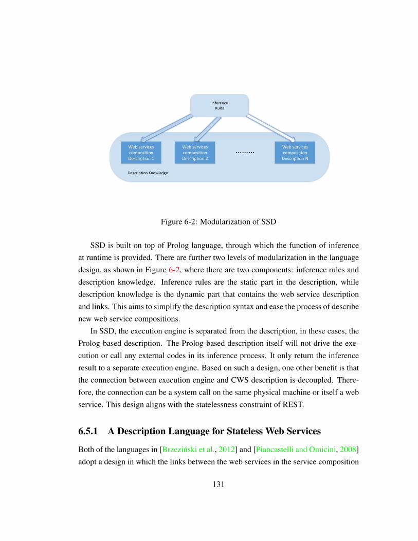
Web services compositionDescription 1
Web services compositionDescription 2
Web services composition
Description N
Description Knowledge
InferenceRules
Figure 6-2: Modularization of SSD
SSD is built on top of Prolog language, through which the function of inferenceat runtime is provided. There are further two levels of modularization in the languagedesign, as shown in Figure 6-2, where there are two components: inference rules anddescription knowledge. Inference rules are the static part in the description, whiledescription knowledge is the dynamic part that contains the web service descriptionand links. This aims to simplify the description syntax and ease the process of describenew web service compositions.
In SSD, the execution engine is separated from the description, in these cases, theProlog-based description. The Prolog-based description itself will not drive the exe-cution or call any external codes in its inference process. It only return the inferenceresult to a separate execution engine. Based on such a design, one other benefit is thatthe connection between execution engine and CWS description is decoupled. There-fore, the connection can be a system call on the same physical machine or itself a webservice. This design aligns with the statelessness constraint of REST.
6.5.1 A Description Language for Stateless Web Services
Both of the languages in [Brzezinski et al., 2012] and [Piancastelli and Omicini, 2008]adopt a design in which the links between the web services in the service composition
131

Figure 6-3: Description resides inExecution Engine
Web services
State
ApplicationComposition
Description
Figure 6-4: Description is Separated with Ex-ecution Engine
are invisible to end-users, because the composition description resides in the executionengine. From a user’s point of view, it is merely a black box. This black box service isthe reason for the lack of the ability to provide interfaces to end-users for the purposeof obtaining the information about the web application’s state, such as the overall goal,achieved tasks, following tasks, etc. It can be observed that there is a high-couplingbetween the execution engine and the knowledge about the descriptions. This impliesthat the application state which drives the execution of CWS or web application arestored and maintained at server-side. There is no channel to feed the state of theservice composition or web application back to the end-user.
Listing 6.4 shows a segment of ROsWeL description [Brzezinski et al., 2012]. Itillustrates a business process connected with the visit of a patient in the clinic labora-tory. In this example, to achieve the onPost(”Doctor/fSSNg”, WFReq, WFResp) goal,several tasks must be achieved, such as print, readForm, makeTest, etc. They are ex-ecuted either by embedded Java code or other services (put predicate in this example)directly in this description. It is lack of mechanism to expose the application state toend-users who call the service, for an instance, ”Doctor/fSSNg” in this example.
Figure 6-3 shows the architecture of web service composition with declarative de-scription residing in the execution engine. In contrast, the declarative description of theCWS is separated from the execution engine in Figure 6-4. In Figure 6-4, each declar-ative description instance of one workflow is transferred in full between the executionengine and declarative description knowledge base. In Figure 6-4, if the execution
132

Listing 6.4: Segment of ROsWeL description example1 onPost("Doctor/fSSNg", WFReq, WFResp):-2 print(SSN),3 readForm("../name.html", Form),4 sendToClient(Form,Res),5 makeTest(Res->FORM->NAME, TestResult)6 ......78 print(X):-9 <I-- --I>
10 <J--11 Variable v = X;12 System.out.println(v.toString());13 return v ;14 --J>.1516 readForm(FilePath, Result):-17 <I-- --I>18 <J--19 // Java code used to read Html form from20 // file and assign it to ’Result’ variable21 --J>.2223 makeTest (PatientName , Result ):-24 put("http://labTest.com/fPatientNameg" ,25 PutReq, PutRes),26 Result = PutRes.27 ......
engine is located on server-side, the architecture appears to be similar to Figure 6-3from the end-user’s point of view. However, by virtue of the separation, the web ser-vices composition description can be shared and accessed explicitly (for each of thedescription instances, it has its URI).
In this design, some essential data of application state are transferred from execu-tion engine to description knowledge base as a query for inference. They are:
1. The initial input data types for the CWS execution;
2. The service as the goal of the CWS execution;
133

Query URIInitial http://<domain>/Init?KB URL=<Knowledge Base>
&G URL=<Goal service>&I Names=<Input types list>Next http://<domain>/Next?KB URL=<Knowledge Base>
&L URL=<Last successful service>Alternative http://<domain>/Next?KB URL=<Knowledge Base>
&L URL=<Last successful service>&N URL=<The last failed service>
Table 6.1: The URI templates for inference query
3. The last service which just executed successfully in the CWS execution;
4. The service which failed in last step in the CWS execution.
Correspondingly, the application state that drives the execution are returned as an in-ference result from description knowledge base. They are:
1. The initial service of the web service composition execution;
2. The next service to be executed in the execution;
3. The alternative service to replace the failed one in the execution.
Table 6.1 shows the URI template for the query from the execution engine to SSDknowledge base. After get the execution request from end-user, the execution enginewill launch these queries to steer the execution. There are three types of queries: (i) thequery to initialise the composition execution. It needs a goal and the types of the inputthe execution engine have at this stage; (ii) the query to get the next step in execution.It needs to know that which is the last successfully executed service in the workflowor the current state of this CWS execution; (iii) the query to get an alternative stepin execution. It needs the last successfully executed service as well as the last failedservice that needs to be replaced. In all three types, the SSD knowledge base needsan identifier for the knowledge base which the execution engine is querying. Eachknowledge base represents a specific workflow with all the related web services andlinks being described. The details of the syntax of this Prolog-based knowledge baseis introduced in section 6.5.2. The reason to choose Prolog is: (i) by nature, it is adeclarative language which fits for the design of SSD; (ii) there are examples of usingProlog for composite REST web services description; (iii) as a general purpose logicprogramming language, it has good implementation and can be used together with
134

Listing 6.5: Inference Rules in SSD1 <query tag>( [ [optional parameters of web services] , ] ) :-2 [ [expression of relations between services]3 , [optional features of web service] ] .
Listing 6.6: Relation Facts in SSD1 child_of(<Child_Service_URI>, <Child_Service_Method>,2 <Parent_Service_URI>, <Parent_Service_Method>,3 <Child_Service_Priority>).
Listing 6.7: Detail of Web service Facts in SSD1 details_of(<Service_URI>, <Service_Method>,2 <Input_MIME>, <Output_MIME>,3 [Input Local Name], [Input Global Name],4 [Output Local Name], [Output Global Name],5 [Input Workflow Tokens], [Output Workflow Tokens]).
some OO languages, such as Java in this thesis’s implementation, through existinglibraries as well.
6.5.2 First-order Logic in SSD
The main component of the SSD is a set of rules. It contains two types of rule: (i) therules for the inference process, which is generic to all the CWS description; (ii) therules to describe certain properties and relations, which is specific description to eachof the CWS.
The rules for the inference process consists of a header, and a set of bodies. Theleft side of the rule (the header) defines a goal, which represents the query from theexecution engine. As described in Table 6.1, there are three types of queries, whichcan be represented by three tags: initial, next and alternative. The right side of the rule(a body) specify the conditions, which has to be fulfilled to reach the goal. Listing 6.5shows the template for the inference rules. For different tags, the rule includes differentparameters or expression on constraining relations between services and features ofweb service. The feature can be the URI of a web service, the I/O MIME types and soon. The core part of the Prolog code is presented in Appendix B.
135

In Listing 6.5, the inference based on both of the types of rules can be true orfalse. It implies that the conditions in the rule are fulfilled (the body is true) thenthe goal is reached. There are results that fulfilled the query. The results will bereturned to the execution engine for further execution of the CWS. The web servicesare constrained by the relations between certain web services, such as Service A isService B’s next step in workflow. They are also constrained by some certain featuresof the web services, such as the Service A with certain function must be the final stepof this workflow. These constraints are all written Prolog.
Each of the CWS description consists two parts: properties of the web serviceand relations among them. The goal in these rules can always be reached becauseit has only header without body. Such rules are called facts. Listing 6.6 shows thetemplate for the facts to describe the relations between web services. It contains thebasic information about the directed link between two web services. Additionally, italso contains an integer (1...n) to represent the priority of this link, which comes fromthe knowledge of the workflow developer. In the case of multiple links from one webservice, the highest priority link is matched in the inference process. The priority alsoimportant for inference engine to find the alternative link.
Listing 6.7 shows the fact template to describe the properties of a web service,such as the URI, method, I/O MIME, I/O names. The I/O names have two sets, oneis the so-called local name to identify I/O data within the scope of one instance ofweb service. Global names can be used to identify I/O data among multiple instancesof one web service. For example, in one simple weather forecast web service, inputis date time, output is temperature. There is only one web service. However, in aworkflow, there can be multiple instances of this web service to query multiple daysof temperature. In this case, DataTime and Temperature will be local name to describethe data type. Some names like DT Day1, DT Day2, Temp Day1, Temp Day2 can bethe global names to identify each data item in a workflow. There are also workflowtokens to control the workflow execution. This is will be further discussed in Section6.6
6.5.3 Ranking for Alternatives
The declarative description of workflow and its runtime, which will be introducedin Section 6.6, do not directly provide a ranking algorithm for web services. There
136
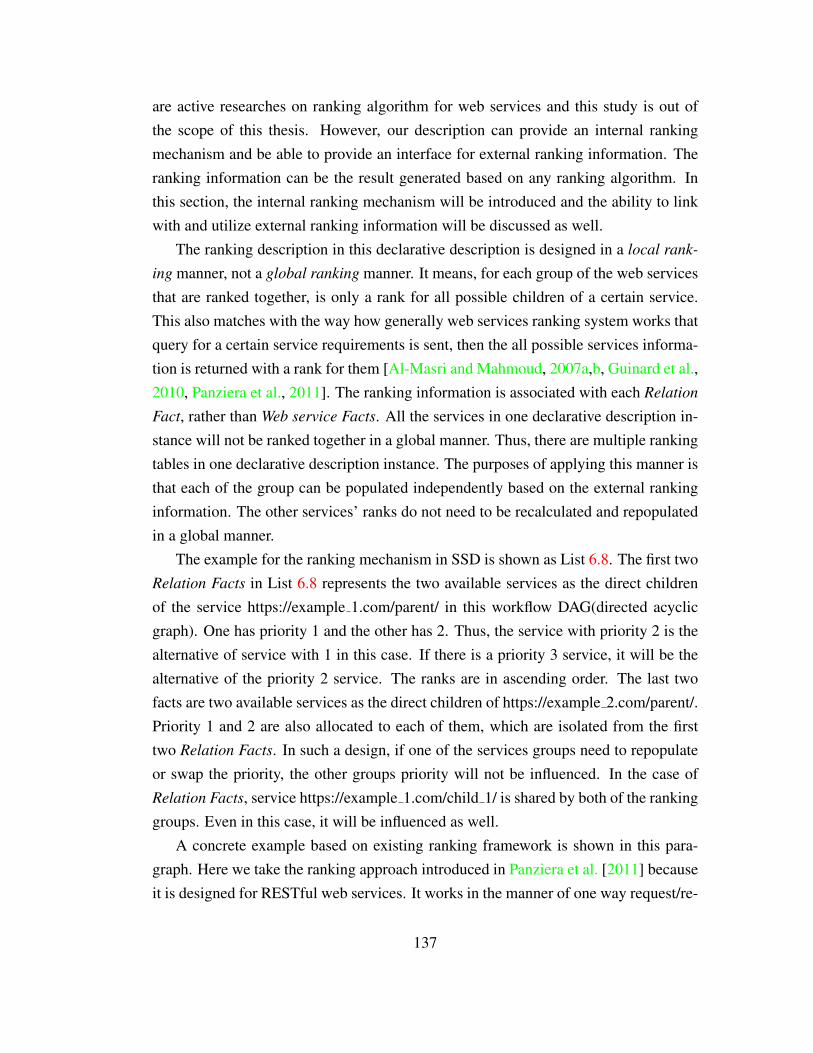
are active researches on ranking algorithm for web services and this study is out ofthe scope of this thesis. However, our description can provide an internal rankingmechanism and be able to provide an interface for external ranking information. Theranking information can be the result generated based on any ranking algorithm. Inthis section, the internal ranking mechanism will be introduced and the ability to linkwith and utilize external ranking information will be discussed as well.
The ranking description in this declarative description is designed in a local rank-
ing manner, not a global ranking manner. It means, for each group of the web servicesthat are ranked together, is only a rank for all possible children of a certain service.This also matches with the way how generally web services ranking system works thatquery for a certain service requirements is sent, then the all possible services informa-tion is returned with a rank for them [Al-Masri and Mahmoud, 2007a,b, Guinard et al.,2010, Panziera et al., 2011]. The ranking information is associated with each Relation
Fact, rather than Web service Facts. All the services in one declarative description in-stance will not be ranked together in a global manner. Thus, there are multiple rankingtables in one declarative description instance. The purposes of applying this manner isthat each of the group can be populated independently based on the external rankinginformation. The other services’ ranks do not need to be recalculated and repopulatedin a global manner.
The example for the ranking mechanism in SSD is shown as List 6.8. The first twoRelation Facts in List 6.8 represents the two available services as the direct childrenof the service https://example 1.com/parent/ in this workflow DAG(directed acyclicgraph). One has priority 1 and the other has 2. Thus, the service with priority 2 is thealternative of service with 1 in this case. If there is a priority 3 service, it will be thealternative of the priority 2 service. The ranks are in ascending order. The last twofacts are two available services as the direct children of https://example 2.com/parent/.Priority 1 and 2 are also allocated to each of them, which are isolated from the firsttwo Relation Facts. In such a design, if one of the services groups need to repopulateor swap the priority, the other groups priority will not be influenced. In the case ofRelation Facts, service https://example 1.com/child 1/ is shared by both of the rankinggroups. Even in this case, it will be influenced as well.
A concrete example based on existing ranking framework is shown in this para-graph. Here we take the ranking approach introduced in Panziera et al. [2011] becauseit is designed for RESTful web services. It works in the manner of one way request/re-
137

Listing 6.8: Ranking example in Relation Facts1 ...2 child_of(https://example_1.com/child_1/, GET,3 https://example_1.com/parent/, GET,4 1).56 child_of(https://example_2.com/child_2/, GET,7 https://example_1.com/parent/, GET,8 2).9
10 child_of(https://example_3.com/child_3/, GET,11 https://example_2.com/parent/, GET,12 1).1314 child_of(https://example_1.com/child_1/, GET,15 https://example_2.com/parent/, GET,16 2).17 ...
spond. Clients send request with service query. Server returns the response with ser-vices and ranking information. The communication is also carried out via RESTfulweb services. The ranking information of certain type of services can be referred toan URI as http://SMEendpoint?rpuri=URI. In this case the SMEendpoint points to theranking service resource. The rprui represents the so-called requested policy compiledby the user. The requested policy contains the requirements to the needed service.Finally, the service will return a response with a list of matching services and Global
Degree(GD) of them. The GDs of matching for all the services are used to deliver aranked list of web services. The ranked list can be used to populate the priority fieldin Relation Facts.
138

6.6 A Runtime System for Speculative Enactment ofWorkflow
6.6.1 System Architecture
In Section 6.5, three types of queries were introduced, which form the core to drivethe enactment of CWS based workflow. Figure 6-5 depicts the basic relations amongthese three types of queries in the enactment of web service composition as describedby SSD. The composition runtime works normally without speculative enactment, sothat no web service will be invoked speculatively, but rather only when they becomenecessary in the workflow.
In Figure 6-5, the runtime starts with a query to find and execute the web services toinitialize. After the execution of each of the web services, there will be a decision to bemade on whether this service has executed successfully. If it has not, the runtime willtry to find an alternative web service and execute it. If it is, the process will check ifthe whole CWS has been completed. If the whole process is not complete, the runtimewill try to find the next web service. A different process happens on the search andexecution of alternative web service. If it can be successfully found, it will be checkedas all the other web services on whether it has been successfully executed. The otherresult is that the whole process will be halted, because no further alternative solutionis available.
The runtime in Figure 6-5 provides an exception handling mechanism by search-ing for an alternative solution. However, the feature of speculative enactment is notreflected by this single-thread runtime. A speculative runtime must provide the fol-lowing basic functions:
1. the ability to execute a web service and all the alternative ones speculatively inparallel;
2. the ability to collect the result or final result from the first completed solution;
3. the ability to stop the redundant services and release the resources when theresult is already collected
In addition, in order to manage the a concurrent system that can achieve the aboverequirements, a control mechanism is need to serve as a bridge between threads toavoid conflicts, such as serializing tokens.
139
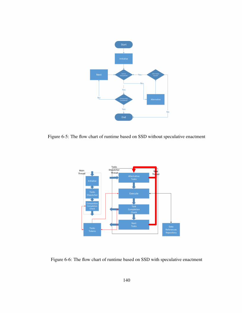
Initialise
Next ServiceCompleted?
AlternativeCompositionCompleted?
Start
No
Yes
No
End
Yes
AlternativeFound?Yes
No
Figure 6-5: The flow chart of runtime based on SSD without speculative enactment
Initialise
TasksDispatcher
CompositionCompletion
Check
AlternativeTasks
Execute
TaskCompletion
Check
NextTasks
TasksTokens
DataReferencesRepository
Main Thread
NewThread
TasksDispatcher
Thread
Figure 6-6: The flow chart of runtime based on SSD with speculative enactment
140

Figure 6-6 depicts the multi-thread based speculative enactment runtime. There aretwo types of threads: the main thread and service dispatcher thread. The main threadcan initialise and finish the enactment of a web service composition. The service dis-patcher thread is in charge of the management of web services, which can be initialisedeither by the main thread or another service dispatcher thread. The first task dispatcherthread, which is initialised by the main thread, starts the management thread of webservices with all the alternative management threads of web services concurrently inmultiple threads manner. Each of these threads will search for next web services andexecute them by more threads recursively. The service dispatcher thread can kill itselfin two ways: (i) the web service execution is unsuccessful; (ii) there is no next webservice to be executed based on the query from knowledge base. It can also be killedby the main thread when the final result has been collected by the main thread. Thismeans the whole composition has been completed and resources should be released.
The management of threads is supported by the task token mechanism in SSD. Thedesign borrows the concepts in Petri-net [Peterson, 1981], which is a mathematicalmodelling languages for the description of distributed systems. A Petri net consistsof places, transitions, and arcs. Arcs run from a place to a transition or vice versa,never between places or between transitions. The places from which an arc runs toa transition are called the input places of the transition. Correspondingly, the placelinked from a transition are called output places of the transition. Places in a Petri netmay contain a discrete number of marks called tokens. A transition of a Petri net mayfire (executed) if there are sufficient tokens in all of its input places. In the case ofspeculative enactment runtime, each web service can only be executed when specifictokens have been collected. Those tokens are described as [Input Workflow Tokens]in List 6.7. And it will only generate specific tokens after it is successfully executed,which are described as [Output Workflow Tokens] in List 6.7. Each token can berepresented by any string, which can be defined by users for identification purpose.Therefore, this task token mechanism has such two essential functions: (i) it maintainsthe dependency between web services that web services can be executed concurrentlyin the right sequence; (ii) the resources occupied by speculative web services can becollected when it is discovered they are not needed, such as when another web servicehas successfully done their work. Those speculative web services can be killed in twoways: (i) the main thread has collected the final result; it then kills all the web servicesthreads that are still executing; (ii) the service dispatcher thread kills itself when it
141

discovers the task token it aims to generate is already in the task token repository.The details of the token checking mechanism is shown in Figure 6-6. The Execute
component checks the token repository when it starts the execution. The executionwill start only when the necessary tokens are in place. The Task Completion Checkcomponent checks if the tokens this web service generated have been collected. If it isso, this service dispatcher thread will kill itself. On the other hand, whenever the tasktoken repository is updated, the main thread will check it to determine if it needs tocomplete the whole process and kill the other ongoing web services. In addition, thereis an independent data references repository. All the execution components communi-cate with it to retrieve and store data references. Each data item is labelled by the I/Oglobal name introduced in Section 6.5.2.
In reality, the enactment runtime is exposed as REST web services, which are writ-ten in Java and support by Jersey library1. Users can call the web service to startthe workflow execution2. The configuration file for this service contains the URI ofthe composite service’s description, which is stored as plain text. The threads men-tioned in last paragraphs are actual threads in the Java based speculative enactmentruntime. Data References Repository is written and deployed separately as an RESTweb service. It uses the URIs presented in Table 6.1. In the workflow execution, theruntime invokes the exposed web services of Data References Repository to collectinformation about execution sequences. This invocation is invisible to end-users. Theso-called token repository is a simple List structure in Java to store string at its ba-sic level, which is instantiated and associated with each workflow execution when theworkflow is started.
6.6.2 Speculative Execution on Parts of the Workflow
Based on the token mechanism in Section 6.6.1, the runtime can speculatively executealternatives for one service. In this case, all the services, which include the priority1 service and all the other alternatives, will generate the same output tokens. Theruntime will ensure if one of the service is successful, the other alternatives will bekilled to save resources. Additionally, this token mechanism can be applied on partsof one workflow to enable the speculative execution of certain part of the workflow,which has more than one service.
1Jersey: https://jersey.java.net/2The URI template is http://. . . /composite/{Service Name}
142

S1
S1'
S2
S4
S3
Input tokens
Output tokens
Alternative Parts
Workflow Parts
P1
P1
P1, P2
P2
P1, P2
Figure 6-7: Speculative Execution of Parts of Workflow
143

As shown in Figure 6-7, one part of workflow is extracted to demonstrate the mech-anism. The thread S1’+S4 is the alternative part of S1+S2+S3. First, S1’ is the alter-native service of S1 and it leads to the alternative part. They need to consume the sameset of tokens in order to be executed. In such case S4 has no alternative relationshipwith the other following services S2 and S3 in the main part. The second importantsetting that makes they are alternative to each other is, S3 and S4 generate the sameoutput tokens. If there are more alternative parts of S1+S2+S3, their final servicesgenerate the same tokens as S3 and their first services also are the alternative servicesof S1. In this speculative execution environment, all the parts start to execute at thesame time.
As introduced in Section 6.6.1, the service dispatcher thread will kill itself, whichcontains a running service or a service of certain part in this case, when it discovers thetask tokens it aims to generate is already in the task token repository as shown in Figure6-6. Thus, in the example of Figure 6-7, when S3 or S4 finishes, they other alternativethread will be killed. However, there is a possible disadvantage on resources. Thealternative thread will only be killed when it arrives the beginning of the final serviceof its part. This can be sorted out by further customise the tokens generated by theservices for this very part of workflow.
The black marks locate beside the bottom corner of each service in Figure 6-7represents their output tokens. Each thread of the part has its own unique and unifiedoutput tokens except the final service. The final service will generate the same tokensand they are the collection of all the unique tokens from each part. For example,main thread has token P1 and alternative thread has token P2. The final service ofeach thread will generate the same token P1+P2. If there is a third thread or evenmore thread, they will have the unique token P3 or Pn and the final token will beP1+P2+P3+...+Pn. Each of these Pn tokens can also represent a collection of tokensas long as they are unique from each other. In this case, it guarantees that when anyof the final service is finished, all the other thread will be killed regardless which stepthey are in. Besides that, it will not kill any of the thread if the final service is notexecuted. Based on such a mechanism, the original token checking algorithm does notneed to be modified. By setting the tokens carefully, speculative execution of parts ofworkflow can be processed without occupying unnecessary resources.
144

6.6.3 A Discussion on Time/Compute Resource Decisions
To have a speculative execution system for a web services based workflow, the primarygoal is to save time. However, the saved time come with a price. The web servicesspeculative execution needs extra computing power. The simplest model is that theuser need to pay for the service for a certain price. The price can be calculated inan one-off or pay-as-you-go manner based on the final executing time. Surely, if wedo not put the resource related decisions in a context of ”Low Carbon Earth”(which isobviously out of the scope this thesis), and believe the market and economics will workout the best solution for service providers, we do not need to consider Time/Compute
Resource Decision when the services are free. The workflow just need to run as manyas possible web services to save time.
Then the question is simplified as, how much are you going to pay for your time?
The speculative execution system can be designed to have such a blank field to let theuser to fill in this number. However, the final decision has to be decided before this fill-ing action by the user. Then, at the system level, in the case that the price is known, thequestion will be, how much time indeed can be saved by this speculative computing?This has to be answer from a more basic question, why we need a speculative execution
system? If all the services can be executed in one go without failure and can serve forour purpose perfectly, there is no necessity to have such a system. It is designed forall the unexpected conditions. Then the question can be simplified as, how unexpected
all these services are? Or by asking, what is the occurrence probability that a web
service will fail or its result has to be discarded? This will be a probability calculationbased on experience. This may has been included in the service-level agreement(SLA)provided by the service provider. Additionally, this can be counted by user based onexperience data to get a more customised result.
With the existence of the following three numbers: (i) the price the user can givefor his/her time; (ii) the probability that one alternative service’s result will be adopted;(iii) the price needs to pay for the execution of this alternative service, a formula canbe worked out for the decision of speculative execution of an alternative service.
D = Mt −Ms/(Ps ∗ Ts) (6.1)
In Equation 6.1, Mt means the price the user would pay for time. Ms represents theprice needs to pay for the execution of a certain alternative service. Ps is the probability
145

that this alternative service will be adopted, which also means the probability of all thehigher priority services will fail. Ts is the service execution time of the alternativeservice. If Ts is longer than the execution time of the service with priority one, theexecution time of the priority one will be used to replace Ts here. The reason tohave such a replacement is that even when the longer alternative service is executedin parallel, the maximum time can be saved is only equal to the execution time of thepriority one service. When D is equal or greater than 0, the alternative service shouldbe executed as speculation. Or it should not. This equation can be also interpreted insuch a way that, the higher price the user can set for his/her time, the higher chancethe alternative should be executed. The lower the price to pay for the execution ofalternative service, the higher chance it should be executed. The higher the probabilitythis alternative service will be used, which also means all the previous services arefailed, the higher chance it should be executed. And finally, the more time can besaved, the higher chance the alternative should be executed.
D = Mt − S ∗Ms/(Ps ∗ Ts) (6.2)
This discussion can lead to an interesting future work. We can further updatethe equation as Equation 6.2. The S in the equation is a coefficient for the systemsensitivity to financial cost. For example, if the S is higher, the lower chance thealternative service will be executed. Users can adjust their sensitivity to financial costcase by case by setting the Mt. The system administrator can set the coefficient S forthe whole system in a more macroscopic view. To work out the appropriate coefficientand find out the appropriate price for certain user’s price for time will finally decidethe efficiency of the whole speculative execution system.
6.7 Evaluation
6.7.1 A Petri Net Model
This model aims to provide a formal foundation based on Petri Net [Peterson, 1981]for the speculative enactment runtime. It contains variables that can used to simulatecertain workflow enactment environments, such as workflow procedure, relationshipamong web services, failure rate of each web service and execution priority of eachweb service, etc. By performing experiments on it, simulation results can be generated,
146

ReadyProcess
Process1000`{pid="1",sp=1}
ServiceExecuted
ActiveProcess
ExceptioninExecution
ActiveProcess
ServicesKB
Service
1`{sid="1",stype="init",itype="I1",otype="O1",er="0.0",sp=1}++1`{sid="2",stype="im",itype="O1",otype="O2",er="0.1",sp=1}++1`{sid="2*",stype="im",itype="O1",otype="O2",er="0.2",sp=2}++1`{sid="2#",stype="im",itype="O1",otype="O2",er="0.2",sp=3}++1`{sid="2##",stype="im",itype="O1",otype="O2",er="0.2",sp=4}++1`{sid="3",stype="im",itype="O2",otype="O3",er="0.1",sp=1}++1`{sid="3*",stype="im",itype="O2",otype="O3",er="0.2",sp=2}++1`{sid="4",stype="goal",itype="O3",otype="O4",er="0.0",sp=1}
FinishedProcess
ActiveProcess
GetNextService
[(#otype (#currentService vap))=(#itype vs) andalso(#sp vs)=1]
input (vap,vs);output (vap2,vap3,vit,vs2,vs3);actionNextStepGenerator(vap,vs);
GetAlternativeService
[(#itype (#currentService vap))=(#itype vs) andalso (#otype (#currentService vap))=(#otype vs) andalso(#sid (#currentService vap)<>(#sid vs)) andalso((#sp (#p vap))+1)=(#sp vs)]
input (vap,vs);output (vap2,vit,vs2,vs3);actionAlterStepGenerator(vap,vs);
GetInitialService
[(#stype vs)="init" andalso(#sp vp)=(#sp vs)]
input (vp,vs);output (vap,vit,vs3);actionExcGenerator(vp,vs);
vs
vap
if (vit=false andalso(#stype (#currentService vap2)="goal"))orelse(vit=true) then 1`vs2++1`vs3else 1`vs2
if(#stype (#currentService vap2)="goal" andalso vit=false)then 1 `vap3else empty
if(#stype (#currentService vap2)="im" andalso vit=false)then 1 `vap3else empty
if( vit=true)then 1 `vap3else empty
if vit=truethen1 `vap2else empty
vs
if vit=falsethen emptyelse 1`vs3
if vit=falsethen1 `vap2else empty
vap
if vit=falsethen emptyelse 1`vs3
vp
if vit=falsethen1 `vapelse empty
vs
if vit=truethen1 `vapelse empty
Figure 6-8: A Petri Net Model of Speculative Enactment Runtime
147

observed and analysed. It can serve as an evaluation tool for the design conceptsbased on the experiment designs, which simulate the target execution environments ofscientific workflow.
Figure 6-8 shows the formalization of a speculative enactment runtime model ofweb service composition. A runtime model is a colored Petri Net represented by atuple S =(P , T , F ,
∑, M0, G , C ), where P and T are disjoint sets of places
and transitions. Places represent states that contain tokens with multiple attributes,and transitions represent activities that can be guarded; transitions are fired when allthe tokens in the corresponding input place arrive. Different token types with multipleattributes are defined as color set. Places and transitions are linked through arcs. F
represents all the arcs the link them. M0 is the initial marking in which some tokensare initially assigned to places.
∑represents all the color sets, which allows tokens to
have data values attached to them like properties of the tokens. G represents a set ofguard functions assigned to each transition, which are Boolean expressions evaluatingto true or false. Guard functions encode token restrictions controlling whether theycan be fired. C is a set of functions for a transition to generate output tokens in certaincolor sets from the input tokens that is defined by other color sets.
The execution of the runtime model starts from the Ready Process place. Thisplace can be customised by the initial marking, which represents all of the lementsof the composite web services(CWS) based workflow that is to be executed. Theother important place in the initial marking is the place Service KB. It contains all theknowledge about each of the web services, such as I/O types, priority, service type(initial, goal, others). The aforementioned are the essential information that is definedalso in the SSD. In addition, for the purpose of driving this model, a pre-defined faultrate of each service is embedded as well. The possibility of activating alternativesolutions is determined based on uniform distribution. The three transitions are thequery services. They are also provided by actual speculative enactment runtime. PlaceService Executed holds the intermediate web services, which activate the followingqueries. After finishing the whole execution, there will be no tokens in this place. Theremaining two places Exception In Execution and Finished Process contain tokens thatrepresent failed workflow and successful workflow after the execution. All the failedservice instances are kept in Exception as a record, as well as to activate the alternativesolution query. All successful processes are be recorded in Finished Process.
To demonstrate the feasibility of SSD for CWS execution, as well as the intuitive
148

Service 1
Service 2
Service 3
Service 4
Figure 6-9: An exemplar composite web service for the Petri net model
No. of No. of total Extra steps oncompleted transitions alternative solution
No substitute 821/1000 4000 N/A1 substitute for S2 & S3 965/1000 4116 0.81(116/144)2 sub. for S2 & 1 for S3 978/1000 4182 6(56/13)3 sub. for S2 & 1 for S3 984/1000 4225 7.16(43/6)
Table 6.2: The Simulation Results of Petri Net Model
understanding on how the SSD supports exception handling, an exemplar CWS iscreated based on the Petri net model. Figure 6-9 depicts the workflow of the CWS. Itis a four step sequential workflow. The second and third web service have substitutesto provide alternative solutions.
This experiment is designed and simulated by using the CPN Tools[Jensen et al.,2007]. The Petri net model is designed as shown in Figure 6-8. There are 1000 CWSinstances of the same workflow being enacted in each of the simulation. They are allinitiated from place Ready Process. In all the scenarios, Service 2, Service 3 and theirsubstitutes all have a success rate of 90%. It means 10% of the executions need to behandled by error handling mechanism. The variables are the number of services thathave substitutes (the alternatives) and the number of substitutes for one service. Thissimulation aims to show the trend that how the declarative description, based on thethree query tags (Initial, Next, Alternative), can influence the number of completedCWS from a macroscopic perspective.
149

Table 6.2 shows the simulation results based on a series simulations under differentconditions. It aims to show that this model is capable of increasing the number ofcompleted CWS. It also aims to show with the increasing of the number of completedCWS, there is more overhead on finding and calling the alternative solutions.
The second column is the number of the completed workflows. For example, in thescenario of no substitute, 821/1000 is approximately equal to the product (81%) of thesimulated success rates of Service 2 and Service 3. The third column shows the overalltransition firing steps in the simulation. When there are alternative solutions, the CWSneeds more steps to complete. The difference between the numbers of other rows withthe number of first row represents the extra execution steps on web service execution.The fourth column shows the extra average overhead on each of the CWS that beingrecovered by new alternative solution. For example, in the row of “One substitute forS2/S3”, 0.81 equals to (4116-4000)/(965-821). Obviously, it can be observed that, withmore alternative web service as substitute, more CWS are able to finish successfully.On the other hand, more successful enactment means more overhead, especially whenthere is no speculative process is introduced so that all the primary and alternativesolutions are executed in a single-thread manner. This issue is rooted in the timewasted on unsuccessful execution and service invocation timeout. This timeout can bea very long time that varies because of different client tools. The situation could beeven worse by considering that some scientific web services may take very long timeto finish in real-world scenario. It means to redo them, by either the original service orthe alternative one, it may double this long time.
In fourth column, the ratio between extra steps on alternative solutions and thenumber of extra successful CWS is increasing from 0.81 to 7.16. It means have 1more successful CWS, the system needs more queries on alternative solutions andmore executions of services. As explained in last paragraph, in a single-thread execu-tion model, the more alternative solutions one web service have, the more time will bespent on long time execution and timeout. They are piled up in a sequential manner.In this simulation experiment, it can be observed that the design of having alternativesolutions for failures in this declarative description is able to raise the number of suc-cessful CWS in the environment that web services have a certain failure rate. However,it also shows that when you apply more alternative solutions, the time resources thatspend on the each successful CWS is more. It is believed by introducing the specu-lative enactment runtime, this trend can be mitigated that all the alternative solutions
150

Figure 6-10: The test composite web service
will be executed in a speculative and parallel way to save time.
6.7.2 A Implementation of the Speculative Enactment Runtime
In Section 6.6, the design of the runtime for speculative enactment has been intro-duced. It is implemented as web services based on a series tools, such as Java language,Prolog, Apache Tomcat. The reasoning process for finding candidates (alternative so-lutions) for speculative enactment is written in Prolog as shown in Appendix B andconnected with web service component in Java by JPL [Singleton et al., 2004]. In thePetri Net evaluation, it is hard to simulate the speculative process, especially the realperformance effect taking full account of the overhead of speculative enactment, suchas the query for speculative solution as well as the impact of network bandwidth. Byevaluating the declarative description in Section 6.7.1, it also exposes the issue thatmore time will be spent on one successful CWS when more alternative solutions areapplied. In this section, an example CWS is created based on the real runtime, whichallows the customisation of the amount of data being transferred between services.This allow conclusions to be drawn on the general trend of network bandwidth impact.
Figure 6-10 depicts the CWS for the test. It contains two applications. Each ofthem has the function to replicate the input data and output it for the following webservice. The CWS is built based on Datapool service and web service management
151

Non-spec.(ms) Spec. Normal(ms)/ Spec. Alter.(ms)/Difference with Non-spec. Difference with Non-spec.
128KB 1127.2 2090.0/963.8 2233.2/1105256KB 1169.8 2118.6/948.8 2189.6/1119.8512KB 1101.4 2105.0/1004 2339.0/1237.61MB 1339.2 2196.0/856.8 2327.8/988.62MB 1784.0 2416.2/632.2 2526.8/742.84MB 1872.0 2720.3/848.3 2850.9/978.98MB 2776.8 3499.0/722.2 3785.1/1008.3
Table 6.3: The simulation results of the composite web service in real runtime
systems that were introduced in Chapter 3 and Chapter 4. DP 1 and DP 2 representthe Datapool service. S 1 and S 2 represent the application based Services. DP 2’ andS 2’ are the alternative solution of DP 2 and S 2. They are invoked concurrently bythe speculative enactment runtime. The input data size can be customised to observethe impact of network bandwidth on the overall performance. The alternative solutionsDP 2’ and S 2’ are deployed in different machine. It is in the same intranet of the mainserver. In this experiment, DP 2 and S 2 are disabled to simulate the situation that analternative solution has to be activated. The environments are listed below:
1. Network: VLAN over gigbit (copper) ethernet;
2. Main server: Linux 2.6.32-31-server: Processor 2.27 GHz Intel Xeon E5520(*16);
3. Alternative server: Mac OS X Version 10.6.7: Processor 3.2 GHz Intel Core i3,Memory 4GB;
4. VMs (the services are deployed in two VMs on each server): each VM is al-located with 2 CPUs and 2GB Memory; Operating System: Linux 2.6.32-28-generic;
5. Client: the client is co-located with the VM on the Mac machine. This VM alsoholds the alternative service.
6. Service container: Apache Tomcat 7.0.28
Table 6.3 shows the results of a series execution of the CWS shown in Figure 6-10.They are executed in three modes. Non-spec. means speculative enactment runtime
152

Figure 6-11: The ratio between the performance of execution modes
is not used in the execution. The services are all executed in the normal way. Spec.
Normal means speculative enactment runtime is applied. The alternative solution isexecuted by the runtime. However, it is not activated to generate the output for theCWS. Spec. Alter. means that the alternative solution is executed concurrently, and theoutput from it is adopted. The relatively simple CWS allows the observation on thetrend of performance when various size of data is applied.
Based on the data from Table 6.3, Figure 6-11 is drawn to show the trend of perfor-mance variance. The blue line shows the ratio between Non-spec. and Spec. Normal.It can be observed that there is still difference between Non-spec. and Spec. Normal.It can be understood as the overhead of the speculative enactment runtime, which in-cludes all the process for query, reasoning, etc. Whereas, the ratio reduces when datasize grows. In this situation, because the overhead is relatively static, the more timespent on other activities in this CWS, the lower the ratio for the overhead of the spec-ulative enactment runtime. The red line, which shows the ratio between Spec. Normal
and Spec. Alter., provides another evidence on the efficiency of the runtime. Acrossthe range of data transfer sizes, the ratio hardly alters, as would be expected. In thesituation that primary solution disabled, it only takes slightly longer time to switch toalternative solution.
Based on this experiment, it can be observed that, by applying the speculativeruntime, a relatively static overhead is recorded which is not varied much based onthe changes of the time a web service costs. It is reflected by that the coefficient ofvariation(CV) of the difference between Spec. Normal and Non-spec. is 15.87%. On
153

the other hand, the CV of the Non-spec. is 38.10%, which is larger. At the same time,the correlation value between Difference with Non-spec.(ms) in fourth column andNon-spec. is -0.4588. There is no positive correlation and it is only weakly correlated.So the overhead is not caused by the extra alternative execution of the service. On thecontrast, this positive correlation can be observed in Table 6.2, that the model runs onsingle thread and no speculative mechanism applied. When the number of substitute(s)increases from 1 to 3, the extra steps spent on new alternative solutions increases from0.81 to 7.16. In the experiment, each step can be deemed as a unit time that spent onone service when all the services are assumed to cost the same time.
6.7.3 The Simulation for Time/Compute Resource Decisions
This simulation aims to evaluate the effectiveness of Equation 6.2 for time/computeresource decisions. An speculative enactment runtime model is built based on ColoredPetri Net(CPN) in CPN Tools[Jensen et al., 2007]. The the simulation largely reusedthe structure of the model shown in Figure 6-8. The differences are mainly on:
• The colorset for service is changed. Now it includes the extra information aboutthe price and estimated execution time of each service.
• On more function IfAlternative() is added for transition GetAlternativeService,which is shown as List 6.9. This function is written based on Equation 6.2, asLine 8 in List 6.9, to decide if an alternative should be executed speculativelybased on the equation.
• The initial services are changed to fit for this workflow simulation. More detailsabout this workflow is introduced in following text.
Listing 6.9: IfAlternative Function
1 {
2 fun IfAlternative(vs:Service)=
3 let
4 val price_ins=(#price vs);
5 val et_ins=(#et vs);
6 val rr_ins=(#rr vs);
7 in
154

Figure 6-12: Equation simulation workflow
8 if Cons_mt-Cons_s*price_ins/(rr_ins*et_ins)>0.0
9 then true
10 else false
11 end
12 }
Workflow shown in Figure 6-12 is used for the test. It includes three services. Theinitial service and goal service will be executed with error rate 0. Their executions willnot be influenced by the speculative enactment runtime and Equation 6.2. In order toshow the direct influence of the equation to the execution of this workflow, one service(priority 1 service in Figure 6-12) in the workflow will be speculatively enacted. Ithas three alternative services in sequence with priority from 2 to 4. All the serviceshave the same error rate 10%. In this workflow all the services have the same price, 10price units. They also have the same estimated execution time(EET), 10 time units. Inthis simulation, the coefficient S, which is the Cons s in List 6.9, is set as 1. The onlyvariable is Mt. It is also the only designated number that can be adjusted by workflowruntime users in the design.
With simple calculation, it can be realised that, by setting Mt in certain range,different level of speculation will be achieved. By setting in the range (1,10], onlypriority 1 service will be executed. By setting in the range (10,100], priority 1 and2 services will be executed and speculated. Range (100,1000] can have priority 1 to3 services being executed and speculated. Range (1000,∞) can have priority 1 to 4services, all of them, being executed in a speculative manner. Thus, to monitor theinfluence of the equation, four scenarios are set with Mt set to 2, 11, 101 and 1001.
155

Mt Round 1(Successed/Failed) Round 2 Round 3 Money2 4506/494 4508/492 4515/485 50000
11 4945/55 4944/56 4951/49 100000101 4993/7 4995/5 4992/8 150000
1001 5000/0 4998/2 4999/1 200000
Table 6.4: The three rounds results of simulation
0.901933333
0.9893333330.998666667 0.9998
0.84
0.86
0.88
0.9
0.92
0.94
0.96
0.98
1
1.02
2 11 101 1001
Wo
rkfl
ow
nSu
cces
snR
ate
Mtn(PricenUnit)
Figure 6-13: Results of simulation
Workflow will be executed in each of the scenarios for 5000 times with 3 rounds,15000 times in total.
From Table 6.4, it can be seen that for all the scenarios, they have almost theconsistent success rate in all the three rounds. The chart in Figure 6-13 further showsthe overall success rate by accumulating the three rounds. The general trend is whenthe order of magnitude of Mt grows, more nines the success rate gets. In Table 6.4, thefourth column shows the costs on the second step execution in the workflow. It growslinearly from 50000 to 200000. Surely, by setting Mt at 2, the user can save 150000 inspeculative enactment by comparing with setting it to 1001. But in the circumstancethat every fail can incur great loss and every lost time unit may worth more than 1000price unit, the extra 150000 will worth it.
In a real-world scenario, users can set their psychological prices for Mt. The dis-tribution of service prices and EET will be more complex for the whole workflow. Thebasic theory about how the equation can be effective and works is already shown in
156

this simulation. Besides, to make the equation more effective, all the variables caneven be set in a dynamic way. This idea will lead to more research. This is furtherdiscussed in Section 8.3.
6.8 Summary
From the evaluation on the Petri net model and the runtime implementation, two pointscan be related as summary:
1. Based on the simulation on the formal model, the design of enactment modelbased on the declarative description is able to increase the number of completedCWS, in the scenario that there is failure rates applied on each web service.
2. Furthermore, based on the results from the experiment on the real runtime, thespeculative enactment model shows that the overhead spent on the process oferror handling is not correlated with the the execution time of alternative service.The overhead is relatively static when the execution time of alternative serviceincreases.
This chapter gave an overview on web service composition, related description lan-guages and especially the declarative description. SSD is proposed to describe CWSdeclaratively that are based on and implementable with the ROA based Datapool ser-vices and the application services introduced in Chapter 3 and 4. For the purpose ofenabling SSD to be implementable in CWS enactment and real world scenario, a de-tailed design on the declarative enactment runtime is proposed as well. Together withthe evaluation based on both a formal Petri-net model and real runtime, this chap-ter shows the capacity of the ROA based runtime for: (i) REST web services failurehandling, which is supported by late-binding feature of SSD and the runtime; (ii) im-proved performance in the scenario of web service failure, which is supported by thespeculative workflow enactment and SSD.
157

Chapter 7
Case Studies
This chapter presents case studies on some applications in real scenarios. There arethree types of cases: (i) a workflow for optimization of the wing internal stiffness dis-tribution. This workflow is based on in-house code written by non-computer scientists.The workflow is composed in the Taverna. (ii) the integration with local program basedon MDO frameworks. This workflow is built based on existing MDO frameworks,which do not have the ability to expose themselves as web services and compositeweb service. (iii) a image processing workflow that built based on existing desktopprograms.
7.1 Optimization of the Wing Internal Stiffness Distri-bution
7.1.1 Scenario
The optimization process is formed by three main steps: aerogynamics analysis, struc-tural load transfer, structural optimization. In these three steps, there are four programswhich are DoubletLattice, LoadTransfer, FiniteElement and LevelSetOptimizer. In ourservices composition case we integrate FiniteElement and LevelSetOptimizer as oneprogram. The tangible functions of each program are listed below:
DoubletLatticeThe DoubletLattice program models the aircraft wing as an infinitely thin layerto compute aerodynamic lift and induced drag. The program reads in the input
158

file, aero input.dat that consists of the geometrical definition of the wing, such asspan and chord, as well as the flight conditions. By simulating the flow vorticesaround the wing, the aerodynamic load distribution is extracted to an output file,aero load.dat. This program is written in FORTRAN 77 and FORTRAN 95.
LoadTransferFluid-structural interaction is an important study when integrating the aerody-namic and the structural discipline. This is because of the two different meshesbetween aerodynamic (DoubletLattice) and structural (FiniteElement) models.The input script, structural input.dat details the element sizes of the wing whichis also going to be modelled in the FiniteElement program. The LoadTransferprogram transfers the calculated aerodynamic loads to the finite element meshvia surface spline and computes the structural loads (structural load.dat). TheLoadTransfer program is written in FORTRAN 95.
FiniteElementThe FiniteElement program reads in the structural loads input and calculates thestiffness of the wing structure. The deflection of the wing is computed based ona linear static equation. Therefore, the strain energy, which is the objective func-tion to be minimized, can be calculated. This program is written in C-program.
LevelSetOptimizerA level-set method is implemented in C-program to optimize the wing structure.The objective is to minimize the strain energy subject to a volume constraint.During the optimization, the structural boundary is moving inward, hence, thevolume is reduced. These involves a number of iterations and in each iteration,the wing deflection and the strain energy are re-calculated as the overall structurestiffness has changed. The solution is converged when the convergence criteriaare met, i.e. the targeted volume is achieved and the objective values of the last5 iterations are less than 0.1
7.1.2 Solution
For the purpose of demonstrating a MDO process in a web services composition, theTaverna workbench is utilized for the jobs of services composition, execution and mon-itoring with the support of the services located in Datapool and SaaS based framework
159

Figure 7-1: The MDO process built in Taverna based on REST web services
proposed in Chapter 3 and 4. We demonstrate all the functional modules with anexample created in Taverna. Figure 7-1 is the screenshot of the services compostiondesign example, which intends to optimize the topology of the internal layout of an air-craft wing structure. All the dark blue boxes (Aerosolve, AeroLoad transfer, BLES3)
are RESTful web services built by the web services management system upon threecommand line programs, DoubletLattice, LoadTransfer and FiniteElement and Lev-
elSetOptimizer as BLES3, which are written in either Fortran or C languages. All thepink boxes (PutInputs4Aerosolve, PutInputs4AeroLoa transfer, PutInputsBLES3) arethe RESTful web services for the Datapool, whose functions are uploading data as webresources for application services. The input ports built in Taverna based on RESTfulweb services are located at the top of Figure 7-1, and output ports are located at thebottom. One local service Data Extractor is utilised to retrieve the data based on theURIs collection return by the last application service.
A simple rectangular wing example is provided and tested by the non-specialistto demonstrate the feasibility of this ROA-based framework. In the aero input.dat, awing structure of 20 strips and 5 chord boxes with a 0 dihedral angle and 4 incidence
160

(a) The initial wing topology (b) The final wing topology
Figure 7-2: The wing topology
is defined. The wings root chord is 8 meters and span is 20 meters. Meanwhile, theratio of root chord and tip chord is 1. The flight condition is set as 0.7 MACH and35000 feet. After the execution of aerodynamics analysis and load transfer steps, thestructural loads that are applied on each finite element nodes are interpolated fromaerodynamic loads using spline method. By using the structural loads transferred fromaerodynamics loads as input, final topology solution is generated by the structuraloptimization step. Figure 7-2 depicts the initial topology and final optimum solution.The solution is generated based on the numerical result from PlotShapeFinal outputport.
7.2 The Integration with local program based MDOframeworks
7.2.1 Scenario
The framework also has the ability to integrate with existing MDO frameworks. Asreviewed in Chapter 2, there are some frameworks that already include a web servicefunction or a server/client architecture. However, some frameworks can only be exe-cuted as local programs. A learning curve is needed for the non-specialists to fill thegap between those local frameworks and online service based functions. In this case,the ability to deploy legacy MDO workflows based on existing MDO frameworks likeOpenMDAO[The OpenMDAO development team , 2010] and Dakota[Sandia NationalLaboratories, 2010] is presented.
With the support of the OpenMDAO runtime installed in the server, the deploy-ment process can be achieved as easily as for any other command-line program. Onthe other hand, Dakota has a different execution approach in that the workflow is de-fined as a input file, which is then executed by the Dakota runtime. With the Dakota
161

<WS_Definition><Service_Name ifPublic="no">sellar_MDF</Service_Name><Application_Name IfDakota="no"
IfExecutableJar="no"IfOpenMDAO="yes"IfPythonModule="no">sellar_MDF_solver.py</Application_Name>
<Inputs><Input IsValue="yes"NotInArgs="no" name="z1" qualifier="-zi"/>
<Input IsValue="yes"NotInArgs="no" name="z2" qualifier="-z2"/>
<Input IsValue="yes"NotInArgs="no" name="x1" qualifier="-x1"/>
</Inputs><STDOut name="sellar_result"/></WS_Definition>
Figure 7-3: The description file for openMDAO MDF service
runtime installed on the server, the workflow can be executed as a web service bysimply uploading the input file through the Datapool service.
7.2.2 Solution
openMDAO ServiceThe executable based on the openMDAO framework is a python script, which iscreated by users. The openMDAO works as a python library to support the func-tionality of the MDO workflow. In this case a Multidisciplinary Design Feasible(MDF) workflow [The openMDAO development team, 2013] is deployed as aRESTful web service based on the deployment GUI tool and the Datapool ser-vice. In this case, the workflow executables have to be deployed to the server asa web service. If other MDO workflows need to be deployed, the correspondingpython script should be deployed in advance as web services through the GUItool as well. The generated web service description is presented in Figure 7-3.
In the description in Figure 7-3, the three parameters of the optimizer are config-ured as inputs. The output stream from the openMDAO framework is configured
162

<WS_Definition><Service_Name ifPublic="yes">dakota_t1</Service_Name><Application_Name IfDakota="yes"
IfExecutableJar="no"IfOpenMDAO="no"IfPythonModule="no"/>
<Inputs><Input IsValue="no" NotInArgs="no"
name="dakota_rosenbrock_2d_in" qualifier="-i"/></Inputs><Outputs><Output IsValue="no" NotInArgs="no"
name="out_2d" qualifier="-o"/></Outputs></WS_Definition>
Figure 7-4: The description file for Dakota service
as the output of the web service. They are all stored in the Datapool service andaccessible through allocated URIs.
Dakota Service
The Dakota has a different architecture as the openMDAO. It is a software pack-age that reads in an .in as a description to the MDOproblem. The user writesthe description rather than a script to solve the problem as what the openMDAOdirects users to do. Thus, to deploy this framework as a web service, first it isassumed the Dakota software is already installed in the server. The generated de-scription of the RESTful web service is presented in Figure 7-4. This descriptionis generated by the GUI based interface introduced in Section 4.3.3. Through theGUI interface, the command-line entry for this software can be deployed as webservice on server side. Then, to solve a specific problem, user just needs tosend the problem description .in input as he/she does for the desktop version ofDakota software to the web service. In this case, a problem called rosenbrock
is used as an example, which is extracted from its User Manual [Eldred et al.,2007].
In Figure 7-4, the necessary information to deploy the Dakota script as web
163

PovRay ImageMagick
POVPNG
JPEG( URI )
Figure 7-5: The image processing workflow
service is described for the whole framework. In it, the input is the .in file.The output of the web service is the output file from the Dakota framework.It can be noticed that, in this case, the service description does not have anapplication name, because the application that this web service aims to wrap hasbeen deployed at the server side. The problem itself is not an executable scriptor program. In other words, all the Dakota related service actually have the sameapplication name.
7.3 Image Processing Workflow
7.3.1 Scenario
PovRay[Persistence of Vision Raytracer Pty. Ltd., 2003] is a ray tracing programwhich generates images from a text-based scene description, which is written in thePOV description language. ImageMagick[ImageMagick Studio, 1999] is a softwaresuite to create, edit, compose, or convert images. Conventionally, the user needs tomanually operate these two different pieces of software to achieve a workflow, suchas generating an image by following an editing step on the image. Surely, there islearning curve for both of the software.
In this case, a workflow, as shown in Figure 7-5 based on web services and theROA framework will be created to generate image from a POV file and then convertthe 3-D image from the png format to the jpeg format. Both of the command-lineexecutables are written as shell scripts. The PovRay executable also has files residethat serve as libraries for 3-D image generation. Both of the PovRay and ImageMagickhave been installed in the target server.
164
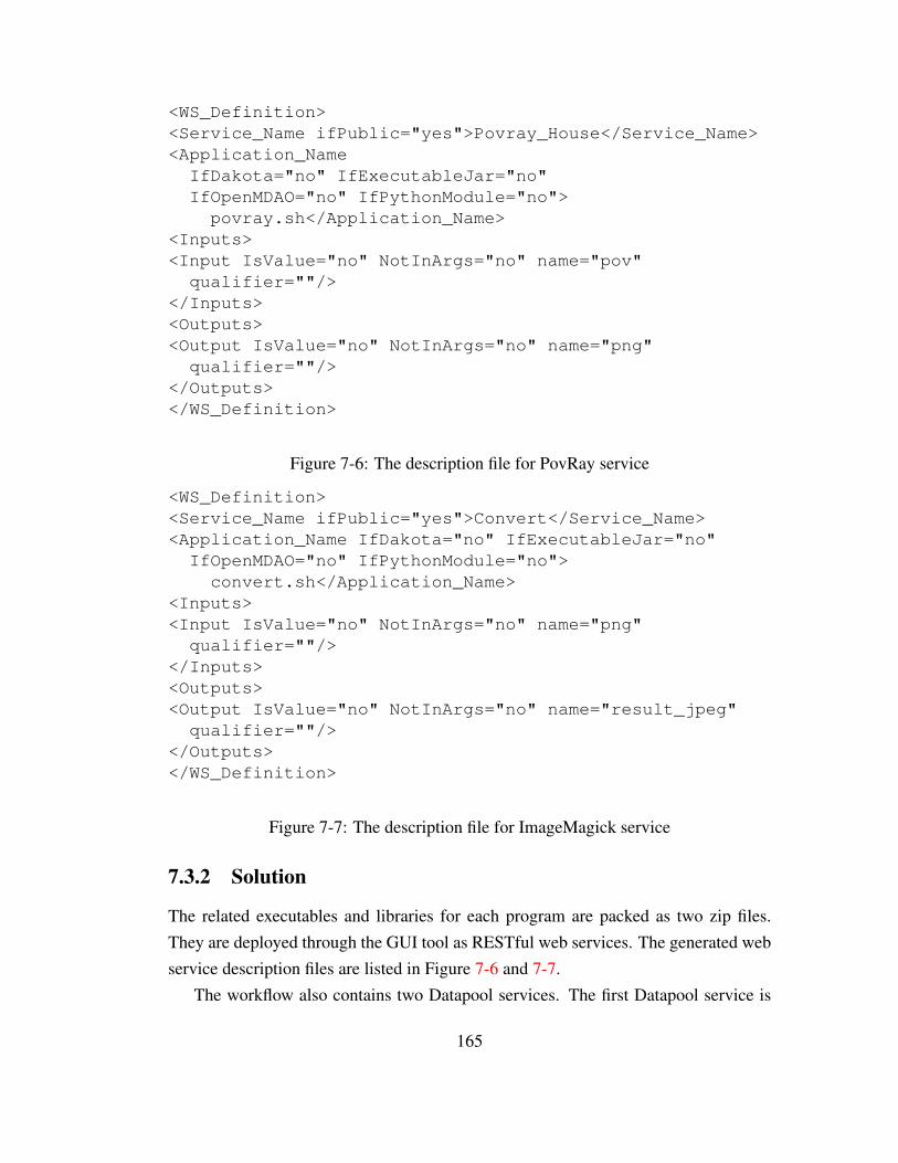
<WS_Definition><Service_Name ifPublic="yes">Povray_House</Service_Name><Application_Name
IfDakota="no" IfExecutableJar="no"IfOpenMDAO="no" IfPythonModule="no">povray.sh</Application_Name>
<Inputs><Input IsValue="no" NotInArgs="no" name="pov"qualifier=""/>
</Inputs><Outputs><Output IsValue="no" NotInArgs="no" name="png"
qualifier=""/></Outputs></WS_Definition>
Figure 7-6: The description file for PovRay service
<WS_Definition><Service_Name ifPublic="yes">Convert</Service_Name><Application_Name IfDakota="no" IfExecutableJar="no"IfOpenMDAO="no" IfPythonModule="no">convert.sh</Application_Name>
<Inputs><Input IsValue="no" NotInArgs="no" name="png"qualifier=""/>
</Inputs><Outputs><Output IsValue="no" NotInArgs="no" name="result_jpeg"
qualifier=""/></Outputs></WS_Definition>
Figure 7-7: The description file for ImageMagick service
7.3.2 Solution
The related executables and libraries for each program are packed as two zip files.They are deployed through the GUI tool as RESTful web services. The generated webservice description files are listed in Figure 7-6 and 7-7.
The workflow also contains two Datapool services. The first Datapool service is
165
used for initial input data uploading. The second one is the one to store intermediatedata, the png file. The Datapool service for ImageMagick receives this png file as aURI reference (step 6 in Figure 4-4). They are invoked from the client-side by anexecutable script written in Python, which supports the invocation of RESTful webservices. One syntax example is shown in Figure 4-10 on Page 90.
7.4 Summary
This chapter covers three types of scenarios:
• in-house legacy code based command line programs, which are composed inexisting WMS;
• legacy workflows in existing software framework, which is wrapped and ex-posed as web service;
• legacy software based command line programs, which is composed program-matically by new code.
Therefore, this framework shows its flexibility to integrate with various types of work-flow platforms. It also fits with the requirements from different skill levels of users.The components of the composite web service can be a piece of code, software or eventhe workflow created by existing workflow framework. The output can be workflow inexisting WMS, web services and in-house customized code.
166

Chapter 8
Conclusion
8.1 Contribution
This thesis studied the feasibility and advantages of applying state-of-the-art computertechnology in scientific workflow modeling in a collaborative environment. Based onthis study, a reference implementation for ROA based workflow modelling was pro-posed, which covered the topics of data management, service management, data andservice virtualisation and service composition. This thesis started with a series ofreviews on related researches and technologies related to those four topics. Amongthem, the data management and web service management formed the foundation ofthis modelling framework. The data and service virtualisation enabled the reusabilityof scientific applications in heterogenous computing environments with various ma-chines/operating systems. The study on web service composition carried out an explo-ration to further release the potentials of this framework, which enabled the descriptionof the composite service declaratively and to execute it by a speculative computing en-actment runtime. Practically, the contributions of this thesis were achieved in threestages:
• A light-weight framework for workflow data management and service manage-ment that is based on RESTful web service to bridge the gap between desktopscientific application and online scientific workflow;
• A data and service virtualisation framework to further enhance the efficiency oncomputing resource and increase the reproducibility of the computing environ-
167

ment for heterogenous scientific applications based on virtualisation/container-ization technology;
• A speculative enactment runtime for scientific workflow, which is based on thelight-weight framework.
A Light-Weight Framework for Bridge-Building from Desktop to CloudThis study has presented an indication for the benefits arising from our light-weight framework for the deployment and execution of scientific application inthe cloud. With our GUI based deployment mechanism, the technical barri-ers are lowered for non-specialist usage of web services and cloud resources.The framework reduces the effort and enhances the efficiency for users toturn legacy code and programs into web services and hence collaborate witheach other. The distributed and asynchronous data staging mechanism helps re-duce end-to-end times by hiding the costs of data staging between services aswell as between client and service, which works as the foundation to enhancethe efficiency of data transfers in the ROA based scientific workflow modelling.Practically, this thesis also evaluates the usefulness and usability of the frame-work through a user study and some experiments, showing how different typesof legacy programs and tools can cooperate seamlessly in workflow with thesupport of our framework.
A PaaS Scientific Workflow Framework based on Data and Services Virtualisation
Chapter 5 proposed a scientific workflow modelling framework based on con-tainerization technology. It also adopted the data staging approach and SaaSplatform introduced in Chapter 3 and 4. By adopting latest technologies, thiswork proposed a new idea about how to overcome the issue of data staging over-head and the compatibility issues brought by heterogenous computing platformsin a scientific workflow. This framework showed its ability to enhance the effi-ciency of computing resources utilisation and to increase the reproducibilityof the computing environment for heterogenous scientific applications. Thischapter also discussed the limitation of such methodology in scientific workflowmodelling. This discussion yielded the guidelines about the suitable solution forscientific workflow in different computing environments.
168

A Speculative Enactment Runtime for Scientific WorkflowIn Chapter 6, a speculative enactment runtime was introduced together with theSpeculative Service Description(SSD). SSD is the first declarative workflow de-scription language that is designed for a speculative enactment runtime. It fur-ther presented the capability of declarative description language in the imple-mentation of scientific workflow, which enhances the fault-tolerance ability ofscientific workflow. It supports the composition of web services that generatesthe workflow as autonomous services. Additionally, it utilizes and benefits fromthe architectural specification of hypermedia distributed systems as described byREST, and from the insights and guidelines of ROA.
On the basis of the SSD and enactment runtime model, this work introducedthe prototype implementation of the speculative enactment runtime. The im-plementation brings in the idea of integrating both objective-oriented and logicprogramming languages to create the web services as the interfaces for the spec-ulative enactment process. This prototype allows the validation of this specula-tive enactment runtime in real application scenarios.
As a summary, this work enhances the efficiency of scientific workflow modellingand presents the feasibility of implementing ROA and RESTful web services in scien-tific workflows with the introducing of new approaches on data management, servicemanagement and service composition in aforementioned two stages. Specifically, thiscan be observed from two perspectives:
1. from the application perspective, as a user of scientific workflows, this workvalidates the feasibility and demonstrates the advantages of applying a new ROAbased workflow framework.
2. from the development perspective, as a computer scientist, this work fills thegap between new web services technology and scientific workflow modellingby developing a more efficient framework based on ROA and RESTful webservices;
169

8.2 Limitations
8.2.1 The Overheads in Web Services based Scientific Workflow
In Section 3.4, Figure 3-5 shows the impact of overheads in network communication.The fluctuation of execution times is caused by the varied network situation. It canbe assumed that, in workflows with different execution time and I/O data size, thisoverhead can impact the total performance. Meanwhile, in Section 6.7, Figure 6-11also shows the overhead and its trend caused by the introducing of speculative enact-ment runtime. This section will discuss the overhead in web services based scientificworkflow and its limitation.
To further investigate the impact of overhead on the performance, first of all, twoexperiments are set up based on a workflow with (i) scalable computing time, (ii) andtransferred data size , which are composed based on the framework. It is the sellarworkflow script sellar MDF solver.py in OpenMDAO in this experiment, which is in-troduced in Chapter 7. The results are discussed in two parts:
Scalable Computing TimeThe code in sellar.py has a very short compute time (one line of script), whichmakes it easy to observe the communication costs. With the addition of a line ofcode to make it sleep for a specified period to simulate a longer computing time.The comparison is between the local version of the prolonged script and the webservice version of the prolonged script. In them, the web service version has twoscenarios that one is deployed on the Amazon EC2 machine, one is deployed onthe intranet of UoB.
In this experiment, the workflow is executed for 139 times to get the mean oftotal execution time. In Figure 8-1, the execution time for three conditions arepresented: local workflow, web service workflow (Intranet environment), webservice workflow (Internet environment). The x axis represents the sleep timein the script, which can be deemed as the computing time of the original localscript. From Figure 8-1, it is not surprising to see generally the execution timeof Internet workflow is the slowest and the local workflow is the fastest. Wecan also observe that the variation in Internet traffic has a significant impact onworkflow execution time.
170

Figure 8-1: Workflow execution time with different sleep time in three situations (Lo-cal workflow, Intranet workflow and Internet workflow)
Figure 8-2: Web service based workflow execution time normalised by the local exe-cution time
Based on the results from Figure 8-1, we derive Figure 8-2 which plots the ratiobetween Internet and Local workflow as well as the ratio between Intranet andLocal workflow. The latter has a clear downward trend as the computational timegrows: from 1.93 at 1s to 1.20 at 5s, and to 1.08 at 10s. In the Internet workflow,we can observe a nonmonotonic trend at the beginning in Figure 8-1, which issimply due to traffic variations in the Internet environment and configuration atserver-side. In this experiment, the server is located on the east coast of America.The server is a AWS free-usage tier one, which is allocated with limited andlow priority computing and communication resources. However, from Figure
171

8-1, we can still see the general trend that the ratio between Internet and Localworkflow drops from 5.08 at 0.5s to 1.22 at 5s. After 10s, we observe thatthe differences between the three conditions have stabilized. At 10s, the ratiobetween Internet workflow and local one reduces to 1.10. It can be observedthe Internet/Local ratio is getting closer or even similar to the Intranet/Localratio when computing time grows. This indicates that, in the circumstance ofthat there is only control flow (or the dataflow’s size is stable), the influenceof network situation on total execution time is getting smaller when computingtime of web service grows. After certain level, such as the 5s computing time inthis case, the influence of network situation on overhead is almost negligible.
Scalable Transferred Data SizeA further experiment will show that how the execution time scales when large-scale data communication is involved in the workflow. It also aims to observesensitivity to the increasing of data size.
As a basis, the framework has a stream style communication design for datahandling that no matter how large the data is, it is never fully loaded into thememory. The data is divided into a stream of small sections. The memory onlyloads one section from the hard drive every time and handles the data in a stream,with the objective of reducing the overall memory footprint. Even in some ex-treme situation when the machine only has very limited memory, it can still dealwith large amounts of data. This is also one of our test that will be shown. Theuser of this framework also does not need to manually configure the memoryheap size for the framework (it is based on Java Virtual Machine), the defaultsize is enough.
In this experiment, different sizes of data ranging from 128K to 256M are sub-mitted to web service deployed through the framework. The web service onserver side will send back a success response when file is successfully received.The whole execution finishes with a further request to a web service to fetch anHTTP response with empty body. The web service simply simulates the processto consume the data uploaded previously. Two network environments are testedhere to provide a comparison. In the first scenario, the service is deployed in an
172

Figure 8-3: Experiment results of data communication
Amazon EC2 machine and the client side is deployed within the University ofBath intranet. In the second, both server and client are within the intranet. Bothservers and the client machine have a single core CPU.
To establish a baseline cost for data transfer alone, we ran an experiment us-ing the Secure File Transfer Protocol (SFTP), in order to get a better picture ofthe influence of the bandwidth and network environment on transmission costs.This data is plotted on Figure 8-3 as well. From Figure 8-3, it can be observedthat data transmission time rises in line with data size as expected. The usefulobservation however, once the transfer size outweighs the overhead costs, is thatwe can observe the overhead for the WS data transfer over SFTP by compar-ing the blue (WS) and green (SFTP) bars. As usual, small volumes are noisyand uninformative, but above 4Mb, there is a clear differential between WS andSFTP, with the former taking longer. The study here is not sufficiently detailedto be anything more than indicative, but it suggests confirmation of the intuitionthat data transfer over HTTP incurs a small but notable overhead compared toSFTP, which is tuned for data transfer. Without more detailed investigation itis hard to say whether the factor is additive or multiplicative, but the ratio isfalling between 16Mb and 256Mb. The second useful observation, which helpsto contextualize these experiments, is that the approximate bandwidth betweenUoB and the EC2 machine is in the range 0.8-1.0Mb/s. A higher performancenetwork should provide higher bandwidth and hence contribute to a lower per-
173
formance crossover point in terms of the minimum data size necessary before itis worth using a WS.
The limitation can be concluded as, (i) the performance of data staging is stillsignificantly impacted by the network; (ii) the network overhead is a stable factor that,with the growth of computing time and data size, the impact turns smaller; (iii) in betternetwork situations, the network overhead takes a smaller part of overall overhead.
On the other hand, the overhead on data staging is not only limited by networklatency. The hardware limitation is yet another influential factor. The mechanicalhard disk can reduce the I/O speed signicantly. A possible direction to explore in thefuture is the adoption of RAM disk. On implementation level, a series solutions canbe adopted, such as ramdiskadm [Oracle, 2011], RapidDisk [Koutoupis, 2010], etc.
8.2.2 The Synchronized Connection based on HTTP
In this framework, the HTTP connections in the workflow are synchronized. Thatmeans at network level, for each HTTP connection, it will not be disconnected fromserver until the end of the computing process. For example, if there is an applicationthat needs a long time of execution, the connection will be maintained as long as theexecution.
At client side, the Taverna workflow has a multi-process mechanism in its execu-tion runtime. Therefore, the synchronized connection will not block the execution ofother available web services invocation. In the Python based and Java based clientside, multi-thread code can be involved as well to avoid the impact of synchronization.In both client types, timeout length can be customized. It allows the client to wait forthe connection, rather than disconnect it automatically. In a nut shell, in this researchwork and prototype, the asynchronized connection is not necessary.
In future implementation, the disadvantages of a synchronized connection poten-tially can be reflected from following aspects: (i) the client with uncustomisable time-out length, such as some of the browsers, will have a problem if the execution time istoo long; (ii) the client machine may experience shutdown or restart in this process, orthe user wants to retrieve the results from another machine; (iii) if there are multipleinstances of a connection, to release the resources as soon as possible will also be apositive factor to the system performance.
174

The asynchronised connections can be supported by pull or push technology. Byimplementing pull technology, such as web feeds, the client can maintain an aggregatorto subscribe each of the remote executions. Besides, the latest push technology can alsoprovide an option as solution. Such as in HTML5, WebSocket [Fette and Melnikov,2011] protocol provides the full-duplex communications channels over a single TCPconnection. Because it uses TCP port number 80, it can be used in the environmentsthat firewalls block non-web Internet connections.
8.3 Future Works
This framework, as an implementation, shows its ability and potential in the appli-cation of scientific workflow. As an outcome of this research, it still can have itspotentials to be further released in future implementation beyond a prototype. Thefuture works will be carried out from two aspects as well: web services managementand speculative enactment runtime.
Web Service ManagementThe future works on web service management will mainly focus on the followingaspects:
• In the future, the framework can be further developed to be deployed onmore platforms, such as Windows and Mac OS.
• The user interface can be migrated from a Client/Server architecture toBrowser/Server architecture.
Speculative Enactment runtimeCurrently, the speculative enactment runtime is used mainly to deal with fault-tolerance or error-handling issues. It has the potential to work as a mechanismto provide alternative solutions in more scenarios. For example, when thereare multiple options of the inputs for a computing process, it will be helpful toprovide a single service that can take multiple input options and generate oneoptimal result. This can be implemented and tested for some cases in specificresearch areas. Currently, there is no such a study case in hand in order to buildthe test workflow and collect the test data. This research and implementationcan only be meaningful when there is such a demand to work out the optimal
175

output from multiple inputs. The possible amount of the inputs and the afford-able computing resources can potentially influence the efficiency of the system.These will lead to the needs for more case studies and researches.At the implementation level, the Prolog based speculative enactment runtime canbe refactored and written in the OO languages, such as C++, Java because thecurrent solution does not have an ideal link between OO languages and Prolog.For example, JPL does not support multi-process requests. Furthermore, with anOO languages based system, it will reduce the costs to deploy the system withless knowledge preparation and software/library support. Besides, the SSD canbe designed and written based on more user-friendly grammar or even align withother description language standards.
Integration of Virtualized Scientific Workflow and Speculative Enactment Runtime
In this thesis, both the virtualized scientific workflow platform and the specu-lative enactment runtime are independently developed based on the works in-troduced in Chapter 3 and Chapter 4. They are both good examples to showthe extendibility of the ROA based scientific workflow platform. Furthermore,these two independently developed systems can be integrated together to gainmore potential.For example, now the speculative enactment runtime is more like a tool that onlyserve for client-side users. The whole speculative process can be explicitly pro-grammed and monitored from user’s point of view. The whole process is nottransparent to users. They are aware of which services are speculatively exe-cuted and what alternative services are invoked. By integrating the virtualizedscientific workflow and speculative enactment runtime, this process can be car-ried out entirely at server-side such that the users do not to be aware that thereis even a speculative process. The speculative enactment process will be trans-parent to users. At server-side, for one service, there can be multiple algorithms,multiple instances or multiple inputs that are executed in parallel in a speculativemanner to serve for one purpose. They are all controlled by the server. From theuser’s point of view, the enactment of this type of server-side speculative ser-
vice does not need to be different from a normal service. Virtual machines canbe dynamically started or stopped for each service execution job based on thenumber of service requests and idle resources. Algorithms can be developed for
176

this dynamic allocation.
Future Works on Speculative Enactment RuntimeIn the discussion about time/compute resource decisions in Section 6.6.3, anequation is proposed about how to make the decision. Equation 8.1 is also pro-posed to further reveal the research potential based on the speculative enactmentin scientific workflow.
D = Mt − S ∗Ms/(Ps ∗ Ts) (8.1)
It is discussed that, users or system administrators can adjust their sensitivityto financial cost case by case by setting the Mt. This setting can be a staticnumber. It can also be dynamically reflected and configured based on somefactors at runtime. Finally, it will lead to a system that not only automaticallyand efficiently, but also economically can achieve the workflow tasks in terms oftime/compute resource costs. The factor can be the idle resources that left in theHPC system. The coefficient can also be set dynamically based on the changeof power price or the daily generated power from the local solar panels. Thefactors can be more. The data about those factors can be collected from a sensornetwork. This combined consideration of efficiency and economy will lead to awide range of future works.
177

Appendix A
The Description of the CancerModelling Workflow
A.1 Introduction
The cancer modeling workflow is composed of three models that concern breast can-cer. They are the deliverables from the research in Kolokotroni et al. [2008a,b, 2011].The workflow is built based on Taverna workbench as depicted in Figure A-1. Theworkflow contains three sub-models. Their input data are read in through a XMLparser. The parser is also used to connect models. The parser collects data from laststep in workflow and combine it with the raw input to generate the input file for nextstep in the workflow. The functions of each model is briefly introduced in followingsections.
A.2 Epirubicin Pharmacokinetcs
The model simulates the pharmacokinetics of Epirubicin and calculates the Area UnderCurve of the plot plasma concentration of the drug against time after administration.More specifically, the pharmacokinetics of Epirubicin is modeled by a three compart-ment open model with elimination from the central compartment
178

Figure A-1: Taverna workflow of cancer model
179

A.3 Epirubicin Pharmacodynamics
The model calculates the cell kill ratio (CKR) of Epirubicin assuming an exponentialdependence of CKR from area under curve under the plot of plasma concentration ofdrug (not logarithm of the concentration) against time after drug administration
A.4 Breast Cancer Therapy: Epirubicin
A generic four-dimensional simulation model of breast cancer response to chemother-apy with single agent Epirubicin. The model is based on the consideration of a discretetime and space stochastic cellular automata.
180

Appendix B
The Core Prolog Code of theEnactment Engine
1 % Definition on how to find out the descendent of service.2 % The usage of PX and P here is to define the priority of the child service or descendent service,3 % When a descendent priority is P, the priority of all the children on this branch that lead to this
descendent should be higher. (1 is highest)4 % The meaning is that when you can not find a priority 1 branch (all children with priority 1) to the
descendent, try less priority route which does not need all the children on this route should bepriority 1.
5 % X,Y : Service identification (URI). XM, YM: Service Method: {PUT, POST, GET, DELETE}67 descendent of(X,MX,Y,MY,P):−child of(X,MX,Y,MY,PX),PX=<P.8 descendent of(X,MX,Y,MY,P):−child of(Z,MZ,Y,MY,PX),PX=<P,descendent of(X,MX,Z,MZ,P).9
10 %%%%%%%%%%%%%%%%%%%%%%%%%%%%%%%%%%%%%%%%%%%%%%%%%%
1112 % Definition on how to match the initial service based on appropriate inputs.13 % Vars: input names; URI D/O: The URI of the destination service and the original service. MD/O:
Method of the service.1415 initial steps(Vars,URI D,MD,URI O,MO):−details of(URI O,MO, , , ,List, , , , ),inVars(List,Vars),
descendent of(URI D,MD,URI O,MO,1).16 initial steps(Vars,URI D,MD,URI O,MO,X):−details of(URI O,MO, , , ,List, , , , ),inVars(List,Vars
),descendent of(URI D,MD,URI O,MO,X).17
181

18 % This function can match the initial service not only based on inputs but outputs as well. Thisfunction is not implemented at Java level.
19 initial steps IO(IVars,OVars,URI O,MO,URI D,MD):−details of(URI O,MO, , , ,ListI, , , , ),details of(URI D,MD, , , , , ,ListO, , ),inVars(ListI,IVars),(OVars=ListO),descendent of(URI D,MD,URI O,MO,1).
2021 %%%%%%%%%%%%%%%%%%%%%%%%%%%%%%%%%%%%%%%%%%%%%%%%%%
2223 % Utilities: definition on how to match the input name to the input lists contained by some service.2425 inVars([List|[]],Vars):−inlist(List,Vars).26 inVars([Item|Tail],Vars):−inlist(Item,Vars),inVars(Tail,Vars).2728 inlist(Item,[Item|Rest]).29 inlist(Item,[DisregardHead|Tail]):−inlist(Item,Tail).3031 %%%%%%%%%%%%%%%%%%%%%%%%%%%%%%%%%%%%%%%%%%%%%%%%%%
3233 % Definition on how to match the appropriate next step.34 % URI N: the URI of next service; MN: the method of the next service.3536 % Find the next step based on not only the present service, but also the destination service. This can
be37 % be used in the circumstances that service composite description has more than one goals.38 next step(URI O,MO,URI D,MD,URI N,MN):−child of(URI N,MN,URI O,MO,1),descendent of(
URI D,MD,URI N,MN,1).39 next step(URI O,MO,URI D,MD,URI N,MN):−child of(URI N,MN,URI O,MO,1),URI D==URI N
,MD==MN.4041 % Find the next step based on the present service when there is only one goal in the service composite
description.42 next step(URI O,MO,URI N,MN):−child of(URI N,MN,URI O,MO,1).4344 %%%%%%%%%%%%%%%%%%%%%%%%%%%%%%%%%%%%%%%%%%%%%%%%%%
4546 % Find the alternative next service. The priority is added by one.47 % URI E: The failed service (with Error).48
182

49 add 1(X,Y):−Y is X+1.50 % Find the alternative service when there are multiple goals in the service composite description.51 next alternative(URI O,MO,URI D,MD,URI E,ME,URI N,MN):−child of(URI E,ME,URI O,MO,X
),add 1(X,Y),child of(URI N,MN,URI O,MO,Y),descendent of(URI D,MD,URI N,MN,Y).52 % Find the alternative service when there is only one goal in the description.53 next alternative(URI O,MO,URI E,ME,URI N,MN):−child of(URI E,ME,URI O,MO,X),add 1(X,Y
),child of(URI N,MN,URI O,MO,Y).
183

Appendix C
The Template for DockerConfiguration File
1 {2 ”Hostname”: ””,3 ”Domainname”: ””,4 ”User”: ””,5 ”AttachStdin”: true,6 ”AttachStdout”: true,7 ”AttachStderr”: true,8 ”PortSpecs”: null,9 ”ExposedPorts”: {
10 ”8000/tcp”: {}11 },12 ”Tty”: true,13 ”OpenStdin”: true,14 ”StdinOnce”: true,15 ”Env”: null,16 ”Cmd”: [17 ”/home/virtual configurable/virtual configurable/env/bin/python”,18 ”/home/virtual configurable/virtual configurable/virtual configurable/manage.py”,19 ”runserver”,20 ”0.0.0.0:8000”21 ],22 ”Image”: ”me1kd/virtual configurable”,23 ”Volumes”: {24 ”/tmp”: {}25 },
184

26 ”WorkingDir”: ””,27 ”Entrypoint”: null,28 ”NetworkDisabled”: false,29 ”MacAddress”: ””,30 ”OnBuild”: null,31 ”Labels”: {},32 ”HostConfig”: {33 ”Binds”: [”/tmp:/tmp”],34 ”Links”: [],35 ”LxcConf”: {},36 ”Memory”: 0,37 ”MemorySwap”: 0,38 ”CpuShares”: 0,39 ”CpuPeriod”: 0,40 ”CpusetCpus”: ””,41 ”CpusetMems”: ””,42 ”BlkioWeight”: 300,43 ”OomKillDisable”: false,44 ”PortBindings”: {45 ”8000/tcp”: [46 {47 ”HostIp”: ”127.0.0.1”,48 ”HostPort”: ”<port>”49 }50 ]51 },52 ”PublishAllPorts”: false,53 ”Privileged”: false,54 ”ReadonlyRootfs”: false,55 ”Dns”: null,56 ”DnsSearch”: null,57 ”ExtraHosts”: null,58 ”VolumesFrom”: [],59 ”CapAdd”: null,60 ”CapDrop”: null,61 ”RestartPolicy”: { ”Name”: ””, ”MaximumRetryCount”: 0 },62 ”NetworkMode”: ”bridge”,63 ”Devices”: [],64 ”Ulimits”: null,65 ”LogConfig”: { ”Type”: ”json−file”, ”Config”: {} },66 ”SecurityOpt”: [],
185

67 ”CgroupParent”: ””68 }69 }
186

Bibliography
Linux-VServer. http://http://linux-vserver.org/. URL http://
linux-vserver.org/. [Online; accessed 26-Sept-2015]. 99
LXC. https://linuxcontainers.org/. URL https://
linuxcontainers.org/. [Online; accessed 26-Sept-2015]. 99
openvz. http://openvz.org/. URL http://openvz.org/. [Online; ac-cessed 26-Sept-2015]. 99
ActiveState Software Inc. stackato. http://www.activestate.com/
stackato, 2014. URL http://www.activestate.com/stackato. [Ac-cessed: 30/12/2013]. 80
Michael Adams and Arthur ter Hofstede. Yawl user manual. User manual, The YAWL
Foundation, 2009. 55
Rama Akkiraju, Joel Farrell, John A Miller, Meenakshi Nagarajan, Amit Sheth, andKunal Verma. Web service semantics-wsdl-s. 2005. 51
Eyhab Al-Masri and Qusay H Mahmoud. Discovering the best web service. In Pro-
ceedings of the 16th international conference on World Wide Web, pages 1257–1258.ACM, 2007a. 137
Eyhab Al-Masri and Qusay H Mahmoud. Qos-based discovery and ranking of webservices. In Computer Communications and Networks, 2007. ICCCN 2007. Pro-
ceedings of 16th International Conference on, pages 529–534. IEEE, 2007b. 137
Rosa Alarcon, Erik Wilde, and Jesus Bellido. Hypermedia-driven restful service com-position. In Service-Oriented Computing, pages 111–120. Springer, 2011. 124
187

G. Alonso, B. Reinwald, and C. Mohan. Distributed data management in workflow en-vironments. In Research Issues in Data Engineering, 1997. Proceedings. Seventh In-
ternational Workshop on, pages 82 –90, apr 1997. doi: 10.1109/RIDE.1997.583708.43
Ilkay Altintas, Chad Berkley, Efrat Jaeger, Matthew Jones, Bertram Ludaescher, andSteve Mock. Kepler: Towards a grid-enabled system for scientific workflows. Inthe Workflow in Grid Systems Workshop in GGF10-The Tenth Global Grid Forum,
Berlin, Germany, 2004. 75
Abdulsalam Alzubbi, Amadou Ndiaye, Babak Mahdavi, Francois Guibault, BenoitOzell, and Jean-Yves Trepanier. On the use of JAVA and RMI in the developmentof a computer framework for MDO. In 8th AIAA/USAF/NASA/ISSMO Symposium
on Multidisciplinary Analysis and Optimization, 2000. 40
Amazon Web Services, Inc. AWS Elastic Beanstalk. http://aws.amazon.
com/elasticbeanstalk/, 2011. URL http://aws.amazon.com/
elasticbeanstalk/. [Accessed: 30/12/2013]. 80
AppFog, Inc. appfog. https://www.appfog.com/, 2013. URL https://
www.appfog.com/. [Accessed: 30/12/2013]. 79
Assaf Arkin, Sid Askary, Scott Fordin, Wolfgang Jekeli, Kohsuke Kawaguchi, DavidOrchard, Stefano Pogliani, Karsten Riemer, Susan Struble, Pal Takacsi-Nagy, et al.Web service choreography interface (wsci) 1.0. Standards proposal by BEA Systems,
Intalio, SAP, and Sun Microsystems, 2002. 47, 48
Paul Barham, Boris Dragovic, Keir Fraser, Steven Hand, Tim Harris, Alex Ho, RolfNeugebauer, Ian Pratt, and Andrew Warfield. Xen and the art of virtualization. ACM
SIGOPS Operating Systems Review, 37(5):164–177, 2003. 98
Adam Barker and Jano Van Hemert. Scientific workflow: a survey and research direc-tions. In Parallel Processing and Applied Mathematics, pages 746–753. Springer,2008. 54
David Booth, Hugo Haas, Francis McCabe, Eric Newcomer, Michael Champion, ChrisFerris, and David Orchard. Web services architecture. 2004. 13, 34
188

Don Box, David Ehnebuske, Gopal Kakivaya, Andrew Layman, Noah Mendelsohn,Henrik Frystyk Nielsen, Satish Thatte, and Dave Winer. Simple object access pro-tocol (soap) 1.1, 2000. 25, 32, 33, 40
Jerzy Brzezinski, Arkadiusz Danilecki, Jakub Flotynski, Anna Kobusinska, and An-drzej Stroinski. Roswel workflow language: A declarative, resource-oriented ap-proach. New Generation Computing, 30(2-3):141–164, 2012. 17, 125, 126, 127,131, 132
Junwei Cao, Stephen A Jarvis, Subhash Saini, and Graham R Nudd. Gridflow: Work-flow management for grid computing. In Cluster Computing and the Grid, 2003.
Proceedings. CCGrid 2003. 3rd IEEE/ACM International Symposium on, pages198–205. IEEE, 2003. 43, 44
William Y Chang, Hosame Abu-Amara, and Jessica Feng Sanford. Transforming en-
terprise cloud services. Springer Science & Business Media, 2010. 98
Neil Chapman, Simone Ludwig, William Naylor, Julian Padget, and Omer Rana.Matchmaking support for dynamic workflow composition. In Proceedings of
3rd IEEE International Conference on eScience and Grid Computing, pages371–378, Bangalore, India, December 2007. IEEE, IEEE. DOI:10.1109/E-SCIENCE.2007.48. 51, 121
Kyle Chard, Wei Tan, Joshua Boverhof, Ravi Madduri, and Ian Foster. Wrap scientificapplications as wsrf grid services using gravi. In Web Services, 2009. ICWS 2009.
IEEE International Conference on, pages 83–90. IEEE, 2009. 45, 75
Ann L Chervenak, Robert Schuler, Matei Ripeanu, Muhammad Ali Amer, ShishirBharathi, Ian Foster, Adriana Iamnitchi, and Carl Kesselman. The globus replicalocation service: design and experience. Parallel and Distributed Systems, IEEE
Transactions on, 20(9):1260–1272, 2009. 44
Workflow Manage Coalition. Terminology & glossary. Technical report, TechnicalReport WFMC-TC-1011, 1996. 52
OMG Corba. Common object request broker architecture, 1995. 25, 40
189
Tom Crick, Peter Dunning, Hyunsun Kim, and Julian Padget. Engineering designoptimization using services and workflows. Phil. Trans. R. Soc. A, 367(1898):2741–2751, 2009. 41
Francisco Curbera, Yaron Goland, Johannes Klein, Frank Leymann, S Weerawarana,et al. Business process execution language for web services, version 1.1. 2003. 48
Jos De Bruijn, Christoph Bussler, John Domingue, Dieter Fensel, Martin Hepp,M Kifer, B Konig-Ries, J Kopecky, R Lara, E Oren, et al. Web service modelingontology (wsmo). Interface, 5:1, 2005a. 50
Jos De Bruijn, Dieter Fensel, M Kifer, J Kopeck, R Lara, H Lausen, A Polleres, D Ro-man, J Scicluna, and I Toma. Relationship of wsmo to other relevant technologies.W3C Member Submission, 2005b. 51
Ewa Deelman, Dennis Gannon, Matthew Shields, and Ian Taylor. Workflows ande-science: An overview of workflow system features and capabilities. Future Gen-
eration Computer Systems, 25(5):528–540, 2009. 42
Docker. What is Docker. https://www.docker.com/whatisdocker. URLhttps://www.docker.com/whatisdocker. [Online; accessed 29-Sept-2015]. 100
Docker. What is Docker? https://www.docker.com/what-docker, 2016.URL https://www.docker.com/what-docker. [Online; accessed 17-June-2016]. 13, 14, 100, 101
MS Eldred, BM Adams, DM Gay, LP Swiler, K Haskell, WJ Bohnhoff, JP Eddy,WE Hart, JP Watson, JD Griffin, et al. Dakota version 4.1 users manual. Technicalreport, Sandia Technical Report SAND2006-6337, Sandia National Laboratories,Albuquerque, NM, 2007. 49, 2007. 163
Cristina Feier, John Domingue, Jos de Bruijn, Dieter Fensel, Holger Lausen, and AxelPolleres. D3. 1v0. 2 wsmo primer. http://www. wsmo. org/TR/d3/d3, 1:v0, 2005. 51
Ian Fette and Alexey Melnikov. The websocket protocol. 2011. 175
Roy Fielding, Jim Gettys, Jeffrey Mogul, Henrik Frystyk, Larry Masinter, Paul Leach,and Tim Berners-Lee. Hypertext transfer protocol–http/1.1. Technical report, 1999.36
190

Roy Thomas Fielding. Architectural Styles and the Design of Network-based Software
Architectures. PhD thesis, University of California, Irvine, 2000. 35, 36
Ian Foster. Lessons from industry for science cyberinfrastructure: Simplicity, scale,and sustainability via SaaS/PaaS. 06 2015. URL http://dx.doi.org/10.
6084/m9.figshare.1449018. 96
Ian Foster and Carl Kesselman. The globus toolkit. The grid: blueprint for a new
computing infrastructure, pages 259–278, 1999. 41
Naoki Fukuta, Ken Satoh, and Takahira Yamaguchi. Towards kiga-kiku services onspeculative computation. In Practical Aspects of Knowledge Management, pages256–267. Springer, Yokohama, Japan, 2008. 129, 130
Galaxy Team. Galaxy optimization. http://galaxy.psu.edu/, 2008. URLhttp://galaxy.psu.edu/. 55
Francis Galiegue and Kris Zyp. Json schema: Core definitions and terminology. Inter-
net Engineering Task Force (IETF), 2013. 105
Yolanda Gil, Ewa Deelman, Mark Ellisman, Thomas Fahringer, Geoffrey Fox, DennisGannon, Carole Goble, Miron Livny, Luc Moreau, and Jim Myers. Examining thechallenges of scientific workflows. Ieee computer, 40(12):26–34, 2007. 42
Carole Anne Goble and David Charles De Roure. myexperiment: social networkingfor workflow-using e-scientists. In Proceedings of the 2nd workshop on Workflows
in support of large-scale science, pages 1–2. ACM, 2007. 91
Li Gong. Jxta: A network programming environment. Internet Computing, IEEE, 5(3):88–95, 2001. 44
Google. Google App Engine. http://developers.google.com/
appengine/, 2008. URL http://developers.google.com/
appengine/. [Online; accessed 02-May-2013]. 46, 79
GoPivotal, Inc. Cloud Foundry. http://www.cloudfoundry.com/, 2011.URL http://www.cloudfoundry.com/. [Accessed: 24/08/2013]. 46, 79
191

Dominique Guinard, Vlad Trifa, Stamatis Karnouskos, Patrik Spiess, and DomnicSavio. Interacting with the soa-based internet of things: Discovery, query, selection,and on-demand provisioning of web services. Services Computing, IEEE Transac-
tions on, 3(3):223–235, 2010. 137
Hugo Haas and Allen Brown. Web Services Glossary. http://www.w3.org/TR/ws-gloss/, 2004. URL http://www.w3.org/TR/ws-gloss/. [Online;accessed 11-February-2011]. 22
David Hollingsworth and UK Hampshire. Workflow management coalition the work-flow reference model. Workflow Management Coalition, 68, 1993. 13, 53
Ali Hussain. Performance of Docker vs VMs. http://www.
slideshare.net/Flux7Labs/performance-of-docker-vs-vms,2014. URL http://www.slideshare.net/Flux7Labs/
performance-of-docker-vs-vms. [Online; accessed 29-Sept-2015].101
ImageMagick Studio. Imagemagick. http://www.imagemagick.org, 1999.URL http://www.imagemagick.org. [Online; accessed 15-Jan-2014]. 164
Michael Isard, Mihai Budiu, Yuan Yu, Andrew Birrell, and Dennis Fetterly. Dryad:distributed data-parallel programs from sequential building blocks. In Proceedings
of the 2nd ACM SIGOPS/EuroSys European Conference on Computer Systems 2007,EuroSys ’07, pages 59–72, New York, NY, USA, 2007. ACM. ISBN 978-1-59593-636-3. doi: http://doi.acm.org/10.1145/1272996.1273005. URL http://doi.
acm.org/10.1145/1272996.1273005. 43
David R Jefferson. Virtual time. ACM Transactions on Programming Languages and
Systems (TOPLAS), 7(3):404–425, 1985. 129
Jelastic, Inc. Jelastic. http://jelastic.com//, 2011. URL http://
jelastic.com/. [Accessed: 30/12/2013]. 80
Kurt Jensen, Lars Michael Kristensen, and Lisa Wells. Coloured petri nets and cpntools for modelling and validation of concurrent systems. International Journal on
Software Tools for Technology Transfer, 9(3-4):213–254, 2007. 149, 154
192
Gopi Kandaswamy, Liang Fang, Yi Huang, Satoshi Shirasuna, Suresh Marru, and Den-nis Gannon. Building web services for scientific grid applications. Ibm Journal of
Research and Development, 50:249–260, 2006. doi: 10.1147/rd.502.0249. 45, 75
Rania Khalaf, Nirmal Mukhi, and Sanjiva Weerawarana. Service-oriented compositionin bpel4ws. In WWW (Alternate Paper Tracks), 2003. 47
Avi Kivity, Yaniv Kamay, Dor Laor, Uri Lublin, and Anthony Liguori. kvm: the linuxvirtual machine monitor. In Proceedings of the Linux Symposium, volume 1, pages225–230, 2007. 98
S. Kodiyalam and J. Sobieszczanski-Sobieski. Multidisciplinary design optimisation-some formal methods, framework requirements, and application to vehicle de-sign. International Journal of Vehicle Design, 25(1):3–22, 2001. URL http://
inderscience.metapress.com/index/903X7U03T201VDTG.pdf. 24
Eleni A Kolokotroni, Eleni Ch Georgiadi, Dimitra D Dionysiou, and Georgios S Sta-matakos. A 4-d simulation model of tumor free growth and response to chemother-apy in vivo: The breast cancer case. Zografeio Lyceum, Istanbul, Turkey September
23-24, 2008, page 31, 2008a. 178
Eleni A Kolokotroni, Georgios S Stamatakos, Dimitra D Dionysiou, Eleni Ch Geor-giadi, Christine Desmedt, and Norbert M Graf. Translating multiscale cancer modelsinto clinical trials: Simulating breast cancer tumor dynamics within the frameworkof the trial of principle clinical trial and the acgt project. In BioInformatics and Bio-
Engineering, 2008. BIBE 2008. 8th IEEE International Conference on, pages 1–8.IEEE, 2008b. 178
Eleni A Kolokotroni, Dimitra D Dionysiou, Nikolaos K Uzunoglu, and Georgios SStamatakos. Studying the growth kinetics of untreated clinical tumors by using anadvanced discrete simulation model. Mathematical and Computer Modelling, 54(9):1989–2006, 2011. 178
Jacek Kopecky, Matthew Moran, Tomas Vitvar, Dumitru Roman, and Adrian Mo-can. D24. 2v0. 1. wsmo grounding. WSMO Working Draft. http://www. wsmo.
org/TR/d24/d24, 2:v0, 2005. 51
193

Jacek Kopecky, Tomas Vitvar, Carine Bournez, and Joel Farrell. Sawsdl: Semanticannotations for wsdl and xml schema. Internet Computing, IEEE, 11(6):60–67,2007. 48, 49, 51
Petros Koutoupis. RapidDisk. http://www.rapiddisk.org/, 2010. URLhttp://www.rapiddisk.org/. [Online; accessed 12-August-2014]. 174
Sriram Krishnan, Brent Stearn, Karan Bhatia, Kim K. Baldridge, Wilfred W. Li, andPeter Arzberger. Opal: SimpleWeb Services Wrappers for Scientific Applications.Web Services, IEEE International Conference on, 0:823–832, 2006. doi: http://doi.ieeecomputersociety.org/10.1109/ICWS.2006.96. 44, 75, 76
Hsiang-Tsung Kung and John T Robinson. On optimistic methods for concurrencycontrol. ACM Transactions on Database Systems (TODS), 6(2):213–226, 1981. 129
Menno Lageman and Sun Client Solutions. Solaris containerswhat they are and howto use them. 2005. 99
Butler Lampson. Lazy and speculative execution in computer systems. In Principles
of Distributed Systems, pages 1–2. Springer, 2006. 129
Edward A Lee and Steve Neuendorffer. MoML: A Modeling Markup Language in
SML: Version 0.4. Citeseer, 2000. 55
Ho-Jun Lee, Jae-Woo Lee, and Jeong-Oog Lee. Development of web services-basedmultidisciplinary design optimization framework. Advances in Engineering Soft-
ware, 40(3):176–183, 2009. 41
Frank Leymann et al. Web services flow language (wsfl 1.0), 2001. 53, 54
J. Lindenbaum, A. Wiggins, and O. Henry. Heroku. http://www.heroku.com,2008. URL http://http://www.heroku.com. [Online; accessed 02-May-2013]. 46, 78
David Liu, Jun Peng, Gio Wiederhold, Ram D. Sriram, Corresponding Aruthor, Kin-cho H. Law, and Kincho H. Law. Composition of engineering web services withdistributed data flows and computations, 2005. 43
194

Bertram Ludascher, Ilkay Altintas, Chad Berkley, Dan Higgins, Efrat Jaeger, MatthewJones, Edward A Lee, Jing Tao, and Yang Zhao. Scientific workflow managementand the kepler system. Concurrency and Computation: Practice and Experience,18(10):1039–1065, 2006. 21, 42, 43, 44, 121
Bakak Mahdavi. The design of a distributed, object-oriented, component-based frame-work in multidisciplinary design optimization. Master’s thesis, School of ComputerScience, McGill University, Montreal, 2002. 40
David Martin, Mark Burstein, Jerry Hobbs, Ora Lassila, Drew McDermott, SheilaMcIlraith, Srini Narayanan, Massimo Paolucci, Bijan Parsia, Terry Payne, et al.Owl-s: Semantic markup for web services. W3C member submission, 22:2007–04,2004. 50
Luis Martin, Alberto Anguita, Norbert M Graf, Manolis Tsiknakis, MathiasBrochhausen, Stefan Ruping, Anca ID Bucur, Stelios Sfakianakis, Thierry Sengstag,Francesca Buffa, et al. Acgt: advancing clinico-genomic trials on cancer-four yearsof experience. In MIE, pages 734–738, 2011. 55
Joaquim R. R. A. Martins and Andrew B. Lambe. Multidisciplinary design opti-mization: A survey of architectures. AIAA Journal, 51:2049–2075, 2013. doi:10.2514/1.J051895. 20
P. Mell and T. Grance. The NIST definition of cloud computing. National Institute
of Standards and Technology, Special Publication 800-145, 2011. URL http://
developers.google.com/appengine/. [Online; accessed 02-May-2013].46, 74, 78, 98
Dirk Merkel. Docker: lightweight linux containers for consistent development anddeployment. Linux Journal, 2014(239):2, 2014. 99
Microsoft. Windows Azure. http://www.windowsazure.com/, 2010. URLhttp://www.windowsazure.com/. [Accessed: 30/12/2013]. 80
Microsoft. Trident project. http://tridentworkflow.codeplex.com/,2011. URL http://tridentworkflow.codeplex.com/. 42
Nilo Mitra, Yves Lafon, et al. Soap version 1.2 part 0: Primer. W3C recommendation,24:12, 2003. 13, 35
195

Derek G. Murray, Malte Schwarzkopf, Christopher Smowton, Steven Smith, AnilMadhavapeddy, and Steven Hand. CIEL: a universal execution engine for dis-tributed data-flow computing. In Proceedings of the 8th USENIX conference on Net-
worked systems design and implementation, NSDI’11, page 9, Berkeley, CA, USA,2011. USENIX Association. URL http://portal.acm.org/citation.
cfm?id=1972470. 43
Henry Ng, Suleyman Geluyupoglu, Frank Segaria, Brett Malone, Scott Woyak,and Greg Salow. Collaborative Engineering Enterprise with Integrated Mod-eling Environment. http://www.phoenix-int.com/resources/
CollaborativeEngineering.php, 2003. URL http://www.
phoenix-int.com/resources/CollaborativeEngineering.php.[Online; accessed 08-August-2011]. 40
Tom Oinn, Matthew Addis, Justin Ferris, Darren Marvin, Martin Senger, Mark Green-wood, Tim Carver, Kevin Glover, Matthew R Pocock, Anil Wipat, et al. Taverna: atool for the composition and enactment of bioinformatics workflows. Bioinformat-
ics, 20(17):3045–3054, 2004. 21, 42, 43, 44, 74, 75, 121
Tom Oinn, Mark Greenwood, Matthew Addis, M. Nedim Alpdemir, Justin Ferris,Kevin Glover, Carole Goble, Antoon Goderis, Duncan Hull, Darren Marvin, Pe-ter Li, Phillip Lord, Matthew R. Pocock, Martin Senger, Robert Stevens, AnilWipat, and Chris Wroe. Taverna: Lessons in creating a workflow environmentfor the life sciences: Research articles. Concurr. Comput. : Pract. Exper., 18(10):1067–1100, August 2006. ISSN 1532-0626. doi: 10.1002/cpe.v18:10. URLhttp://dx.doi.org/10.1002/cpe.v18:10. 54
OpenStack project. Openstack. http://www.openstack.org/, 2012. URLhttp://www.openstack.org/. [Accessed: 30/12/2013]. 80
Oracle. ramdiskadm - administer ramdisk pseudo device. http://docs.oracle.com/cd/E23824_01/html/821-1462/ramdiskadm-1m.html, 2011.URL http://docs.oracle.com/cd/E23824_01/html/821-1462/
ramdiskadm-1m.html. [Online; accessed 12-August-2014]. 174
ORACLE. Remote Method Invocation Home. http://www.oracle.com/
technetwork/java/javase/tech/index-jsp-136424.html, 2011.
196

URL http://www.oracle.com/technetwork/java/javase/tech/
index-jsp-136424.html. [Online; accessed 07-August-2011]. 25, 40
Sharon L. Padula and Ronnie E. Gillian. Multidisciplinary environments: A historyof engineering framework development. In 11th AIAA/ISSMO Multidisciplinary
Analysis and Optimization Conference, 2006. 24
Luca Panziera, Marco Comerio, Matteo Palmonari, and Flavio De Paoli. Distributedmatchmaking and ranking of web apis exploiting descriptions from web sources.In Service-Oriented Computing and Applications (SOCA), 2011 IEEE International
Conference on, pages 1–8. IEEE, 2011. 137
Cesare Pautasso and Erik Wilde. Why is the Web Loosely Coupled? A Multi-FacetedMetric for Service Design. In Proc. of the 18th International World Wide Web Con-
ference (WWW2009), pages 911–920, Madrid, Spain, April 2009. URL http:
//dret.net/netdret/docs/loosely-coupled-www2009/. 22, 37
Cesare Pautasso, Olaf Zimmermann, and Frank Leymann. RESTful Web Services vs.Big Web Services: Making the Right Architectural Decision. In 17th International
World Wide Web Conference (WWW2008), pages 805–814, Beijing, China, April2008 2008. URL http://www2008.org/. 22, 51
Persistence of Vision Raytracer Pty. Ltd. Povray. http://www.povray.org/,2003. URL http://www.povray.org/. [Online; accessed 15-Jan-2013]. 164
Maja Pesic and Wil MP Van der Aalst. A declarative approach for flexible businessprocesses management. In Business Process Management Workshops, pages 169–180. Springer, 2006. 123
James L Peterson. Petri net theory and the modeling of systems. 1981. 141, 146
Phoenix Integration. Analysis Server User Manual. http://www.
phoenix-int.com/˜AnalysisServer/main.html, 2001. URLhttp://www.phoenix-int.com/˜AnalysisServer/. [Online; ac-cessed 23-October-2014]. 40
Giulio Piancastelli and Andrea Omicini. A multi-theory logic language for the worldwide web. In Logic Programming, pages 769–773. Springer, 2008. 14, 124, 125,126, 131
197

Prabhakar Raghavan, Hadas Shachnai, and Mira Yaniv. Dynamic schemes for spec-ulative execution of code. In Modeling, Analysis and Simulation of Computer and
Telecommunication Systems, 1998. Proceedings. Sixth International Symposium on,pages 309–314. IEEE, 1998. 129
Red Hat, Inc. Openshift. https://www.openshift.com/, 2011. URL https:
//www.openshift.com/. [Accessed: 24/08/2013]. 46, 79
Red hat, Inc. Openshift Origin. http://openshift.github.io/, 2011. URLhttp://openshift.github.io/. [Accessed: 30/12/2013]. 80
Jingyuan Ren, Nadya Williams, Luca Clementi, Sriram Krishnan, and Wilfred W Li.Opal web services for biomedical applications. Nucleic acids research, 38(suppl 2):W724–W731, 2010. 46, 75
Leonard Richardson and Sam Ruby. The Resource Oriented Architecture, chapter 4,page 79. O’REILLY, 2007. 38
Nick Russell, Arthur HM Ter Hofstede, David Edmond, and Wil MP van der Aalst.Workflow data patterns: Identification, representation and tool support. In Concep-
tual Modeling–ER 2005, pages 353–368. Springer, 2005. 23
N Sakimura. Json web token (jwt). Technical report, 2015. No. RFC 7519. 108
A. O. Salas and J. C. Townsend. Framework requirements for mdo application devel-opment. In 7th AIAA/USAF/NASA/ISSMO Symposium on Multidisciplinary Analysis
and Optimization, pages 98–4740, 1998. 21, 24
Sandia National Laboratories. The DAKOTA Project. http://dakota.sandia.gov/, 2010. URL http://dakota.sandia.gov/. [Online; accessed 08-March-2013]. 41, 74, 161
Leo Sauermann, Richard Cyganiak, and Max Volkel. Cool uris for the semantic web.2011. 38
M. Senger, A. Rice, P. andBleasby, T. Oinn, and M. Uludag. Soaplab2: more reliableSesame door to bioinformatics programs. In Proc. 9th Bioinformatics Open Source
Conference (BOSC 2008), 2008a. 75
198

Martin Senger, Peter Rice, Alan Bleasby, Tom Oinn, and Mahmut Uludag. Soaplab2:more reliable Sesame door to bioinformatics programs, 2008b. 41, 44
Amit P Sheth, Karthik Gomadam, and Jon Lathem. Sa-rest: semantically interoperableand easier-to-use services and mashups. IEEE Internet Computing, 11(6):91–94,2007. 52
Y. Simmhan, C. van Ingen, G. Subramanian, and Jie Li. Bridging the gap betweendesktop and the cloud for escience applications. In Cloud Computing (CLOUD),
2010 IEEE 3rd International Conference on, pages 474–481, Chengdu, China, July2010. IEEE. doi: 10.1109/CLOUD.2010.72. 47, 80
Munindar P. Singh and Mladen A. Vouk. Scientific Workflows: Scien-tific Computing Meets Transactional Workflows, 1996. URL http:
//www.csc.ncsu.edu/faculty/mpsingh/papers/databases/
workflows/sciworkflows.html. 18
Jan Wielemaker Paul Singleton, Fred Dushin, and Jan Wielemaker. Jpl: A bidirectionalprolog/java interface, 2004. 151
M. Sobolewski. FIPER: The Federated S2S Environment. In JavaOne, Sun’s 2002
Worldwide Java Developer Conference, 2002. 41
Brennan Spies. Web services, part 1: Soap vs. rest. Retrieved March, 12:2010, 2008.16, 32, 33
Ian Taylor, Matthew Shields, Ian Wang, and Andrew Harrison. The triana workflowenvironment: Architecture and applications. In Workflows for e-Science, pages 320–339. Springer, 2007. 21, 42, 43, 44, 55
Satish Thatte. Xlang: Web services for business process design. Microsoft Corpora-
tion, 2001, 2001. 53
The OpenMDAO development team . OpenMDAO. http://openmdao.org,2010. URL http://openmdao.org/. [Online; accessed 08-March-2013]. 74,161
The openMDAO development team. Multidisciplinary Design Feasible (MDF).http://openmdao.org/releases/0.5.0/docs/mdao/mdf.html,
199

2013. URL http://openmdao.org/releases/0.5.0/docs/mdao/
mdf.html. [Online; accessed 14-August-2014]. 162
The Trustees of Indiana University. GFac User Manual. http://www.
extreme.indiana.edu/gfac/userguide.html, 2006. URL http://
www.extreme.indiana.edu/gfac/userguide.html. [Online; accessed28-December-2013]. 13, 77
The Trustees of Indiana University. Invokeing Gfac Web Service. http://
www.extreme.indiana.edu/gfac/invoke.html, 2007. URL http:
//www.extreme.indiana.edu/gfac/invoke.html. [Online; accessed28-December-2013]. 77
The YAWL Foundation. YAWL Project. http://www.yawlfoundation.org/,2004. URL http://www.yawlfoundation.org/. [Online; accessed 15-August-2014]. 42
University of Manchester. Opal plugin for Taverna 2.2. http://www.
taverna.org.uk/2011/02/15/opal-plugin-for-taverna-2-2/,2010. URL http://www.taverna.org.uk/2011/02/15/
opal-plugin-for-taverna-2-2/. [Online; accessed 6-August-2014]. 45
Wil MP Van Der Aalst. The application of petri nets to workflow management. Journal
of circuits, systems, and computers, 8(01):21–66, 1998. 53
Wil MP Van Der Aalst and Maja Pesic. DecSerFlow: Towards a truly declarative
service flow language. Springer, 2006. 127
Wil MP Van Der Aalst and Arthur H. M. ter Hofstede. Yawl: yet another workflowlanguage. Inf. Syst., 30(4):245–275, 2005. 21, 55
Wil MP Van Der Aalst, Arthur HM Ter Hofstede, Bartek Kiepuszewski, and Alistair PBarros. Workflow patterns. Distributed and parallel databases, 14(1):5–51, 2003.55
Anthony Velte and Toby Velte. Microsoft virtualization with Hyper-V. McGraw-Hill,Inc., 2009. 98
200

vmware. ESX and ESXi. http://www.vmware.com/uk/products/
esxi-and-esx/overview, 2012. URL http://www.vmware.com/uk/
products/esxi-and-esx/overview. [Online; accessed 26-Sept-2015]. 98
W3C. Web Services Architecture. http://www.w3.org/TR/ws-arch/
#relwwwrest, 2004. URL http://www.w3.org/TR/ws-arch/
#relwwwrest. [Online; accessed 08-August-2011]. 22, 25, 40, 51
Joan D. Walton, Robert E. Filman, and David J. Korsmeyer. The evolution ofthe DARWIN system. In Proceedings of the 2000 ACM symposium on Applied
computing - Volume 2, SAC ’00, pages 971–977, New York, NY, USA, 2000.ACM. ISBN 1-58113-240-9. doi: http://doi.acm.org/10.1145/338407.338709. URLhttp://doi.acm.org/10.1145/338407.338709. 39
[email protected]. Business Process Management Center of Excellence Glos-sary. https://www.ftb.ca.gov/aboutFTB/Projects/ITSP/BPM_
Glossary.pdf, 2009. URL https://www.ftb.ca.gov/aboutFTB/
Projects/ITSP/BPM_Glossary.pdf. [Online; accessed 02-Jan-2016]. 42
R. P. Weston and J. C. Townsend. A Distributed Computing Environment for Mul-tidisciplinary Design. In 5th AIAA/NASA/ISSMO Symposium on Multidisciplinary
Analysis and Optimization, Panama City Beach, FL, pages 94–4372, 1994. 39
Stephen A White. Introduction to bpmn. IBM Cooperation, 2(0):0, 2004. 53
Alan Williams and Stian Soiland-Reyes. SCUFL2. http://dev.mygrid.
org.uk/wiki/display/developer/SCUFL2, 2012. URL http://dev.mygrid.org.uk/wiki/display/developer/SCUFL2. [Online; accessed06-March-2014]. 54
Qun Zhou, Babak Mahdavi, Dao Jun Liu, Francois Guibault, Benoit Ozell, and Jean-Yves Trepanier. A web-based distribution protocol for large scale analysis and opti-mization applications. In High Performance Computing Systems and Applications,pages 257–270. Springer, 2003. 40
201
Copyright © 2022 FDOKUMEN