AGENDA - IN.gov
43
1 100 North Senate Avenue Room N925 Indianapolis, Indiana 46204 PHONE: (317) 232-5502 FAX: (317) 234-5133 Mitchell E. Daniels, Jr., Governor Michael B. Cline, Commissioner AGENDA July 21, 2011 Standards Committee Meeting MEMORANDUM July 11, 2011 TO: Standards Committee FROM: Scott Trammell, Secretary RE: Agenda for the July 21, 2011 Standards Committee Meeting A Standards Committee meeting is scheduled for 9:00 a.m. on July 21, 2011 in the N955 1 Bay Window Conference Room. Please enter the meeting through the double doors directly in front of the conference room. The following agenda items are listed for consideration Page No. A. GENERAL BUSINESS ITEMS OLD BUSINESS (No items on this agenda) NEW BUSINESS (No items on this agenda) B. CONCEPTUAL PROPOSAL ITEMS 1. LIGHTWEIGHT CONCRETE IN PRESTRESSED CONCRETE BEAMS page 04 C. STANDARD SPECIFICATIONS, SPECIAL PROVISIONS AND STANDARD DRAWINGS PROPOSED ITEMS OLD BUSINESS 1 Corrected on July 12, 2011
-
Upload
khangminh22 -
Category
Documents
-
view
0 -
download
0
Transcript of AGENDA - IN.gov
1
100 North Senate Avenue Room N925 Indianapolis, Indiana 46204
PHONE: (317) 232-5502 FAX: (317) 234-5133
Mitchell E. Daniels, Jr., Governor Michael B. Cline, Commissioner
AGENDA July 21, 2011 Standards Committee Meeting
MEMORANDUM July 11, 2011 TO: Standards Committee FROM: Scott Trammell, Secretary RE: Agenda for the July 21, 2011 Standards Committee Meeting A Standards Committee meeting is scheduled for 9:00 a.m. on July 21, 2011 in the N9551 Bay Window Conference Room. Please enter the meeting through the double doors directly in front of the conference room. The following agenda items are listed for consideration Page No. A. GENERAL BUSINESS ITEMS OLD BUSINESS (No items on this agenda) NEW BUSINESS (No items on this agenda) B. CONCEPTUAL PROPOSAL ITEMS 1. LIGHTWEIGHT CONCRETE IN PRESTRESSED CONCRETE BEAMS page 04 C. STANDARD SPECIFICATIONS, SPECIAL PROVISIONS AND STANDARD DRAWINGS PROPOSED ITEMS OLD BUSINESS
1 Corrected on July 12, 2011

(CONTINUED)
2
Item No. 04(b) 04/19/11 (2012 SS) Mr. Walker page 05 503.02 Materials 503.04 Dowel Bar Assemblies 506.02 Materials 507.02 Materials NEW BUSINESS Item No. 01 07/21/11 (2012 SS) Mr. Wright page 10 805.03 General Requirements 805.04 Pole Installation 805.05 Placing Signal Heads 805.13 Foundations 805.15 Method of Measurement 805.16 Basis of Payment Recurring Special Provision 922-T-168 TRAFFIC SIGNAL MATERIALS AND EQUIPMENT Standard Drawings 805-TSCS-01 TRAFFIC SIGNAL CANTILEVER STRUCTURE SIGNAL ARM DIMENSIONS & DETAILS 805-TSCS-02 TRAFFIC SIGNAL CANTILEVER STRUCTURE POLE DIMENSIONS AND DETAILS ELEVATION 805-TSCS-03 TRAFFIC SIGNAL CANTILEVER STRUCTURE BASE PLATE, BOTTOM SPLICE PLATE DETAILS 805-TSCS-04 TRAFFIC SIGNAL CANTILEVER STRUCTURE SIGNAL ARM CONNECTION DETAILS 805-TSCS-05 TRAFFIC SIGNAL CANTILEVER STRUCTURE HANDHOLE DETAILS 805-TSCS-06 TRAFFIC SIGNAL CANTILEVER STRUCTURE PLACEMENT OF SIGNALS AND SIGNS LOADING FOR ARM 35’ OR LESS 805-TSCS-07 TRAFFIC SIGNAL CANTILEVER STRUCTURE PLACEMENT OF SIGNALS AND SIGNS LOADING FOR ARMS > 35’ TO 60’ 805-TSCS-08 TRAFFIC SIGNAL CANTILEVER STRUCTURE COMBINATION ARM DIMENSIONS & DETAILS 805-TSCS-09 TRAFFIC SIGNAL CANTILEVER STRUCTURE COMBINATION POLE DIMENSIONS AND DETAILS ELEVATION 805-TSCS-10 TRAFFIC SIGNAL CANTILEVER STRUCTURE COMBINATION ARM CONNECTION DETAILS 805-TSCS-11 TRAFFIC SIGNAL CANTILEVER STRUCTURE COMBINATION POLE SPLICE DETAILS FOR ARMS 35’ OR LESS 805-TSCS-12 TRAFFIC SIGNAL CANTILEVER STRUCTURE COMBINATION POLE SPLICE DETAILS FOR ARMS > 35’ TO 60’ 805-TSCS-13 TRAFFIC SIGNAL CANTILEVER STRUCTURE COMBINATION ARM LOADING FOR 35’ ARM OR LESS 805-TSCS-14 TRAFFIC SIGNAL CANTILEVER STRUCTURE COMBINATION ARM LOADING FOR ARMS > 35’ TO 60’ 805-TSCS-15 TRAFFIC SIGNAL CANTILEVER STRUCTURE DRILLED SHAFT FOR ARMS 35’ OR LESS TYPE A
(CONTINUED)
3
805-TSCS-16 TRAFFIC SIGNAL CANTILEVER STRUCTURE DRILLED SHAFT FOR ARMS > 35’ TO 60’ TYPE B 805-TSCS-17 TRAFFIC SIGNAL CANTILEVER STRUCTURE SPREAD FOUNDATION FOR ARMS 35’ OR LESS TYPE C 805-TSCS-18 TRAFFIC SIGNAL CANTILEVER STRUCTURE SPREAD FOUNDATION FOR ARMS > 35’ TO 60’ TYPE D Indiana Design Manual Chapter 77-4.03 Signal Mounting Item No. 02 07/21/11 (2012 SS) Mr. Walker page 39 406.02 Materials 507.05(b) Partial Depth Patching 902.01(b) Asphalt Emulsions cc: Committee Members (11) FHWA (1) ICA (1)
Mr. Strain Date: 07/21/11
CONCEPTUAL PROPOSAL 1. LIGHTWEIGHT CONCRETE IN PRESTRESSED CONCRETE BEAMS
4
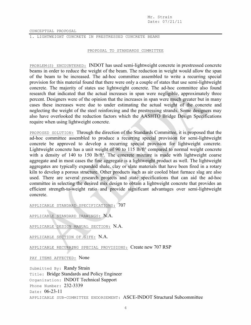
PROPOSAL TO STANDARDS COMMITTEE PROBLEM(S) ENCOUNTERED: INDOT has used semi-lightweight concrete in prestressed concrete beams in order to reduce the weight of the beam. The reduction in weight would allow the span of the beam to be increased. The ad-hoc committee assembled to write a recurring special provision for this material found that there were only a couple of states that use semi-lightweight concrete. The majority of states use lightweight concrete. The ad-hoc committee also found research that indicated that the actual increases in span were negligible, approximately three percent. Designers were of the opinion that the increases in span were much greater but in many cases these increases were due to under estimating the actual weight of the concrete and neglecting the weight of the steel reinforcing and the prestressing strands. Some designers may also have overlooked the reduction factors which the AASHTO Bridge Design Specifications require when using lightweight concrete. PROPOSED SOLUTION: Through the direction of the Standards Committee, it is proposed that the ad-hoc committee assembled to produce a recurring special provision for semi-lightweight concrete be approved to develop a recurring special provision for lightweight concrete. Lightweight concrete has a unit weight of 90 to 115 lb/ft³ compared to normal weight concrete with a density of 140 to 150 lb/ft³. The concrete mixture is made with lightweight coarse aggregate and in most cases the fine aggregate is a lightweight product as well. The lightweight aggregates are typically expanded shale, clay or slate materials that have been fired in a rotary kiln to develop a porous structure. Other products such as air cooled blast furnace slag are also used. There are several research projects and state specifications that can aid the ad-hoc committee in selecting the desired mix design to obtain a lightweight concrete that provides an efficient strength-to-weight ratio and provide significant advantages over semi-lightweight concrete. APPLICABLE STANDARD SPECIFICATIONS: 707 APPLICABLE STANDARD DRAWINGS: N.A. APPLICABLE DESIGN MANUAL SECTION: N.A. APPLICABLE SECTION OF GIFE: N.A. APPLICABLE RECURRING SPECIAL PROVISIONS: Create new 707 RSP PAY ITEMS AFFECTED: None Submitted By: Randy Strain Title: Bridge Standards and Policy Engineer Organization: INDOT Technical Support Phone Number: 232-3339 Date: 06-23-11 APPLICABLE SUB-COMMITTEE ENDORSEMENT: ASCE-INDOT Structural Subcommittee

Mr. Walker Date: 07/21/11
SPECIFICATION REVISIONS (OLD BUSINESS ITEM) REVISION TO STANDARD SPECIFICATIONS
5
PROPOSAL TO STANDARDS COMMITTEE
PROBLEM(S) ENCOUNTERED: The following PCCP items require revisions to section 503: 1. Dowel Bar Protection (503.02, 506.02, 507.02) - The requirements for exposure of bent and straight tie bars from ultraviolet light and moisture for no more than 21 days are also applied for dowel bars. Epoxy coatings commonly used for dowel bars are not sensitive to ultraviolet light or moisture for periods much longer than the 21 days. With anticipation that a very large number of dowel bars will be needed for upcoming concrete projects and that the dowel bars will be commonly stored for more than 21 days, the 21 day restriction should be removed. The other requirements of being free of dirt, loose rust, or scale at the time of concrete placement will still apply. The Project Engineer will have the option of testing the dowel bars if there is suspect that the epoxy coating has been damaged by ultraviolet light. 2. Tie Wires (503.04) - Tie wires which parallel the dowel bars and are welded to the two continuous parallel spacer bars are required to be cut near the center of the tie after the dowel bar assembly is secured in place. The intent of this requirement is to eliminate or reduce the potential of the tie wires to lock the joint, or for the wires to cause micro-surface cracks in the early ages of the concrete. Recent studies have indicated that the tie wires themselves will yield or the welds holding the wires to the basket will fail before they cause damage to the concrete or lock the joint. The benefit of not cutting the tie wires is that uncut tie wires keep the dowels and dowel baskets in better alignment, and more resistant to deflection while paving resulting in smoother pavement. PROPOSED SOLUTION: The following revisions are recommended to be authorized and made effective by a Recurring Special Provision. 1. Remove the 21 day restrictions for protecting the dowel bars from ultraviolet light and moisture and add the option for the Engineer to sample and test the dowel bars if there is suspect that there is ultraviolet damage. 2. Remove the requirement to cut the tie wires prior to the placement of the concrete. Add a requirement for the maximum size and number of tie wires. APPLICABLE STANDARD SPECIFICATIONS: 503.02, 506.02, 507.02, and 503.04 APPLICABLE STANDARD DRAWINGS: None APPLICABLE DESIGN MANUAL SECTION: APPLICABLE SECTION OF GIFE: Section 8

Mr. Walker Date: 07/21/11
SPECIFICATION REVISIONS (OLD BUSINESS ITEM) REVISION TO STANDARD SPECIFICATIONS
6
(CONTINUED) APPLICABLE RECURRING SPECIAL PROVISIONS: None Submitted By: Ron Walker Title: Manager, Office of Materials Management Organization: INDOT Phone Number: 317-610-7251 x 204 Date: 7-11-11 APPLICABLE SUB-COMMITTEE ENDORSEMENT? These specification revisions are recommended by the INDOT/PCCP Technical Committee.

Item No. 04(b) 04/19/11 (2012 SS) Mr. Walker Date: 07/21/11 REVISION TO STANDARD SPECIFICATIONS (OLD BUSINESS ITEM) SECTION 503 – PCCP JOINTS 503.02 MATERIALS 503.04 DOWEL BAR ASSEMBLIES SECTION 506 – PCCP PATCHING 506.02 MATERIALS SECTION 507 – PCCP RESTORATION 507.02 MATERIALS
7
The Standards Specifications are revised as follows: SECTION 503, BEGIN LINE 25, DELETE AS FOLLOWS: The epoxy coating on the dowel bars and bent and straight tie bars shall be protected in accordance with 703.04. SECTION 503, BEGIN LINE 174, DELETE AND INSERT AS FOLLOWS: (c) Suitable struts or ties wires shall be provided to hold the assembly in correct
position during installation. The tie wires shall be size W 7.5 (7 mm) or smaller and there shall be a maximum of 5 tie wires for each dowel bar assembly.
(d) The assembly shall have an upright support welded to the spacer bar and a
continuous bearing member at the end of each dowel. (e) If the upright support consists of a single vertical wire, the support shall be size W
7.5 (7 mm) or greater wire. Otherwise, the support shall be 1/4 in. (6 mm) or greater in diameter.
(f) At the time of placement, dowel bars shall be free of dirt, loose rust, or scale. If
the Engineer suspects the epoxy coating has been damaged by exposure to ultraviolet light, a sample will be obtained and will be tested in accordance with 910.01(b)9.
(fg) The dowel bar assembly shall be held securely in place during placing,
consolidating, and finishing the PCCP by means of metal pins. Pins used on granular subbase shall penetrate a minimum of 12 in. (300 mm) below the dowel bar assembly. Pins shall be size W 7.5 (7 mm) or greater wire and shall be provided with a hook or arm welded to the pin so that it shall secure the assembly in place. A minimum of 8 pins shall be used for each 10, 11, or 12 ft (3.0, 3.4, or 3.7 m) section of assembly. A minimum of 10 pins shall be used for assembly sections greater than 12 ft (3.7 m) and less than or equal to 16 ft (4.9 m).
(gh)After the dowel bar assembly is securely in place, all tie wires which parallel the
dowel bars, and are welded to the 2 continuous parallel spacer bars, shall be cut near the center of the tie. Dowel bars shall be coated with a bond breaking material and the coating shall be evident at the time of placement of the PCCP.
(hi) Dowel bars shall be placed 6 in. (150 mm) from the edges of the pavement and
spaced at 1 ft (0.3 m) on center across the joint.

Item No. 04(b) 04/19/11 (2012 SS)(contd.) Mr. Walker Date: 07/21/11 REVISION TO STANDARD SPECIFICATIONS (OLD BUSINESS ITEM) SECTION 503 – PCCP JOINTS 503.02 MATERIALS 503.04 DOWEL BAR ASSEMBLIES SECTION 506 – PCCP PATCHING 506.02 MATERIALS SECTION 507 – PCCP RESTORATION 507.02 MATERIALS
8
SECTION 506, BEGIN LINE 29, DELETE AND INSERT AS FOLLOWS: The epoxy coating on the dowel bars shall be protected in accordance with 703.04. Dowel bars shall be in accordance with 503.04(f). SECTION 507, BEGIN LINE 19, DELETE AND INSERT AS FOLLOWS:
The epoxy coating on the dowel bars shall be protected in accordance with 703.04. Dowel bars shall be in accordance with 503.04(f).
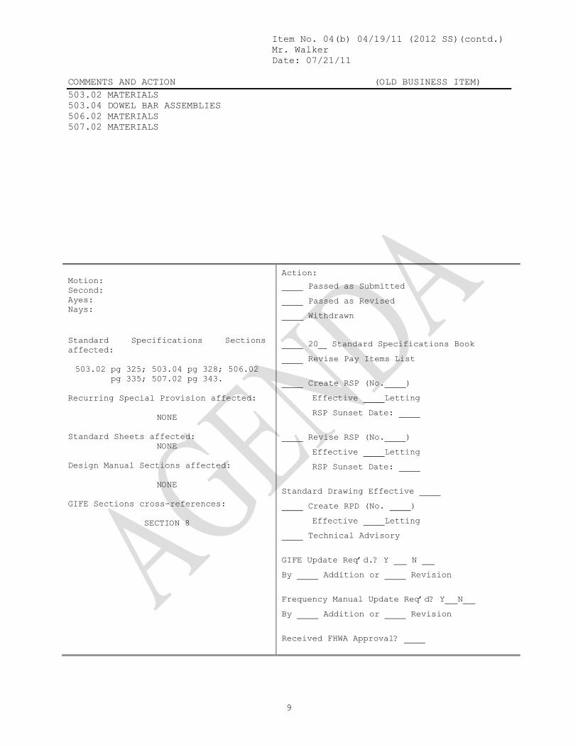
Item No. 04(b) 04/19/11 (2012 SS)(contd.) Mr. Walker Date: 07/21/11 COMMENTS AND ACTION (OLD BUSINESS ITEM) 503.02 MATERIALS 503.04 DOWEL BAR ASSEMBLIES 506.02 MATERIALS 507.02 MATERIALS
9
Motion: Second: Ayes: Nays:
Action:
Passed as Submitted Passed as Revised Withdrawn
Standard Specifications Sections affected: 503.02 pg 325; 503.04 pg 328; 506.02
pg 335; 507.02 pg 343. Recurring Special Provision affected:
NONE
Standard Sheets affected:
NONE Design Manual Sections affected:
NONE
GIFE Sections cross-references:
SECTION 8
20 Standard Specifications Book Revise Pay Items List
Create RSP (No. ) Effective Letting RSP Sunset Date:
Revise RSP (No. ) Effective Letting RSP Sunset Date:
Standard Drawing Effective Create RPD (No. ) Effective Letting Technical Advisory
GIFE Update Req’d.? Y N By Addition or Revision
Frequency Manual Update Req’d? Y N By Addition or Revision
Received FHWA Approval?

Mr. Wright Date: 07/21/11
SPECIFICATION REVISIONS REVISION TO STANDARD SPECIFICATIONS, PROVISION AND STANDARD DRAWINGS
10
PROPOSAL TO STANDARDS COMMITTEE
PROBLEM(S) ENCOUNTERED: Existing Signal Mast Arm standard drawings doesn't meet the latest AASHTO code requirements. PROPOSED SOLUTION: New Signal Cantilever Structures and foundation standard drawings were developed meeting the latest AASHTO code (2009 fifth edition) requirements. APPLICABLE STANDARD SPECIFICATIONS: 805, 922 APPLICABLE STANDARD DRAWINGS: New Standard Drawings 805-TSCS-01 thru 18 APPLICABLE DESIGN MANUAL SECTION: 77-4.03 APPLICABLE SECTION OF GIFE: N.A. APPLICABLE RECURRING SPECIAL PROVISIONS: 805-T-169, 922-T-168 PAY ITEMS AFFECTED: Revision to the related pay items is in the attached 805 section. Submitted By: John Wright Title: Director of Highway and Tech Support Organization: INDOT Phone Number: 317-232-5147 Date: 6/22/2011 APPLICABLE SUB-COMMITTEE ENDORSEMENT: Ad hoc review by industry, subcommittee from INDOT traffic section, Traffic System Division.
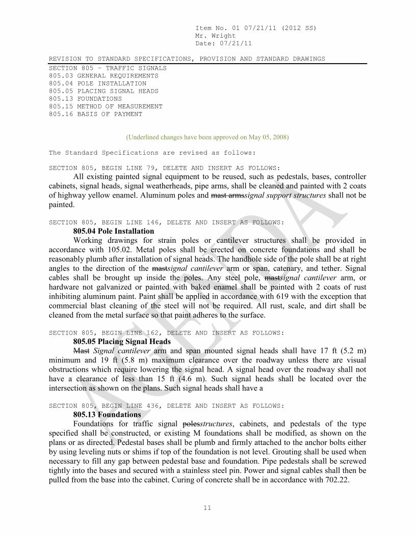
Item No. 01 07/21/11 (2012 SS) Mr. Wright Date: 07/21/11 REVISION TO STANDARD SPECIFICATIONS, PROVISION AND STANDARD DRAWINGS SECTION 805 – TRAFFIC SIGNALS 805.03 GENERAL REQUIREMENTS 805.04 POLE INSTALLATION 805.05 PLACING SIGNAL HEADS 805.13 FOUNDATIONS 805.15 METHOD OF MEASUREMENT 805.16 BASIS OF PAYMENT
11
(Underlined changes have been approved on May 05, 2008)
The Standard Specifications are revised as follows: SECTION 805, BEGIN LINE 79, DELETE AND INSERT AS FOLLOWS: All existing painted signal equipment to be reused, such as pedestals, bases, controller cabinets, signal heads, signal weatherheads, pipe arms, shall be cleaned and painted with 2 coats of highway yellow enamel. Aluminum poles and mast armssignal support structures shall not be painted. SECTION 805, BEGIN LINE 146, DELETE AND INSERT AS FOLLOWS: 805.04 Pole Installation Working drawings for strain poles or cantilever structures shall be provided in accordance with 105.02. Metal poles shall be erected on concrete foundations and shall be reasonably plumb after installation of signal heads. The handhole side of the pole shall be at right angles to the direction of the mastsignal cantilever arm or span, catenary, and tether. Signal cables shall be brought up inside the poles. Any steel pole, mastsignal cantilever arm, or hardware not galvanized or painted with baked enamel shall be painted with 2 coats of rust inhibiting aluminum paint. Paint shall be applied in accordance with 619 with the exception that commercial blast cleaning of the steel will not be required. All rust, scale, and dirt shall be cleaned from the metal surface so that paint adheres to the surface. SECTION 805, BEGIN LINE 162, DELETE AND INSERT AS FOLLOWS: 805.05 Placing Signal Heads Mast Signal cantilever arm and span mounted signal heads shall have 17 ft (5.2 m) minimum and 19 ft (5.8 m) maximum clearance over the roadway unless there are visual obstructions which require lowering the signal head. A signal head over the roadway shall not have a clearance of less than 15 ft (4.6 m). Such signal heads shall be located over the intersection as shown on the plans. Such signal heads shall have a SECTION 805, BEGIN LINE 436, DELETE AND INSERT AS FOLLOWS: 805.13 Foundations Foundations for traffic signal polesstructures, cabinets, and pedestals of the type specified shall be constructed, or existing M foundations shall be modified, as shown on the plans or as directed. Pedestal bases shall be plumb and firmly attached to the anchor bolts either by using leveling nuts or shims if top of the foundation is not level. Grouting shall be used when necessary to fill any gap between pedestal base and foundation. Pipe pedestals shall be screwed tightly into the bases and secured with a stainless steel pin. Power and signal cables shall then be pulled from the base into the cabinet. Curing of concrete shall be in accordance with 702.22.

Item No. 01 07/21/11 (2012 SS)(contd.) Mr. Wright Date: 07/21/11 REVISION TO STANDARD SPECIFICATIONS, PROVISION AND STANDARD DRAWINGS SECTION 805 – TRAFFIC SIGNALS 805.03 GENERAL REQUIREMENTS 805.04 POLE INSTALLATION 805.05 PLACING SIGNAL HEADS 805.13 FOUNDATIONS 805.15 METHOD OF MEASUREMENT 805.16 BASIS OF PAYMENT
12
SECTION 805, BEGIN LINE 458, INSERT AS FOLLOWS: 805.15 Method of Measurement Traffic signal head, pedestrian signal head, pedestrian push button, controller cabinet foundation, M foundation modified to P-1 foundation signal steel strain pole, signal wood pole, signal cantilever structure, signal cantilever structure combination arm, signal cantilever structure pole section 2, signal cantilever structure foundations, signal support foundation, signal service, disconnect hanger, magnetometer detector, microloop detector, loop detector delay amplifier, loop detector delay counting amplifier, loop detector rack, auxiliary BIU panel, signal handhole, signal detector housing, span catenary and tether, and span catenary for flasher will be measured by the number of units installed. SECTION 805, BEGIN LINE 493, INSERT AS FOLLOWS: If specified as pay items, traffic signal controller and cabinet, traffic signal head, pedestrian signal head, pedestrian push button, controller cabinet foundation, M foundation modified to P-1 foundation, signal steel strain pole, signal wood pole, signal cantilever structure, signal cantilever structure combination arm, signal cantilever structure pole section 2, signal cantilever structure foundations, signal support foundation, signal pedestals, signal service, disconnect hanger, magnetometer detector, microloop detector, loop detector delay amplifier, loop detector delay counting amplifier, loop detector rack, auxiliary BIU panel, signal handhole, signal detector housing, span catenary and tether, and span catenary for flasher will be paid for at the contract unit price per each. Conduit of the type specified, signal cable, interconnect cable, electrical signal cable, loop lead-in cable, and saw cut for roadway loop detector and sealant will be paid for at the contract unit price per linear foot (meter). SECTION 805, AFTER LINE 540, DELETE AND INSERT AS FOLLOWS: Signal Cantilever Structure, Mast Arm _____ ft (m) ................................ EACH length Signal Cantilever Structure, _____ ft (m) Signal Arm____ ...................... EACH length length Signal Cantilever Structure, Combination Arm _____ ft (m) .................. EACH length Signal Cantilever Structure, Drilled Shaft Foundation, ____ .................. EACH type Signal Cantilever Structure, Pole Section 2 (17 in. diameter pole) .......... EACH Signal Cantilever Structure, Pole Section 2 (24 in. diameter pole) .......... EACH Signal Cantilever Structure, Spread Footing Foundation, ____ .............. EACH type

Item No. 01 07/21/11 (2012 SS)(contd.) Mr. Wright Date: 07/21/11 REVISION TO STANDARD SPECIFICATIONS, PROVISION AND STANDARD DRAWINGS RSP 922-T-168 TRAFFIC SIGNALS MATERIALS AND EQUIPMENT
13
(Only affected sections of the 922-T-168 TRAFFIC SIGNALS MATERIALS AND EQUIPMENT are shown. Proposed changes shown: deletion – strikethrough; addition - underlined.
Basis for Use: Required for all contracts with 805 pay items). 922-T-168, BEGIN LINE 1075, DELETE AND INSERT AS FOLLOWS: 922.08 Mid-MastSignal Cantilever Arm Mount Signal Bracket The bracket shall permit the following 4 adjustments: (a) rotational adjustment about bracket axis; (b) vertical adjustment; (c) rotational adjustment about mast arm; and (d) rotational adjustment right and left from vertical plane 922-T-168, BEGIN LINE 1095, DELETE AND INSERT AS FOLLOWS: All electrical wiring shall be concealed within the bracket, except that which runs from the bracket to the mast signal cantilever arm. 922-T-168, BEGIN LINE 1272, DELETE AND INSERT AS FOLLOWS: (c) Signal Cantilever Structures 1. General A signal cantilever structure shall be designed in accordance with AASHTO Standard Specifications for Structural Supports for Highway Signs, Luminaires, and Traffic Signals, except where modified herein. For special designs, Wwhere the manufacturer has wind tunnel test data, they may use drag coefficients based on actual tests. Otherwise, the manufacturer shall use the drag coefficients in Table 1.2.5c as indicated below. 2. Signal Support The cantilever traffic signal pole and mast arms shall be designed in accordance with the standard drawings. Structure requiring special designs shall to support the loads in accordance with the plans in a 80 mph (129 km/h) wind with gusts to 104 mph (167 km/h). Loading shall assume die-cast aluminum heads utilize the following design conditions unless otherwise noted. a. 90 mph (145 km/h) wind b. 50 years service life c. Category II fatigue except as noted below
Item No. 01 07/21/11 (2012 SS)(contd.) Mr. Wright Date: 07/21/11 REVISION TO STANDARD SPECIFICATIONS, PROVISION AND STANDARD DRAWINGS RSP 922-T-168 TRAFFIC SIGNALS MATERIALS AND EQUIPMENT
14
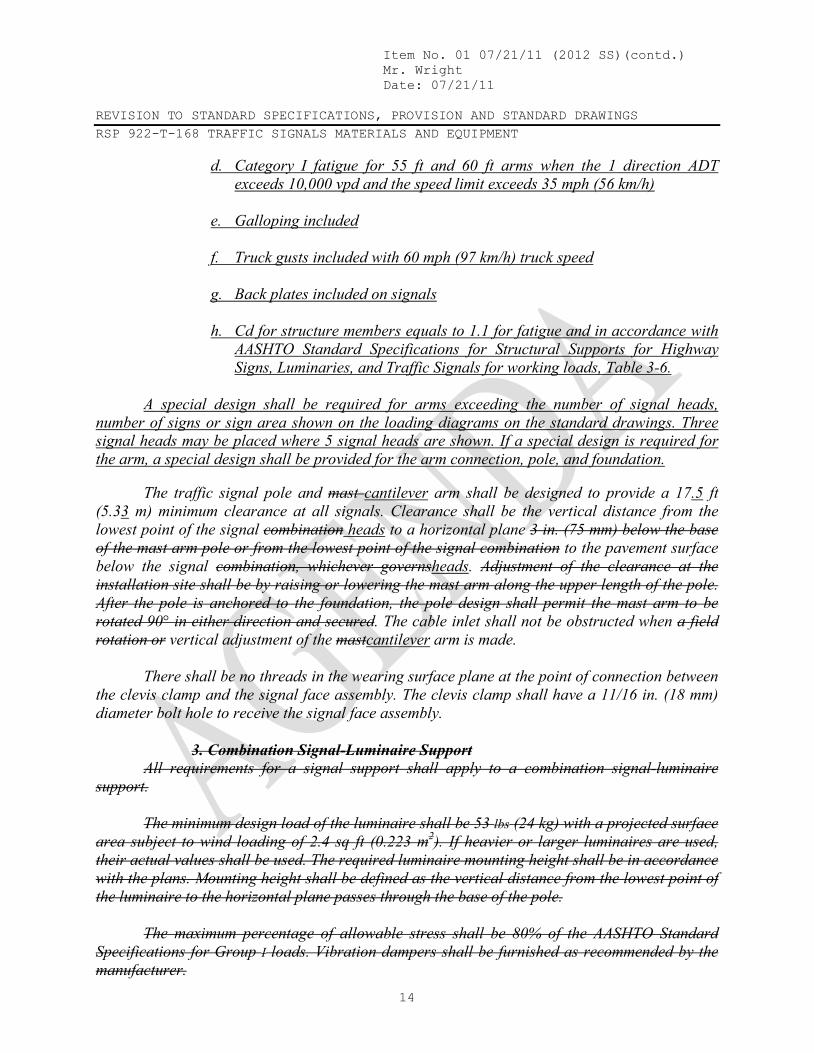
d. Category I fatigue for 55 ft and 60 ft arms when the 1 direction ADT exceeds 10,000 vpd and the speed limit exceeds 35 mph (56 km/h)
e. Galloping included f. Truck gusts included with 60 mph (97 km/h) truck speed g. Back plates included on signals h. Cd for structure members equals to 1.1 for fatigue and in accordance with
AASHTO Standard Specifications for Structural Supports for Highway Signs, Luminaries, and Traffic Signals for working loads, Table 3-6.
A special design shall be required for arms exceeding the number of signal heads, number of signs or sign area shown on the loading diagrams on the standard drawings. Three signal heads may be placed where 5 signal heads are shown. If a special design is required for the arm, a special design shall be provided for the arm connection, pole, and foundation. The traffic signal pole and mast cantilever arm shall be designed to provide a 17.5 ft (5.33 m) minimum clearance at all signals. Clearance shall be the vertical distance from the lowest point of the signal combination heads to a horizontal plane 3 in. (75 mm) below the base of the mast arm pole or from the lowest point of the signal combination to the pavement surface below the signal combination, whichever governsheads. Adjustment of the clearance at the installation site shall be by raising or lowering the mast arm along the upper length of the pole. After the pole is anchored to the foundation, the pole design shall permit the mast arm to be rotated 90° in either direction and secured. The cable inlet shall not be obstructed when a field rotation or vertical adjustment of the mastcantilever arm is made. There shall be no threads in the wearing surface plane at the point of connection between the clevis clamp and the signal face assembly. The clevis clamp shall have a 11/16 in. (18 mm) diameter bolt hole to receive the signal face assembly. 3. Combination Signal-Luminaire Support All requirements for a signal support shall apply to a combination signal-luminaire support. The minimum design load of the luminaire shall be 53 lbs (24 kg) with a projected surface area subject to wind loading of 2.4 sq ft (0.223 m2). If heavier or larger luminaires are used, their actual values shall be used. The required luminaire mounting height shall be in accordance with the plans. Mounting height shall be defined as the vertical distance from the lowest point of the luminaire to the horizontal plane passes through the base of the pole. The maximum percentage of allowable stress shall be 80% of the AASHTO Standard Specifications for Group I loads. Vibration dampers shall be furnished as recommended by the manufacturer.

Item No. 01 07/21/11 (2012 SS)(contd.) Mr. Wright Date: 07/21/11 REVISION TO STANDARD SPECIFICATIONS, PROVISION AND STANDARD DRAWINGS RSP 922-T-168 TRAFFIC SIGNALS MATERIALS AND EQUIPMENT
15
4 3. Pole Requirements a. General The pole shall be a round or multi-sided tapered tube, except the upper 4 to 6 ft (1.2 to 1.8 m) of a signal support pole may be non-tapered. The pole taper rate shall be 0.14 in/ft. The signal support cantilever pole shall have a reinforced handhole 4 6 in. (100 152 mm) by 6 10 in. (150 254 mm) minimum complete with cover and latching device located 18 in. (460 mm) above the base. A 1/2 in. (13 mm) 13 NC threaded grounding nut or approved equivalent shall be provided and be accessible through the handhole. A reinforced handhole 4 in. by 6 in. (102 mm by 152 mm) minimum complete with cover and latching device shall be located near arm connections at locations as indicated in the standard drawings. All poles shall be supplied with a pole splice plate as indicated in the standard drawings. A top cover shall be supplied for installations not utilizing a pole top luminaire. The pole cap shall be secured in place with set screws. The combination signal-luminaire pole shall have a reinforced handhole 4 in. (100 mm) by 8 in. (200 mm) minimum complete with cover and latching device, located 18 in. (460 mm) above the base. The combination signal-luminaire pole shall be provided with a removable pole cap and All poles shall be furnished with an integral wire support hook for the luminaire electrical cable. The cable shall be attached to the hook by a service drop clamp. A wiring hole with a 1 in. (25 mm) to 1 1/2 in. (38 mm) inside diameter grommet shall be provided where the luminaire mast arm attaches to the pole. b. Deflection For special designs, Tthe maximum allowable horizontal deflection of the pole shall be limited to 2.5 % of the structure height under Group I load combinations in accordance with 10.4.2 of the AASHTO Standard Specifications for Structural Supports for Highway Signs, Luminaries, and Traffic Signals under maximum loading conditions shall not exceed a deflection angle of 1° 10” from the vertical axis of the pole for any 1 ft (305 mm) section of the pole along the entire length of the pole. c. Materials The signal cantilever pole and the combination signal-luminaire pole shall be steel or aluminum. Steel poles, base plates, pole splice plates and arm connection plates shall be in accordance with ASTM A 595 or A 572 with a minimum yield strength of 50,000 lbs psi (345 kMPa) and shall be galvanized in accordance with ASTM A 123. Aluminum poles shall be in accordance with ASTM B 221 (B 221M) alloy 6063-T6 or 6005-T5, or ASTM B 241 (B 241M), alloy 6063-T6. d. Hardware All hardware for steel poles except bolts, base plates, pole splice plates, arm, arm connection plates, for the mast arm clamps and anchor bolts shall be in accordance with ASTM A 307 and shall be galvanized in accordance with ASTM A 153 or be mechanically galvanized and conform to coating thickness, adherence, and quality requirements of ASTM A 153, class C. A cast pole cap shall be in accordance with ASTM A 126 and shall be galvanized with a minimum coating of 2 oz/sq ft (0.610 kg/m2). Bolts for the pole splice shall be in accordance with

Item No. 01 07/21/11 (2012 SS)(contd.) Mr. Wright Date: 07/21/11 REVISION TO STANDARD SPECIFICATIONS, PROVISION AND STANDARD DRAWINGS RSP 922-T-168 TRAFFIC SIGNALS MATERIALS AND EQUIPMENT
16
ASTM A 490 and shall be galvanized. The contact area for both pole splice plates to be Class B per AASHTO 10.32.3c with a minimum slip coefficient of 0.5. The surfaces shall be blast-cleaned and have Class B coatings. All hardware for aluminum poles shall be stainless steel in accordance with ASTM A 276, type 304 or type 305. e. Anchor Base A 1 piece anchor base shall be supplied as indicated in the standard drawings secured to the lower end of the pole and shall develop the full strength of the pole. The base shall be provided with 4 holes of adequate size to accommodate 1 1/4 in. (32 mm) anchor bolts equally spaced on a bolt circle of 15 in. (380 mm) diameter and shall have 4 tapped holes for attaching the bolt covers. Four removable bolt covers shall be provided with each base and each cover shall attach to the upright portion of the body of the base by means of 1 hex head cap screw. The steel for the anchor base shall be in accordance with ASTM A 36 (A 36M), A 572 (A 572M), or A 588 (A 588M). Aluminum for the anchor base shall be in accordance with ASTM B 26, alloy 356.0-T6 or 356.0-T7 or ASTM B 209, alloy 6061-T6. f. Arm Requirements (1) Signal and Combination Cantilever Arms The arms shall be a circular or multi-sided tapered tube. The arm taper rate shall be 0.14 in./ft. A signal or combination cantilever arm shall be rigidly attached to the pole as detailed in the standard drawings A signal cantilever arm shall be attached to the pole by circular clamps. One-half of the clamp shall be welded to the cantilever arm. The single member cantilever arm or the upper tapered member of the truss style arm shall have a cable inlets as indicated in the standard drawings adjacent to the clamp complete with grommet. The cable inlet shall be a 1 3/4 in. (44 mm) diameter hole with a 1 1/2 in. (38 mm) inside diameter rubber grommet. The 20, 25, and 30 ft (6.1, 7.6 and 9.2 m) cantilever arms shall have 1 intermediate cable inlet with grommet located 12 ft (3.7 m) from the free end of the arm. The 35 and 40 ft (10.7 and 12.2 m) cantilever arm shall have 2 intermediate cable inlets with grommets located 12 ft (3.6 m) and 24 ft (7.3 m) respectively from the free end of the arm. The intermediate cable inlet shall be 1 in. (25 mm) diameter hole with 3/4 in. (19 mm) inside diameter rubber grommet. The maximum rise of the single member arm shall be 1/2 in. (13 mm) per 1 ft (305 mm) of arm after loading. The maximum rise of the truss style arm shall be as set out in the table. The rise shall be measured vertically from the centerline of the free end of the truss to a plane through the centerline of the upper arm bracket after loading.
Mast Arm Length ft (m)
Total Rise ft - in. (m)
Tolerance in. (mm)
12 - 20 (3.7 - 6.1) 4 - 0 (1.2) ± 1 (± 25) 25 (7.6) 4 - 3 (1.3) ± 1 (± 25)
30 - 40 (9.2 - 12.2) 4 - 7 (1.4) ± 1 (± 25)
Item No. 01 07/21/11 (2012 SS)(contd.) Mr. Wright Date: 07/21/11 REVISION TO STANDARD SPECIFICATIONS, PROVISION AND STANDARD DRAWINGS RSP 922-T-168 TRAFFIC SIGNALS MATERIALS AND EQUIPMENT
17
The end signals on the truss style arms shall be suspended and the intermediate signals shall be rigidly attached. All signals heads on the cantilever single member arms shall be rigidly attached as shown on the standard drawings and installed parallel to the horizontal plane and centered as much as possible to the cantilever arm plans. The cantilever arms shall be used as an enclosed raceway for wiring and shall be free of burrs and rough edges. Both parts of the clamp for the single member arms shall be stamped with the arm length prior to galvanizing. (2) Luminaire Mast Arm for Combination Support The luminaire mast arm shall be in accordance with 922.01(a)1. (3)(2) Materials The signal cantilever and combination arm shall be of the same material as the pole. The luminaire mast arm shall be of the same material as the pole except that a truss type arm shall be in accordance with 922.01(a). Bolts for the mast cantilever arm clamp connections shall be stainless steel in accordance with ASTM A 276, type 304 or 305 ASTM A325 and shall be galvanized. g. Anchor Bolts Four steel anchor bolts, each fitted with 2 hex nuts and 2 flat washers, shall be furnished with each pole. The anchor bolt shall be 1 1/4 in. (32 mm) in diameter as indicated in the standard drawings with a minimum of 10 15 in. (254 380 mm) of 7 NC threads on the upper end. The threads, nuts, and washers shall be galvanized in accordance with ASTM A 153 or be mechanically galvanized and conform to the coating thickness, adherence, and quality requirements of ASTM A 153, class C. The anchor bolt shall be 48 in. (1220 mm) long with a 4 in. (100 mm) right angle bend on the lower end or a square steel washer, 6 in. by 6 in. by 1/2 in. (150 mm by 150 mm by 13 mm), with a hex nut welded onto the lower end. The steel for the bolt shall be in accordance with ASTM A 576, or ASTM A 675 (ASTM A 675M), with a minimum yield strength of 55,000 psi (379380 kMPa), or ASTM A 36 (ASTM A 36M), special quality, modified to 55,000 psi (379380 kMPa) or approved equal. h. Finish All steel material shall be fully galvanized. Galvanizing shall take place after all welding is accomplished. Aluminum poles shall be provided with a satin finish accomplished by mechanical rotary grinding and aluminum mast arms shall be provided with a satin etched finish. i. Certification Unless otherwise specified, all materials covered herein shall be covered by a type C certification in accordance with 916. j. Working Drawings Working drawings and design calculations shall be submitted to the Highway Design and Tech Support, Division of Production Management, central office for approval in accordance

Item No. 01 07/21/11 (2012 SS)(contd.) Mr. Wright Date: 07/21/11 REVISION TO STANDARD SPECIFICATIONS, PROVISION AND STANDARD DRAWINGS RSP 922-T-168 TRAFFIC SIGNALS MATERIALS AND EQUIPMENT
18
with 105.02. The approved drawings will be distributed by the Highway Design and Tech Support, Division of Production Management, central office.
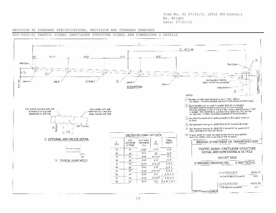
Item No. 01 07/21/11 (2012 SS)(contd.) Mr. Wright Date: 07/21/11 REVISION TO STANDARD SPECIFICATIONS, PROVISION AND STANDARD DRAWINGS 805-TSCS-01 TRAFFIC SIGNAL CANTILEVER STRUCTURE SIGNAL ARM DIMENSIONS & DETAILS
19
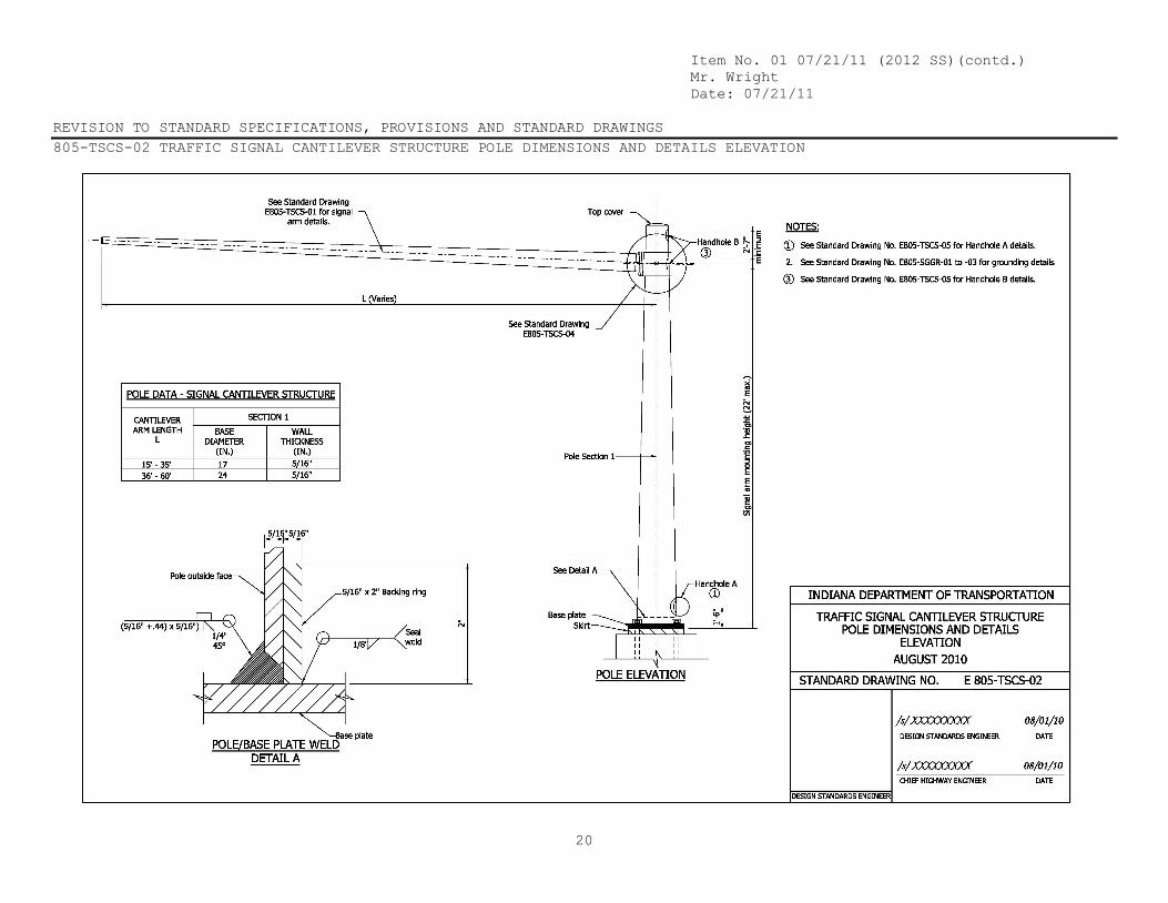
Item No. 01 07/21/11 (2012 SS)(contd.) Mr. Wright Date: 07/21/11 REVISION TO STANDARD SPECIFICATIONS, PROVISIONS AND STANDARD DRAWINGS 805-TSCS-02 TRAFFIC SIGNAL CANTILEVER STRUCTURE POLE DIMENSIONS AND DETAILS ELEVATION
20

Item No. 01 07/21/11 (2012 SS)(contd.) Mr. Wright Date: 07/21/11 REVISION TO STANDARD SPECIFICATIONS, PROVISIONS AND STANDARD DRAWINGS 805-TSCS-03 TRAFFIC SIGNAL CANTILEVER STRUCTURE BASE PLATE, BOTTOM SPLICE PLATE DETAILS
21
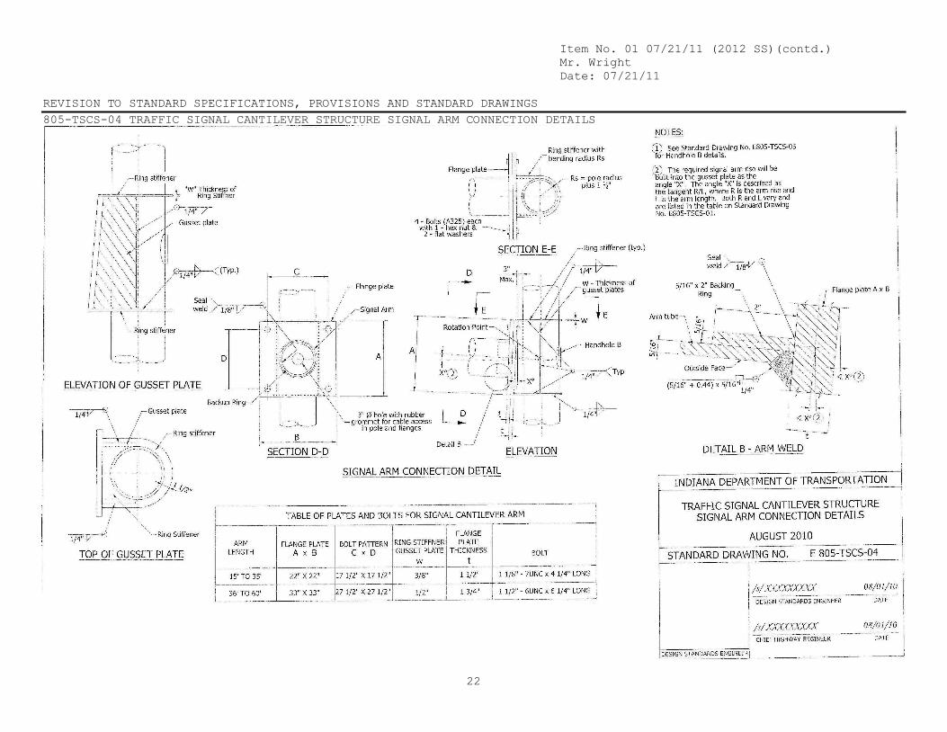
Item No. 01 07/21/11 (2012 SS)(contd.) Mr. Wright Date: 07/21/11 REVISION TO STANDARD SPECIFICATIONS, PROVISIONS AND STANDARD DRAWINGS 805-TSCS-04 TRAFFIC SIGNAL CANTILEVER STRUCTURE SIGNAL ARM CONNECTION DETAILS
22

Item No. 01 07/21/11 (2012 SS)(contd.) Mr. Wright Date: 07/21/11 REVISION TO STANDARD SPECIFICATIONS, PROVISIONS AND STANDARD DRAWINGS 805-TSCS-05 TRAFFIC SIGNAL CANTILEVER STRUCTURE HANDHOLE DETAILS
23
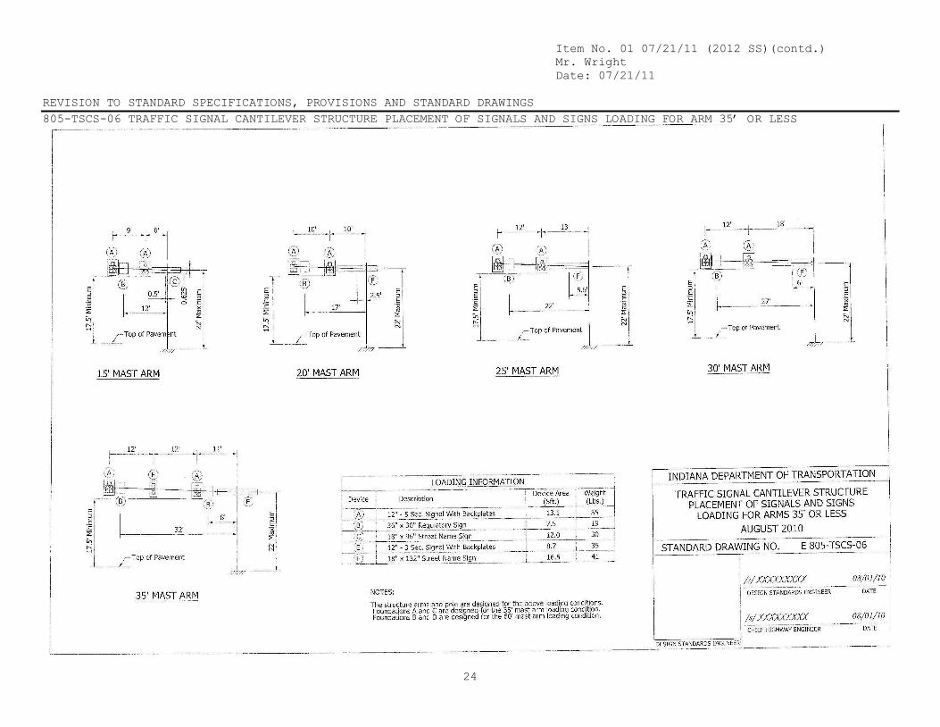
Item No. 01 07/21/11 (2012 SS)(contd.) Mr. Wright Date: 07/21/11 REVISION TO STANDARD SPECIFICATIONS, PROVISIONS AND STANDARD DRAWINGS 805-TSCS-06 TRAFFIC SIGNAL CANTILEVER STRUCTURE PLACEMENT OF SIGNALS AND SIGNS LOADING FOR ARM 35’ OR LESS
24

Item No. 01 07/21/11 (2012 SS)(contd.) Mr. Wright Date: 07/21/11 REVISION TO STANDARD SPECIFICATIONS, PROVISIONS AND STANDARD DRAWINGS 805-TSCS-07 TRAFFIC SIGNAL CANTILEVER STRUCTURE PLACEMENT OF SIGNALS AND SIGNS LOADING FOR ARMS > 35’ TO 60’
25

Item No. 01 07/21/11 (2012 SS)(contd.) Mr. Wright Date: 07/21/11 REVISION TO STANDARD SPECIFICATIONS, PROVISIONS AND STANDARD DRAWINGS 805-TSCS-08 TRAFFIC SIGNAL CANTILEVER STRUCTURE COMBINATION ARM DIMENSIONS & DETAILS
26
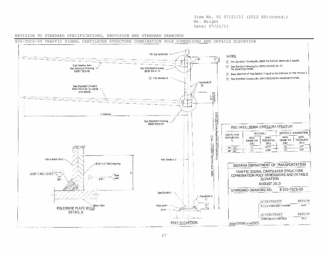
Item No. 01 07/21/11 (2012 SS)(contd.) Mr. Wright Date: 07/21/11 REVISION TO STANDARD SPECIFICATIONS, PROVISION AND STANDARD DRAWINGS 805-TSCS-09 TRAFFIC SIGNAL CANTILEVER STRUCTURE COMBINATION POLE DIMENSIONS AND DETAILS ELEVATION
27
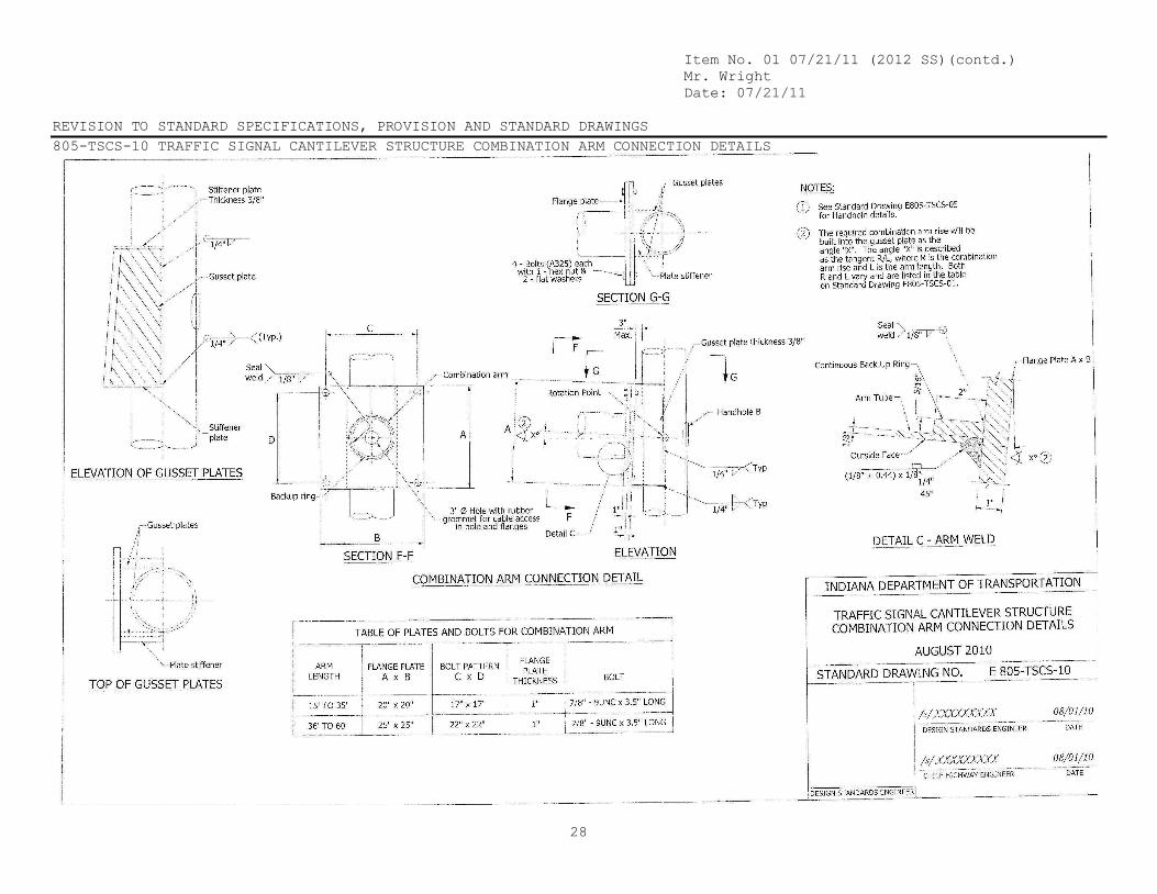
Item No. 01 07/21/11 (2012 SS)(contd.) Mr. Wright Date: 07/21/11 REVISION TO STANDARD SPECIFICATIONS, PROVISION AND STANDARD DRAWINGS 805-TSCS-10 TRAFFIC SIGNAL CANTILEVER STRUCTURE COMBINATION ARM CONNECTION DETAILS
28

Item No. 01 07/21/11 (2012 SS)(contd.) Mr. Wright Date: 07/21/11 REVISION TO STANDARD SPECIFICATIONS, PROVISION AND STANDARD DRAWINGS 805-TSCS-11 TRAFFIC SIGNAL CANTILEVER STRUCTURE COMBINATION POLE SPLICE DETAILS FOR ARMS 35’ OR LESS
29

Item No. 01 07/21/11 (2012 SS)(contd.) Mr. Wright Date: 07/21/11 REVISION TO STANDARD SPECIFICATIONS, PROVISION AND STANDARD DRAWINGS 805-TSCS-12 TRAFFIC SIGNAL CANTILEVER STRUCTURE COMBINATION POLE SPLICE DETAILS FOR ARMS > 35’ TO 60’
30
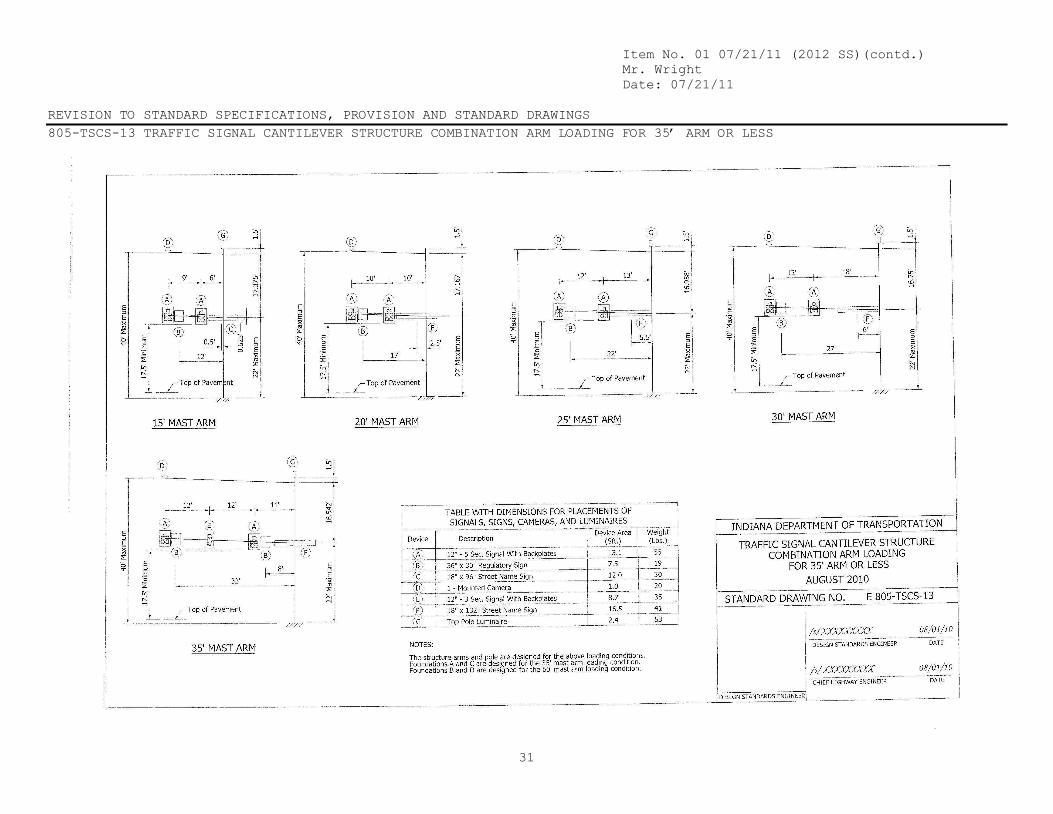
Item No. 01 07/21/11 (2012 SS)(contd.) Mr. Wright Date: 07/21/11 REVISION TO STANDARD SPECIFICATIONS, PROVISION AND STANDARD DRAWINGS 805-TSCS-13 TRAFFIC SIGNAL CANTILEVER STRUCTURE COMBINATION ARM LOADING FOR 35’ ARM OR LESS
31
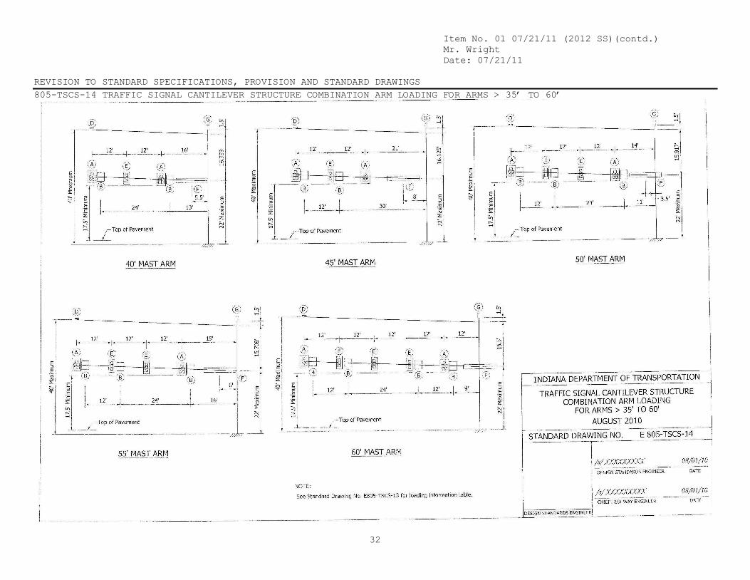
Item No. 01 07/21/11 (2012 SS)(contd.) Mr. Wright Date: 07/21/11 REVISION TO STANDARD SPECIFICATIONS, PROVISION AND STANDARD DRAWINGS 805-TSCS-14 TRAFFIC SIGNAL CANTILEVER STRUCTURE COMBINATION ARM LOADING FOR ARMS > 35’ TO 60’
32

Item No. 01 07/21/11 (2012 SS)(contd.) Mr. Wright Date: 07/21/11 REVISION TO STANDARD SPECIFICATIONS, PROVISION AND STANDARD DRAWINGS 805-TSCS-15 TRAFFIC SIGNAL CANTILEVER STRUCTURE DRILLED SHAFT FOR ARMS 35’ OR LESS TYPE A
33

Item No. 01 07/21/11 (2012 SS)(contd.) Mr. Wright Date: 07/21/11 REVISION TO STANDARD SPECIFICATIONS, PROVISION AND STANDARD DRAWINGS 805-TSCS-16 TRAFFIC SIGNAL CANTILEVER STRUCTURE DRILLED SHAFT FOR ARMS > 35’ TO 60’ TYPE B
34
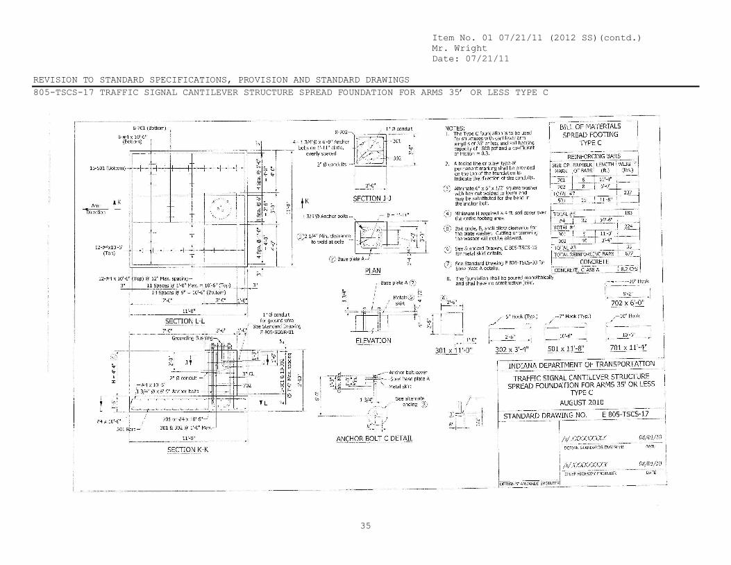
Item No. 01 07/21/11 (2012 SS)(contd.) Mr. Wright Date: 07/21/11 REVISION TO STANDARD SPECIFICATIONS, PROVISION AND STANDARD DRAWINGS 805-TSCS-17 TRAFFIC SIGNAL CANTILEVER STRUCTURE SPREAD FOUNDATION FOR ARMS 35’ OR LESS TYPE C
35

Item No. 01 07/21/11 (2012 SS)(contd.) Mr. Wright Date: 07/21/11 REVISION TO STANDARD SPECIFICATIONS, PROVISION AND STANDARD DRAWINGS
805-TSCS-18 TRAFFIC SIGNAL CANTILEVER STRUCTURE SPREAD FOUNDATION FOR ARMS > 35’ TO 60’ TYPE D
36

Item No. 01 07/21/11 (2012 SS) (contd.) Mr. Wright Date: 07/21/11 REVISION TO STANDARD SPECIFICATIONS, PROVISION AND STANDARD DRAWINGS
REVISION TO IDM CHAPTER 77-4.03 SIGNAL MOUNTING (DRAFT)
37
77-4.03 Signal Mounting
Under most circumstances, the Department’s preferred practice is to install the traffic signal using span, catenary and tether cables, or cantilever structures with poles on all four corners. Pedestrian signals are typically mounted on pedestals or poles. Pedestal or pole mounted supplemental signals may be used if there is a left-turn signal in a median or on the near side of the intersection if the intersection is significantly wide. Figures 77-4B, 77-4C, and 77-4D present the advantages and disadvantages of the post-mounted signal, cable-span signal mounting, and the cantilever signal mounting, respectively.
For span designs, steel strain poles are generally used. Steel strain poles provide greater strength, are easier to maintain and require less space. Wood poles require the use of down-guy cables and are generally limited to temporary installations.
All signal cantilever structures must be designed to meet the AASHTO Standard Specifications for Structural Supports for Highway Signs, Luminaires and Traffic Signals 2009, fifth edition.
For INDOT road projects, signal cantilever structures and its foundations should be according to the standard drawing series 805-TSCS-1 thru 18, Signal Cantilever Structures are designed to the loading conditions per Standard Drawings 805-TSCS-13 & 14. Refer to INDOT specification section 922.05 for any signal cantilever structure requiring special designs.
Overhead highway lighting may be provided, where warranted (see Section 78-2.0), at rural signalized intersections. The traffic signal span-support pole or the cantilever pole may be used for the overhead highway lighting. Figure 77-4E provides an illustration of a combination signal-luminaire pole. The INDOT Standard Specifications present the design criteria for this signal pole. INDOT typically does not use combination poles.
Item No.01 07/21/11 (2012 SS) (contd.) Mr. Wright Date: 07/21/11 COMMENTS AND ACTION 805.03 GENERAL REQUIREMENTS 805.04 POLE INSTALLATION 805.05 PLACING SIGNAL HEADS 805.13 FOUNDATIONS 805.15 METHOD OF MEASUREMENT 805.16 BASIS OF PAYMENT 922-T-168 TRAFFIC SIGNALS MATERIALS AND EQUIPMENT 805-TSCS-01 THRU -18 SIGNAL CANTILEVER STRUCTURES
38
Motion: Second: Ayes: Nays:
Action:
Passed as Submitted Passed as Revised Withdrawn
Standard Specifications Sections affected:
805.16 pg 745 (2012 SS) Recurring Special Provision affected:
805-T-169 TRAFFIC SIGNALS; 922-T-168 TRAFFIC SIGNALS MATERIALS
AND EQUIPMENT Standard Sheets affected:
NONE Design Manual Sections affected:
CHAPTER 77-4.03 GIFE Sections cross-references:
NONE
20 Standard Specifications Book Revise Pay Items List
Create RSP (No. ) Effective Letting RSP Sunset Date:
Revise RSP (No. ) Effective Letting RSP Sunset Date:
Standard Drawing Effective Create RPD (No. ) Effective Letting Technical Advisory
GIFE Update Req’d.? Y N By Addition or Revision
Frequency Manual Update Req’d? Y N By Addition or Revision
Received FHWA Approval?
Mr. Walker Date: 07/21/11
SPECIFICATION REVISIONS REVISION TO STANDARD SPECIFICATIONS
39
PROPOSAL TO STANDARDS COMMITTEE
PROBLEM(S) ENCOUNTERED: Tack coats are a problem when construction traffic tracks the material into the non-paving lanes. A tack coat that would not track would be very beneficial. AE-NT is a tack coat material that does not track and should be allowed as an alternative to to AE-T, AE-PMT, and SS-1h for tack coat applications. PROPOSED SOLUTION: Allow AE-NT to be an alternative to AE-T, AE-PMT, and SS-1h for tack coat applications. APPLICABLE STANDARD SPECIFICATIONS: 406 and 902 APPLICABLE STANDARD DRAWINGS: None APPLICABLE DESIGN MANUAL SECTION: Chapter 52 APPLICABLE SECTION OF GIFE: Section 13 APPLICABLE RECURRING SPECIAL PROVISIONS: Submitted By: Ron Walker Title: Manager, Office of Materials Management Organization: INDOT Phone Number: 317-610-7251 x 204 Date: 6-27-11 APPLICABLE SUB-COMMITTEE ENDORSEMENT?This specification revision is recommended by the INDOT/APAI Technical Committee.
Item No. 02 07/21/11 (2012 SS) Mr. Walker Date: 07/21/11 REVISION TO STANDARD SPECIFICATIONS SECTION 406 – TACK COAT 406.02 MATERIALS SECTION 507 – PCCP RESTORATION 507.05(b) PARTIAL DEPTH PATCHING
40
The Standards Specifications are revised as follows: SECTION 406, BEGIN LINE 9, INSERT AS FOLLOWS: 406.02 Materials The type and grade of asphalt material shall be in accordance with the following: Asphalt Emulsion, AE-T, AE-PMT, SS-1h, AE-NT ............................ 902.01(b) PG Asphalt Binder, PG 64-22 .............................................................. 902.01(a) SECTION 507, BEGIN LINE 107, INSERT AND DELETE AS FOLLOWS: (b) Partial Depth Patching Partial depth patching shall be constructed at locations shown on the plans. Existing joints directed to be patched partial depth, shall be milled to a depth of 3 in. (75 mm) the full width of the lane. The minimum length of milling is 6 in. (150 mm) beyond the map-cracked area. The milled area shall be cleaned of all loose material prior to patching. Cleaning shall be by blowing the milled areas with compressed air at a minimum pressure of 100 psi (690 kPa). When the milled areas are satisfactorily cleaned, the milled areas shall be tacked with AE-T asphalt material in accordance with 406 and patched with HMA.
Item No. 02 07/21/11 (2012 SS)(contd.) Mr. Walker Date: 07/21/11 REVISION TO STANDARD SPECIFICATIONS SECTION 902 – ASPHALT MATERIALS 902.01(b) ASPHALT EMULSIONS
41
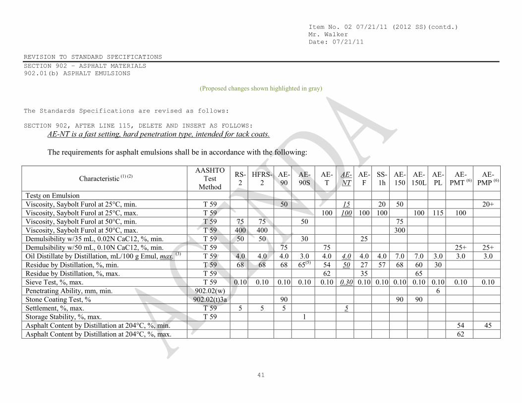
(Proposed changes shown highlighted in gray) The Standards Specifications are revised as follows: SECTION 902, AFTER LINE 115, DELETE AND INSERT AS FOLLOWS: AE-NT is a fast setting, hard penetration type, intended for tack coats. The requirements for asphalt emulsions shall be in accordance with the following:
Characteristic (1) (2) AASHTO
Test Method
RS- 2
HFRS- 2
AE- 90
AE- 90S
AE- T
AE- NT
AE- F
SS- 1h
AE- 150
AE- 150L
AE- PL
AE- PMT (6)
AE- PMP (6)
Tests on Emulsion Viscosity, Saybolt Furol at 25°C, min. T 59 50 15 20 50 20+ Viscosity, Saybolt Furol at 25°C, max. T 59 100 100 100 100 100 115 100 Viscosity, Saybolt Furol at 50°C, min. T 59 75 75 50 75 Viscosity, Saybolt Furol at 50°C, max. T 59 400 400 300 Demulsibility w/35 mL, 0.02N CaC12, %, min. T 59 50 50 30 25 Demulsibility w/50 mL, 0.10N CaC12, %, min. T 59 75 75 25+ 25+ Oil Distillate by Distillation, mL/100 g Emul, max. (3) T 59 4.0 4.0 4.0 3.0 4.0 4.0 4.0 4.0 7.0 7.0 3.0 3.0 3.0 Residue by Distillation, %, min. T 59 68 68 68 65(5) 54 50 27 57 68 60 30 Residue by Distillation, %, max. T 59 62 35 65 Sieve Test, %, max. T 59 0.10 0.10 0.10 0.10 0.10 0.30 0.10 0.10 0.10 0.10 0.10 0.10 0.10 Penetrating Ability, mm, min. 902.02(w) 6 Stone Coating Test, % 902.02(t)3a 90 90 90 Settlement, %, max. T 59 5 5 5 5 Storage Stability, %, max. T 59 1 Asphalt Content by Distillation at 204°C, %, min. 54 45 Asphalt Content by Distillation at 204°C, %, max. 62

Item No. 02 07/21/11 (2012 SS)(contd.) Mr. Walker Date: 07/21/11 REVISION TO STANDARD SPECIFICATIONS SECTION 902 – ASPHALT MATERIALS 902.01(b) ASPHALT EMULSIONS (CONTINUED)
42
Tests on Residue Penetration (0.1 mm) at 25°C, 100g, 5 s, min. (4) T 49 100 100 100 90 50 40 40 50 300+ Penetration (0.1 mm) at 25°C, 100g, 5 s, max. (4) T 49 200 200 200 150 200 40 90 90 200 Penetration (0.1 mm) at 25°C, 50g, 5 s, min. (4) T 49 100 100 Penetration (0.1 mm) at 25°C, 50g, 5 s, max. (4) T 49 300 300 Ductility at 25°C, mm, min. T 51 400 400 400 400 400 Solubility in Org. Sol., %, min. T 44 97.5 97.5 97.5 97.5 97.5 97.5 97.5 97.5 97.5 97.5 97.5 97.5 97.5 Float Test at 50°C, s, max. (4) T 50 Float Test at 60°C, s, min. (4) T 50 1200 1200 1200 1200 1200 1200 Force Ratio T 300 0.3 Elastic Recovery, at 4°C T 301 58 Polymer Content by Infrared 1.5+ 1.5+ Notes: (1) Broken samples or samples more than 10 days old will not be tested. (2) Combined percentage of the residue and oil distillate by distillation shall be at least 70% (note the different units – ml for oil and % for residue). (3) Oil distillate shall be in accordance with ASTM D 396, table 1, grade no. 1 (4) The Engineer may waive the test. (5) Maximum temperature to be held for 15 minutes at 200 ± 5°C. (6) Asphalt shall be polymerized prior to emulsification.
Item No. 02 07/21/11 (2012 SS)(contd.) Mr. Walker Date: 07/21/11 COMMENTS AND ACTION 406.02 MATERIALS 507.05(b) PARTIAL DEPTH PATCHING 902.01(b) ASPHALT EMULSIONS
43
Motion: Second: Ayes: Nays:
Action:
Passed as Submitted Passed as Revised Withdrawn
Standard Specifications Sections affected:
406.02 pg 272; 507.05(b) pg 345; 902.01 pg 804, pg 805.
Recurring Special Provision affected:
NONE
Standard Sheets affected:
NONE
Design Manual Sections affected:
NONE
GIFE Sections cross-references:
NONE
20 Standard Specifications Book Revise Pay Items List
Create RSP (No. ) Effective Letting RSP Sunset Date:
Revise RSP (No. ) Effective Letting RSP Sunset Date:
Standard Drawing Effective Create RPD (No. ) Effective Letting Technical Advisory
GIFE Update Req’d.? Y N By Addition or Revision
Frequency Manual Update Req’d? Y N By Addition or Revision
Received FHWA Approval?

![[2006] 675 IAC 13 Building Codes - IN.gov](https://static.fdokumen.com/doc/165x107/63203c7fb71aaa142a03b871/2006-675-iac-13-building-codes-ingov.jpg)