AFRISO Catalogue Domestic Technology 2015/16
424
15 / 16 Catalogue Domestic Technology
-
Upload
khangminh22 -
Category
Documents
-
view
5 -
download
0
Transcript of AFRISO Catalogue Domestic Technology 2015/16

Do
me
sti
c t
ec
hn
olo
gy
15/1
6CatalogueDomestic Technology
HEATING SYSTEM ACCESSORIESTANK EQUIPMENT
ALARM UNITS
WATER TECHNOLOGYBUILDING AUTOMATION
Technology for environmental protectionMeasuring. Controlling. Monitoring.
AFRISO-EURO-INDEX GmbHLindenstraße 2074363 GüglingenGermany
Phone +49 7135 102-0Fax +49 7135 102-147
15/1
6
05/1
5/en

We would be pleased to help you with any questions you may have. You can reach your contact person on +49 7135 102-
Division I Tank. Heating. Water Technology.North -121Centre -169South -124Export -125
Division II Pressure. Temperature. Level.North -138 or -101Centre -215South -101 or -235Export -207
Division III Gas analysis. Special applications.Germany -131Export -166
Service and repairsHotline -211
www.afriso.com/contact
The catalogue has been presented by:

Dear business partner
Whether you are looking for products for groundwater protection, flue gas monitoring or industrial measuring and control technology solutions for process engineering – the AFRISO range provides proven, competitively priced series products.
To make sure that you will find "your" product even faster and more conveniently, we have split the AFRISO complete catalogue into three individual catalogues:
The catalogue DOMESTIC TECHNOLOGY covers all products for safety and measuring equipment for heating systems, solutions for energy saving and rain-water harvesting as well as alarm units and smart building systems for wireless building automation.
The catalogue INDUSTRIAL TECHNOLOGY comprises the complete range of high-quality measuring instruments and system solutions for pressure, tempe-rature and level as well as customised, industrial solutions for stationary gas analysis – for your specific industrial application.
The catalogue PORTABLE MEASURING INSTRUMENTS covers certified mobile service measuring instruments for flue gas analysis as well as testing and ins-pection equipment for maintenance and diagnostics.
In addition, we develop and manufacture complex customised products as well as complete system solutions – precisely to your specifications. Going against the general trend, we insist on a high degree of vertical manufacturing integra-tion from our own tool design and construction department all the way to fully automatic assembly machines for electronic components. This makes us fast, flexible and independent.
For us, globalisation is an opportunity to market our products – manufactured in Germany and Europe – on a global scale.
As a medium sized company, we place particular importance on personal con-tact with you. There are many factors that set AFRISO apart from others – one of them is the people who make up the company. Competent experts provide you with optimum solutions – both technically and economically. And whenever you need it, a well trained team of service experts is at your disposal.
We look forward to a successful cooperation.
Best regards
Matthias BlasingerManaging Director SalesAFRISO-EURO-INDEX GmbH

Smart Building System: Alarm units and sensors withEnOcean® wireless technology for building automation
Equipment for fuel oil storage tanks and oil-carrying pipes
Equipment for heating systems, boiler rooms and chimneys
Equipment for drinking water supply and rainwater harvesting
Pressure measuring instruments (pressure gauges)
Temperature measuring instruments (thermometers)
Valves and control technology for radiators and hydraulic balancing
Appendix – Technical Information
Level indicators and level controllers
Overfill alarm systems, overfill prevention systems and PTC thermistor level controllers
Leak detectors, leak monitoring systems, inner tank linings and alarm units
Alarm units, signalling devices
How to work with this catalogue
AFRISO at a glance
From page IV
From page VIII
From page 356
From page 391
Overview portable measuring instruments (BlueLine series)
Index
From page 3
From page 23
From page 47
From page 69
From page 97
From page 125
From page 153
From page 273
From page 295
From page 323
From page 219
From page 359

Smart Building System: Alarm units and sensors withEnOcean® wireless technology for building automation
Equipment for fuel oil storage tanks and oil-carrying pipes
Equipment for heating systems, boiler rooms and chimneys
Equipment for drinking water supply and rainwater harvesting
Pressure measuring instruments (pressure gauges)
Temperature measuring instruments (thermometers)
Valves and control technology for radiators and hydraulic balancing
Appendix – Technical Information
Level indicators and level controllers
Overfill alarm systems, overfill prevention systems and PTC thermistor level controllers
Leak detectors, leak monitoring systems, inner tank linings and alarm units
Alarm units, signalling devices
Contents and Product Range
1
2
3
4
5
6
7
9
10
11
8
12
Level – Continuous: Mechanical, pneumatic, hydrostaticLevel – Switches: Float
Valves and control technology for hydraulic balancing: Valve bodies with measuring/adjustment function, lockshield valves, combination blocks, screw fittings with measuring function, fittings with measuring function and line fittings, calculation softwareValves and control technology for radiators: Valve bodies, lockshield valves, combination blocks, thermostat control heads
Bimetal thermometers and gas filled thermometers, industrial thermometers, thermometers/pressure gauges with plastic or copper capil-lary tube, thermostats, safety temperature cut outs, safety temperature switches, thermostats with housing, resistance thermometers
Pressure reducers, water filters, domestic water system centre, check valves, strainers, boiler safety group assemblies, safety valves, signal anodes, sacrificial anodes, rainwater system centre, oil tank conversion kits, inner linings for rainwater tanks, rainwater filters, accessories for rainwater harvesting, backup controller for rainwater storage tanks
Mounting accessories, tank fittings, overpressure devices, tank withdrawal systems, anti-siphon valves, pull cord, screw connections, fuel oil filters, filter inserts, automatic fuel oil de-aerators
AFRISO WATCHDOG alarm units, leak detectors with probes (PTC thermistor, photoelectric, conductivity), drip pans, inner linings for fuel oil/diesel/rainwater/liquid fertiliser/AHL/AdBlue®, tank room linings, gas alarm units for households, domestic, building and industrial applications, gas alarm units in DIN rail housings, gas sensors, test gas units, gas and smoke detectors
Level sensor chain for battery tank facilities, PTC thermistor level sensors for indoor tanks, PTC thermistor level sensors for outdoor tanks, EX-protected PTC thermistor level sensors, overfill prevention systems with EX and WHG approval, level controllers
Bourdon tube pressure gauges, pressure gauges with capillary tube, combined thermometer/pressure gauges, differential pressure gauges, accessories for pressure gauges
Motorised boiler room vents, draft stabilisers, boiler water low level alarms, thermal safety valves, boiler safety group assemblies, safety valves, connection assemblies for expansion vessels, anti-tamper cap valves, flow meters, mixing valves, heating pump assemblies, solar pump assemblies, bypass valves, air/sludge separators, filling fittings, quick air vents, heating controllers, manifold systems for heating systems, thermal actuators
Water valve, water sensors, water meters, single room temperature controller, room temperature sensors, wireless transmitters for temperature/humidity, actuators for radiators, CO2 sensors, rocker switches, presence detector, door/window contact, wireless plug-in socket, relay, wireless gateway
Leak detectors - sight glass principle, leak detectors for systems with liquid in the interstitial space, vacuum/pressure based leak detectors
AFRISO service, training, VDI 3805, specialised company search, checklists for enquiries, conversion table for pressure units, selection criteria for pressure gauges, information on the Pressure Equipment Directive, information on flanges and materials, information on EN 50379, certificates, Terms and Conditions

Table of ContentsOur product range covers measuring, control and monitoring technology for domestic, industrial and environmental applica-tions.This includes products for groundwater protection, flue gas moni-toring, efficient use of energy, use of the sun, geothermal and rain as well as a complete range of pressure, temperature and level instruments.In addition to the products presented in the catalogues, we manu-facture special versions to customer specifications. Please enquire.
Finding informationThe catalogue DOMESTIC TECHNOLOGY is divided into 16 chap-ters. A chapter overview is provided on pages II and III. The blue chapter tabs on the side of the page let you easily find the desired chapter. Each chapter contains a detailed table of contents as well as an overview table and the main features of the products in that chapter to help you find the product page you need fast.To find products, you can also use the comprehensive index in the appendix.Usually, all information on a product is contained on one page and cross references guide you to other pages for fast and easy access to additional information such as fact sheets.
EnquiriesTo make enquiries as simple as possible and to assist you in gath-ering all the necessary information, the appendix contains a num-ber of checklists for enquiries, e.g. for pressure gauges, thermom-eters and level indicators.
Divisions / Contact personsOur sales department is divided into three different divisions. You can find the division in charge of a given product on the corre-sponding catalogue page.
Delivery times / stock itemsAll stock items have part numbers printed in blue in the price lists.Please enquire for the delivery times of non-stock items as they vary greatly depending on the product specifications.
Minimum order quantities / packing unitsMany products can be manufactured in small quantities – in many cases, you may even order a single piece.However, for some items there are minimum ordering quantities or packing units. The price list sections provide the appropriate information.
The product package contains the specified number of products or can be delivered in the specified order quantity
An additional package contains the specified number of products
Small order handling fee / minimum order valueFor very small orders with net values below € 75 a handling fee of € 15 will be charged. No other minimum order conditions apply.
Return of goodsGoods can only be returned after prior approval by us and only up to 3 months after delivery. Please note that only standard stock items can be returned; products not available from stock and devices with ATEX approval cannot be returned. For returned stock items we charge 30 % of the price for testing and handling or at least € 40.00. Shipping costs for returns are to be borne by the customer.
Prices / terms of deliveryPlease refer to your local AFRISO representation or get in touch with the AFRISO headquarters for detailed price information and conditions.Our Terms and Conditions apply (see www.afriso.com).This catalogue supersedes all previous versions, including previ-ous prices. All prices subject to change; the catalogue may con-tain printing errors.
Technical modificationsAs we are constantly improving our products, we reserve the right to technical modifications without prior notice.
How to work with this catalogue
CopyrightCopyright 2015 by AFRISO-EURO-INDEX GmbH.No part of the catalogue may be reproduced, copied, distributed, translated or in any other way processed without prior written approval of AFRISO-EURO-INDEX GmbH.
IV www.afriso.com

AFRISO quality productsAFRISO quality products are continuously being enhanced and are subject to stringent inspections. Quality labels, approvals and certificates designate special features and application areas of our prod-ucts. For certificates and manufacturer's declarations, please refer to chapter 12 or the Downloads > Certificates section of www.afriso.com.
All products with the quality label PROOFED BARRIER® are odour-tight. The quality label is awarded by the Fraunhofer-Institut (IVV) in Freising, Germany, exclusively for components that have passed stringent initial and repeat tests.
The Bio-Oil label certifies chemical resistance and guarantees full performance and functionality of the products even if biodiesel, biofuel or additives are used. The percentage shown corresponds to the maximum permissible admixture.
In flood hazard areas, oil must be kept from escaping from oil tank systems as a result of buoyancy, flooding or damage due to floating refuse. All AFRISO products with the label "flood water proof" meet this requirement. See the individual catalogue pages for details on flood water resistance. After a flood, the information provided in the operating instructions must be observed.
Solar components by AFRISO allow for effective use of thermal solar systems in domestic technology. All labelled products are universally applicable and tuned to each other.
The DVGW is the German technical and scientific association for gas and water. The association is concerned with technical and scientific aspects of the supply of gas and water, implements results in the form of the national German DVGW rules and also contributes to DIN, EN and ISO standards. AFRISO products bearing the DVGW label have been tested and approved in compliance with the strict safety requirements of the DVGW.
The PED (Pressure Equipment Directive 97/23/EC) specifies the requirements for selling pressure equipment within the European Economic Area. Please refer to chapters 10–11 for further details on our mechanical and electronic pressure gauges.
The European Ecodesign Directive covers Energy-related Products (ErP). It went into force in August 2007 and was implemented in the EU member states as separate legislation. This directive is geared towards increased energy efficiency of electronic equipment in order to reduce the negative impact on the environment, such as CO2 emission. ErP-Ready means that the electronic equipment bearing this logo complies with this directive.
PED
Vwww.afriso.com

396 397
Mounting accessories for inner linings 63
Mounting kits for
Fuel oil tank contents gauges 10–11
LAG 53
LAS 50
Water tank contents gauge 8
Mounting valves for quick air vents 166
MS, MSM 168
MSW 276
MT-Profil R 7
N
NB 220 H/QS 42
O
Oil alarm unit OM 5 77
Oil filter spanners 151
Oil filters 140–141
Oil tank conversion kits for rainwater 290
Oil vents 143–150
Oil withdrawal systems 130–132
Oil-on-water detector ÖAWD-1/-8 79
Oil/water alarm unit ÖWU 78
Oil/water alarm unit ÖWWG 3 75
Oil/water alarm unit with burner connection kit 76
Open end spanner for replaceable filter 151
Opticlean ultra-fine filters 140, 142
Optimum filters 140
Overfill prevention systems 41–44
Overpressure device 63, 128
Overpressure safety device 316
P
Paper filters Opticlean 140, 142
Photoelectric probe 89
Pipe for dipstick 6
Piston type anti-siphon KAV 135
Plastic dipsticks 6
Plastic inner linings 59–62
Plastic manhole cover 290
Plastic quick air vents 167
Plug-in socket, wireless 116
Plugs 33, 128–129
Pneumatic level indicators 8–13
Pneumofix 10
Pockets for thermometers 349
Presence detector APD 10 114
Pressure compensation unit DAE 133
Pressure gauge accessories 314–318
Pressure gauges
Heating system 301–303
Overpressure safety device 316
Pressure gauges with capillary tube 304–307
Pressure gauges with capillary tube 304–307
Push-button stop cock 316
Shut-off cocks and valves 314
Pressure gauges for heating installations 301–303
Pressure indicator 151
Pressure type leak detector Europress (LAD-R) 66
Pressure type leak detectors 65–66
PrimoSol® – accessories 200–201
PrimoSol® – solar pump assemblies 197–199
PrimoTherm® – heating pump assemblies 181–196
Probes
Conductivity 88
Float 30, 88
Floor water 88
For alarm units 87–89
Hydrostatic 14–16
Level 17
Appendix Index
Photoelectric 89
PTC thermistor 45, 89
RENA 292
Wall rail 88
WMS 159
ProCalida® 215–217
Protective sleeve, metallised 30
PTC thermistor probe 89
Pull cord 133
Pump assemblies PrimoSol® 197–199
Pump assemblies PrimoTherm® 181–196
Pump assembly for increasing the return temperature
187, 189, 195
Push-button stop cock 316
Q
Quick air vents 166, 167
Quick air vents for solar systems 200
R
Radiator control head, wireless 109, 110
Radiator lockshield valves 240–245
Radiator valves 231–255
Radio remote alarm unit WGL 01 W 82
Radio-controlled water valve WaterControl 01 100
Rainwater harvesting accessories 286–292
Rainwater lining AR-SM 62
Rainwater system centre RWSC 288
Reducers for
Level indicators 10
Level sensors 33
Relay, wireless 117
Relay, wireless 117
RENA – backup controller 292
Repeaters 116–117
Replaceable filter adapter 151
Resistance thermometers 352–354
Rocker switch, wireless 113
Room controller 204–211
Room temperature sensor D – wired 212
Room temperature sensors FT/FTF – wireless 107
RWSC 288
S
Sacrificial anodes 278
Safety group assembly 161–162
Safety group assembly for boilers 277
Safety valves 168, 276
Screw connections 151
Screw fittings with measuring function Q 266
Sealing kit (IP 54) 53, 90
Service instruments 356–357
SFW solar liquid monitor 202
Shut-off cocks for pressure gauges 314
Shut-off valves for pressure gauges 314
Signal anodes U 278
Signalling devices 91–92
Single room temperature controller CosiTherm® 204–211
Single room temperature controller, wireless 104
Single-line filters for fuel oil 140–141
Sintered plastic sieves 139, 142
Siphons 317
Sludge separator 172
Smart building system AFRISOLab 98
Smoke detector GRM 86
Smoke sensors for GRM 87
AppendixIndex
12 12
How to work with this catalogue
AFRISO catalogue DOMESTIC TECHNOLOGY: Clear structure and layout
Clear user guidance Detailed tables of contents Overview tables with product features
Easy-to-find tabs Everything at a glance
153
CHAPTER 7
Pump assemblies for heating and solar thermal systems
Motorised boiler room vent
Boiler safety group assemblies
Safety equipmentfor heating systems
Equipment for heating systems, boiler rooms and chimneys
Equipment for safe operation of heating systems 154
OVERVIEW
SUPPLY AND EXHAUST AIR
Motorised boiler room vent Air-Control 156
Draft stabiliser WZB-1 157
Flow meters DFM 10-1M, 15-2M, 20-2M 174
FLOW MEASUREMENT
3-way/4-way mixing valves ARV 177
Boiler manifolds KSV 180
Heating pump assembly PrimoTherm® 180-1/2 DN 25 183
Heating pump assembly PrimoTherm® 180-3 DN 25 for increased return temperature 187
Actuators ARM 179
Pump assemblies PrimoTherm® 180 DN 25/DN 32 182
Charging unit RTA 60 DN 25 189
Heating pump assembly PrimoTherm® 180-1/2 DN 32 191
Heating pump assembly PrimoTherm® 180-3 DN 32 RTA 195
HEATING PUMP ASSEMBLIES
Solar pump assemblies PrimoSol® 130 198
Quick air vents for solar systems, air separators 201
Solar controller SolarControl® SC 10 203
filling and flushing unit, diaphragm safety valve MSS, connection kit 200
SOLAR THERMAL/SOLAR PUMP ASSEMBLIES
Single room temperature controller CosiTherm® - wired 206
Single room temperature controller CosiTherm® - wireless 209
Single room temperature controllers CosiTherm® 204
Room temperature sensor D - wired 212
Room temperature sensor F - wireless 213
SINGLE ROOM CONTROLLER
Quick air vents 166
Diaphragm safety valves MS, MSM 168
Differential pressure bypass valve DÜ 169
Air separators 171
Sludge separator 172
Flow filters, combined air/flow filters 173
Boiler water low level alarms WMS 158
Thermal safety valve TAS 03 160
Combustion controller FR 1 160
Boiler safety group assemblies KSG 161
Connection assembly for expansion vessel GAK 163
Anti-tamper cap valves 165
Boiler filling and drain valves KFE, filling fittings FA, FAM 170
SAFETY EQUIPMENT
Geothermal manifold ProCalida® GT , Drinking water manifold 217
Heating circuit manifolds ProCalida® MC, EF, VA, IN 216
MANIFOLD SYSTEMS
Thermal actuators TSA-02/03 214
Collector tank for solar liquid, solar liquid monitor SFW 202
7
54
Level Overview
Technical specifications, application areas and suitability depend on the product version. See catalogue data sheet and/or operating instructions for options and details.
i
Overview
Level indicators at a glance
Dipstick MT- Profil R Unimes Unitel Unitop DTA 10 DIT 10 Tank
Control CoFox® ELT CapFox®
EFT 7CapFox®
ENT 7PulsFox® PMG 10
Sonar Fox®
UST 10HydroFox® DMU 08 DMU 09 VibraFox®
GVGCoFox®
CMG 01MagFox® MMG 01
Indoor tanks
Tank
s
• • • • • • • • • • • • • • • • • •
Outdoor tanks • • • • • • • • • • • • • • • •
Electrically isolating tanks • • • • • • • • • • • • • • • • •
Electrically conductive tanks • • • • • • • • • • • • • • • • • •
Pressurised tanks • • • • • •
Unpressurised tanks • • • • • • • • • • • • • • • • • •
< 1,000 mm
Mea
suri
ng r
ang
e • • • • • • • • • • • • • •
Up to 2,000 mm • • • • • • • • • • • • • • • • •
Up to 2,500 mm • • • • • • • • • • • • • • • •
Up to 2,900 mm • • • • • • • • • • • • • • •
Up to 3,000 mm • • • • • • • • • • • • • •
> 3,000 mm • • • • • • • • • • •
Liquid media
Gen
eral
med
ia • • • • • • • • • • • • • • • • • •
Solid media (bulk solids) • •
Powdery media • •
Electrically isolating media • • • • • • • • • • • • • • • •
Electrically conductive media • • • • • • • • • • • • • • • •
Fuel oil/diesel fuel (EN 590)
Sp
ecia
l med
ia • • • • • • • • • • • • • • • •
Biofuel/ biodiesel (EN 14214) • • • • • • • • • • • • • • • •
Water • • • • • • • • • • • • • • • • •
AdBlue® • • • • • • • • •
Measuring principle
Des
ign
Mechanical Mechanical Mechanical Pneumatic Pneumatic Pneumatic Hydrostatic Hydrostatic Conductive Capacitance Capacitance Guided micro-pulse (TDR) Ultrasonic Hydrostatic Hydrostatic Vibration fork Potentiometric Magneto-
strictive
Local display • • • • • • • • • • •
Limit level • • • • • •
Continuous measurement • • • • • • • • • • • • • •
Analogue output (4–20 mA, 0–10 V)
Ind
icat
ion
/sig
nal
• • • • • • •
Binary output (relay, PNP) • • • • •
% liquid level • • • • • •
% volume • • • • • •
Liquid level in cm • • • • • •
Liquid level in mm • • • •
Litres • • • • • • •
m3 • • • •
Technical Approval of the German Institute for Civil Engineering (DIBt) (WHG)
Certificates
•
ATEX •
Display unit DA 10/12/14
Co
ntr
ol u
nit • • • • • • •
Display and control unit VarioFox® 12/14 • • • • • • •
Transducer MFU • • • • • • •
Page 6 Page 7 Page 7 Page 8 Page 9 Page 13 Page 14 Page 15 Page 298 Page 285 Page 303 Page 289 Page 286 Page 284 Page 229 Page 305 Page 296 Page 297
Level
1 1
Smart Building System: Alarm units and sensors withEnOcean® wireless technology for building automation
Equipment for fuel oil storage tanks and oil-carrying pipes
Equipment for heating systems, boiler rooms and chimneys
Equipment for drinking water supply and rainwater harvesting
Pressure measuring instruments (pressure gauges)
Temperature measuring instruments (thermometers)
Valves and control technology for radiators and hydraulic balancing
Appendix – Technical Information
Level indicators and level controllers
Overfill alarm systems, overfill prevention systems and PTC thermistor level controllers
Leak detectors, leak monitoring systems, inner tank linings and alarm units
Alarm units, signalling devices
Contents and Product Range
1
2
3
4
5
6
7
9
10
11
8
12
How to work with this catalogue
AFRISO at a glance
From page IV
From page VIII
From page 356
From page 391
Overview portable measuring instruments (BlueLine series)
Index
Level – Continuous: Mechanical, pneumatic, hydrostaticLevel – Switches: Float
Valves and control technology for hydraulic balancing: Valve bodies with measuring/adjustment function, lockshield valves, combination blocks, screw fittings with measuring function, fittings with measuring function and line fittings, calculation softwareValves and control technology for radiators: Valve bodies, lockshield valves, combination blocks, thermostat control heads
Bimetal thermometers and gas filled thermometers, industrial thermometers, thermometers/pressure gauges with plastic or copper capil-lary tube, thermostats, safety temperature cut outs, safety temperature switches, thermostats with housing, resistance thermometers
Pressure reducers, water filters, domestic water system centre, check valves, strainers, boiler safety group assemblies, safety valves, signal anodes, sacrificial anodes, rainwater system centre, oil tank conversion kits, inner linings for rainwater tanks, rainwater filters, accessories for rainwater harvesting, backup controller for rainwater storage tanks
Mounting accessories, tank fittings, overpressure devices, tank withdrawal systems, anti-siphon valves, pull cord, screw connections, fuel oil filters, filter inserts, automatic fuel oil de-aerators
AFRISO WATCHDOG alarm units, leak detectors with probes (PTC thermistor, photoelectric, conductivity), drip pans, inner linings for fuel oil/diesel/rainwater/liquid fertiliser/AHL/AdBlue®, tank room linings, gas alarm units for households, domestic, building and industrial applications, gas alarm units in DIN rail housings, gas sensors, test gas units, gas and smoke detectors
Level sensor chain for battery tank facilities, PTC thermistor level sensors for indoor tanks, PTC thermistor level sensors for outdoor tanks, EX-protected PTC thermistor level sensors, overfill prevention systems with EX and WHG approval, level controllers
Bourdon tube pressure gauges, pressure gauges with capillary tube, combined thermometer/pressure gauges, differential pressure gauges, accessories for pressure gauges
Motorised boiler room vents, draft stabilisers, boiler water low level alarms, thermal safety valves, boiler safety group assemblies, safety valves, connection assemblies for expansion vessels, anti-tamper cap valves, flow meters, mixing valves, heating pump assemblies, solar pump assemblies, bypass valves, air/sludge separators, filling fittings, quick air vents, heating controllers, manifold systems for heating systems, thermal actuators
Water valve, water sensors, water meters, single room temperature controller, room temperature sensors, wireless transmitters for temperature/humidity, actuators for radiators, CO2 sensors, rocker switches, presence detector, door/window contact, wireless plug-in socket, relay, wireless gateway
Leak detectors - sight glass principle, leak detectors for systems with liquid in the interstitial space, vacuum/pressure based leak detectors
AFRISO service, training, VDI 3805, specialised company search, checklists for enquiries, conversion table for pressure units, selection criteria for pressure gauges, information on the Pressure Equipment Directive, information on flanges and materials, information on EN 50379, certificates, Terms and Conditions
From page 3
From page 23
From page 47
From page 69
From page 97
From page 125
From page 153
From page 273
From page 295
From page 323
From page 219
From page 359
Table of contentswith tabs to go to the chapter.
Overview tableto help you make your selection with comparison of product features.
Index
Chapter table of contentswith navigation bar to go directly to the product.
Find the desired product fast:
VI www.afriso.com

Continuous
Division I
Location-independent level measurement with digital display and minimum level signal (reserve level alarm) with a single measurement. Suitable for tanks up to 400 cm liquid level. For fuel oil EL, L or diesel fuel, FAME 100 % as biodiesel (EN 14214) and water (no drinking water!). In addition, DTA 10 can be used for level measurement with all non-corrosive liquids with a density from 0.5 to 1.5 g/cm3. Remote measurements up to 15 m.
The electro-pneumatic tank contents indicator DTA 10 consists of a battery-operated control unit with digital display and a measuring line. Measured values are displayed in litres, % and liquid level (cm). Simple operation and setup via three function keys. Measurements are requested by means of pressing the control key (Push-to-Read function). If the level falls below a minimum level that is freely adjustable as a percentage, the backlight of the display flashes red to indicate an alarm during the measurement. Standard tank shapes (linear, spherical, cylindrical and horizontal) are stored. Measuring line connec-tion for hose with 4 mm inside diameter.
Application
Description
FunctionsPush-to-Read level measurement
Measuring range (tank height)0/400 cm (fuel oil) 0/350 cm (water)
Measuring accuracy±1.0 cm
Operating temperature rangeAmbient: 0/50 °CStorage: -20/+65 °C Medium: 0/50 °C
DisplayMulti-coloured, backlit graphical display (30 x 50 mm). Blue = Operation Red = Alarm Green = Setup
Indication of litres (5 digits), % or liquid level in cm.
Measuring linePVC hose 4 x 1 mmLength 20 mBalance chamber stainless steel
Supply voltage9 V monobloc battery
Visual alarmBacklight flashes red during measurement process
HousingWall mounting housing made of impact-resistant plastic (ABS) W x H x D: 100 x 188 x 65 mm Degree of protection: IP 20 (EN 60529)
Scope of delivery Control unit 9 V monobloc battery 20 m measuring line with balance chamber Connection kit for G½, G1, G1½ and G2 25 x nail cable clips, 2 x hose clamps Hose adapter (4 mm) Mounting accessories
Technical specifications
Digital tank contents indicator DTA 10
Z A
DG: M, PG: 4 Part no. Price €
DTA 10 52145 179.00
For fuel oil EL, L, diesel fuel, biodiesel, water and other media with a density from 0.5 to 1,5 g/cm3
Universal application in tanks of a height of up to 4 m
Push-to-Read function: Fast start with just a push of a button
Page 130Page 10
A
Level
1
Bimetal standard thermometers/surface mount thermometers/flue gas thermometers
Heating, plumbing
Nominal size50 – 63 – 80 – 100
Measuring elementBimetal helix
Accuracy class2 (EN 13190)
Ranges °C-20/+60, 0/60, 0/120, 0/160
Application areaFull scale value
Operating pressure at ther-mowellMax. 6 bar
ConnectionStem plastic, brass or alumini-um, Ø 9 mm Thermowell G½B, brass, removable (160 °C and higher with locking screw)
Mounting positionNG 50 – 63 – 80 – 100 NG 63 – 80 – 100 bottom
DialUp to 120 °C plastic, greater than 160 °C aluminium, white Dial marking black
PointerPlastic, black
HousingSheet steel galvanised
Push on bezelSheet steel nickel-plated
WindowPlastic
Other ranges Nominal size 34, 160
Heating, ventilation and plumb-ing Fastening by means of spring (ATh Ø F), magnet (ATh Ø M) or universal clamp (ATh Ø S)
Nominal size63 – 80
Measuring elementBimetal spiral
Ranges °C0/60, 0/120
Application areaFull scale value
ConnectionATh F: With heat-conducting element and fastening spring; NG 63 also with universal clamp for pipes 3/8" to 1½". ATh M: 2 x magnet Ø 20 mm
Mounting positionNG 63 – 80 centre back
DialPlastic, white; dial marking black
PointerPlastic, black
HousingATh Ø F: Sheet steel, galvanised ATh Ø M: Plastic, black ATh Ø S: Sheet steel, galvanised
Push on bezelSheet steel nickel-plated
WindowPlastic
Other ranges Plastic housing
Flue gas thermometer RT and flue gas temperature controller RTC for gas and oil fired systems
Nominal size80
Measuring elementBimetal helix
Ranges °CRT: 0/300, 0/500RTC: 0/350
Application areaFull scale value
ConnectionRT: Stem stainless steel 316 L, plain, with adjustable cone, brassRTC: Stem stainless steel 316 L, plain, with ring magnet bracket
Mounting position: centre back
DialAluminium, grey – dial marking black; RTC with green and red reference zones
PointerAluminium, blackRTC with additional max. pointer
HousingSheet steel galvanised
Push on bezelSheet steel nickel-plated
WindowPlastic
Surface mount thermometers
RT / RTCBimetal standard thermometers
Application
Technical specifications
Standard version
OptionsiSee page 336 for prices.
Division II
Heating/plumbing Bimetal thermometers
11
Navigation bar organ-ised according to relevant selection criteria for fast orientation even when browsing through the cat-alogue.
Product advantages and main benefits
Quality labels provide information about special characteristics or application areas of products.
Clearly structured product descrip-tions, divided into application, descrip-tion and technical specifications.
Appropriate accessories with page reference.
Application examples provide a clear picture of the application and available options.
Order infor-mation table with part num-bers, prices and packing unit details plus options/extra charges.
The division provides information about which expert team in the sales and distribution depart-ment can give you more information on the prod-uct. See page V for their extensions.
Since the product range is so extensive, we only include the basic versions. Many other variations and versions are available and listed under Options.
The Info box provides you with important infor-mation, e.g. about order processing, cross references and much more.
Tab
VIIwww.afriso.com

AFRISO monitors, controls and protects the elements fire, water, earth and air – in the broadest sense. On the one hand, these ele-ments symbolically stand for the relief and protection of the envi-ronment – and on the other, they illustrate our fields of activity:
Flue gas control Energy savings Groundwater protection Conservation of resources
Product development revolves around our motto "Technology for Environmental Protection". We strive to improve the environment, to make processes which work with greater environmental com-patibility and to avoid putting a strain on the environment. With a balanced portfolio of innovations, proven products, systems and services, we offer our customers efficient solutions which are of great benefit.
AFRISO product programme.
Technology for environmental protection
With a comprehensive range of building technology products, AFRISO prides itself in "Making Heating Systems". Irrespective of whether the heating system uses regenerative energy or fossil fuels. In addition to this extensive range, a large selection of alarm instruments for the fast detection of level, liquid spillage, leakage, gas or smoke is available.
Mechanical/pneumatic level indicators
Overfill prevention systems/overfill alarm systems
Leak detectors/leak monitoring systems
Inner tank linings
Equipment for fuel oil storage tanks, oil carrying pipes, boiler rooms, boilers and heating systems
Heating controllers
Smart Building systems for building automation
Valves and control technology for radiators and hydraulic balancing
Distribution manifolds for heating, cooling and geothermal sys-tems
Equipment for drinking water supply / rainwater harvesting
The BlueLine series is the perfect solution for official measure-ments, adjustment, servicing, maintenance and repair work. You benefit from an optimally tuned range of measuring instruments which is continuously setting new standards – from basic devices all the way to portable all-in-one flue gas analysers. AFRISO offers gas analysers, gas sampling probes and turnkey analysis systems with data acquisition systems for continuous emission monitoring.
Portable gas analysers
Portable measuring instruments, analysers and testers
Gas alarm units
Stationary gas analysers
Emission measurement technology
Measurement data acquisition systems
Tank. Heating. Water Technology.
Gas analysis
VIII www.afriso.com
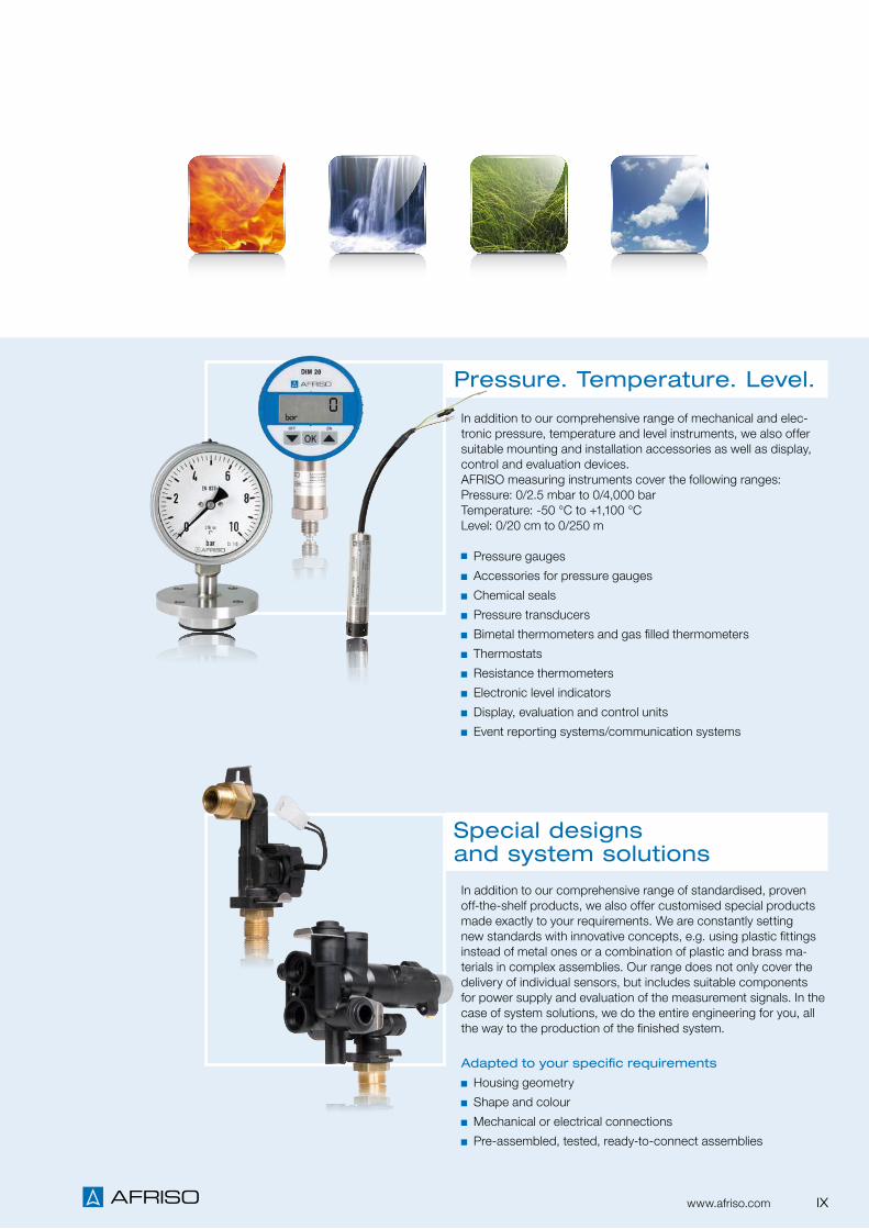
In addition to our comprehensive range of mechanical and elec-tronic pressure, temperature and level instruments, we also offer suitable mounting and installation accessories as well as display, control and evaluation devices.AFRISO measuring instruments cover the following ranges:Pressure: 0/2.5 mbar to 0/4,000 barTemperature: -50 °C to +1,100 °CLevel: 0/20 cm to 0/250 m
Pressure gauges
Accessories for pressure gauges
Chemical seals
Pressure transducers
Bimetal thermometers and gas filled thermometers
Thermostats
Resistance thermometers
Electronic level indicators
Display, evaluation and control units
Event reporting systems/communication systems
In addition to our comprehensive range of standardised, proven off-the-shelf products, we also offer customised special products made exactly to your requirements. We are constantly setting new standards with innovative concepts, e.g. using plastic fittings instead of metal ones or a combination of plastic and brass ma-terials in complex assemblies. Our range does not only cover the delivery of individual sensors, but includes suitable components for power supply and evaluation of the measurement signals. In the case of system solutions, we do the entire engineering for you, all the way to the production of the finished system.
Adapted to your specific requirements
Housing geometry
Shape and colour
Mechanical or electrical connections
Pre-assembled, tested, ready-to-connect assemblies
Pressure. Temperature. Level.
Special designs and system solutions
IXwww.afriso.com

Convincing solutions for a wide variety of applications.
We know your industry
The subject of saving energy has been our focus for more than
40 years. From the start, we have supported the move towards
geothermal and solar systems as well as the use of biogenous
fuels by supplying professional components and assemblies.
Our range for the secure storage of fuel oil and professional
equipment for heating systems reduces operating costs, helps
make optimum use of fuels, provides timely warnings if hazar-
dous situations arise and constitutes an active contribution to
environmental protection. Innovative measuring instruments for
flue gas analysis yield high-precision and reproducible results so
that your customers can achieve their goals: the right amount of
heat at the right time, low energy consumption and low emissi-
ons.
Target markets
Manufacturers of burners and boilers
Manufacturers of solar thermal systems
System supplier of underfloor heating systems
Manufacturers of chilled ceilings
Tank protection/revision
Tank manufacturers
Heating and plumbing system wholesalers
Technical trade/electrical wholesalers
Engineering and planning consultancies
Manufacturers of fittings
Chimney sweeps
Public institutions, municipalities
Building technology
AFRISO is at home wherever there is measuring, controlling or
monitoring required. As a full-range manufacturer, we offer our
customers a broad product portfolio from a single source. A
wealth of experience from numerous applications as well as our
knowledge of the requirements in the individual markets make us
a reliable partner in your industry. We know what is necessary as
X www.afriso.com

AFRISO products meet the requirements
Wide variety of process connections
Large selection of materials
Compact designs
Hygienic and easy to clean
Suitable for CIP and SIP
FDA-listed materials
Silicone-free versions
Resistant to corrosive and abrasive media
High overload safety
Resistant to vibration and temperature
Reliability, precision and a long service life are crucial when it
comes to highly automated processes. Our robust measuring
devices deliver perfect measurement results and reliably monitor
and control simple to highly complex processes – even under
the most adverse conditions. AFRISO solutions meet the perti-
nent directives and standards. Certificates, for example for food-
quality materials, explosion protection and resistance to media
and temperatures attest to this.
Target markets
Machines and plants
Tanks
Food and beverages industry
Chemical industry
Pharmaceutical industry
Cosmetics industry
Biotechnology
Refineries
Offshore industry
Mineral oil industry
Raw materials industry
Hydraulic and pneumatics (fluid engineering)
Medical technology, safety engineering
Energy production
Industrial technology
a result of our many years as a supplier in the OEM business and
our intensive contact with standardisation committees, associa-
tions and guilds. We tap our employees' know-how and expertise
in the industry to make our customers' processes simpler, safer
and more competitive. In process engineering, in building tech-
nology or facilities – you benefit with a strong partner at your side.
XIwww.afriso.com
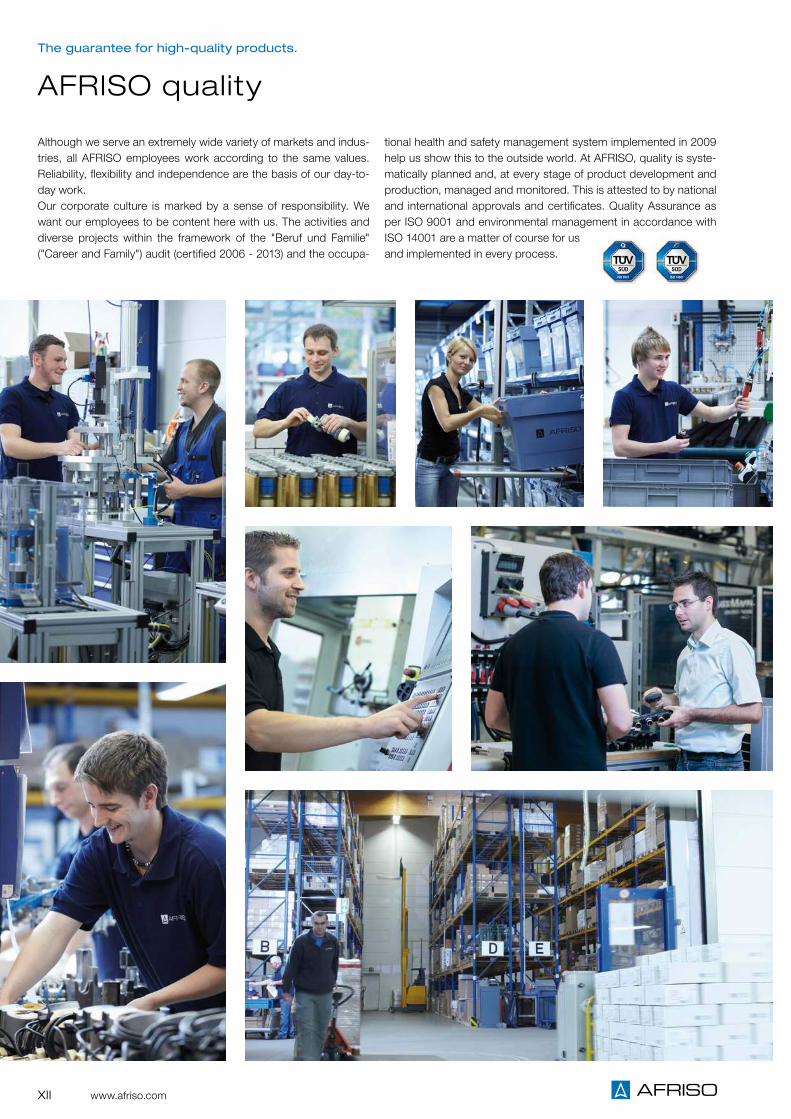
Although we serve an extremely wide variety of markets and indus-tries, all AFRISO employees work according to the same values. Reliability, flexibility and independence are the basis of our day-to-day work. Our corporate culture is marked by a sense of responsibility. We want our employees to be content here with us. The activities and diverse projects within the framework of the "Beruf und Familie" ("Career and Family") audit (certified 2006 - 2013) and the occupa-
tional health and safety management system implemented in 2009 help us show this to the outside world. At AFRISO, quality is syste-matically planned and, at every stage of product development and production, managed and monitored. This is attested to by national and international approvals and certificates. Quality Assurance as per ISO 9001 and environmental management in accordance with ISO 14001 are a matter of course for us and implemented in every process.
The guarantee for high-quality products.
AFRISO quality
XII www.afriso.com

XIIIwww.afriso.com

s
s
s
s
s
ss
s
ss
s
s
s
s
s
s
AFRISO sales office/field staff
AFRISO production site
AFRISO service point for measuring instruments and analysers
AFRISO support centres – close by, guaranteed.
Sites in Germany
We ensure that you get professional,
personal service.With a staff of more than 70 field and internal experts! Please visit www.afriso.com/contact for further information on your specific contact person. Business hours: Monday – Thursday: 7:00 a.m. – 4:50 p.m. Friday: 7:00 a.m.– 3:00 p.m.
Stocks and logisticsMaximum availability, short delivery times. Our range com-prises more than 25,000 different products. More than 2,000 of them are on stock. A total of more than 750,000 individual devices and instruments are available ex stock.
XIV www.afriso.com

AFRISO production sites in Germany
A staff of more than 550
are at work for you in our
five German production
sites.
HeadquartersAFRISO-EURO-INDEX GmbHLindenstr. 2074363 GüglingenBaden-Württemberg
Plant AmorbachAFRISO-EURO-INDEX GmbHFriedhofstr. 363916 AmorbachOdenwald/Bavaria
Plant DietzenbachAFRISO-EURO-INDEX GmbHWaldstr. 23 / Halle C463128 DietzenbachHessen
Plant IllmenseeSystronik GmbHGewerbestr. 5788636 IllmenseeLake Constance/Baden-Württemberg
Alsenz plantGampper GmbHNiedermoscheler Str. 267821 AlsenzRhineland-Palatinate
XVwww.afriso.com

Close, direct customer contact as a result of consistent, international alignment.
On site worldwide for you A tightly woven network of branches, distri-bution partners and service centres guaran-tees optimum consulting and delivery. More than 1,000 AFRISO employees respond to country-specific challenges with close cus-tomer contact and individual service on site – worldwide!
AFRISO Group
A total of more 1,000 employees Export to 65 countries
AFRISO production site
AFRISO branch office
AFRISO representation
AFRISO authorised dealer
HeadquartersAFRISO-EURO-INDEX GmbHLindenstr. 2074363 Güglingen, GermanyTel. +49 7135 102-0Fax [email protected]
VELTA EUROJAUGE S.A.17 A rue des Cerisiers67117 Furdenheim, FranceTel. [email protected]
AFRISO-EUROGAUGE Ltd.Unit 4 Satellite Business VillageGB-Fleming Way, Great BritainCrawley RH10 9NETel. +44 1293 [email protected]
EURO-INDEX bvba607, Leuvensesteenweg1930 Zaventem, BelgiumTel. +32 2 [email protected]
EURO-INDEX B.V.Rivium 2e straat 122909 LG Capelle a/d IJsselThe NetherlandsTel. +31 10 [email protected]
AFRISO AGHauptstr. 319434 Au/SG, SwitzerlandTel. +41 71 [email protected]
AFRISO-EURO-INDEX GmbHReichshofstr. 7a6890 Lustenau, AustriaTel. +43 5577 [email protected]
AFRISO ItaliaVia Mancalacqua 20/2437060 Lugagnano (Verona), ItalyTel. +39 045 [email protected] www.afriso.it
AFRISO IBÉRICACrta. Rubí-Sabadell, km 13, nave 88 A08191 Rubi (Barcelona), SpainTel. +34 9 35 88 12 [email protected]
AFRISO-EURO-INDEX KFTKelenföldi út 2.1115 Budapest, HungaryTel. +36 1 [email protected]
AFRISO spol.s r.o.Zakourilova 102/83914900 Praha 4, Czech RepublicTel. +42 2 [email protected]
AFRISO SP. Z O.O.Szalsza/k. Gliwiceul. Koscielna 742-677 Czekanow, PolandTel. +48 32 330 33 [email protected]
AFRISO-EURO-INDEX SRLBd. Tudor Vladimirescu No 45 A050881 Bucuresti, sect.5, RomaniaTel. +40 21 [email protected]
AFRISO EMA ABKilvägen 223237 Arlöv, SwedenTel. +46 40 [email protected]
AFRISO Ukraine LLCM. Ushakova Str. 1B03179 Kyiv, UkraineTel. +38 044 465 66 [email protected]
AFRISO Ltd.ul. Zolotorozhsky Val, 11, CTp. 27Office 225111033 Moscow, RussiaTel. +7 495 690 93 [email protected]
AFRISO SOUTH AFRICA (PTY) LTD.P.O. Box 112011514 Rynfield, South AfricaTel. +27 11 914 [email protected]
AFRISO Measurement & Control Technology (Suzhou) Co. Ltd.Building No. 1, New-Tech Industrial ParkNo. 98 Hengshan Road215011 Suzhou City, ChinaTel. +86 512 6807 9460 [email protected]
AFRISO India Pvt. Ltd.Unit 17, Electronic Sadan III,MIDC BhosariPune – 411 026Maharashtra, IndiaTel. +91 202 [email protected]
AFRISO NORTH AMERICA2 Homestead DriveMedway, MA 02053Tel. +1 508 [email protected]
AFRISO SUDAMÉRICACalle Moisés Mendelssohn No. 290, Of. 201San Borja – Lima 41, PeruTel. +51 [email protected]
XVI www.afriso.com

Hasvold a.sLofthusveien 650590 Oslo, NorwayTel. +47 22 [email protected]
Lyth-Instrument OyPeltosaarenkatu 211130 Riihimäki, FinlandTel. +358 19 [email protected]
Division I: Power-Flex ApSTaffelbays Allé 22900 Hellerup, DenmarkTel. +45 39 [email protected]
Division II: Erik Faergemann A/SHolmensvej 24a3600 Frederikssund, DenmarkTel. +45 6261 [email protected]
ELSTAVA Ltd.J. Kubiliaus g. 1608236 Vilnius, LithuaniaTel. +370 5 244 [email protected]
EVA-SAT SIAJaunmoku str. 261046, Riga, LatviaTel. +371 [email protected]
Termomont d.o.oLukovac b.b88345 Sovici-GrudeBosnia and HerzegowinaTel. +387 39 670 [email protected]
FLOGA S.A 23 km Thessaloniki - Poligiros57006 Lakkia Vasilika, GreeceTel. +30 239 602 [email protected]
Lachmann Ltd.21 Atir Yeda St.44643 KFAR SABA, IsraelTel.: +972 9 766 [email protected]
EMS Engineering for Measurement Systems10, Mohandeseen Askareen Naser City, 11371 Cairo, EgyptTel. +20 2 [email protected]
Netsach Nigeria Limited5b Jo’babs Dare Close, Off Adeyeri Close, Off Opebi, IkejaLagos, NigeriaTel. +234 1 [email protected]
Automation Engineering Co. LtdNo. 19, First Street, Bokharest Ave.Tehran, IranTel. +98 21 [email protected]
Intrial S. A. C.Calle Maisés Mendelssohn San Borja - Lima 41, PeruTel.: +51 1 [email protected]
U-Thong Co. Ltd. 413, 415, 417 Petchkaseam Rd. Kwangnong-Kangplu, Nongkeam Bangkok 10160 Thailand Tel. +66 2808 8571 [email protected] www.u-thong.com
Phat Dat Trading Eng. Co. Ward 13, Bink Thanh District No. 41/96/18, St. Backbone Ho Chi Minh City, Vietnam Tel. + 84 08355 31725 [email protected] www.phatdatcompany.com
AFRISO representations
XVIIwww.afriso.com

In 1869, our great-grandfather Adalbert Fritz founded his company in Thuringia. When his son Franz Fritz, our grandfather, entered the company, the company name changed to "Adalbert Fritz & Sohn", or, in short, AFRISO – which became a renowned brand for tempe-rature and pressure measurement. For 50 years, the company focussed on glass thermometers, medi-cal glass instruments and laboratory equipment.A small, thin-walled, circular and concentrically shaped metal sheet completely changed the AFRISO world around 1920. Two dia-phragm half shells form a capsule element which expands or con-tracts depending on the pressure.
Precision pressure gauges, blood pressure measurement instru-ments and temperature controllers became the most important products for the time up to 1945 and the new beginning after that.After World War II, Franz Fritz and his son Georg, our father, re-built the company in Kleingartach and in Güglingen/Württemberg. Pneumatic level measurement devices were developed on the basis of pressure measurement instruments, primarily for fuel oil storage tanks. Other innovations included overfill alarms and leak monitoring systems for the safe storage of mineral oil products. Technology for environmental protection became the main focus of the product range. AFRISO secured the market leadership in this sector.
Success for more than 140 years.
Tradition and innovation perfectly in tune
Jürgen and Elmar Fritz, great-grandsons of the company founder
XVIII www.afriso.com

The early 1960s marked the beginning of the internationalisation of AFRISO. AFRISO founded sales and production companies in almost all Western European countries and changed its name to AFRISO-EURO-INDEX. After the oil crisis in 1973/1974, AFRISO developed a comprehen-sive range of products for the efficient and environmentally friendly operation of heating systems. After the political change in Eastern Europe, subsidiaries were founded in Hungary, Romania, the Czech Republic, Poland, the Ukraine, Russia and China.
We are now the fourth Fritz generation to lead the company. We are very well aware of the benefits of a medium-sized company with a long tradition of innovation, run by its owners. And we will continue to be reliable partners for our customers, suppliers and employees.
Elmar Fritz Jürgen Fritz
Georg Fritz 1922 – 2004 Franz Fritz 1890 – 1968 Adalbert Fritz 1846 – 1918
XIXwww.afriso.com

1869 1920 1950 1955 1960 1972 1974
A Tradition of Innovation
AFRISO milestones
Company founded by
Adalbert Fritz. Production of
glass thermometers, glass
instruments and laboratory
equipment.
A new era begins: Production
of capsule elements as the
basis for precision pressure
gauges, blood pressure
measurement devices and
temperature controllers.
Founding of sales and pro-
duction companies in Western
Europe. AFRISO renamed
AFRISO-EURO-INDEX.
Market launch: Level indica-
tors for fuel oil tanks. This is
followed by overfill prevention
systems and leak monitoring
systems for the safe storage
of oil products.
Market launch of
the first portable
electronic flue gas
analyser.
The future lies in
the economical and
environmentally
compatible operation
of heating systems.
AFRISO launches
a broad product port-
folio on the market.
Rebuilding of the company in
Kleingartach and Güglingen/
Württemberg by Franz Fritz
and son Georg Fritz.
1958
Products for electronic level measurement extend the range
for industrial applications.
XX www.afriso.com

19941981 1996 2006 2008 2009 2011
Integration of
SYSTRONIK into the
corporate group.
Measuring instru-
ments for the industry
and the environment
are combined in a
new division.
Founding of
subsidiaries in
South Africa,
China, India and
South America.
Market launch:
Product range for
hydraulic balancing
Internationalisation:
Founding of subsidiaries
in Eastern Europe and
Russia.
Market launch
of the first
compact manifold
made of plastic.
Future-orientated:
The Stationary Gas
Analysis division engi-
neers and implements
system solutions for
emission data acqui-
sition.
Industry focus:
Pressure transducer
range DMU 02 Vario with
high-flexibility connection
technology
Market launch:
Product portfolio for
solar thermal systems.
Innovation: AFRISO presents the
EUROLYZER ST, the first all-in-one
flue gas analyser.
XXIwww.afriso.com

2012 2013 2014
Presentation of the world's
smallest, fully-featured HVAC
all-rounder with TFT colour
display: BLUELYZER ST
Domestic water system
centre HWSC for fast setup
of compact drinking water
installations
Innovation:
Dust measuring instrument
STM 225 with optical
measuring principle.
Wireless smart building
system AFRISOLab for
building automation
Expansion and new brand
identity of the AFRISO group
MULTILYZER STe:
Flue gas analyser with ECO
sensor and countless pos-
sibilities of measured data
communication.
XXII www.afriso.com

Catalogue Domestic Technology 2015 / 2016

Unitop
TankControl
VarioFox
HydroFox DMU 08

3
Level indicators at a glance 4
Level switches Minimelder-R, Maximelder-R 20
CHAPTER 1
Level indicators and level controllers
DISPLAY UNITS
LEVEL – LIMIT LEVEL
OVERVIEW
Digital display units DA 10/12/14 18
Digital display and control units VarioFox® 12/14 19
LEVEL – CONTINUOUS
Dipstick, pipe for dipstick 6
Mechanical level indicators MT-Profil R, Unimes 7
Pneumatic level indicator Unitel 8
Pneumatic level indicator Unitop 9
Mounting accessories for pneumatic level indicators 10
Level indicator with mounting kit for plastic battery tanks 11
Pneumatic level indicator Unitop-Set AdBlue 12
Hydrostatic level indicator TankControl 10 15
Hydrostatic level indicator HydroFox® DMU 08 17
Digital tank contents indicator for fuel oil, diesel fuel and water DIT 10 14
Digital tank contents indicator DTA 10 13
1

4
Level Overview
Technical specifications, application areas and suitability depend on the product version. See catalogue data sheet and/or operating instructions for options and details.
i
Level indicators at a glance
Dipstick MT- Profil R Unimes Unitel Unitop DTA 10 DIT 10 Tank
Control CoFox® ELT CapFox®
EFT 7CapFox®
ENT 7PulsFox® PMG 10
Sonar Fox®
UST 10HydroFox® DMU 08 DMU 09 VibraFox®
GVGCoFox®
CMG 01MagFox® MMG 01
Indoor tanksTa
nks
• • • • • • • • • • • • • • • • • •
Outdoor tanks • • • • • • • • • • • • • • • •
Electrically isolating tanks • • • • • • • • • • • • • • • • •
Electrically conductive tanks • • • • • • • • • • • • • • • • • •
Pressurised tanks • • • • • •
Unpressurised tanks • • • • • • • • • • • • • • • • • •
< 1,000 mm
Mea
suri
ng r
ang
e • • • • • • • • • • • • • •
Up to 2,000 mm • • • • • • • • • • • • • • • • •
Up to 2,500 mm • • • • • • • • • • • • • • • •
Up to 2,900 mm • • • • • • • • • • • • • • •
Up to 3,000 mm • • • • • • • • • • • • • •
> 3,000 mm • • • • • • • • • • •
Liquid media
Gen
eral
med
ia • • • • • • • • • • • • • • • • • •
Solid media (bulk solids) • •
Powdery media • •
Electrically isolating media • • • • • • • • • • • • • • • •
Electrically conductive media • • • • • • • • • • • • • • • •
Fuel oil/diesel fuel (EN 590)
Sp
ecia
l med
ia • • • • • • • • • • • • • • • •
Biofuel/ biodiesel (EN 14214) • • • • • • • • • • • • • • • •
Water • • • • • • • • • • • • • • • • •
AdBlue® • • • • • • • • •
Measuring principle
Des
ign
Mechanical Mechanical Mechanical Pneumatic Pneumatic Pneumatic Hydrostatic Hydrostatic Conductive Capacitance Capacitance Guided micro-pulse (TDR) Ultrasonic Hydrostatic Hydrostatic Vibration fork Potentiometric Magneto-
strictive
Local display • • • • • • • • • • •
Limit level • • • • • •
Continuous measurement • • • • • • • • • • • • • •
Analogue output (4–20 mA, 0–10 V)
Ind
icat
ion
/sig
nal
• • • • • • •
Binary output (relay, PNP) • • • • •
% liquid level • • • • • •
% volume • • • • • •
Liquid level in cm • • • • • •
Liquid level in mm • • • •
Litres • • • • • • •
m3 • • • •
Technical Approval of the German Institute for Civil Engineering (DIBt) (WHG)
Cer
tific
ates
•
ATEX •
Display unit DA 10/12/14
Co
ntr
ol u
nit • • • • • • •
Display and control unit VarioFox® 12/14 • • • • • • •
Transducer MFU • • • • • • •
Page 6 Page 7 Page 7 Page 8 Page 9 Page 13 Page 14 Page 15 Page 298 Page 285 Page 303 Page 289 Page 286 Page 284 Page 229 Page 305 Page 296 Page 297
1

5
Overview
Dipstick MT- Profil R Unimes Unitel Unitop DTA 10 DIT 10 Tank
Control CoFox® ELT CapFox®
EFT 7CapFox®
ENT 7PulsFox® PMG 10
Sonar Fox®
UST 10HydroFox® DMU 08 DMU 09 VibraFox®
GVGCoFox®
CMG 01MagFox® MMG 01
Indoor tanks
Tank
s
• • • • • • • • • • • • • • • • • •
Outdoor tanks • • • • • • • • • • • • • • • •
Electrically isolating tanks • • • • • • • • • • • • • • • • •
Electrically conductive tanks • • • • • • • • • • • • • • • • • •
Pressurised tanks • • • • • •
Unpressurised tanks • • • • • • • • • • • • • • • • • •
< 1,000 mm
Mea
suri
ng r
ang
e • • • • • • • • • • • • • •
Up to 2,000 mm • • • • • • • • • • • • • • • • •
Up to 2,500 mm • • • • • • • • • • • • • • • •
Up to 2,900 mm • • • • • • • • • • • • • • •
Up to 3,000 mm • • • • • • • • • • • • • •
> 3,000 mm • • • • • • • • • • •
Liquid media
Gen
eral
med
ia • • • • • • • • • • • • • • • • • •
Solid media (bulk solids) • •
Powdery media • •
Electrically isolating media • • • • • • • • • • • • • • • •
Electrically conductive media • • • • • • • • • • • • • • • •
Fuel oil/diesel fuel (EN 590)
Sp
ecia
l med
ia • • • • • • • • • • • • • • • •
Biofuel/ biodiesel (EN 14214) • • • • • • • • • • • • • • • •
Water • • • • • • • • • • • • • • • • •
AdBlue® • • • • • • • • •
Measuring principle
Des
ign
Mechanical Mechanical Mechanical Pneumatic Pneumatic Pneumatic Hydrostatic Hydrostatic Conductive Capacitance Capacitance Guided micro-pulse (TDR) Ultrasonic Hydrostatic Hydrostatic Vibration fork Potentiometric Magneto-
strictive
Local display • • • • • • • • • • •
Limit level • • • • • •
Continuous measurement • • • • • • • • • • • • • •
Analogue output (4–20 mA, 0–10 V)
Ind
icat
ion
/sig
nal
• • • • • • •
Binary output (relay, PNP) • • • • •
% liquid level • • • • • •
% volume • • • • • •
Liquid level in cm • • • • • •
Liquid level in mm • • • •
Litres • • • • • • •
m3 • • • •
Technical Approval of the German Institute for Civil Engineering (DIBt) (WHG)
Cer
tific
ates
•
ATEX •
Display unit DA 10/12/14
Co
ntr
ol u
nit • • • • • • •
Display and control unit VarioFox® 12/14 • • • • • • •
Transducer MFU • • • • • • •
Page 6 Page 7 Page 7 Page 8 Page 9 Page 13 Page 14 Page 15 Page 298 Page 285 Page 303 Page 289 Page 286 Page 284 Page 229 Page 305 Page 296 Page 297
Level
1

6 Division I
Continuous
For manual level measurement, primarily in cylin-drical underground tanks. Suitable for the follow-ing media: fuel oil and diesel fuel.
Dipstick made of flexible, break-proof plastic with 100 cm brass chain. Excellent readability due to cm graduation.
Plastic dipstick
Dipstick, pipe for dipstick
Pipe for dipstick
For suspension in 1" pipe. Protects inner tank lin-ings and coatings against damage caused by the dipstick.
Pipe for dipstick, crimped at one end, closed at the other end. Various lengths available, suitable for AFRISO dipsticks.
MaterialSteel, galvanised
Connection
Pipe for dipstick Dipstick
Length 160 cm Length 170 cm
Length 200 cm Length 210 cm
Length 250 cm Length 260 cm
Length 290 cm Length 300 cm
MaterialPlastic
Measuring ranges (tank height) / dipstick length160 cm / 170 cm200 cm / 210 cm250 cm / 260 cm290 cm / 300 cm
Technical specifications
Application
Description
DG: G PG Part no. Price €
Plastic dipstick:
Length 170 cm, measuring range 160 cm* 1 1 - 20010
Length 210 cm, measuring range 200 cm* 1 1 - 20011
Length 260 cm, measuring range 250 cm* 1 1 - 20012
Length 300 cm, measuring range 290 cm* 1 1 - 20013
Cap for pipe for dipstick G1 female x G1¼ 2 1 140 20464
Pipe for dipstick 160 cm* 3 1 - 71315
Pipe for dipstick 200 cm* 3 1 - 71320
Pipe for dipstick 250 cm* 3 1 - 71330
Pipe for dipstick 290 cm* 3 1 - 71335
Cap for pipe for dipstick with connection thread G1 female, zamak
*Extra shipping charges apply for dipsticks and pipes for dipsticks (all lengths).
Level
1

7
The only
mechanical
level indicator
with litre scales
Division I
Continuous
Mechanical level indicators
Description
Technical specifications
Unimes
For continuous level measurement in tanks con-taining fuel oil EL, diesel fuel, biodiesel and other low-viscosity media which do not attack materials of the indicator. For tank heights from 900 to 2,000 mm.
MT-Profil R – G1½ and – G2
Ø 43 mm
G1½G2
Part no. 16500 = G1½
Part no. 16540 = G2
Application
iSee page 10 for suitable reducers.
DG: G, PG: 1 Part no. Price €
Unimes 1 - 11500
Special scale 1 1 11999
MT-Profil R – G1½ 1 50 16500
MT-Profil R – G2 1 50 16540
Reducer G2 x G1½ 10 - 20903
For continuous level measurement in tanks contain-ing fuel oil EL, diesel fuel, biodiesel and water. For tanks heights from 0 to 250 cm. Suitable for use in flood hazard areas.
Measuring range (tank height)0/150 to 0/250 cm
Displayed values 0/150 or 0/250 liquid level in cm
Connection threadG1½ or G2
Housing/float Display: ABS, impact-resistantFloat: PE-HD
Universal, mechanical level indicator with plastic planetary gear. Measuring range is adjustable from 0 to 250 cm by reversible scale.
With reversible scale 0–150 cm and 0–250 cm for fast adaptation to the tank height. Odour-tight. Watertight up to 10 m water column.
Universal mechanical level indicator with fully adjustable brass and nickel silver movement. The pointer deflection amounts to 280° at tank heights and diameters from at least 900 mm to 2,000 mm maximum. Indication in percentage of liquid level, litre scale can be retrofitted. With reference pointer for consumption monitoring.
Measuring range (tank height)0/900 to 0/2,000 mm
Displayed values0/100 % liquid level
Connection threadG1½ and G2
Housing/float Display: ABS, impact-resistantWindow: SANFloat: PE-HD
Special scalesFor Unimes and tanks of any shape and dimen-sion. When ordering, please specify the shape and capacity of tank.
Level
1

8
Level
Division I
Continuous
Pneumatic level indicator Unitel
No power supply required Reference pointer for easy consumption monitoring
Zero correction possible For remote measurements up to 50 m
For continuous level measurement in tanks containing fuel oil, diesel fuel and rainwater. For tank heights from 900 to 3,000 mm (depends on version). Suitable for use in flood hazard areas and for remote measurement up to 50 m.
Universal, pneumatic level indicator with capsule movement. The tank height is fully adjustable. Measuring accuracy ±3 % of full scale value. A dual scale facilitates measurements in rectangular tanks (= linear tanks) and cylindrical tanks. Indication in % volume (Unitel) or % liquid level (Unitel for water). Impact-resistant plastic housing for wall mounting. With zero correction and integrated over-pressure safety device. Reference pointer for easy consumption monitoring. Connection for pipe or hose (6 mm outside diameter, universal) for tight mounting of the measuring line (e.g. Pneumofix). Watertight up to 10 m water column.
Application
Description
Technical specifications
MediumFuel oil or diesel fuel (density = 0.84 g/cm³) or water (density = 1 g/cm³) for Unitel for water
Measuring range (tank height)0/3,000 mm (part no. 72500)0/2,500 mm (part no. 72511)
Measuring accuracy±3 % of full scale value
Operating temperature rangeAmbient: -5/+55 °C
Scale (displayed values)Unitel: Dual scale 0/100 % volumeOuter for rectangular tanks, inner for cylindrical tanksUnitel for water: 0/100 % liquid level
HousingWall mounting housing made of impact-resistant plastic with integrated hand pumpW x H x D 145 x 135 x 65 mm
Montagefix extension kitFor measuring line extension. 10 m PE measuring line 4 x 1 mm with hose extension piece
Unitel-Montagefix Water Complete mounting kit for installation in rainwater harvesting systems with all required installation accessories, consisting of: Unitel for water, 3.1 m standpipe with balance chamber, 10 m PE measuring line 4 x 1 mm, mounting parts and accessories.
iSee chapter 9 for more products for rainwater harvesting
Options
Page 10
A
Page 10
A
DG: G, PG: 1 Part no. Price €
Unitel 1 - 72500
Unitel for water 1 - 72511
Unitel-Montagefix water 1 - 72499
Montagefix extension kit 1 - 20132
Measuring line 4 x 1.50 m reel 1 - 20158
Hose connector 1 10 43945
Page 130
A
1

9Division I
ContinuousContinuous
No power supply required Consumption monitoring with date indication Zero correction possible Sturdy brass connector for reliable and tight installation of the measuring line
For remote measurements up to 50 m
Pneumatic level indicator Unitop
Tank
hei
ght
H
Max. 50 m
For continuous level measurement in tanks containing fuel oil and diesel fuel. For tank heights from 900 to 3,000 mm (depends on version). Suitable for use in flood hazard areas and for remote measurement up to 50 m.
Universal, pneumatic level indicator with capsule movement. The tank height is fully adjustable. Measuring accuracy ±2 % of full scale value. A dual scale facilitates measurements in rectangular tanks (= linear tanks) and cylindrical tanks. The basic version indicates % of volume so that it is independent of the tank shape. Impact-resistant plastic housing for wall mounting. With zero correction at the front side, reference pointer and date indication for easy consumption monitoring; with integrated overpressure device. The mechanism carrier of extremely rugged plastic is separated from the housing for stable zero point and high measurement accuracy. Sturdy brass connector with pressure screw for pipe or hose (Ø 6 mm) for tight monitoring of the measuring line. A vent screw, integrated in the connector, allows you to check the zero setting of the pointer. Watertight up to 10 m water column.
Application
Description
Technical specifications
MediumFuel oil or diesel fuel (density = 0.84 g/cm³)
Measuring range (tank height)0/900 to 0/3,000 mm (part no. 28000)
Measuring accuracy±2 % of full scale value
Operating temperature rangeMedium: 0/35 °C Ambient: -5/+55 °C Storage: -5/+55 °C
Scale (displayed values)Dual scale 0/100 % volume Outer for rectangular tanks, inner for cylindrical tanks
HousingWall mounting housing made of impact-resistant plastic with integrated hand pump W x H x D: 155 x 166 x 73 mm
Scope of deliveryLevel indicator with connection kit and screws,litre scales for cylindrical tanks 3,000/5,000, 7,000/10,000, 16,000/20,000
iSee page 12 for Unitop for AdBlue®.
Page 10
A
Page 10
A
DG: G, PG: 1 Part no. Price €
Unitop 3000 1 - 28000
Level
1

10 Division I
Level Continuous
Mounting accessories pneumatic level indicators
Pneumofix
Montagefix extension kit
DG: G, PG: 1 Part no. Price €
Pneumofix 1 - 20153
Montagefix extension kit 1 - 20132
Measuring line 50 m 1 - 20158
Hose connector 1 10 43945
Condensate trap KG 2 5 - 20320
Reducer 2 x 1½ 10 - 20903
Reducer 1½ x 1 10 - 20905
Flange adapter 1 - 20900
Description
Description
Reducers/adaptersReducer 2 x 1½Reducer G2 x G1½ made of grey plastic (ABS).
Reducer 1½ x 1Reducer G1½ x G1 made of grey plastic (ABS).
Flange adapter for battery tanksFlange adaptor G1½ made of grey plastic (ABS).
Description
Condensate trap KG 2
For protection of pneumatic level indicators against conden-sate. Made of high-grade, impact-resistant plastic. The con-densate trap can be easily unscrewed for emptying. Universal connections for hose or pipe with 6 mm outside diameter. Suitable for use in flood hazard areas. Watertight up to 10 m water column.
Scope of delivery: KG 2, incl. mounting material (screws, screwed connections)
Description
Montagefix extension kit
For extending the measuring line of pneumatic level indicators. Consisting of: 10 m PE measuring line 4 x 1 mm with hose extension piece. Suitable for use in flood hazard areas. Watertight up to 10 m water column.
Pneumofix
Complete, universal mounting kit for pneumatic level indica-tors. Can be used for tanks of up to 3,000 mm in height or diameter. Consisting of screw fitting with dual thread G1 and G1¼, reducer G1 x 1½ x 2. Standpipe in tank (3.1 m long) with balance chamber, condensate trap. Polyethylene meas-uring line, 10 m. Suitable for use in flood hazard areas. Watertight up to 10 m water column. If no connection socket is available at the tank, it is recommended to use Euroflex (see page 130).
Description
① To level indicator② Measuring line L = 10 m③ Hose clamp④ Hose extension piece⑤ Condensate trap⑥ Spacer / balancing chamber⑦ Hose, inside diameter 4⑧ Dual thread tank adaptor⑥
③
⑦
④
⑤
②
⑧
①
Condensate trap KG 2
Reducers
Flange adapter
1

11Division I
Continuous
Level indicator with mounting kit for plastic battery tanks
The tank room under control ① AFRISO-WATCHDOG oil/water alarm unit* ②Unitel** ③ Pull cord***
③②①
*See page 75 for oil/water alarm unit.**See page 8 for Unitel.***See page 133 for pull cord.
This mounting kit enables quick and easy retrofitting of plastic battery tanks without interrup-tion of regular operation.
Immediate installation – no problem!
1. Drill a hole into the flange2. Install the measuring line3. Check the level
Benefits:No components need to be dis-mantled for installation. Oil-carrying pipes do not need to be dismantled and then recommissioned and deaerated.
Many plastic fuel tanks become opaque over the years due to sediments, dirt and age. Often there is no connection available for a level indicator. This special mounting kit makes it possible to connect a pneumatic level indicator quickly and easily. There is no need to switch off the burner. Many withdrawal systems already have corresponding markings on the mounting flanges for the holes.
Attention:In most cases, it is prohibited to drill through the tank wall. This may render the warranty for the tank void.
Application
DG: G, PG: 1 Part no. Price €
Unitel-Set 1 - 72512
Unitel-SetThis universal, pneumatic level indicator for remote measurement comes with a mounting kit for installation on plastic battery tanks.
See the Unitel product description.
Unitel with mounting kit, consisting of a standpipe 2.10 m with weight (Ø 9 mm), self-sealing connection piece for a 10 mm hole, 10 m measuring line, hose clamps, steel nails and a hose extension piece.
Scope of delivery:
Level
1

12
Continuous
Specially calibrated for AdBlue®
Universally adjustable Easy installation Complete with special mounting kit No power supply required
For continuous level measurement in tanks containing AdBlue® (density 1.09 g/cm3). For tank heights from 700 to 2,300 mm. Suitable for use in flood hazard areas and for remote indication up to 50 m. The term AdBlue® is the same as "NOx Reducing Agent AUS 32" and "Urea solution 32.5 %".
Universal, pneumatic level indicator with capsule movement. Specially adjusted to the specific weight (density) of AdBlue® = 1.09 g/cm3. Fully adjustable from 700 to 2,300 mm tank height. Measuring accuracy ±2 % of full scale value. Indication in percentage of level. With zero correction at the front side, reference pointer and date indication for easy consumption monitoring; with integrated overpres-sure safety device. Universal measuring line connection for pipe or hose with an outside diameter of 6 mm. Easy mounting by means of a mounting kit specially designed for AdBlue®. Process connection G1 and G1¼, standpipe HD-PE 2.5 m with stainless steel balance chamber, 10 m measuring line PE 4 x 1 mm, reducer G1 x G1½ x G2. Watertight up to 10 m water column.
Application
Description
Measuring range0/700 to 0/2,300 mm tank height
Measuring accuracy±2 % of full scale value
Operating temperature rangeMedium: 0/35 °CAmbient: -5/+55 °C(Please observe the pertinent regulations concerning the storage of AdBlue®!)
Scale (displayed values)0/100 % liquid level
HousingWall mounting housing made of impact-resistant plastic with integrated hand pumpW x H x D 155 x 166 x 73 mm
Process connectionG1 and G1¼, reducer G1 x G1½ x G2
Standpipe Plastic HD-PE natural Length 2.5 m balance chamber stainless steel
Measuring linePE hose 4 x 1 mmLength 10 m
Scope of deliveryLevel indicator, mounting kit and reducers G2 x G1½ as well as G1½ x G1
Technical specifications
iMake sure to observe all pertinent legislation con-cerning selection of materi-als and construction when building storage facilities for AdBlue®.
See chapter 2 for suitable overfill prevention system and chapter 3 for inner tank linings.
Pneumatic level indicator for AdBlue® – Unitop-Set AdBlue
Measuring line PE 4 x 1 m black
G1¼G1
StandpipeHD-PE natural
Bottom partStainless steel
Page 10
A
DG: G, PG: 1 Part no. Price €
Unitop-Set AdBlue 1 - 28040
Division I
Level
1

13
Continuous
Division II
Location-independent level measurement with digital display and minimum level signal (reserve level alarm) with a single measurement. Suitable for tanks up to 400 cm liquid level. For fuel oil EL, L or diesel fuel, FAME 100 % as biodiesel (EN 14214) and water (no drinking water!). In addition, DTA 10 can be used for level measurement with all non-corrosive liquids with a density from 0.5 to 1.5 g/cm3. Remote measurements up to 15 m.
The electro-pneumatic tank contents indicator DTA 10 consists of a battery-operated control unit with digital display and a measuring line. Measured values are displayed in litres, % and liquid level (cm). Simple operation and setup via three function keys. Measurements are requested by means of pressing the control key (Push-to-Read function). If the level falls below a minimum level that is freely adjustable as a percentage, the backlight of the display flashes red to indicate an alarm during the measurement. Standard tank shapes (linear, spherical, cylindrical and horizontal) are stored. Measuring line connec-tion for hose with 4 mm inside diameter.
Application
Description
FunctionsPush-to-Read level measurement
Measuring range (tank height)0/400 cm (fuel oil) 0/350 cm (water)
Measuring accuracy±1.0 cm
Operating temperature rangeAmbient: 0/50 °CStorage: -20/+65 °C Medium: 0/50 °C
DisplayMulti-coloured, backlit graphical display (30 x 50 mm). Blue = Operation Red = Alarm Green = Setup
Indication of litres (5 digits), % or liquid level in cm.
Measuring linePVC hose 4 x 1 mmLength 20 mBalance chamber stainless steel
Supply voltage9 V monobloc battery
Visual alarmBacklight flashes red during measurement process
HousingWall mounting housing made of impact-resistant plastic (ABS) W x H x D: 100 x 188 x 65 mm Degree of protection: IP 20 (EN 60529)
Scope of delivery Control unit 9 V monobloc battery 20 m measuring line with balance chamber Connection kit for G½, G1, G1½ and G2 25 x nail cable clips, 2 x hose clamps Hose adapter (4 mm) Mounting accessories
Technical specifications
Digital tank contents indicator DTA 10
Z A
DG: M, PG: 4 Part no. Price €
DTA 10 52145
For fuel oil EL, L, diesel fuel, biodiesel, water and other media with a density from 0.5 to 1,5 g/cm3
Universal application in tanks of a height of up to 4 m
Push-to-Read function: Fast start with just a push of a button
Page 130Page 10
A
Level
1

14 Division II
Continuous
Digital tank contents indicator DIT 10
For fuel oil EL, L, diesel fuel, biodiesel and water
Universal application in tanks of up to 4 m in height or diameter
No external supply voltage required Push-to-read function for extremely long battery service life
Suitable for continuous level measurement in tanks containing fuel oil EL, L or diesel fuel and FAME 100 % as biodiesel (EN 14214). Specially suitable for underground tanks and basement tanks, also in flood hazard areas. For filling levels from 900 mm to 4,000 mm.
The hydrostatic level indicator consists of a control unit with digital display and a submersible probe with integrated pressure measuring cell. High measuring accuracy due to electronic sensor (pressure measuring cell). Simple operation due to device setup via menus. No bearing charts required since all standard tank shapes are stored. Watertight up to 10 m water column.
Application
Description
Technical specifications
FunctionsPush-to-read, selection of units, calculation of total volume
Measuring range0/400 mbar
Measuring accuracy±1.5 % FS
Operating temperature rangeMedium: -5/+70 °CAmbient: 0/45 °CStorage: -5/+70 °C
Display4-digit, 12 mm high LCD 7-segment display with additional symbols
Displayed valuesLitres, m³, %, liquid level in mm
Submersible probeHousing: Stainless steel 303Cable: PVC, 6 m with breather tube Diaphragm: Stainless steel 316 L Seals: FKM (Viton) Spacer: POM, PE
Supply voltage1 x lithium battery 3.6 V (included)Service life approx. 5 years
HousingPA6, glass-loaded, blue, Ø 75 mm, wall mounting
Degree of protectionIP 51 (EN 60529)
Scope of delivery Control unit with digital display 5 m connection cable to probe (can be extended by up to 10 m)
Moisture-proof junction box Submersible probe with 6 m submersible cable Screw connector kit G1 x G1½ x G2 Mounting kit for withdrawal flange (PG 9 gland)
Wall mounting
DG: H, PG: 4 Part no. Price €
DIT 10 52150
Spare submersible probe (0/400 mbar)
52153
Spare battery 68309
Level
1

15Division II
Continuous
Application
Description
Technical specifications
Hydrostatic indicator TankControl 10
FunctionsSelection of units, daily saving of level data, consumption monitoring, graphical evaluation of consumption values (up to 5 years), calculation of remaining range, alarm functions (min./max.), sensor error and short circuit alarms.
Measuring range0/400 mbar
Measuring accuracy±1.5 % FS
Operating temperature rangeMedium: -5/+70 °CAmbient: 0/45 °CStorage: -5/+70 °C
DisplayHigh-resolution, backlit graphical display (30 x 50 mm). Indication of either litres (6 digits), m³, % or liquid level in mm. Symbols for alarm functions.
Submersible probeHousing: Stainless steel 303 Cable: PVC, 6 m with breather tube Diaphragm: Stainless steel 316 L Seals: FKM (Viton) Spacer: POM, PE
Supply voltageAC 230 V Lithium battery for data backup (calendar function)
Switching outputsRelay contacts: 2 voltage-free changeover contacts Contact rating: AC 230 V, 2 A
For fuel oil EL, L, diesel fuel, biodiesel and water Graphical indication of consumption and remaining range
With visual/audible alarms, Acknowledge button and 2 relays
Remote measurements up to 15 m
Page 90
A
Continuous level measurement with graphical display for indication of consumption (history), calcula-tion of remaining range (forecast) and signalling of minimum or maximum levels as well as for level control. For tanks from 1,000 to 4,000 mm liquid level. Suitable for fuel oil EL, L, diesel fuel, FAME 100 % as biodiesel (EN 14214), water (no drinking water!) as well as similar liquids. In conjunction with an additional submersible probe for differential alarm also suitable for detecting level differences in com-municating tanks (e.g. battery tanks) which may cause overfilling. It is also possible to connect a float-ing probe for backflow alarms (drain system, e.g. for rain water harvesting systems) or for additional minimum or maximum alarms. Specially designed for building technology. Suitable for use in flood hazard areas.
The hydrostatic level indicator consists of a control unit with numerical and graphical display and a submersible probe with integrated pressure measuring cell. Optionally with additional submersible probe for differential alarm or with floating probe. The system displays either litres, m3, % or liquid level (mm). When the level falls below or exceeds an adjustable minimum or maximum value, the control unit triggers visual and audible (can be acknowledged) alarms. The value for submersible probe 2 is dis-played in mm. If an adjustable level difference between submersible probe 1 and submersible probe 2 is exceeded, an alarm is triggered. Two additional relay contacts are available for external alarm devices, for level control or for connection to telecommunication or building control systems. High measuring accuracy due to electronic sensing. Standard tank shapes are stored. Watertight up to 10 m water column.
Page 92
A
Page 93
A
Ad
diti
onal
pro
be
diff
eren
tial a
larm
Floa
ting
pro
be
Level
1

16
Level Continuous
Division II
Hydrostatic level indicator TankControl 10
Application examples TankControl 10
Monitoring of the level in a fuel oil tank with early signalling of minimum level. With combined alarm light and horn as addi-tional alarm equipment outside of the building and transmission of alarm messages, level data and reaming range to a central building control system.
Monitoring of the levels in two communicating tanks. A sub-mersible probe is installed in each tank. If the level difference exceeds a defined value, the unit triggers an alarm. The caus-es of the uneven levels can be removed prior to filling. Potential damage as a result of different levels in the two tanks is avoided.
Monitoring of the level in an outdoor rain water tank. A com-bined alarm light and horn is connected in the vicinity of the tank; TankControl 10 is installed inside the building. It is also possible to connect a float switch to monitor for backflow from the drain. The system can be extended by a GSM-based event reporting system.
DG: H, PG: 4 Part no. Price €
TankControl 10 52151
Spare submersible probe (0/400 mbar) 52153
Additional probe differential alarm 52152
Visual alarmRed LED
Audible alarmIntegrated piezo buzzer, can be acknowledged
HousingWall mounting housing made of impact-resistant plastic (ABS) W x H x D 100 x 188 x 65 mmDegree of protection: IP 54 (EN 60529)
Scope of delivery Control unit with graphical display and 15 m connection cable to the probe (cannot be extended)
Submersible probe with 6 m submersible cable Moisture-proof junction box Screw connector kit G1 x G1½ x G2 Mounting kit for withdrawal flange at plastic battery tanks
Options Submersible probe for differential alarm Floating probe (spare probe Minimelder)
Technical specifications
iSee "Spare probes Minimelder", page 20, for additional float switch.
1

17Division II
Continuous
Hydrostatic level indicator HydroFox® DMU 08
Compact and sturdy stainless steel design Special calibration for all standard pressure units possible
Version with PUR or FEP cable Optional ATEX version
Application
Description
For electronic, continuous level measurement, e.g. in wells, drilling holes, water, containers or in waste water systems. Suitable for groundwater, drinking water, waste water (with optional FEP cable), diesel fuel, fuel oil; also for use in flood hazard areas.
The level indicators HydroFox® DMU 08 use silicon technology and feature calibrated, amplified sensor signals which are available as standardised voltage or current outputs.
Technical specifications
Measuring accuracyDeviation from the characteristic curve according to IEC 60770 – limit point calibration (non-linearity, hysteresis,repeatability): < ±0.35 % FSO (measuring ranges 0/100 mbar to 0/400 mbar < ±0.5 % FSO)
Measuring rangesRelative pressure: 0/100 mbar to 0/25 bar
Overpressure safetyDepends on pressure range 4 x FS to 15 x FS (burst pressure) 3 x FS to 8 x FS (overload)
Operating temperature rangeMedium: -10/+70 °C Ambient: -10/+70 °CStorage: -25/+70 °CFor Ex version -20/+60 °C with Patm 0.8 bar to 1.1 bar
Temperature error bandIn compensated range 0/70 °C ≤ 400 mbar ≤ ±1 % FSO/10 K ≥ 400 mbar ≤ ±0.75 % FSO/10 K
Dynamic characteristicsResponse time ≤ 10 ms
MaterialsHousing: Stainless steel 316 LDiaphragm: Stainless steel 316 LSeals: FKM (Viton)
Pressure transmission liquidSilicone oil
Supply voltageDC 8–32 VEX version DC 10–28 V
Output signal4–20 mA, 2-wire
Load4–20 mA: Rmax = [(UB – UBmin)/0.02 A] Ω
Current input4–20 mA < 25 mA
Electrical protectionShort circuit proof and protected against reverse polarity
Electrical connection (degree of protection)PUR cable (IP 68) With integrated breather tube for reference to the ambient atmospheric pressure
Accessories (options) Screw connector kit Junction box Anchor clamp Extended weight
Options Ex version (II 1G Ex ia IIC T4 Ga, II 1D Ex ia IIIC T85 °C Da)
Measuring accuracy 0.1 % FSO FEP cable SIL 2 (IEC 61508/61511)
DG: H PG Part no. Price €
DMU 08 with 5 m PUR cable
Measuring range
0/100 mbar 4 31555
0/160 mbar 4 31556
0/200 mbar 4 31557
0/250 mbar 4 31558
0/300 mbar 4 31519
Screw connector kit plastic, G2 x 1½ x 1 1 52125
Junction box with pressure relief port 1 31824
iComplete range of pressure transducers see catalogue INDUSTRIAL TECHNOLOGY.
Page 19
A
Page 18
A
Digital display and control unit VarioFox 12/14
Signalling device
Pressure transducersDMU 08
Junction box with pressure relief port
Level
1

18 Division II
Display units
Display5-digit graphical LC display, backlit (white), text-based user interface, user interface language selectable (German/English/French/Italian), selectable units, custom units can be defined
Measuring range± 99,999 digits (start and end values scalable as required)
Linearity± 0.1 % of measuring range
ResolutionDecimal point position can be set as required
Response time< 0.2 s
Operating temperature rangeAmbient: 0/50 °C
Supply voltageAC 50–253 V / DC 20–253 V 2.5 W / AC 4.4 V
Sensor supplyIntegrated, galvanically isolated supply voltage for transducer: DC 21 V/20 mA
Sensor inputAll analogue standard signals, e.g. 4–20 mA, 0–20 mA, 0–10 V as well as potentiometer
Analogue output0/4–20 mA, galvanically isolated
Housing Standard rack mounting housing W x H x D: 96 x 48 x 135 mm
Panel cut outW x H: 92 x 45 mm
Degree of protection (front)IP 65 (EN 60529)
Electrical connectionPlug-in screw terminals (1.5 mm2)
LinearisationCustomer-specific linearisation with a max. of 24 points for the indication of volume (e.g. litres) in non-linear tanks. Bearing charts for cylindrical horizontal tanks and spherical tanks are pre-pro-grammed.
Min./max. value memoryThe highest and lowest values reached during operation can be displayed
Additional functions DA 12 / 14
Analogue output 20–10 V, galvanically isolated
Switching outputsRelay contacts: 2 x (DA 12) / 4 x (DA 14) voltage-free changeover contacts (adjustable switching hysteresis) Contact rating: AC 250 V, 2 A, 100 VA
Digital display units DA 10/12/14
Grey display with excellent readability Text-based user interface Linearisation for volume indication (24 points) Scalable units, displayed as bar chart Integrated supply voltage for transducer
* Price includes mounting if DA and WAG are ordered together.
iSee the catalogue INDUSTRIAL TECHNOLOGY for the complete range of "Digital Display Units".
Digital display unit DA 12
Signalling device
Pressure transducersDMU 07
DG: H, PG: 4 Part no. Price €
DA 10 31281
DA 12 31282
DA 14 31283
DG: H, PG: 3
Wall mounting hous-ing WAG 01 for one DA*
31287
WAG 02 for two DA* 31288
WAG 03 for three DA* 31289
WAG 04 for four DA* 31290
Page 92
A
Technical specifications
Application Universal application for displaying measured values (DA 10), optionally with additional relay outputs (DA 12/14) for electronic transducers.
Description Digital display unit in plastic housing for control panel mounting. With grey display and automatic off function for the backlight. The universal measurement input can be configured as a current input or a voltage input. Standard bearing charts for cylindrical horizontal tanks and spherical tanks are pre-pro-grammed, additional units can be selected or set up. The units are scalable and shown as bar charts. Limit values can be displayed via a window and a trend function (rising/falling). With display message (flashing error text) if values are exceeded, parameter backup for restoring previous configurations and potentiometer for test purposes.
Level
1

19
Can be used as compact, ready-to-connect filling or emptying controller
Text-based user interface Freely selectable units 2 or 4 switching outputs Data logger function
Digital display and control units VarioFox® 12/14
Universal application for indication of measured values and for control systems. Can also be used as a data logger in conjunction with an SD card.
Compact, ready-to-connect display and control unit in a robust wall-mounting housing. With integrated sensor supply and 2 relay outputs. Together with a transducer (e.g. for pressure, temperature, level, etc.), VarioFox® forms an autonomous measuring and control system. VarioFox® is universally applica-ble and freely configurable.
Description
Technical specifications
Application
Digital display unit VarioFox
Signalling device
Pressure transducersDMU 08
Junction box with pressure relief port
Page 90
A
Display units Level
Division II
Display5-digit graphical LC display, backlit (white), text-based user interface, user interface language selectable (German/English/French), selectable units
Measuring range99,999...– 9.999 (start and end values as well as decimal point scalable as required)
Linearity±0.1 % of measuring range
Resolution10 bits, decimal point position can be set as required
Response time< 0.2 s, filter can be activated
Operating temperature rangeAmbient: 0/50 °C
Supply voltageAC 50–253 V DC 20–253 V 2.7 W / AC 4.2 V
Sensor supplyIntegrated, galvanically isolated power supply for transducer: DC 20 V/20 mA
Analogue inputAll analogue standard signals, e.g. 4–20 mA, 0–20 mA, 0–10 V
Binary input Transistor PNP (e.g. for VibraFox GVG)
Visual alarm1 red LED
Audible alarmIntegrated piezo buzzer, can be acknowledged
Analogue output 10/4–20 mA, galvanically isolated
Analogue output 20–10 V, galvanically isolated
Switching outputsRelay contacts: 2 voltage-free changeover contacts (adjustable switching hysteresis)Contact rating: AC 250 V, 2 A 100 VA
HousingRobust wall mounting housing made of impact-re-sistant plastic (ABS) W x H x D: 100 x 188 x 65 mm Degree of protection: IP 54 (EN 60529)
LinearisationCustomer-specific linearisation with a max. of 24 points for the indication of volume (e.g. litres) in non-linear tanks. Bearing charts for cylindrical horizontal tanks and spherical tanks are pre-pro-grammed.
Min./max. value memoryThe highest and lowest values reached during operation can be displayed
Data storage and clockLong-term monitoring data is stored on a memory card (SD/MMC). Memory card not included. PC evaluation software VarioView for storing the data in daily files (option)
Additional functions VarioFox®14
Relay contacts: 4 voltage-free changeover contacts (adjustable switching hysteresis)
DG: H, PG: 4 Part no. Price €
VarioFox® 12(2 relay contacts) 31235
VarioFox® 14(4 relay contacts) 31236
VarioView evalua-tion software 31238
SD memory card 31237 On request
iSee the catalogue INDUSTRIAL TECHNOLOGY for the complete range of "Digital Display Units".
1

20
Limit level
Division I
Level switches Minimelder-R and Maximelder-R
For fuel oil EL, L, M, oil/water mixtures and many other media
With visual/audible alarms, Acknowledge button and 1 relay
Wall mounting housing for fast, professional mounting
With fail-safe mode
Designed to signal minimum or maximum levels of water, heating oil EL, L, M, oil/water mixtures and neutral, non-viscous and non-adhesive liquids in tanks. System owners are alerted when the supply runs low or if there is a hazard of overfilling.
Minimelder/Maximelder consist of a control unit and a height-adjustable float probe. The Minimelder probe is mounted in the bottom area of the tank and generates an alarm signal when the liquid level falls and the probe is no longer submerged in the liquid. The Maximelder probe is mounted in the top area of the tank and generates an alarm when the liquid reaches the probe. The liquid levels are adjustable. When these levels are reached, the units generate visual and audible alarms. With fail-safe mode: Audible alarm if the probe fails. The integrated relay (normally open contact) can be used for transmission of the signal to external alarm equipment or for connection to telecommunication or building control systems.
Application
Description
Technical specifications
Operating temperature rangeMedium: -5/+50 °CAmbient: -5/+55 °C
Process connection Plastic screw fitting G1, with cable gland for height adjustment
ProbeMagnetic float switchL x Ø: 85 x 25.2 mmFloat: Plastic (PA/PP)Cable: 5 m oil-resistant cable 2 x 0.5 mm2
Weight: BrassDegree of protection: IP 68 (EN 60529)Probe voltage : Max. AC 17 V
Connection probe – control unitLength: 5 m (optionally up to 50 m)
Supply voltage (control unit)AC 230 V
Power input5 VA
Switching outputRelay contact: 1 voltage-free changeover contact Contact rating: AC 250 V, 2 A
Visual indication1 green LED (operation)1 red LED alarm
Audible alarmIntegrated piezo buzzer, can be acknowledged
Function testBy means of Test button
HousingWall mounting housing made of impact-resistant plastic (ABS) W x H x D: 100 x 188 x 65 mm Degree of protection: IP 40 (EN 60529)
DG: G, PG: 4 Part no. Price €
Minimelder-R 1 - 16701
Maximelder-R 1 - 16702
Spare probe for Minimelder 1 - 16703
Spare probe for Minimelder, 50 m 1 - 16719
Spare probe for Maximelder 1 - 16704
Accessories (DG: G, PG: 1)
Mounting frame 1 - 43521
Sealing kit (IP 54) 1 - 43416
Page 90
A
Level
1

21
CATALOGUE INDUSTRIAL TECHNOLOGY
Product solutions for industrial level applications
SonarFox® UST 10
Overview level
For fuel oil and diesel fuel
Available as band electrode or rod probe
Measuring range0/200 mm to 0/3,000 mm
Measuring accuracy ± 2 % FS
Ultrasonic transmitter for non-contact level meas-urement of liquid and solid media
Integrated flow calculation with 32-point linearisation
Measuring ranges 0.2 – 4 m, 0.25 – 6 m or 0.35 – 8 m
Measuring accuracy 0.25 %
CapFox® EFT 7
Page 286
Page 285
Guided micropulse: Level measurement independent of dielectric constant or changes in pressure, temperature or density
Reliable, accurate measurement even with foam, vapour, dust or turbulent surfaces of the medium
Available as mono probe, dual probe or coax probe
Measuring range up to ≤ 24,000 mm
PulsFox® PMG 10
Page 289
Chemical-resistant plastic version
Calibration for all standard pressure units possible
Measuring ranges, relative pressure 0/40 mbar to 0/10 bar
Measuring accuracy < ± 0.35 % FSO
Compact capacitance level switch for powdered and finely grained bulk solids or liquids
Suitable for rough application conditions
Capacitance range0–200 pF
CapFox® ENT 7
Page 303
Page 229
DMU 09
Catalogue Industrial Technology
iThis and further products can be found in the catalogueINDUSTRIAL TECHNOLOGY

Level sensors
Overfill prevention systems
Accessories

23
Overview overfill prevention systems/overfill alarm systems 24
Level sensors with metallised sleeve 30
Level sensor for indoor tanks GWG 12 31
Level sensor chain 26
GWG filler caps, cable extension fitting KVA and reducers 33
Level sensors for outdoor tanks GWG 23 – Ro/T 35
Level sensors for outdoor tanks GWG 83 – UVR/-UVW, GWG 84 – UVT-R 37
Level sensors for outdoor tanks GWG 23 – Wa 36
Level sensors for outdoor tanks GWG 81 – D-Ex 38
Transducers NB 220 H, NB 220 QS 42
Level sensor tester GPR 4 40
Level probes UFS 01, type 76 AH 43
Transducer LS 500, level probe LS 300 EU 44
Transducers UFS 01 41
Universal withdrawing system with level sensor chain 29
Level controllers RG 210 45
CHAPTER 2
Overfill alarm systems, overfill prevention systems and PTC thermistor type level controllers
OVERVIEW
OVERFILL ALARM SYSTEMS
OVERFILL PREVENTION SYSTEMS
LEVEL CONTROLLERS
2

24
Overfill alarm systems/overfill prevention systems at a glance
* See the product description on the corresponding cata-logue page or the operating instructions for suitability for other tanks/media.
** Depending on product version.
Filling Overview
GWG 12 K/1 GWG 12 K/1C GWG 12 K/MT GWG 23 – Ro GWG 23 – T GWG 23 – Wa GWG 83 UV GWG 84 – UVT-R GWG 81-D-Ex UFS 01 NB 220 LS 500
Level sensors Level sensors Overfill prevention systems
Rectangular tanks (DIN 6625-1)Ta
nks
• • • • • •
Cylindrical horizontal steel tanks (EN 12285-1, 12285-2, DIN 6624-1, 6608-2) • • • • • • • • •
Cylindrical vertical steel tanks (DIN 6618-1) • • • • • • • • •
Cylindrical vertical steel tanks (DIN 6619-1) • • • • • • • • •
Cylindrical vertical steel tanks (DIN 6623-1) • • • • • • • • •
Underground tanks for petrol •** • • • • • • •
Aboveground tanks for petrol •** • • • • • • •
Flat bottom tanks (DIN 4119-1) • • • • •
Plastic tanks • • • • • • • • • • •
Other tank types* • • • • • • • • • • • •
Fuel oil EL (DIN 51603-1)
Med
ia
• • • • • • • • • • • •
Diesel fuel (EN 590) • • • • • • • • • • •
Fuel oil EL (DIN 51603-1) with 20 % fatty acid methyl ester (FAME) as biofuel • • • • • • • • • • • •
Fuel oil EL (DIN 51603-1) with 100 % fatty acid methyl ester (FAME) as biofuel • • • • • • • • • • •
Diesel fuel (EN 590) with 20 % fatty acid methyl ester (FAME) as biodiesel • • • • • • • • • • • •
Diesel fuel (EN 590) with 100 % fatty acid methyl ester (FAME) as biodiesel • • • • • • • • • • •
Petrol (EN 228) •** •** • • • •
Aviation petrol • •
Aviation /Gasoline • •
Aviation turbine fuels • •
Special grade fuels • •
Aliphatic hydrocarbons • •
Gearbox oils, motor oils and hydraulic oils • • •
Transformer oil • • •
Vegetable oils • • • • •
Oil/water mixtures • • •
Antifreeze agents • • •
AdBlue® • • •
Other flammable/non-flammable liquids* • • • • • •
Approval for construction products: DIBt approval
Ap
pro
vals
• • •
Approval for construction products: CE as per EC Construction Products Regulation, EN 13616:2004
• • • • • • • • • • • •
ATEX •** • • • • •
Page 31 Page 32 Page 32 Page 35 Page 30 Page 36 Page 37 Page 37 Page 38 Page 41 Page 42 Page 44
2

25
GWG 12 K/1 GWG 12 K/1C GWG 12 K/MT GWG 23 – Ro GWG 23 – T GWG 23 – Wa GWG 83 UV GWG 84 – UVT-R GWG 81-D-Ex UFS 01 NB 220 LS 500
Level sensors Level sensors Overfill prevention systems
Rectangular tanks (DIN 6625-1)
Tank
s
• • • • • •
Cylindrical horizontal steel tanks (EN 12285-1, 12285-2, DIN 6624-1, 6608-2) • • • • • • • • •
Cylindrical vertical steel tanks (DIN 6618-1) • • • • • • • • •
Cylindrical vertical steel tanks (DIN 6619-1) • • • • • • • • •
Cylindrical vertical steel tanks (DIN 6623-1) • • • • • • • • •
Underground tanks for petrol •** • • • • • • •
Aboveground tanks for petrol •** • • • • • • •
Flat bottom tanks (DIN 4119-1) • • • • •
Plastic tanks • • • • • • • • • • •
Other tank types* • • • • • • • • • • • •
Fuel oil EL (DIN 51603-1)
Med
ia
• • • • • • • • • • • •
Diesel fuel (EN 590) • • • • • • • • • • •
Fuel oil EL (DIN 51603-1) with 20 % fatty acid methyl ester (FAME) as biofuel • • • • • • • • • • • •
Fuel oil EL (DIN 51603-1) with 100 % fatty acid methyl ester (FAME) as biofuel • • • • • • • • • • •
Diesel fuel (EN 590) with 20 % fatty acid methyl ester (FAME) as biodiesel • • • • • • • • • • • •
Diesel fuel (EN 590) with 100 % fatty acid methyl ester (FAME) as biodiesel • • • • • • • • • • •
Petrol (EN 228) •** •** • • • •
Aviation petrol • •
Aviation /Gasoline • •
Aviation turbine fuels • •
Special grade fuels • •
Aliphatic hydrocarbons • •
Gearbox oils, motor oils and hydraulic oils • • •
Transformer oil • • •
Vegetable oils • • • • •
Oil/water mixtures • • •
Antifreeze agents • • •
AdBlue® • • •
Other flammable/non-flammable liquids* • • • • • •
Approval for construction products: DIBt approval
Ap
pro
vals
• • •
Approval for construction products: CE as per EC Construction Products Regulation, EN 13616:2004
• • • • • • • • • • • •
ATEX •** • • • • •
Page 31 Page 32 Page 32 Page 35 Page 30 Page 36 Page 37 Page 37 Page 38 Page 41 Page 42 Page 44
FillingOverview
2

26 Division I
Overfill alarm systemsFilling
Level sensor chain
Level differences at the beginning of or during the filling process are not an uncommon phenomenon; there are various reasons for this. If this effect occurs, the causes must be identified and removed as quickly as possible. Possible causes include an insuffi-cient filling speed, pollution in the filling or withdrawal systems or leaks. When conventional tank facilities are filled and the first tank
filled is not equipped with a level sensor, there is a high risk of over-filling and fuel oil spills. Possible fatal consequences: damage to the building, soil contamination, environmental damage (groundwa-ter), long-term odour problems and immense consequential costs. The owner or operator is fully responsible for all damages.
Is the battery tank facility protected against overfill damage?
The current circuit of the level sensor which is supplied from the tank vehicle during the filling process and which serves as a safety shut-off system includes float switches if the GWG level sensor chain is installed. A terminating plug at the last tank closes the current circuit. During normal filling, the filling process is terminated when the maximum level is reached. However, if another tank of the facility (without a level sensor) reaches its maximum level first,
the float switch stops the filling process just as if the level sensor had responded. The additional volume caused by the shut off delay and the content of the filling line is considered. Since the fill-ing level of all tanks must be visually detectable or indicated by means of a level indicator, the tank that has caused the shut off is easy to identify.
Function principle of GWG level sensor chain
4
3 3
1
2
6
5
7 7
8 8
1 GWG connection fitting
2 Base kit
3 Wiring box
4 Tank withdrawal system (example)
5 Level sensor
6 Current circuit loop from tank vehicle
7 Tank contents gauge MT Profil
8 Float switch
9 Terminating plug current circuit
AFRISO GWG level sensor chain for protection against overfilling
9
2

27Division I
Level sensor chain
Application example: GWG level sensor chain as top filling system DE-A-01 with combined filling and vent line, withdrawal line, level sensor, float switches and floating withdrawal.
FillingOverfill alarm systems
The AFRISO GWG level sensor chain is used to protect battery tank facilities against overfilling. The system is suitable for commu-nicating and non-communicating tank facilities. The first tank – in direction of filling – is equipped with the level sensor officially required. With the GWG level sensor chain, each additional tank of the facility contains a level switch to limit the filling level; this level
switch is connected to the wiring box of the first level sensor by means of pre-assembled cables and connectors. A terminating plug is connected at the last tank.
GWG level sensor chain – the best protection against damage caused by overfilling
AFRISO GWG level sensor chain with level sensor, float switches and floating withdrawal. Available for retrofitting of existing systems and for new systems of virtually all well-known manufacturers.
Pic
ture
: DE
HO
US
T G
mb
H
2

28 Division I
Level sensor chain, installation without change to withdrawal system
Overfill alarm systemsFilling
Retrofitting of existing battery tank facilities Reliable protection against overfilling by means of monitoring of all tanks with additional level limiters
Level sensor with metallised sleeve for permanent operation even with biofuel/biodiesel
To be used as part of a control chain for overfill alarm systems to avoid overfilling of tanks.For refitting of battery tanks of almost all manufacturers. Suitable for communicating and non-communicating tank facilities.
Extension kit for setting up a level sensor chain, consisting of tank contents gauge MT-Profil, adjusta-ble float switch SWS, reducer G2 x G1½, wiring box for electrical connection and a connection cable.
To build a level sensor chain, the following work must be performed on the battery tank facility: Optional replacement of the level sensor at the first tank by the level sensor GWG 12 K/1 with metal-lised sleeve. The GWG level sensor adjustment range at the tank facility remains the same.
Electrical connection of the GWG level sensor and the GWG connection fitting, base kit. Mounting of the extension kits to the individual tanks. The float switches SWS are set to 95 % of the tank volume.
Connection of the individual junction boxes of the modules by means of the pre-assembled connec-tion cables. A terminating plug must be connected at the last extension kit of the facility.
As per TRWS 791 and in order to achieve a uniform appearance of the battery tank facility, the tank contents gauge MT-Profil must be installed at the first tank with level sensor.
Application
Description
Technical specifications
Measuring range tank contents indicator (tank height)0/150 to 0/250 cm
Float switchAdjustment range: 80 to 360 mm Float switch SWS probe length: 480 mmConnection cable: 2 m
Connection thread (tank)G1½ or G2
Approval for construction productsBase kit, DIBt: Z-65.17-182
MaterialDisplay unit: ABS, impact-resistantFloat: PE-HDJunction box: PlasticFloat switch: PlasticGWG level sensor sleeve: Plastic, metallisedGWG level sensor fitting: Plastic
Scope of delivery Base kit: wiring box, terminating plug Extension kit: wiring box, float switch, MT-Profil, reducer G2 x G1½, connection cable
Replacement level sensor must be ordered separately
iSee page 7 for addi-tional information on level indicator MT-Profil.
DG: G PG Part no. Price €
Base kit GWG level sensor chain 1 20760
Extension kit GWG level sensor chain 1 20761Replacement level sensor GWG 12 K/1 grey, connection G1, 480 mm probe length, with metallised sleeve, for retrofitting
3 45102
Spare parts
Tank contents gauge MT-Profil R – 1½ 1 16500
Reducer G2 x G1½ 1 20903
Flange adapter G1½, for retrofitting MT-Profil 1 20900
Ext
ensi
on k
it G
WG
leve
l sen
sor
chai
n
Rep
lace
men
t le
vel s
enso
r G
WG
K/K
1 gr
ey
Base kit GWG level sensor chain
2

29Division I
Universal withdrawing system with level sensor chain
FillingOverfill alarm systems
Complete withdrawal system with level sensor chain Universal replacement for withdrawal systems of battery tank facilities
Reliable protection against overfilling by means of monitoring of all tanks
Level sensor with metallised sleeve for permanent operation even with biofuel/biodiesel
Replacement for withdrawal system at battery tank facilities of almost all manufacturers. Depending on the version, suitable for communicating and non-communicating systems. One base unit per system and one extension for each additional tank. The level sensor chain is completely integrated.
The base unit with the level sensor is mounted in the first tank (viewing in direction of filling). An exten-sion is mounted in each additional tank of the battery tank facility. The level sensor and the level limit-ers are fully wired, the cables just need to be plugged in. The connector shipped with the base unit is plugged into the last extension. This closes the circuit. The connection cable to the level sensor fitting is connected in the junction box. The pipes for the withdrawal line can be connected with a diameter of 8 mm or 10 mm.The pipes for the withdrawal line are not included. Universal adapters for the tank connections of tanks of virtually all manufacturers are included. Not suitable for Werit tanks.
Application
Description
Technical specifications
Tank heightUp to 200 cm, can be shortened as required
Connection thread (tank)G1½Enclosed adapters for tank connections:G2, M60 x 4, S75 x 6, flange Ø 68 mm
MediaFuel oil (DIN 51603-1)Diesel fuel (EN 590) with up to 20 % FAME each
Approval for construction productsEC as per Construction Products Regulation (EN 13616)DIBt: Z-65.17-182
Scope of delivery Base unit: Floating withdrawal unit, wiring box, terminating connector, level sensor
Extension: Floating withdrawal unit, wiring box, float switch, connection cable
Adapters for tank connections
DG: G, PG: 3 Part no. Price €
Universal base unit, communicating, level sensor chain 20820
Universal extension, communicating, level sensor chain 20824
Universal base unit, not communicating, level sensor chain 20825
Universal extension, not communicating, level sensor chain 20826
Universal adapters for tank connections
Ext
ensi
on, c
omm
unic
atin
g
Bas
e un
it, c
omm
unic
atin
g
iSee operating instructions for list of suitable tanks and tank connections.
2

30 Division I
Type GWG 12 K/1 GWG 12 K/1C GWG 12 K/MT GWG 23-RO GWG 23-WA GWG 23-T
Application For indoor tanks: rectangular tanks (DIN 6625), battery tanks (DIN 6620) or plastic tanks For outdoor tanks: cylindrical tanks (EN 12285)
Media Fuel oil EL (DIN 51603), diesel fuel (EN 590), FAME 100 % as biofuel or biodiesel
Approval for construction products
CE marking as per EC Construction Products Regulation 305/2011, EN 13616:2004
Level sensor with metallised sleeve
With the GWG level sensors with metallised sleeve, AFRISO offers maximum safety for the filling of tank facilities. In the case of conventional level sensors, a plastic sleeve provides mechanical protec-
tion of the PTC thermistor. The sleeve is open at the bottom and has a slot at the side so that the fuel oil can easily reach the PTC thermistor. However, the openings of the sleeve may get clogged
due to the growth of microorganisms (such as bacteria and fungi) and an air cushion is created which prevents the fuel oil from reaching the PTC thermistor. The rise in the use of biofuel with
a certain percentage of FAME (fatty acid methyl ester) increases this risk. The higher the FAME content, the greater the water content in biofuels. This creates an environment even
more susceptible to the growth of microorganisms. This may cause the level sensor to malfunction and ultimately disable the safety shut-off system. This may lead to overfill
damage for which the owner/operator of the facility is liable.
Permanently reliable
The metallised surface of the new sleeves and the new shape of the slot largely prevent the growth of microorganisms and improve the long-term reliability of the level sensor.
Level sensor GWG with metallised sleeve
Overfill alarm systemsFilling
2

31Division I
To be used as part of a control chain for overfill alarm systems to avoid overfilling of tanks. Designed for use with battery type tanks made of sheet steel according to DIN 6620-1 type B and rectangular tanks accord-ing to DIN 6625-1 welded on site with heights between 1 and 4 m and for plastic tanks, also in battery arrangement (up to 25 individual tanks). Suitable for use in flood hazard areas.
PTC thermistor type level sensor consisting of probe, screw fitting, fitting for wall mounting as well as cable between probe and fitting. Watertight up to 10 m water column. Odour-tight. Metallised sleeve. The GWG connection fitting type 905 yellow is shock-resistant, impact-resistant and deformation-re-sistant. GWG 12 K/1 (bracket) with pre-mounted connection fitting type 905 made of grey plastic. The connection fitting is fixed to an aluminium bracket. The connection cable of the level sensor is facto-ry-wired to the connection fitting. For tanks with direct filling (without filling pipe from the outside). See the ordering table for the available versions, fitting colours, probe and cable lengths. GWG filler cap type 906 (part no. 20430) can also be used.
Level sensors for indoor tanks
Design as per EN 13616 With metallised sleeve for permanent operation even with biofuel/biodiesel
Universal use due to variable height adjustment Impact-resistant, shock-resistant and deformation- resistant GWG level sensor connection fitting (type 905 yellow)
The right version for each application
Application
Description
Process connectionScrew fitting G1, plastic
Media Fuel oil EL (DIN 51603-1) Diesel fuel (EN 590) FAME 100 % as biofuel FAME 100 % as biodiesel
Adjustment rangeProbe length 360 mm: 80 to 338 mmProbe length 480 mm: 80 to 438 mm
Approval for construction productsCE marking as per EC Construction Products Regulation 305/2011, EN 13616:2004
Technical specifications
GW
G 1
2 K
/1
DG: G, PG: 3 Probe length Fitting Cable length Part no. Price €
GWG 12 K/1 yellow 360 mm Yellow 1.5 m 1 25 45100
GWG 12 K/1 grey 360 mm Grey 1.5 m 1 25 45105
GWG 12 K/1 grey 480 mm Grey 1.5 m 1 25 45102
GWG 12 K/1 yellow 360 mm Yellow 5.0 m 1 15 45160
GWG 12 K/1 grey 360 mm Grey 5.0 m 1 15 45165
GWG 12 K/1 360 mm Without 1.5 m 1 25 45166
GWG 12 K/1 360 mm Without 5.0 m 1 20 45167
GWG 12 K/1 with bracket 360 mm Grey 0.4 m 1 25 45104
GWG 12 K/1/5 As desired Grey 5.0 m 1 - 45199
GWG 12 K/1 with bracket
FillingOverfill alarm systems
2

32 Division I
Level sensors for indoor tanks
GWG 12 K/1C (Euroflex 312) GWG 12 K/MT
To be used as part of a control chain for overfill alarm systems to avoid overfilling of tanks. Designed for use with battery type tanks made of sheet steel according to DIN 6620-1 type B and rectangular tanks according to DIN 6625-1 welded on site with heights between 1 and 4 m and for plastic tanks. 12 K/MT also for tanks in battery arrangement (up to 25 individual tanks). Suitable for use in flood hazard areas.
Application
Description PTC thermistor type level sensor consisting of probe, screw fitting, fitting for wall mounting as well as cable between probe and fitting. Watertight up to 10 m water column. Odour-tight. Metallised sleeve. The screw fitting is a withdrawal system Euroflex 312 with quick-action shut-off valve with connection for flow, return and measuring lines. The GWG connection fitting type 905 yellow is shock-resistant, impact-resistant and deforma-tion-resistant.
PTC thermistor type level sensor consisting of mechanical level indicator MT-Profil R, probe, screw fitting, fitting for wall mounting as well as cable between probe and fitting. Watertight up to 10 m water column. Odour-tight. Metallised sleeve. The GWG connection fitting type 905 yellow is shock-resistant, impact-resistant and deforma-tion-resistant.
Technical specifications
FittingType 905 yellow for wall mounting
Process connectionScrew fitting G1½
Medium Fuel oil EL (DIN 51603-1) Diesel fuel (EN 590) FAME 20 % as fuel oil FAME 100 % as biodiesel
Adjustment range80 to 338 mm
Probe length360 mm
Hose lengthPart no. 20190: 2.15 m Part no. 20186: 3.15 m
Cable length5 m
Approval for construction productsCE marking as per EC Construction Products Regulation 305/2011, EN 13616:2004
FittingType 905 yellow for wall mounting
Process connectionScrew fitting G1½
Medium Fuel oil EL (DIN 51603-1) Diesel fuel (EN 590) FAME 100 % as biofuel FAME 100 % as biodiesel
Measuring range level (tank height)Reversible scale 0/150 cm and 0/250 cm.
Adjustment range level sensor80 to 338 mm
Probe length360 mm
Cable length5 m
Approval for construction productsCE marking as per EC Construction Products Regulation 305/2011, EN 13616:2004
DG: G PG Part no. Price €
GWG 12 K/1 C with withdrawal system Euroflex 1 1 10 20190
GWG 12 K/1 C with withdrawal system Euroflex 3 1 10 20186
GWG 12 K/MT with level indicator MT-Profil R 3 1 10 45311
iGWG filler cap see page 128.
Overfill alarm systemsFilling
FO
R BIO-OIL
FÜ
R B I O - Ö
L
20%
2

33Division I
FillingOverfill alarm systems
Accessories for level sensors
GWG filler cap
For facilities that may be operated with fuel oil EL standard and low-sulphur, diesel or biodiesel. Suitable for flood hazard areas.
GWG filler cap with bayonet connection G2 as per EN 14420-6 with integrated level sensor connection fitting. Male coupling made of brass. Filler cap made of oil- and weather-resistant plastic. Watertight up to 10 m water column. Lockable with standard padlock.
Scope of delivery includes green label "Fuel oil EL low-sul-phur" and red label "Also for fuel oil EL standard".
Application
Description
Filler cap K
For facilities that may be operated with fuel oil EL standard and low-sulphur, diesel or biodiesel.
Filler cap with bayonet connection G2 as per EN 14420-6. Male coupling made of brass. Filler cap made of oil- and weather-resistant plastic. Lockable with standard padlock.
Scope of delivery includes green label "Fuel oil EL low-sul-phur" and red label "Also for fuel oil EL standard".
Application
Description
Also for
fuel oil EL
standard
Also for
fuel oil EL
standard
Fuel oil EL
low sul-
phur
Fuel oil EL
low sul-
phur
See page 128 for additional filler caps.
See page 40 for level sensor test instruments.
See page 39 for fittings for level sensors.
DG: G PG Part no. Price €
GWG filler cap 2 1 10 20430
Filler cap K 2 1 10 20440
Reducer G1½ x G1 1 10 - 20905
Reducer G2 x G1½ 1 10 - 20903
Cable extension fitting KVA 1 1 10 40041
GWG filler cap
Filler cap K
Cable extension fitting KVA
Application
Description
Cable extension fitting KVA
For 2-wire electrical cables (max. 42 V/4 A). Suitable for flood hazard areas.
Clamp connections (gland) at both ends for cable diameters between 6 and 8.3 mm. Watertight up to 10 m water column.
Wire cross section: max. 2.5 mm²Degree of protection: IP 68
Reducers
Reducers
Reducer G1½ x G1Reducer G1½ x G1 made of grey plastic (ABS).
Reducer G2 x G1½Reducer G2 x G1½ made of grey plastic (ABS).
2

34 Division I
Level sensors for outdoor tanks as per EN 13616:2004
1 Coupling plug type 902
2 Coupling socket type 903
3 GWG fitting for wall mounting type 905
4 Pipe fitting type 904 with flange plug type 901
Various types of level sensor fittings are available – depending on site conditions and requirements. Customers requiring high quality order the "yellow fitting", oil companies often order the brass fitting.See ordering table, page 39.
GWGFitting907-R-Ms
907-W-Ms
1 3 2
2
Fittings for level sensors
The right version for each application Compact, corrosion-proof design Adjustable for different tank sizes Universal use due to variable height adjustment Yellow tube fitting made of impact-resistant plastic with ATEX approval (zone 0)
Chemical resistance even if used with biodiesel, biofuel or admixtures up to 100 %
Metallised sleeve for permanent operation even with biofuel/biodiesel Easy and fast installation
Benefits
Overfill alarm systemsFilling
4
2

35Division I
FillingOverfill alarm systems
To be used as part of a control chain for overfill alarm systems to avoid overfilling of tanks. For tanks according to EN 12285-1, 12285-2, DIN 6618, 6619, 6623, 6624, 6608, 4119 or equivalent tanks whose diameters and volumes correspond to the EN 12285-1 design. Suitable for the following media: fuel oil EL and diesel fuel as well as biofuel, biodiesel or petrol under certain conditions. See the operat-ing instructions for additional information.
PTC thermistor type level sensor consisting of height-adjustable probe and screw fitting. Pressure- and vacuum-tight. Watertight up to 10 m water column.
GWG 23 – Ro with tube fitting made of yellow plastic, highly impact-resistant, deformation-resistant with strong chain and flange gasket. Also suitable for petrol.
GWG 23 – Ro with tube fitting made of grey plastic. Suitable for the following media: fuel oil, diesel fuel, biofuel and biodiesel. With metallised sleeve.
GWG 23 – T with telescopic tube for height adjustment of the connection fitting. Tube fitting made grey plastic, shock-resistant, with tie, without flange gasket. With metallised sleeve.
When selecting a level sensor, please check to see that the fitting is as close as possible to the access chamber cover – the distance should be no less than 20 mm and no more than 300 mm. See the operating instructions for the adjustment depth in the tank.
G1
125
Leng
th
Application
Description
Technical specifications
Probe lengthFrom 400 to 1,500 mm, probe lengths up to 3,000 mm, see ordering table
Process connectionScrew fitting G1
Operating temperature rangeMedium: -25/+50 °C Ambient: -25/+60 °C
Operating pressure in the tankNo pressure
MaterialGWG fitting: Plastic Probe tube: Steel, galvanised Screw fitting: Brass PTC thermistor: Glass-encapsulated GWG sleeve: Plastic, metallised (grey version)
Approval for construction productsCE marking as per EC Construction Products Regulation 305/2011, EN 13616:2004 GWG with yellow fitting: Ex II 1 G Ex ia IIB T3
iSee page 39 for prices and versions.
Level sensor GWG 23 – Ro/T for outdoor tanks as per EN 13616:2004
Fuel oil EL, diesel fuel, biofuel/biodiesel and petrol
With metallised sleeve for permanent operation even with biofuel/biodiesel
Yellow fitting with ATEX approval (zone 0) Variable height adjustment Suitable for use in flood hazard areas
GW
G 2
3 –
Ro
100
0(7
00)
Min
. 160
, max
. 750
(min
. 160
, max
. 590
)
GW
G 2
3 –
T
2

36 Division I
Application
Description
Level sensor GWG 23 Wa for outdoor tanks as per EN 13616:2004
Technical specifications
Probe lengthFrom 400 to 1,500 mm, probe lengths up to 3,000 mm possible, see ordering table
Process connectionScrew fitting G1
Operating temperature rangeMedium: -25/+50 °C Ambient: -25/+60 °C
Operating pressure in the tankNo pressure
MaterialJunction box: Brass/plastic GWG fitting (wall mounting): Plastic Probe tube: Steel, galvanised Screw fitting: Brass PTC thermistor: Glass-encapsulated GWG sleeve: Plastic
Approval for construction productsCE marking as per EC Construction Products Regulation 305/2011, EN 13616:2004 GWG with yellow fitting: Ex II 1 G Ex ia IIB T3
85Le
ngth
G1
To be used as part of a control chain for overfill alarm systems to avoid overfilling of tanks. For tanks according to EN 12285-1, 12285-2, DIN 6618, 6619, 6623, 6624, 6608, 4119 or equivalent tanks whose diameters and volumes correspond to the EN 12285-1 design. Suitable for the following media: fuel oil EL and diesel fuel as well as biofuel, biodiesel or petrol under certain conditions. See the oper-ating instructions for additional information.
PTC thermistor type level sensor consisting of height-adjustable probe, screw fitting, junction box at the upper end of the tube and fitting for wall mounting. Pressure- and vacuum-tight. Watertight up to 10 m water column.
Fitting for wall mounting For fuel oil EL, diesel fuel and biofuel/biodiesel Yellow fitting with ATEX approval (zone 0) Variable height adjustment Suitable for use in flood hazard areas
iSee page 39 for prices and versions.
GWG fitting for wall mounting
Overfill alarm systemsFilling
2

37Division I
FillingOverfill alarm systems
Level sensor GWG 83/84 for outdoor tanks as per EN 13616:2004
PTC thermistor type level sensor consisting of height-adjustable probe and screw fitting. Pressure- and vacuum-tight. Watertight up to 10 m water column.
GWG 84 – UVT-R with telescopic tube for height adjustment of the GWG connection fitting.
When selecting a level sensor, please check to see that the fitting is as close as possible to the access chamber cover – the distance should be no less than 20 mm and no more than 300 mm. See the operating instructions for the adjustment depth in the tank.
PTC thermistor type level sensor consisting of height-adjustable probe, screw fitting, junction box at the upper end of the tube and GWG fitting for wall mounting. Pressure- and vacuum-tight. Watertight up to 10 m water column.
Description
Application
Technical specifications
Probe lengthFrom 400 to 1,000 mm, see ordering table
Process connectionScrew fitting G1
Operating temperature rangeMedium: -25/+50 °C Ambient: -25/+70 °C
Operating pressure in the tankNo pressure
MaterialGWG fitting: BrassProbe tube: Brass Screw fitting: Brass PTC thermistor: Stainless steel-encapsulated
Approval for construction productsCE marking as per EC Construction Products Regulation 305/2011, EN 13616:2004 EC Type Examination Certificate: TÜV 03 ATEX 2033 Ex II 1G Ex ia IIB T3
Probe lengthFrom 400 to 1,000 mm, see ordering table
Process connectionScrew fitting G1
Operating temperature rangeMedium: -25/+50 °C Ambient: -25/+70 °C
Operating pressure in the tankNo pressure
MaterialJunction box: Brass Probe tube: Brass Screw fitting: Brass PTC thermistor: Stainless steel-encapsulated
Approval for construction productsCE marking as per EC Construction Products Regulation 305/2011, EN 13616:2004 EC Type Examination Certificate: TÜV 03 ATEX 2033 Ex II 1G Ex ia IIB T3
iSee page 39 for prices and versions.
Please enquire for coded inserts for QSS and filling hose safeguard (ASS).
GWG 83 – UVWGWG 83 – UVRGWG 84 – UVT-R
GW
G 8
3 –
UV
R
900(600)
Min. 225, max. 835(min. 225, max. 610)
GW
G 8
4 –
UV
T-R
To be used as part of a control chain for overfill alarm systems to avoid overfilling of tanks. For tanks as per DIN 6608, 6616, 6617, 6619, 6624 and TGL 5315. GWG 83 also for tanks as per EN 12285-1. Suitable for fuel oil EL, diesel fuel and petrol. Also for use in flood hazard areas. See the operating instructions for additional information and media.
GW
G 8
3 –
UV
W
2
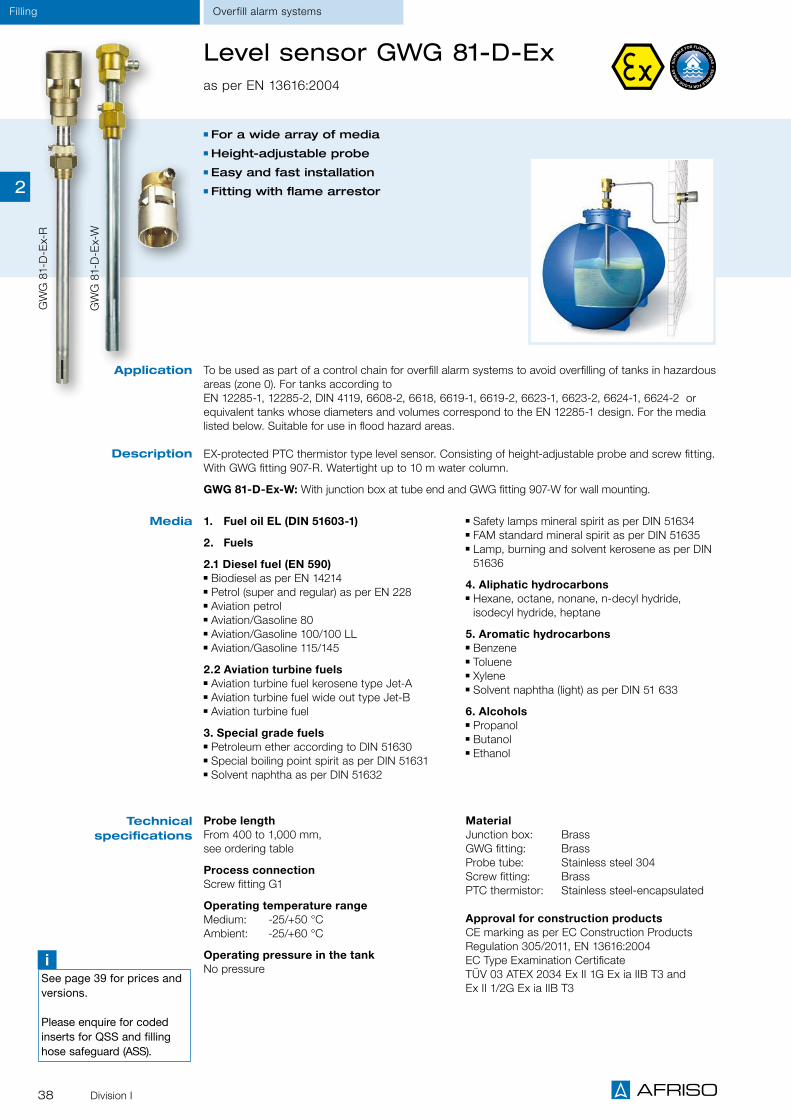
38 Division I
To be used as part of a control chain for overfill alarm systems to avoid overfilling of tanks in hazardous areas (zone 0). For tanks according to EN 12285-1, 12285-2, DIN 4119, 6608-2, 6618, 6619-1, 6619-2, 6623-1, 6623-2, 6624-1, 6624-2 or equivalent tanks whose diameters and volumes correspond to the EN 12285-1 design. For the media listed below. Suitable for use in flood hazard areas.
EX-protected PTC thermistor type level sensor. Consisting of height-adjustable probe and screw fitting. With GWG fitting 907-R. Watertight up to 10 m water column.
GWG 81-D-Ex-W: With junction box at tube end and GWG fitting 907-W for wall mounting.
Level sensor GWG 81-D-Ex as per EN 13616:2004
Application
Description
Media 1. Fuel oil EL (DIN 51603-1)
2. Fuels
2.1 Diesel fuel (EN 590) Biodiesel as per EN 14214 Petrol (super and regular) as per EN 228 Aviation petrol Aviation/Gasoline 80 Aviation/Gasoline 100/100 LL Aviation/Gasoline 115/145
2.2 Aviation turbine fuels Aviation turbine fuel kerosene type Jet-A Aviation turbine fuel wide out type Jet-B Aviation turbine fuel
3. Special grade fuels Petroleum ether according to DIN 51630 Special boiling point spirit as per DIN 51631 Solvent naphtha as per DIN 51632
Safety lamps mineral spirit as per DIN 51634 FAM standard mineral spirit as per DIN 51635 Lamp, burning and solvent kerosene as per DIN 51636
4. Aliphatic hydrocarbons Hexane, octane, nonane, n-decyl hydride, isodecyl hydride, heptane
5. Aromatic hydrocarbons Benzene Toluene Xylene Solvent naphtha (light) as per DIN 51 633
6. Alcohols Propanol Butanol Ethanol
Technical specifications
GW
G 8
1-D
-Ex-
R
GW
G 8
1-D
-Ex-
W
For a wide array of media Height-adjustable probe Easy and fast installation Fitting with flame arrestor
Probe lengthFrom 400 to 1,000 mm, see ordering table
Process connectionScrew fitting G1
Operating temperature rangeMedium: -25/+50 °C Ambient: -25/+60 °C
Operating pressure in the tankNo pressure
MaterialJunction box: BrassGWG fitting: BrassProbe tube: Stainless steel 304 Screw fitting: Brass PTC thermistor: Stainless steel-encapsulated
Approval for construction productsCE marking as per EC Construction Products Regulation 305/2011, EN 13616:2004EC Type Examination Certificate TÜV 03 ATEX 2034 Ex II 1G Ex ia IIB T3 and Ex II 1/2G Ex ia IIB T3
iSee page 39 for prices and versions.
Please enquire for coded inserts for QSS and filling hose safeguard (ASS).
Overfill alarm systemsFilling
2

39Division I
FillingOverfill alarm systems
iOther lengths on request.
Fitting Probe length (mm) DG PG Part no. Price €
GWG 23 – Ro 400 Yellow 400 G 3 1 - 46115
GWG 23 – Ro 700 Yellow 700 G 3 1 - 46116
GWG 23 – Ro 1000 Yellow 1,000 G 3 1 - 46117
GWG 23 – Ro 1500 Yellow 1,500 G 3 1 - 46120
GWG 23 – Ro So Yellow Max. 3,000 G 3 1 - 46118
GWG 23 – Ro 400 Grey 400 G 3 1 - 46125
GWG 23 – Ro 700 Grey 700 G 3 1 - 46126
GWG 23 – Ro 1000 Grey 1,000 G 3 1 - 46127
GWG 23 – Ro 1500 Grey 1,500 G 3 1 - 46129
GWG 23 – Wa 400 Yellow 400 G 3 1 - 46130
GWG 23 – Wa 700 Yellow 700 G 3 1 - 46131
GWG 23 – Wa 1000 Yellow 1,000 G 3 1 - 46132
GWG 23 – Wa 1500 Yellow 1,500 G 3 1 - 46135
GWG 23 – Wa So, special lengths Yellow Up to max. 3,000 G 3 1 - 46133
GWG 23 – T 700 Grey 700Min. length:
860Max. length:
1,290G 3 1 - 47622
GWG 23 – T 1000 Grey 1000 1,160 1,750 G 3 1 - 47623
GWG 81-D-Ex 400-R Brass 400 H 2 4 - 47455
GWG 81-D-Ex 700-R Brass 700 H 2 - - 47456
GWG 81-D-Ex 1000-R Brass 1,000 H 2 - - 47457
GWG 81-D-Ex 400-W Brass 400 H 2 2 - 47440
GWG 81-D-Ex 700-W Brass 700 H 2 9 - 47441
GWG 81-D-Ex 1000-W Brass 1,000 H 2 - - 47442
GWG 83 – UV 400 R Brass 400 H 2 2 - 47504
GWG 83 – UV 500 R Brass 500 H 2 4 - 47505
GWG 83 – UV 600 R Brass 600 H 2 8 - 47506
GWG 83 – UV 700 R Brass 700 H 2 6 - 47507
GWG 83 – UV 800 R Brass 800 H 2 7 - 47508
GWG 83 – UV 900 R Brass 900 H 2 - - 47509
GWG 83 – UV 1000 R Brass 1,000 H 2 11 - 47510
GWG 83 – UV 400 W Brass 400 H 2 4 - 47515
GWG 83 – UV 500 W Brass 500 H 2 25 - 47521
GWG 83 – UV 600 W Brass 600 H 2 - - 47519
GWG 83 – UV 700 W Brass 700 H 2 14 - 47516
GWG 83 – UV 800 W Brass 800 H 2 - - 47522
GWG 83 – UV 900 W Brass 900 H 2 - - 47517
GWG 83 – UV 1000 W Brass 1,000 H 2 2 - 47518
GWG 84 – UVT-R-600-Ms Brass 600Min. length:
825Max. length:
1,210H 2 15 - 47600
GWG 84 – UVT-R-900-Ms Brass 900 1,125 1,735 H 2 13 - 47610
Level sensors for outdoor tanks as per EN 13616:2004
Please enquire for coded plug inserts for QSS and filling hose control system (ASS).
Accessories Fitting DG PG Part no. Price €
GWG fitting 907-W Brass H 2 1 - 40065
GWG fitting 905-W Grey G 1 1 - 40050
GWG fitting 905-W Yellow G 1 1 - 40052
Coupling socket 903 - G 1 1 - 40030
Coupling plug 902 - G 1 1 - 40045
2

40 Division I
Level sensor tester GPR 4
For use with storage tanks for fuel oils and diesel fuels. Not permitted for use in hazardous areas and not for level sensors which are installed in tanks containing hazardous media.
Simple level sensor tester with connector, suitable for all level sensor fittings. A signal lamp indicates function or error. Battery-operated. Delivery with level sensor connection fitting, also suitable for level sensor with brass fitting.
Application
Description
DG: H, PG: 4 Part no. Price €
Level sensor tester GPR 4 62301
Level sensor testers with connector – suitable for all level sensor fittings.
Filling Overfill alarm systems
For fast and easy function tests Suitable for all level sensor fittings Battery operation
iEx-approved level sensor testers on request.
2

41Division I
Overfill prevention systems Filling
Transducer for overfill prevention system UFS 01 (WHG)
To avoid overfilling of stationary tanks and stationary-use tanks.Suitable for a wide range of flammable and non-flammable water-polluting liquids.
Type-approved together with all level probes type series 76 and UFS 01 as part of an overfill prevention system. UFS 01 in a wall mounting housing consists of a transducer and a suitable level probe (to be ordered separately). The transducer contains all display elements and controls as well as all electronic components for signal processing and conversion of the level probe signal into a digital output signal. The level probe and the transducer are connected by means of a two-wire signal cable. When the maximum permissible level is reached, UFS 01 triggers visual and audible alarms. The filling process is stopped. The transducer also features two output relays for connection of event reporting systems, the additional alarm unit ZAG 01 or additional equipment.Ancillary control unit type 907-Z can be connected as an additional control unit to enable connec-tion to a road tanker with filling system.
Compact, modern design With visual/audible alarms, Test and Acknowledge buttons
2 relay outputs for additional alarm equipment, EMS, etc.
Fail-safe, self-monitoring transducer for maximum reliability
Application
Description
Technical specifications
Operating temperature rangeAmbient: -20/+60 °C
Supply voltageAC 230 V or AC/DC 15 – 40 V
Output relay1 changeover contact / 1 normally open contact (can be acknowledged)
HousingWall mounting housing made of impact-resistant plastic (ABS), W x H x D: 100 x 188 x 65 mm
Degree of protectionIP 40 (EN 60529)
Weight 0.6 kg
Approval for construction productsDIBt: Z-65.11-18
DG PG Part no. Price €
Transducer UFS 01, AC 230 V H 4 53202
Transducer UFS 01, AC/DC 15–40 V H 4 53216
Mounting frame G 1 43521
Sealing kit (IP 54) G 1 43416
Ancillary control unit type 907-Z, 230 V H 2 53232
Ancillary control unit type 907-Z, DC 24 V H 2 53262
Fuel oil EL, diesel fuel, biodiesel Diesel/biodiesel mixtures Used gearbox oils and motor oils Unused motor oils, gearbox oils and hydraulic oils
Transformer oil Hexanol 1 Ethyl aceto-acetate (aceto-acetic ester) Acrylic acid 2-ethyl hexylene ester (2-ethyl hexylene acrylate)
Cyclohexyl acetate, benzaldehyde Methyl aceto-acetate
Nitrobenzene, 1.2 dichlorobenzene 2.4 dimethylaniline (N, N dimethylaniline) n octanol (n octyl alcohol) Diethyloxalate Aniline Vegetable oil (also as per EN 51605) Oil/water mixtures (e.g. drilling oil or lubricating oil)
Perchloroethylene and trichloroethylene Antifreeze agents Cleaning agent/water mixtures AdBlue® (urea solution) as per DIN 70070
Media
as well as comparable water-polluting liquids with identical heat conductivity with a flash point of > 55 °C.
iSee page 43 for level probes.
Page 92
A
Page 74
A
P Pump
2

42 Division I
To avoid overfilling of stationary tanks and stationary-use tanks. Suitable for a wide range of flammable and non-flammable water-polluting liquids with a flash point of > 55 ºC (see product description UFS 01 for list of substances).
Application
Transducer NB 220 H Transducer NB 220 QS
Type-approved together with all level probes type series 76 and UFS 01 as part of an overfill preven-tion system. When the level probe comes in con-tact with the liquid, the relay switches.
Type-approved together with all level probes type series 76 and UFS 01 as part of an overfill preven-tion system. With integrated alarm lamp, alarm horn and Mute button for the alarm horn. An external alarm lamp, alarm horn or the additional alarm unit ZAG 01 can be connected via connec-tion terminals. When the level probe comes in contact with the liquid, NB 220 QS generates visual and audible alarms and the relay switches.Ancillary control unit type 907-Z can be con-nected as an additional control unit to enable con-nection to a road tanker with filling system.
Supply voltageAC 230 V or DC 24 V
Power input Max. 4 VA/6 W
OutputVoltage-free changeover contact
Contact ratingAC 250 V, max. 500 VA
Housing (degree of protection)Plug-in housing, (IP 30) W x H x D: 50 x 110 x 110 mm
Approval for construction productsDIBt: Z-65.11-193
Supply voltageAC 230 V
Power inputMax. 4 VA/6 W
Output current circuits 1 x AC 230 V (100 W) e.g. for lamp/solenoid valve, cannot be acknowledged
1 x AC 230 V (50 W) e.g. for horn, can be acknowledged
Housing (degree of protection)Plug-in housing (IP 30)W x H x D 75 x 150 x 110 mm
Approval for construction productsDIBt: Z-65.11-193
Technical specifications
DG: H PG Part no. Price €
Transducer NB 220 H 4 1 - 53210
Transducer NB 220 H – DC 24 V 4 1 - 53219
Transducer NB 220 QS 4 1 - 53213
Ancillary control unit type 907-Z 2 1 - 53232
Additional alarm unit ZAG 01 4 1 - 40633
Transducers for overfill prevention systems (WHG)
iSee page 43 for level probe UFS 01.See page 41 for a list of liquids (substances).
See page 93 for additional alarm unit ZAG 01 with visual/audible alarms.
Description
Overfill prevention systemsFilling
2

43Division I
FillingOverfill prevention systems
High temperature
up to 80 °C
Level probes for overfill prevention systems (WHG)
Level probe for transducers as part of an overfill prevention system for stationary tanks and station-ary-use tanks used to store flammable and non-flammable water-polluting liquids with a flash point of > 55 ºC to 100 ºC (see product description UFS 01 for list of substances).
Level probe UFS 01 Level probe type 76 AH
Approved as part of an overfill prevention system together with level transducer UFS 01, NB 220 H and NB 220 QS. The level probe UFS 01 consists of a probe tube with a stainless steel-encapsulat-ed PTC thermistor sensor at the lower end, a junction box and a screw fitting. Tube length 100 to 3,000 mm in increments of 100 mm. Standard lengths up to 500 mm. The overfill prevention sys-tem must be set up in such a way that the filling process is stopped and a sufficiently loud audible alarm is triggered when the maximum permissible level is reached.
MaterialJunction box: Brass/plastic Probe tube: Stainless steel 316 Ti Screw fitting: Stainless steel 316 Ti PTC thermistor: Stainless steel-encapsulated
Process connectionConnection thread G¾
Operating temperature rangeMedium: -25/+50 °C
Degree of protectionIP 54 (EN 60529)
Approval for construction productsDIBt: Z-65.11-18
Approved as part of an overfill prevention system together with level transducer UFS 01, NB 220 H and NB 220 QS. The level probe type 76 AH con-sists of a probe tube with a stainless steel-encap-sulated PTC thermistor sensor at the lower end, a junction box and a screw fitting. Tube length 100 to 3,000 mm in increments of 100 mm. Standard lengths up to 500 mm. The overfill prevention sys-tem must be set up in such a way that the filling process is stopped and a sufficiently loud audible alarm is triggered when the maximum permissible level is reached.
MaterialJunction box: BrassProbe tube: Stainless steel 304 or 316 Ti Screw fitting: Brass PTC thermistor: Stainless steel-encapsulated
Process connectionConnection thread G¾
Operating temperature rangeMedium: -25/+80 °C
Degree of protectionIP 54 (EN 60529)
Approval for construction productsDIBt: Z-65.11-193
Application
Description
Technical specifications
iSee page 41 for a list of liquids (list of substances).
DG: H, PG: 3 Part no. Price €
Level probe UFS 01100 mm 53245200 mm 53246
300 mm 53247
400 mm 53248
500 mm 53249
Special length 53243 On request
Level probe type 76 AH*500 mm 53214
*Please enquire for other response lengths.
2
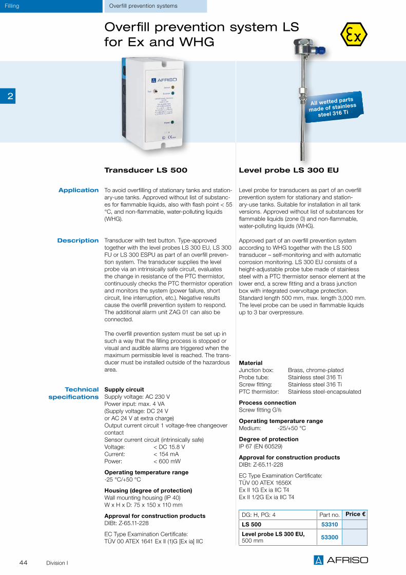
44 Division I
Overfill prevention system LS for Ex and WHG
DG: H, PG: 4 Part no. Price €
LS 500 53310
Level probe LS 300 EU, 500 mm 53300
Transducer LS 500
Supply circuitSupply voltage: AC 230 V Power input: max. 4 VA(Supply voltage: DC 24 V or AC 24 V at extra charge)Output current circuit 1 voltage-free changeover contactSensor current circuit (intrinsically safe)Voltage: < DC 15.8 VCurrent: < 154 mAPower: < 600 mW
Operating temperature range-25 °C/+50 °C
Housing (degree of protection)Wall mounting housing (IP 40) W x H x D: 75 x 150 x 110 mm
Approval for construction productsDIBt: Z-65.11-228
EC Type Examination Certificate: TÜV 00 ATEX 1641 Ex II (1)G [Ex ia] IIC
Application To avoid overfilling of stationary tanks and station-ary-use tanks. Approved without list of substanc-es for flammable liquids, also with flash point < 55 °C, and non-flammable, water-polluting liquids (WHG).
Transducer with test button. Type-approved together with the level probes LS 300 EU, LS 300 FU or LS 300 ESPU as part of an overfill preven-tion system. The transducer supplies the level probe via an intrinsically safe circuit, evaluates the change in resistance of the PTC thermistor, continuously checks the PTC thermistor operation and monitors the system (power failure, short circuit, line interruption, etc.). Negative results cause the overfill prevention system to respond. The additional alarm unit ZAG 01 can also be connected.
The overfill prevention system must be set up in such a way that the filling process is stopped or visual and audible alarms are triggered when the maximum permissible level is reached. The trans-ducer must be installed outside of the hazardous area.
Description
Technical specifications
Overfill prevention systemsFilling
All wetted parts
made of stainless
steel 316 Ti
Level probe LS 300 EU
Level probe for transducers as part of an overfill prevention system for stationary and station-ary-use tanks. Suitable for installation in all tank versions. Approved without list of substances for flammable liquids (zone 0) and non-flammable, water-polluting liquids (WHG).
Approved part of an overfill prevention system according to WHG together with the LS 500 transducer – self-monitoring and with automatic corrosion monitoring. LS 300 EU consists of a height-adjustable probe tube made of stainless steel with a PTC thermistor sensor element at the lower end, a screw fitting and a brass junction box with integrated overvoltage protection. Standard length 500 mm, max. length 3,000 mm. The level probe can be used in flammable liquids up to 3 bar overpressure.
MaterialJunction box: Brass, chrome-plated Probe tube: Stainless steel 316 TiScrew fitting: Stainless steel 316 Ti PTC thermistor: Stainless steel-encapsulated
Process connectionScrew fitting G3/8
Operating temperature rangeMedium: -25/+50 °C
Degree of protectionIP 67 (EN 60529)
Approval for construction productsDIBt: Z-65.11-228
EC Type Examination Certificate:TÜV 00 ATEX 1656XEx II 1G Ex ia IIC T4Ex II 1/2G Ex ia IIC T4
2

45Division I
FillingLevel controllers
PTC thermistor level controller RG 210
Application
Description
Technical specifications
PTC thermistor type level controller with selectable functions: Level switch (1 probe) Level control for filling (2 probes) Level control for emptying (2 probes)
Level switch with 1 probe: The relay switches in case of contact or loss of contact with the liquid. When the switch point is set, it must be observed that the PTC thermistor requires approx. 8 seconds to heat up depending on the ambient temperature.
Level control for filling with 2 probes: Set internal switch to "fill". The relay energises after the min. probe has heated up. Relay de-energises when the max. probe comes into contact with the liquid.
Level control for emptying with 2 probes: Set internal switch to "empty". Relay energises when max. probe has contact with the liquid. Relay de-energises when the min. probe loses contact with the liquid and heats up.
Type 937
Type 150
iNote: Not to be used as an overfill prevention system according to WHG. Requires either the connection of an overflow pipe to the tank or the additional installation of an overfill prevention system according to WHG.
DG: H, PG: 4 Part no. Price €
RG 210 1 - 53206
Flexible PTC thermistor probe type 150 1 - 53208
Flexible PTC thermistor probe type 937 1 - 53204
For use in electrically conductive and non-conductive liquids which are not viscous or adhesive: fuel oil, diesel fuel, emulsions, water, and media which are not corrosive.
Operating temperature range Medium: -25/+55 °CAmbient: -10/+55 °C
ProbePTC thermistor probe, types 150 or 937Cable length 3 m (max. 50 m)Process connection G1
Supply voltageAC 230 V
Power input12 VA
Relay contact (output)1 voltage-free changeover contact
Housing (degree of protection)Plug-in housing (IP 30)W x H x D 53 x 113 x 108 mm
Flexible PTC thermistor probe type 150Flexible PTC thermistor probe designed for use with electrically conductive and non-conductive liquids which are not viscous or adhesive, for connection to RG 210. See RG 210 for further characteristics of the liquids. Stainless steel-en-capsulated PTC thermistor, with oil-resistant probe cable (3 m long) and G1 gland connection, pressure-proof up to 1 bar.
Flexible PTC thermistor probe type 937Flexible PTC thermistor designed for oils and other electrically non-conductive liquids (low-vis-cosity, non-adhesive). The PTC thermistor con-nection wires are not encapsulated. Not suitable for installation in humid environments.
Compact control unit Universal application due to selectable functions Example:
Daily-service tank for fuel oil
①
① Storage tank pump
2

Inner tank linings
Leak detectors - sight glass principle
Vacuum type leak detectors EUROVAC
Leak detectors LAG

47
CHAPTER 3
Leak detectors, leak monitoring systems and inner tank linings
Leak protection, leak monitoring, oil tank conversion 48
OVERVIEW
Leak detectors - sight glass principle LAS 50
Leak detector LAG-13 K 51
Leak detector LAG-14 ER 52
Accessories for leak detectors 53
Vacuum type leak detectors Eurovac 54
Vacuum type leak detector Eurovac NV 55
Vacuum type leak detector Eurovac HV 56
Protective equipment for leak detectors liquid barrier, condensate bar 57
Spare parts for leak detectors 58
LEAK DETECTION
Tank protection package AK-S for fuel oil, diesel 59
Inner linings AF-S for liquid fertiliser AHL, AdBlue® 60
Inner linings for rainwater harvesting 61
Rainwater inner lining AR-SM with magnets 62
Mounting accessories for inner linings 63
Tank room lining 64
LEAK PROTECTION
Pressure type leak detector Europress 65
Pressure type leak detector Europress LAD-R 66
Manifolds for Europress LAD-R 67
3

48 Division I
Leak protection and tank room linings
Professional equipment and convincing solutions for tank protection
The installation of customised AFRISO leak protection linings turns single-walled steel tanks into double-walled tanks. Com-plex drip pans or collection facilities are no longer required. Oil cannot escape even if there is a leak in the outer tank wall. The Eurovac leak detector uses a vacuum in the interstitial space between the inner lining and the tank wall to monitor both walls for leaks. Malfunctions and leaks are immediately signalled.
Damages such as settlement cracks can cause leaks in collec-tion facilities. AFRISO tank room linings in new and renovated installations safely protect tank rooms.
Complete range of products for professional tank protection from a single supplier
Maximum protection against fuel oil accidents with brand products with Technical Approval of the German Institute for Civil Engineering (DIBt)
Chemical resistance even if used with biodiesel, biofuel or admixtures
Inner linings and tank room linings, exactly made to size and ready for easy installation
10 years warranty on material and workmanship for plastic inner linings
Fittings and devices ready to be installed, with all required mounting accessories
Advantages – your benefits
With a comprehensive range of building technology products, AFRISO prides itself in "Making Tanks Safe". In addition to this extensive range, a large selection of alarm instruments for the fast detection of level, liquid spillage, leakage, gas or smoke is available.
Leak monitoring Overview
3

49Division I
Application areas Cylindrical steel or plastic (glass-fibre reinforced plastic) tanks
Double-walled steel tanks Steel tanks manufactured on site
Spherical tanks Tanks with inner lining Inspection ducts Oil storage rooms/collection facilities
Containers, cisterns, cesspits
Media Fuel oil EL Diesel fuel Biofuel Biodiesel AHL AdBlue®
Rainwater Other liquids
If oil tanks can no longer be used or if the heating system is con-verted to other types of energy or if old unused cesspits and cis-terns are available, the containers can be equipped with a plastic inner lining for rainwater harvesting and integrated into a rainwater harvesting system.Various conversion kits, inner linings and a complete range of accessories are available.
Leak monitoring
Oil tank conversion kits
Leak detectors and AFRISO line of alarm unitsThe uniform appearance not only ensures customer confidence, but also underpins the professionalism of the specialised company.
Leak monitoringOverview
3

50 Division I
Leak detection Sight glass principle
Leak detectors LAS - sight glass principle
① Make sure to observe height② Min. 100 mm③ Min. 500 mm④ Max. 5 m to tank bottom
①
②
③
④
Application
Description
For aboveground double-walled tanks containing flammable liquids and non-flammable, water-polluting liquids. Application under atmospheric conditions for steel tanks and double-walled tanks with approv-al for leak detectors. Types LAS 24 E, LAS 39 E and LAS 72 E for all water-polluting liquids. Types LAS 24, LAS 39, LAS 72 and LAS 230 for water-polluting with a flash point of ≥ 55 °C.
Leak detector for liquid systems consisting of a transparent acrylic glass cylinder, stainless steel hous-ing covers and bottoms. Connection thread G1. Approval for construction products DIBt: Z-65.24-381. Version E with wire mesh cylinder. LAS 24 EK for mobile tanks with tilting valve to protect against loss of leak detection fluid during transport and for venting on site. LAS 39 and 72 with G1 connection at the side for up to 4 additional containers with 4.5 litres each. The additional containers allow for leak detection at tanks with a greater interstitial space (see overview).
DG: H, PG: 3 Active volume
Interstitial space of tank
Max. no. of additional tanks Part no. Price €
LAS 24 0.7 l max. 24 l - 43515
LAS 24 E 0.7 l max. 24 l - 43516
LAS 24 EK 0.7 l max. 24 l - 43517
LAS 39 1.1 l max. 39 l 4 43526
LAS 39 E 1.1 l max. 39 l 4 43525
LAS 72 2.1 l max. 72 l 4 43528
LAS 72 E 2.1 l max. 72 l 4 43527
LAS 230 6.6 l max. 232 l - 43550
Mounting kit LAS 0(test valve) - - - 43529
Mounting kit LAS 1* - - - 43530
Mounting kit LAS 2* - - - 43531
Mounting kit LAS 3* - - - 43532
Mounting kit LAS 4* - - - 43533
* Including the corresponding number of additional containers (Ex-Elstat I)
Overview LAS 72 with
additional containers
LA
S 2
4
LA
S 7
2
LA
S 2
30
Versions
Number of
addition-al con-tainers
Active volume LAS 72 and additional
containers in litres
Max. leak detection fluid
in the interstitial space in litres
To be used for tanks
with a volume of litres
0 2.1 l max. 72 l approx. 10,000 l
1 6.6 l max. 230 l approx. 40,000 l
2 11.1 l max. 387 l approx. 60,000 l
3 15.6 l max. 545 l approx. 80,000 l
4 20.1 l max. 700 l* approx. 100,000 l
Values for LAS 39 on request.* Design 1975–1985
Tilting valve closes vent if the tank tips over.
3

51Division I
Leak detectionLiquid-based
Leak detector LAG-13 KClass II, EN 13160-1, -3
Page 53
A
DG: G PG Part no. Price €
LAG-13 K (not intrinsically safe), with container and probe 4 1 5 43500
LAG-13 K (not intrinsically safe), EnOcean®-inside, with container and probe
4 1 - 43504
LAG container white without probe 1 1 - 40730
Control unit LAG-13 K 4 1 - 40630
Accessories
Mounting frame 1 1 - 43521
Sealing kit (IP 54) 1 1 - 43416
LAG mounting kit 1 1 - 40540
Mounting kit for 1 additional LAG container (without con-tainer)
1 1 - 40539
Leak detection fluid - concentrate 1 1 - 43645
Version as per WHG and BetrSichV For monitoring of aboveground, double-walled tanks
With Fail-Safe mode Easy, wireless integration into smart building system AFRISOlab
For double-walled tanks with liquid in the interstitial space. For monitoring flammable and non-flamma-ble water-polluting liquids with a flash point of ≥ 55 °C stored aboveground. Approved for all suitable tanks under atmospheric conditions.
Since July 2003, the LAG-13 leak detector may only be used for replacement deliveries for under-ground, double-walled tanks as a result of the reclassification of water-polluting liquids in Germany!
Class II leak detector (EN 13160-1), not intrinsically safe. Consisting of control unit, leak detection fluid container (LAG container white) and probe. Control unit with operating and alarm indicators, audible/visual alarm, test button and increased interference protection. The audible alarm can be muted with the Acknowledge button. With fail-safe mode: Alarm is triggered if the probe fails. Suitable for panel mounting with a mounting frame; a sealing kit (IP 54) is available for rough application conditions. The LAG container serves as detection container and as expansion vessel at the same time. For aboveground tanks, the ratio between usable contents and total volume of leak detection fluid must be no more than 1:35. If the interstitial space has a greater volume, you must use an additional container.Alarm units with the EnOcean®-inside label allow for easy, wireless integration into your existing build-ing automation systems. The EnOcean® wireless module TCM 320 is already integrated in the device. The AFRISO gateway in conjunction with additional AFRISO products with EnOcean® wireless technol-ogy allow you to configure a whole range of fully customisable, extensible features for the protection of plants and buildings.
Application
Description
Technical specifications
Operating temperature rangeAmbient: -5/+55 °C Storage: -10/+60 °C
Supply voltageAC 230 V
Control unitWall mounting housing made of impact-resistant plastic (ABS) W x H x D: 100 x 188 x 65 mm Degree of protection: IP 40 (EN 60529)
TanksPlastic, white W x H x D: 300 x 325 x 145 mm Usable contents / total contents: 4.5 l / 10 l Outlet: G¾ Degree of protection: IP 20 (EN 60529)
Approval for construction productsCE marking as per EC Construction Products Regulation 305/2011, EN 13160-1 and ÜHP
iSee page 53 for a detailed product description LAG container.
Page 90
A3

52 Division I
Leak detection Liquid-based
Leak detector LAG-14 ERClass II, EN 13160-1, -3
Description
DG: G PG Part no. Price €
LAG-14 ER with relay, including container and probe 4 1 5 43410
LAG container black, without probe 1 1 5 40731
Control unit LAG-14 ER 4 1 - 40642
Accessories
Mounting frame 1 1 - 43521
Sealing kit (IP 54) 1 1 - 43416
ATEX approval Version as per German WHG and BetrSichV
With Fail-Safe mode For monitoring of aboveground, double-walled tanks
For double-walled tanks with liquid in the interstitial space. For monitoring flammable and non-flammable water-pollut-ing liquids stored aboveground. The LAG container can be installed in hazardous areas zones I and II (e.g. manhole of petrol tanks). Approved for all suitable tanks under atmospheric conditions.
Since July 2003, the LAG-14 leak detector may only be used for replacement deliveries for under-ground, double-walled tanks as a result of the reclassification of water-polluting liquids in Germany!
Class II leak detector (EN 13160-1), with intrinsically safe probe circuit. The system consists of a control unit, a container for leak detection fluid (LAG container black) and a probe. Control unit with operating and alarm indicators, audible/visual alarm, test button and increased interference protection. The audible alarm can be muted with the Acknowledge button. The voltage-free relay contact is provided for con-nection of additional external alarm equipment (such as horns,) or an additional alarm unit ZAG 01. With fail-safe mode: Alarm is triggered if the probe fails. Suitable for panel mounting with a mounting frame; a sealing kit (IP 54) is available for rough application conditions. The LAG container serves as detection container and as expansion vessel at the same time. For aboveground tanks, the ratio between usable contents and total volume of leak detection fluid must be no more than 1:35. If the interstitial space has a greater volume, you must use an additional container.
Application
Operating temperature rangeAmbient: -5/+50 °C Storage: -10/+60 °C
Supply voltageAC 230 V
Control unitW x H x D: 100 x 188 x 65 mm Degree of protection: IP 30 (EN 60529)
Switching outputsRelay outputs: 1 voltage-free changeover contact Contact rating: AC 250 V, 2A
TanksAntistatic plastic, black W x H x D: 300 x 325 x 145 mm Usable contents / total contents: 4.5 l / 10 l Outlet: G¾ Degree of protection: IP 20 (EN 60529)
Approval for construction productsCE marking as per EC Construction Products Regulation 305/2011, EN 13160-1 and ÜHP
ATEX approvalEX5 11 02 15639 011 Ex II (1) G [Ex ia] IIC
Technical specifications
Page 90
A
Page 53
A
Page 93
A
iSee page 53 for a detailed product description LAG container.
3

53Division I
Liquid-based Leak detection
Leak detection fluid concentrate
For use with leak detectors for double-walled tanks. Concentrate for mixing the leak detection fluid for the interstitial space. 10 l container with 4 l leak detection fluid concentrate Antifrogen N (BAM no.: 1.3/9790-5.1/3436), can be mixed with water to 8 l at up to -30 °C or 10 l at up to -25 °C. Please enquire for larger contain-ers.
Description
Mounting frame and sealing kit
Suitable for all wall mounting housings of the AFRISO WATCHDOG series (alarm units). Mounting frame for fast integration into control cabinet. Sealing kit for rough application conditions. The sealing kit is easy to mount between the housing cover and base. This increases the degree of protection of the alarm unit to IP 54.
Description
Accessories for leak detectors
LAG container
Detection container for LAG leak detectors. The LAG container also serves as an expansion vessel. For aboveground tanks, the ratio between usable contents and total volume of leak detection fluid must be no more than 1:35. If the interstitial space has a greater volume, you must use an additional container.
Since July 2003, the LAG-14 ER leak detector may only be used for replacement deliveries for underground, double-walled tanks as a result of the reclassification of water-polluting liquids in Germany.
LAG container blackSuitable for LAG-14 ER, for all stored liquids W x H x D: 300 x 325 x 145 mm Usable contents / total contents: 4.5 l / 9.7 l Outlet: G¾ Degree of protection: IP 20 (EN 60529)
LAG container whiteSuitable for LAG-13 K, for all liquids with a flash point ≥ 55 °C W x H x D: 300 x 325 x 145 mm Usable contents / total contents: 4.5 l / 10 l Outlet: G¾ Degree of protection: IP 20 (EN 60529)
Description
Technical specifications
Technical specifications
LAG container white
LAG container black
Leak detection fluid - concentrate
Mounting frame and sealing kit
LAG mounting kit
DG: G, PG: 1 Part no. Price €
LAG container white 1 1 40730
LAG container black 1 1 40731
LAG mounting kit 1 - 40540
Mounting kit for 1 additional LAG container (container not included in scope of delivery) 1 1 40539
Leak detection fluid - concentrate 1 - 43645
Mounting frame 1 1 43521
Sealing kit (IP 54) 1 1 43416
LAG mounting kit
For approved hydraulic mounting of leak detectors.Description
3

54 Division I
Vacuum type leak detectors Eurovac
Your benefits Class I, EN 13160-1, -2 leak detector Modern housing design, in line with other AFRISO devices Large supply voltage range (AC 100–240 V) for worldwide application
With power failure monitoring (with optional 9 V battery) Indication of pump operating time Low-noise operation Electronic pressure sensor for permanently stable switching points
Drilling template included – for easy and fast installation Relay output for additional signalling devices, additional alarm units, event reporting systems or for integration into building control systems
Version in protective housing (IP 55), available with heating and/or horn
VacuumLeak detection
Sintered plastic filter and condensate trap to indicate the current degree of pollution and to protect the pump
Robust wall mounting housing with hole pattern – suitable for most standard vacuum type leak detectors
Connection measuring line
Connection exhaust line
Connection suction line
Control panel with visual/audible alarms and Acknowledge button
Service indicator for annual maintenance
High energy efficiency: economical, powerful DC motor with high starting torque
Supply voltage
New hose connection technolo-gy for permanently improved tightness. Hose connections (Ø 4/6 mm) for the pneumatic connection to the interstitial space of the tank.
Can be combined with EnOcean® wireless module TCM 320 for integration
into building automation
systems.
EnOcean-ready
Eurovac in protective housing
3

55Division I
Vacuum
iSee page 59 for inner lin-ings and mounting accessories.
See the catalogue- PORTABLE MEASURING INSTRUMENTS, page 35, for vacuum testers for leak detectors.
Leak detection
Vacuum type leak detector Eurovac NVas per WHG and BetrSichV, class I, EN 13160-1, -2
With visual and audible alarms, Acknowledge button and switching output
High energy efficiency: economical, powerful DC motor with high starting torque
Service indicator for annual maintenance With power failure monitoring
Class I vacuum type leak detector according to EN 13160 for safe monitoring of double-walled tanks and single-walled tanks with inner lining for the storage of non-flammable liquids and flammable liquids with a flash point ≥ 55 °C as well as AdBlue® (urea solution 32.5 %) according to DIN 70070. The broad voltage range (AC 100–240 V) allows for application in a large variety of countries.
Compact leak detector in a robust wall mounting housing with audible and visual alarms. The audible alarm can be muted with the Acknowledge button. Eurovac NV maintains a vacuum in the interstitial space of the tank (low vacuum range). The vacuum pump is operated by an economical DC motor with a high starting torque (energy efficiency class AA++). Eurovac features a switching output for additional equipment (such as additional alarm unit ZAG 01) or integration into building control systems. The pump operating time can be displayed.Three hose connections (red, white, green) for the pneumatic connection to the interstitial space of the tank. The universal connection pieces can be used for 4 mm and 6 mm hoses.With condensate trap to protect the electronics. Electrical connection from the top or from the bottom. An optional 9 V battery can be connected so that an alarm is triggered in the case of power failure. For outdoor applications, Eurovac NV is available in a protective housing (IP 55). Alarm units with the EnOcean-ready label can be integrated into your existing building automation systems at a later point in time. To do so, plug the EnOcean® wireless module TCM 320 into the EnOcean® interface (PCB of the device). The AFRISO Gateway in conjunction with additional AFRISO products with EnOcean® wireless technology allow you to configure a whole range of fully customisa-ble, extensible features for the protection of plants and buildings.
Application
Description
Technical specifications
Operating temperature rangeAmbient: -5/+50 °C In protective housing with heating: -25/+50 °C
Supply voltageAC 100–240 V
Nominal power< 10 VA
Switching outputRelay contact: 1 voltage-free changeover contact
Contact ratingMax. 250 V, 2 A, resistive load
Operating pressure Interstitial space: -70 mbar
HousingWall mounting housing made of impact-resistant plastic (ABS) W x H x D: 202 x 230 x 70 mm Degree of protection: IP 30 (EN 60529)
Alarm soundMin. 70 dB(A)
Approval for construction productsCE marking as per EC Construction Products Regulation 305/2011, EN 13160-1, -2 and ÜHP
PG: 4 DG Part no. Price €
Eurovac NV (low vacuum) H 43755
Eurovac NV in protective housing (IP 55) without heating, without horn H 43788
Eurovac NV in protective housing (IP 55) without heating, with horn H 43782
Eurovac NV in protective housing (IP 55) with heating, without horn H 43792
Eurovac NV in protective housing (IP 55) with heating and horn H 43789
EnOcean® wireless module TCM 320 G 78082
Page 57
A
Page 93
A
Page 356
A3
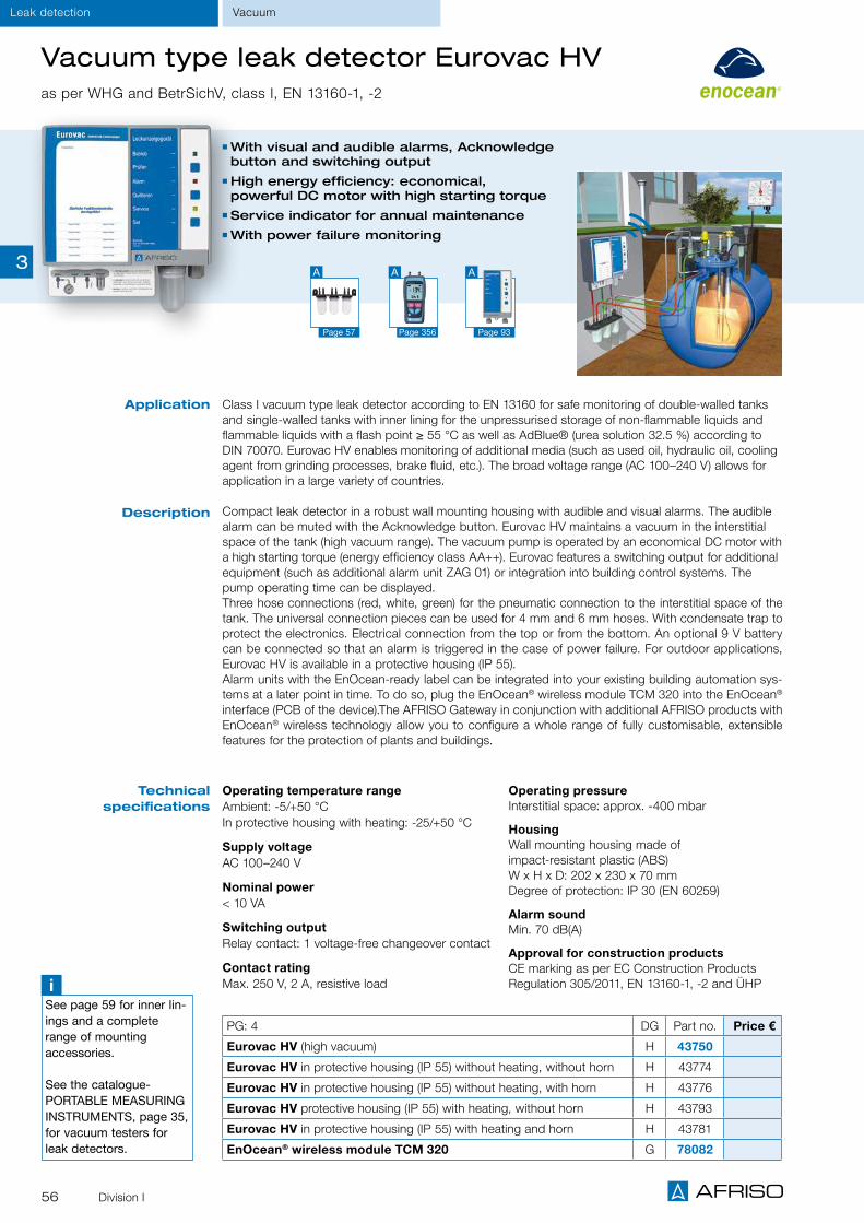
56 Division I
VacuumLeak detection
Vacuum type leak detector Eurovac HVas per WHG and BetrSichV, class I, EN 13160-1, -2
Class I vacuum type leak detector according to EN 13160 for safe monitoring of double-walled tanks and single-walled tanks with inner lining for the unpressurised storage of non-flammable liquids and flammable liquids with a flash point ≥ 55 °C as well as AdBlue® (urea solution 32.5 %) according to DIN 70070. Eurovac HV enables monitoring of additional media (such as used oil, hydraulic oil, cooling agent from grinding processes, brake fluid, etc.). The broad voltage range (AC 100–240 V) allows for application in a large variety of countries.
Compact leak detector in a robust wall mounting housing with audible and visual alarms. The audible alarm can be muted with the Acknowledge button. Eurovac HV maintains a vacuum in the interstitial space of the tank (high vacuum range). The vacuum pump is operated by an economical DC motor with a high starting torque (energy efficiency class AA++). Eurovac features a switching output for additional equipment (such as additional alarm unit ZAG 01) or integration into building control systems. The pump operating time can be displayed.Three hose connections (red, white, green) for the pneumatic connection to the interstitial space of the tank. The universal connection pieces can be used for 4 mm and 6 mm hoses. With condensate trap to protect the electronics. Electrical connection from the top or from the bottom. An optional 9 V battery can be connected so that an alarm is triggered in the case of power failure. For outdoor applications, Eurovac HV is available in a protective housing (IP 55). Alarm units with the EnOcean-ready label can be integrated into your existing building automation sys-tems at a later point in time. To do so, plug the EnOcean® wireless module TCM 320 into the EnOcean® interface (PCB of the device).The AFRISO Gateway in conjunction with additional AFRISO products with EnOcean® wireless technology allow you to configure a whole range of fully customisable, extensible features for the protection of plants and buildings.
Application
Description
With visual and audible alarms, Acknowledge button and switching output
High energy efficiency: economical, powerful DC motor with high starting torque
Service indicator for annual maintenance With power failure monitoring
Operating temperature rangeAmbient: -5/+50 °C In protective housing with heating: -25/+50 °C
Supply voltageAC 100–240 V
Nominal power< 10 VA
Switching outputRelay contact: 1 voltage-free changeover contact
Contact ratingMax. 250 V, 2 A, resistive load
Operating pressureInterstitial space: approx. -400 mbar
HousingWall mounting housing made of impact-resistant plastic (ABS) W x H x D: 202 x 230 x 70 mm Degree of protection: IP 30 (EN 60259)
Alarm soundMin. 70 dB(A)
Approval for construction productsCE marking as per EC Construction Products Regulation 305/2011, EN 13160-1, -2 and ÜHP
Technical specifications
PG: 4 DG Part no. Price €
Eurovac HV (high vacuum) H 43750
Eurovac HV in protective housing (IP 55) without heating, without horn H 43774
Eurovac HV in protective housing (IP 55) without heating, with horn H 43776
Eurovac HV protective housing (IP 55) with heating, without horn H 43793
Eurovac HV in protective housing (IP 55) with heating and horn H 43781
EnOcean® wireless module TCM 320 G 78082
iSee page 59 for inner lin-ings and a complete range of mounting accessories.
See the catalogue- PORTABLE MEASURING INSTRUMENTS, page 35, for vacuum testers for leak detectors.
Page 356
A
Page 57
A
Page 93
A3

57Division I
Vacuum Leak detection
Protective equipment for Eurovac leak detectors
Liquid barrier Condensate bar
For increased reliability and for the protection of vacuum type leak detectors used on dou-ble-walled tanks.
Liquid barrier with condensate trap for visual inspection, complete with fixing bracket for easy mounting to manhole cover. The liquid barrier is mounted directly into the suction line between the leak detector and the double-walled tank. The liquid carried in the suction line (condensate or, in the event of a leak, the medium or groundwater) is collected in the condensate trap of the liquid bar-rier. An integrated float shuts off the suction line if too much liquid is contained in the liquid barrier. The condensate trap can be easily unscrewed for emptying.
Tightness-tested Compact, robust design made of high-strength plastic
Compatible with hoses with 4/6 mm inside diameter
Hose connectionInterchangeable Ø 4 or 6 mm
HousingPlastic
Scope of delivery Liquid barrier with condensate trap Mounting bracket Hose connection Ø 4/6 mm
Application
Description
For the protection of vacuum type leak detectors used on double-walled tanks to avoid ingress of condensate liquid into the device or the system.
Condensate bar with three condensate traps for visual inspection, with integrated bracket for easy wall mounting. If there is no steady gradient in the measuring, exhaust and suction lines from the leak detector to the tank, a condensate bar must be mounted at each lowest point of the lines. When condensate forms, the liquid is collected in the relevant condensate trap. The condensate traps can be easily unscrewed for emptying.
Tightness-tested Compact, robust design made of high-strength plastic
Compatible with hoses with 4/6 mm inside diameter
Hose connectionØ 4 and 6 mm
HousingPlastic
Scope of deliveryCondensate bar with 3 condensate traps
Vent valve
Mea
surin
g.
Vent
Suc
tion
Con
dens
ate
trap
with
ch
eck
valv
e
3-way cock
El. connection
Tank vent
transparent
Gre
en
Red
Liquid barrier
Outer tank wall
Interstitial space
In case of irregular slopeuse condensate bar
Mounting diagram
DG: H, PG: 1 Part no. Price €
Liquid barrier 1 1 43646
Condensate bar 1 1 43692
Technical specifications
3

58 Division I
Spare parts for leak detectorsWhen ordering spare parts, please specify the unit designation (refer to type designation plate on the control unit). Spare parts for discontinued models are also listed. Visit www.afriso.de for additional spare parts lists.
DG: G PG Part no. Price €
LAG probe, plug-in connection, for LAG 13 and LAG 14 1 1 - 40510
Foil keypad for control units 1996 and later 4 1 - 18 05 000002
Foil keypad for control units 2007 and later 4 1 - 18 05 000003
Spare parts LAG mounting kit
Test valve plastic, complete 1 1 - 40555
Double nipple G1 1 1 - 40556
Hose connection G1 (angled) 1 1 - 40557
Hose nipple G¾ 1 1 - 40558
Hose EPDM 14 x 3 (price per m) 1 Specify length
Specify length 40543
LAG spare parts
LAZ spare parts
Eurovac/Europress spare parts
DG: H PG Part no. Price €
Pump with motor LAZ-04/1 (HV) 4 1 - 43651
Pump with motor LAZ-04/3 (NV) 4 1 - 43652
Pressure switch HV 4 1 - 43653
Pressure switch NV 4 1 - 43654
Complete PCB with relay 4 1 - 43639
Check valve LAZ 1 1 - 43605
"Operation" indicator lamp LAZ-04 (yellow) 4 1 - 43659
"Alarm" indicator lamp LAZ-04 (red) 4 1 - 43658
"Operation" indicator lamp LAZ-04 (green) 4 1 - 43661
DG: H PG Part no. Price €
Pump with motor Eurovac HV 4 1 - 43777
Pump with motor Eurovac NV 4 1 - 43783
Pressure switch Eurovac HV up to year of manufacture 07/2011 4 1 - 43780
Pressure switch Eurovac NV up to year of manufacture 07/2011 4 1 - 43787
Foil keypad Eurovac / Europress 4 1 - 18 05 000004
VacuumLeak detection
3

59Division I
Tank protection package AK-S for fuel oil and diesel Inner linings with complete accessories as per EN 13160-7
Tank protection package with Technical Approval of the German Institute for Civil Engineering (DIBt) for cylindrical tanks. Enquire for rectangular and spherical tanks.
Application
Scope of delivery
iOn request: Dimensional drawings for customised inner linings
Tank protection packages for rectangu-lar and spherical tanks
Training seminars on installation of inner linings and leak detectors
DG: H, PG: 1 Part no. Price €
3,000 l 43901.003
5,000 l 43901.005
7,000 l 43901.007
10,000 l 43901.010
13,000 l 43901.013
15,000 l 43901.015
16,000 l 43901.016
20,000 l 43901.020
25,000 l 43901.025
30,000 l 43901.030
40,000 l 43901.040
50,000 l 43901.050
60,000 l 43901.060
80,000 l 43901.080
100,000 l 43901.100
AK-S for cylindrical, standard tanks (EN/DIN)
Description
Leak protection lining according to standard or made to size
Vacuum type leak detector Eurovac Front wall lining made of fleece LSV2 Intermediate layer made of fleece Mipoplast plate 800 x 800 mm Condensate bar triple 4/6 mm Liquid barrier 4/6 mm Angled nipple with spacer 6 x 6 or 6 x 4 mm
Angled nipple long 6 x 6 or 6 x 4 mm PVC suction line 3 x 6 mm perforated and not perforated
Fastening ring 500 mm or 600 mm Hose connector 6 x 6 mm T piece hose connection 6 x 6 x 6 mm Hose connector kit G3/8 x G1/8 x G4/6 mm Warning sign with holder and felt overshoes
For fuel oil EL (DIN 51603-1), diesel fuel (EN 590) and biofuel (EN 14213) as well as biodiesel (EN 14214) with up to 20 % FAME.
DIBt: Z-65.30-162, CE marking as per EC Construction Products Regulation pending
Approval for construction products
Leak protectionInner tank linings
FO
R BIO-OIL
FÜ
R B I O - Ö
L
20%
3

60 Division I
Inner linings AF-S for the storageof liquid fertiliser AHL, AdBlue®
iOn request: Dimensional drawings for customised inner linings
Complete tank protection packages Training seminars on installation of inner linings and leak detectors
DG: H, PG: 1 Part no. Price €
2,000 l 43880.002
3,000 l 43880.003
4,000 l 43880.004
5,000 l 43880.005
6,000 l 43880.006
7,000 l 43880.007
8,000 l 43880.008
9,000 l 43880.009
10,000 l 43880.010
11,000 l 43880.011
12,000 l 43880.012
13,000 l 43880.013
14,000 l 43880.014
15,000 l 43880.015
16,000 l 43880.016
20,000 l 43880.020
25,000 l 43880.025
30,000 l 43880.030
40,000 l 43880.040
50,000 l 43880.050
60,000 l 43880.060
80,000 l 43880.080
100,000 l 43880.100
DG: H, PG: 1 Part no. Price €
Inner linings for AHL and AdBlue® for rectangular tanks per m2 43870
Stainless steel fastening ringV2A flat steel (without seal), 40 x 8 mm, glass bead blasted, 500 mm diameter.
43900N
Stainless steel fastening ringV2A flat steel (without seal), 40 x 8 mm, glass bead blasted, 600 mm diameter.
43900O
Fastening ring
Inner lining
Intermediate layer (fleece)
Liquid barrier
Suction line/suction line perforated
Eurovac leak detector
*Please enquire for larger linings and other shapes. Scope of delivery does not include accessories.
ApplicationFor liquid fertiliser AHL and urea solution 32.5 % AdBlue®.
DescriptionPlastic inner linings, blue, with Technical Approval of the German Institute for Civil Engineering (DIBt) for cylindrical standard tanks, rectangular tanks consisting of steel, glass fibre reinforced or asbestos cement manufactured on site. Made of PVC film WP6120, 0.8 mm thick.
When AdBlue® is stored, the surface temperature must not exceed 35 °C!
Approval for construction productsDIBt: Z-65.30-483, CE marking as per EC Construction Products Regulation pending
Inner linings for AHL and AdBlue® for cylindrical standard tanks (EN/DIN)
Measuring line
Exhaust line
Inner tank liningsLeak protection
3

61Division I
DG: H, PG: 1
Part no. Price €
3,000 l 43888.003
4,000 l 43888.004
5,000 l 43888.005
6,000 l 43888.006
7,000 l 43888.007
8,000 l 43888.008
9,000 l 43888.009
10,000 l 43888.010
11,000 l 43888.011
12,000 l 43888.012
13,000 l 43888.013
14,000 l 43888.014
15,000 l 43888.015
16,000 l 43888.016
17,000 l 43888.017
18,000 l 43888.018
19,000 l 43888.019
20,000 l 43888.020* Scope of delivery does not include accessories.
Inner linings for rainwater harvesting
ApplicationWhen old heating oil storage tanks are taken out of service, for example due to corrosion, or if the heating system is converted to other types of fuel, the existing tanks can be used to collect rain-water. For integration into a rainwater harvesting system, the tank is cleaned and then fitted with a special inner lining suitable for water. The old, standardised manhole cover (Ø 500 mm) is replaced with a plastic cover specially designed for rainwater har-vesting.
DescriptionPlastic inner linings for rainwater tanks. For hygienic sealing of cylindrical or rectangular tanks to be used in rainwater harvesting systems. Please enquire for inner linings for spherical tanks, cis-terns, cesspits and other containers. It is advisable to install a leak detector, but this is not mandatory in the case of cylindrical tanks.
Inner lining for rainwater for cylindrical tanks *
Inner lining for rainwater for rectangular tanks *
iSee page 63 for accessories, see page 290 for plastic manhole cover.
DG: H, PG: 1
Part no. Price €
3,000 l 43887.003
5,000 l 43887.005
7,000 l 43887.007
10,000 l 43887.010
13,000 l 43887.013
15,000 l 43887.015
16,000 l 43887.016
20,000 l 43887.020
25,000 l 43887.025
30,000 l 43887.030
40,000 l 43887.040
50,000 l 43887.050
60,000 l 43887.060
80,000 l 43887.080
100,000 l 43887.100* Scope of delivery does not include accessories.
Other tanks, cisterns, cesspits, etc. can also be sealed and converted to hygienic storage facilities by means of internal linings. Please enquire.
Leak protectionInner tank linings
3

62 Division I
Rainwater inner lining AR-SM with magnets
For converting cylindrical steel DIN tanks such as decommissioned fuel oil tanks, diesel tanks or storage tanks into reliable, high-grade rainwater storage tanks. No pressure or flow required. The rainwater inner lining AR-SM with magnets is suitable for storing rainwater in cylindrical steel tanks (3,000 to 60,000 litres).
The new rainwater inner lining AR-SM (patent pending) with magnets allows owners to convert a decommissioned steel tank into a rainwater storage tank with very little effort. Please note: In the case of coated steel tanks, verify that the attractive force of the magnets is sufficient.
The rainwater inner lining AR-SM is a PVC lining with flat, round, extremely powerful neodymium mag-nets welded into lateral and top areas. The lining is reliably held at the inner wall by the magnets - no pressure or flow are required inside the tank. A tank can be conveniently converted into a rainwater storage tank: First, the tank is measured and then a precisely fitting lining is manufactured. The tank is prepared on the basis of a defined procedure (thorough cleaning of the tank, corrosion checks, etc.); depending on the condition of the tank, a fleece layer is placed on the tank floor for impact protection.
Then the lining is fitted in the tank and inflated by means of a blower; if necessary, the final fit is achieved by means of a vacuum pump. When the PVC lining is inflated, the magnets click into place exactly where planned. The fit of the PVC lining is checked and then it is fastened in the manhole by means of a fastening ring. The tank is ready for storing rainwater immediately after the lining has been installed.
Rainwater inner lining AR-SM, made of plastic film Sikaplan® WP5140-08 black, film thickness 0.8 mm, for closed tanks, with all neodymium magnets welded into the film in the lateral and top areas, with film flange for the standard fastening ring.
iDepending on the local conditions and on the tank, a fleece lining may be required in the bottom area of the tank for impact pro-tection. Different dome dis-tances and special dimen-sions are manufactured at the same conditions.
iNot only cylindrical DIN steel tanks, but certain steel tanks with different geomet-rical shapes can be con-verted into rainwater stor-age tanks. Please enquire.
Description
Application
PG Part no. Price €
Extra charge for additional access chamber
500 mm 1 08027
600 mm 1 08024
Accessories (DG: H)
Fastening ring Ø 500 mm 3 43900A
Fastening ring Ø 600 mm 3 43900C
Fleece LSV2 1 x 2 m plate 1 43952
Scope of delivery
Operation without vacuum type leak detector, no pressure, no current
Easy and fast installation by means of power-ful neodymium magnets
Perfectly fitting, robust PVC lining
DG: H, PG: 1 Part no. Price €
3,000 l 43889.003
5,000 l 43889.005
7,000 l 43889.007
10,000 l 43889.010
13,000 l 43889.013
15,000 l 43889.015
16,000 l 43889.016
20,000 l 43889.020
25,000 l 43889.025
30,000 l 43889.030
40,000 l 43889.040
50,000 l 43889.050
60,000 l 43889.060
80,000 l 43889.080
100,000 l 43889.100
Page 290
A
Page 288
A
Inner tank liningsLeak protection
3

63Division I
DG: H Designation Specification PG Part no. Price €
a) Condensate bar Connections 4/6 mm 1 1 - 43692
b) Liquid barrier with con-densate trap and fastening
bracketConnections 4/6 mm 1 1 - 43646
Angled nipple withspacer
6 x 4 mm 2 1 - 43904
6 x 6 mm 2 1 - 43905
a) Angled nipple short6 x 4 mm 2 1 25 43906
6 x 6 mm 2 1 10 43907
b) Angled nipple long6 x 4 mm 2 1 10 43908
6 x 6 mm 2 1 10 43909
a) Suction line perforated (roll of 100 m) 6 x 3 mm 1 1 - 43910
b) Suction linenot perforated (roll of 100 m) 6 x 3 mm 1 1 - 43911
Fastening ring withround seal,foam rubber
Ø 500 mm 3 1 - 43900A
Ø 550 mm 3 1 - 43900B
Ø 600 mm 3 1 - 43900C
Ø 620 mm 3 1 - 43900D
Hose connector for suction hose
4 x 4 mm 1 1 25 43945
6 x 6 mm 1 1 25 43912
T piece for suction hose
4 x 4 x 4 mm 1 1 25 43944
6 x 6 x 6 mm 1 1 25 43913
Hose connector kit ND 4/6, G3/8 x G1/8
ND 4 x G1/8
ND 6 x G1/8 G3/8 x G1/8
1 1 25 43914
Plate holder with plate and clamp 3 1 - 43918
PVC hose red100 m
4 x 2 mm 1 1 - 43648
6 x 2 mm 1 1 - 43662
PVC hose green100 m
4 x 2 mm 1 1 - 43649
6 x 2 mm 1 1 - 43663
PVC hose transparent100 m
4 x 2 mm 1 1 - 43650
6 x 2 mm 1 1 - 43664
Sealing material 1 kg Glue 0.9 kg
Epple 28 1 1 - 43919
Epple 4851 1 1 - 43920
Overpressure device G1½ opening pressure approx. 25 mbar 1 1 - 20466
Stainless steel fastening ring
V2A flat steel (without seal), 40 x 8 mm, glass bead blasted, 500 mm diameter.
3 1 - 43900N
Stainless steel fastening ring
V2A flat steel (without seal), 40 x 8 mm, glass bead blasted, 600 mm diameter.
3 1 - 43900O
FlangesKT NW 65 3 1 - 44006
KT G2 3 1 - 44007
Foam rubber roll 10 m 50 x 5 mm 1 1 - 43926
Foam rubber roll 10 m 50 x 8 mm 1 1 - 43942
Mipoplast bottom plate 800 x 800 mm 1 1 - 43928
Mounting accessories for inner linings
a) b)
a) b)
a) b)
Leak protectionInner tank linings
3

64 Division I
Tank room lining for fuel oil and diesel fuel storage
MediaFuel oil EL and diesel fuel
DimensionsTank room film: thickness 1.5 mmSynthetic geotextiles, white: width 2 m x running metreAluminium tape: 30 x 2.5 mm x running metre
Approval for construction productsDIBt: Z-59.21-81
Special film for all tank types and sizes. No extensive preparation work in the tank room
Fast mounting without interruption of the heating system
For lining of drip pans and rooms in facilities for the storage of water-polluting liquids. Cost-effective, environmentally friendly and permanently safe protection of the tank room in new installations and renovation projects.
The lining is precisely made to the tank room dimensions. The protective film covers minor cracks and adapts to slightly uneven surfaces. The AFRISO tank room lining consists of polyester film, aluminium tape for fastening the film at the upper edge, geotextiles and nail dowels.Legislation such as the German Water Act contains stringent requirements concerning the safety and tightness of storage rooms and drip pans for aboveground tanks to ensure the protection of the groundwater. Many older tank rooms no longer provide the required safety levels due to cracks in the walls or floors, inadequate coating or other damages.
The lining can be installed during any season since the heating is not interrupted. The tank contents are pumped into an intermediate storage facility. The empty tanks are lifted (e.g. with air cushions). The lining which is manufactured to the tank room dimensions is laid out in the tank room. The film is fixed to the wall by means of a fastening bar. Hard rubber disks are placed below the tanks to protect the film before the tanks are refilled. Extensive preparation work in the tank room is not required. Alarm units can be optionally installed to detect leaks.
DG: H PG Part no. Price €
Tank room lining, per m2 1 43868
Synthetic geotextiles, white per m2 1 43965
Aluminium tape, per running metre 3 43934
Nail dowel per piece (5 pieces per running metre) 3 43617
Page 75
A
Application
Description
Mounting
Technical specifications
Page 92
A
iThe tank room lining is delivered as a complete package. Please specify exact room dimensions and tank volume when ordering.
Inner tank liningsLeak protection
FO
R BIO-OIL
FÜ
R B I O - Ö
L
20%
3

65Division I
Leak detectionPressure
Operating temperature rangeAmbient: -5/+50 °C In protective housing with heating: -25/+50 °C
Supply voltageAC 100–240 V
Nominal power< 10 VA
Switching outputRelay contact: 1 voltage-free changeover contact
Contact ratingMax. 250 V, 2 A, resistive load
Operating pressure Interstitial space: approx. 530 mbar
HousingWall mounting housing made of impact-resistant plastic (ABS) W x H x D: 202 x 230 x 70 mm Degree of protection: IP 30 (EN 60259)
Alarm soundMin. 70 dB(A)
Approval for construction productsCE marking as per EC Construction Products Regulation 305/2011, EN 13160-1, -2 and ÜHP
With visual and audible alarms, Acknowledge button and switching output
Pump operating time can be displayed Service indicator for annual maintenance With power failure monitoring
Application
Description
Technical specifications
Pressure type leak detector Europressas per WHG and BetrSichV, class I, EN 13160-1, -2
Pressure type leak detector according to EN 13160 (class I) for safe monitoring of double-walled tanks and unpressurised storage of flammable and non-flammable liquids, AdBlue® (urea solution 32.5 %) and non-combustible, water-polluting liquids. The flexible voltage supply (AC 100–240 V) allows for application in a large variety of countries.
Compact leak detector in a robust wall mounting housing with audible and visual alarms. The audible alarm can be muted with the Acknowledge button. Europress indicates the pump operating time and features a switching output for additional equipment (such as additional alarm unit ZAG 01) or integra-tion into building control systems. The pump operating time can be displayed. Three hose connections (red, white, green) for the pneumatic connection to the interstitial space of the tank. The universal con-nection pieces can be used for 4 mm and 6 mm hoses.With condensate trap to protect the electronics. Electrical connection from the top or from the bottom. An optional 9 V battery can be connected so that an alarm is triggered in the case of power failure. For outdoor applications, Europress is available in a protective housing (IP 55). Alarm units with the EnOcean-ready label can be integrated into your existing building automation systems at a later point in time. To do so, plug the EnOcean® wireless module into the EnOcean® interface (PCB of the device). The AFRISO Gateway in conjunction with additional AFRISO products with EnOcean® wireless technol-ogy allow you to configure a whole range of fully customisable, extensible features for the protection of plants and buildings.
PU: 1 DG PG Part no. Price €
Europress H 4 43790
Europress in protective housing (IP 55) with horn H 4 43795
Europress in protective housing (IP 55) with horn and heating H 4 43796
Europress with filter, pipe clamp PG42 and drying beads H 4 43701
Mounting kit H 1 43704
Drying filter TF 220 with pipe clamp PG42 H 1 43688
Drying beads, 850 ml H 1 69226
Connection piece G1 x ND 4/6 mm H 1 43698
EnOcean® wireless module TCM 320 G 4 78082
Europress in protective housing
Page 356
A
Page 93
A
Drying filter TF 220
3

66 Division I
Operating temperature rangeAmbient: -25/+60 °C
Supply voltageAC 230 V
Nominal power< 7 VA
Switching outputRelay contact: 1 voltage-free changeover contact
Contact ratingMax. 250 V, 2 A, resistive load
Operating pressure Factory setting "Alarm on" = 2 bar (adjustable from 0/24 bar) "Alarm off" = 6 bar (adjustable from 0/24 bar)
HousingWall mounting housing made of impact-resistant plastic (ABS) according to IEC 60695 W x H x D: 215 x 165 x 100 mm Degree of protection: IP 30 (EN 60529)
Alarm soundMin. 70 dB(A)
Connection pressure lineCopper pipe Ø 6 x 1 mm
Filling linePlug connection DN 5
Approval for construction productsDIBt: Z.65.26-257
DG: H, PU 1 PG Part no. Price €
Europress LAD-R 4 43684
Filling and test fitting 3 43691
Pressure reducer with safety valve, reducer group for nitrogen cylinders 3 43695
LAD-R in protective housing, pre-assembled and ready to be connected, with horn HPW 2. Degree of protection IP 55 4 43694
Application
Description
Leak detector for safe monitoring of double-walled pipes using pressure with inert gas. Suitable for pipes carrying non-flammable, water-polluting liquids and flammable liquids.
Leak detector in a robust wall mounting housing with pressure gauge with contacts, audible and visual alarms. The audible alarm can be muted with a toggle switch. The monitoring pressures for "Alarm On" and "Alarm Off" can be adjusted via the two contacts of the integrated pressure gauge. The pressure gauge continuously measures the pressure in the interstitial space of the pipe. Suitable for the following pressures: In the interstitial space: ≤ 21 bar In the inner pipe: ≤ 16 bar
If the total interstitial space volume does not exceed 1,200 l, several interstitial spaces of a pipeline can be connected to one leak detector via a manifold. A nitrogen cylinder with pressure reducer is connected to the test coupling of the leak detector via a filling and test fitting (please order separately) to fill the interstitial space with inert gas.
Technical specifications
③
Pressure type leak detector Europress LAD-R
For double-walled pipes With visual/audible alarms and switching output
Leak monitoring without stationary supply cylinder
Optional protective housing for outdoor applications
iPlease enquire for heated protective housing!
Page 356
A
Page 93
A
① Mains connection② Filling line③ Pressure line
①②
④
⑤
④ Filling valve⑤ Test valve
PressureLeak detection
③
3

67Division I
Leak detectionPressure
Manifolds for Europress LAD-R
Manifolds for Europress LAD-R are made of brass and feature a shut-off valve. Available with or without a pressure gauge (accuracy class 1.6). The distributors are suitable for monitoring several double-walled pipelines simultane-ously by means of pressure with inert gas (e.g. nitrogen) with a single leak detector. The total interstitial space volume must not exceed 1,200 l. Connection pressure line with copper pipe Ø 6 x 1 mm. The pressure gauge is installed between the shut-off valve and the interstitial space. In a test situation or in the event of a leak, the shut-off valves can be closed so that the leaking pipe can be identified by the pressure drop indicated by the corre-sponding pressure gauge.
DG: H, PG: 2 Pressure gauge X1 L Part no. Price €
Manifold 4 outlets 25 bar 192 200 1 - 43834
Manifold 4 outlets 16 bar 192 200 1 - 43833
Manifold 4 outlets Without 192 200 1 - 43830
Manifold 3 outlets 25 bar 142 150 1 - 43829
Manifold 3 outlets 16 bar 142 150 1 - 43828
Manifold 3 outlets Without 142 150 1 - 43825
Manifold 2 outlets 25 bar 92 100 1 - 43824
Manifold 2 outlets 16 bar 92 100 1 - 43823
Manifold 2 outlets Without 92 100 1 - 43820
Description
LAD-R
Manifold
Double-walled pipe
Interstitial space
Test valveInterstitial
space
Test valve
Test valve
Interstitial space
3

Oil and wateralarm units
Gas and smoke detectors
Signalling devices

CHAPTER 4
Alarm units, probes and signalling devices
Alarm units at a glance 72
OVERVIEW
AFRISO WATCHDOG alarm units for fast detection 70
Oil/water alarm unit ÖWWG 3 75
Oil/water alarm unit with burner connection kit ÖWWG 3 76
Water alarm unit ÖWU for separate detection of oil and water ÖWU 78
Oil-on-water detector ÖAWD 79
ALARM UNITS FOR OIL/WATER
Water alarm unit WM 5 77
Water alarm unit WWG 81
Radio remote alarm unit WGL 01 W 82
Leak detectors CoFox® ELT 500/4, ELT 8 83
ALARM UNITS FOR WATER
Floor water probe BWS 10, wall mounting rail probe WSS, floating probe SWS 88
PTC thermistor probe, photoelectric probe, EnOcean® wireless module TCM 320 89
Additional alarm unit ZAG 01 for alarm units 93
Oil alarm unit OM 5 77
Fuel oil alarm unit HMS 80
ALARM UNITS FOR OIL
Drip pan, mounting frame, seal kit IP 54, DIN rail clip 90
ACCESSORIES
Gas alarm unit GS 1.1 84
Gas alarm unit GS 2.1 , external gas sensor GS 4.1 85
ALARM UNITS FOR GAS/SMOKE
69
Gas and smoke detector GRM 86
Gas and smoke sensors for GRM GS 4.1, RS 1.1 87
Signalling devices horn KH 1, combined warning light and horn, horn HPW 2 92
Test gas unit PGK 10, signalling device warning light with rotating reflector 91
4

70 Division I
Alarm units for fast detection of levels, accumulations of liquids, leakage, gases or smoke
Oil alarm unit OM 5 with EnOcean® wireless module TCM 320 for integration into smart building systems
Photoelectric probe for tank room monitoring
Photoelectric probe with drip pan
Gas and smoke detector GRM
Smoke sensor
Level indicator TankControl with reserve level alarm
1
2
1
2 3
45
6
AFRISO WATCHDOG – for maximum safety
In the building technology sector, there are many risks which should be monitored to avoid annoyance to home owners, janitors, property managers or maintenance personnel and to avert exten-sive damage. AFRISO WATCHDOG alarm units report undesirable events, danger and emergency conditions early so that immediate measures can be taken. AFRISO WATCHDOG alarm units excel with easy and intuitive operation. A large variety of probes and sensors enable fast detec-tion of liquid levels, leakage and accumulations of liquids, gases or smoke. Integrated visual and audible alarms provide the appropri-ate signals in danger conditions. Versions with EnOcean wireless
Fast integration into con-trol cabinets by means of mounting frames.
DIN rail clip for fast and easy mounting of the alarm units.
With seal kit IP 54 for rough
application conditions.
module are available for remote alarms and easy integration into smart building systems. This way, the persons in charge can be notified of an alarm condition - whether or not they have a mobile device. Residential buildings, factories and facilities are protected and monitored.From standard wall mounting to integration into control cabinets using mounting frames – AFRISO WATCHDOG alarm units are easy and quick to install. With very little effort, the devices can also be retrofitted with seal kits for use in rough dirty and wet environ-ments (IP 54).
Alarm units Overview
3
4
5
6
4

71Division I
Alarm unitsOverview
AFRISO WATCHDOG alarm units
Collection facilities below oil and water consuming equipment
Drip pans below storage tanks, burners or motors in buildings or outdoors
Containers, barrels and tanks/ double-walled tanks
Sewage tanks Cisterns and water storage tanks Drinking water installations Oil depots, boiler rooms and rooms with mains water connection
Heating systems Cable and pipe ducts
Canal shafts, manholes and inspection ducts Cellars, kitchens, laundry rooms Warehouses and storage areas Machinery rooms Museums, archives, office buildings Lift shafts High-tech equipment rooms and server rooms Pumping stations and control rooms Catchment and overflow basins Flood risk areas Oil, petrol and grease separators Protective pipes and pipelines
Water, waste water, groundwater Heating circuit water Cooling water Rainwater Fuel oil EL, L, M Diesel fuels or low-viscosity lubricating oils class A III
Motor oils, gearbox oils and hydraulic oils Vegetable oils and transformer oils Beverages
Antifreeze agents and fertilisers Emulsions Sludge, sand Oil, petrol and grease layers Conductive water mixtures and liquids
Gases, vapours, smoke Many other liquids with a flash point of ≥ 55 °C.
Typical application areas
Detectable media
Audible and visual alarms for maximum safety
Additional signalling devices (ZAG, horn, warning light) can be connected
Ready-to-connect device for easy installation and commissioning
High reliability and long service life
Page 92
A
Page 90
A
Page 89
A
Pluggable EnOcean® wireless module TCM 320 for AFRISO-WATCHDOG PCBs, can be ordered separately for EnOcean-ready products.
i
4

72
Alarm units Overview
AFRISO WATCHDOG alarm units at a glanceAlarm unit Probe Media Application Catalogue
page
Water alarm unitWM 5*
Photoelectric probe
Water 5 channels (rooms, locations)WM 5 monitors for water at up to five independent locations
Page 77
Water alarm unitWWG
Water Conductive water mixtures
Electrically con-ductive liquids
Emulsions
1 channelSuitable for water, but also for electri-cally conductive liquids, emulsions and conductive water mixtures.
EnOcean®-ready coming soon
Page 81
Oil/water alarm unit ÖWU* Wall mounting
rail combination probe
Oil + water 1 channelÖWU distinguishes oil alarms and water alarms and indicates the appropriate alarm condition.
EnOcean®-ready
Page 78
Oil/water alarm unit ÖWWG 3 PTC thermi-
stor probe
Electrically con-ductive and non-conductive liquids
1 channelÖWWG 3 generates alarms in the event of accumulations of liquids caused by tank leaks, backflow, flooding, etc. EnOcean®-ready Approval for construction products: ÜHP, DIBt: Z-65.40-339
Page 75
Oil-on-water detector ÖAWD
Oil on water Single-channelÖAWD monitors standing water and calmly flowing bodies of water / water surfaces for pollution by oil.
Page 79
Oil alarm unitOM 5*
Oil 5 channelFor collection facilities below oil con-suming equipment, pipe and cable ducts, pumps and control stations and tanks.Approval for construction products: ÜHP, DIBt: Z-65.40-214
Page 77
Digital tank contents indicator DTA 10
Fuel oil Diesel fuel Water Non-corrosive media (density 0.5 to 1.5 g/cm3)
Single-channelFor manual level measurement and signalling of a minimum level during measurements – battery-operated
Page 13
Level indicator TankControl 10
Fuel oil EL, L Diesel fuel Biodiesel Water
Single-channel/dual-channelFor continuous level measurement and alarms in the event of minimum or maximum levels as well as level control
Page 15
Level switches Minimelder / Maximelder
Water Fuel oil EL, L, M Oil/water mix-tures
Neutral liquids
Single-channelSuitable to signal minimum or maximum levels in tanks containing liquids.
EnOcean®-ready
Page 20
* Application as leak detection system class III as per EN 13160-1/-4 as well as safety device as per worksheet DWA-A 791 and as leak detection system as per worksheet DWA-A779.
Magnetic float switch
Photoelectric probe
Floor water probe BWS 10
Floating probe SWS
Wall mounting rail probe WSS
or
Submersible probe
Pneumatic measuring line
4

73
Alarm unitsOverview
Alarm unit Probe Media Application Catalogue page
Backup controller RENA
Rainwater Single-channelControls backup supply of mains water if the rainwater level is low.
Page 292
Water valve WaterControl 01
Water Rainwater
Multi-channelFor manually or remotely controlled closing and opening of a water pipe in the case of a leak.Multiple sensors can be used.EnOcean®-inside
Page 100
Overfill preventi-on system UFS 01 (WHG)
Flammable liquids
Non-flammable, water-polluting liquids
Single-channelSignals when the maximum level in stationary tanks is reached.Approval for construction products: DIBt: Z-65.11-18
Page 41
Leak detector LAG as per German WHG and BetrSichV
Flammable liq-uids
Non-flammable, water-polluting liquids
Single-channelLeak detector for double-walled tanks with liquid in the interstitial space.Approval for construction products: CE marking as per EC Construction Products Regulation 305/2011, EN 13160-1
Page 51
Boiler water low level alarm WMS
Water in boiler
Single-channelMonitors the water level in the boiler and interrupts the power supply to the burner if the level is below the mini-mum value.Mark of conformity: TÜV HWB 14-345 and 14-348
Page 159
Gas and smoke detector GRM
Explosive gases Vapours Smoke
Dual-channelSuitable for monitoring rooms, buildings and public
Page 86
Alarm unit for low gas level
Gases Single-channelAlarm unit for low gas level for mon-itoring the pressure in gas-filled con-tainers.
Page 117
Alarm units WGA for separators
Oil Petrol Grease (Sludge, sand)
Devices with 1 channel / 2 channels / 3 channelsMonitor, for example, the layer thick-ness and the maximum level of sep-arated liquid in oil, petrol and grease separators.
Page 315
Level probe UFS 01
Conductivity water sensor WaterSensor con or batte-
ry-less mechanical water sensor WaterSensor eco
Pressure gauge with electrical contacts
WG
A-E
S4
(capacitance)
Leak detection fluid container with probe
Gas sensor
Smoke sensor
PTC thermistor probe WGA-R6
Probe WMS
WGA-ES8 (ultrasound, only for WGA 01 D)
Level probe
4

74 Division I
Application examples AFRISO WATCHDOG alarm units
Leak detection in tank and heating rooms with ÖWWG 3. When the maximum level in the catchment basin is reached, the WWG alarm unit controls the draining process by means of a connected pump.
Monitoring and control of domestic equipment, apartments and buildings for function and leaks with the AFRISOhome gateway HG 01. Interconnected sensors, actuators and alarm units increase safety and convenience. Application examples: Heating systems, laundry rooms, base-ments, utility rooms and drinking water installations.
Warning system (water leaks, flooding) for complete buildings with central alarm CoFox®.
Alarm units Overview
4

75Division I
Alarm unitsOil/water
Operating temperature rangeAmbient: -5/+40 °C
ProbeL x Ø: 57 x 14 mmCable length: 3.2 m or 10 m
Supply voltageAC 100–240 V or AC/DC 15–40 V
Nominal power10 VA
Switching outputRelay contact: 1 voltage-free changeover contact
Alarm soundMin. 70 dB (A)
HousingWall mounting housing made of impact-resistant plastic (ABS) W x H x D: 100 x 188 x 65 mm Degree of protection: IP 40 (EN 60529)
Approval for construction productsÜHP, DIBt: Z-65.40-339, CE marking as per EC Construction Products Regulation pending
Scope of delivery Control unit PTC thermistor probe Part no. 44510/44488: 3.2 m Part no. 44494: 10 m
Option EnOcean® wireless module (can be retrofitted)
Oil/water alarm unit ÖWWG 3Class III, EN 13160-1, -4
For storage rooms, manholes, drip pans With visual/audible alarms, Test/ Acknowledge buttons and relay output
Self-monitoring probe EnOcean®-ready
Technical specifications
Applications
Description
DG: G, PG: 4 Probe length Part no. Price €
Oil/water alarm unit ÖWWG 3AC 100–240 V
3.2 m 4451010 m 44494
AC/DC 15–40 V 3.2 m 44488
Spare probe ÖWWG 3, length 3.2 m 44516Spare probe ÖWWG 3, length 10 m 44484Probe fuse 44495Mains fuse 10820EnOcean® wireless module TCM 320 78082
For visual and audible alarms if liquids with a flash point of ≥ 55 °C are detected in, for example, oil storage rooms, drip pans, inspection ducts, ducts, protective pipes, manholes, pipes and cellars. Suitable for the following media: water, fuel oil EL, L or M, diesel fuel or low-viscosity lubricating oils, motor oils, hydraulic oils, vegetable oils and transformer oils, antifreeze agents, oil-water mixtures and emulsions. Use as leak detection system class III as per EN 13160-1/-4 and as leak detection system as per TRWS 791-1.
The oil/water alarm unit in a wall mounting housing triggers visual and audible alarms in the event of accumulations of liquids which can be caused by tank leaks, backflow, flooding, etc. ÖWWG 3 con-sists of a control unit with visual/audible alarm, Test and Acknowledge buttons as well as a flexible PTC thermistor probe. The probe is mounted at the lowest point of the area to be monitored. The alarm is triggered when the probe comes into contact with liquid. The audible alarm can be muted with the Acknowledge button. The visual alarm remains active until the leak has been fixed. The Test button allows you to simulate an alarm condition in order to perform a function check. The self-monitor-ing probe triggers an alarm if it is damaged. The voltage-free relay contact is provided for connection of additional alarm equipment (such as additional alarm unit ZAG 01). ÖWWG 3 is suitable for panel mounting with a mounting frame. A sealing kit (IP 54) is available for rough application conditions. Alarm units with the EnOcean-ready label can be integrated into your existing building automation systems at a later point in time. To do so, plug the EnOcean® wireless module into the EnOcean® interface (PCB of the device). The AFRISO Gateway in conjunction with additional AFRISO products with EnOcean® wireless technology allow you to configure a whole range of fully customisable, extensible features for the protection of plants and buildings.
Page 92
A
Page 90
A
Page 93
A
4

76 Division I
Oil/water alarm unit ÖWWG 3 with burner connection kit
Operating temperature rangeAmbient: -5/+40 °C
ProbeStainless steel-encapsulated PTC thermistorL x Ø: 57 x 14 mm Cable length: 3.2 m
ConnectorBurner: 7-pin, female with 1 m cable Boiler: 7-pin, male, with 1 m cable
Supply voltageAC 230 V
Nominal power10 VA
Alarm soundMin. 70 dB(A)
HousingWall mounting housing made of impact-resistant plastic (ABS) W x H x D: 100 x 188 x 65 mm Degree of protection: IP 40 (EN 60529)
Approval for construction productsÜHP, DIBt: Z-65.40-339, CE marking as per EC Construction Products Regulation pending
Scope of delivery Control unit 1 connected PTC thermistor probe One connected plug each for burner and boiler connection
Option EnOcean® wireless module (can be retrofitted)
For visual and audible alarms in the event of accumulations of liquids below the burner of an oil fuelled system and for switching off the burner in alarm conditions. Suitable for the following media: water, fuel oil EL, L M and diesel fuel.
The ÖWWG 3 oil/water alarm unit consists of a control unit with visual/audible alarm, Test and Acknowledge buttons as well as a flexible PTC thermistor probe. Cable and connector for connection of burner and boiler are fully wired and ready to be connected. In the event of an alarm, the unit trig-gers visual and audible alarms and switches off the burner. The audible alarm can be muted with the Acknowledge button. The visual alarm remains active until the leak has been fixed. The burner then resumes operation. The Test button allows you to simulate an alarm condition in order to perform a function check. Alarm units with the EnOcean-ready label can be integrated into your existing building automation systems at a later point in time. To do so, plug the EnOcean® wireless module into the EnOcean® interface (PCB of the device).The AFRISO Gateway in conjunction with additional AFRISO products with EnOcean® wireless technology allow you to configure a whole range of fully customisa-ble, extensible features for the protection of plants and buildings.
Application
Description
Technical specifications
Connections pre-wired With visual/audible alarms, Test and Acknowledge buttons
Automatic switching off of the burner in alarm conditions
EnOcean®-ready
DG: G, PG: 4 Part no. Price €
Oil/water alarm unit ÖWWG 3 with burner connection kit
44490
EnOcean® wireless module TCM 320
78082
Page 90
A
Alarm units Oil/water
4

77Division I
Alarm unitsOil/water
DG: G, PG: 4 Part no. Price €
Oil alarm unit OM 5 44502
Oil alarm unit OM 5, 24 V 44486
Oil alarm unit OM 5/1 44517
Water alarm unit WM 5 44508
Photoelectric probe 10 m 44503
Oil alarm unit OM 5/water alarm unit WM 5 class III, EN 13160-1/-4
Technical specifications
Application
Description
For visual and audible alarms if liquids with a flash point of ≥ 55 °C are detected. OM 5 is suitable for the following media: fuel oil EL, L or M, diesel fuel or low-viscosity lubricating oils, motor oils, gearbox oils or hydraulic oils, vegetable oils and transformer oils. Use as leak detection system class III as per EN 13160-1/-4 and TRWS 791-1. WM 5 is only suitable for the detection of water.
The unit in a wall mounting housing triggers visual and audible alarms in the event of accumulations of liquids which can be caused by tank leaks, backflow, flooding, etc. OM 5 and WM 5 consist of a con-trol unit with visual/audible alarm, Test and Acknowledge buttons as well as a relay output. Up to five photoelectric probes can be connected. The probes are mounted at the lowest point of the object to be monitored. The alarm is triggered when the probe comes into contact with liquid. The audible alarm can be muted with the Acknowledge button. The visual alarm is cleared once the leak has been fixed. The Test button allows you to simulate an alarm condition in order to perform a function check. The voltage-free relay contact is provided for connection of additional alarm equipment (such as addi-tional alarm unit ZAG 01, horn). The alarm units are suitable for panel mounting with a mounting frame. A sealing kit (IP 54) is available for rough application conditions.
OM 5/1 with additional probe for detection of minimum levels, e.g. in fuel oil tanks.
Operating temperature rangeAmbient: -10/+60 °C
ProbeL x Ø: 33 x 10 mm Cable length: 10 m
Supply voltageOM 5/ WM 5: AC 100–240 V OM 5/1: AC 230 V OM 5: AC/DC 24 V
Nominal power5 VA
Switching outputRelay contact: 1 voltage-free changeover contact
Alarm soundMin. 70 dB(A)
HousingWall mounting housing made of impact-resistant plastic (ABS) W x H x D: 100 x 188 x 65 mm Degree of protection: IP 40 (EN 60529)
Approval for construction productsÜHP, CE marking as per EC Construction Products Regulation pending OM 5 (DIBt): Z-65.40-214
Scope of deliveryOM 5/ WM 5: control unit without probeOM 5/1: control unit 1 photoelectric probe 1 minimum level probe
iPlease order the photoelectric probes separately
For storage rooms, manholes, drip pans, double-walled tanks
With visual/audible alarms, Test/ Acknowledge buttons and relay output
Self-monitoring probe
Page 92
A
Monitors up to 5 tanks
Page 90
A
Page 93
A
4
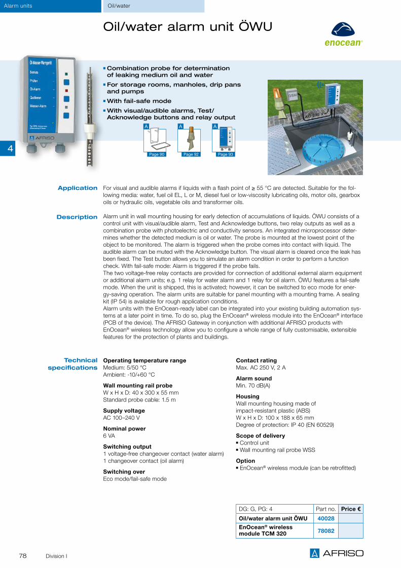
78 Division I
Alarm units Oil/water
Oil/water alarm unit ÖWU
DG: G, PG: 4 Part no. Price €
Oil/water alarm unit ÖWU 40028
EnOcean® wireless module TCM 320 78082
Application
Operating temperature rangeMedium: 5/50 °C Ambient: -10/+60 °C
Wall mounting rail probeW x H x D: 40 x 300 x 55 mm Standard probe cable: 1.5 m
Supply voltageAC 100–240 V
Nominal power6 VA
Switching output1 voltage-free changeover contact (water alarm) 1 changeover contact (oil alarm)
Switching overEco mode/fail-safe mode
Contact ratingMax. AC 250 V, 2 A
Alarm soundMin. 70 dB(A)
HousingWall mounting housing made of impact-resistant plastic (ABS) W x H x D: 100 x 188 x 65 mm Degree of protection: IP 40 (EN 60529)
Scope of delivery Control unit Wall mounting rail probe WSS
Option EnOcean® wireless module (can be retrofitted)
Technical specifications
Combination probe for determination of leaking medium oil and water
For storage rooms, manholes, drip pans and pumps
With fail-safe mode With visual/audible alarms, Test/ Acknowledge buttons and relay output
For visual and audible alarms if liquids with a flash point of ≥ 55 °C are detected. Suitable for the fol-lowing media: water, fuel oil EL, L or M, diesel fuel or low-viscosity lubricating oils, motor oils, gearbox oils or hydraulic oils, vegetable oils and transformer oils.
Alarm unit in wall mounting housing for early detection of accumulations of liquids. ÖWU consists of a control unit with visual/audible alarm, Test and Acknowledge buttons, two relay outputs as well as a combination probe with photoelectric and conductivity sensors. An integrated microprocessor deter-mines whether the detected medium is oil or water. The probe is mounted at the lowest point of the object to be monitored. The alarm is triggered when the probe comes into contact with liquid. The audible alarm can be muted with the Acknowledge button. The visual alarm is cleared once the leak has been fixed. The Test button allows you to simulate an alarm condition in order to perform a function check. With fail-safe mode: Alarm is triggered if the probe fails. The two voltage-free relay contacts are provided for connection of additional external alarm equipment or additional alarm units; e.g. 1 relay for water alarm and 1 relay for oil alarm. ÖWU features a fail-safe mode. When the unit is shipped, this is activated; however, it can be switched to eco mode for ener-gy-saving operation. The alarm units are suitable for panel mounting with a mounting frame. A sealing kit (IP 54) is available for rough application conditions. Alarm units with the EnOcean-ready label can be integrated into your existing building automation sys-tems at a later point in time. To do so, plug the EnOcean® wireless module into the EnOcean® interface (PCB of the device). The AFRISO Gateway in conjunction with additional AFRISO products with EnOcean® wireless technology allow you to configure a whole range of fully customisable, extensible features for the protection of plants and buildings.
Description
Page 92
A
Page 90
A
Page 93
A
4

79Division II
Alarm unitsOil/water
Oil-on-water detector ÖAWD
Application
Description
For the detection of oil layers on water Alarm unit on conductivity principle With visual alarm, Test and Unlock pushbuttons
Relay output for additional alarm
For visual and audible alarms in the event of oil layers on water. Especially suitable for catchment basins, floods and inspection ducts.
Alarm unit in wall mounting housing for the detection of oil layers on water. ÖAWD consists of a control unit with visual/audible alarm, Test/Unlock buttons as well as a relay output. ÖAWD is based on the conductivity principle. The floating probe SWS is used for detection. If an oil layer (of at least 2 mm) is detected, the alarm unit triggers a visual alarm and stores the alarm condition. Once the reason for the alarm condition has been fixed, press the Unlock button to reset ÖAWD. The visual alarm is deactivated. The Test button allows you to simulate an alarm condition in order to perform a function check. The voltage-free relay contact is provided for connection of additional signalling equipment (such as ZAG 01), actuators (pumps, valves), additional alarm units or event reporting systems. The alarm units are suitable for panel mounting with a mounting frame. A sealing kit (IP 54) is available for rough applica-tion conditions.The version ÖAWD-8 is available for applications with turbulent surfaces; this version features a delay of approx. 8 s which helps to avoid false alarms.
Operating temperature rangeMedium: 0/50 °C Ambient: 0/55 °C
Probe SWS2-rod electrode, encapsulated cable connection W x H x D: 200 x 140 x 200 mm Cable length: 10 m Adjustment range: 2/10 mm oil layer thicknessAlso suitable for changing levels
Supply voltageAC 230 V
Nominal power5 VA
Switching outputRelay output: 1 voltage-free changeover contact
Contact ratingAC 250 V, 2 A
Response delayÖAWD-1: 1 s ÖAWD-8: 8 s
HousingWall mounting housing made of impact-resistant plastic (ABS) W x H x D: 100 x 188 x 65 mm Degree of protection: IP 40 (EN 60529)
Scope of delivery Control unit without probe
Technical specifications
DG: H, PG: 4 Part no. Price €
Oil-on-water detector ÖAWD-8 1 - 55105
Oil-on-water detector ÖAWD-1 1 - 55104
Floating probe SWS 1 - 55100
Page 90
A
Page 93
A
4

80 Division I
Alarm units Oil
Fuel oil alarm HMS in connector housing
Operating temperature rangeAmbient: -10/+60 °C
Photoelectric probeProbe head: polyamideCable: 2 m
Supply voltageAC 230 V
Visual indicationGreen lamp Operation Red lamp Alarm
HousingConnector housing W x H x D: 67 x 50 x 125 mmDegree of protection: IP 20 (EN 60529)
Approval for construction productsÜHPDIBt: Z-65.40-214
Scope of delivery Transducer Photoelectric probe with 2 m probe cable Bracket for probe with mounting accessories
For the detection of oil in drip pans below oil-consuming systems, oil pumps, pumping or control stations. Suitable for the following media: water, fuel oil EL, L M, diesel fuel, motor oils, machine oils, hydraulic oils and similar liquids with a flash point of ≥ 55 °C.
The HMS fuel oil alarm unit consists of a transducer and a photoelectric probe. Devices to be moni-tored are connected directly to the socket of the transducer. If there is no leak, the green lamp is on. If the probe detects unwanted liquid, the alarm unit triggers a visual alarm (red lamp) and the socket in the transducer is automatically switched off.
Application
Description
Technical specifications
Immediate switching off of monitored devices in the event of a leak alarm
With visual alarm Ready-to-connect device for fast and easy installation
DG: G, PG: 4 Part no. Price €
Fuel Oil Alarm HMS 44513
4

81Division I
WWG water alarm unit
For visual and audible alarms in the event of accumulations of electrically conductive liquids such as rainwater, tap water, fresh water, waste water, cooling water and heating water.
Alarm unit in wall mounting housing for the detection of even the smallest amounts of water caused by, for example, backflow due to clogged water pipes, water ingress from outdoors, broken pipes or failure of a waste water pump. WWG1 consists of a control unit with visual/audible alarm, Test and Acknowledge buttons, two relay outputs as well as a special floor probe. The probe is mounted at the lowest point of the object to be monitored. The alarm is triggered when the probe comes into contact with liquid. The audible alarm can be muted with the Acknowledge button. The visual alarm is cleared once the leak has been fixed. The Test button allows you to simulate an alarm condition in order to perform a function check. The two voltage-free relay contacts are provided for connection of additional external alarm equipment or alarm units. One relay can be acknowledged (e.g. for an external horn), the other relay cannot (e.g. for an external lamp, a solenoid valve, a pump). The alarm units are suitable for panel mounting with a mounting frame. A sealing kit (IP 54) is available for rough application conditions.Alarm units with the EnOcean-ready label can be integrated into your existing building automation sys-tems at a later point in time. To do so, plug the EnOcean® wireless module into the EnOcean® interface (PCB of the device). The AFRISOhome Gateway in conjunction with additional AFRISO products with EnOcean® wireless technology allow you to configure a whole range of fully customisable, extensible features for the protection of plants and buildings.
Water alarm unit WWG 2 like WWG 1, but with height-adjustable wall mounting rail probe.
Application
Technical specifications
DG: G, PG: 4 Part no. Price €
Water alarm unit WWG1 40029
Water alarm unit WWG 2 40031
EnOcean® wireless module TCM 320 78082
Operating temperature rangeAmbient: -5/+55 °C
Floor probe BWS 11Response level approx. 2–3 mmDimensions Ø x L: 75 x 40 mm
Wall mounting rail probe WSSHeight-adjustable by approx. 200 mm W x H x D: 37 x 320 x 55 mm
Standard probe cables1.5 m, max. length 50 m (shielded)
Function principleConductivity measurement
Supply voltageAC 230 V
Nominal power2.5 VA
Switching output1 1 voltage-free changeover contact 1 1 voltage-free normally open contact (can be acknowledged)
Contact ratingMax. AC 250 V, 2 A
Alarm soundMin. 70 dB(A)
HousingWall mounting housing made of impact-resistant plastic (ABS) W x H x D: 100 x 188 x 65 mm Degree of protection: IP 40 (EN 60529)
Scope of delivery Control unit Floor probe BWS 10 (for WWG 1) Wall mounting rail probe WWS (for WWG 2)
Option EnOcean® wireless module (can be retrofitted)
Alarm units Water
Ideal for laundry rooms, cellars/storage rooms, pump and inspection ducts
With visual/audible alarms, Test and Acknowledge buttons and 2 relay outputs
With floor probe or wall mounting rail probe EnOcean®-ready coming soon
Description
Page 92
A
Page 90
A
Page 93
A
4

82 Division II
Application
Description
Technical specifications
Water/waste waterAlarm units
Radio remote alarm unit WGL 01 W for conductive liquids
For sewage tanks, inspection ducts, gutters and use in flood hazard areas
Wireless transmission of the alarm signal from the probe to the control unit
With visual/audible alarms and Acknowledge button
Relay output for additional alarm
For visual and audible alarms in the event of maximum levels, e.g. in sewage tanks, bodies of water, inspection ducts or open gutters. Suitable for all conductive liquids such as flood water, rainwater, tap water, fresh water, waste water and cooling water.
WGL 01 W consists of a control unit with visual/audible alarm, Acknowledge button and output relay as well as a battery-operated transmitter and a probe. The control unit controls and monitors opera-tion. The integrated transmitter is used for wireless transmission of the alarm signal from the probe to the control unit. Visual and audible alarms are triggered when the probe comes into contact with liquid. The audible alarm can be muted with the Acknowledge button. The visual alarm is automatically reset once the reason for the alarm has been removed. WGL 01 W is self-monitoring and triggers an alarm if the transmitter has no power or when the battery must be replaced.
Control unitWall mounting housing made of impact-resistant plastic (ABS) W x H x D: 130 x 80 x 35 mm Degree of protection: IP 54 (EN 60529)
Supply voltageAC 230 V
Nominal power1 VA
Relay output1 voltage-free switching contact
Transmitter DimensionsH x Ø: 75 x 95 mm
Function principleWireless transmitter, 433 MHz
Operating radius150 m, max. transmission distance 650 m
Operating temperature range-30/+60 °C
Supply voltage3 V battery, CR 123A
Degree of protectionIP 67 (EN 60529)
Probe DimensionsH x Ø: 250 x 20 mmStainless steel with plastic coating
Scope of delivery Control unit Transmitter with battery Probe
DG: H, PG: 4 Part no. Price €
WGL 01 W 53520
Probe
Transmitter
4

83Division II
Alarm units
Leak detectors CoFox®
ELT 500/4, ELT 8
Water alarm unit CoFox® ELT 8
Application
Alarm unit CoFox®
ELT 500/4
Water/chemicals
For the detection of electrically conductive liquids such as water, emulsions or waste water.
Description
Operating temperature rangeAmbient: -10/+60 °C
Response thresholdFully adjustable, 2.5 kOhm – 60 kOhm
Switching outputRelay output: 2 voltage-free changeover contacts
Visual indicationGreen LED: Mains operationRed LED: Alarm condition
Supply voltageAC 230 V or DC 24 V
Probe connections2 probes
Contact ratingMax. AC 250 V, 2 A
Nominal power4 VA (230 V) / 2 VA (24 V)
HousingW x H x D 53 x 113 x 108 mmDegree of protection: IP 30 (EN 60529)
Operating temperature rangeAmbient: -10/+50 °C
Response threshold50 kOhm
Switching outputRelay output: 1 voltage-free changeover contact
Visual indicationGreen LED: Mains operation4 red LEDs: Alarm condition
Supply voltageAC 230 V
Probe connections4 probes
Contact ratingMax. AC 250 V, 2 A
Nominal power3 VA
HousingWall mounting plastic housingW x H x D 53 x 113 x 108 mmDegree of protection: IP 30 (EN 60529)
Technical specifications
See page 88 for probes. See the catalogue INDUSTRIAL TECHNOLOGY, pages 298, 299, 301, for additional information on CoFox® ELT 500/4 and ELT 8.
iDG: H, PG: 4 Part no. Price €
Alarm unit CoFox® ELT 500/4* 53505
Water alarm unit CoFox® ELT 8*
230 V 53503
24 V 53503A
*Please order probes separately.
Water alarm unit in wall mounting housing with visual alarm, operation indicator as well as two relay outputs for additional external signalling equipment or the additional alarm unit ZAG 01. A total of 2 probes can be connected. The probe is mounted at the lowest point of the object to be monitored. The alarm is triggered when the probe comes into contact with liquid and ELT 8 activates the connected alarm equipment. The visual alarm is cleared once the leak has been fixed. ELT 8 enables parallel operation of several probes.
Alarm unit in wall mounting housing with visual alarm, operation indicator, reset button and relay output for additional external signalling equipment or the additional alarm unit ZAG 01. A total of 4 probes can be connected. Leak location by means of LEDs. The alarm is triggered when the probe comes into contact with liquid and the connected alarm equipment is activated. The alarm can be acknowledged with the Reset button. ELT 500/4 features four channels for separate probe circuits so that several probes can be operated in parallel or cascading for large-area monitoring is possible.
4

84 Division III
GasAlarm units
Gas alarm unit GS 1.1
DG: H, PG: 4 Part no. Price €
Gas alarm unit GS 1.1 Methane 1 - 61184
Gas alarm unit GS 1.1 Propane/Butane 1 - 61186
Application
Description
For the detection of flammable gases such as methane, propane, butane in ambient air in residential buildings.
Gas alarm unit with integrated semiconductor sensor and alarm buzzer. LEDs for operation (green), alarm (red), error (yellow), the Test button and the Reset button are located at the front side of the housing. The alarm is triggered when approx. 20 % of the LEL (lower explosive limit) is reached. The audible alarm can be muted with the Reset button. The visual alarm remains active until the alarm condition no longer exists (reset).
Supply voltageAC 230 V
Housing W x H x D: 158 x 90 x 44 mm Degree of protection: IP 20 (EN 60529)
Operating temperature rangeAmbient: 0/50 °C; max. 75 % rH
Alarm valueApprox. 20 % LEL
Alarm toneInternal buzzer, min. 50 dB(A)
Service lifeApprox. 5 years
Technical specifications
Methane
iGS gas alarm units are cross-sensitive to hydrocarbons, lacquers, solvents, alcohols and similar media.
For private homes Detection of gases such as methane, pro-pane, butane in ambient air and genera-tion of gas alarm
4

85Division III
Gas alarm unit GS 2.1
Supply voltage: AC 230 V
HousingW x H x D 158 x 90 x 44 mmDegree of protection: IP 20 (EN 60529)
Operating temperature range Ambient: 0/50 °C; max. 75 % rH
Alarm value: Approx. 20 % LEL
Audible alarm: Internal buzzer, min. 50 dB(A)
Service life: Approx. 5 years
For the detection of flammable gases such as methane, propane, butane in ambient air in resi-dential buildings.
Gas alarm unit with integrated semiconductor sensor, alarm buzzer and relay output for connec-tion of additional external alarm equipment (e.g. horn, warning light). LEDs for operation (green), alarm (red), error (yellow), the Test button and the Reset button are located at the front side of the housing. The alarm is triggered when approx. 20 % of the LEL (lower explosive limit) is reached. The audible alarm can be muted with the Reset button. The visual alarm remains active until the alarm condition no longer exists (reset). The unit features an additional input for connection of an external gas sensor GS 4.1 as a second measur-ing point, e.g. for monitoring different rooms.
Propane
Gas alarm units for the private home
External gas sensor GS 4.1
Supply voltage: Via GS 2.1
HousingW x H x D 80 x 80 x 36 mmDegree of protection: IP 20 (EN 60529)
Operating temperature rangeAmbient: 0/50 °C max. 75 % rH
Alarm value: Approx. 20 % LEL
Service life: Approx. 5 years
Technical specifications
DG: H, PG: 4 Part no. Price €
Gas alarm unit GS 2.1 Methane 1 - 61185
Gas alarm unit GS 2.1 Propane/Butane 1 - 61187
Gas sensor GS 4.1 Methane 1 - 61188
Gas sensor GS 4.1 Propane/Butane 1 - 61189
Alarm units Gas
Application
Description
Additional gas sensor to be used with the gas alarm unit GS 2.1. Enables monitoring at two points in different rooms.
Remote probe for gas alarm unit GS 2.1. LEDs for operation (green), alarm (red), error (yellow) are located at the front side of the housing. Audible alarm is triggered by the gas alarm GS 2.1.
Relay forexternalSensor
iGS gas alarm units are cross-sensitive to hydrocarbons, lacquers, solvents, alcohols and similar media.
4

86 Division III
iPlease order sensors and calibration separately.
Inputs 2 sensors Connection cable 3 wires Wire cross section > 0.5 mm2
Distance control unit – sensorMax. 150 m
Alarm threshold 1 permanently installed alarm threshold for alarm at approx. 20 % LEL (for gases) with alarm memory
Display1 green LED: Operation 1 red LED: Flashing: fault
Steady on: alarm
Audible alarmPiezo buzzer approx. 70 dB(A), can be acknowledged
Switching outputsRelay contacts: 1 voltage-free changeover
contact Contact rating: AC 250 V, 2 A
Supply voltageAC 230 V
Power input15 VA
Operating temperature rangeAmbient: 0/40 °C
Housing Wall mounting housing made of impact-resistant plastic (ABS) W x H x D: 100 x 188 x 65 mm Weight: 0.55 kg Degree of protection: IP 40 (EN 60529)
Application
Technical specifications
Page 87
A
Gas/smokeAlarm units
For natural gas and liquid gas (gas detector) For early detection of smoke(smoke detector)
Audible and visual alarms; Acknowledgebutton and relay output
Self-monitoring for line interruption, shortcircuit and sensor defect
For continuous monitoring for explosive gases, vapours and smoke and for generating alarms in con-junction with the appropriate sensors. GRM is installed in heating rooms and basements, storage, office and residential buildings to increase safety. Not suitable for installation in hazardous areas (EX areas). No test as per DIN 14676/EN 14604.
Alarm unit in a wall mounting housing with audible and visual alarms. GRM features an alarm threshold and is equipped with a relay contact. If the threshold value is exceeded, the unit generates an alarm. The red LED lights up, the audible alarm goes off and the alarm relay switches. The audible alarm can be muted with the Acknowledge button. When the alarm condition no longer exists, you press the Acknowledge button again to clear the visual alarm (alarm memory). The alarm can only be cleared with the Acknowledge button if the reason for the alarm has been removed. If the concentration still exceeds the alarm threshold, pressing the Acknowledge button does not clear the alarm. The volt-age-free relay contact allows you to switch additional external signalling equipment such as the event reporting system EMS, horns, lamps in the case of alarm or fault conditions. GRM is suitable for panel mounting with a mounting frame. A DIN rail clip is available for fast and easy mounting of GRM to standard rails (DIN rail/EH50022). A sealing kit (IP 54) is available for rough application conditions.
The following sensor combinations are possible with GRM:1. 1 gas sensor and 1 smoke sensor2. 2 gas sensors3. 2 smoke sensors4. 1 gas sensor5. 1 smoke sensor
Description
Gas and smoke detector GRM
Page 90
A
DG: H PG Part no. Price €
Gas and smoke detector GRM 4 61150
DIN rail clip 1 43100
4

87Division III
Alarm unitsGas/smoke
Gas and smoke sensors for GRM
Semiconductor gas sensor in plastic housing for connection to gas and smoke detector GRM. For use in dry rooms (e.g. heating installations). Detectable media: methane, propane, butane. LEDs at the sensor indicate the operating and alarm state of the gas alarm system:
LED green: Operation LED yellow: Fault LED red: Gas alarm
When ordering, please specify the gas to be mon-itored since the sensors must be calibrated for the desired gas.
Photoelectronic smoke sensor in plastic housing for connection to gas and smoke detector GRM; no standalone operation. Mainly for domestic technology applications. The smoke sensor is not approved/tested as per DIN 14676 and EN 14604.
The operating and alarm state is indicated directly at the sensor:
Visual: LED red/red Audible: Internal piezo buzzer
Measured gasFlammable gases and vapours in ambient air. Gas sensors are cross-sensitive to hydrocarbons, lacquers, solvents, alcohols and similar media.
Measuring range0–50 % LEL
Measuring principleSemiconductor (service life approx. 5 years, depending on the operating conditions)
Operating temperature rangeAmbient: 0/40 °C
HumidityMax. 75 % rH
HousingWall mounting plastic housingW x H x D 80 x 80 x 35 mmWeight: Approx. 100 g
SensorPhotoelectronic
Measuring principleScattered light principle
Alarm tone85 dB(A) (at a distance of 3 m)
Test buttonFor sensitivity, audible alarm
Operating temperature range Ambient: 5/39 °C
Humidity Max. 80 % rH
HousingWall mounting plastic housing Outside dimensions (Ø x H): 155 x 38 mm Weight: Approx. 195 g
Electrical connectionsScrew terminal strip
Gas sensor GS 4.1 Smoke sensor RS 1.1
Description
Technical specifications
iGas sensor calibrationPrior to shipment, the gas sensors are calibrated to the gas specified by the customer. Therefore, please always indicate the gas type when ordering. Please order sensors and calibration separately.
DG: H, PG: 4 Part no. Price €
Gas sensor GS 4.1 methane 1 - 61188
Gas sensor GS 4.1 Propane/Butane 1 - 61189
Smoke sensor RS 1.1 1 - 61151
4

88 Division II
Probes for alarm units
DG: H, PG: 4 Part no. Price €
Floor water probe BWS 10 1 - 55112
Wall mounting rail probe WSS 1 - 55050
Floating probe SWS 1 - 55100
Floor water probe BWS 10
For the detection of conductive liquids such as flood water, rainwater, tap water, fresh water, waste water, cooling water and heating water.
Floor probe suitable for WWG 1, ELT 8, ELT 680 and ELT 500/4. The probe is mounted at the lowest point of the object to be monitored. The alarm is triggered by the alarm unit when the probe comes into contact with liquid.
Probe diameter: 70 mmCable length: 2 mResponse level: approx. 2–3 mm
Wall mounting rail probe WSS
For the detection of conductive liquids such as flood water, rainwater, tap water, fresh water, waste water, cooling water and heating water.
Height-adjustable wall mounting rail probe suitable for WWG 2, ELT 8, ELT 680 and ELT 500/4. The probe is mounted to the wall at the object to be monitored. The desired response level (distance from probe to floor) is adjusted via the wall mounting rail. The alarm is triggered by the connected alarm unit when the probe comes into contact with liquid.
Dimensions: 37 x 320 x 55 mmCable length: 1.5 mHeight-adjustable by approx. 200 mm
Floating probe SWS
For the detection of oil layers, emulsions or foam on water. Also suitable for changing levels (e.g. flowing bodies of water)
Floating probe suitable for ÖAWD-1, ÖAWD-8, ELT 8 and ELT 680. The probe floats on the water surface. The oil layer thickness (at least 2 mm) is set via the height-adjustable 2-rod probe. The alarm is triggered by the connected alarm unit when the probe comes into contact with the oil layer.
iMany probe versions are available. Please enquire.
Floating probe SWS DimensionsW x H x D 200 x 140 x 200 mm
CableEncapsulated cable connectionLength: 10 m
Adjustment range2/10 mm oil layer thickness
Application
Application
Description
Description
Application
Description
Alarm unitsAccessories
Floor water probe BWS 10
Wall mounting rail probe WSS
4

89Division I
PTC thermistor probe
Probes and accessories for alarm units
PTC thermistor probe
For the detection of liquids with a flash point of ≥ 55 °C. Suitable for the following media: water, fuel oil EL, L or M, diesel fuel or low-viscosity lubricating oils, motor oils, hydraulic oils, vegetable oils and transformer oils, antifreeze agents, oil-water mixtures and emulsions.
Suitable for ÖWWG 3. The probe is mounted at the lowest point of the object to be monitored or in the drip pan. The alarm is triggered by the alarm unit when the probe comes into contact with liquid.
Probe diameter: 14 mmCable length: 3.2 m or 10 mResponse level: 17 mm
Application
Description
Photoelectric probe
For the detection of liquids with a flash point of ≥ 55 °C. Suitable for the following media: water, fuel oil EL, L or M, diesel fuel or low-viscosity lubricating oils, motor oils, gear-box oils or hydraulic oils, vegetable oils and transformer oils.
Floor probe suitable for OM 5 and WM 5. The probe is mounted at the lowest point of the object to be monitored. The alarm is triggered by the alarm unit when the probe comes into contact with liquid.
Probe diameter: 10 mmCable length: 10 mResponse level: 5 mm
Application
Description
EnOcean® wireless module TCM 320
For remote indication and easy integration of AFRISO-WATCHDOG alarm units into smart building systems (e.g. AFRISOLab) based on EnOcean® wireless. Users with mobile devices can immediately take appropriate action in response to an alarm.
EnOcean® wireless module for AFRISO WATCHDOG alarm units. Can be plugged into PCBs of boards which are facto-ry-equipped with a slot for the EnOcean® wireless module. Can be integrated into all AFRISO products with the label "EnOcean-ready" on the front.
Application
Description
Photoelectric probe
EnOcean® wireless module TCM 320
DG: G PG Part no. Price €
PTC thermistor probe ÖWWG 3, length 3.2 m 4 1 - 44516
PTC thermistor probe ÖWWG 3, length 10 m 4 1 - 44484
Photoelectric probe 4 1 - 44503
EnOcean® wireless module TCM 320 4 1 - 78082
Alarm units Accessories
4

90 Division I
Alarm unitsAccessories
Drip pan
For the collection of escaping oil. Drip pans should be mounted below all oil fittings such as filters, oil vents, burn-ers, etc. in order to avoid damages resulting from escaping oil and in order to detect leaks as early as possible.
Drip pan made of white plastic (PE). The drip pans are cas-cadable (in a line or at 90° angles). At the lowest part of the drip pan, the sensor of an oil alarm can be installed. If the drip pan cannot be checked on a daily basis, oil alarms with audible and visual alarms are required. Several cascaded drip pans can be monitored with a single probe. Several independent drip pans can be monitored, e.g. with a single oil alarm OM 5 and several probes. A mounting clamp for the sensor is supplied with the drip pan.
Dimensions (W x D): 600 x 300 mm
Application
Description
Drip pan
Mounting frame
Mounting frame for wall mounting housings 100 x 188 x 65 mm (W x H x D) of the AFRISO WATCHDOG series (alarm units). For fast integration in control cabinets
Sealing kit (IP 54)
Sealing kit for rough application conditions. Suitable for all wall mounting housings of the AFRISO WATCHDOG series (alarm units). The sealing kit is easy to mount between the housing cover and base. This increases the degree of pro-tection of the alarm unit to IP 54.
DIN rail clip
DIN rail clip for fast and easy mounting of AFRISO WATCHDOG alarm units in the control cabinet or for side-by-side mounting of several units on the wall. The clip is mounted by means of screws so that the alarm unit can be clipped onto standard DIN rails.
Accessories for alarm units
Sealing kit (IP 54)
Mounting frame
DG: G, PG: 1 Part no. Price €
Drip pan 1 - 44512
Mounting frame 1 - 43521
Sealing kit (IP 54) 1 - 43416
DIN rail clip 1 - 43100
Description
Description
Description
DIN rail clip
4

91Divisions I/III
Alarm unitsAccessories/signal processing
Accessories for alarm units
Warning light with rotating reflector
For humid rooms and for outdoor installation.
Yellow warning light with rotating reflector. Robust design with AI base. Maintenance-free, suitable for continuous use.
Supply voltageAC 230 V
Degree of protectionIP 55 (EN 60529)
Weight1.8 kg
Mounting positionAny
Application
Description
Technical specifications
Upon request, we design and build complete gas alarm systems for you and service them at regular intervals.
i
Test gas unit PGK 10 for gas alarm units/sensors
For checking, servicing and repairing gas alarm systems.
Plastic case with test gas cap and withdrawal unit (valve, flow meter with stainless steel float for gas flow regulation from 0.5–1.5 l/min and test gas tube). Can accommodate 1 to 2 test gas cylin-ders.
Test gas not included in scope of delivery; please order separately.
PG DG Part no. Price €
Test gas unit PGK 10 (without gas cylinder) 1 E 1 - 61100
Withdrawal unit MiniFloBrass valve and Perspex flow meter with stainless steel float for gas flow control from 0.5 to 1.5 l/min, test gas hose
3 E 1 - 69050
Test gas methane 20 % LEL, non-recyclable cylinder containing 12 l 2 E 1 - 69060
Test gas methane 40 % LEL, non-recyclable cylinder containing 12 l 2 E 1 - 69061
Test gas propane 20 % LEL, non-recyclable cylinder containing 12 l 2 E 1 - 69062
Test gas propane 40 % LEL, non-recyclable cylinder containing 12 l 2 E 1 - 69063
Test gas carbon monoxide (300 ppm), non-recyclable cylinder containing 12 l 2 E 1 - 69064
Synthetic air for zero point calibration, non-recyclable cylinder containing 12 l 2 E 1 - 69065
Part no. Price €
Warning light with rotating reflector 4 H 1 - 61015
4

92 Division I
Alarm units Signal processing
Signalling devices
DG: G, PG: 4 Part no. Price €
Horn KH 1 1 - 61011
Combined warning light and horn 1 - 61020
Horn HPW 2 1 - 61012
Combined warning light and horn
Horn HPW 2Horn KH 1
Combination warning light and horn, can be controlled separately.
Sound pressure90 dB (A), distance 1 m
Supply voltageAC 230 V
Power input10 VA
Degree of protectionIP 33 (EN 60529)
Weight0.19 kg
Horn with continuous tone for use in dry rooms.
Sound pressure90 dB (A), distance 1 m
Supply voltageAC 230 V
Power input6 VA
Degree of protectionIP 20 (EN 60529)
Weight0.18 kg
Horn with continuous tone for use in humid rooms and for outdoor installation.
Sound pressure110 dB (A), distance 1 m
Supply voltageAC 230 V
Power input22 VA
Degree of protectionIP 55 (EN 60529)
Weight1 kg
Description
Technical specifications
4

93Division I
DG: H, PG: 4 Part no. Price €
Additional alarm unit ZAG 01 40633
Additional alarm unit ZAG 01
For indication and transfer of alarm signals from AFRISO WATCHDOG alarm units, AFRISO leak detec-tors or any other switching device. Suitable for triggering additional visual and audible alarms in build-ings, e.g. in the case of underground tank facilities or in rooms which are far away from the dangerous location. Can be connected directly to the output of the alarm unit.
The additional alarm unit in a wall mounting housing signals alarm conditions in conjunction with an alarm unit or a leak detector. ZAG 01 is connected to the voltage-free contact of the alarm unit. A 230 V alarm input is also available. The audible alarm can be muted with the Acknowledge button. The visual alarm is cleared once the leak or event has been fixed. The Test button allows you to per-form a function check.
The voltage-free relay contacts allow for connection of additional external signalling equipment (such as horns), event reporting systems EMS, building control systems or similar equipment. ZAG 01 is suit-able for panel mounting with a mounting frame. A sealing kit (IP 54) is available for rough application conditions.
Application
Description
Operating temperature rangeAmbient/storage: -10/+60 °C
Supply voltageAC 230 V
Nominal power3 VA
Alarm inputInput 1: DC 12 V Input 2: AC 230 V
Switching outputsRelay contact 1: voltage-free changeover contact, can be acknowledgedRelay contact 2: voltage-free changeover contact, cannot be acknowledged Contact rating: AC 250 V, 2 A
Alarm soundMin. 70 dB (A)
HousingWall mounting housing made of impact-resistant plastic (ABS) W x H x D 100 x 188 x 65 mm
Degree of protectionIP 40 (EN 60529)
Technical specifications
Audible and visual alarms for maximum safety
Vendor-independent connection to devices with switching output (relay contact)
With 2 voltage-free changeover contacts (at output side)
Ready-to-connect device for easy installation and commissioning
A
Page 54 Page 70
A
Alarm unitsSignal processing
① Additional alarm unit ZAG 01② Leak detector LAG 13③ LAG container with probe
①
② ③
Page 90
A
4

94
CATALOGUE INDUSTRIAL TECHNOLOGY
Industrial alarm units
Overview alarm units
Gas alarm unit/station GW-S/GW-SK
Probes for GW-S/GW-SK
For oil, petrol and grease separator systems
Probes for all applica-tions: Layer thickness alarm, overflow alarm, sludge alarm, sand alarm or oil-on-water alarm
With visual/audible alarms and relay output
Version WGA 01 D with LC display for plain text messages
Versions with compact DIN rail housing or wall mounting housing
For connection of up to six sensors/measuring points
Options: Serial interface, emergency power module, data logger
Sensor inputs 4–20 mA, RS 232 interface for configuration
Switching outputs 4/6 voltage-free relay contacts
Versions for the detection of flammable or combus-tible gases or for moni-toring oxygen concentra-tions and toxic gases
GS 510 Ex-2.1: Monitoring of combustible gases and vapours or carbon monoxide
Alarm units for separators
Page 315
Page 320
Page 322
Water
Oil
Sand / sludge
iThis and further products can be found in the catalogueINDUSTRIAL TECHNOLOGY
Catalogue Industrial Technology

95www.afriso.com

Water sensors
Temperature control
AFRISOhome gateway
Wireless automation

9797
Building automation with AFRISOLab 98
AFRISO WATCHDOG alarm unit with EnOcean® wireless 122
Radio-controlled water valve WaterControl 01 100
Mechanical water sensor WaterSensor eco 101
Conductivity water sensor WaterSensor con 102
Intelligent alarm units, sensors and components with EnOcean® wireless technology for buildings
OVERVIEW
ALARM UNITS
Room temperature sensor FT/FTF 107
Wireless rocker switch FT4F-rw 113
Universal wireless transmitter FTM 112
HOME COMFORT
WIRELESS AUTOMATION
Wireless water meter AWM 20/25 103
CONSUMPTION DATA ACQUISITION
SMART BUILDING SYSTEM AFRISOLab
Wireless plug-in socket APR 234 with repeater function 116
Door and window contact AMC 10 115
Wireless presence detector APD 10 114
Wireless relay ABR 132 with repeater function 117
Mobile app AFRISOhome 118
AFRISOhome gateway HG 01 119
CENTRAL CONTROL/MANAGEMENT
Wireless actuator AVD 10 for radiators 109
Wireless actuator AVD 20-D for radiators 110
CO2 sensor 111
Single room temperature controller CosiTherm® wireless 104
Wireless transmitter for temperature and/or humidity FTM T/TF 108
5

98
AFRISOLab Overview
Personal building automation with AFRISOLab
Safety means more comfort – the intelligent, energy-saving building with AFRISOLab
AFRISO has been manufacturing alarm units for the safe operation of tank facilities and heating systems for more than 60 years. So far, alarms were mainly signalled directly on site. Transferring alarm messages to building control systems was possible, but it involved con-siderable effort.The wireless transmission standard EnOcean®, available for domestic technology since 2003, breaks new ground for a completely differ-ent approach to building automation. The transmission protocol allows a whole range of different products to be networked on the basis of EnOcean® wireless. This technological milestone breaks new ground for building automation not only in new buildings – reasonably priced intelligent networking becomes possible in existing buildings. Products with an EnOcean® wireless module do not require cable connections to a building control centre and can be used almost anywhere in buildings due to their compact design. Manufacturers from a great variety of areas have teamed up in the EnOcean® Alliance and offer a large range of products. With the Smart Building System AFRISOLab, AFRISO has developed a portfolio of outstanding sensors and alarm units for reliable leakage protection (for example, water/oil) as well as devices for controlling heating systems in an economical way. AFRISOLab products are cost-effective, reliable and practical.Even for end customers, there are no more barriers to entry into the networked world of customised, modularly extensible building automation and security systems. The perfect approach to a flexible smart building solution.
No cables.No cables are required for building automation systems on the basis of the EnOcean® wireless tech-nology. Ten metres of power cable (NYY 3 x 1.5 mm) weigh approx. 2.3 kg – not using this cable saves money and is great for the environment.
No batteries.Energy harvesting is the foundation of battery-less, maintenance-free and flexible building automa-tion. The energy required for sending messages is derived from ambient sources – small move-ments, pressure, light, temperature or vibration are sufficient to allow for power-independent opera-tion of the sensors.
No limits.Renovation projects and new buildings benefit from the new, creative and innovative developments based on EnOcean® wireless technology. There are countless ways of combining EnOcean® prod-ucts.
Division I
5

99
1 Room temperature sensor FT
2 Mechanical water alarm WaterSensor eco
3 Wireless relay ABR 132 with repeater function
4 Room air monitoring: CO2 sensor
5 Single room temperature controller CosiTherm® wireless
6 AFRISOhome gateway HG 01
7 Wireless rocker switch FT4F-rw
8 Door and window contact AMC 10
9 Conductivity water alarm WaterSensor con
10 Radio-controlled water valve WaterControl 01
11 Universal wireless transmitter FTM with pressure gauge with electrical contact for monitoring the solar safety group assembly
12 Universal wireless transmitter FTM with pressure gauge with electrical contact for monitoring the boiler safety group assembly
13 WATCHDOG series oil/water alarm unit ÖWWG 3
14 Universal wireless transmitter FTM with pressure gauge with electrical contact as service indicator, for example, at the vacuum gauge of fuel oil filters
15 Universal wireless transmitter FTM with Minimelder minimum level probe for level monitoring
Not shown
Wireless actuator for radiators AVD 10
Wireless plug-in socket APR 234 with repeater function
Wireless presence detector APD 10
Wireless water meter AWM
A fully featured smart building system on the basis of EnOcean wireless technology networks all light, heating and air conditioning control systems via a central gateway. The gateway processes sensor and consumption data, triggers control action and initiates other measures, and transmits the information to mobile devices such as smartphones, tablets, etc., via WLAN, Internet or GSM. Products from other members of the EnOcean® Alliance for controlling household appliances can also be integrated.
Smart Building with AFRISOLab
2
11 13
10
14
4
15
9
1
5
6
12
AFRISOLabOverview
9
3
8
Division I
7
5

100
Radio-controlled water valve WaterControl 01
Immediate shutting off of thewater pipe in the case of a leak
Reduced damage after pipe burst
For manually or remotely controlled closing and opening of a water pipe in buildings in response to an event message from the water sensors WaterSensor eco or WaterSensor con.
WaterControl 01 consists of a shut-off valve and a control unit with power supply and an EnOcean® wireless module. The shut-off valve features a drinking water-approved ball valve with an electric motor which is integrated in the water-carrying pipe. Four versions with different connection diameters are available: connection threads G¾, G1, G1¼ and G1½. There are five ways to open and close the shut-off valve in the water pipe: Opening/closing the shut-off valve mechanically via the operating handle Opening/closing the shut-off valve electrically via buttons at the control unit Closing the shut-off valve via water sensors Opening/closing the shut-off valve via EnOcean® switch Opening/closing the shut-off valve via AFRISOhome gateway and smartphone
The control unit has a permanent wireless connection to the water sensors WaterSensor eco or WaterSensor con and/or the AFRISOhome gateway. An event message is triggered if the water sensors WaterSensor eco or WaterSensor con detect a leak, e.g. caused by a defective household appliance or a water pipe burst. WaterControl 01 can be used, for example, to shut off the water pipe to keep further water from escaping. The AFRISOhome gateway transmits alarm messages and status messages via WLAN, LAN and GSM to the person in charge (for example, to the owner, the facility manager, the janitor or other configured contacts); the message includes information on which water sensor has signalled the state transition when.
Application
Description
Operating temperature rangeAmbient: 0/50 °CStorage: -10/+80 °CMedium: 4/80 °C
Supply voltageAC 100–240 V
Nominal powerMotor at standstill: < 2 VAMotor running: < 5 VA
HousingWall mounting housing made of impact-resistant plastic (ABS) W x H x D: 100 x 188 x 65 mmWeight: 430 gDegree of protection: IP 40 (EN 60529)
Ball valve (DVGW-tested) with motorW x H x D: 65 x 140 x 70 mmWeight: 800 g to 2 kgDegree of protection: IP 40 (EN 60529)
EnOcean® wirelessFrequency: 868.3 MHz Transmission power: Max. 10 mWRange: 10 to 30 m (depending on room
arrangement and materials in the building)
Number of devices to be connected Max. 1 EnOcean® centre Max. 20 WaterSensor con units Max. 10 WaterSensor eco units Max. 10 EnOcean® switches On/Off
Technical specifications
AFRISOLab Alarm units
A
Page 101
A
Page 118
A
Page 102
DG: G, PG: 4 Part no. Price €
WaterControl 01 G¾ 42675
WaterControl 01 G1 42676
WaterControl 01 G1¼ 42677
WaterControl 01 G1½ 42678
Division I
iSee operating instruc-tions for detailed infor-mation on the range of the EnOcean® wireless module.
5

101
AFRISOLabAlarm units
Mechanical water sensor WaterSensor eco
Flexible location-independent use anywhere in buildings
No battery, no cables required Wireless transmission without power supply in the case of state transitions
For the detection of accumulations of water at defined horizontal surfaces or positions (e.g. below pipes, fittings and in the area of washing machines, below bath tubs or dishwashers, in utility rooms or basements). Suitable for water.
WaterSensor eco is equipped with fibre disks that work as a sensor; it does not require an additional power supply. In the case of a leak, the fibre disks expand and generate the required power to send the event message to WaterControl 01 or to the AFRISOhome gateway. The event message is sent when the fibre disks expand or shrink. WaterControl 01 can be used, for example, to shut off the water pipe to keep further water from escaping. The AFRISOhome gateway transmits alarm messages and state transition messages via WLAN, LAN and GSM to the person in charge (for example, to the owner, the facility manager, the janitor or other configured contacts); the message includes information on which WaterSensor eco has signalled the state transition. The AFRISOhome gateway in conjunction with additional AFRISO products with EnOcean® wireless technology allows the user to configure a whole range of fully customisable, extensible applications.
Application
Description
Operating temperature rangeAmbient: -25/+65 °CStorage: -25/+65 °CMedium: 1/65 °C
Response level1.5 mm
Response delay< 6 min (first 5 responses) up to 1 hour (6th to 10th response)
Supply voltageEnergy harvesting (via fibre disks)
HousingPlastic housing (PC) Colour: White, similar to RAL 9003W x H x D: 80 x 55 x 30 mmWeight: 66 gDegree of protection: IP 43 (EN 60529)
EnOcean® wirelessFrequency: 868.3 MHzTransmission power: Max. 10 mWRange: 10 to 30 m (depending on room arrangement and materials in the building)
Scope of delivery WaterSensor eco Adhesive tape
Necessary additional components WaterControl 01 and/or
AFRISOhome gateway
Technical specifications
A
Page 100
A
Page 118
A
Page 119
DG: L, PG: 4 Part no. Price €
WaterSensor eco 55080
Division I
iSee operating instruc-tions for detailed infor-mation on the range of the EnOcean® wireless module.
5

102
Conductivity water sensor WaterSensor con
Flexible location-independentuse anywhere in buildings
Wireless operation(photovoltaic cell or battery)
Radio transmission, cyclically(function check) and in the caseof state transitions
For the detection of accumulations of water at defined horizontal surfaces or positions (e.g. below pipes, fittings and in the area of washing machines, below bath tubs or dishwashers, in utility rooms or basements). Suitable for water.
WaterSensor con features a conductivity sensor at the bottom. The energy required to send an EnOcean® telegram is generated by means of an integrated photovoltaic cell. An optional battery can be used for application in darker rooms. An extension cable is available for separate mounting of sen-sor and wireless transmitter. WaterSensor con cyclically transmits the actual ambient temperature and the logical state of the conductivity sensor (conductive liquid present or not present) and also sends a telegram when the state changes via the integrated EnOcean® wireless module to WaterControl 01 or to the AFRISO gateway.WaterControl 01 can close the water pipe in response to an event message to keep further water from escaping. The AFRISOhome gateway transmits alarm messages and status messages via WLAN, LAN and GSM to the person in charge (for example, to the owner, the facility manager, the janitor or other configured contacts); the message includes information on which water sensor has signalled the state transition.The AFRISOhome gateway in conjunction with additional AFRISO products with EnOcean® wireless technology allows the user to configure a whole range of fully customisable, extensible applications.
Application
Description
Operating temperature rangeAmbient: 0/40 °CStorage: -20/+60 °CMedium: 0/60 °C
Response level0.5 mm
Temperature measuring rangeMeasuring range: 0/40 °CAccuracy: ±1 K
Supply voltageEnergy harvesting (via photovoltaic cell) or 1/2 AA lithium battery, DC 3.6 V (with daylight less than 200 lx)
HousingPlastic housing (PC) Colour: White, similar to RAL 9003W x H x D: 55 x 50 x 42 mmWeight: 47 gDegree of protection: IP 42 (EN 60529)
EnOcean® wirelessFrequency: 868.3 MHzTransmission power: Max. 10 mWRange: 10 to 30 m (depending on room
arrangement and materials in the building)
Scope of delivery WaterSensor con Without battery
Necessary additional components WaterControl 01and/or
AFRISOhome gateway
Technical specifications
AFRISOLab Alarm units
A
Page 118
A
Page 119
DG: L, PG: 4 Part no. Price €
WaterSensor con 78146
Accessories
1/2 AA lithium battery 78100
Extension cable, 2 m 78141
A
Page 100
Division I
iSee operating instruc-tions for detailed infor-mation on the range of the EnOcean® wireless module.
5

103
Wireless water meter AWM
Water meter for building connection with factory-mounted and configured EDC wireless module (electronic data capture module). It inductively scans the modulator disk to allow for reliable remote reading and integration of water meters into building automation systems.
The wireless water meter is directly integrated into the building connection line. The measured water volume is transmitted to the AFRISOhome gateway. The AFRISOhome app can show calculated totals and daily consumption. If, for example, unusually high flow rates are detected, the water line can be automatically shut off by means of the water valve WaterControl 01 to protect the building.
Application
Description
Easy integration of water consumption values into building automation systems
Building protection via integrated leak detection and automatic shut/off of the water pipe by means of water valve WaterControl 01
Wireless protocol: Wireless M-Bus
Technical specifications
Operating temperature rangeAmbient: 5/55 °CStorage: Frost-protectedMedium: Cold water up to 30 °C Safety up to 50 °C
Annular piston dry rotor (AWM 20)Continuous flow Q3: 4Connection: G¾Length without screw connection: 190 mm
Multi-jet dry rotor (AWM 25)Continuous flow Q3: 10Connection: G1Length without screw connection: 260 mm
Degree of protectionIP 68 (EN 60529)
Version wireless module Wireless M-Bus as per OMS standard, EN 13757-4
Frequency 868 MHz, T1 mode Transmission power: Max. 25 mW Transmission interval: 20 s Wireless protocols AES 128-encrypted Up to 15 years battery life Self-monitoring, manipulation detection, detection of direction of flow
ConformityComplies with current German Drinking Water Act
DG: L, PG: 4 Part no. Price €Wireless water meter AWM 20, annular piston dry rotor, continuous flow Q3: 4, G¾ 78970
Wireless water meter AWM 25, multi-jet dry rotor, continuous flow Q3: 10, G1 78971
A
Page 118
AFRISOLabConsumption data acquisition
A
Page 119
A
Page 100
Division I
5

104
Equipment for heating systems
Single room temperature controller CosiTherm® Wireless
Single room control
Base module BM Power supply of the thermal actuators (AC 230 V)
Switchover of the system to "Heating" or "Cooling"
Control of the heating/cooling pumps
Controller module Comparison of actual and reference temperatures
Volume flow control heating/cooling water via connected thermal actuators
Connection of two or six control circuits, extensible
Connection to room temperature sensors EnOcean® wireless technology
Timer module UM (option) Time data: Date, time, weekday (leap year detection)
Temperature reduction adjustment Additional pump running time adjustment Valve and pump protection function adjustment
For manifold systems for heating and cooling
Timer module for programming tempera-ture reduction, pump operating time and valve protection function
Worldwide access via AFRISOhome gateway
Controls the temperature of individual rooms in connection with manifold systems for heating or cool-ing. EnOcean® wireless technology for integration into building automation systems.
The base version of the single room temperature controller CosiTherm® Wireless consists of a base module, at least one controller module with two or six independent control circuits and a correspond-ing number of room temperature sensors. The controller modules can be interconnected in a modular way to account for the number of control circuits/rooms. One room temperature sensor is required per control circuit; the standard version is battery-less and connected to the controller module via the EnOcean® wireless technology. The room temperature sensor measures the actual temperature in the room. The reference temperature is adjusted via the rotary knob of the room temperature sensor or via the app AFRISOhome. The controller module compares the actual temperature and the reference tem-perature and controls the volume flow of the heating/cooling water via the thermal actuators of the manifold system. An optional timer module with display and an integrated hundred-year calendar can be plugged into the base module. It features two independently programmable switching channels for temperature reduction, nine programmable memory blocks and a valve and pump protection function. The addi-tional pump running time is adjustable. The terminals of the controller modules are colour-coded for easy assignment to the wires of the thermal actuators; in conjunction with the DIN rail snap connectors at the rear of the housing, this facilitates installation.With an AFRISOhome gateway, it is possible to remotely check and, if necessary, adjust the room tem-peratures via the AFRISOhome app (for example, when coming back from winter vacation). This flexi-ble remote control of the room temperature combines multiple benefits: you can increase living comfort and reduce energy costs.In conjunction with additional AFRISO products with EnOcean® wireless technology, the user can con-figure a whole range of fully customisable, extensible applications.
Application
Description
Timer module (option) for programming and display of date, time and weekday
Functions
Division I
5
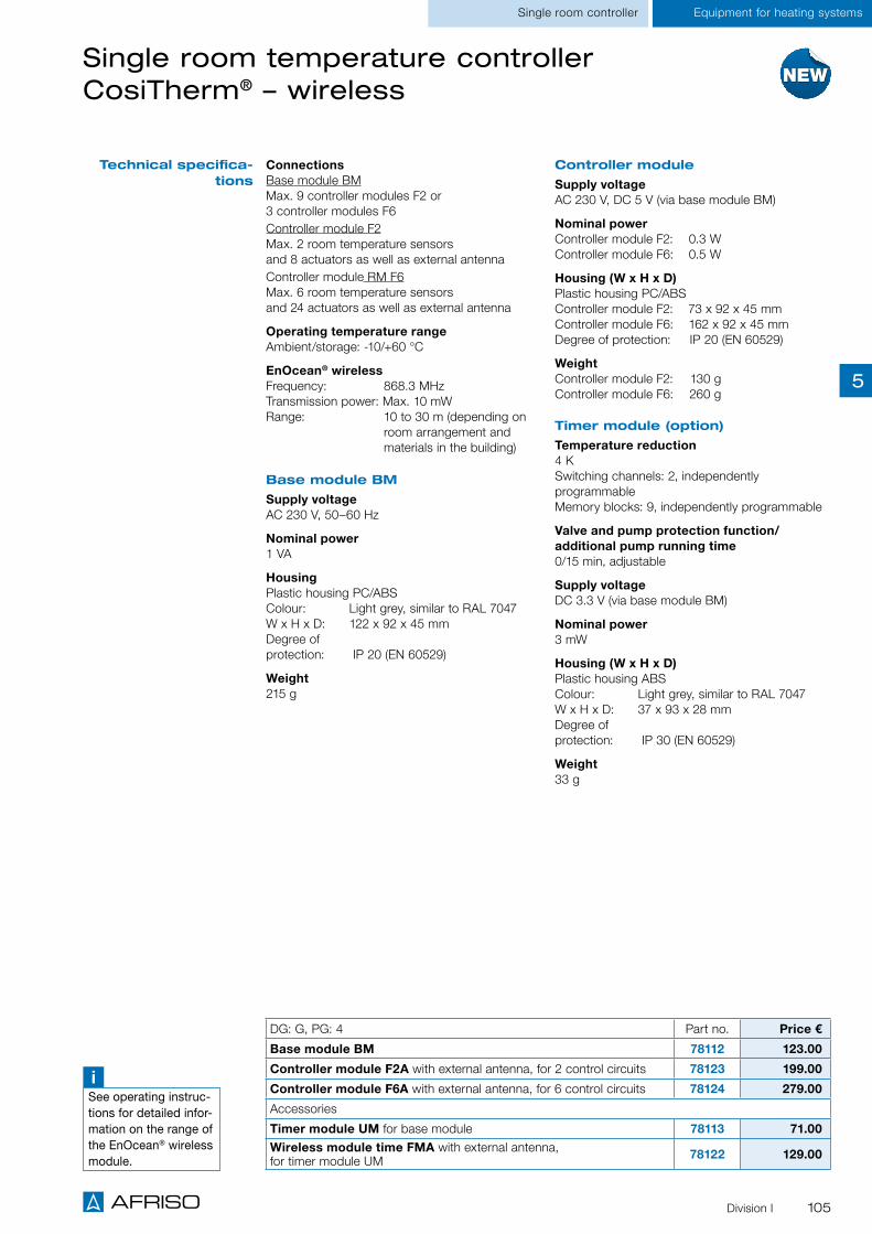
105
Equipment for heating systems
Single room temperature controller CosiTherm® – wireless
Single room controller
DG: G, PG: 4 Part no. Price €
Base module BM 78112 123.00
Controller module F2A with external antenna, for 2 control circuits 78123 199.00
Controller module F6A with external antenna, for 6 control circuits 78124 279.00
Accessories
Timer module UM for base module 78113 71.00Wireless module time FMA with external antenna, for timer module UM 78122 129.00
ConnectionsBase module BM Max. 9 controller modules F2 or 3 controller modules F6Controller module F2 Max. 2 room temperature sensors and 8 actuators as well as external antennaController module RM F6 Max. 6 room temperature sensors and 24 actuators as well as external antenna
Operating temperature rangeAmbient/storage: -10/+60 °C
EnOcean® wirelessFrequency: 868.3 MHzTransmission power: Max. 10 mWRange: 10 to 30 m (depending on room arrangement and materials in the building)
Base module BM
Supply voltageAC 230 V, 50–60 Hz
Nominal power1 VA
Housing Plastic housing PC/ABS Colour: Light grey, similar to RAL 7047 W x H x D: 122 x 92 x 45 mm Degree of protection: IP 20 (EN 60529)
Weight 215 g
Controller module
Supply voltageAC 230 V, DC 5 V (via base module BM)
Nominal powerController module F2: 0.3 W Controller module F6: 0.5 W
Housing (W x H x D)Plastic housing PC/ABS Controller module F2: 73 x 92 x 45 mm Controller module F6: 162 x 92 x 45 mm Degree of protection: IP 20 (EN 60529)
Weight Controller module F2: 130 g Controller module F6: 260 g
Timer module (option)
Temperature reduction 4 K Switching channels: 2, independently programmable Memory blocks: 9, independently programmable
Valve and pump protection function/ additional pump running time0/15 min, adjustable
Supply voltageDC 3.3 V (via base module BM)
Nominal power3 mW
Housing (W x H x D)Plastic housing ABS Colour: Light grey, similar to RAL 7047 W x H x D: 37 x 93 x 28 mm Degree of protection: IP 30 (EN 60529)
Weight 33 g
Technical specifica-tions
Division I
iSee operating instruc-tions for detailed infor-mation on the range of the EnOcean® wireless module.
5

106
Equipment for heating systems Single room control
Single room temperature controller CosiTherm® – wireless
Base module BM Controller module F2
Controller module F6 Timer module UM
Types and dimensions (mm)
Division I
5

107
Extremely flat with a height of 12.5 mm Wireless operation(photovoltaic cell or battery)
Flexible location-independent useanywhere in buildings
Determination of the actual ambient temperature and adjustment of the reference value for the room temperature.
The room temperature sensor FT transmits the actual ambient temperature as well as the reference room temperature via the integrated EnOcean® wireless module to the single room temperature con-troller CosiTherm® Wireless or to the AFRISOhome gateway. The room temperature sensor FTF also transmits the current humidity value. The reference value for the room temperature is adjusted by means of the integrated rotary knob. The actual temperature in rooms with an underfloor heating sys-tem is compared to the reference temperature on an ongoing basis. If there is a difference, the single room temperature controller CosiTherm® Wireless adapts volume flows of the heating/cooling water via the thermal actuators of the manifold system. The energy required to send reference temperature and actual temperature values is generated by means of an integrated photovoltaic cell; it is also possible to use a standard battery. The AFRISOhome gateway transmits alarm messages and changes in temper-ature and/or humidity via WLAN, LAN and GSM to the person in charge (for example, to the owner, the facility manager, the janitor or other configured contacts); the message includes information on which room temperature sensor has signalled the change. The AFRISOhome gateway in conjunction with additional AFRISO products with EnOcean® wireless technology allows the user to configure a whole range of fully customisable, extensible applications.
Application
Description
Operating temperature rangeAmbient: -20/+60 °CStorage: -20/+60 °C
Temperature adjustment range8/30 °C
Temperature measurement0/40 °C Accuracy: ± 1 K
Humidity measurementWith room temperature sensor FTF onlyRoom humidity: 0/100 % r.h. Accuracy: ± 5 % r.h.
Supply voltageEnergy harvesting (via photovoltaic cell) or type 1632 battery, DC 3 V (with daylight less than 200 lx)
HousingPlastic housing PCColour: White, similar to RAL 9003W x H x D: 78 x 82.5 x 12.5 mmWeight: 43 gDegree of protection: IP 30 (EN 60529)
EnOcean® wirelessFrequency: 868.3 MHzTransmission power: Max. 10 mWRange: 10 to 30 m (depending on
room arrangement and materials in the building)
Scope of delivery Room temperature sensor FT/FTF 4 x adhesive dots Without battery
Necessary additional components CosiTherm® Wireless and/or AFRISOhome gateway
Technical specifications
A
Page 118
A
Page 104
Room temperature sensor FT/FTF – wireless
A
Page 119
DG: L, PG: 4 Part no. Price €
Room temperature sensor FT (temperature) 78111
Room temperature sensor FT, set of 3 (temperature) 78975
Room temperature sensor FTF (temperature, humidity) 78119
Room temperature sensor FTF, set of 3 (temperature, humidity) 78976
AFRISOLabHome comfort
Division I
iSee operating instruc-tions for detailed infor-mation on the range of the EnOcean® wireless module.
5

108
Wireless transmitter FTM T/TF for temperature and/or humidity
Flexible location-independent useanywhere in buildings
Radio transmission, cyclically (functioncheck and transmission of values)
Wireless operation(photovoltaic cell or battery)
Easy mounting via wall bracket
Determination of the ambient temperature and air humidity at a defined location.
The temperature sensor FTM T transmits the current ambient temperature via the integrated EnOcean® wireless module to the AFRISOhome gateway. The temperature and humidity sensor FTM TF also transmits the value of the current air humidity. Based on the event message, the AFRISOhome gateway can trigger measures. The energy required to send a wireless telegram is generated by means of the integrated photovoltaic cell. An optional battery can be used for application in darker rooms. The ambient temperature can be readjusted via the single room temperature controller CosiTherm® Wireless in order to keep the room temperature from rising or falling. The AFRISOhome gateway transmits alarm messages and changes in temperature and/or humidity via WLAN, LAN and GSM to the person in charge (for example, to the owner, the facility man-ager, the janitor or other configured contacts); the message includes information on which temperature sensor has signalled the change.The AFRISOhome gateway in conjunction with additional AFRISO products with EnOcean® wireless technology allows the user to configure a whole range of fully customisable, extensible applications.
Application
Description
Operating temperature rangeAmbient: 0/40 °CStorage: -20/+60 °C
Measuring rangeTemperature: 0/40 °CAccuracy: ±1 KHumidity: 0/100 % r.h.Accuracy: ±5 % r.h.
Supply voltageEnergy harvesting (via photovoltaic cell) or 1/2 AA lithium battery, DC 3.6 V (with daylight less than 200 lx)
HousingColour: White, similar to RAL 9003W x H x D: 52 x 40 x 17 mmWeight: 24 gDegree of protection: IP 30 (EN 60529)
EnOcean® wirelessFrequency: 868.3 MHzTransmission power: Max. 10 mWRange: 10 to 30 m (depending on
room arrangement and materials in the building)
Scope of delivery Temperature sensor Wall bracket 2 x adhesive dots Without battery
Necessary additional components CosiTherm® Wirelessand/or
AFRISOhome gateway
Technical specifications
A
Page 118
AFRISOLab Home comfort
A
Page 104
A
Page 119
Wall bracket FTM with snap-on mounting.
DG: L, PG: 4 Part no. Price €
Temperature sensor FTM T 78144
Temperature sensor FTM T, set of 3 78978
Temperature and humidity sensor FTM TF 78145
Temperature and humidity sensor FTM TF, set of 3 78979
Accessories
1/2 AA lithium battery 78100
Division I
iSee operating instruc-tions for detailed infor-mation on the range of the EnOcean® wireless module.
5

109
Bidirectional wireless actuator AVD 10
Wireless control of radiators Extremely easy installation with "snap-on" adapter
Low-noise, energy saving operation Versions with and without display
DG: L, PG: 4 Part no. Price €
Wireless actuator AVD 10, without display 75000
For wireless temperature control in individual rooms. Ideal for heating, ventilation and air conditioning systems. AVD 10 is particularly suitable for use in schools and public buildings in which the temperature may only be adjusted by authorised staff. Adjustments are made exclusively via the AFRISOhome app or via a central operating unit. AVD 10 is also used in areas that are difficult to access. It is advisable to set the reference temperature via the external room temperature sensor FT or the room temperature sensor FTF.
Wireless, bidirectional actuator AVD 10 based on EnOcean® wireless, with integrated frost protection function. The snap-on cover and various adapters allow for easy installation on all standard radiator valves. Battery operation, very low consumption.
The wireless actuator controls, for example, the room temperature in a room with radiators. For this purpose, the actual temperature is measured directly at the actuator or with an additional room tem-perature sensor. The reference temperature can be set, for example, via the AFRISOhome app in combination with an AFRISO gateway. The actual temperature and the reference temperature are compared and necessary change requests are transmitted to the actuator. Additional configurable conditions can be included in the temperature control (for example, temperature reduction if a window is open or in the case of absence). This flexible control of the room temperature combines multiple benefits: you can increase living comfort and reduce energy costs.
The AFRISO gateway in conjunction with additional AFRISO products with EnOcean® wireless tech-nology allows the user to configure a whole range of fully customisable, extensible applications.
Application
Description
Technical specifications
Operating temperature rangeAmbient: 0/50 °CMedium: 0/100 °C
DriveValve stroke: Max. 4.5 mmAdjustment time: 3 s/mmAdjustment force: Max. 120 N
Supply voltage3 V (2 x AA batteries)
HousingColour: White, similar to RAL 9016W x H x D: 65 x 65 x 48 mmWeight: Approx. 250 gDegree of protection: IP 20 (EN 60529)
ConnectionM 30 x 1.5 mm (adapter for Danfoss RA, RAV und RAVL)
EnOcean® wirelessFrequency: 868.3 MHzTransmission power: Max. 10 mWTransmission cycle: 2.5 minutesRange: 10 to 30 m (depending on room arrangement and materials in the building)
Scope of delivery Wireless actuator Connection adapter for Danfoss RA, RAV, RAVL Without battery
Necessary additional components AFRISOhome gateway and/or Room temperature sensor FT/FTF 2 x AA batteries
A
Page 118
AFRISOLabHome comfort
A
Page 115
A
Page 107
Division I
iSee operating instruc-tions for detailed infor-mation on the range of the EnOcean® wireless module.
5

110
Bidirectional wireless actuator AVD 20-D
Wireless control of radiators Large display, intuitive operation via menus Increased energy efficiency of the heating system in the building
Exactly the amount of heat required per room via remote control
DG: L Part no. Price €
Wireless actuator AVD 20-D, with display 78966
Wireless actuator AVD 20-D, with display, set of 3
78967
For setting and controlling the room temperature directly at the radiator and for integration into the building automation system.
AVD 20-D replaces the conventional thermostat head. The large display and the beautifully designed wheel ensure intuitive operation directly at the radiator. Bidirectional communication via the standard-ised EnOcean® wireless technology turns the unit into an intelligent actuator. Integrated functions such as the detection of the flow temperature, detection of both limit positions as well as signalling of the exact valve position provide the decisive data for an optimised heating system.With an AFRISOhome gateway and via the Internet, it is possible to remotely check and, if necessary, adjust the room temperatures via the AFRISOhome app (for example, when coming back from winter vacation). This flexible remote control of the room temperature combines multiple benefits: you can increase living comfort and reduce energy costs. In conjunction with additional AFRISO products with EnOcean® wireless technology, the user can configure a whole range of fully customisable, extensible applications.
Application
Description
Technical specifications
Operating temperature rangePermissible flow temperature: 15/90 °C
DriveValve stroke: 5,5 mmStroke resolution: < 4 mm/stepAdjustment force: Depends on valve, max. 140 NBattery service life: Up to 4 years
Supply voltage3 V (2 x AA lithium batteries)
HousingColour: White, similar to RAL 9010ø x H: 56 x 77 mm (99 mm incl. connection piece)Display: 33 x 27 mmWeight: Approx. 250 g (with battery)Degree of protection: IP 30
Valve connectionM 30 x 1.5 mm
EnOcean® wirelessFrequency: 868.3 MHzTransmission power: Max. 10 mWTransmission cycle: 2.5 minutesRange: 10 to 30 m (depending on room arrangement and materials in the building)
Scope of delivery Wireless actuator 2 x lithium ion batteries (2 x 1.5 V)
AFRISOLab Home comfort
A
Page 118
A
Page 115
A
Page 107
Division I
iSee operating instruc-tions for detailed infor-mation on the range of the EnOcean® wireless module.
5

111
AFRISOLabHome comfort
CO2 sensor
Monitoring of room air quality Compact, unobtrusive design Visual indication of concentration Mains plug version similar to Schuko® CEE mains plug
With or without EnOcean® wireless technology
For continuous monitoring of the carbon dioxide (CO2) concentration in the ambient air. Application in rooms in which many persons work, study or live and and where carbon dioxide levels may conse-quently be elevated. High concentrations of carbon dioxide in the ambient air reduce the ability of persons to concentrate and perform. Ideal for educational institutions, training/meeting rooms, office areas and household.
CO2 sensor with infrared technology in plastic housing, for connection to a standard CEE socket. The CO2 concentration is indicated directly at the device by a colour scale: LED green: No ventilation required LED yellow: Ventilation recommended LED red: Ventilation required
The version CO2 sensor F (with EnOcean® wireless module) sends the measured values to the AFRISOhome gateway for further processing and initiation of appropriate action. For example, it is possible to start a room ventilation system in order to reduce the CO2 concentration. The current carbon dioxide concentration is also displayed by the AFRISOhome app. The AFRISOhome gateway in conjunction with additional AFRISO products with EnOcean® wireless technology allows the user to configure a whole range of fully customisable, extensible applications.
Application
Description
Measuring range0/2,000 ppm
Measuring accuracy400/1,250 ppm: ±30 ppm or ±3 % of measured value1,250/2,000 ppm: ±30 ppm or ±5 % of measured value
Operating temperature rangeAmbient: 0/50 °CStorage: -40/+70 °CHumidity: Max. 95 % r.h.
HousingPlastic housing (PC/ABS), Colour: White, similar to RAL 9003
W x H x D: 69 x 69 x 31 mmWeight: 108 gDegree of protection: IP 20 (EN 60529)
Supply voltageAC 100–240 V via Schuko® CEE mains socket
Nominal power2.5 VA
Visual indicationLED green: < 1,000 ppm CO2
LED yellow: 1,000–1,500 ppm CO2
LED red: > 1,500 ppm CO2
EnOcean® wirelessFrequency: 868.3 MHzTransmission power: Max. 10 mWTransmission cycle: 2.5 minutesRange: 10 to 30 m (depending on room arrangement and materials in the building)
Technical specifications
A
Page 118
A
Page 119
DG: L, PG: 4 Part no. Price €
CO2 sensor 61241
CO2-Sensor F, with EnOcean® wireless module
61240
Division I
Flexible use in buildings due to integrated mains plug.
iSee operating instruc-tions for detailed infor-mation on the range of the EnOcean® wireless module.
5

112
AFRISOLab Wireless automation
Universal wireless transmitter FTM
Equipment can be integrated intobuilding automation systems viavoltage-free contact
Transmitters for a wide rangeof AFRISO probes
Compact design
Monitoring of the switching states of voltage-free contacts. In addition, transmission of ambient temperature.
The universal wireless transmitter can integrate any device with a voltage-free contact into a building automation system. Examples comprise the alarm relays of heating systems or status messages of alarm systems. The voltage-free contact is supplied with voltage by the universal wireless transmitter. A defined recipient is immediately notified of each state transition is via EnOcean® wireless. The univer-sal wireless transmitter is used as a transmission unit for many AFRISO probes such as Minimelder or Maximelder, pressure gauges with electrical contact, etc. The energy required to send the message with the state transition is generated by means of an integrated photovoltaic cell; it is also possible to use a battery in dark rooms.The AFRISOhome gateway transmits alarm messages and state transition messages via WLAN, LAN and GSM to the person in charge (for example, to the owner, the facility manager, the janitor or other configured contacts); the message includes information on which universal transmitter radio FTM has signalled the state transition.The AFRISOhome gateway in conjunction with additional AFRISO products with EnOcean® wireless technology allows the user to configure a whole range of fully customisable, extensible applications.
Floor water probe (for water detection) Minimelder (for signalling minimum levels in tanks) Maximelder (for signalling maximum levels in tanks) Pressure gauge with electrical contact (for signalling limit values)
Application
Description
Operating temperature rangeAmbient: 0/40 °CStorage: -20/+60 °C
Temperature measuring rangeMeasuring range: 0/40 °CAccuracy: ±1 K
Supply voltageEnergy harvesting (via photovoltaic cell) or 1/2 AA lithium battery, DC 3.6 V (with daylight less than 200 lx)
HousingColour: W x H x D: Weight: Degree of protection:
White, similar to RAL 9003 52 x 40 x 17 mm22 g
IP 54 (EN 60529)
EnOcean® wirelessFrequency: 868.3 MHzTransmission power: Max. 10 mWTransmission cycle: 2.5 minutesRange: 10 to 30 m (depending on
room arrangement and materials in the building)
Scope of delivery Universal wireless transmitter FTM Wall bracket 2 x adhesive dots Without battery
Necessary additional components AFRISO probe with plug-in connector AFRISOhome gateway
Technical specifications
A
Page 118
Min
imel
der
/Max
imel
der
A
Page 119
DG: L, PG: 4 Part no. Price €
Universal wireless transmitter FTM 78143
Accessories
Floor water probe BWS con 78142
Minimelder probe for FTM 78147
Maximelder probe for FTM 78148
1/2 AA lithium battery 78100
Division I
iSee operating instruc-tions for detailed infor-mation on the range of the EnOcean® wireless module.
5

113
Wireless rocker switch FT4F-rw
Energy harvesting: Generates the energy for the wireless telegram when button is pressed
No battery, no connection cable required
Flexible and location-independent use
For switching wireless actuators. The switch automatically generates the energy required for wireless telegrams when the switch is operated. Connection cables or batteries are not required.
Flexible use with single or dual rocker. If a single rocker is used, two signals can be transmitted: top part of rocker pressed, bottom part of rocker pressed. Switches with dual rockers can transmit four signals: Two rockers, top and bottom parts pressed. The holding plate can be screwed to a plane surface or glued to walls, glass or furniture by means of the enclosed adhesive film. The unit can also be easily screwed to an existing 55 mm switch box using the existing screw sockets. It is possible to directly teach the wireless rocker switch into many EnOcean® actuators such as the plug-in socket APR 234 or the plug-in socket WaterControl 01. The wireless rocker switch can also be operated as a component of the AFRISOhome gateway.
Application
Description
Supply voltageEnergy harvesting (via press of button)
HousingColour: White, similar to RAL 9003W x H: 80 x 80 mm, outside 63 x 63 mm, inside dimensions of frame 15 mm height
EnOcean® wirelessFrequency: 868.3 MHzTransmission power: Max. 10 mWTransmission cycle: 2.5 minutesRange: 10 to 30 m (depending on room arrangement and materials in the building)
Scope of delivery Frame R1F 1 x rocker WF 1 x dual rocker DWF 1 x frame BRF 1 x plate HP 1 x wireless module 1 x adhesive film
Technical specifications
A
Page 118
DG: L, PG: 4 Part no. Price €
Rocker switch FT4F-rw 78972
AFRISOLabWireless automation
A
Page 116
Dual rocker switch DWF
Division I
iSee operating instruc-tions for detailed infor-mation on the range of the EnOcean® wireless module.
5

114
Wireless presence detector APD 10
The presence detector detects motion in a room and provides for wireless transmission of the motion to actuators or the AFRISOhome gateway. Presence detectors are the most effective devices in build-ing automation when it comes to reducing the energy consumption in infrequently used rooms.
The wireless presence detector APD 10 is solar-operated and communicates with other devices via EnOcean® wireless, for example, to adapt the temperature in infrequently used rooms or to automati-cally switch off the lights in infrequently used rooms. For example, the presence detector can automat-ically switch off lighting systems in hallways or room in conjunction with the relay ABR 132. Additional, complex wiring is not required.
Application
Description
Wireless operation (photovoltaic cell or battery) Direct operation with relay ABR 132 for integrationof the lighting system into the building automationsystem is possible
For energy savings in infrequently used rooms andfor lighting control adapted to actual requirements
DG: L, PG: 4 Part no. Price €
Presence detector APD-10 for ceiling mounting 78969
Technical specifications
A
Page 118
AFRISOLab Wireless automation
Supply voltageIndoor light energy harvestingSupplemental battery (CR2032) or 2-wire connector for external power or remote solar cell (3–5 VDC)
EnOcean® wirelessFrequency: 868.3 MHzTransmission power: Max. 10 mWRange: 10 to 30 m
Transmission interval motion2 minutes
Transmission without motion detection10 and 30 minutes since last motion detection
Motion detection range10 m diameter
Charging time until full25 hours at 200 lx
Sustaining charge time3 hours per 24 hours at 200 lux
Operating time in darkness80 hours (after full charge)
Service life of optional batteryStandard: Continuous battery-less operationInfrequent bright light: 20 years (with 200 lux for 2 hours/day, 7 days/week)Continuously low light: 15 years (with 65 lux for 5 hours/day, 7 days/week)Total darkness: 6.5 years
HousingColour: White, similar to RAL 9003W x H x D: 160 x 60 x 37 mmMounting height: At least 2–3 m (ceiling)
Scope of delivery Wireless presence detector Without battery Mounting kit (2 x screws, 2 x dowels,1 x mounting bracket)
A
Page 117
Division I
iSee operating instruc-tions for detailed infor-mation on the range of the EnOcean® wireless module.
5

115
Door and window contact AMC 10
Battery-less operation Easy adhesive mounting at doorsand windows
Wireless magnetic contact for state monitoring, e.g. of doors and windows.
The door and window contact AMC 10 is a solar-operated, maintenance-free magnetic contact wire-less module. An integrated energy storage module allows for operation for several days even in total darkness. The module monitors the presence of a magnet at the side by means of an integrated Reed contact and signals status changes. The door and window contact can be directly taught into many EnOcean® actuators such as the plug-in socket APR 234 and operated as an additional component with the AFRISOhome gateway.
Application
Description
Technical specifications
DG: L, PG: 4 Part no. Price €
Door and window contact AMC 10 78968
AFRISOLabWireless automation
A
Page 118
A
Page 119
A
Page 116
Operating temperature rangeAmbient: -20/+60 °C
Supply voltageIndoor light energy harvestingNo battery possible
Housing (W x H x D)Colour: White, similar to RAL 9003Reed contact: 19 x 110 x 15 mmMagnet housing: 10 x 37 x 5 mm
Reed contact1 x integrated
Operation start up time with empty energy storage module Typically: 2.5 min at 400 lux and 25 °C
EnOcean® wirelessFrequency: 868.3 MHzTransmission power: Max. 10 mWRange: 10 to 30 m (depending on
room arrangement and materials in the building)
Scope of delivery Door and window contact Magnet 2 x adhesive tape
Division I
iSee operating instruc-tions for detailed infor-mation on the range of the EnOcean® wireless module.
5

116
AFRISOLab Wireless automation
Wireless plug-in socket APR 234 with repeater function
It is possible to teach in up to 30 sensors, control via AFRISOhome app
High switching power up to 3,680 W, therefore also suitable for radiant heaters, etc.
Integrated power metering and repeater function Certified as per IEC 60884-1/-2/-5, EN 60730-1, UDE 0631-1:2012-10
For remote switching of electrical consumers. For power metering of connected devices; with repeater function (levels 1 and 2).
The wireless plug-in socket allows you to remotely control electric appliances. It is possible to teach in up to 30 sensors. This includes, for example, switches, window contacts and presence detectors. This allows you to implement a great variety of functions, for example, switching off the exhaust hood when the window is closed, switching on the light when a person enters the room, etc. The wireless plug-in socket can be operated as a component of the AFRISOhome gateway. This enables remote control via mobile devices. The wireless plug-in socket also features a power metering function to measure the power consumption of connected equipment on an ongoing basis. The integrated repeater function turns the wireless plug-in socket into an indispensable component of a building automation system.
Application
Description
Technical specifications
A
Page 118
A
Page 119
DG: L, PG: 4 Part no. Price €
Wireless plug-in socket APR 234 75004
Operating temperature rangeOperation: -10/+40 °C
Relative humidity0–85 % r.h. (non-condensing)
Supply voltageAC 207–253 VFrequency: 43–67 Hz
Maximum power Switching power: 3,680 W, max. 16 A, cos Ø 1 Continuous power: 2,500 W Inrush capability: 80 A, TV-5 Surge-withstand capability: 2.5 kV, non-destructive, 6 kV, no fire hazard
Power dissipation standby: < 0.5 W Service life of relay contacts: > 50 x 103 cycles
Protective functionsOvercurrent: Switching off of load Overtemperature: Switching off of load Child-proof
HousingColour: White, similar to RAL 9003W x H x D: 51 x 51 x 77 mm Weight: Approx. 70 g
Power/energy measurementPower: Active power in W Energy: Cumulative (values are saved in the case of power failure. Reset is possible via AFRISOhome app.) Accuracy: 5 %, at least 0.5 W
EnOcean® wirelessFrequency: 868.3 MHzTransmission power: Max. 10 mWRange: 10 to 30 m (depending on room arrangement and materials in the building)
Standards Complies with IEC 60884-1/2-5, EN 60730-1 Communication protocol: EnOcean® version based on Dolphin platform (ISO/IEC 14543-3-10)
A
Page 113
Division I
iSee operating instruc-tions for detailed infor-mation on the range of the EnOcean® wireless module.
5

117
Wireless relay ABR 132 with repeater function
It is possible to teach in up to 30 sensors,control via AFRISOhome app
Dimmer function with automatic detection ofconnected lamps
Integrated power metering and repeater function Certified as per EN 60669-2-1, VDE 0632-2-1:2010-03
For remote switching of electrical consumers and for power metering of connected devices; with repeater function (levels 1 and 2). Suitable for direct installation in flush-mounted switches, lamps, etc.
The wireless relay allows for remote control of electric devices. It is possible to teach in up to 30 sen-sors. This includes, for example, switches, window contacts and presence detectors. This allows you to implement a great variety of functions, for example, switching on the light when a person enters the room, etc. The relay can be used in parallel with conventional switches and three-way switches. Existing circuits become part of a building automation system. The relay can be operated as a component of the AFRISOhome gateway. This enables remote control via mobile devices. The wireless relay also features a power metering function to measure the power consumption of connected equipment on an ongoing basis as well as a repeater function.
Application
Description
Technical specifications
A
Page 118
A
Page 119
DG: L, PG: 4 Part no. Price €
Relay ABR 132 75003
AFRISOLabWireless automation
Operating temperature rangeOperation: -10/+45 °C
Relative humidity0–95 % r.h. (non-condensing)
Supply voltageAC 207–253 VFrequency: 43–67 Hz
Maximum power Switching power: 3,680 W, max. 16 A, cos Ø 1 Continuous power: 3.000 W Inrush capability: 80 A, TV-5 Surge-withstand capability: 2.5 kV,non-destructive, 6 kV, no fire hazard
Power dissipation standby: < 0.5 W Service life of relay contacts: > 50 x 103 cycles
Protective functionsOvercurrent: Switching off of load Overtemperature: Switching off of load
HousingColour: White, similar to RAL 9003W x H x D: 27 x 17.5 x 37 mm Weight: Approx. 40 g
Power/energy measurementPower: Active power in W Energy: Cumulative (values are saved
in the case of power failure. Reset is possible via AFRISOhome app.)
Accuracy: 5 %, at least 0.5 W
EnOcean® wirelessFrequency: 868.3 MHzTransmission power: Max. 10 mWRange: 10 to 30 m (depending on
room arrangement and materials in the building)
Standards As per EN 60669-2-1 Communication protocol: EnOcean® versionbased on Dolphin platform (ISO/IEC 14543-3-10)
A
Page 113
Division I
iSee operating instruc-tions for detailed infor-mation on the range of the EnOcean® wireless module.
5

118
Intuitive mobile app for AFRISOhome gateways Location-independent status checks and operation of the building automation system
Operating systems: iOS and Android
User interface for mobile devices such as tablets or smartphones to control and visualise all AFRISOLab EnOcean® wireless building automation sensors and actuators. The AFRISOhome app allows for integration and interoperation of devices based on the wireless standards EnOcean®, Z-Wave, Zigbee and wireless M-Bus. This allows for almost limitless automation. Visit www.afriso.de/afrisolab for a detailed list of devices.
All wireless devices, sensors and actuators integrated into a building automation system can be easily divided into groups by means of AFRISOhome gateways. Actuators in rooms, buildings, etc. can be defined as groups.The access rights for the various groups can be configured separately for mobile devices. After selection of a group, the display of the mobile device shows the various wireless products. The user is provided with a clear overview of the current situation of the building automation system. Logic states, temperature values, information on the air quality and buttons for the actuators are displayed, among other things.
AFRISOhome gateways with the AFRISOhome app provide for countless combination possibilities in wireless building automation. AFRISO offers reliable, safe and innovative devices with EnOcean® wire-less modules. It is also possible to integrate other products of the EnOcean® Alliance into your building automation system. The members of the EnOcean® Alliance provide more than 1,000 products such as window handles, switches, motion detectors and many types of other sensors and actuators. The combination possibilities are practically unlimited.
Application
Description
Mobile app AFRISOhome
AFRISOLab Central control/management
iEnOcean Alliance
The reference temperature of the heating and the actual temperature of WaterSensor con are displayed; in addition, you can see whether WaterSensor con has detected water. A button allows the user to close or open the remotely controlled water valve WaterControl 01.
AFRISOhome app
App structure
A
Page 119
Division I
5

119
AFRISOhome gateway HG 01
Base module of your building management system
Communication via WLAN, LAN or GSM Versatile combinations of products of the EnOcean® and Z-Wave Alliance
Can be combined with additional sensors of the wireless standards Zigbee and M-Bus
For controlling and managing all EnOcean® and Z-Wave wireless sensors and actuators; extensions for ZigBee and wireless M-Bus are available. Events, messages and measured values are documented and alarms are transmitted to mobile devices such as smartphones or tablets, if necessary. The power-saving AFRISOhome gateway HG 01 is ideal for continuous operation as a fully featured building management system based on EnOcean® wireless technology. Ideal for creating a smart building system in apartments, apartment buildings and administration buildings.
The AFRISOhome gateway HG 01 was designed for the reliable operation of building management systems. All sensors and actuators of the EnOcean® and Z-Wave Alliance are immediately recognised by the gateway and can be easily integrated into the building management system via plug & play. LAN, WLAN and/or GSM interfaces are provided for Internet access and communication with routers and smartphones. It is also possible to operate the AFRISOhome gateway without Internet connection; in this case, an independent WLAN network is created. This means that the sensors and actuators can also communicate in holiday homes; in such a case the messages to a smartphone are sent via the GSM module. All user data and passwords are stored and processed locally on the AFRISOhome gateway. Optional extension modules for the wireless standards Zigbee and M-Bus are available, which provide an even wider selection of sensors and actors as well as application possibilities.The free AFRISOhome app (iOS and Android) allows for fast and easy operation of the gateway. Building management systems based on an AFRISOhome gateway excel with virtually unlimited customisability and extensibility.
Application
Description
A
Page 118
AFRISOLabCentral control/management
Division I
Technical specifications
Operating temperature rangeAmbient: 0/40 °CStorage: -20/+60 °C
Supply voltageAC 100–240 VFrequency: 50–60 HzPower input: Max. 10 W
HousingW x H x D: 205 x 146 x 37 mm
EnOcean® wirelessFrequency: 868.3 MHzTransmission power: Max. 10 mWRange: 10 to 30 m (depending on room arrangement and materials in the building)
iSee operating instruc-tions for detailed infor-mation on the range of the EnOcean® wireless module.
5

120
AFRISOLab Central control/management
AFRISOhome gateway HG 01
Mai
ns
conn
ectio
n
GS
M a
nten
na
US
B 2
.0
Min
i US
B 2
.0
Aud
io o
ut
Res
et
WLA
N a
nten
na
LAN
RJ4
5
DG: L, PG: 4 Part no. Price €
AFRISOhome gateway HG 01-GSM with W-LAN, LAN, GSM and wireless modules EnOcean® and Z-Wave 78108
AFRISOhome gateway HG 01 with W-LAN, LAN and wireless modules EnOcean® and Z-Wave 78109
Accessories
Extension module Zigbee - On request
Extension module M-Bus 78973
W-LAN router
Division I
iSee operating instruc-tions for detailed infor-mation on the range of the EnOcean® wireless module.
5

121
AFRISO WATCHDOG alarm units in wall mounting housing
With the proven WATCHDOG line of alarm units, AFRISO has been offering devices for reducing a vast array of risks in buildings and homes for many years. The WATCHDOG alarm units will now successively be EnOcean®-enabled so that an EnOcean® wireless module can be retrofitted. Whether or not an alarm unit already features this technology is indicated by the labels "EnOcean-ready" or "EnOcean-inside" on the nameplate.
All devices of the AFRISO WATCHDOG LINE ARE COMPACT UNITS IN wall mounting housings for pro-fessional and safe installation. Visual alarm and audible alarm that can be acknowledged ensure that the persons in a building are notified of the alarm condition. Residents with or without mobile devices can immediately take appropriate action.The AFRISOhome gateway in conjunction with additional AFRISO products with EnOcean® wireless technology allows the user to configure a whole range of fully customisable, extensible applications.
Collection facilities below oil and water consuming equipment
Drip pans below storage tanks, burners or motors in buildings or outdoors
Containers, barrels and tanks/ double-walled tanks
Sewage tanks Cisterns and water storage tanks Oil depots, boiler rooms and rooms with mains water connection
Heating systems Cable and pipe ducts Canal shafts, manholes and inspection ducts
Pipes and hoses
Typical application areas
EnOcean-readyThe label "EnOcean-ready" indicates that the PCB of the device features a connector for the EnOcean® wireless module. It is sufficient to plug in the TCM 320 wireless module to inte-grate the device into an EnOcean® wireless building automation system.
EnOcean-insideThe label "EnOcean-inside" indicates that the PCB of the device features a connector for the EnOcean® wireless module and that the TCM 320 wireless module is already installed. The device can be immediately integrated into a building automation system.
i
Pluggable EnOcean® wireless module TCM 320 for AFRISO-WATCHDOG PCBs, can be ordered separately for EnOcean-ready products.Part no. 78082Price €:
AFRISOLabAlarm units
Division I
5

122
Alarm unit Probe EnOcean® Media Application
Wall mounting rail probe WSS or
Floor water probe BWS 10
Coming soon
Water
Conductive water mixtures
Electrically con-ductive liquids
Emulsions
1 channelSuitable for water, but also for electrically conductive liquids, emulsions and conductive water mixtures.
i See page 81WWG water alarm unit
Wall mounting rail combinati-on probe
EnOcean®
ready
Oil + water 1 channel
ÖWU distinguishes oil alarms and water alarms and indicates the appropriate alarm condition.
i See page 78Oil/water alarm unit ÖWU
PTC thermi-stor probe
EnOcean®
ready
Electrically conductive and non-conductive liquids
1 channel
ÖWWG 3 generates alarms in the event of accumulations of liquids caused by tank leaks, backflow, flooding, etc.
Approval for construction products: ÜHP, DIBt: Z-65.40-339
i See page 75Oil/water alarm unitÖWWG 3
Magnetic float switch.
EnOcean®
ready
Water
Fuel oil EL, L, M
Oil/water mixtures
Neutral liquids
1 channelSuitable to signal minimum or maximum levels in tanks contain-ing liquids.
i See page 20Level switches Minimelder / Maximelder
Leak detection fluid container with probe
EnOcean®
inside
Flammable liquids with flash point ≥ 55 °C
Non-flammable, water-polluting liquids
1 channelLeak detector for double-walled tanks with liquid in the interstitial space.
Approval for construction products: CE marking as per EC Construction Products Regulation 305/2011, EN 13160-1 and ÜHP
i See page 51Leak detector LAG-13 K as per German WHG and BetrSichV
Alarm units with EnOcean® wireless at a glance
* Application as leak detection system class III as per EN 13160-1/-4 as well as safety device as per worksheet DWA-A 791 and as leak detection system as per worksheet DWA-A779.
Alarm unitsAFRISOLab
Division I
5

123
Alarm unit EnOcean® Media Application
High- or low-vacuum based
EnOcean®
ready
Flammable liquids with flash point ≥ 55 °C
AdBlue® (urea solution 32.5 %)
Non-flammable, water-polluting liquids
For monitoring aboveground or underground double-walled tanks or single-walled tanks with inner lining.
Approval for construction products: CE marking as per EC Construction Products Regulation 305/2011
i See page 54Leak detector Eurovac
Pressure type
EnOcean®
ready
Flammable liquids
AdBlue® (urea solution 32.5 %)
Non-flammable, water-polluting liquids
For monitoring aboveground or underground double-walled tanks.
Approval for construction products: CE marking as per EC Construction Products Regulation 305/2011
i See page 65Leak detector Europress
AA++
A++
AA++
A++
Division I
Alarm units AFRISOLab
5

Anti-siphon valves
Fuel oil filters
AutomaticFuel oil de-aerators
Tank withdrawal systems

125
CHAPTER 6
Equipment for fuel oil storage tanks and oil carrying pipes
Equipment for double-walled underground tanks 126
OVERVIEW
GWG filler cap, overpressure device 128
Vent cap, dip stick pipe cap/filler cap 129
Tank withdrawal system Euroflex 130
Tank withdrawal system Euroflex TH with heating band, Miniflex 132
Pull cord, pressure compensation unit DAE 133
WITHDRAWAL SYSTEMS
Piston type anti-siphon KAV 135
Diaphragm type anti-siphon valve MAV 136
Tester for safety equipment against siphoning 137
ANTI-SIPHON VALVES
Anti-siphon valves 134
Overview fuel oil filters 139
Fuel oil filters Optimum, Opticlean 140
Single-line and dual-line filters for fuel oil 141
Spare parts for filters 142
FUEL OIL FILTERS
Overview automatic fuel oil de-aerators 143
Fuel oil de-aerator Flow-Control 3/K 144
Fuel oil de-aerator Flow-Control 3/M 145
Fuel oil de-aerator FloCo-Top-1K Si 150
Fuel oil de-aerator FloCo-Top-2KM Si / MS-5 / MC-7 / Optimum Si / Optimum MC-18 147
Fuel oil de-aerator FloCo-Top-2 KMF WF / 2MM Si 149
FUEL OIL DE-AERATORS
Screw connections, vacuum gauges, adapters, filter spanners, hand-held suction pumps 151
ACCESSORIES
6

126 Division I
9 Filler cap
10 Cap for dipstick pipe
11 Level indicator Unitop
12 Condensate trap
13 Leak detector Eurovac
14 LAZ mounting kit
15 Liquid barrier
16 Condensate bar
1 Manhole cover
2 Seal
3 Filling pipe with immersion pipe
4 Pipe for dipstick
5 Dipstick
6 Vent cap
7 Level sensor GWG 23
8 Combination fitting made of plastic, also acts as isolating piece
Leak monitoring with vacuum
Equipment for double-walled underground tanks
14
15
OverviewOil fittings
Media Fuel oil EL Diesel fuel Biofuel with up to 100 % FAME Biodiesel with up to 100 % FAME Fuels Rainwater Many other media
Application areas Cylindrical steel or plastic (glass-fibre reinforced plastic) tanks
Double-walled steel tanks Steel tanks welded on site Spherical tanks Tanks with inner lining Oil storage rooms/collection facilities Containers, cisterns, cesspits
1
3
4
11
12
5
6
2
7 8
13
16
9 10
Our product portfolio for the safe operation of fuel oil tanks reduces operating costs, helps make optimum use of fuels, provides timely warnings if hazardous situations arise and contributes to the protection of the environment. Irrespective of the tank size or the fuel to be stored.
6
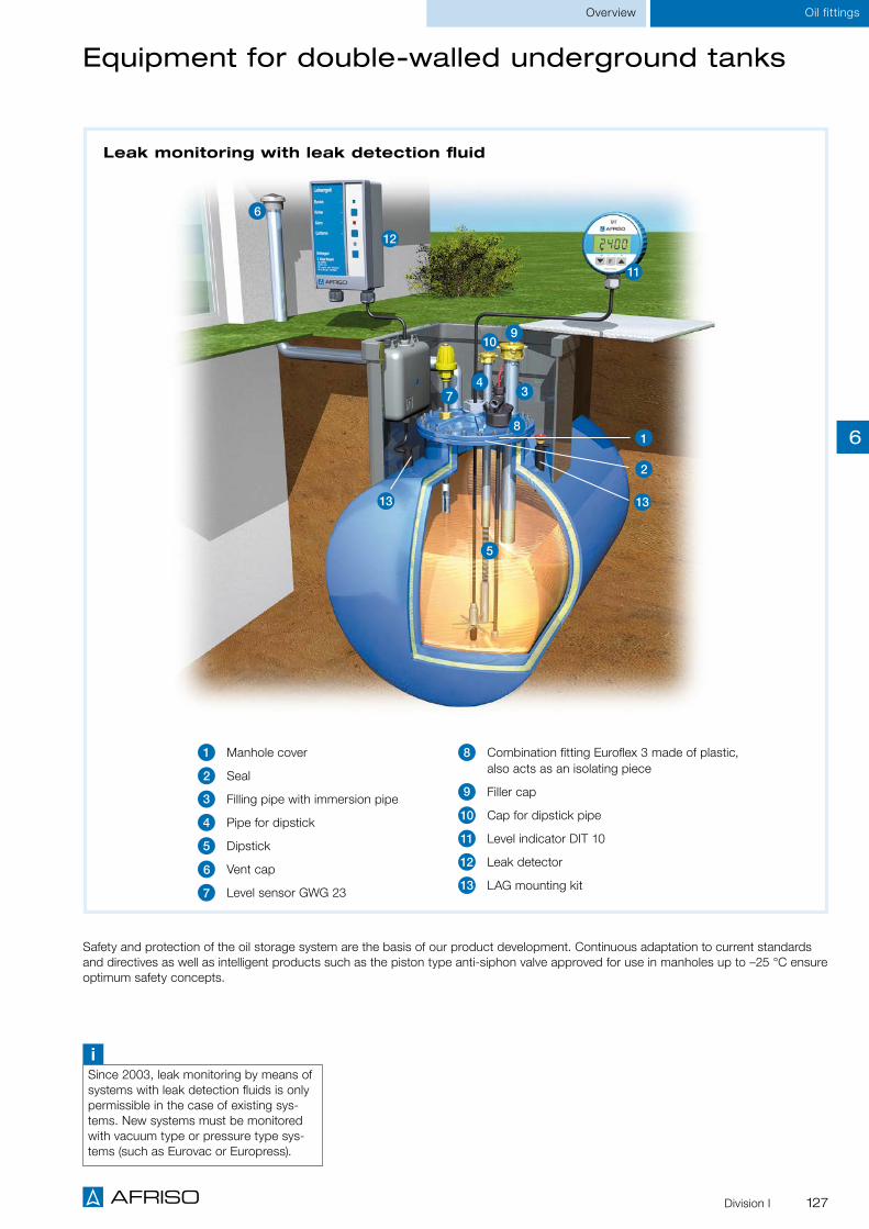
127Division I
Leak monitoring with leak detection fluid
3 4
11
12
5
6
7
8 1
2
13 13
Equipment for double-walled underground tanks
8 Combination fitting Euroflex 3 made of plastic, also acts as an isolating piece
9 Filler cap
10 Cap for dipstick pipe
11 Level indicator DIT 10
12 Leak detector
13 LAG mounting kit
1 Manhole cover
2 Seal
3 Filling pipe with immersion pipe
4 Pipe for dipstick
5 Dipstick
6 Vent cap
7 Level sensor GWG 23
Overview Oil fittings
9 10
Safety and protection of the oil storage system are the basis of our product development. Continuous adaptation to current standards and directives as well as intelligent products such as the piston type anti-siphon valve approved for use in manholes up to –25 °C ensure optimum safety concepts.
iSince 2003, leak monitoring by means of systems with leak detection fluids is only permissible in the case of existing sys-tems. New systems must be monitored with vacuum type or pressure type sys-tems (such as Eurovac or Europress).
6

128 Division I
Accessories
GWG filler caps, overpressure device
Oil fittings
For facilities that may be operated with fuel oil EL standard and low-sulphur, diesel or biodiesel. Suitable for flood hazard areas.
GWG filler cap with bayonet connection G2 as per EN 14420-6 with integrated level sensor con-nection fitting. Male coupling made of brass. Filler cap made of oil- and weather-resistant plastic. Watertight up to 10 m water column. Lockable with standard padlock.
Scope of delivery includes green label "Fuel oil EL low-sulphur" and red label "Also for fuel oil EL standard".
Application
Description
DG: G PG Part no. Price €
GWG filler cap 2 1 10 20430
Overpressure device 1 1 25 20466
iGWG filler caps are also used in building renova-tion projects since the existing GWG wall fitting can no longer be fixed to the outside insulation.
Overpressure deviceGWG filler cap
To avoid overpressure of storage tanks during filling. Suitable for flood hazard areas..
Overpressure device with male connection thread G1½. Opening pressure approx. 25 mbar.Two or more overpressure devices must be installed for filling rates of more than 300 l/min. Watertight up to 10 m water column.
Also for
fuel oil EL
standard
Fuel oil EL
low sul-
phur
6

129Division I
Accessories
Vent caps, dip stick pipe caps/filler caps
Oil fittings
Dip stick pipe cap/filler capVent cap
To cover the vent line.
Cap for vent line.
Metal version: Zamak alloy, thread G1½ or G2.Plastic version: Plug-in type with fixing by means of screw or G2 male thread.
Application
Description
To close dip stick pipes and filling pipes. Suitable for flood hazard areas.
Dip stick pipe cap/filler cap made of Zamak alloy. Watertight up to 10 m water column.
Lockable with standard padlock.
DG: G PG Part no. Price €
Vent cap 2", plastic – plug-in version 1 1 25 20460
Vent cap 1½" plastic – plug-in version 1 1 25 20450
Vent cap G2, plastic – male thread 1 - 200 20462
Vent cap G2 metal 3 1 25 20463
Vent cap G1½ metal 3 1 25 20455
Cap for pipe for dipstick G1 x G1¼ 2 1 140 20464
Filler cap G2 x G2½ Fuel oil EL standard 3 1 55 20445
Filler cap — green G2 x G2½ Low-sulphur fuel oil EL 3 1 25 20452
See page 6 for pipes for dipsticks.
i
6

130 Division I
Tank withdrawal system Euroflex
Withdrawal systemsOil fittings
Quick-action shut-off valve with lever for fast shutting off of the oil supply. Remote operation from outside of the tank room possible with pull cord.
Suitable for use in flood hazard areas. Watertight up to 10 m water column.
Floating withdrawal as per DIN 4755 recommenda-tions. Makes it possible to withdraw fuel oil in the clean area and thus sup-ports optimum functionality of the downstream fittings (e.g. oil filters).
Flexible suction line for maximum variability – also in terms of hose length. The standard lengths 2.15 m and 3.15 m can be short-ened as required without any problems.
Measuring line with balance chamber(for Euroflex 3)
All materials resistant to biofuel and biodiesel with max. 20 % FAME (fatty acid methyl ester).
Version with special G1 screw connection to avoid twisting. Ideal for use with Euroflex with heating band for fast, simple mounting.
Fitting made of high-im-pact, weather-resistant plastic. Approved as an isolating piece.
Version Euroflex 3 with direct connection for pneumatic tank contents gauges. Ideal for retrofitting or for applica-tions involving tanks with few connections.
Figu
re: E
urofl
ex 3
with
floa
t
FO
R BIO-OIL
FÜ
R B I O - Ö
L
20%
6

131Division I
Tank withdrawal system Euroflex
Application
Technical specifications
DG: G, PG: 1 Part no. Price €
Euroflex 2 (2.15), suction hose 2.15 m, without measuring line connection 1 25 20162
Euroflex 3 (2.15), suction hose 2.15 m 1 25 20160
Euroflex 3 (3.15), suction hose 3.15 m 1 25 20164
Euroflex 3 with float, suction hose 2.15 m 1 25 20130
Euroflex 3 with float, suction hose 3.15 m 1 20 20131
Euroflex 312 (GWG 12 K/1C), suction hose 2.15 m 1 10 20190
Accessories
Conversion kit float kit G1 for Euroflex and Miniflex 1 25 20125
Conversion kit float kit G1½ for single tanks and communicating withdrawal systems 1 - 20120
Conversion kit shut-off valve for Euroflex (10/98 and later), Miniflex and AFRISO withdrawal systems for battery tanks for conversion to automatically safeguarding suction lines
1 - 74305
Withdrawal systems Oil fittings
Combination fitting made of high-impact plastic
Integrated, TÜV-tested isolating piece Silent check valve Euroflex 3 for floating withdrawal Suitable for use in flood hazard areas Many versions available
For withdrawal of fuel oil from underground and aboveground tanks in single-line or dual-line mode. Suitable for the following media: fuel oil EL (DIN 51603-1) and diesel fuel (EN 590) as well as biofuel and biodiesel with max. 20 % FAME. Also for use in flood hazard areas.
Combination fitting made of plastic as a withdrawal system with measuring line (not Euroflex 2) and TÜV-tested isolating piece that screws into the tank. G3/8 stainless steel threaded female connections for suction and return lines. Universal compression fittings for pipes with 8 and 10 mm outside diame-ters for connecting the suction line are enclosed. The integrated check valve with elastic valve seat keeps the oil column in the suction line from being interrupted when the burner is off. Quick-action shut-off valve with lever for remote closing in emergency situations. Pressure- and vacuum-tight up to 1 bar.
Euroflex 3 with float and special G1 screw connection for withdrawing oil in the clean area (as per TRWS 791 not recommended in underground tanks). Measuring line connection for hose or pipe with 6 mm outside diameter. Suction hose length 2.15 m or 3.15 m with additional float at the suction hose end.
Euroflex 312 (GWG 12K/1C), combination of level sensor and withdrawal system. With measuring line connection for hose or pipe with 6 mm outside diameter. For battery tanks as per DIN 6620 and tanks as per DIN 6625 manufactured on site. Specially useful if there is no connection socket at the tank. Connection G1½.
ConnectionTank: G1 male thread (Euroflex 312: G1½ male thread) Suction/return line: G3/8 female thread Measuring line: 6 mm
LengthSuction hose: 2.15 m or 3.15 m Measuring hose: 2.15 m or 3.15 m (not Euroflex 2)
Test pressureMax. 6 bar
Flow rateMax. 150 l/h
MaterialScrew fitting: Plastic (POM), blue Suction hose: NBR Balance chamber: Zamak (ZnAl4Cu1)
Approval for construction products Conformity certificate as per EN 12514-2, ÜHP
Description
iPull cord for remote closing see page 133.
Eur
oflex
312
FO
R BIO-OIL
FÜ
R B I O - Ö
L
20%
6

132 Division I
ConnectionTank: G1 male thread Suction line: G3/8 female thread
LengthHeating band: 5 m, 7.5 m or 10 m Suction hose: 2.15 m
Heating capacityAt 10 °C: 25 W/m
ConnectionTank: G1 male thread Suction/return line: G3/8 female thread Measuring line: 6 mm
LengthSuction hose: 2.15 m or 3.15 m Measuring hose: 2.15 m or 3.15 m (not Miniflex 2)
Test pressureMax. 6 bar
Flow rateMax. 150 l/h
MaterialScrew fitting: brassSuction hose: NBRBalance chamber: Zamak (ZnAl4Cu1)
Euroflex with heating band, Miniflex
Euroflex TH Miniflex
For withdrawal of fuel oil from underground and aboveground tanks in single-line or dual-line mode. Suitable for the following media: fuel oil EL (DIN 51603-1) and diesel fuel (EN 590) as well as biofuel and biodiesel with max. 20 % FAME. Also for use in flood hazard areas.
Combination fitting made of brass as a withdrawal system with measuring line that screws into the tank. Threaded female connection for suction and return lines. Universal compression fittings for pipes with 8 and 10 mm outside diameters for the suction line are enclosed. Measuring line connec-tion for hose or pipe with 6 mm outside diameter. The integrated check valve with elastic valve seat keeps the oil column in the suction line from being interrupted when the burner is off. Quick-action shut-off valve with lever for remote closing in emergency situations. Pressure- and vacuum-tight up to 1 bar.
Application
Description
For withdrawal of fuel oil EL or diesel fuel in sin-gle-line mode from tanks that may be subjected to temperatures of less than 5 °C (cloud point, paraf-fin). Suitable for flood hazard areas.
Combination fitting Euroflex 2 as a withdrawal sys-tem with heating band that screws into the tank. A heating band is attached to the suction line; at the bottom of the tank the band forms a spiral around the suction point. The required length depends on the tank type and size as well as the installation site. The self-controlling heating band is designed to avoid overheating and burning out. The band is connected to AC 230 V via a connection cable (2 m) and a residual current device. Adaptation to the tanks with special screw connection to avoid twisting. Watertight up to 10 m water column.
DG: G PG Part no. Price €
Euroflex TH, suction hose 2.15 m, 5 m heating band 1 1 - 21010
Euroflex TH, suction hose 2.15 m, 7.5 m heating band 1 1 - 21011
Euroflex TH, suction hose 2.15 m, 10 m heating band 1 1 - 21012
Miniflex 2, suction hose 2.15 m, without measuring line connection 2 1 25 74200
Miniflex 3, suction hose 2.15 m 2 1 25 74300
Sp
ecia
l scr
ew c
onne
ctio
n to
avo
id t
wis
ting
Technical specifications
iSee Euroflex ordering table for conversion kit for Miniflex
Withdrawal systemsOil fittings
Special screw connection to avoid twisting of hose and heating band.
FO
R BIO-OIL
FÜ
R B I O - Ö
L
20%
6

133Division I
Pull cord, pressure compensation unit
DG: G PG Part no. Price €
Pressure compensation unit DAE 2 20800
Pull cord 1 20475
Pull cord
Pressure compensation unit DAE
Pull cord with handle and a sealable case for the remote acti-vation of quick-action shut-off valves (e.g. Euroflex or Miniflex). TÜV-tested. Consisting of: Pull cord (steel, plastic-coated), 10 m long Handle 4 eyelet screws for deflecting the pull cord Sealable case with wire and lead seal Dowels and screws
Pull cordDescription
Pressure compensation unit DAEUsed to limit pressure increases in closed pipe sections result-ing from expansion caused by temperature changes. Suitable for fuel oil pipe sections which are closed at both ends (e.g. by means of solenoid valves or check valves) and which are sub-ject to considerable temperature differences (e.g. due to pipe heating). Suitable for use in flood hazard areas.
G3/8 female thread connections at both ends. A pipe volume of 725 cm3 can be buffered at a temperature difference of 40 °C. This corresponds to the following max. line lengths (depending on the line diameter): 25.5 m ≥ Ø 8 x 1 14 m ≥ Ø 10 x 1 9 m ≥ Ø 12 x 1
Watertight up to 10 m water column.
Approval for construction productsConformity certificate (ÜHP) as per EN 12514-2 pending
Application
Description
Withdrawal systems Oil fittings
6

134 Division I
For
MA
V:
Det
erm
ine
max
. hei
ght
diffe
renc
e be
twee
n M
AV
and
the
line
at
the
syst
em
Legislation for water pollution control stipulates the use of specific equipment to protect the water. For example, § 62 and § 63 of the German Water Act specify the handling of water-polluting substances in facilities. The regulations may be national and/or local.
In the case of oil consuming systems operating in suction mode where a pipe section is below the maximum tank level, fuel oil can be siphoned out if a leak occurs. Therefore, protection equipment against siphoning must be installed. Anti-siphon valves are used for this purpose; they are available as solenoid, diaphragm or piston type anti-siphon valves. Diaphragm or piston type anti-siphon valve are usually installed in smaller and medium sized facilities; the piston type anti-siphon valve offers a num-ber of decisive advantages.
Depending on the applicable regulations, the valves must be approved.
It must be ensured that the vacuum at the suction end at the burner pump does not exceed 0.4 bar in the worst case.
Factors to be considered include: The maximum suction lift at minimum oil level The suction line length The viscosity of the oil in the storage tank at extreme winter temperatures Additional pressure losses caused by fittings (such as oil filters, shut-off valves, etc.) and lines
Protection equipment against siphoning: anti-siphon valves
Notes on installation
For
KA
V:
Det
erm
ine
actu
al
safe
hei
ght
1 Piston type anti-siphon valve KAV*
2 Diaphragm type anti-siphon valve MAV*
3 Pressure compensation unit DAE
1
2
3
* Mounting position (example), arrangement is variable and must be adapted to suit local conditions.
Anti-siphon valvesOil fittings
Legal and technical
requirements concerning fuel
oil consuming systems
6

135Division I
Anti-siphon valves Oil fittings
For oil carrying pipes in oil consuming systems where a pipe section is below the maximum tank level. KAV keeps fuel oil from being siphoned out of the tank in the case of leaks in the suction line. Suitable for the following media: fuel oil (DIN 51603-1) and diesel fuel (EN 590) as well as biofuel and biodiesel with up to 100 % FAME. Also for use in flood hazard areas.
Vacuum-controlled shut-off system with a completely new function principle. KAV is closed when the burner pump is not in operation. When the burner pump starts, a vacuum is generated in the suction line. This opens the KAV and fuel oil is pumped from the tank. If the suction line has a leak or if the burner pump stops, KAV closes and the suction line between the tank and the burner pump is shut off. KAV features a pressure relief mechanism, i.e. if the fuel oil contained in the suction line heats up and therefore expands, KAV opens. The fuel oil can flow back into the tank (provided that a tank with-drawal fitting without backflow preventer is installed). The pressure relief is independent of the adjusted safe height and operates reliably at a response pressure as low as 300 mbar. KAV is continuously adjustable from 1–4 m. The adjusted value corresponds to the actual safe height (= max. liquid level) and not the installation height (as in the case of diaphragm type anti-siphon valves).This results in reduced line resistance, which has a positive effect on the service life of the burner and the pump. KAV is designed as a sealed system. Therefore, no vent is required and water or dirt cannot get into the system. Since the sensitive diaphragm as the main actuating element has been replaced by a piston, malfunctions caused by pollution, ice or system overpressure (rupture of the diaphragm) are practically impossible. Watertight up to 10 m water column.
Application
Description
Technical specifications
Adjustment of safe heightCorresponds to actual safe height 1–4 m, continuously adjustable
Connection thread3/8 female thread at both ends
Mounting positionAny
Oil flow rateMax. 220 l/h
Operating temperature rangeMedium: 6/40 °C Ambient: -25/+60 °C (function range)
Vacuum-tightUp to -1 bar
Test pressureMax. 10 bar
Response pressure 300 mbar
Housing materialBrass
Approval for construction products DIBt: Z-65.50-415
Scope of deliveryPiston type anti-siphon valve with screw connector kit for pipes Ø 6, 8 and 10 mm and lead sealing kit
DG: G, PG: 2 Part no. Price €
Piston type anti-siphon valve KAV 20240
Pressure gauge (-0.7/+0.9 bar) for indicating the KAV opening pressure 70030
Piston type anti-siphon valve KAV
Piston instead of diaphragm – for maxi-mum safety even in case of pollution, ice or system overpressure
Adjusted value corresponds to the safe height (reduced line resistance)
Also for outdoor use (manhole) Sealed system for error-free operation
With universal screw connections 6/8/10 mm and lead sealing kit
Page 137
AOption: Pressure
gauge for
indicating the KAV
opening pressure
6

136 Division I
Oil fittings Anti-siphon valves
Description
Adjustment of safe height1–4 m (corresponds to installation height), continuously adjustable
Connection thread3/8 female thread at both ends
Mounting positionAny
Oil flow rateMax. 220 l/h
Operating temperature rangeMedium: 6/40 °C
Vacuum-tightUp to -1 bar
Test pressureMax. 6 bar
Housing materialBrass
Approval for construction products DIBt: Z-65.50-415
Scope of deliveryDiaphragm type anti-siphon valve with lead sealing kit
Application
Technical specifications
Diaphragm type anti-siphon valve MAV
For oil carrying pipes in oil consuming systems where a pipe section is below the maximum tank level. MAV keeps fuel oil from being siphoned out of the tank in the case of leaks. Suitable for the following media: fuel oil (DIN 51603-1) and diesel fuel (EN 590) as well as biofuel and biodiesel with max. 20 % FAME. Also for use in flood hazard areas.
MAV is continuously adjustable to a safe height of 1–4 m for optimum adaptation to suit local condi-tions. The adjusted value corresponds to the installation height. MAV shuts off under spring pressure and opens under the vacuum caused by the pump. Watertight up to 10 m water column. If necessary, install a pressure compensation unit.
DG: G PG Part no. Price €
Diaphragm type anti-siphon valve MAV 2 1 - 20139
Screw connections with Cu flat gasket G3/8 x 6 (dual) 3 1 - 20507
Screw connections with Cu flat gasket G3/8 x 8 (dual) 3 1 - 20504
Screw connections with Cu flat gasket G3/8 x 10 (dual) 3 1 - 20505
Screw connections with Cu flat gasket G3/8 x 12 (dual) 3 1 - 20506
Safe height 1–4 m
Lead sealing kit
Page 137
A
6

137Division I
Tester for function tests of built-in "safety equipment against siphoning" (diaphragm type or piston type anti-siphon valves) in oil carrying pipes or withdrawal systems. Test can be performed at all systems with standard filter combinations.If no AFRISO filter cup with test and drain system is available, it is sufficient to replace the existing filter cup with the filter cup of the tester. AFRISO recommends to replace all filter cups without drain system so that the fuel oil filter can be drained rapidly and the function test performed easily during servicing. Suitable for tests with the following media: fuel oil EL (DIN 51603-1) and diesel fuel (EN 590) as well as biofuel and biodiesel with up to 100 % FAME.
The tester for "safety equipment against siphoning" allows to quickly come to a sound conclusion con-cerning the correct operation of anti-siphon valves. Mounting is simple: Screw the filter cup of the test-er into the fuel oil filter of the facility (not necessary in the case of oil filter cups with test and drain sys-tem), plug the hose into the tester drain unit, connect an oil suction pump to the other end of the tester and you are ready for testing. For the test, a vacuum is generated which sucks in oil; the oil flows into the tester cup. The vacuum is maintained in the tester cup via the shut-off fitting and displayed by the pressure gauge. When no more oil flows into the tester cup, there is pressure equilibrium. The vacuum can now be read at the test pressure gauge; with a simple formula (hydrostatic pressure / pressure dif-ference), you can determine whether the siphoning protection works.
Application
Description
Dimensions (W x H x D)Tester: 180 x 286 x 71 mm Case: 395 x 106 x 295 mm
Range-0.6/0 bar
ConnectionG3⁄8 with 60° cone
Operating temperature rangeAmbient: -25/+40 °CStorage: -25/+60 °C
Scope of delivery Tester with long filter cup Vacuum gauge Hose Long tester cup with drain system Plastic case
Technical specifications
Tester for safety equipment against siphoning
Reliable tests of all diaphragm type/piston type anti-siphon valves
Simple check and assessment of the system safety
Test can be performed easily at all systems with standard filter combinations
DG: G, PG: 1 Part no. Price €
Tester anti-siphon valve 1 - 20239
Accessories
Filter cup short with drain system 1 - 20257
Filter cup long with drain system 1 - 20262
Manufacturer-
independent
application
iSafety equipment against siphoning must be checked for correct opera-tion at least every 5 years according to the approval.
Oil fittingsAnti-siphon valves
6

138 Division I
Legend for calculation formula
pgauge ≙ Value displayed by pressure gauge of tester
pg,max ≙ Hydrostatic oil column of fully filled tank; determination: pg,max = 0.084 bar/m x hmax
p3 ≙ Hydrostatic oil column at current level; determination: p3 = 0.084 bar/m x h3
hmax and h3 must be determined directly at the system
Function test at system with piston type anti-siphon valve (KAV from AFRISO)
1. Create vacuum in the test cup using the oil suction pump – oil flows into the cup of the tester if the valves are open.
2. Seal vacuum; measure vacuum (pPgauge) at the pressure gauge when no more oil flows into the cup of the tester.
3. Since the safe height of KAV corresponds to the height difference between the maximum tank level and the lowest point in the line and since the actual tank level has an influence on the opening pressure, the following criterion must be met: [PPgauge + pg,max - p3] < 0
4. If this criterion is met, the anti-siphon function is available.
h3
hmax
➊
➊Connection oil suction pump
PPgauge
1. Create vacuum in the test cup using the oil suction pump – oil flows into the cup of the tester if the valves are open.
2. Seal vacuum; measure vacuum at the pressure gauge when no more oil flows into the cup of the tester.
3. Since the safe height corresponds to the height difference between the mounting position of MAV and the lowest point in the line and since the actual tank level has virtually no influ-ence on the opening pressure, only the following criterion must be met: pPgauge < 0
4. If this criterion is met, the anti-siphon function is available.
Function test at system with diaphragm type anti-siphon valve (e.g. MAV from AFRISO or other manufacturers)
➊
➊Connection oil suction pump
Saf
e he
ight
PPgauge
i
Test principle
Oil fittings Anti-siphon valves
6

139Division I
Oil fittingsFuel oil filters
Comparison of fuel oil filters
Paper filters
Sintered plastic sieves
Felt andStainless steel sieve
Opticlean MS-5/MC-7 ultra-fine filterOptimum filter surface due to folded paper filter.
Mesh size 20–35 µm (MS-5) 5 µm (MC-7)
Filter surface: 500 cm2 (MS-5) 700 cm2 (MC-7)
Opticlean MC-18 ultra-fine filterOptimum filter effectiveness and long service life.
Mesh size: 5–20 µm Filter surface: 1,850 cm2 Can be used with long filter cup.
Replaceable filter cartridgeExcellent filtration. Also suit-able for pressure mode and temperatures of up to 80 °C.
Mesh size: 12–30 µmFilter surface: 967 cm2 Can be used for all AFRISO filter types with additional adapter.
Optimum ultra-fine filtration Specially for small and very small burner capacities
Preferably for single-line mode
Excellent filtration For small and medium burner capacities
Suitable for single- and dual-line mode
Suitable for almost all standard filter combinations.
Proven filtration technology
Filter cup, longExtra long filter cup provides for sedimentation volume and space for all standard, long filter inserts.
Version with drain system Removing the oil from the oil filter quickly
No oil odour caused by oil dripping
Sintered plastic sieve, shortStar shape for large filter surface.
Colour code: Blue Mesh size: 50 µm Filter surface: 115 cm2
Optimum replacement characteristics:Filter base does not swell
Sintered plastic sieve, longExcellent filtration and long service life.
Colour code: WhiteMesh size: 35 µm Filter surface: 200 cm2
Can be used with long filter cup, preferably for single-line mode.
Felt sieveExcellent filtration. Suitable for medium and high burner capacities. Suitable for single- and dual-line mode.
Mesh size: 50–75 µm
Stainless steel sieveGood filtration, pollution visible. For medium and high burner capacities. Suitable for single- and dual-line mode.
Mesh size: 100 µm, Filter surface: 48 cm2 Disadvantage: Air may collect in the filter cup.
Tubular sieve Filter surface 15.3 cm2 below the felt rings.
Disadvantage: Filter fibres may come loose and get into the burn-er nozzles.
Sch
emat
ic r
epre
sent
atio
n
6
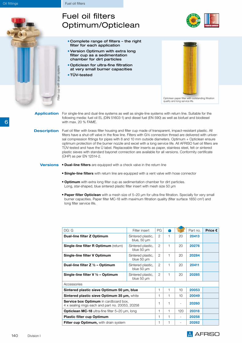
140 Division I
Oil fittings
For single-line and dual-line systems as well as single-line systems with return line. Suitable for the following media: fuel oil EL (DIN 51603-1) and diesel fuel (EN 590) as well as biofuel and biodiesel with max. 20 % FAME.
Fuel oil filter with brass filter housing and filter cup made of transparent, impact-resistant plastic. All filters have a shut-off valve in the flow line. Filters with G3/8 connection thread are delivered with univer-sal compression fittings for pipes with 8 and 10 mm outside diameters. Optimum + Opticlean ensure optimum protection of the burner nozzle and excel with a long service life. All AFRISO fuel oil filters are TÜV-tested and have the Ü label. Replaceable filter inserts as paper, stainless steel, felt or sintered plastic sieves with standard bayonet connection are available for all versions. Conformity certificate (ÜHP) as per EN 12514-2.
Dual-line filters are equipped with a check valve in the return line
Single-line filters with return line are equipped with a vent valve with hose connector
Optimum with extra long filter cup as sedimentation chamber for dirt particles. Long, star-shaped, blue sintered plastic filter insert with mesh size 50 μm
Paper filter Opticlean with a mesh size of 5–20 μm for ultra-fine filtration. Specially for very small burner capacities. Paper filter MC-18 with maximum filtration quality (filter surface 1850 cm2) and long filter service life.
Fuel oil filters Optimum/Opticlean
Application
Description
DG: G Filter insert PG Part no. Price €
Dual-line filter Z Optimum Sintered plastic, blue, 50 µm
2 1 20 20413
Single-line filter R Optimum (return) Sintered plastic, blue 50 µm
2 1 20 20276
Single-line filter V Optimum Sintered plastic, blue 50 µm
2 1 20 20284
Dual-line filter Z ½ – Optimum Sintered plastic, blue 50 µm
2 1 20 20411
Single-line filter V ½ – Optimum Sintered plastic, blue 50 µm
2 1 20 20285
Accessories
Sintered plastic sieve Optimum 50 µm, blue 1 1 10 20053
Sintered plastic sieve Optimum 35 µm, white 1 1 10 20049
Service box Optimum in cardboard box, 4 x sealing rings each and part no. 20053, 20258 1 1 - 20260
Opticlean MC-18 ultra-fine filter 5–20 µm, long 1 1 120 20318
Plastic filter cup Optimum 1 1 - 20258
Filter cup Optimum, with drain system 1 1 - 20262
Complete range of filters – the right filter for each application
Version Optimum with extra long filter cup as a sedimentation chamber for dirt particles
Opticlean for ultra-fine filtration at very small burner capacities
TÜV-tested
Opticlean paper filter with outstanding filtration quality and long service life.
Versions
Fuel oil filters
Filte
r cu
p w
ith d
rain
sys
tem
FO
R BIO-OIL
FÜ
R B I O - Ö
L
20%
6

141Division I
Oil fittingsFuel oil filters
Dual-line filter Z 500 Si/Fi/St
Single-line filter R 500 Si/Fi/St
Single-line filter V 500 Si/Fi/St
Single-line/dual-line filters for fuel oil
For dual-line systems. Suitable for fuel oil EL (DIN 51603-1) and diesel fuel (EN 590).
Brass filter housing, filter cup made of transparent, impact-re-sistant plastic. With check valve in the return line and shut-off valve in the flow line. Universal compression fittings for pipes with 8/10 mm outside diameters included. Watertight up to 10 m water column. Registration num-ber 2Y107/13.Conformity certificate (ÜHP) as per EN 12514-2.
For single-line systems with return supply. Suitable for the following media: fuel oil EL (DIN 51603-1), diesel fuel (EN 590), biofuel and biodiesel with max. 20 % FAME.
Brass filter housing, filter cup made of transparent, impact-re-sistant plastic. With shut-off valve in the flow line as well as vent valve with hose connector. Universal compression fittings for pipes with 8/10 mm outside diameters included.Registration number 2Y106/13.Conformity certificate (ÜHP) as per EN 12514-2.
For single-line systems. Suitable for the following media: fuel oil EL (DIN 51603-1), diesel fuel (EN 590), biofuel and biodiesel with max. 20 % FAME.
Brass filter housing, filter cup made of transparent, impact-re-sistant plastic. With shut-off valve in the flow line. Universal compression fittings for pipes with 8/10 mm outside diameters included. Watertight up to 10 m water column. Registration num-ber 2Y103/13.Conformity certificate (ÜHP) as per EN 12514-2.
Application
Description
DG: G, PG: 2Connection Universal screw
connectionFilters
*Oil throughput
∆p=100 mbarPart no. Price €
Tank Burner
Dual-line filter Z 500 Si 2 x G3/8 female 2 x G3/8 male 2 x 8/10 mm Sintered plastic 200 l/h 1 25 20429
Dual-line filter Z 500 ALS Si, filter cup with drain system 2 x G3/8 female 2 x G3/8 male 2 x 8/10 mm Sintered plastic 200 l/h 1 25 20303
Dual-line filter Z 500 Fi 2 x G3/8 female 2 x G3/8 male 2 x 8/10 mm Felt 200 l/h 1 25 20428
Dual-line filter Z 500 St 2 x G3/8 female 2 x G3/8 male 2 x 8/10 mm Steel 220 l/h 1 25 20425
Single-line filter R 500 Si (return) 1 x G3/8 female 2 x G3/8 male 1 x 8/10 mm Sintered plastic 210 l/h 1 25 20281
Single-line filter R 500 ALS Si, filter cup with drain system 1 x G3/8 female 2 x G3/8 male 1 x 8/10 mm Sintered plastic 210 l/h 1 25 20304
Single-line filter R 500 Fi (return) 1 x G3/8 female 2 x G3/8 male 1 x 8/10 mm Felt 240 l/h 1 25 20282
Single-line filter R 500 St (return) 1 x G3/8 female 2 x G3/8 male 1 x 8/10 mm Steel 250 l/h 1 25 20283
Single-line filter V 500 Si 1 x G3/8 female 1 x G3/8 male 1 x 8/10 mm Sintered plastic 250 l/h 1 25 20292
Single-line filter V 500 ALS Si, filter cup with drain system 1 x G3/8 female 1 x G3/8 male 1 x 8/10 mm Sintered plastic 250 l/h 1 25 20305
Single-line filter V 500 Fi 1 x G3/8 female 1 x G3/8 male 1 x 8/10 mm Felt 290 l/h 1 25 20293
Single-line filter V 500 St 1 x G3/8 female 1 x G3/8 male 1 x 8/10 mm Steel 320 l/h 1 25 20294
Dual-line filter Z ½-500 Si 2 x G½ female 2 x G½ female --- Sintered plastic 310 l/h 1 25 20480
Dual-line filter Z ½-500 Fi 2 x G½ female 2 x G½ female --- Felt 400 l/h 1 25 20481
Dual-line filter Z ½-500 St 2 x G½ female 2 x G½ female --- Steel 500 l/h 1 25 20482
Single-line filter V ½-500 Si 1 x G½ female 1 x G½ female --- Sintered plastic 390 l/h 1 25 20485
Single-line filter V ½-500 Fi 1 x G½ female 1 x G½ female --- Felt 470 l/h 1 25 20486
Single-line filter V ½-500 St 1 x G½ female 1 x G½ female --- Steel 560 l/h 1 25 20487
* At filter insert pollution degree of 50 %.
Dua
l-lin
e fil
ter
with
d
rain
sys
tem
FO
R BIO-OIL
FÜ
R B I O - Ö
L
20%
FO
R BIO-OIL
FÜ
R B I O - Ö
L
20%
6

142 Division I
Oil fittings Fuel oil filters
Spare parts for filters
DG: G Description PG Part no. Price €
Opticlean MC-7 *Ultra-fine filter 5–20 µm, short Filter surface: 700 cm2
1 1 240 20319
Opticlean MC-18 * Ultra-fine filter 5–20 µm, long Filter surface: 1,850 cm2
1 1 120 20318
Opticlean MS-5Ultra-fine filter 20–35 µm, short Filter surface: 500 cm2
1 - 25 20308
Sintered plastic sieve short, 50–70 µm blueFilter base ABS white, engraving "Made in Germany"Box of 25 pieces
1 - 25 20038
Sintered plastic sieve short, 50–70 µm blueFilter base ABS white, engraving "Made in Germany" Box of 100 pieces
1 - 100 20045
Sintered plastic sieve long, 50–70 µm blueFilter base ABS white, engraving "Made in Germany" 1 1 - 20053
Sintered plastic sieve short, 35 µm white Box of 25 pieces 1 - 25 20035
Sintered plastic sieve short, 35 µm white Box of 250 pieces 1 - 250 20027
Sintered plastic sieve long, 35 µm white 1 1 - 20049
Felt sieve Box of 25 pieces 1 - 25 20031
Felt sieve Individually packed in re-sealable bag, in box of 100 pieces
1 - 100 20034
Stainless steel sieve 100 µm 1 1 250 20032
Filter cup short Plastic, for suction mode
Standard 1 - 10 20254
With drain system and transparent drain hose Ø 6 x 500 mm
1 - 10 20257
Filter cup long Plastic, for suction mode
Standard 1 - 10 20258
With drain system and transparent drain hose Ø 6 x 500 mm
1 - 10 20262
Filter cup, brass for pressure mode, without union nut 1 1 - 20261
O ring For filter cup 1 - 10 20422
i* The filter surface of Opticlean ultra-fine filters is up to 37 times greater than that of conventional filter inserts; they excel with an extremely high degree of filtration. Filter fineness of nominal 5 μm (absolute 20 μm) separation are possible.
Even the smallest drops of water and emulsion are retained with high reliability. Opticlean filter cartridges can be used in any stand-ard fuel oil filter, they are metal-free and can be recycled in an environmentally protective way.
6
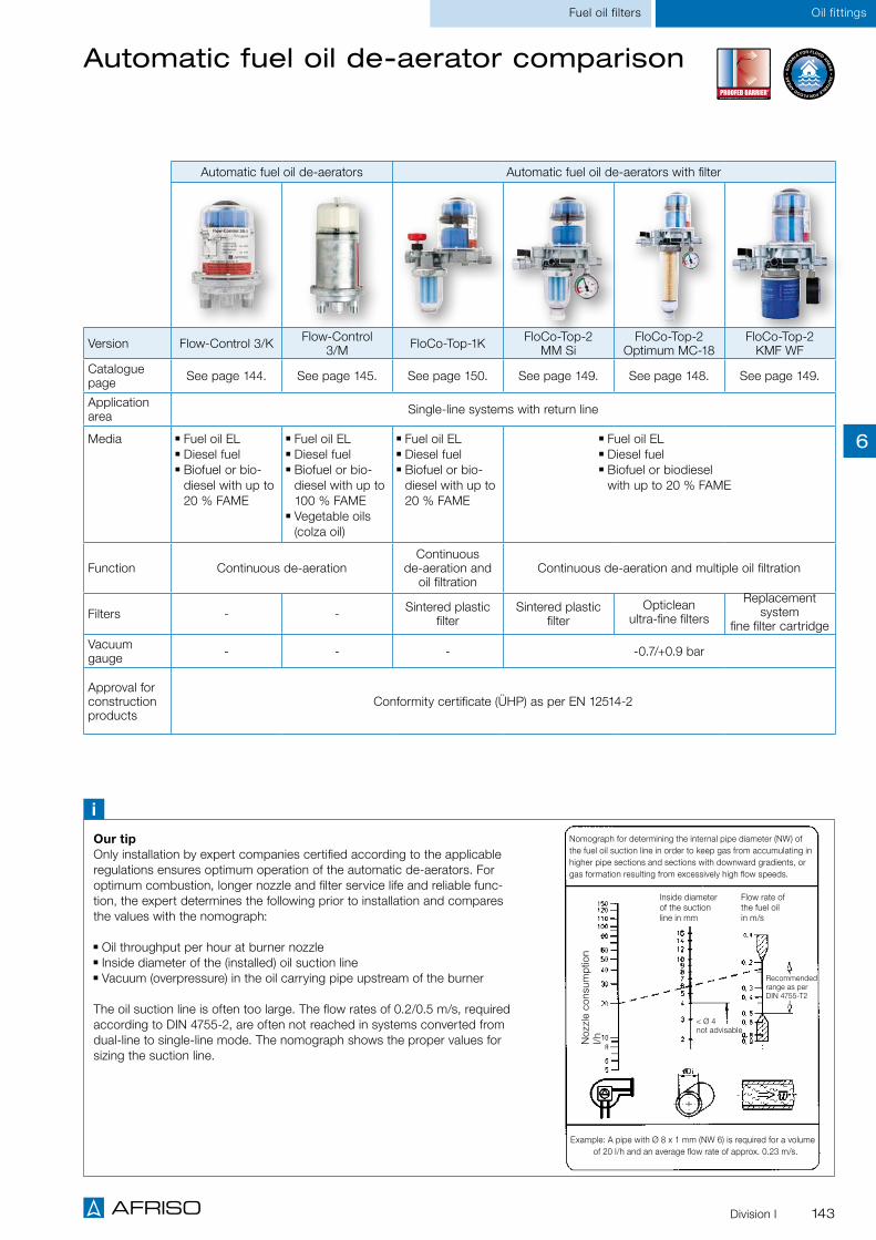
143Division I
Oil fittingsFuel oil filters
Automatic fuel oil de-aerator comparison
Automatic fuel oil de-aerators Automatic fuel oil de-aerators with filter
Version Flow-Control 3/K Flow-Control 3/M FloCo-Top-1K FloCo-Top-2
MM SiFloCo-Top-2
Optimum MC-18FloCo-Top-2
KMF WF Catalogue page See page 144. See page 145. See page 150. See page 149. See page 148. See page 149.
Application area Single-line systems with return line
Media Fuel oil EL Diesel fuel Biofuel or bio-diesel with up to 20 % FAME
Fuel oil EL Diesel fuel Biofuel or bio-diesel with up to 100 % FAME
Vegetable oils (colza oil)
Fuel oil EL Diesel fuel Biofuel or bio-diesel with up to 20 % FAME
Fuel oil EL Diesel fuel Biofuel or biodiesel with up to 20 % FAME
Function Continuous de-aerationContinuous
de-aeration and oil filtration
Continuous de-aeration and multiple oil filtration
Filters - - Sintered plastic filter
Sintered plastic filter
Opticlean ultra-fine filters
Replacement system
fine filter cartridge Vacuum gauge - - - -0.7/+0.9 bar
Approval for construction products
Conformity certificate (ÜHP) as per EN 12514-2
Our tipOnly installation by expert companies certified according to the applicable regulations ensures optimum operation of the automatic de-aerators. For optimum combustion, longer nozzle and filter service life and reliable func-tion, the expert determines the following prior to installation and compares the values with the nomograph:
Oil throughput per hour at burner nozzle Inside diameter of the (installed) oil suction line Vacuum (overpressure) in the oil carrying pipe upstream of the burner
The oil suction line is often too large. The flow rates of 0.2/0.5 m/s, required according to DIN 4755-2, are often not reached in systems converted from dual-line to single-line mode. The nomograph shows the proper values for sizing the suction line.
iNomograph for determining the internal pipe diameter (NW) of the fuel oil suction line in order to keep gas from accumulating in higher pipe sections and sections with downward gradients, or gas formation resulting from excessively high flow speeds.
Inside diameter of the suction line in mm
Flow rate of the fuel oil in m/s
< Ø 4 not advisable
Example: A pipe with Ø 8 x 1 mm (NW 6) is required for a volume of 20 l/h and an average flow rate of approx. 0.23 m/s.
Noz
zle
cons
umpt
ion
l/h
Recommended range as per DIN 4755-T2
6

144 Division I
Oil fittings Fuel oil de-aerators
Automatic fuel oil de-aerator Flow-Control 3/K TÜV-tested
Application
Description
Burner connectionG3/8 male with 60° cone for burner hose or G¼ female (part no. 69978)
Tank connectionG¼ female or oil hose G¼ male x G3/8 union nut for connection to filter
Nozzle capacityMax. 100 l/h
Return flowMax. 120 l/h
Separating capacity air/gasApprox. 4 l/h
Mounting positionFloat housing vertical to the top
Operating temperature rangeMedium: Max. 60 °C Ambient: Max. 60 °C
Operating overpressureMax. 0.7 bar corresponds to static oil column of approx. 8 m.
Test pressure6 bar
Dimensions W x H x D: 95 x 147 x 95 mm
Approval for construction productsTÜV-tested (S 133 2013 E2) Conformity certificate (ÜHP) as per EN 12514-2
Technical specifications
"PROOFED BARRIER" if installed with vent hose
DG: G, PG: 1 Part no. Price €
Flow-Control 3/K 1 25 69930
Flow-Control 3/K (G¼) 1 25 69978
Trouble-free operation due to automatic de-aeration
Dual float safety system keeps oil foam from escaping
Considerably increased fuel oil filter service life – the amount of oil drawn from the tank corresponds exactly to the oil actually burnt
The suction line can usually have a smaller diameter
For single-line systems with return line in oil consuming systems for continuous de-aeration. Suitable for the following media: fuel oil EL (DIN 51603-1) and diesel fuel (EN 590) as well as biofuel and bio-diesel with max. 20 % FAME. Also for use in flood hazard areas. The risk of a leak in the return line going unnoticed is removed with Flow-Control. It is no longer necessary to regularly check the return line for leaks.
Automatic fuel oil de-aerator consisting of a diecast zinc housing with female G¼ connection thread at the tank end and male G3/8 connection threads with 60° cone at the burner end for connection of the burner hoses. De-aerator hood made of transparent plastic. Flow-Control 3/K features two separate float chambers. The upper float chamber contains the operating float; the lower float chamber contains the safety float. The upper float chamber keeps oil foam from escaping via the vent opening (e.g. dur-ing commissioning/filter exchange) and indicates malfunctions of the vent valve. An oil hose with ball-shaped sealing for 60° cone and a G3/8 union nut is supplied for connection to the fuel oil filter. Watertight up to 10 m water column. All Flow-Control versions are TÜV-tested.
Flow-Control 3/K (G¼) with G¼ female thread instead of G3/8 male thread.
iThe devices must not be subjected to undiluted additives, alcohol and acids.
FO
R BIO-OIL
FÜ
R B I O - Ö
L
20%
6

145Division I
Oil fittingsFuel oil de-aerators
Automatic fuel oil de-aerator Flow-Control 3/M TÜV-tested
Application
Description
Burner connectionG3/8 male with 60° cone for burner hose or G¼ female (part no. 70014)
Tank connectionG¼ female or oil hose G¼ male x G3/8 Union nut for connection to filter
Nozzle capacityMax. 100 l/h
Return flowMax. 120 l/h
Separating capacity air/gasApprox. 4 l/h
Mounting positionFloat housing vertical to the top
Operating temperature rangeMedium: Max. 80 °C Ambient: Max. 60 °C
Operating overpressureMax. 0.7 bar (corresponds to static oil column of approx. 8 m)
Test pressure6 bar
Dimensions W x H x D: 95 x 200 x 95 mm
Approval for construction productsTÜV-tested (S 133 2013 E2), Conformity certificate (ÜHP) as per EN 12514-2
Technical specifications
DG: G, PG: 1 Part no. Price €
Flow-Control 3/M 1 25 69929
Flow-Control 3/M (G¼) 1 25 70014
2 separate float chambers for increased system safety
Trouble-free operation due to automatic de-aeration
No unnoticed leakage in the return line Considerably increased fuel oil filter service life – the amount of filtered oil drawn from the tank corresponds exactly to the oil burnt
For single-line systems with return line in oil consuming systems for continuous de-aeration. Suitable for the following media: fuel oil EL (DIN 51603-1) and diesel fuel (EN 590) as well as biofuel and bio-diesel with up to 100 % FAME as well as vegetable oils (colza oil). Also for use in flood hazard areas. Flow Control 3/M is recommended for mounting below the max. fuel oil level in the tank and for any application requiring particular safety.
Automatic fuel oil de-aerator consisting of a diecast zinc housing with female G¼ connection thread at the tank end and male G3/8 connection threads with 60° cone at the burner end for connection of the burner hoses. An oil hose with ball-shaped sealing for 60° cone and a G3/8 union nut is supplied for connection to the fuel oil filter. Flow-Control 3/M features two separate float chambers. The first one consists of a metal de-aerator hood with operating and de-aerating float. The second one is a trans-parent plastic safety float chamber. It keeps oil foam from escaping via the vent opening (e.g. during commissioning/filter exchange) and indicates malfunctions of the vent valve. The risk of a leak in the return line going unnoticed is removed with the single-line system. It is no longer necessary to regularly check the return line for leaks. Also suitable for pressure mode up to 0.7 bar. Watertight up to 10 m water column.
"PROOFED BARRIER" if installed with vent hose
FO
R BIO-OIL
FÜ
R B I O - Ö
L20%
iThe devices must not be subjected to undiluted additives, alcohol and acids.
6

146 Division I
Oil fittings Fuel oil de-aerators
Automatic fuel oil de-aerators FloCo-Top-2 TÜV-tested
Advantages – your benefits
Multiple filtration for maximum separation of dirt particles Reduced height facilitates installation if mounting space is limited Vacuum gauge indicates when it is time to replace the filter Easy installation with click system and AFRISO universal screw connection or standard screw connection
PROOFED BARRIER if installed with vent hose Suitable for use in flood hazard areas
Rotatable service indicator for the system owner. It is easy to see when the filter needs to be changed. If the filter insert is polluted, the vacuum increases and the heating expert can be notified.
Dual float safety system keeps oil foam from escaping
The oil is de-aerated via the vent hose, the system remains odour-tight. Connection via supply air of the room air-independent ventilation of via the return supply of the tank withdrawal system Euroflex.
Drain system for fast and clean filter change
Changeover valve for multiple filtration, e.g. for burners with a consumption of < 20 l/h
Backflow preventer with integrated pressure relief towards the tank
Installation with click system
Pipe connection via univer-sal screw connection or standard screw connection
Bypass valve for draining the oil, e.g. for burner hose replacement
i
With an Opticlean filter insert, 50 % of the parti-cles in the circulated oil are removed with a filter rating of 5 μm (99 % separation of particles > 20 μm) per filtration. This means that several filtra-
tion processes result in a genuine 5 μm filtration! The quality of the fuel oil continuously improves.
Innovative multiple filtration
FO
R BIO-OIL
FÜ
R B I O - Ö
L
20%
New de-aerator
hood6

147Division I
Automatic fuel oil de-aerator FloCo-Top-2 TÜV-tested
Oil fittingsFuel oil de-aerators
FloC
o-To
p-2
KM
O
ptim
um M
C-1
8
FloC
o-To
p-2
KM
O
ptim
um S
i
FloC
o-To
p-2
KM
M
C-7
FloC
o-To
p-2
KM
M
S-5
FloC
o-To
p-2
KM
Si
For single-line systems with return line in oil consuming systems for continuous de-aeration. Suitable for the following media: fuel oil EL (DIN 51603-1) and diesel fuel (EN 590) as well as biofuel and bio-diesel (EN 14214) with max. 20 % FAME. Also for use in flood hazard areas. FloCo-TOP-2 can be installed in any system. Multiple filtration is recommended for burners with an oil consumption of < 20 l/h while larger systems should be operated with single filtration.
Automatic fuel oil de-aerator, safety version, with integrated filter, stop cock and vacuum gauge. Housing with changeover valve for multiple filtration as well as backflow preventer with integrated pres-sure relief towards the tank. Compact de-aerator hood made of transparent plastic with dual float safe-ty system to keep oil foam from escaping via the de-aerator opening. The vent hose is connected at the side in an unobtrusive way. For venting, the oil is guided via the float chamber and can then be added directly to the supply or it can be filtered again by switching a valve. In the case of multiple filtra-tion, the return oil increases the flow rate so that the filter bowl is permanently filled with de-aerated oil. In service mode, the vacuum gauge indicates the pump vacuum. The shut-off valve can be closed to check the suction capacity of the burner pump.Increased vacuum provides information on the degree of pollution of the filter. The drain unit ensures that replacing the filter is easy and clean: Connect the hose, open the drain valve, loosen the union nut of the filter cup and drain the oil in a controlled way. When the burner hose needs to be replaced, it is sufficient to open a bypass valve so that the oil is drained from the float chamber via the filter cup and the drain unit. Watertight up to 10 m water column.
Application
Description
Multiple filtration for maximum separation of dirt particles
Backflow preventer with integrated pressure relief towards the tank
Drain system for fast and clean filter change Bypass valve for easy and clean burner hose replacement
Page 142
A
FOR BIO-OIL
FÜ
R B I O - ÖL
20%
Page 151
A
6
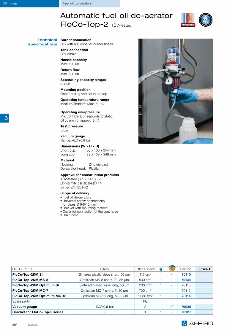
148 Division I
Oil fittings Fuel oil de-aerators
Burner connectionG3/8 with 60° cone for burner hoses
Tank connectionG3/8 female
Nozzle capacityMax. 100 l/h
Return flowMax. 120 l/h
Separating capacity air/gas> 4 l/h
Mounting positionFloat housing vertical to the top
Operating temperature range Medium/ambient: Max. 60 °C
Operating overpressureMax. 0.7 bar (corresponds to static oil column of approx. 8 m)
Test pressure6 bar
Vacuum gaugeRange: -0.7/+0.9 bar
Dimensions (W x H x D)Short cup: 183 x 103 x 254 mm Long cup: 183 x 103 x 348 mm
MaterialHousing: Zinc die cast De-aerator hood: Plastic
Approval for construction productsTÜV-tested (S 133 2013 E2)Conformity certificate (ÜHP) as per EN 12514-2
Scope of delivery Fuel oil de-aerators Universal screw connections for pipes Ø 6/8/10 mm
Bracket with mounting material Cover for connection of the vent hose Drain hose
DG: G, PG: 1 Filters Filter surface Part no. Price €
FloCo-Top-2KM Si Sintered plastic sieve short, 50 µm 115 cm2 1 - 70110
FloCo-Top-2KM MS-5 Opticlean MS-5 short, 20–35 µm 500 cm2 1 - 70134
FloCo-Top-2KM Optimum Si Sintered plastic sieve long, 50 µm 200 cm2 1 - 70115
FloCo-Top-2KM MC-7 Opticlean MC-7 short, 5–20 µm 700 cm2 1 - 70112
FloCo-Top-2KM Optimum MC-18 Opticlean MC-18 long, 5–20 µm 1,850 cm2 1 - 70114
Spare parts PG
Vacuum gauge -0.7/+0.9 bar 2 1 10 70030
Bracket for FloCo-Top-2 series - 1 1 - 70127
Technical specifications
Automatic fuel oil de-aerator FloCo-Top-2 TÜV-tested
6

149Division I
FloC
o-To
p-2
MM
Si
FloC
o-To
p-2
KM
F W
F
Automatic fuel oil de-aerator FloCo-Top-2 TÜV-tested
For single-line systems with return line in oil consuming systems for continuous de-aeration. Suitable for the following media: fuel oil EL (DIN 51603-1) and diesel fuel (EN 590) as well as biofuel and bio-diesel with max. 20 % FAME (FloCo-TOP-2MM up to 100 % FAME). Also for use in flood hazard areas. Watertight up to 10 m water column.
Application
Burner connectionG3/8 with 60° cone for burner hoses
Tank connectionG3/8 female
Nozzle capacityMax. 100 l/h
Return flowMax. 120 l/h
Separating capacity air/gas> 4 l/h
Operating temperature range Medium/ambient: Max. 60 °C
Approval for construction productsTÜV-tested (S 133 2013 E2), Conformity certificate (ÜHP) as per EN 12514-2
Operating overpressureMax. 0.7 bar (corresponds to static oil column of approx. 8 m)
Test pressure6 bar
Vacuum gaugeRange: -0.7/+0.9 bar
DimensionsW x H x D 183 x 103 x 308 mm
MaterialHousing: Zinc die cast De-aerator hood: Plastic (KM version) Metal (MM version)
Scope of delivery Fuel oil de-aerator, universal screw connections for pipes Ø 6/8/10 mm, bracket with mounting material, cover for connection of the vent hose, drain hose
Automatic fuel oil de-aerator, safety version, with integrated fine filter cartridge, shut-off valve, bypass valve, drain system and vacuum gauge for indication of pump vacuum and degree of filter pollution (increasing vacuum). Housing with changeover valve for multiple filtration as well as backflow preventer with integrated pressure relief towards the tank. The shut-off valve can be closed to check the suction capacity of the burn-er pump. De-aerator hood with dual float safety system to keep oil foam from escaping via the de-aerator opening. The replacement system fine filter cartridge is especially suited for smaller burn-er capacities due to the large filter surface (967 cm2) and small mesh size (12–30 μm).
Automatic fuel oil de-aerator, safety version, with integrated filter, shut-off valve, bypass valve, drain system and vacuum gauge for indication of pump vacuum and degree of filter pollution (increasing vacuum). Housing with changeover valve for mul-tiple filtration as well as backflow preventer with integrated pressure relief towards the tank. The shut-off valve can be closed to check the suction capacity of the burner pump. Robust safety ver-sion with metal de-aerator hood and additional transparent hood for visual inspection. Triple float safety system keeps oil foam from escaping via the vent opening.
Technical specifications
Fuel oil de-aerators
Description
FloCo-Top-2KMF WF FloCo-Top-2MM Si
DG: G Filters PG Part no. Price €
FloCo-Top-2MM Si Sintered plastic sieve short, 50 µm 1 1 - 70113
FloCo-Top-2KMF WF Fine filter cartridge, 12–30 µm 1 1 - 70111
Vacuum gauge, -0.7/+0.9 bar 2 1 10 70030
Spare replacement system fine filter cartridge 3 1 - 70010
FO
R BIO-OIL
FÜ
R B I O - Ö
L20%
FO
R BIO-OIL
FÜ
R B I O - Ö
L
20%
Oil fittings
6

150 Division I
Automatic fuel oil de-aerator FloCo-Top-1K TÜV-tested
Fuel oil de-aerator, filter and shut-off valve in a single, compact unit.
Safety system keeps oil foam from escaping
Safety version with metal hood for universal application.
Application
Description
Burner connectionG3/8 male with 60° cone for burner hoses
Tank connectionG3/8 female
Nozzle capacityMax. 100 l/h
Return flowMax. 120 l/h
Separating capacity air/gasApprox. 4 l/h
Mounting positionFloat housing vertical to the top
Operating temperature rangeMedium: Max. 60 °C Ambient: Max. 60 °C
Operating overpressureMax. 0.7 bar corresponds to static oil column of approx. 8 m
Test pressure6 bar
Dimensions W x H x D: 165 x 221 x 99 mm
Approval for construction productsTÜV-tested (S 133 2013 E2),Conformity certificate (ÜHP) as per EN 12514-2
Scope of delivery Fuel oil de-aerators Bracket with mounting material Cover for connection of the vent hose
Technical specifications
DG: G, PG: 1 De-aerator hood Filters Filter cup Part no. Price €
FloCo-Top-1K Si Plastic Sintered plastic sieve short, 50 µm Short 69960
Bracket FloCo-Top-1 series - - - 69946
For single-line systems with return line in oil consuming systems. For continuous de-aeration. Suitable for the following media: fuel oil EL (DIN 51603-1) and diesel fuel (EN 590) as well as biofuel and bio-diesel with max. 20 % FAME. Also for use in flood hazard areas.
Automatic fuel oil de-aerator, safety version, with integrated filter and shut-off valve. Metal housing with G3/8 connection thread at the tank end and male G3/8 connection threads at the burner end with female cone to connect the burner hoses. De-aerator hood made of transparent plastic. With additional trans-parent hood and safety float to keep oil foam from escaping via the vent opening. In addition, it is pos-sible to detect malfunctions in the de-aeration system. Watertight up to 10 m water column.
Page 142
A
Page 151
A
Oil fittings Fuel oil de-aerators
FO
R BIO-OIL
FÜ
R B I O - Ö
L
20%
FloC
o-To
p-1
K S
i
6

151Division I
Oil fittingsAccessories
Screw connection
Vacuum gauge
Replaceable filter adapter
Oil filter spanner
Hand-held suction pump for fuel oil
Accessories for fuel oil de-aerators/oil filters
SW 69
Screw connections
For installation in the oil pipe. See ordering table for versions.
Description
Vacuum gauge
For indication of the filter condition. Available for direct mounting to standard fuel oil filters. G3/8 union nut at filter end, G3/8 male thread with sealing cone 60° at burner end for burner hose. Or with G3/8 female thread x G3/8 male thread for mounting to filter with G3/8 female thread at tank end. Suitable for use in flood hazard areas. Watertight up to 10 m water column.
Description
DG: G PG Part no. Price €
Screw connection G3/8 x 6 mm 3 1 - 20509
Screw connection G3/8 x 8 mm 3 1 - 20508
Screw connection G3/8 x 10 mm 3 1 - 20510
Screw connection G3/8 x 12 mm 3 1 - 20512
Vacuum gauge G3/8 with 60° cone, -0.7/+0.9 bar 2 1 - 20400
Hand-held suction pump for fuel oil with sludge 1 1 - 70058
Replaceable filter adapter 2 1 10 70020
Open end spanner for replaceable filter adapter 3 1 - 70065
Oil filter spanner 1 1 25 70060
Replaceable filter adapter
The replaceable fine filter cartridge can be fitted to all AFRISO filter types (except Z ½-500 and V ½-500) by means of an adapter and can then be operated both in pressure and suction mode.
Description
Hand-held suction pump for fuel oil
For commissioning and after faults in the suction line sys-tem. With check valve/vent valve.
Description
Oil filter spanner
To loosen the union nut of the filter cup and the replacement system fine filter cartridge of automatic fuel oil de-aerators and fuel oil filters
Open end spanner
For easy and fast operation of the replaceable filter adapter.
Description
Description
Open end spanner
6

Pump assemblies for heating and solar thermal systems
Motorised boiler room vent
Boiler safety group assemblies
Safety equipmentfor heating systems

153
CHAPTER 7
Equipment for heating systems, boiler rooms and chimneys
Equipment for safe operation of heating systems 154
OVERVIEW
SUPPLY AND EXHAUST AIR
Motorised boiler room vent Air-Control 156
Draft stabiliser WZB-1 157
Flow meters DFM 10-1M, 15-2M, 20-2M 174
FLOW MEASUREMENT
3-way/4-way mixing valves ARV 177
Boiler manifolds KSV 180
Heating pump assembly PrimoTherm® 180-1/2 DN 25 183
Heating pump assembly PrimoTherm® 180-3 DN 25 for increased return temperature 187
Actuators ARM 179
Pump assemblies PrimoTherm® 180 DN 25/DN 32 182
Charging unit RTA 60 DN 25 189
Heating pump assembly PrimoTherm® 180-1/2 DN 32 191
Heating pump assembly PrimoTherm® 180-3 DN 32 RTA 195
HEATING PUMP ASSEMBLIES
Solar pump assemblies PrimoSol® 130 198
Quick air vents for solar systems, air separators 201
Solar controller SolarControl® SC 10 203
filling and flushing unit, diaphragm safety valve MSS, connection kit 200
SOLAR THERMAL/SOLAR PUMP ASSEMBLIES
Single room temperature controller CosiTherm® - wired 206
Single room temperature controller CosiTherm® - wireless 209
Single room temperature controllers CosiTherm® 204
Room temperature sensor D - wired 212
Room temperature sensor F - wireless 213
SINGLE ROOM CONTROLLER
Quick air vents 166
Diaphragm safety valves MS, MSM 168
Differential pressure bypass valve DÜ 169
Air separators 171
Sludge separator 172
Flow filters, combined air/flow filters 173
Boiler water low level alarms WMS 158
Thermal safety valve TAS 03 160
Combustion controller FR 1 160
Boiler safety group assemblies KSG 161
Connection assembly for expansion vessel GAK 163
Anti-tamper cap valves 165
Boiler filling and drain valves KFE, filling fittings FA, FAM 170
SAFETY EQUIPMENT
Geothermal manifold ProCalida® GT , Drinking water manifold 217
Heating circuit manifolds ProCalida® MC, EF, VA, IN 216
MANIFOLD SYSTEMS
Thermal actuators TSA-02/03 214
Collector tank for solar liquid, solar liquid monitor SFW 202
7

154
Equipment for heating systems Overview
Outside of the storage and boiler rooms1 Level sensor filler cap2 Vent cap3 Digital level indicator TankControl4 Oil alarm unit5 Gas and smoke detector GRM10 Pull cord
In the storage room
6 Tank contents gauge MT-Profil7 Level sensor GWG8 Withdrawal system Euroflex9 Piston type anti-siphon valve KAV13 Tank room lining
AFRISO products in a heating system with oil burner and solar thermal system
In the boiler room
11 Automatic fuel oil de-aerator FloCo-Top-2 series
12 Drip pan
14 Boiler safety group assembly KSG
15 Connection assembly for expansion vessels GAK
16 Boiler water low level alarm WMS-WP6
17 Heating pump assembly PrimoTherm®
18 Sludge separator
19 Air separator
20 Motorised boiler room vent Air-Control
22 Draft stabiliser WZB-123 Boiler safety group assembly
Equipment for safe operation of heating systems
AFRISO offers a broad range of products for the safe operation of heating systems. Irrespective of whether the heating system uses renewable energy or fossil fuels.
Anti-siphon valves, withdrawal systems, level sensors, leak detectors, tank room linings and overfill prevention systems increase the safety of fuel oil storage facilities. Boiler safety group assemblies, solar and heating pump assemblies, connection assemblies for expansion vessels, anti-tamper cap valves, boiler safety group assemblies, diaphragm safety valves, control thermostats, thermal safety valves and boiler water low level alarms are provided as equipment for heating systems.
The EnOcean® wireless technology allows you to easily integrate alarm units and sensors into building automation systems and operate them conveniently via smart-phones or tablets.
7

155
31
2
4 5
6
7
89
10
11
12
13
14
15
16
17
18
19
20 21
22
23
24
29
25
26
28
30
31
32 3334
35
27
Equipment for heating systemsOverview
In the living area 27 Manifolds for underfloor heating systems and radiators28 Thermostat control head 320 KH29 Single room temperature controller CosiTherm®
30 Room temperature sensor RF32 Combination block for compact radiator with valve VarioQ Kombi33 Thermostat combination block Vario THK34 3-way mixing valve ARV35 AFRISOhome gateway HG 01
Solar21 Solar controller SolarControl®
24 Filling and flushing unit 25 Solar pump assembly PrimoSol®
26 Collector tank for solar liquid31 Air separator solar
7

156 Division I
Equipment for heating systems Supply and exhaust air
Motorised boiler room vent Air-Control
Suitable for installation in basement windows or ventilation ducts for burner-controlled oxygen supply of boiler rooms with oil and gas fired burners of up to 50 kW. System or room cannot cool down.
Burner-controlled motorised boiler room vent, consisting of a robust, impact-resistant plastic housing with injection-moulded mounting flange, a mating flange with a protective grille and a gear motor for actuating the slide. Can also be operated manually; with function indication. Boiler rooms which are equipped with oil or gas fired burners must be supplied with a sufficient amount of oxygen (e.g. in accordance with the German FeuVo). This is often achieved by constantly open boiler room windows or by inlet air ducts. The cold air which constantly flows into the boiler room causes the boiler and the water supply as well as the pipes to cool down. As a result, the burner is switched on more frequently and consumes unnecessarily high amounts of fuel. The boiler room window pane (or part of it) is removed and replaced with an acrylic panel with pre-cut openings for Air-Control. The panel is cut to size and then fitted into the frame. Air-Control is mounted onto the pane and is electrically connected to the boiler thermostat. Air-Control can also be mounted onto air ducts. The window remains closed and keeps the warmth inside. As soon as the boiler tem-perature drops, the boiler thermostat switches on Air-Control. Opening the vent activates a microswitch which closes the burner circuit. The burner starts to operate only when the motorised boiler room vent is open and is supplied with pre-warmed ambient air in the ignition phase. The motor-ised boiler room vent remains open during the entire combustion process and provides the boiler room with enough fresh air. The burner switches off when the preset temperature is reached. Air-Control closes automatically.
HousingPlastic (ABS) W x H x D: 260 x 300 x 115 mm Weight 1.0 kg Degree of protection IP 20 (EN 60529)
Installation opening216 x 166 mm
Cross section fresh air supply150 cm2
Supply voltageAC 230 V
Contact ratingAC 250 V, 2 A
Burner capacityMax. 50 kW. For larger installations, several Air-Control units can be installed.
Application
Description
Technical specifications
Options
DG: G, PG: 1 Part no. Price €
Air-Control 1 - 69964
Acrylic glass window pane 1 - 69961
Saves heating costs, is reliable and silent
System or room cannot cool down Sturdy, impact-resistant plastic Complete with accessories for easy installation
Hood PVC
Terminal block
Fixing screw
Connection cable(4-wire)
Protective grille
Window insert (plexiglass)
Insect screenstainless steel mesh
Acrylic glass window pane for cost-effective installation of Air-Control, with openings cut to size W x H: 500 x 500 mm
7

157Division I
Equipment for heating systemsSupply and exhaust air
Saves heating costs, optimises combustion and keeps the chimney draft constant
Stabilises the chimney draft For oil, gas or solid fuel systems
"Chimney connection" always above flue connection
"Flue gas connection" with pipe connection piece
The draft stabiliser for oil, gas or solid fuel systems keeps chimney draft constant and the chimney dry. Suitable for connection to flue gas pipes with Ø 120 to 200 mm by means of pipe connection pieces or to brickwork chimneys or chimneys with several walls by means of special connection pieces.
Draft stabiliser made of galvanised sheet steel with flap. The flap is set by means of a rotary knob acting on a weight for precise adjustment. Depending on the adjustment of the weight, the flap admits more or less secondary air into the chimney when the vacuum gets too high.
The natural chimney draft is approx. 20 to 50 Pa, depending on the height and the cross section of the chimney as well as the weather conditions. These values increase when the temperature increases. The draft stabiliser allows for setting the vacuum required by the manufacturer of the heating system (oil or gas burner/boiler combination, oil or gas furnace, etc.) and keeps this vacuum almost constant. Correct chimney draft is a prerequisite for an optimum combustion process and contributes to a reduction in heating costs.
The draft stabiliser performs the following functions: It limits the vacuum to the required value. It keeps the chimney dry and prevents soot deposits.
Adjustment range (draft requirements):10/26 Pa
Application areaHeights of up to 20 m and chimney group I/II up to 400 cm2, chimney group III up to 500 cm2
Operating temperature rangeFlue gas: Max. 400 °C
Mounting positionFlap axis horizontal Flap vertical
Tightness at ∆p 10 Pa< 3 m3/h
Application
Description
Technical specifications
DG: G, PG: 3 Part no. Price €
Draft stabiliser WZB-1 1 10 69760
WZB-1 with chimney sleeve 1 10 69768
Mounting sleeves
Chimney sleeve for WZB-1 1 - 69761
Pipe connection piece Ø 120/130 mm 1 - 69762
Pipe connection piece Ø 150/160 mm 1 - 69764
Pipe connection piece Ø 180 mm 1 - 69765
Pipe connection piece Ø 200 mm 1 - 69766
Draft stabiliser WZB-1
7

158 Division I
Equipment for heating systems Safety equipment
Boiler water low level alarm WMS-WP6 – mechanical
For sealed heating systems to protect the boiler as per EN 12828 in the case of low water levels. Also suitable for protection against overheating of the heating circuit water as a result of insufficient flow.
Mechanical boiler water low level alarm with float. Consisting of a cast brass body with welding sock-ets and a float mechanism, an electrical switch, test and unlock buttons. TÜV-tested as a water level switch. If the water level in the boiler drops below a minimum level, a float activates a switch. The power supply to the boiler is interrupted. A locking mechanism keeps the burner from switching back on automatically. The test button allows the float to be lowered to simulate a low water alarm condition.
Version WMS-WP6-R2 with male connection thread R2 for direct installation in the boiler.
Operating temperature rangeMedium: Max. 120 °C Ambient: Max. 120 °C
HousingCast brass Height: 358 mm Degree of protection IP 54 (EN 60529)
FloatPlastic
ConnectionWelding socket DN 20 or male thread R2
Operating pressureMax. 10 bar
Test pressure15 bar
Contact ratingAC 250 V, 6 (2) A
Type approval markTÜV.HWB.11-232
Application
Description
Technical specifications
DG: G, PG: 2 Part no. Price €
WMS-WP6 with welding socket DN 20 1 15 42300
WMS-WP6 without locking, with welding socket DN 20 1 15 42305
WMS-WP6-R2 with connection thread R2 male 1 - 42319
Spare parts
Upper part WMS-WP6 with locking 1 - 42310
Upper part WMS-WP6 without locking 1 - 42311
Probe body for WMS-WP6 DN 20 1 - 42368
For protection of the boiler when the water level is too low
TÜV-tested as a water level switch. Direct mounting via welding socket or connection thread
With test button for function check
iAccording to EN 12828, sealed heating systems with capacities of more than 300 kW must be equipped with a TÜV-tested boiler water low level alarm.
Dimensions (mm)
Probe DN 20 Probe R2
R2 DIN 2999
7

159Division I
Equipment for heating systems
Operating temperature rangeMedium: Max. 120 °CAmbient: 0/55 °C
Supply voltageAC 230 V
Switching outputRelay contact: 1 x changeover contactContact rating: AC 250 V, 2 A
Housing control unitWall mounting housing made of impact-resistant plastic (ABS) W x H x D: 100 x 188 x 65 mm Degree of protection: IP 40 (EN 60529)
Housing probeProbe body: Cast brass Housing: Thermoplast GVElectrode rod: Stainless steel 1.4571Degree of protection: IP 54 (EN 60529)
Probe cableH0 5 RN-F 2 x 1 mm2; length: 1.5 m
ConnectionWelding sockets, steel, DN 20W x H x D 130 x 270 x 44 mm
Pressure range: Max. 10 bar
Probe voltage: Max. 12 V
Mark of conformityWMS 2-1: TÜV HWB 14-345WMS 3-1: TÜV HWB 14-348
Safety equipment
For protection of the boiler when the water level is too low
Electronic version with visual alarm and power failure lock.
TÜV-tested as a water level switch. Direct mounting via welding socket
Boiler water low level alarm WMS 2-1/3-1 – electronic
For sealed heating systems to protect the boiler as per EN 12828 and VdTÜV sheet "Water Level 100" (edition 07, 2006) in the case of low water levels. Also suitable for protection against overheating of the heating circuit water as a result of insufficient flow.
This self-monitoring electronic boiler water low level alarm with integrated power failure lock operates on the basis of the conductivity principle (resonant circuit). Consisting of control unit in wall mounting housing with test and unlock buttons, visual alarm, angled probe with welding sockets, electrode and electrode test facility. TÜV-tested as a water level switch. If the water level in the boiler drops below a minimum level, the electrode is no longer submerged. The electronic system de-energises a relay which switches off the power supply for the burner and acti-vates the alarm lamp. The electrical locking mechanism keeps the burner from switching back on automatically. The test button allows you to simulate a low water alarm condition.
Version WMS 3-1 for external power failure lock.
DG: G, PG: 2 Part no. Price €
WMS 2-1, brass with welding socket DN 20 1 5 42351
WMS 3-1, brass with welding socket DN 20 1 5 42352
Spare parts
Control unit for WMS 2-1 1 1 42356
Control unit for WMS 3-1 1 1 42357
Probe WMS brass with welding socket DN 20 1 1 42362
Application
Description
Technical specifications
Dimensions (mm)
170
6584
G1"
2540
Page 90
A
iAccording to EN 12828, sealed heating systems with capacities of more than 300 kW must be equipped with a TÜV-tested boiler water low level alarm.
7

160 Division I
Equipment for heating systems Safety equipment
Thermal safety valvesCombustion controllers
To protect sealed or open solid fuel heating sys-tems as per EN 12828 with a heating capacity of up to 86,000 kcal. Also required for dual-fuel boil-ers which can be operated with solid fuels.
Thermal safety valve with two independent sensor systems. TAS consists of a valve housing, a valve, two independent bellow type displacement probes with liquid-filled temperature probes and a pocket. The capillary tube is protected by a flexi-ble metal hose. TAS is connected to the water outlet of the water heater or to the inlet of the safety heat exchanger. If the response tempera-ture is exceeded, the valve is opened by the ther-mal probe and cooling water is supplied to keep the system from exceeding the maximum operat-ing temperature. Correct operation of TAS can be verified quickly and easily by simply pressing the valve head.
For temperature-dependent adjustment of the air supply damper of solid fuel and dual-fuel boilers. Controls correct air supply for optimum combus-tion.
The FR 1 combustion controller controls the com-bustion air supply. The temperature in the heat generator is detected by an integrated thermostat. The thermostat is connected to the air supply damper by means of a lever and a chain. The air supply is controlled by means of opening or clos-ing the air supply damper, depending on the boil-er flow temperature.
Application
Description
Technical specifications
Operating pressure: Max. 10 bar
Operating temperature range: Ambient: 80 °C
Response temperature: 99 °C
Blow-off capacityat 110 °C and ∆p = 1 bar > 2,400 m3/h
Connections: 2 x G¾ female thread
Connection pocket: G½ male thread
DimensionsPocket length: 146 mm Capillary tube length: 1.300 or 4.000 mm
Housing: Hot-pressed brass
Operating temperature rangeMedium: Max. 115 °C Ambient: Max. 70 °C (at switching button)
Connection: G¾
Dimensions: Pocket length: 53 mm, chain length: 1.2 m
Chain load: 100 to 600 g
Mounting position: Horizontal or vertical
MaterialsHousing: Plastic Stem: Brass Lever/chain: Galvanised steel
Combustion controller FR 1Thermal safety valve TAS 03
DG: G, PG: 2 Part no. Price €Thermal safety valve TAS 03, capillary tube 1.3 m 1 - 42415Thermal safety valve TAS 03, capillary tube 4 m 1 - 42418Screw connector kit for TAS 03 1 20 42450Pocket G½ for TAS 03 1 10 42449Combustion controller FR 1 1 10 42294
Chain
Air supply damper
Installation option FR 1
iSee chapter 11 for the complete range of temperature measuring instruments and control-lers.
NEW:
- Higher response temperature
- Shorter pocket
- Very simple function test
7

161Division I
Equipment for heating systemsSafety equipment
Boiler safety group assemblies KSG
KSG – 3 bar
Description
Technical specifications
Application
KSG Mini – 3 bar
For sealed heating systems as per EN 12828 with a capacity of up to 50 kW.
Complete, pre-assembled, tightness-tested boiler safety group assembly. Consisting of carrier, pres-sure gauge for indicating the system pressure, quick air vent and diaphragm safety valve MS, including form-fit insulation. With self-sealing mounting valves for easy replacement of pressure gauge and air vent.
Boiler connectionG1 female thread
Operating temperature rangeMax. 120 °C
DimensionsW x H x D 183 x 144 x 70 mm
InsulationExpanded polypropylene EPP
CarrierBrass
Diaphragm safety valve MSInlet x outlet: G½ x G¾ Seal: PTFE sealing ring, can be rotatedResponse pressure: 3 bar
Pressure gauge for heating installations Range: 0/4 barDiameter: 63 mm– G3/8 bottom
Quick air ventInlet: G3/8Nominal pressure: 12 bar
For sealed heating systems as per EN 12828 with a capacity of up to 50 kW.
Complete, pre-assembled, tightness-tested boiler safety group assembly, lightweight design. Consisting of carrier, pressure gauge for indicating the system pressure, quick air vent and dia-phragm safety valve MS, including form-fit insula-tion. With self-sealing mounting valves for easy replacement of pressure gauge and quick air vent.
Boiler connectionG1 female thread
Operating temperature rangeMax. 120 °C
DimensionsW x H x D 140 x 150 x 75 mm
InsulationPolystyrene EPS
CarrierBrass
Diaphragm safety valve MSInlet x outlet: G½ x G¾ Seal: PTFE sealing ring, can be rotatedResponse pressure: 3 bar
Pressure gauge for heating installations Range: 0/4 barDiameter: 50 mm–G ¼ bottom back
Quick air ventInlet: G3/8Nominal pressure: 12 bar
DG: G, PG: 2 kW bar Connection Insulation Part no. Price €
KSG Mini Max. 50 3 G1 Yes 1 25 77623
KSG Max. 50 3 G1 Yes 1 10 77938
7

162 Division I
Equipment for heating systems Safety equipment
Boiler safety group assemblies KSG
Description
Technical specifications
Application
KSG Maxi – 3 bar KSG Magnum – 3 bar
For sealed heating systems as per EN 12828 with a capacity of up to 200 / 350 kW.
Complete, pre-assembled, tightness-tested boiler safety group assembly. Consisting of carrier designed as multi-way union, pressure gauge for indicating the system pressure, quick air vent and diaphragm safety valve MS. With self-sealing mounting valves for easy replacement of pressure gauge and quick air vent. The form-fit insulation is also used to package the product for safe trans-port.
Boiler connectionUp to 200 kW: G1¼ female thread Up to 350 kW: G1½ female thread
Operating temperature rangeMax. 120 °C
DimensionsW x H x D 230 x 175 x 104 mm
InsulationPolypropylene EPP
CarrierBrass
Diaphragm safety valve MSUp to 200 kW (inlet x outlet): G1 x G1¼Up to 350 kW (inlet x outlet): G1¼ x G1½Seal: PTFE sealing ring, can be rotatedResponse pressure: 3 bar
Pressure gauge for heating installations Range: 0/4 barDiameter: 63 mm– G3/8 bottom
Quick air ventInlet: G3/8Nominal pressure: 12 bar
For sealed heating systems as per EN 12828 with a capacity of up to 100 kW.
Complete, pre-assembled, tightness-tested boiler safety group assembly. Consisting of carrier, pres-sure gauge for indicating the system pressure, quick air vent and diaphragm safety valve MS. With self-sealing mounting valves for easy replacement of pressure gauge and quick air vent. With insulation.
Boiler connectionG1 female thread
Operating temperature rangeMax. 120 °C
DimensionsW x H x D 183 x 144 x 70 mm
CarrierBrass
Diaphragm safety valve MSInlet x outlet: G¾ x G1 Seal: PTFE sealing ring, can be rotated Response pressure: 3 bar
Pressure gauge for heating installations Range: 0/4 bar Diameter: 63 mm – G3/8 centre back
Quick air ventInlet: G3/8 Nominal pressure: 12 bar
DG: G, PG: 2 kW bar Boiler connection Insulation Part no. Price €
KSG Maxi Max. 100 3 G1 female Yes 1 10 77581
KSG Magnum Max. 200 3 G1¼ female Yes 1 10 77627
KSG Magnum Max. 350 3 G1½ female Yes 1 10 77628
7

163Division I
Equipment for heating systemsSafety equipment
Connection assembly for expansion vessels GAK
Anti-tamper cap valve that can be sealed for connection of MAG. Easy shut-off and draining e.g. for replace-ment of MAG
Quick air vent for automatic venting
Integrated self-seal-ing mounting valve for fast and easy mounting and dismounting of the quick air vent
Vent chamber for collecting and sepa-rating the air and the water in the heating system
Safety valve that can be rotated for protec-tion against overpres-sure
Pressure gauge for direct indication of the system pressure
Diaphragm expansion vessel MAG screw con-nection for fast installa-tion
Sturdy mounting piece with screws and dowels
Connection thread for system connection
Drain valve
Carrier made of solid cast brass
7

164 Division I
Equipment for heating systems
Connection assembly for expansion vessel GAK
For connection of diaphragm expansion vessels up to 50 l for sealed heating systems as per EN 12828 up to a capacity of 50 kW.
Pre-assembled combination fitting consisting of: Carrier made of solid cast brass with integrated anti-tamper cap valve for connection of the diaphragm expansion vessel
Safety valve with type approval Pressure gauge for heating installations with red reference pointer, mounted via self-sealing mounting valve
Quick air vent (12 bar), mounted via self-sealing mounting valve Two form-fit insulation shells
Connections Boiler: G¾ female threadExpansion vessel: G¾ male thread
Operating temperature rangeMedium: Max. 120 °C
Dimensions (with insulation)W x H x D 360 x 185 x 100 mm
InsulationExpanded polypropylene EPP
CarrierBrass, protrusion 300 mm
Diaphragm safety valve MSInlet x outlet: G½ x G¾Seal: Teflon ring, rotatableResponse pressure: 3 barHeat capacity: 50 kW
Pressure gauge for heating installationsBourdon tube pressure gauge with self-sealing mounting valveRange: 0/4 bar, with red reference pointer Diameter: 63 mm – G3/8 bottom
Quick air ventInlet: G3/8Nominal pressure: 12 bar
Scope of delivery GAK 2 insulation shells Mounting accessories: Screws, washers, dowels
Application
Description
Technical specifications
DG: G, PG: 2 Part no. Price €
GAK 3 bar with insulation 1 - 77932
Safety equipment
Easy wall mounting of the robust console with mounting accessories (included)
Time-saving installation with pre-assembled, tightness-tested assembly
Service-friendly: Pressure gauge, air vent and expansion vessel can be replaced without draining
Safe venting due to top-mounted connection for quick air vent
Protrusion 300 mm
7

165Division I
Anti-tamper cap valves
Anti-tamper cap valve with integrated boiler filling and drain valve KFE
Anti-tamper cap valve with drain valve
Anti-tamper cap valve with screw connection G¾ x G¾ or G1 x G1. The shut-off valve is secured against inadvertent closing by means of a cap and a lead seal. Valve operation via standard square spanner AF 5 for radiator vent valves. The expansion vessel can be shut off from the heating system and drained via the drain valve for the required function test or for replacement.
Anti-tamper cap valve with screw connection G¾ x G¾ or G1 x G1. The shut-off valve is secured against inadvertent closing by means of a cap and a lead seal. The integrated boiler filling and drain valve KFE (connection: G¾ eurocone) allows for easy draining of the expansion vessel. For this purpose, a hose can be connected by means of a union nut. The expansion vessel can be shut off from the heating system and drained with a high draining capacity (time saving) via the drain valve for the required function check or for replace-ment.
Application
Description
Technical specifications
DG: G, PG: 2 Part no. Price €
Anti-tamper cap valve G¾ x G¾ with integrated boiler filling and drain valve KFE G¾ 1 25 77949
Anti-tamper cap valve G1 x G1 with integrated boiler filling and drain valve KFE G¾ 1 25 77950
Anti-tamper cap valve G¾ x G¾ with drain cock 1 25 77924
Anti-tamper cap valve G1 x G1 with drain cock 1 25 77934
① Diaphragm expansion vessel② Screw connection③ Anti-tamper cap valve④ Boiler filling and drain valve KFE, G¾ eurocone ⑤ Cap with seal and wire
① Diaphragm expansion vessel② Screw connection③ Anti-tamper cap valve④ Drain valve with hose connection⑤ Cap with seal and wire
Operating pressureMax. 10 bar
Operating temperature rangeOperation: 0/120 °C
Drain capacityFlow coefficient NS: 0.5 m3/h
Operating pressureMax. 10 bar
Operating temperature rangeOperation: 0/120 °C
Drain capacityFlow coefficient NS: 1.5 m3/h
For connection, maintenance and checks of diaphragm expansion vessels in heating systems as per EN 12828 and in solar systems. To be installed at the water inlet of the expansion vessel.
Easy draining,
high draining
capacity
Safety equipment Equipment for heating systems
7

166
Equipment for heating systems
Division I
Quick air vents
Quick air vent 12 bar
DG: G, PG: 2 Mounting valve PU Part no. Price €
Quick air vent G3/8 R3/8 – 25 77700
Quick air vent G3/8, individually packaged R3/8 1 100 77713
Quick air vent G3/8 R½ – 25 77706
Quick air vent G3/8 Without – 25 77710
Quick air vent G½ Without – 25 77752
Angled quick air vent R½, with aqua stop Without 1 10 77753
Accessories
Mounting valve R3/8 x G3/8 – 25 77720
Mounting valve R½ x G3/8 – 25 77723
Application
Description
For automatic venting of sealed heating systems as per EN 12828. Suitable for up to 12 bar/110 °C for water and water/glycol mixtures with up to 50 % glycol.
Automatic quick air vent with mounting valve. Its high, narrow design is perfect in terms of appear-ance and function. Self-sealing connection thread.
For automatic venting of radiators. Suitable for up to 12 bar/110 °C for water and water/glycol mix-tures with up to 50 % glycol.
Automatic quick air vent with aqua stop. The vent cap does not have to be removed during opera-tion of the quick air vent, not even for initial filling or servicing.
Angled quick air vent 12 bar
G3/8
R3/8
G3/8
R1/2
Mounting valves as acces-sories for quick air vents:
ConnectionG3/8 or G½
Operating temperature rangeMax. 110 °C
Nominal pressureMax. 12 bar
HousingBrass
Cover Glass-fibre reinforced plastic
Union ring Brass
ConnectionR½ as per DIN 3858
Operating temperature rangeMax. 110 °C
Nominal pressureMax. 12 bar
HousingBrass, nickel-plated
Cover Glass-fibre reinforced plastic
Union ring Brass, nickel-plated
Safety equipment
i
Technical specifications
Patented two-way venting principle and new venting geometry of all AFRISO quick air vent: Separated air escapes via the central hole in the float in a defined way without taking along water. The slot-shaped vent open-ing provides for a high venting capacity.
i
7

167
Equipment for heating systems
Division I
Quick air vents
Plastic quick air vent Quick air vent Hybrid
For automatic venting of sealed heating systems as per EN 12828. Suitable for water and water/gly-col mixtures with up to 50 % glycol.
Automatic quick air vent made of high-grade glass-fibre reinforced plastic. Its high, narrow design is perfect in terms of appearance and function. Sealing by means of O ring. Mounting valves available as accessories.
ConnectionG3/8 or G½ with O ring
Operating temperature rangeDepending on nominal pressure Max. 95/120 °C See operating instructions
Nominal pressureAt 95 °C: Max. 8 barAt 120 °C: Max. 3.5 bar
HousingGlass-fibre reinforced plastic
Latching ring Glass-fibre reinforced plastic
ConnectionG3/8,, brass with O ring
Operating temperature rangeDepending on nominal pressure Max. 95/120 °C See operating instructions
Nominal pressureAt 95 °C: Max. 8 barAt 120 °C: Max. 3.5 bar
HousingGlass-fibre reinforced plastic
Latching ring Glass-fibre reinforced plastic
Application
Description
Technical specifications
DG: G Mounting valve PG Part no. Price €
Plastic quick air vent G3/8 Without 1 – 25 77766
Plastic quick air vent G½ Without 1 – 25 77761
Quick air vent Hybrid G3/8 Without 1 – 25 77729
Quick air vent Hybrid G3/8 R3/8 1 – 25 77730
Accessories
Mounting valve R3/8 x G3/8 2 – 25 77720
Mounting valve R½ x G3/8 2 – 25 77723
Safety equipment
Patented two-way venting principle and new venting geometry of all AFRISO quick air vent: Separated air escapes via the central hole in the float in a defined way without taking along water. The slot-shaped vent open-ing provides for a high venting capacity.
i
7

168 Division I
Safety equipmentEquipment for heating systems
Diaphragm safety valves MS, MSM
DG: G, PG: 2 Maximum heating capacity
Opening pressure
Pressure gauge
Part no. Price €
MS Rp½ x Rp¾ 50 kW 2.5 bar – 1 84 42385
MS Rp½ x Rp¾ 50 kW 3.0 bar – 1 84 42390
MS Rp¾ x Rp1 100 kW 2.5 bar – 1 84 42386
MS Rp¾ x Rp1 100 kW 3.0 bar – 1 84 42391
MS Rp1 x Rp1¼ 200 kW 2.5 bar – 1 - 42383
MS Rp1 x Rp1¼ 200 kW 3.0 bar – 1 - 42378
MS Rp1¼ x Rp1½ 350 kW 3.0 bar – 1 - 42495
MSM Rp½ x Rp¾ 50 kW 3.0 bar 0/4 bar 1 30 42382
* Enquire for other pressure ratings and connections.
For protection against overpressure in heating systems
For water, water/glycol mixtures, liquids of fluid groups 1 and 2
MSM with pressure gauge for indication of the system pressure
Application
Description
Technical specifications
For sealed heating systems as per TRD 721; VdTÜV sheet Safety Valve 100 and 100/4 sheet 1; EN 12828. Also for water heating systems as per DIN 4751-2 with flow temperatures up to 120 °C and DIN 4751-3 with flow temperatures up to 95 °C. Suitable for water, water/glycol mixtures and liquids of fluid groups 1 and 2 (Pressure Equipment Directive, Art. 9).
Safety valve with factory-adjusted opening pressure. MSM with pressure gauge for indicating the system pressure. The size of the valve inlet determines the unit type, the outlet is ¼" larger.
ConnectionSee selection table
Operating temperature range-20/+120 °C
Opening pressureSee selection table
DimensionsW x H x D 35 x 60 x 45 mm
Housing Brass
CapPA6, red
Pressure gauge for heating installations (for MSM)Diameter: 50 mm–G¼ back Range: 0/4 bar Connection: bottom back
iSee pages 200, 276 for safety valves for solar liquid and drinking water.
MSM with pressure gauge for heating systems
7

169Division I
Equipment for heating systems
Differential pressure bypass valves DÜ
For constant pump pressure in heating systems Reduction of flow noise With adjustment scale Differential pressure fully adjustable Either space-saving angled version or straight version
Application
Description
Technical specifications
For keeping the pump pressure in sealed heating systems as per EN 12828 constant and for reducing flow noise in the heating system.
Differential pressure bypass valve with directly readable adjustment scale. Housing made of brass. Available as straight version or angled version for space-saving installation. The differential pressure in the heating system at full load is set directly at the bypass valve. If the volume flow is reduced, the valve opens to keep the head of the circulation pump constant.
Operating temperature rangeMax. 95 °C, (short-term 120 °C)
Operating pressure Max. 6 bar
Differential pressureFully adjustable 0.1/0.5 bar
HousingAngled version or straight version Material: Brass
Connection angled versionInlet: G¾ female thread Outlet: Screw connection, flat-sealing with union nut G¾
Connection straight versionScrew connection at both sides, flat-sealing with union nut G¾
DG: G, PG: 2 Part no. Price €
DÜ with screw connection, angled version 1 10 42379
DÜ with screw connection, straight version 1 - 42384
Differential pressure bypass valve straight version
Differential pressure bypass valve angled version
Enquire for differential pressure bypass valve DN 32.
Safety equipment
7

170
Equipment for heating systems
Division I
Safety equipment
Filling and drain fittings
For sealed heating systems as per EN 12828.
Filling fitting with housing and spring cap made of brass. Inlet for hose inside diameter 12 mm, outlet G½ female thread. With G¼ connection for pres-sure gauge for heating installations. With pressure reducer, shut-off valve and backflow preventer. Inlet pressure 6 up to 10 bar, outlet pressure adjustable between 0.5 and 3 bar. Version FAM with pressure gauge for heating installations Ø 63 mm, 0/4 bar, G¼ bottom.
Filling fittings FA/FAM
For sealed heating systems as per EN 12828.
Boiler filling and drain valve. Ball valve version made of brass. One side G½ male thread with PTFE sealing ring, other side ½" hose connector with G¾ union nut and blind cap with chain or strap. Available in plain brass (drinking water) or nickel-plated brass (heating circuit water).
Boiler filling and drain valve KFE, brass, nickel-plated Boiler filling and drain valve KFE, brass, plain
DG: G, PG: 2 Part no. Price €
Filling fitting FA 1 5 42405
Filling fitting FAM 1 5 42406
Boiler filling and drain valve KFE, brass plain, in cardboard box 12 72 42401
Boiler filling and drain valve KFE, brass nickel-plated, in cardboard box 12 72 42407
Filling fitting FAM
Filling fitting FA
Application
Description
We provide a large selection of boiler filling and drain valves for OEMs. Please enquire.
7

171
Equipment for heating systems
Division I
Air separator
For removing air from heating systems. The air separator ensures reliable operation, better and faster heat transfer and thus contributes to reduced fuel consumption and emissions. Suitable for hot water heating systems and underfloor heating systems. Air is removed from the system without chemical additives.
Compact air separator with integrated quick air vent in form-fit insulation. The new function principle with two separation chambers ensures a reduced flow speed for effective separation of air and water. The lower the flow rate in the separator, the better the air bubbles can be removed from the water due to the difference in density. The air bubbles rise, collect in the upper area in a calm zone and are automatically removed by means of the quick air vent without taking along water. The quick air vent features an aqua stop to keep water from escaping. The air separator can be installed in the flow (preferred) or return line. Reducer unions G1 female and G¾ female are available for renovation or retrofitting in existing pipes.
Application
Description
DG: G, PG: 2 Part no. Prices €
Air separator G1½ 40682
Accessories
Reducer union kit G1 female 40684
Reducer union kit G¾ female 40685
Pre-assembled, tightness-tested and heat-insulated assembly
Continuous, automatic venting of the system
Cost savings due to fewer malfunctions and longer service life of the system
Fast and easy integration into existing pipes via reducer unions
Function principle
HousingBrass
InsulationEPP
Operating pressureMax. 10 bar
Operating temperature rangeMax. 95 °C
ConnectionsTop G1½ female (union nut) Bottom G1½ male
Mounting positionVertical
Technical specifications Dimensions (mm)
Safety equipment
7

172
Equipment for heating systems
Division I
Safety equipment
Sludge separator
For removing dirt particles from heating systems. Particles can cause problems in fittings and control units. The sludge separator ensures clean water, reliable operation, better and faster heat transfer and thus contributes to reduced fuel consumption and emissions. Suitable for hot water heating systems and underfloor heating systems. Rust, lime particles, calcium, magnesium, oxides, carbonates and sludge as well as larger particles such as chips or construction residues are removed from the water – without the use of chemicals. Excellent for the renovation of system parts subject to sludge accumula-tion.
Compact sludge separator with drain valve in form-fit insulation. The highly efficient concept removes sludge from the water. Plates in the separator deflect the particles into a separate area. From there, the dirt particles can be flushed out during normal operation by means of a valve. The sludge separator can be combined with the air separator and can be installed in the flow (preferred) or return lines. Reducer unions G1 female and G¾ female are available for renovation or retrofitting in existing pipes.
Application
Description
Pre-assembled, tightness-tested and heat-in-sulated assembly
Single-operation cleaning while the system is running
Energy savings due to improved heat transfer at system components
Fast and easy integration into existing pipes via reducer unions
Function principle
HousingBrass
InsulationEPP
Operating pressureMax. 10 bar
Operating temperature rangeMax. 95 °C
ConnectionsTop G1½ female (union nut) Bottom G1½ male
Mounting positionVertical
Technical specifications Dimensions (mm)
DG: G, PG: 2 Part no. Prices €
Sludge separator G1½ 40683
Accessories
Reducer union kit G1 female 40684
Reducer union kit G¾ female 40685
7

173Division I
Equipment for heating systemsSafety equipment
Flow filters, combined air/flow filters
Flow filters and combined air/flow filters remove lime, rust, sludge, dirt and gas from heating systems to provide clean water and trouble-free operation. Suitable for hot water heating systems, underfloor heating systems, solar systems (special versions, please enquire), fuel cells and renovation of system components (sludge removal). Also suitable for removing lime in the circulation circuit of drinking water facilities.
Most advanced heating systems use water for heat transmission. This water may also transport unwanted substances such as lime, calcium, magnesium, oxide, carbonates as well as larger particles such as welding or soldering residue, metal chips and dirt. These substances may cause malfunctions in fittings and control units. A compact flow filter (particle separator) removes these particles from the water. The particles settle in the collection chamber of the filter and can be flushed out via a valve with small amounts of water. Clean water supports trouble-free operation of systems and reduces the fuel and maintenance costs.
Clean system components have better thermal conduction, they provide for faster heating up and thus contribute to reduced fuel consumption and emissions.
The combined air/flow filter was developed for heating systems which are subject to problems caused by oxygen or other gases. The vent valve automatically removes the gases
In the case of drinking water systems, the flow filter is installed in the circulation circuit. Lime particles settle in the flow filter and can be flushed out. This reduces the deposits in pipes and fittings. Special materials which are suitable for drinking water are used for this application.
HousingBrass
Operating pressureMax. 10 bar
Operating temperature rangeMax. 95 °C
Dimensions (W x H x D)Flow filter: 120 x 194 x 60 mm Combined air/flow filter: 120 x 394 x 60 mm
ConnectionsFlow filter: Inlet G¾ Outlet G1Combined air/flow filter: 2 x G¾
Scope of deliveryFlow filters and combined air/flow filters are delivered with form-fit insulation.
Application
Description
Technical specifications
DG: G, PG: 2 Part no. Price €
Flow filter – heating 28 kW 1 5 78210
Flow filter – heating 50 kW 1 5 78211
Combined air/flow filter – heating 28 kW 1 5 78212
Combined air/flow filter – heating 50 kW 1 5 78213
Flow filter – drinking water --- 1 5 78214
Dirt particle separator Suitable for open and sealed circuits Flushing possible during operation of the system
Cost savings due to fewer malfunctions and longer service life of the system
Energy savings due to improved heat transfer at clean system components.
7

174 Division I
Operating temperature rangeMax. 100 °C
Operating pressureMax. 10 bar
Measuring principleRotameter type with counter spring
Measuring range1–3.5 l/min
Nominal diameterDN 10
HousingBrass
ConnectionG¾ x G¾ (eurocone) male thread x union nut
Mounting positionHorizontal, tilted or vertical
Flow meter DFM 10-1M
Direct indication of the flow rate in l/min Compact design
For monitoring the flow in heating/cooling systems. Specially for direct mounting to heating circuit manifolds. Suitable for heating and cooling water as well as water mixtures with standard corrosion protection and antifreeze agents.
Compact flow meter with scale. The flow meter can be installed in pipes in a horizontal, tilted or vertical position. The reading mark corresponds to the lower edge of the rotameter/float.
Application
Description
Technical specifications
iPlease enquire for other versions.
DG: G, PG: 2 Part no. Price €
DFM 10-1M - 10 78619
Dimensions (mm)
Equipment for heating systems Safety equipment
7
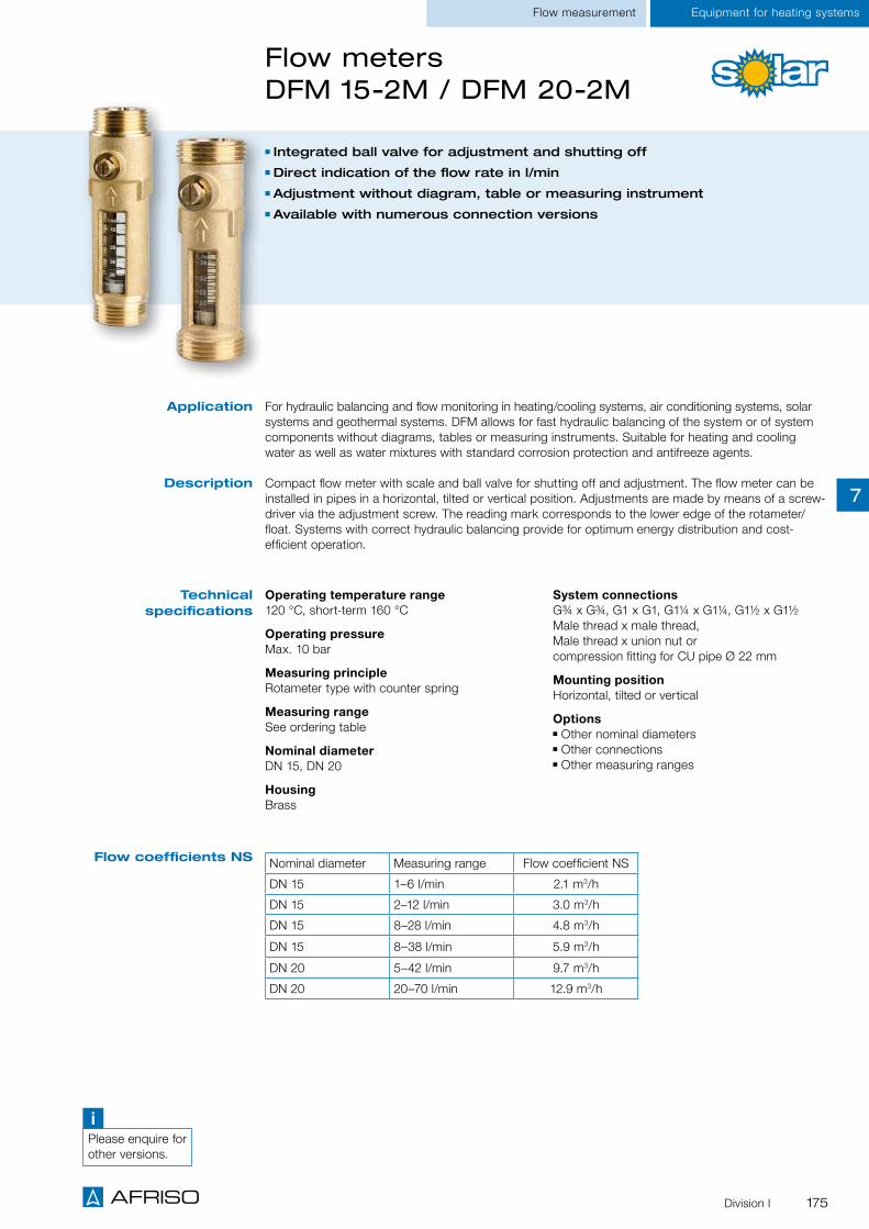
175Division I
Equipment for heating systemsFlow measurement
Nominal diameter Measuring range Flow coefficient NS
DN 15 1–6 l/min 2.1 m3/h
DN 15 2–12 l/min 3.0 m3/h
DN 15 8–28 l/min 4.8 m3/h
DN 15 8–38 l/min 5.9 m3/h
DN 20 5–42 l/min 9.7 m3/h
DN 20 20–70 l/min 12.9 m3/h
Flow meters DFM 15-2M / DFM 20-2M
Operating temperature range120 °C, short-term 160 °C
Operating pressureMax. 10 bar
Measuring principleRotameter type with counter spring
Measuring rangeSee ordering table
Nominal diameterDN 15, DN 20
HousingBrass
System connectionsG¾ x G¾, G1 x G1, G1¼ x G1¼, G1½ x G1½ Male thread x male thread, Male thread x union nut or compression fitting for CU pipe Ø 22 mm
Mounting positionHorizontal, tilted or vertical
Options Other nominal diameters Other connections Other measuring ranges
Integrated ball valve for adjustment and shutting off Direct indication of the flow rate in l/min Adjustment without diagram, table or measuring instrument Available with numerous connection versions
For hydraulic balancing and flow monitoring in heating/cooling systems, air conditioning systems, solar systems and geothermal systems. DFM allows for fast hydraulic balancing of the system or of system components without diagrams, tables or measuring instruments. Suitable for heating and cooling water as well as water mixtures with standard corrosion protection and antifreeze agents.
Compact flow meter with scale and ball valve for shutting off and adjustment. The flow meter can be installed in pipes in a horizontal, tilted or vertical position. Adjustments are made by means of a screw-driver via the adjustment screw. The reading mark corresponds to the lower edge of the rotameter/float. Systems with correct hydraulic balancing provide for optimum energy distribution and cost- efficient operation.
Application
Description
Technical specifications
Flow coefficients NS
iPlease enquire for other versions.
7

176 Division I
Equipment for heating systems Flow measurement
Flow meters DFM 15-2M/DFM 20-2M
Type Nominal diameter Connections Measuring
range Part no. Price €
DFM 15-2M
A
DN 15
G¾ x G¾
1–6 l/min 80958
DN 15 2–12 l/min 80963
DN 15 8–28 l/min 80968
DN 15 8–38 l/min 80973
DN 15
G1 x G1
1–6 l/min 80959
DN 15 2–12 l/min 80964
DN 15 8–28 l/min 80969
DN 15 8–38 l/min 80974
C
DN 15Compression fitting for CU
pipe Ø 22 mm
1–6 l/min 80962
DN 15 2–12 l/min 80967
DN 15 8–28 l/min 80972
DN 15 8–38 l/min 80977
DFM 20-2M
DDN 20
G1 x G15–42 l/min 80978
DN 20 20–70 l/min 80983
E
DN 20G1¼ x G1¼
5–42 l/min 80979
DN 20 20–70 l/min 80984
DN 20G1½ x G1½
5–42 l/min 80980
DN 20 20–70 l/min 80985
Male thread x male thread
Type Nominal diameter Connections Measuring
range Part no. Price €
DFM 15-2M
B
DN 15
G¾ x G¾
1–6 l/min 80960
DN 15 2–12 l/min 80965
DN 15 8–28 l/min 80970
DN 15 8–38 l/min 80975
DN 15
G1 x G1
1–6 l/min 80961
DN 15 2–12 l/min 80966
DN 15 8–28 l/min 80971
DN 15 8–38 l/min 80976
DFM 20-2M
F
DN 20G1¼ x G1¼
5–42 l/min 80981
DN 20 20–70 l/min 80986
DN 20G1½ x G1½
5–42 l/min 80982
DN 20 20–70 l/min 80987
Male thread x union nutDG: G, PG: 2
Types and dimensions (mm)
A
D
B
E
C
F
7

177Division I
Equipment for heating systems
3-/4-way mixing valves ARV
For distribution and mixing Compact design Rotary knob for precise adjustments Low torque for increased service life of actuator
Universal mixing application in water-based heating and cooling systems (radiators, panel heating systems). The 3-way mixer can also be used as a distribution or zone mixer. Suitable for water and water/glycol mixtures with up to 50 % glycol. Not suitable for drinking water.
Compact, low-loss 3-way or 4-way mixing valves with brass base and easy-to-handle rotary knob made of high-strength plastic. The rotary knob with scale allows for easy and accurate manual adjust-ment of the mixing valve. The elevated mark allows for fast position determination. Two scales with "0 to 10" for horizontal installation and "10 to 0" for vertical installation are included for maximum flexibility.
3-way mixing valve for distribution and mixing: The desired flow temperature is obtained via the pre-cise mixing ratio of hot boiler water and cold water from the return line.
4-way mixing valve for dual mixing. The return temperature to the boiler can be high in order to avoid corrosion damage, for example.
The mixing valves are easy to automate with the AFRISO ARM actuators. The low torque ensures a low load and a long service life.
Application
Description
Angle of rotation90°
Operating temperature rangeMedium: -10 / +110 °C
Nominal pressureMax. 10 bar
Flow rateSee ordering table
Leak rate< 1.5 % flow coefficient NS
Required torqueDN 20 / DN 32: < 1 Nm DN 40 / DN 50: < 2 Nm
MaterialHousing: Brass (CW617N) O rings: EPDM
Technical specifications
DG: G, PG: 2 DN Connection Flow coef-ficient NS Part no. Price €
3-way mixing valve ARV 382 20 Rp ¾ 6.3 m³/h 78234
3-way mixing valve ARV 384 25 Rp 1 12 m³/h 78235
3-way mixing valve ARV 385 32 Rp 1¼ 15 m³/h 78236
3-way mixing valve ARV 386 40 Rp 1½ 26 m³/h 78237
3-way mixing valve ARV 387 50 Rp 2 40 m³/h 78238
4-way mixing valve ARV 484 25 Rp 1 12 m³/h 78239
4-way mixing valve ARV 485 32 Rp 1¼ 15 m³/h 78241
4-way mixing valve ARV 486 40 Rp 1½ 26 m³/h 78242
4-way mixing valve ARV 487 50 Rp 2 40 m³/h 78243
Page 179
A
Heating pump assemblies
7

178 Division I
Equipment for heating systems
3-/4-way mixing valves ARV
Heating pump assemblies
DN Connection (female thread) A B C D
ARV 382 20 Rp ¾ 80 53 76.6 74.5
ARV 384 25 Rp 1 82 53 81.6 75.5
ARV 385 32 Rp 1¼ 84 53 84.5 76.5
ARV 386 40 Rp 1½ 116 53 100.5 92.5
ARV 387 50 Rp 2 125 53 106 99.5
ARV 484 25 Rp 1 82 53 81.6 -
ARV 485 32 Rp 1¼ 84 53 83.5 -
ARV 486 40 Rp 1½ 116 53 100.5 -
ARV 487 50 Rp 2 125 53 106 -
3-way mixing valve DN 20, 25, 32 3-way mixing valve DN 40, 50
4-way mixing valve DN 25, 32 4-way mixing valve DN 40, 50
Housing types and dimensions
Dimensions (mm)
AB
D
CA
C
D
B
ACB
ACB
7

179Division I
Equipment for heating systemsHeating pump assemblies
Actuator ARM
Rotary knob with scale Colour LEDs indicate direction of rotation
Integrated protection unit Suitable for mixers of various manufacturers
Universal application for controlling mixing valves DN 20 to DN 50. Perfect solution for automated operation of water-based heating and cooling systems. Suitable for mixers from AFRISO, ESBE (except VRG), Seltron, Somatherm, Hora, WIP, PAW, LK, BRV, IMIT, IVAR, HOVAL and OLYMP. Please enquire for other mounting kits.
Compact, silent actuator with an angle of rotation of 90°. Can be switched over from automatic mode to manual mode. A rotary knob with scale allows for fast and accurate manual adjustment of the mixing valve. Two yellow LEDs indicate the direction of rotation of the actuator, the red LED the switching state of the microswitch (ARM 443 only). Microswitch for controlling a pump. The pre-assembled connection cable with colour-coded wires simplifies installation. Two scales with "0 to 10" for horizontal installation and "10 to 0" for vertical installation are included for maximum flexibility. The integrated protection unit keeps the actuator and mixing valve from blocking for a long service life. A mounting kits allow for adaptation to mixers from a wide variety of manufacturers. ARM is maintenance-free.
Application
Description
Angle of rotation0/90°
Operating temperature rangeAmbient: 0/50 °C
Cable length2 m
Power inputAC 2.5/4 VA
HousingMaterial: Plastic (PC) W x H x D: 84 x 102 x 89 mm Protection class: II Degree of protection: IP 42 (EN 60529)
ARM 323Input signal: 3–point, digital Supply voltage: AC 230 V Torque: 6 Nm Running time: 60 s
ARM 343Input signal: 3–point, digital Supply voltage: AC 230 V Torque: 6 Nm Running time: 120 s
ARM 443Input signal: 3–point, digital Output: Microswitch Supply voltage: AC 230 V Torque: 6 Nm Running time: 120 s
ARM 994:Input signal: 0–10 V, 2–0 V 0–20 mA, 4–20 mA analogue Supply voltage: AC/DC 24 V Torque: 10 Nm Running time: Adjustable 60/90/120 s
Scope of deliveryActuator with mounting kit for mixers from AFRISO, ESBE (except VRG series), Seltron, Somatherm, Hora, WIP, PAW, LK, BRV, IMIT, IVAR, HOVAL, OLYMP
Options 2-point signal control Mounting kits: ESBE VRG series Siemens VBI/VBF series
Centra DR/ZR series Contra DRU series Meibes (all mixers) PAW (short axis) Honeywell V5442/ V5433 series
Technical specifications
DG: G, PG: 4 Input Microswitch Term Torque Part no. Price €ARM 323, 230 V 3-point signal - 60 s 6 Nm 78205
ARM 343, 230 V 3-point signal - 120 s 6 Nm 78208ARM 443, 230 V 3-point signal X 120 s 6 Nm 78215
ARM 994, 24 V 0–10 V, 2–10 V, 0–20 mA, 4–20 mA - 60/90/120 s 10 Nm 78233
7

180
Equipment for heating systems
Division I
Heating pump assemblies
Boiler manifolds for heating pump assemblies PrimoTherm®
Boiler manifold as combination supply and return manifold for two or three heating pump assem-blies. Connection to boiler via G1½ threaded sockets, bottom. Connection to heating pump assembly via flat-sealing union nut G1½.AFRISO boiler manifolds are tightness-tested in the factory. The insulation is also used to package the product for safe transport.
System connectionsBoiler side: Threaded socket G1½Pump assembly: Union nut G1½, flat-sealing
Axis distance125 mm
Operating temperature range Medium: Max. 110°C
Flow3.0 m3/h
System pressureMax. 4 bar
InsulationPolypropylene EPP
Scope of deliveryBoiler manifold with 2 x wall mounting bracket and insulation
Boiler manifold as combination supply and return manifold for two or three heating pump assem-blies. With integrated hydraulic separator for sep-aration of circuits. Connection to boiler via G1½ threaded sockets, bottom, two connections G½ for drain/temperature probe. Connection to heat-ing pump assembly via flat-sealing union nut G1½.AFRISO boiler manifolds are tightness-tested in the factory. The insulation is also used to package the product for safe transport.
System connectionsBoiler side: Threaded socket G1½Pump assembly: Union nut G1½, flat-sealing
Axis distance125 mm
Operating temperature range Medium: Max. 110°C
Flow3.0 m3/h
System pressureMax. 4 bar
InsulationPolypropylene EPP
Scope of deliveryBoiler manifold with 2 x wall mounting bracket and insulation
KSV 125-2/3 KSV 125-2/3 HW
Application
Description
Technical specifications
DG: G, PG: 3 Heating circuits Hydraulic separator Part no. Price €
KSV 125-2 2 No 77608
KSV 125-3 3 No 77609
KSV 125-2 HW 2 Yes 77621
KSV 125-3 HW 3 Yes 77622
For distribution of the heating circuit water in sealed heating systems as per EN 12828 from the boiler to the heating pump assemblies PrimoTherm®.
KS
V 1
25-2
Wall mounting bracket
7
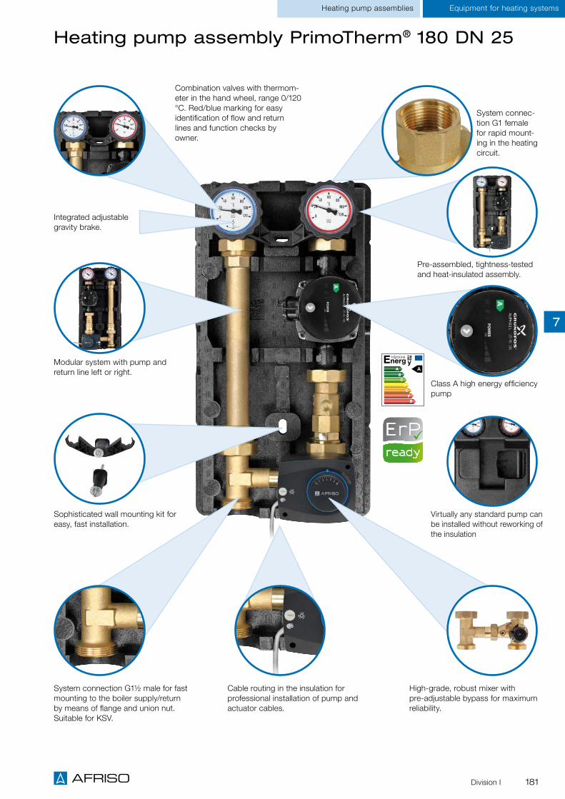
181
Equipment for heating systems
Division I
Heating pump assemblies
Heating pump assembly PrimoTherm® 180 DN 25
Cable routing in the insulation for professional installation of pump and actuator cables.
Pre-assembled, tightness-tested and heat-insulated assembly.
Class A high energy efficiency pump
Virtually any standard pump can be installed without reworking of the insulation
System connec-tion G1 female for rapid mount-ing in the heating circuit.
Combination valves with thermom-eter in the hand wheel, range 0/120 °C. Red/blue marking for easy identification of flow and return lines and function checks by owner.
Modular system with pump and return line left or right.
System connection G1½ male for fast mounting to the boiler supply/return by means of flange and union nut. Suitable for KSV.
Sophisticated wall mounting kit for easy, fast installation.
High-grade, robust mixer with pre-adjustable bypass for maximum reliability.
Integrated adjustable gravity brake.
7

182
Equipment for heating systems
Division I
Heating pump assemblies
Overview of versions Heating pump assemblies PrimoTherm® 180
The heating pump assembly PrimoTherm® excels with its versatility and great number of possible com-binations. The system assembly for the heating circuit is pre-assembled, tightness-tested, heat-insulat-ed and available in three versions and two sizes, each with or without high energy efficiency pump. All circulation pumps offered by AFRISO meet the requirements of the European Ecodesign Directive (stage 2 as of 2015). The universal insulation allows for the installation of virtually any standard pump without reworking of the insulation. In addition, the system is modular so that the flow line can be mounted at the left or the right side; due to the slim design, it is also possible to mount several pump assemblies next to each other on AFRISO boiler manifolds. In addition, each pump assembly compris-es a fastening kit for wall mounting in any position. All PrimoTherm® heating pump assemblies feature a gravity brake to avoid incorrect circulation. The DN 25 versions have the brake in the combination valve; it can be deactivated for servicing. It is also possible to mount temperature probes in the combination valve.
iSee the operating instructions of the pump assemblies for additional details, www.afriso.de/ betriebsanleitungen
Nominal size DN 25 DN 32
Version 180-1 Direct
180-2 3-way mixer
180-3 Fixed value mixing valve
RTA 60 180-1 Direct
180-2 3-way mixer
180-3 Fixed valuemixing valve
Without circulation pump • • • • • •
With Grundfos Alpha2L 25/60 • •
With Wilos Yonos Para 25/6 RKC • • •
With Wilos Stratos Para 30 1-7 • • •
Return temperature increase (RTA) • • • •
Description
The versions PrimoTherm® 180-2 DN 25 and 32 are used in mixed heating cir-cuits. With the 3-way mixer and the actuator, the flow temperature can be adjusted to a desired temperature by adding water from the return. PrimoTherm® 180-2 can also be used to increase the return temperature with solid fuel burners which have a controller for increasing the return temperature. The opening temperature must be set at this controller.
The versions PrimoTherm® 180-3 DN 25 and 32 automatically control the return temperature of the system water to the heat generator to the value adjusted in the valve. The integrated condensation protection valve is the connection between the solid fuel heating system or the buffer storage.
The versions PrimoTherm® 180-1 DN 25 and 32 are used in non-mixed heating circuits, specially for storage tank charging.
iWe provide a great variety of customer- specific pump assemblies for OEMs. Please enquire.
7

183Division I
Equipment for heating systemsHeating pump assemblies
Heating pump assembly PrimoTherm® 180-1 DN 25
Heating pump assembly for use in non-mixed heating circuits, specially for storage tank charging. It connects the heating boiler and the pipe system.
Complete, pre-assembled and tightness-tested heating pump assembly with all required functional components, form-fit insulation and wall mounting unit.
The pump line (flow/hot) consists of: Combination valve with thermometer in the hand wheel (red mark, range 0/120 °C) Ball valve below the pump Pipe for length compensation with screw connection System connection G1½ male (boiler), G1 female (heating circuit)
Suitable for pumps DN 25 with G1½ x 180 mm.
The return line consists of: Combination valve with gravity brake, thermometer in the handle (blue mark, range 0/120 °C) Pipe for length compensation (pump/mixer) with screw connection System connection G1½ male (boiler), G1 female (heating circuit)
Pre-assembled, tightness-tested and heat-insulated assembly
Modular system with flow at left or right
Easy and fast installation With high-efficiency pump class A
Application
Description
Technical specifications
Technical specifications
circulation pump
Options
Axis distance125 mm
System connectionsBoiler G1½ male, heating circuit G1 female
Operating temperature rangeMedium: Tmax = 110 °C
System pressureMax. 10 bar
Flow coefficient NS4.8 m3/h
InsulationPolypropylene EPP
DimensionsW x H x D 250 x 475 x 152 mm
Mixer and actuator, can be retrofitted High-efficiency pump Grundfos ALPHA2 L Other circulation pumps
A
Page 180
Grundfos ALPHA2 L 25-60
Length180 mm
Degree of protectionIP 42
Supply voltageAC 230 V, 50 Hz
Energy efficiency class A
Power input5–45 W
Pumping head/rateStage 1: 1.0 m/ 1.6 m³/h Stage 2: 3.1 m / 2.7 m³/hStage 3: 6.2 m/ 3.1 m³/H or constant differential pressure and constant volume flow
7

184
Equipment for heating systems
Division I
Heating pump assemblies
Heating pump assembly PrimoTherm® 180-1 DN 25
Dimensions (mm)
DG: G, PG: 2 Pump Part no. Price €
PrimoTherm® 180-1 DN 25 OM OP G1½ male x G1 female Without pump 77643
PrimoTherm® 180-1 DN 25 OM GP04 G1½ male x G1 female With Grundfos Alpha 2L 25-60 77645
Accessories and spare parts Specification Part no. Price €
Connection kit G1½ female thread x 1 female thread2 x connection piece G1 female thread, 2 x union nut G1½ female thread, 2 x flat gasket
77612
Connection kit G1½ male thread x 1 male thread2 x O ring ø 28 x 2.5 mm2 x reducer G1½ male thread x 1 male thread
77613
3-way mixer with T piece KV 10 Axis distance 125 mm 77589
250
125
475
152
122
7

185Division I
Equipment for heating systems
Heating pump assembly PrimoTherm® 180-2 DN 25
Pre-assembled, tightness-tested and heat-insulated assembly
High-grade, robust mixer Virtually any standard pump can be installed without reworking of the insulation
Easy and fast installation: Sophisticated wall mounting kit Cable routing integrated in insulation
Heating pump assemblies
Heating pump assembly for use in mixed heating circuits. With the 3-way mixer and the actuator, the flow temperature can be adjusted to a desired temperature by adding water from the return. It con-nects the heating boiler and the pipe system. PrimoTherm® 180-2 is also available as version RTA. It can be used to increase the return temperature with solid fuel burners which have a controller for increasing the return temperature. The opening temperature must be set at this controller.
Complete, pre-assembled and tightness-tested heating pump assembly with all required functional components, form-fit insulation.
The pump line (flow/hot) consists of: Combination valve with thermometer in the hand wheel (red mark, range 0/120 °C) Ball valve below the pump 3-way mixer KVS 10 with actuator ARM 343 System connection G1½ male (boiler), G1 female (heating circuit)
Suitable for pumps DN 25 with G1½ x 180 mm.
The return line consists of: Combination valve with gravity brake, thermometer in the handle (blue mark, range 0/120 °C)
Pipe for length compensation with screw connection T piece for mixer connection System connection G1½ male (boiler), G1 female (heating circuit)
Difference version RTA Interchanged colour codes of thermometers System connection (storage) with additional connection flanges G1 female Additional mounting bracket for upside down or lateral mounting High-efficiency pump WILO YONOS Para 25/6 RKC available
Application
Description
Technical specifications
Options
Axis distance125 mm
System connectionsBoiler G1½ male, heating circuit G1 female
Operating temperature rangeMedium: Tmax = 110 °C
System pressureMax. 10 bar
Flow coefficient NS4.8 m3/h
InsulationPolypropylene EPP
DimensionsW x H x D 250 x 475 x 152 mm
High-efficiency pump Grundfos ALPHA2 L Other circulation pumps Mixer reduction kits for flow coefficient NS 6.3 / 4.0 and 2.5 m3/h
A
Page 180
7

186
Equipment for heating systems
Division I
Heating pump assemblies
Heating pump assembly PrimoTherm® 180-2 DN 25
Dimensions (mm)
DG: G, PG: 2 Pump Part no. Price €
PrimoTherm® 180-2 DN 25 3WM-SM OP G1½ male x G1 female Without pump 77615
PrimoTherm® 180-2 DN 25 3WM-SM GP04 G1½ x G1 female With Grundfos Alpha 2L 25-60 77641
Versions RTA:
PrimoTherm® 180-2 DN 25 RTA 3WM-SM OP G1 female x G1 female
Without pump 77541
PrimoTherm® 180-2 DN 25 RTA 3WM-SM GP01 G1 female x G1 female
With Grundfos Alpha 2L 25-60 77542
PrimoTherm® 180-2 DN 25 RTA 3WM-SM WP02 G1 female x G1 female
With WILO Yonos PARA 25/6 RKC 77543
Accessories and spare parts Specification Part no. Price €
Connection kit G1½ female thread x 1 female thread2 x connection piece G1 female thread, 2 x union nut G1½ female thread, 2 x flat gasket
77612
Connection kit G1½ male thread x 1 male thread2 x O ring ø 28 x 2.5 mm2 x reducer G1½ male thread x 1 male thread
77613
3-way mixer with T piece KV 10 Axis distance 125 mm 77589
Technical specifications
circulation pump
Grundfos ALPHA2 L 25-60
Length180 mm
Degree of protectionIP 42
Supply voltageAC 230 V, 50 Hz
Energy efficiency class A
Power input5–45 W
Pumping head/rateStage 1: 1.0 m/ 1.6 m³/h Stage 2: 3.1 m / 2.7 m³/hStage 3: 6.2 m/ 3.1 m³/H or constant differential pressure and constant volume flow
7

187
Equipment for heating systems
Division I
Heating pump assemblies
Heating pump assembly PrimoTherm® 180-3 DN 25 RTA
Heating pump assembly for automatically controlling the return temperature of the system water to the heat generator to the value adjusted in the valve. An integrated, temperature-controlled condensation protection valve is the connection between the solid fuel heating system or the buffer storage. Using PrimoTherm® 180-3 RTA keeps the temperature in the heating boiler above the condensation point in all operating states. This avoids deposits in the boiler and in the smoke vent and increases the service life of the system; corrosion damage of the heating boiler and chimney fires caused by soot deposits are avoided.
Complete, pre-assembled and tightness-tested heating pump assembly with all required functional components, form-fit insulation and wall mounting unit. With an additional mounting bracket, the unit can be mounted in any position (vertically/horizontally).
The pump line (return) consists of: Combination valve with thermometer in the hand wheel (blue mark, range 0/120 °C) Ball valve above the pump 3-way mixing valve with fixed mixing temperature 60 °C System connection G1 female (boiler), G1 female (storage)
Suitable for pumps DN 25 with G1½ x 180 mm.
The flow line (hot) consists of: Combination valve with gravity brake, thermometer in the handle (red mark, range 0/120 °C)
Pipe for length compensation with screw connection System connection G1 female (boiler), G1 female (storage)
For increased return temperature with solid fuel boilers
With temperature-controlled condensation protection valve
For reduced amounts of condensate in the combustion process
Avoids deposits in the boiler and in the smoke vent
Application
Description
B
A
BA
B
AFunction principle Start mode (heating up of boiler):When the boiler heats up, the condensation protection valve is fully closed in the direction of the consumer. The liquid coming from the boiler is recirculated in the small circuit via the bypass, which causes the boiler temperature to increase more rapidly.
Transition phase:When the opening temperature is reached (60 °C), the circuit to the consumer is opened proportionally and the bypass is reduced accordingly. However, the boiler temperature will not drop below the set temperature.
Regular operation:During further operation, the temperature increases until the condensation protec-tion valve is fully open (return storage A). The bypass (B) is closed correspondingly. If the inlet temperature (return storage A) drops to approx 10 °C above the set opening temperature, the admixture via the bypass (B) is increased proportionally and outlet A is closed proportionally.
7

188 Division I
Equipment for heating systems
Technical specifications
Options
Axis distance 125 mm
System connections G1 female thread at both ends
Operating temperature rangeMedium: Tmax 100 °C
System pressure Max. 10 bar
Opening temperatures60 °C (fixed values)
Nominal size DN 25
System capacityMax. 32 kW at a flow rate of 1,400 I/h and a temperature spread of Δt 20 K
Leak rate Water-tight between connections A->AB, 3 % leak rate of flow coefficient NS between B->AB PN 10. A-AB = Flow coefficient NS: 2.94; B-AB = 2.12
Insulation Polypropylene EPP
Other opening temperatures Other circulation pumps
Technical specifications
circulation pump
WILO YONOS PARA 25/6 RKC
Length180 mm
Supply voltageAC 230 V, 50 Hz
Energy efficiency class A
Power input3–45 W
Pumping head/rateMax. 6.2 m, max. volume flow 3.3 m2/h
Heating pump assembly PrimoTherm® 180-3 DN 25 RTA
Heating pump assemblies
DG: G, PG: 2 Opening temperature Pump Part no. Price €
PrimoTherm® 180-3 DN 25 RTA 60 OP G1 female x G1 female 60 °C Without pump 77576
PrimoTherm® 180-3 DN 25 RTA 45 OP G1 female x G1 female 45 °C Without pump 77577
PrimoTherm® 180-3 DN 25 RTA 55 OP G1 female x G1 female 55 °C Without pump 77578
PrimoTherm® 180-3 DN 25 RTA 60 WPO1 G1 female x G1 female
60 °C WILO YONOS PARA 25/6 RKC 77570
PrimoTherm® 180-3 DN 25 RTA 45 WPO1 G1 female x G1´female
45 °C WILO YONOS PARA 25/6 RKC 77571
PrimoTherm® 180-3 DN 25 RTA 55 WPO1 G1 female x G1 female
55 °C WILO YONOS PARA 25/6 RKC 77572
Dimensions (mm)
7

189Division I
Equipment for heating systemsHeating pump assemblies
Charging unit RTA 60 DN 25 WP03 G1
For charging the storage of solid fuel boilers Compact unit for limited space conditions With temperature-controlled condensation protection valve
Avoids deposits in the boiler and in the smoke vent
Charging unit for direct connection between a solid fuel boiler and a heating system or a buffer stor-age. The compact design allows for mounting to the pipes between the solid fuel boiler and the stor-age even if space is limited. Using the charging unit RTA 60 DN 25 WP03 G1 RTA keeps the tempera-ture in the heating boiler above the condensation point in all operating states. This avoids deposits in the boiler and in the smoke vent and increases the efficiency and the service life of the system. The risk of corrosion damage to the boiler and chimney fires resulting from soot deposits is reduced.
Complete, pre-assembled and tightness-tested charging unit with all required functional components. The compact insulation contains a central carrier with a high energy efficiency pump. The probe sys-tems of the three thermometers held by the insulation are in the corresponding receptacles of the car-rier after mounting. The thermal condensation protection valve and a check valve that can be shut off are contained inside the carrier. Ball valves with connection threads G1 female are screwed to the three system connections.
Application
Description
Start mode (heating up of boiler)When the boiler heats up, the condensation protection valve is fully closed in the direction of the consumer. The liquid coming from the boiler is recircu-lated in the small circuit via the bypass, which causes the boiler temperature to increase more rapidly.
Transition phaseWhen the opening temperature is reached (60 °C), the circuit to the con-sumer is opened proportionally and the bypass is reduced accordingly. The boiler temperature increases and heat is provided to the consumer; howev-er, the return temperature will not fall below the set temperature.
Regular operationDuring further operation, the temperature increases until the condensation protection valve is fully open (return storage A). The bypass (B) is closed correspondingly. If the inlet temperature (return storage A) drops to approx 10 °C above the set opening temperature (e.g. 65 °C), the admixture via the bypass (B) is increased proportionally and outlet A is closed proportionally.
Function principle
A
A
A
AB
AB
AB
B
B
B
7
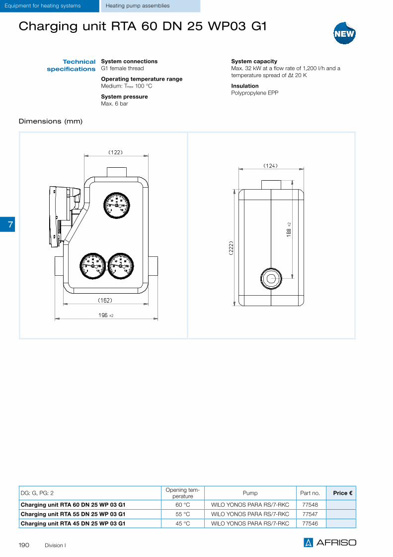
190 Division I
Equipment for heating systems Heating pump assemblies
Technical specifications
System connections G1 female thread
Operating temperature rangeMedium: Tmax 100 °C
System pressure Max. 6 bar
System capacityMax. 32 kW at a flow rate of 1,200 I/h and a temperature spread of Δt 20 K
Insulation Polypropylene EPP
Charging unit RTA 60 DN 25 WP03 G1
Dimensions (mm)
DG: G, PG: 2 Opening tem-perature Pump Part no. Price €
Charging unit RTA 60 DN 25 WP 03 G1 60 °C WILO YONOS PARA RS/7-RKC 77548
Charging unit RTA 55 DN 25 WP 03 G1 55 °C WILO YONOS PARA RS/7-RKC 77547
Charging unit RTA 45 DN 25 WP 03 G1 45 °C WILO YONOS PARA RS/7-RKC 77546
7

191Division I
Equipment for heating systems
Heating pump assembly PrimoTherm® 180-1 DN 32
Heating pump assembly for non-mixed heating circuits, specially for storage tank charging. It connects the heating boiler and the pipe system.
Complete, pre-assembled and tightness-tested heating pump assembly with all required functional components, form-fit insulation and wall mounting unit.
The pump line (flow/hot) consists of: Combination valve with thermometer in the hand wheel (red mark, range 0/120 °C) Ball valve below the pump System connection G2 male (boiler) and additional screw connections G1¼ female x G1¼ female (heating circuit)
Suitable for pumps DN 32 with G2½ x 180 mm.
The return line consists of: Combination valve, thermometer in the hand wheel (blue mark, range 0/120 °C) Pipe for length compensation with gravity brake and screw connection System connection G2 male (boiler) and additional screw connections G1¼ female x G1¼ female (heating circuit)
Pre-assembled, tightness-tested and heat-insulated assembly
Compact design Available with high energy efficiency pump class A
Easy and fast installation
Application
Description
Technical specifications
Axis distance 125 mm
System connections Boiler G1¼ female Heating circuit G1¼ female
Operating temperature rangeMedium: Tmax 110 °C
System pressure Max. 10 bar (observe maximum pressure of circulation pumps used)
Circulation pumpWILO STRATOS PARA 30/1-7 r. K
Length180 mm
Degree of protectionIP 44
Supply voltageAC 230 V, 50 Hz
Nominal size DN 32
Flow coefficient NS 21.0 m³/h
Insulation Polypropylene EPP
Power input5–70 W
Pumping head/rate7 m / 4.5 m3/h
ControlConstant differential pressure Constant volume flow
Heating pump assemblies
DG: G, PG: 2 Pump Part no. Price €
PrimoTherm® 180-1 DN 32 OM OP G1¼ female thread Without pump 77550
PrimoTherm® 180-1 DN 32 OM WP02 G1¼ female thread WILO STRATOS PARA 30/1-7 r. K. 77551
7

192 Division I
Equipment for heating systems
Heating pump assembly PrimoTherm® 180-1 DN 32
Dimensions (mm)
Heating pump assemblies
7

193Division I
Equipment for heating systemsHeating pump assemblies
Heating pump assembly PrimoTherm® 180-2 DN 32
Pre-assembled, tightness-tested and heat-insulated assembly
Compact design Available with high energy efficiency pumps class A and high-grade, robust mixer as well as actuator
Easy and fast installation
Heating pump assembly for mixed heating circuits. It connects the heating boiler and the pipe system. With the 3-way mixer and the actuator, the flow temperature can be adjusted to a desired temperature by adding water from the return.PrimoTherm® 180-2 is also available as version RTA. It can be used to increase the return temperature with solid fuel burners which have a controller for increasing the return temperature. The opening temperature must be set at this controller.
Complete, pre-assembled and tightness-tested heating pump assembly with all required functional components, form-fit insulation and wall mounting unit.
The pump line (flow/hot) consists of: Combination valve with thermometer in the hand wheel (red mark, range 0/120 °C) 3-way mixer KVS 16 with actuator ARM 343 System connection G2 male (boiler) and additional screw connections G1¼ female x G1¼ female (heating circuit)
Suitable for pumps DN 32 with G2½ x 180 mm.
The return line consists of: Combination valve, thermometer in the hand wheel (blue mark, range 0/120 °C) Pipe for length compensation with gravity brake and screw connection System connection G2 male (boiler) and additional screw connections G1¼ female x G1¼ female (heating circuit)
Application
Description
Technical specifications
Axis distance 125 mm
System connections Boiler G1¼ female Heating circuit G1¼ female
Operating temperature rangeMedium: Tmax 110 °C
System pressure Max. 10 bar (observe maximum pressure of circu-lation pumps used)
Nominal size DN 32
Flow coefficient NS 13.0 m³/h
Insulation Polypropylene EPP
Options High-efficiency pump Wilo STRATOS Para 30 1-7
Other circulation pumps
Mixer reduction kits for flow coefficient NS 12.5/10 and 6.3 m3/h
DG: G, PG: 2 Pump Part no. Price €
PrimoTherm® 180-2 DN 32 3WM-SM OP G1¼ female thread Without pump 77553
PrimoTherm® 180-2 DN 32 3WM-SM WP02 G1¼ female thread WILO STRATOS PARA 30/1-7 r. K. 77554
7

194 Division I
Heating pump assembly PrimoTherm® 180-2 DN 32
Dimensions (mm)
Equipment for heating systems Heating pump assemblies
7

195Division I
Equipment for heating systemsHeating pump assemblies
Heating pump assembly PrimoTherm® 180-3 DN 32 RTA
Heating pump assembly for automatically controlling the return temperature of the system water to the heat generator to the value adjusted in the valve. An integrated, temperature-controlled condensation protection valve is the connection between the solid fuel heating system or the buffer storage. Using PrimoTherm® 180-3 RTA keeps the temperature in the heating boiler above the condensation point in all operating states. This avoids deposits in the boiler and in the smoke vent and increases the service life of the system; corrosion damage of the heating boiler and chimney fires caused by soot deposits are avoided.
Complete, pre-assembled and tightness-tested heating pump assembly with all required functional components, form-fit insulation and wall mounting unit.
The pump line (return) consists of: Combination valve with thermometer in the hand wheel (blue mark, range 0/120 °C) Ball valve above the pump 3-way mixing valve with fixed mixing temperature 60 °C System connection G1¼ female (boiler), G1¼ female (storage)
Suitable for pumps DN 32 with G2 x 180 mm.
The flow line (hot) consists of: Combination valve with gravity brake, thermometer in the handle (red mark, range 0/120 °C)
Pipe for length compensation with gravity brake and screw connection
For increased return temperature with solid fuel boilers
With temperature-controlled condensation protection valve
For reduced amounts of condensate in the combustion process
Avoids deposits in the boiler and in the smoke vent
Application
Description
B
A
BA
B
AFunction principle Start mode (heating up of boiler):When the boiler heats up, the condensation protection valve is fully closed in the direction of the consumer. The liquid coming from the boiler is recirculated in the small circuit via the bypass, which causes the boiler temperature to increase more rapidly.
Transition phase:When the opening temperature is reached (60 °C), the circuit to the consumer is opened proportionally and the bypass is reduced accordingly. However, the boiler temperature will not drop below the set temperature.
Regular operation:During further operation, the temperature increases until the condensation protec-tion valve is fully open (return storage A). The bypass (B) is closed correspondingly. If the inlet temperature (return storage A) drops to approx 10 °C above the set opening temperature, the admixture via the bypass (B) is increased proportionally and outlet A is closed proportionally.
7

196
Equipment for heating systems Heating pump assemblies
Technical specifications
Options
Axis distance 125 mm
System connections G1¼ female thread at both ends
Operating temperature rangeMedium: Tmax 110 °C
System pressure Max. 10 bar
Opening temperatures60 °C (fixed values)
Nominal size DN 32
System capacityMax. 93 kW at a flow rate of 4,000 I/h and a tem-perature spread of Δt 20 K
Leak rate Water-tight between connections A->AB, 3 % leak rate of flow coefficient NS between B->AB A-AB = Flow coefficient NS: 7.2; B-AB = 4.8
Insulation Polypropylene EPP
Other opening temperatures Other circulation pumps
Technical specifications
circulation pump
WILO YONOS PARA 30/1-7 r. K
Length180 mm
Supply voltageAC 230 V, 50 Hz
Energy efficiency class A
Power input5–70 W
Pumping head/rate7 m/4.5 m2/h
Heating pump assembly PrimoTherm® 180-3 DN 32 RTA
DG: G, PG: 2 Opening temperature Pump Part no. Price €
PrimoTherm® 180-3 DN 32 RTA 60 OP G1¼ female x G1¼ female
60 °C Without pump 77555
PrimoTherm® 180-3 DN 32 RTA 60 WP02 G1¼ female x G1¼ female
60 °C WILO YONOS PARA 30/1-7 r. K 77556
Dimensions (mm)
Division I
7
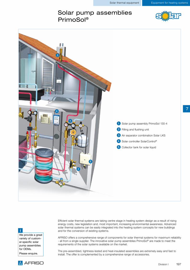
197
Equipment for heating systems
3
4
2
1
5
Solar thermal equipment
Solar pump assemblies PrimoSol®
iWe provide a great variety of custom-er-specific solar pump assemblies for OEMs.
Please enquire.
Efficient solar thermal systems are taking centre stage in heating system design as a result of rising energy costs, new legislation and, most important, increasing environmental awareness. Advanced solar thermal systems can be easily integrated into the heating system concepts for new buildings and for the conversion of existing systems.
AFRISO offers a comprehensive range of components for solar thermal systems for maximum reliability - all from a single supplier. The innovative solar pump assemblies PrimoSol® are made to meet the requirements of the solar systems available on the market.
The pre-assembled, tightness-tested and heat-insulated assemblies are extremely easy and fast to install. The offer is complemented by a comprehensive range of accessories.
Solar pump assembly PrimoSol 130-4
Filling and flushing unit
Air separator combination Solar LKS
Solar controller SolarControl®
Collector tank for solar liquid
1
3
4
5
2
Division I
7

198
Equipment for heating systems Solar thermal equipment
Pre-assembled, tightness-tested and heat-insulated assembly
Available with flow meter with ball valve, integrated filling and flushing unit and vent pot for degassing the heat transfer fluid in the flow line
Solar pump assembly/line for connection of collector and storage tank in intrinsically safe, sealed solar thermal systems. PrimoSol® 130 circulates heat transfer fluids such as water/glycol mixtures in the system.
Complete, pre-assembled and tightness-tested solar pump assembly/line with all required safety and functional components, including form-fit insulation.
Depending on the version, the pump line (return/cold) consists of: Circulation pump Flow meter with ball valve for shut-off, pump side with flange and union nut G1½. Measuring range: 2–12 l/min. With integrated filling and flushing unit, system connection: G¾ male thread.
Combination valve with system connection G¾ male thread, pump side with flange and union nut G1½. With adjustable gravity brake and thermometer in the hand wheel (blue mark, range 0/120 °C)
Safety group assembly with connection for expansion vessel. With solar safety valve 6 bar, outlet Rp¾ female thread, pressure gauge Ø 63 mm, 0/10 bar, mounting valve.
The flow line consists of (130-4 only): Combination valve with adjustable gravity brake and thermometer in the handle (red mark, range 0/120 °C) with system connection G¾
Vent pot to remove the gas from the heat transfer fluid with system connection G¾. Transparent hose 200 mm as venting aid.
The insulation is also used to package the product for safe transport.The safety valve of the safety group assembly complies with Pressure Equipment Directive 97/23/EC
Application
Description
Technical specifications
Axis distance 100 mm
System connections G¾ male thread
Operating temperature rangeAmbient: Tmax = 40 °C Medium: Tmax = 120 °C, short-term Tmax = 160 °C
System pressure Max. 6 bar
Flow meter2–12 l/min
InsulationPolypropylene EPP
Circulation pumpGrundfos UPM 3 Solar 25–75 Length: 130 mm Degree of protection IP 42
Supply voltageAC 230 V, 50 Hz
Power input/pumping head19 W/4.5 m 28 W/5.5 m 35 W/6.5 m 45 W/7.5 m
Options Flow meter 4–16, 8–28 and 8–38 l/min Adapter for system connection G1
Solar pump assembly PrimoSol® 130
A
Page 202 Page 201
A
Page 200
A
DG: G, PG: 2 Part no. Price €
PrimoSol® 130-1 77886
PrimoSol® 130-4 77889
PrimoSol® 130-1
Prim
oSol
® 1
30-4
Division I
7

199
Scope of deliveryPrimoSol® completely pre-assembled with circulation pump and mounting accessories.
Solar pump line PrimoSol® 130-1 Solar pump assembly PrimoSol® 130-4
Solar pump assembly PrimoSol® 130
Dimensions (mm)
① Flow meter with ball valve as well as filling and flushing unit② Safety group assembly③ Combination valve with thermometer (return/cold)④ Combination valve with thermometer (flow)⑤Vent pot for fast and easy venting, especially during filling of the system
① Flow meter with ball valve as well as filling and flushing unit② Safety group assembly③ Combination valve with thermometer (return/cold)
①
④ ③
②
⑤
Insulation 130-1 and 130-4The insulation is also used to package the product for safe transport.
Equipment for heating systemsSolar thermal equipment
Division I
①
③
②
7

200
Accessories for solar thermal systems
Description
Technical specifications
Diaphragm safety valve MSS
Connection kitFilling and flushing unit
ConnectionsInlet: Rp½Outlet: Rp¾
CapPA6, black
Opening pressure6 bar
DimensionsW x H x D 35 x 60 x 45 mm
HousingBrass CW617 N
Operating temperature rangeMedium: -20/+160 °C
Heating capacityMax. 50 kW
ConnectionsG1, compression fitting at both ends Ø 22 mm
DimensionsL: 108 mm
HousingBrass
DG: G, PG: 2 Part no. Price €
Filling and flushing unit 1 1 77781
Diaphragm safety valve MSS 1 84 42330
Connection kit G¾ 1 1 77904
For diaphragm expansion vessels (MAG) suitable for safety group assembly for PrimoSol®.
Consisting of: Bracket for wall mounting Flex pipe (500 mm, 1 union nut and seals)
MAG mounting valve Mounting accessories
For solar thermal systems to pro-tect against overpressure. Suitable for water, water/Antifrogen mixtures, water/Tyfocor mixtures and liquids of fluid groups 1 and 2 (Pressure Equipment Directive, Art. 9).
For solar systems as filling and flushing unit. With ball valve, two boiler filling and drain valves KFE G¾, process connection G1 with union nut and compression fit-tings at both ends.
iPlease enquire for diaphragm safety valves with other pressure ratings.
Equipment for heating systems Solar thermal equipment
Division I
ConnectionsFlex pipe: Union nut G¾ and mounting valve G¾
DimensionsFlex pipe (L): 500 mm Bracket (W x L): 220 x 110 mm
7

201
Vents for solar thermal systems
Description
Description
Description
Description
Quick air vents for solar systems with valve
Quick air vent for use in solar thermal systems with operating temperatures of up to 150 °C and operating pressures of up to 6 bar. Housing made of high-precision turned brass, func-tional parts made of highly temperature-resistant plastic. Completely assembled with ball valve as shut-off unit.Connection G3/8 with O ring seal.
Quick air vents for solar systems
Quick air vent for use in solar thermal systems with operating temperatures of up to 150 °C and operating pressures of up to 6 bar. Housing made of high-precision turned brass, func-tional parts made of highly temperature-resistant plastic. Connection G3/8 with O ring seal.
Air separator
Air separator for use in solar thermal systems or in sealed heating systems as per EN 12828 with operating tempera-tures of up to 150 °C and operating pressures of up to 6 bar. The air separator removes the air from the heat transfer fluid. The air collects in the housing and can be released via a quick air vent or a manual vent valve connected at the G3/8 threaded connection. Compression fitting for Cu pipe Ø 22 mm at both ends.
Air separator combination Solar LKS
Air separator, completely pre-assembled with quick air vents for solar systems, for use in solar thermal systems with oper-ating temperatures of up to 150 °C and operating pressures of up to 6 bar. The air separator removes the air from the heat transfer fluid. The air collects in the housing and can be released via the quick air vent for solar systems connected at the G3/8 connection by actuating the valve. Compression fitting for Cu pipe Ø 22 mm at both ends.
Quick air vents for solar systems with valve
Quick air vents for solar systems
Air separator
Air separator combination Solar LKS
DG: G, PG: 2 Connection Part no. Price €
Quick air vents for solar systems G3/8 1 25 77900
Quick air vents for solar systems with valve G3/8 1 25 77996
Air separator Compression fitting Ø 22 1 - 77851
Air separator combination Solar LKS Compression fitting Ø 22 1 1 77850
Equipment for heating systemsSolar thermal equipment
Division I
7

202
Application
Description
Technical specifications
Collects groundwater polluting solar liquid in the case of system overpressure.
Collector tank for solar liquid with integrated drain valve. Volume 10 l. The collector tank for solar liq-uid is connected to the diaphragm safety valve MSS or to the safety group assembly PrimoSol® of the solar pump assembly via a pipe. A basic volume of 1 to 1.5 l of liquid is always contained in the collector tank to avoid overheating of the col-lector tank if solar liquid escapes suddenly from the solar thermal system.
For early detection of solar liquid in the collector tank for solar liquid.
Solar liquid monitor in wall mounting housing, consisting of a control unit with visual/audible alarm, Test and Acknowledge buttons as well as a probe. The probe is plugged into the collector tank and triggers an alarm if it is submerged in 2–3 mm of liquid. The response level can be adjusted by shortening the probe. The audible alarm can be muted with the Acknowledge but-ton. The visual alarm is cleared once the collector tank has been drained. The Test button allows you to simulate an alarm condition in order to per-form a function check. The two voltage-free relay contacts are provided for connection of additional external alarm equipment or event reporting sys-tems.
DG: G PG Part no. Price €
Collector tank for solar liquid 1 1 1 77796
Solar liquid monitor SFW 01 4 1 1 40036
Solar pump assembly PrimoSol® 130-4 with collector tank for solar liquid in a solar ther-mal system
Collector tank for solar liquid Solar liquid monitor SFW 01
Collector tank for solar liquid, solar liquid monitor
Operating temperature rangeMedium: Max. 95 °C short-term 120 °C (without basic liquid volume)
Dimensions W x H x D 300 x 390 x 145 mm
Weight0.97 kg
Filling volumeMax. 10 l
Operating temperature rangeAmbient: -5/+55 °C
ProbeL: 220 mmResponse level: 2–3 mmCable: 1.5 m (2 x 1.0 mm²)Degree of protection: IP 55 (EN 60529)
Control unitSupply voltage: AC 230 VPower input: 5 VARelay outputs: 2 relay contacts 1 changeover contact 1 normally open contactContact rating: AC 250 V, 2 AVisual alarm: Red LEDAudible alarm: Integrated piezo buzzer, can be acknowledgedDimensions (W x H x D): 100 x 188 x 65 mmDegree of protection: IP 40 (EN 60529)
Equipment for heating systems Solar thermal equipment
Division I
7

203
Solar controller SolarControl SC 10
For system-independent control and monitoring of thermal solar systems. Additional protection equip-ment and alarm signals (such as accumulation of liquid in the collector tank for solar liquid, system overpressure, pressure loss) can be connected, displayed and signalled. Ideal for e.g. retrofitting single-family or two-family homes.
Solar controller in wall mounting housing. The SolarControl microprocessor controls and visualises all program functions. The unit is programmed and operated via a user-friendly, multi-language menu. The temperature probe and the pump are supplied directly via the unit; no additional wiring is required.
A conductivity probe can be connected so that it is possible to monitor for the accumulation of liquids. Signals from alarm equipment can be connected via four digital inputs; customisable text messages can be assigned to the signals.Al warning and alarm signals are logged in the memory, displayed on the colour display with red back-light and signalled via an audible alarm. The audible alarm can be acknowledged with a button.
Application
Technical specifications
DG: H, PG: 4 Part no. Price €
Solar controller SolarControl SC 10 78499
Functions Solar control Alarm/fault message Fault message logging Temperature limitation Frost protection function Defrosting function Collector tank monitoring Holiday function/cooling down mode
Operating temperature rangeAmbient: 0/45 °C
DisplayGraphical LC display with coloured backlight, text-based user interface, user interface language selectable (German/English/French)
Supply voltageAC 230 V
Inputs3 x temperature1 x conductivity probe4 x inputs for voltage-free switching signals
Switching output1 x AC 230 V, 4 A
Visual alarmRed LED, red light on display
Audible alarmIntegrated piezo buzzer, min. 70 dB (A)
HousingWall mounting housing made of impact-resistant plastic (ABS) W x H x D: 100 x 188 x 65 mm Degree of protection: IP 54 (EN 60529)
Scope of delivery Control unit with graphical display Collector sensor Tank sensor
Easy commissioning and programming Multi-language menu and colour display Integrated alarm unit function for extra safety With visual/audible alarms Controlling and monitoring with a single device
Description
Integrated monitoring function for the collector tank for solar liquid
A
Page 202
Equipment for heating systemsSolar thermal equipment
Division I
7

204
Equipment for heating systems Single room controller
Single room temperature controller CosiTherm®
Overview wired version
Base module with controller module for 6 control circuits
Base module with timer module and controller module for 8 control circuits
Base module with timer module and controller module for 12 control circuits
Functions Adjustment of reference temperature 6/30°C Measurement of actual temperature
Overview wireless version
Base module with controller module for 6 control circuits
Base module with timer module and controller module for 8 control circuits
Base module with timer module and controller module for 12 control circuits
Functions Adjustment of reference temperature 6/30°C Measurement of actual temperature Humidity measurement 0/100% r.h. (option)
The controller modules can be combined as required, subject to the conditions on site.
i
Room temperature sensor wired
Room temperature sensor wireless
Division I
7

205
Equipment for heating systemsSingle room control
Base module BM
Controller module D2 Controller module D6
1 Controller module with two control circuits
2 Controller module with six control circuits
3 LED green: Indication mains voltage for thermal actuators
4 LED yellow: Indication thermal actuator active
5 Terminal block for room temperature sensors
6 Terminal block for thermal actuators
Controller module wired
Functions and connections Single room temperature controller CosiTherm®
1 LED green: Operation mains voltage
2 LED green: Operation DC 5 V
3 LED red: Pump "Heating"
4 LED blue: Pump "Cooling"
5 LED blue: Display program mode "Heating" or "Cooling"
6 Connection supply voltage AC 230 V
7 Relay contact pump "Heating"
8 Relay contact pump "cooling"
9 Cascading output "Heating/Cooling"
10 Input switchover "Heating/Cooling"
Base module BM
1 2
3 3 44
5
6
2 3 4 5
9876
1
10
5
6
Division I
7

206
Single room temperature controller CosiTherm® – wired
For manifold systems for heating and cooling
Extremely flat room temperature sensor with a height of 12.5 mm
Room temperature sensor with wire con-nection
Timer module for programming tempera-ture reduction, pump operating time and valve protection function
Controls the temperature of individual rooms in connection with manifold systems for heating and cooling.
The base version of the single room temperature controller CosiTherm® wired consists of a base mod-ule, at least one controller module with two or six independent control circuits and a corresponding number of room temperature sensors. The controller modules can be interconnected in a modular way to account for the number of control circuits/rooms. One room temperature sensor is required per control circuit; it is wired to the controller module. The room temperature sensor measures the actual temperature in the room. The reference temperature is adjusted via the rotary knob of the room tem-perature sensor. The controller module compares the actual temperature and the reference tempera-ture and controls the volume flow of the heating/cooling water via the thermal actuators of the manifold system. An optional timer module with display and an integrated hundred year calendar can be plugged into the base module. It features two independently programmable switching channels for temperature reduction, nine programmable memory blocks and a valve and pump protection function. The addi-tional pump running time is adjustable. The terminals of the controller modules are colour-coded for easy assignment to the wires of the thermal actuators; in conjunction with the DIN rail snap connectors at the rear of the housing, this facilitates installation.
Application
Description
Functions Base module BM Power supply of the room temperature sensors (DC 5 V) and thermal actuators(AC 230 V)
Switchover of the system to "Heating" or "Cooling" Control of the heating/cooling pumps
Controller module Comparison of actual and reference temperatures Volume flow control heating/cooling water via connected thermal actuators
Connection of two or six control circuits, extensible as required
Wired connection of room temperature sensors
Timer module UM (option) Timing: Date, time, weekday (leap year detection) Temperature reduction adjustment Additional pump running time adjustment Valve and pump protection function adjustment
Timer module (option) for programming and display of date, time, weekday
Equipment for heating systems Single room controller
Division I
7

207
ConnectionsBase module BM Max. 9 controller modules D2 or 3 controller modules D6Controller module D2 Max. 2 room temperature sensors and 8 actuatorsController module D6 Max. 6 room temperature sensors and 24 actuators
Operating temperature rangeAmbient/storage: -10/+60 °C
Base module BM
Supply voltageAC 230 V, 50-60 Hz
Nominal power1 VA
Housing Plastic housing PC/ABS W x H x D: 122 x 92 x 45 mm Degree of protection: IP 20 (EN 60529)
Weight 215 g
Controller module
Supply voltageAC 230 V, DC 5 V (via base module BM)
Nominal powerController module D2: 0.1 W Controller module D6: 0.3 W
Housing (W x H x D)Plastic housing PC/ABS Controller module D2: 73 x 92 x 45 mm Controller module D6: 162 x 92 x 45 mm Degree of protection: IP 20 (EN 60529)
Weight Controller module D2: 130 g Controller module D6: 260 g
Timer module UM (option)
Temperature reduction 4 K Switching channels: 2, independently programmable Memory blocks: 9, independently programmable
Valve and pump protection function/ additional pump running time0/15 min, adjustable
Supply voltageDC 3.3 V (via base module BM)
Nominal power3 mW
Housing (W x H x D)Plastic housing ABS Colour: Light grey, similar to RAL 7047W x H x D: 37 x 93 x 28 mm Degree of protection: IP 30 (EN 60529)
Weight 33 g
Technical specifica-tions
Single room temperature controller CosiTherm® – wired
DG: G, PG: 4 Part no. Price €
Base module BM 78112
Controller module D2 for 2 control circuits 78114
Controller module D6 for 6 control circuits 78115
Options
Timer module UM for base module BM 78113
Wireless module FM for timer module UM 78121Wireless module timer FMA with external antenna, for timer module UM 78122
Equipment for heating systemsSingle room control
Division I
7

208
Single room temperature controller CosiTherm® – wired
Base module BM Controller module D2
Controller module D6 Timer module UM
Types and dimensions (mm)
Equipment for heating systems Single room controller
Division I
7

209
Equipment for heating systems
Single room temperature controller CosiTherm® Wireless
Single room control
Base module BM Power supply of the thermal actuators (AC 230 V)
Switchover of the system to "Heating" or "Cooling"
Control of the heating/cooling pumps
Controller module Comparison of actual and reference temperatures
Volume flow control heating/cooling water via connected thermal actuators
Connection of two or six control circuits, extensible
Connection to room temperature sensors EnOcean® wireless technology
Timer module UM (option) Timing: Date, time, weekday (leap year detection)
Temperature reduction adjustment Additional pump running time adjustment Valve and pump protection function adjustment
For manifold systems for heating and cooling
Timer module for programming temperature reduction, pump operating time and valve protection function
Worldwide access via AFRISOhome gateway
Controls the temperature of individual rooms in connection with manifold systems for heating or cool-ing. EnOcean® wireless technology for integration into building automation systems.
The base version of the single room temperature controller CosiTherm® Wireless consists of a base module, at least one controller module with two or six independent control circuits and a correspond-ing number of room temperature sensors. The controller modules can be interconnected in a modular way to account for the number of control circuits/rooms. One room temperature sensor is required per control circuit; the standard version is battery-less and connected to the controller module via the EnOcean® wireless technology. The room temperature sensor measures the actual temperature in the room. The reference temperature is adjusted via the rotary knob of the room temperature sensor or via the app AFRISOhome. The controller module compares the actual temperature and the reference tem-perature and controls the volume flow of the heating/cooling water via the thermal actuators of the manifold system. An optional timer module with display and an integrated hundred year calendar can be plugged into the base module. It features two independently programmable switching channels for temperature reduction, nine programmable memory blocks and a valve and pump protection function. The addi-tional pump running time is adjustable. The terminals of the controller modules are colour-coded for easy assignment to the wires of the thermal actuators; in conjunction with the DIN rail snap connectors at the rear of the housing, this facilitates installation.With an AFRISOhome gateway, it is possible to remotely check and, if necessary, adjust the room tem-peratures via the AFRISOhome app (for example, when coming back from winter vacation). This flexi-ble remote control of the room temperature combines multiple benefits: you can increase living comfort and reduce energy costs.In conjunction with additional AFRISO products with EnOcean® wireless technology, the user can con-figure a whole range of fully customisable, extensible applications.
Application
Description
Timer module (option) for programming and display of date, time and weekday
Functions
Division I
7

210
Equipment for heating systems
Single room temperature controller CosiTherm® – wireless
Single room controller
DG: G, PG: 4 Part no. Price €
Base module BM 78112
Controller module F2A with external antenna, for 2 control circuits 78123
Controller module F6A with external antenna, for 6 control circuits 78124
Accessories
Timer module UM for base module 78113Wireless module time FMA with external antenna, for timer module UM 78122
ConnectionsBase module BM Max. 9 controller modules F2 or 3 controller modules F6Controller module F2 Max. 2 room temperature sensors and 8 actuators as well as external antennaController module RM F6 Max. 6 room temperature sensors and 24 actuators as well as external antenna
Operating temperature rangeAmbient/storage: -10/+60 °C
EnOcean® wirelessFrequency: 868.3 MHzTransmission power: Max. 10 mW Transmission cycle: 2.5 minutesRange: 10 to 30 m (depending on room arrangement and materials in the building)
Base module BM
Supply voltageAC 230 V, 50–60 Hz
Nominal power1 VA
Housing Plastic housing PC/ABS Colour: Light grey, similar to RAL 7047 W x H x D: 122 x 92 x 45 mm Degree of protection: IP 20 (EN 60529)
Weight 215 g
Controller module
Supply voltageAC 230 V, DC 5 V (via base module BM)
Nominal powerController module F2: 0.3 W Controller module F6: 0.5 W
Housing (W x H x D)Plastic housing PC/ABS Controller module F2: 73 x 92 x 45 mm Controller module F6: 162 x 92 x 45 mm Degree of protection: IP 20 (EN 60529)
Weight Controller module F2: 130 g Controller module F6: 260 g
Timer module (option)
Temperature reduction 4 K Switching channels: 2, independently programmable Memory blocks: 9, independently programmable
Valve and pump protection function/ additional pump running time0/15 min, adjustable
Supply voltageDC 3.3 V (via base module BM)
Nominal power3 mW
Housing (W x H x D)Plastic housing ABS Colour: Light grey, similar to RAL 7047 W x H x D: 37 x 93 x 28 mm Degree of protection: IP 30 (EN 60529)
Weight 33 g
Technical specifications
Division I
iSee operating instruc-tions for detailed information on the range of the EnOcean® wireless module.
7

211
Equipment for heating systemsSingle room control
Single room temperature controller CosiTherm® – wireless
Base module BM Controller module F2
Controller module F6 Timer module UM
Types and dimensions (mm)
Division I
7

212
Equipment for heating systems Single room control
Division I
Extremely flat with a height of 12.5 mm Easy surface mounting
Determination of the actual ambient temperature and adjustment of the reference value for the room temperature.
The room temperature sensor D transmits the actual ambient temperature as well as the reference room temperature via the connection wire to the single room temperature controller CosiTherm®. The reference value for the room temperature is adjusted by means of the integrated rotary knob. The actu-al temperature in rooms with an underfloor heating system is compared to the set temperature on an ongoing basis. If there is a difference, the single room temperature controller CosiTherm® adapts vol-ume flows of the heating/cooling water via the thermal actuators of the manifold system.
Application
Description
Operating temperature rangeAmbient: -10/+60 °CStorage: -10/+60 °C
Temperature adjustment range6/30 °C
Temperature reduction4 K
Supply voltageDC 5V, via controller module
Nominal power0.012 VA
Wired connectionMax. 100 m
HousingPlastic housing ABSW x H x D: 78 x 78 x 12.5 mmWeight: 30 gDegree of protection: IP 30 (EN 60529)
Scope of delivery Room temperature sensor D Mounting kit (2 x screws, 2 x screws)
Technical specifications
A
Page 206
Room temperature sensor D - wired
DG: G, PG: 4 Part no. Price €
Room temperature sensor D 78110
7

213
Extremely flat with a height of 12.5 mm Wireless operation (photovoltaic cell or battery)
Flexible location-independent use anywhere in buildings
Determination of the actual ambient temperature and adjustment of the reference value for the room temperature.
The room temperature sensor FT transmits the actual ambient temperature as well as the reference room temperature via the integrated EnOcean® wireless module to the single room temperature con-troller CosiTherm® Wireless or to the AFRISOhome gateway. The room temperature sensor FTF also transmits the current humidity value. The reference value for the room temperature is adjusted by means of the integrated rotary knob. The actual temperature in rooms with an underfloor heating sys-tem is compared to the set temperature on an ongoing basis. If there is a difference, the single room temperature controller CosiTherm® Wireless adapts volume flows of the heating/cooling water via the thermal actuators of the manifold system. The energy required to send reference temperature and actual temperature values is generated by means of an integrated photovoltaic cell; it is also possible to use a standard battery. The AFRISOhome gateway transmits alarm messages and changes in tem-perature and/or humidity via WLAN, LAN and GSM to the person in charge (for example, to the owner, the facility manager, the janitor or other configured contacts); the message includes information on which room temperature sensor has signalled the change. The AFRISOhome gateway in conjunction with additional AFRISO products with EnOcean® wireless technology allows the user to configure a whole range of fully customisable, extensible applications.
Application
Description
Operating temperature rangeAmbient: -20/+60 °CStorage: -20/+60 °C
Temperature adjustment range8/30 °C
Temperature measurement0/40 °C, Accuracy: ± 1 K
Humidity measurementWith room temperature sensor FTF onlyRoom humidity: 0/100 % r.h. Accuracy: ± 5 % r.h.
Supply voltageEnergy harvesting (via photovoltaic cell) or type 1632 battery, DC 3 V (with daylight less than 200 lx)
HousingPlastic housing PCColour: White, similar to RAL 9003W x H x D: 78 x 82.5 x 12.5 mmWeight: 43 gDegree of protection: IP 30 (EN 60529)
EnOcean® wirelessFrequency: 868.3 MHzTransmission power: Max. 10 mWTransmission cycle: 2.5 minutesRange: 10 to 30 m (depending on room arrangement and materials in the building)
Scope of delivery Room temperature sensor FT/FTF 4 x adhesive dots Without battery
Necessary additional components CosiTherm® Wireless and/or AFRISOhome Gateway
Technical specifications
A
Page 118
A
Page 209
Room temperature sensor FT/FTF – wireless
A
Page 119
DG: L, PG: 4 Part no. Price €
Room temperature sensor FT (temperature) 78111
Room temperature sensor FT, set of 3 (temperature) 78975
Room temperature sensor FTF (temperature, humidity) 78119
Room temperature sensor FTF, set of 3 (temperature, humidity)
78976
AFRISOLabHome comfort
Division I
iSee operating instruc-tions for detailed information on the range of the EnOcean® wireless module.
7

214
Equipment for heating systems Actuators
Thermal actuators
TSA-02 TSA-03
Electro-thermal actuator with position indication, limit switch, connection cable and union nut for direct connection to the valve or upper part of the valve. Closed when de-energised. TSA-03 can be used to switch off the pump via the integrated limit switch when all valves are closed.
Electro-thermal actuator with position indication, connection cable and union nut for direct connec-tion to the valve or upper part of the valve. Closed when de/energised; available as 24 V or as 230 V version.
iAFRISO offers custom-er-specific versions of the actuators for many valve upper parts for OEMs. We look forward to your enquiry.
DG: G, PG: 4 Part no. Price €
TSA-02, 230 V 1 10 78882
TSA-02, AC/DC 24 V 1 10 78883
TSA-03, AC 230 V with limit switch 1 10 78871
TSA-03, AC/DC 24 V with limit switch 1 10 78872
For setting the hot water valves in radiators or AFRISO distribution manifolds such as heating/cooling circuit manifolds ProCalida® MC and EF or industrial manifolds IN. Actuators convert the electrical signal received from room or timer thermostats into a valve stroke to control the set temperature via the flow volume.
Application
Operating modeClosed when de-energised
Stroke0/3.2 mmIndication via cams on hood
Opening time< 5 min
Operating temperature rangeAmbient: Max. 60 °C
Supply voltageAC/DC 24 V or AC 230 V Power: 2 W
ConnectionUnion nut: M 30 x 1.5 mm Closing dimension: 10.8 mm Cable length: 1 m
HousingPlasticDegree of protection IP 54 (EN 60529)
Operating modeClosed when de-energised
Stroke0/3.2 mmIndication via cams on hood
Opening time< 5 min
Operating temperature rangeAmbient: Max. 60 °C
Supply voltageAC/DC 24 V or AC 230 V Power: 2 W
Switching output1 voltage-free, normally open contact
Contact ratingAC/DC 24 V, 2/6 A AC 230 V, 0.1/6 A Power: 2 W
ConnectionUnion nut: M 30 x 1.5 mm Closing dimension: 10.8 mm Cable length: 1 m
HousingPlastic, degree of protection IP 40 (EN 60529)
Technical specifica-tions
Description
Division I
7

215
Manifold systems
Manifold systems ProCalida®
for heating, cooling and geothermal systems
Complex, customised manifold systems made of high-grade plastic materials proven over many years
For heating, cooling and geothermal systems Numerous combinations in terms of type and number of heating circuits
Pre-assembled, tightness-tested and ready to be connected Excellent insulation properties (low heat emission and noise transmission; suppression of condensate)
Corrosion-resistant for long service life Vast array of versions for numerous application scenarios and logistics concepts
Can be combined with thermometers, flow meters, thermo-actuators, connection valves and many other components.
Low weight Simplified logistics Compatible control units
Advantages – your benefits
AFRISO has been manufacturing complex plastic manifolds for leading global vendors of floor heating, cooling and geothermal systems for many years. The know-how, together with our excep-tionally high degree of vertical integration including our own tool design allows us to implement even complex geometries to cus-tomer specifications.
High-grade plastic materials enable a great variety of technical fea-tures and optimum, practical designs. Plastic valves are not sus-ceptible to corrosion and deposits. Thermometers and flow meters are easy to integrate. Our offering is complemented by a compre-hensive range of accessories. For decades, experts from the fields of heating, ventilation and air conditioning have been working with AFRISO products under the brands of leading system providers.
Equipment for heating systems
Division I
7

216
Equipment for heating systems
ProCalida® MC 1
Manifold systems
Heating circuitDistance: 50 mm Connection: G¾ eurocone
Operating temperature rangeMedium: Max. 60 °C at 6 bar or max. 90 °C at 3 bar
ProCalida® EF 1
Heating circuit manifold ProCalida® EF 1
Modular, very short plastic heating circuit or cooling circuit manifold with up to 12 heating circuits. Return with stroke valves for actuators, flow with shut-off valves or flow meters as required. Temperature indication at flow and return lines. Main connection with union nut G1. Manual vent, filling and drain valve or quick air vent can be mounted. Flexible connection from left or right as well as from the bottom with a bracket kit.
Heating circuitDistance: 50 mm Connection: G¾ eurocone
Operating temperature rangeMedium: Max. 60 °C at 6 bar or max. 90 °C at 3 bar
Heating circuit manifold ProCalida® MC 1
Modular, very short, robust plastic heating circuit or cooling circuit manifold with up to 12 heating circuits. Return with stroke valves for actuators, flow with shut-off valves or flow meters as required. Temperature indication at flow and return lines. Main connection with union nut G1. Manual vent, filling and drain valve or quick air vent can be mounted. With dovetail guide at both ends for fast mounting to wall mounting bracket and for maximum installation flexibility.
Manifold systems ProCalida®
for heating, cooling and geothermal systems
ProCalida® VA 1
Heating circuitDistance: 50 mm Connection: G¾ eurocone
Operating temperature rangeMedium: Max. 60 °C at 6 bar or max. 90 °C at 3 bar
Heating circuit manifold ProCalida® VA 1
Stainless steel heating circuit manifold with up to 12 heating circuit manifolds. Return with stroke valves for actuators, flow with shut-off valves or flow meters as required. Main connection with union nut G1. With filling and drain valve as well as manual vent. Quick air vent can be fitted. Connection via angular connection piece with ball valve G1 or control valve (return: actuator adaptation M30 x 1.5 male thread/f l ow: adjustment valve or flow meter). Easy snap-on mounting of manifold on wall bracket.
Division I
7

217
ProCalida® IN 1½Heating circuitDistance: 70 or 100 mm Connection: Connection: G1 flat-sealing, compression
fitting for pipe Ø 25 x 2.3/2.5 or Ø 32 x 2.9 and Ø 40 x 3.7 or G¾ eurocone
Operating temperature rangeMedium: -20/+60 °C at 6 bar
Heating circuit/geothermal manifold ProCalida® IN 1½/GT 1½
Modular plastic manifold for industrial or geothermal applica-tions with up to 20 heating circuits. Return either with stroke valves for actuators or with shut-off valves, flow either with shut-off valves or with flow meters as required. Main connec-tion with union nut G1½. Individual installation of filling and drain valve, quick air vent, pressure gauge and thermometer via multi-way union. Easy snap-on mounting of manifold on wall bracket.
Manifold systems ProCalida®
for heating, cooling and geothermal systems
Heating circuitDistance: 80, 90, 100, 110, 130, 140, 150 or 160 mm Connection: Compression fitting for pipe Ø 25 x 2,3/2,5 mm or Ø 32 x 2,9 mm and Ø 40 x 3.7 mm; Customer-specific versions are also available Individual heating circuits can be rotated by 360°Operating temperature rangeMedium: -20/+60 °C at 6 barRange (flow meter)2–12 l/min, 5–42 l/min, 35–70 l/min, 60–125 l/min
ProCalida® GT 3
Geothermal manifold ProCalida® GT 3
Modular manifold for brine, made of plastic, for any number of heating circuits. With one shut-off valve each in the flow and return (adjusted values can be locked via a ring) and integrated flow rate indication in the return. Main circuit connection and heating circuit connections can be made to customer specifica-tions. Individual installation of filling and drain valve, air vent and pressure gauge via cross piece. Thermometer can be integrated in the line and/or in each individual heating circuit. Robust, easy-to-mount wall bracket.
Drinking water connectionsDistance: 45 mmConnection: PEX hose ½"Inlet: ¾" or 1" PEX pipeOutlet: ¾" or 1" PEX pipe, blind
Operating temperature rangeMedium: max. 100 °C at 10 bar
Drinking water manifold
Drinking water manifold
Plastic drinking water manifold with 3, 4, 6 or 8 drinking water connections. Triple and quadruple versions also available in H shape (both ends). Another manifold can be connected to the outlet end.
Manifold systems Equipment for heating systems
Division I
7

Measuring instruments
Combination blocks
Radiator valves
Screw fitting with measuring function, line fittings

219
CHAPTER 8
Valves and control technology for radiators and hydraulic balancing
Calculation software VarioQCalc 227
Handheld measuring instrument HMG 01 229
Handheld measuring instrument HMG 10 230
HYDRAULIC BALANCING
Line fittings AFRISO-Gampper 264
Hydraulic balancing 226
Valves and control technology for radiators and hydraulic balancing 220
OVERVIEW
Thermostat valve bodies VarioQ, adjustable, with measuring function 231
Thermostat valve bodies Vario 236
Radiator lockshield valves type 454Q, with measuring function 240
Radiator lockshield valves type 456, adjustable 243
Combination blocks VarioQ-Kombi, adjustable, with measuring function 246
Thermostat combination blocks Vario THK, adjustable 249
Combination blocks Twin for radiator/underfloor systems 253
RADIATOR CONNECTION
Thermostat control heads 256
Adapters and conversion information thermostat control heads from year of manufacture 1975 261
Screw fittings with measuring function Q 266
Overview line valves 264
Measuring and line fittings Vanitus Eco 268
Volume flow controller Vario E 270
LINE FITTINGS
8

220
Standard Vario VarioQ Type 456 Type 454Q Vario THK Vario- Kombi
VarioQ-Kombi Twin Q Vanitus
EcoVanitus L / XL
FlowCon K/ XL/XXL Flow A AB / ABV EVS/EVC SH / SM
Thermostat valve bodies Radiator lockshield valves Tap blocks Tap blocks
Screw fit-tings with measuring function/
flange
Line fittings
Radiator
Ap
plic
atio
n ar
eas
• • • • • • • • • •
Underfloor/panel heating systems • • • • • • • • • • • • • •
Refrigeration/air condi-tioning • • • • • • • • • • • • •
Hydraulic Balancing • • • • • • • • • • • • • • • •
Static line control • •
Dynamic volume flow control • • • • / -
Pressure-independent control • • • - / •
Standard
Valv
e in
sert
/co
n-
tro
l ins
ert
• • • • • •
Vario • • • •
Vario C • •
Vario E • • •
Adjustment spindle • • • • •
S
Volu
me
rang
e
• • • • • • • • • • • •
M • • • • • • • • • • • • • •
L • • • • • • • • •
L-max • • •
XL • • • • / - •
XXL /Hi–XXL •
Measuring function
Func
tio
ns
• • • • • • • • • •
Adjustable • • • • • • • • • • • • • •
Can be shut off • • • • • • • • • • • - / • - / • • - / •
Can be drained • • • • • • • • • •
Replaceable insert • • • • • • • • • • • • • • • •
Dimension (DN)
Co
nnec
tio
n 10-25 10-20 10-25 10-25 10-15 15 15 15 15 15-300 15-25 15-300 15-900 15-25 15-50/40 15-25 15-150
Thread • • • • • • • • • • • • • • • / - •
Screw connection • • • • • • • • • • • • - / • • •
Flange • • • •
Thermostat head
Co
ntro
l / d
rive
• • • • •Thermal actuator 24 V, 230 V, 0–10 V • • • • • • • •
Motor-driven actuator • • • • • • • - / •
2-point/3-point • • • • • • • • - / •
4–20 mA • • • • • • • • - / •
PWM • • • • • • • • - / •
LON • • • • • • • • - / •
AFRISO planner folder *
Page 236 Page 231 Page 243 Page 240 Page 264AFRISO planner folder *
Page 246 Page 253 Page 266 Page 268AFRISO planner folder *
AFRISO planner folder *
AFRISO planner folder *
AFRISO planner folder *
AFRISO planner folder *
AFRISO planner folder *
Division I
OverviewFittings
Technical specifications, application areas and suitability depend on the product ver-sion. See catalogue data sheet and/or operating instructions for options and details.
i
* Please enquire separately.
Valves and control technology for radiators and hydraulic balancing at a glance
8

Standard Vario VarioQ Type 456 Type 454Q Vario THK Vario- Kombi
VarioQ-Kombi Twin Q Vanitus
EcoVanitus L / XL
FlowCon K/ XL/XXL Flow A AB / ABV EVS/EVC SH / SM
Thermostat valve bodies Radiator lockshield valves Tap blocks Tap blocks
Screw fit-tings with measuring function/
flange
Line fittings
Radiator
Ap
plic
atio
n ar
eas
• • • • • • • • • •
Underfloor/panel heating systems • • • • • • • • • • • • • •
Refrigeration/air condi-tioning • • • • • • • • • • • • •
Hydraulic Balancing • • • • • • • • • • • • • • • •
Static line control • •
Dynamic volume flow control • • • • / -
Pressure-independent control • • • - / •
Standard
Valv
e in
sert
/co
n-
tro
l ins
ert
• • • • • •
Vario • • • •
Vario C • •
Vario E • • •
Adjustment spindle • • • • •
S
Volu
me
rang
e
• • • • • • • • • • • •
M • • • • • • • • • • • • • •
L • • • • • • • • •
L-max • • •
XL • • • • / - •
XXL /Hi–XXL •
Measuring function
Func
tio
ns
• • • • • • • • • •
Adjustable • • • • • • • • • • • • • •
Can be shut off • • • • • • • • • • • - / • - / • • - / •
Can be drained • • • • • • • • • •
Replaceable insert • • • • • • • • • • • • • • • •
Dimension (DN)
Co
nnec
tio
n 10-25 10-20 10-25 10-25 10-15 15 15 15 15 15-300 15-25 15-300 15-900 15-25 15-50/40 15-25 15-150
Thread • • • • • • • • • • • • • • • / - •
Screw connection • • • • • • • • • • • • - / • • •
Flange • • • •
Thermostat head
Co
ntro
l / d
rive
• • • • •Thermal actuator 24 V, 230 V, 0–10 V • • • • • • • •
Motor-driven actuator • • • • • • • - / •
2-point/3-point • • • • • • • • - / •
4–20 mA • • • • • • • • - / •
PWM • • • • • • • • - / •
LON • • • • • • • • - / •
AFRISO planner folder *
Page 236 Page 231 Page 243 Page 240 Page 264AFRISO planner folder *
Page 246 Page 253 Page 266 Page 268AFRISO planner folder *
AFRISO planner folder *
AFRISO planner folder *
AFRISO planner folder *
AFRISO planner folder *
AFRISO planner folder *
221Division I
Overview
a brand of the AFRISO group
Fittings
8

222 Division I
In addition to the catalogue pages, we provide comprehensive product documentation with extensive technical data and characteristics on the AFRISO-GAMPPER product range to HVAC companies with planning departments, plant engineers, domestic technology planners and architects. Please enquire separately.
AFRISO planner folder
OverviewFittings
Valves and control technology for radiators and hydraulic balancing
AFRISO-GAMPPER offers a broad range of proven products comprising standard valve bodies with suitable thermostat control heads and lockshield valves, combination blocks for compact radiators and adjustable radiator and line fittings with measuring function for optimising existing heating systems and hydraulic balancing. The brand GAMPPER ARMATUREN has been a synonym for radiator fittings "Made in Germany" for more than 75 years.
Our comprehensive experience in the areas of domestic technology and building equipment and automation results from single-family home projects all the way to large-scale reference projects. AFRISO-GAMPPER assists planners with full-scale engineering in large projects: engineering data (such as VDI 3805 records), plant engineering or transparent project logistics via HVAC wholesalers. The OEM business covers the entire range from custom-specific development to production at the Alsenz site. Decades of cooperation in associations and institutions working on and preparing standards and legislation ensure that our products are state-of-the-art.
Patented thermostat valve VarioQ with fixed, calibrated measuring unit for high-precision adjustment of radiators.
The first manufacturer who used virtually maintenance-free O rings instead of high-maintenance packings to seal the valve spindle of manual valves.
The inventor of the radiator lockshield valve that can be shut off, adjusted and drained.
The first manufacturer of thermostat valves to receive the top grade for control performance from "Stiftung Warentest", the renowned, independent German consumer organisation.
The inventor of the patented, adjustable radiator thermostat valves VarioQ with measuring function that allow hydraulic bal-ancing of existing heating, refrigeration and air conditioning systems.
Numerous other innovations attesting to global success: patens for tap blocks and combination blocks for valve radiators or combined thermostat valves with integrated return temperature limiter for bathroom radiators and underfloor heating systems.
GAMPPER ARMATUREN:
8

223Division I
Overview
Solutions for hydraulic balancing of existing systems:
1 Compact radiator with thermostat control head 320 KH and adjustable combination block VarioQ-Kombi with measuring function
2 Decentralised radiator and underfloor heating with combination block Twin with adjustable return temperature limiter
3 Manifold system for underfloor heating systems ProCalida with screw fitting with measuring function Q
4 Valve radiator with adjustable thermostat valve body with measuring function VarioQ, thermostat control head 320 KH and radiator lockshield valve type 456
12
3
4
4
a brand of the AFRISO group
Fittings
8

224 Division I
Hydraulic Balancing Overview
Determine the optimum water volume per radiator
Open the measuring nipple
Hydraulic balancing
easier than ever
before:
Hydraulic balancing: Highest efficiency, maximum energy saving and comfort
On its way to the radiators and back to the boiler, the hot water flow always chooses the path of least resistance. Due to this natu-ral law, in heating systems without hydraulic balancing radiators further away from the pump are supplied with insufficient amounts of hot water while radiators close to the pump receive too much hot water. Typical countermeasures such as increased pump
capacities or higher flow temperatures do not improve this situa-tion, but rather amplify the negative effects. Such systems consume much more energy than necessary without providing the expected convenience.
Has your heating system been balanced?
Uneven heat release Heating times of rooms/apartments differ Thermostat valves cannot properly control the room temperature Limited frost protection Disturbing flow noise in valves and pipes Excessive power consumption due to oversized and/or
incorrectly set circulation pumps High losses when the heating system starts or is not used Low efficiency of condensing systems: Excessive flow through
radiators close to the pump leads to high return temperatures and reduces the condensation effect (energy recovery during condensation of the flue gas)
Consequences of lack of hydraulic balancing:
8

225Division I
Hydraulic balancing ensures optimum distribution of the water in the heating system. Based on the actual heat requirements of the building, the circulation pump, the control (flow temperature), the fittings and the valves are adjusted to change the volume flow in the pipes in such a way as to obtain the required flow resistance for all radiators. This forces the hot water to flow through the
system exactly as required. The right method and suitable com-ponents allow for considerable savings. In individual cases, this may amount to as much as 15 % and more of the annual heating capacity.
What is hydraulic balancing?
Advantages – your benefits
Convenience: Rooms are heated evenly
Radiators respond quickly to new thermostat valve settings
Maximum frost protection safety
No flow noise in the heating system
Heating system/pump operate with maximum efficiency to save energy
Increased system reliability
Improved energetic quality of the building
Reduced energy consumption saves money and protects the environment due to less emission
In Germany, hydraulic balancing is obligatory (DIN 18380, German Energy Saving Regulation EnEV). In addition, owners can only benefit from public subsidies after hydraulic balancing has been performed.
Legal obligations hydraulic balancing
Overview
Insert the measuring probes
Adjust the radiator Close the measuring opening – done!
a brand of the AFRISO group
Cop
yrig
ht: V
dZ
– Fo
rum
für
Ene
giee
ffizi
enz
in d
er G
ebäu
det
echn
ik e
.V.
System with hydraulic balancing
Flow limitation for balancing
Adjustable thermostat valve with measuring functionCop
yrig
ht: V
dZ
– Fo
rum
für
Ene
giee
ffizi
enz
in d
er G
ebäu
det
echn
ik e
.V.
System without hydraulic balancing
Low resistance = high flow rate
High resistance = low flow rate
Pump
Hydraulic Balancing
8

226 Division I
Traditional hydraulic balancing often involves a lot of estimating and approximation since precise information on the pipe system is unavailable. This is particularly true of older systems where pipe lengths and cross sections may not be documented so that a decisive factor required for precise adjustment of the valves is missing. The patented Gampper valve range VarioQ uses a dif-ferent approach for hydraulic balancing. The triple-stage system
optimises the heating system on the basis of calculation, meas-urement and adjustment without additional adjustment valves (such as line valves). The heating system expert adjusts the heat distribution directly at each radiator by limiting the amount of hot water - quickly and easily. Even minimum flow rates can be set with this system.
Fast and easy hydraulic balancing
The easy-to-use software determines the required opti-mum water volume as well as the VarioQ valves for each radiator. Only the flow temperature of the system, the radiator capacity and the heat requirements of the rooms to be heated are needed as a basis for the calculation. Parameters and estimated values of the pipe system do not have to be considered.
Calculation software VarioQCalc
The adjustable thermostat valves feature a fixed, calibrated measuring unit for adjustment of the volume flow directly at the valve.
Gampper valve range VarioQ
Hydraulic Balancing Overview
HMG 10 receives its data from VarioQ-Calc via a USB interface. The measur-ing instrument measures the flow rate in litres per hour and the water volume can be easily set at the valve without conversion. In addition, all standard measuring valves and line fittings are stored and can be intuitively selected via the graphical user interface.
Measuring instrument HMG 10
8

227Division I
iFree download of VarioQCalc atwww.afriso.com/varioqcalc
Calculation software for hydraulic balancing. Determination of the required optimum water volume, system spread and selection of the VarioQ valves needed for all individual radiators for optimisation of the flow temperature and the pump capacity in heating systems. Implementing the optimisation calculated with VarioQCalc results in a continuous, permanent condensing effect.
VarioQCalc is based on MS Excel so that it is very easy to use without requiring any special knowl-edge. Only the flow temperature of the system, the radiator capacity and the heat requirements of the rooms to be heated are needed as a basis for the calculation. Ideally, the heating load is re-cal-culated or determined via the room sizes using reference values. Considering incorrectly rated radia-tors (too small or large), it precisely determines the required water volume per radiator, selects the suitable VarioQ valves, generates adjustment recommendations and creates an order list for pur-chasing from your wholesaler.
The calculated individual spread of the radiator as well as the spread of all radiators together (system spread) allows the heating system professional to determine the extent to which the potential of the boiler is used. The system can be optimised in addition to hydraulic balancing by means of changing the flow temperature: The effects on total spread, spread of the individual spread of the radiators and total volume flow become immediately visible.
The calculated water volume and adjustment recommendation per radiator can be directly transmit-ted to the handheld measuring instrument HMG 10 (USB) for adjustment of the valves. Measured values can be returned for documentation and certification purposes.
Application
Description
Calculation results Radiator/total water volume Radiator/system spread Valve recommendation Adjustment recommendation Order list Documentation
Optimisation potential Flow temperature Radiator capacity Condensing effect
System requirements PC WINDOWS operating system MS Excel 2007, 2010, 2013
Software information
Calculation software for hydraulic balancing Fast, easy calculation without knowledge of the pipe system
Valve selection with ordering and adjustment list Easy operation, MS Excel as software basis Direct data transmission to handheld measuring instrument HMG 10
Calculation software VarioQCalc
Calculation software
a brand of the AFRISO group
Hydraulic Balancing
8

228 Division I
Calculation software
iFree download of VarioQCalc atwww.afriso.com/varioqcalc
Calculation software VarioQCalc
1 Flow temperature Flow temperature at which the system is operated/to
be operated.
2 Return temperature, system spread, total supply volume, capacity are calculated by the program
3 Design temperature for radiator's standard capacity System temperature from radiator table at which the standard
capacity is specified. Click "OK" after entering the temperatures.
4 Insert single radiator Inserts a new row with all required formulas. If you have not yet
entered radiator information, the system displays ### or #Value!
5 Insert multiple radiators Prompts for the number of radiators to be inserted. Inserts the
corresponding new rows with all required formulas. If you have not yet entered radiator information, the system displays ### or #Value!
6 Delete selected radiators The selected radiators are deleted.*
7 Delete all radiators Project is reset. CAUTION! All radiators are deleted.
8 Worksheet protection off Enables entries in all cells.
9 Worksheet protection on (default) Locks all cells required for calculation so they cannot be deleted/
overwritten.
10 Order overview Creates a list of the valves recommended for the order.
Contains quantities and part numbers.
11 Adjustment overview Generates an overview of the base settings of the valves during
mounting for printing.
12 Adjustment report for KFW Generates a report after adjustment for application for KFW
funds (Germany).
13 Room no., radiator no., radiator type Cells to be used for describing the radiator.
14 Standard capacity Enter the standard capacity of the radiator according to the
design temperature (see above). The standard capacities of the most typical radiators are stored (75/65/20).
15 Room in m², Watt per m², heating load method 1 (VarioQCalc standard)
Measuring the room, calculating the area, determining the heat requirement per m², VarioQCalc calculates the heating load.
Method 2 (recommended) Calculate the heating load by means of appropriate software, enter the values in the Heating Load column (in this case, it is not necessary to enter the values for room in m² and Watt per m²).
16 Room temperature Required room temperature.
17 Valve design Enter one of the following designs: angled, DG, Kombi angled,
Kombi DG, RLV angled, RLV DG.
18 Valve dimensions Enter one of the following dimensions: 3/8 – ½ – ¾.
* Use only this function to delete radiators since formulas in adjacent cells may be affected if you use the MS Excel standard functions for inserting or deleting cells.
a brand of the AFRISO group
Hydraulic Balancing
12
22
23
45
67
89
101112
1718
1314
15
168

229Division I
Hydraulic BalancingHandheld measuring instrument
For differential pressure measurement and flow rate adjustment in heating and refrigerating systems during hydraulic balancing. To be used in conjunction with VarioQ thermostat valves and combination blocks. If VarioQ valves are used, hydraulic balancing can be done directly at the radiator. It is neither necessary to know the pipeline system nor to perform complex calculations.
HMG 01 is a simple, lightweight handheld measuring instrument with a display for visualisation of the results of measurements. The flow coefficients of the valves with measuring function can be manually set via the keypad (valve bodies VarioQ S, M, L are stored in the memory); the flow rate at the valve can be displayed and the water volume can be easily set at the VarioQ valve without conversion. The measured flow rate and pressure values can be displayed in various units. HMG 01 features an intuitive calibration function for zero correction.
Application
Description
Measuring range0/1,000 kPa / 0/10 bar
Max. overpressure - side: 1,000 kPa / 10 bar + side: 1,500 kPa / 15 bar
Operating temperature rangeAmbient/storage: -5/+50 °C Medium: -5/+90 °C
Weight380 g
DimensionsW x H x D 94 x 218 x 40 mm
DisplayBacklit display 128 x 64 Pixel
Connection2 x plug connection (red/blue)
Supply voltage2 x 1.2 V AA batteries (rechargeable)
Options Hose kit for line fittings Measuring needles for line fittings
Scope of deliveryMeasuring instrument with calibration report, 2 x batteries, 1 pair of measuring hoses for connection of VarioQ valves, adapters and accessories for connection to the system to be balanced, mounting tools
Technical specifications
Hydraulic balancing directly at the radiator with VarioQ valves
Simple measuring instrument for line fittings Measurement/check of differential pressure and flow rate
For heating circuit water and media of other densities
Handheld measuring instrument for hydraulic balancing HMG 01
DG: H, PG: 4 Part no. Price €
HMG 01 68785 718.00
Accessories for line fittings
Measuring needles 480 000.805 41.80
Hose kit 480 000.801 118.00
8

230 Division I
Hydraulic Balancing Handheld measuring instruments
Handheld measuring instrument for hydraulic balancing HMG 10
For differential pressure measurement and flow rate adjustment in heating and refrigerating systems during hydraulic balancing. To be used with VarioQ thermostat valves, VarioQ combination blocks or standard line fittings with measuring function (such as Gampper Vanitus Eco / Vanitus L). If VarioQ valves are used, hydraulic balancing can be done directly at the radiator. It is neither necessary to know the pipeline system nor to perform complex calculations.
HMG 10 is an ergonomic, lightweight handheld measuring instrument. A large, backlit colour display allows for convenient visualisation of all measurement results. All standard measuring valves are stored and can be intuitively selected via the graphical user interface. The measuring instrument measures the flow rate in litres per hour and the water volume can be easily set at the VarioQ valve without conversion. HMG 10 offers a great variety of features for storing pressure and flow data. It is possible to manage a total of 1,200 records.
HMG 10 uses all data and calculation results from VarioQCalc and returns all measured and adjusted values of the balancing procedure for documentation purposes. In addition, projects can be defined with the PC software as required and then transferred to the memory of HMG 10. A mini USB port is provided for communication and battery charging. HMG 10 features an intuitive calibration function for zero correction.
Application
Description
Measuring range0/1,000 kPa / 0/10 bar
Max. overpressure 1,200 kPa / 12 bar
Operating temperature rangeAmbient/storage: -5/+50 °C Medium: -5/+90 °C
Hours of operationMax. 12 hours
Weight420 g
DimensionsW x H x D 80 x 180 x 52 mm
DisplayBacklit colour display 240 x 320 pixels
Connection2 x plug connection (red/blue)
Supply voltageLithium-ion battery 950 mAh
Scope of deliveryMeasuring instrument with calibration report, USB charging adapter, 2 pairs of measuring hoses for connection of VarioQ valves and line fittings, adapters and accessories for connection to the system to be balanced, mounting tools, USB data cable, USB flash drive with PC software
Technical specifications
Lightning-fast hydraulic balancing at the radiator with VarioQ valves
Software-supported measurement/check of differential pressure and flow rate
Characteristic curves of standard line valves and radiator valves stored in the software
For heating circuit water and media of other densities
DG: H, PG: 4 Part no. Price €
HMG 10 68794
8

231Division I
Radiator connectionValve bodies
Thermostat valve bodies VarioQ
Fixed, calibrated measuring unit for accurate adjustment of the radiator
Fully adjustable Valve insert can be replaced without system having to be drained
Lightning-fast hydraulic balancing with series HMG measuring instruments
For measuring and adjusting the volume flow directly at the valve, e.g. with the measuring instruments HMG 01/10/100 for hydraulic balancing. Suitable for small, medium and large water volumes. For installation in dual-pipe heating systems. Design as per standard, therefore, installation in existing sys-tems without changes to the connection pipes.
Patented, low-noise thermostat valve body with fixed, calibrated measuring unit for measuring and adjusting the volume flow directly at the valve. Mounting cap with valve shut-off function. Threaded connection M30 x 1.5 mm for thermostat control heads and actuators. Fully adjustable with ES-SV adjustment key. Valve spindle with double O ring seal. The valve insert can be replaced with the MGV mounting unit at operating pressure without the system having to be drained.
VarioQ is a triple-stage hydraulic balancing system which allows for optimisation of the heating pipe system by means of calculation, measurement and adjustment. The free VarioQCalc software automat-ically determines the optimum water volume per radiator and selects the required VarioQ valves. This information is transferred to the HMG 10/HMG 100 measuring instrument via USB data cable. The measuring instrument measures the flow rate in litres per hour and the water volume can be easily set at the valve without conversion. Even minimum flow rates can be set with this system.
Application
Description
System connectionSee ordering table
Thermostat head/actuator connectionThreaded connection M30 x 1.5 mm
Nominal pressureMax. 10 ba r
Nominal diameterDN 10, DN 15, DN 20, DN 25
Operating temperature rangeMedium: Tmax = 120 °C
HousingVarioQ S-L: Brass/gunmetal, nickel-platedVarioQ Lmax: Gunmetal, nickel-plated VarioQ XL: Gunmetal
Option Version PN 16
Technical specifications
Page 230
A
Page 256
A
iIn the case of axial version or angled-angled version (left/right), use valve body Vario (axial) or Vario angled-angled (left/right) with lockshield valve with measuring function 454 Q.
See page 234 for prices.
Page 243
A
a brand of the AFRISO group
8

232 Division I
Radiator connection Valve bodies
Valve pre-adjustment
Type overview
VarioQ thermostat valves are fully adjustable by means of the ES-SV adjustment key, starting with the open position (8 = open). Mark and counter-mark are aligned. Each 1/8 of a turn corresponds to one flow characteristic, shown in a diagram (see operating instructions).
Valve type Marking at valve insert Colour of mounting cap
Flow rate range in l/h*
Min. Max.
VarioQ S 1 ring/red Red 6 130
VarioQ M 2 rings Black 20 400
VarioQ L 3 rings/green Green 20 400
Marking at valve housing
VarioQ XL 15 x 3 Black 60 1200
VarioQ XL 20 x 10 Black 200 4000
VarioQ XL 25 x 10 Black 200 4000
* The measurable flow rate is much higher than the adjustable range of the valves. The flow rate ranges for the VarioQ valves are shown in the ordering table.
Thermostat valve bodies VarioQ
Valve insert
Marking at valve housing
Mounting capMarking
Counter-mark Mark
Measuring points volume flow – VarioQ section
Measuring point P2 downstream of measuring unit
Fixed, calibrated measuring unit
Measuring point P1 upstream of measuring unit
a brand of the AFRISO group
8

233Division I
Radiator connectionValve bodies
Thermostat valve bodies VarioQ
Types and dimensions as per EN 215, series D
VarioQ S, M, L – angled
VarioQ S, M, L – angled, version BG
VarioQ XL – straight
VarioQ S, M, L – straight
VarioQ S, M, L – straight, version BG
Dimensions (mm) VarioQ XL
DN D d1 d2
Spanner size SW1
Spanner size SW2
H b min
L1 ±2
L2 ±2
L3 ±1
L4 ±1.5
L5 ±1.5
L6 L7 L8
10 Rp3/8 - R3/8 22 27 = Height control head
10.1 59 85 26 52 22 74 26 40
15 Rp½ G¾ R½ 27 30 13.2 66 95 29 58 26 82 29 42
20 Rp¾ - R¾ 32 37 14.5 74 106 34 66 29 96 34 53
DN D Spanner size SW1
H b min
L1 ±2
L2 ±2
15 Rp½ 27 = Height control head
12 80 55
20 Rp¾ 32 13 87 55
25 Rp1 41 15 97 60
Dimensions (mm) VarioQ S, M, L
a brand of the AFRISO group
8

234 Division I
Radiator connection Valve bodies
Thermostat valve bodies VarioQ
DG: V, PG: 2 Version Nominal diameter Connection
Flow coef-ficient*(m3/h)
Flow coef-ficient NS**
(m3/h)Part no. Price €
VarioQ S for small water volumes
Angled
DN 10 Rp3/8 x R3/8
0.019–0.24 0.25
1 35 181 110.101
DN 15 Rp½ x R½ 1 30 181 120.101
DN 20 Rp¾ x R¾ 1 25 181 130.101
Straight
DN 10 Rp3/8 x R3/8
0.019–0.24 0.25
1 35 181 160.101
DN 15 Rp½ x R½ 1 30 181 170.101
DN 20 Rp¾ x R¾ 1 25 181 180.101
Version BG with male thread at both ends
- -0.019–0.24 0.25
1 - xxx xx6.xxx
Version PN 16 - - 1 - xxx xxx.x1x
VarioQ M for medium water volumes
Angled
DN 10 Rp3/8 x R3/8
0.044–0.46 0.68
1 35 181 210.101
DN 15 Rp½ x R½ 1 30 181 220.101
DN 20 Rp¾ x R¾ 1 25 181 230.101
Straight
DN 10 Rp3/8 x R3/8
0.044–0.46 0.68
1 35 181 260.101
DN 15 Rp½ x R½ 1 30 181 270.101
DN 20 Rp¾ x R¾ 1 25 181 280.101
Version BG with male thread at both ends
- -0.044–0.46 0.68
1 - xxx xx6.xxx
Version PN 16 - - 1 - xxx xxx.x1x
VarioQ L for large water volumes
Angled
DN 10 Rp3/8 x R3/8
0.125–0.51 0.94
1 - 181 310.101
DN 15 Rp½ x R½ 1 - 181 320.101
DN 20 Rp¾ x R¾ 1 - 181 330.101
Straight
DN 10 Rp3/8 x R3/8
0.125–0.51 0.94
1 - 181 360.101
DN 15 Rp½ x R½ 1 - 181 370.101
DN 20 Rp¾ x R¾ 1 - 181 380.101
Version BG with male thread at both ends
- -0.125–0.51 0.94
1 - xxx xx6.xxx
Version PN 16 - - 1 - xxx xxx.x1x
* The flow coefficient corresponds to the water flow in m3/h through the valve at a given valve stroke (proportional offset, e.g. 1 K or 2 K) and a differential pressure of 1 bar.
** The flow coefficient NS is the flow coefficient of the valve at nominal stroke (100 % open). *** Extra charge added to standard version in €. Replace the specified digit in the standard part number with this number when ordering.
a brand of the AFRISO group
8
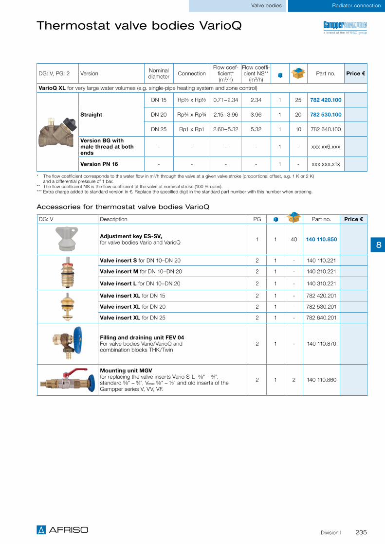
235Division I
Radiator connectionValve bodies
Thermostat valve bodies VarioQ
DG: V, PG: 2 Version Nominal diameter Connection
Flow coef-ficient* (m3/h)
Flow coeffi-cient NS**
(m3/h)Part no. Price €
VarioQ XL for very large water volumes (e.g. single-pipe heating system and zone control)
Straight
DN 15 Rp½ x Rp½ 0.71–2.34 2.34 1 25 782 420.100
DN 20 Rp¾ x Rp¾ 2.15–3.96 3.96 1 20 782 530.100
DN 25 Rp1 x Rp1 2.60–5.32 5.32 1 10 782 640.100
Version BG with male thread at both ends
- - - - 1 - xxx xx6.xxx
Version PN 16 - - - - 1 - xxx xxx.x1x
* The flow coefficient corresponds to the water flow in m3/h through the valve at a given valve stroke (proportional offset, e.g. 1 K or 2 K) and a differential pressure of 1 bar.
** The flow coefficient NS is the flow coefficient of the valve at nominal stroke (100 % open). *** Extra charge added to standard version in €. Replace the specified digit in the standard part number with this number when ordering.
Accessories for thermostat valve bodies VarioQ
DG: V Description PG Part no. Price €
Adjustment key ES-SV, for valve bodies Vario and VarioQ 1 1 40 140 110.850
Valve insert S for DN 10–DN 20 2 1 - 140 110.221
Valve insert M for DN 10–DN 20 2 1 - 140 210.221
Valve insert L for DN 10–DN 20 2 1 - 140 310.221
Valve insert XL for DN 15 2 1 - 782 420.201
Valve insert XL for DN 20 2 1 - 782 530.201
Valve insert XL for DN 25 2 1 - 782 640.201
Filling and draining unit FEV 04 For valve bodies Vario/VarioQ and combination blocks THK/Twin
2 1 - 140 110.870
Mounting unit MGV for replacing the valve inserts Vario S-L 3⁄8" – ¾", standard 3⁄8" – ¾", Vmax 3⁄8" – ½" and old inserts of the Gampper series V, VV, VF.
2 1 2 140 110.860
a brand of the AFRISO group
8

236 Division I
Radiator connection Valve bodies
Thermostat valve bodies Vario
Fully adjustable Valve insert can be replaced without system having to be drained
Various versions and sizes for virtually any application
Suitable for small, medium and large water volumes. For installation in dual-pipe central heating systems.
Low-noise thermostat valve body with threaded connection M30 x 1.5 mm for thermostat control heads and actuators. Mounting cap with valve shut-off function. Fully adjustable with ES-SV adjust-ment key. Valve spindle with double O ring seal. The valve insert can be replaced with the MGV mounting unit at operating pressure without the system having to be drained.
Application
Description
System connectionSee ordering table
Thermostat head/actuator connectionThreaded connection M30 x 1.5 mm
Nominal pressureMax. 10 bar
Nominal diameterDN 10, DN 15, DN 20
Operating temperature rangeMedium: Tmax = 120 °C
HousingGunmetal, nickel-plated
Technical specifications
Valve type Marking at valve insert
Colour of mounting cap
Vario S 1 ring/red Red
Vario M 2 rings Black
Vario L 3 rings/green Green
Page 240
A
Page 256
A
Valve pre-adjustment
Type overview
Vario thermostat valves are fully adjustable by means of the ES-SV adjustment key, starting with the open posi-tion (8 = open). The numbers 1–8 are shown on the adjustment key. Mark and counter-mark are aligned. Each 1/8 of a turn corresponds to one flow characteristic, shown in a diagram (see operating instructions).
Marking
Counter-mark Mark
Page 235
A
Adjustment key ES-SV
a brand of the AFRISO group
iSee page 238 for prices.
8

237Division I
Radiator connectionValve bodies
Thermostat valve bodies Vario
Types and dimensions as per EN 215, series D
Vario S, M, L – angled
Vario S, M, L – axial
Vario S, M, L – angled-angled, left
Vario S, M, L – straight
Vario S, M, L – angled-angled, right
DN D d2
Spanner size SW1
Spanner size SW2
H L0L1 ±2
L2 ±2
L3 ±1
L4 ±1.5
L5 ±1.5
b min
10 Rp3/8 R3/8 22 27 = Height control head
23 59 85 26 52 22 10.1
15 Rp½ R½ 27 30 23 66 95 29 58 26 13.2
20 Rp¾ R¾ 32 37 23 74 106 34 66 29 14.5
Dimensions (mm)
a brand of the AFRISO group
8

238 Division I
Radiator connection Valve bodies
Thermostat valve bodies Vario
DG: V, PG: 2 Version Nominal diameter Connection
Flow coeffi-cient*(m3/h)
Flow coef-ficient NS**
(m3/h)Part no. Price €
Vario S for small water volumes
Angled
DN 10 Rp3/8 x R3/8
0.019–0.25 0.30
1 40 141 110.101
DN 15 Rp½ x R½ 1 40 141 120.101
DN 20 Rp¾ x R¾ 1 - 141 130.101
Straight
DN 10 Rp3/8 x R3/8
0.019–0.25 0.30
1 40 141 160.101
DN 15 Rp½ x R½ 1 40 141 170.101
DN 20 Rp¾ x R¾ 1 - 141 180.101
AxialDN 10 Rp3/8 x R3/8
0.019–0.25 0.301 - 143 110.101
DN 15 Rp½ x R½ 1 - 143 120.101
Angled-angled, right DN 15 Rp½ x R½ 0.019–0.25 0.30 1 - 145 120.101
Angled-angled, left DN 15 Rp½ x R½ 0.019–0.25 0.30 1 - 147 120.101
Vario M for medium water volumes
Angled
DN 10 Rp3/8 x R3/8
0.038–0.40 0.79
1 - 141 210.101
DN 15 Rp½ x R½ 1 40 141 220.101
DN 20 Rp¾ x R¾ 1 25 141 230.101
Straight
DN 10 Rp3/8 x R3/8
0.038–0.40 0.79
1 - 141 260.101
DN 15 Rp½ x R½ 1 40 141 270.101
DN 20 Rp¾ x R¾ 1 25 141 280.101
AxialDN 10 Rp3/8 x R3/8
0.038–0.40 0.791 - 143 210.101
DN 15 Rp½ x R½ 1 - 143 220.101
Angled-angled, right DN 15 Rp½ x R½ 0.038–0.40 0.79 1 - 145 220.101
Angled-angled, left DN 15 Rp½ x R½ 0.038–0.40 0.79 1 - 147 220.101
Vario L for large water volumes
Angled
DN 10 Rp3/8 x R3/8
0.174–0.49 1.10
1 - 141 310.101
DN 15 Rp½ x R½ 1 - 141 320.101
DN 20 Rp¾ x R¾ 1 - 141 330.101
Straight
DN 10 Rp3/8 x R3/8
0.174–0.49 1.10
1 - 141 360.101
DN 15 Rp½ x R½ 1 - 141 370.101
DN 20 Rp¾ x R¾ 1 - 141 380.101
AxialDN 10 Rp3/8 x R3/8
0.174–0.49 1.101 - 143 310.101
DN 15 Rp½ x R½ 1 - 143 320.101
Angled-angled, right DN 15 Rp½ x R½ 0.174–0.49 1.10 1 - 145 320.101
Angled-angled, left DN 15 Rp½ x R½ 0.174–0.49 1.10 1 - 147 320.101
* The flow coefficient corresponds to the water flow in m3/h through the valve at a given valve stroke (proportional offset, e.g. 1 K or 2 K) and a differential pressure of 1 bar.
** The flow coefficient NS is the flow coefficient of the valve at nominal stroke (100 % open).
a brand of the AFRISO group
8

239Division I
Radiator connectionValve bodies
DG: V Description PG Part no. Price €
Adjustment key ES-SV, for valve bodies Vario and VarioQ 1 1 40 140 110.850
Valve insert S for DN 10–DN 20 2 1 - 140 110.221
Valve insert M for DN 10–DN 20 2 1 - 140 210.221
Valve insert L for DN 10–DN 20 2 1 - 140 310.221
Filling and draining unit FEV 04 For valve bodies Vario/VarioQ and combination blocks THK/Twin
2 1 - 140 110.870
Mounting unit MGV for replacing the valve inserts Vario S-L 3⁄8" – ¾", standard 3⁄8" – ¾", Vmax 3⁄8" – ½" and old inserts of the Gampper series V, VV, VF.
2 1 2 140 110.860
Accessories for thermostat valve bodies Vario
a brand of the AFRISO group
8

240 Division I
Radiator connection Lockshield valves
Radiator lockshield valves type 454Q
Fixed, calibrated measuring unit for accurate adjustment of the radiator
Individual radiators can be drained without the system having to be shut off
Lightning-fast hydraulic balancing with series HMG measuring instruments
Application
Description
For measuring the volume flow directly at the screw fitting, e.g. with the measuring instruments HMG 01/10/100 for hydraulic balancing. Suitable for small and medium water volumes. For installation in single-pipe and dual-pipe heating systems. Adjustments are made e.g. via the adjustable thermostat valve Vario in the flow.
Radiator lockshield valve with measuring function type 454Q with drain and adjustment function. Measurement via an integrated, fixed and calibrated measuring unit. With cap to protect against incor-rect operation. The optional filling and draining unit FEV with hose connection G¾ can be used for easy and fast draining.
The radiator lockshield valve is a part of the product range for the triple-stage balancing system VarioQ which allows for optimisation of the heating pipe system by means of calculation, measurement and adjustment. The free VarioQCalc software automatically determines the optimum water volume and selects the required lockshield valves. This information is transferred to the HMG 10 or HMG 100 measuring instrument via USB data cable. The measuring instrument measures the flow rate in litres per hour. Even minimum flow rates can be set with this system.
System connectionSee ordering table
Nominal pressureMax. 10 bar
Nominal diameterDN 10, DN 15
Operating temperature rangeMedium: Tmax = 120 °C
HousingGunmetal, nickel-plated
Technical specifications
Page 230
A
Page 231
A
Page 242
A
a brand of the AFRISO group
iSee page 242 for prices.
8

241Division I
Lockshield valves Radiator connection
Radiator lockshield valves type 454Q
Types and dimensions (mm) as per DIN 3842
Type 454Q S, M – angled
Type 454Q S, M – straight
DN D d2Spanner size SW1
Spanner size SW2
L1 ±2
L2 ±2
L3 ±1
L4 ±1.5
L5 ±1.5
10 Rp3⁄8 R3⁄8 22 27 49 75 26 52 22
15 Rp½ R½ 27 30 51 80 29 58 26
Dimensions (mm)
a brand of the AFRISO group
8

242 Division I
Lockshield valvesRadiator connection
DG: V, PG: 2 Version Nominal diameter Connection
Flow coeffi-cient NS*
(m3/h)Part no. Price €
454Q S for small water volumes, measuring range 20–400 l/h
Angled
DN 10 Rp3/8 x R3/8 0.38 1 - 479 011
DN 15 Rp½ x R½ 0.38 1 40 479 021
Straight
DN 10 Rp3/8 x R3/8 0.38 1 - 479 061
DN 15 Rp½ x R½ 0.38 1 40 479 071
454Q M for medium water volumes, measuring range 20–400 l/h
Angled
DN 10 Rp3/8 x R3/8 1.04 1 - 479 012
DN 15 Rp½ x R½ 1.04 1 40 479 022
Straight
DN 10 Rp3/8 x R3/8 1.04 1 - 479 062
DN 15 Rp½ x R½ 1.04 1 40 479 072
Radiator lockshield valves type 454Q
* The flow coefficient corresponds to the water flow in m3/h through the valve at a given valve stroke (proportional offset, e.g. 1 K or 2 K) and a differential pressure of 1 bar. The flow coefficient NS is the flow coefficient of the valve at nominal stroke (100 % open).
DG: V Version Part no. Price €
Filling and draining unit FEV 03 For type 454Q S and M as well as VarioQ-Kombi 1 - 422 520.810
Accessories for radiator lockshield valves type 454Q
a brand of the AFRISO group
8

243Division I
Lockshield valves Radiator connection
Radiator lockshield valves type 456
Fully adjustable Shutting off individual radiators Reproducible adjustment
To shut off individual radiators so that maintenance work or painting can be performed without having to drain the entire heating system. Suitable for small, medium and large water volumes. For installation in single-pipe and dual-pipe heating systems.
Radiator lockshield valve type 456 with drain, shut-off and adjustment function. With cap (versions S, M, L) to protect against incorrect operation. Adjustable according to flow chart (see operating instructions). The selected setting is reproducible due to the integrated stroke limiter/stop (not versions M Eco, L) and thus independent of draining. The optional filling and draining unit FEV with hose con-nection G½ can be used for easy and fast draining. Draining capacity equal to flow coefficient 1.1. Versions M Eco, L without stroke limiter.
Application
Description
System connection See ordering table
Nominal pressureMax. 10 bar
Nominal diameterDN 10, DN 15, DN 20, DN 25
Operating temperature rangeMedium: Tmax = 120 °C
HousingGunmetal, nickel-plated Version BG: not nickel-plated
Technical specifications
Page 231
A
Page 242
A
iPlease use valve body in flow to adjust the required water volume.
See page 245 for prices.
a brand of the AFRISO group
8

244 Division I
Lockshield valvesRadiator connection
Radiator lockshield valves type 456
Types and dimensions (mm)
DN D d2 SW1 SW2 b min
L1 ±2
L2 ±2
L3 ±1
L4 ±1.5
L5 ±1.5
L6 L7 L8
10 Rp3⁄8 R3⁄8 22 27 10.1 49 75 26 52 22 - - 22
15 Rp½ R½ 27 30 13.2 51 80 29 58 26 26.5 33.5 22
20 Rp¾ R¾ 32 37 14.5 59 91 34 66 29 30.5 38 22
25 Rp1 R1 42 46 16.8 90 125 40 75 34 - - 50
Dimensions (mm)
Type 456 S, M – angled Type 456 S, M – straight
Type 456 L – angled Type 456 L – straight
Type 456 S, M – angled, version BG Type 456 S, M – straight, version BG
a brand of the AFRISO group
8

245Division I
Lockshield valves Radiator connection
DG: V, PG: 2 Version Nominal diameter Connection
Flow coef-ficient NS*
(m3/h)Part no. Price €
Type 456 S for small water volumes (fine adjustment)
AngledDN 10 Rp3/8 x R3/8 0.45 1 - 453 310
DN 15 Rp½ x R½ 0.45 1 - 453 320
StraightDN 10 Rp3/8 x R3/8 0.45 1 - 453 360
DN 15 Rp½ x R½ 0.45 1 - 453 370
Type 456 M Eco for medium water volumes (without stroke limiter)
Angled
DN 10 Rp3/8 x R3/8 1.28 1 50 453 010
DN 15 Rp½ x R½ 1.28 1 40 453 020
DN 20 Rp¾ x R¾ 1.28 1 30 453 030
Version BG with G¾ male thread at both ends, not nickel-plated
DN 15 Rp½ x R½ 1.28 1 - 452 022
Straight
DN 10 Rp3/8 x R3/8 1.28 1 50 453 060
DN 15 Rp½ x R½ 1.28 1 40 453 070
DN 20 Rp¾ x R¾ 1.28 1 30 453 080
Version BG with G¾ male thread at both ends, not nick-el-plated
DN 15 Rp½ x R½ 1.28 1 - 452 072
Type 456 M for medium water volumes (standard version)
Angled
DN 10 Rp3/8 x R3/8 1.28 1 - 453 210
DN 15 Rp½ x R½ 1.28 1 - 453 220
DN 20 Rp¾ x R¾ 1.28 1 - 453 230
Straight
DN 10 Rp3/8 x R3/8 1.28 1 - 453 260
DN 15 Rp½ x R½ 1.28 1 - 453 270
DN 20 Rp¾ x R¾ 1.28 1 - 453 280
Type 456 L for large water volumes (without stroke limiter)
Angled
DN 15 Rp½ x R½ 2.7 1 - 403 020
DN 20 Rp¾ x R¾ 6.2 1 - 403 030
DN 25 Rp1 x R1 8.9 1 8 403 040
Straight
DN 15 Rp½ x R½ 2.0 1 - 403 070
DN 20 Rp¾ x R¾ 4.5 1 - 403 080
DN 25 Rp1 x R1 6.6 1 8 403 090
* The flow coefficient corresponds to the water flow in m3/h through the valve at a given valve stroke (proportional offset, e.g. 1 K or 2 K) and a differential pressure of 1 bar. The flow coefficient NS is the flow coefficient of the valve at nominal stroke (100 % open).
Radiator lockshield valves type 456
DG: V Version Part no. Price €
Filling and draining unit FEV 01 For types 456 S and M 1 20 452 010.803
Filling and draining unit FEV 02 For type 456 L 1 - 402 010.803
Accessories for radiator lockshield valve type 456
a brand of the AFRISO group
8

246 Division I
Lockshield valvesRadiator connection
Combination blocks VarioQ-Kombi for compact radiators with valve
Fixed, calibrated measuring unit for accurate adjustment of the radiator
Hydraulic balancing with series HMG measuring instruments
For wall or floor connection, also suitable for baseboard heating systems
For measuring the volume flow directly at the radiator, e.g. with the measuring instruments HMG 01/10/100 for hydraulic balancing. Suitable for small and medium water volumes. For connection to compact radiators with valve with an axis distance of 50 mm in dual-pipe heating systems. Adjustments are made either via the adjustable valve insert in the compact radiator or via the VarioQ combination block.
Adjustable combination block with measuring function VarioQ-Kombi with drain and shut-off feature. The volume flow is measured via an integrated, fixed and calibrated measuring unit. With cap to pro-tect against incorrect operation.
VarioQ-Kombi is a part of the product range for the triple-stage balancing system VarioQ which allows for optimisation of the heating pipe system by means of calculation, measurement and adjustment. The free VarioQCalc software automatically determines the optimum water volume per radiator and selects the required combination blocks. This information is transferred to the HMG 10 or HMG 100 measuring instrument via USB data cable. The measuring instrument measures the flow rate in litres per hour. Even minimum flow rates can be set with this system.
Application
Description
System connection (valve radiators)G¾ eurocone or G½ female thread
Nominal pressureMax. 10 bar
Nominal diameterDN 15
Operating temperature rangeMedium: Tmax = 120 °C
HousingGunmetal, nickel-plated
Technical specifications
Page 230
A
Page 242
A
a brand of the AFRISO group
iSee page 248 for prices.
8

247Division I
Combination blocks Radiator connection
Combination blocks VarioQ-Kombi for compact radiators with valve
Types and dimensions (mm)
VarioQ-Kombi S, M – angled
VarioQ-Kombi S, M – straight
Adapter for radiators with R½ female thread Cover
a brand of the AFRISO group
8

248 Division I
Combination blocksRadiator connection
DG: V, PG: 2 Version Nominal diameter
Radiator connection
Flow coef-ficient* (m3/h)
Part no. Price €
VarioQ-Kombi S for small water volumes
Angled DN 15
G¾ male
thread eurocone
0.25 1 - 423 721
Straight DN 15
G¾ male
thread eurocone
0.25 1 - 423 771
VarioQ-Kombi M for medium water volumes
Angled DN 15
G¾ male
thread eurocone
0.585 1 20 423 521
Straight DN 15
G¾ male
thread eurocone
0.585 1 20 423 571
VarioQ-Kombi S for small water volumes
Angled DN 15G½
female thread
0.25 1 - 423 821
Straight DN 15G½
female thread
0.25 1 - 423 871
VarioQ-Kombi M for medium water volumes
Angled DN 15G½
female thread
0.585 1 - 423 621
Straight DN 15G½
female thread
0.585 1 - 423 671
Adjustment key Vario Q-Kombi 422 520.800
* The flow coefficient corresponds to the water flow in m3/h through the valve at a given valve stroke (proportional offset, e.g. 1 K or 2 K) and a differential pressure of 1 bar.
Combination blocks VarioQ-Kombi for compact radiators with valve
a brand of the AFRISO group
8

249Division I
Combination blocks Radiator connection
Thermostat combination blocks Vario THK
Fully adjustable Valve insert can be replaced without system having to be drained
Various versions and sizes for virtually any application
Suitable for small and medium water volumes. For mounting to compact or bathroom radiators with centre connection in dual-pipe heating systems. Also for installations with copper pipes.
Low-noise thermostat combination block with threaded connection M30 x 1.5 mm for thermostat con-trol heads and actuators. Mounting cap with valve shut-off function. Fully adjustable with ES-SV adjust-ment key. Valve spindle with double O ring seal.
Application
Description
System connectionG¾ eurocone or G½ female thread
Thermostat head/actuator connectionThreaded connection M30 x 1.5 mm
Nominal pressureMax. 10 bar
Nominal diameterDN 15
Operating temperature rangeMedium: Tmax = 120 °C
MaterialHousing: Brass, nickel-plated Shut-off spindle: Brass
Technical specifications
Valve pre-adjustment Vario THK thermostat combination blocks are fully adjustable by means of the ES-SV adjustment key, starting with the open position (8 = open). Mark and counter-mark are aligned. Each 1/8 of a turn corresponds to one flow characteristic, shown in a diagram (see operating instructions).
Marking
Counter-mark Mark
Page 256
A
Page 239
A
a brand of the AFRISO group
Page 235
A
iSee page 251 for prices.
8

250 Division I
Combination blocksRadiator connection
Thermostat combination blocks Vario THK
Types and dimensions (mm)
Vario THK S, M – version G¾ female thread
Vario THK S, M – version G½ male thread
Adapter for radiators with R½ female thread Cover Vario combination block angled/straight
a brand of the AFRISO group
8

251Division I
Combination blocks Radiator connection
DG: V, PG: 2 Version Nominal diameter
Radiator connection
Flow coeffi-cient*(m3/h)
Flow coeffi-cient NS**
(m3/h)Part no. Price €
Vario THK S for small water volumes
Angled DN 15 G¾ male thread 0.019–0.25 0.30 1 10 221 120.101
Straight DN 15 G¾ male thread 0.019–0.25 0.30 1 10 221 170.101
Vario THK M for medium water volumes
Angled DN 15 G¾ male thread 0.038–0.46 0.68 1 10 221 220.101
Straight DN 15 G¾ male thread 0.038–0.46 0.68 1 10 221 270.101
Vario THK S for small water volumes
Angled DN 15G½
female thread
0.019–0.25 0.30 1 - 221 125.101
Straight DN 15G½
female thread
0.019–0.25 0.30 1 - 221 175.101
Vario THK M for medium water volumes
Angled DN 15G½
female thread
0.038–0.46 0.68 1 - 221 225.101
Straight DN 15G½
female thread
0.038–0.46 0.68 1 - 221 275.101
* The flow coefficient corresponds to the water flow in m3/h through the valve at a given valve stroke (proportional offset, e.g. 1 K or 2 K) and a differential pressure of 1 bar.
** The flow coefficient NS is the flow coefficient of the valve at nominal stroke (100 % open).
Thermostat combination blocks Vario THK
a brand of the AFRISO group
8

252 Division I
Combination blocksRadiator connection
DG: V Description PG Part no. Price €
Adjustment key ES-SV 1 1 40 140 110.850
Valve insert S for DN 15 2 1 - 140 110.221
Valve insert M for DN 15 2 1 - 140 210.221
Adapter for radiator R½ female thread Connection: ½" male x ¾" male eurocone 2 1 - 273 020.040
Cover for thermostat combination blocks Vario THK angled or straight, DN 15 1 1 30 220 000.301
Filling and draining unit FEV 04 For valve bodies Vario/VarioQ and combination blocks THK/Twin
2 1 - 140 110.870
Mounting unit MGV for replacing the valve inserts Vario S-L 3⁄8" – ¾", standard 3⁄8" – ¾", Vmax 3⁄8" – ½" and old inserts of theGampper series V, VV, VF.
2 1 2 140 110.860
Accessories for thermostat combination blocks Vario THK
a brand of the AFRISO group
8

253Division I
Combination blocks Radiator connection
Combination blocks Twin for radiator and underfloor systems
For decentralised underfloor heating With adjustable return temperature limiter Easy, fast on-the-wall mounting
Suitable for small and medium water volumes. For connection to valve radiators, compact radiators or bathroom radiators with centre connection in dual-pipe heating systems. Ideal solution for retrofitting underfloor heating systems, e.g. bathroom modernisation.
Connection combination consisting of flow fitting and return fitting. Return fitting with integrated, adjustable return temperature limiter (20/50 °C) for temperature limitation of floor heat as well as shut-off function and drain function for radiator.
Available in three versions which differ in terms of controlling the floor heat:
Twin with simple temperature limitation of the radiator via shut-off in the flow fitting.
Twin-T Standard with thermostat valve in the flow fitting for temperature control of radiator and floor heat.
Twin-T Vario with fully adjustable thermostat valve in the flow fitting for control of radiator and floor heat.
Application
Description
System connectionG¾ eurocone or G½ female thread
Pipe connectionG¾ eurocone
Thermostat head/actuator connectionThreaded connection M30 x 1.5 mm
Nominal pressureMax. 10 bar
Operating temperature rangeMedium: Tmax = 110 °C
HousingBrass, nickel-plated
Technical specifications
Adjustment of return temperature limiter with standard radiator bleed key.
Easy connection to existing radiators and radiators in new buildings.
Page 252
A
Page 239
A
a brand of the AFRISO group
iSee page 255 for prices.
8

254 Division I
Combination blocksRadiator connection
Combination blocks Twin for radiator and underfloor systems
iDimensions of the return screw fitting correspond to the Twin flow fitting with shut-off.
Types and dimensions (mm)
Twin flow fitting with shut-off – version G¾ female thread
Twin-T flow fitting with thermostat valve – version G¾ female thread
Adapter for radiators with R½ female thread
a brand of the AFRISO group
8

255Division I
Combination blocks Radiator connection
Combination blocks Twin for radiator and underfloor systems
DG: V, PG: 2 Version Fitting*Flow coef-
ficient** (m3/h)
Maximumflow rate (l(h)
(l/h)Part no. Price €
Twin
For radiators with G¾ eurocone
FF 1.8 580
1 - 225 521.100
RF 1.1 360
For radiators with G½ female thread
FF 1.8 580
1 - 225 501.100
RF 1.1 360
Twin-T Standard
For radiators with G¾ eurocone
FF 1.2 380
1 - 225 021.100
RF 1.1 360
For radiators with G½ female thread
FF 1.2 380
1 - 225 001.100
RF 1.1 360
Twin-T Vario
For radiators with G¾ eurocone
FF 0.8 220
1 - 225 221.100
RF 1.1 360
For radiators with G½ female thread
FF 0.8 220
1 - 225 201.100
RF 1.1 360
* The flow coefficient corresponds to the water flow in m3/h through the valve at a given valve stroke (proportional offset, e.g. 1 K or 2 K) and a differential pressure of 1 bar.
** FF = Flow fitting, RF = Return fitting
DG: V Description PG Part no. Price €
Adjustment key ES-SV 1 1 40 140 110.850
Valve insert M for DN 10–DN 20 2 1 - 140 210.221
Accessories for combination blocks Twin
a brand of the AFRISO group
8
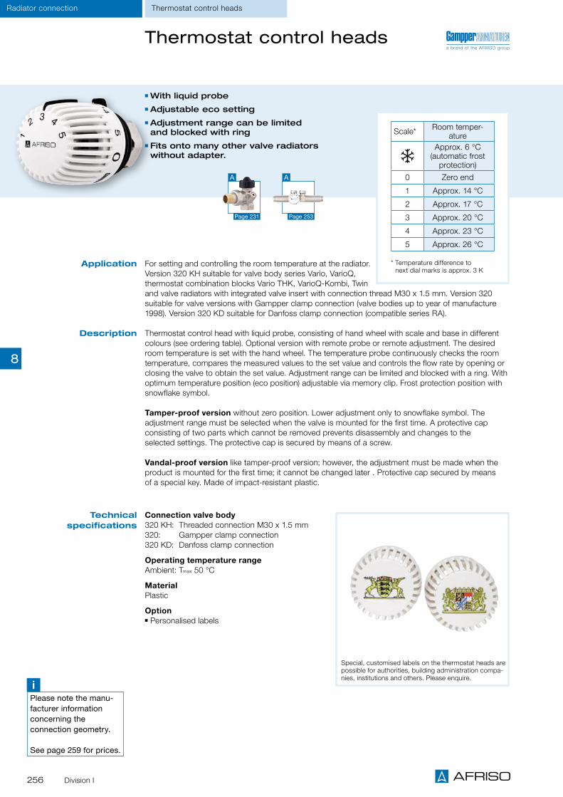
256 Division I
Thermostat control headsRadiator connection
Thermostat control heads
With liquid probe Adjustable eco setting Adjustment range can be limited and blocked with ring
Fits onto many other valve radiators without adapter.
For setting and controlling the room temperature at the radiator. Version 320 KH suitable for valve body series Vario, VarioQ, thermostat combination blocks Vario THK, VarioQ-Kombi, Twin and valve radiators with integrated valve insert with connection thread M30 x 1.5 mm. Version 320 suitable for valve versions with Gampper clamp connection (valve bodies up to year of manufacture 1998). Version 320 KD suitable for Danfoss clamp connection (compatible series RA).
Thermostat control head with liquid probe, consisting of hand wheel with scale and base in different colours (see ordering table). Optional version with remote probe or remote adjustment. The desired room temperature is set with the hand wheel. The temperature probe continuously checks the room temperature, compares the measured values to the set value and controls the flow rate by opening or closing the valve to obtain the set value. Adjustment range can be limited and blocked with a ring. With optimum temperature position (eco position) adjustable via memory clip. Frost protection position with snowflake symbol.
Tamper-proof version without zero position. Lower adjustment only to snowflake symbol. The adjustment range must be selected when the valve is mounted for the first time. A protective cap consisting of two parts which cannot be removed prevents disassembly and changes to the selected settings. The protective cap is secured by means of a screw.
Vandal-proof version like tamper-proof version; however, the adjustment must be made when the product is mounted for the first time; it cannot be changed later . Protective cap secured by means of a special key. Made of impact-resistant plastic.
Application
Description
Connection valve body320 KH: Threaded connection M30 x 1.5 mm 320: Gampper clamp connection 320 KD: Danfoss clamp connection
Operating temperature rangeAmbient: Tmax 50 °C
MaterialPlastic
Option Personalised labels
Technical specifications
iPlease note the manu-facturer information concerning the connection geometry.
See page 259 for prices.
Scale* Room temper-ature
Approx. 6 °C (automatic frost
protection)
0 Zero end
1 Approx. 14 °C
2 Approx. 17 °C
3 Approx. 20 °C
4 Approx. 23 °C
5 Approx. 26 °C
* Temperature difference to next dial marks is approx. 3 K
Special, customised labels on the thermostat heads are possible for authorities, building administration compa-nies, institutions and others. Please enquire.
Page 253
A
Page 231
A
a brand of the AFRISO group
8
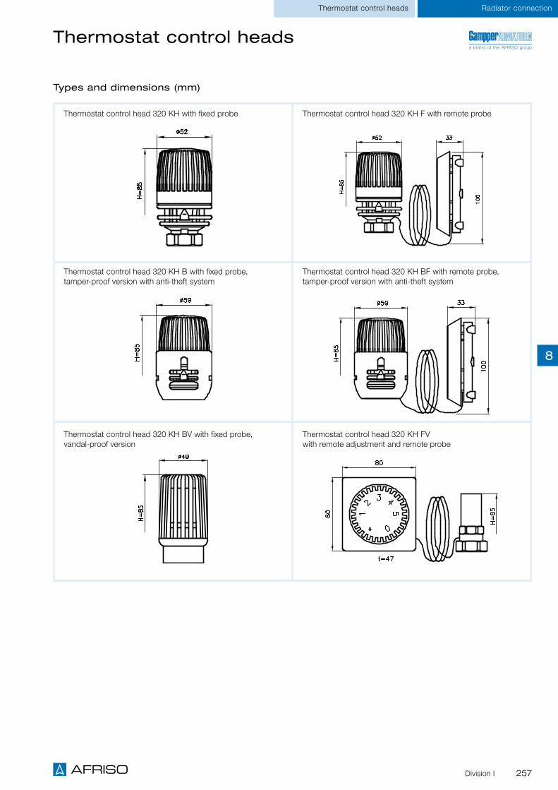
257Division I
Radiator connectionThermostat control heads
Types and dimensions (mm)
Thermostat control head 320 KH F with remote probeThermostat control head 320 KH with fixed probe
Thermostat control head 320 KH FV with remote adjustment and remote probe
Thermostat control head 320 KH B with fixed probe, tamper-proof version with anti-theft system
Thermostat control head 320 KH BV with fixed probe, vandal-proof version
Thermostat control head 320 KH BF with remote probe, tamper-proof version with anti-theft system
Thermostat control headsa brand of the AFRISO group
8

258 Division I
Radiator connection Thermostat control heads
Types and dimensions (mm)
Thermostat control heads
Thermostat control head 320 KH FA with surface mount probe and bracket
Thermostat control head 320 KD with fixed probe, Danfoss clamp connection
Angle adapter
320 KD FV with remote adjustment and remote probe, Danfoss clamp connection
a brand of the AFRISO group
8

259Division I
Thermostat control heads
DG: V, PG: 1 Description 0 settingHand wheel/base
Capillary tube Part no. Price €
Thermostat control head 320 KH With liquid probe, threaded connection M30 x 1.5 mm
With White/black - 1 50 340 002.100
Without White/black - 1 - 340 000.100
Thermostat control head 320 KH With liquid probe, threaded connection M30 x 1.5 mm
With White - 1 - 340 012.100
Without White - 1 - 340 010.100
Thermostat control head 320 KH* With liquid probe, threaded connection M30 x 1.5 mm and personalised label
With White/black - 1 200 340 002.109 On
request
Without White/black - 1 200 340 000.109 On
request
Thermostat control head 320 KH F With remote probe and bracket, thread-ed connection M30 x 1.5 mm
With White/black 1.2 m 1 - 342 102.100
With White/black 2 m 1 30 342 202.100
With White 1.2 m 1 - 342 112.100
With White 2 m 1 - 342 212.100
Without White/black 1.2 m 1 - 342 100.100
Without White/black 2 m 1 - 342 200.100
Without White 1.2 m 1 - 342 110.100
Without White 2 m 1 - 342 210.100
Thermostat control head 320 KH BTamper-proof version with anti-theft system, threaded connection M30 x 1.5 mm
Without White/black - 1 30 344 000.100
Thermostat control head 320 KH BFTamper-proof version with anti-theft system, remote probe and bracket, threaded connection M30 x 1.5 mm
Without White/black 1.2 m 1 - 346 100.100
Without White/black 2 m 1 - 346 200.100
Thermostat control head 320 KH BVVandal-proof version, model withextra security, adjustment by means of adjustment key ES-VA, threaded connection M30 x 1.5 mm
- White - 1 - 344 014.100
Thermostat control head 320 KH FA With surface mount probe, threaded connection M30 x 1.5, version with capillary tube or shifted control range on request
Adjustment range 20°C–50 °C
- White 2 m 1 - 342 219.100
Adjustment range 20 °C–70 °C - White 2 m 1 30 342 259.100
Thermostat control head 320 KH FVWith remote adjustment and remote transmission, threaded connection M30 x 1.5 mm
With White 2 m 1 12 347 200.100
Thermostat control heads with threaded connection
* Minimum order quantity 200 pieces.
a brand of the AFRISO group
Radiator connection
8

260 Division I
Accessories Thermostat control heads
Thermostat control heads with clamp connection: Gampper, Danfoss
DG: V, PG: 1 Description 0 settingHand wheel/base
Capillary tube Part no. Price €
Thermostat control head 320 with liquid probe, Gampper clamp connection.
For valves from 1980 - 1998 (and replacement for models 313 and 314)
With White/black - 1 50 340 002
Without White/black - 1 50 340 000
Thermostat control head 320 F N with remote probe and bracket, Gampper clamp connection.
For valves from 1980 - 1998 (and replacement for models 313 and 314)
With White/black 1.2 m 1 30 342 102
With White/black 2 m 1 30 342 202
Thermostat control head 320N S with liquid probe, Gampper clamp connection
Replacement for thermostat control heads series 312 up to 1980
With White/black - 1 20 340 005
Thermostat control head 320 F N S with remote probe and bracket, Gampper clamp connection.
Replacement for thermostat control heads series 312 up to 1980
With White/black 2 m 1 10 342 205
Thermostat control head 320 KD with liquid probe, Danfoss clamp connection, compatible series RA
With White/black - 1 15 340 002.131
Thermostat control head 320 KD FV with remote adjustment and remote transmission, Danfoss clamp connec-tion, compatible series RA
With White 2 m 1 - 347 200.130
DG: V, PG: 1 Description Part no. Price €
Adjustment key ES-SW Hex key, spanner size SW 2 1 - 276 000.801
Adjustment key ES-VA For control head 320 KH BV 1 - 344 014.804
Angle adapter M30 x 1.5 mm, white 1 - 340 010.200
Tamper-proof cap 320 BK for control heads 320 1 - 344 110
Bracket with accessories For control head 320 FA with surface mount probe 1 - 302 009.014
Accessories for thermostat control heads
a brand of the AFRISO group
8

261Division I
Thermostat control heads
a brand of the AFRISO group
Thermostat control head 316
The thermostat control head 316 can be converted with the adapter 316 KH (part no. 100 010.663) so that the thermostat control heads series 320 KH can be mounted to an adapter. Conversion is also possible by replacing the valve inserts. If this is done, the system must be emptied.
Thermostat control head 312
The thermostat control head 312 can be replaced with the thermostat control head 320 NS (part no. 340 005).
Observe the following when replacing thermostat control heads series 312:
Thermostat control heads 316, 312
Description
Description
Conversion of thermostat control heads from year of 1975 up to date
All standard series 320 thermostat control heads can be mounted to valve bodies with a dual gear.
In the case of valve bodies with a single gear, thermostat control heads version "S" must be mounted. The type designation for a thermo-stat control head with built-in probe is 320 (N)S and for a thermostat control head with remote probe 320 F (N) S, with indication of the capillary tube length.
①Valve insert with dual gear (double hex, AF 24) ①Valve insert with single gear (double hex, AF 24)
①
①
Radiator connection
8
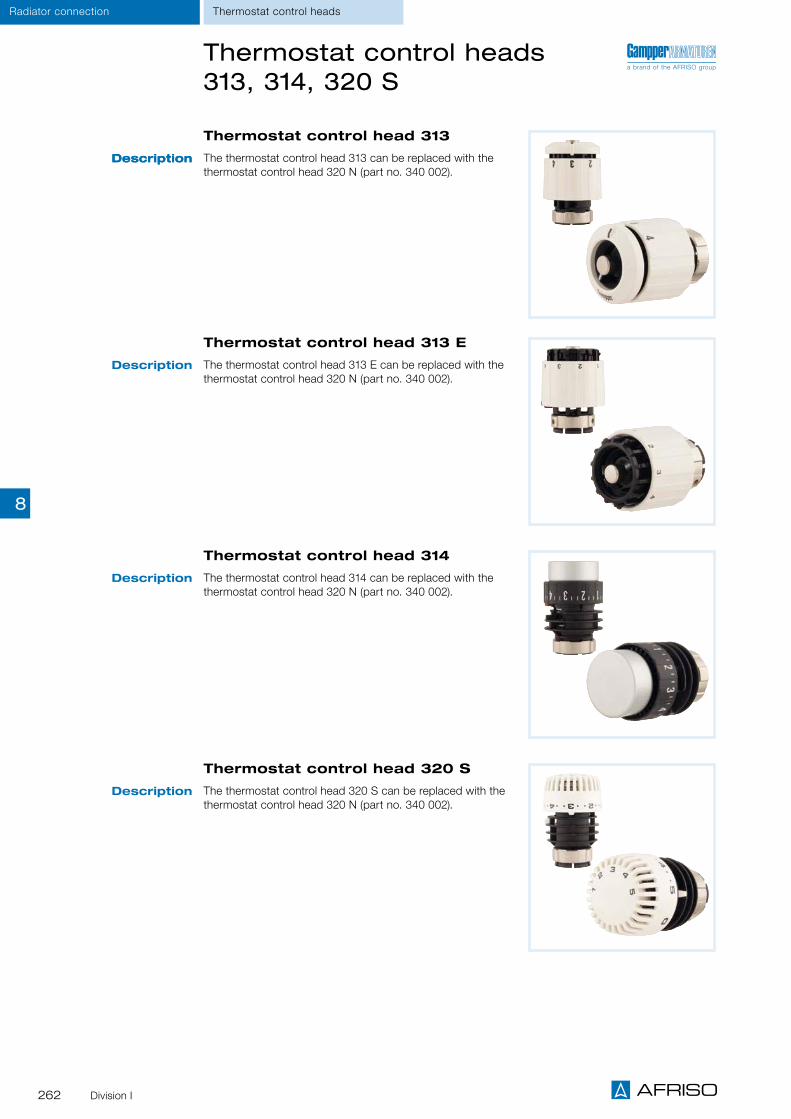
262 Division I
Radiator connection Thermostat control heads
Thermostat control head 314
The thermostat control head 314 can be replaced with the thermostat control head 320 N (part no. 340 002).
Thermostat control head 313
The thermostat control head 313 can be replaced with the thermostat control head 320 N (part no. 340 002).
Description
DescriptionDescription
Thermostat control head 313 E
The thermostat control head 313 E can be replaced with the thermostat control head 320 N (part no. 340 002).
Description
Thermostat control head 320 S
The thermostat control head 320 S can be replaced with the thermostat control head 320 N (part no. 340 002).
Description
a brand of the AFRISO groupThermostat control heads 313, 314, 320 S
8

263Division I
Thermostat control heads
Thermostat control head 320
The thermostat control head 320 is available with Gampper clamp connection, type 320 N (part no. 340 002) or with threaded connection M 30 x 1.5 mm, type 320 KH. All series 320 KH thermostat control heads can be fit to thermostat valves with M 30 x 1.5 mm threaded connection.
Description
Types and dimensions (mm)
Adapter 910 049
Adapter 910 041
Adapter 910 042
Adapter 100 010.663
a brand of the AFRISO groupThermostat control heads 320, adapter M30 x 1.5 mm
Conversion of Gampper clamp connection to threaded connection M 30 x 1.5 mm
For thermostat valve bodies from year of manufacture 1978
Radiator connection
marked: 1
marked: 9 marked: 2
8

264 Division I
AFRISO-Gampper line fittings at a glance
Overview Line fittings
* Please enquire separately.
The AFRISO-Gampper product portfolio in the area of line fit-tings comprises static line control valves, dynamic volume flow controllers and pressure-independent control valves which are usually used for hydraulic balancing in larger heating and refrig-eration systems. This covers hydraulic circuits in sub-distribution systems, riser lines, storey distribution systems and zones.
The fittings are also used directly at the heating or refrigeration units to control the temperature of chilled ceilings, ventilation, induction and facade ventilation systems, trench convectors or similar heat exchanger systems. Innovative solutions which are unique in terms of simplicity and functionality keep being implemented in particular in conjunction with the thermostat valve bodies VarioQ.
Q Vanitus Eco Vanitus Eco XL Vanitus L Vanitus XL FC K XL Flow XXL Flow VarioE SH EVS EVC VarioE VarioC SM
Screw connection/ flange with meas-
uring functionStatic line valves Dynamic volume flow controllers Dynamic control valves
Pressure-independent control valves
Connection Thread Flange Thread Flange Flange Thread Thread/flange Thread Thread Thread Thread/flange
DN 15 • • • • • • Thread • • • Thread
DN 20 • • • • • • Thread • • • Thread
DN 25 • • • • • Thread • • • Thread
DN 32 • • • • Thread • • Thread
DN 40 • • • • • Thread • • Thread
DN 50 • • • • • • Flange • Flange
DN 65 • • • • Flange Flange
DN 80 • • • • Flange Flange
DN 100 • • • Flange Flange
DN 125 • • • Flange Flange
DN 150 • • • Flange Flange
DN 200 • • •
DN 250 • • •
DN 300 • • •
DN 350 •
DN 400 •
DN 450 •
DN 500 •
DN 600 •
DN 800 •
DN 900 •
Page 266 Page 268AFRISO planner folder *
AFRISO planner folder *
AFRISO planner folder *
AFRISO planner folder *
AFRISO planner folder *
AFRISO planner folder *
AFRISO planner folder *
AFRISO planner folder *
AFRISO planner folder *
AFRISO planner folder *
AFRISO planner folder *
AFRISO planner folder *
8

265Division I
Line fittings
Q Vanitus Eco Vanitus Eco XL Vanitus L Vanitus XL FC K XL Flow XXL Flow VarioE SH EVS EVC VarioE VarioC SM
Screw connection/ flange with meas-
uring functionStatic line valves Dynamic volume flow controllers Dynamic control valves
Pressure-independent control valves
Connection Thread Flange Thread Flange Flange Thread Thread/flange Thread Thread Thread Thread/flange
DN 15 • • • • • • Thread • • • Thread
DN 20 • • • • • • Thread • • • Thread
DN 25 • • • • • Thread • • • Thread
DN 32 • • • • Thread • • Thread
DN 40 • • • • • Thread • • Thread
DN 50 • • • • • • Flange • Flange
DN 65 • • • • Flange Flange
DN 80 • • • • Flange Flange
DN 100 • • • Flange Flange
DN 125 • • • Flange Flange
DN 150 • • • Flange Flange
DN 200 • • •
DN 250 • • •
DN 300 • • •
DN 350 •
DN 400 •
DN 450 •
DN 500 •
DN 600 •
DN 800 •
DN 900 •
Page 266 Page 268AFRISO planner folder *
AFRISO planner folder *
AFRISO planner folder *
AFRISO planner folder *
AFRISO planner folder *
AFRISO planner folder *
AFRISO planner folder *
AFRISO planner folder *
AFRISO planner folder *
AFRISO planner folder *
AFRISO planner folder *
AFRISO planner folder *
a brand of the AFRISO group
Overview
8

266 Division I
Screw fittings with measuring function Q
Line fittings Measuring/control fittings
Measuring insert with fixed, calibrated measuring unit
Ideal for small existing underfloor heating manifolds/heating circuit manifolds
For measuring the volume flow, e.g. with the measuring instruments HMG 01/10/100 for hydraulic bal-ancing. Versions QM and QL are ideal for measuring underfloor heating manifolds and heating circuit manifolds.
Screw fitting with measuring function, straight design, with fixed calibrated measuring unit for measur-ing the volume flow.
The optimum volume flow is to be determined by means of a calculation program and can then be directly measured and adjusted with the HMG series measuring instruments. Adjustments are made via standard adjustment valves.
Application
Description
System connectionSee ordering table
Nominal pressureM, L, XXL: Max. 10 bar XL: Max. 25 bar
Nominal diameterDN 15, DN 20, DN 25, DN 32, DN 40, DN 50, DN 65, DN 80, DN 100, DN 125, DN 150, DN 200, DN 250, DN 300
Operating temperature rangeMedium: Tmax = 120 °C
HousingM – XL: Brass/gunmetal XXL: Stainless steel
Technical specifications
Versions XL and XXL for very large water volumes
Page 230
A
a brand of the AFRISO group
8

267Division I
Screw fittings with measuring function Q
DG: V, PG: 2 Version Nominal diameter
Flow rate range (m3/h)
Flow coeffi-cient*
Part no. Price €
M for medium water volumes, PN 16, connection G¾ eurocone
DN 15 0.02 – 0.40 1.04 1 - 408 021
L for large water volumes,PN 16, connection G¾ eurocone
DN 15 0.06 – 1.20 2.85 1 - 408 022
XL for very large water volumes, PN 25
DN 15 0.22 – 0.53 2.8 1 - 778 020
DN 20 0.49 – 1.17 5.3 1 - 778 030
DN 25 0.93 – 2.17 9.7 1 - 778 040
DN 32 1.94 – 4.5 20.2 1 - 778 050
DN 40 2.91 – 6.77 30.2 1 - 778 060
DN 50 5.47 -12.64 55.1 1 - 778 070
XXL for very large water volumes, as measuring flange, PN 16
DN 65 10.87 – 25.0 88.2 1 - 779 080
DN 80 23.0 – 55.3 123.0 1 - 779 090
DN 100 39.0 – 93.7 215.6 1 - 779 120
DN 125 60.7 – 143.1 336.9 1 - 779 130
DN 150 85.36 – 204.8 458.6 1 - 779 140
DN 200 130.7 – 361.7 803.9 1 - 779 150
DN 250 239.7 -564.4 1,249.0 1 - 779 160
DN 300 338.9 – 921.5 1,836.0 1 - 779 170
* The flow coefficient corresponds to the water flow in m3/h through the valve at a given valve stroke (proportional offset, e.g. 1 K or 2 K) and a differential pressure of 1 bar.
Measuring/control fittings
a brand of the AFRISO group
Line fittings
8

268 Division I
Measuring and line fittings Vanitus Eco
Line fittings Measuring/control fittings
Fixed, calibrated measuring unit for accurate adjustment of the volume flow
Fully adjustable With shut-off and drain function
For adjusting the volume flow directly, e.g. with the measuring instruments HMG 01/10/100 for hydraulic balancing.
Screw fitting with measuring function, angled or straight design, with fixed calibrated measuring unit for measuring and adjusting the volume flow. Fully adjustable with adjustment key. Vanitus Eco can be retrofitted as a temperature control valve (e.g. for thermoactive ceilings).
The optimum volume flow is to be determined by means of a calculation program and can then be directly measured and adjusted with the HMG series measuring instruments.
Application
Description
System connectionSee ordering table
Nominal pressureMax. 16 bar
Nominal diameterDN 15, DN 20, DN 25
Operating temperature rangeMedium: Tmax = 120 °C
HousingBrass/gunmetal
Technical specifications
Version XL for very large water volumes
A
Page 230 Page 239
A
a brand of the AFRISO group
8

269Division I
DG: V, PG: 2 Version Nominal width Connection Flow rate range
(m3/h)
Flow coeffi-cient* (m3/h)
Part no. Price €
Vanitus Eco S for small water volumes
Angled DN 15 Rp½ x R½ 0.006 -0.13 0.25 1 - 481 921
Straight DN 15 Rp½ x R½ 0.006 -0.13 0.25 1 - 481 971
Version BG with male thread at both ends
1 - xxx 8xx
Vanitus Eco M for medium water volumes
Angled DN 15 Rp½ x R½ 0.02 – 0.40 0.71 1 - 481 922
Straight DN 15 Rp½ x R½ 0.02 – 0.40 0.71 1 - 481 972
Version BG with male thread at both ends
1 - xxx 8xx
Vanitus Eco L for large water volumes
Angled DN 15 Rp½ x R½ 0.02 – 0.40 1.0 1 - 481 923
Straight DN 15 Rp½ x R½ 0.02 – 0.40 1.0 1 - 481 973
Version BG with male thread at both ends
1 - xxx 8xx
Vanitus Eco Lmax for large water volumes
Straight DN 20 Rp¾ x R¾ 0.06 – 1.20 2.0 1 - 481 984
Version BG with male thread at both ends
1 - xxx 8xx
Vanitus Eco XL for very large water volumes
Straight
DN 15 Rp½ x R½ 0.71 – 2.34 2.34 1 - 782 420
DN 20 Rp¾ x R¾ 2.15 – 3.96 3.54 1 - 782 530
DN 25 Rp1 x R1 2.60 – 5.32 6.00 1 - 782 640
Version BG with male thread at both ends
1 - xxx xx6
* The flow coefficient corresponds to the water flow in m3/h through the valve at a given valve stroke (proportional offset, e.g. 1 K or 2 K) and a differential pressure of 1 bar.
** Extra charge added to standard version in €. Replace the specified digit in the standard part number with this number when ordering.
Measuring/control fittings
Measuring and line fittings Vanitus Eco
a brand of the AFRISO group
Line fittings
8

270 Division I
System connectionSee ordering table
Nominal pressureMax. 25 bar
Nominal diameterDN 15, DN 20, DN 25, DN 32, DN 40, DN 50
Operating temperature rangeMedium: Tmin= -20 °C / Tmax = 120 °C
HousingBrass
Line fittings Control valves
Volume flow controller VarioE
Technical specifications
Keeps the volume flow at a constant level, regardless of differential pressure. No multiple adjustments required
Minimum inlet pressure only 17 kPa Easy adjustment of the volume flow by means of a table Very easy adjustment even in the case of major pressure variations in the system
No pulse line, no partner valve required
The control insert Vario is an automatic volume flow controller which limits the volume flow/keeps it at a constant level regardless of pressure variations. It is adjusted from the outside by means of a special adjustment key.
Application areas As line fitting in the distribution lines For hydraulic optimisation of single line heating systems As control valve upstream of underfloor heating manifolds For adjusting the water volume upstream of chilled ceilings and ceiling radiators
Application
Pre-adjustment
DN Connection Flow rate range m³/h*
Flow coef-ficient NS Part no. Price in €
15 Rp½ x Rp½ 0.10 – 0.412 2.6 736 111.901
20 Rp¾ x Rp¾ 0.157 – 0.609 2.6 736 121.902
25 Rp1 x Rp1 0.276 – 0.825 2.6 736 031.903
25 Rp1 x Rp1 0.535 – 5.83 12.5 736 131.906
32 Rp1¼ x Rp1¼ 0.535 – 5.83 12.5 736 141.906
40 Rp1½ x Rp1½ 3.18 – 16.10 23.0 736 151.907
50 Rp2 x Rp 2 3.18 – 16.10 23.0 736 161.907
① Adjustable pre-adjustment
② Automatic adjustment is controlled depending on the differential pressure
The differential pressure above the pre-adjust-ment (1) is kept at a constant level and automati-cally controls the pre-adjustment (2) which keeps the flow rate at a constant level.
Accessories
Version Nominal diameter Part no. Price in €
Adjustment key --- 739 902
Flushing cap DN 15 – 25 793 910
Flushing cap DN 25 – 40 739 911
Flushing cap DN 40 – 50 739 912
iSee the AFRISO-Gampper planner folder for additional connection possibilities and dimensions.
8

271www.afriso.com

Domestic water system centre
Water filters
Signal anodes and sacrificial anodes
Rainwater harvesting

273
Equipment for drinking water supply and rainwater harvesting
CHAPTER 9
Water filters with pressure reducer, backwashable WAF 04 281
FILTERS
Filters, check valves 275
Strainers, safety valves MSW 276
Boiler safety group assemblies BFK 12/10 and DN 15 277
Signal anode U 278
Thermal mixing valves ATM 280
Sacrificial anodes: Anode I, sacrificial anode and chain anode, anode tester AT1 279
SAFETY EQUIPMENT
Equipment for drinking water supply, water treatment and rainwater harvesting 274
OVERVIEW
Domestic water system centre HWSC 282
DISTRIBUTION STATIONS
Overview rainwater harvesting 286
Rainwater system centre RWSC II 288
Oil tank conversion kit I for rainwater harvesting in homes and gardens 289
RAINWATER HARVESTING
Oil tank conversion kits II + III for rainwater harvesting in gardens 290
Rainwater inner lining AR-SM with magnets 291
Backup controller RENA 292
9
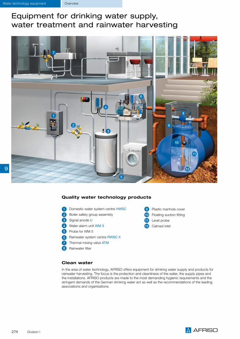
274 Division I
OverviewWater technology equipment
Equipment for drinking water supply, water treatment and rainwater harvesting
Clean water
In the area of water technology, AFRISO offers equipment for drinking water supply and products for rainwater harvesting. The focus is the protection and cleanliness of the water, the supply pipes and the installations. AFRISO products are made to the most demanding hygienic requirements and the stringent demands of the German drinking water act as well as the recommendations of the leading associations and organisations.
Quality water technology products
1 Domestic water system centre HWSC
2 Boiler safety group assembly
3 Signal anode U
4 Water alarm unit WM 5
5 Probe for WM 5
6 Rainwater system centre RWSC II
7 Thermal mixing valve ATM
8 Rainwater filter
9 Plastic manhole cover
10 Floating suction fitting
11 Level probe
12 Calmed inlet
1
6
7
2
3
4
5
8
9
11
10
129

275Division I
Filters Check valve
Filters check valves
DG: G PG Part no. Price €
Filter G 3/8 2 1 - 42580
Filter G½ 2 1 - 42581
Filter G¾ 2 1 - 42582
Filter G1 2 1 - 42583
Filter G1¼ 2 1 - 42584
Filter G1½ 2 1 - 42585
Filter G2 2 1 - 42586
Check valve G3/8 – DN 10 2 1 - 42540
Check valve G½ – DN 15 2 1 - 42541
Check valve G¾ – DN 20 2 1 - 42542
Check valve G1 – DN 25 2 1 - 42543
Check valve G1¼ – DN 32 2 1 - 42544
Check valve G1½ – DN 40 2 1 - 42545
Check valve G2 – DN 50 2 1 - 42546
Description
Technical specifications
Safety equipment Water technology equipment
Filter made of hot-pressed brass with replaceable stainless steel sieve for direct installation in domestic drinking water installations.
Check valve made of brass for direct installation in domestic drinking water installations. Also suitable as a gravity brake. Nylon valve, seal seat NBR, spring stainless steel.
Operating pressureUp to size G1: 16 bar From size G1¼: 10 bar
ConnectionsSee ordering table
Operating temperature rangeMedium: Max. 110 °C
Operating pressureUp to size G1: 12 barSize G1¼ and greater: 10 bar
ConnectionsSee ordering table 9

276 Division I
Water technology equipment Safety equipment
Strainers, diaphragm safety valves MSW
DG: G Maximum heating capacity PG Part no. Price €
Strainer G3/8 – DN 10 - 1 1 - 20811
Strainer G½ – DN 15 - 1 1 - 20812
Strainer G¾ – DN 20 - 1 1 - 20813
Strainer G1 – DN 25 - 1 1 - 20814
Strainer G1¼ – DN 32 - 1 1 - 20815
Strainer G1½ – DN 40 - 1 1 - 20816
Strainer G2 – DN 50 - 1 1 - 20817
MSW Rp½ x Rp¾, 6 bar 75 kW 2 1 84 42421
MSW Rp½ x Rp¾, 8 bar 75 kW 2 1 84 42422
MSW Rp½ x Rp¾, 10 bar 75 kW 2 1 84 42423
MSW Rp¾ x Rp1, 6 bar 150 kW 2 1 84 42425
MSW Rp¾ x Rp1, 8 bar 150 kW 2 1 84 42426
MSW Rp¾ x Rp1, 10 bar 150 kW 2 1 84 42427
MSW Rp1 x Rp1¼, 6 bar 250 kW 2 1 10 42442
MSW Rp1 x Rp1¼, 8 bar 250 kW 2 1 10 42443
MSW Rp1 x Rp1¼, 10 bar 250 kW 2 1 10 42444
MSW Rp1¼ x Rp1½, 6 bar 350 kW 2 1 10 42446
MSW Rp1¼ x Rp1½, 8 bar 350 kW 2 1 5 42447
MSW Rp1¼ x Rp1½, 10 bar 350 kW 2 1 5 42448
MSW Rp1½ x Rp2, 6 bar 600 kW 2 1 5 42476
MSW Rp1½ x Rp2, 8 bar 600 kW 2 1 5 42477
MSW Rp1½ x Rp2, 10 bar 600 kW 2 1 5 42478
Diaphragm safety valve MSW
For sealed drinking water heaters as per EN 806, DIN 1988 and DIN 4753-1 and for protection against overpressure.
The response pressure is factory-set. The size of the valve inlet determines the unit type, the outlet is larger by one dimension.
Application
Opening/response pressureSee ordering table
ConnectionSee ordering table
MaterialHousing: Brass (W67 N), flap: PA 6, blue
Operating temperature rangeMedium: 4/110 °C
Technical specifications
Strainer
Directly screwed into check valves, for domestic water installations (drinking water).
Strainer, consisting of stainless steel sieve, con-nection piece made of nylon.
Operating temperature rangeMedium: Max. 110 °C
Mesh size1.7 mm2
16 holes per cm2
ConnectionsSee ordering table
Description
9

277Division I
Safety equipment Water technology equipment
DG: G, PG: 2 Safety valve Part no. Price €
Boiler safety group assembly BFK 12/6 6 bar 1 - 77986
Boiler safety group assembly BFK 12/10 10 bar 1 - 77988
Boiler safety group assembly DN 15 10 bar 1 - 77976
Boiler safety equipment groups
Boiler safety group assembly BFK 12
Boiler safety group assembly DN 15
Application
Description
For sealed hot drinking water systems or drinking water heaters as per EN 806, DIN 1988 and DIN 4753-1 and for protection against overpressure.
Combination fitting with safety valve 6 bar or 10 bar, shut-off fitting, check valve and test screw. Noise characteristics as per DIN 4109 class 1.
For sealed hot drinking water systems or drinking water heaters as per EN 806, DIN 1988 and DIN 4753-1 and for protection against overpressure.
Combination fitting with rotatable safety valve 10 bar, Bourdon tube pressure gauge 0/16 bar, shut-off fitting, check valve and test screw. Noise characteristics as per DIN 4109 class 1.
ConnectionsCompression fitting at both ends Ø 15 mm
Safety valve10 bar or 6 bar
Operating pressure10 bar
DimensionsW x H x D: 90 x 98 x 62 mm
HousingBrass
Options
ConnectionsSoldered screw connection Ø 18 mm at both ends
Safety valve10 bar, rotatableOutlet thread G¾ Maximum heating capacity : 150 kW
Operating pressure10 bar
DimensionsW x H: 95 x 95 mm
HousingBrass
Bourdon tube pressure gauges0/16 bar, Ø 50 mm, connection G¼
Safety valve 6 or 8 bar Pressure gauges with other pressure ranges Other connection types
Safety valve 8 bar Other connection types
Technical specifica-tions
9

278 Division I
Safety equipmentWater technology equipment
Signal anode U
Application
Description
Technical specifications
DG: G, PG: 3 Connection Part no. Price €
Signal anode U 22–¾ G¾ 1 - 69800
Signal anode U 26–1 G1 1 - 69805
Signal anode U 33–1¼ G1¼ 1 - 69810
Signal unit outside of the boiler indicates when it is time to replace the anode
For enamelled boilers or tanks with passive protection layers
Ideal for replacing conventional sacrificial anodes in hot water tanks (100 to 500 l)
Choice of connection G¾, G1, G1¼
Protection against frequently unnoticed corrosion damage in water heaters. Primarily for use in enam-elled boilers or hot water tanks with other types of passive protective coatings. Signal anodes replace consumed conventional sacrificial anodes primarily in hot water tanks with a capacity of 100 to 500 litres. Defective areas in enamel or other passive protective coatings are subject to corrosion; this causes a flow of current which is transformed into a protective current by the anode material. The anode material thus falls victim to electro-chemical corrosion. Since the protective function of the anode rod is not unlimited, consumed anodes have to be replaced.
Universal, complete signal anode as per EN 12828, made of magnesium alloy. Version with screw fit-ting, signal unit and instruction label. The parts submerged in water are heat-resistant up to operating temperatures of 100 °C and comply with the German Food Act. When the anode material is used up, water penetrates the test space and causes a red discolouration of the signal unit to indicate that the anode is used up. In the case of conventional anodes, the boiler has to be opened for anode inspec-tion.
System pressureMax. 15 bar
Operating temperature rangeMedium: 0/100 ºC
ConnectionsFemale connection G¾, G1 or G1¼
Dimensions (L x Ø)G¾: 500 x 22 mm G1: 500 x 26 mm G1¼: 500 x 33 mm
Signal unit
Screw connection
Seal
Anode mount
Test space
Protective cap for test spaceMagnesium anode, unused
Steel core
9

279Division I
Water technology equipmentSafety equipment
Sacrificial anodes
Anode I Sacrificial anode
Application
Description
DG: G PG Part no. Price €
Anode I 22–500-M8 3 1 45 69806
Anode I 26–500-M8 3 1 35 69811
Anode I 33–500-M8 3 1 20 69808
Sacrificial anode 22–500-¾ 3 1 40 69815
Sacrificial anode 22–700-¾ 3 1 30 69817
Sacrificial anode 26–500-1 3 1 30 69819
Sacrificial anode 26–700-1 3 1 20 69821
Sacrificial anode 33–550-1¼ 3 1 15 69825
Chain anode 22–800-¾ (5 elements) 3 1 35 69829
Chain anode I 22–900-M8 (5 elements) 3 1 35 69804
Accessories (DG: H)
Anode tester AT1 for anode I 4 1 - 69842
Chain anode
Protection against frequently unnoticed corrosion damage in water heaters. Primarily for use in enam-elled boilers or hot water tanks with other types of passive protective coatings. Defective areas in enamel or other passive protective coatings are subject to corrosion; this causes a flow of current which is transformed into a protective current by the anode material. The anode material thus falls victim to electro-chemical corrosion. Since the protective function of the anode rod is not unlimited, consumed anodes have to be replaced.
Sacrificial anode Ø 22, 26, 33 mm as per EN 12828, made of magnesium alloy, for isolated installation. With M8 male, threaded connection, isolating piece and earth cable. Consumption check with AT1 anode tester.
Sacrificial anode Ø 22, 26 or 33 mm as per EN 12828, made of magnesium alloy, suitable for all standard tanks. With screw fit-ting G¾, G1 or G1¼, without signal. See the ordering table for various versions with different lengths, threads and diameters.
Flexible sacrificial anode Ø 22 mm as per EN 12828, made of magnesium alloy. A flexible anode is used if there is insuffi-cient space to install a rigid anode. Consisting of five individ-ual elements along a stainless steel rope and a G¾ or M8 screw fitting (see also Anode I) Length approx 800 – 900 mm.
Tester for consumption check of anode I or isolated standard sacrificial anodes.
Handheld tester with 4-level LED indication Fast and easy indication of the condition of the anode
Reliability of the water heater due to preventive maintenance – consumed anodes are replaced in good time
Anode tester AT1
NEW
Anode individually
packed in
poly bag for increased
hygiene.
9

280 Division I
Operating temperature rangeMedium: Max. 95 °C
Nominal pressureMax. 10 bar
Flow rateFlow coefficient 1.6 m3/h or 2.5 m3/h
Accuracy± 2 °C
MaterialHousing: DZR brass, dezincification-resistant Upper part: Plastic (ABS) Control knob: Plastic (ABS)Seal: EPDM
ConnectionMale or female threads (see table)
Water technology equipment Safety equipment
Thermal mixing valves ATM
High accuracy, fast response With integrated scald protection Maintenance-free Ideal for showers and smaller underfloor heating circuits
Universal units for controlling hot water in sanitary applications or for smaller underfloor heating circuits which are directly connected to the flow (max. 60 °C). Also for panel heating systems such as wall or underfloor heating systems which require a constant mixed water temperature to avoid damage to floors and pipes. Suitable for drinking water or water with up to 50 % glycol.
Thermal mixing valve as per EN 1111 with base made of brass and upper part and control knob made of high-strength plastic. With scale (1 – 6) for easy adjustment of the temperature of the water to be mixed. A cover protects the control knob against improper operation. If the cold water supply is inter-rupted, the mixing valve automatically closes the hot water supply to protect against scalding. ATM maintenance-free.
Application
Description
DG: G, PG: 2 DNFlow
coefficient value
Connection Temperature Part no. Price €
ATM 341 15 1.6 m3/h G¾ male thread 20 / 43 °C 78247
ATM 343 15 1.6 m3/h G¾ male thread 35 / 60 °C 78246
ATM 331 20 1.6 m3/h Rp¾ female thread 20 / 43 °C 78249
ATM 333 20 1.6 m3/h Rp¾ female thread 35 / 60 °C 78248
ATM 361 20 1.6 m3/h G1 male thread 20 / 43 °C 78245
ATM 363 20 1.6 m3/h G1 male thread 35 / 60 °C 78244
ATM 561 20 2.5 m3/h G1 male thread 20 / 43 °C 78283
ATM 563 20 2.5 m3/h G1 male thread 35 / 60 °C 78284
Technical specifications
70 mm
∅ 41,6
∅ 33,1
∅ 3
3,1
95,1
mm
ScaleTemperature of mixed water
ATM 331, 341, 361, 561
ATM 333, 343, 363, 563
1 Approx. 20 °C Approx. 35 °C
2 Approx. 25 °C Approx. 44 °C
3 Approx. 30 °C Approx. 48 °C
4 Approx. 34 °C Approx. 51 °C
5 Approx. 38 °C Approx. 57 °C
6 Approx. 43 °C Approx. 60 °C
9

281Division I
Water filter WAF 04 with pressure reducer, backwashable
With integrated pressure reducer Inlet pressure compensation for constant outlet pressure
Rotatable cover to indicate the next backwashing date
Transparent filter cup shows degree of pollution of the filter
Innovative backwashing system – fast and thor-ough cleaning of the filter, low water consumption
For the protection of drinking water installations against corrosion as per DIN 1988. The pressure reducer reduces the inlet pressure to an even, system-specific pressure in order to protect the installa-tion and to ensure economical water consumption. Water filters help to keep pollutants such as rust particles and sand grains from reaching the domestic water installation and thus protect valves, machines, flow heaters, etc. from malfunctions caused by pollution. Ideal for modernisation of domestic water installations where an existing filter needs to be replaced.
DVGW-tested water filter, compact plastic version with backwashable fine filter, integrated pressure reducer and pressure gauge for the outlet pressure. The fine filter consists of an upper part and a combined lower part. In the operating state "Filtration", the small upper filter is closed so that the water can only flow through the main filter from the outside to the inside. When the ball valve for "Backwashing" is opened, the filter is pressed down until the water supply to the outside of the main filter is interrupted. At the same time, the water flow through the upper filter is opened. The water required for cleaning the filter flows through the upper sieve, the rotating impeller and the main filter from the inside to the outside. This ensures effective cleaning of the filter across the entire surface of the sieve at full inlet pressure. When the ball valve is closed again, the filter automatically resumes nor-mal operation. The pressure reducer operates on the basis of a force comparison system, i.e. the force of a spring counteracts the force of a diaphragm. The input pressure neither acts in the opening nor in the closing direction. Therefore, pressure changes at the inlet pressure side do not affect the outlet pressure.
Application
Description
Technical specifications
MediumDrinking water
Inlet pressureMax. 16 bar
Outlet pressure1.5 – 6 bar
Operating temperature rangeMedium: Max. 30 ºC
Mounting positionVertical or horizontal with filter cup down
ConnectionG¾, G1, G1¼ as required
MaterialHousing: High-grade plastic Fine filter: Stainless steel Filter cup: Shock-resistant, transparent plastic
DVGW approvalNW-9311AT2316
DG: G PG Part no. Price €
WAF 04 R – G¾ 1 42714
WAF 04 R – G1 1 42715
WAF 04 R – G1¼ 1 42716
Accessories
Automatic back-washing unit RA 01 for WAF 03/04
4 42739
Automatic backwashing unit RA 01 (accessory) for setting the time intervals
Water technology equipmentFilters
9

282 Division I
Water technology equipment Distribution stations
Domestic water system centre HWSC
Pressure-reduced supply outlet with backflow
preventer, safety valve and drain hose
Sophisticated wall bracket with 3-point fix-ing via hanger bolts for fast and easy mounting, even if the wall is not level.
Fast and easy conversion of connection from left to right. Only a few parts need to be dismounted. Interfaces are already defined in the insula-tion
Mark at standard height of water meter (0.90 – 1.10 m) as a mounting aid
Guides in the insulation for professional installation of the drain and outlet hoses
1 Storage compartment for spare seals/silicone grease
2 Filtered high pressure outlet (as per DIN 1988), e.g. for garden line
3 Pressure-reduced supply outlets with drain hoses (1 outlet with backflow preventer)
4 Safety valve (6 bar) outlet hose
5 Backflow preventer, DVGW approval
6 Connection G¼ for sampling valve
7 Filter combination with fine filter and pressure reducer, DVGW approval
8 Drain unit consisting of funnel (DN 75) and reducing adaptor (DN 75/DN 50)
1
2
5
8
7
6
4
3
Heat-insulated assembly with transparent door for easy monitoring and backwashing (mark via memory pointer)
9

283Division I
Water technology equipmentDistribution stations
For drinking water installations as per EN 806, DIN 1988 and DIN 4753-1. The system centre combines all functions of conventional water distribution installations in a small-footprint unit: the pressure reduc-er reduces the inlet pressure to an even, system-specific pressure in order to protect the installation and to ensure economical water consumption. The water filter keeps pollutants such as rust particles or sand grains from reaching the domestic water installation, thus protecting valves, machines, boilers, etc. from malfunctions caused by dirt. With its straightforward design and unobtrusive colour, the domestic water system centre fits in perfectly with modern equipment rooms, basements and utility rooms.
Compact, tightness-tested domestic water system centre as a complete solution for the distribution of drinking water in buildings. The base version of HWSC consists of a backflow preventer, filter combina-tion with fine filter and pressure reducer, drain unit with connection possibility to the wastewater sys-tem, three supply outlets, safety valve and all function components. The individual components are DVGW-certified or comply with the DVGW regulations. The assembly is contained in a form-fit insula-tion for easy access and operation. The integrated transparent front door allows for checking the sys-tem pressure and the safety valves and provides easy access to start backwashing; it is not necessary to remove the upper part of the insulation. The memory pointer on the door lets you set the date for the next backwashing procedure.
HWSC excels with a dramatic reduction of the installation time: a drilling template is shipped with the unit for precise positioning of the three holes. Hanger bolts allow for precise adjustment of the domes-tic water system centre to the wall and enable easy horizontal and vertical alignment. HWSC features a variable height adjustment from 65 to 115 mm to allow for precise adaptation to the individual distance of the water meter from the wall. The default connection setting is intended for left-side connection, but HWSC can be converted to right-side connection in a matter of minutes.
The integrated filter combination features an innova-tive backwashing system with rotating impeller which ensures fast and thorough cleaning of the fine filter and low water consumption. The entire sieve surface of the filter insert is cleaned at high pressure. The pressure reducer reduces the inlet pressure to an even, system-specific pressure; part of the water flows directly and without pressure reduction to the high-pressure outlet for the garden line. If this is not required, it can be converted into an additional pressure-reduced supply outlet. The insulation can accommodate up to four supply out-lets; any additional outlets must be mounted outside the insulation. Due to the modular design and the defined connections, it is easy to fit extensions with an automatic backwashing unit, a refill combination for filling heating systems or a water softening system.
Domestic water system centre HWSC
Application
Description
Door for fast checking the system pressure, the safety valve of for starting backwashing.
Extremely compact system centre 395 x 760 mm (W x H) Lightning-fast, easy installation Innovative backwashing system – fast and thorough cleaning of the filter element, low water consumption
Modular design: Can be extended by additional outlets, automatic backwashing unit, refill combinations, etc.
Automatic backwashing unit RA 01 (accessory) for setting the time intervals
9

284 Division I
Water technology equipment Distribution stations
MediumDrinking water
Inlet pressureMax. 16 bar
Operating temperature rangeMedium: 5/30 °C
Mounting positionVerticalSupply outlets to the top
Dimensions (dimensions)W x H x D 395 x 665 x 210 mm
WeightApprox. 12 kg
ConnectionInlet: R1 Supply system: G¾ female thread
MaterialFittings: Brass CW 617N Insulation: Polypropylene EPP Filter housing: Brass (dezincification-resistant) Fine filter: Non-corroding steel Seals: EPDM
DVGW approvalAll components are DVGW-conform. Components with DVGW approval: filter combination, backflow preventer, seals
SVGW approvalComponents with SVGW approval: Filter combination Certificate no. 1310-6204
Domestic water system centre HWSC
Technical specifications
DG: M PG Part no. Price €
Domestic water system centre HWSC 2 42755
Connection kit for refilling of heating system 2 42757
Connection kit for water softening 2 42756
Extension supply outlet G¾ female thread 2 42758
Automatic backwashing unit RA 01 4 42739
Refill combination for heating systems 2 On request
Sampling valve 2 On request
9

285Division I
Water technology equipmentDistribution stations
Domestic water system centre HWSC
Dimensions (mm)
DN 50
395
9

286 Division I
Rainwater harvesting – an ecological necessity
Water technology equipment Rainwater harvesting
75 % of the surface of our planet is covered with water, but only 0.03 % of all this water is potable. Almost 1 billion people have no access to clean water – in Europe, however, toilets are still flushed primarily with drinking water. But even in Europe the call to save water is growing. The effort and money invested in drinking water treatment are on the rise. The almost 2 million rainwater harvesting systems already installed in Germany are evidence of increasingly responsible use of this valuable resource. This figure grows by about 65,000 new systems every year. Approximately 20,000 new systems are installed in France, 8,000 in Great Britain, about 2,500 in Austria and just under 1,500 systems in Switzerland. A rainwater system reduces the annual consumption of drinking water by about half; it often pays for itself within a few years and contributes to sustainable environmental protection.
1
23
4
6
7
8
9
10
5
2
8
4
10
7
5
6
3
9
1
Rainwater system centre RWSC II
Level indication
Floating suction fitting
Calmed inlet
Rainwater suction line
Plastic manhole cover Ø 500 for steel tank with inner lining
Rainwater inner lining
Rainwater filter with stainless steel sieve
Downpipe filter Rainus
Probe for minimum level
Rainwater harvesting in single family homes with the rainwater system centre RWSC II and AFRISO oil tank conversion kits for decommissioned fuel oil tanks.
9

287Division I
Rainwater harvesting Water technology equipment
Drinking water is too valuable for watering gardens, flushing toilets, washing clothes
Rainwater harvesting helps to save energy (treatment and transport)
Even in dry summers, there is usually a sufficient supply of rainwater
Lime-free rainwater is better for horticultural purposes and requires less detergents
Rainwater tanks serve as retainers and protect the mains drainage system from overloads
Climate change has an effect on precipitation: both the intensity of rainfall and the duration of dry periods are on the rise. For an increasing number of municipalities, rainwater harvesting is not just a meaningful, but an essential and necessary part of local and regional water management
In some countries and regions, rainwater harvesting systems are subsidised
Rainwater harvesting saves money and protects the environment
The rainwater collected on the roof area is fed through a filter system to the rainwater storage tank. The rainwater storage tank is connected to a control system (such as the rainwater system centre RWSC II) via a PE pipe. If water is requested, it is provided via the pressure-controlled pump of the RWSC II to the service water system of the domestic installation. If the supply of rainwater is insuffi-cient, the system automatically switches over to drinking water.
Rainwater tanks can be installed in the basement or underground in the garden. New installations normally use plastic or concrete tanks. However, it is also possible to convert existing cisterns, cess-pits or oil tanks. For such purposes, AFRISO supplies special, customised linings made of plastic film (Sikaplan®) as well as plastic manhole covers with all the required connections. The AFRISO rainwater product portfolio focuses on the measuring and control components as well as conversion kits for decommissioned oil tanks.
Facts
Application
Rainwater inner lining AR-SM Easy and fast installation with powerful magnets Pressureless and currentless operation
i See page 291.
9

288 Division I
Water technology equipment Rainwater harvesting
Rainwater system centre RWSC II
RWSC II is a reliable microprocessor-based control unit for the entire operation of rainwater harvesting systems in conjunction with all types of rainwater storage tanks (converted fuel oil tanks, plastic tanks, concrete cisterns). RWSC II is available in 2 versions: RWSC II 550 W is used for distances from the rainwater storage tank of up to 15 m. RWSC II 750 W is designed for distances from the rainwater storage tank between 15 m and 40 m.
The compact RWSC is designed for continuous operation. Mains water backup to the mains water backup tank via a new, proven, reliable float valve. All other components such as the pump, pressure switch, control unit and three-way valve are modular and arranged on top of the mains water backup tank. This ensures easy accessibility for service and maintenance. RWSC II primarily uses rainwater from the rainwater storage tank. If the water level in the rainwater storage tank falls below a preset level, RWSC II switches over to mains water backup and uses mains water via the mains water backup tank. A short rain shower is often sufficient for RWSC II to switch back to rainwater mode. The integrated level indicator TopFlex provides precise information on the water level in the rainwater storage tank. With the digital tank contents indicator DIT, the level can also be displayed in "Litres", "m3", "%" or "Level mm" (option). If there is a danger of backflow, RWSC can be equipped with a backflow monitor (option). Drinking water backup can be monitor with Maximelder. RWSC II has been designed as per DIN 1988 and DIN 1989 and may be installed both above and below the backflow level.
Application
Description
Suitable as a fully automatic rainwater harvesting sys-tem together with all standard rainwater storage tanks.
For single-family homes, apartment buildings as well as small and medium-sized businesses
For garden watering, washing machine and toilet Complies with DIN 1988, DIN 1989, EN 12056, EN 1717 and DVGW directives
DG: M, PG: 4 Part no. Price €
Rainwater system centre RWSC II 550 W 1 - 53106
Rainwater system centre RWSC II 750 W 1 - 53119
FunctionsFully automatic control system for rainwater harvesting systems. RWSC II 550 W for suction distances of up to 15 m or RWSC 750 II W for suction distances between 15 m to max. 40 m. Power input max. 1,500 W, pumping head max. 40 m, suction height max. 8 m. Easy installation – high reliability.
MediumDrinking and rainwater
Pump capacityMax. 4,500 l/h
Pressure Max. 4.5 bar
Operating temperature rangeMedium: 4/35 °CAmbient: 4/40 °C
Supply voltage AC 230 V
DimensionsW x H x D 650 x 600 x 300 mm
Weight27.5 kg without water 45.5 kg with water 18 litres of water in container
Degree of protectionIP 40 (EN 60529)
Technical specifications
RWSC II ready to be connected and function-test-ed, consisting of: 1 RWSC II, ready to be connected 1 fastening kit 1 operating instructions 1 drilling template
2 HT elbows DN 50 for emergency overflow 1 level indicator TopFlex 1 minimum level probe 1 emergency overflow funnel 2 armoured hoses pressure side 1 armoured hose suction side
Scope of delivery
iSee pages 8, 10, 15 for other tank contents indicators.
Page 20
A
Page 14
A
9

289Division I
Water technology equipmentRainwater harvesting
Oil tank conversion kit I for rainwaterusage in homes and gardens
DG: M, PG: 1 Part no. Price €
Oil tank conversion kit I 1 - 53075
If heating oil storage tanks can no longer be used, for example due to corrosion, or if the heating system is converted to other types of fuel, it is a good idea to use the existing tank to collect rainwater and to integrate it into a rainwater harvesting system. For this purpose, the tank is cleaned by a spe-cialised company and then fitted with an inner lining suitable for water. The old, standardised manhole cover (Ø 500 mm) is replaced with a plastic cover specially designed for rainwater harvesting; this considerably facilitates the conversion. The manhole cover contains all the required connections (filter, inlet, suction line and level probes).
Conversion kit I contains: Rainwater system centre RWSC II 550 W Plastic manhole cover Ø 500 mm with 2 connections for pipes Ø 100 mm Cartridge filter PF for direct mounting to the manhole cover. Connections for inlet and outlet for pipes Ø 100 mm. Suitable for roof areas up to 210 m2. Height offset inlet – outlet 60 mm.
2 pipe couplers for the inlet and outlet pipes. Floating suction fitting with 2.15 m long suction hose. Wall duct, conduit Ø 100 mm, for suction line and cables Calmed inlet
Please order the inner lining separately
Application
Description/ scope of delivery
iSee pages 61, 62, 291 for inner linings for rainwater.
Ideal extension for conversion kit: rainwater lining AR-SM with magnets
9

290 Division I
Rainwater harvestingWater technology equipment
Oil tank conversion kits II + III for rainwater usage in gardens
Oil tank conversion made easy. We supply a number of special rainwater components for quick and easy installation of rainwater harvesting systems. The tank cover is the most important component of the kit as it enables simple and clean piping through two openings. The pipe is routed from the down-pipe to the tank top and connected to the filter system. Depending on the site conditions and the avail-able space in the manhole, it is recommended to install a downpipe filter or a cartridge filter. Pipe couplers are used to connect the filter elements. The pipe to the sewage system must form a siphon using the drain pipe elbows. A self-priming jet pump with integrated pressure and dry run protection is ideally suited for water withdrawal.
Application
DG: M, PG: 1 Part no. Price €
Oil tank conversion kit II 1 - 53076
Oil tank conversion kit III 1 - 53077
Plastic manhole cover Ø 500 mm Plastic manhole cover Ø 500 mm
Calmed inlet Calmed inlet
Oil tank conversion kit II for rainwater usage in gardens (up to 75 m2 roof area):
Oil tank conversion kit III for rainwater usage in gardens (up to 210 m2 roof area):
Scope of delivery
Rainus downpipe filter with 2 pipe couplers (DN 100)
Cartridge filter PF with 2 pipe couplers (DN 100)
iSee pages 61, 62, 291 for inner linings for rainwater.
See pages 8, 10, 15 for level measurement.
9

291Division I
Water technology equipmentRainwater harvesting
Rainwater inner lining AR-SM with magnets
For converting cylindrical steel DIN tanks such as decommissioned fuel oil tanks, diesel tanks or storage tanks into reliable, high-grade rainwater storage tanks. No pressure or flow required. The rainwater inner lining AR-SM with magnets is suitable for storing rainwater in cylindrical steel tanks (3,000 to 100,000 litres).
The new rainwater inner lining AR-SM with magnets allows owners to convert a decommissioned steel tank into a rainwater storage tank with very little effort.Please note: In the case of coated steel tanks, verify that the attractive force of the magnets is sufficient.
The rainwater inner lining AR-SM is a PVC lining with flat, round, extremely powerful neodymium mag-nets welded into lateral and top areas. The lining is reliably held at the inner wall by the magnets - no pressure or flow are required inside the tank. A tank can be conveniently converted into a rainwater storage tank: First, the tank is measured and then a precisely fitting lining is manufactured. The tank is prepared on the basis of a defined procedure (thorough cleaning of the tank, corrosion checks, etc.); depending on the condition of the tank, a fleece layer is placed on the tank floor for impact protection.
Then the lining is fitted in the tank and inflated by means of a blower; if necessary, the final fit is achieved by means of a vacuum pump. When the PVC lining is inflated, the magnets click into place exactly where planned. The fit of the PVC lining is checked and then it is fastened in the manhole by means of a fastening ring. The tank is ready for storing rainwater immediately after the lining has been installed.
Rainwater inner lining AR-SM, made of plastic film Sikaplan® WP5140-08 black, film thickness 0.8 mm, for closed tanks, with all neodymium magnets welded into the film in the lateral and top areas, with film flange for the standard fastening ring.
iDepending on the local conditions and on the tank, a fleece lining may be required in the bottom area of the tank as an impact protection. Different dome distances and special dimensions are manufactured at the same conditions.
iNot only cylindrical DIN steel tanks, but certain steel tanks with different geometrical shapes can be converted into rainwater storage tanks. Please enquire.
Description
Application
PG Part no. Price €
Extra charge for additional access chamber
500 mm 1 08027
600 mm 1 08024
Accessories (DG: H)
Fastening ring Ø 500 mm 3 43900A
Fastening ring Ø 600 mm 3 43900C
Fleece LSV2 1 x 2 m plate 1 43952
Scope of delivery
Operation without vacuum type leak detector, no pressure, no current
Easy and fast installation by means of powerful neodymium magnets
Perfectly fitting, robust PVC lining
DG: H, PG: 1 Part no. Price €
3,000 l 43889.003
5,000 l 43889.005
7,000 l 43889.007
10,000 l 43889.010
13,000 l 43889.013
15,000 l 43889.015
16,000 l 43889.016
20,000 l 43889.020
25,000 l 43889.025
30,000 l 43889.030
40,000 l 43889.040
50,000 l 43889.050
60,000 l 43889.060
80,000 l 43889.080
100,000 l 43889.100
9

292 Division I
Rainwater harvestingWater technology equipment
Backup controller RENA for rainwater storage tanks
Level probe
Solenoid valve
FunctionsFully automatic backup controller for supplying drinking water to rainwater tanks with connected water station, with leak monitoring, dry run pro-tection and protection against deposits.
Control unit RENAControl unit with microprocessor
Operating temperature rangeAmbient: 0/40 °C
Schuko CEE socketAC 230 V (fuse T 10 A)
Supply voltageAC 230 V
DimensionsW x H x D 100 x 188 x 65 mm
Degree of protection IP 20 (EN 60529)
Solenoid valveFor drinking water and rainwaterW x H x D: 95 x 80 x 100 mmConnection: G½ x G¾Flow rate: Max. 50 l/min (inlet pressure 4 bar, open outlet)Supply voltage: AC 230 V Mains cable: 3 mDegree of protection: IP 65 (EN 60529)
Level probeFor drinking water and rainwaterSupply voltage: AC 6 V
Scope of delivery RENA backup controller kit Control unit RENA Level probe RENA with 15 m probe cable Solenoid valve (½ x ¾) with 3 m mains cable Operating instructions
Application
Description
Technical specifications
DG: H, PG: 4 Part no. Price €
RENA backup controller kit, complete 1 - 53100
Control unit RENA 1 - 53101
Level probe RENA with 15 m probe cable 1 - 53102
Level probe RENA with 20 m probe cable 1 - 53121
Level probe RENA with 25 m probe cable 1 - 53122
Solenoid valve G½ x G¾ 1 - 53134
Microprocessor-controlled supply of drinking water to rainwater tanks with connected water station
Dry run protection and safety shutdown
2 program times for normal or increased water consumption
Easy handling – fast installation
For monitoring rainwater tanks for sufficient water level. The backup controller RENA, consisting of control unit RENA, probe and solenoid valve, is designed for fully automatic supply of drinking water to rainwater tanks with connected water station. Continuous operation without frequent on and off cycles, two selectable program times for normal or increased water consumption, with leak monitoring, dry run protection and protection against deposits.
The complete backup controller kit consists of a control unit, indicators and controls and a Schuko CEE socket for connection of the water station, a probe for the water tank and a solenoid valve for connection to the water tap. If, as a result of insufficient precipitation or considerable water withdrawal, the level in the tank falls below a specific value, the solenoid valve is opened and fresh water from the drinking water mains system is supplied. 2 program times are selectable, depending on the water con-sumption (e.g. garden watering, car wash). In order to avoid the formation of deposits at the solenoid valve, the valve is opened for one second and closed again three times in a row every week. RENA features a safety shut-off system that responds to leaks in the tank or the pipes. 9

293www.afriso.com

Pressure gauges for differential pressure
Capsule pressure gauges/accessories for pressure gauges
Pressure gauges and thermometers
Pressure gauges for heating installations

295
Mechanical pressure measuring instruments (pressure gauges)
CHAPTER 10
OVERVIEW
Pressure transducers 298
Technical information pressure gauges 300
Bourdon tube pressure gauges for heating/plumbing applications 301
Bourdon tube pressure gauges with capillary tube 305
Pressure gauges and thermometers with capillary tube 304
Combined thermometer/pressure gauges with capillary tube 307
Combined thermometer/pressure gauges / thermo-hydrometers 308
Standard Bourdon tube pressure gauges for differential pressure 311
BOURDON TUBE PRESSURE GAUGES
Shut-off cocks/valves for pressure gauges 314
Overpressure safety device, pressure gauge push-button stop cock 316
ACCESSORIES FOR PRESSURE GAUGES
Accessories for pressure gauges 317
Mechanical pressure measuring instruments 296
Standard capsule pressure gauges 312
DIFFERENTIAL PRESSURE GAUGES 10

296
Mechanical pressure measuring instruments at a glance
Catalogue Industrial Technology Overview
Standard capsule pressure gauges
Capsule pressure gauges for chemical applications
Standard Bourdon tube pressure gauges/gauges for
industrial applications
Bourdon tube pressure gauges/stainless steel pres-
sure gauges Pressure gauges for chemical applications
Standard diaphragm pressure gauges
Stainless steel diaphragm pres-sure gauges, pressure gauges for
chemical applications
Standard spring-diaphragm pressure gauges
for differential pressure
Spring-diaphragm pressure gauges for chemical applications
for differential pressure
Magnetic piston pressure gauges for differential pressure
NG 40H
ous
ing
siz
e• •
NG 50 • • •
NG 63 • • • •
NG 80 • • • •
NG 100 • • • • • • • • •
NG 160 • • • • • •
NG 250 •
Bottom process connection • • • • • • • •
Centre back process connection • • • •
Process connection both ends •
-25/0 mbar to -1000/0 mbar
Ran
ges
• •
0/25 mbar to 0/1000 mbar • • •
-600/0 mbar to -1000/0 mbar • • • (-1 bar) • (-1 bar)
0/0.6 bar to 0/1600 bar • (max. 1,000 bar) •
0/2500 bar to 0/4000 bar Pressure gauges for high pressures
0/10 mbar to 0/25 bar • • (0/250 mbar, 6 bar) (0/250 mbar, 25 bar**) (0/0,25 bar, 0/10 bar)
≥ Class 1.6
Acc
urac
y • • • • • • ± 2.5 % FS ± 2.5 % FS ± 3 % FS
≥ Class 1.0 •** • •
≥ Class 0.6 Precision pressure gauges •
≥ Class 0.25 Precision pressure gauges
Operating temperature range -20/+60 °C
Appli
catio
n area
s • • • • •
Operating temperature range -20/+100 °C • • •
Operating temperature range -20/+150 °C •
Relative pressure measurement
Ap
plic
atio
n ar
eas
• • • • • •
Differential pressure measurement • • • • •
Measurement of gases • • • • • • • • •
Measurement of liquids • • • • • • •
Crystallising media •* •* •** •**
Thermal engineering/pneumatics • • • • • • • • •
Process engineering • • • • • • • • •
Housing filling (glycerine, paraffin)
Op
tio
ns/e
xtra
eq
uip
men
t
•** • • • • • • •
Safety version Safety pressure gauges •** •**
Electrical contacts • • • • •** •
Overload safety 10 x FSD • •** •** Up to 25 bar at both sides •**
Back flange • • • • • •**
Clamp fixing • • • •
3-hole fixing, panel mounting bezel • • • • •
Damping screw • • • • • •
Reference pointer • • • • • • • • •
Max. pointer ≥ 250 mbar ≥ 250 mbar • • • • • • •
Special scale • • • • • • • • •
Bezel for panel mounting •
Page 7 Page 16 Page 21/32 Page 52/55 Page 125 Page 119/123 Page 145 Page 147 Page 134*Only in connection with diaphragm seal. **Depending on version.
10

297
Mechanical pressure measuring instruments at a glance
Standard capsule pressure gauges
Capsule pressure gauges for chemical applications
Standard Bourdon tube pressure gauges/gauges for
industrial applications
Bourdon tube pressure gauges/stainless steel pres-
sure gauges Pressure gauges for chemical applications
Standard diaphragm pressure gauges
Stainless steel diaphragm pres-sure gauges, pressure gauges for
chemical applications
Standard spring-diaphragm pressure gauges
for differential pressure
Spring-diaphragm pressure gauges for chemical applications
for differential pressure
Magnetic piston pressure gauges for differential pressure
NG 40
Ho
usin
g s
ize
• •
NG 50 • • •
NG 63 • • • •
NG 80 • • • •
NG 100 • • • • • • • • •
NG 160 • • • • • •
NG 250 •
Bottom process connection • • • • • • • •
Centre back process connection • • • •
Process connection both ends •
-25/0 mbar to -1000/0 mbar
Ran
ges
• •
0/25 mbar to 0/1000 mbar • • •
-600/0 mbar to -1000/0 mbar • • • (-1 bar) • (-1 bar)
0/0.6 bar to 0/1600 bar • (max. 1,000 bar) •
0/2500 bar to 0/4000 bar Pressure gauges for high pressures
0/10 mbar to 0/25 bar • • (0/250 mbar, 6 bar) (0/250 mbar, 25 bar**) (0/0,25 bar, 0/10 bar)
≥ Class 1.6
Acc
urac
y • • • • • • ± 2.5 % FS ± 2.5 % FS ± 3 % FS
≥ Class 1.0 •** • •
≥ Class 0.6 Precision pressure gauges •
≥ Class 0.25 Precision pressure gauges
Operating temperature range -20/+60 °C
Appli
catio
n area
s • • • • •
Operating temperature range -20/+100 °C • • •
Operating temperature range -20/+150 °C •
Relative pressure measurement
Ap
plic
atio
n ar
eas
• • • • • •
Differential pressure measurement • • • • •
Measurement of gases • • • • • • • • •
Measurement of liquids • • • • • • •
Crystallising media •* •* •** •**
Thermal engineering/pneumatics • • • • • • • • •
Process engineering • • • • • • • • •
Housing filling (glycerine, paraffin)
Op
tio
ns/e
xtra
eq
uip
men
t
•** • • • • • • •
Safety version Safety pressure gauges •** •**
Electrical contacts • • • • •** •
Overload safety 10 x FSD • •** •** Up to 25 bar at both sides •**
Back flange • • • • • •**
Clamp fixing • • • •
3-hole fixing, panel mounting bezel • • • • •
Damping screw • • • • • •
Reference pointer • • • • • • • • •
Max. pointer ≥ 250 mbar ≥ 250 mbar • • • • • • •
Special scale • • • • • • • • •
Bezel for panel mounting •
Page 7 Page 16 Page 21/32 Page 52/55 Page 125 Page 119/123 Page 145 Page 147 Page 134
Catalogue Industrial TechnologyOverview
MF MFW
10
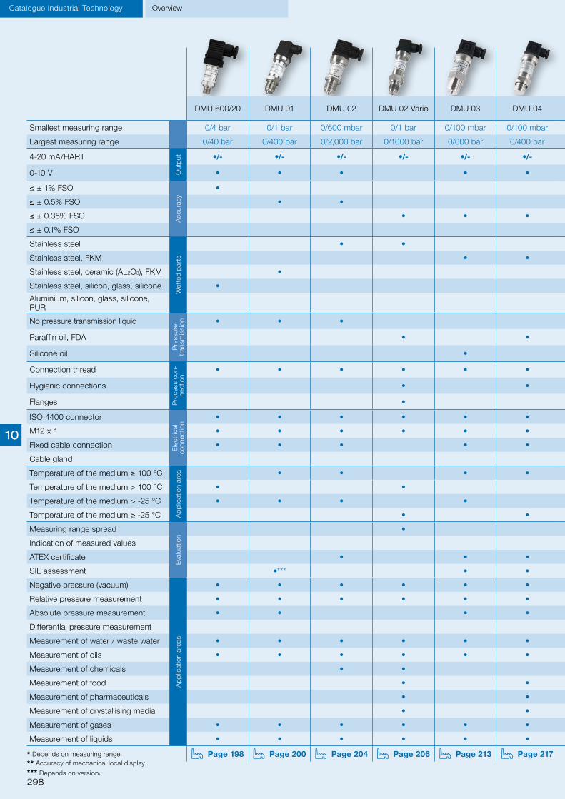
298
* Depends on measuring range.
** Accuracy of mechanical local display.
*** Depends on version.
Overview Catalogue Industrial Technology
DMU 600/20 DMU 01 DMU 02 DMU 02 Vario DMU 03 DMU 04 DMU 05 P DMU 07 DMU 08 DMU 09 DMU 10 D DMU 11 D DMU 13 DIM 20
Smallest measuring range 0/4 bar 0/1 bar 0/600 mbar 0/1 bar 0/100 mbar 0/100 mbar 0/100 mbar 0/40 mbar 0/100 mbar 0/40 mbar 0/6 mbar 0/20 mbar 0/600 mbar 0/1 bar
Largest measuring range 0/40 bar 0/400 bar 0/2,000 bar 0/1000 bar 0/600 bar 0/400 bar 0/600 bar 0/20 bar 0/25 bar 0/10 bar 0/1 bar 0/16 bar 0/40 bar 0/700 bar
4-20 mA/HART
Out
put •/- •/- •/- •/- •/- •/- •/- •/- •/- •/- •/- •/- •/-
0-10 V • • • • • • •
≤ ± 1% FSOA
ccur
acy
• •* •**
≤ ± 0.5% FSO • • • •*
≤ ± 0.35% FSO • • • • • • •
≤ ± 0.1% FSO •
Stainless steel
Wet
ted
par
ts
• •
Stainless steel, FKM • • • • • •
Stainless steel, ceramic (AL2O3), FKM • • • •
Stainless steel, silicon, glass, silicone •
Aluminium, silicon, glass, silicone, PUR •
No pressure transmission liquid
Pre
ssur
e tr
ansm
issi
on • • • • • • •
Paraffin oil, FDA • •
Silicone oil • • • • •
Connection thread
Pro
cess
con
-ne
ctio
n
• • • • • • • • • • • •
Hygienic connections • • •
Flanges • •
ISO 4400 connector
Ele
ctric
al
conn
ectio
n
• • • • • • • • • •
M12 x 1 • • • • • • • •
Fixed cable connection • • • • • • • •
Cable gland •
Temperature of the medium ≥ 100 °C
Ap
plic
atio
n ar
ea • • • • • • • • •
Temperature of the medium > 100 °C • • • • •
Temperature of the medium > -25 °C • • • • •
Temperature of the medium ≥ -25 °C • • • • • • • •
Measuring range spread
Eva
luat
ion
•
Indication of measured values • •
ATEX certificate • • • • •
SIL assessment •*** • • •
Negative pressure (vacuum)
Ap
plic
atio
n ar
eas
• • • • • • • •
Relative pressure measurement • • • • • • • • • • • •
Absolute pressure measurement • • • • •
Differential pressure measurement • •
Measurement of water / waste water • • • • • • • • • • • • •
Measurement of oils • • • • • • • • • • • • •
Measurement of chemicals • • • •
Measurement of food • • •
Measurement of pharmaceuticals • • •
Measurement of crystallising media • • • • •
Measurement of gases • • • • • • • • • • • •
Measurement of liquids • • • • • • • • • • • • •
Page 198 Page 200 Page 204 Page 206 Page 213 Page 217 Page 219 Page 223 Page 225 Page 229 Page 231 Page 233 Page 237 Page 239
10

299
DMU 600/20 DMU 01 DMU 02 DMU 02 Vario DMU 03 DMU 04 DMU 05 P DMU 07 DMU 08 DMU 09 DMU 10 D DMU 11 D DMU 13 DIM 20
Smallest measuring range 0/4 bar 0/1 bar 0/600 mbar 0/1 bar 0/100 mbar 0/100 mbar 0/100 mbar 0/40 mbar 0/100 mbar 0/40 mbar 0/6 mbar 0/20 mbar 0/600 mbar 0/1 bar
Largest measuring range 0/40 bar 0/400 bar 0/2,000 bar 0/1000 bar 0/600 bar 0/400 bar 0/600 bar 0/20 bar 0/25 bar 0/10 bar 0/1 bar 0/16 bar 0/40 bar 0/700 bar
4-20 mA/HART
Out
put •/- •/- •/- •/- •/- •/- •/- •/- •/- •/- •/- •/- •/-
0-10 V • • • • • • •
≤ ± 1% FSO
Acc
urac
y
• •* •**
≤ ± 0.5% FSO • • • •*
≤ ± 0.35% FSO • • • • • • •
≤ ± 0.1% FSO •
Stainless steel
Wet
ted
par
ts
• •
Stainless steel, FKM • • • • • •
Stainless steel, ceramic (AL2O3), FKM • • • •
Stainless steel, silicon, glass, silicone •
Aluminium, silicon, glass, silicone, PUR •
No pressure transmission liquid
Pre
ssur
e tr
ansm
issi
on • • • • • • •
Paraffin oil, FDA • •
Silicone oil • • • • •
Connection thread
Pro
cess
con
-ne
ctio
n
• • • • • • • • • • • •
Hygienic connections • • •
Flanges • •
ISO 4400 connector
Ele
ctric
al
conn
ectio
n
• • • • • • • • • •
M12 x 1 • • • • • • • •
Fixed cable connection • • • • • • • •
Cable gland •
Temperature of the medium ≥ 100 °C
Ap
plic
atio
n ar
ea • • • • • • • • •
Temperature of the medium > 100 °C • • • • •
Temperature of the medium > -25 °C • • • • •
Temperature of the medium ≥ -25 °C • • • • • • • •
Measuring range spread
Eva
luat
ion
•
Indication of measured values • •
ATEX certificate • • • • •
SIL assessment •*** • • •
Negative pressure (vacuum)
Ap
plic
atio
n ar
eas
• • • • • • • •
Relative pressure measurement • • • • • • • • • • • •
Absolute pressure measurement • • • • •
Differential pressure measurement • •
Measurement of water / waste water • • • • • • • • • • • • •
Measurement of oils • • • • • • • • • • • • •
Measurement of chemicals • • • •
Measurement of food • • •
Measurement of pharmaceuticals • • •
Measurement of crystallising media • • • • •
Measurement of gases • • • • • • • • • • • •
Measurement of liquids • • • • • • • • • • • • •
Page 198 Page 200 Page 204 Page 206 Page 213 Page 217 Page 219 Page 223 Page 225 Page 229 Page 231 Page 233 Page 237 Page 239
Overview Catalogue Industrial Technology
10

300 Division II
Technical informationPressure gauges
Pressure gauges – Mechanical pressure measuring instruments with elastic measuring elements
Bourdon tube pressure gaugesThe measuring element of a Bourdon tube pressure gauge is a C shaped or helical metal tube closed at one end. For pressure ranges up to 40 bar, the tube has an oval cross section and the shape of a C. For higher pressure ranges, the tube is bent into the shape of a helix. The oval cross section is obtained during bending. When pressure is applied, both types of bent tubes try to regain their original shapes, the straight tube. In this process, the radius increases and this displacement is converted into a circular movement by the movement. Bourdon tube pressure gauges are suitable for a wide variety of applications in measuring liquids and gases; they are the most commonly used pressure gauges. They are used for pressure measurements from 600 mbar up to several 1000 bar.
Magnetic piston and magnetic diaphragm pressure gaugesMagnetic piston type pressure gauges and magnetic diaphragm pressure gauges are primarily used for measuring differential pressure at filters which are subject to high static pressures. The pressures act on two pressure chambers separated by a diaphragm and/or a piston. If there are different pres-sures in the chambers, a rod with a permanent magnet is axially displaced against a compression spring. The permanent magnet transmits this displacement to the pointer by means of a ring magnet mounted to the pointer hub. The pointer indicates the pressure difference. Magnetic piston pressure gauges and magnetic diaphragm pressure gauges are used for the measurement of differential pres-sure of gases from 2.5 mbar to 10 bar; a static pressure of up to 350 bar is permissible.
Spring-diaphragm pressure gaugesSpring-diaphragm pressure gauges are ideal for measuring low differential pressures at high static pressures. The pressures act on two pressure chambers separated by an elastic diaphragm. If there are different pressures in the chambers, the diaphragm is axially displaced against a compression spring. This displacement is transmitted to a movement by a rod and converted into a rotary move-ment. The differential pressure is directly indicated by a pointer. The diaphragm is held by a metallic support which results in an overpressure safety of up to 25 bar at both sides. Diaphragm pressure gauges are used for liquids that are not highly viscous and for differential pressure from 250 mbar to 25 bar.
Diaphragm pressure gaugesDiaphragm pressure gauges use a concentrically shaped diaphragm which is directly connected to the process connection. The pressure is applied to the process side of the diaphragm. A rod at the oppo-site side which is fitted with a movement converts the displacement of the diaphragm into a rotary movement. Diaphragm pressure gauges are used for gaseous and liquid media within the range from 10 mbar to 25 bar; the media can even be viscous or crystallising if the process connection opening (open flange) is sufficiently large.With a flush welded diaphragm, they are ideal for measurements in hygienic processes.
Capsule pressure gaugesCapsule pressure gauges are used in gas technology applications for low pressure ranges. Two con-centrically shaped diaphragms are connected at the outer edges by means of welding or soldering. One diaphragm has an opening in the centre through which the gas to be measured can flow in. The pressure in the capsule causes it to arch to the outside. A deflection lever at the opposite side of the inlet opening transmits the linear displacement to a movement and converts it into a rotary movement. As early as in the 1920s, AFRISO patented this system as the "fine pressure gauge".Capsule pressure gauges are exclusively used for dry and clean gases at measuring ranges from 6 mbar to 1,000 mbar.
10

301Division II
Bourdon tube pressure gauges for heating/plumbing applications
iSee page 303 for prices.
For gaseous and liquid media which are not highly viscous, do not crystallise and do not attack copper alloys and EPDM. ! For measuring gas or vapour, these gauges must be used in accordance with the table "Selection Criteria as per EN 837-2" (see appendix)!
Application
Nominal size50 – 63 – 80 – 100
Accuracy class (EN 837-1/6)2.5
Ranges (EN 837-1/5)-1/0 bar0/0.6 to 0/25 bar
Application areaStatic load: 3/4 x full scale value Dynamic load: 2/3 x full scale value Short-term: full scale value
Operating temperature rangeMedium: Tmax = +60 °C Ambient: Tmin = -20 °C Tmax = +60 °C
Temperature performanceIndication error when the temperature of the measuring system deviates from the normal temperature of 20 °C: rising temperature approx. ±0.4 %/10 K falling temperature approx. ±0.4 %/10 K of full scale value
Degree of protectionIP 32 (EN 60529)
Technical specifications
Standard version ConnectionNG 50-63 G¼B: Self-sealing thread with PTFE ring for safe and fast installation(Attention: 60° chamfer required at female thread!) Brass, bottom or centre back NG 50-63 G¼B – spanner size SW 14 NG 80-100 G½B – spanner size SW 22
Measuring elementBourdon tube, copper alloy; "C" type tube
MovementBrass
DialPlastic, white Dial marking black
PointerPlastic, black
HousingBlack ABS, highly impact-resistant and corrosion-resistant
WindowClip-in plastic NG 80-100 with adjustable red reference pointer
Special versions Pressure gauges for heating installations NG 50-63-80For sealed heating systems Range: 0/4 bar Connection: NG 50 G¼B bottom back NG 63 G¼B or G3/8B bottom or centre back NG 80 G½B bottom or G¼B centre back (with valve G¼ x G½) Dial with red mark at 2.5 or 3 bar and green sector from 1.5 to 2.5 or 3 bar, window with adjustable red reference pointer and green flag
Hydrometer NG 80–100Water level indicator for open heating systems Ranges: 0/0.6 to 0/10 bar Connection: Brass G½B bottom – SW 22 Dual scale: bar outer scale black metres water column inner scale black. Window with adjustable red reference pointer
With self-sealing connection thread (version G¼B) for fast mounting
Red maximum mark on dial (version HZ) Adjustable red reference pointer and green operation segment on dial (version HZ)
Corrosion-resistant housing
Bourdon tube Pressure gauges
Page 314
A
Mounting valveswith self-sealing coating, automatically close during replacement of gauge to enable fast and cost-effective servicing (see "Accessories for pressure gauges").
10

302 Division II
Pressure gauges Bourdon tube
HZ 50 – bottom back connection RF/HZ 63 – bottom connection
RF/HZ 63 – centre back connection RF 80/HY 80/HZ 80 – bottom connection
HZ 80 – centre back connection RF 100/HY 100 – bottom connection
Bourdon tube pressure gauges for heating/plumbing applications
Housing types and dimensions
Dimensions (mm)
Nominal size (NG) a b b1 c c1 c2 e g g1 G G1 h h1 s SW Spanner
size SW1
50 - 25.8 - 11.2 - - 14 43 - G¼B - - - 3.8 14 -
63 9.8 30.4 29.7 11.2 13 11.5 - 49.9 50.4 G¼B G3⁄8B 49.5 51.5 3.7 14 17
80 12.8 31 32.8 17 11.5 - - 50 - G½B G¼B 64 - 2.8 22 14
100 15.5 - 34.5 17 - - - - - G½B - 74 - 3.5 22 -
10

303Division II
Type RF 50 rad RF 50 ax RF 63 rad RF 63 ax RF 80 rad HY 80 rad* RF 100 rad HY 100 rad*
Version
Housing Ø 50 50 63 63 80 80 100 100
Housing Black ABS, highly impact-resistant and corrosion-resistant
Measuring ele-ment Bourdon tube, copper alloy
Accuracy class 2.5 2.5 2.5 2.5 2.5 2.5 2.5 2.5
Connection G¼B G¼B G¼B G¼B G½B G½B G½B G½B
Thread self-sealing with PTFE sealing ring -
With adjustable red reference pointer
Range (bar) Part no. Part no. Part no. Part no. Part no. Part no. Part no. Part no.
Price €
-1/0 - - 63501 - 63551 - 63601 -
0/0.6 - - - - - - - 63281
0/1 - - - - 63559 63570 63609 63282
0/1.6 - - - - 63560 63571 63610 63283
0/2.5 - - 63511 63536 63561 63572 63611 63284
0/4 - - 63512 63537 63562 63573 63612 63285
0/6 63122 63127 63513 63538 63563 63574 63613 63286
0/10 63123 63128 63514 63539 63564 63575 63614 63287
0/16 63124 63129 63515 63540 63565 - 63615 -
0/25 - - - - 63566 - 63616 -
Bourdon tube pressure gauges for heating/plumbing applications
Type HZ 50 ax HZ 63 rad HZ 63 ax HZ 63 rad HZ 63 ax HZ 80 rad HZ 80 rad HZ 80 ax
Version
Housing Ø 50 63 63 63 63 80 80 80
Housing Black ABS, highly impact-resistant and corrosion-resistant
Measuring ele-ment Bourdon tube, copper alloy
Range 0/4 bar
Dial With red mark at 3 bar and green sector from 1.5 to 3 bar
Window Plastic with adjustable red reference pointer and green flag
Accuracy class 2.5 2.5 2.5 2.5 2.5 2.5 2.5 2.5
Connection G¼B G3/8B G3/8B G¼B G¼B G½BG¼ with
valve G¼ x G½
G¼ with valve
G¼ x G½
Thread Self-sealing with PTFE sealing ring - Self-sealing with PTFE sealing ring
Range (bar) Part no. Part no. Part no. Part no. Part no. Part no. Part no. Part no.
Price €
Part no. 63927 63910 63914 63911 63915 63918 63913 63919
Dial With red mark at 2.5 bar and green sector from 1.5 to 2.5 bar
Price €
Part no. - 63908 63909 - - - - -
Bourdon tube Pressure gauges
DG: G, PG: 2
* Dual scale bar/mWC
10

304 Division II
Pressure gauges and thermometers with capillary tube
For burners, boiler, hot water tanks and air conditioning/refrigeration systems, AFRISO offers different pressure and temperature measuring instruments with various housing versions and connection types. The portfolio covers cost-effective pressure gauges and thermometers with plastic or copper capillary as well as combination instruments such as combined thermometer/pressure gauges. We also provide OEM versions for your specific applications. Please enquire.
Application examples
iSee page 328 for thermo-meters with capillary tube.
Bourdon tubePressure gauges
10

305Division II
Bourdon tube
For gaseous and liquid media which are not highly viscous, do not crystallise and do not attack copper alloys and plastic. ! For measuring gas or vapour, these gauges must be used in accordance with the table "Selection Criteria as per EN 837-2" (see appendix)!
Application
TypeD 1
Nominal size40 – 52 – 45 x 45
Accuracy class (EN 837-1/6)4
Ranges (EN 837-1/5)0 to 4 bar 0 to 6 bar
Application areaStatic load: ¾ x full scale value Dynamic load: 2/3 x full scale value Short-term: full scale value
Operating temperature rangeMedium: Tmax = +80 °C Ambient: Tmin = -20 °C Tmax = +70 °C
Temperature performanceIndication error when the temperature of the measuring system deviates from the normal temperature of 20 °C: rising temperature approx. ±0.4 %/10 K falling temperature approx. ±0.4 %/10 K of full scale value
Degree of protectionIP 32 (EN 60529)
Technical specifications
Standard version ConnectionBrass, back with copper capillary Pressure screw G¼B
Measuring elementBourdon tube, copper alloy "C" type tube
MovementBrass
DialPlastic, white Dial marking black or vice versa
PointerPlastic, black or white
HousingBlack ABS, highly impact-resistant and corrosion-resistant RF 26 = PA 6 glass-fibre reinforced
WindowClip-in plastic, with adjustable red reference pointer NG 52 with push on bezel
Options Reference pointer Special scales Other process connections
Various capillary lengths Capillary made of plastic (PE) Other nominal sizes, for example, NG 26, 37, 42
Bourdon tube pressure gauges with capillary tube EN 837-1
Pressure gauges
Ideal for boilers, burners or wall-mounted heaters Corrosion-resistant, highly impact-resistant plastic housing
Many customised versions available
iPrices on request.
10

306 Division II
Pressure gauges Bourdon tube
DG: G, PG: 2 Description Capillary length Part no.* Price €
RFK 40 Cu
Nominal size Ø 40 mm, range 0/4 bar, black dial – numbers white, plastic housing (black), Cu capillary with PVC coating (R3, white)
1,000 mm 67665115
1,500 mm 67665125
2,000 mm 67665135
Nominal size Ø 40 mm, range 0/6 bar, black dial – numbers white, plastic housing (black), Cu capillary with PVC coating (R3, white)
1,000 mm 67666115
1,500 mm 67666125
2,000 mm 67666135
RFK 52 Cu
Nominal size Ø 52 mm, range 0/4 bar, black dial – numbers white, plastic housing (black), Cu capillary with PVC coating (R3, white)
1,000 mm 67595115
1,500 mm 67595125
2,000 mm 67595135
Nominal size Ø 52 mm, range 0/6 bar, black dial – numbers white, plastic housing (black), Cu capillary with PVC coating (R3, white)
1,000 mm 67596115
1,500 mm 67596125
2,000 mm 67596135
RFK 45 Cu
Nominal size 45 x 45 mm, range 0/4 bar, black dial – numbers white, plastic housing (black), Cu capillary with PVC coating (R3, white)
1,000 mm 67615115
1,500 mm 67615125
2,000 mm 67615135
Nominal size 45 x 45 mm, range 0/6 bar, black dial – numbers white, plastic housing (black), Cu capillary with PVC coating (R3, white)
1,000 mm 67616115
1,500 mm 67616125
2,000 mm 67616135
Bourdon tube pressure gauges with capillary tube RFK for heating/plumbing applications
* Minimum order quantity for non-stock items = 300 pieces
iVersions with plastic capillary, additional product details and other capillary lengths on request.
10
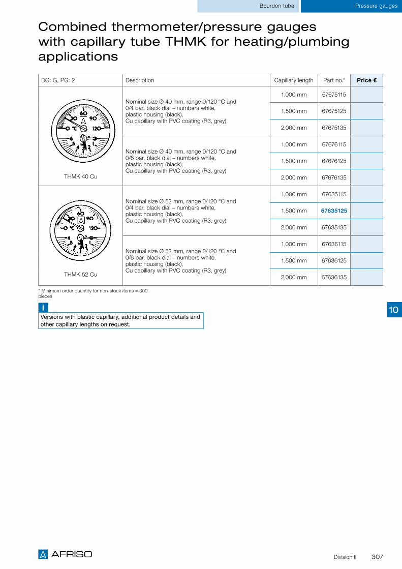
307Division II
Bourdon tube Pressure gauges
DG: G, PG: 2 Description Capillary length Part no.* Price €
THMK 40 Cu
Nominal size Ø 40 mm, range 0/120 °C and 0/4 bar, black dial – numbers white, plastic housing (black), Cu capillary with PVC coating (R3, grey)
1,000 mm 67675115
1,500 mm 67675125
2,000 mm 67675135
Nominal size Ø 40 mm, range 0/120 °C and 0/6 bar, black dial – numbers white, plastic housing (black), Cu capillary with PVC coating (R3, grey)
1,000 mm 67676115
1,500 mm 67676125
2,000 mm 67676135
THMK 52 Cu
Nominal size Ø 52 mm, range 0/120 °C and 0/4 bar, black dial – numbers white, plastic housing (black), Cu capillary with PVC coating (R3, grey)
1,000 mm 67635115
1,500 mm 67635125
2,000 mm 67635135
Nominal size Ø 52 mm, range 0/120 °C and 0/6 bar, black dial – numbers white, plastic housing (black), Cu capillary with PVC coating (R3, grey)
1,000 mm 67636115
1,500 mm 67636125
2,000 mm 67636135
Combined thermometer/pressure gauges with capillary tube THMK for heating/plumbing applications
* Minimum order quantity for non-stock items = 300 pieces
iVersions with plastic capillary, additional product details and other capillary lengths on request.
10

308 Division II
Bourdon tubeCombined thermometer/pressure gauges
Combined thermometer / pressure gauges / thermo-hydrometers
For liquid media which are not highly viscous, do not crystallise and do not attack copper alloys. For combined measurement of pressure and temperature, especially in heating systems and heating boilers.
Application
TypeD 1/D 2
Nominal size63 – 80
Accuracy classPressure gauge/hydrometer: 2.5 (EN 837-1/6)
Application areaPressure gauge/hydrometer: Static load: ¾ x full scale value Dynamic load: 2/3 x full scale value Short-term: full scale value Thermometer: 20/120 °C
RangesPressure gauge/hydrometer: 0/4 bar to 0/10 and 0/6 mWC to 0/60 mWC Thermometer: 20/120 °C
Operating temperature rangeMedium: Tmax = +120 °C Ambient: Tmin = -20 °C Tmax = +60 °C
Temperature performancePressure gauge/hydrometer: Indication error when the temperature of the measuring system deviates from the normal temperature of 20 °C: rising temperature approx. ±0.4 %/10 K falling temperature approx. ±0.4 %/10 K of full scale value
Degree of protectionIP 32 (EN 60529)
Technical specifications
Standard version ConnectionBrass, bottom or centre back G¼B with mounting valve G¼ to R½
Measuring elementPressure: Bourdon tube, copper alloy Temperature: bimetal element
DialPlastic, white Dial marking black with red/blue circular arcs
PointerPressure gauge/hydrometer: plastic, black Thermometer: plastic, red
HousingD1 – plastic, ABS highly impact-resistant D2 – sheet steel black
WindowClip-in plastic with adjustable red mark
Description The combined thermometer/pressure gauge / thermo-hydrometer consists of a Bourdon tube measur-ing system for pressure measurement and a bimetal measuring system for simultaneous temperature measurement. Both values are measured and displayed by a single gauge. A self-closing mounting valve enables easy replacement of the gauge without the necessity to drain the system. An optional M 18 x 1 to G¼ adapter is available if the combined thermometer/pressure gauge has to be mounted into an existing thermowell with M 18 x 1 female thread.
Options Adapter M 18 x 1 to G¼ Special scales Other process connections
See page 310 for prices.
Pressure and temperature measurement with at a single measuring point
With self-sealing connection thread for fast mounting
Bottom connection or back connection
With mounting valve for easy replacement without downtime
Bottom connection version
10

309Division II
Bourdon tube Combined thermometer/pressure gauges
②
TM 63 ax TM 80 ax
TM 63 ax with mounting valve TM 80 ax with mounting valve
TM 80 rad Mounting valve and adapter
Combined thermometer / pressure gauges / thermometer-hydrometers
Housing types and dimensions (mm)
① PTFE sealing ring ① PTFE sealing ring
① Mounting valve ② Pipe thread
① PTFE sealing ring
① Mounting valve ② Pipe thread
①
①
①
① Pipe thread② O ring (NBR)
②
①
②
①
1 A4
19.02.201504.05.2015
bro.Zi.
A0013969
TM80, 20/120°C, 0/4 bar 1/2"radial
-
D201 für Katalog
1:1
0S:\Inventor\PROJEKT_STAMMORDNER\TM80 radial\Katalog\A0013969.idw
A0013969.iam
Für diese Unterlagen behalten wir uns alle Rechte vor. Ohne unsere vorherige Zustimmung darf sie weder vervielfältigt, noch Drittenzugänglich gemacht werden, und sie darf durch den Empfänger oder Dritte auch nicht in anderer Weise mißbräuchlich verwertet werden.
Allgemeintoleranzen
nach
DIN ISO 2768-mK
Technische
Oberflächen
DIN ISO 1302
Maßstab:
(Rohmaße)
(Gewicht)
(Wzg.Nr.)
DIN
Ident-Nr.Projektionsmethode
File:
Änd.-Ziffer Blatt
(Benennung)
Norm
GezeichnetKontrolliert
Datum Name
(Werkstoff)
NG80 30,3
58,5
11,2
G1/4B
14SW
1 PTFE-Dichtring
TM80 Anschluss radial
11,2
1
10

310 Division II
Bourdon tubeCombined thermometer/pressure gauges
Type TM 63, D211 TM 63, D211 TM 80, D111 TM 80, D201 TM 80, D211 TM 80, D211 TH 80, D211
Version
Housing Ø 63 63 80 80 80 80 80
Housing Sheet steel, black ABS highly impact resistant
Sheet steel, black Sheet steel, black
Accuracy class Pressure gauge/hydrometer 2.5
Connection G¼B with mounting valve G¼ to R½
Adapter Without With Without Without Without With Without
Range Part no. Part no. Part no. Part no. Part no. Part no. Part no.
Price €
0/4 bar 20/120 °C 63318 63346 63317 63337 63341 63348 ---
0/6 bar 20/120 °C --- --- --- 63338 63342 --- ---
0/10 bar 20/120 °C --- --- --- 63339 63343 --- ---
0/6 mWC 20/120 °C --- --- --- --- --- --- 63311
0/10 mWC 20/120 °C --- --- --- --- --- --- 63312
0/16 mWC 20/120 °C --- --- --- --- --- --- 63313
0/25 mWC 20/120 °C --- --- --- --- --- --- 63314
0/40 mWC 20/120 °C --- --- --- --- --- --- 63315
0/60 mWC 20/120 °C --- --- --- --- --- --- 63316
* Minimum order quantity for non-stock items = 100 pieces
Combined thermometer / pressure gauges / thermometer-hydrometers
DG: G, PG: 2 Part no. Price €
Mounting valve G¼ to R½, brass 05 00 25 12
Adapter G¼ to M 18 x 1, brass 05 00 40 01
Spare parts
DG: G, PG: 2
10

311Division II
Differential pressure Pressure gauges
Reading examplep1 (+ connection)p2 (- connection)
Δp (differential pressure)
p1
p2
Standard Bourdon tube pressure gauges for differential pressure
TypeD 2
Nominal size100
FunctionThe pressures are measured in two independent Bourdon tube systems ("plus" pressure = high pressure, "minus" pressure = low pressure). The pressure is indicated by means of a dial and a pointer. The differential pressure scale covers 50 % of the range of the "plus" pressure and 50 % of the range of the "minus" pressure. The black pointer ("plus" connection) and the red pointer ("minus" connection) at the differential pressure gauge scale allow you to read the pressures in both systems on the fixed scale.
Accuracy class (EN 837-1/6)1.6
Ranges (EN 837-1/5)0/0.6 to 0/60 bar
Application areaThe maximum pressure in the system must not exceed the full scale value. For good readability, the differential pressure to be measured should not be less than approx. 20 % of the full scale value.
Operating temperature rangeMedium: Tmax = +60 °CAmbient: Tmin = -20 °C Tmax = +60 °C
Temperature performanceIndication error when the temperature of the measuring system deviates from the normal temperature of 20 °C: rising temperature approx. ±0.4 %/10 K falling temperature approx. ±0.4 %/10 K of full scale value
Degree of protectionIP 32 (EN 60529)
Connection Brass, bottom; parallel in line 2 x G½B – spanner size SW 22 (EN 837-1/7.3) Optional: Wetted parts stainless steel
Measuring elementBourdon tube, "C" type tube, copper alloy
MovementBrass
Dial Aluminium, white Dial marking black (bar/mWC)
Pointer/dialAluminium
Housing Sheet steel, black
Push on bezelSheet steel, black
WindowInstrument glass
For differential pressure measurement of gaseous and liquid media which are not highly viscous, do not crystallize and do not attack copper alloys. Specially suitable for heating systems (supply and return pipes).! For measuring gas or vapour, these gauges must be used in accordance with the table "Selection Criteria as per EN 837-2" (see appendix)!
Application
Technical specifications
Indication of plus pressure, minus pressure and differential pressure
Excellent price/performance ratio Two independent Bourdon tube systems Housing and wetted parts also available in stainless steel (option)
DG: M, PG: 2 Part no. Prices €
RF 100 Dif D 201, 0/1 bar 85610201
RF 100 Dif D 201, 0/1.6 bar 85611201
RF 100 Dif D 201, 0/2.5 bar 85612201
RF 100 Dif D 201, 0/4 bar 85613201
RF 100 Dif D 201, 0/6 bar 85614201
RF 100 Dif D 201, 0/10 bar 85615201
RF 100 Dif D 201, 0/16 bar 85616201
iSee the catalogue INDUSTRIAL TECHNOLOGY for other versions.
Page 314
A
10

312
Capsule elementPressure gauges
Division II
For gaseous, dry media which do not attack copper alloys. ! For measuring gas or vapour, these gauges must be used in accordance with the table "Selection Criteria as per EN 837-2" (see appendix)!
Application
TypesD2 / D3
Nominal size100
Accuracy class (EN 837-3/6)1.6
Ranges (EN 837-3/5)0/25 to 0/1000 mbar and all corresponding vacuum and compound ranges with overpressure protection
Application areaStatic load: full scale value Dynamic load: 0.9 x full scale value Overload safety: 1.3 x full scale value
Operating temperature rangeMedium: Tmax = +60 °C Ambient: Tmin = -20 °C Tmax = +60 °C
Temperature performanceIndication error when the temperature of the measuring system deviates from the normal temperature of 20 °C: rising temperature approx. ±0.6 %/10 K falling temperature approx. ±0.6 %/10 K of full scale value
Degree of protectionIP 44 (EN 60529)
ConnectionBrass, bottom G½B – spanner size SW 22 (EN 837-3/7.3)
Measuring elementCapsule element, CuBe alloy
MovementBrass
Zero correctionFrom the front
SealNBR (Perbunan)
DialAluminium, white Dial marking black
PointerAluminium, black
HousingD 2 – black, sheet steel D 3 – stainless steel 304
WindowClip-in plastic
Technical specifications
Standard capsule pressure gauges EN 837-3
Housing: Sheet steel or stainless steel version
With zero correction Ideal for low pressure ranges GOSSTANDART-certified
iSee the catalogue INDUSTRIAL TECHNOLOGY for other versions.
DG: M, PG: 2 Housing Part no. Prices €
KP100 D201, 0/25 mbar Sheet steel 35116201
KP100 D201, 0/40 mbar Sheet steel 35117201
KP100 D201, 0/60 mbar Sheet steel 35118201
KP100 D201, 0/100 mbar Sheet steel 35119201
KP100 D201, 0/160 mbar Sheet steel 35120201
KP100 D201, 0/250 mbar Sheet steel 35121201
KP100 D201, 0/400 mbar Sheet steel 35122201
KP100 D201, 0/600 mbar Sheet steel 35123201
KP100 D201, 0/1000 mbar Sheet steel 35124201
KP100 D301, 0/25 mbar Stainless steel 35116301
KP100 D301, 0/40 mbar Stainless steel 35117301
KP100 D301, 0/60 mbar Stainless steel 35118301
KP100 D301, 0/100 mbar Stainless steel 35119301
KP100 D301, 0/160 mbar Stainless steel 35120301
KP100 D301, 0/250 mbar Stainless steel 35121301
KP100 D301, 0/400 mbar Stainless steel 35122301
KP100 D301, 0/600 mbar Stainless steel 35123301
10

313
Capsule element Pressure gauges
Division II
For gaseous, dry media which do not attack copper alloys. ! For measuring gas or vapour, these gauges must be used in accordance with the table "Selection Criteria as per EN 837-2" (see appendix)!
Application
TypeD 4
Nominal size100
Accuracy class (EN 837-3/6)1.6
Ranges (EN 837-3/5)0/25 to 0/1000 mbar and all corresponding vacuum and compound ranges with overpressure protection
Application areaStatic load: full scale value Dynamic load: 0.9 x full scale value Overload safety: 1.3 x full scale value
Operating temperature rangeMedium: Tmax = +60 °C Ambient: Tmin = -20 °C Tmax = +60 °C
Temperature performanceIndication error when the temperature of the measuring system deviates from the normal temperature of +20 °C: rising temperature approx. ±0.6 %/10 K falling temperature approx. ±0.6 %/10 K of full scale value
Degree of protectionIP 54 (EN 60529)
ConnectionBrass, bottom G½B – spanner size SW 22 (EN 837-3/7.3)
Measuring elementCapsule element, CuBe alloy
MovementBrass
Zero correctionFrom the front
SealNBR (Perbunan)
DialAluminium, white Dial marking black
PointerAluminium, black
HousingStainless steel 304
Bayonet type bezelStainless steel 304
WindowInstrument glass
Technical specifi-cations
Standard capsule pressure gaugesEN 837-3
Housing: Stainless steel version with bayonet bezel
With zero correction Optional overpressure and/or underpressure safety 10 x FSD
Extremely low measuring range from 0/6 mbar
GOSSTANDART-certified
DG: M, PG: 2 Housing Part no. Prices €
KP100 D401, 0/40 mbar Stainless steel 35117401
KP100 D401, 0/60 mbar Stainless steel 35118401
KP100 D401, 0/100 mbar Stainless steel 35119401
KP100 D401, 0/160 mbar Stainless steel 35120401
KP100 D401, 0/250 mbar Stainless steel 35121401
KP100 D401, 0/400 mbar Stainless steel 35122401
iSee the catalogue INDUSTRIAL TECHNOLOGY for other versions.
10

314 Division II
Shut-off cocks and valves for pressure gauges
Shut-off cocks for pressure gauges
Shut-off valves for pressure gauges
Shut-off element between pipe and pressure gauge. Stop cocks with test port allow you to connect both pressure gauges and testers to the pipe. Suitable for liquids, gases and vapour.
VersionDIN 16261 to 16263(or based on DIN)
Operating temperature rangeMedium: -10/+50 °C
Connection and nominal pressureSee price list.
Housing and tapBrass bare metal surface or stainless steel bare metal surface. The tap contains two holes which are arranged in the shape of a T. The function depends on the tap position:1. Vent pressure gauge2. Apply pressure to pressure gauge3. Blow out measuring line4. Apply pressure to tester
VersionDIN 16270 without test portDIN 16271 with test port, male M 20 x 1.5DIN 16272 with test port which can be closed separately, male, see 16271Type A female/female x male connectionType B loose female coupling x male connection and shaft for instrument bracket
Operating temperature rangeBrass -10/ +120 °CSteel 1.0460 -10/ +120 °CStainless steel 316 Ti -20/+200 °C
Connection and nominal pressureSee price list.
Application
Technical specifications
Shut-off or reducing element between pipe and pressure gauge. Stop valves with test port allow you to connect both pressure gauges and testers to the measuring line. Suitable for liquids, gases and vapour.
Parts Brass Steel Stainless steel
Housing Brass 1.0460 316 Ti
Valve spindle Brass 430 F 316 Ti
Valve cone Brass 430 F 316 Ti
Packing PTFE PTFE PTFE
Cap Brass Steel Stainless steel
Union nut Brass Steel Stainless steel
Female/female connection Brass Steel Stainless
steelLoose female coupling Brass Steel Stainless
steelVent screw 316 Ti 316 Ti 316 Ti
Wheel Plastic Plastic Plastic
Materials
Vent Operation
Blow out Test (option)
Pressure gauges Accessories
iSee page 315 for prices.
10

315Division II
Accessories for pressure gauges
Pressure gauge shut-off cock female x femaleConnection Nominal pressure Material PG Part no. Price €
G¼ PN 6 Brass 2 63001G3/8 PN 16 Brass 2 63002G½ PN 16 Brass 2 63003
With round test flange 40 x 5 G½ PN 16 Brass 2 63004
With test flange 60 x 25 x 10 G½ PN 16 Brass 2 63005With sealing gland G½ PN 16 Brass 2 63006
Pressure gauge shut-off cock female/female x maleConnection Nominal pressure Material PG Part no. Price €
G¼ PN 6 Brass 2 63014
G½ PN 16 Brass 2 63027G½ PN 16 1.4571 3 63090
With test flange 60 x 25 x 10 G½ PN 16 Brass 2 63028With test flange 60 x 25 x 10 G½ PN 16 1.4571 3 63091
With male test connection M20 x 1.5 G½ PN 16 Brass 2 63015
With male test connection M20 x 1.5 G½ PN 16 1.4571 3 63016
Pressure gauge shut-off cock loose female x femaleConnection Nominal pressure Material PG Part no. Price €
G½ PN 16 Brass 2 63017
With test flange 60 x 25 x 10 G½ PN 16 Brass 2 63018
Pressure gauge shut-off cock loose female x maleConnection Nominal pressure Material PG Part no. Price €
G½ PN 16 Brass 2 63107
With test flange 60 x 25 x 10 G½ PN 16 Brass 2 63024
Pressure gauge shut-off valve DIN 16270Type A – female/female x male connection Type B – loose female coupling x male connection and shaft for instrument bracket
Type A Type B Connection Nominal pressure Material PG Type A Price € Type B Price €
Part no. Part no.
G¼ PN 125 Brass 2 63094 --- ---G½ PN 250 Brass 2 63092 63046
G½ PN 400 Steel 3 63040 63047
G½ PN 400 1.4571 3 63093 63048
Test connection male M20 x 1.5 DIN 16271 G½ PN 250 Brass 2 63041 63049
G½ PN 400 Steel 3 63042 63108
G½ PN 400 1.4571 3 63044 63109
Extra charge oil-free and grease-free* 63045 63110
Extra charge DVGW-tested ---
* Only for brass and stainless steel.
DG: H
Pressure gauge shut-off cock female x maleConnection Nominal pressure Material PG Part no. Price €
G¼ PN 6 Brass 2 63011G3/8 PN 16 Brass 2 63012G½ PN 16 Brass 2 63013
With round test flange 40 x 5 G½ PN 16 Brass 2 63009
With test flange 60 x 25 x 10 G½ PN 16 Brass 2 63010
Pressure gaugesAccessories
10

316 Division II
Overpressure safety device, Pressure gauge push-button stop cock
Materials overpressure safety device
Parts Brass Stainless steel
Housing Brass 316 TiPiston 316 Ti 316 TiFemale/female connection Steel 303Diaphragm FKM FKMO ring FKM FKM
iSee page 317 for prices.
Pressure gauge push-button stop cock
Overpressure safety device
Adjustable overpressure safety device used to protect the system against peak pressures exceeding the range of the pressure gauge. At measuring points which are subject to great pressure variations, you can install different pressure gauges with different ranges in order to precisely measure even the lower pressures. The overpressure safety devices are adjusted according to the maximum permissible pressure ratings of the various pressure gauges installed.
FunctionWhen the set pressure is reached, a piston valve shuts off the port to the pressure gauge. After the pressure has dropped to a value of approx. 25 % below the closing pressure, the valve opens again.
Operating temperature rangeMax. +80 °C
Overpressure safetyBrass: 600 bar Stainless steel: 1000 barMax. vacuum range up to -1 bar, no adjustment function
Connection G½ female/female connection x male connection
Shut-off element between measuring line and pressure gauge. Normally, the push-button stop cock is closed. In this state, there is no pressure applied to the pressure gauge. Push the button to apply pressure to the pressure gauge and to display the operating pressure. Suitable for gases as per DVGW G260 and SVGW.
TestDVGW- and SVGW-tested, with EC Type Examination Certificate, product ID number CE-0085AQ0985
Operating temperature rangeMedium: 0/+70 °C Ambient: -20/+60 °C
Connection2 x female thread Rp ½, EN 10226Rp ¼ EN 10226½ NPT (without test) ¼ NPT (without test)
Nominal pressure5 bar (MOP 5)
HousingBrass, nickel-plated
G½Spanner size SW 27
Ø 6
G½B
62.532
20
90
20
Spanner size SW 27
Dimensions (in mm)
64
Rp ½ / ½-14 NPT
71.5
Dimensions (Rp ½ / ½-14 NPT)
Dimensions (Rp ¼/ ¼-18 NPT)
Application
Technical specifications
Application
Technical specifications
Overpressure safety device
Pressure gauge push-button stop cock
AccessoriesPressure gauges
Rp ½ / ½-14 NPT
Rp ¼/ ¼-18 NPT
Rp ¼/ ¼-18 NPT
10

317Division II
Accessories for pressure gauges
Siphon DIN 16282 – outlet female/female connection G½
Type Inlet Material Nominal pressure PG Part no. Price €
U shape A* G½B Steel PN 100 3 63147
B Without thread, welded end 20 x 2.6 mm Steel PN 100 3 63148
A* G½B 316 Ti PN 100 3 63149
Circular shape C* G½B Steel PN 100 3 63150
D Without thread, welded end 20 x 2.6 mm Steel PN 100 3 63151
C* G½B 316 Ti PN 100 3 63152* Types A and C are no longer provided for in the new DIN edition.
Siphon – standard – inlet G½
U shape Circular shape Type Outlet Material Nominal pressure PG Part no. Price €
U G½B Steel PN 25 3 63085
U Female/female connection G½B Steel PN 25 3 63153
Circular G½B Steel PN 25 3 63081
Circular Female/female connection G½B Steel PN 25 3 63154
DG: H
Damping device (pressure surge protection) female x male – adjustable
Connection Nominal pressure Material PG Part no. Price €
G½ PN 400 Brass 2 63074
G½ PN 400 Steel 3 63075
G½ PN 400 316 Ti 3 63076
Overpressure safety device G½ female/female connection x male – adjustable, vacuum-tight
Adjustment range in bar Material PG Part no. Price € Material PG Part no. Price €
0.4–2.5 Brass 2 63131 316 Ti 3 63139
2–6 Brass 2 63132 316 Ti 3 63140
5–25 Brass 2 63133 316 Ti 3 63141
20–60 Brass 2 63134 316 Ti 3 63142
50–250 Brass 2 63135 316 Ti 3 63143
240–400 Brass 2 63136 316 Ti 3 63144
Extra charge oil-free and grease-free - 63137 - 63145
Extra charge DVGW-tested - 63138 - 63146
Pressure gaugesAccessories
Pressure gauge push-button stop cock female x female – DVGW- and SVGW-tested/CE-0085AQ0985
Connection Nominal pressure Material PG Part no. Price €
Rp ½, EN 10226 MOP 5 Brass, nickel-plated 2 63031
Rp ¼, EN 10226 MOP 5 Brass, nickel-plated 2 63191
¼-18 NPT* MOP 5 Brass, nickel-plated 2 63193
½-14 NPT* MOP 5 Brass, nickel-plated 2 63235* Without DVGW and SVGW approval.
Mounting valve with self-sealing coating – automatically closes when the pressure gauge is replaced
Female connection Male connection Material PG Part no. Price €
G¼ G¼ Brass 2 77907
G¼ G3/8 Brass 2 77908
G3/8 G3/8 Brass 2 77917
G¼ G½ Brass 2 77914
G3/8 G½ Brass 2 77918
10

318 Division II
Accessories for pressure gauges
Connection nipple – self-sealing
Female connection Male connection Material PG Part no. Price €
G1/8 G¼ Brass 2 63067
G¼ G3/8 Brass 2 63068
G¼ G½ Brass 2 63069
G3/8 G½ Brass 2 63065
DG: H
Pressure gauges Accessories
Union nut + nipple DIN 16284
Female connection Male connection Material PG Part no. Price €
G¼ 6 mm Brass 2 63072
G½ 12 mm Brass 2 63084
G½ 12 mm 316 Ti 3 63070
Reducers and adapters
Female connection Male connection Material PG Part no. Price €
G1/8 G¼ Brass 2 63050
G¼ G1/8 Brass 2 63052
G¼ G3/8 Brass 2 63053
G¼ G½ Brass 2 63054
G¼ G½ 316 Ti 3 63051
G3/8 G¼ Brass 2 63056
G3/8 G½ Brass 2 63057
G½ G¼ Brass 2 63058
G½ G3/8 Brass 2 63059
G½ G3/8 316 Ti 3 63062
G½ M 20 x 1.5 Brass 2 63155
M 20 x 1.5 G½ Brass 2 63156
Female/female connection DIN 16283
Female connection Female connection Material PG Part no. Price €
G¼ left G¼ Brass 2 63101
G¼ left G¼ Steel 3 63102
G¼ left G¼ 316 Ti 3 63103
G½ left G½ Brass 2 63104
G½ left G½ Steel 3 63105
G½ left G½ 316 Ti 3 63106
Female connection Female connection Material PG Part no. Price €
G¼ G1/8 Brass 2 63158
G¼ G¼ Brass 2 63159
G½ G¼ Brass 2 63160
G½ G½ Brass 2 63161
Male connection Male connection Material PG Part no. Price €
G½ G½ Brass 2 63164
G½ G½ 316 Ti 3 63165
10

319
Catalogue Industrial TechnologyOverview pressure measuring instruments
Pressure gauges for industrial applications
For pneumatic and mechanical engineering applications
Highly impact-resistant plastic housing or robust steel or stain-less steel housing
Window with adjustable refer-ence pointer
Options: Special scales, con-nections for different process-es, mounting flanges, etc.
Nominal sizes40 – 50 – 63 – 80 – 100
Accuracy class 1.6
For machine and plant engineering
Robust steel or stainless steel housing
Optionally with electrical contact
Nominal sizes100 – 160
Accuracy class 1.0
Standard pressure gauges
From page 21
From page 32
Can be used in case of heavy vibrations and high, dynamic pressure loads
Less wear and corrosion pro-tection of the measuring system
No steaming up of the inside of the window in case of outdoor applications
Nominal sizes40 – 50 – 63 – 80 – 100 – 160
Accuracy class 1.0 or 1.6
Glycerine filled pressure gauges
From page 38
Pressure gauges for chemical applications
For chemical and process engineering applications
Measuring system fully welded to housing
For temperatures of the medium of up to 150 °C
Nominal sizes50 – 63 – 100 – 160
Accuracy class 1.0 or 1.6
From page 55
iThis and further products can be found in the catalogueINDUSTRIAL TECHNOLOGY
Pressure measuring instrument for industrial applications and process engineering
CATALOGUE INDUSTRIAL TECHNOLOGY
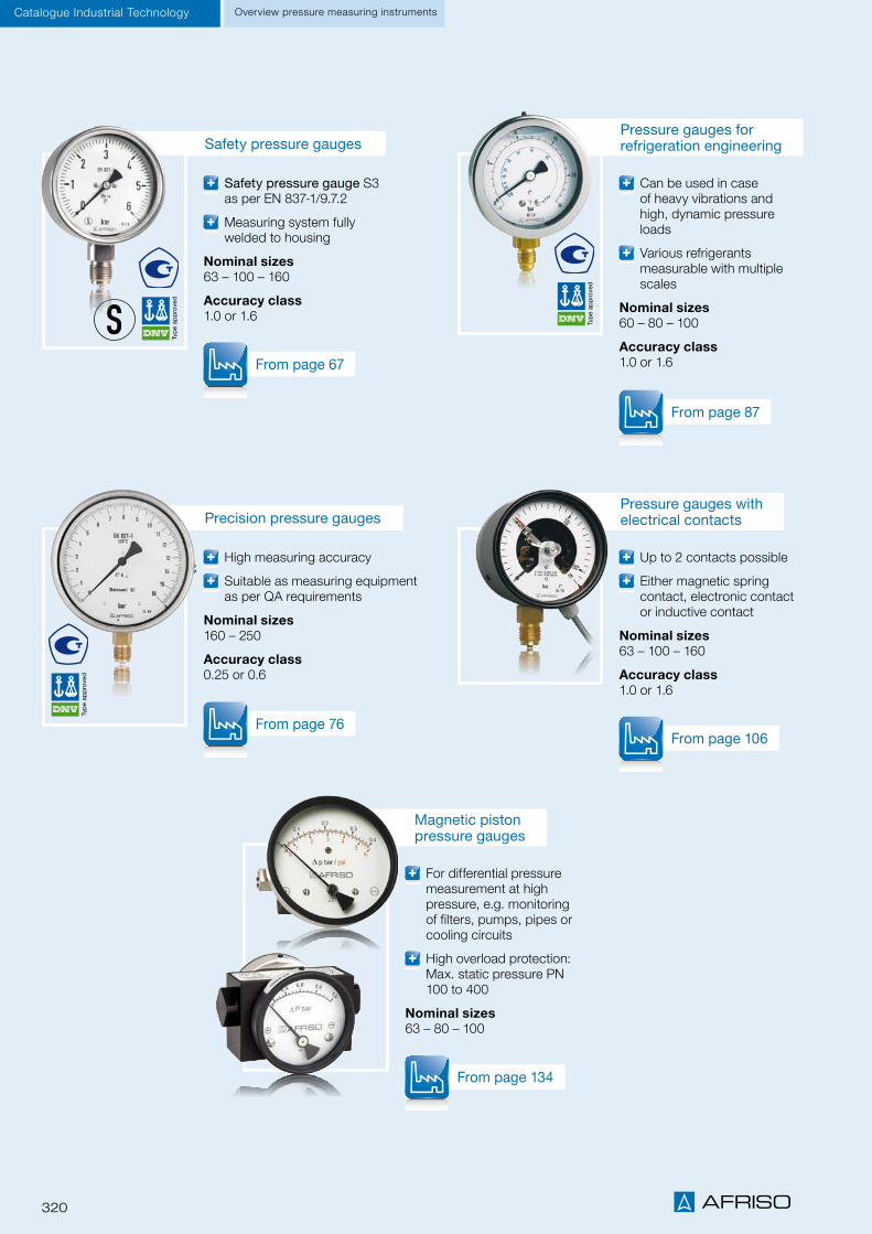
320
Xxxxxx
Catalogue Industrial Technology Overview pressure measuring instruments
High measuring accuracy
Suitable as measuring equipment as per QA requirements
Nominal sizes160 – 250
Accuracy class 0.25 or 0.6
Can be used in case of heavy vibrations and high, dynamic pressure loads
Various refrigerants measurable with multiple scales
Nominal sizes60 – 80 – 100
Accuracy class 1.0 or 1.6
Precision pressure gauges
From page 76
From page 87
Up to 2 contacts possible
Either magnetic spring contact, electronic contact or inductive contact
Nominal sizes63 – 100 – 160
Accuracy class 1.0 or 1.6
For differential pressure measurement at high pressure, e.g. monitoring of filters, pumps, pipes or cooling circuits
High overload protection: Max. static pressure PN 100 to 400
Nominal sizes63 – 80 – 100
Pressure gauges with electrical contacts
From page 106
From page 134
Safety pressure gauge S3 as per EN 837-1/9.7.2
Measuring system fully welded to housing
Nominal sizes63 – 100 – 160
Accuracy class 1.0 or 1.6
Safety pressure gauges
From page 67
Magnetic piston pressure gauges
Pressure gauges for refrigeration engineering

321
Catalogue Industrial TechnologyOverview pressure measuring instruments
Connection technology with numerous versions for applications in many industries
Extremely resistant to shock, pulsation and vibration
Best dynamic pressure resistance at high load changes
Measuring ranges -1/0 to -1/+24 bar 0/1 to 0/600 bar
Compact version for OEMs
Proven ceramic technology
No mechanical ageing of the measuring cell
Measuring ranges 0/1.6 to 0/250 bar
Pressure transducer DMU 02 Vario
From page 206
From page 199
High flexibility due to selectable units
Min./max. memory
Display can be rotated by 330 °
Measuring ranges -1/0 bar, 0/2.5 bar to 0/700 bar
Digital pressure gauge DIM 20
From page 239
Measurement of extremely small differential pressures
Direct indication of the differential pressure
High overload protection
Nominal sizes63 – 100 – 160
Accuracy class 1.6 or 2.5
Pressure gauges for differential pressure
From page 129
Pressure transducer DMU 01K

Bimetal thermometers
Air duct thermometers
Resistance thermometers
Industrial thermometers

323
Temperature measuring instruments and controllers
CHAPTER 11
Bimetal thermometers with plastic housing 331
Bimetal standard thermometers, surface mount thermometers ATh, flue gas thermometers RT/RTC 334
Thermometers and pressure gauges with capillary tube 328
Thermometers with capillary tube THK 329
HEATING/PLUMBING
Bimetal thermometers for industrial applications, bimetal air duct thermometers 339
PLANT/VENTILATION ENGINEERING
Mechanical temperature measuring instruments 324
Electronic temperature measuring instruments 326
OVERVIEW
Pockets for pressure gauges, thermometers, thermostats 349
Thermostats with housing GAT, GTT, GTK, GSA, GSK, GST, GRT, GDT 350
Industrial thermometers 347
Connection types for bimetal thermometers 344
ACCESSORIES
Resistance thermometers WTh 20–23 351
11

324
Thermometers with capillary
Bimetal thermom-eters
Bimetal standard thermometers
Surface mount ther-mometers
Flue gas thermom-eters
Bimetal thermometers for industrial applications
Bimetal air duct thermometers
Bimetal stainless steel thermometers
Bimetal thermometers for chemical applications
Gas filled thermome-ters - chemical
V-shaped industrial thermometers
Heating, plumbingA
pp
licat
ion
area
s• • • • • • •
Machines and plants • • •
Process engineering • • •
Chemical applications • • •
Food industry • • •
Hygienic processes • • •
Corrosive media • • • •
NG 40
Ho
usin
g s
ize
• •
NG 50 • •
NG 52 •
NG 63 • • • • • • •
NG 80 • • • • • • •
NG 100 • • • • • • •
NG 160 • • • •
Profile housing •
-40/+40 °C
Ran
ges
•
-30/+50 °C • •
-20/+60 °C • • • • • • •
-20/+40 °C •
0/60 °C • • • • • • • • •
0/120 °C • • • • • • • • •
0/160 °C • • • • • •
0/200 °C •
> 0/300 °C • •
Class 1 (EN 13190)
Acc
urac
y • • • • •
Class 2 (EN 13190) • • • • •
DIN 16195 •
Plastic
Ho
usin
g
• • •
Sheet steel galvanised • • • • •
Aluminium •
Stainless steel 304 • • •
Stem
Co
nnec
tio
n
• • • • • • • • •
Plug-on •
Mounting flange •
Flange •
Fastening spring •
Magnetic holder •
Capillary tube •
Other ranges
Op
tio
ns
• • • • • • • • •
Other connection designs • • • • • •
Glycerine filling • •
Electrical contacts • •
Page 328 Page 331 Page 334 Page 334 Page 334 Page 248 Page 248 Page 253 Page 253 Page 257 Page 265
OverviewThermometers mechanical
Mechanical temperature measuring instruments at a glance
Technical specifications, application areas and suitability depend on the product version. See catalogue data sheet and/or operating instructions for options and details.
i
11

325
Thermometers with capillary
Bimetal thermom-eters
Bimetal standard thermometers
Surface mount ther-mometers
Flue gas thermom-eters
Bimetal thermometers for industrial applications
Bimetal air duct thermometers
Bimetal stainless steel thermometers
Bimetal thermometers for chemical applications
Gas filled thermome-ters - chemical
V-shaped industrial thermometers
Heating, plumbing
Ap
plic
atio
n ar
eas
• • • • • • •
Machines and plants • • •
Process engineering • • •
Chemical applications • • •
Food industry • • •
Hygienic processes • • •
Corrosive media • • • •
NG 40
Ho
usin
g s
ize
• •
NG 50 • •
NG 52 •
NG 63 • • • • • • •
NG 80 • • • • • • •
NG 100 • • • • • • •
NG 160 • • • •
Profile housing •
-40/+40 °C
Ran
ges
•
-30/+50 °C • •
-20/+60 °C • • • • • • •
-20/+40 °C •
0/60 °C • • • • • • • • •
0/120 °C • • • • • • • • •
0/160 °C • • • • • •
0/200 °C •
> 0/300 °C • •
Class 1 (EN 13190)
Acc
urac
y • • • • •
Class 2 (EN 13190) • • • • •
DIN 16195 •
Plastic
Ho
usin
g
• • •
Sheet steel galvanised • • • • •
Aluminium •
Stainless steel 304 • • •
Stem
Co
nnec
tio
n
• • • • • • • • •
Plug-on •
Mounting flange •
Flange •
Fastening spring •
Magnetic holder •
Capillary tube •
Other ranges
Op
tio
ns
• • • • • • • • •
Other connection designs • • • • • •
Glycerine filling • •
Electrical contacts • •
Page 328 Page 331 Page 334 Page 334 Page 334 Page 248 Page 248 Page 253 Page 253 Page 257 Page 265
Overview Thermometers mechanical
11

326
OverviewThermometers electronic
Electronic temperature measuring instruments at a glance
Technical specifications, application areas and suitability depend on the product version. See catalogue data sheet and/or operating instructions for options and details.
i
Resistance thermome-ter WTh 20
Resistance thermome-ter WTh 21
Resistance thermome-ter WTh 22
Resistance thermome-ter WTh 23
Resistance thermome-ter WTh 24
Resistance thermometers WTh 25
Resistance thermometers WTh 26
Resistance thermometers WTh 27
Resistance thermometers WTh 28
Resistance thermometers WTh 30
Pipeline temperature sensors RTS
Heating, plumbing
Ap
plic
atio
n ar
eas
• • • •
Air conditioning/ventilation • • •
Pipeline engineering • • • •
Mechanical and plant engineer-ing • • • •
Appliance engineering • •
Chemical / process engineering • • •
Pharmaceutical / biotechnology • • •
Food industry / hygienic pro-cesses • • •
Corrosive media • • •
High temperatures • • • •
High pressure loads • •
Cable probe
Vers
ion
•
Fixed thread • • • • •
Screwed pipe connection •
Flange connection • •
Clamp connection • • •
Varivent connection •
Weld-in thermometer •
Pt 100, class A
Sen
sor •
Pt 100, class B • • • • • • • • • •
100 mm
Inst
alla
tio
n le
ng
ths • • • • • • • •
125 mm • •
160 mm • • • • • •
≥ 250 mm • • • • • •
Housing plastic
Mat
eria
l • •
Housing aluminium • • • • • •
Wetted parts 316 Ti • • • • • • • • •
Wetted parts 316 L •
Cable (wire ferrules)
Ele
ctr.
co
nn
ecti
on
•
Cable gland • • • • • • • •
Connector • •
Other designs
Op
tio
ns
• • • • • • • • •
Other process connections • • • • • • • •
Transmitter installation • • • • • • • • •
EX version • • • •
Page 351 Page 351 Page 352 Page 352 Page 267 Page 267 Page 269 Page 269 Page 269 Page 273 Page 277
11

327
Overview Thermometers electronic
Resistance thermome-ter WTh 20
Resistance thermome-ter WTh 21
Resistance thermome-ter WTh 22
Resistance thermome-ter WTh 23
Resistance thermome-ter WTh 24
Resistance thermometers WTh 25
Resistance thermometers WTh 26
Resistance thermometers WTh 27
Resistance thermometers WTh 28
Resistance thermometers WTh 30
Pipeline temperature sensors RTS
Heating, plumbing
Ap
plic
atio
n ar
eas
• • • •
Air conditioning/ventilation • • •
Pipeline engineering • • • •
Mechanical and plant engineer-ing • • • •
Appliance engineering • •
Chemical / process engineering • • •
Pharmaceutical / biotechnology • • •
Food industry / hygienic pro-cesses • • •
Corrosive media • • •
High temperatures • • • •
High pressure loads • •
Cable probe
Vers
ion
•
Fixed thread • • • • •
Screwed pipe connection •
Flange connection • •
Clamp connection • • •
Varivent connection •
Weld-in thermometer •
Pt 100, class A
Sen
sor •
Pt 100, class B • • • • • • • • • •
100 mm
Inst
alla
tio
n le
ng
ths • • • • • • • •
125 mm • •
160 mm • • • • • •
≥ 250 mm • • • • • •
Housing plastic
Mat
eria
l • •
Housing aluminium • • • • • •
Wetted parts 316 Ti • • • • • • • • •
Wetted parts 316 L •
Cable (wire ferrules)
Ele
ctr.
co
nn
ecti
on
•
Cable gland • • • • • • • •
Connector • •
Other designs
Op
tio
ns
• • • • • • • • •
Other process connections • • • • • • • •
Transmitter installation • • • • • • • • •
EX version • • • •
Page 351 Page 351 Page 352 Page 352 Page 267 Page 267 Page 269 Page 269 Page 269 Page 273 Page 277
11

328 Division II
Thermometers and pressure gauges with capillary tube
For burners, boiler, hot water tanks and air conditioning/refrigeration systems, AFRISO offers different temperature and pressure meas-uring instruments with various housing versions and connection types. The portfolio covers thermometers and pressure gauges with plastic or copper capillary as well as combination instruments such as combined thermometer/pressure gauges. We also provide OEM versions for your specific applications. Please enquire.
Application examples
iSee page 304 for pressure gauge with capillary tube.
Heating/plumbingThermometers
11

329Division II
Thermometers with capillary tube THK
DG: G, PG: 2 Description Capillary length Part no.* Price €
THK 37 S Cu
Nominal size 37 mm, range 0/120 °C, black dial – numbers white, plastic housing (black), Cu capillary with PVC coating (R3, grey), Cu probe Ø 6.5 x 30 mm
1,000 mm 67512115
1,500 mm 67512125
2,000 mm 67512135
THK 40 Cu
Nominal size 40 mm, range 0/120 °C, black dial – numbers white, plastic housing (black), Cu capillary with PVC coating (R3, grey), Cu probe Ø 6.5 x 30 mm
1,000 mm 67652115
1,500 mm 67652125
2,000 mm 67652135
THK 52 Cu
Nominal size 52 mm, range 0/120 °C, black dial – numbers white, plastic housing (black), Cu capillary with PVC coating (R3, grey), Cu probe Ø 6.5 x 30 mm
1,000 mm 67502115
1,500 mm 67502125
2,000 mm 67502135
THK 45 Cu
Nominal size 45 x 45 mm, range 0/120 °C, black dial – numbers white, plastic housing (black), Cu capillary with PVC coating (R3, grey), Cu probe Ø 6.5 x 30 mm
1,000 mm 67522115
1,500 mm 67522125
2,000 mm 67522135
* Minimum order quantity for non-stock items = 300 pieces
iAdditional product details and other capillary lengths on request.
ThermometersHeating/plumbing
11

330 Division II
Thermometers with capillary tube THK
DG: G, PG: 2 Description Capillary length Part no.* Price €
THK 58 S Cu
Nominal size (W x H) 58 x 25 mm, mounting position hori-zontal, range 0/120 °C, black dial – numbers white, plastic housing (black), Cu capillary with PVC coating (R3, grey), Cu probe Ø 6.5 x 30 mm
1,000 mm 67542115
1,500 mm 67542125
2,000 mm 67542135
3,500 mm 67542155
THK 150 58 Cu
Nominal size (W x H) 25 x 58 mm, mounting position ver-tical, range 0/120 °C, black dial – numbers white, plastic housing (black), Cu capillary with PVC coating (R3, grey), Cu probe Ø 6.5 x 30 mm
1,000 mm 67542115s
1,500 mm 67542125s
2,000 mm 67542135s
THK 62 Cu
Nominal size (W x H) 62 x 11 mm, mounting position hori-zontal, range 0/120 °C, black dial – numbers white, plastic housing (black), Cu capillary with PVC coating (R3, grey), Cu probe Ø 6.5 x 25 mm
1,000 mm 67562115
1,500 mm 67562125
2,000 mm 67562135
THK 62 Cu
Nominal size (W x H) 62 x 11 mm, mounting position hori-zontal, range 0/120 °C, black dial – numbers white, plastic housing (black), Cu capillary with PVC coating (R3, grey), Cu probe Ø 6.5 x 25 mm
1,000 mm 67582115
1,500 mm 67582125
2,000 mm 67582135
* Minimum order quantity for non-stock items = 300 pieces
Heating/plumbingThermometers
iAdditional product details and other capillary lengths on request.
11

331Division II
Heating/plumbing Bimetal thermometers
Bimetal thermometers with plastic housing for heating and plumbing applications
Heating, plumbing, distribution systems, underfloor heating manifolds
BiTh 50 K with plas-tic thermowell
BiTh 63 K with brass thermowell
BiTh 40 K with plug-on
Nominal size40
Measuring elementBimetal spiral
Ranges0/60 °C
Application areaFull scale value
Operating pressureNo pressure
ConnectionPlastic, plug-on, Ø 15 mm, no thermowell
Mounting positionCentre back
DialPlastic, white – dial marking black
PointerPlastic, black
HousingABS, white
WindowClip-on plastic
Heating, plumbing, distribution systems, underfloor heating manifolds
Nominal size50
Measuring elementBimetal helix
Ranges0/60 °C
Application areaFull scale value
Operating pressure at thermowellMax. 6 bar
ConnectionThermowell plastic, Ø 9 mm, thermowell G½B, plastic, removable
Mounting positionCentre back
DialPlastic, white – dial marking black
PointerPlastic, black
HousingABS, white
WindowClip-in plastic
Heating, plumbing
Nominal size63 – 80 – 100
Measuring elementBimetal helix
Ranges -20/+60, 0/60, 0/120 °C
Application areaFull scale value
Operating pressure at thermowellMax. 6 bar
ConnectionThermowell brass, Ø 9 mm, thermowell G½B, brass, removable, stem length 40 mm optional self-sealing thread with PTFE sealing ring
Mounting positionCentre back (NG 63 bottom back optional)
DialPlastic, white – dial marking black
PointerPlastic, black
HousingABS, black
WindowClip-in plastic
Application
Technical specifications
Standard version
iSee page 333 for prices.
11

332 Division II
Heating/plumbingBimetal thermometers
Bimetal thermometers for heating and plumbing applications
Centre back connection, NG 40
Centre back connection, NG 63 – 80 – 100 Bottom back connection, NG 63
Dimensions (mm)
Nominal size (NG) B B1 D D1 d1 d2 d3 e G L1 L2 L3 L4 SW
40 13 – 40 – 14.8 33 – – – 11 50 – – –
50 11 – 49 – 14 – – – G½B 42 56.5 – – 24
63 14.7 13 62 63.5 12 – 15 16 G½B40/63/100/
150/200
61/85/122/
172/222
14 25 19
80 14.8 – 79 – 12 – – – G½B – – 19
100 15 – 100 – 12 – – – G½B – – 19
Centre back connection, NG 50
Housing types and dimensions (mm)
① Mounting hole
①
11

333Division II
Heating/plumbing Bimetal thermometers
Bimetal thermometers for heating and plumbing applications
Spare thermowells
Connection G½B, brass
Stem length PG Part no. Price
40 mm with PTFE sealing ring 2 63685
40 mm 2 63856
63 mm 2 63686
100 mm 2 63687
150 mm 2 63688
DG: G, PG: 1 DG: G, PG: 2
Type BiTh 40 K BiTh 50 K BiTh 63 K BiTh 80 K BiTh 100 K
Version
Housing Ø 40 50 63 80 100
Housing ABS, white ABS, white ABS, black, plastic clip-in window
Stem Plastic, Ø 15 mm Plastic, Ø 9 mm Plastic, brass or aluminium, Ø 9 mm
Connection Plastic, plug-on, no thermowell
Thermowell G½B, plastic Thermowell G½B, brass, Ø 12 mm outside, removable
Accuracy class Class 2 as per EN 13190
Range (bar) -20/+60 °C -20/+60 °C -20/+60 °C -20/+60 °C -20/+60 °C
Stem length PU* PU* Price €Part no. PU* Price €
Part no. PU* Price €Part no. PU*
40 mm --- --- 63763 100 63776 100 63676 50
63 mm --- --- 63769 100 63777 100 63677 50
100 mm --- --- 63770 100 63778 50 63678 50
150 mm --- --- 63771 50 63779 40 63679 25
Range 0/60 °C 0/60 °C 0/60 °C 0/60 °C 0/60 °C
Stem length Price €Part no.
Price €Part no.
Price €Part no.
Price €Part no.
Price €Part no.
40 mm64066
(See drawing for stem)
100 63749 100 63760 100 63765 100 63698 50
63 mm --- 63761 100 63766 100 63699 50
100 mm --- --- 63762 100 63767 50 63700 50
150 mm --- --- 63764 50 63768 40 63701 52
Range 0/120 °C 0/120 °C 0/120 °C 0/120 °C 0/120 °C
Stem length Price €Part no.
Price €Part no.
Price €Part no.
Price €Part no.
Price €Part no.
40 mm with PTFE sealing ring --- ---- 63702 100 63706 100 63684 50
40 mm --- --- 63704 100 63708 100 63997 50
63 mm --- --- 63710 100 63715 100 63695 50
100 mm --- --- 63711 100 63716 50 63696 50
150 mm --- --- 63714 50 63717 40 63697 25
200 mm --- --- --- 63671 10
* Minimum order quantity for non-stock items 1 PU (packing unit); delivery only in packing units.
11

334 Division II
Heating/plumbingBimetal thermometers
Bimetal standard thermometers/surface mount thermometers/flue gas thermometers
Heating, plumbing
Nominal size50 – 63 – 80 – 100
Measuring elementBimetal helix
Accuracy class2 (EN 13190)
Ranges °C-20/+60, 0/60, 0/120, 0/160
Application areaFull scale value
Operating pressure at ther-mowellMax. 6 bar
ConnectionStem plastic, brass or alumini-um, Ø 9 mm Thermowell G½B, brass, removable (160 °C and higher with locking screw)
Mounting positionNG 50 – 63 – 80 – 100 NG 63 – 80 – 100 bottom
DialUp to 120 °C plastic, greater than 160 °C aluminium, white Dial marking black
PointerPlastic, black
HousingSheet steel galvanised
Push on bezelSheet steel nickel-plated
WindowPlastic
Other ranges Nominal size 34, 160
Heating, ventilation and plumb-ing Fastening by means of spring (ATh Ø F), magnet (ATh Ø M) or universal clamp (ATh Ø S)
Nominal size63 – 80
Measuring elementBimetal spiral
Ranges °C0/60, 0/120
Application areaFull scale value
ConnectionATh F: With heat-conducting element and fastening spring; NG 63 also with universal clamp for pipes 3/8" to 1½". ATh M: 2 x magnet Ø 20 mm
Mounting positionNG 63 – 80 centre back
DialPlastic, white; dial marking black
PointerPlastic, black
HousingATh Ø F: Sheet steel, galvanised ATh Ø M: Plastic, black ATh Ø S: Sheet steel, galvanised
Push on bezelSheet steel nickel-plated
WindowPlastic
Other ranges Plastic housing
Flue gas thermometer RT and flue gas temperature controller RTC for gas and oil fired systems
Nominal size80
Measuring elementBimetal helix
Ranges °CRT: 0/300, 0/500RTC: 0/350
Application areaFull scale value
ConnectionRT: Stem stainless steel 316 L, plain, with adjustable cone, brassRTC: Stem stainless steel 316 L, plain, with ring magnet bracket
Mounting position: centre back
DialAluminium, grey – dial marking black; RTC with green and red reference zones
PointerAluminium, blackRTC with additional max. pointer
HousingSheet steel galvanised
Push on bezelSheet steel nickel-plated
WindowPlastic
Surface mount thermometers
RT / RTCBimetal standard thermometers
Application
Technical specifications
Standard version
OptionsiSee page 336 for prices.
11

335Division II
Heating/plumbing Bimetal thermometers
Bimetal standard thermometers/surface mount thermometers/flue gas thermometers
Bimetal standard thermometersCentre back connection
Bimetal standard thermometersBottom connection
Dimensions (mm)
Nominal size (NG) a b1 b2 b3 D d1 d2 F G L1 L2 L3 SW
50 – 18 – – 50 12 – – G½B 40
63
100
150
141
191
291
86136
19/22
63 10 20 35 15 63 12 - 29.3 G½B 19/22
80 10 21 33 15 80 12 6 47.3 G½B 19/22
100 10 23.7 40.5 – 100 12 – 59.3 G½B 19/22
Housing types and dimensions (mm)
Surface mount thermometer, centre back connection, with fastening springs with magnets
Surface mount thermometersCentre back connection, with universal clamp for pipes 3/8" to 1½"
Flue gas thermometers RTCentre back connection
Flue gas temperature controller RTCCentre back connection
① For hole
① Ø8/Ø12
1 A4
18.10.2012 bro
EURO-INDEX
63650 u. 63652
Darstellung für Katalog
-
ATh 63 M und ATh 80 M
1:1
S:\Inventor\PROJEKT_STAMMORDNER\THERMOMETER_010207\Anlegethermometer\Katalog\63650_63652-Katalog.idw
AFRISO
A0011542_mit_Übersteckring.iam
Für diese Unterlagen behalten wir uns alle Rechte vor. Ohne unsere vorherige Zustimmung darf sie weder vervielfältigt, noch Drittenzugänglich gemacht werden, und sie darf durch den Empfänger oder Dritte auch nicht in anderer Weise mißbräuchlich verwertet werden.
Allgemeintoleranzen
nach
DIN ISO 2768-mK
Technische
Oberflächen
DIN ISO 1302
Maßstab:
(Werkstoff)(Rohmaße)
(Gewicht)
(Wzg.Nr.)
DIN
Ident-Nr.Projektionsmethode
File:
Änd.-Ziffer Blatt
(Benennung)
Norm
GezeichnetKontrolliert
Datum Name
(Ers. f.) (Ers. d)
REV ÄNDERUNG DATUM NAME
16,5
D
b3
25D
25
b3
16,5
20
20
NG63, AN 63650 NG80, AN 63652
11

336 Division II
Heating/plumbingBimetal thermometers
Type BiTh 50 ST BiTh 63 ST BiTh 80 ST BiTh 100 ST
Version
Housing Ø 50 63 80 100
Housing Sheet steel galvanised, push on bezel nickel-plated, plastic window
Stem Brass or aluminium, Ø 9 mm
Connection Thermowell G½B, brass, Ø 12 mm outside, removable*
Accuracy class Class 2 as per EN 13190
Range -20/+60 °C -20/+60 °C -20/+60 °C -20/+60 °C
Stem length Price €Part no.
Price €Part no.
Price €Part no.
40 mm --- 63951 63955 63959
63 mm --- 63952 63956 63960
100 mm --- 63953 63957 63961
150 mm --- 63954 63958 63962
Range 0/60 °C 0/60 °C 0/60 °C 0/60 °C
Stem length Price €Part no.
Price €Part no.
Price €Part no.
Price €Part no.
40 mm 64027B 63860 63865 63869
63 mm 64028B 63861 63866 63870
100 mm 64029B 63862 63867 63871
150 mm 64030B 63864 63868 63872
Range 0/120 °C 0/120 °C 0/120 °C 0/120 °C
Stem length Price €Part no.
Price €Part no.
Price €Part no.
Price €Part no.
40 mm 64031B 63801 63806 63811
63 mm 64032B 63802 63807 63812
100 mm 64033B 63803 63808 63813
150 mm 64034B 63804 63809 63814
200 mm --- --- 63842 63815
Range 0/160 °C 0/160 °C** 0/160 °C** 0/160 °C**
Stem length Price €Part no.
Price €Part no.
Price €Part no.
40 mm --- 63983*** 63987 64015
63 mm --- 63984 63988 64016
100 mm --- 63985 63989 64017
150 mm --- 63986 63990 64018
Minimum order quantity for non-stock items = 25 pieces.* NG 50 with O ring clamp connection** 160 °C and higher = Thermowell with locking screw*** Dial red = Part no. 63674; extra charge 0.50 € / Dial blue = Part no. 63675; extra charge 0.50 €
Bimetal standard thermometers
DG: G, PG: 2
11

337Division II
Heating/plumbing Bimetal thermometers
Bimetal standard thermometers
Spare thermowells
Connection G½B, brass (only for bottom connection)
Stem length Part no. Price €
40 mm 63850
63 mm 63851
100 mm 63852
150 mm 63853
Type BiTh 63 ST BiTh 80 ST BiTh 100 ST
Version
Housing Ø 63 80 100
Housing Sheet steel galvanised, push on bezel nickel-plated, plastic window
Stem Brass or aluminium, Ø 9 mm
Connection Thermowell G½B, brass, Ø 12 mm outside, removable
Accuracy class Class 2 as per EN 13190
Range -20/+60 °C -20/+60 °C -20/+60 °C
Stem length Price €Part no.
Price €Part no.
Price €Part no.
40 mm 64039 64055 64073
63 mm 64040 64056 64074
100 mm 64041 64057 64075
150 mm 64042 64058 64076
Range 0/60 °C 0/60 °C 0/60 °C
Stem length Price €Part no.
Price €Part no.
Price €Part no.
40 mm 64043 64059 64077
63 mm 64044 64060 64078
100 mm 64045 64061 64079
150 mm 64046 64062 64080
Range 0/120 °C 0/120 °C 0/120 °C
Stem length Price €Part no.
Price €Part no.
Price €Part no.
40 mm 64047 64063 64081
63 mm 64048 64064 64082
100 mm 64049 64067 64083
150 mm64050 64068 64084
Minimum order quantity for non-stock items = 10 pieces.
DG: G, PG: 2
DG: H, PG: 2
11

338 Division II
Heating/plumbingBimetal thermometers
Flue gas thermometers/thermometers for heating installations
Surface mount thermometers/eccentric thermometers
Type ATh 63 S ATh 63 F* ATh 80 F* ATh 63 M ATh 80 M BiTh 63 exz
Version
Housing Ø 63 63 80 63 80 63
Housing Sheet steel galvanised, push on bezel nickel-plated, plastic window
Plastic, black, push on bezel nick-el-plated, plastic window Plastic
ConnectionUniversal clamp for pipes 3/8" to
1½"
Heat-conducting element with fas-tening spring for pipes 3/8" to 1½"
2 x magnet Ø 20 mmEccentric male connector Ø 15
mm
Accuracy class Class 2 as per EN 13190
Range 0/120 °C 0/120 °C 0/120 °C 0/120 °C 0/120 °C 20/100 °C
Price €Part no.
Price €Part no.
Price €Part no.
Price €Part no.
Price €Part no.
Price €Part no.
Dial black 63820 63822 63821 63651 63653 68895
Dial red --- --- --- --- --- 63920
Dial blue --- --- --- --- --- 63921
Range 0/60 °C 0/60 °C 0/60 °C 0/60 °C 0/60 °C 0/60 °C
--- 63826 63943 63650 63652---
Type RT 80 RT 80 RTC 80
Version
Housing Ø 80 80 80
Housing Sheet steel galvanised, push on bezel nickel-plated, plastic window
Connection
Plain stem Stainless steel 316 L
Adjustable cone Brass, nickel-plated
8 – 12 mm
Plain stem Stainless steel 316 L
Adjustable cone Stainless steel 12 – 18 mm
Plain stem stainless steel 316, magnet
Accuracy class Class 2 as per EN 13190
Range 0/300 °C 0/500 °C 0/500 °C 0/350 °C
Stem length Price €Part no.
Price €Part no.
Price €Part no.
Price €Part no.
100 mm --- --- --- 63833
150 mm 64238 63830 64164 63832
300 mm 64239 63831 --- ---
DG: G, PG: 3
DG: G, PG: 3
*ATh 63 F/ATh 80 F are also available with plastic housing.
11

339Division II
Mechanical engineering, plant engineering, pipelines, boilers, heating technology
TypeD2
Nominal size63 – 80 – 100 – 160
Measuring elementBimetal helix
Accuracy class1 (EN 13190)
Ranges °C-20/+60, 0/60, 0/120, 0/160
Application area (EN 13190)Continuous load: measuring range Short-term: range
Operating pressure at thermowellMax. 6 bar
Degree of protectionIP 41 (EN 60529)
Air conditioning, ventilation
TypeD2
Nominal size63 – 80 – 100
Measuring elementBimetal helix
Accuracy class2 (EN 13190)
Ranges °C-30/+50, -20/+60, -20/+40, 0/60
Application areaFull scale value
Degree of protectionIP 41 (EN 60529)
Bimetal thermometers for industrial applicationsBimetal air duct thermometers
Technical specifications
Standard version
Options
Bimetal air duct thermometers
Bimetal thermometers for industrial applications
ConnectionStem brass, Ø 9 mm, mounting flange, plastic Ø 60 mm, or back flange, steel
Mounting positionNG 63 – 80 – 100 centre back
DialAluminium, white, Dial marking black
PointerPlastic, black
HousingSheet steel galvanised
Push on bezelSheet steel nickel-plated
WindowPlastic
ConnectionStem brass, Ø 9 mm Thermowell G½B, brass, removable
Mounting positionNG 63 – 80 – 100 – 160 centre back NG 63 – 80 – 100 – 160 bottom
DialAluminium, white, Dial marking black
PointerAluminium, black
HousingSheet steel galvanised
Push on bezelSheet steel nickel-plated
WindowInstrument glass
Other ranges Other stem lengths Accuracy class 1 Steel flange Ø 40/80 mm
Other connection types Other ranges Other stem lengthsi
See page 341 for prices.
Bimetal thermometersPlant/ventilation engineering
11

340 Division II
Bimetal thermometers for industrial applications/Bimetal air duct thermometers
Bimetal thermometers for industrial applicationsCentre back connection
Bimetal air duct thermometersCentre back connection
Dimensions (mm)
Bottom connection
Nominal size (NG) a b b1 b2 D d1 d2 d3 d4 F G l l1 SW
63 10 24 34
Adj
usta
ble
63 9 12 51 60 43.5 G½B 40 10 22
80 10 24 36 80 9 12 51 60 52 G½B 63 10 22
100 10 26 36 100 9 12 51 60 62 G½B 100 10 22
160 - 32 37 160 - - - - 92 G½B 150 - 22
b l
SW
d2 GØD
b1
ØD
G
a
SW
l F
d2
3x120°
d 2
ØD
b2 min. 60 mm
l1
d 1 d 3 d 4
① Adjustable
①
Housing types and dimensions (mm)
Plant/ventilation engineeringBimetal thermometers
11

341Division II
Bimetal thermometersPlant/ventilation engineering
Type BiTh 63 I D211 BiTh 80 I D211 BiTh 100 I D211 BiTh 160 I D211
Version
Housing Ø 63 80 100 160
Housing Sheet steel galvanised, push on bezel nickel-plated, instrument glass window
Stem Brass, Ø 9 mm
Connection Thermowell G½B, brass, Ø 12 mm outside, removable
Accuracy class Class 1 as per EN 13190
Range -20/+60 °C -20/+60 °C -20/+60 °C -20/+60 °C
Stem length Price €Part no.
Price €Part no.
Price € Part no.
Price €Part no.
40 mm 65106211 65206211 65306211 65406211
63 mm 65107211 65207211 65307211 65407211
100 mm 65108211 65208211 65308211 65408211
150 mm 65109211 65209211 65309211 65409211
Range 0/60 °C 0/60 °C 0/60 °C 0/60 °C
Stem length Price € Part no.
Price €Part no.
Price €Part no.
Price €Part no.
40 mm 65131211 65231211 65331211 65431211
63 mm 65132211 65232211 65332211 65432211
100 mm 65133211 65233211 65333211 65433211
150 mm 65134211 65234211 65334211 65434211
Range 0/120 °C 0/120 °C 0/120 °C 0/120 °C
Stem length Price €Part no.
Price € Part no.
Price €Part no.
Price €Part no.
40 mm 65146211 65246211 65346211 65446211
63 mm 65147211 65247211 65347211 65447211
100 mm 65148211 65248211 65348211 65448211
150 mm 65149211 65249211 65349211 65449211
Range 0/160 °C 0/160 °C 0/160 °C 0/160 °C
Stem length Price €Part no.
Price €Part no.
Price €Part no.
Price €Part no.
40 mm 65151211 65251211 65351211 65451211
63 mm 65152211 65252211 65352211 65452211
100 mm 65153211 65253211 65353211 65453211
150 mm 65154211 65254211 65354211 65454211
Bimetal thermometers for industrial applications
DG: H, PG: 2
iSee page 345 for options/extra charges.
11
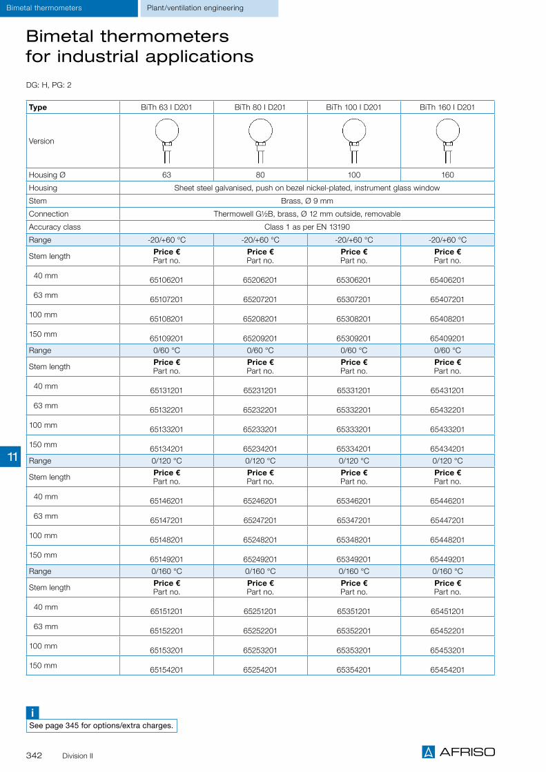
342 Division II
Bimetal thermometers for industrial applications
Type BiTh 63 I D201 BiTh 80 I D201 BiTh 100 I D201 BiTh 160 I D201
Version
Housing Ø 63 80 100 160
Housing Sheet steel galvanised, push on bezel nickel-plated, instrument glass window
Stem Brass, Ø 9 mm
Connection Thermowell G½B, brass, Ø 12 mm outside, removable
Accuracy class Class 1 as per EN 13190
Range -20/+60 °C -20/+60 °C -20/+60 °C -20/+60 °C
Stem length Price €Part no.
Price €Part no.
Price €Part no.
Price €Part no.
40 mm 65106201 65206201 65306201 65406201
63 mm 65107201 65207201 65307201 65407201
100 mm 65108201 65208201 65308201 65408201
150 mm 65109201 65209201 65309201 65409201
Range 0/60 °C 0/60 °C 0/60 °C 0/60 °C
Stem length Price €Part no.
Price €Part no.
Price €Part no.
Price €Part no.
40 mm 65131201 65231201 65331201 65431201
63 mm 65132201 65232201 65332201 65432201
100 mm 65133201 65233201 65333201 65433201
150 mm 65134201 65234201 65334201 65434201
Range 0/120 °C 0/120 °C 0/120 °C 0/120 °C
Stem length Price €Part no.
Price €Part no.
Price €Part no.
Price €Part no.
40 mm 65146201 65246201 65346201 65446201
63 mm 65147201 65247201 65347201 65447201
100 mm 65148201 65248201 65348201 65448201
150 mm 65149201 65249201 65349201 65449201
Range 0/160 °C 0/160 °C 0/160 °C 0/160 °C
Stem length Price €Part no.
Price €Part no.
Price €Part no.
Price €Part no.
40 mm 65151201 65251201 65351201 65451201
63 mm 65152201 65252201 65352201 65452201
100 mm 65153201 65253201 65353201 65453201
150 mm 65154201 65254201 65354201 65454201
DG: H, PG: 2
Plant/ventilation engineeringBimetal thermometers
iSee page 345 for options/extra charges.
11

343Division II
Type BiTh 63 LKF D211
BiTh 80 LKF D211
BiTh 100 LKF D211
BiTh 63 LKB D271
BiTh 80 LKB D271
BiTh 100 LKB D271
Version
Housing Ø 63 80 100 63 80 100
Housing Sheet steel galvanised, push on bezel nickel-plated, plastic window
Sheet steel galvanised, push on bezel nickel-plated, with back flange
Instrument glass window
Stem Brass, Ø 9 mm
Connection Flange, plastic, Ø 60 mm plain
Accuracy class Class 2 as per EN 13190
Range -30/+50 °C -30/+50 °C -30/+50 °C -30/+50 °C -30/+50 °C -30/+50 °C
Stem length Price €Part no.
Price €Part no.
Price €Part no.
Price €Part no.
Price €Part no.
Price €Part no.
100 mm 65613211
65713211
65813211
65613271
65713271 65813271
150 mm 65614211 65714211 65814211
65614271
65714271
65814271
200 mm 65615211 65715211 65815211
65615271 65715271 65815271
Range -20/+60 °C -20/+60 °C -20/+60 °C -20/+60 °C -20/+60 °C -20/+60 °C
Stem length Price €Part no.
Price €Part no.
Price €Part no.
Price € Part no.
Price €Part no.
Price €Part no.
100 mm 65608211
65708211 65808211 65608271
65708271 65808271
150 mm 65609211
65709211
65809211
65609271 65709271 65809271
200 mm 65610211 65710211
65810211
65610271 65710271 65810271
Range -20/+40 °C -20/+40 °C -20/+40 °C -20/+40 °C -20/+40 °C -20/+40 °C
Stem length Price €Part no.
Price €Part no.
Price €Part no.
Price €Part no.
Price € Part no.
Price €Part no.
100 mm 65623211
65723211
65823211
65623271 65723271 65823271
150 mm 65624211 65724211
65824211 65624271 65724271 65824271
200 mm 65625211 65725211 65825211
65625271 65725271 65825271
Range 0/60 °C 0/60 °C 0/60 °C 0/60 °C 0/60 °C 0/60 °C
Stem length Price €Part no.
Price €Part no.
Price €Part no.
Price €Part no.
Price €Part no.
Price €Part no.
100 mm 65633211
65733211 65833211 65633271
65733271
65833271
150 mm 65634211
65734211
65834211 65634271 65734271
65834271
200 mm 65635211 65735211
65835211 65635271
65735271
65835271
DG: H, PG: 2
Bimetal air duct thermometers
Bimetal thermometersPlant/ventilation engineering
iSee page 345 for options/extra charges.
11

344 Division II
Connection types for bimetal thermometers (thermometer)
Plain
Separate screw-in thermowell (with locking screw)
Separate weld-in thermowell (with locking screw)
Fixed male connection
Loose male connection
Loose union nut
Compression fitting, adjustable on stem
DIN thermowell
Thermometers Plant/ventilation engineering
① Housing② Stem③ Recess for locking screw
①
②
③
①
②
③
① Housing② Stem③ Loose connection, with thread for screw connection
①
②
③
① Housing② Thread for screw connection③ Thermowell pushed on, fixed with locking screw
① Housing② Locking screw for fixing.③ Thermowell pushed on, for welding
① Housing② Stem③ Fixed male connection, with thread for screw connection
① Housing② Seals on stem③ Stem④ Compression fitting adjustable
① Housing② Stem③ Thermowell as per DIN 43772 with thread for screw connection
① Housing② Stem③ Loose union nut, with female thread
①
②
③
①
②
③
①
②
④
③
①
②
③
①
②
③
11

345Division II
ThermometersPlant/ventilation engineering
Extra charges - connection types for bimetal thermometers (thermometer)
Type Bimetal thermometers
Material Brass Steel Stainless steel316 Ti
PG 2 3 3Stemlength mm
Price €Part no.
Price €Part no.
Price €Part no.
Separate weld-in thermowell(with locking screw)G½B for stem up to Ø 8 mm for BiTh Ø 10 mm for FTh
45 64506 64511 64501
63 64507 64512 64502
100 64508 64513 64503
150 64509 64514 64504
200 64510 64515 64505
250 64722 --- 64660
300 64723 --- 64721Separate weld-in thermowell(with locking screw)for stem up to Ø 8 mm for BiTh Ø 10 mm for FTh
45 --- 64516 64520
63 --- 64517 64521
100 --- 64450 64453
150 --- 64518 64522
200 --- 64519 64523Stem extensionper 100 mm 1) 64524 --- 64526Thermowell extensionPer 100 mm 64528 --- 64530
Fixed male connection G¼B 64532 --- 64534
Fixed male connection G½B 64447 --- 64454
Fixed male connection G¾B 64535 --- 64537
Loose male connection G¼B 64539 --- 64541
Loose male connection G½B 64542 --- 64544
Loose male connection G¾B 64546 --- 64548
Loose union nut G½, female 64448 --- 64455
Loose union nut G¾, female 64551 --- 64553
Compression fitting adjustable G½B --- --- 64556
Compression fitting adjustable G¾B --- --- 64558Capillary per metreStainless steel --- --- ---
Stem Ø 6 mm 2) On request ---
1) Only applicable to standard lengths 200/250/300 mm – extra charge for special lengths: € 28.00. 2) Only for centre back connection, limited measuring ranges (0–120 °C, 0–300 °C, 0–500 °C).
DG: H
11

346 Division II
Extra charges for bimetal thermometers(industrial version)
DG: H
Thermometers Plant/ventilation engineering
Bimetal thermometers
Housing diameter (mm) < 100 100 160
Price €Part no.
Price €Part no.
Price €Part no.
Red mark on dial64465 64470 64478
1 reference pointer red, external rotary knob adjustment(window = plastic)Tmax 160 °C only for instruments without filling 64467 64471 ---
Other ranges for bimetal thermometers(extra charge as compared to version 0/120 °C)
Minimum stem length centre back
(in mm)*
Minimum stem length bottom
(in mm)*Price €
-20/+40 °C 63 100
-20/+60 °C 63 63-30/+50 °C 63 63-40/+40 °C 63 63
-40/+60 °C 63 630/60 °C 63 1000/80 °C 63 63
0/100 °C 63 63
0/200 °C 63 63
0/250 °C 100 100 On request
0/300 °C 75 63
0/400 °C 75 75 On request
0/500 °C 63 630/600 °C 75 175 On request
* For version with separate thermowell.
11

347Division II
Industrial thermometers
Application
Options
Nominal size110 x 30 – 150 x 36 – 200 x 36
Upper partAluminium, V-shaped, polished, anodised brass-coloured. Numbers of the measuring range on the right scale side below the anodised layer, printed, black. Adjustable by means of brass nut (spanner size SW 22) so that readings from any angle are possible.
Glass insert (capillary)Prismatic capillary, completely made of glass, Ø 6 mm. Graduation marks of the capillary burnt in, black, completely resistant.Main graduation marks corresponding to the num-bers printed on the housing are especially bold and easy to read.
Thermometer fillingStandard version: Blue liquid indicating from -60 to +200 °C.
StemBrass, Ø 10 mm, with fixed thread G½B.Stainless steel version on request.
AccuracyDIN 16195
Ranges °C-30/+50, 0/60, 0/100, 0/120, 0/160
Mounting positionStraightAngled 90°Angled 135°
Stem lengths (mm)40, 63, 100, 160
Heating, industry, mechanical engineering
iSee page 348 for prices.
Technical specifications
Type L L1
VMTh 110 110 4063100160
VMTh 150 150
VMTh 200 200
SW 27
G½BL1L
Ø10
Housing types and dimensions (mm)
G½BSW 27
L1
Ø10
L
Extremely robust due to full metal housing Vibration-resistant glass thermometers Stainless steel version possible Excellent readability due to blue thermometer filling
Other ranges Other stem lengths Other stem materials Other connection threads Upper part anodised aluminium-coloured Upper part made of plastic Thermowells
Page 349
A
Plant engineering ThermometersThermometers
11

348 Division II
Plant engineeringIndustrial thermometersIndustrial thermometers
Type VMTh 110 VMTh 110 VMTh 150 VMTh 150 VMTh 200 VMTh 200
Version
Nominal size 110 x 30 110 x 30 150 x 36 150 x 36 200 x 36 200 x 36DIN 16181 16182 16185 16186 16189 16190Mounting position Straight Angled 90° 1) Straight Angled 90° 1) Straight Angled 90° 1)
Housing Aluminium, anodised brass-colouredStem Brass, Ø 10 mmConnection Version B with screw-in socket G½B, brass 2)
Accuracy As per DIN 16195Range -30/+50 °C -30/+50 °C -30/+50 °C -30/+50 °C -30/+50 °C -30/+50 °CStem length Price €
Part no.Price €Part no.
Price €Part no.
Price €Part no.
Price €Part no.
Price €Part no.
40 mm64101 64120 64136 64150 --- ---
63 mm64102 64121 64137 64151 64165 64181
100 mm64103 64122 64138 64152 64166 64182
160 mm64104 64123 64139 64153 64167 64183
Range 0/60 °C 0/60 °C 0/60 °C 0/60 °C 0/60 °C 0/60 °CStem length Price €
Part no.Price €Part no.
Price €Part no.
Price €Part no.
Price €Part no.
Price €Part no.
40 mm64106 64124 64140 64154 --- ---
63 mm64107 64125 64141 64155 64169 64185
100 mm64108 64126 64142 64156 64170 64186
160 mm64109 64127 64143 64157 64171 64187
Range 0/100 °C 0/100 °C 0/100 °C 0/100 °C 0/100 °C 0/100 °CStem length Price €
Part no.Price €Part no.
Price €Part no.
Price €Part no.
Price €Part no.
Price €Part no.
40 mm--- --- 64330 64335
--- ---
63 mm--- --- 64331 64336
--- ---
100 mm--- --- 64332 64337
--- ---
160 mm--- --- 64333 64338
--- ---
Range 0/120 °C 0/120 °C 0/120 °C 0/120 °C 0/120 °C 0/120 °CStem length Price €
Part no.Price €Part no.
Price €Part no.
Price €Part no.
Price €Part no.
Price €Part no.
40 mm64111 64128 64100 64110 --- ---
63 mm64112 64129 64105 64115 64173 64189
100 mm64113 64130 64144 64158 64174 64190
160 mm64114 64131 64145 64159 64175 64191
Range 0/160 °C 0/160 °C 0/160 °C 0/160 °C 0/160 °C 0/160 °CStem length Price €
Part no.Price €Part no.
Price €Part no.
Price €Part no.
Price €Part no.
Price €Part no.
40 mm64116 64132 64146 64160 --- ---
63 mm64117 64133 64147 64161 64177 64193
100 mm64118 64134 64148 64162 64178 64194
160 mm64119 64135 64149 64163 64179 64195
1) Version with mounting position 135° on request. 2) Extra charge for stainless steel screw-in socket: 29.90 €.
DG: H, PG: 2
Industrial thermometers
11

349Division II
Pockets for thermometers and thermostats with capillary tube
DG: G, PG: 2
Type Pocket½" 7 x 8 mm
Pocket½" 9 x 10 mm
Pocket½" 15 x 16 mm
Profile pocket ½" 15 x 16 mm
Dimensions (mm)
Connection ½ NPT ½ NPT ½ NPT ½ NPT
Pmax* 4 bar 4 bar 4 bar 4 bar
Tmax* 200 °C 200 °C 200 °C 200 °C
Material Brass/Cu alloy
Stem length L1 Price €Part no. PU** Price €
Part no. PU** Price €Part no. PU** Price €
Part no. PU**
50 mm 67320 200 On request67326 200 --- ---
100 mm 67321 200 On request67327 200 67331 200 67335 200
120 mm On request67322 200 On request
67328 200 On request67332 200 On request
67336 200
150 mm 67323 200 67329 200 On request67333 200 67337 200
200 mm 67324 200 67330 200 67334 200 67338 200
As above, but nickel-plated
Stem length L1 Price €Part no. PU** Price €
Part no. PU** Price €Part no. PU** Price €
Part no. PU**
50 mm On request67320N 200 On request 200 --- ---
100 mm 67321N 200 On request 200 67331N 200 67335N 200
120 mm On request67322N 200 On request 200 On request
67332N 200 On request67336N 200
150 mm 67323N 200 On request 200 67333N 200 67337N 200
200 mm 67324N 200 On request 200 67334N 200 67338N 200
* Applies to static load (load always depends on medium, pressure and temperature of medium, flow rate, installation length and material of thermowell).** Delivery only in packing units (PU) – minimum order quantity for non-stock items = 1 packing unit.
Accessories Thermostats
11

350 Division II
Heating/plumbingThermostats
Thermostats with housing
DG: G, PG: 4 Adjustment Operating range/switching point
Capillary length Stem length Type Part no. Price €
Surface mounting thermostats with housing
External 20/60 °C --- --- GAT/7RC 67400X
External 20/90 °C --- --- GAT/7RC 67401X
Internal 20/60 °C --- --- GAT/7HC 67402X
Internal 20/90 °C --- --- GAT/7HC 67403X
Internal 30/70 °C --- --- GSA/9SC 67404X
Immersion thermostats with housing
External 0/90 °C --- 100 mm GTT/7RG 67407X
External 0/90 °C --- 150 mm GTT/7RG 67408AX
External 0/90 °C --- 200 mm GTT/7RG 67408BX
Internal 0/90 °C --- 100 mm GTT/7HG 67413X
Internal 0/90 °C --- 150 mm GTT/7HG 67414AX
Internal 0/90 °C --- 200 mm GTT/7HG 67414BX
Fixed 100 °C --- 100 mm GST/9SG 67417X
Capillary type thermostats with housing/room thermostats with housing
External 0/90 °C 1,000 mm --- GTK/7RD 67421X
External 0/90 °C 2,000 mm --- GTK/7RD 67424X
Internal 70/110 °C 1,500 mm --- GSK/9SF 67418X
External 0/40 °C --- --- GRT/7RT 67464X
External 0/60 °C --- --- GRT/7RT 67465X
Internal 0/40 °C --- --- GRT/7HT 67466X
Internal 0/60 °C --- --- GRT/7HT 67467X
Twin thermostats with housing
Internal/exter-nal 0/90 °C – 30/120 °C --- 100 mm GDT/8HR 67447X
Fixed/external 0/90 °C (100 °C) --- 100 mm GDT/8RS 67453X
Fixed/external 0/90 °C (100 °C) --- 150 mm GDT/8RS 67454AX
Fixed/external 0/90 °C (100 °C) --- 200 mm GDT/8RS 67454BX
* Minimum order quantity for non-stock items = 100 pieces.
11
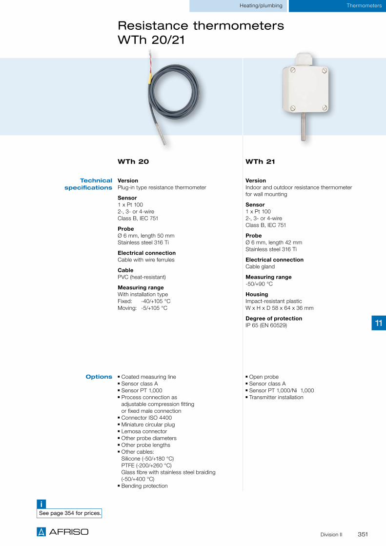
351Division II
Resistance thermometers WTh 20/21
WTh 21WTh 20
VersionPlug-in type resistance thermometer
Sensor1 x Pt 1002-, 3- or 4-wireClass B, IEC 751
ProbeØ 6 mm, length 50 mmStainless steel 316 Ti
Electrical connectionCable with wire ferrules
CablePVC (heat-resistant)
Measuring rangeWith installation type Fixed: -40/+105 °C Moving: -5/+105 °C
VersionIndoor and outdoor resistance thermometer for wall mounting
Sensor1 x Pt 1002-, 3- or 4-wireClass B, IEC 751
ProbeØ 6 mm, length 42 mmStainless steel 316 Ti
Electrical connectionCable gland
Measuring range-50/+90 °C
HousingImpact-resistant plasticW x H x D 58 x 64 x 36 mm
Degree of protectionIP 65 (EN 60529)
Technical specifications
Options
iSee page 354 for prices.
Coated measuring line Sensor class A Sensor PT 1,000 Process connection as adjustable compression fitting or fixed male connection
Connector ISO 4400 Miniature circular plug Lemosa connector Other probe diameters Other probe lengths Other cables: Silicone (-50/+180 °C) PTFE (-200/+260 °C) Glass fibre with stainless steel braiding (-50/+400 °C)
Bending protection
Open probe Sensor class A Sensor PT 1,000/Ni 1,000 Transmitter installation
Heating/plumbing Thermometers
11

352
WTh 22
VersionResistance thermometer especially for use in air ducts
Sensor1 x Pt 1002-, 3- or 4-wireClass B, IEC 751
ProbeØ 8 x 1 mm, perforatedStainless steel 316 Ti
Process connectionMounting flange Ø 40 mm, adjustable, stainless steel
Installation lengths100, 160, 250 mm
HousingImpact-resistant plasticW x H x D 58 x 64 x 36 mm
Degree of protectionIP 54 (EN 60529)
Measuring range0/130 °C
Options Process connection G½B (adjustable compression fitting or fixed male connection)
Sensor class A Sensor PT 1,000 Transmitter installation (standard: 0/100 °C = 4–20 mA)
Resistance thermometers WTh 22/23
Technical specifications
Heating/plumbingThermometers
WTh 23
Division II
VersionCompact screw-in resistance thermometer specially for heating, ventilation and air conditioning applications
Sensor1 x Pt 1002-, 3- or 4-wireClass B, IEC 751
Measuring insertNot replaceable
ThermowellØ 6 mm, stainless steel 316 Ti
Process connectionG¼B stainless steel 316 Ti
Installation length100 mm
Connection head (degree of protection)Type J, aluminium die cast (IP 66)
Measuring range-35/+180 °C
Sensor class A Sensor PT 1,000 Transmitter installation Other thermowell diameters Thermowell with bend, measuring tip with spring Neck Other process connections Other installation lengths
Description
iSee page 354 for prices.
11
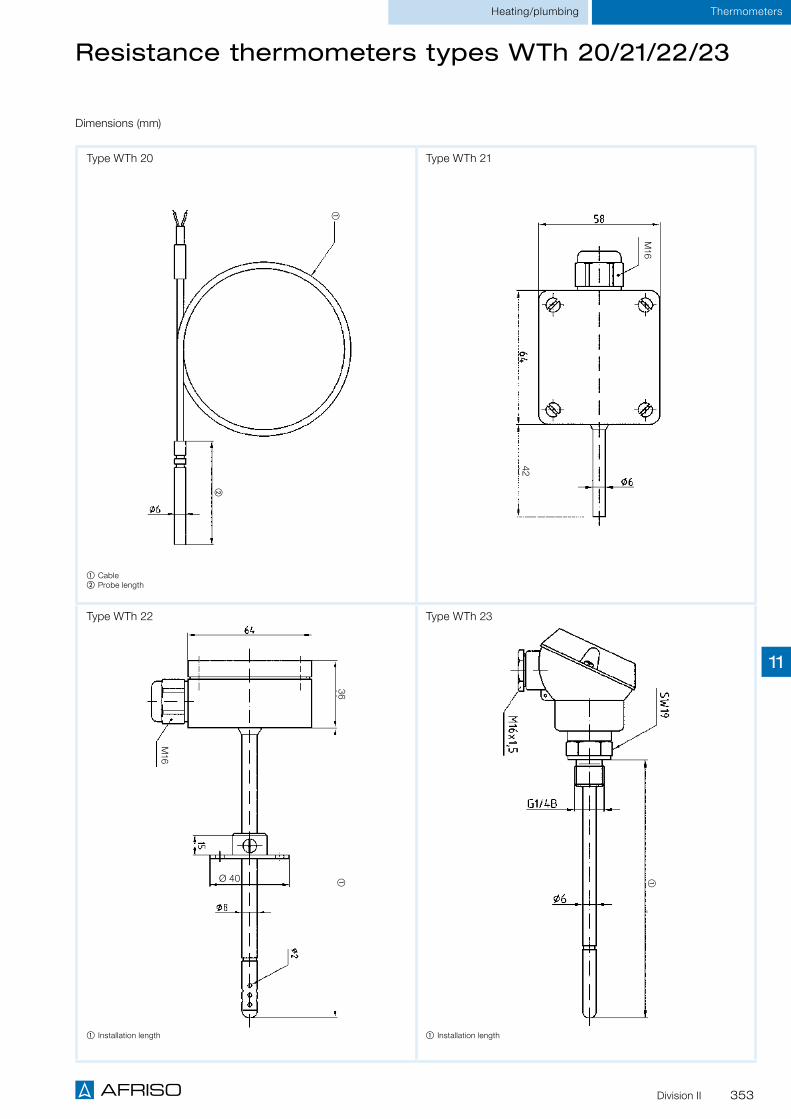
353Division II
Heating/plumbing Thermometers
Resistance thermometers types WTh 20/21/22/23
①
②
Dimensions (mm)
M16
42
①36
Ø 40
M16
① Cable② Probe length
① Installation length
①
① Installation length
Type WTh 20 Type WTh 21
Type WTh 22 Type WTh 23
11

354 Division II
Resistance thermometers
DG: H, PG: 4
Type WTh 20 WTh 21 WTh 22 WTh 23
Version
Sensor 1 x Pt 1003-wire, class B
1 x Pt 1003-wire, class B
1 x Pt 1003-wire, class B
1 x Pt 1003-wire, class B
Thermowell/probe diameterMaterial
6 mmStainless steel 316 Ti
6 mmStainless steel 316 Ti
Perforated 8 mm Stainless steel 316 Ti
6 mmStainless steel 316 Ti
Neck --- --- --- ---
Process connection --- --- Mounting flange Ø 40 mm
G¼BStainless steel 316 Ti
Connection head / electrical connection
PVC cableWire ferrules Plastic/cable gland Plastic/cable gland Type J/cable gland
Measuring range fixed (moving)
-40/+105 °C (-5/+105 °C) -50/+90 °C 0/130 °C -35/+180 °C
Installation length Price €Part no.
Price €Part no.
Price €Part no.
Price €Part no.
44 mm Probe length 50 mmUp to cable length
2,000 mm
32220
Cableextension
per500 mm
32400 --- ---
100 mm --- 32215 32225
160 mm --- 32216 32226
250 mm --- 32217 32227
400 mm --- --- 32228
Extra charges (without PG) Price € Price € Price € Price €
Per additional 100 mm ** installation length
--- ---
1 x Pt 1004-wire
2 x Pt 1002-wire --- --- ---
Sensor class A
Connection headType BBK --- ---
Transmitter installation*DC 7.5–30 V/4–20 mA ---
* Applies to standard measuring ranges (-50/+50, 0/50, 0/100, 0/120, 0/150, 0/200, 0/300 °C), extra charge in all other cases € 11.00. ** Applies up to 1000 mm, one-time extra charge for installation length greater than 1000 mm: € 62.00.
Heating/plumbingThermometers
iSee the catalogue INDUSTRIAL TECHNOLOGY for additional resistance thermometers.
11

355
Temperature measuring instruments and controllers for INDUSTRIAL TECHNOLOGY
CATALOGUE INDUSTRIAL TECHNOLOGY
Overview thermometers Catalogue Industrial Technology
For corrosive media
Pointer adjustable in case of "plain" connection
Nominal sizes63 – 80 – 100
Ranges -20/+60, 0/60, 0/120, 0/160 °C
For chemical, process engineering and food industry applications
Many options for adaptation to specific applications
Nominal sizes63 – 80 – 100
Ranges -20/+60, 0/60, 0/120, 0/160 °C
Bimetal stainless steel thermometers
Page 253
Page 253
For chemical, process engineering and food industry applications
Fast response
Nominal sizes100 – 160
Ranges -20/+60, 0/60, 0/120, 0/160, 0/200, 0/300, 0/400, 0/500 °C
Gas filled thermometers
Page 257
Resistance thermometers WTh 24 - 28
Versions for machine and plant engineering, food, beverages and pharmaceuti-cal industries, biotechnology
For medium to high pressure and flow loads
Pt 100 sensor
Installation length up to 400 mm
Measuring ranges-35/+400, -35/+300, -35/+550 °C
From page 267
Bimetal thermometers for chemical applications
Resistance thermometers WTh 30
Hygienic design as per EHEDG recommendations
Various process connections, transducer can be integrated
Pt 100 sensor
Installation length up to 300 mm
Measuring ranges-50/+200 °C
From page 273
iThis and many other products can be found in the catalogueINDUSTRIAL TECHNOLOGY

356
Catalogue Portable Measuring Instruments Overview service instruments
The BlueLine measuring instrument series at a glance
BLUELYZER ST EUROLYZER STe EUROLYZER STx MULTILYZER STe MAXILYZER NG / NG Plus
Dust measuring instrument
STM 225 / 500Series
S4600 ST Series S2600 TM7 / TMD7 TM6 TM9-IR MFM 22 FT series BlueAir ST GSP series
O2
Par
amet
ers/
mea
sure
d v
alu
es
• • • • •CO (up to 4,000 ppm) • • • •CO (up to 6,000 ppm) •** • • • •CO (up to 10,000 ppm) • •CO2 (calculated) • • • • •NO • • • •NO2 • •NOX • • • •CO (20,000 ppm) / CO (40,000 ppm) •** •**SO2 • •Particulate matter •Methane • • • • •Propane (liquefied gas) • • • • • •Butane •Lambda • • • • •Eta efficiency / eta coefficient • • • • •Flue gas loss qA • • • • •Temperature • • • • • • • • •*** • •Pressure • • • • • • •Dew point • • • • • •Humidity in % • •Volume flow •*** •*** •*** •Measurements of filters, ventilation systems, ducts
Typ
ical
ap
plic
atio
ns
area
s
• • • •Measurements of production facilities, tanks, gas pipes • • • • •Burner adjustment/servicing (gas, oil, solid fuel systems) • • • • • • • •CO ambient measurement •** • • • •Servicing of water heaters • • • • • • • •Servicing of CHP systems • • • •Flue gas measurement • • • • • •Pressure measurement • • • • • • •Measurement of inlet pressure, flow pressure, static pressure, nozzle pressure • • • • • •Pressure / vacuum measurement • • • • • • •Differential pressure measurement •** •** • • • •Vacuum measurement • •Temperature measurement (flue gas, air, external wall) • • • • • • • • •Temperature measurement (water) • • •Temperature measurement (moving objects) •Surface temperature measurement • • • • • • • •Differential temperature measurement • •** •** • • •**Draft / chimney draft measurement • • • • • • •Ventilation loss measurement • •Flue gas loss measurement • • • • •Heating system check •4 Pa test •Gas leak detection •Gas concentration measurement •Flow rate measurement (water)
Humidity measurement (material / moisture / climatic conditions in rooms / mould) •* • •Air velocity •*** •*** •*** •*** •Gas treatment -/•BlmSchV
Ap
pro
vals • • • •
DIN EN 50379-2 • • • • • • •DIN EN 15378 •KÜO • • • •
Page 12 Page 14 Page 16 Page 18 Pages 20/22 Pages 24/26 Page 36 Page 35 Page 52 Page 53 Page 53 Page 54 Page 56 Page 62 Page 46* See product description on the catalogue page or in the operating instructions.** Depends on product version.*** Optional
iThis and many other products can be found in the cataloguePORTABLE MEASURING INSTRUMENTS

357
The BlueLine measuring instrument series at a glance
Catalogue Portable Measuring InstrumentsOverview service instruments
BLUELYZER ST EUROLYZER STe EUROLYZER STx MULTILYZER STe MAXILYZER NG / NG Plus
Dust measuring instrument
STM 225 / 500Series
S4600 ST Series S2600 TM7 / TMD7 TM6 TM9-IR MFM 22 FT series BlueAir ST GSP series
O2
Par
amet
ers/
mea
sure
d v
alu
es
• • • • •CO (up to 4,000 ppm) • • • •CO (up to 6,000 ppm) •** • • • •CO (up to 10,000 ppm) • •CO2 (calculated) • • • • •NO • • • •NO2 • •NOX • • • •CO (20,000 ppm) / CO (40,000 ppm) •** •**SO2 • •Particulate matter •Methane • • • • •Propane (liquefied gas) • • • • • •Butane •Lambda • • • • •Eta efficiency / eta coefficient • • • • •Flue gas loss qA • • • • •Temperature • • • • • • • • •*** • •Pressure • • • • • • •Dew point • • • • • •Humidity in % • •Volume flow •*** •*** •*** •Measurements of filters, ventilation systems, ducts
Typ
ical
ap
plic
atio
ns
area
s
• • • •Measurements of production facilities, tanks, gas pipes • • • • •Burner adjustment/servicing (gas, oil, solid fuel systems) • • • • • • • •CO ambient measurement •** • • • •Servicing of water heaters • • • • • • • •Servicing of CHP systems • • • •Flue gas measurement • • • • • •Pressure measurement • • • • • • •Measurement of inlet pressure, flow pressure, static pressure, nozzle pressure • • • • • •Pressure / vacuum measurement • • • • • • •Differential pressure measurement •** •** • • • •Vacuum measurement • •Temperature measurement (flue gas, air, external wall) • • • • • • • • •Temperature measurement (water) • • •Temperature measurement (moving objects) •Surface temperature measurement • • • • • • • •Differential temperature measurement • •** •** • • •**Draft / chimney draft measurement • • • • • • •Ventilation loss measurement • •Flue gas loss measurement • • • • •Heating system check •4 Pa test •Gas leak detection •Gas concentration measurement •Flow rate measurement (water)
Humidity measurement (material / moisture / climatic conditions in rooms / mould) •* • •Air velocity •*** •*** •*** •*** •Gas treatment -/•BlmSchV
Ap
pro
vals • • • •
DIN EN 50379-2 • • • • • • •DIN EN 15378 •KÜO • • • •
Page 12 Page 14 Page 16 Page 18 Pages 20/22 Pages 24/26 Page 36 Page 35 Page 52 Page 53 Page 53 Page 54 Page 56 Page 62 Page 46


359
CHAPTER 12
Appendix – Technical Information
Seminars and training 360
SERVICE
Enquiry – level measurement 377
CHECK LISTS
Terms and conditions 386
Liquid-based leak detector LAS 381
Liquid-based leak detector LAG 382
Vacuum type leak detectors 383
Pressure type leak detectors 384
Protection equipment against siphoning 385
TERMS/INDEX
TEST REPORTS
AFRISO services 361
Downloads 365
Enquiry – thermometers 378
Enquiry – resistance thermometers 379
Enquiry – pressure gauges 380
Index 391
AFRISO specialised company search 366
VDI 3805 362
3-A 370
EHEDG, reddot 371
Flange standard EN 1092, International comparison of grades 372
TECHNICAL INFORMATION
Conversion table pressure units 373
Pressure Equipment Directive 97/23/EC (PED) 374
Selection criteria /safety considerations for pressure gauges as per EN 837-2 375
ISO 9001, ISO 14001, ATEX 367
CERTIFICATES
Occupational health and safety management system, DNV 368
Pressure Equipment Directive 97/23/EC, GOSSTANDART, PA3PEIIIEH NE 369
Information material – brochures, CD-ROMs 364
12

360
Appendix Service
Professional and practical. With our courses, workshops and seminars, you benefit from our many years of in-depth experience in the field of measuring and control technology. Our entire offering responds to current issues and standards as well as customer requirements. Of course, it is also pos-sible to arrange for individual in-house courses and seminars to be provided at your site.
AFRISO training programme
Courses and Training
Tank protection and leak protection liningTwo-day seminar on the installation of leak pro-tection linings and leak detectors (theory and practice).
Hydraulic BalancingOne-day seminar on hydraulic balancing with the VarioQ valve program with measuring function.
Heating system checkOne-day seminar on the inspection and evaluation of heating systems.
Gas checkOne-day seminar on checking gas installations.
Testing of drinking water pipesOne-day seminar on testing drinking water instal-lations and drainage lines. Legal foundations.
iWe will be glad to answer your questions concerning our seminars. Please get in touch with us. E-mail: [email protected] Telephone: +49-7135-102-222
Visit us at www.afriso.com/training for our full training programme and additional information.
12

361
AppendixService
Information and presentationWhether telephone support or on site: Our con-sultants speak your language – we provide you with personal and individual consulting worldwide. And if you have an in-house event for your cus-tomers, we will be glad to participate.
After sales serviceWhether commissioning, professional mainte-nance, calibration or function checks – a network of service centres and our specialists in the plant support you in getting the maximum out of your AFRISO product. For safe processes, precise measuring results, compliance with legal require-ments and a long service life.
Repair serviceIn the case of a malfunction, send us your instru-ment along with a short description of the prob-lem. We will repair it within five workdays. Promise.
Rental serviceYou cannot afford to do without your instrument? No problem, our on-site service ensures that you remain on duty. We will have your instrument picked up and send you a rental instrument. For a low rental fee. Ask for availability of this service in your country.
Our Service – Your Benefit
iOur service and repair department will be glad to answer your questions. Please get in touch with us. Telephone: +49 7135 102-211
Flexible, cost-aware, on schedule, solution-orientated and fast – the AFRISO team always provides the decisive added value.
12

362 Division I
VDI 3805 – TGA product data interchange format for design
The VDI directive VDI 3805 defines the interchange of product data between manufacturers, planners, builders and owners in the area of technical building equipment (TGA). It ensures a uniform data description of the entire technical building equipment. Files as per VDI 3805 are manufacturer- and software-independent and contain all relevant data such as performance and sizing data, characteris-tics, function descriptions, special properties, assignment of images, data sheets, suitable accesso-ries, part numbers or classification according to the corresponding main groups (VDI sheets). Information on geometry such as connection and design data, materials, surfaces and colours is also available.
The open standard of the TGA product data interchange format allows planners and architects to optimise their planning and design processes. If the components are integrated into heating, ventilation and sanitary system planning, it can be easily checked whether they fit into the design and the product information is automatically integrated into specifications and tenders. Even after completion of the project and the building, the product data allow for efficient support in Facility Management tasks such as maintenance and repair.
What is VDI 3805?
Appendix Service
Advantages of VDI 3805 Various CAD representation modes: coarse and detail view as well as symbolic view
Easy and reliable collision check via defined spaces Detailed description of the connections for easy installation in distribution systems
Representation of connection points, direction of flow, installation dimensions and collision dimensions
Assignment of accessories at a glance Can be used for technical calculations, analyses and simulation (e.g. pipeline calculation, system evaluation)
Low data volume Support of the main CAD formats basing on DXF as well as other formats such as IGES and STEP
Can be used for calculation, business processes and Facility Management
With the VDI 3805 data record from AFRISO-GAMPPER all relevant technical building equipment product data for specifications and tenders is available.
a brand of the AFRISO group
12

363Division I
AppendixService
Easy product selection: WebSelektor
The current version of the VDI 3805 product data record of AFRISO and GAMPPER is available for download at www.afriso.de/vdi3805. In addition, the WebSelector provides online access to the data and you can select the desired product using a range of selection criteria. The geometry data can be placed as 2D or 3D objects in detail and coarse representations or as a symbol, for example by means of drag&drop – independent of the CAD platform used.
In addition, the WebSelector provides high transparency by offering an easy product search and making it possible to switch between the required information on the component such as technical, commercial or geometric data.
WebSelektor for easy product selection and representation of the TGA product data record at www.afriso.de/vdi3805 or www.vdi3805.org
a brand of the AFRISO group
12

364
Appendix Service
Flyers, brochures and product overviews
Flyers, brochures, and product overviews provide information on individual products or complete product ranges for various application areas.
Product literature for end consumers
Product literature for end users is a great medium for fairs, exhibition rooms, mail campaigns and other activities. They present the benefits and applications of AFRISO products for building technology and tank protection in private households in a concise, easy-to-understand way.
New media: DVDs
The AFRISO main catalogues are available on DVD.
AFRISO information material – brochures, flyers and DVDs
Discover new opportunities and sales potential with AFRISO quality products. We offer a large variety of information materials and media for wholesalers, points of sale, associations, HVAC companies and tank protection companies. You can order these media from us free of charge – even large numbers of copies. All printed materials allow you to add your company stamp to the back page.
iAll information material can be downloaded from www.afriso.com. If you want to order printed material for free, simply specify the number of copies required in your e-mail to [email protected].
Technik für UmweltschutzMessen. Regeln. Überwachen.
12

365
AppendixService
Operating instructions
In addition to product descriptions, the operating instructions include detailed technical data, mounting, installation and safety information as well as information on approvals for all AFRISO products.
Forms
Checklists with indication of application conditions and planned use of AFRISO products allow us to quickly process your enquiries or returns.
Software
Due to continuous improvements and to changes in legislation and directives, we provide software updates for elec-tronic measuring instruments on an ongoing basis. The updates and the appropriate instructions can be down-loaded from our website for free.
Certificates
A number of manufacturer certificates and declarations as well as numerous specific approvals, certificates and compliance tests attest to the out-standing quality and performance of AFRISO products.
Downloads
Visit www.afriso.com for comprehensive product information and details, technical specifications, terms and conditions, valuable downloads and the latest news.
12

366
Appendix Service
AFRISO specialised company search
Find a specialised professional company fast
AFRISO has an excellent reputation with end users – numerous consumers visit our website every day. The feature "Specialised company search" on our website assists users in finding qualified companies specialised in AFRISO prod-ucts. You are a company specialised in HVAC, electrical engineering or tank protection and like
to use AFRISO quality products for the profes-sional equipment of tanks, heating systems, drink-ing water installations or for hydraulic balancing? Then register for our service – free of charge, no obligations www.afriso.de/registration.
1. Enter the post code/ZIP or the city, limit the range, if required, and start the search.
2. All registered specialised com-panies are shown on a map with the appropriate information, sort-ed by distance from your site.
This is how the "Find a specialised company" feature works
12

367
AppendixCertificates
At AFRISO, quality is systematically planned and, at every stage of product development and production, managed and monitored. A wide variety of approvals and certificates attests to this. Stringent testing by national and international approval bodies ensures maximum reliability.
Certificates and approvals
12

368
Appendix Certificates
12

369
AppendixCertificates
12

370
Appendix Certificates
12

371Division II
AppendixCertificates
12

372 Division II
Appendix Technical information
Information on the flange standard EN 1092 / international comparison of grades
Conversion to EN 1092The new flange standard EN 1092-1 for all flange types has been in effect since June 2002. Currently, the old standards are still in use. However, this will change since the old standards are no longer maintained and updated. New standards will exclusively refer to EN 1092.
AFRISO flangesAFRISO usually ships type B1 flanges as per EN 1092. This flange type differs from the former type C flanges as per DIN 2630 only in terms of the surface quality of the sealing surface. Flanges according to the old standard are available upon request.
Stainless steel – international comparison of grades
Material no. DIN AISI
1.4301 X 5 CrNi 18 10 304
1.4305 x 8 CrNiS 18-9 303
1.4310 x 12 CrNi 177 / x 10 CrNi 188 301
1.4401 X 5 CrNiMo 17 123 316
1.4404 X 2 CrNiMo 17 132 316 L
1.4435 X 2 CrNiMo 18 143 316 L
1.4462 X 2 CrNiMoN 22 53 318 L
1.4542 X 5 CrNiCuNb 16-4 630
1.4571 X 6 CrNiMoTi 17 122 316 Ti
1.4541 X 6 CrNiTi 18-10 321
OLD(DIN 25../26..)
NEW(EN 1092-1)
Flanges Sealing surface Type Standard RZ (µm) Type RZ (µm)
Flat AB
DIN 2573DIN 2576
–40 – 160
A 12.5 – 50
Raised faceCDE
DIN 2630to
DIN 2638
40 – 1604016
B1 *
B2 **
12.5 – 50
3.2 – 12.5
Tongue
Groove
F
N
DIN 2512
C
D
3.2 – 12.5
Spigot
Recess
V 13
R 13
DIN 2513
E
F
12.5 – 50
Spigot
Recess
V 14
R 14
DIN 2514for
O rings
H
G
3.2 – 12.5
* Typically PN 2.5 to PN 40 ** Typically PN 63 and PN 100
DIN: Deutsches Institut für Normung
AISI: American Iron Steel Institute
12

373Division II
AppendixTechnical information
Conversion table for standard pressure units
Un
itb
ar
mb
ar
Pa
kPa
MP
ak
p/m
m²
kp
/cm
²at
mm
mH
gm
WC
mm
WC
psi
"H2O
"Hg
1 b
ar
110
00
100
00
010
00.
10.
0101
9716
1.01
9716
0.98
6923
750.
062
10.1
9716
1019
7.16
14.5
0377
401.
463
29.5
3
1 m
ba
r0.
001
110
00.
10.
00
010.
00
001
0197
20.
001
0197
160.
00
0986
923
0.75
006
20.
0101
9716
10.1
9716
0.01
4503
770.
4014
630.
0295
3
1 P
a0.
00
001
0.01
10.
001
0.0
00
001
0.0
00
00
0102
0.0
00
0101
970.
00
00
0986
90.
007
5006
20.
00
0101
9716
0.10
1971
60.
00
0145
038
0.0
0401
463
0.0
002
953
1 kP
a0.
0110
100
01
0.0
010.
00
0101
9716
0.01
0197
160.
009
8692
37.
5006
20.
1019
716
101.
9716
0.14
5037
74.
0146
30.
2953
1 M
Pa
1010
00
010
00
00
010
00
10.
1019
716
10.1
9716
9.86
923
750
0.62
101.
9716
1019
71.6
145.
0377
4014
.63
295.
3
1 k
p/m
m²
98.0
665
9806
6.5
9806
650
9806
.65
9.80
665
110
096
.784
173
555.
910
00
100
00
00
1422
.334
439
370.
0828
95.9
016
1 k
p/c
m²
0.98
0665
980.
665
9806
6.5
98.0
665
0.09
8066
50.
011
0.96
7841
735.
559
1010
00
014
.223
344
393.
7008
28.9
5901
6
1 at
m1.
0132
510
13.2
510
1325
101.
325
0.10
1325
0.01
0332
271.
0332
271
760
10.3
3227
1033
2.27
14.6
959
406.
3885
829
.921
26
1 m
mH
g0.
001
3332
241.
3332
2413
3.32
240.
1333
224
0.0
001
3332
20.
00
001
3951
0.0
0135
951
0.0
0131
5789
10.
0136
013
.60
0.01
9336
0.53
524
0.03
937
1 m
WC
0.09
8066
598
.066
598
06.6
59.
8066
50.
009
8066
50.
001
0.1
0.09
6784
173
.556
110
00
1.42
2327
439
.370
082.
8959
016
1 m
mW
C0.
00
009
8067
0.09
8066
59.
8066
50.
009
8066
50.
00
00
0980
70.
00
00
010.
00
010.
00
009
6784
0.07
3556
0.0
011
0.0
0142
2327
0.03
9370
080.
002
8959
02
1 p
si0.
0689
4757
68.9
4757
6894
.757
6.89
4757
0.0
0689
4757
0.0
0703
070.
0703
070.
0680
4651
.715
217
0.70
307
703.
071
27.6
82.
0352
9
1 "H
2O0.
002
4908
92.
4908
924
9.08
90.
2490
890.
00
0249
089
0.0
00
0254
0.0
0254
0.0
0245
8317
1.86
832
0.02
5425
.40.
0361
31
0.07
356
1 "H
g0.
0338
639
33.8
639
3386
.43.
3864
0.0
0338
640.
00
0345
312
0.03
4531
20.
0334
2104
25.4
0.34
5316
345.
316
0.49
115
13.5
951
12

374 Division II
Appendix Technical information
Information on the Pressure Equipment Directive (PED) 97/23/ECPressure Equipment Directive (PED)
The European Pressure Equipment Directive (PED) came into force on May 30, 2002. The following paragraphs provide some information on the Directive itself and on our activities within the framework of this Directive.
AFRISO-EURO-INDEX GmbH pressure gauges with a full scale value of > 0.5 bar are subject to the Pressure Equipment Directive and meet the appropriate requirements.
Since the future application conditions of most pressure gauges are normally not completely known at the time of manufacture, we always manufacture our products in accordance with the most stringent criteria (gases of group 1).
This way, our pressure gauges with a full scale value of 200 bar receive a CE mark according to the conformity assessment procedure.
Pressure gauges with a connection flange of > DN 25 receive a CE mark with a full scale range of 0.5 bar and greater.
The CE mark is attached to the outside of the housing (type designation plate).
A declaration of conformity is provided on request.
Detailed operating instructions and the appropriate data sheets are available at www.afriso.com. They can also be sent to you on request.
Pressure gauges with a full scale value of less than 0.5 bar and loose chemical seals do not fall under the PED and must not carry a CE mark.
Pressure gauges with a full scale value of between 0.5 bar and 200 bar fall under "Good Engineering Practice" and must not carry a CE mark (section 3, paragraph 3).
We are not authorised to CE mark pressure gauges without a company name or a company logo.
Pressure gauges which are used as a part of a safety system installed to protect against exceeding permissible limit values (equipment parts with a safety function) are treated separately.
Our pressure gauges comply with the European Standard EN 837-1 and are manufactured and tested according to the appropriate requirements.12

375Division II
AppendixTechnical information
Selection criteria /safety considerations for pressure gauges as per EN 837-2
Medium Liquid
Housing Without filling With filling
Nominal size 40/50/63/80 100/160/250 40/50/63/80 100/160/250
Range bar ≤ 25 > 25 ≤ 25 > 25 ≤ 25 > 25 ≤ 25 > 25
Code for minimum safety version
0 0 0 0 S1 S1 S1 S1
AFRISO type designation All All All All D6/D7/D8 D6/D7/D8 D7/D8 D7/D8
Medium Gas or steam (attention: not applicable to oxygen + acetylene*)
Housing Without filling With filling
Nominal size 40/50/63/80 100/160/250 40/50/63/80 100/160/250
Range bar ≤ 25 > 25 ≤ 25 > 25 ≤ 25 > 25 ≤ 25 > 25
Code for minimum safety version
0 S2 S1 S3 S1 S2 S1 S3
AFRISO type designation All "A" D4/D9RF
100/160 Si D4x2
D6/D7/D8 "B" D6/D7/D8RF
100/160 Si D8x2
Explanations of key:
„A“ RF 63 Ch D 9x2, RF 63 Si D 4x2, RF 50/63 ST, RF 50/63 GT, RF 63 RG, RF 63 MK/IK D 3x2"B" RF 63 D 7x2, RF 63 Si D 8x2
0 Pressure gauges without blow-outS1 Pressure gauges with blow-outS2 Safety pressure gauges without solid baffle wallS3 Safety pressure gauges with solid baffle wall (for higher safety level)
Note 1:Pressure gauges for oxygen and acetylene must meet the requirements for safety pressure gauges (NS 40 – 80 S2, NS 63/100/160 S3).
Note 2:Pressure gauges with glycerine filling must not be used for oxygen or other oxidation process fluids. High-concentration fluo-rine liquids and chlorinated liquids (for example, halocarbon) can be used for such applications.
Note 3:This table contains the standard safety version with the corresponding keys. Users must take into consideration any informa-tion they have concerning their special requirements and may also use safety pressure gauges at pressures below than 25 bar.
* See page 376 for pressure gauges for oxygen or acetylene.
iSilicone-filled pressure measuring instruments may not be used in production facilities for paint and lacquer and in paint shop environments.
12

376 Division II
Appendix Technical information
Selection criteria /safety considerations for pressure gauges as per EN 837-2
Pressure gauges for oxygen and acetylene
Only safety pressure gauges (S2 and S3) may be used.All materials for wetted parts (parts coming into contact with oxygen or acetylene) must comply with EN 29539.
Pressure gauges for oxygen
The Bourdon tube and other wetted parts must be free from oil and grease. Only lubricants suitable for oxygen at maximum operating pressure may be used.
The dial must bear the word "oxygen" in English and the international symbol for "free from oil and grease" (symbol 0248 according to ISO 7000 with the "oil prohibited" symbol):
Oxygen and acetylene
NG 40 - 80S 2/S 3
NG 100 - 250 S 3
Version RF 50 STRF 50 GTRF 63 STRF 63 GTRF 63 MK/IK D 3x2RF 63 Si D 4x2
RF 100 Si D 4x2RF 160 Si D 4x2
12

377Division II
AppendixChecklists
Checklist for enquiries – level measurement
Company: Project/enquiry:
Quantity
Requirements Level measurement with local display Level measurement without local display Min. level switch Max. level switch Level control Other:
Preferred measuring principle Level detection: PTC thermistor Conductivity Vibration Rotary paddle Capacitance
Continuous measurement: Mechanical Pneumatic Capacitance Hydrostatic Ultrasonic Guided micropulse (TDR) Magnetostrictive
Required outputs 4–20 mA 0–10 V HART RS 232 Limit level contacts, no. Other:
Required accuracy
Medium to be measured
Viscosity/density/granule size
Dielectric constant (εr)
Surface Calm Foam Yes, Thickness: Turbulent No Water content:
Changing media Yes No
EX protection No Yes, EX zone
Overfill prevention system required No Yes, (WHG/TRbF)
Temperatures Tmax medium: Tmax ambient:
Tank height / diameter
Tank shape Cylindrical Rectangular Square Vertical Horizontal
Is the tank pressurised? Not pressurised Yes, max. pressure bar
Is the tank under vacuum? No Yes, max. vacuum bar
Required process connection G1B G1½B G2B Flange: Other:
Mounting type Top mounting Side mounting Other:
Location of tank Aboveground Underground Welded in basement
Tank material
Are there stirrers, struts or other obstructions in the tank (please enclose sketch)
12

378 Division II
Checklist for enquiries – thermometers
Company: Project/enquiry:
Quantity
Application
Medium to be measured
Version Bimetal thermometer Gas filled thermometer
Housing diameter 34 50 63 80 100 160 250
Range
Connection position Bottom Back Every angle version
Connection type Plain Loose male connection Sep. screw-in thermowell Loose union nut Sep. weld-in thermowell Compression fitting., adjustable. DIN/EN thermowell Fixed male connection
Neck No Yes mm
Connection thread G NPT BSPT For welding ¼ 3⁄8 ½ ¾ Other:
Stem length
Mounting for capillary type Wall bracket Back flange 3-hole fixing, panel mounting bezel
Capillary length
Housing Plastic Sheet steel Stainless steel with push on bezel Stainless steel with bayonet bezel
Filling No filling Glycerine Silicone oil Other:
Stem material Brass Stainless steel 1.4571/1.4541 Other:
Thermowell material Brass Steel Stainless steel Other:
Dial Single scale as per EN Dual scale: Special scale:
Customer logo Yes No Manufacturer logo Yes No
Accuracy Class 1 2 as per EN 13190
Electrical contacts(only for gas filled thermometers)
No Magnetic spring contact Inductive contact Electronic contact Single Dual Triple
Switching function:
Other
Appendix Checklists
12

379
Checklist for enquiries – resistance thermometers
Company: Project/enquiry:
Quantity
Application
Medium to be measured
Temperatures Tmax medium: Tmax ambient:
Pressure loads Static: Dynamic: from to
Measuring range
Sensor
1 x 2 x Pt 100 Pt 500 Pt 1000 Other: Class B Class A as per IEC 751 2-wire 3-wire 4-wire
Neck No Yes, length mm
Material 1.4571 Other material:
Installation length mm
Process connection Fixed male connection Union nut Compression fitting G NPT M Other: ¼ ½ 18x1.5 14x1.5 Other: Mounting flange Ø 41 mm Ø 80 mm, adjustable Clamp DN DIN 11851 DN Hygienic DN Other:
Thermowell Weld-in thermowell as per DIN: Flanged thermowell, blind flange DN 25, PN 40 Other:
Material for process connection /thermowell
Stainless steel 1.4571 Other:
Reduced measuring tip No Yes 6 mm 4 mm
Required connection head or electrical connection
Transmitter installation No Yes, output signal 4–20 mA 0–10 V Measuring range of transmitter:
EX protection No Yes, for zone
Other
Division II
AppendixChecklists
12

380
Checklist for enquiries – pressure gauges
Company: Project/enquiry:
Quantity
Application
Medium to be measured
Temperatures Tmax medium: Tmax ambient: Tmin medium: Tmin ambient:
Pressure loads Static: Dynamic: from to
Measuring system Bourdon tube Capsule element Diaphragm Magnetic
piston Other: Spring diaphragm
Housing diameter 26 40 50 63 80 100 160 250 mm" 4½“
Range
Connection position Bottom Back Radial at o'clock
Connection thread G NPT BSPT 1⁄8 ¼ 3⁄8 ½ ¾ Other:
Mounting type Direct Panel mounting bezel + clamp Back flange 3-hole fixing, panel mounting bezel
Housing Plastic Sheet steel, black Sheet steel with clip-in window Stainless steel with bayonet bezel
Housing with blow-out Yes No Safety version S3
Filling Without Glycerine Silicone oil Other:
Window Plastic Instrument-grade glass Laminated safety glass Must be resistant to solvents Yes No Must be resistant to:
Wetted parts Brass Steel Stainless steel 316Ti/316 L Monel Other:
Special coatings (diaphragm) PTFE Other:
Measuring system helium-tested Yes qpv= 10-6 No
Dial Single scale as per EN Dual scale: Special scale:
Customer logo Yes No Manufacturer logo Yes No
Accuracy class 0.1 0.25 0.6 1.0 1.6 2.5
Electrical contacts No Magnetic spring contact Inductive contact Electronic contact Single Dual Triple Quadruple
Switching function:
Other
Division II
Appendix Checklists
12

381Division I
AppendixTest reports
LAS 24, 39, 72 and 230 (24 E, 24 EK, 39 E, 72 E) Technical Approval of the German Institute for Civil Engineering (DIBt) Z-65.24-381
Product
Report Function test liquid based leak detector LAS
Results of visual inspection of the system: Installation as per instructions, no visible damage.
The leak detector was tested by opening the test valve.
The leak detection fluid escaped at a flow rate of at least 0.5 l/min.
Upon termination of the test, the level of the leak detection fluid is correct.
Site of facility
Company
First name / last name
Street
Postcode / city
Notes
Checklist
Specialised company
(as per WHG/AwSV):
Date of test:
Company
First name / last name
Street
Postcode / city Signature/stamp
12

382 Division I
Appendix Test reports
LAG-13 K, LAG-13 KR Approval for construction products: Z-65.24-380 (DIBt) or CE as per EC Construction Products Regulation (EN 13160:2003) and ÜHP (declaration of conformity of the manufacturer after previous test performed by approved testing body).
LAG-14 ER Approval for construction products: Z-65.24-1 (DIBt) or CE as per EC Construction Products Regulation (EN 13160:2003) and ÜHP (declaration of conformity of the manufacturer after previous test performed by approved testing body). TPS03 ATEX 15639 6.
Product
Report Function test liquid based leak detector LAG
Results of visual inspection of the system: Installation as per instructions, no visible damage.
The leak detector was tested by opening the test valve.
Theleakdetectionfluidescapedataflowrateofatleast0.5l/min.
When the probe was removed, the device triggered visual and audible alarms.
When the test button was pressed, the device triggered visual and audible alarms.
The audible alarm can be acknowledged.
The operation and alarm lamps function properly.
Uponterminationofthetest,theleveloftheleakdetectionfluidiscorrect.
Specialised company
as per WHG (AwSV):
Date of test:
Company
Firstname/lastname
Street
Postcode/city Signature/stamp
Notes
Site of facility
Company
Firstname/lastname
Street
Postcode/city
Checklist
12

383Division I
AppendixTest reports
Results of visual inspection of the system: Installation as per instructions, no visible damage.
When the pressure reached the alarm threshold, the device triggered visual and audible alarms.
When the test button was pressed, the device triggered visual and audible alarms.
The audible alarm can be acknowledged.
The operation and alarm lamps function properly.
Condensate traps are installed at the lowest points of the hose lines. The condensate traps have been emptied, if necessary.
Report Function test vacuum type leak detector
LAZ-04/1(HV) EurovacHV Approval for construction products: Z-65.22-4 (DIBt), CE as per EC Construction Products Regulation (EN 13160:2003) and ÜHP (declaration of conformity of the manufacturer after previous test performed by approved testing body.)
LAZ-04/3(NV) EurovacNV Approval for construction products: Z-65.22-382 (DIBt), CE as per EC Construction Products Regulation (EN 13160:2003) and ÜHP (declaration of conformity of the manufacturer after previous test performed by approved testing body.)
Product
Serial number
Measurement
Checklist
Measurements of the switching points yielded the following results:
Alarm on: Pump on:
Alarm off: Pump off:
mbar
mbar
mbar
mbar
Site of facility
Company
Firstname/lastname
Street
Postcode/city
Specialised company
as per WHG (AwSV):
Date of test:
Company
Firstname/lastname
Street
Postcode/city Signature/stamp
12

384 Division I
Appendix Test reports
Results of visual inspection of the system: Installation as per instructions, no visible damage.
Thedryingbeadsinthedryingfilterhavebeenreplacedorreconditioned.
When the pressure dropped below the alarm threshold, the device triggered visual and audible alarms.
When the test button was pressed, the device triggered visual and audible alarms.
The audible alarm can be acknowledged.
The operation and alarm lamps function properly.
Report Function test pressure type leak detector
Europress LAD-10 Approval for construction products: Z-65.23-3 (DIBt).
Europress Approval for construction products: Z-65.23-3 (DIBt) or CE as per EC Construction Products Regulation (EN 13160:2003) and ÜHP (declaration of conformity of the manufacturer after previous test performed by approved testing body).
Product
Serial number
Measurement
Checklist
Measurements of the switching points yielded the following results:
Alarm on:
Alarm off:
mbar
mbar
mbar
mbar
Pump on:
Pump off:
Site of facility
Company
Firstname/lastname
Street
Postcode/city
Specialised company
as per WHG (AwSV):
Date of test:
Company
Firstname/lastname
Street
Postcode/city Signature/stamp
12

385Division I
AppendixTest reports
Report Function test protection equipment against siphoning
Adjustment value
Adjustment value for safe height:
Notes
Site of facility
Company
First name / last name
Street
Postcode / city
Date of test:
CompanySpecialised
company (as per WHG/
AwSV): First name / last name
Street
Postcode / city Signature/stamp
Results of visual inspection: Installation as per instructions, no visible damage.
The adjustment height was tested and lead-sealed.
The fuel oil consumer was started to de-aerate the fuel line and then stopped.
Checklist
Measurement The function test was performed by means of the anti-siphon valve tester according to the instructions:
Measurement result: Siphoning protection works
Siphoning protection does not work
bar
The function test was not performed. A test by simulation of a line leak was performed by opening at the lowest point of the oil line. No significant amount of oil escaped.
KAV only: The adjustment value was adapted to the current level in the tank prior to the test and reset to the maximum possible level after the test.
Test (measurement
alternative)
Product KAV, piston type anti-siphon valve (AFRISO) Approval for construction products: Z-65.50-41 (DIBt)
MAV, diaphragm type anti-siphon valve (AFRISO) Approval for construction products: Z-65.50-415 (DIBt)
Diaphragm valve against siphoning Manufacturer:
Approval:
12

386
General Terms and Conditionsof AFRISO-EURO-INDEX GmbH · Lindenstraße 20 · 74363 Güglingen
Appendix General Terms and Conditions
§ 1 General – Validity(1) The following general terms of sale (general terms and con-
ditions) shall apply exclusively to all of our services rendered and goods delivered. We do not accept conflicting or different terms and conditions of our customers, unless we have explic-itly agreed in writing to the validity of such. Our general terms and conditions shall also apply in the case that we accept without reserve the customer's request to con-clude the contract or the customer's services or goods, even if we are aware of conflicting or different terms and conditions of our customers.
(2) Our general terms and conditions shall only apply to business made with companies.
(3) Our general terms and conditions shall also apply to all future contracts with the customer.
§ 2 Prices – Costs – Delivery(1) Our supply prices are based on currently effective purchase
prices as well as scales of wages and salaries. If the period between closing of the contract and delivery (in the case of call orders, the date agreed for the respective partial delivery shall be deemed to be effective) exceeds 4 (four) months, AFRISO shall have the right to reasonably increase the delivery price if the above costs have increased.
(2) The customer shall bear the shipment costs. All shipments are insured for transport. The customer shall bear the packaging costs.
(3) All specifications given in sketches as well as dimensions and weight specifications are approximate values only.
(4) In cases of small orders with a net purchase value of less than EUR 75.00, AFRISO will charge a processing fee of EUR 15.00 in addition to shipping and packaging.
(5) We reserve the full right of property and title to sketches, cost estimates and similar documents as well as tools which were produced for the order even if the customer is charged sepa-rately for such items.
(6) Partial delivery is possible.(7) The delivery period specified shall commence on the day on
which all details concerning the contract are finalised. If the customer has to provide technical specifications, materials or tools or has to make down payments, the delivery period shall commence with receipt by us of such specifications, materi-als, tools or payments. If the delivery period is exceeded for reasons for which we are responsible, the customer shall have the right – after giving reasonable notice – to withdraw from the contract. Further claims are excluded, unless they are the result of at least gross negligence on our part.
§ 3 Passage of risk – Production delay(1) All deliveries are made at the risk of the customer.(2) We have fulfilled our delivery obligations as soon as the goods
are turned over to the post office, the railway station, the carri-er or the carrying agent or as soon as they have been loaded on one of our vehicles.
(3) Circumstances beyond our control which obstruct or make impossible the production or the delivery of the ordered goods, e.g. acts of God, war, measures of the authorities, shutdowns, strikes, lockouts in our or in our sub-contractors' facilities, release us from our delivery obligations for as long as these obstacles and their after-effects last.
§ 4 Warranty – Customer's disposal obligations(1) Notices of defect must be made immediately upon receipt of
the goods. A sample must be provided(2) Notices of defect concerning latent defects must be made
immediately after the discovery of the defect. A sample must be provided. Our warranty obligations end 12 months after the passage of risk. If the notice of defect is legitimate, the customer shall have the right to request us to take back the goods and to make a replacement delivery. We shall have the right to remedy the defect at our discretion. We shall bear the costs of replacement deliveries to customers.
If the goods continue to be defective after such remedy, the customer shall have the right to request a price reduction or to withdraw from the contract, at the customer's discretion. We shall bear the costs of replacement deliveries to customers. Further warranty claims, especially reimbursement of mount-ing/installation costs and other costs of third parties, are excluded. Further claims are excluded unless a warranted quality is lack-ing.
(3) We shall not be liable for defects caused by inappropriate or careless usage and incorrect mounting, installation, commis-sioning or operation.
(4) Insignificant or typical variations in colour, dimensions, weight and quality shall not be considered to be defects.
(5) The customer shall be obliged to dispose of the delivered goods when they are no longer used at his own cost and in full compliance with all pertinent regulations. The customer shall indemnify us from the obligations according to § 10, section 2 of the German Electronic Equipment Act (obligation of manufacturers to take back their products) and from any claims of third parties in connection with this. The customer shall contractually oblige any other commercial third party to which the customer transfers the delivered goods to dispose of such goods according to the pertinent regulations when such goods are no longer used. If the goods are transferred to further parties, such further parties shall also be contrac-tually obliged to dispose of the goods accordingly. Our claim to indemnification through the customer shall be extended by a period of limitation of two years after the final termination of the usage of the device. The two-year period of suspension of the limitation shall not begin until we receive a written notice of the customer stating that he has ceased to use the device.
§ 5 Customer's violation of rights of third parties If an order is to be filled (design, etc.) according to customer
specifications, the customer shall be responsible for his rights of commercial exploitation of the documents. If the produc-tion according to the specifications of the customer violates the rights of third parties or labelling provisions, the customer shall be obliged to exempt us from all possible compensation claims and cost claims of third parties and to reimburse any costs incurred.
§ 6 Terms of payment(1) Payment shall be due 10 (ten) days after the billing date with
a discount of 2 (two) percent – if the net value exceeds EUR 50.00 – or 30 (thirty) days after the billing date without dis-count. Payment shall be considered to have been made in due time if it is made available in Afriso's account in due time. In cases of cash on delivery or cash before delivery, we grant a discount of 3 (three) percent (invoices for repair work exclud-ed).
(2) If no other agreements are made, the customer shall be obliged to pay the usual bank interest after delivery and the 30th day following the billing date.
(3) If no other agreements are made, payments are set off against the oldest outstanding account including corresponding accessory claims. For each written request for payment caused by default, we charge a fee of EUR 10.00.
(4) We accept bills only upon prior agreement. The discount depends on our bank's rates and shall be due starting with the due date of payment. The customer shall bear the dis-count and collection fees for bills and cheques. Such fees shall be due for immediate payment. Payment by bills and cheques shall be considered as payment only after such bills and cheques are cashed.
(5) Accepting assignments is in our sole discretion. Assignments of any type whatsoever may only be made with our express consent in writing.
12

387
AppendixGeneral Terms and Conditions
(6) A right of retention shall be excluded unless it results from rights/claims of the customer not disputed by us, or from final and conclusive legal titles.
(7) Offset against our claims shall only be possible in the case of undisputed or final and conclusive counterclaims of the cus-tomer.
(8) In the case of customer default, we shall not be obliged to deliver or manufacture ordered goods until all overdue amounts are paid. In such cases as well as in case of the deterioration of the customer's financial position (e.g. protest for non-payment) or the transfer of the customer's business to a third party or the liquidation of the customer's business or the death of the customer, we shall have the right to demand cash before delivery for all undelivered goods. If the customer refuses to accept this procedure, all claims shall become due for immediate payment.
§ 7 Retention of title(1) We retain the title to the delivered goods until all claims result-
ing from the business relations are fulfilled. This includes inter-est, accessory claims, costs of a possible prosecution and costs of necessary intervention resulting from a seizure of the delivered goods by a third party. In the event that an execu-tion is levied upon the delivered goods, the customer shall be obliged to notify us immediately. The customer shall bear the costs of the necessary intervention.
(2) In case of violations of the contract by the customer, in par-ticular default in payment, we shall have the right to take back the delivered goods. In case we take back the delivered goods, this does not constitute a withdrawal from the contract by us, unless we have explicitly declared the termination of the contract. Seizure of the delivered goods by us shall always constitute a termination of the contract. After taking back the goods, we shall have the right to exploit such goods. The returns from such exploitation shall be offset against claims against the customer, with reasonable exploita-tion costs being deducted from such offset.
(3) In case of seizure or other interventions of third parties, the customer shall immediately notify us in writing so that we can institute an action as per § 771 ZPO (German Code of Civil Procedure). If the third party is unable to reimburse the legal and extrajudicial costs of such action as per § 771 ZPO, the customer shall be liable for the loss incurred by us.
(4) The customer shall be entitled to resell the delivered goods within the course of regular business. If the customer resells the goods, all claims against customer's buyer or third par-ties to the complete invoice amount (including VAT) shall be assigned to us, regardless of whether the goods are sold as they are or further processed. The customer shall remain entitled to collect such claims even after the assignment. This does not affect our right to collect such claims ourselves. We undertake not to collect such claims under the following conditions: the customer meets his payment obligations from the returns and is not defaulting in payment, no insolvency proceedings are filed against the customer, payment is not stopped.If any of the latter conditions are not met, we shall be entitled to request the customer to notify us of the assigned claims and the corresponding debtors and provide us with any information and the appropriate documents necessary for us to collect such claims, and to notify its customer of such assignment.
(5) Processing or modification of the delivered goods by the cus-tomer shall always be made on behalf of us. If the delivered goods are combined with other goods not belonging to us, we shall hold the title to the new product to a proportion that cor-responds to the ratio of the value of the goods delivered by us and the value of the other objects used in the new product at the time of processing. The same provisions that apply to the goods delivered under retention of title shall apply to the new product resulting from further processing.
(6) If the goods delivered by us are combined with other objects not belonging to us in a way that it is impossible to separate such goods and objects, we shall acquire co-ownership to such new product to a proportion that corresponds to the
ratio of the value of the goods delivered by us and the value of the other objects used in the combination at the time of processing. If the goods and objects are combined in such a way that the object of the customer is the main object, we shall acquire co-ownership to a proportional share. The cus-tomer shall keep such sole ownership or co-ownership for us.
(7) The customer shall also assign the claims to secure our claims against him which result against a third party from the combi-nation of the delivered goods with real estate.
(8) Upon request by the customer, we undertake to release the securities if the value of our securities exceeds the claims to secure by more than twenty percent. The selection of the securities to be released shall be at our discretion.
§ 8 Liability(1) We shall not be liable in case of violations of immaterial con-
tractual obligations caused by slight negligence. In other cases of slightly negligent violations of obligations, our liability shall be limited to the foreseeable, contractually typical direct average damage with regard to the type of goods or services covered by the contract. This shall also apply to slightly negligent violations of obliga-tions committed by our legal representatives and vicarious agents (such as employees, other staff, subcontractors, etc.).
(2) In case of gross negligence committed by simple vicarious agents, the amount of damages shall be limited to the foresee-able, contractually typical direct average damage with regard to the type of goods or services covered by the contract.
(3) Customer's liability claims shall be subject to a period of limi-tation of one year after delivery of the goods or acceptance of the service.
(4) Above liability limitations as per § 8 section 1 and § 8 section 2 as well as the period of limitations as per § 8 section 3 shall not apply in case of injury or loss of life. Above liability limitations as per § 8 section 1 and § 8 section 2 as well as the period of limitations as per § 8 section 3 shall neither apply in case of claims according to the product liabili-ty act nor in case we have guaranteed certain qualities. Above liability limitations as per § 8 section 1 and § 8 section 2 as well as the period of limitations as per § 8 section 3 shall not apply in case of wilful acts or gross negligence on our part. However, in case of gross negligence on the part of sim-ple vicarious agents, the liability limitation as per § 8 section 2 as well as the period of limitations as per § 8 section 3 shall remain in effect. Above liability limitations as per § 8 section 1 and § 8 section 2 as well as the period of limitations as per § 8 section 3 shall not apply in case of inability of impossibility to perform, pro-vided we are responsible for such inability or impossibility to perform.
(5) Any other liability claims against us, regardless of the legal grounds, shall be excluded.
(6) If our liability is excluded or limited, such exclusion or limitation shall also apply to the personal liability of our legal representa-tives and our vicarious agents.
§ 9 Governing law – Place of performance – Jurisdiction(1) The legal relations between us and our customers are subject
exclusively to the laws of the Federal Republic of Germany.(2) Güglingen is the place of performance of our contractual obli-
gations; this is also the place of performance of the custom-er's contractual obligations.
(3) Our place of business in 74363 Güglingen, Germany, shall be the exclusive place of jurisdiction in case there is no other legal, exclusive place of jurisdiction.
January 2011
AFRISO-EURO-INDEX GmbH · Lindenstr. 20 · 74363 Güglingen · Telephone +49 7135 102-0 · Telefax +49 7135 102-147 · E-mail: [email protected]
12

388

389

390

391
Index
12

392
Appendix Index
A
Accessories for
Alarm units 87–90
Anti-siphon valves 137
Fuel oil de-aerators/oil filters 151
Leak detectors 57
Level sensors 33
Panel mounting and wall mounting 90
Rainwater harvesting 286–292
Solar pump assemblies 200
Solar thermal equipment 197–203
Actuator AVD 11, wireless 109
Actuators ARM 179
Actuators for manifold systems 214
AdBlue – inner linings 60
AdBlue – level indicator 12
Additional alarm unit 93
AFRISO-WATCHDOG alarm units 70–93
Backup controller RENA 292
Boiler water low level alarm WMS 159
Gas and smoke detector GRM 86
Leak detector LAG 51–53
Level indicator TankControl 10 15
Minimelder/Maximelder-R 20
Oil alarm unit OM 5 77
Oil-on-water detector ÖAWD 79
Oil/water alarm unit ÖWU 78
Oil/water alarm unit ÖWWG 3 75–76
Transducer UFS 01 (WHG) 41, 43
Water alarm unit WM 5 77
Water alarm unit WWG 81
AFRISOhome app 118
AFRISOhome gateway HG 01 119
AFRISOLab smart building system 98
Air separators 171, 201
Air-Control 156
AK-S tank protection package (inner linings) 59
Alarm units
AFRISO WATCHDOG 70–93
With EnOcean® wireless 122
Wireless module TCM 320 121
Anti-siphon valve tester 137
Anti-siphon valves 134–136
Anti-tamper cap valves 165
App AFRISOhome 118
AR-SM rainwater lining 61–62, 291
ARM actuators 179
ARV mixing valves 177–178
ATM mixing valves 280
Automatic fuel oil de-aerators 143–150
B
Backup controller RENA 292
Base kit GWG level sensor chain 28
Base module BM Cositherm® 104
BlueLine 356–357
Boiler filling and drain valves KFE 170
Boiler manifolds KSV 179
Boiler safety group assemblies BFK 12, DN 15 277
Boiler safety group assemblies KSG 161–162
Boiler water low level alarm 158–159
Bourdon tube pressure gauges 311
Building centre 119
Burner controlled motorised boiler room vent (Air-Control) 156
Bypass valve DÜ 169
C
Cable extension fitting KVA 33
Cap for dipstick pipe 129
12

393
Capsule pressure gauges 312–313
Chain anodes 279
Charging unit for charging of storage 189
Check valves 275
Chimney sleeve 157
CO2 sensor 111
Collector tank for solar liquid 202
Collector tank for solar liquid 202
Combination blocks for compact radiators 246–248
Combined air/flow filter 173
Combined alarm light and horn 92
Combined pressure gauge/thermometer 308–310
Combined thermometer/pressure gauges /
thermometer-hydrometers 308–310
Combined thermometer/pressure gauges THMK 307
Combustion controller FR 1 160
Condensate bar 57
Condensate trap KG 2 10
Conductivity water sensor 102
Connection assembly for expansion vessel GAK 163
Connection nipple for pressure gauges 318
Control head, wireless 109, 110
Control heads for radiators 256
Controller module F2A Cositherm® 104
Conversion kit float kit 131
Conversion kit for withdrawal systems 131
Conversion kit shut-off valve 131
Conversion kits for oil tanks 290
CosiTherm® single room temperature controller 204–211
Coupling socket/plug 39
D
DA 10/12/14 18
Damping device 317
Detectors 70–71
Diaphragm safety valves 168, 276
Diaphragm type anti-siphon valve MAV 136
Differential pressure bypass valve DÜ 169
Digital display units DA 10/12/14 18
Digital tank contents indicator DTA 10 13
DIN rail clip 90
Dipsticks 6
Display and control units 18–19
Domestic water station HWSC 282–285
Door contact, wireless 115
Draft stabiliser WZB-1 157
Drip pan 90
Dual-line filters for fuel oil 141
E
Electro-thermal actuators 214
Electronic boiler water low level alarm 159
Energy harvesting 98
EnOcean® wireless 98
EnOcean® wireless module TCM 320 121
Equipment for drinking water supply 274–285
Equipment for rainwater harvesting 286–292
Euroflex 130–131
Euroflex with tank heating 132
Europress 65–66
Eurovac NV/HV 54–56
EX products
Leak detector LAG-14 ER 52
Leak detector, sight glass principle LAS 24 EK 50
Level probe 17
Level probe 43
Level sensors (EX) 37–39
Overfill prevention system (Zone 0) 44
Extension kit GWG level sensor chain 28
Extension universal withdrawal system 29
AppendixIndex
12

394
F
Felt sieve 142
Filler caps 33, 128–129
Filling and flushing unit PrimoSol® 200
Filling and test fitting for LAD-R 67
Filling fittings FA/FAM 170
Filter cups 142
Filter spanners 151
Filter spare parts (fuel oil) 142
Filters for drinking water 275, 281–285
Filters for fuel oil 139–150
Fittings for level sensors 33
Flex pipes 200
Floating probe SWS 79
Floating suction fitting 289
FloCo-Top-1 150
FloCo-Top-2 146–149
Floor water probe BWS 10 88
Flow filters 173
Flow-Control 144–145
Flue gas thermometers 334
Frames for panel mounting 90
Fuel oil alarm unit HMS 80
Fuel oil de-aerators 143–150
Fuel oil filters 140–141
Fuel oil filters Optimum/Opticlean 140, 142
Fuel oil withdrawal systems 130–131
G
Gampper valves 220–221
Gas and smoke detector GRM 86
Gas sensors 87
Gateway AFRISOhome 119
GSM gateway 119
H
Hand-held suction pump for fuel oil 151
Heating pump assemblies PrimoTherm® 181–196
HMG measuring instruments 229–230
HMS – fuel oil alarm unit 80
Horns KH 1, HPW 2 92
Hose connectors 8, 10, 63
Hybrid quick air vents 167
Hydraulic balancing 222–230
HydroFox® DMU 08 17
I
Immersion thermostats 350
Inner linings
Fuel oil, diesel and biodiesel 59
Liquid fertiliser AHL, AdBlue 60
Mounting accessories 63
Rainwater 61–62
K
KH 1 – horn 92
KSG 161–162
L
LAD-R 66
LAG container 53
LAG mounting kit 53
Appendix Index
12

395
LAG spare parts 58
LAG-13 K/KR 51
LAG-14 ER 52
LAS 24/39/72/230 50
LAZ spare parts 58
Leak detection fluid concentrate 53
Leak detectors
Europress 65–66
Europress LAD-R 66
Eurovac NV/HV 54–56
LAG 51–52
LAS 50
Liquid-based 51–52
Vacuum-based 54–56
Leak detectors for systems with liquid in the interstitial space 50
Leak monitoring instruments/leak detectors
Fuel oil alarm unit HMS 80
Oil alarm unit OM 5 77
Oil/water alarm unit ÖWWG 3 75–76
Water alarm unit WM 5 77
Level alarm 20
Level controllers 15–16, 45
Level controls for emptying 45, 83
Level indicator for AdBlue 12
Level indicators
HydroFox® DMU 08 17
TankControl 10 15–16
Level indicators – general
Hydrostatic 14–17
Pneumatic 8–13
Mechanical 6–7
Level indicators for fuel oil
Hydrostatic 14–17
Mechanical 6–7
Pneumatic 8–13
Level indicators for water
Hydrostatic 15–17
Pneumatic 8, 13
Level probes DMU 08 17
Level probes for overfill prevention systems 43
Level sensor accessories 33
Level sensor chain 26–29
Level sensor filler caps 33
Level sensors GWG 24–39
Level switch 20, 45
Level switches
Minimelder, Maximelder-R 20
Level switches – general
Float 20
Line fittings 264–265
Liquid barrier 57
LS 300 – level probe 44
M
M-Bus water meter 103
MAG connection kit 200
Manhole cover, plastic 290
Manifold systems ProCalida® 215–217
Manifolds for LAD-R 67
Manifolds heating, cooling and geothermal systems 215–217
Maximelder-R 20
Measuring instruments, portable 356–357
Mechanical boiler water low level alarm 158
Mechanical level indicators 6–7
Mechanical water sensor 101
Metallised sleeve 30
Miniflex 132
Minimelder-R 20
Mixing valves ARV 177–178
Mixing valves ATM 280
Mobile app AFRISOhome 118
Montagefix extension kit 8, 10
Motorised boiler room vent Air-Control 156
AppendixIndex
12

396
Mounting accessories for inner linings 63
Mounting kits for
Fuel oil tank contents gauges 10–11
LAG 53
LAS 50
Water tank contents gauge 8
Mounting valves for quick air vents 166
MS, MSM 168
MSW 276
MT-Profil R 7
N
NB 220 H/QS 42
O
Oil alarm unit OM 5 77
Oil filter spanners 151
Oil filters 140–141
Oil tank conversion kits for rainwater 290
Oil vents 143–150
Oil withdrawal systems 130–132
Oil-on-water detector ÖAWD-1/-8 79
Oil/water alarm unit ÖWU 78
Oil/water alarm unit ÖWWG 3 75
Oil/water alarm unit with burner connection kit 76
Open end spanner for replaceable filter 151
Opticlean ultra-fine filters 140, 142
Optimum filters 140
Overfill prevention systems 41–44
Overpressure device 63, 128
Overpressure safety device 316
P
Paper filters Opticlean 140, 142
Photoelectric probe 89
Pipe for dipstick 6
Piston type anti-siphon KAV 135
Plastic dipsticks 6
Plastic inner linings 59–62
Plastic manhole cover 290
Plastic quick air vents 167
Plug-in socket, wireless 116
Plugs 33, 128–129
Pneumatic level indicators 8–13
Pneumofix 10
Pockets for thermometers 349
Presence detector APD 10 114
Pressure compensation unit DAE 133
Pressure gauge accessories 314–318
Pressure gauges
Heating system 301–303
Overpressure safety device 316
Pressure gauges with capillary tube 304–307
Pressure gauges with capillary tube 304–307
Push-button stop cock 316
Shut-off cocks and valves 314
Pressure gauges for heating installations 301–303
Pressure indicator 151
Pressure type leak detector Europress (LAD-R) 66
Pressure type leak detectors 65–66
PrimoSol® – accessories 200–201
PrimoSol® – solar pump assemblies 197–199
PrimoTherm® – heating pump assemblies 181–196
Probes
Conductivity 88
Float 30, 88
Floor water 88
For alarm units 87–89
Hydrostatic 14–16
Level 17
Appendix Index
12

397
Photoelectric 89
PTC thermistor 45, 89
RENA 292
Wall rail 88
WMS 159
ProCalida® 215–217
Protective sleeve, metallised 30
PTC thermistor probe 89
Pull cord 133
Pump assemblies PrimoSol® 197–199
Pump assemblies PrimoTherm® 181–196
Pump assembly for increasing the return temperature
187, 189, 195
Push-button stop cock 316
Q
Quick air vents 166, 167
Quick air vents for solar systems 200
R
Radiator control head, wireless 109, 110
Radiator lockshield valves 240–245
Radiator valves 231–255
Radio remote alarm unit WGL 01 W 82
Radio-controlled water valve WaterControl 01 100
Rainwater harvesting accessories 286–292
Rainwater lining AR-SM 62
Rainwater system centre RWSC 288
Reducers for
Level indicators 10
Level sensors 33
Relay, wireless 117
Relay, wireless 117
RENA – backup controller 292
Repeaters 116–117
Replaceable filter adapter 151
Resistance thermometers 352–354
Rocker switch, wireless 113
Room controller 204–211
Room temperature sensor D – wired 212
Room temperature sensors FT/FTF – wireless 107
RWSC 288
S
Sacrificial anodes 278
Safety group assembly 161–162
Safety group assembly for boilers 277
Safety valves 168, 276
Screw connections 151
Screw fittings with measuring function Q 266
Sealing kit (IP 54) 53, 90
Service instruments 356–357
SFW solar liquid monitor 202
Shut-off cocks for pressure gauges 314
Shut-off valves for pressure gauges 314
Signal anodes U 278
Signalling devices 91–92
Single room temperature controller CosiTherm® 204–211
Single room temperature controller, wireless 104
Single-line filters for fuel oil 140–141
Sintered plastic sieves 139, 142
Siphons 317
Sludge separator 172
Smart building system AFRISOLab 98
Smoke detector GRM 86
Smoke sensors for GRM 87
AppendixIndex
12

398
Socket, wireless 116
Solar controller 203
Solar liquid monitor SFW 202
Solar pump assemblies PrimoSol® 197–199
Solar thermal equipment 197–203
SolarControl SC 10 203
Spare parts for
Leak detectors LAG, LAZ 58
Solar pump assemblies 197–199
Spare probes for
Minimelder/Maximelder 20
ÖAWD-1, ÖAWD-8 79
OM 5, WM 5 77
ÖWWG 3 75
WMS 2-1/3-1 159
Spare replaceable filter cartridge 149
Spare thermowells 333
Stainless steel sieve 139, 142, 275–276
Strainers 276
Suction fitting, suction hose 286, 289
Surface mount thermometers 334, 338
Switch, wireless 113
T
Tank accessories 48–67
Tank contents indicator DIT 10 14
Tank contents indicator DTA 10 13
Tank conversion kit for rainwater 289–290
Tank fittings 33
Tank linings – mounting accessories 63
Tank linings for
Fuel oil, diesel and biodiesel 59
Liquid fertiliser AHL, AdBlue 60
Rainwater 61–62
Tank protection package AK-S 59
Tank room linings 64
Tank withdrawal systems 130–132
TankControl 10 15–16
TAS 03 – thermal safety valve 160
Temperature controller CosiTherm® 204–211
Test gas unit 91
Test reports 381–385
Tester for safety equipment against siphoning 137
Thermal actuators TSA 214
Thermal safety valve TAS 03 160
Thermal safety valve TAS 03 160
Thermometers
Flue gas 334
For air ducts 339
For heating installations 331
Industrial thermometers 347
Surface 334
With capillary tube 328
Thermometers for heating installations 331–333
Thermostat control head, wireless 109, 110
Thermostat control heads 256–260
Thermostat valve bodies 231–238
Thermostat valve bodies with measuring function 231
Thermostats 350
Thermostats with housing 350
Thermowells for thermometers 333, 337, 344–345
Top filling system 27
Transducers
For overfill prevention systems (WHG) 41–42
LS 500 44
NB 220 H/QS 42
UFS 01 41, 43
TSA – actuators 214
Appendix Index
12

399
U
UFS 01 41, 43
Unimes 7
Unitel 8
Unitel-Montagefix 8
Unitop 9
Unitop-Set AdBlue 12
Universal withdrawal 29
V
Vacuum gauges for fuel oil filters 151
Vacuum type leak detectors 54–56
Valve bodies 231–238
Valves
Anti-siphon 134–136
Anti-tamper cap 165
Check 275
Differential pressure bypass 169
Mounting 166
Pressure gauge 314
Safety 168, 276
Shut-off 131, 314
Wall mounting rail probe WSS 88
Warning light with rotating reflector 91
WATCHDOG alarm units 70–93
Water alarm units
ÖWU 78
WM 5 77
WWG 81
Water filters WAF 04 281
Water meter AWM 103
Water sensors
Watersensor con 102
Watersensor eco 101
Water valve, wireless 100
WaterControl 01 100
Watersensor 101, 102
WGL 01 W 82
Window contact, wireless 115
Wireless actuator AVD 10 109
Wireless actuator AVD 20-D 110
Wireless control 104–106
Wireless gateway 119
Wireless module EnOcean® 98
Wireless module TCM 320 121
Wireless plug-in socket 116
Wireless presence detector APD 10 114
Wireless relay 117
Wireless rocker switch FT4F-rw 113
Wireless room temperature sensor 107
Wireless temperature control 104
Wireless transmitters, temperature/humidity 108
Wireless water meter AWM 103
Wireless water sensors 101
Withdrawal systems 130–132
Withdrawal with level sensor chain 29
WLAN gateway 119
Z
ZAG 93
AppendixIndex
12

Do
me
sti
c t
ec
hn
olo
gy
15/1
6CatalogueDomestic Technology
HEATING SYSTEM ACCESSORIESTANK EQUIPMENT
ALARM UNITS
WATER TECHNOLOGYBUILDING AUTOMATION
Technology for environmental protectionMeasuring. Controlling. Monitoring.
AFRISO-EURO-INDEX GmbHLindenstraße 2074363 GüglingenGermany
Phone +49 7135 102-0Fax +49 7135 102-147
15/1
6
05/1
5/en