afman11-2c-17v3add-a.pdf - Air Force
44
BY ORDER OF THE SECRETARY OF THE AIR FORCE AIR FORCE MANUAL 11-2C-17 VOLUME 3 ADDENDA A 8 AUGUST 2018 Flying Operations C-17 CONFIGURATION AND MISSION COMPLIANCE WITH THIS PUBLICATION IS MANDATORY ACCESSIBILITY: Publications and forms are available for downloading or ordering on the e-Publishing website at www.e-publishing.af.mil. RELEASABILITY: There are no releasability restrictions on this publication. OPR: HQ AMC/A3VX Supersedes: AFI11-2C-17V3ADD-A; 10 July 2014 Certified by: HQ USAF/A3T (Maj Gen Scott F. Smith) Pages: 44 This supporting manual implements AFPD 11-2, Aircrew Operations, supersedes equipment requirements listed in AFI 11-301, Vol 2, Management and Configuration Requirements for Aircrew Flight Equipment (AFE), and is incomplete without AFMAN 11-2C-17 Volume 3, C-17 Operations Procedures. This is a specialized publication intended for use by Airmen who have graduated from technical training related to this publication. It establishes guidance for the configuration of the C-17 aircraft to accomplish safely and successfully their worldwide mobility missions. It applies to individuals at all levels operating C-17 aircraft, including the Air Force Reserve and Air National Guard (ANG), except where noted otherwise. This AFMAN may be supplemented at any level, but all supplements that directly implement this publication must be routed to the Office of Primary Responsibility (OPR) for coordination prior to certification and approval. Refer recommended changes and questions about this publication to the OPR using the AF Form 847, Recommendation for Change of Publication; route AF Forms 847 from the field through the appropriate functional chain of command. The authorities to waive wing/unit level requirements in this publication are identified with a Tier (“T-0, T-1, T-2, T-3”) number following the compliance statement. See AFI 33-360, Publications and Forms Management, Table 1.1 for a description of the authorities associated with the Tier numbers. Submit requests for waivers through the chain of command to the appropriate Tier waiver approval authority, or alternately, to the requestor’s commander for non-tiered compliance items. Ensure that all records created as a result of processes prescribed in this publication are maintained in accordance with (IAW) Air Force Manual (AFMAN) 33-363, Management of Records, and disposed of IAW Air Force Records Disposition Schedule (RDS) located in the Air Force Records Information Management System (AFRIMS). The use of the name or mark of any PLANNING Corrective Actions, 2 October 2018
-
Upload
khangminh22 -
Category
Documents
-
view
0 -
download
0
Transcript of afman11-2c-17v3add-a.pdf - Air Force

BY ORDER OF THE
SECRETARY OF THE AIR FORCE
AIR FORCE MANUAL 11-2C-17
VOLUME 3 ADDENDA A
8 AUGUST 2018
Flying Operations
C-17 CONFIGURATION AND MISSION
COMPLIANCE WITH THIS PUBLICATION IS MANDATORY
ACCESSIBILITY: Publications and forms are available for downloading or ordering on the
e-Publishing website at www.e-publishing.af.mil.
RELEASABILITY: There are no releasability restrictions on this publication.
OPR: HQ AMC/A3VX
Supersedes: AFI11-2C-17V3ADD-A;
10 July 2014
Certified by: HQ USAF/A3T
(Maj Gen Scott F. Smith)
Pages: 44
This supporting manual implements AFPD 11-2, Aircrew Operations, supersedes equipment
requirements listed in AFI 11-301, Vol 2, Management and Configuration Requirements for
Aircrew Flight Equipment (AFE), and is incomplete without AFMAN 11-2C-17 Volume 3, C-17
Operations Procedures. This is a specialized publication intended for use by Airmen who have
graduated from technical training related to this publication. It establishes guidance for the
configuration of the C-17 aircraft to accomplish safely and successfully their worldwide mobility
missions. It applies to individuals at all levels operating C-17 aircraft, including the Air Force
Reserve and Air National Guard (ANG), except where noted otherwise. This AFMAN may be
supplemented at any level, but all supplements that directly implement this publication must be
routed to the Office of Primary Responsibility (OPR) for coordination prior to certification and
approval. Refer recommended changes and questions about this publication to the OPR using the
AF Form 847, Recommendation for Change of Publication; route AF Forms 847 from the field
through the appropriate functional chain of command. The authorities to waive wing/unit level
requirements in this publication are identified with a Tier (“T-0, T-1, T-2, T-3”) number
following the compliance statement. See AFI 33-360, Publications and Forms Management,
Table 1.1 for a description of the authorities associated with the Tier numbers. Submit requests
for waivers through the chain of command to the appropriate Tier waiver approval authority, or
alternately, to the requestor’s commander for non-tiered compliance items. Ensure that all
records created as a result of processes prescribed in this publication are maintained in
accordance with (IAW) Air Force Manual (AFMAN) 33-363, Management of Records, and
disposed of IAW Air Force Records Disposition Schedule (RDS) located in the Air Force
Records Information Management System (AFRIMS). The use of the name or mark of any
PLANNINGCorrective Actions, 2 October 2018

2 AFMAN11-2C-17V3ADDA-A 8 AUGUST 2018
specific manufacturer, commercial product, commodity, or service in this publication does not
imply endorsement by the Air Force.
SUMMARY OF CHANGES
This document has been substantially revised and must be completely reviewed.
Chapter 1— GUIDANCE 5
1.1. General .................................................................................................................... 5
1.2. Responsibilities ....................................................................................................... 5
1.3. Standard Cargo Compartment Configuration Codes .............................................. 5
Table 1.1. Standard Cargo Compartment Configuration Letter Codes. ................................... 5
1.4. Deviations ............................................................................................................... 6
1.5. Weight and Balance ................................................................................................ 6
1.6. Programmed Depot Maintenance ........................................................................... 6
1.7. Revisions. .............................................................................................................. 6
Chapter 2— CONSOLIDATED EQUIPMENT TABLE 7
2.1. Scope ....................................................................................................................... 7
Table 2.1. Aircraft Equipment. ................................................................................................ 7
Table 2.2. Standard Equipment. ............................................................................................... 8
Chapter 3— STANDARD EQUIPMENT WEIGHT AND BALANCE DATA AND FLOOR
PLANS 11
3.1. Scope. ...................................................................................................................... 11
3.2. General .................................................................................................................... 11
3.3. Standard Equipment. ............................................................................................. 11
3.4. Legend of Configurations. .................................................................................... 12
3.5. Troop Life Preserver. .............................................................................................. 13
3.6. Passenger/Troop Drinking Water ........................................................................... 13
3.7. Parachute Requirements.......................................................................................... 13
Table 3.1. Standard Equipment (See Notes). ........................................................................... 13
Figure 3.1. AE-1 Configuration. ............................................................................................... 15

AFMAN11-2C-17V3ADDA-A 8 AUGUST 2018 3
Figure 3.2. AE-2 Configuration. ............................................................................................... 16
Figure 3.3. AE-3 Configuration. ............................................................................................... 17
Figure 3.4. AEC-1 Configuration. ............................................................................................. 18
Figure 3.5. C-1 Configuration. .................................................................................................. 19
Figure 3.6. C-2 Configuration. .................................................................................................. 20
Figure 3.7. C-3 Configuration. .................................................................................................. 21
Figure 3.8. P-1 Configuration. .................................................................................................. 22
Figure 3.9. SP-X Configuration. ............................................................................................... 23
Table 3.2. Seat Pallet/Pallet Availability (See Notes). ............................................................ 23
Figure 3.10. CP-X Configuration. ............................................................................................... 24
Table 3.3. Pallet/Seat Availability (See Notes). ....................................................................... 24
Figure 3.11. ADP-1 Configuration. ............................................................................................. 26
Figure 3.12. ADP-2 Configuration. ............................................................................................. 27
Figure 3.13. ADP-3 Configuration. ............................................................................................. 28
Figure 3.14. ADC-1 Configuration. ............................................................................................ 29
Figure 3.15. ADC-2 Configuration. ............................................................................................ 30
Figure 3.16. CDS-1 Configuration. ............................................................................................. 31
Figure 3.17. DV-1 Configuration. ............................................................................................... 32
Figure 3.18. SD-1 Configuration. ................................................................................................ 33
Figure 3.19. SLC-1 Configuration. ............................................................................................. 34
Chapter 4— REFERENCE DATA 35
4.1. Scope. ...................................................................................................................... 35
4.2. Airdrop .................................................................................................................... 35
4.3. Personnel limitations. .............................................................................................. 35
4.4. Miscellaneous Data. ................................................................................................ 35
Table 4.1. Standard Weights. ................................................................................................... 35
Table 4.2. Crew Weights. ........................................................................................................ 36
Table 4.3. Personnel Limitations (See Notes). ......................................................................... 36

4 AFMAN11-2C-17V3ADDA-A 8 AUGUST 2018
Chapter 5— AIRCREW FLIGHT EQUIPMENT CONFIGURATION REQUIREMENTS 38
5.1. Aircraft-Installed AFE Procedures. ...................................................................... 38
5.2. Aircraft Configuration. ........................................................................................... 38
Table 5.1. Aircrew Flight Equipment Life Sustaining Items ................................................... 39
Attachment 1— GLOSSARY OF REFERENCES AND SUPPORTING INFORMATION 40
Attachment 2— C-17 CONFIGURATION PLANNING SHEET 43

AFMAN11-2C-17V3ADDA-A 8 AUGUST 2018 5
Chapter 1
GUIDANCE
1.1. General . This manual establishes basic cargo compartment configurations, standard
equipment, and location of such equipment aboard the C-17A aircraft. Personnel using this
manual should be aware of the infinite number of available variations. The cargo compartment
limitations listed here are the most typical for day-to-day operations. For operational planning
purposes, each configuration is annotated with minimum time and number of personnel to
configure the aircraft. The times quoted are approximate and are configuration times only; times
do not include time needed to de-configure. For example, to de-configure from a P-1
configuration (full side seats and center seats) and configure for C-2 (clean floor) requires
significantly more than 20 minutes, which is the time allocated to configure a C-2 configuration.
All C-17A aircraft are normally configured with standard quantities of Aircraft Flight Equipment
in accordance with this manual. TO 1C-17A-5-2, Loading Data, USAF Series, C-17A Aircraft,
Job guide TO 1C-17A-2-10JG-70-1, Ground Handling Mission Reconfiguration – Cargo
Compartment, and this manual will be used by maintenance personnel to configure the aircraft.
1.2. Responsibilities . Mobility units performing services on the C-17 aircraft (e.g. aircraft
maintenance unit, terminal services, support equipment branch, and Aircrew Flight Equipment)
are responsible for configurations and inventory of the aircraft with the equipment listed in this
manual, TO 1C-17A-5-2, Job guide TO 1C-17A-2-10JG-70-1, or as outlined in the mission
directives. (T-3) This includes the installation/removal/stowage of the equipment IAW the
configurations and equipment tables outlined here. Personnel engaged in planning operations
must consider the most appropriate configurations to satisfy mission requirements and minimize
variations.
1.3. Standard Cargo Compartment Configuration Codes . Use the standard configuration
letter codes in Table 1.1 when referring to C-17A cargo compartment configurations. Follow
the letter code by the number, which identifies the configuration capability tables outlined here.
Indicate each configuration code in the mission directive.
Table 1.1. Standard Cargo Compartment Configuration Letter Codes.
Letter Code Definition AE Aeromedical Evacuation
AEC Aeromedical Evacuation and Cargo
C Cargo
CP Cargo and Passengers P Passengers SP Seat Pallet (Cargo and Passengers) ADP Airdrop Personnel ADC Airdrop Cargo
CDS Container Delivery System
DV Distinguished Visitor (VIP Support Flights)
SD Static Display SLC Senior Leader In-transit Conference Capsule

6 AFMAN11-2C-17V3ADDA-A 8 AUGUST 2018
1.4. Deviations . The configurations established by this manual may require deviations for a
specific mission. Each deviation will be carefully evaluated prior to mission operation to ensure
flight safety and compatibility with aircraft equipment. Each mission directive will identify the
cargo compartment configuration by code and the deviation, if necessary, to satisfy the mission
requirement. For example, an aeromedical evacuation mission may require more litters than
available in configuration AE-1. Consult the appropriate configuration charts to determine at
what location the desired additional litters can be installed. Indicate in the mission directive by
position the litter tier provisions to be installed (i.e., configuration AE-1, install litter tier
provisions J and L). In any case of deviation, consideration must be given to corresponding
changes in required equipment, including weight and balance revisions. Aircraft supporting JCS
OPORD-007 will be configured In Accordance With (IAW) OPORD-007. Any deviations to
OPORD-007 aircraft will be coordinated through HQ AMC/XOOS.
1.5. Weight and Balance . Configurations, equipment, and necessary supply changes to
conduct airlift missions affect the weight and balance of the aircraft. To standardize equipment
and the location of the equipment, include items shown in Table 2.1 in the basic weight of the
aircraft. Add equipment listed in Table 2.2 as necessary, and enter in references 5, 6, or 7 of DD
Form 365-4, Weight and Balance Clearance Form F. For simplicity, the loadmaster will enter
the weight and moment data contained in the required equipment table for the applicable
configuration. Adjustments will be made when the actual on board weight of these items (due to
deviations) vary from the data shown. When aircraft equipment is moved from its stowage
location, aircraft moment changes are not required on the DD Form 365-4. Electronic computer
data sheets may be used in lieu of the DD Form 365-4 provided these sheets contain the same
data listed on DD Form 365-4.
1.6. Programmed Depot Maintenance . When aircraft are scheduled for Programmed Depot
Maintenance (PDM), home stations will remove all cargo tiedown and fleet (Igloos, Coffee Pots
and Pillows/Blankets) equipment. Bottled water may be included with the aircrew meal order.
1.7. Revisions. See AFMAN 11-2C-17V3, Chapter 1 for AF Form 847, Recommendation for
Change of Publication, and instructions.

AFMAN11-2C-17V3ADDA-A 8 AUGUST 2018 7
Chapter 2
CONSOLIDATED EQUIPMENT TABLE
2.1. Scope . Aircraft basic weight includes equipment listed in Table 2.1. Items listed in
Table 2.2 are added as necessary to attain a specific configuration and/or comply with mission
directives.
Table 2.1. Aircraft Equipment. Item Equipment Quantity Location
1 Aerial Delivery System (ADS) rail bridge 1 FS 1035 left side
2 Aeromed station 3 kits FS 554 left and right 620 right side
3 Aircraft ground wires 2 FS 758 outside right wheel pod
4 CDS Buffer Stop Assembly (BSA) 1 FS 1421 left and right
5 CDS cargo sling assembly 2 Cargo Door
6 CDS gate release cable 6 (4) FS 1395 thru 1446 left/(2) cargo door
7 CDS wishbone assembly 2 Cargo Door
8 Centerline Seat Kit 8 sets FS 1540 thru 1630
9 Chain/MB-1 CGU-4/E 10,000 lbs. 46 FS450 thru 1231 left and right
10 Chain/MB-2 CGU-3/E 25,000 lbs. 46 FS 450 thru 1231 left and right
11 Comm ext cord set 50 & 100 ft 2 Loadmaster drawer
12 Crash axes 2 FS 260 right 530 right side
13 Core TR torque limiter 1 FS 1588 cargo door
14 Device MB-1/CGU4/E 10,000 lbs. 46 FS 413 thru 1184 left and right
15 Device MB-2/CGU3/E 25,000 lbs. 46 FS 438 thru 833 left and right
16 Elev/Retrac ADS rail tool 2 Loadmaster drawer
17 Engine Anti-Rotate wedge 4 FS 1588 cargo door
18 Engine core exhaust cover 4 FS 1588 cargo door
19 Engine fan brake 1 FS 1588 cargo door
20 Engine fan exhaust cover 4 FS 1588 cargo door
21 Engine inlet covers 4 Cargo Door
22 Enhanced center vertical restraint kit 1 FS 738 Rt Fwd Gear Pod
23 Extinguishers, fire 9 FS 227 thru 1060 left and right
24 Fan TR duct hand pump 1 FS 1588 cargo door
25 Fan TR torque limiter 1 FS 1588 cargo door
26 Fan TR valve lockout pin 4 FS 1588 cargo door
27 First aid kit 6 FS 260 thru 760 left and right
28 Foam mattress 2 Crew rest area
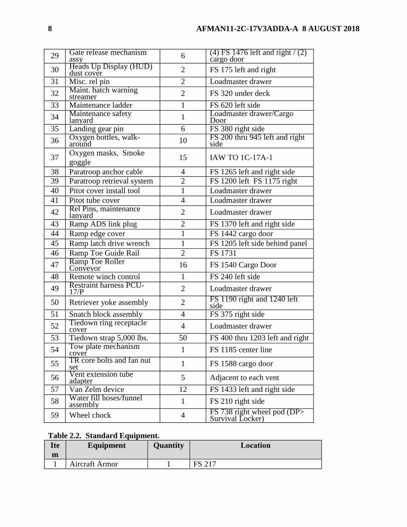
8 AFMAN11-2C-17V3ADDA-A 8 AUGUST 2018
29 Gate release mechanism assy 6 (4) FS 1476 left and right / (2)
cargo door
30 Heads Up Display (HUD) dust cover 2 FS 175 left and right
31 Misc. rel pin 2 Loadmaster drawer
32 Maint. hatch warning streamer 2 FS 320 under deck
33 Maintenance ladder 1 FS 620 left side
34 Maintenance safety lanyard 1 Loadmaster drawer/Cargo
Door 35 Landing gear pin 6 FS 380 right side
36 Oxygen bottles, walk-around 10 FS 200 thru 945 left and right
side
37 Oxygen masks, Smoke
goggle 15 IAW TO 1C-17A-1
38 Paratroop anchor cable 4 FS 1265 left and right side
39 Paratroop retrieval system 2 FS 1200 left FS 1175 right
40 Pitot cover install tool 1 Loadmaster drawer
41 Pitot tube cover 4 Loadmaster drawer
42 Rel Pins, maintenance lanyard 2 Loadmaster drawer
43 Ramp ADS link plug 2 FS 1370 left and right side
44 Ramp edge cover 1 FS 1442 cargo door
45 Ramp latch drive wrench 1 FS 1205 left side behind panel
46 Ramp Toe Guide Rail 2 FS 1731
47 Ramp Toe Roller Conveyor 16 FS 1540 Cargo Door
48 Remote winch control 1 FS 240 left side
49 Restraint harness PCU-17/P 2 Loadmaster drawer
50 Retriever yoke assembly 2 FS 1190 right and 1240 left side
51 Snatch block assembly 4 FS 375 right side
52 Tiedown ring receptacle cover 4 Loadmaster drawer
53 Tiedown strap 5,000 lbs. 50 FS 400 thru 1203 left and right
54 Tow plate mechanism cover 1 FS 1185 center line
55 TR core bolts and fan nut set 1 FS 1588 cargo door
56 Vent extension tube adapter 5 Adjacent to each vent
57 Van Zelm device 12 FS 1433 left and right side
58 Water fill hoses/funnel assembly 1 FS 210 right side
59 Wheel chock 4 FS 738 right wheel pod (DP> Survival Locker)
Table 2.2. Standard Equipment.
Ite
m
Equipment Quantity Location
1 Aircraft Armor 1 FS 217

AFMAN11-2C-17V3ADDA-A 8 AUGUST 2018 9
2 Aircrew Body Armor
(Level IIIA)
5 FS 280
3 Crew comfort items:
Blankets/Pillows
Water container, (5
gal)
Std 2 gal liquid
container
Hot cup
6
1-3
1-2
1
FS 280 Crew rest area
FS 360 left side
Crew galley FS 270 right side
Crew galley FS 270 right side
4 Emergency Passenger
oxygen System
(EPOS)
102 Distributed one each in sidewall seat,
remainder stored in survival
locker/cargo door when not in use.
The additional 86 will be delivered
with the seat pallets.
5 Flares/Flare Can 6 FS 400/Cargo Door
6 Flare Hazard Placard 4 FS 400
7 LPU-6/P (infant cot) 3 Survival Equipment Locker. LPU-6/P
infant survival cots will accommodate
infants up to 18 months/30 pounds.
8 Life preservers crew
LPU-10/P
2 Located in Survival Equipment locker
for use in conjunction with personnel
parachute when required.
9 Life preservers
Adult/Child (A/C)
110
Distributed one each in sidewall seat,
remainder stored in survival
locker/cargo door when not in use.
The additional 78 will be delivered
with the seat pallets.
10 Passenger
blankets/pillows
As
required
Distributed
11 Passenger demo kit 1 FS 400
12 Passenger information
card
1 Set
(102)
Distributed
13 Human Waste Clean-
up Kit
1 FS 280
14 Parachutes, BA-22 2 Survival Equipment locker.
15 Protective Breathing
Equipment (PBE)
6
2 at crew rest area, 1 at Fwd. LM
station, 1 at FS 395 left, 2 at FS 960 (1
left/1 right)
16 Protective clothing kit 1 Survival Equipment locker.

10 AFMAN11-2C-17V3ADDA-A 8 AUGUST 2018
17 Anti-Exposure Suit,
CWU-16/P
As
required
Operations planners, schedulers, or
crew will request Anti-Exposure Suits
for primary aircrew members on any
missions planned to operate above 78
degrees North or below 60 degrees
South latitude. If required, suits will
be pre-positioned in the AFE locker.
18 Survival Vest 5 Survival Equipment locker.
AFMAN11-2C-17V3ADDA-A 8 AUGUST 2018 11
Chapter 3
STANDARD EQUIPMENT WEIGHT AND BALANCE DATA AND FLOOR PLANS
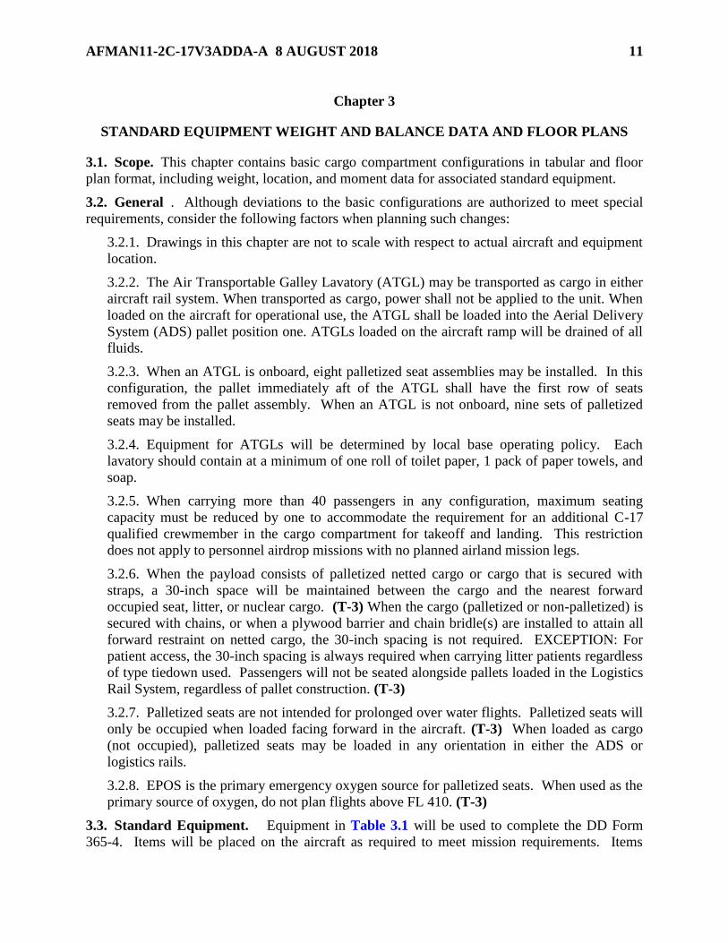
3.1. Scope. This chapter contains basic cargo compartment configurations in tabular and floor
plan format, including weight, location, and moment data for associated standard equipment.
3.2. General . Although deviations to the basic configurations are authorized to meet special
requirements, consider the following factors when planning such changes:
3.2.1. Drawings in this chapter are not to scale with respect to actual aircraft and equipment
location.
3.2.2. The Air Transportable Galley Lavatory (ATGL) may be transported as cargo in either
aircraft rail system. When transported as cargo, power shall not be applied to the unit. When
loaded on the aircraft for operational use, the ATGL shall be loaded into the Aerial Delivery
System (ADS) pallet position one. ATGLs loaded on the aircraft ramp will be drained of all
fluids.
3.2.3. When an ATGL is onboard, eight palletized seat assemblies may be installed. In this
configuration, the pallet immediately aft of the ATGL shall have the first row of seats
removed from the pallet assembly. When an ATGL is not onboard, nine sets of palletized
seats may be installed.
3.2.4. Equipment for ATGLs will be determined by local base operating policy. Each
lavatory should contain at a minimum of one roll of toilet paper, 1 pack of paper towels, and
soap.
3.2.5. When carrying more than 40 passengers in any configuration, maximum seating
capacity must be reduced by one to accommodate the requirement for an additional C-17
qualified crewmember in the cargo compartment for takeoff and landing. This restriction
does not apply to personnel airdrop missions with no planned airland mission legs.
3.2.6. When the payload consists of palletized netted cargo or cargo that is secured with
straps, a 30-inch space will be maintained between the cargo and the nearest forward
occupied seat, litter, or nuclear cargo. (T-3) When the cargo (palletized or non-palletized) is
secured with chains, or when a plywood barrier and chain bridle(s) are installed to attain all
forward restraint on netted cargo, the 30-inch spacing is not required. EXCEPTION: For
patient access, the 30-inch spacing is always required when carrying litter patients regardless
of type tiedown used. Passengers will not be seated alongside pallets loaded in the Logistics
Rail System, regardless of pallet construction. (T-3)
3.2.7. Palletized seats are not intended for prolonged over water flights. Palletized seats will
only be occupied when loaded facing forward in the aircraft. (T-3) When loaded as cargo
(not occupied), palletized seats may be loaded in any orientation in either the ADS or
logistics rails.
3.2.8. EPOS is the primary emergency oxygen source for palletized seats. When used as the
primary source of oxygen, do not plan flights above FL 410. (T-3)
3.3. Standard Equipment. Equipment in Table 3.1 will be used to complete the DD Form
365-4. Items will be placed on the aircraft as required to meet mission requirements. Items

12 AFMAN11-2C-17V3ADDA-A 8 AUGUST 2018
added to or subtracted from the basic configurations will be adjusted on the DD Form 365-4.
Planning agencies will ensure specific items needed, above quantities in the basic configuration,
are annotated on the mission directive. For example, three 5-gallon water containers are
provided for a P-1 configuration. If two additional 5-gallon water containers are required;
annotate the mission description as; “P-1Mod: add two 5-gallon water containers.”
3.4. Legend of Configurations. See Figures 3.1 – Figure 3.19 for details of each
configuration.
3.4.1. AE-1 -- Provides for 9 litter spaces and 54 seats. A minimum of 10 seats is required
for aeromedical evacuation crewmembers. Two HCU-6/E pallet positions are available in
the cargo ramp ADS rails.
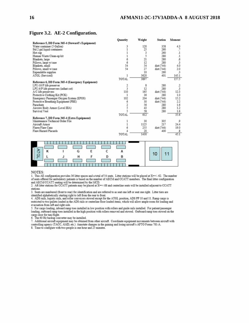
3.4.2. AE-2 -- Provides for an ATGL, 36 litter spaces, and 54 seats. A minimum of 10 seats
are required for aeromedical evacuation crewmembers. Two HCU-6/E pallet positions on
the cargo ramp are available in the ADS rails.
3.4.3. AE-3 -- Provides for 9 litter spaces and 90 seats. A minimum of 10 seats are required
for aeromedical evacuation crewmembers. Two HCU-6/E pallet positions on the cargo ramp
are available in the ADS rails.
3.4.4. AEC-1 – Provides for an ATGL, 6 litter spaces and 49 seats. A minimum of 10 seats
are required for aeromedical evacuation crewmembers. Eight HCU-6/E pallet positions are
available in the ADS rails. Pallets will not be loaded forward of pallet position four of the
ADS rail system.
3.4.5. C-1 -- Provides for 11 HCU-6/E pallets in the ADS rail system and 54 seats.
3.4.6. C-2 -- Provides for a clear cargo floor for loading of general cargo and/or rolling stock
loads and 54 seats.
3.4.7. C-3 -- Provides for 18 HCU-6/E pallets in the logistic rail system. No seats are
available in this configuration.
3.4.8. P-1 -- Provides for an ATGL, 102 seats and 4 HCU-6/E pallets on the cargo ramp.
3.4.9. SP-X -- Provides up to 189 seats on 9 pallets and 4 HCU-6/E pallets on the cargo
ramp. See Table 3.2.
3.4.10. CP-X -- Provides for a mixed configuration of seats and ADS system/ Logistics
system HCU-6 pallets. Number of seats and HCU-6/E pallets varies by configuration. See
Table 3.3.
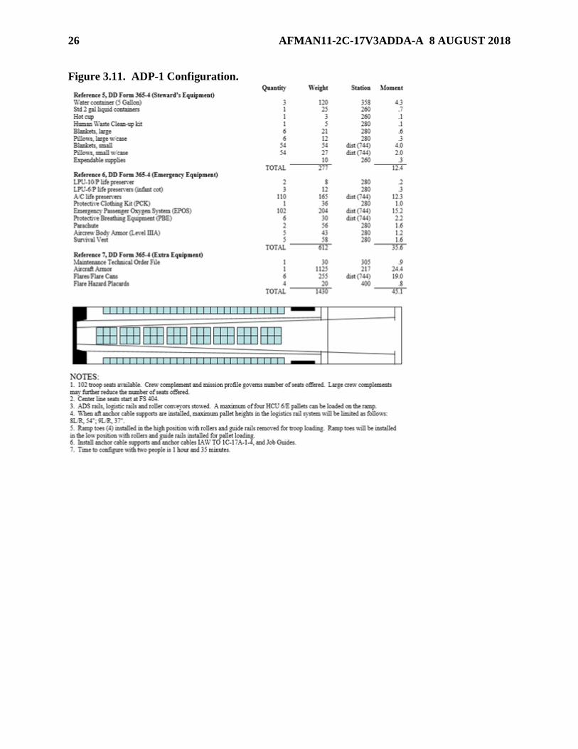
3.4.11. ADP-1 -- Provides for 54 seats for paratroopers, a clear cargo floor for loading 9
HCU-6/E pallets or rolling stock loads, and 4 HCU-6/E pallet positions on the cargo ramp.
3.4.12. ADP-2 -- Provides for 102 seats for paratroopers and 4 HCU-6/E pallet positions on
the cargo ramp.
3.4.13. ADP-3 -- Provides for an ATGL, 102 seats for paratroopers, and 4 HCU-6/E pallet
positions on the cargo ramp.
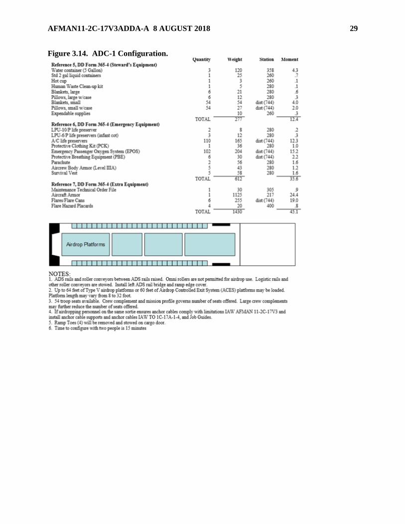
3.4.14. ADC-1 -- Provides for airdrop of up to 64 feet of airdrop of platform loads and 54
seats for paratroopers.

AFMAN11-2C-17V3ADDA-A 8 AUGUST 2018 13
3.4.15. ADC-2 -- Provides for airdrop of up to (8) 18 foot dual row airdrop platforms, (12) 8
foot dual row platforms, or 12 HCU-6/E pallets in the logistics rails.
3.4.16. CDS-1 - Provides for airdrop of up to 40 A-22 containers in a double stick or up to
20 A-22 containers in a single stick, and 54 seats for paratroopers.
3.4.17. DV-1 -- Provides for an ATGL, 129 seats and 4 HCU-6/E pallets on the cargo ramp.
3.4.18. SD-1 -- Used for static display.
3.4.19. SLC-1 -- Used for the Senior Leader In-transit Conference Capsule, communications
module (Viper, Steel Eagle, etc.), and the Senior Leader In-transit Pallet.
3.5. Troop Life Preserver. In the event of a planned airdrop of personnel near or over large
bodies of water, the unit being airdropped will furnish required life preservers. However, the life
preservers (A/C), as indicated in the applicable configurations, will be provided as required to
fulfill the emergency ditching operations requirements.
3.6. Passenger/Troop Drinking Water . Each basic configuration provides for an adequate
amount of drinking water. For example, on cargo configurations, three 5-gallon water containers
are provided. An ATGL, containing sufficient drinking water, may be provided for all passenger
configurations. Additional water containers may be added, as required.
3.7. Parachute Requirements. Parachutes will be positioned in the survival locker.
3.7.1. Parachutes will be used during emergencies IAW TO 1C-17A-1 Section III
procedures.
3.7.2. Airdrop missions require one parachute for each loadmaster. Depending on the type of
drop being performed, a safety harness may be substituted if it can be adjusted to allow
enough mobility to perform all required duties. This option will be at the discretion of the
loadmaster.
3.7.3. If deemed necessary for hazardous acceptance/functional check flights, or when
directed by the OPORD or mission directive, one parachute will be available for each
crewmember.
Table 3.1. Standard Equipment (See Notes).
Reference 5 Stewards Equipment Weight Flt Stn Moment
Water Container (5 Gallon) 40 358 1.43
Std 2 gal liquid container 25 260 0.65
Hot Cup 3 260 0.08
Human Waste Clean-up kit 5 280 0.14
Blanket Large 3.5 280 0.10
Pillow Large w/Case 2 280 0.06
Blanket Small 1 Variable Variable
Pillow Small w/Case 0.5 Variable Variable
Expendable Supplies 10 260 0.26
Passenger Demo Kit 3 380 0.11
Pax info cards (102) 3 280 0.08
ATGL (Serviced) 3620 401 145.2

14 AFMAN11-2C-17V3ADDA-A 8 AUGUST 2018
Reference 6 Emergency
Equipment
Weight Flt Stn Moment
LPU-6P Infant Cot 4 280 0.11
A/C Life Preserver 1.5 Variable Variable
Protective clothing kit 36 280 1.01
BA-22 Parachute 28 280 0.78
LPU-10P 4 280 0.11
EPOS 2 Variable Variable
PBE 5 280 0.14
Survival Vest 11.5 280 0.32
Aircrew Body Armor (Level IIIA) 8.5 280 0.24
Reference 7 Extra Equipment Weight Flt Stn Moment
60 Hz Backup Converter 43 252 1.08
Additional Aeromedical Stations 66 Variable Variable
Seat Pallets DV (5 Seats/Pallet) 591 Variable Variable
Seat Pallets DV (10 Seats/pallet) 767 Variable Variable
Seat Pallets Mass (15 Seats/pallet) 943 Variable Variable
Flares/Flare Cans (Note 1) 255 744 19.0
Flare Hazard Placards (Note 1) 20 400 0.8
Aircraft Armor (Note 1) 1125 217 24.41
SLIP (unoccupied) 1350 Variable Variable
Senior Leaders In-transit Conference
Capsule (SLICC) Berthing Capsule 3790 580 219.8
SLICC Conference Capsule
(unoccupied) 4660 685 319.2
NOTES:
1. Required for contingency missions
or when required by the Threat
Working Group

AFMAN11-2C-17V3ADDA-A 8 AUGUST 2018 15
Figure 3.1. AE-1 Configuration.
16 AFMAN11-2C-17V3ADDA-A 8 AUGUST 2018
Figure 3.2. AE-2 Configuration.

AFMAN11-2C-17V3ADDA-A 8 AUGUST 2018 17
Figure 3.3. AE-3 Configuration.

18 AFMAN11-2C-17V3ADDA-A 8 AUGUST 2018
Figure 3.4. AEC-1 Configuration.

AFMAN11-2C-17V3ADDA-A 8 AUGUST 2018 19
Figure 3.5. C-1 Configuration.

20 AFMAN11-2C-17V3ADDA-A 8 AUGUST 2018
Figure 3.6. C-2 Configuration.

AFMAN11-2C-17V3ADDA-A 8 AUGUST 2018 21
Figure 3.7. C-3 Configuration.

22 AFMAN11-2C-17V3ADDA-A 8 AUGUST 2018
Figure 3.8. P-1 Configuration.

AFMAN11-2C-17V3ADDA-A 8 AUGUST 2018 23
Figure 3.9. SP-X Configuration.
Table 3.2. Seat Pallet/Pallet Availability (See Notes). Configuration
Codes
Seat Pallets
Passenger Seats Available
(Note 1 & 2)
Pallets Positions Available for Cargo
(Note 2 & 3)
SP-1 1 68 12
SP-2 2 83 11
SP-3 3 98 10
SP-4 4 113 9
SP-5 5 128 8
SP-6 6 143 7
SP-7 7 158 6
SP-8 8 173 5
SP-9 9 188 4
NOTES: 1. Numbers based on 15-person seat pallets and utilization of 54 sidewall seats. One seat has been
allocated for the additional crewmember required in the cargo compartment when more than 40
passengers are carried.
2. When the payload consists of palletized netted cargo or when the cargo is secured with straps, a 30-
inch space will be maintained between the cargo and nearest occupied row of seats. When a plywood

24 AFMAN11-2C-17V3ADDA-A 8 AUGUST 2018
barrier and chain bridle(s) are installed to attain all forward restraint on the netted cargo (install IAW TO
1C-17A-9) or when the cargo is secured with chains, the 30-inch spacing is not required. When these
requirements cannot be achieved, subtract five-seats from number available.
3. Numbers based on utilization of ADS pallet positions on the cargo floor, and Logistic pallet positions
on the cargo ramp. Ramp will not be available for ground evacuation when pallets are placed side-by-side
in Logistics pallet positions 8 and 9.
Figure 3.10. CP-X Configuration.
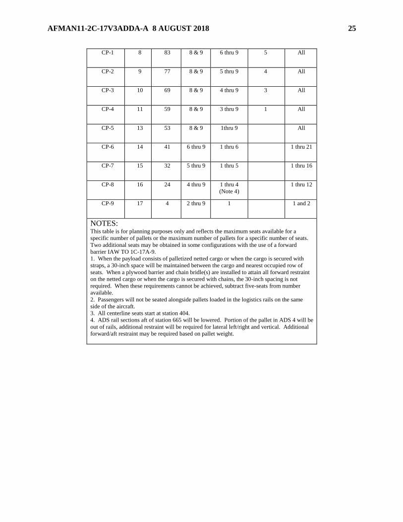
Table 3.3. Pallet/Seat Availability (See Notes). Configuration
Code
Pallets
Available
Seats
Available
(Note 1)
Logistic
Pallets
Positions
Used
(Note 2)
ADS Pallet
Positions
Used
Centerline
Seats
Used (Note
3)
Sidewall
Seats
Used
(Note 2)
CP-0 6 99 8 & 9 8 & 9 8 All
AFMAN11-2C-17V3ADDA-A 8 AUGUST 2018 25
CP-1 8 83 8 & 9 6 thru 9 5 All
CP-2 9 77 8 & 9 5 thru 9 4 All
CP-3 10 69 8 & 9 4 thru 9 3 All
CP-4 11 59 8 & 9 3 thru 9 1 All
CP-5 13 53 8 & 9 1thru 9 All
CP-6 14 41 6 thru 9 1 thru 6 1 thru 21
CP-7 15 32 5 thru 9 1 thru 5 1 thru 16
CP-8 16 24 4 thru 9 1 thru 4
(Note 4)
1 thru 12
CP-9 17 4 2 thru 9 1 1 and 2
NOTES: This table is for planning purposes only and reflects the maximum seats available for a
specific number of pallets or the maximum number of pallets for a specific number of seats.
Two additional seats may be obtained in some configurations with the use of a forward
barrier IAW TO 1C-17A-9.
1. When the payload consists of palletized netted cargo or when the cargo is secured with
straps, a 30-inch space will be maintained between the cargo and nearest occupied row of
seats. When a plywood barrier and chain bridle(s) are installed to attain all forward restraint
on the netted cargo or when the cargo is secured with chains, the 30-inch spacing is not
required. When these requirements cannot be achieved, subtract five-seats from number
available.
2. Passengers will not be seated alongside pallets loaded in the logistics rails on the same
side of the aircraft.
3. All centerline seats start at station 404.
4. ADS rail sections aft of station 665 will be lowered. Portion of the pallet in ADS 4 will be
out of rails, additional restraint will be required for lateral left/right and vertical. Additional
forward/aft restraint may be required based on pallet weight.
26 AFMAN11-2C-17V3ADDA-A 8 AUGUST 2018
Figure 3.11. ADP-1 Configuration.

AFMAN11-2C-17V3ADDA-A 8 AUGUST 2018 27
Figure 3.12. ADP-2 Configuration.

28 AFMAN11-2C-17V3ADDA-A 8 AUGUST 2018
Figure 3.13. ADP-3 Configuration.
AFMAN11-2C-17V3ADDA-A 8 AUGUST 2018 29
Figure 3.14. ADC-1 Configuration.

30 AFMAN11-2C-17V3ADDA-A 8 AUGUST 2018
Figure 3.15. ADC-2 Configuration.

AFMAN11-2C-17V3ADDA-A 8 AUGUST 2018 31
Figure 3.16. CDS-1 Configuration.

32 AFMAN11-2C-17V3ADDA-A 8 AUGUST 2018
Figure 3.17. DV-1 Configuration.

AFMAN11-2C-17V3ADDA-A 8 AUGUST 2018 33
Figure 3.18. SD-1 Configuration.

34 AFMAN11-2C-17V3ADDA-A 8 AUGUST 2018
Figure 3.19. SLC-1 Configuration.

AFMAN11-2C-17V3ADDA-A 8 AUGUST 2018 35
Chapter 4
REFERENCE DATA
4.1. Scope. This chapter contains reference data to assist personnel in load planning.
4.2. Airdrop . Several factors must be considered during planning of cargo airdrop operations.
4.2.1. No overhang of load permitted on platform unless specified in the rigging TO/FM.
4.2.2. Weight and balance will be considered at all times. When multiple passes of airdrop
loads are planned, calculations will be made, prior to takeoff, to determine the aircraft CG
after each load has exited. This is accomplished to assure CG flight limits are not exceeded.
This calculation is required only for those loads remaining on the aircraft following each
pass. For sequential airdrop, calculations will be made to assure CG limits are not exceeded
in the event of a malfunction resulting in platforms remaining on the aircraft.
4.3. Personnel limitations. The Personnel Limitations Chart (Table 4.3) reflects the number of
personnel (crews and passengers/troops) that the crew lavatory and aircraft urinals can
accommodate. Table 4.3 will be considered when determining number of passengers/troops that
can be airlifted without an ATGL.
4.4. Miscellaneous Data. The following tables and figures are provided to aid in configuration
planning, weight and balance:
4.4.1. See Table 4.1 Standard Weights.
4.4.2. See Table 4.2 Crew Weights.
4.4.3. See Table 4.3 Personnel Limitation.
Table 4.1. Standard Weights.
Standard Weight--Crew/Passengers/Patient,
and Troops.
Weight (lbs.)
Passenger (without bags) 175 Passenger Baggage 70 Litter (includes weight of patient) 195 Ambulatory (without bags) 175 Ground Troop (with web gear and weapon) 210 Ground Troop (with web gear, weapon, and ruck
sack) Training
250
Ground Troop (with web gear, weapon, and ruck
sack) Combat
300
Ground Troop (with web gear, weapon, ruck
sack, and duffel bag) Training
350
Ground Troop (with web gear, weapon, ruck
sack, and duffel bag) Combat
400
Parachutist (with web gear, weapon, and ruck
sack) Training
300

36 AFMAN11-2C-17V3ADDA-A 8 AUGUST 2018
Parachutist (with web gear, weapon, and ruck
sack) Combat
350
Parachutist (without weapon or equipment)
Hollywood
220
Ruck sack (Training) 40 Ruck sack (Combat) 80 ATGL (unserviced) 3200 Litter 14 Net set (PALLET HCU-6/E) 65 Net side 463L (HCU-7/E) 22 Net top 463L (HCU-15/C) 21 Oxygen bottle, portable 6 Oxygen mask, 358-1506V and Anti-smoke
goggles
3
Pallet HCU-6/E 290 Pallet w/nets (HCU-6/E; HCU-7/E; HCU-15/C) 355 Winch, Cargo 342 NOTE: Standard weights for passengers/troops are for planning
purposes only.
Table 4.2. Crew Weights.
Crew
Distribution
(200 Lbs
Each)
Crew
Baggage
(50 Lbs
Each)
FS 280 FS 365
No and Flt
Sta
WT MOM No WT MOM MOM
2/177
(P/CP)
400 7.0 3 150 4.2 5.5
1/225
(ACM)
200 4.5 4 200 5.6 7.3
2/225
(ACM)
400 9.0 5 250 7.0 9.1
1/271 (CR) 200 5.4 6 300 8.4 11.0
2/271 (CR) 400 10.8 7 350 9.8 12.8
1/304 (LM) 200 6.1
Table 4.3. Personnel Limitations (See Notes).
Total
Personnel
Lavatory Urinal # 1 Urinal # 2 Total Hours
190 4.6 0.9 0.9 6.4
180 4.7 1.0 1.0 6.7 170 4.9 1.1 1.1 7.1
AFMAN11-2C-17V3ADDA-A 8 AUGUST 2018 37
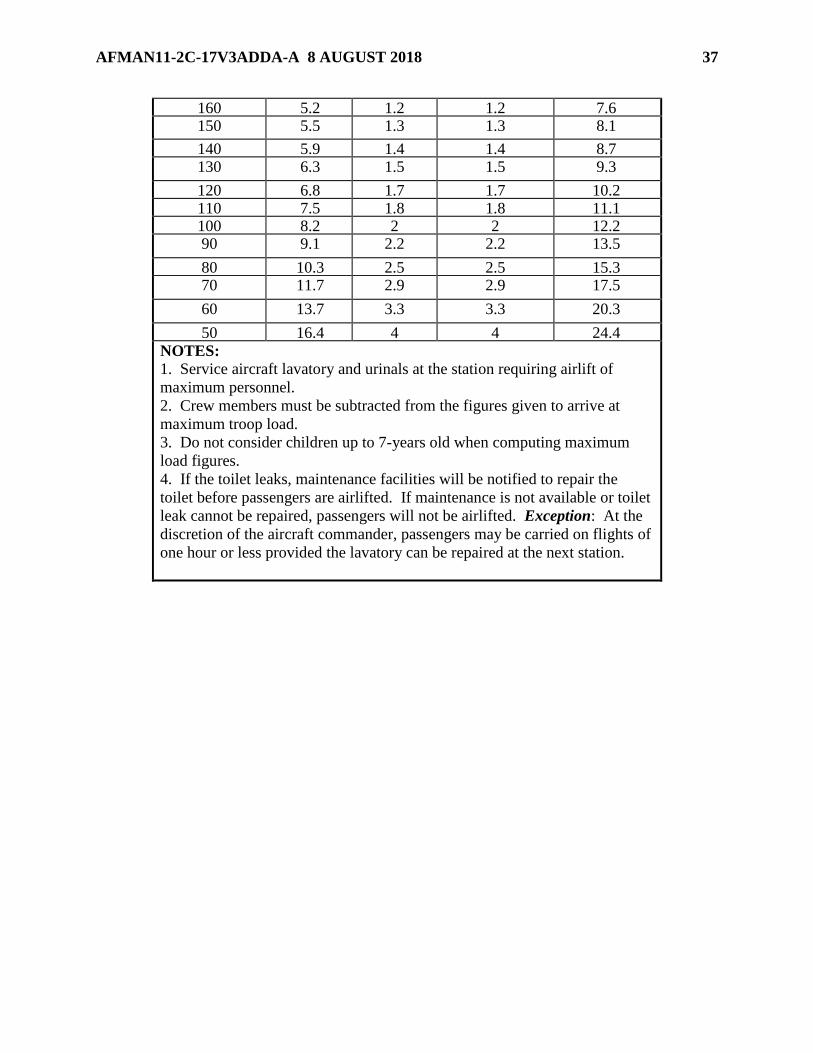
160 5.2 1.2 1.2 7.6 150 5.5 1.3 1.3 8.1
140 5.9 1.4 1.4 8.7 130 6.3 1.5 1.5 9.3
120 6.8 1.7 1.7 10.2 110 7.5 1.8 1.8 11.1 100 8.2 2 2 12.2 90 9.1 2.2 2.2 13.5
80 10.3 2.5 2.5 15.3 70 11.7 2.9 2.9 17.5
60 13.7 3.3 3.3 20.3
50 16.4 4 4 24.4 NOTES:
1. Service aircraft lavatory and urinals at the station requiring airlift of
maximum personnel.
2. Crew members must be subtracted from the figures given to arrive at
maximum troop load.
3. Do not consider children up to 7-years old when computing maximum
load figures.
4. If the toilet leaks, maintenance facilities will be notified to repair the
toilet before passengers are airlifted. If maintenance is not available or toilet
leak cannot be repaired, passengers will not be airlifted. Exception: At the
discretion of the aircraft commander, passengers may be carried on flights of
one hour or less provided the lavatory can be repaired at the next station.

38 AFMAN11-2C-17V3ADDA-A 8 AUGUST 2018
Chapter 5
AIRCREW FLIGHT EQUIPMENT CONFIGURATION REQUIREMENTS
5.1. Aircraft-Installed AFE Procedures. Handle AFE with care to avoid damage.
Prepositioning equipment in accordance with this publication allows flexibility while the aircraft
is away from home-station and standardizes AFE configurations Air Force-wide. For AETC
flying units where AMC is the lead command, units are authorized to load aircraft with only the
mission required AFE. AETC Operations Group Commanders (or equivalent) will ensure an
Operational Risk Management assessment (ORM) is accomplished regarding utilization of AFE
to safely support mission requirements. In the event installed AFE inspection comes due while
aircraft is on alert status of away from home station, follow guidance provided in TO 00-20-1,
Aerospace Equipment Maintenance Inspection, Documentation, Policies, and Procedures.
5.2. Aircraft Configuration. Configure aircraft IAW TO 1C-17A-1, Flight Manual, USAF
Series, C-17A Aircraft and TO 1C-17A-5-2. Store AFE equipment not utilized in the survival
equipment locker or as depicted in TO 1C-17A-5-2. Crewmembers must return all AFE to the
proper storage locations after each mission. Aircraft Commanders may request additional
equipment be positioned aboard aircraft to accommodate aircrew and passenger increases, as
required.
AFMAN11-2C-17V3ADDA-A 8 AUGUST 2018 39
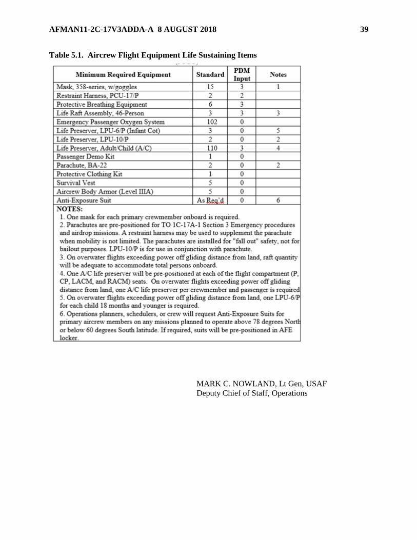
Table 5.1. Aircrew Flight Equipment Life Sustaining Items
MARK C. NOWLAND, Lt Gen, USAF
Deputy Chief of Staff, Operations

40 AFMAN11-2C-17V3ADDA-A 8 AUGUST 2018
Attachment 1
GLOSSARY OF REFERENCES AND SUPPORTING INFORMATION
References
AFMAN 11-2C-17 Volume 3, C-17 Operations Procedures, 16 November 2011
AFI 11-301, Vol 2, Management and Configuration Requirements for Aircrew Flight Equipment
(AFE), 13 June 2017
AFI 33-360, Publications and Forms Management, 1 December 2015
AFMAN 33-363, Management of Records, 1 March 2008
AFPD 11-2, Aircrew Operations, 19 January 2012
TO 00-20-1, Aerospace Equipment Maintenance Inspection, Documentation, Policies, and
Procedures, 11 July 2016
TO 1C-17A-1, Flight Manual, USAF Series, C-17A Aircraft, 15 October 2008
TO 1C-17A-1-4, Airdrop Mission Crew Manual, USAF Series, C-17 Aircraft, 1 May 2013
TO 1C-17A-2-10JG-70-1, Ground Handling Mission Reconfiguration – Cargo Compartment, 1
September 2017
TO 1C-17A-5-2, Loading Data, USAF Series, C-17A Aircraft, 15 July 2008
TO 1C-17A-9, Loading Instructions, USAF Series, C-17 Aircraft, 1 June 2017
Adopted Forms
AF Form 847, Recommendation for Change of Publication
DD Form 365-4, Weight and Balance Clearance Form F
AFTO Form 781-A, Maintenance Discrepancy and Work Document.
Abbreviations and Acronyms
A/C —Adult/Child
ABA —Aircrew Body Armor
ADS —Aerial Delivery System
AE —Aeromedical Evacuation
AECM —Aeromedical Evacuation Crew Member
AERP —Aircrew Eye Respiratory Protection
AETC —Air Education Training Command
AFE —Aircrew Flight Equipment
AFI—Air Force Instruction
AFMAN—Air Force Manual

AFMAN11-2C-17V3ADDA-A 8 AUGUST 2018 41
AFPD—Air Force Policy Directive
AFRC —Air Force Reserve Command
AMC—Air Mobility Command
AMD —Air Mobility Division
ANG —Air National Guard
ATGL —Air Transportable Galley Lavatory
BSA —Buffer Stop Assembly
CCATT —Critical Care Air Transport Team
CDS —Container Delivery System
CG —Center of Gravity
ECVR —Enhanced Center Vertical Restraint
EPOS —Emergency Passenger Oxygen System
ETP —Equal Time Point
FM —Field Manual
FS —Fuselage Station
HUD —Heads Up Display
IAW —In Accordance With
JCS —Joint Chiefs of Staff
MAF —Mobility Air Forces
MAJCOM —Major Command
MOM —Moment
OPORD —Operation Order
OPR —Office of Primary Responsibility
PBE —Protective Breathing Equipment
PCK —Protective Clothing Kit
PDM —Programmed Depot Maintenance
SLICC—Senior Leaders In-transit Conference Capsule
SLIP—Senior Leaders In-transit Pallet
Stan/Eval —Standardization and Evaluation
TACC —Tanker Airlift Control Center
TO —Technical Order
TR —Trust Reverser

42 AFMAN11-2C-17V3ADDA-A 8 AUGUST 2018
USAF —United States Air Force
WT —Weight

AFMAN11-2C-17V3ADDA-A 8 AUGUST 2018 43
Attachment 2
C-17 CONFIGURATION PLANNING SHEET
Figure A2.1. C-17 CONFIGURATION PLANNING SHEET.

44 AFMAN11-2C-17V3ADDA-A 8 AUGUST 2018