AEP Kentucky Power Mitchell R30-05100005-2019.pdf
239
-
Upload
khangminh22 -
Category
Documents
-
view
4 -
download
0
Transcript of AEP Kentucky Power Mitchell R30-05100005-2019.pdf


Kentucky Power Company
Mitchell Plant
Title V Permit Renewal Application
R30-05100005-2014
Prepared For:
Kentucky Power Company
Mitchell Plant
Moundsville, West Virginia
Prepared By:
American Electric Power
Environmental Services
1 Riverside Plaza
Columbus, Ohio 43215
March, 2019
001

i
Kentucky Power Company Mitchell Plant
Regulation 30 Permit Renewal Application Table of Contents
Cover Sheet
Table of Contents
General Application Form 3
Attachment A – Area Map 19
Attachment B – Plot Plan(s) 23
Attachment C – Process Flow Diagram(s) 29
Attachment D – Equipment Table 53
Attachment E – Emission Unit Form(s) 63
Attachment F – Air Pollution Control Devices Form(s) 124
Attachment H – Compliance Assurance Monitoring (CAM) Form(s) 131
Attachment I – Existing Applicable Permits 143
45 CSR 13 Permit R13-2608E 144
Title IV Phase II Acid Rain Permit Renewal R33-3948-2022-5 171
General Permit G60-C057A 183 Attachment K – 45 CSR 2/10 Monitoring Plan 224
Attachment L – Suggested Title V Permit Language 236
002

General Application Forms (general_forms.wpd)
Page 1 of 16
Revised – 10/1/2014
Page _____ of _____
WEST VIRGINIA DEPARTMENT OF ENVIRONMENTAL
PROTECTION
DIVISION OF AIR QUALITY
601 57th Street SE
Charleston, WV 25304
Phone: (304) 926-0475
www.dep.wv.gov/daq
INITIAL/RENEWAL TITLE V PERMIT APPLICATION - GENERAL FORMS
Section 1: General Information
1. Name of Applicant (As registered with the WV
Secretary of State’s Office):
Kentucky Power Company
2. Facility Name or Location:
Mitchell Plant
3. DAQ Plant ID No.:
0 5 1 — 0 0 0 0 5
4. Federal Employer ID No. (FEIN):
6 1 0 2 4 7 7 7 5
5. Permit Application Type:
Initial Permit When did operations commence? MM/DD/1970
Permit Renewal What is the expiration date of the existing permit? 10/15/2019
Update to Initial/Renewal Permit Application
6. Type of Business Entity:
Corporation Governmental Agency LLC
Partnership Limited Partnership
7. Is the Applicant the:
Owner Operator Both
If the Applicant is not both the owner and operator,
please provide the name and address of the other
party.
8. Number of onsite employees:
Approx 220
9. Governmental Code:
Privately owned and operated; 0 County government owned and operated; 3
Federally owned and operated; 1 Municipality government owned and operated; 4
State government owned and operated; 2 District government owned and operated; 5
10. Business Confidentiality Claims
Does this application include confidential information (per 45CSR31)? Yes No
If yes, identify each segment of information on each page that is submitted as confidential, and provide
justification for each segment claimed confidential, including the criteria under 45CSR§31-4.1, and in
accordance with the DAQ's "PRECAUTIONARY NOTICE-CLAIMS OF CONFIDENTIALITY" guidance.
003

General Application Forms (general_forms.wpd)
Page 2 of 16
Revised – 10/1/2014
Page _____ of _____
11. Mailing Address
Street or P.O. Box: P.O. Box K
City: Moundsville State: West Virginia Zip: 26041-
Telephone Number: (304) 843-6000 Fax Number: (304) 843-6080
12. Facility Location
Street: State Route 2 City: Cresap/Moundsville County: Marshall Conty
UTM Easting: 516.00 km UTM Northing: 4409.00 km Zone: 17 or 18
Directions: From Charleston, take I-77 north to exit 179. Travel north on State Route 2 approximately
70 miles to Cresap. Facility is located on State Route 2, approximately 9 miles south of Moundsville, WV.
Portable Source? Yes No
Is facility located within a nonattainment area? Yes No If yes, for what air pollutants?
Sulfur Dioxide
Is facility located within 50 miles of another state? Yes No If yes, name the affected state(s).
Ohio, Pennsylvania
Is facility located within 100 km of a Class I Area1? Yes No
If no, do emissions impact a Class I Area1? Yes No
Source meets BART for SO2 and NOx by implementing CSAPR and
BART Modeling indicated source was insignificant from a PM standpoint.
If yes, name the area(s).
1 Class I areas include Dolly Sods and Otter Creek Wilderness Areas in West Virginia, and Shenandoah National Park and James River Face Wilderness Area in Virginia.
004

General Application Forms (general_forms.wpd)
Page 3 of 16
Revised – 10/1/2014
Page _____ of _____
13. Contact Information
Responsible Official: Douglas J. Rosenberger Title: Plant Manager
Street or P.O. Box: P.O. Box K
City: Moundsville State: WV Zip: 26041-
Telephone Number: (304) 843-6001 Fax Number: (304) 843-6080
E-mail address: [email protected]
Environmental Contact: G. M. (Matt) Palmer Title: Plant Environmental
Coordinator
Street or P.O. Box: P.O. Box K
City: Moundsville State: WV Zip: 26041-
Telephone Number: (304) 843-6048 Fax Number: (304) 843-6080
E-mail address: [email protected]
Application Preparer: G. J. Wooten Title: Principal Engineer
Company: AEP Service Corporation
Street or P.O. Box: 1 Riverside Plaza, 22nd floor
City: Columbus State: OH Zip: 43215-
Telephone Number: (614) 716-1262 Fax Number: (614) 716-1252
E-mail address: [email protected]
005

General Application Forms (general_forms.wpd)
Page 4 of 16
Revised – 10/1/2014
Page _____ of _____
14. Facility Description
List all processes, products, NAICS and SIC codes for normal operation, in order of priority. Also list any
process, products, NAICS and SIC codes associated with any alternative operating scenarios if different from
those listed for normal operation.
Process Products NAICS SIC
Coal Fired Electric Generating Unit Electricity 221112 4911
Provide a general description of operations.
The Mithell Plant is a fossil fuel fired electric generation facility and operates under Standard Industrial Code
(SIC) 4911. The facility consists of two coal-fired steam generators that provide a steam supply to turbine driven
electrical generators and an oil-fired auxiliary boiler that provides auxiliary steam services to the facility. The
facility also includes various supporting operations including by not limited to coal handling, ash handling,
gypsum handling, limestone handling, wastewater treatment system filter cake handling, and various tanks with
insignificant emissions. The facility has the potential to operate seven days per week, twenty-four hours per day,
and 52 weeks per year.
15. Provide an Area Map showing plant location as ATTACHMENT A.
16. Provide a Plot Plan(s), e.g. scaled map(s) and/or sketch(es) showing the location of the property on which
the stationary source(s) is located as ATTACHMENT B. For instructions, refer to “Plot Plan - Guidelines.”
17. Provide a detailed Process Flow Diagram(s) showing each process or emissions unit as ATTACHMENT
C. Process Flow Diagrams should show all emission units, control equipment, emission points, and their
relationships.
006

General Application Forms (general_forms.wpd)
Page 5 of 16
Revised – 10/1/2014
Page _____ of _____
Section 2: Applicable Requirements
18. Applicable Requirements Summary
Instructions: Mark all applicable requirements.
SIP FIP
Minor source NSR (45CSR13) PSD (45CSR14)
NESHAP (45CSR34) Nonattainment NSR (45CSR19)
Section 111 NSPS Section 112(d) MACT standards
Section 112(g) Case-by-case MACT 112(r) RMP
Section 112(i) Early reduction of HAP Consumer/commercial prod. reqts., section 183(e)
Section 129 Standards/Reqts. Stratospheric ozone (Title VI)
Tank vessel reqt., section 183(f) Emissions cap 45CSR§30-2.6.1
NAAQS, increments or visibility (temp. sources) 45CSR27 State enforceable only rule
45CSR4 State enforceable only rule Acid Rain (Title IV, 45CSR33)
Emissions Trading and Banking (45CSR28) Compliance Assurance Monitoring (40CFR64)
CAIR NOx Annual Trading Program (45CSR39)
Regulation Repealed
CAIR NOx Ozone Season Trading Program
(45CSR40) – Regulation Repealed
CAIR SO2 Trading Program (45CSR41) -
Regulation Repealed
19. Non Applicability Determinations
List all requirements which the source has determined not applicable and for which a permit shield is
requested. The listing shall also include the rule citation and the reason why the shield applies.
45 CSR 5: Pursuant to 45CSR5, if 45CSR2 is applicable to the facility, then the facility is exempt from 45CSR5. 45CSR2 is applicable to the facility.
45 CSR 17: Pursuant to 45CSR17, if 45CSR2 is applicable to the facility, then the facility is exempt from 45CSR17. 45CSR2 is applicable to the facility.
40 CFR 60 Subpart D: The fossil fuel fired steam generators potentially affected by this rule have not commenced construction or modification after August 17, 1971.
40 CFR 60 Subpart Da: The electric utility steam generating units potentially affected by this rule have not commenced
construction or modification after September 18, 1978.
40 CFR 60 Subpart K: The facility doesn’t include storage vessels that are used to store petroleum liquids (as defined in 40 CFR 60.111(b)) and have storage capacity greater than 40,000 gallons for which construction, reconstruction, or modification commenced after June 11, 1973 and prior to May 19, 1978.
40 CFR 60 Subpart Ka: The facility does not include storage vessels that are used to store petroleum liquids (as defined in 40
CFR 60.111(b)) and that have a storage capacity greater than 40,000 gallons for which construction, reconstruction, or modification was commenced after May 18, 1978 and prior to July 23, 1984.
Permit Shield
007

General Application Forms (general_forms.wpd)
Page 6 of 16
Revised – 10/1/2014
Page _____ of _____
19. Non Applicability Determinations (Continued) - Attach additional pages as necessary.
List all requirements which the source has determined not applicable and for which a permit shield is
requested. The listing shall also include the rule citation and the reason why the shield applies.
40 CFR 60 Subpart Kb: Storage vessels potentially affected by this rule are exempted because they
contain liquids with a maximum true vapor pressure of less than 3.5 kPa, have a storage capacity of less
than 40 cubic meters, or have not commenced construction, reconstruction or modification after July 23,
1984.
40 CFR 60 Subpart Y: The coal handling equipment potentially affected by this rule has not been
constructed or modified after October 24, 1974.
40 CFR 63 Subpart Q: This facility does not include industrial process cooling towers that have
operated with chromium-based water treatment chemicals on or after September 8, 1994.
Permit Shield
008

General Application Forms (general_forms.wpd)
Page 7 of 16
Revised – 10/1/2014
Page _____ of _____
20. Facility-Wide Applicable Requirements
List all facility-wide applicable requirements. For each applicable requirement, include the underlying
rule/regulation citation and/or construction permit with the condition number. (Note: Title V permit
condition numbers alone are not the underlying applicable requirements).
45CSR6, R30-05100005-2014 Section 3.1.1 and 3.1.2 (Open Burning)
40CFR61, R30-05100005-2014 Section 3.1.3 (Asbestos)
45CSR4, R30-05100005-2014 Section 3.1.4 (Odor)
45CSR11-5.2, R30-05100005-2014 Section 3.1.5 (Standby Plan)
WV Code 22-5-4(a)(14), R30-05100005-2014 Section 3.1.6 (Emission Inventory)
40CFR82, R30-05100005-2014 Section 3.1.7 (Ozone-depleting Substances)
45CSR2, R30-05100005-2014 Section 3.1.9 (Fugitive Particulate Matter Control)
40CFR97.406, R30-05100005-2014 Section 3.1.11 (TR NOx Annual Trading Program)
40CFR97.506, R30-05100005-2014 Section 3.1.12 (TR NOx Ozone Season Trading Program)
40CFR97.606, R30-05100005-2014 Section 3.1.13 (TR SO2 Group 1 Trading Program)
Permit Shield
For all facility-wide applicable requirements listed above, provide monitoring/testing / recordkeeping /
reporting which shall be used to demonstrate compliance. If the method is based on a permit or rule,
include the condition number and/or citation. (Note: Each requirement listed above must have an
associated method of demonstrating compliance. If there is not already a required method in place, then a
method must be proposed.)
45CSR2, 45CSR10, and WV Code 22-5-4(a), R30-05100005-2014 Section 3.3.1 (Stack Testing)
45CSR30-5.1.c.2.A, R30-05100005-2014 Section 3.4.1 (Monitoring Information)
45CSR30-5.1.c.2.B, R30-05100005-2014 Section 3.4.2 (Retention of Records)
45CSR30-5.1.c, R30-05100005-2014 Section 3.4.3 (Odors)
45CSR30-5.1.c, R30-05100005-2014 Section 3.4.4 (Fugitive Particulate Matter Control)
45CSR30-5.1.c.3, R30-05100005-2014 Sections 3.5.1-3.5.3 (Reporting Requirements)
45CSR30-8, R30-05100005-2014 Section 3.5.4 (Certified Emissions Statement)
45CSR30-5.3.e, R30-05100005-2014 Section 3.5.5 (Compliance Certification)
45CSR30-5.1.c.3.A, R30-05100005-2014 Section 3.5.6 (Semi-Annual Monitoring Reports)
R30-05100005-2014 Section 3.5.7 (Emergency Reporting)
45CSR30-5.1.c.3, R30-05100005-2014 Section 3.5.8 (Deviation Reports)
45CSR30-4.3.h.1.B, R30-05100005-2014 Section 3.5.9 (New Applicable Requirements)
Are you in compliance with all facility-wide applicable requirements? Yes No
If no, complete the Schedule of Compliance Form as ATTACHMENT F.
009

General Application Forms (general_forms.wpd)
Page 8 of 16
Revised – 10/1/2014
Page _____ of _____
20. Facility-Wide Applicable Requirements (Continued) - Attach additional pages as necessary.
List all facility-wide applicable requirements. For each applicable requirement, include the rule citation
and/or permit with the condition number.
Permit Shield
For all facility-wide applicable requirements listed above, provide monitoring/testing/recordkeeping/
reporting which shall be used to demonstrate compliance. If the method is based on a permit or rule,
include the condition number and/or citation. (Note: Each requirement listed above must have an
associated method of demonstrating compliance. If there is not already a required method in place, then a
method must be proposed.)
Are you in compliance with all facility-wide applicable requirements? Yes No
If no, complete the Schedule of Compliance Form as ATTACHMENT F.
010

General Application Forms (general_forms.wpd)
Page 9 of 16
Revised – 10/1/2014
Page _____ of _____
21. Active Permits/Consent Orders
Permit or Consent Order Number Date of Issuance
MM/DD/YYYY
List any Permit Determinations
that Affect the Permit (if any)
05/12/2004 PD04-042: No permit needed for SCR
08/05/2004 PD04-064: No permit needed for FGD system
08/24/2005 PD04-073 No permit needed for urea handling
R13-2608E 05/12/2014 Reg 13 permit for FGD support equipment, Dry
Fly Ash and Ash Landfill project and Aux. Boiler
rebuild project/capacity factor limit.
U.S. District Court Consent Decree
regarding Civil Actions C2-99-1182,
C2-05-360 and C2-04-1098
12/13/2007 Consent Decree for NSR lawsuits
R33-3948-2022-5 12/19/2017 Acid Rain Permit
G60-C057A 08/08/2014 Emergency Generator General Permit
/ /
/ /
/ /
/ /
/ /
/ /
/ /
/ /
/ /
/ /
/ /
/ /
/ /
/ /
/ /
/ /
/ /
011

General Application Forms (general_forms.wpd)
Page 10 of 16
Revised – 10/1/2014
Page _____ of _____
22. Inactive Permits/Obsolete Permit Conditions
Permit Number Date of Issuance Permit Condition Number
R13-2608 through R13-2608D MM/DD/Various Permits were revised and replaced
with subsequent versions
G60-C057 10/11/2013 Permit was revised and replace with
subsequent version
/ /
/ /
/ /
/ /
/ /
/ /
/ /
/ /
/ /
/ /
/ /
/ /
/ /
/ /
/ /
/ /
/ /
/ /
/ /
/ /
/ /
/ /
/ /
012

General Application Forms (general_forms.wpd)
Page 11 of 16
Revised – 10/1/2014
Page _____ of _____
Section 3: Facility-Wide Emissions
23. Facility-Wide Emissions Summary [Tons per Year]
Criteria Pollutants Potential Emissions
Carbon Monoxide (CO) 4761.61
Nitrogen Oxides (NOX) 36392.38
Lead (Pb) 3.643
Particulate Matter (PM2.5)1 1100.5
Particulate Matter (PM10)1 3173.3
Total Particulate Matter (TSP) 5428.11
Sulfur Dioxide (SO2) 89746.85
Volatile Organic Compounds (VOC) 563.88
Hazardous Air Pollutants2 Potential Emissions
Hydrogen Chloride 12337
Hydrogen Fluoride 1071
Selenium 48.45
Manganese 3.77
Nickel 1.69
Arsenic 5.62
Mercury Compounds 2.13
Beryllium 13.37
Chromium 2.00
Cobalt 0.74
Lead 3.65
Regulated Pollutants other than Criteria and HAP Potential Emissions
1PM2.5 and PM10 are components of TSP. 2For HAPs that are also considered PM or VOCs, emissions should be included in both the HAPs section and
the Criteria Pollutants section.
013

General Application Forms (general_forms.wpd)
Page 12 of 16
Revised – 10/1/2014
Page _____ of _____
Section 4: Insignificant Activities
24. Insignificant Activities (Check all that apply)
1. Air compressors and pneumatically operated equipment, including hand tools.
2. Air contaminant detectors or recorders, combustion controllers or shutoffs.
3. Any consumer product used in the same manner as in normal consumer use, provided the use results in
a duration and frequency of exposure which are not greater than those experienced by consumer, and
which may include, but not be limited to, personal use items; janitorial cleaning supplies, office
supplies and supplies to maintain copying equipment.
4. Bathroom/toilet vent emissions.
5. Batteries and battery charging stations, except at battery manufacturing plants.
6. Bench-scale laboratory equipment used for physical or chemical analysis, but not lab fume hoods or
vents. Many lab fume hoods or vents might qualify for treatment as insignificant (depending on the
applicable SIP) or be grouped together for purposes of description.
7. Blacksmith forges.
8. Boiler water treatment operations, not including cooling towers.
9. Brazing, soldering or welding equipment used as an auxiliary to the principal equipment at the source.
10. CO2 lasers, used only on metals and other materials which do not emit HAP in the process.
11. Combustion emissions from propulsion of mobile sources, except for vessel emissions from Outer
Continental Shelf sources.
12. Combustion units designed and used exclusively for comfort heating that use liquid petroleum gas or
natural gas as fuel.
13. Comfort air conditioning or ventilation systems not used to remove air contaminants generated by or
released from specific units of equipment.
14. Demineralized water tanks and demineralizer vents.
15. Drop hammers or hydraulic presses for forging or metalworking.
16. Electric or steam-heated drying ovens and autoclaves, but not the emissions from the articles or
substances being processed in the ovens or autoclaves or the boilers delivering the steam.
17. Emergency (backup) electrical generators at residential locations.
18. Emergency road flares.
19. Emission units which do not have any applicable requirements and which emit criteria pollutants (CO,
NOx, SO2, VOC and PM) into the atmosphere at a rate of less than 1 pound per hour and less than
10,000 pounds per year aggregate total for each criteria pollutant from all emission units.
Please specify all emission units for which this exemption applies along with the quantity of criteria
pollutants emitted on an hourly and annual basis:
014

General Application Forms (general_forms.wpd)
Page 13 of 16
Revised – 10/1/2014
Page _____ of _____
24. Insignificant Activities (Check all that apply)
20. Emission units which do not have any applicable requirements and which emit hazardous air pollutants
into the atmosphere at a rate of less than 0.1 pounds per hour and less than 1,000 pounds per year
aggregate total for all HAPs from all emission sources. This limitation cannot be used for any source
which emits dioxin/furans nor for toxic air pollutants as per 45CSR27.
Please specify all emission units for which this exemption applies along with the quantity of hazardous
air pollutants emitted on an hourly and annual basis:
21. Environmental chambers not using hazardous air pollutant (HAP) gases.
22. Equipment on the premises of industrial and manufacturing operations used solely for the purpose of
preparing food for human consumption.
23. Equipment used exclusively to slaughter animals, but not including other equipment at slaughterhouses,
such as rendering cookers, boilers, heating plants, incinerators, and electrical power generating
equipment.
24. Equipment used for quality control/assurance or inspection purposes, including sampling equipment
used to withdraw materials for analysis.
25. Equipment used for surface coating, painting, dipping or spray operations, except those that will emit
VOC or HAP.
26. Fire suppression systems.
27. Firefighting equipment and the equipment used to train firefighters.
28. Flares used solely to indicate danger to the public.
29. Fugitive emission related to movement of passenger vehicle provided the emissions are not counted for
applicability purposes and any required fugitive dust control plan or its equivalent is submitted.
30. Hand-held applicator equipment for hot melt adhesives with no VOC in the adhesive formulation.
31. Hand-held equipment for buffing, polishing, cutting, drilling, sawing, grinding, turning or machining
wood, metal or plastic.
32. Humidity chambers.
33. Hydraulic and hydrostatic testing equipment.
34. Indoor or outdoor kerosene heaters.
35. Internal combustion engines used for landscaping purposes.
36. Laser trimmers using dust collection to prevent fugitive emissions.
37. Laundry activities, except for dry-cleaning and steam boilers.
38. Natural gas pressure regulator vents, excluding venting at oil and gas production facilities.
39. Oxygen scavenging (de-aeration) of water.
40. Ozone generators.
41. Plant maintenance and upkeep activities (e.g., grounds-keeping, general repairs, cleaning, painting,
welding, plumbing, re-tarring roofs, installing insulation, and paving parking lots) provided these
activities are not conducted as part of a manufacturing process, are not related to the source’s primary
business activity, and not otherwise triggering a permit modification. (Cleaning and painting activities
qualify if they are not subject to VOC or HAP control requirements. Asphalt batch plant
owners/operators must still get a permit if otherwise requested.)
015

General Application Forms (general_forms.wpd)
Page 14 of 16
Revised – 10/1/2014
Page _____ of _____
24. Insignificant Activities (Check all that apply)
42. Portable electrical generators that can be moved by hand from one location to another. “Moved by
Hand” means that it can be moved without the assistance of any motorized or non-motorized vehicle,
conveyance, or device.
43. Process water filtration systems and demineralizers.
44. Repair or maintenance shop activities not related to the source’s primary business activity, not including
emissions from surface coating or de-greasing (solvent metal cleaning) activities, and not otherwise
triggering a permit modification.
45. Repairs or maintenance where no structural repairs are made and where no new air pollutant emitting
facilities are installed or modified.
46. Routing calibration and maintenance of laboratory equipment or other analytical instruments.
47. Salt baths using nonvolatile salts that do not result in emissions of any regulated air pollutants. Shock
chambers.
48. Shock chambers.
49. Solar simulators.
50. Space heaters operating by direct heat transfer.
51. Steam cleaning operations.
52. Steam leaks.
53. Steam sterilizers.
54. Steam vents and safety relief valves.
55. Storage tanks, reservoirs, and pumping and handling equipment of any size containing soaps, vegetable
oil, grease, animal fat, and nonvolatile aqueous salt solutions, provided appropriate lids and covers are
utilized.
56. Storage tanks, vessels, and containers holding or storing liquid substances that will not emit any VOC
or HAP. Exemptions for storage tanks containing petroleum liquids or other volatile organic liquids
should be based on size limits such as storage tank capacity and vapor pressure of liquids stored and are
not appropriate for this list.
57. Such other sources or activities as the Director may determine.
58. Tobacco smoking rooms and areas.
59. Vents from continuous emissions monitors and other analyzers.
016

General Application Forms (general_forms.wpd)
Page 15 of 16
Revised – 10/1/2014
Page _____ of _____
Section 5: Emission Units, Control Devices, and Emission Points
25. Equipment Table
Fill out the Title V Equipment Table and provide it as ATTACHMENT D.
26. Emission Units
For each emission unit listed in the Title V Equipment Table, fill out and provide an Emission Unit Form
as ATTACHMENT E.
For each emission unit not in compliance with an applicable requirement, fill out a Schedule of Compliance
Form as ATTACHMENT F.
27. Control Devices
For each control device listed in the Title V Equipment Table, fill out and provide an Air Pollution Control
Device Form as ATTACHMENT G.
For any control device that is required on an emission unit in order to meet a standard or limitation for which
the potential pre-control device emissions of an applicable regulated air pollutant is greater than or equal to
the Title V Major Source Threshold Level, refer to the Compliance Assurance Monitoring (CAM) Form(s)
for CAM applicability. Fill out and provide these forms, if applicable, for each Pollutant Specific Emission
Unit (PSEU) as ATTACHMENT H.
017

Section 6: Certification of Information
28. Certification of Truth, Accuracy and Completeness and Certification of Compliance
Note: This Certification must be signed by a responsible official. The original, signed in blue ink, must be submitted with the application. Applications without an original signed certification will be considered as incomplete.
a. Certification of Truth, Accuracy and Completeness
I certify that I am a responsible official (as defined at 45CSR§30-2.38) and am accordingly authorized to make this submission on behalf of the owners or operators of the source described in this document and its attachments. I certify under penalty oflaw that I have personally examined and am familiar with the statements and information submitted in this document and all its attachments. Based on my inquiry of those individuals with primary responsibility for obtaining the information, I certify that the statements and information are to the best of my knowledge and belief true, accurate, and complete. I am aware that there are significant penalties for submitting false statements and information or omitting required statements and information, including the possibility of fine and/or imprisonment. b. Compliance Certification
Except for requirements identified in the Title V Application for which compliance is not achieved, I, the undersigned hereby certify that, based on information and belief formed after reasonable inquiry, all air contaminant sources identified in this application are in compliance with all applicable requirements. Responsible official (type or print)
Name: Douglas J. Rosenberger Title: Plant Manager Responsible official's signature:
Signature: b��, � Signature Date: �ddatedinbluemk)
3L1t l a.or'j
Note: Please check all applicable attachments included with this permit application:
�
�
�
�
�
□
�
�
ATTACHMENT A: Area Map ATTACHMENT B: Plot Plan(s) ATTACHMENT C: Process Flow Diagram(s) ATTACHMENT D: Equipment Table ATTACHMENT E: Emission Unit Form(s) ATTACHMENT F: Schedule of Compliance Form(s) ATTACHMENT G: Air Pollution Control Device Form(s) ATTACHMENT H: Compliance Assurance Monitoring (CAM) Form(s)
All of the required forms and additional information can be found and downloaded from, the DEP website at www.dep.wv.gov/dag, requested by phone (304) 926-0475, and/or obtained through the mail.
Page __ of __ General Application Forms (general_forrns.wpd) Page 16 of 16
Revised- I0/112014
018

Mitchell Plant Title V Renewal
R30-05100005-2014 Renewal
2019
Attachment A
Area Map
019
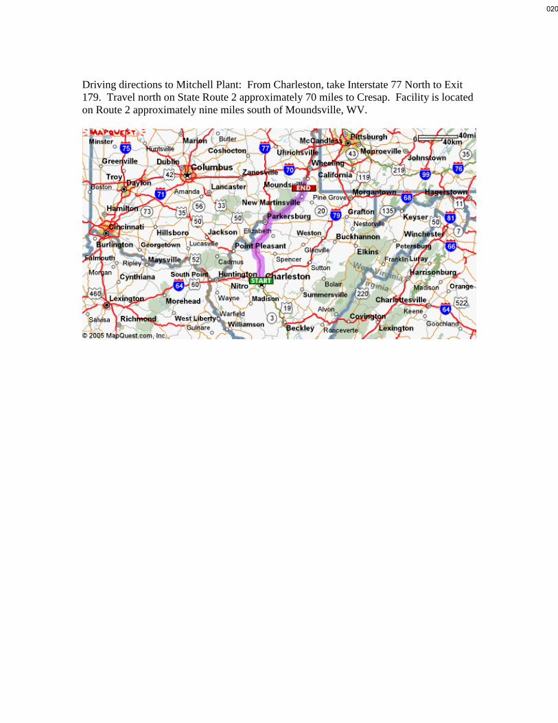
Driving directions to Mitchell Plant: From Charleston, take Interstate 77 North to Exit 179. Travel north on State Route 2 approximately 70 miles to Cresap. Facility is located on Route 2 approximately nine miles south of Moundsville, WV.
020

MITCHELL PLANT
PLANT BOUNDARY
Ohio Power Company
Mitchell Plant
Facility Boundary
Powhatan Point, W.VA. - OH
Quadrangle
USGS Topographic Map
0 ½ 1mi
04.25.02
N
Plant Latitude 39° 49’ 45”
Plant Longitude 80° 48’ 59”Air Quality
Services
021

Mitchell Plant Dry Fly Ash Landfill Boundary
022

Mitchell Plant Title V Renewal
R30-05100005-2014 Renewal
2019
Attachment B
Plot Plan
023

024

025

026

027

028

Mitchell Plant Title V Renewal
R30-05100005-2014 Renewal
2019
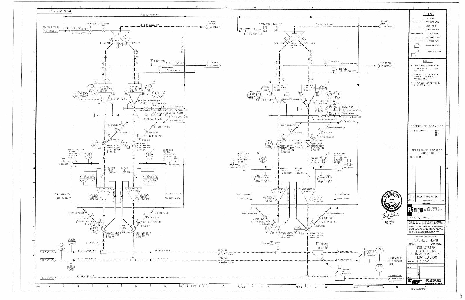
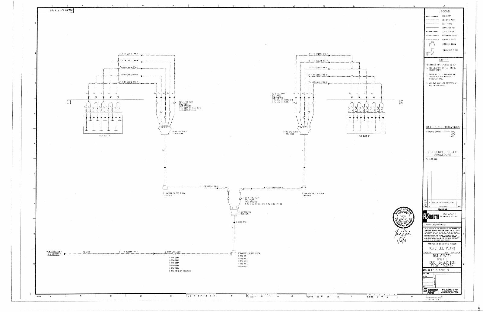
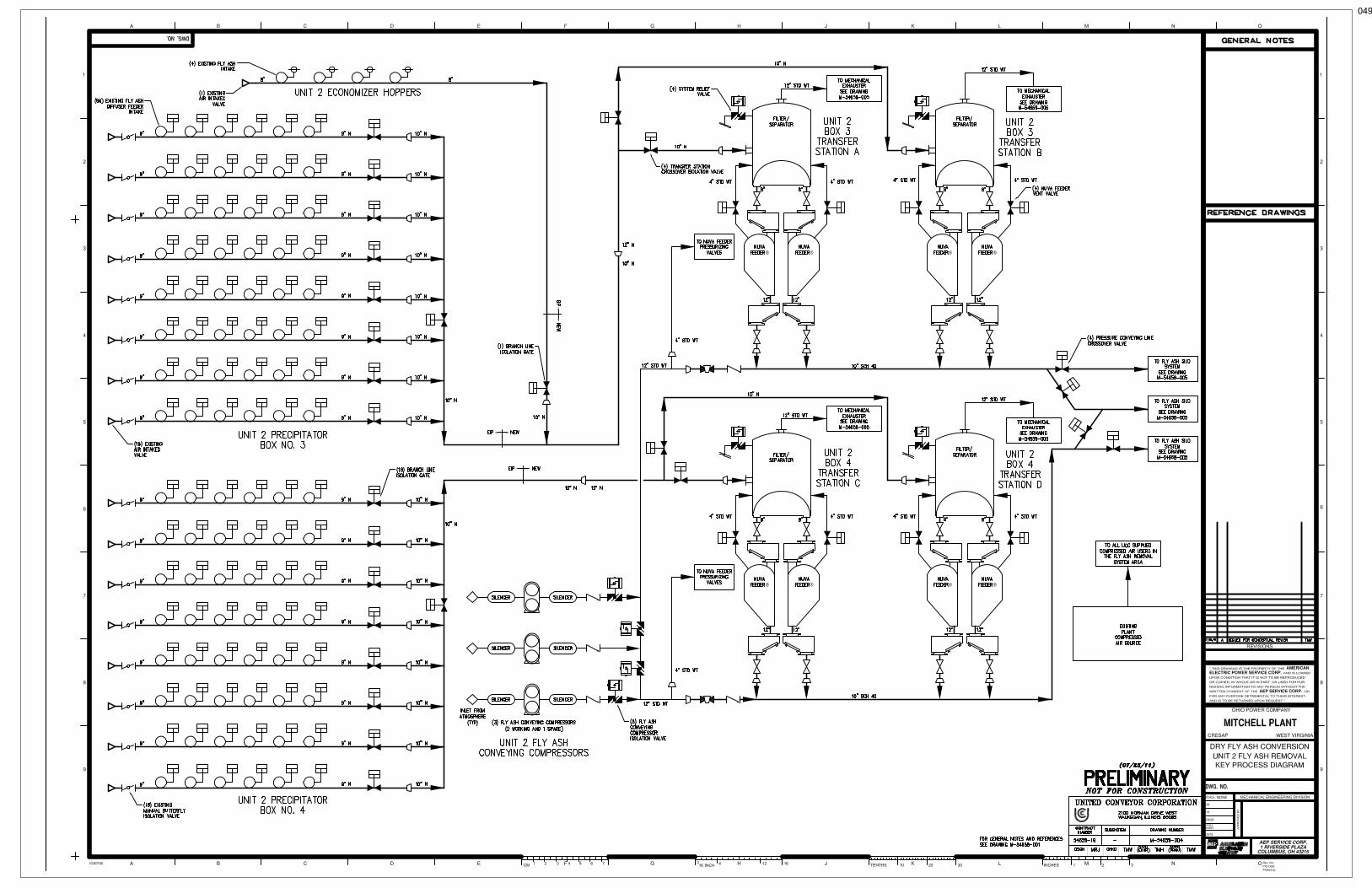
Attachment C
Process Flow Diagrams
029

Mitchell Unit 1
Mitchell Unit 2 Unit 2 SCR*
Unit 1 SCR Unit 1 ESP
Unit 2 ESP
Unit 1 FGD
3C
Unit 2 FGD
6C
Flow Diagram:
Steam Generator and Associated Pollution Control Equipment
New Stack
1-E
2-E
Aux ML1
Stack
Old Stack
CS012
Retire In-place
Mitchell Aux 1
030

Process Flow Diagrams
Limestone Material Handling System- 1S -
Gypsum Material Handling System- 2S -
Emergency Quench Pump Diesel Engines
- 6S, 7S -
3Efugitive dust
15E, 16E
Limestone Material Processing System
- 3S - Vent Dust Filters7C, 8C, 9C
6E, 7E, 8E
Coal Blending System- 5S -
Dry Sorbent Material Handling System- 4S -
(SO3 Mitigation)Vent Dust Filters
10C, 11C
10E, 11E
Magnesium Hydroxide Material Handling System
- 9S -(SO3 Mitigation)
5Efugitive dust
9Efugitive dust
14Efugitive dust
4Efugitive dust
20Efugitive dust
WWT Material Handling System- 11S -
(Wastewater Treatment Material Handling)
Vent Dust Filter16C, 17C
24E , 25E
23Efugitive dust
January 2006
031

032

033

034

035

036

037

038

039
040
041

042

043

044

045

046

047

048
TinWei
Text Box
EMISSIONS SKETCH 1
TinWei
Text Box
TS-1C
TinWei
Text Box
TS-1A
TinWei
Text Box
TS-1B (spare)
TinWei
Text Box
TS-1D (spare)
049
TinWei
Text Box
EMISSIONS SKETCH 2
TinWei
Text Box
TS-2A
TinWei
Text Box
TS-2C
TinWei
Text Box
TS-2D (spare)
TinWei
Text Box
TS-2B (spare)

050
TinWei
Text Box
ME-1A
TinWei
Text Box
EMISSIONS SKETCH 3
TinWei
Text Box
ME-1C (spare)
TinWei
Text Box
ME-1B
TinWei
Text Box
ME-2A
TinWei
Text Box
ME-2C (spare)
TinWei
Text Box
ME-2B
TinWei
Text Box
FAS-A
TinWei
Text Box
FAS-B
TinWei
Text Box
FAS-C
TinWei
Text Box
EP-1
TinWei
Text Box
EP-2
TinWei
Text Box
EP-3
TinWei
Text Box
EP-6
TinWei
Text Box
EP-5
TinWei
Text Box
EP-4
TinWei
Text Box
LEGEND EP EMISSION POINT F FUGITIVE EMISSION POINT

051
TinWei
Text Box
EP-7 (Silo A) EP-8 (Silo B) EP-9 (Silo C)
TinWei
Text Box
BVF-A (Silo A) BVF-B (Silo B) BVF-C (Silo C)
TinWei
Text Box
LEGEND EP EMISSION POINT F FUGITIVE EMISSION POINT
TinWei
Text Box
F-1 (Silo A) F-2 (Silo B) F-3 (Silo C)
TinWei
Text Box
WFA-AA (Silo A) WFA-BA (Silo B) WFA-CA (Silo C)
TinWei
Text Box
WFA-AB (spare) (Silo A) WFA-BB (spare) (Silo B) WFA-CB (spare) (Silo C)
TinWei
Text Box
F-4 (Silo A) F-5 (Silo B) F-6 (Silo C)
TinWei
Text Box
F-7 (Silo A) F-8 (Silo B) F-9 (Silo C)
TinWei
Text Box
EMISSIONS SKETCH 4
TinWei
Line
TinWei
Text Box
TCV-A (Silo A) TCV-B (Silo B) TCV-C (Silo C)
TinWei
Text Box
EP-10 (Silo A) EP-11 (Silo B) EP-12 (Silo C)
TinWei
Text Box
TC-A (Silo A) TC-B (Silo B) TC-C (Silo C)
TinWei
Line
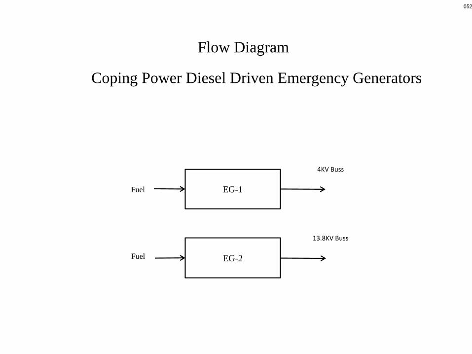
4KV Buss
13.8KV Buss
EG-1
EG-2
Coping Power Diesel Driven Emergency Generators
Fuel
Fuel
Flow Diagram
052

Mitchell Plant Title V Renewal
R30-05100005-2014 Renewal
2019
Attachment D
Title V Equipment Table
053

Title V Equipment Table (equipment_table.doc)
Page 1 of 1
Page ______ of ______ Revised 4/11/05
ATTACHMENT D - Title V Equipment Table
(includes all emission units at the facility except those designated as
insignificant activities in Section 4, Item 24 of the General Forms)
Emission
Point ID1
Control
Device1
Emission
Unit ID1
Emission Unit Description Design
Capacity
Year Installed/
Modified
Boiler & Associated Equipment
Unit 1 High
efficiency
ESP, LNB, SCR, FGD
1E Boiler: Foster Wheeler, Model # 2-85-303 7020 mmBtu/hr 1971
Unit 2 High
efficiency ESP, LNB,
SCR, FGD
2E Boiler: Foster Wheeler, Model # 2-85-304 7020 mmBtu/hr 1971
Aux 1 N/A Aux ML1 Boiler: Foster Wheeler, Model # SD- 25 663 mmBtu/hr 1970, Reconstructed
in 2012
17E None 17S Unit 1 Emergency Diesel Driven Fire Pump 230 HP Approx. 1971
18E None 18S Unit 2 Emergency Diesel Driven Fire Pump 230 HP Approx. 1971
EG-1 None EG-1
CAT® C175-16 (Compression Ignition (CI) Engine)
Certificate No. ECPXL106.NZS-011
Engine ECPXL106.NZS
3,717-bhp@ 1,800rpm
2014
EG-2 None EG-2 CAT® 3516C-HD TA (CI Engine)
Certificate No. ECPXL78.1NZS-024
Engine ECPXL78.1NZS
3,004-bhp@
1,800rpm 2014
EGT01 None EGT01 Diesel Fuel Storage Tank for EG-1 4,800 gallons 2014
EGT02 None EGT02 Diesel Fuel Storage Tank for EG-2 4,800 gallons 2014
Coal Handling
BU WS, PE,
MC BU Barge Unloader (unload barge onto Conveyor R1 4,000 TPH 1971
Station R1 FE, MC
Sta-R1 Conveyor R1 and drop points to Conveyor R2 3,000 TPH 1971
C-R2 WS, PE,
MC C-R2 Conveyor R2 (transfer to Station R2) 3,000 TPH 1971
RCU WS, MC RCU Rail Car Unloader (unload rail cars to feeders R6-1, R6-2 and
R6-3) 3,000 TPH April, 1974
R6-1, R6-2, R6-3
PE, MC R6-1, R6-2,
R6-3 Feeders R6-1, R6-2, R6-3 (transfer points to Conveyor R7) 1,400 TPH April 1974
C-R7 WS, PE,
MC C-R7 Conveyor R7 (transfer to Station R2) 3,000 TPH April 1974
Station R2 FE, MC Sta-R2 Drop point to coal crusher or conveyor R3 N/A April 1974
CR-R2 FE, MC CR-R2 Coal Crusher 2,500 TPH 1971
C-R3 PE, MC C-R3 Conveyor R3 (transfer to Station R3) 3,000 TPH 1971
Station R3 FE, MC Sta-R3 Drop point to conveyor R4 or R1 1 N/A 1971
C-R1 1 PE, MC C-R1 1 Conveyor R1 1 (transfer to radial portable Conveyor R12) 3,000 TPH 1971
C-R12 MC C-R12 Radial Portable Conveyor R12 (transfer to temporary storage
pile) 3,000 TPH 1971
C-R4 PE, MC C-R4 Conveyor R4 (transfer to Station R4) 3,000 TPH 1971
Station R4 FE, MC Sta-R4 Drop point to Sample System and Conveyor R5; and/or
Conveyor R8 N/A
1971
054

Title V Equipment Table (equipment_table.doc)
Page 2 of 1
Page ______ of ______ Revised 4/11/05
C-R8 PE, MC C-R8 Conveyor R8 (transfer to Radial Stacker Conveyor R9) 3,000 TPH April 1974
C-R9 MC C-R9 Radial Stacker Conveyor R9 (transfer to North Yard Storage
Pile – Station R7) 3,000 TPH April 1974
Station R7 FE, MC Sta-R7 Drop point from North Yard Storage Pile through Crusher R7-
1 to Feeder Conveyor BFR7-1 N/A April 1974
CR-R7-1 FE, MC CR-R7-1 Coal Crusher 1,000 TPH April 1974
BFR7-1 FE, MC BFR7-1 Feeder BFR7-1 (transfer to Conveyor R10) 1,100 TPH April 1974
C-R1 0 PE, MC C-R10 Conveyor R10 (transfer to truck load out and Station R4) 1,100 TPH April 1974
C-R5 PE, MC C-R5 Conveyor R5 (transfer to Drive Tower S1) 3,000 TPH 1971
Drive Tower
S1 FE, MC
Drive Tower
S1 Drop point to Conveyor R6 N/A 1971
C-R6 PE, MC C-R6 Conveyor R6 (transfer to Station 2) 3,000 TPH 1971
Station 2 FE, MC Sta-2 Drop point to Radial Stacker Conveyor 2 N/A 1969
RS-2 WS, MC RS-2 Radial Stacker 2 (transfer to surge pile) 4,000 TPH 1969
Station 1A FE, MC Sta-1A Drop point from frozen coal storage area 4 through crusher
CR-1A to Conveyor 1A N/A 1969
CR-1A FE, MC CR-1A Coal Crusher 1,000 TPH 1969
C-1A PE, MC C-1A Conveyor 1A (transfer to Station 1B) 1,100 TPH 1969
Station 1B FE, MC Sta-1B Drop point to Conveyor 1 N/A 1969
C-1 PE, MC C-1 Conveyor 1 (transfer to Station 2) 2,600 TPH 1969
CSA-1 MC CSA-1 Coal Storage Area #1 (Surge Pile) Approx 40 Acres 1969
CSA-2 MC CSA-2 Coal Storage Area #2 (North Yard Storage Pile) Approx 40 Acres April 1974
CSA-3 MC CSA-3 Coal Storage Area #3 (Temporary Storage Pile at R3) Approx 6 Acres
CSA-4 MC CSA-4 Coal Storage Area #4 (conveyor from 1B) Included in CSA-1 1969
SGM1 through SGM16
FE, MC SGM1
through
SGM1 6
Reclaim Hoppers/Vibratory Feeders (Reclaim Area #1 surge pile) transfers to Conveyors 3A, 3B and 3C
300 TPH each 1969
C-3A FE, MC C-3A Conveyor 3A (transfer to Station 3B) 1,100 TPH 1969
Station 3B FE, MC
Sta-3B Drop point to Conveyor 3B N/A 1969
C-3B FE, MC C-3B Conveyor 3B (transfer to Station 3) 1,100 TPH 1969
C-3C FE, MC C-3C Conveyor 3C (transfer to Station 3) 1,100 TPH 1969
Station 3 FE, MC Sta-3 Drop point to Conveyors 4E and/or 4W N/A 1969
C-4E/C-4W PE, MC C-4E/C-4W Conveyors 4E and 4W (transfer to Station 4) 1,100 TPH each 1969
Station 4 FE, MC Sta-4 Drop point to Sample System, Conveyor 7E and/or 7W, and
Conveyor 5 or Emergency Conveyors E25 through E2 1 N/A 1969
C-7E/C-7W PE, MC C-7E/C-7W Conveyors 7E and 7W (transfer to Station 5 1,100 TPH each 1969
C-5 FE, MC C5 Conveyor 5 (transfer to Unit 2 coal silos 3, 4 or 5 and to
Conveyor 6) 1,100 TPH 1969
C-6 FE, MC C-6 Conveyor 6 (transfer to Unit 2 coal silos 1 or 2) 1,100 TPH 1969
C-E25
through C- E21 MC
C-E25 through
C-E21
Emergency conveyors E25 through E21 (used in an emergency
to transfer coal into Unit 2 coal silos) 500 TPH each 1969
055

Title V Equipment Table (equipment_table.doc)
Page 3 of 1
Page ______ of ______ Revised 4/11/05
Station 5 FE, MC Sta-5 Drop point to Conveyor 8 or
Emergency Conveyors E1 1 through E15 N/A 1969
C-8 FE, MC C-8 Conveyor 8 (transfer to Unit 1 coal silos 3, 4, or 5 and to
Conveyor 9) 1,100 TPH 1969
C-9 FE, MC C-9 Conveyor 9 (transfer to Unit 1 coal silos 1 or 2) 1,100 TPH 1969
C-E1 1
through C- E15 MC
C-E1 1 through
C-E15
Emergency conveyors E1 1 through E15 (used in an
emergency to transfer coal into Unit 1 coal silos) 500 TPH 1969
Fly Ash Material Handling
Haul Roads Water Truck Haul Roads Fly Ash Material Haul Roads and Landfill N/A N/A
EP-1 Filter/Separator ME-1A Unit 1 Mechanical Exhauster 1A N/A 2012
EP-2 Filter/Separator ME-1B Unit 1 Mechanical Exhauster 1B N/A 2012
EP-3 Filter/Separator ME-1C (spare)
Unit 1 Mechanical Exhauster 1C N/A 2012
EP-4 Filter/Separator ME-2A Unit 2 Mechanical Exhauster 2A N/A 2012
EP-5 Filter/Separator ME-2B Unit 2 Mechanical Exhauster 2B N/A 2012
EP-6 Filter/Separator ME-2C (spare)
Unit 2 Mechanical Exhauster 2C N/A 2012
EP-7 BVF-A FAS-A Fly Ash Silo A 2,160 tons 2012
EP-8 BVF-B FAS-B Fly Ash Silo B 2,160 tons 2012
EP-9 BVF-C FAS-C Fly Ash Silo C 2,160 tons 2012
F-1 MC WFA-AA Transfer conditioned fly ash from Fly Ash Silo A to Truck via
Pin/Paddle Mixer 360 tph 2012
F-2 MC WFA-BA Transfer conditioned fly ash from Fly Ash Silo B to Truck via
Pin/Paddle Mixer 360 tph 2012
F-3 MC WFA-CA Transfer conditioned fly ash from Fly Ash Silo C to Truck via
Pin/Paddle Mixer 360 tph 2012
F-4 MC WFA-AB
(spare)
Transfer conditioned fly ash from Fly Ash Silo A to Truck via
Pin/Paddle Mixer 360 tph 2012
F-5 MC WFA-BB
(spare)
Transfer conditioned fly ash from Fly Ash Silo B to Truck via
Pin/Paddle Mixer 360 tph 2012
F-6 MC WFA-CB
(spare) Transfer conditioned fly ash from Fly Ash Silo C to Truck via
Pin/Paddle Mixer 360 tph 2012
EP-10, F-7 TC TC-A Transfer dry fly ash from Fly Ash Silo A to Truck via
Pin/Paddle Mixer 300 tph 2012
EP-11, F-8 TC TC-B Transfer dry fly ash from Fly Ash Silo B to Truck via
Pin/Paddle Mixer 300 tph 2012
EP-12, F-9 TC TC-C Transfer dry fly ash from Fly Ash Silo C to Truck via
Pin/Paddle Mixer 300 tph 2012
1S – Limestone Material Handling
BUN-1
(Fugitive) None BUN-1 Limestone Unloading Crane 1,000 TPH 2006
RH-1
(Fugitive) WS, PE RH-1 Limestone Unloading Hopper 60 Tons 2006
VF-1
(Fugitive) FE VF-1 Limestone Unloading Feeder 750 TPH 2006
BC-1 (Fugitive)
PE BC-1 Limestone Dock/Connecting Conveyor 750 TPH 2006
TH-1
(Fugitive) FE TH-1 Limestone Transfer House #1 750 TPH 2006
BC-2
(Fugitive) PE BC-2 Limestone Storage Pile Stacking Conveyor 750 TPH 2006
LSSP (Fugitive)
None LSSP Limestone Active/Long-Term Stockpile 155,000 Tons 2006/2011
056

Title V Equipment Table (equipment_table.doc)
Page 4 of 1
Page ______ of ______ Revised 4/11/05
2S - Gypsum Material Handling
BC-8 (Fugitive)
PE BC-8 Vacuum Collecting Conveyor 200 TPH 2007
TH-3
(Fugitive) FE TH-3 Gypsum Transfer House #3 200 TPH 2007
BC-9
(Fugitive) PE BC-9 Connecting Conveyor 200 TPH 2007
TH-4 (Fugitive)
FE TH-4 Gypsum Transfer House #4 200 TPH 2007
BC-10
(Fugitive) PE BC-10 Connecting Conveyor 200 TPH 2007
TH-5
(Fugitive) FE TH-5 Gypsum Transfer House #5 200 TPH 2007
BC-11 (Fugitive)
PE BC-11 Connecting Conveyor 200 TPH 2007
TH-6
(Fugitive) FE TH-6 Gypsum Transfer House #6 200 TPH 2007
BC-12
(Fugitive) PE BC-12 Stacking Tripper Conveyor 200 TPH 2007
GSP (Fugitive)
FE GSP Gypsum Stockpile 15,600 tons 2007
PSR-1
(Fugitive) FE PSR-1 Traveling Portal Scraper Reclaimer 1,000 TPH 2007
BC-14
Fugitive) PE BC-14 Reclaim Conveyor 1,000 TPH 2007
TH-7 (Fugitive)
FE TH-7 Transfer House #7 1,000 TPH 2007
BC-13
(Fugitive) PE BC-13 Bypass Conveory 200 TPH 2007
BC-15
(Fugitive) PE BC-15 Connecting Conveyor 1,000 TPH 2007
TH-1 (Fugitive)
FE TH-1 Transfer House #1 1,000 TPH 2007
BC-16
(Fugitive) PE BC-16 Transfer Conveyor 1,000 TPH 2007
BL-1
(Fugitive) PE BL-1 Barge Loader 1,000 TPH 2007
BC-14 (Fugitive)
PE BC-14 Reclaim Conveyor Extension 1,000 TPH 2007
TH-8
(Fugitive) FE TH-8 Transfer House 8 1,000 TPH 2007
BC-19
(Fugitive) PE BC-19 Transfer Conveyor 1,000 TPH 2007
TH-9 (Fugitive)
FE TH-9 Transfer House 9 1,000 TPH 2007
BC-20
(Fugitive) PE BC-20 Transfer Conveyor to 20 1,000 TPH 2007
TH-10
(Fugitive) FE TH-10 Transfer House 10 1,000 TPH 2007
BC-21
(Fugitive) PE BC-21 Transfer Conveyor to 21 1,000 TPH 2007
BUN-1
(Fugitive) BUN-1 Clamshell Unloading Crane 1,000 TPH 2007
RH-4
(Fugitive) WS, PE RH-4 Gypsum Unloading Hopper 30 tons 2007
RP-1 (Fugitive)
FE RP-1 Gypsum Rotary Plow 750 TPH 2007
BC-17
(Fugitive) PE BC-17 Dock/Connecting Conveyor 750 TPH 2007
TH-7
(Fugitive) FE TH-7 Transfer House #7 750 TPH 2007
BC-18 (Fugitive)
PE BC-18 Bypass Conveyor 750 TPH 2007
057

Title V Equipment Table (equipment_table.doc)
Page 5 of 1
Page ______ of ______ Revised 4/11/05
TH-6
(Fugitive) FE TH-6 Transfer House #6 750 TPH 2007
3S - Limestone Mineral Processing
VF-2
(Fugitive)
FE VF-2 Limestone Reclaim Feeder 2 750 TPH 2007
VF-3
(Fugitive)
FE VF-3 Limestone Reclaim Feeder 3 750 TPH 2007
BC-3 (Fugitive)
PE BC-3 Limestone Tunnel Reclaim Conveyor 750 TPH 2007
FB-1
(Fugitive) FB-1 Emergency Limestone Reclaim Feeder/Breaker 750 TPH 2007
TH-2
(Fugitive) FE TH-2 Limestone Transfer House 2 750 TPH 2007
BC-4 (Fugitive)
PE BC-4 Limestone Silo A Feed Conveyor 750 TPH 2007
BC-5
(Fugitive) PE BC-5 Limestone Silo B Feed Conveyor 750 TPH 2007
BC-6
(Fugitive) PE BC-6 Limestone Silo C Feed Conveyor (future) 750 TPH 2007
6E BH LSB-1 Limestone Silo A 900 Tons 2007
7E BH LSB-2 Limestone Silo B 900 Tons 2007
8E BH LSB-3 Limestone Silo C (future) 900 Tons 2007
(Fugitive) FE Vibrating Bin Discharger (one per silo) 68.4 TPH 2007
LSWF-1
(Fugitive)
LSWF-2 (Fugitive)
LSWF-
3(Fugitive)
FE LSWF-1
LSWF-2
LSWF-3
Limestone Weigh Feeder (one per silo) 68.4 TPH 2007
(Fugitive) FE Wet Ball Mill (one per silo) 68.4 TPH 2007
4S - Dry Sorbent Material Handling
(Fugitive) FE Truck Unloading Connection (2) 25 TPH 2007
10E BH, FE DSSB 1 Dry Sorbent Storage Silo #1 500 TPH 2007
11E BH, FE DSSB 2 Dry Sorbent Storage Silo #2 500 TPH 2007
(Fugitive) FE Aeration Distribution Bins 4.6 TPH 2007
(Fugitive) FE De-aeration Bins 4.6 TPH 2007
(Fugitive) FE Rotary Feeder 4.6 TPH 2007
5S - Coal Blending System
HTS-1 (Fugitive)
FE HTS-1 Transfer House #1 3,000 TPH 2007
HSC-1
(Fugitive) PE HSC-1 Stacking Conveyor #1 3,000 TPH 2007
HTS-2A
(Fugitive) FE HTS-2A Transfer House #2A 3,000 TPH 2007
HSC-2 (Fugitive)
PE HSC-2 Stacking Conveyor #2 3,000 TPH 2007
HTS-3
(Fugitive) FE HTS-3 Transfer House #3 3,000 TPH 2007
HSC-3
(Fugitive) PE HSC-3 Stacking Conveyor #3 3,000 TPH 2007
058
Title V Equipment Table (equipment_table.doc)
Page 6 of 1
Page ______ of ______ Revised 4/11/05
SH-1
(Fugitive) FE SH-1
Stacking Hopper SH-1 Transfer to SC-3 (receive coal from plant
radial stacker R9) 3,000 TPH 2007
HSC-3 to High
Sulfur Pile
(Fugitive) (CSA-
2, existing)
Stacking
Tube
HSC-3 to High
Sulfur Pile
(CSA-2,
existing)
Transfer from Stacking Conveyor HSC-3 to High Sulfur Pile at
existing North Yard Storage Area (CSA-2) 3,000 TPH 2007
HVF-1 (Fugitive)
FE HVF-1 Coal Reclaim Feeder 1 800 TPH 2007
HVF-2
(Fugitive) FE HVF-2 Coal Reclaim Feeder 2 800 TPH 2007
HVF-3
(Fugitive) FE HVF-3 Coal Reclaim Feeder 3 800 TPH 2007
HVF-4 (Fugitive)
FE HVF-4 Coal Reclaim Feeder 4 800 TPH 2007
HVF-1 through
HVF-4 to HRC-1
(Fugitive)
(Transfer)
FE HVF-1 through
HVF-4 to HRC-1
(Transfer)
Transfer from Vibrating Feeders HVF-1 through HVF-4 to
Reclaim Conveyor HRC-1 1,600 TPH 2007
HRC-1 (Fugitive)
PE HRC-1 Coal Tunnel Reclaim Conveyor 1,600 TPH 2007
HTS-2B
(Fugitive) FE HTS-2B Coal Transfer House #2B 1,600 TPH 2007
HRC-2 (Fugitive)
PE HRC-2 Reclaim Conveyor #2 1,600 TPH 2007
HTS-4
(Fugitive) FE HTS-4 Coal Transfer House #4 1,600 TPH 2007
HRC-3
(Fugitive) PE HRC-3 Reclaim Conveyor #3 1,600 TPH 2007
HTS-5 (Fugitive)
FE HTS-5 Coal Transfer House #5 1,600 TPH 2007
SB-1
(Fugitive) FE SB-1 Surge Bin #1 80 Tons 2007
HBF-1A
(Fugitive) PE HBF-1A Belt Feeder 1A 800 TPH 2007
HBF-1B
(Fugitive) PE HBF-1B Belt Feeder 1B 800 TPH 2007
HBF-1A/1B to
BF-4E/4W
(Fugitive)
FE HBF-1A/1B
to BF-4E/4W
Transfer from Belt Feeders HBF-1A and HBF-1B to Existing Coal Conveyors 4E and 4W
1,600 TPH 2007
6S, 7S - Emergency Quench Water System
15E FE 6S Diesel Engine on Quench Pump #1 60 HP (approx.) 2007
16E FE 7S Diesel Engine on Quench Pump #2 60 HP (approx.) 2007
9S – Magnesium Hydroxide Material Handling System
MHM-1 N/A MHM-1 Magnesium Hydroxide Mix Tank #1 1000 Gal. 2007
MHM-2 N/A MHM-2 Magnesium Hydroxide Mix Tank #2 1000 Gal. 2007
11S – Wastewater Treatment Material Handling
Fugitive FE Truck Unloading Connection (2) 25 TPH 2007
24E BH, FE Lime Storage Silo #1 100 TPH 2007
25E BH, FE Lime Storage Silo #2 100 TPH 2007
Fugitive Building
Enclosure Wastewater Treatment Cake Stockpile 3,600 Tons 2007
Fugitive PE FB-2 Filter Cake Feeder/Breaker 600 TPH 2007
059

Title V Equipment Table (equipment_table.doc)
Page 7 of 1
Page ______ of ______ Revised 4/11/05
Fugitive PE BC-22 Transfer Conveyor 22 600 TPH 2007
Fugitive PE TH-12 Transfer House #12 600 TPH 2007
Miscellaneous Other
Tank #1 N/A Tank #1 Ignition Oil Tank – S. of U1 Cooling Tower 1,500,000 Gal. ~1975
Tank #2 N/A Tank #2 Ignition Oil Tank – N. of U2 Cooling Tower 500,000 Gal. 1971
Tank #3 N/A Tank #3 Ignition Oil Tank – N. of U2 Cooling Tower 500,000 Gal. 1971
Tank #4 N/A Tank #4 Used Oil Tank – S. of U1 Cooling Tower 1,000 Gal. Relocated ~2004
Tank #5 N/A Tank #5 Used Oil Tank – Tractor Shed 500 Gal. ~2000
Tank #6 N/A Tank #6 Sulfuric Acid Tank – W. of Units 1&2 15,000 Gal. 1971
Tank #7 N/A Tank #7 Ammonium Hydroxide Tank – W. of Units 1 &2 4,750 Gal. 1971
Tank #8 N/A Tank #8 Diethylene Glycol Tank – N. of Station R-4 500 Gal. ~2002
Tank #9 N/A Tank #9 Diethylene Glycol Tank – Station 3 300 Gal. ~2002
Tank #10 N/A Tank #10 Diethylene Glycol Tank – Station R-4 300 Gal. ~2002
Tank #11 N/A Tank #11 No.2 Fuel Oil Tank – Coal Transfer Station #3 1,000 Gal. 2007
Tank #12 N/A Tank #12 No.2 Fuel Oil Tank – Coal Transfer Station R-2 3,000 Gal ~2004
Tank #13 N/A Tank #13 No.2 Fuel Oil Tank – Coal Transfer Station R-4 3,000 Gal. ~2004
Tank #14 N/A Tank #14 No.2 Fuel Oil Tank – Drain Receiver Tank 400 Gal. 1969
Tank #15 N/A Tank #15 Gasoline Tank – Main Plant Entrance 8,000 Gal. 1991
Tank #16 N/A Tank #16 Diesel Fuel Tank – Tractor Shed 10,000 Gal 1991
Tank #17 N/A Tank #17 Turbine Oil Tank – U1 ~14,000 Gal. 1971
Tank #18 N/A Tank #18 Turbine Oil Tank – U2 ~14,000 Gal. 1971
Tank #19 N/A Tank #19 Lube Oil Tank – U1 ~20,000 Gal. 1971
Tank #20 N/A Tank #20 Lube Oil Tank – U2 ~18,000 Gal. 1971
Tank #21 N/A Tank #21 Chemical Cleaning Solution Tank 1,000,000 Gal. 1989
Tank #22 N/A Tank #22 EHC System Oil Tank – U1 200 Gal. 1971
Tank #23 N/A Tank #23 New Lube Oil Tank – U1 1,000 Gal. 1971
Tank #24 N/A Tank #24 Used Oil Bulk Tank – U1 275 Gal. ~2002
Tank #25 N/A Tank #25 EHC System Oil Tank – U2 625 Gal. 1971
Tank #26 N/A Tank #26 New Lube Oil Tank – U2 1,000 Gal. 1971
Tank #27 N/A Tank #27 Used Oil Bulk Tank – U2 275 Gal. ~2002
Tank #28 N/A Tank #28 Diesel Fire Pump Fuel Tank – U1 275 Gal. 1971
Tank #29 N/A Tank #29 Diesel Fire Pump Fuel Tank – U2 275 Gal. 1971
060
Title V Equipment Table (equipment_table.doc) Page 8 of 1
Page ______ of ______ Revised 4/11/05
Tank #30 N/A Tank #30 3 Compartment Oil Tank – Tractor Shed Oil Room 920 Gal. ~1995
Tank #31 N/A Tank #31 Single Compartment Oil Tank – Tractor Shed 560 Gal. ~1995
Tank #32 N/A Tank #32 Waste Oil Tank – Tractor Shed Oil Room 500 Gal. ~2000
Tank #33 FE Tank #33 Urea Receiving Hopper 45 Tons 2007
Tank #34 N/A Tank #34 No.2 Fuel Oil Tank – Drain Receiver Tank – overflow tank 1,000 Gal. 2001
Tank #35 N/A Tank #35 TK103-100 Urea Solution Storage Tank 200,000 Gal. 2007
Tank #36 N/A Tank #36 TK102-100 Urea Mix Tank 2,700 Gal. 2007
Tank #37 N/A
Tank #37 CPS Lime Slurry Tank #1 750 Gal. 2007
Tank #38 N/A Tank #38 CPS Lime Slurry Tank #2 750 Gal. 2007
Tank #39 N/A Tank #39 CPS Equalization Tank #1 254,513 Gal. 2007
Tank #40 N/A Tank #40 CPS Equalization Tank #2 254,513 Gal. 2007
Tank #41 N/A Tank #41 CPS Ferric Chloride Mix Tank #1 9,200 Gal. 2007
Tank #42 N/A Tank #42 CPS Ferric Chloride Mix Tank #2 9,200 Gal. 2007
Tank #43 N/A Tank #43 CPS Ferric Chloride Bulk Storage Tank 8,800 Gal. 2007
Tank #44 N/A Tank #44 CPS Acid Bulk Storage Tank 10,575 Gal. 2007
Tank #45 N/A
Tank #45 CPS Polymer Totes (2) 225 Gal. (each) 2007
Tank #46 N/A
Tank #46 Emergency Quench Pump #1 Diesel Tank 70 Gal. 2007
Tank #47 N/A Tank #47 Emergency Quench Pump #2 Diesel Tank 70 Gal. 2007
Tank #48 N/A Tank #48 Aux. Boiler Collection Tank Return UST 500 Gal. 2006
Tank #49 N/A Tank #49 No. 2 Fuel Tank – SW Corner of CSA-2 2000 Gal. 2008
Tank #50 N/A Tank #50 Gypsum Storage Building Fuel Oil Tank 1000 Gal. 2009
Tank #51 N/A Tank #51 Highway Grade Diesel Tank #1 1000 Gal. 2011
Tank #52 N/A Tank #52 Limestone Storage Pile Diesel Tank #1 500 Gal. 2011
Fugitive Enclosure Rock Salt Storage Pile (roadway ice control) 600 Tons 2010 and 2014
Tank #53 N/A Tank #53 Landfill Building Furnace Fuel Oil Tank 2000 Gal. 2018
Tank #54 N/A Tank #54 Landfill Gasoline Tank 520 Gal. 2018
Tank #55 N/A Tank #55 Kerosene Tank 1,000 Gal. 2015
Tank #56 N/A Tank #56 CPS Coagulant Tank 5,000 Gal. 2019
Tank #57 N/A Tank #57 Unit 1 Scale Inhibitor Tank 3,500 Gal. 2015
Tank #58 N/A Tank #58 Unit 2 Scale Inhibitor Tank 3,500 Gal. 2015
Tank #59 N/A Tank #59 Unit 1 Dispersant Tank 5,000 Gal. 2015
Tank #60 N/A Tank #60 Unit 2 Dispersant Tank 5,000 Gal. 2015
061

Title V Equipment Table (equipment_table.doc) Page 9 of 1
Page ______ of ______ Revised 4/11/05
Tank #61 N/A Tank #61 Unit 1 Ferric Chloride Tank 1,500 Gal. 2015
Tank #62 N/A Tank #62 Unit 1 Ferric Chloride Tank 2,500 Gal. 2015
Tank #63 N/A Tank #63 FGD corrosion inhibitor tank 5,000 Gal. 2015
1For 45CSR13 permitted sources, the numbering system used for the emission points, control devices, and emission units should be consistent with the numbering system used in the 45CSR13 permit. For grandfathered sources, the numbering system should be consistent with registrations or emissions inventory previously submitted to DAQ. For emission points, control devices, and emissions units which have not been previously labeled, use the following 45CSR13 numbering system: 1S, 2S, 3S,... or other appropriate description for emission units; 1C, 2C, 3C,... or other appropriate designation for control devices; 1E, 2E, 3E, ... or other appropriate designation for emission points.
062

Mitchell Plant Title V Renewal
R30-05100005-2014 Renewal
2019
Attachment E
Emission Unit Forms
063

Page _____ of _____ Emission Unit Form (emission_unit.doc)
Page 1 of 3
Revised – 07/31/07
ATTACHMENT E - Emission Unit Form
Emission Unit Description Unit 1 Main Boiler
Emission unit ID number:
Unit 1 – ML1
Emission unit name:
Unit 1 Boiler
List any control devices associated
with this emission unit: ESP, SCR,
FGD
Provide a description of the emission unit (type, method of operation, design parameters, etc.):
Unit 1 is coal-fired EGU boiler that also utilizes oil for supplemental firing. Oil use includes, but is not limited to,
periods of start-up, shutdown, stabilization and emergency operations. The boiler may also periodically combust
non-hazardous material such as demineralizer resins, chemical cleaning solution, on-spec used oil, etc. The
nominal design of the Unit 1 boiler is 7,020 mmBtu/hr. Coal is delivered to the site via river barge, rail car, truck or
conveyor. Oil is delivered to the site via river barge or truck.
Manufacturer:
Foster Wheeler
Model number:
2-85-303 Serial number:
Custom
Construction date:
MM/DD/YYYY
Installation date:
05/31/1971
Modification date(s):
MM/DD/YYYY
Design Capacity (examples: furnaces - tons/hr, tanks - gallons): Nominal 7020 mmBtu/Hr (270 TPH with
13,000 BTU/lb Coal Supply) This heat input value is for operation at the nominal boiler rating. Boiler design
enables the boiler to be operated above the nominal rated capacity.
Maximum Hourly Throughput:
Nominal 5,289,000 lb/hr Steam
Maximum Annual Throughput:
Nominal 46,331,640,000 lb/yr
Steam
Maximum Operating Schedule:
8760 hr/yr
Fuel Usage Data (fill out all applicable fields)
Does this emission unit combust fuel? X__Yes ___ No If yes, is it?
X__ Indirect Fired ___Direct Fired
Maximum design heat input and/or maximum horsepower rating:
8590 mmBtu/hr (rating used to model full load operation for FGD
permit determination)
Type and Btu/hr rating of burners:
LNB – Foster Wheeler
List the primary fuel type(s) and if applicable, the secondary fuel type(s). For each fuel type listed, provide
the maximum hourly and annual fuel usage for each.
Primary: Coal; Secondary: Oil; The steam generator is capable of burning coal, and will utilize fuel oil for start-up,
shutdown and for flame stabilization. Other materials burned included non-hazardous water treatment resins,
chemical cleaning solution, on spec used oil, etc.
Describe each fuel expected to be used during the term of the permit.
Fuel Type Max. Sulfur Content Max. Ash Content BTU Value
Coal (Bit.) 4.5 lb/mmBtu 12.5% 13,000 BTU/lb
Oil 0.5% N/A 19,750 BTU/lb
064

Page _____ of _____ Emission Unit Form (emission_unit.doc)
Page 2 of 3
Revised – 07/31/07
Emissions Data
Criteria Pollutants Potential Emissions
PPH TPY
Carbon Monoxide (CO) 531 2324.5
Nitrogen Oxides (NOX) 4139 18131
Lead (Pb) 0.42 1.8
Particulate Matter (PM2.5) 105 461.2
Particulate Matter (PM10) 237 1037.7
Total Particulate Matter (TSP) 351 1537.4
Sulfur Dioxide (SO2) 10243 44862.6
Volatile Organic Compounds (VOC) 64 279
Hazardous Air Pollutants Potential Emissions
PPH TPY
Arsenic 0.64 2.8
Beryllium 1.53 6.7
Chromium 0.23 1.0
Cobalt 0.08 0.4
Manganese 0.43 1.9
Mercury 0.24 1.1
Nickel 0.19 0.8
Selenium 5.53 24.2
Hydrogen Chloride 1408.3 6168.3
Hydrogen Fluoride 122.3 535.6
Regulated Pollutants other than
Criteria and HAP
Potential Emissions
PPH TPY
List the method(s) used to calculate the potential emissions (include dates of any stack tests conducted,
versions of software used, source and dates of emission factors, etc.).
Potential emissions are based on a combination of AP-42 emission factors, regulatory limits, and engineering
knowledge.
065

Page _____ of _____ Emission Unit Form (emission_unit.doc)
Page 3 of 3
Revised – 07/31/07
Applicable Requirements
List all applicable requirements for this emission unit. For each applicable requirement, include the
underlying rule/regulation citation and/or construction permit with the condition number. (Note: Title V
permit condition numbers alone are not the underlying applicable requirements). If an emission limit is
calculated based on the type of source and design capacity or if a standard is based on a design parameter,
this information should also be included.
The following permit conditions are considered the applicable requirements for this emission unit. Where
appropriate, the actual permits are attached to provide the applicable language along with the underlying
rule/regulatory citation. Where appropriate, calculation basis is provided. For existing limits that were previously
captured in the permit, the calculations were provided in the previous permit application(s). No changes to existing
limits are being requested at this time.
Requirements currently captured in Title V permit:
R30-05100005-2014 Sections 4.0 through 4.1 (see Attachment I)
____ Permit Shield
For all applicable requirements listed above, provide monitoring/testing/recordkeeping/reporting which shall
be used to demonstrate compliance. If the method is based on a permit or rule, include the condition number
or citation. (Note: Each requirement listed above must have an associated method of demonstrating
compliance. If there is not already a required method in place, then a method must be proposed.)
The following permit conditions are considered the applicable requirements for monitoring, testing, recordkeeping
and reporting for this emission unit. Where appropriate, the actual permits are attached to provide the applicable
language along with the underlying rule/regulatory citation. No changes are being requested at this time.
Requirements currently captured in Title V permit:
R30-05100005-2014 Sections 4.2 through 4.5 (see Attachment I): Where appropriate, revisions to existing language
are noted.
Are you in compliance with all applicable requirements for this emission unit? X__Yes ___No
If no, complete the Schedule of Compliance Form as ATTACHMENT F.
066

Page _____ of _____ Emission Unit Form (emission_unit.doc)
Page 1 of 3
Revised – 07/31/07
ATTACHMENT E - Emission Unit Form
Emission Unit Description Unit 2 Main Boiler
Emission unit ID number:
Unit 2 – ML2
Emission unit name:
Unit 2 Boiler
List any control devices associated
with this emission unit: ESP, SCR,
FGD
Provide a description of the emission unit (type, method of operation, design parameters, etc.):
Unit 2 is coal-fired EGU boiler that also utilizes oil for supplemental firing. Oil use includes, but is not limited to,
periods of start-up, shutdown, stabilization and emergency operations. The boiler may also periodically combust
non-hazardous material such as demineralizer resins, chemical cleaning solution, on-spec used oil, etc. The
nominal design of the Unit 1 boiler is 7,020 mmBtu/hr. Coal is delivered to the site via river barge, rail car, truck or
conveyor. Oil is delivered to the site via river barge or truck.
Manufacturer:
Foster Wheeler
Model number:
2-85-304 Serial number:
Custom
Construction date:
MM/DD/YYYY
Installation date:
05/31/1971
Modification date(s):
MM/DD/YYYY
Design Capacity (examples: furnaces - tons/hr, tanks - gallons): Nominal 7020 mmBtu/Hr (270 TPH with
13,000 BTU/lb Coal Supply). This heat input value is for operation at the nominal boiler rating. Boiler design
enables the boiler to be operated above the nominal rated capacity.
Maximum Hourly Throughput:
Nominal 5,280,000 lb/hr Steam
Maximum Annual Throughput:
Nominal 46,252,800,000 lb/yr
Steam
Maximum Operating Schedule:
8760 hr/yr
Fuel Usage Data (fill out all applicable fields)
Does this emission unit combust fuel? X__Yes ___ No If yes, is it?
X__ Indirect Fired ___Direct Fired
Maximum design heat input and/or maximum horsepower rating:
8,481 mmBtu/hr (rating used to model full load operation for FGD
permit determination)
Type and Btu/hr rating of burners:
LNB – Foster Wheeler
List the primary fuel type(s) and if applicable, the secondary fuel type(s). For each fuel type listed, provide
the maximum hourly and annual fuel usage for each.
Primary: Coal; Secondary: Oil; The steam generator is capable of burning coal, and will utilize fuel oil for start-up,
shutdown and for flame stabilization. Other materials burned include non-hazardous water treatment resins,
chemical cleaning solution, on spec used oil, etc.
Describe each fuel expected to be used during the term of the permit.
Fuel Type Max. Sulfur Content Max. Ash Content BTU Value
Coal 4.5 lb/mmBtu 12.5% 13,000 BTU/lb
Oil 0.5% N/A 19,750 BTU/lb
067

Page _____ of _____ Emission Unit Form (emission_unit.doc)
Page 2 of 3
Revised – 07/31/07
Emissions Data
Criteria Pollutants Potential Emissions
PPH TPY
Carbon Monoxide (CO) 531 2323.5
Nitrogen Oxides (NOX) 4139 18131
Lead (Pb) 0.42 1.8
Particulate Matter (PM2.5) 105 461.2
Particulate Matter (PM10) 237 1037.7
Total Particulate Matter (TSP) 351 1537.4
Sulfur Dioxide (SO2) 10243 44862.6
Volatile Organic Compounds (VOC) 64 279
Hazardous Air Pollutants Potential Emissions
PPH TPY
Arsenic 0.64 2.8
Beryllium 1.53 6.7
Chromium 0.23 1.0
Cobalt 0.08 0.4
Manganese 0.43 1.9
Mercury 0.24 1.1
Nickel 0.19 0.8
Selenium 5.53 24.2
Hydrogen Chloride 1408.3 6168.3
Hydrogen Fluoride 122.3 535.6
Regulated Pollutants other than
Criteria and HAP
Potential Emissions
PPH TPY
List the method(s) used to calculate the potential emissions (include dates of any stack tests conducted,
versions of software used, source and dates of emission factors, etc.).
Potential emissions are based on a combination of AP-42 emission factors, regulatory limits, and engineering
knowledge.
068

Page _____ of _____ Emission Unit Form (emission_unit.doc)
Page 3 of 3
Revised – 07/31/07
Applicable Requirements
List all applicable requirements for this emission unit. For each applicable requirement, include the
underlying rule/regulation citation and/or construction permit with the condition number. (Note: Title V
permit condition numbers alone are not the underlying applicable requirements). If an emission limit is
calculated based on the type of source and design capacity or if a standard is based on a design parameter,
this information should also be included.
The following permit conditions are considered the applicable requirements for this emission unit. Where
appropriate, the actual permits are attached to provide the applicable language along with the underlying
rule/regulatory citation. Where appropriate, calculation basis is provided. For existing limits that were previously
captured in the permit, the calculations were provided in the previous permit application(s). No changes to existing
limits are being requested at this time.
Requirements currently captured in Title V permit:
R30-05100005-2014 Sections 4.0 through 4.1 (see Attachment I)
____ Permit Shield
For all applicable requirements listed above, provide monitoring/testing/recordkeeping/reporting which shall
be used to demonstrate compliance. If the method is based on a permit or rule, include the condition number
or citation. (Note: Each requirement listed above must have an associated method of demonstrating
compliance. If there is not already a required method in place, then a method must be proposed.)
The following permit conditions are considered the applicable requirements for monitoring, testing, recordkeeping
and reporting for this emission unit. Where appropriate, the actual permits are attached to provide the applicable
language along with the underlying rule/regulatory citation. No changes are being requested at this time.
Requirements currently captured in Title V permit:
R30-05100005-2014 Sections 4.2 through 4.5 (see Attachment I): Where appropriate, revisions to existing language
are noted.
Are you in compliance with all applicable requirements for this emission unit? X__Yes ___No
If no, complete the Schedule of Compliance Form as ATTACHMENT F.
069

Page _____ of _____ Emission Unit Form (emission_unit.doc)
Page 1 of 3
Revised – 07/31/07
ATTACHMENT E - Emission Unit Form
Emission Unit Description Auxiliary Boiler 1
Emission unit ID number:
Aux ML1
Emission unit name:
Auxiliary Boiler 1
List any control devices associated
with this emission unit:
Provide a description of the emission unit (type, method of operation, design parameters, etc.):
Auxiliary Boiler 1 is an oil-fired non-EGU boiler. Use of the auxiliary boiler includes, but is not limited to heating,
startup and shutdown purposes. The nominal design of Auxiliary Boiler 1 is 663 mmBtu/hr. Oil is delivered to the
site via river barge or truck.
Manufacturer:
Foster Wheeler
Model number:
SD-25
Serial number:
Custom
Construction date:
MM/DD/YYYY
Installation date:
1970, Rebuild 2012
Modification date(s):
MM/DD/YYYY
Design Capacity (examples: furnaces - tons/hr, tanks - gallons): Nominal 663 mmBtu/Hr
Maximum Hourly Throughput:
355,000 lb/hr steam
Maximum Annual Throughput:
310,980,000 lb/yr steam Maximum Operating Schedule:
876 hr/yr
Fuel Usage Data (fill out all applicable fields)
Does this emission unit combust fuel? X__Yes ___ No If yes, is it?
X__ Indirect Fired ___Direct Fired
Maximum design heat input and/or maximum horsepower rating:
Nominal 663 mmBtu/hr
Type and Btu/hr rating of burners:
Front Wall
List the primary fuel type(s) and if applicable, the secondary fuel type(s). For each fuel type listed, provide
the maximum hourly and annual fuel usage for each.
Primary: Oil
Describe each fuel expected to be used during the term of the permit.
Fuel Type Max. Sulfur Content Max. Ash Content BTU Value
Oil 0.3% N/A 19,750 Btu/lb
070

Page _____ of _____ Emission Unit Form (emission_unit.doc)
Page 2 of 3
Revised – 07/31/07
Emissions Data
Criteria Pollutants Potential Emissions
PPH TPY
Carbon Monoxide (CO) 206.8 90.6
Nitrogen Oxides (NOX) 99.5 43.56
Lead (Pb) 0.006 0.0026
Particulate Matter (PM2.5) 1.18 0.52
Particulate Matter (PM10) 4.74 2.07
Total Particulate Matter (TSP) 9.47 4.15
Sulfur Dioxide (SO2) 39.78 17.42
Volatile Organic Compounds (VOC) 0.95 0.41
Hazardous Air Pollutants Potential Emissions
PPH TPY
Arsenic 0.0003 0.001
Beryllium 0.0002 0.001
Chromium 0.0002 0.001
Manganese 0.0004 0.002
Mercury 0.0002 0.001
Nickel 0.0002 0.001
Selenium 0.001 0.004
Regulated Pollutants other than
Criteria and HAP
Potential Emissions
PPH TPY
List the method(s) used to calculate the potential emissions (include dates of any stack tests conducted,
versions of software used, source and dates of emission factors, etc.).
Potential emissions are based on a combination of AP-42 emission factors, regulatory limits, and engineering
knowledge.
071

Page _____ of _____ Emission Unit Form (emission_unit.doc)
Page 3 of 3
Revised – 07/31/07
Applicable Requirements
List all applicable requirements for this emission unit. For each applicable requirement, include the
underlying rule/regulation citation and/or construction permit with the condition number. (Note: Title V
permit condition numbers alone are not the underlying applicable requirements). If an emission limit is
calculated based on the type of source and design capacity or if a standard is based on a design parameter,
this information should also be included.
The following permit conditions are considered the applicable requirements for this emission unit. Where
appropriate, the actual permits are attached to provide the applicable language along with the underlying
rule/regulatory citation. Where appropriate, calculation basis is provided. For existing limits that were previously
captured in the permit, the calculations were provided in the previous permit application(s). No changes to existing
limits are being requested at this time.
Requirements currently captured in Title V permit:
R30-05100005-2014 Sections 4.0 through 4.1 (see Attachment I): Where appropriate, revisions to existing language
are noted.
____ Permit Shield
For all applicable requirements listed above, provide monitoring/testing/recordkeeping/reporting which shall
be used to demonstrate compliance. If the method is based on a permit or rule, include the condition number
or citation. (Note: Each requirement listed above must have an associated method of demonstrating
compliance. If there is not already a required method in place, then a method must be proposed.)
The following permit conditions are considered the applicable requirements for monitoring, testing, recordkeeping
and reporting for this emission unit. Where appropriate, the actual permits are attached to provide the applicable
language along with the underlying rule/regulatory citation. No changes are being requested at this time.
Requirements currently captured in Title V permit:
R30-05100005-2014 Sections 4.2 through 4.5 (see Attachment I): Where appropriate, revisions to existing language
are noted.
Are you in compliance with all applicable requirements for this emission unit? X__Yes ___No
If no, complete the Schedule of Compliance Form as ATTACHMENT F.
072

Page _____ of _____ Emission Unit Form (emission_unit.doc)
Page 1 of 3
Revised – 07/31/07
ATTACHMENT E - Emission Unit Form
Emission Unit Description Coal and Ash Handling
Emission unit ID number:
Emission Group 003
Emission unit name:
Coal & Ash Handling
List any control devices associated
with this emission unit: Conveyor
covers, partial and full enclosures,
mechanical controls, water sprays.
Provide a description of the emission unit (type, method of operation, design parameters, etc.):
The coal and ash handling system consists of a barge unloader, railcar unloader, chutes and conveyors, transfer
stations, crushers, storage piles and silos for coal, as well as a wet ash handling system for ash. Note that a project is
currently underway to convert the wet fly ash handling system to a dry fly ash handling system. See attached
description of the coal and ash handling systems.
Manufacturer:
Various
Model number:
Custom Serial number:
N/A
Construction date:
MM/DD/YYYY
Installation date:
See equipment list in Attachment
D
Modification date(s):
MM/DD/YYYY
Design Capacity (examples: furnaces - tons/hr, tanks - gallons): Coal transfer capacity (nominal) – up to 4,000
ton/hr; Fly Ash Handling – up to 980,000 tons per year.
Maximum Hourly Throughput:
Coal: Nominal 3,000 ton/hr
Fly Ash: 720 ton/hr
Maximum Annual Throughput:
Coal - Nominal 26,280,000 ton/yr
Fly Ash – 980,000 ton/yr
Maximum Operating Schedule:
8760 hrs/yr
Fuel Usage Data (fill out all applicable fields)
Does this emission unit combust fuel? ___Yes X__ No If yes, is it?
___ Indirect Fired ___Direct Fired
Maximum design heat input and/or maximum horsepower rating:
N/A
Type and Btu/hr rating of burners:
List the primary fuel type(s) and if applicable, the secondary fuel type(s). For each fuel type listed, provide
the maximum hourly and annual fuel usage for each.
N/A
Describe each fuel expected to be used during the term of the permit.
Fuel Type Max. Sulfur Content Max. Ash Content BTU Value
N/A N/A N/A N/A
073

Page _____ of _____ Emission Unit Form (emission_unit.doc)
Page 2 of 3
Revised – 07/31/07
Emissions Data
Criteria Pollutants Potential Emissions
PPH TPY
Carbon Monoxide (CO)
Nitrogen Oxides (NOX)
Lead (Pb)
Particulate Matter (PM2.5) 7.2 28.6
Particulate Matter (PM10) 36.1 135.8
Total Particulate Matter (TSP) 92.5 318.4
Sulfur Dioxide (SO2)
Volatile Organic Compounds (VOC)
Hazardous Air Pollutants Potential Emissions
PPH TPY
Regulated Pollutants other than
Criteria and HAP
Potential Emissions
PPH TPY
List the method(s) used to calculate the potential emissions (include dates of any stack tests conducted,
versions of software used, source and dates of emission factors, etc.).
Potential emissions are based on a combination of AP-42 emission factors, regulatory limits, and engineering
knowledge.
074

Page _____ of _____ Emission Unit Form (emission_unit.doc)
Page 3 of 3
Revised – 07/31/07
Applicable Requirements
List all applicable requirements for this emission unit. For each applicable requirement, include the
underlying rule/regulation citation and/or construction permit with the condition number. (Note: Title V
permit condition numbers alone are not the underlying applicable requirements). If an emission limit is
calculated based on the type of source and design capacity or if a standard is based on a design parameter,
this information should also be included.
The following permit conditions are considered the applicable requirements for this emission unit. Where
appropriate, the actual permits are attached to provide the applicable language along with the underlying
rule/regulatory citation. Where appropriate, calculation basis is provided. For existing limits that were previously
captured in the permit, the calculations were provided in the previous permit application(s). No changes to existing
limits are being requested at this time.
Requirements currently captured in Title V permit:
R30-05100005-2014 Section 5.1 (see Attachment I): Where appropriate, revisions to existing language are noted.
____ Permit Shield
For all applicable requirements listed above, provide monitoring/testing/recordkeeping/reporting which shall
be used to demonstrate compliance. If the method is based on a permit or rule, include the condition number
or citation. (Note: Each requirement listed above must have an associated method of demonstrating
compliance. If there is not already a required method in place, then a method must be proposed.)
The following permit conditions are considered the applicable requirements for monitoring, testing, recordkeeping
and reporting for this emission unit. Where appropriate, the actual permits are attached to provide the applicable
language along with the underlying rule/regulatory citation. No changes are being requested at this time.
Requirements currently captured in Title V permit:
R30-05100005-2014 Section 5.2 through 5.4 (see Attachment I): Where appropriate, revisions to existing language
are noted.
Are you in compliance with all applicable requirements for this emission unit? X__Yes ___No
If no, complete the Schedule of Compliance Form as ATTACHMENT F.
075

Page _____ of _____ Emission Unit Form (emission_unit.doc)
Page 4 of 3
Revised – 07/31/07
Coal and Ash Handling Description:
Mitchell Plant Coal Handling:
General Description:
Normally, coal is received at the Mitchell Plant by river barge, rail car, truck or conveyor and is placed on
the coal storage piles or transported to the coal silos for immediate plant use.
Railcar Dumping System (Station R-6):
Coal delivered to Mitchell Plant by rail car is unloaded at the rail car dumper and then transported by a
feeder/conveyor system to Station R-2
Coal Barge Unloader (Station R-1):
Coal delivered to Mitchell Plant by river barge is unloaded at Station R-1 (coal barge unloader) and then
transported via multiple conveyors to Station R-2
Station R-2:
Coal from the rail unloading and barge unloading systems enters Station R-2, where it can be crushed and
then transferred to conveyor that transports it to Station R-3.
Station R-3:
At Station R-3, coal can be placed on a conveyor that transports it to Station R-4.
Station R-4:
At Station R-4, coal is sampled and then can be transferred to either a conveyor that transports the coal to
Station 2 or to a series of conveyors ending with a radial stacker that discharges the coal to the North Yard
long-term storage pile.
Station 2:
At Station 2, coal is transferred to a conveyor and then to a radial stacker for distribution on the South Yard
active surge pile.
Station R-7:
Station R-7 is located under the North Yard storage pile. At Station R-7, coal is pushed by dozer into a
reclaim hopper where it is transferred via a feeder/conveyor system to Station R-4. As described
previously, coal that enters Station R-4 can be diverted vial conveyors to the Radial Stacker at Station 2 and
placed on the South Yard surge pile.
Stations 3A, 3B, and 3C:
Stations 3A, 3B and 3C are located under the South Yard surge pile. Coal is reclaimed from the surge pile
through reclaim hoppers at each of these Stations and transferred via a series of feeders/conveyors to
Station 3.
Station 1A:
Station 1A is also located under South Yard surge pile. Coal that is reclaimed from the South Yard surge
through reclaim hoppers at Station 1A can be crushed before being transferred via a feeder and conveyor to
Station 1B.
Station 1B:
At Station 1B, coal is transferred to a conveyor that transports the coal to Station 2. As described
previously, coal that enters Station 2 can be transferred onto the active surge pile via the radial coal stacker
and then transferred via conveyors from the reclaim hoppers to Station 3.
Station 3:
At Station 3, coal is transferred to conveyors that transport the coal to Station 4.
Station 4:
At Station 4, coal is sampled and then transferred to either the Unit 2 silo filling system or to conveyors that
transport the coal to Station 5.
076

Page _____ of _____ Emission Unit Form (emission_unit.doc)
Page 5 of 3
Revised – 07/31/07
Unit 2 Silo Filling:
Coal that is diverted from Station 4 to the Unit 2 silo filling system is discharged into the Unit 2 silos via a
series of conveyors and diversion gates.
Station 5 and Unit 1 Silo Filling:
At Station 5, coal is diverted to a series of conveyors and diversion gates that discharge coal into the Unit 1
silos.
Emergency Conveyor System:
Emergency conveyor systems, located above the Unit 1 and Unit 2 silos provide emergency filling of the
silos if, for any reason, the primary system is inoperable.
Methods of Compliance:
Fugitive emissions from the coal handling and storage systems are controlled by various methods. Typical
measures employed at Mitchell Plant to control fugitive dust emissions from the coal handling and coal
storage facilities include, but are not limited to full and partial transfer point enclosures, coal wetting, full
and partially covered conveyors, compaction, and delivery management techniques. The delivery
management techniques generally minimize the amount of coal in storage: however, coal delivery
capabilities and practices may vary throughout the year. For example, stockpiles may be periodically
increased in size in anticipation of coal unloader outages or temporary mining shutdowns. The Mitchell
Plant employs management techniques to control and minimize fugitive emissions from the coal handling
system and the coal storage areas. The coal handling and storage areas are inspected periodically in
accordance with Title V requirements to insure that compliance with fugitive emissions regulations is being
maintained.
Mitchell Plant Ash Handling:
Fly Ash Handling Description:
The Mitchell Plant fly ash removal system conveys fly ash collected in the electrostatic precipitator
hoppers. Fly ash is removed from the hoppers by a combined vacuum and pressure pneumatic conveying
system. Currently, as the hoppers are emptied, the dry fly ash flows into a transport line where it is
entrained by an air stream and conveyed to a hydroveyor exhauster, where the fly ash is mixed with water
and is pumped to the fly ash pond. However, the wet fly ash system is currently being replaced with a dry
fly ash system and associated landfill. A description of the dry fly ash system, being constructed, follows.
The Mitchell Dry Fly Ash Conversion Project will convert the existing vacuum conveying system, utilizing
a HYDROVEYOR® and dilute slurry system, to a complete dry ash handling system designed to convey
dry, free flowing Fly Ash and Economizer Ash from Units 1 and 2 to three new concrete Fly Ash Silos for
storage and transport.
The Project is composed of three major Systems: Unit 1 Fly Ash Removal System, Unit 2 Fly Ash Removal
System and the Fly Ash Silo System. In conjunction with this project, a new dry fly ash landfill and
associated haul road are being constructed for disposal of the fly ash.
Unit 1 Fly Ash Removal System
The Unit 1 Fly Ash Removal System includes the ash handling Vacuum Conveying System from the
existing precipitator boxes and Economizer hoppers to the new Vacuum/Pressure Transfer Stations and the
ash handling Pressure Conveying System to the new Fly Ash Silos.
There are two Vacuum Conveying Systems, one per precipitator box, provided to convey the ash from the
Fly Ash hoppers and the Economizer Ash hoppers (handled by Box 1 ash handling vacuum system) and are
operated independently of the other System. Each System is designed to convey to one of two new,
dedicated Vacuum/Pressure Transfer Stations (TS-1A, TS-1B or TS-1C, TS-1D). An automatic Transfer
Station crossover exists for each conveying System when one Transfer Station is shut down for
maintenance. There are a total of four Transfer Stations for Unit 1. A Transfer Station consists of one
Filter/Separator assembly and two feeder assemblies.
The vacuum source for the Vacuum Conveying System is supplied by one of three motor driven
Mechanical Exhausters (ME-1A, ME-1B, ME-1C). The three Mechanical Exhausters are connected such
that one is dedicated to each System and one is a spare that can be used by either System. The mixture of
077

Page _____ of _____ Emission Unit Form (emission_unit.doc)
Page 6 of 3
Revised – 07/31/07
ash and air is conveyed in conveyor lines in a dry state to the Filter/Separator of the selected Transfer
Station where ash is removed from the air stream and dumped into the feeder assemblies for pressure
conveying to the Fly Ash Silo System for storage and transport. The Filter/Separator is intended to control
particulate emissions from the conveying air. When conveying air leaves the separating equipment, it passes
through the Mechanical Exhauster and discharges to atmosphere.
There are two Pressure Conveying Systems, one for each unit (one for unit 1 and one for unit 2) serving a
pair of Transfer Stations, provided to convey the ash from the Transfer station feeder assemblies to the new
Fly Ash Silos. The two systems are operated independently of each other. A common spare pressure
conveying line (with automatic crossover) is provided for both conveying Systems. Therefore, there are
three pressure conveying lines routed to the new Fly Ash Silos.
Conveying air for each Pressure System is supplied by one of three motor driven Fly Ash Conveying
Compressors. The three Compressors are connected such that one is dedicated to each System and one is a
spare that can be used by either System.
Two feeder assemblies are located under each Filter/Separator. Each feeder assembly receives material
from the Filter/Separator at low pressure and introduces it into the pressurized conveyor line. The row of
feeder assemblies’ empty, in a timed sequence, into the main conveying line. Here, the material is mixed
with the conveying air and is transported to the Fly Ash Silos.
The material is collected and stored in the Silos, while the conveying air is vented to atmosphere through a
Bin Vent Filter (BVF-A, BVF-B, BVF-C). Each storage silo will be equipped with a bin vent filter. The
bin vent filter is intended to control particulate emissions from the displaced air that is discharged from the
silos. The air discharging through the bin vent filter is a result of the conveying air, dry unloader vent fan
air, the air displacement caused by filling the silo with fly ash, the air displacement caused by expansion
due to temperature difference, and also from fly ash fluidizing air that is blown into the bottom of the
storage silo.
Unit 2 Fly Ash Removal System
The Unit 2 Fly Ash Removal System is similar to the Unit 1 Fly Ash Removal System.
Unit 2 Mechanical Exhausters (ME-2A, ME-2B, ME-2C)
Transfer Stations (TS-2A, TS-2B or TS-2C, TS-2D)
Fly Ash Silo System
The Fly Ash Silo System includes three new concrete Fly Ash Silos, each equipped with its own dedicated
controlled Silo Fluidizing System, Silo Dry Ash Unloading System and Silo Conditioned Ash Unloading
System.
The material collected and stored in the Fly Ash Silos can be unloaded into trucks for removal to a disposal
point in either a dry or conditioned state. Ash is unloaded from a Silo in a dry state into a closed-top tank
truck with a Telescopic Spout (TC-A, TC-B, TC-C). Each spout is equipped with a vent module (TCV-A,
TCV-B, TCV-C). If it is not desired to unload the ash in a dry state, ash is unloaded from a Silo in a
conditioned state into an open-top truck with a Pin Paddle Mixer/Unloader (WFA-AA, WFA-BA, WFA-
CA, WFA-AB, WFA-BB, WFA-CB). The trucks, containing conditioned fly ash, are used to transport the
ash to the new Mitchell Plant dry fly ash landfill being that is being constructed in conjunction with the dry
fly ash project.
Bottom Ash Handling Description:
The Mitchell Plant bottom ash removal facilities are designed as wet transport and storage systems and
therefore have no fugitive emissions. Slag shed from the furnace walls or dislodged by slage blowers falls
through the furnace hopper throats and is collected in ash hoppers. Bottom ash accumulated in the ash
hoppers is removed periodically by sluicing it from the hoppers through an ash gate and bottom ash jet
pump into an ash disposal line. The ash disposal line carries the mixture to the bottom ash disposal ponds.
Methods of Compliance:
As mentioned previously, the current Mitchell Plant fly ash handling and storage systems, and the bottom
ash handling and storage systems are primarily wet systems and therefore have no fugitive dust emissions.
Periodically, bottom ash is reclaimed from the disposal pond for sale or for transfer to the landfill. Due to
078

Page _____ of _____ Emission Unit Form (emission_unit.doc)
Page 7 of 3
Revised – 07/31/07
the high moisture content of the material reclaimed, there are no fugitive emissions. Once the dry fly ash
system is placed into service, a number of methods will be utilized to control fugitive dust including adding
moisture to the fly ash, bin vent filters, etc. as detailed in the equipment table.
079

Page _____ of _____ Emission Unit Form (emission_unit.doc)
Page 1 of 3
Revised – 07/31/07
ATTACHMENT E - Emission Unit Form
Emission Unit Description Limestone Handling and Processing
Emission unit ID number:
Emission Groups 1S
Emission unit name:
Limestone Handling
List any control devices associated
with this emission unit: Conveyor
covers, partial and full enclosures,
water sprays.
Provide a description of the emission unit (type, method of operation, design parameters, etc.):
The limestone handling system consists of a barge unloader, chutes and conveyors, transfer stations, and storage
piles for limestone. See attached description of the limestone handling system.
Manufacturer:
Various
Model number:
Custom Serial number:
N/A
Construction date:
MM/DD/YYYY
Installation date:
See equipment list in Attachment
D
Modification date(s):
MM/DD/YYYY
Design Capacity (examples: furnaces - tons/hr, tanks - gallons): Limestone transfer capacity (nominal) – up to
750 ton/hr
Maximum Hourly Throughput:
Nominal 750 ton/hr
Maximum Annual Throughput:
Nominal 1,100,000 ton/yr Maximum Operating Schedule:
8760 hrs/yr
Fuel Usage Data (fill out all applicable fields)
Does this emission unit combust fuel? ___Yes X__ No If yes, is it?
___ Indirect Fired ___Direct Fired
Maximum design heat input and/or maximum horsepower rating:
N/A
Type and Btu/hr rating of burners:
List the primary fuel type(s) and if applicable, the secondary fuel type(s). For each fuel type listed, provide
the maximum hourly and annual fuel usage for each.
N/A
Describe each fuel expected to be used during the term of the permit.
Fuel Type Max. Sulfur Content Max. Ash Content BTU Value
N/A N/A N/A N/A
080

Page _____ of _____ Emission Unit Form (emission_unit.doc)
Page 2 of 3
Revised – 07/31/07
Emissions Data
Criteria Pollutants Potential Emissions
PPH TPY
Carbon Monoxide (CO)
Nitrogen Oxides (NOX)
Lead (Pb)
Particulate Matter (PM2.5) 0.67 0.52
Particulate Matter (PM10) 4.62 3.68
Total Particulate Matter (TSP) 10.30 8.53
Sulfur Dioxide (SO2)
Volatile Organic Compounds (VOC)
Hazardous Air Pollutants Potential Emissions
PPH TPY
Regulated Pollutants other than
Criteria and HAP
Potential Emissions
PPH TPY
List the method(s) used to calculate the potential emissions (include dates of any stack tests conducted,
versions of software used, source and dates of emission factors, etc.).
Potential emissions are based on a combination of AP-42 emission factors, regulatory limits, and engineering
knowledge. For purposes of determining fugitive emissions associated with this system, the FGD Reg 13 permit
application (permit R13-2608A) calculations were used.
081

Page _____ of _____ Emission Unit Form (emission_unit.doc)
Page 3 of 3
Revised – 07/31/07
Applicable Requirements
List all applicable requirements for this emission unit. For each applicable requirement, include the
underlying rule/regulation citation and/or construction permit with the condition number. (Note: Title V
permit condition numbers alone are not the underlying applicable requirements). If an emission limit is
calculated based on the type of source and design capacity or if a standard is based on a design parameter,
this information should also be included.
The following permit conditions are considered the applicable requirements for this emission unit. Where
appropriate, the actual permits are attached to provide the applicable language along with the underlying
rule/regulatory citation. Where appropriate, calculation basis is provided. For existing limits that were previously
captured in the permit, the calculations were provided in the previous permit application(s). No changes to existing
limits are being requested at this time.
Requirements currently captured in Title V permit:
R30-05100005-2014 Section 5.1 (see Attachment I): Where appropriate, revisions to existing language are noted.
____ Permit Shield
For all applicable requirements listed above, provide monitoring/testing/recordkeeping/reporting which shall
be used to demonstrate compliance. If the method is based on a permit or rule, include the condition number
or citation. (Note: Each requirement listed above must have an associated method of demonstrating
compliance. If there is not already a required method in place, then a method must be proposed.)
The following permit conditions are considered the applicable requirements for monitoring, testing, recordkeeping
and reporting for this emission unit. Where appropriate, the actual permits are attached to provide the applicable
language along with the underlying rule/regulatory citation. No changes are being requested at this time.
Requirements currently captured in Title V permit:
R30-05100005-2014 Section 5.2 through 5.4 (see Attachment I): Where appropriate, revisions to existing language
are noted.
Are you in compliance with all applicable requirements for this emission unit? X__Yes ___No
If no, complete the Schedule of Compliance Form as ATTACHMENT F.
082

Page _____ of _____ Emission Unit Form (emission_unit.doc)
Page 4 of 3
Revised – 07/31/07
Limestone Handling and Processing Description:
Limestone Handling:
The limestone handling system is the portion of the limestone supply system that is not applicable under 40 CFR 60
Subpart OOO NSPS regulations.
Limestone will be delivered to the Mitchell Plant site in river barges having capacities of up to 2000 tons. New
barge docking river cells will be installed parallel to the shoreline near the existing fuel oil unloading pier to store the
incoming and outgoing fleet of limestone barges. A barge haul system will be installed to position the barges for
unloading. The limestone barge unloading equipment, consisting of a 1000 ton per hour free digging capacity
clamshell crane unloader (750 ton per hour average unloading rate), and a receiving hopper/vibratory feeder will be
mounted on the new large diameter river cells.
Limestone will be transferred from the clamshell crane Unloader BUN-1 to the fixed, cell mounted hopper RH-1.
The hopper RH-1 will discharge via a vibrating feeder VF-1 to the tail end of the limestone dock/connecting
conveyor BC-1. The limestone dock/connecting conveyor BC-1 will transfer the limestone from the unloading dock
to the first limestone/gypsum Transfer House #1 (TH-1) on shore. Dust will be controlled at the barge unloading
operation (hopper load-in area) using a dry fog dust suppression system and windscreens. Nozzles will be mounted
around the top of the unloading hopper generating fog to keep any dust generated by dropping the limestone into the
hopper, inside the hopper. Further, the dock/connecting conveyor will utilize a ¾ cover to minimize fugitive dust.
At Transfer House TH-1, the limestone will be transferred from the dock/connecting conveyor BC-1 to the storage-
pile stacking conveyor BC-2. The stacking conveyor BC-2 will convey the limestone to the active/long-term storage
area creating the limestone storage pile (LSSP). The limestone storage pile will be uncovered and have a total
capacity of approximately 41,300 tons. The limestone storage pile (LSSP) will have a capacity of approximately 15-
days at a generator capacity factor of 100%. The long-term portion of the storage pile will be constructed by moving
limestone from the active portion of the pile with mobile equipment to place it in the long-term storage portion of the
pile. At the Transfer House TH-1, fugitive dust will be controlled with the use of fully enclosed chutework located
within an enclosed building. The chutes incorporate closed loading skirts with adjustable rubber seals to minimize
free air flow across the chute. The stacking conveyor BC-2 utilizes a ¾ cover to minimize fugitive dust and
discharges to the limestone storage pile LSSP via a concrete stacking tube ST-1.
083

Page _____ of _____ Emission Unit Form (emission_unit.doc)
Page 1 of 3
Revised – 07/31/07
ATTACHMENT E - Emission Unit Form
Emission Unit Description Limestone Handling and Processing
Emission unit ID number:
Emission Groups 3S
Emission unit name:
Limestone Processing
List any control devices associated
with this emission unit: Conveyor
covers, partial and full enclosures,
baghouses, water sprays.
Provide a description of the emission unit (type, method of operation, design parameters, etc.):
The limestone processing system consists of chutes and conveyors, transfer stations, ball mills, and silos for
limestone. See attached description of the limestone processing system.
Manufacturer:
Various
Model number:
Custom Serial number:
N/A
Construction date:
MM/DD/YYYY
Installation date:
See equipment list in Attachment
D
Modification date(s):
MM/DD/YYYY
Design Capacity (examples: furnaces - tons/hr, tanks - gallons): Limestone transfer capacity (nominal) – up to
750 ton/hr
Maximum Hourly Throughput:
Nominal 750 ton/hr
Maximum Annual Throughput:
Nominal 1,100,000 ton/yr Maximum Operating Schedule:
8760 hrs/yr
Fuel Usage Data (fill out all applicable fields)
Does this emission unit combust fuel? ___Yes X__ No If yes, is it?
___ Indirect Fired ___Direct Fired
Maximum design heat input and/or maximum horsepower rating:
N/A
Type and Btu/hr rating of burners:
List the primary fuel type(s) and if applicable, the secondary fuel type(s). For each fuel type listed, provide
the maximum hourly and annual fuel usage for each.
N/A
Describe each fuel expected to be used during the term of the permit.
Fuel Type Max. Sulfur Content Max. Ash Content BTU Value
N/A N/A N/A N/A
084

Page _____ of _____ Emission Unit Form (emission_unit.doc)
Page 2 of 3
Revised – 07/31/07
Emissions Data
Criteria Pollutants Potential Emissions
PPH TPY
Carbon Monoxide (CO)
Nitrogen Oxides (NOX)
Lead (Pb)
Particulate Matter (PM2.5) 1.14 0.82
Particulate Matter (PM10) 7.50 5.40
Total Particulate Matter (TSP) 15.85 11.43
Sulfur Dioxide (SO2)
Volatile Organic Compounds (VOC)
Hazardous Air Pollutants Potential Emissions
PPH TPY
Regulated Pollutants other than
Criteria and HAP
Potential Emissions
PPH TPY
List the method(s) used to calculate the potential emissions (include dates of any stack tests conducted,
versions of software used, source and dates of emission factors, etc.).
Potential emissions are based on a combination of AP-42 emission factors, regulatory limits, and engineering
knowledge. For purposes of determining fugitive emissions associated with this system, the FGD Reg 13 permit
application (permit R13-2608A) calculations were used. The only exception is that baghouse potential emissions
were adjusted to reflect a more reasonable potential emission total. Previously, the baghous emissions were
calculated assuming dust loading of the control device was equal to the maximum that the device could handle. The
adjustment involves calculating a dust loading that is equal to the maximum that the device will see in the particular
installation.
085

Page _____ of _____ Emission Unit Form (emission_unit.doc)
Page 3 of 3
Revised – 07/31/07
Applicable Requirements
List all applicable requirements for this emission unit. For each applicable requirement, include the
underlying rule/regulation citation and/or construction permit with the condition number. (Note: Title V
permit condition numbers alone are not the underlying applicable requirements). If an emission limit is
calculated based on the type of source and design capacity or if a standard is based on a design parameter,
this information should also be included.
The following permit conditions are considered the applicable requirements for this emission unit. Where
appropriate, the actual permits are attached to provide the applicable language along with the underlying
rule/regulatory citation. Where appropriate, calculation basis is provided. For existing limits that were previously
captured in the permit, the calculations were provided in the previous permit application(s). No changes to existing
limits are being requested at this time.
Requirements currently captured in Title V permit:
R30-05100005-2014 Section 5.1 (see Attachment I): Where appropriate, revisions to existing language are noted.
____ Permit Shield
For all applicable requirements listed above, provide monitoring/testing/recordkeeping/reporting which shall
be used to demonstrate compliance. If the method is based on a permit or rule, include the condition number
or citation. (Note: Each requirement listed above must have an associated method of demonstrating
compliance. If there is not already a required method in place, then a method must be proposed.)
The following permit conditions are considered the applicable requirements for monitoring, testing, recordkeeping
and reporting for this emission unit. Where appropriate, the actual permits are attached to provide the applicable
language along with the underlying rule/regulatory citation. No changes are being requested at this time.
Requirements currently captured in Title V permit:
R30-05100005-2014 Section 5.2 through 5.4 (see Attachment I): Where appropriate, revisions to existing language
are noted.
Are you in compliance with all applicable requirements for this emission unit? X__Yes ___No
If no, complete the Schedule of Compliance Form as ATTACHMENT F.
086

Page _____ of _____ Emission Unit Form (emission_unit.doc)
Page 4 of 3
Revised – 07/31/07
Limestone Processing Description:
Non-Metallic Mineral (Limestone) Processing System:
The “Non-Metallic Mineral Processing” system is the portion of the limestone supply/processing system that is
applicable under 40 CFR 60 Subpart OOO NSPS regulations.
Limestone will be reclaimed from the active conical pile through two below grade vibrating pile drawdown hoppers
DH-1 and DH-2 that discharge onto two reclaim feeders VF-2 and VF-3. The reclaim feeders VF-2 and VF-3 will
discharge onto the tunnel reclaim conveyor BC-3. The tunnel reclaim conveyor BC-3 will discharge onto the silo
“A” feed conveyor BC-4. The silo “A” feed conveyor BC-4 terminates in the limestone silo enclosure above the
northernmost limestone storage silo LSB-1.
Each of the reclaim feeders (VF-2 and VF-3) will be completely enclosed with loading skirts. The portion of the
tunnel reclaim conveyor BC-3 that is located above ground as well as the silo “A” feed conveyor BC-4 utilize ¾
covers to minimize fugitive dust. Each of the transfer points utilizes fully enclosed chutework located within an
enclosed building. The chutes incorporate closed loading skirts with adjustable rubber seals between the skirtboard
and the loaded belt.
An alternate limestone reclaim system has been designed into the Mitchell project. The alternate reclaim system is
used when the reclaim feeders VF-2 and VF-3 are out of service for maintenance or repair or for handling limestone
during periods of time that it may be frozen in clumps. The system consists of a feeder/breaker to receive limestone
directly from under the storage pile or from an end loader. The feeder/breaker discharges to the limestone tunnel
reclaim conveyor BC-3. The limestone tunnel reclaim conveyor can then transfer the limestone to the normal
limestone feed conveyors
Limestone from the silo “A” feed conveyor BC-4 can be fed directly into the northernmost limestone silo LSB-1, or
can be diverted to the silo “B” feed conveyor BC-5 via a diverter gate. The silo “B” feed conveyor BC-5 will
convey the material to limestone silo LSB-2 or to the future silo “C” feed conveyor BC-6 via a diverter gate. Future
silo “C” feed conveyor BC-6 will convey limestone to future limestone silo LSB-3. Each of the silo feed conveyors
utilize a ¾ cover to minimize fugitive dust and each of the transfer points utilize fully enclosed chutework located
within an enclosed building. The chutes incorporate closed loading skirts with adjustable rubber seals between the
skirtboard and the loaded belt.
A bagfilter dust collector system will be provided to serve each of the silos. The limestone silo dust collector will
have an open bottom and will be mounted on top of the limestone silo. All material collected on the bags falls via
gravity into the limestone silo.
Three (including one future) independent FGD reagent preparation trains are provided, supplying complete
redundancy support of 24-hour operation. Provisions have been made in the reagent preparation building design to
expand the building and add the third (future) reagent preparation train (ball mill, classifier, ball mill product tank,
ball mill slurry pumps, etc.) Each of the preparation trains supply limestone slurry to one recirculating feed loop that
distributes slurry to both absorbers (one absorber per generating unit).
The limestone silos LSB-1, LSB-2, and LSB-3 (future) are used to store limestone for feed to the grinding system.
Limestone drops by gravity from the vibrating bin discharger to the limestone weigh feeder LSWF-1, LSWF-2 and
LSWF-3 (future), which conveys the limestone on a belt to the feed chute on the Wet Ball Mill. The limestone
weigh feeder is a weighing, variable speed conveyor with its speed adjusted to set the mass flow. Make-up water is
added to the feed chute and the mixture enters the wet ball mill.
The wet ball mill is a horizontal cylinder partially filled with steel balls that is rotated, tumbling the balls and
grinding the limestone solids. The wet ball mill is motor driven through a gear reducer and is supplied with an air-
operated clutch, which is engaged to start the mill once the mill motor is in operation. The clutch may also be used
to stop the ball mill operation without stopping the motor. The size of the limestone particles is reduced in the ball
mill by a rotating charge of steel balls. The limestone slurry overflows from the ball mill through the mill trommel
and gravity feeds to the ball mill slurry tank. Limestone slurry density is maintained by controlling the make-up
water flow rate to the classifier underflow launder proportional to the limestone feed rate. Each of the ball mill
trains operates as its own separate loop.
087

Page _____ of _____ Emission Unit Form (emission_unit.doc)
Page 5 of 3
Revised – 07/31/07
The mill slurry pump transfers the limestone slurry from the mill slurry tank to the ball mill classifier. Two 100%
ball mill slurry pumps per ball mill slurry tank are provided. Each limestone slurry classifier for the ball mills
contains a battery of cyclones with a minimum of 25% spare capacity. The cyclone classifiers are arranged in a
circular configuration and are fed from a cylindrical feed chamber. The feed chamber contains no internal partitions,
baffles, and/or obstructions and provides a uniform and constant inlet pressure to each cyclone. Fine product slurry
is separated from oversized particles of limestone by the classifier. The fine product collected in the overflow
launder gravity flows to a common header, which in turn feeds the two limestone reagent slurry storage tanks, while
the slurry containing oversized limestone is collected in the underflow launder and gravity flows back to the
corresponding ball mill inlet for regrinding.
The two reagent slurry storage tanks are used to maintain a slurry inventory for feed to the absorbers and to provide
the minimum suction pressure required by the reagent slurry feed pumps. The reagent slurry storage tank agitator
maintains solids in suspension. The reagent slurry feed pump delivers slurry to one of two recirculating feed loop
(one operating, one spare). The reagent slurry feed pump maintains a continuously recirculating flow in the loop and
slurry velocities are constantly maintained while at the same time providing the required reagent feed to each
absorber. Reagent slurry is added to each reaction tank at the base of the absorber in response to the SO2
concentration in the flue gas entering the wet FGD system and the pH of the reaction tank slurry.
The entire processing system beginning at the limestone silo fill point is enclosed in the processing building and all
conveyors and transfer points are totally enclosed. Furthermore, the grinding operation occurs in water (slurry) and
does not produce dust.
088

Page _____ of _____ Emission Unit Form (emission_unit.doc)
Page 1 of 3
Revised – 07/31/07
ATTACHMENT E - Emission Unit Form
Emission Unit Description Gypsum Handling
Emission unit ID number:
Emission Groups 2S
Emission unit name:
Gypsum Handling
List any control devices associated
with this emission unit: Conveyor
covers, partial and full enclosures,
water sprays.
Provide a description of the emission unit (type, method of operation, design parameters, etc.):
The gypsum handling system consists of a barge loader and unloader, chutes and conveyors, transfer stations, and
storage piles for gypsum. See attached description of the gypsum handling system.
Manufacturer:
Various
Model number:
Custom Serial number:
N/A
Construction date:
MM/DD/YYYY
Installation date:
See equipment list in Attachment
D
Modification date(s):
MM/DD/YYYY
Design Capacity (examples: furnaces - tons/hr, tanks - gallons): Gypsum transfer capacity (nominal) – up to
1,000 ton/hr.
Maximum Hourly Throughput:
Nominal 1,000 ton/hr
Maximum Annual Throughput:
Up to Nominal 1,912,000 ton/yr Maximum Operating Schedule:
8760 hrs/yr
Fuel Usage Data (fill out all applicable fields)
Does this emission unit combust fuel? ___Yes X__ No If yes, is it?
___ Indirect Fired ___Direct Fired
Maximum design heat input and/or maximum horsepower rating:
N/A
Type and Btu/hr rating of burners:
List the primary fuel type(s) and if applicable, the secondary fuel type(s). For each fuel type listed, provide
the maximum hourly and annual fuel usage for each.
N/A
Describe each fuel expected to be used during the term of the permit.
Fuel Type Max. Sulfur Content Max. Ash Content BTU Value
N/A N/A N/A N/A
089

Page _____ of _____ Emission Unit Form (emission_unit.doc)
Page 2 of 3
Revised – 07/31/07
Emissions Data
Criteria Pollutants Potential Emissions
PPH TPY
Carbon Monoxide (CO)
Nitrogen Oxides (NOX)
Lead (Pb)
Particulate Matter (PM2.5) 0.74 0.63
Particulate Matter (PM10) 11.78 4.38
Total Particulate Matter (TSP) 47.22 9.99
Sulfur Dioxide (SO2)
Volatile Organic Compounds (VOC)
Hazardous Air Pollutants Potential Emissions
PPH TPY
Regulated Pollutants other than
Criteria and HAP
Potential Emissions
PPH TPY
List the method(s) used to calculate the potential emissions (include dates of any stack tests conducted,
versions of software used, source and dates of emission factors, etc.).
Potential emissions are based on a combination of AP-42 emission factors, regulatory limits, and engineering
knowledge. For purposes of determining potential fugitive emissions associated with this system, the FGD Reg 13
permit application (permit R13-2608A) calculations were used.
090
Page _____ of _____ Emission Unit Form (emission_unit.doc)
Page 3 of 3
Revised – 07/31/07
Applicable Requirements
List all applicable requirements for this emission unit. For each applicable requirement, include the
underlying rule/regulation citation and/or construction permit with the condition number. (Note: Title V
permit condition numbers alone are not the underlying applicable requirements). If an emission limit is
calculated based on the type of source and design capacity or if a standard is based on a design parameter,
this information should also be included.
The following permit conditions are considered the applicable requirements for this emission unit. Where
appropriate, the actual permits are attached to provide the applicable language along with the underlying
rule/regulatory citation. Where appropriate, calculation basis is provided. For existing limits that were previously
captured in the permit, the calculations were provided in the previous permit application(s). No changes to existing
limits are being requested at this time.
Requirements currently captured in Title V permit:
R30-05100005-2014 Section 5.1 (see Attachment I): Where appropriate, revisions to existing language are noted.
____ Permit Shield
For all applicable requirements listed above, provide monitoring/testing/recordkeeping/reporting which shall
be used to demonstrate compliance. If the method is based on a permit or rule, include the condition number
or citation. (Note: Each requirement listed above must have an associated method of demonstrating
compliance. If there is not already a required method in place, then a method must be proposed.)
The following permit conditions are considered the applicable requirements for monitoring, testing, recordkeeping
and reporting for this emission unit. Where appropriate, the actual permits are attached to provide the applicable
language along with the underlying rule/regulatory citation. No changes are being requested at this time.
Requirements currently captured in Title V permit:
R30-05100005-2014 Section 5.2 through 5.4 (see Attachment I): Where appropriate, revisions to existing language
are noted.
Are you in compliance with all applicable requirements for this emission unit? X__Yes ___No
If no, complete the Schedule of Compliance Form as ATTACHMENT F.
091

Page _____ of _____ Emission Unit Form (emission_unit.doc)
Page 4 of 3
Revised – 07/31/07
Gypsum Handling Description:
Gypsum Handling:
At the Mitchell facility, gypsum is created as a by-product of the Wet FGD Process. The gypsum will be collected
from the four vacuum belt filters (including one future vacuum belt filter) that will discharge onto the Gypsum
Vacuum Filter Collecting Conveyor BC-8. The Collecting Conveyor BC-8 will be located inside the dewatering
building and will convey the material to the outside of the building and into Transfer House #3 where the gypsum is
transferred to the gypsum Connecting Conveyor BC-9.
Connecting Conveyor BC-9 conveys the gypsum from Transfer House #3 to Transfer House #4 where it is
transferred to gypsum Connecting Conveyor BC-10. Connecting Conveyor BC-10 conveys the gypsum from
Transfer House #4 to Transfer House #5 where it is transferred to gypsum Connecting Conveyor BC-11. Connecting
Conveyor BC-11 conveys the gypsum from Transfer House #5 to Transfer House #6 where it is transferred to either
gypsum Stacking Tripper Conveyor BC-12 or gypsum Bypass Conveyor BC-13.
The head end of the stacking tripper conveyor BC-12 will be equipped with a traveling tripper able to discharge the
gypsum to create the Gypsum Stockpile (GSP). The stockpile will be a 14,200-ton pile to store the gypsum prior to
transfer for disposal or use. The gypsum stockpile will be located in a fully enclosed building. At the gypsum
stockpile area, the gypsum is reclaimed from the stockpile via a Traveling Portal Scraper Reclaimer PSR-1 and
discharged to gypsum Reclaim Conveyor BC-14. Reclaim Conveyor BC-14 carries the gypsum to Transfer House
#7 where it is transferred to gypsum Connecting Conveyor BC-15. As an alternative to carrying the gypsum on BC-
14 to Transfer House #7, Reclaim Conveyor BC-14 will be designed as a reversible conveyor. As discussed later in
this system description, Reclaim Conveyor BC-14 (operating in the reverse mode) will be designed for transfer to a
conveyor system supplying gypsum to an alternative destination where it will be utilized by a wallboard
manufacturing facility.
As an alternative to placing the gypsum in the stockpile via the stacking tripper conveyor BC-12, Bypass Conveyor
BC-13 can be used to transport the gypsum from Transfer House #6 to Transfer House #7 where it is transferred
directly to Connecting Conveyor BC-15.
Connecting Conveyor BC-15 conveys the gypsum from Transfer House #7 to Transfer House #1 where is transferred
to Transfer Conveyor BC-16. Transfer Conveyor BC-16 conveys the gypsum from Transfer House #1 to the
gypsum Barge Loader BL-1. Barge Loader BL-1 transfers the gypsum to waiting river barges via a telescopic chute.
As mentioned previously, as an alternative to carrying the gypsum on BC-14 to Transfer House #7 and on to the
barge loader BL-1 for loadout, Reclaim Conveyor BC-14 will be designed as a reversible conveyor. In the reverse
mode, Reclaim Conveyor BC-14 will be designed for an extension of the gypsum handling system to allow gypsum
transfer to a wallboard plant that will be constructed south of the Mitchell plant on the eastern side of West Virginia
State Route 2.
At the gypsum stockpile area, the gypsum is reclaimed from the stockpile via Traveling Portal Scraper Reclaimer
PSR-1 and discharged to gypsum Reclaim Conveyor BC-14. Reclaim Conveyor BC-14 (operating in the reverse
mode) carries the gypsum to Transfer House TH-8 where it is transferred to gypsum Transfer Conveyor BC-19.
Transfer Conveyor BC-19 conveys the gypsum to Transfer House TH-9 where it is transferred to gypsum Transfer
Conveyor BC-20. Transfer Conveyor BC-20 conveys the gypsum to Transfer House TH-10 where it is transferred to
gypsum Transfer Conveyor BC-21 crossing State Highway 2. Transfer Conveyor BC-21 conveys the gypsum to a
future wallboard plant. As an alternative to transferring gypsum from Conveyor BC-20 to BC-21 in Transfer House
TH-10, gypsum can also be diverted from Conveyor BC-20 to a small stockpile located at the base of Transfer
House TH-10. The gypsum in the small stockpile will be reclaimed with end loaders and placed into dump trucks
for transport. The purpose of the Transfer House TH-10 diversion gate and small stockpile is to provide a method of
performing a periodic material weight test of the Conveyor BC-19 belt scale by re-weighing the material on a truck
scale.
In order to support operation of the third-party wallboard plant, it will be necessary for additional gypsum to be
delivered to the Mitchell Plant site in river barges having capacities of up to 1500 tons. The gypsum unloading
system will utilize the same barge docking river cells, barge haul system and clamshell barge unloader as the
limestone handling system. The barge unloader’s clamshell bucket will be changed via a quick disconnect when
switching from handling limestone to gypsum.
092

Page _____ of _____ Emission Unit Form (emission_unit.doc)
Page 5 of 3
Revised – 07/31/07
Gypsum will be transferred from the clamshell unloader BUN-1 to the fixed, cell mounted hopper RH-4. The
unloading hopper RH-4 will discharge via a rotary plow RP-1 to the tail end of the gypsum dock/connecting
conveyor BC-17. The gypsum dock/connecting conveyor BC-17 will transfer the gypsum from the unloading dock
to Transfer House TH-7 on shore. Dust will be controlled at the barge unloading operation (hopper load-in area)
using a dry fog dust suppression system and windscreens. Nozzles will be mounted around the top of the unloading
hopper generating fog to keep any dust generated by dropping the gypsum into the hopper, inside the hopper.
At Transfer House TH-7, the gypsum will be transferred from the dock/connecting conveyor BC-17 to reclaim
conveyor BC-14. As previously noted Reclaim Conveyor BC-14 will be designed as a reversible conveyor. In the
reverse mode, Reclaim Conveyor BC-14 will be designed for allow gypsum transfer to a wallboard plant located
south of the Mitchell plant as previously described.
As an alternative to transferring the gypsum from dock/connecting conveyor BC-17 to reclaim conveyor BC-14 for
transport to the wallboard plant, the gypsum can be temporarily diverted to the gypsum stockpile area awaiting
transfer to the wallboard plant. Under this scenario, gypsum from BC-14 is diverted to bypass conveyor BC-18 via
diverter gate DG-8 inside Transfer House TH-7. Bypass conveyor BC-18 will transfer the material to stacking
conveyor BC-12 inside Transfer House TH-6. As previously described, Stacking Conveyor BC-12, equipped with a
traveling tripper, will stack the material into the gypsum stockpile.
Subsequently, as previously described, the gypsum is reclaimed from the stockpile via Traveling Portal Scraper
Reclaimer PSR-1 and discharged to gypsum Reclaim Conveyor BC-14. Reclaim Conveyor BC-14 carries the
gypsum to the gypsum conveyor extension to the wallboard plant.
Because the gypsum material will be damp (10% moisture by weight) from the filtering process, additional dust
collection/suppression equipment is not provided. Nevertheless, the transfer points are designed as fully-enclosed
transfer points and each of the outdoor conveyors utilize ¾ covers.
In the event that the normal gypsum handling system or portions of that system are out of service for
maintenance/repair or if the gypsum product is of poor quality, provisions are being made to allow for emergency
gypsum handling and disposal. The system consists primarily of an emergency stackout conveyor and stockpile.
The gypsum collected from the four vacuum belt filters (including one future vacuum belt filter) is capable of being
discharged onto the Gypsum Vacuum Filter Collecting Backup Conveyor BC-7. The Backup Collecting Conveyor
BC-7 will be located inside the dewatering building and will convey the gypsum to the outside of the building where
it will be stacked out to the emergency gypsum stockpile (GSPE). Gypsum stockpiled on the emergency pile will be
reclaimed using front-end loaders and placed into dump trucks for transfer and disposal off-site or transfer to the
normal gypsum stockpile (GSP). Since the material will be damp (10% moisture by weight) from the filtering
process additional dust collection/suppression equipment is generally not necessary. Nevertheless, a ¾ cover will be
utilized on the outdoor portion of Backup Collecting Conveyor BC-7.
Furthermore, in the event that the Traveling Portal Scraper Reclaimer is not available for service, backup emergency
provisions have been made for reclaiming gypsum from the normal gypsum stockpile (GSP). The emergency
reclaim system consists of a receiving hopper (RH-3) to receive gypsum from a front-end loader. The hopper
discharges via a belt feeder (BF-1) to Reclaim Conveyor BC-14. Gypsum Reclaim Conveyor BC-14 can then
transfer the gypsum to the normal gypsum connecting conveyors. Additionally, the receiving hopper (RH-3) and
belt feeder (BF-1) can be used to blend out-of-spec gypsum with in-spec gypsum at capacities of 10-100 tons per
hour.
093

Page _____ of _____ Emission Unit Form (emission_unit.doc)
Page 1 of 3
Revised – 07/31/07
ATTACHMENT E - Emission Unit Form
Emission Unit Description WWT Handling
Emission unit ID number:
Emission Groups 11S
Emission unit name:
WWT Handling
List any control devices associated
with this emission unit: Conveyor
covers, partial and full enclosures,
baghouses, water sprays.
Provide a description of the emission unit (type, method of operation, design parameters, etc.):
The waste water treatment handling system consists of truck unloading equipment, chutes and conveyors, transfer
stations, lime storage silos, and storage piles for WWT cake. See attached description of the WWT handling
system.
Manufacturer:
Various
Model number:
Custom Serial number:
N/A
Construction date:
MM/DD/YYYY
Installation date:
See equipment list in Attachment
D
Modification date(s):
MM/DD/YYYY
Design Capacity (examples: furnaces - tons/hr, tanks - gallons): WWT Cake transfer capacity (nominal) up to
600 ton/hr.
Maximum Hourly Throughput:
Nominal 600 ton/hr
Maximum Annual Throughput:
Nominal 212,000 ton/yr Maximum Operating Schedule:
8760 hrs/yr
Fuel Usage Data (fill out all applicable fields)
Does this emission unit combust fuel? ___Yes X__ No If yes, is it?
___ Indirect Fired ___Direct Fired
Maximum design heat input and/or maximum horsepower rating:
N/A
Type and Btu/hr rating of burners:
List the primary fuel type(s) and if applicable, the secondary fuel type(s). For each fuel type listed, provide
the maximum hourly and annual fuel usage for each.
N/A
Describe each fuel expected to be used during the term of the permit.
Fuel Type Max. Sulfur Content Max. Ash Content BTU Value
N/A N/A N/A N/A
094

Page _____ of _____ Emission Unit Form (emission_unit.doc)
Page 2 of 3
Revised – 07/31/07
Emissions Data
Criteria Pollutants Potential Emissions
PPH TPY
Carbon Monoxide (CO)
Nitrogen Oxides (NOX)
Lead (Pb)
Particulate Matter (PM2.5) 14.95 0.87
Particulate Matter (PM10) 98.90 5.83
Total Particulate Matter (TSP) 219.56 14.63
Sulfur Dioxide (SO2)
Volatile Organic Compounds (VOC)
Hazardous Air Pollutants Potential Emissions
PPH TPY
Regulated Pollutants other than
Criteria and HAP
Potential Emissions
PPH TPY
List the method(s) used to calculate the potential emissions (include dates of any stack tests conducted,
versions of software used, source and dates of emission factors, etc.).
Potential emissions are based on a combination of AP-42 emission factors, regulatory limits, and engineering
knowledge. For purposes of determining potential fugitive emissions associated with this system, the FGD Reg 13
permit application (permit R13-2608A) calculations were used.
095

Page _____ of _____ Emission Unit Form (emission_unit.doc)
Page 3 of 3
Revised – 07/31/07
Applicable Requirements
List all applicable requirements for this emission unit. For each applicable requirement, include the
underlying rule/regulation citation and/or construction permit with the condition number. (Note: Title V
permit condition numbers alone are not the underlying applicable requirements). If an emission limit is
calculated based on the type of source and design capacity or if a standard is based on a design parameter,
this information should also be included.
The following permit conditions are considered the applicable requirements for this emission unit. Where
appropriate, the actual permits are attached to provide the applicable language along with the underlying
rule/regulatory citation. Where appropriate, calculation basis is provided. For existing limits that were previously
captured in the permit, the calculations were provided in the previous permit application(s). No changes to existing
limits are being requested at this time.
Requirements currently captured in Title V permit:
R30-05100005-2014 Section 5.1 (see Attachment I): Where appropriate, revisions to existing language are noted.
____ Permit Shield
For all applicable requirements listed above, provide monitoring/testing/recordkeeping/reporting which shall
be used to demonstrate compliance. If the method is based on a permit or rule, include the condition number
or citation. (Note: Each requirement listed above must have an associated method of demonstrating
compliance. If there is not already a required method in place, then a method must be proposed.)
The following permit conditions are considered the applicable requirements for monitoring, testing, recordkeeping
and reporting for this emission unit. Where appropriate, the actual permits are attached to provide the applicable
language along with the underlying rule/regulatory citation. No changes are being requested at this time.
Requirements currently captured in Title V permit:
R30-05100005-2014 Section 5.2 through 5.4 (see Attachment I): Where appropriate, revisions to existing language
are noted.
Are you in compliance with all applicable requirements for this emission unit? X__Yes ___No
If no, complete the Schedule of Compliance Form as ATTACHMENT F.
096

Page _____ of _____ Emission Unit Form (emission_unit.doc)
Page 4 of 3
Revised – 07/31/07
WWT Handling Description:
Waste Water Treatment Handling System:
The Wastewater Treatment System is used to treat the FGD wastewater prior to discharge of the water into the plant
wastewater ponds. The wastewater treatment system is designed to reduce the effluent total suspended solids (TSS)
concentration and maintain pH within an acceptable range. In addition to the TSS reduction, the treatment system is
designed to be retrofitted should dissolved metals removal be required in the future. A generic treatment system
process flow diagram has been supplied with this permit application.
The wastewater treatment system process includes equipment for dissolved sulfate desaturation, primary
clarification, chemical addition, mixing and reaction, secondary clarification and filtration. Chemicals are added to
the wastewater stream to improve the removal efficiency of the waste stream solids. The solids removed from the
water stream are dewatered and stored for disposal. Dewatering is accomplished by filter presses (four, including
one future). The design includes a provision to add a polymer at the inlet to the secondary clarifiers if required.
Filter cake storage is in concrete bins, or rooms located beneath the filter presses. After desired dryness is
achieved, the dewatered filter cake drops through a hole in the floor to a dewatered filter cake storage room. The
projected amount of filter cake that will be generated on an annual basis is 212,000 tons/year.
Hydrated lime will be delivered to the site by pneumatic truck equipped with its own positive displacement rotary
blower. The lime will be stored on site in two lime storage silos. A bag type bin vent filter, rated at 99.9 percent
removal efficiency, will be provided to control escape of dust during transfer. Lime feeders and mix tanks will be
located inside an enclosure below the silos.
Along with the lime, several other liquid chemicals will be delivered for use in the wastewater treatment system.
These include ferric chloride and acids delivered by bulk tank truck along with organosulfate (future), and a polymer
delivered by totes.
Disposal of the filter cake that will be generated by the wastewater treatment system will be accomplished by either
placing the material in a barge, or in emergency situations, trucks for transport from the plant site. Each of the cake
storage rooms (four) located beneath the filter presses (three with provisions for the fourth) will be open at one of the
narrow ends for access by front-end loaders (i.e. the building enclosure consists of three walls and a roof). The filter
cake will be removed by front-end loader and deposited into a covered stockpile at the loading end of a
feeder/breaker FB-2, (drag flight-type conveyor). Feeder/breaker FB-2 will transport filter cake to the loading end of
Transfer Conveyor BC-22 (belt type conveyor). Transport conveyor BC-22 will transport and discharge onto
transfer conveyor BC-15 at Transfer House TH-12. Transfer conveyor BC-15 conveys the filter cake to Transfer
House TH-1 where it is transferred to Transfer Conveyor BC-16. Transfer Conveyor BC-16 conveys the filter cake
from Transfer House TH-1 to the Barge Loader BL-1. Barge Loader BL-1 transfers the filter cake to covered river
barges via telescopic chute TC-1. Feeder/breaker FB-2 and Transfer Conveyor BC-22 will limit the maximum load
out capacity to 600 tons per hour.
Filter cake storage will be accommodated inside the storage rooms (maximum of 900 tons each) beneath the filter
presses as well as at the covered loading area of the feeder/breaker (300 tons). In the event barge load out of the
filter cake is disrupted (i.e. high river water conditions stopping barge traffic) and the covered filter cake storage
areas are filled, trucks will be used to transport the filter cake to GSPE, the gypsum emergency stockpile area, (2500
tons) normally used for gypsum and covered by tarps. In the extreme condition that the stockpile area is filled or if
the facility is able to find a third party interested in purchasing the filter cake, trucks will be used to transport the
filter cake off-site.
097

Page _____ of _____ Emission Unit Form (emission_unit.doc)
Page 1 of 3
Revised – 07/31/07
ATTACHMENT E - Emission Unit Form
Emission Unit Description Coal Blending System
Emission unit ID number:
Emission Group 5S
Emission unit name:
Coal Blending System
List any control devices associated
with this emission unit: Conveyor
covers, partial and full enclosures.
Provide a description of the emission unit (type, method of operation, design parameters, etc.):
The coal blending system consists of a chutes and conveyors, transfer stations, and storage piles for coal. See
attached description of the coal blending system.
Manufacturer:
Various
Model number:
Custom Serial number:
N/A
Construction date:
MM/DD/YYYY
Installation date:
See equipment list in Attachment
D
Modification date(s):
MM/DD/YYYY
Design Capacity (examples: furnaces - tons/hr, tanks - gallons): Coal transfer capacity (nominal) – up to 3,000
ton/hr.
Maximum Hourly Throughput:
Nominal 3,000 ton/hr
Maximum Annual Throughput:
Nominal 5,732,544 ton/yr Maximum Operating Schedule:
8760 hrs/yr
Fuel Usage Data (fill out all applicable fields)
Does this emission unit combust fuel? ___Yes X__ No If yes, is it?
___ Indirect Fired ___Direct Fired
Maximum design heat input and/or maximum horsepower rating:
N/A
Type and Btu/hr rating of burners:
List the primary fuel type(s) and if applicable, the secondary fuel type(s). For each fuel type listed, provide
the maximum hourly and annual fuel usage for each.
N/A
Describe each fuel expected to be used during the term of the permit.
Fuel Type Max. Sulfur Content Max. Ash Content BTU Value
N/A N/A N/A N/A
098

Page _____ of _____ Emission Unit Form (emission_unit.doc)
Page 2 of 3
Revised – 07/31/07
Emissions Data
Criteria Pollutants Potential Emissions
PPH TPY
Carbon Monoxide (CO)
Nitrogen Oxides (NOX)
Lead (Pb)
Particulate Matter (PM2.5) 3.65 4.76
Particulate Matter (PM10) 24.08 31.46
Total Particulate Matter (TSP) 50.92 66.52
Sulfur Dioxide (SO2)
Volatile Organic Compounds (VOC)
Hazardous Air Pollutants Potential Emissions
PPH TPY
Regulated Pollutants other than
Criteria and HAP
Potential Emissions
PPH TPY
List the method(s) used to calculate the potential emissions (include dates of any stack tests conducted,
versions of software used, source and dates of emission factors, etc.).
Potential emissions are based on a combination of AP-42 emission factors, regulatory limits, and engineering
knowledge. For purposes of determining potential fugitive emissions associated with this system, the FGD Reg 13
permit application (permit R13-2608A) calculations were used.
099

Page _____ of _____ Emission Unit Form (emission_unit.doc)
Page 3 of 3
Revised – 07/31/07
Applicable Requirements
List all applicable requirements for this emission unit. For each applicable requirement, include the
underlying rule/regulation citation and/or construction permit with the condition number. (Note: Title V
permit condition numbers alone are not the underlying applicable requirements). If an emission limit is
calculated based on the type of source and design capacity or if a standard is based on a design parameter,
this information should also be included.
The following permit conditions are considered the applicable requirements for this emission unit. Where
appropriate, the actual permits are attached to provide the applicable language along with the underlying
rule/regulatory citation. Where appropriate, calculation basis is provided. For existing limits that were previously
captured in the permit, the calculations were provided in the previous permit application(s). No changes to existing
limits are being requested at this time.
Requirements currently captured in Title V permit:
R30-05100005-2014 Section 5.1 (see Attachment I): Where appropriate, revisions to existing language are noted.
____ Permit Shield
For all applicable requirements listed above, provide monitoring/testing/recordkeeping/reporting which shall
be used to demonstrate compliance. If the method is based on a permit or rule, include the condition number
or citation. (Note: Each requirement listed above must have an associated method of demonstrating
compliance. If there is not already a required method in place, then a method must be proposed.)
The following permit conditions are considered the applicable requirements for monitoring, testing, recordkeeping
and reporting for this emission unit. Where appropriate, the actual permits are attached to provide the applicable
language along with the underlying rule/regulatory citation. No changes are being requested at this time.
Requirements currently captured in Title V permit:
R30-05100005-2014 Section 5.2 through 5.4 (see Attachment I): Where appropriate, revisions to existing language
are noted.
Are you in compliance with all applicable requirements for this emission unit? X__Yes ___No
If no, complete the Schedule of Compliance Form as ATTACHMENT F.
100

Page _____ of _____ Emission Unit Form (emission_unit.doc)
Page 4 of 3
Revised – 07/31/07
Coal Blending System Description:
Coal Blending:
At the Mitchell Plant, the installation of the Wet FGD Process will allow the facility to burn a high-sulfur coal
potentially available from a local mine. Nevertheless, it will likely be necessary to blend this high sulfur coal with a
lower sulfur coal in order to obtain the coal qualities necessary for long-term, reliable combustion of the coal in the
Mitchell Units. As such, a coal blending system is planned as an integral part of the FGD retrofit project.
The locally mined coal will enter the Mitchell site via the existing Consol Conveyor 3100. Conveyor 3100’s
discharge will be modified to transport the coal into the Mitchell coal handling system Transfer Station 1 (HTS-1).
In Transfer Station #1, coal will be transferred from Conveyor 3100 to Stacking Conveyor HSC-1. Stacking
Conveyor HSC-1 will transport the coal from Transfer Station #1 to Transfer Station #2A (HTS-2A) where the coal
will be sampled and transferred to Stacking Conveyor HSC-2. Stacking Conveyor HSC-2 will transport the coal
from Transfer Station #2A to Transfer Station #3 (HTS-3) where the coal will be transferred to Stacking Conveyor
HSC-3. As an alternative, coal can be transferred to Stacking Conveyor HSC-3 from existing plant radial stacker R9
via Stacking Hopper SH-1.
Stacking Conveyor HSC-3 transfers the coal from Transfer Station #3 to the existing North Yard Storage area where
it will be discharged through a new Stacking Tube (ST-1) to help form the high sulfur coal pile.
Coal will be reclaimed from the high sulfur coal pile via four under-pile drawdown hoppers/vibratory feeders. Each
of the four vibratory feeders (HVF-1 through HVF-4) transfer coal to Tunnel Reclaim Conveyor HRC-1. Tunnel
Reclaim Conveyor HRC-1 transfers the coal from under the pile to Transfer Station #2B where it is transferred to
Reclaim Conveyor HRC-2. Reclaim Conveyor HRC-2 will transport the coal from Transfer Station #2 to Transfer
Station #4 (HTS-4) where the coal will be transferred to Reclaim Conveyor HRC-3.
Reclaim Conveyor HRC-3 will transport the coal from Transfer Station #4 to Transfer Station #5 where it will
discharge via a surge bin (SB-1) to two Belt Feeders (HBF-1A and HBF-1B). Belt Feeder HBF-1A will discharge
coal onto existing plant coal conveyor 4E. Belt Feeder HBF-1B will discharge coal onto existing plant coal
conveyor 4W. The blending of high sulfur coal with the lower sulfur coal will occur as the high sulfur coal is
discharged from Belt Feeders HBF-1A and HBF-1B onto the existing conveyors 4E and 4W that carry low sulfur
coal from the existing low sulfur coal pile.
In order to minimize fugitive dust generated from the coal blending system, each of the new transfer points will
utilize fully enclosed chutework located within fully enclosed buildings. Furthermore, all outdoor conveyors will
utilize ¾ covers. To further minimize fugitive dust generated from the coal blending system, conveyor to conveyor
transfers will utilize controlled flow transfer chutes.
An alternate high sulfur coal reclaim system has been designed into the Mitchell project. The alternate reclaim
system is used when the reclaim feeders (HVF-1 through HVF-4) are out of service for maintenance/repair or in the
event it is necessary to separate frozen chunks of coal. The system consists of a feeder/breaker (FB) to receive coal
directly from under the storage pile or from a front-end loader. The feeder/breaker discharges to the high sulfur coal
tunnel reclaim conveyor (HRC-1). The high sulfur coal tunnel reclaim conveyor can then transfer the coal to the
normal high sulfur coal reclaim conveyors.
101

Page _____ of _____ Emission Unit Form (emission_unit.doc)
Page 1 of 3
Revised – 07/31/07
ATTACHMENT E - Emission Unit Form
Emission Unit Description Emergency Quench Water System
Emission unit ID number:
Emission Units 6S and 7S
Emission unit name:
Emergency Quench Water
System
List any control devices associated
with this emission unit: Full
enclosures.
Provide a description of the emission unit (type, method of operation, design parameters, etc.):
The emergency quench water system consists of two diesel-engine driven quench pumps. See attached description
of the emergency quench water system.
Manufacturer:
Clark Diesel
Model number:
JU 4R-UF-19 or equal Serial number:
N/A
Construction date:
MM/DD/YYYY
Installation date:
See equipment list in Attachment
D
Modification date(s):
MM/DD/YYYY
Design Capacity (examples: furnaces - tons/hr, tanks - gallons): 60 HP (approx.),
Maximum Hourly Throughput:
5.5 gal./hr (each)
Maximum Annual Throughput:
1,100 gal./yr (combined) Maximum Operating Schedule:
200 hrs/yr (both engines combined)
Fuel Usage Data (fill out all applicable fields)
Does this emission unit combust fuel? _X_Yes ___ No If yes, is it?
_X_ Indirect Fired ___Direct Fired
Maximum design heat input and/or maximum horsepower rating:
0.8 mmBtu/hr nominal, 60 HP
Type and Btu/hr rating of burners:
List the primary fuel type(s) and if applicable, the secondary fuel type(s). For each fuel type listed, provide
the maximum hourly and annual fuel usage for each.
Diesel Fuel
Describe each fuel expected to be used during the term of the permit.
Fuel Type Max. Sulfur Content Max. Ash Content BTU Value
Diesel Fuel 0.2% N/A 141,000 Btu/gal
102
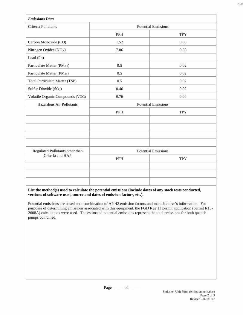
Page _____ of _____ Emission Unit Form (emission_unit.doc)
Page 2 of 3
Revised – 07/31/07
Emissions Data
Criteria Pollutants Potential Emissions
PPH TPY
Carbon Monoxide (CO) 1.52 0.08
Nitrogen Oxides (NOX) 7.06 0.35
Lead (Pb)
Particulate Matter (PM2.5) 0.5 0.02
Particulate Matter (PM10) 0.5 0.02
Total Particulate Matter (TSP) 0.5 0.02
Sulfur Dioxide (SO2) 0.46 0.02
Volatile Organic Compounds (VOC) 0.76 0.04
Hazardous Air Pollutants Potential Emissions
PPH TPY
Regulated Pollutants other than
Criteria and HAP
Potential Emissions
PPH TPY
List the method(s) used to calculate the potential emissions (include dates of any stack tests conducted,
versions of software used, source and dates of emission factors, etc.).
Potential emissions are based on a combination of AP-42 emission factors and manufacturer’s information. For
purposes of determining emissions associated with this equipment, the FGD Reg 13 permit application (permit R13-
2608A) calculations were used. The estimated potential emissions represent the total emissions for both quench
pumps combined.
103

Page _____ of _____ Emission Unit Form (emission_unit.doc)
Page 3 of 3
Revised – 07/31/07
Applicable Requirements
List all applicable requirements for this emission unit. For each applicable requirement, include the
underlying rule/regulation citation and/or construction permit with the condition number. (Note: Title V
permit condition numbers alone are not the underlying applicable requirements). If an emission limit is
calculated based on the type of source and design capacity or if a standard is based on a design parameter,
this information should also be included.
The following permit conditions are considered the applicable requirements for this emission unit. Where
appropriate, the actual permits are attached to provide the applicable language along with the underlying
rule/regulatory citation. Where appropriate, calculation basis is provided. For existing limits that were previously
captured in the permit, the calculations were provided in the previous permit application(s). No changes to existing
limits are being requested at this time.
Requirements currently captured in Title V permit:
R30-05100005-2014 Section 6.1 (see Attachment I): Where appropriate, revisions to existing language are noted.
____ Permit Shield
For all applicable requirements listed above, provide monitoring/testing/recordkeeping/reporting which shall
be used to demonstrate compliance. If the method is based on a permit or rule, include the condition number
or citation. (Note: Each requirement listed above must have an associated method of demonstrating
compliance. If there is not already a required method in place, then a method must be proposed.)
The following permit conditions are considered the applicable requirements for monitoring, testing, recordkeeping
and reporting for this emission unit. Where appropriate, the actual permits are attached to provide the applicable
language along with the underlying rule/regulatory citation. No changes are being requested at this time.
Requirements currently captured in Title V permit:
R30-05100005-2014 Section 6.2 through 6.5 (see Attachment I): Where appropriate, revisions to existing language
are noted
Are you in compliance with all applicable requirements for this emission unit? X__Yes ___No
If no, complete the Schedule of Compliance Form as ATTACHMENT F.
104

Page _____ of _____ Emission Unit Form (emission_unit.doc)
Page 4 of 3
Revised – 07/31/07
Emergency Quench Water System Description:
Emergency Quench Water:
The existing air heaters are electric powered which could fail in case of plant power failure. In this case, the hot flue
gas (600oF) could enter the absorbers. The emergency quench water system is designed to protect the absorbers by
spraying water into the flue gas entering the absorber. The emergency quench system is activated in the event of a
loss of on-site power. Two 100% pumps (including one spare) are provided for redundancy. The pumps are diesel
engine driven to allow operation during blackout conditions. The service water tank provides the water supply.
Each emergency quench pump drive engine is rated at approximately 60 HP. No post-combustion pollution controls
are utilized. Because these diesel engines are each rated at less than 500 brake horsepower, the engines are not
subject to regulation under 40 CFR 63 Subpart ZZZZ (RICE rule).
The diesel fuel is supplied from a storage tanks holding approximately 70 gallons of fuel (one for each engine).
Because the diesel fuel storage tanks are each less than 10,567 gallons capacity and will contain petroleum or
organic liquids with a vapor pressure of 1.5 psia or less at storage temperature, and the emissions from both tanks, in
the aggregate, are less than 2 tons per year, the tanks are considered de-minimis sources. De-minimis sources are not
required to obtain construction permits under 45 CSR 13.
105
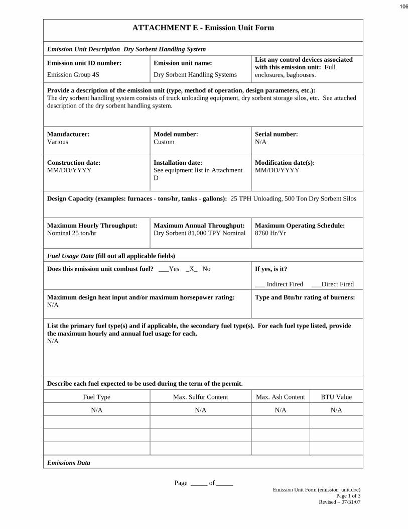
Page _____ of _____ Emission Unit Form (emission_unit.doc)
Page 1 of 3
Revised – 07/31/07
ATTACHMENT E - Emission Unit Form
Emission Unit Description Dry Sorbent Handling System
Emission unit ID number:
Emission Group 4S
Emission unit name:
Dry Sorbent Handling Systems
List any control devices associated
with this emission unit: Full
enclosures, baghouses.
Provide a description of the emission unit (type, method of operation, design parameters, etc.):
The dry sorbent handling system consists of truck unloading equipment, dry sorbent storage silos, etc. See attached
description of the dry sorbent handling system.
Manufacturer:
Various
Model number:
Custom
Serial number:
N/A
Construction date:
MM/DD/YYYY
Installation date:
See equipment list in Attachment
D
Modification date(s):
MM/DD/YYYY
Design Capacity (examples: furnaces - tons/hr, tanks - gallons): 25 TPH Unloading, 500 Ton Dry Sorbent Silos
Maximum Hourly Throughput:
Nominal 25 ton/hr
Maximum Annual Throughput:
Dry Sorbent 81,000 TPY Nominal Maximum Operating Schedule:
8760 Hr/Yr
Fuel Usage Data (fill out all applicable fields)
Does this emission unit combust fuel? ___Yes _X_ No If yes, is it?
___ Indirect Fired ___Direct Fired
Maximum design heat input and/or maximum horsepower rating:
N/A
Type and Btu/hr rating of burners:
List the primary fuel type(s) and if applicable, the secondary fuel type(s). For each fuel type listed, provide
the maximum hourly and annual fuel usage for each.
N/A
Describe each fuel expected to be used during the term of the permit.
Fuel Type Max. Sulfur Content Max. Ash Content BTU Value
N/A N/A N/A N/A
Emissions Data
106

Page _____ of _____ Emission Unit Form (emission_unit.doc)
Page 2 of 3
Revised – 07/31/07
Criteria Pollutants Potential Emissions
PPH TPY
Carbon Monoxide (CO)
Nitrogen Oxides (NOX)
Lead (Pb)
Particulate Matter (PM2.5) 31.31 136.86
Particulate Matter (PM10) 206.77 903.82
Total Particulate Matter (TSP) 438.69 1912.18
Sulfur Dioxide (SO2)
Volatile Organic Compounds (VOC)
Hazardous Air Pollutants Potential Emissions
PPH TPY
Regulated Pollutants other than
Criteria and HAP
Potential Emissions
PPH TPY
List the method(s) used to calculate the potential emissions (include dates of any stack tests conducted,
versions of software used, source and dates of emission factors, etc.).
Potential emissions are based on a combination of AP-42 emission factors, regulatory/permit limits and engineering
knowledge. For purposes of determining potential fugitive emissions associated with this equipment, the FGD Reg
13 permit application (permit R13-2608A) calculations were used.
107

Page _____ of _____ Emission Unit Form (emission_unit.doc)
Page 3 of 3
Revised – 07/31/07
Applicable Requirements
List all applicable requirements for this emission unit. For each applicable requirement, include the
underlying rule/regulation citation and/or construction permit with the condition number. (Note: Title V
permit condition numbers alone are not the underlying applicable requirements). If an emission limit is
calculated based on the type of source and design capacity or if a standard is based on a design parameter,
this information should also be included.
The following permit conditions are considered the applicable requirements for this emission unit. Where
appropriate, the actual permits are attached to provide the applicable language along with the underlying
rule/regulatory citation. Where appropriate, calculation basis is provided. For existing limits that were previously
captured in the permit, the calculations were provided in the previous permit application(s). No changes to existing
limits are being requested at this time.
Requirements currently captured in Title V permit:
R30-05100005-2014 Section 5.1 (see Attachment I): Where appropriate, revisions to existing language are noted.
____ Permit Shield
For all applicable requirements listed above, provide monitoring/testing/recordkeeping/reporting which shall
be used to demonstrate compliance. If the method is based on a permit or rule, include the condition number
or citation. (Note: Each requirement listed above must have an associated method of demonstrating
compliance. If there is not already a required method in place, then a method must be proposed.)
The following permit conditions are considered the applicable requirements for monitoring, testing, recordkeeping
and reporting for this emission unit. Where appropriate, the actual permits are attached to provide the applicable
language along with the underlying rule/regulatory citation. No changes are being requested at this time.
Requirements currently captured in Title V permit:
R30-05100005-2014 Section 5.2 through 5.4 (see Attachment I): Where appropriate, revisions to existing language
are noted.
Are you in compliance with all applicable requirements for this emission unit? X__Yes ___No
If no, complete the Schedule of Compliance Form as ATTACHMENT F.
108

Page _____ of _____ Emission Unit Form (emission_unit.doc)
Page 4 of 3
Revised – 07/31/07
Dry Sorbent Handling System Description:
SO3 Mitigation System:
The installation and operation of a Selective Catalytic Reduction (SCR) system in conjunction with a wet FGD
system on a boiler combusting high sulfur coal can potentially lead to increased concentrations of SO3.
Subsequently, the SO3 reacts with moisture in the stack plume and the atmosphere to support the secondary
formation of H2SO4. If not mitigated, the increase in SO3 and subsequent increase in the formation of H2SO4 can
impact the visible appearance of the discharge plume downwind of the stack.
The Mitchell Plant SCR installation utilizes a low conversion catalyst that helps minimize the conversion of SO2 to
SO3 by the SCR system. Nevertheless, a supplemental SO3 mitigation system is needed to help reduce SO3
concentrations. Based on AEP’s evaluation of various SO3 mitigation systems at other AEP generating facilities, it
was determined that the primary SO3 mitigation system that would be constructed at Mitchell plant was a dry sorbent
injection system. Primarily, the dry sorbent of choice is Trona. Nevertheless, hydrated lime will be used as the dry
sorbent as a backup to the Trona injection. If hydrated lime is used, the dry sorbent injection system will need to be
supplemented with the injection of liquid magnesium hydroxide. For the purposes of this permit application, each of
the options is described.
Dry Sorbent Handling:
The dry sorbent is injected through a pneumatic conveying system to ductwork downstream of the air preheaters as a
means to reduce SO3 in the stack plume. The dry sorbent feed rate for each Mitchell Unit will vary depending on the
sorbent (Trona or Hydrated Lime) being utilized and the sulfur content of the fuel. The Trona feed rate is variable
with an expected maximum feed of up to 4.6 tons per hour (per unit). The Hydrated Lime feed rate is also variable
with an expected maximum feed of up to 4.4 tons per hour (per unit).
Two dry sorbent storage silos at approximately 500 tons each receive dry sorbent from self-unloading trucks. Bin
vent filters are supplied on each silo for the filtered venting of the truck blow-off air and the silo’s fluidizing air
system. An aeration system, consisting of open-type airslides, with operating and standby aeration blowers and
routing valves supplies air to the silos, distribution bin, airslides, and de-aeration bins.
Dry sorbent is discharged out of the silo through a distribution bin and airslides into two de-aeration bins. The de-
aeration bins are periodically filled and serve to control the fluidity of the material and minimize the head pressure
that the material imposes on the downstream variable speed rotary feeders.
The feed stack-up below each de-aeration bin consists of a variable speed rotary feeder, vent hopper, fixed-speed
rotary airlock, and material pick-up tee. There are two such stack-ups (one in-service and one stand-by), each with
the capability to feed the primary conveying line. A pneumatically operated isolation valve is included at the
discharge of the silo bin.
The dry sorbent is fed through a piping system (conveying lines) to injection lances located in the duct downstream
of the air preheaters. Conveying air is supplied by three blower skid packages (two operating and one as standby)
isolated by air-operated valves. Dry, high-pressure air is supplied for purging the bearings on the rotary feeders and
airlocks and for pulsation cleaning of the bags in the bin vent filter at the top of each silo.
Because the dry sorbent handling system is a totally enclosed system using pressurized air as the carrying medium,
particulate emissions are eliminated with the exception of those that are emitted as a result of truck traffic and from
the baghouses installed on the storage silos. On a short-term basis, truck deliveries of dry sorbent are expected to be
up to 2 per hour. At full load conditions, approximately 1550 tons of dry sorbent are potentially required per week.
This equates to approximately 3215 trucks per year assuming a 100% capacity factor.
109

Page _____ of _____ Emission Unit Form (emission_unit.doc)
Page 1 of 3
Revised – 07/31/07
ATTACHMENT E - Emission Unit Form
Emission Unit Description Magnesium Hydroxide Handling System
Emission unit ID number:
Emission Group 9S
Emission unit name:
Magnesium Hydroxide Handling
Systems
List any control devices associated
with this emission unit: Full
enclosures
Provide a description of the emission unit (type, method of operation, design parameters, etc.):
The magnesium hydroxide handling systems consists of truck unloading equipment, mag. hydroxide mix tanks, etc.
See attached description of the magnesium hydroxide handling system.
Manufacturer:
Various
Model number:
Custom Serial number:
N/A
Construction date:
MM/DD/YYYY
Installation date:
See equipment list in Attachment
D
Modification date(s):
MM/DD/YYYY
Design Capacity (examples: furnaces - tons/hr, tanks - gallons): 1,000 gallon mag. hydroxide mix tanks (2)
Maximum Hourly Throughput:
8000 gal/hr delivered Maximum Annual Throughput:
Mag. Hyd. 6,600,000 Gal./yr Maximum Operating Schedule:
8760 Hr/Yr
Fuel Usage Data (fill out all applicable fields)
Does this emission unit combust fuel? ___Yes _X_ No If yes, is it?
___ Indirect Fired ___Direct Fired
Maximum design heat input and/or maximum horsepower rating:
N/A
Type and Btu/hr rating of burners:
List the primary fuel type(s) and if applicable, the secondary fuel type(s). For each fuel type listed, provide
the maximum hourly and annual fuel usage for each.
N/A
Describe each fuel expected to be used during the term of the permit.
Fuel Type Max. Sulfur Content Max. Ash Content BTU Value
N/A N/A N/A N/A
Emissions Data
110

Page _____ of _____ Emission Unit Form (emission_unit.doc)
Page 2 of 3
Revised – 07/31/07
Criteria Pollutants Potential Emissions
PPH TPY
Carbon Monoxide (CO)
Nitrogen Oxides (NOX)
Lead (Pb)
Particulate Matter (PM2.5) 0.08 0.03
Particulate Matter (PM10) 0.51 0.21
Total Particulate Matter (TSP) 2.61 1.08
Sulfur Dioxide (SO2)
Volatile Organic Compounds (VOC)
Hazardous Air Pollutants Potential Emissions
PPH TPY
Regulated Pollutants other than
Criteria and HAP
Potential Emissions
PPH TPY
List the method(s) used to calculate the potential emissions (include dates of any stack tests conducted,
versions of software used, source and dates of emission factors, etc.).
Potential emissions are based on a combination of AP-42 emission factors, regulatory/permit limits and engineering
knowledge. For purposes of determining potential fugitive emissions associated with this equipment, the FGD Reg
13 permit application (permit R13-2608A) calculations were used.
111

Page _____ of _____ Emission Unit Form (emission_unit.doc)
Page 3 of 3
Revised – 07/31/07
Applicable Requirements
List all applicable requirements for this emission unit. For each applicable requirement, include the
underlying rule/regulation citation and/or construction permit with the condition number. (Note: Title V
permit condition numbers alone are not the underlying applicable requirements). If an emission limit is
calculated based on the type of source and design capacity or if a standard is based on a design parameter,
this information should also be included.
The following permit conditions are considered the applicable requirements for this emission unit. Where
appropriate, the actual permits are attached to provide the applicable language along with the underlying
rule/regulatory citation. Where appropriate, calculation basis is provided. For existing limits that were previously
captured in the permit, the calculations were provided in the previous permit application(s). No changes to existing
limits are being requested at this time.
Requirements currently captured in Title V permit:
R30-05100005-2014 Section 5.1 (see Attachment I): Where appropriate, revisions to existing language are noted.
____ Permit Shield
For all applicable requirements listed above, provide monitoring/testing/recordkeeping/reporting which shall
be used to demonstrate compliance. If the method is based on a permit or rule, include the condition number
or citation. (Note: Each requirement listed above must have an associated method of demonstrating
compliance. If there is not already a required method in place, then a method must be proposed.)
The following permit conditions are considered the applicable requirements for monitoring, testing, recordkeeping
and reporting for this emission unit. Where appropriate, the actual permits are attached to provide the applicable
language along with the underlying rule/regulatory citation. No changes are being requested at this time.
Requirements currently captured in Title V permit:
R30-05100005-2014 Section 5.2 through 5.4 (see Attachment I): Where appropriate, revisions to existing language
are noted.
Are you in compliance with all applicable requirements for this emission unit? X__Yes ___No
If no, complete the Schedule of Compliance Form as ATTACHMENT F.
112

Page _____ of _____ Emission Unit Form (emission_unit.doc)
Page 4 of 3
Revised – 07/31/07
Magnesium Hydroxide Handling System Description:
SO3 Mitigation System:
The installation and operation of a Selective Catalytic Reduction (SCR) system in conjunction with a wet FGD
system on a boiler combusting high sulfur coal can potentially lead to increased concentrations of SO3.
Subsequently, the SO3 reacts with moisture in the stack plume and the atmosphere to support the secondary
formation of H2SO4. If not mitigated, the increase in SO3 and subsequent increase in the formation of H2SO4 can
impact the visible appearance of the discharge plume downwind of the stack.
The Mitchell Plant SCR installation will utilize a low conversion catalyst that will help to minimize the conversion
of SO2 to SO3 by the SCR system. Nevertheless, it is anticipated that a supplemental SO3 mitigation system will be
needed to help reduce SO3 concentrations. Based on AEP’s evaluation of various SO3 mitigation systems at other
AEP generating facilities, it has been determined that the primary SO3 mitigation system that will be constructed at
Mitchell plant will be a dry sorbent injection system. Primarily, the dry sorbent of choice is Trona. Nevertheless,
hydrated lime will be used as the dry sorbent as a backup to the Trona injection. If hydrated lime is used, the dry
sorbent injection system will need to be supplemented with the injection of liquid magnesium hydroxide. For the
purposes of this permit application, each of the options is described.
Magnesium Hydroxide Injection:
The purpose of magnesium hydroxide injection is to assist in the mitigation of SO3 in the furnace in the event that
Trona dry sorbent injection in not being used. If hydrated lime dry sorbent is injected into the flue gas downstream
of the air preheater, magnesium hydroxide injection into the furnace will likely be needed to assist in the mitigation
of SO3. Magnesium hydroxide, if use, will be injected into the furnace as a 15% magnesium hydroxide/water slurry.
Approximately 1.5 tons per hour (per unit) of magnesium hydroxide will be required for 90% SO3 mitigation.
The magnesium hydroxide will be delivered to the Mitchell Plant site by tanker truck in a 60% magnesium
hydroxide/water slurry and pumped into one of two storage tanks. The 60% solution is then pumped into a small
mixing tank where it will be diluted with filtered water to a 15% slurry. The 15% slurry is then pumped to the
furnaces and injected. The tanker trucks are expected to have a nominal capacity of approximately 4000 gallons.
The only emissions associated with this material handling system will be fugitive particulate emissions associated
with the delivery truck traffic on the plant site. On a short-term basis, tanker truck deliveries for the magnesium
hydroxide system are expected to be up to 2 per hour.
At full load conditions, approximately 18,000 gallons of 60% slurry will be required per day. This equates to
approximately 1650 truckloads of liquid magnesium hydroxide per year assuming a 100% capacity factor.
113

Page _____ of _____ Emission Unit Form (emission_unit.doc)
Page 1 of 3
Revised – 07/31/07
ATTACHMENT E - Emission Unit Form
Emission Unit Description Urea Handling System
Emission unit ID number:
N/A
Emission unit name:
Urea Handling Systems
List any control devices associated
with this emission unit: Full and
partial enclosures.
Provide a description of the emission unit (type, method of operation, design parameters, etc.):
The urea handling systems consists of truck unloading equipment, screw conveyor, mix tanks, etc. See attached
description of the urea handling system.
Manufacturer:
Various
Model number:
Custom
Serial number:
N/A
Construction date:
MM/DD/YYYY
Installation date:
See equipment list in Attachment
D
Modification date(s):
MM/DD/YYYY
Design Capacity (examples: furnaces - tons/hr, tanks - gallons): 48 Ton Unloading Hopper, 200,000 gal. Urea
Storage Tank.
Maximum Hourly Throughput:
Nominal 50 ton/hr
Maximum Annual Throughput:
Dry urea 26,000 TPY Nominal,
Maximum Operating Schedule:
8760 Hr/Yr
Fuel Usage Data (fill out all applicable fields)
Does this emission unit combust fuel? ___Yes _X_ No If yes, is it?
___ Indirect Fired ___Direct Fired
Maximum design heat input and/or maximum horsepower rating:
N/A
Type and Btu/hr rating of burners:
List the primary fuel type(s) and if applicable, the secondary fuel type(s). For each fuel type listed, provide
the maximum hourly and annual fuel usage for each.
N/A
Describe each fuel expected to be used during the term of the permit.
Fuel Type Max. Sulfur Content Max. Ash Content BTU Value
N/A N/A N/A N/A
Emissions Data
114

Page _____ of _____ Emission Unit Form (emission_unit.doc)
Page 2 of 3
Revised – 07/31/07
Criteria Pollutants Potential Emissions
PPH TPY
Carbon Monoxide (CO)
Nitrogen Oxides (NOX)
Lead (Pb)
Particulate Matter (PM2.5) 0.036 0.009
Particulate Matter (PM10) 2.47 0.64
Total Particulate Matter (TSP) 6.93 1.8
Sulfur Dioxide (SO2)
Volatile Organic Compounds (VOC)
Hazardous Air Pollutants Potential Emissions
PPH TPY
Regulated Pollutants other than
Criteria and HAP
Potential Emissions
PPH TPY
List the method(s) used to calculate the potential emissions (include dates of any stack tests conducted,
versions of software used, source and dates of emission factors, etc.).
Potential emissions are based on a combination of AP-42 emission factors, regulatory/permit limits and engineering
knowledge.
115

Page _____ of _____ Emission Unit Form (emission_unit.doc)
Page 3 of 3
Revised – 07/31/07
Applicable Requirements
List all applicable requirements for this emission unit. For each applicable requirement, include the
underlying rule/regulation citation and/or construction permit with the condition number. (Note: Title V
permit condition numbers alone are not the underlying applicable requirements). If an emission limit is
calculated based on the type of source and design capacity or if a standard is based on a design parameter,
this information should also be included.
The following permit conditions are considered the applicable requirements for this emission unit. Where
appropriate, the actual permits are attached to provide the applicable language along with the underlying
rule/regulatory citation. Where appropriate, calculation basis is provided. For existing limits that were previously
captured in the permit, the calculations were provided in the previous permit application(s). No changes to existing
limits are being requested at this time.
Requirements currently captured in Title V permit:
X.0. Source-Specific Requirements [Urea Handling (Emission points listed in section 1.0. Table)]
X.1. Limitations and Standards The Urea handling system is subject to 45CSR§2-5 as outlined in the facility wide section of this permit
(condition 3.1.12) regarding fugitive dust control system.
____ Permit Shield
For all applicable requirements listed above, provide monitoring/testing/recordkeeping/reporting which shall
be used to demonstrate compliance. If the method is based on a permit or rule, include the condition number
or citation. (Note: Each requirement listed above must have an associated method of demonstrating
compliance. If there is not already a required method in place, then a method must be proposed.)
The following permit conditions are considered the applicable requirements for monitoring, testing, recordkeeping
and reporting for this emission unit. Where appropriate, the actual permits are attached to provide the applicable
language along with the underlying rule/regulatory citation. No changes are being requested at this time.
Requirements currently captured in Title V permit:
X.2. Monitoring, Recordkeeping, and Reporting Requirements See Permit condition 3.3.4. [45 CSR 30-5.1.c]
Are you in compliance with all applicable requirements for this emission unit? X__Yes ___No
If no, complete the Schedule of Compliance Form as ATTACHMENT F.
116

Page _____ of _____ Emission Unit Form (emission_unit.doc)
Page 4 of 3
Revised – 07/31/07
Dry Sorbent and Magnesium Hydroxide Handling System Description:
Urea Handling System:
Ammonia is the reagent used in the SCR process to reduce the NOx, produced in the combustion process to
elemental nitrogen and water vapor. The ammonia is generated from the Urea to Ammonia (U2ATM) system. The
U2ATM system uses dry urea as the feedstock to produce ammonia vapor by hydrolyzing a urea solution to form
ammonia vapor, carbon dioxide and water vapor. The urea solution is prepared from dry urea and steam condensate
water.
The dry urea unloading system includes the equipment necessary to unload dry urea from trucks and transport it to
urea solution mix tank. There is a provision to receive two 25-ton truckloads of dry urea back to back in a hopper
located in a pit constructed by AEP at the Truck Unloading Station. Dry urea is then transferred from the hopper to
a urea solution mix tank via full enclosed screw/drag conveyor equipment. In the mix tank, urea and condensate
water is added in sufficient quantities to convert the dry urea into a 40% (by weight) urea solution for use in the urea
to ammonia conversion process. The design is suitable for either prill or granular urea. The urea solution is
transferred from the mix tank to a urea solution storage tank for use by the U2ATM system.
117

Page _____ of _____ Emission Unit Form (emission_unit.doc)
Page 1 of 3
Revised – 07/31/07
ATTACHMENT E - Emission Unit Form
Emission Unit Description Diesel Engine Driven Coping Power Emergency Generators (EG-1 and EG-2)
Emission unit ID number:
EG-1
EG-2
Emission unit name:
Diesel Driven Coping Power
Emergency Generators EG-1 and
EG-2
List any control devices associated
with this emission unit:N/A
Provide a description of the emission unit (type, method of operation, design parameters, etc.):
These are large diesel driven emergency generators. One rated at 3,717 bhp (EG-1) and one rated at 3,0004 bhp
(EG-2). The generators are intended to provide facility auxiliary power in the event of a regional power grid
outage.
Manufacturer:
Caterpillar
Model number:
C175-16 (EG-1); 3516C-HD TA
(EG-2)
Serial number:
Construction date:
08/2014
Installation date:
08/2014
Modification date(s):
MM/DD/YYYY
Design Capacity (examples: furnaces - tons/hr, tanks - gallons): 3,717 bhp (EG-1) and 3,0004 bhp (EG-2)
Maximum Hourly Throughput:
Maximum Annual Throughput:
Maximum Operating Schedule:
Fuel Usage Data (fill out all applicable fields)
Does this emission unit combust fuel? _X_Yes ___ No If yes, is it? RICE
___ Indirect Fired ___Direct Fired
Maximum design heat input and/or maximum horsepower rating:
3,717 bhp (EG-1) at 1800rpm
3,0004 bhp (EG-2) at 1800rpm
Type and Btu/hr rating of burners:
List the primary fuel type(s) and if applicable, the secondary fuel type(s). For each fuel type listed, provide
the maximum hourly and annual fuel usage for each.
Diesel Fuel
Describe each fuel expected to be used during the term of the permit.
Fuel Type Max. Sulfur Content Max. Ash Content BTU Value
Diesel Fuel 15ppm
118

Page _____ of _____ Emission Unit Form (emission_unit.doc)
Page 2 of 3
Revised – 07/31/07
Emissions Data
Criteria Pollutants Potential Emissions
PPH TPY
EG-1 EG-2 EG-1 EG-2
Carbon Monoxide (CO) 7.66 4.85 1.92 1.21
Nitrogen Oxides (NOX) 59.9 36.4 14.98 9.1
Lead (Pb)
Particulate Matter (PM2.5) 0.05 0.04 0.01 0.01
Particulate Matter (PM10) 0.35 0.26 0.09 0.06
Total Particulate Matter (TSP) 0.44 0.33 0.11 0.08
Sulfur Dioxide (SO2) 0.01 0.01 0.06 0.05
Volatile Organic Compounds (VOC) 0.94 1.18 0.24 0.3
Hazardous Air Pollutants Potential Emissions
PPH TPY
Regulated Pollutants other than
Criteria and HAP
Potential Emissions
PPH TPY
CO2 3961 3185 990.3 796.3
List the method(s) used to calculate the potential emissions (include dates of any stack tests conducted,
versions of software used, source and dates of emission factors, etc.).
Manufacturer’s Data used for NOx, CO, VOC, PM10 and CO2. AP-42 used for SO2
119

Page _____ of _____ Emission Unit Form (emission_unit.doc)
Page 3 of 3
Revised – 07/31/07
Applicable Requirements
List all applicable requirements for this emission unit. For each applicable requirement, include the
underlying rule/regulation citation and/or construction permit with the condition number. (Note: Title V
permit condition numbers alone are not the underlying applicable requirements). If an emission limit is
calculated based on the type of source and design capacity or if a standard is based on a design parameter,
this information should also be included.
The following permit conditions are considered the applicable requirements for this emission unit. Where
appropriate, the actual permits are attached to provide the applicable language along with the underlying
rule/regulatory citation. Where appropriate, calculation basis is provided. For existing limits that were previously
captured in the permit, the calculations were provided in the previous permit application(s). No changes to existing
limits are being requested at this time.
Requirements currently captured in Title V permit:
R30-05100005-2014 Sections 7.0 through 7.1 (see Attachment I): Where appropriate, revisions to existing language
are noted.
____ Permit Shield
For all applicable requirements listed above, provide monitoring/testing/recordkeeping/reporting which shall
be used to demonstrate compliance. If the method is based on a permit or rule, include the condition number
or citation. (Note: Each requirement listed above must have an associated method of demonstrating
compliance. If there is not already a required method in place, then a method must be proposed.)
The following permit conditions are considered the applicable requirements for monitoring, testing, recordkeeping
and reporting for this emission unit. Where appropriate, the actual permits are attached to provide the applicable
language along with the underlying rule/regulatory citation. No changes are being requested at this time.
Requirements currently captured in Title V permit:
R30-05100005-2014 Sections 7.2 through 7.5 (see Attachment I): Where appropriate, revisions to existing language
are noted.
Are you in compliance with all applicable requirements for this emission unit? _X_Yes ___No
If no, complete the Schedule of Compliance Form as ATTACHMENT F.
120

Page _____ of _____ Emission Unit Form (emission_unit.doc)
Page 1 of 3
Revised – 07/31/07
ATTACHMENT E - Emission Unit Form
Emission Unit Description LP Vapor Engine Driven Emergency Generator (LPG)
Emission unit ID number:
LPG
Emission unit name:
LP Vapor Engine Driven
Emergency Generator LPG
List any control devices associated
with this emission unit:N/A
Provide a description of the emission unit (type, method of operation, design parameters, etc.):
This is an 80kW emergency generator driven by a liquid propane vapor engine. The engine is rated at 126
horsepower (LPG). The generator is intended to provide emergency backup power at the Mitchell Plant leachate
pond storage pond in the event of a loss of utility power feed.
Manufacturer:
Generac
Model number:
SG080
Serial number:
Construction date:
11/2013
Installation date:
11/2013
Modification date(s):
MM/DD/YYYY
Design Capacity (examples: furnaces - tons/hr, tanks - gallons): 126 bhp (LPG)
Maximum Hourly Throughput:
Maximum Annual Throughput:
Maximum Operating Schedule:
Fuel Usage Data (fill out all applicable fields)
Does this emission unit combust fuel? _X_Yes ___ No If yes, is it? RICE
___ Indirect Fired ___Direct Fired
Maximum design heat input and/or maximum horsepower rating:
126 bhp (LPG) at 1800rpm
Type and Btu/hr rating of burners:
List the primary fuel type(s) and if applicable, the secondary fuel type(s). For each fuel type listed, provide
the maximum hourly and annual fuel usage for each.
Liquid Propane Gas
Describe each fuel expected to be used during the term of the permit.
Fuel Type Max. Sulfur Content Max. Ash Content BTU Value
Liquid Propane Gas
121

Page _____ of _____ Emission Unit Form (emission_unit.doc)
Page 2 of 3
Revised – 07/31/07
Emissions Data
Criteria Pollutants Potential Emissions
PPH TPY
Carbon Monoxide (CO) 21.75 5.44
Nitrogen Oxides (NOX) 0.74 0.19
Lead (Pb)
Particulate Matter (PM2.5) 0.007 0.002
Particulate Matter (PM10) 0.007 0.002
Total Particulate Matter (TSP) 0.007 0.002
Sulfur Dioxide (SO2) 0.012 0.003
Volatile Organic Compounds (VOC) 0.22 0.06
Hazardous Air Pollutants Potential Emissions
PPH TPY
Regulated Pollutants other than
Criteria and HAP
Potential Emissions
PPH TPY
CO2 148.75 37.2
List the method(s) used to calculate the potential emissions (include dates of any stack tests conducted,
versions of software used, source and dates of emission factors, etc.).
Manufacturer’s Data used for NOx, CO, VOC. AP-42 used for SO2, PM10 and CO2.
122

Page _____ of _____ Emission Unit Form (emission_unit.doc)
Page 3 of 3
Revised – 07/31/07
Applicable Requirements
List all applicable requirements for this emission unit. For each applicable requirement, include the
underlying rule/regulation citation and/or construction permit with the condition number. (Note: Title V
permit condition numbers alone are not the underlying applicable requirements). If an emission limit is
calculated based on the type of source and design capacity or if a standard is based on a design parameter,
this information should also be included.
The following permit conditions are considered the applicable requirements for this emission unit. Where
appropriate, the actual permits are attached to provide the applicable language along with the underlying
rule/regulatory citation. Where appropriate, calculation basis is provided. For existing limits that were previously
captured in the permit, the calculations were provided in the previous permit application(s). No changes to existing
limits are being requested at this time.
Requirements currently captured in Title V permit:
R30-05100005-2014 Sections 7.0 through 7.1 (see Attachment I): Where appropriate, revisions to existing language
are noted.
____ Permit Shield
For all applicable requirements listed above, provide monitoring/testing/recordkeeping/reporting which shall
be used to demonstrate compliance. If the method is based on a permit or rule, include the condition number
or citation. (Note: Each requirement listed above must have an associated method of demonstrating
compliance. If there is not already a required method in place, then a method must be proposed.)
The following permit conditions are considered the applicable requirements for monitoring, testing, recordkeeping
and reporting for this emission unit. Where appropriate, the actual permits are attached to provide the applicable
language along with the underlying rule/regulatory citation. No changes are being requested at this time.
Requirements currently captured in Title V permit:
R30-05100005-2014 Sections 7.2 through 7.5 (see Attachment I): Where appropriate, revisions to existing language
are noted.
Are you in compliance with all applicable requirements for this emission unit? _X_Yes ___No
If no, complete the Schedule of Compliance Form as ATTACHMENT F.
123

Mitchell Plant Title V Renewal
R30-05100005-2014 Renewal
2019
Attachment F
Air Pollution Control Device Forms
124

Air Pollution Control Device Form (control_device.doc) Page 1 of 1
Revised – 01/31/07
Page _____ of _____
ATTACHMENT G - Air Pollution Control Device Form
Control device ID number: ML1 ESP
List all emission units associated with this control device. Unit 1
Manufacturer: Wheelabrator Frye
Model number:
1487
Installation date:
12/30/1977
Type of Air Pollution Control Device: ___ Baghouse/Fabric Filter ___ Venturi Scrubber ___ Multiclone ___ Carbon Bed Adsorber ___ Packed Tower Scrubber ___ Single Cyclone ___ Carbon Drum(s) ___ Other Wet Scrubber ___ Cyclone Bank ___ Catalytic Incinerator ___ Condenser ___ Settling Chamber ___ Thermal Incinerator ___ Flare ___ Other (describe) ________________ ___ Wet Plate Electrostatic Precipitator _X_ Dry Plate Electrostatic Precipitator
List the pollutants for which this device is intended to control and the capture and control efficiencies.
Pollutant Capture Efficiency Control Efficiency
PM 100% 99.85%
Explain the characteristic design parameters of this control device (flow rates, pressure drops, number of bags, size, temperatures, etc.). Avg. Pressure Drop = 0.07 inches H2O, Avg. Gas Flow Rate = 3,000x103 acfm, Avg. Operating temp. = 370 ºF, Design Removal Efficiency = 99.85% Is this device subject to the CAM requirements of 40 C.F.R. 64? _X_ Yes __ No
If Yes, Complete ATTACHMENT H If No, Provide justification.
Describe the parameters monitored and/or methods used to indicate performance of this control device. Monitor opacity as an indicator of electrostatic precipitator performance. Periodic stack tests are performed to assure compliance with the particulate mass emissions standard.
125

Air Pollution Control Device Form (control_device.doc) Page 1 of 1
Revised – 01/31/07
Page _____ of _____
ATTACHMENT G - Air Pollution Control Device Form
Control device ID number: ML1 FGD
List all emission units associated with this control device. Unit 1
Manufacturer: B&W
Model number:
Custom
Installation date:
04/28/2007
Type of Air Pollution Control Device: ___ Baghouse/Fabric Filter ___ Venturi Scrubber ___ Multiclone ___ Carbon Bed Adsorber ___ Packed Tower Scrubber ___ Single Cyclone ___ Carbon Drum(s) _X_ Other Wet Scrubber ___ Cyclone Bank ___ Catalytic Incinerator ___ Condenser ___ Settling Chamber ___ Thermal Incinerator ___ Flare ___ Other (describe) ________________ ___ Wet Plate Electrostatic Precipitator ___ Dry Plate Electrostatic Precipitator
List the pollutants for which this device is intended to control and the capture and control efficiencies.
Pollutant Capture Efficiency Control Efficiency
SO2 100% 95%
Explain the characteristic design parameters of this control device (flow rates, pressure drops, number of bags, size, temperatures, etc.). Full Load Flow Rate = 2.6x10⁶ acfm, Outlet temperature = 128 ºF, Design Removal Efficiency = 95% Is this device subject to the CAM requirements of 40 C.F.R. 64? ___ Yes _X_ No
If Yes, Complete ATTACHMENT H If No, Provide justification. Continuous Emissions Monitoring Used.
Describe the parameters monitored and/or methods used to indicate performance of this control device. Monitoring of SO2 emissions using CEMS
126

Air Pollution Control Device Form (control_device.doc) Page 1 of 1
Revised – 01/31/07
Page _____ of _____
ATTACHMENT G - Air Pollution Control Device Form
Control device ID number: ML1 SCR
List all emission units associated with this control device. Unit 1
Manufacturer:
Model number:
Custom
Installation date:
05/02/2007
Type of Air Pollution Control Device: ___ Baghouse/Fabric Filter ___ Venturi Scrubber ___ Multiclone ___ Carbon Bed Adsorber ___ Packed Tower Scrubber ___ Single Cyclone ___ Carbon Drum(s) _ _ Other Wet Scrubber ___ Cyclone Bank ___ Catalytic Incinerator ___ Condenser ___ Settling Chamber ___ Thermal Incinerator ___ Flare __X Other (describe) Selective Catalytic Reduction ___ Wet Plate Electrostatic Precipitator ___ Dry Plate Electrostatic Precipitator
List the pollutants for which this device is intended to control and the capture and control efficiencies.
Pollutant Capture Efficiency Control Efficiency
NOx 100% 90%
Explain the characteristic design parameters of this control device (flow rates, pressure drops, number of bags, size, temperatures, etc.). NOx Control Efficiency = 90.0%, Design Temperature = 750 ºF, Maximum ammonia slip = 2 ppmvd at 3% O2
Is this device subject to the CAM requirements of 40 C.F.R. 64? ___ Yes _X_ No
If Yes, Complete ATTACHMENT H If No, Provide justification. Continuous Emissions Monitoring Used.
Describe the parameters monitored and/or methods used to indicate performance of this control device. Monitoring of NOx emissions using CEMS
127

Air Pollution Control Device Form (control_device.doc) Page 1 of 1
Revised – 01/31/07
Page _____ of _____
ATTACHMENT G - Air Pollution Control Device Form
Control device ID number: ML2 ESP
List all emission units associated with this control device. Unit 2
Manufacturer: Wheelabrator Frye
Model number:
1487
Installation date:
06/16/1978
Type of Air Pollution Control Device: ___ Baghouse/Fabric Filter ___ Venturi Scrubber ___ Multiclone ___ Carbon Bed Adsorber ___ Packed Tower Scrubber ___ Single Cyclone ___ Carbon Drum(s) ___ Other Wet Scrubber ___ Cyclone Bank ___ Catalytic Incinerator ___ Condenser ___ Settling Chamber ___ Thermal Incinerator ___ Flare ___ Other (describe) ________________ ___ Wet Plate Electrostatic Precipitator _X_ Dry Plate Electrostatic Precipitator
List the pollutants for which this device is intended to control and the capture and control efficiencies.
Pollutant Capture Efficiency Control Efficiency
PM 100% 99.85%
Explain the characteristic design parameters of this control device (flow rates, pressure drops, number of bags, size, temperatures, etc.). Avg. Pressure Drop = 0.07 inches H2O, Avg. Gas Flow Rate = 3,000x103 acfm, Avg. Operating temp. = 370 ºF, Design Removal Efficiency = 99.85% Is this device subject to the CAM requirements of 40 C.F.R. 64? _X_ Yes __ No
If Yes, Complete ATTACHMENT H If No, Provide justification.
Describe the parameters monitored and/or methods used to indicate performance of this control device. Monitor opacity as an indicator of electrostatic precipitator performance. Periodic stack tests are performed to assure compliance with the particulate mass emissions standard.
128

Air Pollution Control Device Form (control_device.doc) Page 1 of 1
Revised – 01/31/07
Page _____ of _____
ATTACHMENT G - Air Pollution Control Device Form
Control device ID number: ML2 FGD
List all emission units associated with this control device. Unit 2
Manufacturer: B&W
Model number:
Custom
Installation date:
01/15/2007
Type of Air Pollution Control Device: ___ Baghouse/Fabric Filter ___ Venturi Scrubber ___ Multiclone ___ Carbon Bed Adsorber ___ Packed Tower Scrubber ___ Single Cyclone ___ Carbon Drum(s) _X_ Other Wet Scrubber ___ Cyclone Bank ___ Catalytic Incinerator ___ Condenser ___ Settling Chamber ___ Thermal Incinerator ___ Flare ___ Other (describe) __________________
___ Wet Plate Electrostatic Precipitator ___ Dry Plate Electrostatic Precipitator
List the pollutants for which this device is intended to control and the capture and control efficiencies.
Pollutant Capture Efficiency Control Efficiency
SO2 100% 95%
Explain the characteristic design parameters of this control device (flow rates, pressure drops, number of bags, size, temperatures, etc.). Full Load Flow Rate = 2.6x10⁶ acfm, Outlet temperature = 128 ºF, Design Removal Efficiency = 95% Is this device subject to the CAM requirements of 40 C.F.R. 64? ___ Yes _X_ No
If Yes, Complete ATTACHMENT H If No, Provide justification. Continuous Emissions Monitoring Used.
Describe the parameters monitored and/or methods used to indicate performance of this control device. Monitoring of SO2 emissions using CEMS
129

Air Pollution Control Device Form (control_device.doc) Page 1 of 1
Revised – 01/31/07
Page _____ of _____
ATTACHMENT G - Air Pollution Control Device Form
Control device ID number: ML2 SCR
List all emission units associated with this control device. Unit 2
Manufacturer:
Model number:
Custom
Installation date:
05/02/2007
Type of Air Pollution Control Device: ___ Baghouse/Fabric Filter ___ Venturi Scrubber ___ Multiclone ___ Carbon Bed Adsorber ___ Packed Tower Scrubber ___ Single Cyclone ___ Carbon Drum(s) _ _ Other Wet Scrubber ___ Cyclone Bank ___ Catalytic Incinerator ___ Condenser ___ Settling Chamber ___ Thermal Incinerator ___ Flare _X_ Other (describe) Selective Catalytic Reduction
___ Wet Plate Electrostatic Precipitator ___ Dry Plate Electrostatic Precipitator
List the pollutants for which this device is intended to control and the capture and control efficiencies.
Pollutant Capture Efficiency Control Efficiency
NOx 100% 90%
Explain the characteristic design parameters of this control device (flow rates, pressure drops, number of bags, size, temperatures, etc.). NOx Control Efficiency = 90.0%, Design Temperature = 750 ºF, Maximum ammonia slip = 2 ppmvd at 3% O2
Is this device subject to the CAM requirements of 40 C.F.R. 64? ___ Yes _X_ No
If Yes, Complete ATTACHMENT H If No, Provide justification. Continuous Emissions Monitoring Used.
Describe the parameters monitored and/or methods used to indicate performance of this control device. Monitoring of NOx emissions using CEMS
130

Mitchell Plant Title V Renewal
R30-05100005-2014 Renewal
2019
Attachment H
Compliance Assurance Monitoring (CAM)
Forms
131

Compliance Assurance Monitoring Plan Form (CAM Plan.doc) Page 1 of 11
Revised – 10/05/06
Page _____ of _____
ATTACHMENT H - Compliance Assurance Monitoring (CAM) Plan Form
For definitions and information about the CAM rule, please refer to 40 CFR Part 64. Additional information (including guidance documents) may also be found at http://www.epa.gov/ttn/emc/cam.html
CAM APPLICABILITY DETERMINATION 1) Does the facility have a PSEU (Pollutant-Specific Emissions Unit considered
separately with respect to EACH regulated air pollutant) that is subject to CAM (40 CFR Part 64), which must be addressed in this CAM plan submittal? To determine applicability, a PSEU must meet all of the following criteria (If No, then the remainder of this form need not be completed):
YES NO
a. The PSEU is located at a major source that is required to obtain a Title V permit;
b. The PSEU is subject to an emission limitation or standard for the applicable regulated air pollutant that is NOT exempt;
LIST OF EXEMPT EMISSION LIMITATIONS OR STANDARDS: • NSPS (40 CFR Part 60) or NESHAP (40 CFR Parts 61 and 63) proposed after 11/15/1990. • Stratospheric Ozone Protection Requirements. • Acid Rain Program Requirements. • Emission Limitations or Standards for which a WVDEP Division of Air Quality Title V permit specifies a
continuous compliance determination method, as defined in 40 CFR §64.1. • An emission cap that meets the requirements specified in 40 CFR §70.4(b)(12).
c. The PSEU uses an add-on control device (as defined in 40 CFR §64.1) to achieve compliance with an emission limitation or standard;
d. The PSEU has potential pre-control device emissions of the applicable regulated air pollutant that are equal to or greater than the Title V Major Source Threshold Levels; AND
e. The PSEU is NOT an exempt backup utility power emissions unit that is municipally-owned.
BASIS OF CAM SUBMITTAL
2) Mark the appropriate box below as to why this CAM plan is being submitted as part of an application for a Title V permit:
RENEWAL APPLICATION. ALL PSEUs for which a CAM plan has NOT yet been approved need to be addressed in this CAM plan submittal.
INITIAL APPLICATION (submitted after 4/20/98). ONLY large PSEUs (i. e., PSEUs with potential post-control device emissions of an applicable regulated air pollutant that are equal to or greater than Major Source Threshold Levels) need to be addressed in this CAM plan submittal.
SIGNIFICANT MODIFICATION TO LARGE PSEUs. ONLY large PSEUs being modified after 4/20/98 need to be addressed in this cam plan submittal. For large PSEUs with an approved CAM plan, Only address the appropriate monitoring requirements affected by the significant modification.
132

Compliance Assurance Monitoring Plan Form (CAM Plan.doc) Page 2 of 11
Revised – 10/05/06
Page _____ of _____
3) a BACKGROUND DATA AND INFORMATION Complete the following table for all PSEUs that need to be addressed in this CAM plan submittal. This section is to be used to provide background data and information for each PSEU In order to supplement the submittal requirements specified in 40 CFR §64.4. If additional space is needed, attach and label accordingly.
PSEU DESIGNATION DESCRIPTION POLLUTANT CONTROL
DEVICE b EMISSION LIMITATION
or STANDARD c MONITORING REQUIREMENT
Unit 1 Coal-Fired Steam Generator PM ESP 45CSR2-4.1.a Monitor Duct Opacity Using COMS
Unit 2 Coal-Fired Steam Generator PM ESP 45CSR2-4.1.a Monitor Duct Opacity Using COMS
EXAMPLE Boiler No. 1 Wood-Fired Boiler PM Multiclone 45CSR§2-4.1.c.; 9.0 lb/hr Monitor pressure drop across multiclone:
Weekly inspection of multiclone
a If a control device is common to more than one PSEU, one monitoring plan may be submitted for the control device with the affected PSEUs identified and any conditions that must be maintained or monitored in
accordance with 40 CFR §64.3(a). If a single PSEU is controlled by more than one control device similar in design and operation, one monitoring plan for the applicable control devices may be submitted with the applicable control devices identified and any conditions that must be maintained or monitored in accordance with 40 CFR §64.3(a).
b Indicate the emission limitation or standard for any applicable requirement that constitutes an emission limitation, emission standard, or standard of performance (as defined in 40 CFR §64.1). c Indicate the monitoring requirements for the PSEU that are required by an applicable regulation or permit condition.
133

Compliance Assurance Monitoring Plan Form (CAM Plan.doc) Page 3 of 11
Revised – 10/05/06
Page _____ of _____
CAM MONITORING APPROACH CRITERIA
Complete this section for EACH PSEU that needs to be addressed in this CAM plan submittal. This section may be copied as needed for each PSEU. This section is to be used to provide monitoring data and information for EACH indicator selected for EACH PSEU in order to meet the monitoring design criteria specified in 40 CFR §64.3 and §64.4. if more than two indicators are being selected for a PSEU or if additional space is needed, attach and label accordingly with the appropriate PSEU designation, pollutant, and indicator numbers.
4a) PSEU Designation: Unit 1
4b) Pollutant: PM
4c) a Indicator No. 1: Opacity
4d) a Indicator No. 2: Opacity
5a) GENERAL CRITERIA Describe the MONITORING APPROACH used to measure the indicators:
Opacity data is measured and recorded by a certified continuous opacity monitoring system (COMS). The 6-minute average
data is recorded and will be used to calculate block 3-hour average opacity
values.
Opacity data is measured and recorded by a certified continuous opacity monitoring system (COMS). The 6-minute average
data is recorded and will be used to calculate block 3-hour average opacity
values.
b Establish the appropriate INDICATOR RANGE or the procedures for establishing the indicator range which provides a reasonable assurance of compliance:
Opacity data has been collected during Method 5 particulate emission testing. The
plan will incorporate existing test data along with CAM stack testing to verify a
conservative indicator range. The proposed upper threshold value of the indicator range
is a 3-hour block average opacity value greater than 10% Opacity
Excess short duration opacity increases occurring during any calendar quarter are
not to exceed 5% of the total operating time.
5b) PERFORMANCE CRITERIA Provide the SPECIFICATIONS FOR OBTAINING REPRESENTATIVE DATA, such as detector location, installation specifications, and minimum acceptable accuracy:
The COMs is located in the duct downstream of the ESP in accordance with 40 CFR 60.13(i)(1); the COMs is installed, maintained and provides data accuracy in
accordance with 40 CFR 75.
The COMs is located in the duct downstream of the ESP in accordance with 40 CFR 60.13(i)(1); the COMs is installed, maintained and provides data accuracy in
accordance with 40 CFR 75.
c For new or modified monitoring equipment, provide VERIFICATION PROCEDURES, including manufacturer’s recommendations, TO CONFIRM THE OPERATIONAL STATUS of the monitoring:
N/A N/A
Provide QUALITY ASSURANCE AND QUALITY CONTROL (QA/QC) PRACTICES that are adequate to ensure the continuing validity of the data, (i.e., daily calibrations, visual inspections, routine maintenance, RATA, etc.):
QA/QC is performed in accordance with 40 CFR 75.
QA/QC is performed in accordance with 40 CFR 75.
d Provide the MONITORING FREQUENCY:
Opacity is measured continuously except for periods of monitor malfunction or
downtime (e.g. calibration, repairs, etc.)
Opacity is measured continuously except for periods of monitor malfunction or
downtime (e.g. calibration, repairs, etc.)
Provide the DATA COLLECTION PROCEDURES that will be used:
Opacity data will be collected and stored in a Data Acquisition System (DAS) on a
block 3-hour average basis.
Opacity data will be collected and stored in a Data Acquisition System (DAS) on a
block 3-hour average basis.
Provide the DATA AVERAGING PERIOD for the purpose of determining whether an excursion or exceedance has occurred:
The opacity values used to compare with the upper threshold value of the indicator range is the block 3-hour average opacity
(short duration opacity increase).
The opacity values used to compare with the upper threshold value of the indicator range is the block 3-hour average opacity (short duration opacity increase) and the
total operating time of the units.
a Describe all indicators to be monitored which satisfies 40 CFR §64.3(a). Indicators of emission control performance for the control device and associated capture system may include measured or predicted emissions (including visible emissions or opacity), process and control device operating parameters that affect control device (and capture system) efficiency or emission rates, or recorded findings of inspection and maintenance activities.
b Indicator Ranges may be based on a single maximum or minimum value or at multiple levels that are relevant to distinctly different operating conditions, expressed as a function of process variables, expressed as maintaining the applicable indicator in a particular operational status or designated condition, or established as interdependent between more than one indicator. For CEMS, COMS, or PEMS, include the most recent certification test for the monitor.
c The verification for operational status should include procedures for installation, calibration, and operation of the monitoring equipment, conducted in
accordance with the manufacturer’s recommendations, necessary to confirm the monitoring equipment is operational prior to the commencement of the required monitoring.
134

Compliance Assurance Monitoring Plan Form (CAM Plan.doc) Page 4 of 11
Revised – 10/05/06
Page _____ of _____
d Emission units with post-control PTE ≥ 100 percent of the amount classifying the source as a major source (i.e., Large PSEU) must collect four or more
values per hour to be averaged. A reduced data collection frequency may be approved in limited circumstances. Other emission units must collect data at least once per 24 hour period.
CAM MONITORING APPROACH CRITERIA
Complete this section for EACH PSEU that needs to be addressed in this CAM plan submittal. This section may be copied as needed for each PSEU. This section is to be used to provide monitoring data and information for EACH indicator selected for EACH PSEU in order to meet the monitoring design criteria specified in 40 CFR §64.3 and §64.4. if more than two indicators are being selected for a PSEU or if additional space is needed, attach and label accordingly with the appropriate PSEU designation, pollutant, and indicator numbers.
4a) PSEU Designation: Unit 2
4b) Pollutant: PM
4c) a Indicator No. 1: Opacity
4d) a Indicator No. 2: Opacity
5a) GENERAL CRITERIA Describe the MONITORING APPROACH used to measure the indicators:
Opacity data is measured and recorded by a certified continuous opacity monitoring system (COMS). The 6-minute average
data is recorded and will be used to calculate block 3-hour average opacity
values.
Opacity data is measured and recorded by a certified continuous opacity monitoring system (COMS). The 6-minute average
data is recorded and will be used to calculate block 3-hour average opacity
values.
b Establish the appropriate INDICATOR RANGE or the procedures for establishing the indicator range which provides a reasonable assurance of compliance:
Opacity data has been collected during Method 5 particulate emission testing. The
plan will incorporate existing test data along with CAM stack testing to verify a
conservative indicator range. The proposed upper threshold value of the indicator range
is a 3-hour block average opacity value greater than 10% Opacity
Excess short duration opacity increases occurring during any calendar quarter are
not to exceed 5% of the total operating time.
5b) PERFORMANCE CRITERIA Provide the SPECIFICATIONS FOR OBTAINING REPRESENTATIVE DATA, such as detector location, installation specifications, and minimum acceptable accuracy:
The COMs is located in the duct downstream of the ESP in accordance with 40 CFR 60.13(i)(1); the COMs is installed, maintained and provides data accuracy in
accordance with 40 CFR 75.
The COMs is located in the duct downstream of the ESP in accordance with 40 CFR 60.13(i)(1); the COMs is installed, maintained and provides data accuracy in
accordance with 40 CFR 75.
c For new or modified monitoring equipment, provide VERIFICATION PROCEDURES, including manufacturer’s recommendations, TO CONFIRM THE OPERATIONAL STATUS of the monitoring:
N/A N/A
Provide QUALITY ASSURANCE AND QUALITY CONTROL (QA/QC) PRACTICES that are adequate to ensure the continuing validity of the data, (i.e., daily calibrations, visual inspections, routine maintenance, RATA, etc.):
QA/QC is performed in accordance with 40 CFR 75.
QA/QC is performed in accordance with 40 CFR 75.
d Provide the MONITORING FREQUENCY:
Opacity is measured continuously except for periods of monitor malfunction or
downtime (e.g. calibration, repairs, etc.)
Opacity is measured continuously except for periods of monitor malfunction or
downtime (e.g. calibration, repairs, etc.)
Provide the DATA COLLECTION PROCEDURES that will be used:
Opacity data will be collected and stored in a Data Acquisition System (DAS) on a
block 3-hour average basis.
Opacity data will be collected and stored in a Data Acquisition System (DAS) on a
block 3-hour average basis.
Provide the DATA AVERAGING PERIOD for the purpose of determining whether an excursion or exceedance has occurred:
The opacity values used to compare with the upper threshold value of the indicator range is the block 3-hour average opacity
(short duration opacity increase).
The opacity values used to compare with the upper threshold value of the indicator range is the block 3-hour average opacity (short duration opacity increase) and the
total operating time of the units. a Describe all indicators to be monitored which satisfies 40 CFR §64.3(a). Indicators of emission control performance for the control device and
associated capture system may include measured or predicted emissions (including visible emissions or opacity), process and control device operating parameters that affect control device (and capture system) efficiency or emission rates, or recorded findings of inspection and maintenance activities.
b Indicator Ranges may be based on a single maximum or minimum value or at multiple levels that are relevant to distinctly different operating conditions, expressed as a function of process variables, expressed as maintaining the applicable indicator in a particular operational status or designated condition, or established as interdependent between more than one indicator. For CEMS, COMS, or PEMS, include the most recent certification test for the monitor.
135

Compliance Assurance Monitoring Plan Form (CAM Plan.doc) Page 5 of 11
Revised – 10/05/06
Page _____ of _____
c The verification for operational status should include procedures for installation, calibration, and operation of the monitoring equipment, conducted in
accordance with the manufacturer’s recommendations, necessary to confirm the monitoring equipment is operational prior to the commencement of the required monitoring.
d Emission units with post-control PTE ≥ 100 percent of the amount classifying the source as a major source (i.e., Large PSEU) must collect four or more
values per hour to be averaged. A reduced data collection frequency may be approved in limited circumstances. Other emission units must collect data at least once per 24 hour period.
136

Compliance Assurance Monitoring Plan Form (CAM Plan.doc) Page 6 of 11
Revised – 10/05/06
Page _____ of _____
RATIONALE AND JUSTIFICATION
Complete this section for EACH PSEU that needs to be addressed in this CAM plan submittal. This section may be copied as needed for each PSEU. This section is to be used to provide rationale and justification for the selection of EACH indicator and monitoring approach and EACH indicator range in order to meet the submittal requirements specified in 40 CFR §64.4.
6a) PSEU Designation: Unit 1
6b) Regulated Air Pollutant: PM
7) INDICATORS AND THE MONITORING APPROACH: Provide the rationale and justification for the selection of the indicators and the monitoring approach used to measure the indicators. Also provide any data supporting the rationale and justification. Explain the reasons for any differences between the verification of operational status or the quality assurance and control practices proposed, and the manufacturer’s recommendations. (If additional space is needed, attach and label accordingly with the appropriate PSEU designation and pollutant):
Kentucky Power believes that the continuous opacity monitoring system (COMS) data is the most appropriate and readily available indicator for continuously evaluating the performance and operations of the electrostatic precipitator and thereby assessing compliance with the applicable particulate emission rate limitation between periodic 40 CFR Part 60, Method 5 compliance testing. Monitoring of other ESP operating parameters such as TR set voltage and current levels may be beneficial in evaluating ESP performance trends on a short term basis as well, however, these are not continuous nor are they direct indicators of conditions in the stack prior to release of the flue gas. For these reasons, a specific corrective action plan has been developed based upon opacity monitoring. This corrective action plan will be implemented at any time there is a short duration or a sustained duration increase in opacity above the upper threshold value of the indicator range. Monitoring: The permittee shall monitor and maintain 6-minute opacity averages measured by a continuous opacity monitoring system, operated and maintained pursuant to 40 C.F.R. Part 75, including the minimum data requirements, in order to determine 3-hour block average opacity values. The 6-minute opacity averages shall be used to calculate 3-hour block average opacity values. The COM QA/QC procedures shall be equivalent to the applicable requirements of 40 C.F.R. Part 75. Except for monitoring malfunctions, associated repairs, and required quality assurance or control activities (including, but not limited to, calibration checks and required zero and span adjustments), the opacity shall be continuously monitored (or shall collect data at all required intervals) at all times that the pollutant-specific emissions unit is operating. Data recorded during monitoring malfunctions, associated repairs and QA/QC activities shall not be used for purposes of 40 C.F.R. Part 64, including data averages and calculations, or fulfilling a minimum data availability requirement. Data availability shall be at least of 50% of the operating time in the 3-hour block to satisfy the data requirements to calculate the 3-hour average opacity. The number of invalid 3-hour blocks shall not exceed 15% of the total 3-hour blocks during unit operation for a quarterly reporting period. Recordkeeping: Records of the block 3-hour COMS opacity averages and corrective actions taken during excursions of the CAM plan indicator range shall be maintained on site and shall be made available to the Director or his duly authorized representative upon request. COMS performance data will be maintained in accordance with 40 C.F.R. Part 75 recordkeeping requirements. The permittee shall maintain records of monitoring data, monitor performance data, corrective actions taken, any written quality improvement plan required pursuant to 40 C.F.R. §64.8 and any activities undertaken to implement a quality improvement plan, and other supporting information required to be maintained under 40 C.F.R. Part 64 (such as data used to document the adequacy of monitoring, or records of monitoring maintenance or corrective actions). Reporting: The permittee shall submit semiannual monitoring reports to the DAQ. A report for monitoring under 40 C.F.R. 64 shall include, at a minimum, the following information: (a) Summary information on the number, duration and cause (including unknown cause, if applicable) of excursions and the corrective actions taken; (b) Summary information on the number, duration and cause (including unknown cause, if applicable) for monitor downtime incidents (other than downtime associated with zero and span or other daily calibration checks); and (c) A description of the actions taken to implement a quality improvement plan (QIP) during the reporting period as specified in 40 C.F.R. §64.8. Upon completion of a QIP, the permittee shall include in the next summary report documentation that the implementation of the plan has been completed and reduced the likelihood of similar levels of excursions or exceedances occurring. For purposes of this corrective action plan: A short duration increase in opacity is defined as an increase in opacity that persists for at least a block three-hour period (30 consecutive 6-minute periods), and which measure greater than the upper threshold value of the indicator range. A sustained increase in opacity (or an excursion) is defined as an increase in opacity that persists for two consecutive 3-hour block periods (two consecutive short duration opacity increase periods), and which measure greater than the upper threshold value of the indicator range. This plan outlines specific corrective action procedures to be implemented by plant personnel for the following scenarios:
Case A: Upon alarm of a Short duration increase in opacity. Case B: Upon alarm of a sustained increase in opacity.
These corrective action procedures do not apply to opacity increases that occur during exempt periods. Assignment of personnel to carry out each step of this plan will be the sole responsibility of Plant Management and may change based upon specific conditions.
137

Compliance Assurance Monitoring Plan Form (CAM Plan.doc) Page 7 of 11
Revised – 10/05/06
Page _____ of _____
Case A: (Short duration increase in opacity.) Plant personnel will continue to observe the COMS data and at the same time initiate a review of other available information (such as: TR set status, voltage, current, operating parameters, etc.) in order to validate and/or identify the cause of the opacity increase. 1. If the opacity does not return to and remain at normal operating levels within (within 180 minutes), further corrective action may become necessary. 1. If the cause of the opacity increase is not already known, unit-operating data will be collected for the purpose of determining the cause of the opacity increase. 1. If the opacity increase occurs after normal working hours, on weekends, or holidays; the unit-operations data may be collected the following working day. 1. Once the cause of the opacity increase is determined, plant personnel will take necessary steps to mitigate the unit operating condition or equipment failure that is found to be causing the short duration opacity increase. B. Case B: (Sustained increase in opacity.) 1. Upon detecting an excursion or exceedance, the permittee shall restore operation of the pollutant-specific emissions unit (including the control device and associated capture system) to its normal or usual manner of operation as expeditiously as practicable in accordance with good air pollution control practices for minimizing emissions. The response shall include minimizing the period of any startup, shutdown or malfunction and taking any necessary corrective actions to restore normal operation and prevent the likely recurrence of the cause of an excursion or exceedance (other than those caused by excused startup or shutdown conditions). Such actions may include initial inspection and evaluation, recording that operations returned to normal without operator action (such as through response by a computerized distribution control system), or any necessary follow-up actions to return operation to within the indicator range, designated condition, or below the applicable emission limitation or standard, as applicable. 2. If the opacity does not return and remain at normal operating levels within a short duration (within 180 minutes), and the cause of the opacity increase is not already known, further analysis of the unit, and auxiliary operating data will be analyzed and recorded for the purpose of determining the cause of the opacity increase. 3. If the opacity increase occurs after normal working hours, on weekends, or holidays, off-shift personnel may be required to determine the cause of the opacity increase and initiate appropriate corrective actions. 4. Plant personnel will initiate the following corrective actions as necessary to reduce stack opacity to normal operating levels:
a. Any individual TR sets that are out-of-service or not operating at normal power levels shall be repaired and/or adjusted as appropriate.
b. ESP rapping procedures may be initiated and/or adjusted as necessary. c. Flue gas conditioning systems will be placed in service or adjusted as necessary. d. Depending on the specific events found to be the cause of the opacity increase, other corrective actions will be implemented as
necessary to reduce the opacity to normal operating levels. If five (5) percent or greater of the block three (3) hour average COMS opacity values indicate excursions of the 10% opacity threshold during a calendar quarter, the permittee shall develop and implement a QIP. The Director may waive this QIP requirement upon a demonstration that the cause(s) of the excursions have been corrected, or may require stack tests at any time pursuant to permit condition 3.3.1. If the opacity level continues to exceed the upper threshold value of the indicator range Opacity after the corrective actions as outlined above for Case B are implemented, plant personnel will contact appropriate management staff to obtain necessary approvals to reduce load, or in extreme cases, commence a unit shutdown in order to remediate the cause of the opacity increase. Based on the results of a determination of actions taken by the permittee, the Administrator or the Director may require the permittee to develop and implement a QIP. If a QIP is required, then it shall be developed, implemented, and modified as required according to 40 C.F.R. §§ 64.8(b) through (e).
8) INDICATOR RANGES: Provide the rationale and justification for the selection of the indicator ranges. The rationale and justification shall indicate how EACH indicator range was selected by either a COMPLIANCE OR PERFORMANCE TEST, a TEST PLAN AND SCHEDULE, or by ENGINEERING ASSESSMENTS. Depending on which method is being used for each indicator range, include the specific information required below for that specific indicator range. (If additional space is needed, attach and label accordingly with the appropriate PSEU designation and pollutant):
• COMPLIANCE OR PERFORMANCE TEST (Indicator ranges determined from control device operating parameter data obtained during a compliance or performance test conducted under regulatory specified conditions or under conditions representative of maximum potential emissions under anticipated operating conditions. Such data may be supplemented by engineering assessments and manufacturer’s recommendations). The rationale and justification shall INCLUDE a summary of the compliance or performance test results that were used to determine the indicator range, and documentation indicating that no changes have taken place that could result in a significant change in the control system performance or the selected indicator ranges since the compliance or performance test was conducted.
• TEST PLAN AND SCHEDULE (Indicator ranges will be determined from a proposed implementation plan and schedule for installing, testing, and performing any other appropriate activities prior to use of the monitoring). The rationale and justification shall INCLUDE the proposed implementation plan and schedule that will provide for use of the monitoring as expeditiously as practicable after approval of this CAM plan, except that in no case shall the schedule for completing installation and beginning operation of the monitoring exceed 180 days after approval.
• ENGINEERING ASSESSMENTS (Indicator Ranges or the procedures for establishing indicator ranges are determined from engineering assessments and other data, such as manufacturers’ design criteria and historical monitoring data, because factors specific to the type of monitoring, control device, or PSEU make compliance or performance testing unnecessary). The rationale and justification shall INCLUDE documentation demonstrating that compliance testing is not required to establish the indicator range.
138

Compliance Assurance Monitoring Plan Form (CAM Plan.doc) Page 8 of 11
Revised – 10/05/06
Page _____ of _____
RATIONALE AND JUSTIFICATION:
The indicator is based upon an opacity/mass relationship of the emissions unit at full load operation. It is anticipated that the 0.05 lb/mmBTU particulate emissions limit will not be exceeded when 3-hour block opacity values remain at or below 10% opacity. Accordingly, the Mitchell Plant can demonstrate a reasonable assurance of compliance with the particulate mass emission limit as long as the 3-hour block average stack (duct) opacity is maintained below the upper threshold value of 10%. opacity. Kentucky Power Company is proposing that the opacity/mass relationship be verified using existing baseline mass particulate emission test results and additional full load “CAM Testing”. Based on previous compliance or performance testing of the electrostatic precipitator using 40 CFR Part 60 methods, Kentucky Power Company believes that compliance with the upper threshold value of 10% opacity for the 3-hour block average periods will provide reasonable assurance of compliance with the particulate emission standard. The 10% threshold was chosen for two reasons: first, the historic particulate emission test data that has been collected over the past few years shows this source to be in compliance with the 0.05 lb/mmBTU particulate limit by a good margin when stack opacity is less than 10% and second, we presume that DAQ established the 10% 45 CSR 2 opacity SIP limit at a level that DAQ believes sources will likely be in compliance with the mass SIP limit to provide a conservative reasonable assurance of compliance with the mass emission limit. The 3-hour block averaging time period was chosen to provide adequate time to make operational corrections to comply with the particulate mass emission standard. Historic baseline test data collected in the past recent years and submitted to WV DEP is summarized below: Test Date Measured Emission Rate Average Opacity 8/21/2000 0.0180 lb/mmBtu 7.0 8/5/2003 0.0147 lb/mmBtu 3.3 7/14/2006 0.0134 lb/mmBtu 3.2 4/7/2009 0.0195 lb/mmBtu 5.1 1/24/2012 0.0337 lb/mmBtu 3.7 12/14/2012 0.0037 lb/mmBtu 6.1 3/18/2014 0.0033 lb/mmBtu 7.6 3/3/2016 0.0030 lb/mmBtu 3.9 12/12/2018 0.0026 lb/mmBtu 6.2 No changes have been made that would significantly impact ESP performance. Data collected during future periodic 45CSR2 mass emissions tests will be used to supplement the existing data set in order to verify the continuing appropriateness of the 10% indicator range value. While the above compliance test data has been used as baseline confirmation of mass emission compliance at full load, additional full load testing was also conducted to supplement the data set with data points collected while operating at or near the 10% opacity threshold. These points were established by “de-tuning” the electrostatic precipitator (making adjustments to operating parameters of the precipitator) and/or making other operational adjustments to the unit to increase the particulate mass loading and opacity downstream of the precipitator. The data set used to establish the opacity/mass relationship and the indicator verification consist of the particulate mass emissions compliance test data and the data collected during the CAM testing program. The CAM testing at elevated opacity levels was performed for one 2-hour test run (as opposed to a full 6-hour time period typical of a compliance test). Limiting the data collection to 2-hours minimized the environmental impacts of operating the particulate control equipment under less than normal operating conditions. Nevertheless, it was understood that more than one run under specific unit operating conditions may be necessary.
139

Compliance Assurance Monitoring Plan Form (CAM Plan.doc) Page 9 of 11
Revised – 10/05/06
Page _____ of _____
RATIONALE AND JUSTIFICATION
Complete this section for EACH PSEU that needs to be addressed in this CAM plan submittal. This section may be copied as needed for each PSEU. This section is to be used to provide rationale and justification for the selection of EACH indicator and monitoring approach and EACH indicator range in order to meet the submittal requirements specified in 40 CFR §64.4.
6a) PSEU Designation: Unit 2
6b) Regulated Air Pollutant: PM
7) INDICATORS AND THE MONITORING APPROACH: Provide the rationale and justification for the selection of the indicators and the monitoring approach used to measure the indicators. Also provide any data supporting the rationale and justification. Explain the reasons for any differences between the verification of operational status or the quality assurance and control practices proposed, and the manufacturer’s recommendations. (If additional space is needed, attach and label accordingly with the appropriate PSEU designation and pollutant):
Kentucky Power believes that the continuous opacity monitoring system (COMS) data is the most appropriate and readily available indicator for continuously evaluating the performance and operations of the electrostatic precipitator and thereby assessing compliance with the applicable particulate emission rate limitation between periodic 40 CFR Part 60, Method 5 compliance testing. Monitoring of other ESP operating parameters such as TR set voltage and current levels may be beneficial in evaluating ESP performance trends on a short term basis as well, however, these are not continuous nor are they direct indicators of conditions in the stack prior to release of the flue gas. For these reasons, a specific corrective action plan has been developed based upon opacity monitoring. This corrective action plan will be implemented at any time there is a short duration or a sustained duration increase in opacity above the upper threshold value of the indicator range. Monitoring: The permittee shall monitor and maintain 6-minute opacity averages measured by a continuous opacity monitoring system, operated and maintained pursuant to 40 C.F.R. Part 75, including the minimum data requirements, in order to determine 3-hour block average opacity values. The 6-minute opacity averages shall be used to calculate 3-hour block average opacity values. The COM QA/QC procedures shall be equivalent to the applicable requirements of 40 C.F.R. Part 75. Except for monitoring malfunctions, associated repairs, and required quality assurance or control activities (including, but not limited to, calibration checks and required zero and span adjustments), the opacity shall be continuously monitored (or shall collect data at all required intervals) at all times that the pollutant-specific emissions unit is operating. Data recorded during monitoring malfunctions, associated repairs and QA/QC activities shall not be used for purposes of 40 C.F.R. Part 64, including data averages and calculations, or fulfilling a minimum data availability requirement. Data availability shall be at least of 50% of the operating time in the 3-hour block to satisfy the data requirements to calculate the 3-hour average opacity. The number of invalid 3-hour blocks shall not exceed 15% of the total 3-hour blocks during unit operation for a quarterly reporting period. Recordkeeping: Records of the block 3-hour COMS opacity averages and corrective actions taken during excursions of the CAM plan indicator range shall be maintained on site and shall be made available to the Director or his duly authorized representative upon request. COMS performance data will be maintained in accordance with 40 C.F.R. Part 75 recordkeeping requirements. The permittee shall maintain records of monitoring data, monitor performance data, corrective actions taken, any written quality improvement plan required pursuant to 40 C.F.R. §64.8 and any activities undertaken to implement a quality improvement plan, and other supporting information required to be maintained under 40 C.F.R. Part 64 (such as data used to document the adequacy of monitoring, or records of monitoring maintenance or corrective actions). Reporting: The permittee shall submit semiannual monitoring reports to the DAQ. A report for monitoring under 40 C.F.R. 64 shall include, at a minimum, the following information: (a) Summary information on the number, duration and cause (including unknown cause, if applicable) of excursions and the corrective actions taken; (b) Summary information on the number, duration and cause (including unknown cause, if applicable) for monitor downtime incidents (other than downtime associated with zero and span or other daily calibration checks); and (c) A description of the actions taken to implement a quality improvement plan (QIP) during the reporting period as specified in 40 C.F.R. §64.8. Upon completion of a QIP, the permittee shall include in the next summary report documentation that the implementation of the plan has been completed and reduced the likelihood of similar levels of excursions or exceedances occurring. For purposes of this corrective action plan: A short duration increase in opacity is defined as an increase in opacity that persists for at least a block three-hour period (30 consecutive 6-minute periods), and which measure greater than the upper threshold value of the indicator range. A sustained increase in opacity (or an excursion) is defined as an increase in opacity that persists for two consecutive 3-hour block periods (two consecutive short duration opacity increase periods), and which measure greater than the upper threshold value of the indicator range. This plan outlines specific corrective action procedures to be implemented by plant personnel for the following scenarios:
Case A: Upon alarm of a Short duration increase in opacity. Case B: Upon alarm of a sustained increase in opacity.
These corrective action procedures do not apply to opacity increases that occur during exempt periods. Assignment of personnel to carry out each step of this plan will be the sole responsibility of Plant Management and may change based upon specific conditions.
140
Compliance Assurance Monitoring Plan Form (CAM Plan.doc) Page 10 of 11
Revised – 10/05/06
Page _____ of _____
Case A: (Short duration increase in opacity.) Plant personnel will continue to observe the COMS data and at the same time initiate a review of other available information (such as: TR set status, voltage, current, operating parameters, etc.) in order to validate and/or identify the cause of the opacity increase. 1. If the opacity does not return to and remain at normal operating levels within (within 180 minutes), further corrective action may become
necessary. 3. If the cause of the opacity increase is not already known, unit-operating data will be collected for the purpose of determining the cause of the
opacity increase. 3. If the opacity increase occurs after normal working hours, on weekends, or holidays; the unit-operations data may be collected the following
working day. 4. Once the cause of the opacity increase is determined, plant personnel will take necessary steps to mitigate the unit operating condition or
equipment failure that is found to be causing the short duration opacity increase. B. Case B: (Sustained increase in opacity.) 1. Upon detecting an excursion or exceedance, the permittee shall restore operation of the pollutant-specific emissions unit (including the control
device and associated capture system) to its normal or usual manner of operation as expeditiously as practicable in accordance with good air pollution control practices for minimizing emissions. The response shall include minimizing the period of any startup, shutdown or malfunction and taking any necessary corrective actions to restore normal operation and prevent the likely recurrence of the cause of an excursion or exceedance (other than those caused by excused startup or shutdown conditions). Such actions may include initial inspection and evaluation, recording that operations returned to normal without operator action (such as through response by a computerized distribution control system), or any necessary follow-up actions to return operation to within the indicator range, designated condition, or below the applicable emission limitation or standard, as applicable.
2. If the opacity does not return and remain at normal operating levels within a short duration (within 180 minutes), and the cause of the opacity increase is not already known, further analysis of the unit, and auxiliary operating data will be analyzed and recorded for the purpose of determining the cause of the opacity increase.
3. If the opacity increase occurs after normal working hours, on weekends, or holidays, off-shift personnel may be required to determine the cause of the opacity increase and initiate appropriate corrective actions.
4. Plant personnel will initiate the following corrective actions as necessary to reduce stack opacity to normal operating levels: a. Any individual TR sets that are out-of-service or not operating at normal power levels shall be repaired and/or adjusted as
appropriate. b. ESP rapping procedures may be initiated and/or adjusted as necessary. c. Flue gas conditioning systems will be placed in service or adjusted as necessary. d. Depending on the specific events found to be the cause of the opacity increase, other corrective actions will be implemented as
necessary to reduce the opacity to normal operating levels. If five (5) percent or greater of the block three (3) hour average COMS opacity values indicate excursions of the 10% opacity threshold during a calendar quarter, the permittee shall develop and implement a QIP. The Director may waive this QIP requirement upon a demonstration that the cause(s) of the excursions have been corrected, or may require stack tests at any time pursuant to permit condition 3.3.1. If the opacity level continues to exceed the upper threshold value of the indicator range Opacity after the corrective actions as outlined above for Case B are implemented, plant personnel will contact appropriate management staff to obtain necessary approvals to reduce load, or in extreme cases, commence a unit shutdown in order to remediate the cause of the opacity increase. Based on the results of a determination of actions taken by the permittee, the Administrator or the Director may require the permittee to develop and
implement a QIP. If a QIP is required, then it shall be developed, implemented, and modified as required according to 40 C.F.R. §§ 64.8(b) through (e).
8) INDICATOR RANGES: Provide the rationale and justification for the selection of the indicator ranges. The rationale and justification shall indicate how EACH indicator range was selected by either a COMPLIANCE OR PERFORMANCE TEST, a TEST PLAN AND SCHEDULE, or by ENGINEERING ASSESSMENTS. Depending on which method is being used for each indicator range, include the specific information required below for that specific indicator range. (If additional space is needed, attach and label accordingly with the appropriate PSEU designation and pollutant):
• COMPLIANCE OR PERFORMANCE TEST (Indicator ranges determined from control device operating parameter data obtained during a compliance or performance test conducted under regulatory specified conditions or under conditions representative of maximum potential emissions under anticipated operating conditions. Such data may be supplemented by engineering assessments and manufacturer’s recommendations). The rationale and justification shall INCLUDE a summary of the compliance or performance test results that were used to determine the indicator range, and documentation indicating that no changes have taken place that could result in a significant change in the control system performance or the selected indicator ranges since the compliance or performance test was conducted.
• TEST PLAN AND SCHEDULE (Indicator ranges will be determined from a proposed implementation plan and schedule for installing, testing, and performing any other appropriate activities prior to use of the monitoring). The rationale and justification shall INCLUDE the proposed implementation plan and schedule that will provide for use of the monitoring as expeditiously as practicable after approval of this CAM plan, except that in no case shall the schedule for completing installation and beginning operation of the monitoring exceed 180 days after approval.
• ENGINEERING ASSESSMENTS (Indicator Ranges or the procedures for establishing indicator ranges are determined from engineering assessments and other data, such as manufacturers’ design criteria and historical monitoring data, because factors specific to the type of monitoring, control device, or PSEU make compliance or performance testing unnecessary). The rationale and justification shall INCLUDE documentation demonstrating that compliance testing is not required to establish the indicator range.
141

Compliance Assurance Monitoring Plan Form (CAM Plan.doc) Page 11 of 11
Revised – 10/05/06
Page _____ of _____
RATIONALE AND JUSTIFICATION:
The indicator is based upon an opacity/mass relationship of the emissions unit at full load operation. It is anticipated that the 0.05 lb/mmBTU particulate emissions limit will not be exceeded when 3-hour block opacity values remain at or below 10% opacity. Accordingly, the Mitchell Plant can demonstrate a reasonable assurance of compliance with the particulate mass emission limit as long as the 3-hour block average stack (duct) opacity is maintained below the upper threshold value of 10%. opacity. Kentucky Power Company is proposing that the opacity/mass relationship be verified using existing baseline mass particulate emission test results and additional full load “CAM Testing”. Based on previous compliance or performance testing of the electrostatic precipitator using 40 CFR Part 60 methods, Kentucky Power Company believes that compliance with the upper threshold value of 10% opacity for the 3-hour block average periods will provide reasonable assurance of compliance with the particulate emission standard. The 10% threshold was chosen for two reasons: first, the historic particulate emission test data that has been collected over the past few years shows this source to be in compliance with the 0.05 lb/mmBTU particulate limit by a good margin when stack opacity is less than 10% and second, we presume that DAQ established the 10% 45 CSR 2 opacity SIP limit at a level that DAQ believes sources will likely be in compliance with the mass SIP limit to provide a conservative reasonable assurance of compliance with the mass emission limit. The 3-hour block averaging time period was chosen to provide adequate time to make operational corrections to comply with the particulate mass emission standard. Historic baseline test data collected in the past recent years and submitted to WV DEP is summarized below: Test Date Measured Emission Rate Average Opacity 8/21/2000 0.0180 lb/mmBtu 7.0 8/5/2003 0.0147 lb/mmBtu 3.3 7/14/2006 0.0134 lb/mmBtu 3.2 4/8/2009 0.0099 lb/mmBtu 5.9 1/26/2012 0.0421 lb/mmBtu 6.2 12/13/2012 0.0038 lb/mmBtu 6.1 3/20/2014 0.0035 lb/mmBtu 7.2 3/2/2016 0.0031 lb/mmBtu 5.9 12/13/2018 0.0045 lb/mmBtu 8.5 No changes have been made that would significantly impact ESP performance. Data collected during future periodic 45CSR2 mass emissions tests will be used to supplement the existing data set in order to verify the continuing appropriateness of the 10% indicator range value. While the above compliance test data has been used as baseline confirmation of mass emission compliance at full load, additional full load testing was also conducted to supplement the data set with data points collected while operating at or near the 10% opacity threshold. These points were established by “de-tuning” the electrostatic precipitator (making adjustments to operating parameters of the precipitator) and/or making other operational adjustments to the unit to increase the particulate mass loading and opacity downstream of the precipitator. The data set used to establish the opacity/mass relationship and the indicator verification consist of the particulate mass emissions compliance test data and the data collected during the CAM testing program. The CAM testing at elevated opacity levels was performed for one 2-hour test run (as opposed to a full 6-hour time period typical of a compliance test). Limiting the data collection to 2-hours minimized the environmental impacts of operating the particulate control equipment under less than normal operating conditions. Nevertheless, it was understood that more than one run under specific unit operating conditions may be necessary.
142

Mitchell Plant Title V Renewal
R30-05100005-2014 Renewal
2019
Attachment I
Existing Applicable Permits
143

144

145

146

147

148
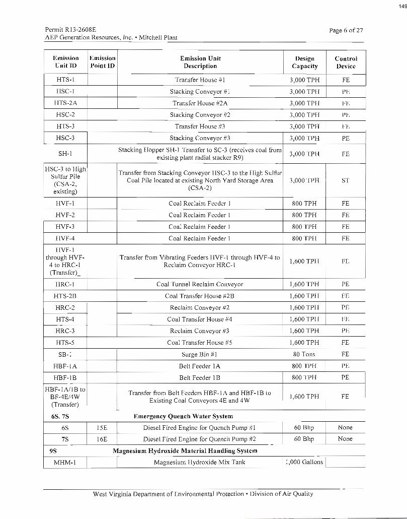
149

150

151

152

153

154

155

156

157

158

159

160

161

162

163

164

165

166

167

168

169

170
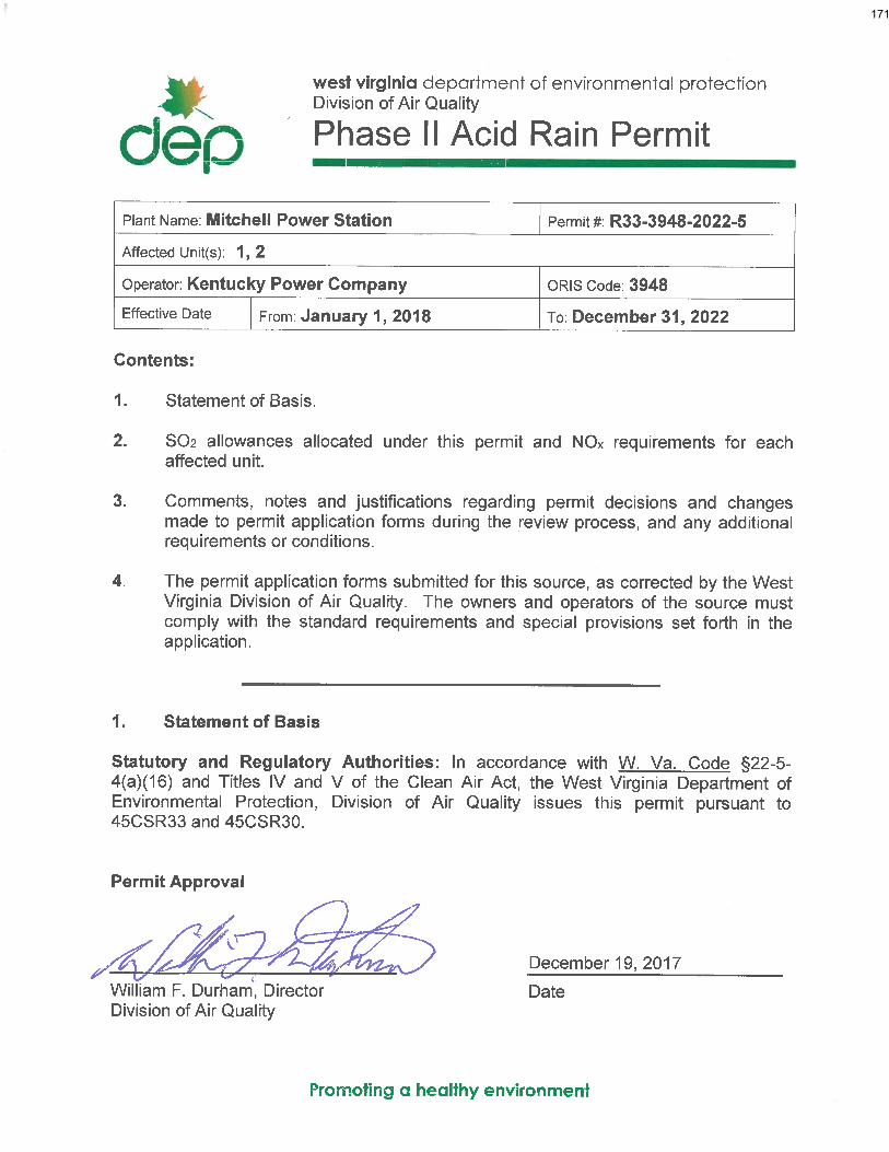
171

West Virginia Department of Environmental Protection Division of Air Quality
Approved: December 19, 2017 Mitchell – R33-3948-2022-5 – Page 2 of 3
Plant Name: Mitchell Power Station Permit #: R33-3948-2022-5 2. SO2 Allocations and NOx Requirements for each affected unit
Unit No. 1
SO2 Allowances Year
2018 2019 2020 2021 2022
Table 2 allowances, as adjusted by 40 CFR Part 73
18995 18995 18995 18995 18995
Repowering plan allowances N/A N/A N/A N/A N/A
The number of allowances actually held by an affected source in a unit account may differ from the number allocated by U.S. EPA. The aforementioned condition does not necessitate a revision to the unit SO2 allowance allocations identified in this permit (See 40 CFR §72.84).
NOX Requirements 2018 2019 2020 2021 2022
NOX Limit (lb/mmBtu) 0.50 0.50 0.50 0.50 0.50 Pursuant to 40 CFR §76.11, the West Virginia Department of Environmental Protection, Division of Air Quality approves four (4) NOx emissions averaging plans for this unit. Each plan is effective for one calendar year for the years 2018, 2019, 2020 and 2021. Under each plan, the unit’s NOx emissions shall not exceed the annual alternative contemporaneous emission limitation (ACEL) of 0.50 lb/mmBtu. Under the plan, the actual Btu-weighted annual average NOx emission rate for the units in the plan shall be less than or equal to the Btu-weighted annual average NOx emission rate for the same units had they each been operated, during the same period of time, in compliance with the applicable emission limitations under 40 CFR §76.5, 76.6 or 76.7, except that for early election units, the applicable emission limitations shall be under 40 CFR §76.7. If the designated representative demonstrates that the requirement of the prior sentence (as set forth in 40 CFR §76.11(d)(1)(ii)(A)) is met for a year under the plan, then this unit shall be deemed to be in compliance for that year with its alternative contemporaneous annual emission limitation and annual heat input limit. In accordance with 40 CFR §72.40(b)(2), approval of the averaging plan shall be final only when the Arkansas Department of Environmental Quality, Air Division, Indiana Department of Environmental Management, Office of Air Quality, the Kentucky Department for Environmental Protection, Division for Air Quality, the Ohio Environmental Protection Agency, Division of Air Pollution Control, the Oklahoma Department of Environmental Quality, Air Quality Division, the Virginia Department of Environmental Quality, Division of Air Quality and the Texas Commission on Environmental Quality, Office of Air have also approved the averaging plan. In addition to the described NOx compliance plans, this unit shall comply with all other applicable requirements of 40 CFR Part 76, including the duty to reapply for a NOx compliance plan and requirements covering excess emissions. Pursuant to 40 CFR Part 76 and 45CSR33, the West Virginia Department of Environmental Protection, Division of Air Quality approves a NOx emissions compliance plan for this unit effective for calendar year 2022. Under this plan the unit’s actual annual average NOx emission rate shall not exceed the applicable limitation of 0.50 lb/mmBtu as set forth in 40 CFR §76.5(a)(2) for Group 1, Phase I dry bottom wall-fired boilers.
3. Comments, notes and justifications regarding decisions, and changes made to the permit
application forms during the review process:
None. 4. Permit application forms: Attached.
172

West Virginia Department of Environmental Protection Division of Air Quality
Approved: December 19, 2017 Mitchell – R33-3948-2022-5 – Page 3 of 3
Plant Name: Mitchell Power Station Permit #: R33-3948-2022-5 2. SO2 Allocations and NOx Requirements for each affected unit
Unit No. 2
SO2 Allowances Year
2018 2019 2020 2021 2022
Table 2 allowances, as adjusted by 40 CFR Part 73
19656 19656 19656 19656 19656
Repowering plan allowances N/A N/A N/A N/A N/A
The number of allowances actually held by an affected source in a unit account may differ from the number allocated by U.S. EPA. The aforementioned condition does not necessitate a revision to the unit SO2 allowance allocations identified in this permit (See 40 CFR §72.84).
NOX Requirements 2018 2019 2020 2021 2022
NOX Limit (lb/mmBtu) 0.50 0.50 0.50 0.50 0.50 Pursuant to 40 CFR §76.11, the West Virginia Department of Environmental Protection, Division of Air Quality approves four (4) NOx emissions averaging plans for this unit. Each plan is effective for one calendar year for the years 2018, 2019, 2020 and 2021. Under each plan, the unit’s NOx emissions shall not exceed the annual alternative contemporaneous emission limitation (ACEL) of 0.50 lb/mmBtu. Under the plan, the actual Btu-weighted annual average NOx emission rate for the units in the plan shall be less than or equal to the Btu-weighted annual average NOx emission rate for the same units had they each been operated, during the same period of time, in compliance with the applicable emission limitations under 40 CFR §76.5, 76.6 or 76.7, except that for early election units, the applicable emission limitations shall be under 40 CFR §76.7. If the designated representative demonstrates that the requirement of the prior sentence (as set forth in 40 CFR §76.11(d)(1)(ii)(A)) is met for a year under the plan, then this unit shall be deemed to be in compliance for that year with its alternative contemporaneous annual emission limitation and annual heat input limit. In accordance with 40 CFR §72.40(b)(2), approval of the averaging plan shall be final only when the Arkansas Department of Environmental Quality, Air Division, Indiana Department of Environmental Management, Office of Air Quality, the Kentucky Department for Environmental Protection, Division for Air Quality, the Ohio Environmental Protection Agency, Division of Air Pollution Control, the Oklahoma Department of Environmental Quality, Air Quality Division, the Virginia Department of Environmental Quality, Division of Air Quality and the Texas Commission on Environmental Quality, Office of Air have also approved the averaging plan. In addition to the described NOx compliance plans, this unit shall comply with all other applicable requirements of 40 CFR Part 76, including the duty to reapply for a NOx compliance plan and requirements covering excess emissions. Pursuant to 40 CFR Part 76 and 45CSR33, the West Virginia Department of Environmental Protection, Division of Air Quality approves a NOx emissions compliance plan for this unit effective for calendar year 2022. Under this plan the unit’s actual annual average NOx emission rate shall not exceed the applicable limitation of 0.50 lb/mmBtu as set forth in 40 CFR §76.5(a)(2) for Group 1, Phase I dry bottom wall-fired boilers.
3. Comments, notes and justifications regarding decisions, and changes made to the permit
application forms during the review process:
None. 4. Permit application forms: Attached.
173

174
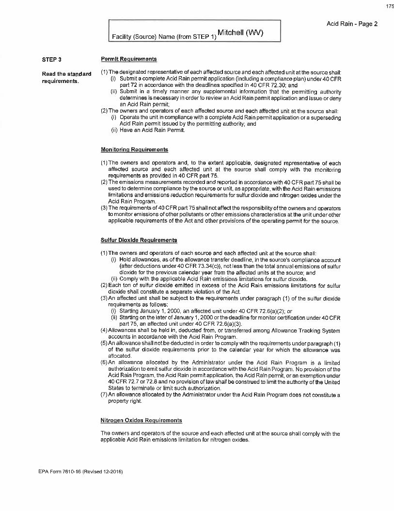
175

176

177

178

179
180

181

182

183
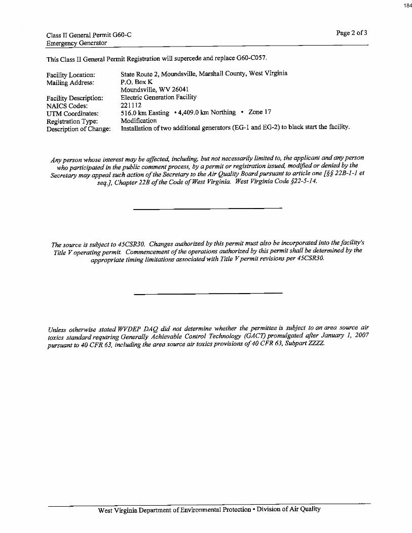
184
185

West Virginia Department of Environmental Protection Joe Manchin, III
Governor Division of Air Quality
Randy C. Huffman
Cabinet Secretary
Class II General Permit
G60-C
for the
Prevention and Control of Air Pollution in regard to the
Construction, Modification, Relocation, Administrative Update and
Operation of Emergency Generators
This permit is issued in accordance with the West Virginia Air Pollution Control Act
(West Virginia Code §§ 22-5-1 et seq.) and 45 C.S.R. 13 — Permits for Construction, Modification,
Relocation and Operation of Stationary Sources of Air Pollutants,
Notification Requirements, Temporary Permits, General Permits and Procedures for Evaluation.
_________________________________________
John A. Benedict
Director
Issued: May 21, 2009
Any person whose interest may be affected, including, but not necessarily limited to, the applicant
and any person who participated in the public comment process, by a permit issued, modified or
denied by the Secretary may appeal such action of the Secretary to the Air Quality Board pursuant
to article one [§§22B-1-1 et seq.], Chapter 22B of the Code of West Virginia. West Virginia Code
§§22-5-14.
——————————————————————
186

G60-C 2 of 38
Emergency Generator
West Virginia Department of Environmental Protection • Division of Air Quality
Table of Contents
1.0. Emission Units 4
2.0. General Conditions 4 2.1. Purpose 4
2.2. Authority 4
2.3. Applicability 4
2.4. Definitions 4
2.5. Acronyms 5
2.6. Permit Expiration and Renewal 6
2.7. Administrative Update to General Permit Registration 6
2.8. Modification to General Permit Registration 6
2.9. Duty to Comply 6
2.10. Inspection and Entry 7
2.11. Need to Halt or Reduce Activity Not a Defense 7
2.12. Emergency 7
2.13. Duty to Provide Information 8
2.14. Duty to Supplement and Correct Information 8
2.15. Credible Evidence 8
2.16. Severability 8
2.17. Property Rights 9
2.18. Notification Requirements 9
2.19. Suspension of Activities 9
2.20. Transferability 9
3.0. Facility-Wide Requirements 10 3.1. Siting Criteria 10
3.2. Limitations and Standards 10
3.3. Monitoring Requirements 11
3.4. Testing Requirements 11
3.5. Recordkeeping Requirements 12
3.6. Reporting Requirements 12
4.0. Source-Specific Requirements 14
4.1. Limitations and Standards 14
4.2. Recordkeeping Requirements 14
5.0. Source-Specific Requirements (R.I.C.E.) 16
5.1. Limitations and Standards 16
5.2. Monitoring Requirements 17
5.3. Testing Requirements 17
5.4. Recordkeeping Requirements 17
5.5. Reporting Requirements 17
6.0. Source-Specific Requirements (Tanks) 18
6.1. Limitations and Standards 18
6.2. Monitoring Requirements 18
6.3. Testing Requirements 18
6.4. Recordkeeping Requirements 18
187

G60-C 3 of 38
Emergency Generator
West Virginia Department of Environmental Protection • Division of Air Quality
6.5. Reporting Requirements 18
7.0. Source-Specific Requirements (Standards of Performance for Stationary Compression
Ignition Internal Combustion Engines (40CFR60 Subpart IIII) 19
7.1. Limitations and Standards 19
7.2. Testing Requirements 23
7.3 Recordkeeping and Reporting Requirements 27
8.0. Source-Specific Requirements (Standards of Performance for Stationary Spark
Ignition Internal Combustion Engines (40CFR60 Subpart JJJJ) 29
8.1. Limitations and Standards 29
8.2. Emission Standards for Owners and Operators 30
8.3. Other Requirements for Owners and Operators 31
8.4. Compliance Requirements for Owners and Operators 32
8.5. Testing Requirements for Owners and Operators 34
8.6. Notification, Reports, and Records for Owners and Operators 37
CERTIFICATION OF DATA ACCURACY 38
188
G60-C 4 of 38
Emergency Generator
West Virginia Department of Environmental Protection • Division of Air Quality
1.0. Emission Units
All emission units covered by this permit are listed on the issued G60-C Registration.
2.0. General Conditions
2.1. Purpose
The purpose of this Class II General Permit is to authorize the construction, modification, administrative
update, relocation, and operation of eligible emergency generators through a Class II General Permit
registration process. The requirements, provisions, standards and conditions of this Class II General Permit
address the prevention and control of regulated pollutants from the operation of emergency generator(s).
2.2 Authority
This permit is issued in accordance with West Virginia air pollution control law W.Va. Code §§ 22-5-1. et
seq. and the following Legislative Rules promulgated thereunder:
2.2.1. 45CSR13 – Permits for Construction, Modification, Relocation and Operation of Stationary
Sources of Air Pollutants, Notification Requirements, Temporary Permits, General Permits and
Procedures for Evaluation;
2.3 Applicability
2.3.1. All emergency generators installed for the purpose of allowing key systems to continue to operate
without interruption during times of utility power outages, including emergency generators
installed at Title V(major) facilities and other facilities having additional point sources of
emissions, are eligible for Class II General Permit registration except for:
a.. Any emergency generator which is a major source as defined in 45CSR14, 45CSR19 or
45CSR30;
b. Any emergency generator subject to the requirements of 45CSR14, 45CSR15, 45CSR19,
45CSR25, 45CSR27, 45CSR30, 45CSR34;
c. Any emergency generator whose estimated hours of operation exceeds 500 hours per year;
d. Any emergency generator located in or which may significantly impact an area which has
been determined to be a nonattainment area. Unless otherwise approved by the Secretary.
e. Any emergency generator which will require an individual air quality permit review process
and/or individual permit provisions to address the emission of a regulated pollutant or to
incorporate regulatory requirements other than those established by General Permit G60-C.
2.3.2. For the purposes of General Permit G60-C, emergency generator means a generator whose
purpose is to allow key systems to continue to operate without interruption during times of utility
power outages.
2.3.3. The West Virginia Division of Air Quality reserves the right to reopen this permit or any
authorization issued under this permit if the area in which the affected facility is located is
federally designated as non-attainment for specified pollutants. If subsequently any proposed
construction, modification and/or operation does not demonstrate eligibility and/or compliance
with the requirements, provisions, standards and conditions of this General Permit, this General
Permit registration shall be denied and an individual permit for the proposed activity shall be
required.
189

G60-C 5 of 38
Emergency Generator
West Virginia Department of Environmental Protection • Division of Air Quality
2.3.4. Except for emergency diesel generators, all emission units covered by this permit, unless they are
classified as De Minimis Sources in 45CSR13 Table 45-13B, must be fueled with pipeline-quality
natural gas, field gas, propane gas, or equivalent with a maximum sulfur content of 20 grains of
sulfur per 100 standard cubic feet and a maximum H2S content of 0.25 grains per 100 cubic feet of
gas (maximum allowed to have in natural gas sold for delivery through the interstate pipeline
system).
[45CSR§13-5.11]
2.4. Definitions
2.4.1. All references to the “West Virginia Air Pollution Control Act” or the “Air Pollution Control Act”
mean those provisions contained in W.Va. Code §§ 22-5-1 to 22-5-18.
2.4.2. The “Clean Air Act” means those provisions contained in 42 U.S.C. §§ 7401 to 7671q, and
regulations promulgated thereunder.
2.4.3. “Secretary” means the Secretary of the Department of Environmental Protection or such other
person to whom the Secretary has delegated authority or duties pursuant to W.Va. Code §§ 22-1-6
or 22-1-8 (45CSR§30-2.12.). The Director of the Division of Air Quality is the Secretary’s
designated representative for the purposes of this permit.
2.5. Acronyms
CAAA
CBI
CEM
CES
C.F.R. or CFR
CO
C.S.R. or CSR
DAQ
DEP
dscm
FOIA
HAP
HON
HP
lbs/hr
LDAR
M
MACT
MDHI
MM
MMBtu/hr or
mmbtu/hr
MMCF/hr or
mmcf/hr
NA
Clean Air Act Amendments
Confidential Business
Information
Continuous Emission Monitor
Certified Emission Statement
Code of Federal Regulations
Carbon Monoxide
Codes of State Rules
Division of Air Quality
Department of Environmental
Protection
Dry Standard Cubic Meter
Freedom of Information Act
Hazardous Air Pollutant
Hazardous Organic NESHAP
Horsepower
Pounds per Hour
Leak Detection and Repair
Thousand
Maximum Achievable
Control Technology
Maximum Design Heat Input
Million
Million British Thermal Units
per Hour
Million Cubic Feet per Hour
Not Applicable
National Ambient Air Quality
NOX
NSPS
PM
PM2.5
PM10
Ppb
Pph
Ppm
PpmV or
ppmv
PSD
Psi
SIC
SIP
SO2
TAP
TPY
TRS
TSP
USEPA
UTM
VEE
Nitrogen Oxides
New Source Performance
Standards
Particulate Matter
Particulate Matter less than 2.5
μm in diameter
Particulate Matter less than
10μm in diameter
Pounds per Batch
Pounds per Hour
Parts per Million
Parts per Million by Volume
Prevention of Significant
Deterioration
Pounds per Square Inch
Standard Industrial
Classification
State Implementation Plan
Sulfur Dioxide
Toxic Air Pollutant
Tons per Year
Total Reduced Sulfur
Total Suspended Particulate
United States Environmental
Protection Agency
Universal Transverse Mercator
Visual Emissions Evaluation
Volatile Organic Compounds
190
G60-C 6 of 38
Emergency Generator
West Virginia Department of Environmental Protection • Division of Air Quality
NAAQS
NESHAPS
Standards
National Emissions Standards
for Hazardous Air Pollutants
VOC
VOL
Volatile Organic Liquids
2.6. Permit Expiration and Renewal
2.6.1. This Class II General Permit shall remain valid, continuous and in effect unless it is revised,
suspended, revoked or otherwise changed under an applicable provision of 45CSR13 or any other
applicable legislative rule.
2.6.2. General Permit registration granted by the Secretary shall remain valid, continuous and in effect
unless it is suspended or revoked by the Secretary or this Class II General Permit is subject to
action or change as set forth in Section 2.6.1 above. [45CSR§13-10.2, 45CSR§13-10.3]
2.6.3. The Secretary shall review and may renew, reissue or revise this Class II General Permit for cause.
The Secretary shall define the terms and conditions under which existing General Permit
registrations will be eligible for registration under a renewed, reissued, or revised General Permit
and provide written notification to all General Permit registrants (or applicants). This notification
shall also describe the registrant’s (or applicant’s) duty or required action and may include a
request for additional information that may be required by any proposed general permit renewal,
reissuance or revision.
2.7. Administrative Update to General Permit Registration
2.7.1. The registrant may request an administrative registration update to their General Permit
registration as defined in and according to the procedures specified in 45CSR§13-4.
[45CSR§13-4.]
2.8. Modification to General Permit Registration
2.8.1. The registrant may request a permit modification to their General Permit registration as defined in
and according to the procedures specified in 45CSR§13-5. [45CSR§13-5.]
2.9. Duty to Comply
2.9.1. The registered affected facility shall be constructed and operated in accordance with the
information filed in the General Permit Registration Application and any amendments thereto.
The Secretary may suspend or revoke a General Permit registration if the plans and specifications
upon which the approval was based are not adhered to.
2.9.2. The registrant must comply with all applicable conditions of this Class II General Permit. Any
General Permit noncompliance constitutes a violation of the West Virginia Code, and/or the Clean
Air Act, and is grounds for enforcement action by the Secretary or USEPA.
2.9.3. Violation of any of the applicable requirements, provisions, standards or conditions contained in
this Class II General Permit, or incorporated herein by reference, may subject the registrant to civil
and/or criminal penalties for each violation and further action or remedies as provided by West
Virginia Code 22-5-6 and 22-5-7.
191

G60-C 7 of 38
Emergency Generator
West Virginia Department of Environmental Protection • Division of Air Quality
2.9.4. Registration under this Class II General Permit does not relieve the registrant herein of the
responsibility to apply for and obtain all other permits, licenses, and/or approvals from other
agencies; i.e. local, state and federal, which may have jurisdiction over the construction and/or
operation of the source(s) and/or affected facility herein permitted.
2.10. Inspection and Entry
2.10.1. The registrant shall allow any authorized representative of the Secretary, upon the presentation of
credentials and other documents as may be required by law, to perform the following:
a. At all reasonable times enter upon the registrant’s premises where a source is located or
emissions related activity is conducted, or where records must be kept under the conditions of
this permit;
b. Have access to and copy, at reasonable times, any records that must be kept under the
conditions of this Class II General Permit;
c. Inspect at reasonable times (including all times in which the affected facility is in operation)
any affected facilities, equipment (including monitoring and air pollution Control equipment),
practices, or operations regulated or required under this Class II General Permit;
d. Sample or monitor at reasonable times, substances or parameters to determine compliance
with the permit or applicable requirements or ascertain the amounts and types of air pollutants
discharged.
2.11. Need to Halt or Reduce Activity not a Defense
2.11.1. It shall not be a defense for a registrant in an enforcement action that it should have been
necessary to halt or reduce the permitted activity in order to maintain compliance with the
conditions of this Class II General Permit. However, nothing in this paragraph shall be construed
as precluding consideration of a need to halt or reduce activity as a mitigating factor in
determining penalties for noncompliance if the health, safety, or environmental impacts of halting
or reducing operations would be more serious than the impacts of continued operations.
2.12. Emergency
2.12.1. An "emergency" means any situation arising from sudden and reasonably unforeseeable events
beyond the control of the source, including acts of God, which situation requires immediate
corrective action to restore normal operation, and that causes the source to exceed a technology-
based emission limitation under this Class II General Permit, due to unavoidable increases in
emissions attributable to the emergency. An emergency shall not include noncompliance to the
extent caused by improperly designed equipment, lack of preventative maintenance, careless or
improper operation, or operator error.
2.12.2 Effect of any emergency. An emergency constitutes an affirmative defense to an action brought
for noncompliance with such technology-based emission limitations if the conditions of Section
2.12.3 below are met.
2.12.3. The affirmative defense of emergency shall be demonstrated through properly signed,
contemporaneous operating logs, or other relevant evidence that:
192

G60-C 8 of 38
Emergency Generator
West Virginia Department of Environmental Protection • Division of Air Quality
a. An emergency occurred and that the registrant can identify the cause(s) of the emergency;
b. The registered affected facility was at the time being properly operated;
c. During the period of the emergency the registrant took all reasonable steps to minimize levels
of emissions that exceeded the emission standards, or other requirements in this Class II
General Permit; and
d. The registrant submitted notice of the emergency to the Secretary within one (1) working day
of the time when emission limitations were exceeded due to the emergency and made a
request for variance, and as applicable rules provide. This notice, report, and variance request
fulfills the requirement of C. S. R. § 45-30-5.1.c.3.B. This notice must contain a detailed
description of the emergency, any steps taken to mitigate emissions, and corrective actions
taken.
2.12.4. In any enforcement proceeding, the registrant seeking to establish the occurrence of an emergency
has the burden of proof.
2.12.5. This provision is in addition to any emergency or upset provision contained in any applicable
requirement.
2.13. Duty to Provide Information
2.13.1. The registrant shall furnish to the Secretary within a reasonable time any information the Secretary
may request in writing to determine whether cause exists for modifying, revoking and reissuing, or
terminating this Class II General Permit Registration or to determine compliance with this General
Permit. Upon request, the registrant shall also furnish to the Secretary copies of records required
to be kept by the registrant. For information claimed to be confidential, the registrant shall furnish
such records to the Secretary along with a claim of confidentiality in accordance with 45CSR31.
If confidential information is to be sent to USEPA, the registrant shall directly provide such
information to USEPA along with a claim of confidentiality in accordance with 40 C.F.R. Part 2.
2.14. Duty to Supplement and Correct Information
2.14.1. Upon becoming aware of a failure to submit any relevant facts or a submittal of incorrect
information in any registration application, the registrant shall promptly submit to the Secretary
such supplemental facts or corrected information.
2.15. Credible Evidence
2.15.1. Nothing in this Class II General Permit shall alter or affect the ability of any person to establish
compliance with, or a violation of, any applicable requirement through the use of credible
evidence to the extent authorized by law. Nothing in this permit shall be construed to waive any
defenses otherwise available to the registrant including but not limited to any challenge to the
credible evidence rule in the context of any future proceeding.
2.16. Severability
2.16.1. The provisions of this Class II General Permit are severable. If any provision of this Class II
General Permit, or the application of any provision of this Class II General Permit to any
circumstance is held invalid by a court of competent jurisdiction, the remaining Class II General
Permit terms and conditions or their application to other circumstances shall remain in full force
and effect.
193

G60-C 9 of 38
Emergency Generator
West Virginia Department of Environmental Protection • Division of Air Quality
2.17. Property Rights
2.17.1. Registration under this Class II General Permit does not convey any property rights of any sort or
any exclusive privilege.
2.18. Notification Requirements
2.18.1. The registrant shall notify the Secretary, in writing, no later than thirty (30) calendar days after the
actual startup of the operations authorized under this permit.
2.19. Suspension of Activities
2.19.1. In the event the registrant should deem it necessary to suspend, for a period in excess of sixty (60)
consecutive calendar days, the affected facility authorized by this permit, the registrant shall notify
the Secretary, in writing, within two (2) calendar weeks of the passing of the sixtieth (60) day of
the suspension period.
2.20. Transferability
2.20.1. This permit is transferable in accordance with the requirements outlined in Section 10.1 of
45CSR13. [45CSR§13-10.1.]
194

G60-C 10 of 38
Emergency Generator
West Virginia Department of Environmental Protection • Division of Air Quality
3.0. Facility-Wide Requirements
3.1. Siting Criteria
3.1.1. All persons submitting a Class II General Permit Registration Application to construct, modify or
relocate an emergency generator shall be subject to the following siting criteria:
a. No person shall construct, locate or relocate any affected facility or emission unit within three
hundred (300) feet of any occupied dwelling, business, public building, school, church,
community, institutional building or public park. An owner of an occupied dwelling or business
may elect to waive the three hundred (300) feet siting criteria.
b. Any person proposing to construct, modify or relocate an emergency generator within three
(300) feet of any occupied dwelling, business, public building, school, church, community,
institutional building or public park may elect to obtain an individual permit pursuant to 45CSR13.
3.2. Limitations and Standards
3.2.1. Open burning. The open burning of refuse by any person, firm, corporation, association or
public agency is prohibited except as noted in 45CSR§6-3.1.
[45CSR§6-3.1.]
3.2.2. Open burning exemptions. The exemptions listed in 45CSR§6-3.1 are subject to the following
stipulation: Upon notification by the Secretary, no person shall cause, suffer, allow or permit any
form of open burning during existing or predicted periods of atmospheric stagnation. Notification
shall be made by such means as the Secretary may deem necessary and feasible.
[45CSR§6-3.2.]
3.2.3. Asbestos. The registrant is responsible for thoroughly inspecting the affected facility, or part of
the affected facility, prior to commencement of demolition or renovation for the presence of
asbestos and complying with 40 C.F.R. § 61.145, 40 C.F.R. § 61.148, and 40 C.F.R. § 61.150. The
registrant, owner, or operator must notify the Secretary at least ten (10) working days prior to the
commencement of any asbestos removal on the forms prescribed by the Secretary if the registrant
is subject to the notification requirements of 40 C.F.R. § 61.145(b)(3)(i). The USEPA, the
Division of Waste Management, and the Bureau for Public Health - Environmental Health require
a copy of this notice to be sent to them.
[40CFR§61.145(b) and 45CSR§15]
3.2.4. Odor. No person shall cause, suffer, allow or permit the discharge of air pollutants which cause
or contribute to an objectionable odor at any location occupied by the public.
[45CSR§4-3.1] [State Enforceable Only]
3.2.5. Permanent shutdown. A source which has not operated at least 500 hours in one 12-month
period within the previous five (5) year time period may be considered permanently shutdown,
unless such source can provide to the Secretary, with reasonable specificity, information to the
contrary. All permits may be modified or revoked and/or reapplication or application for new
permits may be required for any source determined to be permanently shutdown.
[45CSR§13-10.5.]
195

G60-C 11 of 38
Emergency Generator
West Virginia Department of Environmental Protection • Division of Air Quality
3.2.6. Standby plan for reducing emissions. When requested by the Secretary, the registrant shall
prepare standby plans for reducing the emissions of air pollutants in accordance with the
objectives set forth in Tables I, II, and III of 45CSR11.
[45CSR§11-5.2.]
3.3. Monitoring Requirements
See Section 4.2.
3.4. Testing Requirements
3.4.1. Stack testing. Where required by this permit or as otherwise required by the Secretary, in
accordance with the West Virginia Code, underlying regulations, permits and orders, the registrant
shall conduct test(s) to determine compliance with the emission limitations set forth in this permit
and/or established or set forth in underlying documents. The Secretary, or his duly authorized
representative, may at his option witness or conduct such test(s). Should the Secretary exercise his
option to conduct such test(s), the operator shall provide all necessary sampling connections and
sampling ports to be located in such manner as the Secretary may require, power for test
equipment and the required safety equipment, such as scaffolding, railings and ladders, to comply
with generally accepted good safety practices. Such tests shall be conducted in accordance with
the methods and procedures set forth in this permit or as otherwise approved or specified by the
Secretary in accordance with the following:
a. The Secretary may on a source-specific basis approve or specify additional testing or
alternative testing to the test methods specified in the permit for demonstrating compliance
with 40 C.F.R. Parts 60, 61, and 63 in accordance with the Secretary’s delegated authority and
any established equivalency determination methods which are applicable. If a testing method
is specified or approved which effectively replaces a test method specified in the permit, the
permit may be revised in accordance with 45CSR§13-4. or 45CSR§13-5.4 as applicable.
b. The Secretary may on a source-specific basis approve or specify additional testing or
alternative testing to the test methods specified in the permit for demonstrating compliance
with applicable requirements which do not involve federal delegation. In specifying or
approving such alternative testing to the test methods, the Secretary, to the extent possible,
shall utilize the same equivalency criteria as would be used in approving such changes under
Section 3.3.1.a. of this permit. If a testing method is specified or approved which effectively
replaces a test method specified in the permit, the permit may be revised in accordance with
45CSR§13-4. or 45CSR§13-5.4 as applicable.
c. All periodic tests to determine mass emission limits from or air pollutant concentrations in
discharge stacks and such other tests as specified in this permit shall be conducted in
accordance with an approved test protocol. Unless previously approved, such protocols shall
be submitted to the Secretary in writing at least thirty (30) days prior to any testing and shall
contain the information set forth by the Secretary. In addition, the registrant shall notify the
Secretary at least fifteen (15) days prior to any testing so the Secretary may have the
opportunity to observe such tests. This notification shall include the actual date and time
during which the test will be conducted and, if appropriate, verification that the tests will fully
conform to a referenced protocol previously approved by the Secretary. [WV Code § 22-5-
4(a)(15)]
196

G60-C 12 of 38
Emergency Generator
West Virginia Department of Environmental Protection • Division of Air Quality
3.5. Recordkeeping Requirements
3.5.1. Retention of records. The registrant shall maintain records of all information (including
monitoring data, support information, reports, and notifications) required by this permit recorded
in a form suitable and readily available for expeditious inspection and review. Support
information includes all calibration and maintenance records. Said records shall be maintained for
a period of five (5) years on site or in a readily accessible off-site location maintained by the
registrant. Said records shall be readily available to the Director of the Division of Air Quality or
his/her duly authorized representative for expeditious inspection and review. Any records
submitted to the agency pursuant to a requirement of this permit or upon request by the Director
shall be certified by a responsible official. Any records submitted to the agency pursuant to a
requirement of this permit or upon request by the Director shall be certified by a responsible
official. Where appropriate, the registrant may maintain records electronically (on a computer, on
computer floppy disks, CDs, DVDs, or magnetic tape disks), on microfilm, or on microfiche.
3.5.2. Odors. For the purposes of 45CSR4, the registrant shall maintain a record of all odor complaints
received, any investigation performed in response to such a complaint, and any responsive
action(s) taken. [45CSR§4. State Enforceable Only.]
3.6. Reporting Requirements
3.6.1. Responsible official. Any application form, report, or compliance certification required by this
permit to be submitted to the DAQ and/or USEPA shall contain a certification by the responsible
official that states that, based on information and belief formed after reasonable inquiry, the
statements and information in the document are true, accurate, and complete.
3.6.2. Confidential information. A registrant may request confidential treatment for the submission of
reporting required by this permit pursuant to the limitations and procedures of W.Va. Code § 22-
5-10 and 45CSR31.
3.6.3. Correspondence. All notices, requests, demands, submissions and other communications
required or permitted to be made to the Secretary of DEP and/or USEPA shall be made in writing
and shall be deemed to have been duly given when delivered by hand, or mailed first class with
postage prepaid to the address(es) set forth below or to such other person or address as the
Secretary of the Department of Environmental Protection may designate:
If to the DAQ:
Director
WVDEP
Division of Air Quality
601 57th
Street
Charleston, WV 25304-2345
If to the US EPA:
Associate Director
Office of Enforcement and Permits Review
(3AP12)
U.S. Environmental Protection Agency
Region III
1650 Arch Street
Philadelphia, PA 19103-2029
3.6.4. Emission inventory. At such time(s) as the Secretary may designate, the registrant herein shall
prepare and submit an emission inventory for the previous year, addressing the emissions from the
affected facility and/or process(es) authorized herein, in accordance with the emission inventory
submittal requirements of the Division of Air Quality. After the initial submittal, the Secretary
may, based upon the type and quantity of the pollutants emitted, establish a frequency other than
on an annual basis.
197

G60-C 13 of 38
Emergency Generator
West Virginia Department of Environmental Protection • Division of Air Quality
3.6.5. Operating Fee. a. In accordance with 45CSR22 – Air Quality Management Fee Program, the permittee shall not
operate nor cause to operate the permitted facility or other associated facilities on the same or
contiguous sites comprising the plant without first obtaining and having in current effect a
Certificate to Operate (CTO). Such Certificate to Operate (CTO) shall be renewed annually,
shall be maintained on the premises for which the certificate has been issued, and shall be
made immediately available for inspection by the Secretary or his/her duly authorized
representative.
b. In accordance with 45CSR30 – Operating Permit Program, the permittee shall submit a
certified emissions statement and pay fees on an annual basis in accordance with the submittal
requirements of the Division of Air Quality. A receipt for the appropriate fee shall be
maintained on the premises for which the receipt has been issued, and shall be made
immediately available for inspection by the Secretary or his/her duly authorized
representative.
198

G60-C 14 of 38
Emergency Generator
West Virginia Department of Environmental Protection • Division of Air Quality
4.0. Source-Specific Requirements (Units listed in General Permit Registration)
4.1. Limitations and Standards
4.1.1. Operation and Maintenance of Air Pollution Control Equipment. The registrant shall, to the extent
practicable, install, maintain, and operate all pollution control equipment listed in the issued
General Permit Registration and associated monitoring equipment in a manner consistent with
safety and good air pollution control practices for minimizing emissions, or comply with any more
stringent limits set forth in this permit or as set forth by any State rule, Federal regulation, or
alternative control plan approved by the Secretary. [45CSR§13-5.11.]
4.1.2. Minor Source of Hazardous Air Pollutants (HAP). HAP emissions from the affected facility
shall be less than 10 tons/year of any single HAP or 25 tons/year of any combination of HAPs.
Compliance with this Section shall ensure that the affected facility is a minor HAP source.
4.2. Recordkeeping Requirements
4.2.1. Monitoring information. The registrant shall keep records of monitoring information that include
the following:
a. The date, place as defined in this permit and time of sampling or measurements;
b. The date(s) analyses were performed;
c. The company or entity that performed the analyses;
d. The analytical techniques or methods used;
e. The results of the analyses; and
f. The operating conditions existing at the time of sampling or measurement.
4.2.2. Record of Maintenance of Air Pollution Control Equipment. For all pollution control equipment
listed in the General Permit Registration, the registrant shall maintain accurate records of all
required pollution control equipment inspection and/or preventative maintenance procedures
specifically required in this permit.
4.2.3. Record of Malfunctions of Air Pollution Control Equipment. For all air pollution control
equipment listed in the General Permit Registration, the registrant shall maintain records of the
occurrence and duration of any malfunction or operational shutdown of the air pollution control
equipment during which excess emissions occur. For each such case, the following information
shall be recorded:
a. The equipment involved.
b. Steps taken to minimize emissions during the event.
c. The duration of the event.
d. The estimated increase in emissions during the event.
For each such case associated with an equipment malfunction, the additional information shall
also be recorded:
e. The cause of the malfunction.
f. Steps taken to correct the malfunction.
g. Any changes or modifications to equipment or procedures that would help prevent future
recurrences of the malfunction.
4.2.4. Minor Source of Hazardous Air Pollutants (HAP). The registrant shall maintain records of
annual HAP emissions using AP-42 emission factors, GRI-GLYCalc model outputs, manufacturer
199
G60-C 15 of 38
Emergency Generator
West Virginia Department of Environmental Protection • Division of Air Quality
guaranteed values, sample and/or test data, or other methods approved by DAQ demonstrating that
facility-wide emissions are less than those specified in Section 4.1.2.
200

G60-C 16 of 38
Emergency Generator
West Virginia Department of Environmental Protection • Division of Air Quality
5.0 Source-Specific Requirements (Reciprocating Internal Combustion Engines)
5.1. Limitations and Standards
5.1.1. The reciprocating internal combustion engines listed in the General Permit Registration
application shall be operated and maintained in accordance with the manufacturer’s
recommendations and specifications and in a manner consistent with good operating practices.
5.1.2. Regulated Pollutant Limitation. The registrant shall not cause, suffer, allow or permit emissions
of PM, PM10, VOC, SO2, NOX, CO, and formaldehyde, from any registered reciprocating internal
combustion engine to exceed the potential to emit (pounds per hour and tons per year) listed in
the General Permit Registration.
5.1.3. Maximum Fuel Consumption Limitation. The maximum fuel consumption for any registered
reciprocating internal combustion engine listed in the General Permit Registration application
shall not exceed the fuel consumption recorded with registrant’s Class II General Permit
Registration Application without effecting a modification or administrative update. Compliance
with the Maximum Yearly Fuel Consumption Limitation shall be determined using a twelve
month rolling total. A twelve month rolling total shall mean the sum of the fuel consumption at
any given time during the previous twelve consecutive calendar months.
5.1.4. Requirements for Use of Catalytic Reduction Devices
a. Rich-burn natural gas compressor engines equipped with non-selective catalytic reduction
(NSCR) air pollution control devices shall be fitted with a closed-loop, automatic air/fuel
ratio controller to ensure emissions of regulated pollutants do not exceed the potential to emit
for any engine/NSCR combination under varying load. The closed-loop, automatic air/fuel
ratio controller shall control a fuel metering valve to deliver additional fuel when required to
ensure a fuel-rich mixture and a resultant exhaust oxygen content of less than or equal to
0.5%. The automatic air/fuel ratio controller shall also incorporate dual-point exhaust gas
temperature and oxygen sensors which provide temperature and exhaust oxygen content
differential feedback. Such controls shall ensure proper and efficient operation of the engine
and NSCR air pollution control device;
b. Lean-burn natural gas compressor engines equipped with selective catalytic reduction (SCR)
air pollution control devices shall be fitted with a closed-loop automatic feedback controller
to ensure emissions of regulated pollutants do not exceed the potential to emit for any
engine/SCR combination under varying load. The closed-loop automatic feedback controller
shall provide proper and efficient operation of the engine, ammonia injection and SCR
device, monitor emission levels downstream of the catalyst element and limit ammonia slip
to less than 10 ppmv;
c. The automatic air/fuel ratio controller or closed-loop automatic feedback controller shall
provide a warning or indication to the operator and/or be interlocked with the engine ignition
system to cease engine operation in case of a masking, poisoning or overrich air/fuel ratio
situation which results in performance degradation or failure of the catalyst element; and
d. No person shall knowingly:
1. Remove or render inoperative any air pollution or auxiliary air pollution control device
installed subject to the requirements of General Permit G35-A;
2. Install any part or component when the principal effect of the part or component is to
bypass, defeat or render inoperative any air pollution control device or auxiliary air
pollution control device installed subject to the requirements of General Permit G35-A;
or
3. Cause or allow engine exhaust gases to bypass any catalytic reduction device.
201

G60-C 17 of 38
Emergency Generator
West Virginia Department of Environmental Protection • Division of Air Quality
5.2. Monitoring Requirements
5.2.1. Catalytic Oxidizer Control Devices
a. The registrant shall regularly inspect, properly maintain and/or replace catalytic reduction
devices and auxiliary air pollution control devices to ensure functional and effective
operation of the engine’s physical and operational design. The registrant shall ensure proper
operation, maintenance and performance of catalytic reduction devices and auxiliary air
pollution control devices by:
1. Maintaining proper operation of the automatic air/fuel ratio controller or automatic
feedback controller.
2. Following operating and maintenance recommendations of the catalyst element
manufacturer.
5.3. Testing Requirements
5.3.1. See Facility-Wide Testing Requirements Section 3.4.
5.4. Recordkeeping Requirements
5.4.1. To demonstrate compliance with section 5.1.1, 5.1.2, and 5.1.3, the registrant shall maintain
records of the amount and type of fuel consumed in each engine and the hours of operation of each
engine. Said records shall be maintained on site or in a readily accessible off-site location
maintained by the registrant for a period of five (5) years. Said records shall be readily available
to the Director of the Division of Air Quality or his/her duly authorized representative for
expeditious inspection and review. Any records submitted to the agency pursuant to a requirement
of this permit or upon request by the Director shall be certified by a responsible official.
5.5. Reporting Requirements
5.5.1. See Facility-Wide Reporting Requirements Section 3.6.
202

G60-C 18 of 38
Emergency Generator
West Virginia Department of Environmental Protection • Division of Air Quality
6.0. Source-Specific Requirements (Tanks)
6.1. Limitations and Standards
6.1.1. All tanks in the General Permit Registration application will be listed in Section 1.0 (the
equipment table) of the issued registration. Tanks that are less than 20,000 gallons should not, as
a general rule, have permitted emission limits. Section 1.0 of the issued registration will identify
the size of the tank, any controls (such as a floating roof), and may include for tanks of 10,000
gallons or more the expected throughput or turnovers. Depending on the situation, setting a
specific permit condition for maximum throughput, turnovers, or a vapor pressure for the tank is
acceptable. Such situations would include tanks storing TAPs or HAPs, that are not subject to
Rule 27 or a MACT but may be close to the thresholds for these rules. For a source subject to
Rule 27 or a MACT storing the pollutant subject to the MACT or Rule 27 it may be appropriate to
have emission limits for the regulated pollutant and the appropriate MRR to show compliance.
6.1.2. Maximum Tank Throughput Limitation. For tanks subject to the maximum tank throughput limits,
the maximum tank throughput for these tanks shall not exceed the throughput recorded with
registrant’s Class II General Permit Registration without effecting a modification or administrative
update. Compliance with the Maximum Yearly Tank Throughput Limitation shall be determined
using a twelve month rolling total. A twelve month rolling total shall mean the sum of the tank
throughput at any given time during the previous twelve consecutive calendar months.
6.1.3. Regulated Pollutant Limitation. The registrant shall not cause, suffer, allow or permit emissions
of VOC and aggregate emissions of hazardous air pollutants (HAPs), from any tank listed in the
General Permit Registration to exceed the potential to emit (pounds per hour and tons per year)
recorded with the registrant’s Class II General Permit Registration Application.
6.2. Monitoring Requirements
6.2.1. See Facility-Wide Monitoring Requirements.
6.3. Testing Requirements
6.3.1. See Facility-Wide Testing Requirements.
6.4. Recordkeeping Requirements
6.4.1. The registrant shall maintain a record of the tank throughput for tanks with maximum throughput
limits, to demonstrate compliance with section 6.1.2 of this permit. Said records shall be
maintained on site or in a readily accessible off-site location maintained by the registrant for a
period of five (5) years. Said records shall be readily available to the Director of the Division of
Air Quality or his/her duly authorized representative for expeditious inspection and review. Any
records submitted to the agency pursuant to a requirement of this permit or upon request by the
Director shall be certified by a responsible official.
6.5. Reporting Requirements
6.5.1. See Facility-Wide Reporting Requirements.
203

G60-C 19 of 38
Emergency Generator
West Virginia Department of Environmental Protection • Division of Air Quality
7.0 Source-Specific Requirements ( Standards of Performance for Stationary Compression
Ignition Internal Combustion Engines (40CFR60 Subpart IIII))
7.1. Limitations and Standards
7.1.1. Maximum Yearly Operation Limitation. The maximum yearly hours of operation for any
emergency generator listed in the General Permit Registration application shall not exceed 500
hours per year. Compliance with the Maximum Yearly Operation Limitation shall be determined
using a twelve month rolling total. A twelve month rolling total shall mean the sum of the hours
of operation at any given time during the previous twelve consecutive calendar months.
7.1.2. Regulated Pollutant Limitation
The registrant shall not cause, suffer, allow or permit emissions of PM, PM10, VOC, SO2, NOX,
CO, and aggregate emissions of hazardous air pollutants (HAPs), from any emergency generator
listed in the General Permit Registration to exceed the potential to emit (pounds per hour and tons
per year) recorded with the registrant’s Class II General Permit Registration Application.
7.1.3. Recycled or Used Oil
a. The registrant shall not receive, store, burn or fire any recycled or used oil in the
emergency generator registered herein which is considered a hazardous waste or does not
meet the used oil specifications below (40 C.F.R. 279.11, Table 1). The burning of used
or recycled oil which does not meet these specifications shall constitute a violation of
45CSR25, 33CSR20 and the requirements, provisions, standards and conditions of this
Class II General Permit.
Constituent or Property Maximum Allowable Specification
Arsenic 5.0 ppm
Cadmium 2.0 ppm
Chromium 10.0 ppm
Lead 100.0 ppm
PCBs 2.0 ppm
Total Halogen 4000.0 ppm maximum
Mercury 0.20 ppm
Flash Point 100.0 F minimum
b. Recycled or used oil with a Total Halogen content greater than 1000.0 ppm is presumed
to be a hazardous waste under the rebuttable presumption provided in 40 C.F.R.
279.10(b)(1)(ii). Therefore, the registrant may receive, store and burn recycled or used oil
exceeding 1000.0 ppm Total Halogen (but less than 4000.0 ppm maximum) only if the
supplier or marketer has demonstrated that the recycled or used oil is not and does not
contain hazardous waste.
7.1.4. Storage Tanks
a. The content, dimensions, and an analysis showing the capacity of all storage tanks shall
be recorded on the Emergency generator Storage Tank Data Sheet in the registrant’s
Class II General Permit registration;
204

G60-C 20 of 38
Emergency Generator
West Virginia Department of Environmental Protection • Division of Air Quality
b. Petroleum liquid storage tank volume shall not exceed 151 m3 (or 39,889 gallons)
capacity and maximum true vapor pressure shall not exceed 15.0 kPa (2.17 psia) for
petroleum liquid storage tanks greater than 75 m3 (19,812 gallon) capacity; and
c. The registrant shall inform the Secretary of any change in the number of storage tanks or
capacities. The registrant may exchange storage tanks of similar volume as required.
7.1.5. Emission Standards
Owners and operators of pre-2007 model year emergency stationary CI (compression ignition)
ICE (internal combustion engines) with a displacement of less than 10 liters per cylinder that are
not fire pump engines must comply with the emission standards in table 1 to this subpart.
[40CFR§60.4205a]
7.1.6. Emission Standards
Owners and operators of 2007 model year and later emergency stationary CI ICE with a
displacement of less than 30 liters per cylinder that are not fire pump engines must comply with
the emission standards for new nonroad CI engines in §60.4202, for all pollutants, for the same
model year and maximum engine power for their 2007 model year and later emergency stationary
CI ICE. [40CFR§60.4205b]
7.1.7. Emission Standards
Owners and operators of fire pump engines with a displacement of less than 30 liters per cylinder
must comply with the emission standards in table 4 to this subpart, for all pollutants.
[40CFR§60.4205c]
7.1.8. Emission Standards
Owners and operators of emergency stationary CI ICE with a displacement of greater than or
equal to 30 liters per cylinder must meet the requirements in paragraphs (d)(1) and (2) of this
section. [40CFR§60.4205 d]
(1) Reduce NOX emissions by 90 percent or more, or limit the emissions of NOX in the stationary
CI internal combustion engine exhaust to 1.6 grams per KW-hour (1.2 grams per HP-hour).
[40CFR§60.4205d(1)]
(2) Reduce PM emissions by 60 percent or more, or limit the emissions of PM in the stationary CI
internal combustion engine exhaust to 0.15 g/KW-hr (0.11 g/HP-hr). [40CFR§60.4205d(2)]
7.1.9. Owners and operators of stationary CI ICE must operate and maintain stationary CI ICE that
achieve the emission standards as required in §60.4204 and §60.4205 according to the
manufacturer's written instructions or procedures developed by the owner or operator that are
approved by the engine manufacturer, over the entire life of the engine. [40CFR§60.4206]
7.1.10. Fuel Requirements
Beginning October 1, 2007, owners and operators of stationary CI ICE subject to this subpart that
use diesel fuel must use diesel fuel that meets the requirements of 40 CFR 80.510(a).
[40CFR§60.4207a]
7.1.11. Fuel Requirements
Beginning October 1, 2010, owners and operators of stationary CI ICE subject to this subpart with
a displacement of less than 30 liters per cylinder that use diesel fuel must use diesel fuel that meets
the requirements of 40 CFR 80.510(b) for nonroad diesel fuel. [40CFR§60.4207b]
7.1.12. Fuel Requirements
Owners and operators of pre-2011 model year stationary CI ICE subject to this subpart may
petition the Administrator for approval to use remaining non-compliant fuel that does not meet the
fuel requirements of paragraphs (a) and (b) of this section beyond the dates required for the
205

G60-C 21 of 38
Emergency Generator
West Virginia Department of Environmental Protection • Division of Air Quality
purpose of using up existing fuel inventories. If approved, the petition will be valid for a period of
up to 6 months. If additional time is needed, the owner or operator is required to submit a new
petition to the Administrator. [40CFR§60.4207c]
7.1.13. Fuel Requirements
Stationary CI ICE that have a national security exemption under §60.4200(d) are also exempt from
the fuel requirements in this section. [40CFR§60.4207e]
7.1.14. After December 31, 2008, owners and operators may not install stationary CI ICE (excluding fire
pump engines) that do not meet the applicable requirements for 2007 model year engines.
[40CFR§60.4208a]
7.1.15. After December 31, 2009, owners and operators may not install stationary CI ICE with a
maximum engine power of less than 19 KW (25 HP) (excluding fire pump engines) that do not
meet the applicable requirements for 2008 model year engines. [40CFR§60.4208b]
7.1.16. In addition to the requirements specified in §§60.4201, 60.4202, 60.4204, and 60.4205, it is
prohibited to import stationary CI ICE with a displacement of less than 30 liters per cylinder that
do not meet the applicable requirements specified in paragraphs (a) through (f) of this section after
the dates specified in paragraphs (a) through (f) of this section. [40CFR§60.4208g]
7.1.17. The requirements of this section do not apply to owners or operators of stationary CI ICE that
have been modified, reconstructed, and do not apply to engines that were removed from one
existing location and reinstalled at a new location. [40CFR§60.4208h]
7.1.18. If you are an owner or operator, you must meet the monitoring requirements of this section. In
addition, you must also meet the monitoring requirements specified in §60.4211.
[40CFR§60.4209]
7.1.19. If you are an owner or operator of an emergency stationary CI internal combustion engine, you
must install a non-resettable hour meter prior to startup of the engine. [40CFR§60.4209a]
7.1.20. If you are an owner or operator of a stationary CI internal combustion engine equipped with a
diesel particulate filter to comply with the emission standards in §60.4204, the diesel particulate
filter must be installed with a backpressure monitor that notifies the owner or operator when the
high backpressure limit of the engine is approached. [40CFR§60.4209b]
7.1.21. If you are an owner or operator and must comply with the emission standards specified in this
subpart, you must operate and maintain the stationary CI internal combustion engine and control
device according to the manufacturer's written instructions or procedures developed by the owner
or operator that are approved by the engine manufacturer. In addition, owners and operators may
only change those settings that are permitted by the manufacturer. You must also meet the
requirements of 40 CFR parts 89, 94 and/or 1068, as they apply to you. [40CFR§60.4211a]
7.1.22. If you are an owner or operator of a pre-2007 model year stationary CI internal combustion engine
and must comply with the emission standards specified in §§60.4204(a) or 60.4205(a), or if you
are an owner or operator of a CI fire pump engine that is manufactured prior to the model years in
table 3 to this subpart and must comply with the emission standards specified in §60.4205(c), you
must demonstrate compliance according to one of the methods specified in paragraphs (b)(1)
through (5) of this section. [40CFR§60.4211b]
(1) Purchasing an engine certified according to 40 CFR part 89 or 40 CFR part 94, as applicable,
for the same model year and maximum engine power. The engine must be installed and configured
according to the manufacturer's specifications. [40CFR§60.4211b1]
206

G60-C 22 of 38
Emergency Generator
West Virginia Department of Environmental Protection • Division of Air Quality
(2) Keeping records of performance test results for each pollutant for a test conducted on a similar
engine. The test must have been conducted using the same methods specified in this subpart and
these methods must have been followed correctly. [40CFR§60.4211b2]
(3) Keeping records of engine manufacturer data indicating compliance with the
standards.[40CFR§60.4211b3]
(4) Keeping records of control device vendor data indicating compliance with the
standards.[40CFR§60.4211b4]
(5) Conducting an initial performance test to demonstrate compliance with the emission standards
according to the requirements specified in §60.4212, as applicable. [40CFR§60.4211b5]
7.1.23. If you are an owner or operator of a 2007 model year and later stationary CI internal combustion
engine and must comply with the emission standards specified in §60.4204(b) or §60.4205(b), or
if you are an owner or operator of a CI fire pump engine that is manufactured during or after the
model year that applies to your fire pump engine power rating in table 3 to this subpart and must
comply with the emission standards specified in §60.4205(c), you must comply by purchasing an
engine certified to the emission standards in §60.4204(b), or §60.4205(b) or (c), as applicable, for
the same model year and maximum (or in the case of fire pumps, NFPA nameplate) engine power.
The engine must be installed and configured according to the manufacturer's specifications.
[40CFR§60.4211c]
7.1.24. If you are an owner or operator and must comply with the emission standards specified in
§60.4204(c) or §60.4205(d), you must demonstrate compliance according to the requirements
specified in paragraphs (d)(1) through (3) of this section. [40CFR§60.4211d]
(1) Conducting an initial performance test to demonstrate initial compliance with the emission
standards as specified in §60.4213. [40CFR§60.4211d1]
(2) Establishing operating parameters to be monitored continuously to ensure the stationary
internal combustion engine continues to meet the emission standards. The owner or operator must
petition the Administrator for approval of operating parameters to be monitored continuously. The
petition must include the information described in paragraphs (d)(2)(I) through (v) of this section.
[40CFR§60.4211d2]
(i) Identification of the specific parameters you propose to monitor continuously;
[40CFR§60.4211d2(I)]
(ii) A discussion of the relationship between these parameters and NOX and PM emissions,
identifying how the emissions of these pollutants change with changes in these parameters,
and how limitations on these parameters will serve to limit NOX and PM emissions;
[40CFR§60.4211d2(ii)]
(iii) A discussion of how you will establish the upper and/or lower values for these parameters
which will establish the limits on these parameters in the operating limitations;
[40CFR§60.4211d2(iii)]
(iv) A discussion identifying the methods and the instruments you will use to monitor these
parameters, as well as the relative accuracy and precision of these methods and instruments;
and [40CFR§60.4211d2(iv)]
(v) A discussion identifying the frequency and methods for recalibrating the instruments you
will use for monitoring these parameters. [40CFR§60.4211d2(v)]
207

G60-C 23 of 38
Emergency Generator
West Virginia Department of Environmental Protection • Division of Air Quality
7.1.25. Emergency stationary ICE may be operated for the purpose of maintenance checks and readiness
testing, provided that the tests are recommended by Federal, State, or local government, the
manufacturer, the vendor, or the insurance company associated with the engine. Maintenance
checks and readiness testing of such units is limited to 100 hours per year. There is no time limit
on the use of emergency stationary ICE in emergency situations. Anyone may petition the
Administrator for approval of additional hours to be used for maintenance checks and readiness
testing, but a petition is not required if the owner or operator maintains records indicating that
Federal, State, or local standards require maintenance and testing of emergency ICE beyond 100
hours per year. For owners and operators of emergency engines meeting standards under §60.4205
but not §60.4204, any operation other than emergency operation, and maintenance and testing as
permitted in this section, is prohibited. [40CFR§60.4211e]
7.2. Testing Requirements At the time a registered emergency generator is in compliance with an applicable emission standard
and at reasonable times to be determined by the Secretary thereafter, appropriate tests consisting of
visual determinations or conventional in-stack measurements or such other tests as the Secretary may
specify shall be conducted to determine such compliance. The registrant may also be required by the
Secretary to collect, report and maintain additional data on the operation and compliance of any
registered emergency generator.
7.2.1. Stack Testing
For cause, the Secretary may request the registrant to install such stack gas monitoring
devices as the Secretary deems necessary to determine continuing compliance. The data from
such devices shall be readily available for review on-site or such other reasonable location
that the Secretary may specify. At the request of the Secretary, such data shall be made
available for inspection or copying and the Secretary may require periodic submission of
excess emission reports (45CSR13).
7.2.2. Notification of Compliance Testing
For any compliance test to be conducted by the registrant as set forth in this section, a test
protocol shall be submitted to the Secretary at least thirty (30) calendar days prior to the
scheduled date of the test. Such compliance test protocol shall be subject to approval by the
Secretary. The registrant shall notify the Secretary at least fifteen (15) calendar days in
advance of actual compliance test dates and times during which the test (or tests) will be
conducted.
7.2.3. Alternative Test Methods
The Secretary may require a different test method or approve an alternative method in light of
any technology advancements that may occur and may conduct such other tests as may be
deem necessary to evaluate air pollution emissions.
7.2.4. Owners and operators of stationary CI ICE with a displacement of less than 30 liters per
cylinder who conduct performance tests pursuant to this subpart must do so according to
paragraphs (a) through (d) of this section. [40CFR§60.4212]
a. The performance test must be conducted according to the in-use testing procedures in 40
CFR part 1039, subpart F. [40CFR§60.4212a]
b. Exhaust emissions from stationary CI ICE that are complying with the emission standards
for new CI engines in 40 CFR part 1039 must not exceed the not-to-exceed (NTE)
standards for the same model year and maximum engine power as required in 40 CFR
1039.101(e) and 40 CFR 1039.102(g)(1), except as specified in 40 CFR 1039.104(d).
This requirement starts when NTE requirements take effect for nonroad diesel engines
under 40 CFR part 1039. [40CFR§60.4212b]
208

G60-C 24 of 38
Emergency Generator
West Virginia Department of Environmental Protection • Division of Air Quality
c. Exhaust emissions from stationary CI ICE that are complying with the emission standards
for new CI engines in 40 CFR 89.112 or 40 CFR 94.8, as applicable, must not exceed the
NTE numerical requirements, rounded to the same number of decimal places as the
applicable standard in 40 CFR 89.112 or 40 CFR 94.8, as applicable, determined from the
following equation:
NTE Requirement for each pollutant - (1.25) x (STD)
Where:
STD = The standard specified for that pollutant in 40 CFR 89.112 or 40 CFR 94.8, as
applicable.
Alternatively, stationary CI ICE that are complying with the emission standards for new
CI engines in 40 CFR 89.112 or 40 CFR 94.8 may follow the testing procedures specified
in §60.4213 of this subpart, as appropriate. [40CFR§60.4212c]
d. Exhaust emissions from stationary CI ICE that are complying with the emission standards
for pre-2007 model year engines in §60.4204(a), §60.4205(a), or §60.4205(c) must not
exceed the NTE numerical requirements, rounded to the same number of decimal places
as the applicable standard in §60.4204(a), §60.4205(a), or §60.4205(c), determined from
the equation in paragraph (c) of this section.
Where:
STD = The standard specified for that pollutant in §60.4204(a), §60.4205(a), or
§60.4205(c).
Alternatively, stationary CI ICE that are complying with the emission standards for pre-
2007 model year engines in §60.4204(a), §60.4205(a), or §60.4205(c) may follow the
testing procedures specified in §60.4213, as appropriate. [40CFR§60.4212d]
7.2.5. Owners and operators of stationary CI ICE with a displacement of greater than or equal to 30
liters per cylinder must conduct performance tests according to paragraphs (a) through (d) of
this section. [40CFR§60.4213]
a. Each performance test must be conducted according to the requirements in §60.8 and
under the specific conditions that this subpart specifies in table 7. The test must be
conducted within 10 percent of 100 percent peak (or the highest achievable) load.
[40CFR§60.4213a]
b. You may not conduct performance tests during periods of startup, shutdown, or
malfunction, as specified in §60.8(c). [40CFR§60.4213b]
c. You must conduct three separate test runs for each performance test required in this
section, as specified in §60.8(f). Each test run must last at least 1 hour.
[40CFR§60.4213c]
d. To determine compliance with the percent reduction requirement, you must follow the
requirements as specified in paragraphs (d)(1) through (3) of this section.
[40CFR§60.4213d]
(1) You must use Equation 2 of this section to determine compliance with the percent
reduction requirement:
209

G60-C 25 of 38
Emergency Generator
West Virginia Department of Environmental Protection • Division of Air Quality
Where:
Ci = concentration of NOX or PM at the control device inlet,
Co = concentration of NOX or PM at the control device outlet, and
R = percent reduction of NOX or PM emissions.
(2) You must normalize the NOX or PM concentrations at the inlet and outlet of the
control device to a dry basis and to 15 percent oxygen (O2) using Equation 3 of this
section, or an equivalent percent carbon dioxide (CO2) using the procedures described in
paragraph (d)(3) of this section.
Where:
Cadj = Calculated NOX or PM concentration adjusted to 15 percent O2.
Cd = Measured concentration of NOX or PM, uncorrected.
5.9 = 20.9 percent O2−-15 percent O2, the defined O2 correction value, percent.
%O2 = Measured O2 concentration, dry basis, percent.
(3) If pollutant concentrations are to be corrected to 15 percent O2 and CO2
concentration is measured in lieu of O2 concentration measurement, a CO2 correction
factor is needed. Calculate the CO2 correction factor as described in paragraphs (d)(3)(I)
through (iii) of this section.
(i) Calculate the fuel-specific Fo value for the fuel burned during the test using values
obtained from Method 19, Section 5.2, and the following equation:
Where:
Fo = Fuel factor based on the ratio of O2 volume to the ultimate CO2 volume
produced by the fuel at zero percent excess air.
0.209 = Fraction of air that is O2, percent/100.
Fd = Ratio of the volume of dry effluent gas to the gross calorific value of the fuel
from Method 19, dsm 3 /J (dscf/10 6 Btu).
Fc = Ratio of the volume of CO2 produced to the gross calorific value of the fuel
from Method 19, dsm 3 /J (dscf/10 6 Btu).
(ii) Calculate the CO2 correction factor for correcting measurement data to 15 percent
O2, as follows:
210
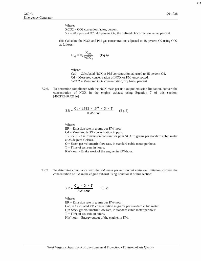
G60-C 26 of 38
Emergency Generator
West Virginia Department of Environmental Protection • Division of Air Quality
Where:
XCO2 = CO2 correction factor, percent.
5.9 = 20.9 percent O2−-15 percent O2, the defined O2 correction value, percent.
(iii) Calculate the NOX and PM gas concentrations adjusted to 15 percent O2 using CO2
as follows:
Where:
Cadj = Calculated NOX or PM concentration adjusted to 15 percent O2.
Cd = Measured concentration of NOX or PM, uncorrected.
%CO2 = Measured CO2 concentration, dry basis, percent.
7.2.6. To determine compliance with the NOX mass per unit output emission limitation, convert the
concentration of NOX in the engine exhaust using Equation 7 of this section:
[40CFR§60.4213e]
Where:
ER = Emission rate in grams per KW-hour.
Cd = Measured NOX concentration in ppm.
1.912x10−-3 = Conversion constant for ppm NOX to grams per standard cubic meter
at 25 degrees Celsius.
Q = Stack gas volumetric flow rate, in standard cubic meter per hour.
T = Time of test run, in hours.
KW-hour = Brake work of the engine, in KW-hour.
7.2.7. To determine compliance with the PM mass per unit output emission limitation, convert the
concentration of PM in the engine exhaust using Equation 8 of this section:
Where:
ER = Emission rate in grams per KW-hour.
Cadj = Calculated PM concentration in grams per standard cubic meter.
Q = Stack gas volumetric flow rate, in standard cubic meter per hour.
T = Time of test run, in hours.
KW-hour = Energy output of the engine, in KW.
211

G60-C 27 of 38
Emergency Generator
West Virginia Department of Environmental Protection • Division of Air Quality
7.3. Recordkeeping and Reporting Requirements
7.3.1. Records, Operation and Compliance
a. For the purpose of determining compliance with the Maximum Yearly Operation Limitation,
a person designated by a Responsible Official or Authorized Representative shall maintain records
of hours of operation utilizing copies of Attachment A - Monthly Hours of Operation Record (or a
similar form containing the same information);
b. For the purpose of determining compliance with the Fuel Type Limitation, a person
designated by a Responsible Official or Authorized Representative shall maintain records of
quantity and type of fuel burned.
c. For the purpose of determining compliance with the Regulated Pollutant Limitation for SO2,
a person designated by a Responsible Official or Authorized Representative shall maintain records
of the maximum sulfur content on a per-shipment basis for fuel oil, recycled or used oil or annual
certification of the sulfur content from the supplier for pipeline quality natural gas.
d. Said records shall be maintained for a period of five (5) years on site or in a readily accessible
off-site location maintained by the registrant. Said records shall be readily available to the
Director of the Division of Air Quality or his/her duly authorized representative for expeditious
inspection and review. Any records submitted to the agency pursuant to a requirement of this
permit or upon request by the Director shall be certified by a responsible official.
7.3.2. Monitoring Information
The registrant shall keep the following records of monitoring information:
a. The date, place as defined in this Class II General Permit and time of sampling measurements;
b. The date(s) analyses were performed;
c. The company or entity that performed the analyses;
d. The analytical techniques or methods used;
e. The results of the analyses; and
f. The operating conditions existing at the time of sampling or measurement.
7.3.3. Equipment Maintenance Records
a. The registrant shall maintain maintenance records relating to failure and/or repair of
emergency generator equipment. In the event of equipment or system failure, these records
shall document the registrant’s effort to maintain proper and effective operation of such
equipment and/or systems;
b. Said records shall be maintained for a period of five (5) years on site or in a readily accessible off-
site location maintained by the registrant. Said records shall be readily available to the Director of
the Division of Air Quality or his/her duly authorized representative for expeditious inspection and
review. Any records submitted to the agency pursuant to a requirement of this permit or upon
request by the Director shall be certified by a responsible official.
7.3.4. Retention of Records
Said records shall be maintained for a period of five (5) years on site or in a readily accessible off-
site location maintained by the registrant. Said records shall be readily available to the Director of
the Division of Air Quality or his/her duly authorized representative for expeditious inspection and
review. Any records submitted to the agency pursuant to a requirement of this permit or upon
request by the Director shall be certified by a responsible official.
7.3.5. Compliance Testing
The owner or operator of any emergency generator shall submit written reports of the results of all
performance tests conducted to demonstrate compliance with the standards set forth in Section
212

G60-C 28 of 38
Emergency Generator
West Virginia Department of Environmental Protection • Division of Air Quality
7.3.6. Certification of Information
Any application form, report, or compliance certification required by this General Permit to be
submitted to the Division of Air Quality and/or USEPA shall contain a certification by the
responsible official that states that, based on information and belief formed after reasonable
inquiry, the statements and information in the document are true, accurate and complete.
7.3.7. If the stationary CI internal combustion engine is an emergency stationary internal combustion
engine, the owner or operator is not required to submit an initial notification. Starting with the
model years in table 5 to this subpart, if the emergency engine does not meet the standards
applicable to non-emergency engines in the applicable model year, the owner or operator must
keep records of the operation of the engine in emergency and non-emergency service that are
recorded through the non-resettable hour meter. The owner must record the time of operation of
the engine and the reason the engine was in operation during that time. [40CFR§60.4214b]
7.3.8. If the stationary CI internal combustion engine is equipped with a diesel particulate filter, the
owner or operator must keep records of any corrective action taken after the backpressure monitor
has notified the owner or operator that the high backpressure limit of the engine is approached.
[40CFR§60.4214c]
213

G60-C 29 of 38
Emergency Generator
West Virginia Department of Environmental Protection • Division of Air Quality
8.0. Source-Specific Requirements (Standards of Performance for Stationary Spark
Ignition Internal Combustion Engines (40CFR60 Subpart JJJJ))
8.1. Limitations and Standards
8.1.1. The provisions of this subpart are applicable to owners, and operators of stationary spark ignition
(SI) internal combustion engines (ICE) as specified below. For the purposes of this subpart, the
date that construction commences is the date the engine is ordered by the owner or operator.
a. Owners and operators of stationary SI ICE that commence construction after June 12, 2006,
where the stationary SI ICE are manufactured:
1. On or after July 1, 2007, for engines with a maximum engine power greater than or equal
to 500 HP (except lean burn engines with a maximum engine power greater than or equal
to 500 HP and less than 1,350 HP);
2. on or after January 1, 2008, for lean burn engines with a maximum engine power greater
than or equal to 500 HP and less than 1,350 HP;
3. on or after July 1, 2008, for engines with a maximum engine power less than 500 HP; or
4. on or after January 1, 2009, for emergency engines with a maximum engine power
greater than 19 KW (25 HP).
b. Owners and operators of stationary SI ICE that commence modification or reconstruction
after June 12, 2006.
[40CFR§60.4230(a)]
8.1.2. The provisions of this subpart are not applicable to stationary SI ICE being tested at an engine test
cell/stand. [40CFR§60.4230(b)]
8.1.3. If you are an owner or operator of an area source subject to this subpart, you are exempt from the
obligation to obtain a permit under 40 CFR part 70 or 40 CFR part 71, provided you are not
required to obtain a permit under 40 CFR 70.3(a) or 40 CFR 71.3(a) for a reason other than your
status as an area source under this subpart. Notwithstanding the previous sentence, you must
continue to comply with the provisions of this subpart as applicable. [40CFR§60.4230(c)]
8.1.4. For the purposes of this subpart, stationary SI ICE using alcohol-based fuels are considered
gasoline engines. [40CFR§60.4230(d)]
8.1.5. Stationary SI ICE may be eligible for exemption from the requirements of this subpart as
described in 40 CFR part 1068, subpart C (or the exemptions described in 40 CFR parts 90 and
1048, for engines that would need to be certified to standards in those parts), except that owners
and operators, as well as manufacturers, may be eligible to request an exemption for national
security. [40CFR§60.4230(e)]
8.1.6. Owners and operators of facilities with internal combustion engines that are acting as temporary
replacement units and that are located at a stationary source for less than 1 year and that have been
properly certified as meeting the standards that would be applicable to such engine under the
appropriate nonroad engine provisions, are not required to meet any other provisions under this
subpart with regard to such engines. [40CFR§60.4230(f)]
214

G60-C 30 of 38
Emergency Generator
West Virginia Department of Environmental Protection • Division of Air Quality
8.2. Emission Standards for Owners and Operators
8.2.1. Owners and operators of stationary SI ICE with a maximum engine power less than or equal to 19
KW (25 HP) manufactured on or after July 1, 2008, must comply with the emission standards in
§60.4231(a) for their stationary SI ICE. [40CFR§60.4233(a)]
8.2.2. Owners and operators of stationary SI ICE with a maximum engine power greater than 19 KW (25
HP) manufactured on or after the applicable date in §60.4230(a)(4) that use gasoline must comply
with the emission standards in §60.4231(b) for their stationary SI ICE. [40CFR§60.4233(b)]
8.2.3. Owners and operators of stationary SI ICE with a maximum engine power greater than 19 KW (25
HP) manufactured on or after the applicable date in §60.4230(a)(4) that are rich burn engines that
use LPG must comply with the emission standards in §60.4231(c) for their stationary SI ICE.
[40CFR§60.4233(c)]
8.2.4. Owners and operators of stationary SI ICE with a maximum engine power greater than 19 KW (25
HP) and less than 75 KW (100 HP) (except gasoline and rich burn engines that use LPG) must
comply with the emission standards for field testing in 40 CFR 1048.101(c) for their non-
emergency stationary SI ICE and with the emission standards in Table 1 to this subpart for their
emergency stationary SI ICE. Owners and operators of stationary SI ICE with a maximum engine
power greater than 19 KW (25 HP) and less than 75 KW (100 HP) manufactured prior to January
1, 2011, that were certified to the standards in Table 1 to this subpart applicable to engines with a
maximum engine power greater than or equal to 100 HP and less than 500 HP, may optionally
choose to meet those standards. [40CFR§60.4233(d)]
8.2.5. Owners and operators of stationary SI ICE with a maximum engine power greater than or equal to
75 KW (100 HP) (except gasoline and rich burn engines that use LPG) must comply with the
emission standards in Table 1 to this subpart for their stationary SI ICE. For owners and operators
of stationary SI ICE with a maximum engine power greater than or equal to 100 HP (except
gasoline and rich burn engines that use LPG) manufactured prior to January 1, 2011 that were
certified to the certification emission standards in 40 CFR part 1048 applicable to engines that are
not severe duty engines, if such stationary SI ICE was certified to a carbon monoxide (CO)
standard above the standard in Table 1 to this subpart, then the owners and operators may meet the
CO certification (not field testing) standard for which the engine was certified.
[40CFR§60.4233(e)]
8.2.6. Owners and operators of any modified or reconstructed stationary SI ICE subject to this subpart
must meet the requirements as specified in paragraphs (f)(1) through (5) of this section.
[40CFR§60.4233(f)]
a. Owners and operators of stationary SI ICE with a maximum engine power less than or equal
to 19 KW (25 HP), that are modified or reconstructed after June 12, 2006, must comply with
the same emission standards as those specified in paragraph (a) of this section.
b. Owners and operators of stationary SI ICE with a maximum engine power greater than 19
KW (25 HP) that use gasoline engines, that are modified or reconstructed after June 12, 2006,
must comply with the same emission standards as those specified in paragraph (b) of this
section.
c. Owners and operators of stationary SI ICE with a maximum engine power greater than 19
KW (25 HP) that are rich burn engines that use LPG, that are modified or reconstructed after
June 12, 2006, must comply with the same emission standards as those specified in paragraph
(c) of this section.
d. Owners and operators of stationary SI natural gas and lean burn LPG engines with a
maximum engine power greater than 19 KW (25 HP), that are modified or reconstructed after
215

G60-C 31 of 38
Emergency Generator
West Virginia Department of Environmental Protection • Division of Air Quality
June 12, 2006, must comply with the same emission standards as those specified in paragraph
(d) or (e) of this section, except that such owners and operators of non-emergency engines and
emergency engines greater than or equal to 130 HP must meet a nitrogen oxides (NOX)
emission standard of 3.0 grams per HP-hour (g/HP-hr), a CO emission standard of 4.0 g/HP-
hr (5.0 g/HP-hr for non-emergency engines less than 100 HP), and a volatile organic
compounds (VOC) emission standard of 1.0 g/HP-hr, or a NOX emission standard of 250
ppmvd at 15 percent oxygen (O2), a CO emission standard 540 ppmvd at 15 percent O2(675
ppmvd at 15 percent O2for non-emergency engines less than 100 HP), and a VOC emission
standard of 86 ppmvd at 15 percent O2, where the date of manufacture of the engine is:
1. Prior to July 1, 2007, for non-emergency engines with a maximum engine power greater
than or equal to 500 HP.
2. Prior to July 1, 2008, for non-emergency engines with a maximum engine power less
than 500 HP.
3. Prior to January 1, 2009, for emergency engines.
e. Owners and operators of stationary SI landfill/digester gas ICE engines with a maximum
engine power greater than 19 KW (25 HP), that are modified or reconstructed after June 12,
2006, must comply with the same emission standards as those specified in paragraph (e) of
this section for stationary landfill/digester gas engines.
[40CFR§60.4233f]
8.2.7. Owners and operators of stationary SI wellhead gas ICE engines may petition the Administrator
for approval on a case-by-case basis to meet emission standards no less stringent than the emission
standards that apply to stationary emergency SI engines greater than 25 HP and less than 130 HP
due to the presence of high sulfur levels in the fuel, as specified in Table 1 to this subpart. The
request must, at a minimum, demonstrate that the fuel has high sulfur levels that prevent the use of
after treatment controls and also that the owner has reasonably made all attempts possible to
obtain an engine that will meet the standards without the use of after treatment controls. The
petition must request the most stringent standards reasonably applicable to the engine using the
fuel. [40CFR§60.4233(g)]
8.2.8. Owners and operators of stationary SI ICE that are required to meet standards that reference 40
CFR 1048.101 must, if testing their engines in use, meet the standards in that section applicable to
field testing, except as indicated in paragraph (e) of this section. [40CFR§60.4233(h)]
8.2.9. Owners and operators of stationary SI ICE must operate and maintain stationary SI ICE that
achieve the emission standards as required in §60.4233 over the entire life of the engine.
[40CFR§60.4234]
8.3. Other Requirements for Owners and Operators
8.3.1. Owners and operators of stationary SI ICE subject to this subpart that use gasoline must use
gasoline that meets the per gallon sulfur limit in 40 CFR 80.195. [40CFR§60.4235]
8.3.2. After July 1, 2010, owners and operators may not install stationary SI ICE with a maximum
engine power of less than 500 HP that do not meet the applicable requirements in §60.4233.
[40CFR§60.4236(a)]
8.3.3. After July 1, 2009, owners and operators may not install stationary SI ICE with a maximum
engine power of greater than or equal to 500 HP that do not meet the applicable requirements in
§60.4233, except that lean burn engines with a maximum engine power greater than or equal to
500 HP and less than 1,350 HP that do not meet the applicable requirements in §60.4233 may not
be installed after January 1, 2010. [40CFR§60.4236(b)]
216

G60-C 32 of 38
Emergency Generator
West Virginia Department of Environmental Protection • Division of Air Quality
8.3.4. For emergency stationary SI ICE with a maximum engine power of greater than 19 KW (25 HP),
owners and operators may not install engines that do not meet the applicable requirements in
§60.4233 after January 1, 2011. [40CFR§60.4236(c)]
8.3.5. In addition to the requirements specified in §§60.4231 and 60.4233, it is prohibited to import
stationary SI ICE less than or equal to 19 KW (25 HP), stationary rich burn LPG SI ICE, and
stationary gasoline SI ICE that do not meet the applicable requirements specified in paragraphs
(a), (b), and (c) of this section, after the date specified in paragraph (a), (b), and (c) of this section.
[40CFR§60.4236(d)]
8.3.6. The requirements of this section do not apply to owners and operators of stationary SI ICE that
have been modified or reconstructed, and they do not apply to engines that were removed from
one existing location and reinstalled at a new location. [40CFR§60.4236(e)]
8.3.7. Starting on July 1, 2010, if the emergency stationary SI internal combustion engine that is greater
than or equal to 500 HP that was built on or after July 1, 2010, does not meet the standards
applicable to non-emergency engines, the owner or operator must install a non-resettable hour
meter. [40CFR§60.4237(a)]
8.3.8. Starting on January 1, 2011, if the emergency stationary SI internal combustion engine that is
greater than or equal to 130 HP and less than 500 HP that was built on or after January 1, 2011,
does not meet the standards applicable to non-emergency engines, the owner or operator must
install a non-resettable hour meter. [40CFR§60.4237(b)]
8.3.9. If you are an owner or operator of an emergency stationary SI internal combustion engine that is
less than 130 HP, was built on or after July 1, 2008, and does not meet the standards applicable to
non-emergency engines, you must install a non-resettable hour meter upon startup of your
emergency engine. [40CFR§60.4237(c)]
8.4. Compliance Requirements for Owners and Operators
8.4.1. If you are an owner or operator of a stationary SI internal combustion engine that is manufactured
after July 1, 2008, and must comply with the emission standards specified in §60.4233(a) through
(c), you must comply by purchasing an engine certified to the emission standards in §60.4231(a)
through (c), as applicable, for the same engine class and maximum engine power. You must also
meet the requirements as specified in 40 CFR part 1068, subparts A through D, as they apply to
you. If you adjust engine settings according to and consistent with the manufacturer's instructions,
your stationary SI internal combustion engine will not be considered out of compliance. In
addition, you must meet one of the requirements specified in (a)(1) and (2) of this section.
a. If you operate and maintain the certified stationary SI internal combustion engine and control
device according to the manufacturer's emission-related written instructions, you must keep
records of conducted maintenance to demonstrate compliance, but no performance testing is
required if you are an owner or operator.
b. If you do not operate and maintain the certified stationary SI internal combustion engine and
control device according to the manufacturer's emission-related written instructions, your
engine will be considered a non-certified engine, and you must demonstrate compliance
according to (a)(2)(i) through (iii) of this section, as appropriate.
1. If you are an owner or operator of a stationary SI internal combustion engine less than
100 HP, you must keep a maintenance plan and records of conducted maintenance to
demonstrate compliance and must, to the extent practicable, maintain and operate the
engine in a manner consistent with good air pollution control practice for minimizing
emissions, but no performance testing is required if you are an owner or operator.
217
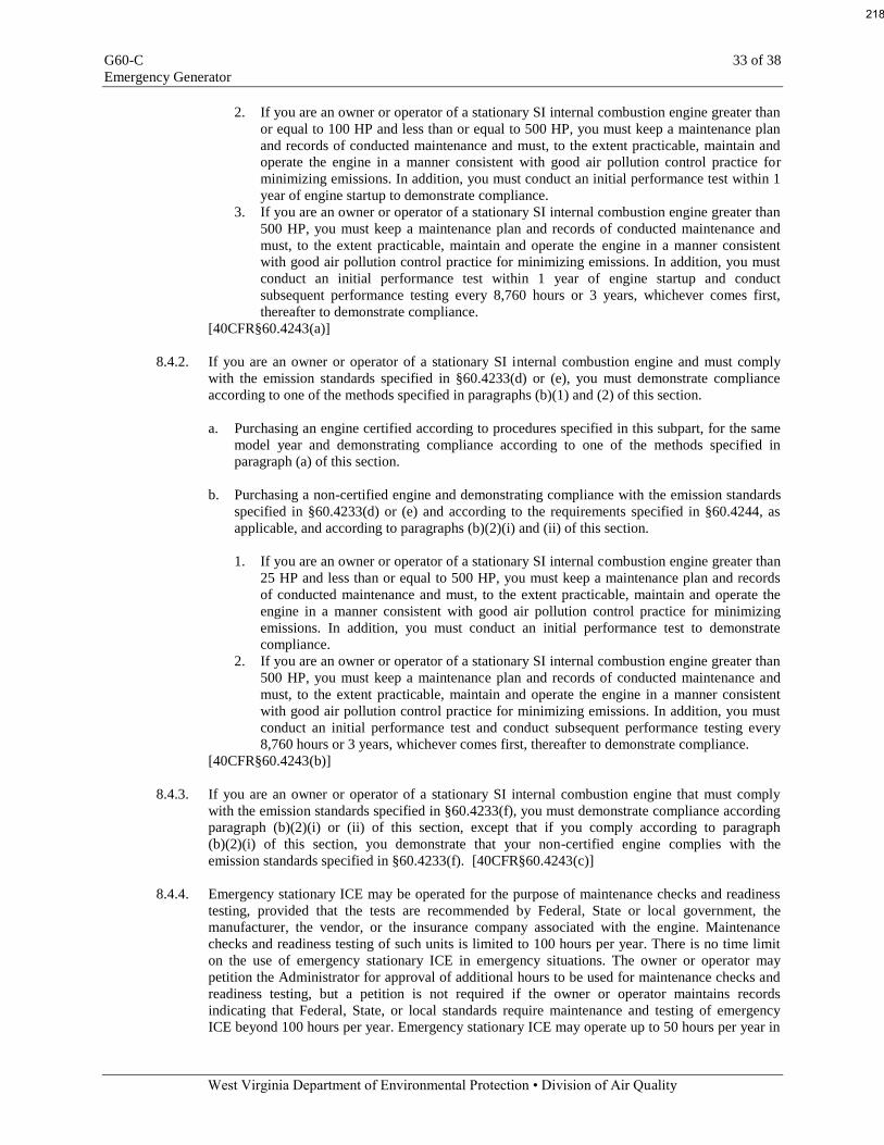
G60-C 33 of 38
Emergency Generator
West Virginia Department of Environmental Protection • Division of Air Quality
2. If you are an owner or operator of a stationary SI internal combustion engine greater than
or equal to 100 HP and less than or equal to 500 HP, you must keep a maintenance plan
and records of conducted maintenance and must, to the extent practicable, maintain and
operate the engine in a manner consistent with good air pollution control practice for
minimizing emissions. In addition, you must conduct an initial performance test within 1
year of engine startup to demonstrate compliance.
3. If you are an owner or operator of a stationary SI internal combustion engine greater than
500 HP, you must keep a maintenance plan and records of conducted maintenance and
must, to the extent practicable, maintain and operate the engine in a manner consistent
with good air pollution control practice for minimizing emissions. In addition, you must
conduct an initial performance test within 1 year of engine startup and conduct
subsequent performance testing every 8,760 hours or 3 years, whichever comes first,
thereafter to demonstrate compliance.
[40CFR§60.4243(a)]
8.4.2. If you are an owner or operator of a stationary SI internal combustion engine and must comply
with the emission standards specified in §60.4233(d) or (e), you must demonstrate compliance
according to one of the methods specified in paragraphs (b)(1) and (2) of this section.
a. Purchasing an engine certified according to procedures specified in this subpart, for the same
model year and demonstrating compliance according to one of the methods specified in
paragraph (a) of this section.
b. Purchasing a non-certified engine and demonstrating compliance with the emission standards
specified in §60.4233(d) or (e) and according to the requirements specified in §60.4244, as
applicable, and according to paragraphs (b)(2)(i) and (ii) of this section.
1. If you are an owner or operator of a stationary SI internal combustion engine greater than
25 HP and less than or equal to 500 HP, you must keep a maintenance plan and records
of conducted maintenance and must, to the extent practicable, maintain and operate the
engine in a manner consistent with good air pollution control practice for minimizing
emissions. In addition, you must conduct an initial performance test to demonstrate
compliance.
2. If you are an owner or operator of a stationary SI internal combustion engine greater than
500 HP, you must keep a maintenance plan and records of conducted maintenance and
must, to the extent practicable, maintain and operate the engine in a manner consistent
with good air pollution control practice for minimizing emissions. In addition, you must
conduct an initial performance test and conduct subsequent performance testing every
8,760 hours or 3 years, whichever comes first, thereafter to demonstrate compliance.
[40CFR§60.4243(b)]
8.4.3. If you are an owner or operator of a stationary SI internal combustion engine that must comply
with the emission standards specified in §60.4233(f), you must demonstrate compliance according
paragraph (b)(2)(i) or (ii) of this section, except that if you comply according to paragraph
(b)(2)(i) of this section, you demonstrate that your non-certified engine complies with the
emission standards specified in §60.4233(f). [40CFR§60.4243(c)]
8.4.4. Emergency stationary ICE may be operated for the purpose of maintenance checks and readiness
testing, provided that the tests are recommended by Federal, State or local government, the
manufacturer, the vendor, or the insurance company associated with the engine. Maintenance
checks and readiness testing of such units is limited to 100 hours per year. There is no time limit
on the use of emergency stationary ICE in emergency situations. The owner or operator may
petition the Administrator for approval of additional hours to be used for maintenance checks and
readiness testing, but a petition is not required if the owner or operator maintains records
indicating that Federal, State, or local standards require maintenance and testing of emergency
ICE beyond 100 hours per year. Emergency stationary ICE may operate up to 50 hours per year in
218

G60-C 34 of 38
Emergency Generator
West Virginia Department of Environmental Protection • Division of Air Quality
non-emergency situations, but those 50 hours are counted towards the 100 hours per year provided
for maintenance and testing. The 50 hours per year for non-emergency situations cannot be used
for peak shaving or to generate income for a facility to supply power to an electric grid or
otherwise supply power as part of a financial arrangement with another entity. For owners and
operators of emergency engines, any operation other than emergency operation, maintenance and
testing, and operation in non-emergency situations for 50 hours per year, as permitted in this
section, is prohibited. [40CFR§60.4243(d)]
8.4.5. Owners and operators of stationary SI natural gas fired engines may operate their engines using
propane for a maximum of 100 hours per year as an alternative fuel solely during emergency
operations, but must keep records of such use. If propane is used for more than 100 hours per year
in an engine that is not certified to the emission standards when using propane, the owners and
operators are required to conduct a performance test to demonstrate compliance with the emission
standards of §60.4233. [40CFR§60.4243(e)]
8.4.6. If you are an owner or operator of a stationary SI internal combustion engine that is less than or
equal to 500 HP and you purchase a non-certified engine or you do not operate and maintain your
certified stationary SI internal combustion engine and control device according to the
manufacturer's written emission-related instructions, you are required to perform initial
performance testing as indicated in this section, but you are not required to conduct subsequent
performance testing unless the stationary engine is rebuilt or undergoes major repair or
maintenance. A rebuilt stationary SI ICE means an engine that has been rebuilt as that term is
defined in 40 CFR 94.11(a). [40CFR§60.4243(f)]
8.4.7. It is expected that air-to-fuel ratio controllers will be used with the operation of three-way
catalysts/non-selective catalytic reduction. The AFR controller must be maintained and operated
appropriately in order to ensure proper operation of the engine and control device to minimize
emissions at all times. [40CFR§60.4243(g)]
8.4.8. If you are an owner/operator of an stationary SI internal combustion engine with maximum engine
power greater than or equal to 500 HP that is manufactured after July 1, 2007 and before July 1,
2008, and must comply with the emission standards specified in sections 60.4233(b) or (c), you
must comply by one of the methods specified in paragraphs (h)(1) through (h)(4) of this section.
a. Purchasing an engine certified according to 40 CFR part 1048. The engine must be installed
and configured according to the manufacturer's specifications.
b. Keeping records of performance test results for each pollutant for a test conducted on a
similar engine. The test must have been conducted using the same methods specified in this
subpart and these methods must have been followed correctly.
c. Keeping records of engine manufacturer data indicating compliance with the standards.
d. Keeping records of control device vendor data indicating compliance with the standards.
[40CFR§60.4243(h)]
8.5. Testing Requirements for Owners and Operators
8.5.1. Owners and operators of stationary SI ICE who conduct performance tests must follow the
procedures in paragraphs (a) through (f) of this section.
a. Each performance test must be conducted within 10 percent of 100 percent peak (or the
highest achievable) load and according to the requirements in §60.8 and under the specific
conditions that are specified by Table 2 to this subpart. [40CFR§60.4244(a)]
219

G60-C 35 of 38
Emergency Generator
West Virginia Department of Environmental Protection • Division of Air Quality
b. You may not conduct performance tests during periods of startup, shutdown, or malfunction,
as specified in §60.8(c). If your stationary SI internal combustion engine is non-operational,
you do not need to startup the engine solely to conduct a performance test; however, you must
conduct the performance test immediately upon startup of the engine. [40CFR§60.4244(b)]
c. You must conduct three separate test runs for each performance test required in this section,
as specified in §60.8(f). Each test run must be conducted within 10 percent of 100 percent
peak (or the highest achievable) load and last at least 1 hour. [40CFR§60.4244(c)]
d. To determine compliance with the NOX mass per unit output emission limitation, convert the
concentration of NOX in the engine exhaust using Equation 1 of this section:
Where:
ER = Emission rate of NOX in g/HP-hr.
Cd= Measured NOX concentration in parts per million by volume (ppmv).
1.912×10−3 = Conversion constant for ppm NOX to grams per standard cubic meter at 20
degrees Celsius.
Q = Stack gas volumetric flow rate, in standard cubic meter per hour, dry basis.
T = Time of test run, in hours.
HP-hr = Brake work of the engine, horsepower-hour (HP-hr).
[40CFR§60.4244(d)]
d. To determine compliance with the CO mass per unit output emission limitation, convert the
concentration of CO in the engine exhaust using Equation 2 of this section:
Where:
ER = Emission rate of CO in g/HP-hr.
Cd= Measured CO concentration in ppmv.
1.164×10−3 = Conversion constant for ppm CO to grams per standard cubic meter at 20
degrees Celsius.
Q = Stack gas volumetric flow rate, in standard cubic meters per hour, dry basis.
T = Time of test run, in hours.
HP-hr = Brake work of the engine, in HP-hr.
[40CFR§60.4244(e)]
220
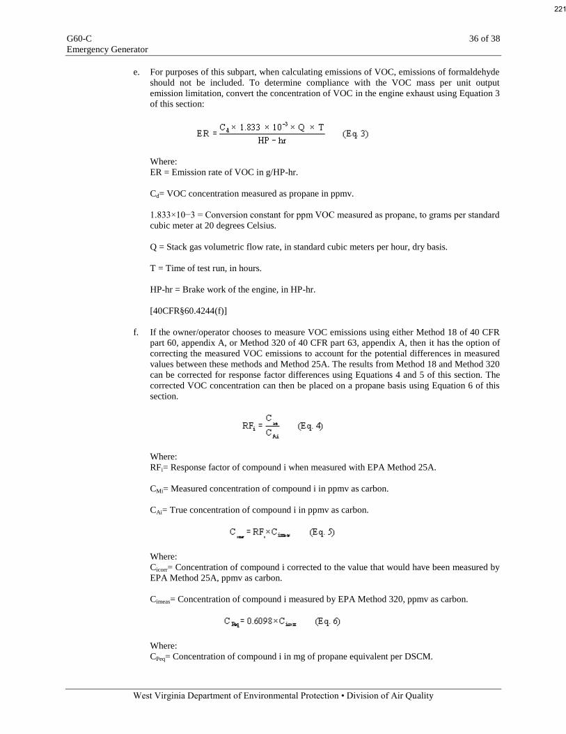
G60-C 36 of 38
Emergency Generator
West Virginia Department of Environmental Protection • Division of Air Quality
e. For purposes of this subpart, when calculating emissions of VOC, emissions of formaldehyde
should not be included. To determine compliance with the VOC mass per unit output
emission limitation, convert the concentration of VOC in the engine exhaust using Equation 3
of this section:
Where:
ER = Emission rate of VOC in g/HP-hr.
Cd= VOC concentration measured as propane in ppmv.
1.833×10−3 = Conversion constant for ppm VOC measured as propane, to grams per standard
cubic meter at 20 degrees Celsius.
Q = Stack gas volumetric flow rate, in standard cubic meters per hour, dry basis.
T = Time of test run, in hours.
HP-hr = Brake work of the engine, in HP-hr.
[40CFR§60.4244(f)]
f. If the owner/operator chooses to measure VOC emissions using either Method 18 of 40 CFR
part 60, appendix A, or Method 320 of 40 CFR part 63, appendix A, then it has the option of
correcting the measured VOC emissions to account for the potential differences in measured
values between these methods and Method 25A. The results from Method 18 and Method 320
can be corrected for response factor differences using Equations 4 and 5 of this section. The
corrected VOC concentration can then be placed on a propane basis using Equation 6 of this
section.
Where:
RFi= Response factor of compound i when measured with EPA Method 25A.
CMi= Measured concentration of compound i in ppmv as carbon.
CAi= True concentration of compound i in ppmv as carbon.
Where:
Cicorr= Concentration of compound i corrected to the value that would have been measured by
EPA Method 25A, ppmv as carbon.
Cimeas= Concentration of compound i measured by EPA Method 320, ppmv as carbon.
Where:
CPeq= Concentration of compound i in mg of propane equivalent per DSCM.
221

G60-C 37 of 38
Emergency Generator
West Virginia Department of Environmental Protection • Division of Air Quality
[40CFR§60.4244(g)]
8.6. Notification, Reports, and Records for Owners and Operators
8.6.1. Owners or operators of stationary SI ICE must meet the following notification, reporting and
recordkeeping requirements.
a. Owners and operators of all stationary SI ICE must keep records of the information in
paragraphs (a)(1) through (4) of this section.
1. All notifications submitted to comply with this subpart and all documentation supporting
any notification.
2. Maintenance conducted on the engine.
3. If the stationary SI internal combustion engine is a certified engine, documentation from
the manufacturer that the engine is certified to meet the emission standards and
information as required in 40 CFR parts 90 and 1048.
4. If the stationary SI internal combustion engine is not a certified engine or is a certified
engine operating in a non-certified manner and subject to §60.4243(a)(2), documentation
that the engine meets the emission standards.
[40CFR§60.4245(a)]
b. For all stationary SI emergency ICE greater than or equal to 500 HP manufactured on or after
July 1, 2010, that do not meet the standards applicable to non-emergency engines, the owner
or operator of must keep records of the hours of operation of the engine that is recorded
through the non-resettable hour meter. For all stationary SI emergency ICE greater than or
equal to 130 HP and less than 500 HP manufactured on or after July 1, 2011 that do not meet
the standards applicable to non-emergency engines, the owner or operator of must keep
records of the hours of operation of the engine that is recorded through the non-resettable hour
meter. For all stationary SI emergency ICE greater than 25 HP and less than 130 HP
manufactured on or after July 1, 2008, that do not meet the standards applicable to non-
emergency engines, the owner or operator of must keep records of the hours of operation of
the engine that is recorded through the non-resettable hour meter. The owner or operator must
document how many hours are spent for emergency operation, including what classified the
operation as emergency and how many hours are spent for non-emergency operation.
[40CFR§60.4245(b)]
c. Owners and operators of stationary SI ICE greater than or equal to 500 HP that have not been
certified by an engine manufacturer to meet the emission standards in §60.4231 must submit
an initial notification as required in §60.7(a)(1). The notification must include the information
in paragraphs (c)(1) through (5) of this section.
1. Name and address of the owner or operator;
2. The address of the affected source;
3. Engine information including make, model, engine family, serial number, model year,
maximum engine power, and engine displacement;
4. Emission control equipment; and
5. Fuel used.
[40CFR§60.4245(c)]
d. Owners and operators of stationary SI ICE that are subject to performance testing must submit
a copy of each performance test as conducted in §60.4244 within 60 days after the test has
been completed. [40CFR§60.4245(d)]
222

G60-C 38 of 38
Emergency Generator
West Virginia Department of Environmental Protection • Division of Air Quality
CERTIFICATION OF DATA ACCURACY
I, the undersigned, hereby certify that, based on information and belief formed after reasonable
inquiry, all information contained in the attached ____________________________________, representing the
period beginning _________________________ and ending _________________________, and any supporting
documents appended hereto, is true, accurate, and complete.
Signature1
(please use blue ink) Responsible Official or Authorized Representative Date
Name & Title (please print or type) Name Title
Telephone No. Fax No.
1 This form shall be signed by a “Responsible Official.” “Responsible Official” means one of the following:
a. For a corporation: The president, secretary, treasurer, or vice-president of the corporation in charge of a
principal business function, or any other person who performs similar policy or decision-making functions
for the corporation, or a duly authorized representative of such person if the representative is responsible
for the overall operation of one or more manufacturing, production, or operating facilities applying for or
subject to a permit and either:
(i) the facilities employ more than 250 persons or have a gross annual sales or expenditures exceeding $25
million (in second quarter 1980 dollars), or
(ii) the delegation of authority to such representative is approved in advance by the Director;
b. For a partnership or sole proprietorship: a general partner or the proprietor, respectively;
c. For a municipality, State, Federal, or other public entity: either a principal executive officer or ranking
elected official. For the purposes of this part, a principal executive officer of a Federal agency includes the
chief executive officer having responsibility for the overall operations of a principal geographic unit of the
agency (e.g., a Regional Administrator of U.S. EPA); or
d. The designated representative delegated with such authority and approved in advance by the Director.
223

Mitchell Plant Title V Renewal
R30-05100005-2014 Renewal
2019
Attachment K
45 CSR 2/10 Monitoring Plan
224

November 17, 2004 Page 1 of 11 Rev. 4.0
45 CSR 2 and 45 CSR 10 Monitoring and Recordkeeping Plan Mitchell Plant Facility Information: Facility Name: Mitchell Plant Facility Address: P.O. Box K
State Route 2 Moundsville, WV 26041 Facility Environmental Contact: Mr. G. M. (Matt) Palmer –Plant Environmental Coordinator A. Facility Description:
Mitchell Plant is a coal-fired electric generating facility with two main combustion units (Units 1 and 2) discharging through a common stack shell that utilizes two separate stack discharge flues. Mitchell plant also has an auxiliary boiler (Aux. 1) that discharges through an independent auxiliary stack (aux 1). Unit 1, Unit 2, and Aux. Boiler 1 each have a design heat input greater than 10 mmBTU/hr making both 45 CSR 2A (Interpretive Rule for 45 CSR 2) and 45 CSR 10A (Interpretive Rule for 45 CSR 10) applicable to these sources.
I. 45 CSR 2 Monitoring Plan: In accordance with Section 8.2.a of 45 CSR 2, following is the proposed plan for monitoring compliance with opacity limits found in Section 3 of that rule: A. Main Stack (CS012)
1. Applicable Standard:
45 CSR 2, §3.1. No person shall cause, suffer, allow or permit emission of smoke and/or particulate matter into the open air from any fuel burning unit which is greater than ten (10) percent opacity based on a six minute block average.
2. Monitoring Method(s):
45 CSR 2, §3.2 …Continuous opacity monitors shall not be required on fuel burning units which employ wet scrubbing systems for emissions control.
225

November 17, 2004 Page 2 of 11 Rev. 4.0
45 CSR 2, §8.2.a.1. Direct measurement with a certified continuous opacity monitoring system (COMS) shall be deemed to satisfy the requirements for a monitoring plan. Such COMS shall be installed, calibrated, operated and maintained as specified in 40 CFR Part 60, Appendix B, Performance Specification 1 (PS1). COMS meeting the requirements of 40 CFR Part 75 (Acid Rain) will be deemed to have satisfied the requirements of PS1.
a. Primary Monitoring Method: While a Continuous Opacity Monitoring
System (COMS) would not be required on a wet scrubbed fuel burning unit, Mitchell Plant has chosen to employ COMS on each of the fuel burning units upstream of the wet scrubbers and located in plant ductwork. As such, the primary method of monitoring opacity at Mitchell Plant will be Continuous Opacity Monitors (COMS). The COMS are installed, maintained and operated in compliance with requirements of 40 CFR Part 75.
b. Other Credible Monitoring Method(s): While Mitchell Plant will use
COMS as the primary method of monitoring opacity of the fuel burning units, we are also reserving the right to use other appropriate method that would produce credible data. These “other monitoring methods” will generally be used in the absence of COMS data or as other credible evidence used in conjunction with COMS data.
3. Recordkeeping:
a. Operating Schedule and Quality/Quantity of Fuel Burned
45 CSR 2A §7.1.a. The owner or operator of a fuel burning unit(s) shall maintain records of the operating schedule, and the quality and quantity of fuel burned in each fuel burning unit as specified in paragraphs 7.1.a.1 through 7.1.a.6, as applicable.
The applicable paragraphs for Mitchell Plant are the following:
§7.1.a.2: For fuel burning unit(s) which burn only distillate oil, such records shall include, but not be limited to, the date and time of start-up and shutdown, the quantity of fuel consumed on a monthly basis and a BTU analysis for each shipment. §7.1.a.4: For fuel burning unit(s) which burn only coal, such records shall include, but not be limited to, the date and time of start-up and shutdown, the quantity of fuel consumed on a daily basis and an ash and BTU analysis for each shipment.
226

November 17, 2004 Page 3 of 11 Rev. 4.0
§7.1.a.6: For fuel burning unit(s) which burn a combination of fuels, the owner or operator shall comply with the applicable Recordkeeping requirements of paragraph 7.1.a.1 through 7.1.a.5 for each fuel burned.
The date and time of each startup and shutdown of Units 1 and 2 will be maintained. The quantity of coal burned on a daily basis as well as the ash and Btu content will also be maintained. From a fuel oil perspective, the quantity of fuel oil burned on a monthly basis, as well as the Btu content will be maintained. The fuel oil analysis will generally be one that is provided by the supplier for a given shipment but in some cases, we may use independent sampling and analyses. The quantity of fuel oil burned on a monthly basis may be maintained on a facility wide basis.
b. Record Maintenance
45 CSR 2A §7.1.b. Records of all required monitoring data and support information shall be maintained on-site for a period of at least five (5) years from the date of monitoring, sampling, measurement or reporting. Support information includes all calibration and maintenance records and all strip chart recordings for continuous monitoring instrumentation, and copies of all required reports.
Records of all required monitoring data and support information will be maintained on-site for at least five (5) years. Support information includes all calibration and maintenance records and all strip chart recordings for continuous monitoring instrumentation, and copies of all required reports.
4. Exception Reporting:
a. Particulate Mass Emissions: 45 CSR 2A, §7.2.a. With respect to excursions associated with measured emissions under Section 4 of 45CSR2, compliance with the reporting and testing requirements under the Appendix to 45CSR2 shall fulfill the requirement for a periodic exception report under subdivision 8.3.b. or 45CSR2.
Mitchell Plant will comply with the reporting and testing requirements specified under the Appendix to 45 CSR 2.
b. Opacity:
45 CSR 2A, §7.2.b. COMS – In accordance with the provisions of this subdivision, each owner or operator employing COMS as the method of monitoring compliance with opacity limits shall submit a “COMS Summary Report” and/or an “Excursion and COMS Monitoring System Performance Report” to the Director on a quarterly basis; the Director may, on a case-by-case basis, require more frequent reporting if the Director deems it necessary to accurately assess the compliance status of the
227

November 17, 2004 Page 4 of 11 Rev. 4.0
fuel burning unit(s). All reports shall be postmarked by the thirtieth (30th) day following the end of each calendar quarter. The COMS Summary Report shall contain the information and be in the format shown in Appendix B unless otherwise specified by the Director.
45 CSR 2A, §7.2.b.1. If the total duration of excursions for the reporting period is less than one percent (1%) of the total operating time for the reporting period and monitoring system downtime for the reporting period is less than five percent (5%) of the total operating time for the reporting period, the COMS Summary Report shall be submitted to the Director; the Excursion and COMS Monitoring System Performance report shall be maintained on-site and shall be submitted to the Director upon request.
45 CSR 2A, §7.2.b.2. If the total duration of excursions for the reporting period is one percent (1%) or greater of the total operating time for the reporting period or the total monitoring system downtime for the reporting period is five percent (5%) or greater of the total operating time for the reporting period, the COMS Summary Report and the Excursion and COMS Monitoring System Performance Report shall both be submitted to the Director.
45 CSR 2A, §7.2.b.3. The Excursion and COMS Monitoring System Performance Report shall be in a format approved by the Director and shall include, but not be limited to, the following information:
45 CSR 2A, §7.2.b.3.A. The magnitude of each excursion, and the date and time, including starting and ending times, of each excursion.
45 CSR 2A, §7.2.b.3.B. Specific identification of each excursion that occurs during start-ups, shutdowns, and malfunctions of the facility. 45 CSR 2A, §7.2.b.3.C. The nature and cause of any excursion (if known), and the corrective action taken and preventative measures adopted (if any). 45 CSR 2A, §7.2.b.3.D. The date and time identifying each period
during which quality- controlled monitoring data was unavailable, except for zero and span checks, and the reason for data unavailability and the nature of the repairs or adjustments to the monitoring system. 45 CSR 2A, §7.2.b.3.E. When no excursions have occurred or there were no periods of quality-controlled data unavailability, and no monitoring systems were inoperative, repaired, or adjusted, such information shall be stated in the report.
228

November 17, 2004 Page 5 of 11 Rev. 4.0
Attached, as Appendices A and B are sample copies of a typical COMS “Summary Report” and “Excess opacity and COM downtime report” that we plan on using to fulfill the opacity reporting requirements. The COMS “Summary Report” will satisfy the conditions under 45 CSR 2A, §7.2.b for the “COMS Summary Report” and will be submitted to the Director according to its requirements. The “Excess opacity and COM downtime report” satisfies the conditions under 45 CSR 2A, §7.2.b.3. for the “Excursion and COMS Monitoring System Performance Report”. The “Excess opacity and COM downtime report” shall be submitted to the Director following the conditions outlined in 45 CSR 2A, §7.2.b.1. and §7.2.b.2. To the extent that an excursion is due to a malfunction, the reporting requirements in section 9 of 45CSR2 shall be followed – 45 CSR 2A, §7.2.d.
B. Aux. Stack (aux 1)
1. Applicable Standard:
45 CSR 2, §3.1. No person shall cause, suffer, allow or permit emission of smoke and/or particulate matter into the open air from any fuel burning unit which is greater than ten (10) percent opacity based on a six minute block average.
2. Monitoring Method:
45 CSR 2, §8.2.a.1. Direct measurement with a certified continuous opacity monitoring system (COMS) shall be deemed to satisfy the requirements for a monitoring plan. Such COMS shall be installed, calibrated, operated and maintained as specified in 40 CFR Part 60, Appendix B, Performance Specification 1 (PS1). COMS meeting the requirements of 40 CFR Part 75 (Acid Rain) will be deemed to have satisfied the requirements of PS1.
45 CSR 2, §8.4.a. The owner or operator of a fuel burning unit(s) may petition for alternatives to testing, monitoring, and reporting requirements prescribed pursuant to this rule for conditions, including, but not limited to, the following: 45 CSR 2, §8.4.a.1. Infrequent use of a fuel burning unit(s) Pursuant to 45 CSR 2, Section 8.4.a and 8.4.a.1, Mitchell Plant previously petitioned the Office of Air Quality (OAQ) Chief for alternative testing, monitoring, and reporting requirements for the auxiliary boiler and associated stack. Based on limited operating hours, the requirement for COMS installation per Section 6.2.a of interpretive rule 45 CSR 2A was determined to be overly-burdensome and sufficient reason for the granting of alternative monitoring methods. The alternative monitoring method based on USEPA Method 9 visible emission readings is described below.
229

November 17, 2004 Page 6 of 11 Rev. 4.0
Primary Monitoring Method: As an alternative to COMS monitoring, a Method 9 reading will be conducted one time per month provided the following conditions are met: 1) The auxiliary boiler has operated at normal, stable load conditions for at least 24 consecutive hours and 2) weather/lighting conditions are conducive to taking proper Method 9 readings. Since the Mitchell auxiliary boiler does not utilize post-combustion particulate emissions controls, operating parameters of control equipment are nonexistent and therefore unable to be monitored.
3. Recordkeeping:
a. Operating Schedule and Quality/Quantity of Fuel Burned
45 CSR 2A §7.1.a. The owner or operator of a fuel burning unit(s) shall maintain records of the operating schedule, and the quality and quantity of fuel burned in each fuel burning unit as specified in paragraphs 7.1.a.1 through 7.1.a.6, as applicable.
The applicable paragraph for the Mitchell Plant auxiliary boilers follows:
§7.1.a.2: For fuel burning unit(s) which burn only distillate oil, such records shall include, but not be limited to, the date and time of start-up and shutdown, the quantity of fuel consumed on a monthly basis and a BTU analysis for each shipment.
As such, the date and time of each startup and shutdown of the auxiliary boiler will be maintained. The quantity of fuel oil burned on a monthly basis, as well as the Btu content will be maintained. The fuel oil analysis will generally be one that is provided by the supplier for a given shipment but in some cases, we may use independent sampling and analyses. The quantity of fuel oil burned on a monthly basis may be maintained on a facility wide basis.
b. Record Maintenance
45 CSR 2A §7.1.b. Records of all required monitoring data and support information shall be maintained on-site for a period of at least five (5) years from the date of monitoring, sampling, measurement or reporting. Support information includes all calibration and maintenance records and all strip chart recordings for continuous monitoring instrumentation, and copies of all required reports. Records of all required monitoring data and support information will be maintained on-site for at least five (5) years. In the case of the auxiliary boilers, strip chart recordings, etc. are generally not available.
4. Exception Reporting:
230

November 17, 2004 Page 7 of 11 Rev. 4.0
Pursuant to 45 CSR 2, Section 8.4.a and 8.4.a.1, Mitchell Plant previously petitioned the Office of Air Quality (OAQ) Chief for alternative testing, monitoring, and reporting requirements for the auxiliary boiler and associated stack. a. Particulate Mass Emissions – As an alternative to the testing and exception
reporting requirements for particulate mass emissions from the auxiliary boiler, the following was previously proposed and approved. Based on an average heat content of approximately 139,877 Btu/gallon (calendar year 2000 data) and an AP-42 based particulate mass emissions emission factor of 2 lbs/thousand gallons, the calculated particulate mass emissions of the auxiliary boiler are 0.01 lb/mmBTU. As such, the fuel analysis records maintained under the fuel quality analysis and recordkeeping section of this plan provide sufficient evidence of compliance with the particulate mass emission limit. For the purpose of meeting exception reporting requirements, any fuel oil analysis indicating a heat content of less than 25,000 Btu per gallon will be reported to the OAQ to fulfill the requirement for a periodic exception report under subdivision 8.3.b. or 45 CSR 2 – 45 CSR 2A, §7.2.a. A heat content of 25,000 Btu/gal and a particulate emissions factor of 2 lbs/thousand gallons would result in a calculated particulate mass emissions of approximately 90% of the applicable 45 CSR 2 standard.
b. Opacity – As an alternative to the exception reporting requirements for opacity
emissions from the auxiliary boiler, the following was previously proposed and approved. We will maintain a copy of each properly conducted (correct weather/lighting conditions, etc.) Method 9 evaluation performed. Any properly conducted Method 9 test which indicates an exceedance shall be submitted to the OAQ on a quarterly basis (within 30 days of the end of the quarter) along with an accompanying description of the excursion cause, any corrective action taken, and the beginning and ending times for the excursion.
To the extent that an excursion is due to a malfunction, the reporting requirements in section 9 of 45CSR2 shall be followed – 45 CSR 2A, §7.2.d.
If no exceptions have occurred during the quarter, then a report will be submitted to the OAQ stating so. This will identify periods in which no method 9 tests were conducted (e.g. unit out of service) or when no fuel oil was received.
II. 45 CSR 10 Monitoring Plan: In accordance with Section 8.2.c of 45 CSR 10, following is the proposed plan for monitoring compliance with the sulfur dioxide weight emission standards expressed in Section 3 of that rule: A. Main Stack (CS012)
231

November 17, 2004 Page 8 of 11 Rev. 4.0
1. Applicable Standard:
45 CSR 10, §3.1.b. For fuel burning units of the Mitchell Plant of Ohio Power Company, located in Air Quality Control Region I, the product of 7.5 and the total actual operating heat inputs for such units discharging through those stacks in million BTU’s per hour.
45 CSR 10, §3.8. Compliance with the allowable sulfur dioxide emission limitations from fuel burning units shall be based on continuous twenty-four (24) hour averaging time…A continuous twenty-four (24) hour period is defined as one (1) calendar day. A new SO2 limit will likely be established as a result of the installation of the flue gas desulfurization system/new stack configuration and the subsequent NAAQS compliance demonstration modeling. Assuming that revised SO2 limit is more stringent than the current limit expressed in 45 CSR 10, Mitchell Plant SO2 emissions will be regulated by the more stringent of the two limits.
2. Monitoring Method:
45 CSR 10, §8.2.c.1. The installation, operation and maintenance of a continuous monitoring system meeting the requirements 40 CFR Part 60, Appendix B, Performance Specification 2 (PS2) or Performance Specification 7 (PS7) shall be deemed to fulfill the requirements of a monitoring plan for a fuel burning unit(s), manufacturing process source(s) or combustion source(s). CEMS meeting the requirements of 40 CFR Part 75 (Acid Rain) will be deemed to have satisfied the requirements of PS2.
a. Primary Monitoring Method: The primary method of monitoring SO2 mass
emissions from the two new stack flues (located within one stack shell) will be Continuous Emissions Monitors (CEMS). Data used in evaluating the performance of the Mitchell Units with the applicable standard will be unbiased, unsubstituted data as specified in definition 45 CSR 10A, §6.1.b.1. Data capture of more than 50% constitutes sufficient data for the daily mass emissions to be considered valid. The CEMS are installed, maintained and operated in compliance with requirements of 40 CFR Part 75. Because Units 1 and 2 will discharge through separate flues and both units are “Type a” fuel burning units as defined in 45 CSR 10, the plant-wide limit is calculated by summing the limits from the two flues.
b. Other Credible Monitoring Method(s): While Mitchell Plant will use CEMS
as the primary method of monitoring SO2 mass emissions from the two flues, we are also reserving the right to use other appropriate methods that would produce credible data. These “other monitoring methods” will generally be used in the absence of CEMS data or as other credible evidence used in conjunction with CEMS data.
232

November 17, 2004 Page 9 of 11 Rev. 4.0
3. Recordkeeping:
a. Operating Schedule and Quality/Quantity of Fuel Burned:
45 CSR 10A, §7.1.a. Fuel burning units - The owner or operator of a fuel burning unit(s) shall maintain records of the operating schedule and the quality or quantity of fuel burned in each unit…
45 CSR 10A, §7.1.c. The owner or operator of a fuel burning unit or combustion source which utilizes CEMS shall be exempt from the provisions of subdivision 7.1.a. or 7.1.b, respectively. As such, Mitchell plant will not maintain records of the operating schedule and the quality and quantity of fuel burned in each unit for purposes of meeting the requirements for a monitoring plan under 45 CSR 10. While fuel sampling and analysis may continue to be performed at this facility, it is done so at the discretion of the owner/operator and is not required by this monitoring plan for the purposes of indicating compliance with SO2 standards.
b. Record Maintenance
45 CSR 10A, §7.1.d. For fuel burning units, manufacturing process sources, and combustion sources, records of all required monitoring data as established in an approved monitoring plan and support information shall be maintained on-site for a period of at least five (5) years from the date of monitoring, sampling, measurement or reporting. Support information includes all calibration and maintenance records and all strip chart recordings for continuous monitoring instrumentation, and copies of all required reports. As such, CEMS records at Mitchell Plant will be maintained for at least five years.
4. Exception Reporting:
45 CSR 10A, §7.2.a. CEMS - Each owner or operator employing CEMS for an approved monitoring plan, shall submit a “CEMS Summary Report” and/or a “CEMS Excursion and Monitoring System Performance Report” to the Director quarterly; the Director may, on a case-by-case basis, require more frequent reporting if the Director deems it necessary to accurately assess the compliance status of the source. All reports shall be postmarked no later than forty-five (45) days following the end of each calendar quarter. The CEMS Summary Report shall contain the information and be in the format shown in Appendix A unless otherwise specified by the Director.
233

November 17, 2004 Page 10 of 11 Rev. 4.0
45 CSR 10A, §7.2.a.1. Submittal of 40 CFR Part 75 data in electronic data (EDR) format to the Director shall be deemed to satisfy the requirements of subdivision 7.2.a. As such, Mitchell Plant will submit the 40 CFR 75 quarterly electronic data reports (EDRs) to the OAQ to meet the requirements for a CEMS Summary Report and the CEMS Excursion and Monitoring System Performance Report. The EDR reports will be submitted to the OAQ no later than 45 days following the end of the quarter. When no excursions of the 24-hour SO2 standard have occurred, such information shall be stated in the cover letter of the EDR submittal.
B. Aux. Stack (aux 1)
1. Applicable Standard:
45 CSR 10, §3.1.e. For type ‘b’ and Type ‘c’ fuel burning units, the product of 3.1 and the total design heat inputs for such units discharging through those stacks in million BTU’s per hour.
45 CSR 10, §3.8. Compliance with the allowable sulfur dioxide emission limitations from fuel burning units shall be based on continuous twenty-four (24) hour averaging time…A continuous twenty-four (24) hour period is defined as one (1) calendar day.
2. Monitoring, Recordkeeping, Exception Reporting Requirements:
45 CSR 10, §10.3. The owner or operator of a fuel burning unit(s) which combusts natural gas, wood or distillate oil, alone or in combination, shall be exempt from the requirements of section 8.
As such, the Mitchell Plant auxiliary boiler (auxiliary stack) is exempt from Testing, Monitoring, Recordkeeping, and Reporting requirements found in 45 CSR 10, Section 8 because the fuel burning source combusts only distillate oil. 45 CSR 10, Section 8 also contains the requirement for the development of a monitoring plan. The simple nature of burning distillate oil results in an SO2 emission rate well below the standard.
While fuel sampling and analysis may continue to be performed at this facility, it is done so at the discretion of the owner/operator and is not required by this monitoring plan for the purposes of indicating compliance with SO2 standards.
Revisions of Monitoring Plan: Mitchell Plant reserves the right to periodically revise the conditions of this monitoring plan. Any revised plan will become effective only after approval by the OAQ.
234

November 17, 2004 Page 11 of 11 Rev. 4.0
Implementation of Revised Monitoring Plan: Implementation of this revised monitoring plan will occur in concurrence with the installation and operation of the new stack for Units 1 and 2 at Mitchell Plant.
235

Mitchell Plant Title V Renewal
R30-05100005-2014 Renewal
2019
Attachment L
Suggested Title V Permit Language
236

Suggested Language - Title V Operating Permit R30-05100005 Page 1 Kentucky Power Co. • Mitchell Plant
West Virginia Department of Environmental Protection Division of Air Quality
Kentucky Power Suggests that the following changes be made to the Title V Permit Equipment Table to reflect recent additions, not impacting Title V permit language.
Emission Point ID1
Control Device1
Emission Unit ID1
Emission Unit Description Design Capacity Year Installed/ Modified
Fugitive Enclosure Rock Salt Storage Pile (roadway ice control) 600 Tons 2010 and 2014
Tank #53 N/A Tank #53 Landfill Building Furnace Fuel Oil Tank 2000 Gal. 2018
Tank #54 N/A Tank #54 Landfill Gasoline Tank 520 Gal. 2018
Tank #55 N/A Tank #55 Kerosene Tank 1,000 Gal. 2015
Tank #56 N/A Tank #56 CPS Coagulant Tank 5,000 Gal. 2019
Tank #57 N/A Tank #57 Unit 1 Scale Inhibitor Tank 3,500 Gal. 2015
Tank #58 N/A Tank #58 Unit 2 Scale Inhibitor Tank 3,500 Gal. 2015
Tank #59 N/A Tank #59 Unit 1 Dispersant Tank 5,000 Gal. 2015
Tank #60 N/A Tank #60 Unit 2 Dispersant Tank 5,000 Gal. 2015
Tank #61 N/A Tank #61 Unit 1 Ferric Chloride Tank 1,500 Gal. 2015
Tank #62 N/A Tank #62 Unit 1 Ferric Chloride Tank 2,500 Gal. 2015
Tank #63 N/A Tank #63 FGD corrosion inhibitor tank 5,000 Gal. 2015
Kentucky Power suggests the following administrative revisions to the Title V permit that will improve the functionality of the permit for plant and WVDEP staff. 4.0 Main Boilers [Em. Unit IDs Unit 1 and Unit 2 – Em. Pt. IDs 1E and 2E]; Auxiliary Boiler [Em. Unit ID Aux 1 – Em. Pt. ID Aux ML1]
Sections 4.0 through 4.6 : With the increasing complexity and significant increase in the number of permit conditions applicable to the Main Boilers and Auxiliary Boiler, these sections have become increasingly more difficult to navigate. The reader is constantly jumping from main boiler requirements to aux boiler requirements and then back again. Previously, the John E. Amos Plant Title V Permit (R30-07900006-2016), was revised to separate the main boiler requirements from the auxiliary boiler requirements. The John E. Amos is very similar to the Mitchell Plant permit and could serve as a template for the administrative improvement. Essentially, the change would involve separating 4.0 through 4.6 into two sections (e.g. 4.0 through 4.6 and 5.0 through 5.6)
237

Suggested Language - Title V Operating Permit R30-05100005 Page 2 Kentucky Power Co. • Mitchell Plant
West Virginia Department of Environmental Protection Division of Air Quality
7.0 Liquid Propane Vapor Engine Driven Emergency Generator and Black Start Emergency Generators [emission point ID(s): LPG, EG-1, EG-2]
Sections 7.0 through 7.6: These sections currently contain a summary of requirements found in General Air Permit G60-C057A. The summary is primarily incorporating the applicable requirements by reference from the General Permit. This method of incorporating requirements into the Title V permit makes it difficult for the permittee and WVDEP enforcement staff to easily determine applicable requirements. The General Permit is written to cover a number of different emergency generator configurations and therefore contains a lot of requirements not applicable to the specific Mitchell Plant equipment. Kentucky Power is suggesting that instead of incorporating by reference, that the actual applicable requirements in the General Permit be listed in sections 7.0 through 7.6 of the Mitchell Title V permit. Previously, the John E. Amos Plant Title V Permit (R30-07900006-2016), was revised to implement an equivalent improvement. The John E. Amos Plant equipment is very similar to the Mitchell Plant equipment. Accordingly, the John E. Amos Title V Permit Section 7.0 through 7.6 could serve as a template for the administrative improvement.
238