the football development model better players, better - NFHS
Upload
khangminh22Category
view
1download
0
October 24 - 25, 2019 Bucharest, Romania
ADVANCED TEXTILES FOR A BETTER WORLD
th edition
ISSN 2068-9101, Vol. 9

THE NATIONAL RESEARCH & DEVELOPMENT INSTITUTE FOR TEXTILES AND LEATHER
Description of the National Library of Romania
TEXTEH 9 INTERNATIONAL CONFERENCE PROCEEDINGS
Coordinator: Emilia Visileanu
Cover and design: Florin Prisecaru
DOIs Crossref indexed
Under evaluation for indexing : Scopus, PRO Quest and Chemical Abstracts
Phone: +040213404200 Fax: +040213405515 e-mail: [email protected]
Copyright 2019 - MINISTRY OF RESEARCH AND INNOVATION

9
th9 TEXTEH INTERNATIONAL CONFERENCE PROCEEDINGSBUCHAREST, ROMANIA OCTOBER 24 - 25, 2019,
TEXTEH 9 INTERNATIONAL CONFERENCE PROCEEDINGS
24 - 25, OCTOBER , 2019

ORGANIZING COMMITTEE
PhD. eng. Carmen Ghituleasa - General Manager INCDTP, RO
PhD. eng. Alina Popescu - Scientific Director INCDTP, RO
PhD. eng. Bojan Dolšak - Dean of Faculty of Mechanical Engineering, University of Maribor,
Slovenia
PhD. Gordana Pavlovic - Dean of the University Zagreb, Faculty of Textile Technology, Zagreb,
Croatia
PhD. Slah Msahli - LGTex, Tunisia
Prof. Jaouadi Mounir - LGTex, Tunisia
Prof. Luis Almeida - University of Minho, Portugal
PhD. Maria Manuela Maia Neves - TecMinho, Portugal
PhD Assist. Prof. Ivana Schwarz - University Zagreb, Faculty of Textile Technology, Zagreb, Croatia MLS Davor Jokic - University Zagreb,Faculty of Textile Technology, Zagreb, Croatia
PhD. eng. Emilia Visileanu - Onorific Editor - Industria Textila magazine, RO
Eng. Loreta Nedelcu - Manager ITA TEXCONF, INCDTP, RO
PhD. eng. Razvan Radulescu - INCDTP, RO
Eng. Razvan Scarlat - INCDTP, RO
Eng. Salistean Adrian - INCDTP, RO
Site Administrator Constantin Dragomir - INCDTP, RO
Graphic Designer Florin Prisecaru - INCDTP, RO
PROGRAMME COMMITTEE
PhD. eng. Carmen Ghituleasa - INCDTP, România
PhD. eng. Alina Popescu - INCDTP, România
PhD. eng. Emilia Visileanu - INCDTP, România
PhD. eng. Alexandra Ene - INCDTP, România
PhD. eng. Carmen Mihai - INCDTP, România
Prof. PhD. Zoran Stjepanovič - University of Maribor, Slovenia
Prof. Aminodin Haji - Yazd University, Yazd, Iran
Eng. Ana Dias - TecMinho, Portugal
Prof. Ana Marija Grancarič - University of Zagreb, Croatia
Prof. Auxiliar António Dinis Marques - University of Minho, Portugal
Prof. Liliana Indrie, Oradea University, România
Prof. Mirela Blaga - Gh.Asachi University, Iasi, România
Prof. Magda Florescu - ASE, România
Prof. Umit Halis Erdogan - Dokuz Eylul University, Izmir, Turkey
Prof. Zűmrűt Bahadir Űnal - Edge University, Izmir, Turkey
Prof. Gizem Karakan Gűnaydin - Pamukkale University, Turkey
Prof. Ghulame Rubbaniy - Zayed University, Abu Dhabi, United Arab Emirates
Prof. Muhammmad Mohsib, University of Engineering and Technology, Pakistan
Prof. Neji Ladbari - LGTex, Tunisia

Unl'Uets1ty of Manbor
Ill
• ,/:. 'J
'-;::,,Yazd niversity
•
Organizer
INCDTP The National R&D Institute for Textiles and INCDTP Leather -Bucharest, Romania
University ofMaribor, Faculty of Mechanical Engineering, Institute of Engineering Materials and Design- Maribor, Slovenia
University of Mon astir, Textile Engineering Laboratory (LGTex), Tunisia
University ofMinho -TecMinho, Portugal
University of Zagreb, Faculty of Textile Technology, Croatia
Yazd University, The Textile Engineering Department, Iran
ITA-Texconf Business Incubator
Ministry of Research and Innovation, Romania
TecMinho
University of Zagreb
Yazd University
Maribor
LGTex
ITA-Texconf
MCI
With the support of:
CO-Organizers

TABLE OF CONTENT
KEYNOTE SESSION
Knitted materials capacity for vibration protection applications .................................................... 6 Mirela Blaga, Neculai-Eugen Seghedin
Supporting digitalization of garment engineering through virtual prototyping ........................... 10 Andreja Rudolf, Andrej Cupar, Zoran Stjepanovič
Development of ready-made clothing products with rosemary oil to use in aromatherapy .......... 15 Sinem Yaprak Karavana, Gökhan Erkan, Gizem Ceylan Türkoğlu Ayşe Merih Sariişik, Burçin Eser, Ali Toprak, Alina Popescu
Interactive electrotextiles - on the way to the textiles of the future .............................................. 20 Ozan Kayacan
PLENARY SESSIONS
Improved mobile bed biofilm reactors to treat cellulosic wastewaters .......................................... 24 Ioana Corina Moga,Ovidiu Iordache, Gabriel Petrescu, Elena Cornelia Mitran, Irina Mariana Sandulache, Bogdan Iulian Doroftei, Lucia Oana Secareanu, Elena Perdum, Georgiana Alexandra Pantazi
Guide for smart practices to support innovation in smart textiles ................................................ 28 Ana Dias, Luís Almeida, Mirela Blaga, Razvan Radulescu , Benny Malengier, Zoran Stjepanovic , Petra Dufkova
The electromagnetic shielding behavior of layered knitted fabric structures .............................. 32 Özlem Kayacan, Neza Bakir, Barkın Traş
Decorating further: Applying cosmetic finishes to the haute couture .......................................... 36 Anika Sitara, Mudassar Abbas, Faiza Anwar
Production and characterization of melt spun poly (ԑ-caprolactone) fibers having different cross sections ................................................................................................................................... 42 Figen Selli, Ümit Halis Erdoğan
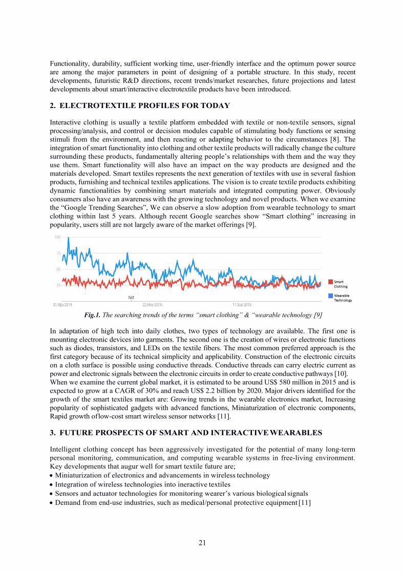
Investigation of the usage of ozone in denim finishing processes ................................................ 47 Ömer Faruk Al, Emre SAM, Merih Sariişik, Gülşah Ekin Kartal

Investigation of friction coefficient of drapery fabrics treated with different ratio of flame retardant .......................................................................................................................................... 52 Gizem Karakan Günaydin Mine Akgün, Ayça Gürarda, Erhan Kenan Çeven
Design of textile UV-SHIELDS by vat dyes modification ............................................................59 Viktoriia Vlasenko, Svitlana Arabuli
Fabrics for Buildtech electromagnetic shields based on plasma magnetron sputtering ........... 63 Lilioara Surdu, Alina Ardeleanu, Emilia Visileanu, Ion Răzvan Rădulescu, Mihai Badic, Cristian Morari, Bogdana Mitu
An investigation on surface resistivity of polypropylene fabrics modified with ionic liquids .... 68 Yasemin Seki, Aylin Altinisik Tagac
Effect of atmospheric pressure DBD plasma on capiliary of cotton-polyester blend fabric ..… 73 Hong Khanh-Thi VU, Ha Thanh NGO
Nanocoating of polyester fabric with graphen oxide .................................................................... 78 Beyza Doğan, Şule Sultan Uğur, Banu Türkaslan
A modified twist-spinning technology: three-roving yarn spinning ............................................. 82 Murat Demir, Musa Kilic
Ecofriendly and sustainable denim finishing techniques ............................................................ 86 Faiza Anwar
Optimizing curing parameters in flame retardant treatment for cotton fabric ......................... 91 Huong Nguyen Thi, Khanh Vu Thi Hong
Innovative UV barrier materials made of organic cotton dyed with natural dyestuffs ............ 96 Jadwiga Sójka- Ledakowicz, Anetta Walawska, Bogumił Gajdzicki, Joanna Olczyk, Joanna Lewartowska – Łukasiewicz
The effect of fiber cross-sectional shape and texturing temperature on knitted fabric air permeability ................................................................................................................................. 100 Halil İbrahim Çelik, Hatice Kübra Kaynak, Esin Sarioğlu, Gizem Karakan Günaydin
Utilizing smart textiles in interior design to replace conventional architectural finishes ...... 105 Amna Khalid Qureshi

Enhancing colour fastness properties of denim fabrics by using nanofilm deposition method ....……………………………………………………………………………………………… 110
Şule Sultan Uğur, Merih Sariişik, Münevver Ertek, Dilek Şarapnal
Treatment of textile wastewater using microbes’ inoculated free-floating aquatic plants based wetlands ............................................................................................................................. 114 Muhammad Qamar Tusief, Mumtaz Hasan Malik, Muhammad Mohsin, Hafiz Naeem Asghar
The tearing strength analysis of denim fabrics with different weft yarn type and weft layout .....……………………………………………………………………………………………… 125 Münevver Ertek Avci, Esin Sarioğlu, Gizem Karakan Günaydin
Effects of artificial ageing on textiles' properties ..................................................................... 132 Elena-Cornelia Mitran, Irina-Mariana Sandulache, Lucia-Oana Secareanu, Ovidiu Iordache, Elena Perdum, Maria Memecica
Effects of intermingling pressure level on properties of polyester knitted fabrics .................. 136 Gonca Balici Kiliç
A new test method to measure the compressibility of spacer fabrics ........................................ 140 Musa Kilic, Gonca Balci Kilic, Murat Demir, Gulsah Celik,Izzet Onal Bugduz, Can Bulut
Skill needs and gaps in qualifications frameworks in the Romanian clothing industry ......... 144 Alexandra Cardoso, Sabina Olaru, Pyerina Carmen Ghituleasa, Mihaela Dascalu, Sabina Socol
Graphene/graphene oxide based coatings for advanced textile applications.......................... 148 Nida Naeem, Mudassar Abbas, Mumtaz Hasan Malik
SEM investigations on old maps with canvas support .............................................................. 153 Dorina Camelia Ilies, Liliana Indrie, Adriana Baidog, Alexandru Ilies, Jan Wendt, Chakrabarty Premangshu, Choudhuri Tathagata, Florin Marcu, Anamaria Axinte
Conducting polymer coated smart textiles.................................................................................. 158 Metin Ak
Study on e-commerce in the clothing industry in Romania ...................................................... 162 Simona Bălășescu, Nicoleta Andreea Neacșu, Carmen Elena Anton, Marius Bălășescu

POSTER SESSION
Surface modification of biomaterial fabric modified by supercritical N2 jet ............................ 166 Foued Khoffi, Yosri Khalsi, Abdel Tazibt, Slah Msahli, Frédéric Heim
Electromagnetic shielding out of plasma coated woven fabrics ................................................. 170 Lilioara Surdu, Ion Razvan Radulescu, Bogdana Mitu
Smart textiles to promote multidisciplinary STEM training ........................................................ 174 Ion Razvan Radulescu, Carmen Ghituleasa, Emilia Visileanu, Lilioara Surdu, Razvan Scarlat, Ana Dias, Lieva Van Langenhove, Zoran Stjepanovic, Mirela Blaga, Petra Dufkova
Antistatic treatment of textile fibers for air tubes in grizutos coal explosive environment ......……………………………………………………………………………………………..… 178 Ioan I. Gâf-Deac, Emilia Visileanu, Constantin Sorin Păun, Cristina Monica Valeca, Ileta Târliman
Nanofiber meshes for abdominal hernia repair – challenges and opportunities ...................... 183 Gratiela Gradisteanu Pircalabioru, Bianca Tihauan, Madalina Axinie, Ana Ivanof, Stelian Sergiu Maier, Carmen Mihai, Alina Vladu
Influence on the UPF level of the content and type of nanoceramics used in the textile treatment ........................................................................................................................................ 187 Emilia Visileanu, Alexandra Ene, Alina Popescu, Razvan Scarlat, Silvia Albici, Dana Stefanescu, Iulian Mancasi, Irina Mariana Sandulache
Obtaining textile with structures and functionalities modeled and referenced classified in the nonmarkov neural networks .............................................................................................. 191 Ioan I. Gâf-Deac, Emilia Visileanu, Diana Loreta Păun, Cristina Monica Valeca, Viorel Streza
Research on designing composite techniques for obtaining the 3d hybrid composites with conductive and semiconductive properties for sensors and actuators ...................................... 196 Raluca Maria Aileni, Laura Chiriac
Fabric based wearable sensor structures .................................................................................... 200 Aytül Timoçin, Özlem Kayacan
DSC analysis of novel polyethilene biofilm carriers................................................................... 204 Ovidiu Iordache, Irina Sandulache, Ioana Corina Moga, Cornelia Mitran, Lucia Secareanu, Elena Perdum, Gabriel Petrescu

Composed techniques for obtaining of the 3d hybrid composites for attenuation of electromagnetic field ................................................................................................................... 208 Raluca Maria Aileni, Laura Chiriac
Preliminary characterization of a contemporary textile art piece ............................................ 212 Elena-Cornelia Mitran, Irina-Mariana Sandulache, Lucia-Oana Secareanu, Ovidiu Iordache, Elena Perdum, Maria Memecica
PVA-gelatin hydrogels containing rosemary essential oil for wound dressings ..................... 216 Denisa-Maria Radulescu, Diana-Elena Radulescu, Gabriela-Cristina Constantinescu, Laura Chirila, Alina Popescu
Fabric for single skin textile wing .............................................................................................. 220 Adrian Salistean, Carmen Mihai, Irina Cristian, Daniela Farima, Cristina Piroi
Using stem principles for understanding smart textiles’ solutions – the slovenian experience ................224 Zoran Stjepanovič, Andrej Cupar, Razvan Radulescu, Andreja Rudolf
WORKSHOP SESSION
Space operational scale of the textile-clothing sector based on creativity, innovation and future ........................................................................................................................................... 228 Eftalea Carpus, Angela Dorogan

6
KNITTED MATERIALS CAPACITY FOR VIBRATION PROTECTION APPLICATIONS
DOI: 10.35530/TT.2019.01
Mirela BLAGA1 and Neculai-Eugen SEGHEDIN2
“Gheorghe Asachi” Technical University of Iasi, Romania, 1Faculty of Industrial Design and Business Management, Blvd. Dimitrie Mangeron, nr.53, E-Mail: [email protected]
2 Faculty of Machine Manufacturing and Industrial Management, Iasi, Romania Blvd. Dimitrie Mangeron, nr. 55, E-Mail:[email protected]
Corresponding author: Mirela Blaga, E-mail: [email protected]
Abstract: The present work is a synthesis of the author’s previous research on weft and warp knitted fabrics response under dynamic stress and their capacity of vibration damping. The main objective of this research is to experimentally investigate the vibration behaviour of these fabrics with an existing testing method, in order to understand how the fabric structural parameters affect their vibration isolation performance. The authors have focused their interest on the knitted fabrics characterization through their natural frequencies, which were determined by employing the free vibrations method. The natural frequency is the rate at which an object vibrates when it is not disturbed by an outside force. A comparative fabrics analysis of the measured natural frequencies is performed and the main parameters of influence are discussed. An ideal knitted spacer fabric developed for anti-vibration purposes, should have the capacity of absorb energy efficiently, still having sufficient stiffness to avoid its collapse and an acceptable thickness in order to maintain a sense of touch and dexterity to complete the tasks. The preliminary results confirmed that knitted fabrics can be engineered and exploited as structures with vibration absorption capabilities.
Key words: Knitted fabrics, parameters, vibrations, natural frequencies.
1. INTRODUCTIONHuman body is frequently exposed to vibration from power tools and industrial machines and fromvehicles like trains and automobiles. This type of energy may come from hand power tools, industrialmachines, riding in trains, planes, auto vehicles, and it is dissipated in the form of vibrations, some ofwhich may affect people. Vibration can cause discomfort, reduction of performance, inducement ofactivity interference and even health and safety risks [1]. Human vibration involves the whole-bodyvibration (WBV) within frequencies 1–100 Hz when a person stands or sits on a shaking surface, andthe hand-transmitted vibration (HTV) between frequencies 8–1000 Hz when holding a vibrating tool[2]. The effects of whole-body vibration include back pain, sciatica, digestive disorders, genitourinaryproblems and hearing damage. Long-term exposure to hand-transmitted vibration has a risk ofdeveloping hand-arm vibration syndrome (HAVS), a well-known example of which is vibration whitefinger (VWF). At present, preventive efforts have been made by using anti-vibration seat cushions [3]for WBV and gloves for HTV made of damping materials like polymeric foams, rubbers, gels and airbladders to reduce the vibration exposure. However, these materials suffer from insurmountablecomfort and recycling problems. Therefore, developing breathable and recyclable materials with goodvibration isolation performance is highly desirable. Gloves with anti-vibration characteristics havebeen developed in response to the growing demand for workers protection against the impactvibrations transmitted to the hands during operation [4]. The degree of vibration reduction provided bygloves generally depends on the thickness and softness of the lining (resilient gel, foam or rubber-likematerial, or an array of air bladders), but also from the person in work. On average, anti-vibrationgloves must provide considerable protection against relatively high vibration frequencies (200 Hz andabove), and might not, on average, increase vibration levels at lower frequencies. To protect againstlower vibration frequencies the contact areas of the glove need to contain thicker resilient material,

7
fact that might affect the handling [5]. The use of weft knitted spacer fabrics as part of the gloves has been tested, as an alternative to the existing materials. It has been concluded that the placement of the spacer fabric in the glove palm contributes to the attenuation of a significant amount of vibration at high frequency range [6]. There are also some investigations on the dynamic vibration transmission property, which consists of key vibration indexes, including the natural frequency, vibration transmission coefficient and damping ratio, as well as, on the relations between structure of the spacer fabric and vibration transmission indices [7]. This paper intends to make an experimental analysis of the knitted fabrics response under dynamic stress and their capacity of vibration damping. The authors characterized the knitted fabrics through their natural frequencies, which were determined by using the free vibrations method, typically used in mechanical engineered field.
2. MATERIALS AND METHOD2.1 MaterialsOn weft fabrics, the investigations were carried out with knitted fabrics from various raw materials: cotton, polyester, acrylic, and polypropylene yarns. The selected knitted samples are double layers and were manufactured on electronic flat knitting machines, CMS 530 E6.2, Stoll. Another group is consisting of spacer fabrics, produced on same technology (E5, E6.2 and E8), from PES/EL for outer layers and PES of different diameters as connnecting yarns. The warp fabrics were a range of spacer fabrics produced on double flat needle beds machines, DK 506 DPLM and RACOP D4-5, from Liba, with 4-6 guide bars, threaded in various ratios, in order to create open or closed surfaces on one or both faces. The fabrics are made from PA, PES yarns and monofilaments as spacer yarns, and they can be used for sports shoes, bags, protective vests, gloves, helmets, cushions, mattresses [8-10].2.2 MethodThe natural frequency is the rate at which an object vibrates when it is not disturbed by an outside force [1]. Dynamic performance of the knitted fabrics are analyzed by testing the behavior of one metallic piece, fixed on the fabric sample, through an adhesive. In order to excite the system, an impact Piezotronics hammer has been used and the natural frequencies were measured with an accelerometer PCB B52 (Figure 1). The signal is processed with one data acquisition card 6023 National Instruments. The frequencies [Hz] are determined in three directions: coursewise, walewise, and perpendicular on the fabric surface. The frequency at the highest peak represents the natural frequency of the fabric.
a. Walewise b. Coursewise c. PerpendicularFig. 1. Direction of measuring the natural frequencies
The shape of the curve reveals the capacity of the system to damp the vibrations, the smoother is the shape, the highest is the fabric damping capacity, i.e. the damping capacity of the fabric in course or wale direction (Figures 2a & b) is lower than in perpendicular direction (Figure 2c). This can be explained by considering the cross section of the structure and the higher number of the friction points between the yarns inside the fabric, in case of perpendicular testing.

8
dBVrms dBVrms dBVrms
b. Coursewise c. Perpendicular
Fig. 2. Natural frequencies of the knitted fabric on various directions
3. RESULTS AND DISCUSSIONSThe results obtained in case of weft fabrics indicate a clear influence on the natural frequencies values,the interlock structure displayed in figure 3 confirm this hypothesis. In general Cotton and PANfabrics expose a comparable response to the vibration testing. PES and PP can be as well comparedfrom this point of view, for all structures, but poses higher values of the fabric’s natural frequenciescompared to the previous ones. The differences of 20-30Hz between the two groups sustain theassumption of the significant influence of raw material type. Observations can be made about stitchdensity influence, with stich cam value (NP) increasing, the fabric becomes looser and the values ofthe frequency are decreasing, due to the knitted fabric rigidity decreasing.
Fig. 3. Natural frequencies of the interlock fabrics
In case of spacer weft knits, it was found that the spacer yarn diameter has a relevant influence on the fabric behaviour. By analysing the samples S4-S7, one can notice that a higher diameter difference of 0.02 mm for S4, determines a higher fabric square mass, with consequences in higher fabric rigidity, and higher values of frequencies, compared to S7 fabric, as can be observed in the graph from figure 4 [8].
Fig. 4. Natural frequencies of the weft spacer fabrics
For the group of spacer warp knitted fabrics, produced on double flat needle beds warp knitting machines, DK 506 DPLM and RACOP D4-5, from Liba, with 4-6 guide bars, threaded in various
Hz Hz Hz
CO PES PNA PP
NP 12.0 NP 13.0 NP 14.0
60
40
20
0
Interlock
S5 S6 S7 S4
Samples
S1 S2 S3
row
wale
perp
10090 80 70 60 50 40 30 20 10
0
Hz
freq
uenc
y [H
z]
a. walewise
9
ratios, it was discovered that spacer yarns threading and the number of connecting guide bars significantly influence the results. As well, the adjustable yarn run-in parameter [mm/rack] has a clear impact on the natural frequency of the fabrics, structures with lower yarn run-in [mm/rack] indicate lower values of natural frequencies and consequently lower fabric rigidity [9]. In other study, the measurements showed that on perpendicular testing direction, the fabric’s thickness is influencing the level of natural frequencies, the thinner fabrics have higher values of the frequencies and are consequently higher rigidity [10]. Other researches confirmed that increasing the fabric thickness can result in a decrease of the resonance frequency due to reduction of stiffness, and thus improve the vibration isolation performance of spacer fabrics [11].
4. CONCLUSIONS
Knitted spacer fabrics are widely used as cushion mattresses under the dynamic condition, wherein the vibration transmission property is one of the main mechanical properties of spacer fabrics. An ideal knitted fabric developed for anti-vibration purposes, should have the capacity of absorbing energy efficiently, doubled by sufficient stiffness to avoid its collapse. As well, it must possess an acceptable thickness in order to maintain a sense of touch and dexterity to complete the tasks. The vibration frequencies of one system which contains knitted fabrics designed for protection purposes, must be different from the knitted fabrics natural frequencies, otherwise the phenomenon of resonance occurs. This research can be helpful to improve the design process of the knitted fabrics with reasonable vibration transmission properties in various applications. It is expected that this study could contribute to the understanding of the vibration behavior of knitted spacer fabrics and provide some useful information to promote their applications in anti-vibration.The lack of literature on the vibration attenuating capability of the commercial products makes the research in this topic relevant and actual.
REFERENCES
[1] Mansfield, N. (2005), Human response to vibration, Taylor&Francis e-Library. [2] Lewis CH, Griffin MJ. (2002), Evaluating the vibration isolation of soft seat cushions using an active anthropodynamic dummy. J Sound Vib, pp. 253:295–311. [3] Reynolds D.D., Angevine E.N. (1977): Hand-arm vibration, Part II: Vibration transmission characteristics of the hand and arm. Journal of Sound and Vibration, 51(2): 255-265. [4] Liu, Y., and Hu, H., (2013), Vibration Isolation Performance of Warp-knitted Spacer Fabrics, available from http://www.academia.edu, accessed at 10.05.2018. [5] Kokas Palicska, L., Augusztinovicz, F.,Szemeredy, A., L. Szucs, J. (2019). Development and test of new kinds of anti-vibration knitted hand protection, 19th World Textile Conference, Autex 2019, 11-15 June 2019, Ghent, Belgium. [6] Sum, N.W., Development of anti-vibration glove with weft knitted spacer fabrics (2013), BA thesis, Institute of Textiles&Clothing, The Hong Kong Polytechnic University, coordinator Dr. Hong Hu. [7] Chaoyu Chen, et.al. (2018), Study of the vibration transmission property of warp-knitted spacer fabrics under forced sinusoidal excitation vibration, Textile Research Journal, Vol. 88(8), pp. 922–931 [8] Mirela Blaga and Neculai-Eugen Seghedin (2017), Knitted Spacer Fabrics Behaviour at Vibrations, Journal of Fashion Technology & Textile Engineering,, Volume 3, Issue 2, http://medcraveonline.com/JTEFT/volume_issues?issueId=1730&volumeId=495. [9] Mirela Blaga, Neculai-Eugen Seghedin and Ana Ramona Ciobanu (2014), Knitted fabrics response to vibrations, XIIIth International Izmir Textile and Apparel Symposium, Izmir, Turkey. [10] Blaga M., Seghedin N.-E., Ciobanu A.- R. (2013), Warp knitted fabrics behaviour under dynamic testing, Industria textilă, 64, 6, pp. 334 – 341, ISSN 1222–5347, 301–368, available at http://www.revistaindustriatextila.ro/images/2013/6_2013.pdf [11] Fuxing Chen, Yanping Liu and Hong Hu (2016), An experimental study on vibration isolation performance of weft-knitted spacer fabrics, Textile Research Journal, Vol. 86(20), pp. 2225–2235.

10
SUPPORTING DIGITALIZATION IN GARMENT ENGINEERING THROUGH VIRTUAL PROTOTYPING
DOI: 10.35530/TT.2019.02
Andreja RUDOLF1, Andrej CUPAR2, Zoran STJEPANOVIČ1 1 University of Maribor, Faculty of Mechanical Engineering, Institute of Engineering Materials and Design, Maribor,
Slovenia, E-Mail: [email protected]; [email protected]
2 University of Maribor, Faculty of Mechanical Engineering, Mechanical Engineering Research Institute, Maribor, Slovenia, E-Mail: [email protected]
Corresponding author: Zoran Stjepanovič, E-mail: [email protected]
Abstract: This contribution deals with the new trends related to the digitalization in garment engineering. More than ten years ago can be found complaints of clothing companies on the lack of effective CAD software to design garments directly in 3D and to provide pattern designer tools for shape modelling and simulation of cloth behavior. Today, with a mass customization, e-commerce, advances in virtual reality applications, the virtual garment development is strongly desired in order to optimize apparel industry’s design and development processes. To survive in global competitive market, garment manufacturers are forced to transform their manufacturing processes toward, having a more flexible production system to meet the rapid changes in the global market, and started the transition to a new technological level through digitalization advances and challenges of Industry 4.0. Described are the possibilities for exploiting advances in digitization in garment engineering through virtual prototyping and production of smart clothing.
Key words: Garments, Digitalization, Digital technologies, Virtual prototyping, Smart Clothing
1. INTRODUCTION
In general, digitalization is the use of digital technologies to change a business model and provide new revenue and value-producing opportunities; it is the process of moving to a digital business [1]. The survey, done by McKinsey [2], showed, that the apparel-sourcing executives look at the digitalization as a “major enabler of the transformation the industry needs if it is to improve its disappointing returns and please increasingly choosy consumers”. The impact of digitalization on garment engineering and production of clothing items is expected to reduce the average lead time by two to eight weeks, helping the companies to achieve the agility needed in a demand- driven market. Furthermore, the cost reduction of at least 2.5 percent is expected through digitization alone [2]. According to the survey, the pioneering companies are already providing a glimpse of this future. The companies that have implemented 3-D design and virtual sampling report shortening the sampling process by two weeks or more, and they often see reductions of 50 percent in the number of samples needed and the cost involved [2]. Taking into account the potential/possibilities/challenges of the fourth industrial revolution (Industry 4.0), the garment manufacturing companies will have to face with the major transformation, which will be greatly supported by the effective digitalization. Virtual prototyping (VP) of clothing products can be stated as one of the vital parts of digitalization of the whole process. The purpose of 3D virtual prototyping is to build a virtual model instead of developing a real product [3]. The advantage of VP is that it enables the designers to make alterations to their design but at far less time and cost. The fashion industry has been attracted to use VP for the

11
product development process, and garments’ presentation/online purchase. In the process of garment development, it involves application of CAD systems intended for development of the garment pattern designs and assessment of their fit to the 3D body model [4].
2. HOW DIGITALIZATION INFLUENCES THE GARMENT INDUSTRY?
Garment design is an integration of all the design elements, including color, texture, space, lines, pattern silhouette, shape, proportion, balance, emphasis or focal point, rhythm and harmony, and each of these contributes towards the visual perception and psychological comfort of the garment [5]. Design, development and production of clothing products have largely relied on the same, often manual, methods despite all the technological advances in the world outside of fashion and garments. More than ten years ago, academic research posited about clothing companies complaints’ on the lack of effective CAD software to design garments directly in 3D and to provide pattern designer tools for shape modelling and simulation of cloth behavior when compared with existing 3D virtual software solutions for other industries. Today, with the growth of demand from better educated consumers, mass customization, e-commerce, advances in virtual reality applications, the virtual garment development is strongly desired in order to optimize apparel industry’s design and development processes [6]. The garment industry is one the main sectors of the industrialization movement for developing countries. With the removal of exportation quotas applied to China in 2005, the textile and clothing sector has started having difficulties with competing in global markets, especially against Chinese firms [7]. To survive in global competitive market, garment manufacturers need to transform their manufacturing processes toward, having a more flexible production system to meet the rapid changes in the global market, deliver orders to customers as early as possible to meet increased customer expectations, by using the human workforce more efficiently to achieve high productivity levels and utilizing all resources effectively, stated Gökalp et al [7]. In the paper, written by Luu and Marques [8], the authors state that garment and footwear industries are considered “low-tech” industries, but already started the transition to a new technological level. In addition, they are present in the article digitization and industry 4.0 in the Portuguese textile & garment sector. In the context of the latter, in recent years, many researchers deepen into Industry 4.0 and how to place digital innovations in the textile and clothing sector in the context of the 4th Industrial Revolution. After three important industrial revolutions, which have had following important influence on textile & clothing sector: (a) First Industrial Revolution was a mechanical revolution – steam engine in England in 1712 – weaving loom in 1785), (b) Second Industrial Revolution was an electrical revolution – electricity began to be used in 1870 – sewing machine began to be produced in a serial manner and (c) Third Industrial Revolution, also called a Digital Revolution, the world is now in the Fourth Industrial Revolution, also called Industry 4.0, that integrates emerging IT concepts, including Cyber-Physical Systems (CPS), Internet of Things (IoT) and big data [7]. Today, with rapidly globalizing business world the information technology (IT) industry is continuously coming up with new technologies. Therefore, it is important to invest in these emerging technologies for businesses to attain competitive advantage and improve their operational efficiency by generating valuable insights to enhance the decision-making process, develop new business models, and drive new revenue streams [7]. A potential of Industry 4.0, which can change completely manufacturing processes and business models in textile and clothing sector is the subject of research of many researchers. Gökalp et al [7] suggested the conceptual smart apparel factory, called Apparel 4.0, with following proposed innovative approaches for production: (a) digital information transfer, (b) predictive maintenance (variety of data analytics and statistical techniques to uncover hidden patterns and capture relationships among devices; cyber-physical systems equipped with sensors, actuators, processors and intelligent electronic systems with internet connectivity), (c) human-robot technology collaboration in cutting department, (d) intelligent manufacturing (RFDI tags), (e) robotic quality control and (f) packaging with cyber physical systems. Within the digital information transfer, researchers highlight, in addition to the 2D or 3D garment pattern design, sending markers of the

12
product to the cutting room via a wireless network and protecting industrial devices against cyber- security threats, the role of digital prototyping in the process of garment development [6-10]. The digital prototypes are used as an essential tool in the modern design process, because their integration can speed up the design process and influence competition between companies [6]. It should be noted that even technology solutions such as the 3D virtual prototyping has been around for some time, the garment engineering uptake them slow or not at all in comparison to other industries, such as, e.g. automotive. On the other hand, research works show how useful are the technological solutions of 3D garment pattern design and 3D virtual prototyping in the process of developing customized clothing for people with different figures, postures, physical deformities, disabled or elderly people who do not fit the usual clothes. Therefore, there is an opportunity for production of value-added products and individualized clothing, respectively, for people with non-standard body figure (elderly), disabilities and people with different kind of health problems who needs adapted clothing. From business and digitalization perspective, today there is also a great research interest in the field of smart clothing, which continuously growing with advance of the internet and technological developments [11].
3. OPPORTUNITIES TO CUSTOMIZE CLOTHING PRODUCTS VIA DIGITALIZATON
3.1 Virtual Prototyping (VP) The purpose of 3D virtual prototyping is to build a virtual model instead of developing a real product. Virtual prototypes can be presented to the client for evaluation and confirmation. The final model/product can then be quickly and easily modified and produced. In recent years, a strong development of computer technology enabled substantial changes in the way of development of new garments and a shift from the conventional to virtual prototyping. Numerous studies highlighted the benefits of 3D human body scanning and its digital data complexity for clothing development [12-14] by using the virtual prototyping also for wheelchair users, people with spine deformity, etc. [14-17], Fig. 1. Namely, today's trends increasingly follow the offer of products according to the individual's needs. This can be strongly seen in the automotive industry or offer of customized aids for the disabled or people with certain medical conditions, etc. Therefore, the development of customized clothing through virtual prototyping can represent a new future in clothing engineering.
Fig. 1. Virtual prototyping of different types of garments
3.2 Smart Clothing (SC) Oliver Behr wrote in the article [11] ‘Our refrigerator can order milk from a food supplier and when we leave our workplace, the smart home heating system starts to prepare a pleasant temperature in our apartment. What sounded like science fiction a few years ago has already been realized technically today.’ Indeed, the latter enabled digital transformation, which has an increasing impact also on the clothing industry and some changes in garment engineering by developing new technologies for producing SC with digital features and intelligent devices, respectively, that are usually connected to the internet and autonomously collect, evaluate and send data to react to certain situations. According to the European Commission, the “Internet of Things (IoT) represents the next

13
step towards the digitization of our society and economy, where objects and people are interconnected through communication networks and report about their status and/or the surrounding environment” [11, 19]. Research interest in the field of SC is continuously growing with improvements of smaller, cheaper and more powerful sensors. Suchlike clothing items with technical hardware and digital characteristics are providing the customer new services and advantages, whilst at the same time they are challenging current business models in the fashion market, mainly on the area of sports and health as passive, active, or ultra-smart textiles [11, 18].
Fig. 2. Smart clothing: (a) smart socks for babies, (b) shape memory shirt and k-cap [18] (b)
4. CONCLUSIONSThe main aim of this contribution was to discuss the possibilities and challenges of digitalizationin garment engineering. Described are the needs for the transition of the garment industry to anew technological level through the digitization advances and challenges of Industry 4.0.Complex, efficient computer-based information systems are already today widely used for design andproduction of textiles/garments/other textile products as well as for the assurance of effectiveinformation flows. The producers of such information systems and computer equipment havesuccessfully adopted the special characteristics of this engineering area. By introducing the newtechnologies into the processes of design, engineering and production of textiles, a substantialincrease in productivity and quality of work can be achieved. Consequently, the textile/clothingindustries are being transformed from traditional, labour-intensive, into highly automated andcomputer-aided branches.Virtual prototyping has a great potential in modern clothing industry because it allowsrapid development of 3D virtual garment prototypes. In a small number of process steps, we maychange patterns, colors, fabric types and other parameters that influence the appearance andbehavior of clothing products. In this contribution, the possibilities of customization of clothingproducts with the support of digitalization and virtual prototyping, also for disabled persons andpersons with spinal deformities, as well as development of smart clothing with digital featuredand intelligent devices, were presented.
ACKNOWLEDGEMENTS
The authors would like to express their thanks to the Slovene Research Agency (Research Programme P2-0123: Clothing Science, Comfort and Textile Materials) and to EC, Erasmus+ project Skills4Smartex (Contract number: 2018-1-RO01-KA202-049110) for financially supporting a part of the study, described in this paper.
(a)

14
REFERENCES [1] Gartner IT Glossary (2019). [online] Available at: https://www.gartner.com [Accessed 18 June
2019]. [2] Digitization: The next stop for the apparel-sourcing caravan (2019). [online] Available at:
https://www.mckinsey.com/ [Accessed 18 June 2019]. [3] Rudolf, A., Jevšnik, S., Stjepanovič, Z. (2016). Virtual prototyping of garments, 3D scanning,
clothing for people with special needs. [online] Available at: www.advan2tex.eu/ [Accessed 5 June 2019].
[4] Rudolf, A., Stjepanovič, Z. (2019). Overview of 3D CAD systems for the clothing industry: Approaches, developments and challenges. Proceedings of the 2nd International Scientific Conference Contemporary Trends and Innovations in the Textile Industry, Belgrade.
[5] Hunter, L., Fan J. (2015). Improving the Comfort of Garments, in Textiles and Fashion, Materials, Design and Technology, Woodhead Publishing Series in Textiles, pp. 739-761.
[6] Papahristou, E., Bilalis, N. (2017). Integrated digital prototyping in the fashion product development, Journal of Textile Engineering & Fashion Technology, Vol. 3, No.1, pp. 586‒591.
[7] Gökalp, E., Gökalp, M. O., Eren, P. E. (2018). Industry 4.0 Revolution in Clothing and Apparel Factories: Apparel 4.0, In: Industry 4.0 From the Management Information Systems Perspectives. Peter Lang Academic Publisher.
[8] Luu, H., Ferreir, F., Marques, A. D. (2019). Digitization and Industry 4.0 in the Portuguese T&C sector, Industria Textila, vol. 70, no. 4, pp. 342 – 345.
[9] Papahristou, E., Bilalis, N. (2015). How to Integrate Recent Development in Technology with Digital Prototype Textile and Apparel Applications, Marmara Journal of Pure and Applied Sciences, no. 1, pp. 32-39.
[10] Popescu, G., Olaru S., Niculescu, C., Foiași, T., Săliștean, A. (2019). New 3D to 2D design method of clothing for teenagers, Industria Textila, vol. 70, no. 4, pp. 298 – 302.
[11] Behr, O. (2018). Fashion 4.0 – Digital Innovation in the Fashion Industry, Journal of technology and innovation management, vol. 2, no. 1, pp. 1–9.
[12] Špelić, I., Petrak, S. (2018) Complexity of 3D Human Body Scan Data Modelling, Tekstilec, vol. 61, no. 4, pp. 235-244.
[13] Wang, X. F., Song, X. Y., Zhang, X., Ying, B. A. (2017) Research on Constructing a Garment Pattern Design Model for Intelligent Clothing Design, Textile Bioengineering and Informatics Symposium Proceedings, vol. 1, pp. 370-376.
[14] Hong, Y., Zeng, X., Bruniaux, P., Liu, K., Chen, Y., Zhang, X. (2017) Collaborative 3D-To-2D Tight-Fitting Garment Pattern Design Process for Scoliotic People, Fibres & Textiles in Eastern Europe, vol. 25, no. 5, pp. 113-118.
[15] Stjepanovič Z., Cupar A., Jevšnik S., Kocjan-Stjepanovič T., Rudolf, A. (2016) Construction of adapted garments for people with scoliosis using virtual prototyping and CASP method, Industria Textila, vol. 67, no. 2, pp. 141–148.
[16] Rudolf, A., Cupar, A., Stjepanovič Z. (2019) Designing the functional garments for people with physical disabilities or kyphosis by using computer simulation techniques, Industria Textila, vol. 70, no. 2, pp. 182-191.
[17] Rudolf, A., Görlichová, L., Kirbiš, J., Repnik, J., Salobir, A., Selimović, I., Drstvenšek, I., (2017) New technologies in the development of ergonomic garments for wheelchair users in a virtual environment, Industria Textila, vol. 68, no. 2, pp. 83–94.
[18] Vagott, J., Parachuru, R. (2018) An Overview of Recent Developments in the Field of Wearable Smart Textiles, Journal of Textile Science & Engineering, Vol. 8, No. 4, pp. 1-10.
[19] Rohen, M. (2013). The Internet of Things. Digital Single Market. European Commission: Unit E.4 – Internet of Things. [online] Available at: https://ec.europa.eu/digital-single- market/printpdf/67432. [Accessed 4 January 2018].

15
DEVELOPMENT OF READY-MADE CLOTHING PRODUCTS WITH ROSEMARY OIL TO USE IN AROMATHERAPY
DOI: 10.35530/TT.2019.03
Sinem Yaprak KARAVANA1, Gökhan ERKAN2, Gizem Ceylan TÜRKOĞLU2, Ayşe Merih SARIIŞIK2, Burçin ESER3, Ali TOPRAK4, Alina POPESCU5
1 Ege University, Faculty of Pharmacy, Department of Pharmaceutical Technology, İzmir, Turkey, [email protected]
2 Dokuz Eylul University, Textile Engineering, İzmir, Turkey, [email protected] 3 Uniteks, R&D Center, İzmir, Turkey, [email protected]
4 Doğal Destek, Aydın, Turkey, e-mail: [email protected] 5 The National Research & Development Institute for Textiles and Leather, Bucharest, Romania,
e-mail: [email protected]
Corresponding author: Ayşe Merih SARIIŞIK E-mail: [email protected]
Abstract: In this study, rosemary oil was obtained from Rosmarinus officinalis L. by water vapor distillation method. Microcapsules were formed in different shell and core ratio using gelatin, gum arabic and ethyl cellulose was employed as shell. Morphological features of the obtained microparticles were examined by scanning electron microscopy (SEM). The bonding structures of microparticles were investigated by using Fourier transformed infrared (FT-IR) spectrometry and thermogravimetric analysis and differential thermal analysis system (DT/TGA). The selected microcapsule formulation was transferred to the fabrics used in sports and leisure garments according to the exhaustion method. The fabrics were examined by SEM for the presence of capsules on the fabrics. Key words: Microencapsulation, Spray Drying, Aromatherapy, Rosemary Oil, Textile Finishing
1. INTRODUCTION
Importance of functional finishing processes in the textile industry are increasing day by day. These functional finishings not only assures giving different features to the textile product, but they also increase the value of the product, create a competitive environment and increase the market share. Aromatherapy can be defined as the use of fragrant essential oils obtained from various parts of plants such as bark, leaves, flowers, fruits, seeds, stems and roots in the natural/herbal treatment. Microencapsulation is a process to protect the perishable functional core materials such as antioxidants, antimicrobials, flammable substances, insecticides, drugs, phase change materials, from external factors (heat, light, oxidation, etc.) with a thin polymer film by preparing micro and nano-sized particles containing these active agents in spherical form. Thus, these active materials can their effects for longer periods [1]. By using encapsulation technology in textile finishing, it is possible to maintain the properties of materials which are not durable against washing. Spray drying is an attractive microencapsulation technique which work with the principle of the transformation of a liquid or a dispersion feed from the liquid state into a powdered material by spraying the feed into a hot drying medium [2, 3]. Rosemary plant (Rosmarinus officinalis) is an evergreen bush which is cultivated for its aromatic oil for pharmaceutical, cosmetic and food industries. The most common components of rosemary are caffeic acid and rosmarinic acid which have known by their antioxidant effect. Rosemary oil includes esters such as borneol, cineoles and several terpenes, mainly -pinene and camphene These active agents have been investigated in many researches because their potential therapeutic properties [4-7]. Essential oil was obtained from Rosmarinus officinalis and characterized by the content of these essential oils (GC-MS). The obtained rosemary oil was encapsulated using different polymer shells (gelatin, arabic gum and ethyl cellulose) according to spray drying method. The morphological properties of the microcapsules were investigated by scanning electron

16
microscopy (SEM). Thebonding structures of microparticles were investigated by Fourier transform infrared (FT-IR) spectrometer and thermogravimetric analysis and differential thermal analysis system (DT / TGA). The selected microparticle formulation was applied to the fabrics used in sports and leisure clothes according to the exhaustion method. In order to determine the presence of capsule on the fabrics the fabrics were examined by SEM.
2. MATERIAL AND METHOD2.1 Material In this study, knitted fabric with Ne 30/1 yarn was used. Gelatin (Gel), gum arabic (GA) and ethyl cellulose (EC) was used as shell material. Gel was donated Sel Gel. GA and EC was obtained from Sigma-Aldrich. Rosemary oil used as core material was obtained from Rosmarinus officinalis by Doğal Destek A.Ş. (Tabia). The surfactants (Tween 80, Span 20) used were obtained from Merck. Tanatex Nano PU was used as binder. All other auxiliary chemicals used in the study are laboratory grade.
2.2. Production of Rosemary Oil and Determination of Composition The raw materials used in the production of rosemary essential oil were obtained from the Rosmarinus officinalis plant grown in the South and Central Aegean. The essential oils chosen for use within the scope of the project are widely used in different fields due to their therapeutic or aromatic effects, they have no reported toxic effects on their topical use and are considered GRAS (Generally Recognized as Safe) [8, 9]. Water vapor distillation method is used for obtaining essential oil. During the production, optimization studies were carried out by Doğal Destek, and the composition of the essential oil was obtained by AGILLENT brand gas chromatography mass spectroscopy (GC-MS).
2.3. Microencapsulation and Characterization Rosemary Oil Capsules The solutions prepared at the different concentrations given in Table 1 were sprayed from the 0.5 mm nozzle into the cabinet with a pump speed of 2.5 /min. The compressor and air circulation speed were operated at maximum. The experiments were carried out in a Lab Plant brand SD-Basic spray drying device with a main cabinet size of 380 mm x 110 mm. Inlet and outlet temperature are set 125˚C and 85 ˚C, respectively.
Table 1: Microparticle formulations
Formulation Polymer Rosemary Oil Surfactant Stirring Yield (%) R1 3% Gel 5% 2 %Tween80 3000 rpm 1h 37.7 R2 3% Gel 7.5% 2% Tween80 3000 rpm 1h 26,9 R3* 3% Gel 3% 2% Tween80 3000 rpm 24h -
R4* 1.25% Gel 0.85% GA 3% 2% Tween80
1% Span20 3000 rpm 24h -
R5 3% EC 1.5% 2% Tween80 3000 rpm 24h 84.3 R6 2% EC 1% 2% Tween80 3000 rpm 24h 70.2
R7 3% EC 1.5% 2% Tween80 2% PEG 400 1% Span20
8000 rpm 1 h 84.6
R8 3% EC 3% 2% Tween80 2% Span20
8000 rpm 1 h 58.7
R9 3% EC 3% 2% Tween80 2% Span20
12000 rpm 1 h 49.5
*15% glutaraldehyde (1%) was added
In order to determine the morphological properties and approximate particle sizes of microparticles, images were taken using SEM. Samples were plated with gold for 1 minute at 20 mA electric current with a coating device to provide conductivity before imaging. Gold coating thickness is 8 nm. The production efficiency of the obtained microcapsules was calculated according to the following equation.
(%)𝑌𝑌𝑌𝑌𝑌𝑌𝑌𝑌𝑌𝑌 = 𝐴𝐴𝐴𝐴𝐴𝐴𝐴𝐴𝐴𝐴𝑌𝑌 𝐴𝐴𝐴𝐴𝑐𝑐𝑐𝑐𝐴𝐴𝑌𝑌𝑌𝑌 𝐴𝐴𝑎𝑎𝑎𝑎𝐴𝐴𝑎𝑎𝐴𝐴 (𝑔𝑔)
𝑇𝑇ℎ𝑌𝑌𝑎𝑎𝑒𝑒𝑌𝑌𝐴𝐴𝑌𝑌𝐴𝐴𝐴𝐴𝑌𝑌 𝐴𝐴𝐴𝐴𝑐𝑐𝑐𝑐𝐴𝐴𝑌𝑌𝑌𝑌 𝐴𝐴𝑎𝑎𝑎𝑎𝐴𝐴𝑎𝑎𝐴𝐴 (𝑔𝑔) × 100
FT-IR analyses were done in the 400-4000 cm-1 wavelength range. The thermal properties of the materials were investigated using a DT-TGA under nitrogen atmosphere. Samples weighing 5-10 mg were compressed into the sample holder to be airtight and the studies were carried out at a

17
scanning speed of 5°C / min, in the range of 0-250°C and with a sensitivity of 0.001°C.
2.4. Application of Capsules and Characterization of Textile Surface The capsule application onto Knitted fabrics were done according to exhaustion method at 25°C for 15min. Laboratory stenter was used for combined drying and fixation process for 7 min at 120°C. The effect of capsule application on mechanical properties were determined with a burst strength method. The color was measured with spectrophotometer before and after finishing. In order to determine the microparticles on the fabrics, the fabrics were examined by SEM. 3. RESULTSWhen the essential oil composition of Rosmarinus officinalis was examined (Figure 1), it was found that besides 42% 1,8-cineole, there are majorly α- and β-pinene, borneol, camphene and limonene. 5000X magnified images of capsules are given in Figure 2. The effects of polymer and essential oil concentration on the morphological properties of capsules were investigated. Despite obtaining more round shape capsules in gelatin formulations (R3) crosslinked with glutaraldehyde, solubility in water was not ensured in both Gel and Gel-GA capsules. When R7, R8, and R9 formulations were examined it was found that stirring speed and surfactants were affected the capsule size and capsules were morphologically spherical.
Fig. 1. Essential oil composition of Rosmarinus officinalis
FT-IR spectra of EC, rosemary oil and the capsules are shown in Fig. 3. Infrared spectra of EC showed characteristics bands for –C–O–C– stretching vibration (1053 cm–1) and C–H stretching bands (2865 and 2975 cm–1) C-H bending was seen at 1380 cm–1 [10]. Main peaks of rosemary oil were observed: O-H groups between 3600-3200 cm-1 and CH3 peak around 2900 cm-1. At the fingerprint region, characteristic 1,8 cineole (eucalyptol) bands were determined at 1374 cm-1 (CH3(CO)), 1214 cm-1 and 1079 cm-1 (C–O–C) and 984 cm-1 (CH2). The FTIR spectra of encapsulated oils from all formulations were showed similar profiles but bands had different intensities. In the finger print region, the transmittance bands observed at 1079 and 1053 cm-1 are referred to C-O bond asymmetric stretching [11]. In R7, R8 and R9 samples, intensity of C=O stretch (1735 cm-1), which is mainly attributed to the keto group of camphor, and the typical C-H stretching bands from 2975 to 2865 cm-1
and at 1460 and 1380 cm-1 were found to be stronger than other formulations [12]. This may be due to better emulsion stability provided by the addition of different surfactants. It is concluded that the presence of rosemary essential oil in the polymeric matrix was provided and there is no significant chemical interaction between rosemary oil and ethyl cellulose.
R1 R2 R3 R4
R5 R6 R7 R8 R9
Fig. 2. SEM Images of Rosemary Capsules

18
EC
Rosemary Oil
R9
R8
R7
R6
R5
4000 3500 3000 2500 2000 1500 1000 500
Fig. 3. FT-IR Spectra of EC-Rosemary Capsules
Fig. 4. SEM photomicrographs of fabrics treated with EC-Rosemary Capsules
Optimum formulation was selected according to structural distribution, capsule morphology, chemical and thermal properties and the production yield. Afterwards the selected formulation was applied to textile surface. SEM photomicrographs are given in Fig. 4 at 100X and 500X magnification, respectively. Studies to determine the effect of washing sequential washing and active substance content in fabrics are in progress.
4. CONCLUSIONS
The aim of this study was to develop an alternative product in sports and leisure clothes. These garments contain nano and micro-sized capsules with rosemary oil. In the production of capsules, ethyl cellulose, which is safe to of contact with the skin, was used as shell polymer. As the capsule production method, spray drying method was chosen that is applicable in industrial scale. It is thought that the use of rosemary oil in the microcapsules will provide aromatherapy as well as control of odor that may occur during sports. With the possible commercialization of the developed product, it is assumed that it will bring innovation to the functional textiles market.
ACKNOWLEDGEMENTS
This work named as “AromaTex” is supported by MANUNET as an international project collaboration between Romania and Republic of Turkey. It is funded by TUBITAK Scientific and Technological Research Council in the frame of the TEYDEB Project 917 0 25 and by UEFISCDI as MNET17 / NMAT-1240.
Tran
smitta
nce (
%)
3485
2975
2865
1735
1460
13
80
1214
1079
10
53
984
Wavenumber (cm-1)
REFERENCES
[1] Ghosh, S.K.: Functional Coatings and Microencapsulation: A General Perspective. S.K. Ghosh. Weinheim: WILEY-VCH Verlag GmbH & Co. KGaA, ISBN 78-3-527-31296-2, (2006), p. 1-28.

19
[1] hosh, S.K.: Functional Coatings and Microencapsulation: A General Perspective. S.K. Ghosh.Weinheim: WILEY-VCH Verlag GmbH & Co. KGaA, ISBN 78-3-527-31296-2, (2006), p. 1-28.[2] Schafroth, N., Arpagaus, C., Jadhav, U.Y., Makne, S., Douroumis, D. Nano and microparticleengineering of water insoluble drugs using a novel spray-drying process. Colloids Surf BBiointerfaces, 2012;90:8–15.[3] Arici, M., Topbas, O., Karavana, S.Y., Ertan, G., Sariisik, M., Ozturk, C. Preparation of naproxen–ethyl cellulose microparticles by spray-drying technique and their application to textile materials.J Microencapsulation, 2014;31(7):654–666.[4] Al-Sereiti, M.R., Abu-Amer, K. M., Sena, P. Pharmacology of rosemary (Rosmarinus officinalisLinn.) and its therapeutic potentials. Indian Journal of Experimental Biology, 1999; 37:124-130.[5] Bozin, B., Mimica-Dukic, N., Samojlik, I., Jovin, E. Antimicrobial and antioxidant properties ofrosemary and sage (Rosmarinus officinalis L. and Salvia officinalis L., Lamiaceae) essential oils.Journal of agricultural and food chemistry, 2007.;55(19):7879-7885.[6] Ali, B., Al-Wabel, N. A., Shams, S., Ahamad, A., Khan, S. A., Anwar, F. Essential oils used inaromatherapy: A systemic review. Asian Pacific Journal of Tropical Biomedicine, 2015; 5(8):601-611.[7] Dănilă, A., Zaharia, C., Şuteu, D., Mureşan, E.I., Lisă, G., Karavana, S.Y., Toprak, A., PopescuA., Chirila, A. Essential mint oil-based emulsions: preparation and characterization. IndustriaTextila,2019;70(1):83-87.[8] Başer, K.H.C. Uçucu yağlar ve aromaterapi Fitomed, 2009:8-25.[9] Beyaz, M. Esansiyel yağlar: antimikrobiyal, antioksidan ve antimutajenik aktiviteleri. AkademikGıda, 2014;12(3):45-53.[10] Turkoğlu, G. C., Sarıışık, A. M., Erkan, G., Kayalar, H., Kontart, O., Öztuna, S. Determinationof antioxidant capacity of capsule loaded textiles. Indian Journal of Fibre & Textile Research (IJFTR),2017;42(2):189-195.[11] Silverstein, R.M., Webster, F.X., Kiemle, D.J. Spectrometric identification of organiccompounds, 7th edn. John Wiley & Sons, 2005:502.[12] Fernandes, R. V. D. B., Borges, S. V., Botrel, D. A., Oliveira, C. R. D. Physical and chemicalproperties of encapsulated rosemary essential oil by spray drying using whey protein–inulin blends ascarriers. International journal of food science & technology, 2014;49(6):1522-1529.

20
INTERACTIVE ELECTROTEXTILES - ON THE WAY TO THE TEXTILES OF THE FUTURE -
DOI: 10.35530/TT.2019.05
Ozan KAYACAN
Dokuz Eylul University, Engineering Faculty, Textile Engineering Department, Izmir, Turkey, E-Mail: [email protected]
Corresponding author: Ozan KAYACAN, E-mail: [email protected]
Abstract: As a result of changing needs and technological developments; interactive technologies became a part of our daily life. Among the other structures, textile based interactive products are getting more and more attention because of their flexible, comfortable and cleanable characteristics with other structural advantages. In the early stages of the investigations, the combination of electronics and textiles were seemed not to be practicable in view of their opposite properties. With the successful results of scientific studies, the integration of electronic components into textiles offers great advantages. These products, called 'the textiles of the future', involve different functions like protection, actuation, communication etc. Various industries such as medical, security, entertainment and sport/well-being develop different types of new generation product using these functions. The development of smart wear is a new challenge for the textile and clothing industry. It has to develop products based not only on design, fashion and comfort concepts but also in terms of functions. In this study, recent developments about smart/interactive garments have been reviewed. Major application areas and futuristic R&D directions for smart textiles were investigated. Recent trends, market researches, future projections and latest developments about interactive electrotextile products have been introduced.
Key words: Electrotextiles, smart garments, interactive products, conductive textiles, flexible electronics.
1. INTRODUCTION
The materials of our surroundings are being “intellectualized”. Whereas, in the past, several components have been needed to satisfy a certain function. Today, technology has allowed us to meet the same function with less components. The concept of “miniaturization” not only means the production of smaller components, but the elimination of components. “Smart Systems and Materials” are getting more and more attention in last decade and have a great potential in the field of textiles. Intelligent textile systems, integrated to electronics, have the capacity of improving the user’s performance by sensing, adopting itself and responding to a situational need [1-3]. The smart/interactive textile structures that integrate electronics and textile materials and the materials that react to the external stimuli physically and chemically have been developed. These products, which are called 'the garments of the future', involve different functions such as protection, actuation, communication etc [4-6]. According to a widely accepted classification in the literature, smart textiles can be classified into three groups. Passive smart textiles: only able to sense the environment/user, based on sensors; Active smart textiles: reactive sensing to stimuli from the environment, integrating an actuator function and a sensing device; Very smart textiles: able to sense, react and adapt their behavior to the given circumstances [3]. The transformative character of textiles means that they are not simply materials to be applied to a specific product or context, but can also function as an interesting sketching medium for surface explorations when designing artefacts [7]. On the other hand, the procedures used to design interactive garments can be grouped into two major topics. The first is to fulfill the needs of the comfort properties as it is an ordinary textile product while the second is to meet the functional requirements as a useful tool.
21
Functionality, durability, sufficient working time, user-friendly interface and the optimum power source are among the major parameters in point of designing of a portable structure. In this study, recent developments, futuristic R&D directions, recent trends/market researches, future projections and latest developments about smart/interactive electrotextile products have been introduced.
2. ELECTROTEXTILE PROFILES FOR TODAY
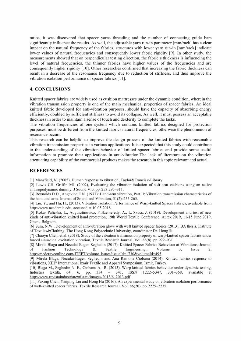
Interactive clothing is usually a textile platform embedded with textile or non-textile sensors, signal processing/analysis, and control or decision modules capable of stimulating body functions or sensing stimuli from the environment, and then reacting or adapting behavior to the circumstances [8]. The integration of smart functionality into clothing and other textile products will radically change the culture surrounding these products, fundamentally altering people’s relationships with them and the way they use them. Smart functionality will also have an impact on the way products are designed and the materials developed. Smart textiles represents the next generation of textiles with use in several fashion products, furnishing and technical textiles applications. The vision is to create textile products exhibiting dynamic functionalities by combining smart materials and integrated computing power. Obviously consumers also have an awareness with the growing technology and novel products. When we examine the “Google Trending Searches”, We can observe a slow adoption from wearable technology to smart clothing within last 5 years. Although recent Google searches show “Smart clothing” increasing in popularity, users still are not largely aware of the market offerings [9].
Fig.1. The searching trends of the terms “smart clothing” & “wearable technology [9]
In adaptation of high tech into daily clothes, two types of technology are available. The first one is mounting electronic devices into garments. The second one is the creation of wires or electronic functions such as diodes, transistors, and LEDs on the textile fibers. The most common preferred approach is the first category because of its technical simplicity and applicability. Construction of the electronic circuits on a cloth surface is possible using conductive threads. Conductive threads can carry electric current as power and electronic signals between the electronic circuits in order to create conductive pathways [10]. When we examine the current global market, it is estimated to be around US$ 580 million in 2015 and is expected to grow at a CAGR of 30% and reach US$ 2.2 billion by 2020. Major drivers identified for the growth of the smart textiles market are: Growing trends in the wearable electronics market, Increasing popularity of sophisticated gadgets with advanced functions, Miniaturization of electronic components, Rapid growth of low-cost smart wireless sensor networks [11].
3. FUTURE PROSPECTS OF SMART AND INTERACTIVE WEARABLES
Intelligent clothing concept has been aggressively investigated for the potential of many long-term personal monitoring, communication, and computing wearable systems in free-living environment. Key developments that augur well for smart textile future are; • Miniaturization of electronics and advancements in wireless technology• Integration of wireless technologies into ineractive textiles• Sensors and actuator technologies for monitoring wearer’s various biological signals• Demand from end-use industries, such as medical/personal protective equipment [11]

22
On the other hand, there are various restraints that need to be overcome for further growth of smart textiles; • Efficient power supply need; In order to fulfill the power needs of the whole system. There are stillinvestigations to develop lightweight power sources with adequate capacity.• Need for cleaning issues of smart textiles; As in all textile products, there is a need for cleaning theinteractive garments in certain periods depending on usage. Washing or cleaning with or without water isrequired.• Level of awareness among consumers; In order to provide a commercial success for smart garments, itis necessary to eliminate prejudice for consumers and increase the awareness and acceptance of products[11].As seen on the market research reports, today, there is a general awareness and acceptance for wearable devicesnot for e-textiles[12]. Many reports in the literature emphasized that smart textiles market will increaseby reaching an incredible market volume within the next 10 years. According to a report released bythe business consulting firm Grand View Research, the global smart fabrics market was worth $878.9million in 2018, and it’s expected to reach $5.55 billion by 2025. As shown in Figure 2, this trendsalso can be seen not only in market value but also in number of devices[13].
Fig. 2: Awareness about Wear-tech products [12] & Cumulative wearable device shipments by category, World markets 2013-2020 [13] category, World markets 2013-2020 [13]
4. CONCLUSION
Smart clothing is an advanced fusion of “technology and fashion”, an innovation that turned fantasy into reality. In respect to body movements, various signals can be obtained from the wearer. These signals can be converted into functional results. For interactive wearable products, it is primarily expected that there should be no difference in appearance from ordinary clothing in order to be commercially successful for that product. So, being a casual garment, design studies have a critical role in developing such prototypes. Improvements can be resulted in a fully-integrated garment in terms of weight and volume i.e. novel improvements such as wireless technologies, cellular communication facilities and advantages of mobile equipment and applications.The technological advancement, fashionable looks, personal disposable income, demand from various sectors, are some of the factors affecting the growth of global smart clothing market. Key characteristics that can affect to product development studies may be categorized as:1) embedded or applied tech,2) fabrication technique: woven, knitted, printed, or embroidered technology, and3) hard or soft components.On the other hand, for mass adoption, the problems about comfort, wear, and launderability issues shouldbe overcome. Such topics about technological advances and/or disadvantages will be among the mainmotivations in overcoming barriers to interactive clothing. On the other hand the internet speed is alsoimportant to make such devices a cornerstone of personal health management. So according to the reports,5G internet connection will be a positive affect for wearable technologies.

23
Big data analysis is necessary to realize the full potential of smart clothing. There are many smart clothing products and use cases where providing personal biometric or environmental data for end users in order to improve the health, safety, and happiness of consumers. These commercial applications, particularly in professional athletics, military, and healthcare have significant market potential. A secondary market of IoT big data platforms will grow to serve these commercial customers and use cases. An investment in developing products that serve commercial use cases will offer investors and shareholders the quickest rate of return. So, the business and enterprise issues will also provide a huge financial value in next years. Marketing strategies and business policy will take a new shape form smart garments. Consumers are moving more into electronic textiles everyday and the trend of interactive clothing is expected to rise.
REFERENCES
[1] Schneegas,S., Amft,P.(Ed.). (2017). Smart Textiles: Fundamentals, Design, and Interaction.Switzerland. Springer.
[2] Mattila, H.(Ed.) (2006). Intelligent Textiles and Clothing, England. Woodhead Publishing.[3] Tao, X. (Ed.) (2015). Handbook of Smart Textiles. Singapore. Springer[4] Vervust,T., Buyle,G., Bossuyt,F., Vanfleteren,J. (2012). Integration of stretchable and washable
electronic modules for smart textile applications, The Jour. of the Text.Inst., 103(10), pp.1127-1138[5] Kayacan,O., (2015). Comparative study about the effect of cleaning processes on the transmission
performance of textile based conductive lines, Industria Textila, 66(4), pp.176-182.[6] Kayacan,O., Kayacan,Ö., Bulgun E., Eser, B., Pamuk,M. (2015). Design methodology and
performance studies of a flexible electrotextile surface, Autex Research Journal, 15(3), pp.153-157[7] Dumitrescu,D., Nilsson,L.,Worbin,L., Persson,A.(2014), Smart textiles as raw materials for design,
Shapeshifting Conference: Auckland Univ of Tech.[8] Ariyatum,B., Holland,R., Harrison,D., Kazi,T. (2005), The future design direction of Smart Clothing
development, The Jour. of the Text.Inst. Vol. 96, No. 4, pp.199–212[9] https://trends.google.com [Accessed 18 Aug. 2019].[10] Şenol,Y., Akkan,T., Yazgan Bulgun,E. Kayacan,O. (2011), "Active T‐shirt", Int.Jour.of Cloth. Sci.
and Tech., Vol. 23 No. 4, pp. 249-257[11] http://ficci.in/spdocument/20811/1-Technotex-2016-Knowledge-Paper.pdf, “Technical Textiles:
Towards a Smart Future”, Technotex 2016 – 5th Int. Exh. & Conf. on Tech. Text. Mumbai, India[Accessed 15 Aug. 2019].
[12] http://www.lightspeedgmi.mx/resourcecenter/newsletter/relationshipconsumerswearabletechnologyfashionbrands/ [Accessed 25 Aug. 2019].
[13] https://www.tractica.com/newsroom/press-releases/cumulative-wearable-device-shipments-to- surpass-750-million-units-by-2020/ [Accessed 29 Aug. 2019].

24
IMPROVED MOBILE BED BIOFILM REACTORS TO TREAT CELLULOSIC WASTEWATERS
DOI: 10.35530/TT.2019.06
Ioana Corina MOGA1, Ovidiu IORDACHE2, Gabriel PETRESCU1, Elena Cornelia MITRAN2, Irina Mariana SANDULACHE2, Bogdan Iulian DOROFTEI1,
Lucia Oana SECAREANU2, Elena PERDUM2, Georgiana Alexandra PANTAZI1
1 DFR Systems SRL, Research and Development Department, Bucharest, Romania 2 National R&D Institute for Textile and Leather (INCDTP), Bucharest, Romania
Corresponding author: Ioana Corina, Moga, E-mail: [email protected]
Abstract: The wastewater treatment sector is a very dynamic field, in continuous development. New technologies are developed, or the existing ones are improved [1]. An efficient biological treatment is based on solid small plastic pieces (biofilm carriers) on which different types of microorganisms attach, develop and grow. This technology is known as Moving Bed Biofilm Reactor (MBBR) technology [2]. The most common materials used for the biofilm carriers’ realization are based on high density polyethylene. This technology is not yet applied for the treatment of the cellulosic wastewaters, since cellulose is hard to be removed by using conventional microorganisms that are usually used in biological wastewater treatment. Some of the authors propose an improved material for carriers to be used in tertiary treatment for textile, paper-mill or tannery wastewaters [3]. The biofilm carriers are adapted for fungal activity. The selected fungal strains (White Root Fungi) capable of removing cellulose from wastewaters [4] will be immobilized on special biofilm carriers. The improved carrier is designed to be used in a MBBR and to favour fungal development in the presence of competing bacteria. Several laboratory experiments related to the fungal attachment on the improved carriers were realized and the results are presented in the paper.
Key words: wastewater treatment, biofilm carrier, fungi, polyethylene, cellulose
1. INTRODUCTION
The main sources of wastewater containing cellulose are: the paper industry, the tanneries, the agrozootechnical farms, the wood industry, the textile industry [1] (Fig.1).
Fig.1. Textile fibres including cellulose-based fibres

25
In addition to industrial wastewater, cellulose can also be found in municipal wastewater [2]. Currently, the cellulose industry is processing, besides the softwoods, significant quantities of annual hardwood and deciduous wood. The cellulose in wastewater is difficult to be removed with conventional biological treatment. The authors propose an innovative solution for cellulose removal from textile wastewaters. An advanced biological stage will be conceived, based on selected fungal strain that will be grown on innovative polyethylene carriers containing cellulose. The carriers are designed to be exploited in a moving bed bioreactor and to favour fungal growth in the presence of competing bacteria.
2. WASTEWATER TREATMENT USING MOBILE BIOFILM CARRIERS
The textile wastewaters are treated through a multitude processes, depending on the diversity of the pollutants [3]. All types of treatments can be found in a textile wastewater treatment plant including physic-mechanical, biological, chemical and advanced treatment processes. Regarding the biological treatment, the activated sludge, is the most well-known process used worldwide. This process has been significant improved starting the 80’s, when the Moving Bed Biofilm Reactor (MBBR) technology was conceived in Norway [1]. Suspended fixed-film packing are introduced inside the biological tanks. MBB tanks are operated similarly to the activated sludge ones with the addition of freely small pieces of biofilm carriers. Advantages of the MBBR technology over the activated sludge technology include shorter retention time, higher efficiency in removal of organic compounds, N and P removal [3]. Also, compared with the activated sludge process, MBBR processes improve reliability, simplify operation, and has a smaller footprint. MBBR technology employs polyethylene biofilm carriers operating aerated or anoxic conditions. Each biofilm carrier increases the biomass inside the tanks through providing protected surface area for biofilm development [1]. This technology provides cost-effective treatment with minimal maintenance as the process generates a smaller quantity of sludge [4]. The authors propose a new direction for the biofilm carrier utilization. Was conceived an advanced tertiary stage to remove the cellulose contained by the textile wastewaters [5]. The mobile biofilm carriers are modified in order to sustain fungal activity. Selected fungi will be immobilized on the improved biofilm carriers, that will be capable to reduce the cellulose content. The new treatment technology is designed as self-sustaining by the exploitation of an innovative fungal carrier containing cellulose. In fact, cellulose is the nutrient source for the bioactive fungal tool proliferation. The MBBR basin was designed conceptually Fig.2. It was considered a laboratory experimental tank. MBBR stage consists in 2 basins: the active basin containing biofilm carriers and settler for sedimentation and disposal of the resulting sludge. During the experimental research the MBBR stage will be adapted to different working conditions.
a. Overview b. Metal diffusers c. Membrane diffusers
Fig.2. The MBBR type purification process

26
Lamiflex 301DX Plastic wheel
e Plastic tub Packed peanuts Nylon belt Kaldness K1 TM 23220 filte
PU foam (polyester), 1 cm³ PU foam (polyether), 1 cm³ HD-PE, Φ9.1 mm Nylon (PA), Φ1 cm Recycled PS, 1 cm³, 99.6% air PP, grooved, Φ1 cm Tube with inner cross, 1 cm³ PU foam (polyether), 1 cm³
Bulpren FCT280 Synsafe G3 Mineral wool LECA Insulating linin Cotton typhoon
EPDM pore rubber, 1 cm³ Cotton material, in a frame of Φ1 cm Rubber foam, 2 cm³ Expanded clay flakes Glass fiber (SiO2) n, 2 cm³ Synthetic organic fibers, 1 cm³
Rubber material type Nitto 1686 Processed materials
Pumic chalk
Melted limestone, -63-6 mm Limestone ballast, -62-6 mm Volcanic lava stone Birch, 1 cm³
Stone BF Natural material Specifications Material Material Type
Two variants of air diffusers were considered, metal with fine bubbles and classic diffusers, with membrane. The main components of the MBBR stage are presented in table 1.
Table 1: Materials and equipment used for the realization of the laboratory MBBR installation for cellulose removal
No. Name M.U. Number 1 Metal tank with PVC interior and plexiglass pcs. 2 2 Air intake blower pcs. 1 3 Blower accessories pcs. 1 4 Blower support pcs. 1 5 Hydraulic network PP-R D.25 air m 6 6 Compressed air flow meter pcs. 1 7 Air pressure gauge pcs. 1 8 Circular membrane diffusers pcs. 4 9 Stainless steel speakers pcs. 4 10 Flange OL D.50 PN10 pcs. 2 11 SDR17 D.63 PN10 SDR17 Adapter pcs. 2 12 EF D.63 SDR17 PN10 socket pcs. 2 13 PEID D.63 SDR17 PN10 pipe m 1 14 Submersible sludge pump pcs. 1 15 Hydraulic network PEID D.63 sludge m 2 16 Hydraulic network PEID D.32 sludge m 3
3. IMPROVED BIOFILM CARRIERS FOR FUNGAL ATACHMENT
The main types of materials used to make biofilm carriers are mineral particles (expanded sand and clays) or plastics (polystyrene, polyethylene and polyurethane) [4]. In the table 2 several materials used worldwide for the manufacture of the biofilm carriers are presented.
Table 2: Materials used worldwide to make biofilm carriers
Some of the authors developed a new material for a proper fungal attachment based on different mixtures between cellulose, talc and high-density polyethylene. The talc increases the efficiency of attaching the biofilm to the biofilm carriers (demonstrated in the ABAWARE project), and the cellulose will ensure the fungal attachment. In Fig. 3 is presented a new model of biofilm carriers, developed by some of the authors, that can be used in MBBR processes.
Plastic materials

27
Fig. 3: New biofilm carrier to be used in MBBR process
During the experimental researches few fungal strains were immobilized on different types of biofilm carrier, as presented in Fig.4.
Fig. 4. Biofilm carriers immobilized with fungi for cellulose based textile wastewaters
4. CONCLUSIONS
Although the specialized fungal immobilization on biofilm carriers is an innovative technology developed within an international research project, the obtain results are promising. A new type and material for specialized fungal attachment was developed and realized. Also, at laboratory level, the fungal attachment was highlighted. The researches will continue by introducing the immobilized biofilm carriers inside the MBBR.
ACKNOWLEDGEMENTS
This work was supported by a grant of the Romanian National Authority for Scientific Research and Innovation, CCCDI – UEFISCDI, project number COFUND-MANUNET III-FUNCELL, within PNCDI III.
REFERENCES
[1] Moga, I.C., Crăciun, N., Ardelean, I., Petrescu, G. and Popa, R. (2018). The potential of biofilmsfrom Moving Bed Bioreactors to increase the efficiency of textile industry wastewater treatment.Industria Textila 69(5), pp. 412-418. Available at: http://www.revistaindustriatextila.ro/[2] Yang, Q., He, Q.H. and Ibrahim, T. (2012). Review on Moving Bed Biofilm Processes, PakistanJournal of Nutrition 11(9), pp. 706-713[3] Crini, G., Lichtfouse, E. (2019). Advantages and disadvantages of techniques used for wastewatertreatment. Environmental Chemistry Letters, 17(1), pp. 145-155.[4] Liu, J., Zhou, J., Xu, N., He, A., Xin, F., Ma, J., Dong, W. (2019). Performance evaluation of a lab- scale moving bed biofilm reactor (MBBR) using polyethylene as support material in the treatment ofwastewater contaminated with terephthalic acid. Chemosphere, 227, pp. 117-123.[5] Bardi, A., Yuan, Q., Suiracusa, G., Chicca, I., Islam, M., Spennati, F., Tigini, V., Di Gregorio, S.,Levin, D.B., Petroni, G., Munz, G. (2014). Effect of cellulose as co-substrate on old landfill leachatetreatment using white-rot fungi, Bioresource Technology 214, pp.1067-1076.

28
7, TZU, Brno, Czech Republic, E-Mail: [email protected]
GUIDE FOR SMART PRACTICES TO SUPPORT INNOVATION IN SMART TEXTILES
DOI: 10.35530/TT.2019.07
Ana DIAS1 , Luís ALMEIDA2 , Mirela BLAGA3, Razvan RADULESCU 4 Benny MALENGIER5 , Zoran STJEPANOVIC6 , Petra DUFKOVA7
1, TecMinho, E-learning Center, Guimarães, Portugal, E-Mail: [email protected] 2, University of Minho, Engineering School, Textile Departments, Guimarães, Portugal, E-Mail: [email protected]
3, Gheorghe Asachi” Technical University of Iasi, Romania, E-Mail: [email protected] 4, INCDTP, Bucharest, Romania, E-Mail: [email protected]
5, University of Ghent, Textile Department, Belgium, E-Mail: [email protected] 6, University of Maribor, Maribor, Slovenia, E-Mail: [email protected]
7, TZU, Brno, Czech Republic, E-Mail: [email protected]
Abstract: Smart Textiles for STEM training (Science, Technology, Engineering and Math’s).is an Erasmus+ project aiming to bridge Textile Companies with the Education sector via Smart Textiles Innovation and Training. Industries have been surveyed to analyze the needs for new jobs and skills in Smart textiles, contributing to improve the links with VET Schools training and closing the gap between industry and education. During the project a number of smart textiles examples and prototypes are worked to be transferred to Schools and used by students and teachers, aiming to foster STEM training. This paper presents the results of the survey applied to selected textile companies on Technical and Smart Textiles, based on data collected from 63 textile enterprises in Romania, Belgium, Slovenia, Portugal and Czech Republic. The survey identifies existing opportunities for producing smart textiles in enterprises and forecasting expected occupations and work profiles for young trainees. The guide for smart practices presents the results of this survey and aims to transfer smart practices from enterprises to Vocational Education and Training (VET) schools and young students. Providing real life prototypes and multi-disciplinary working activities on smart textiles will make textile occupations more attractive to young students, and will improve knowledge, skills and employability of VET students in STEM related fields.
Key words: Technical textiles, Smart textiles skills, Prototypes, STEM training, VET schools
1. INTRODUCTION
A smart textile system has basically five functions: sensors, actuators, data processing, energy supply and communication. The progress in the smart textile domain was possible due to simultaneous development of several technological domains: synthetic fibers, textile technology, electronics and information technology. The guide for smart practices in the textile sector aims to identify the skills needed in enterprises in order to prepare a Course adequate to the expected needs. Smart Textiles for STEM training (Science, Technology, Engineering and Math’s) is an Erasmus+ project. Nicknamed SKILLS4SMARTEX the initiative aims to bridge Textile Companies with the Education sector via Smart Textiles Innovation and Training. Sixty-three companies have been surveyed contributing to improve the links with VET Schools training and closing the gap between industry and education. During the project a number of Smart Textiles examples and prototypes are worked to be transferred to Schools and used by students and teachers, aiming to foster STEM training.

29
This paper presents the results of the survey, based on data collected from enterprises in Romania, Belgium, Slovenia, Portugal and Czech Republic. The research includes also seventeen smart textiles products that represent success stories from industry that are sources of inspiration to professionals and educators. The innovation experiences and collected stories will be transferred to VET Schools, in order to prepare students to the jobs of the future. The idea is to anticipate job profiles and prepare the students with the appropriate skills. Smart textiles products industrially produced in Europe can be used by teachers locally during the students learning process at School, they and their teachers will be invited to visit the respective enterprises and to learn more about the most modern and innovative textile enterprises in their region. Having good examples to work with, teachers and students can have more practical learning experiences, with a multilevel and project based learning of the STEM (Science, Technology, Engineering and Mathematics) subjects, in order to get skills that prepare them to the world-of-work in smart & technical textile field. Providing real life prototypes and multi-disciplinary working activities on smart textiles will make textile occupations more attractive to young students, and will improve knowledge, skills and employability of VET students in STEM related fields.
2. RESEARCH METHODOLOGY
The research was tailored according to Bardach’s methodology which focuses on a smart and interesting idea in a given practice that deserves attention [1]. This type of study characterizes basic and general aspects, as well as the links between them and are thus called “smart practices” research. A methodology of Best Practice Research (BPR) has been developed, based on a questionnaire survey, which was commonly prepared by the project’s partners and included aspects related to:
• Analyzing the interest and capacity of textile enterprises to perform smart and technicaltextiles.• Finding the profile and the number of the workplaces needed by the textile industry.• Identifying the availability of textile enterprises to organize one-day visits with VET studentsor practical training.• Transferring the guide towards important stakeholders, such as: VET schools, professionalassociations, enterprises, regional educational agencies.
The questionnaire includes a total of 33 questions, some are Multiple Answering Questions where the respondent can choose between a rose of alternatives, other questions are using a Likert scale, with selectable values from 0 to 5. For common understanding of terms in what concerns technical and smart textiles, the example of a t-shirt was provided to respondents: Level 0 = basic standard t-shirt Level 1 = functional t-shirt with thermal properties or antibacterial functions Level 2 = t-shirt with passive smart properties e.g. Phase Change Materials (PCM), colour change Level 3 = t-shirt with attached components (sensors – heart rate, temperature…) Level 4 = t-shirt with embedded components (communication sensors like GPS) The research was based on high-value added smart textile products from industries in the partner’s countries to understand the current development and the innovation in the textile sector. The data gathered from the survey will be used to identify the sources sites, namely the textile enterprises providing profiles for high value-added workplaces for young trainees.
3. SURVEY DATA RESULTS
3.1 Results of the questionnaire
The survey was conducted between January and April 2019 and produced a state-of-the-art report on Technical and Smart Textiles in 5 European countries, based on data collected from 63 selected

30
Textile enterprises in Belgium (10), Czech Republic (10), Portugal (12), Romania (21) and Slovenia (10). Data collected during the research revealed that 63% of the companies are from Clothing/fashion and from Technical Textiles and invest at least 4% of their budget in innovation. Most of the companies prefer younger managers and engineers. This is particularly relevant in Portugal and Belgium, where about 90% of the companies prefer people under 40 years old. Concerning innovation, all areas of innovation are mentioned, but technology and design are the top- rated answers. Data Capture is especially relevant for Belgium companies, in line with the evolution of smart textiles for health and sport that require large amounts of data to be analyzed. All areas concerned with technical textiles are relevant, with emphasis on technical textiles for clothing applications (Clothtech, 16%), technical protective fabrics (Protech, 13%), textiles for sports (Sportech, 11%), automotive textiles, including railways, ships, aircraft and spacecraft (Mobiltech, 11%), medical and hygienic textiles (Medtech, 10%). It should be emphasized that more than half of the companies have still either no involvement or involvement only in first generation smart textiles. In terms of first generation (functional smart textiles) there is an emphasis on water and stain resistant, as well as conductive thermic / electric. Concerning second generation (passive smart textiles reacting to the environment), emphasis is on thermal aspects (thermally regulated, heat involving and heat fabric and storage). Colour change fabrics have been highly rated in Slovenia and in Portugal. For third generation (smart textiles with attached or embedded components) emphasis is on temperature regulating. Activity and heart beat reading are given significant importance in Belgium and Slovenia, in line with the focus on Sportech and Medtech. Interactive wear and sport jackets are the emphasis for fourth generation smart textiles (ultra-smart textiles, much more advanced, combining sensors, actuators, and communication, help anticipating needs of the wearer).
3.2 Industry success stories
The guide includes survey results resulting from the seventeen in-depth interviews with most innovative enterprises. Case studies include several areas of smart textiles, involving namely conductive textiles for several applications (optical effects / LED, shielding, measurement of vital life functions), increased thermal comfort, thermal insulation, stockings with gradual compression, etc. As an example, figure 1 presents the product LEDinTEX: a light technology that allows the use of LEDs within the curtains with Jaquard design.
Fig. 1. LEDinTEX (Texteis Penedo, Portugal)
Two very interesting products developed in Slovenia are: • a T-shirt with GPS that measures vital life functions and temperature, intended for
firefighters, soldiers and policemen in the event of a life threatening.• a kinesiological assistant, where the sensors in clothes can monitor adequacy of sporttraining to achieve an increase in condition and muscle mass, respectively. Adequacy is monitoredin the phone application. It is intended for professional sportsman and recreational sportsman.

31
The smart products that have been surveyed represent opportunities and are the basis for forecasting expected occupations and work profiles. They will be used in the training actions within the SKILLS4SMARTEX project.
4. TRANSFER INNOVATIVE IDEAS TO EDUCATION ORGANIZATIONS
The main aim of the Smart textiles for STEM training project is to develop transfer of innovation strategies from research providers towards textile enterprises & VET schools. The main strategy is to link students with textile professions and with companies via existing industrial smart textiles products that are being produced in their respective regions. The students within technical education acquire basic disciplines, such as mathematics, physics, technical drawing, chemistry, biology, mechanics, but the horizon of the end applications and usefulness of such basic disciplines is often not touchable. In correlation with these facts, the Skills4Smartex project is centered on improving knowledge, skills and employability of VET students in the STEM related fields, by providing the adequate examples from industry and the adequate training instruments to students to understand multidisciplinary working. The state of the art in the textile sector, together with the Industry success stories on Smart Textiles products allow VET Schools, their teachers and students to analyse a with range of examples from industry that can be inspiring for the work within a STEM practice in the classroom. Visiting the companies and getting the chance to develop real word prototypes will foster the development of skills and can be an attractive way to shorten the distance between students, VET Schools and the job profiles needed in the industry in each textile region involved in the project. It is expected that thanks to project dissemination the results can be further transferred to other textile regions in Europe.
5. CONCLUSIONS
The guide for smart practices is the supporting raw material for the development of the project e- learning course on smart textiles for textile professionals. Main aim is to offer learning content in advanced textile fields and innovative solutions, especially smart textiles, for the textile enterprises, represented by these professionals. Smart textiles are nowadays used for various application fields within clothing, home textiles and technical textiles applications and have overcome the barrier of classical products. Examples collected from textile companies in Belgium, Czech Republic, Portugal, Romania and Slovenia include sports, medicine, buildings and defense-military applications. They combine textile technologies with electronics, chemistry, physics, and informatics and they represent a multidisciplinary domain. The quality of Vocational Education and Training (VET) in technical fields at European level means competitiveness leverage in the international context and more interconnection between the ecosystem created by Industry, Research organizations and Professional Schools. European VET schools have a good performance and a strong tradition, however, the key competences and STEM multidisciplinary learning capacities have to be increased. The speed-up of technological development is an opportunity for the young VET students, while the development of the textile industry needs new job profiles including well prepared specialists in multidisciplinary fields. The European Textile labor market needs appropriate skilled professional workers, in order to compete on the global markets and this Guide intends to be a contribution to it.
REFERENCES
[1] Blaga, M. at.al (2019). Smart education for smart textiles, Autex2019, 19th World TextileConference on Textiles and Crossroads, Ghent, Belgium.

32
THE ELECTROMAGNETIC SHIELDING BEHAVIOR OF LAYERED KNITTED FABRIC STRUCTURES
DOI: 10.35530/TT.2019.08
Özlem KAYACAN, Neza BAKIR, Barkın TRAŞ
Dokuz Eylül University, Engineering Faculty, Textile Department, Izmir, Turkey Corresponding author: Özlem Kayacan, E-mail: [email protected]
Abstract: The increase in daily usage of electrical and electronic tools simplify the lives of human beings, on the other hand, they also create an enormous electromagnetic pollution. In industrial applications, electromagnetic shielding materials are used to prevent these electromagnetic signals. The studies on human health against the electromagnetic pollution was determined that the widely usage of these electronic devices increases the risk of cancer. Especially in low frequency fields, the most consistent evidence is obtained in childhood leukemia [1]. In order to reduce the damage of these electromagnetic waves, researches have been still made on the electromagnetic shielding effectiveness. Electrically conductive technical textiles are also investigated for this aim. Different textile structures such as knitted, woven, composite or coated textiles etc and also different conductive yarns are produced to prevent these harmful waves [2-5].In this study, it is aimed to investigate the electromagnetic shielding performances of conductive knitted fabrics. In order to search the efficiency of these fabrics, single jersey and interlock knitted structures are produced. By using these fabrics, two different types of double-layered fabric structures are formed and the shielding effectiveness of these structures are investigated experimentally [6.
Key words: Electromagnetic shielding, conductive textiles, single jersey, interlock, double-layered fabrics.
1. INTRODUCTION
The electronic devices cause electromagnetic interferences (EMI), which increases health problems [1, 7-8]. Researches are continued intensely to develop textile surfaces with electromagnetic shielding properties [2-5, 9-13] and in this study, it is aimed to investigate the electromagnetic shielding efficiency of single jersey and interlock knitted structures. By using these fabrics, two different types of double-layered fabric structures are formed using sewing techniques and the shielding effectiveness of these structures are investigated experimentally [6].
2. MATERIAL AND METHOD
Single jersey and interlock knitted fabrics were produced on E=18 gauge electronic circular bed knitting machine using 30/1 Ne Stainless Steel/Cotton yarn (%80 Cotton/%20 Stainless Steel). The properties of these knitted fabrics are given in Table 1. The fabric layers are placed on top of each other in course/wale directions and sewn as two groups as shown in Fig. 1. In the 1st group of samples, individual two layers are sewn at the edges of the fabrics (Fig. 1a), and in the 2nd group of samples, in order to increase the contact points, the layers are also sewn with a distance of 10 cm at widthwise and lengthwise (Fig. 1b)
Table 1. The properties of knitted fabrics
Knitted Structure Stitch Densities
Loop Length (mm) Wales per cm Wales
Interlock 7.1 13.2 0.34 Single Jersey 19.9 18 0.32

33
Fig.1. The fabric layers (a) 1st group of samples (b)2nd group of samples
In this study, free space measurement technique is used in order to determine SE (shielding effectiveness) of knitted fabrics using a spectrum analyzer, Anritsu MS2711D. Fundamental measurement method is based on the signal attenuation on two sides of knitted fabric material located on far field zones of transmitter and receiver antennas. The measurement set- up and the practical measurement set-up is shown in Fig.2. The measurements are realized within a band of 750–3000 MHz.
Fig.2. The measurement and the practical measurement set-up
Fig.3. a) The SE values of single jersey fabrics (V=vertical, H= Horizontal measurement) b) The SE values of double layered single jersey fabrics (SJS1) sewn from the endsc) The SE values of double layered single jersey fabrics (SJS2) with 10 cm stitches
3. RESULTS AND DISCUSSION
The SE results of the single jersey fabrics are given in Fig. 3. In Fig. 3a it can be seen that the mean value of the single jersey SJ is almost 7-8 dB in vertical direction (wale direction). Only in small frequency ranges, the SE value is higher than 10 dB. In horizontal direction (course direction), the SE values are under 10 dB and there is no shielding effect. SE measurements of SJ double layer (SJS1) are

34
seen in Fig. 3b. The highest mean SE value of SJS1V (vertical measurement) is approximately 16 dB between 1010-1068 MHz and 2177-2235 MHz, while the lowest value is 12 dB between 1763-1809 MHz frequency ranges. The SE values of SJS1H (horizontal measurement) is almost 17 dB between 958-1056 MHz, 13 dB between 2166-2206 MHz, 2241-2287 MHz and 2298-2344 MHz and 15 dBbetween 2603- 2689 MHz. When the vertical and horizontal measurements are compared, it can be seenthat the shielding effect of the vertical measurements are approximately 15 dB in low and high frequencyrange. In vertical measurement, the SE values are very effective in a wider frequency range in highfrequency band. SJ double layer (SJS2) with 10 cm stitches are seen In Fig.3c. The SE values of SJS2V(vertical measurement) is approximately 12 dB between 1671-1809 MHz, 14 dB between 2166-2275MHz and 12 dB between 2511-2637 MHz. The SE values of SJS2H (horizontal measurement) is almost13 dB between 1671-1723 MHz and 2172-2281 MHz and 12 dB between 2545-2655 MHz. The resultsof vertical measurements have better shielding values in a wide frequency range than horizontalvalues.
Fig.4. a) The SE values of interlock fabrics (V=vertical, H= Horizontal measurement) b) The SE values of double layered interlock fabrics (IS1) sewn from the endsc) The SE values of double layered interlock fabrics (IS2) with 10 cm stitches
The SE results of the interlock knitted fabric samples (I) are given in Fig. 4. It can be seen in Fig. 4a that the SE values of interlock structures(I) are higher than SE values of SJ structures (Fig. 3a) due to the increase in stainless steel amount. The SE values of IV is 13 dB between 1470-1533 MHz and 1022-1062 Mhz, 14 dB between 1114-1436 MHz and 2494-2551 MHz, 15 dB between 1723-1970 MHz, 2005-2126 MHz and 2264-2321 MHz and 15,6 dB between 2603-2739 Mhz. The highest SE value is 27,524 dB at 1384,25 MHz. In horizontal direction (course direction), the SE values are under 10 dB and there is no shielding effect. In Fig. 4b, SE measurements of double layered interlock fabrics are given. The highest SE values of IS1V (Interlock sewn fabric-vertical measurement) is 26,044 dB at 1988 MHz. The mean SE values higher than 10 dB are obtained 14,6 dB (the highest mean value) between 1119-1298 MHz and 12 dB (the lowest mean value) between 1022-1062MHz.The highest SE values of IS1H is 23,112 dB at 1752,25 MHz. The mean SE values higher than 10 dB are obtained 16,9 dB (the highest mean value) between 1671-1873 MHz and 11,8 dB (the lowest mean value) between 2344-2373 MHz. In Fig 4c, SE measurements of double layered interlock fabrics with 10 cm stitches are given. The highest SE value of IS2V is 23,98 dB at 1194,5 MHz. The mean SE values higher than 13 dB are obtained as 16,14 dB (the highest mean value) between 1119-1303 MHz and 13,09 dB (the lowest mean value) between 2948-3000 MHz. The highest SE value of IS2H is 24,6 dB at 1194,5 MHz. The mean SE
3

35
values higher than 10 dB are obtained as 17,74 dB (the highest mean value) between 1119-1252 MHz and 12,66 dB (the lowest mean value) between 2632-2724 MHz. Doubling the layers affects shielding values positively against one layered single jersey fabric, because of the increase in the conductive material. Sewing the double layers with 10 cm intervals makes a little difference in values, only the frequency band range becomes wider. But in one layered interlock fabrics, SE values are higher because they are produced on double bed knitting machines and the conductive yarn content increases. But doubling of these fabrics and increasing the conductive yarn content make no difference.
4. CONCLUSIONS
In this study, it is aimed to investigate the electromagnetic shielding efficiency of single jersey and interlock knitted structures. By using these fabrics, two different types of double-layered knitted fabric structures are formed using sewing techniques and the shielding effectiveness of these structures are investigated experimentally. It is significant that the electromagnetic shielding values are very effective in the knitted fabrics produced with double bed knitting machines due to the conductive yarn content. Doubling of the layers affects shielding values positively against the one layered single jersey fabric, but in interlock structures, doubling of these fabrics and increasing the conductive yarn content make no difference.
ACKNOWLEDGEMENTS
The authors would like to thank Sun Tekstil, Izmir Türkiye for supplying the yarns and the fabrics for this study and also Res. Ass. Şebnem Seçkin Uğurlu for testing the fabrics’ electromagnetic shielding effects.
REFERENCES
[1] Establishing A Dialogue On Risks From Electromagnetic Fields (2002), World Health Organization.[2] Celen, R., & Ulcay, Y. (2019). Investigating electromagnetic shielding effectiveness of knitted fabrics madeby barium titanate/polyester bicomponent yarn. Jour. of Eng. Fibers andFabrics. https://doi.org/10.1177/1558925019837806.[3] Wróbel IC, Knockaert J, De Mey G, Langenhove LV (2018). Shielding the Electromagnetic Waves byInserting Conductive Lightweight Materials into Woven Curtains. J Fashion Tech. Textile Eng S4:001.[4] Maity, S., & Chatterjee, A. (2018). Conductive polymer-based electro-conductive textile compositesfor electromagnetic interference shielding: A review. Journal of Industrial Textiles, 47(8), 2228–2252. https://doi.org/10.1177/1528083716670310.[5] Ortlek, HG, Kılıç, G, Okyay, G (2011). Electromagnetic shielding characteristics of different fabrics knittedfrom yarns containing stainless steel wire. Industria Textila ; 62(6): 304–308.[6] Bakır, N, Traş, B (2013). Iletken Iplik Içeren Örme Kumaşların Elektromanyetik Kalkanlama ÖzelliklerininIncelenmesi, BSc Thesis, Dokuz Eylul Univ. Eng.Fac. Izmir Turkey.[7] Seyhan, N. (2010). Electromagnetic pollution and our health. Archives of Neuropsychiatry, 47, 158–161.[8] Ammari, M., Lecomte, A., Sakly, M., Abdelmelek, H., & de-Seze, R. (2008). Exposure to GSM 900MHz electromagnetic fields affects cerebral cytochrome coxidase activity. Toxicology, 250, 70–74.[9] Kılıç, G. Örtlek ,H.G., Saraçoğlu, Ö.G. (2007). Elektromanyetik Çevre Kirliliği ve Bu Kirlilikten KorunmadaTekstil Çözümleri. Tekstil Ve Mühendis”, Yıl:14, Sayı:64, sayfa:24-33.[10] Cheng, K.B.(2000), “Production and Electromagnetic Shielding Effectiveness of the KnittedStainless Steel Polyester Fabrics” , J. Text. Eng., Vol. 46, No. 2, , 42-52.[11]. Çeken, F. , Kayacan, Ö. , Özkurt, A. , Uğurlu, Ş. (2011). The electromagnetic shielding properties of copperand stainless steel knitted fabrics.. Tekstil. 60(7), 321-328.[12]. Çeken, F., Kayacan, Ö., Özkurt, A., Uğurlu, Ş.(2012). The electromagnetic shielding properties of someconductive knitted fabrics produced on single or double needle bed of a flat knitting machine. The Jour.of TheText.Inst. Vol. 103, No. 9, 2012, 968–979.[13] Yu, Z., Chen, Y., & He, H. (2018). Preparation and investigation of moisture transfer and electromagneticshielding properties of double-layer electromagnetic shielding fabrics. Jour of Ind. Textiles.https://doi.org/10.1177/1528083718813528.

36
DECORATING FURTHER: APPLYING COSMETIC FINISHES TO THE HAUTE COUTURE
DOI: 10.35530/TT.2019.50
Anika SITARA, Mudassar ABBAS, Faiza ANWAR
University of Management and Technology, Faculty, School of Textile and Design, Lahore, Pakistan,
Abstract: Research and experimentation becomes salient element for the rising of any country’s economic development. Designers are consolidating natural and synthetic materials to enhance the textile surfaces and making something contemporary out-of-the-box. In this high-tech stage of era, functional finishes are becoming part of the textile and fashion world. In this research two decorative functional finishes such as Fluorescent and Phosphorescent (Glow in the Dark) are employed onto cotton substrates to develop haute couture dresses. The main purpose of these finishes is to enhance the aesthetics of the garments rather than decorate them with typical printing materials and techniques. Functional finishes have already been used in past for technical aspects but in limitations. These two major finishes will be utilized with self created print designs on classic theme “Memphis style” .Cut lines are also represent modern era garments for spring season.
Key words: Textile surface, Functional finishes, Glow in the dark, Fluorescent finish, Haute couture, Fashion design
1. INTRODUCTION
Research and experimentation becomes salient element for the rising of any country’s economic development. It gives confidence to researchers and scientists, because the advantage of radical researchers gives intuition to procedures, demonstration, combining modus for sternness, conclusive of accurate for the country and gives a better invariability. In today’s world, technology is over powering each and every aspect of life. Also, it is globally translating the world into making of unique, timeless, high tech and comfortable lifestyle. . In this high-tech stage of era, functional finishes are becoming part of the textile and fashion world. Finished exteriors would be changing mood of the anthology as it represents artist’s ideology about his/her collection. Cotton is used as a predominant fabric. Printing and finishes are incorporated on cotton substrate.
1.1 Fluorescence An abrupt color is appeared when any fluorescent item is exposed to UV light. It arose just because absorbed radiation in the region of spectrum cannot be observed by human eye. But at the same time the emitted lights can be seen in an obvious zone. When emission origin is stopped, then the glow suddenly desists [1]. Initially fluorescent was seen in nature while an experiment was undertaking by a physicist. Many methods were developed to make fluorescent pigments. Later on different techniques were developed in new era but due to expensive prices of color fluorescent is not presently used in wide scale industrial area, back in 1500 BC fluorescence literature was written in Chinese books. At that time it was not interpreted, thousand years back. In 1565, a book named “Historia medicinal de las cosas que se tra eu de nuestras” written by a botanist and a physician called Nicolas Monards about the blue opalescence when mixed with water, derived from the wood called “coatli”. Another botanist Charles Ded l’ ecsule translated this book in Latin in the year of 1574, which helps to give awareness of this strange optical property of wood.

37
A research exposed the fluorescence flower named “Mirabilis Jalapa”. Some of the parts of this flower shows yellow color when put under white light [3]. Different gems and mineral shows their fluorescence characteristics. A series of different colors also found in crude oil, condensate and light oils and tars.
1.2 Phosphorescence “Glow in the Dark” Study predicts that phosphorescent elements deliver the stored light deliberately. It happens, because energy of electrons stayed for much abbreviated period such as (10-9 to 10-6seconds).After that process in shutter area the energy of electrons converts into energy after emitting light. As energy changed, by the lag of time electrons diffuse light for a sufficient period of time electrons in impurity line. If a plentiful emerge sheen on material, then at this state of time they glow[4]. Scientists discovers that there is a bioluminescent found in a smallest sea creature called “Dinoflagellates” .Which collectively brighten up the outer surface layer of sea at night. Cypridna gives a glow in the tone of a bright blue. It can be used as dry powder if mixed with water. It was used by soldiers by World War 2 in many useful ways, like illuminate maps and for reading purpose
Table 1: Long Lasting phosphors
Sulphuric Phosphors ZnS :Co
Earth alkaline metal aluminates Eu2+ : ROa+ (A11-x G9x)2O3b+
Phosphorous is listed at fifteenth number of periodic system. It is related to 17th century when no one was familiar with a chemical element. About hundred years ago scientific history on phosphors is traced. Decay process of electrons is apparently main difference between phosphorescence and fluorescence, resulted from the early researchers. In 1888 German physicist Eilhardt Wiedemann pre- owned “luminescence” which precisely means emission of light. Creatures that live deep in sea where no light beam is approach, they produce their own light with phosphorescence. Creatures who lives in mesopelagic zone have a dept. around 650 to 3000 feet (200-1,000M) would have this kind of body for living purpose. Such as jelly fish, shrimp, worms and squids. Cypridna gives a glow in the tone of a bright blue. It can be used as dry powder if mixed with water. It was used by soldiers by World War 2 in many useful ways, like illuminate maps and for reading purpose[5]. Other uses of Phosphorescence are watches, television tubes, toys, switches, and glowing suits by dancers [6].
1.3 Haute couture Haute couture means to make custom-fitted and high fashion women’s clothes [7].The pioneer of haute couture is Charles Frederick. He was the first to promote his collection through live models in early 1950s. He is also known as the first designer to give a logo to his brand [8]. Worth spending money garments made in this category are made by special order.
1.4 Memphis style design Memphis was a Milan based collective of furniture and product designs which was known by their different and modern designs formed by basic shapes with beautiful and playful colour schemes. It became famous in 1980’s [9].
2. MATERIALS AND METHODS
2.1 Material Cotton fabric is used as a substrate because of the good absorbency, drape, strength, durability, comfortable handle, easily washable .For the woven fabrics, received in grey form, pre-treatment process is conducted before further printing. Next, scouring was done to prepare the surface to apply

38
finishing on them. For sizing mainly both polyvinyl alcohol and polyvinyl acetate are used. While to get an apt fabric, on the primeval desizing and scouring procedure was performed. 2.2 Digital printing chemicals Digital printing is the unique element given to the fabric to make the substrate surfaces appealing aesthetically. It is specially done on Silk fabric base to support stay fresh functional finish. The material required in the process of printing is listed below: • Printing machine• Printing pigments• Digital reactive printed samples on Reggiani digital printing machine a
2.3 Fluorescent printing chemicals• ITO Neon pigment• Yellow 4%• Magenta 4%• Orange 4%a
2.4 Phosphorescent printing chemicals
• Glow in the dark pigment• 15%,Printofix• Binder ET 30% 2.5 Methodology of phosphorescence and fluorescence finish application The application of fluorescence and phosphorescence finishes is applied through the process of rotary printing. The process flow is based on six steps. In this process firstly an adhesive is applied on the back of the substrate. This coating keeps it adhere to conveyor printing blanket. Then, the fabric moves on under the rotating screens. The printing pigments or paste is aroused automatically from these pressure tanks. In next step a squeezer imposes color paste onto the substrate. This squeezer is attached on rotary screens and moving rate is up to 100 yards per minute. The treated fabric is then move to the drying woven for drying. In last step, curing and washing procedure is done to ready the finished fabric. 2.6 Designs Printing designs are developed by keeping in mind the aesthetic look of an haute couture collection. Different shapes and patterns are emerged together to form an appealing design with the range of colors. Following are the final designs printed on fabrics.
Fig. 1. Design.1 inspired by Memphis style printed on cotton fabric Fig. 2. Design.2 Glow in the dark Inspired by “Memphis style” printed on Cotton fabric

39
2.7 Final Product Final garments are made and stitched by a technical process of draping and pattern making. After that it is stitched and hand sewn for the haute couture look. Details of the final product are mentioned in figure 3 & 4.
Fig. 3. Dress.1 a12 paneled floor length Evening Gown “Glow in the Dark” Fig. 4. Dress.2 Skirt with crop top in “Fluorescent colors”
2.8 Equipment The process has been performed of various machines. From printing machine to stitching machine all of the necessary equipment and finishing. Unification of functional finishes on dissimilar superficies and garment accumulation is successfully achieved. Three of the functional finishes were applied on the fabrics. Two of the finishes were applied to adorn the textile surface while other one is applied to keep the fabric fresh. Different self-made designs and patterns inspired by “Memphis Style theme” were also part of the design section. All of the garments stitched by own self with implementation of fashion design skills. The “fluorescence neon prints” were observed under UV lights of different colors in light box. The “Glow in the dark – Phosphorescence” print was checked in dark room. While, alternatively “Stay fresh” is tested by several washes. Fabric remain new like ever before after 70+ washes. The effect of anti-odor test is also performed physically, which brought out the positive result of stench free fabric after wearing in humid weather and sweaty body. The results are phenomenal and garments are technical yet wearable. To counterfeit the research the main aspiration of the thesis is dispersed into three sections. The initial one is comprises of different application of functional finishes in ingenious ways in the field of technical textile and fashion. By also merging the two skills, one is the scientific aspect of textile printing and another is to develop self-chosen theme design. Whereas, the second section includes the introduction of all the functional finishes and designs onto fabric and further convert it into a high- level and wearable Haute couture products. The functional finishes like phosphorescence, fluorescence and stay fresh are expensive. But still their demand in local market is so low. Their functionality and ornamentation quality is applicable in both the textile and fashion industry. Hence, this research is made to open doors for the design researchers to apply and augment the quality of future endeavor into more beneficial, applicable and wearable products. In Pakistan the practice of new innovations in garment sector is still undiscovered and unrecognized. Even the designers are not aware of these technical finishes which can be used alternatives of simple digital printing and embellished dresses. These finishes can be used in many other ways to provide comfortable and futuristic aspect to designers but it has very low customization in Fashion as well as textile industry.

40
Fluorescein or curcumin are fluorescent dyes, which works usually through photo-physical process. Sometimes, fluorescent itself termed as molecule. Generally, the dissemination of electrons found in certain shells and orbitals from any atom. As electrons are kind of rudimentary particles, that’s why electronic transitions are liable for luminescence. When electrons deactivated from excited states, such condition is consider as unstable. Even though, electrons fettering to ground state, the excitation energy is discharged again. This phenomenon is explain in figure 31
2.9 Mechanism of Fluorescence finish Vs. Mechanism of phosphorescence finish
Basically, the main difference between the mechanism of fluorescence and phosphorescence dyes is the instinctive emission of electromagnetic radiation. In this process, when a source of light is removed fluorescence stopped glowing immediately. Whereas, the glowing property of phosphorescent dyes continue even after source of light is evacuated. It can lasts in the extent of second or up to hours and hours. Commonly, electrons of any atom moves in anti-parallel spin just like this symbol (↑↓). In case of fluorescence dyes, there are three states and have several energy levels. When electrons S are lifted up till excited state S1 or S2 by electromagnetic radiation, this excitation is immediately stops for at leastcost, 10-15 sec).After that they fall back to the ground level. The heat produces due to vibrational relaxation. This thermal energy produce because of movement of the molecules. The energy which is keep on releasing until it reach the lowest level of excited state. To reach back from S2 to S1, the vibrational relaxation helps electrons until they reach their bottom state. This process is explained through Jablonski Diagram in figure 2.6 Theoretically, as the surrounding molecules cannot absorbs energy if a too large quantity of energy is created in the last state. The electrons can relax from then but in a non-radiative way. The fluorescence then ensues, which carries out the emission of photons in a certain wavelengths. This process of emission of photons keep on working until they are back in ground state, but electron-spin is kept the same figure. On the other hand, process of phosphorescence is slightly different. All the states are same S, S1 and S2. Even they have antiparallel spin. The addition of an excited triplet T1 lies vigorously in between the S and S1 state. The process of excitation is done through electromagnetic radiation in the same way. At the same time an intersystem crossing is happened because T1 state is much advantageous that state of S2 and the develop an electronic transition between both excited state through internal conversion. Here, the parallel spins (↑↑) of electrons found in triplet state. The process of ISC is also known as “spin-forbidden”. A transition of T1 lowest energy level and S state is spin-forbidden; but the transition in between them is not immediately attainable. Still, it can be occurred with less feasibility. The reversal process of electron spinning causes weak emission of photons. The captured energy stays in this state for a short period, the discharged very slowly and gently. In the end the electrons come back in ground state right after releasing of energy. The mechanism is well explained in this diagram 2.7.
2.10 Testing Process of Phosphorescent and Fluorescent Activity
Phosphorescent: With the application of “Glow in the Dark” pigments photo luminescent activity was evaluated using ASTM standard method E 2072.With the help of this experiment of photo-lumiscence was performed and were tested according to standards [10]. Fluorescent:-

41
In consonance with standard NF EN471 the evaluation of fluorescent colors with basic parameter was performed. To determine saturation and hue each color characterized by the X and Y in accordance to their chromaticity co-ordinates. Their luminance factors measure by
β = Y/Y Where Y = 100
For perfect reflecting diffuser Y = 100 is three-chromatic color coordinate. On the other hand, Y is the co-ordinate for the tested colors. The value of fluorescent parameters of textile specimen were tested when their chromatically co-ordinates X and Y along with luminance factor according to greater or equal value were determined by the standard NF EN471. The equipment used to determine these parameters was DATACOLOR spectrocolorimet.
Table 2: Luminous factor and the chromaticity co-ordinates X and Y as resolute by NF- EN471 standard Dye X Y Minimum value of
luminous Factor Luminous Yellow 0.460;0.398;0.387;0.356 0.611;0.494;0.452;0.540 0.7 Luminous Pink 0.655;0.570;0.595;0.690 0.345;0.340;0.315;0.310 0.25 Luminous Orange 0.610;0.535;0.570;0.655 0.390;0.375;0.340;0.345 0.4
3. CONCLUSIONS
The research and development of this hypothesis deduces that functional finishes can be applied by both ornamental and mechanical point of view. The exceptional combination of Haute couture and functional finishes is introducing a new era in garment making other than safety precaution purpose. Finishes can be experimented through new application processes and ore decorative materials can be added at the time of application process to give ultra-glitter and shine, which makes it more shinny and fancy. It is recommended that more outstanding emanation; such new combinations should be enforced with further development of range of high- end and high-tech garments.
REFERENCES
[1] Hsieh, You-Lo. Chemical structure and properties of cotton. Cotton: Science and Technology, 2007[2] Retrieved from https://www.cottoninc.com/quality-products/nonwovens/cotton-fiber-tech-guide/cotton-
cotton-morphology-and-chemistry/on June 13.2018[3] Retrieved from https://en.wikipedia.org/wiki/Fluorescence/ on June 13.2018[4] Retrieved from http://www.bristol.ac.uk/synaptic/research/techniques/ on June 13.2018[5] Bernard Valeur. Molecular Fluorescence : Principles and Applications.Wiley-VCH Verlag GmbH, 2011

42
PRODUCTION AND CHARACTERIZATION OF MELT SPUN POLY (Ԑ-CAPROLACTONE) FIBERS HAVING DIFFERENT CROSS
SECTIONS
DOI: 10.35530/TT.2019.10
Figen SELLI, Ümit Halis ERDOĞAN Dokuz Eylul University, Department of Textile Engineering, İzmir, Turkey
[email protected] & [email protected]
Abstract: Poly (ԑ-caprolactone) (PCL) is a member of petrochemical raw material based biodegradable polyesters. Numerous studies have applied electrospinning, wet spinning and melt spinning techniques for processing fibers from PCL and its copolymers. The thermoplastic nature, low melting point and high extensibility of PCL makes it a good candidate for processing with melt-spinning method which is an economic and environment friendly fiber production process. Several studies have investigated the production of PCL fibers via melt-spinning; however, there is still significant room for improvement in process parameters and fiber properties. Therefore, in this study, we used different spin pack designs, extrusion and drawing parameters for the melt spinning of neat PCL filaments. Melt-spun solid and hollow multifilaments having smooth surfaces were successfully produced by using a lab-scale melt spinning device. Crystallinity of multifilaments remained unchanged in terms of production parameters. Tensile test results suggest that PCL filaments can be produced using various types of spin packs with decent mechanical properties by means of melt spinning. Hollow structure can extend the field of application of fibers in medical appicatios by taking the advabtage of its carrier properties.
Keywords: Biodegradable fibers, poly (ԑ-caprolactone), melt spinning, hollow fibers, solid fibers
1. INTRODUCTIONVarious synthetic polymers were produced in the early 20th century and are currently being used as raw materials in several industries such as textile, automotive, agriculture and healthcare. Besides, starting in the 21st century, due to the environmental concerns, there is an increasing interest in the development of bio-based and biodegradable polymers in the world. The production of fibers from synthetic biopolymers is a niche market in the application range of biopolymers. Poly (ԑ-caprolactone) (PCL) is a member of petrochemical raw material based biodegradable polyesters. This biodegradable aliphatic polyester is one of the earliest polymers which first synthesized in 1934. Lately, the polymer has attracted substantial interest in medical applications such as sutures and scaffolds [1-2]. Numerous studies have applied electrospinning, wet spinning and melt spinning techniques for processing fibers from PCL and its copolymers. The thermoplastic nature, low melting point (Tm~60 °C) and high extensibility of PCL makes it a good candidate for processing with melt-spinning method which is an economic and environment friendly fiber production process [3]. Several studies have investigated the production of PCL fibers via melt-spinning; however, there is still significant room for improvement in process parameters and fiber properties for industrial scale production [3-5]. Thus, it is necessary to apply modifications to the PCL fibers for some applications. Fibers can be modified by several physical and chemical methods to improve their properties for new application areas in functional textiles. One of the modification methods is changing the cross sections of the fibers from circular to non-round shapes like trilobal, flat, hollow and triangular. Researchs on non-round cross sectional shaped fibers aregenerally focused on melt spun fibers, since it is possible to change the cross sectional shape of the fiber only by changing the shape of the spinneret orifices [6-7]. Therefore this study considers the fabrication and characterization of melt spun poly (ԑ-caprolactone) fibers having different cross sections. We used different spin pack designs, extrusion and drawing parameters to obtain solid and hollow PCL fibers for alternative medical textile applications.

43
2. EXPERIMENTAL
2.1 Materials
Three PCL multifilaments were melt-spun from the PCL polymer CapaTM 6500 pellets provided by Perstorp (UK). The pellets had a mean molecular weight of Mw=50 000 Da, melt flow index of 7.90- 5.90 g/10 min and a melting point of Tm=58-60 ºC.
2.2 Melt spinning
Melt-spinning of multifilaments was carried out on lab type melt spinning device (Fiber Extrusion Technology, Leeds, UK) in Technical Textiles Research and Development Center İzmir (TEKSMER). This melt spinning plant enables the production of mono-, and bi-component fibers with various fiber cross-sections and polymer combinations. Depending on the type of fibers to spin, various spin packs can be set such as hollow, core/sheat, and side by side. In this study solid and hollow spin pack design were installed. Lab type melt spinning device and multifilaments can be seen in Fig. 1.
Fig. 1. Melt-spinning device and PCL multifilaments (solid:PCL_1000, PCL_1001 and hollow:PCL_1002)
2.3 Characterization
Optical microscope (Olympus BX43) was used to analyze the diameter and morphology of multifilaments. The diameter results were averaged over 10 measurements and expressed in μm. The fineness of fibers was calculated as yarn count in tex. Mechanical testing of the filaments was carried out with a standard tensile testing machine (Instron 4411). Tests were performed in 100 mm long test samples at a rate of extension of 100 mm/minute with a 500 N load cell. Thermal properties of the PCL multifilaments were characterized using differential scanning calorimetry (DSC) ranging from - 25 to 120 °C at both a heating and cooling rate of 10 °C min-1 under nitrogen atmosphere. Crystal structure analysis of multifilaments was performed by X-ray diffraction (XRD) by Rigaku D/MAX- 2000 using Cu-K alpha radiation with a scanning range from 3° to 90° and an angle step of 0.02°.
3. RESULT AND DISCUSSION
3.1 Melt spinning of PCL solid and hollow multifilaments
Three different multifilaments with two different spin pack design (solid and hollow) were melt-spun from PCL pellets. The extrusion and drawing parameters of the filaments are summarized in Table 1.
Table 1: Extrusion and drawing parameters of PCL solid and hollow multifilaments
Fiber Yarn Count (tex)
Extrusion temperatures
(°C)
Spin pack design/ temperatures
(°C)
Take-up godet speed
(m/min)
Drawing godet speeds
(m/min)
Winder speed
(m/min)
Draw ratio
PCL_1000 35 45-55-65-70 Solid multifilament/90 200 230-260-290 300 1.5 PCL_1001 24 45-55-65-70 Solid multifilament/95 200 250-300-350 380 1.9 PCL_1002 35 50-65-75-80 Hollow multifilament/95 220 220-240-270 330 1.5
Extrusion temperatures of PCL polymer were below 100°C; extrusion zone temperatures were set between 45°C to 80°C and spin pack temperatures 90-95°C. Hollow multifilament extrusion temparatures were set higher than other two solid fibers in order to get homogenous melt flow and to

44
PCL_1002 PCL_1001 PCL_1000
increase polymer throughput rate. Godet speeds were varied 230 m/min to 350 m/min whereas take-up godet speed was set to 220 m/min for PCL_1002 hollow fiber.
3.2 Fiber morphology and fineness
Light microscope images indicate that solid and hollow PCL monofilaments having smooth surfaces and circular cross sections were successfully produced by means of melt-spinning (Fig. 2). Irregular cross-sections of hollow fibers were observed due to possible compress during section cutting. The diameter was measured for each filament separately as it varied from 21-31 μm (Table 2).
Fig. 2. Longtidunal and cross sectional images of PCL multifilamanets by optical microscopy
3.3 Mechanical properties
Mechanical test results of PCL multifilamnets revealed that the specific stress and elongation at break are in a range of 5.94-7.48 cN/tex and 72-187 mm, respectively. Mechanical properties of multifilaments are summarized in Table 2. According to tensile measurements, PCL_1002 hollow fiber has the highest specific stress (7.48 cN/tex) whereas PCL_1000 has the lowest (5.94 cN/tex). These two filaments have same draw ratio but higher take-up speed of PCL_1002 induced to get improved specific stress value with the aid of stress induced crystallization. Elongation at break results suggest PCL_1001 has the lowest elongation at break due to higher draw ratio of filaments.
Table 2: Mechanical properties of PCL solid and hollow multifilaments
Fiber Yarn Count (tex)
Diameter (μm)
Draw ratio Specific stress (cN/tex)
Elongation at break (mm)
PCL_1000 35 29 1.5 5.94 187.6 PCL_1001 24 21 1.9 6.58 72.5 PCL_1002 35 31 1.5 7.48 178.9
3.4 Thermal properties
Thermal properties of the PCL multifilaments obtained from DSC curves including the melting temperature (Tm), melting enthalpy (ΔHm), crystallization temperature (Tc), crystallization enthalpy (ΔHc) and degree of crystallinity (Xc) are summarized in Table 3.
Table 3: Thermal properties of PCL solid and hollow multifilaments Fiber Tm (°C) ∆Hm (J/g) Tc (°C) ∆Hc (J/g) Xc (%)
PCL_1000 55.46 42.60 30.57 47.66 30.53 PCL_1001 55.13 41.13 30.53 47.60 29.48 PCL_1002 55.14 40.59 30.68 47.69 29.00
The crystallinity of the polymer was estimated according to the equation (1):
% = ΔHmelt/ΔHref x 100 (1)
where ΔHmelt is the heat enthalpy, ΔHref, the heat enthalpy of an ideal crystal (PCL,139.5 J/g) [8]. According to the melting behaviour of filaments, the melting temperature upon second heating was determined to be ≈ 55 ºC and the crystallization temperature upon cooling ≈ 30 ºC for all multifilaments. No significant change in Xc, Tm and Tc was observed for different production parameters and spin pack designs (Fig. 3).

45
Fig. 3. DSC results of PCL filaments based on second heating and the first cooling scan a) melting curves of
multiflaments, b) crystallization curves of multifilaments
3.5 Structural properties
XRD was performed on PCL multifilaments in order to determine the changes in the crystalline structure. Fig. 4 shows the XRD diffractograms of filaments melt-spun with different spin pack design and draw ratios. The diffraction pattern of the solid and hollow filaments indicated two distinct peaks at about 2θ=21° and 2θ=24° corresponding to reflections (110) and (200), respectively [9].
Fig. 4. The XRD patterns of PCL solid and hollow multifilaments
4. CONCLUSIONS In this study melt-spun solid and hollow multifilaments having smooth surfaces and diameters from 21 to 31 μm were successfully produced. Higher draw ratio allowed to have finer filaments with smaller diameter. No significant change in melting and crystallization temperature was observed. Crystallinity of multifilaments remained unchanged in terms of production parameters XRD diffractograms showed distinct diffraction peaks for the drawn filaments which indicate oriented crystallites Tensile test results suggest that PCL filaments can be produced using various types of spin packs with decent mechanical properties by means of melt spinning. Hollow structure can extend the field of application of fibers in medical appicatios by taking the advabtage of its carrier properties.
ACKNOWLEDGEMENTS The authors gratefully acknowledge the funding by Scientific and Technological Research Council of Turkey (TÜBİTAK) under grant 218M446. Authors aslo would like to thank Mutlu Erbaş from TEKSMER for operating the spinning plant.
REFERENCES [1] Labet, M. and Thielemans W. (2009). Synthesis of polycaprolactone: a review. Chemical Society Revievs,
38(12), pp. 3484-3504. [2] Woodruff, M.A. and Hutmacher, D.W.(2010). The return of a forgotten polymer-Polycaprolactone in the
21st century. Progress in Polymer Science, 35(10): pp. 1217-1256. [3] Azimi, B., Nourpanah, B., Rabiee, M., Arbab, S. (2014). Poly (ε-caprolactone) Fiber: An Overview.
Journal of Engineered Fibers and Fabrics, 9(3): pp. 74-90. [4] Selli, F., Erdoğan, Ü.H., Perret, E., Hufenus, R. (2019). Pilot-scale Melt-spinning of Poly(ԑ-caprolactone):
Solid and Liquid-core Filaments. 35th International Conference of the Polymer Processing Society Technical Book, pp.98.
[5] Selli, F., Perret, E., Erdoğan, Ü.H., Hufenus, R. (2018). Production of melt spun Poly (e-Caprolactone) Fibers. 7th International Technical Textiles Congress Proceeding Book, pp.5-12.
[6] Kara, S., Ureyen M. E., Erdogan U. H., (2016). Structural and Antibacterial Properties of PP/CuO Composite Filaments Having Different Cross Sectional Shapes, International Polymer Processing, 31(4), pp. 398-409.
[7] Kara, S., Erdogan U. H., Erdem N., (2012). Effect of Polypropylene Fiber Cross Sectional Shapes on Some Structural/Mechanical Fiber Properties and Compressibility Behaviour of Plain Knitted Fabrics, Fibers and Polymers, 3(6), pp. 790-794.

46
[8] Pal, J., Kankariya, N., Sanwaria, S., Nandan, B., Srivastava, R. K. (2013). Control on molecular weight reduction of poly(epsilon-caprolactone) during melt spinning--a way to produce high strength biodegradable fibers. Material Science and Engineering, 33(7): pp. 4213-4220.
[9] Krishnanand, K., Deopura, B. L., Gupta, B. (2012). Determination of intrinsic birefringence values of polycaprolactone filaments, Polymer International, 62, pp. 49-53.

47
INVESTIGATION OF THE USAGE OF OZONE IN DENIM FINISHING PROCESSES
DOI: 10.35530/TT.2019.20
Ömer Faruk AL1, Emre SAM2, Merih SARIIŞIK3, Gülşah Ekin KARTAL3
1 Roteks Tekstil İhracat San. Tic. A.Ş. İzmir, TURKEY, [email protected] 2 MasculiniTekstil Giyim San. ve Tic. Ltd, Şti. İzmir, TURKEY, [email protected]
3 Dokuz Eylül University, Textile Engineering Department, İzmir, TURKEY, [email protected]
Corresponding author: Merih SARIIŞIK, [email protected]
Abstract: Nowadays, too much water, energy, chemical substances are consumed for the conventional textile finishing processes and more chemicals are exposed to the environmental load. In our world of diminishing resources, the most ideal way of using the available resources has been inevitable in the name of all living things on earth. In order to alleviate the environmental burden and increase the green production understanding, the textile finishing sector continues to work as in other sectors. The chemicals used in the studies are minimized to be preferred environmentally friendly substances. Enzymes used in textile finishing, ultrasound technology and use of ozone as oxidizing agents can be seen as the successful results of these studies [1-4]. In this study, processes that can reduce the environmental load in denim finishing processes were investigated with ozone gas used in many fields in recent years. Denim fabrics were treated with ozone and compared with other conventional denim finishing methods. In this study, which is performed in order to improve the bleaching process with ozone, it is envisaged to reduce the chemicals and water used in conventional denim finishing. The operations were carried out on a total of 20 pants, which were sizing and desized pants. In addition, preliminary trials were carried out at acidic, basic and neutral pHs to examine the effect of pH change on the ozone bleaching process. In accordance with the results of previous studies, it was decided to make the best humidity rate of 60%. Ozone concentration was chosen as 100 g/m3 and 200 g/m3. In addition to these, ozone application time was determined as 20 minutes. Weight loss, tear strength and color measurement analysis of the fabrics were performed before and after the ozone processes.
Keywords: Ozone, denim, bleaching, ecology
1. INTRODUCTION
In our diminishing world, using the available resources in the most ideal way has become inevitable in the name of all the vitality living in the world. In order to alleviate the environmental burden and increase the understanding of green production, studies are continuing in the textile finishing sector as in other sectors. The chemicals used in the studies are minimized and it is aimed to prefer environmentally friendly substances. Successful results of these studies can be seen as the presence of various enzymes in textile finishing, ultrasound technology and the use of ozone as an oxidant.Ozone, which chemical formula is O3, is the active oxygen. It is an effective antimicrobial agent and deodorizing agent. Ozone has a high reactivity. It is colorless and heavier than air. In the presence of oxygen, almost all high energy sources can produce ozone.In the textile industry, the studies carried out with ozone technology are limited. Ozone gas is widely used in denim sector for washing, aging and patterning effects. Apart from this type of usage, there is no area in which it is widely used or is a routine process. For this reason, all the studies about ozone are very important in terms of spreading ozone.In this study, processes that can reduce the environmental load in denim finishing processes were investigated with ozone gas used in many fields in recent years. Denim fabrics were treated with ozone and compared with other conventional denim finishing methods. In this study, which is performed in order to improve the bleaching process with ozone, it is
48
envisaged to reduce the chemicals and water used in conventional denim finishing. The operations were carried out on a total of 20 pants, which were sizing and desized pants. In addition, preliminary trials were carried out at acidic, basic and neutral pHs to examine the effect of pH change on the ozone bleaching process. In accordance with the results of previous studies, it was decided to make the best humidity rate of 60%. Ozone concentration was chosen as 100 g/m3 and 200 g/m3. In addition to these, ozone application time was determined as 20 minutes. Weight loss, tear strength and color measurement analysis of the fabrics were performed before and after the ozone processes
2. MATERIAL AND METHOD
2.1 Material
In this study, 100% Cotton 3/1 twill weave indigo dyed denim trousers were used. Amylase enzyme were used in desizing process (roge amylasse 188RT) and dispersing agent (LAVA SPERSE KDS) were supplied from DYSTAR, wetting agent (FORAN BKS) from FOURKIM, hydrogen peroxide, sodium hypochlorite and enzyme washing process (FORYL C2) were supplied from Rubin Chemical Company.
2.2 Method
Procedures were carried out by dividing the 20 pants into 2 groups. In the first group, trousers without sizing material were used. In the other group, the desizing pants were treated with ozone. In this study, preliminary experiments were conducted in acidic, basic and neutral pH to investigate the effect of pH change on ozone bleaching process. In accordance with the results of previous studies, it was decided that the best moisture content was 60%. Ozone content was selected as 100 g / m3 and 200 g / m3. In addition, ozone application time was determined as 20 minutes. Isatin released as a result of chemical reaction after ozone bleaching process which causes a yellow color precipitation on the product. As a result of experiments with various chemicals to get rid of anthrylic acid, the best result was obtained with hydrogen peroxide as a post-treatment and it was decided to treat with hydrogen peroxide as a post-treatment. Weight loss, tear strength and color measurement analysis of the fabrics were performed before and after the ozone processes.
Table 1: Processes Sized Sample
Desized Sample
Process Time (min)
pH Temperature (oC)
1 11 100 g / m3
ozone 20 5 Room
Temperature 5g / l 5 min hydrogen peroxide bleaching at 60 oC + 2 min cold rinsing
2 12 200 g / m3
ozone 20 5 Room
Temperature 5g / l 5 min hydrogen peroxide bleaching at 60 oC + 2 min cold rinsing
3 13 100 g / m3
ozone 20 7 Room
Temperature 5g / l 5 min hydrogen peroxide bleaching at 60 oC + 2 min cold rinsing
4 14 200 g / m3
ozone 20 7 Room
Temperature 5g / l 5 min hydrogen peroxide bleaching at 60 oC + 2 min cold rinsing
5 15 100 g / m3
ozone 20 10 Room
Temperature 5g / l 5 min hydrogen peroxide bleaching at 60 oC + 2 min cold rinsing
6 16 200 g / m3
ozone 20 10 Room
Temperature 5g / l 5 min hydrogen peroxide bleaching at 60 oC + 2 min cold rinsing
7 17 Sodium hypochlorite bleaching
10 10 50 3 min neutralization with 10 g / l sodium metabisulfite + 2 min cold rinse
8 18 Sodium hypochlorite bleaching
7,5 10 50 3 min neutralization with 10 g / l sodium metabisulfite + 2 min cold rinse

49
9 19 Sodium hypochlorite bleaching
5 10 50 3 min neutralization with 10 g / l sodium metabisulfite + 2 min cold rinse
10 20 1kg fabric / 18kg pumice + 5g / L cellulase30min Stonewashing + Washing
30 7 40 2 min cold rinse
3. RESULTS AND DISCUSSION
The weight loss of the fabrics as a result of 3 different effecting methods and 20 different recipes were shown in Figure 1.
Fig.1. Weight Loss
When the results were examined, it is seen that the lowest weight loss occurs with ozone method. Less weight loss was observed in the desized samples compared to the sized ones. The reason for this can be explained by the fact that ozone does not fully pass through the sizing material and the decrase of the yarn penetration rate. The most weight loss samples were desized, hypochlorite bleached and stone washed ones. .The warp tear strength values of the fabrics were shown in Figure 2 together with the strength value of the raw fabric. .According to the results, no loss of strength was observed in the ozone bleaching processes except for Example 14, but the strength increase was observed. The reason for this is thought to be that ozone does not damage the fabric than indigo and that the density of the fabric is increased by experiencing shrinkage. .It was seen that the ozone washing which showed the highest strength increase was the ozone washing performed in the basic environment. It was determined that ozone concentration and pH change did not have any effect on strength in desized fabrics. While hypochlorite bleaching was not harmed the sized fabrics, it causes loss of strength in the fabric that has been desized. Stone-washing sample, which is one of the effecting processes with mechanical effect, was caused a loss of strength of 32% in the non-sizing fabric, and this value was the method that causes the most damage to the fabric and decreased its strength.

50
Fig.2. Warp Tear Strength Values
The color measurement values of denim fabrics were given in Figure 3. The b* value represents the blue-yellow axis value in the CIE-Lab color system and the blue value increases as the b* value decreases. L* indicates the lightness value and the color lightness increases as the L* value increases.
Fig.3. Color Values of Fabrics
When the color values of denim fabrics were examined, it was found that all bleaching processes in general increased the color lightness of the fabrics. It is seen that the highest clearance value obtained was in prescriptions 12 and 14. This results were showed that the 200g / m3 ozonation for 20 minutes gives the best value for clarity. It was seen that as the amount and duration of ozone increases, the lightness values increase but the pH change wasnot cause a big color difference. When the b * values were compared, it was found that denim fabrics obtained with all recipes in general had better blue values than raw fabrics. It was seen that denim fabrics have a higher blue value especially after hypochlorite bleaching.
5. CONCLUSIONS
As a conclusion, it was seen that the aging effect gives better results than the conventional methods in the fabrics with ozone bleaching process. This has had a better effect on denim fabrics moistened in a basic environment. At the same time, the decolorization of the desized fabrics was higher. For this reason, it will be appropriate to apply ozone after removing the sizing agent. When the ozone concentration was examined, the lightness values of the fabrics treated with 100 g / m3 ozone were lower lightness values than the fabrics treated with 200 g / m3. According to this result, it was seen that the lightness value increases with increasing ozone concentration. It is recommended that, when lighter trousers are required the amount of ozone have to be increased. It is understood that the ozone bleaching process does not cause high strength drops compared to conventional hypochlorite bleaching and enzyme + stone washing. As a result of the analysis, it was determined that ozone process, which is an environment friendly application, can be used on denim in textile industry.

51
REFERENCES [1] Beşen, B. S. (2012). Tekstil Terbiyesinde Ozon Uygulamaları ile Sürdürülebilir, Ekonomik veİnovatif Proseslerin Geliştirilmesi. Yüksek Lisans Tezi. Kahramanmaraş: T.C. Kahramanmaraş Sütçüİmam Üniversitesi Fen Bilimleri Enstitüsü.[2] Eren, H. A., & Aniş, P. (2006). Tekstil Boyama Atıksularının Ozonlama ile Renk Giderimi,Uludağ Üniversitesi Mühendislik-Mimarlık Fakültesi Dergisi. 1(11), pp. 83-91.[3] Iglesias, S. C. (2002). Degradation and biodegradability enhancement of nitrobenzene and 2,4-dichlorophenol by means of advanced oxidatıon processes based on ozone. Barcelona: Universitat DeBarcelona Facultat De Quimica Department D’enginyera Quimica I Metal Lurgia.[4] Beşen, B.S., Balcı, O. 2016, Fading of Cotton Yarn Colored With C.I. Vat Blue 1 (Indigo Dye) viaOzone Application, The Journal of the International Ozone Assocıation-Ozone: Science&Engineering, 38, 5, pp. 395-409.

52
INVESTIGATION OF FRICTION COEFFICIENT OF DRAPERY FABRICS TREATED WITH DIFFERENT RATIO OF FLAME
RETARDANT DOI: 10.35530/TT.2019.12
Gizem Karakan GÜNAYDIN1, Mine AKGÜN2, Ayça GÜRARDA2, Erhan Kenan ÇEVEN2, Bülent ASLAN3
1 Pamukkale University, Buldan Vocational School, Fashion and Design Programme, Denizli, Turkey
E-Mail:[email protected] 2 Bursa Uludağ University, Faculty of Engineering, Department of Textile Engineering, Bursa, Turkey
E-Mail: [email protected], [email protected], [email protected] 3TosunoÄŸlu Textile Company
Corresponding author: Gizem Karakan Günaydın, E-mail: [email protected]
Abstract: As the security precautions with respect to new standards for the furnishing textiles in big platforms such as concert, theatre halls have increased, flame retardancy has become one of the vital required property for drapery fabrics. However, those kind of additional treatment processes may lead to some differences in fabric properties such as friction which should be considered for the consumers. This study aims to evaluate the influence of using different ratio of flame retardant chemicals (g/l) on friction coefficient of drapery fabrics. For this purpose, nine types of fabrics composed of three different weft density (9, 11, 13 threads/cm) were selected. The warp yarns were selected as 400/200 denier/filament while the weft yarns were selected as 800 /200 denier/filament textured micro polyester yarns. Three levels for flame retardant (0, 60 and 90 g/l) were determined as the finishing processes. After the dobby fabrics were woven and exposed to finishing treatments; Friction coefficient values were recorded with Labthink Param MXD-02. ANOVA tests were performed in order to evaluate the significant effect of weft density and flame retardant chemical ratio on friction properties of drapery fabrics. Additionally, SNK tests were conducted for the comparison of means of friction values of drapery fabrics produced at different weft density also of the samples treated with different flame retardant chemical ratio. Experimental results revealed that structural parameters and the finishing processes were influential factors on the surface frictional characteristics of the fabrics. It was clearly observed that surface friction coefficients of drapery fabrics decreased due to the flame retardant process.
Key words: drapery fabric, flame retardant ratio, weft density, fabric friction coefficient
1. INTRODUCTION
Fabric friction is defined as the resistance to motion when the fabric is mechanically rubbed against itself or rubbed against another material. Dimensionless ratio of friction force (F) between two materials to the normal force (N) pressing the bodies together can be described as friction coefficient; µ (µ = F/ N). Frictional properties of fabrics are important for determination of roughness degree, smoothness or other tactile properties. Fabric structures which indicate little friction resistance against the movement applied on their surface may be described as “smooth”. However, coefficient of friction of fabric surfaces may not be enough for the evaluation of smoothness or roughness degree. Moreover, fabric friction is an essential factor on determining fabric features such as abrasion, wear and shrinkage. It is assumed in some studies that fabrics low friction is less affected from the mechanical effects resulting with low abrasion [1-3]. The frictional properties of fabrics vary with the fibre content variations, yarn mechanical properties, fabric structure as well as finishing treatments. Frictional properties of fabrics have been

53
generally evaluated under the subjects of smoothness, roughness and handle. Differences between the static and dynamic frictional forces have been mentioned as one of the correlated parameter with fabric handle [4]. When the influence of fabric structure, yarn type was analysed on the static friction coefficient, it was concluded that condition and chemical history of the fabric were also influential factors. However, structure and fibre nature were found to be more dominant factors [5]. Das et al. investigated the fabric to metal surface and fabric to fabric frictional feature of a series of fabrics made of 100% polyester, 100% viscose and their blends with cotton and viscose. It was found that fabric friction has been influenced by many factors such as fibre type, blend type, blend proportion, yarn structure, fabric structure, compressibility etc. In polyester blends with cotton and with viscose, it was found that frictional force increased as the cellulose ratio in the blend increased [6]. Some researchers claimed that the difference (Fs-Fk) had relationship with the tactile sensation of smoothness of the material. It was observed that material was crunchier and scroopy as the difference became greater [7,8]. The differences between static and kinetic forces have been also found strongly correlated with fabric handle in the works of Hearle and Husain [9]. Little frictional resistance to motion across the fabric surface with low coefficient of friction may indicate that the material is smooth. Additionally, stick-slip motion which reveals the number of peaks and the amplitude of the frictional resistance have been declared to be correlated with the related fabric properties such as yarn sett, structural protuberances [10]. Ajayi investigated the influence of yarn geometry on surface topography and smoothness of fabrics. Author supported that a systematic increase in fabric construction led to increment of frictional resistance where the fabric surface was smoother. It was also concluded that an increase in yarn linear density also resulted with increment of frictional resistance and surface roughness. This result was attributed to the increase in mechanical interlocking of yarn crowns [11]. Sülar et al. emphasized in their study that increase in the weft setting resulted with diminishing of fabric static and kinetic friction coefficient values of plain, 2/1 twill and 3/1 twill woven cotton samples. With respect to weaving pattern of cotton fabrics; plain fabrics indicated the highest fabric friction coefficient values while 3/1 twill fabrics possessed the lowest friction coefficient [12]. Their results were support with the early findings of Behery [13]. Considering the studies regarding the effect of weaving structure on coefficient friction of plain, twill and satin weaves; it was concluded that apparent contact area is the important determinator in fabric frictional characteristics [14]. Another result about the frictional resistance of the fabrics displayed that frictional resistance of fabrics woven from continuous-filament yarns varies according to rubbing direction and the fabric structure [15]. In some recent research, relations between fabric friction and fabric structure and finishing treatments were investigated. It was concluded that there was strong correlation between some frictional parameters such as frictional resistance, the number of peaks, the amplitude of resistance and the difference between static and kinetic frictional forces and some fabric properties such as yarn sett and structural protuberances [3,16]. Drapery fabrics are the main furnishing textile groups which can be produced with different weave patterns by using natural and man-made fibres like cotton, linen, rayon, polyester or blends of those fibres. Surface treatment of polyester fabric with flame retardant chemicals is especially appropriate for upholstery fabrics [17,18]. Apart from early studies, this study gives a brief comparison and evaluation of static (µs) and kinetic (µk) coefficient friction of 100% micro polyester drapery fabrics produced at different weft densities and treated with different ratio of flame retardant agent. As above mentioned in early literature, weft density and the percentage ratio of applied flame retardant finishing agent were thought as the possible factors influencing on the fabric friction properties. As the literature has been investigated, it has been observed that many researches have been conducted related to effect of structural parameters on friction coefficient properties of woven fabrics,

54
while there are fewer studies involving the effect of flame retardant finishing process on friction coefficient of the fabrics. This study aims to evaluate the influence of using different ratio of fire retardant chemicals (g/l) on friction coefficient of drapery fabrics produced at different weft densities.
2. MATERIALS AND METHODS
2.1 Materials
Table 1 indicates the structural properties of nine type of drapery woven fabrics used within this study. The weave structures of the fabrics are given in Figure 1. Dobby fabrics for drapery use were produced on Dornier weaving machine by using the warp yarns of 400/200 denier/filament and the weft yarns of 800/200 denier/filament textured micro polyester yarns at different weft yarn densities of 9, 11 and 13 weft/cm where the warp density was kept constant as 33 warp/cm. Drapery fabrics made of micro polyester yarns were subjected to finishing processes of flame retardancy. Eco-Flam P-207 which is a cyclic phosphonates based compound was used as the flame retardant agent with the ratios of 0, 60 and 90 g/l. The drapery fabrics were firstly impregnated for flame retardancy with the wet pick up of 65%, dried at 170 °C for 45 seconds and cured at 190 °C for 1.5 minutes.
Table 1: Structural properties of fabric samples
Fabric No
Flame retardant ratio (g/l)
Yarn Count (denier/filament)
Yarn Density (thread/cm) Fabric Unit Weight
(g/m2) Warp Weft Warp Weft F1
0 400/200 800/200 33 9 258
F2 11 280 F3 13 301 F4
60 400/200 800/200 33 9 267
F5 11 292 F6 13 328 F7
90 400/200 800/200 33 9 280
F8 11 304 F9 13 333
Fig. 1: Weave structure of dobby drapery fabric
2.2 Methods
Static and kinetic friction coefficients of fabric samples were measured by Labthink Param MXD-02 friction tester according to ASTM D 1894 [19]. Friction coefficients of the samples were measured by fabric-to-fabric (drapery fabric-to-abrasive wool fabric) friction by using standard abrasive wool fabric (ASTM D 4966) [20]. The fabric sample under test was mounted on the sled (mass of sled: 200 g) and standard abrasive wool fabric was mounted on the moving plate (test speed:

55
150 mm/min; stroke 150 mm) of the coefficient tester. Friction measurements were performed in warp direction of fabric samples under test. Three measurements were recorded and the mean was calculated. Prior to all tests, all fabrics were conditioned for 24 hours in standard atmospheric conditions (at the temperature of 20 ± 2 °C and relative humidity of 65 ± 2 %).
2.3 Statistical Analysis
For interpreting the statistical significance of weft density and the amount of flame retardant ratio (g/l) on fabric frictional properties; Randomized two-direction ANOVA was performed. SNK tests were conducted for the comparison of means of static and kinetic friction coefficients. The treatment levels in SNK tests were marked in accordance with the mean values and levels marked by different letter (a, b, c) indicating the significant differences. The significance level (α) selected for all statistical tests in the study is 0.05.
3. RESULTS AND DISCUSSION
The relationship between fabric properties (weft density, finishing process with different flame retardant ratio) and friction coefficient of fabric samples was presented in Figure 2. Considering the untreated samples, it was observed that woven samples with the minimum weft density of 9 weft/cm indicated maximum static and kinetic friction coefficient. Our result was supported in Sülar et al. where the researchers found that static and kinetic friction coefficients decreased as the weft density increased [11]. This situation may be attributed to diminishing crown height as the yarn sett increases as Akgun et al. declared in their research [21]. It was also observed from Figure 2 that, static and kinetic friction coefficient of untreated drapery fabrics produced at 11 and 13 weft/cm weft yarn density showed similar values. When the flame retardant treated samples’ static and kinetic coefficients are considered, it is understood that all flame retardant treated samples reveal lower static and kinetic friction coefficient compared to their untreated counterparts. Additionally, there was not a clear trend for the static and kinetic friction coefficient of treated samples with respect to weft density.As the friction coefficient of sample groups treated with different flame retardant ratio (g/l), it was seen that fabric sample groups without flame retardant finishing process obsessed the highest friction coefficient. The fabric groups treated with 60 g/l and 90 g/l flame retardant agent revealed low friction coefficient values. This result might be attributed to mechanical effect of squeezing cylinders just after the treatment providing a smoother surface for the fabrics as well as lower static and kinetic friction coefficients. It was also emphasized in the before investigations that surface roughness is highly correlated with the fabric friction properties. High and positive Pearson correlation coefficients were obtained between fabric roughness and fabric friction parameters of the fabric samples in Sülar et al.’s study which supports the idea that there is a high relationship between the fabric friction and fabric roughness properties [11]. According to friction results of our study, it is clearly understood that finishing process improved the surface roughness resulting with a smoother surface beside with a lower fabric friction coefficient. In other words, as a result of bending of surface fibres towards the fibre bulk and the lateral compression of the yarns with high pressure in the cylinders just after padding bath, threads are flattened and surface becomes more regular with the reduction of friction results. Crimp heights of flame retardant treated fabrics will be probably correspondingly lower, resulting in lesser resistance due to interlocking of the structure during sliding [5].

56
Fig.2. Change of the friction coefficient of fabrics
Additionally, in order to evaluate the effect of weft density and flame retardant ratio (g/l) on fabric static and kinetic friction coefficient; Completely randomized two-factor analysis of variance (ANOVA) was conducted (Table 2). It was observed that weft density, flame retardant ratio (g/l) and their interaction had significant effect on the fabric static friction coefficient values at significant level of 0.05. However, weft density was a non-significant factor on kinetic fabric coefficient values although flame retardant ratio (g/l) and the interaction of weft density and flame retardant ratio (g/l) were significant factors at significance level of 0.05. SNK results (Table 3) also indicate that drapery fabrics produced at different weft density and the drapery fabrics treated with different ratio of flame retardant chemical possessed different static fabric friction coefficient results. According to SNK results (Table 3), regarding the static friction coefficient results highest value was obtained from the drapery fabrics produced at 9 weft yarn density while minimum value was found among the samples produced at 11 weft yarn density. Kinetic friction coefficient values of fabrics produced with different weft yarn density were not statistically different between each other at significance level of 0.05. Fabrics treated to 60 g/l and fabrics treated to 90 g/l of flame retardant agent revealed statistically the same static and kinetic friction coefficient values which were lower than the static and kinetic friction coefficient of untreated fabrics.
Table 2: Two-way ANOVA results for fabric friction properties Fabric Property Source df F Sig
(p)
Static Friction Coefficient
(µs)
Main Effect
Weft Density (W) 2 5.651 0.01*
Flame Retardant Ratio (F)
2 42.373 0.00*
Interaction W*F 4 5.229 0.00*
Kinetic Friction Coefficient
(µk)
Main Effect
Weft Density (W) 2 2.012 0.16
Flame Retardant Ratio (F)
2 36.711 0.00*
Interaction W*F 4 4.982 0.00* *statistically important according to α=0.05
F8 F9
11 13
90-060-0Fabric Code - Weft Yarn Density - Process Code
0-0
F7
9 13
F6 F5
11
F4
9 13
F3 F2
11
F1
9
0,6
0,4
0,2
0,0
0,69 0,68 0,66 0,65 0,72 0,68
0,80 0,772 0,76 0,8 0,81 0,82 0,85 0,825
0,92 0,92
0,79 0,88
1,0 Static (µs) Kinetic (µk)
1,07 1,2
Fric
tion
Coe
ffici
ent (
µs,µ
k)

57
Table 3: SNK results of fabric properties
Parameter Static Friction
Coefficient (µs)
Kinetic Friction Coefficient
(µk)
Weft Density (threads/cm)
9 0.90 b 0.74 a
11 0.83 a 0.71 a 13 0.86 ab 0.72 a
Flame Retardant Ratio (g/l)
0 0.97 b 0.81 b
60 0.81 a 0.69 a
90 0.81 a 0.68 a
NOTE: The different letters next to the counts indicate that they are significantly different from each other at a significance level of 0.05.
4. CONCLUSIONS
From the results obtained, it has been observed that weft density as one of the main fabric structural properties and flame retardancy finishing process were considered as the influential factors on the fabric friction coefficient results. According to test results and the statistical analysis conducted, weft density, flame retardant ratio (g/l) and the interaction of weft density and flame retardant ratio (g/l) were significant factors on static friction coefficient of the drapery samples. When the friction coefficient of the untreated samples with respect to weft yarn density is investigated, it can be concluded that friction coefficient values decreased as the weft yarn density increased. Weft density has been found as a non-significant factor on kinetic friction coefficient properties of the fabric samples while flame retardant ratio and the interaction of weft density and flame retardant ratio were significant effects on kinetic friction coefficient of the samples at significance level of 0.05. Untreated samples provided higher static and kinetic friction coefficient compared to those treated with 60 and 90 g/l ratio of flame retardant agent. As a conclusion, fabric structural parameters and the finishing processes are one of the influential factors on the surface characteristics of the fabrics. It was observed that surface friction coefficients of drapery fabrics decreased after the flame retardant process. It might be advised to conduct further studies related to relationship between the frictional characteristics of the samples and the surface roughness of the drapery fabrics.
ACKNOWLEDGEMENTS
This work is supported by grants from the Unit of Scientific Research Projects of Pamukkale University in Turkey (Project No:2019KKP072). We wish to express our special thanks to Ece TOSUNOĞLU, Serkan ATAMAN, Bayram BAYSAL and all staff of TOSUNOĞLU Textile Company (Denizli,Turkey) for their technical support. We also would like to express our thanks to Ercan ASLAN from DEVAN CHEMICALS for providing the chemical substances of finishing processes.
REFERENCES
[1] Budinski KG. (2007). Guide to friction, wear and erosion testing. ASTM Stock Number: MNL56,ASTM International, p.95.[2] Apurba, D., Kothari, VK. and Vandana, N.A. (2005). Study on frictional characteristics of wovenfabrics. Autex Res J, vol 5: 133–140.[3] Ajayi, J. O. (1992). Effects of fabric structure on frictional properties. Textile Research Journal,62(2), 87-93.

58
[4] Hearle, J.W.S. and Husain, A.K.M.M.. (1971). Studies in Needled Fabrics. Part Vlll: The Effect of Friction on the Processing and Properties of Needle-bonded Fabrics. J. Text, Institue, (62), 83-107. [5] Thorndike, G. H. and Varley, L. (1961). Measurement of the coefficient of friction between samples of the same cloth. Journal of the Textile Institute Proceedings, 52(6), p 255-271. [6] Das, A., Kothari, V. K., & Vandana, N. (2005). A study on frictional characteristics of woven fabrics. AUTEX Research Journal, 5(3), 133-140. [7] Röder, H.L. (1953). Measurement of the influence of finishing agents on the friction of fibers. J. Text. Inst., 44 (6), T247-T265. [8] Röder, H. L., (1955). The relation between fibre friction and the behavior of fibres and yarns during processing, J. Text. Inst., 46, 84. [9] Hearle, J. W. S., & Husain, A. K. M. M. (1971). Studies in needled fabrics. 8. effect of friction on processing and properties of needle-bonded fabrics. Journal of the Textile Institute, 62(2), 83. [10] Akgun, M., Becerir, B., & Alpay, H. R. (2012). The effect of fabric constructional parameters on percentage reflectance and surface roughness of polyester fabrics. Textile Research Journal, 82(7), 700-707. [11] Ajayi, J. O. (1992). Fabric smoothness, friction, and handle. Textile research journal, 62(1), 52- 59. [12] Sülar, V., Öner, E., & Okur, A. (2013). Roughness and frictional properties of cotton and polyester woven fabrics. Indian Journal of Fibre & Textile Research, 38, 349-356. [13] Behery, H. (Ed). (2005). Effect of Mechanical and physical properties on fabric hand: Friction test, Woodhead Publishing, Cambridge. [14] Wilson, 1963 [15] Zurek, W., Jankowiak, D., & Frydrych, I. (1985). Surface frictional resistance of fabrics woven from filament yarns. Textile research journal, 55(2), 113-121. [16] Ajayi, J. O., Elder, H. M., Kolawole, E. G., Bello, K. A., & Darma, M. U. (1995). Resolution of the stick-slip friction traces of fabrics. Journal of the Textile Institute, 86(4), 600-609. [17] Horrocks, R. and Anand, S.C. (2016). Handbook of technical textiles: Technical fibers for heat and flame protection, Vol. 2 (Technical Textile Applications), In: Woodhead publishing Series in textiles in association with The Textile Institute, Cambridge England. [18] Günaydın, G.K. and Çeven, E.K. (2017). A research on tensile and abrasion properties of fabrics produced from conventional and fire resistant type polyester yarns. Industria Textila, 68(6), 407-414. [19] ASTM D 1894-14:2014. Standard test method for static and kinetic coefficients of friction of plastic film and sheeting. [20] ASTM D 4966-12:2012. Standard test method for abrasion resistance of textile fabrics (Martindale Abrasion Tester method). [21] Becerir, B., Akgun, M., & Alpay, H. R. (2016). Effect of some yarn properties on surface roughness and friction behavior of woven structures. Textile Research Journal, 86(9), 975-989.

59
DESIGN OF TEXTILE UV-SHIELDS BY VAT DYES MODIFICATION DOI: 10.35530/TT.2019.13
Viktoriia VLASENKO1, Svitlana ARABULI1, Valentyna KUCHERENKO1, Arsenii ARABULI1, Petro SMERTENKO2, Natalia LEVYTSKA3
1Kyiv National University of Technologies and Design, Faculty of fashion industry, Kyiv, Ukraine, E-Mail: [email protected]
2V.E. Lashkaryov Institute of Semiconductor Physics, NAS of Ukraine, 41 pr. Nauki, 03028, Kyiv, Ukraine, E-Mail: [email protected]
3Research and Production Enterprise “EKMA-STO” Ltd E-Mail: [email protected]
Corresponding author: Viktoriia Vlasenko, E-mail: [email protected]
Abstract: The problem of human being protecting against UV radiation is becoming more and more significant from year to year and requires urgent solutions. Just UVB causes 50-90% of skin cancer and especially affects children, adolescents and older people. Textile screens are the simplest and most effective means to protect against the negative effects of UV radiation (UVR). Usually, white cotton and linen fabrics are used for summer clothes. However, these materials have a low ultraviolet protective factor (UPF ~ 5). Known developments that relate to the modification of textile materials to protect against UV radiation, suggest the use of dense woven structures; modification with some metals oxides; the use of UV absorbers that are derivats of harmful chemicals (for example, o-hydroxybenzophenones). But these methods do not always provide the sufficiently level of UV protection. In our paper, the effectiveness of vat dyes using to create textile screens for UV protection was investigated. In this study was investigated cotton fabrics dyed with some vat dyes: turquoise, blue, yellow. UVR transmittance studies were performed on optical spectrometer Solar SL40-2 (PSI-Line software). A high pressure discharge lamp DRT-125 was used. As studies have shown, the most effective is a cotton textile screen, dyed with vat blue.
Key words: UV radiation, textile screens, vat dyes, ultraviolet protective factor.
1. INTRODUCTION
Solar radiation is a natural factor in the formation of the Earth's climate and it has a significant impact on the environment. Ultraviolet radiation (UVR) as the part of the solar spectrum plays an important role in many processes in the biosphere. However, it can be very dangerous if its impact exceeds the safe limits. In this case, the ability to protect many species is sharply reduced. As well known, the skin and eyes of human being are the most vulnerable. Ultraviolet radiation is divided into three spectral groups with different effects on living organisms [1-3]:
- UV-A radiation (wavelength 315-400 nm) - is not absorbed by the ozone layer, andforms about 95% of the ultraviolet radiation reaching the earth; it penetrates deeper into the skin than UV-B radiation, and it prolonged exposure can damage the eyes, accelerate skin aging, cause skin cancer and indirect diseases at the DNA level;
- UV-B radiation (wavelength 280-315 nm) - partially absorbed by the ozone layer;directly affects the upper layer of the skin; prolonged exposure leads to burns and sun strikes. High doses of UV-B provoke the appearance of skin cancer and the development of malignant melanoma;
- UV-C radiation (wavelength 100-280 nm) - completely absorbed by the ozone layer.Modified textile materials are one of the effective and affordable UV protection means. The advantages of textile screens for UV protection are their flexibility and the ability to modifying them by various methods [4, 5].

60
As a rule, organic and inorganic substances are used as modifiers. Organic substances are called UV absorbers and inorganic ones are called UV blockers (for example, semiconductor metal oxides: TiO2, ZnO, Al2O3) [6, 7].
Analysis of typical UV absorbers shows that they are derivatives of oxybenzo-phenones, triazoles, esters of benzoic, salicylic, terephthalic acids with phenols (eg resorcinol).
In the table 1 some examples of organic industrial light stabilizers for different polymers are showed [8].
Table 1: Organic industrial light stabilizers Type of light stabilizers Type of light stabilizers
Bis (1,2,2,6,6-pentamethyl-4-piperidinyl)-sebacate + 1-(Methyl)-8-(1,2,2,6,6-) pentamethyl-4-piperidinyl)-
sebacate
Poly-([6-[(1,1,3,3-tetramethylbutyl)amino]-1,3,5- triazine-2,4-diyl][(2,2,6,6-tetramethyl-4-
piperidyl)imino]-1,6-hexanediyl[(2,2,6,6- tetramethyl- 4-piperidyl)imino])
Poly (4-hydroxy-2,2,6,6-tetramethyl-1-piperidine ethanol-alt-1,4-butanedioic acid)
2,2,6,6-tetramethyl-4-piperidyl stearate
For example, the structures of some vat dyes molecules are showed on Fig. 1. The chemical structure of vat dyes is complex and similar to the structure of typical light stabilizers of polymeric materials. Most polycyclic vat dyes contain in the molecules condensed or bound bridging groups of the anthracene nucleus.
Vat Blue Vat Turquoise Vat Yellow
Fig. 1. The chemical structure of vat dyes.
Vat dyes absorb radiation both in the visible and in the UV spectrum. These dyes are multi-cores organic compounds and do not degrade under the influence of UV radiation. They relate to the chemical compounds most resistant to UV action. Therefore, we supposed that textile dyed with vat dyes, shall provide effective protection against UV radiation.
2. EXPERIMENTAL
2.1 Materials
Cotton bleached (untreated) textile material was used in the present work (Table 2).
Table 2: Structure characteristic of untreated fabric
Sample Type of weave
Raw materials, %
Surface density, g/m2
Thickness, mm
Density per 100 mm Warp Weft
Untreated fabric Plane Cotton – 100 110 0,37 300 200

61
The dyeing of the cotton textile fabric samples was carried out using a suspension method [9]. For dyeing cotton fabrics were used Vat Blue, Vat Turquoise, Vat Yellow (Fig.1). The appearance of bleached and dyed fabrics is displayed in the table.3.
Table 3: The appearance of the bleached and Vat dyed fabrics
Bleached (untreated) fabric Vat Blue dyed fabric Vat Turquoise dyed
fabric Vat Yellow dyed fabric
2.2 Methods
UV transmission was measured with using of multichannel optical spectrometer Solar SL40- 2 (3648-pixel CCD sensor TCD1304AP; 600 bars/mm diffraction grating, 200-1000 nm spectral range, ∼ 0.3 nm spectral resolution, registration time ∼ 7 ms) and software PSI-Line. The high-pressure discharge lamp DRT-125 was used for irradiation (Fig. 2, Fig. 3).
Ultraviolet Protection Factor (UPF) was calculated with using the UV transmission experimental datas, [10]. According to the standard AS / NZ4399: 1996 fabrics are rated as providing an:
− “Excellent UV protection” if UPF value is 40 or greater; − “Very good” if UPF values are between 25 – 39; − “Good” if UPF value is in the range 15 – 24; − “Non-rateable” if UPF value is 14 or smaller.
3. RESULTS
The UPF values of the untreated and dyed fabrics with vat dyes are shown in the table 4.
Table 4: UPF values of the bleached (untreated) and dyed fabrics
Sample Mean UVA Transmission
Mean UVB Transmission UPF rating Classification of
textiles by UPF Bleached (untreated) fabric 15,8 10,8 5 Non-rateable Vat Blue dyed fabric 3,4 3,4 15-24 Very Good Vat Turquoise dyed fabric 6,8 6,6 25-29 Good Vat Yellow dyed fabric 6,7 6,8 15-24 Good
Fig. 2. Multichannel optical spectrometer Solar
SL40-2
Fig. 3. High-pressure discharge lamp DRT-125

62
The UPF value of bleached (white untreated) cotton fabric is 5, indicating the very low protection against UV radiation. While bleached, untreated tissue exhibits high ultraviolet transmittance, fewer ultraviolet rays penetrate stained samples on both UVA and UVB areas. The lowest gear, therefore the highest UV protective effect recorded for fabric dyed Vat Blue.
4. CONCLUSIONS
The proposed method of textiles nano-modification with using of multi-core vat dyes allows obtaining textile materials with UPF 15 and UPF 25. In accordance with the Standard AS / NZ 4399: 1996 these materials provide “Good” and “Very good” protection against ultraviolet radiation. Vat dyes are widely available in the world market. This method is simple and effective; it can be used for modifying of textiles of any different chemical nature; insoluble dyes are formed directly in the porous structure of the textiles; it may be used the equipment for textiles finishing. Advantages of vat dyes using: their chemical stability; high resistance to light and to wet treatments; it may be used the conventional technological equipment for finishing and dyeing.
ACKNOWLEDGEMENTS
This study was supported by Ministry of education and science of Ukraine through the project E!10710UV-SHIELD in the frame of Program EUREKA.
REFERENCES
[1] Prue H Hart, Shelley Gorman (2013). Exposure to UV Wavelengths in Sunlight Suppresses
Immunity. To what extent is UV-induced vitamin D3 the mediator responsible? Clin Biochem rev., 34(1), pp. 3-13.
[2] Juzeniene, A., Brekke, P., Dahlback, A., Andersson-Engels, S., Reichrath, J., Moan, K., Holick, M.F., Grant, W.B., Moan, J.(2011). Solar radiation and human health. Reports on Progress in Physics, 74, 066701, pp. 56.
[3] Michael F. Holick (2016). Biological Effects of Sunlight, Ultraviolet Radiation, Visible Light, Infrared Radiation and Vitamin D for Health. Anticancer ResearchMarch, vol. 36 no. 3, pp. 1345-1356.
[4] Wilson, C. A., Bevin, N. K., Laing, R. M., & Niven, B. E. (2008). Solar protection – Effect of selected fabric and use characteristics on ultraviolet transmission. Textile Research Journal, 78, pp. 95–104.
[5] Ghane,M.,Ghorbani, E. (2016). Investigation into the UV-protection of woven fabrics composed of metallic weft yarnes. AUTEX Research Jornal, vol.16 no.3, pp.154-159.
[6] Vlasenko ,V., Smertenko, P., Bereznenko, S., Arabuli, S., Kucherenko, V. (2017). Synthesis of metals nano-particles in the porous structure of textiles for UV-shielding . Vlakna a textil, 4 (24), рр. 30-33.
[7] Farouk, A., Textor, T., Schollmeyer, E., Tarbuk, A., Grancacic, A.M. (2010). Sol-gel-derived inorganic-organic hybrid polymers filled with ZnO nanoparticles as an ultraviolet protection finish for textiles. AUTEX Research Jornal, vol.10 no.3, pp.58-63.
[8] Riham R. Mohamed. (2015). Photostabilization of Polymers. Encyclopedia of Polymers and Composites. Springer-Verlag Berlin Heidelberg.
[9] Садов, Ф.И., Корчагин, М.В., Матецкий, А.И. (1968). Химическая технология волокнистых материалов. Легкая индустрия, С. 784.
[10] Gabrijelcic, H., Urbas, R., Sluga, F., Dimitrovski, K. (2009). Influence of fabric constructional parameters and thread colour on UV radiation protection. Fibers & Textiles in Eastern Europe, vol.17 no.1(72), pp.46-54.

63
FABRICS FOR BUILDTECH ELECTROMAGNETIC SHIELDS BASED ON MAGNETRON SPUTTERING DEPOSITION
DOI: 10.35530/TT.2019.14
Lilioara SURDU1, Cristian STANCU2, Emilia VISILEANU1, Ion Răzvan RĂDULESCU 1, Mihai BADIC3, Cristian MORARI3, Bogdana MITU2
1 INCDTP, Bucharest, Romania, E-M ail: [email protected]; 2 INFLPR Magurele-Bucuresti, Romania E-M ail: [email protected]
3 ICPE-CA, Bucharest, Romania, E-mail: [email protected] Corresponding author: Ion Razvan Radulescu, E-mail: [email protected]
Abstract: Electromagnetic radiation may cause interference for the proper functioning of electronic equipment and risks for human’s health. Protection against the hazards of EM radiation on various frequencies may be achieved by flexible textile fabrics with electrical conductive properties. A novel technology for imparting conductive properties to fabrics is utilizing magnetron sputtering of metallic thin films. This research focuses on plasma coated fabrics with three types of metallic layers: Nick el, Chrome and Titanium. PES woven fabrics of 88 g/m2 were coated by plasma magnetron sputtering with these three types of metals. Coating was performed on both sides of the fabric with a thickness of 400 nm. SEM images provedmetal deposition on the fiber surface, while atomic absorption tests showed the content of deposited metal. Linear resistance of coated fabrics was measured with Ohmmeter for a preliminary check of electric conductivity of the achieved fabrics. Electromagnetic shielding effectiveness tests showed a slight increase of EMSE above the noise level in the frequency range of 100-1000 MHz, of 2- 3 dB. The research studies will continue to improve shielding effectiveness of plasma coated fabrics for electromagnetic shielding.
Key words: protection, interference, Polyester, nick el, chrome, titanium
1. INTRODUCTION
Various sources of electromagnetic radiation are nowadays harmful for the human beings, for the environment and for proper functioning of electronic equipment [1]. In order to avoid electromagnetic interference, one of the solutions is to protect against undesired radiation through shielding [2]. Shielding materials are usually out of metallic plates, with an especially good electric conductivity (106-107 S/m) depending on sort of metal. However, similar shielding performances may be achieved by electrically conductive textile fabrics. These have some advantages, such as lightweight and flexibility, among others [3, 4]. Two main techniques were reported for imparting electrical conductive properties to textile fabrics, namely:
- Coating with metallic layers, particles or conductive polymers; -Inserting conductive yarns into the fabric structure by weaving, knitting or nonwoven making [5]. Advances in spinning technology for producing yarns with metallic fibres or metallic coatings made possible the manufacturing of fabrics with insertion of these yarns, having nowadays already multiple applications, such as: heating textiles, cut-resistant textiles, anti-static textiles and even EM shielding textiles [6-8]. Advances in coating technology with various techniques (metallic dyes, vacuum metallization, flame spraying etc.) were reported too [9 –10]. One of the modern techniques of imparting nanometer scale coatings on fabrics is by magnetron plasma sputtering [11]. This paper aims to investigate plasma coated fabrics with various metallic layers, such as Nickel, Chrome and Titanium, used to shield electromagnetic radiation. For this purpose, a 100% Polyester fabric was coated on both sides in magnetron plasma with the three types of metals, reaching a layer thickness of 400 nm. The content of metals on the fabric was investigated by Scanning Electron Microscopy and Atomic Absorption. The Shielding effectiveness of the achieved fabrics was measured with TEM cell, according to the standard ASTM ES-07.

64
2. MATERIALS & METHODS
2.1 Mate rials The 100% Polyester (PES) fabric was chosen to fit requirements of plasma coating: that is, a high density in terms of yarns/centimetre and a low specific mass in terms of gram per square meter. The physical-mechanical properties of 100% PES fabric are presented in table 1.
Table 1: Physical-mechanical properties of raw 100% PES fabric Property / Sample code 100% PES fabric Measurement standards
Yarn count Warp / Weft [dtex] 122 SR EN ISO 2060:1997 Specific mass [g/m2] 88 SR EN 12127:2003 Density Warp [No. yarns/cm] 41 SR EN 1049-2:2000,
Method A, B Density Weft [No. yarns/cm] 28 Tensile strength Warp [N] 937
SR EN ISO 13934-1/2013 Tensile strength Weft [N] 644 Rel. Elong. Warp [%] 27.2 Rel. Elong. Weft [%] 28.5 Air permeability [/m2/sec] 219.6 SR EN ISO 9237:1999
The 100% PES fabric was coated by magnetron plasma with sputtering targets of Nickel, Chrome and Titanium, on both sides, with a thickness of 400 nm.
2.2 Me thods One treatment method (low pressure sputtering plasma) and three investigation methods (SEM imaging, atomic absorption and TEM cell shielding effectiveness) were applied on the 100% PES raw fabric.
2.2.1 Plasma tre atme nt e quipme nt & parame te rs The coating of the textile fabrics with metal layers (Nickel, Chrome, Titanium) was performed into a dedicated spherical stainless steel vacuum chamber (K.J. Lesker), pumped down to a base pressure down to 3x10⁻⁵ mbar by an assembly of a fore and turbomolecular pumps (Pfeiffer). On a lateral port of the chamber it is mounted a 2“ magnetron sputtering gun from K.J. Lesker, accommodating high purity targets (99.999%) of Nickel, Chrome and Titanium. Large area uniformity was achieved by rotating the substrate holder accommodating the textiles during the deposition process (200 rotation/min). The discharge was ignited in 50 sccm Ar (6.0) flow, at 100 W, by using an Advanced Energy RF generator (13.56 MHz) -model CaesarR provisioned with an automatic matching box for adapting the impedance. The deposition pressure established during the process was 5.3 x10⁻³ mbar, while a metal coating with thickness of 400 nm was deposited on both sides of the textile fabrics. A sketch of the experimental set-up was provided elsewhere [12].
3. RESULTS and DISCUSSION
The adhesion of metals on the textile substrate could be evidenced by SEM images Figure 1 and atomic absorption tests (Table 2).

65
3.1 SEM Image s of tre ate d sample s
Magnification 2000X Magnification 4000X Magnification 8000X
Nicke l
Chrome
Titanium
Fig. 1. SEM images of coated PES fabrics with Nickel, Chrome and Titanium
SEM images were taken with three magnifications of 2000X, 4000X and 8000X, in order to reveal both the general aspect of the coated yarns and the particularities of the coatings. Fiber widths were in the range of 20-24 μm. The results evidenced that very smooth layers are obtained in the case of Ti deposition, while a tendency of metallic particles formation with typical dimension in the range of 0.4-5 μm is noticed especially for Ni coatings.
3.2 Atomic absorption tests Atomic absorption quantifies the content of metallic particles on the textile substrate. Technical procedures however made not possible the evaluation of Titanium content but for Nickel and Chrome coatings on the PES substrate, the results (Table 2) show 12.1 mg, respectively 0.022 mg per kg of coated material. This represents a good uptake of metallic particles too.
Table 2: Atomic absorption results
Sample PES + Ni – 400 nm –both sides PES + Cr – 400 nm – both sides Read 1 (mg/L) 2.355 0.026 Read 2 (mg/L) 2.446 0.022 Read 3 (mg/L) 2.458 0.018 Average (mg/L) in solution 2.420 0.022 Quantity of metal related to 1 kg of material, (mg/kg)
12.1 (after applying dilution factor Df) 0.022
3.3 Electromagnetic shielding e ffec tiveness in the frequency range of 1-1000 MHz
Fig. 2. Shielding effectiveness of metal coated fabrics by magnetron sputtering

66
Results of electromagnetic shielding effectiveness show values between 1-2.2 dB, especially at higher frequencies of 500-1000 MHz. This is a relatively low shielding effectiveness, when compared to requirements of electromagnetic shields of 20-30 dB (Figure 2). However, even if shielding effectiveness of achieved fabrics is low, future research work may be considered, with following improvements: using 100% PES fabrics with wider density (number of yarns per cm), in order to permit metallic particles to penetrate the fabric and to achieve conductive threads and applying a thicker coating on the fabrics, up to 500-600 nm.
4. CONCLUSIONSThis paper envisaged electromagnetic shielding based on plasma coated textile fabrics. Magnetronsputtering plasma deposition was applied on a raw 100% PES fabric, with targets out of Nickel,Chrome and Titanium. A deposition layer was achieved on both sides of the fabric, having thethickness of 400 nm. The nanometer thickness of metallic coatings enable good flexibility of themodified material to be used as electromagnetic shield. An uptake of 12.1 mg of Nickel and0.022 mg of Chrome per kg of material was evidenced on the coated fabrics via atomic absorptiontests. The shielding effectiveness was measured via TEM cell in the frequency range of 1-1000MHz. Values of 2 - 2.5 dB could be achieved only within the frequency range of 100-1000 MHz.These values are small for EMI shielding requirements; however, the results are promising for futureresearch studies.
ACKNOWLEDGEMENTS The work within this project has been performed within Manunet project TexEMFiRe under the contract 28/2018 and INFLPR Nucleus contract 16N/2019.
REFERENCES
[1] Micalus, S., Bechet, P.,Paljanos, A., Aron, M. Mihai, G. Patru, I, Baltag, O., Shielding effectiveness of someconductive textiles and their capability to reduce the mobile phones radiation, International Conference Knowledgebased Organization, vol. XXII, nr. 3, pp. 524-530, 2016.[2] Schwab, A., Electromagnetic compatibility, Bucharest, AGIR Publishing House, 2013.[3] Ziaja J., Koprowska J., Janukiewicz J. - Using plasma metallization for manufacture of textile screens againstelectromagnetic fields, FIBRES & TEXTILES in Eastern Europe January / December / 2008, Vol. 16, No. 5 (70) pp.64-66.[4] Rădulescu I.R., Visileanu E., Pătru I., Surdu L., Costea M., Voicu V., Modelling and testing the electromagneticnear field shielding effectiveness achieved by woven fabrics with conductive yarns, Industria Textila vol. 69, no. 3,2018, pp. 169–176.[5] Ziaja J., Jaroszewski M. - EMI shielding using composite materials with plasma layers, InTechOpen, March 2011,https://www.intechopen.com/books/electromagnetic-waves/emi-shielding-using-composite-materials-with-plasma- layers[6] Safarova, V., Militky, J., A study of electrical conductivity of hybrid yarns containing metal fibers, Journal of Materials Science and Engineering, vol. B2, no. 2, pp. 197-202, 2012.[7] Bekaert – Bekinox metallic yarns, Internet resource https://www.bekaert.com/en/products/basic-materials/textile/ emi-shielding-fibers-and-yarns-for-textiles (accessed Jul. 2019) [8] Statex - Shieldex metallic yarns, Internet resource: https://www.statex.de/en/shieldex-products/(accessed Jul. 2019) [9] Tsafack M.J., Levalois-Grützmacher J., Towards multifunctional surfaces using the plasma-induced graft- polymerization (PIGP) process: Flame and waterproof cotton textiles, Surface & Coating Technology, 201 (2007) pp.5789–5795[10] Rubezien V., Abraitiene A. et al. – Development and investigation of electromagnetic shielding fabrics withdifferent conductive additives, Journal of Electrostatics, 75, 2015, pp. 90-98[11] Koprowska, J., et al., Morphology and Electromagnetic Shielding Effectiveness of PP Nonwovens Modified withMetallic Layers, Fibres and Textiles in Eastern Europe, 5/2015, pp 84-91

67
[12] Satulu V., Mitu B., Pandele A.M., Voicu S.I, Kravets L., Dinescu G.; Composite polyethylene terephthalate track membranes with thin teflon-like layers: Preparation and surface properties, 2019, Applied Surface Science, Vol. 476, pp. 452-459

68
AN INVESTIGATION ON SURFACE RESISTIVITY OF POLYPROPYLENE FABRICS MODIFIED WITH IONIC LIQUIDS
DOI: 10.35530/TT.2019.15
Yasemin SEKI1*, Aylin Altinisik TAGAC2
1Department of Textile Engineering, Dokuz Eylul University, Tınaztepe Campus, İzmir, Turkey, e-mail:[email protected]
2Department of Chemistry, Dokuz Eylul University, Tınaztepe Campus, İzmir, Turkey, e-mail:[email protected]
Corresponding author: Yasemin Seki, E-mail: [email protected]
Abstract: In this study, polypropylene fabric was modified with two types of ionic liquids such as 1- ethyl-2,3-dimethylimidazolium ethyl sulfate (EIL) (2, 6, 10 %w/v in ethanol) and methyl-trin-butylammonium methyl sulfate (10, 15, 20 %w/v in ethanol)at different concentrations. Before modification, the fabrics were pre- treated with chromic acid to activate the surface. The effect of the modifications was investigated by thermogravimetric analysis, surface resistivity measurements and scanning electron microscopy. The pre- treatment changed surface resistivity from 1010 to 1013 ohm/sq. The modifications with the ionic liquids decreased surface resistivity of the PP fabrics short and long-term periods in the range of 106 - 108 ohm/sq. Increasing the concentration of the ionic liquids can be considered as an efficient way to reduce the surface resistivity of PP. Thermal stability of the PP altered after modification. It was observed that a coating layer formed on surface of the fabric and in the gaps of the yarns of PP with modification. This environmentally- friendly method can be used as an alternative way for improving conductivity of PP fabrics generally characterized by their high surface resistivity.
Key words: Polypropylene, ionic liquid, electrical conductivity, textile
1. INTRODUCTIONPolypropylene is recognized as the most widely used petroleum based fiber in textileindustry [1]. Based on its ease of processability, low density, chemical inertness, relativelyspecific strength and low cost, polypropylene is utilized for manufacturing highconsumption materials for different applications in industry. However, because of non- polar and highly hydrophobic nature of polypropylene high surface resistivity occurswhich may resist their use of potential in some applications. Many attempts wereperformed to overcome this drawback. Different types of micron and/or nano sizedadditives such as graphene [2], silver [3], carbon nano-tube [4] were incorporated inpolypropylene for this purpose. Surface treatments were also applied to enhanceconductivity of polypropylene [5,6]. According to our best knowledge, there are verylimited studies investigating the improvement of electrical conductivity of the polypropylenefabric even the other textile fabrics with ionic liquids [7-9]. For this purpose, polypropylene(PP) fabrics were modified with two types of ionic liquids, 1-ethyl-2,3-dimethylimidazoliumethyl sulfate (EIL) (2, 6, 10 %w/v in ethanol) and methyl-trin-butylammonium methyl sulfate(10, 15, 20 %w/v in ethanol) at different concentrations.
2. EXPERIMENTALPolypropylene woven fabrics (F) were treated with two types of ionic liquids such as 1-ethyl-2,3-dimethylimidazolium ethyl sulfate (EIL) and methyl-tri-n-butylammonium methylsulfate (BIL) which were purchased from Sigma-Aldrich Corp. For pre-treatment of the PPfabrics, K2Cr2O7 and H2SO4 were utilized and supplied from Merck Corp.

69
In case of the pre-treatment process, PP fabrics were dipped in chromic acid solution which consisted of K2Cr2O7, H2SO4, and H2O (7: 150: 12 wt %) for 5 min at 35°C and then rinsed with distilled water several times and finally dried. for the modifications, For the ionic liquid treatments, EIL was dissolved in ethanol in 2, 6, and 10 w/v% concentrations and BIL was dissolved in ethanol in 10, 15, 20 wt%/v concentrations by continuously stirring via magnetic stirrer until totally dissolved. the fabrics were modified with these solutions for 5 min at ambient temperature and after removing the excessive solution from the fabric samples, PP fabrics were dried at room temperature. The efficiency of the modifications was assessed by surface resistivity measurements, thermal gravimetric analysis (TGA) and scanning electron microscopy (SEM). Surface resistivity tests of the unmodified and modified PP fabrics were performed in accordance with ASTM D 257–9 using 6517B/E Keithley Electrometer/High Resistance Meter. Thermal stability of PP fibers was determined by thermogravimetric analysis (TGA). TGA was carried out by Perkin Elmer STA 8000 TG/DTA by heating from room temperature to 700 °C by a heating rate of 10 °C/min under N2 atmosphere to avoid oxidation effects. Surface morphology of the unmodified and modified PP fabrics are investigated by JEOL- JJM 6060 model scanning electron microscopy (SEM) operated at 5 kV. The surfaces of the fabrics were coated with Au-Pd by sputter coating prior to scanning to avoid electron beam charging effects during examination
3. RESULTS AND DISCUSSION TGA analysis Figure 1 shows TGA graphs of the unmodified and modified PP fabrics. Thermal degradation of the F was determined by thermogravimetric analysis. The first degradation is due to the dehydration of polypropylene. The pre-treatment increased moisture content of polypropylene from 0.69% to 0.93%. This may be possibly due to the introduction of oxygen based groups after chromic acid treatment. Both of the ionic liquid modifications decreased this value. The pre-treatment increased maximum degradation temperature of the fabric (from 449oC to 458oC). The pre-treatment performed in this study is a type of etching process can be regarded as an oxidative scission of the polymer backbone, producing soluble low molecular weight fractions. After ionic liquid modifications, the polypropylene fabrics presented two maximum degradation temperatures. EIL modified samples presented resembling maximum degradation temperatures with MF. This may be due to the application of low concentrations of EIL. In case of BIL modified fabrics, maximum degradation temperatures decreased with increasing concentrations. This may be due to that the ionic liquids having ammonium counterpart, the thermal stability was found to be lower in comparison with the other ionic liquids.

70
Fig.1. TGA graphs of the unmodified and modified PP fabrics
The efficiency of the ionic liquid treatments was determined by surface resistivity measurements. The surface resistivity of the polypropylene increased from 1010 to 1013 ohm/sq. EIL application decreased the data to 109, 107 and 106 ohm/sq for FE2, FE6 and FE6, respectively. In case of BIL application, FB10 and FB15 presented 107
and 106 ohm/sq resistivity data, respectively. For FB20 coded fabric, the resistivity data is non-available because it became too low (lower than 103 ohm/sq) for the Keithley Electrometer/High Resistance Meter to measure. Therefore, it may be possible to reveal that FB20 sample can be classified as conductive having resistivity data in the range of 101-106 ohm/sq [11]. The surface resistivity of the polypropylene fabrics were tested for two weeks intervals during two months. It is noticed that ionic liquid modified fabrics still exhibit lower surface resistivity values in comparison with the unmodified PP. This is due to the high electrical conductivity performance of the ionic liquids [12,13]. The modified fabrics can still exhibit static dissipative property having surface resistivity between 106-1012 ohm/sq because of their air stability [11,14].
SEM observations Figure 2 presents SEM images of the F fabrics at x1000 magnification. SEM micrographs show that polypropylene fibers have smooth surface structure. However, it is observable that polypropylene fibers were possibly damaged by pre-treatment. The chromic acid modification

71
increases surface roughness by exposing the underlying fibrillar structure [10]. After ionic liquid modifications, there becomes a coating layer observable both on the surface and in the gaps of the yarns.
A B Fig.2. SEM images of the PP fabrics under x1000 magnification
A: a, b, c, d, e: F, MF, FB10, FB15, FB20 B: a, b, c, d, e: F, MF, FE2, FE6, FE10
4. CONCLUSION
In this study, polypropylene fabrics were treated with chromic acid and post-modified with BIL and EIL ionic liquids in order to decrease surface resistivity. Chromic acid enhanced thermal stability of PP but damaged the surface of the fiber optically. The main output of this research is both of the ionic liquids decreased surface resistivity of the PP for short and long- time intervals. Moreover, the increasing concentration was noticed to affect positively electrical conductivity. In some cases, the data was measured to be lower than 106 ohm/sq. this work may suggest an alternative finishing treatment for fabrics for improvement of conductivity performance.
ACKNOWLEDGEMENTS
The authors gratefully acknowledge the funding by Scientific and Technological Research Council of Turkey (TÜBİT AK) under project number of 118M738. The authors want to thank Metehan Atagur from Izmir Katip Celebi University for helping thermal conductivity measurements.
REFERENCES
[1] Kara, Ş.,E rdogan, Ü.H., Erdem, N. (2012). Effect of polypropylene fiber cross sectional shapes on some structural/mechanical fiber properties and compressibility behaviour of plain knitted fabrics, Fibers and Polymers, 13(6), 790-794.

72
[2] Chong, W.G., Huang, J.Q., Xu, Z.L., Qin, X., Wang, X., Kim, J.K. (2017). Lithium–Sulfur Battery Cable Made from Ultralight, Flexible Graphene/Carbon Nanotube/Sulfur Composite Fibers, Advanced Functional Materials, 27(4).[3] Abdelwahab, L.A., El-Hag Ali, A., Zaghlol, R.A., Mohsen, N.A. (2017). Dielectric properties, Impedance Analysis, and Electrical Conductivity of Ag Doped Radiation Grafted Polypropylene, Egypt.J.Rad.Sci.Applic, 30(1), 95-107.[4] Kausar, A. (2017). Physical and Environmental Studies on Poly(isobutylene-alt-maleic acid) Derivative/ Polypropylene Multi-Walled Carbon Nanotube-based Filaments, Frontiers in Science, 7(3), 37-41.[5] Zhang, C.H., Yang, F.L., Wang, W.J., Chen, B. (2008). Preparation and characterization of hydrophilic modification of polypropylene non-woven fabric by dip-coating PVA (polyvinyl alcohol), Seperation and Purification Technology, 61(3), 276-286.[6] Yaman, N., Özdogan, E., Seventekin, N., Ayhan, H. (2009). Plasma treatment of polypropylene fabric for improved dyeability with soluble textile dyestuff, Applied Surface Science, 255(15), 6764-6770.[7] Seki, Y. (2019). Enhancement of Electrical Conductivity of Polyethylene Terephthalate (PET) Fabrics via Ionic Liquids, Polymer plastics technology and engineering, 58(1), 70-76.[8] Seki, Y.; Seki, (2017) Y. Development of Conductivity of Acrylic Polymer Using Ionic Liquids Incorporated with Zinc Oxide Nanoparticles. Polym. Plast. Technol.Eng. 2017, 56(18), 1942–1948.[9] Seki, Y. et al. (2019). The effect of methyl-tri-n-butylammonium methylsulfate and graphite nanoplates on production of antistatic acrylic polymer, Polymer-Plastics Technology and Materials, https://doi.org/10.1080/25740881.2018.1563129.[10] Li, W., Meng, L., Wang, L., Mu, J., Pan, Q. (2016). Surface modification of ultra-high molecular weight polyethylene fibers by chromic acid, Surface and Interface Analysis, 48, 1316-1319.[11] https://www.rtpcompany.com/products/conductive/
[12] Seki, Y.; Seki, Y. Development of Conductivity of Acrylic Polymer Using IonicLiquids Incorporated with Zinc Oxide Nanoparticles. Polym. Plast. Technol.Eng. 2017, 56(18), 1942–1948. DOI: 10.1080/03602559.2017.1298793.[13] Zhang, Q. C.; Sun, S. S.; Pitula, S.; Liu, Q. S.; Welz-Biermann, U.; Zhang, J. J. Electrical Conductivity of Solutions of Ionic Liquids with Methanol, Ethanol, Acetonitrile, and Propylene Carbonate. J. Chem. Eng. Data. 2011, 56, 4659–4664. DOI: 10.1021/je200616t.[14] Vila, J.; Gines, P.; Rilo, E.; Cabeza, O.; Varela, L. M. Great Increase of the Electrical Conductivity of Ionic Liquids in Aqueous Solutions. Fluid Phase Equilib. 2006, 247(1–2), 32–39. DOI: 10.1016/j.fluid.2006. 05.028.

73
EFFECT OF ATMOSPHERIC PRESSURE DBD PLASMA ON CAPILIARY OF COTTON-POLYESTER BLEND FABRIC
DOI: 10.35530/TT.2019.16
Hong Khanh-Thi VU, Ha Thanh NGO Hanoi University of Science and Technology, School of Textile -Leather and Fashion, Department of Textile Materials
and Chemical Textile, Hanoi, Vietnam
Corresponding author: Vu Thi Hong Khanh, E-mail: [email protected]
Abstract: In this study, the cotton-polyester blend fabric was treated by atmospheric pressure DBD plasma (APDBD plasma). Ten different experimental conditions were performed with the change in plasma power and the fabric movement speed. The central composite designs type face centered (CCF) was used to design experiments. The wicking height of un-treated and treated sample were determined. The Design Expert V 10.0.8 software was used to evaluate the relationships between the two variables (plasma power and movement speed of the fabric) and the wicking height of treated fabrics. Two response models between two variables and the wick height in the warp and weft directions of the treated fabric were found. The fiber surface of un-treated and treated sample was also observed by using SEM. The results show that the APDBD plasma treatment for cotton-polyester blend fabric could improve its wicking height, this improvement may depend on the plasma power and fabric movement speed (exposure time). Key words: wick height, fiber surface, SEM, plasma power, CCF
1. INTRODUCTION
Plasma contains the mixture of reactive species (free radicals, electrons and heavy particles) which make it a unique and diverse media for surface modification without altering bulk properties [1, 2]. For textile materials, plasma treatment processes do not leave any residual chemicals, do not consume water. It is a clean and eco-friendly process in comparison to the traditional chemical treatment processes (wet processing) [2]. Generally, plasma can bring out two types of interactions with the surface of textile materials: The first type includes chain scission on the surface and the second type is plasma induced polymerization or grafting [1]. The second one can replace the curing step to polymerize monomers often with undesirable effects on the mechanical properties of fabrics [3, 4, 5]. The atmospheric pressure plasma (APP) seem to be quite suitable for the textile industry [1]. One of the typical plasma discharges operating at atmospheric pressure is the dielectric barrier discharge (DBD). The main characteristic of DBD device is the presence of a dielectric layer within the discharge gap insulating at least one of the electrodes. This presence characterizes DBD over other types of plasma. Plasma in DBD is cold because of the presence of dielectric layer which limits the ohmic (heating) current in the circuit while the displacement current doesn’t have any heating effects [6]. However, DBD is not completely uniform and has short duration. It has been used to modify the surface of textile materials by many researchers [1, 6, 7, 8].In this study, APDBD plasma has been used to modify surface of cotton-polyester blend fabric. According to Kiran [1], surface modification of textiles using plasma-activation is dependent on various parameters: discharge power, exposure time, nature of gas used and the nature of substrate. In our study, the wicking height and surface image of the plasma treated fabric were studied in function of the plasma discharge power and the movement speed of fabric (exposure time). The purpose of the study is to observe the simultaneous effects of plasma power and movement speed of fabric on the wicking height. The SEM images of the treated fibers allows to interpret the change in fabric properties due to the plasma treatment.
2. MATERIALS AND METHODS
Fabric: The polyester cotton blend fabric (30% PET/70% cotton), desized, scoured, bleached and mercerized, supplied by NASILKMEX-Viet Nam. In which, the warp yarn: 35% cotton/65% PET; the weft yarn: 100% cotton. Their technical characteristics are showed in Table 1.

74
Atmospheric pressure DBD plasma treatment .Plasma reactor: DBD plasma reactor with the width of 50cm developed by School of EngineeringPhysics (SEP) of HUST was used for the plasma treatment (Fig. 1). The fabric samples of 35cm width were passed continuously between top and bottom electrodes.
Table 1: Technical characteristics of the fabric
Construction Linear density of yarn (tex) Fabric density (yarn/10 cm) Surface mass of
fabric (g/m2) warp weft warp weft
Twill weaves 2/2 16.66 x 2 25.64 280 420 223
Table. 2: Designed experiments using CCF Exper. No A B X1 (w) X2
(m/min) 1 -1 -1 200 0.4 2 +1 +1 600 2.0 3 0 +1 400 2.0 4 0 0 400 1.2 5 0 0 400 1.2 6 +1 -1 600 0.4 7 0 -1 400 0.4 8 -1 0 200 1.2 9 +1 0 600 1.2
Fig. 1. DBD plasma reactor
Plasma treatment: In this work, the discharge gap between two electrodes: 3mm. The plasma discharge power: from 200 to 600W and the speed of fabric: 0.4 to 2m/min. The plasma treatment for fabric has been carried out with ten different experiments, determined according to the central composite designs type face centered (CCF). The details of these experiments are presented in Table 2, where, X1 and X2 are absolute values of discharge power and speed of fabric, i.e., un-coded values of the factors. A (B) are the coded variables. According to the CFF, the factors are tested at 3 levels minimum, middle and maximum, equivalent to levels − 1, 0 and +1. The absolute values X corresponding the respective coded values can be obtained by a simple linear transformation of the original measurement scale, namely [9]: X = ∆X * coded value + X0 (1) Where: X0 = (Xmin+Xmax)/2, ∆X = (Xmax-Xmin)/2, A (B) = (Xi - X0)/ ∆X (2) The total number of the trials N based on the number of the design factors k (number of factors studied in the experiment). N = 2k + 2k + nc [9], where 2k factorial trials, 2k axial trials and nc center point trials (nc = k). In this study, k=2 so N=10
2.3. Assessment of fabric’s properties The un-treated and treated samples were stored in the standard laboratory conditions for 24 hours; and were measured: The wicking capacity: according to TCVN 5073 – 90: fabric sample size 250mm×50mm (3 strips in the warp direction and 3 in weft direction). The strip was hung vertically and its lower end was dipped into colored distilled water of 10 mm. The height of rise of the liquid at the center of the strip above the water level was measured as a function of time every 5 mins until 30 mins. The final result is the average value of 3 samples. Fiber surface observation: Surface of the fibers was observed by using SEM HITACHI TM4000Plus at SEP of HUST at condition: U= 15kv, X (magnification) = 4000 Processing experimental data: The influence of the variables on the experimental results were adjusted using equation. Y = b0 +ƩbiXi +ƩbijXiXj +ƩciXi2 (3). The Design Expert V 10.0.8 (US, Stat-Ease Inc.) software was used to evaluate these relationships.
3. RESULTS AND DISCUSSIONThe experimental results according to the CCF design are showed in the Tab. 3.

75
Model determination: From the results, Y1, Y2, R1 R2 were output by the Design Expert V 10.0.8. They are the equations of the response models between the wick height in the warp and weft of the treated samples and plasma parameters, Y1, Y2: in un-coded variables, R1, R2: in coded variables. The models and their statistical parameters are shown in Tab. 4
Table 3: Experimental results Model fitting and analysis of variance (ANOVA): Table 4 shows the coefficients of determination (R2) of Y1 and Y2 are higher than 0.5. Furthermore, their p-values are less than 0.05 that means these models are highly significant. Besides, in the Tab. 5, the calculated p-values for lack-of-fit are greater than 0.05 for Y1 and Y2. Therefore, there is no statistically significant evidence that these models do not represent the data at a 95% confidence level. Statistical significance of the terms of the models: Tab. 5 shows all the p-values of the terms of Y1 and Y2 are less than 0.05, which means the coefficients of the terms in these models are significant. As such, all terms of these are accepted. They are significant for the further analyses.
Table 4: Model fitting between the wick height and plasma parameters Model R2 Adj R2 F- value P- value Response equation in un-coded and coded variable
Y1 0.7021 0.6170 8.25 0.0144 Y1 = 17.23 + 0.00175X1 − 0.375X2 𝐸𝐸𝐸𝐸𝐸𝐸𝐸𝐸 (1) R1 = 17.48 + 0.35A -0.30B
Y2 0.8218 0.7709 16.14 0.0024 "Y2"=13.54833+0.00242X1-0.5625X2 Eq (2) R2 = 13.84 + 0.48A – 0.45B
Table 5: Analysis of variance (ANOVA) of the models Model Y1 Model Y2
Source X1 X2 Lack of Fit X1 X2 Lack of Fit F-value 9.51 6.99 1.84 17.29 14.99 4.56 p-Value Probe > F 0.0177 0.0333 0,5115 0.0042 0.0061 0.3439
Effect of atmospheric pressure DBD plasma on wicking height of polyester-cotton blend fabric
a, b,
Effect on wicking height: From Y1, Y2: the surface response curves related to the wicking height in warp and weft in function of the actual variables are showed in Fig 2. The R1, R2 and Fig. 2 shows the higher the plasma power and the lower the speed of fabric are, the higher the wicking height of the treated samples is. So, the plasma treatment imparts hydrophilic property to fabric. This trend has also been observed in other publications [1,8,10].
Fig. 2. Surface response curve related to the wicking height: a) in warp direction; b) in weft direction
Effect on fiber surface: Fig. 4 shows polyester fibers of untreated samples have a smooth surface. At 600W-0.4 m/min, there is a rough appearance along the fiber length; at 600W-2 m/min: the rough points, but only individual points along the length of the fiber; at 200W-2 m/ min: there are also the blisters, but smaller and appear sparser than the sample treated at 600w-2m/ min; and at
X1 Plasm
a power
(w)
X2 Speed
of fabric
(m/min)
Y1 Warp wick. height (cm)
Y2 Welf
wick. height (cm)
Control - - 16.3 12.6 S1 200 0.4 17.4 13.7 S2 600 2.0 17.5 13.8 S3 400 2.0 17.2 13.5 S4 400 1.2 17.7 13.6 S5 400 1.2 17.4 13.8 S6 600 0.4 18.6 15.3 S7 400 0.4 17.4 14.2 S8 200 1.2 17.2 13.3 S9 600 1.2 17.5 14.0 S10 200 2.0 16.9 13.2

76
200W-0.4 m/ min: small nodules but tend to be arranged in streaks. Figure 5 shows the cotton fiber surface of the untreated sample, there are fibril layers in a spiral pattern, but the surface is quite smooth. The treated fiber surfaces have the same behaviors as the treated polyester fiber surfaces. Therefore, in general, on the treated fiber surface, there are damages compared to the untreated fibers. The degree of damage depends on plasma power and fabric speed. However, it is possible that this surface damage is one of the factors that help improve the hydrophilicity of fabric treated in plasma environment.
PET Un-treated 600w-0.4 m/min 600w-2.0 m/min 200w-2.0 m/min 200w-0.4 m/min
Fig. 3: PET fiber surface image of untreated and treated samples at different conditions
Cotton un-treated 600w-0.4 m/min 600w-2.0 m/min 200w-2.0 m/min 200w-0.4 m/min
Fig. 4. Cotton fiber surface image of untreated and treated sample at different conditions
4. CONCLUSIONS
Within the scope of this study, the APDBD plasma treatment for polyester could improve thewicking height. This improvement may depend on the plasma power and fabric movement speed(exposure time). There is a modification on the fiber surface of treated fabric, which also variesaccording to the plasma parameters studied. It may be one of the factors that improve thehydrophilicity of fabric treated with plasma.
ACKNOWLEDGEMENTS This work was comprehended in the framework of project KC.02.13/16-20 which is financed by the MOST of Vietnam. The authors wish to sincerely thank the MOST of Vietnam.
REFERENCES
[1] Kiran H Kale & A N Desai. (2011). Atmospheric pressure plasma treatment of textile using non- polymerising gases. Indian Journal of Eibre & Textile Research. Vol. 36. pp.289-299
[2] Chi-wan Kan A. (2015). Novel Green Treatment for Textiles Plasma Treatment. Boca Raton, CRC Press Tay Lor & Francis Group.
[3] RALUCA MARIA AILENI, LAURA CHIRIAC, SILVIA ALBICI, ADRIANA SUBTIRICA, LAURENTIU CRISTIAN DINCA. (2019). Aspects of the hydrophobic effect sustainability obtained in plasma for cotton fabrics. Industria textila. Vol. 70. Nr.3. pp.223-228
[4] M.J. Tsafack, J. Levalois-Grützmacher. (2006). Flame retardancy of cotton textiles by plasma-induced graft-polymerization (PIGP). Surface & Coatings Technology 201, pp. 2599–2610
[5] Xu Zheng, Guangliang Chen, Zhaoxia Zhang, Jennifer Beem, Sylvain Massey, Jiangfeng Huang.(2013). A two-step process for surface modification of poly(ethylene terephthalate) fabrics by Ar/O2 plasma-induced facile polymerization at ambient conditions. Surface & Coatings Technology 226(2013) 123–129 .

77
[7] Shilta S Palaskar et al. (2016). Plasma induced nano – finish for multifunctional properties on cotton fabric. India journal of fiber & textile research. Vol 41, pp 325-330
[8] Andrea Zille, Fernando Ribeiro Oliveira, Antonio Pedro Souto. (2014). Plasma Treatment in Textile Industry. Plasma Process. Polym. DOI: 10.1002/ppap.201400052
[9] Dutka M., Ditaranto M., Løvås T., Application of a central composite design for the study of NOx emission performance of a low NOx burner, In: Energies, 2015. 8(5), pp. 3606-3627.
[10] NV Bhat, AN Netravali, AV Gore, MP Sathianarayanan, GA Arolkar and RR Deshmukh. (2011). Surface modification of cotton fabrics using plasma technology. Textile Research Journal 81(10). Pp. 1014–1026.
[1] Wafaa M. Raslan, Usama S. Rashed, Hanan El-Sayad, Azza A. El-Halwagy. (2011). Ultraviolet Protection, Flame Retardancy and Antibacterial Properties of Treated Polyester Fabric Using Plasma-Nano Technology. Materials Sciences and Applications, 2011, 2, 1432-1442
[6]

78
NANOCOATING OF POLYESTER FABRIC WITH GRAPHENE OXIDE DOI: 10.35530/TT.2019.17
Beyza DOĞAN1, Şule Sultan UĞUR2, Banu TÜRKASLAN2 1 Süleyman Demirel University, Engineering Faculty, Textile Engineering Department, Isparta, Turkey,
E-Mail: [email protected] Süleyman Demirel University, Engineering Faculty, Chemical Engineering Department, Isparta, Turkey
E-Mail: [email protected], [email protected] author: Şule Sultan UĞUR, E-mail: [email protected]
Abstract: GO is easily dispersed in solvents, dielectric property, transparency, electronic features can be adjusted due to the superior mechanical properties and areas of use are expanding day by day. In this study, graphene oxide was obtained from graphite by using modified Hummers method and then applied to polyester fabric surface according to multilayer coating method. Contrary to the traditional Hummers method in the literature, this study was carried out without the use of NaNO₃ in order to be environmentally friendly. Based on the Layer-by-Layer coating method, GO based nano films have been applied to the polyester fabric surface. After obtaining the GO based nanocomposite polyester fabrics, it was treated with Na₂S₂O₄ and NaBH₄ in order to obtain RGO structure and GO reduction was achieved. A thin coating layer was observed in SEM analysis of the reduced graphene oxide (RGO) and GO coated fabrics. In the EDS analysis, increase in the amount of C and the decrease in the amount of O were determined after the reduction process. The most striking feature of graphene oxide was applied to all fabrics with a 4-probe measuring device and the best result was observed in the polyester fabric which was coated with Na₂S₂O₄ in 10 layer 5 minutes with Layer-by-Layer coating method with 1.47 × 1 0 ³ S/cm².
Keywords: Graphene oxide, multilayer coating, polyester fabric, nanocomposite, nanofilm
1.IINTRODUCTION
Graphene is the name given to a flat monolayer of carbon atoms tightly packed into a two-dimensional (2D) honeycomb lattice and is a basic building block for graphitic materials of all other dimensionalities [1]. Especially in textile researches we witnessed that graphene's multifunctional properties, such as conductivity, supercapacitor, photocatalytic activity, hydrophobicity and antibacterial effect have been used to modify cotton, acrylic, and polyester textile materials[2]. Graphene is more suitable for E-textiles because it can be conducting and semiconducting and applied as a dye to make electrically conducting textiles[3]. The layer-by-layer (LbL) adsorption technique offers an easy and inexpensive process for multilayer formation and allows a variety of materials to be incorporated within the film structures. Therefore, the LbL assembly method can be regarded as a versatile bottom-up nanofabrication technique[4]. In this study, graphene oxide was produced according to modified Hummer method and then applied to polyester fabric surface according to LbL technique. Firstly, the reduction processes coated with polyester fabric graphene oxide were made by selecting certain reducing agents on the surface of the fabrics. Many reducing agents with generally low cost have been developed by a simple method to reduce GO; but, the reduction mechanism by chemical reducing agents has been unclear and the

79
electrical conductivity of the graphene film is very different. Therefore, it is necessary to develop a more effective chemical reduction method to produce graphene-based materials with high electrical conductivity. Na2S204 and NaBH4 have been used as successful reducing agents in many studies and it has been observed that multifunctional properties are gained on the fabric surface. In this study, it is tried to gain electrical conductivity which is the most important feature on the fabric surface.
2. EXPERİMENTAL
GO was obtained from natural graphite, using a modified Hummers method[4]. Contrary to the traditional Hummers method in the literature, this study was carried out without the use of NaNO₃ in order to be environmentally friendly. Firstly, 50 ml of Sulfuric acid (H2SO4) was mixed in an ice bath. Next, 2 g of graphite was added when the mixture temperature was 273,15 K. After the addition of graphite, 2 hours of controlled stirring was carried out. Then, 2g KMnO4 was added to the mixture. After stirring for 2,5 hours, the mixture was taken in a water bath and stirred at 313,15 K for 2 hours. 90 ml of deionized water was added to the solidified suspension.The suspension was stirred at 313.15 K for 3 hours. Next, approximately 200 mL of deionized water was added to the suspension, the temperature was increased to 363 ± 3 K, and the suspension was further mixed for about 30 min. At the end of the process, the suspension temperature was reduced to 131,15 K. 2-6 ml of hydrogen peroxide (H2O2 ) were added and stirring was carried out for 2 hours at an instant temperature. The color of the suspension changed from brown to golden yellow. Finally, suspension was filtered. The suspension was passed through filtration paper and washed with 6 ml Hydrochloric acid (HCl).The filtered suspension was carefully washed with a large amount of deionized water. Production Of Graphene Oxide From Graphite Oxide: 1 g of graphite oxide was stirred with 350 ml of deionized water in the magnetic stirrer for 3 hours. Ultrasonic drying was performed for 2 hours. Followed by centrifugation at 1000 rpm. Polyester fabric surfaces were pretreated before GO coating with 0,1 g Polyethylenimine (PEI) at pH: 10. Polyester fabrics were coated with a simple LbL coating method. As a first step, the fabrics were coated with 10 and 5 minute coating times. 500 ml of deionized water and 0.5 g of GO (pH:5) were stirred in the ultrasonic stirrer for 3 hours. Poly(diallyldimethylammonium chloride) (PDDA) was selected and used as an polyelectrolyte for the anionic polyester fabric surface. 500 ml of deionized water and 1.5 g of PDDA were mixed. The polyester fabric was treated with PDDA and then coated with GO. The GO-coated samples were immersed in 100 ml aqueous solution of 25 mM reducing agents of Na2S2O4. The mixture was kept at 95°C for 60 min under constant stirring. The resulting fabric was washed with a large amount of water several times to remove the excessive reducing agents. At the end, the samples were dried at 90 C for 30 min[3]. Reducing process with NaBH4 was applied for 60 min at 60° C for polyester fabrics. Prior to the reduction, 0,5 M NaBH₄ and 200 ml of dionized water were mixed and then the temperature was increased to 60 °C. After reduction, the fabric was washed with a large amount of water and dried in an oven at 90 ° C for 30 min. The scanning electron microscope (SEM) images of the polyester fabric before and after the GO deposition and GO reduction were acquired on a FEI QUANTA FEG 250(Suleyman Demirel University, YETEM). Element (EDS (EDAX)) analysis has been made in addition to the surface morphology of the fabrics. With the FTIR spectrophotometer, the spectrum is recorded against % transmittance or absorbance in the middle infrared region (4000-400 cm-1). The analysis of fabrics is carried out by ATR technique.

80
Electrical surface resistivity of the fabrics was measured using a standard four-probe method and calculated by the following equation: R= Surface Resistance (Ω), S= Fixed value (0.1), V= Potentıal Applıed To Fabrıc (Volt), I= Applied Current (A) and σ=Conductivity(S/cm)
R= 2 × 𝜋𝜋 × 𝑆𝑆 × 𝑉𝑉 𝐼𝐼
(1)
3. CONCLUSIONS
𝜎𝜎 = 1⁄𝑅𝑅
Electroconductive polyester fabrics were successfully prepared using graphene oxide. GO nanosheets were deposited on the cotton fibers via LbL method followed by chemical reduction which caused their conversion into conductive graphene. Color of the fabric changed from white to brown as a results of coating with the GO. After the reduction process, the color of the fabrics turned black. In SEM analysis (Figure 1), it was observed that thin film layer was formed on the surface of polyester fabrics and LBL coating method was successful.
Coating GO coated Reduced with NaBH4 Reduced with Na2S2O4
10 layers and 5
minutes
10 layers and 10 minutes
Fig. 1. SEM micrograph of a typical GO nanosheet coated polyester fabrics
It was observed that after the reduction process the coating times were not significant in terms of conductivity increase as shown in Table 1. The best conductivity value was observed with a good reducing agent Na2S2O4.
Table 1: Surface Resistance Of Polyester Fabrics After Reduction
Sample Surface resistance (MΩ cm−1) Electrical Conductivity(S/cm) NaBH4–GO–PES (10 layers 10
mınutes) 7.42 1.44×10⁻³
Na2S2O4–GO–PES (10 layers 10 mınutes)
2.84 1.46×10⁻³
NaBH4–GO–PES (10 layers 5 mınutes)
1.51 1.46×10⁻³
Na2S2O4–GO–PES (10 layers 5 mınutes)
2.37 1.47×10⁻³
FTIR spectroscopy showed the diminution of the bands attributed to oxidized groups after reducing GO to RGO. The reduction of oxygen below a certain level is not really feasible because it is difficult to remove remaining hydroxyl groups [6-7]. When RGO were deposited on PES fabrics, no substantial
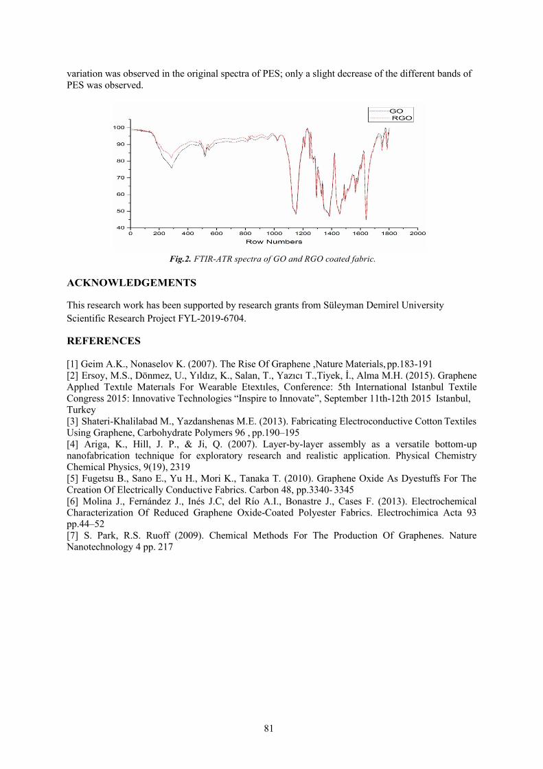
81
variation was observed in the original spectra of PES; only a slight decrease of the different bands of PES was observed.
Fig.2. FTIR-ATR spectra of GO and RGO coated fabric.
ACKNOWLEDGEMENTS
This research work has been supported by research grants from Süleyman Demirel University Scientific Research Project FYL-2019-6704.
REFERENCES
[1] Geim A.K., Nonaselov K. (2007). The Rise Of Graphene ,Nature Materials, pp.183-191[2] Ersoy, M.S., Dönmez, U., Yıldız, K., Salan, T., Yazıcı T.,Tiyek, İ., Alma M.H. (2015). GrapheneApplıed Textıle Materıals For Wearable Etextıles, Conference: 5th International Istanbul TextileCongress 2015: Innovative Technologies “Inspire to Innovate”, September 11th-12th 2015 Istanbul,Turkey[3] Shateri-Khalilabad M., Yazdanshenas M.E. (2013). Fabricating Electroconductive Cotton TextilesUsing Graphene, Carbohydrate Polymers 96 , pp.190–195[4] Ariga, K., Hill, J. P., & Ji, Q. (2007). Layer-by-layer assembly as a versatile bottom-upnanofabrication technique for exploratory research and realistic application. Physical ChemistryChemical Physics, 9(19), 2319[5] Fugetsu B., Sano E., Yu H., Mori K., Tanaka T. (2010). Graphene Oxide As Dyestuffs For TheCreation Of Electrically Conductive Fabrics. Carbon 48, pp.3340- 3345[6] Molina J., Fernández J., Inés J.C, del Río A.I., Bonastre J., Cases F. (2013). ElectrochemicalCharacterization Of Reduced Graphene Oxide-Coated Polyester Fabrics. Electrochimica Acta 93pp.44–52[7] S. Park, R.S. Ruoff (2009). Chemical Methods For The Production Of Graphenes. NatureNanotechnology 4 pp. 217

82
A MODIFIED TWIST-SPINNING TECHNOLOGY: THREE-ROVING YARN SPINNING DOI: 10.35530/TT.2019.18
Murat DEMIR, Musa KILIC
Dokuz Eylül University, Faculty of Engineering, Department of Textile Engineering, İzmir, Turkey
[email protected], [email protected]
Corresponding author: Murat DEMIR, E-mail: [email protected]
Abstract: Ring spinning is one of the oldest and most widely used spinning technology. Recently, many alternative spinning technologies have been introduced. Some of these technologies work on completely different working principle while some of them were developed from conventional system with some modifications. Siro- spun technology which two strands are fed into drafting zone simultaneously is one of the systems that developed from conventional ring spinning. This study focuses on development of three-roving yarn production system that was inspired from siro-spun technology. Roving funnel and delivery cylinder used in siro-spun technology were redesigned for three-roving yarn production and attached on conventional system. Three-roving yarns produced in ring spinning machine were compared with three plied yarns in terms of physical, mechanical and structural properties. For better assessment of this new system, different raw material types were used in yarn production. Results showed that three-roving yarns have better hairiness values and similar mechanical properties for all raw material types. However, unevenness still needs to be improved by further developments on this new system.
Key words: three-roving yarn, multi-strand yarn, siro-spun yarn, twist spinning, delivery cylinder
1. INTRODUCTION
In recent years, the needs for yarns in different properties or for more efficient production processes, many alternative spinning technologies have been introduced. Twist spinning, mostly known siro-spun spinning, is one of those technologies that improved from conventional ring spinning. The working principle of twist spinning relies on simultaneously feeding two strands in the drafting zone and produce two-strand yarn in a single process. While two strands are spun for single yarn production, two small and one large spinning triangle occurs. Emmanuel and Plate [1] stated that stress on single yarn during siro-spun production process related with the two-strand angle and increasing strand angle results greater tension on single yarn. Miao et al. [2] were also investigated the effect of spinning triangle on yarn properties and they concluded that strand length between front cylinder and yarn convergence point is also important for twist on each strand. Tyagi et al. [3] stated that fibers get well oriented in yarn structure with the increasing strand space and by this way, more even yarn structures are obtained. However, after optimum level, greater strand space negatively affects yarn properties. Gokarneshan et al. [4] investigated the relation between strand space and inter fiber cohesion and increasing strand space after optimum level cause poor fiber cohesion. Many researchers compared the properties of siro-spun and other yarn types. Kaushik and Bahtnagar [5] were produced siro-spun yarns with different strand spaces and compared with two-plied yarns. Yildiz and Kilic [6] also compared siro-spun and two-plied yarns and they concluded that siro-spun yarns have better hairiness, mechanical properties and similar unevenness values than two-plied yarns. Örtlek et al. [7] compared conventional, compact and siro-spun yarns with the strand space 8 mm. It was concluded that siro-spun yarns have better hairiness values than other two yarn types and higher breaking elongation than compact yarns. Soltani and Johari [8] compared siro-spun yarns with solo-spun and conventional yarns. They concluded that increasing tension in the spinning triangle results better fiber distribution in yarn structure. Su et al. [9] compared siro-

83
spun and compact-siro-spun yarns and they concluded that compact-siro-spun yarns are in tighter structure. Recently, multi-strand yarn structure has been investigated by researchers. He [10] claimed that three-strand yarn can be used for technical textile in the future and different spinning geometry can occurs during yarn production. Demir and Kilic [11] were investigated production possibilities of three- strand yarns. Su et al. [12], investigated yarn formation point for three-strand yarn production and claimed that tension on each strand is related with the flow movement of each strand. Matsumoto et al. [13] produced three-strand yarns and they claimed that fiber distribution in yarn structure varies basedon the geometry of spinning triangle. Matsumoto et al. [14] also studied fiber distribution in yarn fordifferent fiber fineness. In the other study of Matsumoto et al. [15] fiber length is taken intoconsideration with fiber fineness to investigate fiber distribution for three-strand yarns.This study focuses on development of three-roving yarn production system that was inspired from siro- spun technology [16]. Roving funnel and delivery cylinder used in siro-spun technology were redesigned for three-roving yarn production and attached on conventional system. Three-roving yarns produced in ring spinning machine were compared with three plied yarns in terms of physical, mechanical and structural properties.
2. MATERIALS AND METHODS
2.1 Material In the study, Ne 60/3 three-strand yarns with and without three-grooved delivery cylinder were produced with αe=3.4 twist multiplier. For comparison of the results, Ne 60/3 conventional three-plied yarns with αe=3.4 twist multiplier were also produced. For all types of yarn production, 100% cotton, 100% PES, 100% Tencel, 100% micro Modal fibers were used as raw material. 2.2 Method In this study, two types of three-strand yarns were produced and compared with the three-plied yarns (TPY) that produced with same yarn structural parameters. For the first type of three-strand yarn (TSY), three-strand funnel is placed on conventional system (Figure 1). Secondly, in addition to three-strand funnel, three-grooved delivery cylinder (TSYWDC) was also placed before main drafting area in order to investigate controlled strand space effects on yarn properties (Figure 2). All yarn properties were measured with USTER Tester 5 S800, Uster Tensorapid 4 and Lawson Hemphill CTT. Results of yarns were compared at 95% confidence level.
Fig. 1. Three-strand yarn (TSY) production Fig. 2. Three-strand yarn with delivery cylinder (TSYWDC) production
3. RESULTS AND DISCUSSION
3.1 Hairiness Error bar graphs for hairiness values of TPY, TSY and TSYWDC at 95% confidence level is given in Figure 3. Results showed that TPY have higher H and sh values than TSY and TSYWDC. This situation can be explained by less production process for TSY production as similar as siro-spun and two plied yarn comparison. Moreover, it can also seen that three-grooved delivery cylinder has positive impact for reduction of hairiness values.

84
Fig. 3. Error bar graphs for H and sh values of TPY, TSY and TSYWDC yarns
3.2 Mechanical Properties Error bar graphs for breaking force (cN) and breaking elongation (%) values of three types of yarns are given in Figure 4. ANOVA results for breaking force show that, there is no statistically significant difference between three-plied and both three-strand yarns. Breaking force is related with the number of fibers in cross-section and twist coefficient. As the all yarn types were produced at same count and same twist level, it was expected to see similar results.
Fig. 4. Error bar graphs for breaking force and breaking elongation of TPY, TSY and TSYWDC yarns
3.3 Unevenness Investigating the unevenness results show that, TSY and TSYWDC have higher unevenness (% CVm) and optical unevenness (%CV2D) values than TPY. During yarn production of three-strand yarns, spinning triangle is not stationary (Figure 5-6). When the geometry of spinning triangle changes, length of each strand as well as tenacity and twist on each strand changes. For the future studies, controlling spinning triangle is expected to improve unevenness values of three- strand yarns.
Fig 5. Changes the geometry of spinning triangle during production for TSY and TSYWDC (S: uncontrolled strand space in TSY N: yarn formation point, L= changes on yarn formation point location)
Fig 6. Spinning triangle of TSY and TSYWDC

85
4. CONCLUSIONS
In this study, inspired from siro-spun yarns, three-strand twist yarns were produced placing with three-strand funnel and three-grooved delivery cylinder. Comparing results showed that both three-strand yarns have better hairiness and similar mechanical properties than three plied yarns. Moreover, either for TSY or TSYWDC unevenness values should be improved.
ACKNOWLEDGEMENTS
Thanks to KİPAŞ Mensucat A.Ş. for supporting the experimental part of the study.
REFERENCES
[1] Emanuel A., Plate, D. (1982). Alternative Approach to Two-Fold Weaving Yarn, Part II. TheTheoretical Model, Text Inst, 73 108-116.[2] Miao, M., Cai, Z. and Zhang, Y. (1993). Influence of machine variables on two-strand yarnspinning geometry. Text Res J, 63 (2), 116-120.[3] Tyagi, G.K., Rajdev, A., Mehta, M., Jain, S. and Jindal, B.M. (1987). Contribution of fibre length,fibre linear density and strand spacing to physical and mechanical characteristics of siro-spun viscoseyarns. Indian Journal of Fibre and Textile Research, 12, 63-67.[4] Gokarneshan, N., Anbumani, N. and Subramaniam, V. (2006). Influence of strand spacing on theinterfibre cohesion in siro yarns. The Journal of The Textile Institute, 3 (98), 289-292.[5] Kaushik, R. and Bhatnagar, S. (1992). A comparison of quality aspects of fabrics knitted from two- ply and siro yarns. Indian Journal of Fibre and Textile Res, 17, 69-71.[6] Yıldız, B.S. and Kilic, M. (2017). An investigation on Properties of Siro-spun Yarns. Annals ofUniversity Oradea Fasciles of Textile and Leatherwork. Vol . 18. Pp. 131-136.[7] Örtlek, H., Kılıç, G. and Bilgin, S. (2011). Comparative study on the properties of yarns producedby modified ring spinning method. Industria Textila, 3 (62), 129-133.[8] Soltani, P. and Johari, M. (2012). A study on siro, solo, compact and conventional ring-spun yarns.Part I: yarn strength with relation to physical and structural properties of yarns. The Journal of TextileInstitute, 9 (103), 921-930.[9] Su, X., Gao, W., Liu, X., Xie, C. and Xu, B. (2015). Research on the compact-siro spun yarnstructure. Fibres and Textiles in Eastern Europe, 3 (111), 54-57.[10] He, J. (2007). Variational approach to nonlinear coupled oscillators arising in sirospun yarnspinning. Fibres and Textiles in Eastern Europe, 1 (60), 31-34.[11] Su, X., Liu, X., Xie, C. and Huang, B. (2013). Convergence point of three-strand yarn spinning.Fibres Textiles in Eastern Europe, 3 (99), 48-50.[12] Matsumoto, M., Matsumoto, Y., Kanai, H., Wakako, L. and Fukushima, K. (2014), Constructionof twin staple-core spun yarn with two points of yarn formation in one twisting process. Text Res J,Vol. 84(17) 1858–1866.[13] Matsumoto, Y., Kimura, H., Yamamoto, T., Matsuoko, T. and Fukushima, K. (2009).Characteristics of novel triplet spun yarns made from fibers of differing fineness. Text Res J, 79 (10),947-952.[14] Matsumoto, Y., Kanai, H., Wakako, L., Morooka, H., Kimura, H. and Fukushima, K. (2010).Exploratory Work on the Spinning Condition of the Structure of Staple-core Twin-spun Yarns. TextRes J, Vol 80(11): 1056–1064 DOI: 10.1177/0040517509352521[15] Demir, M. and Kilic, M. (2017). Investigating possibilities of three-strand yarn production. Fibersand Textiles. Vol 24. Pp. 30-35.[16] Demir, M. (2017). An investigation on production possibilities of three-roving sewing threads.MSc Thesis. Dokuz Eylül University, Institute of Natural and Applied Sciences.

86
ECOFRIENDLY AND SUSTAINABLE DENIM FINISHING TECHNIQUES
DOI: 10.35530/TT.2019.19
Faiza Anwar, Ahmad Abdullah
University of Management and Technology, School of Textile and Design, Lahore, Pakistan
Abstract: Denim washing is not such an old thing that is not known to us. It is done to get proper aesthetic look of the fabric. Denim washing or somehow called as denim finishing has its own scope in the market or industrial scale as it enhances the functional activity as well as the make fabric aesthetically more appealing This research work focuses on the different washing techniques of denim fabric keeping the environment as major concern with enzyme (Lava Cell NHC, bio-polish (Lava Cell NBP, enzyme and stone, resin (PULCRA STABITEX ETR+dip and resin spray. For this purpose, the leg tubes of 22×22 inches of denim fabric are made and prescribed recipes are applied on the fabric in an automatic tumble TONELLO machine. After that different tests were performed to investigate change in dimensional, pilling resistance, tensile Strength, tear Strength, absorbency and change in shade variation after different washing. And surface morphology of fabric samples after washing was investigate by SEM analysis. . Key words: Denim, Resin, stone wash
1. INTRODUCTION
Denim is one of the most popular fabrics that have acclaimed most popularity in the past three decades. Denim fabric is rugged cotton twill textile, in which one weft thread passes undertow or more warp threads or one warp threads passes under two or more weft threads[1] .Denim washing is an aesthetic fashion finish that provides the fabric a proper look, shape, comfort and softness in wearing. All of the fashion trends favor or any kind of fading seams can only be achieved through garment processing [1]. Now-a-days, denim jeans is not just used for its hard work, it spreads as the highest fashion wear even it can also say that fashion is today incomplete without denim. Denim comes in all forms, looks and washes to match with every dress. A number of technological factors have contributed to making denim the fashion icon that it is today including vast improvements in spinning, weaving, finishing etc [2]. Denim washing is also considered as the denim finishing in which numerous operations are performed for achieving the better handle and high durability [3]. Denim washing has its own list of objectives, advantages and limitations.

87
According to the researchers, the denim garment washing is a most widely used finishing technique that is necessary to apply for better appearance and to reach a maximum comfort level because before its treatments it’s a hard fabric of containing several contaminants of spinning, weaving and fabric making means initial processing. Hence, the denim finishing got a high demand due to its highly fashionable trend in the market. There a number of denim washing methods that are performed in the industrial state like enzyme wash, bleach wash, acid wash, normal wash, stone wash, pigment dipping, pigment spray wash, stone and combined enzyme wash, bio- polishing, and many more according to the customer’s perspective[4]. Denim washing is important in term of environmental concerns and the effects of different washing techniques on the mechanical properties of fabric. Dr. Heba Assem EL-Dessouki an associate professor of Home Economics Dept., from the faculty of Specific Education, Ain Shams University, Egypt worked on the washing methods to check the mechanical properties of denim fabric [5]. Still there is a lot of work needed to be done to avoid the loss in the mechanical properties and keeping in view the environmental concerns. The purpose of this work is to modify the washing techniques with respect to their comparative washing method to give a complete analysis between the laccases enzymes and the cellulase enzyme for the betterment of achieving the color fading, tensile strength, elongation at break, stiffness, wrinkle recovery and provide the structural analysis through SEM images.
2. MATERIAL AND METHODS
2.1 Material In this research project, a number of chemicals are used for its own specific actions and most of them are from the company Dye Star which is named as below: Lava Cell NHC (Wide Temperature range stone enzymes applied at 30-60oC on pH 6-7),Lava Cell NBP (Neutral Bio-polish enzymes applied at 30-60oC on pH 7-8), Pumice Stone, PULCRA STABITEX ETR+ (Di-methylol-dihydroxy-ethylene urea, methylized in water a transparent yellowish liquid at pH value 4-6), Acetic Acid, Soda Ash, Lava Wet WLA (Wetting Agent), Sera Fix C-PB (A mid soft binder), Lava Fix FF (Fixing agent) and Lava soft EPS (a fatty acid based paste softener. The specification of denim fabric used in this research work is given in the table 1.
Table 1: Specification of Denim fabric
Denim Fabric Specification
Warp Count 7.9Ne
Weft Count 6.5Ne
Ends per inch 64
Picks per inch 47
Fabric Type 100% cotton fabric
Weave Structure 2/1 twill weave
GSM 379.8grams/meter2
Sample size 22”X22”

88
2.2. Methodology
Methodology for denim fabric In this research, the above recipes are applied on the fabric in an automatic tumble TONELLO machine. First of all, the water level is adjusted with respect to the load size which is of 5Kg. After this, the chemicals like Lava Cell NHC or Lava Cell NBP is added into the machine by tank. The stone is added into the machine from the gate. After adding the chemicals, the temperature is set up to 45oC and the pH value is set from 6.5 to 7.5. In the application of resin dip, the fabric is dipped into the resin bath and then a complete hydro- extractor is done for 1mint. After this, the fabric is passed from the oven chamber for drying at 120oC and curing at 150oC for 15 mints. The same phenomenon is done in resin spray method. After the washing, the fabric is dried at temperature 70oC for 40mints.
3. RESULTS AND DISCUSSION OF DENIM FABRIC
3.1 Enzyme wash
Lava Cell NHC is a cellulase based enzyme which is used for both the desizing and for the removal of indigo dyes. It is seen that the tensile strength of the treated specimen is decreased as compared to the untreated specimen in both directions. The tensile strength loss is experienced as a result of the rubbing action of the fabric to fabric, fabric to machine and fabric to enzyme. Warp yarns are more affected by enzyme washing due to its own weaving character of warp faced denim fabric [11,12]. In warp direction, the strength loss in percentage is varied from one to the other like for 0.5% concentration enzyme washed fabric loses strength 21.17%, and 1% concentration enzyme washed fabric loses strength of 15.14% and the 1.5% concentration enzyme washed fabric loses strength 16.10% and in weft direction, the strength loss on enzyme concentration 0.5%, 1% and 1.5% are 20.73%, 19.1% and 29.57% respectively.
Table 2: Tensile strength of Enzyme Washed Denim Fabric Direction Warp Direction Weft Direction Sample
No: Reading
01 Reading
02 Reading
03 Mean Value
Reading 01
Reading 02
Reading 03
Mean Value
Standard Sample 1403 1210 1330 1314.3 955.3 1031.8 968.4 985.2
Sample 01 1049 1100 959 1036 653.7 863.6 836.3 784.5
Sample 02 1211 1036 1099 1115.3 794.4 778.3 818.8 797.2
Sample 03 1157 1051 1100 1102.6 620.7 769.6 691.4 693.9

89
3.2 Bio-polish wash Lava Cell NBP is a neutral based enzyme and clears the surface of the fabric by removing pills from its surface. The chemical also acts like a desizer so it removes the size particles due to which the hard look of the fabric is removed [11,12]. In warp direction, different concentrations of Lava Cell NBP 0.5%, 1% and 1.5% affects the strength loss like 13.01%, 8.92% and 9.31% respectively. It is observed that the 1g/l used of concentration of bio-polish shows better result than the other two as it is most probably used in the industrial area. In weft direction, at washing concentrations of bio-polish 0.5%, 1% and 1.5%, tensile strength loss is 13.91%, 5.41% and 6.35% respectively.
Table 3: Tensile strength of Bio-polished Denim fabric Direction Warp Direction Weft Direction Sample
No: Reading
01 Reading
02 Reading
03 Mean Value
Reading 01
Reading 02
Reading 03
Mean Value
Standard Sample 1403 1210 1330 1314.3 955.3 1031.8 968.4 985.2
Sample 04 1329 1082 1019 1143.3 847.1 873 824.6 848.2
Sample 05 1254 1136 1201 1197 865.7 977.4 952.7 931.9
Sample 06 1333 1148 1095 1192 973.2 853.2 941.4 922.6
3.3 Enzyme and Stone wash It is seen in the table that there is a gradual decrease occurs in the tensile strength of the denim fabric due to the increase in concentration of enzyme as such the effect of pumice stone. This is just of the high rubbing action of fabric with the fabric, fabric with the machine, effect of enzymes concentration and the rubbing action of fabric with the pumice stone. The warp wise strength is gradually decreasing by increasing in concentration of enzyme and constant amount of the pumice stone just like at concentrations 0.5%, 1 % and 1.5% shows the strength loss 10.37%, 14.36% and 25.45% respectively. In weft direction, the strength loss in weft directions at concentrations 0.5%, 1% and 1.5% are 16.3%, 24.5% and 23.9% respectively.
Table 4: Tensile strength of Enzyme and Stone washed Denim Fabric Direction Warp Direction Weft Direction Sample
No: Reading
01 Reading
02 Reading
03 Mean Value
Reading 01
Reading 02
Reading 03
Mean Value
Standard Sample 1403 1210 1330 1314.3 955.3 1031.8 968.4 985.2 Sample 1274 1101 1159 1178 839.7 816.3 817.8 824.6
07 Sample
08 1125 1099 1153 1125.6 782.1 759 690.8 743.9
Sample 09 987.9 952.4 1001 980.4 675.1 792.7 781.3 749.7

90
4. CONCLUSION
In the denim fabric, it can be easily concluded that the 1% concentration of enzymes showsbetter results of tensile strength and tear strength among all the washes, while, the GSM is slightlyincreased due to the occurrence of shrinkage in the fabric. It is seen that the pilling strength ofenzyme wash, bio-polish wash and stone wash is reduced. On the other hand, the pilling results ofresin dip wash and spray wash are very good. In the SEM analysis of denim fabric, a highamount of entanglements between fibers is observed. The alignment of yarns in the fabric ischanged. A high amount of rupture and cracks is also seen in the fabric. The assets of stone andenzymes are also present on the fiber surface. It is concluded that enzyme wash shows betterresults comparatively to the bio-polish wash and stone wash. Also, the most suitable method forthe application of resin is by dipping method because there is no chance of missing of resin on thefabric surface.
REFERENCES
[1] J. H. M. N. F. DAKURI ARJUN, "Technology of Industrial Denim Washing: Review,"International Journal of Industrial Engineering & Technology (IJIET), vol. 3, pp. 25-34, 2013.[2] Saurabh. (2009, 12 october). Denim Washing - Basic Steps and Guide.Available: https://www.denimsandjeans.com/denim/manufacturing-process/denim-washing- basic-steps-and-guide/908[3] W. U. o. B. Elias Khalil from Department of Textile Engineering, Dhaka, Bangladesh,"Sustainable and Ecological Finishing Technology for Denim Jeans," American Associationfor Science and Technology, vol. 2, 10 July 2015.[4] M. I. H. M. M. M. R. Khan, "Characterization and process optmization of indigo dyed cottondenim garments by enzymatic wash," Fashion & textiles a Springeropen Journal, p. 12, 14December 2014.[5] D. H. A. El-Dessouki, "Effect of Different Washing Methods on Mechanical Properties ofEgyptian Denim Fabrics," Internation Design Jounal, vol. 5, pp. 1099-1107, 1st July 2015.[6] A. A. Mansoor Iqbal. Munazza Sohail, Kamran Ahmed, Arsheen Moiz, Khalil Ahmed, "TextileEnvironmental Conditioning: Effect of Relative Humidity Variation on the Tensile Propertiesof Different Fabrics," Journal of Analytical Sciences, Methods and Instrumentation, pp. 92-97,31st january 2012.[7] TesTexTextile, "What is Fabric Pilling Test," vol. 2017, ed. United Kingdom: TesTex, 2017.[8] M. S. Center. Pilling Resistance of Textile Fabrics. Available:http://www.manufacturingsolutionscenter.org/pilling-resistance-testing.html[9] B. Solutions. (2017, 26 November). Data color Match Textile Powerful & Accurate Textile ColorMatching Software. Available: http://www.datacolor.com/business-solutions/product- overview/datacolor-match-textile. [10] A. Islam, "Dimensional Stability to Washing," in Textile Learner. BlogSpot vol. 2014, T. Learner,Ed., ed. Noakhali Textile Engineering College, 2014.

91
OPTIMIZING CURING CONDITIONS IN FLAME RETARDANT TREATMENT FOR COTTON FABRIC
DOI: 10.35530/TT.2019.21
Huong- Thi NGUYEN1,2, Hong Khanh – Thi VU1 1 Hanoi University of Science and Technology, School of Textile -Leather and Fashion, Department of Textile Materials and
Chemical Textile, Hanoi, Vietnam, E-M ail: 2 Hanoi Industrial Textile Garment University, Hanoi, Vietnam, E-M ail:
Corresponding author: Vu Thi Hong, Khanh, E-mail: [email protected]
Abstract: The study of the influence of curing conditions on the properties of the cotton fabric treated with Pyrovatex CP New (PR) and Knittex FFRC was carried out with 10 experiments. The central composite designs type face centered (CCF) was used to design experiments. In these experiments, the curing temperature was varied from 160oC to 180oC and the curing time from 60-120 seconds. The chemical uptake rate, vertical flammability characteristics, LOI value, tensile strength of the untreated and treated samples were determined. Based on the results, 5 response models between the determined properties of the treated fabric and two studied variables were found. From these models, the optimal curing temperature and time were found with the highest fire resistance efficiency and minimum loss for the mechanical properties. They are 180oC and 113.7 seconds
Key words: CCF, LOI value, chemical uptake rate, tensile strength, curing temperature, curing time
1. INTRODUCTION
Although cotton fiber is the most popular and widely used nature material in the textile industry, these fibers are burn easily. Thus, application of flame-retardant materials on cotton cellulose has become an important issue in the textile industry [1]. Durable flame retardant fabric should withstand a higher number of washing cycles. One of the effective durable flame-retardant agents is Pyrovatex CP New (PR) which is an N-methylol dimethyl phosphonopropionamide [2, 3]. PR influences the pyrolysis reaction, prevents the formation of levoglucosan and flammable volatiles, and promotes the formation of char. It has methyl group which reacts with cellulose. Furthermore, crosslinking agents are used to improve the durability of the finish [4]. The loss in both tear and tensile strengths is a problem of this finish because of associated acidic catalytic damage, especially due to the high temperature curing conditions [1], [2]. However, curing at high temperatures is an important factor related to the flame resistance of fabric and its durability [1, 2]. In our previous study [4], Knittex FFRC (DHEU), a non-formaldehyde crosslinking [5] was used in associated with PR. Knittex FFRC can create ether bonding with cellulose and PR, thus creating durable fire-retardant fabric. Therefore, it is necessary to select the optimal curing condition, allowing the ether reaction to produce a durable flame-retardant cotton fabric and affect the mechanical properties of the fabric as little as possible. In this study, in flame retardant finish for cotton fabric with PR and DHEU, the flame-retardant characteristics, tensile strength of the un-treated and treated fabric were measured as the functions of the temperature and time of curing step. The purpose of the study is to predict the optimal curing conditions with the highest fire resistance efficiency and minimum loss for mechanical properties. The novelty of this study is application of the CCF design with RSM to get the optimal temperature and time of curing step in flame-retardant finishing for cotton fabric with PR and DHEU
2. EXPERIMENTAL
2.1. Mate rial Fabric: 100% cotton, 2/1 twill weaves, 17.24 × 35.71 (Tex)/142 × 58 (per inch), weight 190g/m2, desized, scoured, bleached and mercerized, supplied by Hanoi Dyeing Joint Stock Company. Chemichals: Pyrovatex CP New (PR), Knittex FFRC (K), Invadine PBN were supplied by Huntsman.

92
2.2. Method Flame retardant treatment for cotton fabric One bath pad-dry-cure method was used to the flame-retardant finishing. Machine: padder SDL D394A, stenter SDL D398. The flame-retardant finish for fabric has been carried out with ten different experiments. In which: finishing solutions: 450 g/l PR, 108 g/l K, 5 g/l Invadine PBN, wet pick up: 80%, drying: 110°C for 5 minutes, curing temperature and curing time were varied according to the central composite designs type face centered (CCF). The details of these experiments are presented in Table 1, where, X1 and X2 are absolute values of temperature and time Table 1: CCF Design of experiments of curing, i.e., un-coded values. A (B) are the coded variables. According to the CFF, the factors are tested at 3 levels, equivalent to levels − 1, 0 and +1. The absolute values X and the respective coded values can be obtained by a linear transformation of the original measurement scale, namely [6]: X = ∆X * coded value + X0 (1) , where: X0 = (Xmin+Xmax)/2, ∆X = (Xmax-Xmin)/2, A (B) = (Xi - X0)/ ∆X (2) The total number of the trials N based on the number of the design factors k (number of factors studied in the experiment). N = 2k + 2k + nc [6], where 2k factorial trials, 2k axial trials and nc center point trials (nc = k). In this study, k=2 so N=10 Treated samples washing To determine the flame- retardant durability of the treated fabric, it was washed in accordance with ISO-6330 standard clause 6A with non-phosphate ECE reference detergent A. The Electrolux EW 1290W front load washing machine was used.
2.3. Assessment of he tre ate d fabric’s properties Real uptake of recipe chemicals: add-on % on fabric =100 (WF-W0)/WF (Eq. 3)
In Eq. (3), WF and W0 are the standard condition weights of the treated and un-treated samples. The test repeated five times for each experiment. The final results is an average of the 5 tests Flammability test: the untreated and finished fabrics were tested according to the ASTM D 6413 – 2015 (for vertical flammability characteristics), and to the D 2863-97 standard method (for LOI values) was used for evaluating the flammability of the untreated and finished fabrics. Tensile strength test was according to the ISO 13934-1:2013 standard method.
3. RESULTS
The experimental results according to the CCF design are presented in the Table 2.Mode l dete rmination: From the experimental results, the response equations in un-coded variable(Y1, Y2, Y3, Y4, Y5) and in coded variables (R1, R2, R3, R4, R5) were output by the Design Expert V10.0.8. They are the anticipated responses for the add-on (%), LOI value, char length, warp tensile strength, weft tensile strength respectively. These equations and their statistical parameters are shownin Tab.3. The shorted ANOVA related to the Y1, Y2, Y3, Y4, Y5 models are given in Tab. 4. Modelfitting and analysis of variance (ANOVA): Table 3 shows that the coefficients of determination (R2) of all five responses are higher than 80%. In addition, their p-values are less than0.05 in five responses indicating. Tab. 4 shows that, all the p-values of the terms of Y1, Y2, Y3, Y4 and Y5 are less than 0.05, except the p-value of X1
2 in Y1 and of X1X2 in Y3 are higher than 0.05, but they are less than 0.1, so, according to the principle of significance of [6], they can be accepted.Besides, the calculated p-values for lack-of-fit of all models (Tab.4) are greater than 0.05.Therefore, all five models are statistically significant and there is no statistically significant evidence that these models do not represent the data at a 95% confidence level.
Exp No
A B X1 X2
T1 -1 -1 160 120 T2 +1 +1 170 60 T3 0 +1 170 120 T4 0 0 180 60 T5 0 0 170 90 T6 +1 -1 160 60 T7 0 -1 180 120 T8 -1 0 180 90 T9 +1 0 170 90
T10 -1 +1 160 90

93
Effect of curing conditions on the prope rties of the finishe d fabric Effect on combustion behavior: Tab. 3 and Fig. 1, 2 show there is a clear difference in combustion behavior of samples treated at different curing conditions, as follows: Effect on the real uptake: the higher the curing temperature and time are, the higher the add-on on the samples is. However, the add-on increases more slowly when the temperature and time are high.
Table 2: The CCF experimental design and results Run Y1
add-on %
Y2 LOI %
Characteristics of vertical flammability test Tensile strength (N)
After-flame times (s) After-glow times (s) Char Length (mm) Warp Weft
0 OWC
10 OWC
30 OWC
0 OWC
10 OWC
30 OWC
0 OWC
10 OWC
30 OWC
Control
-
14.9
23
-
44
-
-
Comple tely
burned
-
-
899.3
532.8
T1 10.12 19.3 20± 3 20± 2 - 0 0 - 300±0 300±0 - 736.9 448.7 T2 11.2 19.7 16± 3 19± 1 - 0 0 - 300±0 300±0 - 722.9 455.5 T3 13.22 25.9 0 0 0 0 0 0 48±3 49±3 53±5 712.5 447.8 T4 11.79 21.5 18±3 18± 4 - 0 0 - 300±0 300±0 - 711.5 453.9 T5 12.63 20.2 13± 7 8± 4 - 0 0 - 188±20 184±25 - 700.3 450.5 T6 8.15 17.5 19± 3 20± 2 - 0 0 - 300±0 300±0 - 739.9 458.0 T7 15.67 25.1 0 0 0 0 0 0 48±5 43±3 48±7 607.2 440.7 T8 14.83 24.6 0 0 0 0 0 0 58±17 49±7 50±4 652.3 447.8 T9 12.72 20.7 14± 4 - - 0 0 - 197±18 - - 708.3 448.4 T10 9.82 18.4 20±3 21± 2 - 0 0 - 300±0 300±0 - 737.7 454.0
Table 3: Model fitting of test results
Test respon- ses
Model Parameters Response equation in actual and coded variable s
R2 Adj R2 F- value
P- value
Add-on 0.9908 0.9793 86.10 0.0004 Y1 = −185.1508 + 2.114X1 − 0.085X2 + 0.0016X1X2 − 0.0059𝑋𝑋𝑋𝑋2 −0.0008𝑋𝑋𝑋𝑋2
1 2 R1=12.28+2.37A+1.31B+0.48A B-0.59A2-0.71B2
LOI 0.8398 0.7940 18.35 0.0016 Y2=-29.8433+0.2667X1+0.0644X2 R2= 21.24+2.67A+1.93B
Char length 0.8500 0.7749 11.33 0.0070 Y3=-1357.1333+10.6666X1+32.9X2-0.21X1X2 R3=204.2-82.33A-84B-63AB
Warp tensile strength
0.9190 0.8785 22.69 0.0011 Y4=160.789+3.5355X1+13.691X2-0.00844X1X2 R4=700.58-39.97A-16.29B-25.31AB
Weft tensile strength
0.9305 0.9107 46.87 < 0.0001 Y5 = 517.51333 − 0.30517X1 − 0.16783X2 R5=450.53-3.05A-5.04B

94
(a )
Table 4: Shorted ANOVA of the models Source F-
value p-ValueProbe >
F
F- value
p-Value Probe >
F
F- value
p-ValueProbe >
F
F- value
p-Value Probe >
F
F- value
p-ValueProbe >
F Term\Model Y1 Y2 Y3 Y4 Y5 X1 306.28 < 0.0001 24.06 0.0017 13.98 0.0096 45.60 0.0005 25.19 0.0015 X2 94.08 0.0006 12.64 0.0093 14.55 0.0088 10.66 0.0171 68.56 < 0.0001 X1 X2 8.31 0.0449 - - 5.46 0.0582 11.82 0.0138 - - X1
2 7.51 0.0519 - - - - - - - - X2
2 10.70 0.0308 - - - - - - - - Lack of Fit 35.79 0.1221 16.39 0.1869 48.29 0.1088 7.93 0.2630 1.00 0.6450
LOI value: the higher the curing temperature and time are, the higher the LOI of the treated sample is. But for the LOI value to be higher than 25, the curing temperature must be higher than 177oC and the curing time must be longer than 105 seconds. Char length: the higher the curing temperature and time are, the shorter the char length is. However, the effect of curing time on char length is stronger than that of curing temperature
Effect on tensile strength: the higher the curing temperature and time are, the lower the tensile strength of the treated fabric is.
(a) (b) (c) (d)Fig. 1. Vertical flammability of, (a) After treatment, (b) after 10 of washing cycles, (c) After 30 of washing
cycles, and (d) control
cted value cted value
ed value ed value
46
45
60 160
(a) (b) (c) (d) (e)
Fig. 2. Surface response curve: (a) add-on (b) LOI (c) Char length (d, e) Warp and weft tensile strength
The optimal curing temperature and curing time were investigated from the numerical optimization approach with the assistance of software Design-Expert with the aim to get the fabric having the highest flame resistance (LOI≥25), maximum mechanical properties. According to these criteria, Design-Expert software has given the optimal curing temperature and curing time at 180oC for 113.7 seconds
4. CONCLUSIONS
In applying the response surface methodology with CCF experimental design, five response modelsbetween curing condition and the add-on amount, LOI value, char length, warp and weft tensilestrength of the flame retardant treated fabric have been obtained. Moreover, the optimal curingtemperature and time were found with the highest fire resistance efficiency, minimum loss formechanical properties.
760 740 720 700 680 660 640 620 600
110 (c) 180
120
175
100 170
90
80
B: Time (s) 70
165A: Temperature (oC)
0
5
450
445
440
180
120 175
110
100 170 90
80 165A: Temperature (oC) 70 B: Time (s)
60 160
warp
tens
ile s
treng
th (N
)
Wef
t tens
ile st
reng
th (N
)

95
ACKNOWLEDGEMENTS
This work was comprehended in the framework of project KC.02.13/16-20 which is financed by the MOST of Vietnam. The authors wish to sincerely thank MOST of Vietnam.
REFERENCES
[1] Poon, C.-k. and C.-W. Kan. (2016). Relationship between Curing Temperature and Low Stress Mechanical Properties of Titanium Dioxide Catalyzed Flame Retardant Finished Cotton Fabric. Vol. 17, p.380-388.[2] Poon, C.-k. and C.-w. Kan. (2015). Effects of TiO2 and curing temperatures on flame retardant finishing of cotton. Carbohydrate polymers, 2015. 121: p. 457-467. [3] Yang, Z., et al. (2012). A durable flame retardant for cellulosic fabrics. 2012. 97(11): p. 2467-2472.[4] Khanh V. T. H., Huong N. T. (2019) Influence of crosslinking agent on the effectiveness of flame-retardant treatment for cotton fabric. Industria Textila In: 2019[5] MUHAMMAD MOHSIN., et al. (2014). Softener impact on environment friendly low and zero formal- dehyde cross-linker performance for cotton. Industria Textila, 2014, vol. 65, nr. 3[6] Dutka M., Ditaranto M., Løvås T. (2015). Application of a central composite design for the study of NOx emission performance of a low NOx burner, In: Energies, 2015. 8(5), pp. 3606-3627.

96
INNOVATIVE UV BARRIER MATERIALS MADE OF ORGANIC COTTON DYED WITH NATURAL DYESTUFFS
DOI: 10.35530/TT.2019.22
Jadwiga SÓJKA- LEDAKOWICZ, Joanna LEWARTOWSKA, Bogumił GAJDZICKI, Joanna OLCZYK, Anetta WALAWSKA
ŁUKASIEWICZ Research Network – Textile Research Institute, Lodz, Poland Corresponding author: Anetta WALAWSKA, e-mail: [email protected]
Abstract: The paper presents the results of research works on ecological materials that protect humans against the harmful effects of ultraviolet (UV) radiation, made of organic cotton, obtained through the application of selected natural dyes and a new reactive UV absorber with high molar absorption. These materials are intended for clothing, in particular for children and people with photosensitive skin. Instrumental evaluation of obtained colours and barrier properties of textile products for UV radiation were performed, expressed in the UPF (Ultraviolet Protection Factor) value, determined on the basis of measurements of UV transmittance by a textile product. Due to the application area of the new materials, the colour fastness to washing, perspiration, friction and artificial light. For selected newly developed organic cotton products containing in their structure a natural dye and a new UV organic absorber, specialized irritation tests according to OECD were carried out. In addition, the results of studies on antimicrobial properties are presented on the basis of the assessment of antibacterial activity against Gram (+) Staphylococcus aureus and Gram (-) Escherichia coli.
Key words: natural dyes, cationization, natural mordants, K/S, UPF
1. INTRODUCTION
Ultraviolet radiation due to its significant destructive potential causes a number of diseases [1-2]. The threats resulting from excessive exposure to UV radiation include common sunburn, skin photo-aging processes, as well as various types of phototoxic reactions, immune system diseases and life- threatening skin cancers. WHO recommends the use of appropriate clothing, covering the largest as possible area of the body. Breathable cellulose fibre products (cotton, organic cotton, viscose, linen), white or dyed in light intensities, do not provide an adequate level of protection. The barrier properties of this type of products can be increased by using e.g. natural dyes and UV absorbers. Recently, interest in natural dyes has increased due to the growing expectations of customers looking for environmentally friendly and human-friendly clothing products. Natural dyes are any colouring agents - dyes and pigments - obtained mainly from plants, animals or minerals. Depending on the structureand properties, they can be included in one of the currently known dye groups: vat, direct, acid orpigments. Most of the historically known natural dyes are derivatives of anthraquinone,naphthoquinone, indigo and carotenoids [3]. Among the natural dyes listed in the Color Index, thereare the biggest number of yellows (30) and reds (24), much less represented are: oranges - 5, blues-3, blacks - 4, browns - 5. Most of natural dyes do not have affinity for cellulose fibres hence they canhardly dye the fibre, and the obtained colour fastness to wet factors is insufficient. This is largely dueto the weak interaction with the cellulose fibre, which in the water bath has a negative electricalpotential and a dye molecule of natural origin with similar negative electrical potential. Fibres ofanimal origin, i.e. wool, silk, are more easily dyed with natural dyes. The change in the negativepotential of cellulose fibre can occur as a result of its cationization process. The literature describes theprocess of cellulose fibre cationization with various cationic compounds, mainly to eliminate the useof electrolytes in the process of dyeing cotton with reactive dyes [4].The search for ecological solutions also leads to the use of hand-picked organic cotton. This type ofcotton does not irritate the skin and does not cause allergies, because no pesticides are used during itscultivation (50% of all used pesticides in developing countries are for cotton).

97
This paper presents the results of research on the use of the natural dye Wau-Color (Weld-Reseda) and a new reactive UV absorber - A8G to improve the UV protective properties of knitted fabric made of organic cotton fibres, intended for clothing for children and people with photosensitive skin.
2. EXPERIMENTAL
2.1 Materials
Textile materials: organic cotton knitted fabric, single-jersey with area mass of 182 g/m2., GOTS Certificate No. CU815041GOTS-2019-00000307. Subjected to standard industrial washing process. Chemical agents: cationization agent - polymer cation-active heterocyclic compound Texamin ECE (InoTex, Czech Republic). .Natural dye: Wau-Color obtained by extraction from Weld Reseda (Reseda luteola) plant, kindly supplied by NIG-Nahrungs-Ingenieurtechnik GmbH (Germany); contains yellow dye – luteine. Organic UV absorbers: UV absorber – reactive (symbol A8G) based on 1,3,5-triazine derivatives which due to adequate chemical groups is able to react with cellulose hydroxyl groups [5].
2.2 Sample preparation Cationization – applied from the bath containing 0.8 pieces of NaOH per 1 piece of Texamin ECE at 30°C for 30 min and 50°C for 40 min at a liquor ratio of 10:1. Cationization together with application of UV absorber from the bath containing Texamin ECE and NaOH (as above) and UV absorber A8G at 60°C for 100 min, at a liquor ratio of 10:1. Dyeing: with 1%, 2% or 5% o.w.f. of Wau-Color at 98°C for 40 min, at a liquor ratio of 10:1. Such processes were performed using laboratory dyeing machine Redcrome (Ugolini, Italy).
2.3 Methods of assessment Spectrophotometric evaluation of changes in colour intensity of the fabrics Measurement of the remission (R) coefficient with calculations of the value of relative dye intensity (K/S) for dyed fabrics samples were performed on Datacolor 850 spectrophotometer (Datacolor Int., USA) with dataTools software, for illuminant D65 and 10º observer in accordance with EN ISO 105- J01.The concentration of dye on the fabrics after the dyeing process was assessed indirectly by determination of the K/S coefficient using the Kubelka-Munk formula (1) [6] proportional to the dye concentration on the fiber.
K/S = (1-R)2/2R (1) where: K – light absorption coefficient, S – light scattering coefficient, R – light remission rate,
Protective properties of textile fabrics against UV radiation Absorption spectra of textile fabric samples as well as Ultraviolet Protection Factor (UPF) were determined using double beam type of UV-VIS Jasco V-550 (Jasco) with integrating sphere attachment, according to the EN 13758-1 and 2 standard. According to the EN 13758-2 standard textile fabrics have barrier properties against UV radiation if the UPF coefficient is at least 40 and transmittance in the range UVA <5% for textile designed for protective clothing. Colour fastness The dyed textiles were tested for colour fastness to: washing at 40 °C, alkaline and acidic perspiration as well as dry and wet rubbing according to standard test methods: ISO 105-C06 Method A1S, EN ISO 105-E04 and EN ISO 105-X12, respectively. Assessment of microbiological activity The microbial activity of knitted fabrics was tested against a colony of gram-negative bacteria Escherichia coli (ATCC 25922) and gram-positive bacteria Staphylococcus aureus (ATCC 6538) according to AATCC Test Method 100-2012 – Antibacterial Finish on Textile Materials. This method provides a quantitative procedure for the comparison and evaluation of the degree of antibacterial activity after a 24 h exposure to the test fabric. After incubation, the bacterial challenge is eluted from the swatches and enumerated and a percent reduction by the fabric specimen is calculated. Acute dermal irritation test The assay was performed according to Test No. 404: Acute Dermal Irritation/Corrosion of the OECD Guidelines for the Testing of Chemicals in Nofer Institute of Occupational Medicine. Albino rabbits were used to test the organic cotton knitted fabrics, dyed with Wau-Color. For this purpose, a piece of tested fabric was applied to a small area of skin (approximately 6 cm2) of an experimental animal;

98
untreated skin areas of the test animal served as the control. All animals were examined for signs of erythema and edema after 1, 24, 48 and 72 h as well as after 5, 6, 7, 8 , 9, 10, 11, 12, 13 and 14 days.
3. RESULTS AND DISSCUSSIONIn this work, a cationization process of cotton knitwear was applied to change the negative potential of cellulose fibre so that it can be dyed with natural dyes, as well as to eliminate the use of electrolytes in the application of the A8G absorber of the reactive dye type.
Table 1: Values of UPF and transmittance for organic cotton knitted fabric subjected to various variants of cationization with Texamin ECE process and application of organic UV absorberA8G
Table 2: Values of UPF and transmittance for organic cotton knitted fabric subjected to various variants of cationization with Texamin ECE and dyed with Wau-Color
The results of the studies presented in Table 1 show that the cationization process caused a slight increase in the UPF value and a decrease in transmittance in the UVA range, regardless of the Texamin ECE concentration within 1% to 8%. Application of the A8G absorber at a concentration of 0.25% o.f.w. increased the UPF above 40 and reduced the transmittance in the UVA range to a value of about 5%. It has been found (Table 2) that the cationized and then dyed with Wau-Color dye organic cotton knitwear has good UV protection properties - UPF> 40 and TUVAavg <5%.
Figure 1 shows that after the cationization process, the intensity of dyeing of the fabric by means of the Wau-Color dye increases with the increase in the concentration of Texamin ECE. The "saturation point" of a cationized knitted fabric with the dye occurred at a Texamin ECE concentration of 5%, with a tint of both 1% and 2%.
Fig. 1. Intensity of dyeing of the organic cotton knitwear by means of the Wau-Color after the cationization process with Texamin ECE
Organic cotton knitted fabric samples are characterized by good colour fastness to washing (change in colour - 3-4, staining - 5), rubbing (4) and perspiration (Table 3) It was found that organic cotton knitted fabric sample after cationization with Texamin ECE process, showed strong E. coli and S. aureus growth reduction - R> 99% and A> 6.8. The use of dyeing fabric with Wau-color dye maintained this effect (Table 4). The results of the tests carried out at the Nofer Institute of Occupational Medicine confirmed that organic cotton knitted fabric samples dyed with natural dye Wau-Color do not cause skin irritation.
Sample type UPF Transmittance UVAavg [%]
Texamin ECE 1%
Reseda 1% >50 2.82 Reseda 2% >50 1.67
Texamin ECE 3%
Reseda 1% >50 0.66 Reseda 2% >50 0.60
Texamin ECE 5%
Reseda 1% >50 0.76 Reseda 2% >50 0.66
Texamin ECE 8%
Reseda 1% >50 0.87 Reseda 2% >50 0.68
Sample type UPF Transmittance UVAavg. [%]
Raw (only washed) 18.70 9.40 Texamin ECE 1% 26.52 7.31 Texamin ECE 3% 25.51 7.43 Texamin ECE 5% 26.89 7.11 Texamin ECE 8% 25.72 7.42
Texa
m
in
ECE
3% A8G 0,25% 45.97 5.87
A8G 0,5% >50 4.25 A8G 0,75% >50 4.70
9 ECE 1%,Wau1% ECE 1%,Wau 2% ECE 3%,Wau 1% ECE 3%,Wau 2%
ECE 5%,Wau 1% ECE 5%,Wau 2% ECE 8%,Wau1% ECE 8%,Wau 2%
8
7
6
5
4
3
2
1
0
K/S

99
Table 3: The results of colour fastness parameters of organic cotton knitted fabric cationized with 5% of Texamin ECE and dyed with 5% of natural dye Wau-Color (Weld-Reseda)
1) Colour fastness according to “Greyscale”, indicator “5” means – nochange in colour, indicator “1” means– big change in colour; a/ change ofcolour of the sample, b/ staining -cotton, c/ staining – wool, d/ thestaining of the cotton rubbing fabric;
Table 4: Results of microbiological activity tests of organic cotton fabric modified with 5% of Texamin ECE and dyed with 5% of natural dye Wau-Color (Weld-Reseda)
Sample type Microbiological activity against Escherichia coli
(ATCC 11229)
Microbiological activity against Staphylococcus aureus (ATCC 6538)
A L R (%) A L R (%) 1.Cationized with Texamin ECE 5 % 7.5 2.3 99.4 6.8 2.3 99.64
2.Cationized with Texamin ECE 5% anddyed with Wau-Color 5%
7.0 1.7 98.2 6.6 2.3 99.37
A – microbiological activity coefficient; if A ≥ 3 then the fabric has strong antibacterial activity R - the degree of bacterial growth reduction; L – bactericidal activity value; if L ≥ 0 then the fabric is bactericidal
4. CONCLUSIONS
The technology of materials protecting against the harmful effects of UV radiation, based on the use of organically grown organic cotton and natural plant dyes, was developed. For the application of natural dyes with a negative electrical potential on cellulose fibre (cotton) also characterized by a negative electrical potential, a change in the fibre potential is necessary. It is obtained by the application of a cationic compound in cationization process. As a result, a knitted fabric with uniform coloration and good resistance to washing, rubbing and sweat, as well as a strong antibacterial effect was obtained. The newly developed fabric dyed with natural dye Wau-Color does not cause skin irritation.
ACKNOWLEDGEMENTS Presented research results were achieved within the project EUREKA E! 10710 – UV-SHIELD „Innovative textile materials protecting against UV radiation” Agreement No. EUREKA/UV- SHIELD/02/2017 funded by the Polish National Centre for Research and Development.
REFERENCES
[1] Y. Matsumura i H. N. Ananthaswamy, „Toxic effects of ultraviolet radiation on the skin”,Toxicology and Applied Pharmacology, vol. 195, nr 3, pp. 298–308, 2004.
[2] R. M. Lucas, T. McMichael, W. Smith i B. K. Armstrong, „Solar ultraviolet radiation: globalburden of disease from solar ultraviolet radiation”, World Health Organization, 2006.
[3] M. Sequin-Frey, The chemistry of plant and animals dyes, Journal of Chemical Education 58, 4(1981), 301-305.
[4] T. Aktek , A.K. Malekul Millat, Salt free dyeing of cotton fibre – a critical review, InternationalJournal of Textile Science 2017, 6(2), 21-33.
[5] W. Czajkowski, J. Mamnicka, J. Lewartowska, J. Sójka-Ledakowicz, EP2565187[6] J. Mielicki „Outline of chemical treatment of fibres” WNT Warsaw, 1981,(in polish)
Tested feature Results of the test [degree] Colour fastness to: Organic cotton knitted fabric cationized
and dyed Wau-Color 5% o.w.f. ashing a/3-4 b/5 c/5 acid perspiration 1) a/ 3 b/ 3 c/ 5 alkaline perspiration 1) a/ 3 b/ 4 c/ 5 rubbing 1) Dry d/ column 4-5
d/ row 4-5rubbing 1) Wet d/ column 3-4
d/ row 3-4

100
THE EFFECT OF FIBER CROSS-SECTIONAL SHAPE AND TEXTURING TEMPERATURE ON KNITTED FABRIC AIR
PERMEABILITY DOI: 10.35530/TT.2019.23
Halil İbrahim ÇELİK1, Hatice Kübra KAYNAK2, Esin SARIOĞLU3, Gizem KARAKAN GÜNAYDIN4
1,2 Gaziantep University, Faculty of Engineering, Textile Engineering Department, Gaziantep, Turkey, E-Mail: [email protected], [email protected]
3 Gaziantep University, Faculty of Fine Arts, Department of Fashion and Textile Design, Gaziantep, Turkey, E-Mail: [email protected]
4 Pamukkale University, Buldan Vocational School, Fashion&Design Programme, Denizli, Turkey, E-Mail: [email protected]
Corresponding author: Esin, Sarıoğlu, E-mail: [email protected]
Abstract: Texturized yarns are often preferred especially in home textiles and sportswear. To improve polyester filament properties, mechanical, thermal, chemical and combinations of texturing processes are applied. With these processes, filament yarns take on a curved and voluminous structure and gain a permanent form. Properties of the texturized yarn can be varied as raw materials properties, machine type and process factors. This study covers the investigation of the effect of cross-sectional shape of fiber (round and trilobal) and texturing process temperature (150, 175 and 200 0C) on air permeability of false twist textured polyester single jersey knitted fabrics. Results showed that the highest air permeability value was obtained from knitted fabric with round fiber cross-sectional shape polyester filament textured at 150 0C. According to the statistical analysis, both the fiber cross-sectional shape and process temperature were found to have a significant effect on air permeability property.
Key words: fiber cross-section, false twist texturing, polyester, air permeability.
1. INTRODUCTION
Polyester textile filament is the main category of polyester filament which provides wide usage area in textile and fabric production which is used in garment, shoes and household goods. Demand for polyester filament has been increasing rapidly in apparel production compared to natural filament due to its durability, wrinkle resistance, minimum shrinkage and high color retention [1]. Filaments can be textured by different systems according to the final product to be used. The most preferred texturing system for PET filament is false twist texturing system. In literature, there are various studies that involve the effects of the texturing parameters of polyester filament [2-8]. This study was conducted to investigate the effect of polyester fiber cross-sectional shape and texturing process temperature on air permeability of knitted fabrics. In order to compare the significant effect of these parameters on air permeability property, statistical analysis was performed at 95% confidence interval.

101
2. MATERIAL AND METHOD
In this study, fully drawn (FDY) polyester(PET) filament with 150 denier/48 filaments with two different fiber cross-sectional shape (round and trilobal) were textured at 150, 175 and 200°C on false twist texturing machine. The rest of all false twist texturing parameters was kept constant (Table 1).
Table 1: False twist texturing process parameters Production speed (m/min) 400 Draw ratio 1.65 Winding crossing angle (0) 29 Process temperature (0C) 150,175,200 Disc surface speed / Yarn speed (D/Y) 1.90 Oiling speed (rpm) 0.50 Friction disc configuration 1+5+1
Single jersey structure knitted fabric samples were then produced from these PET false twist textured yarn samples via a 3.5” gauge, 22 fein and one feeder sample circular knitting machine at 20±2 rev/min production speed. Before the tests, all the fabric samples were conditioned in standard atmosphere according to TS EN ISO 139 (65±4% relative humidity and 20±2 0C temperature) for 24 h before the tests. Then, the course and wale densities were determined according to TS EN 14971:2006. The fabric thickness and fabric weight were measured by using the standards TS 7128 EN ISO 5048:1998, TS EN 12127:1999, respectively. The yarn loop lengths were measured according to the standard TS EN 14970:2006. Air permeability test was achieved by using ISO 9237 standard at 100 Pa pressure drop at 20 cm2 test area. Statistical analysis lead to assess the effect of the fiber cross-sectional shape and process temperature on air permeability of single jersey knitted fabric at significance level of 0.05. For this purpose, analysis of variance and multiple comparison tests were achieved by means of SPSS package program.
3. RESULT AND DISCUSSION
Considering the changes of cross-sectional shape of fiber before and after texturing process, SEM pictures were taken. The cross-sectional views were given in Figure 1. In the temperature range between 150 and 200°C, the changes in structural cross-sectional shape are seen obviously. The fabric structural properties are given in Table 2.
Table 2: Single jersey fabric samples structural properties Fiber
cross-section Process
temperature (0C) Thickness
(mm) Weight (g/m2)
Course Wale Loop length (mm)
Trilobal 150 0.53 117.07 11 12 3.80 175 0.63 118.18 12 12 3.90 200 0.72 113.07 12 14 4.35
Round 150 0.61 89.51 12 12 3.90 175 0.73 124.92 11 13 4.75 200 0.75 120.65 12 12 4.65
In Table 2, thickness values of knitted fabrics rise as the process temperature increases from 150 to 200°C and the lowest thickness values were obtained from knitted fabrics with trilobal cross-sectional shape of false twist textured polyester at each process temperature. Considering with loop length, the highest loop length value was obtained from fabric from trilobal fiber cross-sectional shape textured at 150°C. On the other hand, knitted fabric with round fiber cross-sectional shape processed at 175°C was determined to have the lowest loop length.

102
(A) Trilobal FDY (B) Round FDY
(C) Trilobal Texturing at 150 0C (D) Round Texturing at 150 0C
(E) Trilobal Texturing at 175 0C (F) Round Texturing at 175 0C
(G) Trilobal Texturing at 200 0C (H) Round Texturing at 200 0C
Fig. 1. SEM photographs of POY and textured filament with trilobal and round cross-sectional shape

103
Fig. 2. Air permeability results of single jersey knitted fabric samples
Air permeability test results indicated with bar graphs are given in Figure 2 with error bars at 95% confidence interval. It is obviously seen in Figure 2, regarding with fiber cross-sectional shape, highest air permeability was obtained from the fabrics with round-cross sectional shaped fibre. This is probably due to the fact that the air gaps between round cross-sectional shape of fibers which enable permeable to air easily are higher than that of trilobal cross-section. It was determined that air permeability of knitted fabrics obtained from false twist textured yarns gaining volume decreased with increasing process temperature. Besides, loop length of knitted fabric also affects the air permeability properties. Here, knitted fabrics with trilobal fiber cross-sectional shape have lower loop length which prevents permeable of air.
Table 3: Analysis of variance test result for air permeability Source Sum of Squares df Mean Square F Sig.
Fiber cross-sectional shape (A) 28073089.701 1 28073089.701 274.841 0.000* Process temperature (B) 13137158.279 2 6568579.140 64.308 0.000* A*B 1034111.120 2 517055.560 5.062 0.011* Error 4187867.857 41 102143.118 - - Total 765057300.000 47 - - - Corrected Total 46829365.957 46 - - -
Table 3 illustrates analysis of variance test result for air permeability of knitted fabrics with different fiber cross- sectional shape textured at different process temperature. Statistical analysis showed that fiber cross-sectional shape had significance effect on air permeability (p<0.05). In a similar manner the texturing process temperature had a significant effect too. Regarding the interaction of parameters, it can be concluded that the interaction of fiber cross-sectional shape and process temperature (A*B) has a statistically significant effect on air permeability of knitted fabrics. Multiple comparison test results of air permeability in terms of process temperature are given in Table 4. According to Table 4, it was determined that there is a significant difference between air permeability of knitted fabrics textured at different process temperatures at significance levelof 0.05. The highest and the lowest air permeability of knitted fabrics were detected at 150 and 200°C process temperature, respectively.
Table 4: Multiple comparison of air permeability in terms of process temperature according to Student-Newman-Keuls method.
Process temperature (0C) N Subset
1 2 3 200 10 3264.0000 175 10 3595.0000 150 10 4559.0000 Sig. 1.000 1.000 1.000 Means for groups in homogeneous subsets are displayed. Based on observed means. The error term is Mean Square(Error) = 99688.333.
a. Uses Harmonic Mean Sample Size = 10.b. Alpha = 0.05.

104
4. CONCLUSION
In this study, the effect of fiber cross-sectional shape and texturing process temperature parameters on air permeability of knitted fabrics was investigated. Results are summarized as below; - Knitted fabrics with trilobal fibre cross-sectional shape fibre provided lower air permeability properties compared to those with cross-sectional shape fibre at each texturing process temperature.It was determined that the average air permeability of knitted fabric with trilobal fiber cross-sectional shape is approximately 50% lower than round fiber cross-sectional shape.-Considering with texturing process temperature effect, it can be said that higher process temperature results with lower air permeability. Hereby, increasing the process temperature enhances polyester filament more voluminous.-Statistical analysis showed that fiber cross-sectional shape and process temperature have a significant effect on air permeability of knitted fabrics.-Regarding the evaluation of the usage area of knitted fabrics, if higher air permeability property is desired; round fiber cross-sectional shape polyester filament should be textured at 150°C process temperature. On the other hand, trilobal fiber cross-sectional shape polyester filament should be textured at 200°C process temperature when fabrics with low air permeability is preferred.
ACKNOWLEDGEMENTS
Authors would like to thank Gürteks Textile Company for their support to the production of false twist textured polyester filament. Especially we would like to thank Kasım Güllü for his valuable contribution.
REFERENCES [1] https://www.factmr.com/report/2443/polyester-filament-market.[2] Özkan Hacıoğulları, S. and Babaarslan, O. (2018). An investigation on the properties of polyester
textured yarns produced with different fiber cross-sectional shapes. Industria Textila, 69(4), pp. 270-276.
[3] Yıldırım, K., Altun, Ş. and Ulcay, Y. (2009). Relationship between yarn properties and process parameters in false-twist textured yarn, Journal of Engineered Fibers and Fabrics, 4(2), pp. 26-32.
[4] Babaarslan, O., Telli, A. and Gören, A.G. (2019). Properties of yarns obtained by combining FDY with POY, CDPET and micro POY polyester filaments under different texturing conditions and their visual effects in knitted fabric, Dokuz Eylül University Faculty of Engineering Journal of Science and Engineering, 21(62), pp.409-418.
[5] Stojanovic, P., Savic, M., Trajkovic, D., Stepanovic, J., Stamenkovic, M. and Kostic, M. (2017). The effect of false-twist texturing parameters on the structure and crimp properties of polyester yarn. Chem. Ind. Chem. Eng. Q. 23 (3), pp.411−419.
[6] Babaarslan, O. and Özkan Hacıoğulları, S. (2013). Effect of fibre cross-sectional shape on the proper- ties of POY continuous filaments yarns. Fibers and Polymers, 14(1), pp.146-151.
[7] Tehran, M.A., Azimi, B. and Mojtahedi, M. R. M. (2011). Investigating the effect of false twist texturing process on the color coordinates variation of spun-dyed polyester filament yarns. Journal of Engineered Fibers and Fabrics, 6(4), pp. 54-62.
[8] Gupta, V.B, and Kumar, M, “Changes in the Structure of Polyethylene Terephthalate Yarn on Texturing”, Textile Research Journal, 45, 1975, 382.
[1]

105
UTILIZING SMART TEXTILES IN INTERIOR DESIGN TO REPLACE CONVENTIONAL ARCHITECTURAL FINISHES
DOI: 10.35530/TT.2019.24
AMNA KHALID QURESHI
School of Textile and Design, University of Management and Technology, C-II Johar Town
Lahore 54770, Pakistan,
Email: [email protected]
Abstract: Many architects and designers coincide that fabric structures have an imperative role to play in creating an ecofriendly future. In recent years, the use of smart textiles has been particularly popular in the construction practices. These are hailed as environmentally friendly, deliberated as architecturally aesthetic and are usually cost effective. There is a growing demand for hybrid textile materials that combine strength and functionality in a lightweight product at a competitive price. These materials are developed with advanced technical interventions. This paper aims to conceptualize the idea of using smart textiles in the interior architecture to ensure sustainability by replacing the conventional architectural finishes. The use of smart textiles that fetches the possibilities offered by both textile and interior design in the present world has been highlighted with examples. Studies illustrate that the use of smart textile materials have several benefits in the built environment in terms of weight, transparency, adaptability, indoor climate, atmosphere and acoustics. Examples are taken from the superlative case studies from all across the world. The research combines the versatile information and explores the diversity of smart textiles, presenting a framework of future prospects for the utilization of the materials in the modern interior design concepts.
Key words: Smart Textiles, Fabrics based Materials, Sustainable Textile Architecture, Conventional Architectural Finishes
1. INTRODUCTION
Since the advent of earliest civilizations, humankind has been engaged in shaping his living environmentaccording to his necessities and to provide himself an adequate shelter. History reveals that textiles has beenused as the key material for the formation of first proper residential unit, most popularly known as the‘nomads tent’. This essential work of art has been formed progressively with the human enhancements ofskills in making sharp tools and support beams. Following the simple, yet indispensable, structural andmaterial principles, this form of dwelling has proven its value through centuries because of its exceptionallyusable and flexible building system. The timely and lifesaving shelter in prehistoric times is still practicaltoday in many kinds of post disaster situations all across the globe. Even now, in the recent times, with themassive technological advancements in materials and design methods, the fabric based finishes in buildingsare becoming practical and more viable method in interior and exterior architecture.The main reasons behind the growing interest and popularity of fabric based structures is thefunctionality in the sagacity that these are highly responsive to variation and are usually economicallyfeasible. The fabric structures are predominantly light weight and require minimal use of materials,therefore can also be labeled as environmentally friendly.

106
2. PROLOGUE - SMART TEXTILES FOR INTERIOR ARCHITECTURE
This paper aims to highlight the most exemplary innovations in the textile based architecture throughout the history and the modern world. The research is consisted of the descriptive narrative with case study analysis. The information collected and discussed in the paper will be helpful in formulating a framework of understanding for future implementations to achieve a sustainable future in the field of textile based interior architecture. The modern era of 21st century has observed an exceptional period of revolution and innovation in the fields of textiles and architecture. The superlative futuristic visions endowed upon by the present day advanced technology has presented the designers with the challenge and excitement to work with the innovative e-textiles or hybrid materials that are the product of cross breed between infrastructures based technology and textiles (O'Mahony, M. 2006). Nanotechnology is yet another exceptionally promising development in the material science of textiles. It is a field of material design where constituents are of an equal scale to atoms and molecules in the natural sphere. Major focus is now being driven to the physical characteristics of the materials that includes the tensile strength, absorbency and resilience. Also, circumspection of the enhanced optical and olfactory properties along with better acoustic controls. The designers and architects eager to work with a range of diversified ideas to create experimental shelters, are highly interested in these advanced technological innovations in the field of textiles. The main stimulation behind the attraction is the diverse range of possibilities presented by these developments in textiles technologies that can be highly functional in building design e.g. in providing shadow or accumulating heat as required, or accentuating support or comfort with the proper incorporation of these technological attributes. Among the varied and most advanced technological innovations, one of the most popular textile materials introduced in the recent times is Ethylene tetrafluoroethylene ETFE (Chilton, J. 2013). This material has given a huge and rapid boost to fabric based finishes in interior and architectural design solutions. Textile materials are now becoming stronger than ever with hybrid technologies forming into smart textiles that are responsive towards their environments. The most applauded attributes of these types of fabrics are that these may harvest solar energy along with light or heat emitting properties, can be highly responsive with interactive digital textile displays available, and fabrics that are sensitive to touch and respond instantly, some of them are manufactured in a way to detect hazardous substances or pollutants present in the atmosphere, and transparent fabric shields that can also change color, or stretchable textile surfaces. All of these characteristics adhere to the fact that textiles have been superficially reinvented for predicted requirements in the contemporary world. The materials are proven to be used as versatile layered membranes that can generate electricity, can provide shade or be transparent as required. The drive to explore innovations is growing for the ever evolving process of problem solving strategies in the building sector. Fabric based building has proven to be very useful in different kinds of environmental conditions owing to its rapid, less time consuming construction prospect and very light weight. These advantages allow materials applications to form structures such as small scale canopies and wide-span stadium roofs to emergency shelters. However, the main disadvantage of fabric structures is mainly poor quality of heat exchange or acoustics controls. These issues are now being worked out by recent innovations and technological advancements in the field of textiles. The present paper aims to look into the modern case studies in detail and though content analysis of the available information, come up with the conceptual framework for future implementation.

107
3. FINDINGS AND DISCUSSON – CASE STUDIES ANALYSIS
The thematic and content analysis of the contemporary era case studies reveal the fact that this millennium has witnessed and, therefore, manifested many innovations in the field of textiles based architecture right from the initial years. Many forms of versatile fabric dwellings, shelters and transformable and multipurpose architectural finishes were introduced as the designers and architects started experimenting with the variety of materials. The major stimulation behind this experimentation was the potential of new textile technologies foreseen by the designers and architects. Further interest was developed as the inherent flexibility of different fabrics were observed and it was found out that certain fabric materials when used as building material possess exemplary and incomparable capacity to be folded and unfolded in different ways. Such applications can be found in many public sector buildings worldwide, accommodating a large number of people, owing to the flexibility and light weightiness of fabric materials. The trend to formulate the futuristic concept in fabric shelters and dwellings was observed amid the century when designers were explicitly involved in working on a greater scale on public building projects. Architectural fabrics and membranes were used on a much wider scale than ever before. One of the key examples of public building projects of this era can be witnessed in Saudi Arabia when Hightex manufactured a huge amount of yardage of Teflon-coated cloth for the Mina Valley refurbishment and expansion for Haj pilgrims. This one time order was the largest the company had ever manufactured. In the same instance, related examples can be found in Britain, where fabrics and membranes began to be used on landscape public buildings such as the Millennium Dome in London and Eden Project in Cornwall. Simultaneously, similar trends were observed in Germany and the United States where architects and designers started to visualize buildings that would largely be composed of fabric. As people became more aware of the social concept of sustainability and there was a growing concern for providing adequate housing and shelter to the general public, the designers also started working for the promotion of this cause. And coincidently, textiles based materials were again counted as main component that proved its worth as a sustainable material, that implies that fabrics were durable, usually cost effective and were environmentally friendly. During the latter part of the century, there was a massive exploration that promoted experimental fabric structures. One fine case of this sort is Orta’s Habitent (Newman, M. 2016). It was the most basic type of fabric structure made from aluminum coated, fleece-lined polyamide. The design was meant to provide shelter to the homeless, with materials derived from sleeping bags and card board boxes converting them into high performance fabric fulfilling the requirement of the moment. The motive was to attract the world’s attention towards the predicament of the destitute and homeless people. Over the years designers took inspiration from her emphasis on symbolism, and started working towards this issue with the same approach but in a pragmatic manner, while opting for more viable options for sustainable housing structures. In similar instances, one example can be found in the Basic House (1999). It is known to be a house of air which delivers an immaculate visualization of the future. The idea is to design buildings that appear and vanish as required, in other words, to develop cities where people can have temporary residences, similar to the concept of contemporary nomads living in inflatable and portable houses that can fold up and can be mobile whenever required. Another outstanding design venture is Azua’s “House in a Pocket” (Krstic, V. 2003). It is made from double-sided metallized polyester that weighs only 200 grams. The special feature is that it can be inflated by the heat of a person’s body or from the sun. For internal climate control, it has dual color on each side with silver on one side and gold on the other and it can be inverted to provide shield from heat or cold. This design sounds supernatural in a lot of ways but, of course, it is visionary and sort of idealistic so it does not appropriately offer practical solutions to existing problems. However, the designers and architects, based on these superlative ideas, started working out on more sustainable solutions in the building and design sector.

108
Fairly recently, due to environmental concerns, the architects and interior designers are now increasingly, considering how the functions and the indoor setting of a building can be improved through strategic surface design. Along with energy efficiency, people are actively looking to acquire maximum thermal comfort in their indoor built environments. For example, one fine strategy to acquire the most desired indoor temperature, can be patterns printed on the surface of ETFE membranes (Chilton, J., & Lau, B. 2015). This technique can sentient the interior of buildings with shadow patterns, as well as serving as a device for climate control. By prudently locating positive- negative patterns on either sides of an ETFE inflated cushion film, this design can be utilized to regulate the direction and intensity of sunlight entering an interior of the building. The patterns start to intersect as soon as the air heats up and the cushions expand. As yet another advantage, patterns printed with plastic photovoltaic that can modify or regulate levels of light can also be used as a device for gathering solar energy. The most prominent feature of the ETFE films are that they are particularly thin (0.2 mm) making these feasible to carry in terms of weight and economically benefitting as the structural requirements of the building can be cost effective. Whereas, this material is also known to be exceptionally non corrosive, with a life span of over thirty years and recently, new ways have been discovered to be recycle the material as well. This innovation can be regarded as a huge breakthrough in the field of textile based interior architecture finishes. On contemplating the modern day fabric structures, we find plenty of public building projects that have utilized the advanced technologies and smart materials to abstain from the highly expensive conventional architectural finishes. One of the finest examples of textile-based architecture in the contemporary world is the Burj al-Arab Hotel in Dubai (Garbe, T. 2008). The design brief was specifically meant to mimic icons such as the Eiffel Tower using textile-based architecture. This is a structure built on its own artificial land, near to the Jumeriah beach. The design is similar to an Arab ship with an Exposed V-shaped design and a huge 180 meters high atrium covered with the two layered PTFE coated glass fiber white cloth. The facade has a cover of 7,500 meter-squares of membrane. The atrium looks closed when viewed from the outside and it appears translucent from inside. These fabric membranes imply a self-cleaning mechanism in the rainy season. Also, these are UV resistant and non- flammable. This type of massive public structures based on textiles materials has set the precedent for modern designers and architects to implement these smart strategies in their residential interior design and architecture concepts to partially or fully replace conventional architectural finishes that are energy intensive, expensive and also deteriorating to the environment. Furthermore, the use of such innovative smart textiles has also offered a diverse range of design possibilities for the architects and designers to solve contemporary issues regarding housing and interior design.
4. CONCLUSION
The detailed assessment of the accessible information, it is appropriate to accept that traditional and conventional architectural finishes are hazardous and no longer practical as far as environment and financial sustainability is concerned. The present exploration of contextual investigations uncover that brilliant textile materials can become another economical and natural alternative in building and structural design. Through the best possible utilization of innovation, adaptable and creative structures and dwellings are conceivable. Present day innovation and the utilization of software have prompted the rise of cross breed hybrid materials implanted with sensors having versatile communication abilities. Cross breed hybrid materials investigate non-customary territories of motivation to deliver new and spearheading materials and can satisfactorily supplant ordinary building wraps up. The study inevitably researches the foundations of the two picked fields, textiles and architecture. It has been observed that the utilization of fabric material in design has basically been limited to the either, cutting edge solutions or to the fairly low-tech arrangements in design. The center ground between these two boundaries has not gotten the consideration it merits. Therefore, it is essential to understand the connection and practicality of this combination with regards to sustainability so that its utilization in the common built environment can be ensured.

109
This research advanced the conceivable outcomes of textile material based solutions in architecture and interior design while investigating the related future potential products. The exploration infers a practical comprehension of the historical backdrop of the utilization of textile material in architectural models, the structures of the crude societies and proceeding with right to the contemporary time frame. The most widely recognized building structure types significant in textile material architectural design are being discussed. The study consolidates the thoughts and ideas starting from the data being discussed. However, these ideas require further investigations to explore the variety of brilliant fabric materials and representations as an image of future potential outcomes for the maximum utilization to ensure sustainability in interior architecture concepts.
REFERENCES
[1] Albers, A. (1957). The Pliable plane; Textiles in architecture. Perspecta, 36-41.[2] Beesley, P., Khan, O., & Stacey, M. (Eds.). (2014). Acadia 2013: adaptive architecture. Riverside Architectural.Cherenack, K., & van Pieterson, L. (2012). Smart textiles: Challenges and opportunities. Journal of Applied Physics,112(9), 091301. 14[3] Chilton, J. (2010). Tensile structures–textiles for architecture and design. In Textiles, polymers and compositesfor buildings(pp. 229-257). Woodhead Publishing.[4] Chilton, J. (2013). Lightweight envelopes: ethylene tetra-fluoro-ethylene foil in architecture. Proceedings of theInstitution of Civil Engineers-Construction Materials, 166(6), 343-357.[5] Chilton, J., & Lau, B. (2015). Lighting and the visual environment in architectural fabric structures. In FabricStructures in Architecture (pp. 203-219). Woodhead Publishing.[6] Garbe, T. (2008). Tents, Sails, and Shelter: Innovations in Textile Architecture. The University of Texas atAustin School of Architecture.[7] Garcia, M. (2006). Architecture+ textiles = architextiles. Architectural Design, 76(6), 5-11.Hensel, M., Menges, A., & Weinstock, M. (2013). Emergent technologies and design: towards a biologicalparadigm for architecture. Routledge.[8] Hildebrandt, J., Brauner, P., & Ziefle, M. (2015, August). Smart textiles as intuitive and ubiquitous userinterfaces for smart homes. In International Conference on Human Aspects of IT for the Aged Population (pp. 423-434). Springer, Cham.[9] Krstic, V. (2003). About other Constructs and Spaces. Transportable Environments, 2, 25-31.Newman, M. (2016). Replacing Home: From Primordial Hut to Digital Network in Contemporary Art. TheSculpture Journal, 25(3), 446.[10] O'Mahony, M. (2006). Textiles for 21st Century Living. Architectural Design, 76(6), 102-107.Quinn, B. (2006). Textiles in architecture. Architectural Design, 76(6), 22-26

110
ENHANCING COLOUR FASTNESS PROPERTIES OF DENIM FABRICS BY USING NANOFILM DEPOSITION METHOD
DOI: 10.35530/TT.2019.25
Şule Sultan UĞUR1, Merih SARIIŞIK2, Münevver ERTEK3, Dilek ŞARAPNAL4
1 Süleyman Demirel University, Engineering Faculty, Textile Engineering Department, Isparta, Turkey, E-Mail:, [email protected]
2 Dokuz Eylül University, Engineering Faculty, Textile Engineering Department, İzmir, Turkey, E-Mail: [email protected]
3, 4 Çalık Denim, Malatya, Turkey, E-Mail: [email protected], [email protected]
Corresponding author: Şule Sultan UĞUR, E-mail: [email protected]
Abstract: The washing and the special treatments (enzyme and/or pumice washing for aged look) on denim garments are the important parameters influencing cloth shade, color fastness and the fabric mechanical properties. The most commonly used indigo dyestuff for dyeing denim fabrics is the process of producing waste, consuming excess energy and wate. In this study, we made an attempt to reduce the environmental damage of denim dyeing processes by using nanocoating method. Indigo and reactive dyed denim fabrics were purchased from GAP Textile and used for obtaining nanofilm coated denim fabrics. Optifix E50 is used for cationic layers and Tanapur EP3027 is used for anionic layers. In the deposition process, denim fabrics were deposited with 10 multilayer films by using a padding machine for padding process and a modified open-width washing machine for continuous process. Scanning electron microscopy measurements were used to verify the presence of the deposited nanolayers. Colour fastness to washing, Colourfastness to Perspiration, Colourfastness to Water, Colourfastness to crocking and tensile strength were performed to examine the LbL process effect on the denim fabric properties. This study shows that continuous nanofilm deposition process can be used for enhancing color fastness properties of especially reactive dyed denim fabrics.
Key words: Colour fastness, multilayer film, denim, sustainability.
1. INTRODUCTION
Denim is constructed in twill weave which included the dyed warp and white weft yarns. The household laundering treatment of denim fabrics is the important parameters influencing cloth shade and the fabric mechanical properties [1-2]. In recent years, a range on denim fabric treatment methods is used, such as diverse types of washing, dyeing, functional finishing and bleaching, in order to get the desired effects [3]. But, especially, the washing and the special treatments (enzyme and/ or pumice washing for aged look) on denim garments are the important parameters influencing cloth shade and the fabric mechanical properties [2].The Layer-by-Layer (LBL) deposition process is based on the sequential adsorption ofoppositely charged colloids (such as charged molecules, nanoparticles, dyes, proteins and other supramolecular species). The LBL process has initiated the easy preparation of nano-composite textile fibers to be used in the manufacture of functional textiles. In recent years, a range on denim fabric

111
treatment methods are used, such as diverse types of washing, dyeing, functional finishing and bleaching, in order to get the desired effects [4, 5]. The LBL method was first performed according to the dip-coating principle, but the biggest disadvantage of this process is the long duration of adsorption times of the layers. For this reason, a new working principle is required for the LBL method to be applied commercially to textile materials. In this research, we applied LBL method to the denim fabrics by using a laboratory type padding machine.
2. EXPERİMENTALIndigo and reactive dyestuff dyed denim fabrics were purchased from Çalık Denim Textile and used for obtaining nanofilm coated denim fabrics. Optifix E50 (OP) and Tanapur EP3027 (TA) were purchased from Tanatex Cop. (Turkey). Aqueous solution of OP was prepared at concentrations of 20 g/lt with using deionized water and the pH of OP solution was adjusted to 7 and used for cationic layer. Aqueous solution of TA was prepared at concentrations of 30 g/lt with using deionized water and the pH of TA solution was adjusted to 5 and used for cationic layer.In the deposition process, denim fabrics were deposited with 10 multilayer films by using a padding machine. For the TA/OP multilayer film deposition process, the denim fabrics were applied in the following solutions alternately: (a) the cationic TA solution, (b) the deionized water, (c) the anionic OP solution, and (d) the deionized water. 10 TA/OP multilayer films were deposited on the denim fabrics by using a laboratory-type padding machine. Multilayer film coated denim fabrics were dried at 120 °C and cured at 150 °C for 2 min.Scanning electron microscopy (SEM) measurements were used to verify the presence of the deposited multilayers. Colour fastness to washing (BS EN ISO 105-C06:2010), Colourfastness to Perspiration (EN ISO 105 E04), Colourfastness to Water (EN ISO 105 E01), colourfastness to crocking (BS EN ISO 105 X12 & AATCC 8) and tensile strength analyses (ASTM 5034 Grab method and Tear ASTM D 1424) were performed to examine the LbL process effect on the denim fabric properties.
3. CONCLUSIONSColourfastness to perspiration, water, washing and crocking tests were carried out and all the test results of the indigo dyed denim fabric (ID), multilayer film deposited indigo dyed denim fabric (ID- LBL), reactive dyed denim fabric (RD) and multilayer film deposited reactive dyed denim fabric (RD- LBL) are given in the Table 1. According to the test results it can be clearly seen that with indigo dyed denim fabrics there is not any change for all the colourfastness test results. But with reactive dyestuff dyed denim fabrics especially perspiration and water fastness tests gives better results. As a result it can be said TA/OP multilayers can be used for enhancing colourfastness properties of reactive dyed denim fabrics.
Table 1: Colour fastness test results of the denim fabrics untreated and coated with 10-layer TA/OP.
Test ID ID-LBL RD RD-LBL C.C 4-5 4-5 4 4-5Acetate 4-5 4-5 4 4-5Cotton 4-5 4-5 1-2 4-5
Acid Nylon 4-5 4-5 2 4-5
Colourfastness To Perspiration EN ISO 105 E04
Polyester 4-5 4-5 3-4 4-5Acrylic 4-5 4-5 3-4 4-5Wool 4-5 4-5 3-4 4-5C.C 4-5 4-5 4 4-5Acetate 4-5 4-5 4 4-5Cotton 4-5 4-5 1-2 4-5
Alkaline Nylon 4-5 4-5 2-3 4-5

112
ID-LBL ID
Polyester 4-5 4-5 3-4 4-5Acrylic 4-5 4-5 3-4 4-5Wool 4-5 4-5 3-4 4-5C.C 4-5 4-5 4 4-5Acetate 4-5 4-5 4 4-5Cotton 4-5 4-5 2 4-5
Colourfastness To Water EN ISO 105 E01
Nylon 4-5 4-5 1-2 4-5Polyester 4-5 4-5 3 4-5Acrylic 4-5 4-5 3 4-5Wool 4-5 4-5 2-3 4-5C.C 4-5 4-5 4 4-5Acetate 4-5 4-5 4-5 4-5
Colourfastness To Washing BS EN ISO 105-C06
Cotton 4-5 4-5 3-4 4-5Nylon 4-5 4-5 4-5 4-5Polyester 4-5 4-5 4-5 4-5Acrylic 4-5 4-5 4-5 4-5Wool 4-5 4-5 4-5 4-5
AATCC 8 Crocking Dry 4 4 4-5 4-5Wet 1-2 1-2 1-2 1-2
The tensile strength and tear strength measurements were carried out for untreated and treated denim fabrics and % difference of the results were given in Table 2.
Table 2: Tensile strength and tear strength test results of the denim fabric untreated and coated with 10- layer TA/OP.
Sample Tensile Strength (kg f) Tear Strength (grf) ASTM 5034 Grab met
Warp % Dif. Weft hod
% Dif. Warp ASTM D 1424
% Dif. Weft % Dif. ID 79 - 33 - 5156 - 4309 - ID-LBL 85 7,59 36 9,09 5267 2,15 4471 3,76 RD 64 - 27 - 4396 - 3273 - RD-LBL 71 10,93 30 11,11 4570 3,96 3391 3,61
For both tensile and tear strength test results, there are substantial differences on the mechanical properties of multilayer film coated denim fabrics. Scanning electron microscopy was used to verify the presence of the deposited multilayers deposited denim fabrics. Multilayers can be clearly seen on the fiber surfaces in the Figure 1.

113
Fig. 1. SEM micrograph of untreated and multilayer film deposited denim fabrics
This study have demonstrate the possibility of using LBL process according to padding application for denim fabrics surface coatings. For indigo dyed denim fabrics multilayer films of TA/OP solutions enhanced mechanical properties. But for reactive dyed denim fabrics LBL process can be an alternative method for enhancing colourfastness and mechanical properties.
REFERENCES
[1] Khedler F., Dhouib S., Msahli S., Sakli F. (2009). The ınfluence of ındustrial finishing treatments and their succession on the mechanical properties of denim garment. Proceedigns of Autex Research Journal, 9, pp. 93-100
[2] Tarhan M., Sarıışık M. A. (2009). Comparison among performance characteristics of various denim fading processes. Textile Research Journal, 79, pp. 3 01-309
[3] Kan C. W., Yuen C.W.M., Wong W. Y. (2011). Optimizing color fading effect of denim fabric by enzyme treatment. Journal of Applied Polymer Science 2011, 120, pp. 3596-3603
[4] Uğur, Ş.S., Sarıışık, M., Aktaş, A.H. (2010). The fabrication of nanocomposite thin films with TiO2 nanoparticles by layer-by-layer deposition method for multi-functional cotton fabrics, Nanotechnology, 21, 325603.
[5] Dubas, S.T., Chutchawalkulchai, E., Egkasit, S., Iamsamai, C., Potiyaraj, P. 2007. Deposition of Polyelectrolyte Multilayers to Improve the Color Fastness of Silk. Textile Research Journal, 77, 437-441.
RD-LBL RD

114
TREATMENT OF TEXTILE WASTEWATER USING MICROBES’ INOCULATED FREE-FLOATING AQUATIC PLANTS BASED
WETLANDS DOI: 10.35530/TT.2019.26
Muhammad Qamar TUSIEF1, 2, Mumtaz Hasan MALIK2*,
Muhammad MOHSIN3, Hafiz Naeem ASGHAR4 1 Department of Fibre and Textile Technology, University of Agriculture, Faisalabad, Pakistan.
[email protected] 2 School of Textile and Design, University of Management and Technology, Lahore, Pakistan.
[email protected] 3 Department of Textile Engineering, University of Engineering and Technology, Faisalabad Campus, Pakistan
[email protected] 4 Institute of Soil and Environmental Sciences, University of Agriculture, Faisalabad. Pakistan.
[email protected] *Corresponding author. Mumtaz Hasan MALIK
Email: [email protected]
Abstract: Textile wastewater is a big source of aquatic and environmental pollution. Currently, various physicochemical textile effluent treatments are practiced in the textile industry, but they have challenges with respect to cost, maintenance, labour management, chemicals usage and production of additional sludge. The present study was carried out to develop a less expensive, chemical-free, green and sustainable plant based floating treatment wetlands (FTWs) system augmented with bacteria to remedy the effluents from textile finishing unit. Two free-floating aquatic plants, Eichhornia crassipes and Pistia stratiotes, were vegetated to develop FTWs system and its efficacy was studied with and without inoculating two plant growth-promoting and pollutant- degrading bacteria, Bacillus cereus and Bacillus subtilis. The worth of this system was analyzed by screening physicochemical parameters like potential hydrogen (pH), electric conductivity (EC), total dissolved solids (TDS), total suspended solids (TSS), biological oxygen demand (BOD) and chemical oxygen demand (COD) of wastewater for hydraulic retention periods of 0, 24, 48 and 72 hours. The pH of the treated wastewaters was changed from acidic to neutral/alkaline side while a significant reduction was found in all other physiochemical parameters as per set limits of industrial and municipal wastewater standards as specified by the National Environmental Quality Standards (NEQS) of Pak istan and Zero Discharge of Hazardous Chemicals (ZDHC) program.
Key words: Free-floating aquatic plants, Floating wetlands, Textile wastewater, Plant-bacteria synergy
1. INTRODUCTION
Textile and clothing industry is one of the most important industries of a number of countries in the world. Besides providing the necessity i.e. clothing to the world population, it is a source of employment, foreign currency earning and sustained economic development for most of the developing countries. However, this industry generates about 70 billion tons of wastewater annually [1]. The wastewater of

115
textile wet processing units contains a complex mixture of chemicals, dyes, salts, detergents, softeners, acids, bases and finishing agents [2]. The untreated or partially treated textile effluents badly affect the flora and fauna if drained to the nearby wastewater or fresh water bodies. This situation is alarming in the developing countries since they generally do not effectively treat the effluents, resulting in the contamination of their valuable water resources [3]. The textile effluents, when discharged directly to the fresh water bodies, result in the depletion of dissolved oxygen causing negative impact on aquatic life and human health [4]. So the treatment of textile wastewater prior to its discharge to nearby wastewater or fresh water bodies is highly desired. Various physical, chemical and biologica l methods like filtration, adsorption, sedimentation, floatation, coagulation, flocculation, oxidation and enzymatic treatments are being applied in textile industry to treat its effluents. However, all these techniques have some limitations like high operational cost, requirement of skilled staff and additional waste like sludge that needs further safe disposal [5]. On the contrary, new lines in environmental sciences have turned the attention of researchers towards exploring eco-friendly, green and effective ways to treat contaminated water [6]. One of such methods is the application of floating treatment wetlands (FTWs), which is plant based treatment system called phytoremediation. In this system, floating plants grow hydroponically on the wastewater body. Plants roots hang down in to the water column [7] and become the source of both mechanica l and biological filtration of pollutants. Mechanical filtration is carried out by plant roots in the form of sedimentation, adsorption and filtration while biological filtration is resulted due to bacterial degradation and plants pollutant uptake mechanism [8]. In order to achieve all this, plant roots play significant role like reducing water velocity, attaching suspended matter on their surface that later on precipitate or adsorb on to the biofilm and results in the form of degradation of organic pollutants under the bacterial action [9]. Thus the key function of plants in this system for wastewater treatment is to provide a surface area for microorganisms’ attachment, pollutant uptake, filtration enhancement and releasing oxygen. In addition to wastewater treatment this system also acts as habitat for wild life above the water surface and aquatic life in the water column [10], improves aesthetic value of the area [11] and becomes high source of biomass for bio-energy purposes [12]. FTWs have been conventionally used to treat many kinds of wastewaters like storm water, municipal wastewater, sewage wastewater and general textile wastewater [2,13,14,15]. However, they showed their limitation to degrade toxic organic compounds and have low purification efficiency [16]. Many additional approaches have been proposed to enhance the efficiency of FTWs, out of which inoculation of plant- growth promoting and pollutant-degrading bacteria proved itself more profic ient [17]. Nevertheless, the application of FTWs augmented with such bacteria to treat textile-finishing effluents has not been applied yet. Hence, this research study was conducted with the objective to open new lines for treating textile effluents in a cost-effective and sustainable way by using plant-microbe interacted FTWs.
2. MATERIAL AND METHODS
2.1 Preparation of finishing wastewater
Textile wastewater was prepared in the laboratory by adding silicon macro emulsion in the tap water at the rate of 0.1 g/L. Acetic acid was also added in it at the rate of 0.1 g/L for mainta ining the pH of the solution at 6.75. The concentration of the prepared solution was closely matched to the actual wastewater of a finishing department of a textile wet processing unit.
2.2 Selection of plants
The locally available free-floating aquatic plants, Eichhornia crassipes (Water hyacinth) and Pistia stratiotes (Water lettuce) were selected for the present study. These plants have been used for the treatment of many types of wastewaters [18,19]. They also grow in abundance in fresh and wastewater bodies located near Lahore and Faisalabad, where a large number of textile wet processing units are present. Adult plants were collected from the nearby drains of some of these units and their nursery was developed in the laboratory.

116
2.3 Selection of bacterial strains
The effluent-degradation and plant-growth ability of bacterial strains, Bacillus cereus and Bacillus subtilis, has been recognized in many research works [20, 11, 21]. These bacterial strains were collected from the Institute of Soil and Environment Sciences, University of Agriculture, Faisalabad, Pakistan. The isolation of these bacteria was made by inoculating media plates with soil and then incubating them at 28 ± 2 0C for 72 hours. The colony farming units (CFU/g soil) were calculated from each soil sample. The verification regarding pollutant degrading ability and the polycyclic aromatic hydrocarbon biodegrading prospective of these bacterial were examined using Bushnell-Haas broth in 24-well plates, while their plant growth promoting efficacy was verified by testing their ACC-deaminase activity through method described by Jacobson [22,23].
2.4 De velopment and te sting of FTWs
In order to check the efficacy of the selected plants and bacterial strains for remediation of wastewater, laboratory scale FTWs systems were developed using nine transparent polyethylene containers (39 cm x 28 cm x 20 cm). Each container was filled with 10 liter of prepared finishing wastewater. One such container was used as a control reactor and the other eight as treatment reactors with the combination of following finishing solutions, plants and bacterial strains:
Control C - Finishing solution only
Treatment T1 – Finishing solution + Eichhornia crassipes plant
Treatment T2 – Finishing solution + Eichhornia crassipes plant + Bacillus cereus bacteria
Treatment T3 – Finishing solution + Eichhornia crassipes plant + Bacillus subtilis bacteria
Treatment T4 – Finishing solution + Pistia stratiotes plant
Treatment T5 – Finishing solution + Pistia stratiotes plant + Bacillus cereus bacteria
Treatment T6 – Finishing solution + Pistia stratiotes plant + Bacillus subtilis bacteria
Treatment T7 – Finishing solution + Bacillus cereus bacteria
Treatment T8 – Finishing solution + Bacillus subtilis bacteria
Five selected plants, having nearly the same mass, were vegetated in each container for treatments T1, T2, T3, T4, T5 and T6. The selected bacteria were inoculated in containers for treatments T7 and T8. For the development of plant-bacteria interaction, the plants were dipped in 500 ml broth of each bacterium for 40 minutes and then the plants were transferred to the containers for treatments T2, T3, T5, and T6. After retention times of 0, 24, 48 and 72 hours, 500 ml treated wastewaters were taken from each treatment container and analyzed for pH, EC, TDS, TSS, BOD, and COD according to the standard procedures [24]. Statistical analysis of the data was made for checking overall significance of the data. Least significant difference (LSD) test was carried out for individual comparison of mean values for significance level of p < 0.05. Regression analysis was also conducted to know the effect of retention time on textile effluent. SAS program version STAT 9.1 of SAS Institute was used for these analyses [25].
3. RESULTS AND DISCUSSION
The effect of various treatments and retention times on the physiochemical parameters of treated wastewater is given below:

117
3.1 Potential Hydrogen (pH)
The pH measurement of polluted water is very important as it affects the nutrients, COD and TSS values of wetlands and also impacts the bacterial population used for pollutant degradation [26]. The overall mean values of pH of treated solutions, given in table 1, showed that it had increased from acidic towards neutral side. More increase in pH was observed for plant-bacteria interactive treatments. Both plants and bacterial strains showed nearly the same efficiency to move the pH towards alkalinity. However, Eichhornia plant showed a better efficacy. The change of pH towards alkaline side is attributed to the consumption of organic acids present in the solution by plants.
The ANOVA for regression (table 2) showed that all the retention times (TM) had significant effects (α=0.05) on pH of the solution. The developed regression model depicted that retention time inversely affected the pH values at the rate of 0.005. The high degree of certainty (r2 = 0.27) ensured the best representation of the data observed by the equation 1.
pH = 6.82 + 0.005 x TM (1)
Table 1: Effect of various treatments (T) and retention times (TM) on pH
Treatment pH Mean LSD value At p < 0.05 TM1 TM2 TM3 TM4
C 6.75 6.77ae 6.77a
f 6.78ae 6.76g 0.0399
T1 6.75 7.45ba 7.60a
a 7.63aa 7.37a 0.061
T2 6.75 7.10ab 7.12a
b 7.13ab 7.04b 0.0541
T3 6.75 6.97bc 7.09a
b 7.11ab 6.99c 0.0723
T4 6.75 7.41ba 7.57a
a 7.60aa 7.34a 0.0692
T5 6.75 7.09ab 7.11a
b 7.12ab 7.05b 0.0603
T6 6.75 6.88cd 7.00b
c 7.08abc 6.92d 0.0692
T7 6.75 6.79ce 6.91b
d 7.03acd 6.86e 0.0747
T8 6.75 6.76ce 6.83b
e 6.97ad 6.82f 0.0692
Mean 6.75 7.02c 7.11b 7.16a 7.02 0.0188 LSD value At p < 0.05
0.0654 0.060 0.0657 0.0282
TM1 = 0 hour, TM2 = 24 hour, TM3 = 48 hour, TM4 = 72 hour
Table 2: ANOVA for regression analysis for retention times
Source DF Dep. Var. pH Dep. Var. EC Dep. Var. TDS
Dep. Var. TSS Dep. Var. BOD Dep. Var. COD
MS P˃F MS P˃F MS P˃F MS P˃F MS P˃F MS P˃F
Model 1 2.1889 0.0001 0.0905 0.0001 78409 0.0001 5472.15 0.0001 2760.82 0.0001 1118.02 0.0001
Error 106 0.0572 0.0020 1059.37 41.9443 29.076 12.983
Corr Total
107
3.2 Electrical Conductivity (EC)
The EC of a solution is the best indicator of presence of dissolved ions in it. According to the Natural Resources Conservation Services (NRCS), water having EC 2 mS/cm is safe for irrigation [27]. The EC value of treated waters, given in table 3, showed that the overall mean values of EC along the column was significantly high (α=0.05) at treatment T8 (1.27dS/m) and low at treatment T1 (1.17dS/m). The overall mean value of EC along the row was high at retention time TM1 (1.27dS/m) and low at retention time TM4 (1.20dS/m). It is clear from the results that all the treatments decreased the EC value of the solution when compared with the control treatment. The maximum reduction of 15.50% from 1.29 to 1.09 dS/m was obtained by treatment T1 for 72 hours retention time (TM4). This reduction in EC might be due to simultaneous reduction of Na+ and K+ contents in the finishing solution and the plant.

118
Table 3: Effect of various treatments (T) and retention times (TM) on EC
Treatment EC Mean LSD value
At p < 0.05 TM1 TM2 TM3 TM4 C 1.29 1.23b
ab 1.19bbc 1.18b
c 1.22de 0.0588 T1 1.29 1.19b
b 1.12cd 1.09c
e 1.17f 0.0557 T2 1.29 1.25a
a 1.21ababc 1.19b
c 1.23cd 0.0588 T3 1.29 1.26a
a 1.24aab 1.23a
ab 1.25abc 0.0516 T4 1.29 1.23ab
ab 1.17 cdbc 1.14c
d 1.20e 0.0685 T5 1.29 1.26ab
a 1.23ababc 1.21b
bc 1.25bcd 0.0541 T6 1.29 1.27a
a 1.25aab 1.24a
ab 1.26ab 0.0541 T7 1.29 1.27a
a 1.26aa 1.25a
a 1.26ab 0.0516 T8 1.29 1.27a
a 1.27aa 1.26a
a 1.27a 0.0451
Mean 1.29 1.25b 1.22c 1.20d 1.23 0.016
LSD value At p < 0.05 0.0533 0.0672 0.0348 0.0241
Analysis of variance (ANOVA) for regression (table 2) showed that the EC was inversely affected by the retention time at the rate of 0.001. The degree of certainty was found high (r2 = 0.30) that ensured the best representation of the data observed by the equation 2.
EC = 1.27 – 0.001 x TM (2)
3.3 Total Dissolved Solids (TDS)
The TDS is the presence of all organic and inorganic substances in the liquid, which can indicate the presence of a broad array of chemical contaminants in water. The data given in table 4 indicated a significant (α=0.05) impact of various treatments and retention times on the TDS value of finishing wastewater. The highest value of TDS (628 mg/L) was for control treatment C at the initia l stage (TM1) while the lowest one (509 mg/L) was noted for treatment T2 with TM4. After comparing the TDS values of all treatments with control treatment, a considerable reduction in TDS value (18.95%) was noted for T2 (Eichhornia crassipes and Bacillus cereus synergism) after 72 hours of retention time. The removal of TDS from wastewater is attributed to the dense root system of plants in FTWs system. The plants take up nutrients and other pollutants through their roots. Moreover roots provide habitats for microbe proliferation that boost up organic pollutants degradation process [28].
The ANOVA for regression (table 2) indicated that all the retention times (TM) had significant effects (α=0.05) on TDS of the solution. Regression mode l deve loped revealed that the time inversely affected the TDS values at the rate of 1.004. The high degree of certainty (r2 = 0.41) ensured the best representation of the data observed by the equation 3.
TDS = 614.68 – 1.004 x TM (3)

119
Table 4: Effect of various treatments (T) and retention times (TM) on TDS
Treatment TDS Mean LSD value At p < 0.05 TM1 TM2 TM3 TM4
C 628 626aa 624a
a 623aa 625a 5.160
T1 628 601bb 587c
b 579cc 599c 9.176
T2 628 531be 513c
f 509cg 545h 5.803
T3 628 541be 521c
f 517cf 552g 11.721
T4 628 611bb 594c
b 587cb 605b 10.567
T5 628 540be 523c
f 519cf 552g 8.730
T6 628 567bd 549c
e 527de 568f 8.098
T7 628 577bcd 561c
d 549cd 579e 14.796
T8 628 581bc 574b
c 553cd 584d 10.525
Mean 628 575b 561c 551d 579 2.825 LSD value At p < 0.05
10.64 10.02 7.90 4.24
3.4 Total Suspended Solids (TSS)
The data presented in table 5 depicted significant effects (α=0.05) of all treatments and retention times on the TSS. Maximum value of TSS (70 mg/L) was for control treatment C at the initial time TM1 that reduced to its maximum level (41 mg/L) under treatment T2 for retention time TM4. These results clearly revealed a remarkable reduction (41.42%) in TSS value of finishing wastewater as compared to control reactor for Eichhornia crassipes-Bacillus cereus combined treatment (T2) at TM4. The TSS removal is mainly a physical separation process and is attributed towards filtering, sedimentation and trapping of suspended solids present in the wastewater by the dense root system of plants hanging down in water column. The role of bacteria is to enhance these activities by boosting up plant growth. For knowing the effect of time on TSS, regression analysis was carried out. The ANOVA of regression for time (table 2) and regression model so developed clearly defined a significant inverse relation between the time and TSS at the rate of 0.027. The resulted high degree of certainty (r2 = 0.55) stamped the best representation of data observed by the equation 4.
TSS = 66.30 – 0.27 x TM (4)
Table 5: Effect of various treatments (T) and retention times (TM) on TSS
Treatment TSS Mean LSD value At p < 0.05 TM1 TM2 TM3 TM4
C 70 69aa 67a
a 67aa 68a 4.51
T1 70 58bbc 53c
bc 52cbc 58bc 4.51
T2 70 54bc 43c
e 41cd 51e 5.41
T3 70 56bbc 45c
e 43cd 53d 5.16
T4 70 61bb 57b
b 54bb 60b 7.17
T5 70 58bbc 45c
e 43cd 53d 5.41
T6 70 58bbc 47c
de 44cd 55d 6.92
T7 70 56bbc 51 cd
bc 49cc 56c 5.16
T8 70 57bbc 53 bc
bc 50cbc 57c 5.41
Mean 70 59b 51c 49d 57 1.61
LSD value At p < 0.05
6.59 4.92 4.61 2.415

120
3.5 Biological Oxygen Demand (BOD)
The biological or biochemical oxygen demand (BOD) is a key indicator of presence of organic pollutants in wastewater. The BOD value of contaminated water reflects the amount of oxygen required by aerobic biological organisms to degrade organic materials present in the wastewater. The comparison of individual means of BOD values of finishing wastewater is given in table 6. It showed that the maximum BOD value of finishing solution (72 mg/L) was at the start of the experiment for control treatment (C) that was reduced significantly with the passage of time under various treatments and minimum value of BOD (47 mg/L) was noted for treatment T2 (Eichhornia crassipes + Bacillus cereus) after retention time TM4. After making comparison between the maximum and minimum values, a considerable reduction (34.72%) was observed for T2 at TM4. All this reflected better performance of plant-bacteria partnership for reducing BOD value of the wastewater. This decrease in BOD under plant-bacteria interaction has already been acknowledged because of supply of oxygen by plants to the system through their photosynthesis process. When more oxygen is available in the form of dissolved oxygen (DO) in water, it increases the organic pollutant degradation due to oxidation reaction resulting decrease in the value of BOD of wastewater, while the presence of bacteria in the system enhances this mechanism by promoting plant growth. Besides this, the bacteria itself decomposes and transform organic pollutants in wastewater [29]. In order to measure the impact of retention time on BOD value, regression analysis was applied (table 2), which disclosed significant effects (α=0.05) of time on it. The regression model so developed determined an inverse relationship between the retention time and BOD value at the rate of 0.19. The value of degree of certainty was found high (r2 = 0.47) that guaranteed the best representation of data observed by the equation 5.
BOD = 71.92 – 0.19 x TM (5)
Table 6: Effect of various treatments (T) and retention times (TM) on BOD
Treatment BOD Mean LSD value At p < 0.05 TM1 TM2 TM3 TM4
C 72 72aa 71a
a 68aa 71a 5.16
T1 72 67abab 65b
bc 65ba 67bc 5.16
T2 72 64bb 51c
f 47ce 58g 5.41
T3 72 67aab 55b
ef 51bde 61f 5.16
T4 72 69abab 67b
ab 66ba 69ab 3.99
T5 72 67aab 59b
de 53bd 63ef 6.92
T6 72 69aab 61b
cd 55bcd 64de 7.59
T7 72 70aa 64b
bcd 59cbc 66cd 4.31
T8 72 70aba 66 abc
bc 63cab 68bc 5.41
Mean 72 68b 62c 59d 65 1.60 LSD value At p < 0.05
5.08 5.89 5.45 2.41
3.6 Chemical Oxygen Demand (COD)
The COD value of wastewater is also an important organic pollutant indicator present in it. The COD measurement reflects the consumption of oxygen to chemically oxidize organic contaminants of wastewater to inorganic end products. The comparison of mean values of COD for various treatments and retention times is presented in table 7. The COD value of finishing solution for control treatment (C) was 119 mg/L at TM1, which was decreased for each treatment with increasing time. However, the maximum reduction in COD value (11.76%) of finishing solution was found for treatment T2 after maximum retention time of 72 hours. This indicated the better efficacy of Eichhornia crassipes plant to degrade pollutants in textile finishing wastewater with the partnership of pollutant degrading and plant growth promoting bacteria Bacillus cereus with increasing retention time. The COD removal in this plant-microbial augmented FTWs system is linked with the filtration process of organic particulates by the

121
dense roots of plants and enhanced chemical processes in the system. The COD reduction can also be explained by higher rates of potential nitrification by hydrophytes in wastewater [14]. For analyzing the effect of time on the COD value of wastewater, regression analysis was carried out. The ANOVA for regression (table 2) indicated a significant (α=0.05) inverse relation between the time and COD value. Time affected inversely the COD value at the rate of 0.12. The high degree of certainty (r2 = 0.45) ensured the best representation of the data observed by the equation 6.
COD = 118.066 – 0.12 x TM (6)
Table 7: Effect of various treatments (T) and retention times (TM) on COD
Treatment COD Mean LSD value At p < 0.05 TM1 TM2 TM3 TM4
C 119 118aa 118a
a 116aa 118 4.51
T1 119 113bab 110b
c 109bcd 113e 5.16
T2 119 109bb 105b
d 105be 109e 5.16
T3 119 113bab 109c
cd 107ced 112d 3.99
T4 119 115abab 111b
bc 111bbc 114c 5.16
T5 119 116aba 111 bc
bc 109ccd 114d 5.88
T6 119 114abab 111b
bc 110bbcd 114cd 5.16
T7 119 116aba 113b
bc 112bbc 115c 5.16
T8 119 117aba 115ab
ab 113bab 116b 5.80
Mean 119 115b 111c 110c 114 1.48 LSD value At p < 0.05
6.02 4.27 3.75 2.22
3.7 Comparison of results with NEQS and ZDHC standards
The best values of pH, EC, TDS, TSS, BOD and COD, obtained in the present study, were compared with the industrial and municipal wastewater quality standards set by NEQS and ZDHC. All the parameters were found within the set limit (table 8), demonstrating the considerable efficacy of this technology to clean textile effluents and making it safe according to NEQS and ZDHC standards to be discharged to nearby drains.
Table 8: Comparison of study’s best results with NEQS and ZDHC standards
Textile effluent properties For T2 and TM4 Units NEQS ZDHC
standards Finishing solution
pH 7.13 ± 0.012 - 6-10 6-9EC 1.19 ± 0.006 dS/m - -
TDS 509 ± 1.734 mg/L 3500 - TSS 41 ± 1.156 mg/L 150 30-150BOD 47 ± 1.156 mg/L 80 30-150COD 105 ± 0.578 mg/L 150 40-400
T2 = treatment reactor containing Eichhornia crassipes and Bacillus cereus, TM4 = 72 hours retention time, the values in ± are the standarderrors

122
3.8 Effects on plant growth
The plant growth analysis was made by visually observing the physical appearance of plants in respect of emerging and growth of new roots and leaves. It was observed that Eichhornia crassipes showed better growth as compared to Pistia stratiotes after 72 hours. It was therefore concluded that Eichhornia crassipes plant had better potential to survive and grow in textile wastewater, which can be a better choice for textile effluents remediation using FTWs technology.
4. CONCLUSIONS
Free-floating aquatic plants based FTWs showed better performance regarding pollutant removal from textile finishing wastewater for all measured parameters when compared with the control reactor. The efficacy of this system was found to be more effective in the presence of pollutant-degrading and plant- growth promoting bacteria. A sizeable reduction in all parameters, 15.50%, 18.95%, 41.42%, 34.72% and 11.76 % in EC, TDS, TSS, BOD and COD respectively, was observed. The pH of the treated wastewater was changed from acidic to neutral/alkaline state. All the values of pollutants indicating parameters of treated wastewater were found within the set limits of industrial and municipal wastewater standards specified by NEQS and ZDHC. Hence the present study marked the free-floating aquatic plants based FTWs augmented with plant-growth promoting and pollutant-degrading bacteria as an efficient tool to remedy wastewater from textile finishing industry. Among the selected plants and bacteria, Eichhornia crassipes in synergism with Bacillus cereus showed better potential for pollutants degradation of finishing effluents. Furthermore, the use of free-floating aquatic plants in the system limited the magnitude of infrastructure involvement and made the system more economical and sustainable for field s scale application, especially the small scale industry of the developing countries. Hence this technique can be a desirable, green and eco-friendly alternative to the existing costly and complicated methods for textile effluents treatment.
REFERENCES
[1] Moga, I.C., Ardelean, I., Petrescu, G., Craciun, N and Popa, R. (2018). The potential of biofilms from movingbed bioreactors to increase the efficiency of textile industry wastewater treatment, Industria Textila, 69(4), pp.412-418.
[2] Tara, N., Arslan, M., Hussain, Z., Iqbal, M., Khan, Q.M and Afzal, M. (2019). On-site performance of floatingtreatment wetland macrocosms augmented with dye-degrading bacteria for the remediation of textile industrywastewater, Journal of Cleaner Production, 217, pp. 541-548.
[3] Khandare, R., Kabra, A., Kada m, A and Govindwar, S. (2013). Treatment of dye containing wastewaters by adeveloped lab scale phytoreactor and enhancement of its efficacy by bacterial augmentation, InternationalBiodeterioration and Biodegradation, 78, pp. 89–97.
[4] Haydar, S and Ba ri, A. (2011). Characterization and study of correlations among major pollution parameters intextile wastewater, Mehran University Research Journal of Engineering and Technology, 30(4), pp. 577-582.
[5] Kurade, M.B., Waghmode, T.R., Khandare, R.V., Jeon, B.H and Govindwar, S.P. (2016). Biodegradation anddetoxification of textile dye Disperse Red 54 by Brevibacillus laterosporus and determination of its metabolic fate,Journal of Bioscience and Bioengineering, 121(4), pp. 442-449.
[6] Greenway, M. (2017). Storm water wetlands for the enhancement of environmental ecosystem services: case studiesfor two retrofit wetlands in Brisbane, Australia, Journal of Cleaner Production, 163, pp. S91-S100.
[7] Wu, H., Zhang, J., Ngo, H.H., Guo, W and Liang, S. (2017). Evaluating the sustainability of free water surface flowconstructed wetlands: methane and nitrous oxide emissions, Journal of Cleaner Production, 147, pp. 152-156.

123
[8] Zhang, L., Zhao,I.J., Cui, I.N., Dai, I.Y., Kong, L., Wu, I.J and Cheng, S. (2016). Enhancing the water purificationefficiency of a floating treatment wetland using a bio film carrier, Environmental Science and Pollution Research,23(8), pp. 7437-7443.
[9] Prajapati, M., Bruggen, J.J.A.van., Dalu, T and Malla, R. (2017). Assessing the effectiveness of pollutant removal bymacrophytes in a floating wetland for wastewater treatment, Applied Water Science, 7(8), pp. 4801-4809.
[10] Faulwetter, J., Burr, M., Cunningham, A., Stewart, F., Camper, A and Stein, O. (2011). Floating treatment wetlandsfor domestic wastewater treatment, Water Science and Technology, 64(10), pp. 2089-2095.
[11] Ija z, A., Shabir, G., Khan, Q.M and Afzal, M. (2015). Enhanced remediation of sewage effluent by endophyte- assisted floating treatment wetlands, Ecological Engineering, 84, pp. 58-66.[12] Shahid, M.J., Arslan, M., Ali, S., Siddique, M and Afza l, M. (2018). Floating Wetlands: A Sustainable Tool for
Waste water treatment, Clean Soil Air Water, 46 (10), pp. 1-13.[13] Headley, T., Tanner, C.C and Council, A.R. (2008). Application of Floating Wetlands for
Enhanced Stormwater Treatment: A Review for Auckland Regional Council, Auckland Regional CouncilTechnical publication TP324, Hamilton, p. 93. www.arc.govt.nz/plans/technical-publications/ technical-
publications-301- 350.cfm. [14] Sirage, A. A., Lens, P.N.P and Bruggen, J.J.A.H.V. (2017). Purifying Municipal Wastewater Using Floating
Treatment Wetlands: Free Floating and Emergent Macrophytes, Advances in Recycling and Waste Management, 2,pp. 1-7.
[15] Todd, J., Brown, E.J and Wells, E. (2003). Ecological design applied, Ecological Engineering, 20(5), pp.421-440.[16] Arslan, M., Imran, A., Khan, Q.M and Afzal, M. (2017). Plant-bacteria partnerships for the remediation of
persistent organic pollutants, Environmental Science and Pollution Research, 24(5), pp. 4322-4336.[17] Saleem, H., Rehman, K., Arslan, M and Afzal, M. (2018). Enhanced degradation of phenol in floating treatment
wetlands by plant-bacterial synergism, International Journal of Phytoremediation, 20(7), pp. 692-698.[18] Akinbile, C.O and Yusoff, M.S. (2012). Assessing water hyacinth (Eichhornia crassipes) and Lettuce (Pistia
stratiotes) effectiveness in aquaculture wastewater treatment, International Journal of Phytoremediation, 14(3), pp.201–211.
[19] Valipour, A., Raman, V.K and Ahn, Y.H. (2015). Effectiveness of Domestic Wastewater Treatment Using a Bio-Hedge Water Hyacinth Wetland System, Water, 7(1), pp. 329-347.
[20] Porwal, H., Mane, A and Velhal, S. (2015). Biodegradation of dairy effluent by using microbial isolates obtainedfrom activated sludge, Water Resources and Industry, 9, pp. 1-15.
[21] Asghar, H.N., Rafique, H.M., Khan, M.Y and Zahir, Z.A. (2017). Phytoremediation of Light Crude Oil by Maize(Zea mays L.) Bio-Augmented with Plant Growth Promoting Bacteria, Soil and Sediment Contamination, 26(7-8),pp. 749-763.
[22] Hanson, K.G., Desai, J.D and Desai, A.J. (1993. A rapid and simple screening technique for potential crude oildegrading microorganisms, Biotechnology Techniques, 7(10), pp. 745-748.
[23] Jacobson, C. B., Pasternak, J. J and Glick, B.R. (1994). Partial purification and characterization of 1-1-aminocyclopropane-1-carboxylate deaminase from the plant growth promoting rhizobacterium Pseudomonasputida GR12-2, Candian Journal of Microbiology, 40(12), pp. 1019-1025.
[24] APHA. (2005). Standard Methods for the Examination of Water and Wastewater, 20th edition, American PublicHealth Association, Wahington, DC.
[25] Clark, V. (2004). SAS/STAT 9.1, In: User's Guide, North Carolina, SAS institute Inc. Cary. NC. USA.[26] Paing, J., Guilbert, A., Gagnon, V and Chazarenc, F. (2015). Effect of climate, wastewater composition, loading rates,
system age and design on performances of French vertical flow constructed wetlands: a survey based on 169 full scalesystems, Ecological Engineering, 80, pp. 46–52.
[27] NRCS (Natural Resources Conservation Service). (1999). National Engineering Handbook Part 651, AgriculturalWaste Management, Field Handbook. US Department of Agriculture, Washington, DC, USA.

124
[28] Abou-Elela, S.I., Elekhnawy, M.A., Khlil, M.T and Hellal, M.S. (2017). Factors affecting the performance ofhorizontal flow constructed treatment wetland vegetated with cyperus papyrus for municipal wastewater treatment,International journal of phytoremediation, 19(11), pp. 1023-1028.
[29] Ijaz, A., Iqbal, Z and Afzal, M. (2016). Remediation of sewage and industrial effluent using bacterially assistedfloating treatment wetlands vegetated with Typha domingensis, Water Science & Technology, 74(9),pp. 2192-2201.

125
THE TEARING STRENGTH ANALYSIS OF DENIM FABRICS WITH DIFFERENT WEFT YARN TYPE AND WEFT YARN LAYOUT
DOI: 10.35530/TT.2019.27
Münevver ERTEK AVCI1, Esin SARIOĞLU2, Gizem KARAKAN GÜNAYDIN3
1 Çalık Denim Textile Industry and Trade Inc. Research and Development Center, Malatya, Turkey, E-Mail: [email protected]
2 Gaziantep University, Faculty of Fine Arts, Department of Fashion and Textile Design, Gaziantep, Turkey, E-Mail: [email protected]
3 Pamukkale University, Buldan Vocational School, Fashion&Design Programme, Denizli, Turkey, E-Mail: [email protected]
Corresponding author: Gizem, Karakan Günaydın, E-mail: [email protected]
Abstract: Denim fabrics which are highly demanded products among the world have high consumption rate in the textile market. Those fabrics may be utilized for different purposes. Durability, elasticity, wearing resistance are the important expected properties from denim fabrics. Tearing resistance of denim fabrics in use is another parameter that should be considered. This study includes the investigation of tearing properties of denim fabrics produced from single core (Polyethylene terephthalate/Polytrimethylene terephthalate (PET/PTT) bicomponent filament and elastane) and dual core (PET/PTT+elastane feeding simultaneously) spun yarns utilized as weft yarns. Denim fabrics with different layout of these weft yarns with uncovered PET/PTT bicomponent filament were produced in order to compare the tearing strength properties in warp and weft wise. Results revealed that highest tearing strength of weft wise was obtained from denim fabrics at 2F:2CY layout where two uncovered PET/PTT bicomponent filament and two PET/PTT bicomponent filament+elastane dual core-spun yarn were used consecutively in the layouts. The lowest tearing strength was found among the denim fabrics at 1F:6CY layout where one uncovered PET/PTT bicomponent filament and six PET/PTT bicomponent filament+elastane dual core-spun yarns were used consecutively in the layouts. According to statistical evaluation; Weft yarn type, weft yarn layout and their interaction in the fabric were found to having significant effects on tearing strength for both warp and weft direction of denim fabric at significance level of 0.05.
Key words: dual core-spun yarn, PET/PTT bicomponent filament, denim, tearing strength.
1. INTRODUCTION
Durability and service life are important parameters beside the comfort properties in denim industry where elastic core-spun yarns are mostly consumed. In the context of slow fashion trend, promoting and recommending the consumption of sustainable and long-lasting quality textile products has resulted with the production of functional products that meet both performance and comfort expectations. Today, it is possible to enhance functional properties to the yarn by using different materials in the yarn core. Even by using two different core materials, the elasticity properties of the fabrics may be improved and the durability can be increased at the same time. This type of yarn structure is called as “multicomponent (dual) core spun yarn”. There are many studies related to dual core-spun yarns with different core material [1-6]. Combination of PET/ PTT filament with elastane fiber is the most popular dual core material in multicomponent core spun yarns. This study aims to investigate the effect of core-spun weft yarn type with different core material (elastane core, PET/PTT bicomponent filament+elastane core and PET/PTT bicomponent filament core) and the effect of layout of the weft yarn in the fabric on tearing strength of denim fabric. Results were statistically evaluated by using SPSS package program. Analysis of variance test was achieved at 95% confidence interval.

126
2. MATERIALS AND METHOD
In this study, single and dual core materials wrapped by cotton fiber were used in order to produce ring core-spun yarn. Cotton fiber used as a sheath fiber in yarn production had 4.8 micronaire filament fineness, 29.33 mm fiber length, 30.6 g/tex strength and 5.6% elongation. Invista spandex with 78 dtex linear density was used as elastane material. Furthermore, PET/PTT bicomponent filament with 55 linear density core material was chosen in the production of the dual core-spun yarn. In addition, uncovered PET/PTT bicomponent filament with 165 dtex linear density was utilized in the different weft layouts with core-spun yarn samples. Properties of PET/PTT bicomponent filaments used for core-spun yarn and uncovered PET/PTT bicomponent filament used for denim fabric production are revealed in Table 1.
Table 1. Properties of PET/PTT bicomponent filaments used for core-spun yarn and denim fabric
Properties Core-spun yarn Denim fabric
PET/PTT bicomponent filament
PET/PTT bicomponent filament
Linear density (dtex) 55 165 Number of filaments 7 68 Strength (gf/den) 4 4 Elongation (%) 17 22 Potential crimp (%) 63 67
Core-spun yarn production at modified ring spinning frame is shown in Figure 1. It is possible to produce single core-spun yarns (elastane and PET/PTT bicomponent filament core) and dual core- spun yarns on the same machine with some modification of the machine. For dual core-spun yarn production, an extra creel loading and feeding mechanism should be added. Hereby, the combining of two core materials can be achieved at the nip point of the drafting system by means of v- grooved roller (Figure 1). Core-spun yarn production parameters are given in Table 2.
Fig. 1. Schematic representation single (a) and dual (b) core-spun yarn production and view of single and dual core-spun yarn structure

127
Table 2: Core-spun yarn production parameters
Core-spun yarn type/ Production parameters
PET/PTT bicomponent filament+elastane dual
core-spun yarn
PET/PTT bicomponent filament
core-spun yarn
Elastane core-spun
yarn Roving count (Ne) 0.70 0.70 0.70 Yarn count (Ne) 18 18 18 Elastane draft ratio 3.62 - 3.62 PET/PTT bicomponent filament draft ratio 1.08 1.08 - Twist (tpm) 760 760 760 Spindle speed (rpm) 12.160 12.160 12.160
Three different core-spun yarn samples were obtained and these yarns were used as weft to produce denim fabric. Here, weft yarn layout in the denim fabric structure is given in Table 3 and a representation of weft yarn layout is shown in Figure 2.
Table 3: Weft yarn layout in the denim fabric No Weft yarn layout Abbreviation 1 1 uncovered F+2 PET/PTT bicomponent filament core-spun yarn
1F:2CY 2 1 uncovered F+2 PET/PTT bicomponent filament+spandex dual core-spun yarn 3 1 uncovered F+2 Elastane core-spun yarn 4 1 uncovered F+4 PET/PTT bicomponent filament core-spun yarn
1F:4CY 5 1 uncovered F+4 PET/PTT bicomponent filament+spandex dual core-spun yarn 6 1 uncovered F+4 Elastane core-spun yarn 7 1 uncovered F+6 PET/PTT bicomponent filament core-spun yarn
1F:6CY 8 1 uncovered F+6 PET/PTT bicomponent filament +spandex dual core-spun yarn 9 1 uncovered F+6 Elastane core-spun yarn 10 2 uncovered F+2 PET/PTT bicomponent filament core-spun yarn
2F:2CY 11 2 uncovered F+2 PET/PTT bicomponent filament +spandex dual core-spun yarn 12 2 uncovered F+2 Elastane core-spun yarn 13 2 uncovered F+4 PET/PTT bicomponent filament core-spun yarn
2F:4CY 14 2 uncovered F+4 PET/PTT bicomponent filament +spandex dual core-spun yarn 15 2 uncovered F+4 Elastane core-spun yarn 16 2 uncovered F+6 PET/PTT bicomponent filament core-spun yarn
2F:6CY 17 2 uncovered F+6 PET/PTT bicomponent filament+spandex dual core-spun yarn 18 2 uncovered F+6 Elastane core-spun yarn
Fig. 2. Illustration of denim fabric sample at 2F:6CY weft yarn layout; F: uncovered PET/PTT bicomponent filament, CY:core-spun yarn
In the production of denim fabrics, Ne 14/1 100% cotton ring spun yarn was used as warp and dyed in Slasher before weaving. Twill 3/1 fabric construction was chosen since it is the most commonly used weaving pattern in denim fabric. Denim fabric weaving was achieved by Picanol brand weaving machine with 550 m/min machine speed. After weaving, fabrics were processed with fabric face singeing and standard finishing treatments. Warp and weft sett, fabric weight of denim fabrics were determined according to BS EN 1049-2 and ISO 3801 standards respectively. Tearing strength test was performed according to TS EN ISO 13937-1 standard by the help of Elmatear test device. Test results were statistically evaluated in order to determine the effect of

128
weft yarn type and layout of weft yarn in denim fabric on tearing strength of denim fabrics at 95% confidence interval using SPSS package program.
3. RESULT AND DISCUSSION
Table 4 illustrates the structural properties of denim fabrics. Figure 3 and 4 indicate warp and weft wise tearing strength test results of denim fabrics, respectively.
Table 4: Structural properties of denim fabrics
No Core Material Weft layout
Warp sett (ends/cm)
Weft sett (picks/cm)
Weight (g/m2)
1 PET/PTT bicomponent filament 1F:2CY
36.6 21.8 249.2 2 PET/PTT bicomponent filament+elastane 44.0 22.4 298.6 3 Elastane 42.2 22.6 301.8 4 PET/PTT bicomponent filament
1F:4CY 36.4 21.2 257.6
5 PET/PTT bicomponent filament+elastane 42.6 22.0 287.2 6 Elastane 42.0 21.8 296.8 7 PET/PTT bicomponent filament
1F:6CY 36.2 21.4 251.6
8 PET/PTT bicomponent filament+elastane 42.0 21.8 304.6 9 Elastane 41.4 21.6 296.4
10 PET/PTT bicomponent filament 2F:2CY
37.6 22.2 258.4 11 PET/PTT bicomponent filament+elastane 43.0 20.0 298.0 12 Elastane 43.8 22.4 292.2 13 PET/PTT bicomponent filament
2F:4CY 36.6 21.0 244.0
14 PET/PTT bicomponent filament+elastane 41.2 21.0 277.8 15 Elastane 42.4 21.4 278.8 16 PET/PTT bicomponent filament
2F:6CY 36.6 20.8 244.6
17 PET/PTT bicomponent filament+elastane 42.2 21.2 288.8 18 Elastane 42.6 21.2 281.8
Fig. 3. Warp wise tearing strength
According to Figure 3, among the fabric groups having 1 uncovered PET/PTT bicomponent filament with different weft layouts; Tearing strength of denims with PET/PTT bicomponent filament core-spun yarn decreases as the number of core-spun yarn in the layout increases from 2 to 6. This may be due to the reduction of total ratio of uncovered PET/PTT bicomponent filaments with high tensile strength along the fabric. It can be concluded that weft yarn parameter cannot directly influence tearing properties of denim fabrics in warp wise. Considering the denim fabrics having 2 uncovered PET/PTT bicomponent filaments with different weft layouts; A decreasing trend was observed for the warp tearing strength as the number of PET/PTT bicomponent filament core-spun yarn in the layout increases from 2 to 6. The maximum tearing strength was obtained from denim fabric with 2F:2CY PET/PTT bicomponent filament core-spun yarn. On the other hand, there is not a general trend for warp wise tearing strength of denim fabrics made of PET/PTT bicomponent filament +elastane dual core spun yarns and also for tearing strength of denim fabrics made of elastane core spun yarns

129
Fig. 4. Weft wise tearing strength
Figure 4 represents the weft wise tearing strength of denim fabrics with different weft yarn types and weft yarn layout. Denim fabrics with 1 and 2 uncovered PET/PTT filaments both revealed a decreasing trend as the number of PET/PTT bicomponent filament core-spun yarn increased from 2 to 6 in each layout. Additionally, denim fabrics with 2 uncovered bicomponent filaments in the layout indicated higher tearing strength in weft wise compared to those having 1 uncovered bicomponent filament in the layout. This may be attributed to high tensile strength of uncovered PET/PTT bicomponent filament. Similar trend was observed among the denim fabrics with elastane core spun yarns. Denim fabrics with elastane core spun yarns generally revealed the lowest weft tearing strength compared to those with PET/PTT bicomponent filament core spun yarn and those with PET/PTT bicomponent filament + elastane dual core spun yarns at each layout except for the weft layout of 2F: 4CY. Highest tearing strength in weft wise was obtained from the denim fabrics having 2 uncovered PET/PTT bicomponent filaments with PET/PTT bicomponent filament+elastane dual core-spun yarn at 2F:2CY layout. In order to analyze the effect of weft yarn type and weft yarn layout, completely randomized two-factor analysis of variance (ANOVA) test was conducted. Analysis of variance test results is given in Table 5. Regarding the effect of weft yarn type and weft yarn layout parameters on the tearing strength of denim fabrics, both parameters were found to be statistically significant at significant level of 0.05. Besides, the interactions of these parameters were also determined to have a statistically significant effect on tearing strength (p<0.05).
Table 5: Analysis of variance test results for denim fabric warp and weft wise tearing strength
Source Dependent Variable Sum of
Squares df Mean Square F Sig.
Weft Yarn type
Warp wise tearing strength (gf) 137020.867 2 68510.433 8.252 0.001* Weft wise tearing strength (gf) 1650052.422 2 825026.211 52.090 0.000*
Weft yarn layout
Warp wise tearing strength (gf) 3197209.600 5 639441.920 77.019 0.000* Weft wise tearing strength (gf) 8553768.189 5 1710753.638 108.013 0.000*
Weft yarn type * Weft yarn layout
Warp wise tearing strength (gf) 1330143.933 10 133014.393 16.021 0.000* Weft wise tearing strength (gf) 1983821.311 10 198382.131 12.525 0.000*
a. R Squared = 0.886 (Adjusted R Squared = 0.860) b. R Squared = 0.914 (Adjusted R Squared = 0.894)
Table 6: The results of Student-Newman-Keuls multiple comparisons test of warp wise tearing strength of denim fabrics with respect to weft yarn type (The error term is Mean Square(Error)=8302.389. a. Uses Harmonic Mean Sample Size = 30. b. Alpha = 0.05)
Weft yarn type N Subset 1 2
PET/PTT bicomponent core-spun yarn 30 5343.93
PET/PTT bicomponent filament+elastane dual core-spun yarn 30 5414.37 Elastane core-spun yarn 30 5435.10 Sig. 1.000 0.381

130
Table 7: The results of Student-Newman-Keuls multiple comparisons test of weft wise tearing strength of denim fabrics with respect to weft yarn type (The error term is Mean Square(Error)= 15838.372. a. Uses Harmonic Mean Sample Size = 30. b. Alpha = 0.05)
Weft yarn type N Subset
1 2 3 Elastane core-spun yarn 30 5283.87 PET/PTT bicomponent filament+elastane dual core-spun yarn 30 5450.43 PET/PTT bicomponent core-spun yarn 30 5615.53 Sig. 1.000 1.000 1.000
Student-Newman-Keuls test results of multiple comparisons of the warp and weft wise tearing strength of denim fabrics with respect to weft yarn type are illustrated in Table 6 and 7, respectively. According to Table 6, it was found that warp wise tearing strength of denim fabrics made from PET/PTT bicomponent core-spun yarn is significantly different from warp wise tearing strength of denim fabrics made of other two core-spun yarn types. In addition, there is no difference between the warp wise tearing strength of denim fabrics with PET/PTT bicomponent filament+elastane dual core spun and elastane core-spun yarn at 0.05 significant level. In Table 7, minimum and maximum tearing strength were obtained from denim fabrics with elastane core-spun yarns and PET/PTT bicomponent core-spun yarns, respectively. And, it was determined that all subgroups were different from each other at 0.05 significance level.
Table 8: The results of Student-Newman-Keuls multiple comparisons test of warp wise tearing strength of denim fabrics with respect to weft yarn layout (The error term is Mean Square(Error)=8302.389. a. Uses Harmonic Mean Sample Size = 15. b. Alpha = 0.05)
Weft yarn layout N Subset
1 2 3 1F:6CY 15 5202.00 2F:6CY 15 5313.60 2F:4CY 15 5324.53 1F:4CY 15 5349.33 1F:2CY 15 5399.53 2F:2CY 15 5797.80 Sig. 1.000 0.056 1.000
Table 8 indicates the results of Student-Newman-Keuls multiple comparisons test of warp wise tearing strength of denim fabrics with respect to weft yarn layout. According to Table 8; Maximum warp wise tearing strength of denim fabrics was provided from 2F:2CY weft layout. Moreover, 1F:6CY weft yarn layout denim fabrics were found to have lowest warp wise tearing strength. It was also determined that there is no significant difference between the warp wise tearing strength of denim fabrics at weft layouts of 2F:6CY, 2F:4CY, 1F:4CY and 1F:2CY. Table 9 shows the results of Student-Newman-Keuls multiple comparisons test of weft wise tearing strength of denim fabrics with respect to weft yarn layout. Considering the weft wise tearing strength of denim fabrics with respect to weft yarn layout, it is clearly seen in Table 9 that 1 F coded weft layouts were found to have lower values than 2F coded ones for the same number of core-spun yarn in the layout. It is observed that there is a significant difference between the tear strength of the weft layouts with the same number of core spun yarn but with different number of uncovered PET/PTT bicomponent filament in the layout. However, the weft layouts of 1F:4CY and 2F:4CY were observed under the same subset at significance level of 0.05.

131
Table 9: The results of Student-Newman-Keuls multiple comparisons test of weft wise tearing strength of denim fabrics with respect to weft yarn layout (The error term is Mean Square(Error)= 15838.372. a. Uses Harmonic Mean Sample Size = 30. b. Alpha = 0.05)
Weft yarn layout N 1 2 3 4 5 1F:6CY 15 4978.00 2F:6CY 15 5237.67 1F:4CY 15 5445.07 2F:4CY 15 5473.67 1F:2CY 15 5582.00 2F:2CY 15 5983.27 Sig. 1.000 1.000 0.536 1.000 1.000
4. CONCLUSION
Denim fabrics are highly demanded fabrics in textile industry. It is possible to improve mechanical properties beside the aesthetic properties with the help of using new yarn structures. Dual core spun yarns may be utilized in denim fabrics for providing the elasticity and the durability properties at the same time. This study has been conducted to investigate the effect of weft layout and weft yarn type on tearing strength properties of denim fabrics. According to experimental test results and statistical analyses; Weft yarn type and weft yarn layout as well as their interaction; Warp yarn type and warp yarn layout as well as their interaction were influential factors on warp and weft wise tearing strength of denim fabrics respectively at significance level of 0.05. Considering the effect of weft yarn type; Denim fabrics with PET/PTT bicomponent core-spun yarn and denim fabrics with elastane core-spun yarns provided higher weft and warp wise tearing strength respectively. Regarding the effect of weft layout; Denim fabrics with 2F:2CY indicated the highest warp tearing strength and weft tearing strength. Fabrics with PET/PTT bicomponent core-spun yarn indicated the maximum warp wise tearing strength while fabrics with PET/PTT elastane dual core- spun yarn revealed the maximum weft wise tearing strength among the fabrics at 2F: 2CY weft layout. When the contribution of the uncovered PET/PTT bicomponent filament to the tearing strength is evaluated; It may be also concluded that tearing strength in warp and weft wise generally increased as the number of PET/PTT bicomponent filament increased in the layout due to its tensile strength. Investigation of the correlations between weft layout of the core-spun yarns and the fabric comfort properties such as air permeability, water vapor permeability, and thermal conductivity may be suggested for the next studies.
ACKNOWLEDGEMENT
Authors would like to thank Çalık Denim Textile Industry and Trade Inc. Research and Development Center for their support to the production of core-spun yarns and denim fabrics.
REFERENCES
[1] Hua. T., Wong. N.S. and Tang. W.M. (2018). Study on properties of elastic core-spun yarns containing amix of spandex and pet/ptt bi-component filament as core. Textile Research Journal. 88(9), pp.1065-1076.
[2] Türksoy, H.G. and Yıldırım, N. (2018). Effect of process variables on the properties of dual-core yarnscontaining wool/elastane. Industria Textila. 69(5), pp.352-356.
[3] Bedez Üte T. (2019). Analysis of mechanical and dimensional properties of the denim fabrics producedwith double-core and core-spun weft yarns with different weft densities. Journal of the Textile Institute. 110(2),pp.179-185.
[4] Babaarslan, O., Sarıoğlu, E., Çelik H.İ. and Ertek Avcı, M. (2019). Denim fabrics woven with dual core- spunyarns. Engineered Fabrics. Ed:Mukesh Kumar Singh, IntechOpen. Chapter 2, 19-39D,OI: 10.5772/intechopen.80286.
[5] Ertaş, O.B., Ünal, B.Z. and Çelik, N. (2016). Analyzing the effect of the elastane-containing dual-core weftyarn density on the denim fabric performance properties. The Journal of the TeIxntsilteitute. 107(1),pp.116-126.
[6] Türksoy, H.G. and Üstündağ, S. (2015). Elastic hybrid yarns for denim fabrics. Industria Textila. 66 (5),pp.306-313.
Subset

132
EFFECTS OF ARTIFICIAL AGEING ON TEXTILES' PROPERTIES DOI: 10.35530/TT.2019.28
Elena-Cornelia MITRAN, Irina-Mariana SANDULACHE, Lucia-Oana SECAREANU, Ovidiu IORDACHE, Elena PERDUM, Maria MEMECICA
1The National R&D Institute for Textiles and Leather Bucharest (INCDTP), 16 Lucretiu Patrascanu, 030508, Bucharest,
Romania, [email protected]
Corresponding author: Elena-Cornelia Mitran, [email protected]
Abstract: In the present paper work it was evaluated the degradation degree of textile material after different types of exposure using micro-destructive methods such as: Scanning Electron Microscopy (SEM), stereomicroscope and Datacolor spectrophotometer. Thus, samples of cotton fabrics were exposed in three different methods: first – outdoors, to natural conditions, second – at a temperature of 60⁰C in an oven and third – buried in commercial plant soil in closed recipients. After 72 hours and 216 hour, specimens of the samples were taken and evaluated. Thereby, microscopic analyzes revealed that the cotton materials are more degraded after burial. The results obtained were correlated with chromatic parameters (DL*, DC*, DE*) and white degree (Berger and CIE). All the samples have color differences in comparison with the unexposed samples; they also present more saturated color and are darker. Cultural heritage represents our history, thus it is important to know how the environment works on textile materials and this way we can manage better the conservation requirements. Future studies will also be carried out on linen and wool fabrics.
Key words: SEM, chromatic parameters, cotton, artificial ageing.
1. INTRODUCTIONIn textile industry, ageing can be defined as the accumulation of all changes in a system with the passing of time [1]. These changes are irreversible and usually cause decline or loss of functionality, although some features may be improved because of ageing [2]. The major consequence regarding textile ageing is degradation. Slater [3] approaches the main causes of degradation of textiles and the mechanisms by which this degradation can occur. A study of the effects of ageing on textile performance generally involves two phases. The first phase is either sampling in-use textiles or using laboratory tests to simulate the expected ageing processes in the field. The second phase is to evaluate the performance of the textile and to compare this performance to the same textile when it is new or to some performance standard. There are several types of artificial ageing such as: thermal, climatic, corrosive stresses and chemical ageing, mechanical and electrical stresses and not least UV ageing. The ageing process is briefly represented in Fig. 1.

133
Fig.1. Ageing processes (https://www.johnmorrisgroup.com/Content/Attachments/ 126552/2015_03_wp_Artificial-ageing_EN.pdf )
2. MATERIALS AND METHODSFor this paper, vegetal types of fibers were used. Thus, cellulosic based fabrics (cotton) were investigated.The artificial ageing methods used were:- Thermal: the samples were exposed at a temperature of 60⁰C for 72 and 216 hours;-Buried in soil: the samples were buried in soil, in closed recipients, at room temperature for 72 and216 hours;- Outdoor exposure: the samples were exposed on the roof for 72 and 216 hours.Preliminary investigations were made with a Scanning Electron Microscope, Quanta 200, SteREODiscoveryV8 stereomicroscope and Datacolor Spectrophotometer (with a D65/10 lamp) forchromatic parameters and white degree [4].
3. RESULTS AND DISCUSSIONSFigure 2 presents the samples exposed for 72 and 216 hours, in comparison with the initial ones.
Fig. 2. Visual evaluation at different periods of exposure
In Table 1 are shown the chromatic parameters and white degree (two systems: CIE and Berger).
Table 1: Chromatic parameters and white degree
Sample L* C* DL* DC* DE* White degree Berger
White degree
CIE T Observation
Control 93.07 0.60 79.96 80.59 -0.27Outdoor 72 h 93.05 0.63 -0.02 0.03 0.05 79.76 80.36 -0.26 Darker, more
saturated
Outdoor 216 h 92.55 0.80 -0.52 0.20 0.56 77.80 78.51 -0.42 Darker, more saturated, more red
Soil 72 h 90.29 6.11 -2.78 5.51 6.18 48.89 48.20 -2.68 Darker, more saturated,
more green
Soil 216 h 85.51 11.23 -7.56 10.63 13.05 20.18 12.11 -7.04 Darker, more saturated,
more green
Thermal 72 h 93.15 0.70 0.08 0.11 0.19 79.80 80.21 -0.10 More saturated, more green
Thermal 216 h 93.02 0.68 -0.05 0.08 0.15 79.59 80.04 -0.13 Darker, more green

134
Evaluating the results obtained for white degree, even if we use Berger or CIE system [5, 6] the biggest differences appear in the soil exposed samples. Except for the sample exposed 72 h at 60⁰C, all samples are darker than the initial one. DC* coordinate give us results regarding the degree of saturation. Positive values indicate more saturated samples, while negative values indicate less saturated samples in comparison with the reference (unexposed sample). All samples are more saturated than the control samples. The values obtained for total color difference between unexposed and exposed samples (DE*) are insignificant in case of thermal exposure and with important differences after burial. In Table 2 are shown the initial samples. SEM results are shown in Table 3; while in Table 4 are presented stereomicroscope images of the samples.
Table 2: Initial samples and types of exposure Outdoor
From left to right: cotton, wool, linen
Soil
Thermal
*In this paper will be presented only the results obtained for cotton
Table 3: SEM results obtained for all three exposures (at a magnification of 2000X)
Initial Outdoor Soil Thermal
72 h 216 h 72 h 216 h 72 h 216 h
Table 4: Stereomicroscope images for cotton fabrics Initial Outdoor Soil Thermal
72 h 216 h 72 h 216 h 72 h 216 h

135
Morphological modifications of the cotton’s fiber structure appeared mainly in the case of the samples which were buried in soil, in contrast with the other ageing methods used. In the case of the cotton sample exposed outdoors, after 72 h there was no noticeable change in the fibers’ morphology. After 216 h, a slight exfoliation at the surface of some of the fibers has been highlighted via SEM, as well as an accumulation of dust and pollen particles. Among the three ageing methods that have been investigated, the most destructive for cotton was the burial in commercial soil. After the 72 h period, the analyzed samples revealed micro-fissures within the cotton fibrous structure and after 216 h the biodegradation has been intensive and caused the breakage of some fibers [7]. The thermal ageing assessment led to similar results as the outdoor exposure, with the exception of dust and pollen particles, which were lacking in this case. As preliminary results of the data obtained, we can say that from the point of view of the visual aspect, soil exposure was the one that caused most of the damage.
4. CONCLUSIONSIn this paper, three artificial ageing methods where evaluated. The textile material used was cotton. For the exposure, samples from this fabric were cut and submitted to thermal, soil and outdoor degradation. The samples were evaluated trough optical methods such as: Scanning Electron Microscopy (SEM), stereomicroscopy and spectrophotometry (Datacolor). All the results obtained indicate soil exposure method is the most degrading. Even after only 72 h the values for buried samples show the worst results. For future studies there will also be analyzed other types of textile materials, such as linen and wool.
ACKNOWLEDGEMENTS This work was supported by a grant of the Romanian Ministry of Research and Innovation, CCCDI- UEFISCDI, project number PN-III-P1-1.2-PCCDI-2017-0878/55PCCDI, within PNCDI III”. The publication of the paper is funded by the Ministry of Research and Innovation within Program 1 - Development of the national RD system, Subprogram 1.2 - Institutional Performance - RDI excellence funding projects, Contract no. 6PFE/2018.
REFERENCES
[1] Timiras P., Quay W., Vernadakis A. (1995). Hormones and ageing. Boca Raton, FL: CRC[2] Johnson M. (2005). The Cambridge handbook of age and ageing. Cambridge: The Cambridge
University Press.[3] Slater K. (1991). Textile degradation. Textile Progress, 21(1), pp. 1–150.[4] Cinko O.U., Becerir B. (2019). Dependence of colour difference formulae on regular changes of
colour coordinates in CIELAB colour space. Revista Industria Textila, 70(3), pp. 248-254[5] Park J. (1993). Instrumental Colour Formulation. Park Dyeing Services Ltd., Nottingham, UK, pp.
7.[6] Puscas E. (1994). Bazele măsurării culorii. Industria de pielărie, 4, pp. 15.[7] Krezhova, D. (2011). Recent Trends for Enhancing the Diversity and Quality of Soybean Products.
InTech, pp. 509-518.

136
EFFECTS OF INTERMINGLING PRESSURE LEVEL ON PROPERTIES OF POLYESTER KNITTED FABRICS
DOI: 10.35530/TT.2019.29
Gonca BALCI KILIC
Dokuz Eylül University, Faculty of Engineering, Department of Textile Engineering, 35397, İzmir, Turkey, E-Mail: [email protected]
Corresponding author: Gonca, BALCI KILIC, E-mail: [email protected]
Abstract: The texturing process is a method to imparts the look and feel of synthetic yarns to yarns made from natural fibers and give it even more superior properties. Texturing process provides bulkiness, extra stretch, porosity, better handle, air permeability and comfort properties to flat continuous filament yarns. Intermingling is an optional process which is made to hold together filaments in the structure of textured yarns. Intermingling pressure level is one of the most significant factors that affect properties of yarns and fabrics produced from these yarns. This study examined the effects of intermingling pressure level (not intermingled, 0.2 bar, 0.5 bar, 0.8 bar and 1.0 bar) on properties of fabrics made of multifilament yarns. For this purpose, physical, visual, surface and comfort properties of polyester knitted fabrics were measured. Within the context of the study, porosity and visual properties were analyzed with image analysis techniques. Results showed that, intermingling pressure level has statistically significant effects on the properties of fabrics such as unit weight, thickness, air permeability and porosity. However, intermingling pressure level has no effect on fabric roughness and overall moisture management capability (OMMC). Although all structural parameters are the same for the yarns and the fabrics, intermingling pressure level has also crucial effect on fabric surface appearances.
Key words: multifilament, textured yarn, intermingling, porosity, air permeability, image analysis
1. INTRODUCTION
Texturing is a method that imparts natural fibre properties to the synthetic fibres. Texturing process provides bulkiness, extra stretch, porosity, better handle, air permeability and comfort properties to flat continuous filament yarns without destroying yarn structure. Since the 1950s various commercial texturing methods have been introduced. False twist texturing which takes the advantage of thermoplastic nature of polymers is one of the most significant texturing processes that become widespread over the years. The steps of false twist texturing process are drawn, twisted, heat-adjusted in the twisted form and de-twisted. The texturing process is performed using friction discs in false twist texturing method. Draw textured yarns consist of continuous filaments with crimp that lack of inter-filament cohesion [1]. Textured yarns can be used with this form ‘non- intermingled’ or it is used as ‘intermingled yarn’ after intermingling process. Intermingling is an optional process which is made to hold together filaments in the structure of textured yarns. This creates intermittent, knot-like entangled nodes along the yarn that significantly increase the inter-filament cohesion [2]. Intermingled yarn is defined in Textile Terms and Definitions, Tenth Edition, published by the Textile Institute. However, synonyms of this term such as mingled, co- mingled, interlaced, tangled or entangled yarns are still used in the industry [1, 3]. Intermingling process specification factors are air pressure, yarn speed and yarn tension [1]. Intermingling and intermingling process parameters have significant effects on yarn and fabric properties and many studies have been deal to investigate these effects on yarn properties [2, 4-6]. On the other hand, there are few studies which analyze the effects on fabric properties [7-8].

137
In this study, it was aimed to analyze the effects of intermingling pressure level on physical, visual, surface, comfort and transfer properties of fabrics made of multifilament polyester yarns.
2. MATERIALS AND METHODS
In this study, single-jersey knitted fabrics produced from melange 100% polyester POY 150 deniers 288 filaments yarns, were used as raw material. POY was consisted of 144 ecru and 144 black filaments [9]. The pressure level was thought to affect the visual properties as well as other features, therefore, melange yarns were preferred in the study. The texturing process was performed using false twist friction discs. Textured yarns were produced under 0.2 bar, 0.5 bar, 0.8 bar and 1.0 bar intermingling pressure levels. For better comparison, textured yarn without intermingling was also produced. The single-jersey knitted fabrics produced by these yarns with same production parameters and 12 courses and 11 wales per cm in fabric structure. Fabric unit weight and thickness were measured to determine physical properties of fabrics. Fabric roughness, air permeability and moisture management properties were also measured, and fabric porosity was calculated for examining the effect of intermingling pressure level on fabric surface, comfort and transfer properties. Mitutoyo SJ 301 surface roughness tester was used for the measurements of fabric roughness and Ra (arithmetic mean of absolute values of the roughness profile deviations) which is the most common used parameter was selected to determine fabric roughness. Multi-directional liquid transmission properties were measured by SDL Atlas MMT test device. Porosity of the fabrics were determined by image analysis method. The Otsu method was used to determine the threshold value to convert images from gray level to binary. In binary image, white pixels represented pore areas and black pixels represented yarns. Moreover, image-processing techniques were also used to analyse the effects of intermingling pressure level on fabric visual properties. For this purpose, randomness (entropy) properties of fabrics were determined. Entropy is a statistical measure of randomness that can be used to characterize the texture of the input image. This parameter is a measure of disorder and higher entropy illustrates the greater the disorder.
3. RESULTS AND DISCUSSION
In this study, effects of intermingling pressure level on the properties of single-jersey knitted fabrics produced with textured polyester yarns were evaluated. For this purpose, analysis of variance (ANOVA) at α = 0.05 significance level was performed, and bar charts and 95% confidence interval graphs were used to visualize the results.
3.1 Physical Properties
Fabric unit weight (g/m2) and thickness (mm) values with 95% confidence interval plots are given in Fig. 1.
Fig. 1. Unit weight and thickness values of fabrics
When the unit weight and thickness values of the fabrics are examined, it is seen that the effect of intermingling pressure level is statistically significant at α=0.05 and fabrics which were produced from not intermingled yarns have the highest values for both fabric structural parameters. The knots are not caused greater thickness values, as the yarns made of finer fibers were intermingled

138
at low pressures. Since intermingling pressure level has an inverse effect on yarn diameter [3], fabric thickness also decreases. As a result, while intermingling pressure level increases fabric thickness measured under 5g/m2 pressure decreases.
3.2 Comfort, Transfer and Surface Properties
Fig. 2 shows the OMMC (Overall Moisture Management Capability) and air permeability values of fabrics. Effect of intermingling pressure level is not found statistically significant on OMMC values, since raw material type is the most important factor in terms of moisture management. On the other hand, intermingling pressure level is statistically significant for air permeability. Due to higher yarn diameter and lower fabric porosity, fabrics produced with not intermingled yarns have the lowest values.
Fig. 2. OMMC (Overall moisture management capability) and air permeability values of fabrics
Within the context of the study, porosities of the fabrics were analysed by image analysis (Fig. 3) Statistical analysis showed that effect of intermingling pressure level on fabric porosity is statistically significant. Knitted fabrics produced by the yarns with 0.8 bar intermingling pressure have the highest values and fabrics produced by the not intermingled yarns have the lowest values (Fig. 4). For fabric roughness, ANOVA shows that effect of intermingling pressure level is not statistically significant for course and wale directions of the fabrics.
Fig. 3: Steps of image analysis for fabric porosity
Fig. 4. 95% confidence intervals for fabric porosity
3.3 Visual Assessment of Fabrics
Fig. 5 illustrates the fabrics’ surface appearances produced by intermingled melange yarns. As it can be seen from the figure, intermingling pressure level has an important visual effect on fabric surface. The randomness (entropy) values of fabric surfaces were calculated using MATLAB. Fig. 6 shows that intermingling pressure level has important effect on fabric surface appearance and fabrics produced by yarns with 0.8 bar pressure level have the most homogenous surface effect.

139
Fig. 5. Fabric surface images
Fig. 6. Image randomness values of fabrics
4. CONCLUSIONS
In this study, effects of intermingling pressure level on properties of fabrics made of multifilament melange PES yarns were investigated. For this purpose, physical, visual, surface and comfort properties of knitted fabrics were measured. Results showed that, intermingling pressure level has statistically significant effect on unit weight, thickness, air permeability, porosity and the appearance of the fabrics. It is seen that fabrics produced by not intermingled yarns have the lowest porosity and air permeability values and the highest unit weight, thickness and visual randomness values. However, intermingling pressure level has no effect on fabric roughness and overall moisture management capability (OMMC). In terms of many fabric properties, 0.8 bar intermingling pressure level may be offered as the optimum level for production of melange multifilament yarns with 150 denier linear density and 288 filaments.
ACKNOWLEDGEMENTS
Thanks to Işıksoy Tekstil for their support about materials.
REFERENCES
[1] Atkinson, C. (2012). False twist textured yarns - Principles processes and applications. Cambridge,UK: Woodhead Publishing Limited, p.10, p. 124, p. 125, p. 128.[2] Duru Baykal, P., Özkan, İ. (2013). The effects of intermingling process parameters and number offilaments on intermingled yarn properties. Journal of the Textile Institute, 104(12), pp. 1292-1302.[3] Hearle, J.W.S., Hollick, L., Wilson, D.K. (2001). Yarn texturing technology. Cambridge, UK:Woodhead Publishing Limited, p.159, p.168.[4] Acar, M., Dudeney, W. L., Jones, J., Jackson, M. R., and Malalasekera, W. (2005). Laser fusion toimpart cohesion to textured filament yarns. Journal of Industrial Textiles, 34(3), pp. 181–193.[5] Özkan Hacıoğulları, S. and Babaarslan O. (2018). An investigation on the properties of polyestertextured yarns produced with different fiber cross-sectional shapes. Industria Textila, 69(4), pp.270-275.[6] Özkan, İ., Kuvvetli Y., Duru Baykal, P. and Erol R. (2014). Comparison of the neural network modeland linear regression model for predicting the intermingled yarn breaking strength and elongation. Journalof The Textile Institute, 105(11), pp. 1203-1211.[7] Uçar N., Karakaş, H. and Şen, S. (2007). Physical and comfort properties of the hoisery knit productcontaining intermingled nylon elastomeric yarn. Fibers and Polymers, 8(5), pp. 558-563.[8] Duru Baykal, P., Özkan, İ. and Özdemir, H. (2018). Effects of Intermingled Yarn Surface Characteristicson Knitted Fabric’s Color Parameters. Journal of Textiles and Engineer, 112(25), pp. 327-334.[9] Kilic, M., Balci Kilic, G. and Öztürkmen B. (2018). Effects of intermingling on properties of false twisttextured yarns. 22nd International Conference STRUTEX, Liberec, Czech Republic, pp. 173-179.

140
A NEW TEST METHOD TO MEASURE THE COMPRESSIBILITY OF SPACER FABRICS
DOI: 10.35530/TT.2019.30
Musa KILIC, Gonca BALCI KILIC, Murat DEMIR, Gulsah CELIK, Izzet Onal BUGDUZ, Can BULUT
Dokuz Eylül University, Faculty of Engineering, Department of Textile Engineering, İzmir, Turkey
Corresponding author: Musa Kilic, E-mail: [email protected]
Abstract: Spacer fabric is a three-dimensional structure that obtained by the connection of two parallel fabric surfaces with the connection threads. Spacer fabrics are widely used for their several functional advantages that they provide unlike conventional fabrics. Compressibility is one of the important functional parameters for these fabric structures. The compressibility values of the spacer fabrics are measured based on the ISO 3386-1 standard. However, this standard is used for structures that have non-axial shear during compression such as foam, sponge and so on. It is thought that this standard is not suitable for spacer fabric structures due to the shear deformation which occurs during the measurement of compressibility. For this purpose, as in accordance with spacer fabrics end-use area, a new test system been proposed to measure of compressibility that prevents shear during the test. Thus, it is aimed to prevent the shear deformation and the deviant results obtained during the test. Within the scope of the study, the compressibility properties of spacer fabric structures, which have undergone different thicknesses and different finishing processes, were measured according to both ISO 3386-1 and the new proposed test method. When the results were compared, it was observed that the results obtained in the new proposed test setup were higher and the difference between the measured results according to both test methods was statistically significant for α = 0.05.
Key words: Spacer fabric, compressibility, bending rigidity, shear deformation
1. INTRODUCTION
Spacer fabrics are textile structures with specific properties that traditional textile structures cannot provide. [1]. With the advantage of the using different materials, flexible product range and three- dimensional structure, spacer fabrics are used in many fields such as sportswear, underwear and outerwear, home textiles, automotive textiles, medical textiles, geotextiles, construction, filtering, protective textiles [2]. Compressibility is one of the most significant properties of the spacer fabrics. Many researchers have been studied about compressibility of spacer fabrics in the literature [3-5]. .Most commonly used methods to determine the compressibility of spacer fabrics are defined for foam, sponge etc. that have no-axial shear behavior. Third dimension of the spacer fabric is formed by using filaments and it is thought that this defined method is not valid because of the structure of the spacer fabrics. A shear deformation is easily seen during the test of spacer fabrics [6]. However, spacer fabrics are generally used in such a way that they do not exhibit shear deformation. In view of the structure of spacer fabrics, conventional compressibility test methods are expected to give inconsistent results. In this study, it is aimed to develop a new method that will eliminate the mentioned shear deformation and will give more realistic results in measuring the compressibility properties of spacer fabrics.
2. MATERIAL AND METHOD
2.1 Material
All spacer fabrics used in the study were produced on Raschel machines using PET monofilament connection thread and two sides open-surface. The experimental part of the study was

141
designed as two-stage. In the first stage, fabrics produced in different thicknesses (7 mm, 10 mm and 12 mm) were tested according to both the traditional and the new proposed method and the effect of the fabric thickness was tried to be observed. In the second part of the study, structures fixed at three different temperatures (165 ° C, 180 ° C and 195 ° C) and three different transition times (6 m / min, 8 m / min and 10 m / min) were used in order to see the effect of different finishing conditions with new proposed method.
2.2 Method
Conventional compressibility tests were carried out in accordance with ISO 3386-1: 1986 Polymeric Materials, Cellular Flexible - Strain Characteristic in Compression - Part 1: Low - Density Materials. In addition, design of the new proposed methods that expected to prevent shear deformation and give more realistic results is seen in Figure 1.
Fig. 1. Design of new test apparatus
Assumptions of new method are as follow; • In ISO 3386-1 compression test, the layer with connection thread is under only shear and bending
stresses.• In new boxed method, friction between box and spacer fabrics is neglected.• In new boxed method, weight of the piece on the spacer fabric is neglected.• In the proposed boxed test method, it is assumed that the fabric is completely inserted into the box
and that there is no shear during the test.All tests were performed by the conventional and by the newly proposed method. In order to determine the amount of shear in the tests carried out by conventional method, the connection filaments of the spacer fabrics are marked from the points where they are attached to the upper and lower fabric surfaces. In order to monitor the shear during the test, all tests were recorded with a high-resolution camera with a DSLR feature placed at the appropriate point of the tester. The measurement tool in Adobe Photoshop was used to measure the shear amount (Figure 2). The thickness of the clamping jaw (25.4 mm) was taken as a reference measure in the photographs obtained from the unboxed test where shear deformation was observed. For each fabric sample, the amount of shear (mm) was measured from 3 different points and their mean values were calculated. Thus, fifteen shear values were recorded for each fabric type in five replicate tests.
Fig 2. Measurement of shear deformation in conventional test by Adobe Photoshop measure tool (Step 1: Measurement of reference point, Step 2: Fabric thickness after 40% compression, Step 3: Shear deformation)
After the determination of the shear amount, the shear angle can be calculated (Figure 3). Thus, the shear force which cannot be measured by the conventional compressibility method will also be calculated.

142
Fig. 3. Force analysis of conventional compression test
In figure 3, R is the resultant force of shear and bending forces. In accordance with the law of conservation of energy, it is expected that the R force will be the same with the bending force measured by newly proposed test method.
3. RESULTS AND DISCUSSION
3.1 Results for Different Thickness Fabrics
In order to examine whether there is a statistically significant difference between the compression load values obtained from traditional and newly developed boxed test methods, variance analysis was carried out at α = 0.05 significance level. ANOVA results are given in Table 1.
Table 1: ANOVA results for conventional and novel proposed compression test methods
Source Sum of Squares
Degree of Freedom (df)
Mean Square
F p
Fabric thickness with 7 mm 8.245 1 8.245 3.836 0.086 Fabric thickness with 10 mm 31.329 1 31.329 7.016 0.029 Fabric thickness with 12 mm 8.501 1 8.501 29.780 0.001
Table 1 shows that there is no statistically significant difference between traditional and boxed test results for 7 mm thick spacer fabrics. However, the difference between conventional and boxed test results for spacer fabrics of 10 mm and 12 mm thickness is statistically significant. In addition, the boxed test result values for all thickness types are higher than the traditional test result values. Figure 4 shows 95% confidence interval graphs for F40 values.
Fig. 4. 95% confidence intervals for F40 values for spacer fabrics with different thicknesses
3.2 Results of Fabrics Produced with Different Finishing Process
In order to find out whether the results of new methods are valid for fabrics that produced under different circumstances, both side open-surface spacer fabrics with same construction and 10

143
mm thickness were tested based on three-different temperature (165 °C, 180 °C and 195 °C) and three different speed (6 m/min, 8 m/min and 10 m/min). In Figure 5, it is seen that boxed test results are generally higher than the traditional test results for all fabric types and the differences are statistically significant.
Fig. 5. 95% confidence intervals for F40 values for spacer fabrics finished at different conditions
4. CONCLUSIONS
In the study, it is aimed to prevent shear deformation and deviated results during traditional compressibility test by the new method. In the experimental study, the compressibility properties of spacer fabric structures of different thicknesses and different finishing processes were measured both according to ISO 3386-1 and the newly proposed test method. When the results were compared, it was found that the results obtained in the newly proposed test apparatus were higher and the difference between the results measured according to both test methods was statistically significant. In addition, as the fabric thickness increased, the difference between traditional and boxed measurement results increased due to increased shear deformation.
REFERENCES
[1] Chen, S. and Shi, D.W. (2019). Low-velocity impact response of 3D polyurethane resincomposites reinforced with spacer fabrics. Industria Textila, 70(2), 111-115.
[2] Ertekin, G. and Marmaralı, A. (2012). The compression characteristic of weft knitted spacerfabrics. Tekstil ve Konfeksiyon, 4, 340-345.
[3] Armakan, D.M. and Roye, A. (2009). A study on the compression behavior of spacerfabrics designed for concrete applications. Fibers and Polymers, 10(1), 116-123.
[4] Liu, Y., Hu, H., Zhao, L. and Long, H. (2011). Compression behavior of warp-knitted spacerfabrics for cushioning applications. Textile Research Journal, 82(1) 11-20.
[5] Zhang, X. and Ma, P. (2017). Compression fatigue resistance of three-dimensionalwarp-knitted spacer structure for car cushion. Fibers and Polymers, 18(3), 605-610.
[6] Orlik, J., Pietsch, K., Fassbender, A., Sivak, O. and Steiner, K. (2018). Simulationand experimental validation of spacer fabrics based on their structure and yarn’s.properties. Applied Composite Materials, 25, 709–724.

144
SKILL NEEDS AND GAPS IN QUALIFICATIONS FRAMEWORKS IN THE ROMANIAN CLOTHING INDUSTRY
DOI: 10.35530/TT.2019.34
Alexandra CARDOSO1, Sabina OLARU2, Pyerina Carmen GHITULEASA2, Mihaela DASCALU3, Sabina SOCOL3
1 CITEVE - CENTRO TECNOLÓGICO DAS INDUSTRIAS TÊXTIL E DO VESTUÁRIO DE PORTUGAL, Vila Nova de Famalicão, Portugal, E-Mail: [email protected]
2 National R&D Institute for Textiles and Leather (INCDTP), Bucharest, Romanaia, E-Mail: [email protected]
3 ASTRICO NORD-EST Association, Savinesti, Romania, E-Mail: [email protected]
Corresponding author: Sabina Olaru, E-mail: [email protected]
Abstract: Starting from the current analysis of the garments industry's critical points, namely the skills deficiency with competencies in this field and its related occupations, the mapping qualification needs and WBL good practices for the Romanian clothing sector was performed. The activities implemented in Romania were desk-based research of existing education and training programs and field-based research through surveys and focus groups, in close cooperation with Romanian T&C companies and VET representatives. The results were attained based on a cooperation structure between partners (T&C associations, Technological Centres, VET providers) and relevant stakeholders (T&C companies, VET providers and qualification experts). Through the analysis of the questionnaires filled by the companies and VET providers, the most important technical competences for the clothing technician were identified. The new profile qualification will be more cross-cutting, more attractive and also with a high employment potential in the various kind of companies. This new profile meets the identified needs, the information provided is harmonized with the level of European competences for which school curricula or other national training programmes are not delivered any longer.
Key words: competences, clothing, technician, qualification
1. INTRODUCTION
Textile & clothing sector in Romania is a core economic sector nationwide (shares in macroeconomic indicators achieved in 2016: 6.38% of the turnover of the manufacturing industry;5% of the industry's turnover; 1.45% of total economic operators; 4,8% of the total number of employees in the national economy; 20.1% of the total employees in the manufacturing industry; 9.7% of the value of goods exports), covering the whole country, gathering 4 clusters in the textile-garment industry , with a structure containing a high share of SMEs. Although the sector is dependent on imports of raw materials, in the clothing sub-sector in recent years there has been a revival of the own design and production to the detriment of outsourcing production system. The number of active companies in 2016 was 6173 in the textile-clothing sector, employing around 180.000 persons [1,2]. The EURATEX report [3] comprises the Top 10 EU 28 countries producing Textiles and clothing. Romania is present in this top, being the 2nd largest employer in the textile and clothing industry in Europe (Figure 1).

145
Fig. 1. Top 10 EU producers of fashion and textiles goods (Source: EURATEX)
2. MAPPING QUALIFICATION NEEDS
CosTUmE is a project co-funded by the Erasmus + Programme of the European Union that intends to create a new and attractive Clothing Technician profile and Qualification based on the existing textile and clothing industry demands and market needs, and recognized at EU level (PT, ES, RO). The main aim of the project will be to mobilize young people and adults in their professional qualification in the VET system, through the acquisition of necessary skills for T&C industry, by the strong connection to fashion, technical textiles, home textiles, sustainability, introduction of new materials and industry 4.0. The project will also intend to facilitate the mobility and employability of the target group in Europe [4]. Starting from the current analysis of the garments industry's critical points, namely the skills deficiency with competencies in this field and its related occupations, the mapping qualification needs and WBL good practices for the Romanian clothing sector was performed. The activities implemented in Romania were desk-based research of existing education and training programs and field-based research through surveys and focus groups, in close cooperation with Romanian T&C companies and VET representatives. The field-based research implemented surveys (build from the desk research) by applying the questionnaires and by organizing focus groups (based on inputs from surveys as a starting point and with the objective of obtaining qualitative and more detailed information from T&C companies and VET providers).
2.1 Desk-based research
The findings obtained from the desk based research conclude that in Romania, the formal and non- formal VET system offers several profiles/qualifications in the area of sewing (Fabric seamstress, Knitwear seamstress, Clothing designer technician, Technician in textile industry, Tailor for customized clothing, Technician in textile industry, Technologist of garment and knitwear, Foreman in textile industry (in the textile, clothing and footwear sector), Clothing pattern designer etc.). So there is too much fragmentation and the occupational standards were drafted some 20 years ago [5-6].

146
In addition, these documents have no NQF and EQF levels associated. Therefore, there is a lack of profiles and qualification associated with the organization of work in the manufacturing of clothing/home textiles or technical textiles [7-11].
2.2 Field-based research
The field-based research aimed to collect field evidence and validate assumptions from the desk research, through surveys and focus groups, within the textile and clothing sector at national level. The Romanian partners, INCDTP and ASTRICO NE contacted the textile-clothing companies and 10 VET providers/experts active in the textile-clothing domain by emails/ by phone and face-to-face meetings, in order to increase their awareness about the CosTUmE project and for them to provide their input on the questionnaires developed in the framework of the project. The number of companies interested in this topic was very high, so 32 textile-clothing companies addressed the questionnaire. The textile-clothing companies involved in the field-based research came from all 4 categories:
• 12 micro-companies (1 to 9 employees);• 6 small companies (10 to 49 employees);• 8 medium companies (50 to 249 employees);• 6 big companies (over 250 to 600 employees).
With respect to the processes carried out in which the textile-companies were involved, the answers were related to:
• Embroidery• Clothing manufacturing• Technical textiles manufacturing• Distribution/retail of textile products• Design of textile products• Home textiles manufacturing• Knitting of textiles• Dyeing yarns• Finishing of textiles• Others (Spinning, Services, Distribution of Shima Seiki Knitting Machines).
The focus group gathered 12 participants, representing companies, VET experts, cluster/association representatives and project members, as follows:
• 5 companies;• 3 VET experts;• 2 associations/cluster - Astrico Nord Est Textile Cluster, Romanian Textile Concept
Cluster.The general conclusion was validated by the companies’ representatives and VET experts, namely that the existing clothing technicians profile is not suitable for the new demands of the sector. Also, new competences such as:
• technical competences Knowledge of production equipment settings Participation in solving all technical problems in the production process Use of the pattern design software for clothing (such as Lectra) Identifying and anticipating problems through market research Aware of the safety rules to operate machines and protect workers Aware of the parameters and the characteristics to operate machines
• transversal competences

147
Capacity to learn and appropriate information Communication Teamwork, especially for the production activity Adjustment to repetitive and routine tasks Foreign languages Work management
were identified and will be integrated in the clothing technician training curricula.
3. CONCLUSIONS
The current research identifies the needs, trends and patterns related to the demands for skills and jobs (skills’ intelligence) and paves the way to diminish the gaps between the qualification offer and labor demands in the Romanian textile and clothing sector. The new profile qualification will be more cross-cutting, more attractive and also with a high employment potential in the various kind of companies. This new profile meets the identified needs, the information provided is harmonized with the level of European competences for which school curricula or other national training programmes are not delivered any longer.
ACKNOWLEDGEMENTS
This work was elaborated through ERASMUS+ Program, conducted with EC support, project title “CosTUmE – Clothing Technician profile Update via Education”, ctr. no. 597854- EPP-1-PT-EPPKA3-VET-JQ. The publication of the paper is funded by the Ministry of Research and Innovation within Program 1 - Development of the national RD system, Subprogram 1.2 - Institutional Performance - RDI excellence funding projects, Contract no. 6PFE/2018.
REFERENCES [1] National Institute of Statistics (2017), Romanian Statistical Yearbook, I.S.S.N. 1220 – 3246
(2018)[2] Olaru S., Grosu C., Cărpuș E., Ghițuleasa C., Greti Puiu M., Bogyo S., Bucuraș S. (2018),
Textile & clothing clusters – sustainable development drive of the Romanian economy, IndustriaTextila, vol. 69, nr. 6, ISSN 1222–5347, pp. 483-488
[3] http://euratex.eu/pages/infographics/ [Accessed 20 Feb. 2019][4] www.clothingtechnician.eu [Accessed 1 Jul. 2019][5] www.site.anc.edu.ro [Accessed 20 Feb. 2019][6] www.tvet.ro [Accessed 20 Feb. 2019][7] European Commission – Education and Training. EU policy in the field of vocational education
and training (VET). Available through B-on: https://ec.europa.eu/education/policies/eu-policy- in-the-field-of-vocational-education-and-training-vet_en [Accessed 22 Apr. 2019]
[8] European ECVET Network. Supporting individuals to transfer and cumulate their learningoutcomes throughout Europe. Available in: http://www.ecvet-secretariat.eu/en [Accessed 22Apr. 2019]
[9] EUR-LEX (2009). Recommendation of the European Parliament and of the Council of 18 June2009 on the establishment of a European Credit System for Vocational Education and Training(ECVET) (Text with EEA relevance). Available through B-on: https://eur-lex.europa.eu/legal- content/EN/ALL/?uri=CELEX:32009H0708%2802%29 [Accessed 22 Apr. 2019]
[10] CEDEFOP (2017). National qualifications framework developments in Europe 2017. Availablethrough B-on: http://www.cedefop.europa.eu/en/publications-and-resources/publications/4163[Accessed 22 Apr. 2019]
[11] CEDEFOP (2018). Analysis and overview of NQF level descriptors in European countries.Available in: http://www.cedefop.europa.eu/files/5566_en.pdf [Accessed 22 Apr. 2019]

148
GRAPHENE/GRAPHENE OXIDE BASED COATINGS FOR ADVANCED TEXTILE APPLICATIONS
DOI: 10.35530/TT.2019.31
Nida NAEEM, Mudassar ABBAS, Mumtaz Hasan MALIK School of Textile and Design, University of Management and Technology, C-II Johar Town, Lahore, Pakistan
Abstract: Today, graphene oxide has been significantly used in many technological sectors, medical sectors as well in textiles due to its abundant applications and dominant characteristics. Graphene oxide is basically a mono layered material synthesized by the oxidation of graphite by the addition of multiple functional groups containing oxygen such as alcohols, carboxylic acids and epoxides and presenting a 2-diamentional honeycomb structure. On the textile surfaces the grapheme oxide can be applied through Pad dry-cure, Dip dry-cure and Spray coating methods. However, the most appropriate method is dipping of the fabric into the graphene suspension and the process is followed by drying and curing techniques. Initially, the fabric swatches have been cut out in a suitable size according to the padder or adjustments on the machine can also be done. 100% pure cotton, polyester, cotton polyester blend, silk, aramids and acrylics have been used as a substrate for the application of graphene to imparts different functional properties. The oxygen content is reduced resulting the increase in the interlayer spacing’s well as functionalization. The oxygen containing groups have been removed with the repossession of the conjugated structure. The reduced graphene oxide has the higher strength as well as high electrical and thermal conductivity which effect the final performance of a materials. Key words: graphene oxide
1. INTRODUCTION
In this era of science and technology and science, the development of the nanomaterials is rapidly increasing to facilitate the world. Similarly, the production of the carbon based nano materials continue to rise which includes, carbon nano tubes, fullerene and graphene oxide. Today, graphene oxide has been significantly used in many technological sectors, medical sectors as well in textiles due to its abundant applications and dominant characteristics. Graphene oxide is basically a mono layered material synthesized by the oxidation of graphite by the addition of multiple functional groups containing oxygen such as alcohols, carboxylic acids and epoxides and presenting a 2- diamentional honeycomb structure[1]. In the graphene sheets, one carbon atom is covalently bonded to other three carbon atoms. Graphene is considered as the material of the future due to its outstanding characteristics like; light weight, high surface area, higher mechanical strength, good elasticity, UV protection, and good antibacterial activity, high thermal and good electric properties. Hummer’s method is the most efficient and cost effective method for the synthesis of graphene. The synthesis route is assisted by stirring and sonication processes. The reduction treatment can be given into the sonication bath to the graphene oxide either by heat or by using the suitable reducing agents like hydrazine or sodium hydrosulfite and oven dried[2]. Bunshi et al (2010) synthesized the graphene oxide by using modified Hummer’s and Offeman method and studied the electrical resistivity of woven fabrics after giving the reduction treatment with the sodium hydrosulfite[3]. Graphene revolutionize the fields of medicine, electronics, engineering, filtration and photovoltaics due its light weight, high mechanical strength and high thermal and electrical conductivity.Graphene can be applied onto all types of textile fabrics by dipping, padding or spray coating. The textile materials treated with the graphene boost up the performance of the textile product. Subsequently, the manufacturing process for the graphene based textiles would be a very important step towards recognizing the next generation of the high performance clothing. Hence, the utilization of graphene will continue to rise for attaining the outstanding properties and for making a well-developed eco-friendly environment[4].

149
2. EXPERIMENTAL
2.1. Materials
The pre-treated poly/cotton fabric (60%cotton/40%polyester) was used as a substrate in this research work which was having the 3/1 twill weave and 250gsm.Graphite powder was supplied by Sigma Aldrich. Potassium permanganate (KMnO4), concentrated sulfuric acid (98% H2SO4), hydrogen peroxide solution (H2O2), hydrochloric acid (35% HCl), sodium hydrosulfite (Na2S2O4) were supplied by Daejung Company. Deionized water was used in the whole experimentation.
2.2 Synthesis of graphene oxide (GO)
The synthesis of graphene oxide was carried out by using the Hummers and Offeman method[5]. 2 gram of graphite powder was measured by using the weighing balance and put into the beaker. The beaker was set into the dry ice bath, and then 60ml of concentrated sulfuric acid was added into this beaker drop-wise and stirred gently for 6 hours keeping the temperature below 5°C of the reaction vessel. 6g of potassium permanganate was added slowly with the violent stirring and keep the reaction vessel below 20°C by using ice bath for 30 minutes. 60ml of deionized water was added drop-wise into the reaction vessel and the reaction was kept at 95°C for 35 minutes with continuous stirring. By the addition of 280ml of deionized water and 20ml of 30% hydrogen peroxide solution, the reaction was stopped. Filtration was carried out. The filter paper was then washed 4-5 times with deionized water and 5% hydrochloric acid solution. After the filtration, the graphene oxide was suspended into the 500ml of deionized water and exfoliated through the ultra-sonication for 4 hours. The resulting solution was centrifuged at 4000rpm for 30 minutes[6]. At the end ultra- filtration was done by use of dialysis membranes, these membranes are filled with the graphene solution. The membranes containing graphene oxide was kept into the cylinder containing deionized water which was changed 2-3 times in a day. The process was done for 4-5 days. At the end, drying process was carried out in which the graphene solution was taken into the beaker and put into an oven for drying. Drying was done at 120°C for about 24 hours. Hence, the nano-sheets of graphene oxide were produced which was grinded into the powder form and ready to use.
2.3 Dip dry-cure method
The dipping process was carried put followed by drying and curing for the application of graphene onto the poly/cotton fabric. Three different samples of the specimen will be cut out of the size of 20/20cm. Three different suspensions of graphene oxide will be made-up by using a sonication bath. 0.1%, 0.5%, and 1% graphene oxide will be used according to the weight of the fabric[6]. For each suspension, about 30 minute’s sonication was carried out to make a homogenous suspension in deionized water. The fabrics were dipped into the dispersed solution of graphene oxide for 1 hour at 60°C. The fabric was passed from the squeezing rollers where the excessive liquor is squeezed. Drying and curing was carried out at the end at 110-130°C for about 2-3 minutes. Washing was done with the deionized water to remove the unfixed finishing material or undesirable contents. The graphene oxide was reduced into graphene by treating the fabric with 0.5% sodium hydro- sulphite solution at 95°C for 30 minutes with continuous stirring. At the end, the fabric samples were dried at 90°C [7].

150
2.4 Characterization of graphene and testing of fabric properties
The chemical analysis of graphene was carried out using the X-ray diffraction (XRD) technique. The thermal resistivity (ISO 11092), moisture vapor transmission (AATCC 195) and air permeability (ISO 9237) of the graphene treated fabric was also analyzed according standards.
3. RESULTS AND DISCUSSIONS
Graphene oxide was applied onto a pre-treated poly/cotton fabric by the dip dry-cure method. Chemical reduction was carried onto a GO treated fabric with sodium hydrosulfite (Na2S2O4). The samples were chemically analyzed using x-ray diffraction technique. The thermal properties, air permeability and water vapor transmission properties were also analyzed. XRD was used to investigate the crystal phase as well as it determined the inter-layer spacing of graphene as well as it explains the morphology of the nanostructured materials as shown in Fig.1.
Fig. 1. XRD pattern of graphene
In Fig.1, X-ray diffraction (XRD) was performed with Bruker’s X-ray diffracto-meter which scans the graphene. The pattern of graphene oxide shows 001 reflection at 9.090 parallel to a layer spacing of d001 = 0.961nm[8]. The interlayer spacing of GO was found to be 0.961 nm according to diffraction peak at 2ϴ =90.9º.
3.1 Air permeability of the fabric
The air permeability was analyzed using the ISO 9237 testing method at the temperature of 21 degree celsius and relative humidity 65% at the pressure of 100Pa.
Table 1: Air permeability, thermal resistance and overall moisture management content of the fabric
Samples Air permeability (mm/sec)
Thermal resistance (m2K/W)
Overall management content of the fabric
(OMMC) T (untreated) 104 0.009 0.668 T1 (0.1%graphene0 106 0.009 0.666 T2 (0.5% graphene) 108 0.007 0.427 T3 (1% graphene) 107 0.008 0.38
Table.1 shows the air permeability (mm/sec), thermal resistance (m2K/W) and overall moisture management content of the fabric.

151
Fig. 2. Air permeability of the fabric (mm/sec)
Figure 2 shows that the graphene treated samples does not deteriorate the air permeability of the fabric making it more breathable because of less closing of pores in the fabric polymeric structure. Thus, the graphene finish does not have any adverse effect onto the breathability of the fabric.
3.2 Thermal resistance of the fabric
ISO 11092 test method was used to check the thermal properties of the tested samples at the temperature of 21°C and 65% relative humidity.
Fig. 3. Thermal resistance of fabric (m2K/W)
Figure 3 shows the thermal resistance of the fabric. The graph shows that, with the rise in graphene concentration from 0.1% to 1%, thermal resistance decrease which means that the thermal conductivity of the fabric rises at high concentration’s as both are inverse of each other.
C is the conductance while, R is the resistivity of the material. Q(W/m2) is the heat flow and L is the thickness of the specimen measured in meters.
3.3 Liquid moisture management properties
AATCC 195 method was employed to check the liquid moisture management properties of the fabric. The test was performed at 21°C and 65% relative humidity.
T(untreated), T1(0.1%graphene), T2(0.5%graphene),…
T3 T2 T1 T
110
108
106
104
102
0,01
0,008
0,006
0,004
0,002
0 T T1 T2 T3
T(untreated), T1(0.1% graphene)), T2(0.5%graphene), T3 (1%graphene)
Ther
mal
resi
stan
ce(m
2K/W
)
Air
perm
eabi
lity
(mm
/sec
)

152
Fig 4: Overall moisture management content
Figure 4 shows the decrease in OMMC value of the samples with the increase in the concentrations of graphene because the application of graphene causes the reduction in pore size that does not allow the water vapor transmission through the fabric.
4. CONCLUSIONIn this research paper, we tried to coat cotton/polyester fabric with graphene –graphene oxide material through the dip dry-cure method.
ACKNOWLEDGEMENTS
I would like to thank Chemistry department of university of management and technology, Nishat textile mills, COMSATS Interdisciplinary Research Centre in Biomedical Materials, National Textile University and everyone associated with this venture.
REFERENCES
[1] Allen, M.J., Tung, V.C. & Kaner, R.B. (2009). Honeycomb Carbon : A Review of Graphene. ChemicalReviews, 1(110), pp.132–145.[2] Chen, D., Feng, H. & Li, J. (2012). Graphene Oxide : Preparation , Functionalization , and ElectrochemicalApplications. Chemical Reviews, 112(11), pp.6027–6053.[3] Chen, J. et al. (2013). An improved Hummers method for eco-friendly synthesis of graphene oxide. Carbon,64(1), pp.225–229.[4] Chatterjee, A., Kumar, M.N. & Maity, S. (2017). Influence of graphene oxide concentration and dippingcycles on electrical conductivity of coated cotton textiles. The Journal of The Textile Institute, 108(11), pp.1910–1916.[5] J.N. Chakraborty, Manas Ranjan Mohapatra, J.K. (2017). Differential functional finishes for textiles usinggraphene oxide. Research Journal of Textile and Apparel, 22(1), pp.77–91.[6] Luo, Z. et al. (2013). Synthesis of highly dispersed titanium dioxide nanoclusters on reduced graphene oxidefor increased glucose sensing. Carbon, 6, pp.470–476.[7] Paulchamy, B., Arthi, G. & Bd, L. (2016). A Simple Approach to Stepwise Synthesis of Graphene OxideNanomaterial. Journal of Nanomedicine & Nanotechnology, 6(1), pp.1–5.[8] Shao, G., Lu, Y. & Wu, F. (2012). Graphene oxide : the mechanisms of oxidation and exfoliation. Journal ofMaterials Science, 47(10), pp.4400–4409.
T(untreated),T1(0.1%graphene),T2(0.5%graphene),T3(1%graphene)
T3 T2 T1 T
0,8
0,6
0,4
0,2
0
OM
MC

153
SEM INVESTIGATIONS ON OLD MAPS WITH CANVAS SUPPORT DOI: 10.35530/TT.2019.32
Dorina Camelia ILIES1, Liliana INDRIE2, Jan WENDT3, Alexandru ILIES1, Ovidiu GACEU1, Elena DEMENCHUK4, Florin MARCU5, Ligia BURTA5, Adriana BAIDOG5, Adina ALBU2, Grigore HERMAN1, Anamaria AXINTE1
1Faculty of Geography, Tourism and Sport, University of Oradea, 1st University Street, Oradea, 410087, Romania, E-mail: [email protected], [email protected], [email protected], [email protected],
[email protected] 2 Faculty of Energy Engineering and Industrial Management, Department of Textiles, Leather and Industrial Management
University of Oradea, B.St.Delavrancea str.no.4,, Oradea, 410058, Romania, E-mail: [email protected], [email protected]
3 Gdańsk University, Faculty of Oceanography and Geography, Institute of Geography,
Bażyńskiego St. 4, 80-309 Gdańsk, Poland, e-mail: [email protected] 4 Immanuel Kant Baltic Federal University, Kaliningrad, Institute of Environmental Management, 14 A. Nevskogo ul.,
Kaliningrad, 236016 Russia, e-mail: [email protected]
5 Faculty of Medicine and Pharmacy, University of Oradea, 10th Piața 1 Decembrie Street, Oradea, 410068, Romania, E-mail: [email protected], [email protected], [email protected]
Corresponding author: Liliana, Indrie, E-mail: : [email protected]
Abstract: Digitization of cultural heritage, has started to play a major role in sustainability; also, old maps investigations can be a valuable source of information. These should be carefully handled by archive workers and those who are studying them, because mycological content can increase both human health and environmental problems. These, together with the conditions in which are stored can deteriorate the composition of the cellulose fibers, respectively the canvas fibers on which are glued. Samples were collected from old maps dating to 1895 and 1910 by specific means and methods in order to investigate their mycological content which revealed the presence of Penicillium ssp and Fusarium spp. Scanning electron microscopy - analysis (SEM) was done for the mentioned materials in order to determinate the deterioration of the fibers.
Key words: Digitization, old maps, SEM investigations, fungi, fibers, deterioration
1. INTRODUCTION
Natural and anthropogenic factors cause the degradation of the fibres in the composition of the materials (even textile) – including old maps stored/exposed in museums, archives or other spaces where these can be covered on dust or can suffer alteration (degradations, biodegradations, etc.) results in stain, dust accumulation and weakness in some parts. The thorough identification of textiles with historical value is useful for a good restoration and preservation process [1]. Samples were collected in this sense from old maps (on textile and paper) dating from 1895 and 1910, from the storage facilities of Bihor County Directorate of National Archives. The monitoring and analysis of the microclimate inside some spaces took place between 01.03 și 21.06. 2019 and it has been observed that the average value of 24.37 ° C of the air temperature falls within the considered temperature range, but it has been shown that the ventilation is deficient; the relative humidity of 33.87% is below the minimum limit, which can in time lead to deterioration of the stored documents.

154
2. LITERATURE REVIEW
Based on the speciality literature [3],[4],[5],[6] the most common microorganisms on the tested materials (laid-paper, wood pulp paper) and cellulose textiles (cotton, linen) include: Alternaria sp., Aspergillus sp., Chaetomium sp., Fusarium sp., Mucor sp., Penicillium sp., Rhizopus sp., Stachybotrys sp., Toxicocladosporium sp., Trichoderma sp., Stemphilium sp., Ulocladium sp. [3]. On the old maps, the most common fungi, after Mallo et al., 2017, are Aspergillus and Penicilium sp. Fungi can cause biodegradation of the materials and influence the human health being mainly transported by air, using via accumulated dust by air. Fungi belong mainly to species characterized by slow growth and xerophilic, the majority from the genera Aspergillus, Paecilomyces, Chrysosporium, Penicillium and Cladosporium [7]. Fungi colonize and grow on paper either by penetrating the microfibril matrix or by superficial growth [8]. In this way, they persist and reproduce in contaminated material item (paper, book, map), as well as becoming a support for the next expansion wave of microorganisms [9]. Additionally, hyphae of cellulolytic fungi grow in the ground exert a mechanical effect and increase the availability of microenvironment for colonization and biofouling non-cellulolytic microorganisms.
3. METHOD
Non-destructive methods have to be used for identifying the type of fibres, the degree of deterioration/degradation such as: Nuclear and associated techniques; Classical Investigation Methods; Evaluation of microbiological contamination of cultural heritage artifacts. In the present study, Light microscope and Scanning Electron Microscope (SEM) [10], [11] were used for fibres condition and morphological appearance. A profile of the material was analysed; a yarn (2 cm) was cut using a sharp scalpel, and then embedded into cells for examination, in order to ascertain the quality of fibres. Fiber samples from (old maps dated 1895 and 1910) were examined to identify the surface morphology and deformation aspects of these fibers and to assess the presence of microorganisms [12].
4. DISCUSSION AND RESULTS
The studied samples were tested in successively increased magnifications. For more precise analysis, two sample fragments were also selected, which were arranged side by side at different magnifications. In the figure 1 (1. a). and b). fibers visible in the lower left corner may indicate possible mechanical and bio/chemical degradation of the tested material.
a) b)
Fig. 1. Degradation of the fibers
This observation is confirmed by figures of the next single-fiber sample (Fig.2. a)) by its enlargement (Fig. 2b)), probably due to fungi of the genus Penicillinum and Fussarium sp. The figure 2 (Fig.2 a); b), c), d) e); f) shows the fibers of the test sample contaminated by dust, as well as probably fungi fiber`s fungal colonization and development.

155
a) b) c)
d) e) Fig. 2. Dust accumulated on the fibres on the
map samples a, b, c, d, e, f: Fungi fibers
b, d, e,f:. colonization
f)
When the highest magnification (4240x) by SEM (Figure 3 a) and b) were observed the hyphae and spores of the fungi on the sample material.
a) b)
Fig. 3. Highest magnification (4240x) using SEM
Classical investigation methods have highlighted the presence of Penicillinum sp. and Fussarium sp. In the human pathology induced by fungi, the negative effects are due in particular to mycotoxins released by fungi. Epidemiological studies show that exposure to Penicillium sp. is associated with: increased risk of wheezing, persistent cough and a higher severity score for asthma [13], PEFV (variability of the maximum expiratory flow), especially in asthmatic persons. Penicillium fungal species, pathogens, respectively: P. citrinum, P. chrysogenum, P. digitatum, P. expansum and P. marneffei (are considered ``opportunistic`` for those persons having AIDS) and immunosuppressed [14], have as a mode of infection mainly the respiratory tract, by inhalation and, rarely, the digestive tract, by ingestion. The spectrum pathology because of Penicillium infection it is varied: respiratory (e.g. pneumonia, brosic asthma), ocular (e.g. keratitis, endophthalmitis) and urinary tract infections [15]. Fusarium species are frequent involved in human infection, by inhalation of spores, consumption of infected foods, contamination of skin lesions, fappendages -onychomycosis, ocular- fungal keratitis and occasional invasive disease. In the lungs, the spectrum of fusariosis [15,16,17,18,19,20] includes allergies(allergic bronchopulmonary fusariosis), hypersensitivity pneumonitis, colonization of a pre-existing cavity and pneumonia.

156
5. CONCLUSIONS
Microclimate investigation of the storage rooms [21] of the archive, old maps investigations can be a valuable source of information for human health protection, environmental problems and cultural heritage conservation. The indoor microclimate for old maps storage can contribute to the deteriorattion /biododegradation of this items. The microclimate monitoring (temperature, humidity, high dust content, lightness, the ventilation of workspaces, storage, etc). We also recommend the use of ultraviolet lamps to purify the air.
ACKNOWLEDGEMENT
The authors wish to acknowledge the support of the grant PN-III-P1-1.2-PCCDI-2017-0686. The authors has equal scientific contribution to the paper.
REFERENCES
[1]. Karadag, Recep, Some Non-Destructive and Micro-Analytical Methods for the Conservation on Textiles from Cultural Heritage Marmara University, Fine of Art Faculty, Natural Dyes Laboratory, Istanbul-Turkey, Proceedings of the 19th International Conference on Cultural Heritage and New Technologies 2014 (CHNT 19, 2014). Vienna 2015, http://www.chnt.at/proceedings-chnt-19/ ISBN 978-3-200-04167-7. Editor/Publisher: Museen der Stadt Wien – Stadtarchäologie [2]. Indrie, D. Oana, M. Ilies, D. C. Ilies, A. Lincu, A. Ilies, Ș. Baias, G. Herman, A Onet, M. Costea, F. Marcu, L. Burta, I. Oana, (2019), Calitatea aerului din interiorul muzeelor și conservarea operelor de artă din materiale textile. Studiu de caz: Casa-muzeu Sălacea, România/ Indoor air quality of museums and conservation of textiles art works. Case study: Salacea Museum House, Romania, 1/2019, pp. 88-93 [3]. Sterflinger K. (2010). Fungi: Their role in deterioration of cultural heritage, Fungal biology reviews, 24 (2010), 47–55. [4]. Górny R.L., Łwniczek-Wałczyk A., Stobnicka A., Gołofit-Szymczak M. and M. Cyprowski (2015). Fibers as carriers of microbiial partiles, Medycyna Pracy, 66(4), 511-523. [5]. Lavin, P., Saravia, S.G., & Guiamet, P. (2015). Scopulariopsis sp. and Fusarium sp. in the Documentary Heritage: Evaluation of Their Biodeterioration Ability and Antifungal Effect of Two Essential Oils. Microbial Ecology, 71, 628-633. [6]. Maciąg T. (2017). Fungi of air and archival documents on the example of the archives of the Municipal Social Welfare Center in Katowice [Zagrzybienie powietrza I dokumentów archiwalnych na przykładzie archiwum Miejskiego Ośrodka Pomocy Społecznej w Katowicach], Bibliotheca Nostra. Śląski Kwartalnik Naukowy, 1, 98-113. [7]. Pinzari F. and M. Montanari (2011). Mould growth on library materials stored compactus-type shelving units, in: S.A. Abdul-Wahab (ed.), Sick Building Syndrome in Public Buildings and Workplaces, Springer, Berlin, 2011, 196-203. [8]. Szczepanowska H. and A.R. Cavaliere (2012). Conserving our cultural heritage: The role of fungi in biodeterioration, in: E. Johanning, P. R. Morey, P. L. Auger (eds.), Bioaerosols – Fungi, Bacteria, Mycotoxins in Indoor and Outdoor Environments and Human Health, Fungal Research Group, Albany, 293-309. [9]. Pinzari F., G. Pasquariello, A. De Mico (2006). Biodeterioration of Paper: A SEM Study of Fungal Spoilage Reproduced Under Controlled Condition, Macromolecular Symposia, 238, 57-66. [10]. Turalija, M. Bischof, S., Katovié, D.(2009). Use of the scanning electron microscope (SEM) for textiles, Tekstil, Zagreb, December, 58(12), pp.640-649 [11]. Wei, Q.F., Wang, X.Q. Mather, R.R., Fotheringham, A.F. (2004). New Approaches to Characterisation of Textile Materials Using Environmental Scanning Electron Microscope, FIBRES & TEXTILES in Eastern Europe April / June 2004, Vol. 12, No. 2 (46), pp. 79-83 [12].Amin, Enas Abo El Enem (2018). Technical investigation and conservation of a tapestry textile from the Egyptian Textile Museum, Cairo, Scientific Culture, 4, vol. 3, 35-46.

157
[13]. Madsen, A. M., Larsen, S. T., Koponen, I. K.,. Kling, K. I., Barooni, A., Karottki, D. G., Tendal, K., Wolkoff, P. (2006). Generation and Characterization of Indoor Fungal Aerosols for Inhalation Studies, DOI: 10.1128/AEM.04063-15, Environmental Microbiology, April 2016 Volume 82. [14]. Zheng J, Gui X, Cao Q, et al. (2015). A Clinical Study of Acquired Immunodeficiency Syndrome Associated Penicillium Marneffei Infection from a Non-Endemic Area in China. PLoS One. 2015;10(6):e0130376. Published 2015 Jun 17. [15]. Egbuta MA, Mwanza M, Babalola OO. (2017). Health Risks Associated with Exposure to Filamentous Fungi. Int J Environ Res Public Health. 2017;14(7):719. Published 2017 Jul 4. [16]. Georgiadou S.P., Velegraki A., Arabatzis M., Neonakis I., Chatzipanagiotou S., Dalekos G.N., Petinaki E. (2014). Cluster of Fusarium verticillioides bloodstream infections among immunocompetent patients in an internal medicine department after reconstruction works in Larissa, Central Greece. J. Hosp. Infect. 86:267–271. doi: 10.1016/j.jhin.2014.01.011. [17]. Nucci, M., Anaissie, E.()2007. Fusarium Infections in Immunocompromised Patients. Clin. Microbiol. Rev. 2007;20:695–704. doi: 10.1128/CMR.00014-07. [18]. Palmero D1, Rodríguez JM, de Cara M, Camacho F, Iglesias C, Tello JC. (2011). Fungal microbiota from rainwater and pathogenicity of Fusarium species isolated from atmospheric dust and rainfall dust. J Ind Microbiol Biotechnol. 2011 Jan;38(1):13-20. doi: 10.1007/s10295-010-0831-5. Epub 2010 Sep 5. [19]. Antonissen G, Martel A, Pasmans F, et al. The impact of Fusarium mycotoxins on human and animal host susceptibility to infectious diseases. Toxins (Basel). 2014;6(2):430–452. Published 2014 Jan 28. doi:10.3390/toxins6020430 [20]. Šišić A, Baćanović-Šišić J, Karlovsky P, et al. (2018). Roots of symptom-free leguminous cover crop and living mulch species harbor diverse fusarium communities that show highly variable aggressiveness on pea (pisum sativum). Plos one. 13(2):e019196, 2018 feb 14. doi:10.1371/journal.pone.0191969 [21]. Lincu, A., Ilieș, M., Ilieș, D.C., Herman, G.V., Baias, S., Gozner, M., Costea, M., & Mihincău, D. (2018). Conservating the Traditional Cellars of Salacea, Bihor County, Romania. GeoJournal of Tourism and Geosites, 23(3), 748–758. https://doi.org/10.30892/gtg.23311-325

158
CONDUCTING POLYMER COATED SMART TEXTILES DOI: 10.35530/TT.2019.33
Metin Ak Pamukkale University, Faculty of Art and Science, Chemistry Department, Denizli, Turkey,
Abstract: Conducting polymers have the potential to be used in many technological fields due to their unique optical and electrical properties In this study, 3,4-ethylenedioxythiophene has been dispersed in aqueous medium by PSS and electrochemically coated on textile material. In order to increase the conductivity of cotton-based textile material, 40 micron thick steel wires have been added during weaving. Electrochemical characterization of the coated textile material has been carried out by the cyclic voltammetry technique. Furthermore, by applying different potentials to the textile material, the color change has been determined with the naked eye. Unlike the related literature, conductive polymer coated textile material obtained by electrochemical polymerization instead of chemical polymerization can be used in many wearable electronics fields.
Keywords: conducting polymers; polyethylenedioxythiophene; smart textile; electrochemistry
1. INTRODUCTION
Flexible and wearable electronics have attracted great interest from industry and academy over the last decade [1,2]. Among them, wearable and flexible sensors that can monitor daily health status or human activity monitoring have great potential in home health care practice [3]. Textile is ideal for wearable applications due to its soft nature, light weight, wearable comfort, natural microstructure and unique properties of air permeability. However, the combination of conventional silicon-based rigid electronic materials with flexible textiles poses a major problem. For this purpose, there is a need for the production of self-flexible and wearable electronics that use textiles or fabrics directly as functional fabrics in order to achieve a perfect integration of multifunctional electronics and textiles. The greatest challenge in the production of wearable electronics is to make the textile material conductive. For this purpose, many functional materials such as graphene, CNT, nanoparticles have been tried to provide conductivity by coating on the textile surface (Fig. 1a) [4]. One of the most common used functional conducting materials for coating textiles is conducting polymers. Conducting polymers (CPs) can be synthesized to produce materials with unique and diverse properties. Especially CPs have the potential to be used in many technological fields due to their unique optical and electrical properties [5,6]. Conducting polymers are synthesized through the electrochemical or chemical polymerization of various organic aromatic molecules such as pyrrole, thiophene, aniline, furan, indole, carbazole etc. The most studied conductive polymers in the literature are shown in Fig. 1b. These polymers with a delocalized π-electron band structure are doped by the counter anions and become conductive in their oxidized state. By reducing the conductive polymers, the counter anions remove from the structure to form insulating un-doped state. Thanks to chemical and physical changes such as optical, electrical and volume between theirs neutral and oxidizing states, CPs can be used in many different technological applications [7].
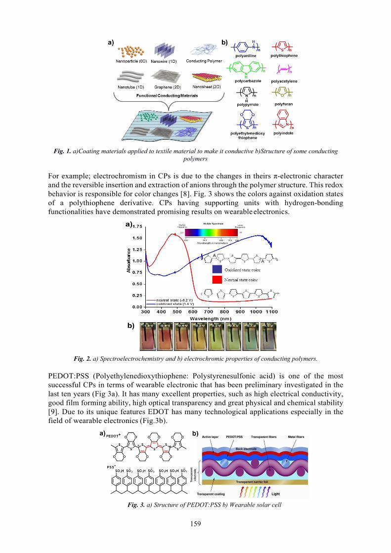
159
Fig. 1. a)Coating materials applied to textile material to make it conductive b)Structure of some conducting polymers
For example; electrochromism in CPs is due to the changes in theirs π-electronic character and the reversible insertion and extraction of anions through the polymer structure. This redox behavior is responsible for color changes [8]. Fig. 3 shows the colors against oxidation states of a polythiophene derivative. CPs having supporting units with hydrogen-bonding functionalities have demonstrated promising results on wearable electronics.
Fig. 2. a) Spectroelectrochemistry and b) electrochromic properties of conducting polymers.
PEDOT:PSS (Polyethylenedioxythiophene: Polystyrenesulfonic acid) is one of the most successful CPs in terms of wearable electronic that has been preliminary investigated in the last ten years (Fig 3a). It has many excellent properties, such as high electrical conductivity, good film forming ability, high optical transparency and great physical and chemical stability [9]. Due to its unique features EDOT has many technological applications especially in the field of wearable electronics (Fig.3b).
Fig. 3. a) Structure of PEDOT:PSS b) Wearable solar cell

160
In this study, EDOT monomer has been dispersed in aqueous medium by PSS and electrochemically coated on textile material. In order to increase the conductivity of cotton- based textile material, stainless steel wires 0.035 mm in diameter have been added during weaving. Electrochemical characterization of the coated textile material has been carried out by the cyclic voltammetry technique. Furthermore, by applying different potentials to the textile material, the color change has been determined with the naked eye.
2. MATERIALS AND METHODS
2.1 Materials
3,4-Ethylenedioxythiophene (EDOT) 97% and poly(4-styrenesulfonic acid) (PSS) (Mw ~75,000, 18 wt. % in H2O) was obtained from Sigma-Aldrich company. Cotton based textile material containing stainless steel wires (0.035 mm diameter) was obtained from Akin Textile company (Istanbul, Turkey).
2.2 Methods
Electrochemical polymerization of EDOT was performed using an Ivium compactstat instrument. The polymerization was performed in an electrolysis cell equipped with the cotton based textile material containing stainless steel wires (1x4 cm) as working, Pt mesh and Ag wire as counter and reference electrodes respectively (Fig 4). The textile material have coated with PEDOT in the 0.1 M PSS (in water) electrolyte solution via cyclic voltammetry technique at 50 mV/s scan rate. Electrodynamic coating was performed in the -0.7-1.3 V potential range.
Fig. 4. a) Cotton based textile material containing stainless steel wires b) Design of the electrochemical cell
3. RESULTS AND DISSCUSSION
Electro-polymerization was performed in an electrolysis cell equipped with the cotton based textile material containing stainless steel wires as working electrode. Pt mesh and Ag wire was used as counter and reference electrodes respectively. Cyclic voltammetry was performed in 0.1 M PSS/water via repetitive cycling at a potential scan rate of 50 mV s−1. In the first scan, only one oxidation peak at 1.25 V is observed, which can be attributed to the oxidation of EDOT and a reduction peak at -0.3 V corresponding to reduction of the PEDOT. A new oxidation peak appears at about 0.22 V during the second scan which has originated from the oxidation of polymer. After seven CV cycles, the increase in the redox wave current densities implied that the amount of conducting polymers deposited on the textile material has been increased (Figure 5a). As a result of electropolymerization with cyclic voltammetry technique, EDOT monomer polymerized and coated on textile material. The prepared conductive polymer coated textile material was washed in water to remove unreacted monomer and supporting electrolyte residues. Then, in order to investigate the electroactivity of the conductive polymer layer coated on the textile material, cyclic voltammetry technique at different scanning rates was applied in monomer-free electrolyte solution. As expected, when scan rate increases in cyclic

161
voltammetry the peak current values were increase. This result proved that the polymer layer produced on the textile material was electroactive. As can be seen from Fig. 5, electroactive polymer layer becomes blue at the applied potential adjusted at -0.8 V for conductive polymer coated textile material, whereas it becomes transparent when applied potential at 1.3 V.
4. CONCLUSIONS
Fig. 5. Knitted agrotextile product
In this study, EDOT monomer has been dispersed in aqueous medium by PSS and electrochemically coated on textile material. In order to increase the conductivity of cotton-based textile material, 40 micron thick steel wires have been added during weaving. Electrochemical characterization of the coated textile material has been carried out by the cyclic voltammetry technique. Furthermore, by applying different potentials to the textile material, the color change has been determined with the naked eye. Unlike the related literature, conductive polymer coated textile material obtained by electrochemical polymerization instead of chemical polymerization can be used in many wearable electronics fields.
ACKNOWLEDGEMENTS
This work supported by PAU-BAP 2019KRM004-109 project.
REFERENCES
[1] He, T., Shi, Q., Wang, H., Wen, F., Chen, T., Ouyang, J., Lee, C., (2019). Beyond energyharvesting-multi-functional triboelectric nanosensors on a textile, Nano Energy, 57, pp. 338-352
[2] Kwon, J., Takeda, Y., Shiwaku, R., Tokito, S., Cho, K., Jung, S. (2019). Three-dimensionalmonolithic integration in flexible printed organic transistors, Nature Communications, 10 (1), art.no. 54
[3] Nightingale, A.M., Leong, C.L., Burnish, R.A., Hassan, S.-U., Zhang, Y., Clough, G.F., Boutelle,M.G., Voegeli, D., Niu, X. (2019). Monitoring biomolecule concentrations in tissue using awearable droplet microfluidic-based sensor, Nature Communications, 10 (1), art. no. 2741
[4] Wang, B., Facchetti, A. (2019) Mechanically Flexible Conductors for Stretchable and WearableE‐Skin and E‐Textile Devices. Advanced Materials 31, art. no. 1901408.
[5] Soganci, T., Baygu, Y., Kabay, N., Gök, Y., Ak, M. (2019). Comparative Investigation ofPeripheral and Nonperipheral Zinc Phthalocyanine-Based Polycarbazoles in Terms of Optical,Electrical, and Sensing Properties, ACS Applied Materials and Interfaces, 10 (25), pp. 21654-21665.
[6] Ayranci, R., Demirkol, D.O., Timur, S., Ak, M. (2017) Rhodamine-based conjugated polymers:Potentiometric, colorimetric and voltammetric sensing of mercury ions in aqueous medium,Analyst, 142 (18), pp. 3407-3415.
[7] Guler, E., Soyleyici, H.C., Demirkol, D.O., Ak, M., Timur, S. (2014). A novel functionalconducting polymer as an immobilization platform, Materials Science and Engineering C, 40, pp.148-156.
[8] Soganci, T., Gumusay, O., Soyleyici, H.C., Ak, M., (2018). Synthesis of highly branchedconducting polymer architecture for electrochromic applications, Polymer, 134, pp. 187-195.
a) b) c)

162
STUDY ON E-COMMERCE IN THE CLOTHING INDUSTRY IN ROMANIA
DOI: 10.35530/TT.2019.57
Simona BĂLĂȘESCU1, Nicoleta Andreea NEACȘU2, Carmen Elena ANTON3, Marius BĂLĂȘESCU4
1,2,4Transilvania University of Brașov, Faculty of Economic Sciences and Business Administration, Department of Marketing, Tourism-Services and International Affairs, Brașov, Romania,
E-Mail: [email protected]; [email protected]; [email protected] University of Brașov, Faculty of Economic Sciences and Business Administration, Department of Finance, Accounting and Economic Theory, Brașov, Romania, E-Mail: [email protected]
Abstract: The fast evolution of the Internet over the last decade had a major impact on all aspects of life, mainly on the business world, stimulating the emergence of a new form of commerce, namely e-commerce. The development of e-commerce has made its mark on the market, with changes taking place both at the level of consumer behavior and at the level of business management. The e-commerce market has been constantly evolving in recent years, and in Romania it has recorded the highest growth in recent years at European level. The study analyzes the sales of clothing products in the online environment in Romania. Thus, quantitative marketing research is conducted at the population level in Romania, a research aimed at knowing the opinions and attitudes of citizens in relation to the purchase of clothing items from online stores. In this research, special attention was paid to the knowledge of the reasons why consumers choose to buy clothing items online. The results of this research can be used by online store managers to find out how they can improve their services, but also for offline store managers who want to get into the online business.
Keywords: Online stores, quantitative research, internet, consumers, attitudes-behaviors.
1. INTRODUCTION
Over the last decade, the Internet has evolved into a very important tool, having a significant impact on all aspects of life. Every year or even every few months, significant changes occur so that it is impossible to predict what certain forms they will reach in the next 10 years [1]. It is a vast, complex and yet permissive environment that keeps on being of high interest for many of us. The enormous potential of developing a business has stimulated a boost and trending of new alluring concepts, such as electronic business (e-business) and electronic commerce (e-commerce). Over time, this has proven to be not only a viable alternative, but also a highly profitable alternative to the traditional way of doing business or trade [2]. Along with the evolution of telecommunications and intrinsically of the Internet, a new type of business has emerged internationally: e-commerce. It has completely revolutionized into a disruptive business model within the companies’ environment, but also the way people shop. The increasing number of online stores is supported by the tendency of the customers towards saving time, comfort and the search for new experiences in the purchasing process. Moreover, consumers also benefit from other advantages of e-commerce, thus being able to choose from a myriad of products and services, without being constrained by physical limits or operating hours.
2. LITERATURE REWIEV
The Internet has had a significant impact in all areas of society, but above all, it has hugely impacted the dynamics of the business world. Economic activities in all fields have undergone significant

163
transformations because of the increasing ease of accessing, processing, storing and communicating information. What has completely changed the way markets work is the huge amount of available information. By the modern means of digital data usage, business’ models have been restructured and new opportunities for increasing the standard of living have constantly appeared [3]. The Internet offers sellers and buyers a powerful communication channel and makes it possible for both parties to meet through electronic markets [4, 5]. For some companies, e-commerce means any financial transaction that applies computer technology. On the other hand, for others, the concept of e-commerce covers the whole sales circuit, including marketing and sales itself [6]. For customers, e-commerce means any commercial transactions made through the Internet by purchasing different products such as travel tickets, CDs, books, etc. Thus, the e-commerce identity is defined by the activities of buying and selling through the Internet channel[3]. Trust in online transactions is often considered to be a key factor in determining the success and failure of e-commerce. Even though Internet transactions have grown steadily in recent years, e-commerce is still a relatively new concept for most people. Thus, the lack of confidence in the online environment is often a strong reason for potential customers to give up buying online. This is particularly caused by distance, anonymity and lack of physical interaction. Also, data security and privacy issues have proven to be barriers for online shopping [7]. Building trust becomes a difficult issue with the e-commerce, because of a certain lack of common interaction between the seller and the buyer as there was no previous interaction or they do not have enough details about each other [8]. Usually, trust is gained by reputation and then by experience. Reputation emerges from sources such as the media or friends. Recommendations made by people the consumer trusts have a great influence when the consumer decides whether a site or a seller is trustworthy. If the individual then chooses to purchase goods or services over the Internet, the actual experience will be added to the reputation [9]. A basic aspect of electronic business are the electronic payment transactions. Related to the consumers’ environment, the electronic procedures for e-payments are similar to those used with the usual POS’s in shops. The major difference comes from the fact that this type of business is mainly online and depends completely on the Internet [3]. The most popular electronic payment systems can be grouped into four categories: electronic checks, micropayments, bank card paying systems, online transactions systems [6]. The e-commerce market has been constantly evolving and Romania has registered a significant growth over the last years, at European level. The online market for clothing items in Romania is constantly developing, both quantitatively and qualitatively, its value being estimated at € 258 million, representing a share of 5.6% from the whole industry, and approximately 10% of the total e-commerce share in Romania. . This means an increase of 30% in 2018, being more dynamic than the growth of the entire industry (15%) [10].
3. RESEARCH METHODOLOGY
In order to better understand the Romanian customer behaviour upon the purchase of clothing items from the online stores, quantitative marketing research was conducted based on a sample of 216 respondents, residing in Romania. Considering the aim of this paper, the research had the following objectives:
Determining the extent to which respondents purchase clothing items from the online environment;
Identifying the main reason why respondents order online; Identifying the most popular payment method; Identifying the level of trust in online stores; Understanding the reasons why the respondents did not buy online.
Within this paper, the sampling method wasn’t random and we relied on a survey that was built up from the voluntary answers provided by our respondents. For data collection, we approached the online questionnaire survey method. The questionnaire (which includes 20 questions) was designed on the Google Forms platform and was shared on the Facebook social network. Being shared in the online environment, the questionnaire gathered 216 respondents, the researcher having no control over those who completed it. After collecting the information by means of the questionnaire, the statistical data was processed within the SPSS (Statistical Package for Social Sciences) system [11].

164
4. RESEARCH RESULTS
In Romania, the e-commerce represents a new perspective that should be a further issue within the process of economic growth and sustainable development. The online market for clothing is constantly expanding due to the many benefits consumers identify, such as the wide variety of brands and available products, access to reviews from other buyers, better value for money, but also a simplified purchasing process. This very context generated the need to conduct a research that would provide an overview of the attitudes and opinions of Romanian citizens have on the purchase of clothing items from online stores. The research revealed a lot of relevant information. Research shows that out of the total number of respondents, 77.8% bought clothing items, from the online environment, within 2018, while 22.4% did not approach this shopping way for clothing items. Most of the respondents, respectively 36.7% purchased clothing from the online environment with a frequency of 2 and 6 times a year, while 24.5% purchased more than 6 times a year, while only 11.8% buy online once a year. The main reasons why the respondents allegedly choose to purchase clothing items from an online store are: "rich product offer" (51.2%), followed by "convenience" (20.2%), "lower prices" (14, 3%), "lack of time" (13.1%) and 1.2% of the respondents invoked as the main reason "avoiding crowding in shops" (Fig 1). The reasons why respondents have some concerns about purchasing clothing online are: "I prefer to try the product before buying it" (36.4%), "the sizes does not fit" (29.5%), "I don’t trust the quality of the products ”(27.3%),“ the delivery cost”(4.5%) and“ the delivery time is too long ”(2.3%) (Fig. 2).
Fig.1. Reasons pro online-shop Fig. 2. Reasons pro traditional shop
Most of the respondents (73.9%) visit the online clothing stores even if they do not intend to buy any product, while 26.1% do not have this behavior. The most often payment method used by the respondents is the "courier payment" with a percentage of 65.3%, followed by the "online card payment" method preferred by 32% of the respondents and other modalities representing 2, 7% of the respondents.
5. CONCLUSIONS
The rapid evolution of the Internet over the last decade has had a major impact on all aspects of life, mainly in the business world, stimulating the emergence of a new form of commerce, namely e- commerce. The development of e-commerce has made a major impact on the market, with changes taking place both at the level of consumer behavior and at the level of business management. E-commerce is an entirely new experience for consumers, greatly influencing their lives. Even if it is anew concept, and buyers are skeptical about it, e-commerce has an impressive evolution in terms of themany advantages it offers them, namely, access to a more varied assortment, removing the physicalbarriers, the possibility of access a wealth of comparative information between companies, competitorsand products, buyers can choose the products at the most advantageous price for them. Also, e-commerce,including trade in clothing products, has many advantages for traders, such as: facilitating access to worldmarkets, access to new consumer segments, reducing costs in terms of advertising, supply, sales, but thecosts of messaging or mail. The major disadvantage affecting both consumers and traders is related to datasecurity and the risk of fraud. Other disadvantages are: lack of consumer confidence, their mentality, butalso the lack of direct contact with the purchased products. Traders have quickly understood theusefulness of e-commerce and have introduced it into the chain of information technology.

165
Today, this type of trade is the easiest way to increase sales, due to the many advantages it has over traditional trade. One of the most important aspects is the availability, the electronic commerce having permanent availability, the presence of the employees becoming unnecessary. Another aspect is the coverage area, the traditional trade being geographically limited. Even if from this point of view, e- commerce has several strengths, the two forms of commerce are not mutually exclusive, on the contrary, they complement each other. Moreover, online commerce stimulates traditional commerce, allowing consumers access to a wider range of products and services at competitive prices. The textile industry is in a continuous transformation, and the online market for garments is constantly growing, mainly due to the perceived benefits of consumers such as: the assortment range more varied than traditional stores, access to reviews from other buyers, but also a better value for money [12].
REFERENCES
[1] Dinu, G., Dinu, L. (2014), Using Internet as a Commercial Tool: a Case Study of E-Commerce in Resita, Procedia Engeneering, 69, pp. 469-476.
[2] Apăvăloaie, E.(2014), The impact of the Internet on the Business Environment, Procedia Economics and Finance, 15, pp. 951-958.
[3] Popescul, D. (2008), Comerț & afaceri mobile, Ed. Universității “Alexandru Ioan Cuza”, Iași, pp.40-110.
[4] Huang, C., Liang, W., Lai, Y. (2010), The agent-based negotiation process for B2C e-commerce, Expert Systems with Applications, 37, pp. 348-359.
[5] Vasilache, D. (2004), Plați electronice-o introducere, ed Rosetti, Bucuresti, pag.120.[6] Şerbu, R. (2004), Comerțul electronic, ed. Continent, Sibiu, pag. 11-42.[7] Oliviera, T., Alhinho, M., Rita, P., Dhillon, G. (2017), Modelling and testing consumer trust
dimensions in e-commerce, Computers in Human Behavior, 71, pp.153-164.[8] Kim, Y., Peterson, A. (2017), A Meta-analysis of Online Trust Relationships in E-commerce,
Journal of Interactive Marketing, 38, pp. 44-54.[9] Abbasi, P., Birgham, B., Sarencheha, S. (2011), Good's History and Trust in Electronic Commerce,
Procedia Computer Science, 3, pp. 827–832.[10] Market Opportunity Research (2019), [online] Available at: https://mkor.ro/blog/conferinta-fashion-
route/ [Accessed 27 May 2019].[11] Neacşu, N.A., Băltescu, C., Bălăşescu, S., Boşcor, D. (2017), The influence of design and
aesthetics elements in choosing clothing, In: Industria Textilă, 2017, no. 5, pp. 375-379, Industria Textila Official Website. [online] Available at: http://www.revistaindustriatextila.ro/ [Accessed 24 May 2019].
[12] Tudor, L. (2018), Change in Textile and Clothing Industry, In: Industria Textilă, 2018, no. 1, pp. 37-43, Industria Textila Official Website. [online] Available at: . http://www.revistaindustriatextila.ro/ [Accessed 12 June 2019].

166
SURFACE MODIFICATION OF BIOMATERIAL FABRIC USING SUPERCRITICAL N2 JET
DOI: 10.35530/TT.2019.36
Foued KHOFFI1,2,3, Yosri KHALSI2,3, Abdel TAZIBT2, Slah MSAHLI1, Frédéric HEIM3
1 University of Monastir, LGTex, Monastir, Tunisia. 2 Centre de Recherche d’innovation et de Transfert de Technologie, TJFU, Bar-Le-Duc, France.
3 University of Haute-Alsace, LPMT, Mulhouse, France.
Corresponding author: Foued KHOFFI, E-mail: [email protected]
Abstract: Textile biomaterials have been largely used over the last decades as vascular grafts, hernia meshes and heart valve leaflet [1-2]. Once implanted in vivo, the natural porosity of textile materials tends to induce exaggerated tissue ingrowth, which may prevent the implants from remaining flexible [3]. One hypothesized way to limit the foreign body reaction process is to increase the material surface roughness [4]. Supercritical N2 jet particle projection is a novel technique to provide enough velocity to micro particles to induce plastic deformation on the textile impacted surface. The aim of this study is to investigate the influence of micro particles laden supercritical N2 jet projection parameters like jet static pressure, standoff distance and particle size on the roughness of PET fabric surfaces. Results bring out that particles projected by the jet N2 SC generate craters on the surface of monofilament as well as multifilament fabric, allowing topographical modifications at the yarn scale. We found that larger particles induce larger crater diameters. Moreover, increasing the static jet pressure from 300 to 1000 bars further allows increase in the crater diameter. For a pressure of 500 bar, the standoff distance must be greater than 300 mm in order to obtain significant roughness values without breaking the PET monofilament fabrics. Thus, this treatment increased the roughness of the monofilament fabric from 0.78 μm to 1.22 μm. The results obtained in this work show that it is possible to create a roughness on a PET fabric using the N2 jet technology.
Key words: biomaterial- textile- surface modification- roughness -supercritical N2 jet
1. INTRODUCTION
The essential requirement of a material to be used as biomaterials is its ability to receive an appropriate host response. This response depends on how similar the implant behaves as compared to the real organ. Such requirement is commonly termed as biocompatibility. Biomateria ls with a low leve l of biocompatibility readily induce different infections within the patients. Control of the degree of biocompatibility is still a challenge to overcome within the health care industry as these polymers very often do not possess the surface properties needed for various applications [1]. Consequently, their surface needs to be refined to the microstructure level to obta in better performance in biomedical applications in terms of biocompatibility [2-3]. Various chemical and physical methods for modification of the polymer surfaces have been developed and are currently be ing studied, including chemical and plasma treatment, ion implantation, and UV-irradiation. Yet no surface modification technique is unanimously accepted since these methods are often associated with undesirable side effects. One of them is the degradation of the internal bulk of the material. Biomaterials have very precise requirements that derive from the mechanical performance of the bulk properties. These provisions can be categorized informa lly into three main groups inc luding mechanical performance, mechanical durability, and physical properties. In total hip replacement surgeries for example, the biomateria l used for constructing a prosthetic implant must be mechanically strong and rigid.

167
In case of valve replacement, the leaflet of valve must be flexible and tough; otherwise it will cause hindrance in blood flow. Textile synthetic vascular graft material requires very specific modulus properties in order to behave like real vascular soft tissue when implanted within the body such that the walls of the artery or vein pulsate in a similar manner to real tissue [4]. In that latter application fibrous constructions would provide a good combination of strength and flexibility. However, textiles are characterized by specific roughness features due to the yarn crossing in the ir construction. It has been shown in the literature that fibroblast tissue in-growth depends on the characteristics of the textile pores of a surface and on the topography of the yarns involved in the textile construction. Vaesken et al. [5] studied the interaction between various textiles in vivo in heart valve position and concluded that pore size and yarn diameter are the most critical parameters, which control the tissue ingrowth. In this work, the potential of a nove l mechanical surface treatment is investigated, which could be particularly suited for textile constructions, which are networks of fibers. It consists in spraying on the surface to be treated a cold and dry flow of solid partic les embedded within a high-speed nitrogen jet (N2), which itself does not interact with the material surface. Some work has already been done on studying the interaction between a N2 jet and metallic flat surfaces [6], but no results are available in literature about the effect of the considered process on textile material. The main goal is to provide experimenta l data about the behavior of PET textile material characterized by simple surface geometry with respect to the N2 processing conditions. In particular, the influence of the process parameters on the obtained roughness is studied.
2. MATERIEL AND METHODS
2.1 Mate rial
The textile samples used in this study are PET monofilament fabric. This fabric is woven from threads made from continuous PET monofilaments and is supplied by Sefar Fyltis (Lyon, FRANCE). The characteristics of the textile fabric used in this study are summarized in table 1.
Table 1: Characteristics of the textile fabric
Sample Woven Fabric Surface density (g/m2) 70 Yarn density, warp (yarn/cm) 38 Yarn density, weft (yarn/cm) 38 Filament diameter (µm) 100 Yarn count (tex) 10.8
2.2 Supe rcritical Nitrogen e quipment
The surface treatment technology used in this work consists of spraying onto the surface to be treated solid partic les embedded within a dense High-Speed Supercritical Nitrogen Jet HSNJ. The jet is generated by a pump namely “Nitrojet” which is a product patented from IHI NitroCision company. The system and the handling procedure have been described in detail in a last publication by Kha lsi et al. [7].
2.3 Surface treatme nt procedure
The surface modification tests were carried out on Monofilament fabric textile. Samples were treated with a Supercritical nitrogen jet charged with glass particles (with a size range 45-53 μm). Two parameters were varied in the study: (1) the pressure (300 and 500 bar), (2) the stand of distance (700, 600, 500, 400, 300 mm…until the breaking). Each test was repeated five times for statistical purposes. An average of 7 seconds time was necessary between the mask removal and the particle delivery. All tests were performed in a static mode where the tool did not move relative to the sample surface.

168
Untreated SoD 500 mm SoD 400 mm 1,4
1,2
1,0
0,8
0,6
0,4
0,2
0,0
2.4 Characte rization technique s
Samples were treated with a supercritical nitrogen jet and characterized for material modification assessment. Different types of analysis were carried out on the samples: SEM analysis, mechanical tests and roughness measurement.
3. RESULTS AND DISCUSSION
From the fabric surface SEM images analysis, significant visual difference could be observed between the initial state and after surface modification using a Supercritical nitrogen jet charged with glass partic les. Figure 1B and 1C represent the sample surface SEM images respectively at SoD 500 mm and at SoD 400 mm. These images clearly showed a difference in their local surface morphology of filaments. It can be clearly observed that the surfaces of the untreated filament are relatively smooth with a cylindrical shape (Figure 1A). However, the surfaces of the monofilament treated appeared rough with impact craters (Figure 1B) or with a presence of fibrils on the surface of filament (Figure 1C). For several configurations at a pressure 500 bar (SoD < 400 mm), the filament surfaces are shredded with certainly a loss for material.
Fig. 1. SEM Photographs of Monofilament PET fabric samples, 100μm at P: 500 Bar; A: vierge, B: SoD 500mm, C: SoD 400mm
The surface analysis by optically profilometer (Fig.2) confirmed for both materials the modifications related to the fabric surfaces topography already observed at SEM level. The results show that the mean surface roughness increases with the pressure and the standoff distance regardless of the fabric. It is observed that the treatment increased the roughness of the monofilament fabric from 0.78 μm to 1.22 μm
Fig. 2. Surface roughness topography of fabric samples untreated and treated at P: 500 bar
The tensile strength properties were studied for treated and untreated fabrics. To understand the effect of surface modification on mechanical performances of samples, tensile tests were performed on strip before and after treatment with supercritical nitrogen jet. Table 2 compares the ultimate strength and strain values of samples obtained for the various treatment configurations.
Ra (µ
m)

169
Table 2: Mechanical results of woven fabric before and after treatment
Pressure (bar) Standoff Distance (mm) Strength (N) Strain (% )
Untreated 66.62 ± 3.64 81.11 ± 7.43 700 64.18 ± 2.45 67.7 ± 5.39
500 600 62.41 ± 2.89 62.97 ± 5.89 500 61.33 ± 3.01 59.43 ± 7 400 57.25 ± 5.71 58.98 ± 4.87 700 64.14 ± 1.8 66.85 ± 3.69 600 63.81 ± 2.72 62 ± 4.97
300 500 62.68 ± 3.1 60.13 ± 6.86 400 58.12 ± 4.29 59.07 ± 5.93 300 56.62 ± 2.62 57.77 ± 2.71
It can be observed a slight reduction in ultimate strength and ultimate strain of the fabric after treatment. Maxima l reductions of 15% of strain at P=300 bar and 14% of strain at P = 500 were obtained respectively in samples with SoD = 300mm and SoD = 400mm. This quantitative result confirms the observations made at a macroscopic leve l, which showed accentuated fibrils for the configuration P = 500 bar and SoD 400.
4. CONCLUSION
The aim of this study is to investigate the influence of micro particles laden supercritical N2 jet projection parameters like jet static pressure, standoff distance and particle size on the roughness of PET fabric surfaces. Results bring out that particles projected by the jet N2 SC generate craters on the surface of monofilament fabric, allowing topographical modifications at the yarn scale. The results obtained in this work show that it is possible to create a roughness on a PET fabric using the N2 jet technology. To enhance this study, biologica l tests must be performed to access how the changes of surface affect the behavior of textile materials with the cells.
ACKNOWLEDGEMENTS
This work was supported by Institut Carnot, under number UMS3653-M3-P01-F02-AAP2017.They gratefully acknowledge the cooperation of their partners in the project: CRITT TJFU and LPMT.
REFERENCES
[1] Tathe, A., Ghodke, M., Nika lje, A.P. (2010). A brief review: biomaterials and the ir application.Int J Pharm Pharm Sci 2, pp. 19-23.
[2] Seal, B.L., Otero, T.C., Panitch, A. (2001). Polymeric biomateria ls for tissue and organregeneration. Mater. Sci. Eng., pp 34:147-230
[3] Grodzinski J., (1999). Biomedical application of functiona l polymers. React Funct Polym ;39, pp99-138.
[4] Khoffi, F., Heim, F., Chakfe, N, T. Lee, J. (2015). Transcatheter fiber heart valve: Effect ofcrimping on material performances. J Biomed Mater Res Part B: Appl Biomater, 103B, pp. 1488-1497.
[5] Vaesken, A., Pelle A., Pavon-Djavid G., Rancic J., Chakfe N. and F. Heim F. (2018). Heartvalves from polyester fibers: a preliminary 6-month in vivo study. Biomed. Eng./Biomed. Tech.,27;63(3), pp. 271-278.
[6] Laribou. H, Fressengeas C., Entemeyer D., Jeanclaude V. and Tazibt A. (2012). Effects of theimpact of a low temperature nitrogen jet on metallic surfaces. Proc. R. Soc. A, 468;2147, pp 3601-3619.
[7] Khalsi, Y., Heim, F., Jason, T.L., Tazibt, A. (2018). N2 supercritica l jet to modify the characteristics of polymer material surfaces: influence of the process parameters on the surfacetopography. Polym. Eng. Sci., 59, pp 616-624.

170
ELECTROMAGNETIC SHIELDING OUT OF PLASMA COATED WOVEN FABRICS DOI: 10.35530/TT.2019.37
Lilioara SURDU1, Ion Razvan RADULESCU1, Emilia VISILEANU1, Bogdana MITU2
1 INCDTP – Bucharest, Romania, E-M ail: [email protected]
2 INFLPR – M agurele -Bucharest, Romania, E-M ail: [email protected]
Corresponding author: Lilioara Surdu, E-mail: [email protected]
Abstract: Electromagnetic radiation of telecommunication is undesired in rooms for data privacy [1]. One way to shield EM radiation is by achieving textile fabrics with electrical conductive properties [2,3]. Buildtech technical textiles are used in constructions and as such they need fireproof properties, too. Magnetron plasma sputtering is a novel technique for rendering nanometer scale coatings on woven fabrics. It is an eco-friendly technique, which leaves the bulk properties of the fabric unaltered and modifies only the surface properties. Thus, textile EM shields out of magnetron plasma coated fabrics keep initial properties of textile materials, such as flexibility, light weight, 3D shape-ability, good mechanical resistance and receive as well novel functionalities. The ERA-NET Manunet TexEMFiRe project aims to research Buildtech technical fabrics with electromagnetic shielding and fireproof properties, made out of magnetron plasma coating. TexEMFire envisages an optimization of plasma coated fabrics based on fabric structure parameters (density) and plasma coating parameters (generator power) The project has duration of two years (Apr. 2018-Mar. 2020) and five partners: INFLPR, INCDTP, Majutex from Romania and UniUPO and TecnoLab from Italy. Project website is: http://texemfire.inflpr.ro/ .
Key words: magnetron, Buildtech, protection
1. INTRODUCTION
Technical textiles for the Building – construction sector are named Buildtech, according to TechTextil international fair. Buildtech textiles are used for various purposes, such as fibers or fabrics reinforced walls, tarpaulins for sun and UV protections, tents for outdoor protection etc. Some of basic functionalities for such textile materials are first of all fire-retardant properties. It is of utmost importance to render construction materials including textiles, resistance to burning, in order to ensure protection of humans and goods against accidents caused by flames and fire. Another, more recent hazard, arose with development of telecommunication: the electromagnetic (EM) radiation. Undesired EM radiation causes interference of electronic equipment and affections to human’s health, such as cancer [1]. In order to prevent such severe problems, the Electromagnetic Compatibility (EMC) field states as solution the shielding of radiation [2]. Some basic protection functionalities are ensured, by achieving technical textiles for constructions both with fire-retardant and electromagnetic shielding properties. Plasma treatment of fabrics represents a novel technology of functionalizing fabrics with already marketable products [3]. Plasma represents the fourth state of matter, while cold plasma may be used as laboratory technology to impart various functionalities to materials, including textiles. Plasma functionalization has several advantages: it achieves thin, nanometer coating on fabrics, modifying only surface properties and leaving bulk properties of textiles unaltered. It is an ecofriendly technique, when compared to wet treatments on fabrics for achieving same functionalities [6-8]. Aim of this paper is to present research results in plasma coated fabrics with fire-retardant and electromagnetic shielding properties for Buildtech domain.

171
2. THE TEXEMFIRE PROJECT
TexEMFiRe – “Manufacturing textiles with electromagnetic shielding and fire retardant properties by plasma based methods” is an ERA-NET Manunet project for the period Apr. 2018- Mar. 2020, still ongoing project (figure 1).
Fig. 1. Logo of program and project
TexEMFiRe has five partners from two countries – Romania and Italy (table 1):
Table 1: TexEMFiRe project’s partners
CO: National Institute for Lasers, Plasma & Radiation Physics (INFLPR)
www.inflpr.ro
P1: National Research and Development Institute for Textiles and Leather (INCDTP)
www.certex.ro
P2: SC MAJUTEX SRL
www.majutex.ro
P3: Tecnolab del Lago Maggiore S.R.L.
www.tecnolab.name/en
P4: Università degli Studi del Piemonte Orientale “Amedeo Avogadro”
www.uniupo.it
TexEMFiRe main aim is introduction of magnetron plasma sputtering for achieving Buildtech technical textiles with good electromagnetic shielding and fire retardant properties. Metallic particles, such as copper, nickel etc., with a good electric conductivity (~107 S/m), were sputtered out of a target towards textile substrate in low-pressure plasma medium.
3. ELECTROMAGNETIC SHIELDING FABRICS
Textile substrates used where out of 100% cotton and 100% PES with following physical-mechanic properties (table 2):

172
Table 2: Physical-mechanical properties
No. Fabric sample Woven fabrics prope rties
1 Fabric 100% cotton – 210g/m2
Yarn type U Nm 20/1
B Nm 20/1
Density U fire/cm 30 B fire/cm 15
Weave Twill 3/1 2 Fabric 100% cotton –
405 g/m2
Yarn type U Nm 10/1 B Nm 10/1
Density U Fire / cm 26 B Fire / cm 16
Weave Plain weave Ru = Rb = 2
3 Fabric 100% PES – 205 g/m2
Yarn type U Dtex 167/48x2
B Dtex 167/48x2
Density U Fire /cm 35 B Fire /cm 21
Weave Twill 2/1 4 Fabric 100% PES –
245 g/m2
Yarn type U Dtex 167/48x2 B Dtex 167/48x2
Density U Fire /cm 36 B Fire /cm 34
Weave P 4/4
These 100% cotton and 100% PES fabrics were coated by magnetron plasma sputtering with Copper particles. A low pressure plasma equipment with two vacuum pumps and an advanced energy RF generator (13.56 MHz) was used for this purpose within INFLPR laboratory (Figure 2).
Fig. 2. Magnetron plasma installation at INFLPR
The samples were coated on both sides of the fabric with a 400 nm thick Copper layer. Shielding effectiveness values [dB] for the frequency range of [0.1-1000 MHz] was determined via a TEM cell (Standard ASTM ES07) for sample 1 out of 100% cotton and sample 3 out of 100% PES (Figure 3).
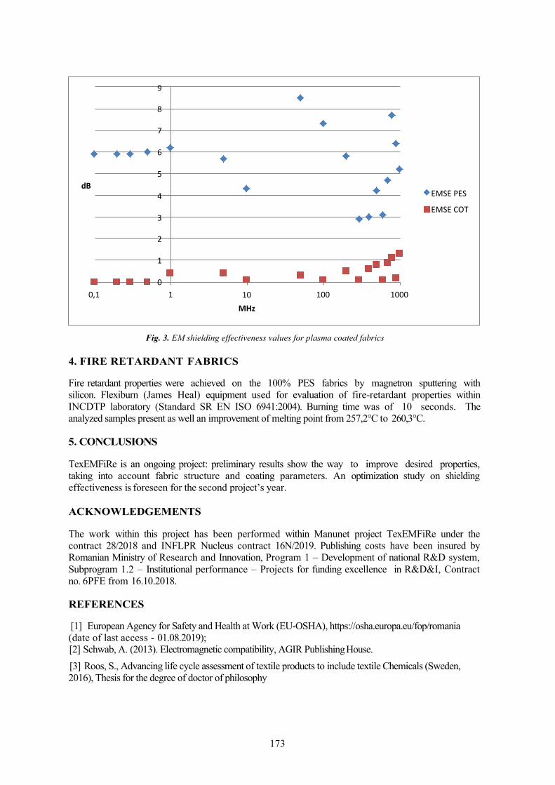
173
Fig. 3. EM shielding effectiveness values for plasma coated fabrics
4. FIRE RETARDANT FABRICS
Fire retardant properties were achieved on the 100% PES fabrics by magnetron sputtering with silicon. Flexiburn (James Heal) equipment used for evaluation of fire-retardant properties within INCDTP laboratory (Standard SR EN ISO 6941:2004). Burning time was of 10 seconds. The analyzed samples present as well an improvement of melting point from 257,2°C to 260,3°C.
5. CONCLUSIONS
TexEMFiRe is an ongoing project: preliminary results show the way to improve desired properties, taking into account fabric structure and coating parameters. An optimization study on shielding effectiveness is foreseen for the second project’s year.
ACKNOWLEDGEMENTS
The work within this project has been performed within Manunet project TexEMFiRe under the contract 28/2018 and INFLPR Nucleus contract 16N/2019. Publishing costs have been insured by Romanian Ministry of Research and Innovation, Program 1 – Development of national R&D system, Subprogram 1.2 – Institutional performance – Projects for funding excellence in R&D&I, Contract no. 6PFE from 16.10.2018.
REFERENCES
[1] European Agency for Safety and Health at Work (EU-OSHA), https://osha.europa.eu/fop/romania (date of last access - 01.08.2019);[2] Schwab, A. (2013). Electromagnetic compatibility, AGIR Publishing House.[3] Roos, S., Advancing life cycle assessment of textile products to include textile Chemicals (Sweden, 2016), Thesis for the degree of doctor of philosophy
100010010 MHz
10,1
3
2
1
0
EMSE PES
EMSE COT 4
dB
9
8
7
6
5

174
SMART TEXTILES TO PROMOTE MULTIDISCIPLINARY STEM TRAINING
DOI: 10.35530/TT.2019.38
Ion Razvan RADULESCU1, Carmen GHITULEASA1, Emilia VISILEANU1, Lilioara SURDU1, Razvan SCARLAT1, Ana DIAS2, Lieva VAN LANGENHOVE3, Zoran
STJEPANOVIC4, Mirela BLAGA5, Petra DUFKOVA6 1INCDTP – Bucharest, Romania, [email protected] , [email protected]
2 TecM inho – University of Minho, Guimaraes, Portugal, [email protected] 3Ghent University, Faculty of Engineering and Architecture, Department of Materials, Textiles and Chemical Engineering
(MaTCh), Ghent, Belgium, [email protected] 4University of Maribor, Faculty of Mechanical Engineering, Institute of Engineering Materials and Design, Maribor,
Slovenia, [email protected] 5Technical University "Gh. Asachi", Faculty of Textiles, Leather and Industrial Management, Iasi, Romania,
[email protected] 6TZU Textile Testing Institute, Brno, Czech Republic, [email protected]
Corresponding author: Ion Razvan Radulescu, [email protected]
Abstract: Smart textiles consist of multi-disciplinary knowledge. Disciplines such as physics, mathematics, material science or electrics is needed in order to be able to design and manufacture a smart textiles product. This is why knowledge in smart textiles may be used to showcase high school and university students in basic years of preparation some applications of technical disciplines they are learning. The Erasmus+ project “Smart textiles for STEM training – Skills4Smartex” is a strategic partnership project for Vocational Education and Training aiming to promote additional knowledge and skills for trainees in technical fields, for a broader understanding of interconnections and application of STEM, via smart textiles. Skills4Smartex is an ongoing project within the period Oct. 2018-Sept. 2020, with a partnership of six research providers in textiles www.skills4smartex.eu. The project has three intellectual outputs: the Guide for smart practices (O1), the Course in smart textiles (O2) and the Dedicated e-learning Instrument (O3). The Guide for smart practices consists in the analysis of a survey with 63 textile companies on partnership level and interviews with 18 companies. Main aim of O1 is to transfer from source site to target sites technical and smart textile best practices and the profile of workforce needed for the future textile industry. The needs analysis achieved within O1will serve to conceive the Course for smart textiles with 42 modules (O2), to be accessed via the Dedicated e-learning Instrument (O3). All outputs are available with free access on the e-learning platform: www.adva2tex.eu/portal.
Key words: vocational education and training, mathematics, physics, material science, electrics, interconnections.
1. INTRODUCTION
Vocational trainees and students in basic stage of higher education learn a series of theoretical disciplines and they are eager to get the touch of practice, to understand final applications of their knowledge. STEM stands for Science, Technology, Engineering and Mathematics and often, education in these fields requires interconnection of theory and practice. Multi-disciplinarily is a modern way to tackle new research domains and students have to learn how to apply various disciplines. For all these challenges, the project Skills4Smartex offers a solution via applications of smart textiles. Smart textiles combine knowledge in material science, mathematics and physics as well as electrotechnics. Smart textile prototypes are an excellent way to showcase final applications of multi-disciplinary domains.

175
100%
90%
80%
70%
60%
50%
40%
30%
20%
10%
0%
Existing Required NA
4: > 51 years
3: 41 -50 years47%
1: < 30 years
2: 31 – 40 years
29%16%
8%
Erasmus+ Skills4Smartex “Smart textiles for STEM training” is a strategic partnership project in the field of Vocational Education and Training, for the period Oct. 2018-Sept. 2020.
Skills4Smartex includes a partnership of six research providers in textiles: INCDTP-Bucharest coordinates a prestigious consortium: TechMinho-University of Minho, Ghent University, University of Maribor, Technical University Iasi and the Textile Testing Institute – Brno. The project website has the URL address www.skills4smartex.eu.
2. RESULTS OF THE SURVEY
Output 1 of Skills4Smartex achieved to identify the needs of workforce within smart and technical textiles, by means of a questionnaire based survey, with 34 questions. The elaborated questionnaire was sent to a number of 63 textile companies on consortium level, from countries like Belgium, Czech Republic, Portugal, Romania and Slovenia. The results of the survey are summarized within figures 1-3.
a) On fields of interest b) On expected age Fig. 1. Profile of workforce needed
Figure 1a presents the work profiles with higher education studies needed in the textile industry. There is a large need for Electronics and IT engineers when compared to existent work force. Quality engineers and textile engineers have the largest share when it comes to existent workforce, however demand of textile engineers is still at high percent of 30%. Another category of needed work force are marketing assistants and clothing designers, with 30% respectively 33%. Less interest was reported for chemistry engineers, a fact explained by less used chemical finishing. Figure 1b states the fact that textile professionals are mostly demanded with age expectation between 31-40 years, having a share of 47%, followed by the younger generation of specialists aged under 30 years, having a share of 29%.Experienced professionals over 51 years are still demanded, for their long-lasting expertise, with a percent of 8%. Figure 2 shows modalities to foster innovations in technical and smart textiles within companies on partnership level. Great shares were reported for participation in fairs (28%) and partnership with research providers (26%), such as universities and research institutes. Still, suppliers and clients are involved within innovation process (24%) and consumer analysis is performed for market tendencies (22%), for the interviewed companies.

176
stain resistance18%
absorb vapours
hydrophobic non-porous
Other
conductive thermic / electric
water resistant 18%16%
plasma treatment
optical treatment 5%9%
5%14%5%10%
UV PPEs
Fig. 2. Modalities to foster innovation in technical and smart textiles for companies
Figure 3 presents the interest of textile companies on partnership level to produce first generation smart textiles. Highest interest was reported for water resistant and conductive thermic and electric textile products with 18%. Another category of products was the stain resistance textiles (16%) and Personal Protection Equipment - PPE with ultraviolet light protection (14%). Other products were less envisaged, such as hydrophobic textiles (10%) or textiles to absorb water vapours (9%). Plasma and optical treatments on textiles, although modern technologies to impart novel functionalities on fabrics, had less interest (5%).
Fig. 3. Interest of companies in developing first generation smart textiles
3. CONCLUSIONS
Skills4Smartex project is still ongoing. Its results for the first year cover the Guide for smart practices of 74 pages with graphs and comments related to survey on smart textiles, some interviews with companies, meant to enable transfer of best practices from source sites (companies with results in smart textiles) to target sites (other interested companies and VET schools) and methods for an efficient smart practice transfer.
Analysis of consumer behaviour and market tendencies
Participation in fairs and other promotion events
24%28%
Suppliers and clients are involved within production & innovation process
26%22%
Partnerships with research providers

177
Fig. 4. The Skills4Smartex team at the Joint staff event at UGent
Future activities include the elaboration of the course’s modules from STEM to SMART (shows basic disciplines relation to smart textiles) and from SMART to STEM (shows components of smart textile prototype into basic disciplines). Each partner is responsible for a chapter and each chapter tackles modules on physics and maths, material science and chemistry plus electronics, in both approaches. Chapters are: Novel fibres for smart textiles applications: INCDTP, Materials & methods (plane materials, composites) for smart textiles: UT Iasi, Virtual prototyping of sensors on garments: Uni Maribor, Smart textile design: TecMinho, Smart textiles prototypes: UGent, Data processing: INCDTP and New methods for testing smart textiles: TZU. Draft content of modules from STEM to SMART has been accomplished at the Joint staff event at UGent, 22-24.05.2019 (Figure 4). The total number of 42 modules will be however difficult to access: this is why Output3 of Skills4Smartex foresees a dedicated e-learning instrument, which will enable selection of desired module via a filter. The instrument will be programmed in PHP/MySQL and enables quick and direct access (without authentication) to the project’s modules. This feature of the instrument is in line with the requirements of Erasmus+ program, which states free access for all outcomes resulting from the funded projects.
ACKNOWLEDGEMENTS
This project has been funded with support of the European Commission.
REFERENCES [1] Erasmus+ Program Guide (2019). EC Official Website. [online] Available at: https://ec.europa.eu/programmes/erasmus-plus/resources/programme-guide_en [Accessed 20.05.19].[2] Nixon, R. (2014) Learning PHP, MySQL & JavaScript: With JQuery, CSS & HTML5, O’Reilly Media Inc., Massachusetts, USA[3] Moodle Manuals (2019), Moodle website [online] Available at: https://docs.moodle.org/37/en/Moodle_manua ls [Accessed 20.05.19].

178
ANTISTATIC TREATMENT OF TEXTILE FIBERS FOR AIR TUBES IN GRIZUTOS COAL EXPLOSIVE ENVIRONMENT
DOI: 10.35530/TT.2019.42
Ioan I. GÂF-DEAC1, Emilia VISILEANU2, Constantin Sorin PĂUN3,
Cristina Monica VALECA4 and Ileta TÂRLIMAN5
1Senior Lecturer, PhD in Economics, PhD in Engineering, Scientific Researcher, Institute of National
Economy, Romanian Academy,/USH Bucharest, 13, 13 September St., 050711, Academy House, Bucharest, Romania e-
mail: [email protected] 2PhD, Scientific Researcher I, National R&D Institute for Textiles and Leather Bucharest (INCDTP)
16 Lucretiu Patrascanu, 030508 Bucharest, Romanaia e-mail: [email protected], webpage: http://www.certex.ro
3Lecturer, PhD, Carol Davila University of Medicine and Pharmacy, Bucharest
/Floreasca Hospital, Bucharest 8 Floreasca St., 014461, Bucharest, Romania
e-mail: [email protected], PhD, University of Piteşti
1 Târgul din Vale St., 110040, Pitești, Romania e-mail: [email protected]
5 The Social Services Agency of Bucharest
20 Ion Campineanu St., 010033, Bucharest, Romanaia e-mail: [email protected]
Abstract: In the paper / communication, the problem of electrostatic loading of textile fibers in the air pipes is being treated in an innovative way, occasioning explosive hazards. The thematic aspect approached is essentially required in mining security solutions in the underground exploitation of energy coal and coke in the Jiu Valley mines, where methane (CH4) and coal dust are found to form the grizzly atmosphere. It is specified that methane and coal dust in a concentration of 9.8% have the maximum devastating potential of explosion, with all the medical / deadly consequences among people. Observations show that synthetic fibers used in partial air tubes have low electrical conductivity and load significantly, electrostatically. The proposed variant of the authors is to resort to the choice of different textile fibers placed on the stack / range of electrostatic stresses.
Keywords: antistatic treatment, textile fibers, ventilation tubes, explosive gas, environment
1. INTRODUCTION
The actual reality in the mining sector, when using textile tubes to provide partial underground airing in coal mines, highlights the drawbacks of static electricity loading.

179
The safety of work and mining personnel is ensured when it is possible to neutralize the respective tasks, creating conditions for avoiding the ignition of methane gas and the production of gas explosions. In the textile field, the thesis and the reality are accepted that, when rubbing two surfaces, one of them, namely that characterized by a value of the higher dielectric constant, positively loads (Cohn's rule).
2. THEORETICAL AND EXPERIMENTAL WORK
Materials and method
According to P.S.H. Henry, (Reed Woodhead Publishing Limited, 2008, p. 665), it can be seen from
the practice that the loads which electrostatically mark the dangerous limit to the air tubs and the rubber
bands from the underground conveyors are 1500 μC / m2. The transfer of electrostatic charges is
operated for infinitesimal areas of 100 nm2.
In laboratories the electrostatic charge of textile fibers can be measured using Faraday cylinders. For
example, the Fraser 715 Static Meter can indicate where and how electrostatic charging,
magnitude and polarity are to occur. The electrostatic charge on the surface of a textile material can be
measured at a distance of 100 mm.
Order of the Ministry of Interior of Romania, Nr. 108 of 1 August 2001 for the approval of the
General Provisions on the Reduction of Fire Risks Due to Electrostatic Charges, published in the
Official Gazette no. 597 of September 24, 2001 shows that antistatic is the intrinsic feature of the
material not to be charged with static electricity in environments at risk of fire or explosion.
Static electricity is the energy of electrical nature due to electrochemical phenomena, friction, heating,
relative change of contact surfaces. The formation and accumulation of electrostatic charges is
associated with the occurrence of an electrical charge on the surface of an insulating or insulated
conductor.
The most common types of electrification are: friction, direct contact, influence, electrochemical and
photoelectric action.
The main materials and substances likely to form and accumulate electrostatic charges are artificial
fibers and wool-based textiles.
Depending on the characteristics of the technological processes and the reaction capacity, solutions
for the static electricity dispersion can be adopted by: a) earthing; b) neutralizing tasks; c) reducing
friction; d) atmospheric humidification; e) increasing the conductivity of insulating bodies.
C. Allende (2013) in the title paper Conventional and numerical models of blasting gas behavior in
auxiliary ventilation of mining headings, in Tunnelling and Underground Space Technology,
(February 2013, p.4) show that “In order to predict the effects of turbulence fluids it is not necessary
to do so without resolving all scales of the smallest turbulent fluctuations. In general, turbulence
models attempt to identify new models of the original Navier–Stokes equations – Reynolds Average
Navier–Stokes (RANS). The equations only represent the mean flow quantities and all the scales and
fields of turbulence are modelled.”

180
On the other hand, “Electrospinning is a process by which electrostatic field super thin fibres from
polymer solution or polymer melt are produced. This study is a theoretical analysis of the distribution
of the electrostatic field forming around spinning points in the area where polymer streams are formed
and stretched. The model parameters were as follows: the number of capillaries, the distance between
the capillaries, the capillary tip – including the electrode distance and the value of the supply voltaje”.
(R. Rangkupan, et al., Electrospinning Process of Molten Polypropylene in Vacuum, in Journal of
Metals, Materials and Minerals. Vol. 12 No. 2 pp. 81-87, 2003)
In the underground exploitation of energetic coal in the mines of the Jiu Valley, the presence of
methane (CH4) and coal dust leads to the formation of the gritty atmosphere.
Methane and coal dust in a concentration of 9.8% has the maximum devastating potential of
explosion, with all the medical and deadly consequences of the smoke.
In the paper / communication, the problem of electrostatic loading of textile fibers in the air pipes is
being treated in an innovative way, occasioning explosion hazards.
The innovative solutions proposed by us for the dispersion of static electricity from the textile
material embedded in the partial air ducts in the underground grizzus mines are based on grounding
knowledge and decisions in the field by means of finite mixed multimodal models characterized by
linear regression.
Using proximity matrices for electrostatic charge values of textile fibers, we obtain calibration
variants of hazard classifications for dangerous electrostatic charges.
3. RESULTS AND DISCUSSION
From practical, practical observation, synthetic fibers typically have low electrical conductivity and,
on this background, load significantly, electrostatically.
It is notorious that electrification is achieved by rubbing two non-conductive materials, thus two
constituent elements of the charge assembly, characterized by dielectricity.
The process occurs when the electrons on one of the surfaces pass / slide, on the other surface. [11]
When friction occurs, there is a mechanical and thermal energy supply. In this quasi-dynamic
environment, the material characterized as significantly electronegative yields the electrons of the
most electroppositive.
Materials are loaded positively or negatively, depending on their nature. It is noticeable that natural
materials usually become positive, and synthetic ones are negatively affected.
In the textile field, it is accepted the thesis and the fact that, when rubbing two surfaces, one of them,
namely characterized by a higher dielectric constant value, positively loads.
In the mining sector, in the use of textile tubes to provide partial underground airing, particularly in
coal mines, the inconveniences found in static electricity can be counteracted / remedied by
neutralizing the load as soon as it signals that it has formed. In this way, the conditions for avoiding
the ignition of methane gas and the production of explosions are achieved.
An alternative procedure in the art is to increase the superficial conductivity. [4]

181
Neutralization of tasks is one of the most commonly used ways. The proposed procedure is to use
fiber mixtures for the production of textile products, found in the partial air tube
construction, resistant to electrostatic charges.
Our proposal is to resort to the choice of different textile fibers placed on the electrostatic stretch
scale / range. .
However, such mixtures are limited by the fact that the blending of the fibers can not be generalized.
In this innovative, textile recipe, some criteria differ from anti-electrostatic ones. [5] For the
situation in the mining sector, the use of textile tubes for partial underground airing, especially in
coal mines, mentions: the destination in the gritty mines of the textile product obtained from the
blending of fibers, the specific availability of materials raw, particular technological
difficulties of textile processing, particularly with respect to filament.
However, in our opinion, the increase of superficial conductivity can be materialized by
inserting metallic threads into the texture of the textile product, which means the use of
metallization of its surface, in the context of various antistatic agents.
Of the set of antistatic agents, those who are engaged in highly configured mechanisms that increase
the conductivity of the textile fiber surface are distinguished.
In the mining sector, in the use of textile tubes to provide partial underground airing in coal
mines, such an approach means effectively preventing the accumulation of electricity by
means of accentuated discharge speeds. [7]
Among the anti-static chemical agents, non-permanent antistatic products, which are of permanent
character in the final treatments, aim at improving the underground behavior, the grizzled mines
and the explosions of methane gas of the textile materials in the galleries and
abates.
Our proposal for substances with temporary / non-permanent antistatic effect refers to tensides.
They have hydrophilic-hydrophobic asymmetric structures and adsorb on the surface of the
fibers, modifying the surface properties of the textile material.
The cationic quaternary ammonium compounds (in this case, the hydrocarbon radical contains 16-
22 carbon atoms) are retained in the series of antistatic tensides. Non-ionic surfactants are
ethoxylates of fatty acids, fatty alcohols, alkylphenols, alkylamines, alkylamides and phosphorus
compounds. [3] Textile fibers, however, are in the dielectric class, with dielectric constant, thermal
conductivity being specific.
Fibers with significant accumulation capacity of electrostatic charges must be unloaded from the
accumulated loads, thus achieving mining security conditions for the mining mining situation
when using textile tubes to provide partial underground aeration, especially in coal mines.
4. CONCLUSION
Fabric softening (depositing on their surface a film that reduces the coefficient of friction), increasing
the superficial hygroscopicity, and thus electrical conductivity, are other alternatives for reducing

182
electrostatic charges.
As such, we believe that innovative technologies are needed to develop the process of designing new
chemical structures in textile products with antistatic effects.
Similarity and antistatic disparity are viewed in the present assertions as expressions of correlation
properties (non-correlation or quasi-complete correlation).
However, it is useful to identify quantitative descriptors that, in linear / nonlinear chemical structure
of textiles, suggest ways to control / control dangerous dangerous electrostatic charges.
REFERENCES
[1] Arita, Y., Shiratori, S. S., Ikezaki, K., 2003. Methods for the Detection and Visualization ofCharge Trapping Sites in Amorphous Parts in Crystalline Polymers, Journal of Electrostatics,57, 263-271
[2] Chubb, John, 2002. New Approaches fir Electrostatic Testing of Materials, Journal ofElectrostatics, 54, 233-244.
[3] Greason, W. D., 2000. Investigation of a Test Methodology for Triboelectrification, Journal ofElectrostatics, 49, 245-256.
[4] Hersh, S. P., Resistivity and Static Behavior of Textile Surfaces, In Surface Characteristics ofFibers and Textiles. J. M. Schick, ed., New York, USA, Marcel Dekker, 1975, 243-267.
[5] Langmuir-Blodgett Layers, Journal of Electrostatics, 51-52, 351-358.[6] i, C. et al. Improving the antistatic ability of polypropylene fibers by inner antistatic agent filled
with carbon nanotubes, Composites Science and Technology, 2004, 64(13), 2089- 2096.[7] Kadolph, Sara J (2007). Textiles (10 ed.). Pearson/Prentice-Hall. ISBN 0-13-118769-4.[8] Slade, Philip E., Antistats, In Handbook of Fiber Finish Technology, New York, USA, Marcel
Dekker, 1998, 273-274.[9] Sello, S. B. and Stevens, C. V., Antistatic Treatments, In Chemical Processing of Fibers and
Fabrics, Vol. 2B. New York, USA, Marcel Dekker, 1984, 298-313.[10] Treatment of textile fibers with antistatic agent and product thereof, Patent US 2742379 A[11] Wilson, D. The electrical resistance of textile materials as a measure of their anti-static
properties, Journal of the Textile Institute, 1963, 54(3), T97-105.[12] Wilson, N. Static Electricity and Textiles, Shirley Institute, 1987[13] Zhao, Y. et al. Superhydrophobic cotton fabric fabricated by electrostatic assembly of silica
nanoparticles and its remarkable buoyancy, Applied Surface Science, 2010, 256(22), 6736-6742.

183
NANOFIBER MESHES FOR ABDOMINAL HERNIA REPAIR – CHALLENGES AND OPPORTUNITIES
DOI: 10.35530/TT.2019.40
Gratiela GRADISTEANU PIRCALABIORU1,2, Bianca TIHAUAN2, Madalina AXINIE2, Ana IVANOF2, Stelian Sergiu MAIER2 1Research Institute of University of Bucharest (ICUB), University of Bucharest, 91-95 Splaiul
Independentei, Bucharest, 050095,Bucharest, Romania 2 Sanimed International IMPEX SRL, Sos. București Măgurele 70F, Bucharest 051434, Romania
Abstract: Implantation of any prosthetic material triggers a cascade of events that mark the initiation of the healing process. In the case of abdominal mesh implantation, the course of inflammation and wound healing are paramount. The biomaterials employed as a medical device are in close proximity with devitalized tissue parts which can promote microbial colonization resulting in infection and subsequently impaired wound healing. The advent of nanofiber based systems provides novel opportunities to develop hernia meshes with increased biocompatibility and good material strength. Electrospun nanofiber matrices exhibit morphological similarities to the natural extra-cellular matrix (ECM), with ultrafine continuous fibers, high porosity high surface-to-volume ratio, and variable pore-size distribution. This mini review summarizes the advantages and challenges associated to nanofiber systems. Keywords: nanofiber, hernia mesh, electrospinning, tissue engineering
1. INTRODUCTION A hernia is defined as a protrusion or prolapse of an organ through the wall of the cavity where it normally resides [1]. Based on their physical location, hernias can be inguinal (70–75% of cases), femoral (6–17% of cases) or umbilical (3–8.5% f cases). Hernias are routinely repaired by the use of surgical meshes. So far, a wide array of meshes are commercially available but synthetic meshes can become rigid after scar plate maturation subsequently leading to reduced compliance of the abdominal wall. Hence, a mesh to perfectly mimic the physiology of the abdominal wall still does not exist. Within this context, tissue-engineered scaffolds have emerged to repair the host damaged tissue by providing a biodegradable extracellular matrix environment to mimic the normal host response. The ECM is comprised of a nanofibrous network of regulatory and structural polysaccharides and proteins. Cells interact with the ECM by employing cell surface receptors and cell adhesive ligands the regulate cellular adhesion, proliferation, migration, and differentiation [2].
2. NANOFIBERS FOR HERNIA MESHES Nanofibers are generally fibers with a diameter less than 100 nm, but fibers produced via ultrafine manufacturing techniques (i.e. electrospinning) harbouring diameters less than 1000 nm, are also classified as nanofibers. Nanofiber scaffolds have certain benefits including good suitability for high- density functionalization, high surface area to volume ratio, unconventional mechanical properties and elevated diffusive capacities. Several nanotechnological approaches exist for nanofiber development including electrospinning, phase separation, melt-blowing, self-assembly and template synthesis. Among these, electrospinning and self-assembly are mostly used due their high versatility [3-5]. Electrospinning requires the application of a strong electrical field to a droplet formed from a polymer solution. Charging of the fluid produces the deformation of the droplet and the fluid jet ejection from the tip of the cone. The charged jet is further accelerated toward the counter electrode, thinnning rapidly due to droplet elongation and evaporation of the solvent until solid or wet fibers are deposited onto a substrate, generally a planar surface from the top of the counter electrode. Electrospinning is a cheap and simple process that yields continuous fibers and hollow fibers. Due to its versatility,

184
electrospinning may be applied to a variety of materials in order to obtain knitted structures [6], core- shell structures or aligned nanofibers [7]. Electrospun nanofiber scaffolds can provide a cheap hernia mesh harboring customized mechanical properties, drug release capabilities, degradation rates, and high capacity to support native tissue regeneration. Electrospun meshes can be made from bioresorbable polymers including Polylactide-Co- Glycolide (PLGA1090), Polydioxanone (PDO), Polycaprolactone (PCL), Polylactide-CoGlycolide (PLGA8218), and Poly-L-Lactide (PLLA) as well as from non-resorbable polymers including Polyethylene Terephthalate (PET) and Polyurethane (PU) (Fig.1).
Fig. 1. SEM micrograph of PET-Collagen nanofibers obtained via electrospinning (mean
diameter 140 ± 38 nm)
Mesh integration lasts about 12 weeks and is a progressive event starting from the implantation accompanied by the foreign body reaction and is finalized as the overall strength increases gradually. The resulting tissues is less elastic with only 70–80% of the strength of the native connective tissue[9] Importantly, an aggressive integration may be harmful to the surrounding tissue leading to a severe body reaction, fibrosis, inflammation, infection, and ultimately mesh rejection [10]. The fibrotic reaction is triggered by the chemical nature of the biomaterial implanted and as well as its physical characteristics. Thus, integration and overall healing in case of implantable surgical depends on the intrinsic mesh characteristics such as the primary material, pore size, filament structure, and tailored coatings. Pore size and porosity govern the tissue reaction to the prostheses because they affect bacterial growth and cell proliferation. Bacterial colonies established mainly in the spaces between pores and fibers. Macroporous meshes with large pores may facilitate entry of fibroblasts, macrophages, and collagen fibers that will develop the new connective tissue, integrate the prosthesis to the host and hinder microbial colonization [11]. Microporous meshes, with a porosity smaller than 10 µm exhibited higher rejection rates because scar tissue rapidly bridges small pores subsequently leading to minimum integration, and chronic inflammation. Electrospun nanofiber matrices harbour a a wide range of mechanical properties entirely different from original bulk materials. Thus, the mechanical properties of fiber matrices depend on th , fabrication procedure, chemical composition fiber diameter and their alignment. Fiber alignment in nanofiber matrices significantly improves the mechanical properties. For example, poly(ε- caprolactone) non-aligned nanofiber matrices exhibited a tensile modulus of 2.1 ± 0.4 MPa. Fiber alignment was enhanced when the mandrel speed was increased from 4.0 to 8.0 m s−1 and the resulting nanofibers showed tensile moduli 7.2 ± 0.6 and 11.6 ± 3.1, respectively [12] .Ideal choice of polymer and fabrication approach, optimization of fiber diameter composition, aligning fibers and nanofiber cross-linking are several strategies to alter the mechanical properties of the nanofiber meshes. Altogether, these efforts can yield mechanical properties to meet the requirements of an ideal hernia mesh. Nanofibrous systems have certain advantages including higher microporous structure, a high specific surface area for cell attachment and a 3D micro environment for cell–cell and cell–biomaterial contact. Compared to commercial surgical meshes, nanofibers exhibit higher porosity and smaller pore size. For instance, efficient cell attachment and proliferation were present in fiber systems with average diameters smaller than 1 µm and an average pore size of 14 µm [13]. Importantly, in commercially

185
available meshes, the cells exhibit impaired attachment and proliferation – since cells were observed around the fibers. Conversely, in the case of nanofiber based meshes, host cells attach to the fibers and further proliferate while establishing contact with underlying nanofibers, hence leading to interlayer growth. The use of nanofiber based meshes is hindered by several factors including nanofiber availability and poor mechanical properties. The majority of nanofibers are obtained by electrospinning (ES); however, ES has been limited to laboratory-based research due to challenges of obtaining increasing yields. Morevover, ES requires the use of a solvent and can be costly but most importantly it increases the danger of contamination of the final materials with toxic organic solvents. Routinely, electrospinning involves the use of several fluorinated and toxic organic solvents in order to dissolve the polymers. It is well known that toxic solvents have the potential to affect the structural conformation of several biopolymers and proteins and lead to undesired cellular response. These toxic organic solvents urgently need replacement with aqueous based or less toxic solvents during ES. Moreover, several aspect require optimization including the nanofiber production efficiency, packing, shipping and handling. Within this context, Forcespinning® (FS) has emerged as a process that is based on developing nanofibers through the application of centrifugal forces [14]. This novel method shows great potential to produce yields at an industrial scale as well as to produce nanofibers from melt based systems.
3. CONCLUSIONS
Surgical meshes are widely used for hernia repair. Among the various types of meshes currently available, nanofibers have emerged as a potent structure to be used as a coating, due to their ultralightweight quality, which can potentially minimize the inflammatory response from the body and also due to their functional porosity important for cell adhesion and proliferation. Nanofiber systems have the potential to be used in combination with currently available commercial meshes to improve the mechanical strength required to bear the intra-abdominal pressure exerted by the human body. Future studies are required to analyse the effect of nanofiber morphology, the mesh design (i.e., uniaxial aligned, radially aligned, orthogonally patterned) needed to improve the mesh structural properties, and most importantly their in vivo effects.
ACKNOWLEDGEMENTS The authors gratefully acknowledge the financial support of the ManuNet grant PariTex (grant no. 95/2019).
REFERENCES [1] Williams, L.S.; Hopper, P.D (2015). Understanding Medical-Surgical Nursing, 5th ed.; F.A.
Davis: Philadelphia, PA, USA, p. 770 [2] Popat, K (2010) . Nanotechnology in Tissue Engineering and Regenerative Medicine, 1st ed.;
CRC Press: Boca Raton, FL, USA, 2010. [3] Guo J, Su H, Zeng Y, et al (2007). Reknitting the injured spinal cord by self-assembling peptide
nanofiber scaffold. Nanomedicine. 2007;3, pp.311–21. [4] Zhang Y, Lim CT, Ramakrishna S, et al (2005). Recent development of polymer nanofibers for
biomedical and biotechnological applications. J Mater Sci Mater Med. 2005;16, pp.933–46. [5] Panseri S, Cunha C, Lowery J, et al (2008). Electrospun micro- and nanofiber tubes for
functional nervous regeneration in sciatic nerve transections. BMC Biotechnol.8, p.39. [6] Bini T B, Gao S, Wang S and Ramakrishna S (2006). Poly(l-lactide-co-glycolide) biodegradable
microfibers and electrospun nanofibers for nerve tissue engineering: an in vitro study J. Mater. Sci. 41 6453–9
[7] Corey J M, Lin D Y, Mycek K B, Chen Q, Samuel S, Feldman E L and Martin D C (2007) Aligned electrospun nanofibers specify the direction of dorsal root ganglia neurite growth J. Biomed. Mater. Res. A 83 636–45
[8] Shankaran V, Weber DJ, Reed RL, Luchette FA (2011). A review of available prosthetics for ventral hernia repair. Ann Surg.;253(1):16–26
[9] Earle D.B., Mark L.A (2008). Prosthetic Material in Inguinal Hernia Repair: How Do I Choose? Surg. Clin. North Am. 2008;88, pp.179–201. doi: 10.1016/j.suc.2007.11.002.

186
[10] Schumpelick V., Fitzgibbons R.J (2010). Hernia Repair Sequelae. 1st ed. Springer; Berlin/Heidelberg, Germany
[11] Zogbi L. The Use of Biomaterials to Treat Abdominal Hernias (2008). In: Pignatello R., editor. Biomaterials Applications for Nanomedicine. 1st ed. Volume 18. InTech; Rijeka, Croatia: pp. 359–382.
[12] Li W J, Mauck R L, Cooper J A, Yuan X and Tuan R S (2007) Engineering controllable anisotropy in electrospun biodegradable nanofibrous scaffolds for musculoskeletal tissue engineering J. Biomech. 40 1686–93
[13] Brown, P.; Stevens, K. Nanofibers and Nanotechnology in Textiles, 1st ed.; CRC Press: Boca Raton, FL, USA, 2007
[14] Padron, S.; Fuentes, A.; Caruntu, D.; Lozano, K. Experimental study of nanofiber production through forcespinning. J. Appl. Phys. 2013, 113

187
INFLUENCE ON THE UPF LEVEL OF THE CONTENT AND TYPE OF NANOCERAMICS USED IN THE TEXTILE TREATMENT
DOI: 10.35530/TT.2019.41
Emilia VISILEANU 1, Alexandra ENE1, Alina Popoescu,1 Razvan SCARLAT1, Dana STEFANESCU2, Iulian MANCASI3 Irina Mariana SANDULACHE1 Silvia ALBICI1 1The National Research and Development Institute for Textiles and Leather, 16, Lucretiu Patrascanu street,
Bucharest, Romania, cod 030508, [email protected] 2 SC TANEX SRL, 47 B, București-Măgurele road, București,Romania, cod 051432, [email protected]
3Majutex SRL, 46, Dafina Doamna street, Barnova, Iasi, Romania, cod 707035, [email protected]
Abstract: The main goal of the study was to develop new innovative aspects such as a new approach to produce comfortable UV shielding fabrics with UPF > +50 by engineering innovative structured textiles surfaces, combining natural selected dyes and modified nanoclays leading to high UV rays reflection and increased use of renewable resources (natural dyes) and safe natural minerals (clays) with high impact on human health and environment (avoidance of the substances excluded by eco- labels and the REACH SVHC candidate list) were envisaged. The paper present the level of UPF obtained by using different textile materials treated with NanomerR I.31PS, Nanomer clay and NanomerR I.28 E, Nanomer clay.
Keywords: UV rays, protective textiles, comfortable, nanomer
1. INTRODUCTION
UPF-rated clothing enhances everyone’s protection against UV-related health risks, but it is especially helpful for: sun-sensitive people: people with fair skin that burns easily are more vulnerable to UV rays; children: kids have thinner, more sensitive skin. Damage at an early age can also increase their risk of more serious problems later in life; people at high elevations, in equatorial regions, or on snow or water: sun intensity is greater in each of these environments; people taking medications: Sun sensitivity is increased by a wide range of drugs, including acne treatments, antihistamines, antibiotics, certain anti-inflammatories, even herbal supplements[1]. Double-check all your medications for cautions about the sun. A UPF rating of 25 indicates the fabric of a garment will allow 1/25th (roughly 4 percent) of available UV radiation to pass through it. A garment rated UPF 50 permits only 1/50th (roughly 2 percent) UV transmission [2,3]. Any fabric that allows less than 2 percent UV transmission is labeled UPF 50+. Fabrics rated below UPF 15 are not considered UV- protective. A typical white cotton T-shirt, for example, offers about a UPF 5 rating, which means that 20 percent (1/5) of available UV radiation passes through it [4-5]. Many attempts were performed to create protective textiles against the destructive effects of UV rays:treatment with UV absorbers able to convert electronic excitation energy into thermal energy, acting as radical scavengers and singlet oxygen quenchers; inclusion into fibers or as finishes of metal oxide

188
nano particles (TiO2, ZnO) but used in low quantity, they have no effect on UV rays absorption and, used in large quantities, impair the textile properties and act as photocatalysts, degradating textiles; dyeing with different types of dyes: some dyes or pigments absorbs in UV increasing the UPF of textiles;design of tightly fabric structure: UV protection is strongly related to the fibres physico- chemical properties, presence of UV absorbers, construction, thickness, porosity, stretch, moisture content, color and the finishing of the fabrics[6].
2. MATERIALS AND METHODS
For the treatment with hybrid ceramic nanocomposites, 100% cotton knits were used. The following nanoceramic composites were used for the experimentations:- Nanomer I.28E, a modified surface nanoclay containing 25-30% trimethyl stearyl ammonium, Sigma-Aldrich, USA;- Nanomer I.31PS, a montmorillonite whose surface is modified with 15-35% octadecylamine and 0.5-5% aminopropyltriethoxysilane, Sigma Aldrich, USA.In fig. 1 are presented SEM images of nanomers and in fig.2, EDX spectrogram for I.28 E nanomer and in fig.3 and fig. 4 for I.31PS nanomer.
Fig. 1. SEM imagies I.28 E Fig. 2. EDX-I.28.E
Fig. 3. SEM imagies I.31PS Fig. 4. EDX-I.31PS
From the EDS energy dispersive spectral analyzes, the majority of the elements Carbon and Oxygen are observed and in small percentages Silicon, Aluminum, Iron and Calcium the mass percentages determined being semi-quantitative. The fabrics were dyed with reactive dyes Red S-3B and Blue SF-R and treated with ceramic nanocomposites I.28E and I,31PS (0,5% and 1,0 %), in the same bath. The UPF values were evaluated according to the Australian/ New Zealand standard (AS/ NZS 4399-1996), for the ultraviolet spectral range with a wavelength of 290-400 nm using the Varian spectrophotometer equipped with an integrated sphere accessory and a support for fabrics. For each sample, UPF is calculated according to the following equation:
UPFi = ΣEλSλΔλ/Σ EλSλTλΔλ (1)

189
where E is CIE relative spectral efficiency; S is the solar spectral radiation; T is the spectral transmission of the fabric; Δλ is the difference of the wavelengths expressed in nm and λ is the wavelength expressed in nm.
3. RESULTS AND DISCUTIONS
In the table 1 are presented UPF values obteined before and after the treatment of the textile materials with ceramic nanocomopsite for both color variants and quantity of nanomers (0,5% and 1,0%). Tables 2 and 3 show the results obtained on the Varian spectrophotometer.
Table 1: UPF values obtained before and after treatment
Indicator Initial I.28 E I.31 PS
UPF
Red Blue 0,5 % 1% 0,5 % 1% Red Blue Red Blue Red Blue Red Blue
nondetectable
non
non
non
50+
50+
50+
50+
50+
Table 2: Results obtained on the Varian spectrophotometer
After treatment with I.28E and I.31 PS in concentration of 0.5 g / l and 1.0 g / l, very high values of non-detectable UPF in I.28E were obtained and measurable in I.31 PS in the case of textiles materials dyed with red dye.The concentration of nanomer did not change the value of UPF.
Table 3: Results obtained on the Varian spectrophotometer

190
The values obtained for UPF, in the case of blue knitted materials, are as large as those of red-dyed knitwear. However, in the case of blue color, some small decreases of UPF are observed in treatment with I.28 E – at 1,0g /l and I.31 PS at both concentrations (0.5 and 1.0 g / l), the values being yet at 50+. And in the case of blue color the untreated variant has a very high protection factor, provided only by dyed one. To perform the SEM analyzes for the surface of the treated textiles, only the secondary electron SESI detector from the sample chamber was used for a better topography / morphology of the analyzed area (fig.5). Magnifications of 1000 X 5000 X 20000X and greases of 50000X were used. The analyzes show a uniform morphology of fibers covered by polymeric material + nanoparticles of different sizes. EDX showed the same composition of nanomers (fig.6).
Fig. 5. SEM images red and blue color-I.28E Fig. 6. EDS spectra
4. CONCLUSIONS
1. 100% cotton knitwear was treated with 2 types of nanoceramics: I.28E and I.31PS in twoconcentrations 0.5 and 1.0 g / l, in the same phase with dyeing with Red S-3B and Blue SF-R dyes.2. EDX analyzes on the composition of nanoceramics show that the majority of the elements areCarbon and Oxygen and in small percentages Silicon, Aluminum, Iron and Calcium the masspercentages determined being semi-quantitative.3. Treatments with nanoceramics I.28E and 31.PS result in obtaining excellent UPF values in bothconcentrations of 0.5g / l and 1.0g / l.4. The influence of the dye on the UPF value is not significant, the values obtained being excellent forRed S-3B and Blue SF-R.
ACKNOWLEDGMENTS
This work was carried out in the project: Design and development of materials with UV protection, acronym UV-Shield, carried out in European and International Cooperation Program - Subprograms 3.5 - Other European and international initiatives and programs - EUREKA Traditional project, EUREKA-Cluster, Eurostars implemented with the support of Ministry of Research and Innovation, project no.55/2017, Eureka Number E!10710.
REFERENCES:
[1] Dubrovski, Polona Dobnik (2010). Woven Fabric Engineering (PDF).http://cdn.intechopen.com/pdfs/12251/InTech-Wowen_fabric_and_ultraviolet_protection.pdf: InTech.pp. 273–296. ISBN 978-953-307-194-7.[2] "Ultraviolet Protection Factor (UPF) Testing". Australian Radiation Protection and Nuclear SafetyAgency (ARPANSA). Retrieved November 29, 2014.[3] "About Us". Solar Protective Factory. Retrieved July 5, 2014.[4] "Safe in the sun", Consumer Reports, 00107174, July 2000, Vol. 65, Issue 7[5] "What to Know About Sunscreen Before Buying It". Consumer Reports. May 2014. RetrievedDecember 20, 2014.[6] Monzavi A, Montazer M, Malek R. M. A. A „Novel Polyester Fabric Coated with Nanoclay forDiscoloration of Reactive Red 4 Dye from Aqueous Solution,” Orient J Chem 2017;33(4). Availablefrom: http://www.orientjchem.org/?p=34349

191
OBTAINING TEXTILE WITH STRUCTURES AND FUNCTIONALITIES MODELED AND REFERENCED CLASSIFIED
IN THE NONMARKOV NEURAL NETWORKS DOI: 10.35530/TT.2019.39
Ioan I. GÂF-DEAC1, Emilia VISILEANU2, Diana Loreta PĂUN3, Cristina Monica VALECA4, and Viorel STREZA5
1Senior Lecturer, PhD in Economics, PhD in Engineering, Scientific Researcher,
Institute of National Economy, Romanian Academy,/USH Bucharest, 13, 13 September St., 050711, Academy House, Bucharest, Romania
e-mail: [email protected], Scientific Researcher I, National R&D Institute for Textiles and Leather Bucharest (INCDTP)
16 Lucretiu Patrascanu, 030508 Bucharest, Romanaia e-mail: [email protected], webpage: http://www.certex.ro
3Senior Lecturer, PhD, Carol Davila University of Medicine and Pharmacy, Bucharest /Manager National Institute of Endocrinology C.I. Parhon, Bucharest
34-36 Bd. Aviatorilor, 011863, Bucharest, Romania e-mail: [email protected], PhD, University of Piteşti
1 Târgul din Vale St., 110040, Pitești, Romania e-mail: [email protected] PhD. St., University of Petroșani
20 Universitatii St., 332006, Petroșani, Romania
Abstract: In the paper the new original idea is launched that in fact the behavior of the fabric must be examined from the point of view of preserving the quasi-constant "fixed" behavior in the form, the use properties and the content of the use / consumption, respectively in order to ensure a networks of interspaces in the fabric which allow flexibility of the properties and characteristics required by the use. Based on this, systematized sources of evidence are obtained to obtain products with referenced structured and referenced structures and functionalities in non-Markov neural networks. As such, the "empty" spaces in textile fabrics with structures and functionalities modeled and referenced in non-Markovian neural networks are in fact only generically called so because there is an "absolute vacuum".
Keywords: textile fabrics, modeled structures and functionalities, neural networks
1. INTRODUCTION
In textile production there is a need to provide a network of fabric interstices to allow for theflexibility of the constructive-functional properties and the characteristics required by the use.It is appreciated that the whole fabric structure of textile is conventionally in a permanent "mobiledynamism" under neutral-inclusive optimization.In essence, it is considered necessary to identify an equivalent indicator of degrees of freedom ina neural non-Markovian textile network with implications assimilated to the commodity values inaccordance with the requirements of clothing manufacturers, those using textile materials.

192
2. THEORETICAL AND EXPERIMENTAL WORK
Materials and methodThe approach to article / communication in context refers mainly to the merging of fibers into a
"textile" that is of the "quasi-infinitely irregular network" type. (Figure 1)
Fig. 1. The spaces of the quasi-infinitely irregular network of textile fibers with physical properties dependent on their material structure
F1 , F2,…,Fn = quasi-horizontal fibers; F11, F22,…,Fnn = quasi-vertical fibers; S(F1, Fn),…,S(F11, Fnn) = “empty” spaces.
The so-called "empty" spaces, in fact, are only generically cataloged because there is no "absolute void". These spaces can accommodate: 1) air (gases), 2) liquids, 3) material substances from the environment. On the other hand, even long-chain molecules can be found in disordered or "oriented arrangement". We appreciate that the entire textile fabric structure, shown schematically above, is in a permanent "mobile dynamism" (DM) under neutral-inclusive optimization. (Figure 2)
Fig. 2. Algorithm of neutral-inclusive optimization of the structure and physic-dynamic situations of textile fibres
T = textile; (DM) = mobile dynamism; Dz = imbalances; Re = rebalancing; (SNI) = Neutral- inclusive situations for structural and physic-dynamic optimization of the textile fibres.

193
The behavior of the textile fabric must be examined in the following ways: a) keeping quasi-constant "fixed" behavior at the level of the form, use properties and material content in accordance with the production / consumption (consumption), b) providing a set of constructive-functional looms of the fabric, taking into account the lengths, the diameter, the flexibility of the fibers; providing a network for fabric, behavior at variations in temperature, humidity, light, chemical agents, pressure, erosion, torsion, and so on. c) providing a network of interspaces in the fabric that allow the flexibility of the constructive-functional properties and the characteristics required by the use. We appreciate the need to intercorrelate (integrated, articulated) study of the three perspectives of behavior. The main purpose of the research is to obtain an optimization indicator (minMax) of the configuration, properties and structure of the fibers / textile fabric in the non-Markov dynamic mobility regime. In the first place, we consider that it is necessary to formalize an equivalent Indicator of Degrees of Freedom for Textile Neural - Non-Markov Networks (IEGLRTNN) = (Igln). In fact, it is envisaged projection of some Classification of Textile Reference Models, Ctrm, in function (in relation) to the registered sizes by (Igln), so as to identify results with implications (consequences, effects) assimilated (considered) orderly values for textile products in accordance with the requirements of contemporary manufacturers (Cpu) of clothing, of those who use textile materials in industrial processes, in medicine and in the military industry:
T0 f[(SNI)] →T1f[(Igln)] →T2f[Ctrm] →Ti= Toptim (1)
in which: T0; T1; T2,…,Ti = phases, stages of appreciation of the size and characteristics
of fabric considered to be commendable value; Toptim = registered (achieved,
accomplished) value.
Developers of innovative technologies and advanced knowledge-based textile
production programs can use the method and research results in applications for competitiveness.
3. RESULTS AND DISCUSSION
Methods of investigating textile fabric structures need sources of evidence to obtain products
with modeling and referenced functional structures and functions in non-Markov neural networks.
Therefore, we appreciate that the explanation of the fiber structure with the above mentioned
characteristics is based on information sources, which refer to: general physical properties,
thermal analysis, absorption of infrared radiation, nuclear magnetic resonance, optical
properties, chemistry of fibrous material - preparation, molecular composition, optical
diffraction studies, electron microscopy and electron diffraction, optical microscopy, density, etc.
From an analogous perspective, in fact, the requirements for fiber formation in a general non-

194
Markovian regime refer to long chain molecules that provide the constitution of long-fiber filaments.
When molecules or fibers are too short, it is possible to record the loss of strength.
We appreciate that textile fabrics with structure and functionality referenced and referenced in non-
Markov neural networks require a more or less parallel arrangement of molecules and side forces to
reunite molecules and to impart cohesion to the structure.
Therefore, the physical properties of textile fibers are somewhat cantonal in the constitutive area
with the freedom of molecular movement, which gives the fabric the extensibility of the fibers.
In fact, a certain type of opening for physical matrix spaces for moisture absorption and, as the
case may be, for the absorption of dyes, is achieved in this way.
In fiber retelling found in structures and functionalities modeled and referenced in nonlinear
neural networks, side forces maintain orientation and molecular characteristic arrangements.
Two-dimensional visions in the field do not have a fundamentally quantifiable basis, but only reflect
the fiber design concept found in structures and functionalities modeled and referenced in non-
Markov neural networks.
The accessibility, order, orientation, and extension of textile structures and their modeling and
referenced functionalities in non-Markov neural networks are quantified in order of rank, degree
of orientation, and magnitude of molecular extensions.
Besides, we do not find perfectly structured structures, because they are never perfectly oriented
or fully extended.
However, a structured textile structure referenced in non-Markov neural networks is completely
disordered if it is completely disoriented.
4. CONCLUSIONS
The production of textile fabrics with structured and classified functionalities and functionalities
in non-Markov neural networks is a unique, original approach, launched for the first time in the
scientific literature in the field.
Practitioners, developers of strategies, tactics as well as innovative eco-technologies and advanced
textile-based textile production programs can use the method and research results in applications for
competitiveness.
The "empty" spaces in textile fabrics with structures and functionalities that are modeled and
referenced in non-Markov neural networks in fact are only generically called so because there is
an "absolute vacuum".
The advanced analysis and method for scientific research in the field provides solutions for
providing a set of constructive and functional freedoms of the fabric, taking into account the lengths,
the diameter, the flexibility of the fibers; it is also found that a network of tissues, the temperature,
humidity, light, chemical agents, pressure, erosion, torsion and so on.

195
REFERENCES [1] Elman, Jeffrey L. (1990). Finding Structure in Time. Cognitive Science. 14 (2): 179–211[2] Hinton, G.E. and Salakhutdinov, R.R. Reducing the dimensionality of data with neural
networks. Science, 313 (5786):504–507, 2006.[3] Kingma, Diederik, Jimmy Ba, - Adam: A Method For Stochastic Optimization, Published as
a conference paper at ICLR 2015[4] Pascanu, Razvan and Bengio, Yoshua. Revisiting natural gradient for deep networks. arXiv
preprint arXiv:1301.3584, 2013.[5] Schmidhuber J., -Einforcement learning in Markovian and non-Markovian environments,
in: S. Touretzky, ed., Advances in Neural Information Processing Systems 3 (MorganKaufmann, San Mateo, CA, 1991) 500-506
[6] Singh, S.P. - Transfer of learning across compositions of sequential tasks, in: ProceedingsEighth International Workshop on Machine Learning, Evanston, IL (1991) 348-352. 1411S.P. Singh, Transfer of learning by composing solutions of elemental sequential tasks, Mach.Learn. 8 (1992) 323-339. 1421
[7] Sthrun and K. Moller, - Planning with an adaptive world model, in: D.S. Touretzky, ed..Advances in Neural Imitation Processing: (Morgan Kaufmann, San Mateo, CA, 1991)
[8] Zeiler, Matthew D. Adadelta: An adaptive learning rate method. arXiv preprint 1212.5701,2012.

196
RESEARCH ON DESIGNING COMPOSITE TECHNIQUES FOR OBTAINING THE 3D HYBRID COMPOSITES WITH CONDUCTIVE
AND SEMICONDUCTIVE PROPERTIES FOR SENSORS AND ACTUATORS
DOI: 10.35530/TT.2019.45
Raluca Maria AILENI, Laura CHIRIAC
National Research & Development Institute for Textiles and Leather, Romania, DCIM, Bucharest, Romania, [email protected]
Abstract: In the paper are presented several aspects concerning the experimental preparation for sensors and actuators by using the factorial scheme based on independent and dependent variables and principal component analysis. The leading technologies envisaged are the classical ones (padding, coating, and printing) and advanced technologies such as RF plasma, microwave, and 3D printing. PCA is a statistical procedure well known by researchers and is based on orthogonal transformation of the variables possible correlated into a set of variable linearly uncorrelated (PC). The resulting vectors are a linear combination of the variables and contain x observation and represent an uncorrelated orthogonal set. Besides, in this paper are presented several technological flows for obtaining conductive or semiconductive 3D composite materials by using the standard and advanced technologies above mentioned.
Keywords: sensors, textiles, electroconductive, plasma, microwave
1. INTRODUCTION
To design the composite based on 3D electroconductive polymers for sensors and actuators should be used input data specific (parameters of the installations and independent parameters) and output data (volume resistivity, surface resistivity, the electrical resistance, and electrical conductivity). The composed techniques for obtaining a composite materials based on the advanced technologies (microwave, plasma, digital 3D printing) and classic technologies (padding, coating, printing) can be used in obtaining a composite materials on the basis of the polymeric array 3D with electromagnetic properties, but also on the intrinsic properties of polymers (conductive, semiconductor and insulator). At the same time, for the manufacture of advanced materials for sensors or actuators, has been taken account of the features which must be satisfied by material for sensors (liabilities) and actuators (active):
To achieve the sensors should be used materials for electrodes with specific surfaceresistivity 101-104 Ω and semiconductors with the surface resistance values between 105-107
Ω. Sensors[1] convert the size of the input energy (mechanical energy, electric, magnetic,thermal, chemical energy) into electrical energy. The materials used have specific electricalproperties (conductive and semiconductive) because it can allow high accuracy and precisionof data.To achieve the actuators (items that can be activated to stimulus actions mechanical,magnetic, optical, thermal, etc.) shall be used smart materials [2]) such as piezoelectricmaterials[3], electrostrictive materials, magnetostrictive materials, materials with rheologicalproperties, shape-memory materials [4] (heat-sensitive materials), sensitive to pH, andelectrochromic materials.Actuators act by the energy conversion (electrical, mechanical, optical, chemical or thermal)of a form in another, and depending on the type of the input energy conversion into output

197
energy, and there are different types of energy conversions which correspond to different types of actuators (Table 1).
Table 1: Types of actuators No. Crt.
TheType of actuator Energy conversion Action
1 The heat shield Curd stretching Mechanical 2 Magnetic media Magnetomechanical Mechanical 3 Strength Electromechanical Mechanical 4 Piezoelectric
injectors Piezoelectric Diagram
5 Optoelectric Optoelectric Diagram 6 Optotermic Optothermic Thermal 7 Magnetorheologic Magnetic holder Rheologic 8 Electrochemic Electrochemical Chemical 9 Photochemical
degradation Photochemical Chemical
An example is known artificial muscles carry out based on the electric active polymers [5, 6, 7] electroactive and ionic electroactive). For the achievement of the polymeric compositematerials with 3D Properties suitable for use in the framework of the actuators or sensors can use advanced technologies such as RF plasma, 3D printing, and microwave. The literature, it is known that the treatment of textiles in RF plasma of Ar and O2 leads to obtain the activation of areas and increase the fabric hydrophily [8, 9]. Also, the treatment of textiles in RF plasma CF4, C2F6 lead to obtaining hydrophobic surfaces [10, 11].
2. EXPERIMENTAL PART
For the carrying out of the trials have used the installation of plasma equipment (INCDTP) parameters and it has established a factorial plan for tests 4 independent variable factors that influence the process by two distinct values, as follows: Time (1-2 minutes), power (40 - 50 kHz), (60-70) gas flow and pressure 0.01-0.02 kPa). To obtain materials with electroconductive properties have been selected for laboratory experiments at the level of the following processes composed: O2 RF plasma Padding with variate size of metallic microparticles 3D printingwith conductive filaments; O2 RF plasma Coating with pasta based on magnetic or metallic microparticles 3D printing with conductive filaments; RF plasma C2F6 3D printing with conductive filaments; RF plasma CF4 3D printing with conductive filaments; Argon RF plasma Padding with dispersions based on metallic microparticles 3Dprinting with conductive filaments; Argon RF plasma Coating with pasta based on microparticles drying withmicrowave 3D printing with conductive filaments
3. CORRELATIVE ANALYSYS
To provide these correlations between dependent and independent variables (parameters of the installation of the plasma) has been achieved a factorial analysis (analysis of principal components (ACP) ) to resolve the following issues: Reducing the complexity of the data (data reduction) (table 2-5); Highlighting and establishing of these correlations of the variables (table 2); The determination of the latent variables (fewer) which are located at the rear of thevariables measured (more); the behavior, variant of the variables measured can be found inthe variant of hidden variables (influencing factors), which determined by the association.

198
Thus, if there are variables (factors) x1, x2, ... xp, it is desirable to determine certain variables (components) C1, C2,…,Cm, where 𝐶𝐶𝐶𝐶 𝑌𝑌𝑌𝑌 = 𝑤𝑤𝑤𝑤 𝑌𝑌𝑌𝑌 1𝑋𝑋𝑋𝑋 1 + 𝑤𝑤𝑤𝑤 𝑌𝑌𝑌𝑌 2𝑋𝑋𝑋𝑋 2 + ⋯ + 𝑤𝑤𝑤𝑤 𝑋𝑋𝑋𝑋 𝑌𝑌𝑌𝑌 , to obtain m<<p.
Table 2: Their Vectors Variables PC1 PC2 PC3 PC4 Power -1.000 0.000 0.000 0.000 Pressure 0.000 0.000 0.000 1000 Gas flow 0.000 -1.000 0.000 0.000 Time 0.000 0.000 -1.000 0.000
Table 3: The analysis of the covariance array Their values 26.667 26.667 0.267 0.000 Proportion 0.498 0.498 0.005 0.000 Cumulative 0.498 0.995 1000 1000
Table 4: The main components unrotted array Variable Factor1 Factor2 Factor3 Factor4 Communality Power 0.000 0.000 0.000 -1.000 1000 Pressure 0.000 0.000 1000 0.000 1000 Gas flow 0.000 -1.000 0.000 0.000 1000 Time -1.000 0.000 0.000 0.000 1000 Variance 1.0000 1.0000 1.0000 1.0000 4.0000 % Of The Var
0.250 0.250 0.250 0.250 1000
Table 5: The array of major components rotated using the varimax method Variable Factor1 Factor2 Factor3 Factor4 Communality Power 0.000 0.000 0.000 1000 1000 Pressure 0.000 0.000 -1.000 0.000 1000 Gas flow 0.000 1000 0.000 0.000 1000 Time 1000 0.000 0.000 0.000 1000 Variance 1.0000 1.0000 1.0000 1.0000 4.0000 % Of The Var
0.250 0.250 0.250 0.250 1000
To establish the influence of the variables could be used Pareto chart (figure 1), which represents the percentages of influence on the effectiveness of the trials and is used for the choice of the optimum parameters. In percentages are given the factors which have a strong influence on the experiment.
Fig. 1. Cumulative Pareto Chart
Pareto principle is based on the forecast the effects of causes. Also, x% of effects are produced by y % causes. The empirical demonstrate as natural phenomena submit such a

199
timing after the rule x/y, where x=80%, and the y=20%. Of this 20 % of experiments, Experiments can be considered to be effective.
4. CONCLUSIONSIn conclusion, the factorial scheme is useful in principal components analysis to: decrease the complexity of the data (data reduction) (table 2-5); establish the correlations of the variables (table 2) useful in the prediction of the variablesdependencies; discover the latent variables; establish the experimental matrix.
ACKNOWLEDGMENTS This scientific paper is funded by the Ministry of research and innovation within the National Project "3D for sensory systems for monitoring and the attenuation of electromagnetic waves (3D ELECTROTEX", Contract PN 19 17 01 01 and Program 1 - Development of the national RD system, Subprogram 1.2 - Institutional Performance - RDI excellence funding projects, Contract no. 6PFE/2018.
REFERENCES
[1] Reddy, J.N. (1999). The aid shall on laminated composite with integrated sensors and actuators.Engineering structures, 21(7), pp.568-593.
[2] Schwartz, M. (2002). The Encyclopedia of Smart Materials, 2 Volume Set. The Encyclopedia ofSmart Materials, 2 Volume Set, by Mel Schwartz, pp. 1176. ISBN 0-471-17780-6. Wiley-VCH,p.1176 screws.
[3] Sharma, p. (2019). Vibration Analysis of Functionally Graded Piezoelectric PiezoelectricActuators. Springer.
[4] Akbari, S. Sakhaei, A.H., Panjwani, S., Kowsari, K., Serjourei, A., and GE Q. (2019). 3DMultimaterial Printed Soft Actuators Powered by Shape Memory Alloy wires. Sensors andactuators: Physical, 290, pp.177-189.
[5] Fernandez-Villamarin, M., Brooks, L. and Mendes, P.M. (2019). The rolls of photochemicalreactions in the development of Advanced Soft Materials for biomedical applications. AdvancedOptical Materials, p.1900215.
[6] Yang Lu, C., Y, wang, J., was, R, X, Zhao, Zhao, L., Ming, Y, Y, Hu, Lin, H., Tao, X, Y and Li(2018). High-performance graphdiyne-based electrochemical actuators. Naturecommunications, 9(1), p.752.
[7] Stanciu, V.A. and Bizdoaca, N.G., a Electroactive polymer artificial. Experiments.[8] Thangavelu, V. and Chidambaram, p. (2019). Comparison of Moisture Management Properties
of the plasma Treated Single Jersey Fabric with different types of polyester yarns. Fibres &Textiles in Eastern Europe.
[9] Karahan, h.a. and Özdoğan, E. (2008). Improvements of surface functionality of cotton fibers byatmospheric plasma treatment. Fibers and polymer" number, 9(1), pp.21-26.
[10] Sun, D. and Stylios, G.K. (2006). Fabric surface properties affected by low temperature plasmatreatment. Journal of materials processing technology, 173(2), pp.172-177.
[11] N.W. Edwards, and Goswami, p. (2017). 9.1 Plasma treatments. Waterproof and WaterRepellent Textiles and Clothing, p.215.

200
FABRIC BASED WEARABLE SENSOR STRUCTURES DOI: 10.35530/TT.2019.44
Aytül TİMOÇİN, Özlem KAYACAN
Dokuz Eylül University, Engineering Faculty, Textile Engineering Department, Izmir, Turkey
Corresponding author: Özlem Kayacan, E-mail: [email protected]
Abstract: Nowadays, the electronics are free of their rigid structures and become flexible. As a result of this structural transformation and minimization of electronic materials, they can be integrated into textiles as wearable devices. The sensors are one of the main structures of personalized wearable monitoring devices and they can be classified into physical, chemical, electrical and biological ones. The wearable electronic sensors are able to monitor majorly biomedical signals and other ambient variants. Gesture, body temperature, respiration, pulse, blood gas etc. are among the measured physiological parameters. The other monitored parameters can be defined as environmental variants such as ambient temperature, humidity, sound, gas etc. Different types of textile based sensors are used in wearable personalized devices using different conductive materials in order to measure the vital parameters. Metal coated fabrics, fibres containing metals or metal based additives, knitted and woven structures produced by using conductive yarns etc. can be used as textile based sensors. These sensor structures can be used in several fields such as medical, sport, artistic communities, military and aerospace. In this paper fabric, based wearable sensor types will be reviewed and also it will be focused on the recent advances in the field of these sensors and their usage areas.
Key words: Textile based sensor, conductive textiles, electronics, biological parameter, environmental parameters.
1. INTRODUCTION
The technological advances in last centuries has influenced our lives. Different researches are performed for monitoring our physiological parameters. Wearable sensors are one of the important area that can be easily used to measure these parameters and most progress has been achieved in the area of sensoring. They are the externally used devices attached to any individual to measure physiological parameters of interest. The range of wearable sensors varies from minuscule to large scaled devices physically fitted to the user operating on wired or wireless terms [1, 2]. Many parameters such as temperature, cardiogram, biopotentials (myographs, encephalographs), acoustic (heart, lungs), digestion, joints, ultrasound (blood flow), biological, chemical, motion (respiration, motion), pressure (blood), radiation (IR, spectroscopy), odour, sweat, mechanical skin parameters and electric (skin) parameters can be measured [3, 4]. The use of wearable sensors has a better prospect with improved technical qualities and a better understanding of the currently used research methodologies [2]. Different types of conductive yarns, coated fabrics, composite structures are used to produce wearable sensors using knitting, woven, embroidery techniques etc [5]. In this paper, fabric based wearable sensor types will be reviewed and also it will be focused on the recent advances in the field of these sensors and their usage areas [6].
2. SMART FABRIC SENSORS
There are different types of wearable sensors such as capacitive sensors, strain sensors, optical fabric sensors, fabric sensors for detection of chemicals and gases, temperature and humidity sensors [2, 7] .

201
2.1 Capacitive Sensors
Capacitive sensors are usually designed for pressure and tactile sensing [8]. Conductive textile materials are acting as conductive plates separated by dielectrics and these plates can be woven, sewn and embroidered with conductive threads/fabrics or they can be painted, printed with conductive inks or conductive polymers. Synthetic foams, spacer fabrics, soft non-conductive polymers can be used as dielectric materials [8, 9]. The capacitance of a capacitive pressure sensor depends on the area of two conductive parallel plates, the conductive material and the distance between each other. When the distance between the conductive plates decreases, the capacitance increases, and when the distance between the conductive plates increases, the capacitance decreases. The conductive element and production technique influence the pressure range measurement and the measurement sensitivity. Capacitive pressure sensors can be used as respiration monitoring, muscle activity and motion detection. Respiration monitoring is a valuable method for diagnosing many diseases related to the functioning of the heart and lungs. The most popular methods that are applied in monitoring is to utilize a belt or sensor integrated into a garment. The fabric type sensors are not commercial they are prototypes [9].
Fig. 1. Textile Pressure Sensor with 16 sensing elements embroidered with conductive yarn [10]
Fig. 2. Textile Pressure Sensor with 16 sensing elements embroidered with conductive yarn [11]
2.2 Strain Sensors
Strain sensors are devices that can convert physical deformations into measurable signals [12]. Strain sensors may be based on several types of principles such as resistive, piezoelectric, capacitive, and optical. The resistive type is the most common used sensor. They are made with one conductive textile layer [1]. The working principle of a resistive pressure sensor is based on an electric resistance. The electrical resistance increases when the resistive material is stretched or compressed. And higher resistance makes the output voltage increase. This way, the stretch or compression can be correlated to the sensed voltage [9]. The amount of change in the response determines the sensitivity of textile sensor which is given as gauge factor (GF)
𝐺𝐺𝐺𝐺 = ∆𝑅𝑅/𝑅𝑅0
𝜀𝜀 (1)

202
∆R is the difference between the resistances, R0 is the initial resistance and𝜀𝜀 is the applied strain ratio. GF is the magnitude of the resistance change over applied strain [1] A capacitive strain sensor relies on the geometrical effect of a stretchable capacitor to measure the strain. Nanomaterial can be used in electrodes [13]. In capacitive sensors, the GF is measured using capacitance values as in Eq 2. ∆C is the difference between capacitances, C0 is the initial capacitance.
𝐺𝐺𝐺𝐺 = ∆𝐶𝐶/𝐶𝐶0
𝜀𝜀 (2)
Piezoelectric strain sensors are based on the piezoelectric characteristic of non- centrosymmetric materials, where electric charges are generated in response to applied strain. Various piezoelectric materials such as ZnO nanostructures, poly(vinylidenefluoride-co- trifluoroethylene) (PVDF-TrFE) and polylactic acid (PLA) have been used to develop wearable strain sensors [14]. Coating conductive materials (PPy coated fabrics, silver coated etc.), non-elasting conducting fibrous structures (such as graphene fabrics et.), elastic conducting fibrous composite yarns (carbon-matric composites) etc. are used to fabricate the strain sensors. These sensors can be used for determining health monitoring (heart rate, respiration, movement and pressure blood), body movement measurements and data gloves.
2.3 Optical Sensors
Plastic optical fibers are used in the textile structure. They are used as oximetry monitoring, pressure sensors [3]. The working principle of optical textile sensors is based on the variation of the light intensity, the fiber cross section geometry or other instrinc material properties. Fiber optic sensors need a sensor system composed of light source, a photo detector and electronic equipment. Optical fibers are generally coated with cladding materials. Polymethyl methacrylate, polycarbonate, polystyrole, thermoplastic silicone etc. can be the core material. These sensors can be used at soldier uniform to detect chemical and biological threats [8, 9].
2.4 Chemical, Gas, Humidity and Temperature Sensors
Gas and chemical sensors are produced with a sensitive layer, which can be a coated fabric or e- textiles. Chemical sensors are used in healthcare, forensic, sports, fitness, and security surveillance. Skin mounted devices emerged for continuous monitoring of electrolytes, metabolites, pH, and significant biochemicals (e.g. glucose and lactate) in body fluids, which can alert users from dehydration, fatigue, and early disease symptoms [14]. Humidity sensors are produced as resistive or capacitive type. In resistive type, the conductivity change is measured in order to have moisture variation. Polymer/substrates such as PEDOT-PSS/lycra tactel,etc, stainless steel yarns are used in resistive humidity fabrics. In capacitive type, the change in dielectric constant is measured in order to have water vapor variation. Polyethersulfone, polysulfone can be used as capacitive humidity sensors. Temperature sensors can be fabricated on flexible materials such as plastics and polyimide sheets. These materials can be attached or integrated to the fabric structure. Platinum and nichrome etc. elements can be coated on flexible surfaces as the resistance temperature detectors or they can be woven into the textile structure [8, 9]. These sensors can be used to measure body temperature which is one of the vital signals, closely related to various types of illnesses/diseases (e.g., heat stroke, congestive heart failure, infection, fever), physiological status, and cognitive status of human body. Wearable temperature monitoring requires good flexibility, fast response, wide sensing range and high sensitivity [14].

203
Fig. 3. Neurofabric™, a Diabetic Sock and Foot Monitoring System (Temperature sensor) [15]
3. CONCLUSIONS
In this paper various types of textile sensors are reviewed briefly. These sensors are usually used together in order to measure the humans’ biological signals. Technological advances in textile technology (fabrication techniques etc.) high-performance wearable sensors with reliable sensing capability will increase the growth of electronic textiles with increasing applications.
REFERENCES
[1] Seyedin S., Zhang, P., Naebe, M., Qin S., Chen, J., Wanga, X. and Razal J. M. (2019) Textile StrainSensors: A Review of the Fabrication Technologies, Performance Evaluation and Applications. Mater. Horiz., 6,pp.219-249[2]. Nag, N., Mukhopadhyay S.C. (2015). Wearable Electronics Sensors: Current Status and FutureOpportunities, Editor(s): Mukhopadhyay S.C. Wearable Electronics Sensors. Springer International Publishing ,Switzerland, pp.3-7.[3] Cherenack, K. and van Pieterson L. (2012). Smart Textiles: Challenges and Opportunities Journal of AppliedPhysics, pp.112.[4] Van Langenhove L., Hertleer C., Westbroek P, Prınıotakıs, J.(2007), Textile sensors for healthcare, Editor:Van Langenhove L.,Smart textiles for medicine and healthcare pp:106-122[5]. Xue,P., Tao,X., Leung,M.Y., Zhang,H. (2005), Electromechanical Properties of Conductive Fibres, Yarnsand Fabrics, Editor(s): Xiaoming Tao, Wearable Electronics and Photonics, Woodhead Publishing, pp 81-104,UK[6] Timoçin, A, (2019),An Investigation on the Design and the Effectiveness of Textile Stretch Sensors, MScThesis, Dokuz Eylul University Graduate School of Natural and Applied Sciences, Izmir Turkey[7]. Jeong K. J., Yoo S. K. (2010). Electro-Textile Interfaces Textile-Based Sensors and Actuators, Editor(s):Cho, G., Raton, B. Smart clothing – technology and applications, CRC Press, Taylor & Francis Group, pp 89-111.[8] Castano L., Flatau A.B. (2014). Smart fabric sensors and e-textile technologies: A review, Smart Mater.Struct. 23, 053001 (27pp)[9] Gonçalves C., Ferreira da Silva A., Gomes J.and Simoes R. (2018). Wearable E-Textile Technologies: AReview on Sensors, Actuators and Control Elements, Inventions, 3, 14; doi:10.3390/inventions3010014[10] Meyer J., Lukowicz P. and Troster G (2006). Textile Pressure Sensor for Muscle Activity and MotionDetection, 10th IEEE International Symposium on Wearable Computers, DOI: 10.1109/ISWC.2006.286346,IEEE Xplore[11] www.fraunhofer.de/en/press/research-news/2015/may/Pressure-monitoring-stockings-to-prevent-wounds- in- diabetics.html, 10.08.2019[12] Window A. L. (1993). Strain Gauge Technology, Springer, 2nd edn.[13] Merritt, C. R.,. Nagle, H. T and Grant, E .(2009). Textile-Based Capacitive Sensors for RespirationMonitoring, IEEE Sensors Journal, Vol. 9, No. 1, January[14] Yao S., Swetha P., Zhu Y. (2018). Nanomaterial-Enabled Wearable Sensors for Healthcare, Adv.Healthcare Mater. 7, 1700889.[15] www.textileworld.com/textile-world/features/2018/07/smart-textiles-offer-development-opportunities-in- medical-health-applications/, 10.08.2019

204
DSC ANALYSIS OF NOVEL POLYETHILENE BIOFILM CARRIERS DOI: 10.35530/TT.2019.11
Ovidiu IORDACHE1, Irina SANDULACHE1, Ioana Corina MOGA2, Cornelia MITRAN1,3, Lucia SECAREANU1, Elena PERDUM1, Gabriel PETRESCU2,
1National R&D Institute for Textile and Leather (INCDTP), 16 Lucretiu Patrascanu Street, District 3, Bucharest, Romania 2DFR Systems L.L.C., 46 Drumul Taberei Street, District 6, Bucharest
3Politehnica University of Bucharest, 313 Splaiul Independentei, District 6, Bucharest
Corresponding author: Ovidiu, Iordache, E-mail: [email protected]
Abstract: MBBR (Moving Bed Biofilm Reactor) wastewater treatment technology relies heavily on the type of used HDPE (High Density Polyethylene) carriers, that use immobilized biofilm for the removal of organic and inorganic substances in the treated wastewater. Present work explored DSC (Differential Scanning Calorimetry) analysis on four novel variants of HDPE carriers. DSC is a thermoanalytical technique in which the difference in the amount of heat required to increase the temperature of a sample and reference is measured as a function of temperature. The four novel carriers were composed of novel recipes of mixes of polyethylene with inorganic and organic compounds (patent pending), designed for greater microbial biofilm development. DSC analysis. DSC analysis was carried out in order to understand the behavior of the developed carriers, in various scenarios. High density polyethylene (HDPE) is a weak, semi- crystalline, thermoplastic polymer that is part of the polyolefin class. Analysis revealed that the temperatures at which the melting process of crystalline zones in the macromolecular structures occur, gradually decreases from the sample with only HDPE in composition to the one with addition of a mix of inorganic and organic compounds.
Key words: carriers, MBBR, DSC, HDPE
1. INTRODUCTION
Modern wastewater treatment systems use microbial biofilm [1], in MBBR systems, in order to degrade or reduce the concentration of certain pollutants. Polyethylene carriers are at the heart of an MBBR system, which are based on the concept where moving plastic (HDPE) carriers with immobilized microbial biofilm, are mixed in a controlled environment (reactor), in order to remove organic and inorganic substances in the targeted water [2]. Immobilized microbial biofilm poses great versatility, with its biggest strengths residing in tolerance to high organic load and high resistance to environmental changes and toxic chemicals. The microbial biofilm grows within the internal spacers of the HDPE carriers, which are carefully designed with high internal surface area. These biofilm carriers are suspended and mixed throughout the water phase, in a controlled environment, that is fined tuned in order to meet the treatment demands of the targeted wastewater. Four novel structures of HDPE carriers were tested, consisting in a mix of polyethylene with inorganic and organic compounds (patent pending), in order to obtain new carriers with both high specific surface area, and a surface that will allow the specific microorganisms to attach, grow and form a biofilm. Calorimetry is an analysis technique that allows measuring of thermal properties of various materials in order to establish a connection between temperature and specific physical properties of constituent chemicals [3][4].

205
2. MATHERIALS AND METHODS
2.1 HDPE carriers
Four HDPE (High Density Polyethylene) carriers were developed, based on a mix of polyethylene with inorganic and organic compounds (patent pending). The final composition had a density close the density of water (1g/cm3) which allows for excellent flotation inside the treatment tank. The mix and formulations that were chosen for the execution of the carriers will allow for both increased surface area for the biological microorganisms to attach to, and also nutritive substrate that will maintain metabolic growth. The four variants were noted as follows: 1F – with the highest percentage of HDPE (Fig. 1); 2F (Fig. 2); 3F (Fig. 3); 4F – with the lowest percent of HDPE, and the highest percentage of organic and inorganic compounds (Fig. 4).
Fig. 1. 1F carrier Fig. 2. 2F carrier Fig. 3. 3F carrier Fig. 4. 4F carrier
2.2 DSC analysis
DSC analysis measures the amount of energy absorbed or released by a sample when it is heated or cooled, providing quantitative and qualitative data on endothermic (heat absorption) and exothermic (heat evolution) processes. In this study, DSC analysis was carried out on Diamond DSC (Perkin Elmer) which allows the sample and reference pans to be heated by two independent furnaces embedded in a temperature-controlled heat sink, thus leading to high sensitivity analyses. The temperature program for the analyses, was as follows: Sample mass: 1F=7.2mg; 2F=7mg; 3F=6.6mg; 4F=8.5mg; Maintaining, for 1’, at 30oC; Increasing from 30oC to 500oC, with a rate of 10oC/min; Maintaining, for 2’, at 500oC.
3. RESULTS AND DISCUSSIONS
Physical analysis was carried out in order to understand the behavior of the developed carriers, in various scenarios, thus aiming at building and contributing to a knowledge base in this direction. Differential Scanning Calorimetry (DSC), as a thermo-analytical technique, was used to measure the melting point, that measures the amount of energy absorbed or released by a sample when it is heated or cooled. Bellow, are showcased the obtained thermograms for each carrier (Fig. 5-8).
Fig. 5. 1F carrier thermogram

206
Fig. 6. 2F carrier thermogram
Fig. 7. 3F carrier thermogram
Fig. 8. 4F carrier thermogram
HDPE is a weak, semi-crystalline, thermoplastic polymer that is part of the polyolefin class [5]. According to data centralized in Table 1, the temperature at which the melting process of crystalline zones in the macromolecular structures occur, gradually decreases from sample 1F to sample 4F. The melting enthalpies represent the amount of energy consumed for melting the crystalline zones in the HDPE structure. The highest melting enthalpy is associated with 2F sample.

207
Table 1: Temperatures and enthalpies associated with the melting process of HDPE carriers
Carrier Onset temp., oC Peak temp., oC ΔH, J/g 1F 122.64 127.61 155.7248 2F 120.61 128.36 179.0059 3F 112.02 128.16 174.8932 4F 111.35 129.53 160.1541
In the case of the thermogram of sample 3F, two additional endothermic peaks appear, compared to the other samples, which could be attributed to the other constituents of the sample, besides the polymeric matrix. The temperatures at which the thermolysis of the constituents from the samples takes place are showcased in Table 2.
Table 2: The thermolysis temperatures of the carriers’ constituents
Carrier Onset temp., oC Peak temp., oC ΔH, J/g 1F 436.32 441.79 -84.90022F 417.58 440.71 -218.22753F 299.58 300.78 -24.10544F 477.40 477.69 -0.1807
5. CONCLUSIONS
Present work explored the use of DSC (Differential Scanning Calorimetry) in the analysis of physical properties of four novel carriers, for use in MBBRs systems, made of a mix of polyethylene with inorganic and organic compounds. Results showed that depending on the composition of the carriers, there are variances within the temperature at which the melting process of crystalline zones, in the macromolecular structures, occur. Therefore, as the quantity of the HDPE in the carriers decreases, so is the melting processes of crystalline zones in the macromolecular structures, which is caused by the addition of organic and inorganic compounds in the componence of the carriers, where the 4F carrier has the highest amount of such compounds.
ACKNOWLEDGEMENTS
This work was supported by a grant of the Romanian National Authority for Scientific Research and Innovation, CCCDI – UEFISCDI, project number 21, COFUND-MANUNET III-FUNCELL, within PNCDI III.
REFERENCES
[1] Iordache Ovidiu, Cornea Calina Petruta, Popa Gabriela, Dumitrescu Iuliana, Diguta Camelia,Varzaru Elena, Rodino Steliana, Ionescu Ioana, Matei Adrian. Evaluation of decolorisationabilities of some textile dyes by fungal isolates. Industria Textila, 2016, vol. 67, nr. 2;
[2] Katharine Z. Coyte, Hervé Tabuteau, Eamonn A. Gaffney, Kevin R. Foster, William M. Durham.Proc Natl Acad Sci U S A. 2017 Jan 10; 114(2): E161–E170. Published online 2016 Dec 22;
[3] Hohne G, Hemminger W, Flammersheim H-J. Differential Scanning Calimetry: An Introductionfor Practitioners. Berlin, Germany: Springer-Verlag, 1996;
[4] Haines PJ, Reading M, Wilburn FW. Differential thermal analysis and differential scanningcalorimetry. In Brown ME, editor. (ed): Handbook of Thermal Analysis and Calorimetry, vol 1The Netherlands: Elsevier Science BV; 1998;279–361;
[5] Van Holde KE, Curtis Johnson W, Shing Ho P. Thermodynamics and biochemistry. In Principlesof Physical Biochemistry, 2nd ed Upper Saddle River, NJ, USA: Pearson Prentice Hall, 2006;72–105.

208
COMPOSED TECHNIQUES FOR OBTAINING OF THE 3D HYBRID COMPOSITES FOR ATTENUATION OF ELECTROMAGNETIC
FIELD DOI: 10.35530/TT.2019.43
Raluca Maria AILENI, Laura CHIRIAC
National Research & Development Institute for Textiles and Leather, Romania, DCIM, Bucharest, Romania, [email protected]
Abstract: In the paper are presented several aspects concerning the composed methods for obtaining the materials capable of reducing the electromagnetic field by reflection/absorption. This study offers a structured presentation about advanced materials with electromagnetic properties that can be used to develop screens for electromagnetic attenuation. Besides is presented a factorial plan, selection of the eigenvectors, and analysis based on principal component. The ACP (principal component analysis) could solve the problems in selecting the optimal parameters used in experiments by reducing the complexity of the data and analyzing the variance of the variables from influencing factors. The investigation of the methods for electromagnetic radiation screens development is attractive due to the area of application, such as protection of the electronic designed for hospitals and special applications in the military area and in the field of transport, but also for the protection of the houses required due to the use of electronic devices (phones, PC, TV) involving mobile or Wifi/WLAN networks. In general, for the attenuation of electromagnetic radiation in the home can use paints, curtains, window blinds or carpets made of fabric, knitted or non-woven materials, with conductive yarns, fibers or polymeric film with adequate electroconductive or electromagnetic properties.
Keywords: electromagnetic, resistivity, electrical, textile, principal component analysis, factorial plan
1. INTRODUCTION
The study of methods for electromagnetic radiation shielding presents an increased interest for the protection of the electronic designed for hospitals and special applications in the military area and in the field of transport, but also for the protection of the building required due to the use of electronic devices (phones, PC, TV) involving mobile telephony aerials and Wifi/WLAN networks. In general, for the attenuation of electromagnetic radiation in the home can use curtains, window blinds or carpets made of fabric, knitted or non-woven materials, with conductive wires or polymeric film with electroconductive properties. Conductive parts or magnetic materials are used for the achievement of the screens of electric, magnetic, and electromagnetic fields. An electromagnetic screen is a tire lead which separates the space in 2 regions, one containing the electromagnetic waves and others which does not contain such waves. To achieve the electromagnetic attenuation screens [1] will use the special treatment of textile surfaces with materials having different degrees of magnetism [2]: -Diamagnetic skis materials such as micro/nanoparticle C (graphite), Ag, Cu, Pb and Znhaving χm <0, µr<0;-Paramagnetic materials properties such as micro/nanoparticle such as Al, Cr having χm >0and µr>µ0-Ferromagnetic materials such as micro/nanoparticle of Fe and Ni, having χm≈106. Magneticsusceptibility of the material is inversely proportional to the temperature, depends onthe frequency of the magnetic field. If the temperature exceeds the critical temperature(Curie), ferromagnetic material becomes paramagnetic;

209
-ferrimagnetic materials such as ferrites based on Fe, Mn, Zn, Ni or Mg having χm≈104.-antiferromagnetic materials such as manganese oxide, ferrous chloride, chromium, copper(I)chloride and iron oxide II.The electromagnetic protection performed by a screen is done by: Electromagnetic attenuation by reflection Electromagnetic attenuation by absorption
At the same time, for the manufacture of advanced materials to be used for electromagnetic shielding will take into account the characteristics to be satisfied by the material such as: -The thickness of the composite screen made of textile materials and magnetic material/non- magnetic (𝛿𝛿𝛿𝛿 [mm]);-The conductivity composite material (𝜎𝜎𝜎𝜎 [S·m-1]);-Electrical resistivity of composite material (𝜌𝜌𝜌𝜌 [Ω·m]);-The magnetic permeability of the composite material (µr [H/m]);-Magnetic susceptibility (χm), electric susceptibility (χe)-The geometry of the screen (deposits of micro/magnetic nanoparticle/non-magnetic grid typeor continuous).
2. EXPERIMENTAL PART
For the design of the composite techniques for obtaining a composite materials on the basis of 3D polymeric electroconductive properties for electromagnetic attenuation screens was running from a series of input data (independent parameters such as the parameters of the installations used (type of gas, the gas flow, power, time, pressure), the thickness of the composite screen (δ), the temperature of the material (t), the relative humidity of the material (H [%]), magnetic susceptibility (χm), electric susceptibility (χe) and magnetic permeability (µr) and data output (surface resistivity, volume resistivity, electrical resistance, electrical conductivity relative to the material (σ) and to mitigate electromagnetic screening purposes (ae). For the achievement of the polymeric composite materials with 3D properties to reduce the electromagnetic field and used to obtain electromagnetic screens has been taken into account several technologies: Advanced Technologies: RF plasma (argon, oxygen and based on its compounds), 3D digital printing and microwaves. In the scientific literature, it is known that the treatment of textiles in RF plasma of Ar and O2 leads to obtain the activation of areas and increase hydrophily fabric [3]. Also, the treatment of textiles in RF plasma CF4, C2F6 lead to obtaining hydrophobic surfaces [4].The standard technologies (padding, coating and direct printing).Using parameters of the installation of the plasma, within the INCDTP, which may vary, it has established a plan divided unrequired ½ experimenting with 5 influencing factors and 2 levels, as follows: time (1-2 minutes), power (40 - 50 kHz), gas flow (60-70 sccm), pressure (0.02-0.03 kPa) and type of gas used (V1= Ar/O2, V2=CF4/C2F6). By using the technologies coating, printing, and 3D digital printing, it can determine the thickness of the layer of conductive paste/magnetic filed. To obtain the attenuation properties of materials with electromagnetic shielding properties have been selected for laboratory experiments at the level of the following compound processes that lead to the development of conductive surfaces or magnetic to achieve the electromagnetic screens:RF plasma Ar/O2 print 3D with ESD filamentsRF plasma Ar/O2 coating with micro/nanoparticles microwave drying ;RF plasma CF4/C2F6 print 3D with ESD filaments;RF plasma Ar/O2 print 3D with conductive filaments;RF plasma Ar/O2 coating with a paste based on metallic micro/nanoparticlesmicrowave drying 3D printing with filaments ESD.

210
Variable PC1 PC2 PC3 PC4
Pressure 0.000 0.000 0.000 -1.000
Power -1.000 0.000 0.000 0.000
Gas flow 0.000 -1.000 0.000 0.000
Time 0.000 0.000 -1.000 0.000
Their values 26.667 26.667 0.267 0.000
Proportion 0.498 0.498 0.005 0.000
Cumulative 0.498 0.995 1000 1000
3. CORRELATIVE ANALYSYS
To provide these correlations between variables was done the factorial plan (table 1) and analysis of principal components (ACP) [5, 6, 7]. The ACP aimed to solve the problems by reducing the complexity of the data, highlighting and mounting of these correlations of variables (Table 2-5) and the determination of the latent variables which are located at the rear of the variables measured. The analysis of the variance of the variables [8] measured can be obtained from the variant of hidden variables (influencing factors), which determined by the association. Thus, if there are variables (factors) x1, ... xp, it is desirable to determine certain variables (components) C1,…,Cm, whe𝐶𝐶𝐶𝐶re 𝑌𝑌𝑌𝑌 = 𝑤𝑤𝑤𝑤 𝑌𝑌𝑌𝑌 1𝑋𝑋𝑋𝑋 1 + 𝑤𝑤𝑤𝑤 𝑌𝑌𝑌𝑌 2𝑋𝑋𝑋𝑋 2 + ⋯ + 𝑤𝑤𝑤𝑤 𝑋𝑋𝑋𝑋 𝑌𝑌𝑌𝑌 , to obtain m <<p..
Table 1: Plasma Unrequired Testing Plan StdOrder RunOrder CenterPt Blocks Pressure
[KPa] Power [KHz]
Gas flow [Sccm]
Time [Min]
The LPG type
13 1 1 1 0.02 40 70 2 CF4/C2F6 6 2 1 1 0.03 40 70 1 CF4/C2F6
16 3 1 1 0.03 50 70 2 CF4/C2F6 5 4 1 1 0.02 40 70 1 Ar/O2
15 5 1 1 0.02 50 70 2 Ar/O2 8 6 1 1 0.03 50 70 1 Ar/O2
10 7 1 1 0.03 40 60 2 CF4/C2F6 12 8 1 1 0.03 50 60 2 Ar/O2 7 9 1 1 0.02 50 70 1 CF4/C2F6 2 10 1 1 0.03 40 60 1 Ar/O2 3 11 1 1 0.02 50 60 1 Ar/O2 9 12 1 1 0.02 40 60 2 Ar/O2 4 13 1 1 0.03 50 60 1 CF4/C2F6 1 14 1 1 0.02 40 60 1 CF4/C2F6
11 15 1 1 0.02 50 60 2 CF4/C2F6 14 16 1 1 0.03 40 70 2 Ar/O2
Table 2: Eigenvectors Table 3: The analysis of the covariance array
Table 4: The main components unrotated array Variable Factor1 Factor2 Factor3 Factor4 Communality Pressure -0.842 0.000 0.000 0.539 1000 Power -0.539 0.000 0.000 -0.842 1000 Gas flow 0.000 0.000 -1.000 0.000 1000 Time 0.000 -1.000 0.000 0.000 1000 Variance 1.0000 1.0000 1.0000 1.0000 4.0000 % Of The Var
0.250 0.250 0.250 0.250 1000
Table 5: The array of major components rotated using the varimax method Variable Factor1 Factor2 Factor3 Factor4 Communality Pressure 0.000 0.000 1000 0.000 1000 Power 0.000 0.000 0.000 1000 1000 Gas flow 0.000 1000 0.000 0.000 1000 Time 1000 0.000 0.000 0.000 1000 Variance 1.0000 1.0000 1.0000 1.0000 4.0000 % Of The 0.250 0.250 0.250 0.250 1000
where

211
4. CONCLUSIONS
It can be concludedThe use of materials with higher electrical conductivity results in an increase in mitigating electromagnetic screen. The effectiveness of the screen for quasistationary electromagnetic fields tends to infinity with increasing frequency.The value of the attenuation factor in the quasistationary electromagnetic field depends on the frequency, the thickness of the screen, electrical conductivity, magnetic permeability of the fabric and the geometry of the screen.The losses by reflection do not depend on the thickness of the shielding material;The losses by absorption depend on the thickness of the screen.The shielding of the magnetic fields is generally difficult and can be achieved with magnetic screens made by surface treatment of textiles with dispersion or Easter ferromagnetic particles;For the shielding of the low-frequency magnetic fields (< 10-100 kHz) will achieve the screens in the textile materials covered with magnetic microbead particle, and for shallow frequency (< 1 kHz), it is recommended to use materials with high µr;For the shielding of the fields with frequencies between 1-100 kHz will use textile materials treated by coating/print with pasta based on iron having a small µr.For the shielding of the large frequency fields (> 100 kHz) will use non-magnetic material with high conductivity.For the realization of a screen with the effect of electromagnetic attenuation (EM) are essential both the design, construction and operation of the EM analysis and electromagnetic screen connection to the earth.
ACKNOWLEDGMENTS
This scientific paper is funded by the Ministry of research and innovation within the National Project "3D for sensory systems for monitoring and the attenuation of electromagnetic waves (3D ELECTROTEX", Contract PN 19 17 01 01, and Program 1 - Development of the national RD system, Subprogram 1.2 - Institutional Performance - RDI excellence funding projects, Contract no. 6PFE/2018.
REFERENCES [1] Catuteanu V., Iancu O. (1972) materials and electronic components, E.D.P. 1972[2] Stet D., notes, of course, electromagnetic compatibility[3] Thangavelu, V. and Chidambaram, p. (2019) Comparison of Moisture Management Properties of
the plasma Treated Single Jersey Fabric with different types of polyester yarns. Fibres & Textilesin Eastern Europe.
[4] Sun, D. and Stylios, G.K. (2006) Fabric surface properties affected by low temperature plasmatreatment. Journal of materials processing technology, 173(2), pp.172-177.
[5] Moore, B. (1981) Principal component analysis in linear systems: Controllability, observability,and model reduction. IEEE transactions on automatic control, 26(1), pp.17-32.
[6] Aït-Sahalia, Y. and Xiu, D. (2019) Principal component analysis of high-frequency data. Journalof the American Statistical Association, 114(525), pp.287-303.
[7] Happ, C. and Greven, S. (2018) Multivariate functional principal component analysis for dataobserved on different (dimensional) domains. Journal of the American Statistical Association,113(522), pp.649-659.
[8] Bandalos, D.L. and Finney, S.J. (2018) Factor analysis: Exploratory and confirmatory. Thereviewer’s guide to quantitative methods in the social sciences (pp. 98-122). Routledge.

212
PRELIMINARY CHARACTERIZATION OF A CONTEMPORARY TEXTILE ART PIECE
DOI: 10.35530/TT.2019.46
Elena-Cornelia MITRAN, Irina-Mariana SANDULACHE, Lucia-Oana SECAREANU, Ovidiu IORDACHE, Elena PERDUM, Maria MEMECICA
The National R&D Institute for Textiles and Leather Bucharest (INCDTP), 16 Lucretiu Patrascanu, 030508, Bucharest,
Romania, [email protected]
Corresponding author: Elena-Cornelia Mitran, [email protected]
Abstract: The present article aims to make a preliminary analyze regarding the fibrous composition of an "opreg"(part of a female folk costume composed of a richly decorated piece of fabric and long fringes applied on the lower edge) from the modern-contemporary period, using two micro-destructive methods: Scanning Electron Microscopy (SEM) and optical microscopy. In order to have a better understanding and a precise result, different fibres from the opreg were analyzed- brightly colored cotton yarn (green, pink, lilac) together with synthetic silver and gold composite yarns (lurex). Hand-made textiles have a very important meaning for our history, therefore it is imperious to know what kind of fibres were used in order to be able to create an adequate environment to preserve them. Further analyzes will be carried out in order to have a more detailed image about opreg characteristics and how it was obtained.
Key words: SEM, fibrous composition, optical microscope,contemporary period.
1. INTRODUCTION
Textiles have evolved a lot, especially over the last years, and the term "textile" now has a very broad meaning. The term "textile" was originally used for fabrics; however it currently applies to fibers, filaments and yarns, natural or synthetic, and to most products derived from them. These include wires, ropes, strings and braids; woven, knitted and non-woven fabrics; knitwear and clothing; household textiles, furniture and upholstery textiles; carpets and other fibrous floor coverings; industrial textiles, geotextiles and medical textiles [1]. The chronological evolution of the chemical fibers (and also of the textile yarns) can be made as following: 1) 1889s – 1930s: the processes of filamentary yarns based on natural polymers appeared (for example based on cellulose, yarns were called vegetable silk). • The first test was carried out by Hilaire de Chardonnet, a French researcher who, at the World Exhibition in Paris, in 1889, presented a nitrocellulose-based yarn fabric [2]. The fiber obtained from it is known as "Chardonnay Silk". • In 1891, the research team conducted by Charles Frederick Cross, Edward John Bevan and their collaborator Clayton Beadle, discovered the "Viscous Process" [3]. 2) 1930s-1940s: was a period based mainly on the production of short fibers (cotton and wool). It is also the period when the first synthetic fibers are developed. • A famous researcher in this field is Wallace Hume Carothers. He, together with his team from the laboratory "DuPont Experimental Station" obtained neoprene [4], polyamide 6.6 and nylon [5]. * At the same time, Paul Schlack, a German researcher, obtained, using a much simpler process than Carothers, another polyamide: poly-ε-caprolactam (polyamide 6).

213
• Another starting point in obtaining synthetic fibers is represented by the synthesis of polyurethanes (the process of polyadition of poly-isocyanate and polyol) by Otto Bayer and collaborators, in 1937 [6]. • Polyacrylonitrile (PAN) is other type of fiber synthesized during this period. This fiber is also known as Creslan 61. In 1931, chemist Herbert Rein managed to obtain a PAN sample and succed to dissolve it in pyridine benzchloride [7]. Thus, he obtained the first fibers based on PAN in 1938, fibers that entered mass production in 1946 (this delay occurred due to the war, the inability to melt the polymer without degrading it and other shortcomings encountered at that time) [8]. PAN fibers are mainly used in the knitwear sector. 3) 1940s - 1960s: expansion period of synthetic fibers and filamentary yarns. • Polyester fibers based on polyethylene terephthalate were obtained in 1941 by John Rex Whinfield and his collaborator James Tennant Dickson [9]. • Polyolefins (eg polyethylene and polypropylene) were obtained between 1950-1953 by Karl Ziegler and Giulio Natta. Following these findings they won, in 1963, the Nobel Prize in Chemistry. • Elastane, Lycra or Spandex was invented in 1959 by the chemist Jr. Joseph Clois Shivers [10]. Initially it was called "Fiber K", after which the name was changed to "Lycra" [11]. 4) 1960 - 1970: the diversification of synthetic production fibers takes place. At this stage, due to the danger of the disappearance of artificial fibers, improvements have been made in the technologies of manufacturing cellulose based fibers (especially short fibers). • Poly-paraphenylenediamine terephthalamide - fiber also known as Kevlar - was invented in 1964 by chemist Stephanie Kwolek and her team [12]. • Poly-methamphenylenediamine terephthalamide - a fiber also known as Nomex - was invented by Wilfred Sweeny, a researcher at DuPont Laboratory. • Carbon fiber: in 1960 Richard B. Millington, together with Robert C. Nordberg, developed a technology for the production of fibers with 99% carbon content [13]. 5) 1970s - present: the period of improvement regarding the technological processes. After the 1970s new fibers with remarkable properties and with target uses were developed in certain fields. Nowadays, textile production presents advanced technologies, the big companies in this industry having large factories in different countries, with hundreds of employees. In parallel with the industry, hand-made textiles are still produced in many countries exactly as they were produced many years ago [14].
In the present work component parts of an "opreg" (part of a female folk costume composed of a richly decorated piece of fabric and long fringes applied on the lower edge) from the modern- contemporary period were analyzed.
2. MATERIALS AND METHODS
Preliminary SEM investigations of the samples were performed using a FEI Quanta 200 Scanning Electron Microscope. Each sample was placed on a specimen stub using double sided conductive carbon tape and analyzed using the following parameters: HV: 20.00 kV; detector: GSED; vac. mode: Low Vacuum. The colored threads were analyzed at a magnification of 2000X and the gold and silver one at a magnification of 500X [15]. The other type of morphological evaluation was performed using an optical microscope: Olympus BX51 equipped with a UC30 camera. The magnification was UPlanFL N 10X/0.30
3. RESULTS AND DISCUSSIONS
In Table 1 are presented pictures with the opreg and the analyzed threads: green, pink, purple, silver and golden.

214
Table 1: Opreg component threads
Table 2: Identification of fibrous composition
Green thread Purple thread Pink thread Silver thread Golden thread
Table 3: SEM micrographs
Green thread Purple thread Pink thread Silver thread Golden thread
As it can be seen in Table 2 and 3, the colored yarns are made of cotton fibers. Silver and gold thread are most likely modern metal-polymer composite threads (for example Lurex). The increasing production of synthetic yarns in the modern-contemporary period has determined the use of these yarns even in the folk textile products. Metallic threads, especially gold, silver and copper have been used since ancient times to make some impressive models. With the development of technologies and industires in the modern-contemporary period there have been introduced new types of fibers that replaced them (with improved characteristics: low cost, lightweight, etc.).
4. CONCLUSIONS
In the present work, a preliminary characterization of an opreg made using brightly colored cotton yarn (green, pink, lilac) together with synthetic silver and gold yarns has been performed. Following

215
these investigations, it was possible to determine the type of fiber used to make this textile traditional product. Further analyzes will be carried out in order to have a more detailed image about opreg characteristics and how it was obtained.
ACKNOWLEDGEMENTS
This work was supported by a grant of the Romanian Ministry of Research and Innovation, CCCDI- UEFISCDI, project number PN-III-P1-1.2-PCCDI-2017-0878/55PCCDI, within PNCDI III”. The publication of the paper is funded by the Ministry of Research and Innovation within Program 1 - Development of the national RD system, Subprogram 1.2 - Institutional Performance - RDI excellence funding projects, Contract no. 6PFE/2018. We also want to thank Mrs. Iulia Anania from "Dimitrie Gusti" National Village Museum for her support.
REFERENCES
[1] Lomov S., Verpoest I., Robitaille F., 2005a, Capitolul 1. Manufacturing and internal geometry oftextiles, Design and manufatcure of textile composites, Woodhead Publishing Limited, pag. 1.
[2] Time life books, 1991, Inventive Genius (Library of Curious and Unusual Facts).[3] Cross C.F., Bevan E.J., 1892, British Patent no.8700, Improvements in Dissolving Cellulose and
Allied Compounds[4] Carothers W.H., Williams I., Collins A.M., Kirby J.E., 1937, "Acetylene Polymers and their
Derivatives. II. A New Synthetic Rubber: Chloroprene and its Polymers", J. Am. Chem. Soc.,53 (11), pag. 4203.
[5] Sivaram S., 2017, Wallace Hume Carothers and the Birth of Rational Polymer Synthesis,Resonance, pag. 339.
[6] Bayer O., 1937, Classic PU Patent of the Month: Otto Bayer’s Invention of Polyurethane andPolyurea, German Patent, DE728981.
[7] Rein H., 1934, DE-Patent 631756, Verfahren zur Lösung von polymerem Acrylsäurenitril.[8] Rein H., 1948, Polyacrylnitril-Fasern Eine neue Gruppe von synthethischen Fasern, Angewandte
Chemie, 60, pag. 159.[9] Whinfield J.R., Dickson J.T., 1949, Improvements Relating to the Manufacture of Highly
Polymeric Substances, Br. Patent 578 079; A Polymeric Linear Terephthalic Esters, U.S. Patent2,465,319
[10] Shivers J.C., 1958, U.S. Patent 3,023,192, Segmented copolyetherester elastomers, filed May29, 1958, issued Feb 27, 1962.
[11] Reisch M., 1999, What’s that stuff?, CENEAR 77(7), pag. 70.[12] Brown D.E., 2002, Inventing Modern America: From the Microwave to the Mouse, The MIT
Press.[13] Millington R.B., Nordberg R.C, 1961, Process for preparing carbon fibers, US Patent No.
3294489A[14] Wilson J., 2000, Capitolul 1. An overview of textile and textile design from fibre to product
purchase, Handbook of textile design – Principles, processes and practice, WoodheadPublishing Limited, pag. 1.
[15] Sandulache Irina-Mariana, Ciutaru Dana-Georgeta, Mitran Elena-Cornelia, Secareanu Oana-Lucia,Iordache Ovidiu-George, Perdum Elena , 2019, APPRAISAL OF THE OVERALL CONDITIONOF ARCHAEOLOGICAL SILK FABRIC FRAGMENTS, FASCICLE OF TEXTILES,LEATHERWORK-ANNALS OF THE UNIVERSITY OF ORADEA, vol XX, no.1, pag 101

216
PVA-GELATIN HYDROGELS CONTAINING ROSEMARY ESSENTIAL OIL FOR WOUND DRESSINGS
DOI: 10.35530/TT.2019.56
Denisa-Maria RADULESCU, Diana-Elena RADULESCU, Gabriela-Cristina CONSTANTINESCU, Laura CHIRILA, Alina POPESCU
The National Research-Development Institute for Textile and Leather, Textile Chemistry & Environmental Protection
Research Department, Bucharest, Romania, E-Mail: [email protected]
Corresponding author: Denisa-Maria Radulescu, E-mail: [email protected]
Abstract: Wound healing represents one of the most important processes evaluated in the biomedical field. In this regard, healing is defined as a dynamic and complex process in which the tissue integrity and the normal functions of the damaged tissue are restored. The purpose of this research was to achieve the main characteristics of an ideal wound dressing to prevent maceration, provide a moist environment, remove the exudate that is accumulated from the wound and to maintain a proper permeability to the wound bed. Different hydrogels were designed and developed through the esterification reaction of polyvinyl alcohol (PVA) with gelatin (GELL). The hydrogels were prepared in various weight ratios of PVA:GELL (4:1 and 1:4), by adding rosemary essential oil as an active compound. The incorporation of Rosemarinus officinalis L (rosemary) essential oil in PVA/GELL hydrogels represents a potential method for the improvement of the wound healing process. Further, the developed hydrogels were applied by immersion on cotton gauze. The synthetized specimens were evaluated from morphological and rheological point of view, by performing Optical Microscopy, fluid uptake ability and porosity measurements.
Key words: wound healing, hydrogel, PVA, gelatin, dressing, rosemary essential oil.
1. INTRODUCTION
Epithelial tissue is susceptible to numerous harmful lesions, including burns and bacterial infections. For instance, when the injured surface comes in contact with pathogens, complications of the healing process may occur. In this regard, wound dressings were developed to enhance healing capacity, due to their properties such as wound cleanliness, moisture retention, antibacterial properties and stability [1], [2]. Nowadays, hydrogels represent one of the most developed systems able to enhance the healing process. Due to their specific properties, such as hydrophilic nature, high water absorbance, adequate flexibility and capacity to encapsulate active agents, hydrogels are excellent candidates for wound healing applications [3]. Gelatin (GELL) is intensively used in food, medicine and chemical industry. Gelatin contains essential properties (gelling property, water absorbance capacity, film-formation ability) that recommend it for hydrogels development. Moreover, in dry state, it exhibits brittleness, low flexibility and extremely fast degradation rate issues [4]. To surpass these drawbacks, hydrogels are combined with synthetic polymers to improve mechanical and chemical stability. In this regard, poly (vinyl alcohol) (PVA) is a potential candidate for wound healing hydrogels development due to its excellent properties (solubility, chemical and mechanical stability and low toxicity) [5]. Moreover, to enhance the healing process, active agents can be entrapped into hydrogel systems and further applied on cotton gauzes. Rosemary essential oil (Rosmarinus officinalis L) is acknowledged for its benefic biological properties such as: antimicrobial, anti-inflammatory and antiviral capacity [6], [7]. The aim of this study was to develop PVA:GELL hydrogels for rosemary essential oil entrapment at different ratios and their application on cotton gauzes. The resulted samples were characterized by performing Optical Microscopy, fluid uptake ability and porosity assessments.

217
2. EXPERIMENTAL
2.1 Materials
In order to develop the hydrogel systems, PVA (87-90% hydrolyzed, Mw 30 000 - 70 000) was purchased from Sigma Aldrich (Germany). Gelatin (from bovine skin, gel strength ~225g Bloom, Type B) was also purchased from Sigma Aldrich (Germany). For the esterification reaction between PVA and GELL, hydrochloric acid 37% pure was procured from Consors SRL (Romania). Rosemary essential oil provided by DOĞAL DESTEK (Turkey) was used as biologically active compound. Deionized water served as the solvent for preparing hydrogel solution. Phosphate buffer solution (PBS) and ethanol (absolute, ≥99.8%) were procured from Merck (Germany) for further measurements.
2.2 Preparation of hydrogels
The PVA:GELL hydrogels were synthesized by preparing a PVA solution in distilled water under magnetic stirring 2 h at 60 °C. Subsequently, gelatin was added in the aqueous PVA solution until complete dissolution. Furthermore, HCl was introduced drop-wise for esterification of the synthesized hydrogels. The obtained PVA:GELL hydrogels were poured in 90 mm x 15 mm Petri dishes and maintained at 40 °C for 24h to dry in the oven. 0.15% rosemary essential oil was incorporated in analogous hydrogels prior to gelatin addition. Further, cotton gauze, with the mass per unit area of 26 g/m2, was used for the deposition of the polymeric solutions in the same matter. All the obtained samples are presented in Table 1.
Table 1: Samples codification
Sample Weight Ratio Rosemary essential Oil
Cotton gauze PVA Gelatin
P1 10% 2.5% - - P2 10% 2.5% + -P3 2.5% 10% - -P4 2.5% 10% + -P5 10% 2.5% - +P6 10% 2.5% + +P7 2.5% 10% - +P8 2.5% 10% + +
2.3 Methods
2.3.1 Optical Microscopy Optical microscopy images were performed to determine the morphology of PVA:GELL hydrogels and the treated cotton gauzes by using an Olympus BX 43.
2.3.2 Fluid Uptake Ability and Porosity 2.3.2.1 Swelling Degree In order to determine fluid uptake ability, the samples were measured in dry state. Each sample was immersed in PBS and placed in the oven. Further, swollen samples were weighted to determine the fluid uptake ability (swelling degree by using the following equation:
𝑆𝑆𝑆𝑆𝑆𝑆𝑆𝑆 (%) = 𝑊𝑊𝑊𝑊𝑐𝑐𝑐𝑐 − 𝑊𝑊𝑊𝑊𝑌𝑌𝑌𝑌 × 100
𝑊𝑊𝑊𝑊𝑌𝑌𝑌𝑌Where Ws and Wd are the weights of swollen and dry samples respectively.
2.3.2.2 Porosity The samples (W1) were weighted after drying at 50°C for 2h. Subsequently, the specimens were

218
immersed in absolute ethanol for 4h. The weight of the swollen samples was determined after the removal of excess ethanol (W2). The porosity is generally calculated according to the formula:
𝑃𝑃𝑃𝑃(%) = 𝑊𝑊𝑊𝑊2 − 𝑊𝑊𝑊𝑊1
× 100 𝜌𝜌𝜌𝜌𝑉𝑉𝑉𝑉
Where, ρ represents the density of ethanol, V represents the volume of the samples and W1 and W2 are the weights of the specimens before and after immersion in ethanol.
3. RESULTS AND DISCUSSIONS
3.1 Optical Microscopy
a) b) c) d)
e) f) g) h)
Fig. 1. Optical microscopy images of the developed samples performed at x 20 000 magnification: a) P1; b) P2; c) P3; d) P4; e) P5; f) P6; g) P7 and h) P8
The hydrogels surface and cotton fiber morphology is observed in Fig. 1. Both hydrogels weight ratios, 4:1 and 1:4 show a homogeneous surface with a dense internal structure which contains pores. From pore distribution point of view, it is distinguished a smooth and uniform distribution in all the evaluated samples. Moreover, the hydrogels maintain their morphology even in the case of deposition on cotton gauzes. Regarding essential oil entrapment, the oil incorporation into the hydrogel structure can be observed in Fig. 1 b), d) but also in the case of hydrogel deposition on cotton gauzes as shown in Fig. 1 f), h).
3.2 Fluid Uptake Ability and Porosity
a) b) Fig. 2. Rheological properties of resulted specimens regarding a) swelling degree and b) porosity
The fluid uptake ability was assessed by determining the swelling behavior of the developed samples, as shown in Fig. 2 a). While PVA:GELL hydrogels with 4:1 weight ratio present a swelling degree between 130 - 190%, PVA:GELL hydrogels with the 1:4 weight ratio exhibited superior swelling degree, up to 600 - 700%, an ideal fluid uptake ability that recommend them for wound healing. Further, the hydrogels applied on cotton gauzes presented similar values regarding the fluid uptake capacity.

219
Regarding the porosity of the obtained samples, it can observe that an increased PVA content will lead to the formation of a more uniform film, with a decreased porosity. Further, by increasing the gelatin content, the porosity of the hydrogel will also increase, thus allowing a high water or exudate absorbance from the wound surface, as represented inFig. 2 b). Therefore, PVA:GELL with the weight ratio 4:1 indicated a decreased porosity between 15 - 45%, while the hydrogels with higher gelatin content exhibited increased porosities, from 60 to 90%. The deposition on cotton gauzes enhances the samples porosity as compared to hydrogels that have not been subsequently applied on textile materials.
4. CONCLUSION
PVA:GELL hydrogels were prepared by the esterification between the hydroxyl groups of poly vinyl alcohol (PVA) and the carboxyl groups of gelatin. The incorporation of rosemary essential oil does not affect the swelling behavior and porosity of the obtained samples. Both systems exhibited satisfactory fluid uptake capacities and represent a suitable solution for wound dressing applications. Nonetheless, PVA:GELL with 1:4 weight ratio is preferred due to its higher swelling degree and porosity compared to 4:1 system. The main reason of this selection is determined by the higher content of gelatin that generates superior porosity and higher fluid uptake, respectively, recommending the system as an ideal solution for the development of wound dressings.
ACKNOWLEDGMENT
This work was carried out through the Nucleus Programme, with the support of MCI, Project no. 4N / 08.02.2019, PN 19 17 03 01 , project title: "Integrated multifunctional systems based on nanocomposites and pharmacodynamic therapeutic agents for different skin conditions - BIOPANTEX"
REFERENCES
[1] Wang, K., Wang, J., Li, L., Xu, L., Feng, N., Wang, Y., Fei, X., Tian, J., Li, Y. (2019). Synthesisof a novel anti-freezing, non-drying antibacterial hydrogel dressing by one-pot method.Switzerland: Chemical Engineering Journal, 372, pp. 216-225.
[2] Wang, Y., Zhou, P., Xiao, D., Zhu, Y., Zhong, Y., Zhang, J., Sui, X., Feng, X., Xu, H., Mao, Z.(2019). Chitosan-bound carboxymethylated cotton fabric and its application as wound dressing.United Kingdom: Carbohydrate Polymers, 221, pp. 202-208.
[3] Kamoun, E. A., Kenawy, E.-R. S. and Chen, X. (2017). A review on polymeric hydrogelmembranes for wound dressing applications: PVA-based hydrogel dressings. Egypt: Journal ofAdvanced Research, 8(3), pp. 217-233.
[4] Fan, L., Yang, H., Yang, J., Peng, M., Hu, J. (2016). Preparation and characterization ofchitosan/gelatin/PVA hydrogel for wound dressings. United Kingdom: Carbohydrate Polymers,146, pp. 427-434.
[5] Wang, J., Zhang, C., Yang, Y., Fan, A., Chi, R., Shi, J., Zhang, X. (2019). Poly (vinyl alcohol)(PVA) hydrogel incorporated with Ag/TiO2 for rapid sterilization by photoinspired radicaloxygen species and promotion of wound healing. Netherlands: Applied Surface Science, 494, pp.708-720.
[6] Darie-Niţă, R. N., Vasile, C., Stoleru, E., Pamfil, D., Zaharescu, T., Tarţău, L., Tudorachi, N.,Brebu, M. A., Pricope, G. M., Dumitriu, R. P., Leluk, K. (2018). Evaluation of the RosemaryExtract Effect on the Properties of Polylactic Acid-Based Materials. Basel,Switzerland: Materials, 11(10), pp. 1825-1858.
[7] Cerempei, A., Danko, A., Popescu, C., Mureșan, R., Mureșan, A. (2014). Textile materials treatedwith antimicrobial skin care emulsion optimized by mathematical modelling. Romania: Industriatextilă, 65(4), pp. 213-219.

220
FABRIC FOR SINGLE SKIN TEXTILE WING DOI: 10.35530/TT.2019.09
Adrian SALISTEAN1, Carmen MIHAI1, Irina CRISTIAN2, Daniela FARIMA2, Cristina PIROI2
1The National R&D Institute for Textiles and Leather Bucharest, Bucharest, Romania, [email protected] 2“Gheorghe Asachi” Technical University, Faculty of Industrial Design and Business Management, Iasi, Romania
Abstract: The fabrics used to make parachutes and paragliders must have the several specific characteristics: the mass of fabric per unit of surface must be low while the other physical- mechanical characteristics (the axial breaking strength load, the relative and absolute elongation, the tear resistance of the fabric and the assemblies, air permeability) must be at a maximum. The paper deals with the analysis of qualitative aspects of several parachute fabrics that are used as a baseline in the development of a novel fabric. The results of experiments have materialized in statistical data, diagrams and graphs and their interpretation leads to the determination of the fabric variant that best meets the requirements of the destination. The destination is a patent pending inflatable wing design that utilizes a single skin construction and solid reinforcements in the sewing for shape stability. It is worth noting that the experimental results were compared with values indicated in specific international testing norms.
Keywords: parachute, paraglider, single sail, technical textile, fabric testing
1. INTRODUCTIONThe laws of mechanics and aerodynamics apply to the performance and stress analysis of parachute systems. However, the textile fabrics used in parachute construction have distinctly different mechanical and environmental characteristics than metals or composites. The man-made fibers are based on cellulose, protein or resin composites. The cellulose group includes rayon; the protein and resin groups include Nylon, Dacron, Kevlar, and others. For parachute fabrics the Nylon is by far the most used material. Dacron, Spectra, Kevlar, Vectran are trademarks of fibers that are mainly used in parachute line manufacturing. Nylon was developed shortly before WWII by DuPont for use in clothing [1], has become the primary fiber for parachute fabrics. Nylon is a synthetic resin (polyamide) with high tenacity caused by long, highly oriented molecules and high intermolecular forces that resist slippage. Nylon tenacity ranges from 2.5 to 9.5 grams per denier; its elongation ranges from 29 to 40%. Nylon type 6.6, used for parachute fabrics, is rated at 6.6 grams per/denier, approximately equivalent to a tenacity of 8,000 kg/cm2, which compares favourably to other materials used in the aerospace industry. Nylon is abrasion resistant, durable, and little affected by humidity, fungus, bacteria, organic solvents and alkalis. Nylon is sensitive to ultraviolet radiation (sunlight) this sensitivity can be reduced but not eliminated by appropriate treatment of the fabric. Nylon melts when subjected to fire but does not burn. This fabric can be used, with little loss in strength, at temperatures of up to 120oC. Nylon loses 50% of its strength at about 165 oC, becomes sticky at higher temperatures. and melts at 250oC If subjected to repeated stresses, nylon exhibits a certain hysteresis in its strain characteristics, but fully recovers after few minutes [2]. But long exposure to high mechanical stresses and high temperatures notably decreases the strength of the fabric. The fabric that we want to develop will use high tenacity Nylon 66 yarns and it will be tailored for use in the manufacturing process of a paraglider type wing design that utilizes a single skin construction and solid reinforcements in the sewing for shape stability.

221
2. METHOD AND TEST RESULTS
In order to establish a baseline for the fabric characteristics several COTS fabrics were analysed. The fabrics used in the testing were selected so they cover a wide array of parachute types.Therefore we selected as material one (S1), a fabric commonly used in paraglider manufacturing. This fabric is a rather heavy fabric having polyurethane and silicone coating for UV protection.The second material (S2) is a fabric used in most of the Ram-Air parachutes available today. It’s a light fabric with polyurethane coating for zero air permeability.The third material (S3) is a fabric with similar structure as S2 but without polyurethane coating. This fabric is only calendered and it’s commonly referred to as F111 type fabric. This type of fabric has some air permeability therefore is mainly used in reserve ram-air parachutes or partially on the intrados side of main parachutes.Testing of the tear resistance of the samples was done on the Tinius Olsen Dynamometer H5KT dynamometer. The device is designed to test a wide range of materials (yarns, fabrics, leather) for traction, flexion, and assembly strength (made by sewing, thermofusion, etc.). We did testing with extracted yarns from the weave to establish a baseline. In table 1 are listed the test results for the fabric
Table 1: Test results Test Name S1 S2 S3 Units Standard Fabric mass 59 47 40 g/m2 SR EN 12127:2003
Yarn count Warp 474 534 532 threads / 10cm
SR EN 1049-2:2000; Method A, B Weft 432 508 524
Yarn linear density
Warp 61.8 (55.62) 41.2 (37.08) 32.6 (29.34) DTex (den) SR 6430:2012; Method A Weft 69.4 (62.46) 46.4 (41.76) 32.2 (28.98)
Yarn breaking strength
Warp 1.943 1.728 1.522 N SR EN ISO 2062:2010; Method
B Weft 1.803 1.582 1.498
Yarn elongation at breaking force
Warp 25.64 38.80 27.87 % Weft 27.70 38.52 32.57
Fabric breaking strength
Warp 541 431 450 N SR EN ISO 13934- 1:2013 Weft 480 412 450
Fabric elongation at breaking force
Warp 24.9 27.8 27.4 % Weft 29.1 39.3 33.9
Fabric tearing strength
Warp 20.7 66.1 35.8 N SR EN ISO 13937- 3:2002 Weft 20.7 66.3 29.2
Fabric bursting strength 370.8 334.2 334.3 Kpa EN ISO 13938- 2/2002 43.2 42.2 36.6 mm
Fabric air permeability 0 0 11.57 l/m2/sec (200Pa)
SR EN ISO 9237:1999
Raw material 100% PA 100% PA 100% PA - SR 13231-95 Coating PU and Silicone
coating PU coating None - SR ISO 1833-95
Link type Ripstop Ripstop Ripstop - -
The values of the structural parameters of the fabrics (air permeability, mass, thickness, etc.) were used in conjunction with the extracted yarn test results to determine the multivariate regression equations in which the independent variables were considered the breaking strengths in warp and weft.
Fig.1. H5KT dynamometer

222
Fig.2. Breaking strength and trendline for each yarn
Fig.3. Elongation at breaking and trendline for each yarn
Further on we can assess the strength transfer coefficient [3] given mathematically as:
Where: Tf1: Yarn tenacity before its integration in fabric expressed in N/Tex.
Tf2: Theoretical yarn tenacity after its integration in woven structure, including the influence of the weave structure/finishing treatments and is expressed also in N/Tex.
The strength transfer coefficient C for the given samples has the following values: S1 sample: Warp 1.14; Weft 0.97 S2 sample: Warp 0.78; Weft 1.03 S2 sample: Warp 1.16; Weft 1.56
Further on we tested a plain Nylon 6.6 yarn in order to compare with the extracted yarns. The test reports that the yarn extracted from the fabrics had almost double the breaking strength than our sample yarn. We didn’t have at the time high tenacity yarn but this shows that the yarn used in paraglider and parachute fabrics is indeed high tenacity Nylon 66.

223
Fig.4. Breaking strength for Nylon 66 yarn
3. CONCLUSIONS
The fabric breaking strength is in line with the breaking strength of the yarn, this validates the testing methods and yarn extraction method. A strength transfer coefficient greater than one means the woven structure has higher theoretical tenacity than all the yarns combined. This means that the calendred fabric S3 woven structure amplifies better the yarn tenacity than coated fabrics; however the S1 fabric is not far behind and has way better breaking strength, lower elongation and also lower airt permeability, probably because of the double-ripstop structure.The highest yarn elongation of S2 influences in an interesting way the tearing behavior and tearing strength results. The S2 fabric gets the highest tearing resistance due to this but is not necessarily the correct one since the fabric teared incompletely. Some threads remained in structure and influenced the results.Due to the nature of the single sail wing, the amount of fabric used in the manufacture is almost halved therefore the fabric can be a little heavier and also can have a less than perfect air permeability because the shape is maintained by several rigid members. Thus we conclude that the fabric must use yarn of high tenacity Nylon 66; the link used double-ripstop and coated with a very thin layer of polyurethane.Further on the fabric must be woven and determine its physical characteristics and check to see if these are within the expected values.
REFERENCES
[1] T.W.Knache, „Parachute Recovery Systems –Design Manual”, Para Publishing, Santa Barbara, California, 1992;[2] Dan Poynter, „The Parachute Manual - A Technical Treatise on Aerodynamic Decelerators” Vol.2, Santa Barbara, California, 1984;[3] Irina Cristian & Saad Nauman & Francois Boussu & Vladan Koncar (2012) A Study of Strength Transfer from tow to Textile Composite Using Different Reinforcement Architectures; DOI 10.1007/s10443-011-9215-x[4] U.S. Department of Transportation, „Parachute rigger handbook”, FAA Flight Standards Service, 2005

224
USING STEM PRINCIPLES FOR UNDERSTANDING SMART TEXTILES’ SOLUTIONS – THE SLOVENIAN EXPERIENCE
DOI: 10.35530/TT.2019.58 Zoran STJEPANOVIČ1, Andrej CUPAR2,
Razvan RADULESCU3, Andreja RUDOLF1
1University of Maribor, Faculty of Mechanical Engineering, Institute of Engineering Materials and Design, Maribor, Slovenia, E-Mail: [email protected]; [email protected]
2University of Maribor, Faculty of Mechanical Engineering, Mechanical Engineering Research Institute, Maribor, Slovenia, E-Mail: [email protected]
3INCDTP - The National Research & Development Institute for Textiles and Leather Bucharest, Romania E-Mail: [email protected]
Abstract: The contribution gives an overview of the Erasmus+ project Smart textiles for STEM training – Skills4Smartex, funded by the European Commission. Presented are main objectives, aims and expected results, focused on experiences, gained through the first year’s project activities’ in Slovenia. The project aims to improve the knowledge, skills and employability of students in the fields, related to STEM (Science, Technology, Engineering, Mathematics) by providing appropriate training tools to understand multidisciplinary work through smart textiles. The main objectives of the project are: (1) Creating a Guide on smart practices meant for supporting innovation in textile enterprises; (2) Creating a Course in smart textiles, meant for multidisciplinary thinking; (3) Creating a dedicated e-learning instrument, meant for channeling the interest of VET students for "serious games"; (4) Improving the skills of students by means of practical work in constructing smart textile prototypes. The project activities began with a survey on smart/technical textiles completed by 63 textile companies at the EU level; 10 of them were from Slovenia. The aim was to identify existing opportunities for producing smart textiles in enterprises and forecasting expected occupations and work profiles for young trainees. The results will be published in a guide meant for transferring smart practices from enterprises to Vocational Education and Training (VET) schools and young students.
Keywords: E+ project, Skills4Smartex, STEM, smart textiles, Slovenia
1. INTRODUCTIONThe Erasmus+ project Smart textiles for STEM training – Skills4Smartex is third in the row of the successful projects devoted to e-learning in the wider scope of textiles. The projects were carried out by the consortium, consisting of the Universities and Institutes from different European countries. The first project was entitled E-learning course for advanced textile fields – Advan2Tex and was carried out in the period 2014-2016. The project Knowledge matrix for innovation and competitiveness in textile enterprises – TexMatrix followed in the period 2016-2018. Advan2Tex project aimed to provide e-learning contentfor professionals in textiles, young entrepreneurs and students in higher education. The project consortiumdeveloped seven e-learning modules, meant to foster the involved target groups to apply the knowledgewithin their own textile organizations. TexMatrix project was based on an organizational managementinstrument named the Knowledge Matrix for Innovation, where the intangible assets of innovationcapability of the involved textile companies were quantified/improved [1-5]. The project Skills4Smartex -Smart textiles for STEM training, is also funded with the support from the European Commission. It is astrategic partnership - KA2 - Vocational Education and Training, in the field of transfer of innovationfrom research providers towards textile companies and VET schools.
The project partners are: INCDTP - The National R&D Institute for Textiles and Leather, Bucharest, Romania (coordinator), TecMinho, Interface of the University of Minho, Portugal, Ghent University, Faculty of Engineering and Architecture, Department of Materials, Textiles and Chemical Engineering, Belgium, Technical University “Gh. Asachi” Iasi, Faculty of Textiles, Leather and Industrial Management, Romania, TZU, Textile Testing Institute, Brno, Czech Republic, and University of Maribor, Faculty of Mechanical Engineering, Institute of Engineering Materials and Design, Maribor, Slovenia.

225
2. OBJECTIVES AND OUTPUTS OF THE SKILLS4SMARTEX PROJECTSkills4Smartex project aims to improve the knowledge, skills and employability of STEM students in the fields related to STEM (Science, Technology, Engineering, Mathematics) by providing appropriate training tools to understand multidisciplinary work through smart textiles. The main objectives of the project are: (1) Creating a Guide on smart practices meant for supporting innovation in textile enterprises; (2) Creating a Course in smart textiles, meant for multidisciplinary thinking; (3) Creating a Dedicated e-learning instrument, meant for channeling the interest of VET students for "serious games"; (4) Improving the skills of VET students by means of practical work in constructing smart textileprototypes.
Taking into account the four objectives of the project, the project consortium will design/produce the following outputs: O1 – Guide for smart practices; O2 – Course in smart textiles; O3 – Dedicated e-learning instrument.
There are several tasks, distributed among the whole project consortium for each of the outputs. The tasks, related to the first output, started with the elaboration of the questionnaire and performing the survey by involving altogether 63 textile companies from Belgium (10), Czech Republic (10), Portugal (12), Romania (21) and Slovenia (10). The survey aimed at a state-of-the-art report related to Technical and Smart Textiles with the goal to identify existing opportunities for producing smart textiles in European companies and forecasting expected occupations and work profiles for young trainees. Furthermore, an in-depth analysis was performed by including 3-4 representative companies having more experiences/products related to technical/smart textiles from each of the involved countries. The results will be published in a Guide meant for transferring smart practices from enterprises to Vocational Education and Training schools and young students. Providing real life prototypes and multi-disciplinary working activities on smart textiles will make textile occupations more attractive to young students, and will improve knowledge, skills and employability of VET students in STEM related fields (STEM – Science, Technology, Engineering and Mathematics) [2, 6]. The Guide will be implemented on-line using the Moodle e-learning platform [7].
The tasks within the second output, Course in smart textiles, relate to the elaboration of the chapters for the smart textile course with multiple choice tests for each of the chapters. An important part of represents the elaboration of the smart textile prototypes, which will help the participants of the blended courses understand the basic principles of design/production/functions of smart textile materials/products.
The third output leads to design/implementation the e-learning materials on the project platform. Each of the project partners will prepare and execute the blended courses for 20 participants (VET schools, students, companies’ employees). Before that, workshops will be organized with a goal to promote the project’s objectives, outputs, and to attract/invite the participants for the blended courses.
3. TECHNICAL AND SMART TEXTILES SECTOR IN SLOVENIAIn this part of the paper we are presenting the most important facts related to the results of the survey on technical and smart textiles, performed in textile companies in participating countries, with a special focus on Slovenia [8].
In Slovenia, most of companies participating in a survey are involved in clothing/fashion and technical textiles sector, similarly as in other countries, Figures 1 and 2. Mainly, they are small companies, with less than 10 employees (40%).
Fig. 1. Type of the industry (consortium level) Fig. 2. Type of the industry (Slovenia)

226
The surveyed Slovenian companies produce technical textiles mainly for protective fabrics to improve people safety in the workplaces (17 %), technical textiles for clothing applications (14 %), textiles used in a domestic environment - interior decoration and furniture, carpeting, protection against the sun, cushion materials, fireproofing, pillows, floor and wall coverings, textile reinforced structures/fittings (10 %), textiles used for chemical and electrical applications and textiles related to mechanical engineering (10 %), while other types of technical textiles are less represented (7 %). The results of the survey at the consortium level are similar, with some deviations, Figures 3 and 4.
Fig. 3. Type of technical textiles (consortium level) Fig. 4. Type of technical textiles (Slovenia)
At the consortium level, more than half of the companies have either no involvement or involvement only in the first generation of smart textiles. Companies which reported “other” in the questionnaire, refer Participation in European projects in the field of smart textiles. According to the survey, 37 % of the Slovenian companies have expertise related to the first generation of smart textiles, 25 % in second generation, 11 % in third generation and 5 % in fourth generation, while 19 % of the surveyed companies have no expertise until now.
The generations of smart textiles are defined as follows [8]:
First generation: functional smart textiles - all effects are mentioned, with emphasis on water and stain resistant, as well as conductive thermic / electric.
Second generation: passive smart textiles reacting to the environment - All effects are mentioned, with emphasis on thermal aspects (thermally regulated, heat involving and heat fabric and storage). Colour change fabrics have been highly rated in Slovenia and in Portugal.
Third generation: smart textiles with attached or embedded components - All effects are mentioned, with emphasis on temperature regulating. Activity reading and heart beat reading are given significant importance in Belgium and Slovenia, in line with the focus on Sportech and Medtech.
Fourth generation: Ultra smart textiles, much more advanced, combines sensors, actuators, and communication, help anticipating needs of the wearer - Interactive wear and sport jackets.
4. CONCLUSIONSIn this contribution we have presented the goals and outputs of the Erasmus+ project Skills4Smartex. In the foreseen e-learning materials both bottom-up and top-down approaches will be applied in order to use the STEM principles for understanding smart textiles’ solutions. The bottom-up approach means from STEM to SMART focusing on the basic sciences (maths, physics, chemistry and electrics) that contribute to the construction of a smart textile product. The top-down approach means from SMART to STEM and focuses on smart textile prototypes, which will be constructed by the project partners. Providing real life prototypes and multi-disciplinary working activities on smart textiles will make textile occupations more attractive to young students, and will improve knowledge, skills and employability of VET students in STEM related fields. The Slovenian experience supports such approach and needs, which was confirmed also by the analysis of the survey amongst the textile companies.

227
ACKNOWLEDGEMENT
This project has been funded with support from the European Commission. This paper reflects the viewsonly of the authors, and the Commission cannot be held responsible for any use, which may be made of the information contained therein.
REFERENCES
[1] Application form on Skills4Smartex project (2018). Erasmus+ KA202.[2] Report on a survey regarding the technical and smart textiles at the EU level and Slovenia
(2019). E+ Skills4Smartex project internal documentation.[3] e-learning portal Advan2Tex (2019). TexMatrix – Matrix of knowledge for innovation and
competitiveness in textile enterprises, Skills4Smartex – Smart textiles for STEM training.[online] Available at: http://www.advan2tex.eu/portal/.
[4] Rădulescu, I.R et al. (2018). E-Learning course for textiles, Tendencije razvoja u tekstilnojindustriji - Dizajn, Tehnologija, Menadžment, Belgrade.
[5] Rădulescu, I.R., et al. (2016). New advances in textile’s e-learning, The 12th InternationalScientific Conference eLearning and Software for Education Bucharest, April21-22, 2016.Erasmus+ EU programme for education, training, youth and sport. [online] Available at:https://ec.europa.eu/programmes/erasmus-plus [Accessed 12. 9. 2017].
[6] Blaga M., Rădulescu R., Van Langenhove L., Stjepanovič Z., Dias A., Dufkova P.(2019).Smart education for smart textiles. Proceedings of the 19th World Textile Conference onTextiles at the Crossroads AUTEX 2019, Ghent, Belgium.
[7] Radulescu, I.R., Stjepanović, Z., Dufkova, P., Almeida, L., Blaga, M. (2017). E-learning inadvanced textiles. Industria textilæa, vol. 68, nr. 3, pp. 226-231.
[8] Technical and smart textiles - State of the art Report (2019). E+ Skills4Smartex projectinternal documentation.

228
SPACE OPERATIONAL SCALE OF THE TEXTILE-CLOTHING SECTOR BASED ON CREATIVITY, INNOVATION AND FUTURE
DOI:10.35530/TT.2019.04
Eftalea CĂRPUȘ, Angela DOROGAN National R&D Institute for Textile and Leather, Bucharest, Romania, [email protected]
Abstract: The textile industry is one of the most important polluters of the environment. The linear economic system, which dominates the sector, puts pressure on resources, pollutes and degrades the natural environment and its ecosystems and creates significant negative societal impacts on a local scale, regional and global. Given the multitude of technologies, which are growing exponentially, the complexity of current economic processes and society and the need to respond to growing environmental risk challenges, it is necessary to operationalize the textile sector through convergent solutions: disruptive innovation, circular economy, education for sustainable development. The article outlines the benchmarks of the spatial operational scale for creativity, innovation in the context of the textile field, from fiber to textiles, in the succession of (un)conventional, processing processes, on traditional production chains, finalized by specific activities for clothing production, respectively on multidisciplinary production chains, completed by activities specific to obtaining textile systems.
Key words: space operational scale, textile domain, creativity, innovation
1. THE TEXTILE - GARMENTS SECTOR PRESENTS THE REPORT
Given the fragmentation, internationalization, capital intensity and profitability, Euler Hermes analyzes indicate that the textile industry is trending over the next few years, as sales are expected to decelerate close to 1.5% / year in 2019 and stabilize slightly at 2 % / year in 2020, compared to the average growth of 3.5% that took place between 2014 and 2018 [01]. But even in these conditions, the textile industry is one of the most important polluters of the environment. The linear economic system, which dominates the sector, puts pressure on resources, pollutes and degrades the natural environment and its ecosystems and creates significant negative societal impacts on a local scale, Regional and global (figure 1).
Fig. 1. Value chain textile product-pollution source [02] Fig. 2. Changes with environmental impact [02]
By 2030, global textile consumption is expected to increase by 63%, from 62 million tonnes today to 102 million tonnes, with corresponding effects in the field of waste and environmental protection (fig. 2). If the textile industry continues in this way, (300 million tonnes of resources consumed, 22 million tonnes of microfibre in the ocean, 26% CO2), the implications are major and require capturing the current opportunities to obtain better results from an economic point of view, Ecological and social.
2. SOLUTIONS BASED ON CREATIVITY, INNOVATION AND FUTURE FOR THE SUSTAINABLE DEVELOPMENT OF THE SECTOR
Against the backdrop of ever-increasing competitiveness and major global challenges, 'innovative practices and creative solutions are a springboard to economic growth and well-being.'The challenges are all the more complex as the explosion of knowledge is general in nature and is based on: a) Internet of Things or Industry 4.0; b) Big data - cheaper storage media, faster processing methods more efficient algorithms; c) Rhythm of technological changes and intense activity of

229
disruptive innovation; d) The existence of a society based on knowledge and transdisciplinary collaboration. The major challenges (table 1), which govern the world, refer to the demographic and climate changes to globalization and to sustainable energy sources.
Table 1: Major challenges Source: [03] Globalization - Scientific and technological progress;
- Opening of new markets;- Knowledge-based economy;
Demographic changes - The structure by age and occupation changed;- Economic efficiency and equality between the ages;- Migration;
Climatic changes - Reduction of greenhouse gas emissions;- Adaptation to inevitable changes.
Safe, sustainable and competitive energy sources
- Limited reserve, high demands;- Reducing carbon emissions.
In 1982, Buckminster Fuller - 20th century visionary, systems theorist, author, designer, inventor, and scientist - presented the 'knowledge doubling curve', to which IBM added its predictions after 1982. Until 1990 Mankind doubles its knowledge every one hundred years, until 1945 the rate of doubling decreased to 25 years, followed by a new decrease within 12-13 months until 1982. Starting with 1982, IBM mentions that on average, the knowledge of humanity doubles every 13 months with the observation that the doubling rate is variable for different types of knowledge and estimates that the doubling rate will decrease to 12 hours. Given the multitude of technologies, which are growing exponentially, the complexity of current economic processes and society and the need to respond to growing environmental risk challenges, it is necessary to operationalize the textile sector through convergent solutions: disruptive innovation, circular economy, education for sustainable development.
2.1 Disruptive innovation means crossing borders and creating new conceptual spaces, disruptive innovation creating new markets or reconfiguring new ones, transforming a product that was traditionally so inaccessible that few customers could afford it in a mass product. Disruptive technology is defined, very simply, as one that is about to completely change the rules in its own domain [04]. The successful companies of the future will be the ones that not only adopt the new technologies, but will generate the change themselves. The disruptive forces with the greatest impact in the activity sector of companies that change the game anticipate the needs of consumers and look for new solutions, have been identified as the following: a) Behavior change, b) Digital technologies, c) Threat from competitors [05] [06] [07]. Everett M. Rogers, in the reference paper Diffusion of Innovations, identifies the stages of adoption of new technologies (table 2) by the general public.
Table 2: Stages of adoption of new technologies Source: [08]
StepsInnovators That part of the public that is very open to innovation Early adopters A great open to new products and interest for them Early majority Marks the moment when a product begins to be accepted by the general public Most late After the product has already been validated, it is adopted by a large majority of the public,
more conservative Slow adopters The 'late', reluctant to new products, but who will adopt the new products after they have
been validated by the majority
The specialized literature indicates, as key moments of the road to success in the context of the existence of a hyper-converged infrastructure, identifying the success trends, developing a good product, choosing the right moment, understanding the market and its needs, promoting the products to reach the target group.
2.2 Circular economy - Europe needs to transform its economic model from a growth pattern of 'obtaining, manufacturing, using, eliminating' - a linear model that assumes that resources are abundant, available and cheap to eliminate - to a pattern that favours Reuse, repair, reconditioning

230
and recycling of existing materials and products (fig. 3). The objective of the circular economy is to reproduce the quasicyclic functioning of natural ecosystems [09]. The circular economy model synthesizes several major schools of thought. The estimated impact of the implementation of the circular economy at European level will be manifested simultaneously on four levels [11]; [12]: - economically, by increasing competitiveness, GDP and transforming it into a sustainable one at thelevel of the European economy, supporting innovative initiatives;- socially, through integration and social cohesion, increasing the quality of life, changing consumerbehavior, creating new jobs;
Fig. 3. The circular economy model [10]
- from the environment, by reducing the negative and irreversible effects on the climate and the environment;- efficient use of resources (reducing the dependence of the European economy on imports of raw materials).
2.3 Education for sustainable development -"Education for Sustainable Development (EDD) determines a reorientation of education to motivate people to take responsibility in the problems facing the entire planet. But it is more than learning about sustainable development. It is supported the accumulation of knowledge for understanding the complexity of the world, developing interdisciplinary understanding, critical thinking, but also the capacity to act to meet these challenges through sustainable solutions" [13]. Education for Sustainable Development is a key tool for achieving the SDGs [14]. This education must become an integral part of the quality of education, inherent in the concept of continuous learning. Competence-focused education, ensuring that all students acquire the knowledge and skills needed to promote sustainable development, including through education for sustainable development and sustainable lifestyles, widespread expansion of facilities for continuous promotion and improvement throughout life, expansion into formal education University of sustainable development as principles and speciation and emphasizing the role of interdisciplinary research in the development of a sustainable society are 2030 targets for Romania.
3. STARTING POINTS FOR NEW PERSPECTIVES
For the textile-garments sector, defining the starting points for new perspectives of sustainable development, influences the way of scientific approach of the strategies of the economic agents, able to avoid the risks, the uncertainties and the crises. Respecting the "waste hierarchy" (fig. 4) and considering the estimated benefits for climate change brought about by the recovery of textile waste (fig. 5), it is up to the economic agents to define their option of existence and development [15].
Fig. 4. Waste hierarchy different materials [15] Fig. 5. Benefits for climate change vs. to capitalize on [15]

231
Among the framework actions that can be implemented, through a minimal effort to change the concepts of existence, we can mention: (table 3).
Starting point Inclusion in the profile strategies of the role of waste management.
Promote the efficiency of resource utilization and circular economy.
Implementation of ecological design principles in the develop- ment agent's economic policy.
- Reducing the impact on the environment throughout the product life cycle.- Consumer safety and health.-Recycling and reuse.
Cluster policy development. - Supports synergies and innovations in the area of circular economy.- Development of thematic clusters, creation of premises for reconcilingeconomic and environmental imperatives.
Development of interoperable databases for circular economy, of waste trading platforms.
- Implementation of a centralized data reporting system.- Realization of a dynamic interaction process between: research - the businessenvironment - the professional training system - public factors.-Development of the industrial symbiosis process.- Better information for all stakeholders on the opportunities and challenges ofthe circular economy in the field of textile waste.- Implementation of best practices in the field.- Closing the resource consumption loops, maintaining the competitiveness ofthe business environment in a dynamic market.
The research, education and communication component.
- Establishing a thematic strategy for transdisciplinary research.- Promoting education for sustainable development at all levels of education,training young people for new skills specific to the circular green economy.- Eco-awareness, intelligent consumption, by promoting awareness campaigns /information of communities.
4. CONCLUSIONS
The factorial over-dimensioning of economic, social and environmental phenomena and processes, which define the current society, impose on the textile sector, the need to adopt a vision that will allow a production resilient to the effects of climate change, through intelligent, green and inclusive economic growth. Researching the methods and tools of strategic management and sustainable development of enterprises offers solutions for the implementation of a coherent, systematically elaborated policy - an absolutely necessary condition for an existence and a sustainable development.
ACKNOWLEDGEMENTS
This work is funded by the UEFISCDI Romania, within PN III, 1st Program/ Complex projects completed in R&D consortia, project no. 11PCCDI/ 2018-2020.
REFERENCES
[1] *** - Textiles - Euler Hermes, https://www.eulerhermes.com/en_global/economic-research/[2] Morlet, A. et al. - A New Textiles Economy: Redesigning Fashion’s Future, 2017, https://www.ellenmacarthurfoundation.org/[3] Hubner, D. at al. – Creativitate si inovare - Stimularea competitivitatii in regiuni, Panorama Inforegio, nr. 29, 2009, https://ec.europa.eu/regional_policy/[4] *** - Initiativele disruptive, 2019, https://medium.com[5] Iurcu, V. - De la omidă la fluture: cum răspund companiile schimbărilor disruptive, 2018, https://start-up.ro/;[6] *** – Cum raspund companiile din Romania schimbarilor disruptive, 2018, https://doingbusiness.ro/[7] *** - Viitorul este al companiilor disruptive, 2018, https://www.managerexpress.ro/[8] *** - Inovatie disruptiva sau concentrate pe nevoile pietei?, 2018,[9] Bourg, D. et al. - Environnement et Enterpries. Paris: Pearson Education France, 2006, p. 139
Table 3: Starting points vs. effects caused Effect

232
[10] *** - Economia circular ce este? , 2017, https://www.argumentpress.ro/[11] Rizos, V. et al. - The Circular Economy A review of definitions, processes and impact, 2017, https://www.ceps.eu/ ;[12] Reichel, A et al - Circular economy in Europe, Developing the knowledge base, 2016, https://www.eea.europa.eu[13] Lazar, D. et al – Educatia pentru dezvoltare durabila (RO) – Education for sustainable development (EN), 2015, https://www.academia.edu/.[14] *** - Romania Sustainable Development Strategy 2030 http://dezvoltaredurabila.gov.ro/[15] *** - Strategia Naţională de Gestionare a Deşeurilor; Ministerul Mediului si Schimbarilor Climatice, 2013, http://www.mmediu.ro/beta/wp-content/uploads/2013/01/2013-01-11-DGDSP-SNGD.pdf

Copyright © 2022 FDOKUMEN