
adnoc group projects & engineering
117
ADNOC Classification: Internal THE CONTENTS OF THIS DOCUMENT ARE PROPRIETARY. ADNOC GROUP PROJECTS & ENGINEERING PIPING BASIS OF DESIGN Specification PT&CS EFFECTIVE DATE: AGES-SP-09-001
-
Upload
khangminh22 -
Category
Documents
-
view
1 -
download
0
Transcript of adnoc group projects & engineering
ADNOC Classification: Internal
THE CONTENTS OF THIS DOCUMENT ARE PROPRIETARY.
ADNOC GROUP PROJECTS & ENGINEERING PIPING BASIS OF DESIGN Specification
PT&CS EFFECTIVE DATE:
AGES-SP-09-001

ADNOC Classification: Internal

AGES-SP-09-001 Rev. No: 1 Page 2 of 116
ADNOC Classification: Internal
GROUP PROJECTS & ENGINEERING FUNCTION/ PT&CS DIRECTORATE
CUSTODIAN Group Projects & Engineering / PT&CS
DISTRIBUTION Specification applicable to ADNOC & ADNOC Group Companies
The Group Projects & Engineering Function is the owner of this Specification and responsible for its custody, maintenance and periodic update.
In addition, Group Projects & Engineering Function is responsible for communication and distribution of any changes to this specification and its version control.
This document will be reviewed and updated in case of any changes affecting the activities described in this document.
AGES-SP-09-001 Rev. No: 1 Page 3 of 116
ADNOC Classification: Internal
INTER-RELATIONSHIPS AND STAKEHOLDERS
The following are inter-relationships for implementation of this Specification:
ADNOC Upstream and ADNOC Downstream Directorates; and
ADNOC Onshore, ADNOC Offshore, ADNOC Sour Gas, ADNOG Gas Processing. ADNOC LNG, ADNOC Refining, ADNOC Fertilisers, Borouge, Al Dhafra Petroleum, Al Yasat
The following are stakeholders for the purpose of this Specification:
ADNOC PT&CS Directorate
This Specification has been approved by the ADNOC PT&CS is to be implemented by each ADNOC Group company included above subject to and in accordance with their Delegation of Authority and other governance- related processes in order to ensure compliance.
Each ADNOC Group company must establish/nominate a Technical Authority responsible for compliance with this Specification.
DEFINED TERMS / ABBREVIATIONS / REFERENCES
‘ADNOC’ means Abu Dhabi National Oil Company.
‘ADNOC Group’ means ADNOC together with each company in which ADNOC, directly or indirectly, controls fifty percent (50%) or more of the share capital.
‘Approving Authority’ means the decision-making body or employee with the required authority to approve Policies and Procedures or any changes to it.
‘Business Line Directorates’ or ‘BLD’ means a directorate of ADNOC which is responsible for one or more Group Companies reporting to, or operating within the same line of business as, such directorate.
‘Business Support Directorates and Functions’ or ‘Non- BLD’ means all the ADNOC functions and the remaining directorates, which are not ADNOC Business Line Directorates.
‘CEO’ means chief executive officer.
‘Group Company’ means any company within the ADNOC Group other than ADNOC.
‘Standard’ means normative references listed in this specification.
‘COMPANY’ means ‘Abu Dhabi National Oil Company or any of its group companies. It may also include an agent or consultant authorized to act for, and on behalf of the COMPANY’.
‘CONTRACTOR’ means the party which carries out the project management, design, engineering, procurement, construction, commissioning for ADNOC projects.
‘SHALL’ Indicates mandatory requirements “Group Company” means any company within the ADNOC Group other than ADNOC.
CONTROLLED INTRANET COPY
The intranet copy of this document [located in the section under Group Policies on One ADNOC] is the only controlled document. Copies or extracts of this document, which have been downloaded from the intranet, are uncontrolled copies and cannot be guaranteed to be the latest version.

AGES-SP-09-001 Rev. No: 1 Page 4 of 116
ADNOC Classification: Internal
TABLE OF CONTENTS
GENERAL ................................................................................................................................................. 11
1 PURPOSE ....................................................................................................................................... 11
1.1 INTRODUCTION ................................................................................................................... 11
2 SCOPE ............................................................................................................................................ 11
2.1 COVERAGE .......................................................................................................................... 11
2.2 EXCLUSIONS ....................................................................................................................... 11
2.3 FORMAT OF SPECIFICATION ............................................................................................ 12
3 DEFINED TERMS / ABBREVIATIONS / REFERENCES .............................................................. 12
4 NORMATIVE REFERENCES ......................................................................................................... 15
4.1 INTERNATIONAL CODES & STANDARDS ........................................................................ 15
SECTION A - APPLICABLE CODES & STANDARDS .......................................................................... 16
5 REFERENCE DOCUMENTS .......................................................................................................... 16
5.1 ADNOC STANDARDS ......................................................................................................... 16
6 DOCUMENT PRECEDENCE .......................................................................................................... 16
7 SPECIFICATION DEVIATION / CONCESSION CONTROL .......................................................... 16
SECTION B - PLANT LAYOUT ................................................................................................................ 17
8 DESIGN ........................................................................................................................................... 17
8.1 DESIGN CODE ..................................................................................................................... 17
8.2 PIPING MATERIALS ............................................................................................................ 17
8.3 CRITICALITY RATING ......................................................................................................... 17
9 PLANT LAYOUT OVERVIEW ........................................................................................................ 17
9.1 PLANT LAYOUT PRIMARY ISSUES ................................................................................... 17
9.2 PLANT LAYOUT REQUIREMENTS .................................................................................... 18
AGES-SP-09-001 Rev. No: 1 Page 5 of 116
ADNOC Classification: Internal
9.3 ORDER OF EQUIPMENT ..................................................................................................... 19
9.4 GROUPED EQUIPMENT LAYOUT ...................................................................................... 19
9.5 SAFETY ................................................................................................................................ 19
9.6 ELEVATED CRANE HANDLING REQUIREMENTS ........................................................... 22
9.7 OFFSHORE DROPPED OBJECT STUDY........................................................................... 23
9.8 MAINTENANCE AREAS ...................................................................................................... 24
9.9 PERSONNEL ACCESS AND ESCAPE ............................................................................... 24
9.10 ENVIRONMENT .................................................................................................................... 25
9.11 PROCESS ............................................................................................................................. 26
9.12 CONSTRUCTION AND INSTALLATION ............................................................................. 26
9.13 ADEQUATE DECKING AND PAVEMENT AREAS ............................................................. 27
9.14 ROTATING EQUIPMENT MAINTENANCE ......................................................................... 27
9.15 CRANE ACCESS .................................................................................................................. 27
10 PLOT PLAN .................................................................................................................................... 28
10.1 PLOT PLAN .......................................................................................................................... 28
10.2 TOPOGRAPHY & DRAINAGE ............................................................................................. 28
10.3 IMPORT / EXPORT PIPELINES AND UTILITY SERVICES ................................................ 28
10.4 UNIT PLOT SIZE .................................................................................................................. 28
10.5 FUTURE EXPANSION.......................................................................................................... 29
10.6 WELL HEAD ......................................................................................................................... 29
10.7 LAYOUT OF PIPE RACKS .................................................................................................. 31
10.8 ROADS, FENCING AND GATES ......................................................................................... 31
10.9 DESIGN AND DRAWING PROCEDURES ........................................................................... 33
10.10 LAYOUT AND SAFETY DISTANCES GUIDELINES .......................................................... 33
AGES-SP-09-001 Rev. No: 1 Page 6 of 116
ADNOC Classification: Internal
SECTION C - PLANT PIPING ................................................................................................................... 34
11 DETAIL PIPING DESIGN ................................................................................................................ 34
11.1 DETAILED INFORMATION REQUIRED .............................................................................. 34
11.2 PIPING ABOVE GROUND LEVEL ....................................................................................... 35
11.3 PIPING CONNECTED TO MULTIPLE EQUIPMENT ........................................................... 35
11.4 PIPE RACK DIMENSIONS & PIPING .................................................................................. 36
11.5 PIPE TRACKS OR SLEEPERS ........................................................................................... 37
11.6 CLEARANCES AND ACCESSIBILITY ................................................................................ 38
11.7 PIPING ACCESS FOR MAINTENANCE / REMOVAL ......................................................... 42
11.8 LARGE DIAMETER PIPING ACCESS FOR CLEANING & INSPECTION ......................... 43
11.9 PIPING DEAD LEGS ............................................................................................................ 43
11.10 FLANGE JOINTS .................................................................................................................. 43
11.11 VALVES ................................................................................................................................ 43
11.12 TIE-INS .................................................................................................................................. 48
11.13 PUMPS .................................................................................................................................. 49
11.14 CENTRIFUGAL COMPRESSORS ....................................................................................... 51
11.15 RECIPROCATING COMPRESSOR PIPING ........................................................................ 53
11.16 PRESSURE VESSELS ......................................................................................................... 54
11.17 COLUMNS / TOWERS AND VERTICAL VESSELS ............................................................ 55
11.18 COLUMN PIPING ................................................................................................................. 56
11.19 REBOILER PIPING SYSTEMS ............................................................................................ 57
11.20 PRESSURE SAFETY VALVE (PSV) .................................................................................... 57
11.21 SHELL AND TUBE HEAT EXCHANGERS .......................................................................... 57
11.22 PLATE EXCHANGERS ........................................................................................................ 59
AGES-SP-09-001 Rev. No: 1 Page 7 of 116
ADNOC Classification: Internal
11.23 AIR COOLED HEAT EXCHANGERS / FIN FANS ............................................................... 59
11.24 PACKAGED EQUIPMENT PIPING ...................................................................................... 60
11.25 FIRED HEATERS / FURNACES .......................................................................................... 61
11.26 BURNER PIPING .................................................................................................................. 62
11.27 PIPELINE PIG LAUNCHER / RECEIVER ............................................................................ 62
11.28 FLOWLINE BATTERY LIMIT VALVES ................................................................................ 63
11.29 OILY WATER SEPARATORS .............................................................................................. 63
11.30 FLARES ................................................................................................................................ 63
11.31 COOLING TOWERS ............................................................................................................. 64
11.32 OFFSITE STORAGE ............................................................................................................ 64
11.33 LOADING AND UNLOADING FACILITIES ......................................................................... 66
11.34 PIPING THROUGH WALLS AND CONCRETE FLOORS ................................................... 67
11.35 PIPING VIBRATIONS ........................................................................................................... 67
11.36 ACOUSTICALLY INDUCED VIBRATION (AIV) .................................................................. 68
11.37 FLOW INDUCED VIBRATION (FIV) .................................................................................... 68
11.38 FLOW METER PIPING ......................................................................................................... 68
11.39 PIPING FLEXIBILITY ........................................................................................................... 68
11.40 PIPE SUPPORTING ............................................................................................................. 69
11.41 INSTRUMENT AND SAMPLE PIPING ................................................................................. 69
11.42 VENT AND DRAIN PIPING .................................................................................................. 70
11.43 THERMAL INSULATION & HEAT TRACING ...................................................................... 70
12 OFFSHORE / MODULE ADDITIONAL REQUIREMENTS ............................................................ 71
12.1 PLATFORM SAFE AREAS .................................................................................................. 71
12.2 PLATFORM / MODULE EQUIPMENT LAYOUT ................................................................. 72

AGES-SP-09-001 Rev. No: 1 Page 8 of 116
ADNOC Classification: Internal
12.3 GAS TURBINES ................................................................................................................... 73
12.4 ELECTRICAL GENERATORS ............................................................................................. 73
12.5 FIRED HEATERS ................................................................................................................. 73
12.6 TEMPORARY EXPLOSIVES STORES ................................................................................ 73
12.7 PLATFORM NATURAL VENTILATION ............................................................................... 73
12.8 MINIMIZING THE EFFECTS OF BLAST LOADS ................................................................ 73
12.9 PLATFORM PIPELINES AND RISERS ............................................................................... 74
12.10 PLATFORM VENT AND FLARE .......................................................................................... 74
12.11 MODULE PIPING .................................................................................................................. 74
12.12 NOISE ................................................................................................................................... 75
12.13 MECHANICAL HANDLING STUDY ..................................................................................... 75
12.14 LAYDOWN AREAS .............................................................................................................. 75
12.15 CAISSONS ............................................................................................................................ 76
12.16 LONG SHAFT VERTICAL PUMPS ...................................................................................... 76
12.17 POLLUTION CONSIDERATIONS ........................................................................................ 76
12.18 OFFSHORE DRAINS............................................................................................................ 76
12.19 DRAIN DECK ........................................................................................................................ 76
12.20 OFFSHORE PIPE PENETRATIONS .................................................................................... 76
12.21 OFFSHORE PIPE SLEEVES ............................................................................................... 77
13 UTILITY PIPING DESIGN ............................................................................................................... 77
13.1 UTILITY HOSE STATIONS .................................................................................................. 77
13.2 INSTRUMENT AIR PIPING .................................................................................................. 78
13.3 PLANT/SERVICE AIR SYSTEM .......................................................................................... 78
13.4 EMERGENCY FIXTURES – EYE WASHING ...................................................................... 78
AGES-SP-09-001 Rev. No: 1 Page 9 of 116
ADNOC Classification: Internal
13.5 HEAT TRANSFER FLUID PIPING ....................................................................................... 79
13.6 UNDERGROUND PIPING .................................................................................................... 79
13.7 CLOSED DRAIN PIPING ...................................................................................................... 80
13.8 COOLING WATER PIPING .................................................................................................. 81
13.9 WATER FOR GENERAL PURPOSES ................................................................................. 81
13.10 FIRE WATER (FW) SYSTEM ............................................................................................... 81
13.11 STEAM PIPING ..................................................................................................................... 82
13.12 STEAM TRAPS ..................................................................................................................... 83
13.13 DRIP LEG (BOOT) ................................................................................................................ 85
13.14 VALVES IN STEAM APPLICATION .................................................................................... 86
13.15 STEAM LANCES & RINGS .................................................................................................. 86
SECTION D – APPENDICES .................................................................................................................... 88
APPENDIX A1 SMALL-BORE PIPING ................................................................................................. 88
A1.1 GENERAL ............................................................................................................................. 88
A1.2 NORMAL SERVICE .............................................................................................................. 88
A1.3 CRITICAL SERVICE ............................................................................................................. 88
A1.4 DESIGN REQUIREMENTS FOR SMALL-BORE CONNECTIONS ..................................... 88
APPENDIX A2 MODULARISATION ...................................................................................................... 94
A2.1 CONSIDERATIONS .............................................................................................................. 94
A2.2 DEFINING THE PROJECT MODULE PHILOSOPHY ......................................................... 94
A2.3 DETERMINING MODULE SIZE ........................................................................................... 94
A2.4 MODULE HAUL ROADS ...................................................................................................... 95
A2.5 MODULE HOOK-UP PHILOSOPHY .................................................................................... 96
APPENDIX A3 SPECIFICATIONS AND REFERENCES ...................................................................... 97

AGES-SP-09-001 Rev. No: 1 Page 10 of 116
ADNOC Classification: Internal
A3.1 ADNOC STANDARDS AND SPECIFICATIONS ................................................................. 97
A3.2 INTERNATIONAL CODES AND STANDARDS ................................................................. 100
A3.3 TYPICAL ILLUSTRATIVE SKETCHES/DRAWINGS ........................................................ 108

AGES-SP-09-001 Rev. No: 1 Page 11 of 116
ADNOC Classification: Internal
GENERAL 1 PURPOSE
1.1 Introduction This specification provides the Basis of Design for piping system and layout of piping within onshore and offshore process and utility units, including offsite units. This guide should be used as a starting point for the development of plans, electronic models, and working drawings. This specification should be coordinated with the overall site, offsites and platform layout for geotechnical, grading, zoning, building codes, life safety code, fire codes, blast and other regulatory requirements, and COMPANY’s and insurer’s risk assessment requirements.
The Purpose of this specification is to formulate and maintain a consistent layout philosophy to provide an overall basis for piping design for onshore and offshore installations.
This specification is intended to describe and define the methods of general plant layout principals to create a safe, operable, maintainable and constructible plant, designed in accordance with applicable relevant codes, standards and procedures.
2 SCOPE This Specification describes and defines the methods and layout principles for onshore and offshore plant, to create a safe, operable, maintainable and constructible plant designed in accordance with applicable relevant local regulations, codes and standards.
This Specification shall be used to define and clarify piping layout requirements within Company for onshore and offshore facilities.
This Specification shall be used as guide to what engineering / design functions / deliverables are required from Contractor and shall be issued as a contractual part of Contractor design scope.
This Specification shall be the basis of plant layout design scopes, augmented by project specific documents which focus on individual project, process and site requirements.
Equipment and piping layout have a fundamental impact on safety, efficiency, reliability, maintenance, operation and the life cycle cost of the facility. Studies addressing accessibility, hazard identification and comprehensive reviews utilizing plot-plan drawings, shall demonstrate that the layout design:
Provides safe and efficient access for Operation, regular inspections and Maintenance activities.
Mitigates hazards, minimizes risks and accommodate emergency response requirements.
Facilitates efficient operator, inspections and maintenance functions.
Considers relevant constructability issues.
The rules and guidelines are detailed in this specification and shall be followed and complied with for any new or modification to ADNOC Group of Company facilities.
2.1 Coverage This Specification covers the piping design for the Onshore and Offshore Piping as per ASME B31.3.
2.2 Exclusions The following pipework is outside the scope of this specification, unless otherwise noted:
AGES-SP-09-001 Rev. No: 1 Page 12 of 116
ADNOC Classification: Internal
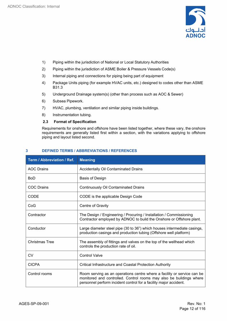
1) Piping within the jurisdiction of National or Local Statutory Authorities
2) Piping within the jurisdiction of ASME Boiler & Pressure Vessels Code(s)
3) Internal piping and connections for piping being part of equipment
4) Package Units piping (for example HVAC units, etc.) designed to codes other than ASME B31.3
5) Underground Drainage system(s) (other than process such as AOC & Sewer)
6) Subsea Pipework.
7) HVAC, plumbing, ventilation and similar piping inside buildings.
8) Instrumentation tubing.
2.3 Format of Specification Requirements for onshore and offshore have been listed together, where these vary, the onshore requirements are generally listed first within a section, with the variations applying to offshore piping and layout listed second.
3 DEFINED TERMS / ABBREVIATIONS / REFERENCES
Term / Abbreviation / Ref. Meaning
AOC Drains Accidentally Oil Contaminated Drains
BoD Basis of Design
COC Drains Continuously Oil Contaminated Drains
CODE CODE is the applicable Design Code
CoG Centre of Gravity
Contractor The Design / Engineering / Procuring / Installation / Commissioning Contractor employed by ADNOC to build the Onshore or Offshore plant.
Conductor Large diameter steel pipe (30 to 36”) which houses intermediate casings, production casings and production tubing (Offshore well platform)
Christmas Tree The assembly of fittings and valves on the top of the wellhead which controls the production rate of oil.
CV Control Valve
CICPA Critical Infrastructure and Coastal Protection Authority
Control rooms Room serving as an operations centre where a facility or service can be monitored and controlled. Control rooms may also be buildings where personnel perform incident control for a facility major accident.
AGES-SP-09-001 Rev. No: 1 Page 13 of 116
ADNOC Classification: Internal
Term / Abbreviation / Ref. Meaning
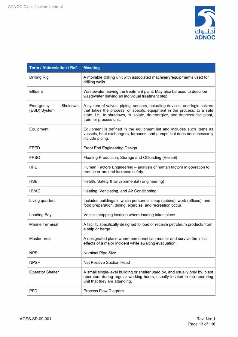
Drilling Rig A movable drilling unit with associated machinery/equipment’s used for drilling wells
Effluent Wastewater leaving the treatment plant. May also be used to describe wastewater leaving an individual treatment step.
Emergency Shutdown (ESD) System
A system of valves, piping, sensors, actuating devices, and logic solvers that takes the process, or specific equipment in the process, to a safe state, i.e., to shutdown, to isolate, de-energize, and depressurise plant, train, or process unit.
Equipment Equipment is defined in the equipment list and includes such items as vessels, heat exchangers, furnaces, and pumps’ but does not necessarily include piping.
FEED Front End Engineering Design..
FPSO Floating Production, Storage and Offloading (Vessel)
HFE Human Factors Engineering – analysis of human factors in operation to reduce errors and increase safety.
HSE Health, Safety & Environmental (Engineering)
HVAC Heating, Ventilating, and Air Conditioning
Living quarters Includes buildings in which personnel sleep (cabins), work (offices), and food preparation, dining, exercise, and recreation occur.
Loading Bay Vehicle stopping location where loading takes place.
Marine Terminal A facility specifically designed to load or receive petroleum products from a ship or barge.
Muster area A designated place where personnel can muster and survive the initial effects of a major incident while awaiting evacuation.
NPS Nominal Pipe Size
NPSH Net Positive Suction Head
Operator Shelter A small single-level building or shelter used by, and usually only by, plant operators during regular working hours, usually located in the operating unit that they are attending.
PFD Process Flow Diagram

AGES-SP-09-001 Rev. No: 1 Page 14 of 116
ADNOC Classification: Internal
Term / Abbreviation / Ref. Meaning
RV Relief Valve, also referred to as a pressure safety valve (PSV)
Reservoir The underground formation where oil and gas has accumulated. It consists of a porous rock to hold the oil or gas, and a cap rock that prevents its escape.
Riser That part of a subsea pipeline that is situated between the connecting flange at the mudline nearest to the platform and the first flange above water level.
SIF Stress Intensification Factor, normally for fatigue stress calculation.
Shall The word “Shall” denotes that the requirement is mandatory.
Should The word “Should” denotes that the requirements is highly recommended but is not mandatory.
This Specification Piping Basis of Design ADNOC AGES-SP-09-001
Temporary refuge / shelter A location (typically in an enclosure or building) that will enable occupants to survive defined major accidents for the specified endurance period.
Temporary buildings Prefabricated buildings, modular buildings, trailers, or other structures used in support of construction or maintenance activities and not intended to be used for the life of the facility.
UFD Utility Flow Diagram
Vendor VENDOR is the company engaged in a purchase contract with PURCHASER, for the supply of materials or equipment. During the Bidding or Tender stage shall be referred to as BIDDER.
Wellhead A wellhead is a general term used to describe the component at the surface of an Oil/Gas/Water well that provides the structural and pressure containing interface for the drilling and production equipment.
Wireline Operations Various operations that are performed by lowering instruments or tools on a wire into the well.
Well Workover Remedial work to the equipment within a well, the well pipe work, or relating to attempts to increase the rate of flow.
Well Platform An offshore structure that is permanently fixed to the seabed and houses the well head.
Well Cellar An Onshore concrete pit that houses the wellhead.

AGES-SP-09-001 Rev. No: 1 Page 15 of 116
ADNOC Classification: Internal
4 NORMATIVE REFERENCES
4.1 International Codes & Standards These are located in APPENDIX Section D Sect. A3.2

AGES-SP-09-001 Rev. No: 1 Page 16 of 116
ADNOC Classification: Internal
SECTION A - APPLICABLE CODES & STANDARDS 5 REFERENCE DOCUMENTS
5.1 ADNOC Standards These are located in APPENDIX Section D Sect. A3.1
6 DOCUMENT PRECEDENCE The specifications and codes referred to in this specification shall, unless stated otherwise, be the latest approved issue at the time of Purchase Order placement.
It shall be the CONTRACTOR 'S responsibility to be, or to become, knowledgeable of the requirements of the referenced Codes and Standards.
The CONTRACTOR shall notify the COMPANY of any apparent conflict between this specification, the related data sheets, the Codes and Standards and any other specifications noted herein.
Resolution and / or interpretation precedence shall be obtained from the COMPANY in writing before proceeding with the design/manufacture.
In case of conflict, the order of document precedence shall be:
1) UAE Statutory requirements
2) ADNOC Codes of Practice
3) Project Specifications and other project documents
4) COMPANY Specifications & Standards
5) National / International Standards
7 SPECIFICATION DEVIATION / CONCESSION CONTROL In case of conflict between documents in the same level of hierarchy, the most stringent requirement shall be applicable unless specifically agreed with COMPANY. Such interpretation of the most stringent requirement shall be subject to COMPANY’s approval utilizing a technical query sheet. In all such cases of conflict, COMPANY’s decision shall be final
Any technical deviations to this specification and its attachments including, shall be sought by the CONTRACTOR only through technical deviation request format. Technical deviation requests require COMPANY’S review/approval, prior to the proposed technical changes being implemented. Technical changes implemented prior to COMPANY approval are subject to rejection.

AGES-SP-09-001 Rev. No: 1 Page 17 of 116
ADNOC Classification: Internal
SECTION B - PLANT LAYOUT 8 DESIGN
The design service life for new facilities shall be considered as 30 years unless specified in the project documentation.
8.1 Design Code The design codes applicable for the piping shall be ASME B31.3. The Code specification break between piping and pipeline shall be indicated in all relevant P&IDs.
Note
Special consideration has to be given for Offshore manned facilities, (e.g., Processing complex and associated manned islands). The piping and pipeline code break shall be at the first flange in the Riser side or as defined in the P&IDs. The wall thickness calculation for the piggable piping shall be performed in accordance with ASME B31.3 code to have controlled inner diameter (ID) of the topside piping to match the ID of the DNV pipeline in order to ensure smooth transition of pigs. This will result in non-standard pipe outside diameter in order to compensate for the increased wall thickness from ASME B31.3 pressure calculations.
8.2 Piping Materials Piping materials shall comply with “Piping Material Specification AGES-SP-09-002.
The piping components not covered in the piping classes and PMS shall be treated as special piping components and a logical special part number (SP-XXX) shall be allocated to each such component. This numbers shall appear in the P&IDs, piping layouts and the isometric drawings.
Special piping parts list along with datasheet shall be prepared with brief specification of the components. The detailed specification or drawing for the special components shall be prepared separately for the procurement.
8.3 Criticality Rating Criticality Rating shall be defined in accordance with COMPANY Criticality Rating Specification.
9 PLANT LAYOUT OVERVIEW
9.1 Plant Layout Primary Issues
The overall design of a facility provides the basis of safe, reliable plant operation. Plant layout is concerned with arrangement of buildings, process & utility equipment and its interconnections within the onshore and offshore plant limits. This guideline specification makes clear distinction between the layout of the various plant facilities and the arrangement of process/utility vessels and equipment etc., within the plant area. The plant layouts for new construction, expansions and modifications on existing facilities shall provide for a maximum of safety and exposure protection from the spread of fire, with ease of operation and maintenance consistent with economical design.
The primary design considerations to be taken into account when laying out the facilities are listed below:
Safety

AGES-SP-09-001 Rev. No: 1 Page 18 of 116
Environment
Process Efficiency, Criticality & Reliability
Underground facilities such as trenches, foundations, cables, drain piping network, etc.
Fabrication and Construction
Installation
Hook-Up and Commissioning
Operation and Maintenance
Cost
Rail, Road, sea access
Feed and export pipelines
Drilling rig access and approach and drilling requirements as applicable.
9.2 Plant Layout requirements
As a minimum, following considerations to be assessed & carried out to an appropriate level of detail.
Potential hazards associated with process conditions, equipment layout, ignition sources, fuel sources, toxic releases, chemicals etc., shall be considered during facility layout design stage.
Less stringent exceptions to or variances from requirements mentioned in this specification shall be supported and documented by a risk assessment.
Risk assessment should be considered for plant expansion, modifications, revamping and also for installation of temporary facilities.
Environmental considerations shall be considered in the plant layout to ensure that “no damage” to the environment.
At all stages, criticality of plant / equipment and implications of loss due to asset damage, business interruption and reputation should be considered, as well as those for safety of personnel.
Typically Plot Plans are developed taking into consideration the following activities/studies:
Overall field layout & Pipeline corridors
Plot plan layout study,
Standards Plot plan for Well pads/Clusters
Piping studies,
HSE studies/reviews
Drilling requirements and Drill rig approach for well specific piping..
The following are the typical assessments/reviews that may affect the plant layout development:
Hazard Identification Reviews (HAZID),
AGES-SP-09-001 Rev. No: 1 Page 19 of 116
Hazard and Operability Study (HAZOP),
PHSER review,
HSE Critical Equipment Systems (HSECES),
Fire and Blast Analysis,
a) EERA (Escape, Evacuation and Rescue Analysis) b) Quantitative Risk assessment (QRA)
Fire Safety Assessment (FSA), Gas Dispersion and Heat Radiation Analysis,
Consequential Risk Assessment,
Design review of Layouts, (including plot plant review)
3D Model review,
Material Handling Study,
Constructability Study.
Below noted requirements as part of plant integrity management shall be considered:
a) The inspection of the equipment, for both new and existing plant modifications, must be given adequate consideration during all the stages from initial design through shop manufacture, site fabrication or erection, commissioning and subsequent operation. It shall be ensured that equipment has been designed, fabricated and installed according to the Specifications, Codes and Standards approved by COMPANY.
b) Access shall be ensured for thorough and timely inspection of the production equipment including stationary and mobile cranes, overhead cranes, structures, storage tanks, boilers, pressure vessels, piping and related pressure containing equipment.
c) Dead leg management
9.3 Order of Equipment Maximum economy of pipework and supporting steel is an important factor in producing the design of the plant. Equipment should be located to minimize runs of alloy pipework and large bore pipe, without compromising the piping flexibility and support requirements.
9.4 Grouped Equipment Layout Use grouped layout, where similar equipment is grouped together to ease operation, maintenance and control. Wherever it does not conflict with loss control, consider accessibility for maintenance and operations in determining spacing and layout. Locate equipment needing frequent overhaul, maintenance or cleaning at unit boundaries. Locate large vessels or equipment close to unit boundaries to allow easy access of cranes.
9.5 Safety
Summary of Objectives The safety layout objectives include, but are not limited to, the following:
a) Separate flammable inventory from sources of ignition
b) Segregate high and low risk equipment and piping.
c) The more hazardous equipment should be located downwind.
AGES-SP-09-001 Rev. No: 1 Page 20 of 116
d) Minimize the requirement for people to be in hazardous areas.
e) Large inventories should be segregated as far as is practical, containment curbs should be utilised.
f) Areas containing hydrocarbons should be open and well ventilated to prevent an accumulation of escaping gas and to provide better venting in the event of an explosion thus reducing blast overpressures.
g) Locate equipment, pipelines and piping to protect personnel and limit escalation of potential incidents.
h) Provide fire and blast walls where required by HSE studies.
i) Workplaces located in potentially dangerous areas shall be suitably protected.
j) Provide for personnel escape and evacuation in the event of an emergency.
k) Stairways shall connect directly to egress routes.
l) Position hazardous equipment to minimize the effects of dropped or swinging crane loads.
m) Position safety equipment in appropriate locations.
Hazardous Areas a) A hazardous area is a facility area where flammable gas is, or has the potential to be,
present in sufficient quantities such as to require electrical equipment, working in that area to be certified accordingly.
b) The extent of hazardous areas shall be taken into account when laying out equipment. Refer to the relevant code and the area classification map for development and extent of hazardous areas.
c) The extent of the hazardous areas shall be taken into account when laying out equipment. Where possible, equipment should be grouped in areas of similar classification and requiring similar fire detection and protection.
Non-Hazardous Areas Non-hazardous areas are those which are not classified as hazardous by the above definitions.
Hazardous Inventories Process units with hazardous inventories shall be located to minimize the risk of any inadvertent release of fluid to personnel within the site and also on activities outside the site boundary. Topography, prevailing winds, personnel safety and nearby population centres shall be considered in selecting the most suitable location.
Continuous Ignition Sources Continuous ignition sources shall be located upwind of the process units. The safety distances between equipments shall be based on Facility Layout & Separation Distances Guidelines, AGES- GL-03-001 and shall be verifed based on detail project specific applicable HSE studies like FSA, QRA, etc.
Group Hazardous Equipment Equipment items, which could be considered a possible source of hazard, should be grouped together and where possible located separately from other areas of the plant for example heaters

AGES-SP-09-001 Rev. No: 1 Page 21 of 116
and furnaces either separated or located at the corner of the unit. Location of hazardous equipment should not compromise economical pipe runs, as this will increase costs. By careful positioning of the relevant equipment, hazardous area classifications may be simplified, thus reducing the plot size.
Flammable Material Storage Flammable material storage should be located on safe non-hazardous areas away from process units. Flammable material may only be stored on a process unit plot provided it is not possible to be allocated in non-hazardous areas, additional risk reduction measures are incorporated, and a comprehensive risk assessment has been conducted.
Potential Release of Large Vapour Cloud Where large amounts of flammable vapours could be released and a vapour cloud explosion could occur, a detailed hazard analysis and evaluation should be made to determine vapour cloud explosion overpressure circles. Onshore where applicable, base the minimum spacing required between units shall be based on required by the HSE Safety distances and HSE studies.
FERA/QRA to Ensure Hazard ALARP The facilities must incorporate the requirements of specific safety studies, for example Fire and Explosion Risk analysis (FERA)) and Quantative Risk Assessment (QRA) including Fire Safety Assessment (FSA), to ensure that all possible hazards have been reduced to a level that is “as low as is reasonably practicable” (ALARP).
Damage Escalation to Adjacent Areas In conformance to FERA & FSA, the maximum calculated size of flammable gas cloud from one plant area should not significantly intrude into adjacent areas. The effects of damage caused in one area will minimise the escalation to adjacent areas and hence safety distances shall be adjusted/updated based on QRA report.
Blast Study A blast study by HSE shall normally be carried out for onshore as well as offshore platforms.
Explosion hazards shall be managed to reduce the exposure to possible explosion overpressure. The magnitude of a gas explosion is not significantly increased by proximity of adjacent plant units. However, reductions of explosion hazard severity should be sought early in the design layout to reduce the likely effects.
Vessels or Tanks Containing Flammable Liquids at Grade. Vessels or Tanks containing flammable liquids should be located at grade. ONSHORE LPG storage should be buried or mounded tanks
Grouping of Vessels Grouping of vertical vessels should be considered to benefit construction.
Equipment Elevation The elevation of equipment shall consider the relative vertical distances and pressure drop in the piping between equipment to maintain the process (NPSH). These considerations shall include re- boiler circuits and gravity flow requirements, pumps and suction filters as specified by Process. Slope and no pocket requirements shall be followed. Flare headers shall be sloped without pockets, towards flare knockout drums.
AGES-SP-09-001 Rev. No: 1 Page 22 of 116
Elevations of exchangers shall be minimized, but should be of sufficient height to allow lines from the underside of exchangers to clear the ground/deck to allow the installation of drains. Unless necessary to elevate exchangers for process requirements, elevations of exchangers shall generally be determined, by the lowest allowable bottom of pipe of the largest diameter line attached to the bottom of the exchanger.
Elevation of underground drain drums should be optimised especially in high water table area.. Location of such underground drums shall be suitably selected i.e. should be not located at edge of the plot as it will increase the depth
Cooling water piping shall ensure coolers remain flooded in the event of loss of supply.
Unless specifically indicated on the P&IDs, control valves shall preferably be located at grade.
Low point requirements shall be followed. Sump layouts shall consider location, depth of the sump, pump size, cycle rate, storage volume required, inlet elevations and constructability.
Additional Offshore Considerations Equipment positioning should avoid pockets in gas, vent, and flare systems to allow piping to free drain.
To reduce the risk of escalating events, equipment containing large inventories of combustibles such as separators should maximize separation.
To the maximum extent practical, large vessels should be located where they do not block major explosions venting paths.
Equipment shall occupy the minimum space consistent with its function and its operations and maintenance requirements without compromising safety. The arrangement should maximize the use of common maintenance equipment and laydown areas.
9.6 Elevated Crane Handling Requirements
General If elevated equipment requires crane handling, space to manipulate a boom, a manually operated travelling crane, or a monorail and trolley shall be provided.
Material Handing Facilities Permanent handling facilities for maintenance access shall be maximized as practical as possible. The material handing studies shall be carried out based on the available material handling crane capacity with the COMPANY work areas for routine maintenance and repair activities during normal operations.
Avoid Lifts over Operating Equipment Equipment layout shall avoid the necessity to lift heavy pieces of maintainable components, valves, etc., during unit operation over in-service process lines or equipment.
Crane Dropped Object and Swinging Load Protection Crane operations over hazardous equipment should be avoided. If pipework and equipment is not covered by deck or other structure with strength to withstand a possible impact, dropped object’ protection shall be considered.

AGES-SP-09-001 Rev. No: 1 Page 23 of 116
9.7 Offshore Dropped Object Study
General Dropped objects and swinging load impacts can occur due to the following factors:
a) Human error (including inadequate fastening, incorrect crane operator’s judgement or inaccurate load weight recorded in the shipping manifest)
b) Mechanical failure (failure of components of the lifting equipment, crane control, power systems, or of the crane boom)
c) Environmental conditions.
Criteria Dropped object safety criteria include the following requirements:
a) Weather deck areas directly above the well bay including deck hatches shall be designed to accommodate dropped drilling items that may fall from the drilling mast with no loss of containment to hydrocarbon systems in the well bay below.
b) When determining deck impact due to falling drilling tubulars lifted in bundles, the energy value used shall consider the tubes to be individual items which separate when dropped and fall loosely.
c) Tote tank & general laydown areas shall accommodate a full tote tank dropped from peak handling height without loss of containment within any process area beneath.
d) Enclosures intended for occupancy or housing critical control / emergency functions should be designed to accommodate routine lift items (e.g. containers, skips) dropped from peak handling height without causing roof breach or global collapse.
Swing Load Impact - Vulnerable Platform Areas and Equipment Swinging loads may impact and damage equipment containing process hydrocarbons, safety related (e.g. the TR) or personnel.
The following areas are potentially vulnerable to swinging loads:
• Living quarters
• Laydown areas
• Turbine exhausts
Swinging load protection in the form of heavy-duty hand-railing is required in the following locations:
• Along the platform edge(s) of laydown areas to prevent objects / containers falling overboard
• Where vulnerable critical or hydrocarbon containing equipment / piping (e.g. small-bore piping and instrumentation) is within 2m of the edge of a laydown area
• Where there is the potential for objects to fall from laydown areas onto decks below (e.g. as a result of a swinging load impact), resulting in potential for loss of hydrocarbon integrity
AGES-SP-09-001 Rev. No: 1 Page 24 of 116
Heavy-duty hand-railings should be capable of restraining a swinging load with impact energy of 40 kJ (9 tonne tote tank at ~ 3m/s). The protection level provided for an accidental event expects some repairable damage to occur.
Study A study covering dropped objects and mechanical handling is a mandatory requirement for offshore installations unless otherwise specified. In these installations, space is limited, mechanical handling is difficult and structural damage can occur due to accidental dropped object and swinging load hazards to topside facilities from routine handling operations.
Studies shall assess and consider the following:
a) The vulnerabilities and structural protection provisions.
b) The methods (including by helicopter) and materials handling requirements for routine transfer and movements. These shall include freight moved by ISO containers, skips, tubulars, baskets special packages equipment or bulk materials in liquid or powder form and diesel fuel transfer.
c) Prevailing wind directions for supply boat operations
d) Crane number, load capacity and radius.
e) Crane usage risk assessments carried out during the design stage will include estimates of frequencies and weight of normal / routine lifts.
f) Additional specific dropped object risk assessments studies for lifts (typically) above 9 tonnes, may be also be required. These may include the following considerations:
• Installation
• Hook-up and commissioning
• Non-routine lifts
• Hazards associated with dropped objects to sea
g) Drilling activities in well bay areas are usually addressed by the Drilling Contractor.
9.8 Maintenance Areas
Areas shall be designated as necessary to allow maintenance of equipment such as disassembly of pumps, compressors, tube bundle removal of exchangers,etc. Such maintenance areas shall not interfere with escape routes.
Particular emphasis should be placed on items of equipment that require regular maintenance or which are critical to production.
9.9 Personnel Access and Escape
Means of egress including fixed ladders, fixed industrial stairs, platforms, railings and applicable clearances should be designed in accordance with the standards and instructions included in this Specification and as defined in HSErequirement ( Refer HSE-OS-ST21).

AGES-SP-09-001 Rev. No: 1 Page 25 of 116
In areas under red zones and amber zone where Self-Contained Breathing Apparatus (SCBA) / Emergency Escape Breathing Apparatus (EEBA) are to be always carried by all personnel’s the means of egress shall be suiable for escape donning SCBA/EEBA and shall be in line with HSE documents.
a) Primary access: stairs only
b) Secondary access can be ladder, provided its designed for escape donning SCBA/EEBA.
Obstructions to means of egress should not be permitted and shall be continuously maintained free of all obstructions or impediments to full instant use in the case of fire or other emergency. The required capacity of a means of egress system are not to be diminished along the path of egress travel.
The bottom flight of stairs to grade level onshore shall be orientated away from the plant, similarly offshore at each emergency access level, the orientation of the flight of stairs landing on that level shall be orientated towards the main emergency egress.
9.10 Environment
Prevailing Winds & Noxious Smells The orientation of the plant layout is most influenced by the prevailing wind and local environmental characteristics. The prevailing wind should direct plant flare / vent plumes and any hydrocarbon gas discharge resulting from leaks away from the occupied areas and the local infrastructure. Similar consideration should be given to equipment that can emit noxious smells for example waste treatment units; they should not be located close to an area where personnel will be working, or in the proximity of residential property. These items should be sited where the prevailing wind will carry any noxious smells away from those sensitive areas.
Discharge to Atmosphere Discharges of process and utillity streams to atmosphere shall be in compliance to ADNOC HSE standards and in accordance with P&ID. Where applicable relevent HSE studies to be performed and recommendations of the same shall be implemented in piping layouts.
Noise Noise shall be limited in accordance with ADNOC HSE standards. Special consideration shall be given to piping routing for equipments/devices such as steam exhauts, flares, etc.
Blowdown Inventory The layout should be designed to minimize pipe run lengths and therefore reduce blowdown inventory.
Spillage Due consideration must be given to the containment and disposal of any spillage of pollutants.
Safety Gradient The layout of the plant should provide a ‘safety gradient’. This will result in the most safety critical equipment areas being located the furthest distance from normally occupied/administration area. This will also result in personnel safety egress progressing to successively inherently safe areas.
AGES-SP-09-001 Rev. No: 1 Page 26 of 116
9.11 Process
General Equipment should be located to streamline the process flow and simplify piping systems without compromising pipe support and stress requirements. The sequence of equipment is generally defined by the process flow requirements, which also frequently dictate relative elevations, thus indicating the need for structures. Other process considerations include the limitations of pressure or temperature drop in transfer lines dictating the proximity of the equipment.
Avoid Pocket Piping a) Positioning equipment to avoid pockets in gas, vent, and flare systems to allow piping to
free drain will reduce the need for additions to the drainage systems.
b) Drain tanks and vent knock-out drums should be located at a level which permits pipework in the associated collection systems to fall with the correct gradient/slope and without pockets.
c) Vapour lines in wet, carbon dioxide or corrosive service should have no liquid pockets.
d) Two-phase lines should be of minimum lengths, bends and without pockets, to minimize potential slugging.
e) Compressor suction lines should have no liquid pockets.
f) Two-phase lines from coolers should free-drain to the knock-out-drum.
g) All process and utility drains shall be sloped to the respective drums.
Flashing Liquid Service Control valves and pumps operating at bubble point conditions should be located close to the associated vessel as practical to obviate flashing at the valve or pump inlet and as indicated in the P&IDs. Pumps must have adequate Net Positive Suction Head (NPSH).
Minimum Straight Lengths for Flow Minimum required straight inlet and outlet requirements shall be considered for example compressor suction lines, pump suction lines, flow controlling elements and vane straightening (schoepentoeter – sharp horn) devices and as indicated in the P&IDs.
9.12 Construction and Installation
General
a) The engineer has a duty to develop a layout which can be fabricated and constructed safely.
b) Constructability review shall be conducted early in the design stage of the project.
Extent of Modularisation / Pre-Fabrication The extent of modularisation or prefabrication shall be defined/agreed with the COMPANY during FEED stage of the project based on project requiremets and futher detailed during the execution phase. Refer APPENDIX A2 for more details on Modularisation
AGES-SP-09-001 Rev. No: 1 Page 27 of 116
Field Fabrication at Unit Limits Wherever specified, Field fabricated towers, fired heaters, tanks etc. should be located at accessible location/unit limits for construction convenience, if practicable. Exceptions may be taken in consideration of process design or hazard management benefits.
Optimizing the Use of Supporting Structures a) Wherever feasible grouping of structures, platforms, access way shall be considered.
b) Isolation valves, blowdown valves and the pipework may be mounted with the same structure supporting the related equipment as practical as possible. This measure will reduce the risk of differential deformation under blast load conditions. Noting that differential structural deformation is likely to cause overstressing of pipe connections and loss of containment integrity.
Installation a) Availability of suitable capacity cranes may need to be considered Onshore. For Offshore,
availability of lift barges shall be considered.
b) Accessibility for Installation of future equipment.
c) Module/Skid Transportation – temporary supports, acceleration loads for stress analysis shall be considered.
Operations and Maintenance a) Provide space to safely operate and maintain the facility.
b) As practicable, provide permanent handling facility for the frequent maintenance of components.
c) Locate crane laydown areas to allow good visibility from crane cabin.
d) Provide adequate access routes to crane laydown areas, workshops etc.
e) Allocate space for any additional mechanical handling systems.
f) Incorporate mechanical handling volumes into the design ( in 3D models, etc) to prevent re- work later.
9.13 Adequate Decking and Pavement Areas Provide adequate decking and pavement areas for expected maintenance and repair activities. Consider space required for personnel, maintenance equipment, tools, disassembled equipment components and safety gear.
9.14 Rotating Equipment Maintenance Rotating equipment layout shall be configured to allow maintenance, removal, lifting access and replacement of rotors and other major maintainable components.
9.15 Crane Access a) For onshore facilities, mobile crane for material handling shall have equipment and
structures arranged to permit stable mobile crane access to service air coolers, compressors, exchangers, etc as identified in material handling report.
AGES-SP-09-001 Rev. No: 1 Page 28 of 116
b) Permanent installed mechanical handling equipment like EOT crane, monorails, pad eye. etc., shall be provided in covered areas for example equipment under shelters, under platforms, etc where frequent material handing is required, and mobile crane access is not feasible. In case of valves and equipments located on top of elevated pipe racks, where suitable mobile crane access is not feasible due to elevation for frequent material handling, suitable permanent material handling facilities shall be provided and agreed with COMPANY
c) Consider the maintenance 3D envelope required for crane operations and other rigging activities.
10 PLOT PLAN
10.1 Plot Plan a) The plot plan shows the arrangement of the key features of each facility and its relationship
with the overall plant arrangement.
b) The plot plan is finalised following specific design reviews like Plot plant reviews, 3D model reviews, HSE reviews, constructability reviews, etc.
c) The plot plan defines the overall plot size and shape, locations, distances and orientation relationships between equipment, location and major elevations of structures, roads and access.
d) The plot plan forms the basis from which the detailed plant design is developed and from which associated investment commitments are made.
10.2 Topography & Drainage Topography, prevailing winds, personnel safety, and nearby population centres shall be considered in selecting the most suitable location. Topography may also be a consideration with respect to gravity systems. Natural falls of the terrain should be considered with respect to high water table, SABKHA areas, drainage tanks and lagoons, to potentially reduce civil excavation costs.
10.3 Import / Export Pipelines and Utility Services The orientation of the plant with respect to the import / export pipelines and utility services should also be considered, to provide the most economical solution, while not jeopardizing safety from any possible hydrocarbon leaks.
10.4 Unit Plot Size a) The site area shall be divided into plots, and if possible, the plots should be rectangular.
The COMPANY specific Drafting Guidelines/Specifications shall be followed during development of plot plans and other engineering drawings
b) A single plot may contain more than one process unit or section.
c) The overall plant layout is generally subdivided into general areas dedicated to:
Process area,
Utility area,
Offsite,
Services

AGES-SP-09-001 Rev. No: 1 Page 29 of 116
d) The site area shall be divided into plots and size shall be as per AGES-GL-03-001- Facilities Layout & Separation Distances Guidelines.
e) Equipment handling toxic / lethal material shall be located with the restricted access or in accordance with local statutory regulations.
10.5 Future Expansion a) In addition to the project scope facilities existing plant, space shall be allocated for future
plant expansion (as identified in the project scope), with special reference to the surrounding topography and the location of the following features:
• Pipelines or flowlines corridors.
• Flare location / sterile area.
• High voltage power lines and pylons above ground, or cables underground.
• Natural expansion of storage and export systems.
b) Future space shall be clearly indicated/marked in the respective drawings
10.6 Well Head Typically for onshore and islands, for well head piping various configurations are used depending on various factors like Reservoir/Development philosophy & Drilling requirements, number of wells, availability of different type of rigs, space constraints, etc. These can be broadly categorised as
Off Pad wells
Well Pads & Clusters/Drill centres
Off Pad wells These are single individual Producers (Oil/Water/Gas) and Injectors (Gas/Water or combination) with associated well facilities, located remotely in a field with its own individual flow line to a gathering station. A typical Off pad plot plan includes a well head area and valve compound area. The sepration distance between the two shall be based on HSE ,Drilling requirements and as per project documentation.
The development of the plot layout and piping for the Off pad Wellheads shall consider the following, as a minimum:
a) The interconnecting piping between the wellhead and valve compound/ flow line isolation shall be of removable design and consist of suitable number of break flanges and removable pipe supports to facilitate for well workover.
b) All the associated operating facilities of well shall be enclosed in a common valve compound area. These facilities includes, Well head Control panel, Chemical injection skid, Electrical/Instrument technical rooms, solar panel, cold vents, etc as applicable.
c) The associated facilities should be located upwind / crosswind of the prevailing wind direction in relation to the wellhead as practical as possible.
d) Rig approach and accessibility to the well shall be given due consideration in locating the above facilities.
e) Piping shall be designed to facilitate Well workover and Well wireline operations.
f) Well head cellar shall be provided with cover grating and sand barrier.
AGES-SP-09-001 Rev. No: 1 Page 30 of 116
g) Well tag pole & wind sock shall be located within the well head area. The well tag pole shall also include safety sign for high H2S.
h) Al well heads outside the CICPA Fence area shall have its own fence in line with CICPA requirements. Removable fence is required for well area to facilitate well workover and fixed fence for the valve compound area
i) Safety distances between well, equipments & facilities shall be in line with HSE requirements and drilling requirements
Well Pads. Clusters & Drill centres: Well Pads, Clusters,& Drill Centres are group of wells ( Producers and Injectors) arranged in a particular patterns . Well spacing in these are different due to dedicated type of drilling rig facilities. The common process facilites for these group of well like Production manifolds, injection manifolds, MPFM, etc are located a certain distance fron the wells rows based on HSE and Drilling requirements The common oil production trunk line from these Well Pad, Cluster, etc are connected to nearest Processing stations and the common gas & water injection pipeline tie in from associated injection headers. Branch overhead power line or underground power cable as applicable are connected to these facilities to provide the electric power. Different terminology is currently used ( in ADNOC Group companies) to describe these arrangements like Well Pad, Well Plats, Well Hub, Drill Centres, Clusters, etc based on multiple factors including Reservoir, drilling, location, well spacing, onshore areas, offshore islands, project specific requirements.
The development of the plot layout and piping for the Well Pad, Well Plats, Clusters, Drill Centres etc shall consider the following, as a minimum:
a) The associated process facilities should be located upwind / crosswind of the prevailing wind direction in relation to the well bays .
b) Piping shall be designed to facilitate Well workover and Well wireline operations.
c) Rig approach and accessibility to the well shall be given due consideration.
d) In cases like Clusters, Drill Centres, etc where well bays are located within the common fenced areas, the wells are located in rows with well head piping, cables,etc inside a concrete trench. The plot also includes dedicated drilling space,, heavy paving for rig movement, rig gates, etc and shall meet drilling requirements . The well head piping in such cases are located in heavy duty trench designed for rig loads. The clearance between the wells and the common pipe rack/facilities shall be based on drilling requirements
e) In case like Well Pad, Well Plats, etc where well bays are located outside of process facilities, the well head piping are located in removable pipe supports and have break flanges to facilitate well workover activities. The clearance between the well bays and the common pipe way shall be based on drilling requirements
f) As applicable operating facilities includes common Welhead control panel, Production & injection facilities, MPFM/Test separators, pig traps, Electrical &, Instrument equipment rooms, Transformers, associated pipe racks/ pipe way, blowdown/closed drain vessel , flares, Chemical injection skids etc
g) Well head cellar shall be provided with cover grating.
h) Well tag shall be suitably located within the well head area.
i) The fencing shall be in line with CICPA requirements and suitable access for Rig access & layout.
AGES-SP-09-001 Rev. No: 1 Page 31 of 116
j) Safety distances between well, equipment & facilities shall be in line with HSE requirements.
10.7 Layout of Pipe Racks
General
a) Where practical, inside-plot piping shall be routed on overhead pipe racks. The preferred layout arrangement of a process unit is a pipe rack located in the centre of the unit with large equipment on both sides.
b) Pipe rack configurations are dictated by the equipment layout, site conditions, the process flows between equipment, number of equipment items, quantity and size of the lines and economic consideration.
c) The final layout of the pipe rack to meet the specific requirements of the project could result in a variety of configurations (e.g. T, L or U shape). Changes of direction in pipe racks must be accommodated by changes in elevation and usually equally spaced about the midpoint of the main pipe rack elevations to suit required clearances.
Rack Access & Clearances a. Operator access to equipment and grade level instruments, should be provided between the
edge of equipment and the pipe rack (for pipe rack inside the plant). For outside the plant pipe racks, paved/interlock paved operator access shall be provided below the rack.
b. Access ways along side the top level of the pipe rack shall be provided for periodic inspection of piping and weld joints for offshore pipe racks /bridges. For Onshore, this requirement can be optimised based on project requirement in agreement with COMPANY.
c. For pipe rack clearances refer Table 1 below
Alignment of Rack and Structure Columns As practical as possible, if a pipe rack forms a part of the structure, or is located next to the structure, the stanchions of the pipe rack should be in line with the columns of the structure, to make optimal use of space for incoming and outgoing pipes.
10.8 Roads, Fencing and Gates
General Normal segregation between adjoining process units is by a road system, which will also reduce the risk and spread of localized fires. All requiremets of COMPANY specification for rods shall be followed.
Security and Fencing a) The Plant must be enclosed with a fence and should be closed to general public. Access to
general service area should be made normally through a single point entry with a security checkpoint. Locate the main gate to permit control of traffic from the Security office adjacent to the main gate. An adequate parking area should be provided in a safe and controlled area near the gate. Other means of entry should be normally closed and limited to exceptional and emergency purposes only.
b) Gates giving access to the perimeter roads should be provided on all sides of the plot, for emergency access. Emergency escape gates shall be in line with HSE requirement.

AGES-SP-09-001 Rev. No: 1 Page 32 of 116
Perimeter / Public Road Connections The perimeter road should be connected at a minimum of two points with the public road system to ensure the site can be approached from two directions in the event of a major fire.
Traffic Circulation Plan a) A traffic circulation plan shall be made to arrange the roads such that vehicles do not pass
through process areas or violate area classifications.
b) Tankers and vehicles shall circulate using a one-way system, turning areas are not permitted.
c) Railway crossings, crossroads, road junctions, dead ends, sharp bends and ramps should be avoided.
Road Sizing a) Road widths and overhead clearances should be sized to handle large moving equipment
and emergency vehicles. Trucks and cranes require large lateral and overhead clearances to avoid collision with pipe racks. Corner radii should suit the turning circle of the largest vehicle and any special loads. Clearances for passage of mobile equipment shall be based on the largest piece of equipment anticipated. Roads widths and design shall be as per COMPANY Specification for Roads and Paving
This shall include road width plus road shoulder, adjacent drainage channels (if required), etc.
Pedestrian pathways adjacent to roads should be included in areas of high personnel concentration and traffic movement
b) For vertical clearances over roads refer Table 1 in section 11.6
Paved areas
a) Area grading is generally provided for drainage away from Process Area toward catch basins to prevent accumulation of flammable liquid or vapour adjacent to or beneath equipment. Within the process area minimal concrete paving should be supplied for walkways interconnecting major items of equipment, platforms, stairways and buildings.
b) Paving (minimum 2.5m) should be supplied around pumps or other machinery located in the open, underneath furnaces, and any other areas where spillage is likely to occur during normal operation. Areas containing alkalis acids, or other chemicals or toxic materials should be paved and bunded to prevent spillage spreading.
c) For other items of equipment requiring infrequent maintenance, such as exchanger tube bundles, column internals etc. it should only be necessary to ensure that there is adequate clear space for access purposes and the area should be paved
d) All paving shall be based on COMPANY Road and paving specification
Plant Area Access a) Plant areas shall be accessible on all four sides by a road.
b) At least two sides of a process unit should be provided with access roads into the unit, for firefighting purposes. These roads shall be designed to be kept open during facility
AGES-SP-09-001 Rev. No: 1 Page 33 of 116
maintenance campaigns to allow passage of fire trucks or other equipment in case of an emergency.
c) Perimeter and process unit roads should not have dead ends, as these may cause restrictions to traffic and personnel during emergencies.
d) There should always be at least one route to future expansion areas without pipe rack crossings. Otherwise pipe bridges/culverts are to be designed accordingly for future expansion and planned maintenance areas.
Parking Areas Adequate parking space shall be available for vehicles waiting:
a) To load and unload.
b) For the weighbridge.
c) For designated parking places for employees and visitors.
d) Covered areas (for sun protection) shall be provided for designated parking places for employees and visitors.
e) Car and bus parks for personnel and visitors and their access roads should be in a safe area and outside security points.
10.9 Design And Drawing Procedures COMPANY Drawing specifications and 3D modelling procedures/specifications shall be followed for developing the drawings and 3D model.
10.10 Layout and Safety Distances Guidelines
This specifications specifies the clreances and the inter equipment distances based on operation, maintencess and constuction access. For recommended equipment spacing and other safety based on HSE requirements shall be as per Facility Layout and Separation Distances Guidelines AGES-GL-03-001.
Standard separation distances between should be regarded as a minimum unless otherwise specified in recommendations of Fire Risk/Safety Assessment calculated distances and QRA recommendations
In addition for sour applications all the requirements and guidelines as per ADNOC standard “Management of Hydrogen Sulphide (H2S) standard, HSE-OS-ST21 shall be adopted in various stages of plant layout development. This standard is applicable for all stages of lifecycle of facilities including design in facilities where H2S hazard is applicable.
When available, the facility-specific thermal radiation, toxic dispersion and blast overpressure analyses should be used to establish the optimum separation distances. In addition, industry guidance for highly reactive chemicals, such as alkyls and peroxides, may require additional protection layers and specify different separation distances than those provided in Facility Layout and Separation Distances Guidelines AGES-GL-03-001.

AGES-SP-09-001 Rev. No: 1 Page 34 of 116
SECTION C - PLANT PIPING 11 DETAIL PIPING DESIGN
11.1 Detailed Information Required
The following information, not limiting (not listed in order of importance) should be available as applicable to allow the piping layout and design to proceed:
Overall Plot Plan.
Project Basis of Design.
Scope of Work.
PFDs
P&IDs.
Process Requirements.
Piping Material specification.
Indicative Equipment Layouts from Process / Licensors.
Equipment Data Sheets.
Prevailing Wind Direction.
Onshore: Administration building, parking area, workshop, warehouse and laboratory sizes.
Climatic conditions, wind direction and frequency.
Control room size.
Field Instrument details and Analyzer Shelters size.
Drainage philosophy.
Incoming pipeline approach and utility service locations.
Stated preferences on extent of modularization or skidding of equipment and pipe racks.
Storage tank requirements.
Electrical and Instrument room sizes and HVAC requirements.
Electrical sub-station and transformer requirements.
Equipment list with approximate sizes.
Maintenance handling philosophy.
Safety philosophy.
Surrounding infrastructure information, including road and railway details.
Future requirements.
Additional design considerations with offshore plant are:
Size of Accommodation module, helipad, crane and laydown areas.

AGES-SP-09-001 Rev. No: 1 Page 35 of 116
Project Blast Specification.
11.2 Piping above Ground Level
Studies shall be made during design stage to develop major piping routings and plan for final equipment location.
Piping entering and leaving a plot area, or a processing unit should be grouped together.
Piping shall be routed above ground level (Pipe rack/bridges/sleepers) or within culverts (which can be internally inspected) at road crossings.
Piping with instrument connections shall be routed so that safe access to these connections is ensured.
Changes in direction shall not create pockets in piping systems without a drain connection arrangement.
Piping shall be arranged for ease of removal of equipment for inspection or servicing, with maintenance areas kept clear of piping.
Piping shall not be routed above equipment such as heat exchangers, pumps, compressors, automated valves but routed along the side of such equipment.
All uninsulated adjacent lines shall be located so that the bottom of pipes (BOP) or underside elevation of support are at the same elevation depending upon the method of support.
Adjacent lines that are mounted on pipe shoes or reinforcing pads which share the same supporting steel shall be located such that bottom of shoe or reinforcing pad are at the same elevation as the bottom of adjacent lines without pipe shoe or reinforcing pads.
Piping should be routed to provide a simple, shortest-possible run, allowing easy support and with the minimum number of fittings adequate for expansion and flexibility.
Piping shall be routed such that overhead clearance (headroom) is maintained or stumbling hazards such as obstruction to walkways and other paths of travel or equipment movement are avoided.
Diagonal and skewed angles of piping layout in horizontal plane should be avoided.
11.3 Piping Connected to Multiple Equipment
Piping connected to more than one piece of equipment (for example a pump and its spare) shall be designed and supported in accordance with the following:
a) Excessive loads on equipment do not occur when one branch of the pipe is disconnected (for example during maintenance operations);
b) If multiple nozzles are applied, (for example on air-cooler banks) the connecting piping is designed so that small dimensional errors in construction can be accommodated;
c) The piping itself is adequately designed to compensate for any thermal expansion due to differential temperatures between operating equipment and spare equipment.

AGES-SP-09-001 Rev. No: 1 Page 36 of 116
11.4 Pipe Rack Dimensions & Piping
Dimensions of Racks
a) Generally, most inline plant arrangements are furnished with a central pipe rack system that acts as the main artery of the unit supporting process interconnection, feeds, product and utility piping, instrument and electrical cables, and, sometimes, air coolers and drums.
b) Usually, the pipe rack is made of structural steel, either single level or multi-level, to suit the width and capacity for the units it is serving. Typically pipe racks are upto 4 tier and widths of 6m, 8m or 10m for single bays and 12m, 16m or 20m for double bays having 4 tiers maximum
c) The width is determined by factors such as the quantity of piping and cabling to be carried on the main run of the pipe rack (with an allowance for future expansion), access way located beneath the pipe rack, or the equipment (if any) supported above the pipe rack. The layout that results in the most economical design should be chosen.
d) The requirements of expansion bays, anchor bays, bracing pattern, etc., shall be arrived upon consultation with piping stress engineer and structural engineer at the beginning of the pipe rack layout.
e) All piping on pipe racks shall be routed to avoid blocking access for further additions, modifications or repair. Piping on pipe racks shall change elevation at each change in direction, using a 90° elbow in each vertical plane concurrent with each pipe direction except for no pocket lines and flare headers. Individual piping coming into (or out of) a main pipe rack shall enter (or leave) perpendicular to the pipe rack direction using typically two 90° elbows to place the line at an elevation above or below the main pipe rack elevation.
f) Piping shall be laid out parallel or perpendicular to plant North to maximum extent feasible. All uninsulated lines shall be arranged such that the bottoms of pipe (B.O.P.) are at the same elevation. All principal lines running from north to south shall have a minimum difference in elevation from lines running east to west of at least 3 times the largest nominal pipe size, and in no case less than 600 mm difference in elevation.
Capacity for Future Expansion a) Minimum spare space provision on major/main piperack shall be 25% and shall be
maintained during end of FEED Engineering and 20% spare space shall be maintained during end of EPC on each tier of piperack. However for sub/unit pipe racks this shall be 20% in FEED and 15% in EPC respectively on each tier of piperack This does not include known future pipes indicated in P&ID/project documentation. No cantilevers extenstions allowed on new piperacks.
b) The load critera for this future space shall be as described in Structural design basis AGES- SP-01-003
c) To optimise the pipe support span, minimum line size on piperack shall be maintained as NPS 2. Intermediate beams of pipe racks shall be sized for supporting lines NPS 3 & below or non metallic pipe as applicable
d) In a pipe rack the heaviest and / or the hottest pipes should be located at the outer edges of the pipe rack to provide space for expansion loops and to reduce the moments in the beams caused by the weight and thermal expansion of the pipes.

AGES-SP-09-001 Rev. No: 1 Page 37 of 116
e) Piping or components of austenitic stainless steel, duplex/super duplex stainless steel, nickel alloy or 9% nickel steel shall be designed such that they are protected from contamination with molten zinc due to fire for example run on the opposite side of the rack to galvanised utility lines. For components which are insulated, the cladding is considered to be sufficient protection.
f) The piping system containing cryogenic fluid should be grouped separately and located on different pipe rack tiers.The piping system containing cryogenic fluid should be located at the sides of the pipe rack to provide space for contraction loops and to reduce the moments from the pipe loads
g) In a multilevel pipe rack, pipe carrying corrosive fluids should be on the bottom level.
h) In-line valves in overhead piperacks should be avoided. If unit or battery limit isolation valves located on the pipe rack, shall be provided with permanent platform with ladder for operation and maintenance. Depending upon the location/arrangement, adequeate head room clearance, removable spool, material handingling facilities shall be provided.
Additional Considerations a) Electrical & Instrument cable trays, if routed on pipe rack should be run in the top tier of the
pipe racks. Routing of cables trays on pipe rack will require COMPANY approval. The preferred location for onshore application is below the pipe racks.
b) Equipment, which is a potential source of fire, shall not be located under pipe racks unless specifically agreed with COMPANY due to space constraints in brown field areas /islands.
c) Small-bore lines shall not be supported by larger lines.
d) The use of flanged joints in pipe racks should be avoided.
e) Drainage trenches should not be run under pipe racks.
f) Area under plant pipe racks, shall be paved as it has leakage potential such as flanged connections, valves , sampling points etc.. However, for offsite pipe racks and other pipe racks where leakage is unlikely, paving surfacing shall be reviewed based on project requirement”
g) Air coolers may be located above overhead pipe racks if approved by COMPANY.
11.5 Pipe Tracks or Sleepers
Piping may be routed on pipe-tracks or sleeper supports. These supports are an economic solution usually pre-cast concrete with a 50mm wide carbon steel insert load plate on the top surface. Unlike pipe racks, pipe tracks block access at low level and shall be used only in offsite areas where space is not a premium or where safety access and equipment access requirements are minimal.
Outside the plot and in tankage areas, pipes should normally be laid on pipe sleepers. There should be not less than 1 m distance between the nearest edge of a pipe sleeper and the toe of a bund.
The elevation of the pipe-tracks is set by access requirements to drains. A minimum of 300 mm clearance between underneath of lines and grade is recommended in paved areas. In offsite/unpaved areas this shall be increased to minimum 450 mm. (Also refer to Table 1).

AGES-SP-09-001 Rev. No: 1 Page 38 of 116
Piping running on ground level in desert areas/outside plant area, where sand accumulation is expected shall have enough elevation (minimum 600 mm) clearances to allow for sand cleaning activities. As sand is more prone to fence accumulate against solid structures, piping support should be designed to minimize accumulations.
Normally pipe sleeper width is determined based on the present design requirements. An adequate contingency and future requirement shall be considered in design. Minimum provision on pipe sleepers of 15% spare space shall be maintained during end of FEED Engineering and 10% spare space during end of EPC. This does not include known future pipes indicated in P&ID / project documentation
Requirement of expansion loops, anchor location, etc., shall be discussed in consultation with stress engineer and structural engineers at the beginning of the pipe sleeper layout.
Pipes 2" and above on sleepers shall be provided with pipe shoes to avoid external corrosion at support location due to corrosive environment (classified as C5-I or C5-M in ISO 12944-2), moisture accumulation and painting damage due to rubbing action at pipe bottom surface in contact with support. Provision of 20 mm (3/4 in) diameter round bar welded on top or supported on pipe shoes for corrosion mitigation for pipes is acceptable if agreed with COMPANY
11.6 Clearances and Accessibility
General
Minimum clearances for equipment, structures, platforms and supports shall be in accordance with the following table. In addition to below, HSE requirements of inter-unit safe distances in line with Facility Layout & Separation Distances Guidelines AGES-GL-03-001 and for sour service environment the requirements of Management of Hydrogen Sulfide (H2S), HSE-OS-ST21shall be met.
Table 1 – Clearances and Accessibility
ITEM DESCRIPTION CLEARANCE
Railway Headroom over railroads (from top of rail) 6.8 m
Roads
Headroom for primary access roads and haul roads (from the crown)
6.4 m
Headroom for secondary roads (from the crown) which do not require crane access and do not serve multiple process areas/plant
4.9 m
Maintenance Access ways at Grade
Horizontal and vertical clearance for equipment maintenance by hydraulic mobile crane
3.0 m x 3.6 m
Vertical clearance for crane access ( other than main plant roads)
6.0 m
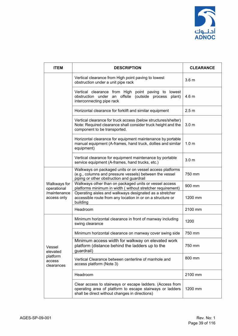
AGES-SP-09-001 Rev. No: 1 Page 39 of 116
ITEM DESCRIPTION CLEARANCE
Vertical clearance from High point paving to lowest obstruction under a unit pipe rack
3.6 m
Vertical clearance from High point paving to lowest obstruction under an offsite (outside process plant) interconnecting pipe rack
4.6 m
Horizontal clearance for forklift and similar equipment 2.5 m
Vertical clearance for truck access (below structures/shelter) Note: Required clearance shall consider truck height and the component to be transported.
3.0 m
Horizontal clearance for equipment maintenance by portable manual equipment (A-frames, hand truck, dollies and similar equipment)
1.0 m
Vertical clearance for equipment maintenance by portable service equipment (A-frames, hand trucks, etc.)
3.0 m
Walkways for operational /maintenance access only
Walkways on packaged units or on vessel access platforms (e.g., columns and pressure vessels) between the vessel piping or other obstruction and guardrail
750 mm
Walkways other than on packaged units or vessel access platforms minimum in width ( without stretcher requirement) 900 mm
Operating aisles and walkways designated as a stretcher accessible route from any location in or on a structure or building
1200 mm
Headroom 2100 mm
Vessel elevated platform access clearances
Minimum horizontal clearance in front of manway including swing clearance
1200
Minimum horizontal clearance on manway cover swing side 750 mm
Minimum access width for walkway on elevated work platform (distance behind the ladders up to the guardrail)
750 mm
Vertical Clearance between centerline of manhole and access platform (Note 3)
800 mm
Headroom 2100 mm
Clear access to stairways or escape ladders. (Access from operating area of platform to escape stairways or ladders shall be direct without changes in directions)
1200 mm
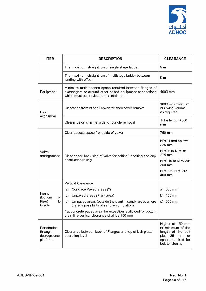
AGES-SP-09-001 Rev. No: 1 Page 40 of 116
ITEM DESCRIPTION CLEARANCE
The maximum straight run of single stage ladder 9 m
The maximum straight run of multistage ladder between landing with offset
6 m
Equipment
Minimum maintenance space required between flanges of exchangers or around other bolted equipment connections which must be serviced or maintained.
1000 mm
Heat exchanger
Clearance from of shell cover for shell cover removal
1000 mm minimum or Swing volume as required
Clearance on channel side for bundle removal Tube length +500
mm
Valve arrangement
Clear access space front side of valve 750 mm
Clear space back side of valve for bolting/unbolting and any obstruction/railing
NPS 4 and below: 225 mm
NPS 6 to NPS 8: 275 mm
NPS 10 to NPS 20: 350 mm
NPS 22- NPS 36: 400 mm
Piping (Bottom of Pipe) to Grade
Vertical Clearance
a) Concrete Paved areas (*)
b) Unpaved areas (Plant area)
c) Un paved areas (outside the plant in sandy areas where there is possibility of sand accumulation)
* at concrete paved area the exception is allowed for bottom drain line vertical clearance shall be 150 mm
a) 300 mm
b) 450 mm
c) 600 mm
Penetration through deck/ground/ platform
Clearance between back of Flanges and top of kick plate/ operating level
Higher of 150 mm or minimum of the length of the bolt plus 25 mm or space required for bolt tensioning

AGES-SP-09-001 Rev. No: 1 Page 41 of 116
ITEM DESCRIPTION CLEARANCE
Notes:
1) An un-obstructed clearance shall be provided around the valves installed in concrete pits for maintenance and repair works.
2) A continuous and unobstructed path of exit travel shall be provided from any point in a building, elevated equipment or structure
3) Platforms shall be positioned so that the manhole centerline is not less than 0.6 m above the platform, with 0.8 m preferred. The bottom of the manhole entry shall not be more than 1 m above the platform.
4) This clearence table dimensions doesnot include HSE requirements.. Additional HSE requirement if any shall be applicable
Pipe To Pipe Spacing The design shall take the following criteria into consideration for pipe spacing:
Thermal insulation
Wall and floor seating detail (pipe supports and guides thereon)
Side movements due to expansion
Linear movement at changes of direction
Flange Outside diameter
Where one or more pipes are running alongside each other and are guided, provision is to be made in the spacing for these guides.
Adjacent pipe guides should be staggered to minimise pipe space requirements.
Adjacent flanges should be staggered to minimise pipe space requirements.
Valves and flanges should be staggered whenever possible to ease operation and reduce space.
The distance between pipes shall allow for the turning of a spectacle blind, where present.
Expansion loop nests shall be checked for differential expansion between the pipes at different temperature
When Pipes and/or Flange is insulated the, insulation thickness shall be added to minimum spacing.

AGES-SP-09-001 Rev. No: 1 Page 42 of 116
Table 2 – Pipe Clearances
ITEM DESCRIPTION
Pipe (Aboveground) in Tracks, Trenches & Pipe Racks/bridges
The minimum clearance between a flange (without insulation) and a pipe or the insulation of a pipe in pipe tracks and trenches and on pipe racks for tool access
75 mm*
The minimum clearance between a flange (with insulation) and a pipe or insulation of a pipe in pipe tracks and trenches and on pipe racks
30 mm*
The minimum clearance between adjacent un-insulated and un-flanged pipes (where no flanges are present) 75 mm*
The minimum clearance between the insulation of a low-temp pipe and any other object
100 mm*
The minimum clearance between the outside diameter of pipe, flange and structural member in Trench
100mm*
The minimum cclearance between the pipe edge and the trench wall for LRUT measurement
300 mm
Vertical clearance underneath the bottom of pipe in trenches/culvers to facilitate inspection
300 mm
Notes:
1) *With full consideration of thermal movements, anchors or guides.
2) The Flange shall of larger diameter in the above table.
11.7 Piping Access for Maintenance / Removal
General Piping and pipe supporting structures shall be designed so that cranes and trucks access is provided for maintenance or removal of valves, in-line instruments, tube bundles and shell / channel covers and for operational reasons.
Tripping Hazard Piping layout shall not result in tripping hazards.
Removable Pipe Spools Removal or replacement of equipment shall be possible with a minimum dismantling of piping and same shall be shown in the P&IDS. The installation of removable spools shall take into account the spool asymmetry, vertical clearances and manoeuvring space available, and insulation.
Slurry Piping Long Radius Elbows & Cleanout Slurry piping shall be provided with long radius elbows and provided with sufficient clean‑out facilities.

AGES-SP-09-001 Rev. No: 1 Page 43 of 116
11.8 Large Diameter Piping Access for Cleaning & Inspection Access shall be provided to the inside of large bore (when specified in P&IDs) pipe requiring manual cleaning and inspection prior to initial start-up.
11.9 Piping Dead Legs Piping layout shall eliminate/avoid dead legs as far as possible. COMPANY review and approval of dead legs is required and they may be avoided by one or combination of the following:
a) Avoid additional extension of pipe running on pipe ways, racks or trenches for supporting purposes;
b) Arrange piping configurations to avoid stagnancy like for example manifolds, etc.
c) Upgrade of Materials of construction in case dead leg is not avoidable.
d) In case dead leg is unavoidable, it shall be managed by COMPANY Dead Leg Management system/specification.
11.10 Flange Joints a) Flange joints in piping systems shall be installed only to facilitate maintenance and
inspection.
b) Piping systems with RTJ flanges shall be designed to allow removal of equipment and pipe sections without the need to remove very long sections of piping system.
c) Flanges shall not be located above main roads and primary escape ways.
11.11 Valves
Installation a) Valves should be positioned with their stems pointing upwards; however, horizontally
pointing stems and intermediate positions may be accepted on case to case basis.
b) Valves shall not be installed with their stem below horizontal except for gate valves in Flare piping.
c) To avoid accidental blocking due to dropped seat , gate valves installed at safety/relief valves shall be positioned with the stem pointing horizontally.
d) Valves with an extended bonnet, in liquid service with normal operating temperature from below -50°C shall be installed with the stem vertical or with a maximum inclination of 30° from the vertical.
e) Gate valves in a fouling service shall be positioned with the stem horizontal. This is to mitigate closing difficulties when bottom cavities become filled with solids/dirt.
f) Butterfly valves in services where collection of dirt in the lower shaft bearing could occur shall have the stem horizontal.
g) Since drain valves in liquid service with design temperature below -46°C shall be installed with the stem in the vertical position, the drain connections require a support/bracing. The drain connection should be braced to the process line.
Support a) Special care shall be taken to ensure that large valves are adequately supported.

AGES-SP-09-001 Rev. No: 1 Page 44 of 116
b) Valve support by manufacturer, is intended for shop testing, inspection, maintenance, storage & transportation. Such supports are not intended to be used as permanent pipe support unless there are space limitations for pipe supports and these valve supports are designed specifically by Vendor for pipe loads with COMPANY approval.
Valve Access Requirements a) All the operating valves shall be provided with proper permanent access for operation and
maintenance. However, non-operating valves like Check Valve including one-time operation valve like tie-in valve may be provided at location without permanent access with prior approval from COMPANY. All safety critical valves such as HIPPS, riser ESD valves, blowdown valves, PSV isolation valves, process ESD valves and specific non-return check valves as identified in P&IDs shall be provided with permanent access for operation and maintenance.
b) Chain-operated valves should not be used.
c) Acceptable access depends on valve type and shall be in accordance with the following Table 3:
Table 3 – Valve Access Requirements
Accessibility Requirements
Valve Type Grade/Fixed
Platform Portable
Platform (d) Fixed
Ladder Portable
Ladder (d)
Operating Valves (a) Yes No No No
Operating Valves, Small (a, c)
Yes
No
Yes
No
Non-Operating Valves (b)
Yes
Yes
No
No
Non-Operating Valves, Small (b, c)
Yes
Yes
Yes
Yes
Notes:
a) Operating valves are valves that are essential for plant operation.
b) Non-operating valves are the valves used only during maintenanceor for start-up/ tie-in operation.
c) Small valves are defined as valves that can be easily operated with one hand and are normally NPS 1 1/ 2 and below and are lever/hand wheel operated
d) Wherever Portable platform/ladder is selected, space provision has to be ensured and portable platform shall be provided part of project.Also height of such valves shall be limited to 4m

AGES-SP-09-001 Rev. No: 1 Page 45 of 116
Ergonomic Aspects of Valves a) In general, the location of valve hand wheels, handles and stems shall not obstruct operating
aisles, walkways or platforms.
b) The valves shall be positioned in easily accessible way for the operation purpose. Preferably valve hand-wheel or lever shall be oriented in the position A, indicated on the Figure below. Where it is not possible to orient the hand-wheels in position A, the hand-wheels may be oriented in position B indicated on Figure below with COMPNY approval. Wherever hand- wheel orientation is not feasible either in the position A or B indicated in the Figure below, valve shall be made accessible by providing additional access platform . Chain operated valves are prohibited and shall not be used without COMPANY approval
ERGONOMIC VALVE POSITIONING
a) The outside edge of adjacent hand wheels should not be closer than 50mm to avoid hand
injuries.
b) Unit isolating valves shall be grouped together, so that they can be reached from the main operating access routes.
Emergency Shutdown valves a) ESD valves shall be installed with the ease of removal for maintenance. ESD valve and
adjacent block valves shall be separated by pipe spool of sufficient length. ESD valve actuators shall be oriented along with the axis of the piping and not orthogonally.
b) The location of ESD valves, and extent of fireproofing requirements, shall be in accordance with the outcome of the HSE and QRA studies.
c) Emergency shutdown (ESD) and major isolation valves are to be preferably located at grade level or shall be provided with good and safe access and be located a minimum of 15 m

AGES-SP-09-001 Rev. No: 1 Page 46 of 116
horizontally from the equipment protected or as defined in Facility Layout and Separation Distances Guidelines AGES-GL-03-001.
d) Unless agreed otherwise with COMPANY, actuated valves shall be handled in assembled condition (Valve and Actuator).
Instrument Accessibility Allowable access depends upon instrument type and shalll be in accordance with the following table:
Table 4 - Instrument Access and Visibility
Instrument Type Process connection / Instrument accessibility requirement (a, b)
Instrument Visibility
Portable Platform or Ladder
Fixed Ladder Grade or Fixed Platform
Thermocouples & (TE) Resistance Bulbs
Yes Yes Yes -
Test Thermowells (TW) Yes Yes Yes -
Dial Thermometers (TG) Yes Yes Yes Yes
Pressure Gauges (PG) No Yes Yes Yes
Level Gauges (LG) No Yes Yes Yes
Orifice Plates (FE) No (c) No No -
Level Displacement (LT/LC) No No Yes Yes
Level Switches (LS) No No Yes Yes
Transmitters No No Yes Yes
Indicators Inline (FI) No Yes Yes Yes
Control Valves No No Yes Yes
Sample connection tap No No Yes -
Analysis Tap with retractable probes or flue gas probes
No No Yes -
Safety Relief Valve No No Yes -
Notes:
AGES-SP-09-001 Rev. No: 1 Page 47 of 116
Instrument Type Process connection / Instrument accessibility requirement (a, b)
Instrument Visibility
Portable Platform or Ladder
Fixed Ladder Grade or Fixed Platform
a) The prefered arrangement for accesbility of instruments and associated root valve is fixed platform followed by fixed ladder. Portable ladder option shall be seleted only when permanent platform/ladder are not feasiable due to space contraints(if stated “yes”) in the above table) .Layout arrangement shall ensure that above is complied.
b) Wherever limited accessibility by means of Portable platform/ladder is indicated, the process connections for pressure instruments and differential pressure, flow, or level instruments may be located not more than 4m vertically above grade level or 2.5m vertically above walkways or platforms, provided that such locations are accessible by means of a mobile platform or ladder, and that the requirements of below are met:
i. In such cases the instruments (transmitters etc) shall be installed in an easily accessible location by extending the instrument impulse line(s).
ii. For dial thermometers, limited accessibility is acceptable only when the instrument mounted directly on the process connection can be read from an accessible location. The distance between grade or platform level and the instrument shall be a maximum of 0.5m horizontally and/or 2m vertically.
iii. Where limited accessibility cannot be accepted, platforms shall be extended, or, additional platforms shall be provided to attain the permanent accessibility
c) For orifice plate in viscous / congealing / particulate or slurry fluids which require de-clogging of orifice tapings, portable platform is a preferred option subject to accessibility to orifice installation.
Spectacle blind , Spade and Spacer a) Spectacle blinds, spades, spacers and blind flanges shall have the same material and
ASME class rating as the pipe class of the connected piping.
b) In order to prevent icing problems, spectacle blinds shall not be installed in pipes with operating temperatures below 0°C. Spacer and blanks shall be considered instead of spectacle blinds in such cases.
c) Piping shall be properly designed, supported and installed so that the flanges do not move when the bolting is removed for spading purposes. The piping shall be sufficiently flexible to be able to install the required isolation fittings (spades, blind plates etc.) and there shall be sufficient space to turn spectacle blinds, where provided.
d) Spade / Spacer & Spectacle Blind shall not be directly inserted between two isolating valves such that it difficult to remove bolting once installed. A spool piece shall be installed between two valves such that bolts can be easily removed during spading operation.
e) Spade / Spacer & Spectacle blinds shall not be installed in conjuction with iinsulating gasket on one side. In case insulating gasket is required, it shall be installed on seprate set of flanges

AGES-SP-09-001 Rev. No: 1 Page 48 of 116
f) Spectacle blinds or spades should be positioned in horizontal lines whenever possible. Spectacle blinds, spacers and blinds maintainability and operation to be considered accessible from deck level or permanent platform.
g) Blinds that weigh over 20 kilograms shall be accessible from mobile equipment or shall be provided with davits or hitching points.
h) Closely grouped flanges with blinds are to be staggered.
i) Adequate space for swinging a spectacle blind, reinstalling the blind, removal shall be considered. Flange spreader is preffered over of jackscrew to avoid corrosion issues and damage to flanges.
j) Piping arrangement shall identify dedicated common storage space/racks for blind and spacers in the layout at every level/unit area.
k) The blinds identification shall be legibly stamped on it, including size and ASME rating, and possible service description.
11.12 Tie-Ins
General An existing valve or flanged connection should be used to tie-in to existing piping systems wherever possible. Where an isolation valve or flanged connection is not readily available in the existing piping system, a hot tie-in connection (cut and weld type of tie-in connection) may be used.
Types of Tie-In The types of tie-in connections typically used for the connection of new piping system with an existing piping system include:
a) Cold tie-in connection for example flanged connection.
b) Hot tie-in connection (for example cut and weld type of connection);
c) Hot tap tie-in connection.
Hot Taps Hot tap tie-in connection shall only be considered when both “cold tie-in connection” and “hot tie- in connection” cannot be executed on the existing piping system due to process operations limitations.
Additional Considerations a) Special attention shall be paid by extensive site surveys when designing the tie-ins location
on existing systems so as to minimize shutdowns resulting in loss of production.
b) The new lines connected to the existing lines shall be supported to minimize the loads added on existing lines and shall take care of the flexibility of the new system considered as a whole.
c) All new piping at tie-ins shall follow the new assigned piping classes by each project. Existing classes may be used and that subject to COMPANY approval in case the assigned project piping class are not covering required material.

AGES-SP-09-001 Rev. No: 1 Page 49 of 116
11.13 Pumps a) Sufficient space shall be provided around the pumps for maintenance/operational access
with a permanent handling system like monorail, mobile handling equipment’s, A Frames, EOT cranes for pumps under shelter etc. All valves in the pump piping shall be provided with proper operation and maintenance access. The piping around the pump shall be routed in such a way that allows lifting of the pumps and motors for the maintenance purpose.
b) Pump suction and discharge piping shall be sufficiently flexible and adequately supported to prevent the equipment nozzles from being subjected to any stress that could disturb their alignment or internal clearances or otherwise affect the equipment and jeopardize its operation. For pump alignment purpose, adjustable type support shall be provided in suction and discharge piping at minimum distance from the pump nozzle.
c) Suction piping shall be as short and as direct as possible, avoiding high spots where pockets of gas or air could accumulate. Only eccentric reducers (top flat) may be used for pipe diameter changes in horizontal pipes. In vertical pipes, eccentric or concentric reducers can be used. Suction piping shall not have pockets where gas can accumulate. However, if this is unavoidable, venting facilities shall be provided.
d) The length of the straight pipe from the last elbow to the suction nozzle shall be sufficient to ensure minimum turbulence at the pump suction. The minimum straight length, which shall not include any reducer, strainer or stop-flow valve, shall be as stated in Table below. And adequacy of same shall be confirmed by vendor during EPC stage.
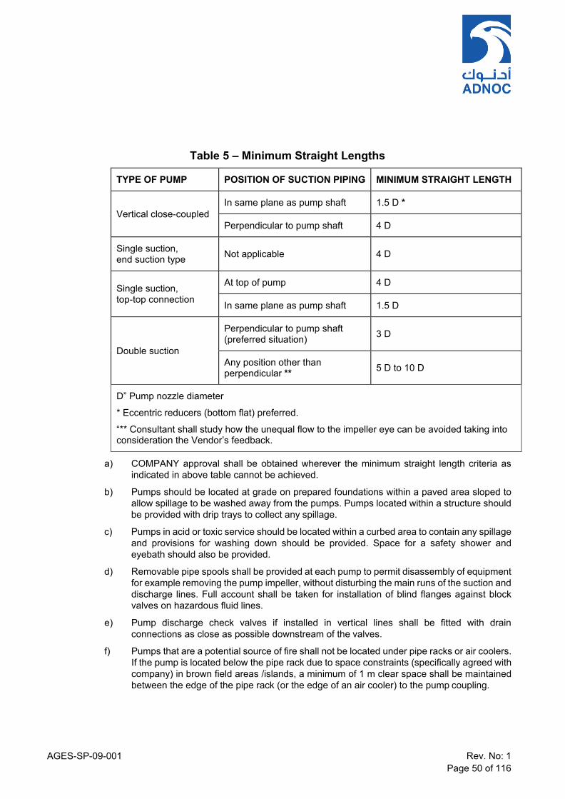
AGES-SP-09-001 Rev. No: 1 Page 50 of 116
Table 5 – Minimum Straight Lengths
TYPE OF PUMP POSITION OF SUCTION PIPING MINIMUM STRAIGHT LENGTH
Vertical close-coupled
In same plane as pump shaft 1.5 D *
Perpendicular to pump shaft 4 D
Single suction, end suction type
Not applicable
4 D
Single suction, top-top connection
At top of pump 4 D
In same plane as pump shaft 1.5 D
Double suction
Perpendicular to pump shaft (preferred situation)
3 D
Any position other than perpendicular **
5 D to 10 D
D” Pump nozzle diameter
* Eccentric reducers (bottom flat) preferred.
“** Consultant shall study how the unequal flow to the impeller eye can be avoided taking into consideration the Vendor’s feedback.
a) COMPANY approval shall be obtained wherever the minimum straight length criteria as indicated in above table cannot be achieved.
b) Pumps should be located at grade on prepared foundations within a paved area sloped to allow spillage to be washed away from the pumps. Pumps located within a structure should be provided with drip trays to collect any spillage.
c) Pumps in acid or toxic service should be located within a curbed area to contain any spillage and provisions for washing down should be provided. Space for a safety shower and eyebath should also be provided.
d) Removable pipe spools shall be provided at each pump to permit disassembly of equipment for example removing the pump impeller, without disturbing the main runs of the suction and discharge lines. Full account shall be taken for installation of blind flanges against block valves on hazardous fluid lines.
e) Pump discharge check valves if installed in vertical lines shall be fitted with drain connections as close as possible downstream of the valves.
f) Pumps that are a potential source of fire shall not be located under pipe racks or air coolers. If the pump is located below the pipe rack due to space constraints (specifically agreed with company) in brown field areas /islands, a minimum of 1 m clear space shall be maintained between the edge of the pipe rack (or the edge of an air cooler) to the pump coupling.

AGES-SP-09-001 Rev. No: 1 Page 51 of 116
g) Pumps handling LPG and other light hydrocarbon services (or heavier hydrocarbons above their flash point) shall be located to be accessible for firefighting and more than of 3 m from pipe racks and major process structures and as specified in the safety distance tables.
h) Valve hand wheels or handles shall be oriented so that they will not impact pump maintenance or motor removal.
i) All water piping and pump cooling jackets shall be arranged for complete draining.
j) Auxiliary piping shall be neatly routed along the baseplate and shall not extend across the operating floor. This piping shall not obstruct operation, handling and inspection covers, bearing caps, upper halves of casing, etc.
k) When temporary conical strainer is specified for pump suction piping in the P&ID, the suction piping shall be designed so that the temporary strainers may be easily installed or removed without springing the pipe. Installation of spacer rings may be required after temporary strainers are removed.
l) Permanent strainers shall be installed in pump suction lines when depicted on P&IDs. Y- Type strainers are required for permanent installation in vertical suction lines. In horizontal suction lines Y-type, T-type or bucket-type strainers shall be used. Generally, up to NPS 6 Y-type, NPS 8 to NPS 16 T-type and for NPS 18 and larger suction lines, bucket type strainers are recommended unless specifically indicated in P&ID.
m) The design and material for strainers in chemical services and for special pumps shall fulfil the process and pump requirements.
n) Enough clearance shall be provided for removal of strainer element and draining.
11.14 Centrifugal Compressors
Compressors and its associated facilities like scrubbers, coolers and piping represent the highest gas release that can create potential hazard due to ignition associated with rotating equipment. Hence, this equipment should be located downwind of ignition sources like fired heaters, flares or any open flame equipment.
These units are generally located in the open area and grouped together in an adequately ventilated open area lined up along the primary road to facilitate maintenance and firefighting. Requirement of shelter shall be based on project specific requirements and has to be agreed with COMPANY. Other considerations are as follows:
a) Normally knock out drums, interstate coolers, after coolers are associated with the compressors and are located at minimum distance from compressors. However adequate space shall be provided between Compressor and related equipment to ensure clear access for maintenance and firefighting equipment at least from two sides.
b) The suction line between a knock-out drum and the compressor shall be as short as practicable, without pockets, and slope towards the knock-out drum. When a continuous slope is not possible, low points shall be provided with a drain to remove any possible accumulation of liquid Additional Considerations
c) Based on the climatic conditions, the requirements of shelter shall be decided and shall be designed to secure sufficient space for maintenance and operation. When compressors are housed under shelters, sides are fully open if height is low or particularly closed from top for tall Shelter to provide adequate ventilation to avoid accumulation of gases.

AGES-SP-09-001 Rev. No: 1 Page 52 of 116
d) In case compressors are housed under shelters, accessibility and maintenance for heavy parts such as upper casing (split type casing) and rotors removal shall be from an overhead traveling crane. However, for removal of drivers like motor can be by removable cut out in roof by means of mobile crane or any other suitable means to be agreed during project stage.
e) Compressors with top suction and discharge lines shall be routed to provide clearance for overhead maintenance requirements or be made up with removable spool pieces.
f) The spacing between centrifugal compressors shall be based on maintenance requirements.
g) Temporary and permanent filter shall be installed on the suction of each compressor. It shall be designed and supplied by the Manufacturer of the compressor.
h) The installation of the spring hangers and aligning the compressor connected piping should be done under the close supervision of Manufacturers of spring hanger and compressor. The setting of spring hangers during the running condition of compressors not permitted.
i) To determine maintenance clearances and required lifting equipment capacities, Vendor data shall be reviewed for specific compressor and maximum lifting loads.
j) Piping shall be supported so as to minimize dead load on compressor nozzles and to ensure piping loads and moments with in allowable limits. In order to prevent transmission of vibrations to a compressor house, compressor piping shall not be supported or connected to the building structure.
k) Compressors and associated equipment should be located to minimize pressure drop in the suction pipe work. Inlet lines require a minimum straight run of piping upstream of the suction nozzle which varies between 3 and 8 times the nominal pipe size. In any case, Suction and discharge pipe of compressor shall have straight runs at the inlet and outlet in accordance with compressor manufacturer’s recommendations.
l) The rotating equipment engineer should be consulted early in the layout development in order to determine a base-line requirement. When this has been done, check that the machine elevation allows requirement to be met in the case of installation with bottom entry piping.
m) The height of the compressor is in some instances determined by the Lube oil (LO) skid. The lube oil console should be located at grade, local to the machine, must be accessible from a road and must be lower than the compressor to allow gravity drain of oil to the console oil tank. Lube oil tanks and pumps should not be located directly under any compressor. In order to avoid a fire hazard, lubricating oil, control oil and seal oil pipes shall not be routed in the vicinity of hot process or hot utility pipes.
n) Lube oil and seal oil consoles shall be located close to compressors. The console shall be provided access and sufficient clearance for the removal of oil cooler tubes, filter removal and pump maintenance.
o) No equipment except the Seal oil (SO) rundown tanks /emergency seal pot and its piping shall be located on close to Compressors based on vendor requirement Seal oil (SO) rundown tanks, which are located above the compressor to provide gravity feed during compressor rundown in the event of power failure.
p) A platform surrounding the compressor and driver should be supplied, level with the top of the foundation and lube oil, drain and utility piping should be located underneath.
AGES-SP-09-001 Rev. No: 1 Page 53 of 116
q) Centrifugal compressors shall have full platforming at operating level. Steps shall be provided at least at two ends of the platforms. Area above gear box shall be kept free to ensure direct access by crane.
Laydown and Maintenance Areas a) Laydown and maintenance areas should be provided at both the end and side of the
compressor and to the side of the driver. Maintenance bays for compressors shall be provided. Maintenance bays shall be accessible from roads to facilitate loading and unloading of parts onto trucks, etc.
b) Vendor recommended special tools and tackles shall be utilized. Generally, a large structure will be required to support the compressor inlet and outlet piping and this must be designed to ensure that the access to the compressor and its laydown areas are not restricted.
c) Fire Water sprinkler piping shall be provided with break-up flanges for dismantling, if necessary, during compressor maintenance.
d) Piping shall be routed to provide clearance for overhead maintenance requirements or be provided with removable spool pieces.
e) Piping at compressors shall be sufficiently flexible and adequately supported to prevent the equipment nozzles from being subjected to any stress that could disturb their alignment and internal clearance.
Steam Driver In the case of a Steam turbine driven compressor, if exhaust steam is condensed, the turbine and compressor shall be located at an elevated level and the condenser shall be located at a lower level, normally outside the compressor house.
Additional Considerations a) During FEED and initial stage of EPC ,hot/cold gas bypass requirement & exact number of
PSV’s cannot be finalized. In the layout, space provision to be considered to accommodate expected design growth
b) Non-slam check valves are often required on compressor discharge lines. If the valves specified are of the type equipped with external counter balance arms, ensure that there is sufficient space for the valve to function properly.
c) All operating valves must be readily accessible, preferably from grade. Group compressor block valves with handwheels facing in one direction where possible.
11.15 Reciprocating Compressor Piping
Compressors and its associated facilities like scrubbers, coolers and piping represent the highest gas release that can create potential hazard due to ignition associated with rotating equipment. Hence, this equipment should be located downwind of ignition sources like fired heaters, flares or any open flame equipment.
These units are generally located in the open area and grouped together in an adequately ventilated open area lined up along the primary road to facilitate maintenance and firefighting. Requirement of shelter shall be based on project specific requirements and has to be agreed with COMPANY. Other considerations are as follows:

AGES-SP-09-001 Rev. No: 1 Page 54 of 116
a) Improperly designed reciprocating compressor piping results in pulsations which can produce severe vibrations, reduce capacity of the machine and increase horsepower requirements. Line design should be simple with suction and discharge piping as straight as possible between compressors and headers. Lines should be run as close to grade as possible. On reciprocating compressors, piping must be designed with allowance for vibration and pulsation problems. Supports shall be arranged such a way to avoid any resonance effect.
b) When the compressor piping has been designed, the compressor vendor or vendor’s independent testing organization shall carry out an analog study which identifies any potential pulsation problem areas and allows modifications to eliminate the problem during the design phase of the project. The sizing, routing, supporting and restraining of the suction and discharge piping is subject to review by means of an analog computer study, as outlined in the compressor specification (per API 618 & AGES-SP-05-003).
c) The spacing between reciprocating compressors shall be based on maintenance requirements and withdrawal area required to remove piston and connecting rod.
d) Avoid branch connections in headers mid-way between supports, locate them close to a support whenever possible. Make branch connections in the top of headers to avoid liquid carryover.
e) Compressor piping should never be supported from shelter steelwork, the operating floor or the compressor foundation. Pipe supports must be provided with independent foundations to avoid transmission of vibrations.
f) Suction lines shall be internally cleaned and the extent of cleaning shall be indicated on the P&IDs.
g) Horizontal, straight line, reciprocating compressors shall have access to cylinder valves. Access shall be from grade or platform as required. Accessibility shall be provided for cleaning of suction strainers, blinding and de-blinding of lines, oil cooler maintenance, adjustment of snubber and cylinder supports
h) Depending on unit size and installation height, horizontal opposed and gas engine drive reciprocating compressors may require full platforming at the operating level.
i) To avoid the possibility of vibration and setting up a standing wave, pipe supports need to be sufficiently stiff and may need to be spaced at irregular intervals, where reciprocating compressor discharge piping is run in the rack, this may require additional support steel.
11.16 Pressure Vessels a) Pressure vessel piping shall be designed in such a way that manways and platforms shall
be located on the access side.
b) Man-ways should be on or about a longitudinal centerline of vessel. Permanent platforms shall be provided at manways above 3.0 m centerline elevation from highest point of finished surface to ensure minimum headroom clearance is available below the platform.
c) Wherever practical, platforms between lined-up equipment such as scrubbers, columns, towers, etc., shall be grouped/interconnected together to access/approach the manways, valves and instruments.
d) Pressure gauge and liquid level gauge connections on all vessels or bridles shall be oriented so that the instruments face the main operating aisle.
AGES-SP-09-001 Rev. No: 1 Page 55 of 116
e) Adequate space to be provided for handling and storage of catalyst (both fresh and spent), including mobile equipment access where appropriate.
f) Vessel drain valves shall be located so an operator can observe the liquid level gauge while manually adjusting the valve.
g) Nozzles, manways, instrument connections etc., shall be orientated to avoid interference with internal baffles, trays or piping.
h) Vessel trim material shall be suitable for service intended and applicable pipe class shall be indicated in the P&ID
Horizontal vessel Horizontal Vessels are normally arranged to conform to the main flow sequence to provide an economical piping design and facilitate plant operation. These are generally grouped together in a row with their shells lined up to provide an orderly arrangement of platforms and structures. Other considerations are as follows:
a) Horizontal vessels should be located at grade with longitudinal axis perpendicular to pipe way if possible.
b) Horizontal Vessels should be located as close as possible to related equipment such as pumps, heat exchangers, re-boilers, drum and condenser with sufficient access for firefighting and maintenance.
c) All instruments should be located at one side of the horizontal vessel to facilitate operation and maintenance.
d) For the horizontal vessels handling catalyst or inner element to be replaced periodically, adequate space shall be provided on the access side of equipment for handling, loading and unloading of catalyst or lowering internals.
e) Large vessels should be located such that they do not block major explosion venting path.
11.17 Columns / Towers and Vertical Vessels a) These are self-supporting and usually placed in a row with their shells lined up to provide
an orderly arrangement with their manholes and platforms facing an open area or access road to facilitate construction and maintenance. Circular or segmental platforms with side- step off ladders should be supported directly from the column shell. Other considerations are as follows:
b) For maximum economy order of columns shall be arranged to give shortest piping runs and lowest pumping losses.
c) Towers, Columns and Vertical vessels should be located close to the pipe rack. These should be located with their common edge close to the pipe rack at a minimum separation distance as per AGES -GL-03-001
d) Only one rows of Vertical Vessels, towers, columns along one side of pipe rack is recommended to avoid maintenance access blockage
e) The elevation of the bottom tangent line of vertical vessel, towers and columns is governed by the NPSH requirements of the associated pumps or by any gravity flow requirements. Additionally, the process requirement of thermos-siphoning aspect shall be considered.

AGES-SP-09-001 Rev. No: 1 Page 56 of 116
f) Where possible, access platforms on adjacent vertical vessels, towers and columns shall be interconnected for ease of operator access, but with adequate allowance for differential expansion of the equipment.
g) For columns with internals, an adequate drop out area shall be provided for maintenance.
h) Manholes should be located on a common center line and access platforms should be located on the access aisles.
i) Spread of foundation below grade level shall be considered while locating the columns and towers to avoid foundation clashes.
j) Piping on columns shall be installed radially along the column and oriented towards the pipe rack side. Manholes and associated platforms shall be opposite the piping.
k) Davits shall be provided on the top of all columns as per Pressure vessel specification AGES-SP-06-002. They shall be oriented in such a way as to allow for direct handling from the floor to the various platforms
Relief Valves Located on Columns Where PSVs and de-pressurising valves are located on vessels, they shall be accessible on main platform levels.
11.18 Column Piping a) Nozzle orientation shall be established with respect to process requirements, maintenance
and adjacent operating requirements, together with any fabrication constraints imposed by the vessel design. Nozzles, manways, instrument connections etc. shall be orientated to avoid interference with internal down comers, baffles, and trays or piping.
b) Column piping shall drop or rise immediately upon leaving the nozzle, then run parallel and as close as practicable to the vessel. Where piping runs to / from the rack, it shall normally run straight down from the nozzle and be individually supported / guided from supports bolted to vessel clips, then be routed round the column, if required, at the rack side steel elevation, before running across to the rack at right angles. Pipes shall normally be supported in the vertical leg, as close to the first bend as possible. Maximum guide spacing for wind shall not be exceeded. Piping intended for vacuum services shall be routed as short as possible with minimum bends and flanged joints.
c) Small-bore utility piping run down the column, shall be grouped as much as possible to minimize supports / guides and will run on the pipe rack side of the column. Piping shall be supported where possible from clips welded onto the vessel.
d) Lines connecting columns and control valve manifolds at grade or on adjacent structures should be flexible enough to absorb vertical expansion and differential horizontal movements from wind, earthquake etc.
e) Unless specifically indicated on the P&IDs, control valves shall preferably be located at grade instead of on the platform. Where possible block valves shall be located directly against the vessel nozzles.

AGES-SP-09-001 Rev. No: 1 Page 57 of 116
11.19 Reboiler Piping Systems
General Thermosyphon reboiler should be located as close as possible to the columns that they serve. All reboiler piping runs should be as short as possible with minimum bends, dictated by process and mechanical stress requirements and not for layout convenience. Thermosyphon outlet piping shall not include any pocketed or downward sloping sections. Reboiler vapour return piping shall be free draining and drain towards the reboiler.
Reboilers Support Vertical thermo-siphon type reboilers are usually supported by the tower and are located to be accessible for maintenance. Where the reboiler is too large to mount directly on the column, a support structure should be positioned close to the process column. Care must be taken to allow for the removal of any tube sheet etc. and this may require additional platforming local to the reboiler, which should also be utilized for instrumentation access.
11.20 Pressure Safety Valve (PSV) a) Safety valves shall be accessible. Wherever feasible, they should be located at platforms
which are designed for other purposes. Safety valves with a centreline elevation over 2m above high point of finished surface shall be accessible from a platform.
b) Pressure safety valves shall be mounted as close as possible to the equipment or pressure systems being protected.
c) For safety valves where the outlet line connected to the flare header, the safety valve outlet shall be self-draining into the flare header. All branch connections shall be connected to the top of the main header. The upstream side of safety valves shall be free draining to the process side
d) The low point of outlet piping of safety valve discharging to atmosphere (applicable for non- hydrocarbon service) shall be provided with a weep hole of 10mm diameter to ensure complete removal of all liquids accumulated in the discharge piping system.
e) Safety valve discharge piping shall be designed to withstand the dead loads and the blow- off loads. Blow-off design loads shall consider the most severe case, such as possible flashing conditions and liquid entrainment in vapour flows.
f) Inlet lines to safety valves and de-pressuring valves shall be self-draining to the process equipment.
g) Spring-loaded and pilot-operated or assisted safety valves as well as thermal expansion valves shall always be installed in the upright position. Liquid shall be drained from the valve both at the valve inlet and outlet.
h) The requirement of interlocking (castle or equivalent type lock and key arrangement) of inlet and outlet block valves to prevent accidental violation of valve operation shall be as specified in P & IDs.
11.21 Shell and Tube Heat Exchangers Heat exchanges are generally grouped together wherever possible and placed on grade unless otherwise due to process reason or any other technical reasons. This equipment should be lined up along the maintenance roads to facilitate maintenance and firefighting. Tube bundles shall normally be removed with mobile cranes along with tube bundle extractor.

AGES-SP-09-001 Rev. No: 1 Page 58 of 116
Where mobile crane access is not possible, monorail with hoist shall be provided. Other considerations are as follows:
a) Shell and tube exchangers should be oriented and located such that their tube bundles will not project into an escape route or primary road when withdrawn for inspection and maintenance.
b) For maintenance access, spacing should be enough to permit tube bundle removal, as well as flange gasket removal. An adequate drop out area shall be provided for maintenance
c) The piping design shall allow for wrench room for unbolting exchanger flange in line with the clearances as specified in section 11.6 above.
d) Permanent monorails or lifting beam shall be provided for all elevated exchangers (bundle end), located within steel structures, as well as for exchangers at grade where crane access is impractical.
e) Piping installation shall allow easy disassembly of exchanger heads and bundles. Heat exchanger piping layout shall be done in such a way that there is sufficient space available for easy removal of shell covers, channel covers, channels and pipe bundles. There shall be sufficient access available for pulling out the tube bundle during maintenance.
f) The fixed and sliding saddle of the horizontal shell and tube heat exchanger shall be decided in such a way that helps releasing the expansion/contraction of the connected piping. In a typical exchanger layout with all exchanger piping running into the rack, the fixed end should be located on the shell side support farthest from the channel end and closest to the rack, to minimise differential thermal expansion.
g) Stacked heat exchangers to minimize the plot space may be either bolted or welded nozzle- to-nozzle. The latter option eliminates flange leakage but puts restrictions on the maintenance of the exchangers.
h) Enough space shall be kept between adjacent heat exchanger inlet and outlet valve manifolds.
i) Wherever possible, cooling water piping to exchanger units shall be arranged so that exchanger remains full of water during a water supply failure.
j) Whenever specified, portable pickling and passivation tanks shall be considered for pickling and passivation of heat exchangers during routine maintenance and turnaround maintenance. The plant layout shall consider storage space for passivation/pickling tanks and associated temporary connections. Adequate space shall be available around the heat exchangers for this purpose.
k) When setting the elevation of the exchangers, minimum bottom of pipe elevation to allow drainage from piping connected to the bottom nozzles shall be considered.
l) Piping connected to shell-and-tube exchanger channel box shall be self-supported or provided with permanent supports so that the channels can be removed without having to provide temporary supports for the piping. To allow removal of covers, heads, channels, bundles and shells, pipes shall not be supported on heat exchanger shell or heads. Channel piping shall be arranged with a removable section between the exchanger and block valves so that full access is available for bundle pulling and tube cleaning.

AGES-SP-09-001 Rev. No: 1 Page 59 of 116
Exchanger Tube Bundle Extraction a) All shell and tube exchangers require clear space for rodding out or tube bundle removal,
even fixed tube exchangers shall require some form of maintenance work, such as tube plugging etc. and shall therefore require maintenance space. Tube bundles shall be removed by “jacking out” the channel head tube sheet flange against the mating shell flange. A clear space for tube bundle removal shall be provided. The tube pulling area should not encroach upon roads. Tube bundle pulling by hydro-extractor shall be considered for exchangers at elevated structures. In absence of hydro-extractor, a dropdown bay may be considered. Where davits are supplied for head removal, adequate space should be provided for full swing of the head. Supplier recommended special tools and tackles shall be utilized.
b) Vertical Exchangers with Removable Tube Bundles, shall be provided with an overhead trolley beam
c) Platforms serving vertical and horizontal exchangers should not interfere with removal of the channel end or bundle. The structure in front of tube bundle removal should be designed to take the load of the tube bundle and bundle puller, in order to allow maintenance to place tube bundle down if required. The hand railing in such location shall be removable type if applicable.
11.22 Plate Exchangers Plate exchangers are generally small and are normally used where corrosive fluids are in the process which requires special facilities in terms of spillage. They are normally sited on a paved floor for wash down and containment of any spillage collection. Additional space is required local to these items. Plates are generally added or removed from the side of the unit and withdrawal space equal to 120% of the unit width should be allowed on one side only.
11.23 Air Cooled Heat Exchangers / Fin Fans a) Air coolers may have their own supporting structures or be located above the main pipe
rack and maintained using of mobile lifting equipment. Other considerations are as follows:
b) Fin Fans are either positioned over pipe racks with access from a common access walkway above the pipe rack or located in a separate row outside the main equipment row, remote from the central pipe rack, with a separate access walkway beside the units. Stair access to the air cooler walkway should be provided at each end, with additional intermediate access if walkways exceed egress limits.
c) The access walkways should connect to local platforming directly under the units, for maintenance of both motors and fans (from top for Induced draft fans). The fin fan manufacturer, who supplies the necessary lifting/handling equipment, often supplies this associated platforming required for operational and maintenance of cooler motors, fans, belts etc. Provision for material handling of the maintainable/removable parts like motor trolley for motor maintenance etc. shall be provided.
d) Vessels, pumps or exchangers handling hydrocarbon shall not be located under air coolers. In addition, avoid placement of flanges under air coolers.
e) Air coolers should be located in a separate row outside main equipment row and in accordance with process requirement away from crane drop zones to avoid damage of cooler tube bundles.
AGES-SP-09-001 Rev. No: 1 Page 60 of 116
f) Equipment shall not be located above air coolers.
g) Location of air coolers shall be such that hot air emitted is not a hazard or an inconvenience to personnel and has no adverse effect on the operation of adjacent equipment. To account this, these shall be located downwind of the facilities to take advantage of the prevailing wind to disperse hot air away from operating areas.
h) Where there are many air coolers mounted along the length of the pipe rack, care must be taken in positioning them relative to each other. If positioned too close to each other, re- circulation problems may occur, where one set of fin fans exhaust air may be sucked into the next fin fan air cooler inlet for example drawing in warm air instead of cool air.
i) Wherever possible air coolers should be grouped with a common elevation. Air coolers with different fan intake elevation shall not be located adjacent to one another to avoid hot air circulation.
j) Platforms shall be provided below the air-cooled exchangers to access the motors and fan drives. These platforms must allow access without scaffolding. The height of the fan inlets of forced draft coolers or of the underside of the bundle of induced draft coolers shall be at least one fan diameter above the nearest solid horizontal obstruction to airflow. This shall be reconfirmed by the Air Cooler Vendor
k) In case of forced draft air coolers, the arrangement and size of the permanent maintenance access platform beneath the fans shall not restrict the air flow to the fans.
l) When air coolers are located above the pipe racks, a minimum clearance of 3 m between the lowest part of air coolers and the top of the pipe rack shall be considered. The supports of the air coolers should coincide with the pipe rack width to transmit the air cooler loads to the pipe rack columns.
m) The maximum tube bundle overhang shall be limited to 1 m from the cooler column supports.
n) Tube bundles to be removed shall be handled by crane. Equipment, structures and piping must not interfere with access by this crane.
o) Air cooled heat exchangers shall be sufficiently far from high temperature equipment such as fired heaters, etc. to minimise the effects of hot air circulation
p) To avoid hot air impact during operation & maintenance, PSVs and any other valve assemblies not to be located at higher elevated platforms in the vicinity of Air Cooler (such on platform for air cooler bundle access platform).
q) Air-cooler piping should be arranged symmetrically to provide uniform distribution to inlet manifolds. In addition the connecting piping shall be designed so that small dimensional errors in construction can be accommodated
11.24 Packaged Equipment Piping a) The piping layout within equipment skids supplied as a complete package shall be the
responsibility of the equipment package supplier while maintaining all requirements related to piping design, layout, spacing etc. as defined in this specification. The package supplier should restrain all the piping at the edge of the skid by line stops, guides or anchors as required by the piping design.
AGES-SP-09-001 Rev. No: 1 Page 61 of 116
b) The tie- in points on packaged equipment shall be brought to the edge of the skid and terminate with flanges. As far as possible utility connections, flare, vent and drains shall be terminated as single tie-ins at edge of the skid.
c) The equipment and installations shall be shop assembled to the maximum extent practical, mounted and delivered onto a skid or on multiple skids so that erection at fabrication yard can be minimized. Large or fragile items which cannot safely be transported on the skid shall be removed after completion and shipped separately.
d) Prefabricated modules shall not be considered as packaged units and all requirements of this specification apply.
e) During FEED and in early stage of design, the area/space required for packages shall be fixed considering allowance for growth during EPC stage.
f) All Packaged equipment’s shall undergo reviews to demonstrate, safety access, operational and maintenance access including material handling aspects of individual components during the design stage of the project (e.g., like 3D model reviews, etc.).
11.25 Fired Heaters / Furnaces a) Fired heaters / furnaces may be single or grouped units, sharing a common stack, with the
exhaust gases being controlled by individual dampers.
b) Fired heaters are continuous ignition source and as a main cause of hazard. These are generally located upwind or crosswind of process units so that flammable gases from hydrocarbon and other processing areas cannot be blown into the open flames by prevailing wind. Fired Heaters should be lined up along the primary roads (from at least two sides access) to allow easy maintenance and provide adequate access for firefighting. Safety and maintenance requirements shall include the following:
c) Heaters should be located at the outer sides of the fire zone, away from fuel sources and at a higher elevation than bulk storage equipment to minimize the potential for ignition of hydrocarbon gas release or liquid spills.
d) Adequate space for lifting and handling facilities for maintenance shall be provided for the fire tube replacement.
e) Sufficient access, clearance and provision shall be provided at fired equipment for removal of tubes, cleaning of tubes, soot blowers, air preheater baskets, burners, fans and other related serviceable equipment.
f) Bottom fired heaters should have 2.1m clearance for burner removal.
g) Snuffing steam manifolds and associated purging inert gas system as applicable shall be located a safe distance from the heaters they protect. This distance shall be 15m minimum or as defined in Facility Layout & Separation Distances Guidelines AGES-GL-03-001.
h) Heater stacks shall terminate a minimum of 4.6m above any platform within a radius of 12.5m.
i) Heaters / furnaces shall be arranged with the centreline of the stacks on a common line in the case of circular heaters. Wherever a common stack is furnished to serve more than one heater, the stacks shall be located at the end or side, whichever is away from the unit. For individual box heaters, their edge on the rack side shall be aligned. Where air preheating is

AGES-SP-09-001 Rev. No: 1 Page 62 of 116
required, space should be provided for the exchanger and fans, which shall be local to the heater.
j) Vertical heaters are usually supplied with stub supporting feet and the necessary steel or concrete legs are designed by the Contractor elevate the heater to the required height.
k) Where required, platforms shall be installed to facilitate operation and maintenance. The operating platform at the burner control side shall be 1.8 m wide, and the other sides of this platform shall be 1.2 m wide. All other platforms and interconnecting walkways shall be as per clearance Table 1
l) Generally, a common platform for a group of heaters should be arranged at the burner operating level with stair access and secondary means of escape. Normally all platforming associated with the heater is supplied by the heater vendor.
m) The floor around the heater shall be paved and sloped to drain spillage away from underneath the heater. No pits or trenches should be allowed to extend anywhere near or under the heater.
11.26 Burner Piping a) Burner piping shall be arranged to minimize obstruction to access. Below the furnace, the
piping shall be arranged such that the operator has a clear unobstructed route of emergency escape from below the furnace.
b) Therefore, valves for fuel admission, purge air and steaming-out shall be within reach of the operator when observing the burner via the designated peephole
c) Floor-fired furnaces: combination oil and gas firing valves shall be operable from burner observation door platform.
d) Side-fired furnaces: firing valves shall be located to be operable while viewing the flame from the observation door.
11.27 Pipeline Pig Launcher / Receiver a) Launcher and receivers should be positioned at the edge of the plant / platform and their
doors should point directly away from the plant / outboard of the facility to reduce the possibility of damage from any projectiles. Impact wall shall be introduced if safe distances from other plant facilities are not available and agreed with COMPANY
b) Requirements of COMPANY specification for Pig launcher and Receiver shall all also be followed.
c) Elevation of Pig traps to be decided to suit pigging operation requirement, loading of pigs and also based on elevation of drain nozzle from grade
d) Road access to the Pig Launcher / Receiver shall be provided. Proper access to nozzles and door shall be provided.
e) Laydown areas shall be provided for the loading / unloading of the largest intelligent pigs
f) Consideration shall be given to mechanical handling facilities for pigs like jib crane, pig trolley etc.
g) Where a sight glass is specified on the drain line, sufficient space must be provided for observation of flow. The traps shall have a pressure indicator positioned so that it will be visible to personnel operating the pig trap closures.
AGES-SP-09-001 Rev. No: 1 Page 63 of 116
h) A spillage retention tray provided with drain shall be installed. The retention tray for the pig trap shall be sized according to the length and volume.
i) Space for future Pig traps and its associated future pipeline approach shall be provided and number of future traps to be agreed with COMPANY.
11.28 Flowline Battery Limit Valves Flowline Battery Limit Valves are generally located near the fence with the Manifold sufficiently away from these valves. Sufficient space shall be provided for the handling and maintenance of these valves.
11.29 Oily Water Separators a) Contaminated water drainage from onsite and offsite areas shall be routed to suitable
treatment facilities located remote and lowest grade from the plant area with approach road for vehicle accessibility. These facilities should be located to maximize gravity flow. If flammable vapours are present, consider locating the oily water separation facilities remote and downwind from sources of ignition, in the prevailing wind direction.
b) An open (i.e. vented-to-atmosphere) system shall be provided for the drainage of water contaminated by oil, such as may originate from the following sources:
• Rain-water, wash down water and firewater which are liable to be oil contaminated.
• Spillages and leaks from process equipment.
• Drainage from sample points, drain cocks, hydrocarbon overflows and equipment fittings.
c) Oily water drainage from non-hazardous areas shall be collected in headers separate from those for hazardous areas. It is essential that flammable vapour leakage through oily water drains to non-hazardous areas be prevented. The oily water drain headers from non- hazardous areas shall be provided with a seal pot in addition to individual traps at inlet gulley’s.
d) For drainage philosophy refer Company Specification for Drainage Systems
11.30 Flares
Flares are generally located remote from all other facilities. The location of flares cross wind / downwind of the facilities would ensure that prevailing wind will not direct unignited hydrocarbon gases, toxic gases and hot gas streams away from the Safe Area. The location, spacing, orientation and height of flares shall be determined, for the particular site, by a full assessment of the factors involved.
The following general principles should be applied:
a) In practice, because they are a source of thermal radiation, and a possible source of ignition flares are generally located remote from process facilities, storage areas, utility areas, and service/office areas, but well inside the property line. They should also be well away from public occupied areas that are, or may be in the future, located adjacent to the site boundaries. A cross-wind location from process facilities and similar sources of major release of flammable vapour is preferred.
b) Flares and vents should be built downwind from buildings to minimise odours
AGES-SP-09-001 Rev. No: 1 Page 64 of 116
c) The flare(s) should be located in such a way so as to allow the shortest, most direct route(s) for the closed relief header(s), whilst avoiding passage through special fire risk areas.
d) Where more than one flare is provided, the location of each shall be based on operational requirements. The locations of all flares should be determined by any need for independent operation or maintenance of individual flares. This may require suitable spacing of separate flare stacks, or a tower-mounted multi-flare stack system. The latter should have facilities for lowering the stacks separately, to ensure that maintenance on any one flare stack can be carried out while the remaining flare stack system remains in operation.
e) The size of the sterile area will be dependent upon the height of the flare, flaring rate, radiation limits and their proximity as an ignition source from a pressurised gas release. H2S and SO2 dispersion from the unignited and ignited flares shall be considered in terms of toxicity, air quality and the prevailing wind direction. Refer AGES-GL-03-001 Facility Layout & Separation Distances Guidelines for requirements of Sterile atrea
f) The location of flare and vent stacks shall address noise levels onsite and offsite during flaring.
g) Closed relief systems shall slope towards a knock-out vessel near the flare stack or to an intermediate liquid/solids knock-out vessel. The discharge line from this K.O. vessel should then slope towards the K.O. vessel of the flare. Slope requirements shall be in line with Process design criteria AGES-GL-08-001.
h) The outlet line from a relief valve shall be self-draining into the flare header.
i) Connecting branches shall, if possible, connect to the top of the header, or, in any case, drain into the header.
11.31 Cooling Towers a) Cooling towers are one of the sources of water vapour release and shall be located away
and downward of the process equipment, substation and main pipe rack to avoid the damage due to water blowout, evaporation, corrosion, visibility issues on roads and adjacent structures. See also 13.8 for details of cooling water piping.
b) The area around cooling towers should be suitable for water basins and in the case of natural draught cooling towers substantial foundations will be required. Forced draught cooling towers can be extremely noisy, so consideration must be given to locating them away from populated areas. These items require maintenance to fans and easy access to the water basins for cleaning.
11.32 Offsite Storage
Storage Tanks
a) Special consideration should be given to offsite storage tankage, due to the large volume of inventory stored. Offsite storage consists mainly of atmospheric tankage within bunded (diked) areas and transfer / booster pumps positioned as close as is physically possible to the tankage, while remaining outside the diked areas.
b) Storage tanks should be grouped and arranged in rows. The tanks shall be surrounded by dike made of soil, concrete or solid masonry with drainage to remote impounding area, with a primary or secondary road for adequate firefighting accessibility.

AGES-SP-09-001 Rev. No: 1 Page 65 of 116
c) Tankage area shall be subdivided into various groups determined by the contents of the tanks and the relative shape and area of the plot available access and firefighting must also be considered.
d) The location of tankage relative to process units must be such as to ensure maximum safety distances from possible incidents and with HSE requirements (Facility Layout & Separation Distances Guidelines, AGES-GL-03-001)
e) Primarily requirements for the layout of tanks farms are summarized as follows:
i. Inter tank spacing and separation distances between tank and boundary line and tank and other facilities are of fundamental importance.
ii. Suitable roadways should be provided for approach to tank sites by mobile firefighting equipment and personnel.
iii. The fire water system should be laid out to provide adequate fire protection to all parts of the storage area and the transfer facilities.
iv. Bunding and draining of the area surrounding the tanks should be such that a spillage from any tank can be controlled to minimize subsequent damage to the tank and its contents. They should also minimize the possibility of other tanks being involved.
v. Tank farms should not be located at higher levels than process units in the same catchment area.
vi. Storage tanks holding flammable liquids should be installed in such a way that any spill shall not flow towards a process area or any other source of ignition.
vii. Tanks should be located downwind of flares, furnaces and heaters.
viii. Emergency shutdown valves on the line connected to tanks shall be located outside dike area. Pump house and transfer piping shall be located outside the dike area. Spacing between the tanks and vessels shall be in accordance with local regulations and HSE requirements (Facility Layout & Separation Distances Guidelines, AGES-GL- 03-001).
f) Access and escape routes from tankage areas should be directed away from the inner area of combined tanks.
g) The pump suction must not be higher than the tank discharge nozzles to enable the tank to be pumped down to a low level without cavitation. Pockets in the pipe work should be avoided; otherwise cavitation will occur and damage the pumps
h) Pipes connected to tanks shall be sufficiently flexible to cope with thermal expansion/contraction, tank settlement, and the outward movement of the shell and the inclination of nozzles under hydrostatic load. The first pipe support shall be located sufficiently far away from the tank to allow for tank settlement and the thermal expansion of the vertical pipe leg. If tank settlement above an acceptable limit is expected, precautions shall be taken to cope with this settlement
i) Piping shall be connected and supported after hydrostatic testing of the tank.
j) Piping shall as far as possible be routed aboveground and parallel, combined in one track from bund wall to the tanks. There shall be access to manholes, mixing nozzles, drains and other facilities on the tanks.
AGES-SP-09-001 Rev. No: 1 Page 66 of 116
k) Piping shall be supported on either concrete sleepers or steel frames. Steel frame supports can be used as an intermediate support between concrete sleepers to support small-bore piping. Small-bore utility piping required for more than one tank may be routed along an interconnecting overhead walkway, if available.
l) Manifolds shall be located outside the bund wall in a concrete paved curbed area.
m) Piping should pass over, rather than through, the dyke wall. Lines crossing through shall be kept to a minimum and, if line displacement is to be expected, the dyke wall shall be (partly) replaced by a concrete wall. Only the pump suction piping may only be routed through dyke walls if it cannot be passed over dyke wall.
11.33 Loading and Unloading Facilities a) Raw materials and products may be transported to and from the plant by either road or rail,
and in some cases by sea. Reference should be made to the relevant international and COMPANY codes and regulations for the transport of goods, both hazardous and non- hazardous. In all cases, local codes must also be reviewed for any requirements, which may be different from, or more stringent than, the recommendations in the standard codes.
b) Road and rail loading / unloading areas are generally located close to their storage facilities, but situated on the edge of the site, downwind of the process plant. The proposed routes of road and rail tankers etc. to loading / unloading areas should be established as early as possible, to determine overall road and rail networks and locations of weighbridges, ticket offices, marshalling areas, gate houses etc.
c) Facility Layout & Separation Distances Guidelines, AGES-GL-03-001 guidelines shall be followed for safe distances of these facilities.
d) Truck loading racks for flammable and combustible liquids should be located near the plant gate to avoid truck traffic near process areas. Tank car loading racks for flammable liquids should be located to avoid road blockage when spotting rail cars, ensuring passage for fire trucks or other service vehicles at all times. Truck loading facilities shall be located close to product movement gate.
e) A suitable firefighting system in line with HSE requirements, should be installed and two, separate and opposite, access routes provided for fire fighting vehicles. The loading / unloading bay areas should allow for free and safe access for personnel around all agreed differing sizes of tanker and the adjacent islands. Due to the possibility of spillage, the whole area should be paved, sloped away and should have the facility for wash down with a suitable drainage system.
f) Loading/unloading areas for road transport shall have adequate space for access for filling, parking and manoeuvring. A drive-through rack arrangement is preferred.
g) Loading/unloading areas for rail transport shall include adequate spur tracks for standing, filling, shunting and, may require a siding for unserviceable rolling stock.
h) Offshore Loading, Single Point Mooring (SPM) and Ship berthing facilities shall be designed strictly as per applicable International Codes and Standards to cover the following guidelines:
i. Design criteria,
ii. Material selection,
iii. Tie-in methods,
AGES-SP-09-001 Rev. No: 1 Page 67 of 116
iv. Installation methods,
v. Inspection requirements,
vi. System reliability,
vii. Project costs and schedule.
Loading Jetty Piping a) The long jetty piping shall be checked against the thermal expansion and if required
sufficient expansion loops shall be considered.
b) The loading and unloading pipes for different products to or from a jetty are normally connected to headers located at the end of the jetty.
c) Connecting pipes between the loading arms and the headers shall slope down to the headers for drainage.
d) Where practical, the loading and unloading pipes shall slope down towards the shore for drainage.
e) Piping on jetties shall be minimum 2 NPS size, except for instrument, drain, vent and sample connections.
f) Flow meters their filters and deaerators, shall be accessible for operation and maintenance. The deaerator outlet shall have a flame arrester.
g) Piping reaction forces on the loading arm flange shall be minimized.
11.34 Piping Through Walls and Concrete Floors a) Sleeves or holes through walls, decks and floors of buildings and through table tops shall
have a size permitting the passage of a flange of the relevant pipe size, or the size of the required insulation, whichever is the larger, to allow the installation of prefabricated piping.
b) Piping through walls and decks “Pipe penetration and metallic sleeves” shall be sealed appropriately after pipe installation to avoid chimney draught in the case of fire. Sealant material shall be such that it can get compressed to some extent allowing pipe movement and should not damage insulation.
c) Piping shall be routed to prevent penetration of major structural elements supporting decks and walls.
d) Flanges on a vertical pipe or vessel nozzle that penetrates through deck shall have a minimum of 150 mm gap or space required for hydraulic bolt tensioning whichever is higher, between the top of the kick plate and the flange bottom nut surface to allow sufficient space for a wrench and a hand.
e) Pipe penetration through fire/blast wall is strictly prohibited.
11.35 Piping Vibrations Extra precautions shall be taken for two-phase flow. Particularly if the flow pattern is intermittent (slug or plug flow), the piping system shall be subjected to dynamic excitation forces. The piping system including the small-bore piping subjected to two phase flow shall be stress analysed and adequately supported against intermittent slug loads based on the recommendations of the stress calculations.
AGES-SP-09-001 Rev. No: 1 Page 68 of 116
Piping upstream and downstream of devices which may imply excessive vibration (such as anti- surge valves, choke valves, etc.,) shall comprise straight length on each side of the device of at least two diameters or 0.6 m whichever is the greater. Supports shall be installed on each side and as close as possible of such device.
11.36 Acoustically Induced Vibration (AIV) a) Acoustic Induced Vibration (AIV) is a flow rate and pressure drop driven phenomenon that
occurs at pressure reducing devices of gas or vapour systems and is generally applicable to lines in gas service. In a Gas System, high levels of high frequency acoustic energy can be generated by a pressure reducing device such as a Relief, Control , Compressore Anti surge, choke valves or Orifice plate. The amplitude of this energy is governed primarily by the Flow rate & Pressure drop.
b) This vibration takes the form of local pipe wall flexure (the shell flexural mode of vibration) resulting in potentially high dynamic stress levels at circumferential discontinuities on the pipe wall, such as small-bore connections, fabricated tees or welded pipe supports. Excitation due to this can lead to fatigue failure of pipe or welded downstream connections.
i. For studying the effect of “high frequency acoustic excitation” on piping systems, sound power level of piping system shall be calculated
ii. Piping systems with sound power level (PWL) > 155 dB shall be further assessed and designed in accordance to “, Energy Institute guidelines for the avoidance of vibration induced fatigue failure in process pipework.
11.37 Flow Induced Vibration (FIV) a) Flow induced vibrations (FIV) are more predominant in turbulent flow regime piping systems
(2-phase flow or flow discontinuities etc). The turbulent flow regime generates potentially high levels of kinetic energy local to the turbulent source. This energy is distributed across a wide frequency range, the majority of the excitation is concentrated at low frequency. This type of vibration leads to displacement of piping system and in some cases also leads to damage to pipe supports.
b) The Contractor’s procedure for the identification and treatment of lines subject to FIV shall be based on the Energy Institute’s ‘Guidelines for The Avoidance of Vibration Induced Fatigue Failure in Process Pipework”.
11.38 Flow meter Piping a) Flow meters except Rota meters should be in the horizontal line. Vertical orifice runs may
be used with the approval of COMPANY after confirming with the flow meter vendor.
b) Sufficient upstream and downstream straight length pipe shall be provided for the flow meter piping as per Vendor recommendation.
c) The orifice flange taps shall be oriented in such a way that suits the measurement of fluid flow passing through the pipe.
d) For normal applications, the angle between the tapping should be approximately 90 degree.
11.39 PIPING FLEXIBILITY Piping flexibility requirements shall be as per COMPANY Specification related to piping stress analysis.

AGES-SP-09-001 Rev. No: 1 Page 69 of 116
11.40 PIPE SUPPORTING Pipe supporting requirements shall be as per COMPANY Specification related to pipe supports and pipe stress analysis.
11.41 Instrument and Sample Piping a) Vessel Trims
The piping class for vessel trim components shall be derived from the vessel design conditions and shall be as per the P&IDS. The piping class shall be a COMPANY standard piping class, or a Project Specific piping class derived from a COMPANY standard.
1. For each vessel trim, a piping line number or numbers shall be allocated for each vessel.
2. Piping isometric drawing shall be prepared to detail the trim for each vessel or equipment item.
b) Standpipes
1. Shall satisfy the specifications of the relevant piping class. If there are more than two pairs of level gauge connections, one or more standpipes shall be used.
2. The minimum diameter of a standpipe shall be DN 80 (NPS 3).
3. The equipment connections shall be DN 50 (NPS 2).
4. The block valves shall be fitted in either of the following configurations:
• Between the level gauges and the standpipe;
• Between the standpipe and the equipment.
c) Sample Connections
1. Provision of sample points and its tap off shall be as per the P&ID. For pipe in a horizontal or inclined plane, the sample connection shall be located at the side of the pipe unless otherwise indicated on the P&ID.
2. The sampling point shall be positioned so that the valves are easy to operate and taking the sample shall not impair the safety of personnel or plant or cause environmental impact.
3. Sample take-off connections shall not be located at dead ends of piping and be easily accessible and should be at ground level. However, sample pipes shall be as short as possible as and not longer than 8m.
d) Orifice Flanges and Orifice Meter Runs
1. Orifice flanges with flange tapings shall be in accordance with ASME B16.36.
2. Material and components for instrument connections shall be determined based on the relevant piping classes.
e) Orifice Runs
1. Orifice runs should be located in horizontal piping. Vertical orifice runs may only be used with the approval of the COMPANY.
2. Sufficient upstream and downstream straight length pipe shall be provided for the flow meter piping as per Vendor recommendation.
AGES-SP-09-001 Rev. No: 1 Page 70 of 116
f) Orifice Tap Orientation:
1. The orifice flange taps shall be oriented in such a way that suits the measurement of fluid flow passing through the pipe.
2. For vertical piping, the taps shall point in the direction from which they are accessible.
3. For normal applications on average size piping, the angle between the taps should be approximately 90°. For large size piping a somewhat smaller angle may be more practicable and is therefore acceptable.
4. For horizontal pipes, the orientation should be such that the taps are self-draining on gas service or steam service and are self-venting on liquid service, but in locations where sub-zero temperatures may occur the taps for liquid service shall be self-draining.
5. For horizontal piping, bolts shall not obstruct the vertical position of the tab on the orifice plate (upwards on gas and steam service, downwards on liquid service).
11.42 Vent and Drain Piping a) Vent and drain valves used for instrument maintenance, decommissioning of plant during
turnarounds and operational venting and draining, shall be clearly visible from the operator vantage point at access platforms and walkways.
b) Vents and drains shall be as short as possible. If long connections are required (e.g. due to thick insulation on the main pipe), then due care shall be taken at design stage to route and adequately support the vent and drain lines against differential thermal expansion, pressure pulsation, flow induced vibration etc./, in the main line. These lines shall be properly supported, braced and or larger branch sizes shall be used to avoid fatigue failure at branch connection. Also refer to Appendix A1 for requirements of small bore piping.
c) Drains shall be located so that there is sufficient free space underneath to install temporary facilities to discharge the drained liquid.
d) The number of vent and drain connection in the piping system shall be optimized and shall meet the operation and maintenance requirements.
e) Drains shall be located so that there is an adequate free space underneath to install temporary facilities to discharge the drained liquid. Vents and drains should be as short as possible.
f) Hydrostatic Vent & Drain Connections:
I. Are not required to be shown on P&IDs but shall be shown on piping layouts and the isometrics drawings.
II. Hydrostatic vent connections at high point and drain at low point shall be provided for all piping subject to hydrostatic test.
III. Hydrostatic vents and drains may be without valve and plugged only (threaded and seal welded) or blind flanged based on pipe size, service and as applicable pipe class in line with Piping Material Specification and COMPANY standard piping hook-up connection
11.43 Thermal Insulation & Heat tracing Thermal insulation must be provided whenever necessary to assure the operation of the installation at the temperature required by the process studies or for protection of the personnel
AGES-SP-09-001 Rev. No: 1 Page 71 of 116
(although protection by physical barriers such as stainless steel open mesh guards or protective metal sheeting/screens shall be preferred whenever possible).
Any required tracing and thermal insulation shall comply with the Company specifications for Thermal Insulation and Heat tracing . Piping requiring insulation shall be as per the fluid list/Line list and shall be indicated in the P&IDS
Surfaces shall be appropriately protected in accordance with in line with COMPANY Painting and Coating specification before installation of thermal insulation
• The primary thermal insulation system materials selection shall be based on the minimum and maximum process operating temperature ranges
• Materials shall be compatible with the substrate and all other insulation materials with which they have contact
• All insulated pipes NPS 2 and above shall rest, at their points of support, on shoes at least 100 mm high. For piping NPS 11/2 and below, these shoes shall be 50 mm high minimum
• Each line shall be insulated separately; a common insulation cover should not enclose adjacent lines to the pipe
• Protection of the personnel by physical barriers such as stainless steel open mesh guards or protective metal sheeting/screens must be provided on uninsulated piping and equipment when the service temperature thereof is over 60°C..
12 OFFSHORE / MODULE ADDITIONAL REQUIREMENTS
12.1 Platform Safe Areas a) The Safe Area on a platform shall be located in a non-hazardous area at the end of the
platform upwind of production, drilling, process, pipeline, and flare facilities. Facilities and equipment normally located in the Safe Area include, temporary refuge, living quarters, central control room, radio room, firewater pumps, emergency generator and switchgear, lifeboats, muster area, helideck and non-hazardous utilities equipment.
b) Survival craft and muster areas shall be located within the Safe Area. The launch mechanisms shall provide the survival craft with adequate clearance from any fixed object throughout the descent path and at sea level.
c) Large platforms and those located in frequent severe wave environments may require survival craft at several locations around the platform.
d) A minimum of two alternative egress routes are required from all areas of the platform back to the Safe Area / Temporary Refuge.
e) The layout shall include features such as firewalls, blast walls, etc. to maintain the integrity of the Safe Area.
f) A temporary refuge should be designated within the safe area. This is an area where personnel can assemble while investigations, emergency response and evacuation preplanning can be undertaken in the event of an incident.
g) Any room or rooms within the safe area can be designated as the temporary refuge as long as the necessary protection (firewalls, blast walls, ventilation, etc.) is provided to ensure its integrity while an incident is being controlled or until the platform has been evacuated.
h) Living quarters, control rooms, switchgear and motor control centres shall be pressurised with air drawn from a safe location.

AGES-SP-09-001 Rev. No: 1 Page 72 of 116
i) Workshops, storerooms, offices etc. shall be located in the Safe Area whenever practical.
j) Firewater pumps should be segregated from each other as far as practical within the safe area. Caissons are located to prevent ship impact.
k) Non-hazardous utility equipment (for example compressed air and seawater) can be located within the safe area.
l) Process equipment or utilities handling combustibles such as heating medium oil shall not be located within or below a Safe Area.
12.2 Platform / Module Equipment Layout a) Locate higher risk equipment the maximum practical distance away from the Safe Area.
(Maintain a Pressure Profile)
b) Locate the lower risk equipment between the safe area and the higher risk to provide a buffer zone.
c) Weight and CoG impact on how a facility is split for fabrication and installation, this can have a large effect on the layout.
d) The fabrication yards that will be available when the topsides / modules are built should be considered, along with their maximum crane lifting capacity.
e) The topsides / module fabrication contractor should have an input to the layout.
f) Locate equipment, risers and piping to protect personnel and limit escalation of potential incidents.
g) Equipment shall occupy the minimum space consistent with its function and its operations and maintenance requirements without compromising safety. The arrangement should maximize the use of common maintenance equipment and laydown areas.
h) It will be necessary to evaluate which hazardous equipment for example production wells, process facilities, compression, crude pumps, etc. poses the higher potential risk. The most hazardous equipment for example compressor trains, high pressure pumps etc. shall be located in well ventilated areas for example no equipment deck above, and as far from the Safe Area as practical. Barriers such as a plated deck under the compression modules, with fire and / or blast walls at the side, shall be designed to provide protection for personnel, limit escalation of potential events, define limits of deluge areas, etc.
i) Hydrocarbons (and other combustibles) shall be separated to the maximum extent practical from known ignition sources. Combustion engine driven equipment shall be adequately separated from potential hydrocarbon releases or located in properly ventilated enclosures.
j) Separation, along with blast walls, containment curbs and deck drains, need to be considered during layout of major equipment containing large inventories of combustibles such as separators.
k) Avoid locating heavy equipment on cantilevers outside main structural framing.
l) Locate risers and caissons to prevent from boat impact.
m) Position the helideck to CAAP requirements and local regulatory authorities.
n) It is important that spaces included to manage explosion hazards are clearly identified and preserved as safety critical. Where space is constrained and blast walls are required, the
AGES-SP-09-001 Rev. No: 1 Page 73 of 116
location of these need to be identified as early as possible to enable piping layout and design to proceed.
o) There is always pressure to reduce size / volume / weight of layouts to reduce cost. Care must be taken to ensure safety, operations and maintenance requirements are not compromised.
12.3 Gas Turbines a) Gas turbines are normally enclosed, cooled and ventilated by forced, filtered air drawn from
a non-classified location.
b) Gas turbine exhaust stacks should be located to avoid re-circulation of hot exhaust gases to the turbine inlet air system.
c) The impact of gas turbine exhaust heat plumes should be evaluated with respect to helicopter and crane operations.
Turbine Air Intakes If locating gas turbine air intakes, it is important to avoid:
a) Salt ingestion, by positioning the intake at as high an elevation as practical.
b) Intake or recirculation of exhaust air from air fin heat exchangers, turbine exhausts or other exhausts.
12.4 Electrical Generators Electrical generators for normal platform power should be located outside the safe area and should be as remote from the process as practical.
12.5 Fired Heaters Fired heaters should be located on the upper deck in an open well-ventilated non-hazardous area away from inventories of flammable materials and the Safe Area. If this is not possible, fire walls are required.
12.6 Temporary Explosives Stores Temporary explosives stores shall be located on the outer edge of the deck, where they can be safely jettisoned, and away from the Safe Area and escape routes.
12.7 Platform Natural Ventilation a) The accumulation of combustible gases or vapours in the atmosphere within modules can
create hazards. Natural ventilation shall be maximized to the extent possible in areas containing high pressure hydrocarbons for example wellheads, production separators, compressors, etc.
b) The layout design should balance the trade-offs of better ventilation provided by floor grating with the increased pollution protection and reduced chance of penetration by dropped objects provided by floor plate.
12.8 Minimizing the Effects of Blast Loads a) Explosion hazards may be mitigated by reducing blast overpressures at critical areas and /
or strengthening structural components to resist the blast. It is preferred to reduce potential overpressures by improving venting rather than structural strengthening. However, a combination of overpressure reduction with limited strengthening may be considered.

AGES-SP-09-001 Rev. No: 1 Page 74 of 116
b) Explosion overpressure reduction may be achieved by reducing congestion in an area, improving explosion venting or deflecting the blast away from critical areas.
c) Equipment (especially large vessels) piping, etc. shall be positioned / orientated to maximize explosion venting. Free ventilation should be provided on as many sides of an area as possible. Areas with explosion venting on less than two sides should be avoided.
d) Predicted deflections of blast walls and equipment should not impede egress routes.
12.9 Platform Pipelines and Risers a) Pipeline equipment includes risers, ESD valves and other facilities such as pig and / or
sphere launchers and receivers, and associated kicker line piping and valves.
b) Risers and ESD valves shall be located as far away from then Safe Area as practical.
c) ESD valves, actuators and instrumentation shall be located in areas to minimize potential risks of damage from falling objects, liquid hydrocarbon overflow, explosions or flame impingement. They must also be located on or near to the top of the riser and be readily accessible for maintenance and testing.
d) Risers shall be protected from boat impact.
e) Pipeline and riser routings shall take into account platforms crane activity, support vessels and their anchor lines, supply boat operating areas and future developments.
12.10 Platform Vent and Flare a) The results from flare radiation and gas dispersion analysis of potential events shall be
available for use during the early phases of the platform layout design to verify the adequacy of the distance separating the flare or high-pressure vent from exposed areas on the platform.
b) The flare and / or high-pressure vent tower or boom shall be located downwind of facility.
c) Flare and vent systems shall be designed and located to minimize the probability of liquids carryover onto the platform or on normal supply boat areas.
12.11 Module Piping a) Preliminary piping studies will be required as part of layout development to identify the
impact of pipe racks, valve and instrument access, and pipe stress requirements. Additional requirements include:
b) Piping routes should, as far as practical avoid explosion vent areas.
c) Routing of process piping through non-hazardous areas should be avoided.
Control / Relief Valves If practicable, these shall be grouped at main operating levels.
Standard Pipe Spacing Due to the complexity of offshore piping, a standard pipe spacing method is not practical. In this instance designers shall take the following criteria into consideration when determining pipe spacing:
1. Thermal insulation

AGES-SP-09-001 Rev. No: 1 Page 75 of 116
2. Acoustic insulation
3. Wall and floor sealing details
4. Side movement at corners
5. Linear movement at corners
6. Flange ratings and locations
7. Offshore butt welding
8. Installation and operation of spades
For minimum clearance between pipes – outside of pipe or insulation, to outside of adjacent flanges refer to section 11.6.2.
Air Distribution Header For offshore facilities, where practicable, the distribution header shall form a ring main and shall be arranged with sufficient isolation valves to ensure that selected sections of the main or groups of users can be isolated, without affecting the air supply to other users.
12.12 Noise a) Layouts shall take into account the relative positions of noisy equipment in relation to the
living areas.
b) Structures and equipment shall be designed to prevent the propagation of vibration.
c) Where necessary, suitable acoustic enclosures or insulation shall be used to reduce noise.
12.13 Mechanical Handling Study a) A mechanical handling study should be performed during layout design to address lifting
requirements, craneage, supply boats, general materials movement on and off the platform, and prevailing weather environment. This will determine items such as the number, location, capacity, and boom length of cranes, location and size of laydown areas, access ways, removable hatches, location and space allocation for fixed and mobile lifting equipment, etc.
b) Cranes should generally be capable of accessing operating and storage areas of the platform, supply boats, drilling pipe rack, drilling V-door, designated laydown areas, quarters galley, laydown area, helideck, and chemical storage tanks (totes).
c) In the typical case where two cranes are provided, they should normally be located on opposite sides of the facility. It is also desirable that they be arranged so that one crane can service the other, including space for boom laydown and maintenance. Access shall also be provided for periodic crane inspection and maintenance.
12.14 Laydown Areas a) Laydown areas should be provided at all deck levels in a location that is readily accessible
by deck crane and such that equipment loaded to or from supply boats need not be lifted directly above process equipment.
b) Adequate facilities and access should be provided for the movement of equipment etc. to and from cantilevered laydown areas for deck crane access. Deck hatches shall be provided as required to move equipment between decks.

AGES-SP-09-001 Rev. No: 1 Page 76 of 116
c) Any requirements for sub-sea equipment should be addressed and space allocated in the layout.
12.15 Caissons a) Caissons especially those for seawater and firewater pumps should be located for ease of
support, installation, maintenance, and protection from boat impact.
b) Possible contamination from discharge caissons at water intakes should be taken into account when positioning caissons.
12.16 Long Shaft Vertical Pumps Long shaft vertical pumps such as offshore seawater and firewater pumps, shall be accessible by crane to allow removal for maintenance.
12.17 Pollution Considerations a) Planning and construction of offshore production facilities must make provision for
containment and proper disposal of any type of hazardous substance. These are defined as hydrocarbons, caustic or acid chemicals and raw sewage.
b) Care should be taken to separate the location of seawater pump suction caissons and the area where outfall caissons are discharging.
c) The release of flammable liquids or vapours must be considered, whether during normal or abnormal conditions. Vent and emergency relief systems associated with process equipment must be located with due consideration of prevailing winds, locations or other equipment (including rigs), utility fresh air intakes and helicopter approaches.
12.18 Offshore Drains a) Drains from hazardous and non-hazardous areas shall not be interconnected and shall run
as entirely separate systems.
b) Drains shall not bridge fire walls except via seal pots.
c) Drains shall be designed with a minimum fall of 1: 100.
12.19 Drain Deck a) Drain Deck is lowest deck on the platform. Generally, this deck contains open & closed
drain vessels and their transfer pumps and riser ESDV valves and their associated isolation valves.
b) This deck provides access to boat landings, all utility connections, sump caissons and platform support structure inspection. To optimize the cost of topside deck structures, it is normal to provide an air gap from the bottom of the lowest deck structure and above the 100-year wave crest, see AGES-GL-03-001 for this dimension.
12.20 Offshore Pipe Penetrations Penetrations are classified as follows and shall comply with one of the following:
“Unclassified, Open” Compliant with All of the Following: The penetration allows a flange to pass through;
A sleeve with minimal 100 mm (4 in) extension is installed;

AGES-SP-09-001 Rev. No: 1 Page 77 of 116
Thermal insulation of the pipe shall not contact the sleeve and can be installed and maintained inside the penetration.
"Unclassified, Closed and / or Watertight" Compliant with All of the Following: The penetration allows a flange to pass through;
A sleeve with minimal 100 mm (4 in) extension is installed on both sides;
A watertight sealing device is slipped over the sleeve-extension and the pipe (including insulation);
To achieve a closed penetration, the installation of a sealing device or compound between the pipe and sleeve may be done if the pipe supporting properties of the seal do not compromise the integrity of the installation.
‘Classified, fireproof and certified’ meeting at least the classification of the penetrated wall / deck.
12.21 Offshore Pipe Sleeves a) For offshore facilities, sleeves shall be a minimum length of 260 mm (10.25 in) for the
bulkhead or wall sleeve and 225 mm (8.75 in) for a deck sleeve.
b) The minimum distances between pipe and sleeve in a single-pipe penetration for all fire ratings, based on the use of suitable silicone material, shall be as follows:
Up to and including DN 150 (NPS 6) - 50 mm (2 in).
> DN 150 - DN 350 (NPS 6 – NPS 14) - 75 mm (3 in).
> DN 350 (NPS 14) - 100 mm (4 in).
c) Rationale: Usage of silicone material is for weather protection, the penetration itself shall be in accordance with the classification of fire rating of the wall and this can be achieved by other means.
d) Penetration size shall allow as a minimum the following:
• pipe vibrations ± 0,1 mm (4 mil), 100 Hz, 1 hour;
• pipe axial movements ± 17 mm (0.67 in);
• pipe radial movements ± 17 mm (0.67 in).
13 UTILITY PIPING DESIGN
13.1 Utility Hose Stations a) Where utility hose stations are specified, they should be located so that all points of use in
the area can be reached by 15m long hoses.
b) Each type of utility medium shall be provided with a dedicated type of hose with quick coupling type connection to prevent contamination and inadvertent connection to the wrong utility medium. All the utility connections shall have colour coding as per project specification. Each utility station shall be numbered for identification and be shown on the P&IDs and the layout drawings
c) The utility station provided shall be located in such a way that they are easily accessible approximately 1.2 m above grade level or elevated platforms from the main passage to

AGES-SP-09-001 Rev. No: 1 Page 78 of 116
provide for the maintenance, purging and cleaning requirements of equipment such as exchangers, pumps, compressors, furnaces, vessels/columns (vessels require a utility station at each manhole) etc.. The piping shall be securely bolted to a supporting structure.
d) The permanent ends of quick-coupling connectors shall be oriented downward direction to prevent accidental injury to operating personnel. It shall be supported adequately to absorb the forces during the connection and disconnection of hoses.
e) Each utility take-off connection for steam, water, air, and nitrogen shall be located at the top of the horizontal main header or auxiliary header
f) All the utility connections in nitrogen service shall be provided with check valves to prevent reverse flow.
g) Each utility line shall be provided with an isolation valve just upstream of the specified hose connector at the termination.
h) Installation of a water/steam mixing device shall be considered for certain areas as specified in P&IDs.
13.2 Instrument Air Piping a) Block valves shall be provided for every take-off (branch) and shall be located in the branch
at the header end for future extensions.
b) The battery limit between Piping & Instrument group for instrument air piping shall be the first isolation valve in the instrument air piping branch. Continuation of supply tubing from the branch isolation shall be by the Instrument Group.
c) Take off point shall be provided within 15m of the instrument location. In case the header is not available within this proximity, a sub header shall be routed to the vicinity of the instrument, to provide the take off point and block valve at a distance < 15m from the instrument.
d) Branch connection from headers and sub headers shall always be taken from the top of headers.
e) All headers and sub headers shall have drain valves at low points in the system and at dead ends, to free the system of water that may collect.
13.3 Plant/Service Air System a) The Plant/Service air system shall supply air for air-operated tools, cleaning, etc. The
system shall have drain connections at the lowest points.
b) Plant/Service air hose connections at utility stations shall be located where required for maintenance at grade per Section 13.1 and at all manhole platforms on vertical vessels and columns.
13.4 Emergency Fixtures – Eye Washing a) Eye washing fountains and emergency showers shall be provided near equipment or pipe
manifolds where operating personnel would be subjected to hazardous sprays or spills such as acid, caustic or phenol service. These items shall be indicated in the P&ID’s. The fixtures shall be installed at location conveniently accessible for emergency use.
b) Eye washing fountains and emergency shower heads shall be suitable for outdoor installations in line with HSE requirements.

AGES-SP-09-001 Rev. No: 1 Page 79 of 116
13.5 Heat Transfer Fluid Piping a) The use of flanged and threaded connections should be minimized. Welded construction
should be used wherever possible.
b) Any connection that is expected to be disassembled shall be provided with an upstream double block-and-bleed valve arrangement to protect personnel.
c) Some heat transfer fluids can freeze at ambient temperatures. If appropriate, heat tracing of the system should be provided to prevent freezing of lines when the system is shutdown.
d) If the piping system is cleaned or flushed using a water solution, the entire system shall be thoroughly dried.
e) Thermal fluids have a high coefficient of thermal expansion. Provisions shall be made to safely absorb the increased volume of thermal fluid at operating temperatures (for example an expansion tank).
13.6 Underground Piping
General Plant drains, firewater, cooling water, storm water, sewers and cableways, are run underground. Sizing and arrangement of underground systems should be fixed in early stage of the project to ensure that installation is simultaneous with foundation work. Proper space for draw boxes on cableways, anchors on underground cooling water pipes and manholes on sewers shall be considered. Fire mains shall be located between the perimeter road and the plant.
Underground Piping Burial Depth a) The minimum depth of the underground buried lines from top of the buried pipe shall be as
below, unless otherwise approved by the COMPANY.
Table 6 – Pipe Burial Depth
Metallic Piping Non-metallic piping
In areas inaccessible to traffic 0.9 m 1.0 m
b) For buried pipes crossing roads (including areas accessible to traffic) inside plant areas
1) For Metallic pipes the preferred method is to provide culverts under access roads. When determining width and height of culvert, care must be taken to allow sufficient room round the pipe work for maintenance, insulation and painting. Elevating piping on a cross-over rack / bridge is expensive and introduces unnecessary pockets in the lines. When determining width and height of culvert, care must be taken to allow sufficient room round the pipe work for maintenance, insulation and painting.
2) Buried piping shall not be used for pressurized hydrocarbon service unless approved by the COMPANY with suitable protection methods.
3) For Non-metallic pipes suitable protection methods (Culverts/inverts/casing, etc.,) shall be provided. In addition, manufacturer shall submit detail calculation in line with AWWA M45.
c) Insulated pipes should not be buried.
AGES-SP-09-001 Rev. No: 1 Page 80 of 116
d) Soil settlement and thermal expansion of the piping shall be taken into account in the design of underground piping.
e) For buried pipes operating at a temperature of 60°C or below, there shall be a clear distance of at least 300 mm between the pipe and any electrical or instrument cables.
f) For buried pipes operating above 60°C, there shall be a clear distance of at least 600 mm between the pipe and any electrical or instrument cables.
g) The underground piping if recommended in carbon steel construction shall be externally coated / protected against corrosion in line with COMPANY specification
h) For buried pipes, which have impressed current cathodic protection, there shall be a clear distance of at least 1 m between the pipe and any parallel-running cables, to prevent stray current corrosion of the steel wire armouring or those cables in line with COMPANY Cathodic Protection specification.
i) Piping shall be designed so that the complete system can be flushed and cleaned (for example “dead ends” should be avoided).
j) Whenever underground pipes, cable, or instrument lines cross public roads, they shall be combined together, with appropriate spacing, and pass through underground “culverts” instead of being directly buried
k) Flange connections for the U/G drain piping system shall be eliminated. In case they are necessary, they shall be placed in a pit. This is for easy inspection in case of leakage.
l) Valve pits with adequate maintenance and clearances shall be provided for all valves in Underground piping. Direct buried valves are not allowed.
13.7 Closed Drain Piping a) These are defined as fully contained drains, hard piped from the systems to be drained to
the collection systems before safe disposal to the environment. As a general rule, any facility containing hazardous liquids which need to be drained for operational and maintenance reasons shall be connected to a closed drain system.
b) Additionally, backflow from high pressure to low pressure systems across common drain systems in the event of mal operation should be considered during design.
c) Closed Drain Drums should be located suitably at the Process Area to optimize elevation and routing of sloping free-draining lines underground drain lines.
d) Closed drain drums shall be located in underground pit. The size of the pit and access shall consider operational, maintenance and inspection requirements with minimum primary stair access and secondary ladder access in line with HSE requirements.
e) Pressure drain systems shall be closed systems. Closed drain systems shall be completely independent from the open drain system.
f) Drain lines shall be sloped as follows: 1:300 for main headers and 1:100 for sub headers unless indicated otherwise in P&ID. Branch lines, which are used intermittently, (such as vessel drains), shall enter drain headers from above the centre line, of the drain header to prevent liquids from standing in the branch lines.
g) Adequate rodding points shall be provided at start of header/sub headers and all directional changes in drain lines to facilitate cleaning of the drain lines.
AGES-SP-09-001 Rev. No: 1 Page 81 of 116
13.8 Cooling Water Piping a) Small branches (NPS < 1 1/2 ) shall be taken from the top of headers to avoid blockage.
Larger branches may be taken from the bottom or side.
b) Block valves for every branch from cooling water supply and return headers shall be located either at the header or at the equipment being served.
c) If the cooling water distribution pipework is an underground system, all instrument and unit limit valves shall be installed in concrete pits.
d) Large cooling water pipes may require special supports to avoid subsidence.
e) Main distribution pipes shall have drain facilities at the lowest points to permit complete draining within 6 hours. Venting facilities shall be provided to relieve air pockets.
Cement-Lined Pipes a) Cement-lined pipes for cooling water application with sizes NPS 36 and larger shall be
provided with inspection hand hole of minimum size NPS 8 and maintenance manhole of minimum size NPS 24. The distance between manholes should be no more than 100m.
b) The piping materials shall be selected from the applicable piping classes; refer to ADNOC Piping Material Specification AGES-SP-09-002.
13.9 Water for General Purposes a) Utility water branch lines shall be taken from the top of the header.
b) Block valves shall be provided for branch connections less than NPS < NPS 2 and shall be located both at the header and at the equipment
c) A clear distinction shall be made between potable water (water of drinking water purity), industrial water and various kinds of cooling water.
13.10 Fire Water (FW) System a) Process plants should be provided with a suitable firewater ring main system in accordance
with HSE requirements. The fire water system piping shall encompass all piping, fittings, and valves extending from the supply source to the isolation valves for fixed fire equipment and entry points to buildings. No distribution main piping shall terminate in a dead end. The mains of the water distribution-piping network shall be laid out in closed loops with dual supply.
b) Normal FW systems consist of a small recirculating ‘jockey’ pump maintaining the system pressure, in parallel with the FW pump. When the main the FW pump starts up or shuts down, it creates a surge pressure in the FW system. Contractor shall carry out a surge analysis to demonstrate the firewater pumps and control system will not produce surges of pressure greater than the pressure capability of the FW piping system. The surge analysis should ensure the pump characteristic curve and impellor inertia of the purchased pump is incorporated. If the study shows a need, then suitable damping shall be designed and installed to provide surge protection like surge vessel and pressure/vacuum valves to assure that the system is water filled for all operating conditions
c) The obtained surge pressures shall be included in the piping stress analysis to ensure acceptable levels of stresses and loads. Accordingly, the piping design pressure shall be selected.

AGES-SP-09-001 Rev. No: 1 Page 82 of 116
d) Systems using GRE / GRP piping are particularly vulnerable to surge, where the resulting dynamic loads could cause joints to fail. Stress analysis shall be carried out by GRE vendor taking into consideration the surge/thrust loads at hydrants, monitors, etc. and thrust blocks if required shall be provided in line with Vendor recommendation. Localised thickness increase and reinforcement of joints shall be considered to meet the surge/thermal loads
e) The above ground GRE Fire water piping (applicable for Offshore facilities) shall be frequently supported with hold down and guides and line stops shall be located at straight pipe runs to cater to pressure surges
f) Within or near Onshore plant process and other fire exposed areas, fire mains shall be installed underground unless specifically stated and agreed with COMPANY. In tank farm and other offsite plant areas, lines may be installed aboveground. Locating fire water lines in process pipe ways/ racks is not permitted.
Firewater Tanks a) Firewater tanks should be located in a non-hazardous area, local to the fire pump house.
Both the firewater tanks and fire pump shall be located in accordance to AGES-GL-03-001 Facility Layout & Separation Distances Guidelines.
b) Provisions shall be made to facilitate frequent inspection, testing, and maintenance as described in NFPA 25 and HSE requirements.
Hydrants & Monitors a) Fire equipment’s like Hydrants, monitors, foam system, deluge system etc. shall be located
based on HSE requirements. Adequate access space and lay bays for fire equipment like fire truck, foam truck, foam tanks etc. shall be provided.
b) Fire hydrants and monitors shall be protected by crash barrier.
c) Fire hydrants and monitors shall be well supported and designed for thrust loads/forces.
d) All underground sectionalising / block valves shall be located in concrete pit with either have their stems protruding above grade and shall be equipped with position indicators above grade, etc. as specified in P&IDs. The clearances within the pits for accessibility & maintenance shall be as per Table 1 and Table 2 above.
13.11 Steam Piping a) Piping in steam service within the boiler package limit shall be in accordance with ASME
B31.1 and design code ASME B31.3 shall be applied for outside the boiler package limit. Steam piping shall be arranged in such a way that the lines shall be adequately sloped to avoid water hammer effect due to condensate accumulation.
b) Piping and equipment in steam system shall be designed for full vacuum to withstand vacuum conditions caused by condensation of gaseous steam.
c) Stagnant and reverse-flow conditions shall be avoided in steam distribution systems.
d) Pipes to consumers shall branch off from the top of the steam supply pipe in order to prevent condensate from going to the steam consumers. They shall branch off from the bottom of the steam supply pipe only when the condensate is required to be drained from the steam supply pipe into a steam trap.

AGES-SP-09-001 Rev. No: 1 Page 83 of 116
e) The isolation valve(s) for a steam supply branch to user shall be provided near off-take to minimize condensate accumulation in branch lines during shutdown for extended periods.
f) Steam pipes shall have a block valve at the boundary of the process unit. Flanges shall be provided at these locations to allow for spading (spades or spectacle blinds) to isolate the steam systems during maintenance of the unit. Instrument connections for flow, pressure and temperature measurements shall be installed downstream of the block valves to the plant or unit.
g) All steam pipes shall be provided with drain facilities at the low points and at the dead end to remove condensate. Accumulated steam condensate shall be drained from the common steam supply pipe via drip legs and steam traps.
h) Exhaust steam pipes shall enter at the top of the exhaust collecting pipe to prevent steam condensate from running back into neighbouring steam consumers.
i) Steam vents shall be routed to a safe location away from personnel access and shall not be combined with any lubricating oil, seal oil or process vent.
j) Steam vents used for long duration during start-up phases should be equipped with silencers. The silencers shall be located at an elevation for safe discharge away from any obstruction that can redirect the discharging fluid onto equipment or personnel, while keeping the connecting piping length to a minimum without pockets. Noise levels shall be limited to 85 dB (A) at 1 meter for design of silencers.
k) Insulation should not be used for the silencer to mitigate the risk of corrosion under insulation. Instead, wire mesh should be provided for personnel protection.
l) The silencer shall have its own drain from the lowest point of the body. The drain line shall have unobstructed routing to safe location at grade.
m) Quick introduction of steam into cold piping can result in thermal stresses as well as violent water hammer. Warm-up facilities shall be provided for steam lines and connected equipment, to prevent water hammering scenario.
n) All components of piping and valves shall be insulated. For valves and flanges, removable insulation jackets shall be used to facilitate reinstallation after maintenance works. It shall be ensured that insulation is in place for steam lines prior to commissioning, to decrease condensate formation during start-up.
o) Sufficient space should be provided around any steam line to allow for insulation, pipe supports, thermal growth, welding, maintenance repairs and replacements
p) 1% slope shall be provided for steam distribution headers in the normal steam flow direction, with necessary measures to minimize line sagging.
q) The pipe routing should be as short and as direct as possible with consideration to be flexible to accommodate the movements of piping during thermal expansions.
r) The end of main steam headers shall be provided with valved blow-off connection of size minimum NPS 3/4.
13.12 Steam Traps a) The function of a steam trap is to discharge condensate from steam piping or equipment
which use steam as the heating medium, without permitting live steam to escape. Steam trap selection shall be robust enough to avoid water hammer
AGES-SP-09-001 Rev. No: 1 Page 84 of 116
b) Steam traps shall be installed at low points or at natural drainage points, for example in front of risers, expansion loops, and changes of direction, (closed) valves and regulators. In saturated steam service, steam traps shall be fitted to drip legs. Steam traps shall be located as near as possible to the condensate outlet of the equipment or piping to be drained.
c) Sections of steam distribution headers, heating elements, coils, tracers, etc., shall each have a steam trap.
d) The uninsulated portion of the trap shall be as minimum as possible (but adequate enough for routine maintenance). This is to ensure that a sensing element senses the temperature condition closest to the operating temperatures of the trap.
e) Steam trap manifolds shall have a low point drain for draining the system at shutdown and for start-up blow-off.
f) The connecting piping up to and including the downstream block valve of a steam trap shall be designed for full steam system pressure and temperature.
g) Steam traps should discharge into a condensate recovery system, for energy and water conservation.
h) Drain piping arrangement at the steam trap assembly shall be such that condensate from the drain valves are routed away from the concrete pedestals / paving, to nearest drainage system, to avoid damage due to direct steam / condensate impingement.
i) Inverted bucket type or Bi-metallic /Thermostatic or Thermodynamic steam traps shall be used with steam header drip legs and for steam tracing manifolds. For main headers, use of Inverted Bucket type steam traps are recommended. Use of Venturi type steam traps shall be subject to COMPANY approval. Suitable steam traps for process equipment shall be designed and selected on an individual basis, based on the required service conditions.
j) To remove excess water downstream of de-super heaters, liquid float drain traps of condensate load capacity equal to injected Boiler Feed Water (BFW) control valve (TCV) capacity shall be installed
k) All steam traps shall be provided with a unique tag number (Indicating Unit number, Steam System, Serial number). Steam trap tag numbers shall be indicated on Piping General Arrangement Drawings and Piping Isometrics. Contractor shall issue a steam trap register indicating the details and location.
l) Typical steam trap piping arrangement is shown below sketch. Steam traps shall be installed horizontally, be accessible and close to the equipment to be drained. A strainer of 40 mesh screen size with drain valve(s) shall be installed upstream of any steam trap if it is not integral with the steam trap. Isolation valves shall be provided for steam trap maintenance without having to turn off the steam supply.

AGES-SP-09-001 Rev. No: 1 Page 85 of 116
STRAINER WITH DRAIN VALVE STEAM TRAP
STEAM HEADER
DRIP LEG
DRAIN VALVE
TO COND.
HEADER
13.13 Drip Leg (Boot)
TO OPEN DRAIN
a) The risk of water hammer due to condensate slugs moving at high velocities shall be eliminated by condensate collection and drainage from low points of piping system. All steam headers shall have drip leg (boot) with steam trap at the end to remove steam condensate formed during operation and start-up / commissioning. The drain points shall be designed and located such that condensate can reach the steam traps.
b) Drip leg with steam trap shall be installed at the following locations in both saturated and superheated service. Drip legs with steam trap assembly shall be indicated in relevant documents such as Piping General Arrangement Drawings and Piping Isometrics to ensure that these facilities are included in design and installed as per requirements:
i. At low points or at natural drainage points, e.g., expansion loops, changes of direction, closed valves and regulators.
ii. Upstream of vertical line sections.
iii. Near “dead” ends. “Dead” ends include line sections to control valves, battery limit valves and other block valves where steam can be at standstill and no back slope to a line section with steam flow is provided.
iv. Downstream of de-superheaters.
v. In saturated steam lines at recommended maximum intervals of 50m and at 150m intervals for superheated steam lines, even where there are no natural drain points.
c) The bottom of a drip leg shall be fitted with a drain valve for cleaning purpose. The drain valve shall be provided at accessible location. An additional break flanges shall be provided downstream this drip leg drain valve to facilitate cleanout. Discharge from drip leg drain valve shall be routed away from the concrete pedestals / paving, to the nearest drain header, to avoid damage due to direct steam / condensate impingement
DRIP
LEG

AGES-SP-09-001 Rev. No: 1 Page 86 of 116
d) Drip legs shall be provided in accordance with the following dimensions (refer sketch below):
i. For steam pipe of size (D) NPS 4 and below, the nominal diameter of the drip leg (DL) shall be the same as that of the steam pipe size (D).
ii. For steam pipe of size (D) NPS 6 to NPS 8, nominal diameter of the drip leg (DL) shall be NPS 4.
iii. For steam pipe of size (D) greater than NPS 8, the nominal diameter of the drip leg (DL) shall be at least 50% of the steam pipe size.
iv. To prevent re-entrainment of condensate from drip legs, the length of a drip leg (L), measured from the bottom of the steam line to the bottom of the drip leg, shall be two (2) times the nominal steam line diameter (D) with a minimum of NPS 10. For steam pipe sizes (D) > NPS 10, the length of drip leg (L) shall be limited to NPS 20.
v. Placement of steam trap connection shall be done horizontally from the side of the drip leg.
13.14 VALVES IN STEAM APPLICATION
Valves in all steam services should be installed with the valve stem in the vertical upright position to prevent the entrapment of fluid in the bonnet. Where this is not practical, the stem shall be positioned between the vertical and horizontal positions. The stem shall in no case be installed below the horizontal position.
13.15 Steam Lances & Rings
Steam Lances Where steam is required to control fires, steam lances with 15m long electrically earthed hoses shall be provided to allow operations to reach the flanges of concern based on HSE requirements.
AGES-SP-09-001 Rev. No: 1 Page 87 of 116
Steam Rings a) Piping and equipment flanges, 6 inch and larger, which are not readily accessible in piping
for hydrogen service and operating at or above the auto-ignition temperature shall have smothering steam rings with weather protection covers to extinguish a possible fire from leaking hydrogen based on HSE requirements.
b) The supply line block valves to the rings should be operated at a safe location 15 m horizontally from valve to ring.
c) The block valves shall be marked to indicate which steam ring they are serving.
d) Steam rings and piping should have 8 mm (0.3 in) diameter drain holes at low points.
AGES-SP-09-001 Rev. No: 1 Page 88 of 116
SECTION D – APPENDICES APPENDIX A1 SMALL-BORE PIPING
A1.1 General Since small-bore branches (NPS 2 and below) to large bore piping are relatively susceptible to failure, the following points shall be considered in piping design for avoidance of vibration induced fatigue of small-bore piping and branch connections:
This section specifies additional requirements for the small-bore branch connection with respect to piping routing, supporting and pipe material requirements stated elsewhere in the applicable COMPANY specifications.
This Specification does not directly apply to small bore piping within the standard package units such as chemical injection units. However, its recommendation/constraints should be considered when specifying, ordering or installing new equipment package unit/piping system. Moreover this requirements are applicable for engineered packages (such as Fuel Gas Conditioning Skids, Gas Sweetening Unit, Hydro Cyclone Packages, Vapour Recovery Packages,.etc.)
Minimum branch size for piping systems with Carbon Steel metallurgy is dependent on the Service Category on the fluid handled by the Piping system. Small-bore piping is classified as follows unless specifically agreed with COMPANY. The below service is only related to small-bore piping and its requirements.
A1.2 Normal Service Below listed services in carbon steel metallurgy and with corrosion allowance less than or equal to 3 mm shall be considered as non-critical service.
a) Utility services those are Non-hazardous and Non-sour (instrument air, plant air, low pressure steam-Class 150, Nitrogen etc);
b) Treated Water in pressure class 600 and below;
c) Non-sour hydrocarbon services in class 150 (fuel, lube oil, sweet gas etc);
d) Non-sour drain lines.
A1.3 Critical Service This category covers all remaining services not included in above.
A1.4 Design Requirements for Small-bore Connections Small-bore piping and piping connections shall be designed as per applicable Piping Material
Classification. Following are the minimum requirements for small-bore connection.
Small-bore Branch Location
a) The number of small-bore branches to piping shall be minimized
b) Location of branch connection for small-bore piping to the main piping should be located at positions where vibration amplitudes are lower, such as near fixed points at pipe supports (closer to the rigid supports on the main pipe). The use of larger piping is preferred over the use of support bracing to small-bore piping
c) The overall unsupported length of small-bore branch piping shall be as short as possible.
d) The mass of unsupported valves/instrumentation shall be minimized.
AGES-SP-09-001 Rev. No: 1 Page 89 of 116
e) Branch connection shall be taken from pipe spool only. No branch connection shall be taken from pipe fittings (on reducers, elbows etc.).
f) Secondary pipe branches on small- bore branches shall be avoided.
g) Requirement of additional support for the main line to be considered if small-bore branches are located near to the elbows, reducers or valves.
h) Small-bore branches shall not be located on removable spools unless otherwise specifically approved from COMPANY.
i) Branches shall not be located in high stress areas. Branches shall be avoided downstream of high capacity gas pressure reducing systems such as compressor recycle systems, high rate depressurizing valves and safety relief valves (acoustic fatigue). If this is not avoidable, branches shall be located well away from these sources of vibration (with the compliance to Process requirement).
j) Small-bore branches shall be located in a way to minimize length of stagnant flow (e.g. minimizing the distance between a normally closed valve and the pipe header).
Minimum Branch Size
a) Minimum branch size for the pressure instrumentation with diaphragm seals shall be NPS2 irrespective of line metallurgy and service category.
b) Process branches and non-flowing branches (such as local drains, vents, instrumentation connections, etc.) from carbon steel lines shall be minimum NPS2 for Critical services (minimum size of NPS 2 facilitates the integrity verification of the carbon steel piping by UT). Line size shall not be reduced up to the first isolation valve from the branching. However, where accepted, line size can be reduced at valve (reduced bore valve with downstream flange of the valve sized to required connecting size).
c) Minimum branch size for the process and non-flowing branches connection in non critical service shall be NPS1 (in both CRA and CS metallurgy).
d) Minimum branch size for the process branches and non-flowing branches with CRA metallurgy shall be NPS1 (both critical & non critical service) .

AGES-SP-09-001 Rev. No: 1 Page 90 of 116
Table A1.4.2 – Minimum Branch Size
Location Minimum Branch size ( NPS)
Critical Service Normal Service
Small-bore branching for pressure instrumentation with diaphragm seals
NPS2 NPS2
Small-bore branching in carbon steel piping: process branches and non-flowing branches (for local drains, instrumentation connections, etc).
NPS2 NPS1
Small-bore branching in CRA Piping: process branches and non-flowing branches (for local drains, instrumentation connections, etc).
NPS1 NPS1
Small-bore branching in API 10000 lines NPS2 -
Branch Table
The selection of small-bore branch connection component shall be in accordance with Table below.
Minimum Branch Size
H
EAD
ER S
IZE
(NPS
)
1 1 LEGEND
1.5 2 1 1. Equal Tee
2 2 2 1 2. Reducing Tee
3
3
2
2 3. Flageolet / Weldolet / insert
Weldolet
4 3 2 2
≥6 3 3 3
1 1.5 2
BRANCH SIZE (NPS)
Note: Where O’lets are used, using of short contoured body fittings is preferable (i.e. one-piece forgings such as flangeolet rather than weldolet and nipple).
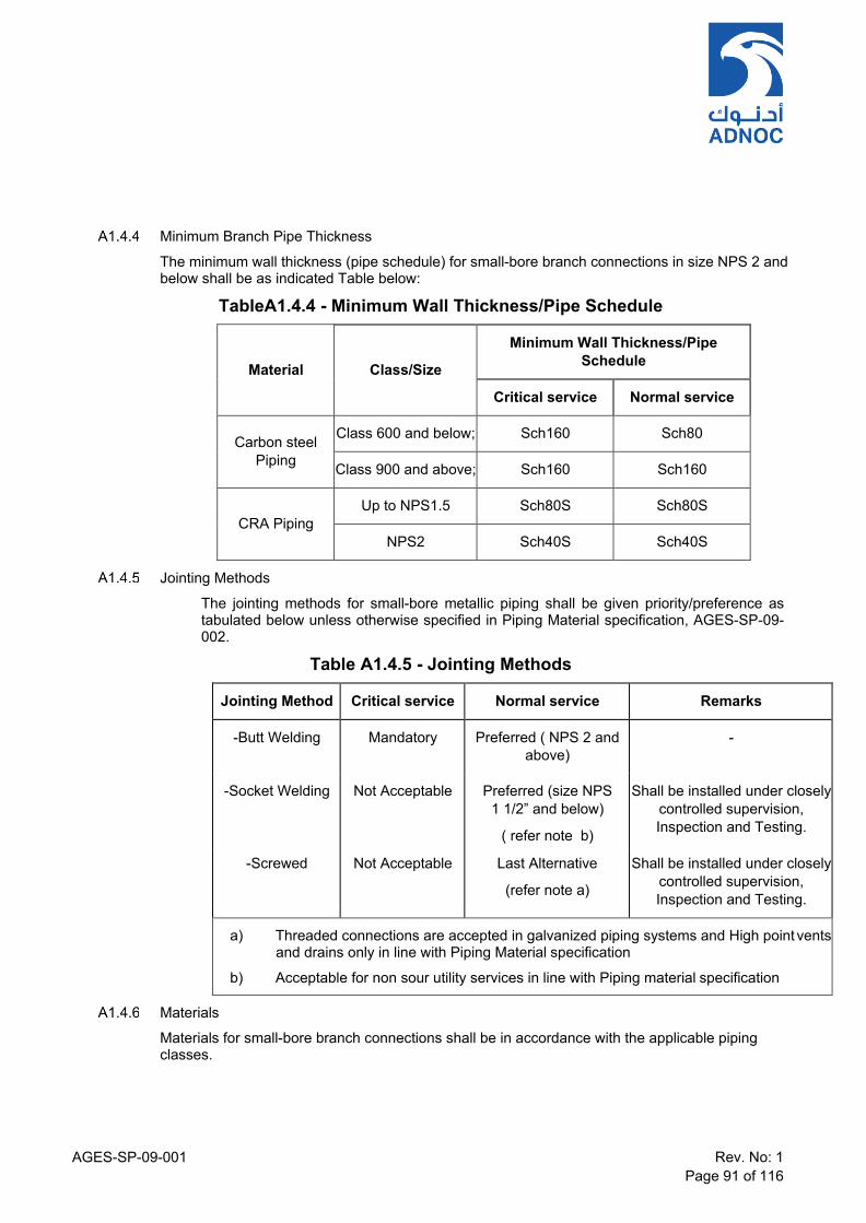
AGES-SP-09-001 Rev. No: 1 Page 91 of 116
Minimum Branch Pipe Thickness
The minimum wall thickness (pipe schedule) for small-bore branch connections in size NPS 2 and below shall be as indicated Table below:
TableA1.4.4 - Minimum Wall Thickness/Pipe Schedule
Material
Class/Size
Minimum Wall Thickness/Pipe Schedule
Critical service Normal service
Carbon steel
Piping
Class 600 and below; Sch160 Sch80
Class 900 and above; Sch160 Sch160
CRA Piping
Up to NPS1.5 Sch80S Sch80S
NPS2 Sch40S Sch40S
Jointing Methods
The jointing methods for small-bore metallic piping shall be given priority/preference as tabulated below unless otherwise specified in Piping Material specification, AGES-SP-09- 002.
Table A1.4.5 - Jointing Methods
Jointing Method Critical service Normal service Remarks
-Butt Welding Mandatory Preferred ( NPS 2 and above)
-
-Socket Welding Not Acceptable Preferred (size NPS 1 1/2” and below)
( refer note b)
Shall be installed under closely controlled supervision, Inspection and Testing.
-Screwed Not Acceptable Last Alternative
(refer note a)
Shall be installed under closely controlled supervision, Inspection and Testing.
a) Threaded connections are accepted in galvanized piping systems and High point vents and drains only in line with Piping Material specification
b) Acceptable for non sour utility services in line with Piping material specification
Materials
Materials for small-bore branch connections shall be in accordance with the applicable piping classes.
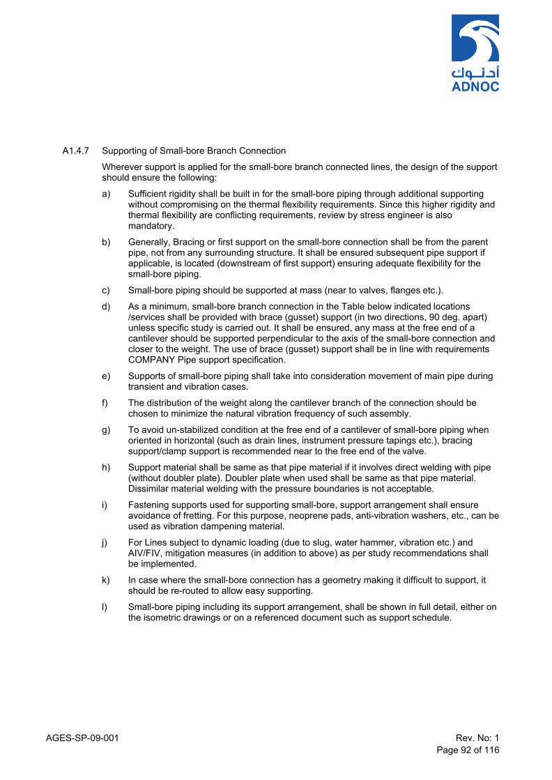
AGES-SP-09-001 Rev. No: 1 Page 92 of 116
Supporting of Small-bore Branch Connection
Wherever support is applied for the small-bore branch connected lines, the design of the support should ensure the following:
a) Sufficient rigidity shall be built in for the small-bore piping through additional supporting without compromising on the thermal flexibility requirements. Since this higher rigidity and thermal flexibility are conflicting requirements, review by stress engineer is also mandatory.
b) Generally, Bracing or first support on the small-bore connection shall be from the parent pipe, not from any surrounding structure. It shall be ensured subsequent pipe support if applicable, is located (downstream of first support) ensuring adequate flexibility for the small-bore piping.
c) Small-bore piping should be supported at mass (near to valves, flanges etc.).
d) As a minimum, small-bore branch connection in the Table below indicated locations /services shall be provided with brace (gusset) support (in two directions, 90 deg. apart) unless specific study is carried out. It shall be ensured, any mass at the free end of a cantilever should be supported perpendicular to the axis of the small-bore connection and closer to the weight. The use of brace (gusset) support shall be in line with requirements COMPANY Pipe support specification.
e) Supports of small-bore piping shall take into consideration movement of main pipe during transient and vibration cases.
f) The distribution of the weight along the cantilever branch of the connection should be chosen to minimize the natural vibration frequency of such assembly.
g) To avoid un-stabilized condition at the free end of a cantilever of small-bore piping when oriented in horizontal (such as drain lines, instrument pressure tapings etc.), bracing support/clamp support is recommended near to the free end of the valve.
h) Support material shall be same as that pipe material if it involves direct welding with pipe (without doubler plate). Doubler plate when used shall be same as that pipe material. Dissimilar material welding with the pressure boundaries is not acceptable.
i) Fastening supports used for supporting small-bore, support arrangement shall ensure avoidance of fretting. For this purpose, neoprene pads, anti-vibration washers, etc., can be used as vibration dampening material.
j) For Lines subject to dynamic loading (due to slug, water hammer, vibration etc.) and AIV/FIV, mitigation measures (in addition to above) as per study recommendations shall be implemented.
k) In case where the small-bore connection has a geometry making it difficult to support, it should be re-routed to allow easy supporting.
l) Small-bore piping including its support arrangement, shall be shown in full detail, either on the isometric drawings or on a referenced document such as support schedule.

AGES-SP-09-001 Rev. No: 1 Page 93 of 116
Table A1.4.7 - Small-bore Branch Locations/Services
Location (a) Bracing Requirement
Reciprocating compressors
All small-bore connections connected with the reciprocating compressor circuit shall be provided with bracing support from parent pipe
Centrifugal compressors/Centrifugal pumps
Any small-bore connections to piping within the greater of 6m or up to two pipe supports, measured along the pipe axis from the equipment nozzle
Piping system subject to Process induced vibration (AIV, FIV, Slug flow, water hammer etc.,)
All small-bore piping connections shall be provided with brace support unless specific study is conducted
Pressure throttling devices (BDV, PSV/PRV, pressure let down station etc.,)
Any small-bore branch piping on the inlet and out piping within the greater of 6m or up to two pipe supports, measured along the pipe axis from throttling device
Small-bore connection with multiple isolation valves or cantilever mass not located closer to the branch (with pipe spool more than 150 mm or arrangement involving more than one elbow)
Brace support shall be provided
Note a): Other applicable cases should be identified during the design stage
.

AGES-SP-09-001 Rev. No: 1 Page 94 of 116
APPENDIX A2 MODULARISATION A2.1 Considerations
The main objective for modularisation is to save on site infrastructure, costs, construction and commissioning time. Modules shall be designed as an open structure containing mechanical equipment, piping, inline instruments, cable trays, lighting and junction boxes as well as permanent lifting devices required for maintenance.
A2.2 Defining the Project Module Philosophy Each Project that decides to use modules has a construction choice. The choice can range from various levels of partial pre-assembly together with conventional stick-built plant right through to full modularisation with minimal stick-built plant
The Project modularisation philosophy shall typically be established during the FEED phase of a project. At the beginning of FEED, a multi-discipline team shall be formed to address the following key parameters:
a) Engineering and Design
b) Shipping and Transportation
c) Material supply & Procurement
d) Fabrication
e) Preservation
f) Installation
g) Hook-ups
h) Pre-Commissioning and Commissioning
i) Testing
j) Marine Facility Interfaces
A Project Modularisation Plan shall be prepared, outlining the general philosophy, procedures and criteria to be applied to the design of modules. This procedure details the key parameters of the Modularisation Plan that reflect the needs of the Piping Group.
A2.3 Determining Module Size a) Before any basic module layouts can be produced, the answers to the following key
questions shall be established:
b) Module Type – “Raised Base” design or “Buried Base” design?
c) Module Transportation – how are modules to be transported between the module fabrication yard and the job site?
d) Module Haul Road – have haul roads and turning circles been included in the site / plot plan development?
e) Module Installation – by crane, hydraulic jacks or by self-propelled module transporters SPMT’s?
f) Module Size – what is the maximum module length, width & height?
g) Module Weight - what is the maximum module weight?

AGES-SP-09-001 Rev. No: 1 Page 95 of 116
h) Module Main Structural Steel – what is the optimal grid spacing to use for the chosen module size?
i) Module Bottom Deck Elevation – dependent on module type
j) Module Primary Steel Configuration – “I” sections or tubular sections?
k) Vendor Packages – which equipment is to be vendor modules / packages?
l) Dressed Vessels – which vessels will be dressed; which vessels will be modularised?
m) Tanks – will they be site erected, or can they be prefabricated onto modules?
n) Buildings – modularised or site erected?
o) In order to establish the answers to the above questions, the Piping group, in conjunction with the other members of the multi-discipline modularization team, shall define the module haul road and module hook-up, as part of the overall Project Modularisation Philosophy.
A2.4 Module Haul Roads Haul Road Route
The route required for the on-site module haul road shall be determined at the earliest possible stage in the project, as this will have a major impact on the site plan and plot plan development. The Construction Group shall co-ordinate closely with Plant Layout to determine the optimum routing. The haul road layout shall ensure allowances are made for any future expansion and future module movements.
Haul Road Width
The haul road width will vary for each project, based on the selected maximum module size and the method of transportation. There may be more than one haul road required within the site; each one shall be sized to suit the maximum module size required to travel on it. This is defined as the road space (generally primed and sealed) in which the self-propelled modular transporter (SPMT) trailers manoeuvre. This is dependent on the maximum number of trailer line placements. Generally, the haul road width will be determined by the overall width of the SPMT’s, plus 2m either side for manoeuvrability, plus hard shoulders.
Street Furniture Clearance
This is defined as the airspace occupied by the maximum overhang of the largest module beyond the SPMT’s, while being manoeuvred in the path of the haul road. Generally, the street furniture clearance is determined by the width of the largest module, plus 2m either side for manoeuvrability.
Haul Road Gradient
SPMT suppliers advise that a maximum of 4% gradient combined with a maximum 1% cross slope should be used for laying out the haul routes. This shall be confirmed by the Construction Group with the actual project SPMT suppliers. The maximum change in gradient over the module length shall not exceed the SPMT’s hydraulic range.
Haul Road Radii and Turning Circles
The ability of a trailer / load combination to negotiate a sharp bend is dependent on the trailer load configuration and steering capability. For the SPMT type trailer, the steering is almost unlimited. SPMT trailers are capable of rotating 360 degrees on the spot. In general, the sharper the turn, the wider the road width required. SPMT suppliers have also stipulated that turning shall only be performed on flat areas with no slope.

AGES-SP-09-001 Rev. No: 1 Page 96 of 116
Factors to be Determined
The relationship between trailer lines, road width, turning radius and module envelope shall be studied on a case by case basis as part of the transportation studies in conjunction with the Construction Group. Generally, the largest module is identified in width and length, in order to determine the following:
a) Haul Road (primed & sealed) Inside Radius
b) Haul Road (primed & sealed) Outside Radius
c) Street Furniture Clearance Inside Radius
d) Street Furniture Clearance Outside Radius
e) Carousel Turning radius
A2.5 Module Hook-Up Philosophy The Project hook-up strategy will form an important part of the overall modularisation plan, having a direct impact on the key project requirements of minimising installation cost, schedule assurance, cost assurance, construction / commissioning project work hours expended on site, and exposure to risk associated with any expected lack of skilled personnel available to work at the project site.
The Project hook-up strategy shall be defined for the following key areas:
a) Module and piping alignment
b) Fabrication and site foundation tolerances and dimensional control
c) Engineering design – layout, line spacing, access, coating and insulation
d) Fabrication
e) Construction and field hook-up
f) Testing and Pre-commissioning
During EPC execution a hook-up plan shall be developed for each module interface type, supplemented by module specific hook-up plans where required by discipline, interface type and hook-up location.
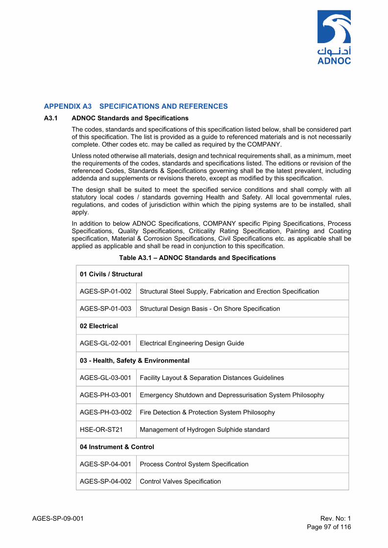
AGES-SP-09-001 Rev. No: 1 Page 97 of 116
APPENDIX A3 SPECIFICATIONS AND REFERENCES A3.1 ADNOC Standards and Specifications
The codes, standards and specifications of this specification listed below, shall be considered part of this specification. The list is provided as a guide to referenced materials and is not necessarily complete. Other codes etc. may be called as required by the COMPANY.
Unless noted otherwise all materials, design and technical requirements shall, as a minimum, meet the requirements of the codes, standards and specifications listed. The editions or revision of the referenced Codes, Standards & Specifications governing shall be the latest prevalent, including addenda and supplements or revisions thereto, except as modified by this specification.
The design shall be suited to meet the specified service conditions and shall comply with all statutory local codes / standards governing Health and Safety. All local governmental rules, regulations, and codes of jurisdiction within which the piping systems are to be installed, shall apply.
In addition to below ADNOC Specifications, COMPANY specific Piping Specifications, Process Specifications, Quality Specifications, Criticality Rating Specification, Painting and Coating specification, Material & Corrosion Specifications, Civil Specifications etc. as applicable shall be applied as applicable and shall be read in conjunction to this specification.
Table A3.1 – ADNOC Standards and Specifications
01 Civils / Structural
AGES-SP-01-002 Structural Steel Supply, Fabrication and Erection Specification
AGES-SP-01-003 Structural Design Basis - On Shore Specification
02 Electrical
AGES-GL-02-001 Electrical Engineering Design Guide
03 - Health, Safety & Environmental
AGES-GL-03-001 Facility Layout & Separation Distances Guidelines
AGES-PH-03-001 Emergency Shutdown and Depressurisation System Philosophy
AGES-PH-03-002 Fire Detection & Protection System Philosophy
HSE-OR-ST21 Management of Hydrogen Sulphide standard
04 Instrument & Control
AGES-SP-04-001 Process Control System Specification
AGES-SP-04-002 Control Valves Specification
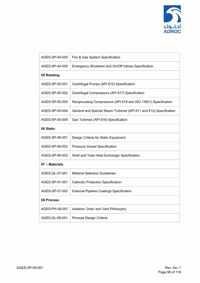
AGES-SP-09-001 Rev. No: 1 Page 98 of 116
AGES-SP-04-003 Fire & Gas System Specification
AGES-SP-04-005 Emergency Shutdown and On/Off Valves Specification
05 Rotating
AGES-SP-05-001 Centrifugal Pumps (API 610) Specification
AGES-SP-05-002 Centrifugal Compressors (API 617) Specification
AGES-SP-05-003 Reciprocating Compressors (API 618 and ISO 13631) Specification
AGES-SP-05-004 General and Special Steam Turbines (API 611 and 612) Specification
AGES-SP-05-005 Gas Turbines (API 616) Specification
06 Static
AGES-SP-06-001 Design Criteria for Static Equipment
AGES-SP-06-002 Pressure Vessel Specification
AGES-SP-06-003 Shell and Tube Heat Exchanger Specification
07 – Materials
AGES-GL-07-001 Material Selection Guidelines
AGES-SP-07-001 Cathodic Protection Specification
AGES-SP-07-002 External Pipeline Coatings Specification
08 Process
AGES-PH-08-001 Isolation, Drain and Vent Philosophy
AGES-GL-08-001 Process Design Criteria
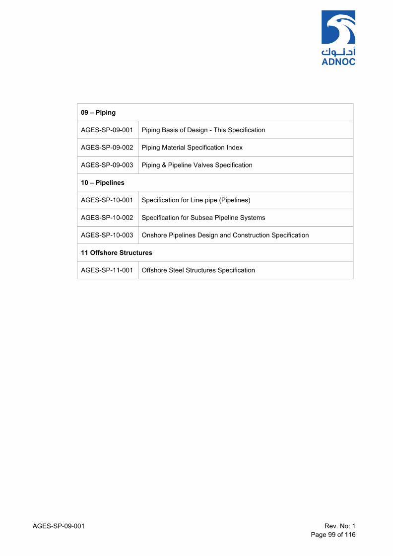
AGES-SP-09-001 Rev. No: 1 Page 99 of 116
09 – Piping
AGES-SP-09-001 Piping Basis of Design - This Specification
AGES-SP-09-002 Piping Material Specification Index
AGES-SP-09-003 Piping & Pipeline Valves Specification
10 – Pipelines
AGES-SP-10-001 Specification for Line pipe (Pipelines)
AGES-SP-10-002 Specification for Subsea Pipeline Systems
AGES-SP-10-003 Onshore Pipelines Design and Construction Specification
11 Offshore Structures
AGES-SP-11-001 Offshore Steel Structures Specification
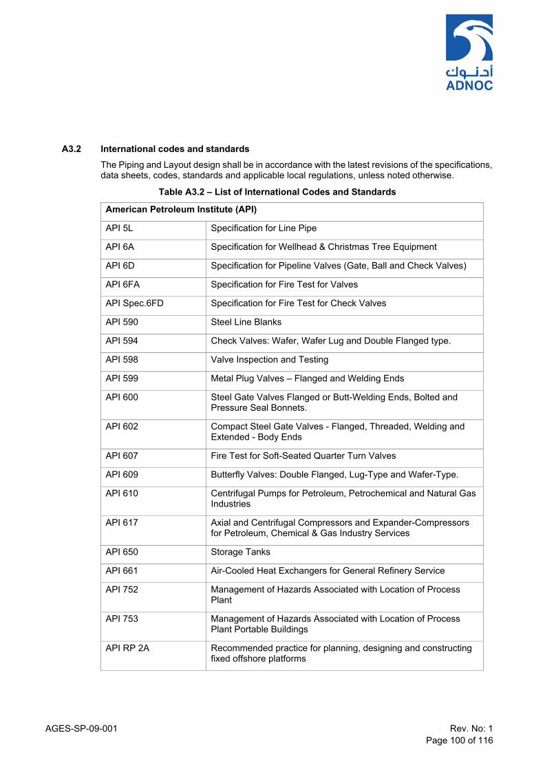
AGES-SP-09-001 Rev. No: 1 Page 100 of 116
A3.2 International codes and standards The Piping and Layout design shall be in accordance with the latest revisions of the specifications, data sheets, codes, standards and applicable local regulations, unless noted otherwise.
Table A3.2 – List of International Codes and Standards
American Petroleum Institute (API)
API 5L Specification for Line Pipe
API 6A Specification for Wellhead & Christmas Tree Equipment
API 6D Specification for Pipeline Valves (Gate, Ball and Check Valves)
API 6FA Specification for Fire Test for Valves
API Spec.6FD Specification for Fire Test for Check Valves
API 590 Steel Line Blanks
API 594 Check Valves: Wafer, Wafer Lug and Double Flanged type.
API 598 Valve Inspection and Testing
API 599 Metal Plug Valves – Flanged and Welding Ends
API 600 Steel Gate Valves Flanged or Butt-Welding Ends, Bolted and Pressure Seal Bonnets.
API 602 Compact Steel Gate Valves - Flanged, Threaded, Welding and Extended - Body Ends
API 607 Fire Test for Soft-Seated Quarter Turn Valves
API 609 Butterfly Valves: Double Flanged, Lug-Type and Wafer-Type.
API 610 Centrifugal Pumps for Petroleum, Petrochemical and Natural Gas Industries
API 617 Axial and Centrifugal Compressors and Expander-Compressors for Petroleum, Chemical & Gas Industry Services
API 650 Storage Tanks
API 661 Air-Cooled Heat Exchangers for General Refinery Service
API 752 Management of Hazards Associated with Location of Process Plant
API 753 Management of Hazards Associated with Location of Process Plant Portable Buildings
API RP 2A Recommended practice for planning, designing and constructing fixed offshore platforms

AGES-SP-09-001 Rev. No: 1 Page 101 of 116
American Petroleum Institute (API)
API RP 2G Recommended practice for production facilities on offshore structures
API RP 2L Recommended Practice for Planning, Designing and Constructing Heliports for Fixed Offshore Platforms
API RP 2T Recommended Practice for Planning Designing and Constructing Tension Leg Platforms
API RP 14E Recommended Practice for Design and Installation of Offshore Production Platform Piping Systems.
API RP 14C
Recommended Practice for Analysis, Design, installation and Testing of Basic Surface Safety Systems for Offshore Production Platforms
API RP 14G Recommended Practice for fire Prevention and Control on Open Type Offshore Production Platforms
API RP 14F Recommended Practice for Design and Installation of Electrical Systems for Fixed and Floating Offshore Petroleum Facilities
API RP 14J Recommended Practice for Design and Hazardous Analysis for Offshore Production Facilities
API RP 500 Recommended Practice for Classification of Areas for Electrical Installations at Drilling Rigs on Land and on Marine Fixed and Mobile platforms
API RP 505
Recommended Practices for Classification of Locations for Electrical Installations at Petroleum Facilities Classified as Class I, Zone 0, Zone 1 and Zone 2
API RP 520 Part 1 & 2 Sizing, Selection and Installation of Pressure-Relieving Devices in Refineries
API RP 521 Guide for Pressure Relieving and Depressuring Systems
API RP 752 Management of Hazards Associated with Location of Process Plant Buildings
API RP 1102 Steel Pipelines Crossing Railroads and Highways
API RP 1111 Recommended Practice for Design, Construction, Operation and Maintenance of Offshore Hydrocarbon Pipelines
API STD 611 General-purpose Steam Turbines for Petroleum, Chemical, and Gas Industry Services
API STD 612 Petroleum, Petrochemical and Natural Gas Industries - Steam Turbines - Special-Purpose Applications
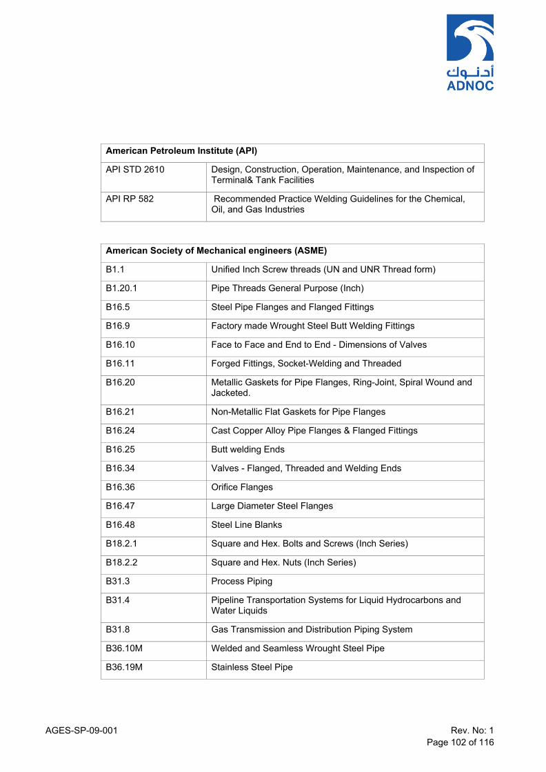
AGES-SP-09-001 Rev. No: 1 Page 102 of 116
American Petroleum Institute (API)
API STD 2610 Design, Construction, Operation, Maintenance, and Inspection of Terminal& Tank Facilities
API RP 582 Recommended Practice Welding Guidelines for the Chemical, Oil, and Gas Industries
American Society of Mechanical engineers (ASME)
B1.1 Unified Inch Screw threads (UN and UNR Thread form)
B1.20.1 Pipe Threads General Purpose (Inch)
B16.5 Steel Pipe Flanges and Flanged Fittings
B16.9 Factory made Wrought Steel Butt Welding Fittings
B16.10 Face to Face and End to End - Dimensions of Valves
B16.11 Forged Fittings, Socket-Welding and Threaded
B16.20 Metallic Gaskets for Pipe Flanges, Ring-Joint, Spiral Wound and Jacketed.
B16.21 Non-Metallic Flat Gaskets for Pipe Flanges
B16.24 Cast Copper Alloy Pipe Flanges & Flanged Fittings
B16.25 Butt welding Ends
B16.34 Valves - Flanged, Threaded and Welding Ends
B16.36 Orifice Flanges
B16.47 Large Diameter Steel Flanges
B16.48 Steel Line Blanks
B18.2.1 Square and Hex. Bolts and Screws (Inch Series)
B18.2.2 Square and Hex. Nuts (Inch Series)
B31.3 Process Piping
B31.4 Pipeline Transportation Systems for Liquid Hydrocarbons and Water Liquids
B31.8 Gas Transmission and Distribution Piping System
B36.10M Welded and Seamless Wrought Steel Pipe
B36.19M Stainless Steel Pipe

AGES-SP-09-001 Rev. No: 1 Page 103 of 116
ASTM & ASME BOILER & PRESSURE VESSEL CODE
ASME BPVC Sect. II Materials & (Part D) Properties
ASME Section II Part C Specification for Welding Rods, Electrodes and Filler Metals
ASME BPVC Sect. V Non-destructive Examination
ASME BPVC Sect. VIII Pressure Vessels
ASME BPVC Sect. IX Qualification Standard for Welding and Brazing Procedures, Welders, Brazers and Welding & Brazing Operators
ASTM D5162 Discontinuity (Holiday) Testing of Nonconductive Protective Coating on Metallic Substrates
ASTM Standards for Forgings, Castings, Plate Materials and various Piping Components
Material Specifications are not directly referenced in this standard, see Piping Material Specifications for details of piping materials used.

AGES-SP-09-001 Rev. No: 1 Page 104 of 116
British Standard Institution (BSI) / Euro norms (EN)
BS EN 593 Industrial Valves - Metallic Butterfly Valves
BS 1414 Steel Wedge Gate Valves (Flanged & Butt-welding Ends) for the Petroleum, Petrochemical and Allied Industries.
BS 1452 Specification for Plastics piping Systems for water supply – Un- plasticised Polyvinyl Chloride (PVC-U).
BS 1868 Steel Check Valves (Flanged and Butt-Welding Ends) for the Petroleum, Petrochemical and Allied Industries.
BS 1873 Steel Globe and Globe Stop and Check Valves (Flanged and butt-welding ends) for the Petroleum, Petrochemical and Allied Industries.
BS 5351 Steel Ball Valves for Petroleum, Petrochemical and Allied Industries.
BS 5352 Steel Gate, Globe and Check Valves 50mm & smaller for the Petroleum, Petrochemical and Allied Industries.
BS 6755 Part 1 Testing of Valves Part 1: Production Pressure Testing Requirement
Part 2 Testing of Valves Part 2: Fire Type Testing Requirements. BS 7531 Specification for Compressed Non-Asbestos Fibre Jointing.
BS EN 12266 -1 Industrial valves Testing of valves Part 1: Pressure tests, test procedures and acceptance criteria Mandatory requirements
BS EN 12266 -2
Industrial Valves - Testing of Valves Part 2: Tests, Test Procedures and Acceptance Criteria Supplementary Requirements
BS EN ISO 10434 Bolted bonnet steel gate valves for the petroleum, petrochemical and allied industries
BS EN ISO 10497 Testing of valves Fire type-testing requirements
BS EN ISO 1461 Hot dip galvanized coatings on fabricated iron and steel articles - Specifications and test methods
BS EN ISO 15761 Steel gate, globe and check valves for sizes DN 100 and smaller, for the petroleum and natural gas industries
BS EN ISO 17292 Metal ball valves for petroleum, petrochemical and allied industries

AGES-SP-09-001 Rev. No: 1 Page 105 of 116
Center for Chemical Process Safety (CCPS) Published by American Institute of Chemical Engineers
CCPS Appendix B Guidelines for Siting and Layout of Facilities – Distance Tables
Civil Aviation Authority
CAP 437 Offshore helicopter Landing Areas
CAAP 70 Abu Dhabi CAAP 70 heliports
CAAP 71 Abu Dhabi CAAP 71 helidecks
CAAP 72 Abu Dhabi CAAP 72 aircraft landing areas
Det Norske Veritas (DNV)
OS-F101 Submarine Pipeline Systems
European Norms (EN)
EN 10204 Inspection Documents for the Delivery of Metallic Products.
Engineering Equipment and Materials Users Association (EEMUA)
EEMUA 234 Specification for 90/10 Copper Nickel Alloy Piping for Offshore
Energy Institute (EI)
2nd Edition 2008 Guidelines for The Avoidance of Vibration Induced Fatigue Failure in Process Pipework. (HSE & MTD Issue)
EI 1 Model Code of Safe Practice, Part 1, 8th edition, June 2010
EI 15 Model Code of Safe Practice, Part 15, 4th edition, June 2015
EI 19 Model Code of Safe Practice – Part 19: Fire Precautions at Petroleum
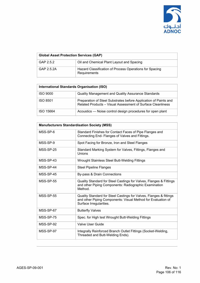
AGES-SP-09-001 Rev. No: 1 Page 106 of 116
Global Asset Protection Services (GAP)
GAP 2.5.2 Oil and Chemical Plant Layout and Spacing
GAP 2.5.2A Hazard Classification of Process Operations for Spacing Requirements
International Standards Organisation (ISO)
ISO 9000 Quality Management and Quality Assurance Standards
ISO 8501 Preparation of Steel Substrates before Application of Paints and Related Products – Visual Assessment of Surface Cleanliness
ISO 15664 Acoustics — Noise control design procedures for open plant
Manufacturers Standardisation Society (MSS)
MSS-SP-6 Standard Finishes for Contact Faces of Pipe Flanges and Connecting End- Flanges of Valves and Fittings.
MSS-SP-9 Spot Facing for Bronze, Iron and Steel Flanges
MSS-SP-25 Standard Marking System for Valves, Fittings, Flanges and Unions
MSS-SP-43 Wrought Stainless Steel Butt-Welding Fittings
MSS-SP-44 Steel Pipeline Flanges
MSS-SP-45 By-pass & Drain Connections
MSS-SP-55 Quality Standard for Steel Castings for Valves, Flanges & Fittings and other Piping Components: Radiographic Examination Method.
MSS-SP-55 Quality Standard for Steel Castings for Valves, Flanges & fittings and other Piping Components: Visual Method for Evaluation of Surface Irregularities.
MSS-SP-67 Butterfly Valves
MSS-SP-75 Spec. for High test Wrought Butt-Welding Fittings
MSS-SP-92 Valve User Guide
MSS-SP-97 Integrally Reinforced Branch Outlet Fittings (Socket-Welding, Threaded and Butt-Welding Ends).
AGES-SP-09-001 Rev. No: 1 Page 107 of 116
National Association of Corrosion Engineers (NACE)
TM-0177 Laboratory Testing of Metals for Resistance to specific forms of Environmental Cracking in H₂S Environments.
TM-0284 Evaluation of Pipeline and Pressure Vessel Steels for Resistance to Hydrogen Induced Cracking.
NACE MR0175 / ISO 15156
Sulphide Stress Cracking Resistant Metallic Material for Oilfield Equipment
NACE MR0103/ISO 17945
Petroleum, petrochemical and natural gas industries – Metallic materials resistant to sulphide stress cracking in corrosive petroleum refining environments
SP-0472 Method and Controls to prevent In-service Environmental cracking of Carbon Steel Weldments in Corrosive Refining Environments.
National Fire Protection Association (NFPA)
NFPA 101 Life Safety Code
NFPA 15 Standard for Water Spray Fixed Systems for Fire Protection
NFPA 20 Standard for Installation of Stationary Pumps for Fire Protection
NFPA 24 Standard for the Installation of Private Fire Service Mains and Their Appurtenances
NFPA 25 Standard for the Inspection, Testing, and Maintenance of Water- Based Fire Protection Systems
NFPA 30 Flammable and Combustible Liquids Code
NFPA 59A Standard for the Production, Storage, and Handling of Liquefied Natural
Gas (LNG)
National Electrical Manufacturer Association (NEMA)
SM 23 Steam Turbines for Mechanical Drive Service
AGES-SP-09-001 Rev. No: 1 Page 108 of 116
A3.3 Typical Illustrative Sketches/Drawings Below are typical illustrative sketches and drawings of plant layouts and piping arrangement. These are for reference only

AGES-SP-09-001 Rev. No: 1 Page 109 of 116
TYPICAL ILLUSTRATIVE ARRANGEMENT & DETAILS
Grade-Mounted Horizontal Inline Arrangement

AGES-SP-09-001 Rev. No: 1 Page 110 of 116
Typical Access Requirements in a Vertical Arrangement

AGES-SP-09-001 Rev. No: 1 Page 111 of 116
Typical Access Requirements in an Inline Arrangement

AGES-SP-09-001 Rev. No: 1 Page 112 of 116
Typical Underground Arrangements
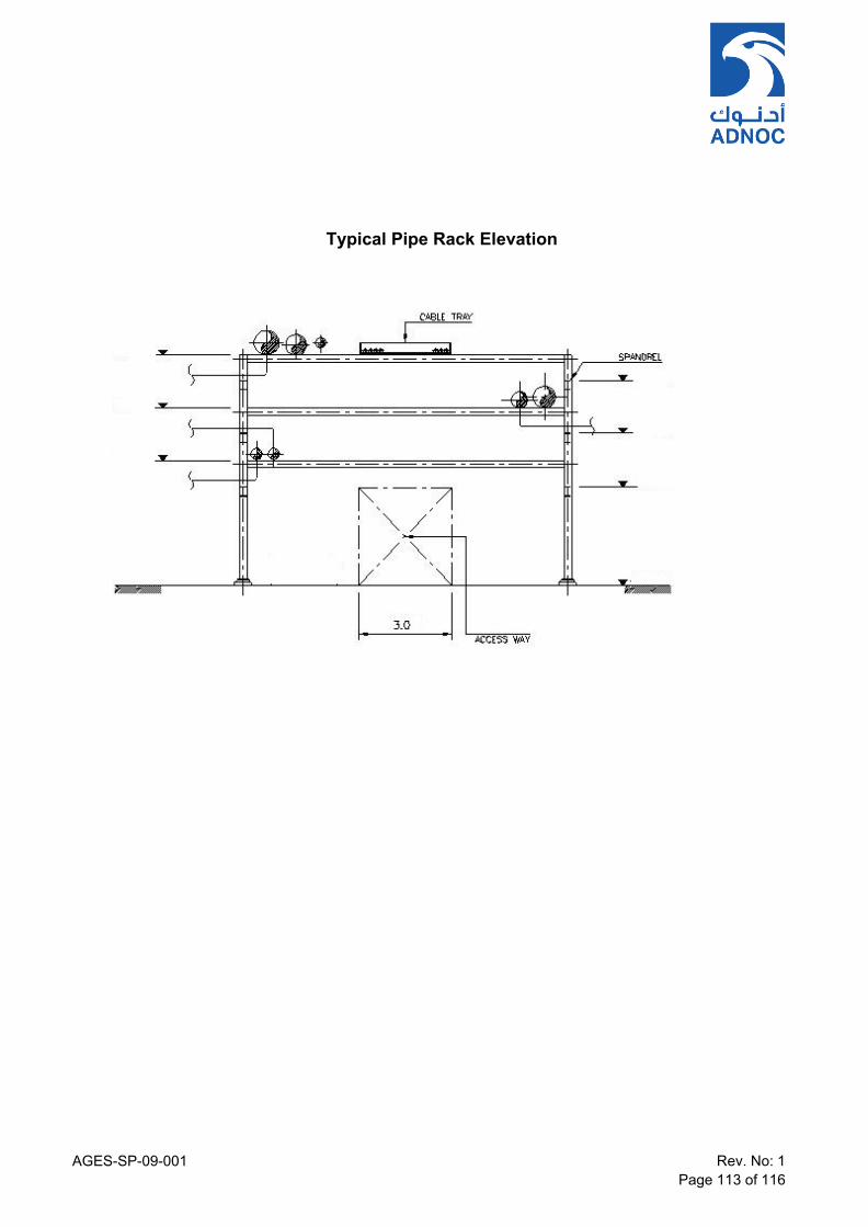
AGES-SP-09-001 Rev. No: 1 Page 113 of 116
Typical Pipe Rack Elevation

AGES-SP-09-001 Rev. No: 1 Page 114 of 116
Typical Process Unit Road and Paving Arrangement
Note: This has to be read in conjunction with CIVIL specification. For Raod and Paving
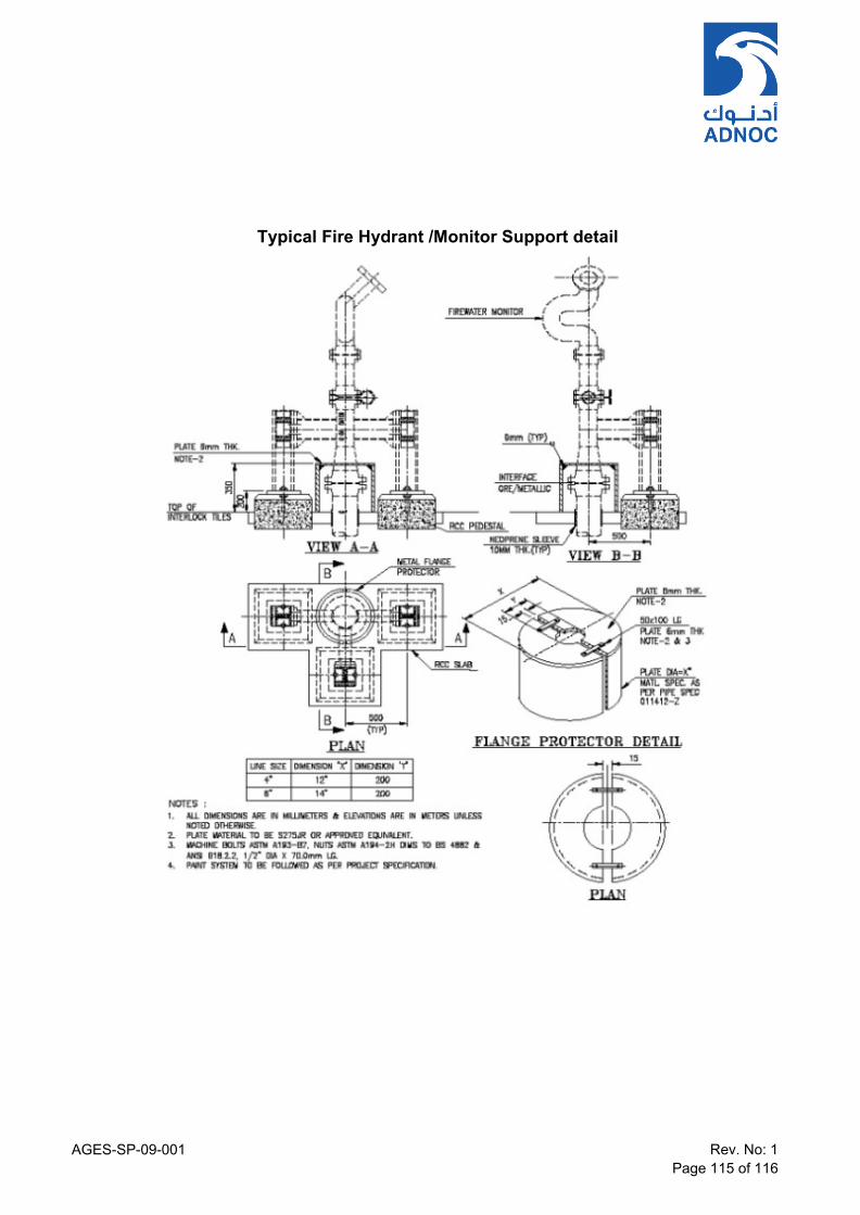
AGES-SP-09-001 Rev. No: 1 Page 115 of 116
Typical Fire Hydrant /Monitor Support detail
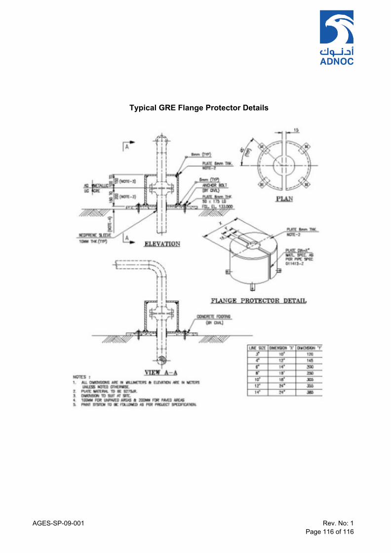
AGES-SP-09-001 Rev. No: 1 Page 116 of 116
Typical GRE Flange Protector Details