
Obligatory Reduction of Ferric Chelates In Iron Uptake by Soybeans
Upload
khangminh22Category
view
1download
0
I
(Acts whose publication is obligatory)
DIRECTIVE 2001/85/EC OF THE EUROPEAN PARLIAMENT AND OF THE COUNCIL
of 20 November 2001
relating to special provisions for vehicles used for the carriage of passengers comprising morethan eight seats in addition to the driver's seat, and amending Directives 70/156/EEC and 97/27/EC
THE EUROPEAN PARLIAMENT AND THE COUNCIL OF THEEUROPEAN UNION,
Having regard to the Treaty establishing the EuropeanCommunity, and in particular Article 95 thereof,
Having regard to the proposal from the Commission (1) ,
Having regard to the opinion of the Economic and SocialCommittee (2),
Acting in accordance with the procedure laid down in Article251 of the Treaty (3), in the light of the joint text approved bythe Conciliation Committee on 25 June 2001,
Whereas:
(1) The internal market comprises an area without internalfrontiers, in which the free movement of goods,persons, services and capital is ensured. It is importantto adopt measures to that end.
(2) The technical requirements which motor vehicles mustsatisfy pursuant to national laws relate, inter alia, tospecial provisions for vehicles used for the carriage ofpassengers comprising more than eight seats in additionto the driver's seat.
(3) Those requirements differ from one Member State toanother.
(4) Owing to differences in technical prescriptions, thesevehicles have been prevented from being put on to the
Community market. The adoption of harmonisedrequirements by all of the Member States in place oftheir national regulations should facilitate the properfunctioning of the internal market for these vehicles.
(5) It is therefore necessary that all Member States adoptthe same requirements either in addition to, or in placeof, their existing rules in order, in particular, to allowthe EC type-approval procedure which is the subject ofCouncil Directive 70/156/EEC of 6 February 1970 onthe approximation of the laws of the Member Statesrelating to the type-approval of motor vehicles and theirtrailers (4) to be applied in respect of each type ofvehicle.
(6) This Directive is one of the separate Directives of the ECtype-approval procedure, which was established byDirective 70/156/EEC.
(7) To acknowledge advances already made in order toimprove accessibility for persons of reduced mobility tovehicles of Classes I and II, existing types of vehicleshould be permitted to have a steeper slope in parts ofthe gangway than new types of vehicle.
(8) Since the objectives of the proposed action, namely theavoidance of barriers to trade within the Communitythrough the application of EC vehicle type-approval forsuch vehicles, cannot be sufficiently achieved by theMember States on account of the scale and impact ofthe action proposed in the sector in question, and cantherefore be better attained at Community level, theCommunity may adopt measures, in accordance withthe principle of subsidiarity as set out in Article 5 of theTreaty. In accordance with the principle ofproportionality, as set out in that Article, this Directivedoes not go beyond what is necessary in order toachieve those objectives.
(1) OJ C 17, 20.1.1998, p. 1.(2) OJ C 129, 27.4.1998, p. 5.(3) Opinion of the European Parliament of 18 November 1998 (OJ C
379, 7.12.1998, p. 80) confirmed on 27 October 1999 (OJ C 154,5.6.2000, p. 47), Council Common Position of 26 September 2000(OJ C 370, 22.12.2000, p. 1) and Decision of the EuropeanParliament of 14 February 2001 (OJ C 276, 1.10.2001, p. 124).Decision of the European Parliament of 3 October 2001 andCouncil Decision of 8 October 2001.
(4) OJ L 42, 23.2.1970, p. 1. Directive as last amended by EuropeanParliament and Council Directive 98/91/EC (OJ L 11, 16.1.1999,p. 25).
13.2.2002 L 42/1Official Journal of the European CommunitiesEN
(9) In order to distinguish between existing and new typesof vehicle, it is necessary to refer to Council Directive76/756/EEC of 27 July 1976 on the approximation ofthe laws of the Member States relating to the installationof lighting and light-signalling devices on motor vehiclesand their trailers (1).
(10) It is desirable to take account of the existing technicalrequirements adopted by the UN Economic Commissionfor Europe (UN/ECE) in its Regulation No 36 (�UniformProvisions concerning the Approval of Large PassengerVehicles with regard to their General Construction�), itsRegulation No 52 (�Uniform Provisions concerning theConstruction of Small-Capacity Public Service Vehicles�),its Regulation No 66 (�Uniform Provisions Concerningthe Approval of Large Passenger Vehicles with regard tothe Strength of their Superstructure�) and its RegulationNo 107 (�Uniform Provisions concerning the Approvalof Double-Deck Large Passenger Vehicles with regard totheir General Construction�), which are annexed to theAgreement of 20 March 1958 concerning the adoptionof uniform conditions for approval and reciprocalrecognition of approval for motor vehicle equipmentand parts.
(11) While the principal aim of this Directive is to guaranteethe safety of passengers, it is also necessary to providetechnical prescriptions to allow accessibility for personsof reduced mobility to the vehicles covered by theDirective, in accordance with the Community transportand social policies. Every effort must be made toimprove access to these vehicles. To this end,accessibility for persons of reduced mobility can beachieved either by technical solutions applied to thevehicle, as covered by this Directive, or by combiningthem with appropriate local infrastructure to guaranteeaccess for wheelchair users.
(12) As a result of the foregoing, it is necessary to amendDirective 70/156/EEC and Directive 97/27/EC of theEuropean Parliament and of the Council of 22 July1997 relating to the masses and dimensions of certaincategories of motor vehicles and their trailers (2).
(13) The measures necessary for the implementation of thisDirective should be adopted in accordance with CouncilDecision 1999/468/EC of 28 June 1999 laying downthe procedures for the exercise of implementing powersconferred on the Commission (3),
HAVE ADOPTED THIS DIRECTIVE:
Article 1
For the purposes of this Directive:
� �vehicle� shall mean any motor vehicle of category M2 orM3, as defined in Annex II, Part A, of Directive70/156/EEC,
� �bodywork� shall mean a separate technical unit as definedin Article 2 of Directive 70/156/EEC,
� �class of vehicle� shall mean a vehicle which complies withthe class description given in Annex I to this Directive.
Article 2
1. With effect from 13 August 2003 Member States maynot refuse EC type-approval or national type approval:
� of a vehicle,
� of a bodywork,
� of a vehicle the bodywork of which has already beentype-approved as a separate technical unit,
or refuse or prohibit the sale, registration or entry into serviceof a vehicle or of a bodywork as a separate technical unit, ongrounds relating to the provisions for vehicles used for thecarriage of passengers and comprising more than eight seats inaddition to the driver's seat, if the requirements of thisDirective and the Annexes thereto are satisfied.
2. Paragraph 1 shall also apply to low-floor vehicles ofClass I or II, type-approved before 13 August 2002 pursuantto Directive 76/756/EEC, benefiting from the 12,5 % gangwayslope specified in paragraph 7.7.6.2 of Annex 1.
3. Subject to the provisions of paragraph 4 below, witheffect from 13 February 2004, Member States:
� shall no longer grant EC type-approval for a type ofvehicle and a type of bodywork as a separate technicalunit,
(1) OJ L 262, 27.9.1976, p. 1. Directive as last amended byCommission Directive 97/28/EC (OJ L 171, 30.6.1997, p. 1).
(2) OJ L 233, 25.8.1997, p. 1.(3) OJ L 184, 17.7.1999, p. 23.
L 42/2 13.2.2002Official Journal of the European CommunitiesEN
� may refuse the registration, sale or entry into service ofnew vehicles and new bodyworks as separate technicalunits,
on grounds relating to the provisions for vehicles used for thecarriage of passengers and comprising more than eight seats inaddition to the driver's seat, if the requirements of thisDirective and the Annexes thereto are not complied with.
4. With effect from 13 February 2005, Member States mayrefuse the registration, sale or entry into service of newvehicles and new bodyworks as separate technical units whichhave been type-approved according to the provisions ofparagraph 2.
Article 3
1. Vehicles of Class I shall be accessible for people withreduced mobility including wheelchair users according to thetechnical provisions laid down in Annex VII.
2. Member States shall be free to choose the mostappropriate solution to achieve improved accessibility invehicles other than those of Class I. However, if vehicles otherthan those of Class I are equipped with devices for people withreduced mobility and/or wheelchair users, they shall complywith the relevant requirements of Annex VII.
Article 4
Directive 70/156/EC shall be amended as follows:
1. in Annex I:
(a) the following items shall be added to item 0.2:
� 0.2.0.1. Chassis: . . . . . . . . . . . . . . . . . . . . . . . . . . . . . . . . . . . . . . . . . . . . . . . . . . . . . . . . .
0.2.0.2. Bodywork/complete vehicle: . . . . . . . . . . . . . . . . . . . . . . . . . . . . . . . . . . . . . . . . .�;
(b) the following items shall be added to item 0.3:
� 0.3.0.1. Chassis: . . . . . . . . . . . . . . . . . . . . . . . . . . . . . . . . . . . . . . . . . . . . . . . . . . . . . . . . .
0.3.0.2. Bodywork/complete vehicle: . . . . . . . . . . . . . . . . . . . . . . . . . . . . . . . . . . . . . . . . .�;
(c) the following items shall be added to item 0.3.1:
� 0.3.1.1. Chassis: . . . . . . . . . . . . . . . . . . . . . . . . . . . . . . . . . . . . . . . . . . . . . . . . . . . . . . . . .
0.3.1.2. Bodywork/complete vehicle: . . . . . . . . . . . . . . . . . . . . . . . . . . . . . . . . . . . . . . . . .�;
(d) the following item shall be added to item 2.4.2:
� 2.4.2.9. Position of centre of gravity of the vehicle at its technically permissible maximumladen mass in the longitudinal, transverse and vertical directions: . . . . . . . . . . . . . .�;
(e) the following item shall be inserted:
� 2.4.3. For bodywork approved without chassis
2.4.3.1. Length (j): . . . . . . . . . . . . . . . . . . . . . . . . . . . . . . . . . . . . . . . . . . . . . . . . . . . . . . .
2.4.3.2. Width (k): . . . . . . . . . . . . . . . . . . . . . . . . . . . . . . . . . . . . . . . . . . . . . . . . . . . . . . .
2.4.3.3. Nominal height (in running order) (1) on intended chassis type(s) (for suspensionadjustable for height, indicate normal running position): . . . . . . . . . . . . . . . . . . . .�;
(f) item 13 shall be replaced by the following:
�13. SPECIAL PROVISIONS FOR VEHICLES USED FOR THE CARRIAGE OFPASSENGERS COMPRISING MORE THAN EIGHT SEATS IN ADDITION TO THEDRIVER'S SEAT
13.1. Class of vehicle (Class I, Class II, Class III, Class A, Class B): . . . . . . . . . . . . . . . . . . .
13.1.1. EC type-approval number of bodywork approved as a separate technical unit: . . . . .
13.2.2002 L 42/3Official Journal of the European CommunitiesEN
13.1.2. Chassis types where the EC type-approved bodywork can be installed(manufacturer(s), and types of incomplete vehicle): . . . . . . . . . . . . . . . . . . . . . . . . . .
13.2. Area for passengers (m2)
13.2.1. Total (S0): . . . . . . . . . . . . . . . . . . . . . . . . . . . . . . . . . . . . . . . . . . . . . . . . . . . . . . . .
13.2.2. Upper deck (S0a) (1): . . . . . . . . . . . . . . . . . . . . . . . . . . . . . . . . . . . . . . . . . . . . . . . . .
13.2.3. Lower deck (S0b) (1): . . . . . . . . . . . . . . . . . . . . . . . . . . . . . . . . . . . . . . . . . . . . . . . .
13.2.4. For standing passengers (S1): . . . . . . . . . . . . . . . . . . . . . . . . . . . . . . . . . . . . . . . . . .
13.3. Number of passengers (seated and standing)
13.3.1. Total (N): . . . . . . . . . . . . . . . . . . . . . . . . . . . . . . . . . . . . . . . . . . . . . . . . . . . . . . . .
13.3.2. Upper deck (Na) (1): . . . . . . . . . . . . . . . . . . . . . . . . . . . . . . . . . . . . . . . . . . . . . . . .
13.3.3. Lower deck (Nb) (1): . . . . . . . . . . . . . . . . . . . . . . . . . . . . . . . . . . . . . . . . . . . . . . . .
13.4. Number of passengers seated
13.4.1. Total (A): . . . . . . . . . . . . . . . . . . . . . . . . . . . . . . . . . . . . . . . . . . . . . . . . . . . . . . . .
13.4.2. Upper deck (Aa) (1): . . . . . . . . . . . . . . . . . . . . . . . . . . . . . . . . . . . . . . . . . . . . . . . .
13.4.3. Lower deck (Ab) (1): . . . . . . . . . . . . . . . . . . . . . . . . . . . . . . . . . . . . . . . . . . . . . . . .
13.5. Number of service doors:
13.6. Number of emergency exits (doors, windows, escape hatches, intercommunicationstaircase and half staircase)
13.6.1. Total: . . . . . . . . . . . . . . . . . . . . . . . . . . . . . . . . . . . . . . . . . . . . . . . . . . . . . . . . . . .
13.6.2. Upper deck (1): . . . . . . . . . . . . . . . . . . . . . . . . . . . . . . . . . . . . . . . . . . . . . . . . . . . .
13.6.3. Lower deck (1): . . . . . . . . . . . . . . . . . . . . . . . . . . . . . . . . . . . . . . . . . . . . . . . . . . . .
13.7. Volume of luggage compartments (m3): . . . . . . . . . . . . . . . . . . . . . . . . . . . . . . . . . .
13.8. Volume of luggage transportation on the roof (m2): . . . . . . . . . . . . . . . . . . . . . . . . .
13.9. Technical devices facilitating the access to vehicles (e.g. ramp, lifting platform,kneeling system), if fitted: . . . . . . . . . . . . . . . . . . . . . . . . . . . . . . . . . . . . . . . . . . . .
13.10. Strength of superstructure
13.10.1. EC type-approval number, if available: . . . . . . . . . . . . . . . . . . . . . . . . . . . . . . . . . . .
13.10.2. For superstructures not yet approved
13.10.2.1. Detailed description of the superstructure of the vehicle type including itsdimensions, configuration and constituent materials and its attachment to any chassisframe:
13.10.2.2. Drawings of the vehicle and those parts of its interior arrangement which have aninfluence on the strength of the superstructure or on the residual space:
13.10.2.3. Position of centre of gravity of the vehicle in running order in the longitudinal,transverse and vertical directions: . . . . . . . . . . . . . . . . . . . . . . . . . . . . . . . . . . . . . .
13.10.2.4. Maximum distance between the centre lines of the outboard passenger seats: . . . . . .
13.11. Points of this Directive to be accomplished and demonstrated for this separatetechnical unit: . . . . . . . . . . . . . . . . . . . . . . . . . . . . . . . . . . . . . . . . . . . . . . . . . . .�;
L 42/4 13.2.2002Official Journal of the European CommunitiesEN
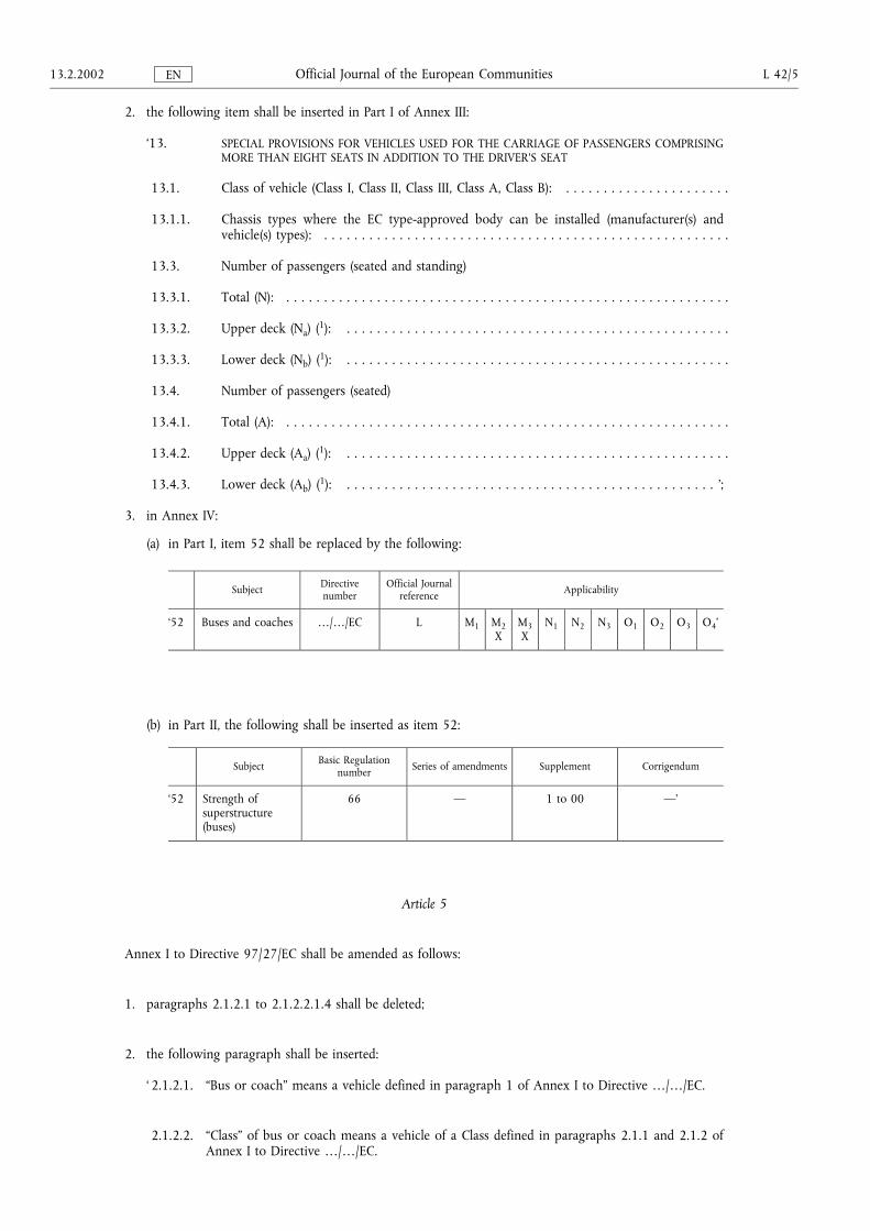
2. the following item shall be inserted in Part I of Annex III:
�13. SPECIAL PROVISIONS FOR VEHICLES USED FOR THE CARRIAGE OF PASSENGERS COMPRISINGMORE THAN EIGHT SEATS IN ADDITION TO THE DRIVER'S SEAT
13.1. Class of vehicle (Class I, Class II, Class III, Class A, Class B): . . . . . . . . . . . . . . . . . . . . . .
13.1.1. Chassis types where the EC type-approved body can be installed (manufacturer(s) andvehicle(s) types): . . . . . . . . . . . . . . . . . . . . . . . . . . . . . . . . . . . . . . . . . . . . . . . . . . . . . .
13.3. Number of passengers (seated and standing)
13.3.1. Total (N): . . . . . . . . . . . . . . . . . . . . . . . . . . . . . . . . . . . . . . . . . . . . . . . . . . . . . . . . . . .
13.3.2. Upper deck (Na) (1): . . . . . . . . . . . . . . . . . . . . . . . . . . . . . . . . . . . . . . . . . . . . . . . . . . .
13.3.3. Lower deck (Nb) (1): . . . . . . . . . . . . . . . . . . . . . . . . . . . . . . . . . . . . . . . . . . . . . . . . . . .
13.4. Number of passengers (seated)
13.4.1. Total (A): . . . . . . . . . . . . . . . . . . . . . . . . . . . . . . . . . . . . . . . . . . . . . . . . . . . . . . . . . . .
13.4.2. Upper deck (Aa) (1): . . . . . . . . . . . . . . . . . . . . . . . . . . . . . . . . . . . . . . . . . . . . . . . . . . .
13.4.3. Lower deck (Ab) (1): . . . . . . . . . . . . . . . . . . . . . . . . . . . . . . . . . . . . . . . . . . . . . . . . . �;
3. in Annex IV:
(a) in Part I, item 52 shall be replaced by the following:
Subject Directivenumber
Official Journalreference Applicability
�52 Buses and coaches �/�/EC L M1 M2X
M3X
N1 N2 N3 O1 O2 O3 O4�
(b) in Part II, the following shall be inserted as item 52:
Subject Basic Regulationnumber Series of amendments Supplement Corrigendum
�52 Strength ofsuperstructure(buses)
66 � 1 to 00 ��
Article 5
Annex I to Directive 97/27/EC shall be amended as follows:
1. paragraphs 2.1.2.1 to 2.1.2.2.1.4 shall be deleted;
2. the following paragraph shall be inserted:
� 2.1.2.1. �Bus or coach� means a vehicle defined in paragraph 1 of Annex I to Directive �/�/EC.
2.1.2.2. �Class� of bus or coach means a vehicle of a Class defined in paragraphs 2.1.1 and 2.1.2 ofAnnex I to Directive �/�/EC.
13.2.2002 L 42/5Official Journal of the European CommunitiesEN

2.1.2.3. �Articulated bus or coach� means a vehicle defined in paragraph 2.1.3 of Annex I toDirective �/�/EC.
2.1.2.4. �Double-deck bus or coach� means a vehicle defined in paragraph 2.1.6 of Annex I toDirective �/�/EC.�
Article 6
The measures necessary for the adaptation to technical progress of this Directive shall be adopted inaccordance with the procedure set out in Article 7(2).
Article 7
1. The Commission shall be assisted by the Committee for Adaptation to Technical Progress set up byArticle 13 of Directive 70/156/EEC (hereinafter referred to as �the Committee�).
2. Where reference is made to this paragraph, Articles 5 and 7 of Decision 1999/468/EC shall apply,having regard to the provisions of Article 8 thereof.
The period laid down in Article 5(6) of Decision 1999/468/EC shall be set at three months.
3. The Committee shall adopt its rules of procedure.
Article 8
1. Member States shall adopt and publish the laws, regulations and administrative provisions necessaryto comply with this Directive before 13 August 2003. They shall forthwith inform the Commissionthereof.
When Member States adopt these provisions, these shall contain a reference to this Directive or shall beaccompanied by such reference at the time of their official publication. The procedure for such referenceshall be adopted by Member States.
2. Member States shall communicate to the Commission the texts of the main provisions of nationallaw which they adopt in the field covered by this Directive.
Article 9
This Directive shall enter into force on the day of its publication in the Official Journal of the EuropeanCommunities.
Article 10
This Directive is addressed to the Member States.
Done at Brussels, 20 November 2001.
For the European Parliament
The PresidentN. FONTAINE
For the Council
The PresidentA. NEYTS-UYTTEBROECK
L 42/6 13.2.2002Official Journal of the European CommunitiesEN
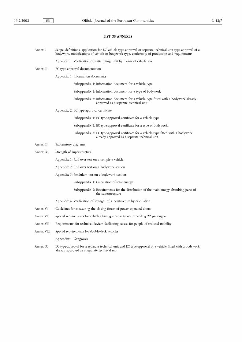
LIST OF ANNEXES
Annex I: Scope, definitions, application for EC vehicle type-approval or separate technical unit type-approval of abodywork, modifications of vehicle or bodywork type, conformity of production and requirements
Appendix: Verification of static tilting limit by means of calculation.
Annex II: EC type-approval documentation
Appendix 1: Information documents
Subappendix 1: Information document for a vehicle type
Subappendix 2: Information document for a type of bodywork
Subappendix 3: Information document for a vehicle type fitted with a bodywork alreadyapproved as a separate technical unit
Appendix 2: EC type-approval certificate
Subappendix 1: EC type-approval certificate for a vehicle type
Subappendix 2: EC type-approval certificate for a type of bodywork
Subappendix 3: EC type-approval certificate for a vehicle type fitted with a bodyworkalready approved as a separate technical unit
Annex III: Explanatory diagrams
Annex IV: Strength of superstructure
Appendix 1: Roll over test on a complete vehicle
Appendix 2: Roll over test on a bodywork section
Appendix 3: Pendulum test on a bodywork section
Subappendix 1: Calculation of total energy
Subappendix 2: Requirements for the distribution of the main energy-absorbing parts ofthe superstructure
Appendix 4: Verification of strength of superstructure by calculation
Annex V: Guidelines for measuring the closing forces of power-operated doors
Annex VI: Special requirements for vehicles having a capacity not exceeding 22 passengers
Annex VII: Requirements for technical devices facilitating access for people of reduced mobility
Annex VIII: Special requirements for double-deck vehicles
Appendix: Gangways
Annex IX: EC type-approval for a separate technical unit and EC type-approval of a vehicle fitted with a bodyworkalready approved as a separate technical unit
13.2.2002 L 42/7Official Journal of the European CommunitiesEN
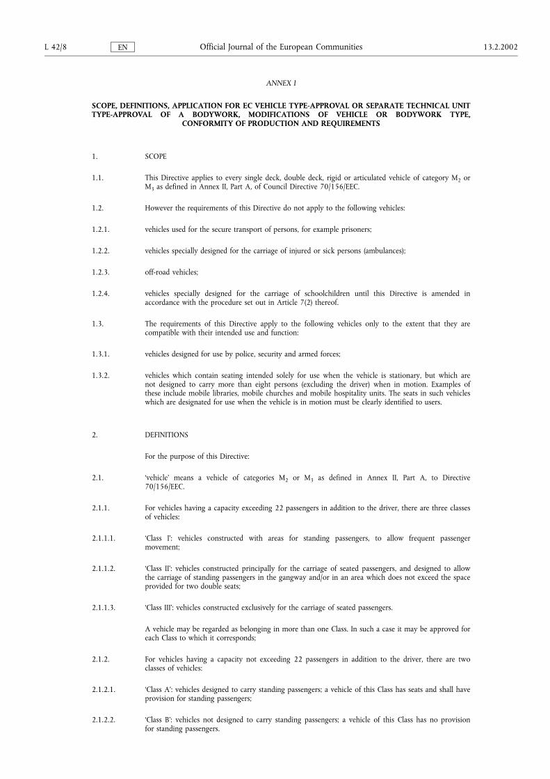
ANNEX I
SCOPE, DEFINITIONS, APPLICATION FOR EC VEHICLE TYPE-APPROVAL OR SEPARATE TECHNICAL UNITTYPE-APPROVAL OF A BODYWORK, MODIFICATIONS OF VEHICLE OR BODYWORK TYPE,
CONFORMITY OF PRODUCTION AND REQUIREMENTS
1. SCOPE
1.1. This Directive applies to every single deck, double deck, rigid or articulated vehicle of category M2 orM3 as defined in Annex II, Part A, of Council Directive 70/156/EEC.
1.2. However the requirements of this Directive do not apply to the following vehicles:
1.2.1. vehicles used for the secure transport of persons, for example prisoners;
1.2.2. vehicles specially designed for the carriage of injured or sick persons (ambulances);
1.2.3. off-road vehicles;
1.2.4. vehicles specially designed for the carriage of schoolchildren until this Directive is amended inaccordance with the procedure set out in Article 7(2) thereof.
1.3. The requirements of this Directive apply to the following vehicles only to the extent that they arecompatible with their intended use and function:
1.3.1. vehicles designed for use by police, security and armed forces;
1.3.2. vehicles which contain seating intended solely for use when the vehicle is stationary, but which arenot designed to carry more than eight persons (excluding the driver) when in motion. Examples ofthese include mobile libraries, mobile churches and mobile hospitality units. The seats in such vehicleswhich are designated for use when the vehicle is in motion must be clearly identified to users.
2. DEFINITIONS
For the purpose of this Directive:
2.1. �vehicle� means a vehicle of categories M2 or M3 as defined in Annex II, Part A, to Directive70/156/EEC.
2.1.1. For vehicles having a capacity exceeding 22 passengers in addition to the driver, there are three classesof vehicles:
2.1.1.1. �Class I�: vehicles constructed with areas for standing passengers, to allow frequent passengermovement;
2.1.1.2. �Class II�: vehicles constructed principally for the carriage of seated passengers, and designed to allowthe carriage of standing passengers in the gangway and/or in an area which does not exceed the spaceprovided for two double seats;
2.1.1.3. �Class III�: vehicles constructed exclusively for the carriage of seated passengers.
A vehicle may be regarded as belonging in more than one Class. In such a case it may be approved foreach Class to which it corresponds;
2.1.2. For vehicles having a capacity not exceeding 22 passengers in addition to the driver, there are twoclasses of vehicles:
2.1.2.1. �Class A�: vehicles designed to carry standing passengers; a vehicle of this Class has seats and shall haveprovision for standing passengers;
2.1.2.2. �Class B�: vehicles not designed to carry standing passengers; a vehicle of this Class has no provisionfor standing passengers.
L 42/8 13.2.2002Official Journal of the European CommunitiesEN
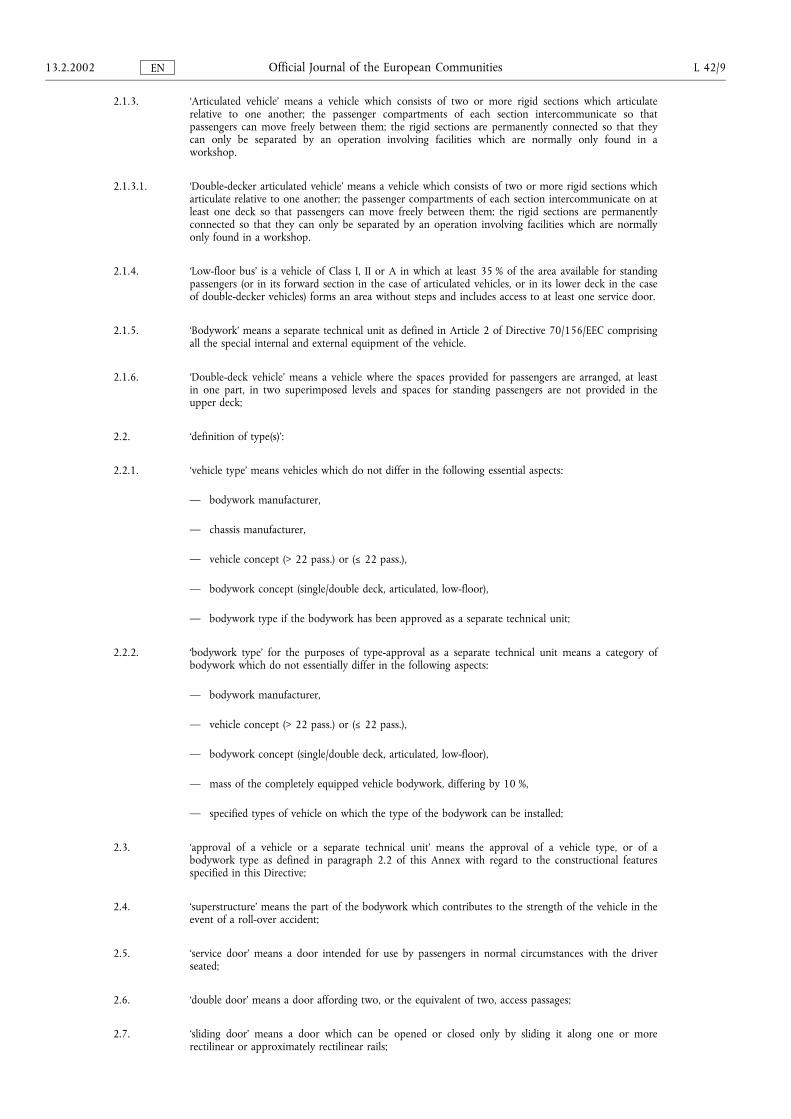
2.1.3. �Articulated vehicle� means a vehicle which consists of two or more rigid sections which articulaterelative to one another; the passenger compartments of each section intercommunicate so thatpassengers can move freely between them; the rigid sections are permanently connected so that theycan only be separated by an operation involving facilities which are normally only found in aworkshop.
2.1.3.1. �Double-decker articulated vehicle� means a vehicle which consists of two or more rigid sections whicharticulate relative to one another; the passenger compartments of each section intercommunicate on atleast one deck so that passengers can move freely between them; the rigid sections are permanentlyconnected so that they can only be separated by an operation involving facilities which are normallyonly found in a workshop.
2.1.4. �Low-floor bus� is a vehicle of Class I, II or A in which at least 35 % of the area available for standingpassengers (or in its forward section in the case of articulated vehicles, or in its lower deck in the caseof double-decker vehicles) forms an area without steps and includes access to at least one service door.
2.1.5. �Bodywork� means a separate technical unit as defined in Article 2 of Directive 70/156/EEC comprisingall the special internal and external equipment of the vehicle.
2.1.6. �Double-deck vehicle� means a vehicle where the spaces provided for passengers are arranged, at leastin one part, in two superimposed levels and spaces for standing passengers are not provided in theupper deck;
2.2. �definition of type(s)�:
2.2.1. �vehicle type� means vehicles which do not differ in the following essential aspects:
� bodywork manufacturer,
� chassis manufacturer,
� vehicle concept (> 22 pass.) or (Ä 22 pass.),
� bodywork concept (single/double deck, articulated, low-floor),
� bodywork type if the bodywork has been approved as a separate technical unit;
2.2.2. �bodywork type� for the purposes of type-approval as a separate technical unit means a category ofbodywork which do not essentially differ in the following aspects:
� bodywork manufacturer,
� vehicle concept (> 22 pass.) or (Ä 22 pass.),
� bodywork concept (single/double deck, articulated, low-floor),
� mass of the completely equipped vehicle bodywork, differing by 10 %,
� specified types of vehicle on which the type of the bodywork can be installed;
2.3. �approval of a vehicle or a separate technical unit� means the approval of a vehicle type, or of abodywork type as defined in paragraph 2.2 of this Annex with regard to the constructional featuresspecified in this Directive;
2.4. �superstructure� means the part of the bodywork which contributes to the strength of the vehicle in theevent of a roll-over accident;
2.5. �service door� means a door intended for use by passengers in normal circumstances with the driverseated;
2.6. �double door� means a door affording two, or the equivalent of two, access passages;
2.7. �sliding door� means a door which can be opened or closed only by sliding it along one or morerectilinear or approximately rectilinear rails;
13.2.2002 L 42/9Official Journal of the European CommunitiesEN
2.8. �emergency door� means a door intended for use by passengers as an exit only exceptionally, and inparticular in an emergency;
2.9. �emergency window� means a window, not necessarily glazed, intended for use as an exit by passengersin an emergency only;
2.10. �double or multiple window� means an emergency window which, when divided into two or moreparts by imaginary vertical line(s) (or plane(s)), exhibits two or more parts respectively, each of whichcomplies as to dimensions and access with the requirements applicable to a normal emergencywindow;
2.11. �escape hatch� means an opening in the roof or the floor intended for use as an emergency exit bypassengers in an emergency only;
2.12. �emergency exit� means an emergency door, emergency window or escape hatch;
2.13. �exit� means a service door, intercommunication staircase, half-staircase or emergency exit;
2.14. �floor or deck� means that part of the body work whose upper surface supports standing passengers,the feet of seated passengers and the driver and any crew member, and may support the seatmountings;
2.15. �gangway� means the space providing access by passengers from any seat or row of seats to any otherseat or row of seats or to any access passage from or to any service door or intercommunicationstaircase and any area for standing passengers; it does not include:
2.15.1. the space extending 300 mm in front of any seat; except where a sideways-facing seat is situatedabove a wheel-arch, in which case this dimension may be reduced to 225 mm;
2.15.2. the space above the surface of any step or staircase; or
2.15.3. any space which affords access solely to one seat or row of seats or a facing pair of transverse seats orrow of seats;
2.16. �access passage� means the space extending inwards into the vehicle from the service door up to theoutermost edge of the upper step (edge of the gangway), intercommunication staircase orhalf-staircase. Where there is no step at the door, the space to be considered as access passage shall bethat which is measured according to paragraph 7.7.1 up to a distance of 300 mm from the startingposition of the inner face of the dual panel;
2.17. �driver's compartment� means the space intended for the driver's exclusive use except in the case of anemergency and containing the driver's seat, the steering wheel, controls, instruments and other devicesnecessary for driving or operating the vehicle;
2.18. �mass of the vehicle in running order� means the mass defined in section 2.5 of Annex I to Directive97/27/EC;
2.19. �technically permissible maximum laden mass � (M)� means the mass defined in section 2.6 of AnnexI to Directive 97/27/EC;
2.20. �passenger� means a person other than the driver or a member of the crew;
2.21. �passenger with reduced mobility� means all people who have difficulty when using public transport,such as disabled people (including people with sensory and intellectual impairments, and wheelchairusers), people with limb impairments, people of small stature, people with heavy luggage, elderlypeople, pregnant women, people with shopping trolleys, and people with children (including childrenseated in pushchairs);
2.22. �wheelchair user� means a person who due to infirmity or disability uses a wheelchair for mobility;
2.23. �member of the crew� means a person assigned to operate as a co-driver or the possible assistant;
L 42/10 13.2.2002Official Journal of the European CommunitiesEN
2.24. �passenger compartment� means a space intended for passengers' use excluding any space occupied byfixed appliances such as bars, kitchenettes, toilets or baggage/goods compartments;
2.25. �power-operated service door� means a service door which is operated exclusively by energy other thanmuscular energy and the opening and closing of which, if not automatically operated, is remotelycontrolled by the driver or a member of the crew;
2.26. �automatically operated service-door� means a power-operated service door which can be opened (otherthan by means of emergency controls) only after a control is operated by a passenger and afteractivation of the controls by the driver, and which closes again automatically;
2.27. �starting prevention device� means an automatic device which prevents the vehicle being driven awayfrom rest;
2.28. �driver-operated service door� means a service door which normally is opened and closed by the driver;
2.29. �priority seat� means a seat with additional space for a passenger with reduced mobility and markedaccordingly;
2.30. �boarding device� means a device to facilitate wheelchair access to vehicles, such as lifts, ramps, etc.;
2.31. �kneeling system� means a system which lowers and lifts totally or partially the body of a vehiclerelative to the normal position of travel;
2.32. �lift� means a device or system with a platform that can be raised and lowered to provide passengeraccess between the floor of a passenger compartment and the ground or kerb;
2.33. �ramp� means a device to bridge the gap between the floor of a passenger compartment and theground or kerb;
2.34. �portable ramp� means a ramp that may be detached from the vehicle structure and capable of beingdeployed by a driver or crew member;
2.35. �demountable seat� means a seat that can be easily detached from the vehicle;
2.36. �front� and �rear� mean the front or rear of the vehicle according to the normal direction of travel andthe terms; �forward�, �foremost�, �rearward� and �rearmost�, etc. shall be construed accordingly;
2.37. �intercommunication staircase� means a staircase which allows communication between the upper andlower decks;
2.38. �separate compartment� means a space in the vehicle which may be occupied by passengers or crewwhen the vehicle is in use, and which is separated from any other passenger or crew space, exceptwhere any partition allows passengers to see into the next passenger space, and connected by agangway without doors;
2.39. �half-staircase� is a staircase from the upper deck which terminates in an emergency door.
3. APPLICATION FOR EC TYPE-APPROVAL OF A VEHICLE OR OF A BODYWORK AS A SEPARATETECHNICAL UNIT
3.1. The application for EC type-approval of a vehicle or for EC separate technical unit type-approval orfor EC type-approval of a vehicle fitted with bodywork already approved as a separate technical unitpursuant to Article 3(4) of Directive 70/156/EEC of a vehicle type or of a bodywork type or of avehicle type fitted with bodywork already approved as a separate technical unit with regard to itsspecial provisions for vehicles used for the carriage of passengers comprising more than eight seats inaddition to the driver's seat shall be submitted by their respective manufacturer.
13.2.2002 L 42/11Official Journal of the European CommunitiesEN
3.2. In the case of an application for EC type-approval of a vehicle made by assembling a chassis withtype-approved bodywork, the term manufacturer refers to the assembler.
3.3. A model for the information document is given in Annex II, Appendix 1:
Subappendix 1: for a vehicle type,
Subappendix 2: for bodywork type, and
Subappendix 3: for a vehicle type fitted with bodywork already approved as a separate technicalunit
3.4. A vehicle or body representative of the type to be approved fitted with the special equipment shall besubmitted to the technical service responsible for the type-approval tests.
4. GRANTING OF EC VEHICLE TYPE-APPROVAL
4.1. If the relevant requirements are satisfied, EC type-approval pursuant to Article 4(3) of Directive70/156/EEC shall be granted.
4.2. A model for the EC type-approval certificate is given in Annex II, Appendix 2:
Subappendix 1: for a vehicle type,
Subappendix 2: for a body type,
Subappendix 3: for a vehicle type fitted with a body already approved as a separate technical unit,
4.3. An approval number in accordance with Annex VII to Directive 70/156/EEC shall be assigned to eachtype of vehicle or type of bodywork approved. The same Member State shall not assign the samenumber to another type of vehicle or type of bodywork.
4.4. Markings
4.4.1. In the case of a bodywork approved as a separate technical unit, the bodywork shall bear:
4.4.1.1. the trademark or trade name of the manufacturer of the bodywork;
4.4.1.2. the manufacturer's trade description;
4.4.1.3. the EC type-approval number specified in paragraph 4.3.
4.4.2. These marks must be clearly legible and indelible, even when the bodywork is fitted on a vehicle.
5. MODIFICATION OF THE TYPES AND AMENDMENTS TO APPROVAL
5.1. In the case of modifications of the vehicle type or of a type of bodywork in particular approvedpursuant to this Directive, the provisions of Article 5 of Directive 70/156/EEC shall apply.
6. CONFORMITY OF PRODUCTION
Measures to ensure the conformity of production shall be taken in accordance with the provisions laid down in Article10 of Directive 70/156/EEC.
7. REQUIREMENTS
7.1. General
7.1.1. Unless otherwise stated, all measurements shall be made when the vehicle is at its mass in runningorder and it is standing on a smooth and horizontal ground surface and in the normal condition fortravel. If a kneeling system is fitted, it shall be set so the vehicle is at its normal ride height for travel.In the case of the approval of bodywork as a separate technical unit the position of the body relativeto the flat horizontal surface shall be specified by the manufacturer.
L 42/12 13.2.2002Official Journal of the European CommunitiesEN
7.1.2. Wherever there is a requirement in this Directive for a surface in the vehicle to be horizontal or at aspecific angle when the vehicle is at its mass in running order, in the case of a vehicle withmechanical suspension, the surface may exceed this slope or possess a slope when the vehicle is at itsmass in running order, provided that this requirement is met when the vehicle is in the loadingcondition declared by the manufacturer. If a kneeling system is fitted to the vehicle it shall not be inoperation.
7.2. Area available for passengers
7.2.1. The total surface area S0 available for passengers is calculated by deducting from the total area of thefloor of the vehicle:
7.2.1.1. the area of the driver's compartment;
7.2.1.2. the area of steps at doors and the area of any other step with a depth of less than 300 mm, and thearea swept by the door and its mechanism when it is operated;
7.2.1.3. the area of any part over which the vertical clearance is less than 1 350 mm measured from the floordisregarding permitted intrusion specified in paragraph 7.7.8.6.3 and 7.7.8.6.4. In the case of vehiclesof Class A or B, this dimension may be reduced to 1 200 mm;
7.2.1.4. the area of any part of the vehicle to which access by passengers is prevented as defined in paragraph7.9.4;
7.2.1.5. the area of any space reserved solely for the carriage of goods or baggage and from which passengersare excluded;
7.2.1.6. the area required to provide a clear working area at serveries;
7.2.1.7. the floor area occupied by any staircase, half-staircase, intercommunication staircase or the surface ofany step.
7.2.2. The surface area S1 available for standing passengers is calculated by deducting from S0:
7.2.2.1. the area of all parts of the floor in which the slope exceeds the maximum permissible values asdetermined in paragraph 7.7.6;
7.2.2.2. the area of all parts which are not accessible to a standing passenger when all the seats are occupied;with the exception of folding seats;
7.2.2.3. the area of all parts where the clear height above the floor is less than the gangway height specified inparagraph 7.7.5.1 (handholds shall not be taken into account in this connection);
7.2.2.4. the area forward of a transverse vertical plane passing through the centre of the seating surface of thedriver's seat (in its rearmost position);
7.2.2.5. the area 300 mm in front of all seats other than folding seats, except where a sideways-facing seat issituated above the wheel arch, in which case this dimension may be reduced to 225 mm. In the caseof variable seating arrangements, of any seat when considered to be in use, see paragraph 7.2.4;
7.2.2.6. any surface not being excluded by the provisions in paragraphs 7.2.2.1 to 7.2.2.5 above, on which itis not possible to place a rectangle of 400 mm × 300 mm;
7.2.2.7. in vehicles of Class II, the area in which standing is not allowed;
7.2.2.8. in double-deck vehicles, any area of the upper deck;
7.2.2.9. the surface of the wheelchair space(s) when considered occupied by a wheelchair user(s), see paragraph7.2.4.
13.2.2002 L 42/13Official Journal of the European CommunitiesEN
7.2.3. There shall be on the vehicle a number (P) of seating places, other than folding seats, which conformto the requirements of 7.7.8. If the vehicle is of Class I, II or A the number of seating places on eachdeck shall be at least equal to the number of square metres of floor on that deck available forpassengers and crew (if any) rounded down to the nearest whole number; this number may, invehicles of Class I, excluding the upper deck, be reduced by 10 %.
7.2.4. In the case of a vehicle equipped with a variable seating capacity the area available for standingpassengers (S1) and the provisions of paragraph 7.3 shall be determined for each of the followingconditions as applicable:
7.2.4.1. with all possible seats occupied followed by the remaining area for standing passengers and, if spaceremains, any wheelchair spaces occupied;
7.2.4.2. with all possible standing areas occupied followed by the remaining seats available for seatedpassengers and, if space remains, any wheelchair spaces occupied;
7.2.4.3. with all possible wheelchair spaces occupied followed by the remaining area for standing passengersand then the remaining seats available for use occupied.
7.3. Marking of vehicles
7.3.1. The vehicle shall be clearly marked in a manner visible on the inside in the vicinity of the front doorin letters or pictograms not less than 15 mm high and numbers not less than 25 mm high, with:
7.3.1.1. the maximum number of seating places the vehicle is designed to carry;
7.3.1.2. the maximum number of standing places, if any, the vehicle is designed to carry;
7.3.1.3. the maximum number of wheelchairs which the vehicle is designed to carry, if any.
7.3.2. If a vehicle is designed to have a variable number of seating places, area available for standingpassengers or number of wheelchairs carried, the requirements of 7.3.1 shall apply to each maximumseating capacity and the corresponding number of wheelchairs and standing passengers as appropriate.
7.3.3. Space shall be provided in the driver's area, in a position clearly visible to the driver, in letters orpictograms not less than 10 mm high and numbers not less than 12 mm high, with:
7.3.3.1. the mass of baggage which may be carried when the vehicle is loaded with the maximum numbers ofpassengers and crew and the vehicle is not exceeding the technically permissible maximum mass, orthe permissible mass of any axle. This shall include the mass of baggage:
7.3.3.1.1. in baggage compartments (mass B, paragraph 7.4.3.3.1 of Annex I to Directive 97/27/EC);
7.3.3.1.2. on the roof if equipped for the carriage of baggage (mass BX, paragraph 7.4.3.3.1 of Annex I toDirective 97/27/EC).
7.4. Stability test
7.4.1. The stability of a vehicle shall be such that the point at which overturning occurs would not be passedif the surface on which the vehicle stands were tilted to both sides in turn to an angle of 28 degreesfrom the horizontal.
7.4.2. For the purposes of the above test, the vehicle shall be at its mass in running order as described inparagraph 2.18, with the addition of:
L 42/14 13.2.2002Official Journal of the European CommunitiesEN
7.4.2.1. loads equal to Q (as defined in paragraph 7.4.3.3.1, Annex 1 to 97/27/EC) shall be placed on eachpassenger seat. If the vehicle is intended for standees or with a crew member who is not seated, thecentre of gravity of the loads Q or 75 kg representing them, shall be uniformly distributed over thestandee or crew area respectively, at a height of 875 mm. Where a vehicle is equipped to carryluggage on the roof, a uniformly distributed mass (BX) of not less than that declared by themanufacturer in accordance with paragraph 7.4.3.3.1 of Annex I to 97/27/EC representing suchbaggage shall be secured to the roof. The other baggage compartments shall not contain any baggage.
7.4.2.2. if the vehicle has a variable seating capacity, standing capacity or is designed to carry one or morewheelchairs, in respect of any area of the passenger compartment in which such variations occur, theloads in paragraph 7.4.2.1 shall be the greater of:
the mass represented by the number of seated passengers that may occupy the area including themass of any demountable seats; or
the mass represented by the number of standing passengers that may occupy the area; or
the mass of wheelchairs and users that may occupy the area at a total mass of 250 kg each placedat a height of 500 mm above the floor in the centre of each wheelchair space; or
the mass of seated passengers, standing passengers and wheelchairs users and any combination ofthese that may occupy the area.
7.4.3. The height of any step used to prevent a wheel of the vehicle from slipping sideways on a tilt test rigshall not be greater than two-thirds of the distance between the surface upon which the vehicle standsbefore it is tilted and that part of the rim of that wheel which is nearest to the surface when thevehicle is loaded in accordance with paragraph 7.4.2.
7.4.4. During the test, no parts of the vehicle which are not intended to come into contact in normal useshall do so, nor shall any part become damaged or displaced.
7.4.5. Alternatively, a calculation method can be used to show that the vehicle will not overturn under theconditions described in paragraphs 7.4.1 and 7.4.2. Such a calculation shall take into account thefollowing parameters:
7.4.5.1. masses and dimensions;
7.4.5.2. height of centre of gravity;
7.4.5.3. spring rates;
7.4.5.4. vertical and horizontal tyre rates;
7.4.5.5. characteristics of the control of air pressure in the air springs;
7.4.5.6. position of the centre of moments;
7.4.5.7. torsion resistance of the body.
The method of calculation is described in Appendix 1 to this Annex.
7.5. Protection against fire risks
7.5.1. E n g i n e c o m p a r t m e n t
7.5.1.1. No flammable sound-proofing material or material liable to become impregnated with fuel, lubricantor other combustible material shall be used in the engine compartment unless the material is coveredby an impermeable sheet.
13.2.2002 L 42/15Official Journal of the European CommunitiesEN
7.5.1.2. Precautions shall be taken, either by a suitable layout of the engine compartment or by the provisionof drainage orifices, to avoid, so far as possible, the accumulation of fuel, lubricating oil or any othercombustible material in any part of the engine compartment.
7.5.1.3. A partition of heat-resisting material shall be fitted between the engine compartment or any othersource of heat (such as a device designed to absorb the energy liberated when a vehicle is descending along gradient, e.g. a retarder, or a device for heating the interior of the body other, however, than adevice functioning by warm water circulation) and the rest of the vehicle. All fixings clips, gaskets, etc.used in conjunction with the partition shall be fire resistant.
7.5.1.4. A heating device operating other than by hot water may be provided in the passenger compartment ifit is encased in material designed to resist the temperatures generated by the device, emits no toxicfumes and is positioned such that no passenger is likely to come into contact with any hot surface.
7.5.2. E l e c t r i c a l e q u i p m e n t a n d w i r i n g
7.5.2.1. All cables shall be well insulated and all cables and electrical equipment shall be able to withstand thetemperature and humidity conditions to which they are exposed. In the engine compartment,particular attention shall be paid to their suitability to withstand the environmental temperature andthe effects of all likely contaminants.
7.5.2.2. No cable used in an electrical circuit shall carry a current in excess of that acceptable for such a cablein the light of its mode of installation and the maximum ambient temperature.
7.5.2.3. Every electrical circuit feeding an item of equipment other than the starter, the ignition circuit(positive ignition), the glow-plugs, the engine-stopping device, the charging circuit and the batteryearth connection shall include a fuse or a circuit breaker. They may, however, be protected by acommon fuse or a common circuit-breaker, provided that its rated capacity does not exceed 16 A.
7.5.2.4. All cables shall be well protected and shall be held securely in position in such a way that they cannotbe damaged by cutting, abrasion or chafing.
7.5.2.5. Where the voltage exceeds 100 V RMS (root-mean-square) in one or more electrical circuits in avehicle, a manually-operated isolating switch which is capable of disconnecting all such circuits fromthe main electrical supply shall be connected in each pole of that supply which is not electricallyconnected to earth, and shall be located inside the vehicle in a position readily accessible to the driver,provided that no such isolating switch shall be capable of disconnecting any electrical circuit supplyingthe mandatory external vehicle lights. This paragraph does not apply to high tension ignition circuitsor to self-contained circuits within a unit of equipment on the vehicle.
7.5.2.6. All electrical cables shall be so located that no part can make contact with any fuel line or any part ofthe exhaust system, or be subjected to excessive heat, unless suitable special insulation and protectionis provided, as for example to a solenoid operated exhaust valve.
7.5.3. B a t t e r i e s
7.5.3.1. All batteries shall be well secured and easily accessible.
7.5.3.2. The battery compartment shall be separated from the passenger compartment and driver'scompartment and ventilated to outside air.
7.5.3.3. The battery terminals shall be protected against the risk of short circuit.
7.5.4. F i r e e x t i n g u i s h e r s a n d f i r s t - a i d e q u i p m e n t
7.5.4.1. Space shall be provided for the fitting of one or more fire extinguishers, one being near the driver'sseat. In vehicles of Class A or B the space shall be not less than 8 dm3 and in Class I, II or III not lessthan 15 dm3.
L 42/16 13.2.2002Official Journal of the European CommunitiesEN
7.5.4.2. Space shall be provided for the fitting of one or more first-aid kits. The space provided shall be notless than 7 dm3, the minimum dimension shall not be less than 80 mm.
7.5.4.3. Fire extinguishers and first-aid kits may be secured against theft or vandalism (e.g. in an internal lockeror behind breakable glass), provided that the locations of these items are clearly marked and means areprovided for persons to extract them easily in an emergency.
7.5.5. M a t e r i a l s
No flammable material shall be permitted within 100 mm of the exhaust system or any othersignificant source of heat unless the material is effectively shielded. Where necessary, shielding shall beprovided to prevent grease or other flammable materials coming into contact with the exhaust systemor other significant heat sources. For the purposes of this paragraph, a flammable material isconsidered to be one which is not designed to withstand the temperatures likely to be encountered inthat location.
7.6. Exits
7.6.1. N u m b e r o f e x i t s
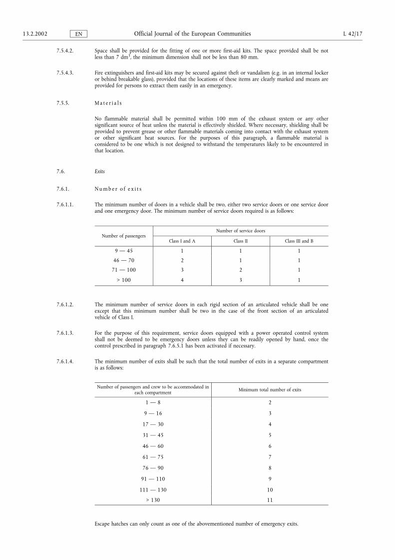
7.6.1.1. The minimum number of doors in a vehicle shall be two, either two service doors or one service doorand one emergency door. The minimum number of service doors required is as follows:
Number of passengersNumber of service doors
Class I and A Class II Class III and B
9 � 45 1 1 1
46 � 70 2 1 1
71 � 100 3 2 1
> 100 4 3 1
7.6.1.2. The minimum number of service doors in each rigid section of an articulated vehicle shall be oneexcept that this minimum number shall be two in the case of the front section of an articulatedvehicle of Class I.
7.6.1.3. For the purpose of this requirement, service doors equipped with a power operated control systemshall not be deemed to be emergency doors unless they can be readily opened by hand, once thecontrol prescribed in paragraph 7.6.5.1 has been activated if necessary.
7.6.1.4. The minimum number of exits shall be such that the total number of exits in a separate compartmentis as follows:
Number of passengers and crew to be accommodated ineach compartment Minimum total number of exits
1 � 8 2
9 � 16 3
17 � 30 4
31 � 45 5
46 � 60 6
61 � 75 7
76 � 90 8
91 � 110 9
111 � 130 10
> 130 11
Escape hatches can only count as one of the abovementioned number of emergency exits.
13.2.2002 L 42/17Official Journal of the European CommunitiesEN
7.6.1.5. Each rigid section of an articulated vehicle shall be treated as a separate vehicle for the purpose ofdetermining the minimum number and the position of exits, except for 7.6.2.4. Toilet compartmentsor galleys are not considered to be separate compartments for the purposes of defining the number ofemergency exits. A number of passengers shall be determined for each rigid section.
7.6.1.6. A double service door shall count as two doors and a double or multiple window as two emergencywindows.
7.6.1.7. If the driver's compartment does not provide access to the passenger compartment by means of apassageway complying with one of the conditions described in paragraph 7.7.5.1.1, the followingconditions shall be met:
7.6.1.7.1. the driver's compartment shall have two exits, which shall not both be in the same lateral wall; whenone of the exits is a window, it shall comply with the requirements set out in paragraphs 7.6.3.1 and7.6.8 for emergency windows;
7.6.1.7.2. one or two seats are permitted alongside the driver for additional people, in which case both the exitsreferred to in paragraph 7.6.1.7.1 shall be doors. The driver's door shall be accepted as the emergencydoor for the occupants of those seats, provided that the driver's seat, the steering wheel, the enginehousing, the gear lever, the hand brake control, etc. do not constitute too great an obstruction. Thedoor provided for those additional people shall be accepted as the emergency door for the driver. Upto five additional seats may be fitted in a compartment incorporating the driver's compartment,provided that the additional seats and the space for these seats comply with all requirements of thisDirective and at least one door giving access to the passenger compartment complies with therequirements of paragraph 7.6.3 for emergency doors;
7.6.1.7.3. in the circumstances described in paragraphs 7.6.1.7.1 and 7.6.1.7.2, the exits provided for the driver'scompartment shall not count as one of the doors required by paragraphs 7.6.1.1 to 7.6.1.2, nor asone of the exits required by paragraph 7.6.1.4, except in the case mentioned in paragraphs 7.6.1.7.1and 7.6.1.7.2. Paragraphs from 7.6.3 to 7.6.7, 7.7.1, 7.7.2 and 7.7.7 shall not apply to such exits.
7.6.1.8. If the driver's compartment and seats adjacent to it are accessible from the main passengercompartment by means of a passageway complying with one of the conditions described in paragraph7.7.5.1.1, no external exit is required from the driver's compartment.
7.6.1.9. If a driver's door or other exit from the compartment is provided in the circumstances described inparagraph 7.6.1.8, it may only count as an exit for passengers provided:
7.6.1.9.1. it is not necessary to squeeze between the steering wheel and the driver's seat, in order to make use ofthat exit;
7.6.1.9.2. it satisfies the requirements relating to the dimensions of emergency doors indicated in paragraph7.6.3.1.
7.6.1.10. Paragraphs 7.6.1.8. and 7.6.1.9 do not preclude there being a door or other barrier between thedriver's seat and the passenger compartment, provided that this barrier can be released quickly by thedriver in an emergency. A driver's door in a compartment protected by such a barrier shall not becounted as an exit for passengers.
7.6.1.11. Escape hatches, additional to the emergency doors and windows, shall be fitted in vehicles of Class II,III and B. They may also be fitted in the case of Class I and A vehicles. The minimum number ofhatches shall be:
Number of passengers Number of hatches
not exceeding 50 1
exceeding 50 2
7.6.2. S i t i n g o f e x i t s
Vehicles having a capacity exceeding 22 passengers shall meet the requirements shown below. Vehicleshaving a capacity not exceeding 22 passengers may meet either the requirements shown below orthose contained in Annex VI, paragraph 1.2.
L 42/18 13.2.2002Official Journal of the European CommunitiesEN
7.6.2.1. The service door(s) shall be situated on the side of the vehicle that is nearer to the side of the roadcorresponding to the direction of traffic in the country in which the vehicle is to be licensed foroperation and at least one of them shall be in the forward half of the vehicle. This does not precludethe provision of a door in the rear face of a vehicle for use by wheelchair passengers.
7.6.2.2. Two of the doors referred to in paragraph 7.6.1.1 shall be separated such that the distance betweentransverse vertical planes through their centres of area is not less than 40 % of the overall length ofthe passenger compartment. If one of these two doors forms part of a double door this distance shallbe measured between the two doors which are furthest apart.
7.6.2.3. The exits shall be placed in such a way that their number on each of the two sides of the vehicle issubstantially the same.
7.6.2.4. At least one emergency exit shall be situated either in the rear face or in the front face of the vehiclerespectively. For Class I vehicles and for vehicles with a rear part permanently closed off from thepassenger compartment, this requirement is fulfilled if an escape hatch is fitted.
7.6.2.5. The exits on the same side of the vehicle shall be suitably spaced out along the length of the vehicle.
7.6.2.6. A door shall, provided that it is not a service door, be permitted in the rear face of the vehicle.
7.6.2.7. If escape hatches are fitted they shall be positioned as follows: if there is only one hatch, it shall besituated in the middle third of the vehicle; if there are two hatches, they shall be separated by adistance of at least 2 m measured between the nearest edges of the apertures in a line parallel to thelongitudinal axis of the vehicle.
7.6.3. M i n i m u m d i m e n s i o n s o f e x i t s
7.6.3.1. The several kinds of exit shall have the following minimum dimensions:
Class I Class IIand III Remarks
Service door Dooraperture
Height(mm)
1 800 1 650 �
Width (mm) Single door:
Double door:
650
1 200
This dimension may be reducedby 100 mm when themeasurement is made at thelevel of the handholds
Emergencydoor
Height(mm)
1 250 �
Width (mm) 550
Emergencywindow
Area (mm2) 400 000 It shall be possible to inscribe inthis area a rectangle of 500 mm× 700 mm
Emergency window situated in the rearface of the vehicle. If the manufacturerdoes not provide an emergency windowof the minimum dimensions prescribedabove
It shall be possible to inscribe in the emergency windowaperture a rectangle 350 mm high and 1 550 mm wide.The corners of the rectangle may be rounded to a radius ofcurvature not exceeding 250 mm.
Escape hatch Hatchaperture
Area (mm2) 400 000 It shall be possible to inscribe inthis area a rectangle measuring500 mm × 700 mm
7.6.3.2. Vehicles having a capacity not exceeding 22 passengers may meet either the requirements shown inparagraph 7.6.3.1 or those contained in Annex VI, paragraph 1.1.
13.2.2002 L 42/19Official Journal of the European CommunitiesEN
7.6.4. T e c h n i c a l r e q u i r e m e n t s f o r a l l s e r v i c e d o o r s
7.6.4.1. Every service door shall be capable of being easily opened from inside and from outside the vehiclewhen the vehicle is stationary (but not necessarily when the vehicle is moving). However, thisrequirement shall not be construed as precluding the possibility of locking the door from outside,provided that the door can always be opened from the inside.
7.6.4.2. Every control or device for opening a door from the outside shall be between 1 000 and 1 500 mmfrom the ground and not more than 500 mm from the door. In vehicles of Classes I, II and III everycontrol or device for opening a door from the inside shall be between 1 000 and 1 500 mm from theupper surface of the floor or step nearest to the control and not more than 500 mm from the door.This shall not apply to controls located within the driver's area.
7.6.4.3. Every one-piece manually-operated service door which is hinged or pivoted shall be so hinged orpivoted that if the open door comes into contact with a stationary object while the vehicle is movingforwards it tends to close.
7.6.4.4. If a manually-operated service door is fitted with a slam lock it shall be of the two-stage type.
7.6.4.5. On the inside of a service door there shall not be any device intended to cover the inside steps whenthe door is closed. This does not exclude the presence in the step well, when the door is closed, of thedoor-operating mechanism and other equipment attached to the inside of the door which does notform an extension of the floor on which passengers may stand. This mechanism and equipmentshould not be dangerous for the passengers.
7.6.4.6. If the direct view is not adequate, optical or other devices shall be installed to enable the driver todetect from his seat the presence of a passenger in the immediate interior and exterior vicinity ofevery side service door which is not an automatically operated service door. In the case of a servicedoor in the rear face of the vehicle not exceeding 22 passengers, this requirement is satisfied if thedriver is able to detect the presence of a person 1,3 m tall standing 1 m behind the vehicle.
7.6.4.7. Every door which opens towards the interior of the vehicle and its mechanism shall be so constructedthat its movement is not likely to cause injury to passengers in normal conditions of use. Wherenecessary, appropriate protection devices shall be fitted.
7.6.4.8. If a service door is located adjacent to a door to a toilet or other internal compartment the servicedoor shall be proofed against unintentional operation. However, this requirement shall not apply if thedoor is locked automatically when the vehicle is moving at a speed exceeding 5 km/h.
7.6.4.9. In the case of vehicles having a capacity not exceeding 22 passengers, the service doors of which arein the rear face of the vehicle, the leaves shall not be capable of being opened more than 115 ° norless than 85 ° and, when open, shall be capable of being held automatically in that position. This doesnot preclude the ability to override that stop and open the door beyond that angle when it is safe todo so; for example, to enable reversing against a high platform for loading or to open the doorsthrough 270 ° to allow a clear loading area behind the vehicle.
7.6.5. A d d i t i o n a l t e c h n i c a l r e q u i r e m e n t s f o r p o w e r - o p e r a t e d s e r v i c e d o o r s
7.6.5.1. In the event of an emergency, every power-operated service door shall be capable, when the vehicle isstationary (but not necessarily when the vehicle is moving), of being opened from inside and, whennot locked, from outside by controls which, whether or not the power supply is operating:
7.6.5.1.1. override all other door controls;
7.6.5.1.2. in the case of interior controls, are placed on, or within 300 mm of, the door, at a height of not less1 600 mm above the first step;
7.6.5.1.3. can be easily seen and clearly identified, when approaching the door and when standing in front of thedoor and if additional to the normal opening controls, be clearly marked for emergency use.
7.6.5.1.4. can be operated by one person when standing immediately in front of the door;
L 42/20 13.2.2002Official Journal of the European CommunitiesEN
7.6.5.1.5. cause the door to open, or enable the door to be easily opened by hand;
7.6.5.1.6. may be protected by a device which can be easily removed or broken to gain access to the emergencycontrol; the operation of the emergency control, or the removal of a protective cover over the control,shall be indicated to the driver both audibly and visually, and
7.6.5.1.7. in the case of a driver-operated door which does not comply with the requirements of paragraph7.6.5.6.2, it shall be such that after the controls have been operated to open the door and returned totheir normal position, the door will not close again until the driver subsequently operates a closingcontrol.
7.6.5.2. A device may be provided which is operated by the driver from the driving seat to deactivate theoutside emergency controls in order to lock the service doors from outside. In this case, the outsideemergency controls shall be reactivated automatically either by the starting of the engine or before thevehicle reaches a speed of 20 km/h. Subsequently, deactivation of the outside emergency controls shallnot occur automatically, but shall require a further action by the driver.
7.6.5.3. Every driver-operated service door shall be capable of operation by the driver when in the driving seatusing controls which, except in the case of a foot control, are clearly and distinctively marked.
7.6.5.4. Every power-operated service door shall activate a visual tell-tale, which shall be plainly visible to thedriver when seated in the normal driving position in any ambient lighting condition, to warn that adoor is not fully closed. This tell-tale shall signal whenever the rigid structure of the door is betweenthe fully open position and a point 30 mm from the fully closed position. One tell-tale may serve forone or more doors. However, no such tell-tale shall be fitted in respect of a front service door whichdoes not comply with the requirements of 7.6.5.6.1.1 and 7.6.5.6.1.2.
7.6.5.5. Where controls are provided for the driver to open and close a power operated service door, they shallbe such that the driver is able to reverse the movement of the door at any time during the closing oropening process.
7.6.5.6. The construction and control system of every power-operated service door shall be such that apassenger is unlikely to be injured by the door or trapped in the door as it closes.
7.6.5.6.1. This requirement shall be considered satisfied if the following two requirements are met.
7.6.5.6.1.1. The first requirement is that when the closing of the door at any measuring point described in AnnexV is resisted by a clamping force not exceeding 150 N, the door shall reopen automatically to itsfullest extent and, except in the case of an automatically-operated service door, remain open until aclosing control is operated. The clamping force may be measured by any method to the satisfaction ofthe competent authority. Guidelines are given in Annex V to this Directive. The peak force may behigher than 150 N for a short time provided that it does not exceed 300 N. The reopening systemmay be checked by means of a test bar having a section of height 60 mm, width 30 mm with cornersradiused to 5 mm.
7.6.5.6.1.2. The second requirement is that whenever the doors are closed onto the wrist or fingers of a passenger:
7.6.5.6.1.2.1. the door reopens automatically to its fullest extent and, except in the case of an automatically operatedservice door, remains open until a closing control is operated, or
7.6.5.6.1.2.2. the wrist or fingers can be readily extracted from the doors without risk of injury to the passenger.This requirement may be checked by hand, or by means of the test bar mentioned in paragraph7.6.5.6.1.1, tapered at one end over a length of 300 mm from a thickness of 30 mm to a thickness of5 mm. It shall not be treated with polish nor lubricated. If the door traps the bar it shall be capable ofbeing easily removed, or
7.6.5.6.1.2.3. the door is maintained at a position allowing the free passage of a test bar having a section of height60 mm, width 20 mm, with corners radiused to 5 mm. This position shall not be more than 30 mmdistant from the fully closed position.
13.2.2002 L 42/21Official Journal of the European CommunitiesEN
7.6.5.6.2. In the case of a front service door the requirement of paragraph 7.6.5.6 shall be considered satisfied ifthe door:
7.6.5.6.2.1. fulfils the requirements of paragraphs 7.6.5.6.1.1 and 7.6.5.6.1.2, or
7.6.5.6.2.2. is fitted with soft edges; these shall not, however be so soft that if the doors are closed on the test barmentioned in paragraph 7.6.5.6.1.1 the rigid structure of the doors will reach the fully closed position.
7.6.5.7. Where a power-operated service door is held closed only by continued application of the powersupply there shall be provided a visual warning device to inform the driver of any failure in the powersupply to the doors.
7.6.5.8. A starting prevention device, if fitted, shall be effective only at speeds of less than 5 km/h and shall beincapable of operation above that speed.
7.6.5.9. If the vehicle is not fitted with a starting prevention device, an audible warning to the driver shall beactivated if the vehicle is driven away from rest when any power-operated service door is not fullyclosed. This audible warning shall be activated at a speed exceeding 5 km/h for doors complying withthe requirements of paragraph 7.6.5.6.1.2.3.
7.6.6. A d d i t i o n a l t e c h n i c a l r e q u i r e m e n t s f o r a u t o m a t i c a l l y o p e r a t e d s e r v i c e d o o r s
7.6.6.1. Activation of the opening controls
7.6.6.1.1. Except as provided in paragraph 7.6.5.1, the opening controls of every automatically operated servicedoor shall be capable of being activated and deactivated only by the driver from his seat.
7.6.6.1.2. Activation and deactivation may be either direct, by means of a switch, or indirect, for example byopening and closing the front service door.
7.6.6.1.3. Activation of the opening controls by the driver shall be indicated inside and, where a door is to beopened from outside, also on the outside of the vehicle; the indicator (e.g. illuminated push-button,illuminated sign) shall be on or adjacent to the door to which it relates.
7.6.6.1.4. In the case of direct actuation by means of a switch, the functional state of the system shall be clearlyindicated to the driver, by, for example, the position of the switch or an indicator lamp or anilluminated switch. The switch shall be specially marked and arranged in such a way that it cannot beconfused with other controls.
7.6.6.2. Opening of automatically operated service doors
7.6.6.2.1. After activation of the opening controls by the driver, it shall be possible for passengers to open thedoor as follows:
7.6.6.2.1.1. from inside, for example by pressing a push-button or passing a light barrier, and
7.6.6.2.1.2. from outside, except in the case of a door intended only as an exit and marked as such, by, forexample, pressing an illuminated push-button, a push-button beneath an illuminated sign, or a similardevice marked with a suitable instruction.
7.6.6.2.2. The pressing of the push-buttons mentioned in paragraph 7.6.6.2.1.1, and the use of the means ofcommunication with the driver mentioned in paragraph 7.7.9.1, may send a signal which is storedand which, after the activation of the opening controls by the driver, effects the opening of the door.
7.6.6.3. Closing of automatically operated service doors
7.6.6.3.1. When an automatically operated service door has opened it shall close again automatically after a timeinterval has elapsed. If a passenger enters or leaves the vehicle during this time interval, a safety device(e.g. a footboard contact, light barrier, one-way gate) shall ensure that the time until the door closes issufficiently extended.
L 42/22 13.2.2002Official Journal of the European CommunitiesEN
7.6.6.3.2. If the passenger enters or leaves the vehicle while the door is closing, the closing process shall beinterrupted automatically and the door shall return to the open position. The reversal may be actuatedby one of the safety devices referred to in paragraph 7.6.6.3.1 or by any other device.
7.6.6.3.3. A door that has closed automatically in accordance with paragraph 7.6.6.3.1 shall be capable of beingopened again by a passenger in accordance with paragraph 7.6.6.2; this shall not apply if the driverhas deactivated the opening controls.
7.6.6.3.4. After deactivation of the opening controls of the automatically operated service doors by the driver,open doors shall close in accordance with paragraphs 7.6.6.3.1 to 7.6.6.3.2.
7.6.6.4. Inhibition of the automatic closing process on doors marked for special service, e.g. for passengerswith prams, passengers with reduced mobility, etc.
7.6.6.4.1. The driver shall be able to inhibit the automatic closing process by actuation of a special control. Apassenger shall also be able to inhibit the automatic closing process directly by pressing a specialpush-button.
7.6.6.4.2. The inhibition of the automatic closing process shall be indicated to the driver, e.g. by a visual tell-tale.
7.6.6.4.3. Re-establishment of the automatic closing process shall in any case be capable of being done by thedriver.
7.6.6.4.4. Paragraph 7.6.6.3 shall apply to the subsequent closing of the door.
7.6.7. T e c h n i c a l r e q u i r e m e n t s f o r e m e r g e n c y d o o r s
7.6.7.1. Emergency doors shall be capable of being easily opened from inside and from outside when thevehicle is stationary. However, this requirement shall not be construed as precluding the possibility oflocking the door from the outside, provided that the door can always be opened from the inside bythe use of the normal opening mechanism.
7.6.7.2. Emergency doors, during their use as such, shall not be of the power-operated type unless, once thecontrol prescribed in paragraph 7.6.5.1 has been actuated and returned to its normal position, thedoors do not close again until the driver subsequently operates a closing control. They shall also notbe of the sliding type except in the case of vehicles having a capacity not exceeding 22 passengers. Forthese vehicles a sliding door, which has been shown to be capable of being opened without the use oftools after a frontal barrier collision test in accordance with Directive 74/297/EEC, can be accepted asan emergency door.
7.6.7.3. Every control or device for opening an emergency door from the outside shall be between 1 000 and1 500 mm from the ground and not more than 500 mm from the door. In vehicles of Classes I, II andIII every control or device for opening a emergency door from the inside shall be between 1 000 and1 500 mm from the upper surface of the floor or step nearest to the control and be not more than500 mm from the door. This shall not apply to controls located within the drivers area.
7.6.7.4. Hinged emergency doors fitted to the side of the vehicle shall be hinged at their forward edge andshall open outwards. Check-straps, chains or other restraining devices shall be permitted, provided thatthey do not prevent the door from opening to, and remaining open at, an angle of at least 100 °. If ameans is provided sufficient to give free passage to the emergency door access gauge, the 100 °minimum angle shall not apply.
7.6.7.5. Emergency doors shall be proofed against unintentional operation. However, this requirement shall notapply if the emergency door is locked automatically when the vehicle is moving at a speed exceeding5 km/h.
7.6.7.6. All emergency doors shall be provided with an audible device to warn the driver when they are notsecurely closed. The warning device shall be operated by movement of the door catch or handle andnot by movement of the door itself.
13.2.2002 L 42/23Official Journal of the European CommunitiesEN
7.6.8. T e c h n i c a l r e q u i r e m e n t s f o r e m e r g e n c y w i n d o w s
7.6.8.1. Every hinged or ejectable emergency window shall open outwards. Ejectable types shall not becometotally detached from the vehicle when operated. The operation of ejectable windows shall be suchthat inadvertent ejection is effectively prevented.
7.6.8.2. Every emergency window shall:
7.6.8.2.1. either be capable of being easily and instantaneously operated from inside and from outside thevehicle by means of a device recognised as satisfactory, or
7.6.8.2.2. be made of readily breakable safety glass. This latter provision precludes the possibility of using panesof laminated glass or of plastic material. A device shall be provided adjacent to each emergencywindow, readily available to persons inside the vehicle, to ensure that each window can be broken.
7.6.8.3. Every emergency window which can be locked from the outside shall be so constructed as to becapable of being opened at all times from inside the vehicle.
7.6.8.4. If the emergency window is of a type horizontally hinged at the top edge, an appropriate device shallbe provided to hold it fully open. Every hinged emergency window shall operate so as not to obstructclear passage from inside or outside the vehicle.
7.6.8.5. The height of the lower edge of an emergency window fitted in the side of the vehicle from thegeneral level of the floor immediately below it (excluding any local variations such as the presence of awheel or transmission housing) shall be not more than 1 200 mm nor less than 650 mm in the caseof a hinged emergency window, or 500 mm in the case of a window made of breakable glass.
However, in the case of a hinged emergency window, the height of the lower edge may be reduced toa minimum of 500 mm provided that the window aperture is equipped with a guard up to a height of650 mm to prevent the possibility of passengers falling out of the vehicle. Where the window apertureis equipped with a guard, the size of the window aperture above the guard shall not be less than theminimum size prescribed for an emergency window.
7.6.8.6. Every hinged emergency window which is not clearly visible from the driver's seat shall be fitted withan audible warning device to warn the driver when it is not completely closed. The window lock, andnot the movement of the window itself, shall actuate this device.
7.6.9. T e c h n i c a l r e q u i r e m e n t s f o r e s c a p e h a t c h e s
7.6.9.1. Every escape hatch shall operate so as not to obstruct the clear passage from inside or outside thevehicle.
7.6.9.2. Roof escape hatches shall be either ejectable, hinged or made of readily breakable safety glass. Floorhatches shall be either hinged or ejectable and shall be fitted with an audible warning device to warnthe driver when it is not securely closed. The floor escape hatch lock, and not the movement of thehatch itself, shall actuate this device. Floor escape hatches shall be proofed against unintentionaloperation. However this requirement shall not apply if the floor hatch is locked automatically whenthe vehicle is moving at a speed exceeding 5 km/h.
7.6.9.3. Ejectable types shall not become totally detached from the vehicle when operated such that the hatchis not a danger to other road users. The operation of ejectable escape hatches shall be such thatinadvertent operation is effectively prevented. Floor ejectable hatches shall eject only into thepassenger compartment.
7.6.9.4. Hinged escape hatches shall hinge along the edge towards the front or rear of the vehicle and shallhinge through an angle of at least 100 °. Hinged floor escape hatches shall hinge into the passengercompartment.
7.6.9.5. Escape hatches shall be capable of being easily opened or removed from the inside and from theoutside. However, this requirement shall not be construed as precluding the possibility of locking theescape hatch for the purpose of securing the vehicle when unattended, provided that the escape hatchcan always be opened or removed from the inside by the use of the normal opening or removalmechanism. In the case of a readily breakable hatch, a device shall be provided adjacent to the hatch,readily available to persons inside the vehicle, to ensure that the hatch can be broken.
L 42/24 13.2.2002Official Journal of the European CommunitiesEN
7.6.10. T e c h n i c a l r e q u i r e m e n t s f o r r e t r a c t a b l e s t e p s
Retractable steps if fitted shall comply with the following requirements:
7.6.10.1. the operation of retractable steps may be synchronised with that of the corresponding service oremergency door;
7.6.10.2. when the door is closed no part of the retractable step shall project more than 10 mm beyond theadjacent line of the bodywork;
7.6.10.3. when the door is open and the retractable step is in the extended position, the surface area shallconform to the requirements of paragraph 7.7.7 of this Annex;
7.6.10.4. in the case of a power-operated step, it shall not be possible for the vehicle to move from rest, underits own power, when the step is in the extended position. In the case of a manually operated step, anaudible indication shall alert the driver when the step is not fully retracted;
7.6.10.5. a power-operated step shall not be capable of being extended when the vehicle is in motion. If thedevice to operate the step fails, the step shall retract and remain in the retracted position. However,the operation of the corresponding door shall not be hindered in the event of such a failure or by thestep being damaged or obstructed;
7.6.10.6. when a passenger is standing on a power-operated retractable step, the corresponding door shall beincapable of being closed. Compliance with this requirement shall be checked by placing a mass of 15kg, representing a small child, at the centre of the step. This requirement shall not apply to any doorwithin the driver's direct field of view;
7.6.10.7. the movement of the retractable step shall not be liable to cause any bodily harm either to passengersor to persons waiting at bus stops;
7.6.10.8. the corners of retractable steps facing forwards or rearwards shall be rounded to a radius of not lessthan 5 mm; the edges shall be rounded to a radius of not less than 2,5 mm;
7.6.10.9. when the passenger door is open, the retractable step shall be securely held in the extended position.When a mass of 136 kg is placed in the centre of a single step or a mass of 272 kg is placed in thecentre of a double step the deflection at any point on the step shall not exceed 10 mm.
7.6.11. M a r k i n g s
7.6.11.1. Each emergency exit shall be marked, inside and outside the vehicle, by an inscription reading, forexample:
�Emergency exit�
�Issue de secours�
�Salida de emergencia�
�Nødudgang�
�Notausstieg�
�¸nodoy jimdýmot�
�Uscita di sicurezza�
�Nooduitgang�
�Saida de emergência�
�Hätäuloskäynti�
�Nödutgång�
supplemented, where appropriate, by one of the symbols shown in Annex II, paragraph 3.4 of CouncilDirective 92/58/EEC.
7.6.11.2. The emergency controls of service doors and of all emergency exits shall be marked as such inside andoutside the vehicle either by a representative symbol or by a clearly-worded inscription.
7.6.11.3. Clear instructions concerning the method of operation shall be placed on or close to every emergencycontrol of an exit.
13.2.2002 L 42/25Official Journal of the European CommunitiesEN
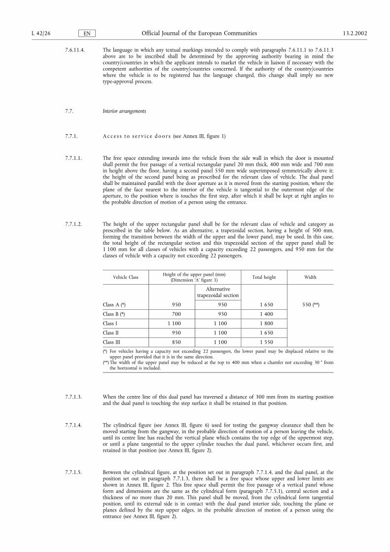
7.6.11.4. The language in which any textual markings intended to comply with paragraphs 7.6.11.1 to 7.6.11.3above are to be inscribed shall be determined by the approving authority bearing in mind thecountry/countries in which the applicant intends to market the vehicle in liaison if necessary with thecompetent authorities of the country/countries concerned. If the authority of the country/countrieswhere the vehicle is to be registered has the language changed, this change shall imply no newtype-approval process.
7.7. Interior arrangements
7.7.1. A c c e s s t o s e r v i c e d o o r s (see Annex III, figure 1)
7.7.1.1. The free space extending inwards into the vehicle from the side wall in which the door is mountedshall permit the free passage of a vertical rectangular panel 20 mm thick, 400 mm wide and 700 mmin height above the floor, having a second panel 550 mm wide superimposed symmetrically above it;the height of the second panel being as prescribed for the relevant class of vehicle. The dual panelshall be maintained parallel with the door aperture as it is moved from the starting position, where theplane of the face nearest to the interior of the vehicle is tangential to the outermost edge of theaperture, to the position where is touches the first step, after which it shall be kept at right angles tothe probable direction of motion of a person using the entrance.
7.7.1.2. The height of the upper rectangular panel shall be for the relevant class of vehicle and category asprescribed in the table below. As an alternative, a trapezoidal section, having a height of 500 mm,forming the transition between the width of the upper and the lower panel, may be used. In this case,the total height of the rectangular section and this trapezoidal section of the upper panel shall be1 100 mm for all classes of vehicles with a capacity exceeding 22 passengers, and 950 mm for theclasses of vehicle with a capacity not exceeding 22 passengers.
Vehicle Class Height of the upper panel (mm)(Dimension �A� figure 1) Total height Width
Alternativetrapezoidal section
Class A (*) 950 950 1 650 550 (**)
Class B (*) 700 950 1 400
Class I 1 100 1 100 1 800
Class II 950 1 100 1 650
Class III 850 1 100 1 550
(*) For vehicles having a capacity not exceeding 22 passengers, the lower panel may be displaced relative to theupper panel provided that it is in the same direction.
(**) The width of the upper panel may be reduced at the top to 400 mm when a chamfer not exceeding 30 ° fromthe horizontal is included.
7.7.1.3. When the centre line of this dual panel has traversed a distance of 300 mm from its starting positionand the dual panel is touching the step surface it shall be retained in that position.
7.7.1.4. The cylindrical figure (see Annex III, figure 6) used for testing the gangway clearance shall then bemoved starting from the gangway, in the probable direction of motion of a person leaving the vehicle,until its centre line has reached the vertical plane which contains the top edge of the uppermost step,or until a plane tangential to the upper cylinder touches the dual panel, whichever occurs first, andretained in that position (see Annex III, figure 2).
7.7.1.5. Between the cylindrical figure, at the position set out in paragraph 7.7.1.4, and the dual panel, at theposition set out in paragraph 7.7.1.3, there shall be a free space whose upper and lower limits areshown in Annex III, figure 2. This free space shall permit the free passage of a vertical panel whoseform and dimensions are the same as the cylindrical form (paragraph 7.7.5.1), central section and athickness of no more than 20 mm. This panel shall be moved, from the cylindrical form tangentialposition, until its external side is in contact with the dual panel interior side, touching the plane orplanes defined by the step upper edges, in the probable direction of motion of a person using theentrance (see Annex III, figure 2).
L 42/26 13.2.2002Official Journal of the European CommunitiesEN
7.7.1.6. The free passage clearance for this figure shall not include any space extending to 300 mm in front ofany uncompressed seat cushion of a forward or rearward facing seat or 225 mm in the case of seatsfitted at wheel arches, and to the height of the top of the seat cushion.
7.7.1.7. In the case of a folding seat, this space shall be determined with the seat in the position of use.
7.7.1.8. However, a folding seat for use by the crew may obstruct the access passage to a service door when inthe position of use provided that:
7.7.1.8.1. it is clearly indicated, both in the vehicle itself and on the EC type-approval certificate (see Annex II,Appendix 2), that the seat is for the use of crew only;
7.7.1.8.2. when the seat is not in use it folds automatically as necessary to enable the requirements ofparagraphs 7.7.1.1 or 7.7.1.2 and 7.7.1.3, 7.7.1.4 and 7.7.1.5 to be met;
7.7.1.8.3. the door is not considered to be a mandatory exit for the purpose of paragraph 7.6.1.4, and
7.7.1.8.4. when the seat is in the position of use, and when it is in the folded position, no part of it shall beforward of a vertical plane passing through the centre of the seating surface of the driver's seat in itsrearmost position and through the centre of the exterior rear-view mirror mounted on the oppositeside of the vehicle.
7.7.1.9. In the case of vehicles having a capacity not exceeding 22 passengers a doorway and the route bywhich passengers gain access to it shall be considered unobstructed if they have:
7.7.1.9.1. measured parallel with the longitudinal axis of the vehicle, there is a clearance of not less than220 mm at any point and 550 mm at any point being more than 500 mm above the floor or steps(Annex III, figure 3);
7.7.1.9.2. measured perpendicular to the longitudinal axis of the vehicle, there is a clearance of not less than300 mm at any point and 550 mm at any point being more than 1 200 mm above the floor or stepsor less than 300 mm below the ceiling (Annex III, figure 4).
7.7.1.10. The service door and emergency door dimensions in paragraph 7.6.3.1 and the requirements ofparagraphs 7.7.1.1 to 7.7.1.7, 7.7.2.1 to 7.7.2.3, 7.7.5.1 and 7.7.8.5 shall not apply to a vehicle ofClass B with a technically permissible maximum mass not exceeding 3,5 tonnes and up to 12passengers seats in which each seat has unobstructed access to at least two doors.
7.7.1.11. The maximum slope of the floor in the access passage shall not exceed 5 % when measured with thevehicle at its mass in running order standing on a horizontal surface. Any kneeling device shall not beengaged.
7.7.2. A c c e s s t o e m e r g e n c y d o o r s (see Annex III, figure 5)
The following requirements shall not apply to driver's doors used as emergency exits in vehicleshaving a capacity not exceeding 22 passengers.
7.7.2.1. The free space between the gangway and the emergency door aperture shall permit the free passage ofa vertical cylinder 300 mm in diameter and 700 mm high from the floor and supporting a secondvertical cylinder 550 mm in diameter, the aggregate height of the assembly being 1 400 mm.
The diameter of the upper cylinder may be reduced at the top to 400 mm when a chamfer notexceeding 30 ° from the horizontal is included.
7.7.2.2. The base of the first cylinder shall be within the projection of the second cylinder.
7.7.2.3. Where folding seats are installed alongside this passage, the free space for the cylinder shall berequired to be determined when the seat is in the position for use.
7.7.2.4. As an alternative to the dual cylinder, the gauging device described in paragraph 7.7.5.1 may be used(see Annex III, figure 6).
13.2.2002 L 42/27Official Journal of the European CommunitiesEN
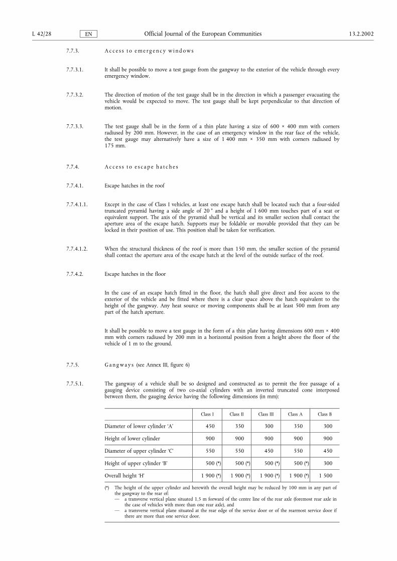
7.7.3. A c c e s s t o e m e r g e n c y w i n d o w s
7.7.3.1. It shall be possible to move a test gauge from the gangway to the exterior of the vehicle through everyemergency window.
7.7.3.2. The direction of motion of the test gauge shall be in the direction in which a passenger evacuating thevehicle would be expected to move. The test gauge shall be kept perpendicular to that direction ofmotion.
7.7.3.3. The test gauge shall be in the form of a thin plate having a size of 600 × 400 mm with cornersradiused by 200 mm. However, in the case of an emergency window in the rear face of the vehicle,the test gauge may alternatively have a size of 1 400 mm × 350 mm with corners radiused by175 mm.
7.7.4. A c c e s s t o e s c a p e h a t c h e s
7.7.4.1. Escape hatches in the roof
7.7.4.1.1. Except in the case of Class I vehicles, at least one escape hatch shall be located such that a four-sidedtruncated pyramid having a side angle of 20 ° and a height of 1 600 mm touches part of a seat orequivalent support. The axis of the pyramid shall be vertical and its smaller section shall contact theaperture area of the escape hatch. Supports may be foldable or movable provided that they can belocked in their position of use. This position shall be taken for verification.
7.7.4.1.2. When the structural thickness of the roof is more than 150 mm, the smaller section of the pyramidshall contact the aperture area of the escape hatch at the level of the outside surface of the roof.
7.7.4.2. Escape hatches in the floor
In the case of an escape hatch fitted in the floor, the hatch shall give direct and free access to theexterior of the vehicle and be fitted where there is a clear space above the hatch equivalent to theheight of the gangway. Any heat source or moving components shall be at least 500 mm from anypart of the hatch aperture.
It shall be possible to move a test gauge in the form of a thin plate having dimensions 600 mm × 400mm with corners radiused by 200 mm in a horizontal position from a height above the floor of thevehicle of 1 m to the ground.
7.7.5. G a n g w a y s (see Annex III, figure 6)
7.7.5.1. The gangway of a vehicle shall be so designed and constructed as to permit the free passage of agauging device consisting of two co-axial cylinders with an inverted truncated cone interposedbetween them, the gauging device having the following dimensions (in mm):
Class I Class II Class III Class A Class B
Diameter of lower cylinder �A� 450 350 300 350 300
Height of lower cylinder 900 900 900 900 900
Diameter of upper cylinder �C� 550 550 450 550 450
Height of upper cylinder �B� 500 (*) 500 (*) 500 (*) 500 (*) 300
Overall height �H� 1 900 (*) 1 900 (*) 1 900 (*) 1 900 (*) 1 500
(*) The height of the upper cylinder and herewith the overall height may be reduced by 100 mm in any part ofthe gangway to the rear of:� a transverse vertical plane situated 1,5 m forward of the centre line of the rear axle (foremost rear axle in
the case of vehicles with more than one rear axle), and� a transverse vertical plane situated at the rear edge of the service door or of the rearmost service door if
there are more than one service door.
L 42/28 13.2.2002Official Journal of the European CommunitiesEN
The diameter of the upper cylinder may be reduced at the top to 300 mm when a chamfer notexceeding 30 ° from the horizontal is included.
The gauging device may come into contact with strap hangers, if fitted, or other flexible objects suchas seat belt components, and move them away.
7.7.5.1.1. If there is no exit forward of a seat or row of seats:
7.7.5.1.1.1. in the case of forward-facing seats, the front edge of the cylindrical gauge defined in 7.7.5.1 shallreach at least until the transverse vertical plane tangential to the foremost point of the foremost frontrow seat back and be retained in that position. From this plane, it must be possible to move the panelshown in Annex III, figure 7, in such a way that starting from the contact position with the cylindricalgauge, the panel side facing the exterior of the vehicle is displaced forwards a distance of 660 mm.
7.7.5.1.1.2. in the case of sideways facing seats, the forward part of the cylindrical gauge must reach at least thetransversal plane which coincides with a vertical plane passing through the centre of the forward seat(Annex III, figure 7).
7.7.5.1.1.3. in the case of rearward facing seats, the forward part of the cylindrical gauge shall reach at least thetransverse vertical plane tangential to the face of the seat cushions of the forward row or seat(Annex III, figure 7).
7.7.5.2. On vehicles of Class I, the diameter of the lower cylinder may be reduced from 450 mm to 400 mmin any part of the gangway to the rear of:
7.7.5.2.1. a transverse vertical plane situated 1,5 m forward of the centre line of the rear axle (foremost rear axlein the case of vehicles with more than one rear axle), and
7.7.5.2.2. a transverse vertical plane situated at the rear edge of the rearmost service door.
7.7.5.3. On vehicles of Class III the seats on one side or on both sides of the gangway may be movablelaterally, it being then possible to reduce the width of the gangway to a figure corresponding to alower cylinder diameter of 220 mm, on condition that the operation of a control on each seat, readilyaccessible to a person standing in the gangway, shall be sufficient to cause the seat to return easilyand, if possible, automatically, even when it is loaded, to the position corresponding to a minimumwidth of 300 mm.
7.7.5.4. On articulated vehicles, the gauging device defined in paragraph 7.7.5.1 shall be able to passunobstructed through the articulated section. No part of the soft covering of that section, includingparts of bellows, shall project into the gangway.
7.7.5.5. Steps may be fitted in the gangways. The width of such steps shall not be less than the width of thegangway at the top of the steps.
7.7.5.6. Folding seats allowing passengers to sit in the gangway shall not be permitted.
7.7.5.7. Laterally sliding seats which in one position encroach on the gangway shall not be permitted excepton vehicles of Class III and subject to the conditions prescribed in paragraph 7.7.5.3.
7.7.5.8. In the case of vehicles to which paragraph 7.7.1.9 applies, a gangway shall not be necessary, providedthe access dimensions specified in that paragraph are respected.
7.7.5.9. The surface of gangways and access passages shall be slip-resistant.
7.7.6. S l o p e o f g a n g w a y
The slope of the gangway, measured with the vehicle unladen on a horizontal surface, and with thekneeling system not activated, shall not exceed:
7.7.6.1. 8 % in the case of a vehicle of Class I, II and A;
7.7.6.2. 12,5 % in the case of low-floor vehicles of Class I or II referred to in Article 2(2), in respect of theinner part of the gangway, 2 m either side of the second axle centre line and, if appropriate, of thethird axle, for a total length of 2 m;
13.2.2002 L 42/29Official Journal of the European CommunitiesEN
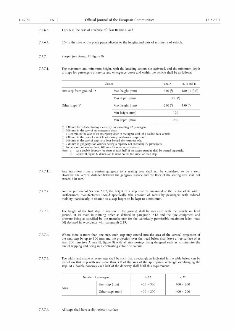
7.7.6.3. 12,5 % in the case of a vehicle of Class III and B, and
7.7.6.4. 5 % in the case of the plane perpendicular to the longitudinal axis of symmetry of vehicle.
7.7.7. S t e p s (see Annex III, figure 8)
7.7.7.1. The maximum and minimum height, with the kneeling system not activated, and the minimum depthof steps for passengers at service and emergency doors and within the vehicle shall be as follows:
Classes I and A II, III and B
First step from ground �D� Max height (mm) 340 (1) 380 (1) (2) (5)
Min depth (mm) 300 (*)
Other steps �E� Max height (mm) 250 (3) 350 (4)
Min height (mm) 120
Min depth (mm) 200
(*) 230 mm for vehicles having a capacity not exceeding 22 passengers.(1) 700 mm in the case of an emergency door;
1 500 mm in the case of an emergency door in the upper deck of a double deck vehicle.(2) 430 mm in the case of a vehicle with solely mechanical suspension.(3) 300 mm in the case of steps at a door behind the rearmost axle.(4) 250 mm in gangways for vehicles having a capacity not exceeding 22 passengers.(5) For at least one service door; 400 mm for other service doors.Note: 1. At a double doorway the steps in each half of the access passage shall be treated separately.
2. Annex III, figure 8, dimension E, need not be the same for each step.
7.7.7.1.1. Any transition from a sunken gangway to a seating area shall not be considered to be a step.However, the vertical distance between the gangway surface and the floor of the seating area shall notexceed 350 mm.
7.7.7.2. For the purpose of Section 7.7.7, the height of a step shall be measured at the centre of its width.Furthermore, manufacturers should specifically take account of access by passengers with reducedmobility, particularly in relation to a step height to be kept to a minimum.
7.7.7.3. The height of the first step in relation to the ground shall be measured with the vehicle on levelground, at its mass in running order as defined in paragraph 2.18 and the tyre equipment andpressure being as specified by the manufacturer for the technically permissible maximum laden mass(M) declared in accordance with paragraph 2.19.
7.7.7.4. Where there is more than one step, each step may extend into the area of the vertical projection ofthe next step by up to 100 mm and the projection over the tread below shall leave a free surface of atleast 200 mm (see Annex III, figure 8) with all step nosings being designed such as to minimise therisk of tripping and being in a contrasting colour or colours.
7.7.7.5. The width and shape of every step shall be such that a rectangle as indicated in the table below can beplaced on that step with not more than 5 % of the area of the appropriate rectangle overhanging thestep. At a double doorway each half of the doorway shall fulfil this requirement.
Number of passengers > 22 Ä 22
AreaFirst step (mm) 400 × 300 400 × 200
Other steps (mm) 400 × 200 400 × 200
7.7.7.6. All steps shall have a slip resistant surface.
L 42/30 13.2.2002Official Journal of the European CommunitiesEN
7.7.7.7. The maximum slope of the step in any direction shall not exceed 5 % when the unladen vehicle isstanding on a smooth and horizontal surface in its normal condition of travel (in particular anykneeling device shall not be engaged).
7.7.8. P a s s e n g e r s e a t s a n d s p a c e f o r s e a t e d p a s s e n g e r s
7.7.8.1. Minimum seat width
7.7.8.1.1. The minimum width of the seat cushion, dimension F (Annex III, figure 9), measured from a verticalplane passing through the centre of that seating position, shall be:
Class I, II, A, B 200 mm
Class III 225 mm
7.7.8.1.2. The minimum width of the available space for each seating position, dimension G (Annex III, figure 9)measured from a vertical plane passing through the centre of that seating position at heights between270 and 650 mm above the uncompressed seat cushion shall be not less than:
individual seats: 250 mm
continuous rows of seats for 2 or more passengers: 225 mm
7.7.8.1.3. For vehicles 2,35 m in width or less, the width of the available space for each seating position,measured from a vertical plane passing through the centre of that seating position at heights between270 and 650 mm above the uncompressed seat cushion shall be 200 mm (see Annex III, figure 9 bis).In case of compliance with this paragraph the requirements of paragraph 7.7.8.1.2. shall not apply.
7.7.8.1.4. For vehicles having a capacity not exceeding 22 passengers, in the case of seats adjacent to the wall ofthe vehicle, the available space does not include, in its upper part, a triangular area 20 mm wide by100 mm high (see Annex III, figure 10). In addition, the space needed for safety belts and theiranchorages and for the sun visor should be considered as exempted.
7.7.8.2. Minimum depth of seat cushion (dimension K, see Annex III, figure 11)
The minimum depth of a seat cushion shall be:
7.7.8.2.1. 350 mm in vehicles of Class I, A and B, and
7.7.8.2.2. 400 mm in vehicles of Class II and Class III.
7.7.8.3. Height of seat cushion (dimension H, see Annex III, figure 11)
The height of the uncompressed seat cushion relative to the floor shall be such that the distance fromthe floor to a horizontal plane tangential to the front upper surface of the seat cushion is between 400and 500 mm: this height may however be reduced to not less than 350 mm at the wheel arches andat the engine compartment.
7.7.8.4. Seat spacing (see Annex III, figure 12)
7.7.8.4.1. In the case of seats facing in the same direction, the distance between the front of a seat squab and theback of the squab of the seat preceding it (dimension H), shall, when measured horizontally and at allheights above the floor between the level of the top surface of the seat cushion and a point 620 mmabove the floor, not be less than:
H
Class I, A and B 650 mm
Class II and III 680 mm
13.2.2002 L 42/31Official Journal of the European CommunitiesEN
7.7.8.4.2. All measurements shall be taken, with the seat cushion and squab uncompressed, in a vertical planepassing through the centre line of the individual seating place.
7.7.8.4.3. Where transverse seats face one another the minimum distance between the front faces of the seatsquabs of facing seats, as measured across the highest points of the seat cushions, shall be not lessthan 1 300 mm.
7.7.8.4.4. Measurements shall be taken with reclining passenger seats and adjustable driving seats with their seatbacks and other seat adjustments in the normal position of use specified by the manufacturer.
7.7.8.4.5. Measurements shall be taken with any folding table fitted to a seat back in the folded position.
7.7.8.4.6. Seats which are mounted on a track or other system which permits the operator or the user to easilyvary the interior configuration of the vehicle shall be measured in the normal position of use specifiedby the manufacturer in the application for the approval.
7.7.8.5. Space for seated passengers (see Annex III, figure 13)
7.7.8.5.1. A minimum clear space in front of each passenger seat shall be provided as shown in Annex III, figure13. The seat back of another preceding seat or a partition whose contour corresponds approximatelyto that of the inclined seat back may intrude into this space as provided by paragraph 7.7.8.4. Thelocal presence in this space of seat legs shall also be permitted provided that adequate space remainsfor the passenger's feet. In the case of seats alongside the driver's seat in vehicles with up to 22passengers, intrusion of the dashboard, instrument panel, windscreen, sun visor, seat belts and seat beltanchorages shall be allowed.
7.7.8.5.2. However, at least two in Class I and Class II and one in Class A forward or rearward facing seatsspecifically intended and marked for passengers with reduced mobility other than wheelchair usersshall be provided in that part of the bus which is most suitable for boarding. These seats shall bedesigned for passengers with reduced mobility so as to provide enough space, shall have suitablydesigned and placed handholds to facilitate entry and exit of the seat, and provide communication inaccordance with paragraph 7.7.10 from the seated position.
7.7.8.5.2.1. These seats shall provide at least 110 % of the space specified in item 7.7.8.5.1.
7.7.8.6. Free space above seating positions
7.7.8.6.1. Over each seating position and, except in the case of the front row seats in a vehicle up to 22passengers, its associated foot space, there shall be measured a free space with a height of not lessthan 900 mm measured from the highest point of the uncompressed seat cushion and at least1 350 mm from the mean level of the floor in the foot space. In the case of vehicles to whichparagraph 7.7.1.10. applies, this dimension may be reduced to 1 200 mm measured from the floor.
7.7.8.6.2. This free space shall be extended over the zone defined:
7.7.8.6.2.1. by longitudinal vertical planes 200 mm either side of the median vertical plane of the seating position,and
7.7.8.6.2.2. by a transverse vertical plane through the rearmost upper point of the seat back and by a transversevertical plane 280 mm in front of the foremost point of the uncompressed seat cushion, measured ineach case at the median vertical plane of the seating position.
7.7.8.6.3. From the edges of the free space defined by paragraphs 7.7.8.6.1 and 7.7.8.6.2, the following zonesmay be excluded:
7.7.8.6.3.1. in the case of the upper part of outboard seats, a zone with a rectangular cross-section 150 mm inheight and 100 mm in width (see Annex III, figure 14);
7.7.8.6.3.2. in the case of the upper part of outboard seats, a zone with a triangular cross-section whose apex issituated 650 mm from the floor and whose base is 100 mm in width (see Annex III, figure 15);
L 42/32 13.2.2002Official Journal of the European CommunitiesEN
7.7.8.6.3.3. in the case of the footwell of an outboard seat, a zone of a cross-sectional area not exceeding 0,02 m2
(0,03 m2 for Class I low-floor vehicles) and having a maximum width not exceeding 100 mm(150 mm for Class I low-floor vehicles) (see Annex III, figure 16);
7.7.8.6.3.4. in the case of a vehicle for up to 22 passengers, in the case of the seating places nearest to the rearcorners of the body, the outer rear edge of the free space, viewed in plan, may be rounded to a radiusnot exceeding 150 mm (see Annex III, figure 17).
7.7.8.6.4. In the free space defined by paragraphs 7.7.8.6.1, 7.7.8.6.2 and 7.7.8.6.3, the following additionalintrusions shall be permitted:
7.7.8.6.4.1. intrusion of the back of another seat, its supports and its attachments (e.g. folding table);
7.7.8.6.4.2. in the case of a vehicle for up to 22 passengers, intrusion of a wheel arch provided that one of thefollowing two conditions is fulfilled:
7.7.8.6.4.2.1. the intrusion does not extend beyond the median vertical plane of the seating position (see Annex III,figure 18), or
7.7.8.6.4.2.2. the nearest edge of the area 300 mm in depth available for the feet of the seated passenger isadvanced no more than 200 mm from the edge of the uncompressed seat cushion and to not morethan 600 mm in front of the squab of the seat, these measurements being made in the median verticalplane of the seating position (see Annex III, figure 19). In the case of two seats facing each other thisprovision shall apply to only one of the seats and the remaining space for the feet of seated passengersmust be at least 400 mm;
7.7.8.6.4.3. in the case of seats alongside the driver's seat in vehicles with up to 22 passengers intrusion ofhopper-type windows when open and their fittings, of the dashboard/instrument panel, windscreen,sun visors, seat belts, seat belt anchorages and front dome.
7.7.9. C o m m u n i c a t i o n w i t h t h e d r i v e r
7.7.9.1. On vehicles of Class I, II and A, a means shall be provided to enable passengers to signal to the driverthat she/he should stop the vehicle. The controls for all such communication devices shall haveprotruding buttons, in vehicles of Class I and A no more than 1 200 mm from the floor, and shall bea contrasting colour or colours. Controls shall be distributed adequately and evenly throughout thevehicle. Activation of the control shall also be indicated to the passengers by means of one or moreilluminated signs. The sign shall display the words, for example:
�bus stopping�
�arrêt demandé�
�parada solicitada�
�standser�
�Bus hält�
�rsÜrg�
�fermata richiesta�
�bus stopt�
�paragem�
�pysähtyy�
�stannar�,
or equivalent, and/or a suitable pictogram and shall remain illuminated until the service door(s) open.Articulated vehicles shall have such signs in each rigid section of the vehicle. Double-deck vehiclesshall have them on each deck.
7.7.9.2. Communication with the crew compartment. If a crew compartment is fitted without access to thedriver or passenger compartments, a means of communication between the driver and this crewcompartment shall be provided.
13.2.2002 L 42/33Official Journal of the European CommunitiesEN
7.7.10. H o t - d r i n k m a c h i n e s a n d c o o k i n g e q u i p m e n t
7.7.10.1. Hot-drink machines and cooking equipment shall be so installed or guarded that no hot food or drinkis likely to be spilled on any passenger due to emergency braking or cornering forces.
7.7.10.2. On vehicles fitted with hot-drink machines or cooking equipment, all passenger seats shall haveadequate provision for setting down hot food or drink whilst the vehicle is in motion.
7.7.11. D o o r s t o i n t e r i o r c o m p a r t m e n t s
Every door to a toilet or other interior compartment:
7.7.11.1. shall be self-closing, and shall not be fitted with any device to hold it open if, when open, it couldobstruct passengers in an emergency;
7.7.11.2. shall, when open, not conceal any handle, control device for opening or obligatory marking associatedwith any service door, emergency door, emergency exit, fire extinguisher or first kit aid;
7.7.11.3. shall be provided with a means to enable the door to be opened from outside the compartment in anemergency;
7.7.11.4. shall not be capable of being locked from the outside unless it can always be opened from the inside.
7.8. Artificial lighting
7.8.1. Internal electrical lighting shall be provided for the illumination of:
7.8.1.1. all passenger compartments, crew compartments, toilet compartments and the articulated section of anarticulated vehicle;
7.8.1.2. any step or steps;
7.8.1.3. the access to any exits and the area immediately around the service door(s);
7.8.1.4. the internal markings and internal controls of all exits;
7.8.1.5. all places where there are obstacles.
7.8.2. There shall be at least two internal lighting circuits such that failure of one will not affect the other. Acircuit serving only permanent entry and exit lighting can be considered as one of these circuits.
7.8.3. Provisions shall be made to protect the driver from the effects of glare and reflections caused byartificial interior lighting.
7.9. Articulated section of articulated vehicles
7.9.1. The articulated section that interconnects rigid portions of the vehicle shall be so designed andconstructed as to allow at least one rotary movement about at least one horizontal axis, and at leastone vertical axis.
7.9.2. When the articulated vehicle at its mass in running order is stationary on a horizontal level surfacethere shall not be between the floor of either of the rigid sections and the floor of the rotating base orof the element replacing that base an uncovered gap of a width exceeding:
7.9.2.1. 10 mm when all the wheels of the vehicle are on the same plane, or
7.9.2.2. 20 mm when the wheels of the axle adjacent to the articulated section are resting on a surface whichis 150 mm higher than the surface on which the wheels of the other axles are resting.
L 42/34 13.2.2002Official Journal of the European CommunitiesEN
7.9.3. The difference in level between the floor of the rigid portions and the floor of the rotating base,measured at the joint, shall not exceed:
7.9.3.1. 20 mm in the conditions described in paragraph 7.9.2.1, or
7.9.3.2. 30 mm in the conditions described in paragraph 7.9.2.2.
7.9.4. On articulated vehicles means shall be provided to physically prevent access by passengers to any partof the articulated section where:
7.9.4.1. the floor has an uncovered gap not complying with the requirements of paragraph 7.9.2;
7.9.4.2. the floor cannot carry the mass of the passengers;
7.9.4.3. the movements of the walls constitute a danger to passengers.
7.10. Direction-holding of articulated vehicles
When an articulated vehicle is moving in a straight line the longitudinal median planes of its rigidportions shall coincide and form a continuous plane without any deflection.
7.11. Handrails and handholds
7.11.1. G e n e r a l r e q u i r e m e n t s
7.11.1.1. Handrails and handholds shall be of adequate strength.
7.11.1.2. They shall be so designed and installed as to present no risk of injury to passengers.
7.11.1.3. Handrails and handholds shall be of a section enabling passengers to grasp them easily and firmly.Every handrail shall provide a length of at least 100 mm to accommodate a hand. No dimension ofthe section shall be smaller than 20 mm or greater than 45 mm except in the case of handrails ondoors and seats and, in the case of a vehicle of Class II, III and B, in access passages. In these caseshandrails having a minimum dimension of 15 mm shall be permitted provided that one otherdimension is of at least 25 mm. Handrails shall not have sharp bends.
7.11.1.4. The clearance between a handrail or handhold and the adjacent part of the vehicle body or walls shallbe of at least 40 mm. However, in the case of a handrail on a door or a seat, or in the access passageof a vehicle of Class II, III and B, a minimum clearance of 35 mm shall be permitted.
7.11.1.5. The surface of every handrail, handhold or stanchion shall be colour contrasting and slip-resistant.
7.11.2. H a n d r a i l s a n d h a n d h o l d s f o r s t a n d i n g p a s s e n g e r s
7.11.2.1. Handrails and/or handholds shall be provided in sufficient number for each point of the floor areaintended, in conformity with paragraph 7.2.2, for standing passengers. For this purpose, strap hangers,if fitted, may be counted as handholds, provided that they are held in their position by suitable means.This requirement shall be deemed to be fulfilled if, for all possible sites of the testing device shown inAnnex III, figure 20 hereto, at least two handrails or handholds can be reached by the device'smovable arm. The testing device may be freely turned about its vertical axis.
7.11.2.2. When applying the procedure described in paragraph 7.11.2.1, only such handrails and handholdsshall be considered as are not less than 800 mm and not more than 1 900 mm above the floor.
7.11.2.3. For every position that can be occupied by a standing passenger, at least one of the two requiredhandrails or handholds shall be not more than 1 500 mm above the level of the floor at that position.This does not apply to an area adjacent to a door where the door or its mechanism in open positionwould prevent the use of this handhold.
13.2.2002 L 42/35Official Journal of the European CommunitiesEN

7.11.2.4. Areas which can be occupied by standing passengers and are not separated by seats from the sidewalls or rear wall of the vehicle shall be provided with horizontal handrails parallel to the walls andinstalled at a height of between 800 mm and 1 500 mm above the floor.
7.11.3. H a n d r a i l s a n d h a n d h o l d s f o r s e r v i c e d o o r s
7.11.3.1. Door apertures shall be fitted with handrails and/or handholds on each side. In the case of doubledoors this requirement can be fulfilled by fitting one central stanchion or one central handrail.
7.11.3.2. Handrails and/or handholds to be provided for service doors shall be such that they include a graspingpoint available to a person standing on the ground adjacent to the service door or on any of thesuccessive steps. Such points shall be situated, vertically, between 800 mm and 1 100 mm above theground or above the surface of each step, and horizontally:
7.11.3.2.1. for the position appropriate to a person standing on the ground, not more than 400 mm inwardsfrom the outer edge of the first step, and
7.11.3.2.2. for the position appropriate to a particular step, not outwards from the outer edge of the stepconsidered, and not more than 600 mm inwards from that same edge.
7.11.4. H a n d r a i l s t o p r i o r i t y s e a t i n g
7.11.4.1. A handrail at a height of between 800 mm and 900 mm above the floor level shall be providedbetween the priority seats as described in paragraph 7.7.8.5.2 and the service door suitable forboarding and alighting. A break is permitted where it is necessary to gain access to a wheelchair space,a seat located at a wheel arch, a staircase, an access passage or a gangway. Any break in the handrailshall not exceed 1 050 mm and a vertical handrail shall be provided on at least one side of the break.
7.12. Guarding of step wells
Where any seated passenger is likely to be thrown forward into a step well as a result of heavybraking, a guard shall be fitted. The guard shall have a minimum height from the floor on which thepassenger's feet rest of 800 mm and shall extend inwards from the wall of the vehicle at least as far as100 mm beyond the longitudinal centre line of any seating position where the passenger is at risk orto the riser of the innermost step; whichever is the lesser dimension.
7.13. Baggage racks and occupant protection
The occupants of the vehicle shall be protected from objects liable to fall from baggage racks underbraking or cornering forces. If baggage compartments are fitted, they must be designed in such a waythat baggage is prevented from falling in the event of sudden braking.
7.14. Trap doors, if fitted
Every trap door, that is not an escape hatch, on the floor of a vehicle shall be so fitted and securedthat it cannot be dislodged or opened without the use of tools or keys and no lifting or securingdevice shall project by more than 8 mm above floor level. Edges of projections shall be rounded.
7.15. Visual entertainment
Forms of visual entertainment for passengers, for example television monitors or videos, shall belocated out of the driver's view when the driver is seated in his normal driving position. This shall notpreclude any television monitor or similar device used as part of the driver's control or guidance ofthe vehicle, for example to monitor service doors.
L 42/36 13.2.2002Official Journal of the European CommunitiesEN
Appendix
VERIFICATION OF STATIC TILTING LIMIT BY MEANS OF CALCULATION
1. A vehicle may be shown to meet the requirement specified in paragraph 7.4 of Annex I by a calculationmethod approved by the technical service for conducting the tests.
2. The technical service responsible for conducting the tests may require tests to be carried out on parts of thevehicle to verify the assumptions made in the calculation.
3. Preparations for calculation
3.1. The vehicle shall be represented by a spatial system.
3.2. Due to the location of the centre of gravity of the body of the vehicle and the different spring rates of thevehicle suspension and tyres, axles do not generally lift simultaneously on one side of the vehicle as a result oflateral acceleration. Therefore, lateral tilting of the body over each axle has to be ascertained on the suppositionthat the wheels of the other axle(s) remain on the ground.
3.3. To simplify matters, it shall be assumed that the centre of gravity of the unsprung masses lies in thelongitudinal plane of the vehicle on the line passing through the centre of the wheel rotation axle. The smallshifting of the roll centre due to deflection of the axle can be neglected. The air suspension control should notbe taken into account.
3.4. The following parameters, at least, shall be taken into account:
vehicle data such as wheel base, tread width and sprung/unsprung masses, location of the centre of gravity ofthe vehicle, deflection and rebound and the spring rate of the vehicle suspension, considering also nonlinearities, horizontal and vertical spring rate of the tyres, torsion of the superstructure, location of the rollcentre of the axles.
4. Validity of the calculation method.
4.1. The validity of the calculation method shall be established to the satisfaction of the technical service, e.g. on thebasis of a comparative test with a similar vehicle.
13.2.2002 L 42/37Official Journal of the European CommunitiesEN
ANNEX II
EC TYPE-APPROVAL DOCUMENTATION
Appendix 1
Information documents
S u b a p p e n d i x 1
INFORMATION DOCUMENT No � (*)
pursuant to Annex I of Council Directive 70/156/EEC relating to EC type-approval of a vehicle with respect tothe special provisions for vehicles used for the carriage of passengers comprising more than eight seats in
addition to the driver's seat (Directive �./�/�.)
The following information, if applicable, must be supplied in triplicate and include a list of contents. Any drawingsmust be supplied in appropriate scale and in sufficient detail on size A4 or on a folder of A4 format. Photographs,if any, must show sufficient detail.
If the systems, components or separate technical units have electronic controls, information concerning theirperformance must be supplied.
0. GENERAL
0.1. Make (trade name of manufacturer): . . . . . . . . . . . . . . . . . . . . . . . . . . . . . . . . . . . . . . . . . . . . . . . . . . . .
0.2. Type: . . . . . . . . . . . . . . . . . . . . . . . . . . . . . . . . . . . . . . . . . . . . . . . . . . . . . . . . . . . . . . . . . . . . . . . . . .
0.2.0.1. Chassis: . . . . . . . . . . . . . . . . . . . . . . . . . . . . . . . . . . . . . . . . . . . . . . . . . . . . . . . . . . . . . . . . . . . . . . . . .
0.2.0.2. Bodywork/complete vehicle: . . . . . . . . . . . . . . . . . . . . . . . . . . . . . . . . . . . . . . . . . . . . . . . . . . . . . . . . . .
0.3. Means of identification of type, if marked on the vehicle (b): . . . . . . . . . . . . . . . . . . . . . . . . . . . . . . . . . .
0.3.0.1. Chassis: . . . . . . . . . . . . . . . . . . . . . . . . . . . . . . . . . . . . . . . . . . . . . . . . . . . . . . . . . . . . . . . . . . . . . . . . .
0.3.0.2. Bodywork/complete vehicle: . . . . . . . . . . . . . . . . . . . . . . . . . . . . . . . . . . . . . . . . . . . . . . . . . . . . . . . . . .
0.3.1. Location of that marking: . . . . . . . . . . . . . . . . . . . . . . . . . . . . . . . . . . . . . . . . . . . . . . . . . . . . . . . . . . .
0.3.1.1. Chassis: . . . . . . . . . . . . . . . . . . . . . . . . . . . . . . . . . . . . . . . . . . . . . . . . . . . . . . . . . . . . . . . . . . . . . . . . .
0.3.1.2. Bodywork/complete vehicle: . . . . . . . . . . . . . . . . . . . . . . . . . . . . . . . . . . . . . . . . . . . . . . . . . . . . . . . . . .
0.4. Category of vehicle (c): . . . . . . . . . . . . . . . . . . . . . . . . . . . . . . . . . . . . . . . . . . . . . . . . . . . . . . . . . . . . .
0.5. Name and address of manufacturer: . . . . . . . . . . . . . . . . . . . . . . . . . . . . . . . . . . . . . . . . . . . . . . . . . . . .
0.8. Address(es) of assembly plant(s): . . . . . . . . . . . . . . . . . . . . . . . . . . . . . . . . . . . . . . . . . . . . . . . . . . . . . . .
1. GENERAL CONSTRUCTION CHARACTERISTICS OF THE VEHICLE
1.1. Photographs and/or drawings of a representative vehicle: . . . . . . . . . . . . . . . . . . . . . . . . . . . . . . . . . . . .
1.2. Dimensional drawing of the whole vehicle: . . . . . . . . . . . . . . . . . . . . . . . . . . . . . . . . . . . . . . . . . . . . . . .
(*) The item numbers and footnotes used in this information document correspond to those set out in Annex I to Directive70/156/EEC. Items not relevant for the purpose of this Directive are omitted.
L 42/38 13.2.2002Official Journal of the European CommunitiesEN
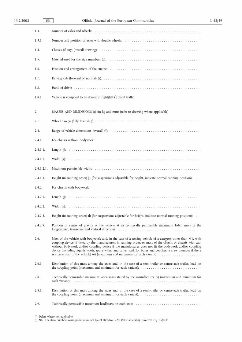
1.3. Number of axles and wheels: . . . . . . . . . . . . . . . . . . . . . . . . . . . . . . . . . . . . . . . . . . . . . . . . . . . . . . . . .
1.3.1. Number and position of axles with double wheels: . . . . . . . . . . . . . . . . . . . . . . . . . . . . . . . . . . . . . . . . .
1.4. Chassis (if any) (overall drawing): . . . . . . . . . . . . . . . . . . . . . . . . . . . . . . . . . . . . . . . . . . . . . . . . . . . . . .
1.5. Material used for the side members (d): . . . . . . . . . . . . . . . . . . . . . . . . . . . . . . . . . . . . . . . . . . . . . . . . .
1.6. Position and arrangement of the engine: . . . . . . . . . . . . . . . . . . . . . . . . . . . . . . . . . . . . . . . . . . . . . . . . .
1.7. Driving cab (forward or normal) (z): . . . . . . . . . . . . . . . . . . . . . . . . . . . . . . . . . . . . . . . . . . . . . . . . . . . .
1.8. Hand of drive: . . . . . . . . . . . . . . . . . . . . . . . . . . . . . . . . . . . . . . . . . . . . . . . . . . . . . . . . . . . . . . . . . . . .
1.8.1. Vehicle is equipped to be driven in right/left (1) hand traffic
2. MASSES AND DIMENSIONS (e) (in kg and mm) (refer to drawing where applicable)
2.1. Wheel base(s) (fully loaded) (f): . . . . . . . . . . . . . . . . . . . . . . . . . . . . . . . . . . . . . . . . . . . . . . . . . . . . . . . .
2.4. Range of vehicle dimensions (overall) (*): . . . . . . . . . . . . . . . . . . . . . . . . . . . . . . . . . . . . . . . . . . . . . . . .
2.4.1. For chassis without bodywork
2.4.1.1. Length (j): . . . . . . . . . . . . . . . . . . . . . . . . . . . . . . . . . . . . . . . . . . . . . . . . . . . . . . . . . . . . . . . . . . . . . . .
2.4.1.2. Width (k): . . . . . . . . . . . . . . . . . . . . . . . . . . . . . . . . . . . . . . . . . . . . . . . . . . . . . . . . . . . . . . . . . . . . . . .
2.4.1.2.1. Maximum permissible width: . . . . . . . . . . . . . . . . . . . . . . . . . . . . . . . . . . . . . . . . . . . . . . . . . . . . . . . . .
2.4.1.3. Height (in running order) (l) (for suspensions adjustable for height, indicate normal running position): . . .
2.4.2. For chassis with bodywork
2.4.2.1. Length (j): . . . . . . . . . . . . . . . . . . . . . . . . . . . . . . . . . . . . . . . . . . . . . . . . . . . . . . . . . . . . . . . . . . . . . . .
2.4.2.2. Width (k): . . . . . . . . . . . . . . . . . . . . . . . . . . . . . . . . . . . . . . . . . . . . . . . . . . . . . . . . . . . . . . . . . . . . . . .
2.4.2.3. Height (in running order) (l) (for suspensions adjustable for height, indicate normal running position): . . .
2.4.2.9. Position of centre of gravity of the vehicle at its technically permissible maximum laden mass in thelongitudinal, transverse and vertical directions: . . . . . . . . . . . . . . . . . . . . . . . . . . . . . . . . . . . . . . . . . . . .
2.6. Mass of the vehicle with bodywork and, in the case of a towing vehicle of a category other than M1, withcoupling device, if fitted by the manufacturer, in running order, or mass of the chassis or chassis with cab,without bodywork and/or coupling device if the manufacturer does not fit the bodywork and/or couplingdevice (including liquids, tools, spare wheel and driver and, for buses and coaches, a crew member if thereis a crew seat in the vehicle) (o) (maximum and minimum for each variant): . . . . . . . . . . . . . . . . . . . . . .
2.6.1. Distribution of this mass among the axles and, in the case of a semi-trailer or centre-axle trailer, load onthe coupling point (maximum and minimum for each variant): . . . . . . . . . . . . . . . . . . . . . . . . . . . . . . . .
2.8. Technically permissible maximum laden mass stated by the manufacturer (y) (maximum and minimum foreach variant): . . . . . . . . . . . . . . . . . . . . . . . . . . . . . . . . . . . . . . . . . . . . . . . . . . . . . . . . . . . . . . . . . . . .
2.8.1. Distribution of this mass among the axles and, in the case of a semi-trailer or centre-axle trailer, load onthe coupling point (maximum and minimum for each variant): . . . . . . . . . . . . . . . . . . . . . . . . . . . . . . . .
2.9. Technically permissible maximum load/mass on each axle: . . . . . . . . . . . . . . . . . . . . . . . . . . . . . . . . . . .
(1) Delete where not applicable.(*) NB: The item numbers correspond to Annex I(a) of Directive 92/53/EEC amending Directive 70/156/EEC.
13.2.2002 L 42/39Official Journal of the European CommunitiesEN
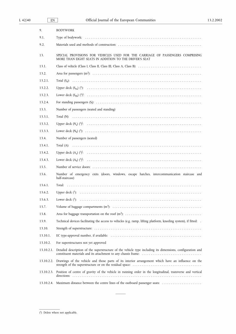
9. BODYWORK
9.1. Type of bodywork: . . . . . . . . . . . . . . . . . . . . . . . . . . . . . . . . . . . . . . . . . . . . . . . . . . . . . . . . . . . . . . . .
9.2. Materials used and methods of construction: . . . . . . . . . . . . . . . . . . . . . . . . . . . . . . . . . . . . . . . . . . . . . .
13. SPECIAL PROVISIONS FOR VEHICLES USED FOR THE CARRIAGE OF PASSENGERS COMPRISINGMORE THAN EIGHT SEATS IN ADDITION TO THE DRIVER'S SEAT
13.1. Class of vehicle (Class I, Class II, Class III, Class A, Class B): . . . . . . . . . . . . . . . . . . . . . . . . . . . . . . . . . . .
13.2. Area for passengers (m2): . . . . . . . . . . . . . . . . . . . . . . . . . . . . . . . . . . . . . . . . . . . . . . . . . . . . . . . . . . . .
13.2.1. Total (S0): . . . . . . . . . . . . . . . . . . . . . . . . . . . . . . . . . . . . . . . . . . . . . . . . . . . . . . . . . . . . . . . . . . . . . . .
13.2.2. Upper deck (S0a) (1): . . . . . . . . . . . . . . . . . . . . . . . . . . . . . . . . . . . . . . . . . . . . . . . . . . . . . . . . . . . . . . .
13.2.3. Lower deck (S0b) (1)l: . . . . . . . . . . . . . . . . . . . . . . . . . . . . . . . . . . . . . . . . . . . . . . . . . . . . . . . . . . . . . . .
13.2.4. For standing passengers (Sl): . . . . . . . . . . . . . . . . . . . . . . . . . . . . . . . . . . . . . . . . . . . . . . . . . . . . . . . . . .
13.3. Number of passengers (seated and standing)
13.3.1. Total (N): . . . . . . . . . . . . . . . . . . . . . . . . . . . . . . . . . . . . . . . . . . . . . . . . . . . . . . . . . . . . . . . . . . . . . . .
13.3.2. Upper deck (Na) (1)l: . . . . . . . . . . . . . . . . . . . . . . . . . . . . . . . . . . . . . . . . . . . . . . . . . . . . . . . . . . . . . . .
13.3.3. Lower deck (Nb) (1): . . . . . . . . . . . . . . . . . . . . . . . . . . . . . . . . . . . . . . . . . . . . . . . . . . . . . . . . . . . . . . . .
13.4. Number of passengers (seated)
13.4.1. Total (A): . . . . . . . . . . . . . . . . . . . . . . . . . . . . . . . . . . . . . . . . . . . . . . . . . . . . . . . . . . . . . . . . . . . . . . .
13.4.2. Upper deck (Aa) (1)l: . . . . . . . . . . . . . . . . . . . . . . . . . . . . . . . . . . . . . . . . . . . . . . . . . . . . . . . . . . . . . . .
13.4.3. Lower deck (Ab) (1)l: . . . . . . . . . . . . . . . . . . . . . . . . . . . . . . . . . . . . . . . . . . . . . . . . . . . . . . . . . . . . . . .
13.5. Number of service doors: . . . . . . . . . . . . . . . . . . . . . . . . . . . . . . . . . . . . . . . . . . . . . . . . . . . . . . . . . . . .
13.6. Number of emergency exits (doors, windows, escape hatches, intercommunication staircase andhalf-staircase)
13.6.1. Total: . . . . . . . . . . . . . . . . . . . . . . . . . . . . . . . . . . . . . . . . . . . . . . . . . . . . . . . . . . . . . . . . . . . . . . . . . .
13.6.2. Upper deck (1): . . . . . . . . . . . . . . . . . . . . . . . . . . . . . . . . . . . . . . . . . . . . . . . . . . . . . . . . . . . . . . . . . . .
13.6.3. Lower deck (1): . . . . . . . . . . . . . . . . . . . . . . . . . . . . . . . . . . . . . . . . . . . . . . . . . . . . . . . . . . . . . . . . . . .
13.7. Volume of baggage compartments (m3): . . . . . . . . . . . . . . . . . . . . . . . . . . . . . . . . . . . . . . . . . . . . . . . . .
13.8. Area for baggage transportation on the roof (m2): . . . . . . . . . . . . . . . . . . . . . . . . . . . . . . . . . . . . . . . . . .
13.9. Technical devices facilitating the access to vehicles (e.g. ramp, lifting platform, kneeling system), if fitted: .
13.10. Strength of superstructure: . . . . . . . . . . . . . . . . . . . . . . . . . . . . . . . . . . . . . . . . . . . . . . . . . . . . . . . . . . .
13.10.1. EC type-approval number, if available: . . . . . . . . . . . . . . . . . . . . . . . . . . . . . . . . . . . . . . . . . . . . . . . . . .
13.10.2. For superstructures not yet approved
13.10.2.1. Detailed description of the superstructure of the vehicle type including its dimensions, configuration andconstituent materials and its attachment to any chassis frame: . . . . . . . . . . . . . . . . . . . . . . . . . . . . . . . . .
13.10.2.2. Drawings of the vehicle and those parts of its interior arrangement which have an influence on thestrength of the superstructure or on the residual space: . . . . . . . . . . . . . . . . . . . . . . . . . . . . . . . . . . . . . .
13.10.2.3. Position of centre of gravity of the vehicle in running order in the longitudinal, transverse and verticaldirections: . . . . . . . . . . . . . . . . . . . . . . . . . . . . . . . . . . . . . . . . . . . . . . . . . . . . . . . . . . . . . . . . . . . . . . .
13.10.2.4. Maximum distance between the centre lines of the outboard passenger seats: . . . . . . . . . . . . . . . . . . . . . .
(1) Delete where not applicable.
L 42/40 13.2.2002Official Journal of the European CommunitiesEN
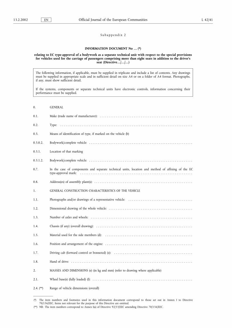
S u b a p p e n d i x 2
INFORMATION DOCUMENT No � (*)
relating to EC type-approval of a bodywork as a separate technical unit with respect to the special provisionsfor vehicles used for the carriage of passengers comprising more than eight seats in addition to the driver's
seat (Directive�/�/�)
The following information, if applicable, must be supplied in triplicate and include a list of contents. Any drawingsmust be supplied in appropriate scale and in sufficient detail on size A4 or on a folder of A4 format. Photographs,if any, must show sufficient detail.
If the systems, components or separate technical units have electronic controls, information concerning theirperformance must be supplied.
0. GENERAL
0.1. Make (trade name of manufacturer): . . . . . . . . . . . . . . . . . . . . . . . . . . . . . . . . . . . . . . . . . . . . . . . . . . . .
0.2. Type: . . . . . . . . . . . . . . . . . . . . . . . . . . . . . . . . . . . . . . . . . . . . . . . . . . . . . . . . . . . . . . . . . . . . . . . . . .
0.3. Means of identification of type, if marked on the vehicle (b)
0.3.0.2. Bodywork/complete vehicle: . . . . . . . . . . . . . . . . . . . . . . . . . . . . . . . . . . . . . . . . . . . . . . . . . . . . . . . . . .
0.3.1. Location of that marking
0.3.1.2. Bodywork/complete vehicle: . . . . . . . . . . . . . . . . . . . . . . . . . . . . . . . . . . . . . . . . . . . . . . . . . . . . . . . . . .
0.7. In the case of components and separate technical units, location and method of affixing of the ECtype-approval mark: . . . . . . . . . . . . . . . . . . . . . . . . . . . . . . . . . . . . . . . . . . . . . . . . . . . . . . . . . . . . . . .
0.8. Address(es) of assembly plant(s): . . . . . . . . . . . . . . . . . . . . . . . . . . . . . . . . . . . . . . . . . . . . . . . . . . . . . . .
1. GENERAL CONSTRUCTION CHARACTERISTICS OF THE VEHICLE
1.1. Photographs and/or drawings of a representative vehicle: . . . . . . . . . . . . . . . . . . . . . . . . . . . . . . . . . . . .
1.2. Dimensional drawing of the whole vehicle: . . . . . . . . . . . . . . . . . . . . . . . . . . . . . . . . . . . . . . . . . . . . . . .
1.3. Number of axles and wheels: . . . . . . . . . . . . . . . . . . . . . . . . . . . . . . . . . . . . . . . . . . . . . . . . . . . . . . . . .
1.4. Chassis (if any) (overall drawing): . . . . . . . . . . . . . . . . . . . . . . . . . . . . . . . . . . . . . . . . . . . . . . . . . . . . . .
1.5. Material used for the side members (d): . . . . . . . . . . . . . . . . . . . . . . . . . . . . . . . . . . . . . . . . . . . . . . . . .
1.6. Position and arrangement of the engine: . . . . . . . . . . . . . . . . . . . . . . . . . . . . . . . . . . . . . . . . . . . . . . . . .
1.7. Driving cab (forward control or bonneted) (z): . . . . . . . . . . . . . . . . . . . . . . . . . . . . . . . . . . . . . . . . . . . .
1.8. Hand of drive: . . . . . . . . . . . . . . . . . . . . . . . . . . . . . . . . . . . . . . . . . . . . . . . . . . . . . . . . . . . . . . . . . . . .
2. MASSES AND DIMENSIONS (e) (in kg and mm) (refer to drawing where applicable)
2.1. Wheel base(s) (fully loaded) (f): . . . . . . . . . . . . . . . . . . . . . . . . . . . . . . . . . . . . . . . . . . . . . . . . . . . . . . . .
2.4. (**) Range of vehicle dimensions (overall)
(*) The item numbers and footnotes used in this information document correspond to those set out in Annex I to Directive70/156/EEC. Items not relevant for the purpose of this Directive are omitted.
(**) NB: The item numbers correspond to Annex I(a) of Directive 92/53/EEC amending Directive 70/156/EEC.
13.2.2002 L 42/41Official Journal of the European CommunitiesEN
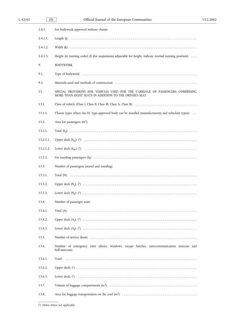
2.4.1. For bodywork approved without chassis
2.4.1.1. Length (j): . . . . . . . . . . . . . . . . . . . . . . . . . . . . . . . . . . . . . . . . . . . . . . . . . . . . . . . . . . . . . . . . . . . . . . .
2.4.1.2. Width (k): . . . . . . . . . . . . . . . . . . . . . . . . . . . . . . . . . . . . . . . . . . . . . . . . . . . . . . . . . . . . . . . . . . . . . . .
2.4.1.3. Height (in running order) (l) (for suspensions adjustable for height, indicate normal running position): . . .
9. BODYWORK
9.1. Type of bodywork: . . . . . . . . . . . . . . . . . . . . . . . . . . . . . . . . . . . . . . . . . . . . . . . . . . . . . . . . . . . . . . . .
9.2. Materials used and methods of construction: . . . . . . . . . . . . . . . . . . . . . . . . . . . . . . . . . . . . . . . . . . . . . .
13. SPECIAL PROVISIONS FOR VEHICLES USED FOR THE CARRIAGE OF PASSENGERS COMPRISINGMORE THAN EIGHT SEATS IN ADDITION TO THE DRIVER'S SEAT
13.1. Class of vehicle (Class I, Class II, Class III, Class A, Class B): . . . . . . . . . . . . . . . . . . . . . . . . . . . . . . . . . . .
13.1.1. Chassis types where the EC type-approved body can be installed (manufacturer(s) and vehicle(s) types): . .
13.2. Area for passengers (m2):
13.2.1. Total (S0): . . . . . . . . . . . . . . . . . . . . . . . . . . . . . . . . . . . . . . . . . . . . . . . . . . . . . . . . . . . . . . . . . . . . . . .
13.2.1.1. Upper deck (S0a): (1) . . . . . . . . . . . . . . . . . . . . . . . . . . . . . . . . . . . . . . . . . . . . . . . . . . . . . . . . . . . . . . .
13.2.1.2. Lower deck (S0b): (1) . . . . . . . . . . . . . . . . . . . . . . . . . . . . . . . . . . . . . . . . . . . . . . . . . . . . . . . . . . . . . . .
13.2.2. For standing passengers (Sl): . . . . . . . . . . . . . . . . . . . . . . . . . . . . . . . . . . . . . . . . . . . . . . . . . . . . . . . . . .
13.3. Number of passengers (seated and standing)
13.3.1. Total (N): . . . . . . . . . . . . . . . . . . . . . . . . . . . . . . . . . . . . . . . . . . . . . . . . . . . . . . . . . . . . . . . . . . . . . . .
13.3.2. Upper deck (Na): (1) . . . . . . . . . . . . . . . . . . . . . . . . . . . . . . . . . . . . . . . . . . . . . . . . . . . . . . . . . . . . . . . .
13.3.3. Lower deck (Nb): (1) . . . . . . . . . . . . . . . . . . . . . . . . . . . . . . . . . . . . . . . . . . . . . . . . . . . . . . . . . . . . . . . .
13.4. Number of passenger seats
13.4.1. Total (A): . . . . . . . . . . . . . . . . . . . . . . . . . . . . . . . . . . . . . . . . . . . . . . . . . . . . . . . . . . . . . . . . . . . . . . .
13.4.2. Upper deck (Aa): (1) . . . . . . . . . . . . . . . . . . . . . . . . . . . . . . . . . . . . . . . . . . . . . . . . . . . . . . . . . . . . . . . .
13.4.3. Lower deck (Ab): (1) . . . . . . . . . . . . . . . . . . . . . . . . . . . . . . . . . . . . . . . . . . . . . . . . . . . . . . . . . . . . . . . .
13.5. Number of service doors: . . . . . . . . . . . . . . . . . . . . . . . . . . . . . . . . . . . . . . . . . . . . . . . . . . . . . . . . . . . .
13.6. Number of emergency exits (doors, windows, escape hatches, intercommunication staircase andhalf-staircase)
13.6.1. Total: . . . . . . . . . . . . . . . . . . . . . . . . . . . . . . . . . . . . . . . . . . . . . . . . . . . . . . . . . . . . . . . . . . . . . . . . . .
13.6.2. Upper deck: (1) . . . . . . . . . . . . . . . . . . . . . . . . . . . . . . . . . . . . . . . . . . . . . . . . . . . . . . . . . . . . . . . . . . .
13.6.3. Lower deck: (1) . . . . . . . . . . . . . . . . . . . . . . . . . . . . . . . . . . . . . . . . . . . . . . . . . . . . . . . . . . . . . . . . . . .
13.7. Volume of baggage compartments (m3): . . . . . . . . . . . . . . . . . . . . . . . . . . . . . . . . . . . . . . . . . . . . . . . . .
13.8. Area for baggage transportation on the roof (m2): . . . . . . . . . . . . . . . . . . . . . . . . . . . . . . . . . . . . . . . . . .
(1) Delete where not applicable.
L 42/42 13.2.2002Official Journal of the European CommunitiesEN
13.9. Technical devices facilitating the access to vehicles (e.g. ramp, lifting platform, kneeling system), if fitted: .
13.10. STRENGTH OF SUPERSTRUCTURE
13.10.1. EC type-approval number, if available: . . . . . . . . . . . . . . . . . . . . . . . . . . . . . . . . . . . . . . . . . . . . . . . . . .
13.10.2. For superstructures not yet approved
13.10.2.1. Detailed description of the superstructure of the vehicle type including its dimensions, configuration andconstituent materials and its attachment to any chassis frame: . . . . . . . . . . . . . . . . . . . . . . . . . . . . . . . . .
13.10.2.2. Drawings of the vehicle and those parts of its interior arrangement which have an influence on thestrength of the superstructure or on the residual space: . . . . . . . . . . . . . . . . . . . . . . . . . . . . . . . . . . . . . .
13.10.2.3. Position of centre of gravity of the vehicle in running order in the longitudinal, transverse and verticaldirections: . . . . . . . . . . . . . . . . . . . . . . . . . . . . . . . . . . . . . . . . . . . . . . . . . . . . . . . . . . . . . . . . . . . . . . .
13.10.2.4. Maximum distance between the centre lines of the outboard passenger seats: . . . . . . . . . . . . . . . . . . . . . .
13.11. Points of this Directive to be accomplished and demonstrated for this separate technical unit: . . . . . . . . .
13.2.2002 L 42/43Official Journal of the European CommunitiesEN
S u b a p p e n d i x 3
INFORMATION DOCUMENT No � (*)
pursuant to Annex I of Council Directive 70/156/EEC relating to EC type-approval of a vehicle where thebodywork has previously obtained the EC type-approval as a separate technical unit, with respect to the
special provisions for vehicles used for the carriage of passengers comprising more than eight seats inaddition to the driver's seat (Directive �/�/�)
The following information, if applicable, must be supplied in triplicate and include a list of contents. Any drawingsmust be supplied in appropriate scale and in sufficient detail on size A4 or on a folder of A4 format. Photographs,if any, must show sufficient detail.
If the systems, components or separate technical units have electronic controls, information concerning theirperformance must be supplied.
0. GENERAL
0.1. Make (trade name of manufacturer): . . . . . . . . . . . . . . . . . . . . . . . . . . . . . . . . . . . . . . . . . . . . . . . . . . . .
0.2. Type: . . . . . . . . . . . . . . . . . . . . . . . . . . . . . . . . . . . . . . . . . . . . . . . . . . . . . . . . . . . . . . . . . . . . . . . . . .
0.2.0.1. Chassis: . . . . . . . . . . . . . . . . . . . . . . . . . . . . . . . . . . . . . . . . . . . . . . . . . . . . . . . . . . . . . . . . . . . . . . . . .
0.2.0.2. Bodywork/complete vehicle: . . . . . . . . . . . . . . . . . . . . . . . . . . . . . . . . . . . . . . . . . . . . . . . . . . . . . . . . . .
0.3. Means of identification of type, if marked on the vehicle (b): . . . . . . . . . . . . . . . . . . . . . . . . . . . . . . . . . .
0.3.0.1 Chassis: . . . . . . . . . . . . . . . . . . . . . . . . . . . . . . . . . . . . . . . . . . . . . . . . . . . . . . . . . . . . . . . . . . . . . . . . .
0.3.0.2. Bodywork/complete vehicle: . . . . . . . . . . . . . . . . . . . . . . . . . . . . . . . . . . . . . . . . . . . . . . . . . . . . . . . . . .
0.3.1. Location of marking: . . . . . . . . . . . . . . . . . . . . . . . . . . . . . . . . . . . . . . . . . . . . . . . . . . . . . . . . . . . . . . .
03.1.1. Chassis: . . . . . . . . . . . . . . . . . . . . . . . . . . . . . . . . . . . . . . . . . . . . . . . . . . . . . . . . . . . . . . . . . . . . . . . . .
03.1.2. Bodywork/complete vehicle: . . . . . . . . . . . . . . . . . . . . . . . . . . . . . . . . . . . . . . . . . . . . . . . . . . . . . . . . . .
0.4. Category of vehicle (c): . . . . . . . . . . . . . . . . . . . . . . . . . . . . . . . . . . . . . . . . . . . . . . . . . . . . . . . . . . . . .
0.5. Name and address of manufacturer: . . . . . . . . . . . . . . . . . . . . . . . . . . . . . . . . . . . . . . . . . . . . . . . . . . . .
0.8. Address(es) of assembly plant(s): . . . . . . . . . . . . . . . . . . . . . . . . . . . . . . . . . . . . . . . . . . . . . . . . . . . . . . .
1. GENERAL CONSTRUCTION CHARACTERISTICS OF THE VEHICLE
1.1. Photographs and/or drawings of a representative vehicle: . . . . . . . . . . . . . . . . . . . . . . . . . . . . . . . . . . . .
1.2. Dimensional drawing of the whole vehicle: . . . . . . . . . . . . . . . . . . . . . . . . . . . . . . . . . . . . . . . . . . . . . . .
1.3. Number of axles and wheels: . . . . . . . . . . . . . . . . . . . . . . . . . . . . . . . . . . . . . . . . . . . . . . . . . . . . . . . . .
1.3.1. Number and position of axles with double wheels: . . . . . . . . . . . . . . . . . . . . . . . . . . . . . . . . . . . . . . . . .
1.4. Chassis (if any) (overall drawing): . . . . . . . . . . . . . . . . . . . . . . . . . . . . . . . . . . . . . . . . . . . . . . . . . . . . . .
1.5. Material used for the side members (d): . . . . . . . . . . . . . . . . . . . . . . . . . . . . . . . . . . . . . . . . . . . . . . . . .
1.6. Position and arrangement of the engine: . . . . . . . . . . . . . . . . . . . . . . . . . . . . . . . . . . . . . . . . . . . . . . . . .
(*) The item numbers and footnotes used in this information document correspond to those set out in Annex I to Directive70/156/EEC. Items not relevant for the purpose of this Directive are omitted.
L 42/44 13.2.2002Official Journal of the European CommunitiesEN

1.8. Hand of drive: . . . . . . . . . . . . . . . . . . . . . . . . . . . . . . . . . . . . . . . . . . . . . . . . . . . . . . . . . . . . . . . . . . . .
1.8.1. Vehicle is equipped to be driven in right/left (1) hand traffic:
2. MASSES AND DIMENSIONS (e) (in kg and mm) (refer to drawing where applicable)
2.1. Wheel base(s) (fully loaded) (f): . . . . . . . . . . . . . . . . . . . . . . . . . . . . . . . . . . . . . . . . . . . . . . . . . . . . . . . .
2.4. (*) Range of vehicle dimensions (overall): . . . . . . . . . . . . . . . . . . . . . . . . . . . . . . . . . . . . . . . . . . . . . . . . . .
2.4.1. For chassis without bodywork
2.4.1.1. Length (j): . . . . . . . . . . . . . . . . . . . . . . . . . . . . . . . . . . . . . . . . . . . . . . . . . . . . . . . . . . . . . . . . . . . . . . .
2.4.1.2. Width (k): . . . . . . . . . . . . . . . . . . . . . . . . . . . . . . . . . . . . . . . . . . . . . . . . . . . . . . . . . . . . . . . . . . . . . . .
2.4.1.2.1. Maximum width: . . . . . . . . . . . . . . . . . . . . . . . . . . . . . . . . . . . . . . . . . . . . . . . . . . . . . . . . . . . . . . . . . .
2.4.1.3. Height (in running order) (l) (for suspensions adjustable for height, indicate normal running position): . . .
2.6. Mass of the vehicle with bodywork and, in the case of a towing vehicle of a category other than M1, withcoupling device, if fitted by the manufacturer, in running order, or mass of the chassis or chassis with cab,without bodywork and/or coupling device if the manufacturer does not fit the bodywork and/or couplingdevice (including liquids, tools, spare wheel and driver and, for buses and coaches, a crew member if thereis a crew seat in the vehicle) (o) (maximum and minimum for each variant): . . . . . . . . . . . . . . . . . . . . . .
2.6.1. Distribution of this mass among the axles and, in the case of a semi-trailer or centre axle trailer, load onthe coupling point (maximum and minimum for each variant): . . . . . . . . . . . . . . . . . . . . . . . . . . . . . . . .
2.8. Technically permissible maximum laden mass stated by the manufacturer (y) (maximum and minimum): .
2.8.1. Distribution of this mass along the axles and, in the case of a semi-trailer or centre-axle trailer, load on thecoupling point (maximum and minimum): . . . . . . . . . . . . . . . . . . . . . . . . . . . . . . . . . . . . . . . . . . . . . . .
2.9. Technically permissible maximum mass/load on each axle: . . . . . . . . . . . . . . . . . . . . . . . . . . . . . . . . . . .
13.10. Strength of superstructure . . . . . . . . . . . . . . . . . . . . . . . . . . . . . . . . . . . . . . . . . . . . . . . . . . . . . . . . . . .
13.10.1. EC type-approval number, if available: . . . . . . . . . . . . . . . . . . . . . . . . . . . . . . . . . . . . . . . . . . . . . . . . . .
13.10.2 For superstructures not yet approved . . . . . . . . . . . . . . . . . . . . . . . . . . . . . . . . . . . . . . . . . . . . . . . . . . .
13.10.2.1. Detailed description of the superstructure of the vehicle type including its dimensions, configuration andconstituent materials and its attachment to any chassis frame: . . . . . . . . . . . . . . . . . . . . . . . . . . . . . . . . .
13.10.2.2. Drawings of the vehicle and those parts of its interior arrangement which have an influence on thestrength of the superstructure or on the residual space: . . . . . . . . . . . . . . . . . . . . . . . . . . . . . . . . . . . . . .
13.10.2.3. Position of centre of gravity of the vehicle in running order in the longitudinal, transverse and verticaldirections: . . . . . . . . . . . . . . . . . . . . . . . . . . . . . . . . . . . . . . . . . . . . . . . . . . . . . . . . . . . . . . . . . . . . . . .
13.10.2.4. Maximum distance between the centre lines of the outboard passenger seats: . . . . . . . . . . . . . . . . . . . . . .
(1) Delete where not applicable.(*) NB: The item numbers correspond to Annex I(a) of Directive 92/53/EEC amending Directive 70/156/EEC.
13.2.2002 L 42/45Official Journal of the European CommunitiesEN
Appendix 2
S u b a p p e n d i x 1
MODEL
(maximum format: A4 (210 × 297 mm))
EC TYPE-APPROVAL CERTIFICATE
Stamp of EC type-approval authority
Communication concerning the
� EC type-approval (1)
� extension of EC type-approval (1)
� refusal of EC type-approval (1)
� withdrawal of EC type-approval (1)
of a type of a vehicle/component/separate technical unit (1) with regard to Directive �./�/EC, as last amended byDirective �/�/EC
EC type-approval number: . . . . . . . . . . . . . . . . . . . . . . . . . . . . . . . . . . . . . . . . . . . . . . . . . . . . . . . . . . . . . . . . . . . .
Reason for extension: . . . . . . . . . . . . . . . . . . . . . . . . . . . . . . . . . . . . . . . . . . . . . . . . . . . . . . . . . . . . . . . . . . . . . . .
SECTION I
0.1. Make (trade name of manufacturer): . . . . . . . . . . . . . . . . . . . . . . . . . . . . . . . . . . . . . . . . . . . . . . . . . . . . . . . .
0.2. Type: . . . . . . . . . . . . . . . . . . . . . . . . . . . . . . . . . . . . . . . . . . . . . . . . . . . . . . . . . . . . . . . . . . . . . . . . . . . . . .
0.3. Means of identification of type if marked on the vehicle/component/separate technical unit (1) (2): . . . . . . . . . .
0.3.1. Location of that marking: . . . . . . . . . . . . . . . . . . . . . . . . . . . . . . . . . . . . . . . . . . . . . . . . . . . . . . . . . . . . . . .
0.4. Category of vehicle (1) (3): . . . . . . . . . . . . . . . . . . . . . . . . . . . . . . . . . . . . . . . . . . . . . . . . . . . . . . . . . . . . . . .
0.5. Name and address of manufacturer: . . . . . . . . . . . . . . . . . . . . . . . . . . . . . . . . . . . . . . . . . . . . . . . . . . . . . . . .
0.7. In the case of components and separate technical units, location and method of affixing of the EC type-approvalmark: . . . . . . . . . . . . . . . . . . . . . . . . . . . . . . . . . . . . . . . . . . . . . . . . . . . . . . . . . . . . . . . . . . . . . . . . . . . . . .
0.8. Address(es) of assembly plant(s): . . . . . . . . . . . . . . . . . . . . . . . . . . . . . . . . . . . . . . . . . . . . . . . . . . . . . . . . . . .
(1) Delete where not applicable.(2) If the means of identification of type contains characters not relevant to describe the vehicle, component or separate technical unit
types covered by this type-approval certificate such characters shall be represented in the documentation by the symbol:�?� (e.g.ABC??123??).
(3) As defined in Annex II A to Directive 70/156/EEC.
L 42/46 13.2.2002Official Journal of the European CommunitiesEN
SECTION II
1. Additional information (where applicable): see addendum
2. Technical service responsible for carrying out the tests: . . . . . . . . . . . . . . . . . . . . . . . . . . . . . . . . . . . . . . . . . .
3. Date of test report: . . . . . . . . . . . . . . . . . . . . . . . . . . . . . . . . . . . . . . . . . . . . . . . . . . . . . . . . . . . . . . . . . . . .
4. Number of test report: . . . . . . . . . . . . . . . . . . . . . . . . . . . . . . . . . . . . . . . . . . . . . . . . . . . . . . . . . . . . . . . . . .
5. Remarks (if any): see addendum
6. Place: . . . . . . . . . . . . . . . . . . . . . . . . . . . . . . . . . . . . . . . . . . . . . . . . . . . . . . . . . . . . . . . . . . . . . . . . . . . . . .
7. Date: . . . . . . . . . . . . . . . . . . . . . . . . . . . . . . . . . . . . . . . . . . . . . . . . . . . . . . . . . . . . . . . . . . . . . . . . . . . . . . .
8. Signature: . . . . . . . . . . . . . . . . . . . . . . . . . . . . . . . . . . . . . . . . . . . . . . . . . . . . . . . . . . . . . . . . . . . . . . . . . . .
9. The index to the information package lodged with the approval authority, which may be obtained on request, isattached.
13.2.2002 L 42/47Official Journal of the European CommunitiesEN
Addendum to EC type-approval certificate No �
concerning the EC type-approval of a vehicle with regard to Directive �/�/EC as last amended by Directive �/�/EC
1. Additional information
1.1. Category of vehicle (M2, M3) (1): . . . . . . . . . . . . . . . . . . . . . . . . . . . . . . . . . . . . . . . . . . . . . . . . . . . . . . . . .
1.2. Bodywork concept (single/double-deck, articulated, low-floor) (1): . . . . . . . . . . . . . . . . . . . . . . . . . . . . . . . .
1.3. Technically permissible maximum mass (kg): . . . . . . . . . . . . . . . . . . . . . . . . . . . . . . . . . . . . . . . . . . . . . . .
1.4. Number of passengers (seated and standing):
1.4.1. Total (N): . . . . . . . . . . . . . . . . . . . . . . . . . . . . . . . . . . . . . . . . . . . . . . . . . . . . . . . . . . . . . . . . . . . . . . . . .
1.4.2. Upper deck (Na) (1): . . . . . . . . . . . . . . . . . . . . . . . . . . . . . . . . . . . . . . . . . . . . . . . . . . . . . . . . . . . . . . . . . .
1.4.3. Lower deck (Nb) (1): . . . . . . . . . . . . . . . . . . . . . . . . . . . . . . . . . . . . . . . . . . . . . . . . . . . . . . . . . . . . . . . . . .
1.4.4. Number of passengers seated:
1.4.4.1. Total (A): . . . . . . . . . . . . . . . . . . . . . . . . . . . . . . . . . . . . . . . . . . . . . . . . . . . . . . . . . . . . . . . . . . . . . . . . .
1.4.4.2. Upper deck (Aa) (1): . . . . . . . . . . . . . . . . . . . . . . . . . . . . . . . . . . . . . . . . . . . . . . . . . . . . . . . . . . . . . . . . . .
1.4.4.3. Lower deck (Ab) (1): . . . . . . . . . . . . . . . . . . . . . . . . . . . . . . . . . . . . . . . . . . . . . . . . . . . . . . . . . . . . . . . . . .
1.5. Volume of baggage compartments (m3): . . . . . . . . . . . . . . . . . . . . . . . . . . . . . . . . . . . . . . . . . . . . . . . . . . .
1.6. Area for baggage transportation on the roof (m2): . . . . . . . . . . . . . . . . . . . . . . . . . . . . . . . . . . . . . . . . . . . .
1.7. Technical devices facilitating access to vehicles (ramp, lifting platform, kneeling system): . . . . . . . . . . . . . . .
1.8. Position of centre of gravity of the laden vehicle in the longitudinal, transverse and vertical directions: . . . . .
1.9. Superstructure strength
1.9.1. EC type-approval number, if required: . . . . . . . . . . . . . . . . . . . . . . . . . . . . . . . . . . . . . . . . . . . . . . . . . . . .
5. Remarks: . . . . . . . . . . . . . . . . . . . . . . . . . . . . . . . . . . . . . . . . . . . . . . . . . . . . . . . . . . . . . . . . . . . . . . . . . .
(1) Delete where not applicable.
L 42/48 13.2.2002Official Journal of the European CommunitiesEN
S u b a p p e n d i x 2
MODEL
(maximum format: A4 (210 × 297 mm))
EC TYPE-APPROVAL CERTIFICATE
Stamp of EC type-approval authority
Communication concerning the
� EC type-approval (1)
� extension of EC type-approval (1)
� refusal of EC type-approval (1)
� withdrawal of EC type-approval (1)
of a type of a vehicle/component/separate technical unit (1) with regard to Directive �./�/EC, as last amended byDirective �/�/EC
EC type-approval number: . . . . . . . . . . . . . . . . . . . . . . . . . . . . . . . . . . . . . . . . . . . . . . . . . . . . . . . . . . . . . . . . . . . .
Reason for extension: . . . . . . . . . . . . . . . . . . . . . . . . . . . . . . . . . . . . . . . . . . . . . . . . . . . . . . . . . . . . . . . . . . . . . . .
SECTION I
0.1. Make (trade name of manufacturer): . . . . . . . . . . . . . . . . . . . . . . . . . . . . . . . . . . . . . . . . . . . . . . . . . . . . . . . .
0.2. Type: . . . . . . . . . . . . . . . . . . . . . . . . . . . . . . . . . . . . . . . . . . . . . . . . . . . . . . . . . . . . . . . . . . . . . . . . . . . . . .
0.3. Means of identification of type if marked on the vehicle/component/separate technical unit (1) (2): . . . . . . . . . .
0.3.1. Location of that marking: . . . . . . . . . . . . . . . . . . . . . . . . . . . . . . . . . . . . . . . . . . . . . . . . . . . . . . . . . . . . . . .
0.4. Category of vehicle (1) (3): . . . . . . . . . . . . . . . . . . . . . . . . . . . . . . . . . . . . . . . . . . . . . . . . . . . . . . . . . . . . . . .
0.5. Name and address of manufacturer: . . . . . . . . . . . . . . . . . . . . . . . . . . . . . . . . . . . . . . . . . . . . . . . . . . . . . . . .
0.7. In the case of components and separate technical units, location and method of affixing of the EC approvalmark: . . . . . . . . . . . . . . . . . . . . . . . . . . . . . . . . . . . . . . . . . . . . . . . . . . . . . . . . . . . . . . . . . . . . . . . . . . . . . .
0.8. Address(es) of assembly plant(s): . . . . . . . . . . . . . . . . . . . . . . . . . . . . . . . . . . . . . . . . . . . . . . . . . . . . . . . . . . .
(1) Delete where not applicable.(2) If the means of identification of type contains characters not relevant to describe the vehicle, component or separate technical unit
types covered by this type-approval certificate such characters shall be represented in the documentation by the symbol: �?� (e.g.ABC??123??).
(3) As defined in Annex II A to Directive 70/156/EEC.
13.2.2002 L 42/49Official Journal of the European CommunitiesEN
SECTION II
1. Additional information (where applicable): see addendum
2. Technical service responsible for carrying out the tests: . . . . . . . . . . . . . . . . . . . . . . . . . . . . . . . . . . . . . . . . . .
3. Date of test report: . . . . . . . . . . . . . . . . . . . . . . . . . . . . . . . . . . . . . . . . . . . . . . . . . . . . . . . . . . . . . . . . . . . .
4. Number of test report: . . . . . . . . . . . . . . . . . . . . . . . . . . . . . . . . . . . . . . . . . . . . . . . . . . . . . . . . . . . . . . . . . .
5. Remarks (if any): see addendum
6. Place: . . . . . . . . . . . . . . . . . . . . . . . . . . . . . . . . . . . . . . . . . . . . . . . . . . . . . . . . . . . . . . . . . . . . . . . . . . . . . .
7. Date: . . . . . . . . . . . . . . . . . . . . . . . . . . . . . . . . . . . . . . . . . . . . . . . . . . . . . . . . . . . . . . . . . . . . . . . . . . . . . . .
8. Signature: . . . . . . . . . . . . . . . . . . . . . . . . . . . . . . . . . . . . . . . . . . . . . . . . . . . . . . . . . . . . . . . . . . . . . . . . . . .
9. The index to the information package lodged with the approval authority, which may be obtained on request, isattached.
L 42/50 13.2.2002Official Journal of the European CommunitiesEN
Addendum to EC type-approval certificate No �
concerning the EC type-approval of a bodywork as a separate technical unit with regard to Directive �/�/EC as lastamended by Directive �/�/EC
1. Additional information
1.1. Category of vehicle where the body can be installed (M2, M3) (1): . . . . . . . . . . . . . . . . . . . . . . . . . . . . . . . .
1.2. Bodywork concept (single/double-deck, articulated, low-floor) (1): . . . . . . . . . . . . . . . . . . . . . . . . . . . . . . . .
1.3. Chassis type(s) where the body can be installed: . . . . . . . . . . . . . . . . . . . . . . . . . . . . . . . . . . . . . . . . . . . . .
1.4. Number of passengers (seated and standing)
1.4.1. Total (N): . . . . . . . . . . . . . . . . . . . . . . . . . . . . . . . . . . . . . . . . . . . . . . . . . . . . . . . . . . . . . . . . . . . . . . . . .
1.4.2. Upper deck (Na) (1): . . . . . . . . . . . . . . . . . . . . . . . . . . . . . . . . . . . . . . . . . . . . . . . . . . . . . . . . . . . . . . . . . .
1.4.3. Lower deck (Nb) (1): . . . . . . . . . . . . . . . . . . . . . . . . . . . . . . . . . . . . . . . . . . . . . . . . . . . . . . . . . . . . . . . . . .
1.4.4. Number of passengers seated
1.4.4.1. Total (A): . . . . . . . . . . . . . . . . . . . . . . . . . . . . . . . . . . . . . . . . . . . . . . . . . . . . . . . . . . . . . . . . . . . . . . . . .
1.4.4.2. Upper deck (Aa) (1): . . . . . . . . . . . . . . . . . . . . . . . . . . . . . . . . . . . . . . . . . . . . . . . . . . . . . . . . . . . . . . . . . .
1.4.4.3. Lower deck (Ab) (1): . . . . . . . . . . . . . . . . . . . . . . . . . . . . . . . . . . . . . . . . . . . . . . . . . . . . . . . . . . . . . . . . . .
1.5. Volume of baggage compartments (m3): . . . . . . . . . . . . . . . . . . . . . . . . . . . . . . . . . . . . . . . . . . . . . . . . . . .
1.6. Area for baggage transportation on the roof (m2): . . . . . . . . . . . . . . . . . . . . . . . . . . . . . . . . . . . . . . . . . . . .
1.7. Technical devices facilitating access to vehicles (ramp, lifting platform, kneeling system): . . . . . . . . . . . . . . .
1.9. Strength of superstructure
1.9.1. EC type-approval number, if required: . . . . . . . . . . . . . . . . . . . . . . . . . . . . . . . . . . . . . . . . . . . . . . . . . . . .
5. Remarks: . . . . . . . . . . . . . . . . . . . . . . . . . . . . . . . . . . . . . . . . . . . . . . . . . . . . . . . . . . . . . . . . . . . . . . . . . .
6. Points accomplished and demonstrated for this separate technical unit: . . . . . . . . . . . . . . . . . . . . . . . . . . . .
(1) Delete where not applicable.
13.2.2002 L 42/51Official Journal of the European CommunitiesEN
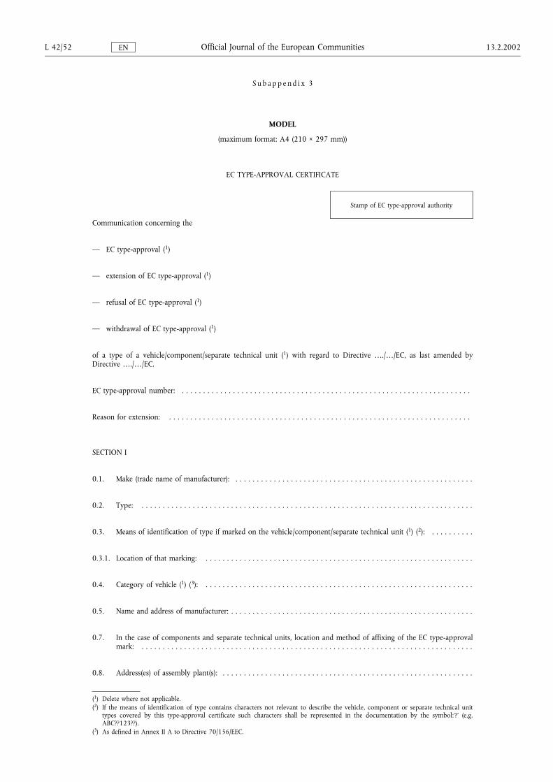
S u b a p p e n d i x 3
MODEL
(maximum format: A4 (210 × 297 mm))
EC TYPE-APPROVAL CERTIFICATE
Stamp of EC type-approval authority
Communication concerning the
� EC type-approval (1)
� extension of EC type-approval (1)
� refusal of EC type-approval (1)
� withdrawal of EC type-approval (1)
of a type of a vehicle/component/separate technical unit (1) with regard to Directive �./�/EC, as last amended byDirective �./�/EC.
EC type-approval number: . . . . . . . . . . . . . . . . . . . . . . . . . . . . . . . . . . . . . . . . . . . . . . . . . . . . . . . . . . . . . . . . . . . .
Reason for extension: . . . . . . . . . . . . . . . . . . . . . . . . . . . . . . . . . . . . . . . . . . . . . . . . . . . . . . . . . . . . . . . . . . . . . . .
SECTION I
0.1. Make (trade name of manufacturer): . . . . . . . . . . . . . . . . . . . . . . . . . . . . . . . . . . . . . . . . . . . . . . . . . . . . . . . .
0.2. Type: . . . . . . . . . . . . . . . . . . . . . . . . . . . . . . . . . . . . . . . . . . . . . . . . . . . . . . . . . . . . . . . . . . . . . . . . . . . . . .
0.3. Means of identification of type if marked on the vehicle/component/separate technical unit (1) (2): . . . . . . . . . .
0.3.1. Location of that marking: . . . . . . . . . . . . . . . . . . . . . . . . . . . . . . . . . . . . . . . . . . . . . . . . . . . . . . . . . . . . . . .
0.4. Category of vehicle (1) (3): . . . . . . . . . . . . . . . . . . . . . . . . . . . . . . . . . . . . . . . . . . . . . . . . . . . . . . . . . . . . . . .
0.5. Name and address of manufacturer: . . . . . . . . . . . . . . . . . . . . . . . . . . . . . . . . . . . . . . . . . . . . . . . . . . . . . . . . .
0.7. In the case of components and separate technical units, location and method of affixing of the EC type-approvalmark: . . . . . . . . . . . . . . . . . . . . . . . . . . . . . . . . . . . . . . . . . . . . . . . . . . . . . . . . . . . . . . . . . . . . . . . . . . . . . .
0.8. Address(es) of assembly plant(s): . . . . . . . . . . . . . . . . . . . . . . . . . . . . . . . . . . . . . . . . . . . . . . . . . . . . . . . . . . .
(1) Delete where not applicable.(2) If the means of identification of type contains characters not relevant to describe the vehicle, component or separate technical unit
types covered by this type-approval certificate such characters shall be represented in the documentation by the symbol:�?� (e.g.ABC??123??).
(3) As defined in Annex II A to Directive 70/156/EEC.
L 42/52 13.2.2002Official Journal of the European CommunitiesEN
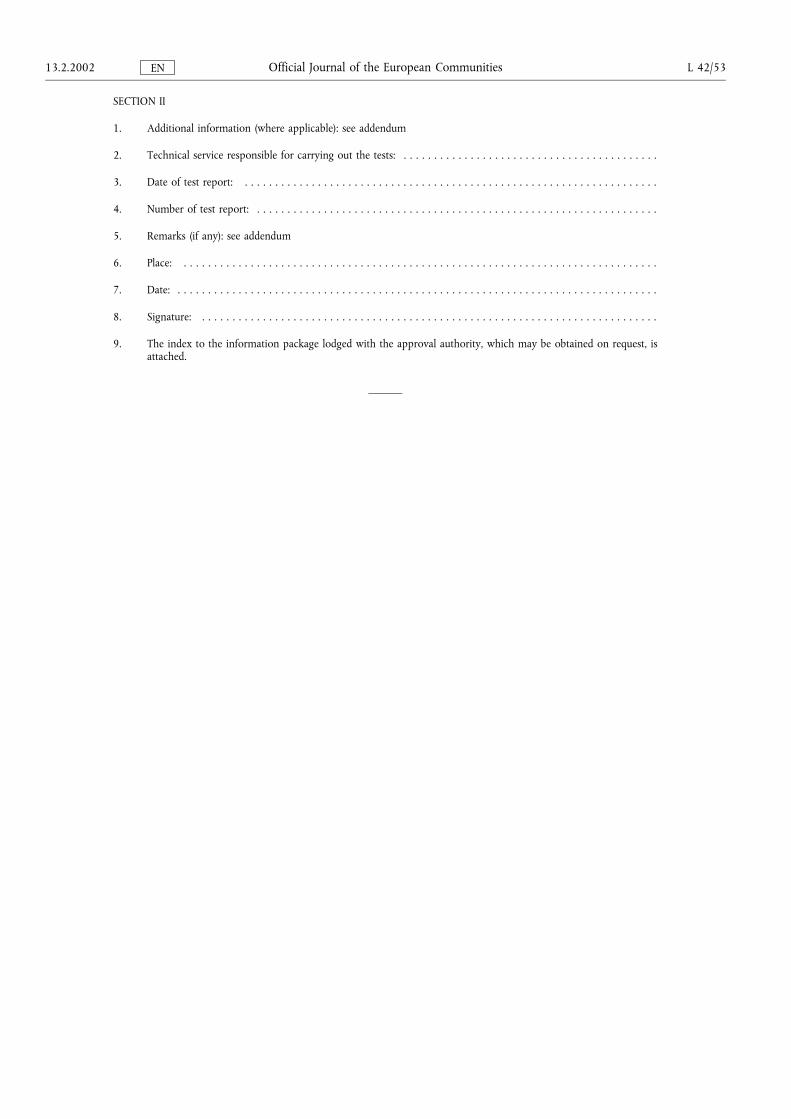
SECTION II
1. Additional information (where applicable): see addendum
2. Technical service responsible for carrying out the tests: . . . . . . . . . . . . . . . . . . . . . . . . . . . . . . . . . . . . . . . . . .
3. Date of test report: . . . . . . . . . . . . . . . . . . . . . . . . . . . . . . . . . . . . . . . . . . . . . . . . . . . . . . . . . . . . . . . . . . . .
4. Number of test report: . . . . . . . . . . . . . . . . . . . . . . . . . . . . . . . . . . . . . . . . . . . . . . . . . . . . . . . . . . . . . . . . . .
5. Remarks (if any): see addendum
6. Place: . . . . . . . . . . . . . . . . . . . . . . . . . . . . . . . . . . . . . . . . . . . . . . . . . . . . . . . . . . . . . . . . . . . . . . . . . . . . . .
7. Date: . . . . . . . . . . . . . . . . . . . . . . . . . . . . . . . . . . . . . . . . . . . . . . . . . . . . . . . . . . . . . . . . . . . . . . . . . . . . . . .
8. Signature: . . . . . . . . . . . . . . . . . . . . . . . . . . . . . . . . . . . . . . . . . . . . . . . . . . . . . . . . . . . . . . . . . . . . . . . . . . .
9. The index to the information package lodged with the approval authority, which may be obtained on request, isattached.
13.2.2002 L 42/53Official Journal of the European CommunitiesEN
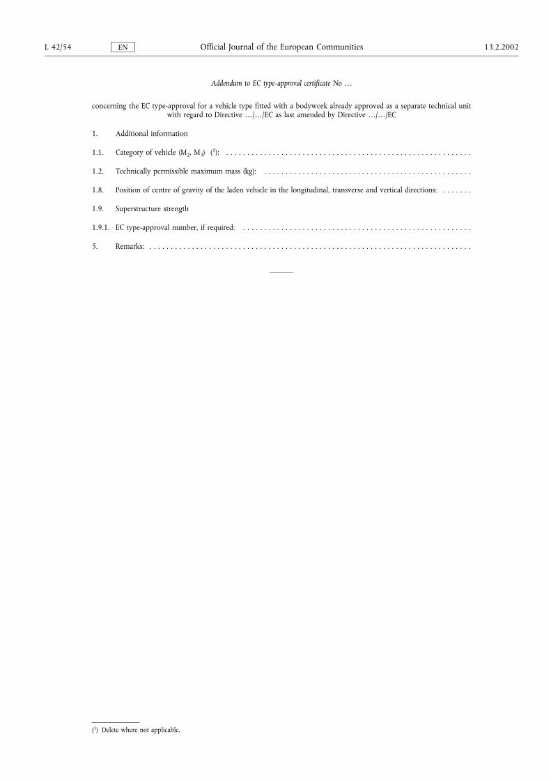
Addendum to EC type-approval certificate No �
concerning the EC type-approval for a vehicle type fitted with a bodywork already approved as a separate technical unitwith regard to Directive �/�/EC as last amended by Directive �/�/EC
1. Additional information
1.1. Category of vehicle (M2, M3) (1): . . . . . . . . . . . . . . . . . . . . . . . . . . . . . . . . . . . . . . . . . . . . . . . . . . . . . . . . . .
1.2. Technically permissible maximum mass (kg): . . . . . . . . . . . . . . . . . . . . . . . . . . . . . . . . . . . . . . . . . . . . . . . . .
1.8. Position of centre of gravity of the laden vehicle in the longitudinal, transverse and vertical directions: . . . . . . .
1.9. Superstructure strength
1.9.1. EC type-approval number, if required: . . . . . . . . . . . . . . . . . . . . . . . . . . . . . . . . . . . . . . . . . . . . . . . . . . . . . .
5. Remarks: . . . . . . . . . . . . . . . . . . . . . . . . . . . . . . . . . . . . . . . . . . . . . . . . . . . . . . . . . . . . . . . . . . . . . . . . . . . .
(1) Delete where not applicable.
L 42/54 13.2.2002Official Journal of the European CommunitiesEN
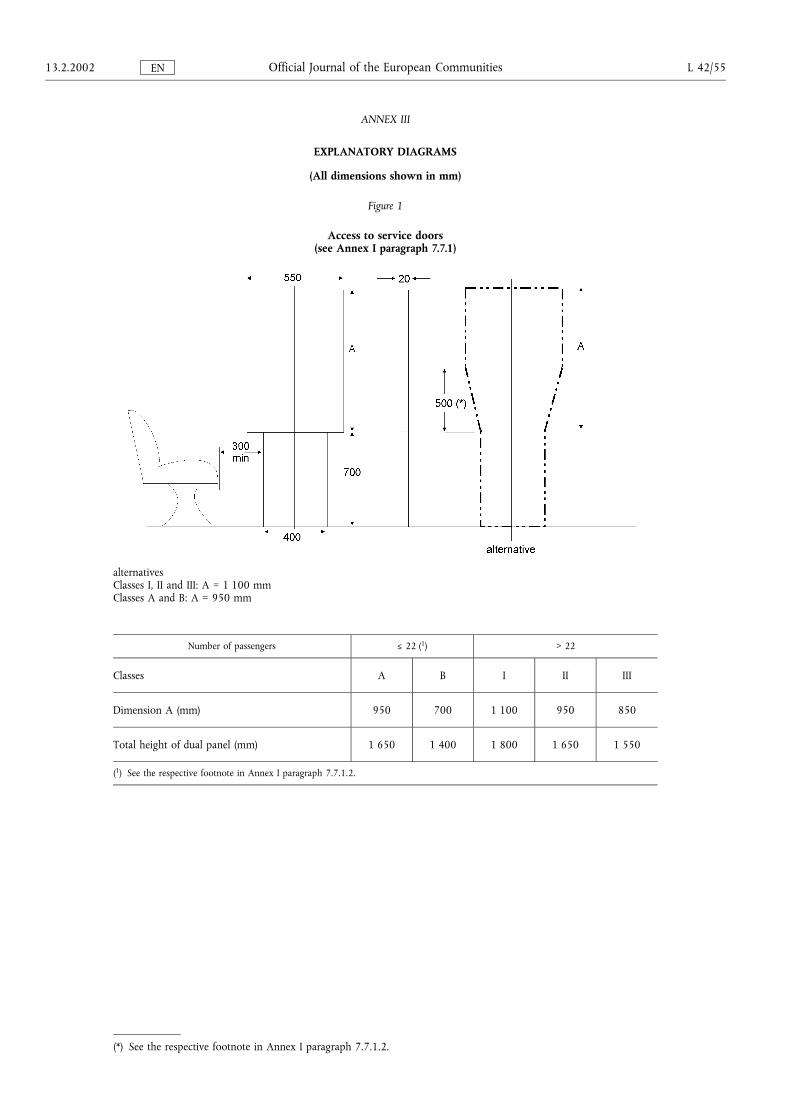
ANNEX III
EXPLANATORY DIAGRAMS
(All dimensions shown in mm)
Figure 1
Access to service doors(see Annex I paragraph 7.7.1)
alternativesClasses I, II and III: A = 1 100 mmClasses A and B: A = 950 mm
Number of passengers Ä 22 (1) > 22
Classes A B I II III
Dimension A (mm) 950 700 1 100 950 850
Total height of dual panel (mm) 1 650 1 400 1 800 1 650 1 550
(1) See the respective footnote in Annex I paragraph 7.7.1.2.
(*) See the respective footnote in Annex I paragraph 7.7.1.2.
13.2.2002 L 42/55Official Journal of the European CommunitiesEN
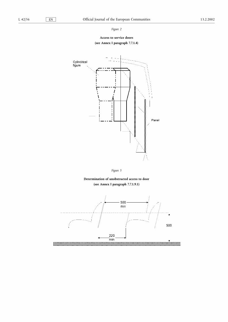
Figure 2
Access to service doors
(see Annex I paragraph 7.7.1.4)
Figure 3
Determination of unobstructed access to door
(see Annex I paragraph 7.7.1.9.1)
L 42/56 13.2.2002Official Journal of the European CommunitiesEN
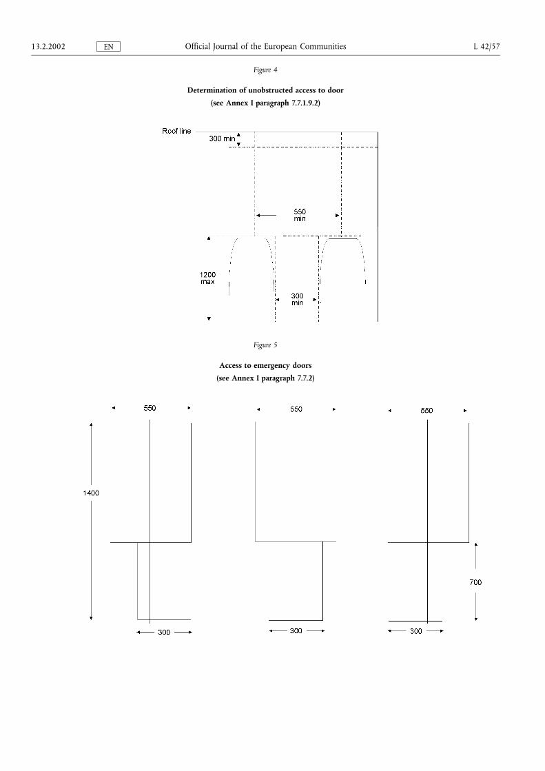
Figure 4
Determination of unobstructed access to door
(see Annex I paragraph 7.7.1.9.2)
Figure 5
Access to emergency doors
(see Annex I paragraph 7.7.2)
13.2.2002 L 42/57Official Journal of the European CommunitiesEN
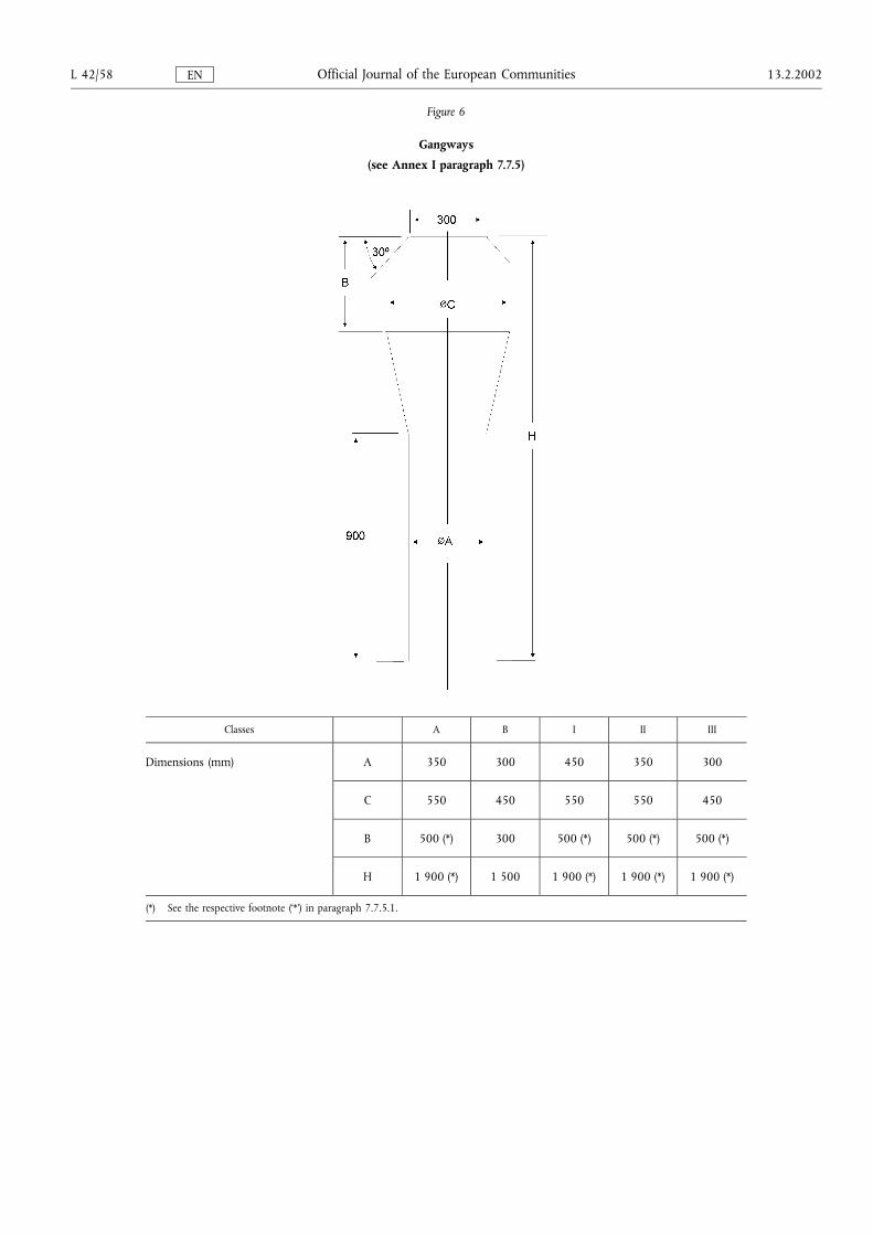
Figure 6
Gangways
(see Annex I paragraph 7.7.5)
Classes A B I II III
Dimensions (mm) A 350 300 450 350 300
C 550 450 550 550 450
B 500 (*) 300 500 (*) 500 (*) 500 (*)
H 1 900 (*) 1 500 1 900 (*) 1 900 (*) 1 900 (*)
(*) See the respective footnote (�*�) in paragraph 7.7.5.1.
L 42/58 13.2.2002Official Journal of the European CommunitiesEN
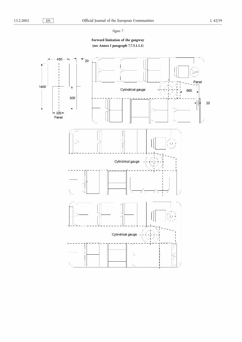
Figure 7
Forward limitation of the gangway
(see Annex I paragraph 7.7.5.1.1.1)
13.2.2002 L 42/59Official Journal of the European CommunitiesEN
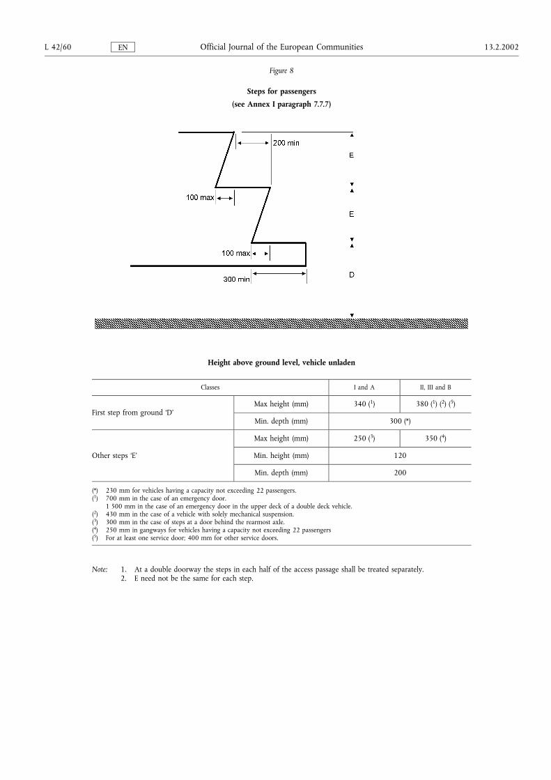
Figure 8
Steps for passengers
(see Annex I paragraph 7.7.7)
Height above ground level, vehicle unladen
Classes I and A II, III and B
First step from ground �D�Max height (mm) 340 (1) 380 (1) (2) (5)
Min. depth (mm) 300 (*)
Other steps �E�
Max height (mm) 250 (3) 350 (4)
Min. height (mm) 120
Min. depth (mm) 200
(*) 230 mm for vehicles having a capacity not exceeding 22 passengers.(1) 700 mm in the case of an emergency door.
1 500 mm in the case of an emergency door in the upper deck of a double deck vehicle.(2) 430 mm in the case of a vehicle with solely mechanical suspension.(3) 300 mm in the case of steps at a door behind the rearmost axle.(4) 250 mm in gangways for vehicles having a capacity not exceeding 22 passengers(5) For at least one service door; 400 mm for other service doors.
Note: 1. At a double doorway the steps in each half of the access passage shall be treated separately.2. E need not be the same for each step.
L 42/60 13.2.2002Official Journal of the European CommunitiesEN
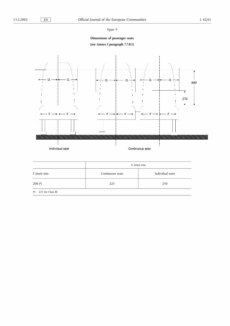
Figure 9
Dimensions of passenger seats
(see Annex I paragraph 7.7.8.1)
G (mm) min
F (mm) min Continuous seats Individual seats
200 (*) 225 250
(*) 225 for Class III
13.2.2002 L 42/61Official Journal of the European CommunitiesEN
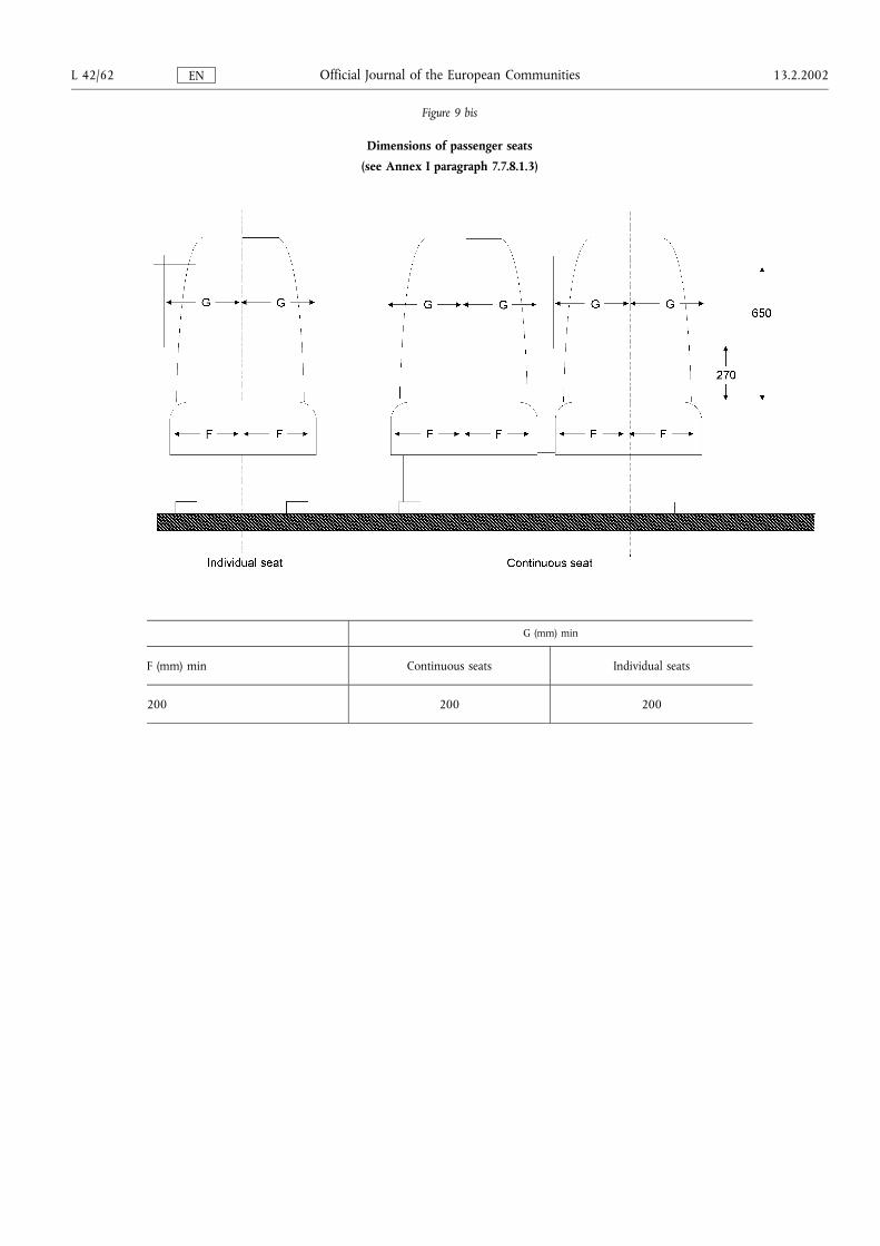
Figure 9 bis
Dimensions of passenger seats
(see Annex I paragraph 7.7.8.1.3)
G (mm) min
F (mm) min Continuous seats Individual seats
200 200 200
L 42/62 13.2.2002Official Journal of the European CommunitiesEN
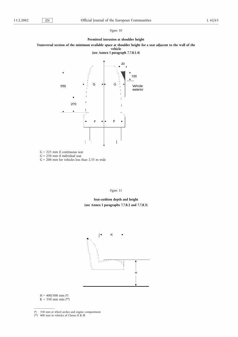
Figure 10
Permitted intrusion at shoulder height
Transversal section of the minimum available space at shoulder height for a seat adjacent to the wall of thevehicle
(see Annex I paragraph 7.7.8.1.4)
G = 225 mm if continuous seatG = 250 mm if individual seatG = 200 mm for vehicles less than 2,35 m wide
Figure 11
Seat-cushion depth and height
(see Annex I paragraphs 7.7.8.2 and 7.7.8.3)
H = 400/500 mm (*)K = 350 mm min (**)
(*) 350 mm at wheel arches and engine compartment(**) 400 mm in vehicles of Classes II & III
13.2.2002 L 42/63Official Journal of the European CommunitiesEN
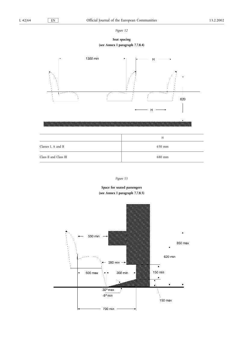
Figure 12
Seat spacing
(see Annex I paragraph 7.7.8.4)
H
Classes I, A and B 650 mm
Class II and Class III 680 mm
Figure 13
Space for seated passengers
(see Annex I paragraph 7.7.8.5)
L 42/64 13.2.2002Official Journal of the European CommunitiesEN
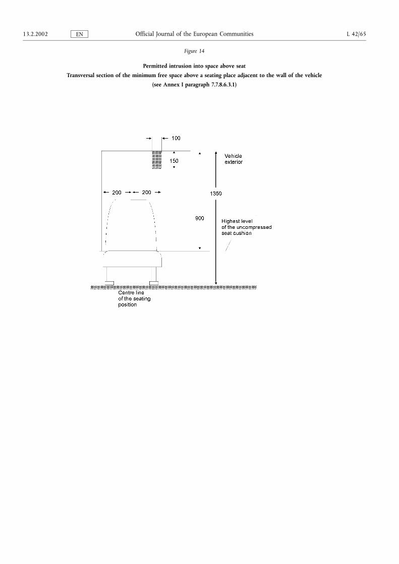
Figure 14
Permitted intrusion into space above seat
Transversal section of the minimum free space above a seating place adjacent to the wall of the vehicle
(see Annex I paragraph 7.7.8.6.3.1)
13.2.2002 L 42/65Official Journal of the European CommunitiesEN

Figure 15
Permitted intrusion above a seating position
(see Annex I paragraph 7.7.8.6.3.2)
L 42/66 13.2.2002Official Journal of the European CommunitiesEN
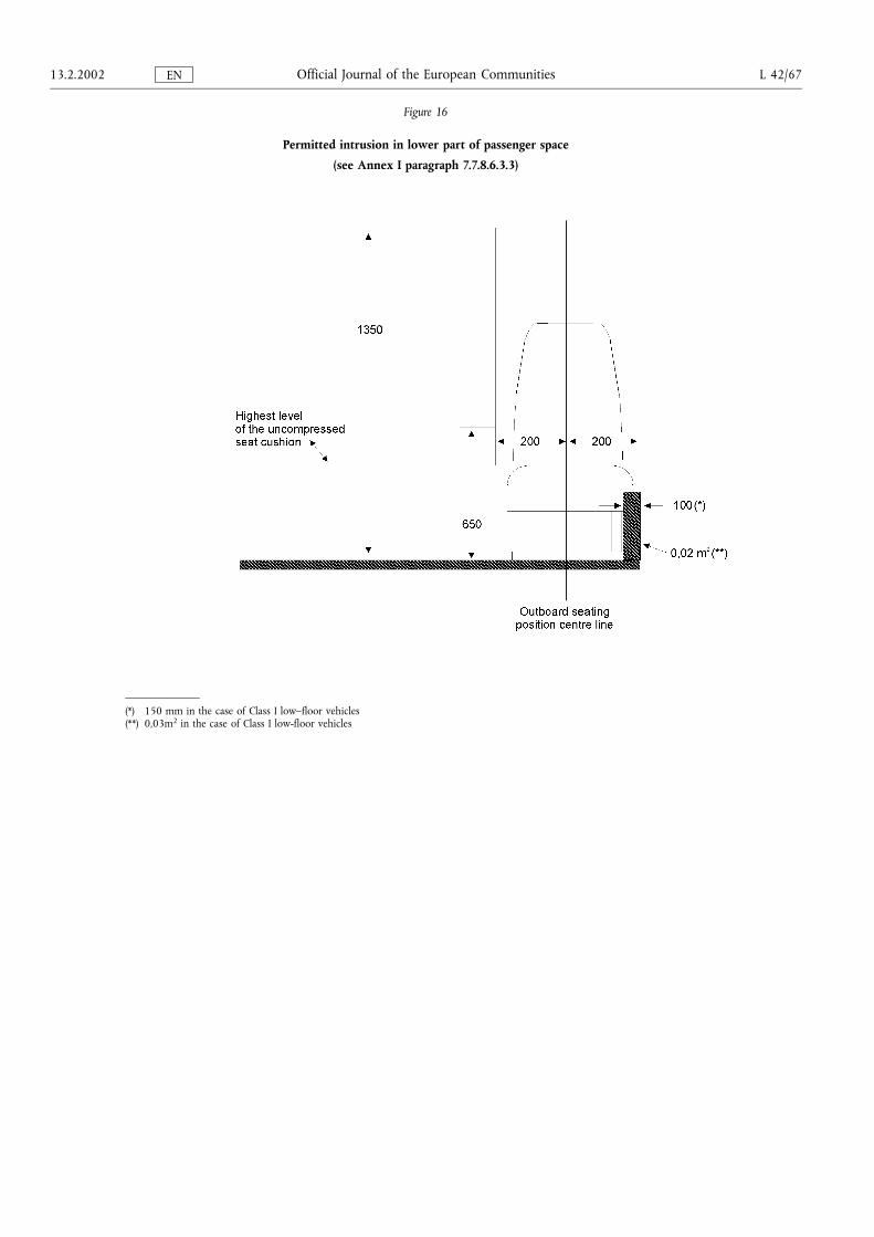
Figure 16
Permitted intrusion in lower part of passenger space
(see Annex I paragraph 7.7.8.6.3.3)
(*) 150 mm in the case of Class I low�floor vehicles(**) 0,03m2 in the case of Class I low-floor vehicles
13.2.2002 L 42/67Official Journal of the European CommunitiesEN
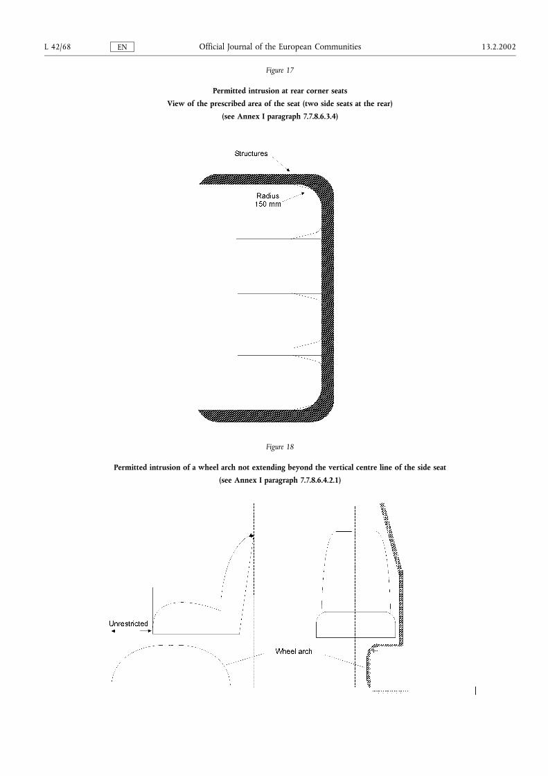
Figure 17
Permitted intrusion at rear corner seats
View of the prescribed area of the seat (two side seats at the rear)
(see Annex I paragraph 7.7.8.6.3.4)
Figure 18
Permitted intrusion of a wheel arch not extending beyond the vertical centre line of the side seat
(see Annex I paragraph 7.7.8.6.4.2.1)
L 42/68 13.2.2002Official Journal of the European CommunitiesEN
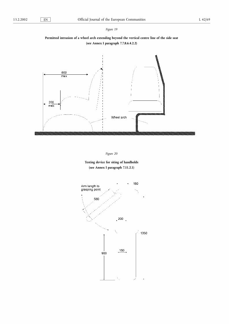
Figure 19
Permitted intrusion of a wheel arch extending beyond the vertical centre line of the side seat
(see Annex I paragraph 7.7.8.6.4.2.2)
Figure 20
Testing device for siting of handholds
(see Annex I paragraph 7.11.2.1)
13.2.2002 L 42/69Official Journal of the European CommunitiesEN
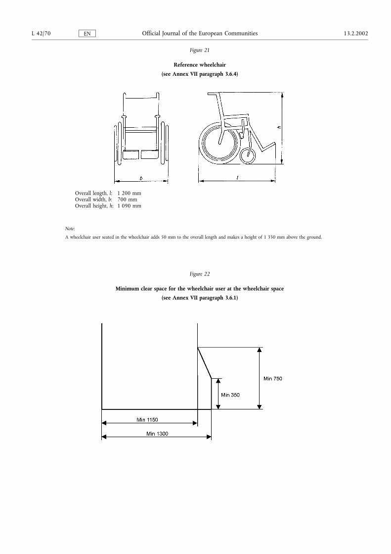
Figure 21
Reference wheelchair
(see Annex VII paragraph 3.6.4)
Overall length, l: 1 200 mmOverall width, b: 700 mmOverall height, h: 1 090 mm
Note:
A wheelchair user seated in the wheelchair adds 50 mm to the overall length and makes a height of 1 350 mm above the ground.
Figure 22
Minimum clear space for the wheelchair user at the wheelchair space
(see Annex VII paragraph 3.6.1)
L 42/70 13.2.2002Official Journal of the European CommunitiesEN
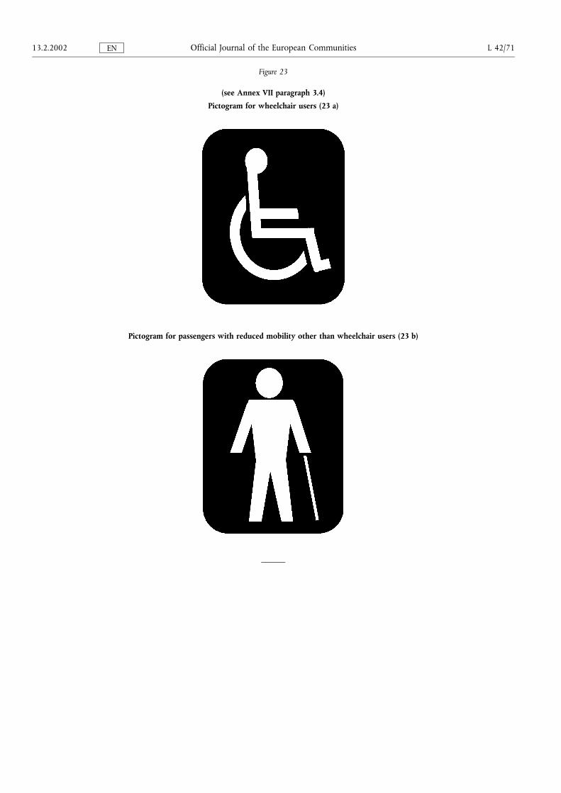
Figure 23
(see Annex VII paragraph 3.4)
Pictogram for wheelchair users (23 a)
Pictogram for passengers with reduced mobility other than wheelchair users (23 b)
13.2.2002 L 42/71Official Journal of the European CommunitiesEN
ANNEX IV
STRENGTH OF SUPERSTRUCTURE
1. Scope
This Annex applies to all single deck Class II and III vehicles.
2. Definitions
For the purposes of this Annex:
2.1. �residual space� means the space to be preserved in the passenger compartment during and after the structurehas been subjected to one of the tests prescribed in this Annex;
2.2. �superstructure� means the part(s) of a vehicle structure which contribute to the strength of the vehicle in theevent of a roll-over accident;
2.3. �body section� means a section containing at least two identical vertical pillars on each side representative of apart or parts of the structure of the vehicle;
2.4. �total energy� means the energy assumed to be absorbed by the complete structure of the vehicle. This may bedetermined as shown in this Annex.
3. General specifications and requirements
If the superstructure has obtained the approval according to the Regulation UN/ECE No 66 of the EconomicCommission for Europe, it is considered that it complies with these general specifications and requirements.
3.1. The superstructure of the vehicle shall be of sufficient strength to ensure that during and after it has beensubjected to one of the methods of test or calculation prescribed in paragraph 4:
3.1.1. no displaced part of the vehicle intrudes into the residual space, as specified in paragraph 5, and
3.1.2. no part of the residual space projects outside the deformed structure.
3.2. The requirements of paragraph 3.1 shall apply to the vehicle including all its structural parts, members andpanels and all projecting rigid parts such as baggage racks, ventilation equipment, etc. However, bulkheads,partitions, rings or other members reinforcing the superstructure of the vehicle and fixed appliances, such asbars, kitchenettes or toilets, shall be ignored for the purposes of paragraph 3.1.
3.3. In the case of an articulated vehicle each part of the vehicle shall comply with the requirements specified inparagraph 3.1.
4. Test methods
4.1. Each type of vehicle shall be verified according to one of the following methods at the discretion of themanufacturer or according to an alternative method approved by the competent authority:
4.1.1. a roll-over test on a complete vehicle in accordance with the procedure set out in Appendix 1;
4.1.2. a roll-over test on a body section or sections representative of a complete vehicle in accordance with Appendix2;
4.1.3. a pendulum test on a body section or sections in accordance with Appendix 3; or
4.1.4. a verification of strength of superstructure by calculation in accordance with Appendix 4.
L 42/72 13.2.2002Official Journal of the European CommunitiesEN
4.2. If the methods prescribed in paragraphs 4.1.2, 4.1.3 or 4.1.4 cannot take account of a significant variationbetween one section of the vehicle and another, for example an air-conditioning installation on the roof,additional test methods or calculations shall be submitted to the technical service. In the absence of suchadditional information the vehicle may be required to undergo the method of test prescribed in paragraph4.1.1.
5. Residual space
5.1. For the purpose of paragraph 2.1, the residual space means the volume within the passenger compartmentwhich is swept when the transverse vertical plane defined in figure 1(a) is moved in a straight line or lines sothat the point �R� in figure 1(a) passes from the �R� point of the rearmost outer seat, through the �R� point ofevery intermediate outer seat to the �R� point of the foremost outer passenger seats.
5.2. The position of the �R� point shown in figure 1(b) shall be assumed to be 500 mm above the floor under thepassengers' feet, 300 mm from the inside surface of the side of the vehicle and 100 mm in front of the seatback in the centre line of the outboard seats.
6. Interpretation of test results
6.1. If body sections are tested, the technical service responsible for conducting the test shall ensure that the vehiclecomplies with the conditions specified in Subappendix 2 of Appendix 3, which contains requirements for thedistribution of the main energy absorbing parts of the superstructure of a vehicle.
13.2.2002 L 42/73Official Journal of the European CommunitiesEN
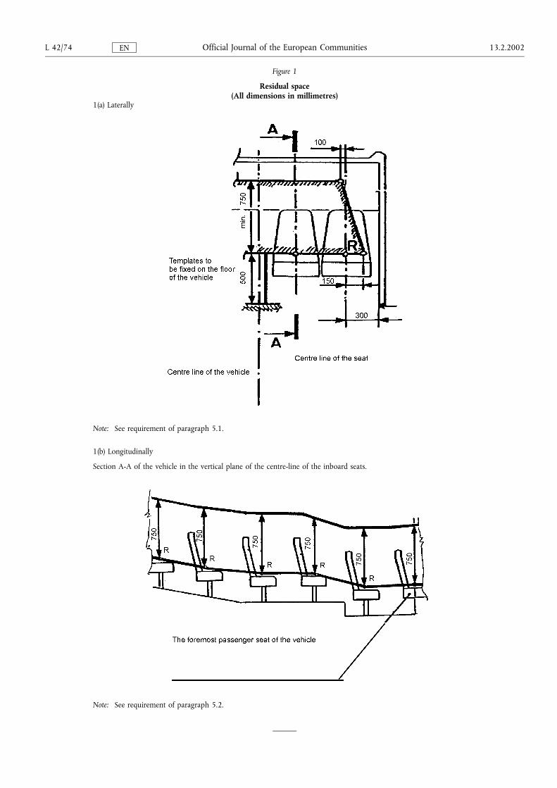
Figure 1
Residual space(All dimensions in millimetres)
1(a) Laterally
Note: See requirement of paragraph 5.1.
1(b) Longitudinally
Section A-A of the vehicle in the vertical plane of the centre-line of the inboard seats.
Note: See requirement of paragraph 5.2.
L 42/74 13.2.2002Official Journal of the European CommunitiesEN
Appendix 1
ROLL-OVER TEST ON A COMPLETE VEHICLE
1. Test condition
1.1. While the vehicle need not be in a fully finished condition, it shall be representative of production vehicles inrespect of the mass of the vehicle in running order, centre of gravity and distribution of mass as declared by themanufacturer.
1.2. Driver and passenger seats shall be placed with their backs, if adjustable, in their most upright position. Theheight of the seats, if adjustable, shall be in the highest position.
1.3. Every door and opening window of the vehicle shall be closed and latched but not locked. Windows and glazedbulkheads or screens may be glazed or unglazed at the applicant's discretion. If they are unglazed, an equivalentweight shall be imposed on the vehicle at the appropriate positions.
1.4. Tyres shall be inflated to the pressure prescribed by the vehicle manufacturer and, if the vehicle has anair-spring suspension system, the air supply to the air spring shall be ensured. Any automatic levelling systemshall be adjusted with the vehicle on a flat, horizontal surface to the level specified by the manufacturer. Shockabsorbers shall operate normally.
1.5. Fuel, battery acid and other combustible, explosive or corrosive materials may be substituted by other materials,provided that the conditions prescribed in paragraph 1.1 are met.
1.6. The impact area shall consist of concrete or other rigid material.
2. Test procedure (see figure 1)
2.1. The vehicle shall be placed on a platform in order to be rolled over on one side. This side shall be specified bythe manufacturer.
2.2. The position of the vehicle on the platform shall be such that when the platform is horizontal:
2.2.1. the axis of rotation is parallel to the longitudinal axis of the vehicle,
2.2.2. the axis of rotation is 0 to 200 mm from the vertical step between the two levels,
2.2.3. the axis of rotation is 0 to 100 mm from the side of the tyre at the widest axle,
2.2.4. the axis of rotation is 0 to 100 mm below the horizontal starting plane on which the tyres stand, and
2.2.5. the difference between the height of the horizontal starting plane and the horizontal lower plane on whichimpact takes place shall be not less than 800 mm.
2.3. Means shall be provided to prevent the vehicle moving along its longitudinal axis.
2.4. The test apparatus shall prevent the tyres from sliding sideways in the direction of roll-over by means of sidewalls.
2.5. The test apparatus shall ensure the simultaneous lifting of the axles of the vehicle.
2.6. The vehicle shall be tilted without rocking and without dynamic effects until its rolls over. The angular velocityshall not exceed 5 degrees per second (0,087 rad/sec).
2.7. High-speed photography, deformable templates or other suitable means shall be used to determine that therequirement of paragraph 3.1 of this Annex has been met. This shall be verified at not less than two positions,nominally at the front and rear of the passenger compartment, the exact positions being at the discretion of thetechnical service. Templates shall be fixed to substantially non-deformable parts of the structure.
13.2.2002 L 42/75Official Journal of the European CommunitiesEN

Figure 1
L 42/76 13.2.2002Official Journal of the European CommunitiesEN
Appendix 2
ROLL-OVER TEST ON A BODYWORK SECTION
1. Test conditions
1.1. The bodywork section shall represent a section of the unladen vehicle.
1.2. The geometry of the bodywork section, the axis of rotation and the position of the centre of gravity in thevertical and lateral directions shall be representative of the complete vehicle.
1.3. The mass of the bodywork section, expressed as a percentage of the unladen mass of the vehicle in runningorder, shall be specified by the manufacturer.
1.4. The energy to be absorbed by the bodywork section, expressed as a percentage of the total energy which wouldbe absorbed by a complete vehicle, shall be specified by the manufacturer.
1.5. The percentage of total energy described in paragraph 1.4 shall not be less than the percentage of the totalmass of the vehicle in running order described in paragraph 1.3.
1.6. The test conditions specified in paragraph 1.6 of Appendix 1 and in paragraphs 2.1 to 2.6 of Appendix 3 shallapply.
2. Test procedure
2.1. The test procedure shall be the same as the procedure described in Appendix 1, except that the bodyworksection described above shall be used instead of a complete vehicle.
13.2.2002 L 42/77Official Journal of the European CommunitiesEN
Appendix 3
PENDULUM TEST ON A BODYWORK SECTION
1. Energy level and direction of impact
1.1. The energy to be transmitted to a particular bodywork section shall be the sum of the energies declared by themanufacturer to be allocated to each of the cross-sectional rings included in that particular bodywork section.
1.2. The appropriate proportion of the energy prescribed in Subappendix 1 to this Appendix shall be applied to thebodywork section by the pendulum such that at the moment of impact the direction of motion of the pendulummakes an angle of 25 degrees (+ 0°; ¯ 5°) to the central longitudinal vertical plane of the bodywork section. Theprecise angle within this range shall be specified by the vehicle manufacturer.
2. Test conditions
2.1. A sufficient number of tests shall be carried out for the technical service conducting the test to be satisfied thatthe requirement specified in paragraph 3.1 of this Annex has been met.
2.2. For the purposes of the test, bodywork sections shall have sections of the normal structure fitted between thepillars in relation to the floor, underframe, sides and roof. Sections of such components as baggage racks,ventilation ducting, etc., where fitted, shall also be included.
2.3. Every door and opening window of the bodywork section shall be closed and latched but not locked. Windowsand glazed bulkheads or screens may be glazed or unglazed at the applicant's discretion.
2.4. Where appropriate, seats may also be included, at the option of the manufacturer, in their normal positions inrelation to the structure of the bodywork section. The normal fixings and joints between all members andattachments shall be incorporated. The backrests if adjustable shall be in their most upright position and theheight of the seats, if adjustable, shall be in the highest position.
2.5. The side of the bodywork section to be impacted shall be at the discretion of the manufacturer. Where morethan one bodywork section is required to be tested, both shall be impacted on the same side.
2.6. High speed photography, deformable templates or other suitable means shall be used to determine that therequirement specified in paragraph 3.1 of this Annex has been met. Templates shall be fixed to a substantiallynon-deformable part of the structure.
2.7. The bodywork section to be tested shall be firmly and securely attached to the mounting frame through thecross-bearers or parts which replace these in such a way that no significant energy is absorbed in the supportframe and its attachments during the impact.
2.8. The pendulum shall be released from such a height that it strikes the bodywork section at a speed of between 3and 8 m/s.
3. Description of the pendulum
3.1. The striking face of the pendulum shall be made of steel, or plywood 20 mm-5 mm thick, and the mass of thependulum shall be evenly distributed. Its striking face shall be rectangular and flat, having a width of not lessthan the width of the bodywork section being tested and a height of not less than 800 mm. Its edges shall berounded to a radius of curvature of not less than 15 mm.
3.2. The body of the pendulum shall be rigidly attached to two rigid bars. The axis of the bars shall be not less than3 500 mm from the geometric centre of the body of the pendulum.
L 42/78 13.2.2002Official Journal of the European CommunitiesEN
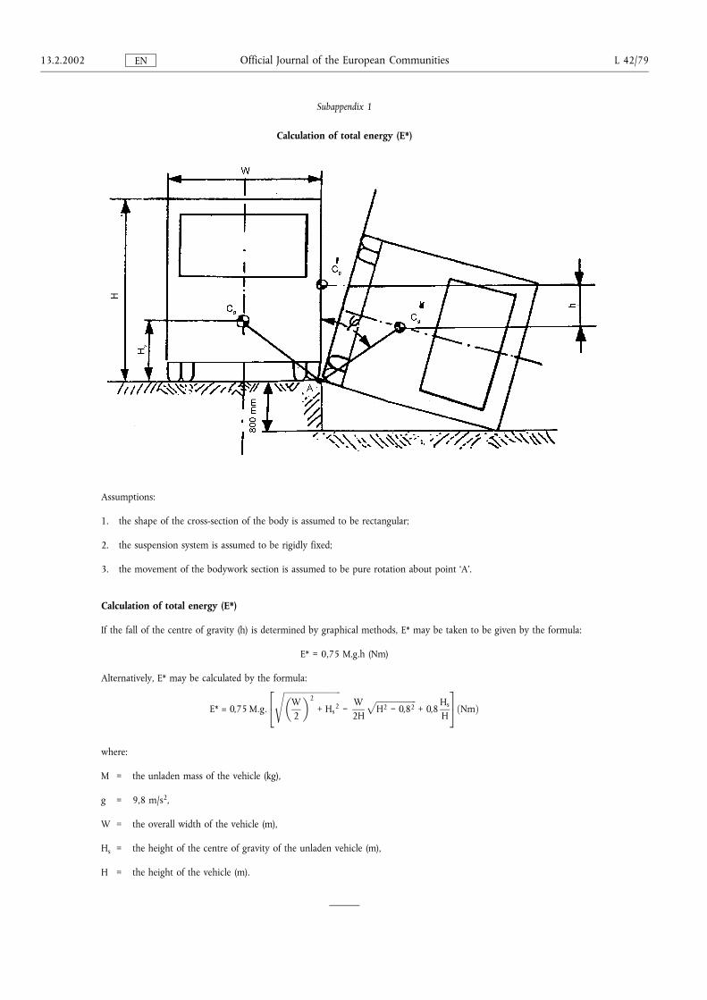
Subappendix 1
Calculation of total energy (E*)
Assumptions:
1. the shape of the cross-section of the body is assumed to be rectangular;
2. the suspension system is assumed to be rigidly fixed;
3. the movement of the bodywork section is assumed to be pure rotation about point �A�.
Calculation of total energy (E*)
If the fall of the centre of gravity (h) is determined by graphical methods, E* may be taken to be given by the formula:
E* = 0,75 M.g.h (Nm)
Alternatively, E* may be calculated by the formula:
E* = 0,75 M:g:
����������������������������W2
�2
+ Hs2
s¯
W2H
�������������������H2 ¯ 0,82
p+ 0,8
Hs
H
24 35�Nm�
where:
M = the unladen mass of the vehicle (kg),
g = 9,8 m/s2,
W = the overall width of the vehicle (m),
Hs = the height of the centre of gravity of the unladen vehicle (m),
H = the height of the vehicle (m).
13.2.2002 L 42/79Official Journal of the European CommunitiesEN
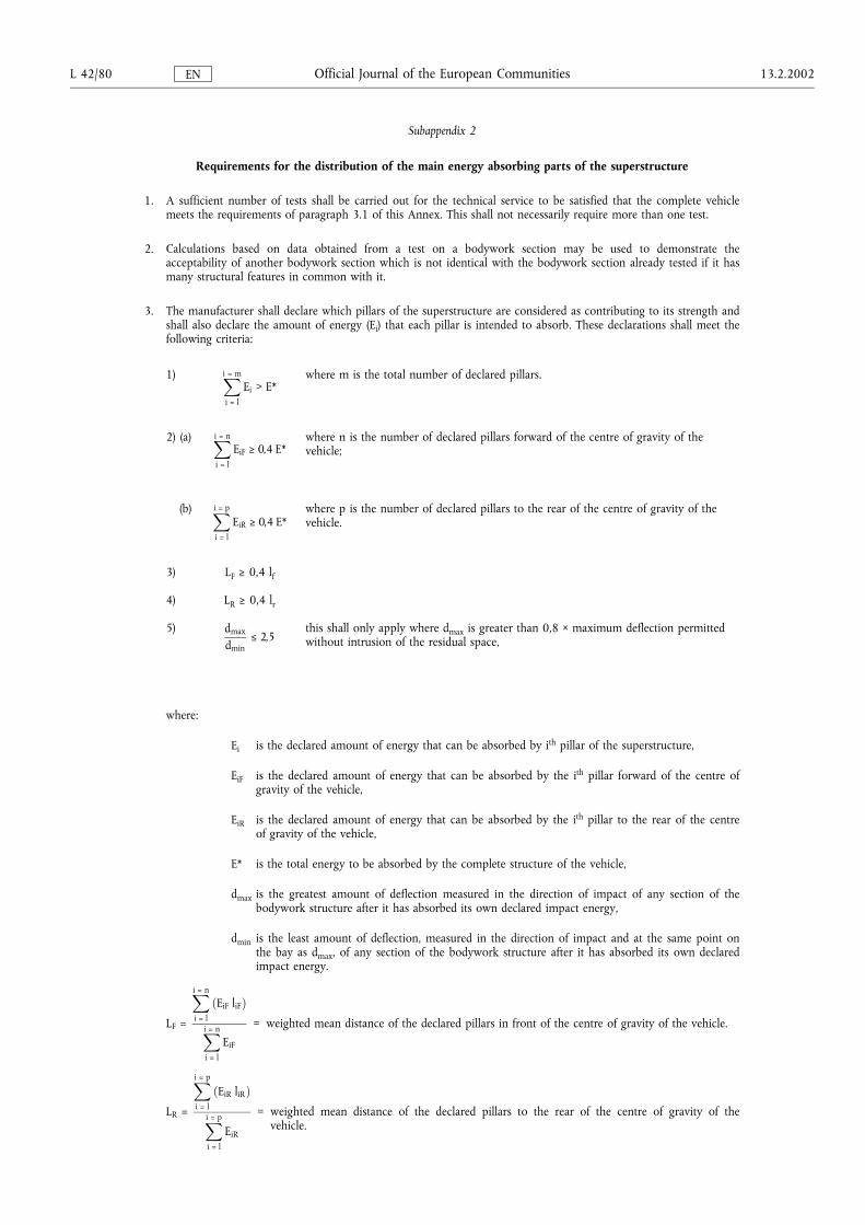
Subappendix 2
Requirements for the distribution of the main energy absorbing parts of the superstructure
1. A sufficient number of tests shall be carried out for the technical service to be satisfied that the complete vehiclemeets the requirements of paragraph 3.1 of this Annex. This shall not necessarily require more than one test.
2. Calculations based on data obtained from a test on a bodywork section may be used to demonstrate theacceptability of another bodywork section which is not identical with the bodywork section already tested if it hasmany structural features in common with it.
3. The manufacturer shall declare which pillars of the superstructure are considered as contributing to its strength andshall also declare the amount of energy (Ei) that each pillar is intended to absorb. These declarations shall meet thefollowing criteria:
1) Xi = m
i = l
Ei > E*where m is the total number of declared pillars.
2) (a) Xi = n
i = l
EiF Å 0,4 E*where n is the number of declared pillars forward of the centre of gravity of thevehicle;
(b) Xi = p
i = l
EiR Å 0,4 E*where p is the number of declared pillars to the rear of the centre of gravity of thevehicle.
3) LF Å 0,4 lf
4) LR Å 0,4 lr
5) dmax
dminÄ 2,5
this shall only apply where dmax is greater than 0,8 × maximum deflection permittedwithout intrusion of the residual space,
where:
Ei is the declared amount of energy that can be absorbed by ith pillar of the superstructure,
EiF is the declared amount of energy that can be absorbed by the ith pillar forward of the centre ofgravity of the vehicle,
EiR is the declared amount of energy that can be absorbed by the ith pillar to the rear of the centreof gravity of the vehicle,
E* is the total energy to be absorbed by the complete structure of the vehicle,
dmax is the greatest amount of deflection measured in the direction of impact of any section of thebodywork structure after it has absorbed its own declared impact energy,
dmin is the least amount of deflection, measured in the direction of impact and at the same point onthe bay as dmax, of any section of the bodywork structure after it has absorbed its own declaredimpact energy.
LF =
Xi = n
i = l
�EiF liF�
Xi = n
i = l
EiF
= weighted mean distance of the declared pillars in front of the centre of gravity of the vehicle.
LR =
Xi = p
i = l
�EiR liR�
Xi = p
i = l
EiR
= weighted mean distance of the declared pillars to the rear of the centre of gravity of thevehicle.
L 42/80 13.2.2002Official Journal of the European CommunitiesEN
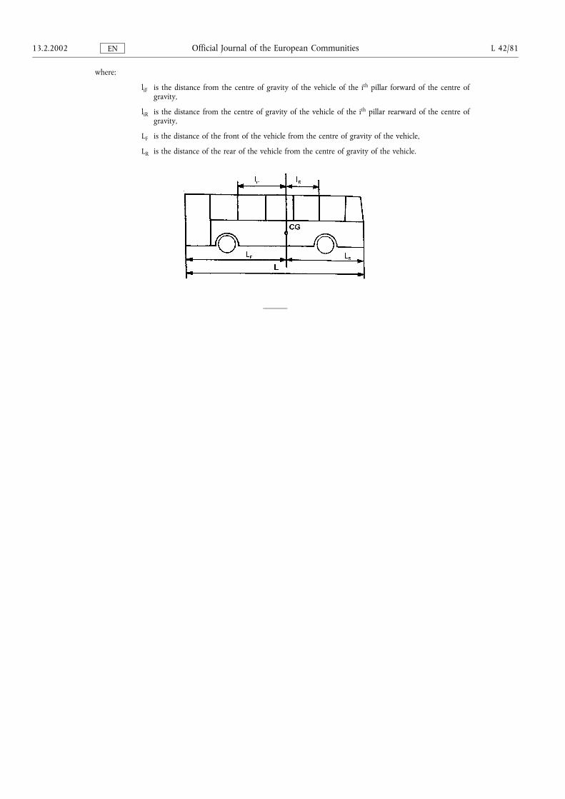
where:
liF is the distance from the centre of gravity of the vehicle of the ith pillar forward of the centre ofgravity,
liR is the distance from the centre of gravity of the vehicle of the ith pillar rearward of the centre ofgravity,
LF is the distance of the front of the vehicle from the centre of gravity of the vehicle,
LR is the distance of the rear of the vehicle from the centre of gravity of the vehicle.
13.2.2002 L 42/81Official Journal of the European CommunitiesEN
Appendix 4
VERIFICATION OF STRENGTH OF SUPERSTRUCTURE BY CALCULATION
1. A superstructure or sections of a superstructure may be shown to meet the requirement specified in paragraph3.1 of this Annex by a calculation method approved by the technical service responsible for conducting thetests.
2. If the structure is likely to be subject to deformations beyond the elastic limit of the materials used, then thecalculations shall simulate the behaviour of the structure when undergoing large plastic deformations.
3. The technical service responsible for conducting the tests may require tests to be carried out on joints or partsof the structure to verify the assumptions made in the calculation.
4. Preparations for calculation
4.1. Calculations cannot be started until the structure has been analysed and a mathematical model of it produced.This will define the separate members to be considered and identify the points at which plastic hinges maydevelop. The dimensions of the members and the properties of material used must be stated. Physical tests mustbe made on the hinge points to determine the force (moment of rotation)-deformation characteristics in theplastic mode as this is essential data for the calculations. The strain rate and the dynamic yield stressappropriate for this strain rate must be determined. If the calculation method will not indicate when asignificant fracture will occur, it will be essential to determine, by experiment, separate analyses or appropriatedynamic distribution. Distribution of loading along the length of a vehicle shall be stated.
4.2. The calculation method shall include the deformations up to the elastic limits of the materials followed by theidentification of where plastic hinges will form and the subsequent formation of other plastic hinges unless theposition and sequences of formation of plastic hinges is known from previous experience. The method shallaccommodate the changes of geometry of the structure that take place, at least up to the stage where thedeformations have passed the acceptable limits. The calculations shall simulate the energy and the direction ofimpact which would occur if that particular superstructure were to be submitted to the roll-over tests prescribedin Appendix 1. The validity of the calculation method shall have been established by comparison with theresults of physical tests, which need not necessarily have been made in connection with the vehicle now beingapproved.
5. Tests of section of superstructure
When a calculation method is used for a section of the complete superstructure, the same conditions shall applyas stated above for the complete vehicle.
L 42/82 13.2.2002Official Journal of the European CommunitiesEN
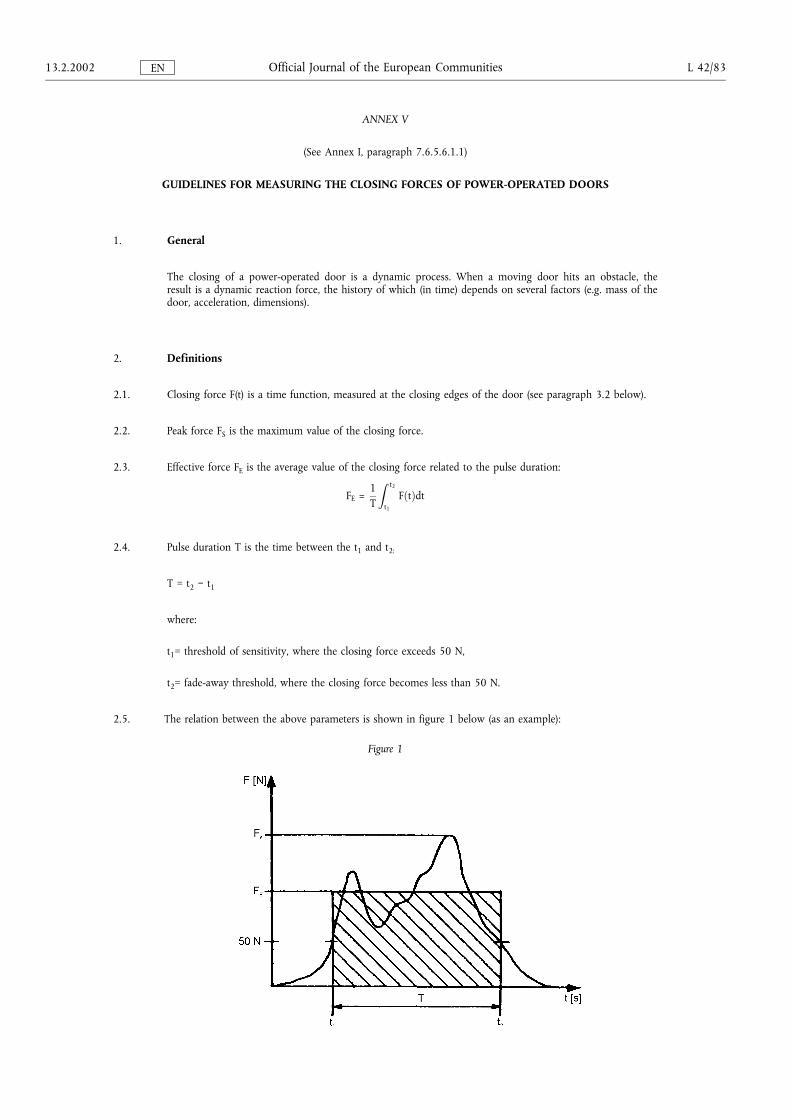
ANNEX V
(See Annex I, paragraph 7.6.5.6.1.1)
GUIDELINES FOR MEASURING THE CLOSING FORCES OF POWER-OPERATED DOORS
1. General
The closing of a power-operated door is a dynamic process. When a moving door hits an obstacle, theresult is a dynamic reaction force, the history of which (in time) depends on several factors (e.g. mass of thedoor, acceleration, dimensions).
2. Definitions
2.1. Closing force F(t) is a time function, measured at the closing edges of the door (see paragraph 3.2 below).
2.2. Peak force FS is the maximum value of the closing force.
2.3. Effective force FE is the average value of the closing force related to the pulse duration:
FE =1T
Z t2
t1
F�t�dt
2.4. Pulse duration T is the time between the t1 and t2:
T = t2 ¯ t1
where:
t1= threshold of sensitivity, where the closing force exceeds 50 N,
t2= fade-away threshold, where the closing force becomes less than 50 N.
2.5. The relation between the above parameters is shown in figure 1 below (as an example):
Figure 1
13.2.2002 L 42/83Official Journal of the European CommunitiesEN
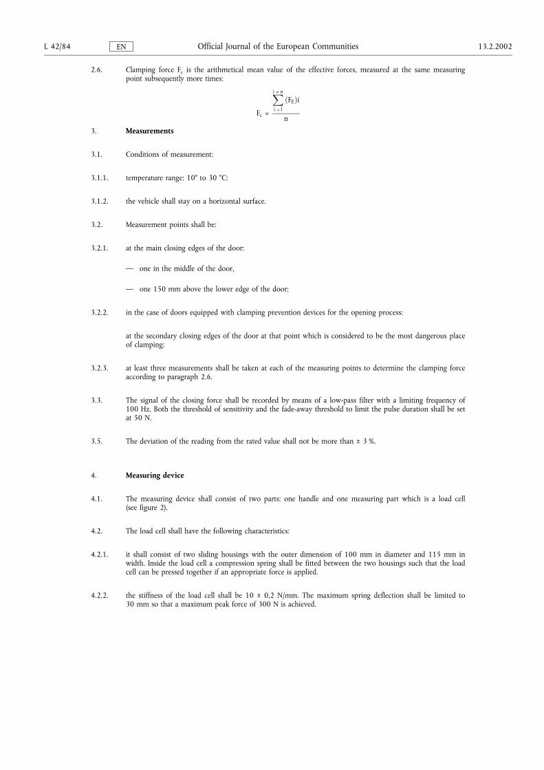
2.6. Clamping force Fc is the arithmetical mean value of the effective forces, measured at the same measuringpoint subsequently more times:
Fc =
Xi = n
i = l
�FE�i
n
3. Measurements
3.1. Conditions of measurement:
3.1.1. temperature range: 10° to 30 °C;
3.1.2. the vehicle shall stay on a horizontal surface.
3.2. Measurement points shall be:
3.2.1. at the main closing edges of the door:
� one in the middle of the door,
� one 150 mm above the lower edge of the door;
3.2.2. in the case of doors equipped with clamping prevention devices for the opening process:
at the secondary closing edges of the door at that point which is considered to be the most dangerous placeof clamping;
3.2.3. at least three measurements shall be taken at each of the measuring points to determine the clamping forceaccording to paragraph 2.6.
3.3. The signal of the closing force shall be recorded by means of a low-pass filter with a limiting frequency of100 Hz. Both the threshold of sensitivity and the fade-away threshold to limit the pulse duration shall be setat 50 N.
3.5. The deviation of the reading from the rated value shall not be more than ± 3 %.
4. Measuring device
4.1. The measuring device shall consist of two parts: one handle and one measuring part which is a load cell(see figure 2).
4.2. The load cell shall have the following characteristics:
4.2.1. it shall consist of two sliding housings with the outer dimension of 100 mm in diameter and 115 mm inwidth. Inside the load cell a compression spring shall be fitted between the two housings such that the loadcell can be pressed together if an appropriate force is applied.
4.2.2. the stiffness of the load cell shall be 10 ± 0,2 N/mm. The maximum spring deflection shall be limited to30 mm so that a maximum peak force of 300 N is achieved.
L 42/84 13.2.2002Official Journal of the European CommunitiesEN
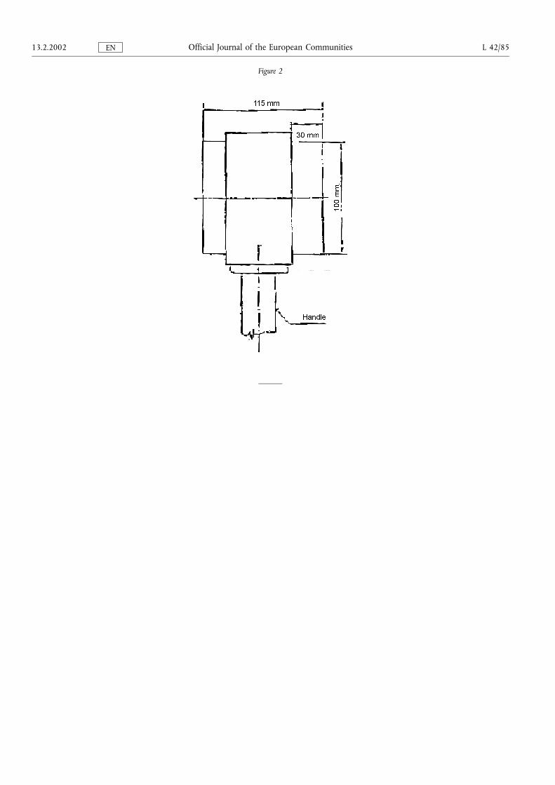
Figure 2
13.2.2002 L 42/85Official Journal of the European CommunitiesEN

ANNEX VI
SPECIAL REQUIREMENTS FOR VEHICLES HAVING A CAPACITY NOT EXCEEDING 22 PASSENGERS
1.1. Minimum dimensions for exits
The several kinds of exits shall have the following minimum dimensions:
Aperture Dimensions Remarks
Service door Entry heightClass:A: 1 650 mmB: 1 500 mm
The service door entry height shall be measured as thevertical distance measured on a vertical plane of thehorizontal projections of the mid-point of the door apertureand the top surface of the lowest step.
Aperture height The vertical height of the service door aperture shall besuch as to permit the free passage of the dual panel referredto in paragraph 7.7.1.1. of Annex I. The upper corners maybe reduced with round-offs, with a radius of not more than150 mm.
WidthSingle door: 650 mmDouble door: 1 200 mm
For Class B vehicles where the service door aperture heightlies between 1 400 mm and 1 500 mm a minimum singledoor aperture width of 750 mm shall apply. For all thevehicles the width of any service door may be reduced by100 mm when the measurement is made at the level of thehand holds and by 250 mm in cases where intruding wheelarches or the actuating mechanism for automatic orremote-control doors or the rake of the windscreen sorequire.
Emergencydoor
Height: 1 250 mmWidth: 550 mm
The width may be reduced to 300 mm in cases whereintruding wheel arches so require, providing that the widthof 550 mm is respected at the minimum height of 400 mmabove the lowest part of the door aperture. The uppercorners may be reduced with round-offs, with a radius ofnot more than 150 mm.
Emergencywindow
Aperture area: 4 000 cm2 A 5 % tolerance shall, however, be permitted in respect ofthis area for type-approvals issued for one year followingthe entry into force of this Directive. It shall be possible toinscribe in this area a rectangle of 500 mm × 700 mm.
L 42/86 13.2.2002Official Journal of the European CommunitiesEN
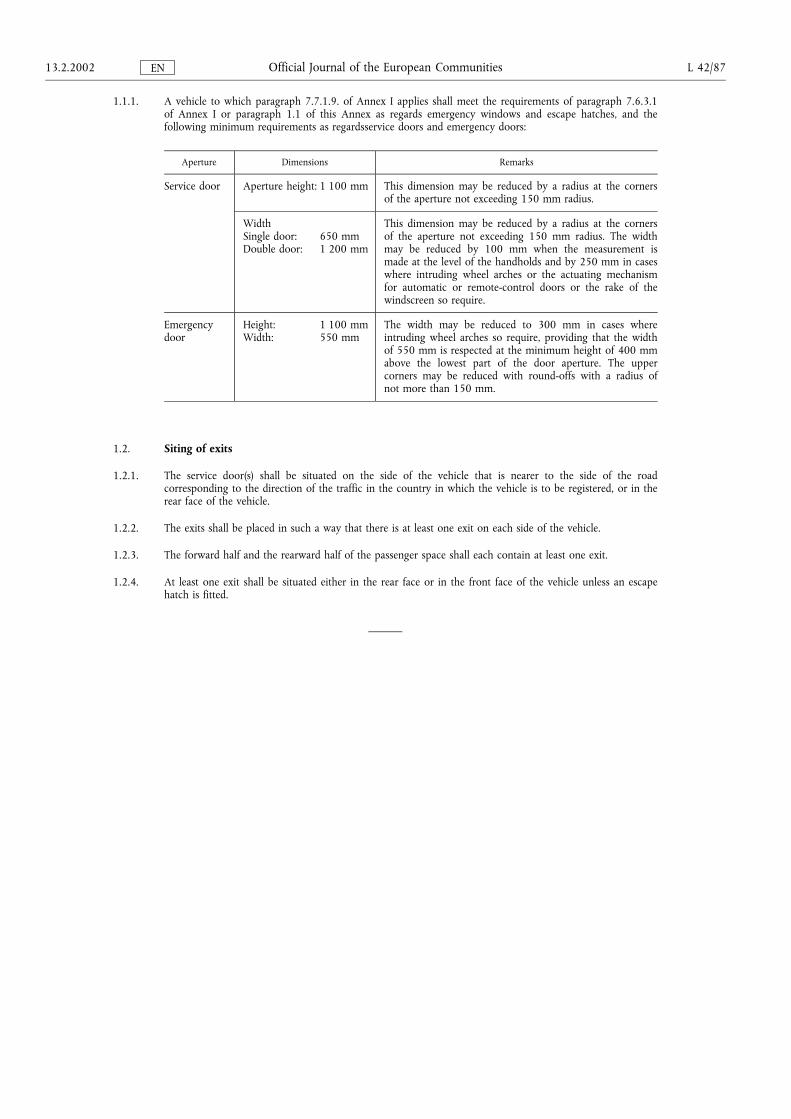
1.1.1. A vehicle to which paragraph 7.7.1.9. of Annex I applies shall meet the requirements of paragraph 7.6.3.1of Annex I or paragraph 1.1 of this Annex as regards emergency windows and escape hatches, and thefollowing minimum requirements as regardsservice doors and emergency doors:
Aperture Dimensions Remarks
Service door Aperture height: 1 100 mm This dimension may be reduced by a radius at the cornersof the aperture not exceeding 150 mm radius.
WidthSingle door: 650 mmDouble door: 1 200 mm
This dimension may be reduced by a radius at the cornersof the aperture not exceeding 150 mm radius. The widthmay be reduced by 100 mm when the measurement ismade at the level of the handholds and by 250 mm in caseswhere intruding wheel arches or the actuating mechanismfor automatic or remote-control doors or the rake of thewindscreen so require.
Emergencydoor
Height: 1 100 mmWidth: 550 mm
The width may be reduced to 300 mm in cases whereintruding wheel arches so require, providing that the widthof 550 mm is respected at the minimum height of 400 mmabove the lowest part of the door aperture. The uppercorners may be reduced with round-offs with a radius ofnot more than 150 mm.
1.2. Siting of exits
1.2.1. The service door(s) shall be situated on the side of the vehicle that is nearer to the side of the roadcorresponding to the direction of the traffic in the country in which the vehicle is to be registered, or in therear face of the vehicle.
1.2.2. The exits shall be placed in such a way that there is at least one exit on each side of the vehicle.
1.2.3. The forward half and the rearward half of the passenger space shall each contain at least one exit.
1.2.4. At least one exit shall be situated either in the rear face or in the front face of the vehicle unless an escapehatch is fitted.
13.2.2002 L 42/87Official Journal of the European CommunitiesEN
ANNEX VII
REQUIREMENTS FOR TECHNICAL DEVICES FACILITATING ACCESS FOR PASSENGERS WITH REDUCEDMOBILITY
1. GENERAL
This Annex contains the provisions which apply to a vehicle designed for easy access for passengers withreduced mobility and wheelchair users.
2. SCOPE
These requirements shall apply to vehicles permitting easier access for passengers with reduced mobility.
3. REQUIREMENTS
3.1. Steps
The height of the first step from the ground of at least one service door shall not exceed 250 mm forvehicles of Class I and A and 320 mm for vehicles of Class II, III and B.
As an alternative for vehicles of Class I and A, the first step from the ground shall not exceed 270 mm intwo door openings, one entrance and one exit.
A kneeling system and/or retractable step may be engaged.
The height of the steps other than the first step from the ground at the abovementioned door(s), in anaccess passage and in a gangway, shall be not more than 200 mm for vehicles of Class I and A and 250mm for vehicles of Class II, III and B.
The transition from a sunken gangway to a seating area shall not be considered to be a step.
3.2. Priority seats and space for passengers with reduced mobility
3.2.1. A minimum number of forward or rearward facing seats designated as priority seats for disabledpassengers shall be situated in a position near to a service door(s) suitable for boarding and alighting. Theminimum number of priority seats shall be four in Class I, two in Class II and Class III and one in Class Aand B. A seat that folds out of the way when not in use shall not be designated as a priority seat.Paragraph 7.7.8.5.2 of Annex I shall not apply to vehicles that comply with this requirement.
3.2.2. There shall be adequate space under, or adjacent to, at least one of the priority seats for a guide dog.
3.2.3. Armrests shall be fitted on seats between the seating position and the gangway and shall be capable ofbeing moved easily out of the way to permit clear access to the seat.
Handrails or handholds shall be fitted adjacent to priority seats in such a way as to allow the passenger tograsp them easily.
3.2.4. The minimum width of a priority seat cushion, measured from a vertical plane passing through the centreof that seating position, shall be 220 mm on each side or, in the case of a continuous seat, 220 mm perseating position on each side.
3.2.5. The height of the uncompressed seat cushion relative to the floor shall be such that the distance from thefloor to a horizontal plane tangent to the front upper surface of the seat cushion is between 400 mm and500 mm.
3.2.6. The foot space at priority seating positions shall extend forward of the seat from a vertical plane throughthe forward edge of the seat cushion. The foot space shall not have a slope in any direction of more than8 %.
L 42/88 13.2.2002Official Journal of the European CommunitiesEN
3.2.7. Each priority seating position shall have a free height of not less than 1 300 mm for vehicles of Class Iand A and 900 mm for vehicles of Class II, measured from the highest point of the uncompressed seatcushion. This free height shall extend over the vertical projection of the whole of the seat and theassociated foot space. Intrusion of a seat back or other object into this space shall be permitted providedthat a minimum clear vertical space extending 230 mm in front of the seat cushion is maintained. Wherethe priority seat is positioned facing a bulkhead more than 1,2 m in height this space shall be 300 mm.
3.3. Communication devices
3.3.1. Communication devices shall be placed adjacent to any priority seat and within any wheelchair area andshall be at a height between 700 mm and 1 200 mm above the floor.
3.3.2. Communication devices situated in the low-floor area shall be at a height between 800 mm and 1 500mm where there are no seats.
3.3.3. The control for all internal communication devices shall be capable of operation with the palm of thehand and shall be in a contrasting colour or colours and tone.
3.3.4. If a vehicle is fitted with a ramp or lift, a means of communication with the driver shall be fitted outside,adjacent to the door, and not higher than 1 300 mm from the ground.
3.4. Pictograms
3.4.1. Vehicles fitted with a wheelchair space and/or priority seats shall have pictograms in accordance withAnnex III, figure 23(a) visible from the outside, both on the front nearside of the vehicle and adjacent tothe relevant service door(s). Appropriate pictograms shall also be placed internally adjacent to thewheelchair space or to the priority seat.
3.5. Floor slope
The slope of any gangway, access passage or floor area between any priority seat or wheelchair space andat least one entrance and one exit or a combined entrance and exit shall not exceed 8 %. Such slopingareas shall be provided with a non-slip surface.
3.6. Wheelchair accommodation provisions
3.6.1. For each wheelchair user provided for in the passenger compartment there shall be a special area at least750 mm wide and 1 300 mm long. The longitudinal plane of the special area shall be parallel to thelongitudinal plane of the vehicle and the floor surface of the special area shall be slip resistant.
In the case of a wheelchair space designed for a forward facing wheelchair, the top of preceding seatbacksmay intrude into the wheelchair space if a clear space is provided as shown in Annex III, figure 22.
3.6.2. There shall be at least one doorway through which wheelchair users can pass. In the case of vehicles ofClass I, at least one wheelchair access door shall be a service door. The wheelchair access door shall bear aboarding aid complying with the provisions of paragraph 3.11.2 (a kneeling system) of this Annex; thisshall be in combination with the provisions of paragraph 3.11.3 (a lift) or 3.11.4 (a ramp) of this Annex.
3.6.3. A door for wheelchair access, that is not a service door, shall have a minimum height of 1 400 mm. Theminimum width of all doors providing wheelchair access to the vehicle shall be 900 mm which may bereduced by 100 mm when the measurement is made at the level of handholds.
3.6.4. It shall be possible to move from the outside of the vehicle through at least one of the doors forwheelchair access into the special area(s) with a reference wheelchair of the dimensions shown in AnnexIII, figure 21.
13.2.2002 L 42/89Official Journal of the European CommunitiesEN
3.7. Seats in the wheelchair space
3.7.1. Folding seats may be fitted in a wheelchair space. However, such seats when folded and out of use shallnot intrude into the wheelchair space.
3.7.2. A vehicle may be equipped with demountable seats fitted in the wheelchair space provided that such seatsmay be easily removed by the driver or a crew member.
3.7.3. Where the foot space of any seat, or part of a folding seat when in use, intrudes into a wheelchair space,those seats shall have a sign fixed on or adjacent to them with the following text:
�Please give up this space for a wheelchair user�.
3.8. Stability of wheelchairs
3.8.1. Wheelchair restraint system. As an alternative to the requirements contained in paragraphs 3.8.1.1 to3.8.1.2.3, restraint systems may comply with the requirements contained in paragraphs 3.8.2 to 3.8.2.11.
3.8.1.1. In a vehicle where passenger seats are not required to be fitted with any kind of occupant restraint system,the wheelchair space shall be fitted with a restraint system in order to warrant the stability of thewheelchair.
A static test shall be carried out in accordance with the following requirements:
(a) a force of 250 daN ± 20 daN per wheelchair shall be applied on the restraint system itself;
(b) the force shall be applied in the horizontal plane of the vehicle and towards the front of the vehicle ifthe restraint system is not attached to the floor of the vehicle. If the restraint system is attached to thefloor, the force shall be applied in an angle of 45 ° ± 10 ° to the horizontal plane and towards thefront of the vehicle;
(c) the force shall be maintained for a period of not less than 1,5 seconds;
(d) the restraint system shall be capable of withstanding the test. Permanent deformation, includingpartial rupture or breakage of the restraint system, shall not constitute failure if the required force issustained for the specified time. Where applicable, the locking device enabling the wheelchair to leavethe vehicle shall be operable by hand after removal of the traction force.
3.8.1.2. When passenger seats are required with occupant restraint systems, each wheelchair space shall beprovided with a restraint system capable of restraining the wheelchair and its occupant.
This restraint system and its anchorages shall be designed to withstand forces equivalent to the onesrequired for the passenger seats and occupant restraint systems.
A static test shall be carried out in accordance with the following requirements:
(a) the forces referred hereto shall be applied in forward and rearward direction, separately and on therestraint system itself;
(b) the force shall be maintained for a period of not less than 0,2 seconds;
(c) the restraint system shall be capable of withstanding the test. Permanent deformation, includingpartial rupture or breakage of the restraint system shall not constitute failure if the required force issustained for the specified time. Where applicable, the locking device enabling the wheelchair to leavethe vehicle shall be operable by hand after removal of the traction force.
L 42/90 13.2.2002Official Journal of the European CommunitiesEN
3.8.1.2.1. In forward direction in the case of a separate wheelchair and wheelchair user restraint system
3.8.1.2.1.1. For category M2:
(a) 1 110 daN ± 20 daN in the case of a lap belt. The force shall be applied on the wheelchair userrestraint system in the horizontal plane of the vehicle and towards the front of the vehicle if therestraint system is not attached to the floor of the vehicle. If the restraint system is attached to thefloor, the force shall be applied in an angle of 45 ° ± 10 ° to the horizontal plane of the vehicle andtowards the front of the vehicle;
(b) 675 daN ± 20 daN in the horizontal plane of the vehicle and towards the front of the vehicle on thelap portion of the belt and 675 daN ± 20 daN in the horizontal plane of the vehicle and towards thefront of the vehicle on the torso portion of the belt in the case of 3-point belt;
(c) 1 715 daN ± 20 daN in an angle of 45 ° ± 10 ° to the horizontal plane of the vehicle and towards thefront of the vehicle on the wheelchair restraint system;
(d) the forces shall be applied simultaneously.
3.8.1.2.1.2. For category M3:
(a) 740 daN ± 20 daN in the case of a lap belt. The force shall be applied on the wheelchair userrestraint system in the horizontal plane of the vehicle and towards the front of the vehicle if therestraint system is not attached to the floor of the vehicle. If the restraint system is attached to thefloor, the force shall be applied in an angle 45 ° ± 10 ° to the horizontal plane of the vehicle andtowards the front of the vehicle;
(b) 450 daN ± 20 daN in the horizontal plane of the vehicle and towards the front of the vehicle on thelap portion of the belt and 450 daN ± 20 daN in the horizontal plane of the vehicle and towards thefront of the vehicle on the torso portion of the belt in the case of 3-point belt;
(c) 1 130 daN ± 20 daN in an angle of 45 ° ± 10 ° to the horizontal plane of the vehicle and towards thefront of the vehicle on the wheelchair restraint system;
(d) the forces shall be applied simultaneously.
3.8.1.2.2. In forward direction in the case of a combined wheelchair and wheelchair user restraint system
3.8.1.2.2.1. For category M2:
(a) 1 110 daN ± 20 daN in an angle of 45 ° ± 10 ° to the horizontal plane of the vehicle and towards thefront of the vehicle on the wheelchair user restraint system in the case of a lap belt;
(b) 675 daN ± 20 daN in an angle of 45 ° ± 10 ° to the horizontal plane of the vehicle and towards thefront of the vehicle on the lap portion of the belt and 675 daN ± 20 daN in the horizontal plane ofthe vehicle and towards the front of the vehicle on the torso portion of the belt in the case of 3-pointbelt;
(c) 1 715 daN ± 20 daN in an angle of 45 ° ± 10 ° to the horizontal plane of the vehicle and towards thefront of the vehicle on the wheelchair restraint system;
(d) the forces shall be applied simultaneously.
3.8.1.2.2.2. For category M3:
(a) 740 daN ± 20 daN in an angle of 45 ° ± 10 ° to the horizontal plane of the vehicle and towards thefront of the vehicle on the wheelchair user restraint system in the case of a lap belt;
(b) 450 daN ± 20 daN in an angle of 45 ° ± 10 ° to the horizontal plane of the vehicle and towards thefront of the vehicle on the lap portion of the belt and 450 daN ± 20 daN in the horizontal plane ofthe vehicle and towards the front of the vehicle on the torso portion of the belt in the case of 3-pointbelt;
(c) 1 130 daN ± 20 daN in an angle of 45 ° ± 10 ° to the horizontal plane of the vehicle and towards thefront of the vehicle on the wheelchair restraint system;
(d) the forces shall be applied simultaneously.
13.2.2002 L 42/91Official Journal of the European CommunitiesEN
3.8.1.2.3. In rearward direction
(a) 810 daN ± 20 daN in an angle of 45 ° ± 10 ° to the horizontal plane of the vehicle and towards therear of the vehicle on the wheelchair restraint system.
3.8.2. Alternative wheelchair restraint system:
3.8.2.1. a wheelchair space shall be fitted with a wheelchair restraint system suitable for general wheelchairapplication and shall allow the carriage of a wheelchair and a wheelchair user facing the front of thevehicle;
3.8.2.2. a wheelchair space shall be fitted with a wheelchair user restraint system which shall comprise of aminimum of two anchorage points and a pelvic restraint (lap belt) designed and constructed ofcomponents intended to perform in a similar manner to those of a seat belt conforming to Directive77/541/EEC as amended;
3.8.2.3. any restraint system fitted to a wheelchair space shall be capable of being easily released in the case of anemergency.
3.8.2.4. any wheelchair restraint system shall either:
3.8.2.4.1. meet the dynamic test requirements described in paragraph 3.8.2.8 and be securely attached to vehicleanchorages meeting the static test requirements in paragraph 3.8.2.6; or
3.8.2.4.2. be securely attached to vehicle anchorages such that the combination of restraint and anchorages meetsthe requirements of paragraph 3.8.2.8.
3.8.2.5. any wheelchair user restraint shall either:
3.8.2.5.1. meet the dynamic test requirements described in paragraph 3.8.2.9 and be securely attached to vehicleanchorages meeting the static test requirements in paragraph 3.8.2.6; or
3.8.2.5.2. be securely attached to vehicle anchorages such that the combination of restraint and anchorages meetsthe dynamic test requirements described in paragraph 3.8.2.9 when attached to anchorages set up asdescribed in paragraph 3.8.2.6.7.
3.8.2.6. A static test shall be carried out on the anchorage points for both the wheelchair restraint system and thewheelchair user restraint in accordance with the following requirements:
3.8.2.6.1. the forces specified in paragraph 3.8.2.7 shall be applied by means of a device reproducing the geometrythe wheelchair restraint system;
3.8.2.6.2. the forces specified in paragraph 3.8.2.7.3 shall be applied by means of a device reproducing thegeometry of the wheelchair user restraint and by means of a traction device specified in paragraph 5.3.4of Annex I to Directive 76/115/EEC;
3.8.2.6.3. the forces in paragraph 3.8.2.6.1 and paragraph 3.8.2.6.2 shall be applied simultaneously in the forwarddirection and at an angle of 10 ° ± 5 ° above the horizontal plane;
3.8.2.6.4. the forces in paragraph 3.8.2.6.1 shall be applied in the rearward direction and at an angle of 10 ° ± 5 °above the horizontal plane;
3.8.2.6.5. the forces shall be applied as rapidly as possible through the central vertical axis of the wheelchair space;and
3.8.2.6.6. the force shall be maintained for a period of not less than 0,2 seconds.
3.8.2.6.7. the test shall be carried out on a representative section of the vehicle structure together with any fittingprovided in the vehicle which is likely to contribute to the strength or rigidity of the structure.
3.8.2.7. The forces specified in paragraph 3.8.2.6 are:
3.8.2.7.1. in the case of anchorages provided for a wheelchair restraint system fitted to a category M2 vehicle:
L 42/92 13.2.2002Official Journal of the European CommunitiesEN
3.8.2.7.1.1. 1 110 daN applied in the longitudinal plane of the vehicle and towards the front of the vehicle at a heightof not less than 200 mm and not more than 300 mm measured vertically from the floor of thewheelchair space, and
3.8.2.7.1.2. 550 daN applied in the longitudinal plane of the vehicle and towards the rear of the vehicle at a height ofnot less than 200 mm and not more than 300 mm measured vertically from the floor of the wheelchairspace;
3.8.2.7.2. in the case of anchorages provided for a wheelchair restraint system fitted to a category M3 vehicle:
3.8.2.7.2.1. 740 daN applied in the longitudinal plane of the vehicle and towards the front of the vehicle at a heightof not less than 200 mm and not more than 300 mm measured vertically from the floor of thewheelchair space, and
3.8.2.7.2.2. 370 daN applied in the longitudinal plane of the vehicle and towards the rear of the vehicle at a height ofnot less than 200 mm and not more than 300 mm measured vertically from the floor of the wheelchairspace;
3.8.2.7.3. in the case of anchorages provided for a wheelchair user restraint system the forces shall be in accordancewith the requirements of paragraph 5.4 of Annex I to Directive 76/115/EEC.
3.8.2.8. A wheelchair restraint system shall be subject a dynamic test carried out in accordance with the followingrequirements:
3.8.2.8.1. a representative wheelchair test trolley of mass 85 kg shall, from a speed of between 48 km/h to 50 km/hto rest, be subject to a deceleration-time pulse:
3.8.2.8.1.1. exceeding 20 g in the forward direction for a cumulative period of at least 0,015 seconds;
3.8.2.8.1.2. exceeding 15 g in the forward direction for a cumulative period of at least 0,04 seconds;
3.8.2.8.1.3. exceeding a duration of 0,075 seconds;
3.8.2.8.1.4. not exceeding 28 g and for not more than 0,08 seconds;
3.8.2.8.1.5. not exceeding a duration of 0,12 seconds, and
3.8.2.8.2. a representative wheelchair test trolley of mass 85 kg shall, from a speed of between 48 km/h to 50 km/hto rest, be subject to a deceleration-time pulse:
3.8.2.8.2.1. exceeding 5 g in the rearward direction for a cumulative period of at least 0,015 seconds;
3.8.2.8.2.2. not exceeding 8 g in the rearward direction and for not more than 0,02 seconds;
3.8.2.8.3. the test in paragraph 3.8.2.8.2 shall not apply if the same restraints are used for the forward and rearwarddirection or if an equivalent test has been conducted;
3.8.2.8.4. for the above test, the wheelchair restraint system shall be attached to either:
3.8.2.8.4.1. anchorages fixed to the test rig which represents the geometry of the anchorages in a vehicle for whichthe restraint system is intended, or
3.8.2.8.4.2. anchorages forming part of a representative section of the vehicle for which the restraint system isintended, set up as described in paragraph 3.8.2.6.7.
3.8.2.9. A wheelchair occupant restraint shall comply with the test requirements specified in paragraph 2.7.8.4 ofAnnex I to Directive 77/541/EEC or an equivalent test to the deceleration-time pulse in paragraph3.8.2.8.1. A seat belt approved to Directive 77/541/EEC and so marked shall be deemed to comply.
3.8.2.10. A test in paragraph 3.8.2.6, 3.8.2.8 or 3.8.2.9 shall be deemed to have failed unless the followingrequirements are met:
3.8.2.10.1. no part of the system shall have failed, or shall have become detached from its anchorage or from thevehicle during the test;
13.2.2002 L 42/93Official Journal of the European CommunitiesEN
3.8.2.10.2. mechanisms to release the wheelchair and user shall be capable of release after completion of the test;
3.8.2.10.3. in the test in paragraph 3.8.2.8 the wheelchair shall not move more than 200 mm in the longitudinalplane of the vehicle during the test;
3.8.2.10.4. no part of the system shall be deformed to such an extent after completion of the test that, because ofsharp edges or other protrusions, the part is capable of causing injury.
3.8.2.11. Its operating instructions shall be clearly displayed adjacent to it.
3.8.3. In alternative to the provisions of paragraph 3.8.1.1, the wheelchair space shall be designed for thewheelchair user to travel unrestrained with the wheelchair facing rearwards against a support or backrest,in accordance with the following provisions:
(a) one of the longitudinal sides of the space for a wheelchair shall rest against a side or wall of thevehicle;
(b) a support or backrest perpendicular to the longitudinal axis of the vehicle shall be provided in theforward end of the wheelchair space;
(c) the support or backrest shall be designed for the wheels or the back of the wheelchair to rest againstthe support or backrest in order to avoid the wheelchair from tipping over;
(d) the support or backrest of the seat row in front shall be able to withstand a force of 250 daN ±20 daN per wheelchair. The force shall be applied in the horizontal plane of the vehicle and towardsthe front of the vehicle in the middle of the support or backrest. The force shall be maintained for aperiod of not less than 1,5 seconds;
(e) a handrail or handhold shall be fitted to the side or wall of the vehicle in such a way to allow thewheelchair user to grasp it easily;
(f) a retractable handrail or any equivalent device shall be fitted on the opposite side of the wheelchairspace in order to restrict any lateral shift of the wheelchair and to allow the wheelchair user to graspit easily;
(g) the floor surface of the special area shall be slip resistant;
(h) a sign shall be fixed adjacent to the wheelchair area with the following text:
�This space is reserved for a wheelchair. The wheelchair must be placed facing rearwards resting against thesupport or backrest with the brakes on.�
3.9. Door controls
3.9.1. Any opening control adjacent to a door referred to in paragraph 3.6, whether being outside or inside ofthe vehicle, shall not be higher than 1 300 mm from the ground or the floor.
3.10. Lighting
3.10.1. Adequate lighting shall be provided to illuminate the area inside and immediately outside the vehicle toallow people with reduced mobility to board and alight in safety. Any lighting likely to affect the driver'svision shall operate only while the vehicle is at rest.
3.11. Provisions for boarding aids
3.11.1. General requirements
3.11.1.1. The controls actuating the boarding aids shall be clearly marked as such. The extended or loweredposition of the boarding aid shall be indicated by a tell-tale to the driver.
L 42/94 13.2.2002Official Journal of the European CommunitiesEN

3.11.1.2. In the event of the failure of a safety device, lifts, ramps and kneeling systems shall be incapable ofoperation, unless they can be safely operated by manual effort. The type and location of the emergencyoperating mechanism shall be clearly marked. In the event of power failure, lifts and ramps must becapable of manual operation.
3.11.1.3. Access to one of the service or emergency doors on the vehicle may be obstructed by a boarding aidproviding the following two conditions are satisfied from both inside and outside the vehicle:
� the boarding device does not obstruct the handle or other device for opening the door,
� the boarding device can be readily moved to leave the doorway clear for use in an emergency.
3.11.2. Kneeling system
3.11.2.1. A switch shall be required to enable operation of the kneeling system.
3.11.2.2. Any control which initiates the lowering or raising of any part or the whole of the bodywork relative tothe road surface must be clearly identified and be under the direct control of the driver.
3.11.2.3. The lowering or raising process shall be capable of being stopped and immediately reversed by a controlboth within the reach of the driver, whilst seated in the cab, and also adjacent to any other operatingcontrols provided for the operation of the kneeling system.
3.11.2.4. Any kneeling system which is fitted to a vehicle shall not:
allow the vehicle to be driven at a speed of more than 5 km/h when the vehicle is lower than the normalheight of travel, or
allow the vehicle to be raised or lowered when the operation of the service door is prevented for anyreason.
3.11.3. Lift
3.11.3.1. General provisions
3.11.3.1.1. Lifts shall only be capable of operation when the vehicle is at standstill. When raising of the platform andbefore lowering is initiated a device preventing the wheelchair from rolling off shall automatically comeinto operation.
3.11.3.1.2. The lift platform shall not be less than 800 mm wide and not less than 1 200 mm long and shall becapable of operating when carrying a mass of at least 300 kg.
3.11.3.2. Additional technical requirements for power-operated lifts
3.11.3.2.1. The operating control shall be designed in such a way that, if released, it automatically returns to the offposition. As it does so the movement of the lift shall immediately be stopped and it shall be possible toinitiate a movement in either direction.
3.11.3.2.2. A safety device (e.g. reversing mechanism) shall protect areas not visible to the operator, where themovement of the lift might trap or crush objects.
3.11.3.2.3. In the event of one of these safety devices coming onto operation, the movement of the lift shallimmediately be stopped and movement in the opposite direction initiated.
3.11.3.3. Operation of power-operated lifts
3.11.3.3.1. Where the lift is at a service door situated within the direct field of vision of the driver of the vehicle, thelift may be operated by the driver when in the driver's seat.
13.2.2002 L 42/95Official Journal of the European CommunitiesEN
3.11.3.3.2. In all others cases, the controls shall be adjacent to the lift. They shall be capable of being activated anddeactivated only by the driver from his seat.
3.11.3.4. Manually operated lift
3.11.3.4.1. The lift shall be designed for operation by controls adjacent to the lift.
3.11.3.4.2. The lift shall be so designed that excessive forces are not required to operate it.
3.11.4. Ramp
3.11.4.1. General provisions
3.11.4.1.1. The ramp shall only be capable of operation when the vehicle is at standstill.
3.11.4.1.2. Edges on the outside shall be rounded to a radius of no less than 2,5 mm. Corners on the outside shall berounded to a radius of not less than 5 mm.
3.11.4.1.3. The ramp shall be at least 800 mm wide. The slope of the ramp, when extended or folded out on to akerb of 150 mm in height, should not exceed 12 %. A kneeling system may be used to achieve this test.
3.11.4.1.4. Any ramp which when ready for use exceeds 1 200 mm in length shall be fitted with a device to preventthe wheelchair rolling off the sides.
3.11.4.1.5. Any ramp shall be capable of operating safely with a load of 300 kg
3.11.4.2. Modes of operation
3.11.4.2.1. Extension and retraction of the ramp may be carried out either manually or power-operated.
3.11.4.3. Additional technical requirements for power-operated ramps.
3.11.4.3.1. Extension and retraction of the ramp shall be indicated by flashing yellow lights and an audible signal; theramps shall be identifiable by clearly visible red and white retro-reflecting hazard markings on the outeredges.
3.11.4.3.2. Extension of the ramp in the horizontal direction shall be protected by a safety device.
3.11.4.3.3. In the event of one of these safety devices coming into operation, the movement of the ramp shallimmediately be stopped.
3.11.4.3.4. The horizontal movement of a ramp shall be interrupted when it is loaded with a mass of 15 kg.
3.11.4.4. Operation of power-operated ramps.
3.11.4.4.1. Where the ramp is at a service door situated within the direct field of vision of the driver of the vehicle,the ramp may be operated by the driver when in the driver's seat.
3.11.4.4.2. In all others cases, the controls shall be adjacent to the ramp. They shall be capable of being activated anddeactivated only by the driver from his seat.
3.11.4.5. Operation of manually operated ramp.
3.11.4.5.1. The ramp shall be so designed that excessive forces are not required to operate the ramp.
L 42/96 13.2.2002Official Journal of the European CommunitiesEN

ANNEX VIII
SPECIAL REQUIREMENTS FOR DOUBLE-DECK VEHICLES
This Annex contains the requirements for double-deck vehicles, where these differ from the basic requirements ofAnnex I. The paragraphs or subparagraphs below shall replace those paragraphs or subparagraphs with equivalentnumbers in Annex I. Unless otherwise stated below, all the other requirements of Annex I shall apply to double-deckvehicles. The numbering of paragraphs below follows that of Annex I.
7.4.2.1. Loads equal to Q (as defined in paragraph 7.4.3.3.1, of Annex I to Directive 97/27/EC) shall be placed oneach upper deck passenger seat. If the vehicle is intended to be used with a crew member who is notseated, the centre of gravity of the mass on 75 kg representing the crew member shall be placed in theupper deck gangway at a height of 875 mm. The baggage compartments shall not contain any baggage.
7.5.5. F i r e e x t i n g u i s h e r s a n d f i r s t - a i d e q u i p m e n t
7.5.5.1. Space shall be provided for the fitting of two fire extinguishers, one being near the driver's seat and oneon the upper deck. The space shall be not less than 15 dm3.
7.6. Exits
7.6.1. N u m b e r o f e x i t s
7.6.1.1. Every double-deck vehicle shall have two doors on the lower deck (see also paragraph 7.6.2.2). Theminimum number of service doors required is as follows:
Number of passengersNumber of service doors on a double-deck vehicle
Class I and A Class II Class III and B
9�45 1 1 1
46�70 2 1 1
71�100 2 2 1
> 100 4 3 1
7.6.1.4. The minimum number of emergency exits shall be such that the total number of exits is as follows, thenumber of exits for each separate deck and each separate compartment being determined separately. Toiletcompartments or galleys are not considered to be separate compartments for the purposes of defining thenumber of emergency exits. Escape hatches can only count as one of the abovementioned number ofemergency exits:
Number of passengers and crew per compartment to beaccommodated in each compartment or deck Minimum total number of emergency exits
1�8 2
9�16 3
17�30 4
31�45 5
46�60 6
61�75 7
76�90 8
91�110 9
111�130 10
> 130 11
13.2.2002 L 42/97Official Journal of the European CommunitiesEN
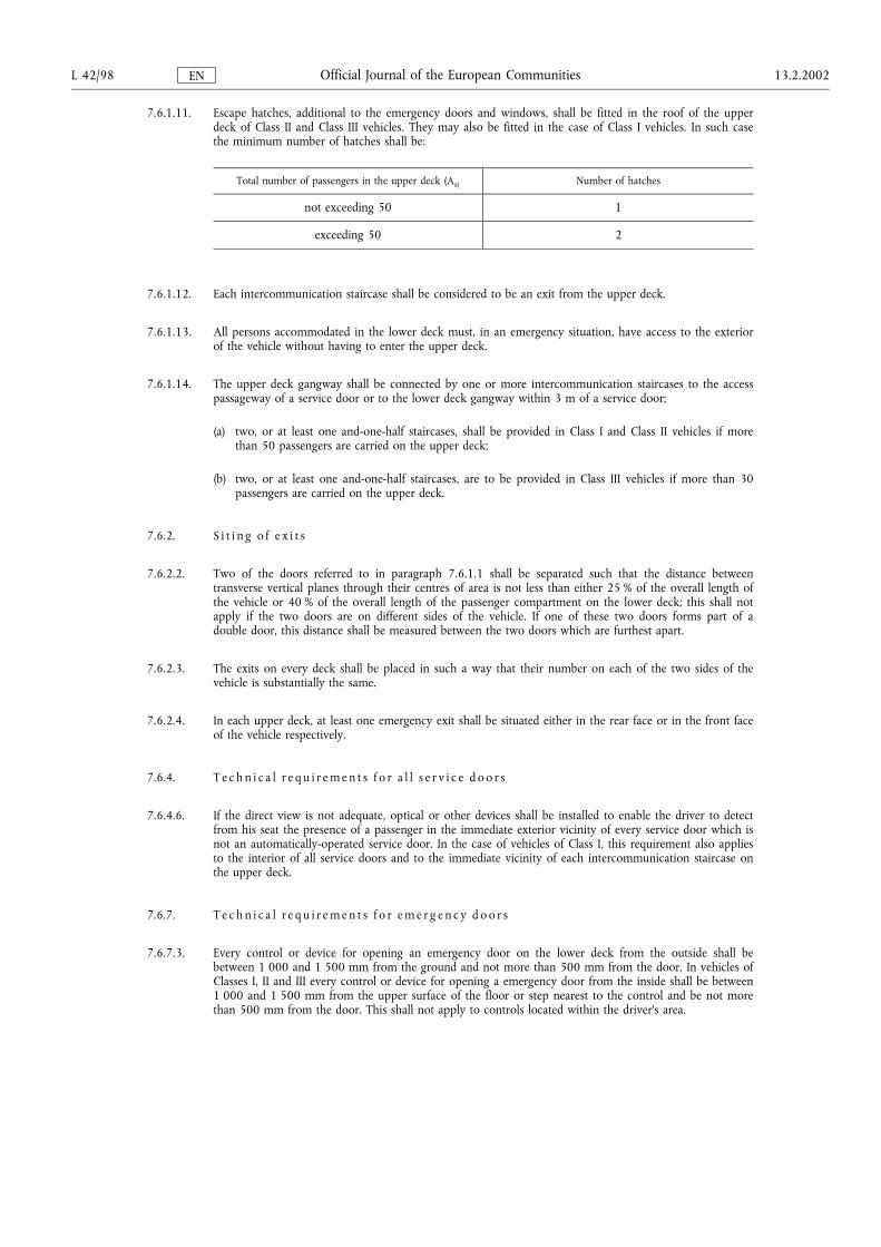
7.6.1.11. Escape hatches, additional to the emergency doors and windows, shall be fitted in the roof of the upperdeck of Class II and Class III vehicles. They may also be fitted in the case of Class I vehicles. In such casethe minimum number of hatches shall be:
Total number of passengers in the upper deck (Aa) Number of hatches
not exceeding 50 1
exceeding 50 2
7.6.1.12. Each intercommunication staircase shall be considered to be an exit from the upper deck.
7.6.1.13. All persons accommodated in the lower deck must, in an emergency situation, have access to the exteriorof the vehicle without having to enter the upper deck.
7.6.1.14. The upper deck gangway shall be connected by one or more intercommunication staircases to the accesspassageway of a service door or to the lower deck gangway within 3 m of a service door;
(a) two, or at least one and-one-half staircases, shall be provided in Class I and Class II vehicles if morethan 50 passengers are carried on the upper deck;
(b) two, or at least one and-one-half staircases, are to be provided in Class III vehicles if more than 30passengers are carried on the upper deck.
7.6.2. S i t i n g o f e x i t s
7.6.2.2. Two of the doors referred to in paragraph 7.6.1.1 shall be separated such that the distance betweentransverse vertical planes through their centres of area is not less than either 25 % of the overall length ofthe vehicle or 40 % of the overall length of the passenger compartment on the lower deck; this shall notapply if the two doors are on different sides of the vehicle. If one of these two doors forms part of adouble door, this distance shall be measured between the two doors which are furthest apart.
7.6.2.3. The exits on every deck shall be placed in such a way that their number on each of the two sides of thevehicle is substantially the same.
7.6.2.4. In each upper deck, at least one emergency exit shall be situated either in the rear face or in the front faceof the vehicle respectively.
7.6.4. T e c h n i c a l r e q u i r e m e n t s f o r a l l s e r v i c e d o o r s
7.6.4.6. If the direct view is not adequate, optical or other devices shall be installed to enable the driver to detectfrom his seat the presence of a passenger in the immediate exterior vicinity of every service door which isnot an automatically-operated service door. In the case of vehicles of Class I, this requirement also appliesto the interior of all service doors and to the immediate vicinity of each intercommunication staircase onthe upper deck.
7.6.7. T e c h n i c a l r e q u i r e m e n t s f o r e m e r g e n c y d o o r s
7.6.7.3. Every control or device for opening an emergency door on the lower deck from the outside shall bebetween 1 000 and 1 500 mm from the ground and not more than 500 mm from the door. In vehicles ofClasses I, II and III every control or device for opening a emergency door from the inside shall be between1 000 and 1 500 mm from the upper surface of the floor or step nearest to the control and be not morethan 500 mm from the door. This shall not apply to controls located within the driver's area.
L 42/98 13.2.2002Official Journal of the European CommunitiesEN
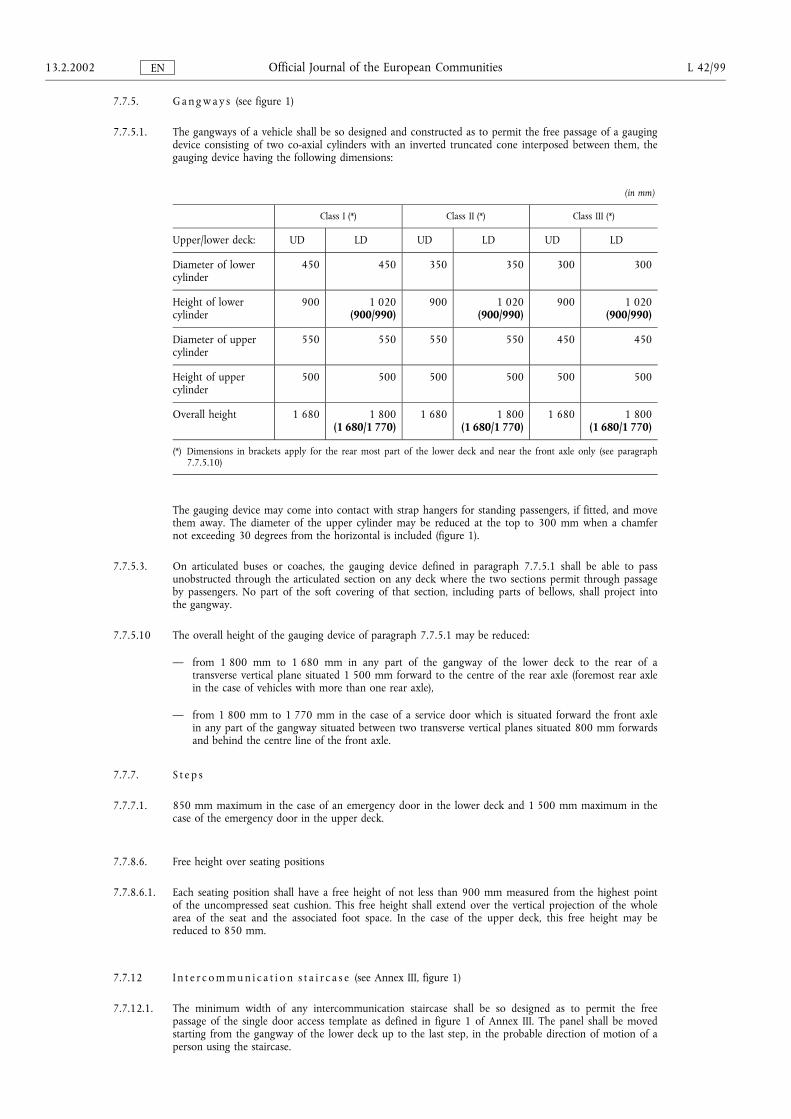
7.7.5. G a n g w a y s (see figure 1)
7.7.5.1. The gangways of a vehicle shall be so designed and constructed as to permit the free passage of a gaugingdevice consisting of two co-axial cylinders with an inverted truncated cone interposed between them, thegauging device having the following dimensions:
(in mm)
Class I (*) Class II (*) Class III (*)
Upper/lower deck: UD LD UD LD UD LD
Diameter of lowercylinder
450 450 350 350 300 300
Height of lowercylinder
900 1 020(900/990)
900 1 020(900/990)
900 1 020(900/990)
Diameter of uppercylinder
550 550 550 550 450 450
Height of uppercylinder
500 500 500 500 500 500
Overall height 1 680 1 800(1 680/1 770)
1 680 1 800(1 680/1 770)
1 680 1 800(1 680/1 770)
(*) Dimensions in brackets apply for the rear most part of the lower deck and near the front axle only (see paragraph7.7.5.10)
The gauging device may come into contact with strap hangers for standing passengers, if fitted, and movethem away. The diameter of the upper cylinder may be reduced at the top to 300 mm when a chamfernot exceeding 30 degrees from the horizontal is included (figure 1).
7.7.5.3. On articulated buses or coaches, the gauging device defined in paragraph 7.7.5.1 shall be able to passunobstructed through the articulated section on any deck where the two sections permit through passageby passengers. No part of the soft covering of that section, including parts of bellows, shall project intothe gangway.
7.7.5.10 The overall height of the gauging device of paragraph 7.7.5.1 may be reduced:
� from 1 800 mm to 1 680 mm in any part of the gangway of the lower deck to the rear of atransverse vertical plane situated 1 500 mm forward to the centre of the rear axle (foremost rear axlein the case of vehicles with more than one rear axle),
� from 1 800 mm to 1 770 mm in the case of a service door which is situated forward the front axlein any part of the gangway situated between two transverse vertical planes situated 800 mm forwardsand behind the centre line of the front axle.
7.7.7. S t e p s
7.7.7.1. 850 mm maximum in the case of an emergency door in the lower deck and 1 500 mm maximum in thecase of the emergency door in the upper deck.
7.7.8.6. Free height over seating positions
7.7.8.6.1. Each seating position shall have a free height of not less than 900 mm measured from the highest pointof the uncompressed seat cushion. This free height shall extend over the vertical projection of the wholearea of the seat and the associated foot space. In the case of the upper deck, this free height may bereduced to 850 mm.
7.7.12 I n t e r c o m m u n i c a t i o n s t a i r c a s e (see Annex III, figure 1)
7.7.12.1. The minimum width of any intercommunication staircase shall be so designed as to permit the freepassage of the single door access template as defined in figure 1 of Annex III. The panel shall be movedstarting from the gangway of the lower deck up to the last step, in the probable direction of motion of aperson using the staircase.
13.2.2002 L 42/99Official Journal of the European CommunitiesEN
7.7.12.2. Intercommunication staircases shall be so designed that, during heavy braking of the vehicle moving inthe forward direction, there is no danger of a passenger being projected downwards.
This requirement is considered to be fulfilled if at least one of the following conditions is met:
7.7.12.2.1. no part of the staircase is forward descending;
7.7.12.2.2. the staircase is equipped with guards or a similar provision;
7.7.12.2.3. there is an automatic device in the upper part of the staircase which prevents the use of the staircasewhen the vehicle is in motion; this device shall be easily operable in an emergency.
7.7.12.3. It shall be verified, by use of the cylinder of paragraph 7.7.5.1, that access conditions from the gangways(upper and lower) to the staircase are adequate.
7.11. Handrails and handholds
7.11.5. H a n d r a i l s a n d h a n d h o l d s f o r i n t e r c o m m u n i c a t i o n s t a i r c a s e s
7.11.5.1. Suitable handrails or handholds shall be provided at each side of all intercommunication staircases. Theseshall be positioned between 800 mm and 1 100 mm above the tread edge of each step.
7.11.5.2. The handrails and/or handholds to be provided shall be such that they include a grasping point availableto a person standing on the lower or upper deck adjacent to the intercommunication staircase, and at anyof the successive steps. Such points shall be situated vertically between 800 mm and 1 100 mm above thelower deck or each above the surface of each step, and,
7.11.5.2.1. for the position appropriate to a person standing on the lower deck, not more than 400 mm inwardsfrom the outer edge of the first step, and
7.11.5.2.2. for the position appropriate to a particular step, not outwards from the outer edge of the step considered,and not more than 600 mm inwards from the same edge.
7.14. Guarding of stepwells and exposed seats
7.14.2 On the upper deck of a double-deck vehicle, the intercommunication staircase well shall be protected byan enclosed guard having a minimum height of 800 mm measured from the floor. The lower edge of theguard shall not be more than 100 mm from the floor.
7.14.3 The front windscreen ahead of passengers occupying upper-deck front seats must be provided with apadded guard. The higher edge of that protection shall be situated vertically between 800 mm and 900mm above the floor where the passenger's feet rest.
7.14.4 The riser of each step in a staircase shall be closed.
L 42/100 13.2.2002Official Journal of the European CommunitiesEN
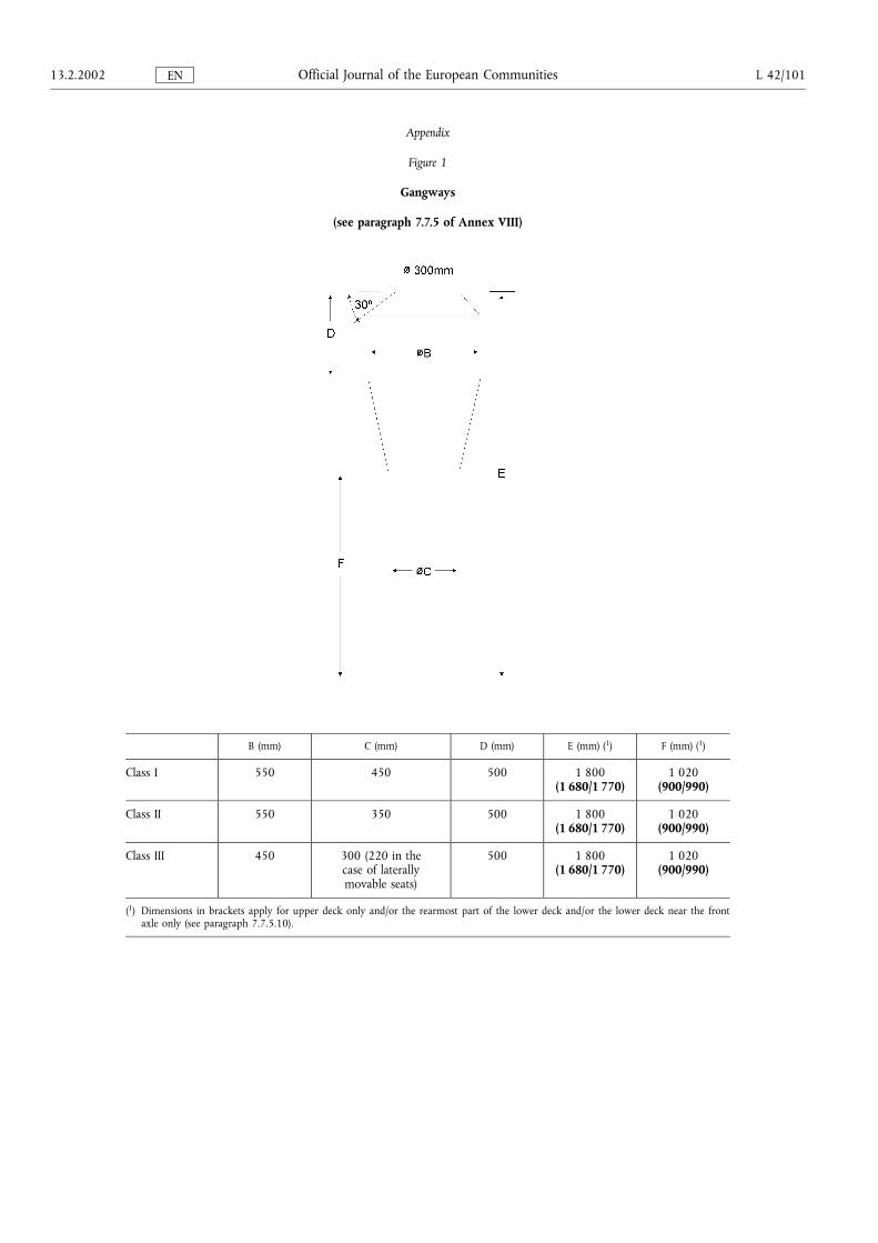
Appendix
Figure 1
Gangways
(see paragraph 7.7.5 of Annex VIII)
B (mm) C (mm) D (mm) E (mm) (1) F (mm) (1)
Class I 550 450 500 1 800(1 680/1 770)
1 020(900/990)
Class II 550 350 500 1 800(1 680/1 770)
1 020(900/990)
Class III 450 300 (220 in thecase of laterallymovable seats)
500 1 800(1 680/1 770)
1 020(900/990)
(1) Dimensions in brackets apply for upper deck only and/or the rearmost part of the lower deck and/or the lower deck near the frontaxle only (see paragraph 7.7.5.10).
13.2.2002 L 42/101Official Journal of the European CommunitiesEN
ANNEX IX
EC TYPE-APPROVAL FOR A SEPARATE TECHNICAL UNIT AND EC TYPE-APPROVAL OF A VEHICLEFITTED WITH A BODYWORK ALREADY APPROVED AS A SEPARATE TECHNICAL UNIT
1. Separate technical unit type-approval
1.1. In order to be granted separate technical unit type-approval to this Directive for a vehicle bodywork, themanufacturer must demonstrate to the satisfaction of the approval authority the accomplishment of theconditions declared by the manufacturer. The remaining conditions to this Directive must be accomplished anddemonstrated according to paragraph 2.
1.2. Approval may be granted subject to conditions to be met by the completed vehicle (such as, for example,characteristics of suitable chassis, restriction on use or installation), these conditions being recorded on theapproval certificate.
1.3. Any such conditions must be communicated to the purchaser of the vehicle bodywork or the next stage builderof the vehicle in an appropriate form.
2. EC type-approval of a vehicle fitted with a bodywork already approved as a separate technical unit
2.1. In order to be granted EC type-approval to this Directive for a vehicle fitted with a bodywork which has alreadybeen granted approval as a separate technical unit, the manufacturer must demonstrate to the satisfaction of theapproval authority compliance with the requirements of this Directive that would not have already beenaccomplished and demonstrated according to paragraph 1, considering any previous type-approval asuncompleted vehicle.
2.2. Any requirement established according to paragraph 1.2 must be fulfilled.
L 42/102 13.2.2002Official Journal of the European CommunitiesEN
Copyright © 2022 FDOKUMEN