Acme Electric Dry-Type Distribution Transformers - Steven ...
44
Dry-Type Distribution Transformers 600 Volt Class and Below Single and Three Phase Section 1 Courtesy of Steven Engineering, Inc - (800) 258-9200 - [email protected] - www.stevenengineering.com
-
Upload
khangminh22 -
Category
Documents
-
view
2 -
download
0
Transcript of Acme Electric Dry-Type Distribution Transformers - Steven ...
Dry-Type DistributionTransformers
600 Volt Class and BelowSingle and Three Phase
Section 1
Courtesy of Steven Engineering, Inc - (800) 258-9200 - [email protected] - www.stevenengineering.com
2 toll free 800.334.5214 ACME ELECTRIC | www.hubbell.com/acmeelectric/en
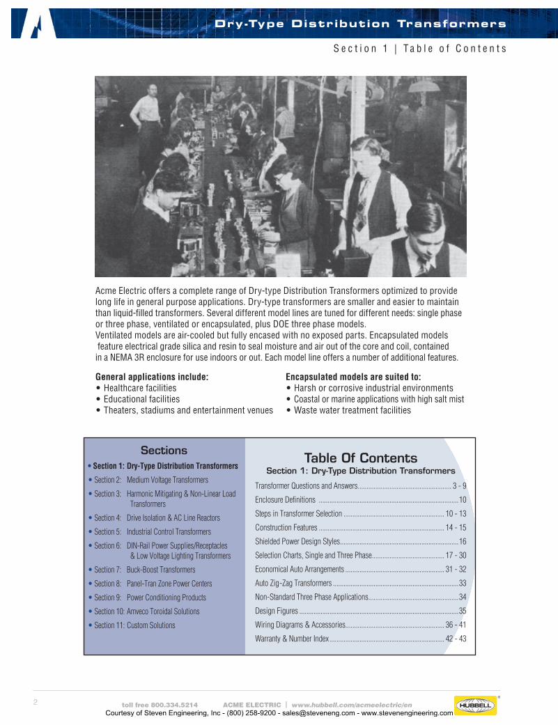
Acme Electric offers a complete range of Dry-type Distribution Transformers optimized to provide long life in general purpose applications. Dry-type transformers are smaller and easier to maintain than liquid-filled transformers. Several different model lines are tuned for different needs: single phase or three phase, ventilated or encapsulated, plus DOE three phase models. Ventilated models are air-cooled but fully encased with no exposed parts. Encapsulated models feature electrical grade silica and resin to seal moisture and air out of the core and coil, contained in a NEMA 3R enclosure for use indoors or out. Each model line offers a number of additional features.
Dry-Type Distribution Transformers
S e c t i o n 1 | T a b l e o f C o n t e n t s
Sections• Section 1: Dry-Type Distribution Transformers
• Section 2: Medium Voltage Transformers
• Section 3: Harmonic Mitigating & Non-Linear Load Transformers
• Section 4: Drive Isolation & AC Line Reactors
• Section 5: Industrial Control Transformers
• Section 6: DIN-Rail Power Supplies/Receptacles & Low Voltage Lighting Transformers
• Section 7: Buck-Boost Transformers
• Section 8: Panel-Tran Zone Power Centers
• Section 9: Power Conditioning Products
• Section 10: Amveco Toroidal Solutions
• Section 11: Custom Solutions
General applications include:• Healthcare facilities• Educational facilities• Theaters, stadiums and entertainment venues
Encapsulated models are suited to:• Harsh or corrosive industrial environments• Coastal or marine applications with high salt mist• Waste water treatment facilities
Table Of ContentsSection 1: Dry-Type Distribution Transformers
Transformer Questions and Answers ..................................................... 3 - 9
Enclosure Definitions ...............................................................................10
Steps in Transformer Selection ......................................................... 10 - 13
Construction Features ....................................................................... 14 - 15
Shielded Power Design Styles ...................................................................16
Selection Charts, Single and Three Phase ......................................... 17 - 30
Economical Auto Arrangements ........................................................ 31 - 32
Auto Zig-Zag Transformers .......................................................................33
Non-Standard Three Phase Applications...................................................34
Design Figures ..........................................................................................35
Wiring Diagrams & Accessories........................................................ 36 - 41
Warranty & Number Index ................................................................. 42 - 43
Courtesy of Steven Engineering, Inc - (800) 258-9200 - [email protected] - www.stevenengineering.com
3toll free 800.334.5214 ACME ELECTRIC | www.hubbell.com/acmeelectric/en
1. What is a transformer and how does it work?A transformer is an electrical apparatus designed to convert alternating current from one voltage to another. It can be designed to “step up” or “step down” voltages and works on the magnetic induction principle. A transformer has no moving parts and is a completely static solid state device, which insures, under normal operating conditions, a long and trouble-free life. It consists, in its simplest form, of two or more coils of insulated wire wound on a laminated steel core. When voltage is introduced to one coil, called the primary, it magnetizes the iron core. A voltage is then induced in the other coil, called the secondary or output coil. The change of voltage (or voltage ratio) between the primary and secondary depends on the turns ratio of the two coils.
2. What are taps and when are they used?Taps are provided on some transformers on the high voltage winding to correct for high or low voltage conditions, and still deliver full rated output voltages at the secondary terminals. Standard tap arrangements are at two-and-one-half and five percent of the rated primary voltage for both high and low voltage conditions. For example, if the transformer has a 480 volt primary and the available line voltage is running at 504 volts, the primary should be connected to the 5% tap above normal in order that the secondary voltage be maintained at the proper rating. The standard ASA and NEMA designation for taps are “ANFC” (above normal full capacity) and “BNFC” (below normal full capacity).
3. What is the difference between Insulating, Isolating and Shielded Winding transformers?Insulating and isolating transformers are identical. These terms are used to describe the isolation of the primary and secondary wind-ings, or insulation between the two. A shielded transformer is designed with a metallic shield between the primary and secondary windings to attenuate transient noise. This is especially important in critical applications such as computers, process controllers and many other microprocessor controlled devices. All two, three and four winding transformers are of the insulating or isolating types. Only autotransformers, whose primary and secondary are connected to each other electrically, are not of the insulating or isolating variety.
4. Can transformers be operated at voltages other than nameplate voltages? In some cases, transformers can be operated at voltages below the nameplate rated voltage. In NO case should a transformer be operated at a voltage in excess of its nameplate rating, unless taps are provided for this purpose. When operating below the rated voltage, the kVA capacity is reduced correspondingly. For example, if a 480 volt primary transformer with a 240 volt secondary is operated at 240 volts, the secondary voltage is reduced to 120 volts. If the transformer was originally rated 10 kVA, the reduced rating would be 5 kVA, or in direct proportion to the applied voltage.
5. Can 60 Hz transformers be operated at 50 Hz?ACME transformers rated below 1 kVA can be used on 50 Hz service. Transformers 1 kVA and larger, rated at 60 Hz, should not be used on 50 Hz service, due to the higher losses and resultant heat rise. Special designs are required for this service. However, any 50 Hz transformer will operate on a 60 Hz service.
6. Can transformers be used in parallel? Single phase transformers can be used in parallel only when their impedances and voltages are equal. If unequal voltages are used, a circulating current exists in the closed network between the two transformers, which will cause excess heating and result in a shorter life of the transformer. In addition, impedance values of each transformer must be within 7.5% of each other. For example: Transformer A has an impedance of 4%, transformer B which is to be parallel to A must have an impedance between the limits of 3.7% and 4.3%. When paralleling three phase transformers, the same precautions must be observed as listed above, plus the angular displacement and phasing between the two transformers must be identical.
7. Can Acme Transformers be reverse connected?ACME dry-type distribution transformers can be reverse connected without a loss of kVA rating, but there are certain limitations. Transformers rated 1 kVA and larger single phase, 3 kVA and larger three phase can be reverse connected without any adverse effects or loss in kVA capacity. The reason for this limitation in kVA size is, the turns ratio is the same as the voltage ratio. Example: A transformer with a 480 volt input, 240 volt output can have the output connected to a 240 volt source and thereby become the primary or input to the transformer, then the original 480 volt primary winding will become the output or 480 volt secondary. On trans-formers rated below 1 kVA single phase, there is a turns ratio compensation on the low voltage winding. This means the low voltage winding has a greater voltage than the nameplate voltage indicates at no load. For example, a small single phase transformer hav-ing a nameplate voltage of 480 volts primary and 240 volts secondary, would actually have a no load voltage of approximately 250 volts, and a full load voltage of 240 volts. If the 240 volt winding were connected to a 240 volt source, then the output voltage would
Dry-Type Distribution Transformers
S e c t i o n 1 | Q u e s t i o n s a n d A n s w e r s
Courtesy of Steven Engineering, Inc - (800) 258-9200 - [email protected] - www.stevenengineering.com

4 toll free 800.334.5214 ACME ELECTRIC | www.hubbell.com/acmeelectric/en
consequently be approximately 460 volts at no load and approximately 442 volts at full load. As the kVA becomes smaller, the compensation is greater— resulting in lower output voltages. When one attempts to use these transformers in reverse, the transformer will not be harmed; however, the output voltage will be lower than is indicated by the nameplate.
8. Can a Single Phase Transformer be used on a Three Phase source? Yes. Any single phase transformer can be used on a three phase source by connecting the primary leads to any two wires of a three phase system, regardless of whether the source is three phase 3-wire or three phase 4-wire. The transformer output will be single phase.
9. Can Transformers develop Three Phase power from a Single Phase source? No. Phase converters or phase shifting devices such as reactors and capacitors are required to convert single phase power to three phase.
10. How do you select transformers? (1) Determine primary voltage and frequency. (2) Determine secondary voltage required. (3) Determine the capacity required in volt-amperes.
This is done by multiplying the load current (amperes) by the load voltage (volts) for single phase. For example: if the load is 40 amperes, such as a motor, and the secondary voltage is 240 volts, then 240 x 40 equals 9600 VA. A 10 kVA (10,000volt-amperes) transformer is required. ALWAYS SELECT THE TRANSFORMER LARGER THAN THE ACTUAL LOAD. This is done for safety purposes and allows for expansion, in case more load is added at a later date. For 3 phase kVA, multiply rated volts x load amps x 1.73 (square root of 3) then divide by 1000. (4) Determine whether taps are required. Taps are usually specified on larger transformers. (5) Use the selection charts in Section I.
11. What terminations are provided? Primary and Secondary Terminations are provided on ACME Dry-Type Transformers as follows: No lugs—lead type connection on 0-25 kVA single phase 0-15 kVA three phase encapsulated units
Bus-bar terminations (drilled to NEMA standards) 37.5-250 kVA single phase 150-500 kVA three phase Lugs 15-112.5 kVA three phase
12. Can 60 Hz transformers be used at higher frequencies? ACME transformers can be used at frequencies above 60 Hz up through 400 Hz with no limitations provided nameplate voltages are not exceeded. However, 60 Hz transformers will have less voltage regulation at 400 Hz than 60 Hz.
13. What is meant by regulation in a transformer?Voltage regulation in transformers is the difference between the no load voltage and the full load voltage. This is usually expressed in terms of percentage. For example: A transformer delivers 100 volts at no load and the voltage drops to 95 volts at full load, the regulation would be 5%. ACME dry-type distribution transformers generally have regulation from 2% to 4%, depending on the size and the application for which they are used.
14. What is temperature rise in a transformer?Temperature rise in a transformer is the temperature of the windings and insulation above the existing ambient or surrounding temperature.
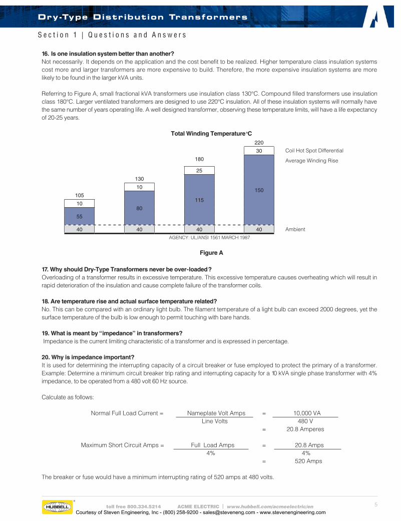
15. What is “Class” in insulation? Insulation class was the original method used to distinguish insulating materials operating at different temperature levels. Letters were used for different designations. Letter classifications have been replaced by insulation system temperatures in degrees Celsius. The system temperature is the maximum temperature at the hottest spot in the winding (coil). Graphical representations of four insulation systems recognized by Underwriters’ Laboratories, Inc. are shown in Figure A. These systems are used by Acme for a large part of the product line.
Dry-Type Distribution Transformers
S e c t i o n 1 | Q u e s t i o n s a n d A n s w e r s
Courtesy of Steven Engineering, Inc - (800) 258-9200 - [email protected] - www.stevenengineering.com
5toll free 800.334.5214 ACME ELECTRIC | www.hubbell.com/acmeelectric/en
16. Is one insulation system better than another?Not necessarily. It depends on the application and the cost benefit to be realized. Higher temperature class insulation systems cost more and larger transformers are more expensive to build. Therefore, the more expensive insulation systems are more likely to be found in the larger kVA units.
Referring to Figure A, small fractional kVA transformers use insulation class 130°C. Compound filled transformers use insulation class 180°C. Larger ventilated transformers are designed to use 220°C insulation. All of these insulation systems will normally have the same number of years operating life. A well designed transformer, observing these temperature limits, will have a life expectancy of 20-25 years. Total Winding Temperature oC
220
30 Coil Hot Spot Differential
180
150
Average Winding Rise
25
130
115
10
105
8010
55
40 40 40 40 AmbientAGENCY: UL/ANSI 1561 MARCH 1987
Figure A
17. Why should Dry-Type Transformers never be over-loaded? Overloading of a transformer results in excessive temperature. This excessive temperature causes overheating which will result in rapid deterioration of the insulation and cause complete failure of the transformer coils.
18. Are temperature rise and actual surface temperature related? No. This can be compared with an ordinary light bulb. The filament temperature of a light bulb can exceed 2000 degrees, yet the surface temperature of the bulb is low enough to permit touching with bare hands.
19. What is meant by “impedance” in transformers? Impedance is the current limiting characteristic of a transformer and is expressed in percentage.
20. Why is impedance important? It is used for determining the interrupting capacity of a circuit breaker or fuse employed to protect the primary of a transformer. Example: Determine a minimum circuit breaker trip rating and interrupting capacity for a 10 kVA single phase transformer with 4% impedance, to be operated from a 480 volt 60 Hz source.
Calculate as follows:
Normal Full Load Current = Nameplate Volt Amps = 10,000 VA Line Volts 480 V = 20.8 Amperes
Maximum Short Circuit Amps = Full Load Amps = 20.8 Amps
4% 4% = 520 Amps
The breaker or fuse would have a minimum interrupting rating of 520 amps at 480 volts.
Dry-Type Distribution Transformers
S e c t i o n 1 | Q u e s t i o n s a n d A n s w e r s
Courtesy of Steven Engineering, Inc - (800) 258-9200 - [email protected] - www.stevenengineering.com
6 toll free 800.334.5214 ACME ELECTRIC | www.hubbell.com/acmeelectric/en
Example: Determine the interrupting capacity, in amperes, of a circuit breaker or fuse required for a 75 kVA, three phase transformer, with a primary of 480 volts delta and secondary of 208Y/120 volts. The transformer impedance (Z) = 5%. If the secondary is short circuited (faulted), the following capacities are required:
Normal Full Load Current =Volt Amps
=75,000 VA
√ 3 x Line Volts √ 3 x 480 V= 90 Amps
Maximum Short Circuit Amps =Full Load Amps
=90 Amps
5% 5%
= 1,800 Amps
The breaker or fuse would have a minimum interrupting rating of 1,800 amps at 480 volts.
Note: The secondary voltage is not used in the calculation. The reason is the primary circuit of the transformer is the only winding being interrupted.
21. Can Single Phase Transformers be used for Three Phase applications? Yes. Three phase transformers are sometimes not readily available whereas single phase transformers can generally be found in stock. Three single phase transformers can be used in delta connected primary and wye or delta connected secondary. They should never be connected wye primary to wye secondary, since this will result in unstable secondary voltage. The equivalent three phase capacity when properly connected of three single phase transformers is three times the nameplate rating of each single phase transformer. For example: Three 10 kVA single phase transformers will accommodate a 30 kVA three phase load.
22. Does ACME provide “Zig-Zag” Grounding Transformers? Yes. Please refer to Page 35 for a special diagram which can be used to connect standard single phase off-the-shelf transformers in a three phase zig-zag manner. This system can be used for either grounding or developing a fourth wire from a three phase neutral. An example would be to change a 480 V — three phase — three wire system to a 480Y/277 V — three phase — four wire system.
23. What color are ACME Dry-Type Transformers? ASA 61 (NEMA) light gray is used on all enclosed transformers from .050 to 1000 kVA.
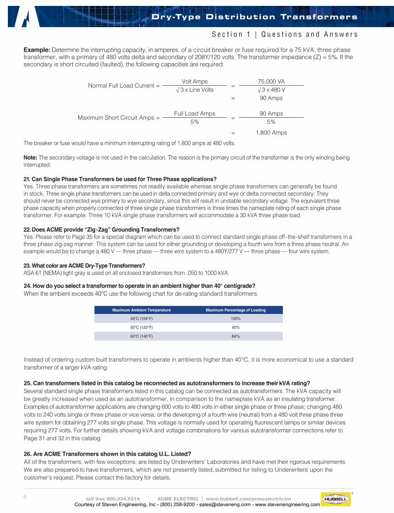
24. How do you select a transformer to operate in an ambient higher than 40° centigrade? When the ambient exceeds 40°C use the following chart for de-rating standard transformers.
Maximum Ambient Temperature Maximum Percentage of Loading
40°C (104°F) 100%
50°C (122°F) 92%
60°C (140°F) 84%
Instead of ordering custom built transformers to operate in ambients higher than 40°C, it is more economical to use a standard transformer of a larger kVA rating.
25. Can transformers listed in this catalog be reconnected as autotransformers to increase their kVA rating? Several standard single phase transformers listed in this catalog can be connected as autotransformers. The kVA capacity will be greatly increased when used as an autotransformer, in comparison to the nameplate kVA as an insulating transformer. Examples of autotransformer applications are changing 600 volts to 480 volts in either single phase or three phase; changing 480 volts to 240 volts single or three phase or vice versa; or the developing of a fourth wire (neutral) from a 480 volt three phase three wire system for obtaining 277 volts single phase. This voltage is normally used for operating fluorescent lamps or similar devices requiring 277 volts. For further details showing kVA and voltage combinations for various autotransformer connections refer to Page 31 and 32 in this catalog.
26. Are ACME Transformers shown in this catalog U.L. Listed? All of the transformers, with few exceptions, are listed by Underwriters’ Laboratories and have met their rigorous requirements. We are also prepared to have transformers, which are not presently listed, submitted for listing to Underwriters’ upon the customer’s request. Please contact the factory for details.
Dry-Type Distribution Transformers
S e c t i o n 1 | Q u e s t i o n s a n d A n s w e r s
Courtesy of Steven Engineering, Inc - (800) 258-9200 - [email protected] - www.stevenengineering.com
7toll free 800.334.5214 ACME ELECTRIC | www.hubbell.com/acmeelectric/en
27. Is CSA certification available for transformers shown in this catalog? Most ACME Transformers have been evaluated and meet the Canadian Standards. Instead of utilizing the CSA mark, ACME utilizes the cUL mark to show the products meet these standards.
28. What is BIL and how does it apply to transformers listed in this catalog? BIL is an abbreviation for Basic Impulse Level. Impulse tests are dielectric tests that consist of the application of a high frequency steep wave front voltage between windings, and between windings and ground. The Basic Impulse Level of a transformer is a method of expressing the voltage surge (lightning, switching surges, etc.) that a transformer will tolerate without breakdown. All transformers manufactured in this catalog, 600 volts and below, will withstand the NEMA standard BIL rating, which is 10 KV. This assures the user that he will not experience breakdowns when his system is properly protected with lightning arrestors or similar surge protection devices.
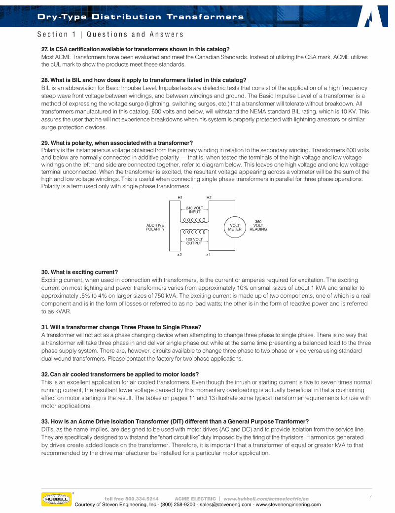
29. What is polarity, when associated with a transformer? Polarity is the instantaneous voltage obtained from the primary winding in relation to the secondary winding. Transformers 600 volts and below are normally connected in additive polarity — that is, when tested the terminals of the high voltage and low voltage windings on the left hand side are connect ed together, refer to diagram below. This leaves one high voltage and one low voltage terminal unconnected. When the transformer is excited, the resultant voltage appearing across a voltmeter will be the sum of the high and low voltage windings. This is useful when connecting single phase transformers in parallel for three phase operations. Polarity is a term used only with single phase transformers.
30. What is exciting current? Exciting current, when used in connection with transformers, is the current or amperes required for excitation. The exciting current on most lighting and power transformers varies from approximately 10% on small sizes of about 1 kVA and smaller to approximately .5% to 4% on larger sizes of 750 kVA. The exciting current is made up of two components, one of which is a real component and is in the form of losses or referred to as no load watts; the other is in the form of reactive power and is referred to as kVAR.
31. Will a transformer change Three Phase to Single Phase?A transformer will not act as a phase changing device when attempting to change three phase to single phase. There is no way that a transformer will take three phase in and deliver single phase out while at the same time presenting a balanced load to the three phase supply system. There are, however, circuits available to change three phase to two phase or vice versa using standard dual wound transformers. Please contact the factory for two phase applications.
32. Can air cooled transformers be applied to motor loads?This is an excellent application for air cooled transformers. Even though the inrush or starting current is five to seven times normal running current, the resultant lower voltage caused by this momentary overloading is actually beneficial in that a cushioning effect on motor starting is the result. The tables on pages 11 and 13 illustrate some typical transformer requirements for use with motor applications.
33. How is an Acme Drive Isolation Transformer (DIT) different than a General Purpose Tranformer?DITs, as the name implies, are designed to be used with motor drives (AC and DC) and to provide isolation from the service line. They are specifically designed to withstand the “short circuit like” duty imposed by the firing of the thyristors. Harmonics generated by drives create added loads on the transformer. Therefore, it is important that a transformer of equal or greater kVA to that recommended by the drive manufacturer be installed for a particular motor application.
Dry-Type Distribution Transformers
S e c t i o n 1 | Q u e s t i o n s a n d A n s w e r s
Courtesy of Steven Engineering, Inc - (800) 258-9200 - [email protected] - www.stevenengineering.com
8 toll free 800.334.5214 ACME ELECTRIC | www.hubbell.com/acmeelectric/en
The underlying problem is low voltage at the motor terminals. If the ampere rating of the motor and transformer overcurrent device falls within the motor’s 50% RPM draw requirements, a problem is likely to develop. The overcurrent device may not open under intermediate motor ampere loading conditions. Overheating of the motor and/or transformer would occur, possibly causing failure of either component.
This condition is more pronounced when one transformer is used to power one motor and the running amperes of the motor is in the vicinity of the full load ampere rating of the transformer. The following precautions should be followed:
(1) When one transformer is used to operate one motor, the running amperes of the motor should not exceed 65% of the transformer’s full load ampere rating.
(2) If several motors are being operated from one transformer, avoid having all motors start at the same time. If this is impractical, then size the transformer so that the total running current does not exceed 65% of the transformer’s full load ampere rating.
35. Why are Small Distribution Transformers not used for Industrial Control Applications?Industrial control equipment demands a momentary overload capacity of three to eight times normal capacity. This is most prevalent in solenoid or magnetic contactor applications where inrush currents can be three to eight times as high as normal sealed or holding currents but still maintain normal voltage at this momentary overloaded condition. Distribution transformers are designed for good regulation up to 100 percent loading, but their output voltage will drop rapidly on momentary overloads of this type making them unsuitable for high inrush applications.
Industrial control transformers are designed especially for maintaining a high degree of regulation even at eight times normal load. This results in a larger and generally more expensive transformer. For a complete listing of ACME industrial control transformers, refer to Section 5.
34. How are transformers sized to operate Three Phase induction type squirrel cage motors? The minimum transformer kVA rating required to operate a motor is calculated as follows:
Minimum Transformer kVA =Running Load Amperes x 1.73 x Motor Operating Voltage
1000
Note: If motor is to be started more than once per hour add 20% additional kVA.
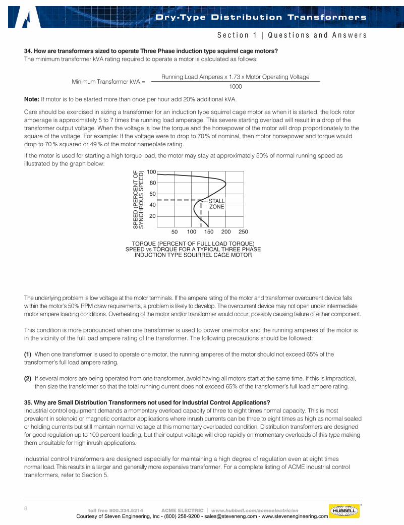
Care should be exercised in sizing a transformer for an induction type squirrel cage motor as when it is started, the lock rotor amperage is approximately 5 to 7 times the running load amperage. This severe starting overload will result in a drop of the transformer output voltage. When the voltage is low the torque and the horsepower of the motor will drop proportionately to the square of the voltage. For example: If the voltage were to drop to 70% of nominal, then motor horsepower and torque would drop to 70 % squared or 49% of the motor nameplate rating.
If the motor is used for starting a high torque load, the motor may stay at approximately 50% of normal running speed as illustrated by the graph below:
Dry-Type Distribution Transformers
S e c t i o n 1 | Q u e s t i o n s a n d A n s w e r s
Courtesy of Steven Engineering, Inc - (800) 258-9200 - [email protected] - www.stevenengineering.com
9toll free 800.334.5214 ACME ELECTRIC | www.hubbell.com/acmeelectric/en
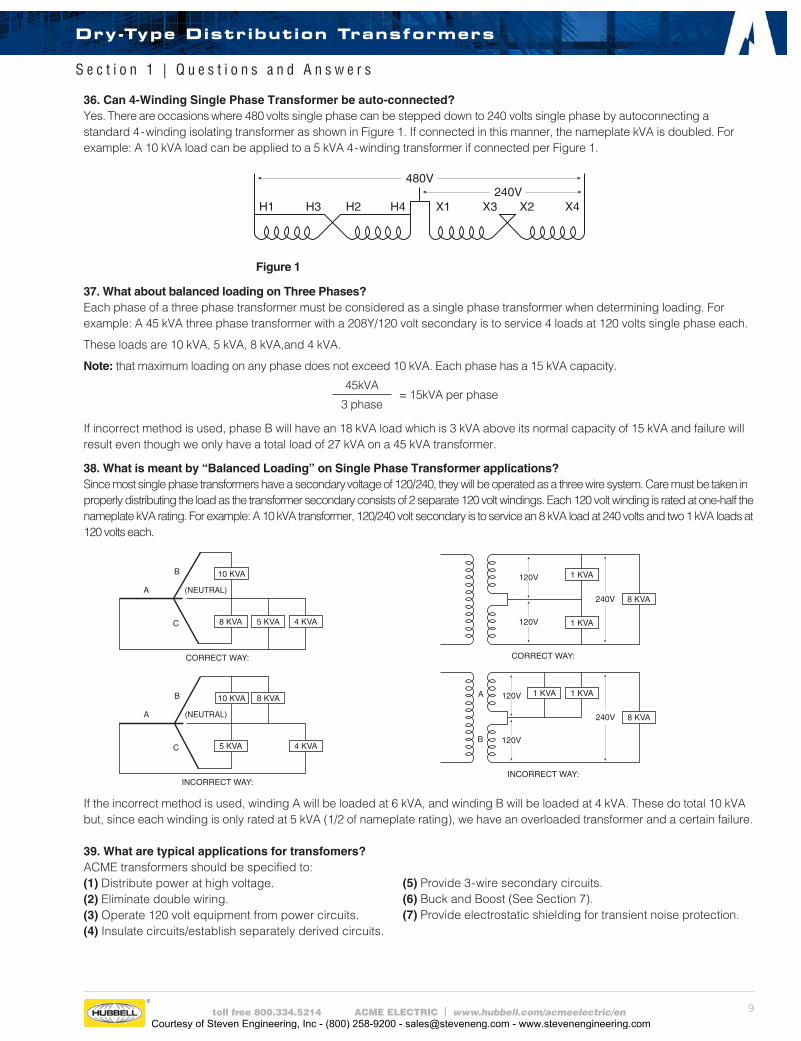
36. Can 4-Winding Single Phase Transformer be auto-connected? Yes. There are occasions where 480 volts single phase can be stepped down to 240 volts single phase by autoconnecting a standard 4-winding isolating transformer as shown in Figure 1. If connected in this manner, the nameplate kVA is doubled. For example: A 10 kVA load can be applied to a 5 kVA 4-winding transformer if connected per Figure 1.
Figure 1
37. What about balanced loading on Three Phases? Each phase of a three phase transformer must be considered as a single phase transformer when determining loading. For example: A 45 kVA three phase transformer with a 208Y/120 volt secondary is to service 4 loads at 120 volts single phase each.
These loads are 10 kVA, 5 kVA, 8 kVA,and 4 kVA.
Note: that maximum loading on any phase does not exceed 10 kVA. Each phase has a 15 kVA capacity.
45kVA= 15kVA per phase
3 phase
If incorrect method is used, phase B will have an 18 kVA load which is 3 kVA above its normal capacity of 15 kVA and failure will result even though we only have a total load of 27 kVA on a 45 kVA transformer.
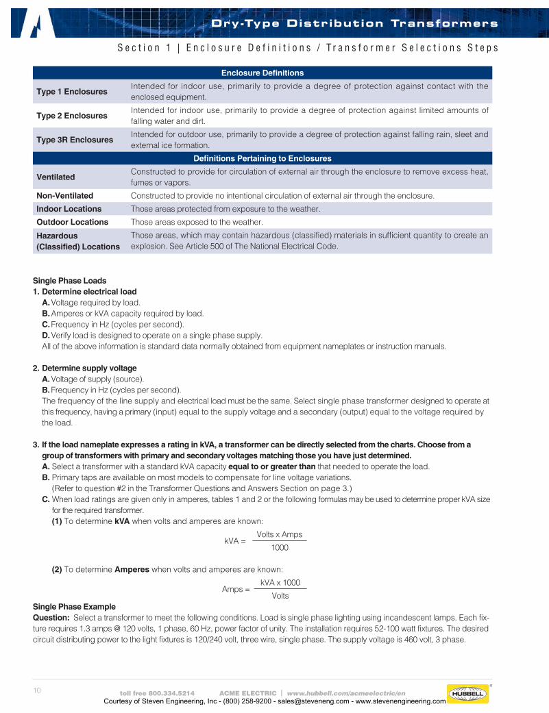
38. What is meant by “Balanced Loading” on Single Phase Transformer applications? Since most single phase transformers have a secondary voltage of 120/240, they will be operated as a three wire system. Care must be taken in properly distributing the load as the transformer secondary consists of 2 separate 120 volt windings. Each 120 volt winding is rated at one-half the nameplate kVA rating. For example: A 10 kVA transformer, 120/240 volt secondary is to service an 8 kVA load at 240 volts and two 1 kVA loads at 120 volts each.
If the incorrect method is used, winding A will be loaded at 6 kVA, and winding B will be loaded at 4 kVA. These do total 10 kVA but, since each winding is only rated at 5 kVA (1/2 of nameplate rating), we have an overloaded transformer and a certain failure. 39. What are typical applications for transfomers?ACME transformers should be specified to:(1) Distribute power at high voltage.(2) Eliminate double wiring.(3) Operate 120 volt equipment from power circuits.(4) Insulate circuits/establish separately derived circuits.
(5) Provide 3- wire secondary circuits.(6) Buck and Boost (See Section 7).(7) Provide electrostatic shielding for transient noise protection.
Dry-Type Distribution Transformers
S e c t i o n 1 | Q u e s t i o n s a n d A n s w e r s
Courtesy of Steven Engineering, Inc - (800) 258-9200 - [email protected] - www.stevenengineering.com
10 toll free 800.334.5214 ACME ELECTRIC | www.hubbell.com/acmeelectric/en
Single Phase Loads1. Determine electrical load A. Voltage required by load. B. Amperes or kVA capacity required by load. C. Frequency in Hz (cycles per second). D. Verify load is designed to operate on a single phase supply. All of the above information is standard data normally obtained from equipment nameplates or instruction manuals.
2. Determine supply voltage A. Voltage of supply (source). B. Frequency in Hz (cycles per second). The frequency of the line supply and electrical load must be the same. Select single phase transformer designed to operate at this frequency, having a primary (input) equal to the supply voltage and a secondary (output) equal to the voltage required by the load.
3. If the load nameplate expresses a rating in kVA, a transformer can be directly selected from the charts. Choose from a group of transformers with primary and secondary voltages matching those you have just determined.
A. Select a transformer with a standard kVA capacity equal to or greater than that needed to operate the load. B. Primary taps are available on most models to compensate for line voltage variations. (Refer to question #2 in the Transformer Questions and Answers Section on page 3.) C. When load ratings are given only in amperes, tables 1 and 2 or the following formulas may be used to determine proper kVA size
for the required transformer. (1) To determine kVA when volts and amperes are known:
kVA =Volts x Amps
1000
(2) To determine Amperes when volts and amperes are known:
Amps =kVA x 1000
VoltsSingle Phase ExampleQuestion: Select a transformer to meet the following conditions. Load is single phase lighting using incandescent lamps. Each fix-ture requires 1.3 amps @ 120 volts, 1 phase, 60 Hz, power factor of unity. The installation requires 52-100 watt fixtures. The desired circuit distributing power to the light fixtures is 120/240 volt, three wire, single phase. The supply voltage is 460 volt, 3 phase.
Enclosure Definitions
Type 1 EnclosuresIntended for indoor use, primarily to provide a degree of protection against contact with the enclosed equipment.
Type 2 EnclosuresIntended for indoor use, primarily to provide a degree of protection against limited amounts of falling water and dirt.
Type 3R EnclosuresIntended for outdoor use, primarily to provide a degree of protection against falling rain, sleet and external ice formation.
Definitions Pertaining to Enclosures
VentilatedConstructed to provide for circulation of external air through the enclosure to remove excess heat, fumes or vapors.
Non-Ventilated Constructed to provide no intentional circulation of external air through the enclosure.
Indoor Locations Those areas protected from exposure to the weather.
Outdoor Locations Those areas exposed to the weather.
Hazardous (Classified) Locations
Those areas, which may contain hazardous (classified) materials in sufficient quantity to create an explosion. See Article 500 of The National Electrical Code.
Dry-Type Distribution Transformers
S e c t i o n 1 | E n c l o s u r e D e f i n i t i o n s / T r a n s f o r m e r S e l e c t i o n s S t e p s
Courtesy of Steven Engineering, Inc - (800) 258-9200 - [email protected] - www.stevenengineering.com
11toll free 800.334.5214 ACME ELECTRIC | www.hubbell.com/acmeelectric/en
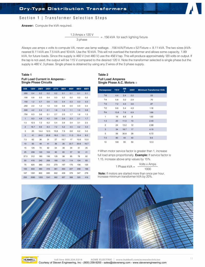
①When motor service factor is greater than 1, increase full load amps proportionally. Example: If service factor is 1.15, increase above amp values by 15%.
1 Phase kVA =Volts x Amps
1000 Note: If motors are started more than once per hour, increase minimum transformer kVA by 20%.
Table 1Full Load Current in Amperes–Single Phase Circuits
Horsepower 115 V208 V
230V Minimum Transformer KVA
1/6 4.4 2.4 2.2 .53
1/4 5.8 3.2 2.9 .70
1/3 7.2 4.0 3.6 .87
1/2 9.8 5.4 4.9 1.18
3/4 13.8 7.6 6.9 1.66
1 16 8.8 8 1.92
1.5 20 11.0 10 2.40
2 24 13.2 12 2.88
3 34 18.7 17 4.10
5 56 30.8 28 6.72
7.5 80 44 40 9.6
10 100 55 50 12.0
Table 2Full Load AmperesSingle Phase A.C. Motors ①
kVA 120 V 208 V 240 V 277 V 380 V 440V 480 V 600 V
.050 0.4 0.2 0.2 0.2 0.1 0.1 0.1 0.1
.100 0.8 0.5 0.4 0.3 0.2 0.2 0.2 0.2
.150 1.2 0.7 0.6 0.5 0.4 0.3 0.3 0.3
.250 2.0 1.2 1.0 0.9 0.6 0.5 0.5 0.4
.500 4.2 2.4 2.1 1.8 1.3 1.1 1.0 0.8
.750 6.3 3.6 3.1 2.7 2.0 1.7 1.6 1.3
1 8.3 4.8 4.2 3.6 2.6 2.3 2.1 1.7
1.5 12.5 7.2 6.2 5.4 3.9 3.4 3.1 2.5
2 16.7 9.6 8.3 7.2 5.2 4.5 4.2 3.3
3 25 14.4 12.5 10.8 7.9 6.8 6.2 5.0
5 41 24.0 20.8 18.0 13.1 11.3 10.4 8.3
7.5 62 36 31 27 19.7 17 15.6 12.5
10 83 48 41 36 26 22.7 20.8 16.7
15 125 72 62 54 39 34 31 25
25 208 120 104 90 65 57 52 41
37.5 312 180 156 135 98 85 78 62
50 416 240 208 180 131 114 104 83
75 625 360 312 270 197 170 156 125
100 833 480 416 361 263 227 208 166
167 1391 802 695 602 439 379 347 278
250 2083 1203 1041 902 657 568 520 416
Answer: Compute the kVA required.
1.3 Amps x 120 V= .156 kVA for each lighting fixture
3 phase Always use amps x volts to compute VA, never use lamp wattage. .156 kVA/Fixture x 52 Fixture = 8.11 kVA. The two sizes (kVA-nearest 8.11 kVA are 7.5 kVA and 10 kVA. Use the 10 kVA. This will not overload the transformer and allows some capacity, 1.89 kVA, for future loads. Since the supply is 460 V (not 480 V) use the 456 V tap. This will produce approximately 120 volts on output. If the tap is not used, the output will be 115 V compared to the desired 120 V. Note the transformer selected is single phase but the supply is 480 V, 3 phase. Single phase is obtained by using any 2 wires of the 3 phase supply.
Dry-Type Distribution Transformers
S e c t i o n 1 | T r a n s f o r m e r S e l e c t i o n S t e p s
Courtesy of Steven Engineering, Inc - (800) 258-9200 - [email protected] - www.stevenengineering.com
12 toll free 800.334.5214 ACME ELECTRIC | www.hubbell.com/acmeelectric/en
Three Phase Loads1. Determine electrical load A. Voltage required by load. B. Amperes or kVA required by load. C. Frequency in Hz (cycles per second). D. Verify load is designed to operate on three phase. All the above information is standard data normally obtained from equipment nameplates or instruction manuals.
2. Determine supply voltage A. Voltage of supply (source). B. Frequency in Hz (cycles per second). The frequency of the line supply and electrical load must be the same. A three phase transformer is selected which is designed to operate at this frequency having a primary (input) equal to the supply voltage and a secondary (output) equal to the voltage required by the load.
3. If the load nameplate expresses a rating in kVA, a transformer can be directly selected from the charts. Choose from the group of transformers with primary and secondary voltages matching that which you have just determined.
A. Select a transformer with a standard kVA capacity equal to or greater than that needed to operate the load. B. Primary taps are available on most models to compensate for line voltage variations.
(Refer to question #2 in the Transformer Questions and Answers Section on page 3.) C. When load ratings are given only in amperes, tables 3 and 4 or the following formulas may be used to determine proper kVA size for the
required transformer. (1) To determine three phase kVA when volts and amperes are known:
Three Phase kVA =Volts x Amps x 1.73
1000
(2) To determine Amperes when kVA and volts are known:
Amps =3 Phase kVA x 1000
Volts x 1.73
Three Phase ExampleQuestion: Select a transformer to fulfill the following conditions. Load is a three phase induction motor, 25 horsepower @ 240 volts, 60 Hz and a heater load of 4 kilowatts @ 240 volts single phase. The supply voltage is 480Y/277, three phase, 4 wire.
Answer: Compute the kVA required. Motor—From table 4 the current is 68 amps.
240 volts x 68 Amps x 1.73= 28.2 kVA
1000
(The kVA can also be obtained from Table 4)
Heater — 4 kVAA three phase transformer must be selected so that any one phase is not overloaded. Each phase should have the additional 4 kVA rating required by the heater even though the heater will operate on one phase only. So, the transformer should have a minimum kVA rating of 28.2 + 4 + 4 + 4 or 40.2 kVA. Refer to the appropriate selection chart. A 480 delta primary — 240 delta secondary transformer may be used on a 4 wire, 480Y/277 volt supply. The fourth wire (neutral) is not connected to the transformer. To not overload the transformer, a 45 kVA transformer should be selected.
Note: Any two wires of the 240 volts, 3 phase developed by the secondary of the transformer may be used to supply the heater. Any 2 wires of a 3 phase system is single phase.
Dry-Type Distribution Transformers
S e c t i o n 1 | T r a n s f o r m e r S e l e c t i o n s S t e p s
Courtesy of Steven Engineering, Inc - (800) 258-9200 - [email protected] - www.stevenengineering.com

13toll free 800.334.5214 ACME ELECTRIC | www.hubbell.com/acmeelectric/en
①When motor service factor is greater than 1, increase full load amps proportionally. Example: If service factor is 1.15, increase above amp values by 15%.
3 Phase kVA =Volts x Amps x 1.73
1000
Note: If motors are started more than once per hour, increase minimum transformer kVA by 20%.
Table 3Full Load Current in Amperes–Three Phase Circuits
Horsepower 208 V 230V 460V 575VMinimum
Transformer KVA
1/2 2.2 2.0 1.0 0.8 0.9
3/4 3.1 2.8 1.4 1.1 1.2
1 4.0 3.6 1.8 1.4 1.5
2 7.5 6.8 3.4 2.7 2.7
3 10.7 9.6 4.8 3.9 3.8
5 16.7 15.2 7.6 6.1 6.3
10 31 28 14 11 11.2
15 46 42 21 17 16.6
20 59 54 27 22 21.6
25 75 68 34 27 26.6
30 88 80 40 32 32.4
40 114 104 52 41 43.2
50 143 130 65 52 52
60 170 154 77 62 64
75 213 192 96 77 80
100 273 248 124 99 103
125 342 312 156 125 130
150 396 360 180 144 150
200 528 480 240 192 200
Table 4Full Load AmperesThree Phase A.C. Motors ①
kVA 208 V 240 V 380 V 440V 480 V 600 V
3 8.3 7.2 4.6 3.9 3.6 2.9
4.5 12.5 10.8 6.8 5.9 5.4 4.3
6 16.6 14.4 9.1 7.8 7.2 5.8
9 25 21.6 13.7 11.8 10.8 8.6
15 41 36 22.8 19.6 18.0 14.4
22.5 62 54 34.2 29 27 21.6
30 83 72 45.6 39 36 28
45 124 108 68.4 59 54 43
75 208 180 114 98 90 72
112.5 312 270 171 147 135 108
150 416 360 228 196 180 144
225 624 541 342 294 270 216
300 832 721 456 392 360 288
500 1387 1202 760 655 601 481
750 2081 1804 1139 984 902 721
1000 2775 2405 1519 1312 1202 962
Dry-Type Distribution Transformers
S e c t i o n 1 | T r a n s f o r m e r S e l e c t i o n S t e p s
Courtesy of Steven Engineering, Inc - (800) 258-9200 - [email protected] - www.stevenengineering.com
14 toll free 800.334.5214 ACME ELECTRIC | www.hubbell.com/acmeelectric/en
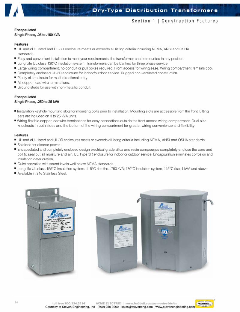
Encapsulated Single Phase, .05 to .150 kVA Featuresn UL and cUL listed and UL-3R enclosure meets or exceeds all listing criteria including NEMA, ANSI and OSHA
standards.n Easy and convenient installation to meet your re quirements, the transformer can be mounted in any position.n Long Life UL class 130°C insulation system. Transformers can be banked for three phase service.n Large wiring compartment, no conduit or pull boxes required. Front access for wiring ease. Wiring compartment remains cool.n Completely enclosed UL-3R enclosure for indoor/outdoor service. Rugged non-ventilated construction.n Plenty of knockouts for multi-directional entry.n All copper lead wire terminations.n Ground studs for use with non-metallic conduit.
Encapsulated Single Phase, .250 to 25 kVA
n Installation keyhole mounting slots for mounting bolts prior to installation. Mounting slots are accessible from the front. Lifting ears are included on 3 to 25 kVA units.
n Wiring flexible copper leadwire terminations for easy connections outside the front access wiring compartment. Dual size knockouts in both sides and the bottom of the wiring compartment for greater wiring convenience and flexibility.
Featuresn UL and cUL listed and UL-3R enclosures meets or exceeds all listing criteria including NEMA, ANSI and OSHA standards.n Shielded for cleaner power.n Encapsulated and completely enclosed design electrical grade silica and resin compounds completely enclose the core and
coil to seal out all moisture and air. UL Type 3R enclosure for indoor or outdoor service. Encapsulation eliminates corrosion and insulation deterioration.
n Quiet operation with sound levels well below NEMA standards.n Long life UL class 155°C insulation system. 115°C rise thru .750 kVA; 180°C insulation system, 115°C rise, 1 kVA and above.n Available in 316 Stainless Steel.
Dry-Type Distribution Transformers
S e c t i o n 1 | C o n s t r u c t i o n F e a t u r e s
Courtesy of Steven Engineering, Inc - (800) 258-9200 - [email protected] - www.stevenengineering.com
15toll free 800.334.5214 ACME ELECTRIC | www.hubbell.com/acmeelectric/en
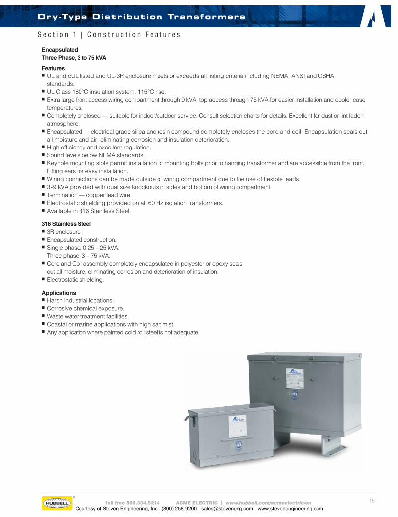
Encapsulated Three Phase, 3 to 75 kVA
Featuresn UL and cUL listed and UL-3R enclosure meets or exceeds all listing criteria including NEMA, ANSI and OSHA
standards.n UL Class 180°C insulation system. 115°C rise.n Extra large front access wiring compartment through 9 kVA; top access through 75 kVA for easier installation and cooler case temperatures.n Completely enclosed — suitable for indoor/outdoor service. Consult selection charts for details. Excellent for dust or lint laden atmosphere.n Encapsulated — electrical grade silica and resin compound completely encloses the core and coil. Encapsulation seals out all moisture and air, eliminating corrosion and insulation deterioration.n High efficiency and excellent regulation.n Sound levels below NEMA standards.n Keyhole mounting slots permit installation of mounting bolts prior to hanging transformer and are accessible from the front.
Lifting ears for easy installation.n Wiring connections can be made outside of wiring compartment due to the use of flexible leads.n 3-9 kVA provided with dual size knockouts in sides and bottom of wiring compartment.n Termination — copper lead wire.n Electrostatic shielding provided on all 60 Hz isolation transformers.n Available in 316 Stainless Steel.
316 Stainless Steel n 3R enclosure.n Encapsulated construction.n Single phase: 0.25 – 25 kVA. Three phase: 3 – 75 kVA.n Core and Coil assembly completely encapsulated in polyester or epoxy seals out all moisture, eliminating corrosion and deterioration of insulation.n Electrostatic shielding.
Applicationsn Harsh industrial locations.n Corrosive chemical exposure.n Waste water treatment facilities.n Coastal or marine applications with high salt mist.n Any application where painted cold roll steel is not adequate.
Dry-Type Distribution Transformers
S e c t i o n 1 | C o n s t r u c t i o n F e a t u r e s
Courtesy of Steven Engineering, Inc - (800) 258-9200 - [email protected] - www.stevenengineering.com
16 toll free 800.334.5214 ACME ELECTRIC | www.hubbell.com/acmeelectric/en
VENTILATED Single Phase 37.5 to 250 kVA, Three Phase 15 to 1000 kVA
Featuresn With weather shield, UL Type 3R enclosure or Type 2 enclosure without weather shield. UL and cUL listed.n UL Class 220°C insulation system, 150°C rise.n Extra large wiring compartment for easier installation and cooler case temperatures.n NEMA standard bus bar terminals, no special tools needed to make clearly marked connections. Tap changing easily
accomplished with jumpers.n Aluminum windings for increased insulation life, cooler operation, lower losses.n Noise and vibration isolating pads standard to assure quiet operation.n Large permanently legible nameplates on front.n Single phase units can be banked for 3 phase service.n All units have ground studs for use with non-metallic conduit.n Suitable for wall or “trapeze” mounting. Wall brackets are available for units up to 50 kVA single and 75 kVA three phase.n Other models are available with class 220°C insulation and either 115°C or 80°C rise operating temperature. n Three phase units15-112.5 kVA have pre-installed lugs.
Energy Efficient TransformersDOE 2016 - DOE 10 CFR Part 431 NRCan 2019 - SOR/2018-201
Replacing older general purpose transformers with our DOE 2016/NRCan 2019 will result in increased profitability from lower operating costs as well as a positive impact on the environment from a reduced carbon footprint.
Features: n Core Design. Cores are high-quality electrical steel from industry-leading suppliersn 3R Compliant. All new units ship with weather shields already installedn Flexibility. When a weather shield is not needed, it can easily be removedn Terminal Lugs. Primary and secondary terminals come standard with lugs (up to 112.5kVA) for quicker, easier connections n Isolating Pads. Extra padding reduces noise and vibration, assuring quiet operationn Aluminum Windings. Aluminum provides increased insulation life, cooler operation, and lower lossesn Consistent Fit/Form. Enclosure sizes of DOE 2016 units are identical to TP-1 sizes
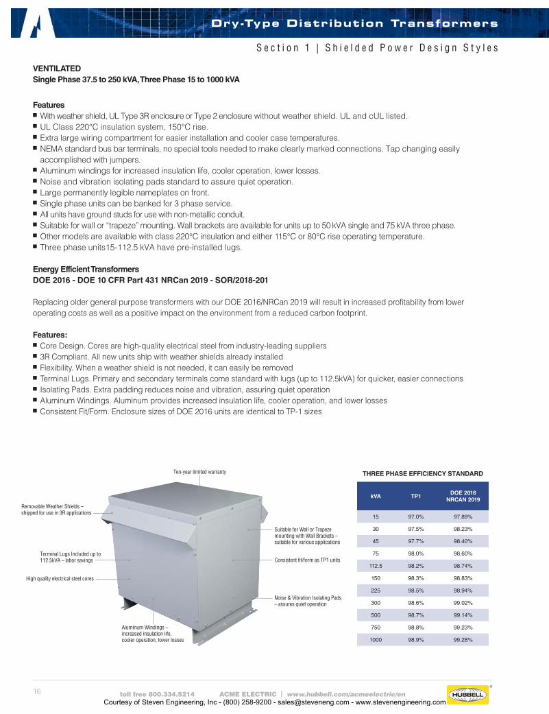
Ten-year limited warranty
Removable Weather Shields – shipped for use in 3R applications
Terminal Lugs Included up to 112.5kVA – labor savings
High quality electrical steel cores
Aluminum Windings – increased insulation life, cooler operation, lower losses
Suitable for Wall or Trapeze mounting with Wall Brackets – suitable for various applications
Consistent fit/form as TP1 units
Noise & Vibration Isolating Pads – assures quiet operation
THREE PHASE EFFICIENCY STANDARD
kVA TP1DOE 2016
NRCAN 2019
15 97.0% 97.89%
30 97.5% 98.23%
45 97.7% 98.40%
75 98.0% 98.60%
112.5 98.2% 98.74%
150 98.3% 98.83%
225 98.5% 98.94%
300 98.6% 99.02%
500 98.7% 99.14%
750 98.8% 99.23%
1000 98.9% 99.28%
Dry-Type Distribution Transformers
S e c t i o n 1 | S h i e l d e d P o w e r D e s i g n S t y l e s
Courtesy of Steven Engineering, Inc - (800) 258-9200 - [email protected] - www.stevenengineering.com

17toll free 800.334.5214 ACME ELECTRIC | www.hubbell.com/acmeelectric/en
SINGLE PHASE
120/208/240/277 PRIMARY VOLTS — 120/240 SECONDARY VOLTS — 1Ø, 60 Hz
kVACatalog Number
Height (Inches)(Cm.)
Width (Inches)(Cm.)
Depth (Inches)(Cm.)
Weight (Lbs.)(Kg.)
Mounting Type(Wall)(Floor)
Knockouts (Inches)(Cm.)
Weather Shield
Wiring Diagrams
Design Figures
1.0 T279740S 10.50 (26.7) 5.50 (14.0) 5.13 (13.0) 23 (10.4) W 0.50-0.75 (1.3-1.9) NA 23 B
1.5 T279741S 11.62 (29.5) 5.50 (14.0) 5.13 (13.0) 30 (13.6) W 0.50-0.75 (1.3-1.9) NA 23 B
2.0 T279742S 13.00 (33.0) 5.50 (14.0) 5.13 (13.0) 37 (16.8) W 0.50-0.75 (1.3-1.9) NA 23 B
3.0 T279743S 11.50 (29.2) 10.31 (26.2) 7.13 (18.1) 55 (24.9) W 0.75-1.25 (1.9-3.2) NA 23 C
5.0 T279744S 14.38 (36.5) 10.31 (26.2) 7.13 (18.1) 75 (34.0) W 0.75-1.25 (1.9-3.2) NA 23 C
7.5 T279745S 15.19 (38.6) 13.50 (34.3) 10.84 (27.5) 105 (47.6) W 0.75-1.25 (1.9-3.2) NA 63 D
10.0 T279746S 15.19 (38.6) 13.50 (34.3) 10.84 (27.5) 124 (56.2) W 0.75-1.25 (1.9-3.2) NA 63 D
15.0 T279747S 16.94 (43.0) 14.12 (35.9) 11.59 (29.4) 171 (77.6) W 1.00-1.50 (2.5-3.8) NA 63 D
25.0 T279748S 18.44 (46.8) 16.13 (41.0) 13.34 (33.9) 261 (118.4) W 1.00-1.50 (2.5-3.8) NA 63 D
190/200/208/220 X 380/400/416/440 PRIMARY VOLTS — 110/220 SECONDARY VOLTS — 1Ø, 50/60 Hz EXPORT MODEL
kVACatalog Number
Height (Inches)(Cm.)
Width (Inches)(Cm.)
Depth (Inches)(Cm.)
Weight (Lbs.)(Kg.)
Mounting Type(Wall)(Floor)
Knockouts (Inches)(Cm.)
Weather Shield
Wiring Diagrams
Design Figures
*1.0 TF279300S 10.50 (26.7) 5.50 (14.0) 5.13 (13.0) 24 (10.9) W 0.50-0.75 (1.3-1.9) NA 65 B
*2.0 TF279301S 13.00 (33.0) 5.50 (14.0) 5.13 (13.0) 38 (17.2) W 0.50-0.75 (1.3-1.9) NA 65 B
*3.0 TF279302S 11.50 (29.2) 10.31 (26.2) 7.13 (18.1) 55 (24.9) W 0.75-1.25 (1.9-3.2) NA 65 C
*5.0 TF279303S 14.38 (36.5) 10.31 (26.2) 7.13 (18.1) 75 (34.0) W 0.75-1.25 (1.9-3.2) NA 65 C
*7.5 TF279304S 15.19 (38.6) 13.50 (34.3) 10.84 (27.5) 115 (52.2) W 0.75-1.25 (1.9-3.2) NA 65 D
*CE Marked
Maximum exciting current 5% at 50 Hz.
190/200/208/220 X 380/400/416/440 PRIMARY VOLTS — 120/240 SECONDARY VOLTS — 1Ø, 50/60 Hz EXPORT MODEL
kVACatalog Number
Height (Inches)(Cm.)
Width (Inches)(Cm.)
Depth (Inches)(Cm.)
Weight (Lbs.)(Kg.)
Mounting Type(Wall)(Floor)
Knockouts (Inches)(Cm.)
Weather Shield
Wiring Diagrams
Design Figures
* 1.0 TF217437S 10.50 (26.7) 5.50 (14.0) 5.13 (13.0) 24 (10.9) W 0.50-0.75 (1.3-1.9) NA 14 B
* 2.0 TF217439S 13.00 (33.0) 5.50 (14.0) 5.13 (13.0) 38 (17.2) W 0.50-0.75 (1.3-1.9) NA 14 B
* 3.0 TF249873S 11.50 (29.2) 10.31 (26.2) 7.13 (18.1) 55 (24.9) W 0.75-1.25 (1.9-3.2) NA 14 C
* 5.0 TF252520S 14.38 (36.5) 10.31 (26.2) 7.13 (18.1) 75 (34.0) W 0.75-1.25 (1.9-3.2) NA 14 C
* 7.5 TF252794S 15.19 (38.6) 13.50 (34.3) 10.84 (27.5) 115 (52.2) W 0.75-1.25 (1.9-3.2) NA 14 D
* 10.0 TF252795S 15.19 (38.6) 13.50 (34.3) 10.84 (27.5) 125 (56.7) W 0.75-1.25 (1.9-3.2) NA 14 D
* 15.0 TF252796S 16.94 (43.0) 14.12 (35.9) 11.59 (29.4) 170 (77.1) W 1.00-1.50 (2.5-3.8) NA 14 D
* 25.0 TF252797S 18.44 (46.8) 16.13 (41.0) 13.34 (33.9) 300 (136.0) W 1.00-1.50 (2.5-3.8) NA 14 D
*CE Marked
All Wiring Diagrams begin on page 35.
Dry-Type Distribution Transformers
S e c t i o n 1 | S e l e c t i o n C h a r t s
Courtesy of Steven Engineering, Inc - (800) 258-9200 - [email protected] - www.stevenengineering.com
18 toll free 800.334.5214 ACME ELECTRIC | www.hubbell.com/acmeelectric/en
190/208/220/240 X 380/416/440/480 PRIMARY VOLTS — 120/240 SECONDARY VOLTS — 1Ø, 50/60 Hz EXPORT MODEL
kVACatalog Number
Height (Inches)(Cm.)
Width (Inches)(Cm.)
Depth (Inches)(Cm.)
Weight (Lbs.)(Kg.)
Mounting Type(Wall)(Floor)
Knockouts (Inches)(Cm.)
Weather Shield
Wiring Diagrams
Design Figures
*1.0 TF279260S 10.50 (26.7) 5.50 (14.0) 5.13 (13.0) 24 (10.9) W 0.50-0.75 (1.3-1.9) NA 64 B
*2.0 TF279261S 13.00 (33.0) 5.50 (14.0) 5.13 (13.0) 38 (17.2) W 0.50-0.75 (1.3-1.9) NA 64 B
*3.0 TF279262S 11.50 (29.2) 10.31 (26.2) 7.13 (18.1) 55 (24.9) W 0.75-1.25 (1.9-3.2) NA 64 C
*5.0 TF279263S 14.38 (36.5) 10.31 (26.2) 7.13 (18.1) 75 (34.0) W 0.75-1.25 (1.9-3.2) NA 64 C
*7.5 TF279264S 15.19 (38.6) 13.50 (34.3) 10.84 (27.5) 115 (52.2) W 0.75-1.25 (1.9-3.2) NA 64 D
*10.0 TF279265S 15.19 (38.6) 13.50 (34.3) 10.84 (27.5) 125 (56.7) W 0.75-1.25 (1.9-3.2) NA 64 D
*15.0 TF279266S 16.94 (43.0) 14.12 (35.9) 11.59 (29.4) 170 (77.1) W 1.00-1.50 (2.5-3.8) NA 64 D
*25.0 TF279267S 18.44 (46.8) 16.13 (41.0) 13.34 (33.9) 300 (136.1) W 1.00-1.50 (2.5-3.8) NA 64 D
*CE Marked
Maximum exciting current 5% at 50 Hz.
240 PRIMARY VOLTS — 120/240 SECONDARY VOLTS — 1Ø, 60 Hz AUTO-TRANSFORMERS
kVACatalog Number
Height (Inches)(Cm.)
Width (Inches)(Cm.)
Depth (Inches)(Cm.)
Weight (Lbs.)(Kg.)
Mounting Type(Wall)(Floor)
Knockouts (Inches)(Cm.)
Weather Shield
Wiring Diagrams
Design Figures
1.0 T253060 9.06 (23.0) 4.37 (11.1) 4.20 (10.7) 15 (6.8) W 0.50-0.75 (1.3-1.9) NA 12 B
1.5 T253061 9.68 (24.6) 4.50 (11.4) 4.51 (11.5) 19 (8.6) W 0.50-0.75 (1.3-1.9) NA 12 B
2.0 T253062 10.50 (26.7) 5.50 (14.0) 5.13 (13.0) 24 (10.9) W 0.50-0.75 (1.3-1.9) NA 12 B
3.0 T253063 11.62 (29.5) 5.50 (14.0) 5.13 (13.0) 30 (13.6) W 0.50-0.75 (1.3-1.9) NA 12 B
5.0 T253064 13.00 (33.0) 5.50 (14.0) 5.13 (13.0) 38 (17.2) W 0.50-0.75 (1.3-1.9) NA 12 B
7.5 T253065 11.50 (29.2) 10.31 (26.2) 7.13 (18.1) 55 (24.9) W 0.75-1.25 (1.9-3.2) NA 12 C
10.0 T253066 15.19 (38.6) 13.50 (34.3) 10.84 (27.5) 115 (52.2) W 0.75-1.25 (1.9-3.2) NA 12 D
15.0 T253067 15.19 (38.6) 13.50 (34.3) 10.84 (27.5) 115 (52.2) W 0.75-1.25 (1.9-3.2) NA 12 D
All Wiring Diagrams begin on page 35.
Dry-Type Distribution Transformers
S e c t i o n 1 | S e l e c t i o n C h a r t s
208 PRIMARY VOLTS — 120/240 SECONDARY VOLTS — THREE WINDINGS — 1Ø, 60 Hz — DOE/NRCan 2019 Compliant
kVACatalog Number
Height (Inches)(Cm.)
Width (Inches)(Cm.)
Depth (Inches)(Cm.)
Weight (Lbs.)(Kg.)
Mounting Type(Wall)(Floor)
Knockouts (Inches)(Cm.)
Weather Shield
Wiring Diagrams
Design Figures
37.5 TP536491S 25.50 (64.8) 24.40 (62.0) 19.40 (49.3) 257 (117.0) F ① NA WSA1 58 E
50.0 TP536503S 25.50 (64.8) 24.40 (62.0) 19.40 (49.3) 340 (154.2) F ① NA WSA1 17 E
75.0 TP536513S 35.40 (89.9) 31.90 (81.0) 26.88 (68.2) 420 (190.5) F NA WSA3 17 E
① Wall mounting brackets are available for these sizes, refer to page 41.
Courtesy of Steven Engineering, Inc - (800) 258-9200 - [email protected] - www.stevenengineering.com
19toll free 800.334.5214 ACME ELECTRIC | www.hubbell.com/acmeelectric/en
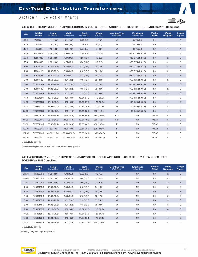
240 X 480 PRIMARY VOLTS — 120/240 SECONDARY VOLTS — FOUR WINDINGS — 1Ø, 60 Hz — DOE/NRCan 2019 Compliant
kVACatalog Number
Height (Inches)(Cm.)
Width (Inches)(Cm.)
Depth (Inches)(Cm.)
Weight (Lbs.)(Kg.)
Mounting Type(Wall)(Floor)
Knockouts (Inches)(Cm.)
Weather Shield
Wiring Diagrams
Design Figures
.05 ① T153004 6.41 (16.3) 3.14 (8.0) 3.05 (7.7) 4 (1.8) W 0.875 (2.2) NA 1 A
.10 ① T153005 7.16 (18.2) 3.89 (9.9) 3.67 (9.3) 5 (2.3) W 0.875 (2.2) NA 1 A
.15 ① T153006 7.16 (18.2) 3.89 (9.9) 3.67 (9.3) 7 (3.2) W 0.875 (2.2) NA 1 A
.25 ① T253007S 8.68 (22.0) 4.08 (10.4) 3.88 (9.9) 10 (4.5) W 0.50-0.75 (1.3-1.9) NA 2 B
.50 ① T253008S 9.06 (23.0) 4.37 (11.1) 4.20 (10.7) 15 (6.8) W 0.50-0.75 (1.3-1.9) NA 2 B
.75 ① T253009S 9.68 (24.6) 4.75 (12.1) 4.50 (11.4) 19 (8.6) W 0.50-0.75 (1.3-1.9) NA 2 B
1.00 T253010S 10.50 (26.7) 5.50 (14.0) 5.13 (13.0) 24 (10.9) W 0.50-0.75 (1.3-1.9) NA 2 B
1.50 T253011S 11.62 (29.5) 5.50 (14.0) 5.13 (13.0) 30 (13.6) W 0.50-0.75 (1.3-1.9) NA 2 B
2.00 T253012S 13.00 (33.0) 5.50 (14.0) 5.13 (13.0) 38 (17.2) W 0.50-0.75 (1.3-1.9) NA 2 B
3.00 T253013S 11.50 (29.2) 10.31 (26.2) 7.13 (18.1) 55 (24.9) W 0.75-1.25 (1.9-3.2) NA 2 C
3.00 T2530134S 11.50 (29.2) 10.31 (26.2) 7.13 (18.1) 55 (24.9) W 0.75-1.25 (1.9-3.2) NA 3 C
5.00 T253014S 14.38 (36.5) 10.31 (26.2) 7.13 (18.1) 75 (34.0) W 0.75-1.25 (1.9-3.2) NA 2 C
5.00 T2530144S 14.38 (36.5) 10.31 (26.2) 7.13 (18.1) 75 (34.0) W 0.75-1.25 (1.9-3.2) NA 3 C
7.50 T2535153S 15.19 (38.6) 13.50 (34.3) 10.84 (27.5) 115 (52.2) W 0.75-1.25 (1.9-3.2) NA 4 D
10.00 T2535163S 15.19 (38.6) 13.50 (34.3) 10.84 (27.5) 125 (56.7) W 0.75-1.25 (1.9-3.2) NA 4 D
15.00 T2535173S 16.94 (43.0) 14.12 (35.9) 11.59 (29.4) 170 (77.1) W 1.00-1.50 (2.5-3.8) NA 4 D
25.00 T2535183S 18.44 (46.8) 16.13 (41.0) 13.34 (33.9) 250 (113.0) W 1.00-1.50 (2.5-3.8) NA 4 D
37.50 TP530193S 25.50 (64.8) 24.39 (61.9) 19.37 (49.2) 280 (127.0) F ② NA WSA1 5 E
50.00 TP530203S 25.50 (64.8) 24.39 (61.9) 19.37 (49.2) 350 (158.8) F ② NA WSA1 5 E
75.00 TP530213S 35.47 (90.1) 31.90 (81.0) 26.88 (68.3) 430 (195.0) F NA WSA3 5 E
100.00 TP530223S 41.52 (105.4) 32.90 (83.5) 29.87 (75.9) 525 (238.0) F NA WSA4 5 E
167.00 TP530233S 45.60 (115.8) 39.50 (100.3) 35.50 (90.1) 1050 (476.3) F NA WSA5 5 E
250.00 TP530243S 45.60 (115.8) 39.50 (100.3) 35.50 (90.1) 1440 (653.2) F NA WSA5 5 E
①Suitable for 50/60Hz
② Wall mounting brackets are available for these sizes, refer to page 41.
240 X 480 PRIMARY VOLTS — 120/240 SECONDARY VOLTS — FOUR WINDINGS — 1Ø, 60 Hz — 316 STAINLESS STEEL DOE/NRCan 2019 Compliant
kVACatalog Number
Height (Inches)(Cm.)
Width (Inches)(Cm.)
Depth (Inches)(Cm.)
Weight (Lbs.)(Kg.)
Mounting Type(Wall)(Floor)
Knockouts (Inches)(Cm.)
Weather Shield
Wiring Diagrams
Design Figures
0.25 ① T253007SS 8.68 (22.0) 4.08 (10.4) 3.88 (9.9) 10 (4.5) W NA NA 2 B
0.50 ① T253008SS 9.06 (23.0) 4.37 (11.1) 4.20 (10.7) 15 (6.8) W NA NA 2 B
0.75 ① T253009SS 9.68 (24.6) 4.75 (12.1) 4.50 (11.4) 19 (8.6) W NA NA 2 B
1.00 T253010SS 10.50 (26.7) 5.50 (14.0) 5.13 (13.0) 24 (10.9) W NA NA 2 B
1.50 T253011SS 11.62 (29.5) 5.50 (14.0) 5.13 (13.0) 30 (13.6) W NA NA 2 B
2.00 T253012SS 13.00 (33.0) 5.50 (14.0) 5.13 (13.0) 38 (17.2) W NA NA 2 B
3.00 T253013SS 11.50 (29.2) 10.31 (26.2) 7.13 (18.1) 55 (24.9) W NA NA 3 C
5.00 T253014SS 14.38 (36.5) 10.31 (26.2) 7.13 (18.1) 75 (34.0) W NA NA 3 C
7.50 T253515SS 15.19 (38.6) 13.50 (34.3) 10.84 (27.5) 115 (52.2) W NA NA 4 D
10.00 T253516SS 15.19 (38.6) 13.50 (34.3) 10.84 (27.5) 125 (56.7) W NA NA 4 D
15.00 T253517SS 16.94 (43.0) 14.12 (35.9) 11.59 (29.4) 170 (77.1) W NA NA 4 D
25.00 T253518SS 18.44 (46.8) 16.13 (41.0) 13.34 (33.9) 250 (113.0) W NA NA 4 D
①Suitable for 50/60Hz
All Wiring Diagrams begin on page 35.
Dry-Type Distribution Transformers
S e c t i o n 1 | S e l e c t i o n C h a r t s
Courtesy of Steven Engineering, Inc - (800) 258-9200 - [email protected] - www.stevenengineering.com
20 toll free 800.334.5214 ACME ELECTRIC | www.hubbell.com/acmeelectric/en
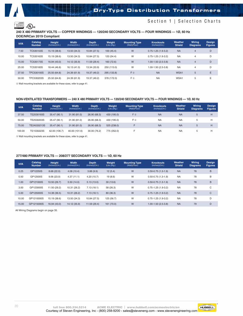
277/480 PRIMARY VOLTS — 208/277 SECONDARY VOLTS — 1Ø, 60 Hz
kVACatalog Number
Height (Inches)(Cm.)
Width (Inches)(Cm.)
Depth (Inches)(Cm.)
Weight (Lbs.)(Kg.)
Mounting Type(Wall)(Floor)
Knockouts (Inches)(Cm.)
Weather Shield
Wiring Diagrams
Design Figures
0.25 GP12250S 8.68 (22.0) 4.08 (10.4) 3.88 (9.9) 12 (5.4) W 0.50-0.75 (1.3-1.9) NA 78 B
0.50 GP12500S 9.06 (23.0) 4.37 (11.1) 4.20 (10.7) 19 (8.6) W 0.50-0.75 (1.3-1.9) NA 78 B
1.00 GP121000S 10.50 (26.7) 5.50 (14.0) 5.13 (13.0) 30 (13.6) W 0.50-0.75 (1.3-1.9) NA 78 B
3.00 GP123000S 11.50 (29.2) 10.31 (26.2) 7.13 (18.1) 58 (26.3) W 0.75-1.25 (1.9-3.2) NA 78 C
5.00 GP125000S 14.38 (36.5) 10.31 (26.2) 7.13 (18.1) 80 (36.3) W 0.75-1.25 (1.9-3.2) NA 78 C
10.00 GP1210000S 15.19 (38.6) 13.50 (34.3) 10.84 (27.5) 125 (56.7) W 0.75-1.25 (1.9-3.2) NA 78 D
15.00 GP1215000S 16.94 (43.0) 14.12 (35.9) 11.59 (29.4) 161 (70.0) W 1.00-1.50 (2.5-3.8) NA 79 D
240 X 480 PRIMARY VOLTS — COPPER WINDINGS — 120/240 SECONDARY VOLTS — FOUR WINDINGS — 1Ø, 60 Hz DOE/NRCan 2019 Compliant
kVACatalog Number
Height (Inches)(Cm.)
Width (Inches)(Cm.)
Depth (Inches)(Cm.)
Weight (Lbs.)(Kg.)
Mounting Type(Wall)(Floor)
Knockouts (Inches)(Cm.)
Weather Shield
Wiring Diagrams
Design Figures
7.50 TC535153S 15.19 (38.6) 13.50 (34.3) 10.84 (27.5) 100 (45.4) W 0.75-1.25 (1.9-3.2) NA 4 D
10.00 TC535163S 15.19 (38.6) 13.50 (34.3) 10.84 (27.5) 120 (54.4) W 0.75-1.25 (1.9-3.2) NA 4 D
15.00 TC535173S 16.94 (43.0) 14.12 (35.9) 11.59 (29.4) 160 (72.6) W 1.00-1.50 (2.5-3.8) NA 4 D
25.00 TC535183S 18.44 (46.8) 16.13 (41.0) 13.34 (33.9) 250 (113.0) W 1.00-1.50 (2.5-3.8) NA 4 D
37.50 TPC530193S 25.50 (64.8) 24.39 (61.9) 19.37 (49.2) 295 (133.8) F ① NA WSA1 5 E
50.00 TPC530203S 25.50 (64.8) 24.39 (61.9) 19.37 (49.2) 378 (172.0) F ① NA WSA1 5 E
① Wall mounting brackets are available for these sizes, refer to page 41.
NON-VENTILATED TRANSFORMERS — 240 X 480 PRIMARY VOLTS — 120/240 SECONDARY VOLTS — FOUR WINDINGS — 1Ø, 60 Hz
kVACatalog Number
Height (Inches)(Cm.)
Width (Inches)(Cm.)
Depth (Inches)(Cm.)
Weight (Lbs.)(Kg.)
Mounting Type(Wall)(Floor)
Knockouts (Inches)(Cm.)
Weather Shield
Wiring Diagrams
Design Figures
37.50 TE2530193S 35.47 (90.1) 31.90 (81.0) 26.90 (68.3) 430 (195.0) F ① NA NA 5 H
50.00 TE2530203S 35.47 (90.1) 31.90 (81.0) 26.90 (68.3) 430 (195.0) F ① NA NA 5 H
75.00 TE2A530213S 35.47 (90.1) 31.90 (81.0) 26.90 (68.3) 525 (238.0) F NA NA 5 H
100.00 TE1530223S 42.00 (106.7) 40.00 (101.6) 30.00 (76.2) 775 (352.0) F NA NA 5 H
① Wall mounting brackets are available for these sizes, refer to page 41.
All Wiring Diagrams begin on page 35.
Dry-Type Distribution Transformers
S e c t i o n 1 | S e l e c t i o n C h a r t s
Courtesy of Steven Engineering, Inc - (800) 258-9200 - [email protected] - www.stevenengineering.com

21toll free 800.334.5214 ACME ELECTRIC | www.hubbell.com/acmeelectric/en
600 PRIMARY VOLTS — 120/240 SECONDARY VOLTS — THREE WINDINGS — 1Ø, 60 Hz — DOE/NRCan 2019 Compliant
kVACatalog Number
Height (Inches)(Cm.)
Width (Inches)(Cm.)
Depth (Inches)(Cm.)
Weight (Lbs.)(Kg.)
Mounting Type(Wall)(Floor)
Knockouts (Inches)(Cm.)
Weather Shield
Wiring Diagrams
Design Figures
.05 ① T153104 6.41 (16.3) 3.14 (8.0) 3.05 (7.7) 4 (1.8) W 0.875 (2.2) NA 8 A
.10 ① T153105 7.16 (18.2) 3.89 (9.9) 3.67 (9.3) 5 (2.3) W 0.875 (2.2) NA 8 A
.15 ① T153106 7.16 (18.2) 3.89 (9.9) 3.67 (9.3) 7 (3.2) W 0.875 (2.2) NA 8 A
.25 ① T253107S 8.68 (22.0) 4.08 (10.4) 3.88 (9.9) 10 (4.5) W 0.50-0.75 (1.3-1.9) NA 9 B
.50 ① T253108S 9.06 (23.0) 4.37 (11.1) 4.20 (10.7) 15 (6.8) W 0.50-0.75 (1.3-1.9) NA 9 B
.75 ① T253109S 9.68 (24.6) 4.75 (12.1) 4.50 (11.4) 19 (8.6) W 0.50-0.75 (1.3-1.9) NA 9 B
1.00 T253110S 10.50 (26.7) 5.50 (14.0) 5.13 (13.0) 24 (10.9) W 0.50-0.75 (1.3-1.9) NA 9 B
1.50 T253111S 11.62 (29.5) 5.50 (14.0) 5.13 (13.0) 30 (13.6) W 0.50-0.75 (1.3-1.9) NA 9 B
2.00 T253112S 13.00 (33.0) 5.50 (14.0) 5.13 (13.0) 38 (17.2) W 0.50-0.75 (1.3-1.9) NA 9 B
3.00 T2531131S 11.50 (29.2) 10.31 (26.2) 7.13 (18.1) 55 (24.9) W 0.75-1.25 (1.9-3.2) NA 10 C
5.00 T2531141S 14.38 (36.5) 10.31 (26.2) 7.13 (18.1) 75 (34.0) W 0.75-1.25 (1.9-3.2) NA 10 C
7.50 T2536151S 15.19 (38.6) 13.50 (34.3) 10.84 (27.5) 115 (52.2) W 0.75-1.25 (1.9-3.2) NA 10 D
10.00 T2536161S 15.19 (38.6) 13.50 (34.3) 10.84 (27.5) 125 (56.7) W 0.75-1.25 (1.9-3.2) NA 10 D
15.00 T2536171S 16.94 (43.0) 14.12 (35.9) 11.59 (29.4) 170 (77.1) W 1.00-1.50 (2.5-3.8) NA 10 D
25.00 T2536181S 18.44 (46.8) 16.13 (41.0) 13.34 (33.9) 250 (113.0) W 1.00-1.50 (2.5-3.8) NA 10 D
37.50 TP531193S 25.50 (64.8) 24.40 (62.0) 19.40 (49.3) 275 (125.0) F ② NA WSA1 11 E
50.00 TP531203S 29.90 (76.0) 28.15 (71.5) 22.37 (56.8) 340 (154.0) F ② NA WSA2 11 E
75.00 TP531213S 35.47 (90.0) 31.90 (81.0) 26.88 (68.3) 430 (195.0) F NA WSA3 11 E
100.00 TP531223S 41.52 (105.4) 32.90 (83.5) 29.87 (75.9) 525 (238.0) F NA WSA4 11 E
167.00 TP531233S 45.60 (115.8) 39.5 (100.3) 35.5 (90.2) 1050 (476.3) F NA WSA5 11 E
① Suitable for 50/60Hz
② Wall mounting brackets are available for these sizes, refer to page 41.
All Wiring Diagrams begin on page 35.
Dry-Type Distribution Transformers
S e c t i o n 1 | S e l e c t i o n C h a r t s
Courtesy of Steven Engineering, Inc - (800) 258-9200 - [email protected] - www.stevenengineering.com
22 toll free 800.334.5214 ACME ELECTRIC | www.hubbell.com/acmeelectric/en
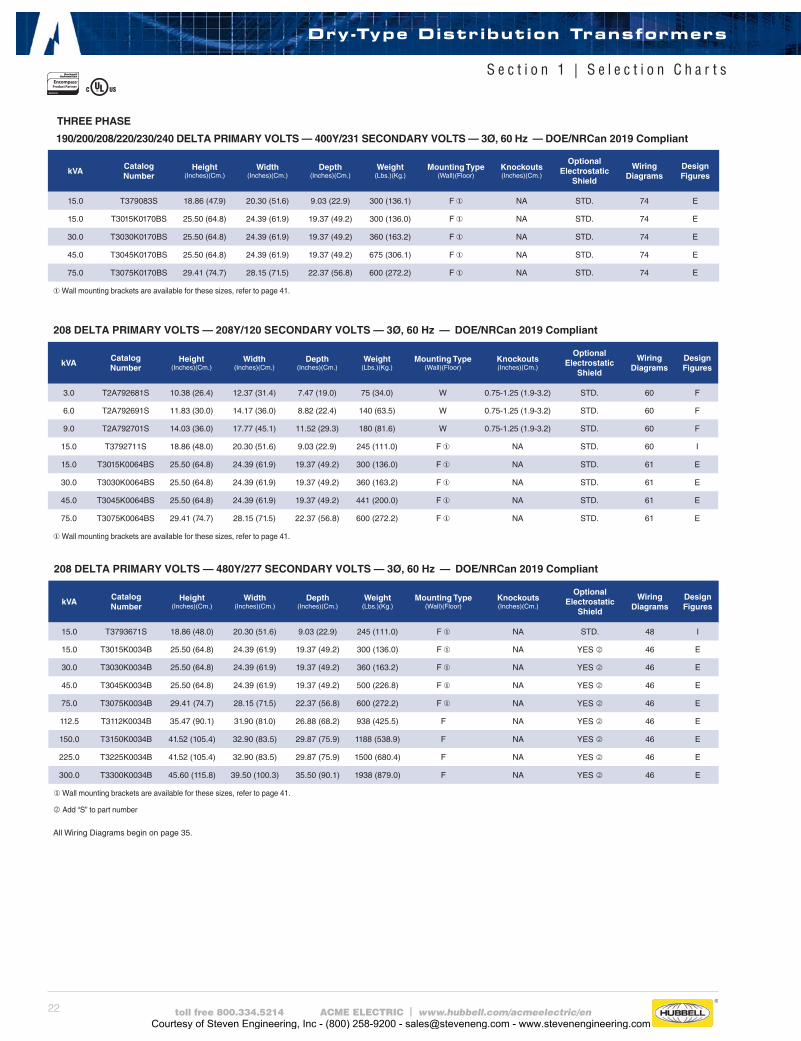
190/200/208/220/230/240 DELTA PRIMARY VOLTS — 400Y/231 SECONDARY VOLTS — 3Ø, 60 Hz — DOE/NRCan 2019 Compliant
kVACatalog Number
Height (Inches)(Cm.)
Width (Inches)(Cm.)
Depth (Inches)(Cm.)
Weight (Lbs.)(Kg.)
Mounting Type(Wall)(Floor)
Knockouts (Inches)(Cm.)
Optional Electrostatic
Shield
Wiring Diagrams
Design Figures
15.0 T379083S 18.86 (47.9) 20.30 (51.6) 9.03 (22.9) 300 (136.1) F ① NA STD. 74 E
15.0 T3015K0170BS 25.50 (64.8) 24.39 (61.9) 19.37 (49.2) 300 (136.0) F ① NA STD. 74 E
30.0 T3030K0170BS 25.50 (64.8) 24.39 (61.9) 19.37 (49.2) 360 (163.2) F ① NA STD. 74 E
45.0 T3045K0170BS 25.50 (64.8) 24.39 (61.9) 19.37 (49.2) 675 (306.1) F ① NA STD. 74 E
75.0 T3075K0170BS 29.41 (74.7) 28.15 (71.5) 22.37 (56.8) 600 (272.2) F ① NA STD. 74 E
①Wall mounting brackets are available for these sizes, refer to page 41.
208 DELTA PRIMARY VOLTS — 208Y/120 SECONDARY VOLTS — 3Ø, 60 Hz — DOE/NRCan 2019 Compliant
kVACatalog Number
Height (Inches)(Cm.)
Width (Inches)(Cm.)
Depth (Inches)(Cm.)
Weight (Lbs.)(Kg.)
Mounting Type(Wall)(Floor)
Knockouts (Inches)(Cm.)
Optional Electrostatic
Shield
Wiring Diagrams
Design Figures
3.0 T2A792681S 10.38 (26.4) 12.37 (31.4) 7.47 (19.0) 75 (34.0) W 0.75-1.25 (1.9-3.2) STD. 60 F
6.0 T2A792691S 11.83 (30.0) 14.17 (36.0) 8.82 (22.4) 140 (63.5) W 0.75-1.25 (1.9-3.2) STD. 60 F
9.0 T2A792701S 14.03 (36.0) 17.77 (45.1) 11.52 (29.3) 180 (81.6) W 0.75-1.25 (1.9-3.2) STD. 60 F
15.0 T3792711S 18.86 (48.0) 20.30 (51.6) 9.03 (22.9) 245 (111.0) F ① NA STD. 60 I
15.0 T3015K0064BS 25.50 (64.8) 24.39 (61.9) 19.37 (49.2) 300 (136.0) F ① NA STD. 61 E
30.0 T3030K0064BS 25.50 (64.8) 24.39 (61.9) 19.37 (49.2) 360 (163.2) F ① NA STD. 61 E
45.0 T3045K0064BS 25.50 (64.8) 24.39 (61.9) 19.37 (49.2) 441 (200.0) F ① NA STD. 61 E
75.0 T3075K0064BS 29.41 (74.7) 28.15 (71.5) 22.37 (56.8) 600 (272.2) F ① NA STD. 61 E
①Wall mounting brackets are available for these sizes, refer to page 41.
All Wiring Diagrams begin on page 35.
Dry-Type Distribution Transformers
S e c t i o n 1 | S e l e c t i o n C h a r t s
THREE PHASE
208 DELTA PRIMARY VOLTS — 480Y/277 SECONDARY VOLTS — 3Ø, 60 Hz — DOE/NRCan 2019 Compliant
kVACatalog Number
Height (Inches)(Cm.)
Width (Inches)(Cm.)
Depth (Inches)(Cm.)
Weight (Lbs.)(Kg.)
Mounting Type(Wall)(Floor)
Knockouts (Inches)(Cm.)
Optional Electrostatic
Shield
Wiring Diagrams
Design Figures
15.0 T3793671S 18.86 (48.0) 20.30 (51.6) 9.03 (22.9) 245 (111.0) F ① NA STD. 48 I
15.0 T3015K0034B 25.50 (64.8) 24.39 (61.9) 19.37 (49.2) 300 (136.0) F ① NA YES k 46 E
30.0 T3030K0034B 25.50 (64.8) 24.39 (61.9) 19.37 (49.2) 360 (163.2) F ① NA YES k 46 E
45.0 T3045K0034B 25.50 (64.8) 24.39 (61.9) 19.37 (49.2) 500 (226.8) F ① NA YES k 46 E
75.0 T3075K0034B 29.41 (74.7) 28.15 (71.5) 22.37 (56.8) 600 (272.2) F ① NA YES k 46 E
112.5 T3112K0034B 35.47 (90.1) 31.90 (81.0) 26.88 (68.2) 938 (425.5) F NA YES k 46 E
150.0 T3150K0034B 41.52 (105.4) 32.90 (83.5) 29.87 (75.9) 1188 (538.9) F NA YES k 46 E
225.0 T3225K0034B 41.52 (105.4) 32.90 (83.5) 29.87 (75.9) 1500 (680.4) F NA YES k 46 E
300.0 T3300K0034B 45.60 (115.8) 39.50 (100.3) 35.50 (90.1) 1938 (879.0) F NA YES k 46 E
①Wall mounting brackets are available for these sizes, refer to page 41.
kAdd “S” to part number
Courtesy of Steven Engineering, Inc - (800) 258-9200 - [email protected] - www.stevenengineering.com
23toll free 800.334.5214 ACME ELECTRIC | www.hubbell.com/acmeelectric/en
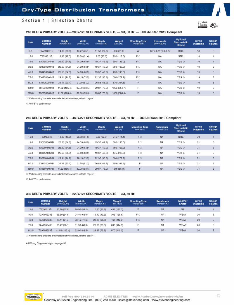
240 DELTA PRIMARY VOLTS — 208Y/120 SECONDARY VOLTS — 3Ø, 60 Hz — DOE/NRCan 2019 Compliant
kVACatalog Number
Height (Inches)(Cm.)
Width (Inches)(Cm.)
Depth (Inches)(Cm.)
Weight (Lbs.)(Kg.)
Mounting Type(Wall)(Floor)
Knockouts (Inches)(Cm.)
Optional Electrostatic
Shield
Wiring Diagrams
Design Figures
9.0 T2A533601S 14.03 (36.0) 17.77 (45.1) 11.52 (29.3) 180 (81.6) W 0.75-1.25 (1.9-3.2) STD. 18 F
15.0 T3533611S 18.86 (48.0) 20.30 (51.6) 9.03 (23.0) 250 (113.0) F ① NA STD. 18 I
15.0 T3015K0044B 25.50 (64.8) 24.39 (61.9) 19.37 (49.2) 300 (136.0) F ① NA YES k 19 E
30.0 T3030K0044B 25.50 (64.8) 24.39 (61.9) 19.37 (49.2) 360 (163.2) F ① NA YES k 19 E
45.0 T3045K0044B 25.50 (64.8) 24.39 (61.9) 19.37 (49.2) 438 (198.6) F ① NA YES k 19 E
75.0 T3075K0044B 29.41 (74.7) 28.15 (71.5) 22.37 (56.8) 600 (272.2) F ① NA YES k 19 E
112.5 T3112K0044B 35.47 (90.1) 31.90 (81.0) 26.88 (68.2) 870 (394.6) F NA YES k 19 E
150.0 T3150K0044B 41.52 (105.4) 32.90 (83.5) 29.87 (75.9) 1223 (554.7) F NA YES k 19 E
225.0 T3225K0044B 41.52 (105.4) 32.90 (83.5) 29.87 (75.9) 1500 (680.4) F NA YES k 19 E
①Wall mounting brackets are available for these sizes, refer to page 41.
kAdd “S” to part number
240 DELTA PRIMARY VOLTS — 480Y/277 SECONDARY VOLTS — 3Ø, 60 Hz — DOE/NRCan 2019 Compliant
kVACatalog Number
Height (Inches)(Cm.)
Width (Inches)(Cm.)
Depth (Inches)(Cm.)
Weight (Lbs.)(Kg.)
Mounting Type(Wall)(Floor)
Knockouts (Inches)(Cm.)
Optional Electrostatic
Shield
Wiring Diagrams
Design Figures
15.0 T3796931S 18.90 (48.0) 20.30 (51.6) 9.00 (22.9) 245 (111.1) F ① NA STD. 70 I
15.0 T3015K0074B 25.50 (64.8) 24.39 (61.9) 19.37 (49.2) 300 (136.0) F ① NA YES k 71 E
30.0 T3030K0074B 25.50 (64.8) 24.39 (61.9) 19.37 (49.2) 360 (163.2) F ① NA YES k 71 E
45.0 T3045K0074B 25.50 (64.8) 24.39 (61.9) 19.37 (49.2) 475 (215.5) F ① NA YES k 71 E
75.0 T3075K0074B 29.41 (74.7) 28.15 (71.5) 22.37 (56.8) 600 (272.2) F ① NA YES k 71 E
112.5 T3112K0074B 35.47 (90.1) 31.90 (81.0) 26.88 (68.2) 859 (389.6) F NA YES k 71 E
150.0 T3150K0074B 41.52 (105.4) 32.90 (83.5) 29.87 (75.9) 1216 (551.6) F NA YES k 71 E
①Wall mounting brackets are available for these sizes, refer to page 41.
kAdd “S” to part number
380 DELTA PRIMARY VOLTS — 220Y/127 SECONDARY VOLTS — 3Ø, 50 Hz
kVACatalog Number
Height (Inches)(Cm.)
Width (Inches)(Cm.)
Depth (Inches)(Cm.)
Weight (Lbs.)(Kg.)
Mounting Type(Wall)(Floor)
Knockouts (Inches)(Cm.)
Weather Shield
Wiring Diagrams
Design Figures
15.0 T3795511S 20.80 (52.8) 20.90 (53.1) 10.20 (25.9) 435 (197.3) F NA NA 24 I
30.0 T2A795523S 25.50 (64.8) 24.40 (62.0) 19.40 (49.3) 365 (165.6) F ① NA WSA1 20 E
45.0 T2A795533S 29.41 (74.7) 28.15 (71.5) 22.37 (56.8) 468 (212.3) F ① NA WSA2 20 E
75.0 T2A795543S 35.47 (90.1) 31.90 (80.0) 26.88 (68.3) 693 (314.3) F NA WSA3 20 E
112.5 T2A795553S 41.52 (105.4) 32.90 (83.5) 29.87 (75.9) 970 (440.0) F NA WSA4 20 E
①Wall mounting brackets are available for these sizes, refer to page 41.
All Wiring Diagrams begin on page 35.
Dry-Type Distribution Transformers
S e c t i o n 1 | S e l e c t i o n C h a r t s
Courtesy of Steven Engineering, Inc - (800) 258-9200 - [email protected] - www.stevenengineering.com
24 toll free 800.334.5214 ACME ELECTRIC | www.hubbell.com/acmeelectric/en
Dry-Type Distribution Transformers
S e c t i o n 1 | S e l e c t i o n C h a r t s
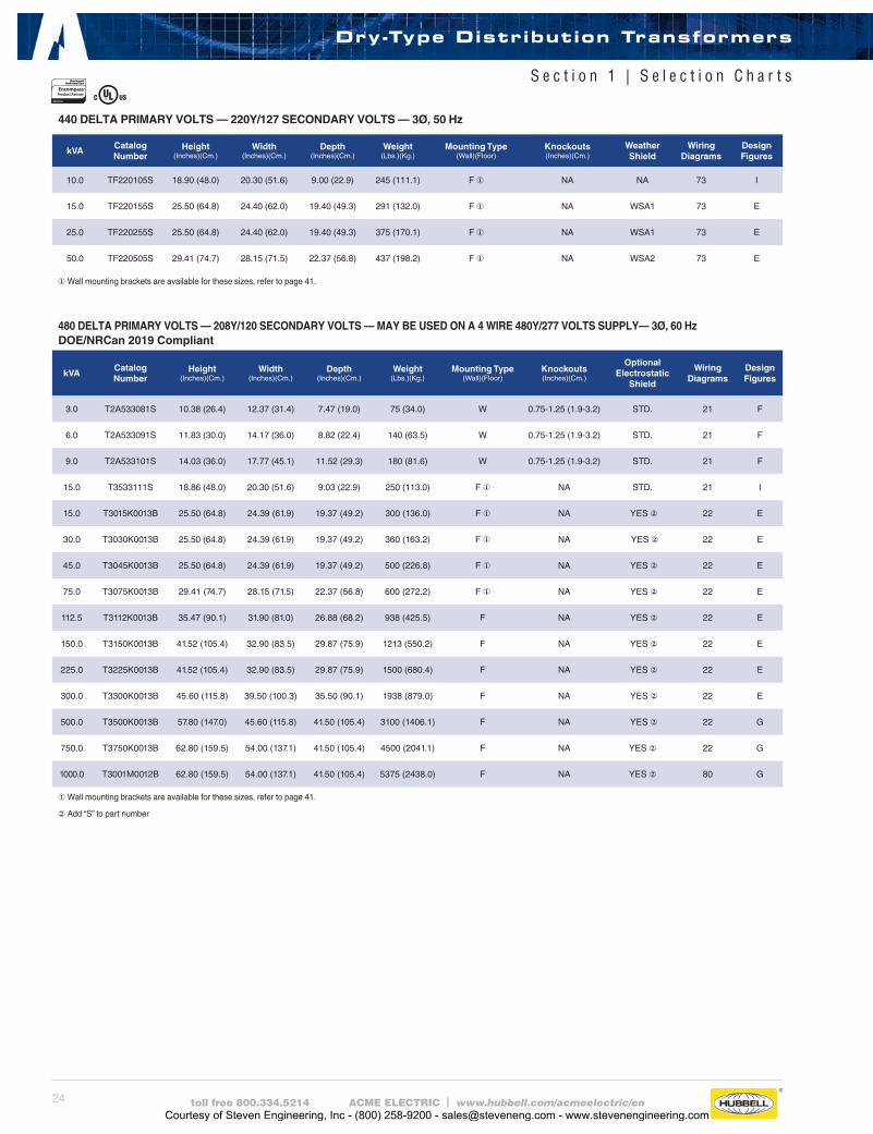
440 DELTA PRIMARY VOLTS — 220Y/127 SECONDARY VOLTS — 3Ø, 50 Hz
kVACatalog Number
Height (Inches)(Cm.)
Width (Inches)(Cm.)
Depth (Inches)(Cm.)
Weight (Lbs.)(Kg.)
Mounting Type(Wall)(Floor)
Knockouts (Inches)(Cm.)
Weather Shield
Wiring Diagrams
Design Figures
10.0 TF220105S 18.90 (48.0) 20.30 (51.6) 9.00 (22.9) 245 (111.1) F ① NA NA 73 I
15.0 TF220155S 25.50 (64.8) 24.40 (62.0) 19.40 (49.3) 291 (132.0) F ① NA WSA1 73 E
25.0 TF220255S 25.50 (64.8) 24.40 (62.0) 19.40 (49.3) 375 (170.1) F ① NA WSA1 73 E
50.0 TF220505S 29.41 (74.7) 28.15 (71.5) 22.37 (56.8) 437 (198.2) F ① NA WSA2 73 E
①Wall mounting brackets are available for these sizes, refer to page 41.
480 DELTA PRIMARY VOLTS — 208Y/120 SECONDARY VOLTS — MAY BE USED ON A 4 WIRE 480Y/277 VOLTS SUPPLY— 3Ø, 60 Hz DOE/NRCan 2019 Compliant
kVACatalog Number
Height (Inches)(Cm.)
Width (Inches)(Cm.)
Depth (Inches)(Cm.)
Weight (Lbs.)(Kg.)
Mounting Type(Wall)(Floor)
Knockouts (Inches)(Cm.)
Optional Electrostatic
Shield
Wiring Diagrams
Design Figures
3.0 T2A533081S 10.38 (26.4) 12.37 (31.4) 7.47 (19.0) 75 (34.0) W 0.75-1.25 (1.9-3.2) STD. 21 F
6.0 T2A533091S 11.83 (30.0) 14.17 (36.0) 8.82 (22.4) 140 (63.5) W 0.75-1.25 (1.9-3.2) STD. 21 F
9.0 T2A533101S 14.03 (36.0) 17.77 (45.1) 11.52 (29.3) 180 (81.6) W 0.75-1.25 (1.9-3.2) STD. 21 F
15.0 T3533111S 18.86 (48.0) 20.30 (51.6) 9.03 (22.9) 250 (113.0) F ① NA STD. 21 I
15.0 T3015K0013B 25.50 (64.8) 24.39 (61.9) 19.37 (49.2) 300 (136.0) F ① NA YES ② 22 E
30.0 T3030K0013B 25.50 (64.8) 24.39 (61.9) 19.37 (49.2) 360 (163.2) F ① NA YES ② 22 E
45.0 T3045K0013B 25.50 (64.8) 24.39 (61.9) 19.37 (49.2) 500 (226.8) F ① NA YES ② 22 E
75.0 T3075K0013B 29.41 (74.7) 28.15 (71.5) 22.37 (56.8) 600 (272.2) F ① NA YES ② 22 E
112.5 T3112K0013B 35.47 (90.1) 31.90 (81.0) 26.88 (68.2) 938 (425.5) F NA YES ② 22 E
150.0 T3150K0013B 41.52 (105.4) 32.90 (83.5) 29.87 (75.9) 1213 (550.2) F NA YES ② 22 E
225.0 T3225K0013B 41.52 (105.4) 32.90 (83.5) 29.87 (75.9) 1500 (680.4) F NA YES ② 22 E
300.0 T3300K0013B 45.60 (115.8) 39.50 (100.3) 35.50 (90.1) 1938 (879.0) F NA YES ② 22 E
500.0 T3500K0013B 57.80 (147.0) 45.60 (115.8) 41.50 (105.4) 3100 (1406.1) F NA YES ② 22 G
750.0 T3750K0013B 62.80 (159.5) 54.00 (137.1) 41.50 (105.4) 4500 (2041.1) F NA YES ② 22 G
1000.0 T3001M0012B 62.80 (159.5) 54.00 (137.1) 41.50 (105.4) 5375 (2438.0) F NA YES ② 80 G
① Wall mounting brackets are available for these sizes, refer to page 41.
②Add “S” to part number
Courtesy of Steven Engineering, Inc - (800) 258-9200 - [email protected] - www.stevenengineering.com

25toll free 800.334.5214 ACME ELECTRIC | www.hubbell.com/acmeelectric/en
Dry-Type Distribution Transformers
S e c t i o n 1 | S e l e c t i o n C h a r t s
480 DELTA PRIMARY VOLTS –– COPPER WINDINGS –– 208Y/120 SECONDARY VOLTS –– 3Ø, 60 Hz — DOE/NRCan 2019 Compliant
kVACatalog Number
Height (Inches)(Cm.)
Width (Inches)(Cm.)
Depth (Inches)(Cm.)
Weight (Lbs.)(Kg.)
Mounting Type(Wall)(Floor)
Knockouts (Inches)(Cm.)
Optional Electrostatic
Shield
Wiring Diagrams
Design Figures
15.0 TC533111S 18.86 (48.0) 20.30 (51.6) 9.03 (22.9) 245 (111.0) F ① NA STD. 21 I
15.0 T3015K0013BC 25.50 (64.8) 24.39 (61.9) 19.37 (49.2) 353 (160.1) F ① NA YES ② 22 E
30.0 T3030K0013BC 25.50 (64.8) 24.39 (61.9) 19.37 (49.2) 498 (225.9) F ① NA YES ② 22 E
45.0 T3045K0013BC 25.50 (64.8) 24.39 (61.9) 19.37 (49.2) 572 (259.5) F ① NA YES ② 22 E
75.0 T3075K0013BC 29.41 (74.7) 28.15 (71.5) 22.37 (56.8) 750 (340.2) F NA YES ② 22 E
112.5 T3112K0013BC 35.47 (90.1) 31.90 (81.0) 26.88 (68.2) 1103 (500.3) F NA YES ② 22 E
150.0 T3150K0013BC 41.52 (105.4) 32.90 (83.5) 29.87 (75.9) 1477 (669.9) F NA YES ② 22 E
225.0 T3225K0013BC 41.52 (105.4) 32.90 (83.5) 29.87 (75.9) 1872 (849.1) F NA YES ② 22 E
300.0 T3300K0013BC 45.60 (115.8) 39.50 (100.3) 35.50 (90.1) 2233 (1012.9) F NA YES ② 22 E
500.0 T3500K0013BC 57.80 (147.0) 45.60 (115.8) 41.50 (105.4) 4059 (1841.1) F NA YES ② 22 G
750.0 T3750K0013BC 62.80 (159.5) 54.00 (137.1) 41.50 (105.4) 6192 (2808.6) F NA YES ② 22 G
① Wall mounting brackets are available for these sizes, refer to page 41.
②Add “S” to part number
Courtesy of Steven Engineering, Inc - (800) 258-9200 - [email protected] - www.stevenengineering.com
26 toll free 800.334.5214 ACME ELECTRIC | www.hubbell.com/acmeelectric/en
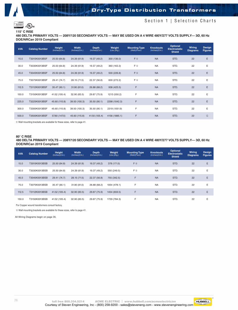
80° C RISE480 DELTA PRIMARY VOLTS — 208Y/120 SECONDARY VOLTS — MAY BE USED ON A 4 WIRE 480Y/277 VOLTS SUPPLY— 3Ø, 60 HzDOE/NRCan 2019 Compliant
kVA Catalog Number Height (Inches)(Cm.)
Width (Inches)(Cm.)
Depth (Inches)(Cm.)
Weight (Lbs.)(Kg.)
Mounting Type(Wall)(Floor)
Knockouts (Inches)(Cm.)
OptionalElectrostatic
Shield
Wiring Diagrams
Design Figures
15.0 T3015K0013BSB 25.50 (64.8) 24.39 (61.9) 19.37 (49.2) 378 (171.5) F ① NA STD. 22 E
30.0 T3030K0013BSB 25.50 (64.8) 24.39 (61.9) 19.37 (49.2) 550 (249.5) F ① NA STD. 22 E
45.0 T3045K0013BSB 29.41 (74.7) 28.15 (71.5) 22.37 (56.8) 755 (342.5) F NA STD. 22 E
75.0 T3075K0013BSB 35.47 (90.1) 31.90 (81.0) 26.88 (68.2) 1054 (478.1) F NA STD. 22 E
112.5 T3112K0013BSB 41.52 (105.4) 32.90 (83.5) 29.87 (75.9) 1454 (659.5) F NA STD. 22 E
150.0 T3150K0013BSB 41.52 (105.4) 32.90 (83.5) 29.87 (75.9) 1729 (784.3) F NA STD. 22 E
For Copper wound transformers consult factory.
① Wall mounting brackets are available for these sizes, refer to page 41.
115° C RISE480 DELTA PRIMARY VOLTS — 208Y/120 SECONDARY VOLTS — MAY BE USED ON A 4 WIRE 480Y/277 VOLTS SUPPLY— 3Ø, 60 HzDOE/NRCan 2019 Compliant
kVA Catalog Number Height (Inches)(Cm.)
Width (Inches)(Cm.)
Depth (Inches)(Cm.)
Weight (Lbs.)(Kg.)
Mounting Type(Wall)(Floor)
Knockouts (Inches)(Cm.)
OptionalElectrostatic
Shield
Wiring Diagrams
Design Figures
15.0 T3015K0013BSF 25.50 (64.8) 24.39 (61.9) 19.37 (49.2) 300 (136.0) F ① NA STD. 22 E
30.0 T3030K0013BSF 25.50 (64.8) 24.39 (61.9) 19.37 (49.2) 360 (163.3) F ① NA STD. 22 E
45.0 T3045K0013BSF 25.50 (64.8) 24.39 (61.9) 19.37 (49.2) 500 (226.8) F ① NA STD. 22 E
75.0 T3075K0013BSF 29.41 (74.7) 28.15 (71.5) 22.37 (56.8) 600 (272.2) F ① NA STD. 22 E
112.5 T3112K0013BSF 35.47 (90.1) 31.90 (81.0) 26.88 (68.2) 938 (425.5) F NA STD. 22 E
150.0 T3150K0013BSF 41.52 (105.4) 32.90 (83.5) 29.87 (75.9) 1213 (550.2) F NA STD. 22 E
225.0 T3225K0013BSF 45.60 (115.8) 39.50 (100.3) 35.50 (90.1) 2298 (1042.3) F NA STD. 22 E
300.0 T3300K0013BSF 45.60 (115.8) 39.50 (100.3) 35.50 (90.1) 2319 (1051.9) F NA STD. 22 E
500.0 T3500K0013BSF 57.80 (147.0) 45.60 (115.8) 41.50 (105.4) 4156 (1885.1) F NA STD. 22 G
①Wall mounting brackets are available for these sizes, refer to page 41.
All Wiring Diagrams begin on page 35.
Dry-Type Distribution Transformers
S e c t i o n 1 | S e l e c t i o n C h a r t s
Courtesy of Steven Engineering, Inc - (800) 258-9200 - [email protected] - www.stevenengineering.com

27toll free 800.334.5214 ACME ELECTRIC | www.hubbell.com/acmeelectric/en
115° C RISE480 DELTA PRIMARY VOLTS — 208Y/120 SECONDARY VOLTS — 3Ø, 60 Hz 316 STAINLESS STEEL ENCAPSULATED TRANSFORMERS
kVACatalog Number
Height (Inches)(Cm.)
Width (Inches)(Cm.)
Depth (Inches)(Cm.)
Weight (Lbs.)(Kg.)
Mounting Type(Wall)(Floor)
Knockouts (Inches)(Cm.)
OptionalElectrostatic
Shield
Wiring Diagrams
Design Figures
3.0 T2A53308SS 10.38 (26.4) 12.37 (31.4) 7.47 (19.0) 75 (34.0) W NA STD. 21 F
6.0 T2A53309SS 11.83 (30.0) 14.17 (36.0) 8.82 (22.4) 140 (63.5) W NA STD. 21 F
9.0 T2A53310SS 14.03 (35.6) 17.77 (45.1) 11.52 (29.3) 180 (81.6) W NA STD. 21 F
15.0 T353311SS 18.86 (47.9) 20.30 (51.6) 9.03 (22.9) 250 (113.0) F NA STD. 21 I
30.0 T379312SS 24.81 (63.0) 27.13 (68.9) 11.14 (28.3) 613 (278.1) F NA STD. 22 I
45.0 T379313SS 25.31 (64.3) 30.18 (76.7) 12.76 (32.4) 780 (354.0) F NA STD. 22 I
75.0 T379314SS 26.82 (68.1) 34.68 (88.1) 15.25 (38.7) 1126 (511.0) F NA STD. 22 I
115° C RISE480 DELTA PRIMARY VOLTS — 208Y/120 SECONDARY VOLTS — 3Ø, 60 Hz ENCAPSULATED TRANSFORMERS
kVACatalog Number
Height (Inches)(Cm.)
Width (Inches)(Cm.)
Depth (Inches)(Cm.)
Weight (Lbs.)(Kg.)
Mounting Type(Wall)(Floor)
Knockouts (Inches)(Cm.)
OptionalElectrostatic
Shield
Wiring Diagrams
Design Figures
30.0 T3793123S 24.81 (63.0) 27.13 (68.9) 11.14 (28.3) 613 (278.1) F NA STD. 22 I
45.0 T3793133S 25.31 (64.3) 30.18 (76.7) 12.76 (32.4) 780 (354.0) F NA STD. 22 I
75.0 T3793143S 26.82 (68.1) 34.68 (88.1) 15.25 (38.7) 1126 (511.0) F NA STD. 22 I
All Wiring Diagrams begin on page 35.
Dry-Type Distribution Transformers
S e c t i o n 1 | S e l e c t i o n C h a r t s
Courtesy of Steven Engineering, Inc - (800) 258-9200 - [email protected] - www.stevenengineering.com
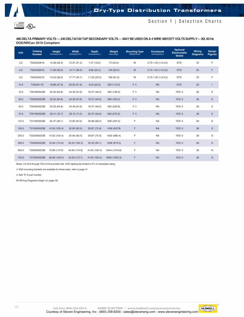
28 toll free 800.334.5214 ACME ELECTRIC | www.hubbell.com/acmeelectric/en
480 DELTA PRIMARY VOLTS — 240 DELTA/120 TAP SECONDARY VOLTS — MAY BE USED ON A 4 WIRE 480Y/277 VOLTS SUPPLY— 3Ø, 60 HzDOE/NRCan 2019 Compliant
kVACatalog Number
Height (Inches)(Cm.)
Width (Inches)(Cm.)
Depth (Inches)(Cm.)
Weight (Lbs.)(Kg.)
Mounting Type(Wall)(Floor)
Knockouts (Inches)(Cm.)
Optional Electrostatic
Shield
Wiring Diagrams
Design Figures
3.0 T2A533281S 10.38 (26.4) 12.37 (31.4) 7.47 (19.0) 75 (34.0) W 0.75-1.25 (1.9-3.2) STD. 25 F
6.0 T2A533291S 11.83 (30.0) 14.17 (36.0) 8.82 (22.4) 140 (63.5) W 0.75-1.25 (1.9-3.2) STD. 25 F
9.0 T2A533401S 14.03 (36.0) 17.77 (45.1) 11.52 (29.3) 180 (81.6) W 0.75-1.25 (1.9-3.2) STD. 25 F
15.0 T3533411S 18.86 (47.9) 20.30 (51.6) 9.03 (22.9) 250 (113.0) F ① NA STD. 25 I
15.0 T3015K0023B 25.50 (64.8) 24.39 (61.9) 19.37 (49.2) 300 (136.0) F ① NA YES ② 26 E
30.0 T3030K0023B 25.50 (64.8) 24.39 (61.9) 19.37 (49.2) 360 (163.2) F ① NA YES ② 26 E
45.0 T3045K0023B 25.50 (64.8) 24.39 (61.9) 19.37 (49.2) 500 (226.8) F ① NA YES ② 26 E
75.0 T3075K0023B 29.41 (74.7) 28.15 (71.5) 22.37 (56.8) 600 (272.2) F ① NA YES ② 26 E
112.5 T3112K0023B 35.47 (90.1) 31.90 (81.0) 26.88 (68.2) 938 (425.5) F NA YES ② 26 E
150.0 T3150K0023B 41.52 (105.4) 32.90 (83.5) 29.87 (75.9) 1406 (637.8) F NA YES ② 26 E
225.0 T3225K0023B 41.52 (105.4) 32.90 (83.5) 29.87 (75.9) 1500 (680.4) F NA YES ② 26 E
300.0 T3300K0023B 45.60 (115.8) 39.50 (100.3) 35.50 (90.1) 1938 (879.0) F NA YES ② 26 E
500.0 T3500K0023B 57.80 (147.0) 45.60 (115.8) 41.50 (105.4) 3344 (1516.8) F NA YES ② 26 G
750.0 T3750K0023B 62.80 (159.5) 54.00 (137.1) 41.50 (105.4) 4260 (1932.3) F NA YES ② 26 G
Notes: 3.0 kVA through 750.0 kVA provided with 120V lighting tap limited to 5% of nameplate rating.
① Wall mounting brackets are available for these sizes, refer to page 41.
②Add “S” to part number
Dry-Type Distribution Transformers
S e c t i o n 1 | S e l e c t i o n C h a r t s
All Wiring Diagrams begin on page 35.
Courtesy of Steven Engineering, Inc - (800) 258-9200 - [email protected] - www.stevenengineering.com
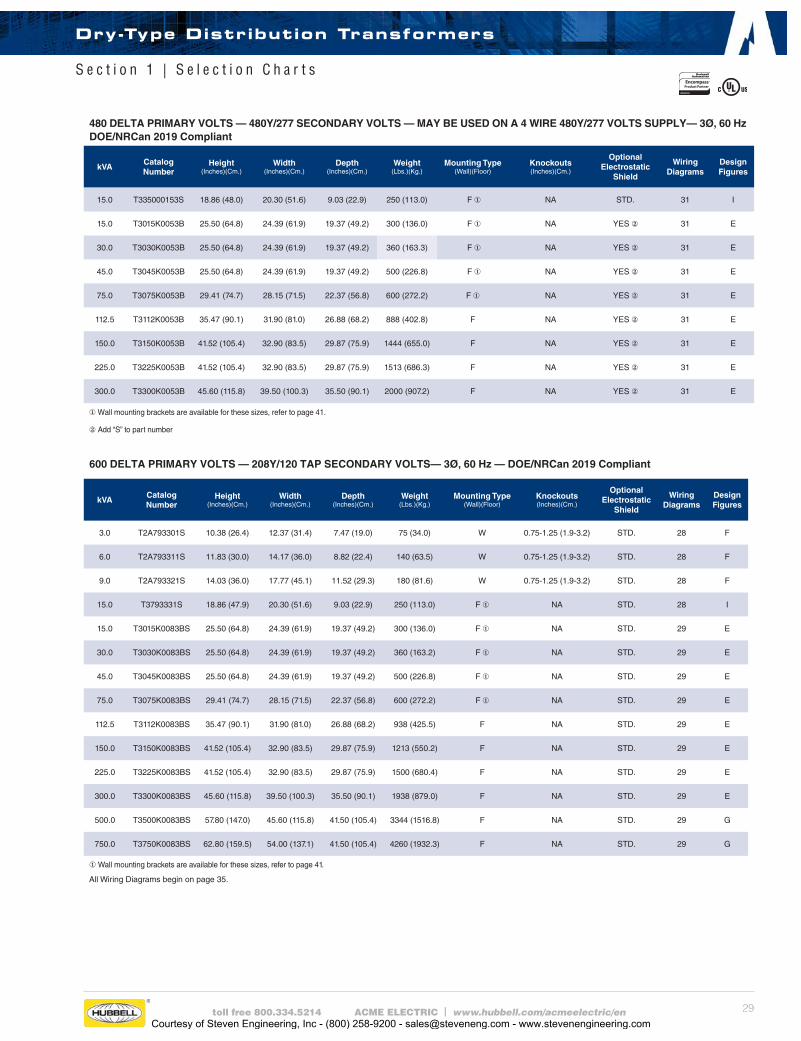
29toll free 800.334.5214 ACME ELECTRIC | www.hubbell.com/acmeelectric/en
600 DELTA PRIMARY VOLTS — 208Y/120 TAP SECONDARY VOLTS— 3Ø, 60 Hz — DOE/NRCan 2019 Compliant
kVACatalog Number
Height (Inches)(Cm.)
Width (Inches)(Cm.)
Depth (Inches)(Cm.)
Weight (Lbs.)(Kg.)
Mounting Type(Wall)(Floor)
Knockouts (Inches)(Cm.)
Optional Electrostatic
Shield
Wiring Diagrams
Design Figures
3.0 T2A793301S 10.38 (26.4) 12.37 (31.4) 7.47 (19.0) 75 (34.0) W 0.75-1.25 (1.9-3.2) STD. 28 F
6.0 T2A793311S 11.83 (30.0) 14.17 (36.0) 8.82 (22.4) 140 (63.5) W 0.75-1.25 (1.9-3.2) STD. 28 F
9.0 T2A793321S 14.03 (36.0) 17.77 (45.1) 11.52 (29.3) 180 (81.6) W 0.75-1.25 (1.9-3.2) STD. 28 F
15.0 T3793331S 18.86 (47.9) 20.30 (51.6) 9.03 (22.9) 250 (113.0) F ① NA STD. 28 I
15.0 T3015K0083BS 25.50 (64.8) 24.39 (61.9) 19.37 (49.2) 300 (136.0) F ① NA STD. 29 E
30.0 T3030K0083BS 25.50 (64.8) 24.39 (61.9) 19.37 (49.2) 360 (163.2) F ① NA STD. 29 E
45.0 T3045K0083BS 25.50 (64.8) 24.39 (61.9) 19.37 (49.2) 500 (226.8) F ① NA STD. 29 E
75.0 T3075K0083BS 29.41 (74.7) 28.15 (71.5) 22.37 (56.8) 600 (272.2) F ① NA STD. 29 E
112.5 T3112K0083BS 35.47 (90.1) 31.90 (81.0) 26.88 (68.2) 938 (425.5) F NA STD. 29 E
150.0 T3150K0083BS 41.52 (105.4) 32.90 (83.5) 29.87 (75.9) 1213 (550.2) F NA STD. 29 E
225.0 T3225K0083BS 41.52 (105.4) 32.90 (83.5) 29.87 (75.9) 1500 (680.4) F NA STD. 29 E
300.0 T3300K0083BS 45.60 (115.8) 39.50 (100.3) 35.50 (90.1) 1938 (879.0) F NA STD. 29 E
500.0 T3500K0083BS 57.80 (147.0) 45.60 (115.8) 41.50 (105.4) 3344 (1516.8) F NA STD. 29 G
750.0 T3750K0083BS 62.80 (159.5) 54.00 (137.1) 41.50 (105.4) 4260 (1932.3) F NA STD. 29 G
①Wall mounting brackets are available for these sizes, refer to page 41.
480 DELTA PRIMARY VOLTS — 480Y/277 SECONDARY VOLTS — MAY BE USED ON A 4 WIRE 480Y/277 VOLTS SUPPLY— 3Ø, 60 HzDOE/NRCan 2019 Compliant
kVACatalog Number
Height (Inches)(Cm.)
Width (Inches)(Cm.)
Depth (Inches)(Cm.)
Weight (Lbs.)(Kg.)
Mounting Type(Wall)(Floor)
Knockouts (Inches)(Cm.)
Optional Electrostatic
Shield
Wiring Diagrams
Design Figures
15.0 T335000153S 18.86 (48.0) 20.30 (51.6) 9.03 (22.9) 250 (113.0) F ① NA STD. 31 I
15.0 T3015K0053B 25.50 (64.8) 24.39 (61.9) 19.37 (49.2) 300 (136.0) F ① NA YES ② 31 E
30.0 T3030K0053B 25.50 (64.8) 24.39 (61.9) 19.37 (49.2) 360 (163.3) F ① NA YES ② 31 E
45.0 T3045K0053B 25.50 (64.8) 24.39 (61.9) 19.37 (49.2) 500 (226.8) F ① NA YES ② 31 E
75.0 T3075K0053B 29.41 (74.7) 28.15 (71.5) 22.37 (56.8) 600 (272.2) F ① NA YES ② 31 E
112.5 T3112K0053B 35.47 (90.1) 31.90 (81.0) 26.88 (68.2) 888 (402.8) F NA YES ② 31 E
150.0 T3150K0053B 41.52 (105.4) 32.90 (83.5) 29.87 (75.9) 1444 (655.0) F NA YES ② 31 E
225.0 T3225K0053B 41.52 (105.4) 32.90 (83.5) 29.87 (75.9) 1513 (686.3) F NA YES ② 31 E
300.0 T3300K0053B 45.60 (115.8) 39.50 (100.3) 35.50 (90.1) 2000 (907.2) F NA YES ② 31 E
①Wall mounting brackets are available for these sizes, refer to page 41.
②Add “S” to part number
All Wiring Diagrams begin on page 35.
Dry-Type Distribution Transformers
S e c t i o n 1 | S e l e c t i o n C h a r t s
Courtesy of Steven Engineering, Inc - (800) 258-9200 - [email protected] - www.stevenengineering.com
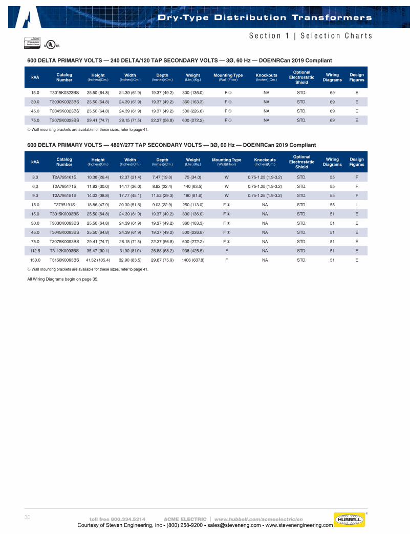
30 toll free 800.334.5214 ACME ELECTRIC | www.hubbell.com/acmeelectric/en
600 DELTA PRIMARY VOLTS — 480Y/277 TAP SECONDARY VOLTS — 3Ø, 60 Hz — DOE/NRCan 2019 Compliant
kVACatalog Number
Height (Inches)(Cm.)
Width (Inches)(Cm.)
Depth (Inches)(Cm.)
Weight (Lbs.)(Kg.)
Mounting Type(Wall)(Floor)
Knockouts (Inches)(Cm.)
Optional Electrostatic
Shield
Wiring Diagrams
Design Figures
3.0 T2A795161S 10.38 (26.4) 12.37 (31.4) 7.47 (19.0) 75 (34.0) W 0.75-1.25 (1.9-3.2) STD. 55 F
6.0 T2A795171S 11.83 (30.0) 14.17 (36.0) 8.82 (22.4) 140 (63.5) W 0.75-1.25 (1.9-3.2) STD. 55 F
9.0 T2A795181S 14.03 (38.8) 17.77 (45.1) 11.52 (29.3) 180 (81.6) W 0.75-1.25 (1.9-3.2) STD. 55 F
15.0 T3795191S 18.86 (47.9) 20.30 (51.6) 9.03 (22.9) 250 (113.0) F ① NA STD. 55 I
15.0 T3015K0093BS 25.50 (64.8) 24.39 (61.9) 19.37 (49.2) 300 (136.0) F ① NA STD. 51 E
30.0 T3030K0093BS 25.50 (64.8) 24.39 (61.9) 19.37 (49.2) 360 (163.3) F ① NA STD. 51 E
45.0 T3045K0093BS 25.50 (64.8) 24.39 (61.9) 19.37 (49.2) 500 (226.8) F ① NA STD. 51 E
75.0 T3075K0093BS 29.41 (74.7) 28.15 (71.5) 22.37 (56.8) 600 (272.2) F ① NA STD. 51 E
112.5 T3112K0093BS 35.47 (90.1) 31.90 (81.0) 26.88 (68.2) 938 (425.5) F NA STD. 51 E
150.0 T3150K0093BS 41.52 (105.4) 32.90 (83.5) 29.87 (75.9) 1406 (637.8) F NA STD. 51 E
① Wall mounting brackets are available for these sizes, refer to page 41.
600 DELTA PRIMARY VOLTS — 240 DELTA/120 TAP SECONDARY VOLTS — 3Ø, 60 Hz — DOE/NRCan 2019 Compliant
kVACatalog Number
Height (Inches)(Cm.)
Width (Inches)(Cm.)
Depth (Inches)(Cm.)
Weight (Lbs.)(Kg.)
Mounting Type(Wall)(Floor)
Knockouts (Inches)(Cm.)
Optional Electrostatic
Shield
Wiring Diagrams
Design Figures
15.0 T3015K0323BS 25.50 (64.8) 24.39 (61.9) 19.37 (49.2) 300 (136.0) F ① NA STD. 69 E
30.0 T3030K0323BS 25.50 (64.8) 24.39 (61.9) 19.37 (49.2) 360 (163.3) F ① NA STD. 69 E
45.0 T3045K0323BS 25.50 (64.8) 24.39 (61.9) 19.37 (49.2) 500 (226.8) F ① NA STD. 69 E
75.0 T3075K0323BS 29.41 (74.7) 28.15 (71.5) 22.37 (56.8) 600 (272.2) F ① NA STD. 69 E
① Wall mounting brackets are available for these sizes, refer to page 41.
All Wiring Diagrams begin on page 35.
Dry-Type Distribution Transformers
S e c t i o n 1 | S e l e c t i o n C h a r t s
Courtesy of Steven Engineering, Inc - (800) 258-9200 - [email protected] - www.stevenengineering.com
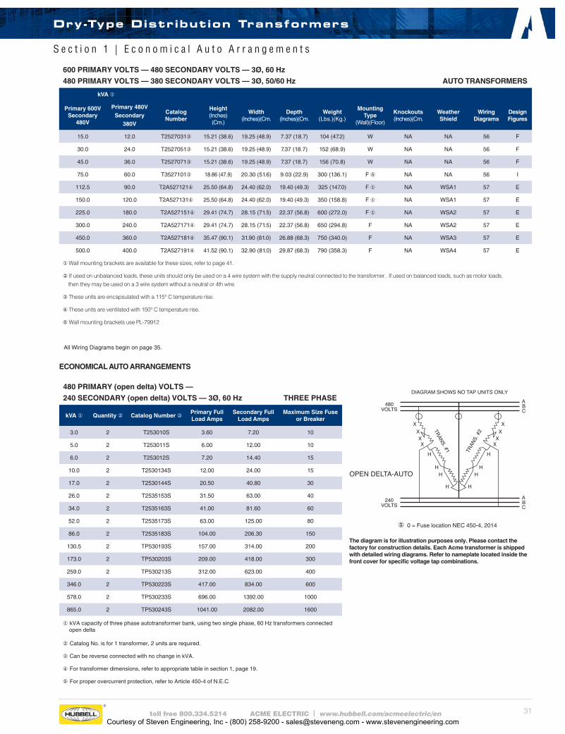
31toll free 800.334.5214 ACME ELECTRIC | www.hubbell.com/acmeelectric/en
600 PRIMARY VOLTS — 480 SECONDARY VOLTS — 3Ø, 60 Hz
480 PRIMARY VOLTS — 380 SECONDARY VOLTS — 3Ø, 50/60 Hz AUTO TRANSFORMERS
kVA ①
Primary 600VSecondary
480V
Primary 480VSecondary
380V
CatalogNumber
Height(Inches)(Cm.)
Width(Inches)(Cm.
Depth(Inches)(Cm.
Weight(Lbs.)(Kg.)
MountingType
(Wall)(Floor)
Knockouts(Inches)(Cm.
Weather Shield
Wiring Diagrams
Design Figures
15.0 12.0 T2527031③ 15.21 (38.6) 19.25 (48.9) 7.37 (18.7) 104 (47.2) W NA NA 56 F
30.0 24.0 T2527051③ 15.21 (38.6) 19.25 (48.9) 7.37 (18.7) 152 (68.9) W NA NA 56 F
45.0 36.0 T2527071③ 15.21 (38.6) 19.25 (48.9) 7.37 (18.7) 156 (70.8) W NA NA 56 F
75.0 60.0 T3527101③ 18.86 (47.9) 20.30 (51.6) 9.03 (22.9) 300 (136.1) F ⑤ NA NA 56 I
112.5 90.0 T2A527121④ 25.50 (64.8) 24.40 (62.0) 19.40 (49.3) 325 (147.0) F ① NA WSA1 57 E
150.0 120.0 T2A527131④ 25.50 (64.8) 24.40 (62.0) 19.40 (49.3) 350 (158.8) F ① NA WSA1 57 E
225.0 180.0 T2A527151④ 29.41 (74.7) 28.15 (71.5) 22.37 (56.8) 600 (272.0) F ① NA WSA2 57 E
300.0 240.0 T2A527171④ 29.41 (74.7) 28.15 (71.5) 22.37 (56.8) 650 (294.8) F NA WSA2 57 E
450.0 360.0 T2A527181④ 35.47 (90.1) 31.90 (81.0) 26.88 (68.3) 750 (340.0) F NA WSA3 57 E
500.0 400.0 T2A527191④ 41.52 (90.1) 32.90 (81.0) 29.87 (68.3) 790 (358.3) F NA WSA4 57 E
① Wall mounting brackets are available for these sizes, refer to page 41.
②If used on unbalanced loads, these units should only be used on a 4 wire system with the supply neutral connected to the transformer. If used on balanced loads, such as motor loads, then they may be used on a 3 wire system without a neutral or 4th wire.
③These units are encapsulated with a 115° C temperature rise.
④These units are ventilated with 150° C temperature rise.
⑤Wall mounting brackets use PL-79912
480 PRIMARY (open delta) VOLTS —
240 SECONDARY (open delta) VOLTS — 3Ø, 60 Hz THREE PHASE
kVA ① Quantity ② Catalog Number ③Primary Full Load Amps
Secondary Full Load Amps
Maximum Size Fuse or Breaker
3.0 2 T253010S 3.60 7.20 10
5.0 2 T253011S 6.00 12.00 10
6.0 2 T253012S 7.20 14.40 15
10.0 2 T2530134S 12.00 24.00 15
17.0 2 T2530144S 20.50 40.80 30
26.0 2 T2535153S 31.50 63.00 40
34.0 2 T2535163S 41.00 81.60 60
52.0 2 T2535173S 63.00 125.00 80
86.0 2 T2535183S 104.00 206.30 150
130.5 2 TP530193S 157.00 314.00 200
173.0 2 TP530203S 209.00 418.00 300
259.0 2 TP530213S 312.00 623.00 400
346.0 2 TP530223S 417.00 834.00 600
578.0 2 TP530233S 696.00 1392.00 1000
865.0 2 TP530243S 1041.00 2082.00 1600
① kVA capacity of three phase autotransformer bank, using two single phase, 60 Hz transformers connected open delta
②Catalog No. is for 1 transformer, 2 units are required.
③Can be reverse connected with no change in kVA.
④For transformer dimensions, refer to appropriate table in section 1, page 19.
⑤For proper overcurrent protection, refer to Article 450-4 of N.E.C.
The diagram is for illustration purposes only. Please contact the factory for construction details. Each Acme transformer is shipped with detailed wiring diagrams. Refer to nameplate located inside the front cover for specific voltage tap combinations.
ECONOMICAL AUTO ARRANGEMENTS
⑤0 = Fuse location NEC 450-4, 2014
All Wiring Diagrams begin on page 35.
Dry-Type Distribution Transformers
S e c t i o n 1 | E c o n o m i c a l A u t o A r r a n g e m e n t s
Courtesy of Steven Engineering, Inc - (800) 258-9200 - [email protected] - www.stevenengineering.com
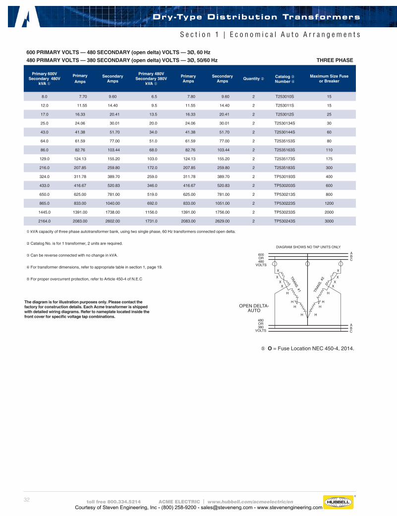
32 toll free 800.334.5214 ACME ELECTRIC | www.hubbell.com/acmeelectric/en
⑤ O = Fuse Location NEC 450-4, 2014.
The diagram is for illustration purposes only. Please contact the factory for construction details. Each Acme transformer is shipped with detailed wiring diagrams. Refer to nameplate located inside the front cover for specific voltage tap combinations.
600 PRIMARY VOLTS — 480 SECONDARY (open delta) VOLTS — 3Ø, 60 Hz
480 PRIMARY VOLTS — 380 SECONDARY (open delta) VOLTS — 3Ø, 50/60 Hz THREE PHASE
Primary 600VSecondary 480V
kVA ①
Primary Amps
Secondary Amps
Primary 480VSecondary 380V
kVA ①
Primary Amps
Secondary Amps
Quantity ② Catalog ③Number ④
Maximum Size Fuse or Breaker
8.0 7.70 9.60 6.5 7.80 9.60 2 T253010S 15
12.0 11.55 14.40 9.5 11.55 14.40 2 T253011S 15
17.0 16.33 20.41 13.5 16.33 20.41 2 T253012S 25
25.0 24.06 30.01 20.0 24.06 30.01 2 T2530134S 30
43.0 41.38 51.70 34.0 41.38 51.70 2 T2530144S 60
64.0 61.59 77.00 51.0 61.59 77.00 2 T2535153S 80
86.0 82.76 103.44 68.0 82.76 103.44 2 T2535163S 110
129.0 124.13 155.20 103.0 124.13 155.20 2 T2535173S 175
216.0 207.85 259.80 172.0 207.85 259.80 2 T2535183S 300
324.0 311.78 389.70 259.0 311.78 389.70 2 TP530193S 400
433.0 416.67 520.83 346.0 416.67 520.83 2 TP530203S 600
650.0 625.00 781.00 519.0 625.00 781.00 2 TP530213S 800
865.0 833.00 1040.00 692.0 833.00 1051.00 2 TP530223S 1200
1445.0 1391.00 1738.00 1156.0 1391.00 1756.00 2 TP530233S 2000
2164.0 2083.00 2602.00 1731.0 2083.00 2629.00 2 TP530243S 3000
① kVA capacity of three phase autotransformer bank, using two single phase, 60 Hz transformers connected open delta.
②Catalog No. is for 1 transformer, 2 units are required.
③Can be reverse connected with no change in kVA.
④For transformer dimensions, refer to appropriate table in section 1, page 19.
⑤For proper overcurrent protection, refer to Article 450-4 of N.E.C
Dry-Type Distribution Transformers
S e c t i o n 1 | E c o n o m i c a l A u t o A r r a n g e m e n t s
Courtesy of Steven Engineering, Inc - (800) 258-9200 - [email protected] - www.stevenengineering.com
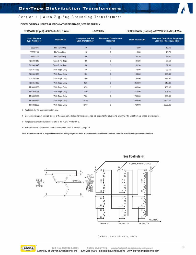
33toll free 800.334.5214 ACME ELECTRIC | www.hubbell.com/acmeelectric/en
See Footnote②
O = Fuse Location NEC 450-4, 2014.③
PRIMARY (Input): 480 Volts 3Ø, 3 Wire ①50/60 Hz SECONDARY (Output): 480Y/277 Volts 3Ø, 4 Wire
Use 3 Pieces of Type Number ④
Available InNameplate kVA For Each Transformer
Number of Transformers Required
Three Phase kVAMaximum Continious Amperage
Load Per Phase (277 Volts)
T253010S No Taps Only 1.0 3 10.80 12.50
T253011S No Taps Only 1.5 3 15.60 18.75
T253012S No Taps Only 2.0 3 20.70 25.00
T2530134S Taps & No Taps 3.0 3 31.20 37.50
T2530144S Taps & No Taps 5.0 3 51.90 62.50
T2535153S With Taps Only 7.5 3 78.00 93.50
T2535163S With Taps Only 10.0 3 103.80 125.00
T2535173S With Taps Only 15.0 3 156.00 187.50
T2535183S With Taps Only 25.0 3 259.50 312.00
TP530193S With Taps Only 37.5 3 390.00 468.00
TP530203S With Taps Only 50.0 3 519.00 625.00
TP530213S With Taps Only 75.0 3 780.00 935.00
TP530223S With Taps Only 100.0 3 1038.00 1250.00
TP530233S With Taps Only 167.0 3 1734.00 2085.00
① Applicable for the above connection only.
② Connection diagram (using 3 pieces of 1 phase, 60 hertz transformers connected zig-zag auto) for developing a neutral (4th wire) from a 3 phase, 3 wire supply.
③ For proper over-current protection, refer to the N.E.C. Article 450-5..
④ For transformer dimensions, refer to appropriate table in section 1, page 19.
Each Acme transformer is shipped with detailed wiring diagrams. Refer to nameplate located inside the front cover for specific voltage tap combinations.
DEVELOPING A NEUTRAL FROM A THREE PHASE, 3-WIRE SUPPLY
NEUTRAL
B
POINTA,B OR C
TONEUTRALYIELDS277 V
SINGLEPHASE4 WIRE
C
A
B
C
A
INPUT480 V
3Ø3 WIRE
B CAXX
XX
X
H
H
H
H
X
XX
X
H
H
H
H
XX
X
H
H
H
H
COMMON TRIP DEVICE
NEUTRAL
TRANS. #3TRANS. #2TRANS. #1
Dry-Type Distribution Transformers
S e c t i o n 1 | A u t o Z i g - Z a g G r o u n d i n g T r a n s f o r m e r s
Courtesy of Steven Engineering, Inc - (800) 258-9200 - [email protected] - www.stevenengineering.com
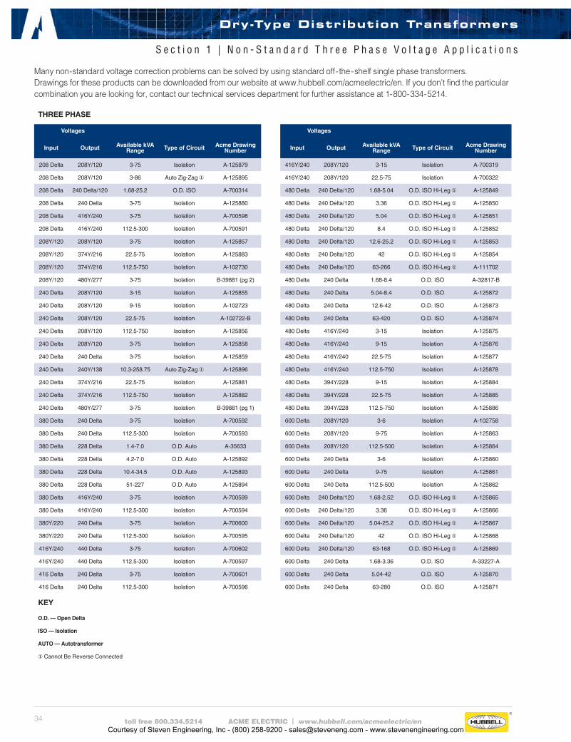
34 toll free 800.334.5214 ACME ELECTRIC | www.hubbell.com/acmeelectric/en
THREE PHASE
Voltages
Input Output Available kVA Range Type of Circuit Acme Drawing
Number
208 Delta 208Y/120 3-75 Isolation A-125879
208 Delta 208Y/120 3-86 Auto Zig-Zag ① A-125895
208 Delta 240 Delta/120 1.68-25.2 O.D. ISO A-700314
208 Delta 240 Delta 3-75 Isolation A-125880
208 Delta 416Y/240 3-75 Isolation A-700598
208 Delta 416Y/240 112.5-300 Isolation A-700591
208Y/120 208Y/120 3-75 Isolation A-125857
208Y/120 374Y/216 22.5-75 Isolation A-125883
208Y/120 374Y/216 112.5-750 Isolation A-102730
208Y/120 480Y/277 3-75 Isolation B-39881 (pg 2)
240 Delta 208Y/120 3-15 Isolation A-125855
240 Delta 208Y/120 9-15 Isolation A-102723
240 Delta 208Y/120 22.5-75 Isolation A-102722-B
240 Delta 208Y/120 112.5-750 Isolation A-125856
240 Delta 208Y/120 3-75 Isolation A-125858
240 Delta 240 Delta 3-75 Isolation A-125859
240 Delta 240Y/138 10.3-258.75 Auto Zig-Zag ① A-125896
240 Delta 374Y/216 22.5-75 Isolation A-125881
240 Delta 374Y/216 112.5-750 Isolation A-125882
240 Delta 480Y/277 3-75 Isolation B-39881 (pg 1)
380 Delta 240 Delta 3-75 Isolation A-700592
380 Delta 240 Delta 112.5-300 Isolation A-700593
380 Delta 228 Delta 1.4-7.0 O.D. Auto A-35633
380 Delta 228 Delta 4.2-7.0 O.D. Auto A-125892
380 Delta 228 Delta 10.4-34.5 O.D. Auto A-125893
380 Delta 228 Delta 51-227 O.D. Auto A-125894
380 Delta 416Y/240 3-75 Isolation A-700599
380 Delta 416Y/240 112.5-300 Isolation A-700594
380Y/220 240 Delta 3-75 Isolation A-700600
380Y/220 240 Delta 112.5-300 Isolation A-700595
416Y/240 440 Delta 3-75 Isolation A-700602
416Y/240 440 Delta 112.5-300 Isolation A-700597
416 Delta 240 Delta 3-75 Isolation A-700601
416 Delta 240 Delta 112.5-300 Isolation A-700596
KEY
O.D. — Open Delta
ISO — Isolation
AUTO — Autotransformer
①Cannot Be Reverse Connected
Voltages
Input Output Available kVA Range Type of Circuit Acme Drawing
Number
416Y/240 208Y/120 3-15 Isolation A-700319
416Y/240 208Y/120 22.5-75 Isolation A-700322
480 Delta 240 Delta/120 1.68-5.04 O.D. ISO Hi-Leg ① A-125849
480 Delta 240 Delta/120 3.36 O.D. ISO Hi-Leg ① A-125850
480 Delta 240 Delta/120 5.04 O.D. ISO Hi-Leg ① A-125851
480 Delta 240 Delta/120 8.4 O.D. ISO Hi-Leg ① A-125852
480 Delta 240 Delta/120 12.6-25.2 O.D. ISO Hi-Leg ① A-125853
480 Delta 240 Delta/120 42 O.D. ISO Hi-Leg ① A-125854
480 Delta 240 Delta/120 63-266 O.D. ISO Hi-Leg ① A-111702
480 Delta 240 Delta 1.68-8.4 O.D. ISO A-32817-B
480 Delta 240 Delta 5.04-8.4 O.D. ISO A-125872
480 Delta 240 Delta 12.6-42 O.D. ISO A-125873
480 Delta 240 Delta 63-420 O.D. ISO A-125874
480 Delta 416Y/240 3-15 Isolation A-125875
480 Delta 416Y/240 9-15 Isolation A-125876
480 Delta 416Y/240 22.5-75 Isolation A-125877
480 Delta 416Y/240 112.5-750 Isolation A-125878
480 Delta 394Y/228 9-15 Isolation A-125884
480 Delta 394Y/228 22.5-75 Isolation A-125885
480 Delta 394Y/228 112.5-750 Isolation A-125886
600 Delta 208Y/120 3-6 Isolation A-102758
600 Delta 208Y/120 9-75 Isolation A-125863
600 Delta 208Y/120 112.5-500 Isolation A-125864
600 Delta 240 Delta 3-6 Isolation A-125860
600 Delta 240 Delta 9-75 Isolation A-125861
600 Delta 240 Delta 112.5-500 Isolation A-125862
600 Delta 240 Delta/120 1.68-2.52 O.D. ISO Hi-Leg ① A-125865
600 Delta 240 Delta/120 3.36 O.D. ISO Hi-Leg ① A-125866
600 Delta 240 Delta/120 5.04-25.2 O.D. ISO Hi-Leg ① A-125867
600 Delta 240 Delta/120 42 O.D. ISO Hi-Leg ① A-125868
600 Delta 240 Delta/120 63-168 O.D. ISO Hi-Leg ① A-125869
600 Delta 240 Delta 1.68-3.36 O.D. ISO A-33227-A
600 Delta 240 Delta 5.04-42 O.D. ISO A-125870
600 Delta 240 Delta 63-280 O.D. ISO A-125871
Many non-standard voltage correction problems can be solved by using standard off-the-shelf single phase transformers. Drawings for these products can be downloaded from our website at www.hubbell.com/acmeelectric/en. If you don’t find the particular combination you are looking for, contact our technical services department for further assistance at 1-800-334-5214.
Dry-Type Distribution Transformers
S e c t i o n 1 | N o n - S t a n d a r d T h r e e P h a s e V o l t a g e A p p l i c a t i o n s
Courtesy of Steven Engineering, Inc - (800) 258-9200 - [email protected] - www.stevenengineering.com
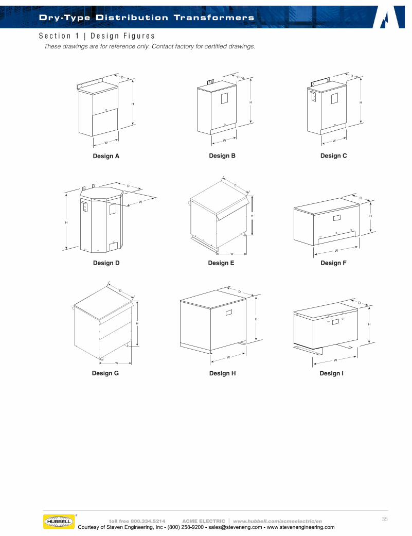
35toll free 800.334.5214 ACME ELECTRIC | www.hubbell.com/acmeelectric/en
These drawings are for reference only. Contact factory for certified drawings.
Design B
Design E
D
H
W
Design H Design I
Design F
Design CDesign A
Design G
D
H
W
Design D
S e c t i o n 1 | D e s i g n F i g u r e s
Dry-Type Distribution Transformers
Courtesy of Steven Engineering, Inc - (800) 258-9200 - [email protected] - www.stevenengineering.com
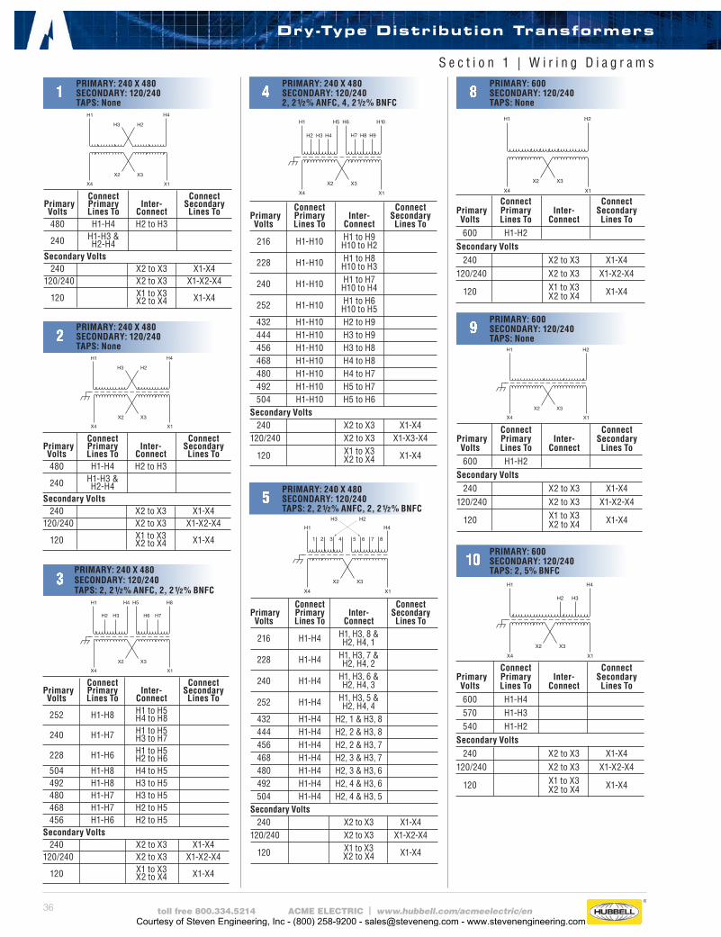
36 toll free 800.334.5214 ACME ELECTRIC | www.hubbell.com/acmeelectric/en
10PRIMARY: 600SECONDARY: 120/240TAPS: 2, 5% BNFC
1PRIMARY: 240 X 480SECONDARY: 120/240TAPS: None
Connect Connect Primary Primary Inter- Secondary Volts Lines To Connect Lines To 480 H1-H4 H2 to H3 240 H1-H3 & H2-H4 Secondary Volts 240 X2 to X3 X1-X4 120/240 X2 to X3 X1-X2-X4 120 X1 to X3 X1-X4 X2 to X4
3PRIMARY: 240 X 480SECONDARY: 120/240TAPS: 2, 21/2% ANFC, 2, 21/2% BNFC
Connect Connect Primary Primary Inter- Secondary Volts Lines To Connect Lines To 252 H1-H8 H1 to H5 H4 to H8 240 H1-H7 H1 to H5 H3 to H7 228 H1-H6 H1 to H5 H2 to H6 504 H1-H8 H4 to H5 492 H1-H8 H3 to H5 480 H1-H7 H3 to H5 468 H1-H7 H2 to H5 456 H1-H6 H2 to H5Secondary Volts 240 X2 to X3 X1-X4 120/240 X2 to X3 X1-X2-X4 120 X1 to X3 X1-X4 X2 to X4
Connect Connect Primary Primary Inter- Secondary Volts Lines To Connect Lines To 216 H1-H4 H1, H3, 8 & H2, H4, 1 228 H1-H4 H1, H3, 7 & H2, H4, 2 240 H1-H4 H1, H3, 6 & H2, H4, 3 252 H1-H4 H1, H3, 5 & H2, H4, 4 432 H1-H4 H2, 1 & H3, 8 444 H1-H4 H2, 2 & H3, 8 456 H1-H4 H2, 2 & H3, 7 468 H1-H4 H2, 3 & H3, 7 480 H1-H4 H2, 3 & H3, 6 492 H1-H4 H2, 4 & H3, 6 504 H1-H4 H2, 4 & H3, 5Secondary Volts 240 X2 to X3 X1-X4 120/240 X2 to X3 X1-X2-X4 120 X1 to X3 X1-X4 X2 to X4
Connect Connect Primary Primary Inter- Secondary Volts Lines To Connect Lines To 216 H1-H10 H1 to H9 H10 to H2 228 H1-H10 H1 to H8 H10 to H3 240 H1-H10 H1 to H7 H10 to H4 252 H1-H10 H1 to H6 H10 to H5 432 H1-H10 H2 to H9 444 H1-H10 H3 to H9 456 H1-H10 H3 to H8 468 H1-H10 H4 to H8 480 H1-H10 H4 to H7 492 H1-H10 H5 to H7 504 H1-H10 H5 to H6Secondary Volts 240 X2 to X3 X1-X4 120/240 X2 to X3 X1-X3-X4 120 X1 to X3 X1-X4 X2 to X4
Connect Connect Primary Primary Inter- Secondary Volts Lines To Connect Lines To 600 H1-H2 Secondary Volts 240 X2 to X3 X1-X4 120/240 X2 to X3 X1-X2-X4 120 X1 to X3 X1-X4 X2 to X4
S e c t i o n 1 | W i r i n g D i a g r a m s
Connect Connect Primary Primary Inter- Secondary Volts Lines To Connect Lines To 600 H1-H2 Secondary Volts 240 X2 to X3 X1-X4 120/240 X2 to X3 X1-X2-X4 120 X1 to X3 X1-X4 X2 to X4
Connect Connect Primary Primary Inter- Secondary Volts Lines To Connect Lines To 600 H1-H4 570 H1-H3 540 H1-H2 Secondary Volts 240 X2 to X3 X1-X4 120/240 X2 to X3 X1-X2-X4 120 X1 to X3 X1-X4 X2 to X4
2PRIMARY: 240 X 480SECONDARY: 120/240TAPS: None
Connect Connect Primary Primary Inter- Secondary Volts Lines To Connect Lines To 480 H1-H4 H2 to H3 240 H1-H3 & H2-H4 Secondary Volts 240 X2 to X3 X1-X4 120/240 X2 to X3 X1-X2-X4 120 X1 to X3 X1-X4 X2 to X4
4PRIMARY: 240 X 480SECONDARY: 120/2402, 21/2% ANFC, 4, 21/2% BNFC
8PRIMARY: 600SECONDARY: 120/240TAPS: None
5PRIMARY: 240 X 480SECONDARY: 120/240TAPS: 2, 21/2% ANFC, 2, 21/2% BNFC
9PRIMARY: 600SECONDARY: 120/240TAPS: None
Dry-Type Distribution Transformers
Courtesy of Steven Engineering, Inc - (800) 258-9200 - [email protected] - www.stevenengineering.com
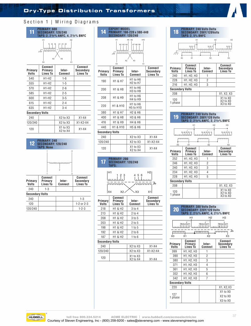
37toll free 800.334.5214 ACME ELECTRIC | www.hubbell.com/acmeelectric/en
S e c t i o n 1 | W i r i n g D i a g r a m s
Connect Connect Primary Primary Inter- Secondary Volts Lines To Connect Lines To
190 H1 & H7 H1 to H6 H2 to H7
200 H1 & H8 H1 to H6 H3 to H8
208 H1 & H9 H1 to H6 H4 to H9
220 H1 & H10 H1 to H6 H5 to H10
380 H1 & H7 H2 & H6
400 H1 & H8 H3 & H6
416 H1 & H9 H4 & H6
440 H1 & H10 H5 & H6
Secondary Volts
240 X2 to X3 X1-X4
120/240 X2 to X3 X1-X2-X4
120 X1 to X3 X1-X4 X2 to X4
Connect Connect Primary Primary Inter- Secondary Volts Lines To Connect Lines To
540 H1-H2 1-6
555 H1-H2 1-5
570 H1-H2 2-6
585 H1-H2 2-5
600 H1-H2 3-5
615 H1-H2 2-4
635 H1-H2 3-4
Secondary Volts
240 X2 to X3 X1-X4
120/240 X2 to X3 X1-X2-X4
120 X1 to X3 X1-X4 X2 to X4
11PRIMARY: 600SECONDARY: 120/240TAPS: 2, 21/2% ANFC, 4, 21/2% BNFC
Connect Connect Primary Primary Inter- Secondary Volts Lines To Connect Lines To 240 H1, H2, H3 1 228 H1, H2, H3 2 216 H1, H2, H3 3 Secondary Volts 208 X1, X2, X3 120 X1 to X0 1 phase X2 to X0 X3 to X0
18PRIMARY: 240 Volts DeltaSECONDARY: 208Y/120VoltsTAPS: 2, 5% BNFC
Connect Connect Primary Primary Inter- Secondary Volts Lines To Connect Lines To
240 1-3
Secondary Volts
240 1-3
120 1-2 or 2-3
120/240 1-2-3
12PRIMARY: 240SECONDARY: 120/240TAPS: None
14EXPORT MODEL PRIMARY: 190-220 x 380-440 SECONDARY: 120/240
H11 2 3
H24 5 6
X1X3X2X4
Connect Connect Primary Primary Inter- Secondary Volts Lines To Connect Lines To 218 H1 & H2 3 to 4 213 H1 & H2 2 to 4 208 H1 & H2 3 to 5 203 H1 & H2 2 to 5 198 H1 & H2 1 to 5 192 H1 & H2 2 to 6 187 H1 & H2 1 to 6Secondary Volts 240 X2 to X3 X1-X4 120/240 X2 to X3 X1-X2-X4
120 X1 to X3 X2 to X4 X1-X4
17PRIMARY: 200SECONDARY: 120/240TAPS:
19PRIMARY: 240 Volts DeltaSECONDARY: 208Y/120 VoltsTAPS: 2, 21/2% ANFC, 2, 21/2% BNFC
X1
H1
X2 X3
H3H2
X0
12312312345 45 45
Connect Connect Primary Primary Inter- Secondary Volts Lines To Connect Lines To 252 H1, H2, H3 1 246 H1, H2, H3 2 240 H1, H2, H3 3 234 H1, H2, H3 4 228 H1, H2, H3 5 Secondary Volts 208 X1, X2, X3 120 X1 to X0 1 phase X2 to X0 X3 to X0
X3
H1
H3
123
H2 H3
X2X1X0
4567 1234567 1234567
Connect Connect Primary Primary Inter- Secondary Volts Lines To Connect Lines To 399 H1, H2, H3 1 390 H1, H2, H3 2 380 H1, H2, H3 3 371 H1, H2, H3 4 361 H1, H2, H3 5 352 H1, H2, H3 6 342 H1, H2, H3 7 Secondary Volts 220 X1, X2,X3
127 X1 to X0
1 phase X2 to X0 X3 to X0
20PRIMARY: 380 Volts DeltaSECONDARY: 220Y/120 VoltsTAPS: 2, 21/2% ANFC, 4, 21/2% BNFC
Dry-Type Distribution Transformers
Courtesy of Steven Engineering, Inc - (800) 258-9200 - [email protected] - www.stevenengineering.com
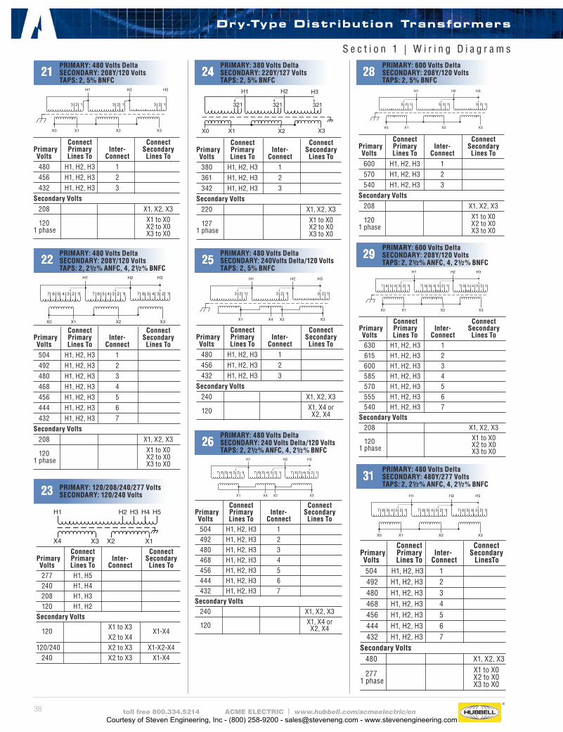
38 toll free 800.334.5214 ACME ELECTRIC | www.hubbell.com/acmeelectric/en
Connect Connect Primary Primary Inter- Secondary Volts Lines To Connect Lines To 480 H1, H2, H3 1 456 H1, H2, H3 2 432 H1, H2, H3 3 Secondary Volts 208 X1, X2, X3 120 X1 to X0 1 phase X2 to X0 X3 to X0
X1
H1
X2 X3
H3H2
X0
12312312345 45 4567 67 67
Connect Connect Primary Primary Inter- Secondary Volts Lines To Connect Lines To 504 H1, H2, H3 1 492 H1, H2, H3 2 480 H1, H2, H3 3 468 H1, H2, H3 4 456 H1, H2, H3 5 444 H1, H2, H3 6 432 H1, H2, H3 7 Secondary Volts 208 X1, X2, X3 120 X1 to X0 1 phase X2 to X0 X3 to X0
H1 H5
X1X2X3X4
H4H3H2
Connect Connect Primary Primary Inter- Secondary Volts Lines To Connect Lines To 277 H1, H5 240 H1, H4 208 H1, H3 120 H1, H2 Secondary Volts
120 X1 to X3
X1-X4 X2 to X4 120/240 X2 to X3 X1-X2-X4 240 X2 to X3 X1-X4
H3
X1
H3
123 123
X2
123
X3
H2H1
X0
Connect Connect Primary Primary Inter- Secondary Volts Lines To Connect Lines To 380 H1, H2, H3 1 361 H1, H2, H3 2 342 H1, H2, H3 3 Secondary Volts 220 X1, X2, X3 127 X1 to X0 1 phase X2 to X0 X3 to X0
Connect Connect Primary Primary Inter- Secondary Volts Lines To Connect Lines To 480 H1, H2, H3 1 456 H1, H2, H3 2 432 H1, H2, H3 3 Secondary Volts 240 X1, X2, X3 120 X1, X4 or X2, X4
Connect Connect Primary Primary Inter- Secondary Volts Lines To Connect Lines To 600 H1, H2, H3 1 570 H1, H2, H3 2 540 H1, H2, H3 3 Secondary Volts 208 X1, X2, X3 120 X1 to X0 1 phase X2 to X0 X3 to X0
Connect Connect Primary Primary Inter- Secondary Volts Lines To Connect Lines To 504 H1, H2, H3 1 492 H1, H2, H3 2 480 H1, H2, H3 3 468 H1, H2, H3 4 456 H1, H2, H3 5 444 H1, H2, H3 6 432 H1, H2, H3 7 Secondary Volts 240 X1, X2, X3 120 X1, X4 or X2, X4
X1 X2 X3X4
H1 H3H2
12312312345 45 4567 67 67
Connect Connect Primary Primary Inter- Secondary Volts Lines To Connect Lines To 630 H1, H2, H3 1 615 H1, H2, H3 2 600 H1, H2, H3 3 585 H1, H2, H3 4 570 H1, H2, H3 5 555 H1, H2, H3 6 540 H1, H2, H3 7 Secondary Volts 208 X1, X2, X3 120 X1 to X0 1 phase X2 to X0 X3 to X0
X1
H1
X2 X3
H3H2
X0
12312312345 45 4567 67 67
Connect Connect Primary Primary Inter- Secondary Volts Lines To Connect LinesTo 504 H1, H2, H3 1 492 H1, H2, H3 2 480 H1, H2, H3 3 468 H1, H2, H3 4 456 H1, H2, H3 5 444 H1, H2, H3 6 432 H1, H2, H3 7 Secondary Volts 480 X1, X2, X3 277 X1 to X0 1 phase X2 to X0 X3 to X0
21PRIMARY: 480 Volts Delta SECONDARY: 208Y/120 VoltsTAPS: 2, 5% BNFC
24PRIMARY: 380 Volts DeltaSECONDARY: 220Y/127 VoltsTAPS: 2, 5% BNFC
28PRIMARY: 600 Volts DeltaSECONDARY: 208Y/120 VoltsTAPS: 2, 5% BNFC
22PRIMARY: 480 Volts Delta SECONDARY: 208Y/120 VoltsTAPS: 2, 21/2% ANFC, 4, 21/2% BNFC
23 PRIMARY: 120/208/240/277 Volts SECONDARY: 120/240 Volts
25PRIMARY: 480 Volts DeltaSECONDARY: 240Volts Delta/120 VoltsTAPS: 2, 5% BNFC
26PRIMARY: 480 Volts DeltaSECONDARY: 240 Volts Delta/120 VoltsTAPS: 2, 21/2% ANFC, 4, 21/2% BNFC
29PRIMARY: 600 Volts DeltaSECONDARY: 208Y/120 VoltsTAPS: 2, 21/2% ANFC, 4, 21/2% BNFC
31PRIMARY: 480 Volts DeltaSECONDARY: 480Y/277 VoltsTAPS: 2, 21/2% ANFC, 4, 21/2% BNFC
S e c t i o n 1 | W i r i n g D i a g r a m s
Dry-Type Distribution Transformers
Courtesy of Steven Engineering, Inc - (800) 258-9200 - [email protected] - www.stevenengineering.com
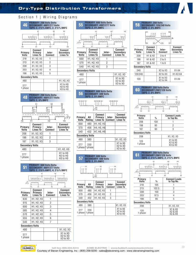
39toll free 800.334.5214 ACME ELECTRIC | www.hubbell.com/acmeelectric/en
Connect Connect Primary Alt Primary Inter- Secondary Volts Rating Lines To Connect Lines To 600 480 H1, H2, H3 1 570 456 H1, H2, H3 2 540 432 H1, H2, H3 3 Secondary Volts 480 380 X1, X2, X3 277 220 X1 to X0 1 phase 1 phase X2 to X0 X3 to X0
X1
H2 H3
X3X2
123123123
H1H0
Connect Connect Primary Primary Inter- Secondary Volts Lines To Connect Lines To 208 X1, X2, X3 1 198 X1, X2, X3 2 187 X1, X2, X3 3 Secondary Volts 480 H1, H2, H3 277 H1 to H0 1 phase H2 to H0 H3 to H0
Connect Connect Primary Primary Inter- Secondary Volts Lines To Connect Lines To 630 H1, H2, H3 1 615 H1, H2, H3 2 600 H1, H2, H3 3 585 H1, H2, H3 4 570 H1, H2, H3 5 555 H1, H2, H3 6 540 H1, H2, H3 7 Secondary Volts 480 X1, X2, X3 277 X1 to X0 1 phase X2 to X0 X3 to X0
Connect Connect Primary Alt Primary Inter- Secondary Volts Rating Lines To Connect Lines To 600 480 H1, H2, H3 570 456 H4, H5, H6 540 432 H7, H8, H9 Secondary Volts 480 380 X1, X2, X3 277 220 X1 to X0 1 phase 1 phase X2 to X0 X3 to X0
Connect Connect Primary Primary Inter- Secondary Volts Lines To Connect Lines To 218 X1, X2, X3 1 213 X1, X2, X3 2 208 X1, X2, X3 3 203 X1, X2, X3 4 198 X1, X2, X3 5 Secondary Volts 480 H1, H2, H3 277 H1 to H0 1 phase H2 to H0 H3 to H0
H1
X1
H2 H3
X3X2
H0
12312312345 45 45
46PRIMARY: 208 Volts DeltaSECONDARY: 480Y/277 VoltsTAPS: 2, 21/2% ANFC, 2, 21/2% BNFC
58PRIMARY: 208 VoltsSECONDARY: 120/240 VoltsTAPS: 2, 5% BNFC
Connect Connect Primary Primary Inter- Secondary Volts Lines To Connect Lines To 600 H1, H2, H3 1 570 H1, H2, H3 2 540 H1, H2, H3 3 Secondary Volts 480 X1, X2, X3 277 X1 to X0 1 phase X2 to X0 X3 to X0
55PRIMARY: 600 Volts DeltaSECONDARY: 480Y/277 VoltsTAPS: 2, 5% BNFC
48PRIMARY: 208 Volts DeltaSECONDARY: 480Y/277 VoltsTAPS: 2, 5% BNFC
51PRIMARY: 600 Volts DeltaSECONDARY: 480Y/277 VoltsTAPS: 2, 21/2% ANFC, 4, 21/2% BNFC
56PRIMARY: 600 Volts DeltaSECONDARY: 480 VoltsTAPS: 2, 5% BNFC
57PRIMARY: 600 VoltsSECONDARY: 480 VoltsTAPS: 2, 5% BNFC
H11 2 3
H24 5 6
X1X3X2X4
Connect Connect Primary Primary Inter- Secondary Volts Lines To Connect Lines To 208 H1 & H2 3 to 4 198 H1 & H2 2 to 5 187 H1 & H2 1 to 6 Secondary Volts 240 X2 to X3 X1-X4 120/240 X2 to X3 X1-X2-X4 120 X1 to X3 X1-X4 X2 to X4
60PRIMARY: 208 Volts DeltaSECONDARY:208Y/120 VoltsTAPS: 2, 5% BNFC
Primary Connect Leads Volts % to Tap No. 208 100 1 198 95 2 187 90 3 Secondary Volts 208 X1, X2, X3 120 X1 & X0 1 phase X2 & X0 X3 & X0
Primary Connect Leads Volts % to Tap No. 218 105 1 213 102.5 2 208 100 3 203 97.5 4 198 95 5 Secondary Volts 208 X1, X2, X3 120 X1 & X0 1 phase X2 & X0 X3 & X0
61PRIMARY: 208 Volts DeltaSECONDARY:208Y/120 VoltsTAPS: 2, 21/2% ANFC, 2, 21/2% BNFC
S e c t i o n 1 | W i r i n g D i a g r a m s
Dry-Type Distribution Transformers
Courtesy of Steven Engineering, Inc - (800) 258-9200 - [email protected] - www.stevenengineering.com
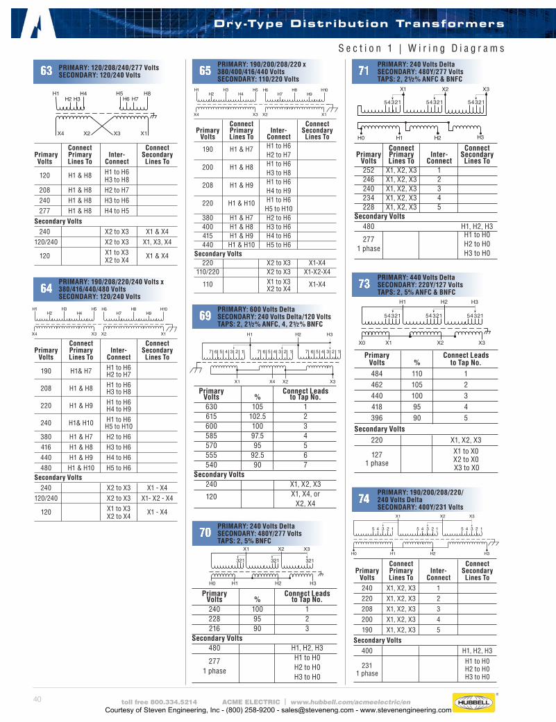
40 toll free 800.334.5214 ACME ELECTRIC | www.hubbell.com/acmeelectric/en
H3
X1
H3
123 123
X2
123
X3
H2H1H0
H8H6 H7
X1X3X2X4
H1H2 H3
H4 H5
Connect Connect Primary Primary Inter- Secondary Volts Lines To Connect Lines To 120 H1 & H8 H1 to H6 H3 to H8 208 H1 & H8 H2 to H7 240 H1 & H8 H3 to H6 277 H1 & H8 H4 to H5 Secondary Volts 240 X2 to X3 X1 & X4 120/240 X2 to X3 X1, X3, X4 120 X1 to X3 X1 & X4 X2 to X4
Connect Connect Primary Primary Inter- Secondary Volts Lines To Connect Lines To 190 H1& H7 H1 to H6 H2 to H7 208 H1 & H8 H1 to H6 H3 to H8 220 H1 & H9 H1 to H6 H4 to H9 240 H1& H10 H1 to H6 H5 to H10 380 H1 & H7 H2 to H6 416 H1 & H8 H3 to H6 440 H1 & H9 H4 to H6 480 H1 & H10 H5 to H6 Secondary Volts 240 X2 to X3 X1 - X4 120/240 X2 to X3 X1- X2 - X4 120 X1 to X3 X1 - X4 X2 to X4
H1H2
H3H4
H5 H6H7
H8H9
H10
X4 X3 X2 X1
H1H2
H3H4
H5 H6H7
H8H9
H10
X4 X3 X2 X1
Connect Connect Primary Primary Inter- Secondary Volts Lines To Connect Lines To 190 H1 & H7 H1 to H6 H2 to H7 200 H1 & H8 H1 to H6 H3 to H8 208 H1 & H9 H1 to H6 H4 to H9 220 H1 & H10 H1 to H6 H5 to H10 380 H1 & H7 H2 to H6 400 H1 & H8 H3 to H6 415 H1 & H9 H4 to H6 440 H1 & H10 H5 to H6 Secondary Volts 220 X2 to X3 X1-X4 110/220 X2 to X3 X1-X2-X4 110 X1 to X3 X1-X4 X2 to X4
X1 X2 X3X4
H1 H3H2
12312312345 45 4567 67 67
Primary Connect Leads Volts % to Tap No. 630 105 1 615 102.5 2 600 100 3 585 97.5 4 570 95 5 555 92.5 6 540 90 7 Secondary Volts 240 X1, X2, X3 120 X1, X4, or X2, X4
Primary Connect Leads Volts % to Tap No. 240 100 1 228 95 2 216 90 3 Secondary Volts 480 H1, H2, H3 277 H1 to H0 1 phase H2 to H0 H3 to H0
Connect Connect Primary Primary Inter- Secondary Volts Lines To Connect Lines To 252 X1, X2, X3 1 246 X1, X2, X3 2 240 X1, X2, X3 3 234 X1, X2, X3 4 228 X1, X2, X3 5 Secondary Volts 480 H1, H2, H3
277 H1 to H0
1 phase
H2 to H0 H3 to H0
H0
123451234512345
X3X2X1
H1 H2 H3
63 PRIMARY: 120/208/240/277 Volts SECONDARY: 120/240 Volts 65
PRIMARY: 190/200/208/220 x380/400/416/440 VoltsSECONDARY: 110/220 Volts
71PRIMARY: 240 Volts DeltaSECONDARY: 480Y/277 VoltsTAPS: 2, 21/2% ANFC & BNFC
64PRIMARY: 190/208/220/240 Volts x 380/416/440/480 VoltsSECONDARY: 120/240 Volts
69PRIMARY: 600 Volts DeltaSECONDARY: 240 Volts Delta/120 VoltsTAPS: 2, 21/2% ANFC, 4, 21/2% BNFC
70PRIMARY: 240 Volts DeltaSECONDARY: 480Y/277 VoltsTAPS: 2, 5% BNFC
X3
H1
H3
H2
123
H3
X2X1X0
451234512345
Primary Connect Leads Volts % to Tap No. 484 110 1 462 105 2 440 100 3 418 95 4 396 90 5 Secondary Volts 220 X1, X2, X3 127 X1 to X0
1 phase X2 to X0 X3 to X0
73PRIMARY: 440 Volts DeltaSECONDARY: 220Y/127 VoltsTAPS: 2, 5% ANFC & BNFC
H1
X1
H2 H3
X3X2
H0
12312312345 45 45
Connect Connect Primary Primary Inter- Secondary Volts Lines To Connect Lines To 240 X1, X2, X3 1 220 X1, X2, X3 2 208 X1, X2, X3 3 200 X1, X2, X3 4 190 X1, X2, X3 5 Secondary Volts 400 H1, H2, H3
231 H1 to H0
1 phase
H2 to H0 H3 to H0
74PRIMARY: 190/200/208/220/ 240 Volts DeltaSECONDARY: 400Y/231 Volts
S e c t i o n 1 | W i r i n g D i a g r a m s
Dry-Type Distribution Transformers
Courtesy of Steven Engineering, Inc - (800) 258-9200 - [email protected] - www.stevenengineering.com
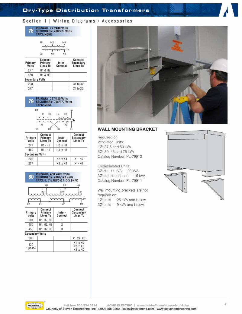
41toll free 800.334.5214 ACME ELECTRIC | www.hubbell.com/acmeelectric/en
X1
H1 H2 H3
X2 X3
Connect Connect Primary Primary Inter- Secondary Volts Lines To Connect Lines To 277 H1 & H2 480 H1 & H3 Secondary Volts 208 X1 to X2 277 X1 to X3
78PRIMARY: 277/480 VoltsSECONDARY: 208/277 VoltsTAPS: NONE
H1 H6
X1X4X3X6
H5H4H2 H3
X5 X2
Connect Connect Primary Primary Inter- Secondary Volts Lines To Connect Lines To 277 H1 - H5 H2 to H4 480 H1 - H6 H3 to H4 Secondary Volts 208 X2 to X4 X1 - X5 277 X3 to X4 X1 - X6
79PRIMARY: 277/480 VoltsSECONDARY: 208/277 VoltsTAPS: NONE
X3
H1 H2
123
H3
X2X1X0
123123
Connect Connect Primary Primary Inter- Secondary Volts Lines To Connect Lines To 504 H1, H2, H3 1 480 H1, H2, H3 2 456 H1, H2, H3 3 Secondary Volts 208 X1, X2, X3
120 X1 to X0
1 phase
X2 to X0 X3 to X0
80PRIMARY: 480 Volts DeltaSECONDARY: 208Y/120 VoltsTAPS: 1, 5% ANFC & 1, 5% BNFC
WALL MOUNTING BRACKET
Required on:Ventilated Units:1Ø, 37.5 and 50 kVA 3Ø, 30, 45 and 75 kVACatalog Number: PL-79912
Encapsulated Units:3Ø dit., 11 kVA — 20 kVA 3Ø std. distribution — 15 kVACatalog Number: PL-79911
Wall mounting brackets are not required on: 1Ø units — 25 kVA and below 3Ø units — 9 kVA and below
S e c t i o n 1 | W i r i n g D i a g r a m s / A c c e s s o r i e s
Dry-Type Distribution Transformers
Courtesy of Steven Engineering, Inc - (800) 258-9200 - [email protected] - www.stevenengineering.com
42 toll free 800.334.5214 ACME ELECTRIC | www.hubbell.com/acmeelectric/en
GP1210000S ____________________ 20
GP121000S _____________________ 20
GP1215000S ____________________ 20
GP12250S ______________________ 20
GP123000S _____________________ 20
GP125000S _____________________ 20
GP12500S ______________________ 20
T153004 ________________________ 19
T153005 ________________________ 19
T153006 ________________________ 19
T153104 ________________________ 21
T153105 ________________________ 21
T153106 ________________________ 21
T2527031 _______________________ 29
T2527051 _______________________ 29
T2527071 _______________________ 29
T253007S_______________________ 19
T253007SS _____________________ 19
T253008S_______________________ 19
T253008SS _____________________ 19
T253009S_______________________ 19
T253009SS _____________________ 19
T253010S_______________________ 19
T253010SS _____________________ 19
T253011S_______________________ 19
T253011SS _____________________ 19
T253012S_______________________ 19
T253012SS _____________________ 19
T2530134S _____________________ 19
T253013S_______________________ 19
T253013SS _____________________ 19
T2530144S _____________________ 19
T253014S_______________________ 19
T253014SS _____________________ 19
T253060 ________________________ 18
T253061 ________________________ 18
T253062 ________________________ 18
T253063 ________________________ 18
T253064 ________________________ 18
T253065 ________________________ 18
T253066 ________________________ 18
T253067 ________________________ 18
T253107S_______________________ 21
T253108S_______________________ 21
T253109S_______________________ 21
T253110S_______________________ 21
T253111S_______________________ 21
T253112S_______________________ 21
T2531131S _____________________ 21
T2531141S _____________________ 21
T2535153S _____________________ 19
T253515SS _____________________ 19
T2535163S _____________________ 19
T253516SS _____________________ 19
T2535173S _____________________ 19
T253517SS _____________________ 19
T2535183S _____________________ 19
T253518SS _____________________ 19
T2536151S _____________________ 21
T2536161S _____________________ 21
T2536171S _____________________ 21
T2536181S _____________________ 21
T279740S_______________________ 17
T279741S_______________________ 17
T279742S_______________________ 17
T279743S_______________________ 17
T279744S_______________________ 17
T279745S_______________________ 17
T279746S_______________________ 17
T279747S_______________________ 17
T279748S_______________________ 17
T2A527121 _____________________ 29
T2A527131 _____________________ 29
T2A527151 _____________________ 29
T2A527171 _____________________ 29
T2A527181 _____________________ 29
T2A527191 _____________________ 29
T2A533081S ____________________ 24
T2A53308SS ____________________ 25
T2A533091S ____________________ 24
S e c t i o n 1 | W a r r a n t y / A l p h a n u m e r i c a l N u m b e r C a t a l o g I n d e x
Dry-Type Distribution Transformers
Acme Electric 10-Year Limited* WarrantyAcme Electric (Acme) warrants to the original purchaser to correct by repair, replacement or refund of original purchase price, at Acme’s option, products manufactured and sold by its Power Distribution Products Division, that may fail in service within the applicable period as set forth below, from the date of manufacture provided however, that conditions of operation have been normal at all times, and that the equipment has not been subjected to abnormal stress from such causes as incorrect primary voltage or frequency, improper ventilation or improper use. This warranty is made on the condition that prompt notice of defect is given to Acme in writing within the warranty period, and that Acme’s inspection reveals to its satisfaction that the original purchaser’s claim is valid under the terms of this warranty. Acme’s obligation under this warranty, which is in lieu of all other warranties, express or implied, including the implied warranty of fitness for a particular purpose and merchantability, is limited to replacing or repairing defective products or parts, free of charge, provided they are returned to the factory, or refund of original purchase price, at Acme’s option. However, purchased components (except for timers and photocells used in low voltage lighting power supplies) including but not limited to capacitors, circuit breakers, terminal blocks, batteries, fuses and tubes shall not be covered under this warranty. Repairs or replacement deliveries shall not interrupt or prolong the term of this warranty. Acme will not be liable for any special, indirect, consequential or incidental damages, including, without limitation, from loss of use, data, function or profits deriving out of or in connection with the use or performance of the product and shall have no liability for payment of any other damages whether in an action of contract, strict liability or tort. The remedy provided herein states Acme Electric’s entire liability and buyer’s sole and exclusive remedy here under. Rights may vary in certain states.
*Warranty Period:Standard Catalog Transformers — 10-year limited; Medium Voltage Transformer — 3-year limited, Custom products — 1 year.
Courtesy of Steven Engineering, Inc - (800) 258-9200 - [email protected] - www.stevenengineering.com

43toll free 800.334.5214 ACME ELECTRIC | www.hubbell.com/acmeelectric/en
S e c t i o n 1 | A l p h a n u m e r i c a l N u m b e r C a t a l o g I n d e x
T2A53309SS ____________________ 25
T2A533101S ____________________ 24
T2A53310SS ____________________ 25
T2A533281S ____________________ 26
T2A533291S ____________________ 26
T2A533401S ____________________ 26
T2A533601S ____________________ 23
T2A792681S ____________________ 22
T2A792691S ____________________ 22
T2A792701S ____________________ 22
T2A793301S ____________________ 27
T2A793311S ____________________ 27
T2A793321S ____________________ 27
T2A795161S ____________________ 28
T2A795171S ____________________ 28
T2A795181S ____________________ 28
T2A795523S ____________________ 23
T2A795533S ____________________ 23
T2A795543S ____________________ 23
T2A795553S ____________________ 23
T3001M0012B __________________ 24
T3015K0013B ___________________ 24
T3015K0013BC _________________ 24
T3015K0013BSB ________________ 25
T3015K0013BSF ________________ 25
T3015K0023B ___________________ 26
T3015K0034B ___________________ 22
T3015K0044B ___________________ 23
T3015K0053B ___________________ 27
T3015K0064BS __________________ 22
T3015K0074B ___________________ 23
T3015K0083BS __________________ 27
T3015K0093BS __________________ 28
T3015K0170BS __________________ 22
T3015K0323BS __________________ 28
T3030K0013B ___________________ 24
T3030K0013BC _________________ 24
T3030K0013BSB ________________ 25
T3030K0013BSF ________________ 25
T3030K0023B ___________________ 26
T3030K0034B ___________________ 22
T3030K0044B ___________________ 23
T3030K0053B ___________________ 27
T3030K0064BS __________________ 22
T3030K0074B ___________________ 23
T3030K0083BS __________________ 27
T3030K0093BS __________________ 28
T3030K0170BS __________________ 22
T3030K0323BS __________________ 28
T3045K0013B ___________________ 24
T3045K0013BC _________________ 24
T3045K0013BSB ________________ 25
T3045K0013BSF ________________ 25
T3045K0023B ___________________ 28
T3045K0034B ___________________ 22
T3045K0044B ___________________ 23
T3045K0053B ___________________ 27
T3045K0064BS __________________ 22
T3045K0074B ___________________ 23
T3045K0083BS __________________ 27
T3045K0093BS __________________ 28
T3045K0170BS __________________ 22
T3045K0323BS __________________ 28
T3075K0013B ___________________ 24
T3075K0013BC _________________ 24
T3075K0013BSB ________________ 25
T3075K0013BSF ________________ 25
T3075K0023B ___________________ 26
T3075K0034B ___________________ 22
T3075K0044B ___________________ 23
T3075K0053B ___________________ 27
T3075K0064BS __________________ 22
T3075K0074B ___________________ 23
T3075K0083BS __________________ 27
T3075K0093BS __________________ 28
T3075K0170BS __________________ 22
T3075K0323BS __________________ 28
T3112K0013B ___________________ 24
T3112K0013BC _________________ 24
T3112K0013BSB ________________ 25
T3112K0013BSF ________________ 25
T3112K0023B ___________________ 26
T3112K0034B ___________________ 22
T3112K0044B ___________________ 23
T3112K0053B ___________________ 27
T3112K0074B ___________________ 23
T3112K0083BS __________________ 27
T3112K0093BS __________________ 28
T3150K0013B ___________________ 24
T3150K0013BC _________________ 24
T3150K0013BSB ________________ 25
T3150K0013BSF ________________ 25
T3150K0023B ___________________ 26
T3150K0034B ___________________ 22
T3150K0044B ___________________ 23
T3150K0053B ___________________ 27
T3150K0074B ___________________ 23
T3150K0083BS __________________ 27
T3150K0093BS __________________ 28
T3225K0013B ___________________ 24
T3225K0013BC _________________ 24
T3225K0013BSF ________________ 25
T3225K0023B ___________________ 26
T3225K0034B ___________________ 22
T3225K0044B ___________________ 23
T3225K0053B ___________________ 27
T3225K0083BS __________________ 27
T3300K0013B ___________________ 24
T3300K0013BC _________________ 24
T3300K0013BSF ________________ 25
T3300K0023B ___________________ 26
T3300K0034B ___________________ 22
T3300K0053B ___________________ 27
T3300K0083BS __________________ 27
T335000153S ___________________ 27
T3500K0013B ___________________ 24
T3500K0013BC _________________ 24
T3500K0013BSF ________________ 2 5
T3500K0023B ___________________ 26
T3500K0083BS __________________ 27
T3527101 _______________________ 29
T3533111S _____________________ 24
T353311SS _____________________ 25
T3533411S _____________________ 26
T3533611S _____________________ 23
T3750K0013B ___________________ 24
T3750K0013BC _________________ 24
T3750K0023B ___________________ 26
T3750K0083BS __________________ 27
T379083S_______________________ 22
T3792711S _____________________ 22
T3793123S _____________________ 25
T379312SS _____________________ 25
T3793133S _____________________ 25
T379313SS _____________________ 25
T3793143S _____________________ 25
T379314SS _____________________ 25
T3793331S _____________________ 27
T3793671S _____________________ 22
T3795191S _____________________ 28
T3795511S _____________________ 23
T3796931S _____________________ 23
TC533111S _____________________ 24
TC535153S _____________________ 20
TC535163S _____________________ 20
TC535173S _____________________ 20
TC535183S _____________________ 20
TE1530223S ____________________ 20
TE2530193S ____________________ 20
TE2530203S ____________________ 20
TE2A530213S ___________________ 20
TF217437S _____________________ 17
TF217439S _____________________ 17
TF220105S _____________________ 24
TF220155S _____________________ 24
TF220255S _____________________ 24
TF220505S _____________________ 24
TF249873S _____________________ 17
TF252520S _____________________ 17
TF252794S _____________________ 17
TF252795S _____________________ 17
TF252796S _____________________ 17
TF252797S _____________________ 17
TF279260S _____________________ 18
TF279261S _____________________ 18
TF279262S _____________________ 18
TF279263S _____________________ 18
TF279264S _____________________ 18
TF279265S _____________________ 18
TF279266S _____________________ 18
TF279267S _____________________ 18
TF279300S _____________________ 17
TF279301S _____________________ 17
TF279302S _____________________ 17
TF279303S _____________________ 17
TF279304S _____________________ 17
TP530193S _____________________ 19
TP530203S _____________________ 19
TP530213S _____________________ 19
TP530223S _____________________ 19
TP530233S _____________________ 19
TP530243S _____________________ 19
TP531193S _____________________ 21
TP531203S _____________________ 21
TP531213S _____________________ 21
TP531223S _____________________ 21
TP531233S _____________________ 21
TP536491S _____________________ 18
TP536503S _____________________ 18
TP536513S _____________________ 18
TPC530193S ____________________ 20
TPC530203S ____________________ 20
Dry-Type Distribution Transformers
Courtesy of Steven Engineering, Inc - (800) 258-9200 - [email protected] - www.stevenengineering.com
AE_CAT_1_0013/2019
COMMERCIAL CONSTRUCTIONA Division of Hubbell Incorporated (Delaware)
©2019 Hubbell. All rights reserved. Information subject to change. Trademarks are property of their respective owners.
ACME ELECTRICMenomonee Falls, WI 53051www.hubbell.com/acmeelectric/en800-334-5214
Our history is strong,engaging and dedicated…
just like our people.
The Acme Electric Legacy
Acme Electric provides power quality and conversion equipment to OEM, industrial and commercial markets. Founded in 1917 in Cleveland, Ohio as the Acme Electric and Machine Company, the company has a legacy of providing innovative electrical products. Acme is now part of Hubbell Incorporated, one of the largest electrical manufacturers in North America. Hubbell’s history of innovation extends back to 1888 and the invention of the pull chain light switch and the electric plug.
Acme’s original product line of motor-driven battery chargers, electrical appliances and electrical generators has transformed to a diversified mix of high-quality low voltage, medium voltage and 3 phase transformers and power supplies.
Learn more about us at www.hubbell.com/acmeelectric/en
Courtesy of Steven Engineering, Inc - (800) 258-9200 - [email protected] - www.stevenengineering.com