Accurate Time-Linked Data Acqusition System Field Deploymemt and Operational Experience
10
AIAA-2001-0038 1 ACCURATE TIME-LINKED DATA ACQUISITION SYSTEM FIELD DEPLOYMENT AND OPERATIONAL EXPERIENCE *† Dale Berg and Jose Zayas Sandia National Laboratories Albuquerque, New Mexico 87185-0708 ABSTRACT The Accurate Time-Linked Data Acquisition System (ATLAS) became fully operational on the Long-term Inflow and Structural Test (LIST) turbine at Bushland, Texas in May of 2000. In the LIST configuration, one data acquisition unit is mounted on the rotor and two additional acquisition units are mounted near the base of the turbine. All communication between the rotor unit and the ground is via telemetry. Data acquisition on all three units is synchronized (within +/- 1 microsecond) by slaving the units to universal time with the Sandia-developed Programmable Accurate Time Synchronization Module. A total of 74 channels of instrumentation is monitored by the three acquisition units. Data acquisition occurs at a 30 Hz rate for a continuous data throughput of over 35,000 bits per second, resulting in over 2 GB of ASCII data per day. Implementation of the system is discussed and operational experience is reviewed. INTRODUCTION A typical wind turbine data acquisition application, such as that shown in Figure 1, consists of one or more ground-based data acquisition units (GBUs) and at least one rotor-based unit (RBU). Each unit acquires data from sources such as the met tower, the turbine rotor, the turbine nacelle, and the turbine tower. Many different combinations of hardware and software have been used to gather data from wind turbines in the past. However, most of that data is in short segments, typically twenty minutes or less in length, and often the data from the RBU is difficult to accurately time- correlate with the data from the GBU. It has become increasingly obvious in the past few years that, in order to truly understand the critical fatigue loading of wind * Sandia is a multiprogram laboratory operated by Sandia Corporation, a Lockheed Martin company, for the U.S. Department of Energy under contract DE- AC04-94AL85000. † This paper is declared a work of the U.S. Government and is not subject to copyright protection in the United States. turbines, researchers need time-series data that is continuous over a period of hours, days, or months 1 . In addition, accurate time correlation between the rotor- based data and the ground-based data is required to enable researchers to determine the impact of turbine inflow on the structural response. Additional information on ATLAS requirements and development may be found in references 2 and 3. The Accurate Time-Linked Data Acquisition System (ATLAS) has been developed by the Wind Energy Technology Department at Sandia National Laboratories to address these needs by acquiring continuous, long-term, time-synchronized data from multiple GBUs and RBUs for a period of weeks or months. ATLAS consists of both hardware and software components. The major hardware components are data acquisition systems, time- synchronization and communications management units, and, in some applications, telemetry modules. The software consists of the NREL-developed ADAS (Advanced Data Acquisition System)-II data acquisition software (modified to handle continuous data acquisition) and the custom-written ATLAS user- interface, hardware configuration, and programming software 4 . Data Acquisition Subsystem (DAS) ATLAS utilizes a commercially available data acquisition system known as the KAM-500, ‡ which is built and sold by ACRA Control of Dublin, Ireland § . The KAM-500 is a small, rugged, modular, lightweight data acquisition system with a relatively low power consumption that is designed for remote operation in harsh environments. Its operational temperature range is from -40° to +85° C (-40° to +185° F), and it can withstand 100g shock loads. ‡ Company names and specific product information given throughout this paper are given for information only and do not imply endorsement by SNL § ACRA Control Ltd., Landscape House, Landscape Road, Dublin, Ireland.
-
Upload
independent -
Category
Documents
-
view
2 -
download
0
Transcript of Accurate Time-Linked Data Acqusition System Field Deploymemt and Operational Experience
AIAA-2001-0038
1
ACCURATE TIME-LINKED DATA ACQUISITION SYSTEM FIELD DEPLOYMENT ANDOPERATIONAL EXPERIENCE*†
Dale Berg and Jose ZayasSandia National Laboratories
Albuquerque, New Mexico 87185-0708
ABSTRACT
The Accurate Time-Linked Data Acquisition System(ATLAS) became fully operational on the Long-termInflow and Structural Test (LIST) turbine at Bushland,Texas in May of 2000. In the LIST configuration, onedata acquisition unit is mounted on the rotor and twoadditional acquisition units are mounted near the baseof the turbine. All communication between the rotorunit and the ground is via telemetry. Data acquisitionon all three units is synchronized (within +/- 1microsecond) by slaving the units to universal timewith the Sandia-developed Programmable AccurateTime Synchronization Module. A total of 74 channelsof instrumentation is monitored by the threeacquisition units. Data acquisition occurs at a 30 Hzrate for a continuous data throughput of over 35,000bits per second, resulting in over 2 GB of ASCII dataper day. Implementation of the system is discussedand operational experience is reviewed.
INTRODUCTION
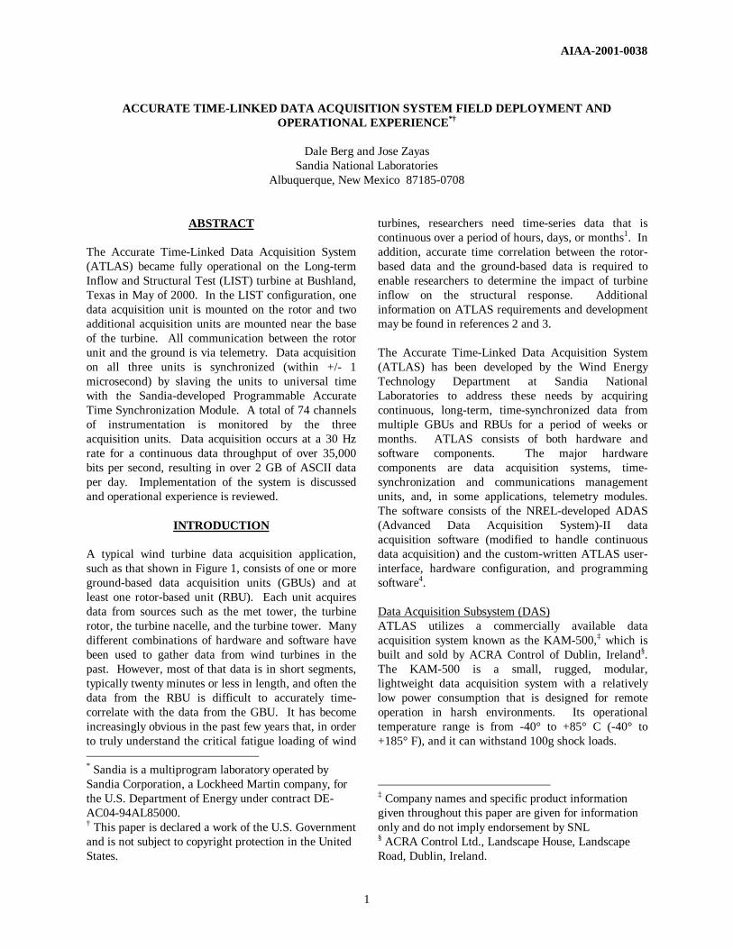
A typical wind turbine data acquisition application,such as that shown in Figure 1, consists of one or moreground-based data acquisition units (GBUs) and atleast one rotor-based unit (RBU). Each unit acquiresdata from sources such as the met tower, the turbinerotor, the turbine nacelle, and the turbine tower. Manydifferent combinations of hardware and software havebeen used to gather data from wind turbines in thepast. However, most of that data is in short segments,typically twenty minutes or less in length, and often thedata from the RBU is difficult to accurately time-correlate with the data from the GBU. It has becomeincreasingly obvious in the past few years that, in orderto truly understand the critical fatigue loading of wind * Sandia is a multiprogram laboratory operated bySandia Corporation, a Lockheed Martin company, forthe U.S. Department of Energy under contract DE-AC04-94AL85000.† This paper is declared a work of the U.S. Governmentand is not subject to copyright protection in the UnitedStates.
turbines, researchers need time-series data that iscontinuous over a period of hours, days, or months1. Inaddition, accurate time correlation between the rotor-based data and the ground-based data is required toenable researchers to determine the impact of turbineinflow on the structural response. Additionalinformation on ATLAS requirements and developmentmay be found in references 2 and 3.
The Accurate Time-Linked Data Acquisition System(ATLAS) has been developed by the Wind EnergyTechnology Department at Sandia NationalLaboratories to address these needs by acquiringcontinuous, long-term, time-synchronized data frommultiple GBUs and RBUs for a period of weeks ormonths. ATLAS consists of both hardware andsoftware components. The major hardwarecomponents are data acquisition systems, time-synchronization and communications managementunits, and, in some applications, telemetry modules.The software consists of the NREL-developed ADAS(Advanced Data Acquisition System)-II dataacquisition software (modified to handle continuousdata acquisition) and the custom-written ATLAS user-interface, hardware configuration, and programmingsoftware4.
Data Acquisition Subsystem (DAS)ATLAS utilizes a commercially available dataacquisition system known as the KAM-500,‡ which isbuilt and sold by ACRA Control of Dublin, Ireland§.The KAM-500 is a small, rugged, modular,lightweight data acquisition system with a relativelylow power consumption that is designed for remoteoperation in harsh environments. Its operationaltemperature range is from -40° to +85° C (-40° to+185° F), and it can withstand 100g shock loads.
‡ Company names and specific product informationgiven throughout this paper are given for informationonly and do not imply endorsement by SNL§ ACRA Control Ltd., Landscape House, LandscapeRoad, Dublin, Ireland.
2
Data are acquired simultaneously from all channels,and the acquisition time can be precisely specified byan externally supplied synchronization pulse. The dataare then formatted into a pulse-code-modulated (PCM)digital serial stream for transmission over an RS-422
cable, a fiber optic link, or a telemetry link to the hostcomputer. The data are decoded by the receivingcomputer and placed into computer memory forretrieval and manipulation with software.
The KAM-500 is programmable from a remotecomputer; the data channel selection, data samplingrates, filter cut-off frequencies, channel gains andoffsets, bridge excitation voltages, and PCM format aresome of the options that can be set from a ground-based computer. The programming information can betransferred via hard-wire or telemetry from thecomputer to the DAS at any time.
Time Synchronization and Communications ModuleAs mentioned in the preceding section, the KAM-500sfeature simultaneous acquisition on all channels. Thedata acquisition timing for each unit may be initiatedby an external clock, so the problem of synchronizingdata acquisition on all the DAS units becomes one ofmaintaining synchronous external clocks for thevarious units. If all units are connected by hard wire,this is not a problem, because we can slave all units tothe same clock. However, if there is no hard-wirecommunication, as may be the case for someinstallations, synchronization becomes a problem, dueto the variable time delay inherent in telemetry.Independent clocks are inadequate because the drift of
even a highly accurate, temperature-stabilized clock ison the order of one part per million. This correspondsto an error accumulation of as much as 86 milliseconds(ms) per day per clock, for a difference of up to 172 ms(nearly 1/5 second) per day between two clocks. At
sample rates of 10 Hz or higher, twoindependent systems could be out ofsynchronization by more than one sampleinterval at the end of a single day. While thismay not be a big problem for somemeasurements, it is unacceptable for ourapplication.
We have developed the Programmable Time-Accurate Synchronization Module (PATSyM)to maintain time synchronization between DASunits. Each PATSyM utilizes a small, single-card Global Positioning Satellite (GPS) systemreceiver to re-synchronize its internal 8 MHzclock to universal time (within +/- 1microsecond) once each second. The internalclock is then used to generate the clock signalsthat trigger the data acquisition. Data acquiredfrom two independent DAS units, eachcontaining a PATSyM, is time synchronized towithin +/- 2 microseconds. The PATSyM also
latches the GPS time, accurate to one microsecond,whenever data are acquired. This time is available tothe user for inclusion in each data frame as a time-stamp identifier for that frame.
Data Communication Radio LinksData must be transferred from the rotor- and ground-based units to the ground-based computer concurrentwith data acquisition to enable continuous dataacquisition over a period of hours, days, or weeks.Although rotor slip rings may be available to effect thistransfer from the rotor on some turbines, many of theturbines on which the ATLAS will be used will nothave them, and telemetry will be required. Rather thanattempt to add the telemetry capability at a later date,we have included it as an integral element of ATLAS.
The rotating turbine blades of a wind turbine create asevere multi-path environment for a telemetry system.ATLAS utilizes low-cost, commercially-available,frequency-hopping, spread-spectrum radio modems,which are resistant to this multi-path interference. TheWIT 2400 units from Digital Wireless Corporation**
operate in the 2.4 GHz frequency band at data rates upto 115 kbps. 2.4 GHz falls in the ISM (industry, ** Digital Wireless Corporation, One Meca Way,Norcross, GA 30093-2919.
Figure 1. Data Acquisition System Schematic
3
science, and medical) frequency band, and, with amaximum transmit power of 100 mW, may be operatedwithout a license from the Federal CommunicationsCommission (FCC). Up to 16 distinct networks ofthese modems may operate in the same vicinity withoutinterfering with each other.
ATLAS incorporates two pair of these modems; onepair operates in asynchronous mode for programmingthe RBU and monitoring the GPS receiver status, and asecond set operates in synchronous mode fortransferring the PCM data from the RBU to theground.
Prior ATLAS Field DeploymentThe first ATLAS prototype was deployed in the field inthe summer of 1998 on an Atlantic Orient Corporation(AOC) turbine at the U.S. Department of AgricultureExperiment Station near Bushland, Texas. Successwith that system was less than spectacular, dueprimarily to lightning damage to the instrumentationand to the wind turbine. In June of 1999, we turnedour efforts toward implementing ATLAS on the Long-term Inflow and Structural Test (LIST) turbine, alsolocated at Bushland.
Additional information on ATLAS may be found inreferences 2-6.
LIST PROGRAM APPLICATION
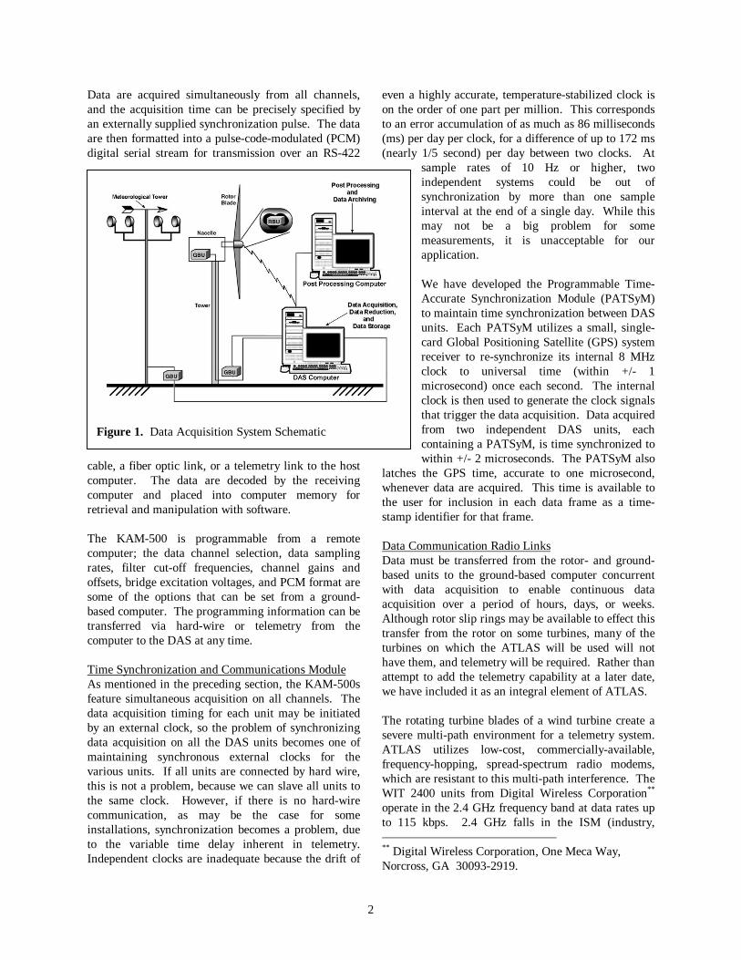
The goal of the LIST program is to acquire long-term,continuous data from a series of wind turbines over anumber of years. The current measurement program inBushland is intended to debug the hardware andsoftware in preparation for future testing of larger scalewind turbines in a variety of wind environments.Figure 2 shows the general layout for the LISTprogram. The test machine is B, the center one in arow of three Micon 65s. These are fixed-pitch,constant speed, upwind machines. The turbine rotor isinstrumented with strain gauges to measure flap andedge bending at the hub and 40% span on each blade,as well as main shaft bending and torque. The tower isinstrumented with strain gauges and accelerometers tomeasure fore-aft and side-to-side bending andacceleration. We also monitor the yaw position, rotorazimuth, rotor speed, and turbine status (on/off). Inaddition, we monitor the power output from all threeturbines, together with extensive meteorological data.Additional information on the LIST instrumentationmay be found in reference 7.
The ground-based control and acquisition computer forATLAS is located in the control building,approximately 59 meters (192 ft) from the base of thetest turbine. The ground-based unit, which includesthe master DAS and one slave DAS, is located in asmall instrumentation building near the base of theturbine, as shown in Figure 2. Data are transferredfrom the master DAS to the computer via fiber-opticlink. User communications with the master unit utilizea second fiber-optic link. The data reception modemfor the rotor-based unit (RBU 3) is located inside theinstrumentation building, with the antenna mounted onthe roof of that building. The distance between therotor transmitting antenna and the receiving antenna isapproximately 25 m (80 ft). User communicationswith the rotor unit utilize a modem placed inside thecontrol building in a window with a clear view of the
turbine. The distance from the rotor unit antenna tothe control building antenna is approximately 64 m(209 ft).
The prevailing wind direction is from the southwest, sothe rotor is normally oriented to give thecommunications antenna a clear view of the controlbuilding. However, that orientation places the datatransmission antenna for the RBU on the opposite sideof the tower from the receiving antenna on theinstrumentation building. In spite of that, we have avery good radio data link between the RBU and theground receiving modem.Rotor-Based Instrumentation
NTurbine
Anemometer Tower
ControlBuilding
Reservoir
Turbine C
Turbine BTurbine A
InstrumentationBuilding
PrevailingWind
Terra
ce Cha
nnel
Terrace Channel
Water W
ay
0 50 100
Scale, m
Road
Road
Figure 2. LIST Layout
4
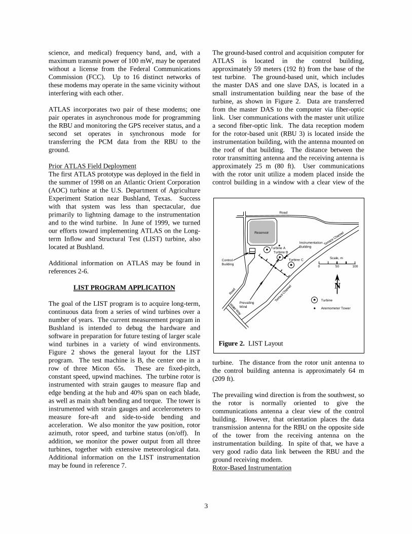
The rotor-based unit for LIST, which we call RBU 3,was designed to acquire 15 channels of strain-gaugedata. As shown in Figures 3 and 4, the componentsare enclosed in a water proof PVC-type container.This container is a design normally used for skindiving and other underwater work and has a sealing lidand a carrying handle. The back of the container hasbeen cut out and replaced with an aluminum platewhich serves as a base plate for mounting components.When RBU 3 is mounted to the rotor, this plate ismounted to the metal rotor face so it serves as a heatsink to dissipate the heat generated in RBU 3 duringoperation. A similar arrangement on the AOCapplication last year was sufficient to keep the internaltemperature of a similar RBU to within 20° F above theambient temperature. Before we installed the backingplate on that system, the internal temperature stabilizednear 160° F, 70° F above ambient.
The three distinct sections of RBU 3 are shown inFigure 3. On the left side are the lightning protectionunits which provide protection for all externally-connected lines except for the 110 VAC power line.These Citel†† devices contain both a fast-actingsemiconductor diode and a gas tube between the lineand ground. The semiconductor diode provides quickresponse to an electrostatic discharge such aslightning, but it cannot handle much power. The gastube, on the other hand, does not switch quickly andneeds a voltage potential of about 100V to fire, but canhandle large amounts of power. The Citelspecifications claim a response time of less than 1nanosecond, with a peak current capability of 10 kA.These units have proven to be quite effective; anumber of severe thunder showers occurred at the sitethis past summer and RBU 3 suffered no detectabledamage.
†† Citel Corporation, 1111 Park Centre Boulevard,Suite 340, Miami, FL 33169
Figure 3. RBU 3 Components
A 6-slot KAM-500 containing three 8-channel, full-bridge strain gauge modules and a single PATSyMmodule is located in the center of the RBU 3 container.The strain gauge modules are used to acquire 15channels of strain data from the rotor blades and hub,while the PATSyM module provides the time-synchronization with the ground–based unit andrecords the time at which each data frame is acquired.
The power supply is located on the right side of thepicture. In RBU 3, the power supply is enclosed in itsown metal case to shield the KAM-500 and input linesfrom the electrical noise generated by the 12-VDCswitching power supply. The Cosel‡‡ MMB50-5 powersupply generates +/- 12 VDC to power the KAM-500and the strain gauges. This supply provides good, low-noise power even when subjected to significantfluctuations in input power frequency, wave-formshape and voltage. DC-to-DC convertors powered bythis unit generate +8 VDC to power the modems and+5 VDC to power the PATSyM.
RBU 3 also contains two Digital Wireless WIT-2400frequency hopping modems, as shown in Figure 3, tocommunicate with the ground. One modem is used tocontinually transmit PCM data to the ground-basedmaster unit, where it is merged into the single datastream that goes to the ground computer. The othermodem provides two-way RS-232 communicationbetween RBU-3 and the ground for monitoring theGPS status and time and for programming the KAM-500 unit.
The GPS antenna receiver unit is mounted on RBU 3so that the antenna is located on the center of rotationwhen the unit is mounted on the turbine. Thiseliminates antenna wobble during turbine operationand results in excellent reception of satellite signals.Initially, we were concerned about the effects ofrotation, as the GPS receiver companies we contactedhad never heard of an application in which the antennarotated. We found that rotation is not a major problembelow about 150 rpm. Above that speed, the number ofsatellites that the receiver can find graduallydiminishes. At about 350 rpm, the receiver can nolonger lock on the required three satellites, andsynchronization with universal time is lost. We havenot experimented with antenna location to determine
‡‡ Cosel USA, 1546 Montague Expressway, San Jose,CA 95131
5
how detrimental position wobble is to the signalreception, but we do not anticipate a wobble of severalcentimeters to have much effect, since the locationresolution of the receiver is only +/- 3 meters.
110 VAC power is provided to RBU 3 through a rotarytransformer mounted on the turbine main shaft. Thetransformer is powered by an uninterruptable powersupply (UPS) mounted on the ground that also provideslightning protection.
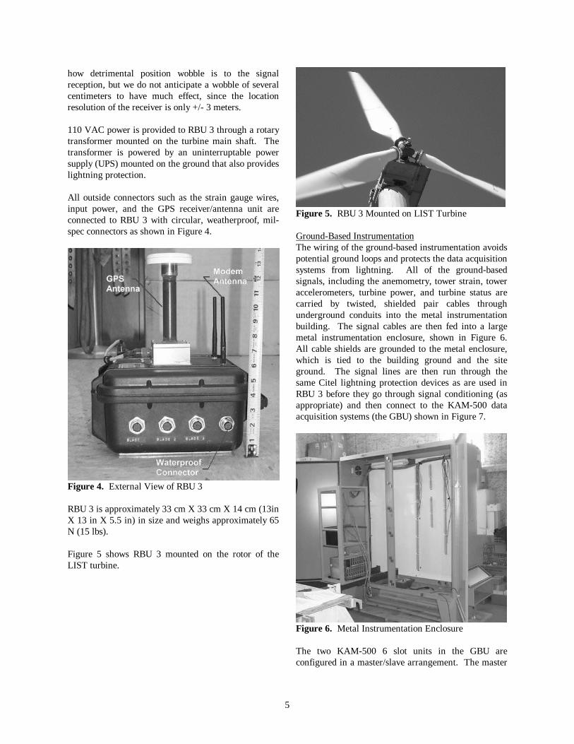
All outside connectors such as the strain gauge wires,input power, and the GPS receiver/antenna unit areconnected to RBU 3 with circular, weatherproof, mil-spec connectors as shown in Figure 4.
Figure 4. External View of RBU 3
RBU 3 is approximately 33 cm X 33 cm X 14 cm (13inX 13 in X 5.5 in) in size and weighs approximately 65N (15 lbs).
Figure 5 shows RBU 3 mounted on the rotor of theLIST turbine.
Figure 5. RBU 3 Mounted on LIST Turbine
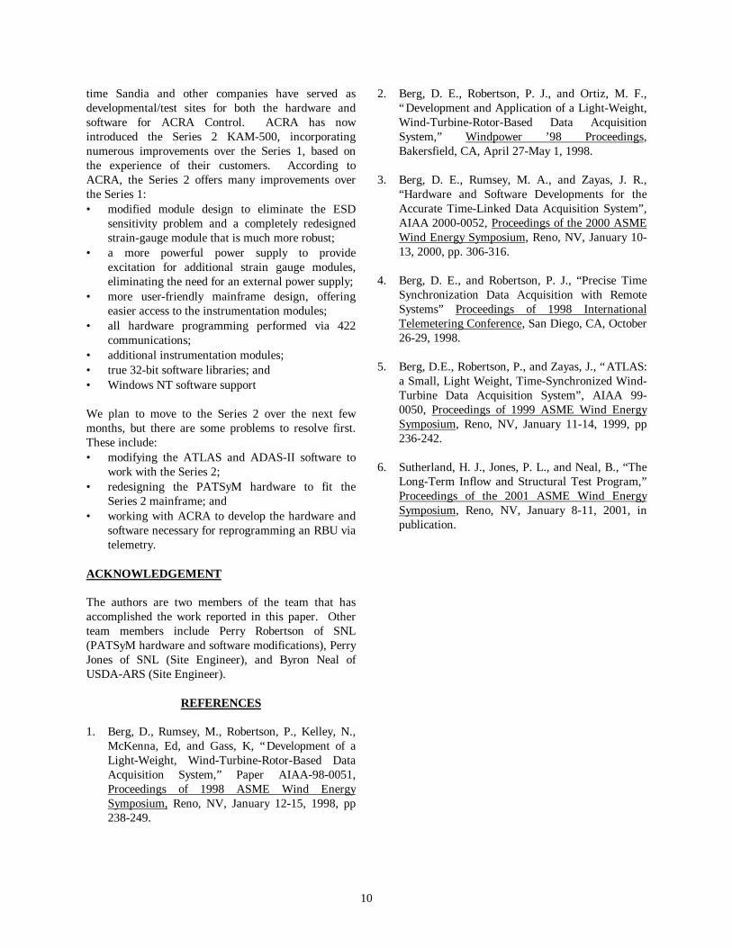
Ground-Based InstrumentationThe wiring of the ground-based instrumentation avoidspotential ground loops and protects the data acquisitionsystems from lightning. All of the ground-basedsignals, including the anemometry, tower strain, toweraccelerometers, turbine power, and turbine status arecarried by twisted, shielded pair cables throughunderground conduits into the metal instrumentationbuilding. The signal cables are then fed into a largemetal instrumentation enclosure, shown in Figure 6.All cable shields are grounded to the metal enclosure,which is tied to the building ground and the siteground. The signal lines are then run through thesame Citel lightning protection devices as are used inRBU 3 before they go through signal conditioning (asappropriate) and then connect to the KAM-500 dataacquisition systems (the GBU) shown in Figure 7.
Figure 6. Metal Instrumentation Enclosure
The two KAM-500 6 slot units in the GBU areconfigured in a master/slave arrangement. The master

6
contains a strain gauge module, a PATSyM module,and two merger/decoder modules. Themerger/decoders accept data streams from the slaveunit and the RBU and merge those streams with dataacquired by the master unit into a single output datastream. One merger/decoder receives the data acquiredby RBU 3 via the receiving antenna located on the roofof the instrumentation building. The second onereceives data acquired by the slave system in theinstrumentation enclosure. The strain gauge modulecollects the strain and accelerometer data from thetower, while the PATSyM provides the time-synchronization with RBU 3 and captures the time atwhich each data frame is acquired.
The PATSyM in the master unit also provides the timesynchronization for the 6-slot slave unit locatedimmediately adjacent to the master, as seen in Figure7. This unit contains six, 8-channel analog moduleswhich are used to collect data from 46 analogchannels. The PCM output stream of the slave istransmitted via hard wire to the master merger/decodermodule.
The RS-422 data stream from the master unit,containing the data from the RBU and the slave unit, istransmitted to the computer in the control building viafiber optic cable and RS-422/fiber optic modems toavoid signal noise and equipment damage due tolightning strikes.
Figure 7. Ground-based Data Acquisition Units in theInstrumentation Enclosure
Data Acquisition and StorageIn the LIST configuration all of the data from theindividual units are merged into a single data stream.Each sample of data is transmitted as a single dataframe, a 1-dimensional array of 74, 16-bit elements,with each element containing either systeminformation or sampled data as illustrated in Table 1.Of the 74 channels, 59 are turbine data and the other15 are either time- or hardware-specific information.At our 30 Hz sample rate, 2.6 million data frames,approximately 2.1 GB of ASCII data, are collecteddaily. Once the data are received and stored in a fileon the ground computer, a second computer accessesthe file via a local-area network, compresses it, storesthe compressed file to another disk, and then deletesthe original file. The compressed files are thenmanually transferred onto a CD for long-term storageor later processing.
OPERATIONAL EXPERIENCE WITH ATLAS

7
We have been using ATLAS in the field environmentfor close to two years. While ATLAS has distinctadvantages over more conventional systems foracquiring data from distributed hardware, we haveexperienced some problems with the system.
Accurate Record of Data Acquisition TimesWe have found the availability of the universal time tobe very useful for debugging, time correlation, andquality assurance purposes. The LIST configurationincludes the sample times of both the RBU and theGBU in the data stream. Those times are then used tocorrelate the RBU data with the appropriate GBU data.We have found that the data in any given framecontains RBU data that are offset from the GBU databy one sample interval – the time delay in telemeteringthe data from the rotor prevents it from being mergedinto the correct GBU data frame.
We can also check for the loss of RBU data byexamining the sample time intervals in each data file.If we experience a communications failure between therotor and the ground (RBU data is lost), the RBU datathat is merged into the master data stream is notupdated – it remains the same until new information isreceived from the RBU. Thus, if the time incrementbetween two RBU samples is 0, one or more RBU dataframes have been lost.
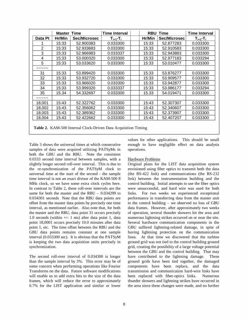
The time-synchronization accuracy resulting fromPATSyM is illustrated in Tables 2 and 3. Table 2shows the actual universal times at which consecutivesamples of data were acquired utilizing the internalKAM-500 system clocks (rather than the PATSyM) onthe master and on the RBU. The sample rate was set at
30 Hz, so 10 minutes of data should correspond to18,000 data points. Note that the time intervalbetween most samples is very consistent at 0.033300seconds for both the master and the RBU. The secondroll-over interval (the interval between the last samplein one second and the first sample in the next second)differs from this value. This interval is 0.033337 or0.033338 seconds for the master (between data points 3and 4 or 34 and 35) and 0.033294 or 0.033295 secondsfor the RBU (between data points 4 and 5 or 34 and35). The important thing to notice in this table,however, is that the cumulative sample time error isgrowing as time goes on. Master data point 31 occurs0.999037 seconds after master data point 1 and masterdata point 18,001 occurs 9 minutes, 59.422379 secondsafter master data point 1. At 30 Hz, data point 31should occur precisely 1 second after point 1, and point18,001 should occur precisely 10 minutes after point 1.A similar cumulative error occurs for the RBU. RBUdata point 31 occurs 0.998994 seconds after RBU datapoint 1, and RBU data point 18,001 occurs 9 minutes,59.430024 seconds after RBU data point 1. For boththe master and the RBU, 18,017 data points correspondto approximately 10 minutes of data. Thus, actual dataacquisition rate is 30.001 Hz for both acquisition units.Also, note that the times at which RBU data points areacquired are drifting slightly with respect to the timesat which the master data points are acquired. Based onthe observed drift in this 10-minute file (0.007645 sec),the two clocks will drift one full sample period(0.033300) with respect to each other in approximately44 minutes. This corresponds to a drift ofapproximately 33 sample periods in one day and wouldmake time-correlation of the data quite difficult.
Frame 1 Status SyncWord 1 Sync Word 2 Data Word 1 Data Word 2 … GPS-Year ...Frame 2 Status SyncWord 1 Sync Word 2 Data Word 1 Data Word 2 … GPS-Year ...~~~~~Frame N Status SyncWord 1 Sync Word 2 Data Word 1 Data Word 2 … GPS-Year ...
Table 1. LIST PCM Data Frame Contents
8
Table 3 shows the universal times at which consecutivesamples of data were acquired utilizing PATSyMs inboth the GBU and the RBU. Note the consistent0.0333 second time interval between samples, with aslightly longer second roll-over interval. This is due tothe re-synchronization of the PATSyM clock touniversal time at the start of the second - the sampletime interval is not an exact divisor of the KAM-500 8MHz clock, so we have some extra clock cycles here.In contrast to Table 2, these roll-over intervals are thesame for both the master and the RBU – 0.034299 to0.034301 seconds Note that the RBU data points areoffset from the master data points by precisely one timeinterval, as mentioned earlier. Also note that, for boththe master and the RBU, data point 31 occurs precisely1.0 seconds (within +/- 1 ms) after data point 1, datapoint 18,0001 occurs precisely 10.0 minutes after datapoint 1, etc. The time offset between the RBU and theGBU data points remains constant at one sampleinterval (0.033300 sec). It is obvious that the PATSyMis keeping the two data acquisition units precisely insynchronization.
The second roll-over interval of 0.034300 is longerthan the sample interval by 3%. This error may be ofsome concern when performing operations like FourierTransforms on the data. Future software modificationswill enable us to add extra bits to the size of the dataframes, which will reduce the error to approximately0.7% for the LIST application and similar or lower
values for other applications. This should be smallenough to have negligible effect on data analysisoperations.
Hardware ProblemsOriginal plans for the LIST data acquisition systemenvisioned using fiber optics to transmit both the data(the RS-422 link) and communications (the RS-232link) between the instrumentation building and thecontrol building. Initial attempts to use the fiber opticswere unsuccessful, and hard wire was used for bothlinks. For two weeks we experienced exceptionalperformance in transferring data from the master unitto the control building – we observed no loss of GBUdata frames. However, after approximately two weeksof operation, several thunder showers hit the area andnumerous lightning strikes occurred on or near the site.Several hardware communication components in theGBU suffered lightning-related damage, in spite ofhaving lightning protection on the communicationlines. At that time we discovered that the turbineground grid was not tied to the control building groundgrid, creating the possibility of a large voltage potentialbetween the GBU and the control building. That mayhave contributed to the lightning damage. Theseground grids have been tied together, the damagedcomponents have been replace, and the datatransmission and communication hard-wire links havebeen replaced with fiber-optics links. Numerousthunder showers and lightning strikes have occurred inthe area since these changes were made, and no further
Master Time Time Interval RBU Time Time IntervalData Pt Hr/Min Sec/Microsec Ti+1-Ti Hr/Min Sec/Microsec Ti+1-Ti
1 15:33 52.900383 0.033300 15:33 52.877283 0.0333002 15:33 52.933683 0.033300 15:33 52.910583 0.0333003 15:33 52.966983 0.033337 15:33 52.943883 0.0333004 15:33 53.000320 0.033300 15:33 52.977183 0.0332945 15:33 53.033620 0.033300 15:33 53.010477 0.033300
~~~~~31 15:33 53.899420 0.033300 15:33 53.876277 0.03330032 15:33 53.932720 0.033300 15:33 53.909577 0.03330033 15:33 53.966020 0.033300 15:33 53.942877 0.03330034 15:33 53.999320 0.033337 15:33 53.986177 0.03329435 15.34 54.332697 0.033300 15.33 54.019471 0.033300
~~~~~18,001 15:43 52.322762 0.033300 15:43 52.307307 0.03330018,002 15:43 52.356062 0.033300 15:43 52.340607 0.03330018,003 15:43 52.389362 0.033300 15:43 52.373907 0.03330018,004 15:43 52.422662 0.033300 15:43 52.407207 0.033300
Table 2. KAM-500 Internal Clock-Driven Data Acquisition Timing

9
hardware components have been lost due to lightningdamage.
Once the lightning-caused damage was repaired, wefound that some of the data files created on the groundcomputer contained duplicate data frames. Weeventually traced those extra frames to an error in thePATSyM logic program which introduced anasynchronous clock running in parallel with thenormal synchronous clock. Somehow the two clocksoccasionally conflicted with each other and resulted inthe insertion of an extra data frame in the disk file.Detailed examination of data files created over a periodof several weeks following our correction of the logicerror confirmed the elimination of this problem.
The radio link for transferring data from RBU 3 to theground has proven to be quite robust. In a typical 10minute period, we experience six data frames lost fromRBU. Considering the 18,000 data frames acquiredduring 10 minutes, the RBU radio link to ground losesonly 0.04% of the data transferred over it.
During the ATLAS development we experiencednumerous failures of the RS-422 data communicationchip. This was due to the large static charge build upand associated electrostatic discharges (ESD) that arecommon in dry areas such as Albuquerque andBushland (and the California wind farms). Theoriginal chips were sensitive to ESD, but that had notbeen a problem in Ireland and Europe – it became aproblem only when they were used in the low humidityof the U.S. southwest. ACRA identified a pin-
compatible replacement chip with much greaterresistance to ESD, and we have few failures of thosecomponents now. ACRA is using the more robustchips on all new systems they produce.
During the development of the ATLAS dataacquisition system several different types of DASmodules have failed, the most troublesome one beingthe strain-gauge module. Although strain gauge datahas been successfully acquired from both the AOC andthe LIST projects, these modules still continue to fail.Repair of the modules entails shipment to ACRA inIreland, with a minimum turn-around time of fourweeks. The repair time has not been a problem to thispoint, since we have an adequate supply of spares.According to ACRA, some of the damage is due toESD, but that doesn’t explain all of the damages.Extreme care in handling and programming thesemodules has reduced the frequency of failure, but hasnot eliminated it. A thorough check is now routinelyperformed on each module before it is installed in adata system, and if any suspicious data is spotted, themodule is immediately removed and inspected. Inaddition, a shunt calibration technique to checkchannel circuit integrity and help detect bad channelson these modules has been developed. This can beperformed on any strain-gauge module at any time byremote control.
FUTURE PLANS
The KAM-500 Series 1 DAS units have been used inthe development of the ATLAS hardware. During this
Master Time Time Interval RBU Time Time IntervalData Pt Hr/Min Sec/Microsec Ti+1-Ti Hr/Min Sec/Microsec Ti+1-Ti
1 13:30 21.998943 0.034299 13:30 21.965242 0.0333002 13:30 22.032842 0.033300 13:30 21.998542 0.0343013 13:30 22.066142 0.033300 13:30 22.032843 0.0333004 13:30 22.099442 0.033300 13:30 22.066143 0.033300
~~~~~31 13:30 22.998542 0.034301 13:30 22.965243 0.03330032 13:30 23.032843 0.033300 13:30 22.998543 0.03429933 13:30 23.066143 0.033300 13:30 23.032842 0.03330034 13:30 23.099443 0.033300 13:30 23.066142 0.033300
~~~~~18,001 13:40 21.998543 0.034299 13:40 21.965242 0.03330018,002 13:40 22.032842 0.033300 13:40 21.998542 0.034300
18,003 13:40 22.066142 0.033300 13:40 22.032842 0.03330018,004 13:40 22.099442 0.033300 13:40 22.06142 0.033300
Table 3. PATSyM-Driven Data Acquisition Timing
10
time Sandia and other companies have served asdevelopmental/test sites for both the hardware andsoftware for ACRA Control. ACRA has nowintroduced the Series 2 KAM-500, incorporatingnumerous improvements over the Series 1, based onthe experience of their customers. According toACRA, the Series 2 offers many improvements overthe Series 1:• modified module design to eliminate the ESD
sensitivity problem and a completely redesignedstrain-gauge module that is much more robust;
• a more powerful power supply to provideexcitation for additional strain gauge modules,eliminating the need for an external power supply;
• more user-friendly mainframe design, offeringeasier access to the instrumentation modules;
• all hardware programming performed via 422communications;
• additional instrumentation modules;• true 32-bit software libraries; and• Windows NT software support
We plan to move to the Series 2 over the next fewmonths, but there are some problems to resolve first.These include:• modifying the ATLAS and ADAS-II software to
work with the Series 2;• redesigning the PATSyM hardware to fit the
Series 2 mainframe; and• working with ACRA to develop the hardware and
software necessary for reprogramming an RBU viatelemetry.
ACKNOWLEDGEMENT
The authors are two members of the team that hasaccomplished the work reported in this paper. Otherteam members include Perry Robertson of SNL(PATSyM hardware and software modifications), PerryJones of SNL (Site Engineer), and Byron Neal ofUSDA-ARS (Site Engineer).
REFERENCES
1. Berg, D., Rumsey, M., Robertson, P., Kelley, N.,McKenna, Ed, and Gass, K, “Development of aLight-Weight, Wind-Turbine-Rotor-Based DataAcquisition System,” Paper AIAA-98-0051,Proceedings of 1998 ASME Wind EnergySymposium, Reno, NV, January 12-15, 1998, pp238-249.
2. Berg, D. E., Robertson, P. J., and Ortiz, M. F.,“Development and Application of a Light-Weight,Wind-Turbine-Rotor-Based Data AcquisitionSystem,” Windpower ’98 Proceedings,Bakersfield, CA, April 27-May 1, 1998.
3. Berg, D. E., Rumsey, M. A., and Zayas, J. R.,“Hardware and Software Developments for theAccurate Time-Linked Data Acquisition System”,AIAA 2000-0052, Proceedings of the 2000 ASMEWind Energy Symposium, Reno, NV, January 10-13, 2000, pp. 306-316.
4. Berg, D. E., and Robertson, P. J., “Precise TimeSynchronization Data Acquisition with RemoteSystems” Proceedings of 1998 InternationalTelemetering Conference, San Diego, CA, October26-29, 1998.
5. Berg, D.E., Robertson, P., and Zayas, J., “ATLAS:a Small, Light Weight, Time-Synchronized Wind-Turbine Data Acquisition System”, AIAA 99-0050, Proceedings of 1999 ASME Wind EnergySymposium, Reno, NV, January 11-14, 1999, pp236-242.
6. Sutherland, H. J., Jones, P. L., and Neal, B., “TheLong-Term Inflow and Structural Test Program,”Proceedings of the 2001 ASME Wind EnergySymposium, Reno, NV, January 8-11, 2001, inpublication.