Acceptance Test Plan: v0.6 - Sites at Lafayette
100
Acceptance Test Plan: v0.6 April 6, 2017 Lafayette College: Electrical and Computer Engineering Acceptance Test Plan: v0.6 Greg Flynn This document outlines all of the tests required to deliver LFEV-Y5. The plan is presented as an overview with the ATP number next to the test. This refers to the document that describes the test procedure. The requirements are from the SoW for 2017 LFEV-Y5 v0.6
-
Upload
khangminh22 -
Category
Documents
-
view
2 -
download
0
Transcript of Acceptance Test Plan: v0.6 - Sites at Lafayette

Acceptance Test Plan: v0.6
April 6, 2017
L a f a y e t t e C o l l e g e : E l e c t r i c a l a n d C o m p u t e r E n g i n e e r i n g
Acceptance Test Plan: v0.6 Greg Flynn This document outlines all of the tests required to deliver LFEV-Y5. The plan is presented as an overview with the ATP number next to the test. This refers to the document that describes the test procedure. The requirements are from the SoW for 2017
LFEV-Y5 v0.6

Acceptance Test Plan: v0.6
April 6, 2017
2
Table of Contents
ATP overviews ..................................................................................................................... 6
Compliance Matrix ............................................................................................................. 9
Deliverables ....................................................................................................................... 11 D000: PDR ....................................................................................................................................11 D001: CDR .....................................................................................................................................11 D002: User Manuals ..................................................................................................................11 D003: Maintenance Manual ...................................................................................................11
Maintenance manual.......................................................................................................................... 12 D004: ATP .....................................................................................................................................13 D005: ATR.....................................................................................................................................13 D007: Project Website .............................................................................................................13 D008: Final Presentation and Delivery .............................................................................13 D009: Conference Paper, Presentation, and Video .......................................................14 D012: Software Maintainability Plan .................................................................................15 D013: Purchasing Report ........................................................................................................15 D014: Project Management and Status Letters...............................................................15
Waived or modified requirements and questions ............................................... 16
ATP-01 checklist: Accumulator integration ........................................................... 17
ATP-02 checklist: Charging Accumulator ............................................................... 18
ATP-03 checklist: CAN Bus link .................................................................................. 19
ATP-04 checklist: Safety loop ...................................................................................... 20
ATP-07 checklist: Shutdown ........................................................................................ 21
ATP-08 checklist: GLV grounding .............................................................................. 22
ATP-09 checklist: Documentation ............................................................................. 23 TSV: Pacman ................................................................................................................................23 TSV: AMS .......................................................................................................................................23 TSV: Control panel PCB ............................................................................................................24 TSV: Cell Retainer Positive End ............................................................................................24 TSV: Cell Retainer Negative End ...........................................................................................25 TSV: Top Bar of Cell Retainer ................................................................................................25 TSV: Top Bar of Cell Retainer ................................................................................................25 TSV: Mid Cell Internal Wall ....................................................................................................26 TSV: Mounting Bar of Internal Wall ....................................................................................26 TSV: Side Bar of Cells ................................................................................................................26 TSV: T-Slot Aluminum Extrusion Long ...............................................................................27 TSV: T-Slot Aluminum Extrusion Short ..............................................................................27 TSV: Pack Top Negative End ..................................................................................................27 TSV: Pack Top Positive End ....................................................................................................28 TSV Front Exterior Side Panel ...............................................................................................28 TSV: Back Exterior Side Panel ...............................................................................................28 TSV Internal Bottom Plate ......................................................................................................29 TSV Left Side Panel (PacMAN & Fan) ..................................................................................29 TSV Connector Panel Negative Side ....................................................................................29 TSV: Connector Panel Positive Side ....................................................................................30 TSV: Exterior Panel ...................................................................................................................30

Acceptance Test Plan: v0.6
April 6, 2017
3
TSV: LCD Cover Plate ................................................................................................................30 TSV: Right Side Panel ................................................................................................................31 TSV: HV to AIRS connector (L-shaped Conductor) .........................................................31 TSV: AIRs Replacement Bar ...................................................................................................31 TSV: Relay to fuse connector .................................................................................................32 TSV: Rounded fuse bus bar (shortened) ...........................................................................32 TSV: Aluminum Jumper Slotted (Bus Bar) ........................................................................32 TSV: Middle Aluminum Jumper Slotted (Bus Bar) (Extended) .................................33 TSV: Slotted Bus Bar .................................................................................................................33 TSV: LCD Bracket .......................................................................................................................33 TSV: AIRs Replacement Bar Mount .....................................................................................34 TSV: AIRs Replacement Bar Mount .....................................................................................34 TSV: AIRs Extender....................................................................................................................34 TSV: Replacement Bar (Mounting) ......................................................................................35 TSV: Replacement Bar 2 (Mounting) ..................................................................................35 TSV: Replacement Bar 3 (Mounting) ..................................................................................35 TSV: Replacement Bar 4 (Mounting) ..................................................................................36 TSV: Top Center Removable Panel (L16-TSV-13.1).......................................................36 TSV: Pack 1 ...................................................................................................................................36 TSV: Pack 2 and Pack 4 ............................................................................................................37 TSV: Pack 3 ...................................................................................................................................37 TSI: Container .............................................................................................................................38 TSI: Front Panel ..........................................................................................................................38 TSI: Back Panel ...........................................................................................................................38 TSI: Bus bar 1 (AIR to connector) ........................................................................................39 TSI: Bus bar 2 (connector to connector) ...........................................................................39 TSI: PCB .........................................................................................................................................39 TSI: Dyno panel ...........................................................................................................................40 GLV: Container ............................................................................................................................40 GLV: Front panel.........................................................................................................................40 GLV: Back panel ..........................................................................................................................41 GLV: PCB ........................................................................................................................................41 GLV: Dyno panel .........................................................................................................................41 Cooling: Assembly .....................................................................................................................42
ATP-10 checklist: Hazmat ............................................................................................. 43
ATP-11 checklist: Safety practice ............................................................................... 43 Wires ..............................................................................................................................................43
Internal wiring ..................................................................................................................................... 43 W1 ............................................................................................................................................................. 43 W2 ............................................................................................................................................................. 44 W3 ............................................................................................................................................................. 44 W6 ............................................................................................................................................................. 45 W7 ............................................................................................................................................................. 45 W11 ........................................................................................................................................................... 46 W12 ........................................................................................................................................................... 46 W13 ........................................................................................................................................................... 47 W15 ........................................................................................................................................................... 47 W18 ........................................................................................................................................................... 47 W20 ........................................................................................................................................................... 47 W21 ........................................................................................................................................................... 47 W22 ........................................................................................................................................................... 48 W23 ........................................................................................................................................................... 48

Acceptance Test Plan: v0.6
April 6, 2017
4
W24 ........................................................................................................................................................... 48 W25 ........................................................................................................................................................... 48 W26 ........................................................................................................................................................... 48 W28 ........................................................................................................................................................... 49 W31 ........................................................................................................................................................... 49 W32 ........................................................................................................................................................... 50 W33 ........................................................................................................................................................... 50 W34 ........................................................................................................................................................... 50 W35 ........................................................................................................................................................... 50 W36 ........................................................................................................................................................... 50
Indicators .....................................................................................................................................51 IMD fault light ....................................................................................................................................... 51 Fault light ................................................................................................................................................ 51 AIRs Light ............................................................................................................................................... 52 Drive light ............................................................................................................................................... 52 Safety Light ............................................................................................................................................ 53 Cruise light ............................................................................................................................................. 54 High Voltage Present light ............................................................................................................... 54 Grounded Low Voltage Present Light ......................................................................................... 54 Tractive System Energized Light .................................................................................................. 55 Tractive System Active Light .......................................................................................................... 55 Brake light .............................................................................................................................................. 56
Buttons and switches ...............................................................................................................56 Driver Reset ........................................................................................................................................... 56 Driver BRB ............................................................................................................................................. 57 Inertial switch ....................................................................................................................................... 57 Drive Button .......................................................................................................................................... 58 Cruise button ........................................................................................................................................ 59 Scroll button .......................................................................................................................................... 60 Select Button ......................................................................................................................................... 61 GLV Master Switch .............................................................................................................................. 62 TSV Master Switch .............................................................................................................................. 63 RHSBRB ................................................................................................................................................... 64 RHS MReset ........................................................................................................................................... 65 LHSBRB ................................................................................................................................................... 66
PCBs ................................................................................................................................................67 AMS ........................................................................................................................................................... 67 Pacman .................................................................................................................................................... 68 TSV Control Panel PCB ...................................................................................................................... 69 TSI PCB .................................................................................................................................................... 70 GLV PCB ................................................................................................................................................... 70
Fuses ...............................................................................................................................................71 Accumulator Fuse ............................................................................................................................... 71 Accumulator Blade Fuses................................................................................................................. 72 Pacman Fuse ......................................................................................................................................... 73 TSI precharge relay fuse ................................................................................................................... 73
Enclosures ....................................................................................................................................74 Pack ........................................................................................................................................................... 74 TSI .............................................................................................................................................................. 74 GLV ............................................................................................................................................................ 74
ATP-12 checklist: Maintainability ............................................................................. 75 Software ........................................................................................................................................75

Acceptance Test Plan: v0.6
April 6, 2017
5
Pacman code ......................................................................................................................................... 75 AMS code ................................................................................................................................................ 75 VSCADA code......................................................................................................................................... 75 Cell application code .......................................................................................................................... 76 TSI code ................................................................................................................................................... 76 Remote software code ....................................................................................................................... 76
ATP-13 checklist: Demonstration .............................................................................. 77
Appendix A ......................................................................................................................... 78 Final report ............................................................................................................................................ 78
D010: Project Poster.................................................................................................................78
ATP-14 checklist: Disposal ........................................................................................... 78
Formula-Hybrid 2016 Electrical Inspection .......................................................... 79 Accumulator Data ......................................................................................................................80
ACCUMULATOR DATA FOR BATTERIES .................................................................................... 80 ACCUMULATOR DATA FOR CAPACITORS ................................................................................. 80
Preliminary Electrical Inspection (required prior to Mechanical Inspection) ....81 Operating Voltage ............................................................................................................................... 81 Safety Circuit ......................................................................................................................................... 81 Indicator Operation ............................................................................................................................ 81 TSMPs....................................................................................................................................................... 81 Ground Low Voltage .......................................................................................................................... 82 Vehicle Grounding .............................................................................................................................. 82 Tractive System Wiring .................................................................................................................... 82 TSMPs....................................................................................................................................................... 82 Indicators and Safety Labels ........................................................................................................... 82 Safety Components ............................................................................................................................. 82
Full Inspection: Documentation/ESF .................................................................................85 Full Electrical: Inspection .......................................................................................................88 Full Electrical: Pouch Cells .....................................................................................................90 Final Demonstration .................................................................................................................91 Inspectors Reference ...............................................................................................................94

Acceptance Test Plan: v0.6
April 6, 2017
6
ATP overviews None of these tests can be viewed as completed until appropriate documentation has been uploaded to the webpage.
Item Item description
Demonstrated Requirements
Successful Test Criteria
Verification Method
ATP-01 Accumulator integration
R001a R001c R001d R001e R002a R002c R004a (TSV part) R005a R005b (Manual)
Packs power motor and all telemetry is recorded by VSCADA. Control by using the throttle. Verify by accelerating and looking at dash, pack screens, and log files remotely
Test
ATP-02 Charging Accumulator
R001b R001g R002b R002h
Packs charge by the charging port and open the safety loop VSCADA reacts correctly Verify by looking at the dash
Test
ATP-03 CAN Bus link R002a R002c R002d R002e R002f R002g R002j R002k R003a(8) R003d R004a (CAN Bus part) R005a (CAN Bus part) R005c (CAN Bus part) R007c R007d
DAQ by VSCADA of TSI, GLV, TSV, Cooling. Verify by looking at cell phone and looking at dash and remote computer in each mode of VSCADA. All DAQ methods should happen simultaneously
Test
ATP-04 Safety loop R001g R002b
Fault by: Crashing
Test

Acceptance Test Plan: v0.6
April 6, 2017
7
R002c R002d R002k R002m R003b R003c R003d R004a (Safety loop part) R005c (IMD fault) R007b
BRB IMD Cooling VSCADA limit Pack fault Throttle fault Brake fault User defined limit (warn) User defined limit (halt) Pack charging Verify by looking at the dash, the remote computer and the cellphone
ATP-05 Cruise Control R002l R005b (Software)
Motor can maintain desired speed Verify by checking motor speed compared to target
Test
ATP-06 24h endurance test
GPR006 At the end of all other tests leave the car running for 24h
Test
ATP-07 Shutdown R002k R002i
VSCADA works after unexpected GLV shutdown All hardware in safe state Packs stop powering motor with GLV shutdown TSI works after unexpected TSV shutdown
Test
ATP-08 GLV grounding R003a(2) Ensure that there is only 1 connection between ground and chassis ground
Inspection
ATP-09 Documentation GRP001 Complete and accurate documentation
Inspection
ATP-10 Hazmat GPR004 No hazardous materials used
Analysis
ATP-11 Safety practice GPR005 Good practice used for safety
Inspection

Acceptance Test Plan: v0.6
April 6, 2017
8
ATP-12 Maintainability GPR007 Ensure that the project is maintainable
Analysis and test
ATP-13 Demonstration GPR011 Have a video and demo setup
Inspection
ATP-14 Disposal GPR012 Dispose of all materials as required
Inspection

Acceptance Test Plan: v0.6
April 6, 2017
9
Compliance Matrix All requirements should also have a QA by each subsystem before integration.
Requirement Test(s) to demonstrate acceptance
R001a ATP-01 R001b ATP-02 OR https://sites.lafayette.edu/ece492-
sp16/files/2016/05/QAR001b.pdf
R001c ATP-01
R001d ATP-01 R001e ATP-01
R001f https://sites.lafayette.edu/ece492-sp16/files/2016/05/QAR001e.pdf
R001g ATP-02
R002a ATP-01 or ATP-03
R002b ATP-02 R002c ATP-01 OR ATP-03 OR ATP-04
R002d ATP-01 OR ATP-03 OR ATP-04 R002e ATP-03
R002f ATP-03 R002g ATP-03
R002h ATP-02 OR ATP-03
R002i ATP-02 R002j ATP-03
R002k ATP-03 R002l Waived
R002m ATP-04 R003a(1) Any ATP
R003a(2) ATP-08
R003a(3) QA by GLV R003a(4) ATP-02
R003a(5) ATP-02
R003a(5) ATP-02
R003a(6) ATP-02 R003a(7) ATP-02
R003a(8) ATP-03
R003b ATP-04 R003c QA by GLV
R003d ATP-03 R004a ATP-01 AND ATP-03 AND ATP-04
R004b QA by Interconnect R005a ATP-01 AND ATP-03
R005b ATP-01 AND ATP-07
R005c ATP-04 R005d QA by TSI
R006 Any ATP R007a QA by Cooling
Acceptance Test Plan: v0.6
April 6, 2017
10
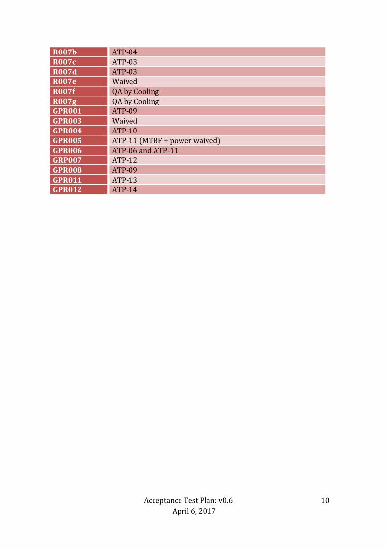
R007b ATP-04
R007c ATP-03 R007d ATP-03
R007e Waived
R007f QA by Cooling R007g QA by Cooling
GPR001 ATP-09 GPR003 Waived
GPR004 ATP-10 GPR005 ATP-11 (MTBF + power waived)
GPR006 ATP-06 and ATP-11
GRP007 ATP-12 GPR008 ATP-09
GPR011 ATP-13 GPR012 ATP-14

Acceptance Test Plan: v0.6
April 6, 2017
11
Deliverables
D000: PDR https://sites.lafayette.edu/ece492-sp17/files/2017/01/PDR_Presentation_v2.pdf
D001: CDR https://sites.lafayette.edu/ece492-sp17/files/2017/02/2017_CDR_Presentation.pdf
D002: User Manuals
D003: Maintenance Manual

Acceptance Test Plan: v0.6
April 6, 2017
12
Maintenance manual
Attach link to each of the maintenance manuals for this document.

Acceptance Test Plan: v0.6
April 6, 2017
13
D004: ATP
http://sites.lafayette.edu/ece492-sp17/testing/atp/
D005: ATR
Attach link to the ATR.
D007: Project Website
Attach link to the site for each document required.
D008: Final Presentation and Delivery
Links to the final presentation provided. Link to the video.

Acceptance Test Plan: v0.6
April 6, 2017
14
D009: Conference Paper, Presentation, and Video
Link to the paper. Link to the video.

Acceptance Test Plan: v0.6
April 6, 2017
15
D012: Software Maintainability Plan https://sites.lafayette.edu/ece492-sp17/files/2017/02/MaintainabilityPlanFinal.pdf
D013: Purchasing Report
Link to purchasing reports provided.
D014: Project Management and Status Letters
Link to WBS and status letter provided.

Acceptance Test Plan: v0.6
April 6, 2017
16
Waived or modified requirements and questions Requirement Reason
R003a(4) Cannot tell if GLV is from the battery or 24VDC
R002h Cannot tell if GLV is from the battery or 24VDC R007e Waived
R005d We’ve changed the switches
R002l Waived GPR003 Waived
GPR005 (Power and MTBF/MTTR waived)

Acceptance Test Plan: v0.6
April 6, 2017
17
ATP-01 checklist: Accumulator integration Test Pass
a) Packs can deliver 200A through TSI b) Voltage measured at TSVMP is as expected c) Throttle controls RPM d) Throttle implausibility causes exit of drive mode e) Two moves required to enter drive mode f) Throttle and brake together prevent drive mode from
starting
g) Throttle and brake together exit drive mode h) TSAL lights come on when HV present outside packs i) TSEL lights come on when AIRS closed j) RTDS come on for 1-3 seconds when drive mode entered k) HV present light comes on when HV present l) Packs display telemetry on screen m) VSCADA can set the throttle n) VSCADA can set the valve on the dyno Pass count: /14 (Test) Variable to measure Value (a) Current according to current sensor (a+l) Current according to pack 1 (a+l) Current according to pack 2 (a+l) Current according to pack 3 (a+l) Current according to pack 4 (a) Current according to TSI (b) Voltage at TSVMP with 50A load (b) Voltage at TSVMP with no draw (c) Max RPM (d) APPS1 voltage at implausibility (d) APPS2 voltage at implausibility (m) Max RPM (n) Max torque

Acceptance Test Plan: v0.6
April 6, 2017
18
ATP-02 checklist: Charging Accumulator Test Pass
a) Safety loop opens when charging b) Dash board shows that packs are charging c) Packs can be left charging after they are full d) VSCADA can acquire charging graphs Pass count: /4 Attach VSCADA data dump showing voltage and current with respect to time. This should be an excel document with data as well as a graph.

Acceptance Test Plan: v0.6
April 6, 2017
19
ATP-03 checklist: CAN Bus link Test Seen by VSCADA Seen by Remote Seen by android Cell Temperature /28 /28 /28 Cell Voltage /28 /28 /28 Pack Current /4 /4 /4 Pack SoC /4 /4 /4 Pack Status /4 /4 /4 Pack Voltage /4 /4 /4 GLV Voltage GLV SoC GLV Current GLV Temperature Safety loop status RPM gauge (Dyno)
Strain gauge Throttle position Brake status IMD resistance FWD/REV status Precharge status MC temp MC current Cooling temp in Cooling flow Cooling temp out TSI temp Speed Safety loop status Pass count: /78 Attach excel document of data for VSCADA receiving data. Attach graphs from the android application. Attach screen shots of the remote computer in operation.

Acceptance Test Plan: v0.6
April 6, 2017
20
ATP-04 checklist: Safety loop Fault Safety
loop trip (Fault lit)
Seen on VSCADA
Seen on Remote
Seen on Android
Driver resettable BRB Non driver resettable BRB Crash protection Over temperature cooling Under flow cooling IMD fault Cell overtemp Cell overcurrent Cell overvoltage Cell undervoltage Brake overtravel VSCADA defined violation Pass count: /48 Add logs from VSCADA showing faults. Add screen shots from the remote computer showing the faults. Add screen shots from the android application showing the faults.

Acceptance Test Plan: v0.6
April 6, 2017
21
ATP-07 checklist: Shutdown Test Pass VSCADA powers up with no user input GLV shutdown prevents TSV being present at TSVMP TSVMS shutdown prevents TSV being present at TSVMP VSCADA has recorded data up to the shutdown TSVMS shutdown while under load does not create any issues Pass count: /5 Shutdown time (yyyy-mm-dd hh:mm:ss UTC): Attach log from VSCADA showing data up until GLV shutdown.

Acceptance Test Plan: v0.6
April 6, 2017
22
ATP-08 checklist: GLV grounding

Acceptance Test Plan: v0.6
April 6, 2017
23
ATP-09 checklist: Documentation For every subassembly in a subsystem this checklist should be completed. I have attempted to capture them all but if there are parts not included they need to be added. Part numbers should go in a tree structure all the way down to commercial parts.
TSV: Pacman
TSV: AMS

Acceptance Test Plan: v0.6
April 6, 2017
24
TSV: Control panel PCB
TSV: Cell Retainer Positive End

Acceptance Test Plan: v0.6
April 6, 2017
25
TSV: Cell Retainer Negative End
TSV: Top Bar of Cell Retainer
TSV: Top Bar of Cell Retainer

Acceptance Test Plan: v0.6
April 6, 2017
26
TSV: Mid Cell Internal Wall
TSV: Mounting Bar of Internal Wall
TSV: Side Bar of Cells

Acceptance Test Plan: v0.6
April 6, 2017
27
TSV: T-Slot Aluminum Extrusion Long
TSV: T-Slot Aluminum Extrusion Short
TSV: Pack Top Negative End

Acceptance Test Plan: v0.6
April 6, 2017
28
TSV: Pack Top Positive End
TSV Front Exterior Side Panel
TSV: Back Exterior Side Panel

Acceptance Test Plan: v0.6
April 6, 2017
29
TSV Internal Bottom Plate
TSV Left Side Panel (PacMAN & Fan)
TSV Connector Panel Negative Side

Acceptance Test Plan: v0.6
April 6, 2017
30
TSV: Connector Panel Positive Side
TSV: Exterior Panel
TSV: LCD Cover Plate

Acceptance Test Plan: v0.6
April 6, 2017
31
TSV: Right Side Panel
TSV: HV to AIRS connector (L-shaped Conductor)
TSV: AIRs Replacement Bar

Acceptance Test Plan: v0.6
April 6, 2017
32
TSV: Relay to fuse connector
TSV: Rounded fuse bus bar (shortened)
TSV: Aluminum Jumper Slotted (Bus Bar)

Acceptance Test Plan: v0.6
April 6, 2017
33
TSV: Middle Aluminum Jumper Slotted (Bus Bar) (Extended)
TSV: Slotted Bus Bar
TSV: LCD Bracket

Acceptance Test Plan: v0.6
April 6, 2017
34
TSV: AIRs Replacement Bar Mount
TSV: AIRs Replacement Bar Mount
TSV: AIRs Extender

Acceptance Test Plan: v0.6
April 6, 2017
35
TSV: Replacement Bar (Mounting)
TSV: Replacement Bar 2 (Mounting)
TSV: Replacement Bar 3 (Mounting)

Acceptance Test Plan: v0.6
April 6, 2017
36
TSV: Replacement Bar 4 (Mounting)
TSV: Top Center Removable Panel (L16-TSV-13.1)
TSV: Pack 1

Acceptance Test Plan: v0.6
April 6, 2017
37
TSV: Pack 2 and Pack 4
TSV: Pack 3
Acceptance Test Plan: v0.6
April 6, 2017
38
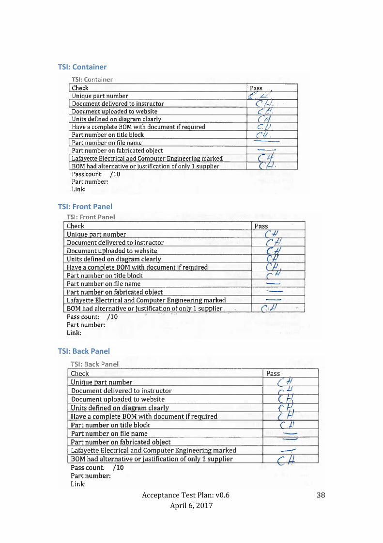
TSI: Container
TSI: Front Panel
TSI: Back Panel

Acceptance Test Plan: v0.6
April 6, 2017
39
TSI: Bus bar 1 (AIR to connector)
TSI: Bus bar 2 (connector to connector)
TSI: PCB

Acceptance Test Plan: v0.6
April 6, 2017
40
TSI: Dyno panel
GLV: Container
GLV: Front panel
Acceptance Test Plan: v0.6
April 6, 2017
41
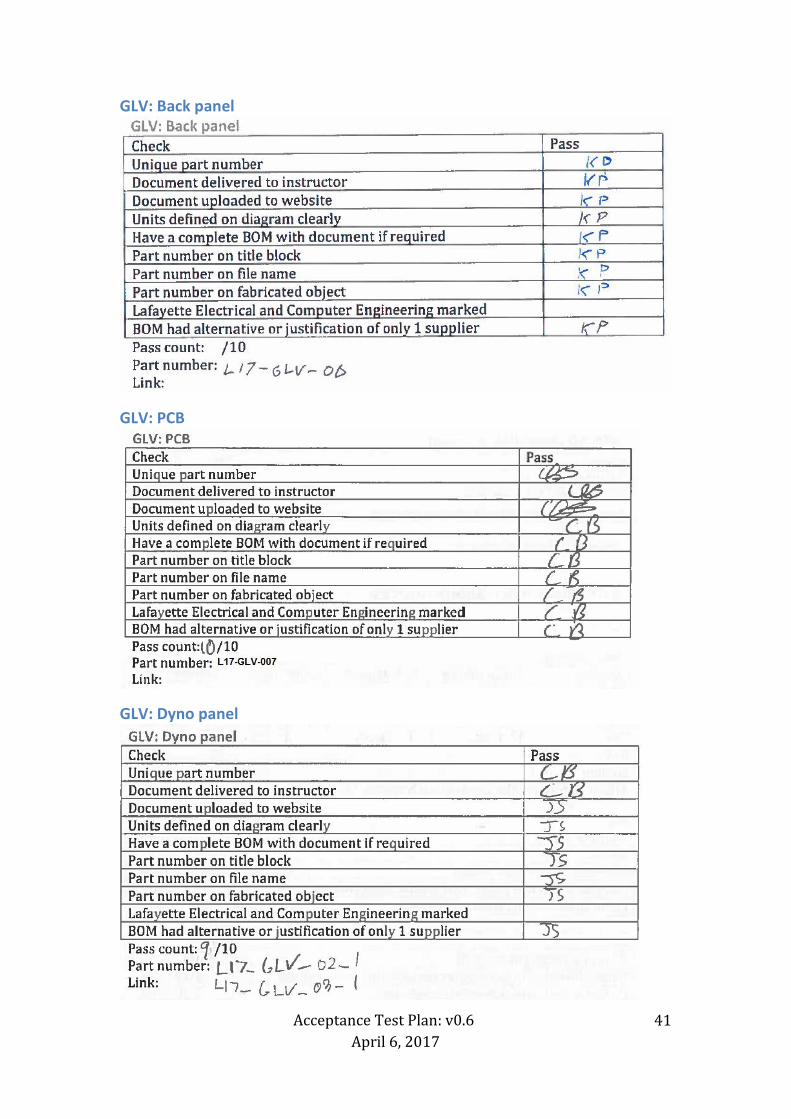
GLV: Back panel
GLV: PCB
GLV: Dyno panel

Acceptance Test Plan: v0.6
April 6, 2017
42
Cooling: Assembly Check Pass Unique part number Document delivered to instructor Document uploaded to website Units defined on diagram clearly Have a complete BOM with document if required Part number on title block Part number on file name Part number on fabricated object Lafayette Electrical and Computer Engineering marked BOM had alternative or justification of only 1 supplier Pass count: /10 Part number: Link:

Acceptance Test Plan: v0.6
April 6, 2017
43
ATP-10 checklist: Hazmat
Attach link to hazmat documentation.
ATP-11 checklist: Safety practice
Wires
Internal wiring
Attach pictures of the inside of each system to document.
W1
Attach image as evidence

Acceptance Test Plan: v0.6
April 6, 2017
44
W2
W3

Acceptance Test Plan: v0.6
April 6, 2017
45
W6
W7

Acceptance Test Plan: v0.6
April 6, 2017
46
W11
W12

Acceptance Test Plan: v0.6
April 6, 2017
47
W13
W15 Count: 1 Check Pass Wires correctly color coded GF Cable labeled with gauge/max temperature/max voltage GF Cable labeled with reference designator GF Pass count: /3 Attach image as evidence
W18
W20
W21

Acceptance Test Plan: v0.6
April 6, 2017
48
W22 Count: 1 Check Pass Wires correctly color coded GF Cable labeled with gauge/max temperature/max voltage GF Cable labeled with reference designator GF Pass count: /3 Attach image as evidence
W23
W24 Count: 1 Check Pass Wires correctly color coded GF Cable labeled with gauge/max temperature/max voltage GF Cable labeled with reference designator GF Pass count: /3 Attach image as evidence
W25
W26

Acceptance Test Plan: v0.6
April 6, 2017
49
W28
W31

Acceptance Test Plan: v0.6
April 6, 2017
50
W32
W33
W34
W35
W36

Acceptance Test Plan: v0.6
April 6, 2017
51
Indicators
IMD fault light
Pass count: /4 Attach image of illuminated light
Fault light

Acceptance Test Plan: v0.6
April 6, 2017
52
AIRs Light
Drive light
Pass count: /4 Attach image of illuminated light

Acceptance Test Plan: v0.6
April 6, 2017
53
Safety Light

Acceptance Test Plan: v0.6
April 6, 2017
54
Cruise light
Check Pass Clear indicator of function Green LED Located in cockpit Illuminates when cruise mode entered Pass count: /4 Attach image of illuminated light
High Voltage Present light
Check Pass Clear indicator of function Red LED Located in cockpit Illuminates when HV outside of packs Pass count: /4 Attach image of illuminated light
Grounded Low Voltage Present Light
Acceptance Test Plan: v0.6
April 6, 2017
55
Tractive System Energized Light
Check Pass 2Hz-5Hz frequency when on Amber strobe Located on dyno specific panel (will be on car in future) Illuminates when AIRs closed Pass count: /4 Attach image of illuminated light
Tractive System Active Light
Check Pass 2 lights present (LHS + RHS) Red lights Located on dyno specific panel (will be on car in future) Illuminates when HV present outside of car Pass count: /4 Attach image of illuminated light

Acceptance Test Plan: v0.6
April 6, 2017
56
Brake light
Check Pass 1 light present Red light Located on dyno specific panel (will be on car in future) Illuminates when brake pressed and GLV on Pass count: /4 Attach image of illuminated light
Buttons and switches
Driver Reset

Acceptance Test Plan: v0.6
April 6, 2017
57
Driver BRB
Inertial switch
Pass count: /4 Attach image of button/switch:

Acceptance Test Plan: v0.6
April 6, 2017
58
Drive Button

Acceptance Test Plan: v0.6
April 6, 2017
59
Cruise button

Acceptance Test Plan: v0.6
April 6, 2017
60
Scroll button

Acceptance Test Plan: v0.6
April 6, 2017
61
Select Button

Acceptance Test Plan: v0.6
April 6, 2017
62
GLV Master Switch

Acceptance Test Plan: v0.6
April 6, 2017
63
TSV Master Switch

Acceptance Test Plan: v0.6
April 6, 2017
64
RHSBRB
Acceptance Test Plan: v0.6
April 6, 2017
65
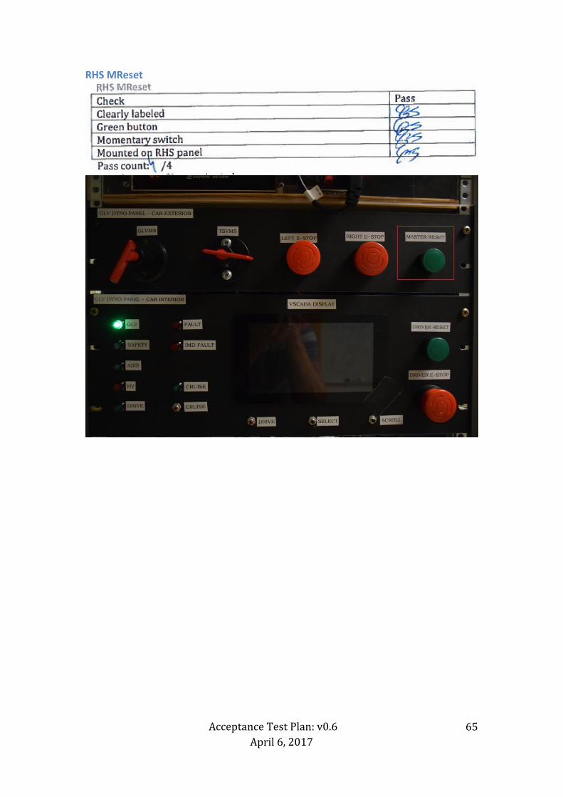
RHS MReset

Acceptance Test Plan: v0.6
April 6, 2017
66
LHSBRB

Acceptance Test Plan: v0.6
April 6, 2017
67
PCBs
AMS

Acceptance Test Plan: v0.6
April 6, 2017
68
Pacman

Acceptance Test Plan: v0.6
April 6, 2017
69
TSV Control Panel PCB

Acceptance Test Plan: v0.6
April 6, 2017
70
TSI PCB
GLV PCB

Acceptance Test Plan: v0.6
April 6, 2017
71
Fuses
Accumulator Fuse

Acceptance Test Plan: v0.6
April 6, 2017
72
Accumulator Blade Fuses

Acceptance Test Plan: v0.6
April 6, 2017
73
Pacman Fuse
TSI precharge relay fuse

Acceptance Test Plan: v0.6
April 6, 2017
74
Enclosures
Pack
TSI
GLV

Acceptance Test Plan: v0.6
April 6, 2017
75
ATP-12 checklist: Maintainability
Software
Pacman code
AMS code
VSCADA code
Pass count: /9

Acceptance Test Plan: v0.6
April 6, 2017
76
Cell application code
TSI code
Remote software code
Pass count: /9

Acceptance Test Plan: v0.6
April 6, 2017
77
ATP-13 checklist: Demonstration
Pass count: /5 Attach link to video, slides and image of display.

Acceptance Test Plan: v0.6
April 6, 2017
78
Appendix A
Final report
Check Completed Maintenance manuals completed 3x DVD presented (or flash drive) DVD artwork ATP-09 completed Attach image of DVD or flash drive. Attach link to the final report with all of the documentation.
D010: Project Poster Check Completed Poster dimensions 47"x35" QR code to webpage Web link present Link to the poster provided.
ATP-14 checklist: Disposal Check Pass All materials stored in the same room Webpage updated to a final version Old material removed from webpage Test equipment returned Trash cleaned in 400 and 401 Items disposed in accordance with Hazmat procedures Paper recycled Webpage matches demonstration Pass count: /8 Attach link to disposal procedure. Attach image of clean lab at the end.

Acceptance Test Plan: v0.6
April 6, 2017
Formula-Hybrid 2016 Electrical Inspection
Note: Preliminary Electrical Inspection must be completed before mechanical inspection or performing any work on the vehicle. Team # School:
Date Started: Vehicle Name:
Time Started: Team Leader(s):
Faculty Advisor(s):
Rules and Safety Officer (RSO)
RSO Name:
Cell Phone Number:
Backup RSO:
Backup RSO Cell Phone Number:
Date and Time Signoff By Inspector Preliminary:
Accum. Energy & Fuel Allocation:
Safety & Charging (EV8 - Team Garage):
Documentation: ESF & FMEA
Full Electrical (Documentation):
Full Electrical (Inspection):
Full Electrical (Pouch Cells):
Full Electrical (Demonstration):
Rain Test:
Approved to Compete (Chief Inspector):
Notes
FH-2016 Rev - CoverPage Page 1 of 16

Acceptance Test Plan: v0.6
April 6, 2017
80
Accumulator Data
ACCUMULATOR DATA FOR BATTERIES
Chemistry: Manufacturer: Part/Model number:
Nominal Cell Voltage
Datasheet Value V. At 2C rate: V@80%soc= V V@20%soc= V Average = V
Nominal Cell AH
AH at 2C Rate AH (2C is twice the cell capacity in Amps, or the current for a discharge time of 0.5h)
Nominal Cell Capacity Wh using [ ] Datasheet or [ ] Average V
Configuration
P/S Code: In Series: In Parallel: Total Cells:
Total Rated Capacity: Wh FH Fuel Equivalency Capacity (Wh x 0.8): Wh (FH Rules Appendix A) Battery chemistry: Does cell contain metallic Li? Yes[ ] No [ ]
Segment Energy Limit (EV3.3.3, Table 9): MJ Wh Number of Cells in Segment
ACCUMULATOR DATA FOR CAPACITORS
Chemistry: Manufacturer: Part/Model number:
Capacity Per Unit
[Cell] / [Module] Capacity (F): Maximum Operating Voltage (V):
Configuration
P/S Code: In Series: In Parallel: Total [Cells]/[Modules]:
Overall Capacity
# Strings Farads per String: String Max Voltage (V)
FH Fuel Equiv. Rating
Rated Capacity: Wh See FH Rules Appendix A.
Segment Energy Limit (EV3.3.3, Table 9): MJ Wh Number of Cells in Segment
Notes/Actions
FH-2016 Rev - Accumulator Data Page 2 of 16

Acceptance Test Plan: v0.6
April 6, 2017
81
Preliminary Electrical Inspection (required prior to Mechanical Inspection)
Complies
Ref
Summary
Type
FH Inspector
Initials
Verify the following information is contained within the vehicle's documentation/ESF:
[ESF paragraphs noted, as applicable]
Operating Voltage: [ESF Section 1] Pre 1.2.1 Maximum operating voltage is 300V
Pre 1.2.2 GLV voltage is less than 30 Vdc or 25 Vac
Safety Circuit: [ESF Section 6.1] Pre 5.1.1 TS shutdown circuit directly carries AIR coil current, including master, shutdown switches.
Pre
5.1.2
The shutdown circuit consists of at least 2 master switches, 3 shut-down buttons, the brake-over-travel-switch, the
insulation monitoring device (IMD), all required interlocks and the accumulator management system (AMS).
Pre 5.5.2
5.5.4
Big Red Buttons must open the safety loop when pushed and must not act through logic or a microcontroller. Normally- closed, push-pull or push-rotate are all acceptable BRBs.
Pre
5.5.3 Pressing any shutdown button must open the shutdown circuit, open the AIRs, kill the engine and fuel pumps (See Table
37 for Shutdown Priority Table).
Pre
5.6.2
5.7.2
5.7.3
Side mounted red buttons must shut down ALL electrical systems (with the exception of the engine starter). Control, telemetry, and instrumentation MAY remain energized if the cockpit BRB is depressed. Refer to Table 16
Pre
5.3.1
5.3.2
The GLVMS:
(a) disables power to ALL electrical circuits, including the alternator, lights, fuel pump(s), ignition and electrical controls.
(b) All GLV (i.e battery, alternator) current must flow through this switch.
Pre
5.4.1
5.4.2
5.4.3
The TSMS: (a) must be the last switch in the safety loop carrying the holding current to the AIRs.
(b) must be identified with a sticker of a red lightning bolt in a blue triangle (see Figure 34)
Pre
5.5.6 Electronic systems that contain internal energy storage (i.e. hold-up energy to allow an orderly shutdown of the system
upon loss of the GLV) must be prevented from back-feeding power onto the GLV.
Indicator Operation: [ESF Sections 5.10, 6.6, 6.7]
Pre 3.4.7
3.4.8
REMOVABLE ACCUMULATOR CONTAINERS ONLY: Accumulator Voltage indicator is directly controlled by HV, not
software or the AIR control signal
Pre 4.10.1 The car is equipped with a TSEL which must be lit and clearly visible any time the AIR coils are energized
Pre
4.12.3
TSVP must be directly controlled by voltage being present at the output of the accumulator (no Software control is permitted). No TS voltage is present at the TSVP. If isolated DC/DC converter used, output of converter is ground
referenced
TSMPs: [ESF Section 1]
Pre
4.4.5
The ESF shows where the TSMPs are connected to the positive and negative motor controller or inverter supply lines.
Pre 4.4.6 Each TSMP is protected with an appropriately rated current limiting device (e.g., fuse or resistor).
Pre
Ensure Fuse Table is attached to the ESF. Complete review will happen during the documentation stage in full inspection
FH-2016 Rev - Preliminary Page 3 of 16

Acceptance Test Plan: v0.6
April 6, 2017
82
Preliminary Electrical Inspection (required prior to Mechanical Inspection)
Complies
Ref
Summary
Type
FH Inspector
Initials
Inspect the vehicle for the following:
Ground Low Voltage: Pre 1.2.3 The GLV system is grounded to the chassis
Pre 6.1.5 GLV System is properly fused within close proximity to power sources (i.e. battery, alternator, etc).
Pre 3.8.1 GLV battery is securely attached to frame
Pre
3.8.5
One terminal of GLV battery securely fastened to frame using adequate size/length wire and robustly connected?
Pre 3.8.3 Non-grounded GLV battery terminal is insulated
Vehicle Grounding:
Pre
4.3.1
Except for components of the GLV system, all metal parts accessible when the vehicle is configured for driving,
maintenance, or charging have a resistance below 300 milliohm (measured at 1 amp) to the GLV system ground.
Pre
4.3.2
All accessible parts of the vehicle containing conductive material (including coated metal parts or carbon-fiber parts)
which might contact a damaged wire or electrical part, have a resistance below 100 ohm to the GLV system ground. If no
convenient conductive point is available for testing, then an area of coating may be removed to create one.
Pre 4.3.3 Conductors used for grounding shall be stranded and 16 AWG minimum.
Tractive System Wiring: Pre T4.5.1 There is no HV or TS wiring in the driver's compartment (Whether contained within conduit or not)
Pre
4.5.1 All parts of the TS circuity are protected by electrically insulating material. When the TS enclosures are in place, no
conductive part of the TS circuitry can be touched with a 6 x 100 mm probe.
TSMPs:
Pre 4.4.1
4.4.4
Two 4 mm, shrouded, banana-jack TSMPs are installed in an easily accessible well marked location. Access must not
require the removal of body panels.
Pre 4.4.2 The TSMPs are protected by a non-conductive housing that can be opened without tools.
Pre
4.4.3
The TSMP must be protected from being touched with the bare hand / fingers, even when the housing is opened.
Pre 4.4.8 4.4.9 A shrouded, 4mm, banana-jack GLV ground terminal is available near the TSMP.
Indicators and Safety Labels: Pre 4.6.1 A High Voltage sticker is applied to every container if TS voltage is > 30 Vdc
Pre 4.10.1 4.10.4 The TSEL is mounted under the highest point of the main roll hoop and helmet must not contact the TSEL
Pre 4.10.7 There are no other lights mounted in proximity to the TSEL.
Pre
3.4.7 REMOVABLE ACCUMULATOR CONTAINERS ONLY: There is a prominent indicator for voltage > 30V (LED or analog) when AIRs are closed
Safety Components: Pre 5.2.1 There is both a Grounded Low Voltage Master Switch (GLVMS) and a Tractive System Master Switch (TSMS).
Pre
5.2.2 The GLVMS and TSMS are located on the right side of the vehicle, in proximity to the Main Hoop, at the driver’s shoulder height and is easily actuated from outside the car.
Pre 5.2.4 The GLVMS and TSMS are direct acting, i.e. it cannot act through a relay or logic.
Pre 5.2.3 Both master switches must be of the rotary type, with a red, removable key.
Pre 5.2.5 The master switches are not mounted onto removable body work, etc.
Pre 5.2.6 The function of both switches is clearly marked with “GLV” and “TSV”.
Pre 5.5.1 Three shut-down buttons are installed on the vehicle (left, right and cockpit).
Pre
5.6.1
One big red button is located on each side of the vehicle behind the driver’s compartment at approximately the level of the driver’s head. The minimum allowed diameter of the shutdown buttons on both sides of the car is 40 mm.
Pre 5.7.1
5.7.5
The cockpit-mounted master switch must be easily accessible by the driver in any steering wheel position. The minimum allowed diameter of the shutdown button in the cockpit is 24 mm.
Pre 5.5.5 The shutdown buttons are not to be mounted onto removable body work,etc.
FH-2016 Rev - Preliminary Page 4 of 16

Acceptance Test Plan: v0.6
April 6, 2017
83
Preliminary Electrical Inspection (required prior to Mechanical Inspection)
Complies
Ref
Summary
Type
FH Inspector
Initials
The following is the Preliminary Demonstration. The team should be able to perform the following actions upon request. Ability to
complete these actions constitutes passing the applicable rules.
Pre A6.4.2 Team should demonstrate their jack stand procedure. (Quick jack is not allowed for powered testing)
Pre A6.4.2 4.7.5
RSO should explain and team should demonstrate their Lock-Out/Tag Out procedure
Pre
4.8.2 With meter attached to TSMPs, team should energize car. There should be a second action to put the car into “Ready-To- Drive” mode (Full demonstration of this requirement will happen during Full Inspection)
Pre 4.11 “Ready-To-Drive” Sound occurs
Pre
4.10
TSEL is activated when AIR coils are energized: -Brightness
-Color
-Flash Rate
-Position
Pre
4.12
TSVP light -Location
-Color
-TSVP is activated when accumulator voltage is greater than 32VDC or 1/3 max tractive
system bus voltage (whichever is higher)
Pre 5.2.7 Ensure both master switches are parallel to the fore-aft axis of the vehicle
Pre
5.1.3
5.5.2
5.5.3
5.7.4
Check operation of Big Red Buttons (repeat for each button) - Voltage should be <30V in less than 5 seconds. Time Measured
- Voltage meter or indicator on accumulator indicates HV until output is <30V
-Cockpit button is resettable
Note: Preliminary Inspection Demonstration may be repeated during Full Inspection if there is any question of safety circuit operation
The following is for REFERENCE ONLY with regards to demonstration requirements.
A6.4.2 Jack Stand Procedure (Quick Jack is not permitted for powered testing)
A6.4.2 4.7.5 RSO can explain and team should demonstrate their Lock-Out/Tag-Out Procedure
Ready to Drive Sound
4.11.1 The car must make a characteristic sound, for a minimum of 1 second and a maximum of 3 seconds, when it is ready to
drive.
4.11.2 The sound emitting device must produce a tone between 2500-3500Hz at 68dB(A) at 2Ft, or be a Mallory Sonalert SC648AJR or equivalent.
Indicators:
4.10.5 The TSEL is clearly visible from all horizontal directions even in bright sunlight.
4.10.2 4.10.3 The TSEL is amber and flashes continuously with a frequency of 2-5 Hz.
4.10.6 The TSEL must be visible from a person standing up to 3m away from the TSAL itself. The person's minimum eye height is
1.6m.
4.12 Two TSVP lights are present. Each TSVP must be each side of the roll bar near the shutdown buttons and easily seen from the side of the vehicle
4.12.1 TSVP must be red and comply with DOT FMVSS 108 for trailer clearence lamps
4.12.2 TSVP must be lit and visible any time the voltage outside of the accumulator container exceeds 32VDC or 1/3 maximum
tractive bus voltage (whichever is higher)
FH-2016 Rev - Preliminary Page 5 of 16
Acceptance Test Plan: v0.6
April 6, 2017
84
Preliminary Electrical Inspection (required prior to Mechanical Inspection)
Complies
Ref
Summary
Type
FH Inspector
Initials
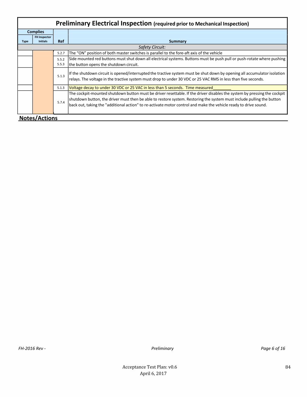
Safety Circuit:
5.2.7 The “ON” position of both master switches is parallel to the fore-aft axis of the vehicle
5.5.2
5.5.3
Side mounted red buttons must shut down all electrical systems. Buttons must be push pull or push-rotate where pushing
the button opens the shutdown circuit.
5.1.3
If the shutdown circuit is opened/interrupted the tractive system must be shut down by opening all accumulator isolation
relays. The voltage in the tractive system must drop to under 30 VDC or 25 VAC RMS in less than five seconds.
5.1.3 Voltage decay to under 30 VDC or 25 VAC in less than 5 seconds. Time measured
5.7.4
The cockpit-mounted shutdown button must be driver resettable. If the driver disables the system by pressing the cockpit
shutdown button, the driver must then be able to restore system. Restoring the system must include pulling the button
back out, taking the "additional action" to re-activate motor control and make the vehicle ready to drive sound.
Notes/Actions
FH-2016 Rev - Preliminary Page 6 of 16

Acceptance Test Plan: v0.6
April 6, 2017
85
Full Inspection: Documentation/ESF Complies
Ref
Summary
Type
FH Inspector
Initials
Verify the following information is contained within the vehicle's documentation/ESF: [ESF paragraphs noted, as applicable]
Fusing: Doc 6.1.1 All electrical systems must be properly fused
Doc
6.1.2 All conductors must be fused with a fuse rating <= current rating of conductor. Note: to know whether a vehicle passes this item, you do not need to consider the current that actually flows.
Doc 6.1.3 All fuses and holders must be rated for the highest voltage in the system they protect Doc 6.1.4 Interrupt rating of fuses must be greater than short circuit current. Doc 6.1.6 Branch circuits must be fused if the branch wire is too small to be protected by the main fuse
Doc 3.6.5 Series fuses must have lower rating than isolation relays (AIRs) Doc 6.1.7 Parallel cells in a battery or cap bank individually fused or certification from mfr. attached.
Doc
6.1.8 Parallel strings in a battery or capacitor bank individually fused; full-current conductors sized for sum of ratings or
separately fused.
Doc
6.1.9
6.1.10
Are any fusible links OR internal cell protection used for paralleling? If so attach documentation of 6.1.7 a,b,c.
Doc 6.1.11 Attach fusing table. All pertinent fuse information is in ESF
Motors: [ESF Section 4.1] Doc A.2.1.1 Motor is electric
4.2.3 Does the vehicle have outboard wheel motors Yes [ ] No [ ]. If Yes:
Doc Are the wheel motors interlocked for damage scenarios.
Isolation and Insulation:
Doc 1.2.4
1.2.5
The Tractive System is galvanically isolated from the GLV system and chassis and other conductive parts of the car.
Doc 3.7.5 GLV connections to the AMS are galvanically isolated.
Doc
4.5.4
All controls, indicators and data acquisition connections or similar must be galvanically isolated from the TS.
Doc
3.7.6 External connections (i.e. laptop) to tractive system components are galvanically isolated with connection to frame ground. Documented in ESF
Doc 2.3.1 Accelerator/Motor Controller Inputs are galvanically isolated from TS
Doc 1.2.6 The tractive system motor(s) is connected to the accumulator through a motor controller.
Doc 1.3.1 Electrical insulating materials are UL (or equivalent) listed.
Doc
4.5.10 Conduit is UL Listed for conduit. Not UL Recognized, and not sleeving. (NMPT-B is allowable only in limited situations)
Doc 1.3.1
1.3.2
Insulating material temperature rating is appropriate for location AND greater than 90C. Isolation between GLV and
TS is rated for 150C
Doc
4.5.5 Appropriately insulation materials have been used for the intended vehicle location. None are below 90C. No electrical tape or coatings are used alone for insulation.
Doc
4.5.6
All wires, terminals, and conductors used in the HV are appropriate for the application and thus marked: (1) sized appropriately for the continuous current rating of the fuse protecting them and marked with the current or wire
gauge, (2) temperature rated for their environment (at least 90C) (3) insulation voltage rating. The lowest insulation voltage is V. Part numbers or standards designations printed on parts are documented in the Electrical design report, if needed.
Doc
4.1.1
The electrical design report contains PCB TS-GLV isolation information, including photographs if necessary.
Doc
4.1.7
4.1.8
On each team designed PCB, TS and GLV circuits are on separate, clearly-marked areas of the board. Spacing
complies with the FH rules. Samples or photos are provided in Electrical design report. All mixed HV-GLVS PCBs are
accessible for inspection.
FH-2016 Rev - Documentation Page 7 of 16

Acceptance Test Plan: v0.6
April 6, 2017
86
FH-2016 Rev - Documentation Page 8 of 16
Full Inspection: Documentation/ESF Complies
Ref
Summary
Type
FH Inspector
Initials
IMD: [ESF section 6.2, 6.3]
Doc 5.9.1
5.9.2 IMD installed is a Bender A-ISOMETER ® iso-F1 IR155-3203 or -3204 or approved equivalent
Doc
5.9.3 The response value of the IMD is set tono less than 500 ohm / volt maximum tractive system operation voltage.
Doc
5.9.4
An insulation fault or IMD failure causes shut down of all electrical systems (with the exception of the engine starter, control, instrumentation and telemetry) and the internal combustion system. Action cannot be controlled
via logic or microcontroller.
Doc
5.9.8 IMD ground connection must be wired according to MFG instructions so the ground detector is functional
AMS: [ESF section 5.8] Doc 3.7.1 Accumulator is monitored when both active and charging. Doc 3.7.2 AMS measures sufficient cell voltages (1 cell for lithium, 6 cells for PbA & NiMH)
Doc 3.7.3
3.7.7 AMS measures sufficient and representative cell temperatures per Table 12.
Doc 3.7.4 AMS voltage sense wires are appropriately protected by fuses or resistors Doc 3.7.9 Is AMS team designed? If so, does it comply with all the requirements of EV3.6.9? (Consult rule book)
Accumulator and Accumulator Container: [ESF Sections 5]
Doc
3.1.1
Acceptable technologies: Lithium Ion Batteries, NiMH Batteries, Lead Acid Batteries, Rechargeable Batteries not listed below, Capacitors, Ultracaps, Supercaps
Technologies NOT permitted: Molten Salt Batteries, Thermal Batteries, Fuel Cells, Atomic Batteries, Mechanical
Flywheel Batteries
Doc
3.1.2 Have manufacturer's data sheets showing accumulator rating been submitted?
Doc
App F MSDS Sheets for Accumulator
Doc
3.4.3 Segment isolation meets requirements (<120V and 6MJ)? Note that this is rated energy, not FH capacity. No tools
required to isolate the segments
Doc
3.5.2 Mounting system is designed to withstand 20g horizontal and 10g vertical (Min 4 Bolts for tube cars, see 3.5.2 for monocoque)
Doc
3.5.5 Container material is fire-resistant
Doc 3.5.7 Segments are separated with insulating barrier. For all Lithium based cells, must also be fire-resistant
Doc
3.4.2 Each accumulator container contains at least one fuse?
Doc
3.6.1 At least two isolation relays must be installed in every accumulator container
Doc 3.6.2 Relays must open both poles of accumulator Doc 3.6.4 Isolation relays are of "normally open" type. Doc 3.6.6 Relays containing mercury are not permitted Doc 4.7.1 An HVD is provided to quickly disconnect the accumulator, independently of the AIR.
Doc
3.4.10 There are no unnecessary GLV circuits in the accumulator container. AMS and AIR circuitry is acceptable. Must explain in ESF.
Pre-Charge/Discharge: [ESF sections 5.11]
Doc
4.9.1 The vehicle has a means of precharging the intermediate circuit to at least 90% of the current accumulator voltage before closing the last AIR.
Doc 4.9.2 A pre-charge sequence using time is acceptable (describe method).
Doc
4.9.3 If a discharge circuit is needed for EV5.1.3, the team has shown the calculations demonstrating that it is designed to handle the maximum discharge current for at least 15 seconds.
Doc
4.9.4 The discharge circuit is wired so it is always active whenever the shutdown circuit is open. The discharge circuit is fail-safe.
Doc
4.9.6 Pre-Charge circuitry always on discharge circuits, or components that dissipate significant power must rated for maximum expected operating temperature and documented in ESF

Acceptance Test Plan: v0.6
April 6, 2017
87
Full Inspection: Documentation/ESF Complies
Ref
Summary
Type
FH Inspector
Initials
GLV/Torque Control: [ESF Sections 7]
Doc
3.8.4 Is GLV battery team-built lithium? If so, is protection described in ESF? Battery must have OV/UV/SC and Over Temp protection (Review)
Doc
2.2.1
All analog torque control signals must have continuous error checking which can detect open circuit, short to
ground and short to sensor power and will shut down the torque production when a fault is detected
2.3.2 Accelerator/Motor Controller bonded to GLV Ground (i.e. negative/common tied to ground) … Digital pedal position encoders must incorporate error checking
… All digital communications directly controlling torque production must have a timeout such that is a valid command is not received, torque production in shut down
General: Doc 4.1.1 Electrical device layout is documented accurately in the ESF Doc 9.1 FMEA is present and complete Doc 4.1.1 Electrical design report is complete, understandable, and correct. (Use back for comments).
Notes/Actions
FH-2016 Rev - Documentation Page 9 of 16

Acceptance Test Plan: v0.6
April 6, 2017
88
Full Electrical: Inspection
Complies
Ref
Summary
Type
FH Inspector
Initials
Inspect the vehicle for the following: Note: Those items with an * require special attention to ensure safety of tractive system.
TS Wiring:
Insp*
4.5.2 Nonconductive covers prevent inadvertent contact with any TS circuitry. Covers are secure and rigid. No body
panels function as the sole TS circuitry insulation.
Insp*
4.5.7
All TS wiring technique is to professional standards and with adequate strain relief and protection from loosening
due to vibration, etc. Conductors and terminals have not been modified from their original size and shape and are
appropriate for the use.
Insp*
4.5.15
All HV circuitry uses current paths through conventional conductor materials, such as copper or aluminum. No
structural components or fasteners are used as primary conductors. No clamped connections in stressed, statically
indeterminate stack-ups include materials subject to creep or plastic deformation.
Insp* 4.5.17 TS wiring must be mechanically shielded against damage from rotating or moving parts
Insp
4.2.1
All TS parts, cables, and wiring are contained within the frame, and protected from crash or roll-over per rule 4.2.1
Insp 4.2.2 If subject to potential side or rear impact, TS parts must be protected per T3.3.
Insp
4.2.4
No TS components project below the lower surface of the frame or monocoque, visible from the side or front.
Insp*
4.5.8
4.5.9
All TS wiring running outside of electrical enclosures is shielded, double insulated cable or enclosed in separate, orange, nonconductive conduit. Tractive System wiring greater than 25mm^2 may be run outside of conduit if
shielded and properly terminated.
Insp
4.5.13
If shielded double insulated cable used, location of cabling is within the frame of the vehicle. Cabling outside the
frame but within the surface envelope of the vehicle must be in conduit or connected to wheel motors
Insp*
4.5.16
If shielded double insulated cable used, all shields are properly terminated on both ends and connected to chassis.
Insp
4.5.10 Conduit is UL Listed for conduit. Not UL Recognized, and not sleeving. (NMPT-B is allowable only in limited situations)
Insp
4.5.12 TSV Conduit or cable is securely anchored at least at each end so that it can withstand a force of 200N without straining the cable, and must be located out of the way of possible snagging or damage.
Insp
4.5.12 Fittings/connectors must be appropriate for the conduit/cable used for the TSV. See EV4.5 for special exceptions for wheel motors
Insp 4.5.3 TS components and their containers are protected from rain or splash moisture. TS/GLV Separation
Insp 4.1.2 There is no connection between the frame or other conductive surface and the TS circuits. Insp 4.1.3 There are no GLV circuits in the HV conduit or connector (except interlock connections).
Insp
4.1.5 Within each enclosure, TS and GLV circuits are separated by UL recognized 150° C insulating barriers or maintain spacing (See Table 15).
Insp 4.1.6 TS and GLV spacing is clearly evident. Parts and wires are positively secured to maintain spacing.
Insp
4.1.9
4.1.10
Bare perforated boards with both TS and GLV are inspectable and meet spacing requirements. Plated perforated board or generic conductor patterns may not be used.
HVD Insp 4.7.3 The HVD is clearly marked "HVD".
Insp
4.7.4 Positive means of securing HVD in disconnected state exists (lockable switch, removable plug if it can't accidently connect). Procedure exist in ESF for the HVD
Firewall: Insp T4.5.1 Firewalls separate driver's compartment from accumulators and lithium GLV batteries Insp 4.3 Firewalls comply with EV4.3 grounding requirements (<300mOhm if metallic, <100 ohm carbon fiber) Insp T4.5.1 Firewalls separate the driver compartment from all HV components. Insp 4.2.5 There is insulating material between tractive system terminals and firewall if within 2"
FH-2016 Rev - Inspection Page 10 of 16

Acceptance Test Plan: v0.6
April 6, 2017
89
Accumulator and Accumulator Container Insp 3.2.1 Accumulator is segmented and enclosed?
3.2.2 Are there spare accumulators? Yes [ ] No [ ] If Yes then:
Insp Are spare accumulators identical to vehicle units and presented for inspection?
3.2.3 Are accumulator contents accessible? Yes [ ] No [ ] if No then:
Insp Are adequate photos provided? Insp 3.4.1 Is cell to container (if conductive) insulation adequate? Insp 3.4.1 External conductive container surfaces are grounded?
Insp
3.4.1 If conductive penetration of container are present, they are located outside of and cannot penetrate insulative barrier
Insp
3.4.4
3.4.5
SMD Connect (if needed) is a switch or a removable plug and has positive means to ensure SMD remains in
disconnected state
Note: Use of Tools to isolate segments in NOT acceptable
Insp
3.4.3 Segment isolation means meets requirements (<120V and 6MJ energy)? Note that this is rated energy, not FH capacity.
Insp 3.4.6 There are no soldered connections to cells in the high current path
Insp
3.4.9 Minimum Spacing/Creep Distance for conductive materials, including cell to cell connections in accumulator meets Table 10
Insp 3.5.1 Container is rugged and rigidly-mounted. Insp 3.5.3 Containers are within surface envelope (See IC1.5.1 for envelope) Insp 3.5.4 Materials are mechanically robust Insp 3.5.6 Cells are appropriately secured using mechanical fasteners Insp 3.5.7 Segments are separated with insulating barrier. For Lithium based cells, must also be fire resistant Insp 3.5.8 Holes only for wiring, ventilation, cooling or fasteners. See EV4.5 Insp 3.4.9 Container must adequately enclose accumulator Insp 3.5.10 An accumulator that can vent explosive gas must have a ventilation system, or.. Insp 3.5.11 Sealed accumulators must have pressure release valves Insp 3.6.1 At least two isolation relays must be installed in every accumulator container Insp 3.6.3 When open, no TS Voltage may be present outside container, including to AMS.
Insp
4.1.4 There are no unnecessary GLV circuits in the accumulator container. AMS and AIR circuitry is acceptable. Must explain in ESF.
Insp 3.5.9 Accumulator is marked "High Voltage" sticker. See 3.5.9 for sticker guidelines Ground Low Voltage:
Insp 3.8.2 Wet cell GLV batteries in driver's compartment must have container and barrier Insp 4.6.3 All external, uninsulated, heat sinks are grounded to the GLV system ground.
General:
Insp
4.6.1 Every housing or enclosure containing parts of the TS (except motor housings) is labeled with a "High Voltage" sticker.
Insp
4.6.2 All electrically conductive or potentially conductive TS housing materials have a low-resistance (under 300 milliohm) connection to GLV system ground.
Insp
4.5.14 Wheel Motors ONLY: at least one wire of the interlock system must accompany each conduit or cable to wheel motor
Insp
3.7.10
AMS Test Port accessible with jumper/connector for normal operation installed?(Molex or 4 Shrouded Banana)?
Insp 1.3.3 Vinyl electrical tape and rubber-like paints and coatings are not used for insulating materials. Insp 6.1.5 Fuses must be physically located at the end of the wiring closest to an uncontrolled energy source
Insp 6.1 Physically inspect key TS fuses Insp 6.1 Physically inspect key GLV fuses
Notes/Actions
FH-2016 Rev - Inspection Page 11 of 16

Acceptance Test Plan: v0.6
April 6, 2017
90
Full Electrical: Pouch Cells (Not applicable) Complies
Ref
Summary
Type
FH Inspector
Initials
Note: Accumulators utilizing pouch type lithium ion cells are subject to the following rules. Do NOT complete this section if prismatic or cylindrical cells are used.
Doc 3.9 Are pouch type lithium cells used? Yes [ ] No [ ]
Insp 3.9.1 Cells in a stack are arranged face-to-face (Edge-To-Edge is NOT allowed)
Doc
3.9.2 Did team request variance from 3.8.2 from rules committee? Yes [ ] No [ ]. If No, then review documentation for
compliance to 3.8.2 below:
-
Mechanical restraining system of the pouch cell must -Be capable of applying >=10 psi without yielding for all temps <=150°C
-Allow the stack to expand 8%-12% in volume before reaching 10 psi
-Use fire retardant and creep immune materials
-Not impinge on the cell separator internal to the cell
-Be electrically insulated from the cells (if made of conductive materials)
-Documented in the ESF
Insp
3.9.3 A fire resistant soft elastic filler material is present between every cell. Material is evenly distributed through the stack and applying even pressure to each cell surface
Insp 3.9.4 Cell tabs are mechanically restrained and cannot move relative to the cell
Insp
3.9.4 Cell tabs are connected above the level of the tab insulator (metallic parts of the battery assembly may not bridge the insulation gap provided by the tab insulator)
Insp 3.9.4 Cell Tabs are insulated to prevent accidentally short circuit of adjacent cells
Insp
3.9.5 Cells held in position using a repeated frame (or equivalent). Frame does not change shape of the cell, inpinge on the cell separator, or allow the edge of the cell to move in relation to the rest of the cell
Insp
3.9.6
Entire stack is firmly anchored in the accumulator enclosure and clean of shavings or filings from manufacture
Full Electrical: Virtual Accumulator Complies
Ref
Summary
Type
FH Inspector
Initials
Note: Vehicles with multiple interconnected accumulator containers may be considered as a single "Virtual Accumulator Container" if the
Doc
3.3
Does the vehicle has multiple interconnected containers and does team desire for the vehicle for the accumulators to
be considered as a "Virtual Accumulator Container? Yes [ ] No [ ]. If yes, continue with the following inspection
Insp 3.3.5 All accumulators are NOT removable
Insp
3.3.1
3.3.2
The interconnecting conduit that contain high current tractive wiring is red (or painted red) flexible metallic liquid tight steel electrical conduit (NEC type LFMC). Conduit containing GLV, AMS wiring, etc may be red or orange non-
metallic conduit
Insp
3.3.1 The interconnecting conduit is securely fastened at each end with fitting rated for metallic LFMC and are properly grounded to the GLV ground (<300mOhm)
Insp 3.3.3 The interconnecting conduit is supported every 150mm (~6 in)
Insp
3.3.4
Separate interconnecting conduit are used for the following:
(a) Individual Tractive System Conductors (one conductor per "high-current" TSV conductor)
(b) GLV level wiring
(c) AMS wiring (i.e. sense wires that are at TS potential)
Insp
3.3.7 If an interconnecting conduit is the lowest point in the virtual accumulator housing, it has a 3-5mm drain hole in its lowest point
Insp
3.3.8
Accumulator segmentation is satisfied at the individual accumulator level AND at the virtual accumulator level
Notes/Actions
FH-2016 Rev - Specials Page 12 of 16

Acceptance Test Plan: v0.6
April 6, 2017
91
Final Demonstration (See attached procedure that covers these rules)
Complies
Ref
Summary
Type
FH Inspector
Initials
The team should be able to perform any of the following actions upon request.
Ability to complete these actions constitutes passing the applicable rules.
Demo
Step 1
A.6.4.2
Team should demonstrate their jack stand procedure. (Quick jack is not allowed for powered testing)
Demo
Step 2
4.7.5 With meter attached to TSMPs, team should energize car. There should be a second action to put the car into
“Ready-To-Drive” mode (Full demonstration of this requirement will happen during Full Inspection)
Demo Step 3
2.1.1
Ensure torque control is actuated by a right foot pedal.
Demo
Step 4
N/A
Ask team to slightly depress the pedal to show drive wheel will rotate.
Demo Step 5
2.1.2
Ask team to release pedal to demonstrate pedal returns to original position. Ensure presence of positive stop.
Demo Step 6
2.2 Ask team to slightly depress the pedal to rotate drive wheel. Interrupt torque command signal. Torque production should stop within 1 sec . Power down the vehicle
Demo
Step 7
N/A Perform the steps 8-13 to demonstrate safety circuit operation. Note: Each time the car is energized, ensure two
actions must be taken to achieve “Ready to Drive”
Demo
Step 8
5.1.6
5.8
Energize the vehicle. Slightly depress the right foot pedal to rotate wheels. Open the Brake Over Travel Switch. AIRs should open and wheels should spin freely. Ensure the driver cannot reset the brake over travel switch with foot or
hand
Demo
Step 9
1.2.7
Reset Brake Over Travel Switch and energize the vehicle. Open the GLV Master Switch. AIRs should open.
Demo
Step 10
5.4.1
Close GLV Switch and energize the vehicle. Open the TSMS. Air should open
Demo
Step 11
4.8
Close the TSMS and energize the vehicle. Ask the team to open the Big Red Button in the cockpit. AIRs should open. Close the Big Red Button in the cockpit. AIRs should NOT close. Perform second action to achieve “Ready to Drive.”
AIRs should close.
Demo
Step 12
4.9
Open any big red button during the pre-charge stage. Ensure the Pre-charge is disabled.
Demo
Step 13
3.7
With car de-energized, attach AMS test connector. Energize the vehicle. Induce an AMS fault using the potentiometer based on the ESF. AIRs should open. Remove fault. Ask team to reset AMS. Ensure driver cannot
reset AMS.
Demo
Step 14
N/A
Remove meter from TSMP and the AMS test connector. Connect IMD test box
Demo
Step 15
5.9
Induce fault to high pole of TS (level based on TS Voltage). Ensure shutdown occurs within 30 seconds. Fault light in
cockpit should illuminate. Remove fault. Ensure the TS system does not re-energize (i.e. latches off due to fault)
Demo
Step 16
5.9
Induce fault to low side of TS (level based on TS Voltage). Ensure shutdown occurs within 30 seconds. Fault light in
cockpit should illuminate. Remove fault. Ensure the TS system does not re-energize (i.e. latches off due to fault)
Demo
Step 17
5.9.5
Ensure driver cannot reset IMD
Demo
Step 18
4.7
Remove the HVD in under 10 seconds (Ensure no panels could interfere with the HVD removal). Replace HVD
Demo
Step 19
5.5.3
HYBRIDS ONLY (to be performd in a designated area): With the vehicle on the jack stands, enable the IC engine.
Press one of the side mounted BRBs. Ensure the IC engine turns off (Inspector optionally may also use a DMM to
ensure fuel pump is disabed if it is easily accessible. Repeat for the other side mounted button and the cockpit BRB.
FH-2016 Rev - Demonstration Page 13 of 16

Acceptance Test Plan: v0.6
April 6, 2017
92
The following is for REFERENCE ONLY with regards to demonstration requirements.
Torque Control: Demo 2.1.1 Torque control sensor actuated by a right foot pedal
Demo 2.1.2 Foot pedal returns to original position when not actuated and has positive stops to protect sensor
Demo
2.2.1 All plausibility detections schemes must detect and shutdown torque production within 1 second of the errors first occurrence or loss of communication.
Demo
2.2.2 Teams must be prepared to demonstrate error detection at Electrical Tech Inspection. Unplugging a connector is an acceptable method of demonstration
Safety Circuit/Shutdown Demo 5.8.1 The brake over-travel switch shuts down the tractive system, the IC engine and the fuel pumps
Demo 5.8.2 The brake over-travel switch is not driver-resettable
Demo 5.1.6 Check that motor spins freely when TS is deactivated.
Demo
1.2.7 The GLV system must be energized in order to activate the tractive system. If the GLV system shut down, the tractive system must de-activate immediately.
Demo 4.7.6
4.7.6
4.7.7
The team can remove the HVD in under 10 seconds, from the ready-to-drive condition, without the use of tools
Demo
4.8.1 The driver can make the car ready to drive without assistance. For AMS, IMD, or other inaccessible shutdown circuit opens, the drives alone cannot make the car ready-to-drive.
Demo
4.8.1 The driver must be able to re-activate or reset the tractive system from within the cockpit without the assistance of any other person except for situations in which the AMS or IMD have shut down
Demo
4.8.2 At least one action in addition to enabling the shutdown circuits is required to set the car to ready-to-drive mode. A start button shall not be such that it can inadvertently be left in the “on” position.
Demo 4.9.1 The precharge is disabled by an opened shutdown circuit.
Demo
4.9.5 Pre-Charge circuit must operate regardless of the sequence of operation used to energize the vehicle (i.e. restarting after automatic shut down of safety circuit
Demo 5.1.7
5.1.8 Shutdown circuit operates to state diagram in Figure 31
AMS
Demo
3.7.8 AMS disables all electrical systems, disables IC drive system, and opens AIRs until manually reset by other than driver.
Demo 3.7.10 Does AMS trip at level documented in ESF?
IMD
Demo
5.1.5 The driver must not be able to re-activate the tractive system from within the car in case of an AMS or IMD fault. Wireless reset shutdown circuit is not permitted
Demo
5.9.5 TS remains inactive until manually reset by other than the driver (IMD Fault). Driver must not be able to reset an
IMD fault from within the car.
Demo 5.9.6
5.9.7
A red indicator light in the cockpit indicates IMD status. It is visible in bright sunlight, and marked "IMD" or "GFD".
7.1
The IMD test is passed if the IMD shuts down the tractive system within 30 seconds at a fault resistance of 250
ohm/volt (50% below the response value) - Note: Proper wiring proven through successful testing of the IMD
Demo IMD test. Shuts down HV? Latches off? Labeled cockpit light?
Demo
7.2
The insulation resistance between the tractive system and control system ground will be measured during Electrical Tech Inspection. The available measurement voltages are 250 V and 500 V. All cars with a maximum nominal
operation voltage below 500 V will be measured with the next available voltage level. For example, a 175 V system
will be measured with 250 V; a 300 V system will be measured with 500 V etc.
Demo The measured insulation resistance is >= 500 ohm/volt related to the maximum nominal tractive system operation
voltage
Notes/Actions
FH-2016 Rev - Demonstration Page 14 of 16

Acceptance Test Plan: v0.6
April 6, 2017
93
EV8 - High Voltage Procedures and Tools
This form is completed in the team's garage. Complies
Ref
Summary
Type
FH Inspector
Initials
Charging Systems
S&C 8.1.1 Team knows the location of the designated charging area
S&C
EV3.4.3 Are the accumulator energy and voltage levels below the segmentation limit? Yes [ ] No [ ]. Complete Table on
Page EV3.
S&C 8.1.2 Vehicle has maintenance plugs
S&C
8.1.3
8.1.4
Team has appropriate insulated tools for working on the accumulator.
Visible "High Voltage" sign displayed when working on the accumulator
S&C 8.2.5 Has a label prepared complying with EV8.2.4: Team name and Safety Officer phone number(s).
S&C
8.2.6
No exposed connections during charging
S&C
8.2.9
Review Charging Process with Inspector
S&C
8.2.11 High voltage wiring to/from an off board charger is UL listed.
All flexible cables comply with NEC Article 400; double insulated.
S&C 8.2.12 Charger is UL listed (or waiver approved by FHRC)
S&C
8.2.14 Charging port is only energized when the tractive system is energized and TSEL is flashing. Charging system is
disconnected if safety circuit is opened
Accumulator Hand Cart
S&C
8.3.1
Team has accumulator hand cart? Yes [ ] No [ ]. If Yes, then:
S&C
8.3.2
Cart has dead man's switch
S&C
8.3.3
Brake capable of full stop when loaded with accumulator
S&C
8.3.4
Hand cart rated for accumulator load
Required Tools
S&C 8.4
Tools required:
S&C a. Insulated screw drivers
S&C b. Multimeter with protected probe tips
S&C c. Insulated wrenches, if screwed or bolted connections are used in the tractive system
S&C d. Face shield which meets ANSI Z87.1-2003
S&C e. HV insulating gloves which are within test date and protective outer glove
S&C f. 2 HV insulating blankets of sufficient size to cover accumulator
S&C g. Safety glasses with side shields for all team members which meet ANSI Z87.1-2003
S&C Appendix F Fire Extinguishers
S&C Appendix F Chemical Spill Absorbent & MSDS for Accumulator
S&C Appendix F Describe team response to an accumulator fire and to an electrolyte spill
Notes/Actions
FH-2016 Rev - EV8 Page 15 of 16
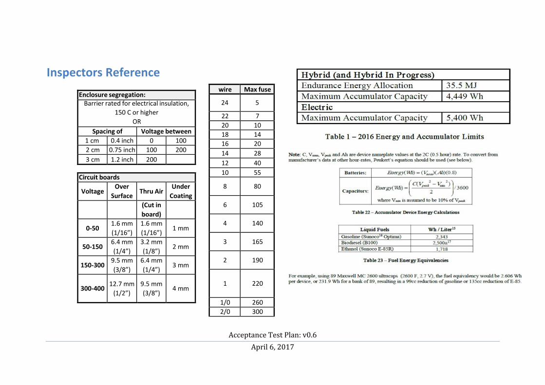
Acceptance Test Plan: v0.6
April 6, 2017
wire Max fuse
24
5
22 7 20 10 18 14 16 20
14 28
12 40
10 55
8
80
6
105
4
140
3
165
2
190
1
220
1/0 260
2/0 300
Inspectors Reference
Enclosure segregation:
Barrier rated for electrical insulation, 150 C or higher
OR
Spacing of Voltage between 1 cm 0.4 inch 0 100
2 cm 0.75 inch 100 200
3 cm 1.2 inch 200
Circuit boards
Voltage Over
Surface
Thru Air Under
Coating
(Cut in
board)
0-50 1.6 mm
(1/16”)
1.6 mm
(1/16”)
1 mm
50-150 6.4 mm
(1/4”)
3.2 mm
(1/8”)
2 mm
150-300 9.5 mm
(3/8”)
6.4 mm
(1/4”)
3 mm
300-400
12.7 mm
(1/2”)
9.5 mm
(3/8”)
4 mm

Acceptance Test Plan: v0.6
April 6, 2017
95
6.10.5 Any time a vehicle is energized and capable of electric motion (See section 3.1.5) the drive wheels must be supported clear of the ground or
removed, complying with the requirements of Section 6.10.6.
6.10.7 Safety glasses must be worn at all times while working on a vehicle, and by anyone within 10 ft. (3 meters) of a vehicle that is being worked on.
4.11 Energized electrical work is any work to be performed where energized high voltage will be exposed and present and the vehicle will be
energized for testing. Teams must receive approval from an electrical safety inspectors prior to any energized electrical work being performed.
Inspectors will review the work to be done with the team and upon approval place a “Danger High Voltage” work sign outside the pit.
During the energized electrical work the number of people in the pit area may be limited by the electrical inspectors. Failure to follow
this rule will result in disqualification from the event in progress.
Charging must be attended by someone knowledgeable, no other work
on car (elec or mech) Medical emergency procedure (direct ambulance
crew contact during hours they are on site)
If an emergency crew is within sight, make contact. Otherwise Dial 911
FH-2016 Rev - Inspectors Reference Page 16 of 16

Acceptance Test Plan: v0.6
April 6, 2017
96
Figure 1 - FSM for TSI

Acceptance Test Plan: v0.6
April 6, 2017
97
Figure 2 - ATP-01 block diagram

Acceptance Test Plan: v0.6
April 6, 2017
98
Figure 3 - ATP-02 block diagram

Acceptance Test Plan: v0.6
April 6, 2017
99
Figure 4 - ATP-03 block diagram

Acceptance Test Plan: v0.6
April 6, 2017
100
Figure 5 - ATP-04 block diagram