About this CD Notes on DFID Policy Notes on PIARC
1236
INTRODUCTION Containing: About this CD Notes on DFID Policy Notes on PIARC
-
Upload
khangminh22 -
Category
Documents
-
view
1 -
download
0
Transcript of About this CD Notes on DFID Policy Notes on PIARC

INTRODUCTION
Containing:
About this CDNotes on DFID Policy
Notes on PIARC

1. INTRODUCTION
Purpose and scope
1.1 This Note is a practical guide to the management ofmaintenance operations. It outlines a rational approachthat will help maintenance engineers organize andcontrol the activities for which they are responsible, so asto improve efficiency and make more productive use ofmaintenance resources.
1.2 The maintenance operations discussed here are thoserequired to keep roads in good condition and repair. TheNote does not deal with any form of road improvementworks, pavement strengthening or reconstruction, evenwhere these activities are undertaken by an organizationresponsible also for normal maintenance.
1.3 The Note offers advice on techniques basic to goodmaintenance practice, but it does not set out to define'model' systems that should be copied generally or todescribe all the management procedures an idealmaintenance organization would follow. This is becausein any location the best management system will be onewhich is matched closely to the technical skills, humanresources and equipment available to the individualmaintenance organization; and the most effectiveprocedures will be those that are appropriate to theexperience and capabilities of its staff. Using this Note,engineers will be able to assess the range of managementtechniques applicable to road maintenance and soidentity methods they can usefully put into practicewithin the context of their own organizations.
Structure of the Note
1.4 Following this introduction, Section 2 summarizesthe responsibilities of the maintenance engineer andcomments on the approach he should adopt to keymanagement tasks. Section 3 sets out a classification ofmaintenance activities, and Section 4 defines thesequence of management tasks which the engineer has tofulfil. These tasks are the subject of Sections 5 to 11,which explain each stage of the management process inturn. Appendices A to D provide details of technicalprocedures and illustrate standard forms and worksheets.Appendix E illustrates typical defects found on roads.
2. THE ROLE OF THEMAINTENANCE ENGINEER
2.1 Roads are expensive to build. They repay theirinitial investment only by means of long4erm care andmaintenance. A road system that is well maintainedbrings important social and economic benefits:
• the transport links on which developmentdepends are kept in good working order
• roads have a longer lifetime of service becausetheir surfaces do not deteriorate so rapidly
• vehicle operating costs are reduced becausetraffic is able to run smoothly
• transport operations are safer and more reliable
2.2 The maintenance engineer responsible foroperations at regional or district level has a key roleto play in achieving these benefits. His successdepends largely on the way he approaches the taskof management.
Management responsibilities
2.3 This task normally involves five mainresponsibilities:
• planning the annual programme ofmaintenance work for his area, assessing theresources needed and preparing an appropriatebudget estimate
• arranging that funds are allocated fairly to thevarious parts of the road network, and decidingon priorities if the funds available do not allowhim to undertake the full programme
• authorising and scheduling work• making sure that his staff know how to carry
out the work methodically and efficiently• monitoring the quality and effectiveness of
maintenance activities.
2.4 Each of these responsibilities forms a major step inthe sequence of maintenance management explained inSections 5 to 11 of this Note.
Involvement on site
2.5 In performing his management role, the maintenanceengineer will, of course, have many hours of office workon matters such as planning and administration. But it isessential that he also gets out into the field as much aspossible. The simple procedure of seeing things forthemselves would help maintenance engineers overcomemany of the problems that at present affect theiroperations.
2.6 There are several reasons why site visits areimportant:
1
ABOUT THIS CD-ROM
This CD-ROM is part of a new venture to broaden the range of media in which DFID’s work ispublished. This first version contains research documentation coming out of the TransportResearch Laboratory (now TRL Limited), historically DFID’s main agency for research andadvice in transport matters. In recent years, many more organisations have become involved inDFID transport programmes, and future issues in the CD-ROM series will include reports fromall of them, as appropriate. The reports reproduced here are still available as printed reports byrequest from:
TRL LimitedCrowthorneBerkshire, RG45 6AUUnited Kingdom.
Fax: +44 (0)1344 770356E-mail: [email protected].

INTRODUCTION TO DFID AND ITS POLICY TOWARDSTRANSPORT FOR DEVELOPMENT
The Department for International DevelopmentThe Department for International Development (DFID) is the British Government Departmentresponsible for promoting development. The Department’s central policy focus is a commitmentto halve the proportion of people living in extreme poverty by 2015, an internationally agreeddevelopment target. Associated targets include ensuring basic health care provision and universalaccess to primary education by the same date. DFID works with other governments as well as theprivate sector and the research community towards the achievement of these targets. Much of itswork is carried out in collaboration with multilateral institutions including the World Bank, UNagencies and the European Commission.
The bulk of DFID’s assistance is concentrated on the poorest countries in Asia and Sub-SaharanAfrica. DFID also contributes to eliminating poverty and supporting sustainable development inmiddle-income countries as well as helping countries in Central and Eastern Europe (‘transitioncountries’), in order to ensure that the largest number of people benefit from the process ofchange.
DFID formulates its strategy for operation in relation to the needs of regions and individualcountries. Strategy is also determined with respect to individual institutions and developmentthemes, especially those aimed at achieving the International Development Targets. A series of‘strategy papers’ define the priorities and methods for tackling key development challenges.These can be found on DFID’s web site at www.dfid.gov.uk.
DFID organisationDFID’s activities are organised around seven major development themes, each handled by aseparate department:
• Education• Health and population• Engineering (Infrastructure and Urban Development Department)• Rural livelihoods and environment• Social development• Governance• Economics, statistics and enterprise development.
Infrastructure and Urban Development DepartmentThe Infrastructure and Urban Development Department (IUDD) deals with engineering aspectsof rural and urban services and related infrastructure. The provision, maintenance and operationof these is essential for sustainable social and economic growth, which in turn play an importantrole in improving the lives of poor people.
IUDD’s programme addresses issues in seven sectors:• Energy• Geosciences• Transport• Water resources and saniation• Urban development. (This includes solid waste management, power, housing and
physical planning)• Environmental engineering

• Information, communications and technology.
IUDD runs its own research programme to help achieve its goals. The ‘Knowledge andResearch’ (KaR) programme addresses the generation, dissemination, adoption and impact ofknowledge in helping to eliminate poverty. More information on the KaR programme may befound from the DFID web site and the web sites of the organisations responsible for thedissemination of information within each IUDD sector (accessible from the DFID web site).
TransportDFID assistance with transport focuses mainly on road travel, which concerns the poorest peoplein most countries. Road users travel by foot, by ‘intermediate’ means of transport and bymotorised vehicles. The two main thrusts of DFID work in the roads sub-sector are to:a. Improve transport sector efficiency by (i) reducing the costs of providing and managing
infrastructure and (ii) optimising the overall costs of using road transport systems.b. Improve transport services in ways that specifically meet the needs of poor people.
DFID is collaborating with international organisations to assist development partners inimplementing policies and programmes which will achieve the above objectives. This assistanceincludes strengthening institutions, improving capacity to adopt new policies and encouragingprivate sector participation in order to spread successful implementation.
ResearchKnowledge, research and technology underpin all DFID’s work. DFID spends well over £100million each year on development-oriented research and capacity building, managed through itsthematic and regional programmes. See the ‘Knowledge and Research’ page of the Transport-Links web site (www.transport-links.org, due to be opened in mid-2001) for more informationon DFID’s research programme in the transport sector, and the relevant links from there or fromDFID’s own web site for information on research in the other development sectors.
Publications and dissemination of informationThe results of research are broadcast by wide publication of reports and by forming partnershipswith organisations in UK and overseas. Where transfer of knowledge is a key objective, resultsare broadcast specifically through programmes involving education, training, consultancy andtechnical co-operation.
DFID’s publications policy is to provide information about its activities and objectives in bothprint and electronic form. DFID puts out its own free magazine, Developments, describingactivities and issues mainly at policy level. The emphasis here is upon how British developmentassistance works in partnership with developing countries to help eradicate poverty. DFID’s website contains a publications list. The site also includes a Discussion Group feature where usersmay send their comments on development programmes direct to DFID.
IUDD commissions the publication of Newsletters for each of its sectors. The newsletters,produced every six months, give details of progress on KAR projects as well as presenting itemsof general news interest.
Dissemination of development issues in the individual IUDD sectors is handled by externalorganisations. The addresses of these can be found from the DFID web site. TRL Limited (theTransport Research Laboratory) manages DFID’s dissemination programme in the transportsector, compiling the Transport newsletter and operating the Transport-Links web site.

INTRODUCTION TO PIARC
The Permanent International Association of Road Congresses (PIARC) is the oldest of theinternational associations concerned with roads and road engineering. Founded in 1909, it wasgranted consultative status (category II) to the Economic and Social Council of the UnitedNations in 1970. PIARC has 97 member Governments and 2,100 members in 129 countries.
PIARC is a non-political and-non profit making association. Its vision is to be the worldleader in providing information on roads and road transport policy and practices within anintegrated sustainable transport context. The general aim of the Association is to improveinternational co-operation and to foster progress in road transport policy, road technology androad network operation. PIARC serves its members by:
• being a leading international forum for analysis and discussion of the full spectrumof transport issues related to roads and road transport,
• identifying, developing and disseminating best practice and giving better access tointernational information,
• providing within its activities special emphasis for developing countries andcountries in transition,
• developing and promoting efficient tools for decision making on matters related toroads and road transport.
To achieve these aims PIARC:• creates and co-ordinates Technical Committees,• organises, every four years, a World Road Congress and a Winter Road Congress,
plus various technical events,• publishes a large number of documents including a quarterly magazine
("Routes/Roads").
PIARC is assisted in its task by Technical Committees and specialised technical groups,composed of engineers and experts appointed from member countries. Approximately 850engineers and experts are gathered for this purpose from 50 countries. The TechnicalCommittees and specialised groups operate continuously and participate in internationalmeetings dealing with their particular subjects.
The twenty Technical Committees are:C 1 Technical Committee on Surface CharacteristicsC 2 Technical Committee on Community ConsultationC 3 Technical Committee on Technological Exchanges and DevelopmentC 4 Technical Committee on Interurban Roads and Integrated Interurban TransportC 5 Technical Committee on Road Tunnel OperationC 6 Technical Committee on Road ManagementC 7/8 Technical Committee on Road PavementsC 9 Technical Committee on Financing and Economic EvaluationC 10 Technical Committee on Urban Roads and Integrated Urban TransportC 11 Technical Committee on Road Bridges and other StructuresC 12 Technical Committee on Earthworks, Drainage, SubgradeC 13 Technical Committee on Road SafetyC 14 Technical Committee on Sustainable Development and TransportC 15 Technical Committee on Performance of Road AdministrationsC 16 Technical Committee on Network Operations

C 17 Technical Committee on Winter MaintenanceC 18 Technical Committee on Risk Management for RoadsC 19 Technical Committee on Freight TransportC 20 Technical Committee on Appropriate Development
PIARC publicationsTechnical Committees and Working Groups publish compiled documents, recommendationsand state of the art methodologies. These documents, intended for decision makers, designengineers, field engineers and researchers, are based on wide international consensus. Alldocuments are published in the two official languages of the Association, French and English.The publication catalogue is available from PIARC’s web site at http://www.piarc.org/.
The English version of the International Road Maintenance Handbook may be ordered from:Transport Research LaboratoryCrowthorneBerkshire RG45 6AUUnited Kingdom
Fax: +44 (0)1344 770356E-mail: [email protected]
The Handbook is also published in French, Spanish, Portuguese and Brazilian Portuguese. Formore details, please contact PIARC Central Office at:
27 rue Guénégaud75006 PARISFrance.
Fax: +33(1) 46 33 84 60Web site: http://www.piarc.org/

Overseas Road Notes
1 – 18 & 31

Transport and Road Research Laboratory Overseas Unit
Department of TransportOverseas Development Administration
Overseas Road Note 1
Maintenance managementfor district engineers(2nd edition)
Overseas UnitTransport and Road Research LaboratoryCrowthorne Berkshire United Kingdom1987

ACKNOWLEDGEMENTS
This Note was drafted by Dr R Robinson of theTRRL Overseas Unit. It is based on an original textproduced by Scott Wilson Kirkpatrick and Partners.Certain details of the inspection proceduresrecommended are based on those developed forSystem BSM by John Burrow & Partners. The pavedroad intervention levels were devised by Dr J Rolt,the appendix illustrating typical defects wasprepared by Dr G Morosiuk, and other contributionswere made by Mr D M Brooks, all of the TRRLOverseas Unit. Final editing was carried out byHarold Lewis, Consultant Technical Editor.
First published 1981Reprinted with minor revisions 1983Second edition 1987Reprinted with minor revisions 1995
OVERSEAS ROAD NOTES
Overseas Road Notes are prepared principally forroad and road transport authorities in countriesreceiving technical assistance from the BritishGovernment. A limited number of copies is availableto other organisations and to individuals with aninterest in roads overseas, and may be obtained from:
Overseas CentreTransport Research LaboratoryCrowthorne, Berkshire, RG45 6AUUnited Kingdom
© Crown copyright 1987Limited extracts from the text may be producedprovided the source is acknowledged. For moreextensive reproduction, please write toHead of Overseas Centre,Transport Research Laboratory
ISSN 0951-8987

CONTENTS
page1. Introduction 1
Purpose and scope 1
Structure of the Note I2. The role of the maintenance engineer 1
Management responsibilities 1
Involvement on site 1Delegation 2Training 2
Using microcomputers 2Implementation 2
3. Maintenance activities 3
4. Management tasks 35. Inventory 4
Content and preparation 4
Presentation 46. Inspection 6
Frequency of inspection 6
Condition survey 6Recording results 7
7. Determination of maintenance requirements 11
Recurrent and periodic maintenance of unpaved roads 11Intervention levels on paved roads 12Diagnozing the cause of deterioration 12
Specifying the work required 128. Resource estimation 16
Choice of work method 16
Use of contractors 16Labour 16Equipment 17
Materials 19Resource allocation 20
9. Identification of priorities 22
Maintenance activities by order of importance 22Roads by order of importance 22Priority matrix 23
Adapting priorities to local conditions 23Determining the work programme 23
10. Work scheduling and execution 24
Schedules 24Worksheets 24
11. Monitoring 26
Site inspections 26Desk review 26

pageReferences 26Appendix A - Field procedures for inventory and condition measurement surveys 27
A.l General procedure 27Recording 27Organization of teams 27
Safety 27Transport 27Notes for inspectors 28
Duties of team members 28Order of work 28Accuracy 28
A.2 Condition measurement 28General considerations 28Side drains and turnouts (all roads) 28
Loss of material (gravel roads) 29Deformation (all roads) 29Cracking (paved roads) 29
Pot-holes (all roads) 29Edge drainage (paved roads) 29Edge step (paved roads) 29
Appendix B - Management of grading for unpaved roads 32B.1 Determining optimum grading frequencies 32B.2 Monitoring of optimum frequencies 32
B.3 Measurement methods 33Reference 33
Appendix C - Traffic counting 34
C.1 Frequency and duration of counts 34C.2 Estimation of ADT from counts 34C.3 Manual counts 34
C.4 Automatic counters 34C.5 Moving observer counts 34C.6 Development of traffic counts 35
Appendix D - Recommended standard forms 36Appendix E - Illustrations of typical defects 42

1. INTRODUCTION
Purpose and scope
1.1 This Note is a practical guide to the management ofmaintenance operations. It outlines a rational approachthat will help maintenance engineers organize andcontrol the activities for which they are responsible, so asto improve efficiency and make more productive use ofmaintenance resources.
1.2 The maintenance operations discussed here are thoserequired to keep roads in good condition and repair. TheNote does not deal with any form of road improvementworks, pavement strengthening or reconstruction, evenwhere these activities are undertaken by an organizationresponsible also for normal maintenance.
1.3 The Note offers advice on techniques basic to goodmaintenance practice, but it does not set out to define'model' systems that should be copied generally or todescribe all the management procedures an idealmaintenance organization would follow. This is becausein any location the best management system will be onewhich is matched closely to the technical skills, humanresources and equipment available to the individualmaintenance organization; and the most effectiveprocedures will be those that are appropriate to theexperience and capabilities of its staff. Using this Note,engineers will be able to assess the range of managementtechniques applicable to road maintenance and soidentity methods they can usefully put into practicewithin the context of their own organizations.
Structure of the Note
1.4 Following this introduction, Section 2 summarizesthe responsibilities of the maintenance engineer andcomments on the approach he should adopt to keymanagement tasks. Section 3 sets out a classification ofmaintenance activities, and Section 4 defines thesequence of management tasks which the engineer has tofulfil. These tasks are the subject of Sections 5 to 11,which explain each stage of the management process inturn. Appendices A to D provide details of technicalprocedures and illustrate standard forms and worksheets.Appendix E illustrates typical defects found on roads.
2. THE ROLE OF THEMAINTENANCE ENGINEER
2.1 Roads are expensive to build. They repay theirinitial investment only by means of long4erm care andmaintenance. A road system that is well maintainedbrings important social and economic benefits:
• the transport links on which developmentdepends are kept in good working order
• roads have a longer lifetime of service becausetheir surfaces do not deteriorate so rapidly
• vehicle operating costs are reduced becausetraffic is able to run smoothly
• transport operations are safer and more reliable
2.2 The maintenance engineer responsible foroperations at regional or district level has a key roleto play in achieving these benefits. His successdepends largely on the way he approaches the taskof management.
Management responsibilities
2.3 This task normally involves five mainresponsibilities:
• planning the annual programme ofmaintenance work for his area, assessing theresources needed and preparing an appropriatebudget estimate
• arranging that funds are allocated fairly to thevarious parts of the road network, and decidingon priorities if the funds available do not allowhim to undertake the full programme
• authorising and scheduling work• making sure that his staff know how to carry
out the work methodically and efficiently• monitoring the quality and effectiveness of
maintenance activities.
2.4 Each of these responsibilities forms a major step inthe sequence of maintenance management explained inSections 5 to 11 of this Note.
Involvement on site
2.5 In performing his management role, the maintenanceengineer will, of course, have many hours of office workon matters such as planning and administration. But it isessential that he also gets out into the field as much aspossible. The simple procedure of seeing things forthemselves would help maintenance engineers overcomemany of the problems that at present affect theiroperations.
2.6 There are several reasons why site visits areimportant:
1

• they enable the maintenance engineer to becomethoroughly familiar with road conditions in the area,and so recognize trouble spots and other placeswhere difficulties are likely to occur
• he can gain first-hand knowledge of the extent andquality of the maintenance that has actually beencarried out, instead of having to rely on what hereads in reports
• he can use this knowledge to assess maintenancepriorities much more confidently
• his presence on the spot means that he can advise onproblems as they arise
• seeing him regularly on site should boost the moraleof road gangs and improve their standard of workand their output. His attitude will have moreinfluence on their performance than any otherfactor, and site visits are the most effective way ofdemonstrating his commitment to getting the jobdone successfully.
Delegation
2.7 The maintenance engineer should use hisknowledge of road conditions to decide which operationsneed his personal supervision and which he can safelydelegate to staff. On lengths of road where maintenanceis straightforward and easy to specify in advance, itshould be possible to leave day-to-day work in the handsof suitably trained foremen or contractor's staff. On otherroads where there are problems requiring complicatedtreatment and on-the-spot judgment, the maintenanceengineer will have to become personally involved indetermining what needs to be done and supervising thework. Thy key point is that he should not let his time betaken up by simple operations which less qualified staffare able to manage.
Training
2.8 Delegation will only succeed if staff have theknowledge and competence to fulfil the duties they aregiven. The maintenance engineer has to make sure thatsupervisors, foremen and other personnel receive thenecessary training, and that there are enough trained staffto carry out his instructions. This means that training isan important part of his responsibilities.
2.9 Though training methods are outside the scope ofthis document, there are some basic points to remember.First, every member of staff should have appropriatetraining. Secondly, this training should be built into thework programme and include practical on-the-jobexperience as well as more formal courses. Thirdly,training should be an on-going feature of employment inthe maintenance organization, so that competent staff areavailable to take over when more experienced personnelare promoted or transferred to other duties.
2
Using microcomputers
2.10 Now that 'micros' are becoming widelyavailable, their application to maintenance managementis a subject where staff training may be particularlyuseful. A growing range of specialised software isavailable to help process data and analyze problems, andusing a micro can save considerable time beside freeingthe maintenance engineer for inspection and monitoringon site. But expenditure on computers can prove anexpensive mistake if the system is not chosen with careand if suitable personnel are not available to make thebest use of it. Maintenance can be managed efficientlywithout a micro; and even if there is one in the office, itdoes not lessen the need for regular and accurate datacollection in the field.
Implementation
2.11 For most organizations, the managementapproach recommended in this Note will take some timeto implement - perhaps a period of several years. Themaintenance engineer should not try to put everythinginto practice at once. It is better to introduce newmethods and procedures gradually, starting withstraightforward measures that will produce early andpositive results. Proceed step by step, and wait until onestage is working reasonably well before moving to thenext. Concentrate first on the sections of road that carrythe largest volumes of traffic and ensure these areadequately maintained before dealing with less busyroads.

3. MAINTENANCE ACTIVITIES
3.1 For the purposes of management, the most useful wayto classify maintenance activities is in terms of theirfrequency. There are four categories:
• routine maintenance, required continually on everyroad whatever its engineering characteristics or trafficvolume
• recurrent maintenance, required at intervals duringthe year with a frequency that depends on the volume of
traffic using the road
• periodic maintenance, required only at intervals of
several years
• urgent maintenance, needed to deal with emergencies
and problems calling for immediate action when a roadis blocked.
3.2 Examples of activities within these categories are asfollows:
routine:grass cutting; drain clearing; recutting ditches; culvertmaintenance; road signs maintenance
recurrent on unpaved roads:repairing pot-holes and ruts; dragging; grading
recurrent on paved roads:repairing pot-holes; patching; repairing edges; sealing cracks
periodic on unpaved roads:regravelling
periodic on paved roads:resealing (surface dressing, slurry sealing, fog spray, etc.);
regravelling shoulders; road surface marking
urgent:
removal of debris and other obstacles; placement of warningsigns and diversion works.
3.3 Routine maintenance, by definition, has to be undertakenon a regular basis: its frequency does not depend on thecharacter of the road or the amount of traffic. For this reasonit is treated as a fixed-cost item in the maintenance budget.Recurrent and periodic maintenance, however; are treated asvariable-cost activities, because the frequency with whichthey are required is dependent on the engineering and trafficcharacteristics of the particular road.
4. MANAGEMENT TASKS
4.1 As noted in para 2.3, the maintenance engineer has theresponsibility of structuring these activities into aprogramme of maintenance work throughout his area, withan appropriate allocation of resources. This responsibilityinvolves a sequence of tasks, which are discussed in turn inSections 5 to II, and can be summarised as follows:
(i) inventory: recording the basic characteristics ofeach section of the road network
(ii) inspection: examining the road and measuring itscondition
(iii) determination of maintenance requirements:
analyzing why defects are occurring; and specifying
what maintenance activities are needed to put themright and delay further deterioration
(iv) resource estimation: costing the maintenanceprogramme in order to define an overall budget
(v) identification of priorities: deciding the work thathas to take precedence if resources are limited
(vi) work scheduling and performance:controlling the work as it is carried out
(vii) monitoring : checking the quality and effectivenessof the work.
4.2 Because unpaved roads deteriorate more rapidly thanpaved roads, they require more frequent attention. Therecurrent maintenance listed for unpaved roads in para 3.2should be applied at regular and predetermined intervalsthroughout the year. These activities must not be deferreduntil defects show up in the course of an annual or seasonalinspection. Methods of calculating how frequently they needto be undertaken during the year are discussed in Section 7.
3

5. INVENTORY
Content and preparation
5.1 The inventory is a set of information about the basicengineering and traffic characteristics of the road network. Itdefines the key features of each section of road and indicatesthe level of traffic use. This information is an essentialreference source for the subsequent stages of inspection andanalysis.
5.2 The content of the inventory should be directlyrelevant to maintenance management. When it is first drawnup, it should be as simple as possible and need containinformation only on the following items:
• type of surface and construction
carriageway and shoulders
•• cross-section width
carriageway and shoulders
•• traffic volume
annual average daily traffic (numbers of vehicles per
day).
5.3 As the inventory is built up, information on thefollowing items can be added:
• structures
pipe culverts; box culverts: bridges
•• junctions
location
•• road furniture
road signs; road markings; guard rails.
5.4 It will also be helpful to include data on other factorsinfluencing maintenance needs, such as rainfall and runoff,topography and soil conditions. These factors can influencethe degree of priority given to various operations when thework programme is prepared (para 9.9-9.10). In addition,data about the distribution and engineering properties of soilswill be useful in identifying possible sources of maintenancematerials.
5.5 Appendix A of this Note describes the field proceduresused in setting up an inventory, including the organization ofteams and transport. The maintenance engineer can delegatethe preparation and day-to-day supervision of the work to asenior technician who fully understands the procedures, ifone is available. If not, he should undertake this task himself.
4
Presentation
5.6 There are three useful ways of presenting theinformation recorded in the inventory:
• diagrammatic maps
• strip maps
• card index systems.
5.7 Fig. 5.1 shows a typical diagrammatic map. It isbasically a road plan of the area marked to indicate trafficlevels, categories of road surface and road widths. This kindof map is particularly helpful in giving an overview of thewhole network, enabling the maintenance engineer to see ata glance how roads with differing features relate to eachother.
5.8 Fig. 5.2 is an example of a strip map. This is a simpleannotated drawing which records significant informationabout a section of road and its surroundings. Its principal useis in the field, where it provides a quick means of referenceduring inspections and surveys - especially for the locationof chainage. It is often convenient to staple strip mapstogether so as to form a pocket-sized notebook for each road.
5.9 Card index systems are useful for registering details ofitems such as road structures and road signs. They can easilybe updated when these items are repaired or replaced, so asto provide a continuous record of their condition andmaintenance history.
5.10 Where the means are available, it may be practical touse computer-based inventory systems; but the database of amaintenance inventory - particularly in its initial stages ofdevelopment - will rarely be complex enough to require theapplication of computer technology.

Fig.5.1 Diagrammatic map of maintenance district
5

Fig.5.2 Strip-map of road inventory
6
6. INSPECTION
6.1 Recommended procedures for field inspections aredescribed in Appendix A: they are similar to inventoryprocedures, but their emphasis is on the condition of theroad rather than its basic characteristics. They identifylocations where deterioration is occurring, measure theextent of the problem and define the action needed to putmatters right. It is likely that, while the managementsystem is being developed, the early inspections will haveto rely largely on a visual assessment of defects: butmeasurement techniques should be introduced as soon asit is practicable to do so, following the guidance inAppendix A.
Frequency of inspection
6.2 The maintenance engineer should have the entirelength of the road network inspected at least once a year- and he should aim to improve on this frequency if it is atall practicable. In regions where there are distinct wet anddry seasons, a total inspection ought to be made in eachpart of the year. The wet season inspection will beparticularly useful in detecting cracking in bituminoussurfaces (since this defect is more easily visible when theroad surface is drying after rain) and in assessing theefficiency of drainage.
6.3 The day-to-day supervision of inspection work canbe delegated to trained technicians. But the maintenanceengineer should visit the inspection teams, especially atlocations where detailed assessments are required (para6.5).
6.4 The network inspection will need to be completed intime for its results to be fed into the preparation of thefollowing year's budget estimates. Since mostorganizations prepare their estimates in the second half ofthe financial year, the maintenance engineer has to makesure that the inspection programme is undertaken earlyenough to produce the necessary input.
Condition surveys
6.5 In assessing the condition of the road, it is advisableto adopt a two – stage process of inspection:
(i) In the first stage a trained but relatively unskilledteam uses standard procedures and simpleequipment to measure and record defects in theroad. It is led by a technician who determinesroutine and recurrent maintenance needs andidentifies locations where further examination isnecessary. Occasional monitoring of these surveysby the maintenance engineer is recommended.
(ii) The second stage involves a more experienced team,led by an engineer, whose task is to

determine the requirements for periodic workby making such additional investigations,measurements and analyses as are required.
6.6 The advantages of this approach are that it providesa double check on the state of the road and the scale ofmaintenance requirements, and it uses professionalresources in a cost-effective way by directing themspecifically to locations that call for skilled inspections andtreatment.
Recording results
6.7 Figs 6.1-6.3 show how standard pre-printed formscan be used to record the results of inspection surveys. Eachroad should be divided into sub-sections and a separateform used for each sub-section. Different forms are neededfor paved roads (Fig. 6.1), unpaved roads (Fig. 6.2) and forstructures and road furniture (Fig. 6.3). Note that the formfor unpaved roads includes space for the results ofmonitoring surveys that should be carried out at a later dateto gauge the effectiveness of the maintenance programme(para 7.5). Blank versions of the forms are supplied inAppendix D.
6.8 Pre-printed forms are especially useful in providinga check-list that tells the technician what items are to beexamined during an inspection, and so reduces thepossibility that significant information may be omitted. Theexamples of forms shown here are intended only as a guide.In some cases the maintenance engineer may receive anissue of standard forms from his organization. In othercases, he may find it more useful to draw up his own form,designed to suit the particular road conditions in his area.
6.9 Whatever form is used, it should be easy tounderstand and to complete. The technician responsible forthe inspection should fill in the results on site, recordingthem accurately and legibly. The forms should then beretained in the office so as to provide a permanent record ofinspection results. There is no need to make fair copies offorms completed on site: this wastes time and involves therisk of errors when information is transcribed.
6.10 It may, however, be useful to summarise key resultsin the form of statistical tables or diagrams - for example,graphs that show rates of deterioration over time.
7

8
Fig.
6.1
Exa
mpl
e of
insp
ectio
n fo
rm fo
r pav
ed ro
ad

9
Fig.
6.2
Exa
mpl
e of
insp
ectio
n fo
rm fo
r unp
aved
road
s

10
Fig.
6.2
Exa
mpl
e of
insp
ectio
n fo
rm fo
r unp
aved
road
s
7. DETERMINATIONOF MAINTENANCEREQUIREMENTS
Recurrent and periodic maintenance of unpavedroads
7.1 As noted in para 4.2, unpaved roads need aprogramme of regular and systematic attention. Therequirements for recurrent maintenance on these roads haveto be determined independently of the results of networkinspections.
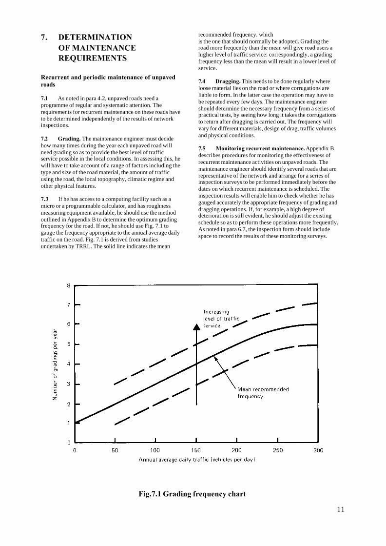
7.2 Grading. The maintenance engineer must decidehow many times during the year each unpaved road willneed grading so as to provide the best level of trafficservice possible in the local conditions. In assessing this, hewill have to take account of a range of factors including thetype and size of the road material, the amount of trafficusing the road, the local topography, climatic regime andother physical features.
7.3 If he has access to a computing facility such as amicro or a programmable calculator, and has roughnessmeasuring equipment available, he should use the methodoutlined in Appendix B to determine the optimum gradingfrequency for the road. If not, he should use Fig. 7.1 togauge the frequency appropriate to the annual average dailytraffic on the road. Fig. 7.1 is derived from studiesundertaken by TRRL. The solid line indicates the mean
recommended frequency. whichis the one that should normally be adopted. Grading theroad more frequently than the mean will give road users ahigher level of traffic service: correspondingly, a gradingfrequency less than the mean will result in a lower level ofservice.
7.4 Dragging. This needs to be done regularly whereloose material lies on the road or where corrugations areliable to form. In the latter case the operation may have tobe repeated every few days. The maintenance engineershould determine the necessary frequency from a series ofpractical tests, by seeing how long it takes the corrugationsto return after dragging is carried out. The frequency willvary for different materials, design of drag, traffic volumesand physical conditions.
7.5 Monitoring recurrent maintenance. Appendix Bdescribes procedures for monitoring the effectiveness ofrecurrent maintenance activities on unpaved roads. Themaintenance engineer should identify several roads that arerepresentative of the network and arrange for a series ofinspection surveys to be performed immediately before thedates on which recurrent maintenance is scheduled. Theinspection results will enable him to check whether he hasgauged accurately the appropriate frequency of grading anddragging operations. If, for example, a high degree ofdeterioration is still evident, he should adjust the existingschedule so as to perform these operations more frequently.As noted in para 6.7, the inspection form should includespace to record the results of these monitoring surveys.
Fig.7.1 Grading frequency chart
11

7.6 Regravelling. This is a periodic activity that willneed to be performed whenever the existing layer of gravelbecomes unacceptably thin. If this layer is found to be lessthan 50mm thick for more than 20 per cent of the length ofthe sub-section of road being inspected (Table 7.1),regravelling should take place. Appendix A includes adviceon the inspection procedure.
Intervention levels on paved roads
7.7 In dealing with paved roads, the maintenanceengineer must interpret the inspection results (Section 6) soas to decide when and where repairs are needed and whatform of maintenance activity is required. Like a doctortreating an illness, he has to recognize the symptoms thatindicate it is time to take remedial action. These indicationsare termed 'intervention levels': i.e. they identify the stageor circumstance in which the maintenance engineer shouldintervene and the action he should take to stop fartherdeterioration. Intervention levels can be defined forunpaved roads too, as shown in Table 7.1, though thefrequency of recurrent operations is determined in advance(paras 7.1-7.5).
7.8 It is advisable always to adopt intervention levelssuited to the particular local conditions. As a guide, Tables7.1-7.3 set out recommended intervention levels forunpaved roads, paved roads, and road structures andfurniture, respectively. The recommended levels are basedon the assumption that the road network is already beingmaintained to an adequate standard and that sufficientresources are available to keep up this standard. In otherwords, they represent a target that the maintenance engineershould aim eventually to achieve. If, as will often be thecase, he has too few resources at his disposal to apply therecommended levels, he can adopt alternative levels that aremore appropriate to the workload and capabilities of hisorganization.
7.9 Some of the intervention levels in Tables 7.1-7.3 areexpressed in quantitative terms and require
measurements to be made, as explained in Appendix A.Others involve simply a visual assessment. While themanagement system is being introduced, it is likely that themaintenance engineer will have to rely entirely on thevisual assessment of defects, but he should try to introducethe use of measurement techniques as skills and resourcespermit.
Diagnozing the cause of deterioration
7.10 It is important to identify the cause of deteriorationand to put this right if possible, rather than just treating thesymptom. For example, there is little point in continuallyfilling in pot-holes in a road if they keep occurring onlybecause of poor drainage. Finding the real problem andfocusing attention on its solution will produce a more cost-effective use of maintenance resources.
7.11 Some problems, of course, may be outside the scopeof maintenance. For example, a road across flat countrywith inadequate drainage outfalls may experience basefailure as a result of the capillary rise of water in the wetseason. The only solution to the problem is to raise the levelof the road. This would be a road improvement, not amaintenance operation: as such, it may warrant a specialallocation of resources in accordance with theorganization's procedures for road improvement work.
Specifying the work required
7.12 The maintenance engineer should examine thecompleted inspection forms (para 6.7) and compare theinspection results with intervention levels of the typerecommended in Tables 7.1-7.3. He can then determine themaintenance needs of each sub-section of the road networkand specify the work required. The necessary action shouldbe marked on the inspection forms, preferably in a differentcolour from that used for the survey results. The forms willprovide a permanent record of maintenance requirements.
TABLE 7.1
MAINTENANCE INTERVENTION LEVELS: UNPAVED ROADS
Defect Level
Extent (& of
Sub-section length) Action Programme Notes
Gravel
thickness
<50mm >20 Regravel Periodic
Camber
Roughness
Rutting
Corrugations
Pot-holes
(See paras
7.1-7.5)
Grade/drag Recurrent Planned on a
Programmed basis
12

TABLE 7.2
MAINTENANCE INTERVENTION LEVELS: PAVED ROADS
13

TABLE 7.2 (Continued)
14
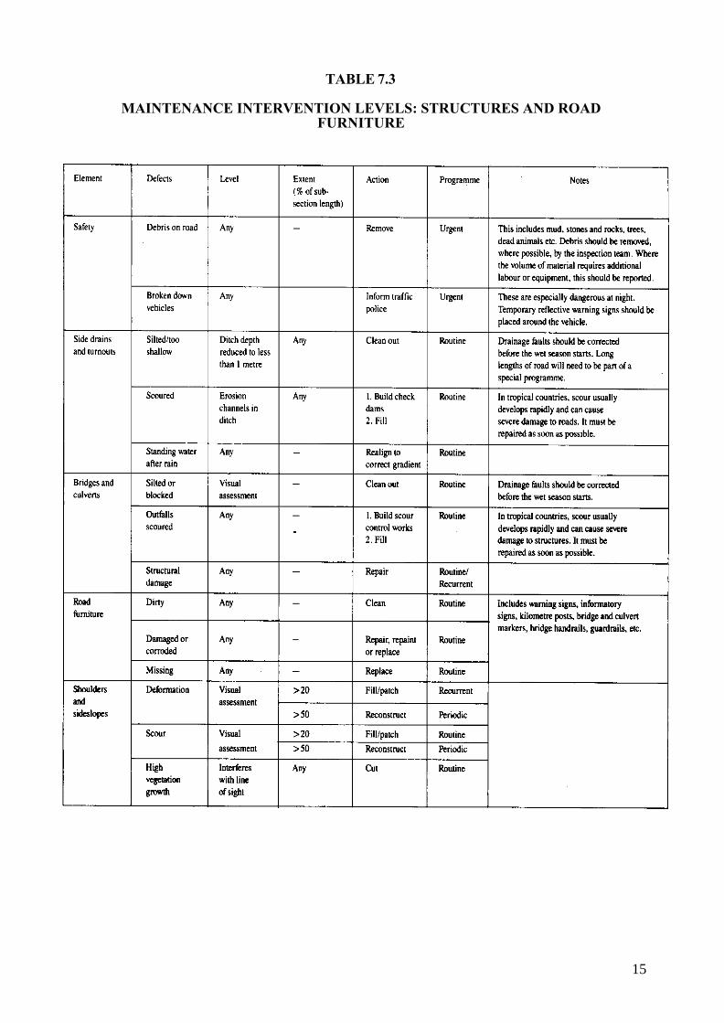
TABLE 7.3
MAINTENANCE INTERVENTION LEVELS: STRUCTURES AND ROADFURNITURE
15

8. RESOURCE ESTIMATION
Choice of work method
8.1 Maintenance operations involve three types ofresources materials, labour and equipment. It is easy toestimate directly the quantities of materials needed for anoperation (para 8.15), but the amounts of labour andequipment required will depend on the method used incarrying out the work. There are some activities that canonly be done by manual labour; there are others whereplant and machinery are essential; but many activitiesoffer the option of either method. Trying to combinemanual labour and machinery on the same task willnormally lead to inefficiency. The maintenance engineerwill therefore have to choose between a method thatlargely makes use of manual labour and a method basedon the use of machinery.
8.2 In making this choice he has to take account ofseveral factors:
• the probable costs of each method in relation to theavailable budget
• the standard of work resulting from each method.Machinery normally produces a truer surface and amore consistent finish than manual labour. but thismay not always be required. For example, it wouldbe difficult to find any economic justification forgiving low-volume roads the close tolerances oflevel and smoothness that machinery can achieve
• the implications for the way the work is organized.If large-scale works are involved, labour-basedmethods will require precise organization andmanagement. Labour has to be available insufficient numbers in the right place and at the righttime. Transporting the labour force to and fromworksites can cause problems; standardised, good-quality tools and equipment will be needed toachieve high levels of output; the health andnutrition of the men must be thought about, sinceimproved standards help to increase productivity.
8.3 Table 8.1 gives an assessment of the potentialoffered by various maintenance activities for the use oflabour-based and machinery-based methods.
Use of contractors8.4 Though maintenance organizations normallyemploy their own labour force, there is a range ofactivities that can be undertaken for them by localcontractors. If the policies of his organization allow theuse of contractors, the maintenance engineer shouldexamine this possibility.
16
8.5 Contracting work out can have the advantage ofrelieving pressure on the organization's labour resourcesand it can offer a high level of efficiency at a competitivecost. On the other hand, the organization will have toprepare detailed contract documents, set up a tenderingprocedure and provide contract supervision - all of whichmay require a substantial amount of time and effort onthe part of its staff. There is also a risk that contractorsbidding for maintenance work on a regular basis mayintroduce 'price fixing' to increase their profitability, andso involve the organization in higher costs. Themaintenance engineer will have to weigh up these factorsin relation to the capacities of his organization and theperformance of local contractors.
8.6 The following activities should present nosignificant problems of administration or quality controlif contracted out on the basis of competitive tenders:
• Supply of materialsSteel reinforcementBitumen productsCement and limeNatural gravelScreened gravelRock aggregate (for subsequent crushing by thehighways department)Crushed aggregate (for surface dressing andconcrete)Washed sand (for concrete or slurry sealing)Precast concrete blocksPrecast concrete box culverts or pipesGabion baskets.
• Maintenance operationsRecutting of side drains and turnoutsReconstruction of culvertsRegravellingResealing: surface dressing, slurry sealing, fogspray, etc.Grass cutting and bush clearing.
8.7 Specialist contractors can also be brought in toundertake the supply and maintenance of machinery andvehicles.
8.8 The maintenance engineer should satisfy himselfthat any contractor invited to tender for a job is capableof completing it satisfactorily, has the necessarypersonnel and equipment available, and is sufficientlyknowledgeable about estimating procedures and currentmarket rates to submit realistic prices.
8.9 It is vital that the maintenance engineer ensures thatall contracts are properly supervised and that allspecifications are met before he authorises payment.
Labour8.9 Table 8.2 indicates the outputs of work that can be

expected from teams engaged on normal maintenanceactivities, using manual labour or machinery asappropriate. Each output is expressed as a range: theamount of work that a team in fact achieves should liewithin this range, depending on local conditions. Forexample, a labour-based approach to clearing side drainsis likely to involve between 4 and 10 men using simplehand equipment, and the team can be expected to clearbetween 30 and 60 metres of drain per man-day. Amachinery-based approach to the same task will reducethe labour requirement to 2 or 3 men using a grader andshovels, and they will be able to clear as a team between4 and 7 km per day.
8.10 The maintenance engineer should use Table 8.2 as a
guide in assessing the levels of productivity associatedwith various operations, and estimating the amount oflabour required for each activity.
8.11 The values given in the table refer only toworking time. They make no allowance for time that isnon-productive, i.e. not spent actually working. Non--productive time can build up significantly duringmaintenance operations, and it should be an aim ofmanagement to reduce it to a minimum.
Equipment
8.12 Many activities need only simple equipment suchas picks and shovels. It is important to have enough ofthese available to meet day-to-day requirements.
TABLE 8.1
POTENTIAL FOR USE OF LABOUR-BASED & MACHINERY-BASED METHODS
POTENTIAL FORACTIVITY
LABOUR MACHINERY
Ditch cleaning and cutting
Cleaning and minor repairs to culverts and bridges
Good (*)
Good
Good (*)
Poor
Building scour controls
Repair of structures
Good
Good
Poor
Poor
Grading unpaved surfaces
Dragging and brushing of unpaved surfaces
Patching sanding or local sealing of bituminous surfaces
Impracticable
Poor
Good
Good
(Skilled)¢Good
Poor
Filling on unpaved surfaces and slopes
Grass cutting
Manufacturing signs
Repairing and replacing traffic signs
Road line markings
Good
Good
Goodu
(Skilled) ¢
Good
Fair
Poor
Good(**)
Fairu
Poor
Good
Stockpiling gravel
Regravelling gravel surfaces
Stockpiling chippings
Surface dressing
Fair
Fair
Poor
Fair
(Skilled) ¢
Good
Good
Good
Good
(Skilled) ¢
NOTES:(*) The potential in these activities is dependent upon suitable design of the ditch cross-section. 'V-shaped
ditches are suitable for maintenance by grader, whereas flat bottomed ditches are suitable for maintenance byhand or mechanical shovel.
(**) The potential in this activity is dependent on the width of the shoulder and presence o f obstructions such asroad furniture and culvert headwalls.
u Some methods of manufacture may require the use of specialised plant (eg. vacuum application of reflectivesheeting to sign plates).
¢ The expression 'skilled' implies that specific training of operatives is essential
17

TABLE 8.2
OUTPUTS OF WORK
* The unit of ‘pass-km’ is the actual distance the grader travels while working. To determine the length of road graded, thisfigure must be divided by the number of ‘passes’ necessary to cover the whole width of the road.
18

TABLE 8.2 (Continued)
8.13 The maintenance engineer will probably not beresponsible for the supply of plant and vehicles, sincethis is usually handled separately within the organization.But he should keep aware of the supply situation andmust do his best to make sure that equipment issystematically maintained in good working order.Shortage of working equipment or vehicles is almostalways a major symptom of inefficiency in maintenanceorganizations.
8.14 The essential point is to establish a daily routineof equipment maintenance. This can be done through thefollowing measures carried out by the maintenanceengineer:
• ensuring that operators appreciate the purpose andbenefits of preventative maintenance, understand themaintenance needs of the equipment they use, andare trained to look after this equipment on a dailybasis
• arranging for a regula r supply of oil and grease, etc,to be made available; this supply will need securestorage facilities under the supervision of a storeman
• checking for himself that the daily maintenanceroutine is being carried out, and demonstrating hispersonal concern for maintenance standards
• using his site visits to observe how operators treattheir equipment and discouraging its mishandling ormisuse.
Materials
8.15 The procedures for estimating quantities ofmaterials needed in maintenance operations are relativelystraightforward. Where the extent of the work can bedefined precisely - for example, in the case of surfacedressing or regravelling - quantities are taken off inaccordance with standard engineering practice. For otheractivities where requirements are less easy to definesuch as edge repairs to bituminous surfaces, patchingpot-holes and repairing defects in culverts -quantities aregauged on the basis of inspection results, again followingstandard practice; but these estimates will of necessity beless precise. The quantities ordered should include anallowance for any emergency work that may be needed,for example in repairing storm damage to culverts orvehicle damage to bridge parapets.
19

8.16 In planning his programme of work, themaintenance engineer should take account of the deliveryperiods for materials. If deliveries are likely to beuncertain, it will be advisable to stockpile basic materialssuch as aggregates cement and bitumen. These will needto be stored securely and kept in good condition.
Resource allocation
8.17 Fig 8.1 shows how a standard form can be used torecord the resources required for each activity and theirestimated costs. A blank copy of the form is included inAppendix D.
8.18 The extent to which the maintenance engineer caninfluence how the available budget is spent will dependon the resource allocation procedures in his organization.Some authorities may allocate specific amounts oflabour, equipment and materials whose costs are chargedfor the whole year regardless of use. Others may onlydefine a total budget and leave the maintenance engineerfree to purchase materials and hire whatever labour andequipment are needed. In most cases, the procedures willfall somewhere between these extremes.
8.19 The maintenance budget may include sumsallocated by the organization to various activities otherthan actual maintenance operations. The maintenanceengineer must take these sums into account whencalculating the resources available for road works. Thefollowing items may be involved:
• establishment: staff and buildings for materialstesting, surveys, training, records, accounts andother administration
• equipment: operation and maintenance oftransport and equipment, including workshopfacilities
• emergencies: some funds may be set aside tocover the costs of reopening roads afteremergencies or accidents
• contracts: supply of materials or equipment. orcontractors services as part of the maintenanceprogramme
• technical assistance: e.g. advice to otherorganizations or local communities.
20
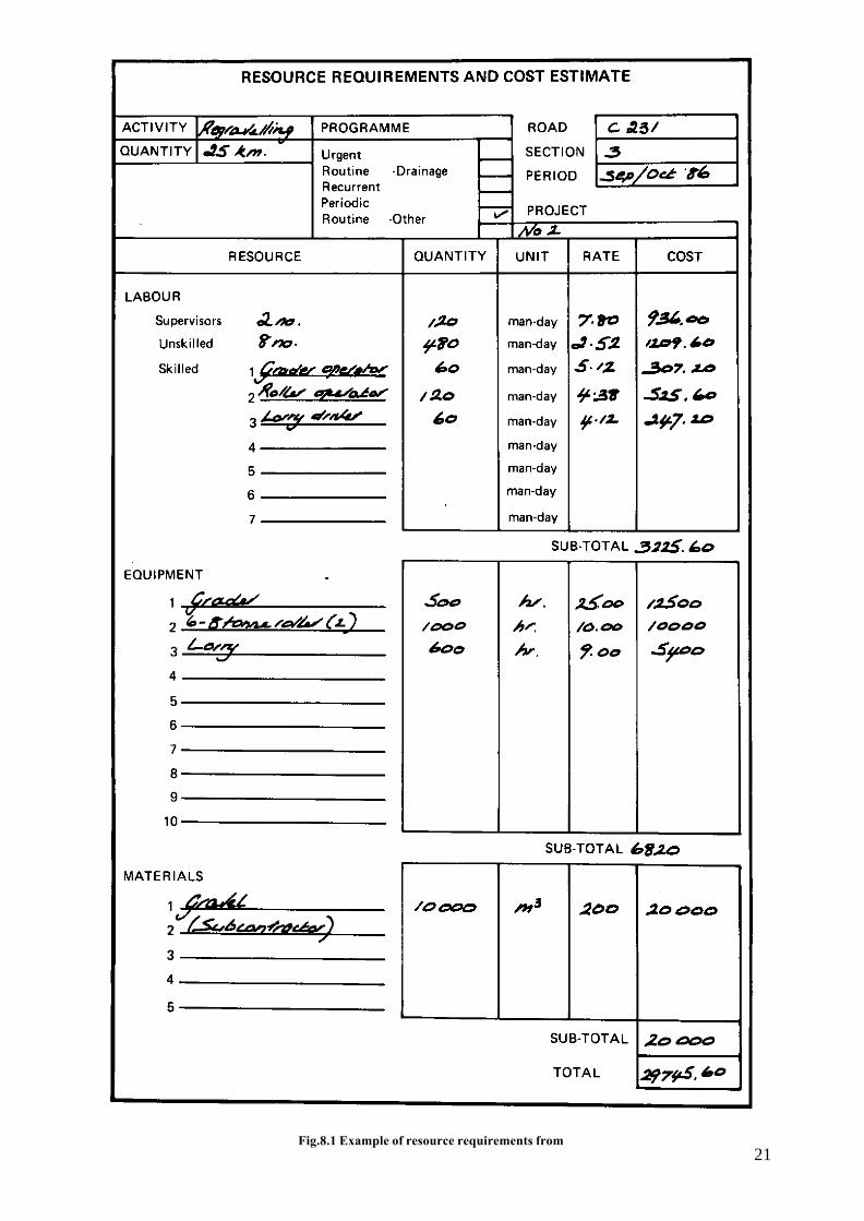
Fig.8.1 Example of resource requirements from21

9. IDENTIFICATION OFPRIORITIES
9.1 If he is fortunate, the maintenance engineer mayfind that he has all the resources he needs to carry out thefull programme of work. But it is more likely that resourceswill be limited and he will have to decide the most effectiveway of applying them. This means working out an order orpriority, with the operations that have the strongest claimon resources placed at the head of the list and those thathave least claim placed at the end. This section of the Noteexplains a method that will enable the maintenanceengineer to identify priorities objectively and consistently.
9.2 The method is straightforward: it simply relates theimportance of the maintenance activity to the importance ofthe road. It asks two basic questions: (i) how critical is aparticular maintenance activity to the traffic performance ofthe road? (ii) how significant is the particular road as atransport link?
Maintenance activities by order of importance
9.3 Maintenance activities may be ranked in thefollowing order of importance:
Urgent
• Emergency repairs to blocked or impassable roads
• Removal of debris and stabilisation of side slopes
By definition, urgent works of this type demand toppriority: past experience will indicate the scale ofthe resources that need to be set aside foremergencies.
Routine drainage work
• Cleaning out and recutting ditches and turnouts
• Cleaning out bridges and culverts
• Filling scoured areas
• Building check-dams and scour controls
• Repair of drainage structures
This work always deserves high priority becauseneglected drainage can rapidly lead to deteriorationof the whole road. It should not be assumed that alldrainage work must take precedence over allrecurrent work. The key point is that repairingsurface defects caused by poor drainage will be awaste of time and effort unless the drainage is putright first.
Recurrent work
• Dragging, brushing, grading or filling of unpavedroads
• Patching or local sealing of paved roads
22
Periodic work
• Regravelling of unpaved roads
• Surface dressing of paved roads
Periodic work can be treated as a series of distinctprojects that have to compete for the resourcesavailable and can be undertaken separately,deferred or brought forward as required.
Other routine work
• Filling on shoulders and slopes
• Grass cutting
• Cleaning, repainting, repairing and replacing roadfurniture
Special
• Overlaying
• Reconstruction
These activities should be treated as capitalprojects whose funding does not come out of themaintenance budget. If this principle is notestablished, there is a danger that a major overlayor reconstruction scheme will swallow upvirtually the whole of the maintenance budget,leaving nothing for routine and recurrent work.
Roads by order of importance
9.4 The roads that carry the heaviest loads of trafficare normally the most important parts of the networkfrom an economic standpoint, and they are the roadsliable to deteriorate most rapidly from wear and tear.There may also be roads with relatively low levels oftraffic which nevertheless have key strategic importancebecause of the places they link. Generally there will beonly one or two such roads in any region. Since it is vitalto keep these strategically important roads in goodcondition, it makes sense to give them top priority formaintenance work.
9.5 The remainder of the network should be classifiedby the level of traffic on each road. This level is usuallyexpressed in terms of the estimated annual average dailytraffic (ADT); i.e. the total traffic in both directionsduring the year. divided by 365. The estimate can onlybe reliable if it is derived from actual traffic counts. Thismeans that traffic information is needed about every partof the network, including minor and unpaved roads. Forthe purposes of maintenance planning, a simple trafficcount procedure as outlined in Appendix C will beadequate; but the maintenance engineer should note thatcounts lasting for less than 7 consecutive days are liableto very large errors, particularly where traffic levels arelow.

TABLE 9.1
ROADS CLASSIFIED BYCATEGORY OF IMPORTANCE
Category ADT Surface Type
12345678
(Strategic roads)Greater than 1000500 – 1000200 – 500Greater than 200Less than 20050 – 200Less than 50
PavedPavedPavedPavedUnpavedPavedUnpavedUnpaved
9.6 Table 9.1 sets out a simple classification of roadsby category of importance based on traffic level. It ismeant as an example which the maintenance engineercan adapt to reflect the character of his road network andthe general levels of traffic.
9.7 An axle load survey, in addition to traffic counts,may be justified if the traffic composition on a particularroad is believed to be significantly different from that onthe network as a whole - for example, on a road thatcarries large numbers of heavy freight vehicles. Thesurvey, which can be completed in a few days using aportable weighbridge, involves the preparation of asuitable site and usually will require the assistance of thepolice in enforcing the operation. The Transport andRoad Research Laboratory (1978) has published abooklet (Road Note 40) which offers guidance onprocedures for axle load surveys.
Fig.9.1 Matrix of maintenance priorities
Priority matrix
9.8 Fig 9.1 is a matrix which shows how theclassification of maintenance activities should be relatedto the classification of roads. Maintenance activities arenumbered from 1 (highest priority - urgent maintenanceon strategic roads) to 48 (lowest priority -special workson unpaved roads with very low levels of traffic). Thematrix is designed to ensure that every road in thenetwork receives at least the minimum maintenanceneeded to keep it operational, while at the same timefocusing recurrent and periodic maintenance on theeconomically important roads with high traffic levels. Asnoted in para 9.4, strategically important roads haveabsolute priority for resources, even where special worksare concerned.
Adapting priorities to local conditions
9.9 The maintenance engineer should use the matrixto produce a master list identifying in order of priority allthe works that need to be done on his network. While thenumbering scheme in Fig 9.1 is a rational and consistentorder of priority, it is not meant to be inflexible. Theremay well be local conditions of soil type, topography andclimate which influence maintenance requirements ondifferent parts of the road network, and these maywarrant an amended order of priority. The maintenanceengineer should feel free to reorder the list of priorities tosuit local conditions, where necessary.
9.10 The type of local factors involved may include,for example, the presence of expansive clay subgradeswhich are likely to cause maintenance problems, or thecombination of steep slopes and high rainfall where run-off may accelerate the process of erosion.
Determining the work programme
9.11 The next step is to compare the resource costs ofthe proposed maintenance works with the resource fundsavailable. The type of form shown in Fig 8.1 provides auseful means of doing this, since it summarises theresource requirements and estimated costs of eachmaintenance task (para 8.17). The forms should all beplaced in a ring binder, initially following the order ofpriority defined in the master list, with the top prioritytasks at the front and the lowest priority tasks at the end.The order of the forms in the file can be changed wherenecessary to take account of local conditions as describedin para 9.9. By working through the file, the maintenanceengineer can calculate how far the available resourceswill extend, and so he is able to identify which tasks hecan include in his programme for the year and whichtasks he will have to defer until the next financial year.
9.12 Budgeting procedures within his organizationmay mean that the funds available for routine, recurrentand
23

periodic maintenance are not interchangeable. Someflexibility and adjustment of priorities may be necessaryto make sure that all the funds available for a particularcategory of work are used.
9.13 It is often useful to have routine and recurrentmaintenance work organized at a sub-district level. Inthis case each sub-district should be given a programmeof work based on the priorities defined in the master list.Periodic maintenance work organized directly at districtlevel should have its priorities assessed in the same way.In this situation, the maintenance engineer should givecareful thought to the location and organization of hismaintenance crews so as to check whether existingarrangements meet the requirements of the district asefficiently as possible. He should recommend toheadquarters any necessary changes.
24
1O. WORK SCHEDULING ANDEXECUTION
Schedules
10.1 The maintenance engineer's next task is toprepare detailed work schedules for the teams under hisdirection. The schedules are essentially sets ofinstructions which tell the foremen or technicianssupervising an activity how much work is to be doneeach day, the time it should take and the labour,equipment and materials to be used. Schedules shouldcover periods of not less than 2 weeks and not more than4 weeks: shorter periods would probably not warrant theeffort of preparing a schedule, while longer periodswould risk losing a sense of urgency.
10.2 In drawing up schedules, the maintenanceengineer should first discuss the work with the foremenand supervisors who will have to put the schedules intopractice. It is essential for these personnel to feelconfident that the 'production target' the output of workrequired each day is pitched at a realistic level. Oneuseful idea is to ask the foremen to draft their ownschedules: the maintenance engineer can use these as abasis for discussion and the results can be helpful indeveloping the work schedules that are issued to teams.
Worksheets
10.3 Fig 10.1 shows an example of a completedworksheet. This provides a daily record of the progressmade on a job and the resources used, allowing the actualoutput of work to be measured against the target output.The target is the first item to be recorded on theworksheet; the amounts of each resource to be used areentered next, in the top half of each line. The worksheetis then issued to the supervisor who enters in the bottomhalf of each line the progress actually made and theresources used day by day. At the end of the scheduleperiod, the supervisor returns the completed forms to themaintenance engineer who calculates in percentage termshow much of the production target has been achieved andso is able to assess the productivity of the work. Anysignificant shortfalls that may occur, or instances of over-achievement, can be discussed with the supervisorypersonnel when the next schedule is being prepared.
10.4 The execution of maintenance tasks at districtlevel is the subject of Overseas Road Note 2 (TRRLOverseas Unit 1985).

25
Fig.
10.1
Exa
mpl
e of
wor
kshe
et

11. MONITORING
11.1 Monitoring serves two main purposes: it enablesthe maintenance engineer to check the quality andeffectiveness of the work being done, as noted in para4.1; and it provides data that can be used to improve themanagement and performance of future maintenanceoperations. There are two aspects to the task:
• site inspections
• desk review.
Site inspections
11.2 Section 2 of this Note emphasized the importanceof site inspections in the work of the maintenanceengineer and the advantages to be gained from taking apersonal involvement in the inspection process (para2.6). Because of the length of road to be covered,inspection visits will require the use of a motor vehicle,which should be driven slowly along the section beingexamined. Enough time should be allowed for themaintenance engineer to make a series of detailedinspections on foot. He should examine closely the roadsurface, side drains, culverts and soils. It is best if hetravels as a passenger: he can then concentrate on hisinspection, and when he goes off to look at the road hisdriver can follow with the vehicle.
Desk review
11.3 This is an offic e task which involves reviewingall the maintenance documentation - inspection reports,resource requirement forms, work schedules andcompleted worksheets - so as to assess the performanceof the programme and the effectiveness of themanagement system. It provides an opportunity to checkthat adequate resources were allocated to each task andthat maintenance problems were treated efficiently; costestimates can be compared with expenditure andproduction targets with output; and the reasons forinconsistencies or shortfalls can be identified. In somecases, resources may have been insufficient; in others,targets may have been pitched too high.
11.4 The maintenance engineer should discuss theresults of the desk review with this supervisors and try tofind ways of remedying any deficiencies. It is likely thatsome of these may result from factors beyond the controlof the maintenance staff, but it should be possible toidentify those points that can be put right and to planappropriately for the following year.
26
REFERENCES
TRANSPORT AND ROAD RESEARCHLABORATORY, 1978. A guide to the measurement ofaxle loads in developing countries using a portableweighbridge. Road Note 40. London: HMSO, availablefrom TRRL Overseas Unit.
TRRL OVERSEAS UMT, 1985. Maintenancetechniques for District Engineers. Overseas Road Note2. Crowthorne: Transport and Road ResearchLaboratory, 2nd edition, available from TRRLOverseas Unit.

APPENDIX A
FIELD PROCEDURES FORINVENTORY AND CONDITIONMEASUREMENT SURVEYS
A.1 GENERAL PROCEDURE
Recording
A.1.1 Inventories and inspections use largely the samefield procedures. Standard forms for recording the resultsof surveys are included in Appendix D.
A.l.2 The road should first be divided into sections of 5to 20 kilometres. These sections should be reasonablyuniform in terms of their geometric characteristics,construction, terrain and traffic, but they need not allhave the same length. Each section should then bedivided into sub-sections of 100 to 200 metres in length.
A.1.3 The aim is to measure and record all defectsappearing in each sub-section. Because this is a time-consuming process, it may only be possible initially totake representative measurements over perhaps one 25metre length in each sub-section. As inspection teamsbecome more skilled and as more teams are introduced, itshould become practicable to increase the coverage ofthe surveys until measurements are taken over the entiresub-section.
A.l.4 The extent of characteristics or defects should berecorded on the forms by simply marking the locationswhere defects occur. Defects whose extent is assessed interms of length (eg cracking) are indicated by recordingthe assessment of extent (Fig 6.1). Table Al sets out acheck list of the equipment required for the field work ofinspections. At first, only items 1-8 will be needed sincethe inspection will be carried out largely by visualassessment, but as the maintenance system develops andas measurement methods are introduced, the remainingitems can be added to the list.
Organisation of teams
A.1.5 The basic duties of the team are the observation,measurement and recording of information. Compositionof teams will depend upon local circumstances and thetype and category of road, but normally the team willconsist of a team leader and an assistant. In some cases,where traffic densities are high, an additional assistantwill be needed for safety purposes and to help directtraffic. If a detailed structural survey of the road is to becarried out at the same time as the inspection, additionalteam members may also be needed.
TABLE A1
EQUIPMENT FOR INSPECTIONS
ItemNo.
Description
1234
5678
TransportWarning signs and reflective jacketsMaps of the areaField inspection instructions and codeswhere applicablePrinted inspection formsReport sheets for 'urgent' defectsClip-boardsBallpoint pens or pencils
9
101112
1314
Road marking crayons or chalk, roadmarking paint and brush30m fibre measuring tape3m steel measuring tapeMeasuring wheel with stand or, if theroad is adequately provided with kmposts a bicycle fitted with a distance-measuring cyclometer2m straight-edge and calibrated wedgeSpirit level for measuring camber witha 2m straight edge
Safety
A.1.6 This is a most important aspect of the work. Theroad being inspected may have vehicles travelling at highspeed. Any person working on the road should thereforetake simple and sensible precautions. Even where trafficis not heavy, safety procedures should not be relaxed,since there may then be a danger from unexpectedvehicles.
A.1.7 All members of the field survey team should wearhigh visibility fluorescent and reflective safety jackets atall times during the survey. In rural areas, warning signsshould be placed at each end of the work area. If avehicle is provided it should be fitted with warning signsor warning lights, and should be parked between theteam and the oncoming traffic.
Transport
A.1.8 Transport is needed to carry teams to and fromtheir place of work, to carry equipment, to givetemporary shelter during bad weather and to provideprotection on heavily-trafficked roads. Either land roversor vans can be used, but the land rover has a particularadvantage as a protective vehicle in that warning signscan be easily attached to it. Where possible, vehiclesshould display hazard warning lights. If the vehicle isused simply to transport the survey team at the start andthe end of the day's work, the team leader and the drivermust be in no doubt as to the time and place ofcollection.
27

Notes for inspectors
A.1.9 The maintenance engineer should prepare notesfor inspectors which include further guidance on therecommendations given in this Note and rules andinterpretations suited to local conditions. The notesshould include any additional detail necessary forassessing and recording individual items, together with alist of standard criteria.
A.1.10 Clerical work should be done by the inspectors.This will give them closer involvement in themanagement process, and is likely to result in higherstandards of inspection and recording.
Duties of team members
A.1.Il• Team leader
He has the overall responsibility for the work of theteam. He should carry out a visual inspection of thecarriageway, shoulders and drainage, assessstructural condition and record all information onthe relevant forms. With a team of two, the leaderusually pushes a measuring wheel
•• AssistantWhen inspecting procedures are first introduced, theteam leader will make his assessment on the basis ofa visual inspection. As the maintenance system isdeveloped, assessments will be based on thedetailed measurement of defects. An assistant willbe needed to carry out these measurements.On roads where traffic is heavy, additionalassistants may be needed, in particular to makerutting measurements on the far side of thecarriageway, to control traffic and generally to assistin measurement procedures
•• DriverWhen a vehicle is provided, a driver is necessary toenable the inspector to concentrate on the job inhand. The driver should be responsible for erectingand moving advance warning signs where no otherperson is provided for this task. He can also assist intraffic control or in making measurements. Wherepossible he should, as a safety measure, park hisvehicle on the road between the on-coming trafficand the inspection team and switch on his hazardwarning lights.
Order of work
A.1.12 Before leaving the depot, the inspector shouldpersonally check that all of the equipment needed hasbeen collected together and loaded in the vehicle. Heshould ensure that the vehicle has sufficient fuel or thatarrangements have been made to refuel on the way.
28
A.1.13 Once on site. the inspector must establish thestart of the length to be inspected. From this point, heand his team should methodically record defects orfeatures. The start point should be a kilometre post or astructure, if possible.
Accuracy
A.1.14 Correct, accurate and legible recording in thefield is essential to avoid unnecessary effort in checkingerrors later. It is important to record the correct chainagesfor the start and end of defective areas, in the case ofcondition measurement surveys, or changes incharacteristics in the case of an inventory. Chainagesshould be recorded to the nearest metre, and widths to thenearest 0.1 metre. For condition measurement surveys, itis also useful at this time to paint the outline of areas ofpaved roads that need patching, since this will makethem easier to find when the work is carried out later.
A.2 CONDITION MEASUREMENT
General considerations
A.2.1 In order to establish maintenance needs, it isnecessary to compare the measured condition of the roadwith maintenance intervention levels such as those setout in Tables 7.1-7.3. These levels may need to bemodified by the maintenance engineer to suit localconditions as noted in para 7.8.
A.2.2 When the maintenance system is introduced, itwill probably only be possible for the inspector to assessthe severity of defects by observation. As the system isdeveloped, physical measurement of defects should begradually introduced into the inspection procedure; butthe quality of visual assessment can be improved byhaving first-hand knowledge of the physicalmeasurement techniques.
A.2.3 Most defects require either the area or thelength of deterioration to be measured. The area or lengthof deterioration must first be identified and classifiedusing the method outlined in the following paragraphs.As each sub-section is approximately 100-200 metreslong, it is probable that several occurrences of the sametype of deterioration will be found within the sub-section. These should be added together to give the totalextent for each sub-section.
Side drains and turnouts (all roads)
A.2.4 The level of the water table beneath the roadhas a major influence on the strength of the subgrade. Tokeep water out of the pavement structure, side drainsshould

be maintained at least one metre below the road surface .The depth of side drains should be measured atapproximately 25 metre intervals using a straightedgeand measuring tape as indicated in Fig. Al.
Loss of material (gravel roads)
A.2.5 An estimate can be made of the thickness ofgravel on the road by examining pot-holes or by digginga small hole in the road surface until subgrade is reachedand probing the depth with a measuring tape. Materialshould then be replaced and compacted with a handtamper or punner.
A.2.6 Ideally, thicknesses should be measuredimmediately after grading. But in view of the difficultyof timing such measurements and the need to carry outsurveys on a routine basis, the following approach maybe more appropriate. The survey team should takemeasurements on each sub-section or at 200 metreintervals along the road. At each survey point, the teamshould identify any obvious ruts and should dig twoholes: one in the rut and the other at the peak betweenruts. The gravel thickness should be recorded as theaverage of the two measurements, as shown in Fig. A2.
Deformation (all roads)
A.2.7 Ruts are measured using the deformation gaugeshown in Fig. A3. Initially, measurements will be madeat only one point on each sub-section or at 200 metreintervals along the road, but as the survey procedure isimproved and extended, more frequent measurementsshould be taken until recordings are made every 25metres.
A.2.8 Rut depths are measured by placing a twometre straightedge transversely to the road edge over thewheelpath. The deepest part of the depression beneaththe straight edge is measured and recorded as the rutdepth using a calibrated wedge as shown in Fig A3. Thedepth of rut indicated is the value recorded. In somecases, a bump may have formed at the edge of awheelpath owing to shoving of material in the pavement.The condition should then be reported as a comment onthe form and an indication of the seriousness of thecondition obtained by placing one end of the straightedgeon the bump and the measuring the maximum rut depthin the wheelpath. Measurements of rutting are made inthe two wheeltracks nearest the edge on both sides of theroad, and the higher of the two rutting values is recorded.
A.2.9 Corrugations on unpaved roads are measuredby placing the straightedge longitudinally in thewheelpaths spanning the corrugation crests. Corrugationdepths are measured at the deepest point of the troughsusing the calibrated wedge. The highest value of depthfrom any trough in any wheelpath is the value that shouldbe recorded.
Cracking (paved roads)
A.2.10 A crack can have the appearance of a line inthe surfacing (particularly for asphalt) without twoclearly defined edges. This condition indicates an earlystage in the deterioration process, when the surfacing stillremains waterproof. For the purpose of conditionmeasurement surveys, it is more practical to define acrack as being visible from standing height. Such a crackwould, on close inspection, have two clearly definededges at the surface. It should be remembered that thiscondition is much further along the deterioration paththan that described above. Water may be penetrating intothe pavement through cracks of this severity whether theroad is surfaced in asphalt or surface dressing.
A.2.ll In bright sunlight, it is often very difficult tosee even quite wide cracks. A method of shading the areaunder observation should be used. The width of cracks inasphalt can change markedly between early morning andmid-day owing to thermal expansion. In some cases,cracks can close completely and not be seen at all.Surveys are best carried out in the morning or duringcloudy weather conditions, particularly when the road isdrying out after rain.
A.2.12 During surveys, cracking should be recorded intwo classes: wheeltrack cracking and non-wheeltrackcracking. In each case, the total length of road affectedby cracking should be recorded regardless of the area orseverity of cracking across the road.
Pot-holes (all roads)
A.2.13 The number of pot-holes in the sub-sectionshould be counted and recorded.
Edge damage (paved roads)
A.2.14 This is measured at the edge of the paved areaof the road at the same chainage where rutting ismeasured. Excessive edge damage is recorded if the edgeis eroded by more than l5Omm from the originalposition. The measuring wedge, which is I5Omm long,provides a simple means of measuring this defect.
Edge step (paved roads)
A.2.15 This is measured at the same chainages as therutting. Measurements are taken on both sides of the roadat the point where the carriageway meets the shoulder.The measuring wedge should be placed on the shoulderwith its 'toe' against the edge of the carriageway. If thestep is greater than the 50mm marker, an excessive edgestep should be recorded.
A.2.16 On certain roads, particularly where an overlayhas been applied, there may be an edge step which is aconstruction feature. In this case, measurement of thestep should still be made in the same way. If themeasurement exceeds 50mm, a defect should berecorded.
29

Fig.A1 Measuring depth of side drains with straight edge and measuring tape
Fig.A2 Measurement of gravel thickness as the average of two measurements
30

Fig.A3 Deformation gauge (straight-edge and calibrated wedge)
31

APPENDIX B
MANAGEMENT OF GRADING FORUNPAVED ROADS
B.1 DETERMINING OPTIMUM GRADINGFREQUENCIES
B.1.1 Ideally, an appropriate frequency of gradingshould be identified for each individual road. However, it ismore practical to determine optimum grading frequenciesfor groups of roads with similar traffic levels, similarmaterials types and sizes, and sharing similar topographicand other physical features. The more often a road isgraded, the smoother its surface will become and the lessdeterioration there will be between gradings. The end resultwill be lower vehicle operating costs on the road. The aimis to choose a frequency of grading which minimises thesum of maintenance costs and vehicle operating costsduring the maintenance year.
B.1.2 The easiest way to determine vehicle operatingcosts for particular grading frequencies is to use a roadinvestment model such as RTIM3 or HDM-III. Details ofhow to obtain copies of RTIM3 are available from:
Overseas CentreTransport Research LaboratoryCrowthorneBerkshire RG45 6AUUnited Kingdom.
B.1.3 Details about obtaining HDM-III are availablefrom:
Transportation DepartmentThe World Bank1818 H Street NWWashington DC 20433USA.
B.1.4 If computer facilities are not available, tables ofvehicle operating costs can be obtained free of charge fromTRL Overseas Centre at the above address. However, useof the tables for this particular application is very laboriousand is recommended only if there is no other option. Abetter method is to program the relationships in the tableson a suitable hand calculator and to use these to determinevehicle operating costs.
B.1.5 The analysis must be carried out for each selectedroad surface material type, climate, road geometry andtraffic level, and vehicle operating costs determined for arange of grading frequencies. The results should be plottedin graph form. For each material type, climate and roadgeometry, curves such as those shown in Fig. B 1 should beobtained. The minimum cost plotted at each traffic levelwill indicate the optimum grading
32
Fig.Bl Typical curves showing optimum gradingfrequency for different traffic levels on roads with similar
climate, materials and geometry
frequency. The grading frequency should be applied toparticular roads on the network by selecting the traffic levelon the graph closest to that found in the field. Differentoptimum values will be obtained, not only for differenttraffic levels, but also for roads with different materialtypes, with different geometries and in different climaticareas. It is necessary to undertake separate analyses foreach of these cases.
B.2 MONITORING OF OPTIMUMFREQUENCIES
B.2.1 By whatever means the optimum gradingfrequencies are determined, they should be implemented inthe field and a monitoring system should be established tocheck their effectiveness. A representative sample ofunpaved roads in each group should be
monitored for a period of at least one year, andmeasurements should be taken of roughness and rut depthimmediately before and after each scheduled maintenancegrading. Traffic levels on these roads should also bemonitored.
B.2.2 Modifications to the grading frequencies can thenbe made to ensure that the mean values of roughness andrut depth measured in the field agree with those required bythe analysis using the investment model. This ensures thatthe sum of road maintenance and vehicle operating cost isminimised. In this way, by the end of the year, gradingfrequencies will have been obtained that are suitable forlocal conditions and are close to the optimum. A sample ofthe road network should have its performance monitored ona continuing basis to make sure that the grading frequencieseffectively keep roads in a condition that is close to theoptimum. Adjustments can then be made to the gradingfrequencies as necessary'.
B.3 MEASUREMENT METHODS
B.3.1 Rut depths should be measured with astraightedge and wedge following the method described inAppendix A.
B.3.2 Roughness will normally be measured with a'response-type' instrument such as a 'bump integrator','NAASRA meter' or ‘Mays ride meter'. It will be necessaryto calibrate this instrument to ensure that the resultsobtained are consistent with either the InternationalRoughness Index ('RI) or the 'towed fifth wheel bumpintegrator' values used for vehicle operating costcalculations in the road investment models. Equations nowexist (Sayers 1986) for relating these standard roughnessvalues to the absolute longitudinal profile of the road. Theresponse-type instruments used can be calibrated byoperating them over roads with various levels of roughness.The longitudinal profile can be determined by measuringthe road with a staff and engineer's level. However, thismethod is laborious and the calculations needed todetermine the calibrated values are time-consuming. Twoinstruments have been developed by TRL which providealternative methods for calibrating response-type measuringdevices more easily, the MERLIN and the Profile beam('Abay' beam). The TRL Profile beam is a Class 1instrument (Sayers 1986) which samples the profile of aroad section at l00mm intervals. It has a microprocessor tocalculate the standard roughness values and can provide anautomatic readout of calibrated roughness. The MERLIN isa Class 2 instrument. It is a simple, robust and inexpensivedevice which is easily maintained, easy to use and can bemade by local craftsmen. It measures surface undulations atintervals along the road section and has a graphicalprocedure for data analysis to enable
an estimate of roughness to be obtained without complexcalculation (Cundill 1991). Drawings of the MERLIN areavailable from the Overseas Centre, TRL.
REFERENCES
CUNDILL, M A, (1991). The MERLIN low-cost roadroughness measuring machine. TRRL Research Report RR301. Crowthorne: Transport Research Laboratory, availablefrom TRL Overseas Centre.
SAYERS, M W et a l, 1986. Guidelines for conducting andcalibrating road roughness measurements. World BankTechnical Paper 46. Washington DC: International Bankfor Reconstruction and Development.
33

APPENDIX C
TRAFFIC COUNTING
C.1 FREQUENCY AND DURATION OFCOUNTS
C.1.1 The purpose of the traffic counts is to classifyroads in broad categories for maintenance planningpurposes. A high level of accuracy is not required. Onroads carrying more than about 1000 vehicles per day, aone-day manual count will usually be sufficient toprovide an estimate of ADT for the maintenanceclassification. On roads with fewer vehicles, accountshould be taken of daily and seasonal variations:
• the effects of local market days, which mayaccount for a high proportion of annual traffic onlow-volume roads, may be allowed for by makingtwo counts, one on a market day and one on anon-market day
• a count should be carried out during each mainclimatic and/or agricultural season so that theeffect of seasonal rainfall and of variations inagricultural activity (especially during and justafter harvest-time, when traffic flows usuallyshow a marked increase) are taken into account.Counts extending over 16 hours (from 6 am to 10pm) will usually be adequate, but, in somecountries where traffic is heavy at night countsshould extend over 24 hours.
C.2 ESTIMATION OF ADT FROMCOUNTS
C.2.1 The estimation of ADT must take account of thefactors noted above. The following example indicates therecommended procedure:
Example
C.2.2 Counts were taken near a village which has amarket every eight days. The wet season lasts for aboutfour months and the dry season eight months.
1. Two 16-hour counts were taken at the end of the dryseason (low level of agricultural activity)Count on market day = 73 vehiclesCount on non-market day = 21 vehicles
2. Two 16-hour counts were taken at the end of the wetseason (harvest time)Count on market day = 94 vehiclesCount on non-market day = 48 vehicles
C.2.3 For this example of an eight day traffic cycle, theaverage daily traffic is calculated for each season asfollows:
Average daily traffic (dry season)Tdry = (1/8 x 73) + (7/8 x 21) = 28 vehicles
Average daily traffic (wet season)Twet = (1/8 x 94) + (7/8 x 48) = 54 vehicles
34
The ADT is taken as the weighted mean of the seasonalflows, calculated thus:
ADT = (8/12 x 28) + (4/12 x 54) = 37 vehicles
C.3 MANUALCOUNTS
C.3.1 The equipment required for manual countingcomprises a supply of pre-printed forms, pencils andclip-boards. A shelter from sun or rain may be required.At low traffic volumes, the work is not demanding andthe main problem is likely to be ensuring that theenumerators stay on the job. Unscheduled visits by theengineer or a senior supervisor may be necessary tosecure discipline and attention to the work. If theproportion of heavy vehicles in the traffic flows isexpected to be high, classified counts may be necessary.
C.4. AUTOMATIC COUNTERS
C.4.1 It is now possible to obtain cheap and reliableautomatic traffic counters recording total numbers of axlepairs which can be used to supplement manual counts orto count for periods of more than one day on low volumeroads. The equipment normally consist of a small rubbertube fixed across the road and attached to a pneumaticcounter. When vehicles drive over the tube. it iscompressed and a pulse of air triggers the counter. Theinstrument records one count for the passage of twoaxles. These traffic counters need careful adjustment toensure that bicycles, motorcycles and pedestrians are notcounted and that heavy or fast vehicles are not 'doublecounted'. Provided that they are checked regularly andthe rubber tube replaced when it is damaged, their use isrecommended.
C.4.2 Buried loop detectors can be used instead ofpneumatic tubes and are generally more reliable.However, their permanent installation will not normallybe justified solely for traffic counts for maintenancepurposes.
C.4.3 The maintenance engineer should select one ofhis staff trained in the installation and use of counters tobe responsible for their checking and maintenance. Heshould also arrange for the daily inspection of the counterand recording of the counter reading. In some locations,automatic counters may be subject to theft or damage.The counters themselves can be protected by lockablecabinets attached to solid objects, but the tubes cannot beeffectively protected from deliberate interference. Whenthis is experienced and regular inspection is not sufficientto prevent it, automatic counters of this type should notbe used.
C.5 MOVING OBSERVER COUNTS
C.5.1 Moving observer counts can usually be carriedout by the maintenance engineer or supervisor in thecourse of personal inspections, using a hand-tally torecord the

number of vehicles. The flow can be estimated from theexpression: -
(x + y)q =
t
where q = total flow in both directions in time tx = number of vehicles met (ie. travelling in
the opposite direction)y = number of vehicles that overtake the
observer minus the number he overtakest = journey time
C.5.2 This expression assumes that flows in eachdirection are equal. If the observer can drive so that hepasses as many vehicles as pass him in the direction oftravel (this can usually be achieved without risk at lowtraffic volumes), the expression becomes:-
xq = _______
t
C.5.3 Counts of this type are useful as a cross-check onstatic counts and to assess the extent of variations in flowfrom day-to-day or between one season and another.
C.6 DEVELOPMENT OF TRAFFICCOUNTS
C.6.1 When the maintenance system is first applied, itwill probably not be possible to include traffic counts aspart of the maintenance planning process. Initially, trafficlevels on the roads within the maintenance district mayhave to be estimated. But there is no substitute forcounting vehicles. As the maintenance system develops,the traffic counting methods described in this Appendixshould gradually be introduced into the managementprocess.
35

APPENDIX D
RECOMMENDED STANDARD FORMS
36

37

38

39

40

41

APPENDIX E
ILLUSTRATIONS OF TYPICALDEFECTS
Photographs are provided that illustrate the mostcommon, or important, defects described in Tables 7.1-7.3 of recommended maintenance intervention levels.For paved roads, more categories of cracking are shownthan are described in the text to assist engineers indetermining possible causes of failure. To aid clarity, thephotographs, in most cases, show deterioration which isworse than that at which intervention is recommended.
42

Debris on road.
Broken down vehicle.
43

Side drain silted and too shallow.
Blocked side drain.
44
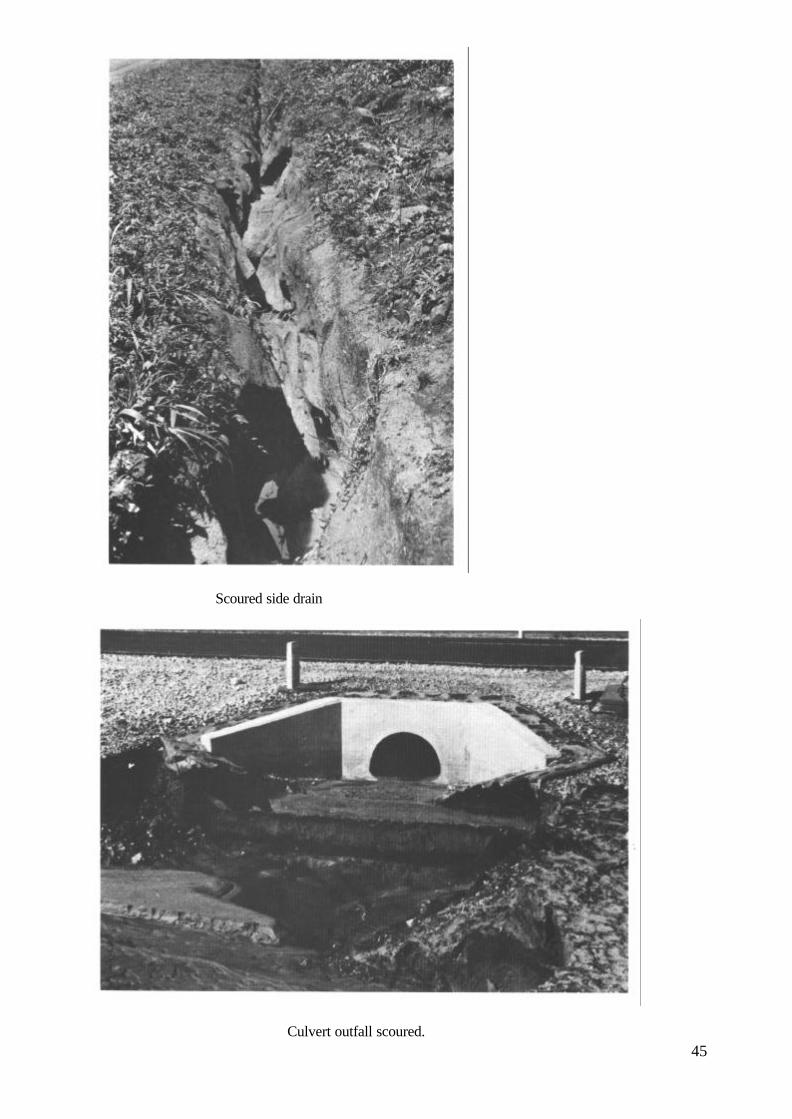
Scoured side drain
Culvert outfall scoured.45

Scoured side drain.
Standing water in side drain.
46

Structural damage of bridge superstructure.
Structural damage of bridge abutment.47

Dirty road sign.
Damaged road sign.
48

Missing road sign.
Damaged road furniture.49

Deformation of shoulder.
Scour of shoulder and sideslope.
50

High vegetation growth and standing water.
Pot-holes on unpaved road and high roadside vegetation growth.51

Roughness and lack of camber on unpaved road.
Rutting and lack of camber on unpaved road.52

Roughness, rutting, pot-holes and lack of camber on unpaved road.
Corrugations on unpaved road.
53

Fatting-up and bleeding on paved road.
54
Stripping of aggregate from paved road.

Pot-hole on paved road.
Edge damage on paved road.
55

Edge step on paved road.
Edge damage and step on paved road.
56

Wheeltrack rutting and cracking on paved road.
Wheeltrack rutting, cracking and pot-hole on paved road.57

Crocodile cracking on paved road.
Block cracking on paved road.58

Longitudinal cracking in the wheeltrack on paved road.
Longitudinal cracking on the centre line on paved road.59

Transverse cracking on paved road.
Longitudinal and transverse cracking on paved road.60
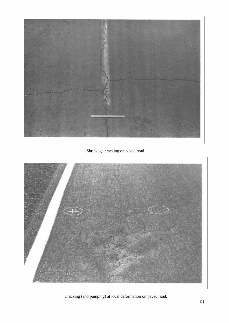
Shrinkage cracking on paved road.
Cracking (and pumping) at local deformation on paved road.61

Parabolic cracking and slipping on paved road.
Slipping at edge of paved road.62


Transport and Road Research Laboratory Overseas Unit
Department of TransportOverseas Development Administration
Overseas Road Note 2
Maintenance techniques for DistrictEngineers(2nd Edition)
Overseas UnitTransport and Road Research LaboratoryCrowthorne Berkshire United Kingdom1985

ACKNOWLEDGEMENTS
This Note was drafted by Mr L S Hitch, Mr T F Jonesand Dr R Robinson of the TRRL Overseas Unit.It is based on an original text produced by Scott WilsonKirkpatrick and Partners, consulting engineers.
First published 1981Second edition 1985Reprinted with minor revisions 1987
OVERSEAS ROAD NOTES
Overseas Road Notes are prepared principally for roadand road transport authorities in countries receivingtechnical assistance from the British Government. Alimited number of copies is available to other organisations and to individuals with an interest in roads overseas, and may be obtained from:
Transport and Road Research LaboratoryCrowthorne, Berkshire RG11 6AUUnited Kingdom
© Crown Copyright 1985Limited extracts from the text may be producedprovided the source is acknowledged. For moreextensive reproduction, please write toHead of Overseas Unit,Transport and Road Research Laboratory

1. INTRODUCTION
1.1 SCOPE OF THIS NOTE
This Note describes the principal techniques that will beused to maintain roads within a District in a developingcountry. Particular attention is paid to the planning anddesign aspects of the work, as it is in this area that theEngineer will make the largest contribution. Practicalexecution is not described in detail.
The Note first discusses the merits of using labour orequipment-based operations and examines the scope forusing local contractors for maintenance work. Theimportance of safety during maintenance work is thendiscussed and each of the various maintenancetechniques is described in turn.
1.2 THE ENGINEER'SRESPONSIBILITIES
One of the key persons in any maintenance organisationis the professional engineer who is responsible forrunning the organisation at District or operational levelAlthough the District or Maintenance Engineer willusually be constrained to work within whatever manage-ment system is operated by his Department, there isinvariably scope for improving the cost-effectiveness ofthe use of the resources available for road maintenance.
By adopting the same professional approach towardsroad maintenance as to any other engineering activity, hecan inspire Ids staff to improve their own performance.The Maintenance Engineer should therefore show apersonal commitment to maintenance work by regularlyinspecting the roads under his control and making Insstaff aware of his interest. By getting out of the officeand into the field as much as possible, the Engineer willbe able to get to know his road network thoroughly andwill readily identify trouble spots and other areas ofdifficulty. He will be able to assess priorities and willgain first-hand knowledge of what maintenance hasactually been carried out, instead of having to rely onreports from others. He will also see the quality of themaintenance work carried out and will be able to use hisprofessional skill and expertise to solve problems on-the-spot as they arise. Seeing him actually on site will give aboost to staff morale and this will result in animprovement in both the quality and quantity of workdone. If there is one single factor which influences thestandard of road maintenance more than all others, it isthe attitude of the Engineer responsible.
The Engineer will find it difficult to follow this advice ifhe is overburdened with routine administrative work andit is essential that he delegates such activities to clericaland administrative staff as much as possible.
The Engineer will require adequate trained staff to carryout Ids instructions and he will need to arrange for super-visers, foremen and specialist artisans to attend suitabletraining courses. Accordingly the Maintenance Engineermust arrange for on-the-job training for labourers andother junior staff.
The supply and maintenance of equipment and vehiclesis usually organised as a separate Departmental functionand will be beyond the control of the MaintenanceEngineer. lack of suitable vehicles is always a majorfactor in maintenance organisations that are inefficient.The Maintenance Engineer must be aware of the impor-tance of proper maintenance of equipment and vehiclesand should actively concern himself with theorganisation of this, as far as Departmental proceduresallow.
The work of the District or Maintenance Engineer fallsinto three categories:-
(i) Assessment of requirements: establishingwhat needs to be done in physical terms;
(ii) Allocation of resources: estimating the men,materials and equipment required fordifferent tasks, determining priorities andallocating resources to ensure the most cost-effective results;
(iii) Monitoring: checking that the work doneproduces the desired results.
The management aspects of this work are described inmore detail in a separate Note (TRRL Overseas Unit,1981).
1

2. METHODSOFUNDER-TAKING MAINTENANCE
2.1 LABOUR AND EQUIPMENT
Most maintenance operations offer considerable scopefor the application of labour-based methods and some areonly practicable by such methods. No recommendation ismade here for either equipment-intensive or labour-intensive methods, but Table 1 indicates the potential forequipment and labour-based methods in differentmaintenance operations.
In choosing between equipment-based and labour-basedmethods, consideration should be given to the standard ofwork achieved by each method as well as to costs and tothe way in which the work is organised. It is not alwaysnecessary for labour-based operations to have the samestandards of finish that can be
obtained by equipment. For example, on low-volumeroads maintained by labour-based methods, there isunlikely to be any economic justification for insisting onthe close tolerances of level and smoothness that can beachieved by the use of equipment.
Equipment and labour cannot be substituted directly foreach other as, in addition to the question of standardsalready mentioned, it will usually be necessary to makechanges in work organisation. The following pointsshould be borne in mind when considering the use oflabour-intensive maintenance methods: -
(i) It is necessary to check carefully that labourwill be available in the actual place where it iswanted, and at the time it is wanted.
(ii) Adequate organisation and management arecritical considerations for large scale labourintensive works.
TABLE 1POTENTIAL FOR EQUIPMENT AND LABOUR
POTENTIAL FORACTIVITY
EQUIPMENT LABOUR
Ditch cleaning and cuttingCleaning and minor repair to culverts and bridges
Good (*)Poor
Good (*)Good
Building scour controlsRepair of structures
Grading unpaved surfaces
Dragging and brushing of unpaved surfacesPatching sanding or local sealing of bituminous surfaces
PoorPoor
Good(Skilled) (ØØ)GoodPoor
GoodGood
Impracticable
PoorGood
Filling on unpaved surfaces and slopesGrass cuttingManufacturing signs
Repairing and replacing traffic signsRoad line markings
PoorGood (**)Fair (Ø)
PoorGood
GoodGoodGood (Ø)(Skilled) (ØØ)GoodFair
Stockpiling gravelRegravelling gravel surfacesStockpiling chippingsSurface dressing
GoodGoodGoodGood(Skilled) (ØØ)
FairFairPoorFair(Skilled) (ØØ)
NOTES:(*) The potential in these activities is dependent upon suitable design of the ditch cross-section. 'V'-shaped
ditches are suitable for maintenance by grader whereas flat bottomed ditches are suitable for maintenance by handor by mechanical shovel.
(**) The potential in this activity is dependent on the width of the shoulder and presence of obstructions such as roadfurniture and culvert headwalls.
(Ø) Some methods of manufacture may require the use of specialised plant (eg. vacuum application of reflectivesheeting to sign plates).
(ØØ) The expression 'skilled' implies that specific training of operatives is essential.
2

(iii) The health and nutrition of the labour force arevery important and improvements can increaseproductivity.
(iv) Standardised tools of good quality are vital inorder to achieve high levels of output.
(v) It is normally inefficient to have labour andmachinery working alongside each other on thesame task.
(vi) Arrangements may need to be made totransport labour to and from the work sites. Forlarge labour forces, this can be a substantialtask.
2.2 DIRECT-LABOUR AND CONTRACT
Road maintenance organisations usually carry out muchof their work by direct-labour. However, some mainten-ance activities can be done by small local contractorsand, where Departmental policy permits, the Mainten-ance Engineer should consider whether the use of suchcontractors is advantageous.
The use of contractors can reduce the burden on scarcegovernment staff and also bring lower costs as a result ofcompetitive pressures on efficiency which are unlikely tobe obtained within a government department. However,contract work does require the preparation of detailedcontract documents and a high degree of supervision, andthe staff requirements and extra work involved for thisshould not be underestimated. There is also a danger thatcontractors bidding for maintenance work on a regularbasis might introduce ‘price fixing' to increase theirprofitability, and this will result in an increased cost tothe maintenance department.
The following activities should present no seriousproblems in the control of quality or quantity if carriedout by contract on the basis of competitive tender:-
Supply of MaterialsNatural gravelScreened gravelRock aggregate (for subsequent crushing by Depart-mental crusher)Crushed rock aggregate (for surface dressing andconcrete)Washed sand (for concrete)Precast concrete blocksPrecast concrete culvert rings
Maintenance OperationsExcavation of side drains and turnoutsConstruction of culvertsRegravellingSurface dressingGrass-cutting and bush-clearing
In addition, the supply or maintenance of equipment andvehicles can be undertaken by specialist contractors.
The Maintenance Engineer should satisfy himself thatany contractor asked to tender is capable of completingthe work satisfactorily, that he has the necessaryequipment and staff, and that he has sufficient knowledgeof estimating (or of current market rates) to be able tosubmit realistic prices.
3

Fig.1 Standard signs

3. SAFETY MEASURES ANDTRAFFIC CONTROL
3.1 PRINCIPLES
When work is being carried out on or close to thecarriageway, it is the Maintenance Engineer'sresponsibility to see that adequate measures are taken towarn and protect road users and maintenance workers.He should instruct all supervisors and fore men in safetymeasures, including traffic control, and the use oftemporary road signs.
In selecting and positioning temporary road signs, thefollowing principles should be applied:-
(i) only standard signs should be used,
(ii) the signs must be clean and in good condition,
(iii) the standard signs should be displayed in astandard layout,
(iv) the layout used must give drivers time tounderstand and respond to the informationwhich the signs convey.
Recommended standard signs are shown in Fig. 1.
It may not be possible for the Engineer to purchase orobtain the necessary signs from Departmental stores, butthe manufacture of adequate signs should be within thecapabilities of a central signs workshop. Each roadmaintenance gang should be provided with signsappropriate to the work it is carrying out and all foremenand supervisors should be trained in their use and layout.All temporary signs must be removed as soon as thework they relate to is complete. If they are not the valueof the signing will be reduced.
From the point of view of safety and traffic control, roadmaintenance work may be divided into four categories:
(i) work which does not affect the carriageway,such as cleaning out side drains and cuttinggrass on verges (Section 3.2);
(ii) work requiring partial closure of thecarriageway, such as repair work to surface orbase which is restricted to one lane whiletraffic continues to use the other lane (Section3.3);
(iii) work on the centre line, such as white linepainting (Section 3.4);
(iv) work requiring total closure of the road, withconstruction of a temporary diversion, such asthe reconstruction of a damaged culvert(Section 3.5).
Whenever possible during maintenance work, yellow
or orange safety vests should be worn by the supervisorand all of the workforce. All vehicles and equip mentshould be painted yellow or orange and should carry redand white striped marker boards front and rear. Allvehicles and equipment should work with headlightsswitched on and, where possible, should carry yellowflashing warning lights. If warning lights are notavailable, vehicles and equipment should carry a yellowor orange flag.
3.2 EDGEWORKING
Where road works are being carried out which do notaffect the carriageway, or where works such as gradingor dragging are being carried out, the sign layout shownin Fig. 2 is recommended.
Warning signs should be placed before work starts andmust be placed in the following order:
1. 'Men working' signs should be placed at theapproaches to the work area.
2. 'Road clear' signs should be placed at the ends ofthe work area.
When the work has been completed, signs should beremoved in reverse order. Signs must not be left on theroad or at the roadside overnight. They should beremoved and returned to the depot.
3.3 LANECLOSURE
For repairs to the carriageway such as patching whichrequires closure of one lane, the sign layout shown inFig. 3 is recommended.
Before work starts, warning signs, barriers and conesmust be placed around the work area. Work will becarried out on one side of the road at a time allowingtraffic to pass on the other. Signs must be placed in thefollowing order:
1. 'Men working' signs should be placed 200 metresin front of the work area.
2. 'Road narrows' signs should be placed 100 metresin front of the work area.
3. 'Keep left/right' arrows should be placed at thestart of the work area.
4. Barriers should be placed at each end of the workarea.
5. 'Keep left/right' arrows should be placed next tothe barriers.
6. Cones should be placed in a taper at theapproaches to the work area and at a spacing of10 metres along the middle of the road next to thework area.
7. 'Road clear' signs should be placed 200 metresbeyond the work area.
5

Fig.2 Sign layout for edge working (drawnfor driving on the left)
Fig.3 Sign layout for lane closure (drawn fordriving on left)

Traffic controllers should stand opposite the barriers onthe other side of the road holding reversible 'stop/go'signs. One controller should be appointed by thesupervisor as the leader. He should decide when tochange the direction of the signs and the other controllershould follow his lead. In this way, the controllers workclosely together to ensure that only traffic from onedirection is allowed to pass at a time. When the workarea is short, only one traffic controller may be needed.The Maintenance Engineer should train these men in theuse of the signs and only the trained men should beallowed to operate them. Police assistance in trainingmay be helpful.
On low traffic roads, the Maintenance Engineer mayapprove the use of a simpler system of traffic control.
Patching work should not be left unfinished over-nightbut, if this sign layout is being used for repairs to aculvert or a washout, then at night the approaches mustbe adequately lit. Kerosene lanterns may be adequate onlightly-trafficked roads or where speeds are low, buthigh-intensity lamps should, if possible, be used onheavily trafficked roads. A watchman should always bein attendance to ensure that the lamps are working andare not interfered with or stolen. Lamps should show ayellow light. Flashing lamps are best as they consumeless power and are more easily seen.
When the work has been completed, signs should beremoved in reverse order.
3.4 CENTRE LINE WORKING
When painting centre line markings on the road,considerable care must be taken and it is most importantto pay a great deal of attention to safety measures. Thesign layout shown in Fig. 4 is recommended.
Before work starts, warning signs, barriers and conesmust be placed around the work area. They must beplaced in the following order:
1. 'Men working' signs should be placed 200 metres infront of the work area at the side of the road.
2. 'Road narrows' signs should be placed 100 metres infront of the work area at the side of the road.
3. 'Keep left' arrows* should be placed in the centre ofthe road at the start of the work area.
4. Barriers should be placed behind the 'keep left'signs.
5. Cones should be placed at a spacing of 10 metres oneither side of the work area.
* Assumes driving on the left.
6. 'Road clear' signs should be placed 200 metresbeyond the ends of the work area at the side of theroad.
When the work has been completed, signs should beremoved in reverse order. Signs must not be left on theroad or at the roadside overnight. They should beremoved and returned to the depot.
3.5 DIVERSIONS
A diversion will enable maintenance work to be carriedout more efficiently and more safely. In particular,diversions are needed for regravelling work and majorculvert repairs. If traffic is to be diverted for more than aday or two, or the work is being carried out during thewet season, the diversion should be constructed with anadequate base and surfaced with gravel. A small gangshould be allocated to keep the diversion in goodcondition. Diversions should be wide enough to allowtwo lorries to pass.
After the diversion has been completed and before workstarts, warning signs, barriers and cones must be placedaround the work area. The layout shown in Fig. 5 isrecommended. Signs must be placed in the followingorder:
1. 'Men working' signs should be placed 200 metres infront of the work area.
2. 'Turn left/right ahead' arrows should be placed100 metres in front of the work area.
3. Cones should be placed diagonally across the roadto lead into the diversion.
4. 'Keep left/right' arrows should be placed at bothends of the lines of cones.
5. Barriers should be placed behind the lines of cones.
6. 'Road clear' signs should be placed 200 metresbeyond the ends of the diversion.
Diversions will usually be in operation at night as well asby day and the approaches must be adequately lit.Kerosene lanterns may be adequate on lightly-traffickedroads or where speeds are low but high-intensity lampsshould if possible be used on heavily trafficked roads. Awatchman should always be in attendance to ensure thatthe lamps are working and are not interfered with orstolen. Lamps should show a yellow light. Flashinglamps are best as they consume less power and are moreeasily seen.
When the work has been completed, signs should beremoved in reverse order.
7

Fig.4 Sign layout for centre line working(drawn for driving on the left)
Fig.5 Sign layout for diversion (drawn fordriving on the left)

3.6 DEVELOPMENT OF SAFETYMEASURES
In many developing countries, no safety measures areprovided at all during maintenance works. TheMaintenance Engineer must understand that the safety ofhis workers and of the road user during maintenanceoperations is his responsibility. He must train his staff inmethods of signing and traffic control and make themunderstand the need for safe working.
Initially it will probably not be possible to provide all thesafety equipment recommended here. However, simplesigns can be easy and cheap to make and it is possible toimprovise cones and barriers. Turfs of grass cut from theroadside can be used instead of cones and effective roadmarkers can be made from old oil drums painted withblack and white bands and filled with sand, stones orwater. If signs cannot be provided, a maintenance vehicleshould be parked on the road between the on-comingtraffic and the maintenance workers with its lightsswitched on.
When traffic volumes are very low, the Engineers mayallow his workers to relax these standards. In particular itmay not be necessary to use 'stop/go' signs. However, byrelaxing standards, road users and maintenance workersmust not be placed in a hazardous position.
4. MAINTENANCE OF ROADFURNITURE
4.1 TRAFFIC SIGNS
Traffic signs are the principal means of conveyinginformation about the road to drivers and, as the roadnetwork becomes more extensive, the number of trafficsigns increases. As traffic flows increase, an increasingeffort on their maintenance is needed.
The sizes, colours and layouts of signs have, in mostdeveloping countries, been standardised in accordancewith international protocol and incorporated in Depart-mental standards. It is important that all signs shouldcomply with these standards.
Signs which are clean and in good repair can be easilyseen and understood and inspire confidence, that theirmessage is accurate and reliable. Damaged or missingsigns should, for the same reasons, be replaced promptly.Signs which are no longer needed (e.g. because of roadimprovements) should be removed, as should temporarysigns upon completion of the maintenance works towhich they are related. The provision and care of signs isvery cheap and cost effective.
Signs should be inspected and cleaned at least twice ayear. If there are enough signs, it may be worth setting upa small team which tours the District, covering all roadsin rotation, which carries out this work as well asrepainting posts and replacing damaged signs. Thecleaning and inspection team will need to be providedwith equipment such as that listed in Section 4.4.
Major repairs, particularly to sign faces, are better carriedout in a central workshop which is equipped to do thiswork under good conditions and supervision. (This isparticularly important in relation to signs which havelegal force.)
It is worthwhile keeping records of traffic signs; theyshould be included in an inventory and transferred to asigns register (which may be a card-index) in whichinspections, repairs and replacements are recorded. It isuseful if their location is recorded on a strip-map.
4.2 RAILS AND POSTS
Guard rails and parapet rails are provided to protect roadusers guard rails to prevent vehicles from running overhigh embankments and parapet rails on bridges tosafeguard pedestrians. They should be repaired promptlyif damaged, and kept clean and repainted regularly so asto maintain their visibility and prevent corrosion.
Kilometre posts provide both drivers and the mainten-ance organisation with the basic reference for theposition of any point on the road. Kilometre posts
9

should be kept clean and repainted regularly, andvegetation should be cleared so that they can easily beread from a moving vehicle.
Similar requirements apply to bridge and culvert markerposts. It is recommended that each bridge and culvert isprovided with a marker post (or posts), serially numberedwithin the kilometre in which it is located, thus:79/3 is the third culvert or bridge in km 79. Thesenumbers should be used as references in the culvert andbridge registers.
Delineator posts are usually provided only on bends.They should be kept clean and repainted regularly,preferably with reflective paint if reflectors are not fitted.Vegetation should be cleared so that they can be easilyseen.
4.3 WHITE LINES AND REFLECTIVESTUDS
White lines are being used increasingly on principal two-lane roads in developing countries for centre line, laneand edge markings, and for 'stop' or 'give way' lines.They are particularly useful as an aid to night driving. Anote on their maintenance is therefore appropriate.
White lines may be of paint or hot-applied plastic. Bothmaterials may be reflectorised with small glass beads(ballotini). Emulsion paint gives a good performance onsurface dressed roads with a good surface texture but, onpremix roads or roads with less texture depth paint has ashort life (perhaps only a few months under heavytraffic) and will require renewing regularly. Hot-appliedplastic has a much longer life and should require muchless maintenance effort. Its application requires the use ofspecialised equipment and properly trained operators.Paint, on the other hand, can be applied manually,although this will be a very slow procedure and the useof a portable paint sprayer is preferable. Whichevermethod is used, road markings should always be appliedusing templates or a straight edge. Such equipment willusually be provided through the central equipmentorganisation.
Reflective road studs may be used in conjunction withwhite lines. They should be replaced promptly if they arelost or damaged and protected by masking when surfacedressing is being carried out. They should be installed bymen who have been suitably trained. Particular attentionshould be paid to safety measures when men are workingin the middle of busy roads (see Section 3.4).
10
4.4 MAINTENANCE GANGS
The composition of a typical road furniture gang is givenbelow. Such a gang would be reponsible for field repairsto traffic signs, guard rails, parapet rails, marker anddelineator posts. They should also be responsible forcleaning signs. The Maintenance Engineer may find thatlocal circumstances mean that a different compositionwith different tools and equipment are needed.
Personnel1 Overseer/Gang leader1 Driver2 Labourers
Vehicles and equipment1 Truck or van, equipped for carrying signs without
damageAssorted signsAssorted tools, including spanners, etc
1 Pick-axe1 Spade or shovel1 Saw1 Hand rammer Dry mixed concrete1 Small ladder
WaterDetergentPaintsBrushesSolvent for brush cleaningSafety equipment as recommended in Section 3.
A typical gang for road marking might consist of thefollowing. These would be responsible for painting whitelines and replacing reflective studs.
Personnel1 Overseer/Gang leader1 Driver2 Painters or labourers
Vehicles and equipment1 Small truck
Stencils30 metre tapeStringPaintsBrushesSolvents for brush cleaningSafety equipment as recommended in Section 3.2.
If thermoplastic paint is being used, it must be appliedusing a specially equipped truck and skilled operators inplace of the painters or labourers. The truck should bepainted yellow or orange and be equipped with flashingyellow warning lights.

5 MAINTENANCE OFDRAINAGE, SHOULDERSAND SLOPES
5.1 THE DRAINAGE SYSTEM
One of the most important aspects of the design of a roadis the provision made for protecting the road fromsurface water or ground water. If water is allowed toenter the structure of the road, the pavement will beweakened and it will be much more susceptible todamage by traffic. Water can enter the road as a result ofrain penetrating the surface or as a result of theinfiltration of ground water. The road surface must beconstructed with a camber so that it sheds rain-waterquickly and the formation of the road must be raisedabove the level of the local water table to prevent it beingsoaked by ground water.
Water can also have a harmful effect on shoulders,slopes, ditches and other features. High water velocitiescan cause erosion which, when severe, can lead to theroad being cut. Alternatively, low velocities in drainagefacilities can lead to silt being deposited which, in turn,can lead to a blockage. Blockages often result in furthererosion.
A good road drainage system, which is properlymaintained, is vital to the successful operation of a road.It has four main functions:
(i) to convey rainwater from the surface of thecarriageway to outfalls (streams and turn-outs);
(ii) to control the level of the water table in thesubgrade beneath the carriageway;
(iii) to intercept surface water flowing towardsthe road;
(iv) to convey water across the line of the road ina controlled fashion.
The first three functions are performed by side drains andthe fourth by culverts, drifts and bridges.
Common drainage problems include:
(i) blocking of drains by debris or vegetation;
(ii) silting: the deposition of silt in the bottom ofdrains and culverts, often reducing thegradient;
(iii) erosion of the bottom of side drains inerodible soils or on steep gradients, particu-larly where insufficient turn-outs result inlarge flows in drains;
(iv) erosion at culvert outfalls, resulting fromhigh discharge velocities;
(v) erosion of shoulders and side slopes.
Even if the drainage system of a new road has beencarefully designed, it is likely that for several years afterconstruction it will be necessary to observe itsperformance closely and to make additions and amend-ments to it. Reference is therefore made here to designmatters where these can be seen as forming part of themaintenance function.
Both in the design and in maintenance of drainage, it isimportant to interfere as little as possible with the naturalflow of water. Culverts on natural water-courses shouldfollow the existing alignment as closely as practicableand re-alignment (often resulting in sharp changes indirection) should be avoided. The surface flows in drainsand culverts should also be kept to a minimum by the useof frequent turn-outs where side drains cannot bedischarged to existing water courses. In side-longground, where discharge from the side drain on the highside passes to the low side, it is best to use frequent smallculverts rather than occasional large ones. In such cases,the spacing will be governed by the maximum flowacceptable in the side drains and the capacity of theculverts will not usually be a constraint as the minimumrequirements for access for maintenance (often taken as600mm diameter or 600mm x 600mm box) will ensureadequate capacity.
5.2 SIDE DRAINS
The level of the water table beneath the carriageway is amajor influence on the strength of the subgrade. Thebottom of side drains should normally be main tained at alevel at least one metre below formation level (theunderside of the sub-base). If side drains have beenconstructed too shallow and they are not performingproperly, they should be deepened as part of themaintenance operation. The performance of side drainsshould be monitored over time by the MaintenanceEngineer to determine designs and dimensionsappropriate to local topographical, climatic and soilconditions.
Side drains are usually built to the same gradient as theroad. This may result in high velocities and erosion onsteep gradients and silting on flat or reductions ingradient. Volumes in the side drains can usually bereduced by constructing frequent turn-outs.
In highly erodible soils, additional measures may beneeded to prevent or control erosion. Grass should beencouraged to grow in drainage ditches as this helps bindtogether the topsoil and inhibits erosion. Where theerosion is only just starting, the most effective control islikely to be to dam the side drain at frequent intervals andto construct additional turn-outs. More severe erosionmay need check-dams as shown in Fig. 6.
11

Fig.6 Check-dams for sidedrains

Fig.7 Layout of turn-outs

Dumping rock into an erosion gully is not usuallyeffective unless a filter of finer material is also used.Rocks in steel wire mesh baskets or gabions may bemore effective. These are shown in Fig. 6. Gabionsshould be extended well into the sides of ditches toprevent scour around their edges. Protection should alsobe provided at the foot of check-dams either by rock rip-rap or gabion mattresses as found appropriate. In verysteep sections on highly erodible soil, it may benecessary to line the ditch with concrete, masonry or rip-rap. In time, erosion prevention measures maythemselves require repair.
Removal of silt should form part of the routinemaintenance programme. Silt should be thrown at leasttwo metres clear of the side drains away from the road. Itmust never be used to repair road surfaces. If silting ofside drains persists, it may be advisable to realign theditches to increase water velocities, if this is possible.
The discharge from side drains should, whereverpossible, be taken to existing natural watercourses.Where this is not possible, the side drains should beinterrupted at intervals by dams, and the flow dis chargedto turn-outs (see Fig. 7). Here the water will be dispersedby seepage, evaporation, or by surface flow. Turn-outsshould be built so that they have a longitudinal gradientof about 1 in 50 to 1 in 100 (ie. nearly parallel to thecontours) and of such length that they run out to zerodepth. The spoil from turn-outs should be thrown to thelow side. The junction of the side drain and the turn-outshould have a radius of at least five metres. This avoidsthe tendency for scour to occur at this point. Spacing ofturn-outs depends on several factors including theerodibility of the soil, the width and gradient of road andcross-slope of the ground. On highly erodible soils, thespacing may initially be based on those indicated inTable 2. Spacings may be increased on soils with greaterresistance to erosion. Observation of the performance ofthe side drains and turn-outs in practice will indicate ifany changes are necessary.
TABLE 2
TURN-OUT SPACING
Gradient Spacing(metres)
1 in 100 or less1 in 100 to 1 in 501 in 50 to 1 in 201 in 20 to 1 in 10more than 1 in 10
5040251510
14
In agricultural areas, the construction and maintenance ofturn-outs can cause difficulty with farmers. The mattershould be discussed at the outset with the farmer as it isoften possible to integrate road and farm drainage. In thelast resort, it may be necessary to ask for the assistanceof the Civil Authorities. Compensation may need to bepaid.
Turn-outs should receive the same attention as sidedrains during maintenance. Both can be maintained byhand or with a grader. The cross-section of the ditch orturn-out determines the most appropriate method ofmaintenance.
The use of cut-off drains should be avoided as theysome times cause small land-slips. Because they are oftendifficult for maintenance crews to locate, they are oftenneglected and become ineffective.
5.3 FORDS AND DRIFTS
Fords and drifts are often used on lightly trafficked roadsat watercourses with seasonal flows. They may becovered by deep water for short periods when traffic maynot be able to pass, or by shallow water for longerperiods. For much of the year they may be dry.
Maintenance of fords and drifts should be carried outafter flooding and much of it consists of maintenance tocarriageway, earthworks and culverts as for a normallength of road. In addition, warning signs, marker postsand depth indicators should be checked, and repaired orreplaced as necessary. The crossing should be checked toensure that the carriageway has not scoured or washedout, and any damage should be repaired. Erosion down-stream of the ford is a common problem and, ifnecessary, a masonry or concrete apron should beconstructed. An alternative may be to use stone gabionsor mattresses. Any silt or debris must be cleared from thecarriageway.
Some drifts have a culvert passing under them. These cancause the deposition of silt up-stream of the drift whichtends to block the entrance to the culvert, making itinoperative. If culverts are used in drifts, they should belarge enough and steep enough to be self-cleaning.
5.4 CULVERTS
Culverts are provided to convey water from the upstreamside of the road to the downstream side. They may bebuilt on the line of existing watercourses or to carry thebuild-up of water which results from the presence of theroad. In either case, silting, choking by debris orstructural collapse will usually result in over-topping anddamage to the road. Maintenance comprises keeping thewaterway clear, controlling scour and repairing structuraldamage.

Erosion of outlet channels from culverts is a commonproblem and if not dealt with promptly is likely to resultin damage to the culvert and the road. This is caused byhigh discharge velocities from the outlet, and solutionswhich do not take account of this are not likely to bepermanently effective. If the discharge velocity cannot bereduced by increasing the area of cross-section of theculvert and reducing its gradient, perhaps with a drop-inlet, then some type of energy-dissipating outlet shouldbe used. As a first step, a fan discharge constructed withmasonry or concrete should be tried. Stone gabions ormattresses downstream of the outlet may be a cheapalternative. Drop outlets are good, but on many sitesthere is insufficient height to construct these.
The checking and removal of debris from culverts can bedifficult, particularly if the culverts are small. Long-handled shovels or shovels attached to rods are useful forclearing out culverts which are too small for a man to getinside. Trees or branches blocking culvert entrancesshould be sawn into convenient sized pieces to help theirremoval and carting away. Culverts which get regularlyblocked by debris should have a grill constructed at theirupstream entrance.
Culverts made with corrugated metal pipes can beabraded by water carrying silt and sand which can wearaway the protective zinc coating. This will result in theculvert pipe rusting away. If the culvert is large enoughfor a man to enter, the rust can be removed with a wirebrush and the pipe coated with a thick layer of hotbitumen or tar. Alternatively, a flat concrete invert can beconstructed.
Culverts made from concrete rings can be subject todifferential settlement. This is a construction fault andmajor settlement problems can only be corrected byreconstruction. Minor mis-alignments should be repairedby grouting the joints in the pipes with concrete toprovide a waterproof seal.
5.5 BRIDGES
Bridge inspection and maintenance requires specialistknowledge and skills, some of which will only be held bya qualified bridge engineer. The maintenance of largebridges is beyond the scope of this Note. However, somerepairs to small bridges can be accomplished by a normalroad maintenance unit and notes on these are includedhere.
The maintenance of the waterways under bridgesinvolves the same principles as that for culverts. Themain operations involve keeping the waterway clear,controlling scour and repairing structural damage.Maintenance methods are similar to those describedunder the maintenance of side drains, fords, drifts andculverts (Section 5.2 to 5.4). Debris should be removed
as soon as possible after floods, and eroded and scouredareas should be repaired. These should be filled withcompacted gravel and then protected with rip-rap,concrete or gabions. Deposits of silt and sand should beremoved where necessary to restore the original channel.
Simple repairs can be carried out to the decks of timberbridges. Loose plans can be re-fixed using screws ornails whose length is two or three times the thickness ofthe plank. Defective planks should be replaced with newplanks of the correct thickness, length and width, whichshould be treated with wood preservative. All nail headsshould be driven flush with the surface. Whenever planksare replaced, the condition of the timber underneathshould be checked.
Small painting jobs can be undertaken such as therepainting of railings or, occasionally, steel beams. Alldust, dirt, rust and old paint scale should be removed,where possible with an oxy-acetylene burner, and thenwith a wire brush. The steelwork should be given coatsof primer, undercoat and topcoat. Only good qualitypaint should be used and it should be brushed thoroughlyinto the steel. Ample time should be allowed betweencoats for the paint to dry. Brushes should be washedthoroughly after use with thinners, petrol or kerosene.The colour of the topcoat should be as bright as possiblefor better visibility and safety.
5.6 SHOULDERS
Shoulders provide lateral support for the carriageway.They also provide accommodation for stopped vehiclesand, on narrow roads, provide room for passing vehicles.Besides being used by vehicles, they are also used bypedestrians, cyclists and for animal driving. Shouldersmay be paved, gravel, earth or may be grassed.
Paved shoulders are subject to the same type of defectsas paved carriageways and are repaired using the samemethods as described in Section 7 (Maintenance of pavedroads). It will usually be convenient to carry out repairsto this type of shoulder at the same time as the repairs tothe carriageway with the same maintenance gang.Periodically, it is necessary to reseal shoulders and thisshould be carried out in the same way as for manualsurface dressing (Section 7.6).
Similarly, maintenance of earth and gravel shoulders isessentially the same as for unpaved roads. Most defectsare corrected by grading, although ruts and pot-holes canbe repaired manually (see Section 6.5). One of theobjects of grading is to retrieve gravel lost to theshoulder and place it back on to the carriageway. On noaccount, must sediment from the ditch be graded on tothe shoulder. The grader should cut to the bottom of alldefects in the shoulder and spread the material so that,when compacted, it is level with the carriageway edgeand slopes away to the ditch at a
15

steeper crossfall than the carriageway. For unpavedroads, this grading should be carried out at the same timeas grading of the carriageway and in the same way (seeSection 6.2).
If shoulders are worn away by the action of traffic andthe level falls below that of the carriageway at the edge,water can collect at the edge of the road and infiltrate thebase. This considerably weakens the structure of the roadand usually results in severe deformation of thecarriageway. In the case of paved roads, the edge starts todisintegrate and break away. This type of edge damage isdifficult to repair effectively, but must be patched usingmethods similar to those described in Section 7.4. Edgerepairs must be accompanied by the placing andcompacting of new material on the shoulder or therepairs will be ineffective. Periodic regravelling of theshoulders should be carried out in a similar way to thatdescribed in Section 6.4.
Grassed shoulders can cause problems if the grass trapsmaterial washed off the road, leading to the shoulderlevel building up and trapping water at the edge of thecarriageway. If this occurs, the shoulders should begraded-off as described above. Where there are bushesand high grass growing on the shoulder which interferewith lines of sight, these should be cut back as short aspossible. This can be done using a tractor-mower or byhand using scythes and cutlasses. Where there is muchroad side furniture, hand cutting will be easier than usinga machine.
When there is extensive damage to shoulders as a resultof erosion or washouts, repairs are needed urgently andshould be carried out as described in Section 5.7.
5.7 SLOPES
For all slips and settlements of cut and fill slopes whichaffect the road, the maintenance gang should placewarning signs, cones and barriers around the siteaccording to the layouts described in Section 3. Severedamage, where the road is cut by a landslide or awashout will usually have to be repaired by special gangsoften needing heavy construction equip ment. Less severedamage can often be repaired by the maintenance gang.Although slips and settlements can occur as a result ofslopes being too steep, they are much more usuallyassociated with the presence of water in the soil.
In the case of landslide material blocking the road, all thematerial should be removed and carted away on a tippertruck or on wheelbarrows and dumped where it cannotaffect the road. Roadside ditches should be cleared of alldebris and ditch shapes should be
16
reinstated. When shoulders have been cleared, theirlevels should be checked to ensure that water can flowfrom the carriageway uninterrupted into the drain. Whenthe failed slope is not to be reinstated, the sides of theslip area should be rounded off.
Where there has been severe erosion or slips which haveremoved part of the carriageway or shoulder, or iferosion of slopes threatens the road structure, repairs areneeded urgently. Loose material must be removed andthe damaged area should be cut back to sound material.New material must be placed and compacted in 50-7 mmlayers using small vibrating rollers or hand tampers. Itmay be necessary to add water to the fill material toassist compaction. When reinstating slopes in thesecases, gab ions can be used for all or part of the repairwork. In all cases, protection measures should be taken tostop the slip occurring again. Thin will probably involveimprovements to the drainage system and may requirepaving of the slope itself using rip-rap, masonry orconcrete. The use of gabions for filling material removesthe need for slope protection. Establishing grass or othervegetation on the slope may be a cheaper form ofprotection. It may also be necessary to surface theshoulder with gravel or with a bituminous surfacedressing.
5.8 MAINTENANCE GANG
For general maintenance work to drainage features,shoulders and slopes, the detailed composition of themaintenance gang will depend on whether the work is tobe carried out by labour4ntensive or equipment. intensivemethods. A suggested basic gang size is given below, butthis will need to change for different operations andsituations, and the Maintenance Engineer should develophis own gang compositions to meet his own localcircumstances.
Personnel1 Overseer/Gang leader1 Driver
Several labourers
Vehicles and equipment1 Small truck or tractor-and-trailer1 Hand-held vibrating roller (0.25 Mg) plus a plank to
help load onto truck or trailer, or one hand rammerfor each labourer used on compaction work
1 Pick-axe for every two labourers1 Broom for every two labourers1 Shovel or hoe for every two labourers plus
extension rods for culvert clearing1 Rake for every two labourers1 200 litre drum for water1 Bucket or watering can1 Axe
Safety equipment as recommended in Section 3.

Materials
Patching materials as indicated in Tables 3 and 4 forunpaved shoulders and slopes and as indicated inTables 5-7 for paved shoulders.
Cement, sand and ballast may be needed for makingconcrete for repairs to culverts and paved ditches. Water,if not obtainable on site, must be carried.
Grass cutting work can be done by this same gangequipped with scythes and cutlasses or by a specially-equipped tractor mower. Shoulder grading should becarried out with a grader of at least 135 horse powerworking in conjunction with compaction equipmentwherever possible.
6. MAINTENANCE OFUNPAVED ROADS
6.1 TYPES OF MAINTENANCE
The principal operation in maintaining earth and gravelroads is grading. Dragging or brushing may also becarried out with the objective of controlling the develop-ment of corrugations, and light or routine grading is alsocarried out for this reason. Heavy grading is used toreshape the road surface and to restore it to its correctcamber or crossfall and to provide a smooth runningsurface. Heavy grading can be combined with regravell-ing to restore the thickness of the gravel surface. Fillingor patching are labour-intensive operations to deal withthe worst defects on low-volume roads for which theexpense of grading or other machine activities cannot bejustified.
6.2 GRADING
6.2.1 Types of grading
Light grading is a light trimming of the surface of theroad which should be carried out on a routine basisparticularly in the dry season to control roughness andcorrugations. When undertaking light grading in the dryseason, loose material should be bladed towards the edgeof the road. If several graders are available, it is moreefficient to use them together on the same job. In thiscase, they should work one behind the other covering thewhole width of the road. In the wet season, materialshould be graded towards the centre of the road. Lightgrading maybe carried out by motor graders, but a morecost-effective technique is to use tractor-towed graderswhich are capable of similar outputs and standard ofwork on properly constructed roads.
Heavy grading consists of scarifying and cutting to thebottom of deformations and then reshaping the surface. Itusually requires the use of a 135 horse power motorgrader but, in some cases, the tractor-towed grader couldalso be utilised. Heavy grading operations should alwaysbe carried out at the beginning of the wet season toensure that the road has the correct profile for effectivelyshedding water during the rains. When possible, it shouldalso be carried out at the end of the wet season when themoisture content of the surfacing material is still highenough to help recompaction and prevent loss of fines.This is particularly important when heavy grading isneeded to remove ruts and potholes. Scarifying to thedepth required to remove these will result in theproduction of a considerable depth of loose materialsand, in the dry season, this cannot be recompacted unlesslarge amounts of water are added. The surface will thenbe
17

quickly deformed and fines will be scattered by traffic.Heavy grading of gravel is inadvisable without theprovision of additional surfacing material if theremaining thickness of gravel is less than 75mm.
The frequency at which grading should be carried outwill depend upon the traffic, the climate and the nature ofthe surface material. Gravels of average quality willprobably need grading after 12,000-15,000 vehiclepasses and good quality gravels may sometimes be leftfor 25,000 vehicle passes. For roads that are liable tocorrugate, grading may be needed after the passage ofonly 1,500-2,000 vehicles. Some gravels, particularlythose which are self-cementing or which contain largesize material, are not suitable for grading as this results inthe surface being torn up. Patching or regravelling isneeded to repair these. The frequency of grading willalso depend upon the daily traffic level as, at high trafficlevels, a higher level of service may be expected,requiring more frequent grading. More guidance on thechoice of grading frequency is given in Overseas RoadNote 1.
6.2.2 Crossfall
Earth and gravel roads require steeper crossfalls thanbituminous surfaces if rainwater is to be shed satis-factorily. If the grader operator has been trained onconstruction work for paved roads, it will probably benecessary to ensure that he understands the differentrequirements for unpaved surfaces. Crossfall on graveland earth roads should be between I in 25 and I in 15(4-6 per cent). It is very important to ensure correctcamber on steep alignments. 'Flat' cambers are frequentlythe cause of the longitudinal gullying commonly foundon such alignments.
Crossfall should be checked on site using a simplecamber board, such as that illustrated in Fig. 8 which canbe carried on the grader. Use of the camber board isillustrated in Fig. 9. It should be placed on its edge acrossthe road with its narrower end pointing towards thecentre line. If the level bubble is central, then the camberis correct. Checks
Fig.8 Five per cent camber board
should be made at approximately 100 metre intervalsalong the road and if the camber is too steep or too flat,then the road must be graded again.
6.2.3 Steep hills
Steep hills on unpaved roads, where the longitudinalgradient is steeper than the crossfall, are prone to severeerosion in the wheel paths, particularly when thesecoincide in the centre of the road. Considerable attentionmust be paid to maintaining adequate cross-fall in thesesituations as this will minimise the erosion. If severedamage persists, consideration should be given to pavingthe gradient either by surface dressing or preferably witha concrete pavement.
6.2.3 Grader operation
The quality of workmanship in maintaining earth andgravel roads depends to a great extent on the skill andjudgement of the individual grader operator. Carelessoperation can cause extensive damage to a road, forexample by flattening the crown so that rainwater is notdischarged, by cutting too deeply in dry weather or byblading plastic material from side drains on to thecarriageway.
The Maintenance Engineer must get to know the abilityof each grader operator and should find out the capabilityof each type of grader in use in his District. Themanufacturers of graders publish manuals which explainthe correct use of their machines in various applicationsand these should be obtained and studied by theEngineer. A particularly useful document is GradingIllustrated (Aveling-Barford, undated). With thisinformation he will be better able to explain hisrequirements to grader operators and to ensure that theyare carried out.
Arrangements must be made for graders to be checkedmechanically, greased and fuelled before each day'swork. The Maintenance Engineer must make operatorsunderstand the need for preventative maintenance of theirmachines and must try and ensure that equipment is notmishandled, misused or abused by operators in

Fig.9 Use of camber board
Fig.10 Transition of camber on approach to bends

the field. This can only be achieved by proper trainingand regular site visits by the Engineer. Arrangementsmay also need to be made to refuel graders on the job ifnecessary. This may be done either with a refuellingtruck visiting the working site, or with an arrangement torefuel at a maintenance camp.
For heavy grading, the grader works on one side of theroad at a time, if at all possible, and works in passes ofabout 200 metres in length. Graders must not stop onjunctions or on bends where they will be a danger totraffic. On straight stretches of road the operator shouldaim to develop a crown on the road. The surface shouldbe cambered to fall away from the crown with a slope of4-6 per cent. The shape of the road must be maintainedacross culverts but, on sharp bends, the surface must besuperelevated and must be flat from shoulder to shoulderwith the outer shoulder higher. Any crown on a bend canbe very dangerous to traffic. On the transition from bendsin the road to straight sections, the camber on the outsidelane should be gradually reduced until the normal cross-section shape is obtained again (see Fig. 10).
For heavy grading, it is important to cut to the bottom ofsurface defects and, if the road surface is hard, thegrader's tines should be used to loosen the material. Thegrader should start from the edge of the road and worktowards the centre. Gravelled shoulders should be treatedas part of the running surface. The first and secondpasses cut to the bottom of the surface irregularity anddeposit a windrow just beyond the centre line. If water isto be added, then the water tankers should spray the roadat this point. The windrow is then spread back across theroad depositing all the material on the carriageway togive the correct camber. The material may need to besprayed again with water during this operation. After thecamber has been checked, the other side of thecarriageway is graded in a similar way to complete thework and leave a smooth even surface. This is illustratedin Fig. 11.
It is essential that the grader does not make a final passdown the centre of the road with the blade horizontal.This flattens the centre of the road and causes water topond. This leads to rapid deterioration of the surface.Windrows must not be left in the middle of the roadovernight as this is a danger to traffic.
If compaction equipment is available for use, it mustfollow up closely behind the grader but must only workon sections where grading has been completed to avoidinterference with the grading operation. Rolling shouldstart at the edge of the road and work towards the middle.Providing that the work is carried out in the wet season,watering of the road will not be necessary before rolling.Otherwise water should
20
Fig.11 Grading
be added, as necessary, during the rolling operation togive the correct moisture content for compaction. Therollers should aim to progress from section to section atthe same rate as the graders.
In the dry season, grading is essentially a draggingoperation to remove loose dry material from the surfaceof the road and to fill in potholes and ruts (see Section6.3).
6.2.4 Grading gang
For heavy grading, the grader needs to be powerfulenough to cut to the bottom of the deformation in theroad and a minimum size of 135 horse power is usuallyrecommended. However, if the wearing course does notcontain an excessive amount of oversize material, atractor-towed grader could be used instead. The operatorwill normally be assisted by a machine attendant whohelps direct traffic and grader turning, and removes largestones and other unwanted material from the path of thegrader. He should work well ahead of the grader to stopit being delayed. The grader should carry a camber boardand traffic signs as indicated in Section 3.2. Rollersshould be used if available and water tankers should beused in conjunction with rollers if necessary.

For light grading, up to three graders can be used as thisis more efficient for supervision, maintenance andrefueling. The graders can be less powerful than thoseneeded for heavy grading. Traffic signs should be used asdescribed in Section 3.2.
All graders should be fitted with yellow flashing warninglights, and these plus headlights should be switched onwhen the graders are working.
6.3 DRAGGING AND BRUSHING
Regular and frequent dragging can be used, in the dryseason, to delay the formation of corrugations on earthand gravel roads by removing loose material from thesurface. Dragging will not remove severe corrugationsonce they have formed, nor will it restore camber or lostmaterial. These defects must be corrected by heavygrading.
6.3.1 Design of drag
Typical drag units are shown in Fig. 12. The first consistsof a metal 'A' frame constructed from 100 x 65 x 3mmchannel on to which are bolted used grader blades. Theleading one of these is angled to the direction of travel.The second unit is constructed from 100 x 75 x 3mmchannel, but has additional blades for re-distributing thewindrow. The approximate weights of these units are 250and 375 kg respectively and they are relatively cheap tomanufacture. Many other forms of drag have been usedin various countries, such as railway rail, roIled steeljoists, tolards, timber baulks, etc. However, the two typesillustrated in Fig. 12 are recommended because of theirproven performance in quantified field trials and theirease of manufacture. They should be towed at speedsfrom 5-8 kilometres per hour and are capable ofmaintaining roads carrying up to about 100 vehicles perday. They are also effective for dealing withcorrugations.
6.3.2 Brushing
Brushing is generally effective only on very lightlytrafficked roads with surfaces containing loose material.Typical tractor drawn brushes constructed from locallyavailable material are shown in Fig. 13. The actualbrushes used on the first type illustrated are made frombrushwood tied tightly together. These must not be madeout of old steel cable which is dangerous if broken offand left lying on the road. The tyre sledge illustratedconsists of old tractor or heavy lorry tyres cut in halfaround their circumference and bolted or chainedtogether. It is important that all the tyres are in contactwith each other, as in the illustration, to ensure properdistribution of the loose material. Brushes made out oftrees dragged behind a vehicle are not very effective forredistributing loose material on the road.
6.3.3 Method of operation
The basic method of operation for both dragging andbrushing is the same.
The frequency with which dragging should be carried outdepends on the traffic loading, the rate of development ofcorrugations and the soil type. A road carrying 100vehicles per day may need to be dragged every twoweeks using the metal drags illustrated in Fig. 12. Onedragging pass will probably be necessary every 3 to 4weeks for roads carrying 50 vehicles per day and everyfour to six weeks for traffic levels of 25 vehicles per day.Simple experiments should be carried out by theMaintenance Engineer to determine the optimumfrequencies for different conditions.
The drag should be designed where possible so that itswidth adequately covers half the road. This enables themaintenance to be carried out with a single pass in eachdirection.
For the best results, four main adjustments can be madeaccording to the conditions; namely depth of cut, angleof cutting blades relative to direction of traffic, towingangle of drag and weight of drag. The drags illustrated inFig. 13 have height adjustments at each end of the cuttingblades and the position of the blades on the drag can alsobe changed to obtain the required volume of windrowedmaterial. Varying the towing angle between tractor anddrag can also achieve different volumes of windrows, butthis is more difficult to control. The depth of cut can alsobe varied by weighting the drag. The level of surfaceroughness and size of the gravel wearing course willlargely dictate the optimum weight of drag. However, thedesigns in Fig. 13 can still be utilised by changing thethickness of the channel sections.
The tractor or grader towing the drag should always workin the same direction as traffic and should not stop onjunctions or on bends. Drags should be towed at speedsof 5-8 km/h depending on the type of drag and on thecondition of the road surface. Care must be taken not todrive too fast or tile drag will skip over the surfaceirregularities and will also generate a lot of dust. Withbrushes made of thorn scrub or brushwood, the operatormust ensure that pieces which may break off the drag arenot left lying on the road surface where they will be adanger to following traffic. Pass lengths should be aslong as possible, preferably of the order of severalkilometres.
6.3.4 Dragging gang
Dragging can be carried out by a small crew of a tractordriver and/or grader operator and a machine attendant,depending on the availability of equipment. It is most
21

Fig.12 Metal cutting drags

Fig.13 Types of brush drag

efficient to use several graders working in a team, onebehind the other, spreading across the whole width of theroad.
Machinery should, where possible, be fitted with flashingyellow warning lights, and these plus headlights shouldbe switched on when working. If warning lights are notavailable, machinery should carry flags. Traffic signsshould be used as described in Section 3.2.
6.4 REGRAVELLING
6.4.1 The task
The surfacing material of gravel roads is worn away bytraffic, eroded by rain and blown away as dust. Wherethis occurs the subgrade will be exposed particularly inruts and depressions. Before all the material has been lostand the subgrade loses shape and gets damaged, the roadrequires regravelling. Regravelling is also used to correctloss of shape, ruts, potholes and erosion gullies, whenthese have become severe.
Before regravelling work is carried out, it is important tomake any necessary repairs or improvements to thedrainage system of the road. If this is not done, the newgravel surface will deteriorate very quickly.
6.4.2 Quality of gravel
Most Roads Departments have standard specificationsfor gravels for surfacings (and for bases, where these areused). In practice, what is used will depend largely onwhat is available, and it may be necessary to use lower-grade material than is commonly specified. In dryclimates, a fairly high proportion of clay binder isdesirable to prevent the surface from ravelling andbecoming corrugated. In wet climates, the presence ofclay in the material is a disadvantage since it makes thesurface slippery and prone to soften and rut under traffic.Suggested specifications in terms of grading andplasticity characteristics are given in Tables 3 and 4.
6.4.3 Organisation and equipment
Regravelling will be the major item of expenditure on themaintenance of gravel roads and its organisation shouldbe carefully planned to ensure maximum efficiency.
The following will provide a basis for an estimate of theplant required for regravelling:
Gravel production: 1 bulldozer1 loading shovel1 grader8 tipping lorries 1 6/8 tonne steel-wheeled roller and6 labourers 1 pneumatic-tyred roller
24
TABLE 3
PARTICLE SIZE DISTRIBUTION FORGRAVEL SURFACINGS
Percentage passing (*)Nominal maximum sizeB S sieve
size 37.5mm 19mm 9.5mm
37.5199.54.752.36
425µm75µm
10080-10055-8040-6030-5015-305-15
-100
80-10060-8545-7025-4510-25
--
10080-10050-8025-4510-25
(*) Not less than 10% should be retained between eachpair of such successive sieves specified for use,excepting the largest pair.
TABLE 4
PREFERRED PLASTICITY CHARACTERISTICSFOR GRAVEL SURFACINGS
Climate
LiquidLimitnot toExceed(%) (*)
PlasticityIndexrange
(%) (*)
LinearShrinkage
(%)
Moist tropicaland wet tropical
Seasonal wetTropical
Arid and semi-arid
35
45
55
4 – 9
6 – 20
15 – 30
2 – 5
3 – 10
8 - 15
(*) Higher limits may be acceptable for some lateritesor concretionary gravels that have a structure that isnot easily broken down by traffic. Lower limits maybe appropriate for some other gravels that are easilybroken down by traffic. Any variation from theselimits should be based on carefully collated localexperience.
Production can be estimated as 450-500m3/day on a 5kilometre average haul. If the haul exceeds 5 kilometres,additional lorries should be provided so that the otherplant is fully utilised.
Regravelling: 1 grader1 6/8 tonne steel-wheeled roller and1 pneumatic – tyred roller

2 water tankers, if water is available1 water pump1 lorry
20 labourers
Production can be estimated as 300-350m3/day.
To provide 100mm of gravel on one kilometre of road7.5 metres wide will require 750 m3 of gravel (compactedvolume) so that the above team could regravel about halfa kilometre of road per day.
Well in advance of the work, a start should be made tostockpile gravel at the borrow pit or quarry. In addition,arrangements must be made to obtain water close to theregravelling site. Whenever possible, a bulldozer orgrader should open up a diversion track adjacent to theroad. If a traffic diversion can be opened adjacent to thework site, it will enable the job to be carried out moreefficiently and more safely. If traffic is heavy, thediversion may need to be gravelled and a grader assignedto keep the surface in good condition. After the diversionhas been completed and before the work starts, warningsigns, barriers and cones must be erected around thework area as described in Section 3.5. If it is not possibleto open a diversion, 'lane closed' signing must be used asdescribed in Section 3.3.
6.4.4 Spreading gravel
It is advisable to reshape the existing surface beforeplacing additional material. If this is not done it is likelythat existing deformation will be reflected in the newsurface. A hard surface should be scarified with a graderto a depth of about 50 mm to ensure a good bondbetween the new and existing material. The edges of theroad should be 'boxed-out' to provide support for the newmaterial. The camber of the graded surface should bechecked to ensure that it is between 4 and 6 per cent.
At the quarry, the tippers should be loaded for transportto site. The supervisor at the quarry should ensure thatgravel is taken from the right place and that the trucks areloaded correctly. Tippers circulate continuously betweenthe quarry and the site. Usually the gravel is supplied inadvance and tipped in heaps on one side of the road atthe correct spacing to give the required thickness ofmaterial when spread across the road. If the diversion hasnot been opened, material must be tipped onto theshoulder and warning signs placed at either end. If thegravel is fairly moist, this will not cause any seriousproblems, but dry gravel is likely to segregate during theloading, tipping and subsequent spreading operations. Abetter method of spreading gravel is to use a spreaderbox towed by a lorry. This is much faster than spreadingusing a
grader, but does require a continuous feed of lorries orthe method becomes very ineffcient.
Ideally, the moisture content of new gravel should beadjusted to optimum for compaction. In practice, thismay be impracticable in view of the cost of providing,transporting and applying large amounts of water.However, it is usually possible to take advantage of theclimate and to carry out regravelling work at thebeginning of the dry season when the natural moisturecontent of gravel from borrow pits is close to optimum. Itis important that the work is planned to obtain maximumbenefit in this way. If additional water is required andavailable, the tankers should spray the road initially,before the new gravel is spread. The new gravel is thenspread right across the road using the grader. The newmaterial is alternately spread by the grader and wateredby the tanker until its moisture content is correct forcompaction. The tankers circulate continuously betweenthe site and the source of water.
Once the material has been spread evenly across the roadand it is at the correct moisture content, it should begraded to shape as described in Section 6.2.3. Finally, thecamber should be checked with the camber board and, ifthe required standard has not been reached, the gradingshould be repeated.
6.4.5 Compaction
Compaction should not be left to the action of traffic asthis quickly becomes concentrated in the wheeltracks andleads to deformation of the road. Rollers should be usedif available as, even though it may not be possible toachieve full compaction, the limited compaction obtainedwill improve the quality of the surface. Four passes of aroller will give a worthwhile degree of compaction atoptimum moisture content, while eight or more will beneeded to bring relative compaction up to that required.
Compaction should start as soon as the grader hasfinished a section. The rollers should start at the edge ofthe road and work towards the centre and continuerolling until full compaction has been achieved. Thisshould be organised to finish at the same time as thegrader finishes the next section. It is essential to checkthe thickness of the compacted layer.
6.4.6 Continuous working
The work should continue along the road in sections. Aseach section is completed, the traffic signs, cones andbarriers are moved along the road to the next section.This opens the road at the completed
25

end for traffic, and closes it at the other end to allow newgravel to be dumped. As the work proceeds, it will benecessary to open new diversions.
6.5 FILLING AND PATCHING
These are manual operations which can be used forrepairs to the surface where defects develop on a smallscale and heavy grading or regravelling is not justified.They can also be used when equipment is not available.They can be used to repair pot-holes, ruts, soft-spots anderosion gullies. The operations are sometimes known asspot regravelling. Patching may also be needed on self-cementing gravels or gravels containing large lumps ofmaterial as, in these cases, grading will only cause moredamage to the surface. Filling and patching are notsatisfactory methods of repairing corrugations anddragging or grading is needed to remove these. Wherethere are large numbers of pot-holes, the road will needheavy grading and possibly regravelling.
The quality of the material used should be the same asthat used for regravelling (Tables 3 and 4). It should bestockpiled at the nearest maintenance camp or dumpedby the side of the road near where it will be used.
Before work starts, signs must be set up as described inSection 3.3. Loose material and standing water shouldthen be brushed from the area to be repaired. large ordeep pot-holes should have their sides cut back to bevertical and should be deepened to reach sound material.If the material is dry, the area to be repaired should besprinkled with water and it is then also useful to mix thepatching material with water as well. The patch shouldthen be filled in layers of about 50-70mm at a time. Eachlayer should be compacted with hand rammers or withsmall vibrating compactors. It is not advisable to rollwith the wheels of the truck or tractor as insufficientcompaction can be obtained in this way. The layers of thepatch should be built up in this way and, finally, thepatch is filled with gravel to approximately 30mm abovethe level of the road surface and is spread and raked tothe correct shape. The patch is then compacted to give asurface which is slightly above the level of thesurrounding road. Both large and small areas are repairedin the same way.
Patching work started must not be left unfinished over-night. At the end of each day, tools and traffic signsshould be taken back to the maintenance camp and thesite must be left clean and tidy with no stockpiles ofmaterial left on the road.
Details of the maintenance gang and equipment neededfor filling and patching work are given in Section 5.8.The District Engineer will need to modify this basic unitto meet his own local conditions and for differentsituations.
26
6.6 DUST PREVENTION
6.6.1 The dust problem
In the dry areas of many developing countries, unpavedroads are often affected by dust. This may have beengenerated by the interaction between vehicular tyres andthe unbound surface or by the effect of wind. Dust is amaintenance problem because it results in the loss ofmaterial from the road surface which has to be replaced.It is a contributory factor to road accidents because of thereduction in visibility and it also pollutes the atmosphereclose to the road.
It has been shown that well constructed and adequatelymaintained unpaved roads carrying 100 vehicles per dayin dry areas can lose over 25 tonnes of dust per kilometreeach year. In addition, it has been found that, when thewearing course contains an excessive amount of materialfiner than l0mm, the annual dust loss can be greater than33 tonnes per kilometre. Losses on older roads withlower levels of maintenance will be much higher. Thisloss of material increases the permeability of the surfacelayer and results in the early development of pot-holes,all of which accelerate the need for regravelling.
6.6.2 Remedial treatment
The major types of remedial treatment for dust proofingunpaved roads are as follows:-
(i) application of a bituminous seal
(ii) chemical stabilisation and coating withdeliquescent salts
(iii) application of waste local materials such asoiled gravels, sulphur liquors, molasses,palm oil, vegetable oil, bamboo oil, lime,charcoal, etc
(iv) addition of water.
With the exception of the bituminous seal, all of thesetreatments provide only temporary improvements. Manyof the additives are soluble in water and will requirerenewal at the end of the rainy season. Apart from theuse of local materials, most treatments are alsoexpensive.
If dust treatment is being considered, careful costingsshould be carried out to ensure that the costs of repeatedapplications of the additive over several years arecheaper than the more permanent treatment by surfacedressing.

7. MAINTENANCE OFPAVED ROADS
7.1 TYPES OF MAINTENANCE
Maintenance operations on paved roads can be dividedinto those used to repair local failures and those used toimprove the whole carriageway.
Local surfacing failures such as cracking (withoutrutting), stripping and fretting may be repaired by localsealing. Fatting-up of bitumen over small areas is not aproblem unless the bitumen is 'bleeding' when it shouldbe repaired by sanding. Localised structural failure,where there is rutting and cracking, or pot-holing shouldbe repaired by patching.
Whilst surface dressing is essentially a waterproofingoperation some minor surfacing defects such as loss oftexture, fine cracking and fretting can often be correctedby this process. An alternative to surface dressing isslurry sealing. This is almost always carried out byspecialist contractors and only brief notes are given on ithere. It is usually more costly than surface dressing. Sandsealing is a form of surface dressing, but it should onlybe used where there is a shortage of aggregate and anabundance of sand. Its use is not recommended in mostcases and no notes are given on it here.
Reflection cracking sometimes occurs on roadsconstructed with cement or lime stabilised bases. It ischaracterised by a regular rectangular crack pattern andis caused by shrinkage of the base. It is not a sign offailure, but the surface should be sealed to keep outwater. If the cracks are widely spaced (greater than 1metre), they can be sealed with a bituminous binder. Ifthey are closely spaced, it is probably better to surfacedress.
Where there is extensive structural failure, the road willneed to be overlaid or reconstructed. For overlays to beeconomical, they must be placed when the road is in a'critical' condition and before complete failure hasoccurred. Such major repairs are very expensive and usetechniques more similar to construction thanmaintenance. Their use is beyond the scope of this Noteand they are not described.
7.2 LOCAL SEALING
This may be used to seal relatively small areas ofsurfacing failure where the size of the works does notjustify using a bulk bitumen distributor (eg. lengths ofroad less than 100 metres long). The method used willneed to take account of the equipment, materials and menavailable to do the work.
Frequently the process relies on the manual applicationof binder using watering cans, hand-pumps and lances,
etc. Such considerations automatically limit the range ofbinders which can be used to bitumen emulsions and lowviscosity cut-backs. Control of the bitumen applicationrate will often be poor and requires careful super-visionby an experienced foreman. Uneven distribution ofbitumen is a common fault when it is applied using hand-lances. Typical productivities for hand-sprayingemulsion are 600-1000 litres per day for a unit of threemen with one sprayer.
Cover aggregate should be of a small nominal size suchas 6 mm chippings or coarse sand and should be lightlyrolled.
This work should be carried out by the patching gang(see Sections 7.4.3 and 5.8).
7.3 CRACK SEALING
This is used where reflection cracking has occurred andthe aim is to fill the cracks as completely as possible withbituminous binder to keep out water.
The method and materials used will depend on theequipment available for the work. Viscous binders willneed a hand-lance with a relatively fine jet capable ofgetting the binder into the cracks. The use of a wateringcan for viscous binders is not effective, besides beingwasteful and untidy. If sophisticated spraying equipmentis available, it should be capable of filling cracks withpenetration grade binders such as 80/100 or 60/70. Lesseffective equipment can only use bitumen emulsion forsealing the cracks. Sealed cracks may be blinded withquarry fines.
This work should be carried out by the patching gang(see Sections 7.4.3 and 5.8).
7.4 PATCHING
7.4.1 Procedure
The need for patching is usually the first sign of majorpavement deterioration. It may be carried out on arecurrent basis or prior to the application of a surfacedressing or overlay. The cause of the local failure thatrequires patching will often be related to problems of on-road or off-road drainage, and it is most important thatthese defects are identified and remedied before thepatching operation begins.
With all patching work, it is important to remove thefailed area entirely and to cut the road back to soundmaterial. The sides and bottom of the patch should besquared-off to provide a firm coherent surface. Wherebituminous patching material is to be used, the excavatedand trimmed area should be carefully brushed, moistenedslightly with water and painted with bitumen emulsion orrapid-curing cut-back so as to provide a good bond withthe in-filling material.
27

Recommended materials for patching are described inSection 7.4.2. The material should be compacted into thehole in 50-7Omm layers using hand-rammers or a smallvibrating roller. The surface of the completed patchshould be slightly higher than the road surface so as topermit final compaction by traffic. The patch should besealed using bitumen emulsion or cut-back and blindedwith sand, crushed rock fines or small chippings.
7.4.2 MaterialsThe materials used for patching will depend on thosepresent in the existing road. Recommendations are givenin Table 5.
TABLE 5
RECOMMENDATIONS FOR PATCHINGMATERIALS
Layer Existing material Repair materialGravel Gravel of at least as
good quality as theoriginal
Base
Cement stabilised,bitumen stabilised,crushed rock orbitumen macadam
Graded crushedrock plus fines, soilcement or premixmacadam
Surface dressing(new, thin)
Seal with binder andsmall chippings
Surface
Surface dressingswhich have built up toseveral centimetresthickness and premixsurfaces
Premix macadamplus seal of bindercovered with sand,crushed rock finesor small chippings
Specifications for suitable gravels, which may be usedfor patching, have been given earlier in Tables 3 and 4.These are also suitable for stabilisation with 5-10 percent of cement. If crushed rock is used for the patchingmaterial, gradings can be again taken from Table 3 oralternatively from Table 6.
TABLE 6
ALTERNAT[VE GRADING FOR CRUSHED ROCKPATCHING MATERIAL
BS sieve % passing
37.5 mm201052.36600µm75µm
10080-10055-8040-6030-5015-30
5-15
28
Premix macadam should comply with the requirementsgiven in Table 7.
TABLE 7
REQUIREMENTS FOR PREMIXED MACADAMUSED FOR PATCHING MATERIAL
14mm nominal sizeBS sieve(mm)
% passing
2014106.33.3575µm
10090-10055-7525-4515-252-6
Binder content 4 – 5%
The binder to be used for premix patching material willusually be a soft penetration grade bitumen or a fairlyviscous medium-curing cut-back, such as MC800 orMC3000, depending upon local conditions and thepossible need to stockpile patching material. Premixmacadam patching material must be mixed using apugmill-type mixer. This may be at a central mixingplant where quality can be most easily controlled,although purpose-built mobile mixers are now availableto permit cold or hot-mixed material to be manufacturedon site.
The mixes described above are adequate for small-scalepatching work but, for larger-scale work. it is desirable touse higher-grade materials under close quality control.
7.4.3 Patching gang
Details of the maintenance gang and equipment neededfor patching work are given in Section 5.8. The DistrictEngineer will need to modify this basic unit to meet hisown local conditions and for different situations.
7.5 MECHANISED SURFACE DRESSING
7.5.1 General principles
Surface dressing consists of spraying the road surfacewith a film of binder followed by the application of alayer of stone chippings which is then rolled. Surfacedressing has three main purposes:
(i) to seal the road surface against water,(ii) to prevent disintegration of the surface,(iii) to provide a non-skid wearing surface.
Surface dressing will not restore the riding quality ofmis-shapen roads nor will it significantly strengthen theroad structure.

The use of mechanised surface dressing methods offersimportant advantages over manual methods. Mechanicalbitumen sprayers allow the close adjustment of rates ofapplication so that these can be accurately controlled andthe adverse affects of excessive, insufficient or variableamounts of binder can be avoided. The rate of progressof a mechanised unit is much higher than can beachieved by manual methods.
A separate document (TRRL Overseas Unit, 1982) givesdetailed guidance for specialist surface dressingoperations.
7.5.2 Design of surface dressing
The design should take into account the type of existingroad surface, the traffic, the available chippings and theclimate.
7.5.2.1 Type of existing road surface Beforedeciding on the specification for the surface dressing, asite visit is essential to assess the condition and hard nessof the old road surface. For all practical purposes,surfaces may be divided into the following categories:-
TABLE 8
ROAD SURFACE TYPES
Very hard Surfaces such as concrete or exceptionallylean bituminous mixtures with dry stonysurfaces into which there will be negligiblepenetration of chippings under very heavytraffic.
Hard Surfaces containing some hard bituminousmortar into which chippings will penetrateonly slightly under heavy traffic.
Normal Surfaces into which chippings will pene-trate moderately under heavy and mediumtraffic.
Soft Surfaces into which chippings willpenetrate considerably under heavy andmedium traffic.
Very soft Surfaces into which even the largest chippings will be submerged under heavytraffic. Such surfaces are usually rich inbinder.
7.5.2.2 Traffic categories The volume of trafficthat the road is required to carry is an important factor inthe design of the surface dressing. Heavy vehicles embedchippings into the road surface and the amount of thisembedment depends on the number and weights of thesevehicles. Traffic should be considered in terms of thenumber of commercial vehicles a day in the lane underconsideration. Lane traffic categories are shown in Table9.
TABLE 9
LANE TRAFFIC CATEGORIES
Category
Approximate number of vehicles withunladen weight greater than 1.5 tonnescarried per day in the lane underconsideration
12345
Over 20001000-2000200-100020- 200
Less than 20
7.5.2.3 Chippings The chippings should comply inall respects with the requirements of BS 63:Specification for single sized roadstone and chippings(BSI, 1971), the main points of which are summarised inAppendix A. Samples of the chippings to be used shouldbe tested before the start of the work and subsequently asnew deliveries are received. The sampling and testingshould be in accordance with the methods described inBS 812 (BSI, 1975).
The size of chippings should be chosen to suit theamount of traffic and hardness of the existing roadsurface, as given in Table 10.
The quantity of chippings needed must be sufficient tocover the entire surface of the binder film after rolling.The most reliable way of ensuring a complete cover is tolay a slight excess of chippings. The rate at whichchippings should be spread depends on their size, shapeand specific gravity, but rates can be estimated using Fig.14.
The least dimension of at least 200 chip pings should bemeasured, using the method described in Appendix A,and the 'Average Least Dimension' (ALD) determined.The Average Least Dimension is then entered in Fig. 14to intersect line AB and the approximate rate ofapplication of chippings can be read off. This rate shouldonly be used as a guide for supply purposes; the actualrate of spread should be adjusted as required on sitewhen the spreading characteristics of the chippings canbe observed.
7.5.2.4 Binder Surface dressing binders should havea viscosity of between 104 and 5 x 10⁵ centistokes at theprevailing road temperature. At higher viscosities, stonewill not be wetted by the binder and will be lost by whip-off. At lower viscosities, the binder will be too fluid tohold the stone. Figure 15 shows the viscosity/ roadtemperature relationship for a wide range of binders. Daytime road temperatures in the tropics range generallyfrom 300C to 700C, from which it will
29

TABLE 10
RECOMMENDED CHIPPING SIZE (mm)
Lane traffic category
Approximate number of commercial vehicles currently carried per dayin the lane under considerationType of surface
(1)Over 2000
(2)1000-2000
(3)200-1000
(4)20-200
(5)Less than 20
Very hardHardNormalSoftVery soft
10 mm1420****
10 mm141420***
6 mm10141420**
6 mm6
101414
6 mm66
1010
* Unsuitable for surface dressing.** 20 mm chippings may be used for remedial treatment where traffic speeds are low. Very particular care should be
taken when using 20 mm chippings to ensure that no loose chippings remain on the surface when the road is openedto unrestricted traffic as there is a high risk of windscreen breakage.
Note:The size of chippings specified is related to the mid-points of lane traffic category ranges 2-5: lighter traffic conditions maymake the next smaller size of stone more appropriate.
TABLE 11
CONDITION CONSTANTS
Traffic
Very LightLightMediumMedium HeavyHeavyVery Heavy
Vehicles/day
0-5050-250
250-500500-1500
1500-30003000+
Constant
+3+10-1-3-5
Types of Chippings
Round/dustyCubicalFlakyPre-coated
Constant
+20-2-2
Existing surface
Untreated/primed baseVery lean bituminousLean bituminousAverage bituminousVery rich bituminous
+6+40-1-3
Climatic conditions
Wet and coldTropical (wet and hot)TemperateSemi-arid (dry and hot)Arid (very dry and very hot)
+2+10-1-2
be seen that the most appropriate binders are MC 3000 orpenetration grades up to 80/100. The choice may berestricted in practice either as a result of Departmentalpurchasing policy or by what is commercially available.
In order to design the rate of application of binder, anappropriate constant should be selected from Table 11for each of the four sets of conditions listed. The fourconstants are then added together to give the appropriatefactor.
30
The Average Least Dimension of the chippings and thefactor obtained from the condition constants in Table 11are then entered in Fig. 14 to give the rate of applicationof binder.
7.5.3 Equipment
Few districts will have a length of bitumen-surfaced roadlarge enough to justify a permanent, full-time surface

Fig. 14 Surface dressing design chart
*1 For slow traffic or climbing grades steeper than 3 per cent, reduce the rate of spreadof binder by 10 per cent
2. For fast traffic or down grades steeper than 3 per cent increase the rate of spreadof binder by 10 to 20 per cent
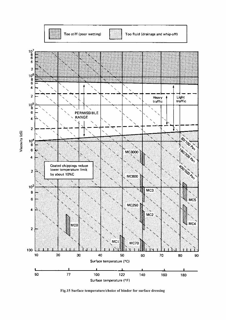
Fig.15 Surface temperature/choice of binder for surface dressing

dressing unit. It is more likely that a mobile unit,comprising the specialised machines and operators, willmove from district to district in accordance with acentrally-planned schedule, with non-specialised plantand labour provided by the district in which the unit isworking. However, a large part of the work involved inorganising and carrying out the surface dressingoperation will fall to the District Engineer. The operationof a mechanised surface dressing unit will probablyrepresent the largest single item of road maintenanceexpenditure and should receive corresponding attention.
A typical surface dressing unit might comprise:
1 bitumen distributor (capacity 5000-8000litres) with pressurised spray bar and oil-fired heaters
1 or 2 bitumen preheaters, oil-fired
8 or more tipper lorries (supplied by District)
1 or 2 chipping spreaders, if lorries are not fittedwith spreaders
2 rubber-tyred rollers
1 loading shovel (unless hand loading is used).
In determining the make-up of the surface dressing unit itis important to keep a balance between the various itemsof equipment so that each is utilised to the maximumpossible extent. A common fault is that there are too fewlorries hauling chippings to keep up with the output ofthe bitumen distributor. Spraying must stop when nochippings are available for spreading.
Such a unit is potentially capable of single-coat applica-tion at rates of up to two kilometres of 2-lane road perday, using some 20,000 litres of bitumen and 200 tonnesof chippings. In practice progress would fall short of thisas a consequence of imbalances in equipment,interference by traffic and non-productive time, but therate of use of materials will still be very high and it isimportant to ensure that stockpiles are adequate both inextent and location.
7.5.4 Application
7.5.4.1 Preparation of the surface A surfacedressing does not contribute directly to the strength of aroad pavement, neither does it improve the riding qualityof the existing surface. Therefore it is essential that theunderlying material has sufficient strength to withstandthe expected traffic loading and is also within thetolerance required for the level of the final runningsurface.
Any area of the road showing signs of structural weak-ness should be strengthened and any depressions in the
surface should be filled. Patching should be done well inadvance of the surface dressing. For best results, thisshould be completed during the previous season toensure that as uniform a texture as possible is avail-ablefor the subsequent dressing.
It is important that the surface to be treated is clean. Dustand loose aggregate must be swept from the surface sothat the binder film can adhere easily.
7.5.4.2 Application of binder The final quality ofthe surface dressing will depend largely on the efficiencyof the method of application of the binder, which must beapplied uniformly over the road surface. The mechanisedbitumen distributor must therefore be fitted with meansof controlling the rate of spread of binder longitudinallyon the road. In addition, the transverse rate of applicationacross the spray bar should be checked at least once ayear in the depot.
Because the distributor is mounted on springs, the spraybar will tend to rise as the load of bitumen in the tankdecreases. The correct spray pattern is dependent on thespray bar being kept at the correct height above the roadsurface and the spray bar must therefore be adjustable inheight, under the control of the operator.
The amount of binder actually sprayed for any single runof the distributor must be within plus or minus 10 percent of the amount calculated by multiplying the areasprayed by the specified rate. In addition to checking theaverage rate of spread over a substantial area of road bymeans of readings from the dipstick fitted to thedistributor, the actual rate of spread on the road should bedetermined by means of a tray test as described inAppendix A.
7.5.4.3 Spraying temperatures Thermometersmust be fitted to the bitumen distributor to measure thetemperature of the binder delivered to the spray bar. Thespraying temperature for any given grade of bitumen willbe related to the design of the spray bar nozzles. It isgood practice for a thermometer also to be fitted to thespray bar as inaccurate readings are likely to occur whenthermometers within the tank become exposed as thelevel of binder falls.
The application temperatures for different grades ofbitumen are given in Table 12 for each type of jet.Whirling spray jets atomise the hot binder and expel it asa finely divided spray in the shape of a hollow cone. Ahood is required to eliminate wind effects. No specialsetting is required for these jets and the transversedistribution is fairly insensitive to the height of the barabove the road. An unexpected characteristic of these jetsis that the rate of spread is increased as the temperatureof the binder falls. Slotted jets expel
33

the hot binder in a thin fan-shaped film and consequentlya hood is not required over the bar to protect it fromwind. Slotted jets need to be set with the slots at an
TABLE 12
SPRAYING TEMPERATURES
Spraying temperature
Whirlingspray jets
°cSlot jets
°cCutback gradesMC30RC/MC70RC/MC250RC/MC800RC/MC3000
Penetration grades400/500280/320180/20080/100
50-6065-8095-115115-135135-155
160-170165-175170-190180-200
40-5055-7080-90
105-115120-130
140-150150-160155-165165-175
angle to the horizontal of 15 to 30° so as to permitoverlap of adjacent fan patterns. The slots in these jetsare not easily blocked and have a fairly high rate ofdelivery thus the road speed of the machine whenspraying is higher than that of a machine fitted withatomising, whirling spray jets.
Because of the inflammable nature of the solvent used inRC-type cutbacks, application temperatures for RCgrades should be restricted to the lower parts of theranges given in Table 12. No smoking or naked flamesshould be allowed when heating, pumping or sprayingany cutbacks. Fire extinguishers should always be readilyat hand.
7.5.4.4 Jointing strips It is most important toensure that the thickness of the binder film is not reducedat longitudinal joints. There must be a clearunderstanding of the jointing technique appropriate to thetype of distributor used.
For example, on some machines the intensity ofapplication falls away towards the edges of the stripbeing sprayed. Adjacent strips should then be overlappedsufficiently to give the required uniformity of spread.This means that the first strip laid must be left uncoveredby chippings for a width of several centimetres along theedge to be overlapped.
Other types of machine are designed to apply the fullthickness of the binder film to the extreme edge of thestrip. With these, great care must be taken to make
34
a good butt joint as an inaccuracy will lead to chippingsnot adhering.
A good clean transverse joint may be obtained by the useof a strip of building paper spread across the road onwhich to start and stop spraying.
7.5.4.5 Application of chippings Chippingsshould be applied uniformly over the freshly sprayedbinder film by a mechanical spreader which shouldfollow closely behind the sprayer. Greater uniformity ofspread will be achieved with spreaders fitted withmetering devices. Any thinly chipped areas found afterthe passage of a mechanical spreader should be chippedover by hand to obtain shoulder-to-shoulder cover. Anysurplus chippings accidentally spilled on to the roadsurface should be removed.
7.5.4.6 Rolling Rubber tyred rollers are stronglyrecommended for rolling surface dressings. Rollingshould start immediately after the chippings have beenspread. The faces of the chippings in contact with thebinders should be pressed into it, so that maximumadhesion occurs and slow-moving rubber tyres are idealfor this purpose. Steel-tyred rollers tend to crushchippings and to bridge local depressions. If steel rollershave to be used, they should be the lightest available andin no case should their weight exceed 8 tonnes.
7.5.4.7 Aftercare and opening to traffic Slowmoving traffic can help to roll and align the chippingsimmediately after surface dressing, but vehicle speedsmust be restricted to 30 km/h or less until there issufficient adhesion to ensure that the chippings will notbe plucked from the surface. This period of time willvary from a few hours to a day or more, depending on theclimatic conditions and the type of binder employed.Excess chippings should be swept up and taken awaybefore opening the road to unrestricted traffic. Signs maybe used to warn of possible damage to windscreens.
7.5.4 Control
The success of any surface dressing depends to a largeextent on the control of all aspects of the design,application and quality of materials. Table 13 is a check-list of the items that require checking in chronologicalorder. This should be read in conjunction with AppendixA.
7.6 MANUAL SURFACE DRESSING
7.6.1 Applicability
Labour-based techniques for surface dressing may be

TABLE 13
CONTROL OF SURFACE DRESSING
Stage when actionshould be taken
Action Required
1. Before start ofjob
(i) Check that any pot-holesor edge-failures have beenrepaired.
(ii) Check grading, shape and(if necessary) the resistanceto polishing of aggregate.
(iii) Ensure that chippings arenot dusty or dirty.
(iv) Check that binder is ofcorrect type and viscosity.
(v) Check availability andcondition of plant.
(vi) Ensure that traffic controlmeasures are adequate.
2. Before startingdaily work
(i) Ensure that the surfaceto be dressed has beenadequately swept andcleaned.
(ii) Check binder temperature.(iii) Test spray bar jets.
3. During work (i) Check rates of spread ofbinder.
(ii) Check that chippingspreading follows closelybehind binder distributorand that coverage is correct.
(iii) Check that rollers followimmediately after thespreading of chippings.
(iv) Check binder temperature atintervals.
3. After surfacedressing
(i) Limit traffic speed whenroad is first opened totraffic.
(ii) Remove surplus chippings.
used on small or remote projects, where the use of plantis too expensive or impracticable. The design principlesand standards described in the preceding section relatingto mechanical methods apply generally to labour-basedwork. The following paragraphs describe differenceswhere these are justified, as well as outlining someaspects of manual techniques.
7.6.2 Chippings
Chippings for surface dressing will normally be smallerthan 20 mm nominal size. Production of these relativelysmall sizes by hand-breaking is uneconomic even at low
wage rates and is not recommended. Hand-screening ofriver gravel, however, may be worth consideringprovided that the product complies with the require mentsnoted in Appendix A. Notes on hand-screening are givenin a separate document (Robinson, 1979).
7.6.3 Binder
For small-scale work it may be more convenient to usebitumen-emulsion, applied at the ambient temperature,rather than cut-back or penetration grade which requirepre-heating. Cationic emulsions are now probably morecommonly used than anionics as they are claimed to bemore effective in depositing a binder film on to acidicaggregates. However, as with anionic emulsions, theprincipal break mechanism is the evaporation of water.Disadvantages common to both types are:
(i) Poor adhesion to dry or dusty surfaces.This may be overcome by slightlydampening the surface before spraying.
(ii) Low effective bitumen content (usually notmore than 60%), which must be allowedfor when calculating rates of application.Emulsions containing up to 70 per centbitumen have been developed, but have tobe heated (to 70-800C) before spraying,thus losing the advantage of use withunheated equipment.
(iii) Low viscosity emulsions tend to drain fromthe crown of the road before the breakoccurs; cover aggregate is therefore poorlyheld at the crown, while excess binderaccumulates at the edges.
(iv) Some emulsions tend to coagulate if storedor transported in unsuitable conditions. Ifemulsion has to be stored for long periods,the drums should be turned overoccasionally.
7.6.4 Application of binder
Bitumen (cut-back, penetration grade or emulsion) maybe applied manually using hand-operated sprayers or bymeans of watering-cans. The choice of binder type willneed to be related at least partly to the applicationequipment available. In either case, the road surfaceshould be marked out in a rectangular grid such that thearea to be covered by each full container (drum or can) isdefined. This may be done by placing stones (about fist-size) at the corners of the area to be covered.
Provided that the work is set out in this way and thebitumen applied systematically, it should be possible toget acceptably uniform rates of application. It will benecessary to supervise the work carefully and to instructoperators in detail in the methods to be used. Unevendistribution of bitumen is a common fault when bitumenis applied by hand-lances.
35

Bitumen for labour-based surface dressing work shouldbe brought to the site in drums and distributed along thework in accordance with the requirements for rate ofspread.
Typical productivities for hand-spraying emulsion are600-1000 litres per day for a unit of three men with onesprayer.
7.6.5 Application of chippings
Chippings should be delivered to the site in dumps atintervals of about 400 metres, from where they are takento the work in wheelbarrows, with an average haul of 100metres. The chippings are usually spread by a swingingmovement with the shovel and this operation alsorequires close supervision if full coverage is to beachieved. It is necessary to apply a greater excess whenspreading chippings manually than when mechanisedspreaders are used, the excess being recovered bybrooming after rolling and trafficking. Productivity forspreading chippings, including haulage from dumps bywheelbarrows, is about one m3 /man-day.
7.6.6 Rolling
There is no practicable alternative to mechanical rolling.The low outputs from labour-based work will result inunder-utilisation of self-propelled rollers, and it may bebetter to consider the use of tractor-drawn rollers. Anyroller should preferably be rubber-tyred, as explainedpreviously.
7.6.7 Gang size
The following gang sizes have been found to bepracticable:
Spraying bitumen 500 m2 /day - 3 men plus 1 sprayerSpreading chippings 500 m2/day - 6 men plus 4 wheel-barrows
Loading/unloading drums, cleaning surface and otherodd jobs - 7 men
Total - 16 men plus 1 foreman.Also required:
(i) periodic use of truck or tractor/trailer fordelivery of chippings
(ii) tractor-drawn rubber-tyred roller.
7.7 SLURRY SEALING
Slurry seals are mixtures of fine aggregates, bitumenemulsions and additional water. When freshly mixed,they have a thick creamy consistency and can be spreadto a thickness of 5 to 10 mm.
The principal application of slurry seals is as a mainten-ance treatment for old bituminous surfaces. Because oftheir low viscosity, they can readily penetrate surface
36
voids and cracks and hold together surfaces that arestarting to fret or ravel. Costs are higher than for surfacedressing, but the resulting layer can improve the ridingquality of the road which a surface dressing would not.The higher costs may therefore sometimes be justified,particularly for badly cracked or lean bituminoussurfacings. However, a slurry seal will not have suchgood surface texture as a surface dressing and maytherefore be slippery in wet weather.
Both anionic and cationic emulsions may be used, butcationic emulsion is normally used in slurries containingacidic aggregates. Anionic slurries may be premixed in astatic mixing plant but, because emulsions in cationicslurries break relatively quickly, these have to beprepared in a purpose-built mixing and laying machine.A contractor usually supplies this equipment, itsoperators and the bitumen binder; the maintenanceorganisation will usually supply the aggregate, water andthe labour force. The laying technique can range fromsimple 'squeegees' to modern mixer-spreader units.
The following specification is reproduced by permissionof Colas (East Africa) Ltd.
Aggregate Gradations (all percent cumulative, passing)
Sieve Fine Seal General Seal CoarseSurface
10mm 100 100 1006.3 mm 100 100 -5.0 mm 100 85-100 70-90
2.36 mm 100 65-90 45-701.18 mm 65-90 45-70 28-50600 µm 40-60 30-50 19-34300 µm 25-42 18-30 15-25150 µm 15-30 10-21 7-1875 µm 10-20 5-15 5-15
Slurry CompositionPer m3 Percent by mass
Aggregate 1m3 81-83Cement (catalyst) 15kg 1
Terolas A3 bitumenemulsion * 280-330 16-18
litres
Water As required
* Type A3 is a slow setting anionic emulsion, 55 percent bitumen (minimum)
Coveragem2 /m3
Old surfaces 130-250
New surfaces:On 20mm aggregate 130 – 170On 14mm aggregate 170 – 240On 10mm aggregate 180 – 250On primed base 150 – 180 (in 2 layers)

8. REFERENCES
AVELING-BARFORD, undated. Grading illustrated.Technical Publication TP 549. Grantham: Aveling-Barford Ltd.
BSI, 1971. Specification for single-sized road-stone andchippings. BS63: 1971 (Part 2). London: BritishStandards Institution.
BSI, 1975. Methods for sampling and testing of mineralaggregates, sands and fillers. BS812: 1975 (Parts 1, 2and 3). London: British Standards Institution.
ROBINSON, R, 1979. Some manual methods of screen-ing aggregates for labour-intensive road construction.TRRL Supplementary Report 503. Crowthome: Transportand Road Research Laboratory.
TRRL OVERSEAS UNIT, 1981. Maintenance manage-ment for District Engineers. Overseas Road Note 1.Crowthorne: Transport and Road Research Laboratory.
TRRL OVERSEAS UNIT, 1982. A guide to surfacedressing in tropical and sub4ropical countries. OverseasRoad Note 3. Crowthorne: Transport and Road ResearchLaboratory.
APPENDIX A
ADDITIONAL NOTES ON SURFACEDRESSING
A.1 CHIPPINGS
A.1.1 Size
The chippings for a surface dressing should be of single-sized crushed rock, roughly cubical in shape and cleanand free from dust. The nominal sizes used may varybetween 6 mm to 20 mm according to the local require-ments. The chippings should comply with BS63.-Specification for single sized roadstone and chippings(BSI, 1971). It is most important that the chippingsshould be single sized. Graded chippings make designand construction much more difficult and their use,without the much closer control which is required, willlead to loss of the larger sizes of chipping and to fatting-up of the surface dressing. Single sized aggregate may bemore expensive to produce than graded aggregates, buttheir higher cost can be offset by better performance. Theremaining sizes of stone can be absorbed into othersectors of the road construction programme.
Recommendations for the grading of surface dressingaggregate are given in Table A1.
The use of rounded-gravel aggregates should, if possible,be avoided because it is difficult for the binder film tohold them in place and because of their poor surfacefriction properties. If their use cannot be avoided,adjustments must be made to the rate of spread ofbitumen. The rounded aggregates do not interlock andmore bitumen is required to hold the particles firmly tothe road surface than is required for cubical aggregates.
A.1.2 Average least dimension
Once the surface dressing is laid, the traffic will orientatethe chipping to lie as flat as possible with the leastdimension vertical. Therefore the Average LeastDimension (ALD) is the measurement which bestclassifies the chippings and gives a guide to the requiredrate of spread of bitumen and the rate of spread ofchippings. Two methods for determining the AverageLeast Dimension of the chippings are given below:-
Method 1The ALD of chippings may be determined by taking arepresentative sample, say 200 chippings, and measuringthe least dimension of each chipping with a pair ofcalipers. The average of a series of such measurements isthen the ALD of the chippings.
Method 2A sieve analysis is first carried out on a surface-drysample of the chippings and the results plotted on a
37

38
TA
BL
E A
1
GR
AD
ING
AN
D S
HA
PEO
F C
HIP
PIN
GS

Fig. A1 Average least dimension chart
large scale grading curve. The median size of chipping isthen determined as that theoretical sieve size throughwhich 50 per cent of the material will pass. The flakinessindex is determined as in Section A.1.3. Then usingFigure Al the median size is marked on scale A andflakiness index on scale C. A straight line is drawnbetween the two marks and the Average LeastDimension read off on scale B.
A.l.3 Flakiness
The flakiness index of chippings should not exceed 35.The method for determining flakiness index is givenbelow. The chippings should also satisfy at least one ofthe following strength criteria:-
Aggregate crushing value - less than 25 (Values up to 35may be permitted for lightly trafficked roads)
Aggregate abrasion value - less than 12
Ten per cent fines value - not less than 8
Aggregate impact value - less than 30
Descriptions of these tests are given in BS812. Methodsfor sampling and testing mineral aggregates, sands andfillers Part 3: Mechanical properties (BSI, 1975).
The flakiness index of an aggregate is the percentage byweight of particles in it whose least dimension (thick-ness) is less than three fifths of the nominal size. The testis not applicable to material passing a 6.30 mm sieve.
Apparatus consists of:-
(i) A metal thickness gauge of the pattern shown inFigure A2. The width of the slot used in thegauge shall be the dimension specified in the'thickness gauge' column of Table A2 for theappropriate fractions.
(ii) BS test sieves as shown in Table A2 (BSI, 1969).
(iii) A balance accurate to 0.5 per cent of the weightof the test sample.
1. Sample quantities are g iven in Table A2.Allowance should be made for the later rejectionof particles retained on 63 mm BS
39

Fig.A2 Thickness gauge
TABLE A2
DIMENSIONS OF THICKNESS GAUGES
Aggregate size-fraction
BS test sieve nominal aperture size
100% passing 100% retained
Thickness gaugeWidth of slot
Minimum massfor subdivision
mm
63.050.037.528.020.014.010.0
mm
50.037.528.020.014.010.06.30
mm
33.9 + 0.326.3 + 0.319.7 + 0.314.4 + 0.1510.2 + 0.157.2 + 0.14.9 + 0.1
kg
503515521
0.5
test sieve and passing 6.30 mm BS test sieve. Thetest sample shall be obtained from the laboratorysample by quartering, and dried.
2. The sample shall be weighed and separated into theappropriate size fractions from Table A2, columns1 and 2, by sieving, rejecting material retained on a63 mm sieve or passing a 6.3 mm sieve. Record thesum of all fractions M 1, discard those which are 5per cent or less of M 1 and record the remainder asM 2.
3. Each appropriate fraction shall be gauged in turnfor thickness on the thickness gauge.
4. The total amount M 3 passing the thickness gaugeshall be weighed to an accuracy of at least 0.5 percent of the weight of the test sample.
5. The flakiness index is the total weight M3 of thematerial passing the various thickness gauges,expressed as a percentage of the total weight M 2 ofthe sample gauged to the nearest whole number,and shall be reported together with the sieveanalysis.
M 3 x 100Flakiness Index =
M 2
40

A.1.4 Adhesion and pre-treatment
The most critical period for a surface dressing occursimmediately after the chippings have been applied. Atthis stage the chippings have not formed an interlockingmosaic and they are held mainly by adhesion forces inthe binder film. This adhesion takes time to develop andis completely stopped if the chippings remain wet.Adhesion is very slow to develop if the chippings aredusty. However in hot climates the chippings may bewashed with fresh or salt water just prior to spreadingsince the chippings dry out in a few minutes after theyare spread on the road and the development of adhesionis not significantly delayed.
If adhesion problems are experienced it may be useful totreat the chippings with a light spray of diesel oil orkerosene prior to spreading. Enough should be added torender the surface of the chippings slightly damp.
A.1.5 Stockpiling
Chippings should be stored in stockpiles which are largeenough to supply four to five days work without haulsexceeding 15 kilometres.
Stockpiles will typically be about 2000 tonnes and willrequire an area of about 1000 m2 if formed by tippingfrom lorries. If suitably located, these areas will be re-used at intervals of three to five years, and somepermanence in their construction will be justified by areduction in wastage of chippings.
They may be surfaced, either with a two-coat surfacedressing, bricks or concrete, with a compacted gravelbase in each case. A concrete or brick wall about onemetre high on three sides will define the stockpile, avoidcontaimination and simplify measurement.
A.2 BINDER
A.2.1 Grade
The performance and qualities required of a surfacedressing binder makes the choice of the binder critical.
The binder must:-
(i) be sprayable at a reasonable temperature,
(ii) 'wet' the surface of the road and remain in acontinuous film waterproofing the roadstructure,
(iii) not run off a steep gradient or cambered roador form pools of binder,
(iv) 'wet' and adhere to the stone chippings at roadtemperature,
(v) be strong enough to resist the traffic force and
retain the chippings even at the highest ambienttemperatures,
(vi) be flexible at the lowest ambient temperature,neither cracking and allowing water to enternor brittle thus allowing the chippings to breakfree,
(vii) resist excessive weathering and hardening oncethe initial hardening has taken place.
Surface dressing work will normally be carried out withcut-back or penetration-grade bitumens. Cut-backbitumens are likely to be of the high-viscosity, medium-curing type. The advantage of these binders is that thecutting agent (normally kerosene) lowers the viscositysufficiently to obtain good wetting of the chippings bythe binder. Also the small quantity of cutting agentpresent results in a reasonably rapid set to hold thechippings after initial adhesion has been achieved.Penetration-grade bitumens may be used in the drier.hotter regions, depending upon actual road tempera turesat the time of working.
With mechanised methods, the rate of consumption ofbitumen is high and it is desirable that it is supplied inbulk rather than in drums, with their associated problemsof handling and leakage. It is more economic to transportbitumen in bulk than in drums and the pre-heaters can, iflarge enough, act as holding tanks and ensure thatoccasional interruptions to the supply do riot disrupt thewhole operation.
It is not usually necessary to test the grade of the bitumenon site, reliance being placed on the supplier's certificate.
A.2.2 Viscosity
Surface dressing binders should have a viscosity ofbetween l04 and 5 x l05 centistokes at the prevailing roadtemperature. At higher viscosities, stone will not bewetted by the binder and will be lost by whip-off; atlower viscosities wetting will occur but the binder will betoo fluid to hold the stone. Figure 15 shows therelationship between binder viscosity and road tempera-ture for a wide range of binders and provides a means ofselecting a suitable binder for use with a particular roadsurface temperature. Daytime road surface tempera turesin dry weather in the tropics are likely to range from300C to 700C according to region and season. Thissuggests that the most suitable binders for surfacedressing will be between MC 3000 and 80/100 penbitumen. The use of a more viscous bitumen than 80/100pen is not recommended. Occasionally chippings have tobe spread manually instead of by mechanical gritters. insuch cases it may be advisable to use a slightly lessviscous binder than would otherwise have been required.(See also Section 7.6 on manual surface dressing).
41

It is unlikely that the complete range of possible binderswill be available to the engineer and therefore forpractical reasons it will probably be necessary to selectperhaps two binders for general surface dressing use. Inthis case MC 3000 and 180/200 pen are likely to be themost suitable: MC 3000 for roads with pre vailing surfacetemperatures less than 450C and 180/ 200 pen whenprevailing surface temperatures are 450C and above.
A.2.3 Measuring the rate of spread of thebinder
A.2.3.1 Average rate There are two methods ofmeasuring the average rate of spread of the binder. In thefirst the volume of binder sprayed is calculated fromweighbridge records and this is divided by the measuredarea covered in a day. Although this is useful in checkingquantities for payment, it does not reveal differences inrates of spread along the road and is therefore of limitedvalue.
A better method, which should be used on every site, isto measure the average rate over an area of 500 - 800square metres. If the distributor is fitted with an accuratedipstick, this method can be of considerable value eventhough it does not give a measure of maximum variation.To make the test, the distributor is placed on a levelstretch of road and the position of the wheels are marked.Dipstick readings are taken, repeating the dips untilconsistent readings are obtained. Binder is sprayed by thenormal technique until about 10 per cent of the totalvolume in the tank has been used. Dipstick readings aretaken with the distributor in the same position as before.
The area covered is then measured accurately and theaverage rate of spread calculated after allowance hasbeen made for any variation in the intensity of appli-cation at the longitudinal joint (see jointing of strips,Section 7.5.4.4).
A.2.3.2 Longitudinal variation Longitudinalvariation in the rate of spread of the binder can bechecked with a tray test. In this test, light metal traysabout 200 mm square by 5 mm deep, and numbered, areplaced at intervals along the road in the path of the binderdistributor. After the distributor has passed, the trays areremoved, wrapped in weighed sheets of paper and takenaway to be weighed; the rate of spread can then becalculated for each point on the road. A balance accurateto 0.1 gramme installed in a car, van or mobile laboratorypermits the results from five trays to be obtained within10 minutes. The spacing and number of trays used can bevaried to suit the circumstances of the particularinvestigation, but at least five
42
trays should be used. When using this test, care must betaken to raise the protective hood on the distributor, iffitted, so that it does not touch the trays, but not so muchas to let any wind disturb the spray.
The tray test only gives an approximation to the averagerate of spread. If it is to be used, it must be rememberedthat the maximum variation shown by individual trayswill be greater than that of groups of trays. The meanresult from three or more trays, spaced at intervals of notless than 10 metres, should fall within 10 per cent ofspecification.
A.3 REFERENCES
1351 1969. Specification for test sieves. BS4IO: 1969.London: British Standards Institution.
BSI, 1971. Specification for single sized road-stone andchippings. BS63: 1971 (Part 2). London: BritishStandards Institution.
BSI, 1975. Methods for sampling and testing mineralaggregates, sands and fillers. BS812: 1975 (Parts 1, 2and 3). London: British Standards Institution.

International
Road Maintenance
Volumes 1 - 4


INTERNATIONALROAD MAINTENANCE
HANDBOOK
PRACTICAL GUIDELINES FORRURAL ROAD MAINTENANCE
Volume I of IV
Roadside Areasand Drainage
Financed and coordinated by

Revised by R C Petts of Intech Associates, UKwith the financial support of ODA
under assignment to
TRANSPORT RESEARCH LABORATORY, UK
as a development of the UN ECA handbooks prepared byjoint cooperation of the governments of FRANCE, GERMANY
and the UNITED KINGDOM and first published in 1982.
©WORLD COPYRIGHT RESERVED 1994Extracts from the text may be reproduced
provided the source is acknowledged as follows.PIARC Road Maintenance Handbook
English version published byTransport Research Laboratory, UK
ISRN by complete set of 4 Volumes: 0 9521860 12I5BN for Volume I: 0 952186020

CONTENTS
FOREWORD i
INTRODUCTION x
Part A - LIST OF TERMS 1
ROAD CROSS SECTION 2
DRAINAGE FEATURES 3
GLOSSARY OF TERMS 4
General Terms 6
Components of the Highway 7
Defects 13
Drainage 16
Maintenance Activities 20
Maintenance Plant and Equipment 23
Materials 27
Survey Terms 30
I - iv

CONTENTS CONTINUED
Part B - WORKS MANAGEMENT AND SAFETY 33
GENERAL 34
SAFETY 35
MANPOWER 37
ORGANISATION 38
I-v

CONTENTS CONTINUED
Part C - ROAD SIDE AREAS 41
1.THE TASK 43 1.1 SHOULDERS 47 1.2 SLOPES 49
2.DEFECTS 51 2.1 LISTOFDEFECTS 51 2.2 SHOULDERS 53 2.3 SLOPES 61
3.RESOURCES 67 3.1 PERSONNEL 69 3.2 PLANT AND TOOLS 71 3.3 MATERIALS 77 3.4 SIGNS AND SAFETY EQUIPMENT 79
4. MAINTENANCE METHOD 83 4.1 PRELIMINARY TASKS 83 4.2 TEMPORARY SIGNPOSTING 89 4.3 EXECUTION OF THE WORK 93 4.4 COMPLETION AND REMOVAL OF
TEMPORARY SIGNS 143 4.5 WORK REPORT 147
5.RESOURCES 151 5.1 PERSONNEL 151 5.2 PLANT AND TOOLS 153 5.3 MATERIALS 155 5.4 SIGNS AND SAFETY EQUIPMENT 157
I - vi

CONTENTS CONTINUED
Part C - ROAD SIDE AREAS CONTINUED
6. MAINTENANCE METHOD 159 6.1 PRELIMINARY TASKS 159 6.2 EXECUTION OF THE WORK 161
I - vii

CONTENTS CONTINUED
Part D - DRAINAGE 163
1.THE TASK 165 1.1 OBJECTIVE 169 1.2 ACTIVITIES 171
2.DEFECTS 175 2.1 LISTOFDEFECTS 175 2.2 DITCHES AND DRAINS 177 2.3 CULVERTS 187 2.4 DRIFTS AND CAUSEWAYS 195 2.5 MANHOLES AND DRAINAGE PIPES 199
3.RESOURCES 203 3.1 PERSONNEL 205 3.2 PLANT AND TOOLS 207 3.3 MATERIALS 211 3.4 SIGNS AND SAFETY EQUIPMENT 213
4. MAINTENANCE METHOD 215 4.1 PRELIMINARY TASKS 215 4.2 TEMPORARY SIGNPOSTING 219 4.3 EXECUTION OF THE WORK 221 4.4 COMPLETION AND REMOVAL OF
TEMPORARY SIGNS 283 4.5 WORK REPORT 287
5. RESOURCES 291 5.1 PERSONNEL 291 5.2 PLANT AND TOOLS 293 5.3 MATERIALS 295 5.4 SIGNS AND SAFETY EQUIPMENT 295
I-viii

CONTENTS CONTINUED
Part D - DRAINAGE 163
1.THE TASK 1651.1 OBJECTIVE 1691.2 ACTIVITIES 171
2.DEFECTS 1752.1 LISTOFDEFECTS 1752.2 DITCHES AND DRAINS 1772.3 CULVERTS 1872.4 DRIFTS AND CAUSEWAYS 1952.5 MANHOLES AND DRAINAGE PIPES 199
3.RESOURCES 2033.1 PERSONNEL 2053.2 PLANT AND TOOLS 2073.3 MATERIALS 2113.4 SIGNS AND SAFETY EQUIPMENT 213
4. MAINTENANCE METHOD 2154.1 PRELIMINARY TASKS 2154.2 TEMPORARY SIGNPOSTING 2194.3 EXECUTION OF THE WORK 2214.4 COMPLETION AND REMOVAL OF
TEMPORARY SIGNS 2834.5 WORK REPORT 287
5. RESOURCES 2915.1 PERSONNEL 2915.2 PLANT AND TOOLS 2935.3 MATERIALS 2955.4 SIGNS AND SAFETY EQUIPMENT 295
I-viii

CONTENTS CONTINUED
Part D - DRAINAGE CONTINUED
6. MAINTENANCE METHOD 2976.1 PRELIMINARY TASKS 2976.2 EXECUTION OF THE WORK 299
GENERAL INDEX 303
I – ix

FOREWORD
The road transport network of any country plays a vital role in itseconomy, and the physical condition of its infrastructure is critical.Without adequate and timely maintenance, highways and rural roadsalike inexorably deteriorate, leading to higher vehicle operating costs,increased numbers of accidents, and reduced reliability of transportservices. When repair work can no longer be delayed it will ofteninvolve extensive rehabilitation, and even reconstruction, costingmany times more than simpler maintenance treatment carried outearlier. The need to protect the existing network and keep it in goodcondition is paramount, often taking precedence over newinvestment.
PIARC has been in the forefront in promoting this message and indrawing attention to the dangers of neglect. The matter has becomeincreasingly important in recent years for all the highways of theworld, but especially so for those in developing countries where thereis constant pressure on slender budgets and, in many, an urgentneed to cater for growing traffic loads and volumes.
In the late 1970's, the aid ministries of France, the Federal Republicof Germany and the United Kingdom joined forces to produce a“Road Maintenance Handbook” for maintenance foremen andworkers in Africa. Published in 1982 under the auspices of theEconomic Commission for Africa, the three volumes - in French andEnglish - soon became widely known and used. By the end of thedecade their use had spread far beyond Africa, and theirstraightforward instructions were being used for training purposes aswell as for
I-I

FOREWORD continued
on-the-job guidance in many countries. The need to reprint providedthe opportunity to review the contents in the light of experience andmake them more suitable for the wider audience now commanded.PIARC's Committee on Technology Transfer and Development,formerly the Committee on Roads in Developing Regions, undertookto help with this review, which was generously funded by the UKOverseas Development Administration. A sub-committee wasestablished, embracing the three original donor countries, otherdeveloped and developing countries, and the World Bank. Althoughmuch of the original text has been retained, the new handbooksincorporate more information on labour and tractor-basedtechniques, and on the development of manpower management andthe all-important question of safety at work. The range ofmaintenance problems addressed has been extended to strengthentheir international appeal.
The past ten years have seen major reforms in the general thrust ofmaintenance policy and in its organisation, management andexecution. These changes will continue, and PIARC will play its partalong with other institutions in encouraging the process and pressingfor further progress. Only a full appreciation of maintenance at thehighest levels of policy-making and financial planning can ensuresuccess. But these handbooks have a humbler task-to ensure thatthe men and women at the operational level are suitably skilled andtrained and are using the appropriate tools and techniques, and haveinterest and motivation in their work.
I – ii

FOREWORD continued
PIARC has been proud to nurture this project to the point where thenew handbooks are available, but its involvement will reach farbeyond that. It will provide the necessary international frameworkwithin which the handbooks can be translated and printed in manylanguages. Its worldwide membership of key figures in the nationalprovision and management of highways will assist with theirdissemination, ensuring that they find their way into the mostappropriate hands in both the public and private sectors. Collectively,these hands will play a fundamental part in sustaining the vital assetwhich our roadway networks truly represent.
Victor J Mahbub,President of PIARC.
I - iii

INTRODUCTION
THE HANDBOOK
This is a guide for the maintenance foreman or supervisorassigned to bitumen or unpaved roads in tropical and moderateclimates. The objective of the HANDBOOK is to assist him in allaspects of his work whether carried out by direct labour or bycontract. Its pocket format enables the volume relevant to the day'swork to be easily carried and consulted on site. The HANDBOOKshould be his ready reference book. The text is concise and wellillustrated. A quick reference should be all that is necessary.
This HANDBOOK does not include a course of study or discussunderlying causes of defects. Inspections, material sources,specifications and testing are also outside its scope. Furthermore it issufficient here to remind the foreman that his plant and vehiclesshould be well maintained without telling him how to do it.
Even though the HANDBOOK is intended for use by themaintenance foreman, it will also be useful reading for the engineeror senior supervisor. This will make him more conscious of his dutiestowards the foreman and enable him to ensure that the maximumbenefit is obtained from the HANDBOOK. Each supervisor mustunderstand his responsibility and the part he has to play.
The HANDBOOK can also be used in training centres. With theassistance of country-specific supplementary information,photographic slides, models, and other supporting material, it will bea valuable tool for the trainer and can be distributed to students.
I - x

Road maintenance requires a range of organisational and technicalskills and the work on roads in use by traffic makes the workpotentially hazardous to both the workmen and road users.
It is therefore essential that appropriate formal and on-the-jobtraining is given to each category of personnel involved in roadmaintenance activities to achieve efficient and safe operations.
The foreman usually has an important role in the initial and ongoingtraining of personnel.
Roads are an enormous national investment and requiremaintenance to keep them in a satisfactory condition and ensuresafe passage at an appropriate speed and with low road user costs.
Late or insufficient maintenance will increase the ultimate repaircosts and raise road user costs and inconvenience, and reducesafety.
Road Maintenance is therefore an essential function and should becarried out on a timely basis.
There is a diversity of maintenance activities, the class and type ofthe road, the cross section to be maintained, the defects recognised,and the resources available. However the general methods proposedhere for each activity (with some exceptions) are given under thefollowing headings:
- The task- Defects- Resources- Maintenance method
I - xi

Where appropriate options are shown for carrying out the work by:
I) Heavy Equipment,ii)Tractor based methods, oriii) Labour based methods.
The decision on which method to be used should be made by theengineer or senior supervisor based on considerations of resourcesavailable, cost, policy etc.
Maintenance operations are usually grouped in each countryaccording to planning, organisational and funding arrangements.They can normally be categorised as either ROUTINE or PERIODIC.
For the purposes of this HANDBOOK the following grouping is used.
ROUTINE: Operations required to be carried out once or more peryear on a section of road. These operations aretypically small scale or simple, but widely dispersed,and require skilled or un-skilled manpower. The needfor these can, to a degree, be estimated and plannedand can sometimes be carried out on a regular basis.
PERIODIC: Operations that are occasionally required on a sectionof road after a period of a number of years. They arenormally large scale and require specialist equipmentand skilled resources. These operations are costly andrequire specific identification and planning. In this
I – xii

handbook periodic also includescertain Improvemnt works such
as thin bituminous overlays.
From time to time urgent or emergency works of any nature may berequired and these are dealt with as the need arises.
The HANDBOOK consists of 4 separate volumes:
VOLUME I - MAINTENANCE OF ROADSIDE AREAS AND DRAINAGEPART A - List of TermsPART B - Works Management and SafetyPART C - Roadside AreasPART D - DrainageGeneral Index
VOLUME II- MAINTENANCE OF UNPAVED ROADSPART A - GradingPART B - Labour Based ReshapingPART C - DraggingPART D - PatchingPART E - Regravelling (Mechanised)PART F - Regravelling (Labour and Tractors)
VOLUME III- MAINTENANCE OF PAVED ROADSPART A - General RepairsPART B - Surface Dressing (Mechanised)PART C - Resealing OptionsPART D - Thin Overlays
I - xiii

VOLUME IV - MAINTENANCE OF STRUCTURES AND TRAFFICCONTROL DEVICES
PART A - BridgesPART B - Traffic Control Devices
VOLUME I
PART A - LIST OF TERMS
This volume provides a List of Terms used in the Handbook and anIndex covering all of the four volumes.
PART B - WORKS MANAGEMENT AND SAFETY
General guidelines are provided regarding management and safetyof the maintenance operations.
This volume also describes the maintenance of roadside areas anddrainage. Although generally straight forward these operations areoften neglected. They are, however, important and have the followingobjectives:
• To minimise the safety risk to road users due to poor shouldersand slopes, poor visibility, grazing animals or fire hazard etc.
• To ensure the stability of the road foundations.
• To ensure that all rain and ground water is directed away from theroad, and does not endanger its strength or stability.
I - xiv

PART C - ROADSIDE AREAS
Routine and Periodic Maintenance activities are described whichkeep the roadside areas in their intended and stable condition, andkeep vegetation under control.
Most of the tasks require labour, although some may be carried outby mechanised methods if the equipment is available.
PART D - DRAINAGE
The drainage system is the most important component of a highwayor rural road, even in locations with only occasional rainfall. TheRoutine Maintenance of the drainage system of ditches, pipe drains,culverts and drifts is essential to preserve the road structure andrunning surface. Most of the activities can be carried out by labourmethods.
NOTE: In many countries women carry out road maintenance tasksand supervisory duties. The use of male descriptions and diagramsin this handbook is for convenience only. The guidelines areapplicable whether the work is carried out or supervised by men orwomen.
I – xv

Part A
LIST OF TERMS
NOTE: ROAD CROSS SECTION, DRAINAGEFEATURES AND OTHER TERMS AREINDICATED IN THE TEXT OF EACH
VOLUME BY AN ASTERISK (*)
I - 1

PART A-LIST OF TERMS
ROAD CROSS SECTIONS
PAVED ROAD SECTION
UNPAVED ROAD SECTION
NOT TO SCALE
1. SUBGRADE 13. ORIGINAL GROUND LEVEL2. ROADWAY 14. CUTTING SLOPE3. CARRIAGEWAY 15. EMBANKMENT SLOPE4. SHOULDER 16. DITCH INSIDE SLOPE5. CAMBER/CROSSFALL 17. DITCH OUTSIDE SLOPE6. SURFACING 18. DITCH INVERT7. ROADBASE 19. ROAD CENTRELINE8. SUB-BASE 20. GRAVEL SURFACE (WHERE9. PAVEMENT CONSTRUCTED)10. EMBANKMENT 21. V-DITCH11 CUTTING 22. TRAPEZOIDAL DITCH12. SUBGRADE SURFACE
/FORMATION
NOTE: Ditch shape according to conditions and maintenance method
1-2

PART A - LIST OF TERMS
DRAINAGE FEATURES
I-3

PART A- LIST OF TERMS
GLOSSARY OF TERMS
Page Page
4WD 23Abney Level 30Aggregate Silo (Hopper) 23Aggregate 27Aggregate Brooming 20Alligator Cracks 13Apron 16Asphalt 27Asphaltic Concrete 27Attendant or Lengthman 20Basin 16Berm 16Bitumen Heater-DistributerTruck 23Bituminous Binder, Asphalt 27Bituminous Slurry(Slurry-Seal) 27Bleeding 13Blinding 7Block Cracking 13Bridge 7Camber 7Camber Board 30Carriageway 8Cascade 16Catchpit 16Catchwater Drain 17Causeway or Vented Drift 8Chippings 28Chute 16Coffer Dam 8Compaction 20Counterfort Drain 17Cracking 13Crazing 13Cribwork 28Crown 5Culvert 8Cut (Cutting) 9
Page Pag
Cut-off/Catchwater Drain 17Debris Rack or Grill 17Deck 9Depression 13Ditch (Drain) 17Drag 23Drainage 17Drainage Pipe 17Drift or Ford 9EdgeCracking 13Embankment 9Excess Aggregate 14Flow Spreader 18FogSeal 20Formation 9Fretting 14Gabion 28Glazing 14Gritter 23Hoist 24Hopper 24Invert 18Layby 9Lengthman 20Loss of Surface Aggregate 14Manhole 18Margins 10Mechanical Broom 24Mitre Drain 18Mixing Plant 24Outfall 18Parapet 10Pass 20Patching 20Patching Vehicle 24Paved Road 6Pavement 10Paver-Screed-Plate 25Periodic Maintenance 21
I - 4

PART A - LIST OF TERMS
GLOSSARY OF TERMSCONTINUED
Page
Permeable Soils 18Plumbing 30Profile 30Ramps 25Ravelling 15Riprap 19Roadbase and Subbase 10Road Maintenance 21Road Paver Adjusting-Blocks 25Road Paver 25Roadway 10Routine Maintenance 21Sand Mixtures 28Sanding 21Scarifying 22Scour 14Scour Checks 19Scuppers 10Shoulder 11Slip 14Slope 11Slot 30Slurry Seal 22Sod 28Soffit 19Spray Lance 25Squeegee 26Streaking 15Stringer 11Stripping 15Subbase 10Subgrade 11Subsoil Drainage 19Surfacing 11Surface Treatment 11Surface Dressing 22Tar Binder 28Template 31TorqueWrench 26
TraflicLane 12Transverse Joint 12Transverse Joint Taper 12Traveller 31Turf 29Underdrainage (Sub-SoilDrainage) 19Unpaved Road 6Urgent Maintenance 22Vented Drift 8Weephole 19Windrow 22Wingwall 12
I – 5

PART A - LIST OF TERMS
GENERAL TERMS
Paved Road
For the purpose of this handbook a paved road is a roadwith a bituminous surfacing.
Unpaved Road
For the purpose of this handbook an unpaved road is aroad with a soil or gravel surface.
I - 6

PART A- LIST OF TERMS
COMPONENTS OF THE HIGHWAY
Blinding
a) A layer of lean concrete, usually 5 to 10 cm thick,placed on soil to seal it and provide a clean and levelworking surface to build the foundations of a wall, orany other structure.
b) An application of fine material e.g. sand, to fill voidsin the surface of a pavement or earthworks layer.
Bridge
A structure usually with a span of 5 metres or more,providing a means of crossing above water, a railway oranother obstruction, whether natural or artificial. Abridge consists of abutments, deck and sometimeswingwalls and piers.
Camber
The road surface is normally shaped to fall away fromthe centre line to either side. The camber is necessaryto shed rain water and reduce the risk of passingvehicles colliding. The slope of the camber is called thecrossfall. On sharp bends the road surface should falldirectly from the outside of the bend to the inside.
I -7

PART A - LIST OF TERMS
Carriageway
The road pavement or bridge deck surface on whichvehicles travel.
Causeway or Vented Drift
Low level structure constructed across streams or riverswith openings to permit water to pass below road level.The causeway may become submerged in floodconditions.
Coffer Dam
A temporary dam built above the ground to give accessto an area which is normally, or has a risk of being,submerged or waterlogged. Cofferdams may beconstructed of soil, sandbags or sheetpiles.
Crown
The highest point of the cross section of the roadcarriageway, usually the centre line.
Culvert
A structure allowing water to flow under the road andhaving an open span of normally between 0.5 and about5 metres. The opening may be round, rectangular orarched. The invert, walls and soffit often form an integralunit.
I - 8

PART A- LIST OF TERMS
Cut (Cutting)
Excavation in natural ground usually with gradedslopes.
Deck
The part of a bridge that spans between abutments orpier supports, and carries the road traffic.
Drift or Ford
A stream or river crossing at bed level over which thestream or river water can flow.
Embankment
Constructed earthworks below the pavement raising theroad above the surrounding natural ground level.
Formation
The shaped surface of the earthworks, or subgrade,before constructing the pavement layers.
Layby
An area adjacent to the road for the temporary parkingof vehicles.
I - 9

PART A - LIST OF TERMS
Margins
The right of way or land area maintained or owned bythe road authority.
Parapet
The protective edge, barrer, wall or railing at the edge ofa bridge deck.
Pavement
The constructed layers of the road on which thevehicles travel.
Roadbase and Subbase
Pavement courses between surfacing and subgrade.
Roadway
The portion of a highway, including shoulders, forvehicular use.
Scuppers
Drainage pipes or outlets in a bridge deck.
I - 10

PART A- LIST OF TERMS
Shoulder
Paved or unpaved part of the highway next to the outeredge of the pavement. The shoulder provides sidesupport for the pavement and allows vehicles to stop orpass in an emergency.
Slope
A natural or artificially constructed soil surface at anangle to the horizontal.
Stringer
Longitudinal beam in a bridge deck or structure.
Subgrade
Upper layer of the natural or imported soil (free ofunsuitable material) which supports the pavement.
Surfacing
Top layer of the pavement. Consists of wearing course,and sometimes a base course or binder course.
Surface Treatment
Construction of a protective surface layer e.g. by sprayapplication of a bituminous or tar binder, blinded withcoated or uncoated aggregate.
I – 11

PART A - LIST OF TERMS
Traffic Lane
The portion of the carriageway defined by roadmarkings for the movement of a single line of vehicles.
Transverse Joint
Joint normal to, or at an angle to, the road centre line.
Transverse Joint Taper
Slope or ramp of premix material at the end of a freshlylaid premix course.
Wingwall
Retaining wall at a bridge abutment to retain and protectthe embankment fill behind the abutment.
I – 12

PART A- LIST OF TERMS
DEFECTS
Bleeding
Excess binder on the surface of the pavement.
Block Cracking
Interconnected cracks forming a series of largepolygons usually with sharp corners or angles.
Cracking
Narrow breaks in a surfacing or pavement materialcaused by overloading, fatigue or weakness of thematerial.
Crazing (Alligator Cracks)
Interconnecting network of cracks in the road surfacing.
Depression
Localised low areas of limited size in the pavementsurface or in any other surface.
Edge Cracking
Longitudinal cracking near the edge of the pavement.
I – 13

PART A- LIST OF TERMS
Excess Aggregate
Aggregate particles not coated with binder afterapplication of binder.
Fretting
The loss of chippings from the surface seal or premixlayer due to poor bond between the aggregate and theseal or binder.
Glazing
Wear or embedment of chippings in the surfacing givinga smooth, shiny appearance.
Loss of Surface Aggregate
Removal of aggregate from a surface dressing, or fromsurfacings with coated aggregate.
Scour
Erosion of a channel bed area by water in motion,producing a deepening or widening of the channel.
Slip
Slope material sliding downhill because of instability,water penetration or flow.
I – 14

PART A- LIST OF TERMS
StreakingAlternate lean and heavy lines of bitumen runningparallel to the pavement centre tine, caused by blockedor incorrectly set spray nozzles.
Stripping (Ravelling)
The loss of surface seal from the pavement due to poorbond between the seal and the lower pavement layer.
I – 15

PART A- LIST OF TERMS
DRAINAGE
Apron
The flat invert of the culvert inlet or outlet.
Basin
A structure at a culvert inlet or outlet to containturbulence and prevent erosion.
Berm
A low ridge or bund of soil to collect or redirectsurface water
Cascade
A drainage channel with a series of steps, sometimeswith intermediate silt traps or ponds, to take water downa steep slope.
Catchpit
A manhole or open structure with a sump to collect silt.
Chute
An inclined pipe, drain or channel constructed in or on aslope.
I – 16

PART A LIST OF TERMS
Counterfort Drain
A drain running down a slope and excavated into it. Theexcavation is partly or completely filled with freedraining material to allow ground water to escape.
Cut-off/Catchwater Drain
A ditch constructed uphill from a cutting face to interceptsurface water flowing towards the road.
Debris Rack or Grill
Grill, grid or post structure located near a culvertentrance to hold back floating debris too large to passthrough the culvert.
Ditch (Drain)
A long narrow excavation designed or intended tocollect and drain off surface water.
Drainage
Interception and removal of ground water and surfacewater by artificial or natural means.
Drainage Pipe
An underground pipe to carry water.
I – 17

PART A-LIST OF TERMS
Flow Spreader
A structure designed to disperse the flow at the outfall ofa ditch or drain to minimise the risk of erosion downstream.
Invert
The lowest point of the internal cross-section of aditch or culvert
Manhole
Accessible pit with a cover forming part of the drainagesystem and permitting inspection and maintenance ofunderground drainage pipes.
Mitre Drain
Or Turn Out Drain, leads water away from the SideDrains to the adjoining land.
Outfall
Discharge end of a ditch or culvert.
Permeable Soils
Soils through which water will drain easily e.g. sandysoils. Clays are generally impermeable except whencracked or fissured.
I – 18

PART A - LIST OF TERMS
Riprap
Stones, usually between 5 to 50 kg, used to protect thebanks or bed of a river or watercourse from scour.
Scour Checks
Small checks in a ditch or drain to reduce water velocityand reduce the possibility of erosion.
Soffit
The highest point in the internal cross-section of aculvert, or the underside of a bridge deck.
Underdrainage (Sub-Soil Drainage)
System of pervious pipes or free draining material,designed to collect and carry water in the ground.
Weephole
Opening provided in retaining walls or bridge abutmentsto permit drainage of water in the filter layer or soil layerbehind the structure. They prevent water pressurebuilding up behind the structure.
I – 19

PART A- LIST OF TERMS
MAINTENANCE ACTIVITIES
Aggregate Brooming
Using a broom to spread chippings on a surface.
Attendant or Lengthman
A person contracted to maintain a section of road. Canbe male or female and the term "Attendant" or"Lengthman" assumes either sex.
Compaction
Reduction in bulk of fill or other material by rolling ortamping.
Fog Seal
A very light film of binder sprayed onto a road to bind orenrich the surface.
Pass
A single longitudinal traverse made by a grader, roller orother piece of equipment working on the road.
Patching
The execution of minor local repairs to the pavementand shoulders.
I – 20

PART A – LIST OF TERMS
Periodic Maintenance
Operations that are occasionally required on a sectionof road after a period of a number of years. They arenormally large scale and require specialist equipmentand skilled resources to implement, and usuallynecessitate the temporary deployment of thoseresources on the road section. These operations arecostly and require specific identification and planning forimplementation, and often require design.
Road Maintenance
Suitable routine, periodic and urgent activities to keeppavement, shoulders, slopes, drainage facilities and allother structures and property within the road margins asnear as possible to their as-constructed or renewedcondition. Maintenance includes minor repairs andimprovements to eliminate the cause of defects andavoid excessive repetition of maintenance efforts.
Routine Maintenance
Operations required to be carried out once or more peryear on a section of road. These operations are typicallysmall scale or simple, but widely dispersed, and requireskilled or un-skilled manpower. The need for some ofthese can be estimated and planned on a regular basise.g. vegetation control.
Sanding
Spreading course sand onto a bituminous road surfacethat is bleeding.
I - 21
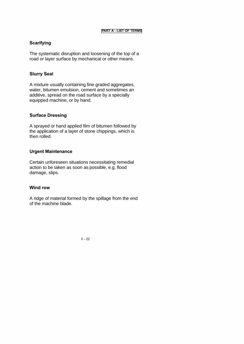
PART A - LIST OF TERMS
Scarifying
The systematic disruption and loosening of the top of aroad or layer surface by mechanical or other means.
Slurry Seal
A mixture usually containing fine graded aggregates,water, bitumen emulsion, cement and sometimes anadditive, spread on the road surface by a speciallyequipped machine, or by hand.
Surface Dressing
A sprayed or hand applied film of bitumen followed bythe application of a layer of stone chippings, which isthen rolled.
Urgent Maintenance
Certain unforeseen situations necessitating remedialaction to be taken as soon as possible, e.g. flooddamage, slips.
Wind row
A ridge of material formed by the spillage from the endof the machine blade.
I – 22

PART A - LIST OF TERMS
MAINTENANCE PLANT AND EQUIPMENT
4WD
Four Wheel Drive vehicle or equipment.
Aggregate Silo (Hopper)
Storage container for aggregate which is fed from thetop and emptied from the bottom.
Bitumen Heater-Distributer Truck
A truck with an insulated tank and heating system,designed to apply a bituminous binder at an even anduniform rate of spread.
Drag
An apparatus towed behind a vehicle or piece ofequipment to remove minor irregularities andredistribute loose surface material.
Gritter
A self propelled machine or an apparatus fitted to theback of a tipper truck, to spread chippings in acontrolled and constant rate of spread.
I - 23

PART A - LIST OF TERMS
Hoist
A hydraulic, mechanically or manually operated liftingdevice.
Hopper
The body of a road paving machine into which thepremixed materials are tipped prior to spreading.
Mechanical Broom
Motor-operated rotary broom used to sweep loosematerial and objects from the pavement surface, usuallyattached to a tractor.
Mixing Plant
Mechanical plant designed to grade and mix mineralaggregates and binder to produce premix material.
Patching Vehicle
A specialist truck equipped with a bitumen tank of about2000 litres capacity, with or without heater, coverfor personnel, hopper for aggregate, and hand-spray lance.
I - 24

PART A- LIST OF TERMS
Paver-Screed-Plate
A levelling device with a flat bottom mounted at the rear of thepaver, which strikes off the fresh premix at the desiredthickness and provides some initial compaction to the mix.
Ramps
Timber or steel planks for loading and unloading small itemsof equipment.
Road Paver
A self-propelled or tractor-drawn machine designed to evenlyspread and partially compact aggregate mixtures.
Road Paver Adjusting-Blocks
Wooden blocks of the same thickness as the uncompactedpremix mat, which are placed under the screed plate beforespreading starts in order to adjust the thickness control. Whenstarting from a previously laid mat, the block thickness equalsthe difference between the loose mat thickness and the rolledmat thickness.
Spray Lance
Apparatus permitting hand-application of bituminous binder ata desired rate of spread through a nozzle.
I - 25

PART A-LIST OF TERMS
Squeegee
A small wooden or metal board with a handle forspreading bituminous mixtures by hand.
Torque Wrench
A spanner or wrench with a mechanism to indicate oryield when a pre-set torque is applied.
I – 26

PART A - LIST OF TERMS
MATERIALS
Aggregate
Hard mineral elements of construction materialmixtures, for example: sand, gravel, crushed rock.
Asphalt
Sometimes used to describe plant mixed bituminousmaterials. See also Bituminous Binder.
Asphaltic Concrete
A high quality manufactured mixture of bitumen andaggregates.
Bituminous Slurry (Slurry-Seal)
Mixture, usually of fine-grained aggregates, water,bituminous binder (emulsion), cement, and sometimesan additive, for a road surface seal.
Bituminous Binder, Asphalt
A petroleum oil based or natural product used to bind orcoat aggregates for road pavements.
I – 27

PART A - LIST OF TERMS
Chippings
Clean, strong, durable pieces of stone made bycrushing or napping rock. The chippings are screenedto obtain material in a small size range.
Cribwork
Timber or reinforced concrete beams laid in aninterlocking grid, and filled with soil to form a retainingwall.
Gabion
Stone-filled wire or steel mesh cage. Gabions are oftenused as retaining walls or river bank scour protectionstructures.
Sand Mixtures
Sands of different gradings, mixed to provide therequired material for a bituminous mixture.
Sod
As Turf but with more soil attached (usually more than10 cms).
Tar Binder
A binder made from processing coal.
I – 28

PART A – LIST OF TERMS
Turf
A grass turf is formed by excavating an area of livegrass and lifting the grass complete with about 5 cms oftopsoil and roots still attached.
I - 29

PART A - LIST OF TERMS
SURVEY TERMS
Abney Level
Small hand held slope measuring and levellingequipment.
Camber Board
Apparatus for checking the crossfall of the road camber,or the shoulder.
Plumbing
Using a calibrated line, with a weight attached to thebottom, to measure the depth of water.
Profile
An adjustable board attached to a ranging rod forsetting out.
Slot
A sample cross section of the road or drain constructedas a guide for following earthworks or reshaping.
I - 30

PART A - LIST OF TERMS
Template
A thin board or timber pattern used to check the shapeof an excavation.
Traveller
A rod or pole of fixed length (e.g. 1 metre) used forsighting between profile boards for setting out levelsand grades.
I - 31

Part B
WORKSMANAGEMENT AND
SAFETY
I – 33

PART B - WORKS MANAGEMENT AND SAFETY
GENERAL
The maintenance foreman or supervisor has animportant role in the road maintenance operations. He isthe road authority's or contractor's representative mostin contact with the actual works.
He is usually responsible for the day to day schedulingof work, organising the resources, arranging safetymeasures, directing and controlling the work andpreparing basic reports of the work carried out.
The maintenance foreman or supervisor must haveand display qualities of:
- Responsibility
- Experience
- Consciousness
- Impartiality and honesty
in his dealings with labour, artisans and operators underhis responsibility, and his supervisors.
This Part of the handbook provides some generalguidelines on management for road maintenanceforemen and supervisors.
I - 34

PART B - WORKS MANAGEMENT AND SAFETY
SAFETY
Many Road maintenance operations are potentiallydangerous, both to the maintenance workers and to theroad users.
It is the responsibility of the maintenance foreman orsupervisor to insist that all risks are minimised by:
� ensuring that the necessary temporary traffic signsand protection are provided and correctly located onsite for the duration of the works. Where necessary,traffic should be stopped during the placement orremoval of temporary signs,
� arranging for safety vests and helmets to be worn inappropriate circumstances, e.g. when working onthe carriageways or shoulders, or on bridges,
� ensuring that all plant and vehicles are parked offthe carriageway or behind protective barriers andsigns, when not in use,
� ensuring that no materials are left in a dangerouslocation and that the road adjacent to the worksite iskept clean and swept of any debris arising from themaintenance work,
� ensuring that proper precautions are taken whenhandling dangerous substances e.g hot bitumen,corrosive or poisonous substances,
I - 35

PART B - WORKS MANAGEMENT AND SAFETY
� ensuring that all excavations are protected forthe benefit of all road users, equipment andworkers,
� ensuring that all operators are trained in theoperation of their equipment. If they are notadequately trained when they are assigned tothe foreman or supervisor, he should himselfprovide, or arrange for, the necessaryinstruction. Operators and labourers alike mustbe informed of the potential risks of andprocedures for working with or close tomachinery,
� ensuring that traffic control operations areproperly carried out and that road users are notunnecessarily delayed,
� ensuring all ladders or scaffolding used inbridge maintenance are securely fixed,
� ensuring that where work on the carriageway orshoulder remains unfinished overnight, thenproper warning lights are arranged and, ifnecessary, protected,
� ensuring that all sites are left tidy and cleared ofdebris when the work is completed.
I - 36

PART B - WORKS MANAGEMENT AND SAFETY
MANPOWER
This is the vital resource, whether operating machinesor using handtools, for the success of the roadmaintenance operations.
A well motivated workforce will perform many timesbetter than an unmotivated one.
The foreman or supervisor must play his part inmotivating the workforce by:
� being firm and fair in all his dealings with theworkforce,
� scheduling and organising the work so that it isefficiently carried out,
� arranging a fair workload for each member of theworkforce,
� discussing and trying to resolve work and personnelproblems as they arise,
� encouraging good quality work from the workforceand care of the equipment and handtools,
� ensuring that each member of the workforce istrained and able to carry out his allocated task. Theforeman or supervisor should carry out or arrangeany necessary initial or refresher training,
� ensuring that payment arrangements are timely, complete and correct.
I - 37

PART B - WORKS MANAGEMENT AND SAFETY
ORGANISATION
The maintenance foreman or supervisor shouldschedule and organise work according to theWorksheet or other instructions.
Equipment and handtools should be arranged asnecessary to carry out the task. Mechanical supportarrangements will be necessary for sophisticatedequipment or items working away from the base forextended periods. Fuel, lubricants, consumable spares,and daily servicing must be ensured to keep equipmentoperational.
Handtools should be of construction quality with properhandles; not merely tree branches cut and formed onsite. Good quality handtools can significantly improveproductivity and minimise injuries. Arrangements shouldbe made to repair or replace worn or broken handtools.
Materials should be arranged and transported to site.They should comply with the specifications and betested when necessary.
The signs and safety equipment should be arrangedaccording to the guidelines or requirements.
The foreman or supervisor should ensure thatequipment items are not misused.
Work may be carried out by a mobile gang, a ganglocated or recruited in the locality of the work andwalking or cycling to work, or by individual attendants orlengthmen.
I - 38

PART B - WORKS MANAGEMENT AND SAFETY
Daily tasks or targets should be used whereverpossible. These work outputs should be developed fromlocal experience. Ideally the workforce should bereleased for the day once their task has been achievedwith regard to quantity and satisfactory quality.
Dayworks arrangements, whereby a worker stays for aset time period, usually achieves lower productivity. Thisarrangement should be avoided wherever possible.
Gangs, attendants or lengthmen may be set weekly orfortnightly tasks where supervision arrangements allowonly infrequent visits for instruction and inspection.
The work should be recorded on the appropriate formsas accurately as possible. This helps to monitor theprogress of the work and plan for future maintenanceoperations.
The foreman or supervisor is the "eyes and ears" ofthe Engineer, who necessarily can only make infrequentvisits to the site. The foreman or supervisor should keepthe engineer fully informed of progress on site and anyproblems encountered.
Finally it must be emphasised that the work of theforeman or supervisor is practically orientated. Most ofhis time should be spent on site organising andcontrolling work and solving the problems that occurthere. Time spent in the office should be minimised, tocarry out the necessary arrangements for support,administration, payments and reporting.
I - 39

Part C
ROAD SIDE AREAS
I – 41


PART C - ROADSIDE AREAS
1. THE TASK
� Roadside Areas include the shoulders* andsideslopes, and all surface areas within the roadrnargins* maintained by the Road Authority, exceptthe carriageway*
Although these areas are normally not used bytraffic, their maintenance contributes to the safety ofroad users and stability of the road.
� Roadside Areas maintenance is normally aROUTINE* activity although occasionally somePERIODIC* maintenance activities are required.
See List of Terms, Volume I
I – 43


PART C - ROADSIDE AREAS
� Most Roadside Areas maintenance activities canbe achieved by labour, and are suitable for beingcarried out by a mobile or local gang, or by anindividual attendant or lengthman living close to theroad.
� Roadside Areas consist of:
� shoulders of paved roads,� slopes and other surface areas within the road
margin.
Paved shoulders and laybys* are treated as paved*roads. Their maintenance is described in Volume Ill ofthe Handbook.
* See List of Terms, Volume I
I – 45


PART C - ROADSIDE AREAS
1.1 SHOULDERS
� The OBJECT of shouIder* maintenance is to retainthe shape and levels of the shoulder, so that:
� the road pavement* has adequate side support,� traffic can safely use the shoulder in an emergency,� water drains from the carriageway* to the roadside
ditch.
� Shoulder maintenance consists of the followingactivities
Routine* Activities
REMOVING OBSTRUCTIONSRESHAPING SHOULDERSVEGETATION CONTROL
Periodic* Activities
ADDING SHOULDER MATERIAL
* See List of Terms, Volume I.
I – 47


PART C - ROADSIDE AREAS
1.2 SLOPES
� The OBJECT of maintenance of slopes and otherroadside areas is to ensure that:
� the slopes are protected against the potentialerosion forces of water, and to retain their shapeand stability,
� the safety risk to road users is minimised due topoor visibility, grazing animals or fire hazard.
� Maintenance of Slopes and other roadside areasconsists of the following activities:
Routine* Activities
VEGETATION CONTROL
Periodic* Activities
EROSION CONTROLSLIP REPAIR
* See List of Terms, Volume L
I –49
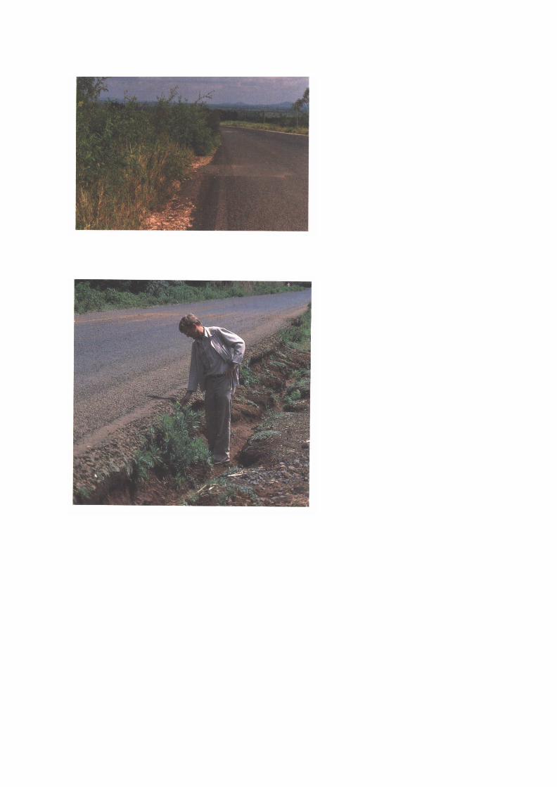

PART C – ROADSIDE AREAS
2. DEFECTS
2.1 LIST OF DEFECTS
On the following pages commonly occurring defects areshown. Their probable causes are given together with asuggested maintenance activity. In addition the resultsof neglected repair are mentioned:
� Defect
� Main causes of the defect
� Development: consequences if maintenance is notrapidly carried out,
� Remedies: usual repair treatments.
I – 51


PART C - ROADSIDE AREAS
2.2 SHOULDERS
DEFECT: OBSTRUCTIONS ON SHOULDER*
Rocks, trees or tree branches, soil heaps, wind blownsand, abandoned vehicles/debris.
Main Causes
- material fallen from slopes or trees, material blown- or washed onto the shoulders,- debris left by road users.
Development, if neglected
- hazard to road users,- obstruction of water flow from carriageway*.
Remedies
- remove obstructions and dispose of safely.
* See List of Terms, Volume I.
I – 53


PART C – ROADSIDE AREAS
SHOULDERS
DEFECT: SHOULDER HIGHER THAN CARRIAGEWAY,SHOULDER MISSHAPED
Main Causes
� carriageway* surface material has collected on theshoulder by the action of traffic/water,
� soil from the cutting has slipped onto the shoulder,� vegetation has trapped material on the shoulder,� shoulder material has been displaced by the action
of traffic.
Development, if neglected
� surface water can pond at the edge of thecarriageway and weaken the pavement andshoulder*,
� danger of accidents,� the roadside ditch may become blocked by the
excess material.
Remedies
� reshape or regrade shoulder surface to the correctlevel,
� vegetation control.
* See List of Terms, Volume I.
I – 55


PART C-ROADSIDE AREAS
SHOULDERS
DEFECT: SHOULDER LOWER THAN CARRIAGEWAY,RUTS OR DEPRESSIONS
Main Causes
� traffic has been travelling on the sholder andmaterial has been worn away,
� water erosion of the shoulder,� settlement of the shoulder,� the carriageway has been overlaid leaving the
shoulder surface lower than the pavement*.
Development, if neglected
� inadequate support for the road pavement,� water collects and softens the shoulder and
pavement* foundation,� the edge of the pavement will break when vehicle
wheels run over it,� increased risk of accidents.
Remedies
� add shoulder material.
* See List of Terms, Volume I.
I – 57


PART G - ROADSIDE AREAS
SHOULDERS
DEFECTS: HIGH VEGETATION ON SHOULDER
Main Causes
Grass, weeds, bushes or trees have been allowed togrow unchecked.
Development, if neglected
� surface water can pond at the edge of thecarrageway and weaken the pavement*,
� silt accumulates at the edge of the carriageway,� the visibility for road users is reduced, with increased
risk of accidents with persons or animals,� increased fire hazard in the dry season.
Remedies
- vegetation control.
* See List of Terms, Volume I.
I – 59


PART C - ROADSIDE AREAS
2.3 SLOPES
DEFECT: VEGETATION OVERGROWN ON SLOPES
Main Causes
� insufficient grass cutting, bush clearing and treetrimming.
Development, if neglected
� overgrown trees or branches can fall and block thecarriageway*,
� visibility for road users is reduced, with increasedrisk of accidents with persons or animals,
� the vegetation can block the drainage system orprevent it being inspected or maintained,
� increased fire hazard in the dry season.
Remedies
� vegetation control.
* See List of Terms, Volume I.
I – 61


PART C -ROADSIDE AREAS
SLOPES
DEFECT: SURFACE WATER EROSION
Main Causes
� rainwater concentrated into channels at the top ofthe slope,
� lack of vegetation cover.
Development, if neglected
� deep erosion of the slope,� slips*,� obstruction of roadside ditch or shoulder*.
Remedies
Erosion prevention or repair by means of:
� berm*,� cut-off ditch for cuttings,� kerb or channel drain and chute* for embankments,� turfing,� seeding,� waffling,� stone pitching.
* See List of Terms, Volume L
I – 63


PART C-ROADSIDE AREAS
SLOPES
DEFECT: EARTH SLIP
Main Causes
� the slope was too steep for its height, and the soil,� water penetrating the slope from above,� ground water pressure or flow.
Development, if neglected
� the soil in the slope may continue to movedownwards, blocking/cutting the roadway,
� water in roadside ditches cannot flow and pondingwill occur.
Remedies
Slip repair by means of:
� reducing slope angle,� clearing slip material,� surcharging the slope,� gabjons*,� cribwork,� masonry retaining wall,� concrete retaining wall.
* See List of Terms, Volume L
I – 65


PART C-ROADSIDE AREAS
3. RESOURCES
The following recommendations relate to carrying outthe work using a mobile gang.
Where appropriate, options for equipment or labourmethods are described.
Reduced transport resources will be required if the workis carried out by a local gang, with labourers walking toand from work each day.
The gang size and other resources will be varieddepending on the type and number of activities, thequantity of work to be achieved, and the resourcesavailable.
Many of the activities described can be carried out byan attendant or lengthman. This approach is describedin Pages l –149 to I -161.
I – 67


PART C - ROADSIDE AREAS
3.1 PERSONNEL
From the following resources.
� Supervisors
� 1 foreman or overseer visiting regularly,� 1 headman for each 10 to 20 workmen.
� Plant Operators and Drivers
� 1 light vehicle driver (for foreman or overseer)1,� 1 tipper/flat bed truck driver2 ,
� 1 tractor-mower driver3,
� 1 tractor-trailer driver4,� 1 tractor driver and 1 towed grader operator, or 1
motorgrader operator5,� 1 water tanker driver5,� 1 roller operator5,� 1 bulldozer operator6,� 1 loader operator6,� 2 additional tipper drivers6,
1 If a light vehicle is used,2 If a mobile gang is used, or for materials/debris transport,3 If vegetation control is mechanised,4 Alternative for transporting materials and shoulder gravel up to about 10km,5 If shoulder repairs are carried out by mechanised methods,6 If slip repair and slope stabilisation are carried out by mechanisedmethods.
I – 69


PART C -ROADSIDE AREAS
� Workforce
� 1 to 2 masons,� 10 to 20 workmen,� 2 traffic controllers (when working on the shoulders).
3.2 PLANT AND TOOLS
From the following resources.
� 1 light vehicle or motorcycle,� 1 tipper/flatbed truck or tractor-trailer (part-time)1,� 1 tractor with mower or rotary brush cutter
attachment2 1 tractor and towed grader, or 1motorgrader3,
� 1 roller3,� 1 water tanker3 with water pump,� 1 bull doze 1,� 1 wheeled or racked loader4,� 2 additional tipper trucks 4,
1 For transporting mobile gang or transporting debris or materials,2 If vegetation control is mechanised,3 If shoulder repairs are carried out by mechanised methods,4 If sip repair and slope stabilisation are carded out by mechanised methods.
I – 71


PART C - ROADSIDE AREAS
� Small items of Equipment1
� 1 slasher, sickle or scythe per workman,� 1 rake or hayfork per workman,� 1 bushknife per workman,� 5 hoes for every 10 workmen,� 5 shovels for every 10 workmen,� 5 mattocks for every 10 workmen,� 2 sledgehammers,� 4 handrammers,� 2 brooms,� 2 pickaxes,� 2 crowbars,� 2 bow saws,� 1 two-man saw,� 2 brush hooks,� 2 axes,� 2 to 8 wheelbarrows,� 2 files (for sharpening tools),� 1 small vibrating roller or plate compactor,� ropes for tree felling,� 1 ladder for tree felling,� handtools for retaining wall construction.
1 Depending on activities to be carried out.
I – 73


PART C-ROADSIDE AREAS
� Tool and supplies
To check the finished shoulder crossfall* a camberboard will be required, made from 20 mm treatedplywood or hardwood to give a 1 in 20 (5%) slope.
- lubricating oils for equpitment**,- setting out aids for retaining walls**.
� Support**
If mechanised methods are used for slip repair andslope stabilisation. A low loader will be required totransport some of the equipment items to and from thework site.
* See List of Terms, Volume L
** If applicable.
I – 75


PART C -ROADSIDE AREAS
3.3 MATERIALS1
� Gravel obtained from a quarry or gravel pit forshoulder repairs must be of a quality that meets theDepartmental Specifications and also be approvedby the Maintenance Engineer.
� A source of water will be needed as near as possibleto the site for shoulder repairs.
� Materials for retaining wall construction to accordingto Departmental designs and specifications:
� aggregates, sand, cement,� masonry stone or brick, or blocks,� gabion wire baskets,� 3 mm binding wire,� wooden stakes,� gabion filling stone,� cribwork* components(timber or concrete),� sandbags
1 Depending on activities to be carried out.* See List of Terms Volume L.
I - 77


PART C - ROADSIDE AREAS
3.4 SIGNS AND SAFETY EQUIPMENT
When adding gravel to the shoulders or for slip repairs,the following items should be provided where possible1.
� Traffic Signs� 2 Reversible "Stop/Go" signs,
� 2 "Speed Limit" signs (50 km/hr)*,
� 2 "Men Working” signs*
� 2 "No Overtaking" signs,
� I "Road Narrows From Right" sign,
� I "Road Narrows From Left" sign,
� 2 "End of Restriction" signs*.
� Barriers
� 2 lane closure barriers.
� Traffic ConesAs many as are required; at least 10 will usually beneeded.
1 For other Roadside Areas maintenance tasks, only the asterisked* itemsmay be required. When carrying out dispersed tasks, the following additionalsigns may be required.
� 2 "Grading Shoulders" signs,� 2 "Mowing" signs.
I – 79


PART C - ROADSIDE AREAS
•• Safety Equipment
Use should be made of the following equipment forpersonnel and the different vehicles as far as possible:
� yellow/orange shoulder belts for the foreman, andthe other workmen working on the shoulders,
� red and white striped marker boards attached to allvehicles and plant.
I – 81

TYPICAL WORKSHEET
ROADSIDE AREAS
Worksheet No: Date:
District
Zone: Gang:
Road No.: from to
Location(s):
Work to be carried out:
Work to be completed by: (Date)
Signed

PART C - ROADSIDE AREAS
METHOD A: MOBILE GANG
4. MAINTENANCE METHOD
4.1 PRELIMINARY TASKS
� The Worksheet will indicate the location and extentof the work to be carried out and the time,equipment and personnel required for the job.
I – 83


PART C - ROADSIDE AREAS
Before setting out to start the job, a check should bemade to ensure that everything needed is ready.
� The Truck, tractor and trailer, or other plant mustbe fuelled, checked mechanically and have waterand oil levels checked.
� Traffic signs, barriers and cones must beobtained and loaded onto the truck or trailer,according to the task.
I - 85


PART C - ROADSIDE AREAS
� Tools and small equipment must be obtained andloaded onto the truck or trailer. The roller may beloaded with the help of ramps* or a hoist*.
� Arrangements must be made for obtaining water forshoulder repairs.
� Arrangements must be made to load gravel onto thetruck or trailer either at the depot or at a quarry.
* See List of Terms, Volume L
I – 87


PART C - ROADSIDE AREAS
METHOD A: MOBILE GANG
4.2 TEMPORARY SIGNPOSTING
When adding gravel to the shoulders, or for slip repairs,warning signs, barriers and cones must be placedaround the work area.
Work should be carried out on one side of the road at atime, allowing traffic to pass on the other.
Signs must be placed in the following order:
� "Men Working" signs should be placed 200 metresin front of the work area.
� "Road Narrows" signs should be placed 100metres in front of the work area.
� "Speed Limit" signs should be placed at the start ofthe work area.
� Barriers should be placed at each end of the workarea.
� Cones should be placed in a taper at theapproaches to the work area and at a maximumspacing of 10 metres along the middle of the roadnext to the work area.
� "End of Restriction" signs should be placed 50metres beyond the work area.
I – 89


PART C - ROADSIDE AREAS
� Traffic controllers should stand next to the barriersin the centre of the road to operate the reversible
"Stop/Go" signs.
The controller closest to the oncoming traffic shoulddecide when to stop the flow and allow traffic to travel inthe other direction. Traffic should be stopped in bothdirections when works vehicles enter, leave or turn atthe worksite.
On low-traffic roads or for other Roadside Area's tasks,the Maintenance Engineer may approve the use of asimpler system of traffic control:
� Only the "Men Working" and "End ofRestriction"signs may be required for mostRoadside Areas tasks,
� when reshaping the shoulders by motor or towedgrader, "Grading Shoulders" signs should beplaced alongside the "Men Working" signs,
� when grass cutting with a tractor, "Mowing" signsshould be placed alongside the "Men Working"signs.
I – 91


PART C - ROADSIDE AREAS
METHOD A: MOBILE GANG
4.3 EXECUTION OF THE WORK
Shoulders
REMOVING OBSTRUCTIONS
This is a Routine* activity.
Obstructions such as rocks, fallen trees or branches,soil heaps, windblown sand, abandoned vehicles/debris,are a hazard to road users and may prevent the flow ofwater from the carriageway to the drainage system.
These obstructions should be loaded onto a truck ortrailer, or otherwise removed from the shoulder, anddisposed of at a safe location. Materials can often bespread safely on adjacent slopes.
This activity is often carried out in conjunction with othertasks.
* See List of Terms, Volume L
I – 93


PART C-ROADSIDEAREAS
Shoulders
RESHAPING SHOULDERS
This is a Routine* activity, to repair high or mis-shapedshoulders.
a) Mechanised Method
The existing surface of the shoulder should be scarified*with the tines of a motor or towed grader. This willloosen the raised areas and allow the loosened materialto key into any existing low areas.
The shoulders should be reshaped to slightly above thefinal level and the correct crossfall using the motor ortowed grader blade.
Care must be taken not to damage the edge of the roadpavement* with the blade.
The cross fall of the uncompacted material should bechecked with a camber board.
Excess material and vegetation should be graded to theembankment side slope. In cuttings, excess materialand vegetation should be graded into a windrow* forremoval by wheelbarrow, tractor and trailer or truck.Material should not be deposited on the carriageway* orinto the drainage ditch.
* See List of Terms, Volume I.
I – 95
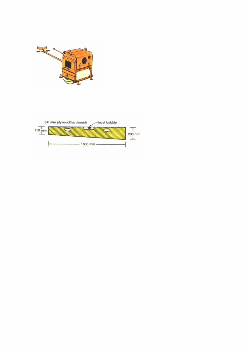

PART C- ROADSIDE AREAS
If the material is dry it should be sprinkled with water.
The shoulder is then compacted using a self propelled,
towed or pedestrian roller.
The compacted surface should butt smoothly onto the
road pavement*.
Check the finished crossfall* with the camber board and
repeat the reshaping if necessary.
Brush all loose material and debris from the
carrageway*.
*See List of Terms, Volume 1
I - 97


PART C - ROADSIDE AREAS
b) LabourMethod
The low surfaces and all high material should beloosened with a pick axe or mattock.
The shoulder should be reshaped to slightly above thefinal level and the correct crossfall using a shovel andrake.
The crossfall of the uncompacted material should bechecked with a camber board.
Excess material should be spread over theembankment slope or transported by wheelbarrow to aconvenient and safe dumping site. Material should notbe deposited on the carriageway* or in the drainageditch.
If the material is dry it should be sprinkled with water.
The shoulder is then compacted with hand rammers ora hand roller.
The compacted surface should butt smoothly onto theroad pavement*.
Check the finished crossfall* with the camber board andrepeat the reshaping if necessary.
Brush all loose material and debris from thecarriageway*.
* See List of Terms, Volume I.
I - 99


PART C-ROADSIDE AREAS
Shoulders
VEGETATION CONTROL
This is a Routine* activity, involving control of grass,weeds, bush and trees.
With the exception of arid areas, grass and weed cuttingand bush clearing on shoulders* is a basic maintenanceactivity. It is carried out at least once a year after therainy season, or more often where the climate causesvegetation to grow rapidly.
Most of the activities required for this task may becarried out by an agricultural tractor equipped with asicklebar mower, flail mower or rotary brush cutters.
Alternatively all of the activities may be achieved usinglabour and handtools.
� Grass Cutting and Bush Control.
Grass, weeds and bush should be cut at least once ayear after vegetation reaches full growth or according tolocal experience.
a) Mechanised Method
� mow only on level ground, free from obstructionsand debris,
� do not mow when grass is wet, if experience showsthis to be unsatisfactory,
� mow all shoulder areas between pavement andedge of road side ditch.
* See List of Terms, Volume L
I – 101

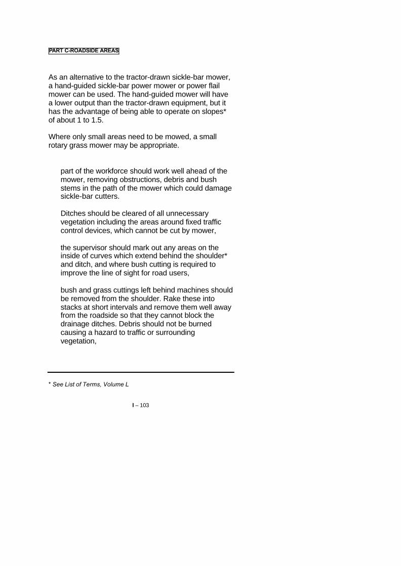
PART C-ROADSIDE AREAS
As an alternative to the tractor-drawn sickle-bar mower,a hand-guided sickle-bar power mower or power flailmower can be used. The hand-guided mower will havea lower output than the tractor-drawn equipment, but ithas the advantage of being able to operate on slopes*of about 1 to 1.5.
Where only small areas need to be mowed, a smallrotary grass mower may be appropriate.
� part of the workforce should work well ahead of themower, removing obstructions, debris and bushstems in the path of the mower which could damagesickle-bar cutters.
Ditches should be cleared of all unnecessaryvegetation including the areas around fixed trafficcontrol devices, which cannot be cut by mower,
� the supervisor should mark out any areas on theinside of curves which extend behind the shoulder*and ditch, and where bush cutting is required toimprove the line of sight for road users,
� bush and grass cuttings left behind machines shouldbe removed from the shoulder. Rake these intostacks at short intervals and remove them well awayfrom the roadside so that they cannot block thedrainage ditches. Debris should not be burnedcausing a hazard to traffic or surroundingvegetation,
* See List of Terms, Volume L
I – 103


PART C - ROADSIDE AREAS
The use of all mowing and cutting equipment ispotentially hazardous. Particular care must betaken when using this equipment and clearingany blockages.
b) Labour Method
As an alternative to mowing and in areasinaccessible to power equipment, (especially ditchside-slopes or on other steep slopes), the vegetationshould be trimmed by hand. Sickles, scythes,slashers, bushknives, axes, saws or similarhandtools will be required.
� Trees
Dead or leaning trees within the right-of-way whichmay fall on the carriageway* or block the drainage*system, or block sight lines should be removed. Thefelling of trees, or the removal of large branches atheights of more than 2 metres above ground levelcan be hazardous. This work should only be carriedout under expert supervision or by experiencedworkers.
Trees should be felled using two-man saws or axes.Ladders should be used for climbing trees, and ropesshould be used to restrain trees and control felling.Traffic should be halted when the tree is finallytoppled. All debris should be removed and disposedof safely.
* See List at Terms, Volume I.
I – 105


PART C - ROADSIDE AREAS
� Herbicides
Herbicides (weed-killer) are chemical agentsintended to destroy or reduce vegetation growth. It isnot recommended that herbicides or any chemicalmethods be used to control roadside vegetation.Some reasons are:
� herbicides can cause pollution of crops, riversand streams and drinking water supplies,
� herbicides are often dangerous to health,� herbicides are expensive, and must often be
imported,� herbicides do not always produce satisfactory
results.
� Burning
Do not burn roadside vegetation to control its growthor the debris from Vegetation Control activities. Theresults may be more harmful than desired:
� the fire could spread and destroy valuablevegetation (trees, grass), and traffic controldevices,
� vegetation may grow faster after burning,� smoke and flames blowing across the highway
are dangerous for traffic.
I – 107


PART C-ROADSIDE AREAS
Shoulders
ADDING SHOULDER MATERIAL
This is normally a Periodic* activity to repair shouldersthat have settled, or been eroded by traffic and water. Itis also required when an overlay is applied to the roadpavement*.
a) Mechanised Method
The existing surface of the shoulder should bescarified* with the tines of a motor or towed grader.This will loosen the surface and allow a key for theadded material.
New shoulder material is oft-loaded or tipped ontothe shoulder, allowing a small surplus torequirements.
The added material should be shaped to slightlyabove the final level and the correct crossfall usingthe motor or towed grader blade.
Care must be taken not to damage the edge of theroad pavement* with the blade.
See List of Terms, Volume 1
I – 109


PART C - ROADSIDE AREAS
The crossfall of the uncompacted material should bechecked with a camber board.
Excess material should be graded to the embankmentside slope. In cuttings, excess material should begraded into a windrow* for removal by wheelbarrow,tractor and trailer, or truck. Material should not bedeposited on the carriageway or into the drainage ditch.
If the material is dry it should be sprinkled with water.
The shoulder is then compacted using a self propelled,towed or pedestrian roller.
The compacted surface should butt smoothly onto theroad pavement*.
Check the finished crossfall with the camberboard andrepeat the reshaping if necessary.
Brush all loose material and debris from thecarriageway.
* See List of Terms, Volume J.
I - 111


PART C-ROADSIDE AREAS
b) Labour Method
The existing surface of the shoulder should be loosenedwith a pickaxe or mattock to allow a key for the addedmaterial.
New shoulder material is off-loaded or tipped onto theshoulder, allowing a small surplus to requirements.
The added material should be shaped to slightly abovethe final level and the correct .crossfall using ashovel/hoe and rake.
The crossfall of the uncompacted material should bechecked with a camber board.
Excess material should be collected and transported bywheelbarrow for use further along the shoulder ordiscarded safely by spreading over the embankmentslope or at a convenient location.
If the material is dry it should be sprinkled with water,using containers or a small water bowser.
The shoulder should be compacted using a handrammer or a hand roller.
Check the work and clear debris as for the MechanisedMethod.
I - 113


PART C-ROADSIDE AREAS
Slopes
VEGETATION CONTROL
This is a Routine* activity involving the control of grass,weeds, bush and trees.
The activities involved are the same as for shoulders*(Page I - 101), however the frequency of vegetationcontrol operations may be reduced.
The principal objective will be to keep sight lines and thedrainage system free of excess vegetation.
* See List of Terms, Volume I.
I – 115


PART C -ROADSIDE AREAS
Slopes
EROSION CONTROL
This is a periodic* activity, although its requirement isusually very localised.
Erosion is usually caused by rainwater concentration onthe slopes or by lack of vegetation cover.
A number of options can be used to prevent or repairerosion on slopes and other Roadside Areas:
� berm for cuttings,� cutoff ditch for cuttings,� kerb or channel drain for embankments,� turfing,� seeding,� wattling,� stone pitching.
* See List of Terms, Volume L
I – 117


PART C-ROADSIDE AREAS
� Berms tor cuttings
A soil berm or bund can be built by hand along thetop of a cutting face to prevent surface water flowingover the cutting face. The berm should be located tolead all water to a safe location for discharge ordispersal. The berm may need to be seeded toencourage vegetation growth and stability. Soilshould not be excavated where it will allow water topond or to seep into the cutting.
� Cut-off ditch for cuttings
This produces the same effect as the berm, howeverit will probably suffer more erosion and thereforerequire more maintenance. A cut-off ditch is notsuitable for permeable* soils.
� determine location and alignment of ditch fromlocal inspection; not too close to the edge of theslope. Follow the natural contour of the hill asclosely as possible but with enough grade topermit water to flow,
� excavate ditch to about 50 cm depth. The sidesof the ditch must not be too steep, otherwisethey will collapse into the ditch and cause ablockage. Excavated material should be spreadon the downslope side,
� protect outfall* of ditch if erosion is likely, by useof turfing, wattling or stone pitching,
� check the ditch regularly in the rainy season sothat any necessary corrections or repairs can becarried out immediately.
* See List of Terms, Volume L
I - 119


PART C - ROADSIDE AREAS
� kerb or Channel drain, for embankments
A kerb or channel drain may be built at the edge ofthe carriageway or the back of the shoulder. Thekerb may be of dressed stone, precast or insituconcrete. If the gradient falls throughout theembankment the kerb or drain may discharge at thecut-fill location. If there is a low point on theembankment, a chute* or cascade* will be requiredto safely discharge the water down the slope.
For further details See Page I - 247.
* See List of Terms, Volume I
I – 121


PART C - ROADSIDE AREAS
� Turfing (grass sodding)
This method is suitable when climate and soilconditions are favourable and when fresh grasssods* (soil clumps containing grass and its roots)are available.
The general procedure is:
� prepare the area to be tunfed* to required levelsand slopes,
� where no topsoil is present, haul suitable topsoilto site and spread evenly to a depth of not lessthan 5 cm. Water as required,
� cover the area with freshly cut sods withoutweeds. Sods are to have thickly matted rootswhich should not have dried out. Tamp sods withtamper or use hand roller. On slope use stakesto hold sods in position,
� water the turves at intervals until the grass takeshold.
Other patterns of sodding are:
� spot sodding (sods spaced about 50 cm in holesdeep enough to take sod and about 5 cmtopsoil),
� trench sodding. Lay sods on 5 cm topsoil bed inparallel trenches. Trench spacing about 50 cmalong contour or x-shaped pattern.
* See List of Terms, Volume 1.
I – 123


PART C - ROADSIDE AREAS
� Seeding
Grass seeding will only be successful if climate andsoil conditions are favourable. The best advice canbe provided by the local department of agricultureon:
� topsoil required,� seed type, rate of spread,� fertilizer types, rate of spread,� most favourable season and weather for
seeding,� other preparatory treatment of the soil (for
example mixing-in ground limestone).
Typical procedure:
� loosen the soil to a depth of 10 cm in the area tobe seeded using rakes or similar tools,
� spread the topsoil to a depth of at least 5 cm,� water the area to be seeded,� apply fertilizer at the specified rate,� apply ground limestone at the specified rate and
mix-in,� apply seeds by hand at the specified rate,� lightly roll the seeded area within 24 hours using
hand roller, only if the soil does not adhere to theroller,
� the seeded area should be watered as requireduntil the grass has taken hold.
I – 125


PART C-ROADSIDE AREAS
� Wattling
These are bundles of plant stems up to 3 m long,tied together and laid in shallow trenches, stakedinto position on contour lines (lines of the sameheight), or x - form lines.
As with turfing and seeding, a favourable climateand soil conditions are essential for the successfuluse of wattling.
Wattling helps to stabilize slopes, reduce surfaceerosion and provides a bench on which grass canbecome established. Plant stems which root easilyare preferred. Advice on suitable plants and plantingtime should be obtained from the local departmentof agriculture.
Typical procedure:
� cut wattling stems at suitable source andtransport them to site immediately. Stems shouldnot be allowed to dry
� out, tie bundles of stems 15 - 20 cm diameter,alternating the ends,
� excavate a trench in the slope along the desiredline. The trench should be deep enough toaccommodate tied wattling stems (this work canbe completed beforehand),
� place wattling stems in trench and use stakes tofix them in position. Overlap bundles and stakethrough the overlaps,
� cover the wattling with topsoil and tamp themfirmly in place, -watering may be necessary untilthe roots take hold.
I – 127


PART C - ROADSIDE AREAS
� Stone Pitching
This work is generally limited to small but importantareas, for example* or culverts.
Any rough stone can be used for stone pitching orriprap. The size should be as uniform as possibleand the individual stones should weigh 10 to 20 kg.Heavier stones are preferred if riprap* is not to begrouted. The slope* should not be steeper than 1 to1.5.
� transport stone and materials and off load at site,� compact the slope to the desired shape,� lay the stones in one layer with close joints,
starting at the bottom of the slope with the largerstones. Stones should be supported by soil,smaller stones may be used to help wedge themin place. Larger stones should be buried deeperso that the final top surface will be uniform.
When the stone pitching is to be grouted:
� wet the stone as thoroughly as possible,� grout the spaces between stones with a mortar
(1 cement: 4 sand),� brush surface of the stone pitching with a stiff
broom,� protect the work from the sun using sacks or
similar material, and keep wet for at least 3 daysafter grouting.
* See List of Terms, Volume L
I – 129


PART C - ROADSIDE AREAS
Slopes
SLIP REPAIR AND SLOPE STABILISATION
This is a periodic* or Urgent activity, although itsrequirement is usually very localised.
Slips or slope instability are usually caused by adverseground conditions or water or both. The remedial worksshould be specified by the Maintenance Engineer afteran inspection of the site and the necessaryinvestigations.
Dealing with slips and unstable slopes is hazardous andparticular care should be taken to safeguard manpower,equipment and the road users.
The principal remedial options are:
� reducing slope angle,� clearing slip material,� surcharging the slope,� gabions,� cribwork,� masonry retaining wall,� concrete retaining wall.
* See List of Terms, Volume I.
I – 131


PART C-ROADSIDE AREAS
� Reducing Slope Angle
Where a cutting face has slipped, one option is toreduce the angle of at least the upper part of theslope. This will increase overall stability and helpprevent further slips. It is often advisable toreduce the slope angle before clearing theexisting slip material.
Care must be taken in case further slippage occurs.A bulldozer may be used if there is access and littlerisk of causing further slips by this heavy piece ofequipment. Alternatively labourers may excavate thematerial and transport it to a safe dumping site usingwheelbarrows.
I – 133


PARTC -ROADSIDE AREAS
� Clearing Slip Material
This is a hazardous activity and should be plannedand executed carefully. The slip material should beexcavated so that, at all times, the slip andembankment or cutting face are stable.
Do not work under an overhanging slope as soilmay suddenly slide again.
Excavate soil to reduce the angle at the top of theslope before slip clearing, if possible or necessary.
� excavate all slipped soil from carrjageway*,shoulder* and ditch* by loader or by hand,
� load onto trucks, tractor and trailer orwheelbarrows and remove to suitable dumpsites,
� do not excavate too deep and damage the roador shoulder surface when using a front-endloader,
� remove last layer of slipped soil from theshoulder or carriageway by hand,
� clear the ditch and regrade or reshape ifnecessary,
� tine grade the roadway shoulder area with motoror towed grader if available, or by hand,
� if the area requires to be protected from furtherslipping, the most suitable method can only bedetermined from site inspection.
If flowing water or excessive moisture isencountered, then a drainage blanket of granularmaterial, or pipes, should be laid before building anyof the repair measures described on Pages I - 137to I - 141.
* See List of Terms, Volume I.
I – 135


PART C -ROADSIDE AREAS
� Surcharging the Slope
A cutting slope with a wide verge at the base or anembankment slope, may be surcharged to stabilisea slip without removing it. This involves widening thebase of the slope by placing material to resist furtherslipping. The material should be placed in layers of15 - 20 cms by hand or machine, and compactedwith a roller or by hand rammers.
If water or moisture is suspected as a cause of theslip, a drainage blanket of granular material shouldbe laid before placing the fill material. It may also benecessary to excavate counterfort* drains into theslip material to allow water to drain away from theslip face. Extreme care must be taken whencarrying out this activity.
The final earthworks should be shaped to shedrainwater, and planted if necessary. Certain treescan be planted which will develop root systems tostabilise the slope and reduce undergroundmoisture. Advice should be sought from the localdepartment of agriculture.
* See List of Terms, Volume 1
I – 137

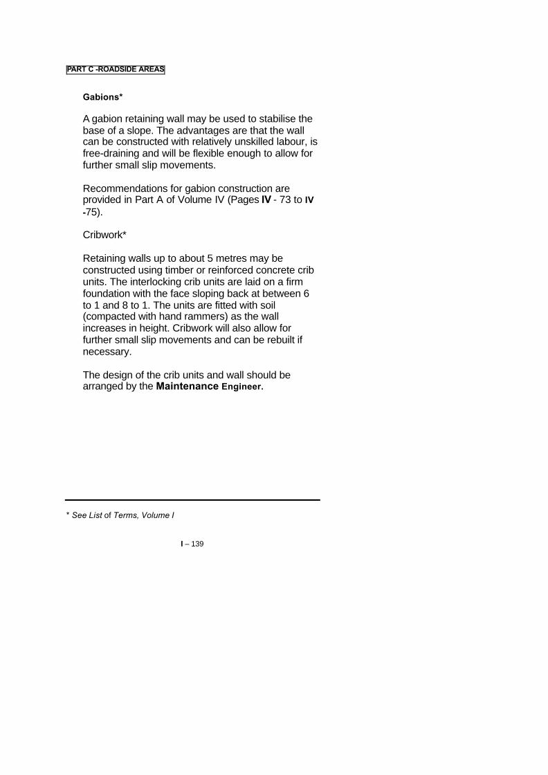
PART C -ROADSIDE AREAS
� Gabions*
A gabion retaining wall may be used to stabilise thebase of a slope. The advantages are that the wallcan be constructed with relatively unskilled labour, isfree-draining and will be flexible enough to allow forfurther small slip movements.
Recommendations for gabion construction areprovided in Part A of Volume IV (Pages IV - 73 to IV-75).
� Cribwork*
Retaining walls up to about 5 metres may beconstructed using timber or reinforced concrete cribunits. The interlocking crib units are laid on a firmfoundation with the face sloping back at between 6to 1 and 8 to 1. The units are fitted with soil(compacted with hand rammers) as the wallincreases in height. Cribwork will also allow forfurther small slip movements and can be rebuilt ifnecessary.
The design of the crib units and wall should bearranged by the Maintenance Engineer.
* See List of Terms, Volume I
I – 139


PART C - ROADSIDE AREAS
� Masonry Retaining Wall
Where there is a stable foundation, a masonryretaining wall may be constructed to retain the baseof unstable slopes.
Recommendations on masonry wall construction areprovided in Part A of Volume IV (Pages IV - 65 to IV-67).
� Concrete Retaining Wall
Where there is a stable foundation, a reinforced orunreinforced concrete retaining wall may beconstructed to retain the base of unstable slopes.
These walls may require specialist skills for designand construction not available in a maintenancedepartment. These should be organised by theMaintenance Engineer.
I – 141


PART C - ROADSIDE AREAS
METHOD A: MOBILE GANG
4.4 COMPLETION AND REMOVAL OF TEMPORARYSIGNS
� Load tools, equipment and unused materials backonto the truck or trailer.
� Where they have been used remove the signs,cones and barriers and load them onto the truck ortrailer in the following order:
1 "End of Restriction" signs,
2 Traffic cones,
3 "Speed Limit” signs,
4 Barriers,
5 "Road Narrows" signs,
6 "Men Working" signs.
I - 143


PART C - ROADSIDE AREAS
� Ensure that the site is left clean and tidy with nostockpiles of material left on the shoulder.
� Move onto the next job.
� Inspect traffic signs and clean if necessary.
I – 145

TYPICAL WORK REPORT
ROADSIDE AREAS
Work Report No: Date:
District: Gang
Zone Road No
Section: from km to km
Location(s):
WORK ACHIEVED:
MANPOWER USED:
Name Grade Hours worked
Name Grade Hours worked
Name Grade Hours worked
EQUIPMENT USED: DIESEL USED:
Hrs litres
Hrs litres
MATERIALS USED:
COMMENTS:
Foreman:

PART C - ROADSIDE AREAS
4.5 WORK REPORT
The report must be filled in each day, detailing:
� the work carried out,
� the resources used.
I – 147


PART C – ROADSIDE AREAS
METHOD B: LABOUR BASED
In some road maintenance Systems an individualattendant or lengthman lives close to a road and isresponsible for the ROUTINE MAINTENANCE activitieson that road.
The following activities are suitable for this method:
REMOVING OBSTRUCTIONS
RESHAPING SHOULDERS
VEGETATION CONTROL (SHOULDERS ANDSLOPES)
Furthermore the following PERIODIC MAINTENANCEactivities may be carried out by attendants:
ADDING SHOULDER GRAVEL (small scale)
EROSION CONTROL (certain techniques)
I - 149


PART C-ROADSIDE AREAS
METHOD B: LABOUR BASED
5. RESOURCES
5.1 PERSONNEL
� Supervisor
� foreman or overseer visiting regularly.
� Workforce
� attendant or lengthman.
I – 151


PART C - ROADSIDE AREAS
METHOD B: LABOUR BASED
5.2 PLANT AND TOOLS1
� 1 broom,� 1 pickaxe,� 1 shovel,� 1 hoe or mattock,� 1 rake,� 1 hand rammer with metal shoe,� 1 wheelbarrow,� 1 bucket or watering can,� 1 grass slasher, sickle or scythe,� 1 bush knife or bush hook,� 1 axe,� 1 bowsaw,� 1 file for sharpening tools.
Depending on activities to be carried out.
I – 153


PART C - ROADSIDE AREAS
METHOD B: LABOUR BASED
5.3 MATERIALS
� Gravel for patching shoulders should beobtained from the quarry by truck or tractor andtrailer. This is most efficiently done when majorregravelling works are being carried out in thearea of the road.
� The gravel should be stockpiled at convenientlocations where shoulder repairs are expectedfor the attendant to use on his section of road.The stockpiles must not obstruct the road, theshoulder or the drainage system.
� Where there is no space in the road reserve thestockpile should be placed downhill of a turnoutdrain to avoid blocking the drainage system.
I – 155


PART C-ROADSIDE AREAS
METHOD B: LABOUR BASED
5.4 SIGNS AND SAFETY EQUIPMENT
When working on the shoulder the following should beprovided.
� Traffic Signs
2 "Men Working" signs,
OR
2 yellow/orange flags for placing on the shoulder.
� Clothing
Yellow or orange coloured safety vest or safetyharness to be worn by the attendant when workingon the shoulder.
I - 157


PART C-ROADSIDE AREAS
METHOD B: LABOUR BASED
6. MAINTENANCE METHOD
6.1 PRELIMINARY TASKS
� The handtools are assigned to the attendant whokeeps them at his home for use as necessary.
� The worksheet will indicate the location and extent ofthe work to be carried out and the time required forthe job.
I - 159


PART C - ROADSIDE AREAS
METHOD B: LABOUR BASED
6.2 EXECUTION OF THE WORK
� The attendant should use the wheelbarrow to carrythe tools and safety items to the site.
� The warning signs or flags must be placed eitherside of the worksite.
� The attendant should use the wheelbarrow totranspont the gravel material from the stockpiles tothe "Adding Shoulder Gravel" site.
� The tasks should be carried out as described for theMobile Gang.
� The warning signs or flags must be removed after
the work.
� The work report must be filled in for each day'swork.
I – 161

Part D
DRAINAGE
I - 163


PART D - DRAINAGE
1. THE TASK
� The Drainage System consists of side drains*, mitre(turnout) drains*, cut-off drains*, drainage pipes*,manholes*, chutes*, cascades, culverts*, drifts* andsubsoil* drains.
The purpose of the system is to rapidly collect andconduct rain and ground water away from the road.
Water can cause widespread damage to the road byweakening the pavement* or foundations, anderosion. The Drainage System is therefore themost important component of a highway or ruralroad, even in locations with only occasional rainfall.
* See List of Terms, Volume I
I – 165


PART D - DRAINAGE
� The Routine Maintenance* of the drainage systemis essential to preserve the road structure andrunning surface. Occasionally major repairs orimprovements are required to be carried out underPeriodic Maintenance*.
� Most Drainage maintenance activities can beachieved by labour, and are suitable for beingcarried out by a mobile or local gang, or by anindividual attendant or lengthman living close to theroad.
� For the descriptions in this Part D (Drainage), it isassumed that all vegetation has been removed fromthe area around drainage features to enabledrainage maintenance to be carried out. Vegetationcontrol tasks are described in Part C of this volume.
* See List of Terms, Volume I
I – 167


PART D – DRAINAGE
1.1 OBJECTIVE
� Water can seriously damage any road
It can
� erode soils,� weaken pavements*,� destroy shoulders* and slopes*,� wash-out culverts*, embankments* and even
bridges*
The satisfactory operation of the drainage system istherefore a vital condition for a satisfactory road.
� The OBJECT of maintenance is to ensure thatdrainage system elements remain free ofobstructions, and retain their intended cross-sections and grades.
They must function properly so that
� surface water and� groundwater
can drain freely and quickly away from the road orunder the road.
*See List of Terms, Volume I
I – 169


PART D - DRAINAGE
1.2 ACTIVITIES
1.2.1 Ditches* and Drains*
Routine* Activities� CLEARING AND CLEANING� RESHAPE/REGRADE/DEEPEN� EROSION CONTROLa) Regrade/Realign Drainsb) Repair Liningc) Provide/Repair Scour Protection
Periodic* Activities� PROVIDE NEW MITRE (TURNOUT) DRAIN� EROSION CONTROLa) (Re)Line Drainb) Construct Cascade/Catchpitc) Construct Flow Spreader
1.2.2 CuIverts*
Routine Activities� CLEARING AND CLEANING� EROSION REPAIR� CRACKING REPAIR� HEADWALL/APRON REPAIR
Periodic Activities� REPAIR OF INVERT� (RE)CONSTRUCT CULVERT AT CORRECT
LEVEL AND FALL� CONSTRUCT OUTFALL BASIN*
* See List of Terms, Volume I.
I – 171


PART D - DRAINAGE
1.2.3 Drift* and Causeways*
Routine* Activities
� MINOR REPAIRS
� GRADING/CLEARING
� REPLACE GUIDE-POSTS
1 .2.4 ManhoIes* and Drainage Pipes*
Routine Activities
� CLEAR MANHOLE AND UNDERGROUND PIPES
� REPLACE MANHOLE COVER OR GRATING
� CLEAR MANHOLE AREA
� CLEAN CATCHPIT SUMP
Periodic Activities
� RELAY DRAINAGE PIPE
* See List of Terms, Volume I.
I – 173


PART D - DRAINAGE
2 DEFECTS
2.1 LIST OF DEFECTS
On the following pages commonly occurring defects areshown. Their probable causes are given together with asuggested maintenance activity. In addition the resultsof neglected repair are mentioned:
§ Defect
§ Main causes of the defect
§ Development: consequences if maintenance is notrapidly carried out
§ Remedies: usual repair treatments.
I – 175


PART D - DRAINAGE
2.2 DITCHES* AND DRAINS*
DEFECT: OBSTRUCTIONS
Main Causes- vegetation growth, bushes, fallen trees, debris, loose
silt, loose rocks.
Development, if neglected- blockage of ditch.
Remedies- clearing and cleaning.
DEFECT: SILTING
Main Causeslnvert* slope is too flat, the water cannot flow atsufficient speed.
Development, if neglected:- Blockage of the ditch.
Remedies
- deepen ditch (desilting), and/or provide new mitredrains (turnouts),
where deepening or turnouts are not possible becauseof topography, the construction of a new culvert* with adrop-inlet may be possible, in order to discharge wateronto the other side of the road.
* See List of Terms, Volume I.
I – 177


PART D - DRAINAGE
DEFECT: PONDING IN DITCH AND ON SHOULDER
Main Causes- the ditch cross-section is too small,- the ditch gradient is too flat.
Development, if neglectedThe shoulder material becomes soft and can easilyerode. The pavement* can also be flooded andthereby weakened.
Remedies- deepen ditch,- provide new mitre drain.
DEFECT: DITCH CROSS-SECTION IS DESTROYED(UNLINED DITCH)
Main Causes- vehicular or animal traffic, cave-in.
Development, if neglectedPartial silting will result if the ditch sides havecollapsed. Erosion can start where water flow passesthe blocked section.
Remedies- reshape/regrade ditch, line drain.
* See List of Terms, Volume I.
I – 179


PART D - DRAINAGE
DEFECT: INVERT* AND SIDES OF DITCH* AREERODED
§ Main Causes
Invert slope is too steep.
§ Development, if neglected
The water flows at high speed and starts erodingthe soil. The ditch becomes deeper (ravine). Thesides then cave-in, the road shoulder and even partof the carriageway* can be washed away.
§ Remedies
Erosion control:
- Regrade/realign drains,- provide repair scour protection,- line drain slopes and invert,- construct cascade.
* See List of Terms, Volume I
I – 181


PART D-DRAINAGE
DEFECT: DITCH* LINING IS DAMAGED
§ Main Causes
- poor construction workmanship,- soil settlement, erosion of soil under ditch lining,- poor alignment or sudden change in flow direction.
§ Development, if neglected
When flowing water reaches the soil protected by thelining,. erosion starts. The amount of soil washedaway increases, the lining is further damaged by lossof support, leading to complete destruction of thelining.
§ Remedies
Erosion control:
- repair lining,- realign drain.
* See List of Terms, Volume l
I – 183

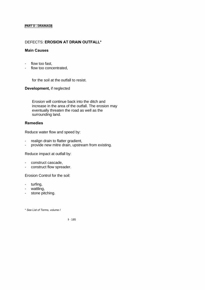
PART D - DRAINAGE
DEFECTS: EROSION AT DRAIN OUTFALL*
Main Causes
- flow too fast,- flow too concentrated,
for the soil at the outfall to resist.
Development, if neglected
Erosion will continue back into the ditch andincrease in the area of the outfall. The erosion mayeventually threaten the road as well as thesurrounding land.
Remedies
Reduce water flow and speed by:
- realign drain to flatter gradient,- provide new mitre drain, upstream from existing.
Reduce impact at outfall by:
- construct cascade,- construct flow spreader.
Erosion Control for the soil:
- turfing,- wattling,- stone pitching.
* See List of Terms, volume I
I - 185


PART D - DRAINAGE
2.3 CULVERTS*
DEFECT: SILTING, SANDING, BLOCKAGE BYDEBRIS
Main Causes
� Invent* slope too flat,� culvert constructed too low, so that material from the
stream bed becomes deposited in the culvert,� vegetation and floating debris carried by water have
become lodged in the culvert.
Development, if neglected
The intended waterway opening will be so reducedthat flood water cannot flow. It will back-up or pondon the upstream side of the culvert and mayeventually over-flow the road embankment*. Theroad is then in danger of being washed away.
Remedies
� clearing and cleaning,� if floating debris is a problem, the provision of a
debris rack* should be considered.
If the culvert regularly silts up:
� reconstruct at correct level and fall.
See List of Terms, Volume I.
I – 187


PART D - DRAINAGE
DEFECT: SETTLEMENT CRACKS
Main Causes
Settlement of soil below culvert*.
Development, if neglected
� minor damage: If the settlement is minor, only lightcracking will result in headwalls, wingwalls and themain structure. This will hardly affect the functioningof the structure,
� major damage: If the settlement is severe, it willcause large relative movement of culvert pipes sothat embankment soil will enter through the cracksand block the culvert, or the culvert may collapse.The culvert must then be reconstructed.
Remedies
- cracking repair,- reconstruct at correct level and fall.
* See List of Terms Volume I.
I – 189


PART D - DRAINAGE
DEFECT: THE STEEL CULVERT INVERT' ISDAMAGED BY RUST
Main Causes
� poor quality galvanising or surface protection,� protective surfacing worn away by water flow,� weathering (after long service life).
Development, if neglected
Severe damage to structure invert, probable partial orcomplete collapse of the structure.
Remedies
� repair of invert,� reconstruct at correct level and fall.
*See List of Terms, Volume I.
I – 191


PART D - DRAINAGE
DEFECT: EROSION OF STREAM BED AT CULVERTOUTLET
Main Causes� the culvert invert has been constructed too steep so
that the water flows too fast,� the culvert invert has been constructed too flat with
an excessive drop at the outfall (these are design orconstruction mistakes).
Development, if neglectedThe stream bed is washed away and a pool orravine develops. The culvert downstream head andwingwalls* and even a section of the culvert androad embankment can collapse into the pool orravine.
Remedies� erosion repair,� construct outfall basin*.
DEFECT: MINOR HEADWALL/APRON* DAMAGE
Main Causes
� minor settlement,� scour or erosion.
Development, if neglected
� erosion at the headwall/apron,� culvert blockage or collapse.
Remedies� headwall/apron repair.
* See List of Terms, Volume I.I – 193


PART D - DRAINAGE
2.4 DRIFTS AND CAUSEWAYS*
The surfaces of submersible crossings are oftenconstructed as a concrete slab. There is a high risk ofwashouts and slab movement caused by the waterturbulence. Routine* maintenance should correct anyminor defects as they occur, to avoid later extensiveand costly major works.
The Routine* activities can include concrete or masonryrepair, placing of gabions* and erosion protection ofcauseway* openings as in the case of culverts.
DEFECT: MINOR DEFECTS
Main Causes
� settlement of slab,� erosion.
Development, if neglected
The cracks in the drift* structure spread and widenespecially during the following flood season. Erosionwill undermine the drift. The drift will break up.
Remedies
Minor repairs.
* See List of Terms, Volume I.
I – 195


PART D - DRAINAGE
DEFECT: DRIFT* OR CAUSEWAY* IS COVEREDWITH DEBRIS
Main CausesNatural movement of river bed material by flowingwater.
Development, if neglectedThe limits of the paving cannot be seen; vehiclesmay drive onto loose river bed material at the edgeof the drift and become damaged or immobilised.
RemediesGrading/Clearing drift surface. The surface must becleared of all loose material.
DEFECT: GUIDE-POSTS (MARKERS) ARE MISSINGOR DAMAGED
Main CausesAccident, flood damage, vandalism.
Development, if neglectedWhen the drift or causeway becomes submergedduring flood, the edge of the pavement cannot beseen. Vehicles can accidentally drive into deepwater.
RemediesReplace guideposts.
*See List of Terms, Volume I
I – 197


PART D - DRAINAGE
2.5 MANHOLES* AND DRAINAGE PIPES*
DEFECT: WATER IS FLOWING UP AT MANHOLE
Main CausesThe manhole or connected underground pipes areblocked and water cannot flow as intended.
Development, if neglected
� flooding of road shoulder* or carriageway*� drainage system becomes ineffective, danger of
earth slip or weakening of pavement*.
RemediesClear manhole and underground pipes.
DEFECT: MANHOLE COVER OR GRATING ISMISSING/DAMAGED
Main CausesAccident, vandalism.
Development, if neglectedOpen manholes become a danger to people andanimals. Vegetation and debris have uncontrolledaccess and blockage can occur.
RemediesReplace manhole cover or grating.
* See List of Terms, Volume I.
I – 199


PART D - DRAINAGE
DEFECT: THE MANHOLE* IS COVERED WITH SOILAND VEGETATION
Main CausesSilting of the ground area at manhole; manholecover level possibly set too low.
Development, if neglected
Possible blockage of the drainage system at themanhole, due to an undetected accumulation of siltin the manhole.
RemediesClear manhole area.
DEFECT: THE CATCHPIT* SUMP IS COMPLETELYSILTED UP
Main CausesSilt and debris collecting in the sump has not beenremoved sufficiently regularly.
Development, if neglectedPossible blockage of the drainage system at thecatchpit, or down stream due to a build up of silt ordebris.
RemediesClean catchpit sump.
* See List of Terms, Volume I
I – 201


PART D - DRAINAGE
3. RESOURCES
The following recommendations relate to carrying outthe work using a mobile gang.
Where appropriate options for equipment or labourmethods are described.
Reduced transport resources will be required if the workis carried out by a local gang, with labourers walking toand from work each day.
The gang size and other resources may be varieddepending on the type and number of activities, thequantity of work to be achieved, and the resourcesavailable.
Many of the activities described can be carried out byan attendant or lengthman. This approach is describedin Pages I – 28 to I -299.
I - 203

PART D - DRAINAGE
3.1 PERSONNEL
From the following resources.
� Supervisors
� 1 foreman or overseer visiting regularly,� 1 headman for each 10 to 20 workmen.
� Plant Operators and Drivers
� 1 light vehicle driver (for foreman or overseer)1,� 1 tipper/flat bed truck driver2,� 1 tractor-trailer driver3,� 1 tractor driver and 1 towed grader operator, or 1� motorgrader operator4.
� Workforce
� 1 to 2 masons,� 10 to 20 workmen.
1 If a light vehicle is used.2 (f B mobile gang is used, or for materials/debris transport.3 Alternative for transporting materials up to about 10 km, or debris.4 (f drains are cleared/reshaped by mechanical methods.
I –205


PART D - DRAINAGE
3.2 PLANT AND TOOLS
� 1 light vehicle or motorcycle,� 1 tipper/flatbed truck or tractor-trailer (part-time) 1,� 1 tractor and towed grader, or 1 motorgrader2,� 1 water pump 3,
� 1 hand winch3.
I For transporting mobile gang or transporting debris or materials.2 If drain cleaning/reshaping is mechanised.3 For culvert/pipe repair work.
I – 207
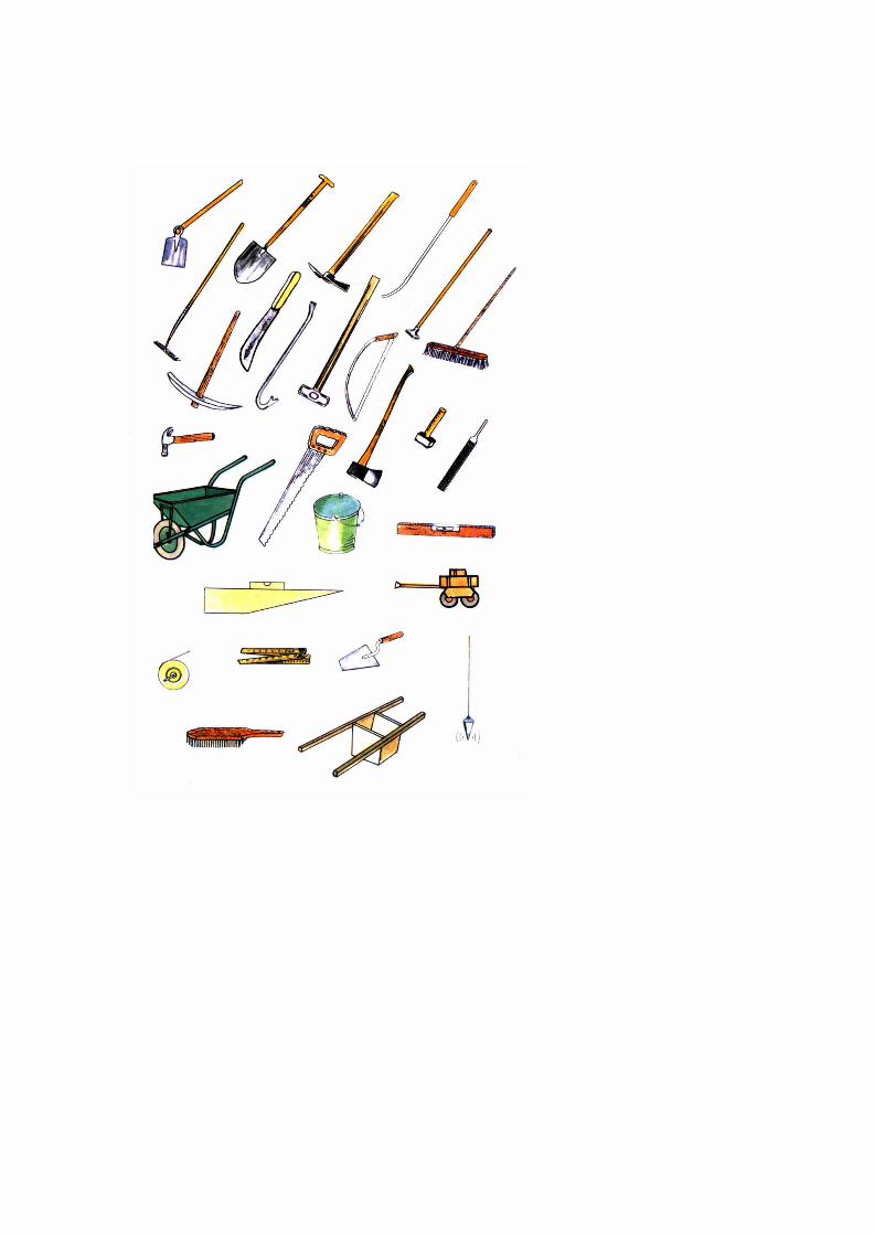

PART D -DRAINAGE
•• Small items of Equipment1
� 1 hoe for everyworkman,
� 1 shovel for everyworkman,
� 5 mattocks for every10 workmen,
� 5 slashers,� 5 rakes,� 5 bushknives,� 2 sledgehammers,� 4 handrammers,� 2 brooms,� 2 pickaxes,� 2 crowbars,� 2 bow saws,� 2 brush hooks,� 2 axes,� 5 wheelbarrows,� carpenter's saws,� 2 claw hammers,� 2 mallets,� 2 chisel sets,� 2 files (for sharpening
tools),� 1 plate compactor,� ropes for controlling
culvert components,� assorted nails and
pegs,� long handled
shovel/spike for culvertcleaning,
� rods and fittings forclearing pipe drains,
� 5 buckets,� manhole cover lifting
keys,� 1 spirit level,� 1 line and level or
abney level,� 1 ditch template and
spirit level,� 5 ranging rods and
profiles,� 2 mason's hammers,� 2 club hammers,� 2 mason's chisels,� 2 mason's trowels,� 2 pointing trowels,� 2 mason's floats,� 2 straight edges (2
metre),� 2 measuring tapes (30
metre),� 2 folding rules (2
metre),� 2 plumb bobs,� 2 setting out strings,� 2 hand brushes� aggregate measuring
box (equivalent to 1 bag of cement).
I Depending on activities to be carried out.
I – 209


PART D - DRAINAGE
3.3 MATERIALS1
� A source of water will be needed as near as possibleto the site for masonry repairs.
� Materials for culvert, drift, manhole or pipe repairs,according to local construction methods:
� aggregates, sand, cement,� plastic sheet to protect cement,� masonry stone or brick or blocks,� gabion wire baskets,� 3 mm binding wire,� wooden stakes,� gabion filling stone,� concrete culvert rings,� corrugated steel culvert rings and fittings,� drainage pipes,� manhole covers,� jute or plastic sacks for sandbags,� drain lining tiles.
1 Depending on activities to be carried out*See List of Terms, Volume I.
I – 211


PART D - DRAINAGE
3.4 SIGNS AND SAFETY EQUIPMENT
Drainage activities do not usually involve work on, orthe need to close, all or part of the road carriagewayor shoulder.
Where occasionally such works are required (e.g.relaying a cross culvert), then Signs and SafetyEquipment suitable for Bridgeworks should be used(Volume IV, Part A, Pages IV - 27 to 29).
I – 213

TYPICAL WORKSHEET
DRAINAGE
Worksheet No: Date:
District:
Zone: Gang:
Road No from to
Location(s):
Work to be carried out:
Work to be completed by: (Date)
Signed:

PART D - DRAINAGE
METHOD A: MOBILE GANG
4. MAINTENANCE METHOD
4.1 PRELIMINARY TASKS
� The Worksheet will indicate the location and extentof the work to be carried out and the time,equipment and personnel required for the job.
I - 215


PART D - DRAINAGE
Before setting out to start the job, a check should bemade to ensure that everything needed is ready.
� The Truck, tractor and trailer, or other plant mustbe fuelled, checked mechanically and have waterand oil levels checked.
� Traffic signs, barriers and cones must beobtained and loaded onto the truck or trailer, if workis required on the carriageway or shoulders.
� Tools, small equipment and materials, must beobtained and loaded onto the truck or trailer.
� Arrangements must be made for obtaining water forculvert or pipe repairs.
I – 217


PART D - DRAINAGE
METHOD A: MOBILE GANG
4.2 TEMPORARY SIGNPOSTING
Where work is required on the road carriageway orshoulders, signs should be provided and placedaccording to the recommendations of Volume IV, Part A- Bridges, Pages IV - 35 to 37.
I – 219


PART D - DRAINAGE
METHOD A: MOBILE GANG
4.3 EXECUTION OF THE WORK
Ditches and Drains
CLEARING AND CLEANING
This is a Routine* activity.
The object is to remove all soil, high vegetation,materials and objects from the ditch* which couldpossibly interfere with water flow or cause aneventual blockage of the ditch. This can include forexample, rocks, loose silt and sand, weeds, trees,bushes, including their roots, etc. Dispose of thesematerials well away from the roadside so that waterflow will not be impeded and they will not fall orwash back into the drain.
On unlined ditches a short grass cover can help tostabilise the invert* and sides of the drain. Thereforewhere a side drain is established to the correct depthand profile with grass cover and no erosion, it isadvisable to merely cut the grass short. This willleave the roots in place to bind the surface together.
*See List of Terms, Volume I.
I – 221


PART D - DRAINAGE
Ditches and Drains
RESHAPE/REGRADE/DEEPEN
This is a Routine* activity that can be carried out bylabour methods. In some locations it may be carriedout by mechanised methods.
a)Labour Method
The object is to remove material from the ditch toobtain the correct cross-section and grade.
It is advisable to adopt a trapezoidal ditch shapewhen using labour methods. The excavation using ahoe/mattock and shovel is easier than for a V-shaped ditch. An added advantage is that the flatinvert causes less concentration of water than a V-ditch.
A ditch template* should be used to obtain thecorrect drain shape.
� using the template a 50 cm wide sIot* should beexcavated to the correct ditch shape every 10metres. The slots act as a guide for excavatingthe ditch to the correct shape,
� in flat areas, the gradient of the ditch should bechecked using ranging rods and profiles orsimilar methods, to ensure that water will notpond. The levels at adjacent slots should bechecked using a line and level or abney level*,and the level of the slot adjusted if necessary.
*See List of Terms, Volume I.
I – 223


PART D - DRAINAGE
� excavate all surplus material between the slotsand to the correct shape with the aid ofstringlines stretched between the slots. Ifnecessary the intermediate invert levels can bechecked using a traveller* sighted between theranging rod profiles.
� material excavated from the drain must beremoved and spread well clear of the drain sothat it cannot later fall or wash back into theditch.
� the shape can be checked during the excavationactivity using the ditch template*.
When excavating a completely new ditch it ispreferable to split the task into two operations:
i. cut the central rectangular shape and check witha template (INVERT).
ii. cut the slopes and check with the full template (SLOPES).
The alignment or route of the drain should be set outusing stringlines and pegs.
The ranging rods and profiles should be set up atthe start and outfall* of the ditch. Intermediateprofiles may be required on long ditches. The levelsof intermediate slots can be determined using thetraveller.
*See List of Terms, Volume I.
I –225


PART D – DRAINAGE
b) Mechanised Method
This activity is suggested where long sections of V-shaped ditches* are to be maintained and cleanedand where high daily outputs are possible. Theactivity may be carried out by a motor or towedgrader. The grader should always work in thedirection of water flow in the ditch.
Case 1:
When the grader can operate only on the shoulder*and in the ditch, but not beyond the ditch:
� start by grading the outside sIope* of the ditch,windrowing the soil to the bottom of the ditchbetween the rear wheels. (This can be repeatedto obtain the desired depth of ditch),
� the second pass* cleans the invert* of the ditchby removing the windrow to the top of the ditchat road shoulder,
� the third pass is required to move the windrowmaterial away from the shoulder ditch edge.
THE MATERIAL MUST BE REMOVED FROM THESITE.
UNDER NO CIRCUMSTANCES IS THE MATERIALTO BE SPREAD ONTHE ROAD.
*See List of Terms, Volume I.
I – 227


PART D - DRAINAGE
� on completion, the ditch should generally have adepth of 50 cm (minimum), which can bechecked with a ranging rod and tape/rule,
� if necessary the grade of the ditch invert can bechecked using the methods described in a)Labour Method (Page I - 223).
Case 2:
� When the grader can operate beyond the ditch.Reverse the operations shown previously:
� grade the inside slope, windrowing material tothe bottom of the ditch. Repeat as necessary toachieve the desired depth of ditch,
� remove the windrow material to the top of theoutside slope,
� move windrow away from ditch edge and spreadthe material so that it will not wash back into theditch,
� on completion, the ditch should have a depth of50 cm (minimum), which can be checked with aranging rod and tape/rule,
� if necessary the grade of the ditch invert can bechecked using the methods as described in a)Labour Method (Page I - 223).
I – 229


PART D - DRAINAGE
Ditches and Drains
EROSION CONTROL
A number of Routine* activities are possible toprevent or repair erosion damage to ditches* anddrains*
Drain sections are often laid at a steep gradient oron sharp bends without erosion protection along orat the outfall of the drain. The following optionsshould be considered:
a) Regrade/Realign Drains
b) Repair Lining
c) Provide/Repair Scour Protection
If these Routine* activities are inadequate, thenconsideration should be given to the periodic*activities described on Pages I - 241 to I - 247.
*See List of Terms, Volume I
I – 231


PART D - DRAINAGE
a) Regrade/Realign Drain
� the drain* may be extended with a flat outfall toreduce the speed of the water when leaving theditch. The gradient should ideally be between2% and 5%,
� the drain could be realigned to follow the contourlines more closely, until a location is reachedwhere it may safely discharge.
Both of the above options should use the techniquesdescribed under Reshape/Regrade/Deepen PagesI - 223 to I - 229.
Water cannot flow smoothly around sharp bends.The result is usually a collapse of drain sides. Thefollowing repair measures are suggested:
� relay drain sections to a smooth easy curve andgrout smooth any open joints, or
� install special precast curved ditch sections.
*See List of Terms, Volume I
I – 233


PART D - DRAINAGE
b) Repair Lining
Ditches* lined with masonry or other material needrepair when the lining is damaged. The cause ofsuch damage is usually settlement of thesupporting soil.
The repair work is to be carried out as soon aspossible as the ditch can be quickly destroyed ifwater can flow under or behind the lining.
The procedure is:
� remove settled or damaged precast sections or
loose stone blocks,
� compact the underlying soil,
� backfill with suitable material and compact to correctlevels,
� replace the precast sections or blocks to the correctline and grade, bedding them on mortar (1 cement :4 sand),
� grout up any open joints with mortar,
� remove all debris.
*See List of Terms, Volume I.
I – 235


PART D - DRAINAGE
c) Provide/Repair Scour Protection
Unlined ditches* may suffer from scour of the invertand sides.
� simple repairs may be achieved by fillin~ theaffected areas with soil and ~ where climaticconditions are favourable. The turves willprobably need to be pegged in place to retainthem, and watered until established,
� simple scour checks may be constructed ofwood or stones. Larger ones may be constructedof stone masonry, brick or concrete. Theyreduce the speed and erosion force of the water.They also hold back the silt carried by the waterflow to provide a series of gently sloping sectionsof ditch separated by steps.
The scour checks must not be too high otherwisewater will be forced onto the surrounding ground, theshoulder* or the ~ The scour check constructionshould therefore be controlled with the aid of atemplate*.
*See List of Terms, Volume I
I – 237


PART D - DRAINAGE
Scour checks should not be constructed on ditches withgradients of less than 4%. This will encourage too muchsilting of the drain and could lead to road damage.
The gradient of the side drain should be checked withan abney level* or line and level to determine therequirements for scour checks.
After the basic scour check has been constructed, anapron should be built immediately downstream eitherusing stones or grass turves pinned to the ditch invertwith wooden pegs. The apron will help resist the forcesof the water flowing over the scour check. Grass sodsshould be placed against the upstream face of the scourcheck, to prevent water seeping through the scourcheck and to encourage the silting behind the scourcheck. The long term objective is to establish completegrass cover over the silted scour checks to stabilisethem.
� more substantial Erosion Control measures aredescribed on Pages I - 245 to I - 247,
� turfing, wattling and stone pitching of slopes aredescribed on Pages I - 123 to I - 129 and areoptions for protecting areas downstream fromoutfalIs.
* See List of Terms, Volume I.
I - 239


PART D - DRAINAGE
Ditches and Drains
A number of Periodic* activities may be required toachieve more substantial or permanent repairs andimprovements to Ditches* and Drains
PROVIDE NEW MITRE DRAIN* (TURNOUT)
EROSION CONTROL:
a) (Re)Line Drain,
b) Construct Cascade*,
c) Construct Flow Spreader*.
*See List of Terms, Volume I.
I – 241


PART D – DRAINAGE
Ditches and Drains
PROVIDE NEW MITRE* (TURNOUT) DRAIN
Where water ponds, or the side drain carries toomuch water or where erosion occurs, it may bepossible to construct additional mitre drains(turnouts).
Frequent mitre drains prevent water volumes frombuilding up, and discharge water onto thesurrounding land in small quantities, thereforereducing the risk of erosion.
Mitre drains may be desirable at spacings of 20metres on some gradients. If water cannot bedischarged from a drain over a distance of 200metres, consideration should be given to otheroptions:
� line drain (Page I - 245),
� construct new cross culvert (Page I - 265), torelieve the water flow in the ditch/drain.
*See List of Terms, Volume I
I – 243


PART D - DRAINAGE
Ditches and Drains
EROSION CONTROL
a) (Re)Line Drain*
When an unlined drain is frequently damaged, anew lining can be provided. The lining may beconstructed with masonry stone, brick, precastconcrete tiles or completely precast drain units.
The activity may also be required if an existing liningis substantially damaged by previous poorworkmanship, settlement or erosion.
The drain should be hand excavated to the largercross section required, using the guidelines onPages I - 223 to I - 225.
After compaction of the earth profile with handrammers, the stone or concrete panels should bebedded and jointed with mortar of 1 cement : 4sand.
*See List at Terms, Volume I
I – 245


PART D - DRAINAGE
b) Construct Cascade/Catchpit*
Where large volumes of water are required to betaken down a slope, an unlined or lined ditch* willprobably provide insufficient resistance to erosion.
A cascade* should be constructed in place of theslope drain* or chute*. Alternatively a basin* orcatchpit should be constructed at the base of a linedslope drain or chute.
The cascade or basin will slow the flow of the waterand trap silt to reduce the risk of erosiondownstream.
The cascade may be constructed of stone masonry,brick or concrete.
A catchpit may be constructed at a point where adrain changes direction, to resist erosion forces.
c) Construct Flow Spreader*
Where a ditch must discharge onto a steep or fragileslope, the water flow may be dispersed byconstructing a flow spreader. This will reduce therisk of erosion. The flow spreader may beconstructed of stone masonry, brick or concrete.
*See List of Terms, Volume I.
I – 247


PART D - DRAINAGE
CULVERTS*
Routine* Activities
CLEARING AND CLEANING
In order to function properly, a culvert must retainthe full opening over its complete length. In addition,the upstream approaches and the downstream areamust be free of obstructions. Floating debris (treebranches, bushes, etc.) carried by water is a greatdanger to culverts. The debris may completely blockthe culvert inlet.
The following Routine activities may be required:
� if debris racks* are already provided, theseshould be freed of all accumulated obstructions,
� sanding or silting of culverts, especially thosewith openings smaller than 1 metre, is aparticular problem. These culverts can becleaned by pulling a cable or rope through, towhich is attached any suitable object (e.g. abucket). Alternatively a long handled trowel andspike can be used. If the silting problemcontinues despite regular clearing, it may benecessary to reconstruct the culvert at a higherlevel or enlarge it (Page I - 265),
� material and debris from the culvert must bespread or dumped where they cannot cause anobstruction to water flow, preferably on thedownstream side of the culvert, well away fromthe watercourse.
*See List of Terms, Volume I
I – 249


PART D - DRAINAGE
Culverts
EROSION REPAIR
Major repairs are described under periodic* Activities(Pages I-259to1-269).
Where only light erosion of the stream bed has takenplace at the culvert* outlet proceed as follows:
� fill eroded area with stone blocks of about 30 cmsize to produce a rough energy dissipator. Theblock pitching or riprap* should preferably extendbeyond the eroded area. If larger stone sizes areavailable, these should also be used. In the dryseason or when the water flow is light or nonexistent, the blocks can be grouted with aconcrete mix (1 cement : 4 sand : 8 gravel).
� where stone is not available, logs can be used,lined across the stream bed and extending intothe stream banks for anchorage. For additionalstability use steel cramps to tie logs to oneanother.
*See List of Terms, Volume I.
I – 251


PART D - DRAINAGE
� jute (or plastic) sacks, filled with soil can also beused as an alternative to rock lining. The soil canbe mixed with about 5% cement for extrastability,
� do not overfill sacks. Tie sacks either with softgalvanised wire or strong string so that theycannot open, even when roughly handled,
� lay sacks flat in layers, the sacks in one layercovering the joints in the layer below.
I –253


PART D - DRAINAGE
Culverts
GRACKING REPAIR
Cracks1 in concrete or masonry are easily identifiedduring low-water or dry periods. They should berepaired as soon as possible.
Proceed as follows:
� clean out all cracks with brush and water. Removeold mortar from any damaged masonry joints andclean the joints,
� where compressed air is available, deposits incracks can be more easily removed,
� wet the crack openings before filling with a mortar (1cement : 4 sand),
� fill cracks with mortar,
� trowel the mortar smooth after the crack has beenfilled.
1 cracks in dry concrete structure surfaces may be more easily seen, if thesurface is first dampened with water using a hand water sprayer or similar.
I – 255


PART D - DRAINAGE
Culverts
HEADWALL/APRON REPAIR
Where part or all of a masonry or brick headwall/apron*has been damaged by erosion or settlement, a repairshould be carried out as soon as possible.
The procedure is:
� remove settled or damaged section of theheadwalilap ron,
� compact the underlying soil,
� rebuild the headwall or apron using similar materials
to the original,
� grout up all joints with mortar (1 cement : 4 sand),
� when the walls are strong enough (after 2 or 3 days)backfill behind walls with soil,
� remove all debris.
*See List of Terms, Volume I.
I – 257


PART D - DRAINAGE
Culverts
A number of periodic* activities may be required toachieve more substantial or permanent repairs andimprovements to Culverts*:
REPAIR OF INVERT*
RECONSTRUCT CULVERT AT CORRECT LEVELAND FALL
CONSTRUCT OUTFALL BASIN*
*See List of Terms, Volume I.
I -259


PART D - DRAINAGE
Culverts
REPAIR OF INVERT
Corrugated steel culverts* will corrode it the protectivegalvanising or coating is damaged. The lnverts* areparticularly at risk from this type of damage.
Carry out the repair when the surface rusting starts. Donot wait until holes appear in the steel. Start work afterthe invert has dried out (dry season work) and all debrishas been removed.
METHOD A: Painting with bitumen
� remove any rust from steel sections as far aspossible, using steel wire brush, or other suitabletool,
� heat straight run (penetration) bitumen in asuitable bitumen heater until pourable butpreferably not heated to more than 100 C,
� apply a thick coat (3 - 4 mm) of bitumen over thelower half of the culvert. The bitumen can bepoured and brushed well into the surface. Try toachieve as smooth a surface as possible,
� excess bitumen should not be left on the invertwhich might allow accumulation of water.
Care must be taken when heating and handling thebitumen, protective gloves and clothing should be worn.
*See List of Terms, Volume I
I – 261
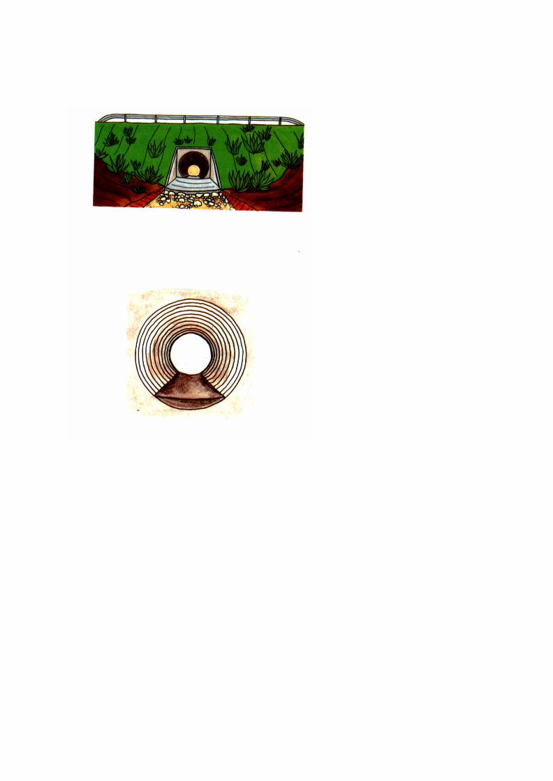

PART D – DRAINAGE
METHOD B: CONCRETE LINING
� remove any rust as previously,
� mark out the edges of the concrete slab alongthe inside walls of the culvert* using stringline orchalk line,
� pour concrete slab (1 cement : 2 sand : 4 gravel)of 10 cm minimum thickness over the completelength of the culvert invert*. The concretesurface should slope slightly to the centre lineaxis of the culvert and then be trowelled smooth,
� normally no steel bar reinforcement will berequired,
� the inlet and outlet aprons are to be concretedas necessary to adjust for the new culvert invertlevels.
*See List of Terms Volume I
I – 263


PART D - DRAINAGE
Culverts
(RE)CONSTRUCT CULVERT* AT CORRECT LEVELAND FALL
Many culverts are installed too low because thehorizontal alignment of the road was given priority atdesign/construction stage.
Where culverts are installed too low they, usuallyhave very long outfalls which repeatedly silt upalong with the culverts themselves. Besidesrequiring a high level of desilting and manpowerinput, the heaps of desilted material can take upvaluable farming land and continue to increase insize. In these circumstances it is advisable to raisethe level of the culvert by re-excavation andrelaying.
Furthermore culverts of inadequate diameter havesometimes been installed. Culverts of less than 60cm opening are extremely difficult to desilt, and thepreferred minimum size for ease of maintenance is 1metre.
In these situations consideration should be given toreconstructing the culvert at the correct level andgrade, to a suitable diameter (60 cm or larger).
*See List of Terms, Volume I
I – 265


PART D - DRAINAGE
Culverts that have collapsed or are beyond repairshould also be reconstructed. Where erosionproblems exist in the side drains this may be due toexcessive water volume f!owing. Considerationshould be given to constructing a new cross culvertto relieve the flow in the side drain.
All new or reconstructed culverts should be builtaccording to Road Department designs andspecifications.
The road level may need to be raised for a suitabledistance either side of the new/reconstructed culvertto accommodate the raised soffit* of the culvert.
*See List of Terms, Volume I.
I – 267


PART D - DRAINAGE
Culverts
CONSTRUCT OUTFALL BASIN
If a more substantial or permanent repair thandescribed on Page I - 257 is required, a Basin* orCatchpit* structure should be constructed at theoutfall of the culvert.
The basin will reduce the energy in the water andallow it to flow downstream with less risk of erosion.
The basin may be constructed of stone, brick orconcrete.
*See List of Terms, Volume I
I –269


PART D - DRAINAGE
Drifts* and Causeways*
Routine* Activities
MINOR REPAIRS
In the case of paved fords (masonry, brick or concreteslab), cracks should be filled with a bituminous mortar.Before filling, remove all soil and sand and cleanthoroughly with water. Refer to Volume III "Maintenanceof Paved Roads", Crack Sealing (Page III - 57).
Potholes should be broken out down to slab depth,cleaned and then filled with concrete (1 cement : 2 sand4 gravel), mortared stone work or bricks as appropriate.
Erosion cavities immediately upstream or downstreamof the drift or causeway should be filled with largestones or rip rap. In the case of serious or recurringerosion, ~ mattresses should be laid on the bed of thewatercourse with their top surface at the same level as,or slightly below the level of, the drift or causewayinverts*.
*See List of Terms, Volume I
I – 271


PART D - DRAINAGE
Drifts* and Causeways*
GRADING/CLEARING
Water will deposit silt, sand and debris on the drift*or causeway* from time to time, and in or againstthe causeway openings.
This must be regularly removed to avoid danger totraffic and the risk of erosion at the drift orcauseway.
Material and debris should be removed by hand anddisposed of well clear of, and downstream from, thecrossing.
A motor or towed grader may be used for clearingthe paved surface, however the windrow must bespread clear and downstream of the crossing toallow the free passage of water.
*See List of Terms, Volume I
I – 273


PART D - DRAINAGE
REPLACE GUIDE-POSTS
Missing or damaged marker or guide-posts on driftsor causeways should be replaced as required beforethe flood season. Use steel pipe of suitable diameterand length and painted in black and white sections.
� examine the pipe sockets, remove water, sand,silt, loose mortar etc. if present. Socket depthshould be at least 15 cm. Use mason's hammersand chisels to enlarge or deepen the hole ifnecessary,
� place the pipe in the socket and pack it ifnecessary to the correct position and height. Usea mortar (1 cement : 3 sand) to grout the spacebetween pipe and socket wall,
� timber guide-posts are not recommended asthey can easily break. However hardwood postscan be used if properly anchored in the socket(tight fit) so that they will not be washed awaywith the following flood.
I – 275


PART D - DRAINAGE
ManhoIes* and Drainage Pipes'
Routine* Activities
CLEAR MANHOLE AND UNDERGROUND PIPES
� remove manhole cover or grating,
� before entering manhole, ensure it is free fromnoxious gases,
� remove all debris, sand and silt from manholeusing handtools and buckets,
� if water still cannot flow, rod from the manholedownstream of the blockage until the blockagehas been removed and water flows again,
� if rodding from the downstream manhole is notsuccessful or not possible, pump water from thewater-filled manhole and attempt to clear theblockage from this manhole using roddingequipment.
*See List of Terms, Volume I.
I – 277


PART D - DRAINAGE
ManhoIes* and Drainage pipes*
REPLACE MANHOLE COVER OR GRATING
� when a manhole* cover or grating is damaged orbroken, remove it completely, including partswhich may have fallen into the manhole,
� when a cover or grating is missing, search thevicinity. If it is found undamaged, replace it onthe manhole. Be sure that the cover or grating isseated properly and level around the completerim. This will prevent unwanted movement andbreakage,
� if a new cover or grating has to be provided,ensure that the correct size is used,
� if a cover or grating cannot be immediatelyreplaced, make a temporary cover repair usingwooden planks of adequate thickness.
*See List of Terms, Volume I.
I – 279


PART D - DRAINAGE
ManhoIes* and Drainage Pjpes*
CLEAR MANHOLE AREA
� locate manhole* using the drainage plan, or bytrial excavations,
� remove all vegetation within a distance of 2 to 3metres from the manhole and remove from thesite,
� excavate all deposits of silt or soil covering themanhole down to a depth of at least 10 cmbelow manhole cover level and for a distance ofat least 1 metre from the manhole edges,
� check that the manhole is free of sand or silt andreplace the cover.
CLEAN CATCH PIT SUMP
Follow the same procedure as for CLEAR MANHOLEAND UNDERGROUND PIPES (described on Page I -277). Remove all silt and debris from the catchpit sump.
Periodic* Activities
RELAY DRAINAGE PIPE
Reconstruct pipe to correct levels and grade, and toconstruction specifications.
*See List of Terms, Volume I.
I – 281


PART D - DRAINAGE
METHOD A: MOBILE GANG
4.4 COMPLETION AND REMOVAL OF T~MPORARYSIGNS
� Load tools, equipment and unused materials backonto the truck or trailer.
� Where they have been used remove the signs,cones and barriers and load them onto the truck ortrailer in the following order:
1 "End of Restriction" signs,
2 Traffic cones,
3 "Speed Limit" signs,
4 Barriers,
5 "Road Narrows" signs,
6 "Men Working" signs.
I – 283


PART D - DRAINAGE
� Ensure that the site is left clean and tidy with nostockpiles of material left behind.
� Move onto the next job.
� Inspect traffic signs and clean if necessary.
I – 285

TYPICAL WORK REPORT
ROADSIDE AREAS
Work Report No: Date:
District: Gang
Zone Road No
Section: from km to km
Location(s):
WORK ACHIEVED:
MANPOWER USED:
Name Grade Hours worked
Name Grade Hours worked
Name Grade Hours worked
EQUIPMENT USED: DIESEL USED:
Hrs litres
Hrs litres
MATERIALS USED:
COMMENTS:
Foreman:

PART D - DRAINAGE
4.5 WORK REPORT
The report must be filled in each day, detailing:
� the work carried out,
� the resources used.
I –287


PART D - DRAINAGE
METHOD B: LABOUR BASED
In some road maintenance Systems an individualattendant or Iengthman lives close to a road and isresponsible for the ROUTINE MAINTENANCE activitieson that road.
The following activities are suitable for this method:
Ditches and Drains
CLEARING AND CLEANINGRESHAPE/REGRADE/DEEPENEROSION CONTROLPROVIDE NEW MITRE (TURNOUT) DRAIN
Culvert
CLEARING AND CLEANING EROSION REPAIR
Drifts and Causeways
GRADING/CLEARING
Manholes and Drainage Pipes
CLEAR MANHOLE AND UNDERGROUND PIPESCLEAR MANHOLE AREACLEAN CATCH PIT SUMP
I –289


PART D - DRAINAGE
METHOD B: LABOUR BASED
5. RESOURCES
5.1 PERSONNEL
� Supervisor
� 1 foreman or overseer visiting regularly.
� Workforce
� attendant or Iengthman.
I –291


PART D - DRAINAGE
METHOD B: LABOUR BASED
5.2 PLANT AND TOOLS1
� 1 broom,� 1 pickaxe,� 1 shovel,� 1 hoe or mattock,� 1 rake,� 1 hand rammer with metal shoe,� 1 wheelbarrow,� 1 bucket or watering can,� 1 grass slasher, sickle or scythe,� 1 bush knife or bush hook,� 1 axe,� 1 bowsaw,� 1 file for sharpening tools,� 1 long handled shovel/spike for culvert cleaning,� 1 ditch template and spirit level.
1 Depending on activities to be carried out.
I – 293


PART D - DAINAGE
5.3 MATERIALS
The activities suitable for attendant or lengthman donot require imported materials. For simple ditchchecks (timber and stones), materials can usually beobtained in the area of the work.
5.4 SIGNS AND SAFETY EQUIPMENT
No special arrangements are required for TrafficSigns or Clothing.
I – 295


PART D - DRAINAGE
METHOD B: LABOUR BASED
6. MAINTENANCE METHOD
6.1 PRELIMINARY TASKS
� The handtools are assigned to the attendant whokeeps them at his home for use as necessary.
� The worksheet will indicate the location and extent ofthe work to be carried out and the time required forthe job.
I – 297


PART D - DRAINAGE
METHOD B: LABOUR BASED
6.2 EXECUTION OF THE WORK
� The attendant should use the wheelbarrow to carrythe tools and safety items to the site, and collect anymaterials locally.
� The work report must be filled in for each day's work.
I – 299

User of this Handbook:
NAME:
ADDRESS:
DATE:
I -302
GENERAL INDEX

GENERAL INDEXPage Page
Aggregate Loss III -21 Camber II - 41Aggregate Loss III - 99 Camber II - 245Aggregates III - 33 Camber II - 253Aggregates Ill-ill Camber 11-293Aggregates III -207 Camber Formation II - 109Angle, Slope I - 133 Cascade I - 247Apron I -193 Catchpit 1-247Apron I - 257 Catchpit I - 281Apron IV -69 Causeway I - 195Attendant I -149 Causeway I-271
Channel I-121Barriers IV- 13 Chippings Application III -183Base Patching III - 71 Clean Culvert I - 249Bearings IV - 9 Cleaning I - 289Bearings IV- 41 Cleaning IV- 111Bend II - 43 Cleaning/Clearing IV - 41Berm I -119 ClearDrainage I -221Binder III - 35 Clearing I - 289Binder III -117 Compaction II -39Binder III -207 Compaction II - 109Binder Application III - 181 Compaction III -241Binder Content III - 211 Compaction II - 255Bitumen III - 35 Compaction II - 307Bitumen Application III - 175 Concrete Lining I -263Bitumen Emulsion III -177 Connectors IV -11Bitumen Temperature III - 143 Connectors IV -45Bitumen Paint I -261 Corrugations 11-9Bituminous Concrete III - 197 Corrugations II -71Bituminous Binders III - 117 Crack Sealing Ill-5Bituminous Macadam III - 197 Crack Sealing III - 57Bituminous Mortar III - 197 Cracks I - 189Blade Position II -49 Cracks III - 11Bleeding III - 9 Cracks III - 93Bleeding III -91 Cribwork I - 139Bolts IV - 45 Crossfall II - 35Borrow Pit II -243 Crown II -35Bridge Deck II - 47 Culverts I - 249Bridges IV - 1 Culverts II -47Burning I - 107 Culvert Cracking I - 255
I - 303
GENERAL INDEX

GENERAL INDEX CONTINUEDPage
PageCulvert Defects I - 187 Drift I - 195Culvert Invert I - 261 Drift I - 271Culvert, Reconstruct I - 265Curve II - 43 Edge Damage III -19Cut-off ditch I - 11 Edge Subsidence III - 17
Emulsion III - 185Daily Planning II -289 Emulsion III - 187Damaged Signs IV -91 Erosion I - 181Debris I -187 Erosion I -231Debris I - 197 Erosion I - 289Debris IV -9 Erosion IV - 17Debris IV -41 Erosion Control I - 149Deck IV - 41 Erosion Control I - 245Deepen Drain I - 223 Erosion Gullies II - 9Deepen Drain I - 289 Erosion Gullies II - 71Defective Masonry IV - 11 Erosion Gullies II - 157Defective Paint IV - 89 Erosion Gullies II -217Deformation Ill - 103 Erosion Gullies II -269Depressions III - 5 Erosion, Outfall I - 185Depressions III - 15 Erosion, Outlet I - 193Depressions III - 63 Erosion Repair I - 251Distance Marker IV -97 Erosion, Slopes I -63Distance Marker IV - 129 Erosion, Slopes I - 117Ditch, Grade II -55 Excavation II - 105Ditches I - 177Diversion II - 233 Fines III - 207Diversion II - 241 Fixings IV - 11Double Dressing III - 87 Fixings IV - 45Dragging II - 115 Flood Debris IV - 9Dragging, Graders II - 141 Flow Spreader I -247Dragging, Tractors II - 135 Fog Spray III - 185Drags II -125 Fretting III - 99Drain I-223Drainage I -163 Gabions I - 139Drainage Cleaning I - 221 Gabions IV - 73Drainage Defects I - 177 General Repairs III - 1Drainage Pipe I - 199 Glazing III -97Drainage Pipes I -277 Grade Ditch II - 55Drains I -177 Graded Seal III - 87
I – 304
GENERAL INDEX

GENERAL INDEX CONTINUEDPage Page
Grading I - 273 Lining Repair I - 235Grading Il -1 Loading II -301Grading Light II -31 Local Sealing Ill-SGrading Heavy II -32 Local Sealing III -53Gravel Excavation II - 297 Longitudinal Joint Ill - 249Gravel Loss II -217 Loss of Shape II -7Gravel Loss II - 269 Loss of Shape II - 71Gravel Material II -227 Loss of Shape II -217Gravel Patching II - 205 Loss of Shape II - 269Gravel, Patching II - 167Gravel, Patching II - 183 Major Defects IV-15Gravel Stockpiles II - 205 Management I - 33Guard Rail IV -93 Manhole I -199Guard Rail IV - 121 Manhole I -201Guide Posts I -275 Manhole I -277
Manhole I -289Hauling II - 303 Manpower I - 37Headwall I - 193 Marker Posts I - 275Headwall I -257 Mitre Drain I -243Herbicides I - 107 Mix Temperature III -241
Mixtures III -35Jointing III -249Joints IV - 41 Nails IV - 45Joints IV -45 Non Structural Defects IV -9Kerb I - 121 Obstructions I -53Kilometre Stone IV – 97 Obstructions I - 93Kilometre Stone IV - 129 Obstructions I - 149
Obstructions I - 177Labour Based Drainage....I -289 Off Loading II -305Labour Based Patching II - 199 Organisation I -38Labour Based Reshaping .II - 65 Outfall Basin I - 269Labour Based Surfacing III - 169 Outfall Erosion I -185Labour Based Work I - 149 Outlet Erosion I - 193Landslip I -65 Overlay III -191Layby I -45Lengthmen I – 14 9Paint IV - 11Line Drain I – 245 Painting IV - 53Lining Damaged I - 183 Patching II - 153
I – 305
GENERAL INDEX

GENERAL INDEX CONTINUEDPage Page
Patching Ill-5 Repainting IV-113Patching III - 67 Reshape Drain I - 223Patching III - 71 Reshape Drain I - 289Pavement Markings IV -95 Retaining Wall I - 141Pavement Markings IV - 123 Retaining Wall IV - 65Paver III -235 Rivets IV -47Pitching I - 129 Road Markings IV -95Planking IV -41 Road Markings IV -
123Planks IV - 49 Road Side Areas I - 41Planning II -270 RoIling III -
155PlantMix III -197 Rust I -191Plant Mix III -209 Ruts II - 7Pointing Masonry IV - 57 Ruts II - 71Ponding I -179 Ruts II -157Posts, Guide/Marker I -197 Ruts II -217Potholes II - 7 Ruts II - 269Potholes II -71 Ruts III - 15Potholes II -157 Rutting III -17Potholes II - 217Potholes II - 269 Safety I - 35Potholes III - 23 Safety Barrier IV - 59Premix III - 69 Safety Barrier IV - 93Preparation II -293 Safety Barriers IV -
121Productivity II - 286 Safety Defects IV - 13
Safety Measures IV - 33Quarry II -243 Sand III -207Quarry Preparation II -295 Sanding III -5
Sanding Ill-SiRandom Stone IV -61 Sandwich Seal III -87Rate of Spread Ill - 145 Scour IV -69Rebuild Drain I - 281 Scour Protection I - 237Reconstruct Culvert I - 265 Scuppers IV - 9Regrade I -289 Scuppers IV-41Regrade Drain I -223 Seal III -67Regrade Drain I - 233 Sealing, Cracks III - 57Regravelling (Labour and Sealing, Local III - 53Tractors) II -263 Seeding I - 125Regravelling(Mechanised) .II – 213 Setting Out II -97Regulatory Signs IV - 143 Setting Out Ill -
179
I – 306

GENERAL INDEX
GENERAL INDEX CONTINUEDPage Page
Settlement I - 189 Stabilisation I - 131Shoulder I - 47 Stockpile I - 155Shoulder I -149 Stockpiling Gravel II -297Shoulder Depressions I - 57 Stockpiling Gravel II - 309Shoulder Gravel I - 149 Stone III - 207Shoulder Material I - 109 Stone Pitching I - 129Shoulder, Reshape I - 95 Storage of Signs IV - 139Shoulder Ruts I - 57 Streaking III - 101Shoulder Vegetation I - 59 Stripping III - 99Shoulder, Vegetation I - 101 Structural Defects IV - 11Shoving III -25 Subsidence III - 17Sign Replacement IV - 127 Superelevation II -43Sign Size IV-145 Support II -225Signs, Regulatory IV - 143 Support II -277Signs Store IV - 139 Surcharging I - 137Signs, Temporary IV - 145 Surface Dressing III -83Silted/Blocked Ditches II -9 Surface Dressing Ill - 165Silted/Blocked Ditches II -71 Surface Dressing III -169Silting I - 177Silting I -187 Tack Coat III -65Single Seal III -87 Tack Coat III -213Slip I - 131 Tack Coat III - 233Slip I - 135 Temperature III - 143Slope Angle I - 133 Temperature III - 241Slopes I -49 Temporary Signs IV - 145Slopes I - 61 Termites IV - 43Slopes Erosion I - 63 Traffic Signs IV - 81Slopes Erosion I - 117 Transverse Joint III -251Slopes, Slip I -65 Turfing I - 123Slopes, Vegetation I - 61 Turnouts II - 59Slopes, Vegetation I - 115Slurry III - 57 Untreated Wood IV - 11Slurry Seal III -187Sodding I -123 Vegetation I -149Soft Spots II -157 Vegetation IV-91Spot Regravelling II -215 Vegetation Control IV - 119Spot Regravelling II -267 Vegetation, Shoulder I -59Spray Bar III - 145 Vegetation, Slopes I -61Spreading II - 305 Vegetation, Slopes I - 115
I – 307
GENERAL INDEX

GENERAL INDEX CONTINUED
Page
Warning Signs IV - 13Wattling I -127Weepholes IV-9Windblown Debris IV - 9Windrow II - 51Windrow II - 143Wood Preservation IV - 55Workshop Repair IV - 119
I - 308

ACKNOWLEDGEMENTS
The contents of this handbook draw on many sources,past and present, and it would be impossible toacknowledge them all individually. Much of the materialis an updating of the UN/ECA Maintenance Handbookfor Africa, compiled by experts from France, Germanyand the United Kingdom, and published in 1982. Itsthree volumes encapsulated the broad experience ofhighway engineers, maintenance managers,consultants and researchers from many differentcountries.
The present revision was undertaken by Mr R.C. Pettsof Intech Associates, in close association with theOverseas Centre of the Transport Research Laboratory.The work was funded by the UK Overseas DevelopmentAdministration and supported and guided by asubcommittee drawn from the PIARC Committee onTechnology Transfer and Development (C3). Itbenefited from the collective wisdom of that committeeand the countries represented within it. These includedAustralia, Algeria, Belgium, Brazil, Burkino Faso,France, Germany, India, Italy, Morocco, Poland,Portugal, Senegal, Spain, Turkey, the United States ofAmerica, the United Kingdom and the World Bank.
On behalf of the subcommittee I would like to record oursincere thanks to all those who contributed, in whateverway, to the production of this second version of theMaintenance Handbook and to making it more valuableto a wider international audience. I am sure it will fulfil itsintended purpose of strengthening the capabilities ofmaintenance workforces and giving them a strongersense of professional pride in the vital work they aredoing.
I – 309

ACKNOWLEDGEMENTS continued
Any revision of this kind is an ongoing process, andcomments or suggestions for further improvementsshould be made known to the PIARC Central Office at27 rue Guenegaud 75006 PARIS, France.Fax +33(1) 46 3384 60
J Stuart YerrellChairman, Subcommittee C3-6d

WHAT IS PIARC?Founded in 1909 following the 1st Internationla Road Congress heldin Paris in 1908, the Permanent International Association of RoadCongresses (PIARC) is the oldest of the international associationsconcerned with roads and road engineering.
The general aim of the Association is to improve international co-operationand to foster progress in:
• the formulation of road transport policies• the planning, construction, improvement and maintenance of
roads• the operation and management of road systems
within the context of wider policies towards transport.
To achieve these aims PIARC:
• organises a World Road Congress every four years and varioustechnically oriented events
• creates and co-ordinates Committees• publishes a number of documents including a periodic bulletin
It is assisted in its task by National Committees. PIARC is a nonpolitical and non-profit association
It was granted consultative status, category II, to the Economic andSocial Council of the United Nations in 1970.
The official languages of PIAC are French and English
There are several catagories of members: Governments, regionalauthorities, public bodies, collective members and Individualmembers
As of 1 January 1994, PIARC has 72 member Governments and2100 members in 100 countries.
PIARC has strong links with several regional organisations and is infavour of networking between countries dealing with similarquestions. PIARC may help to create and/or develop such networks.
I -311

PIARC Committees and Working Groups are composed ofengineers and experts appointed by member countries. They act ona continuous basis between each Congress and participate ininternational meetings dealing with subjects within their competence
On average they hold two plenary meetings a year. As of 1 January1994, Committees and Working Groups gather approximately 700engineers and experts from 40 countries.
Thirteen Committees and four Working Groups are active (period1991 - 1995)
• COMMITTEES
C 1 Technical Committee on Surface CharacteristicsC 3 Committee on Technological Exchanges and DevelopmentC 4 Committee on interurban RoadsC 5 Committee on Road TunnelsC 6 Committee on Road ManagementC 7 Technical Committee on Concrete RoadsC 8 Technical Committee on Flexible RoadsC 9 Economic and Finance CommitteeC 10 Comm 11cc on Urban AreasC 11 Committee on Road BridgesC 12 Technical Committee on Earthworks Drainage, SubgradeC 13 Committee on Road SafetyC 14 Committee on the Environment
• WORKING GROUPS
G 1 PIARC Winter Road CongressG 2 Natural Disaster ReductionG 3 Modern Traffic Control and ManagementG 4 Heavy Freight Vehicle issues
• PIARC PUBLICATIONS - Committees and Working Groupspublish synthetic documents recommendations and state of theart. These documents intended for decision makers, design andfield engineers and researchers, are based on wide internationalconsensus
I – 312

• CONGRESS DOCUMENTS - The documents published on theoccasion of World Road Congresses are an invaluable source ofinformation and experts agree on the fact that they are mostinteresting and unique.
• PERIODICAL BULLETIN “Routes/Roads” - The AssociationBulletin was issued for the first time in 1911. It featurescomprehensive files on road matters in various countries, articleswritten by members of Committees and Working Groups andnews of interest to the world road community. Its issues of ahundred pages are published three to four times a year.
• TECHNICAL DICTIONARY OF ROAD TERMS AND LEXICON -
The first edition of the DICTIONARY was issued in 1931. Thesixth edition (French/English) was published in 1990. TheDictionary is published with the financial support of UNESCO andis translated into eighteen languages: Arabic, Chinese, Croatian,Czech, Danish, Dutch, German, Greek, Hungarian, Italian,Japanese, Lithuanian, Polish, Portuguese, Romanian, Russian,Spanish and Slovak. The Lexicon contains over 12,000expressions in English and French and is also available oncomputer disk.
All these documents are published in French and English. PIARCpublications catalogue is free of charge and can be orderedthrough:
ANRTP32, rue du Marché commun
Centre de Gros - Case postale 122044082 NANTES Cédex 03 (FRANCE)
Fax: +33 40 50 13 64
I -313

WHERE TO ORDER THE HANDBOOK
The English version of
Volume I: Maintenance of Roadside Areas and
Drainage
Volume II: Maintenance of Unpaved Roads
Volume Ill: Maintenance of Paved Roads
Volume IV: Maintenance of Structures and TrafficControl Devices
may be ordered from:
Transport Research LaboratoryCrowthorne, Berkshire RG1 1 6AUUnited Kingdom
The Road Maintenance Handbook is also beingpublished in French, Spanish and Portuguese. Otherlanguages are under consideration. For more details,please contact PIARC Central Office - 27 RueGuenégaud, 75006, PARIS, France.Fax:+33 (1) 46 33 84 60.
Printed by:- Borough Press (Wiltshire) Ltd, SN2 6YW, UK
I - 314

Volume II
Maintenance ofUnpaved Roads AIPC
R
PIARC

INTERNATIONALROAD
MAINTENANCEHANDBOOK
PRACTICAL GUIDELINES FORRURAL ROAD MAINTENANCE
Volume II of IV
Unpaved roads
Financed and coordinated by

Revised by R C Petts of Intech Associates, UKWith the financial support of ODA
under assignment to
TRANSPORT RESEARCH LABORATORY, UK
as a development of the UN ECA handbooks prepared byjoint cooperation of the governments of FRANCE, GERMANY
and the UNITED KINGDOM and first published in 1982.
@WORLD COPYRIGHT RESERVED 1994Extracts from the text may be reproducedprovided the source is acknowledged as
follows.PIARC Road Maintenance Handbook
English version published byTransport Research Laboratory, UK
ISBN for complete set of 4 Volumes: 0 9521860 12ISBN for Volume II: 0 9521860 39

CONTENTS
FOREWORD .............................................................i
INTRODUCTION ...................................................... x
Part A - GRADING ................................................... 1
1. THE TASK ........................................................... 3
2. DEFECTS ............................................................ 7
3. RESOURCES........................................................11
3.1 PERSONNEL 133.2 PLANT AND TOOLS 153.3 SIGNS AND SAFETY EQUIPMENT 19
4. MAINTENANCE METHOD .........4.1 PRELIMINARY TASKS4.2 TEMPORARY SIGNPOSTING4.3 GRADING THE RUNNING SURFACE4.4 GRADING DITCHES4.5 COMPLETION AND REMOVAL OF
TEMPORARY SIGNS4.6 WORK REPORT
2323272955
6163

CONTENTS CONTINUED
Part B - LABOUR BASED RESHAPING .................... 65
1. THE TASK .......................................................... 69
2. DEFECTS……. .................................................... 71
METHOD A: ROUTINE RESHAPING3. RESOURCES....................................................... 73
3.1 PERSONNEL 733.2 PLANT AND TOOLS 753.3 SIGNS AND SAFETY EQUIPMENT 77
4. MAINTENANCE METHOD .................................... 794.1 PRELIMINARY TASKS 794.2 EXECUTION OF THE WORK 81
METHOD B: MAJOR RESHAPING5. RESOURCES………………………………………………85
5.1 PERSONNEL 855.2 PLANT AND TOOLS 875.3 SUPPORT AND SAFETY ARRANGEMENTS 89
6. MAINTENANCE METHOD .................................... 916.1 PRELIMINARY TASKS (as necessary) 916.2 TEMPORARY SIGNPOSTING 936.3 EXECUTION OF THE WORK 956.4 COMPLETION AND REMOVAL OF
TEMPORARY SIGNS 1116.5 WORK REPORT 113

CONTENTS CONTINUED
Part C - DRAGGING .....................................……………115
1. THE TASK…………………………………………………117
2. DEFECTS………………………………………………….119
3. RESOURCES..……………………………………………121
3.1 PERSONNEL3.2 PLANT AND TOOLS3.3 SIGNS AND SAFETY EQUIPMENT
4. MAINTENANCE METHOD ..........................4.1 PRELIMINARY TASKS4.2 WORKING WITH A TRACTOR AND DRAG4.3 DRAGGING WITH GRADERS4.4 WORK REPORT
121123129
.......... 131131135141151

CONTENTS CONTINUED
Part D - PATCHING .............................................. 153
1. THE TASK .........................................................155
2. DEFECTS ..........................................................157
METHOD A: MOBILE GANG3. RESOURCES......................................................161
3.1 PERSONNEL 1613.2 PLANT AND TOOLS 1633.3 MATERIALS 1673.4 SIGNS AND SAFETY EQUIPMENT 169
4. MAINTENANCE METHOD ...................................1734.1 PRELIMINARY TASKS 1734.2 TEMPORARY SIGNPOSTING 1794.3 EXECUTION OF THE WORK 1834.4 COMPLETION AND REMOVAL OF
TEMPORARY SIGNS4.5 WORK REPORT
193197
METHOD B: LABOUR BASED5. RESOURCES .............................. . .................... 201
5.1 PERSONNEL 2015.2 PLANT AND TOOLS 2035.3 MATERIALS 2055.4 SIGNS AND SAFETY EQUIPMENT 207
6. MAINTENANCE METHOD ............ ..................... 2096.1 PRELIMINARY TASKS 2096.2 EXECUTION OF THE WORK 211
II -vii
CONTENTS CONTINUED
Part E - REGRAVELLING (Mechanised) ……………...213
1. THE TASK .......................................................215
2. DEFECTS ........................................................ 217
3. RESOURCES ................................................... 219
3.1 PERSONNEL ............................................... 2193.2 PLANT AND TOOLS ..................................... 2213.3 MATERIALS ................................................ 2273.4 SIGNS AND SAFETY EQUIPMENT ................ 229
4. MAINTENANCE METHOD ................................. 2354.1 PRELIMINARY TASKS .................................. 2354.2 TEMPORARY SIGNPOSTING ........................ 2414.3 EXECUTION OF THE WORK ......................... 243
TEMPORARY SIGNS 2574.5 WORK REPORT 261

CONTENTS CONTINUED
Part F - REGRAVELLING (Labour and Tractors) ...263
............................................................... 2671. THE TASK
2. DEFECTS ......................................................... 269
3. RESOURCES .................................................... 271
3.1 PERSONNEL ............................................... 2713.2 PLANT AND TOOLS ...................................... 2733.3 MATERIALS ................................................. 2753.4 SUPPORT AND SAFETY ARRANGEMENTS 277
4. MAINTENANCE METHOD …………………………..2794.1 PRELIMINARY TASKS (as necessary)................2794.2 TEMPORARY SIGNPOSTING ...........................2854.3 EXECUTION OF THE WORK ............................2874.4 COMPLETION AND REMOVAL OF
TEMPORARY SIGNS.....................................3114.5 WORK REPORT ..............................................313

FOREWORD
The road transport network of any country plays a vital rolein its economy, and the physical condition of itsinfrastructure is critical. Without adequate and timelymaintenance, highways and rural roads alike inexorablydeteriorate, leading to higher vehicle operating costs,increased numbers of accidents, and reduced reliability oftransport services. When repair work can no longer bedelayed it will often involve extensive rehabilitation, andeven reconstruction, costing many times more than simplermaintenance treatment carried out earlier. The need toprotect the existing network and keep it in good condition isparamount, often taking precedence over new investment.
PIARC has been in the forefront in promoting this messageand in drawing attention to the dangers of neglect. Thematter has become increasingly important in recent yearsfor all the highways of the world, but especially so for thosein developing countries where there is constant pressure onslender budgets and, in many, an urgent need to cater forgrowing traffic loads and volumes.
In the late 1970's, the aid ministries of France, the FederalRepublic of Germany and the United Kingdom joined forcesto produce a "Road Maintenance Handbook" formaintenance foremen and workers in Africa. Published in1982 under the auspices of the Economic Commission forAfrica, the three volumes - in French and English - soonbecame widely known and used. By the end of the decadetheir use had spread far beyond Africa, and theirstraightforward instructions were being used for trainingpurposes as well as for

FOREWORD continued
on-the-job guidance in many countries. The need toreprint provided the opportunity to review the contents inthe light of experience and make them more suitable forthe wider audience now commanded. PIARC'sCommittee on Technology Transfer and Development,formerly the Committee on Roads in DevelopingRegions, undertook to help with this review, which wasgenerously funded by the UK Overseas DevelopmentAdministration. A sub-committee was established,embracing the three original donor countries, otherdeveloped and developing countries, and the WorldBank. Although much of the original text has beenretained, the new handbooks incorporate moreinformation on labour and tractor-based techniques, andon the development of manpower management and theall-important question of safety at work. The range ofmaintenance problems addressed has been extended tostrengthen their international appeal.
The past ten years have seen major reforms in thegeneral thrust of maintenance policy and in itsorganisation, management and execution. Thesechanges will continue, and PIARC will play its part alongwith other institutions in encouraging the process andpressing for further progress. Only a full appreciation ofmaintenance at the highest levels of policy-making andfinancial planning can ensure success. But thesehandbooks have a humbler task-to ensure that the menand women at the operational level are suitably skilledand trained and are using the appropriate tools andtechniques, and have interest and motivation in theirwork.

FOREWORD continued
PIARC has been proud to nurture this project to the pointwhere the new handbooks are available, but its involvementwill reach far beyond that. It will provide the necessaryinternational framework within which the handbooks can betranslated and printed in many languages. Its worldwidemembership of key figures in the national provision andmanagement of highways will assist with theirdissemination, ensuring that they find their way into themost appropriate hands in both the public and privatesectors. Collectively, these hands will play a fundamentalpart in sustaining the vital asset which our roadwaynetworks truly represent.

INTRODUCTION
THE HANDBOOK
This is a guide for the maintenance foreman orsupervisor assigned to bitumen or unpaved roads intropical and moderate climates. The objective of theHANDBOOK is to assist him in all aspects of his workwhether carried out by direct labour or by contract. Itspocket format enables the volume relevant to the day's workto be easily carried and consulted on site. The HANDBOOKshould be his ready reference book. The text is concise andwell illustrated. A quick reference should be all that isnecessary.
This HANDBOOK does not include a course of study ordiscuss underlying causes of defects. Inspections, materialsources, specifications and testing are also outside itsscope. Furthermore it is sufficient here to remind theforeman that his plant and vehicles should be wellmaintained without telling him how to do it.
Even though the HANDBOOK is intended for use by themaintenance foreman, it will also be useful reading for theengineer or senior supervisor. This will make him moreconscious of his duties towards the foreman and enable himto ensure that the maximum benefit isobtained from the HANDBOOK. Each supervisor mustunderstand his responsibility and the part he has to play.
The HANDBOOK can also be used in training centres. Withthe assistance of country -specific supplementaryinformation, photographic slides, models, and othersupporting material, it will be a valuable tool for the trainerand can be distributed to students.

Road maintenance requires a range of organisational andtechnical skills and the work on roads in use by trafficmakes the work potentially hazardous to both the workmenand road users.
It is therefore essential that appropriate formal and on-the-job training is given to each category of personnelinvolved in road maintenance activities to achieve efficientand safe operations.
The foreman usually has an important role in the initial andongoing training of personnel.
Roads are an enormous national investment and requiremaintenance to keep them in a satisfactory condition andensure safe passage at an appropriate speed and with lowroad user costs.
Late or insufficient maintenance will increase the ultimaterepair costs and raise road user costs and inconvenience,and reduce safety.
Road Maintenance is therefore an essential function andshould be carried out on a timely basis.
There is a diversity of maintenance activities, the class andtype of the road, the cross section to be maintained, thedefects recognised, and the resources available. Howeverthe general methods proposed here for each activity (withsome exceptions) are given under the following headings:
- The task- Defects- Resources- Maintenance method

Where appropriate options are shown for carrying out thework by:
i) Heavy Equipment,ii) Tractor based methods, oriii) Labour based methods.
The decision on which method to be used should be madeby the engineer or senior supervisor based onconsiderations of resources available, cost, policy etc.
Maintenance operations are usually grouped in eachcountry according to planning, organisational and fundingarrangements. They can normally be categorised as eitherROUTINE or PERIODIC.
For the purposes of this HANDBOOK the following groupingis used.
ROUTINE: Operations required to be carried out onceor more per year on a section of road. Theseoperations are typically small scale orsimple, but widely dispersed, and requireskilled or un-skilled manpower. The need forthese can, to a degree, be estimated andplanned and can sometimes be carried outon a regular basis.
PERIODIC: Operations that are occasionally required ona section of road after a period of a numberof years. They are normally large scale andrequire specialist equipment and skilledresources. These operations are costly andrequire specific identification and planning.In this

handbook PERIODIC also includes certainimprovement works such as thin bituminousoverlays.
From time to time urgent or emergency works of any naturemay be required and these are dealt with as the needarises.
The HANDBOOK consists of 4 separate volumes:
VOLUME I - MAINTENANCE OF ROADSIDE AREAS ANDDRAINAGE
PART A - List of TermsPART B - Works Management and SafetyPART C - Roadside AreasPART D - DrainageGeneral Index
VOLUME 11- MAINTENANCE OF UNPAVED ROADSPART A - GradingPART B - Labour Based ReshapingPART C - DraggingPART D - PatchingPART E - Regravelling (Mechanised)PART F - Regravelling (Labour and Tractors)
VOLUME III - MAINTENANCE OF PAVED ROADSPART A - General RepairsPART B - Surface Dressing (Mechanised)PART C - Resealing OptionsPART D - Thin Overlays

VOLUME II
VOLUME IV - MAINTENANCE OF STRUCTURES ANDTRAFFIC CONTROL DEVICES
PART A - BridgesPART B - Traffic Control Devices
Each Part A, B, C, D, E, and F describes tasks concerningunpaved roads*.
An unpaved road can be a track which has developed withuse over a number of years or it can be a purpose built roadthat has a properly designed and engineered alignment,cross section and drainage. Earth roads are constructedusing the natural soil found on the route. Gravel roads aresurfaced with a layer of material which is stronger than thenatural in situ soil.
With proper maintenance, an unpaved road can provide agood level of service for traffic volumes up to severalhundred vehicles per day. The two main purposes ofmaintenance are to repair or reduce the damage caused bythe combination of the weather and traffic, and to provide asmooth passage for vehicles.
The first objective of unpaved road maintenance is to keepthe road in such a condition that it sheds water quickly. Ifthe road does not shed water, the surface will become soft,and ruts and pot-holes will quickly appear. In this way earthroads can soon become impassable.
NOTE - Terms with an asterisk are defined in List of Terms (SeeVolume I - Part A).

PART A - GRADING
Maintenance is needed to restore a good camber* on theroad to enable water to drain off quickly. This is bestachieved by regular grading. On gravel roads, grading isalso needed to restore gravel from the shoulders which hasbeen lost from the road surface, to fill pot-holes andcorrugations.
PART B - LABOUR BASED RESHAPING
The road camber can also be restored by labour basedreshaping. This is a viable option when grading equipmentis too expensive or not available.
PART C - DRAGGING
In dry areas, dragging the road surface may be effective inproviding a smooth passage for vehicles and in controllingthe formation of corrugations. The object is to correct minordefects on the road surface. Dragging may be carried outwith a motorgrader, towed grader or with a drag towed by atractor or other vehicle.
PART D - PATCHING
Holes in the road may need to be patched. Patching can becarried out by a mobile gang or by labour based roadattendants.
NOTE - Terms with an asterisk are defined in List of Terms (SeeVolume I - Part A).

PART E - REGRAVELLING (Mechanised)
As the surface of a gravel road wears away, new gravelmust be added before rapid deterioration of the surfacestarts. Regravelling may also be needed to correct otherdefects when these become severe, and may also be usedto improve an engineered earth road to a gravel road.
PART F - REGRAVELLING (Labour and Tractors)
This option avoids the need for heavy equipment. Tractorhaulage of gravel can be economical for distances up toabout 10 km with labour used to excavate, load, unload andspread the gravel.
NOTE: In many countries women carry out roadmaintenance tasks and supervisory duties. The use of maledescriptions and diagrams in this handbook is forconvenience only. The guidelines are applicable whetherthe work is carried out or supervised by men or women.

Part A
GRADING
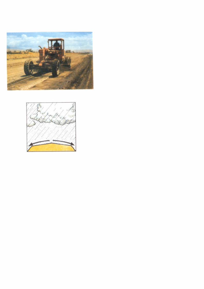

PART A - GRADING
1. THE TASK
The task is to improve earth and gravel roads by gradingthe existing surface material. Grading is normally aROUTINE MAINTENANCE task. It is carried out by selfpropelled or towed graders.
The object is to restore the camber* by returning materialfrom the sides and shoulders towards the centre of theroad. This will enable water to drain off easily.
A road with a flat or dished surface will collect water. Trafficand water together will quickly cause potholes and roughspots.
See List of Terms,Volume 1.


PART A - GRADING
Rollers should be used to compact* the road after gradingwhenever possible as this will improve the initial quality ofthe reshaped surface.
Work is best scheduled to follow a period of rain, as themoisture in the material will greatly help compaction byrollers or traffic. For some materials the addition of watercan be justified.
Grading can also be used to restore the shape of shoulders,ditches and turnouts (see also Volume I).
* See List of Terms,Volume 1.


PART A - GRADING
2. DEFECTS
Grading is used to correct
♦ Loss of shape
♦ Ruts
♦ Potholes


PART A - GRADING
♦ Corrugations
♦ Erosion Gullies
♦ Silted or Blocked Ditches


PART A - GRADING
3. RESOURCES
These comprise personnel, plant and tools, signs and safetyequipment.
Grading is a fast moving activity often carried out at longdistances from the equipment base. Although it may becarried out by individual graders or towed graders, it is bestorganised using mobile units of 2-3 grading machines witharrangements for temporary overnight accommodation.
This reduces travelling time between base and worksitesand eases supplies and mechanical support problems.
The number and types of grading machines, rollers,watering equipment, and mobile accommodation depend onthe:
m road condition (light or heavy grading),
♦ moisture conditions,
♦ compaction requirements,
♦ organisational requirements,
♦ accommodation arrangements,
♦ resources available.


PART A - GRADING
3.1 PERSONNEL
The categories and numbers of personnel depend on theequipment resources used. Each grading gang shouldinclude:
♦ Supervisors
1 foreman.
♦ Plant Operators and Drivers
1 operator for each motor grader,1 driver for each tractor,1 operator for each towed grader,1 light vehicle driver,1 operator for each motorised roller,1 driver for each water tanker.
♦ Work Force
1 machine attendant for each item of plant andequipment,1 mechanic for daily servicing and minor repairs.


PART A - GRADING
3.2 PLANT AND TOOLS
Motor Graders
Motor graders of 100 hp (75 kW) or more can be usedfor light or heavy grading.
Heavy Tractors and Towed Graders
100 hp (75 kW) 4WD* tractors and heavy (5 tonne)towed graders can be used for light or heavy grading.
Light Tractors and Towed Graders
50 hp (38 kW) tractors and light (2 tonne) towed graderscan be used for light grading.
Rollers
1 or 2 rollers, if available. Rubber tyred rollers arepreferred. They can be self propelled or tractor drawn.
" See List of Terms, Volume I.


PART A - GRADING
♦ Water
When water tankers are needed and available, thenumber required will depend on the distance that waterhas to be hauled. These should be fitted with a spraybar.
♦ Water Pump
A separate water pump will be needed if none is fitted tothe water tankers. The pump should be of sufficientcapacity to fill the tankers quickly.
♦ Caravan
If the mobile units stay away from base overnight and noaccommodation is available, caravans or tents could beused.
♦ Other Vehicles
Transport for the supervisor.
♦ Tools
Camber board* made as shown from 20 mm treatedplywood or hardwood to give a 1 in 20 (5%) slope andcarried on the grading machine.
A selection of hand tools will be required by the machineattendants (see Part D, Page II - 165).
* See List of Terms, Volume I.


PART A - GRADING
3.3 SIGNS AND SAFETY EQUIPMENT
The following items should be used where possible.
♦ Traffic Signs
- 2 "Men Working" signs,- 2 "End of Restriction" signs.
These should be clean and in good condition.
♦ Clothing
Yellow or orange coloured safety vests or safetyharnesses should be worn by the machine attendants.


PART A - GRADING
♦ Vehicles
The grading equipment should be painted yellow ororange and should carry red and white stripedmarker boards front and rear.
♦ Lights
The grading equipment should work with headlightsswitched on and, where possible, yellow flashingwarning lights.
♦ Flags
If yellow flashing warning lights are not available,vehicles and equipment should carry a yellow ororange flag.

TYPICAL WORKSHEET
GRADING
Worksheet No: . . . . . . . . . . . . . . . . . . Date: . . . . . . . . . . . . . . . . . . . . .
District:………………………………………………………………………...
Zone: .......................…………………. Gang: …………………………….
Road Zone…………………from ……………………to……………………
Section from km . . . . . . . . . to km . . . . . . . . . in . . . . . . . . …. m width
Light Grading
Heavy Grading
EQUIPMENT TO BE USED:
Motorgraders: : ........................................... …………………………..
Tractors: ................................................ ………………………………
Towed Graders:…………………………………………………………..
Tankers/Bowsers: ........................................………………………….
Rollers: ...............................................…………………………………
Caravans: .............................................……………………………….
Watering
Compaction

PART A - GRADING
4. MAINTENANCE
4.1 PRELIMINARY TASKS
♦ The worksheet will indicate the location and extent ofthe work to be carried out, the time, equipment andpersonnel required for the job.
II-23


PART A - GRADING
Before setting out to start the job, a check should be madeto ensure that everything needed is ready.
♦ Plant and machinery must be checked mechanically,greased and fuelled. The oil and water levels must bechecked.
♦ Arrangements must be made to refuel the plant on thejob if necessary. This may be with a refuelling truckvisiting the working site, or with an arrangement torefuel at a maintenance or temporary camp.
♦ Traffic signs and camber board must be obtained,loaded on the grading equipment and taken to site.These must be properly stored/secured on the gradingequipment.
♦ If the grading crew is staying away overnight,arrangements must be made for accommodation,supplies, etc.

NOTE: SHOWN FOR DRIVING ON THE RIGHT

PART A - GRADING
4.2 TEMPORARY SIGNPOSTING
Before work starts, warning signs must be placed at eachend of the work area to ensure the safety:
♦ of the road users,
♦ of the personnel and plant to be deployed on the site.
Signs must be placed in the following order:-
♦ "Men Working" signs should be placed at theapproaches to the work area.
♦ "End of Restriction" signs should be placed at the endof the work area.
Work should not be carried out at night.
II-27

- -- ,-. ~/ ~ \- t, ~-

PART A - GRADING
4.3 GRADING THE RUNNING SURFACE
♦ Preparation
Patching (Part D) of large potholes or depressions shouldbe carried out in advance of the grading.
Areas of standing water should be drained. This preparationwill ease the work and make the resulting surface lastlonger.
♦ Scarifying*
It may be necessary to scarify the existing surface to cut tothe bottom of any surface defects and loosen the materialfor reshaping.
♦ Machine Attendants
These help direct traffic and grader turning, and removelarge stones and other unwanted material from the path ofthe grader.
♦ Grading
The grader works on one side of the road at a time andworks in passes* about 200 metres long to convenient andsafe turning points.
*See List of Terms, Volume I.

HEAVY GRADING
LIGHT GRADING
200 m approx
HEAVYGRADING

PART A - GRADING
Light Grading will normally require 4 passes to reshape theroad.
Heavy Grading will require additional passes to achieve therequired camber. Work should be completed on one side ofthe road at a time.
An even number of passes should be used to avoid a flatfinished crown*.
Normally initial cutting passes* are required to bringmaterial in from the edges of the road. Spreading passesredistribute the material away from the crown.
* See List of Terms, Volume I.


PART A - GRADING
The initial passes* cut to the bottom of the surfaceirregularity and deposit a windrow* just beyond the centreline.
The water tanker sprays the windrow with water, ifrequired.
The windrow is spread back across the road depositing allthe material to give the correct camber*.
A second application of water may be required to obtain thecorrect moisture content for compaction.
* See List of Terms, Volume 1.


PART A - GRADING
The aim should be to develop a proper crown* on the road.
The road should be cambered to fall away from the crown ata rate of about 6 to 7 cm for each metre from the centre ofthe road before compaction. This should achieve a crossfallof about 4 to 6 cm per metre (4 to 6%) after compaction.
If there is insufficient camber*, water will not drain easilyfrom the surface of the road, potholes will form and the roadwill deteriorate quickly. This is particularly important ongradients, where the rain water tends to run along the roadforming erosion channels.
* See List of Terms, Volume 1.


PART A - GRADING
♦ Do not make a final pass down the centre of the roadwith the grader blade horizontal.
This flattens the centre of the road and causes water topond leading to rapid deterioration of the surface.
♦ Do not leave a windrow on the road overnight as this isa danger to traffic.
II-37


PART A - GRADING
♦ Compaction
When compaction* plant is being used, it must followclose up behind the grader, but only on sections wheregrading has been completed. About eight passes* of aroller will be needed to achieve full compaction, workingtowards the centre of the road.
♦ Shoulders are treated as part of the running surface.
♦ Junctions and Bends
Graders must not stop near junctions or bends where
they will be a danger to traffic
* See List of Terms, Volume 1.
II-39


PART A - GRADING
♦ Check theCamber
Camber should be checked with a camber board atabout 100 metre intervals along the road.
To use the camber board* place it on its edgeacross the road with the shorter end pointingtowards the centre line.
Check the level bubble.If it is central, the camber is correct. If it is notcentral, the camber is either too steep or too flat andfurther grading and compaction are required.
* See List of Terms, Volume I.


PART A - GRADING
♦ On bends the surface must be straight (at 4-6%) fromshoulder to shoulder with the outer shoulder higher.This is called superelevation.
Any crown on a bend can be very dangerous to traffic.


PART A - GRADING
The superelevation must be retained for the completelength of the bend.
On the transition at each end of the bend into the straightsections, the superelevation should be gradually reduceduntil the normal cross section shape with 1 in 20 (5%)camber* is obtained again.
See List of Terms, Volume 1.
11-45


PART A - GRADING
♦ The shape of the road must be maintained overculverts to avoid a hump. Material should be brought inif necessary from either side of the culvert to maintain acover to the top of the culvert of at least 3l4 culvertdiameter.
m Bridge decks should be kept free from gravel. Loosematerial should be swept away by the attendants.
It is important to have smooth approaches to the bridge.They should be smoothed out using the back of the bladewith the grader working in reverse, or by hand.
11-47


PART A - GRADING
♦ For most grading work, the cutting blade is set to bevertical.
♦ For cutting hard surfaces, the cutting blade should beset back at the top to give the most effective cuttingangle.
♦ For spreading, the cutting blade should be set forwardat the top.
II-49


PART A - GRADING
♦ To form a windrow*
Point all wheels straight ahead and angle the blade.
The angle should be sharp enough to let surfacematerial roll freely off the end of the blade.
Travel forward slowly in low gear keeping the bladelevel and 5-10 cm into the surface material.
On graders with this facility lean the front wheels inthe same direction as the windrow to help counterside thrust on the blade.
The windrow must be formed outside or betweenthe rear wheels.
* See List of Terms, Volume 1.


PART A - GRADING
♦ Handling a windrow
Angle the blade to left or right according to the jobrequirement.
The angle should allow material to roll freely off theend of the blade.
To move or mix material: Travel forwards slowly inlow gear. Pick up material from one side of themachine and pass it to the other.
TRY TO MATCH THE GEAR AND SPEED TO THEWORK TO BE DONE.
To get more power: Angle the bladetowards the windrow. Lean the frontwheels against the side thrust.
THE REAR WHEELS SHOULD NOT BE ALLOWEDTO RUN OVER THE WINDROW.


11-55
PART A - GRADING
4.4 GRADING DITCHES
Before the road surface is graded, the side ditches must becleaned.
♦ Narrow flat-bottomed ditches are not well suited tomaintenance by grader. These are best cleaned outby hand.This work is described in Volume I.
♦ Graders should be used to maintain V-shaped ditchesand wide flat-bottomed ditches.
♦ Material from the ditch should not normally be gradedonto the running surface. In certain circumstances theengineer may instruct the recovery and mixing of theditch material, where the running surface lacks suitablefines present in the ditch.


11-57
PART A - GRADING
♦ The first pass* cleans the side slope near the road andwindrows the material to the bottom of the ditch.
♦ On wide flat-bottomed ditches, the second pass cleansthe ditch bottom.
♦ The next pass cleans the ditch back slope and removesthe material to the top of the ditch.
♦ If possible, a third pass is used to push the materialaway from the edge of the ditch, to prevent it washingback.
* See List of Terms, Volume I


PART A - GRADING
♦ The completed ditch should be at least 1 metre deep.
♦ Turnouts should be constructed and maintained with agrader.
These should lead the water away from the edge of theroad and follow closely the natural contours of theground.
♦ Turnouts should be spaced more closely as gradientsbecome steeper.
♦ The discharge of water should be "little and often" tominimise erosion risk on adjoining land.
II-59


11-61
PART A - GRADING
4.5 COMPLETION AND REMOVAL OF TEMPORARYSIGNS
♦ Remove the traffic signs and load them back on thegrader.
♦ Move on to next job.
♦ Clean the traffic signs on return to the depot

TYPICAL WORK REPORT
GRADING
Work Report No: . . . . . . . . . . . . . Date: . . . . . . . . . . . . . . . . . .
District: ..................................................Gang:
Zone: .....................................................Road No:. ..............
Section: . . . . . . . . . . from km . . . . . . . . . to km . . . . . . . . .
QUANTITY OF WORK ACHIEVED:
WEATHER CONDITIONS:
Light grading . . . . . . . ............................. ....... .. kms
Heavy grading . . . . . ................................................ kms
Watering. . . . . ............ ................................. kms
Compaction.... ............................................. kms
Sunny Cloudy Rain
EQUIPMENT USED: DIESEL USED:
........................ ............................ Hrs ................. ......................litres
........................ ............................ Hrs ................. ......................litres
........................ ............................ Hrs ................. ......................litres
........................ ............................ Hrs ................. ......................litres
........................ ............................ Hrs ................. ......................litres
........................ ............................ Hrs ................. ......................litres
MANPOWER USED: .....................................
COMMENTS:
Foreman: .............................................

PART A - GRADING
4.6 WORK REPORT
♦ The report must be filled in each day, detailing:
- the work carried out,
- the resources used.

Part B
LABOUR BASEDRESHAPING
II-65

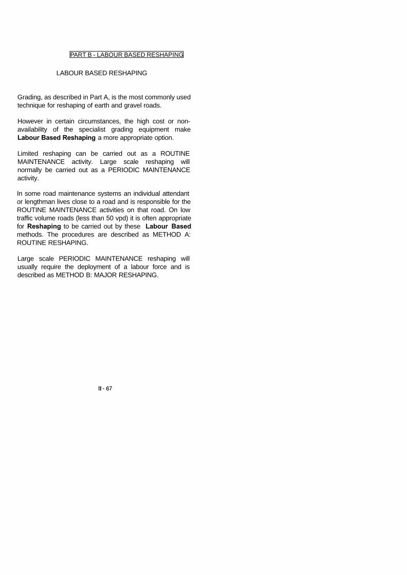
PART B - LABOUR BASED RESHAPING
LABOUR BASED RESHAPING
Grading, as described in Part A, is the most commonly usedtechnique for reshaping of earth and gravel roads.
However in certain circumstances, the high cost or non-availability of the specialist grading equipment makeLabour Based Reshaping a more appropriate option.
Limited reshaping can be carried out as a ROUTINEMAINTENANCE activity. Large scale reshaping willnormally be carried out as a PERIODIC MAINTENANCEactivity.
In some road maintenance systems an individual attendantor lengthman lives close to a road and is responsible for theROUTINE MAINTENANCE activities on that road. On lowtraffic volume roads (less than 50 vpd) it is often appropriatefor Reshaping to be carried out by these Labour Basedmethods. The procedures are described as METHOD A:ROUTINE RESHAPING.
Large scale PERIODIC MAINTENANCE reshaping willusually require the deployment of a labour force and isdescribed as METHOD B: MAJOR RESHAPING.


PART B - LABOUR BASED RESHAPING
1. THE TASK
The task is to restore the shape of earth and gravel roadsby Labour Based methods.
The object is to restore the camber* by returning materialfrom the road sides and shoulders towards the centre of theroad. This will enable water to drain off easily.
A road with a flat or dished surface will collect water, andtraffic will quickly cause potholes and rough spots.
It may also be necessary to carry out work on the mitredrains and culverts (Volume I) to ensure that water candrain away from the reshaped camber.
* See List of Terms, Volume I.


PART B - LABOUR BASED RESHAPING
2. DEFECTS
Labour Based Reshaping is used to correct
♦ Loss of Shape
♦ Ruts
♦ Potholes
♦ Corrugations
♦ Erosion Gullies
♦ Silted or Blocked Side Ditches


PART B - LABOUR BASED RESHAPING
METHOD A: ROUTINE RESHAPING
3. RESOURCES
3.1 PERSONNEL
♦ Supervisor
- 1 foreman or overseer visiting regularly.
♦ Workforce
- 1 or 2 attendants or lengthmen for each section ofroad.
II -73


PART B - LABOUR BASED RESHAPING
METHOD A: ROUTINE RESHAPING
3.2 PLANT AND TOOLS
1 pickaxe,1 shovel,1 hoe or mattock,1 rake,1 hand rammer with metal shoe,1 wheelbarrow,1 ditch and slope template and spirit level,1 camber board and spirit level.
II-75


PART B - LABOUR BASED RESHAPING
METHOD A: ROUTINE RESHAPING
3.3 SIGNS AND SAFETY EQUIPMENT
On low volume roads the following should be provided.
♦ Traffic Signs
2 "Men Working" signs,
2 yellow/orange flags to be placed on the road shoulder.
♦ Clothing
Yellow or orange coloured safety vest or safety harnessto be worn by the attendant.

TYPICAL WORKSHEET
RESHAPING
Worksheet No: . . . . . . . . . . . . . . . . . . Date:
District: . . . . . . . . . . . . . . . . . . . . . Road No:. . . . . . . . . . . . . .
Section from km: . ..............................to km:………………………
Roadway width. ..................................................................................m
Ditch and Slope width . . . . . . . . . . . . . . . . . . . . . . . . . . . . . . . . . . m
Ditch depth ...........................................................................................cm
Cross fall………………………………………………………………..%

PART B - LABOUR BASED RESHAPING
METHOD A: ROUTINE RESHAPING
4. MAINTENANCE METHOD
4.1 PRELIMINARY TASKS
♦ The handtools are assigned to the attendant who keepsthem at his home for use as necessary.
♦ The worksheet will indicate the location and extent of thework to be carried out and the time required for the job.


PART B - LABOUR BASED RESHAPING
METHOD A: ROUTINE RESHAPING
4.2 EXECUTION OF THE WORK
The attendant or lengthman transports the toolsand safety items to the site using the wheelbarrow.
The warning signs or flags are placed either side ofthe worksite.
The attendant or lengthman trims the surfacingmaterial with the pickaxe, hoe or mattock and rakesit to form the required camber and crossfall.
The shape is checked with the camber board andspirit level.
If gravel stockpiles are provided, any localdepressions are filled with material transported inthe wheelbarrow.
The loose material is compacted with the handrammer.


PART B - LABOUR BASED RESHAPING
METHOD B: MAJOR RESHAPING
This method is appropriate when complete reshaping of theroad cross section is required and the material in the sidedrains or at the side of the road is suitable for constructingthe running surface. The method may also be used toreshape the road prior to (re)gravelling (Part E or F).
Major Reshaping may be carried out on low traffic volumeroads which are still open to vehicles. However it ispreferable to close the road and divert traffic, at least duringworking hours.
For Major Reshaping of high traffic volume roads, the roadshould be closed and diversions provided during workinghours.
II-83


PART B - LABOUR BASED RESHAPING
METHOD B: MAJOR RESHAPING
5. RESOURCES
5.1 PERSONNEL
Supervisor
- 1 foreman or overseer,- 1 headman for each 10 to 20 workmen (usually from
the local workforce).
♦ Workforce
20 to 40 workmen.
♦ Support (as necessary)
water carriers,storeman,watchmen,handtool sharpening and repairs.


PART B - LABOUR BASED RESHAPING
METHOD B: MAJOR RESHAPING
5.2 PLANT AND TOOLS
Approximate requirements - number will depend onconditions.
- 1 pickaxe for every 10 workmen,- - 1 hoe for every 2 workmen,- - 1 mattock for every 10 workmen,- - 1 shovel for every 2 workmen,- - 1 rake for every 5 workmen,- - 1 hand rammer for every 10 workmen,- - 1 wheelbarrow for every 10 workmen,- - 1 bush knife for every 10 workmen,- - 2 crowbars,- - 4 files (for sharpening tools),- - axe,- - saw,- - grass slasher,- - 10 ranging rods and adjustable profiles,- - 1 tape measure (30 metre),- - 1 camber board and spirit level,- - 1 ditch and slope template,- - 2 mason's hammers,- - wooden pegs,- - balls of string/sisal twine,- - if available, a hand or animal drawn
roller.
II-87


PART B - LABOUR BASED RESHAPING
METHOD B: MAJOR RESHAPING
♦ 5.3 SUPPORT AND SAFETY ARRANGEMENTS
Arrangements should be made, for the following:
♦ Recruitment of workmen if employed casually,
♦ Setting up temporary, site camp
supervisor's accommodation and facilities,handtool storage,water supply.
♦ Payment of wages,
♦ Signs and Safety Equipment
when working on a low traffic volume road open totraffic, the signs and safety equipment detailed inPart D (Patching, Method A, Page II - 169) shouldbe used.
when closing the road and providing a diversion, thesigns and safety equipment detailed in Part E(Mechanised Regravelling, Page II - 229) should beused.
II - 89

TYPICAL WORKSHEET
RESHAPING
Worksheet No: . . . . . . . . . . . . . . . . . . Date: . . . . . . . . . . . . . . . . . . . . .
District: . . . . . . . . . . . . . . . . . . . . . Road No:. . . . . . . . . . . . . . . . . .
Section from km: ..................................... to km:
Roadway width .......................................m
Ditch and Slope width . . . . . . . . . . . . . . . . . . . . . . . . . . . . . . . . . . . . m
Ditch depth ............................................................................. cm
Cross fall ........................................…………………………………….%

PART B - LABOUR BASED RESHAPING
METHOD B: MAJOR RESHAPING
6. MAINTENANCE METHOD
6.1 PRELIMINARY TASKS (as necessary)
♦ Recruit or inform local work force.
♦ Set up temporary site camp for supervisor.
♦ Set up water supply arrangements.
♦ Plan payment arrangements.
♦ The worksheet will indicate the location and extentof the work to be carried out, along with the timerequired for the job.
II - 91

NOTE: SHOWN FOR DRIVING ON RIGHT

PART B - LABOUR BASED RESHAPING
METHOD B: MAJOR RESHAPING
6.2 TEMPORARY SIGNPOSTING
When working on a low traffic volume road open to traffic,the signs and safety equipment should be deployed asshown in paragraph 4.2 of Part D (Page II -179).
When closing the road and providing a diversion, the signsand safety equipment should be deployed as shown inparagraph 4.2 of Part E (Page II - 243).
On low-traffic roads, the Maintenance Engineer mayapprove the use of a simpler system of traffic control.
II - 93

1sti3rd! 5th !6th~4th~2ndl
PASSES BYROLLERROLLER

PART B - LABOUR BASED RESHAPING
METHOD B: MAJOR RESHAPING
6.3 EXECUTION OF THE WORK
The Method comprises the following steps:
♦ SETTING OUT
♦ EXCAVATION OF DITCH AND SLOPE
♦ EXCAVATION OF BACKSLOPE
♦ CAMBER FORMATION AND FINAL COMPACTION


PART B - LABOUR BASED RESHAPING
METHOD B: MAJOR RESHAPING
SETTING OUT
m The PROFILE method of setting out enables a smoothvertical alignment to be re-established on a severelydeteriorated road surface.
a The alignment will consist of straight gradients andvertical curves.
The centre line of the road is pegged every 10 metres.
m A ranging rod is fixed at each 10 metre peg. Eachranging rod is fitted with a profile board. The profileboard can slide up and down the ranging rod and beclamped at any height.


PART B - LABOUR BASED RESHAPINI
METHOD B: MAJOR RESHAPING
m Setting out is arranged in sections of 60 to 100 metres,which approximate to either straight gradients or verticalcurves.
II-99


PART B - LABOUR BASED RESHAPINI
METHOD B: MAJOR RESHAPING
Check that the amount of earthworks at each centre line(finished level) peg is acceptable, or repeat the procedureusing different assumptions.


PART B - LABOUR BASEDRESHAPING
METHOD B: MAJOR RESHAPING
Once the centre line level pegs are fixed, set out the pegsfor the edge of the roadway and both sides of the ditchusing the tape measure, camber board and spirit level forthe required road cross section.
Pegs should be driven in to the required finished crosssection level, or a fixed height above.


PART B - LABOUR BASEDRESHAPING
METHOD B: MAJOR RESHAPING
EXCAVATE DITCH AND SLOPE
m Material is excavated from the ditch and slope area andused to form the camber until the required shape of ditchand slope is achieved.
Check shape with the ditch and slope template, andspirit level.
m If too much material is excavated discard the surplusmaterial well beyond the side drain.
m If the filling placed is greater than 15 cm deep, then it ispreferable to spread and compact the fill material withrakes and hand rammers or a hand/animal drawn rollerin 15-20 cm layers.


PART B - LABOUR BASED RESHAPING
METHOD B: MAJOR RESHAPING
EXCAVATE BACKSLOPE
If insufficient material is excavated to form the camber, digadditional material from the backslope or from beyond theside drain.


PART B - LABOUR BASEDRESHAPING
METHOD B: MAJORRESHAPING
CAMBER FORMATION AND FINAL COMPACTION
m Continue adding material to the camber to achievethe required profile after compaction.
n Stringlines stretched directly and diagonally acrossthe running surface between the setting out pegscan be used to check the shape.
n Compact the fill material to the final profile,preferably using a hand or animal drawn roller.


PART B - LABOUR BASEDRESHAPING
6.4 COMPLETION AND REMOVAL OF TEMPORARYSIGNS
On completion of the work the temporary signs and safetyequipment are removed as described in Parts D (Pages II -193 and II - 195) or E (Pages II - 257 and II -259) asapplicable.

TYPICAL WORK REPORT
RESHAPING
Work Report No: . . . . . . . . . . . . . . . . . Date: . . . . . . . . . . . . . .
District: . . . . . . . . . . . . . . . . . . . . . . . Gang: . . . . . . . .. . . .
Zone: ............... .............................................................Road No:
Section: . . . . . . . . . . . . . from km ............. to krn
QUANTITY OF WORK ACHIEVED:
Reshaping: .............................................m
WEATHER CONDITIONS
Rain 0
MANPOWER USED: . . . . . . . . . . . . . . . . . . . . .
COMMENTS ..........................
Foreman: . . . . .

PART B - LABOUR BASED RESHAPINI
6.5 WORK REPORT The report must be filled in
each day, detailing The work carried out, The
resources used.

Part C
DRAGGING


PART C - DRAGGING
1. THE TASK
The task is to improve earth and gravel roads by draggingthe existing surface material. Dragging is normally aROUTINE MAINTENANCE task.
The object of regular and frequent dragging is to smoothout minor defects in the road surface and remove loosematerial from the surface. This results in a better runningsurface for traffic.
On some roads a thin layer of sand is used to cover theroad base material and protect it from traffic wear. Frequentdragging is used to redistribute the sand disturbed by thetraffic.
Dragging can be carried out using self propelled or towedgraders. Towed graders weighing 1 tonne or more aresuitable for this task. Alternatively, specially made drags*can be used, towed behind agricultural tractors.
On low-volume roads, frequent dragging may be used toreduce the need to grade the road. Grading is normallyrequired after a number of dragging operations to mix theaccumulated loose material back into the road surface.
See List of Terms, Volume 1.


PART C - DRAGGING
2. DEFECTS
Dragging is used to correct
Minor surface deformation.
Dragging will not remove corrugations once they haveformed, nor will it restore camber* or lost material. Gradingis needed to correct these problems.
" See List of Terms, Volume 1.


PART C - DRAGGII
3. RESOURCES
3.1 PERSONNEL
Plant Operators and Drivers
1 tractor driver and/or 1 grader operator for eachmachine.
Work Force
1 machine attendant for each tractor or motor grader.


PART C - DRAGGING
3.2 PLANT AND TOOLS
m 1 Motor Grader plus additional motor graders ifavailable.
For each towed grader or drag:
x 1 Agricultural Tractor(It is sometimes possible to use draught animals totow the drag).
WITH
n 1 Towed Grader
OR
m 1 Drag


PART C - DRAGGING
TYPES OF DRAG(Listed in order of increasing effectiveness)
Brushwood DragSmall branches tied together.
Tyre Sledge Old truck or tractor tyreschained together.
Cable Drag Bundles of steel cables bound together andfixed in a frame, weighted with concrete blocks to enableit to cut into the surface.
Care must be taken that pieces of the steel cable whichmay break off the drag are not left lying on the road.
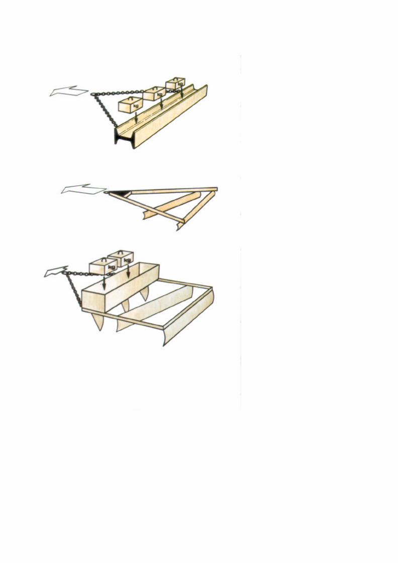

ART C - DRAGGING
Beam Drag rolled steel joists) or steel rail(s), weightedwith concrete blocks, and towed at an angle to the road.
Frame Drag steel "A" frame using oldgrader blades.
m Tolardthree to five blades at different angles under a boxweighted with concrete blocks.


PART C - DRAGGING
3.3 SIGNS AND SAFETY EQUIPMENT
The following should be used where possible.
Clothing
Yellow or orange coloured safety vest or safety harnessto be worn by the machine attendant.
Vehicles
The grader or tractor and drag should be painted yellowor orange and should carry red and white striped markerboards front and rear.
Lights
The grader or tractor should work with headlightsswitched on and, where possible, should carry yellowflashing warning lights.
Flags
If yellow flashing warning lights are not available,vehicles and equipment should carry yellow or orangeflags.

TYPICAL WORKSHEET
DRAGGING
Worksheet No: . . . . . . . . . . . . . . . . . . Date: . . . . . . . . . . . . . . . . . . . . . District:
.................................................
Zone: ...................................................... Gang:
Road No: . . . . . . . . . . . . . . from km . . . . . . . to km . . . . . . . . . . . . .
Section from km . . . . . . . . . to km
EQUIPMENT TO BE USED:
Motorgraders: . . . . . . . . . .
Tractors: ..............................
Drags: ..................................................
TowedGraders: ...........................................
. . . . . . . in . . . . . . . . . m width

PART C - DRAGGINI
4. MAINTENANCE METHOD
4.1 PRELIMINARY TASKS
m The worksheet will indicate the location and extent of thework to be carried out and the time, equipment andpersonnel required for the job'


PART C - DRAGGING
Before setting out to start the job, a check should be made to ensure
that everything needed is ready.
n Plant and machinery must be checked mechanically, greased and
fuelled.
m Drags must be checked to ensure that they are
complete and that any weights required are loaded.


PART C - DRAGGINI
4.2 WORKING WITH A TRACTOR AND DRAG
The Machine Attendantdirects traffic and helps the driver when turning thetractor and drag,
removes unwanted material from path of tractor andclears the drag.
m If the work is being done with a tractor, it should work inthe same direction as the traffic.
The driver should not stop at junctions or on bends.


PART C -DRAGGING
m The tractor tows the drag at up to 5 km/hrdepending on the type of drag and on the type andcondition of the road surface.
n The length of pass will be given on the worksheetand should be as long as possible.
m The number of passes needed will depend uponthe conditions and the width of the road.
m The equipment should work in the same directionas the traffic flow.
II - 137


PART C - DRAGGING
m DO NOT drive too fast or the drag will jump over the surface
irregularities and raise a lot of dust, it will also cause a hazard to
traffic.
m Pieces of thorn scrub or steel cable which break off the drag must
not be left on the road surface.


PART C - DRAGGING
4.3 DRAGGING WITH GRADERS
m When the work is to be done by motor grader or towedgrader, it is most efficient if several graders can worktogether on the same section of road, one behind theother.
In this case, graders work in the same direction alongthe road for several kilometres. On narrow roads twograder passes may be sufficient.
Great care is required to warn approaching vehicles andallow them to pass the grading machines safely. Ifnecessary a light vehicle should travel ahead of thegraders with warning lights and signs.
m The object is to remove the loose material from thesurface of the road and spread it evenly.
There are two basic methods of working. The first spreadsmaterial from the centre line to both edges of the road(Method A). The second spreads material from one side ofthe road to the opposite edge (Method B).


PART C - DRAGGINI
METHOD A
m The grader starts from the centre of the road and
works towards the edge.
Shoulders are treated as part of the running surface.
a The first and second passes cut to the bottom of thesurface irregularity and deposit a windrow at the edge ofthe road. Two passes may be required each side forwide roads.
m The other side of the carriageway is now graded in asimilar way to complete the work and leave a smootheven surface between windrows.


PART C -DRAGGING
METHOD B
m The grader starts from one edge of the road and workstowards the other edge.
Shoulders are treated as part of the running surface.
m The first and second passes cut to the bottom of thesurface irregularity and deposit a windrow at the centreof the road. Two passes may be required each side forwide roads.
m The third and fourth passes cut to the bottom of thesurface irregularity and move the windrow to the edge ofthe road.


PART C - DRAGGING
For both methods of dragging with a grader:
m Slots should be cut through the windrows by themachine attendant at approximately 10 metre intervalsalong the edges of the road.
These will enable water to drain from the road surface inthe event of unexpected rain.
m As loose material will have been removed from thesurface of the road and a hard surface should remain,rolling should not be necessary with this type ofdragging.


PART C - DRAGGING
Windrows must not be left at the edge of the road duringthe wet season.
They tend to dam up the water leading to erosion ofshoulders and side slopes.
The windrows should be mixed back into the runningsurface with a full grading operation before the wetseason is established (Part A).
m DO NOT make a final pass* down the centre of the roadwith the grader blade horizontal.
This flattens the centre of the road and causes water topond. This leads to rapid deterioration of the surface.
See List of Terms,Volume I.

TYPICAL WORK REPORT
DRAGGIN
Work Report No: . . . . . . . . . . . . .Date: . . . . . . . . . . . . . . . . . .
District: ..................................................Gang:
Zone: .....................................................Road No:.
Section: . . . . . . . . . .
QUANTITY OF WORK ACHIEVED:
Dragging: ..........................................................................................kms
WEATHER CONDITIONS:
Sunny 0 Cloudy 0 Rain El
from km . . . . . . . . . .to km . . . . . . . . .
EQUIPMENT USED:
........................ ............................ Hrs
........................ ............................ Hrs
........................ ............................ Hrs
MANPOWER USED: . . . . . . . . . . . . . . . . . .
COMMENTS: ..........................................
DIESEL USED:
................... .......................litres
................... .......................litres
................... .......................litres
Foreman: .............................................

PART C - DRAGGING
4.4 WORK REPORT
The report must be filled in each day, detailing:
the work carried out, the resources used.

Part D
PATCHING


PART D - PATCHING
1. THE TASK
Patching is sometimes required between grading orreshaping operations, or before grading when the potholesor depressions are large.
Patching may either be used to repair worn or eroded areasor can be used to restore areas which become soft whenwet.
This maintenance activity consists of replacing or addingnew gravel surfacing material over relatively small areas.
Patching may be carried out by a mobile gang or by labourbased methods.
Patching is normally used to refer to resurfacing workinvolving less than 1 or 2 truck or trailer loads of materialper day. Large scale work is usually called SpotRegravelling or Gravelling (Parts E or F).


PART D - PATCHINI
2. DEFECTS
Patching is used to correct
Potholes
Ruts
Soft Spots
Erosion Gullies


PART D -PATCHINI
Patching is not a satisfactory method of repairingcorrugations. Grading (Part A) or labour based reshaping(Part B) should be used to repair these defects.
Where there are large numbers of potholes, the section willneed scarifying* with a self propelled grader and possiblyregravelling (Part E or F).
Patching may be used instead of grading on selfcementinggravels or gravels with large lumps.
* See List of Terms,Volume f.


PART D - PATCHINI
METHOD A: MOBILE GANG
3. RESOURCES
3.1 PERSONNEL
Supervisors
1 foreman.
Plant Operators and Drivers
1 driver.
Workforce
- 2 to 6 labourers, - 2traffic controllers.

_ ..9

PART D - PATCHING
METHOD A: MOBILE GANG
3.2 PLANT AND TOOLS
Vehicles
1 small truck.
OR
1 tractor and trailer(s).
If two trailers are available, one trailer can be loadedwhile the other is hauled to the worksite.
Compactors
1 hand controlled vibrating roller, and fuel (plus ramps"to help load onto truck or trailer).
OR
1 hand rammer with metal shoe for each labourer usedon compaction work.
See List of Terms,Volume I.


PART D - PATCHING
• Tools
1 broom for every two labourers,
1 pickaxe for every two labourers,
1 shovel for every two labourers,
1 hoe or mattock for every two labourers,
1 rake for every two labourers,
1 wheelbarrow,
1 hand rammer with metal shoe for each labourerused on compaction work (if no vibrating roller isavailable),
1 drum for water (200 litre),
1 bucket or watering can.


PART D - PATCHING
METHOD A: MOBILE GANG
3.3 MATERIALS
m Gravel for patching should be stockpiled at the quarry ormaintenance camp, or dumped at the side of the roadnear where it will be used (so that it does not block theroad or drainage system).
The gravel must be at least as good a quality as thematerial already surfacing the road. Its use must beapproved by the Maintenance Engineer and must meetDepartmental specifications.
m Water must be carried from the depot if it is notobtainable near the site.
In either case, a container will be needed.


PART D - PATCHING
METHOD A: MOBILE GANG
3.4 SIGNS AND SAFETY EQUIPMENT
The following items should be provided where possible.
Traffic Signs
- 2 Reversible "Stop/Go" signs,
- 2 "Speed Limit" signs (50 km/hr),
- 2 "Men Working" signs,
- 1 "Road Narrows From Right" sign,
- 1 "Road Narrows From Left" sign,
- 2 "End of Restriction" signs.
Barriers
2 lane closure barriers.
Traffic Cones
As many as are required; at least 10 will usually be needed.


PART D - PATCHING
Clothing
Yellow or orange coloured safety vests or safetyharnesses to be worn by the supervisor and all thework force.
Vehicles
All vehicles and equipment should be paintedyellow or orange and should carry red and whitestriped marker boards front and rear.
Lights
All vehicles and equipment should work withheadlights switched on and, where possible,should carry yellow flashing warning lights.
Flags
If yellow flashing warning lights are not available,each vehicle and item of equipment should carryyellow or orange flags.

TYPICAL WORKSHEET
PATCHING
Worksheet No: . . . . . . . . . . . . . . .
District:
Zone: .
Date: ..................
Gang: .................
Road No:. ..............
Materials: . . . . . . . . .trucks of . . . . . . . . . .
trailers of . . . . . . . . .
m3= ..............m3
m3= .............m3

PART D - PATCHING
METHOD A: MOBILE GANG
4. MAINTENANCE METHOD
4.1 PRELIMINARY TASKS
n The worksheet will indicate the location and extent of thework to be carried out and the time, equipment andpersonnel required for the job.


PART D - PATCHING
Before setting out to start the job, a check shouldbe made to ensure that everything needed is ready.
w The Truck or tractor and trailer must befuelled, checked mechanically and have waterand oil levels checked.
m Traffic signs, barriers and cones must beobtained and loaded onto the truck or trailer.

o'

PART D - PATCHING
Tools and equipment must be obtained and loaded ontothe truck or trailer. The roller may be loaded with thehelp of ramps* or a hoist.
m The drum must beon site.
with water if none is available
m Arrangements must be made to load gravel onto thetruck or trailer either at the depot or at a quarry.
See List of Terms,Volume 1.

NOTE: SHOWN FOR DRIVING ON THE RIGHT

PART D - PATCHING
METHOD A: MOBILE GANG
4.2 TEMPORARY SIGNPOSTING
Before work starts, warning signs, barriers and cones mustbe placed around the work area.
Work should be carried out on one side of the road at atime, allowing traffic to pass on the other.
Signs must be placed in the following order:
"Men Working" signs should be placed 200 metres infront of the work area.
"Road Narrows" signs should be placed 100 metres infront of the work area.
"Speed Limit" signs should be placed at the start of thework area.
Barriers should be placed at each end of the work area.
Cones should be placed in a taper at the approaches tothe work area and at a maximum spacing of 10 metresalong the middle of the road next to the work area.
"End of Restriction" signs should be placed 50 metresbeyond the work area.


PART D - PATCHINI
m Traffic controllers should stand next to the barriers inthe centre of the road to operate the reversible"Stop/Go" signs.
The controller closest to the oncoming traffic should decidewhen to stop the flow and allow traffic to travel in the otherdirection. Traffic should be stopped in both directions whenworks vehicles enter, leave or turn at the worksite.
On low-traffic roads, the Maintenance Engineer mayapprove the use of a simpler system of traffic control.
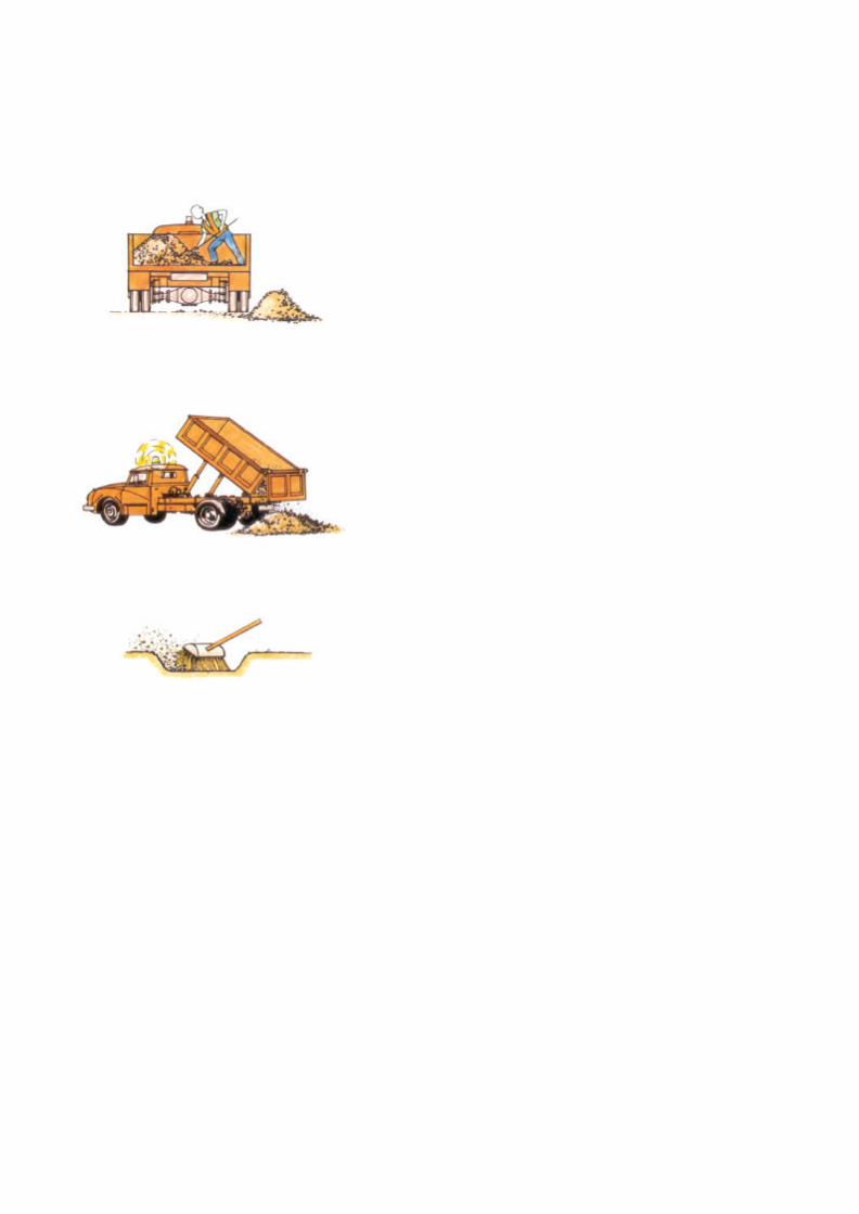

PART D - PATCHING
METHOD A: MOBILE GANG
4.3 EXECUTION OF THE WORK m The
material is off-loaded manually.
OR
Tipped onto the shoulder adjacent to where the patching isrequired. Material must never be dumped onto the road.
m Loose material and standing water is brushed fromthe pothole or rut to be patched.


PART D - PATCHINI
m Large or deep potholes should have their sides cut back tobe vertical and to reach sound material.
m The moisture content of the material can be checkedquickly by squeezing it in the hand.
If the material is wet enough to stick together, it is suitablefor use.
If water runs out of the material, it is too wet and should notbe used.
x If the material is dry, the area to be patched should besprinkled with water and water should also be added to thepatching material.


PART D - PATCHING
m The area is filled with gravel to a depth of about 10centimetres.
m if the material is dry, it should be sprinkled with water to
help compaction.
m The layer is then compacted using the roller or hand
rammer.
m In this way the thickness of the patch is built up in layers.


PART D - PATCHING
m Finally, the patched area is filled evenly with the gravelto approximately 3 centimetres above the level of thesurface and is spread and raked to the correct shape.
3 centimetres is approximately the thickness of a rakehandle.
m The patch is then compacted using the roller or handyammer to give a surface which is slightly above thelevel of the surrounding road.
m Both large or small areas to be patched are repaired inthe same way, the yammer is used for the smallerpotholes. The roller is used for larger areas although thehand yammers will still be required for the corners andshort edges.

A

PART D - PATCHING
m Patching work started must not be left unfinishedovernight.
At night the site should be made safe for traffic and allsigns and obstacles removed from the road.


PART D - PATCHING
METHOD A: MOBILE GANG
4.4 COMPLETION AND REMOVAL OF TEMPORARYSIGNS
Load tools, equipment and unused materials back onto thetruck or trailer.
Remove the signs, cones and barriers and load them ontothe truck or trailer in the following order:
1 "End of Restriction" signs,
Traffic cones,
"Speed Limit" signs,
Barriers,
"Road Narrows" signs,
6 "Men Working" signs.
Equipment and traffic signs must not be left at the road side foruse the next day.


PART D - PATCHING
m Ensure that the site is left clean and tidy with nostockpiles of material left on the road.
Move onto the next job.
m Inspect traffic signs and clean if necessary.

TYPICAL WORK REPORT
PATCHING
Work Report No: . . . . . . . . . . . . .
District: . . . . . . . . . . . . . . . . . . . .
Zone:......................
WEATHER CONDITIONS:
Sunny
MATERIALS USED:
Gravel: ..................
EQUIPMENT USED:
MANPOWER USED: . . . , . . . . . . . . . . . . . . . . . . .
COMMENTS: ..........................................
................... ........................................... Hrs
Date: ..................
Gang: .................
Road No:. .............
from km . . . . . . . . . . to km . . . . . . . . .
Cloudy
DIESEL USED:
Rain 0
................... ..................... Hrs................. ................... ........................litres
................. ..................... . litres
......... .................... .......... Hrs................. ..... .................. ...................litres
Foreman: .......................................

PART D - PATCHING
4.5 WORK REPORT
The report must be filled in each day, detailing:
the work carried out, the resources used.


PART D - PATCHING
PATCHING
METHOD B: LABOUR BASED
In some road maintenance systems an individual attendantor lengthman lives close to a road and is responsible for theROUTINE MAINTENANCE activities on that road. On lowtraffic volume roads (less than about 50 vpd*) it is oftenappropriate for patching to be carried out by these labourbased methods.
vpd: vehicles per day


PART D - PATCHING
METHOD B: LABOURBASED
5. RESOURCES
5.1 PERSONNEL Supervisor 1 foreman
or overseer visiting regularly.
Workforce - attendant or
lengthman.


PART D - PATCHINI
METHOD B: LABOUR BASED
5.2 PLANT AND TOOLS
1 broom,
1 pickaxe,
1 shovel,
1 hoe or mattock,
1 rake,
1 hand rammer with metal shoe,
1 wheelbarrow,
1 bucket or watering can.
II - 203


PART D - PATCHING
METHOD B: LABOUR BASED
5.3 MATERIALS
n Gravel for patching should be obtained from the quarryby truck or tractor and trailer. This is most efficientlydone when major regravelling works are being carriedout in the area of the road.
m The gravel should be stockpiled at convenient locationsfor the attendant to use on his section of road. Thestockpiles must not obstruct the road, the shoulder orthe drainage system.
m Where there is no space in the road reserve thestockpile should be placed downhill of a turnout drain toavoid blocking the drainage system.
m If possible a one truck or trailer load stockpile should beleft every 100 to 200 metres along the road.
II - 205


PART D -PATCHING
METHOD B: LABOUR BASED
5.4 SIGNS AND SAFETY EQUIPMENT
On low traffic volume roads the following should beprovided.
Traffic Signs
2 "Men Working" signs,
OR
2 yellow/orange flags for placing on the shoe
Clothing
Yellow or orange coloured safety vest or safety harnessto be worn by the attendant.
u - 207

TYPICAL WORKSHEET
PATCHING
Worksheet No: . . . . . . . . . . . . . . . Date: . . . . . . . . . . . . . . . . . .
District: ..............................................
Road No:. ............................................
Section: . . . . . . . . . . from km .............................to krn
Materials: . . . . . . . . , trucks of . . . . . . . . . . m3= ..............m'
trailers of . . . . . . . . .m3= . . . . . . m3

PART D - PATCHING
METHOD B: LABOUR BASED
6. MAINTENANCE METHOD
6.1 PRELIMINARY TASKS
n The handtools are assigned to the attendant who keepsthem at his home for use as necessary.
m The worksheet will indicate the location and extent of thework to be carried out and the time required for the job.
II-209


PART D - PATCHING
METHOD B: LABOUR
6.2 EXECUTION OF THE WORK
m The attendant should use the wheelbarrow to carrythe tools and safety items to the site.
m The warning signs or flags must be placed eitherside of the worksite.
m The attendant should use the wheelbarrow totransport the gravel material from the stockpiles tothe patching site.
m The patching should be carried out as shown forthe mobile gang.
m The warning signs or flags must be removed afterthe work.
m The work report must be filled in for each day's

Part E
REGRAVELLING(mechanised)


PART E - REGRAVELLING (mechanised)
1. THE TASK
The surfacing material of unpaved roads is worn away bytraffic, eroded by rain and blown away as dust.
Before all the gravel surfacing has worn away the roadrequires regravelling.
Regravelling is normally a PERIODIC MAINTENANCE task.
It is important that the Maintenance Engineer plansregravelling work well in advance so that work is carried outbefore serious defects appear.
Before regravelling is carried out, it is important to make anynecessary repairs or improvements to the camber" anddrainage system of the road. If this is not done, the newgravel surface will deteriorate very quickly.
Regravelling is normally carried out with one layer 15 cmthickness.
Usually a continuous layer of gravel is laid on the existingrunning surface, however on some occasions only shortstretches showing severe defects are covered under a spotregravelling operation.
"Mechanised" regravelling using heavy plant is described inthis Part (E). Part F describes regravelling carried out bylabour and tractor methods.
See List of Terms,Volume).


PART E - REGRAVELLING (mechanised)
2. DEFECTS
Regravelling is used to correct
m Loss of surfacing material
Regravelling is needed before the subgrade* is exposed onthe road surface. This will be seen particularly in ruts anddepressions.
Regravelling is also used to correct
• Loss of shape
Ruts
Potholes
Erosion Gullies
When these are severe.
In these cases grading (Part A) or reshaping (Part B) iscarried out before the regravelling operation.
See List of Terms,Volume 1.


PART E - REGRAVELLING (mechanised)
3. RESOURCES
3.1 PERSONNEL
Supervisors
- 1 foreman at the road site, - 1 foremanat the quarry or stockpile.
Plant Operators and Drivers
- 1 bulldozer operator,- 1 loader operator,- 1 driver for each tipper truck,- 1 grader operator,- 1 operator for each roller,- 1 driver for each water tanker.
Workforce
- 1 machine attendant for each item of plant andequipment,
- mechanics for daily servicing and minor repairs.


PART E - REGRAVELLING (mechanised)
3.2 PLANT AND TOOLS
The numbers of each type of plant will depend on the gravelhaul distance and plant availability.
Bulldozers
1 bulldozer.
Loaders
1 wheeled or tracked loader.
Trucks
tipper trucks, depending on haul distance andavailability (typically 4 to 6).
Graders
1 grader, preferably of at least 135 hp (100 kW).


PART E - REGRAVELLING (mechanised)
Rollers
- 1 or 2 rollers.
Water Tankers
- 1 water tanker, if the gravel being laid is dry.
More tankers will be needed if water has to be brought along distance.
Pumps
- 1 pump of sufficient capacity to load the tankersquickly.
Other Vehicles
- 2 light vehicles for transport of the two supervisors.
II - 223


PART E - REGRAVELLING(mechanised)
Support
A low loader will be required to transport some of theequipment items between successive quarry and worksites. Transport for fuel will also be required.Arrangements must also be made for lubrication,servicing and minor repairs, and site refuelling.
Options
For small regravelling jobs or short hauls (up to about 10km), it may be appropriate to work with simpler plantthan described in this Part of the handbook. Gravel canbe quarried and loaded by hand and hauled to the siteusing tractors and trailers. See Part F for this option.
Tools
A camber board made as shown from 20 mm treatedplywood or hardwood to give a 1 in 20 (5%) slope.
A selection of handtools will be required for the machineattendants (see Part D, Page II - 165).
II - 225


PART E - REGRAVELLING (mechanise
3.3 MATERIALS
m Gravel obtained from a quarry or gravel pit must beof a quality that meets the Departmentalspecifications and also be approved by the
m A source of water will be needed as near aspossible to the site.
II - 227


PART E - REGRAVELLING (mechanised)
3.4 SIGNS AND SAFETY EQUIPMENT
Whenever possible during regravelling, a diversion shouldbe opened for traffic and the following safety items shouldbe provided.
Traffic Signs
- 2 "Men Working" signs,
- 1 "Turn Left" arrow,
- 1 "Turn Right" arrow,
- 4 "Keep Left/Right" arrows,
- 2 "End of Restriction" signs.
Barriers
- 2 lane closure barriers.
Traffic Cones
As many as are required, but at least 10 will usually beneeded.
II - 22s


PART E - REGRAVELLING (mechanise
Clothing
Yellow or orange coloured safety vests or safetyharnesses are to be worn by the supervisor and all thework force.
Vehicles
All vehicles and equipment should be painted yellow ororange and should carry red and white striped markerboards front and rear.
Lights
All vehicles and equipment should work with headlightsswitched on and, where possible, should carry yellowflashing warning lights.
Flags
If yellow flashing warning lights are not available, eachvehicle and item of equipment should carry a yellow ororange flag.


PART E - REGRAVELLING (mechanised)
Although the road will be completely closed, it is stillnecessary for workmen to wear safety vests and forvehicles to carry warning lights for the safety of siteoperations.
No Diversion
If it is not practical to provide a diversion, then working mustbe restricted to one side of the road at a time and safetyequipment as listed under Gravel Patching in Part D(Pages II - 169 and II - 179) will be required. This includesboth safety vests and warning lights on vehicles.
II - 233

TYPICAL WORKSHEET
REGRAVELLING
Worksheet No: . . . . . . . . . . . . .
. . District: . . . . . . . . . . . . . . . . .
. . . Zone:......................
Section: . . . . . . . . . .from km
Date: ..................
Gang: .................
Road No:. ..............
to km.........
Length: from km . . . . . . . . . to km . . . . . . . . . . . . _ . . . . . . . . m
Width: ............................................,.........................................._ ........ ..................m
Thickness (compacted): ............. ............................= ........................CM
Gravel: . . . . . , . . . . . . . trucks of . . . . . . . . . . . m3= ...............m3
Water: . . . . . . . . . . tankers of . . . . . . . . . . litres= . . . . . . . . litres

PART E - REGRAVELLING(mechanised)
4. MAINTENANCE METHOD
4.1 PRELIMINARY TASKS
The Worksheet should indicate the location andextent of the work to be carried out and the time,equipment and personnel required for the job.
m Where Spot Regravelling is specified, the extent ofthe sections to be regravelled should be markedout on site.
II - 235


PART E - REGRAVELLING (mechanised)
Before the start of the job, a check should be made toensure that everything needed is ready.
m Arrangements must be made to take gravel from theborrow pit or quarry and test it for approval. This shouldbe done well in advance of the work.
Arrangements must be made to obtain water close tothe site. This should be done well in advance of thework.
m The condition and "availability" of the equipment must bechecked and the numbers of each type of equipmentmust be decided.
m Trucks and plant must be fuelled, greased, checkedmechanically and have water and oil levels checked.Arrangements must be made for refuelling on site ifrequired. This may either be with a refuelling truckvisiting the working site, or by arrangement to refuel at amaintenance camp. Arrangements must be made for thenecessary mechanical support on site.
Accommodation
It may be necessary to make arrangements foraccommodation for personnel close to the work site.
m At the beginning of the job, traffic signs, barriers andcones must be obtained and loaded onto a truck.
II - 237


PART E - REGRAVELLING (mechanised)
Site Preparation
Wherever possible, before the regravelling work starts, thegrader should open a diversion adjacent to the road.
If traffic is diverted from the work site, it will enable the job to becarried out more efficiently and safely.
m No Diversion
If the site conditions are such that it is not practical to build adiversion, then signs must be placed as shown for Gravelpatching (Part D), Pages II - 169 and II - 179, and workingmust be restricted to one side of the road at a time.
On low-traffic roads, the Maintenance Engineer may approvethe use of a simpler system of traffic control.
II-239

NOTE: SHOWN FOR DRIVING ON THE RIGHT

PART E - REGRAVELLING (mechanised)
4.2 TEMPORARYSIGNPOSTINGAfter the diversion has been completed and beforework starts, warning signs, barriers and cones mustbe placed around the work area.
Signs must be placed in the followingorder:
m "Men Working" signs should be placed 200metres in front of the work area.
m "Turn Left/Right" arrows should be placed 100metres in front of the work area.
z Cones should be placed diagonally across theroad to lead into the diversion.
m "Keep Left/Right" arrows should be placed at theends of the lines of cones.
m Barriers should be placed behind the lines of
m "End of Restriction" signs should be placed 50metres beyond the ends of the diversion.
At night yellow lamps should also be used to markthe extent of the works at the diversions.


PART E - REGRAVELLING (mechanise
4.3 EXECUTION OF THE WORK
m Quarry or Borrow Pit
Before the regravelling work starts, gravel should be
stockpiled at the quarry or borrow pit. It may also be
helpful to start hauling the material to site. Plan the
quarry excavations and stockpiles so that:
- the quarry can be fully exploited with removal of themaximum amount of gravel,
- the overburden is stockpiled so that it will not hinderfuture extension, and that it can be used to reinstatethe quarry,
- the best material is taken, where gravel quality is
variable within the quarry,
- material is stockpiled to minimise segregation,
- environmental damage by poor drainage anderosion is minimised both during and afterexploitation of the quarry.
The quarry layout should:
permit efficient excavation and stockpiling of gravel,
allow the trucks to enter and leave withoutobstructions.
n repair the quarry access road, if necessary, to ensuresafe passage of trucks.
II - 243


PART E - REGRAVELLING (mechanised)
After signs have been placed, the existing roadsurface must be graded as described in Paragraph4.3 of Part A of this Volume.
The road surface must be graded-off to provide a firmregular surface on which to work and the edgesshould be "boxed" to provide support for the newgravel. The graded surface should be watered andcompacted.
The camber* should be checked with a camber boardand the road level should fall 4 to 6 cm for each onemetre width of road (4-6 %).
The drainage system should be checked andrepaired if necessary (see Volume I, Part D),otherwise the performance of the gravel surface willbe affected.
At the quarry or borrow pit, the bulldozer shouldhave stockpiled sufficient gravel for the work. Theexcavating and stockpiling of gravel should create low,broad heaps to prevent segregation of the coarsermaterial.
When the initial grading of the road is complete, theloader should start to load the tippers with gravel fortransport to the regravelling site.
" See List of Terms,
II - 245


PART E - REGRAVELLING (mechanised)
Tippers should always circulate continuously betweenthe quarry and the site.
m Dumping should start at the far end of the site so that theheaps of gravel do not impede tippers delivering laterloads.
m Material should be dumped on one side of the road only.Loads should be placed at the correct spacing asinstructed by the Maintenance Engineer, necessary togive the required thickness of gravel over the completeroad width.
n If the road is not closed, material should be dumped onthe shoulder.
m The tankers should have filled up with water using thepump and then have driven to the site.
II - 247


PART E - REGRAVELLING(mechanise
m Spreading of the gravel can start when there is aworking length of at least 200 metres of dumpedmaterial.
m Initially the road is sprayed with
m The regravelling material is then spread rightacross the road using the grader.
II - 249


PART E - REGRAVELLING(mechanised)
m The material is alternately spread by the grader andwatered with the tanker until its moisture content iscorrect for compaction*.
The amount of water to be added must be determinedby moisture content tests on site or by the MaintenanceEngineer.
The tankers circulate continuously between the site andthe source of water.
m The new material is now graded as described inParagraph 4.3 of Part A (Page II - 29) of this Volume toproduce a camber" of 4 to 6 cm for each one metrewidth of road (4 to 6 %).
See List of Terms,Volume 1.


PART E - REGRAVELLING (mechanised)
m The camber* should now be checked with the camberboard at approximately 100 metre intervals along the road.
m To use the camber board
Place it on its edge across the road with the shorter endpointing towards the centre line.
Check the level bubble
If it is central, the camber is correct. If it is not central, thecamber is either too steep or flat and further grading andcompaction are required.
m If the camber does not fall 4 to 6 cm for each one metrewidth of straight road, the grading must be repeated.
* See List of Terms,Volume I.
II - 253


PART E - REGRAVELLING(mechanisE
m When the correct camber* has been achieved, rollingcan start.
Water should not be added during rolling as the materialmay stick to the wheels or drums.
Rolling should start at the edge of the road and worktowards the middle. The roller should aim to progressfrom section to section at the same rate as the grader.
About eight passes of the roller will be needed toachieve full compaction.
It is possible to regravel without the use of water andcompaction, but it is difficult to achieve satisfactoryresults.
See List of Terms,Volume 1.
II - 255


PART E - REGRAVELLING (mechanised)
4.4 COMPLETION AND REMOVAL OF TEMPORARYSIGNS
The work proceeds along the road in sections. As eachsection is completed, the traffic signs, cones and barriersare moved along the road. This opens the road at thecompleted end for traffic, and closes it at the other end toallow new gravel to be dumped.
As work proceeds, it will be necessary to open newdiversions and move the diversion signs.
When the work is finally completed,
Remove the traffic signs, cones and barriers and loadthem onto the truck in the following order:
1 "End of Restriction" signs,
Barriers,
"Keep Left/Right" arrows,
4 Cones
5 "Turn Left/Right" arrows,
6 "Men Working" signs.
II - 257


PART E - REGRAVELLING(mechanise
m Ensure that the site is left clean and tidy with nostockpiles of material left on the road.
m Move on to the next job.
m Inspect traffic signs and clean if necessary.
II - 259

TYPICAL WORK REPORT
REGRAVELLING
Work Report No: . . . . . . . . . . . . .
District: . . . . . . . . . . . . . . . . . . . .
Zone:
Section: . . . . . . . . . .
WEATHER CONDITIONS:
Sunny LJ
QUANTITY OF WORK ACHIEVED:
Length: from km . . . . . . .
Width: ..........................................................................._ ...........................m
Thickness (compacted): .................................................= .......
cm
Gravel: . . . . . . . . . . . . . trucks of . . . . . . . . . . . m3= . . . . . . . m3
Date: .................. Gang:
.................
Road No:. ..............
from km . . . . . . . . . . to km . . . . . . . . .
. . to km ............ .............._ ........ ..........m
EQUIPMENT USED:
MANPOWER USED: . . . . .
................... ..................... Hrs
................... ..................... Hrs
. Hrs......
................... ..................... Hrs
................... ..................... Hrs
................... ..................... Hrs
COMMENTS: ..........................................
Foreman:.............................
DIESEL USED:
litres
litres
litres
litres
litres
................... .......................litres

PART E - REGRAVELLING (mechanised)
4.5 WORK REPORT
The report must be filled in each day, detailing:
the work carried out, the resources used.

Part F
REGRAVELLING(Labour and Tractors)
II - 263


PART F - REGRAVELLING (Labour andTractors)
LABOUR AND TRACTOR REGRAVELLING
Mechanised Regravelling, as described in Part E, is themost commonly used technique for the renewal of a gravelrunning surface.
However in certain circumstances, the high cost or nonavailability of the specialist equipment make Labour andTractor Regravelling a more appropriate option.
In this case use is made of local labour to excavate andload gravel at the quarry, and unload and spread thematerial at the road site.
Haulage is carried out by agricultural tractors of 45 hp (34kW) or greater, and gravel trailers.
Compaction is provided by tractor drawn rollers, or by theuse of the loaded trailers.
This method is usually appropriate for gravel hauls up toabout 10 km.
In areas where animal traction is established, the gravelmay usually be hauled economically for distances up toabout 3 km using small carts.
For haulage distances greater than 10 km trucks are usuallymore economical. However these may be loaded manually.
II - 265


PART F - REGRAVELLING (Labour and Tractors)
1. THE TASK
The surfacing material of unpaved roads is worn away bytraffic, eroded by rain and blown away as dust.
Before all the gravel surfacing has worn away the roadrequires regravelling.
Regravelling is normally a PERIODIC MAINTENANCE task.
It is important that the Maintenance Engineer plansregravelling work well in advance so that work is carried outbefore serious defects appear.
Before regravelling is carried out, it is important to make anynecessary repairs or improvements to the camber anddrainage system of the road. If this is not done, the newgravel surface will deteriorate very quickly.
Regravelling is normally carried out with one layer of 15 cmthickness.
Usually a continuous layer of gravel is laid on the existingrunning surface, however on some occasions only shortstretches showing severe defects are covered under a spotregravelling operation.
This Part describes Regravelling using Labour andTractor methods.
Mechanised regravelling using heavy plant is described inPart E (Page II - 213).
II - 267


Regravelling is used to correct
n Loss of surfacing material
PART F - REGRAVELLING (Labour and Tractors)
2. DEFECTS
Regravelling is needed before the subgrade* is exposedon the road surface. This will be evident particularly inruts and depressions.
Regravelling is also used to correct
• Loss of shape
Ruts
Potholes
Erosion Gullies
When these are severe.
In these cases reshaping (Part B) is carried out before theregravelling operation.
See List of Terms,Volume I.
II - 269

;EGRAVELLING PLANNING GUIDELINES
Assumes good haul routes, 45 - 75 HP (34 - 56 kW) tractors, 3 m' trailers and the~roductivities shown on Page II - 286)
:1 Q E= E... Y
O
0-1
1-2
2-3
3-4
4-5
5-6
6-7
7-8
8-9
9-10
„- N QUANTITY EQUIVALENT LENGTH OF GRAVELLED ROAD APPROX. LABOURO s OFMETRES/DAY FORCE REQUIRED
GRAVEL (EXCAVATION,
m U HAULED 0.4m'/m RUN 0.66m'/m RUN 0.9m'/m RUN LOADING,
M a: m'/DAY COMPACTED COMPACTED COMPACTED UNLOADING AND(LOOSE) * .. *t* SPREADING ONLY)
2 I 126 I 252 I 156I 112 -I --63 -- 90
2 108 133 96 54 - 773 ~
~162
-216324
~200
~144
81 - 115
2 78 156 96 70 39 - 563 144 104 59_834 ~
156-117-234-~
312193 139 78 - 111
3 90~~
180 111~~
80 45 - 64
4 120 240 148 107 60 - 855 150 300 185 734 75 - 1074 108
~216(
133~
96~
54 - 77
5 135 270 167 120 67 - 966 762 324 200 144 81 1754 84 168 104 75 42 - 605 105 210 130 94 53 - 756 126 252 156 112 63 - 907 147 294 181 131 73 - 1054 72 144 89 64 36 - 515 90 180 111 80 45 - 646 1a3 216 133 96 54-777 126 252 156 112 63 - 90
4 72 144 89 64 36 - 515 90 780 111 80 45 - 646 1OS 216 133 96 54 - 777 126 252 156 112 63 - 904 60 120 74 54 30 - 436 75 150 93 67 38 - 546 90 7 80 111 80 45 - 647 105~
210130 94 53 - 75
4
t 96 59 43 24-34
4 0 metres wide and 10 cms thick5 4 metres wide and 12 cms thick6 0 metres wide and 15 cms thick

REGRAVELLING PLANNING GUIDELINES
(Assumes good haul routes, 45 - 75 HP (34 - 56 k1A) tractors, 3 m9 trailers and theproductivltles shown on Page II - 286)
ut u. N QUANTITY EQUIVALENT LENGTH OF GRAVELLED ROAD APPROX. LABOURO m OF METRES/DAY FORCE REQUIRED
a a EW ~ GRAVEL (EXCAVATION,
= h_ ~ a HAULED O,qm3/m RUN 0.65ms/m RUN 0.9ms/m RUN LOADING
o ~ ~ m3/DAY COMPACTED COMPACTED COMPACTED UNLOADING AND(LOOSE) . .. ... SPREADING ONLY)
0 - 7 2 126 252 156 112 i63 - 90
1 - 2 2 108 216 133 96 54 - 773 162 324 200 144 81 - 115
2 - 3 2 78 156 96 70 39 - 563 117 234 144 104 59 - 834 156 312 193 139 78 - 111
3 - 4 3 90 180 111 80 45 - 644 120 240 148 107 60 - 855 150 300 185 134 75 - 107
4 - 5 4 108 216 133 96 54 - 775 135 270 167 120 67 - 966 162 324 200 144 81 - 115
5- 6 4 84 168 104 75 42 - 605 105 210 130 94 53 - 756 126 252 156 112 63 - 907 147 294 181 131 73 - 105
6 - 7 4 72 744 89 64 36 - 615 90 180 111 80 45 - 646 108 216 133 96 54 - 777 126 252 156 112 63 - 90
7 - 8 4 72 744 89 64 36 - 515 90 180 711 80 45 - 646 108 216 133 96 54 - 777 726 252 156 112 63 - 90
8 - 9 4 60 120 74 54 30 - 435 75 150 93 67 38 - 546 90 180 111 80 45 - 647 105 210 130 94 53 - 75
9 - 10 4 48 96 59 43 24 - 345 60 120 74 54 30-436 72 744 89 64 36 - 517 84 168 10475
i42 - 60
i
e.g 4 0 metres wide and 10 cms thick
5.4 metres wide and 12 cms thick
6.0 metres wide and 15 cms thick

PART F - REGRAVELLING (Labour and
3.1 PERSONNEL
Supervisors
3. RESOURCES
- 1 foreman or overseer at the quarry,- 1 overseer at the road site.
Plant Operators and Drivers
- 1 driver for each tractor.
Workforce
- depending on number of tractors, haul distanceand labour productivity.
Support (as necessary)
- mechanics for daily servicing and repair,- water carriers,- storeman,- watchmen,- handtool sharpening and repairs.
II-271


PART F - REGRAVELLING (Labour and Tractors)
3.2 PLANT AND TOOLS
Tractors
The number of tractors required will depend on thegravel haul distance and plant availability.
The Table on Page II - 270 gives guidelines on thenumber of working tractor and labour resources requiredfor hauling gravel over various distances.
Additional tractors may be required for hauling rollers,water and fuel.
Trailers
- 2 trailers per tractor if possible.
This allows one trailer to be filled while the other ishauled to the road site.
3 m3 capacity trailers are most suitable for 45 to 75 hp(34 to 56 kW) tractors.
Other Items
- 1 towed deadweight roller or hand operatedvibrating roller,
- 1 towed water bowser,- 1 towed fuel bowser,- light vehicles) for the transport of the two
supervisors.
II - 273


PART F - REGRAVELLING (Labour andTractors)
• Tools
Typical handtool requirements for a workforce of up to100 labourers.
70 shovels, 20 hoes, 50mattocks, 50 pickaxes, 10bushknives, 5 wheelbarrows, 8crowbars, 20 rakes, 4sledgehammers, 2 tapemeasures (30 m), 10 buckets, 5water containers, 1 camber boardand spirit level, 2 mason'shammers, wooden pegs, balls ofstring/sisal twine, 4 fifes (forsharpening tools).
3.3 MATERIALS
• Gravel obtained from a quarry or gravel pit must be of aquality that meets the Departmental specifications andalso be approved by the Maintenance Engineer.
II - 275


PART F - REGRAVELLING (Labour and Tractors)
3.4 SUPPORT AND SAFETY ARRANGEMENTS
Arrangements should be made, as necessary, for the
following:m Recruitment of workmen if employed casually.
w Setting up temporary site camps
supervisors' accommodation and facilities,secure handtool storage, water supply.
m Payment of wages.
Signs and Safety Equipment.
When working on a low traffic volume road open totraffic, signs and safety equipment detailed in Part D(Patching, Method A), Page II - 169 and II - 179 shouldbe used.
When closing the road and providing a diversion, thesigns and safety equipment detailed in Part E(Mechanised Regravelling), Pages 11 - 229/231/233 andII - 241 should be used.
II - 277

TYPICAL WORKSHEET
REGRAVELLING
Worksheet No: . . . . . . . . . . . . . . .
District: . . . . . . . . . . . . . . . . . . . .
Zone:......................
Date: ..................
Gang: .................
RoadNo:. ..............
from km . . . . . . . . . .to km . . . . . . . . .
Length: from km . . . . . . . . . to km .........................._ ........ ..........m
Width: ..........................................................................._ ...............................m
Thickness (compacted): .................................................= .............................CM
Gravel: . . . . . . . . . . . . . trucks of . . . . . . . . . . . m3= . . . . . . . m3
Water: . . . . . . . . . . tankers of . . . . . . . . . litres= . . . . . . . . litres

PART F - REGRAVELLING (Labour and Tractors)
4. MAINTENANCE METHOD
4.1 PRELIMINARY TASKS
The Worksheet will indicate the location and extentof the work to be carried out and the time,equipment and personnel required for the job.
m Where Spot Regravelling is specified, the extent ofthe sections to be regravelled should be markedout on site.
II - 279


PART F - REGRAVELLING (Labour and Tractors)
Before the start of the job, a check should be made toensure that everything is arranged as necessary.
Identify gravel source, test material and make anyacquisition arrangements.
m Ensure adequate quantities of gravel are available for
the job.
m Recruit or inform local labour force.
m Set up temporary site camp for supervisors.
m Set up water supply arrangements.
Plan payment arrangements.
m Tractors must be fuelled and have their water and oillevels checked. All items of plant must be greased andchecked mechanically.
m Arrangements must be made for refuelling on site and


PART F - REGRAVELLING (Labour and Tractors)
Site Preparation
Wherever possible, before the regravelling work starts, adiversion should be constructed adjacent to the road. Itcan normally be of earth road standard.
If traffic is diverted from the work site, it will enable thejob to be carried out more efficiently and safely.
II - 283

NOTE: SHOWN FOR DRIVING ON THE RIGHT

PART F - REGRAVELLING (Labour and Tractors)
4.2 TEMPORARY SIGNPOSTING
When working on a low traffic volume road open to traffic,the signs and safety equipment should be deployed asshown in paragraph 4.2 of Part D (Page II - 179).
When closing the road and providing a diversion, the signsand safety equipment should be deployed as shown inparagraph 4.2 of Part E (Page II - 241).
On low traffic volume roads, the Maintenance Engineer mayapprove the use of a simpler system of traffic control.
II - 285

TYPICAL PRODUCTIVITY TARGETS
ACTIVITY TASK RATERESHAPING ROAD 20 - 50 m/MANDAYCLEARING BUSH 200 - 1000 m2/MANDAYEXCAVATING OVERBURDEN +LOADING ONTO 2 - 4 m3/MANDAYWHEELBARROW IF NECESSARYHAULING OVERBURDEN BY QUANTITY NO OF TRIPS/DAYWHEELBARROW
0 - 40m 10.5 M31MANDAY 21040 - 60m 8.0 M31MANDAY 16060 - 80m 6.5 m3/MANDAY 130
80 - 100m 5.5 m3/MANDAY 110EXCAVATING GRAVEL 1.6 - 2.4 m3/MANDAY (INSITU)
2 - 3 m3/MANDAY (LOOSE)LOADING GRAVEL 8 - 10 m3/MANDAY (LOOSE)OFFLOADING AND SPREADING 12 - 16 m3/MANDAY (LOOSE)
* NOTES:
Targets for hauling and tipping only: excludes loading and spreading. Assumingwheelbarrow volume equivalent to 0 05 cum of compacted/insitu material (0.07cumloose) when struck level with top of bodywork. 2 wheelbarrows assigned to eachhauling labourer Good haul route (Reduce targets for poor haul route).

PART F - REGRAVELLING (Labour and Tractors)
4.3 EXECUTION OF THE WORK The following
steps are normally required: r DAILY PLANNING r
PREPARATION OF ROAD SURFACE r
PREPARATION OF QUARRY/ACCESS ROAD r
GRAVEL EXCAVATION AND STOCKPILING
r LOADING r
HAULING
r OFF LOADING AND SPREADING r
COMPACTION
r STOCKPILING GRAVEL FOR ROUTINEMAINTENANCE
When using a large labour force, it is essential to break thework down into simple manageable operations to achievesatisfactory productivity and quality.
II - 287

REGRAVELLING:TYPICAL TARGET TRACTOR TRIPS PER
20
a.15
4O
Uc04
10
N
.L4
25
a, ~20 v0.E.O
15L4.
h 10a. 'GE-wO
O S z
0
45-55 HP TRACTOR
0-1 1-2 2-3 3-4 4-5 5-6 6-7 7-8 8-99-10Hauling Distance in km
a POOR HAUL ROUTE El GOOD HAUL ROUTE
56-75 HP TRACTOR
0-1 1-2 2-3 3-4 4-5 5-6 6-7 7-8 8-9 9-10Hauling Distance in km
® POOR HAUL ROUTE 0 GOOD HAUL ROUTE

PART F - REGRAVELLING (Labour andTractors)
DAILY PLANNING
The deployment of tractors and trailers and the number oflabourers for each activity depend on:
- quantity of gravel already stockpiled,
- the haul distance,
- number of serviceable tractors and trailers,
- tractor power,
- haul route condition.
II - 289

TYPICAL REGRAVELLING LABOUR REQUIREMENTS
90
so
~,
70
60
aL
QL
L7
50
0
LN
40
'3
z 30
20
10
020 40 60 RO 100
120Target Volume m3/clay (loose)

PART F - REGRAVELLING (Labour and Tractors)
The plans for each day should be prepared at the end of thepreceding day's work.
Tasks should be set based on local experience, howeverthe typical targets shown on Page II - 286 may be used as aguideline.


PART F - REGRAVELLING (Labour and Tractors)
PREPARATION OF SURFACE
After signs have been placed, the existing surface shouldbe reshaped to the correct camber as described in Part Bof this Volume.
If possible, the reshaped surface should be compacted.
The camber* should be checked with a camber board andspirit level. The road level should fall 4 to 6 cm for each onemetre width of road (4 to 6 %).
The drainage system should be checked and repaired ifnecessary (see Volume I). Otherwise the performance ofthe gravel surface will be affected.
See List of Terms, Volume 1.
II - 293


PART F - REGRAVELLING (Labour and Tractors)
PREPARATION OF QUARRY AND ACCESS
Plan the quarry excavations and stockpiles so that:
the quarry can be fully exploited with removal of themaximum amount of gravel,
the overburden is stockpiled so that it will not hinderfuture extension, and that it can be used to reinstatethe quarry,
the best material is taken, where gravel quality isvariable within the quarry,
environmental damage by poor drainage anderosion is minimised both during and afterexploitation of the quarry.
The quarry layout should:
permit efficient excavation and stockpiling of gravel,
allow the tractors and trailers to enter and leavewithout obstructions.
Repair the quarry access road, if necessary, to ensuresafe passage of tractors and trailers.
II - 295


PART F - REGRAVELLING (Labour andTract<
Gravel should be excavated and stockpiled at least oneday before it is required to be hauled.
Gravel should be excavated and stockpiled alongside toallow easy loading and avoid multiple handling.
Where possible excavate bays, using gang tasks, sothat trailers can be backed in for loading.
Ramps into loading bays must not be too steep fortractors hauling loaded trailers.
u - 2s7


PART F - REGRAVELLING (Labour and Tractors)
z In hillside quarries, excavate material to ease loadingand ensure safety of workmen.
m Workmen must have enough room to work safety andcomfortably.
n Sufficient room must be allowed for turning tractors andtrailers.
II - 299

TRAILER LOADING HEIGHT
YES

PART F - REGRAVELLING (Labour and Tractors)
LOADING
Where possible trailers should be parked at the same heightas, or preferably below, stockpiles for ease of loading.
The loading gang should be divided into groups of 4 to 6workmen. These groups load the empty trailers in the orderin which they arrive at the quarry.
All trailers must be loaded to the correct load line.


PART F - REGRAVELLING (Labour and Tractors)
HAULING
n Gravelling should commence from where the quarryaccess joins the road to be regravelled.
m Initially the road should be gravelled away from thequarry access in both directions simultaneously. Withshort hauls this will reduce congestion at the unloadingsites.
m When hauls exceed about 1 km, gravelling shouldcontinue only in one direction at a time.
The advantages are:
the tractors and trailers compact the material as they
haul over the already laid gravel, damage to existing
road camber is minimised,
gravelling traffic does not interfere with reshaping
activities, gravelling can recommence sooner after
rainfall.
Ideally one tractor works with two trailers to maximiseuse of the tractor,
II - 303
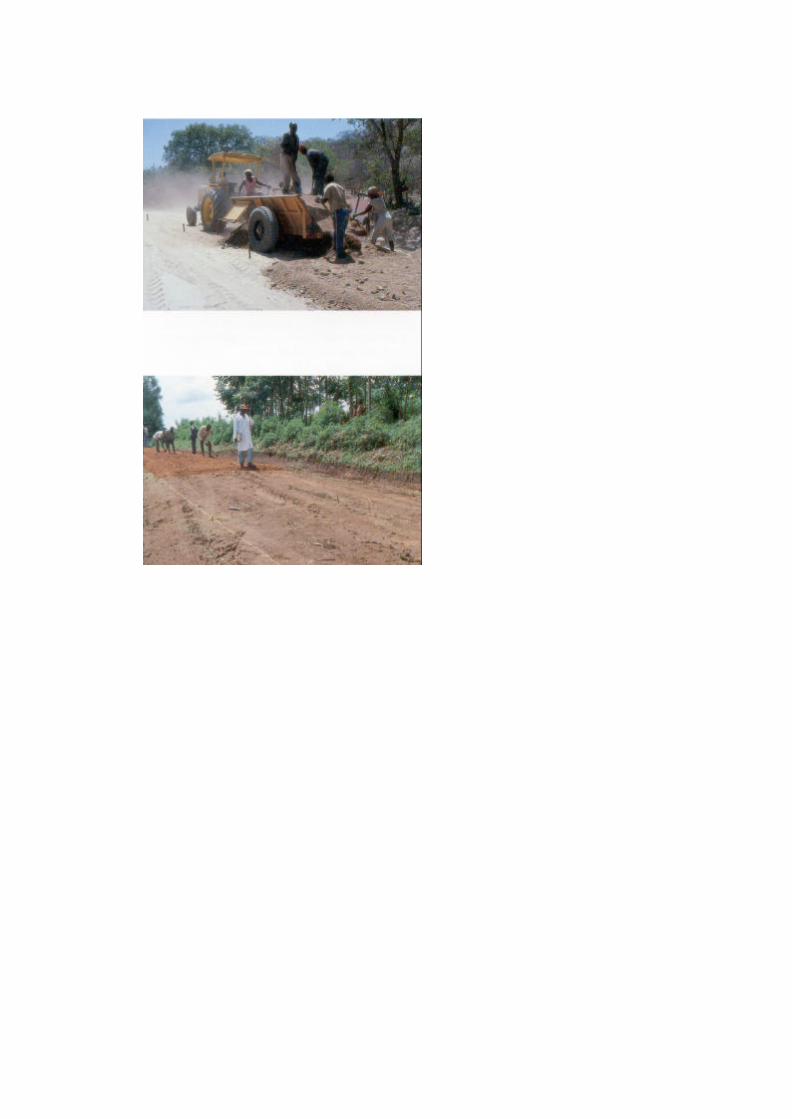

PART F - REGRAVELLING (Labour and Tractors)
OFFLOADING AND SPREADING
~ It is important to off load the trailers as quickly aspossible.
w Usually no more than 4 workmen can comfortably workon a trailer at a time.
m The material from one trailer is unloaded and spreadwithin a "box" marked out by pegs and string/sisal twine.The pegs are set at the finished road level with the aid ofthe camber board and spirit level.
m Any gravel lumps or stones larger than 5 cm should bebroken down using sledge hammers, or removed.
II - 305


PART F - REGRAVELLING (Labour and Tractors)
COMPACTION
m If available, the gravel layer should be watered using thetowed water bowser before compaction.
m If available, compaction should be carried out with atractor drawn deadweight roller or a hand operatedvibrating roller.
m If compaction equipment is not available, someconsolidation can be achieved by driving the loadedtrailers over the freshly laid material. The drivers shouldbe instructed to drive on different parts of the roadwaywith each pass.
II-307


PART F - REGRAVELLING (Labour any
STOCKPILING GRAVEL FOR ROUTINEMAINTENANCE
If attendants or lengthmen are used for follow up routinemaintenance, gravel stockpiles should be provided forpatching activities.
Where possible, gravel stockpiles of one trailer loadshould be placed at 100 to 200 m intervals along theroad.
m The stockpiles should be placed well clear of the roadand outside the side drains.
Where there is no space in the road reserve, thestockpile should be placed in the side drain immediatelydownhill of a turnout drain to avoid blocking thedrainage system.
II - 309


PART F - REGRAVELLING (Labour and Tractors)
4.4 COMPLETION AND REMOVAL OF TEMPORARYSIGNS
On completion of the work the temporary signs and safetyequipment are removed as described in Parts D, (Page I -193) or E, (Page 11 - 257) as applicable.

TYPICAL WORK REPORT
REGRAVELLING
Work Report No: . . . . . . . . . . . . .
District: . . . . . . . . . . . . . . . . . . . .
Zone:......................
Section: . . . . . . . . . .
WEATHER CONDITIONS:
Sunny L__1
Date: .................. Gang:
.................
RoadNo:. ..............
from km . . . . . . . . . .to km . . . . . . . . .
Cloudy El
QUANTITY OF WORK ACHIEVED:
Length: from km . . . . . . . . . to km . . . . . . . . . . .
Width: ..........................................................................._ ...........................m
Thickness (compacted): .................................................= ..........................cm
Gravel: . . . . . . . . . . . . . trailers of . . . . . . . . . . m3= . . . . . . . m3
Water: . . . . . . . . . . tankers of . . . . . . . . . . litres= . . . . . . . . litres
. _ ........ .......... m
EQUIPMENT USED:
................... ..................... Hrs
................... ..................... Hrs
................... ..................... Hrs
................... ..................... Hrs
................... ..................... Hrs
................... ..................... Hrs
MANPOWER USED: .....................................
COMMENTS: . . . . . . . . .
Foreman: .............................................
DIESEL USED:
litres
litres
litres
litres
litres
litres

PART F - REGRA VELLING (Labour and Tracts
4.5 WORK REPORT
m The report must be filled in each day, detailing
- the work carried out,
- the resources used.

User of this Handbook:
NAME:
ADDRESS
DATE:

ACKNOWLEDGEMENTS
The contents of this handbook draw on many sources, pastand present, and it would be impossible to acknowledgethem all individually. Much of the material is an updating ofthe UN/ECA Maintenance Handbook for Africa, compiled byexperts from France, Germany and the United Kingdom,and published in 1982. Its three volumes encapsulated thebroad experience of highway engineers, maintenancemanagers, consultants and researchers from many differentcountries.
The present revision was undertaken by Mr R.C. Petts ofIntech Associates, in close association with the OverseasCentre of the Transport Research Laboratory. The work wasfunded by the UK Overseas Development Administrationand supported and guided by a subcommittee drawn fromthe PIARC Committee on Technology Transfer andDevelopment (C3). It benefited from the collective wisdomof that committee and the countries represented within it.These included Australia, Algeria, Belgium, Brazil, BurkinoFaso, France, Germany, India, Italy, Morocco, Poland,Portugal, Senegal, Spain, Turkey, the United States ofAmerica, the United Kingdom and the World Bank.
On behalf of the subcommittee I would like to record oursincere thanks to all those who contributed, in whateverway, to the production of this second version of theMaintenance Handbook and to making it more valuable to awider international audience. I am sure it will fulfil itsintended purpose of strengthening the capabilities ofmaintenance workforces and giving them a stronger senseof professional pride in the vital work they are doing.

ACKNOWLEDGEMENTS continued
Any revision of this kind is an ongoing process, andcomments or suggestions for further improvements shouldbe made known to the PIARC Central Office at 27 rueGuenegaud, 75006, PARIS, France.Fax: +33 (1) 46 33 84 60.
J. Stuart YerrellChairman, Subcommittee C3-6d

WHAT IS PIARC?
Founded in 1909 following the 1St International Road Congress held m Parisin 1908, the Permanent International Association of Road Congresses(PIARC) is the oldest of the international associations concerned with roadsand road engineering.
The general aim of the Association is to improve international cooperationand to foster progress in-
a the formulation of road transport policies, a the planning, construction,
improvement and maintenance of roads, a the operation and management
of road systems, within the context of wider polices towards transport.
To achieve these aims PIARC:
a organises a World Road Congress every four years and varioustechnically oriented events,
x creates and co-ordinates Committees,w publishes a number of documents including a periodical bulletin
It is assisted in its task by National Committees. PIARC is a non politicaland non-profit association.
It was granted consultative status, category II, to the Economic and Social
Council of the United Nations in 1970. The official languages of PIARC are
French and English.
There are several categories of members Governments, regionalauthorities, public bodies, collective members and individual members.
As of 1 January 1994, PIARC has 72 member Governments and 2,100members in 100 countries.
PIARC has strong links with several regional organisations and is m favourof networking between countries dealing with similar questions. PIARC mayhelp to create and/or develop such networks.

PIARC Committees and Working Groups are composed of engineers andexperts appointed by member countries. They act on a continuous basisbetween each Congress and participate in international meetings dealingwith subjects within their competence.
On average they hold two plenary meetings a year. As of 1 January 1994,Committees and Working Groups gather approximately 700 engineers andexperts from 40 countries.
Thirteen Committees and four Working Groups are active (period 1991-1995).
COMMITTEES
C 1 - Technical Committee on Surface CharacteristicsC3- Committee on Technological Exchanges and Development C4 -Committee on Interurban RoadsC5- Committee on Road TunnelsC6- Committee on Road ManagementC7- Technical Committee on Concrete Roads C8-Technical Committee on Flexible RoadsC9- Economic and Finance CommitteeC 10 - Committee on Urban AreasC 11 - Committee on Road BridgesC 12 - Technical Committee on Earthworks, Drainage, Subgrade C 13- Committee on Road SafetyC 14 - Committee on the Environment
WORKING GROUPS
G 1 - PIARC Winter Road CongressG2- Natural Disaster ReductionG3- Modern Traffic Control and ManagementG4- Heavy Freight Vehicle Issues
m PIARC PUBLICATIONS - Committees and Working Groups publishsynthetic documents, recommendations and state of the art. Thesedocuments, intended for decision makers, design and field engineersand researchers, are based on wide international consensus
I I - 320

CONGRESS DOCUMENTS - The documents published on theoccasion of World Road Congresses are an invaluable source ofinformation and experts agree on the fact that they are most interestingand unique.
PERIODICAL BULLETIN "Routes/Roads" - The Association Bulletinwas issued for the first time in 1911. It features comprehensive files onroad matters in various countries, articles written by members ofCommittees and Working Groups and news of interest to the world roadcommunity. Its issues of a hundred pages are published three to fourtimes a year.
TECHNICAL DICTIONARY OF ROAD TERMS AND LEXICON -Thefirst edition of the DICTIONARYwas issued m 1931. The sixthedition (French/English) was published m 1990. The Dictionary ispublished with the financial support of UNESCO and is translated intoeighteen languages: Arabic, Chinese, Croatian, Czech, Danish, Dutch,German, Greek, Hungarian, Italian, Japanese, Lithuanian, Polish,Portuguese, Romanian, Russian, Spanish and Slovak The Lexiconcontains over 12,000 expressions m English and French and is alsoavailable on computer disk
All these documents are published in French and English. PIARCpublications catalogue is free of charge and can be ordered through:
ANRTP32, rue du March commun
Centre de Gros - Case postale 122044082 NANTES Codex 03 (FRANCE)
Fax: +33 40 50 13 64

WHERE TO ORDER THE HANDBOOK
The English version of
Volume I: Maintenance of Roadside Areas and
Drainage
Maintenance of Unpaved Roads
Maintenance of Paved Roads
Maintenance of Structures and Traffic
Control Devices
may be ordered from:
Transport Research LaboratoryCrowthorne, Berkshire RG11 6AUUnited Kingdom
Volume II:
Volume III:
Volume IV:
The Road Maintenance Handbook is also beingpublished in French, Spanish and Portuguese. Otherlanguages are under consideration. For more details,please contact PIARC Central Office - 27 RueGuenegaud, 75006, PARIS, France. Fax: +33 (1) 46 3384 60.
Printed by:- Borough Press (Wiltshire) Ltd, SN2 6YW, UK
II - 322

CONTENTS
FOREWORD ................……………………………i
INTRODUCTION………………………… ….viii
Part A - GENERAL REPAIRS ………………… 1
1. THE TASK................................................................
3
2. DEFECTS…………………………………………..…………………………………2.1 DEFECTS
2.2 LIST OF DEFECTS
7 7 7
3. RESOURCES…………………………………..
3.1 PERSONNEL3.2 PLANT AND TOOLS3.3 MATERIALS3.4 SIGNS AND SAFETY
4. MAINTENANCE METHODS ......................... .4.1 PRELIMINARY TASKS4.2 TEMPORARY SIGNPOSTING4.3 EXECUTION OF THE WORK4.4 COMPLETION AND REMOVAL
OF TEMPORARY SIGNS4.5 WORK REPORT
2727293337
39394751
7781

CONTENTS CONTINUED
Part B - SURFACE DRESSING (MECHANISED) ..... 83
1. THE TASK ........................................................ 851.1 APPLICATION 851.2 DIFFERENT TYPES OF SURFACE
DRESSING
2. DEFECTS2.1 DEFECTS2.2 LIST OF DEFECTS
3. RESOURCES3.1 PERSONNEL 1053.2 PLANT AND TOOLS3.3 MATERIALS3.4 SIGNS AND SAFETY EQUIPMENT
4. MAINTENANCE METHODS4.1 PRELIMINARY TASKS4.2 TEMPORARY SIGNPOSTING4.3 EXECUTION OF THE WORK4.4 COMPLETION AND REMOVAL OF
TEMPORARY SIGNPOSTING4.5 WORK REPORT
87
898989
105
107111121
125125135141
157163

CONTENTS CONTINUED
Part C - RESEALING OPTIONS ......................................165
1. THE OPTIONS .................................................………...167
2. LABOUR BASED SURFACE DRESSING ....…..........169
2.1 RESOURCES REQUIRED 1712.2 HEATING THE BINDER
(for cut back bitumen) 1752.3 USING BITUMEN EMULSION 1772.4 SETTING OUT THE WORK 1792.5 APPLYING THE BINDER 1812.6 APPLYING THE CHIPPINGS 183
3. FOG SPRAY.....................................................................185
4.SLURRY SEAL ............................................................... 187

CONTENTS CONTINUED
Part D - THIN OVERLAYS ................................................191
1. THE TASK ………………………………………………1.1 APPLICATION1.2 DIFFERENT TYPES OF THIN OVERLAYS
2. DEFECTS ...........................................................……
193193197
199
201201203205215
217217229231
253257
3. RESOURCES .......................……………….………...3.1 PERSONNEL3.2 PLANT AND TOOLS3.3 MATERIALS3.4 SIGNS AND SAFETY EQIPMENT
4. MAINTENANCE METHODS .......... ................……..4.1 PRELIMINARY TASKS4.2 TEMPORARY SIGNPOSTING4.3 EXECUTION OF THE WORK4.4 COMPLETION AND REMOVAL OF
TEMPORARY SIGNS4.5 WORK REPORT

FOREWORD
The road transport network of any country playsa vital role in its economy, and the physicalcondition of its infrastructure is critical. Withoutadequate and timely maintenance, highways andrural roads alike inexorably deteriorate, leadingto higher vehicle operating costs, increasednumbers of accidents, and reduced reliability oftransport services. When repair work can nolonger be delayed it will often involve extensiverehabilitation, and even reconstruction, costingmany times more than simpler maintenancetreatment carried out earlier. The need to protectthe existing network and keep it in good conditionis paramount, often taking precedence over newinvestment.
PIARC has been in the forefront in promoting thismessage and in drawing attention to the dangersof neglect. The matter has become increasinglyimportant in recent years for all the highways ofthe world, but especially so for those indeveloping countries where there is constantpressure on slender budgets and, in many, anurgent need to cater for growing traffic loads andvolumes.
In the late 1970's, the aid ministries of France,the Federal Republic of Germany and the UnitedKingdom joined forces to produce a "RoadMaintenance Handbook" for maintenanceforemen and workers in Africa. Published in 1982under the auspices of the Economic Commissionfor Africa, the three volumes - in French andEnglish - soon became widely known and used.By the end of the decade their use had spreadfar beyond Africa, and their straightforwardinstructions were being used for trainingpurposes as well as for

FOREWORD continued
on-the-job guidance in many countries. The need toreprint provided the opportunity to review thecontents in the light of experience and make themmore suitable for the wider audience nowcommanded. PIARC's Committee on TechnologyTransfer and Development, formerly the Committeeon Roads in Developing Regions, undertook to helpwith this review, which was generously funded bythe UK Overseas Development Administration. Asub-committee was established, embracing thethree original donor countries, other developed anddeveloping countries, and the World Bank. Althoughmuch of the original text has been retained, the newhandbooks incorporate more information on labourand tractor-based techniques, and on thedevelopment of manpower management and theall-important question of safety at work. The rangeof maintenance problems addressed has beenextended to strengthen their international appeal.
The past ten years have seen major reforms in thegeneral thrust of maintenance policy and in itsorganisation, management and execution. Thesechanges will continue, and PIARC will play its partalong with other institutions in encouraging theprocess and pressing for further progress. Only afull appreciation of maintenance at the highestlevels of policy-making and financial planning canensure success. But these handbooks have ahumbler task-to ensure that the men and women atthe operational level are suitably skilled and trainedand are using the appropriate tools and techniques,and have interest and motivation in their work.

FOREWORD continued
PIARC has been proud to nurture this project tothe point where the new handbooks are available,but its involvement will reach far beyond that. It willprovide the necessary international frameworkwithin which the handbooks can be translated andprinted in many languages. Its worldwidemembership of key figures in the national provisionand management of highways will assist with theirdissemination, ensuring that they find their way intothe most appropriate hands in both the public andprivate sectors. Collectively, these hands will playa fundamental part in sustaining the vital assetwhich our roadway networks truly represent.
Victor J Mahbub,President of

INTRODUCTION
THE HANDBOOK
This is a guide for the maintenance foreman orsupervisor assigned to bitumen or unpaved roadsin tropical and moderate climates. The objective ofthe HANDBOOK is to assist him in all aspects of hiswork whether carried out by direct labour or bycontract. Its pocket format enables the volumerelevant to the day's work to be easily carried andconsulted on site. The HANDBOOK should be hisready reference book. The text is concise and wellillustrated. A quick reference should be all that isnecessary.
This HANDBOOK does not include a course ofstudy or discuss underlying causes of defects.Inspections, material sources, specifications andtesting are also outside its scope. Furthermore it issufficient here to remind the foreman that his plantand vehicles should be well maintained withouttelling him how to do it.
Even though the HANDBOOK is intended for use bythe maintenance foreman, it will also be usefulreading for the engineer or senior supervisor. Thiswill make him more conscious of his duties towardsthe foreman and enable him to ensure that themaximum benefit is obtained from the HANDBOOK.Each supervisor must understand his responsibilityand the part he has to play.
The HANDBOOK can also be used in trainingcentres. With the assistance of country-specificsupplementary information, photographic slides,models, and other supporting material, it will be avaluable tool for the trainer and can be distributed tostudents.

Road maintenance requires a range oforganisational and technical skills and the work onroads in use by traffic makes the work potentiallyhazardous to both the workmen and road users.
It is therefore essential that appropriate formaland on the-job training is given to each category ofpersonnel involved in road maintenance activitiesto achieve efficient and safe operations.
The foreman usually has an important role in theinitial and ongoing training of personnel.
Roads are an enormous national investment andrequire maintenance to keep them in a satisfactorycondition and ensure safe passage at anappropriate speed and with low road user costs.
Late or insufficient maintenance will increase theultimate repair costs and raise road user costs andinconvenience, and reduce safety.
Road Maintenance is therefore an essentialfunction and should be carried out on a timelybasis.
There is a diversity of maintenance activities, theclass and type of the road, the cross section to bemaintained, the defects recognised, and theresources available. However the generalmethods proposed here for each activity (withsome exceptions) are given under the followingheadings:
The taskDefectsResourcesMaintenancemethod

Where appropriate options are shown for carryingout the work by:
i) Heavy Equipment,ii) Tractor based methods, oriii) Labour based methods.
The decision on which method to be used should bemade by the engineer or senior supervisor basedon considerations of resources available, cost,policy etc.
Maintenance operations are usually grouped ineach country according to planning, organisationaland funding arrangements. They can normally becategorised as either ROUTINE or PERIODIC.
For the purposes of this HANDBOOK the followinggrouping is used.
ROUTINE: Operations required to be carried outonce or more per year on a section ofroad. These operations are typicallysmall scale or simple, but widelydispersed, and require skilled orun-skilled manpower. The need forthese can, to a degree, be estimatedand planned and can sometimes becarried out on a regular basis.
PERIODIC: Operations that are occasionallyrequired on a section of road after aperiod of a number of years. They arenormally large scale and requirespecialist equipment and skilledresources. These operations arecostly and require specificidentification and planning. In this

handbook PERIODIC also includescertain improvement works such asthin bituminous overlays.
From time to time urgent or emergency works ofany nature may be required and these are dealtwith as the need arises.
The HANDBOOK consists of 4 separatevolumes:
VOLUME I - MAINTENANCE OF ROADSIDEAREAS AND DRAINAGE
PART A - List of TermsPART B - Works Management and SafetyPART C - Roadside AreasPART D - Drainage General Index
VOLUME II - MAINTENANCE OF UNPAVED ROADSPART A - GradingPART B - Labour Based ReshapingPART C - DraggingPART D - PatchingPART E - Regravelling (Mechanised) PART F - Regravelling (Labour and Tractors)
VOLUME III - MAINTENANCE OF PAVED ROADSPART A - General RepairsPART B - Surface Dressing(Mechanised)PART C - Resealing OptionsPART D - Thin Overlays
111 - xi

VOLUME IV - MAINTENANCE OF STRUCTURESAND TRAFFIC CONTROL DEVICES
PART A - BridgesPART B - Traffic ControlDevices
VOLUME III
Each Part A, B, C, and D describes tasksconcerning exclusively paved roads*. Roads ofthat category have been given a surface course,generally containing bitumen or tar, because oftheir importance and their higher traffic.
Maintenance of the paved surface has thefollowing objectives:
• To maintain the impermeability of the roadsurface, preventing water penetrating the surfaceor edge of the road pavement and weakening thepavement layers or foundation.
• To retain or renew the road surface quality andtherefore good riding and safety conditions.
PART A - GENERAL REPAIRS
General repairs are routine maintenance tasks.Sometimes they are preliminary tasks, carried outbefore periodic maintenance operations.
NOTE - Terms with an asterisk are defined in List of Terms (See Volume 1-Part A).

PART B - SURFACE DRESSING (MECHANISED)
Surface dressing is a periodic maintenance task. It isused to reseal the road surface and improve the ridingquality/safety. Usually it is necessary to do generalrepairs before carrying out surface dressing.
PART C - RESEALING OPTIONS
Mechanised surface dressing is the most common typeof periodic maintenance reseal. However in certaincircumstances other techniques, such as Labour Basedsurface dressing, Fog spray or Slurry seal are moreappropriate.
PART D - THIN OVERLAYS
A thin overlay is a periodic maintenance task. It is usedto reseal the road surface, cover minor depressions orstrengthen the road pavement. As with surfacedressings, it is frequently necessary to do generalrepairs in preparation. An existing road surface that iscracked should not be overlaid without an investigationof the cause by the engineer.
NOTE: In many countries women carry out roadmaintenance tasks and supervisory duties. The use ofmale descriptions and diagrams in this handbook is forconvenience only. The guidelines are applicablewhether the work is carried out or supervised by menor women.
III - xm

Part A
GENERAL REPAIRS

NOTE: SHOWN FOR DRIVING ON THE RIGHT

PART A - GENERAL REPAIRS
1. THE TASK
GENERAL REPAIRS are normally a ROUTINEMAINTENANCE activity. However they are alsocarried out in advance of some PERIODICMAINTENANCE operations.
� The term General Repairs covers all types ofwork on the road pavement*:
� of a localised nature and� of limited size.
� The OBJECT is to:
� improve the surface condition of the road� improve the pavement* structure� prevent water penetrating the pavement structure
� General Repairs must be carried out in goodtime in order to prevent further deteriorationresulting in danger to traffic and leading todisintegration of the pavement.
� General Repairs employ simple methods butcover a large range of small work operations.
� Due to the materials, skill and safetyrequirements, this task is usually carried out by amobile gang
See List of Terms, Volume I


PART A - GENERAL REPAIRS
� A particular General Repair technique isinvolved for each type of defect.
This Part of the Handbook deals with thefollowing techniques*:
SANDINGLOCAL SEALINGCRACK SEALINGFILLING INDEPRESSIONSSURFACE PATCHING
In the case of surface repairs, use is made ofbituminous binders, sands and aggregates.
In the case of repairs to the pavement structure,use is made of natural or crushed materials andsometimes of cold bituminous mixtures.
� Often when work is carried out on pavementGeneral Repairs, it is also necessary to repairdefects on the shoulders* and side ditcheswhen the pavement defect is due to them. Thiswill help to prevent the problem recurring. e.g.,
- construction or cleaning out of ditches,- construction or cleaning of drainage
outlets,- patching and reshaping of shoulders.
* See List of Terms, Volume 1.


PART A - GENERAL REPAIRS
2. DEFECTS
2.1 DEFECTS
Defects can occur in:
� The road surface (a)
� wear of the surface layer of the road,� cracking of the surface layer,� fatting-up of binder to the road surface.
� The pavement structure (b)
� deformation,� potholes.
2.2 LIST OF DEFECTS
Information follows on the different types of defect withrespect to:
� Location: parts of the pavement where the defectusually appears,
� Main Causes of the defect,
� Development: consequences if maintenance is notrapidly carried out,
� Remedies: usual repair treatments.


PART A - GENERAL REPAIRS
DEFECT: BLEEDING*
LocationMay involve a part or the whole of the roadsurface.Main causes- too much binder,- unsuitable binder.
Development, if neglected- the road surface becomes slippery when wet,- separation and break-away of surface layer under the
action of traffic.
Remedies- sanding (Page III - 51),- surface dressing (Page III – 83).
See List of Terms, Volume I.

PART A - GENERAL REPAIRS
DEFECT: CRACKS(in the surface and in the pavement structure)
Locationa. longitudinal: parallel to the centre line (often along the
wheel tracks or along the edges of the surfacing).
b. transverse: perpendicular to the road direction(across the whole or part of the cross-section).
c. mesh cracking: intersecting cracks dividing thepavement surface into isolated elements of differentsizes down to the small elements involved in crazing.
Main Causes- poor quality materials,- poor workmanship,- insufficient pavement thickness for the traffic being
carried,- shrinkage (see Note),- pavement age.
NOTE: Shrinkage: cement treatment of road base results in areduction in volume after the cement has set and dried out.

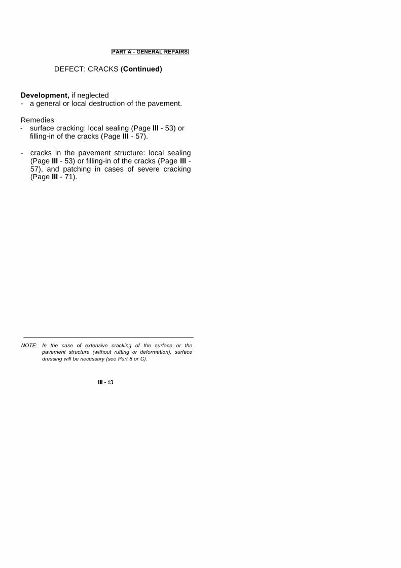
PART A - GENERAL REPAIRS
DEFECT: CRACKS (Continued)
Development, if neglected- a general or local destruction of the pavement.
Remedies- surface cracking: local sealing (Page III - 53) or
filling-in of the cracks (Page III - 57).
- cracks in the pavement structure: local sealing(Page III - 53) or filling-in of the cracks (Page III -57), and patching in cases of severe cracking(Page III - 71).
NOTE: In the case of extensive cracking of the surface or thepavement structure (without rutting or deformation), surfacedressing will be necessary (see Part 8 or C).


PART A - GENERAL REPAIRS
DEFECT: RUTS AND DEPRESSIONS
Location- in the wheel tracks of vehicles (ruts),- local areas (depressions*).
Main Causes- insufficient foundation or pavement strength for
the traffic being carried,- inadequate stability of the bituminous* surfacing
materials.
Development, if neglected- if water is able to penetrate into the body of the
pavement, then there will be a rapid increase inthe degree of rutting often leading to crackingand breakup of the pavement.
Remedies- slight rutting (less than 5 cm): filling in of the ruts
and depressions (Page III - 63),- deep rutting: local restoration of the pavement
structure (Page III - 71).
*See List of Terms, Volume 1.


P ART A - GENERAL REPAIRS
DEFECT: EDGE SUBSIDENCE AND RUTTING
LocationUsually along the edges of the pavement where itborders unsealed shoulders.
Main Causes- inadequate or badly maintained
shoulder- penetration of water into the pavement structure
or foundation and resulting loss of bearingstrength,
- poor drainage,- narrow carriageway.
Development, if neglected- rapid during the rainy season leading to the
disintegration of the edges of the pavement.
Remedies- slight subsidence (less than 5 cm): filling in of
ruts and depressions (Page III - 63) andrestoration of shoulder (see Volume I),
- deep subsidence: local restoration of thepavement structure (Page III - 71) andrestoration of the shoulder (see Volume I),
Also consider improvements to the drainage (seeVolume I), or sealing of the shoulder (Part B or C) tohelp prevent the problem recurring.


PART A - GENERAL REPAIRS
DEFECT: EDGE DAMAGE(degradation of pavement structure)
LocationAlong the edges of thepavement'`.Main Causes- wear of the shoulder* (formation of step),- action of water,- insufficient compaction of the edges of bituminous
pavements,- road too narrow.
Development, if neglected- rapid during the rainyseason.Remedies- local restoration of the pavement structure
(Page III -71).
*See List of Terms, Volume I.


PART A - GENERAL REPAIRS
DEFECT: LOCAL AGGREGATE LOSS
LocationSmall areas or strips of the road surface.
Main Causes- Loss of surface aggregate due to: insufficient
binder due to faulty spray jet,- aggregate dirty when laid,- insufficient penetration of aggregate,- poor premix quality or workmanship.
Development, if neglected- minor stripping/fretting/streaking'*.
Remedies- surfacing patching (Page III - 67).
*See List of Terms, Volume I.NOTE: For large areas of aggregate loss, surface dressing should beconsidered as a remedy (Part B or C).


III - 23
PART A - GENERAL REPAIRS
DEFECT: POTHOLES(degradation of the pavement structure)
LocationNo particular location but often in areas showing cracks,deformation or aggregate loss.*
Main Causes- poor quality of material used for the construction of the
pavement,- infiltration of water,- break away of material under the action of traffic,- final stage in the development of crazing* or of a
depression*.
Development, if neglected- progressive enlargement of the hole and formation of
additional potholes.
Remedies- local restoration of the pavement structure (Page III
-71).
*See List of Terms, Volume I.
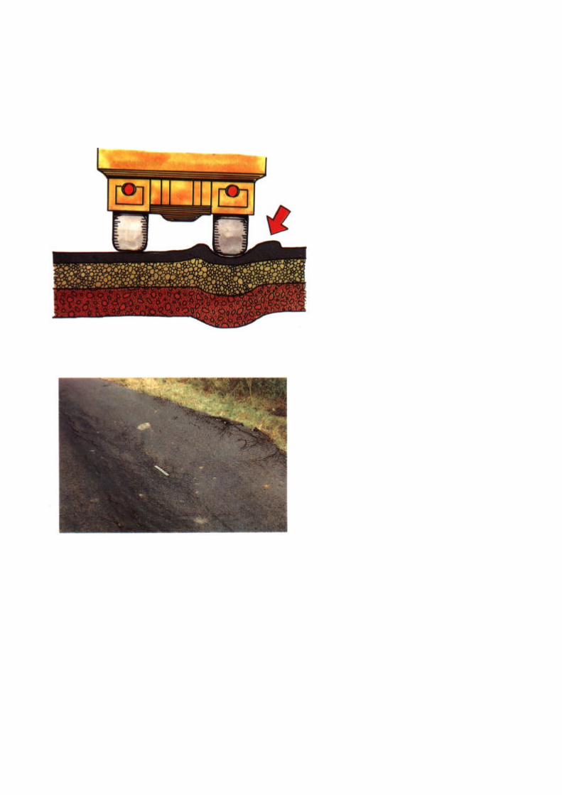

PART A - GENERAL REPAIRS
DEFECT: SHOVING(defects in the surface or pavement structure)
LocationUsually on either side of the wheel tracks. Theirregularities are usually associated with deformation andsubsidence.
Main Causes- ingress of water: reduced bearing capacity of the
pavement,- materials: of poor quality,- workmanship: insufficient compaction,- traffic: passage of vehicles which are too heavy for the
pavement structure.
Development, if neglected- forcing up of weak materials as deformation occurs,- progressive disintegration of the pavement.
Remedies- small irregularities: filling in of irregularities (Page III -
63),- large irregularities together with cracks: local
restoration of the pavement structure (Page III - 71).
III - 25


PART A - GENERAL REPAIRS
3. RESOURCES
3.1 PERSONNEL
� Work Force
� 1 foreman,� 1 spray lance/bitumen operator,� 2 to 4 workmen,� 2 traffic controllers.
� Plant Operators and Drivers
� 1 patching vehicle* driver,� 1 tipper/flat bed truck driver,� 1 vibrating roller operator.
OR
� 1 tractor driver,� 1 vibrating plate operator.
*If this vehicle is available.
III - 27


PART A - GENERAL REPAIRS
3.2 PLANT AND TOOLS
� Patching Vehicle*
Specially equipped vehicle or towed equipmentfitted with a heated tank for the binder and adouble hopper for the aggregates.
OR
If, not available, a suitable means of heating(unless bitumen emulsion is used) and applyingthe bitumen are required. e.g. towed bitumenheater/distributor.
� Tipper/Flat Bed Truck, or Tractor and Trailer
For transporting the aggregates, small items ofequipment and the personnel.
If such a vehicle is not available a truck or tractor & trailer is used totransport:
� the personnel,� the equipment,� the aggregates,� binder in drums,� premixed materials (if used).


PART A - GENERAL REPAIRS
� A small vibrating roller (or, if not available, avibrating plate compactor or hand rammers) foruse in compacting the aggregates and othermaterials. The vibrating roller can betransported by mounting it on a special trailerwhich is towed by the truck. Otherwise ramps ora hoist are required to help load onto truck ortrailer.
� Small items of equipment:- 2 wheelbarrows,- 4 shovels,- 4 pickaxes,- 2 hand rammers,- 4 brooms,- 2 watering cans,- 2 squeegees,- bitumen thermometer.
If bitumen emulsion is used
� 1 cold emulsion single drum sprayer.
Tools and supplies- 1 drum of diesel oil for use in cleaning the spray
lance*, and other tools,- 1 spare jet for the spray lance,- 1 box of tools for use in dismantling the spray
lance,- rags,- number of paint brushes,- 1 metal bucket,- 1 two-metre straight edge,- chalk for marking.
*See List of Terms, Volume 1.


III - 33
PART A - GENERAL REPAIRS
3.3 MATERIALS
The materials used consist of aggregates*, andbituminous binders* that are either appliedseparately or in the form of a bituminous mixture.
� Aggregates** The aggregates may be:
� sand mixtures* ................................d/D (a)� stone chippings* ............................. d/D (b)� natural gravel or crushed rock ........d/D (c)
The materials should meet the gradingrequirements set by the engineer.
The maximum size of aggregate varies according tothe type of work involved, normally:
� sanding ................................Dmax = 5 mm� surfacing ..............................Dmax=10 mm� base courses . …… Dmax =40 mm
(Dmax = nominal maximum diameter)
In addition to the grading it is also necessary tocheck the hardness and the cleanliness of theseaggregates. These properties should be testedregularly according to the specifications.
*See List of Terms, Volume 1.**For Aggregate abbreviations see Page III - III.


III - 35
PART A - GENERAL REPAIRS
� Bituminous binder*This can consist of:
� a cold bitumen emulsion (a),� a hot cut back bitumen (b).
The bitumen is either applied to the road surfaceas a film or used in bituminous mixtures.
� Bitumen filmThe bituminous binder is applied with a spraybar/lance*, or by hand from a measuring container,to cover the surface and ensure that it will beimpervious to water.
The bitumen film is covered with stone chippings oraggregates to provide protection from traffic.
� Bituminous mixtures (c)The bituminous binder is used to bond the othermaterials together.
Bitumen mixtures can consistof:
� bitumen emulsion slurries - applied immediatelyafter manufacture,
� cold bitumen emulsion mixtures - manufacturedin advance of their application,
� hot fluxed or cut back bitumen mixtures (hotmix) applied immediately after manufacture.
*See List of Terms, Volume I.


PART A - GENERAL REPAIRS
3.4 SIGNS AND SAFETY EQUIPMENT
� Advance Warning SignsThe following signs are to be placed on the shoulder forboth directions of traffic:
� 2 "Men Working" signs,� 2 "End of Restriction" signs.
� Site Protection Equipment:
� 4-10 traffic cones,� 2 reversible
"Stop/Go" signs.
� Safety EquipmentUse should be made of the following equipment forpersonnel and the different vehicles as far as possible:
� yellow/orange shoulder belts for the foreman, the spray lance operator and the other workmen,� red and white striped marker boards attached to the patching vehicle, the truck or tractor and trailer.
A fire extinguisher should be provided for each vehicleworking with or near heated bitumen.

TYPICAL WORKSHEET
GENERAL REPAIRS
Worksheet No: . . . . . . . . . . . . . . . . . . Date: . . . . . . . . . . . . . . . . . . . . .
District: .................................................
Zone: ................................................... Gang:
Road No:. . . . . . . . . . . . from km .....................to km ............
from km .....................to km ............
from km ………………to km ……….
TYPE OF REPAIR:
Sanding
Local sealing
Crack sealing
Filling in depressions
MATERIALS: Type of
binder: . . . . .
Aggregates: . . . . . . . .
Bituminous mixtures:
QUANTITIES REQUIRED:
Binder: . . . . . . . . . . . …………………………………………………………kg
Aggregates: . . . . . . . . ………………………………………………………..m3
Bituminous mixtures………………………………………………………… .m3
STOCK POSITION & COMMENTS:
………………………………………………………………………………………………………………………………………………………………………………………………………………………………………………………………………………………………………………………………………………………………
Surface patching
Base patching
Resurfacing of shoulders

III - 39
PART A - GENERAL REPAIRS
4. MAINTENANCE METHODS
4.1 PRELIMINARY TASKS
Successful results for General Repairs depend ongood preparation and organisation of the work.There are three preparation activities:
1 Refer to the WorkSheets
These sheets give the dates when work onthe road section concerned is to be carriedout, the activities required, as well asinformation on the materials that are to beused.


III - 41
PART A - GENERAL REPAIRS
2 Examine the section of road to be repaired
The section of road to be repaired must be examinedalong its whole length in order to determine:
� the types of defect to be repaired (Pages III - 7 to III
- 25), the extent of the defects,
and to
� check the resources required.


III - 43
PART A - GENERAL REPAIRS
3 Resource Availability
Before the work starts it is necessary to ensure:
� that all necessary personnel are available,
� that all items of equipment to be used are availableand in good condition,
� that all small items of equipment, hand tools andthe necessary traffic signs are available,


PART A - GENERAL REPAIRS
� that the required type and quantity ofbinder, as specified on the work sheet, isavailable,
� that the aggregate is available at thestorage locations specified on the worksheet.


PART A - GENERAL REPAIRS
4.2 TEMPORARY SIGNPOSTING
Traffic signs conforming to the regulations must becorrectly placed before starting any work. This is to ensurethe safety:
� of the road users,� of the personnel working on the site,� of the vehicles and equipment to be used on the site.
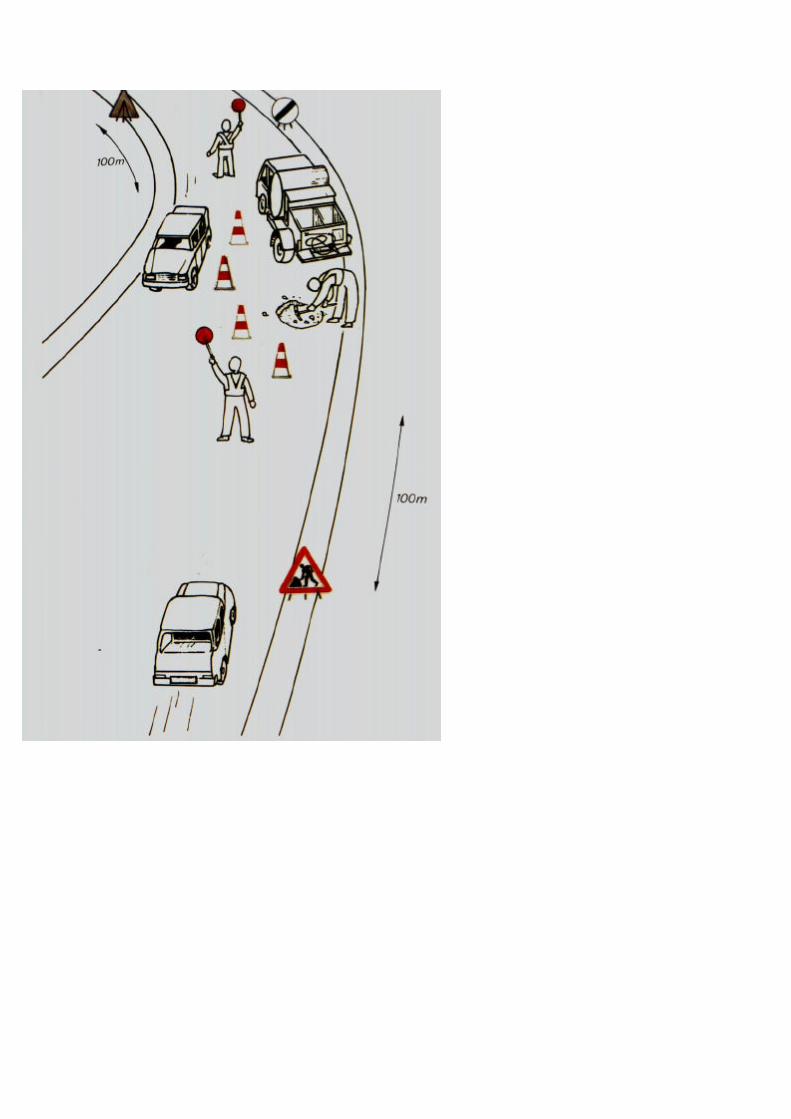

PART A - GENERAL REPAIRS
The signs are:
� located on the shoulder on the side of theapproaching traffic, 100 m ahead of each endof the roadworks:
� 1 "Men Working" sign,
� located along the length of theroadworks:
� to 10 traffic cones, as required to clearlyseparate the traffic from the roadworks.
� located on the shoulder on the side of thedeparting traffic, at each end of the site:
� 1 "End of Restriction" sign.
NOTE: In busy traffic 2 men must be assigned to direct the traffic inalternate directions past the roadworks.
III - 49


III - 51
PART A - GENERAL REPAIRS
4.3 EXECUTION OF THE WORK
SANDING
Sanding is the treatment to be used where theroad surface is bleeding*, coarse sand up to 5 mmshould be used where possible. Two activities,which may need to be repeated, are involved in thetreatment:
1 The sand is scattered by shovel over theaffected surfaces from a truck or trailer (a).
2 The sand is then spread out with a broomso that the surface is evenly covered (b).
* See List of Terms, Volume 1.


PART A - GENERAL REPAIRS
LOCAL SEALING
This treatment is used to repair cracks (Page III -11). It is also employed as the final treatment in thecase of any local repair to the road (Page III - 71).
The treatment is applied in four stages:
1 Sweep the area (a)
This is carried out by hand. The road surfacemust be clean and dry following this operation.
2 Mark out the area to be sealed (b)
The surfacing that is to be covered is outlined inchalk.


PART A - GENERAL REPAIRS
3 Distribution of the binder (c)
The binder is distributed over the surface using aspray lance'` or a watering can at the followingrates:
1.5 kg/M2 for bitumen emulsion,� 1 kg/m 2 for cut back bitumen.� 1 kg/m 2 for cut back bitumen.
It is important not to overheat the cut backbitumen or cationic emulsion as this will affect itsdurability. A thermometer should be used tocheck the temperature during heating (see PageIII - 143). Anionic emulsion does not normallyrequire heating.
Smoking should not be allowed when handlingcut back bitumen.
4 Distribution of the aggregate (d)
The aggregate is scattered by shovel from the truck ortrailer. The material used is:
� coarse sand up to 5 mm, when dealing with cracks,
� chippings (such as 6-10 mm size) for local surfacingrepairs.
The whole of the surface must be covered.
*See List of Terms, Volume 1.NOTE: When chippings are applied, they must be compacted with thesmall roller.


PART A - GENERAL REPAIRS
CRACK SEALING
This is an alternative treatment used to repair cracks(Page III - 11).
Treatment of closely spaced cracks
The cracks are filled in with a bituminous slurry infour steps:
1 Sweep the area (a)
This is carried out by hand. The road surfacemust be clean and dry following this operation.
2 Mark out the area to be repaired (b)
The area to be repaired is outlined with chalk.


PART A - GENERAL REPAIRS
3 Production of the slurry (c)
The slurry is produced by mixing bitumenemulsion with coarse sand, up to 5 mm, in awheel barrow in the following proportions:
� sand 20 litres� emulsion 6 litres
The emulsion does not normally require heating.However the emulsion drums will require rollingto thoroughly mix the contents before use.
4 Spreading the slurry (d)
This is carried out with a squeegee*. Thematerial must be spread out in a thin layer,approximately 5 mm thick, over the whole of themarked out area. The slurry must be allowed todry completely before allowing traffic to pass
*See List of Terms, Volume I


PART A - GENERAL REPAIRS
CRACK SEALING (Continued)
Treatment of Isolated Cracks
In these cases the cracks are filled in with a hot cutback bitumen.
1 Sweeping the area (a)
The crack to be filled must be clean following thisoperation.
2 Heating the binder
Do not overheat the cut back bitumen as this willaffect its durability. Use a bitumen thermometerto check the temperature during heating (seePage III -143).
3 Distribution of the binder(b)
This is carried out using a spray lance orwatering can to follow the line of the crack. Thenozzle of the spray lance or the spout of thewatering can must be held close to the roadsurface. The width of spread should be kept assmall as possible.
4 Distribution of the sand(c)
Coarse sand is scattered over the strip of binderusing a shovel.


PART A - GENERAL REPAIRS
FILLING IN DEPRESSIONS
This treatment is applied to deal with subsidence(Page III - 15) and surface irregularities due toshoving (Page III - 25). The depressions are filledwith a cold mix asphalt* prepared in advance andstored at the depot. The repair is carried out in sixsteps:
1 Sweep the area (a)
The depressions must be swept out by hand. Thesurface of the depression must be clean and dry.
2 Mark out the area to be repaired (b)
The surface area of the depression that is to befilled in must be outlined with chalk.
Remove any high spots with a pick axe.
3 Obtain the cold mix(c)
* See List of Terms, Volume I.


PART A - GENERAL REPAIRS
4 Application of a tack coat (d)
Hot cut back bitumen is applied with a spraylance or watering can at a rate of about 0.5kg/m2. Do not overheat the cut back bitumen asthis will affect its durability. Use a bitumenthermometer to check the temperature duringheating.
5 Fill in the depression (e)
The cold mix is placed within the marked outlineusing a rake and leaving an excess thickness ofabout one third of the depth of the depression inorder to allow for compaction.
6 Compaction of the material (f)
The material is compacted thoroughly using thesmall vibrating roller, plate or a rammer, until thelevel is 3 mm proud of the surrounding surface.
7 Resealing
The repair must be sealed to prevent penetrationof water (Page III - 53).


PART A - GENERAL REPAIRS
SURFACING PATCHING
This treatment is used to repair local aggregate loss(Page III - 21) and is carried out in the followingsteps:
1 Sweep the area
The area must be swept out by hand. The surfacemust be clean and dry.
2 Mark out the area to be repaired
The surfacing that is to be repaired is outlined inchalk.
OPTION 1: SEAL
Use cold emulsion or hot cut back bitumen to sealthe area to be repaired and provide a tack coat atthe following rates:
� 1.5 kg/m2 for bitumen emulsion� kg/m2 for cut back bitumen.
Apply the chippings (such as 6-10 mm size) andensure a complete coverage. Lightly roll thechippings into the bitumen using a roller or vehicletyres.


PART A - GENERAL REPAIRS
OPTION 2: PREMIX
A hot cut back bitumen is applied to the area of therepair with a spray lance or watering can, at a rateof about 0.5 kg/m2 to form a tack coat.
Spread fine cold mix (made from material up to 5mm size) evenly over the area and compact it levelwith the surrounding surface using the smallvibrating roller or plate, or a rammer.


PART A - GENERAL REPAIRS
BASE PATCHING
This is the treatment that is used to repair:
� mesh cracking (Page III - 11),� ruts and depressions (Page III - 15),� edge subsidence and rutting (Page III -17),� edge surface failure (Page III - 19),� potholes (Page III - 23),� shoving (Page III - 25).
Four steps are involved:
1 Marking out the area to be repaired
The area to be treated is marked out with chalk bydrawing a rectangle around the defects.


PART A - GENERAL REPAIRS
2 Excavation of the area to be repaired
It is necessaryto:� remove all material from within the
marked out area of the road surface,
� increase the depth of the hole until firm, drymaterial is found and then trim the walls ofthe hole so that they are vertical. If water orexcessive moisture is present, thenarrangements must be made to drain itaway from the pavement foundation.
� trim the bottom of the hole such that it isflat, horizontal and free from loose materialthen compact it.
III - 73


PART A - GENERAL REPAIRS
3 Backfilling the hole
The hole is filled with a selected well gradedmaterial brought to the site in a truck or trailer. Thismaterial can consist of:
� a material of the same quality as that of thebase layer that is to be repaired,
� or a cold mix asphalt*.
The material is placed in the hole and compacted inone or more layers of regular thickness dependingon the depth involved. The last layer, prior tocompaction, must have an excess thickness ofabout 1/5 the depth of the final layer, in order toallow for settlement on compaction.
Compaction is continued depending on the size ofthe excavation, using the vibrating roller, platecompactor or with a yammer, until the surface is
4 Resealing
The repair must be sealed to prevent penetration ofwater (Page III - 53).
*See List of Terms, Volume I.


PART A - GENERAL REPAIRS
4.4 COMPLETION AND REMOVAL OF TEMPORARYSIGNS
On completing the repairs and before removing the trafficsigns which protect the site, the following activities must becarried out:
� remove all excavated material from the road,
� sweep all aggregate from the edges of therepairs,
� sand all areas where too much binder hasbeen applied.
In the days following completion of the work,all areas where the binder has migrated tothe road surface must also be sanded again.

NOTE: SHOWN FOR DRIVING ON THE RIGHT

PART A - GENERAL REPAIRS
� On completion of the repairs and finishing thework, park the vehicles on the shoulder. Thetwo men who have been responsible fordirecting the traffic will remove the traffic signsand load them on the truck in the followingorder:� the traffic cones
(a),� the two "End of Restriction"
� signs, the two "Men
Working" signs (b).

TYPICAL WORK REPORT
GENERALREPAIRS
Work Report No: . . . . . . . . . . . . . . . . . Date: . . . . . . . . . . . . . . . . . .
District:…………………………………………………………………….
Zone: ......................………………..
Road No:. . . . . . . . . .
Gang: ..……
from km ................. to km…………………
from km ................. to km………………..
from km ................. to km………………..
TYPE OF REPAIR:Sanding � Surface patching �
Local sealing � Base patching �
Crack sealing � Resurfacing of shoulders �
Filling in depressions �
MATERIALS USED:Type of binder: . . . . ……………………………………………………Aggregates: . . . . . . . ………………………………………………….Bituminous mixtures: . …………………………………………………
QUANTITIES USED:Binder: .................................................................................... .... ....kgAggregates: .................................................................................. . m3
Bituminous mixtures: . . . . . . . . . . . . . . . . . . . . . . . . . . . . . . . . . . m 3
COMMENTS:……………………………………………………………………………………………………………………………………………………………………………………………………………………………………………………….Foreman ..................................................Date:……………………….

PART A - GENERAL REPAIRS
4.5 WORK REPORT
This report must be filled in each day detailing:
� the work carried out,
� the resources used.

Part B
SURFACE DRESSING(mechanised)

PART B - SURFACE DRESSING (mechanised)
1. THE TASK
SURFACE DRESSING is normally a PERIODICMAINTENANCE activity.
1.1 APPLICATION
� A surface dressing can be used for dealing with alarge road surface area where:
� the surface is extensively worn,� the surface has become permeable or
cracked allowing water to penetrate thebase and cause deterioration,
� there is inadequate surface texture so thatskid resistance is reduced,
� It will usually be necessary to carry out somepatching work before proceeding with thisoperation, particularly where there is basedamage, subsidence, potholes, etc.
� The surface dressing is generally appliedover the complete width of the pavement(although in some cases, over only a halfwidth) and over lengths of road ranging froma few hundred metres to several kilometres.
� With good planning and organisation, thiswork can achieve high outputs.
� Surface dressing must be applied only in dryweather.
� Surface dressing will not correctdepressions, and deformation of the roadpavement or severe cracking.


PART B - SURFACE DRESSING (mechanised)
1.2 DIFFERENT TYPES OF SURFACE DRESSING
A distinction is made between:
� Single surface dressing (a):
� 1 layer of bituminous binder,� 1 layer of chippings.
� Double dressing (b):
� 2 layers of bituminous binder, each covered witha layer of chippings.
� Graded seal (c):
� 1 layer of bituminous binder, followed by either:� 2 layers of chippings of different compatible
sizes e.g. 10/14 and 4/6, the second layerserving to fill the gaps between the larger firststones and completely cover the road surface,
or
� 1 layer of graded aggregate or gravel with stonegraded over a wide size range (e.g. 3 to 17 mm).
� Sandwich seal
� 1 layer of chippings (e.g. 10/14),� 1 layer of bituminous binder,� 2nd layer of chippings (e.g. 4/6).
This seal is suitable for existing surfaces withextensive bleeding.
III - 87


PART B - SURFACE DRESSING (mechanised)
2. DEFECTS
2.1 DEFECTS
Defects treated by surface dressing are usuallythose involving large areas of the road surface:
� wear of the surface layer,� permeable surface,� migration of binder to the surface.
The use of a surface dressing can sometimesprevent any increase in the deformation of thepavement structure (preventive treatment).
2.2 LIST OF DEFECTS
Information follows on the different types of defectwith respect to:
� Location: parts of the pavement where thedefect usually appears,
� Main causes of the defect,
� Development: consequences if maintenance isnot rapidly carried out,
� Remedies: usual repair treatment.


PART B - SURFACE DRESSING (mechanised
DEFECT: BLEEDING*
LocationMay involve part or the whole of the roadsurface.Main causes� too much binder,� unsuitable binder.
Development, if neglected� separation and breakaway of surface layer under the
action of traffic,
Remedies� sanding (see Page III - 51),� surface dressing.
*See List of Terms, Volume I.


PART B - SURFACE DRESSING (mechanised)
DEFECT: CRACKS(in the surface and the body of the pavement)
Locationa) longitudinal: parallel to the centre line (often along
the wheel tracks or along the edges of the road).
b) transverse: perpendicular to the road direction(across the whole or part of the cross-section).
c) mesh cracks: intersecting cracks dividing thepavement surface into isolated elements ofdifferent sizes down to the small elementsinvolved in crazing.
Main causes� poor quality materials,� poor workmanship,� insufficient pavement thickness for the traffic
being carried,� shrinkage (see Note),� pavement age.
NOTE: Shrinkage: cement treatment of road base results in areduction in volume after the cement has set.


PART B - SURFACE DRESSING (mechanise)
Development, if neglected� a general or local disintegration of the pavement.
Remedies- surface cracking: application of a surface dressing,- severe cracks in the pavement structure: patching
(Page III - 71) followed by the application of thesurface dressing.

PART B - SURFACE DRESSING (mechanised)
DEFECT: GLAZING*
LocationThe pavement surface ingeneral.Main causes
� wear but no removal of the surface chippings (a),� embedment of the chippings into the base (b).
Development, if neglected- continued wear of the chippings resulting in the
pavement surface becoming more and more slippery,particularly when wet.
Remedies� application of a surface dressing,� application of a thin bituminous overlay (see Part D).
*See List of Terms, Volume 1.


PART B - SURFACE DRESSING (mechanised)
DEFECT: LOSS OF SURFACE AGGREGATE(Stripping/fretting)*
LocationOn surface dressing or premix surfacing. Usually in wheeltracks.
Main causesBreakaway of surface aggregate or seal due to:
� poor adhesion of the surface dressing to the base,� aggregate dirty when laid,� insufficient penetration of aggregate,� poor premix quality or workmanship,� insufficient or erratic distribution of binder.
Development, if neglected- progressive break-away of chippings resulting in the
surfacing becoming more slippery, more permeable, or worn out by traffic.
Remedies� application of a surface dressing, or, - application of a thin
bituminous overlay (see Part D).
* See List of Terms, Volume I.
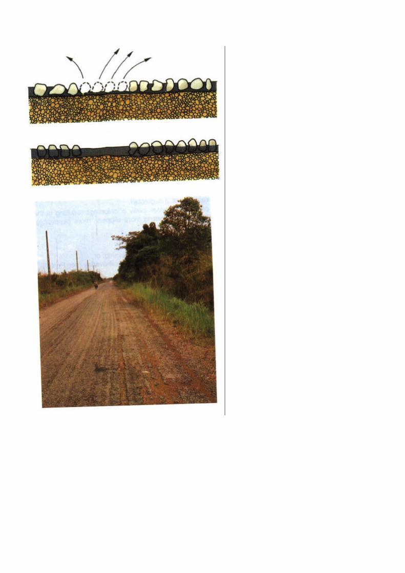

PART B - SURFACE DRESSING (mechanised)
DEFECT: STREAKING*
LocationParallel to the centre line and extending overappreciable lengths.
Main cause� faulty operation of the spraying equipment
applying the surface dressing, giving rise tostreaks of insufficient binder.
Development, if neglected- the surface will become more permeable and
potholes or deformation will probably occur.
Remedies� application of a surface dressing,� application of a thin bituminous overlay (see
Part D).
*See List of Terms, Volume I.


PART B - SURFACE DRESSING (mechanised)
DEFECT: DEFORMATION
LocationVarious forms of local settlement of the pavement,usually along the wheel tracks, or along the edges of theroad.
Main Causes� insufficient strength of the pavement structure or
foundation,� inadequate stability of the surface layer (bituminous
mixture).
Development, if neglected� rapid increase in the settlement during the rainy season
and a break up of the pavement if water penetrates thebase.
RemediesSlight subsidence:
� application of a surface dressing as apreventive measure.
Appreciable subsidence:
� patching (Page III - 71) followed by theapplication of a surface dressing or a thinoverlay (see Part D).
NOTE: A slurry seal (Part C) can be applied in place of a surfacedressing when the subsidence is not excessive.


PART B - SURFACE DRESSING (mechanised)
3. RESOURCES
3.1 PERSONNEL
� Working Force
� 1 foreman,� 1 overseer,� 1 spray bar operator,� 1 attendant for aggregate
trucks,� 2 - 4 chip spreading
labourers,� 2 traffic controllers.
� Plant Operators and Drivers
� 1 mechanical broom operator,� 1 bitumen distributor driver,� or 4 aggregate truck drivers,� 2 roller operators,� 1 loader operator (for the loading of
chippings),� 1 truck driver,� 1 light vehicle driver.


III - 107
PART B - SURFACE DRESSING (mechanised)
3.2 PLANT AND TOOLS
� 1 mechanical broom,
� 1 bitumen distributor of 5,000 to 8,000 litrescapacity, with working thermometer,
� 3 or 4 aggregate trucks each of 5 to 6 m 3
capacity and fitted with tailgate gritters*,
� 2 rubber tyred rollers with tyres inflated to apressure of 6 kg/cm 2,
� 1 wheeledloader,
� 1 lightvehicle,
� 1 tippertruck
NOTE: If a self propelled chipping spreader is available, theaggregate trucks will not require tailgate gritters.
See List of Terms, Volume1.


PART B - SURFACE DRESSING (mechanised)
� Test Equipment
� calibration tray and test equipment formeasuring bitumen rate of spread.
� Small Items of Equipment
� 2-4 shovels,� brooms,� 2 rakes,� 2 pickaxes,� 2 wheelbarrows.
� Tools and Supplies
� rolls of strong paper (at least 50 cm wide),� 1 drum of diesel oil to clean the spray bar and
tools,� a number of spare spray bar jets,� 1 box of tools for use in dismantling the spray
bar jets and adjusting the chippingequipment,
� oil drums cut along their axis to collectbitumen during testing of spray bar,
� box of rags,� paint brushes,� metal buckets,� chalk or paint for marking,� stringlines,� half drums for testing spray bar jets.


PART B - SURFACE DRESSING (mechanised)
3.3 MATERIALS
The materials required for surface dressingusually consist of:
� one or several types of aggregate"(chippings),
� a bituminous binder*.
� Aggregates
Aggregates are obtained from approvedsources and the material has usually beencrushed. It is normally delivered to the worksite as a uniformly graded material where:
d: is the size of the smallest particles inmillimetres,
D: is the size of the largest particles, again in
The most commonly employed d/D gradings areas follows:
4/6 - 6/10 - 10/14
Sometimes a "graded seal" is used by makingtwo applications of aggregate of two differentsizes, or one application of a continuouslygraded aggregate.
*See List of Terms, Volume 1.


PART B - SURFACE DRESSING (mechanised) l
Aggregates to be used for surface dressing must conform to thespecifications and:
� have a given grading (as specified on the work sheet) (a),
� be of a suitable shape, preferably cubical (b),
� be strong enough so that they will not crush under traffic, (c),
� be sufficiently clean. Dirty or dusty aggregate will not adhereto the bitumen, (d).
If aggregates are dusty they should be:
� washed, or
� lightly sprayed with diesel, creosote orkerosene before use (pretreating).
This will promote bonding with the bitumen. Thepretreating can be achieved by mixing at thestockpile, by spraying on a belt conveyor or byusing a concrete mixer.


III - 115
PART B - SURFACE DRESSING (mechanised)
Use is made of:
� a single uniformly graded aggregate in thecase of a single surface dressing (e), or
� two uniformly graded aggregates in the caseof a double surface dressing, or
� a single surface dressing with two layers ofchippings (f), or
� a single continuously graded aggregate in thecase of a "graded seal" (g),
NOTE:The grading classification of the aggregate and the shape,strength and cleanliness of the aggregate particles will be the subjects oflaboratory tests poor to making use of the material.


PART B - SURFACE DRESSING (mechanised)
� Bituminous Binders*
Different types of bituminous binder are available:
� penetration grade bitumens (a),� cut back bitumens (b),� bitumen emulsions (c).
These three different types of binder are classified in thelaboratory in terms of:
� the penetration in the case of the penetration gradebitumens (d),
� the viscosity in the case of the cut back bitumens (e),
� the bitumen content and breaking speed in the caseof the emulsions (f).
These classifications are determined by carrying out testsillustrated opposite.
* See List of Terms, Volume
NOTE. The type of border to be used is determined as a functionof:
� the road temperature� the climate (dry or wet weather)� the heating facilities available,� the type of aggregate to be used


PART B - SURFACE DRESSING (mechanised)
Successful surface dressing depends on thedegree to which the binder adheres to theaggregate (good bonding characteristics).
The binder and aggregates must be selectedaccording to the results of a laboratory study aimedat establishing the suitability of the aggregates andthe binder for surface dressing.
In some cases an additive may be mixed with thebinder to improve bonding.
If on site it is found that the binder does not adherewell to the aggregate (poor bonding characteristics),then it will be necessary to:
� stopwork,
� inform the responsible person
� collect samples of the binder and aggregate foruse in carrying out further laboratory tests.


PART B - SURFACE DRESSING (mechanise
3.4 SIGNS AND SAFETY EQUIPMENT
� Advance Warning Signs (a)
The following signs are to be placed on the shoulderfor both directions of traffic:
� 2 "Men Working" signs,� 2 "Road Narrows" signs, (one each
hand),� 2 "Loose Chippings" signs,� 2 "No Overtaking" signs,� 2 "Speed Limit" signs (50 km/hr).
� Site Protection Equipment(b)
The following signs are to be erected on theroad to define the boundary of the roadworks:
� 2 "Lane Closed" barriers with "End ofRoadworks" written on the reverse side,
� 100 traffic cones per kilometre length ofroadworks,
� 2 reversible "Stop/Go"signs.
NOTE: When the surface dressing is to be applied m one pass over thefull width of the road, it will be necessary to desert the traffic and tomake use of the warning and diversion signs shown opposite (c).


PART B - SURFACE DRESSING(mechanised
� End of Restriction Signs (d)
The following signs are to be placed on theshoulder for each direction of traffic:
� 2 "End of Restriction" signs.
� Safety Equipment (e)
Use is to be made of the following equipment forpersonnel and vehicles:
� yellow shoulder belts for each of the traffic controloperators located at the beginning and end of theroadworks, and all workmen,
� signs marked with alternate red and white diagonalstrips for mounting on the vehicles,
� if possible, a triangular sign fitted with three flashinglights for mounting on the roof of the light vehicle.
A fire extinguisher should be provided for each vehicleworking with or near heated bitumen.

TYPICAL WORKSHEET
SURFACE DRESSING
Worksheet No:……………..
District: . . . . . . . . .
Zone:.
Road No:.............. Section:
from km: . . . . . . . . Type of
Date: ..........
..................................................................Gang:
from: .......................... to:
to km: . . . . . . . . . . . in . . . . . . m width
Rates of spread:
1 st layer . . . . . . kg/m2
.............................................................................2nd layer ..............kg/m2
Type of aggregate: 1st layer . . . . . . . . . . . . . . . 2nd layer . . . . . . . . . . .
Rates of spread (I/m2): 1st layer . . . . . . . . . . .
Binder . . . . . . . . . . . t
Quantities required: Aggregate ......................m3 Of
Aggregate ..................................................m3 of
Stocks:
Binder: .................... t
Aggregate: ...............m3
................ ................m3 .....................................
. 2nd layer

III - 125
PART B - SURFACE DRESSING (mechanised)
4. MAINTENANCE METHODS
4.1 PRELIMINARY TASKS
To achieve successful results it is essential toproperly plan, prepare and organise surface
There are four preparationactivities:
1 Refer to the Work Sheet
This contains all the information needed to plan andorganise the work.


PART B - SURFACE DRESSING (mechanised)
2 EquipmentCheckOne week before work is to start, a check should bemade to ensure:
� that all items of equipment to be used are in goodcondition,
� that arrangements have been made for providingthe vehicles with fuel,
� that arrangements have been made for carryingout maintenance work on the equipment,
� that all personnel are available (Page III - 105),


III - 129
PART B - SURFACE DRESSING (mechanised)
� that all hand tools and traffic signs areavailable,
� that arrangements have been made for the supplyof the binder and aggregate, and that the qualityand quantity of these materials and the locationswhere they are to be stored are as specified on thework sheet,
� that all bitumen heating equipment andpumps are available.


III - 131
PART B - SURFACE DRESSING (mechanised)
3 Check that the Preparatory Work has been carriedout
The success of the surface dressing depends on theproper preparation of the existing surface. Thispreparation is carried out by the General Repairs gang.
A week before work is to start it is necessary to ensure:
� that all potholes have been repaired (see Part A),
� that the edges of the road have been repaired (see PartA),
� that the existing surface is clean and free of dirt, or otherdebris that would affect the bond of the new surfacedressing (clean if necessary).


PART B - SURFACE DRESSING (mechanised)
4 Organise the Work
The day before work starts, the foremanmust:� inspect the condition of the existing surface for
the last time to ensure that it is clean, that ithas been properly repaired and that the edgesof the road where they join onto the shoulderare properly defined,
� assess likelihood of goodweather,
� send the mechanical broom and the rollers to the site and locate them off the road, if possible, to protect both
the road users and the equipment.


PART B - SURFACE DRESSING (mechanised)
4.2 TEMPORARY SIGNPOSTING
Traffic signs conforming to the regulations mustbe correctly placed before starting any work. This isto ensure the safety:
� of the roadusers,
� of the personnel working on the site,
� of the vehicles and equipment to be used on the site.
The traffic signs must belocated:� ahead of the worksite (in both traffic directions)
to give advance warning of danger,
� along the length of the roadworks to protect thesite from traffic when it is not possible to build adiversion,
� at the end of the roadworks as an indication thatthere is no further restriction.


III - 137
PART B - SURFACE DRESSING (mechanised
Traffic signs will consist of:
� Ahead of the Roadworks (for both directions oftraffic), on the shoulder on the side of theapproaching traffic:
� "Men Working",� "Loose Chippings",� "Road Narrows",� "No Overtaking",� "Speed Limit" (50 km/hr).
� On the half-width of road where work istaking place, at each end of the works:
� 1 traffic barrier,� 1 man controlling successive flows of traffic in
alternate directions.
� Along the length of the roadworks:
� traffic cones.
On long works sections intermediate trafficcontrollers may be required to transfer "Stop/Go"instructions. Alternatively portable traffic lights orhand radio sets should be used.


III - 139
PART B - SURFACE DRESSING (mechanised)
� At the end of the roadworks (for both directions oftraffic).
� on the shoulder on the side of the departing traffican: "End of Speed Restriction" sign should be placed50 metres beyond the traffic barrier.


PART B - SURFACE DRESSING (mechanised)
4.3 EXECUTION OF THE WORK
A surface dressing is usually applied to half the width of
the road at a time. There are seven steps:
1. Sweep the complete road surface where thebinder is to be applied so that it is perfectly clean(a).
2. Mark out the road surface
A string-line is run along the edge of the carriagewaywhere work starts to ensure good alignment of theedge of the surface dressing (b).
3. Check and adjust the binder distributor
� Off the road:
� check the temperature of the binder (Refer to thechart on Page III - 143, or other guidelines).
� check that all the spray bar jets are operatingproperly (c). Use split oil drums to collect binder.


III -143
PART B - SURFACE DRESSING (mechanised)
Spraying temperatures forbinders
CUTBACKGRADES
(US ASPHALTINSTITUTE)
WHIRLINGSPRAY JETS
SLOT JETS
MIN°C
MAX°C
MIN°C
MAX°C
MC 30 50 60 40 50RC/MC 70 65 80 55 70RCIMC 250 95 115 80 90RC/MC 800 115 135 105 115RC/MC 3000 135 150 120 130PENETRATION GRADES400/500 160 170 140 150280/320 165 175 150 160180/200 170 190 155 16580/100 180 200 165 175
NOTE: Because of the inflammable nature of the solvent used in RC-type cutbacks, application temperatures for RC grades shouldbe restricted to the lower pails of the ranges given above.
Attention is also drawn to the need to extinguish flames andprohibit smoking when heating, pumping or spraying allcutbacks. Fire extinguishers should always be readily at hand.


III - 145
PART B - SURFACE DRESSING (mechanised)
� On the road:
� adjust the height "h" of the spray bar soeach point of the road is sprayed by binderfrom three separate jets,
� adjust the angle of the spray bar so that it isparallel to the road surface to obtain a goodtransverse distribution of the binder (d),
� adjust the width covered by the spray bar sothat 1/3 of the spray coming from the last jeton the spray bar overlaps the centre line ofthe road. This will ensure that the correctamount of binder will be deposited along thecentre of the road following the second passof the binder distributor (e).
� Carry out a rate of spread test for the bitumendistributor and provide a driver's chart (rate ofspread calibration).
� The second pass of the distributor on the other lanemust take place in the same direction.


PART B - SURFACE DRESSING (mechanised)
4 Place strips of strong paper in position toensure regular transverse joints at the beginningand end of each pass of the distributor.
The length "L" of each pass will be determined bythe number and capacity of the gritting lorries(see the typical values given in the table shownopposite).
5 Distribute the binder
The binder must only be applied to a completelydry surface (application of surface dressingduring the rainy season should therefore beavoided if possible).


PART B - SURFACE DRESSING (mechanised)
� position the distributor 10 to 15 metres from thebeginning of the surface that is to be treated andline it up with the marked outer edge of the road(f),
� advise the driver of the speed at which he is to
� check gates on the gritting lorries.
The distribution of the binder can now start providingthat the gritting lorries and the roller are ready forimmediate operation.
NOTE: This should be obtained from the driver's chart or alternativelyfrom the technician responsible.


III - 151
PART B - SURFACE DRESSING (mechanised)
The distributor jets are opened over the first strip ofpaper and closed over the strip at the end of the run(g).
A test of the rate of spread of bitumen should becarried out during the spraying operation.
No person or vehicle must be allowed onto thesurface sprayed with binder.
6 Distribute the Aggregate
The aggregate is distributed by driving thegritting trucks backwards (h) as follows:
� for the first half-width of the road, aggregateis spread over the binder leaving a 20 cm stripuncovered along the centre line (i),


PART B - SURFACE DRESSING (mechanised)
� for the second half-width of the road,aggregate is spread over the remaining width ofthe binder including the strip left un-covered.
Any adjustments to gritting width are made byopening or closing the appropriate tailgate flaps. Ifthe sprayed width is wider than the full truck grittingwidth, then a second gritting truck must followimmediately covering the rest of the binder.
The distribution of the chippings is startedimmediately after the application of the binder suchthat the distance between the binder distributor andthe gritting truck never exceeds 75 metres(preferably 30 metres).
Following the initial passage of the gritting truck,check that the complete surface has been coveredwith aggregate adding additional stone by hand ifnecessary, and then:
- use brooms to sweep back any aggregate thatmay have fallen onto the uncovered strip ofbinder or beyond the edge of the road (j),
- remove the strong paper laid at the beginningand end of the road section being treated (k).


PART B - SURFACE DRESSING (mechanised)
7 Roll the Dressing
Rolling is carried out using two rollers runningbackwards and forwards at a distance of at least 50metres from the gritting trucks at speeds of notmore than 8 km/hr. A number of passes (usually 5)of the rollers should be made over the completesurface.
When the rolling has been completed, providing itdoes not rain, the treated section of road is opened
To do this remove:
� the traffic barrier,� the traffic cones, using vehicle with headlights to
warn oncoming traffic and to protect workmen.
If traffic discipline is poor, convoy vehicles can beused to restrict speed for the first 2 hours.
IMPORTANT NOTE: At the end of the day, the surface dressing mustbe completed over the whole width of the road section.
All spraying equipment and tools must be thoroughly cleaned at theend of the day
Spray bars and nozzles should be flushed out with diesel.
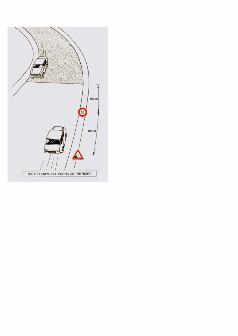

PART B - SURFACE DRESSING (mechanised)
4.4 COMPLETION AND REMOVAL OFTEMPORARY SIGNPOSTING
The road is left open to traffic at the end of the dayleaving the following signs in place at the ends ofthe treated section of road:
� "50 km/hr Speed Limit" sign,� "Loose Chippings" sign.


III - 159
PART B - SURFACE DRESSING(mechanised)
Finishing work is carried out during the weekfollowing the application of the surface dressing.
There are four activities required:
1 Place the traffic signs in position
The following traffic signs must be placed on theshoulder for both directions of traffic:
� "Men Working",� "Loose Chippings",� "No Overtaking",� "50 km/hr Speed
Limit",At the end of theroadworks,� "End of Speed Restriction".
If traffic is heavy, barriers, cones and traffic controlshould also be used.


III - 161
PART B - SURFACE DRESSING (mechanised)
2 Remove excess material as soon as possible
Excess chippings are removed by sweeping lightly byhand or with a mechanical broom. If left on the roadthey can damage vehicles and shatter windscreens.
3 Sand any areas where bleeding* has occurred
This is done by throwing coarse sand over the affectedareas (Page III - 51).
4 Remove the traffic signs
All traffic signs are removed on completing the finalwork.
*See List of Terms, Volume I.

TYPICAL WORK REPORT
SURFACE DRESSING
Work Report No: . . . . . . . . . . . . . . . . . Date: . . . . . . . . . . . . .
District:........... .......……………... Road No:.............……….
Section: . . . . . . . . . . . from km . . . . . . . . . to km . . . . . . . . .. .AGGREGATE STOCKPILE:
Location: . . . . . . . . . . . . . . . . . . . . . Haul Distance: . . . . . . .
SURFACE DRESSING:
Length: . . . . . . . . . . . .
WORKING TIME:from: ..........to: .......……………
Width:.......... ...... Area:………………..
Reasons for stoppages: . . . . .. . . .
WEATHER: Sunny Cloudy Rain 0
CHIPPINGS: 2 - 6mm / 4 - 6mm / 6 - 10mm / 10 - 14mm/ . .
Sources of Supply: . . . . . . . . . . . . . . . . . . . . . . . . . . . . . .
BINDER:
Type: .................. Viscosity:
Temperature: On arrival: .
......... Source: .
. . . . On emptying tank: . . . . . . . .
. . .WORK: Single seal / Double seal / Double Chipping Layer
Rate of Spread:Binder
Rate of Spread:Chippings
istlayer ....................2nd layer . . . . . . .
. . . 1 st layer . . . .
2ndlayer ....................(Separate manpower and equipment reports)COMMENTS:
Foreman: ..... ..... . ......... ......... .. . . . . . . Date: .. . . ............ . .
kg/m2
kg/m2
.... I/m2
. . I/m2

PART B - SURFACE DRESSING (mechanised)
4.5 WORK REPORT
The report must be filled in each day, detailing:
� the work carried out,
� the resources used.

III - 165
Part C
RESEALINGOPTIONS


III - 167
PART C - RESEALING OPTIONS
1. THE OPTIONS
Mechanised SURFACE DRESSING, described inPart B, is the most common type of treatment forthe PERIODIC MAINTENANCE reseal of abituminous pavement.
However, in certain circumstances the maintenanceneeds or available resources make other reseal
These optionsare:� LABOUR BASED SURFACE DRESSING
� FOG SPRAY*
� SLURRY SEAL*
Although the planning, procedures and safetyrequirements for these alternative treatments aresimilar to those for SURFACE DRESSING, this Partof the Handbook describes the principal differences.
For all common arrangements, such as traffic andsafety measures, refer to Part B.
*See List of Terms, Volume I.

PART C - RESEALING OPTION:
2. LABOUR BASED SURFACE DRESSING
In remote locations, for limited areas (such as shoulders)or when the specialist equipment is too expensive or is notavailable, surface dressing may be carried out by labourbased methods. The quality of work will be just as good asby mechanised methods if the works are properlymanaged.
Labour based surface dressing may be carried out usingbitumen emulsion or cut back bitumen. Materialsspecifications are the same as for mechanised surfacedressing.
The activities that need particular attention are:
� heating and temperature control of the bitumen when cut back bitumen is used.
� applying the bitumen at the correct rate of spread.
� complete coverage of the binder by the chippingsbefore the binder cools/breaks.
Up to 800 m2 per day of labour based surfacedressing can be achieved by one crew.


PART C - RESEALING OPTIONS
2.1 RESOURCES REQUIRED
� Personnel
� 1 foreman,� 1 bitumen heater operator,� 1 - 2 bitumen layers/spray lance operators,� squeegee operators,� drivers,� 2 traffic controllers,� 4-6 workmen.
� Plant and Tools
� 1 bitumen heater and towing/carrying vehicle,� 1 spray lance if available,� 1 truck for transporting aggregates,� 1 light vehicle for supervision and general duties,� 1 bitumen thermometer.


PART C - RESEALING OPTIONS
� Small Items of Equipment
� 2 wheel barrows,� shovels,� pickaxes,� 2 rakes,� brooms,� watering cans or other bitumen dispensers,� squeegees.
� Tools and Supplies
� 1 drum of diesel oil for use in cleaningthe tools and equipment,
� rags,� number of paint brushes,� 2 metal buckets,� chalk, or paint for marking,� stringlines.


PART C - RESEALING OPTIONS
2.2 HEATING THE BINDER(for cut back bitumen)
The binder will normally be delivered to site indrums. It should be decanted into a suitablebitumen heater which may be:
� towed,� static, or� vehicle mounted.
The heating may be carried out by:
� diesel burners,� wood,� coal or other fuel.
If necessary the specified amount of dieselshould be added to achieve the required viscosityof cutback.
Care must be taken to ensure that the materials:
� are well mixed,� are not overheated.
It is IMPORTANT to use a bitumen thermometer.
Bitumen application temperature ranges are shown on PageIII - 143.


PART C - RESEALING OPTIONS
2.3 USING BITUMEN EMULSION
If bitumen emulsion is used as the binder it will notnormally require heating*.
Emulsions consist of bitumen droplets mixed withwater in such a way that, when applied, the waterevaporates leaving the bitumen to "break" and toperform as a normal penetration grade. The choiceof emulsions should be made with regard to thetype of stone being used and reference to thesuppliers.
It should be noted that bitumen emulsions have alimited storage life. They should normally be usedwithin 6 months of purchase. Drums should berolled to mix the contents thoroughly before use.
*Cationic emulsion will need to be heated


PART C - RESEALING OPTIONS
2.4 SETTING OUT THE WORK
Robust containers, such as watering cans, must beused for carrying and applying the hot cut back oremulsion to the road surface. Each container musthave a fixed volume mark of known quantity.
The area of road to be covered by one containercan be calculated using the specified rate of spreadof binder.
To achieve the length of road to be covered by onecontainer divide the volume by the width of road tobe sealed and the rate of spread.
Using stringlines, mark the cleaned area of the roadsurface with chalk for each container of binder.


III - 181
PART C - RESEALING OPTIONS
2.5 APPLYING THE BINDER
When the binder has reached the requiredtemperature it is poured into the containers andcarefully carried to the placement site*.
Emulsions will normally be used directly from thedrums after thorough mixing.
The binder is poured over the marked area asevenly as possible. The squeegees are usedimmediately to ensure even distribution.
The personnel handling hot bitumen must besupplied with protective clothing and footwear.
If a hand lance is available this may be used toapply the binder. However practice and skill arerequired to evenly apply the correct amount ofbinder.
*Beware of the build up of cold bitumen on the inside of thecontainers.


III – 183
PART C - RESEALING OPTIONS
2.6 APPLYING THE CHIPPINGS
The chippings should be applied as soon aspossible after the binder is distributed.
This may be done by:
� spreading the chippings by hand from stockpilespreviously placed on the road shoulder,
� casting the chippings by hand from the rear of a truckreversing slowly over the previously laid stone.
Care must be taken to ensure as complete a coverage aspossible without over applying chippings.
Workmen can follow up with a wheel barrow to top upareas where the chippings are spread too thinly.
The finished work is carefully rolled with the emptychipping truck as soon as the chippings are spread.


PART C - RESEALING OPTIONS
3. FOG SPRAY
A fog spray is a very light film of binder which issprayed onto a "dry" or "hungry" road surface tobind together and hold in place stone particles thatotherwise would be picked off by traffic.
Typically a fog spray is used to help retainchippings on a new surface dressing that may bepoorly held for some reason, or to enrich thesurface of an old and lean bituminous surface.
The binder used is normally a bitumen emulsion,which should be sprayed at a rate of 0.7 to 0.9kg/m2 (for a 60 percent emulsion), to achieve aresidual bitumen application of 0.4 to 0.6 kg/m 2.
Where "pick up" of the binder by vehicle tyres islikely to occur, the surface may be blinded with alight sprinkling of fine sand or crusher dust.


PART C - RESEALING OPTION:
4. SLURRY SEAL
In this process a fine, graded, aggregate is mixed atambient temperature with water, dope (an additive)and a bitumen emulsion, having a relatively highbitumen content. Some cement is also usuallyadded.
The mixture is applied to the road surface as a free-flowing slurry in a layer 5 mm to 10 mm thick. Themixture penetrates and seals surface voids andcracks very effectively; hence the process isparticularly well suited to the maintenance of oldbitumen surfaces.
Slurry seals may not resist reflection cracking inasphalt concrete surfacing.
When the emulsion "breaks" an impermeablebitumenrich surface results. The skid resistance ofsuch a surface can be rather low and hence slurryseals are often used as a second treatment on topof a single surface dressing. In this way the tops ofthe chippings will penetrate through the slurry sealand provide skid resistance. The slurry holds thechippings very securely and provides a durable,impervious and non-skid surface.

Slurry seal machine; (diagrammatic)

PART C - RESEALING OPTIONS
The aggregates used in slurry seals are normallynot greater than 6 mm in size but somespecifications include material up to 10 mm in size.
Slurry seals can be made with simple, slowbreaking, (stable) anionic emulsions in a staticmixing plant (such as a cement mixer) and thenspread on the road by hand or by simple dragspreaders. However, the normal technique is to usemechanised mixer/spreader units which enablefaster breaking cationic emulsions to be used.
These units are self-propelled and have storagecapacity for the bitumen emulsion, the aggregate,the cement and water. One machine can spreadapproximately 8,000 m2 of slurry seal per day.
When spread the slurry needs little, if any,compaction and on a busy road, traffic compactionalone will suffice once the emulsion has "broken".On lightly trafficked roads a pneumatic-tyred rollershould be used. In heavy traffic, where the roadcannot be closed for long, chemical agents may beincorporated in the slurry to control the "break" ofthe emulsion so that traffic can pass over the newslurry seal within 20 to 30 minutes of laying.
Mechanised slurry sealing is normally carried out bya specialist contractor.
The Road Authority should set a specification forslurry seal mixing and laying.

Part D
THIN OVERLAYS


III - 193
PART D - THIN OVERLAYS
1. THE TASK
OVERLAYING is normally a PERIODICMAINTENANCE or IMPROVEMENT activity.
1.1 APPLICATION
� Thin overlays applied over large areas can beused to:
� fill small surface deformations which areuncomfortable and dangerous to traffic,
� improve insufficient surface texture whichis dangerous for traffic,
� seal permeable surfaces which allow waterto penetrate the base and causedeterioration.
� They are usually more durable than surfacedressings.
� Overlays are usually applied to important roadswith heavy traffic and high speeds.
� When deformation is severe, the overlay workmust be preceded by the levelling ofdepressions and ruts, and repairs to potholes(Volume III, Part A).
� This work may also be accompanied by therestoration of shoulders and ditches (seeVolume I).
� Overlays must be applied during dry weather.


III – 195
PART D - THIN OVERLAYS
� Thin overlays must NOT be applied to aseverely cracked pavement without a detailedpavement investigation.
� Thick overlays (more than 5 cm) which addsubstantially to the strength of the pavement,require detailed investigation and design, andare outside the scope of this Handbook.However many of the guidelines are alsoapplicable to thick overlays.
NOTE: Overlay works are normally carried out by contract


PART D - THIN OVERLAYS
1.2 DIFFERENT TYPES OF THIN OVERLAY
� Overlays always consist of hot plant mixed bitumencoated aggregate and a bituminous binder.
Thin overlay types are:
(Aggregate size):
0/50/6 to 0/120/6 to 0/12
bituminous mortarsbituminous macadamsbituminous concretes
� They are spread by a paving machine in a singlelayer of maximum thickness:
� cm for bituminous mortars,� cm for bituminous macadams and
bituminous (asphaltic) concretes.
� Plant mixes are sometimes known as asphalts*.
*See List of Terms, Volume 1.


PART D - THIN OVERLAYS
2. DEFECTS
Defects requiring thin overlay treatment generally involvefairly large areas.
These defects can concern:
� the surface:
� wear (glazing*, cracking*, streaking*)� surfacing failure (cracking),� excess binder (bleeding
� the pavement structure:
- minor deformation (0 - 10 mm).
*See List of Terms, Volume I.


PART D - THIN OVERLAYS
3. RESOURCES
3.1 PERSONNEL
� Site Work
� 1 foreman,� 1 overseer for traffic control,� 1 overseer for the works,� 1 spray bar operator,� 1 payer attendant,� 2 traffic controllers,� 2 labourers for spreading,� 2 labourers for finishing.
� Plant Operators and Drivers
� 1 mechanical broom operator,� 1 bitumen distributor driver,� 1 payer operator,� 1 steel wheel roller operator,� 1 rubber tyred roller operator,� 1 driver for each tipper truck,� 1 night watchman,� 1 light vehicle driver.


PART D-THIN OVERLAYS
3.2 PLANT AND TOOLS
� 1 mechanical broom,� 1 binder distributor with working thermometer,� 1 payer/finisher,� 1 rubber tyred roller,� 1 steel wheeled roller (6 to 8 tonnes),� tipper trucks as necessary to keep payer supplied,� 1 light vehicle,� bitumen thermometer for premix material.
� small items of equipment (see Part B, Page III - 109),� hand tools and supplies (see Part B, Page III -109).
� tarpaulins to cover premix material during transportto the site.
III - 203


PART D - THIN OVERLAYS
3.3 MATERIALS
It is important to be aware of the:
� materials used for producing the plant mix,
� different types of plant mix,
� binder content,
� materials required for the application.
III - 205


PART D - THIN OVERLAYS
MATERIALS USED FOR PRODUCING THE PLANT MIX
These are:
� aggregates constituting the "mineralframework",
� bituminousbinder.
Aggregates (fines, sands, stone)
� Fines (or fillers) (a) mineral powders from soundrock. A fraction of the fines can consist ofcement or lime in certain cases.
� Sands (b):
� fine (dune, sea, river or pit sand),� coarse (most often from crushing).
� Stone (c) crushed hard rock sieved to conform toa grading in the following range: retained on a 2, 4or 6 mm sieve and passing an 8, 10 or 12 mmsieve.
Bituminous binder
A penetration grade bitumen (d): usually one of80/100, 60/70 or 40/50. 60/70 bitumen is usuallypreferred however 80/100 is more commonlyavailable.
III - 207


PART D - THIN OVERLAYS
DIFFERENT TYPES OF PLANT MIX
There are three broad classes ofmixes:� bituminous mortars
� bituminous macadams
� bituminous concretes
(a)
(b)
(c)
Bituminous mortars consist of a mixture of:
� fines (or fillers),� one or more sands,� bituminous binder.
Bituminous macadams and bituminous concretecomprise in addition, one or more sizes of stone.
Bituminous concretes are surfacings of the highestquality and meeting the strictest specifications.
NOTES:
� The thickness of the overlay must not be less than 2.5 cm, andshould be at least 1.5 times the maximum stone size.
� Bituminous macadams may be either dense or open mixtures
III - 209


P =
PART D -THIN OVERLAYS
BINDER CONTENT
The binder content of the plant mix is given by
weight of bitumen x 100
total weight of mix
This varies for each mix type with:
§ the fines content,
§ the grading.
Binder contents are given below:
Type of Plant Mix Binder Content "p"� bituminous mortar (a) 6 - 10
� bituminous macadam: (b) dense 4 - 7 Open 4 - 5
� bituminous concrete: (b) 5 - 8

TACK COAT
BINDER CLASS(p.lll -117)
TYPICAL RATES OFSPREAD
CUT BACK 50/100 - 150/200BITUMEN 400/600 - 1001250- MEDIUMCURING
0.1 kg/m2- RAPID TOCURING 0.4 kg/m2COAL TAR RT4 TO RT9BITUMEN 65 TO 70EMULSION

PART D - THIN OVERLAYS
MATERIALS REQUIRED FOR THE APPLICATION
� Tack Coat(a)The binder to be employed may consist of:
� a rapid or medium cut back bitumen (hot),� a tar (hot),� a rapid breaking bitumen emulsion (hot or
cold)".
The amount of binder to be used depends on thecondition of the surface.
The main types of binder together with the averagerates of spread are listed in the table opposite.
� Plant Mix(b)
*Cationic emulsion will need to be heated.


III – 215
PART D - THIN OVERLAYS
3.4 SIGNS AND SAFETY EQUIPMENT
Apply the recommendations of Part B (Pages III - 121and III - 123) with the following amendment:
� Traffic Control Equipment (the "Loose Chippings" sign is not needed for this operation).

TYPICAL WORKSHEET
THINOVERLAYS
Worksheet No: . . . . . .
District: . . .
PREPARATORY WORK:
Potholes LI Depressions
............ ............ Date:
. . to km: . . . . . . width . . . . . . . m
Edge damage 0
TACK COAT:
Border: . . . . . . . . . . . . . . . . Rate of spread: . . . . . . . . . . . . . . . kg/m2
OVERLAY:
Binder: ..................................................
Aggregate:...............................................
Coverage: ......................................................................................kg/m2
Nominal thickness: . . . . . . . . . . . . . . . . . . . . . . . . . . . . . . . . . . . . . . cm
LOCATION OF MIXING PLANT:
Haul distance: . . . . . . . . . .
TRANSPORT: . . . . . . . . . . .
........ ....... time:
. ............ ....... trucks:

III - 217
PART D - THIN OVERLAYS
4. MAINTENANCE METHODS
It is essential to properly plan, prepare andorganise overlay activities to achieve successfulresults.
4.1 PRELIMINARY TASKS
There are four preparation activities:
1 Refer to the Work Sheet
This contains all the information needed to plan andorganise the work.


III - 219
PART D - THIN OVERLAYS
2 Equipment Check
One week before start of the work a checkshould be made to ensure:
� that all the equipment required is available andin good working order,
� that arrangements have been made for fuelfor the equipment, and its maintenance,
� that all personnel are available (Page III - 201),


III - 221
PART D-THIN OVERLAYS
� that hand tools and traffic signs areavailable,
� that there is sufficient transport for the premixed materials, to ensure a continuous layingoperation


PART D-THIN OVERLAY
3 Check that the preparatory work has been properly carried out
The success of the thin overlay depends on thepreparation of the existing surface by the routinemaintenance gang (see Part A).
One week before the overlay the following must bechecked:
� that all potholes have been repaired (see Part A),� that road edges have been repaired (see Part A).
� that the existing surface is clean and free of dirt, orother debris that would affect the bond of the newsurfacing (clean it if necessary).
III - 223


PART D - THIN OVERLAYS
4 Organise the Work
The day before work starts the foreman must:
� inspect the condition of the existing surface for the
last time to ensure that it is clean and has been
properly repaired.
� assess the likelihood of good weather.
� check with the person in charge of the mixingplant that he will be able to supply the site andcheck the timetable for the start and end of themixing operation.
� check the route that will be used by the supplytrucks between the mixing plant and the site andnote the probable time for the journey.
III - 225


PART D - THIN OVERLAYS
� send to the site:
� the mechanical broom,� the payer finisher,� the rubber tyred roller,� the steel wheeled roller (and ensure a
water supply for it),� signs and safety equipment.
� arrange a night watchman for the equipment thatis left overnight and ensure that correct trafficsigns are erected to safeguard any equipmentleft on the road. Equipment can be left:
� off the road (a) - this is preferable as it issafer for both the road users and theequipment,
� at the roadside (b), ONLY if properwarning signs are provided (Page III -229).
III - 227
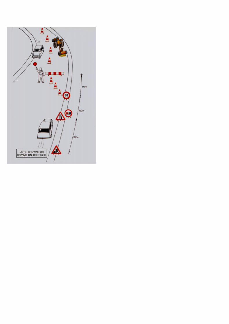

PART D-THIN OVERLAYS
4.2 TEMPORARY SIGNPOSTING
Traffic signs conforming to the regulations mustbe correctly placed before starting any work. This isto ensure the safety:
� of the roadusers,
� of the personnel working on the site,
� of the vehicles and equipment to be used on
The traffic signs must be located:
� ahead of the worksite (in both traffic directions)to give advance warning of danger,
� along the length of the roadworks to protect thesite from traffic when it is not possible to build adiversion,
� at the end of the roadworks as an indication thatthere is no further restriction.
Details of signs to be used and their locations aregiven in Part B, Pages III - 136 to 139. The "LooseChippings" signs are not required.
Flashing warning lights must be used if any part ofthe carriageway is closed off overnight.
III - 229


III - 231
PART D - THIN OVERLAYS
4.3 EXECUTION OF THE WORK
Overlays are generally laid over half the width of thecarriageway at a time.
There are eight steps:
1 Sweep the Surface
So that it is perfectly clean before laying the tackcoat.
2 Mark the Carriageway
A stringline is run along the edge of the carriagewaywhere work starts to ensure good alignment of theedge of the tack coat.


PART D-THIN OVERLAYS
3 Apply the Tack Coat
Making sure that the carriageway is dry, use thedistributor to spray half the width of the roadobserving all the precautions and provisionsdescribed on Pages III - 141 to 151.
Working from the rate of spread specified in thework sheet, inform the distributor driver of thespeed to be observed.
If a vehicle mounted bitumen distributor is notavailable the tack coat may be applied by hand asdescribed in Part C.
NOTE: The overlay material should not be placed too soon after thetack coat, as this will prevent the break of the emulsion orevaporation of the cutting agent in the cut back.
Traffic must not be allowed to dove on the tack coat.
III - 233
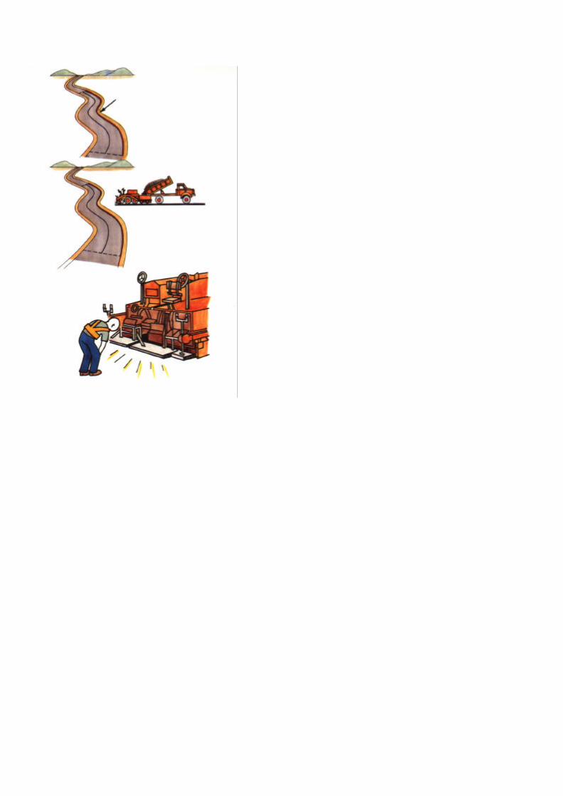

PART D - THIN OVERLAYS
4 Set up the guide system for the paver
The payer works with its adjusting screws set sothat the material can be placed in a layer ofconstant thickness.
It follows the stringline at the edge of the first half ofthe carriageway.
5 Prepare the equipment
The payer is set up to spread the plant mix overhalf the width of the carriageway.
The paver finisher:
Check the screed plate* to ensure it is clean toavoid defects in the surfacing. It must also beheated so that the material does not stick at thestart of spreading,
*See List of Terms, Volume I.
III - 235


PART D-THIN OVERLAYS
adjust the height of the screed plate by placingspacer blocks of thickness "e",
ensure that the hopper* of the payer is clean, dryand contains no cold material.
6 Placing the mix
In the case of rain, work must be stopped.
When the tipper trucks are backing onto the paver,care must be taken that they do not bump it,
*See List of Terms, Volume1.
III - 237
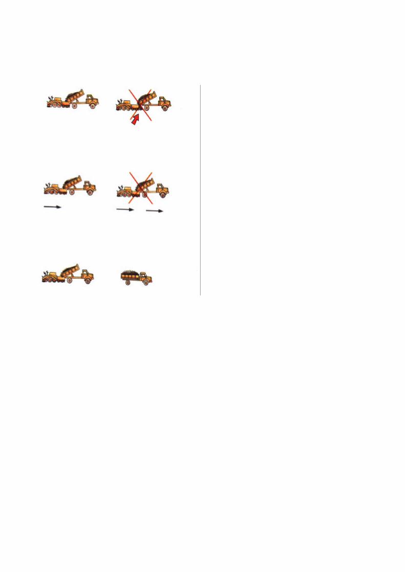

PART D - THIN OVERLAYS
ensure that the material is not spilled whilst thehopper is being filled,
place the truck's gear lever in neutral so that it canbe pushed by the payer until its body is empty,
ensure that in addition to the tipper truck supplyingthe payer, the next truck is waiting so that the payercan work continuously.
When an emulsion tack coat is used the mix mustnot be laid before the emulsion breaks.
III - 239

BINDER (°C)MINIMUM
PLACING TEMPERATUREBITUMEN 80/100 125BITUMEN 60/70 130BITUMEN 40/50 135

III - 241
PART D - THIN OVERLAYS
The temperature of mix:
The table opposite shows the minimum temperature ofthe mix (in the hopper) when it is laid.
Check mat thickness:
Check the thickness of the uncompacted matregularly with a probe and adjust the payer screedplates if necessary.
7 Compaction
Initial compaction is carried out with the rubbertyred roller (see Note Page III - 247). Using thismachine it is important to:
� check that the tyres are clean to avoid pickingup the asphalt from the surface (a),
� check the tyre pressures which must all be thesame and equal to 6 kg/cm2 when warm (b).


PART D - THIN OVERLAYS
For good compaction, the roller must:
� work as close to the payer as possible,
� be operated with its driven wheels closest to thepaver.
Make parallel passes beginning:
� for the first half of the carriageway at the edge (a),
� for the second half of the carriageway at the centreline (b).
Each compacted strip must partially overlap thepreceding one.
III - 243
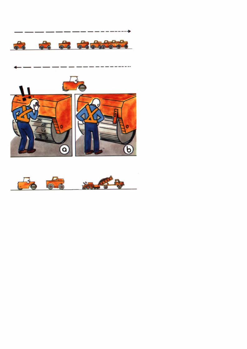

PART D - THIN OVERLAYS
At the end of a pass, speed is gradually reduced sothat the roller can reverse without jerking.
The second stage of compaction, is carried out with a6-8 tonne steel wheel roller (see Note Page III - 247).When using this machine:
� check that the rollers are clean to avoid marking thesurface (a),
� Insure that the spray system contains water and isin working order (b).
For good compaction, the roller must work:
� as close as possible to the rubber tyred roller,
III - 245


PART D - THIN OVERLAYS
� make parallel passes beginning:
for the first half of the carriageway at the edge (a),for the second half of the carriageway at the centreline (b).
At the end of each pass, speed is gradually reducedso that the roller can reverse without jerking.
Compaction must be completed before the materialcools too much.
NOTE: For each roller, the number of passes needed depends on thetype of material and the thickness of the layer. the number willbe determined by the engineer.
However all traces left by the rubber tyred roller must beremoved by the steel wheel roller.
Compaction trials should be carved out at the start of eachoverlay job.
III- 247
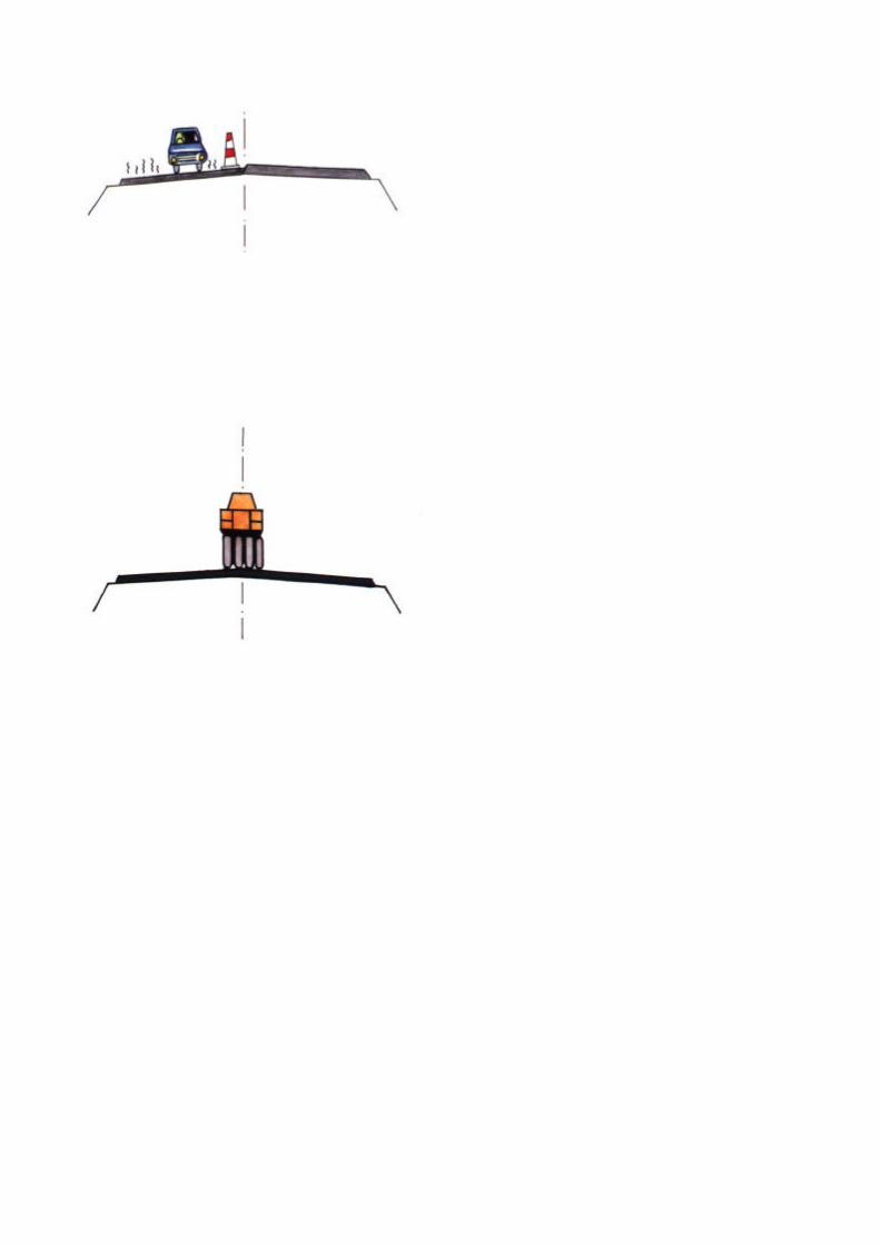

PART D - THIN OVERLAYS
8 Jointing
Joints should be made with care. A joint willaffect:
� the impermeability of the surface,� the durability of the overlay,� the finished appearance and roughness
of the road.
� The longitudinal joint
The correct procedure is asfollows:
� spread the material on the second half of thecarriageway while the material on the first half isstill hot,
� rake back in a straight line any excessmaterial spilled on the first half of the roadwhen laying material on the second half,
� compact the second half of thecarriageway covering the whole joint area.
III - 249


III - 251
PART D-THIN OVERLAYS
� The transverse joint*
The correct procedure is asfollows:
� remove a strip of compacted materialabout 1 metre wide with a neat verticalcut,
� before restarting work, place a block ofequal thickness to the amount ofcompaction settlement between thescreed plate and the compacted surface,
� compact the joint over a length of 30-40cm with the steel wheeled roller, workingbackwards.
9 Checks
� the transverse slope is checked using astraight edge and spirit level,
� the other material tests should be carriedout by the laboratory technicians.
* See List of Terms, Volume I.


PART D - THIN OVERLAYS
4.4 COMPLETION AND REMOVAL OFTEMPORARY SIGNS
As soon as the overlay has been completed.
There are two activities required:
1 Clean the work area
Each day before moving the traffic signs, it isnecessary to remove all excess material left overafter making the transverse joints.
2 Provide Ramps
Where the overlay will be used by traffic betweenworkdays, temporary ramps must be provided atthe end of each day's work. This is done bytapering out the overlay mat over a distance of10-20 cm. These ramps must be cut back to atransverse joint (see Page III -250) before workrestarts.
At the completion of the works, the overlay must besmoothly run into the existing road surface byexcavating the existing surface and replacing it with
III - 253


PART D - THIN OVERLAYS
� At the end of each day, the road is opened totraffic, but the following signs must be retained atthe ends of the new section:
� "Men Working" sign,� "50 km/hr Speed Limit" sign,� "End of Restriction" sign.
� When all work has finished, the road is opened totraffic without restriction.
All the signs are then removed in the following order:
� the traffic barriers,
� the traffic cones, using vehicle with headlights to warn oncoming traffic and to protect workmen,
� the two "End of Restriction" signs,
� the two "Speed Limit" signs,
� the two "Road Narrows" signs,
� the two "No Overtaking" signs,
� the two "Men Working" signs.
III - 255

TYPICAL WORK REPORT
THIN OVERLAYS
Work Report No: . . . . . . . . . . . . . . . .
District: . . . . . .
Date: .....................
............... ............................................Road No:
.tokm:....................
TACK COAT:
Binder: ..................................................
Total Area: . . . . . . . . . . . . . . . m x . . . . . . . . . . . m = . . . . .Quantity used: . . . . . . . . . . . . . . . . . . . . . . . . . . . . . . .
Rate of spread:
PLANT MIX:
Type: ...........
Total area: . . . . . . . . . . . . . . . m x . . . . . . . . . . . m = . . . . .
Quantity used: ......................................
Rate of spread:
WEATHER: Sunny 0 Cloudy El Rain El
(Separate manpower and equipment reports)
COMMENTS:
Foreman: ...................... .........................Date: .....................
.. . m2
tonnes
kg/m2
... m2
tonnes
kg/m2

PART D - THIN OVERLAYS
4.5 WORK REPORT
The report must be filled in each day by the
foreman detailing:
§ the work carried out,
§ the resources used.
III - 257

Notes and Sketches
III - 259

User of this Handbook:
NAME……………………………………………
ADDRESS………………………………………
……………………………………………………
……………………………………………………
……………………………………………………
DATE……………………………………………
III - 260

III - 261
ACKNOW LEDGEMENTS
The contents of this handbook draw on many sources,past and present, and it would be impossible toacknowledge them all individually. Much of thematerial is an updating of the UN/ECA MaintenanceHandbook for Africa, compiled by experts fromFrance, Germany and the United Kingdom, andpublished in 1982. Its three volumes encapsulated thebroad experience of highway engineers, maintenancemanagers, consultants and researchers from manydifferent countries.
The present revision was undertaken by Mr R.C. Pettsof Intech Associates, in close association with theOverseas Centre of the Transport ResearchLaboratory. The work was funded by the UK OverseasDevelopment Administration and supported andguided by a subcommittee drawn from the PIARCCommittee on Technology Transfer and Development(C3). It benefited from the collective wisdom of thatcommittee and the countries represented within it.These included Australia, Algeria, Belgium, Brazil,Burkino Faso, France, Germany, India, Italy, Morocco,Poland, Portugal, Senegal, Spain, Turkey, the UnitedStates of America, the United Kingdom and the WorldBank.
On behalf of the subcommittee I would like to recordour sincere thanks to all those who contributed, inwhatever way, to the production of this second versionof the Maintenance Handbook and to making it morevaluable to a wider international audience. I am sure itwill fulfil its intended purpose of strengthening thecapabilities of maintenance workforces and givingthem a stronger sense of professional pride in the vitalwork they are doing.

ACKNOWLEDGEMENTS continued
Any revision of this kind is an ongoing process, andcomments or suggestions for further improvementsshould be made known to the PIARC Central Officeat 27 rue Guenegaud, 75006, PARIS, France.Fax: +33 (1) 46 33 84 60.
J. Stuart YerrelChairman, Subcommittee C3-6d
III - 262

WHAT IS PIARC?
Founded in 1909 following the 1St International RoadCongress held m Pans in 1908, the PermanentInternational Association of Road Congresses (PIARC) isthe oldest of the international associations concernedwith roads and road engineering.
The general aim of the Association is to improveinternational cooperation and to foster progress in.
� the formulation of road transport policies,� the planning, construction, improvement and
maintenance of roads,� the operation and management of road systems,
within the context of wider policies towards transport.
To achieve these aims PIARC:
� organises a World Road Congress every four yearsand various technically oriented events,
� creates and co-ordinates Committees,� publishes a number of documents including a
periodical bulletin.
It is assisted in its task by National Committees. PIARC isa non political and non-profit association.
It was granted consultative status, category II, to theEconomic and Social Council of the United Nations m1970. The official languages of PIARC are French andEnglish
There are several categories of members: Governments,regional authorities, public bodies, collective members andindividual members.
As of 1 January 1994, PIARC has 72 memberGovernments and 2,100 members m 100 countries.
PIARC has strong links with several regional organisationsand is in favour of networking between countries dealingwith similar questions. PIARC may help to create and/ordevelop such networks.
III - 263

PIARC Committees and Working Groups are composedof engineers and experts appointed by member countriesThey act on a continuous basis between each Congressand participate m international meetings dealing withsubjects within their competence.
On average they hold two plenary meetings a year. As of1 January 1994, Committees and Working Groups gatherapproximately 700 engineers and experts from 40countries.
Thirteen Committees and four Working Groups are active(period 1991 -1995).
� COMMITTEESC1 - Technical Committee on Surface CharacteristicsC3- Committee on Technological Exchanges and DevelopmentC4- Committee on Interurban RoadsC5 - Committee on Road TunnelsC6- Committee on Road ManagementC7- Technical Committee on Concrete RoadsC8 - Technical Committee on Flexible RoadsC9 - Economic and Finance CommitteeC10 - Committee on Urban AreasC11 - Committee on Road BudgesC12 - Technical Committee on Earthworks, Drainage, SubgradeC13 - Committee on Road SafetyC14 - Committee on the Environment
� WORKING GROUPS
G1- PIARC Winter Road CongressG2- Natural Disaster ReductionG3- Modern Traffic Control and ManagementG4- Heavy Freight Vehicle Issues
� PIARC PUBLICATIONS - Committees and WorkingGroups publish synthetic documents, recommendationsand state of the art. These documents, intended fordecision makers, design and field engineers andresearchers, are based on wide international consensus.

CONGRESS DOCUMENTS - The documentspublished on the occasion of World Road Congressesare an invaluable source of information and expertsagree on the fact that they are most interesting andunique.
PERIODICAL BULLETIN "Routes/Roads" - TheAssociation Bulletin was issued for the first time in1911. It features comprehensive files on road mattersin various countries, articles written by members ofCommittees and Working Groups and news of interestto the world road community. Its issues of a hundredpages are published three to four times a year.
TECHNICAL DICTIONARY OF ROAD TERMS ANDLEXICON -The first edition of the DICTIONARY wasissued in 1931. The sixth edition (French/English) waspublished in 1990. The Dictionary is published with thefinancial support of UNESCO and is translated intoeighteen languages: Arabic, Chinese, Croatian,Czech, Danish, Dutch, German, Greek, Hungarian,Italian, Japanese, Lithuanian, Polish, Portuguese,Romanian, Russian, Spanish and Slovak. TheLexicon contains over 12,000 expressions in Englishand French and is also available on computer disk.
All these documents are published in French andEnglish. PIARC publications catalogue is free ofcharge and can be ordered through:
ANRTP32, rue du March commun
Centre de Gros - Case postale 122044082 NANTES Cedex 03 (FRANCE)
Fax: +33 40 50 13 64
III - 265

WHERE TO ORDER THE HANDBOOK
The English version of
Volume I: Maintenance of Roadside Areas and
Drainage
Volume II: Maintenance of Unpaved Roads
Volume III: Maintenance of Paved Roads
Volume IV: Maintenance of Structures and Traffic
Control Devices
may be ordered from:
Transport Research LaboratoryCrowthorne, Berkshire RG11 6AUUnited Kingdom
The Road Maintenance Handbook is also beingpublished in French, Spanish and Portuguese. Otherlanguages are under consideration. For more details,please contact PIARC Central Office - 27 RueGuenegaud, 75006, PARIS, France.Fax: +33 (1) 46 33 84 60.
Panted by:- Borough Press (Wiltshire) Ltd, SN2 6YW, UK
III - 266


INTERNATIONALROAD MAINTENANCE
HANDBOOK
PRACTICAL GUIDELINES FOR RURALROAD MAINTENANCE
Volume IV of IV
Structures andTraffic Control Devices
Financed and coordinated by

Revised by R C Petts of Intech Associates, UKwith the financial support of ODA
under assignment to
TRANSPORT RESEARCH LABORATORY, UK
as a development of the UN ECA handbooks preparedby joint cooperation of the governments of FRANCE, GERMANY
and the UNITED KINGDOM and first published in 1982.
© WORLD COPYRIGHT RESERVED 1994Extracts from the text may be reproduced
provided the source is acknowledged as follows:
PIARC Road Maintenance Handbook
English version published byTransport Research Laboratory, UK
ISBN for complete set of 4 Volumes: 0 9521860 12 JSBNfor Volume IV: 0 9521860 55

CONTENTS
FOREWORD…………………………………………………… i
INTRODUCTION………………………………………………. vi
Part A – BRIDGES……………………………………………. 1
1. THE TASK…………………………………………………… 31.1 OBJECTIVE 31.2 ACTIVITIES 5
2. DEFECTS…………………………………………………… 72.1 LIST OF DEFECTS 7
3. RESOURCES……………………………………………… 193.1 PERSONNEL 193.2 PLANT AND TOOLS 213.3 MATERIALS 253.4 SIGNS AND SAFETY EQUIPMENT 27
4. MAINTENANCE METHOD………………………………. 314.1 PRELIMINARY TASKS 314.2 SAFETY MEASURES 334.3 TEMPORARY SIGNPOSTING 354.4 EXECUTION OF THE WORK 394.5 COMPLETION AND REMOVAL
OF TEMPORARY SIGNS 774.6 WORK REPORT 79
IV - iv

IV - v
CONTENTS CONTINUED
Part B - TRAFFIC CONTROL DEVICES……………...81
1. THE TASK…………………………………………….. 831.1 OBJECTIVE 851.2 ACTIVITIES 85
2. DEFECTS……………………………………………… 872.1 LIST OF DEFECTS 87
3. RESOURCES…………………………………………. 993.1 PERSONNEL 993.2 PLANT AND TOOLS 993.3 MATERIALS 1013.4 SIGNS AND SAFETY EQUIPMENT 103
4. MAINTENANCE METHOD…………………………. 1074.1 PRELIMINARY TASKS 1074.2 TEMPORARY SIGNPOSTING 1094.3 EXECUTION OF THE WORK 1114.4 COMPLETION AND REMOVAL
OF TEMPORARY SIGNS 1354.5 WORK REPORT 1374.6 STORING AND TRANSPORTATION 139
5. REGULATORY SIGNS………………………………143
6. STANDARD TEMPORARY SIGNS……………….. 145

IV - i
FOREWORD
The road transport network of any country plays a vital rolein its economy, and the physical condition of itsinfrastructure is critical. Without adequate and timelymaintenance, highways and rural roads alike inexorablydeteriorate, leading to higher vehicle operating costs,increased numbers of accidents, and reduced reliability oftransport services. When repair work can no longer bedelayed it will often involve extensive rehabilitation, andeven reconstruction, costing many times more than simplermaintenance treatment carried out earlier. The need toprotect the existing network and keep it in good condition isparamount, often taking precedence over new investment.
PIARC has been in the forefront in promoting this messageand in drawing attention to the dangers of neglect. Thematter has become increasingly important in recent yearsfor all the highways of the world, but especially so for thosein developing countries where there is constant pressure onslender budgets and, in many, an urgent need to cater forgrowing traffic loads and volumes.
In the late 1970's, the aid ministries of France, the FederalRepublic of Germany and the United Kingdom joined forcesto produce a "Road Maintenance Handbook" formaintenance foremen and workers in Africa. Published in1982 under the auspices of the Economic Commission forAfrica, the three volumes - in French and English - soonbecame widely known and used. By the end of the decadetheir use had spread far beyond Africa, and theirstraightforward instructions were being used for trainingpurposes as well as for

IV - - iii
FOREWORD continued
On-the-job guidance in many countries. The need to reprintprovided the opportunity to review the contents in the light ofexperience and make them more suitable for the wideraudience now commanded. PIARC's Committee onTechnology Transfer and Development, formerly theCommittee on Roads in Developing Regions, undertook tohelp with this review, which was generously funded by theUK Overseas Development Administration. A sub-committee was established, embracing the three originaldonor countries, other developed and developing countries,and the World Bank. Although much of the original text hasbeen retained, the new handbooks incorporate moreinformation on labour and tractor-based techniques, and onthe development of manpower management and the all-important question of safety at work. The range ofmaintenance problems addressed has been extended tostrengthen their international appeal.
The past ten years have seen major reforms in the generalthrust of maintenance policy and in its organisation,management and execution. These changes will continue,and PIARC will play its part along with other institutions inencouraging the process and pressing for further progress.Only a full appreciation of maintenance at the highest levelsof policy-making and financial planning can ensure success.But these handbooks have a humbler task-to ensure thatthe men and women at the operational level are suitablyskilled and trained and are using the appropriate tools andtechniques, and have interest and motivation in their work.

FOREWORD continued
PIARC has been proud to nurture this project to the pointwhere the new handbooks are available, but its involvementwill reach far beyond that. It will provide the necessaryinternational framework within which the handbooks can betranslated and printed in many languages. Its worldwidemembership of key figures in the national provision andmanagement of highways will assist with theirdissemination, ensuring that they find their way into themost appropriate hands in both the public and privatesectors. Collectively, these hands will play a fundamentalpart in sustaining the vital asset which our roadwaynetworks truly represent.
Victor J Mahbub,President of PIARC.
IV - iii

INTRODUCTION
THE HANDBOOK
This is a guide for the maintenance foreman orsupervisor assigned to bitumen or unpaved roads intropical and moderate climates. The objective of theHANDBOOK is to assist him in all aspects of his workwhether carried out by direct labour or by contract. Itspocket format enables the volume relevant to the day's workto be easily carried and consulted on site. The HANDBOOKshould be his ready reference book. The text is concise andwell illustrated. A quick reference should be all that isnecessary.
This HANDBOOK does not include a course of study ordiscuss underlying causes of defects. Inspections, materialsources, specifications and testing are also outside itsscope. Furthermore it is sufficient here to remind theforeman that his plant and vehicles should be wellmaintained without telling him how to do it.
Even though the HANDBOOK is intended for use by themaintenance foreman, it will also be useful reading for theengineer or senior supervisor. This will make him moreconscious of his duties towards the foreman and enable himto ensure that the maximum benefit is obtained from theHANDBOOK. Each supervisor must understand hisresponsibility and the part he has to play.
The HANDBOOK can also be used in training centres. Withthe assistance of country-specific supplementaryinformation, photographic slides, models, and othersupporting material, it will be a valuable tool for the trainerand can be distributed to students.
IV - vi

VI - vii
Road maintenance requires a range of organisational andtechnical skills and the work on roads in use by trafficmakes the work potentially hazardous to both the workmenand road users.
It is therefore essential that appropriate formal and on-the-job training is given to each category of personnel involvedin road maintenance activities to achieve efficient and safeoperations.
The foreman usually has an important role in the initial andongoing training of personnel.
Roads are an enormous national investment and requiremaintenance to keep them in a satisfactory condition andensure safe passage at an appropriate speed and with lowroad user costs.
Late or insufficient maintenance will increase the ultimaterepair costs and raise road user costs and inconvenience,and reduce safety.
Road Maintenance is therefore an essential function andshould be carried out on a timely basis.
There is a diversity of maintenance activities, the class andtype of the road, the cross section to be maintained, thedefects recognised, and the resources available. Howeverthe general methods proposed here for each activity (withsome exceptions) are given under the following headings:
- The task- Defects- Resources- Maintenance method

IV - viii
Where appropriate options are shown for carrying out thework by:
i) Heavy Equipment,ii) Tractor based methods, oriii) Labour based methods.
The decision on which method to be used should be madeby the engineer or senior supervisor based onconsiderations of resources available, cost, policy etc.
Maintenance operations are usually grouped in eachcountry according to planning, organisational and fundingarrangements. They can normally be categorised as eitherROUTINE or PERIODIC.
For the purposes of this HANDBOOK the following groupingis used.
ROUTINE: Operations required to be carried out onceor more per year on a section of road.These operations are typically small scale orsimple, but widely dispersed, and requireskilled or un-skilled manpower. The need forthese can, to a degree, be estimated andplanned and can sometimes be carried outon a regular basis.
PERIODIC: Operations that are occasionally required ona section of road after a period of a numberof years. They are normally large scale andrequire specialist equipment and skilledresources. These operations are costly andrequire specific identification and planning.In this

handbook PERIODIC also includes certainimprovement works such as thin bituminousoverlays.
From time to time urgent or emergency works of any naturemay be required and these are dealt with as the needarises.
The HANDBOOK consists of 4 separate volumes:
VOLUME I -MAINTENANCE OF ROADSIDE AREASAND DRAINAGE
PART A - List of TermsPART B - Works Management and SafetyPART C - Roadside AreasPART D - DrainageGeneral Index
VOLUME II - MAINTENANCE OF UNPAVED ROADSPART A - GradingPART B - Labour Based ReshapingPART C - DraggingPART D - PatchingPART E - Regravelling (Mechanised)PART F - Regravelling (Labour and Tractors)
VOLUME 111- MAINTENANCE OF PAVED ROADSPART A - General RepairsPART B - Surface Dressing (Mechanised)PART C - Resealing OptionsPART D - Thin Overlays
IV - ix

VOLUME IV - MAINTENANCE OF STRUCTURESAND TRAFFIC CONTROL DEVICES
PART A - BridgesPART B - Traffic Control Devices
VOLUME IV
This volume describes the maintenance of bridges (Part A),and traffic control devices (Part B).
The objective of bridge maintenance is to keep thestructures in sound condition and safe for traffic.
Where a bridge spans a watercourse, the water must flowfreely at all flood levels without damaging the bridge or thewaterway.
The objective of traffic control device maintenance is to keepall signs, guide posts, markings and barriers in a goodcondition so that they fulfil their function. This will keep roadusers informed and help to make their travel as safe aspossible.
PART A - BRIDGES
Routine and Periodic Maintenance activities are describedwhich can be carried out by a gang without specialist skillsor equipment. Major structural repairs are beyond the scopeof this handbook and require specific skills for identificationand remedy.
IV - x

IV - xi
PART B - TRAFFIC CONTROL DEVICES
The necessary activities for cleaning, repair andreplacement of traffic control devices are described.Details of the standard temporary signs required for roadmaintenance works are provided.
NOTE: In many countries women carry out roadmaintenance tasks and supervisory duties. The use of maledescriptions and diagrams in this handbook is forconvenience only. The guidelines are applicable whetherthe work is carried out or supervised by men or women.

IV - 1
Part A
BRIDGES


PART A - BRIDGES
1. THE TASK
The task is to carry out:
� Routine* maintenance activities
and when necessary
� Periodic* maintenance activities (major repairs andimprovements).
1.1 OBJECTIVE
The object is to keep bridges* in sound structural conditionand safe for traffic.
Where a bridge spans a watercourse, the water must flowfreely at all flood levels without damaging the bridge or thewaterway.
*See List of Terms, Volume 1.
IV - 3


PART A - BRIDGES
1.2 ACTIVITIES
Routine* Activities
CLEANING/CLEARING
MINOR REPAIRS (STRUCTURAL)
� Repair of loose/missing connectors and fixings
� Replace damaged planks
� Painting
� Wood preservation
� Pointing masonry.
MINOR REPAIRS (SAFETY)
Repair barriers and safety features
Periodic *Activities.
MAJOR REPAIRS
� Random stone filling
� Retaining wall
� Riverbed scour* apron
� Gabions*.
*See List of Terms, Volume I.
IV - 5


PART A - BRIDGES
2. DEFECTS
Defects in bridges should be detected early and repairedpromptly. If they are neglected the resulting damage willusually require more extensive repairs or even lead to thecollapse of the structure.
2.1 LIST OF DEFECTS
In order to properly remedy a bridge defect, its cause mustbe assessed. Only when the cause is known, is it possible tosuccessfully cure the problem.
On the following pages commonly occurring defects areshown. Their probable causes are given together with asuggested maintenance activity. In addition the results ofneglected repair are mentioned:
� Defect
� Main causes of the defect
� Development: consequences if maintenance is not rapidlycarried out,
� Remedies: usual repair treatments.
IV - 7
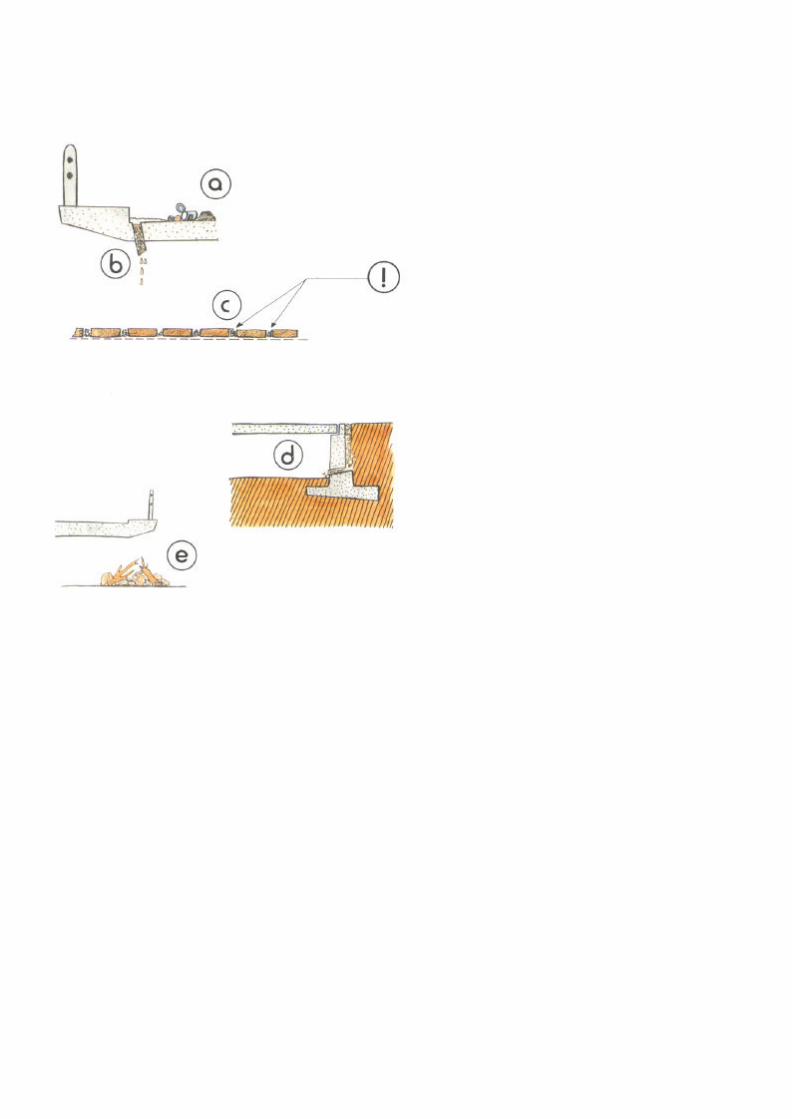
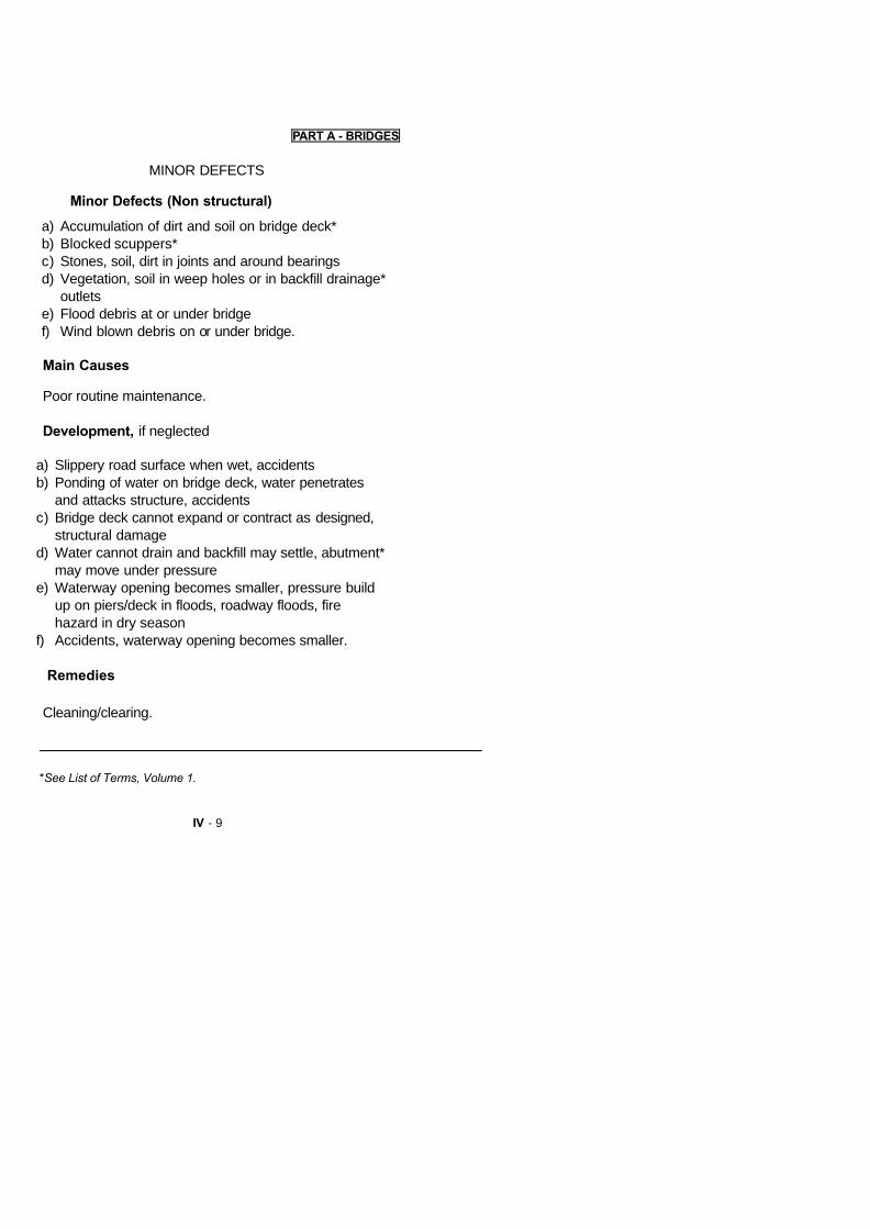
IV - 9
PART A - BRIDGES
MINOR DEFECTS
� Minor Defects (Non structural)
a) Accumulation of dirt and soil on bridge deck*b) Blocked scuppers*c) Stones, soil, dirt in joints and around bearingsd) Vegetation, soil in weep holes or in backfill drainage*
outletse) Flood debris at or under bridgef) Wind blown debris on or under bridge.
Main Causes
Poor routine maintenance.
Development, if neglected
a) Slippery road surface when wet, accidentsb) Ponding of water on bridge deck, water penetrates
and attacks structure, accidentsc) Bridge deck cannot expand or contract as designed,
structural damaged) Water cannot drain and backfill may settle, abutment*
may move under pressuree) Waterway opening becomes smaller, pressure build
up on piers/deck in floods, roadway floods, firehazard in dry season
f) Accidents, waterway opening becomes smaller.
Remedies
Cleaning/clearing.
*See List of Terms, Volume 1.

IV - 11
PART A - BRIDGES
MINOR DEFECTS
� Minor Defects (Structural)
a) Loose or missing nailed/bolted connectors or fixingsb) Damaged running boards and deck planksc) Rusty steel, faded paintd) Untreated woode) Defective masonry joints.
Main Causes
a) Loss or loosening through age, action of traffic, rust,or poor workmanship
b) Action of traffic, water, decayc) Weatheringd) Lack of wood-preservation treatmente) Settlement, poor construction.
Development, if neglected
a) Loss of planking and railing; weakened truss,damage tovehicle tyres
b) Loss of plankingc) Corrosion of steel memberd) Loss of wood member by fungus or insect attacke) Local collapse of masonry structure.
Remedies
Minor Repairs (Structural)a) Repair of loose or missing connectors or fixingsb) Replace defective planksc) Paintingd) Wood preservatione) Pointing masonry.


PART A - BRIDGES
MINOR DEFECTS
� Minor Defects (Safety)
a) Damaged safety barrier or parapet*b) Damaged warning signs
� Main Causes
a) Accident damageb) Accident damage, weathering
� Development, if neglected
a) Reduced safety for bridge usersb) Reduced safety for bridge users
� Remedies
a) Repair barrier or parapetb) Repair or replace warning
signs
'* See List of Terms, Volume I
IV - 13


PART A - BRIDGES
MAJOR DEFECTS
All major defects must be brought to the attention of, andinspected by, the Bridge Engineer or Inspector.
This Handbook deals only with the more straight forwardmajor repairs relating to stream bed or bank erosion:
random stone fillingretaining wallriverbed scour aprongabions.
For any of the following defects the Bridge Inspector orEngineer must be informed, investigate and arrangedetailed plans for appropriate remedies.
- structural timber decay, splitting or insect attack- bulging masonry- cracked concrete or masonry- honeycombed concrete- spalling concrete- serious rust or chemical stains- exposed or corroding reinforcement, or prestressing
steel- damp patches on the concrete- seriously corroded structural steelwork- damaged/distorted structural steelwork- loose structural rivets, bolts or other fixings- cracks in structural steelwork- settlement of deck, piers or abutments- erosion requiring piling works- repairs to steel panel bridges (e.g. Bailey).
IV - 15


PART A - BRIDGES
Major Defect: Erosion
Stream bed or stream bank eroded
Main Causes
Fast water flow; undermining of unprotected soil banksby stream.
Development, if neglected
Undermining and settlement/washout of bridge*foundations and road embankment*.
Remedies
Waterway repair by means of:
- random block filling- block masonry retaining wall- riverbed scour apron- gabions.
* See List of Terms, Volume I.
IV - 17


PART A - BRIDGES
3. RESOURCES
These comprise personnel, plant and tools, materials, signsand safety equipment.
The following lists contain the resources that may berequired on a regular or occasional basis. The manpowerand items required on a particular day will depend on themaintenance operations being carried out.
3.1 PERSONNEL
� Supervisors
- 1 foreman/overseer.
� Plant Operators andDrivers- 1 truck driver.
� Workforce- 3 to 6 labourers- 1 to 2 carpenters- 1 to 2 masons- 1 to 2 painters- 1 to 2 steelworkers- 1 to 2 skilled concrete workers- 1 to traffic controllers.
IV - 19


PART A - BRIDGES
3.2 PLANT AND TOOLS
- 1 flat-bed truck (equipped if possible withwinch and hoist*)
- 1 compressor with pneumatic breaker- 1 to 2 winches- 1 hoist- 1 water pump- 1 concrete mixer- oxyacetylene burner- extendable ladders
" See List of Terms, Volume 1.
IV - 21


PART A - BRIDGES
3.2 PLANT AND TOOLS Continued
- shovels- hand and power
saws (for timberand steel)
- rakes- crowbars- screw-drivers- rope 50 m- assorted
carpenter's tools- chisels- plumb-bob- pliers- pickaxes- hammers (of
various sizes)- torch light- wheelbarrows- trowels- wrenches
(spanners)- torque wrench- set of jacks- measuring tapes- straight edge- brooms- paint brushes,
paint rollers- brace and drill
bits- buckets- handbrush
IV - 23
- spirit level- bow-saw- wire brushes- scaffolding poles
and fittings- scaffolding planks
or boards- temporary
steelwork panels(e.g. Bailey)
- rivet dies- sledge hammers- paint burner (blow
lamp)- paint scrapers- aggregate
measuring box(equivalent to 1bag of cement).


PART A - BRIDGES
3.3 MATERIALS
- cement (to be stored dry), plastic sheet- concrete aggregates (sand and stone)- timber, (assorted sizes)- nails, screws, bolts, nuts, cramps- rust protection paint (use red lead or zinc- chromate primers or equal), selected
finishing paints for steel, wood and concreteand paint solvents
- creosote-coaltar solution (or similar) forwood protection
- rock riprap- masonry stone- gabion* wire baskets- 3 mm binding wire- wooden stakes- gabion filling stone- jute or plastic sacks- chemicals' for use against termites (white
ants)- bituminous felt (packing)- chalk, or similar markers.
* See List of Terms, Volume I1 For example: Pentachlorophenol, or similar
IV - 25


PART A - BRIDGES
3.4 SIGNS AND SAFETY EQUIPMENT
The following items should be provided where possible
� TrafficSigns- 2 reversible "Stop/Go"- signs, 2 "Speed Limit" signs (50 km/hr),- 2 "Men Working" signs,- 1 "Road Narrows From Right" sign,- 1 "Road Narrows From Left" sign,- 2 "No Overtaking" signs- 2 "End of Restriction" signs,- warning lights for night work.
� Barriers
2 lane closure barriers.
� Traffic Cones
As many as are required; 6 to 10 will usually be needed.
IV - 27


PART A - BRIDGES
� Clothing
Yellow or orange coloured safety vests or safetyharnesses to be worn by the supervisor and all ofthe work force.
Protective gloves should be provided for heavy dutyand chemical handling activities.
1 lightweight safety helmet should be provided foreach supervisor and workman.
1 first aid kit.
� Vehicles
All vehicles and equipment working on the roadwayshould be painted yellow or orange and should carryred and white striped marker boards front and rear.
� Lights
All vehicles and equipment should work withheadlights switched on and, where possible, shouldcarry yellow flashing warning lights.
� Flags
If yellow flashing warning lights are not available,each vehicle and item of equipment should carryyellow or orange flags.
IV - 29

TYPICAL WORKSHEET
BRIDGE MAINTENANCE

PART A - BRIDGES
4. MAINTENANCE METHOD
4.1 PRELIMINARY TASKS
� The worksheet will indicate the bridge location andextent of the work to be carried out and the time,equipment and personnel required for the job.
Before setting out to start the job, a check should bemade to ensure that everything needed is ready.
� The manpower required for the specified work must bearranged.
� The truck must be fuelled, checked mechanically andhave water and oil levels checked.
� The equipment, handtools and materials requiredmust be organised.
� Traffic signs, barriers and cones must be obtainedand loaded onto the truck.
IV - 31


PART A - BRIDGES
4.2 SAFETY MEASURES
Bridge maintenance work can be hazardous,especially when normally inaccessible parts of thestructure have to be inspected or maintained. Whenladders are used, always observe the following safetyrules:
- always inspect a ladder before use,- use only a ladder which is in good condition,- never paint a ladder as this may hide defects,- never use a spliced ladder or extend the ladder by
splicing,- the top of the ladder must always have firm support
at both rails,- the foot of the ladder must rest on a firm base,- for best stability place the base of the ladder one
third (1/3) to one quarter (1/4) of its length away fromthe support wall or beam,
- when working at heights greater than 3 metresabove ground level, a second worker should securethe base of the ladder, or it should be securelylashed,
- always face the ladder when ascending ordescending, otherwise balance is easily lost,
- never lean beyond arm reach, otherwise balance iseasily lost.
IV - 33


PART A - BRIDGES
4.3 TEMPORARY SIGNPOSTING
Before work starts, warning signs, barriers and cones mustbe placed around the work area on the bridge.
Where necessary work should be carried out on one side of
the road at a time, allowing traffic to pass on the other.
Signs must be placed in the following order:
� "Men Working" signs should be placed 300 metres infront of the work area.
� "Road Narrows" and "No Overtaking" signs shouldbe placed 200 metres in front of the work area.
� "Speed Limit" signs should be placed 100 metres infront of the work area.
� Barriers should be placed at each end of the work area.
� Cones should be placed in a taper at the approaches tothe work area and at a maximum spacing of 10 metresalong the middle of the road next to the work area.
� "End of Restriction" signs should be placed 50metres beyond the work area.
Any vehicle or equipment being used for the works must beparked within the coned area.
IV - 35


PART A - BRIDGES
� Traffic controllers should stand next to the barriers inthe centre of the road to operate the reversible"Stop/Go" signs.
The controller closest to the oncoming traffic should decidewhen to stop the flow and allow traffic to travel in the otherdirection. Traffic should be stopped in both directions whenworks vehicles enter, leave or turn at the worksite.
On low-traffic roads, the Maintenance Engineer mayapprove the use of a simpler system of traffic control.
� If it is necessary to close the bridge for repair works, adiversion should be arranged and additional barriersand signs will be required as shown.
IV - 37


PART A - BRIDGES
4.4 EXECUTION OF THE WORK
The most frequent activities of the bridge maintenance crewwill be the routine "cleaning and clearing".
Timber bridges will also require regular visits to repair loosenail and bolt connections, and replace worn or damagedplanking.
IV - 39


PART A - BRIDGES
Routine* Activities
CLEANING / CLEARING
� Deck*Broom the bridge deck and sidewalks clear of all loosesoil, dirt, aggregate, debris, and remove these fromsite.
� PlankingRemove all dirt and stones lodged between deckplanking.
� Scuppers*Clear all drainage* scuppers of dirt and debris so thatrainwater can drain freely.
� Joints, BearingsRemove all dirt and debris in joints between beams andabutment walls, and around beam bearings orsupports.
� Flood or Wind Debris, VegetationRemove debris carried by floodwater or wind andlodged at piers and abutments, or at any point underbridge.Remove growing trees and bushes from area underbridge and directly upstream and downstream, bycutting off near ground level. Dispose of material awayfrom bridge and stream.Any signs or reflectors on, or at, the bridge should beexamined and if necessary washed clean, taking carenot to scratch any reflective paint surfaces.
* See List of Terms, Volume 1.
IV - 41


PART A - BRIDGES
� Termites
Remove termite or "white-ant" tunnels in the vicinityof timber bridges using hoes, shovels or othersuitable tools. At the same time soak the groundwith an approved effective chemical solutionsagainst wood-destroying insects.
Locate the termite nest if possible. Excavate groundand soak with approved chemicals. Soil poisoningcan be effective but may need to be reapplied inareas of severe termite activity.
Wood-termites are difficult to exterminate completely.Once a timber bridge or part thereof is attacked, mostrepair measures are only temporarily effective. Onlypressure treated timber, which has been carefullyhandled after treatment, can effectively resist insectattack.
Where pressure-treated timber is not available, local soilsoaking treatment with an approved preservatives andreplacement of infested timber are among the limitedmeasures possible.
Infested timber removed from a bridge should becompletely burned.
Where termites are common, it is essential that frequentinspections are made.
1 Pentachlorophenol-oil solution can be used, but it is toxic forhumans and plants and is also a fire hazard. It should be handledwith care and only by workmen who have received instructionsregarding proper application. Care must be taken not tocontaminate water supplies or watercourses.
IV - 43


PART A - BRIDGES
MINOR REPAIRS (STRUCTURAL)
� Repair of loose/missing connectors and fixings
The most common timber connectors are nails andbolts. These work loose under traffic and must befrequently checked. When lost or rusted, they must bereplaced.
a) Bolted Joints
The bolt shaft must fit tightly in the drilled hole.Washers must be thick enough and of ample diameterso that the timber does not crush when the nut istightened.
b) Nailed Joints
Nails are a frequent source of trouble, especially whenthe wrong type or length are used. They work loose intimber decks and running boards, can also be drawnout by tyre-suction, and damage vehicle tyres.
Examine running boards under passing traffic formovement. Extract all loose nails. Renail at differentpoints (not in old nail holes), using nails about 3 timesthe plank thickness. Prebore the holes in the planks ifthey tend to split when driving the nails. The diameterof the bored hole should be slightly smaller than thenail diameter. For better resistance to nail withdrawal,use nails with irregular shanks, for example:
- annular grooved nail
- spirally grooved nail.
IV - 45


PART A - BRIDGES
On steel bridges friction grip bolts do not normally workloose. Bearing bolts may work loose and should betightened using a torque wrench'` to the settings instructedby the Engineer.
Loose rivets should be heated carefully with anoxyacetylene torch until blood red in colour. They shouldthen be beaten tight using cup shaped dies which fit overthe hot rivet and sledge hammers. Care must be taken notto over-heat the rivet (light yellow) or the surrounding steel.
* See List of Terms , Volume I.
IV - 47


PART A - BRIDGES
� Replace Damaged Planks
a) Running
- extract all nails, remove deflective planksand clean deck area at contact surfaces,
- use new planks of same dimensions as theplanks to be replaced. New planks must bewell seasoned and treated with a woodpreservative. Use about 3 nails for ends ofeach plank and 2 nails every 25 cms alongthe plank. Do not drive nails near the edgeof the plank; stay at lease 3 cm from theedge. All nail heads must be flush with thesurface of the plank.
Do not use defective timber, for example planks with:
- bows,
- crooks,
- twists,
- cups,
- excessive knots.
IV - 49


PART A - BRIDGES
b) Deck Planks
- extract nails and lift off running boards and deckplanks carefully to avoid damage to the timberstringers*.
- examine top surface of stringers for decay ordamage. (Decayed stringers will need to bereplaced).
- cover top of stringer with a layer of bituminousfelt, place new transverse planking, properlyseasoned, and treated with wood preservative,and nail in position. Retain ventilation/drainagegaps between planks.
- when new deck planks are in position, relay oldrunning boards if in good condition. Otherwisereplace these with new properly seasoned andtreated planks. Nail into position usingstaggered joints.
*See List of Terms, Volume1.
IV - 51


PART A - BRIDGES
� Painting
Steelwork painting by the bridge gang is generallyrestricted to small scale work, for example painting ofrailings and occasionally, steel beams. Care must betaken to ensure a satisfactory job.
The following steps are recommended:
1. Clean all metal surfaces by removing dirt, dust,rust scale and loose paint. Where possible use aburner (blow torch) and then wire brush thesurface to remove all loose particles.
Apply priming coat with a brush: brushthoroughly into the steel surface ensuring thatthe paint covers with an even thin film with nodrips. Clean brushes at regular intervals to
3. Allow priming coat to dry thoroughly (24 hours oraccording to local experience).
4. Apply intermediate coat (using an oil-based,metallic based, synthetic resin or other provenhigh-quality paint) in the same manner as for thepriming coat.
2
5. Allow the intermediate coat ample time to drythoroughly.
6. Apply a final coat as in (4). The colour of boththe intermediate coat and the final coat shouldbe as bright as possible for better visibility andsafety.
For painting of concrete or stone surfaces, see PartB, "Traffic Control Devices".
IV - 53


PART A - BRIDGES
� Wood Preservation
Wood preservation of structural timber can only bethoroughly and reliably achieved by pressureimpregnation where the preservative liquid is injecteddeep into the timber. When pressure treatment ofreplacement sections cannot be employed, apply asuperficial treatment. This method is only of verylimited value and cannot be regarded as permanent,especially if the wood comes into contact with the soilor is used in moist climates.
A suggested procedure for superficial treatment is asfollows, working with protective gloves and clothing:
1. Apply the wood preservative) with a paint brush.2. Ensure the preservative completely covers the
wood surface and ends, and that every crack isalso filled with oil. Brush-in at the same time. Nopart should be left untreated as fungi could theneasily enter.
3. Allow the first coat time to dry.4. Repeat a second application in the same manner.5. When the surface of treated wood has been
damaged by handling, transport, bored-bolt holes,or sawing, apply oil treatment to the exposedsurfaces as above before installing in the bridge.
6. After brushing work is completed, clean all brushesand containers with solvent.
Wash all traces of preservative where it comes in contactwith the skin!
1 For example: a solution of coal -tar creosote and used motor-oil.
IV - 55


PART A - BRIDGES� Pointing Masonry
This activity should only be carried out on masonrystructures in reasonably good condition. If the structurehas settled or is in danger of collapse, only completereconstruction can be recommended.
- clean and rake out defective joints of weak mortar,soil and vegetation using compressed air or awater spray, hammer and chisel,
- at locations where the joint has to be completelyrenewed, the stone or brick should be eased out ofplace temporarily until a new mortar bed is placed,
- dampen the joint surfaces where fresh mortar hasto be applied,
- mix a mortar of cement and sand as required (1cement: 3 sand) and add only enough water topermit mortar to be applied,
- apply fresh mortar to joint, filling all spaceavailable, compacting with a suitable woodenyammer. Do not use mortar which has fallen onthe ground,
- smooth joints with a suitable too( (a piece ofrubber or plastic water hose, or bent reinforcingsteel),
- the final mortar surface should be inset slightlyfrom the stone/brick surface to achieve a tidyfinish,
- in dry weather conditions, mortar can dry outquickly. Prevent this by sprinkling water on jointsafter the mortar has set and until mortar hascompletely hardened. Alternatively cover the workarea with wet jute sacks or similar,
- clean visible stone or brick surfaces which havebeen stained by mortar or cement -water in theprocess of the work so that the finished work willpresent a neat appearance,
- remove surplus materials and leave the site ina clean and tidy condition.
IV - 57


PART A - BRIDGES
MINOR REPAIRS (SAFETY)
� Repair barriers and safety features
Steel safety barriers, railing or parapets are damaged byvehicles from time to time. They must be repaired tocontinue to provide their safety function.
The damaged section should be dismantled by unbolting orusing cutting equipment if necessary.
A new section should be bolted or welded in place andpainted if necessary.
If new sections are not available the damaged parts shouldbe repaired in the workshops and reinstalled.
Damaged signs should be repaired as described in Part B(Traffic Control Devices).
IV - 59


PART A - BRIDGES
Periodic* Activities
MAJOR REPAIRS
This Part deals with only the more straightforward repairs.Complicated major defects (discussed on Page IV - 15)require specific detailed instructions, drawings andspecifications to be prepared and are not covered by thisHandbook.
� Random Stone Filling
This activity may be required as an emergencymeasure to fill eroding riverbank areas under water. Itis limited to local repair of small bank areas and wherethe water is relatively shallow (up to 1.5 metres).
If possible prepare an approximately level beddingarea where the stone blocks are to be dumped.
OPTION 1: USING LARGE STONES
Place the largest stones in the lower layers.
Build up layers ensuring a stable construction.
Continue placing until stream bank regains asatisfactory shape.
* See List of Terms, Volume I.
IV - 61


PART A - BRIDGES
OPTION 2: IN STRONG CURRENTS
Where there is a danger that the stones will be washedaway by strong currents, small wire baskets should bemade from chain link fencing or woven wire. Theseshould be filled with the stones and placed in layers. Thecompleted baskets will be stronger if they are alsowoven together.
OPTION 3: USING SMALL STONES/SAND/SOIL
Where stone is not available, use jute or strong plasticsacks filled about 1/2 to 2/3 full and firmly tied. Place inposition as above.
IV - 63


PART A - BRIDGES
� Retaining Wall
This can be constructed to protect the toe of anembankment or short lengths of stream-bank.Construct when the river bed is dry and when thefree height of wall (0.5 H) is limited to a maximum ofabout 1.5 metres. If the river bed does not dry out acoffer dam* will need to be constructed to allow dryworking.
Determine beforehand that the soil is firm enough atthe foundation level by digging holes to theestimated level. The Engineer should inspect andapprove the excavation before any work is started.
Excavate foundation according to the plans.
Prepare level foundation bed and compact until bedis firm.
Spread 5 cm of mortar (1 cement : 6 sand) orconcrete blinding* (1 cement : 4 sand : 8 stone) asa clean working area and let this set hard.
Use (1 cement : 4 sand) mortar for all masonrywork. Use a gauge box to measure the mixproportions. Add only enough water to make themix workable.
Mix only the quantity of mortar that can be usedwithin one hour.
* See List of Terms, Volume 1.
IV - 65


PART A - BRIDGES
Place largest stones lying flat in the lower layers on amortar bed and fill all spaces with small stone and mortar.Each stone must be seated firmly, but no stone shouldtouch another. Mortar joints should be 1 to 4 cms thick.
Place each succeeding layer on a bed of mortar, filling thespaces as before.
Build the ends of the walls first to set the correct size andprofile. On long walls split the job into bays of 5 to 10metres length for ease of construction.
Use a stringline and spirit level to check the line and level ofeach layer.
When the foundation is complete, backfill around it in layers,tamping each soil layer until no further compaction isattained.
Complete the wall to full height. Where weep holes arespecified construct them with a filter plug to prevent finematerial being washed through (lean concrete will besuitable).
Cover completed work with wet sacking regardless of workprogress to prevent mortar from drying out too quickly.
Backfill in layers behind the wall using gravel, broken stone,quarry waste or other free draining material.
IV - 67


PART A - BRIDGES
� Riverbed Scour* Apron
Loss of riverbed material by fast flowing water at piers,abutments and wing walls is best identified and repairedat low water level or when the river bed is dry.
The scoured area should be refilled with rock usingstone pieces of 10 to 30 kg weight, or heavier. Thedecision on stone size must be made, taking intoaccount what is locally available.
* See List of Terms, Volume I.
IV - 69


PART A - BRIDGES
IF SCOUR AREA DRIES OUT:
1. Stake out the area around the pier or wall wherescour has occurred.
2. Excavate to estimated lowest scour level.
3. Place riprap stone in layers in the excavation,starting with the smaller size stone in the lowestlayer.
4. Fill spaces between stones with smaller size stone.
5. Continue work layer after layer until normal bed levelis reached. The top layer should contain theheaviest stones and have a flat even surface at riverbed level.
IF SCOURED AREA IS SUBMERGED:
When it is not possible to place the riprap apron inregular layers due to water flow, the scour area can befilled by random filling of the scour depression.
1. Establish the extent of scour by survey, plumbing*the riverbed. Use poles or marker buoys to identifythe extent of the work required.
2. Using stone blocks as above, drop riprap materialinto the scour depression from the bridge, a boat orfrom the bank until the depression has been filled.Replumb the riverbed throughout the work to checkprogress.
* See List of Terms, Volume I.
IV - 71


PART A - BRIDGES
� Gabions*
Where available, gabions can also be used asstream-bank protection structures. They are usuallymade of zinc coated steel baskets, although may also bemade from welded mesh sheets, galvanised chainlinkfencing and woven wire depending on thecircumstances. The baskets are hand-filled with rockand stones between 12 and 30 cm size.
In this way they attain great stability, but will allow minorsettlement.
The gabion baskets are normally supplied folded flatcomplete with tying wire so that the transport volume isminimised.
Foundations should be excavated level and cleaned asfor a conventional structure, with any unsuitable materialremoved and replaced with good soil, stone or gravel,and compacted. The baskets should be erected in theirfinal position.
* See List of Terms, VolumeI.
IV - 73


PART A - BRIDGES
Cages should be woven together using 3 mm binding wiresecuring all edges every 15 cms with a double loop. Thebinding wire should be drawn tight with a pair of heavy dutypliers and secured with multiple twists (1 and 2). The centregabion only should be filled initially to act as an anchorage.
The connected baskets should be stretched and staked withwires and pegs to achieve the required shape (3).Filling should be carried out by hand using hard durablestones not larger than 250 mm and not smaller than the sizeof the mesh. The best size range is 125 to 200 mm. Thestones should be tightly packed with a minimum of voids.
Boxes of 1 metre height should be filled to 1/3 height.Horizontal bracing wires should then be fitted and tensionedwith a windlass to keep the vertical faces even and free ofbulges (4 and 5). Further bracing should be fixed after fillingto 2/3 height. 500 mm height boxes should be braced at midheight only. 250/330 mm deep gabions do not requireinternal bracing.The stones should be carefully packed to about 3 to 5 cmsabove the top of the box walls to allow for settlement.Smaller material can be used to fill the voids on the topface, but excessive use of small stones should be avoided.
The lids are then closed and stretched tightly over thestones, (carefully) using crowbars if necessary (6). Thecorners should be temporarily secured to ensure that themesh covers the whole area of the box. The lid should thenbe securely woven to the tops of the walls removing stonesif necessary to prevent the lid from being overstretched.
IV - 75


PART A - BRIDGES
4.5 COMPLETION AND REMOVAL OF TEMPORARYSIGNS
� Clean tools.
� Load all tools, equipment and surplus materials ontothe truck. The carriageway'` sidewalks and approachesof the bridge must be left in a tidy and cleancondition.
� Check the site under the bridge, that no item has beenoverlooked or forgotten, or that no heaps of material orspoil have been left.
� Collect all cones, warning signs, flags and barriers.
� Clean them and load them onto the truck.
� Proceed to the next site or back to the depot.
* See List of Terms, Volume 1.
IV - 77

TYPICAL WORK REPORT
BRIDGE MAINTENANCE

PART A - BRIDGES
4.6 WORK REPORT
� The report must be filled in each day, detailing:
- the work carried out,
- the resources used.
IV - 79

Part B
TRAFFIC CONTROLDEVICES
IV - 81


PART B - TRAFFIC CONTROL DEVICES
1. THE TASK
The task is to carry out all necessary:
- Routine* maintenance activities and
- Periodic* maintenance activities
of traffic control devices, for example
� Signs, reflectors, guide-posts
� Kilometre-stones
� Guardrails and
� Pavement markings.
* See List of Terms, Volume1.
IV - 83


IV - 85
PART B - TRAFFIC CONTROL DEVICES
1.1 OBJECTIVE
� Traffic control devices must always serve theirintended function:
- giving orders,- giving warning,- reducing hazards.
� Traffic control devices must always be clean andvisible.
� Traffic control devices must be correctly located.� Traffic control devices must be securely mounted or
fixed.
They should be kept in a condition similar to that atoriginal installation.
1.2 ACTIVITIES
Routine* Activities
� Cleaning� Repainting� Repairing on the site� Repairing in the workshop� Vegetation control
Periodic* Activities.
� Replacing guardrails� Pavement marking� Replacing sign� Repairing or Relocating kilometre-stone
* See List of Terms, Volume I.


PART B - TRAFFIC CONTROL DEVICES
2. DEFECTS
Defects in traffic control devices should be detected earlyand repaired promptly. Neglected repair can lead to trafficaccidents.
2.1 LIST OF DEFECTS
On the following pages commonly occurring defects areshown. Their probable causes are given together with asuggested maintenance activity. In addition, the results ofneglected maintenance are mentioned:
Routine Activities
� Defect
The road sign is dirty and/or dusty.
Main Cause
Traffic raises dust clouds during dry weather or splashesmud during wet weather onto signs and posts.
Development if neglected
- the sign does not serve intended use,- the danger of rusting of a steel plate sign increases,- increased danger of accidents.
Remedy
Cleaning
IV - 87


PART B - TRAFFIC CONTROL DEVICES
� Defect
The painted surface is faded or flaking off
a) steel posts or sign platesb) timber guide-post and signsc) concrete kilometre-stone.
Main Cause
Weathering, ageing.
Development if neglected
- the sign does not serve intended use,- the danger of rusting of a steel plate sign
increases,- increased danger of accidents.
Remedy
Repainting
a) steel surfaceb) timber surfacec) concrete surface.
IV - 89


PART B - TRAFFIC CONTROL DEVICES
� Defect
a) bolts have been broken or removed from a signsupport
b) a timber or steel post is brokenc) the sign is demolished or severely damaged.
Main Causes
a) vandalism/accidentb,c) accident.
Development if neglected
Danger to traffic and persons.
Remedy
a,b) repairing on the sitec) repairing in the workshop.
� Defect
The road signs and guide-posts are not visible.
Main Cause
Vegetation has grown up around the signs and reducedvisibility.
Development if neglected
Increased danger of accidents to road users.
Remedy
Vegetation control, see Part C, "Roadside Areas" in VolumeI.
IV - 91


PART B - TRAFFIC CONTROL DEVICES
Periodic Activities
� Defect
Guardrail and post are damaged.
Main Causes
Vehicle accidentInsect attack (wooden posts).
Development if neglected
The guardrail cannot effectively hold back a vehicle at thedamaged area and therefore does not serve its intendedpurpose.
Remedy
Replacing guardrails and/or posts.
IV - 93


PART B - TRAFFIC CONTROL DEVICES
� Defect
The pavement line-markings are worn.
Main Cause
Traffic action and weathering.
Development, if neglected
The pavement line-markings will in time wear completelyaway and cease to be of any guidance to road users. Thereis an increased danger of accidents particularly on curvesand narrow highways at night.
Remedy
Pavement marking.
� Defect
a) the sign is illegible (or missing)b) the sign is damaged beyond repair.
Main Causes
a) weathering, corrosion or vandalismb) traffic accident, vandalism, brush fire.
Development, if neglected
The road users lose the benefit of important traffic signs andthe danger of accidents is increased.
Remedy
Replacing sign.
IV - 95


PART B - TRAFFIC CONTROL DEVICES
� Defect
a) the kilometre-stone is damagedb) the kilometre-stone is too close to the carriageway*c) the distance shown on the kilometre-stone is wrong.
Main Causes
a) accidentb) the stone has been positioned incorrectly or the
carriageway has been widenedc) the road has been reconstructed thereby shortening
overall distances.
Development, if neglected
a,b) the kilometre-stone becomes a traffic hazard tovehicles which may have to drive onto the shoulder*
c) the distance shown is greater than it should be. Thekilometre-stone is not serving its intended purpose forroad users and maintenance personnel.
Remedy
Relocating or replacing kilometre-stone.
* See List of Terms, Volume1.
IV - 97


PART B - TRAFFIC CONTROL DEVICES
3. RESOURCES
3.1 PERSONNEL
� Supervisors
- 1 foreman/overseer.
� Plant Operators and Drivers
- 1 truck driver.
� Workforce
- 2 labourers,- 1 carpenter) part-time,- 1 mason ) part-time- 2 (or more) painters,- 1 to 2 traffic controllers.
3.2 PLANT AND TOOLS
- 1 flat-bed truck- 1 ladder.
Special equipment may sometimes be required, forexample:
- compressor and pneumatic hammer (toremove foundations of signs orkilometre-stones during replacement, or forsimilar work),
- \compressed air-driven grinding tool forremoving rust,
- line-marking machine.
IV - 99


IV - 101
PART B - TRAFFIC CONTROL DEVICES
3.2 PLANT AND TOOLS Continued
- assorted hand tools (spanners,screw-drivers, hammers etc.),
- cleaning utensils, buckets,- set of paint brushes of various sizes,
and paint rollers,- spade, shovel,- hoe/mattock, axe,- pickaxe, steel wire brushes,- saws, chisels, spirit level,- hand rammer,- brace and drill bits,- folding rule (2 metre),- stencils for pavement markings,- tape measure (30 metre),- string,- 2 grass slashers/sickles/scythes,- 2 bush knives,- 2 drums (200 litre) as water containers,- brooms,- hand auger (for post holes).
3.3 MATERIALS
- assorted replacement signs, posts,and fixing brackets,
- assorted bolts, nuts, screws,- timber preservative, rust treatment
paint/primer,- paints,- solvents, sand paper,- cement, sand, aggregate,- detergent, cleaning cloths,- self-adhesive tape,- water, kerosene (for cleaning signs),- guardrail sections, posts and fittings.


PART B - TRAFFIC CONTROL DEVICES
3.4 SIGNS AND SAFETY EQUIPMENT
Pavement marking is a potentially hazardous activity and itis important that the following items are provided:
� Traffic Signs
- 2 Yellow/orange flags,- 2 "Keep Left/Right" arrows,- 2 "Speed Limit" signs (50 km/hr),- 2 "Speed Limit" signs (80 km/hr),- 2 "Men Working" signs,- 2 "No Overtaking" signs,- 2 "Line Painting Ahead" signs,- 2 "End of Restriction" signs.
� Traffic Cones
As many as are required to protect the freshly paintedmarkings (at least 20).
When maintenance work on roadside signs or guardrailsrequires that part of the carriageway* is used, the signs andsafety equipment detailed on Page IV - 35 should be used.
* See List of Terms, Volume 1.
IV - 103


PART B - TRAFFIC CONTROL DEVICES
� Clothing
Yellow or orange coloured safety vests or safetyharnesses to be worn by the supervisor and all of thework force.
- 1 lightweight safety helmet should be providedfor each supervisor and workman,
- 1 first aid kit.
� Vehicles
All vehicles and equipment working on the roadway shouldbe painted yellow or orange and should carry red and whitestriped marker boards front and rear.
� Lights
All vehicles and equipment should work with headlightsswitched on and, where possible, should carry yellowflashing warning lights.
� Flags
If yellow flashing warning lights are not available, eachvehicle and item of equipment should carry yellow or orangeflags.
IV - 105

TYPICAL WORKSHEET
TRAFFIC CONTROL DEVICES

PART B - TRAFFIC CONTROL DEVICES
4. MAINTENANCE METHOD
4.1 PRELIMINARY TASKS
� The worksheet will indicate the locations and type ofwork to be carried out and the time, equipment andpersonnel required for the job.
Before setting out to start the job, a check should bemade to ensure that everything needed is ready.
� The manpower required for the specified work mustbe arranged.
� The truck must be fuelled, checked mechanicallyand have water and oil levels checked.
� The equipment, handtools and materials requiredmust be organised.
� Traffic signs, barriers and cones must be obtainedand loaded onto the truck.
IV - 107


PART B - TRAFFIC CONTROL DEVICES
4.2 TEMPORARY SIGNPOSTING
When work is necessary on the carriageway or shoulder,warning signs, barriers and cones must be placed aroundthe work area before work starts. For centre line pavementmarkings the Signs must be placed in the following order:
� "Men Working" and "Line Painting Ahead" signsshould be placed 300 metres in front of the work area.
� "80 km/hr Speed Limit" and "No Overtaking" signsshould be placed 200 metres in front of the work area.
� "50 km/hr Speed Limit" signs should be placed 100metres in front of the work area.
� "Keep Left/Right" arrows should be placed at the startof the work.
� Cones should be placed along the work area and at amaximum spacing of 10 metres along the middle of theroad to protect the workforce and freshly paintedmarkings.
� "End of Restriction" signs should be placed 50metres beyond the work area.
Any vehicle or equipment being used for the works must beparked off the carriageway.
For edge markings and any other work on the carriagewayor shoulder, where the carriageway plus shoulders is lessthan 7.5 metres wide, the signs should be provided asshown on Page IV - 35 with additional cones as required.
IV - 109


IV - 111
PART B - TRAFFIC CONTROL DEVICES
4.3 EXECUTION OF THE WORK
Most of the activities can be carried out with hand tools.Where specialised work is required, workshop andpaintshop facilities will be necessary.
Do not leave any unattended obstructions on thecarriageway at night.
Vegetation control is described in Volume I, Part C.
Routine Activities
� Cleaning
This activity is limited to cleaning signs, reflectors, guide-posts and kilometre-stones in order to retain theireffectiveness.
- clean signs, reflectors, guide-posts etc. at least twice ayear or more often if local conditions require,
- wash the surface using a cloth, water and detergentsolution. Take care not to scratch the surface or damagea reflective paint surface,
- after washing, remove all traces of detergent with acloth, and soft brush, and rinse with water,
- clean the back of the sign at the same time using waterand a cloth. Use a hand brush to remove dirt fromcorners and fittings,
- where signs or reflectors are contaminated with bitumenor oil streaks, use kerosene for cleaning and then washdown with water.


IV - 113
PART B - TRAFFIC CONTROL DEVICES
� Repainting
This activity involves painting or repainting:
- supporting posts for signs,- rear panels of signs,- kilometre-stones,- guide-posts, culvert marker posts.
Do not paint the front face of a sign. This work is best done inthe paintshop. A reflective material surface should never betouched-up with paint as it will immediately lose itseffectiveness over the repainted area.
In general:
- surfaces to be painted are to be cleaned free ofrust, dirt and all other contamination,
- use only clean soft brushes or rollers,
- painting should only be carried out during dryweather. Do not paint on a wet surface or duringrain,
- paints must be thoroughly mixed beforeapplication. If thinners are to be used, followmanufacturer's instructions, take precautionsagainst fire,
- when reflectors are set into or mounted onsurfaces to be painted, cover these completelywith paper or tape for protection during painting.


PART B - TRAFFIC CONTROL DEVICES
a) Repainting Steel Surfaces(Sign supports, rear panels of signs etc.)
- if surface paint is flaky use a wire brush to remove allloose paint and rust,
- clean surface area to be repainted using water andcloth, and then allow surface to dry thoroughly,
- use sandpaper on existing paint to provide a key for thenew paint. Brush the surface clean,
- as soon as the surface is dry, apply a prime coat` evenlyto all areas where old paint is damaged or removed.Allow to dry,
- apply the finishing coat- replace lids firmly on paint cans and thoroughly clean
brushes and rollers.
b) Repainting Timber Surfaces
� remove all loose paint using a wire brush ifnecessary,
� clean dust or dirt from surface using a cloth andwater. Allow surface to dry,
� apply a prime coat* evenly to all areas where theold paint is damaged or removed. Allow the primecoat to dry,
� apply one finishing coat* of specified colour,� reseal paint cans airtight, and thoroughly clean
brushes and rollers.
*Use only paints of approved type and colour.
IV - 115


IV - 117
PART B -TRAFFIC CONTROL DEVICES
c) Repainting Concrete or Stone Surfaces
- wash thoroughly all dirt, soil, dust etc. from surfaces andallow to dry,
- apply one coat of water-based, cement or latex paint ofspecified colour to visible surfaces,
- numbers or letters can be painted with the same type ofpaint of a specified contrasting colour.
� Repainting on the site
� correct wrongly facing or tilted sign. Move post toupright position. Check plumb and orientation.Recompact soil backfill. Backfill around base of postwith concrete if necessary to improve stability, usingtemporary supports if required until concrete sets,
� replace bolts and nuts. If necessary apply a drop ofoil to the bolt or screw before tightening with wrenchor screw-driver. Be sure that the drilled holes arewell aligned, and that the bolt thread will not bedamaged when inserting,
� replace timber support for signs. Use temporarystrut to support sign and remove damaged postfrom its foundation; clean out foundation of loosesoil. Remove any traces of insect infested timber.Replace post with similar post treated with woodpreservative and attach to sign. Backfill andcompact with hand rammer.
Other minor repairs are:
� setting posts deeper for extra sign stability. Thedepth of buried post should be at least 1/4 thelength of the post where no concrete bases areprovided. Signs must be fixed at the specifiedheight.


IV - 119
PART B - TRAFFIC CONTROL DEVICES
� Repairing in the workshop
Signs which cannot be repaired on the site must berepaired in the workshop or paintshop.
- dismantle the sign from its posts) carefully retaining allnuts, bolts or screws. Transport it to the workshop,
- when the sign has been repaired, transport it to the site;reinstall it in its original location. Be sure all bolts, nutsand screws are replaced and properly tightened.
Do not remove signs which have legal status, e.g. "STOP"signs. These MUST be replaced,(See Page IV - 127).
� Vegetation Control
Refer to Volume I, Part C.


IV - 121
PART B - TRAFFIC CONTROL DEVICES
Periodic Activities
� Replacing Guardrails
Unbolt damaged guardrail panels and posts and remove.Retain all undamaged bolts and nuts.
� if the timber or steel post is damaged, it must beextracted and replaced,
� new timber posts must be of the correct length,pressure treated if possible, and the top sawn at anangle to allow rainwater to run off. Drill the holes forbolts,
� excavate the post hole wide enough to allow use of thetamper to compact soil around the post. Alternatively,an excavation can be hand bored using a hand-augerfor the lower half of the excavation,
� place the post in the excavation, check position, heightand alignment. The post must be kept vertical and inalignment during backfilling,
� place the backfill in layers not exceeding 10 cm loosesoil. Compact the loose soil with a hand rammer,adding water if necessary until no further compaction*is attainable. Repeat until the soil backfill is level withthe ground surface,
� where steel posts are used, they should be cast into aconcrete footing as shown (a), allow the concrete toset,
� assemble the new guardrails, taking care that thesection overlaps are installed exactly as before. (Thejoint overlaps must correspond with the direction of thetraffic in the nearest lane*),
� tighten all bolts and nuts.
*See List of Terms, Volume 1.


PART B - TRAFFIC CONTROL DEVICES
� Pavement Marking
Pavement marking is usually limited to repainting existingworn centre lines, overtaking guidelines and shoulder edgelines, in order to restore them to their intended colour andoutline. Markings also have to be renewed after resealing,overlay or some patching operations. Renewal sectionsshould be marked out with chalk by the road surveyor.
- no painting work should start until all warning and speedreduction signs and the flagmen are in position asindicated in the temporary signposting plan (Page IV -109). Ensure that the workforce can work safely,
� the road surface must be dry,
� clean existing road markings where required using a stiffbrush. No dirt, dust or other contamination should be lefton the surface to be painted,
� apply the paint sparingly after thoroughly mixing andadjusting the stencil to the line edges. Thick paint linestend to crack on drying. Paint only within the limits of theexisting markings, otherwise the edges will look ragged.Do not leave open paint cans unattended. If a spilloccurs, clean pavement surface immediately,
� the road marking paint should dry in about 10 - 15minutes (depending on paint type and weatherconditions). Do not remove any cones or allow traffic torun over the freshly painted lines before the paint is dryenough for traffic.
IV - 123


PART B - TRAFFIC CONTROL DEVICES
- ensure that the warning cones are correctly spaced andlocated along the line being painted. Cones displaced bytraffic should be reset in position without delay,
- observe the progress of the work and move the flagmenand warning signs as soon as the paint has dried over asufficiently long section of road,
- the work must be organised so that all painted areas willbe traffic-dry by the time cones and signs have to beremoved at the end of the day's work,
- remove any unwanted markings using a blowlamp andscraper. Do not overheat the bitumen road surface.
Road line-marking can also be carried out using mechanicalequipment, for example hand or self-propelled line-markingmachines. The manufacturer's instructions regarding thecare and maintenance of the machine must be strictlyfollowed in order to ensure that they function reliably. Allother precautions and preliminary works will be the same asfor manual methods. The temporary sign-posting musthowever be moved at more frequent intervals to keep pacewith the faster progress of the work. More traffic cones willbe required.
IV - 125


PART B - TRAFFIC CONTROL DEVICES
*Graded crushed stone or gravel.
Replacing sign
� remove damaged sign, supporting post and, ifnecessary, the foundation block,
� locate replacement sign as close as possible to theold one in the correct location and orientation,
� excavate the new post foundation, trim thefoundation sides vertical. The foundation for a singlepost standard sign would be at least 30 cm x 30 cmwide and 50 cm deep if a concrete backfill is used.The foundation should be at least 90 cm deep forsoil backfill,
� assemble replacement sign on new post, tighteningall bolts, nuts and screws,
� for concrete backfill prepare a mix (1 cement : 3sand : 6 stone*) adding only enough water to obtaina workable mix,
� erect new post in the middle of the foundation. Usetemporary struts to hold post in position and checkfor alignment and orientation,
� the sign must be slightly turned away from the roadso that mirror reflection (caused by headlights atnight) is avoided,
� pour concrete and compact with a hand rammer, orplace and compact soil in 10 cm layers,
� smooth the concrete surface to a slight slopedownwards from post to edge of foundation,
� remove damaged sign, surplus soil, and concreteand all debris from the site. Do not leave any part ofthe old sign exposed above ground level. Reinstatethe area of the old sign.
IV - 127


PART B - TRAFFIC CONTROL DEVICES
� Repairing or Relocating Kilometre -stone
Kilometre stones are necessary to inform road users of theirlocation, and to identify and locate maintenance works.
They are normally relocated in a simple excavation which isthen backfilled with soil. The depth of the excavationdepends on the size and shape of the kilometre-stone.
The location is normally determined and staked out by theroad surveyor.
Some kilometre-stones may be required to be more stableand therefore set on a concrete foundation.
The kilometre-stone should be set as far back from the roadedge as possible or as far as the shoulder* width wilt allow,and yet be visible to road users. It should not be placed onthe edge of an embankment* or road ditch* where tilting orsettling is likely.
* See List of Terms, Volume 1.
IV - 129


PART B - TRAFFIC CONTROL DEVICES
a) Kilometre -stone with concrete foundation
� when relocating the existing kilometre-stone,remove it from its concrete foundation. Backfill theexcavation and compact until the surface is levelwith the surrounding ground,
� transport new or existing kilometre-stone to its newlocation fixed by the surveyor. 2 Stakes and a lineshould be used to set out the location and face ofthe kilometre-stone,
� excavate the new foundation to allow for 25 cmconcrete around the perimeter and 10 cm under thebase. The sides should be vertical and the baselevel,
� place a 10 cm layer of dry-mix concrete(1 cement : 3 sand : 6 stone*) in the foundation andcompact,
� place kilometre-stone on the dry concrete bed,check its level and orientation. Mix just sufficientwater to make the rest of the concrete workable andbackfill the foundation with the concrete until it isslightly above the ground level. Trowel the concretesurface smooth and to a slight slope downwards tothe edge of the concrete,
� if necessary repaint the kilometre-stone asdescribed on Page IV - 117,
� remove excess soil, concrete and debris from thesite.
*Graded crushed stone on gravel
IV - 131


PART B - TRAFFIC CONTROL DEVICES
b) Kilometre -stone without concrete foundation
� excavate the foundation at the location fixed by thesurveyor and deep enough for stability (usually halfthe depth of the kilometre-stone) and wide enoughto allow for compaction of the backfill with availablehand rammers,
� level off foundation base and compact with the handrammer,
� centre the kilometre-stone in the foundationexcavation, check plumb and correct orientation,
� backfill evenly around the kilometre-stone base inloose layers not exceeding 10 cm, compact with thehand rammer,
� as soon as the compacted backfill has reached alevel slightly higher than the surrounding ground,smooth-off the soil surface and remove surplus soilaway from the site.
IV - 133

PART B - TRAFFIC CONTROL DEVICES
4.4 COMPLETION AND REMOVAL OF TEMPORARYSIGNS
� clean tools.
� load all tools, equipment and surplus materials onto thetruck. The carriageway* and shoulders* must be left ina tidy and clean condition.
� collect all cones, warning signs, flags and barriers in the reverse order to placing them, and load them onto the truck.
� proceed to the next site or back to the depot.
� clean the temporary traffic signs on return to the depot.
*See List of Terms, Volume 1.
IV - 135

TYPICAL WORK REPORT
TRAFFIC CONTROL DEVICES

PART B - TRAFFIC CONTROL DEVICES
4.5 WORK REPORT
� The report must be filled in each day, detailing:
- the work carried out,
� the resources used.
IV - 137


PART B - TRAFFIC CONTROL DEVICES
4.6 STORING AND TRANSPORTATION
All districts of the highway maintenance organisation shouldhave a supply of traffic control devices in storage for use:
� as temporary and maintenance works signposting,
� as replacement items and
� in new locations.
Certain permanent regulatory signs have a legal status andstocks of these should be held to immediately replace anydamaged signs.
Signs, support posts, guide-posts, barriers, paint and otheritems in constant use and demand by the maintenancegangs will represent the bulk of the stock.
General guidelines for storage:
� always store signs, road markers and other items in adry building where they cannot be damaged. Signs canbe laid flat in shelves or stored vertically. Always useheavy paper or cardboard as spacers between eachsign to prevent scratching. Identical items are to bestored together for ease of location,
� paints and solvents should be stored in a well-ventilatedfire-proof room (brick or concrete walls, ceiling andfloor). Store smaller cans on shelves and larger heavierdrums on timber floor spacers to reduce the risk ofattack by rust. Where paint is stored for a long time thecans can be turned occasionally to prevent settling. Useold stock first,
IV - 139


PART B - TRAFFIC CONTROL DEVICES
- paint brushes can be stored almost indefinitely providedthey are clean and dry. After use they should bethoroughly cleaned and returned to the store,
- check warning lights for satisfactory operation at leastonce a month. If kerosene lamps are used, keep 2 ormore ready for immediate use with filled tanks andadequate wicks.
Electric batteries deteriorate in the course of time evenwhen not used. Dispose of old and weak batteries.
- load, transport and off load traffic control items with care.Rough handling or dropping can cause scratches whichreduce service life. During transportation, protect allpainted surfaces with sufficient cardboard or timberspacers.
Do not allow any item to bounce around on the bed of thetruck. On arrival at the maintenance site unload all itemscarefully.
Do not throw items from the truck onto the ground.
IV - 141


PART B - TRAFFIC CONTROL DEVICES
5. REGULATORY SIGNS
These signs have a legal status and must be obeyed byroad users. All regulatory signs used in the area ofresponsibility of the road authority should be kept in stockfor immediate replacement of damaged signs.
Some examples of regulatory signs are shown opposite.
IV - 143


PART B - TRAFFIC CONTROLDEVICES
6. STANDARD TEMPORARY SIGNS
The diagrams on the opposite and following pages showtraffic control devices for maintenance sites on paved andunpaved roads. They are intended to include all essentialtemporary signposting that will be required for themaintenance works described in this Handbook. Local laws,regulations or practices may necessitate the provision ofother temporary signs. Suggested signposting plans areshown in each of the 4 Volumes of the Handbook for theindividual maintenance activities.
IV - 145


……………………………………………………………
……………………………………………………………
……………………………………………………………
……………………………………………………………
……………………………………………………………
……………………………………………………………
……………………………………………………………
……………………………………………………………
……………………………………………………………
User of this Handbook:
NAME: ........................................................................
ADDRESS: ………………………………………………
………………………………………………………….….
………………………………………………………….….
……………………………………………………………..
DATE:………………………………………………………
IV - 154

ACKNOWLEDGEMENTS
The contents of this handbook draw on many sources, pastand present, and it would be impossible to acknowledgethem all individually. Much of the material is an updating ofthe UN/ECA Maintenance Handbook for Africa, compiled byexperts from France, Germany and the United Kingdom,and published in 1982. Its three volumes encapsulated thebroad experience of highway engineers, maintenancemanagers, consultants and researchers from many differentcountries.
The present revision was undertaken by Mr R.C. Petts ofIntech Associates, in close association with the OverseasCentre of the Transport Research Laboratory. The work wasfunded by the UK Overseas Development Administrationand supported and guided by a subcommittee drawn fromthe PIARC Committee on Technology Transfer andDevelopment (C3). It benefited from the collective wisdomof that committee and the countries represented within it.These included Australia, Algeria, Belgium, Brazil, BurkinoFaso, France, Germany, India, Italy, Morocco, Poland,Portugal, Senegal, Spain, Turkey, the United States ofAmerica, the United Kingdom and the World Bank.
On behalf of the subcommittee I would like to record oursincere thanks to all those who contributed, in whateverway, to the production of this second version of theMaintenance Handbook and to making it more valuable to awider international audience. I am sure it will fulfil itsintended purpose of strengthening the capabilities ofmaintenance workforces and giving them a stronger senseof professional pride in the vital work they are doing.
IV - 155

ACKNOWLEDGEMENTS continued
Any revision of this kind is an ongoing process, andcomments or suggestions for further improvements shouldbe made known to the PIARC Central Office at 27 rueGuenegaud, 75006, PARIS, France.Fax: +33 (1) 46 33 84 60.
J. Stuart YerrellChairman, Subcommittee C3-6d
IV - 156

WHAT IS PIARC?
Founded in 1909 following the 1St International Road Congress held inParis in 1908, the Permanent International Association of RoadCongresses (PIARC) is the oldest of the international associationsconcerned with roads and road engineering.
The general aim of the Association is to improve international co-operation and to foster progress in.
� the formulation of road transport policies,� the planning, construction, improvement and maintenance of roads,� the operation and management of road systems,
within the context of wider polices towards transport.
To achieve these aims PIARC:
� organises a World Road Congress every four years and various technically oriented events,� creates and co-ordinates Committees,� publishes a number of documents including a periodical bulletin.
It is assisted in its task by National Committees. PIARC is a non politicaland non-profit association.
It was granted consultative status, category II, to the Economic and
Social Council of the United Nations in 1970. The official languages of
PIARC are French and English.
There are several categories of members: Governments, regionalauthorities, public bodies, collective members and individual members.
As of 1 January 1994, PIARC has 72 member Governments and 2,100members in 100 countries.
PIARC has strong links with several regional organisations and is infavour of networking between countries dealing with similar questions.PIARC may help to create and/or develop such networks
IV - 157

PIARC Committees and Working Groups are composed of engineers andexperts appointed by member countries. They act on a continuous basisbetween each Congress and participate in international meetings dealingwith subjects within their competence.
On average they hold two plenary meetings a year. As of 1 January 1994,Committees and Working Groups gather approximately 700 engineers andexperts from 40 countries
Thirteen Committees and four Working Groups are active (period 1991-1995).
§ COMMITTEES
C1 - Technical Committee on Surface CharacteristicsC3 - Committee on Technological Exchanges and DevelopmentC4- Committee on Interurban RoadsC5 - Committee on Road TunnelsC6- Committee on Road ManagementC7- Technical Committee on Concrete RoadsC8- Technical Committee on Flexible RoadsC9- Economic and Finance CommitteeCIO- Committee on Urban AreasC11 - Committee on Road BadgesC12 - Technical Committee on Earthworks, Drainage, SubgradeC13 - Committee on Road SafetyC14 - Committee on the Environment
§ WORKING
G 1 - PIARC Winter Road CongressG2- Natural Disaster ReductionG3- Modern Traffic Control and ManagementG4- Heavy Freight Vehicle Issues
§ PIARC PUBLICATIONS - Committees and Working Groups publishsynthetic documents, recommendations and state of the art. Thesedocuments, intended for decision makers, design and field engineersand researchers, are based on wide international consensus.
IV - 158

� CONGRESS DOCUMENTS - The documents published on theoccasion of World Road Congresses are an invaluable source ofinformation and experts agree on the fact that they are mostinteresting and unique.
� PERIODICAL BULLETIN "Routes/Roads" - The AssociationBulletin was issued for the first time m 1911. It featurescomprehensive files on road matters in various countries, articleswritten by members of Committees and Working Groups andnews of interest to the world road community. Its issues of ahundred pages are published three to four times a year.
� TECHNICAL DICTIONARY OF ROAD TERMS AND LEXICON-The first edition of the DICTIONARY was issued in 1931 Thesixth edition (French/English) was published in 1990. TheDictionary is published with the financial support of UNESCO andis translated into eighteen languages: Arabic, Chinese, Croatian,Czech, Danish, Dutch, German, Greek, Hungarian, Italian,Japanese, Lithuanian, Polish, Portuguese, Romanian, Russian,Spanish and Slovak. The Lexicon contains over 12,000expressions in English and French and is also available oncomputer disk.
All these documents are published in French and English PIARCpublications catalogue is free of charge and can be ordered through:
ANRTP32, rue du Marché commun
Centre de Gros - Case postale 122044082 NANTES Cédex 03 (FRANCE)
Fax: +33 40 50 13 64
IV - 159

WHERE TO ORDER THE HANDBOOK
The English version of
Volume I: Maintenance of Roadside Areas and
Drainage
Volume II: Maintenance of Unpaved Roads
Volume III: Maintenance of Paved Roads
Volume IV: Maintenance of Structures and Traffic
Control Devices
may be ordered from:
Transport Research LaboratoryCrowthorne, Berkshire RG11 6AUUnited Kingdom
The Road Maintenance Handbook is also being published inFrench, Spanish and Portuguese. Other languages areunder consideration. For more details, please contactPIARC Central Office - 27 Rue Guenegaud, 75006, PARIS,France. Fax: +33 (1) 46 33 84 60.
Printed by.- Borough Press (Wiltshire) Ltd, SN2
IV - 160