A system to navigate a robot into a ship structure
30
A System to Navigate a Robot into a Ship Structure ∗ Markus Vincze, Minu Ayromlou, Wolfgang Ponweiser, Michael Zillich Institute of Flexible Automation, Vienna University of Technology Gusshausstr. 27-29/361, 1040 Vienna, Austria, e-mail: [email protected] Simon Hoffgaard, Ole Madsen Aalborg University, Department of Production, 9220 Aalborg DK Carlos Beltran, Antonios Gasteratos Laboratory for Integrated Advanced Robotics University of Genova, 16145 Genova, IT October 3, 2001 Abstract A prototype system has been built to navigate a walking robot into a ship structure. The 8-legged robot is equipped with a stereo head. From the CAD-model of the ship good viewpoints are selected such that the head can look at locations with sufficient edge features, which are extracted automatically for each view. The pose of the robot is estimated from the features detected by two vision approaches. One approach searches ∗ This work has been mainly supported by the RobVision project Esprit 28867 and is partly supported by the Austrian Science Foundation (FWF) under grant P13167-MAT and EU-Project GRD1-1999-10693 FlexPaint. 1
-
Upload
independent -
Category
Documents
-
view
0 -
download
0
Transcript of A system to navigate a robot into a ship structure
A System to Navigate a Robot into a Ship Structure∗
Markus Vincze, Minu Ayromlou, Wolfgang Ponweiser, Michael Zillich
Institute of Flexible Automation, Vienna University of Technology
Gusshausstr. 27-29/361, 1040 Vienna, Austria, e-mail: [email protected]
Simon Hoffgaard, Ole Madsen
Aalborg University, Department of Production, 9220 Aalborg DK
Carlos Beltran, Antonios Gasteratos
Laboratory for Integrated Advanced Robotics
University of Genova, 16145 Genova, IT
October 3, 2001
Abstract
A prototype system has been built to navigate a walking robot into a ship structure.
The 8-legged robot is equipped with a stereo head. From the CAD-model of the ship
good viewpoints are selected such that the head can look at locations with sufficient
edge features, which are extracted automatically for each view. The pose of the robot is
estimated from the features detected by two vision approaches. One approach searches
∗This work has been mainly supported by the RobVision project Esprit 28867 and is partly supported
by the Austrian Science Foundation (FWF) under grant P13167-MAT and EU-Project GRD1-1999-10693
FlexPaint.
1
in stereo images for junctions and measures the 3D position. The other method uses
monocular image and tracks 2D edge features. Robust tracking is achieved with a
method of Edge Projected Integration of Cues (EPIC). Two inclinometers are used
to stabilise the head while the robot moves. The results of the final demonstration to
navigate the robot within centimeter accuracy are given.
Keywords: Navigation, ship building application, vision, model-based tracking
1 Project Overview
Robot navigation is a common problem in mobile robotics. In most cases, the problem is
considered a 2D problem. The sensor data is projected to the ground plane and then used
for path planning and robot control. The task of navigating a climbing robot into a ship
structure requires 3D navigation, since the robot shall be also able to climb walls.
The main motivation for this project is the business demand of the end user Odense
Shipyard, DK, who are ultimately looking for a robotic operator that can replace human
workers to perform the task outlined within a shipyard environment. Of particular interest
is to execute the final welding task at the dock, where conditions for the human worker are
exhausting and dangerous. Weather and working conditions are hard along the year and
the rate of accidents is high.
The objective of the RobVision project is to develop a system for navigating and posi-
tioning a robotic vehicle in the body of a large vessel during production. The robot will in
the next step be equipped to deliver work packages for inspection, welding and other tasks.
The specific technical goal is to develop a vision system that finds and tracks the robot
location relative to the 3D structure of the ship with respect to a CAD-model provided by
the ship manufacturer.
This paper focuses on the RobVision system aspects: the conclusions that led to the
2
design of this system, to report on the key performance issues (reliability of sensing and
accuracy of pose), and to discuss the lessons learned and how to improve the system towards
industrial usage.
The paper proceeds by reviewing related work. Section 2 presents the system require-
ments and Section 3 a system overview. Then the main components are outlined, feature
extraction (Section 4), control of the head and 3D feature measurement (Section 5) and
tracking 2D features and pose estimation (Section 6). Section 7 presents the results of the
demonstrations and Section 8 presents the lessons learned.
1.1 Related Work
The work of this project is related to navigating mobile robots in indoor environments or
grasping parts with a robot. Most systems rely on laser range sensors or sonic sensors and
navigate in 2D (e.g., [11]). For 3D navigation approaches could be used that hold a 3D
CAD-map of the building and use landmarks, such as walls or pillars, for navigation (e.g.
[18, 17, 10, 21]). The robot assumes a rough position and matches the landmarks of its
map to those detected by the vision system. The main problems are a changing background
and high computational demands. For example, a space application where background is
dark and the object consists of parts of different surface characteristics, requires dedicated
hardware to run at frame rate [28]. Probably the most successful system that uses vision
to control a mechanism is the automatic car and air-vehicle approach using dynamic vision
[12]. It integrates the dynamic aspects of a continuously operating system and image data
to update the model description of the world.
Another series of technique that can be used for 3D navigation relate to object recog-
nition. Object recognition matches image features to features in a data base of multiple
objects [14, 29]. The match reports object hypotheses, which are subsequently verified to
3

report the most likely object. As a by-product of this process, most approaches report an
estimate of the object pose. Impressive results have been shown using edge features (e.g.,
[14, 29, 5, 9]). However, object recognition suffers from two common problems. (1) Match-
ing requires extensive search and cannot be scaled to operate in real-time for 3D objects
of reasonable complexity [6]. Newest results on using indexing [5, 4] still require several
seconds in simple cases and minutes in more complex images. Therefore most approaches
are not used for navigation. An exception is a noticeable work that realises fast indexing by
exploiting image and stereo lines, though the authors concede the “reliability-bottleneck”
introduced by using one type of feature [10]. And (2), the recognition rates are high under
the assumption of good feature extraction. Invariant (to perspective distortion [29] or to
illumination [1]) features enable robust recognition, however this requires a solution to the
equally difficult problem of robust feature segmentation.
While in the above works geometric features such as line are extracted from the image for
pose estimation, the approach in [16] uses individual control points along object edges. The
control points are searched normal to the edge direction and then used for pose estimation.
[24] improves this work by adding a median filter to detect outliers for fitting the line and
the pose. They report the improvements using black and white objects with little clutter in
the background. In [27] this approach is extended with an image processing method that
enables tracking realistic objects in front of cluttered background using cue integration.
Regarding reliable feature extraction, cue integration has been found in a few approaches
as feasible approach [7]. An approach studied most closely is voting in cue integration.
Voting is a model-free approach and requires a common classification space. Plurality voting
gives best results when using four simple blob trackers [22]. In [19] the authors show that
weighted consensus voting of five cues for view-based tracking performs better than a fuzzy
fusion method and the single cues. The approach in [3] uses voting to integrate four cues
4

to find planar surfaces but requires a good initial start segmentation to give good results.
2 Technical Requirements
The ship building process requires to reduce the time in the dock, which is the production
bottleneck. In particular welding and inspection are very time consuming. To automate the
welding and inspection task, the following scenario has been proposed: A walking robot is
autonomously navigated through the ship structure. Using sensors it can estimate its 3D
pose while moving. 3D information is needed since the robot has to step over T-trusses,
which produce a rigid structure, and it has to climb walls to reach welds at the ceiling. For
the same reasons a walking and climbing robot is needed. To automate the task the idea is
to utilise the existing CAD model of the ship for task specification.
The RobVision project presented a demonstrator to enable autonomous robots in ship
building. The approach is flexible, because it can operate in any environment that has dis-
tinct features and that is modelled or that can be modelled. In more detail the requirements
for the system are the following:
• Manual specification of the task, if possible off-line and using the CAD model.
• Reliable navigation: ensure that the robot is not lost in the structure. The initialisa-
tion should be possible from a coarsely know starting location and can take seconds.
The robot can be fixed during this time.
• Accuracy: the robot must be placed within the entire structure within ±10cm. The
seam following sensor for welding will adjust to reach welding accuracy. However, a
target goal of ±1cm has been set, since then the accuracy of producing the structure
could be evaluated and reported.
• Operation at robot walking speed: 3cm/s velocity requires an update rate of 0.1s to
5

give sufficient feedback for controlling the robot motion. Hence tracking operates at
three frame cycles (= 120ms).
• Autonomous behaviour: the selection of specific behaviours (initialisation, tracking,
welding) should be done depending on the situation and without user interference.
• Automated operation: navigate automatically using the manual task specification of
the path, including intermediate target poses. This requires to automate the process of
extracting an adequate portion of the CAD model as reference for the sensing system.
The main goal was to achieve the 3D navigation task and to obtain robust visual track-
ing. Robustness is tackled by developing a method of robust visual finding and tracking
by integrating redundant low level image cues and high level object knowledge. For the
extraction of basic visual cues independent and complimentary modules have been designed
(see Section 5 and 6).
3 System Overview
3.1 Specifying the Task
OSS has developed an off-line path planning program called PathPlanner, to plan the motion
of the walking robot through a ship structure. The tool shows the robot and the ship section
graphically in one display as the user enters or modifies the position descriptors in a dialog.
Each robot position is defined by a pose, i.e. position (X, Y, Z) and orientation (Roll, Pitch,
Yaw), a tolerance, and a gait. The tolerance specifies the required accuracy that the robot
controller needs to achieve before changing focus to the next position in the path. The gait
is the required mode walking for the robot to pass the local part of the path. A number of
other descriptors for the entire path can also be set: Task Name, Model ID, Begin Attribute,
and End Attribute.
6

Figure 1: View of PathPlanner for off-line specification of the robot welding and inspection
task.
Fig. 1 (and the top left corner of the Fig. 2) shows an example of a typical mock-
up section and the path specification. An operator interacts with the model to specify
intermediary points (IPs), which roughly describe the path along which the robot should
move. Whilst each IP describes a pose, additional attributes attached to these IPs describe
specific properties applicable to either the robot or the environment. For example, one of
these attributes provides the robot with information about what type of walking gait it
should adopt (for example, high gait to step over a truss, or narrow gait to step out the
hole of the mock-up).
3.2 System Architecture
Figure 2 shows the arrangement of system components for robot navigation. The task of
C2V (CAD to Vision developed by AAU) is to take the user defined path, to extract features
that are visible and to send these features to the two vision systems PRONTO (developed
by DIST) and V4R (Vision for Robotics, developed by INFA). Hence, C2V needs to select
good views that contain many features. The goal is to automatically select features that
are expected to be robust and can be used by the vision systems to reliably calculate pose.
7

Figure 2: Principal approach of the RobVision project indicating the main functions of
the system components C2V (CAD to Vision, view generation and feature extraction),
PRONTO (head control and 3D feature finding) and V4R (Vision for Robotics, 2D feature
tracking, pose estimation). In the top left picture, the white co-ordinate systems are the
intermediate target poses defined by the user. The trajectory between these intermediate
target poses is calculated automatically by V4R. The robot uses this information and the
robot pose message of the V4R system to stay on the trajectory.
8

Figure 3: A close-up of the Eurohead mounted on the robot front.
Using the view direction, PRONTO controls the head to look at the specified directions.
Figure 3 shows the head mounted on the robot. PRONTO also searches for junction features
and measures the 3D position.
The feature list is also used by V4R to find 2D line, junction and ellipse arc features.
The two vision systems mutually report about features found to increase the reliability of
finding and tracking features. Finally, V4R estimates at each tracking cycle the pose of the
head and the pose of the robot with respect to the coordinate system of the ship. Knowing
its present pose from the message of V4R and the path described by the IP, the robot can
calculate its trajectory and can traverse to the next IP and finally the final target pose.
The robot Robug IV has been developed by Portech, Portsmouth, UK. The robot can
carry a weight of 50 kg and is actuated pneumatically. The body of the robot is designed
to carry a robot arm for the welding or inspection task. Figure 4 shows the robot at the
entrance hole of the mock-up.
9
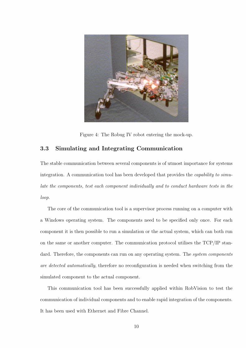
Figure 4: The Robug IV robot entering the mock-up.
3.3 Simulating and Integrating Communication
The stable communication between several components is of utmost importance for systems
integration. A communication tool has been developed that provides the capability to simu-
late the components, test each component individually and to conduct hardware tests in the
loop.
The core of the communication tool is a supervisor process running on a computer with
a Windows operating system. The components need to be specified only once. For each
component it is then possible to run a simulation or the actual system, which can both run
on the same or another computer. The communication protocol utilises the TCP/IP stan-
dard. Therefore, the components can run on any operating system. The system components
are detected automatically, therefore no reconfiguration is needed when switching from the
simulated component to the actual component.
This communication tool has been successfully applied within RobVision to test the
communication of individual components and to enable rapid integration of the components.
It has been used with Ethernet and Fibre Channel.
10

Fibre channel has been used to synchronise the images for the two vision systems. Using
fibre channel one image is transferred in about 4ms. Hence it can be assured that both
vision systems operate on the same image.
3.4 Discussion of System Approach
Before describing the system components in more detail, we give the reasons for selecting
this setup. After a study of walking robots (CLAWAR thematic network), the Portech
robot has been found as the most advanced system in terms of walking abilities and payload
capacity in relation to its own weight. However it turned out that the pneumatic actuation
is a disadvantage, since it introduces jerks in the body motion.
While mounting many cameras on the body is an option, it was decided to use an active
head approach. The main advantage is that the head can compensate on-line for the angular
part of the irregular robot body motion.
The CAD model is a huge source of information. With the active head it is possible to
optimise view point selection. This ability adds to reliability and makes C2V adaptive and
flexible to other environments and situations. The principles to choose good view points are
given in Section 4.
The use of two vision systems has two reasons. The practical reason is that the partners
brought considerable experience in different techniques and the integration on one platform
(either Windows or Linux) would be a large burden. The technical reason is that these
systems present complementary functionalities. First, Pronto is primarily used for initiali-
sation while V4R is used for tracking. Pronto needs several seconds and V4R operates in
120ms tracking cycles. For a reliable pose estimation the integration of many features gives
better accuracy, as will be shown in Section 7. Pronto measures junctions in 3D using the
stereo head, while V4R measures junction, line and ellipse features in one 2D image. Pronto
11
is too slow for tracking. Fast model-based tracking in V4R works only in one image, which
uses less computing power while still enabling full 6D pose estimation.
4 Feature Extraction: CAD to Vision (C2V)
The basic idea of C2V is to select good view points, to send new view points along the
path, and to provide model and feature information to the vision systems, which then find
features in the images and determine pose from the features found. Sending and supervising
the present view point operates at a rate of 1s.
The C2V component automatically extracts distinct features from the object model to
enable visual navigation. It also automatically evaluates the quality of view points to look
at for the vision system. The CAD subsystem concentrates on determining the reference
features, which are defined as a coherent set of an intermediate point (IP), the corresponding
robust features that should be seen in a view and a robot gait. The features are geometric
references determined from the CAD model of the work piece, i.e. surface boundaries
and intersections, represented as lines, circles, half circles, junctions (intersections of edges),
regions, etc. By robust we mean features, which will not be confused by the vision subsystem
when viewed from the specific intermediate point or which are too small to be significant.
C2V consists of 3 major systems:
• C2VoffLine (RobCad): C2VoffLine is the part of the AAU system that simulates the
motion of the robot and cameras from the path created by the Odense shipyard.
During this simulation of the movements the features are collected, which the camera
will to see during the execution of the task (Figure 5 gives an example desk top
view). To simplify the system and make it available to a large number of customers,
a simplified version has been developed: C2VoffLine (Windows NT), described next.
12

Figure 5: Example of mock-up in the C2Voffline system. For part of the demonstration a
cart was used since the robot was not always available. The top left is the view as seen from
the left camera of the stereo head. From this view features are extracted automatically.
• C2VoffLine (Windows NT): The kernel (C2Vkernel) used in the RobCad version is
implemented in an NT-based version of C2VoffLine. The NT version does not have all
the functionality and the same degree of automation, which is found in the RobCad
solution, but this version is fully capable of creating features for demos and can be
used by any user.
• C2VonLine: C2VonLine is the specially designed communication software of C2V that
communicates with the entire RobVision network at the demanded rate. The software
is used to send Models and Features generated by C2VoffLine depending on the present
pose of the robot.
The loop between the vision subsystem and the CAD subsystem will then be as follows:
1. After a small robot motion, the knowledge of the former pose and the direction of the
13
movement the vision subsystem predicts the robot pose, which is also passed on to
the CAD subsystem.
2. If the view changed considerably due to the robot movement, the CAD subsystem
provides new 3D geometric features detected in the CAD model for these poses using
the present view of the camera(s).
3. If the features or images are recognised by the vision subsystem, keep the view di-
rection. The robot moves towards its target. Go to 2 and continue the loop from
there.
4. If the features or images are not recognised by the vision subsystem, the cameras move
to another direction of view. This view point is suggested by the CAD subsystem
evaluating areas that are rich with features to render the task of the vision system
more easy.
5. Go to 3 and continue the loop from there.
The procedure described above and the use of the model is generic, which enables feature
extraction and tracking for any object that is represented by a CAD model. Details on the
method to extract features can be found in [8].
5 Head Control and 3D Feature Measurement: PRONTO
The PRONTO system fulfils several tasks, which in brief are:
• Head control and calibration.
• Inclinometer sensor data acquisition, distribution to other systems and use for head
stabilization.
14

• Image acquisition and delivery to other systems and image processing.
• Communications and synchronization with V4R vision system.
PRONTO, therefore, performs a large number of complex and interrelated task that need
to be synchronized. For these reasons the software is implemented in C++ as a multi-
thread object oriented distributed application with the aid of the distributed programming
technology DCOM (Distributed Component Object Model) to create a software architecture
that tries to simplify the complexity of this subsystem. From the hardware point of view
PRONTO consists of a computer with two processors running Windows NT, Pronto and
controlling the Eurohead (the head is shown in Figure 2 above).
Fig. 6 shows the CAD-model of the head and gives its main specifications. The accuracy
of the Eurohead has been evaluated in detail in [13]. A maximum error of 1 cm for a point
measurement at 1.1 metre distance has been found.
The point measurement task is solved by finding and measuring the 3D junctions with
a Hough technique for extracting the lines on the image planes of a stereo pair using the
features from C2V. The extracted lines and the junctions are related to the CAD model
using a weighted least mean squares method. Then a closed loop method follows, such that
by simultaneously moving the three degrees of freedom of the head the junction is fixated at
the principal point of the image in both images. When this is the case the two cameras are
verging on the certain junction and the direct kinematics of the head are applied in order
to determine the 3D position of the junction relative to the head.
15
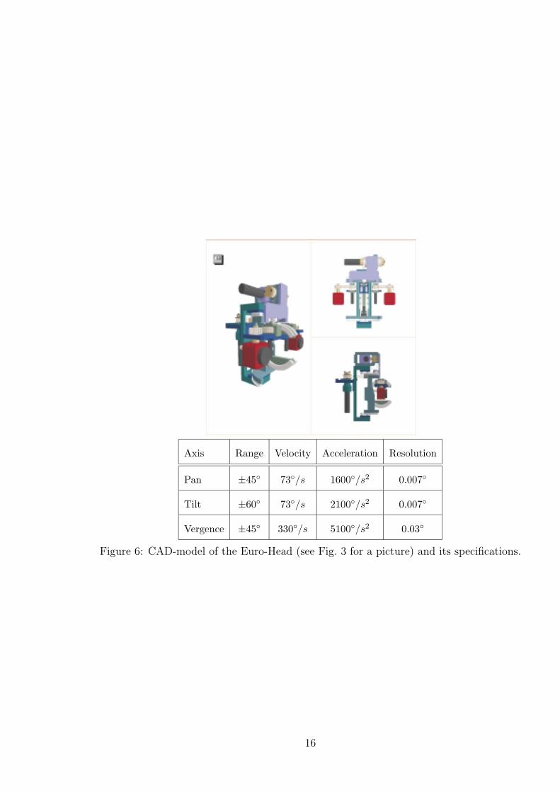
Axis Range Velocity Acceleration Resolution
Pan ±45◦ 73◦/s 1600◦/s2 0.007◦
Tilt ±60◦ 73◦/s 2100◦/s2 0.007◦
Vergence ±45◦ 330◦/s 5100◦/s2 0.03◦
Figure 6: CAD-model of the Euro-Head (see Fig. 3 for a picture) and its specifications.
16

6 2D Feature Tracking and Pose Estimation: Vision
for Robotics (V4R)
The task of the vision system is to extract features from the cues of images and relate
them to the features provided by C2V. C2V provides geometric features such as line, arc,
junctions, region, and attributes connected to these features. The attributes of a line can
be, for example, welded or not welded, chamfered, or rounded. Regions can have attributes
such as intensity, texture, or colour.
The V4R software package is a well tested prototype, which is available to interested
researchers from the authors. V4R provides a tool for tracking using images from video
(mpeg), life camera, or image sequences. V4R contains two major components, which can
be exploited separately: (1) framework for tracking of features and (2) pose estimation using
a model and the features found in the image.
The tracking tool within V4R is capable of following line, junction and ellipse features
at field rate. The tracking method is edge based and uses a scheme of Edge Projected
Integration of Cues (EPIC) to obtain robustness against varying background and continuous
illumination changes [25]. The goal of tracking is to be able to follow fast motions. Therefore
fast cycle rate and a windowing approach have been adopted using the result of the formal
derivations regarding the dynamics of the robot - vision system [20]. The entire vision
system of INFA is designed in C++ and presents a generic structure for any model-based
vision method [27]. Its development pays tribute to the developments of the XVision system
by Greg Hager [15].
The pose estimation tool of V4R uses the object model and the features found in the
image to determine an optimal pose. The following features are utilised for pose estimation:
line, 2D point (junction), 3D point, and surface normal. Outliers are detected and a least
17

Figure 7: Tracking windows to search for line features.
squares procedure over all remaining features gives a best pose fit.
Figure 7 shows the windows projected into the image. Section 7 shows tracking results.
6.1 Performance Evaluation of 2D Feature Finding Methods
To track the edges (lines, ellipses) a method for cue integration (Edge Projected Integration
of Cues, EPIC) is used, which has been proposed in [25]. EPIC uses cues (intensity, colour,
texture, ) to distinguish object from background edgels. However, the initialisation of the
feature cannot use this information and it is therefore the most critical step.
For first finding the edge feature several methods can be used. This section introduces
a comparison of methods to find the edges.
During the project the following methods have been evaluated when the model is first
projected into the image. One reference method for the evaluation is tracking, where pre-
vious information can be taken into account. This is simpler than finding the feature for
the first time. The second reference is only using the edge information from a classical edge
extractor. For all methods the warped image approach of [15] has been used.
1. Only-edge: Edge finding only using an edge filter as in [15] and least squares fit to
18

Figure 8: Initialisation (left) and detection results (right) when horizontally displacing the
image of the ship section in ten pixel steps. The EPIC-centre algorithm is used in this
example.
find line.
2. Tracking: Using information from a simulated previous finding.
3. LMedS: uses zero crossings to find edgels and a Least Median Square regression to fit
the line.
4. EPIC-centre: Integration using the centre location as most likely source to indicate
edgels.
The methods have been evaluated on real images of typical ship sections. Figure 8 shows
a typical example. The detection of features has been tested by moving the images in the
horizontal and vertical axis. This renders the initialisation inaccurate by a know range
covering plus and minus 30 pixels to the correct centre position.
The four algorithms have been tested. The results are summarised in Figure 9. The
detection rate gives the percentage of lines found of all lines initialised. Each data point
corresponds to 128 lines in two dozen images. Figure 9 also shows the percentage of the
detected lines that has been detected correctly. It shows that the Only-edge method detects
19

−30 −20 −10 0 10 20 300.2
0.3
0.4
0.5
0.6
0.7
0.8
0.9
1
Displacement distance [pixel]
Per
cent
age
lines
foun
d
Only−edge
Tracking
EPIC−centre
LMedS
0 5 10 15 20 25 300.3
0.4
0.5
0.6
0.7
0.8
0.9
1
Displacement distance [pixel]
Suc
cess
/failu
re r
ate
Only−edge
Tracking
EPIC−centre
LMedS
Figure 9: The detection rate (left) and the success/failure rate of the ”Only-edge”, the
”LMedS”, the ”EPIC-centre” and the ”Tracking” algorithms over the distance relative to
correct localisation. The S/F rate (right) is given by the relation of correctly versus falsely
found features over all features found.
many lines but also many incorrect lines. The LMedS improves the performance, but adding
the centre information is better even if the displacement becomes larger.
A significant problem is the false detection of features due to ambiguities in the image.
The introduction of probabilistic likelihood values to evaluate the quality of a line did not
proof successful. Lines have been found with many edgels along the line. Therefore other
measures has to be taken. The basic approach is to integrate the topological knowledge
from the CAD model.
Double lines cause severe problems due to ambiguity. Displacements of junctions on
both image planes due to either wrong estimation of the robot position or bad construction
also causes problems. On the other hand, exactly this information can be exploited to
discriminate features: parallel lines and lines intersecting at a junctions must show some
specific properties. The use of this topological information is referred to as validation. It
helps to disambiguate local ambiguities. This has been implemented and evaluated in detail
in [27]. The reader is referred to this article while this paper focuses on the system aspects.
Using the validation it is possible to robustly track complex scenes as given here with a
20

standard Pentium PC 500 MHz at frame rate. In the project only 120 ms have been used to
run several other tools to improve the system performance. Frame or field rate is achieved
in stand alone applications.
7 Demonstration Results
The final demonstration of the RobVision project brought together all of the tools to demon-
strate the integrated system at the demonstration site at Odense Shipyard in Odense, DK.
It is the goal to highlight some of the system aspects. A claim has been that redundant
features improve the accuracy of pose estimation. Results of an evaluation are shown here
and will be followed by a discussion of head stabilisation.
An example of tracking is given in Figure 10. The motion of the robot is depicted in
Figure 11. The jerky motion of the robot can be clearly seen. While tracking is fast and
shows good robustness, the maximum allowed object motion is still restricted. The use
of inertial sensors proved effective to compensate fast angular motions. This aspect will
be investigated more closely by integrating a full 6D inertial sensor suit with the optical
tracking methods.
Several measurement sets of eight tests each have been executed with the integrated
system as given in Fig. 2. The head orientation was roughly parallel to the T-truss, which
makes it easier to take a reference measurement. Table 1 summarises the measurements
and gives the standard deviations and the mean error to the reference measurement. The
maximum deviations are +58/−14mm and +1/−0 degrees. The three dimensional standard
deviation is 4.64mm. However, it is observed that the z-measurement deviates consistently.
The measurements have been taken in the centre of the mock-up and it was observed that
the bottom plate of the mock-up bends downwards. The reference measure is biased by this
bending of the plate. Considering the result of this set of measurements, a measurement
21
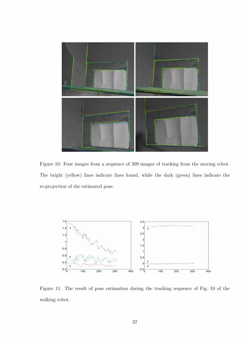
Figure 10: Four images from a sequence of 309 images of tracking from the moving robot.
The bright (yellow) lines indicate lines found, while the dark (green) lines indicate the
re-projection of the estimated pose.
0 100 200 300 4000.2
0.4
0.6
0.8
1
1.2
1.4
1.6
x
y
z
0 100 200 300 400-0.5
0
0.5
1
1.5
2
2.5
3
3.5
x
y
z
Figure 11: The result of pose estimation during the tracking sequence of Fig. 10 of the
walking robot.
22

Measure x [mm] y [mm] z [mm] roll [deg] pitch [deg] yaw [deg] position 3D [mm]
Uncertainty using Monocular and Stereo Features
std 5.49 3.29 8.48 0 0.92 0.35 4.64
mean 4.88 8.62 51.25 0 0.62 0.13 52.49
Uncertainty using Monocular Measurements
std 22.87 22.83 19.53 0 1.16 0.46 37.33
Table 1: The standard deviation (std) of the measurements and the mean distance to the
reference measurement for the integrated and the monocular case. A reference for the roll
axis was difficult to obtain, so this measurement is not regarded. The last column presents
the 3D position standard deviation respectively the mean.
tool to determine the deviations of the mock-up would be helpful. Such a tool is planned
as extension of RobVision.
The standard deviation of 4.64 mm reported in these tests is in the range of the pilot
goal for the RobVision system (2σ < 10mm). The accuracy of the measurement is also seen
in the overlay of the features over the image. For the tracking sequence Fig. 10 shows this
overlay and indicates the quality of pose estimation. The same measurements have been
made without the 3D junction information. The standard deviations have been found to be
not as good (see Table 1). The 3D point measurements alone give also not good confidence
values and for the two or three points measured the full pose cannot be always calculated.
The measurement sets indicate that the system reports in the worst case a standard
deviation of 35 mm. However, the reference measurements are difficult to obtain and seem
biased. Repeated performance indicates a standard deviation of 4.64 mm. The features
have been at a distance of one metre to three metres to the camera(s). On average about
10 line features and two to three 3D junctions are used. Using all features results in the
more accurate pose estimates. Hence the redundancy of using two visual methods to find
23

and measure features has shown its advantage.
This result compare favourably with the need of the ship building application of placing
the robot within ±10cm. However, the target goal of ±1cm could not be quiet reached. On
the other hand, the systematic errors (e.g., of the floor plate) indicate the need to measure
the actual dimensions of the mockup. To obtain a measurement of the planar surfaces
projected light or depth imaging is proposed.
Tracking in Figure 10 used no head stabilisation. Using the stabilisation of three in-
clinometers mounted on the EuroHead slightly improves the pose signal in the Figure 11.
The two horizontal inclinometers are directly used to actively compensate the robot body
motion. The loop is closed at a higher rate than the visual loop (20ms). The third, vertical,
body rotation cannot be compensated by the head. However, the signal of the inclinometer
is transmitted to V4R and V4R uses the signal to adjust the reference body frame accord-
ingly. The main effect is more reliability of tracking, since the jerky motion is reduced and
the likelihood of loosing track is reduced. This is best reported by the percentage of features
that is not found for comparable sequences. For the sequence in Figure 10 the ratio of not
found features improved from 21 to 11 percent, mainly due to the fact of the lower image
motion. One edge (in the back left) is not found during most of the sequence due to bad
contrast. The performance of tracking using EPIC and validation is given in more detail in
[27].
In summary, tracking operates at a cycle rate of 120ms when using a full line and
junction 3D wire-frame model of the mock-up with about 20 lines visible. Head stabilisation
considerably improves reliability of tracking. The accuracy obtained is ±1cm per metre
distance to the ship structure.
24

8 Lessons Learned
The final demonstration of the project showed the feasibility to navigate a walking robot
through part of the ship structure. While the goal of building a concept demonstrator has
been fulfilled, several system aspects need reconsideration to obtain a system complying to
industrial and commercial needs.
The accuracy of the head is sufficient, however at larger distances 3D point measure
accuracy degrades. Points further than 3 metres do not improve pose accuracy. This is fine
for the small sections at the ship but a wider baseline is necessary to obtain better accuracy.
A practical aspect is to improve the range of the head axes to turn the head further to
the left or right and, hence, to be able to follow features a longer time. A range of at least
±90◦ is advisable.
The foremost improvement was and still is the reliability of sensing. In particular the
jerky robot motions ask for a counter measure. The posture control of the robot eventually
makes up for drastic jerks (e.g., when the robot lifts a leg) and visual tracking is regained.
A more robust approach was indicated by the use of inclinometers to actively stabilise
the cameras. The next prototype will be equipped with a full 6D inertial system. The
fast response of inertial sensor and the ability to measure high accelerations of the inertial
system complements the more accurate image-based tracking. Visual sensing is used to
correct the typical drift of the inertial sensors. The stabilisation using inclinometers for
three axes already improved performance. It is expected that the full 6D compensation will
further improve the tracking results and that it is also advantageous over many fixed but
not actively compensated cameras. This result agrees with the findings from air-vehicle [12]
and helicopter steering [2]. Integrating 6D inertial and vision sensing has been shown in
simulation studies in [23], however a lot of experimental work is needed to achieve reliable
system performance and accurate interplay of the sensors.
25

While the work on RobVision improved robustness of tracking considerably, more needs
to be done. For better pose estimation the distance of features should be taken into account.
The distance of features could be also used to adapt the size (by changing the resolution) of
the search window. The biggest problem that has been encountered is that of not finding
edge features due to poor contrast. However, from manually investigating these cases it
seems that pyramid or scale-space approaches would adapt detection depending on relative
significance. This line of work will be pursued in future projects.
Finally, a lesson that has been confirmed is the known fact that integration is up for
surprises and that it is time consuming. The communication tool described in 3.3 turned
out to cut down on site integration time considerably. It enables to test operability of
command exchange and reduces the time on-site to problems of physical connection and the
dynamic system aspects.
9 Summary of Results
The objective of the RobVision project is to navigate a walking robot into ship sections
using visual feedback. The system consists of the components walking robot, CAD-system,
and two redundant vision systems that provide the feedback to steer the robot. The system
demonstrated the following.
• A modular walker is able to operate with 6 or 8 legs without any hardware or software
changes and can carry a work package of 50kg into the cell.
• C2V can use the CAD-model to evaluate and deliver significant features that the
cameras on the robot should see along the path of the robot.
• The redundancy of two vision systems is useful to improve the reliability of finding
and tracking features.
26

• Features such as lines, 2D and 3D points and junctions, ellipses, or surface normals
can be integrated with one algorithm to determine the pose of the object.
• Image processing is executed in 120 ms (and can be improved to obtain frame rate,
40 ms), which allows fast real-time operation.
• The approach is ready to be applied to locate and measure any object that has been
described with a standard CAD-system.
This technique opens up other potential applications. The model-based approach enables
to measure any modelled object and to feed back the measurement data directly into the
CAD-system. The impact of this capability is manifest. The industrial partners in the
ship building and the construction industry can supervise the production quality and con-
sequently reduce production time.
Acknowledgements
This work has been mainly supported by the RobVision project Esprit 28867 and is partly
supported by the Austrian Science Foundation (FWF) under grant P13167-MAT and EU-
Project GRD1-1999-10693 FlexPaint.
References
[1] Alferez, R., Wang, Y.F.: Geometric and Illumination Invariants for Object Recognition,
IEEE Transactions on PAMI 21(6), 1999, pp. 505-536.
[2] O. Amidi, T. Kanade, R. Miller: Vision-based Autonomous Helicopter Research at
Carnegie Melolon Robotics Institute (1991-1998), in [26].
27

[3] C. G. Brutigam: A Model-Free Voting Approach to Cue Integration, Dissertation, KTH
Stockholm, 1998.
[4] Beis, J.S., Lowe, D.G.: Indexing without Invariants in 3D Object Recognition, Pattern
Analysis and Machine Intelligence, Vol.21, No.10, 1999, pp. 1000 - 1015.
[5] Beveridge, J.R., Riseman, E.M.: How Easy is Matching 2D Line Models Using Local
Search?, Pattern Analysis and Machine Intelligence, Vol.19, No.19, 1997, pp.564 - 579.
[6] Christensen, H.I., Kragic, D.: Robust Vision for Manipulation and Navigation, in:
Markus Vincze (ed.): Proc. Robust Vision for Industrial Applications 1999, 23rd Work-
shop AGM/AAPR.
[7] Christensen, H.I., Hager, G.D., Eds.: Sensor Based Intelligent Robotics; International
Workshop Dagstuhl, Oct. 2000, Seminar 0421, Selected Papers; Springer Lecture Notes
in Computer Science, 2001.
[8] Deliverables of the RobVision project, also available from robvision.infa.tuwien.ac.at,
2000.
[9] Dickinson, S.J., Wilkes, D., Tsotsos, J.K.: A Computational Model of View Degeneracy,
IEEE Transactions on PAMI, vol.21, no.8, 1999, 673-689.
[10] Eberst, C., Barth, M., et.al., Robust Vision-based Object Recognition Integrating
Highly Redundant Cues for Indexing and Verification, IEEE ICRA 2000, pp. 3757-
3764.
[11] Rencken, W., Feiten, W., Soika, M.: Large Consistent Geometric Landmark Maps; in
[7], pp. 164-183.
[12] Fuerst, S., Dickmanns, E.D.: A Vision Based Navigation System for Autonomous Air-
craft; Robotics and Autonomous Systems 28, pp.173-184, 1999.
28

[13] Gasteratos A., Sandini, G.: On the Accuracy of the Eurohead, LIRA - TR 2/00, July
2000.
[14] Grimson, W.E.L.: Object Recognition by Computer, MIT Press, 1990.
[15] Hager, G. and Toyama, K. (1998): The XVision-System: A Portable Substrate for
Real-Time Vision Applications, Computer Vision and Image Understanding, 69 (1),
23-37.
[16] Harris, C,: Tracking with rigid models, In A. Blake and A. Yuille, editors, Active Vision,
pages 59-73, MIT Press, 1992.
[17] Kim, D.S., Nevatia, R.: Recognition and localization of generic objects for indoor
navigation using functionality, Image and Vision Computing 16(11), Special Issue SI,
1998 Aug 1, 729-743.
[18] Kosaka, A., Nakazawa, G.: Vision-Based Motion Tracking of Rigid Objects Using
Prediction of Uncertainties; ICRA, pp.2637-2644, 1995.
[19] Kragic, D., Christensen, H.I.: Cue Integration for Manipulation, in [26], pp. 1 - 16.
[20] Krautgartner, P., Vincze, M.: Optimal Image Processing Architecture for Active Vision
Systems; Int. Conf. on Vision Systems, Gran Canaria, S. 331-347, January 13-15, 1999.
[21] Nagel, H.H., Muller, T., Gengenbach, V., Gehrke, A.: Spatially-Adaptive Filtering in a
Model-based Machine Vision Approach to robust Workpiece Tracking; in [26], 2000.
[22] Pirjanian, P., Christensen, H.I., Fayman, J.A.: Application of Voting to fusion of
Purposive Modules: An Experimental Investigation, Robotics & Autonomous Sys.,
Vol.23, 1998, pp. 253-266.
29

[23] Rehbinder, H., Ghosh, B.K.: Multi-rate fusion of visual and inertia data; MFI 2001
Baden-Baden, 2001.
[24] Thompson, R.L., Reid, I.D., Munoz, L.A., Murray, D.W.: Providing synthetic views for
teleoperation using visual pose tracking in multiple cameras, IEEE SMC Part A 31(1),
43 -54, 2001.
[25] Vincze, M., Ayromlou, M., Kubinger, W.: An Integrating Framework for Robust Real-
Time 3D Object Tracking; Int. Conf. on Vision Systems, Gran Canaria, S. 135-150,
January 13-15, 1999.
[26] Vincze, M., Hager, G.D., Eds.: Robust Vision for Vision-Based Control of Motion,
IEEE Press, 2000.
[27] Vincze, M., Ayromlou, M., Ponweiser, W., Zillich, M.: Edge Projected Integration of
Image and Model Cues for Robust Model-Based Object Tracking; Int. J. of Robotics
Research, 2001.
[28] Wunsch, P., Hirzinger, G.: Real-Time Visual Tracking of 3-D Objects with Dynamic
Handling of Occlusion; ICRA, pp.2868-2873, 1997.
[29] Zisserman, A., Forsyth, D., et.al., 3D object recognition using invariance, Artificial
Intelligence, Vol.78, 1995, pp. 239 - 288.
30