A Study on Warm Hydroforming of Al and Mg Sheet Materials
14
Ho Choi Materials Research Team, Advanced Technology Center, R & D Division, Hyundai Motor Company and Kia Motors Corporation, Gyung-Gi, 445–706, South Korea Muammer Koç NSFI/UCR Center for Precision Forming (CPF), and Department of Mechanical Engineering, Virginia Commonwealth University (VCU), Richmond, VA 23284-3015 Jun Ni Department of Mechanical Engineering, and S.M. Wu Manufacturing Research Center, University of Michigan, Ann Arbor, MI 48109-2136 A Study on Warm Hydroforming of Al and Mg Sheet Materials: Mechanism and Proper Temperature Conditions Hydroforming of lightweight materials at elevated temperature is a relatively new process with promises of increased formability at low internal pressure levels. In this study, the mechanism of warm hydroforming processes is presented in terms of its formability by comparison with warm forming, and cold hydroforming processes. Additionally, a strat- egy is proposed to control process parameters, such as temperature, hydraulic pressure, blank holder force, and forming speed. As a part of this strategy, the proper temperature condition is determined by adaptive-isothermal finite element analysis (FEA) and a de- sign of experiment (DOE) approach. The adaptive-isothermal FEA determines the tem- perature levels of the blank material, which is selectively heated, by checking position of the blank material and adopting temperature level of the neighboring tooling. The pro- posed adaptive-isothermal FEA/DOE approach leads to the optimal temperature condi- tion in a warm hydroforming system accurately and rapidly as opposed to costly and lengthy experimental trial and errors and/or fully coupled thermo-mechanical simula- tions. Other process parameters are also optimized in a continued study (Choi et al., 2007, “Determination of Optimal Loading Profiles in Warm Hydroforming of Lightweight Materials,” J. Mater. Process. Techn., 190(1–3), pp. 230–242.). DOI: 10.1115/1.2951945 Keywords: warm hydroforming, lightweight materials, temperature condition, formability 1 Introduction In response to ever increasing demands for fuel economy im- provements, environmental conservation, pollution reduction, and for an overall sustainable mobility infrastructure, the transporta- tion industry has increased the level of research on the use of lightweight materials such as aluminum Al, magnesium Mg, advanced high strength steels AHSSs, and composites to replace components made of low carbon steel to cost effectively realize lightweight structures. It was reported by Schultz that a 10% weight reduction in an average automotive body could improve the fuel efficiency by 6–8% 1. Along the same line, it was pre- sented that weight reduction as high as 40–60% and 60–75% can be achieved by replacing steel autobody panels with aluminum and magnesium, respectively 2. However, the cost of lightweight parts is estimated to be higher than that of mild steel structures because of the raw material and production costs with existing manufacturing technologies. For aluminum alloys, cost increases of up to 30–100% are expected, while it is forecasted to be around 50–150% for magnesium alloys 2. On the other hand, since 80% of total energy consumption throughout the life cycle of an auto- mobile occurs during utilization driving period, the use of light- weight parts is still seen as a prominent, long-term, and cost- effective response to the fuel efficiency and emission reduction demands 3. In order to realize lightweight structures and prospective ben- efits in an efficient way, development of alternative, novel, and cost-effective manufacturing processes to convert such light- weight materials into desired shapes and forms is needed. For sheet and tubular material applications such as autobody panels and structures, warm hydroforming technology with selective heating and cooling has been proposed and investigated by many researchers recently to overcome low formability limitations at room temperature of the aluminum and magnesium sheet alloys 4–9. The potential benefits of the warm hydroforming technol- ogy are further increased formability, part consolidation, reduced number of process steps, and eventually substantial mass reduc- tions in vehicles, as illustrated in Fig. 1. There are many variables that should be controlled for a suc- cessful warm hydroforming process Fig. 2. These variables can be categorized into two groups. The first group includes the vari- ables that can be controlled slowly on time basis. An example of such a variable is the temperature of the tooling and hydraulic medium, which in turn affect temperature distribution of blank material. Generally, the tooling and the hydraulic medium have large a thermal capacity which results in very slow responses, in ranges of hours. Therefore, the temperature levels of the tooling and the hydraulic medium cannot be controlled on a time basis during a forming cycle, which is usually in the range of 10–30 s depending on the part size. To ensure increased part formability, an appropriate way would be to control the temperature levels spatially with selective heating or cooling devices. The second group consists of variables that can be controlled rapidly on time basis in response to the part forming process. For example, blank holder force BHF, hydraulic pressure, and punch speed can be controlled rapidly in response to the forming process. These vari- ables can be controlled temporally on the foundation of the pre- determined optimal temperature distribution Fig. 2. The second group of the process variables is also optimized through a fuzzy control algorithm in the continued study by the authors 10. Among the process parameters, temperature condition has a great influence on material properties flow stress and strain of lightweight materials, as shown is Fig. 3b. For instance, it was Manuscript received February 16, 2007; final manuscript received November 11, 2007; published online July 10, 2008. Review conducted by Jian Cao. Journal of Manufacturing Science and Engineering AUGUST 2008, Vol. 130 / 041007-1 Copyright © 2008 by ASME Downloaded From: http://manufacturingscience.asmedigitalcollection.asme.org/ on 02/18/2016 Terms of Use: http://www.asme.org/about-asme/terms-of-use
-
Upload
khangminh22 -
Category
Documents
-
view
3 -
download
0
Transcript of A Study on Warm Hydroforming of Al and Mg Sheet Materials
1
pftlaclwtsbapbmo5omwed
ecws
2
J
Downloaded Fr
Ho ChoiMaterials Research Team,
Advanced Technology Center,R & D Division,
Hyundai Motor Companyand Kia Motors Corporation,
Gyung-Gi, 445–706, South Korea
Muammer KoçNSFI/UCR Center for Precision Forming (CPF),
and Department of Mechanical Engineering,Virginia Commonwealth University (VCU),
Richmond, VA 23284-3015
Jun NiDepartment of Mechanical Engineering,
and S.M. Wu Manufacturing Research Center,University of Michigan,
Ann Arbor, MI 48109-2136
A Study on Warm Hydroforming ofAl and Mg Sheet Materials:Mechanism and ProperTemperature ConditionsHydroforming of lightweight materials at elevated temperature is a relatively new processwith promises of increased formability at low internal pressure levels. In this study, themechanism of warm hydroforming processes is presented in terms of its formability bycomparison with warm forming, and cold hydroforming processes. Additionally, a strat-egy is proposed to control process parameters, such as temperature, hydraulic pressure,blank holder force, and forming speed. As a part of this strategy, the proper temperaturecondition is determined by adaptive-isothermal finite element analysis (FEA) and a de-sign of experiment (DOE) approach. The adaptive-isothermal FEA determines the tem-perature levels of the blank material, which is selectively heated, by checking position ofthe blank material and adopting temperature level of the neighboring tooling. The pro-posed adaptive-isothermal FEA/DOE approach leads to the optimal temperature condi-tion in a warm hydroforming system accurately and rapidly as opposed to costly andlengthy experimental trial and errors and/or fully coupled thermo-mechanical simula-tions. Other process parameters are also optimized in a continued study (Choi et al.,2007, “Determination of Optimal Loading Profiles in Warm Hydroforming of LightweightMaterials,” J. Mater. Process. Techn., 190(1–3), pp. 230–242.).�DOI: 10.1115/1.2951945�
Keywords: warm hydroforming, lightweight materials, temperature condition,formability
IntroductionIn response to ever increasing demands for fuel economy im-
rovements, environmental conservation, pollution reduction, andor an overall sustainable mobility infrastructure, the transporta-ion industry has increased the level of research on the use ofightweight materials such as aluminum �Al�, magnesium �Mg�,dvanced high strength steels �AHSSs�, and composites to replaceomponents made of low carbon steel to cost effectively realizeightweight structures. It was reported by Schultz that a 10%eight reduction in an average automotive body could improve
he fuel efficiency by 6–8% �1�. Along the same line, it was pre-ented that weight reduction as high as 40–60% and 60–75% cane achieved by replacing steel autobody panels with aluminumnd magnesium, respectively �2�. However, the cost of lightweightarts is estimated to be higher than that of mild steel structuresecause of the raw material and production costs with existinganufacturing technologies. For aluminum alloys, cost increases
f up to 30–100% are expected, while it is forecasted to be around0–150% for magnesium alloys �2�. On the other hand, since 80%f total energy consumption throughout the life cycle of an auto-obile occurs during utilization �driving� period, the use of light-eight parts is still seen as a prominent, long-term, and cost-
ffective response to the fuel efficiency and emission reductionemands �3�.
In order to realize lightweight structures and prospective ben-fits in an efficient way, development of alternative, novel, andost-effective manufacturing processes to convert such light-eight materials into desired shapes and forms is needed. For
heet and tubular material applications such as autobody panels
Manuscript received February 16, 2007; final manuscript received November 11,
007; published online July 10, 2008. Review conducted by Jian Cao.ournal of Manufacturing Science and EngineeringCopyright © 20
om: http://manufacturingscience.asmedigitalcollection.asme.org/ on 02/18
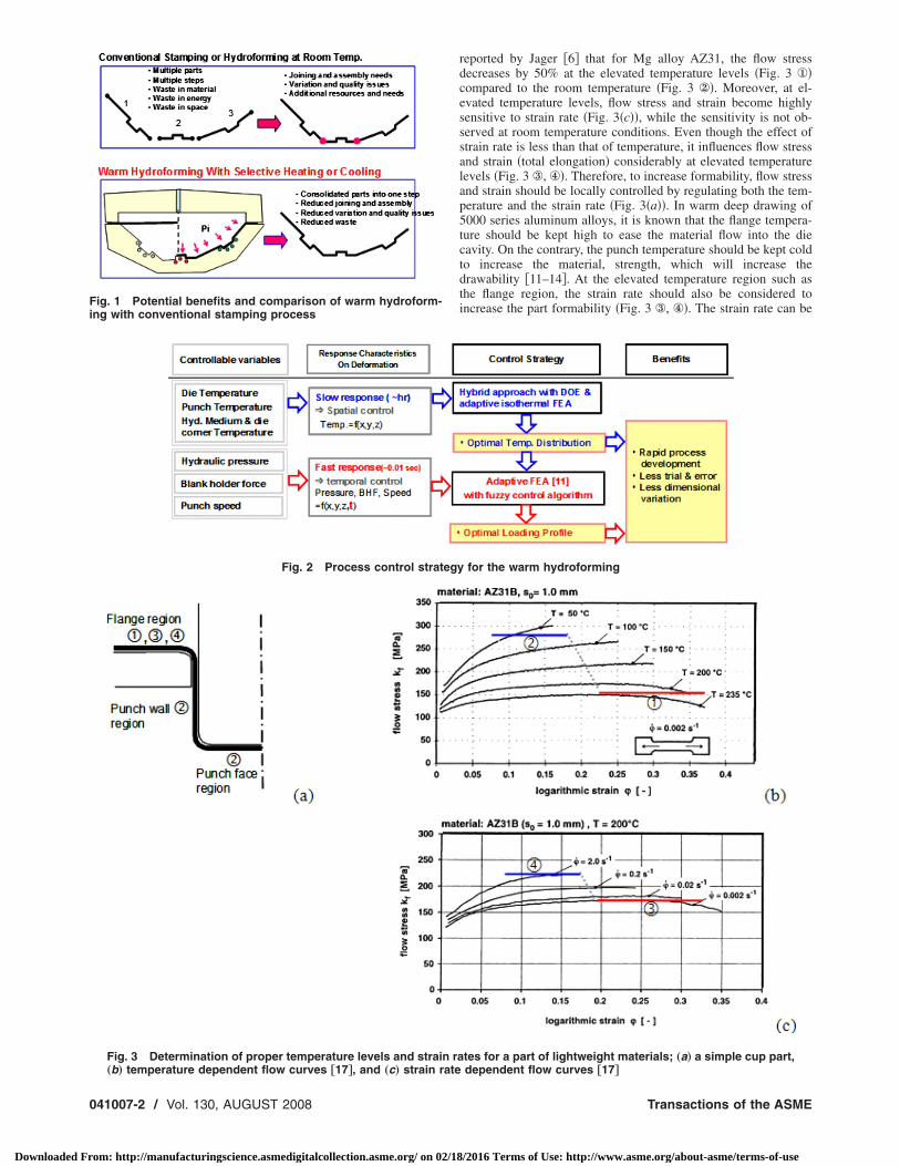
and structures, warm hydroforming technology with selectiveheating and cooling has been proposed and investigated by manyresearchers recently to overcome low formability limitations atroom temperature of the aluminum and magnesium sheet alloys�4–9�. The potential benefits of the warm hydroforming technol-ogy are further increased formability, part consolidation, reducednumber of process steps, and eventually substantial mass reduc-tions in vehicles, as illustrated in Fig. 1.
There are many variables that should be controlled for a suc-cessful warm hydroforming process �Fig. 2�. These variables canbe categorized into two groups. The first group includes the vari-ables that can be controlled slowly on time basis. An example ofsuch a variable is the temperature of the tooling and hydraulicmedium, which in turn affect temperature distribution of blankmaterial. Generally, the tooling and the hydraulic medium havelarge a thermal capacity which results in very slow responses, inranges of hours. Therefore, the temperature levels of the toolingand the hydraulic medium cannot be controlled on a time basisduring a forming cycle, which is usually in the range of 10–30 sdepending on the part size. To ensure increased part formability,an appropriate way would be to control the temperature levelsspatially with selective heating or cooling devices. The secondgroup consists of variables that can be controlled rapidly on timebasis in response to the part forming process. For example, blankholder force �BHF�, hydraulic pressure, and punch speed can becontrolled rapidly in response to the forming process. These vari-ables can be controlled temporally on the foundation of the pre-determined optimal temperature distribution �Fig. 2�. The secondgroup of the process variables is also optimized through a fuzzycontrol algorithm in the continued study by the authors �10�.
Among the process parameters, temperature condition has agreat influence on material properties �flow stress and strain� of
lightweight materials, as shown is Fig. 3�b�. For instance, it wasAUGUST 2008, Vol. 130 / 041007-108 by ASME
/2016 Terms of Use: http://www.asme.org/about-asme/terms-of-use
Fing with conventional stamping process
Fig. 2 Process control strategy
„b… temperature dependent flow curves †17‡, and „c… strain rate
041007-2 / Vol. 130, AUGUST 2008
Downloaded From: http://manufacturingscience.asmedigitalcollection.asme.org/ on 02/18
reported by Jager �6� that for Mg alloy AZ31, the flow stressdecreases by 50% at the elevated temperature levels �Fig. 3 ①�compared to the room temperature �Fig. 3 ②�. Moreover, at el-evated temperature levels, flow stress and strain become highlysensitive to strain rate �Fig. 3�c��, while the sensitivity is not ob-served at room temperature conditions. Even though the effect ofstrain rate is less than that of temperature, it influences flow stressand strain �total elongation� considerably at elevated temperaturelevels �Fig. 3 ③, ④�. Therefore, to increase formability, flow stressand strain should be locally controlled by regulating both the tem-perature and the strain rate �Fig. 3�a��. In warm deep drawing of5000 series aluminum alloys, it is known that the flange tempera-ture should be kept high to ease the material flow into the diecavity. On the contrary, the punch temperature should be kept coldto increase the material, strength, which will increase thedrawability �11–14�. At the elevated temperature region such asthe flange region, the strain rate should also be considered toincrease the part formability �Fig. 3 ③, ④�. The strain rate can be
for the warm hydroforming
tes for a part of lightweight materials; „a… a simple cup part,
ig. 1 Potential benefits and comparison of warm hydroform-
Fig. 3 Determination of proper temperature levels and strain ra
dependent flow curves †17‡Transactions of the ASME
/2016 Terms of Use: http://www.asme.org/about-asme/terms-of-use
cAos
�mdmihstTaTpctmc
FE
J
Downloaded Fr
ontrolled by changing the punch speed or the hydraulic pressure.fter determining the optimal temperature distribution spatially,ptimal loading profiles of the punch speed and hydraulic pressurehould be determined.
In this paper, a focus on the effect of temperature distributionspace basis� on the mechanism of warm hydroforming process isade. In the first section, the development and validation of two
ifferent finite element �FE� models based on the existing experi-ental results are presented. In the second section, different form-
ng behaviors of warm hydroforming, warm forming, and coldydroforming processes on the same temperature conditions aretudied to obtain a better understanding of the mechanism behindhe formability improvement in the warm hydroforming process.hird, a new methodology, adaptive-isothermal finite elementnalysis �FEA� is proposed to optimize temperature conditions.his method is developed to determine rapidly and accurately theroper temperature conditions for a given tooling, part, and pro-ess configuration as opposed to lengthy and costly fully coupledhermomechanical simulations. Applicability of the proposed
ethod is then verified. Finally, a summary of the findings andonclusions are presented.
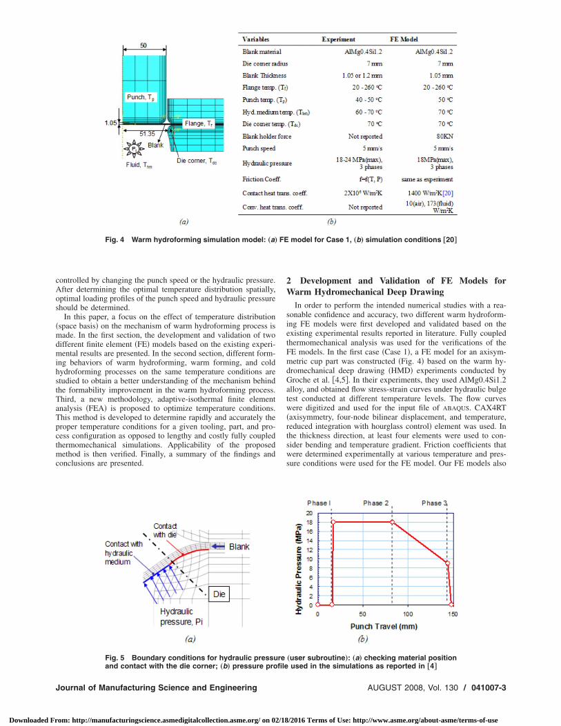
Fig. 4 Warm hydroforming simulation model: „a…
Fig. 5 Boundary conditions for hydraulic pressu
and contact with the die corner; „b… pressure profileournal of Manufacturing Science and Engineering
om: http://manufacturingscience.asmedigitalcollection.asme.org/ on 02/18
2 Development and Validation of FE Models forWarm Hydromechanical Deep Drawing
In order to perform the intended numerical studies with a rea-sonable confidence and accuracy, two different warm hydroform-ing FE models were first developed and validated based on theexisting experimental results reported in literature. Fully coupledthermomechanical analysis was used for the verifications of theFE models. In the first case �Case 1�, a FE model for an axisym-metric cup part was constructed �Fig. 4� based on the warm hy-dromechanical deep drawing �HMD� experiments conducted byGroche et al. �4,5�. In their experiments, they used AlMg0.4Si1.2alloy, and obtained flow stress-strain curves under hydraulic bulgetest conducted at different temperature levels. The flow curveswere digitized and used for the input file of ABAQUS. CAX4RT�axisymmetry, four-node bilinear displacement, and temperature,reduced integration with hourglass control� element was used. Inthe thickness direction, at least four elements were used to con-sider bending and temperature gradient. Friction coefficients thatwere determined experimentally at various temperature and pres-sure conditions were used for the FE model. Our FE models also
model for Case 1, „b… simulation conditions †20‡
„user subroutine…: „a… checking material position
re used in the simulations as reported in †4‡AUGUST 2008, Vol. 130 / 041007-3
/2016 Terms of Use: http://www.asme.org/about-asme/terms-of-use
a
irhmcawelfSwm�tscs
bwamasmbsurpsnatiGewtcmptbd
0
Downloaded Fr
dopted the pressure profiles reported in their experiments.Boundary and loading conditions regarding to application of
nternal �counter� pressure �Pi� in die cavity and around the corneregion are illustrated in Fig. 5. For accurate modeling of sheetydroforming process, Pi should be applied only onto the ele-ents of blank material entering into die cavity where they get in
ontact with hydraulic medium. In order to establish such loadingnd boundary conditions, a user subroutine algorithm to determinehen and where Pi should be applied must be developed. In gen-
ral, hydraulic pressure is not applied to the blank material if it isocated between blank holders or if the blank conforms �i.e., inull contact with� to the die corner surface, as shown in Fig. 5�a�.pecifically, three different criteria were adopted to determinehen and where to apply the hydraulic pressure to the blank ele-ents: �1� if the blank material elements are in the die cavity area,
2� if there is any contact between the blank material elements andhe die surface, particularly around the die corner, and �3� thetatus of predetermined pressure profile at that instance. If all theriteria are satisfied, hydraulic pressure is applied at the corre-ponding pressure level, as illustrated in Fig. 5�b�.
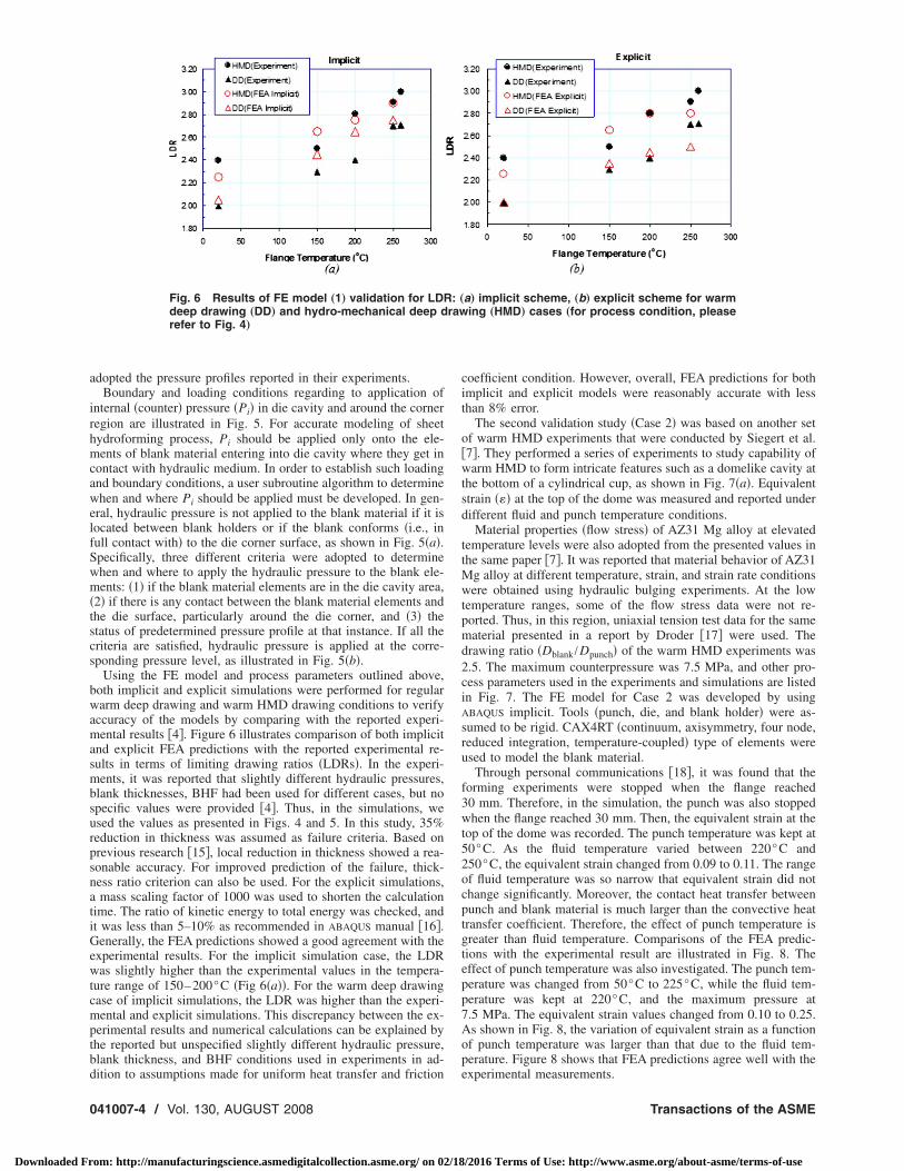
Using the FE model and process parameters outlined above,oth implicit and explicit simulations were performed for regulararm deep drawing and warm HMD drawing conditions to verify
ccuracy of the models by comparing with the reported experi-ental results �4�. Figure 6 illustrates comparison of both implicit
nd explicit FEA predictions with the reported experimental re-ults in terms of limiting drawing ratios �LDRs�. In the experi-ents, it was reported that slightly different hydraulic pressures,
lank thicknesses, BHF had been used for different cases, but nopecific values were provided �4�. Thus, in the simulations, wesed the values as presented in Figs. 4 and 5. In this study, 35%eduction in thickness was assumed as failure criteria. Based onrevious research �15�, local reduction in thickness showed a rea-onable accuracy. For improved prediction of the failure, thick-ess ratio criterion can also be used. For the explicit simulations,mass scaling factor of 1000 was used to shorten the calculation
ime. The ratio of kinetic energy to total energy was checked, andt was less than 5–10% as recommended in ABAQUS manual �16�.enerally, the FEA predictions showed a good agreement with the
xperimental results. For the implicit simulation case, the LDRas slightly higher than the experimental values in the tempera-
ure range of 150–200°C �Fig 6�a��. For the warm deep drawingase of implicit simulations, the LDR was higher than the experi-ental and explicit simulations. This discrepancy between the ex-
erimental results and numerical calculations can be explained byhe reported but unspecified slightly different hydraulic pressure,lank thickness, and BHF conditions used in experiments in ad-
Fig. 6 Results of FE model „1… validation for LDRdeep drawing „DD… and hydro-mechanical deep drefer to Fig. 4…
ition to assumptions made for uniform heat transfer and friction
41007-4 / Vol. 130, AUGUST 2008
om: http://manufacturingscience.asmedigitalcollection.asme.org/ on 02/18
coefficient condition. However, overall, FEA predictions for bothimplicit and explicit models were reasonably accurate with lessthan 8% error.
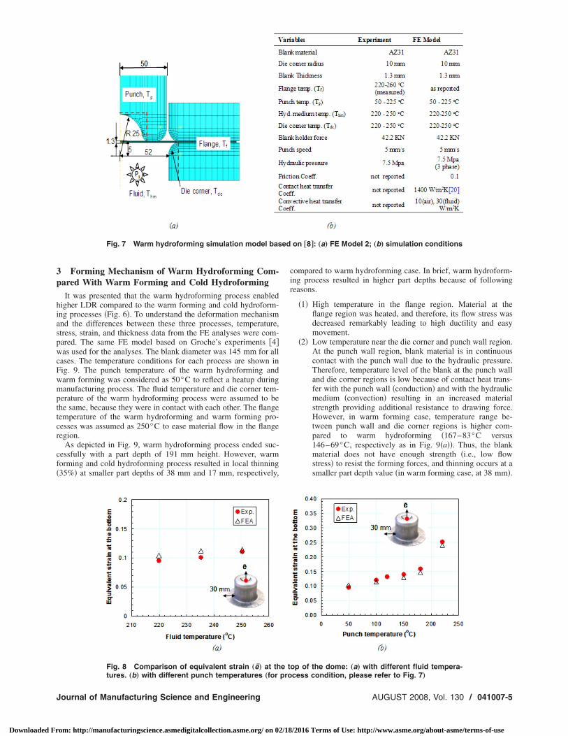
The second validation study �Case 2� was based on another setof warm HMD experiments that were conducted by Siegert et al.�7�. They performed a series of experiments to study capability ofwarm HMD to form intricate features such as a domelike cavity atthe bottom of a cylindrical cup, as shown in Fig. 7�a�. Equivalentstrain ��� at the top of the dome was measured and reported underdifferent fluid and punch temperature conditions.
Material properties �flow stress� of AZ31 Mg alloy at elevatedtemperature levels were also adopted from the presented values inthe same paper �7�. It was reported that material behavior of AZ31Mg alloy at different temperature, strain, and strain rate conditionswere obtained using hydraulic bulging experiments. At the lowtemperature ranges, some of the flow stress data were not re-ported. Thus, in this region, uniaxial tension test data for the samematerial presented in a report by Droder �17� were used. Thedrawing ratio �Dblank /Dpunch� of the warm HMD experiments was2.5. The maximum counterpressure was 7.5 MPa, and other pro-cess parameters used in the experiments and simulations are listedin Fig. 7. The FE model for Case 2 was developed by usingABAQUS implicit. Tools �punch, die, and blank holder� were as-sumed to be rigid. CAX4RT �continuum, axisymmetry, four node,reduced integration, temperature-coupled� type of elements wereused to model the blank material.
Through personal communications �18�, it was found that theforming experiments were stopped when the flange reached30 mm. Therefore, in the simulation, the punch was also stoppedwhen the flange reached 30 mm. Then, the equivalent strain at thetop of the dome was recorded. The punch temperature was kept at50°C. As the fluid temperature varied between 220°C and250°C, the equivalent strain changed from 0.09 to 0.11. The rangeof fluid temperature was so narrow that equivalent strain did notchange significantly. Moreover, the contact heat transfer betweenpunch and blank material is much larger than the convective heattransfer coefficient. Therefore, the effect of punch temperature isgreater than fluid temperature. Comparisons of the FEA predic-tions with the experimental result are illustrated in Fig. 8. Theeffect of punch temperature was also investigated. The punch tem-perature was changed from 50°C to 225°C, while the fluid tem-perature was kept at 220°C, and the maximum pressure at7.5 MPa. The equivalent strain values changed from 0.10 to 0.25.As shown in Fig. 8, the variation of equivalent strain as a functionof punch temperature was larger than that due to the fluid tem-perature. Figure 8 shows that FEA predictions agree well with the
a… implicit scheme, „b… explicit scheme for warming „HMD… cases „for process condition, please
: „raw
experimental measurements.
Transactions of the ASME
/2016 Terms of Use: http://www.asme.org/about-asme/terms-of-use
3p
hiaspwcFwmpttcr
cf�
ed
J
Downloaded Fr
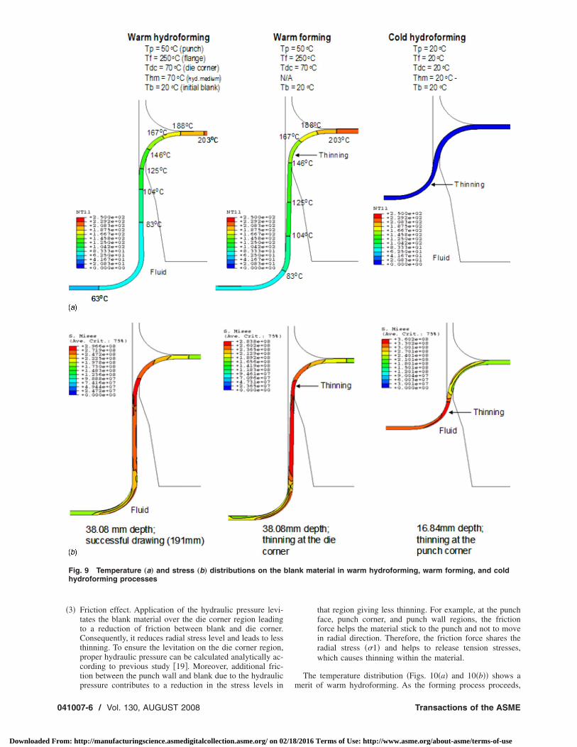
Forming Mechanism of Warm Hydroforming Com-ared With Warm Forming and Cold HydroformingIt was presented that the warm hydroforming process enabled
igher LDR compared to the warm forming and cold hydroform-ng processes �Fig. 6�. To understand the deformation mechanismnd the differences between these three processes, temperature,tress, strain, and thickness data from the FE analyses were com-ared. The same FE model based on Groche’s experiments �4�as used for the analyses. The blank diameter was 145 mm for all
ases. The temperature conditions for each process are shown inig. 9. The punch temperature of the warm hydroforming andarm forming was considered as 50°C to reflect a heatup duringanufacturing process. The fluid temperature and die corner tem-
erature of the warm hydroforming process were assumed to behe same, because they were in contact with each other. The flangeemperature of the warm hydroforming and warm forming pro-esses was assumed as 250°C to ease material flow in the flangeegion.
As depicted in Fig. 9, warm hydroforming process ended suc-essfully with a part depth of 191 mm height. However, warmorming and cold hydroforming process resulted in local thinning35%� at smaller part depths of 38 mm and 17 mm, respectively,
Fig. 7 Warm hydroforming simulation model bas
Fig. 8 Comparison of equivalent strain „e… at th
tures. „b… with different punch temperatures „for proournal of Manufacturing Science and Engineering
om: http://manufacturingscience.asmedigitalcollection.asme.org/ on 02/18
compared to warm hydroforming case. In brief, warm hydroform-ing process resulted in higher part depths because of followingreasons.
�1� High temperature in the flange region. Material at theflange region was heated, and therefore, its flow stress wasdecreased remarkably leading to high ductility and easymovement.
�2� Low temperature near the die corner and punch wall region.At the punch wall region, blank material is in continuouscontact with the punch wall due to the hydraulic pressure.Therefore, temperature level of the blank at the punch walland die corner regions is low because of contact heat trans-fer with the punch wall �conduction� and with the hydraulicmedium �convection� resulting in an increased materialstrength providing additional resistance to drawing force.However, in warm forming case, temperature range be-tween punch wall and die corner regions is higher com-pared to warm hydroforming �167–83°C versus146–69°C, respectively as in Fig. 9�a��. Thus, the blankmaterial does not have enough strength �i.e., low flowstress� to resist the forming forces, and thinning occurs at asmaller part depth value �in warm forming case, at 38 mm�.
on †8‡: „a… FE Model 2; „b… simulation conditions
op of the dome: „a… with different fluid tempera-
e t cess condition, please refer to Fig. 7…AUGUST 2008, Vol. 130 / 041007-5
/2016 Terms of Use: http://www.asme.org/about-asme/terms-of-use
0
Downloaded Fr
�3� Friction effect. Application of the hydraulic pressure levi-tates the blank material over the die corner region leadingto a reduction of friction between blank and die corner.Consequently, it reduces radial stress level and leads to lessthinning. To ensure the levitation on the die corner region,proper hydraulic pressure can be calculated analytically ac-cording to previous study �19�. Moreover, additional fric-tion between the punch wall and blank due to the hydraulic
Fig. 9 Temperature „a… and stress „b… distributions on thehydroforming processes
pressure contributes to a reduction in the stress levels in
41007-6 / Vol. 130, AUGUST 2008
om: http://manufacturingscience.asmedigitalcollection.asme.org/ on 02/18
that region giving less thinning. For example, at the punchface, punch corner, and punch wall regions, the frictionforce helps the material stick to the punch and not to movein radial direction. Therefore, the friction force shares theradial stress ��1� and helps to release tension stresses,which causes thinning within the material.
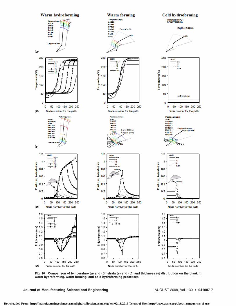
The temperature distribution �Figs. 10�a� and 10�b�� shows a
nk material in warm hydroforming, warm forming, and cold
blamerit of warm hydroforming. As the forming process proceeds,
Transactions of the ASME
/2016 Terms of Use: http://www.asme.org/about-asme/terms-of-use
J
Downloaded Fr
Fig. 10 Comparison of temperature „a… and „b…, strain „c… and „d…, and thickness „e… distribution on the blank in
warm hydroforming, warm forming, and cold hydroforming processesournal of Manufacturing Science and Engineering AUGUST 2008, Vol. 130 / 041007-7
om: http://manufacturingscience.asmedigitalcollection.asme.org/ on 02/18/2016 Terms of Use: http://www.asme.org/about-asme/terms-of-use
tthacd
0
Downloaded Fr
he temperature of the part near the punch wall decreases due tohe contact between the punch wall and the material. For the warmydroforming case, the temperature of a part near the punch wallnd face is approximately 69°C �Fig. 10�a��. The blank materialooled by the punch then sustains high drawing forces with re-uced thinning. In case of warm forming, due to the high tem-
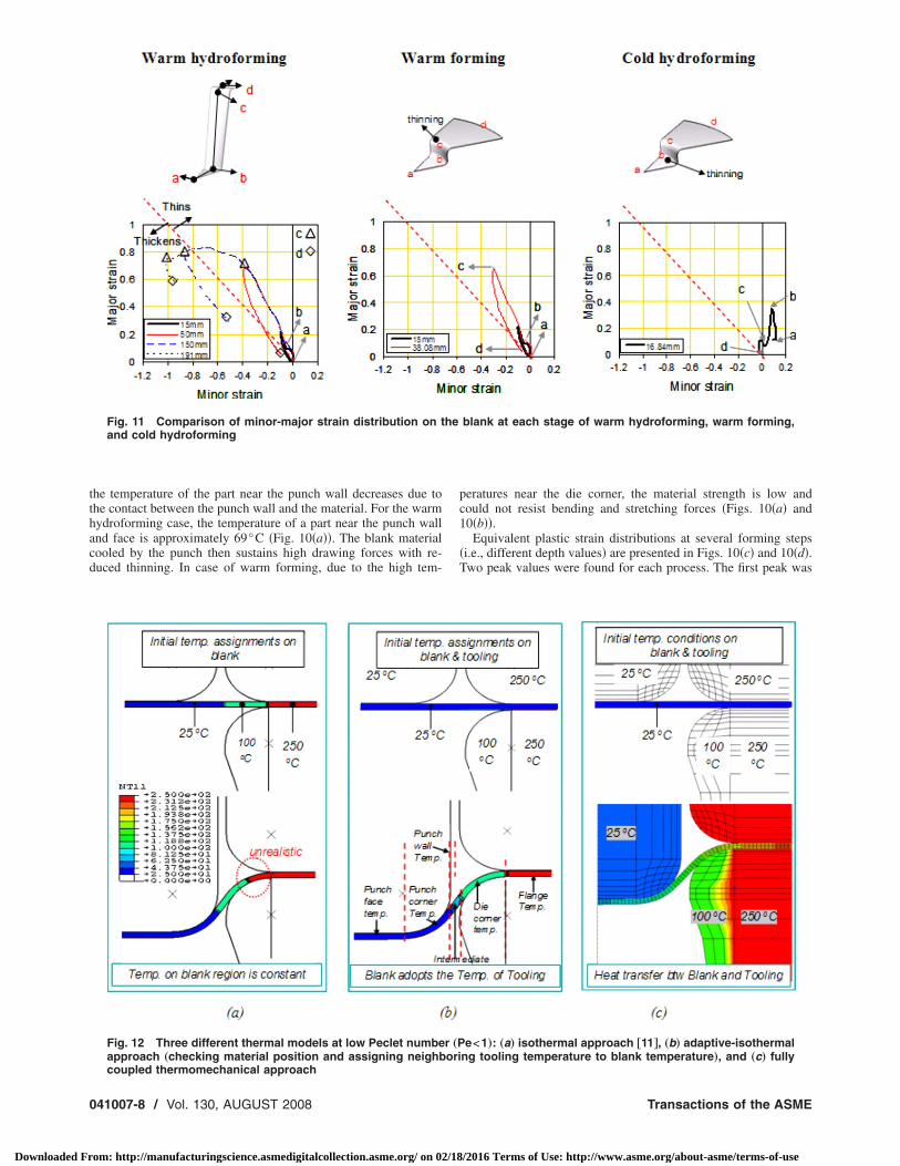
Fig. 11 Comparison of minor-major strain distribution on tand cold hydroforming
Fig. 12 Three different thermal models at low Peclet numbeapproach „checking material position and assigning neighb
coupled thermomechanical approach41007-8 / Vol. 130, AUGUST 2008
om: http://manufacturingscience.asmedigitalcollection.asme.org/ on 02/18
peratures near the die corner, the material strength is low andcould not resist bending and stretching forces �Figs. 10�a� and10�b��.
Equivalent plastic strain distributions at several forming steps�i.e., different depth values� are presented in Figs. 10�c� and 10�d�.Two peak values were found for each process. The first peak was
blank at each stage of warm hydroforming, warm forming,
e<1…: „a… isothermal approach †11‡, „b… adaptive-isothermalng tooling temperature to blank temperature…, and „c… fully
he
r „Pori
Transactions of the ASME
/2016 Terms of Use: http://www.asme.org/about-asme/terms-of-use
Fisothermal approach
corner and fluid temp.
Journal of Manufacturing Science and Engineering
Downloaded From: http://manufacturingscience.asmedigitalcollection.asme.org/ on 02/18
found at the punch corner region and the second was found at thedie corner region. In the warm hydroforming case, the secondpeak value �equivalent strain at the die corner region� was lowerthan the warm forming and cold hydroforming processes. It isapparent that the maximum strain of the warm hydroforming at50 mm depth was lower than that of the warm forming at a partdepth of 38 mm. For the cold hydroforming process, the strain atthe punch face region was very high, and thinning appeared nearthe punch corner region.
Thickness distribution on the blank is similar to strain distribu-tion, as shown in Fig. 10�e�. The warm hydroforming processresults in less local thinning when compared to the other pro-cesses. For the warm forming process, the localized thinning oc-curred near the die corner, and thickness change was very sharp.The thinning for the cold hydroforming occurred at the punchcorner region, and thinning was distributed all over the punchface.
Finally, the major and minor strain distributions at differentstages of the forming processes are depicted in Fig. 11. For thecold hydroforming process, the blank material near the punch face
ner and definition of Peclet number
nt methodologies: „a… isothermal FEA/DOE, „b… adaptive-EA/DOE. Tp=punch temperature, Tf=flange temp., Tdc=die
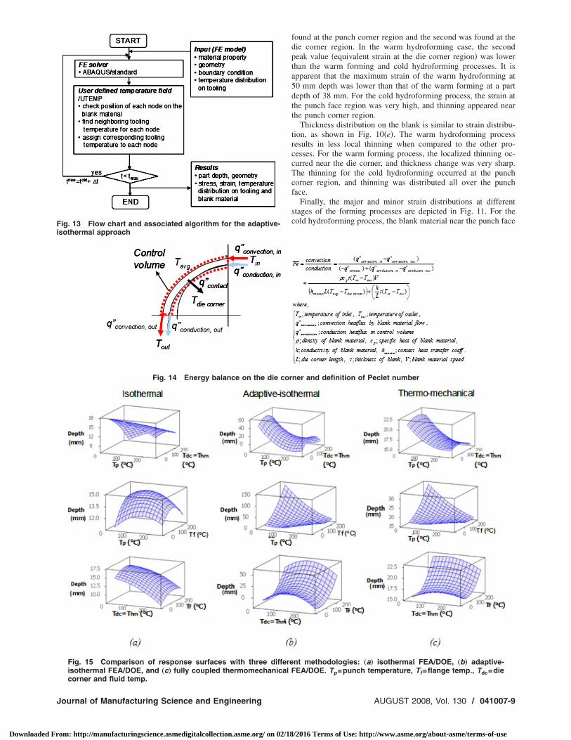
ig. 13 Flow chart and associated algorithm for the adaptive-
Fig. 14 Energy balance on the die cor
Fig. 15 Comparison of response surfaces with three differeisothermal FEA/DOE, and „c… fully coupled thermomechanical F
AUGUST 2008, Vol. 130 / 041007-9
/2016 Terms of Use: http://www.asme.org/about-asme/terms-of-use
wnrltfmtwnmctw5sFu
4f
hwip�ob
pmtaFdsirattt
… A
0
Downloaded Fr
as elongated biaxially �a�. Peak strain appears at the punch cor-er region �b�. Then, the strain decreases in die corner and flangeegion ��c� and �d�� because the drawing force could not be de-ivered because of the thinning. At the edge of the flange region,he minor and major strains were almost zero �d�. For the warmorming process, the punch face region �between a and b� was notuch stretched compared to the cold hydroforming process. Near
he die corner region �c�, magnitudes of major and minor strainsere increased and thinning occurred. At point �c�, excessive thin-ing �35%� occurred, and assumed as a failure condition. Theagnitude of major and minor strains at the flange edge did not
hange much, but a slight thickening of blank was observed. Inhe case of the warm hydroforming process, the strain distributionas similar to that in the warm forming until the part depth was0 mm. As the forming process proceeded, the minor and majortrains both dropped causing thickening at the flange region. Inig. 11, it can be observed that the warm hydroforming processtilizes the blank material more efficiently.
Determination of Proper Temperature Distributionor Warm Hydroforming Process
It was shown that certain temperature conditions in the warmydroforming process increase the forming limits of the light-eight materials �4,6�. For regular warm deep drawing process, it
s well known that cold punch temperatures and warm flange tem-eratures increase the formability in a simple deep drawing case11�. Hence, in this session, a methodology for the determinationf optimal temperature distribution for warm hydroforming wille prescribed.
For accurate modeling of warm hydroforming, the most appro-riate numerical solution scheme would be fully coupled thermo-echanical FEA �nonisothermal FEA� with properly defined ma-
erial and contact models �Fig. 12�c��. However, due to complexnd nonlinear iterations and calculations, the thermomechanicalEA takes a very long time and a great amount of resources,epending on the size of the parts being simulated. Therefore, aimplified approach is needed. Kim �11� suggested a hybridsothermal/thermomechanical FEA approach to reduce time andesources for an investigation of warm forming processes. In hispproach, it is assumed that a constant but spatially nonuniformemperature distribution on blank and no heat transfer betweenooling and material �isothermal FEA� exists. After determining
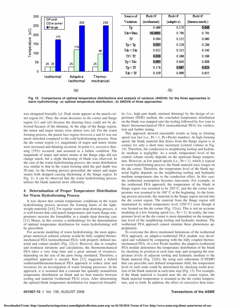
Fig. 16 Comparisons of optimal temperature distributionswarm hydroforming: „a… optimal temperature distribution. „b
he optimal blank temperature distribution for improved formabil-
41007-10 / Vol. 130, AUGUST 2008
om: http://manufacturingscience.asmedigitalcollection.asme.org/ on 02/18
ity �i.e., high part depth, minimal thinning� by the design of ex-periment �DOE� method, the concluded temperature distributionon the blank was mapped onto the tooling followed by few �one tothree� thermomechanical FEA �nonisothermal FEA� for verifica-tion and further tuning.
This approach showed reasonable results as long as formingspeed was fast �i.e., Pe�1, Pe=Peclet number�. At high formingspeed, the blank material that draws from the flange region is incontact for only a short time increment �control volume in Fig.14�. Therefore, the conduction to neighboring tooling and hydrau-lic medium is negligible. As a result, temperature level of thecontrol volume mostly depends on the upstream flange tempera-ture. However, at low punch speeds �i.e., Pe�1�, which is typicalin warm hydroforming process, the blank material stays longer onthe die corner. Therefore, the temperature level of the blank ma-terial highly depends on the neighboring tooling and hydraulicmedium temperatures due to the conduction effect. In this case,the isothermal assumption becomes inaccurate. For example, inthe isothermal FEA approach, the temperature of the blank inflange region was assumed to be 250°C, and the die corner tem-perature was assumed to be 100°C at the beginning. As the form-ing process proceeds, the material in the flange region moved intothe die corner region. The material from the flange region stillmaintained its initial temperature level �250°C� even though itwas located on the die corner �Fig. 12�a��. This is not an accuratemodeling at a low forming speed �i.e., Pe�1�. In reality, the tem-perature level on the die corner is more dependent on the tempera-ture level of the neighboring tooling and hydraulic medium. Theisothermal FEA approach cannot simulate these phenomena ap-propriately.
To overcome the above mentioned limitations of the isothermalFEA approach, an adaptive-isothermal FEA module was devel-oped and validated by comparing with the fully coupled thermo-mechanical FEA. At a low Peclet number, the adaptive-isothermalFEA module determines the temperature distribution of the blankby checking its position at each time step, and assigning the tem-perature levels of adjacent tooling and hydraulic medium to theblank material �Fig. 12�b��. By using user subroutine �UTEMP�that can prescribe user defined temperature field, the temperaturelevel of each node could be determined by checking nodal posi-tion of the blank material at each time step �Fig. 13�. For example,if the blank material is located near the die corner region, theblank material temperature is assumed as the die corner tempera-
analysis of variance „ANOVA… for the three approaches inNOVA of three approaches
and
ture, and so forth. In addition, the effect of convective heat trans-
Transactions of the ASME
/2016 Terms of Use: http://www.asme.org/about-asme/terms-of-use
fwcsdtcmp
TomcgapmnsaswcccwTfltt
2mtp
J
Downloaded Fr
er between hydraulic medium and blank can be also consideredhen the blank material floats on the die corner. This approach
an take transient temperature changes into account. Since thistudy concerns with Al, Mg alloys, which have high thermal con-uctivity and diffusivity, the time to reach steady state tempera-ure conditions is around 2 s after the temperature conditionshanges. If we consider punch speeds of 5 mm /s, blank size, andaterial flow, the assumption of adopting neighboring tool tem-
erature as blank temperature is quite reasonable.
4.1 Comparison of Methodologies to Determine a Properemperature Distribution. To compare the validity and accuracyf the three simulation approaches discussed above �i.e., isother-al FEA, adaptive-isothermal FEA, fully coupled thermome-
hanical FEA�, three models are tested using the same part andeometry conditions as in Case 1 in Sec. 2 �4�. The variables thatffect the formability are selected as the temperature levels on theunch face �Tpf�, punch corner �Tpc�, punch wall �Tpw�, hydraulicedium �Thm�, die corner �Tdc�, and flange region �Tf�. The total
umber of variables is 6, which is quite large to conduct a re-ponse surface method �RSM� analysis. Therefore, a screeningnalysis was first conducted by two-level fractional factorial de-ign. From the screening analysis, the most effective variablesere found to be the temperature of the punch corner �Tpc�, die
orner �Tdc�, and flange �Tf�. Another condition that should beonsidered was the hydraulic medium temperature �Thm� and dieorner temperature �Tdc�. Because they are in continuous contactith each other, they were considered to be the same �Tdc=Thm�.hus, the variables that were used for the RSM were punch,ange, and die corner temperatures. The Box-Behnken array with
hree variables was used �21�. Part depth when the blank washinned by 35% was selected as a response of the analysis.
The temperature range of each variable was between 25°C and50°C. The response surfaces calculated by each model �isother-al, adaptive-isothermal, and thermomechanical model� are illus-
rated in Fig. 15. The isothermal model shows a poor capability to
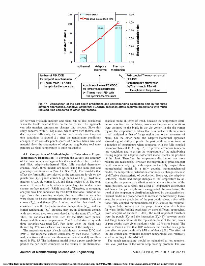
Fig. 17 Comparison of the part depth predictiondifferent approaches. Adaptive-isothermal FEA/Dreduced time compared to other approaches.
redict the part depth compared to the results of the thermome-
ournal of Manufacturing Science and Engineering
om: http://manufacturingscience.asmedigitalcollection.asme.org/ on 02/18
chanical model in terms of trend. Because the temperature distri-bution was fixed on the blank, erroneous temperature conditionswere assigned to the blank in the die corner. In the die cornerregion, the temperature of blank that is in contact with die corneris still assigned as that of flange region due to the movement ofblank. On the other hand, the adaptive-isothermal approachshowed a good ability to predict the part depth variation trend asa function of temperature when compared with the fully coupledthermomechanical FEA �Fig. 15�. To prevent erroneous tempera-ture conditions and to assign the temperature of the neighboringtooling region, the adaptive-isothermal model checks the positionof the blank. Therefore, the temperature distribution was morerealistic and reasonable. However, the magnitude of predicted partdepth was relatively high with respect to the fully coupled ther-momechanical model. In a fully coupled thermomechanicalmodel, the temperature distribution continuously changes becauseof diffusive characteristic of conduction. However, the adaptive-isothermal model had abrupt changes of the temperature by as-signing the temperature distribution artificially as a function of theblank position. As a result, the effect of temperature distributionand hence the part depth were exaggerated. In conclusion, thetrend of the temperature distribution achieved by the adaptive iso-thermal model is a proper choice to increase the formability. How-ever, for accurate prediction of the part depth values, a few addi-tional fully coupled thermomechanical FEA studies are required.
Figure 16�a� summarizes the proper temperature distributionfor warm hydroforming predicted by three different approaches.From analysis of variance �F-test�, the most important variableswere the punch �Tp� and the interaction �Tp�Tf� between punchand flange temperature. At the replication point of the rsm, errorsof part depths were given randomly with �5% error bound. Thevalue of Prob�F less than 0.05 indicates that variable has signifi-cant effect on part depth with 95% confidence �21�. The effect ofthe die corner and hydraulic medium temperature was relativelysmall according to the ANOVA.
The punch temperature should be maintained at low tempera-
nd corresponding calculation time by the threeapproach offers accurate predictions with much
s aOE
ture level just like in the warm deep drawing problem. The low
AUGUST 2008, Vol. 130 / 041007-11
/2016 Terms of Use: http://www.asme.org/about-asme/terms-of-use
0
Downloaded Fr
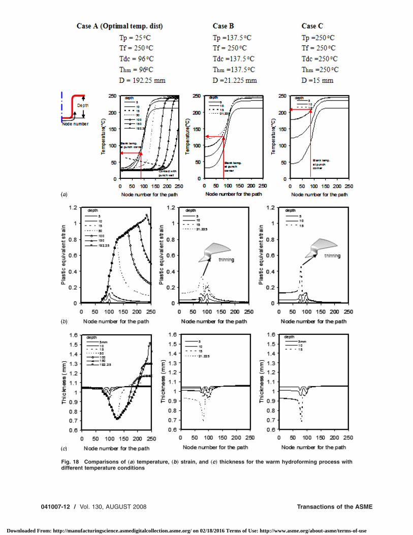
Fig. 18 Comparisons of „a… temperature, „b… strain, and „c… thickness for the warm hydroforming process with
different temperature conditions41007-12 / Vol. 130, AUGUST 2008 Transactions of the ASME
om: http://manufacturingscience.asmedigitalcollection.asme.org/ on 02/18/2016 Terms of Use: http://www.asme.org/about-asme/terms-of-use
tstTadttpttT4Ii
fttowtpa2
atcd�btrpc�wCbtwtcaCApit�uuip
5
fitc
J
Downloaded Fr
emperature level at the punch region enhances the materialtrength and hence enables high drawing force. The high flangeemperature is desirable to reduce flow stress in the flange region.he die corner and hydraulic medium temperature should be keptt low or medium temperature levels. Figure 17 shows the partepth prediction when the optimized temperature distributions de-ermined by three different approaches are used in fully coupledhermomechanical FEA. The adaptive-isothermal approach couldredict the part depth with reasonable accuracy with respect to thehermomechanical results with a substantial time saving. The rela-ive time needed for each approach is also compared in Fig. 17.he relative time used for adaptive-isothermal simulation was0% less than that of the fully coupled thermomechanical model.t is expected to realize substantial time savings if the adaptive-sothermal model is used for the three dimensional case models.
To further understand the effect of temperature distribution onormability in the warm hydroforming process, three differentemperature distribution cases were analyzed by fully coupledhermomechanical analysis and is shown in Fig. 18. In Case A, theptimal temperature distribution obtained in the previous sectionas assumed. In this case, the achievable part depth before 35%
hinning was 192 mm. Cases B and C had the same flange tem-erature �250°C�, but the punch temperature levels were 137.5°Cnd 250°C, respectively. Case B resulted in a part depth of1 mm, while Case C ended up with 15 mm of part depth.
Figure 18�a� illustrates the temperature distribution of the blankt different forming stages for each case �A, B, and C�. Initially,he blank material was at a uniform temperature of 25°C for allases. For Case A �optimal temperature�, a steep temperature gra-ient between the flange region �250°C� and punch region25°C� appeared once forming proceeded. Due to the conductionetween the flange region and the punch region and the convec-ion with the hydraulic fluid, the temperature of the punch corneregion �Node 85� increased to 86°C within 3 s corresponding to aart depth of 15 mm. For Case B, the temperature of the punchorner region �Node 85� was at 136.4°C at the same part depth15 mm�. In Case C, the temperature near the punch corner regionas 200.4°C in 3 s corresponding to a part depth of 15 mm.onsidering the initial blank temperature �25°C�, the increase inlank temperature was large due to the high conductivity of ma-erial. For Case A, once the material contacted with the punchall, the temperature dropped quickly because of contact between
he punch wall and the blank material �Fig. 18�. Therefore, in-reased material strength at low temperature and wall friction en-bled a higher drawing force and less thinning. On the contrary,ases B and C resulted in localized thinning at small part depths.t high punch temperature level �137°C and 250°C�, the tem-erature of the blank material, which contacts with the punch,ncreased quickly. Therefore, the flow stress decreased at the highemperature. A local thinning was found near the punch cornerFigs. 18�b� and 18�c�� in both Cases B and C. If Case C �highniform temperature� is compared with cold hydroforming �Fig-re 10�, Case C has slightly lower part depth. This means that anmproper temperature distribution, even if higher, can result inoor formability compared to the cold hydroforming case.
Discussion and ConclusionsA mechanism for understanding warm hydroforming, as well as
or studying the effect of temperature distribution on the formabil-ty of the lightweight materials under warm hydroforming condi-ions, was investigated in this study. In summary, the followingonclusions can be drawn.
�1� Based on the comparison of three different processes andtemperature optimization, the following guidelines are sug-gested to increase formability in warm hydroforming pro-cess: �a� The punch should be kept cold �25°C� to decreasethe blank temperature and increase the material strength at
the punch and die corner regions by the contact heat trans-ournal of Manufacturing Science and Engineering
om: http://manufacturingscience.asmedigitalcollection.asme.org/ on 02/18
fer. �b� The flange region should be kept at the high tem-perature �250°C� to ease the flow of blank material into diecavity. �c� The die corner and hydraulic fluid should be atlow or medium temperature levels �100°C�. The effect ofhydraulic fluid temperature was found to be insignificant.Convective heat transfer coefficient �30–180 W /m2 K� be-tween the hydraulic fluid �oil or water� and the blank wasmuch less than the contact heat transfer coefficient�1400 W /m2 K� between the tooling and the blank. As aresult, temperature distribution and material property weremostly governed by the neighboring tooling temperature.�d� Hydraulic pressure levitated the blank material on thedie corner and decreased radial stress level. At the punchface and punch wall region, the friction force sharesstretching force and helps to release the stress of the blankmaterial, which causes thinning. Finally, all these effectslead to minimizing local thinning.
�2� A novel approach, adaptive-isothermal FEA/DOE, is dem-onstrated to result in rapid and accurate prediction of theproper temperature distribution. The computational timesaving can be as high as 40% compared to the thermome-chanical FEA/DOE approach. This approach adaptively as-sumes the temperature �or boundary� conditions of the rigidtooling onto the blank material depending on the Pecletnumber. Hence, it accurately represents the heat transfereffects reasonably while maintaining the time saving ben-efits as opposed to the fully coupled thermomechanicalsimulations.
�3� For ultimate success in warm hydroforming, in conjunctionwith the determination of optimal temperature, optimalloading paths for hydraulic pressure, punch speed, and BHFshould be determined. This work is also conducted in thecontinued study �10�.
References�1� Schultz, R. A., 1999, “Aluminum for Light Vehicles—An Objective Look at
the Next Ten to Twenty Years” 14th International Aluminum Conference, Mon-treal, Canada, Ducker Research, Sept. 15.
�2� Carpenter, J. A., 2004, “The Freedomcar Challenge and Steel,” American Ironand Steel Institute, Great Designs in Steel Seminar, Livonia MI, Feb., pp.96–111.
�3� Mildenberger, U., and Khare, A., 2000, “Planning for an Environment-Friendly Car,” Technovation, 20, pp. 205–214.
�4� Groche, P., 2002, “Hydromechanical Deep-Drawing of Aluminum-Alloys atElevated Temperature,” CIRP Ann., 51�1�, pp. 215–218.
�5� Groche, P., and Dörr, J., 2004, personal communications, Darmstadt Univer-sity.
�6� Siegert, K., 2003, “Pneumatic Bulging of Magnesium Az31 Sheet Metals atElevated Temperatures,” CIRP Ann., 52�1�, pp. 241–244.
�7� Siegert, K., and Jäger, S., 2004, “Warm Forming of Magnesium Sheet Metal,”SAE 2004 World Congress & Exhibition, Detroit, MI, Mar., Paper No. 2004-01-1043.
�8� Novotny, S., 2003, “Process Design for Hydroforming of Lightweight MetalSheets at Elevated Temperatures,” J. Mater. Process. Technol., 138, pp. 594–599.
�9� Li, D., and Ghosh, A., 2003, “Tensile Deformation Behavior of AluminumAlloys at Warm Forming Temperatures,” Mater. Sci. Eng., A, 352�1–2�, pp.279–286.
�10� Choi, H., Koc, M., and Ni, J., 2007, “Determination of Optimal Loading Pro-files in Warm Hydroforming of Lightweight Materials,” J. Mater. Process.Technol., 190�1–3�, pp. 230–242.
�11� Kim, H. S., Koc, M., and Ni, J., 2004, “Determination of Proper TemperatureDistribution for Warm Forming of Aluminum Sheet Materials,” ASME J.Manuf. Sci. Eng., 128�3�, pp. 622–633.
�12� van den Boogaard, A. H., and Huetink, J., 2006, “Simulation of AluminumSheet Forming at Elevated Temperatures,” Comput. Methods Appl. Mech.Eng., 195�48–49�, pp. 6691–6709.
�13� Takata, K., Ohwue, T., Saga, M., and Kikuchi, M., 2006, “Formability ofAl–Mg Alloy at Warm Temperature,” Mater. Sci. Forum, 331–337, pp. 631–636.
�14� Abedrabbo, N., Pourboghrat, F., and Carsley, J., 2006, “Forming of AluminumAlloys at Elevated Temperature—Part 2: Numerical Modeling and Experimen-tal Verification,” Int. J. Plast., 22�2�, pp. 342–373.
�15� Kim, H. S., Koc, M., and Ni, J., 2006, “Finite Element Modeling and Analysisof Warm Forming of Aluminum Alloys—Validation Through ComparisonWith Experiments and Determination of a Failure Criterion,” ASME J. Manuf.
Sci. Eng., 128�3�, pp. 613–621.AUGUST 2008, Vol. 130 / 041007-13
/2016 Terms of Use: http://www.asme.org/about-asme/terms-of-use

0
Downloaded Fr
�16� ABAQUS user manual, Hks.�17� Dröeder, K. G., 1999, “Untersuchungen Zum Umformen Von Veinblenchen
Aus Magnesiumknetlegiereungen,” Ph.D. thesis, University of Hannover.�18� Jäger, S., 2004, personal communications, Stuttgart University.�19� Choi, H., Koc, M., and Ni, J., 2007, “A Study on the Analytic Modeling for
Warm Hydro-Mechanical Deep Drawing of Lightweight Materials,” Int. J.
41007-14 / Vol. 130, AUGUST 2008
om: http://manufacturingscience.asmedigitalcollection.asme.org/ on 02/18
Mach. Tools Manuf., 47�11�, pp. 1752–1766.�20� Takuda, H., 2002, “Finite Element Simulation of Deep Drawing of Aluminum
Alloy Sheet With Accounting for Heat Conduction,” J. Mater. Process. Tech-nol., 120, pp. 412–418.
�21� Montgomery, D. C., Design and Analysis of Experiments, 5th ed., Wiley, NewYork.
Transactions of the ASME
/2016 Terms of Use: http://www.asme.org/about-asme/terms-of-use