a study on chair design by interactive three-dimensional ...
10
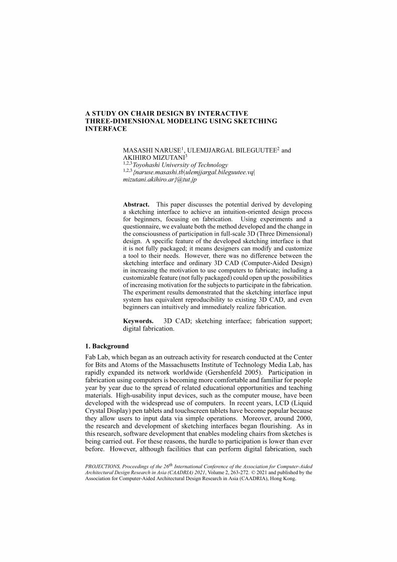
A STUDY ON CHAIR DESIGN BY INTERACTIVE THREE-DIMENSIONAL MODELING USING SKETCHING INTERFACE MASASHI NARUSE 1 , ULEMJJARGAL BILEGUUTEE 2 and AKIHIRO MIZUTANI 3 1,2,3 Toyohashi University of Technology 1,2,3 {naruse.masashi.tb|ulemjjargal.bileguutee.vq| mizutani.akihiro.ar}@tut.jp Abstract. This paper discusses the potential derived by developing a sketching interface to achieve an intuition-oriented design process for beginners, focusing on fabrication. Using experiments and a questionnaire, we evaluate both the method developed and the change in the consciousness of participation in full-scale 3D (Three Dimensional) design. A specific feature of the developed sketching interface is that it is not fully packaged; it means designers can modify and customize a tool to their needs. However, there was no difference between the sketching interface and ordinary 3D CAD (Computer-Aided Design) in increasing the motivation to use computers to fabricate; including a customizable feature (not fully packaged) could open up the possibilities of increasing motivation for the subjects to participate in the fabrication. The experiment results demonstrated that the sketching interface input system has equivalent reproducibility to existing 3D CAD, and even beginners can intuitively and immediately realize fabrication. Keywords. 3D CAD; sketching interface; fabrication support; digital fabrication. 1. Background Fab Lab, which began as an outreach activity for research conducted at the Center for Bits and Atoms of the Massachusetts Institute of Technology Media Lab, has rapidly expanded its network worldwide (Gershenfeld 2005). Participation in fabrication using computers is becoming more comfortable and familiar for people year by year due to the spread of related educational opportunities and teaching materials. High-usability input devices, such as the computer mouse, have been developed with the widespread use of computers. In recent years, LCD (Liquid Crystal Display) pen tablets and touchscreen tablets have become popular because they allow users to input data via simple operations. Moreover, around 2000, the research and development of sketching interfaces began flourishing. As in this research, software development that enables modeling chairs from sketches is being carried out. For these reasons, the hurdle to participation is lower than ever before. However, although facilities that can perform digital fabrication, such PROJECTIONS, Proceedings of the 26 th International Conference of the Association for Computer-Aided Architectural Design Research in Asia (CAADRIA) 2021, Volume 2, 263-272. © 2021 and published by the Association for Computer-Aided Architectural Design Research in Asia (CAADRIA), Hong Kong.
-
Upload
khangminh22 -
Category
Documents
-
view
1 -
download
0
Transcript of a study on chair design by interactive three-dimensional ...
A STUDY ON CHAIR DESIGN BY INTERACTIVETHREE-DIMENSIONAL MODELING USING SKETCHINGINTERFACE
MASASHI NARUSE1, ULEMJJARGAL BILEGUUTEE2 andAKIHIRO MIZUTANI31,2,3Toyohashi University of Technology1,2,3{naruse.masashi.tb|ulemjjargal.bileguutee.vq|mizutani.akihiro.ar}@tut.jp
Abstract. This paper discusses the potential derived by developinga sketching interface to achieve an intuition-oriented design processfor beginners, focusing on fabrication. Using experiments and aquestionnaire, we evaluate both the method developed and the change inthe consciousness of participation in full-scale 3D (Three Dimensional)design. A specific feature of the developed sketching interface is thatit is not fully packaged; it means designers can modify and customizea tool to their needs. However, there was no difference between thesketching interface and ordinary 3D CAD (Computer-Aided Design)in increasing the motivation to use computers to fabricate; including acustomizable feature (not fully packaged) could open up the possibilitiesof increasing motivation for the subjects to participate in the fabrication.The experiment results demonstrated that the sketching interface inputsystem has equivalent reproducibility to existing 3D CAD, and evenbeginners can intuitively and immediately realize fabrication.
Keywords. 3D CAD; sketching interface; fabrication support;digital fabrication.
1. BackgroundFab Lab, which began as an outreach activity for research conducted at the Centerfor Bits and Atoms of the Massachusetts Institute of Technology Media Lab, hasrapidly expanded its network worldwide (Gershenfeld 2005). Participation infabrication using computers is becoming more comfortable and familiar for peopleyear by year due to the spread of related educational opportunities and teachingmaterials. High-usability input devices, such as the computer mouse, have beendeveloped with the widespread use of computers. In recent years, LCD (LiquidCrystal Display) pen tablets and touchscreen tablets have become popular becausethey allow users to input data via simple operations. Moreover, around 2000,the research and development of sketching interfaces began flourishing. As inthis research, software development that enables modeling chairs from sketches isbeing carried out. For these reasons, the hurdle to participation is lower than everbefore. However, although facilities that can perform digital fabrication, such
PROJECTIONS, Proceedings of the 26th International Conference of the Association for Computer-AidedArchitectural Design Research in Asia (CAADRIA) 2021, Volume 2, 263-272. © 2021 and published by theAssociation for Computer-Aided Architectural Design Research in Asia (CAADRIA), Hong Kong.

264 M. NARUSE, U. BILEGUUTEE AND A. MIZUTANI
as Fab Lab, are becoming more common and a personal fabrication revolutionis taking place, such fabrication remains far from easy for those not associatedwith it. In the general participation process of (1) training to use software suchas CAD (Computer-Aided Design) and CAM (Computer-Aided Manufacturing)and (2) designing and processing one’s work, the education conducted for skillacquisition is by no means “fun.” Information on design input using LCD pentablets and touchscreens has not been fully clarified yet. Moreover, currently, theuse of digital tools to reach a user’s sound design is not well understood.
2. Research objectivesThis study aims to confirm whether the following two objectives could beachieved: (1) developing a straightforward design input method to aid beginnerswho do not possess specialized knowledge and skills to easily operate, design,process, and fabricate by their intuition and (2) opening up fabrication tosociety using digital carving technology by eliminating the requirement to learnthree-dimensional (3D) CAD, which is a prerequisite for participation and isinfluencing the field of architecture and furniture design. First, we developed amethod that enables beginners’ participation in fabrication using digital designand digital processing technology without having to learn 3D CAD. Specifically,we created a system that allows beginners to design chairs. We focused on thefollowing operations from 3D CAD in ordinary digital fabrication: (1) makedesign input/editing possible as if sketching with paper and pen, (2) automatedetail generation for component mounting, and (3) semiautomate data generationrequired to operate the processing machine.
3. Introduction of interactive 3D modeling by sketching interface3.1. RELATED WORK
In a previous study (Mizutani et al. 2019) that focused on CNC (ComputerNumerical Control) chair fabrication, the authors devised a system that enabledpeople unfamiliar with CAD operations to design. However, research on designinput methods, specifically device studies, had not yet been conducted. Aninteractive tool called SILK (Sketching Interfaces Like Krazy) (Landay andMyers2001) is one of the pioneering technologies classified as sketching interfaces;its system replaces designing through traditional CAD graphical user interfaceswith just sketching. Research on two-dimensional (2D) graphics, such as screenand website design, as well as on sketching interfaces for 3D graphics has beenconducted in the same manner. As the first example of incorporating interactivity,SKETCH (Zeleznik et al. 2006) was remarked upon as being different fromthe earlier batch-processing approach of outputting the line drawing input to thecomputer as a 3D shape. These studies clarified that even beginners and childrenwith no experience in 3D graphics can easily create 3D models using a sketchinginterface. Research on and development of such methods have been activelyconducted since around 2000, and a review of those studies was conducted byIgarashi (2006).
The most similar study to our research was on SketchChair (Greg Saul et al.

A STUDY ON CHAIR DESIGN BY INTERACTIVETHREE-DIMENSIONAL MODELING USING SKETCHING
INTERFACE
265
2011), a system that allows users to design a chair by merely inputting a sideview (2D) of the chair from the user interface. The system’s primary feature isthat it allows a human being to sit on the generated chair model within a physicsengine, which then performs a stability analysis. The chair’s stability and theperson’s sitting posture when sitting can be visually confirmed, enabling usersto envision the size, scale, and sitting comfort with ease. In other words, thesystem is equipped with functions that support novices who do not possess sucha skill set or knowledge to design original chairs. In ordinary furniture design,3D CAD is used not only to design shapes but also to create design drawings andprocessing data. One of the features of such a system that can be considered asboth an advantage and disadvantage is that the design drawings for processingchair parts are automatically generated by the software. At about the same timeas the release of SketchChair, Kostas Terzidis pointed out in his book (2006) that,currently, designers cannot demonstrate their creativity because toolmakers suchas software vendors have prepared essential parts of the design process in advanceso that the designers are mere “tool users” who tweak the form within a range ofprearranged operability. So it cannot be said that SketchChair is out of the categoryof “tool maker” and “tool user” defined by Kostas Terzidis and that users cannotbe more creative than they are supposed to. Additionally, it cannot be said thatwe should expect to see an effect of increasing the willingness to participate infull-scale 3D design and encouraging opportunities for participation beyond that.Nearly a decade has passed since the release of SketchChair, but to date, the inputand design methods of other sketching interfaces have not been generalized. Thereasons for this are (1) the emergence of easy-to-learn software such as SketchUp,which has made 3D design itself more effortless, and (2) the emergence of visualprogramming interfaces, which make it possible for designers to write their ownalgorithms and develop original tools.
3.2. SYSTEM OVERVIEW
In this research, we mainly aim to get users actively involved in full-scale 3Ddesign after making chairs using the developed system. Therefore, the designprocess was conducted by leaving a yohaku (i.e., a design mechanism withflexibility to adapt to the user’s skill level) in the support system so that thedesigners could modify and customize the tools to their needs. The base systemfor development was powered by Rhinoceros and Grasshopper (Robert McNeel& Associates; developed by the Rhinoceros plug-in graphical algorithm editor),which are design platforms providing user-friendly programming environmentsand compatibility with open-source plugins. The specific system configurationswere (1) creating a web application-based sketching interface, (2) enabling theuser to customize, on Rhinoceros and Grasshopper, dimensions of chair part anddetails of joints for assembling. This system is intended for people who have noexperience with 3D CAD that includes up to inexperienced architects in 3D frompeople who are not professional. How to use the system differs depending on theuser’s skill level in 3D design. Although some design restrictions are set as theinitial stage, it is assumed that the tools will be modified later according to theuser’s wishes. This statement is the true meaning of yohaku.
266 M. NARUSE, U. BILEGUUTEE AND A. MIZUTANI
3.3. SUPPORT SYSTEM FEATURES
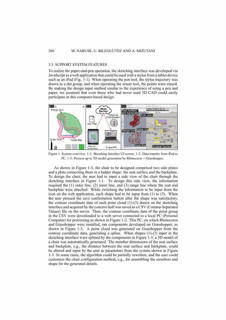
To realize the paper-and-pen operation, the sketching interface was developed viaJavaScript as a web application that could be used with a stylus from a tablet devicesuch as an iPad (Fig. 1-1). When operating the pen tool, the stylus trajectory wasdrawn as a dot group, and when operating the eraser tool, the points were erased.By making the design input method similar to the experience of using a pen andpaper, we assumed that even those who had never used 3D CAD could easilyparticipate in this computer-based design.
Figure 1. System overview. 1-1: Sketching interface UI screen. 1-2: Data transfer from iPad toPC. 1-3: Process up to 3D model generation by Rhinoceros + Grasshopper.
As shown in Figure 1-3, the chair to be designed comprised two side platesand a plate connecting them in a ladder shape: the seat surface and the backplate.To design the chair, the user had to input a side view of the chair through thesketching interface in Figure 1-1. To design this side view, the informationrequired the (1) outer line, (2) inner line, and (3) range line where the seat andbackplate were attached. While switching the information to be input from theicon on the web application, each shape had to be input from (1) to (3). Whenthe user pressed the save confirmation button after the shape was satisfactory,the contour coordinate data of each point cloud (1)-(3) drawn on the sketchinginterface and acquired by the concave hull was saved as a CSV (Comma-SeparatedValues) file on the server. Then, the contour coordinate data of the point groupin the CSV were downloaded to a web server connected to a local PC (PersonalComputer) for processing as shown in Figure 1-2. This PC, on which Rhinocerosand Grasshopper were installed, ran components developed on Grasshopper, asshown in Figure 1-3. A point cloud was generated on Grasshopper from thecontour coordinate data, generating a spline. When shapes (1)-(3) input in thesketching interface were splined by the components in Figure 1-3, a 3D model ofa chair was automatically generated. The member dimensions of the seat surfaceand backplate, e.g., the distance between the seat surface and backplate, couldbe altered and input by the user as parameters from the system shown in Figure1-3. In some cases, the algorithm could be partially rewritten, and the user couldcustomize the chair configuration method, e.g., for assembling the members andshape for the generated details.
A STUDY ON CHAIR DESIGN BY INTERACTIVETHREE-DIMENSIONAL MODELING USING SKETCHING
INTERFACE
267
This process summarized above was repeated until the user was satisfied.When the user reached their ideal chair design, the operation data for the digitalprocessing machine, such as a CNC router, were generated. Since the systemshown in Figure 1-3 could automatically output the spline data required forgenerating the operation data, easily performing the series of CAD operationsrequired for generating the G-code was possible. Thus, via the above procedure,we built a mechanism that allows users to participate in computer-based designimmediately and without learning 3D CAD.
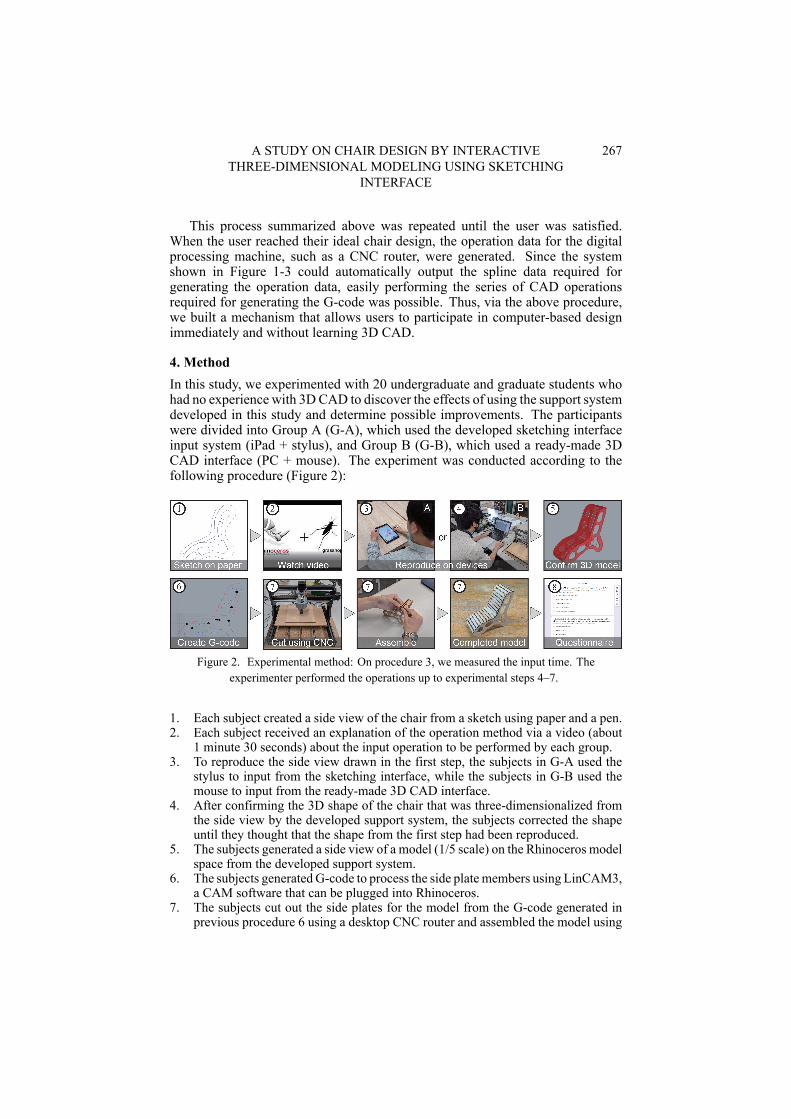
4. MethodIn this study, we experimented with 20 undergraduate and graduate students whohad no experience with 3DCAD to discover the effects of using the support systemdeveloped in this study and determine possible improvements. The participantswere divided into Group A (G-A), which used the developed sketching interfaceinput system (iPad + stylus), and Group B (G-B), which used a ready-made 3DCAD interface (PC + mouse). The experiment was conducted according to thefollowing procedure (Figure 2):
Figure 2. Experimental method: On procedure 3, we measured the input time. Theexperimenter performed the operations up to experimental steps 4–7.
1. Each subject created a side view of the chair from a sketch using paper and a pen.2. Each subject received an explanation of the operation method via a video (about
1 minute 30 seconds) about the input operation to be performed by each group.3. To reproduce the side view drawn in the first step, the subjects in G-A used the
stylus to input from the sketching interface, while the subjects in G-B used themouse to input from the ready-made 3D CAD interface.
4. After confirming the 3D shape of the chair that was three-dimensionalized fromthe side view by the developed support system, the subjects corrected the shapeuntil they thought that the shape from the first step had been reproduced.
5. The subjects generated a side view of a model (1/5 scale) on the Rhinoceros modelspace from the developed support system.
6. The subjects generated G-code to process the side plate members using LinCAM3,a CAM software that can be plugged into Rhinoceros.
7. The subjects cut out the side plates for the model from the G-code generated inprevious procedure 6 using a desktop CNC router and assembled the model using
268 M. NARUSE, U. BILEGUUTEE AND A. MIZUTANI
the precut seat surface and backplate parts.8. The subjects responded to a questionnaire survey on the system’s use as developed
for the participants and their own changes in consciousness regarding fabricationusing computers.
5. Results from user experiment and Discussion5.1. QUESTIONNAIRE RESULT AND DISCUSSION
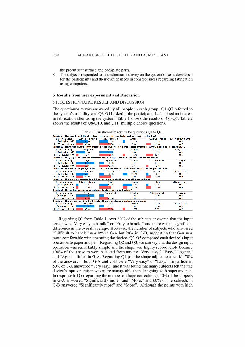
The questionnaire was answered by all people in each group. Q1-Q7 referred tothe system’s usability, and Q8-Q11 asked if the participants had gained an interestin fabrication after using the system. Table 1 shows the results of Q1-Q7, Table 2shows the results of Q8-Q10, and Q11 (multiple choice question).
Table 1. Questionnaire results for questions Q1 to Q7.
Regarding Q1 from Table 1, over 80% of the subjects answered that the inputscreen was “Very easy to handle” or “Easy to handle,” and there was no significantdifference in the overall average. However, the number of subjects who answered“Difficult to handle” was 0% in G-A but 20% in G-B, suggesting that G-A wasmore comfortable with operating the device. Q2-Q5 compared each device’s inputoperation to paper and pen. Regarding Q2 and Q3, we can say that the design inputoperation was remarkably simple and the shape was highly reproducible because100% of the answers were selected from among “Very easy,” “Easy,” “Agree,”and “Agree a little” in G-A. Regarding Q4 (on the shape adjustment work), 70%of the answers in both G-A and G-B were “Very easy” or “Easy.” In particular,50% of G-A answered “Very easy,” and it was found that many subjects felt that thedevice’s input operation was more manageable than designing with paper and pen.In response to Q5 (regarding the number of shape corrections), 50% of the subjectsin G-A answered “Significantly more” and “More,” and 60% of the subjects inG-B answered “Significantly more” and “More”. Although the points with high
A STUDY ON CHAIR DESIGN BY INTERACTIVETHREE-DIMENSIONAL MODELING USING SKETCHING
INTERFACE
269
response rates of “Significantly more” and “More” were nearly the same in bothG-A and B, it can be inferred that the factors are different. Considering the answersof the subjects in G-A to Q2, Q3, and Q4, this might have been related to thedevice’s straightforwardness compared with using paper and pen, suggesting thatcorrections were easily repeatable. However, G-B used a ready-made softwarewherein the spline’s control points could be controlled by free mouse operation.More slight adjustments could bemade thanwith paper and pen, whichwas cited asa factor that increased the number of corrections. Besides regarding Q5, even 40%of subjects in G-A answered “Same,” it can be inferred the developed sketch inputsystem is closer to the operation of pen and paper. Regarding Q6 and Q7, 100%of the respondents in both groups answered “Agree” or “Agree a little.” For Q7(concerning the difficulty of the work), 80% of the subjects in G-A answered “Veryeasy.” Therefore, it was found that the developed sketching interface achievedimmediate and highly satisfying design input.
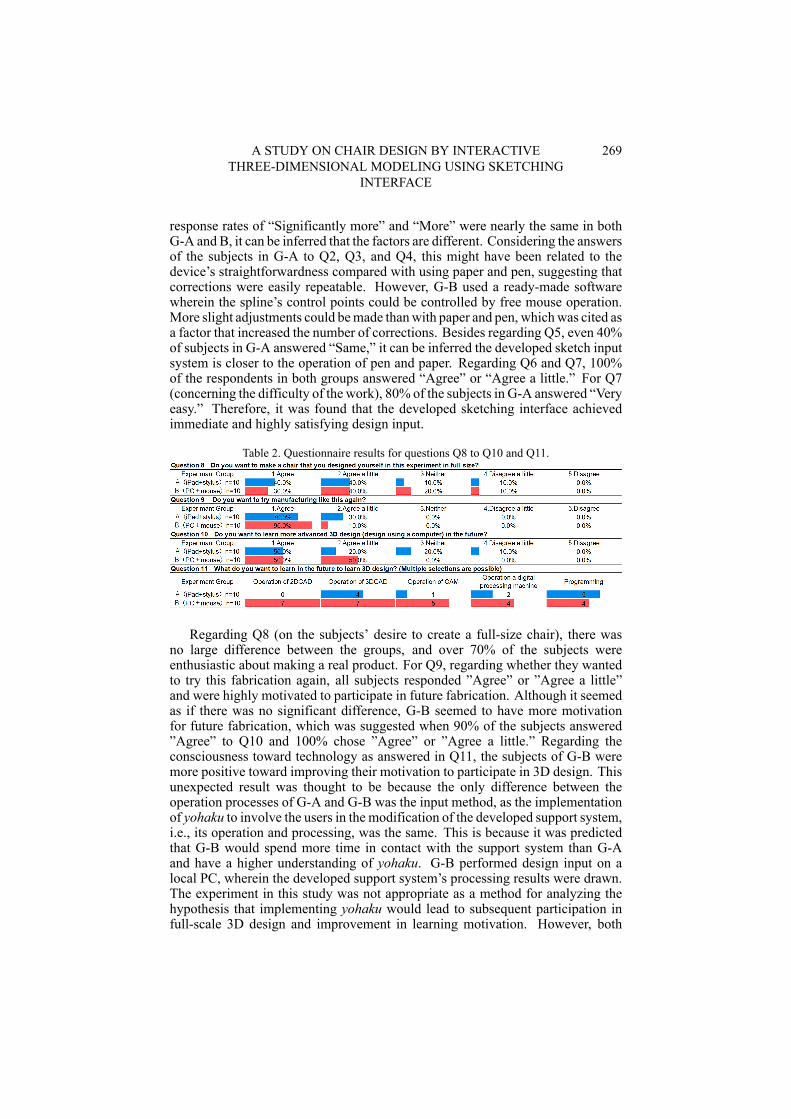
Table 2. Questionnaire results for questions Q8 to Q10 and Q11.
Regarding Q8 (on the subjects’ desire to create a full-size chair), there wasno large difference between the groups, and over 70% of the subjects wereenthusiastic about making a real product. For Q9, regarding whether they wantedto try this fabrication again, all subjects responded ”Agree” or ”Agree a little”and were highly motivated to participate in future fabrication. Although it seemedas if there was no significant difference, G-B seemed to have more motivationfor future fabrication, which was suggested when 90% of the subjects answered”Agree” to Q10 and 100% chose ”Agree” or ”Agree a little.” Regarding theconsciousness toward technology as answered in Q11, the subjects of G-B weremore positive toward improving their motivation to participate in 3D design. Thisunexpected result was thought to be because the only difference between theoperation processes of G-A and G-B was the input method, as the implementationof yohaku to involve the users in the modification of the developed support system,i.e., its operation and processing, was the same. This is because it was predictedthat G-B would spend more time in contact with the support system than G-Aand have a higher understanding of yohaku. G-B performed design input on alocal PC, wherein the developed support system’s processing results were drawn.The experiment in this study was not appropriate as a method for analyzing thehypothesis that implementing yohaku would lead to subsequent participation infull-scale 3D design and improvement in learning motivation. However, both
270 M. NARUSE, U. BILEGUUTEE AND A. MIZUTANI
groups showed a high level of motivation to participate in fabrication in the future,indicating the usefulness of a design system that leaves in a mechanism that is notfully packaged.
5.2. ANALYSIS AND CONSIDERATION OF THE MATCH RATE OF FIGURES
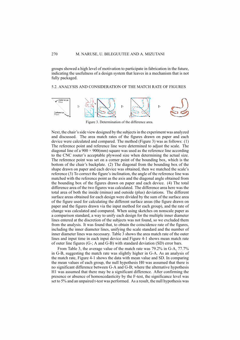
Figure 3. Determination of the difference area.
Next, the chair’s side view designed by the subjects in the experiment was analyzedand discussed. The area match rates of the figures drawn on paper and eachdevice were calculated and compared. The method (Figure 3) was as follows: (1)The reference point and reference line were determined to adjust the scale. Thediagonal line of a 900 × 900(mm) square was used as the reference line accordingto the CNC router’s acceptable plywood size when determining the actual size.The reference point was set on a corner point of the bounding box, which is thebottom of the chair’s backplate. (2) The diagonal from the bounding box of theshape drawn on paper and each device was obtained, then we matched the scale’sreference (3) To correct the figure’s inclination, the angle of the reference line wasmatched with the reference point as the axis and the diagonal angle obtained fromthe bounding box of the figures drawn on paper and each device. (4) The totaldifference area of the two figures was calculated. The difference area here was thetotal area of both the inside (minus) and outside (plus) deviations. The differentsurface areas obtained for each design were divided by the sum of the surface areaof the figure used for calculating the different surface areas (the figure drawn onpaper and the figures drawn via the input method for each group), and the rate ofchange was calculated and compared. When using sketches on nonscale paper asa comparison standard, a way to unify each design for the multiple inner diameterlines entered at the discretion of the subjects was not found, so we excluded themfrom the analysis. It was found that, to obtain the coincidence rate of the figures,including the inner diameter lines, unifying the scale standard and the number ofinner diameter lines was necessary. Table 3 shows the area match rate of the outerlines and input time in each input device and Figure 4-1 shows mean match rateof outer line figures (G-; A and G-B) with standard deviation (SD) error bars.
From Table 3, the average value of the match rate was 79.2% in G-A, 77.7%in G-B, suggesting the match rate was slightly higher in G-A. As an analysis ofthe match rate, Figure 4-1 shows the data with mean value and SD. In comparingthe mean values of each group, the null hypothesis H0 was assumed that there isno significant difference between G-A and G-B; where the alternative hypothesisH1 was assumed that there may be a significant difference. After confirming thepresence or absence of homoscedasticity by the F-test, the significance level wasset to 5% and an unpaired t-test was performed. As a result, the null hypothesis was
A STUDY ON CHAIR DESIGN BY INTERACTIVETHREE-DIMENSIONAL MODELING USING SKETCHING
INTERFACE
271
accepted because the p-value was greater than the significance level of 5%, and nosignificant difference could be confirmed [ t (18) = 0.36, p = 0.7233 ]. Since nosignificant difference could be confirmed and the difference in the matching rate ofeach group was small, it can be said that each input device has the same degree ofgraphic reproducibility. Next, the analysis was performed against the input time.From Table 3, the average input time was 469 (s) for G-A, and 873 (s) for G-Bwhich was shorter for G-A. Figure 4-2 shows the data with mean value and SD. Incomparing themean values of each group, the null hypothesis H0was assumed thatthere is no significant difference between groups; where the alternative hypothesisH1 was assumed that there may be a significant difference. After confirming thepresence or absence of homoscedasticity by F-test, the significance level was setto 5% and an unpaired t-test was performed. As a result, it was found that the nullhypothesis was rejected because the p value was smaller than the significance levelof 5%, and there was a significant difference[ t (14) = 3.33, p = 0.0049]. Since asignificant difference was confirmed, the confidence interval (CI) was calculatedand found to be 95%, CI = (358, 580) in G-A; 95%, CI = (663, 1084) in G-B.
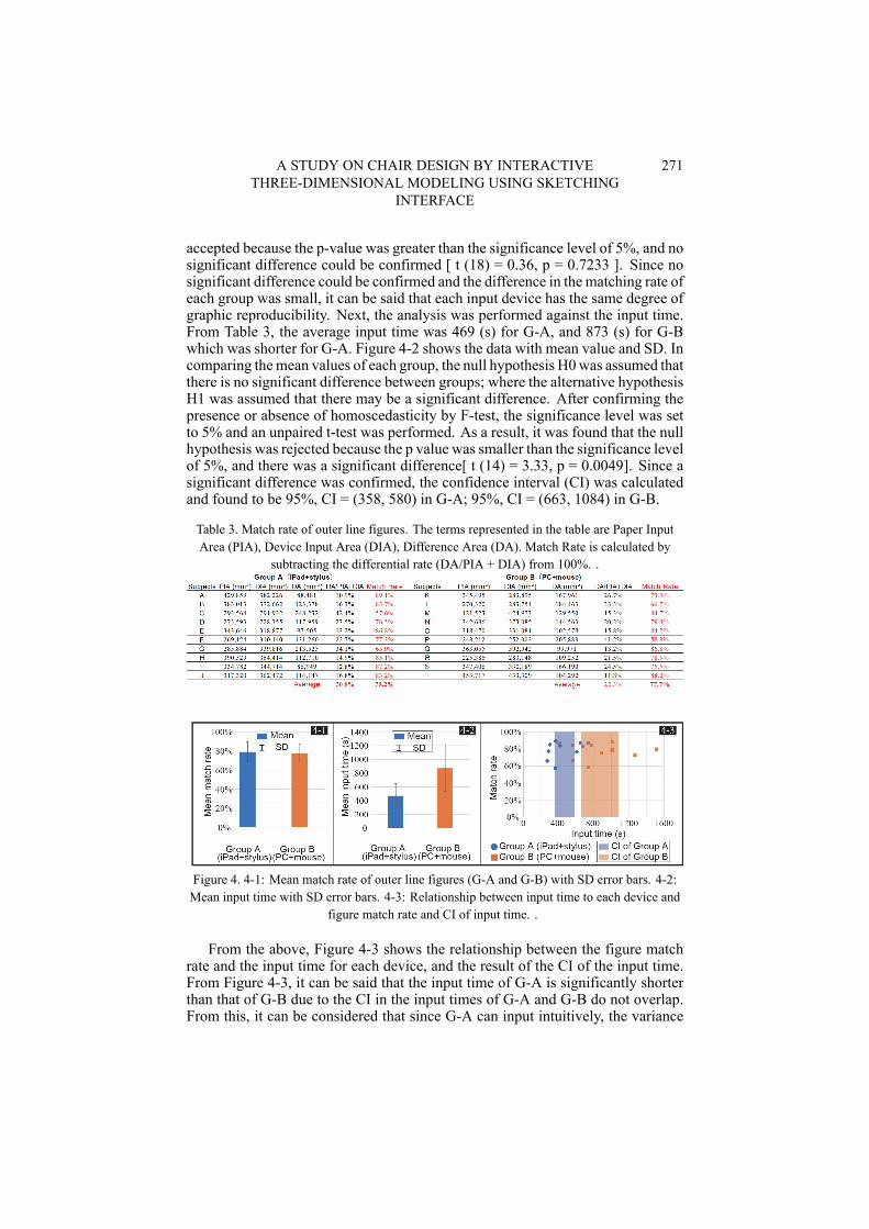
Table 3. Match rate of outer line figures. The terms represented in the table are Paper InputArea (PIA), Device Input Area (DIA), Difference Area (DA). Match Rate is calculated by
subtracting the differential rate (DA/PIA + DIA) from 100%. .
Figure 4. 4-1: Mean match rate of outer line figures (G-A and G-B) with SD error bars. 4-2:Mean input time with SD error bars. 4-3: Relationship between input time to each device and
figure match rate and CI of input time. .
From the above, Figure 4-3 shows the relationship between the figure matchrate and the input time for each device, and the result of the CI of the input time.From Figure 4-3, it can be said that the input time of G-A is significantly shorterthan that of G-B due to the CI in the input times of G-A and G-B do not overlap.From this, it can be considered that since G-A can input intuitively, the variance
272 M. NARUSE, U. BILEGUUTEE AND A. MIZUTANI
of the input time by the subject is small and the figure can be reproduced in ashorter time than G-B. By contrast, in G-B, it can be considered that the varianceof the input time among the subjects became large due to the skill level of thesubject’s PC operation. From the above, it can be said that the developed sketchinput system has immediate reproducibility equivalent to that of existing 3D CAD,and even people without specialized knowledge can intuitively realize fabricationusing a computer.
6. Conclusion and Future WorkUsing the developed sketching interface, even beginners without specializedknowledge could reproduce designs as if sketching with paper and pen. Moreover,it was found that design input could be performed more easily and immediatelythan with ordinary 3D CAD. Herein, analyzing and considering the effect ofimproving people’s motivation to participate in fabrication using computers solelyby comparing the differences in design input methods were impossible. However,it has been shown that yohaku in a design systemmay increase people’s willingnessto participate, although comparing our developed systemwith other fully packagedsystems to determine whether this is accurate is necessary. In future research, if amethod to confirm the effect of implementing yohaku is developed, studies on howto construct such a system should be conducted. This could include researchinghow to determine the right amount of yohaku and developing a system that couldfurther open up fabrication using computers to society. By achieving this, thedeveloped tool will become more flexible to accommodate the user’s proficiencyin 3D design, and will contribute to raising the level of understanding of 3D designin the architecture industry in the future.
AcknowledgmentsThe research team would like to thank Michael Makoto Martinsen for assistancewith proofreading, Naoto Muramatsu for assistance with methodology, and theindividuals who participated in the experiments. This work was supported by JSPSKAKENHI Grant Number JP19K15169.
ReferencesGershenfeld, N.A.: 2005, FAB”:The Coming Revolution on Your Desktop-From Personal
Computers to Personal Fabrication, Basic Books.Igarashi, T.: 2006, Recent Trends in Sketching Interfaces, Computer Software, 23, 3-13.Kostas, T.: 2006, Algorithmic Architecture, Architectural Press.J.A. Landay and B.A. Myers (eds.): 2001, Sketching Interfaces: Toward More Human Interface
Design, IEEE.Mizutani, A., Karashima, K., Egami, F. and Muramatsu, N.: 2019, REPORT ON THE
UTILIZED OF A PUBLIC Fab FACILITY THROUGH CRAFTING WORKSHOP, AIJJ. Technol. Des, 25(59), 309-314.
Saul, G., Lau, M., Mitani, J. and Igarashi, T.: 2011, SketchChair: An All-in-one ChairDesign System for Endusers, The fifth International conference on Tangible, Embedded andEmbodied Interaction, Funchal, Portugal, 73-80.
Zeleznik, R.C., Herndon, K.P. and Hughes, J.F.: 2006, SKETCH: an interface for sketching 3Dscenes, ACM SIGGRAPH 2006, Boston, MA, USA, 9.