Catalytic cracking of hydrocarbons over modified ZSM-5 zeolites to produce light olefins A review
Upload
khangminh22Category
view
0download
0
energies
Review
A Review on the Production of Light Olefins Using SteamCracking of Hydrocarbons
Zahra Gholami 1,* , Fatemeh Gholami 2 , Zdenek Tišler 1 and Mohammadtaghi Vakili 3
�����������������
Citation: Gholami, Z.; Gholami, F.;
Tišler, Z.; Vakili, M. A Review on the
Production of Light Olefins Using
Steam Cracking of Hydrocarbons.
Energies 2021, 14, 8190. https://
doi.org/10.3390/en14238190
Academic Editor: Gianni Bidini
Received: 22 September 2021
Accepted: 3 December 2021
Published: 6 December 2021
Publisher’s Note: MDPI stays neutral
with regard to jurisdictional claims in
published maps and institutional affil-
iations.
Copyright: © 2021 by the authors.
Licensee MDPI, Basel, Switzerland.
This article is an open access article
distributed under the terms and
conditions of the Creative Commons
Attribution (CC BY) license (https://
creativecommons.org/licenses/by/
4.0/).
1 ORLEN UniCRE a.s., Revolucní 1521/84, 400 01 Ústí nad Labem, Czech Republic; [email protected] New Technologies—Research Centre, University of West Bohemia, 301 00 Plzen, Czech Republic;
[email protected] Green Intelligence Environmental School, Yangtze Normal University, Chongqing 408100, China;
[email protected]* Correspondence: [email protected]; Tel.: +420-471-122-239
Abstract: Light olefins are the main building blocks used in the petrochemical and chemical industriesfor the production of different components such as polymers, synthetic fibers, rubbers, and plasticmaterials. Currently, steam cracking of hydrocarbons is the main technology for the production oflight olefins. In steam cracking, the pyrolysis of feedstocks occurs in the cracking furnace, wherehydrocarbon feed and steam are first mixed and preheated in the convection section and thenenter the furnace radiation section to crack to the desired products. This paper summarizes olefinproduction via the steam cracking process; and the reaction mechanism and cracking furnace arealso discussed. The effect of different operating parameters, including temperature, residence time,feedstock composition, and the steam-to-hydrocarbon ratio, are also reviewed.
Keywords: olefin production; steam cracking; cracking furnace; ethylene; propylene; butenes;reaction parameters
1. Introduction
Light olefins, including ethylene, propylene, butenes, and butadiene, are the mainbuilding blocks used in chemical industries for the production of polymers, solvents,construction, synthetic fibers, etc. [1–3]. Ethylene can be used for the production ofpolyethylene, polyvinylchloride, etc. Due to increasing demand for polyethylene, ethyleneproduction is expected to increase from 169 million metric tons (MMT) in 2017 to 210 MMTin 2022. Propylene is used for the production of polypropylene, acrylonitrile, etc., with theproduction of about 116 MMT in 2017, which is expected to reach 142 MMT in 2022 [4]. Theannual production of butenes is around 132 MMT, and among these, isobutene is mainlyused as raw material for the production of alkylates, as well as to produce high-octaneadditives for gasoline blending, including MTBE and ETBE [5].
Different technologies have been used for the production of light olefins using differentfeedstocks, such as crude oil, natural gas, coal, and biomass (Figure 1) [6,7]. Natural gasused as a feedstock can go through various processes: (1) separation process to producemethane, ethane, and propane; (2) oxidative coupling of methane (OCM) via ethane;and (3) methanol production via steam reforming of natural gas [6]. The products ofthese processes can then go through further reactions to produce olefins as final products.Olefins are produced through different technologies, whereas steam cracking (SC) and fluidcatalytic cracking (FCC) are the main technologies for the production of light olefins [8–16].
Energies 2021, 14, 8190. https://doi.org/10.3390/en14238190 https://www.mdpi.com/journal/energies
Energies 2021, 14, 8190 2 of 25
Figure 1. Different technologies for olefin production, reproduced from [6].
Energies 2021, 14, 8190 3 of 25
Zhao et al. [14] performed a comprehensive economic analysis of twenty processes forthe production of light olefins using different sources of feedstock, including fossil fuels(natural gas, coal, and petroleum) and biomass and CO2 as renewable resources (Table 1).During this study [14], the SC process—the leading technology for olefin production—wasconsidered the benchmark. Their analysis revealed that currently almost all methods thatuse renewable resources are economically unattractive compared with the conventionalSC process.
Table 1. Description and attributes of conversion pathways [14].
No. Process Feedstock Main Products
1 Steam cracking of mixed petroleum (PSC) Naphtha Ethylene, propylene2 Steam cracking of ethane (ESC) Ethane Ethylene3 Propane dehydrogenation (PDH) Propane Propylene4 Catalytic pyrolysis process of heavy oil (CPP) Atmospheric residuum Ethylene, propylene5 Deep catalytic cracking of heavy oil (DCC) Wax oil Propylene
6 Coal gasification produces syngas; methanol is synthesizedfrom syngas and converted into olefins (CMTO) Coal Ethylene, propylene
7 NG reforming produces syngas; methanol is synthesized fromsyngas and converted into olefins (NMTO) NG Ethylene, propylene
8 Methanol is synthesized from CO2 hydrogenation andconverted into olefins (RMTO) CO2 and H2 Ethylene, propylene
9 Biomass gasification produces syngas; methanol issynthesized from syngas and converted into olefins (BMTO) Bio-waste Ethylene, propylene
10 Coal gasification produces syngas; methanol is synthesizedfrom syngas and converted into propylene (CMTP) Coal Propylene
11 NG reforming produce syngas; methanol is synthesized fromsyngas and converted into propylene (NMTP) NG Propylene
12 Methanol is synthesized from CO2 hydrogenation andconverted into propylene (RMTP) CO2 and H2 Propylene
13Biomass gasification produces syngas; methanol is
synthesized from syngas and converted into propylene(BMTP)
Bio-waste Propylene
14 Oxidative coupling of methane derived from NG (NOCM) NG Ethylene
15 Oxidative coupling of methane derived from hydrogenationof CO2 (ROCM) CO2 and H2 Ethylene
16 Oxidative coupling of methane derived from biogas (BOCM) Biomass Ethylene
17 Coal gasification produces syngas, and syngas is convertedinto olefins through FT synthesis (CFTO) Coal Ethylene, propylene
18 NG reforming produces syngas, and syngas is converted intoolefins through FT synthesis (NFTO) NG Ethylene, propylene
19 Biomass gasification produces syngas, and syngas isconverted into olefins through FT synthesis (BFTO) Bio-waste Ethylene, propylene
20 Ethanol is produced through anaerobic fermentation andconverted into ethylene through dehydration (BEDH) Ethanol Ethylene
The total production costs (TPCs) for olefin production via different technologiesare shown in Figure 2a. According to this analysis, the TPCs of processes includingNMTO, CMTO, BMTO, NMTP, CMTP, DCC, CPP, PDH, and ESC were lower than thoseof steam cracking. The coal-derived methods (CMTO and CMTP) with the lowest TPCswere economically competitive. However, all FTO processes had TPCs higher than thebenchmark, although the CFTO method had the lowest TPC among the FTO pathways.The BMTO and BMTP pathways had TPCs close to the benchmark; however, the TPCsof other processes using biomass-derived feedstocks (BOCM, BEDH, and BFTO) werehigher than the TPC of steam cracking. Olefin production processes using CO2 as feedstock(RMTO, RMTP, and ROCM) were found to be expensive. Figure 2b shows the individualcontribution of different parameters to the TPC of different production methods. The costof raw material was the main parameter affecting the TPCs in most of the processes. The

Energies 2021, 14, 8190 4 of 25
cost of raw materials in oil-derived technologies, including CCP, DCC, PSC, and PDH,was more than 75% of the TPC. The large byproduct revenues of the oil-derived pathwayshelped to offset the production costs. The byproduct revenues can offset the TPCs of PSC,CPP, and DCC by 41.9%, 46.3%, and 69.6%, respectively. In NG-derived processes (NFTO,NMTO, NOCM, NMTP, and ESC), the cost of raw materials constituted more than 65%of the TPC. In addition to the raw materials, the cost of utilities was around 13–24% inNG-derived processes. In the CO2-derived processes (RMTO, RMTP, and ROCM) the maincost of the raw material belonged to the cost of hydrogen. In coal- and biomass-derivedprocesses, except for BEDH and CFTO (BMTP, BMTO, BFTO, BOCM, CMTP, and CMTO),the costs of raw materials were around 39–51% of the TCPs. In CFTO and BEDH pathways,88.6% and 62.4% of TPCs corresponded to the cost of raw materials. The costs of utilitiesand depreciation were responsible for 27–40% and 12–31% of the TPCs, respectively [14].
Figure 2. (a) Total production costs of different olefin production technologies, (b) a detailed break-down of the TPCs of different production pathways [14].
Steam cracking is a conventional, well-known process for olefin production, and usingSC technology about 40% of the hydrocarbons are converted into olefins [17]. It has beenreported that conventional methods, such as the steam cracking of oil and ethane, are themost energy-efficient processes, with about 60 GJ per tons of high-value chemicals (HVCs).The total energy used in methane-based pathways (80 GJ/tHVCs) is about 30% higherthan that of conventional steam cracking methods. Coal- and biomass-based processes,with a total energy use of 90–130 GJ/tHVCs, consume about 60–150% more energy thanconventional methods [18]. The SC technology, with low CO2 emissions, is one of thebest-performing methods for olefin production, and without significant breakthroughs inprocess intensification, it will not be easy to replace this well-established technology [19].

Energies 2021, 14, 8190 5 of 25
About 70% of the production cost in a typical naphtha- or ethane-based cracking unitbelongs to the cost of the required energy [4], and this high energy demand is due to theendothermic characteristics of the cracking of the C–C bonds of the hydrocarbons [19]. Dueto the importance and increasing demand for olefins in chemical industries, this paperdiscusses the steam cracking process as a well-established technology for olefin production.The cracking furnace, including the radiation section (firebox) and convection section, areexplained. The effect of reaction parameters, including the temperature, residence time, thesteam-to-hydrocarbon ratio, and the feedstock composition are also described in this paper.
2. Steam Cracking
In industry, olefin plants are used for the production of ethylene and propylene, whichare the main feedstocks for the production of polyolefins, which account for 50–60% of allcommercial organic chemicals [1]. In the steam cracking process, saturated hydrocarbonsbreak into smaller unsaturated hydrocarbons through a reaction with steam. A schematicdiagram of the steam cracking process is shown in Figure 3 [20]. The feed for the steamcracking unit can be gaseous or liquid hydrocarbons, such as ethane, propane, butane,naphtha, and gas oil. Butadiene, butylene, aromatics, and benzene-rich pyrolysis gasolineare produced when heavy liquid feeds such as naphtha and gas oils are used as feedstock,whereas methane, ethylene, propylene, and benzene can be produced from any optionalfeedstocks [21].
Figure 3. Simplified block diagram for the typical steam cracking process [20].
The product distribution in steam cracking depends on the composition of the feed-stock, the hydrocarbon-to-steam ratio, cracking temperature, and residence time in thefurnace. Light olefins, including ethylene and propylene, are produced when light hy-drocarbons such as natural gas, ethane, and LPG (propane and butane) are used as thefeedstock of the steam cracker unit. The SC process comprises homogeneous pyrolysis ina tube furnace at around 800 ◦C with a short residence time of around one second [22].Steam cracking is the leading technology for ethylene production, and was developed inthe 1960s. Recent developments have been made to scale up the plants’ size and improvethe overall economics; however, its principles have not been changed [23]. The SC processproduces a very small percentage of total butene production. The yield of pyrolysis C4 ishighly dependent on the type of feedstock. C4 yields of almost 2% and 4% are reported forlight hydrocarbon feedstocks, ethane, and propane, respectively, whereas using naphthaand gas oil as the liquid feedstock resulted in around 12% of pyrolysis C4 [24]. Generally,based on the composition of the feedstock and the reaction conditions, the products ofsteam cracking contain 10–35 wt.% ethylene; 5–20 wt.% propylene; 1–15 wt.% C4 fractions,mainly butadiene and butenes; 1–10 wt.% of aromatics, mainly BTX (benzene, toluene, andxylene); and 0–15 wt.% of heavy hydrocarbons (pyrolysis oils) [6,20,25].
Energies 2021, 14, 8190 6 of 25
Several successive distillation, refrigeration, and extraction processes are required forproduct separation. A very low temperature (−114 ◦C) is required for the demethaniza-tion process. Methane and hydrogen are separated at cryogenic temperatures. A largedistillation column with 120–180 trays with a high reflux ratio is used for the separationof ethylene and ethane (C2 compounds). Extractive distillation or hydrogenation is usedto remove the produced acetylene. Propylene and propane are re-boiled at around 80 ◦Cwith the quench water and separated in C3 splitter. The ethylene and propylene refriger-ation systems can be operated at low temperatures (between −110 ◦C and −150 ◦C) forcooling and high pressure (15–30 bar) for compression. Remaining ethane and propane arerecycled as feedstock. Finally, the C4 compounds and aromatic gasoline are separated. Thecontent of paraffins and aromatics of the naphtha (feedstock) can affect the total productyield [6,25].
Similarly to the naphtha steam cracking process, the steam cracking of ethane andother feedstocks also involves three steps—(1) pyrolysis, (2) fractionation and compression,and (3) recovery and separation. These processes can differ in terms of their feedstockcompositions and designs/arrangements, and the fractionation and separation sectionscan also be affected. For example, ethane cracking requires a slightly higher furnacetemperature as well as a higher capacity of C2 splitter, but fewer infrastructure facilities arerequired. In this system, storage tanks or recovery equipment for propylene, butadiene,and BTX aromatics are not required, but it is necessary to have an ethane vaporizer andsuper-heater [6].
3. Reaction Mechanism
The free radical mechanism was proposed for the decomposition of hydrocarbons inthe 1930s [26]. It has been assumed that after decomposition, hydrocarbons are dissociatedinto two free radicals. The dissociation happens only through the separation of C–C bonds,which have lower strength than the C–H bond, and the breaking of a C–H bond is negligiblecompared with that of a C–C bond. Paraffin hydrocarbons are decomposed through thebreaking of C–C bonds, producing two free radicals. The possibility of the interaction oftwo dissociated radicals together is very low. The free radicals are able to (1) decomposeby breaking into a smaller radical and a compound or creating a compound with thesame carbon number as that of the original hydrocarbon by losing a hydrogen atom, or(2) creating a saturated hydrocarbon by taking a hydrogen atom from the surroundinghydrocarbon molecules. For example, methane and hydrogen radicals can be formedwhen a free methyl radical takes a hydrogen atom from the hydrocarbon molecules. Thedecomposition of paraffin hydrocarbons involves is a chain of reactions, wherein freeradicals or free hydrogen atoms react with a hydrogen atom of the other hydrocarbonmolecule. Then, the hydrocarbon radical decomposes into a compound and a hydrogenatom or a smaller free radical, and this cycle is continued excessively. The product’scomposition is determined by the chain cycle, and it almost does not depend on thehydrocarbon’s primary composition [23,26]. The simplest free radical mechanism can beobserved for ethane cracking, where ethane splits into two methyl radicals in the chaininitiation step (Equation (1)). Propagation proceeds via the reaction of an ethane moleculewith a methyl radical, resulting in the formation of a methane molecule and an ethyl radical(Equation (2)). The formed ethyl radical can be dissociated into ethylene and hydrogenradicals (Equation (3)). Hydrogen radicals attack another ethane molecules and produce anew ethyl radical and hydrogen molecule (Equation (4)) [1,10,23,26–29].
Initiation:CH3 −CH3 → CH•3 + CH•3 (1)
Propagation:CH•3 + C2H6 → C2H•5 + CH4 (2)
C2H•5 → H• + C2H4 (3)
H• + C2H6 → H2 + C2H•5 (4)

Energies 2021, 14, 8190 7 of 25
C2H•5 + C2H4 → C4H•9 (5)
C2H•5
etc.Termination:
H• + H• → H2 (6)
CH•3 + H• → CH4 (7)
H• + C2H•5 → C2H6 (8)
CH•3 + C2H•5 → C2H4 + CH4 (9)
C2H•5 + CH•3 → C3H8 (10)
C2H•5 + C2H•5 → C4H10 (11)
etc.Similarly, the radicals higher than ethyl formed through the reaction of an ethyl radical
with an ethylene molecule (Equation (5)) can also dissociate into an ethylene hydrocarbonand a free radical or hydrogen atom. The termination step proceeds via the interaction oftwo radicals and the formation of saturated or unsaturated molecules (Equations (6)–(11)).Small amounts of heavier hydrocarbons are produced through the termination of the largerradicals formed according to Equation (5) [1,10,23,26–29].
Compared with gaseous feedstocks, the reaction mechanism for the thermal crackingof heavier alkanes is more complex because there are numerous parallel reactions. Inaddition to the radical reactions, secondary reactions and other molecular reactions canalso take place during the thermal cracking, as below [29–32]:
• Radical reactions
(1) Chain initiation reactions
e.g., C9H20 → C5H•11 + 1–C4H•9 ; C5H12 → C3H•7 + C2H•5(2) Chain propagation reactions
e.g., C9H20 + H• → C9H•19 + H2 ; C9H•19 → C7H•15 + C2H4
(3) Chain termination reactions
e.g., C2H•5 + H• → C2H6
(4) Secondary reactions
e.g., C3H6 + H• → C3H•5 + H2 ; C2H4 + H• → C2H•5
• Molecular reactions
(1) Olefin isomerizatione.g., C6H•11 → 2–C6H•11
(2) Dehydrogenation reaction
e.g., C3H8 → C3H6 + H2 ; C4H8 → C4H6 + H2
(3) Diels—Alder Molecular reaction
e.g., C4H6 + C2H4 → C6H6 + 2H2
(4) Other molecular reactions
e.g., C3H8 → C2H4 + CH4; C5H10 → C2H4 + C3H6
A schematic of the main reactions involved in the cracking of heavier alkanes is shownin Figure 4 [33]. The cracking of heavy alkanes into smaller alkanes is the main reaction,and these reactions create the primary cracking network (reaction I). In the next step, theproducts of the primary cracking go through secondary reactions (reactions II and III),

Energies 2021, 14, 8190 8 of 25
resulting in the formation of light products that are rich in olefins, and the yield andcomposition of these products depend on the operating conditions.
Figure 4. Main reactions involved in the cracking of higher alkanes, reproduced from [33].
The dehydrogenation of olefins (reaction IV) can result in the formation of highlyunsaturated products such as acetylene, which are known to be undesired impuritiesin C2 and C3 olefinic cuts, which show noticeable chemical reactivity. Heavy productscan be formed via the Diels and Alder reaction or cycloaddition (reaction V). Aromatichydrocarbons and particularly benzene are formed if the compounds formed through thecycloaddition are subjected to an intense dehydrogenation process (reaction VI). Theseare the natural precursors of condensed polyaromatic materials, which, according to theirsolid-state or pasty, are known as tar and coke (reaction VII) [1,23,26,33–35].
Coke formation is observed during the cracking of lighter alkanes; however, its amountis lower than that formed during the cracking of heavier alkanes. Decoking in differentparts of the cracking unit is required regularly. For the decoking process, the furnace mustbe shut down first, then high-pressure air and steam are fed into the furnace while it isheated up to about 900 ◦C (or even up to 1100 ◦C). Deposited coke on the wall and tubes isburned off or washed away with high-pressure water, or they can be removed mechanically.The decoking process is required every 14–100 days, depending on the type of feedstocks,severity, and coil configuration. Decoking of a naphtha cracking unit is required every15–40 days, and the process can take 20–40 h [1,6,33].
4. Cracking Furnace
As the heart of the process, the cracking furnace is the crucial factor in the economicaland smooth running of the olefin plant. The gas-phase reactions that take place in thecracking furnace are highly endothermic, and the required process heat is supplied fromthe burners. The furnace consists of a radiation section (firebox), convection section, andstack (Figure 5). The liquid hydrocarbons (such as light and heavy naphtha, gas oil, orpreprocessed hydrocracker output products) or gaseous hydrocarbon feedstock (such asethane, propane, and butane) enters the cracking furnace, where steam and hydrocarbonfeed are mixed and preheated in the furnace convection section, and then enters the furnaceradiation section. More than 300 million tons of CO2 per year are emitted from steam

Energies 2021, 14, 8190 9 of 25
cracking units [19]. Using green energy, reducing coke formation, and improving the heattransfer in the radiation section can help to reduce CO2 emissions [19]. Depending on thefeedstock, the preheating temperature is 500–680 ◦C [23,32,36,37]. The preheated mixturethen enters a fired tubular reactor and is heated up to 850 ◦C, under a controlled residencetime, temperature profile, and partial pressure [36].
Figure 5. Thermal cracking furnace in a typical olefin plant [36].
Inside the reactor tube, at the short residence time of 0.1–0.5 s, hydrocarbons inthe feedstock are cracked into smaller molecules, mostly ethylene, propylene, and di-olefins [23]. The thermal conditions of the firebox are severe, and the temperature of thereactor skin or wall is 850–1100 ◦C, and the energy content of the hot gas stream leaving thissection is recovered. Due to the harsh reaction conditions, in addition to common alloys(such as HK-40, HP-40 NB, and HP-40 WNB), the reactor tubes are also made from specialmaterials such as Inconel 600 (nickel-chromium alloy) with high resistance to carburization,corrosion, and heat. In order to prevent the breakdown of the reactor coil, there is usuallyan upper limit on the tube wall temperature. The reactor effluent must be cooled downquickly to avoid further cracking of the products via the secondary reactions and decreasingthe yield of main products. The cooling process is performed in a closely installed transferline exchanger (TLE), where the temperature of the gas stream is decreased rapidly from800–850 ◦C to 400–500 ◦C within 0.02–0.1 s. The cracking products are then separatedinto the desired cuts using a complex sequence of separation and chemical-treatmentsteps [23,36,37].

Energies 2021, 14, 8190 10 of 25
4.1. Convection Section
The feedstock (gas or liquid) enters the cracking furnace, and before entering the radi-ation section, the steam and hydrocarbon feed are mixed and preheated in the convectionsection. One function of steam dilution is increasing the temperature and thermal energyof the feedstock. Steam is also used for the feed dilution and for decreasing the feed’spartial pressure inside the cracking coils, consequently reducing the carbonization rate andcoke formation inside the reactor tube walls [20,34,37]. Otherwise, the high temperatureof the cracking process would result in a higher rate of coke formation. The depositionof cokes inside the tube’s wall results in a higher pressure drop, thus a higher partialpressure of hydrocarbons and a higher rate of coke formation. This phenomenon could alsoimpede the heat transfer, which may increase the temperature of the tube skin above themaximum allowed temperature (around 1040–1150 ◦C). The ratio of steam to hydrocarbondepends on the feedstock composition. It has been reported that steam-to-hydrocarbonratios (kgsteam/kghydrocarbon) of 0.25–0.4 for gaseous feeds and 0.5–1.0 for liquid feeds areused in steam cracking processes [32,38]. For example, the ratios of steam to ethane andsteam to naphtha are 0.3–0.4 and 0.6–0.7 kgsteam/Kghydrocarbon, respectively [20].
As shown in Figure 5, the tube bank coils’ arrangement in the convection section ofa cracking furnace is as follows: (1) the feed preheater (FPH), which is used to preheatthe hydrocarbon feed before mixing with steam; (2) the economizer (ECO), for heatingup the boiling feed water for TLE; (3) the dilution steam super-heater (DSSH), for super-heating the dilution steam for mixing with the hydrocarbon feed; (4) heat transfer coil I(HTC-I), for heating the hydrocarbon feed and steam; (5) high-pressure steam superheaterI (HPSSH-I), for superheating of the high-pressure steam; (6) high-pressure steam super-heater II (HPSSH-II), for further superheating of the steam; and (7) heat transfer coil II(HTC-II), which is the last step in heating the steam and hydrocarbon feed before enteringthe radiant section [32].
The mixture of the feed and steam is preheated in the convection section of the furnacevia convective heat exchange against the hot flue gases leaving the radiant section. About50% of the heat from flue gases is recovered in the convection section, including 35.5% forthe process heat duty, which is the required energy for preheating of the feedstock anddilution steam to the incipient cracking temperature, and about 16% for the utility heatingduty, which is the required energy for heating of the high-pressure boiler feed water (BFW)from 110 ◦C to 180 ◦C before entering the TLE and to superheat the saturated high-pressuresteam produced in the TLEs. The mixture of feed and steam enters the reactor tube in theradiation section, and the cracking reactions occur inside the reactor tube. The flue gastemperature at the stack was observed to be above 400 ◦C, whereas due to the waste heatrecovery in the modern and upgraded plants, the temperature of flue gases at the stack hasdecreased to less than 100 ◦C [23,25,32,36,37].
One of the crucial issues in the convection section is the cleaning of the coils, whichaffects the performance of the furnace. A significant flue gas heat loss to the environmentcan be caused by fouled tube banks. The temperature of the flue gas at the furnace stackcould be increased by gradual fouling over time and also because of the increased thermalload from higher plant rates than those in the original design. Thus, it is required tokeep the stack flue gases as cool as possible through periodical maintenance and coilcleaning. Coil fouling may take place on both inside and outside surfaces. The incompletecombustion and soot deposition on the tube could result in fouling on the outside surfaces.The fouling inside the surface could be caused by the deposition of coke inside the tubes;increasing the temperature of hydrocarbon feed above the cracking temperature also resultsin coke deposition [25,32,36,37]. Because of the tight arrangements of the tube banks andclose spacing of adjacent coil services, cleaning the convection section is very difficult [32].Regular inspection and maintenance of coils is required to maintain the furnace efficiencyand avoid decreasing the furnace’s effectiveness. Thermal degradation of liquid feedstockwas reported to be the main reason for the deposition of coke on the tube wall, and becauseof the impingement of droplets, the deposition of coke is mainly observed in inlet-bend,

Energies 2021, 14, 8190 11 of 25
and the complete evaporation of the heavy feedstocks can eliminate coke formation. Cokeformation in the inlet-bend could also be reduced by decreasing the droplet size of thespray feed flow at the inlet of the superheater [39].
4.2. Radiation Section
Combustion reactions occur in the radiation section of the furnace. Radiation is themain mechanism for heat transfer to the reactor tubes, which hang in the center of theradiation (firebox) section. The standard industrial designed heights and widths of theradiation section are up to 15 m and 2–3 m, respectively. Firing can be carried out withfloor- or wall-mounted radiant burners (or a combination of both), which use fuel gas or acombination of liquid and gas fuel. In order to provide the flames for heating the reactortubes, fuel and air are mixed and flow into the burners [23,32]. The pressure in the firebox isslightly negative, and the flue gas flows upward [23]. The combustion process requires fuel,air, or oxygen, and ignition to occur. Water vapor, carbon dioxide, nitrogen, and oxygenfrom the excess air are the main combustion products. At air or oxygen concentrations lowerthan the required stoichiometric values, a long smoky flame containing some poisonouscarbon monoxide could be generated due to incomplete combustion. The incompletecombustion could also result in coke formation inside the tubes and flame impingementand the formation of hot spots on the furnace tubes. Thus, to avoid incomplete combustion,excess air is fed to the burners [32]. It is worth mentioning that the addition of too muchair results in the formation of a very bright flame, reducing the heat of combustion. Theanalysis of flue gas in the stack can help to control the ratio of air to fuel as an importantparameter in combustion [23,32].
The length of the firebox is determined by the total production rate and the residencetime of the cracking. The required number of radiant coils could be between 16 and128 coils per furnace, depending on the residence time, furnace design, and capacity. Shortresidence times require a higher number of individual coils, rather than longer residencetimes, for the same production capacity, which is due to the differences in the length of theshort-residence-time and long-residence-time coils. Long-residence-time coils can have alength of 60–100 m per coil, and the length of short-residence-time coils can be 10–16 m percoil. Depending on the feedstock, the length of the tubes also varies in the range of 45–90 m.For example, the required number of coils for a specific ethylene capacity is defined by theradiant coil surface, which is around 10–15 m2 per ton of feedstock for liquid feedstocks.The production rate per coil can be determined according to its length, diameter, andcharge rate, which translates into a certain heat flux on the radiant coil [23,32].
The geometry of the tube reactor depends on the type of feedstock. Fixed-diametertubes are applied for gaseous feedstocks (ethane, propane, and butane), and for heav-ier liquid feedstocks such as gasoline and naphtha, multi-diameter tubes are used. Thisselection process for the tubes is attributed to the higher possibility of coke formationin the liquid cracking process and a higher pressure drop along the reactor. The reac-tor performance is affected by the configuration of pyrolysis coils. The design of thesecoils requires comprehensive kinetics, according to the radical mechanism, and a precisedescription of hydrodynamics and heat transfer. There are some optimization softwarepackages, such as CRACSIM, SPYRO, and PYROSIM, which belong to the main ethyleneproducer companies. SPYRO, developed by KTI/Technip, is able to simulate and optimizethe pyrolysis reactions of the cracking process inside the firebox, with the feedstocks inthe range of ethane to gasoline. SPYRO was used to design most of the ethylene plantslicensed by KTI/Technip [32].
In addition to the radiant coils, cracking reactions also occur in the subsequent heat-insulate transfer line, the nearly-adiabatic zone, and TLE [40]. Belohlav et al. [40] usedfour different cracking coils for the kinetic model optimization (Figure 6), including (A)long single-row coils, with fixed-diameter tubes, which is usually used for gaseous feeds;(B) and (C) split coils, which are typical reactors with a short residence time of 0.2–0.8 s,with multi-diameter tubes, which are used for liquid hydrocarbons; and (D) short single-

Energies 2021, 14, 8190 12 of 25
row tubes with residence times less than 0.1 s [32,40]. The yield of ethylene in the modelledreactors (according to the type of cracking reactor), according to the reactor designs shownin Figure 6, are given in Table 2.
Figure 6. Schematic representation of cracking reactor designs used for kinetic model optimizationby Belohlav et al. [40].
Table 2. The yield of ethylene (wt.%) at the outlets of reactor sections for the different reactortypes [40].
Reactor SectionRadiant Coil Type
A B C D
Radiation zone 48.1 26.3 26.8 29.2Adiabatic zone 48.5 27.4 29.3 30.4Cooling zone 47.2 27.2 29.2 31.2
At a high temperature in the adiabatic zone, the yield of ethylene increases slightly, andas a result of condensation reactions at a lower temperature, the ethylene yield decreasesin the cooling zone. The adiabatic transfer line is defined as a straight tube with a specifiedinner and outer diameter, length, and construction steel. The reactor tubes inside thefurnace receive heat flux from the burners installed on the floor and/or the wall of thefurnace. The transfer line exchangers of the rectors with short residence times are modeledas a simple long tube with a millisecond residence time and as cones with back-to-backbundles of 244–366 short tubes [40].
4.3. Furnace Draft
The required pressure difference in the furnace, called the draft or draught, can beinduced through different methods, including natural draft, forced draft, induced draft,and balanced draft methods [32,41,42]. Natural draft is utilized in many burners in refineryand petrochemical process heater services. In the natural draft, the density of the inletair decreases due to the heat in the furnace, and gases flow naturally through the stackand cause a pressure drop which is normally negative, and it is typically less than 25 mm(1 in) in the water column at the burner location. This negative pressure in the furnacedepends on the temperature and height of the radiant firebox and the level of the draftat the top of the radiant firebox. This negative pressure results in the flowing of fresh airat the air doors around the burners. Sometimes, an induced draft (ID) fan can enhancethe natural draft [41]. Induced draft systems utilize a fan at the stack inlet to pull thegases out of the furnace. The fan could be appropriately designed to handle the high gastemperature. However, a significant amount of energy from the flue gases is removed inthe upstream convection section, and the temperature of gases reaching the ID fan shouldnot be very high.
Another method for producing draft in the furnace is the forced draft (FD) system, inwhich a fan is used to provide a combustion oxidizer stream (usually air) to the burnersat a positive pressure. Air doors and a stack damper control the FD system. Due to theincreased turbulent mixing in the flame at a higher level of the pressure drop, the flame
Energies 2021, 14, 8190 13 of 25
dimensions can be significantly smaller. In addition, the oxygen combustion stream can becontrolled over a wider range of heat release. The combustion efficiencies can be improvedand operated with low excess oxygen over a wider range of fuel input at this improvesmixing and enhances control conditions [32,41,42].
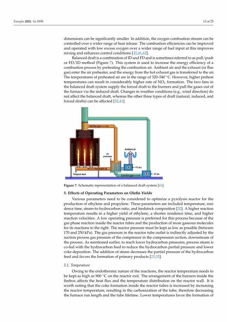
Balanced draft is a combination of ID and FD and is sometimes referred to as pull/pushor FD/ID method (Figure 7). This system is used to increase the energy efficiency of acombustion process by preheating the combustion air. Ambient air and the exhaust (or fluegas) enter the air preheater, and the energy from the hot exhaust gas is transferred to the air.The temperatures of preheated air are in the range of 320–540 ◦C. However, higher preheattemperatures can result in considerably higher rate of NOx formation. The two fans inthe balanced draft system supply the forced draft to the burners and pull the gases out ofthe furnace via the induced draft. Changes in weather conditions (e.g., wind direction) donot affect the balanced draft, whereas the other three types of draft (natural, induced, andforced drafts) can be affected [32,41].
Figure 7. Schematic representation of a balanced draft system [41].
5. Effects of Operating Parameters on Olefin Yields
Various parameters need to be considered to optimize a pyrolysis reactor for theproduction of ethylene and propylene. These parameters are included temperature, resi-dence time, steam-to-hydrocarbon ratio, and feedstock composition [32]. A higher reactiontemperature results in a higher yield of ethylene, a shorter residence time, and higherreaction velocities. A low operating pressure is preferred for this process because of thegas phase reaction inside the reactor tubes and the production of more gaseous moleculesfor its reactions to the right. The reactor pressure must be kept as low as possible (between170 and 250 kPa). The gas pressure in the reactor tube outlet is indirectly adjusted by thesuction process gas pressure of the compressor in the compression section, downstream ofthe process. As mentioned earlier, to reach lower hydrocarbon pressures, process steam isco-fed with the hydrocarbon feed to reduce the hydrocarbon partial pressure and lowercoke deposition. The addition of steam decreases the partial pressure of the hydrocarbonfeed and favors the formation of primary products [23,32].
5.1. Temperature
Owing to the endothermic nature of the reactions, the reactor temperature needs tobe kept as high as 900 ◦C on the reactor exit. The arrangement of the burners inside thefirebox affects the heat flux and the temperature distribution on the reactor wall. It isworth noting that the coke formation inside the reactor tubes is increased by increasingthe reactor temperature, resulting in the carbonization of the tube, therefore decreasingthe furnace run length and the tube lifetime. Lower temperatures favor the formation of

Energies 2021, 14, 8190 14 of 25
secondary products via oligomerization reactions; thus, it is necessary to apply an optimumtemperature profile along the coil to avoid long residence times at low temperatures. Firedtubular reactors are mainly used in commercial pyrolysis units for ethylene production, inwhich the temperature of the reactants increases continuously from the inlet (500–680 ◦C)to the outlet (775–875 ◦C) of the reactor coils. In modern cracking furnaces, a rapid heatingsystem is used at the inlet of the radiant coils, and the temperature rises quickly to therequired reaction temperature. However, due to the low temperature, the reaction rateconstants are low. In the middle of the coil, the rate of increasing the temperature is lower,but the cracking rates are significantly higher. Owing to the endothermic characteristics ofthe reaction, most of the heat is transferred to the mixture. At the coil outlet, the rate of thetemperature rise increases again, though it is lower than the rate of the temperature rise inthe inlet of the coil [23].
The effects of different operating conditions, including temperature, the steam-to-hydrocarbon ratio (atmospheric gas oil), and residence time, on the yield of the products,were investigated by Depeyre et al. [43]. As shown in Figure 8a–c, regardless of the steam-to-hydrocarbon ratio, the yields of methane and ethylene increased with the increasingof the temperature, whereas the yields of propylene and butenes reached a maximumand then decreased at higher temperatures. For the different steam-to-hydrocarbon ratios,the highest gas conversion was obtained at about 750 ◦C. The ratio of the total weightof the produced gas per weight of the injected gas oil used as feedstock is referred toas gas conversion. The amount of deposited carbon also increases with temperature.It has been reported that both radical reactions and molecular secondary reactions areinvolved in the reaction; however, in a higher-temperature reaction (above 750 ◦C), themolecular reactions are the dominant reactions. Gál and Lakatos [44] studied the effect ofcoil outlet temperature (COT) on the product yields and variation in the coke formationrate, using natural gas as a feedstock for the steam cracking process. They reported thatby increasing the COT from 830 ◦C to 845 ◦C, the ethylene yield increased from 30% to35%, and increasing the temperature above 845 ◦C did not cause a considerable increase inthe yield (Figure 9a). The yields of methane and propylene showed little changes whenchanging the temperature from 830 ◦C to 845 ◦C. Interestingly, the coke formation increasedsignificantly (from 7% to 23%) when increasing the temperature.
Figure 8. Effect of temperature at different steam-to-hydrocarbon (ST:HC) mass ratios (a) ST:HC = 1.01,(b) ST:HC = 1.03, (c) ST:HC = 1.33; and (d) the effect of ST:HC on the product yields of the thermalsteam cracking of an atmospheric gas oil, reproduced from [43].

Energies 2021, 14, 8190 15 of 25
Figure 9. (a) Effect of coil outlet temperature on the product yields [44]; (b) effect of temperature onlight olefin yield; and (c) coke formation for the cracking of Arabian Light crude oil using thermalcracking [45].
Al-Absi and Al-Khattaf [45] reported that the conversion in thermal cracking is afunction of contact time and temperature during the cracking of Arabian Light (AL) crudeoil. Increasing the temperature from 550 ◦C to 650 ◦C resulted in a sharp increase inthe C2–C4 olefin yield from 3.8 wt.% to 22.9 wt.% (Figure 9b). The main drawback ofhigh-temperature cracking is the rapid coke formation and carburization, resulting in ashorter lifetime of the reactor tube. The important reactions for coke formation are di- andpoly-alkenes, the cyclization of alkenes, aromatization, and condensation. Polyaromaticcompounds formed via these reactions are the main source of coke during the reaction.Similarly to the results of other reports, coke formation during the cracking of AL crudeoil also increased when increasing the temperature (Figure 9c). However, nowadays,engineers are trying to develop new technologies to reduce coke formation and to usebetter metallurgy to endure the high temperatures.
Che et al. [46] performed the thermal cracking of a vacuum residue to investigate theproduct distribution at different temperatures and a steam-to-hydrocarbon weight ratio of0.6. By increasing the temperature from 600 ◦C to 700 ◦C, the conversion increased from90.67% to 93.97% (Table 3). Due to the stronger bond breaking at the higher temperatures,the gas yield also increased gradually with temperature. The yield of C2–C4 olefinsincreased by 47% (from 17.71% to 18.73%) when the temperature increased from 600 ◦C to700 ◦C. The olefinicity (weight ratio of unsaturated open-chain hydrocarbons with at leastone double bond, including C2, C3, and C4 olefins, in the cracked gas) of 53–67% confirmedthat alkenes are the main components in the gaseous products. Increasing the temperatureenhanced the intensity of condensations, and consequently the coke yield increased.
Energies 2021, 14, 8190 16 of 25
Table 3. Conversion and composition of thermal cracking products of VR [46].
ProductTemperature (◦C)
600 650 700
Conversion (%) 90.67 91.55 93.97Gas yield (wt.%) 18.92 27.38 35.32Gas composition (wt.%)
Methane 2.91 5.01 9.44Ethylene 5.76 6.92 6.66Propylene 4.76 6.38 6.95Butenes 2.19 4.02 5.12C2–C4 olefins 12.71 17.32 18.73
Olefinicity (%) 67.16 63.26 53.03Coke yield (wt.%) 8.20 8.49 9.13
5.2. Residence Time
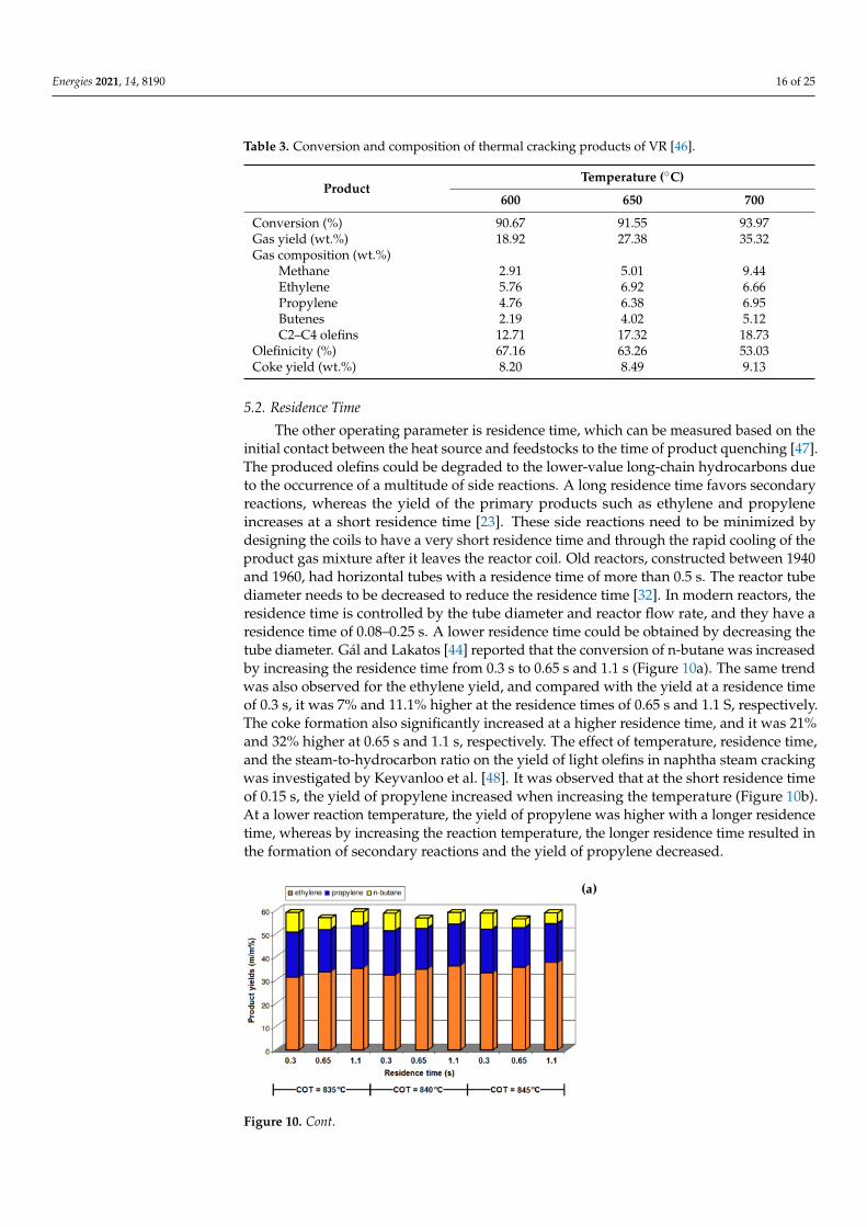
The other operating parameter is residence time, which can be measured based on theinitial contact between the heat source and feedstocks to the time of product quenching [47].The produced olefins could be degraded to the lower-value long-chain hydrocarbons dueto the occurrence of a multitude of side reactions. A long residence time favors secondaryreactions, whereas the yield of the primary products such as ethylene and propyleneincreases at a short residence time [23]. These side reactions need to be minimized bydesigning the coils to have a very short residence time and through the rapid cooling of theproduct gas mixture after it leaves the reactor coil. Old reactors, constructed between 1940and 1960, had horizontal tubes with a residence time of more than 0.5 s. The reactor tubediameter needs to be decreased to reduce the residence time [32]. In modern reactors, theresidence time is controlled by the tube diameter and reactor flow rate, and they have aresidence time of 0.08–0.25 s. A lower residence time could be obtained by decreasing thetube diameter. Gál and Lakatos [44] reported that the conversion of n-butane was increasedby increasing the residence time from 0.3 s to 0.65 s and 1.1 s (Figure 10a). The same trendwas also observed for the ethylene yield, and compared with the yield at a residence timeof 0.3 s, it was 7% and 11.1% higher at the residence times of 0.65 s and 1.1 S, respectively.The coke formation also significantly increased at a higher residence time, and it was 21%and 32% higher at 0.65 s and 1.1 s, respectively. The effect of temperature, residence time,and the steam-to-hydrocarbon ratio on the yield of light olefins in naphtha steam crackingwas investigated by Keyvanloo et al. [48]. It was observed that at the short residence timeof 0.15 s, the yield of propylene increased when increasing the temperature (Figure 10b).At a lower reaction temperature, the yield of propylene was higher with a longer residencetime, whereas by increasing the reaction temperature, the longer residence time resulted inthe formation of secondary reactions and the yield of propylene decreased.
Figure 10. Cont.

Energies 2021, 14, 8190 17 of 25
Figure 10. (a) Effect of residence time on the product yields [42], (b) effect of residence time on thepropylene yield (steam-to-oil ratio = 0.5 g/g) [48].
In a study by Han et al. [49], the influence of the residence time of the yield of lightolefins in the steam cracking of a mixture of waste oil and naphtha was studied. Byincreasing the residence time from 0.3 s to 0.4 s, the yield of ethylene increased, whereasa further increase in the residence time resulted in a decrease in the total yield of C2–C4light olefins. Raw materials have sufficient time for the reaction at longer residence times(up to 0.4 s); however, as mentioned earlier, the secondary reactions also start to occur atlonger residence times, resulting in a lower gas yield and higher coke formation. The effectof residence time was more prominent on the yield of ethylene than that of propylene andbutadiene. In another study by Karaba et al. [50], the effect of residence time on the productdistribution of the steam cracking process at 815 ◦C was evaluated. In this study, a mixtureof 10 wt.% FT vacuum residue and 90 wt.% hydrocracked vacuum distillate (HCVD) wasused as the feedstock. The shorter residence time resulted in higher yields of ethyleneand propylene, whereas the yields of ethane, benzene, toluene, and oil decreased (Table 4).Sedighi et al. [30] also reported that an increase in the residence time led to a higher rate ofethylene formation, whereas the propylene yield decreased. Accurate control of residencetimes and temperature are crucial to avoid secondary reactions while still allowing themaximum cracking of the feedstock.
Table 4. Effect of residence time on the product yields for the steam cracking of a mixture of 10 wt.%FT residue and 90 wt.% HCVD at 815 ◦C [50].
Products Yields (wt.%)Residence Time (s)
0.22 0.30 0.51
Methane 4.6 6.8 8.9Ethane 1.6 1.8 2.6
Ethylene 32.7 30.4 28.1Propane 0.3 0.5 0.4
Propylene 15.8 15.3 13.7Acetylene 0.6 0.5 0.4i-butane 0.0 0.0 0.0
Propadiene 0.7 0.4 0.3n-butane 0.0 0.1 0.1
t-2-butene 0.3 0.3 0.31-butene 6.6 3.6 1.3i-butene 1.5 1.5 1.2
c-2-butene 0.3 0.4 0.3Propyne 0.5 0.5 0.4
1,3-butadiene 8.7 8.1 6.3Cyclopentadiene + isoprene 3.6 3.2 2.8
Benzene 4.2 6.6 9.8Toluene 2.1 3.3 4.6
Ethylbenzene 0.4 0.4 0.3Xylenes 1.3 1.8 2.6C5–C6 4.6 3.5 2.2C7–C12 2.9 2.9 3.0
Oil 6.6 8.2 10.3

Energies 2021, 14, 8190 18 of 25
5.3. Steam-to-Hydrocarbon Ratio
The ratio of steam to hydrocarbon feedstock is another parameter that needs to beconsidered during the cracking reaction. Steam and feedstock are mixed and preheatedin the convection section of the cracking furnace to vaporize the liquid feedstock [51].The steam-to-hydrocarbon ratio (ST:HC) depends on the feedstock type and is controlledbetween 0.3 and 0.7 on a weight basis. Steam is used as an inert that is premixed with thefeed to reduce the partial pressure of the hydrocarbons, therefore reducing the coke forma-tion and carbonization rates. The temperature and thermal energy of the feedstock alsoincrease with the addition of steam. The ST:HC ratio is around 0.3 kgsteam/Kghydrocarbonfor the lighter gaseous feeds, such as ethane, and increases to 0.6 kgsteam/Kghydrocarbonfor the heavier hydrocarbons, such as naphtha and gas oil [32]. It is important to havean optimum ratio of steam to hydrocarbon to avoid negative effects on product yieldsand reduce the specific energy consumption of the production unit. The influence of thesteam-to-hydrocarbon ratio in the steam cracking of natural gas was studied by Gál andLakatos [44], and the basic value for ST:HC was considered to be 0.5 in that study. Theirresults (Table 5) showed that reducing the ST:HC ratio up to 10% did not significantlyaffect the product yields, but a shorter reaction time was expected due to the higher cokeformation. A further decrease in the ST:HC ratio (up to 30%) resulted in a decrease in theethylene formation and increased the coke formation. By reducing the ST:HC ratio at both835 ◦C and 840 ◦C, methane formation showed a rising trend.
Table 5. Effect of the steam-to-hydrocarbon ratio on the product yields [44].
COT (◦C) 835 840 835 840 835 840 835 840
Reduction of ST:HCRatio 5% 5% 10% 10% 20% 20% 30% 30%
ProductsMethane 18.22 18.75 18.32 18.72 18.53 19.06 19.27 19.89Ethylene 32.22 33.73 32.97 33.18 31.78 32.25 30.46 30.87
Propylene 20.63 20.15 20.68 20.34 20.79 20.32 21.14 20.87Butadiene 3.97 3.85 3.97 3.89 3.98 3.86 3.64 3.57n-butane
(Residual) 8.74 7.58 8.72 7.88 8.68 7.56 8.64 7.54
Benzene + Toluene 1.61 1.63 1.71 1.74 1.81 1.89 1.98 2.05Coke 0.0084 0.0089 0.0091 0.0097 0.0107 0.012 0.0128 0.015
The product distribution in the thermal cracking of atmospheric gas oil at 800 ◦Cand a residence time of 0.4 s was studied by Abghari et al. [52]. It was found that byincreasing the ST:HC ratio, the yield of methane and ethylene decreased, whereas thepropylene yield did not change much. Similarly, a study on the effect of the steam-to-gas-oil ratio in a cracking reaction at 750 ◦C (Figure 8d) revealed that the partial pressure ofhydrocarbons was reduced via steam dilution; the gas conversion and the yields of methaneand ethylene were decreased, whereas the coke formation increased [43]. In another studyby Sedighi et al. [30,53], the effect of the steam-to-hydrocarbon ratio on the product yieldsin the steam cracking of heavy liquid hydrocarbon (at 843 ◦C and a residence time of 0.17 s)was studied, and it was reported that the yields of methane and ethylene increased whenincreasing the ST:HC ratio, whereas propylene yield decreased slightly. The evaluation ofthe effect of the ST:HC ratio on the product distribution in the steam cracking of a mixtureof waste oil and naphtha by Han et al. [49] revealed that the yield of light olefins reached amaximum when increasing the ratio from 0.42 to 0.65, then decreased when increasing theST:HC ratio up to about 0.9. Increasing the ratio above 0.9 did not significantly affect theyields, and they remained unchanged. At constant total pressure, a more diluted feedstock(higher ST:HC ratio) with a lower partial pressure of hydrocarbon results in a higher rateof ethylene formation.
Ethane steam cracking in an industrial tubular reactor was modeled and optimized byJiang et al. [35]. By increasing the steam-to-ethane ratio, the selectivity to ethylene increasedfrom 69% to 82%, whereas at the same time, the conversion of ethane decreased from 74%
Energies 2021, 14, 8190 19 of 25
to 55%. The optimum ratio of steam to ethane was found to be in the range of 0.3 to 0.4 inorder to obtain the highest ethylene yield. Increasing the steam-to-ethane ratio from 0 to1.0 resulted in a 46% decrease in coke formation (from 0.0092 to 0.0042 kg/(h.m2)). It isimportant to operate at the optimum steam-to-hydrocarbon ratio to achieve the highestpossible yields of light olefins and an acceptable coke formation rate.
5.4. Feedstock Composition
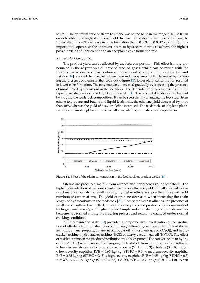
The product yield can be affected by the feed composition. This effect is more pro-nounced in the re-pyrolysis of recycled cracked gases, which can be mixed with thefresh hydrocarbons, and may contain a large amount of olefins and di-olefins. Gál andLakatos [44] reported that the yield of methane and propylene slightly decreased by increas-ing the presence of olefins in the feedstock (Figure 11); lower olefin concentration resultedin lower coke formation. The ethylene yield increased gradually by increasing the presenceof unsaturated hydrocarbons in the feedstock. The dependency of product yields and thetype of feedstock was studied by Dominov et al. [54]. The product distribution is changedby varying the feedstock composition. It can be seen that by changing the feedstock fromethane to propane and butane and liquid feedstocks, the ethylene yield decreased by morethan 40%, whereas the yield of heavier olefins increased. The feedstocks of ethylene plantsusually contain straight and branched alkanes, olefins, aromatics, and naphthenes.
Figure 11. Effect of the olefin concentration in the feedstock on product yields [44].
Olefins are produced mainly from alkanes and naphthenes in the feedstock. Thehigher concentration of n-alkanes leads to a higher ethylene yield, and alkanes with evennumbers of carbon atoms result in a slightly higher ethylene yields than those with oddnumbers of carbon atoms. The yield of propene decreases when increasing the chainlength of hydrocarbons in the feedstock [23]. Compared with n-alkanes, the presence ofisoalkanes results in lower ethylene and propene yields and produces higher amounts ofhydrogen, methane, C4, and higher olefins. Simple and aromatic ring compounds, such asbenzene, are formed during the cracking process and remain unchanged under normalcracking conditions.
Zimmermann and Walzl [23] provided a comprehensive investigation of the produc-tion of ethylene through steam cracking using different gaseous and liquid feedstocks,including ethane, propane, butane, naphtha, gas oil (atmospheric gas oil (AGO)), and hydro-cracker residue (hydrocracker residue (HCR) or heavy vacuum gas oil (HVGO). The effectof residence time on the product distribution was also reported. The ratio of steam to hydro-carbon (ST:HC) was increased by changing the feedstock from light hydrocarbon (ethane)to heavier feedstocks, as follows: ethane, propane (ST:HC = 0.3) < butane (ST:HC = 0.35)< low-severity naphtha, P/E = 0.65 kg/kg (ST:HC = 0.4) < medium-severity naphtha,P/E = 0.55 kg/kg (ST:HC = 0.45) < high-severity naphtha, P/E = 0.45 kg/kg (ST:HC = 0.5)< AGO, P/E = 0.54 kg/kg (ST:HC = 0.8) < AGO, P/E = 0.53 kg/kg (ST:HC = 1.0). When

Energies 2021, 14, 8190 20 of 25
ethane was used as the feedstock, the coil inlet temperature was in the range of 650–680 ◦C,and the conversion was 60–75% in commercial furnaces. A typical conversion of 90–93%was reported for the propane cracking in the furnace, and conversion increased to 94–96%when using butane as the feedstock. Reducing the residence time resulted in the lowerformation of methane and the higher formation of ethylene. Due to the presence of a largeamount of condensed polynuclear aromatics in gas oil, heavier products (C5+) were formedusing AGO as the cracking feedstock. During the cracking process, these aromatic compo-nents remained unchanged or condensed to other molecules with a higher molecular mass.HCR, the residue of the hydrocrackers, which are working at severe operating conditions,is a highly saturated product with a low content of aromatics and polyaromatics. The yieldof ethylene using the HCR or HVGO is almost similar to naphtha cracking (~26%) [23].
The product distribution in the thermal cracking of different types of crude oil wasevaluated by Al-Absi et al. [55]. The crude oils with different API gravities of 34◦ (ArabLight: AL), 39◦ (Arab Extra Light: AXL), and 51◦ (Arab Super Light: ASL) were usedas the cracking feedstock. A lower API gravity indicates a heavier crude with a higherdensity. The density of the selected feedstocks at 15 ◦C were in the following order: AL(892 kg/m3) > AXL (828 kg/m3) > ASL (774 kg/m3). The paraffin, isoparaffin, olefin,naphthene, and aromatic (PIONA) contents of the naphtha fraction of these crude oils were:34/32/0/19/15 wt.%, 34/31/0/8/27 wt.%, and 46/18/0/9/27 wt.% for ASL, AXL, andAL, respectively. There was a linear relationship between the conversion of the feedstocksand temperature and this was increased by increasing the temperature (Table 6).
The conversions of all feedstocks were about 14% at 600 ◦C and the highest conversion(32.8%) belonged to the heaviest feedstock (AL) at 650 ◦C. Similarly to the conversion, theyield of C2–C4 olefins increased by increasing the temperature. The ethylene formationobeyed the free radical and beta-scission mechanisms. At higher temperatures, the cleavageof C–C bond uncharged molecules resulted in the formation of very reactive free radicals.These free radicals undergo beta-scission and produce ethylene and primary free radicals.The yields of propylene and butenes also followed the same trend as ethylene and increasedwhen increasing the temperature [55].
Table 6. Conversion and yields of product for the thermal cracking of different crude oils [55].
Feed ASL AXL AL
Temperature (◦C) 600 625 650 600 625 650 600 625 650Conversion (%) 14.5 21.1 27.6 14.0 21.6 27.0 14.2 23.3 32.8Product yield (%)
H2 0.1 0.1 0.1 0.1 0.1 0.1 0.1 0.1 0.2C1 1.5 2.5 3.6 1.7 2.8 3.5 1.8 3.1 4.6C=
2 2.6 4.1 6.1 3.1 5.0 6.5 2.8 5.1 7.6C=
3 3.1 5.0 6.8 3.4 5.5 6.9 3.2 5.7 8.6C=
4 3.4 4.9 6.0 3.2 4.6 5.6 3.0 4.7 6.7C=
2 −C=4 9.1 14.0 18.9 9.7 15.1 19.0 9.0 15.5 22.9
C=3 /C=
2 1.2 1.2 1.1 1.1 1.1 1.1 1.1 1.1 1.1Coke 0.2 0.3 0.3 0.3 0.4 0.5 0.4 0.6 0.8
The effect of feedstock composition on the product distribution in the steam crackingprocess, as studied by Geerts et al. [56], also revealed that the steam cracking of the naphthafraction resulted in higher yields of ethylene and propylene (36%) than the yields of theseproducts (28.3%) obtained from the steam cracking of wide-range gas oil (WRGO). However,the yields of pyrolysis fuel oil (PFO) and pyrolysis gasoline (Pygas) were higher whenWRGO was used as the feedstock. The pyrolysis of light and heavy naphtha feedstocksand their mixtures was evaluated by Karaba et al. [57]. It was reported that the productdistribution depended on the feedstock’s properties, and light naphtha could lead to higheryields of the light olefins. Pyrolysis of the feedstock containing 20–60 wt.% of heavynaphtha resulted in a higher ethylene yield (around 1.1 wt.% higher), whereas the additionof light naphtha to the heavy naphtha feedstock caused a decrease in the yields of methane,

Energies 2021, 14, 8190 21 of 25
C4 hydrocarbons, and benzene (Figure 12). Even this slight increase in the ethylene yieldcould make a significant improvement at the industrial scale. For example, for an ethyleneplant with 30 tons per hour of naphtha feedstock, this 1.1 wt.% increase in the ethyleneyield results in an additional 330 kg of ethylene per hour per one steam cracker, whichmeans about 300 EUR per hour per one steam cracker [57].
Zámostný et al. [58] studied the pyrolysis of feedstocks with different hydrocarbonchain lengths at 810 ◦C, 400 kPa, and residence times of 0.2–0.4 s in the reaction zone. Theyfound that longer-chain hydrocarbons with a higher number of carbon atoms showed ahigher probability of the hydrogen abstraction reaction; thus, the hydrogen transfer ratecould increase and result in a higher conversion rate. The feedstock conversion increasedfrom 78% for n-pentane to 99% for n-hexane. The yield of ethylene also increased for longerhydrocarbon chains because despite the original position of the unpaired electron in theformed radicals, they can produce more ethylene molecules through the successive-betascission of C–C bonds. However, in very-long-chain hydrocarbons, the beta-scission ofC–H bonds could interrupt the beta-scission of the C–C bonds and result in the increasedformation of 1-alkene. Due to the more evident effect of alkyl radicals with odd carbonnumbers produced during the cracking process, the yield of propylene and methanedecreased when increasing the chain length [58].
Figure 12. Potential product yield increases (T: 810 ◦C, P: 4 bar, F: 65 Nml/min) depending on thecontent of heavy naphtha in the blend with light naphtha [57].
Recently, the effect of normal/cyclo-alkane in the product distribution of hydrocarbonpyrolysis was studied by Hou et al. [59]. Pyrolysis of n-hexane, n-heptane, cyclohexane,and methylcyclohexane was performed at 650–830 ◦C, under atmospheric pressure. Themolecular structures could determine the initial cleavage of C–C bonds and the forma-tion of radicals, which affect the hydrogen abstraction, beta-scission, secondary cracking,radical combination aromatization, and Diels–Alder reactions in the pyrolysis process.The direct cleavage of C–C bonds and the production of alkyl radicals were observed forthe n-hexane feedstock, while cyclohexane with the cyclic structure with the consecutivereactions of ring-opening, isomerization, and decomposition led to the formation of alkyland alkenyl radicals. A lower conversion and a higher selectivity to 1,3-butadiene andaromatics were observed in the pyrolysis of cyclohexane. Similarly to the results reportedby Zámostný et al. [58], a longer hydrocarbon chain length weakened the C–C bonds andthus increased the number of free radicals, resulting in higher conversion and selectivity toheavier products. A demethylation reaction was observed in the presence of the methylsubstituent, which can improve the formation of radicals (methyl, cycloalkyl, and methylcy-

Energies 2021, 14, 8190 22 of 25
cloalkyl). A higher conversion rate was obtained with the pyrolysis of methylcyclohexanethan with cyclohexane. Pyrolysis of the mixture of n-hexane and cyclohexane revealedthat the formation of radicals and hydrogen abstraction were decreased by increasing thecyclohexane content. Due to the competition of cyclohexane and n-hexane for the radicalsin hydrogen abstraction, the n-hexane decomposition could be suppressed with a highercontent of cyclohexane [59].
6. Conclusions
Olefins are critical components in chemical industries and, depending on the feed-stock’s properties, they are produced using different pathways, such as thermal cracking,fluid catalytic cracking, the conversion of methanol to olefins, Fischer–Tropsch synthe-sis, and oxidative coupling of methane. However, thermal cracking, which occurs in acracking furnace, is the main industrial process for the production of light olefins. Thisreview discussed the cracking mechanism, the cracking furnace, and the effect of differentoperating parameters on the product distribution. According to studies of the effect ofdifferent reaction parameters on olefin yields, it can be concluded that the maximum yieldof olefins can be obtained by providing these conditions: (1) a higher coil outlet tempera-ture, (2) a short residence time in the radiant coil, (3) low partial pressure of hydrocarbons,which can be achieved through the addition of steam, (4) highly saturated feedstock, and(5) faster quenching of the cracked gases. The process involving cracking reactions underthese conditions also minimizes the yield of methane and aromatic components with highmolecular mass.
Author Contributions: Conceptualization, Z.G.; writing—original draft preparation, Z.G. and F.G.;writing—review and editing, Z.G., F.G., Z.T. and M.V. All authors have read and agreed to thepublished version of the manuscript.
Funding: This publication is a result of the project which was carried out within the financial supportof the Ministry of Industry and Trade of the Czech Republic with institutional support for long-termconceptual development of research organization. The result was achieved using the infrastructureincluded in the Efficient Use of Energy Resources Using Catalytic Processes (LM2018119) project,which has been financially supported by MEYS within the targeted support of large infrastructures.
Conflicts of Interest: The authors declare no conflict of interest.
References1. Hsu, C.S.; Robinson, P.R. Petroleum Science and Technology; Springer International Publishing: Cham, Switzerland, 2019.2. Speight, J.G. (Ed.) Organic Chemistry. In Environmental Organic Chemistry for Engineers; Butterworth-Heinemann: Oxford, UK,
2017; Chapter 2; pp. 43–86. [CrossRef]3. Fakhroleslam, M.; Sadrameli, S.M. Thermal Cracking of Hydrocarbons for the Production of Light Olefins; A Review on Optimal
Process Design, Operation, and Control. Ind. Eng. Chem. Res. 2020, 59, 12288–12303. [CrossRef]4. Deloitte. The Future of Petrochemicals: Growth Surrounded by Uncertainty. 2019. Available online: https://www2.deloitte.com/
content/dam/Deloitte/us/Documents/energy-resources/us-the-future-of-petrochemicals.pdf (accessed on 28 June 2021).5. Blay, V.; Louis, B.; Miravalles, R.; Yokoi, T.; Peccatiello, K.A.; Clough, M.; Yilmaz, B. Engineering zeolites for catalytic cracking to
light olefins. ACS Catal. 2017, 7, 6542–6566. [CrossRef]6. Ren, T.; Patel, M.; Blok, K. Olefins from Conventional and Heavy Feedstocks: Energy use in Steam Cracking and Alternative
Processes. Energy 2006, 31, 425–451. [CrossRef]7. Amghizar, I.; Vandewalle, L.A.; Van Geem, K.M.; Marin, G.B. New Trends in Olefin Production. Engineering 2017, 3, 171–178.
[CrossRef]8. Dugkhuntod, P.; Wattanakit, C. A Comprehensive Review of the Applications of Hierarchical Zeolite Nanosheets and Nanoparticle
Assemblies in Light Olefin Production. Catalysts 2020, 10, 245. [CrossRef]9. Akah, A.; Williams, J.; Ghrami, M. An Overview of Light Olefins Production via Steam Enhanced Catalytic Cracking. Catal. Surv.
Asia 2019, 23, 265–276. [CrossRef]10. Alotaibi, F.M.; González-Cortés, S.; Alotibi, M.F.; Xiao, T.; Al-Megren, H.; Yang, G.; Edwards, P.P. Enhancing the Production of
Light Olefins from Heavy Crude Oils: Turning Challenges into Opportunities. Catal. Today 2018, 317, 86–98. [CrossRef]11. Roudgar Saffari, P.; Salarian, H.; Lohrasbi, A.; Salehi, G. The Numerical Simulation of Olefin Production Furnace for Pollution
Reduction: Two Case Studies. Gas Process. J. 2021, 9, 15–32. [CrossRef]

Energies 2021, 14, 8190 23 of 25
12. Depeyre, D.; Flicoteaux, C.; Chardaire, C. Pure n-hexadecane Thermal Steam Cracking. Ind. Eng. Chem. Process Des. Dev. 1985, 24,1251–1258. [CrossRef]
13. Bender, M. An Overview of Industrial Processes for the Production of Olefins—C4 Hydrocarbons. ChemBioEng Rev. 2014, 1,136–147. [CrossRef]
14. Zhao, Z.; Jiang, J.; Wang, F. An Economic Analysis of Twenty Light Olefin Production Pathways. J. Energy Chem. 2021, 56, 193–202.[CrossRef]
15. Gholami, Z.; Gholami, F.; Tišler, Z.; Tomas, M.; Vakili, M. A Review on Production of Light Olefins via Fluid Catalytic Cracking.Energies 2021, 14, 1089. [CrossRef]
16. Alabdullah, M.; Rodriguez-Gomez, A.; Shoinkhorova, T.; Dikhtiarenko, A.; Chowdhury, A.D.; Hita, I.; Kulkarni, S.R.; Vittenet, J.;Sarathy, S.M.; Castaño, P.; et al. One-Step Conversion of Crude Oil to Light Olefins using a Multi-Zone Reactor. Nat. Catal. 2021,4, 233–241. [CrossRef]
17. Zacharopoulou, V.; Lemonidou, A.A. Olefins from biomass intermediates: A review. Catalysts 2018, 8, 2. [CrossRef]18. Ren, T.; Patel, M.K. Basic Petrochemicals from Natural Gas, Coal and Biomass: Energy use and CO2 Emissions. Resour. Conserv.
Recycl. 2009, 53, 513–528. [CrossRef]19. Amghizar, I.; Dedeyne, J.N.; Brown, D.J.; Marin, G.B.; Van Geem, K.M. Sustainable Innovations in Steam Cracking: CO2 Neutral
Olefin Production. React. Chem. Eng. 2020, 5, 239–257. [CrossRef]20. Seifzadeh Haghighi, S.; Rahimpour, M.R.; Raeissi, S.; Dehghani, O. Investigation of ethylene production in naphtha thermal
cracking plant in presence of steam and carbon dioxide. Chem. Eng. J. 2013, 228, 1158–1167. [CrossRef]21. Garg, A. Fired Heaters-Key to Efficient Operation of Refineries and Petrochemicals; HarbisonWalker International: Sugar Land, TX,
USA, 2017.22. Subramanian, R.; Schmidt, L.D. Renewable Olefins from Biodiesel by Autothermal Reforming. Angew. Chem. Int. 2005, 44,
302–305. [CrossRef]23. Zimmermann, H.; Walzl, R. Ethylene. In Ullmann’s Encyclopedia of Industrial Chemistry; Wiley: Weinheim, Germany, 2009.
[CrossRef]24. Geilen, F.M.A.; Stochniol, G.; Peitz, S.; Schulte-Koerne, E. Butenes. In Ullmann’s Encyclopedia of Industrial Chemistry; Wiley:
Weinheim, Germany, 2014; pp. 1–13. [CrossRef]25. Moreira, J.V. Steam Cracking: Kinetics and Feed Characterisation; Instituto Superior Tecnico: Lisbon, Portugal, 2015; pp. 1–10.
Available online: https://fenix.tecnico.ulisboa.pt/downloadFile/1126295043834327/JVM_ExtendedAbstract.pdf (accessed on3 February 2021).
26. Rice, F.O. The Thermal Decomposition of Organic Compounds from the Standpoint of Free Radicals. I. Saturated Hydrocarbons.J. Am. Chem. Soc. 1931, 53, 1959–1972. [CrossRef]
27. Van Goethem, M.W.M. Next Generation Steam Cracking Reactor Concept. Ph.D. Thesis, Technical University of Delft, Delft,The Netherlands, 2010.
28. Moulijn, J.A.; Makkee, M.; van Diepen, A.E. Chemical Process Technology, 2nd ed.; John Wiley & Sons: Oxford, UK, 2013.29. Depeyre, D.; Flicoteaux, C. Modeling of Thermal Steam Cracking of n-hexadecane. Ind. Eng. Chem. Res. 1991, 30, 1116–1130.
[CrossRef]30. Sedighi, M.; Keyvanloo, K.; Towfighi, D.J. Olefin Production from Heavy Liquid Hydrocarbon Thermal Cracking: Kinetics and
Product Distribution. Iran. J. Chem. Chem. Eng. 2010, 29, 135–147. [CrossRef]31. Dente, M.; Ranzi, E.; Goossens, A.G. Detailed Prediction of Olefin Yields from Hydrocarbon Pyrolysis Through a Fundamental
Simulation Model (SPYRO). Comput. Chem. Eng. 1979, 3, 61–75. [CrossRef]32. Sadrameli, S.M. Thermal/Catalytic Cracking of Hydrocarbons for the Production of Olefins: A State-of-the-Art Review I: Thermal
cracking review. Fuel 2015, 140, 102–115. [CrossRef]33. Chauvel, A.; Lefebvre, G. Petrochemical Processes 1. In Synthesis-Gas Derivatives and Major Hydrocarbons, 2nd ed.; Editions Technip
Paris: Paris, France, 1989.34. Van Goethem, M.W.M.; Barendregt, S.; Grievink, J.; Moulijn, J.A.; Verheijen, P.J.T. Model-based, Thermo-Physical Optimisation
for High Olefin Yield in Steam Cracking Reactors. Chem. Eng. Res. Des. 2010, 88, 1305–1319. [CrossRef]35. Jiang, B.-B.; Liao, Z.-W.; Mohsin, A.; Sun, J.-Y.; Wang, J.-D.; Yang, Y.; Yang, Y.-R. Modeling and Optimization of Ethane Steam
Cracking Process in an Industrial Tubular Reactor with Improved Reaction Scheme. China Petrol. Process. Petrochem. Technol. 2020,22, 117–125.
36. Karimzadeh, R.; Godini, H.R.; Ghashghaee, M. Flowsheeting of Steam Cracking Furnaces. Chem. Eng. Res. Des. 2009, 87, 36–46.[CrossRef]
37. Variny, M.; Mierka, O.; Gašparovic, L. Experiences and Future Prospects of GRUCON—SLOVNAFT Cooperation in EnergyAuditing Field. In Proceedings of the 42nd International Conference of SSCHE, Tatranské Matliare, Slovakia, 25–29 May 2015;Slovak Society of Chemical Engineering: Bratislava, Slovakia, 2015; pp. 351–358.
38. Marcos, J.M.M. Modelling of Naphtha Cracking for Olefins Production. Master’s Thesis, Technical University of Lisbon, Lisbon,Portugal. 2016. Available online: https://fenix.tecnico.ulisboa.pt/downloadFile/563345090415270/Thesis_Joao_Marcos_73026.pdf (accessed on 17 April 2021).
39. Mahulkar, A.V.; Heynderickx, G.J.; Marin, G.B. Simulation of the Coking Phenomenon in the Superheater of a Steam Cracker.Chem. Eng. Sci. 2014, 110, 31–43. [CrossRef]

Energies 2021, 14, 8190 24 of 25
40. Belohlav, Z.; Zamostny, P.; Herink, T. The Kinetic Model of Thermal Cracking for Olefins Production. Chem. Eng. Process. 2003, 42,461–473. [CrossRef]
41. Baukal, C.E.; Vaccari, M.; Claxton, M.G. Chapter 20—Burners for Reformers and Cracking Furnaces. Comput. Aided Chem. Eng.2019, 45, 937–984. [CrossRef]
42. Wang, Q.; Xu, H.; Pan, L.; Sun, L. Active Disturbance Rejection Control of Boiler Forced Draft System: A Data-Driven Practice.Sustainability 2020, 12, 4171. [CrossRef]
43. Depeyre, D.; Flicoteaux, C.; Arbabzadeh, F.; Zabaniotou, A. Modeling of Thermal Steam Cracking of an Atomspheric Gas Oil. Ind.Eng. Chem. Res. 1989, 28, 967–976. [CrossRef]
44. Gál, T.; Lakatos, B.G. Thermal Cracking of Recycled Hydrocarbon Gas-Mixtures for Re-Pyrolysis: Operational Analysis of SomeIndustrial Furnaces. Appl. Therm. Eng. 2008, 28, 218–225. [CrossRef]
45. Al-Absi, A.A.; Al-Khattaf, S.S. Conversion of Arabian Light Crude Oil to Light Olefins via Catalytic and Thermal Cracking.Energy Fuels 2018, 32, 8705–8714. [CrossRef]
46. Che, Y.; Hao, J.; Zhang, J.; Qiao, Y.; Li, D.; Tian, Y. Vacuum Residue Thermal Cracking: Product Yield Determination andCharacterization Using Thermogravimetry–Fourier Transform Infrared Spectrometry and a Fluidized Bed Reactor. Energy Fuels2018, 32, 1348–1357. [CrossRef]
47. Hulet, C.; Briens, C.; Berruti, F.; Chan, E.W. A Review of Short Residence Time Cracking Processes. Int. J. Chem. React. Eng. 2005,3, 1–74. [CrossRef]
48. Keyvanloo, K.; Towfighi, J.; Sadrameli, S.M.; Mohamadalizadeh, A. Investigating the Effect of Key Factors, Their Interactionsand Optimization of Naphtha Steam Cracking by Statistical Design of Experiments. J. Anal. Appl. Pyrolysis 2010, 87, 224–230.[CrossRef]
49. Han, L.; Ding, C.Q.; Lui, H. Studies on Olefin Production by Steam Cracking of Waste Oil Blended with Naphtha. Appl. Mech.Mater. 2013, 291, 738–743. [CrossRef]
50. Karaba, A.; Rozhon, J.; Patera, J.; Hájek, J.; Zámostný, P. Fischer-Tropsch Wax from Renewable Resources as an Excellent Feedstockfor the Steam-Cracking Process. Chem. Eng. Technol. 2021, 44, 329–338. [CrossRef]
51. Abbasali, S.M.Z.; Farsi, M.; Rahimpour, M.R. Simulation and Dynamic Optimization of an Industrial Naphtha Thermal CrackingFurnace Based on Time Variant Feeding Policy. Chem. Prod. Process Model. 2018, 13, 1–15. [CrossRef]
52. Abghari, S.Z.; Darian, J.T.; Karimzadeh, R.; Omidkhah, M.R. Determination of Yield Distribution in Olefin Production by ThermalCracking of Atmospheric Gasoil. Korean J. Chem. Eng. 2008, 25, 681–692. [CrossRef]
53. Sedighi, M.; Keyvanloo, K.; Towfighi, J. Experimental Study and Optimization of Heavy Liquid Hydrocarbon Thermal Crackingto Light Olefins by Response Surface Methodology. Korean J. Chem. Eng. 2010, 27, 1170–1176. [CrossRef]
54. Dominov, P.; Gilyazetdinova, R.; Zhirnov, B.; Tarasov, I.; Khlestkin, R. Overview world technologies of pyrolysis and perspectiveof development. Electron. Sci. J. Oil Gas Bus. 2009, 1, 23–32. Available online: http://ogbus.ru/files/ogbus/eng/authors/Dominov/Dominov_1.pdf (accessed on 29 January 2021).
55. Al-Absi, A.A.; Aitani, A.M.; Al-Khattaf, S.S. Thermal and Catalytic Cracking of Whole Crude Oils at High Severity. J. Anal. Appl.Pyrolysis 2020, 145, 104705. [CrossRef]
56. Geerts, M.; Ristic, N.; Djokic, M.; Ukkandath Aravindakshan, S.; Marin, G.B.; Van Geem, K.M. Crude to Olefins: Effect ofFeedstock Composition on Coke Formation in a Bench-Scale Steam Cracking Furnace. Ind. Eng. Chem. Res. 2020, 59, 2849–2859.[CrossRef]
57. Karaba, A.; Dvoráková, V.; Patera, J.; Zámostný, P. Improving the Steam-Cracking Efficiency of Naphtha Feedstocks byMixed/Separate Processing. J. Anal. Appl. Pyrolysis 2020, 146, 104768. [CrossRef]
58. Zámostný, P.; Belohlav, Z.; Starkbaumová, L.; Patera, J. Experimental Study of Hydrocarbon Structure Effects on the Compositionof its Pyrolysis Products. J. Anal. Appl. Pyrolysis 2010, 87, 207–216. [CrossRef]
59. Hou, X.; Ma, Z.; Chen, B.; Zhang, J.; Ning, Y.; Zhao, L.; Yuan, E. Role of normal/cyclo-alkane in hydrocarbons pyrolysis processand product distribution. J. Anal. Appl. Pyrolysis 2021, 156, 105130. [CrossRef]
Copyright © 2022 FDOKUMEN