
ÿþM i c r o s o f t W o r d - c a r a t u l a - Repositorio UMSA
Upload
khangminh22Category
view
1download
0
AL/CF-TR-1995-0204
A R M S T R O N G L A B O R A T O R Y
EYE / VOICE MISSION PLANNING INTERFACE (EVMPI)
Franz Hatfield Eric A. Jenkins
Michael W. Jennings
SYNTHETIC ENVIRONMENTS, INC. 5587 McLEAN DRIVE
McLEAN VA 22101-4002
DECEMBER 1995
19960516 090 FINAL REPORT FOR THE PERIOD 12 MAY 1995 TO 11 DECEMBER 1995
Approved for public release; distribution is unlimited
AIR FORCE MATERIEL COMMAND ;WRIGHT-PATTERSON AIR FORCE BASE, OHIO 45433-6573;
S33C ©TTATTW T-V™~ , üü iL

NOTICES (
When US Government drawings, specifications, or other data are used for any purpose other than
a definitely related Government procurement operation, the Govemmen: thereby incurs no
responsibility nor any obligation whatsoever, and the fact that the Government may have
formulated, furnished, or in any way supplied the said drawings, specrications, or other data, is
not to be regarded by implication or otherwise, as in any manner licensng the holder or any other
person or corporation, or conveying any rights or permission to manufacture, use, or sell any
patented invention that may in any way be related thereto.
Please do not request copies of this report from the Armstrong Laboratory. Additional copies may
be purchased from:
National Technical Information Service
5285 Port Royal Road
Springfield, Virginia 22161
Federal Government agencies and their contractors registered with the Defense Technical
Information Center should direct requests for copies of this report to:
Defense Technical Information Center
8725 John J. Kingman Road, Suite 0944-
Ft. Belvoir, Virginia 22060-6218
DISCLAIMER
This Technical Report is published as received and has not
been edited by the Technical Editing Staff of the Armstrong
Laboratory.
TECHNICAL REVIEW AND APPROVAL AL/CF-TR-1995-0204
This report has been reviewed by the Office of Public Affairs (PA) and is releasable to the National
Technical Information Service (NTIS). At NTIS, it will be available to the general public,
including foreign nations.
This technical report has been reviewed and is approved for publication.
FOR THE COMMANDER
KENI
Human Engineering Division
Armstrong Laboratory

REPORT DOCUMENTATION PAGE Form Approved
OMB No. 0704-0188
Public reporting burden for This collection of information is estimated to average 1 hour per response, including the time for reviewing instructions, searching existing data sources, gathering and maintaining the data needed, and completing and reviewing the collection of information. Send comments regarding this burden estimate or any other aspect of this collection of information, including suggestions for reducing this burden, to Washington Headquarters Services, Directorate for Information Operations and Reports, 1215 Jefferson Davis Highway, Suite 1204, Arlington, VA 22202-4302, and to the Office of Management and Budget, Paperwork Reduction Project (0704-0188), Washington, DC 20503.
1. AGENCY USE ONLY (Leave blank) 2. REPORT DATE December 1995
3. REPORT TYPE AND DATES COVERED Final Report, 12 May 95 to 11 Dec 95
4. TITLE AND SUBTITLE
Eye/Voice Mission Planning Interface (EVMPI) (U)
6. AUTHOR(S) Franz Hatfield Eric A. Jenkins Michael W. Jennings
5. FUNDING NUMBERS
C F41624-95-C-6012 PE 62202F PR 3005 TACH WU5B
7. PERFORMING ORGANIZATION NAME(S) AND ADDRESS(ES)
Synthetic Environments, Inc. 5587 McLean Drive McLean VA 22101-4002
8. PERFORMING ORGANIZATION REPORT NUMBER
TR-J103-1
9. SPONSORING /MONITORING AGENCY NAME(S) AND ADDRESS(ES) Armstrong Laboratory, Crew Systems Directorate Human Engineering Division Human Systems Center Air Force Materiel Command Wright-Patterson AFB, OH 45433-7022
10. SPONSORING/MONITORING AGENCY REPORT NUMBER
AL/CF-TR-1995-0204
11. SUPPLEMENTARY NOTES
12a. DISTRIBUTION /AVAILABILITY STATEMENT
Approved for public release; distribution is unlimited.
12b. DISTRIBUTION CODE
13. ABSTRACT (Maximum 200 words) Pilots and other crew station operators need better ways of interacting with their systems, including more efficient human-machine dialog and better physical interface devices and interaction techniques. The goal of the Eye/Voice Mission Planning Interface (EVMPI) research is to integrate voice recognition and eye-tracking technology with aviation displays in order to reduce pilot cognitive and manual workload. The EVMPI technology allows an operator to gaze on user interface items of interest and issue verbal commands/queries that can be interpreted by the system, thus permitting hands-free operation of cockpit displays. This report describes the concept for the EVMPI, general principles for integrating eye and voice input, an EVMPI architecture, and the user interface implementation and evaluation of several aviation mission planning tasks. A primary benefit that arises from the integration of multiple input modalities to infer user intent is that robust performance can be obtained, even when the component technologies (eye and voice) are imperfect. This reduces the accuracy requirements on the individual technologies. GOMS models for eye/voice and conventional throttle/stick interaction protocols were developed for a select set of operator tasks. A preliminary comparison reveals that eye/voice interaction can significantly reduce the total number of operations that need to be performed in particular tasks. Additional empirical research is required to substantiate these findings and to generalize the results to broad classes of operator tasks.
14. SUBJECT TERMS Eye Tracking, Speech Recognition, Human Computer Interaction
15. NUMBER OF PAGES 111
16. PRICE CODE
17. SECURITY CLASSIFICATION OF REPORT
UNCLASSIFIED
18. SECURITY CLASSIFICATION OF THIS PAGE
UNCLASSIFIED NSN 7540-01-280-5500
19. SECURITY CLASSIFICATION OF ABSTRACT
UNCLASSIFIED
20. LIMITATION OF ABSTRACT
UNLIMITED Standard Form 298 (Rev. 2-89) Prescribed by ANSI Std. Z39-18 298-102

THIS PAGE INTENTIONALLY LEFT BLANK

PREFACE
This report documents the results of a Phase I Small Business Innovative Research (SBIR) project conducted by Synthetic Environments, Inc. (SEI) under contract F41624-95- C-6012 to the USAF Armstrong Laboratory, Crew Systems Directorate. Ms. Gloria Calhoun is the contract technical monitor.
The goal of this research is to investigate and define a concept for an Eye/Voice Mission Planning Interface (EVMPI) that integrates voice recognition and eye-tracking technology to provide access to and control of aviation displays.
During the course of this work, SEI received technical support from Mr. Joshjm Borah of Applied Science Laboratories (ASL). ASL provided technical assistance in the calibration, use and integration of the eye-tracking system within the EVMPI development environment.
m

TABLE OF CONTENTS
1. INTRODUCTION 1
1. 1 HUMAN-SYSTEM INTERFACES FOR TACTICAL INFORMATION AND MISSION PLANNING SYSTEMS 2 1.2 THE RATIONALE FOR COMBINING MULTIPLE INPUT MODALITIES 2 1.3 METHODOLOGY 3
1.4 OUTLINE OF THE REPORT 4
2. AVIATION MISSION PLANNING PROBLEM 6
2.1 ILLUSTRATION OF EYE/VOICE INTERACTION TO ENHANCE MISSION PLANNING 6 2.2 MISSION PLAN TYPES AND SCENARIO ANALYSIS 7
3. EVMPI CONCEPT OF OPERATIONS U
3.1 CONCEPTUAL ORGANIZATION OF THE EVMPI 12 3.2 OPERATIONAL CONCEPT 13
3.2.1 Airborne Mission Planning Support. 13 3.2.2 Ground-Based Mission Planning Support J5
4. INPUT DEVICE TECHNOLOGY 17
4.1 VOICE RECOGNITION 17
4.2 EYE-TRACKING 20
4.3 TECHNICAL ISSUES IN INTEGRATING EYE TRACKING AND VOICE RECOGNITION 21 4.4 PREVIOUS WORK IN INTEGRATING MULTIPLE INPUT MODALITIES 22
5. PRINCD7LES AND GUIDELINES FOR EYE/VOICE INTERACTION 25
5.1 GENERAL PRINCIPLES 25
5.1.1 Facilitate Natural Interaction 25 5.1.2 Minimize Training Requirements 26 5.1.3 Eye Point-of-Gaze for Deictic Reference 27 5.1.4 Feedback on User Commands 27 5.1.5 Feedback on Object Selection 28 5.1.6 Memory Aids for Speech Input. 28
5.2 DIALOG INTERACTION STYLES 29
5.2.1 Specific Deictic Reference • 29 5.2.2 Approximate Deictic Reference 30 5.2.3 Voice Only. 31 5.2.4 Eyes Only 31
5.3 DISPLAY FEEDBACK 32
5.3.1 Visual Feedback 32 5.3.2 Audio Feedback 33
6. DEVELOPMENT ENVIRONMENT 35
6.1 OVERVIEW 35
6.2 EYE-TRACKER COMPONENT 36
6.2.1 Eye-Tracking System Set Up and Test.... 36 6.2.2 Eye-Tracker Initial Calibration 37 6.2.3 Eye-Tracker Re-Calibration 37
6.3 VOICE RECOGNITION COMPONENT 38
6.4 VISUAL INTERFACE 39
6.5 EVMPI ALGORITHMS 42
6.5.1 Time Correlation of Eye POG and Verbal Utterances 42 6.5.2 Eye-Tracker Data Smoothing 43 6.5.3 Observations 44
7. EVMPI ARCHITECTURE 45
7.1 OMG ARCHITECTURE 45
IV

7.2 OMG EVMPI IMPLEMENTATION APPROACH 46
8. TASK ANALYSIS 50
8.1 TASK ANALYSIS APPROACHES 50 8.2 GOMS ANALYSIS 50
8.2.1 GOMS Analysis for User Interface Design 51 8.2.2 GOMS Analysis for Parallel Activities. 52
9. EYE/VOICE INTERACTION DIALOGS 55
9.1 TARGET DESIGNATION TASK: SUPPORT FOR DEICTIC REFERENCE 55 9.1.1 Conventional MFD Interaction Dialog Synopsis 55 9.1.2 EVMPI Interaction Dialog Synopsis 55
9.2 FLIR HAND-OFF TASK: SUPPORT FOR MFD CLIENT AREA PANNING AND ZOOMING 56 9.3 CPM-GOMS ANALYSIS 56
9.3.1 GOMS Analysis Applied to the Target Designation Task 57 9.3.2 Hands-Busy Task Version. 57 9.3.3 Eye/Voice Task Version. 57 9.3.4 Functional Level Models 58 9.3.5 Activity Level Models 59 9.3.6 CPM-GOMS Analysis 60
10. SUMMARY AND RECOMMENDATIONS 62
10.1 SUMMARY 62 10.2 RECOMMENDATIONS 63
REFERENCES 65
APPENDICES 68
A. ANNOTATED BIBLIOGRAPHY 68 B. MISSION PLANNING SCENARIOS 76 C. STRIKE PLANNING SCENARIO TIMELINE 82 D. GOMS ANALYSIS 93

LIST OF FIGURES
FIGURE 2-1: STRIKE MISSION REFERENCE SCENARIO 9 FIGURE 3-1: CONCEPTUAL ORGANIZATION OF EVMPI CREW STATION 12 FIGURE 3-2: EVMPI AIRBORNE AND GROUND-BASED SEGMENTS 13 FIGURE 3-3: AIRBORNE EVMPI WITH HELMET-MOUNTED OPTICS 14 FIGURE 3-4: DUAL MIRROR VPD DESIGN CONCEPT [KOCIAN, 1987; BORAH, 1989B] 15 FIGURE 3-5: EYE-TRACKER OPTICAL PATH FOR DUAL MIRROR VPD HELMET [BORAH, 1989B] 16 FIGURE 4-1: INLINE CONFIRMATION PROTOCOL 19 FIGURE 4-2: INLINE DISCONFIRMATION PROTOCOL 20 FIGURE 6-1: EVMPI DEVELOPMENT ENVIRONMENT 35 FIGURE 6-2: PHONETIC ENGINE 500 SPEECH PROCESSING PIPELINE 39 FIGURE 6-3: EVMPI MULTI-FUNCTION DISPLAYS 40 FIGURE 6-4: EXAMPLE OPENINVENTOR™ SCENE GRAPH 42 FIGURE 6-5: CORRELATING TIME-STAMPED UTTERANCES AND POINT-OF-GAZE 43 FIGURE 7-1: OMG OBJECT MANAGEMENT ARCHITECTURE 46 FIGURE 7-2: EVMPI SHOWN AS A COMPONENT (EVFC) WITHIN THE COMMON FACILITIES COMPONENT . 47 FIGURE 7-3: INTERACTION BETWEEN EVFC AND A MISSION PLANNING APPLICATION 49 FIGURE 8-1: EXAMPLE GOMS TASK DECOMPOSITION 51 FIGURE 8-2: EXAMPLE CPM-GOMS MHP OPERATOR NETWORK FOR HANDS-BUSY TARGET SEARCH ... 54 FIGURE 9-1: MULTI-FUNCTION DISPLAY WITH SURFACE MODE RADAR IMAGE SHOWN 58 FIGURE 9-2: FUNCTIONAL LEVEL MODEL FOR TARGET DESIGNATION TASK 59 FIGURE C-l: STRIKE PLANNING SCENARIO 86
FIGURE D- l: ACTIVITY NETWORK FOR SEARCH FOR TARGET, GOAL HANDS-BUSY VERSION 98 FIGURE D-2: ACTIVITY NETWORK FOR REFINE STEERPOINT LOCATION, GOAL HANDS-BUSY VERSION 100 FIGURE D-3 : ACTIVITY NETWORK FOR SEARCH FOR TARGET, GOAL EYE/VOICE VERSION 102 FIGURE D-4: ACTIVITY NETWORK FOR REFINE STEERPOINT LOCATION, GOAL EYE/VOICE VERSION 103
VI

LIST OF TABLES
TABLE 2.1: MISSION PLANNING SCENARIOS 8 TABLE 2.2: COCKPIT FUNCTIONAL TASKS SUPPORTED IN THE CURRENT EVMPI 9 TABLE 2.3: EXAMPLE ANALYSIS OF WEAPON SYSTEM OPERATION IN AIR-TO-GROUND ENGAGEMENT.. 10 TABLE 4.1: CLASSIFICATION OF INPUT DEVICES FROM HE AND KAUFMAN [1993] 17 TABLE 10.1: MILITARY AND COMMERCIAL APPLICATIONS OF EVMPI TECHNOLOGY 62 TABLE 10.2: PHASE II TECHNICAL OBJECTIVES AND ASSESSMENT 63
Vll

THIS PAGE INTENTIONALLY LEFT BLANK
via

1. INTRODUCTION
Pilots and other mission planning system operators need better ways of interacting with their systems, including more efficient human-machine dialog and better physical interface devices and interaction techniques. The goal of the Eye/Voice Mission Planning Interface (EVMPI) research is to integrate voice recognition and eye-tracking technology with aviation displays in order to reduce the pilot's cognitive and manual workload.1 In its current state of development, the EVMPI technology allows an operator to gaze on user interface items of interest and issue verbal commands/queries that can be interpreted by the system, thus permitting hands-free operation of what are currently simulated cockpit displays. This report describes the concept for the EVMPI, presents general principles for integrating eye and voice input in the form of human-computer interaction dialogs, and describes the implementation of a demonstration system. Preliminary evaluation results of eye/voice interaction for selected mission planning tasks are also provided.
EVMPI technology can best be exploited in applications where hands are busy, or simply not available. Examples of the former category include military aircraft cockpits and other crew stations, and hospital emergency rooms. The most obvious examples where use of hands is not available at all are disabled persons afflicted with quadriplegia or a similar impairment of lower body control; for these persons, without some form of assistive device for input, computers (especially those with graphical user interfaces) are simply not accessible at all.
It is expected that the EVMPI technology can be generalized to applications falling outside these more obvious areas. These applications include hands-free control of teleoperated vehicles, hands-free operation of augmented reality displays (e.g., for machinery repair), interfaces to three-dimensional (3-D) environments that allow more efficient means for navigation and control, and interfaces to collaborative work environments where people are moving about and working with others in shared media spaces (e.g., communicating via wall-size information displays). Other uses of this technology include entertainment applications, where new input/output device technology is intrinsically pleasurable to use, or learning applications, where new device technology may motivate one to take part in a learning experience that might otherwise be avoided. In addition, the EVMPI technology will likely be used in emerging wearable computing applications, where the user will speak into a head-attached microphone, moving about the environment untethered, while his/her eyes scan a variety of displays; eventually, this can be implemented with remotely placed eye- tracking systems, in an unobtrusive way.
While the scope of applications that can benefit from this technology is quite broad, the focus of the EVMPI research and development effort is on how the technology can be used to help operators of aviation mission planning systems (i.e., pilots and tactical operations support personnel) better perform their functions.
1 Some prefer the term "speech recognition" to "voice recognition" because it is more restrictive. The latter term usually includes the problem of identifying individual speakers (speaker identification). We will use the terms speech recognition and voice recognition interchangeably in this report.

1.1 HUMAN-SYSTEM INTERFACES FOR TACTICAL INFORMATION AND MISSION PLANNING
SYSTEMS
Pilots, other crew station operators, and personnel in combat information and tactical command centers are faced with daunting information management problems. Given the amount of information that is available, the levels of uncertainty associated with it, the compressed, stressful decision time frames, and the criticality of mission success, these personnel need all the support that technology can provide. They need better means for sorting through large amounts of information as well as better representations of this information that allow inspection at varying levels of detail. But they also need better ways of interacting with information, i.e., better physical interface devices and interaction techniques and they need user interfaces that exhibit mixed-initiative behavior, where the human need not initiate all the problem-solving activity, but is supported by computer agents that act on his/her behalf.
To support improved battlefield awareness and decision making, the DoD has shown considerable interest in such technologies as virtual reality and data visualization to make large, complex information spaces more readily accessible and easier to comprehend. In a virtual battle space, pilots and other operators will view a synthetic world through special goggles or helmet-mounted displays (HMDs) and they will take actions based on their interaction with "objects" in this environment.2 These HMDs will eventually be supplemented with eye-tracking devices in order to access objects and toggle virtual switches, all without moving the hands. Eye point-of-gaze will accomplish many of the functions previously achieved by moving a cursor. Interrogation of interactive objects and command entry will be accomplished with voice recognition. More intriguing is the possibility of correlating eye point-of-gaze and voice input to accomplish operator tasks that could not be as efficiently accomplished using only one modality. Characterizing the tasks that can best benefit from the combined input and quantifying the increased efficiency of task performance are among the long-term goals of this research; we have made some initial steps in this direction during this effort (see Chapter 9).
1.2 THE RATIONALE FOR COMBINING MULTIPLE INPUT MODALITIES
The EVMPI concept is intended to increase the quality and efficiency of aviation mission planning task performance. The concept and approach recognizes the limitations and constraints imposed by the individual input modalities (eye and voice) and is intended to compensate for them in the best possible way. Since the cockpit is a hands-busy task environment, replacing the number of tasks requiring hand manipulation by more efficient, primarily cognitive tasks (thought and speech generation) should improve pilot performance. While there is typically more information in an utterance than other forms of user input (e.g., pointing), to infer intent correctly requires the user to make unambiguous utterances. Errorless speech recognition is especially difficult to accomplish in a noisy environment and when the operator is performing under stressful conditions. While speech recognition systems have achieved dramatic improvement in terms of word and phrase recognition over the past several years, they still cannot resolve all interpretation ambiguity. This residual ambiguity must be resolved somehow and eye-tracking can help make the voice recognition task easier, provided that eye information is made available to the voice recognition process.
2 These environments may be composed of images of the "real world" (either completely synthesized or real objects viewed through the goggles) and synthetic overlays such as maps; when synthetic and actual scenes are viewed together, this is referred to as "augmented reality."

The cognitive workload on the operator can also be reduced by allowing him/her to say things imprecisely or roughly. This is practical if another input modality, such as pointing, can be used to further disambiguate the user's intent, e.g., by resolving object references. For example, a pilot might say "designate [that] airfield as the target and assign it a waypoint."3 rather than describing the points verbally or moving a cursor and clicking to designate the intended positions.
Using eye point-of-gaze to control a cursor as a substitute for manual cursor control will alleviate manual workload, but merely substituting hand control with eye control probably will not produce the gains in operator productivity that are possible. In fact, entirely new interaction dialogs must be developed that will combine voice and eye input in an optimal way. We have begun this search for new dialogs and have begun to codify a set of principles for designing eye/voice dialogs (see Chapter 5).
In principal, multiple input channels (e.g., voice and pointing) are always better than a single one since they offer more information. The challenges are to use this information effectively and to engineer a system that can properly integrate multiple real-time data input streams in as natural a way as possible.
The design of EVMPI and the specific interaction dialogs that underlie it should explicitly consider the capabilities that will be offered in future ground-based automated mission planning systems and aircraft crew stations. In particular, such systems will feature 3-D graphics and will require new techniques for navigation and control. Intuitive and natural navigation in 3-D environments has not yet been achieved.4 While both eye-tracking and voice recognition offer the potential for greatly facilitating navigation and control functions, neither one by itself is sufficient for achieving the robust human-system interface performance required.
1.3 METHODOLOGY
The overall goal of this research was to investigate and define a concept for integrating eye-tracking and voice recognition in an aviation control interface. Our methodology for accomplishing this overall objective involved a number of activities. We conducted a literature review covering such areas as aviation display technology, speech and gesture recognition, and eye-tracking techniques. We reviewed specific research and interface implementations that combined multiple input modalities in the interface, e.g., eye-tracking and voice, eye-tracking and keyboard, gesture and voice, keyboard and voice, and eye- tracking, voice and gesture combined. We also reviewed a number of general references in the human-computer interaction field, including task analysis techniques (e.g., GOMS) and input device research.
We integrated a development and test environment that includes an eye-tracker, a voice recognition system and a visual display. We wrote software for an EVMPI controller that fuses the eye-tracker and voice input streams and controls a set of three simulated aviation multi-function displays. We wrote the application code and syntax for a small command vocabulary that is used by the voice recognition system. We wrote drivers for
3 Sometimes waypoints are referred to as "steerpoints." We will use the two terms interchangeably throughout this document. 4 See, for example, [Robertson et al., 1993], [Stytz et al., 1994], [Hatfield and Cromarty, 1994] and [Fairchild et al., 1988] for a discussion of navigation techniques being considered for virtual environments.

serial port communications and other interprocess communications code to allow UNIX, Windows and DOS programs to interact in real time.
We synthesized a set of principles and guidelines for applying integrated eye and voice technology in a computer interface. To explore the utility and reasonableness of these principles and guidelines, we designed several interaction dialogs for selected aviation mission planning tasks. To test our intuition, we constructed prototypes of these interaction dialogs and determined how well they worked. In order to establish an empirical basis for comparing eye/voice with conventional user interaction techniques, we developed GOMS analysis models of both interaction approaches for a specific target designation task. While we did not estimate the times associated with specific activities (deferred to Phase II), the models provide insight into the number of operations that are performed in each approach, and it became apparent that eye/voice significantly reduced the number of operations for the specific task chosen. Future research will augment these models with specific time estimates, providing a firm engineering foundation for determining under what conditions it is best to use eye/voice interaction.
Finally, we developed a computational architecture for the EVMPI, which isolates a domain independent fusion component from the specifics of any particular user application. This enables the EVMPI to work with any computer application that is "eye/voice aware."
1.4 OUTLINE OF THE REPORT
This report is organized as follows. Chapter 1 (this chapter) provides an overview of the research project, the role of user interfaces in tactical information processing and mission planning systems, the rationale for integrating eye and voice in an aviation interface and the study methodology. Chapter 2 discusses the aviation mission planning problem and how mission planning systems can benefit from integrated eye-tracking and voice recognition technology; a simple illustration of the use of eye and voice in mission planning is given. Chapter 3 presents the concept of operations for the Eye/Voice Mission Planning Interface (EVMPI), describing how the EVMPI would fit into both airborne and ground-based mission planning support. Chapter 4 reviews the individual technologies (eye and voice) and discusses some issues associated with integrating the two in real time. Chapter 5 provides principles and guidelines for integrating eye and voice in human-computer interaction dialogs; the observations here are based on other researchers' work as well as our own experience in integrating eye and voice inputs in our experimental development environment. Chapter 6 describes the development environment that was used to construct the demonstration EVMPI system. Chapter 7 presents a high level, object-based architecture for the EVMPI and describes the general approach for combining the two input streams, including smoothing algorithms and calibration approaches. Chapter 8 discusses the problem of comparing and evaluating alternative interaction approaches; it discusses task analysis in general and the particular methodology of GOMS (Goals, Operators, Methods and Selectors) that was used to perform a comparative analysis of conventional and eye/voice interaction performance for our example tasks. Chapter 9 presents in detail the mission planning tasks and corresponding interaction dialogs that were implemented in the demonstration EVMPI system; the results of the GOMS analysis, comparing the two approaches are presented in this chapter. Chapter 10 presents summary remarks and recommendations for additional development of the EVMPI concept.
Several appendices are provided. Appendix A contains an annotated bibliography. Appendix B provides a summary of the different types of aviation mission plans and Appendix C contains the complete strike scenario that was used as the reference military

scenario; we used this scenario as a basis for selecting specific operator tasks for which we designed and implemented interaction dialogs. Appendix D contains GOMS functional and activity analysis results for the target designation task that we implemented.

2. AVIATION MISSION PLANNING PROBLEM
Cockpit workload, particularly in fourth generation strike/fighter aircraft, often exceeds the physical and cognitive capabilities of pilots when performance is most critical to mission success. The pilot processes a large volume of aircraft system and situational information to make decisions that require physical actions. The physical actions required to maximize the performance of a fourth generation aircraft include multiple, coordinated movements of the feet, hands, fingers and eyes. The high "g" (acceleration) environment commonly encountered in combat further exacerbates the pilot's physical workload and mental state, often preventing exercise of manual interaction. Current Hands On Throttle and Stick (HOTAS) technology helps to relieve the pilot's workload by simplifying the physical actions required to operate aircraft weapon systems. Introducing voice/eye technology offers the potential for further reducing cockpit workload by eliminating many of the physical action requirements altogether and replacing them with coordinated spoken- word and eye-pointing input.
To explore the utility of eye/voice as a control interface, we needed a realistic tactical scenario to provide operational context and to guide the development effort. In this chapter, we list the range of aviation mission scenarios we considered and then describe the specific strike planning scenario that we used as our "reference scenario." Specific operator tasks were extracted from the reference scenario for which it appeared that integrated eye/voice interaction would be appropriate.
2.1 ILLUSTRATION OF EYE/VOICE INTERACTION TO ENHANCE MISSION PLANNING
The mission planning process involves the integration of individual aircraft capabilities into a master attack plan. Each aircraft capability must be detailed and optimized according to its impact upon the mission. Mission planning is a series of decisions that optimize the integration of the individual aircraft capabilities and thus the entire aircraft (and several aircraft) into the master attack plan. Thorough mission planning will address each major mission execution decision along with the foreseen options. Typically, the options are consolidated into standard tactical responses and/or pre-planned actions. These responses and actions constitute "tactics."
For example, the typical strike mission plan is composed of the following plan components: navigation plan, strike tactics plan, weapons plan and aircraft systems plan. Navigation planning results in the selection of the optimum route to and from the target based on the enemy's integrated air defense posture/capabilities and own-force's goals and capabilities/limitations. The goal is to get to the target safely and on-time and return safely. Strike tactics address the decisions that optimize aircraft capabilities against offense and defenses. The goal is to avoid/counter/react to enemy surface and air threats successfully in order to accurately locate and destroy the target. Weapons planning addresses the need to load and deliver the appropriate weapon type in the appropriate quantity from the proper position to ensure the desired results. The goal is to match weapons with targets and tactics. Aircraft system planning takes place throughout each of the planning processes mentioned. As strike mission tactics and decisions are tested and evaluated in training and in combat, they generally become standardized for given situations. Hence, mission planning begins with an application of standard tactics and decisions based upon the given situation. Non-standard tactics and decisions are highlighted and planned for specifically. Because mission tactics, decisions and the associated terminology are standardized, the mission planning task itself can be reduced to a finite and relatively small number of decision contexts. These decision

contexts greatly constrain the interpretive task (fusion of voice and eye movement data) that must be accomplished in order to properly infer the pilot's or other user's intent.
Eye and voice interactivity will allow a pilot to specify a general mission plan using a relatively small number of terms and using eye point-of-gaze to indicate specific geographical locations and points of interest as well as to provide additional information to help the voice recognition process resolve verbal referents (e.g., "this," "that" and "here"). The initial plan can be further elaborated in a pilot-system interactive dialog once the general plan has been created and even while the aircraft is enroute.
For example, given a single aircraft mission where the target is an undefended aircraft hangar 200 miles away with surface-to-air and air-to-air threats between 100 and 150 miles away, the mission planning process with voice recognition and eye tracking might proceed in accordance with the following pilot utterances and eye-movements (utterances that must be coordinated with eye-movements are enclosed in square brackets; our annotations are indicated in parentheses):
"Plan strike mission for single aircraft" "Launch [here]" (eyepoint designates departure airfield) "Place a waypoint [here]" (eyepoint designates where to place the waypoint) "Target is steel reinforced aluminum aircraft hangar [here]" (eyepoint designates target) "Time on target 1240:15" "SA3 [here] ... SA2 [here] ..." (the defense sites may already be designated in the tactical data base) "MIG29 alert [here]" (area may already be designated in the tactical data base) "No refuel" "Land [here]" (eyepoint designates landing point).
A general strike plan for this scenario can be created with this information alone. Tomorrow's mission planning systems will have access to and be able to integrate data for aircraft performance, the threat(s), the geography and terrain, targets, munitions effectiveness and standard tactics for given missions, targets and threats. What is missing is an efficient means for a human to interact with this planning knowledge base, both on the ground and while airborne.
2.2 MISSION PLAN TYPES AND SCENARIO ANALYSIS
Mission planning covers a range of tasks from ground-based, pre-flight planning and preparation tasks, to in-flight mission re-planning and mission execution. The trend in mission planning systems is to enable planning (and in-flight re-planning) to occur at virtually the same time that mission plan execution takes place. This trend essentially merges planning and execution into a single integrated activity rather than the highly stylized (separate) phases of the past.
We investigated potential mission scenarios to illustrate the application of integrated eye/voice input. Table 2.1 summarizes five scenarios representative of the major air warfare missions. Appendix B describes each of these scenarios in more detail. We chose a strike scenario (see Appendix C for a detailed description of the general strike scenario) to serve as the basis for selecting specific mission planning tasks that were prototyped in our eye/voice

development environment. We focused on beyond visual range flight during which the pilot is intensely engaged in manipulating the various multi-function displays (MFDs). We selected this mission scenario (and subsequently the set of tasks that are part of it) because it maps into a fairly hands-busy activity timeline. The MFDs in a typical high performance combat aircraft implement about sixty to one-hundred functions, requiring substantial hand manipulation (possibly in connection with the stick). Stokes and Wickens [1988] point out that the problem with configurable displays is that the pilot must remember what is not being displayed and how to obtain it. If hand-manipulation of MFDs were simply replaced by voice commands alone, the pilot would be forced to memorize on the order of one-hundred command utterances. We hypothesized that eye/voice input can significantly reduce pilot manual workload in this hands-busy environment without incurring the additional cognitive (memory) load that would arise through use of voice alone.
TABLE 2.1: MISSION PLANNING SCENARIOS
Mission Suppression of Enemy Air Defenses (SEAD) Counter Air
Strike
Theater Missile Defense (TMD)
Close Air Support (CAS)
Objectives Destroy or deny enemy surface-to-air missile (SAM) sites, radar sites and related command, control and communication (C3) sites Defensive Counter Air (DCA): place an aerial barrier between the friendly force disposition being defended and threat aircraft
Offensive Counter Air (OCA); preemptively engage and destroy threat aircraft that pose a potential threat to friendly forces Ingress safely to the target, deliver ordnance on target at the appropriate time, and egress safely from the target Locate and destroy enemy tactical ballistic missiles (TBMs) and their support structures Locate and destroy enemy ground forces engaged with friendly ground forces _____
We developed a detailed strike mission scenario, referred to as the reference scenario, for the purpose of identifying concrete in-cockpit mission planning tasks that are routinely conducted (see Fig. 2-1 and Appendix C for details). From this set of tasks, we identified several that may potentially benefit from eye/voice interaction technology (see Table 2.2).
5 At least one author [Taylor, 1989] has observed the need to supplement voice technology in the cockpit with visual prompts in order to reduce the memory problems associated with restricted vocabularies.

Initial Point. _Pop-up Point 6 Target
Threat Airfield -Strip Alert
Enemy Territory
PUimmg Start-up Initiilize System! Set Systems Tui
Point 1: Departure Turn Point 2: Weapons Check / Descent Point 3: Begin Low Level Route Point 4:«Counter Air Point 5: Initial Point / Pop-up Point Point 6: Target Point 7: Resume Low Level Route Point 8: End Route / Ascent Point 9: Home Field
\
Figure 2-1: Strike Mission Reference Scenario
Table 2.3 illustrates how a weapon system operation task might be decomposed into more elemental sub-tasks. In Chapter 9, we describe some of the subtasks listed in Table 2.3 in additional detail and summarize the results of a GOMS analysis, a procedure we used to compare eye/voice with conventional manually intensive means for accomplishing the task in order to determine the precise cognitive, perceptual and motor activities required for their accomplishment.
TABLE 2.2: COCKPIT FUNCTIONAL TASKS SUPPORTED IN THE CURRENT EVMPI
Mission Planning Task General Task0 Protocol /Modalities Selection of ground target or waypoint
Specific deictic reference Eye to select geographic location of target, voice to designate
Designation of ground target as a navigation waypoint
Specific deictic reference Eye to select target, voice to instantiate as waypoint
Designation of ground target as a navigation waypoint
Scene navigation: instantaneous teletransport
Eye to designate position about which to zoom in; voice to initiate zoom
Target hand-off to FLIR Approximate deictic reference Eye to select MFD, voice to hand-off target to FLIR
Control of FLIR camera Scene navigation: smooth teletransport
Voice to start, stop and lock camera; eye to indicate panning direction
Entry of waypoints (lat and long) Simple numerical entry Voice to enter numerical data
1 See Chapter 5 for a discussion of general tasks.

TABLE 2.3: EXAMPLE ANALYSIS OF WEAPON SYSTEM OPERATION IN AIR-TO-GROUND ENGAGEMENT
Sub-Task Pilot Performs the Following: Sub-Task Type
Visual Attention Manual Operation
Monitor radar picture Radar display (MFD)
Increase display resolution
Radar display (MFD) to confirm result
HOTAS (stick and throttle) selection
Selection
Move cursor over target
Radar display (MFD) Coordinated eye-hand movement of cursor control button to move cursor on radar display
Location
Select target Radar display (MFD) to confirm result
HOTAS (stick and throttle) selection
Selection
Correlate radar image with target description
Radar display (MFD) Mental comparison
Handover to FLIR FLIR display (MFD) and Radar display (MFD) to correlate images
HOTAS (stick and throttle) selection
Selection
Monitor FLIR FLIR display (MFD other than Radar display)
Correlate FLIR image with target description
Mental comparison
Move cursor over target
FLIR display (MFD) Coordinated eye-hand movement of cursor control button to move cursor on radar display
Location
Select target FLIR display (MFD) to confirm result
HOTAS (stick and throttle) selection
Selection
10

3. EVMPI CONCEPT OF OPERATIONS
There are a number of potential military applications where EVMPI technology may be effectively employed. In general, any work environment where one or more individuals are attending to information systems in support of command and control functions could potentially benefit from EVMPI.
The focus of this research and development is on the military cockpit. The EVMPI can provide a radically different cockpit control technology than what is now deployed. Specifying requirements in terms of existing functions and existing military aviation displays would be one way to describe how this technology might be used. It is perhaps more important to consider the new opportunities that this technology might present in terms of new and different functions that could be performed and the novel ways of presenting information and control interfaces to operators.
While eye/voice interaction will probably have the greatest payoff in the cockpit since this is an environment that gives rise to intense cognitive and manual workload, the utility of eye/voice in the ground-based portion of mission planning should not be ignored. The mission planning support system configurations may be different in these two environments. For example, remote optics rather than head-mounted optics might be used to track eye point-of-gaze in ground-based systems because they are less encumbering, but the same basic software and interaction styles could be used in both environments; this would enable an operator to easily transition from ground-based pre-flight planning tasks to airborne tasks since a common interface would reduce learning requirements.
The EVMPI technology provides the opportunity to radically re-design cockpit displays to take advantage of the very different control mechanisms provided by eye and voice. Since current cockpit displays are heavily dependent on manual input, the introduction of a technology that dramatically reduces the amount of manual input required, may have far-reaching effects on future cockpit designs. Based on the limited experience in implementing eye/voice dialogs, we can speculate that this technology could change cockpit displays in the following fundamental ways:
• Hierarchical menu selection will be largely replaced with voice commands that make navigation of deep hierarchies unnecessary, thereby increasing the speed with which commands are entered. On the negative side, there will be an increasing memory load on the operator to remember commands. To reduce this load, new designs for memory aids are needed. These may include text and synthesized speech reminders that are displayed under appropriate contextual conditions
• The number of functions that can be executed by pressing buttons on the stick and throttle will be reduced or will be relegated to backup mechanisms
• Spatialized audio will become increasingly used in cockpits as a way of organizing and keeping distinct ownship communications (voice input and synthesized speech) and communications from other platforms
• Helmet-mounted eye-tracking will be integrated with virtual panoramic displays in high performance military aircraft, and will become an integral part of the closed cockpit concept. Cockpit display panel mounted eye-tracking will become common in larger, transport and other support aircraft.
11

Looking beyond mission planning to command decision and situation rooms, there is potential for inserting EVMPI technology into work environments featuring multiple individuals collaborating on some task such as theater-level command and control and crisis management.
3.1 CONCEPTUAL ORGANIZATION OF THE EVMPI
Fig. 3-1 provides an operator-level concept for interacting with the EVMPI. The user monitors a visual display and can issue verbal commands and requests while visually attending to the display. In some cases, only the verbal portion of the interaction will be used to interpret the user's intent, e.g., latitude and longitude entry; in other cases, both eye movement and parsed voice will be used to establish context and operator intent. Some amount of training will be required on the part of the user to match eye point-of-gaze with verbal commands, but this will be minimized and made as natural as possible. System feedback will be provided in the form of visual events (e.g., changes in object color, intensity or other properties) and audio events (e.g., synthesized speech and non-speech audio such as button clicks). Button pressing can also be accommodated; for example, stick and throttle button presses can be integrated with other modalities.
Visual Cues Synthesized Speech Non-Speech Audio
Eye-Tracking
Voice Recognition
Mouse/ Keyboard
Interaction Feedback
Interaction Interpreter
Single Message of User Intent
Figure 3-1: Conceptual Organization of EVMPI Crew Station
In Fig. 3-1, input from one or more modalities (eye, voice or mouse ) are time- stamped according to their time of occurrence and passed to a fusion component which produces a single message of user intent. The fusion component effectively reconstructs the interaction event set as the user intended it by correlating events in time. For example, the interaction consisting of uttering "designate that hangar as the target" and fixating a particular object on the display sets off a variety of processing steps, many of which can be accomplished concurrently:
7 In the cockpit, the "mouse" is represented by the several buttons on the throttle and stick. In our demonstration system, we simulate cockpit button presses with a workstation mouse.
12

• Comparing the time-stamp of the utterance as a whole and/or the utterance of the specific word "that" to the eye point-of-gaze at the same time to find a referent for "that"
• Extracting a list (with screen coordinates) of all objects of type HANGAR in the visual display
• Making an inference about which hangar was intended based on the proximity of all hangars to the recorded point-of-gaze
• Generating feedback to the user in the form of an understanding response after the message has been understood.
3.2 OPERATIONAL CONCEPT
Fig. 3-2 illustrates that the EVMPI technology can be used in multiple operational environments. The concept entails both airborne and ground-based segments. The two segments largely differ in the hardware used by the operator, but the interface is the same. In ground-based applications and non-fighter aircraft, workstations featuring remote optics for eye-tracking are used, while in the air, the eye-tracking is integrated into the helmet.
Figure 3-2: EVMPI Airborne and Ground-Based Segments
3.2.1 Airborne Mission Planning Support
Stokes and Wickens [1988] describe the problems in designing effective and safe aviation interfaces. A visual workload problem arises because there are many, separate indicators of aircraft control state and system status, each of which requires foveal vision for precise reading [p. 390]. This has motivated the design of both head-up displays that essentially bring more information into the pilot's foveal view, and in the design of peripheral displays that seek to relieve foveal vision. This condition forces interface designers to exploit multiple input channels, such as visual, auditory and force feedback.
13

Both head-up and peripheral displays can be implemented in a virtual cockpit. In our airborne EVMPI concept, eye-tracking and voice recognition are integrated into the helmet, possibly along with virtual panoramic displays (VPDs) to support either a totally virtual or augmented reality.
We believe that the mission planning system interface that is used on the ground should be accessible to the pilot while in the air, minimizing the gap between pre-flight and in-flight mission planning support. In the EVMPI concept, after the initial plan is created or while it is being created, the system would query the pilot in order to tailor specific plan features, input deviations from standard tactics or fill-out missing information. The queries would cover the navigation, strike tactics, weapons and aircraft systems planning described above. The pilot could alter any or all parts of the plan as he/she saw fit while on the ground, and make necessary adjustments while in the air.
Montanaro et al. [1991] identify graphical support requirements for Air Force tactical mission planning. Organized in terms of the tasks to be performed in mission planning (i.e., mission preparation, simulation, execution and review), the authors identify salient characteristics of maps, threat zones, weather and route planning that pervade all mission planning tasks and that can benefit from graphical support. The analysis provided in this report helps define the role that general graphical techniques can play in reducing operator cognitive load and increasing understanding of the tactical situation and resource allocation alternatives. Moitra et al. [1991] present specific interactive techniques for supporting Air Force mission planning. Techniques for resource allocation, scheduling and cost-benefit analysis are given. The authors view the mission planning problem as an iterative process and emphasize the importance of using interactive graphical techniques to visualize the interdependence among decision variables and problem parameters as the plan is being developed.
Fig. 3-3 illustrates the airborne version of the EVMPI with helmet-mounted optics. In this configuration, the optics track the pilot's point-of-gaze which may be directed at either virtual objects presented in a heads-up display or on actual cockpit gauges and displays. Point-of-gaze and verbal commands would be combined to control the HUD and individual displays.
Figure 3-3: Airborne EVMPI with Helmet-Mounted Optics
14

In a variation on this scheme, the cockpit is entirely "closed," with both external views (outside the cockpit) and internal cockpit controls all generated synthetically. In this case, the EVMPI is integrated in the helmet with a virtual panoramic display (VPD). See Fig. 3-4.
COMBINER/ BEASSEMBLY R CONTOURED HELMET SHELL
AbbbMb CLOSURE BOUNDARY"
QUICK-RELEASE BUTTON
RELAY OPTICS ASSEMBLY
Figure 3-4: Dual Mirror VPD Design Concept [Kocian, 1987; Borah, 1989b]
Fig. 3-5 illustrates how the eye-tracker would be integrated with the VPD optics.
3.2.2 Ground-Based Mission Planning Support
Several configurations are envisioned for ground-based mission planning support. One configuration would be the ground-based counterpart of the airborne EVMPI. Another configuration suitable for use in command and control rooms would consist of multiple remotely-mounted eye-tracking units to support personnel freely moving about the space. These concepts are described further below.
A ground-based workstation configuration would consist of desk-top mounted optics for eye imaging; the speech recognition hardware/software would be hosted in the workstation. The operator would wear a microphone as usual; possibly this microphone would be wireless, sending its signal to a receiver mounted on the workstation. Since remote optics (vs. head-mounted) are being used in this configuration, the operator would have to limit his/her head movement to within a specified volume. A feedback mechanism, such as a warning tone, or a low intensity light beam would provide continuous, unobtrusive feedback to the operator that his head is positioned within the permissible volume.
A variation on this configuration is to use some device to track head movement. To keep the configuration unobtrusive, head tracking should be wireless so that the operator need not be tethered to the workstation. One could mount small magnetic or infrared tracking sensors or reflectors on a low-weight visor or baseball cap; a remote source would interpret the reflected energy/signal to compute the operator's head position.
15

Figure 3-5: Eye-Tracker Optical Path for Dual Mirror VPD Helmet [Borah, 1989b]
Another variation on this ground-based configuration is to use another camera, perhaps with a wide angle lens, to track the head and acquire the gross eye position. Positional information from this camera would be passed to the eye-imaging camera, and the operator would be warned (either visually or audibly) when eye position could no longer be monitored. The disadvantage of this solution is that it involves more imaging hardware and mechanical movement, which drives cost up.
Another version of the ground-based EVMPI could be adapted to work in large rooms with multiple operators. Examples include command posts and situation rooms. The USAF Rome Laboratory, in conjunction with the MIT Media Laboratory [Slavinski, 1995; Negroponte and Bolt, 1994], has been investigating the concept of large screen data walls on which a particular military situation is projected. Individual operations specialists (operators) stand in front of the wall (or are seated nearby) and interact with graphical objects on the display wall by gesturing (pointing) to them and then verbally interrogating or issuing commands to them.
Gestures could be replaced or augmented with remote eye-tracking to achieve a more natural, flexible and efficient interaction style. For example, an operator might query or annotate an icon denoting a particular military unit by visually acquiring (fixating) it and issuing a command/query, such as "Give me the current fuel status." In situation rooms with multiple operators, eye point-of-gaze must be tracked for each individual, meaning that several eye-tracking units would have to be set up and possibly integrated so that as an operator physically moves across the room, his/her position is handed off to another eye- tracker. Speaker identification must also be performed or microphones must be tuned to filter out background speakers.
16

4. INPUT DEVICE TECHNOLOGY
This chapter contains a review of input device technology, emphasizing eye-tracking and voice recognition. After discussing each input modality, we review work that has combined multiple modalities in the interface.
A principal aim of this research effort is to define interaction dialogs that maximally exploit the combined modalities of voice and eye-tracking input. He and Kaufman [1993] provide a classification of input devices in terms of the number of degrees of freedom they offer (i.e., OD, ID, 2D, 3D and special) and the functionality (i.e., locating, choosing, commanding and valuating) that they provide. They rate each device (when used separately) according to its suitability for use in performing the various input functions. Table 4.1 provides their classification scheme.
TABLE 4.1: CLASSIFICATION OF INPUT DEVICES FROM HE AND KAUFMAN [1993*]
Type OD ID 2D 3D special locator choice command valuator Keyboard • 1 2 3 1 Dial • 3 Mouse • 3 3 1 Isotrak • 3 Flying Mouse • • 3 3 1 Spaceball • 3 2 1 Dataglove • 3 1 3 Eye-tracker • 2 2 Voice • 2 3 1 Tablet • 3 2
Legend: 3 - Very suitable; 2 - suitable; 1 - can be used
The He and Kaufman classification provides some insight into the characteristics of tasks that can best benefit from voice recognition and eye tracking individually and in conjunction with one another. Under the authors' scheme, eye-tracking is suitable (but not ideally suited) for spatially locating objects and entering choices, while voice input is ideally suited for command entry. Between the two modalities (voice and eye-tracking), all major functions that are currently performed by input devices are covered. This view is also supported by Glenn et al. [1984], who consider the combination of voice and eye input for performing tactical mission planning functions. While neither eye-tracking nor voice input by themselves are ideally suited for choice tasks (according to He and Kaufman's scheme), when used together, they may become very suitable. The dialogs we designed attempt to exploit the benefits offered by the individual modalities to achieve a synergistic effect.
4.1 VOICE RECOGNITION
Voice (speech) recognition can add significant functionality to a host of military (and non-military) applications where hands and eyes are busy. Speech recognition has long been considered as a critical technology in cockpit automation programs as a means of reducing pilot workload. It has also been investigated for use in command and control systems such as the ARPA/Navy Fleet Command and Control Battle Management Program (FCCBMP) where eyes are busy scanning displays and there are frequent requests for additional information that involve database operations. In C3I applications, speech recognition obviates shifting
17

attention from displays to input devices such as keyboards and mice. Weinstein [1991] and Negroponte and Bolt [1993] discuss military applications of speech processing for mission planning and Taylor [1989] discusses the use of speech in the cockpit. Montanaro et al. [1991] identify specific mission planning tasks that can benefit from another input channel such as speech. House [1988] provides a comprehensive bibliography (circa 1987) of speech recognition and Rabiner and Juang [1993] an introduction to the topic. Speech recognition can increase the pilot's accessibility to an automated mission planning system in the following ways:
• Permit hands-free operation (for a subset of the interaction operations) • Increase the amount of time the user has to attend to the visual display (by avoiding
manual input) • Facilitate easy navigation to and access of named (or nameable) objects appearing on
the display • Achieve better performance in some user interface tasks (command entry, object
selection/choice) • Increase system reliability and robustness (by providing an additional input channel).
Voice recognition is increasingly being used in the workplace. Applications in the medical field, manufacturing and banking attest to the practicality and acceptance of this technology. Personal computer and workstation vendors have begun to offer voice recognition as a standard feature. The acceptance of voice recognition has been achieved by adopting constrained lexicons and coordinating voice input with other user interface contextual states. Language use has been constrained in two ways to improve overall intent recognition accuracy. First, a designer may specify a language syntax so that there are only a few valid utterances recognized by the system at any point in its processing. Second, the designer may further ease the interpretation task by insisting that only certain utterances will be allowed (correctly interpreted) when the system is in a particular contextual state.
Speech recognition systems are typically categorized along the following dimensions: (1) continuous (or connected) speech versus isolated-word recognition; (2) large vocabulary versus small vocabulary; (3) speaker-independent versus speaker-dependent (requires training or it does not).
Rudnicky and Hauptmann [1992] provide a set of principles for the design of spoken language systems. These principles cover such topics as user plasticity (speakers adapt their style to the listener), the design of interaction protocols, error recovery, system response time, exploiting the constraints of dialog structure, and the synergistic effect of multimodal interaction. An explicit assumption is that speech interfaces, unlike keyboard interfaces, are inherently errorful. In keyboard interfaces, a keystroke has an unambiguous interpretation, but words and phrases cannot, in general, be unambiguously interpreted. The authors argue for speaker independent systems because they allow casual users to access applications; they argue for connected speech, rather than isolated word recognition, because connected speech systems do not require the speaker to attend to his/her speech (e.g., pause between words) as is the case in isolated word recognition; they argue for large vocabularies, where the application warrants it, because they provide a more flexible and natural way to interact with the system.
Bradford [1995] discusses some of the issues and challenges in making speech-based human-machine interfaces more closely resemble human-human conversation. He begins with the observation that there are practical limits to the reliability of speech signal processing and that the recognition of user actions (utterances) is "inherently error prone." (For comparison, human performance in isolated word recognition is reported to be only about 97%.) To reduce recognition errors, systems must exploit syntax, semantics and task
18

pragmatics. While natural, connected word speech raises the possibility of multiple recognition errors, the additional words may provide sufficient contextual clues in order to disambiguate user intent. Additional research is needed to determine the optimal granularity for spoken commands. Bradford argues for a research program to better analyze how human- human conversational techniques (e.g., clarification, back channel utterances, dialog repair, turn taking and topic introduction) can be adapted for use in human-computer conversations, and how to exploit prosody and register to improve recognition rates. Given the effect of human emotion (e.g., stress) on speech, Bradford argues for research into recognition algorithms that will normalize speech that has been modified by emotion.
Schmandt [1994] provides a comprehensive discussion of speech-based interfaces, beginning with the physiological components of speech production and perception, and covering such topics as speech encoding, recognition and synthesis techniques, and the engineering of speech for interactive applications. He describes interaction techniques to deal with various recognition error classes and discusses alternative confirmation strategies and error recovery techniques.
Rudnicky and Hauptmann [1992] present alternative interaction protocols to recover from incorrect word/phrase recognition. Fig. 4-1 describes an inline confirmation protocol that packs confirmation of the current utterance into the subsequent voice transaction. Fig. 4-2 describes an inline disconfirmation protocol that packs discontinuation of the current utterance into the next voice transaction. Some empirical results are given that indicate that inline disconfirmation of failed word/phrase recognition is both more natural and more efficient in systems with relatively high successful recognition rates.
1. User speaks utterance 2. Computer recognizes utterance and displays recognition 3. If recognition is:
a) Correct, then user confirms recognition with a special word and speaks next utterance immediately
b) Not correct, user repeats the utterance
4. If the computer:
a) Recognizes the confirmation portion of the utterance, it carries out the action for the old recognition and proceeds to Step 2 using the rest of the utterance
b) Does not recognize a confirmation, proceed with Step 2
Figure 4-1: Inline Confirmation Protocol
Rudnicky and Hauptmann also describe one experiment in combining voice and gesture for efficient and natural interaction, but point out that more research is required to obtain conclusive results that show how system functions should be optimally allocated to different modalities.
Taylor [1989] discusses practical problems with the introduction of speech (both recognition and generation) into the cockpit. The paper is based on two experiments, one in a single seat fighter cockpit simulator and the other in a Wessex 2 helicopter. Taylor reports the need to (1) augment voice recognition with visual prompts to avoid problems with pilot memorization of restricted vocabularies, and (2) provide some form of feedback to the pilot that utterances have been correctly interpreted (particularly if the recognition process is errorful). The author also points out that the hierarchical structure associated with multi- function displays need not be retained in the speech dialog; rather, dialog can be organized in
19

a flatter structure. The design trade then becomes between the increased access speed to commands in a level structure and the increased memory load to remember all the allowable commands.
1. User speaks utterance 2. Computer recognizes utterance and displays recognition 3. If recognition is:
a) Correct, then user speaks next utterance immediately b) Not correct, user speaks special disconfirmation word and repeats the utterance
4. If the computer:
a) Recognizes the disconfirmation portion of the utterance, it proceeds to Step 2 using the rest of the utterance
b) Does not recognize a confirmation, it carries out the old recognition and proceeds to Step 2 using the new utterance
Figure 4-2: Inline Disconfirmation Protocol
4.2 EYE-TRACKING
Research in the 1970s and early 1980s focused on technology for measuring and recording eye movement data and was largely motivated by increasing our understanding of the physiology of the eye. Young and Sheena [1975] provide a survey of eye-tracking devices and recording techniques. Borah [1989a] summarizes the three categories of eye tracking technology: electro-oculography, scleral coil contact lens, and optical techniques. He discusses what each technology measures and the accuracy possible. He also describes the limitations of each technology (e.g., degree of invasiveness, size, and constraints on operator movement) that would have implications for deployment in military operational or training environments. For helmet-mounted eye-tracking in a cockpit, Borah concludes that the pupil-to-corneal reflection (dual feature) eye-tracking technique is the most practical, based on accuracy, size and invasiveness requirements.
Eye-trackers have been used in high performance flight simulators for a number of years to support area of interest displays [Kalawsky, 1993]. Considerably less experience exists in integrating eye-tracking in the user interface in a more general way. Starker and Bolt [1990] and Jacob [1991; 1993] were among the first to investigate ways of using eye movement as an integral part of human-computer dialog. Jacob [1993] defined an approach for integrating eye movement data that involves two steps. In the first step, eye-tracker data is pre-processed in order to recognize fixations and compensate for tracker calibration errors; the outputs of this first step are discrete "tokens," which are higher level semantic representations that effectively amount to interpretations of user intent. In the second step, various interaction techniques are applied that support such functions as moving objects and scrolling text. In a system that involves another modality, such as voice, one could get by with less pre-processing (step 1) since the second modality (e.g., voice) would provide additional information that may permit high reliability assessments of user intent.
Common visual tasks in the cockpit that might be supported with eye-tracking include obtaining visual feedback from continuous tracking tasks, searching for targets, and visual monitoring of displays [Calhoun and Janson 1991]. Calhoun and Janson investigated the use of eye-tracking for switch selection in combination with a concurrent manual
20

tracking task. While their study concluded that eye-controlled switch selection with manual consent was as effective as manual switching only, they concluded that additional research is needed to evaluate eye control with a variety of task-loaded conditions.8 The authors note in their study that eye-tracking is a promising candidate for controlling operations under acceleration, when a pilot is only able to move arms and hands with difficulty.
Eye-tracking has been identified as a requirement in advanced crew stations such as the "Super Cockpit," where it must be integrated with helmet-mounted virtual displays. The specific operational tasks requiring eye-tracking in the Super Cockpit include eye-controlled switching, eye-slaved aiming, pilot state monitoring and evaluation of candidate displays [Borah, 1989b].
4.3 TECHNICAL ISSUES IN INTEGRATING EYE TRACKING AND VOICE RECOGNITION
Both eye-tracking and voice can be used to "point," the former by the user fixating a particular object, the latter by the user uttering an object's identifier. But each of these techniques, when used alone, has limitations that prevents it from fully replacing pointing devices in use today. The problem is that while eye-tracking is useful for pointing, it is not as effective for entering choices and commands. Jacob [1991; 1993] rejects trained eye movement (used in interfaces for disabled persons) such as blinking for selecting or actuating user interface objects because it is unnatural; his research found that combining eye movement and button pressing produced superior results. Jacob's finding can probably be generalized to say that combining eye movement and any device for choice/command (such as voice) is likely to produce superior results. The problem with eye-tracking as a general interface mechanism is that it does not convey user intent very well; a mouse, by comparison, is capable of conveying a small, but useful number of explicit intents. Thus, eye tracking must be supplemented with another interface modality in order to fully perform the functions of a mouse.
Voice is a natural modality for some functions that are not well-performed by eye movement alone. The spoken word is a medium capable of communicating a much richer set of user intentions than eye movement, but it is a poor device for pointing. The expressive richness of speech is both a plus and a minus. With speech, we can express virtually any intention, but it requires a listener to select the interpretation that best fits our intent. Even among human speakers/listeners, this can be a daunting task at times. The problem with using voice to refer (point) to objects is that each object must be uniquely identified, i.e., named to resolve referential ambiguity. But this is exactly where pointing techniques excel over verbalization. In a tactical context, a pilot might want to know the heading of a particular object. To do this with speech recognition alone would require the human to say something like: "Bogey 4 <pause> heading." It would be much more natural if the pilot were able to direct his gaze at a tactical object of interest appearing in a display and simply say: "Heading." Thus, multiple modalities provide more flexibility in the dialog that we can have with the computer.
To integrate eye movement and voice, there must be some provision made for concurrently interpreting both signals to assemble a single message of the user's intent. For example, the display object (window or other user interface object) associated with the operator's line of gaze at the time of making an utterance can be used to tip-off the speech
8 Calhoun and Janson also investigated eye-controlled selection with voice consent, but found it to be inferior to the eye selection/manual consent approach. They ascribe the inferior eye/voice performance to the limitations of voice recognition technology that existed at the time.
21

recognition component to constrain its recognition search to valid utterances for that screen object only. This can be implemented in our EVMPI development environment by signaling the speech recognition system to load in a small vocabulary/syntax developed specifically for that window context.9 On the other hand, what if the user is not gazing at any particular object (e.g., maybe looking away at the time he/she makes the utterance)? How should the speech recognition component behave then? Perhaps no differently, although the time to process the speech may take longer since no constraining information can be used. If this time is excessive, the user may detect the delay and feel the system is not being responsive. Alternatively, the speech recognition component could use the last object gazed at as a default; the success of this strategy would depend largely on the type of application and the number and complexity of user interface objects.
Successfully integrating eye and voice depends critically on being able to synchronize multiple, real-time data streams. There are issues associated with incomplete information (e.g., dropped or stale data frames) and latency that must be addressed. Data streams must be interpreted with respect to each other. If the user makes an utterance containing referential ambiguity, e.g., "Get that heading, " the resolution of "that" must be made in the context of what the user was looking at when the utterance or the individual word "that" was made, and not what he/she is looking at when the speech is finally processed. Inputs from each modality must be time-stamped.10
4.4 PREVIOUS WORK IN INTEGRATING MULTIPLE INPUT MODALITIES
The Massachusetts Institute of Technology (MIT) was a leader in the investigation of alternative interface technologies. One of the earliest reports of the use of eye-tracking in human-computer interface research was by Bolt [1984], who summarizes MIT's work in developing interfaces that feature speech and gesture recognition as well as eye-tracking. Given the limitations of the technology (e.g., speech recognition) that existed at the time, most of the interface concepts proposed relied upon exploiting features of the application and display context to constrain the interpretation of the various input modalities. For example, to compensate for inaccuracies in deictic gestures (or eye-tracking point of gaze) in an object selection task, the information in a speech utterance might be used to disambiguate the item referred to. This strategy to improve intent interpretation is still valid today even though the core technologies (speech recognition and eye-tracking) have improved dramatically.
Negroponte and Bolt [}"994] provide a summary of recent work at the MIT Media Laboratory in support of the US Air Force Rome Laboratory research program in advanced human-computer interfaces and collaborative environments. The paper summarizes the current work in integrating gesture and speech for resolving references. The use of deictic and iconic gestures is examined.
Calhoun et al. [1984] describe the use of eye-tracking for the selection of switches in a cockpit. A smoothing algorithm is applied to eye point-of-gaze time series data in order to determine the point of regard in a fixed coordinate system. Switch locations are mapped into this coordinate system and when the eye point-of-gaze is computed to be within a specified switch location (within 2 cm of the center of the switch) for a period of time (or number of
9 With the small syntax and vocabulary implemented thus far, we have not found it necessary to do this yet, but expect to do so in later development. The capability to load and unload syntaxes is readily supported in our current speech recognition system. 10 In the current EVMPI, we use the time of the beginning of the utterance, not the time of an individual referential word. This will be changed in later development to allow individual word time-stamping.
22
data samples) above some threshold amount, the switch is considered "selected." A switch that has been selected is highlighted to provide the subject with feedback. The subject must confirm (or provide consent for) the selection by manually pressing a button or making a verbal confirmation utterance. Calhoun and Janson [1991] found that eye-controlled selection with manual confirmation was about as efficient as manual selection with manual confirmation for a specific switching task.
Glenn et al. [1984] describe the Oculometer and Automated Speech Interface System (OASIS), a concept for a system that integrates voice recognition and eye-tracking to interact with a graphical display. The utility of voice to convey discrete messages (commands) and eye-tracking to disambiguate verbal utterances is noted. The use of eye- tracking in OASIS is oriented around cursor control and there is an underlying assumption that a feedback cursor generally needs to be displayed. The OASIS design uses special time- tagged words, e.g., "NOW," that trigger time-position reference processing. Upon detection of one of these special words, the OASIS system controller takes note of the eye point-of- gaze at the time the special word was uttered. In the interaction dialogs described, the operator typically must coordinate the special time-tagged words with his/her point-of-gaze. This approach may unduly force the operator to attend to point-of-gaze and verbalizations, i.e., the mechanisms for accomplishing a task, rather than the substance of the task itself.
Koons et al. [1993] describe work at the Massachusetts Institute of Technology (MIT) Media Lab to develop a prototype system that combines speech, gesture and eye- tracking in the interface. The prototype system fuses time-stamped eye and hand positional information with time-stamped speech through a process of multiple frame instantiation (one for each modality). By applying constraint reasoning, these frames can be merged into a single interpretation of the interaction event. For example, the utterance "the square below the red triangle" may be sufficient to disambiguate the referents in an uncluttered scene, but when this utterance is combined with deictic gesture, it may remove all ambiguity and/or enhance interpretation performance by limiting the spatial area within which to search. The prototype system implemented gesture and eye-tracking for deictic purposes only, but explores the uses of gesture and eye features/behavior to convey other meaning. The speech recognition component in the prototype is discrete word and is able to time-tag individual words in an utterance, allowing for a fine grain analysis of the utterance.
The approach taken by these researchers seems to be aimed more at getting a machine to do conversational understanding by exploiting all modes of expression (eye, gesture and voice) that humans use when talking with one another. The success of their approach, like any natural language understanding program, will rely on fairly extensive amounts of knowledge encoded about the objects in an application. The EVMPI, on the other hand, uses eye and voice in a manner that exploits the constraints imposed by aviation displays having specific functions and behaviors. One implication of this is that the EVMPI need not have general reasoning capabilities (e.g., spatial reasoning) that would be required to interpret an utterance like "the object above that one." This type of phrase (and its associated eye point-of-gaze coordinates) would simply not be used in a mission planning task. Rather, the EVMPI language is a sublanguage (a subset of natural language), and this significantly eases the interpretation task.
Wahlster [1991] addresses the problem of combining verbal and non-verbal behavior (gesture) in an interface and describes the XTRA (Expert Translator) architecture for a multimodal interface that features a gesture analysis component. In the relatively limited number of systems combining graphical user interfaces with gesture, there has always been a one-to-one mapping between the region that the user points to (the demonstrantum) and the region that the user intends to refer to (the referent). Wahlster relaxes this assumption and the user is permitted to make inexact pointing gestures and point to a part of the interface
23

when he/she wants to refer to a larger part as a whole (pars-pro-toto deixis). Dealing with this more general case means that the multi-modal interface must have and maintain a fairly sophisticated discourse model, whereby the dialog can be tracked and contextually-based inferences can be made with regard to the denotation of dialog referents. The EVMPI could be designed in such a way that the mapping between what the operator is fixating (the demonstratum) and the referent is one-to-one, thereby obviating a complex discourse model similar to the one in XTRA. This might be accomplished by pre-defining "eye-sensitive" areas of the screen and object types that occupy the screen and, in general, by designing the screen to simplify referent identification. Visual or audio feedback that indicates when a referent has been successfully identified would likely be helpful as well (see [Taylor, 1989]).
Wauchope [1994] describes how a natural language interface (Eucalyptus) featuring speech input has been integrated with a conventional graphical user interface (GUI). The purpose of Eucalyptus is to show that graphical and natural language interfaces have complementary strengths when used together. Eucalyptus supports deixis with accompanying natural language expressions (processed spoken utterances). Eucalyptus is designed to be integrated with an existing GUI rather than replacing it; the functionality in the existing GUI remains intact. The intent is not to verbally operate the interface widgets, but to directly interact with the underlying application program and application-level objects. This design approach (or philosophy) is applicable to the EVMPI effort, since the real payoff in combining voice and eye input will not be simply to provide a better means of manipulating multi-function and other menu-based displays (though it could be used in this manner), but to provide an alternative to the hierarchical, menu-based approach altogether. The application domain used to illustrate the Eucalyptus concept is a hypothetical command and control system located in a Navy E2 Airborne Early Warning aircraft.11
11 The Eucalyptus environment includes a Speech Systems, Inc. PE200 voice recognition system, an earlier and workstation-based version of the PE500 speech recognition system that we used in this effort.
24

5. PRINCIPLES AND GUIDELINES FOR EYE/VOICE INTERACTION
This chapter provides a set of general principles and guidelines for conceptualizing and designing eye/voice interaction dialogs. These principles/guidelines are prescriptive in nature and are not intended to be hard and fast rules. Designing a user interface is as much an artistic endeavor as it is an exercise in engineering, and designing interaction dialogs for modalities that are not yet widely used, makes the problem that much more difficult. However, our objective is to begin to define some first principles for this endeavor. These principles are based not only on the intuition and experience we gained in developing eye/voice dialogs for EVMPI, but on our experience with other forms of human-computer interaction (e.g., mouse and keyboard) and what is generally known about the functions that various input device technology can support [He and Kaufmann, 1993; Foley et al., 1990]. Following the discussion of principles, we discuss interaction styles and the various ways in which eye and voice can be used both together and separately to support cockpit mission planning tasks.
5.1 GENERAL PRINCIPLES
There are several general design principles that should be kept in mind while designing interaction dialogs for the EVMPI. These are just guidelines, and occasional violation of a guideline for good reason can provide an overall benefit in the naturalness, performance or other criterion of evaluation for the interface. The principles are:
• Facilitate natural interaction • Minimize the requirement for training to effectively use the interface • Use eye point-of-gaze measurement as deixis to indicate general user interface spatial
areas or specific objects of interest • Provide feedback on user verbal commands, e.g., voice feedback to confirm
commands • Provide feedback on user object selection, e.g., visual feedback to indicate object(s)
selected • Provide context-dependent memory aids, e.g., text representations of valid
utterances.
Each of these principles is discussed below.
5.1.1 Facilitate Natural Interaction
The user should be able to interact with the system (via the interface) in as natural a manner as possible. More specifically, this means that normal visual scanning and verbalization should be accommodated as much as possible.
With respect to speech, the user should be able to use normal, connected word speech without excessive memorization of a stylized command language. The system should allow the user to say the same thing in slightly different ways and the system should provide the user with memory aids to identify approximately correct utterances. If the EVMPI technology is to be relatively application independent, this principle argues the case for large vocabulary speech recognition technology. Otherwise, special vocabularies will have to be created in each new application and non-native vocabularies are generally not handled as
25
efficiently in today's speech recognition systems, and will therefore slow down the interpretation process.
With respect to eye movement, the user should not be required to stare at interface objects for excessive periods of time in order to select them. During normal visual scanning, fixations tend to average about 250 msec [Borah, 1989]. In support of our goal of natural interaction, our dialogs should not rely on extended fixation times, but rather work within an approximate 250 msec dwell time budget.
Spurious selection of objects should be minimized so that the system does not automatically select whatever the user is looking at [Jacob, 1991]. In today's graphical user interfaces, merely highlighting/selecting an item by placing the cursor over it, does not (or should not) result in execution of a "substantive action," particularly one that cannot be undone.12 It should take another action, such as a mouse click to activate the object or perform the function. We believe the EVMPI should embody this principle as well: it should take more than a glance to execute a "substantive action," and in general will require a combination of eye and voice (or eye and manual input). This same principle has been adhered to in other eye-controlled switching work [Calhoun et al., 1984; Calhoun and Janson, 1991; Jacob, 1991; and Glenn et al., 1984].
However, this does not mean that selecting/specifying the task to be accomplished (e.g., by highlighting an object) and execution of the task must be accomplished in a serial fashion. When serialized, the overall task time can be lengthy. With voice and eye, the input can be nearly simultaneous and natural. Our approach is different then that implemented by other researchers in that we try to perform operations concurrently where possible. It is generally possible to do so when there is little chance of damage and recovery is possible, for example, in information seeking tasks such as system status checking. Obviously, this approach would not work in critical, potentially devastating tasks such as weapon release. A good user interface design would require an additional confirmatory step, possibly requiring an explicit manual intervention, after the task had been fully specified through eye and voice input.
5.1.2 Minimize Training Requirements
The system should be easy to learn to use. In part, this principle is supported by the principle of natural interaction. The ultimate goal is to require no training at all, which places a heavy burden on the system to derive the correct interpretation of the user's intent. Because of performance constraints, the amount of time that can be devoted to the interpretation task is not without bound. One way to increase performance is to make the interpretation task easier by requiring some user training. As an example, if an utterance is sufficiently descriptive, eye movement data may provide no additional information that would improve the interpretive process. It may be simpler and more effective to define a precise verbal command that can quickly be interpreted than attempt to fuse eye data with a vague verbalization.
In our EVMPI design and implementation, we have used continuous speech recognition instead of isolated word recognition so the user does not have to learn to pace his utterances. We have also eschewed speaker-dependent technology since it requires the user to spend time up-front training the system.
12 Simply moving the cursor on top of an object may produce an information message about what that object can do, but this is not a "substantive action" in our use of the term, though it may be very useful.
26

5.1.3 Eye Point-of-Gaze for Deictic Reference
Eye point-of-gaze has generally been used for deictic reference and selection tasks in particular [Calhoun et al., 1984; Jacob, 1991; Starker and Bolt, 1990]. Eyes are also used to indicate turn-taking in conversational speech and this use may be usefully incorporated into future conversational speech systems. Other uses of eyes such as conveying attention over time, expressing emotional states and attitudes have not yet been explored in prototype systems [Koons et al., 1993].
While we expect that eye movement data will be used for deictic reference in the EVMPI, it may be used not only to select specific objects such as switches, but to refer to entire regions of the display for the purpose of setting context. For example, by noting that the user was most recently looking at the radar multi-function display (MFD) versus *he navigation MFD, we can make a plausible inference that the next uttered command will refer to a weapons employment or targeting task rather than a navigation task. Armed with this plausible inference, we can prioritize the speech processing to first attempt to interpret the next utterance in the context of a weapon employment function rather than a navigation function. While this will not always be the best approach (the user could be thinking of accomplishing a navigation task even though he/she is looking at the radar display), it will work often enough to be worthwhile.13 Thus, we expect to use eye movement data in EVMPI to help establish broad (human-machine) conversational context as well as make precise deictic reference to display objects.
5.1.4 Feedback on User Commands
Generally, the user will interact with the EVMPI to obtain information or issue commands. In situations where the effects of a command can be potentially devastating (such as weapon release), it is essential that users obtain confirmation that their commands have been properly interpreted before they are executed. Requests for information, on the other hand, generally do not require confirmation in advance, though it may be useful from a resource utilization standpoint to confirm the request prior to execution.14 Applications with potentially devastating effects typically do not have "Undo" functions in their repertoire; at best an "Abort" operation might be defined, but this would have to be exercised in sufficient time by the user.1
In the EVMPI, certain commands should give rise to a confirmation loop in which the system provides its interpretation of the user's intent and waits for the user to confirm or disconfirm the system's interpretation (possibly repeatedly prompting the user until a response is received). This confirmatory feedback could be presented in the form of speech or speech with text/graphics. For example, after the user tells the system to designate a map position as a waypoint, the system could respond by uttering something like "waypoint 7
13 We often follow the point-of-gaze of another we are talking to in order to find the object of his/her interest. Sometimes this other person is merely staring through space, but much of the time, there is some relevance to the object being attended to. 14 As an example, some text search programs will prompt the user to confirm a search request immediately following a lengthy search formulation step in order to preclude the system from wasting time on searching for the wrong thing. 15 If an application did have an "Undo" function that could be executed any number of times, then the application probably would not be considered as having potentially devastating effects.
27

designated; confirm" while flashing the waypoint symbol at the appropriate place on the navigational display. The user might respond with "waypoint confirmed."
We implemented only limited forms of feedback in our current system implementation, but will expand on these in future development. The results of a waypoint designation task are only revealed to the user by placing a new waypoint symbol on the display; we recognize that this will be inadequate in dense displays where several waypoints are shown. In the current EVMPI, some verbal commands are ignored if the pilot is not looking at the appropriate display when the command is uttered. While we do not currently notify the operator that his/her command has been ignored, we could easily do so, possibly through speech feedback.
5.1.5 Feedback on Object Selection
Since many of the operator's actions involve selecting display objects from which either the general context is established or specific referents are interpreted, it is important to provide a means to inform the user that a particular object has been selected without excessively drawing attention to the object. This may be achieved by subtlety changing the color, intensity or other behavior (e.g., blinking) of the selected object. This visual feedback could possibly be reinforced with soft audio cues, e.g., dull clicks as the object is selected.
5.1.6 Memory A ids for Speech Input
Bradford [1995] notes that purely speech-based interfaces cannot simply reproduce the hierarchical menu structure of conventional graphical user interfaces because, for prompt sequences of any length, it would be impossible for most users to remember the exact sequence to get to the desired command. Hierarchical menus work because the user can visually re-acquire the information from the screen to see where he is, whereas in speech only interfaces, an utterance cannot be re-acquired once it is spoken.
Taylor [1989] points out the need to augment speech recognition with prompts so that pilots need not memorize large vocabularies. These prompts should be organized so that only the ones that are meaningful for a specific context are displayed prominently, while retaining access to the full vocabulary. This means that with minimal effort, the user can determine what can meaningfully be said given the present system context, and with more effort, he/she can access every meaningful utterance (whether in context or not).
Prompts can be provided in text form or voice. Long voice prompts or explanations of system status cannot be tolerated in a cockpit environment, and in any event, should be interruptible by the operator, i.e., once started, they should not need to run to completion, but should be pre-emptible by the operator. When interrupts are allowed, however, the system must determine where the interruption was intended, which can be difficult if system latency is high, and what action to take next, which introduces additional complexity into the human-machine dialog (see Schmandt, 1994, p. 109, for a discussion of interruptible command sequences).
28

5.2 DIALOG INTERACTION STYLES
Ultimately, we need to design interaction dialogs that generate a single message of user intent from potentially multiple input modalities. A major question that we have begun to address, but which deserves further study is: What are the general features of an interaction protocol that need to be considered when designing an eye/voice dialog? We consider several interaction styles that could be used either by themselves or with other styles.
5.2.1 Specific Deictic Reference
Rime and Schiartura [1991] describe deictic gestures to include pointing or motioning to direct a listener's attention to objects or events in the surrounding environment. In traditional user interfaces, we use coordinated eye and hand movement to guide a cursor to the object of interest (target acquisition). Once on top of the interface object, we press down on a button (to select the object) and then perform some other action (like pressing an "OK" button or double clicking the object) to accomplish the desired action. In these cases, the eye-movement is as much devoted to the target acquisition task as it is to giving the user a visual point of reference for his task. It might actually be more natural to simply issue a verbal command, e.g., "perform function-A on object-B" without looking at the display at all.
Calhoun and Janson [1991] investigated the use of eye-tracking for the selection of switches in a cockpit. Switches were selected (indicated to the subject by highlighting) based on eye point-of-gaze averaged over several observations. This interaction style has been used in commercial systems for disabled persons to facilitate their access to computers. The nature of the interaction requires the operator to attend to his/her point-of-gaze for the purpose of interface object selection. In the experiments by Calhoun and Janson, total switch activation time averaged about 1.75 seconds, with 70-75 percent of the time devoted to acquiring and fixating the target, and the remaining 25-30 percent devoted to making the confirmation. If the required eye dwell time on target is not excessive, the interaction will appear natural. However, as the required dwell time is increased in order to reduce the likelihood of incorrect object selection, it will appear increasingly unnatural and may result in some eye strain.
We used specific deictic reference to implement a target designation task (see Section 9.1). Based on our experience with the current EVMPI, it is clear that placing a waypoint on a display precisely with eye to control position is not an easy task. This observation is confirmed by Borah [1989b], who points out that humans successfully perform aiming tasks by aligning two or more visual images (e.g., gun sights), but do not reliably achieve the same accuracy through unaided positioning of the eye visual axis on a target. One solution to this problem is to simply make the target bigger. We implemented this approach in the current EVMPI by providing a zoom-in capability that allows ones to expand a radar display around a particular point. By successive zooming, the operator can achieve precise target designation. The downside of this approach is that the zoomed-in display requires more interface real estate, and the overall task time to precisely position the waypoint with the eye may take longer (given several zooms) than when using a cursor only. However, existing aircraft radar MFDs already support zoom-in capability, which pilots use anyway to obtain the necessary precision, so the approach is not without precedent.
29

5.2.2 Approximate Deictic Reference
Consider the following example. I'm driving a car and you are in the passenger's seat. I raise my right hand from the steering wheel, point off to the right side and say, "Look at that house." Since it is a densely populated residential street, you respond with "Which house." I reply (as your head is spinning around to catch a glimpse of the rapidly disappearing house), "The red one." You respond, "Oh, that one. What about it?"
In this example, the purpose of my gesture was to direct your visual gaze in the direction of the referent (the red house). Had there not been any other houses nearby, a gesture might not have been required, or if the red house were the only one on the right side of the block, I might have accomplished the same result with a lazy nod to our right side. In this example, it is important to observe that the gesture only very imprecisely indicated the object to which I was referring. In fact, the gesture, combined with the utterance, was insufficient for you to disambiguate the referent ("that house"). It was only after you had received the information about a red house that you were able to disambiguate the referent. Had I said, "Look at that red house" to begin with, the communication would have been fully adequate in this case. Augmenting the gesture with a nod in the direction of the house would not have helped you disambiguate the referent further; it would only have made your "house target acquisition" problem a bit more efficient because it directed your point-of-gaze to an approximate azimuth.
The role of the gesture in this case is to augment the verbal information so that you can disambiguate the referent. The gesture need only be precise enough to fulfill this function. Just as gesture and speech acts [Searle, 1976] can be effectively used for communication among humans, point-of-gaze (or some form of gesture, manual or body) can be used to communicate with a computer interface. In this form of interaction, the eye point-of-gaze data can be used to partially circumscribe the set of user interface objects that are relevant to the associated speech act. Eye point-of-gaze is used as deixis and only has meaning in the context of the overall speech act. We term this use of eye point-of-gaze as "approximate deixis."
Wahlster [1991] describes the architecture of XTRA (Expert Translator), which combines verbal and non-verbal behavior (gesture) in the interface. The XTRA architecture features a gesture analysis component and a fairly sophisticated discourse model that permits the user to make inexact pointing gestures. We consider Wahlster's work to fall in the category of approximate deixis.
While use of eye point-of-gaze for approximate deictic reference is quite natural, this form of interaction depends on a richer discourse model than is required for switch selection. In the latter, the discourse model is relatively simple; whatever is consciously selected and then (possibly) confirmed becomes the referent in any associated manual or verbal command.
The sophistication required in an eye/voice discourse model depends on a number of features, any one of which may impose limitations or provide opportunities for engineering a workable solution for a particular application. These features include:
• The ease with which interface objects can be discriminated, which depends on the size of an object, the density of objects on the screen, eye-tracker accuracy/precision and overall system latency
• The explicitness supported by the language syntax and semantics, e.g., a "red house" is more explicit than just a "house"
30

• The explicitness of the utterances issued by the user (who may not choose to use the most explicit utterance that the recognizer can interpret)
• The accuracy and speed of the speech recognition process • The accuracy and speed of the eye-voice fusion process, e.g., the speed with which
alternative hypotheses are evaluated/eliminated.
Another constraint imposed by approximate deictic reference is that eye point-of- gaze data and utterances must be correlated in time in order to disambiguate referents and infer overall intent. This means that the user must generally speak and visually fixate at roughly the same time. It would not be possible, for example, to close one's eyes, utter "Move that waypoint," open one's eyes and fixate on the desired waypoint. Or more realistically, it would not be possible to glance at a waypoint, look out the cockpit and issue a verbal command (if the total command has a spatial referent part). Thus, approximate deictic reference breaks down as utterance and eye point-of-gaze become increasingly disjoint events.
We believe that approximate deictic reference will become an important component of interfaces that support collaborative work. People depend on others' gestures or glances to keep conversational focus, particularly when spatial reasoning tasks are being jointly worked on.16 In the current EVMPI, we use approximate deictic reference to indicate the direction in which to slew the FLIR camera.
5.2.3 Voice Only
Some interaction tasks naturally lend themselves to voice input only. For example, entry of navigational waypoints, consisting of series of numerical latitude and longitude data and other numerical information, typically occurs through the keyboard (currently input through the Up Front Control - UFC). Speech input is a natural alternative.17 Eye movement may be used to set the context, e.g., by selecting a "waypoint input" function, but after the task context is set, voice input is all that is needed to complete the task.
Voice only input can be used to control ongoing processes. For example, we used voice only in our interaction dialogs to start and stop the slewing of a FLIR camera (see Chapter 9.2 for more detail). An utterance, in combination with a specific point-of-gaze, would initiate the movement in a desired direction, but an utterance to "stop" or "lock" the camera would be sufficient to discontinue the slewing process.
5.2.4 Eyes Only
Eye movement data, used by itself, could support navigation of informational displays. For example, one might set the context by fixating a particular information area text label such as "Waypoint Entry." By fixating this label, a window filled with allowable verbal utterances would appear. The user could visually scan the set of verbal utterances, which would go away automatically after a set period of time. Alternatively, the user could say "close" to get rid of the window. This would work as long as the operator's point-of-gaze
,6 Consider how inconvenient it is when we are reviewing a document with a colleague over the phone and we must continually refer to a sentence by something like "the second paragraph, last sentence." 17 However, some numerical data, particularly data representing a continuous variable, might better be input through a "valuator device" such as a slide bar or potentiometer style device, which typically requires hand manipulation via a mouse. It would be impractical in most cases to turn a knob by verbalizing "more ... more ... more...."
31

did not intersect another information category (eye-sensitive) area that would result in an inadvertent overlay of a new window on top of the original.
We used eye input only to control movement of a FLIR camera in one of our interaction dialogs (see Chapter 9.2 for more detail). After the camera was placed in motion (began to slew) by a voice command, the eye point-of-gaze was used to indicate in which direction it should move. This is much more natural than saying "move in the direction of 280 degrees," but is less accurate since it is difficult to specify a precise azimuth with the eye only.
5.3 DISPLAY FEEDBACK
One of the advantages of mechanical cockpit display devices such as switches and press tiles, is that they provide tactile feedback when an operation is accomplished. The tactile feedback may be reinforced with audio as in the sharp but unobtrusive sound of a switch being thrown. The operator now has two sources of information that the operation he has just performed has been properly carried out. Without manual input, there can be little tactile feedback, so this places the burden on the visual and auditory components of the display to provide adequate feedback to the operator. Visual feedback can be supplemented with audio feedback. We examine each in turn.
5.3.1 Visual Feedback
Once a display object is fixated by the operator, it may be highlighted by placing a colored or higher intensity border around the object. Text can be shown in reverse video to indicate it has been acquired. Based on our experience in applying these techniques in the current EVMPI, we have found them to be both natural and unobtrusive as long as the hue and intensity of the border or the text is not excessive. We speculate that this approach is acceptable because it is now routinely used to denote focus of attention in graphical user interfaces. Even in character-based interfaces, the use of reverse video text is so common as to go unnoticed most of the time. By using the same techniques found in systems equipped with mouse pointing devices, users quickly accommodate.
We specifically rejected displaying a cursor on the screen, where the position of the cursor indicates the current eye point-of-gaze (POG). Glenn et al. [1984] speculate that if a feedback cursor is slaved to the eye, the cursor movement might stimulate eye movements which would produce further movement of the cursor, leading to a destructive form of feedback. Reports by Borah [1994; 1995] point out that the operator can be distracted from the task at hand when constantly presented with a POG cursor; the presentation of the cursor may lead to undesired eye movements arising from the natural tendency to "chase" the cursor, and an extra mental effort to suppress these movements. A POG cursor has the advantage that it unambiguously indicates to the operator what the system thinks the operator is looking at. This would allow the operator to make adjustments to the cursor if the eye-tracker is not precisely calibrated. Except for showing the cursor during initialization or re-calibration, we saw little need for displaying a POG cursor. Moreover, in many cases the precise position of POG is not required (e.g., when an entire display device such as an MFD must be referenced) and the constantly displayed cursor may only get in the way.
Thus far, we have only discussed the use of visual feedback to indicate when an object is acquired and not when the object is selected, executed or otherwise caused to change state. In general, we rely on speech input to execute a function; the process of acquiring the object
32

usually only provides context to the operation that follows. For example, when we say "Nav Designate" while fixating a particular region of a radar display, the verbal command causes a new waypoint to be added where the operator is fixating. The use of eye POG is only to provide the context (i.e., the exact spatial position) for the waypoint designation operator.
We have noticed that when some operators use eye-tracking for acquiring objects, there may be an experience of "the eyes anticipating where you are going to look." It may appear that the computer system registers your point of gaze (e.g., by highlighting an object) before your own brain registers what it is looking at. This creates the subjective experience that the system is running ahead of you. It is as if the transport delay in the eye- tracking/computing system is less than the transport delay in the human perceptual/cognition system, and indeed, it is reasonable to speculate that this would vary among individuals. We have not investigated this phenomenon, but it may present some interesting human factors problems. If it is a problem, one solution is to introduce some latency into the computing system to retard the reporting or rendering of the display.
5.3.2 Audio Feedback
Researchers have been investigating the use of sound in computer interfaces to convey information from the computer to the user for more than a decade. Buxton [1989] notes the ability of most computer users to simultaneously monitor a number of non-speech audio signals while performing a motor/visual task. Gaver [1989] identified two major gains in using sound: an increase in direct engagement with the world modeled by the computer and increased flexibility in getting information about that world. In the context of data visualization, Astheimer [1993] notes the benefits of using another interface modality to provide additional information if the visual presentation is already overloaded. The benefits of adding non-speech audio to a visual interface can be summarized as follows:
• Sound adds additional bandwidth, i.e., another channel • Sound increases the user's sense of engagement; people have come to expect sound to
accompany animated images • The auditory channel excels at certain tasks:
- Channel is always open - Effective at drawing our attention to observations without requiring constant
attention - Sonic representations induce strong associative memories - Effective at discerning time-varying and logarithmic data
• Sound can be used to - Signal danger or other interesting situations (alerting function) - Cue the eyes where to look (orienting function) - Compare data streams presented to the left and right ears (e.g., for
navigation).
While sound is often advocated for use in displays that are visually overloaded because sound requires little or no visual display area, auditory clutter may rival visual clutter [Stokes and Wickens, 1988].
Buxton [1989] organizes non-speech audio messages into three general types: alarms and warnings, status and monitoring indicators and encoded messages. The latter can be used to represent numerical data in terms of patterns of sound. A number of researchers have been investigating the use of sound to encode statistical data including Bly [1985] and Mansur et al. [1985]. The emerging research area of data sonification involves the mapping of
33
numerically represented relations in some domain under study to relations in an acoustic domain for purposes of interpreting, understanding or communicating relations in the domain under study [Scaletti, 1992].
Sonification can be applied to mission planning interfaces as part of ground-based mission rehearsal. Specific examples include:
• Sounds (of varying type, pitch and amplitude) can be issued when an aircraft passes nearby interesting objects and selectable thresholds are breached. Examples include - Air raid sirens when passing air defense sites (increase and decrease according to
proximity) - Intermittent artillery fire for shooters - White noise to depict duration of jamming effects - Natural weather sounds to depict interesting meteorological conditions - Alarms for low-level flight danger - Engine sputtering/coughing for fuel depletion - Use of Doppler effects to denote point approach and egress
• Sound can be synchronized with animated scenes of mission plan execution to reflect increasing/decreasing performance with respect to one or more measures of effectiveness (MOEs) - User selects performance indicator "overlays" and attaches sounds - Visual indicators point the direction to go for increased performance; sound
shows the absolute increase or marginal increase along some vector.
In our current implementation of the EVMPI, we have used speech feedback to confirm (by repeating back) the commands issued by the operator. In future development, we expect to add sounds as a replacement for the tactile feedback that an operator experiences when pressing tiles or throwing switches.
34

DEVELOPMENT ENVIRONMENT
6.1 OVERVIEW
Fig. 6-1 depicts the development environment that was used to create the current EVMPI. There are three major components: the EVMPI visual display, the speech recognition subsystem and the eye-tracking subsystem. The EVMPI visual display is hosted on a Silicon Graphics workstation18 and is coded in X-Windows/MOTIF. The eye-tracking software runs under DOS and the speech recognition program runs under Windows. The speech recognition component connects directly to an Ethernet LAN running TCP/IP, while the eye-tracking control PC connects to the visual display component through an RS232 serial connection.
Visual Display Component •Silicon Graphics IndRjKZ •Or Pentium 120 MHz Solaris •X/Motif
Eye-Tracking Component •ASL 4000SU Control Unit •ASL Head-Mounted Optics •Intel 486/33 MHz CPU •DOS
Speech Recognition Component •Intel Pentium 133 MHz CPU •SSI Phonetic Engine 500 •Windows
TCP/IP Ethernet - 10 Mbp
Figure 6-1: EVMPI Development Environment
The eye-tracking component is Applied Science Laboratories' Series 4000 eye- movement measurement system. The ASL system measures point of gaze and pupil diameter with automatic calibration and real-time data recording. The 4000 system works by detecting two features of the eye, the pupil and the corneal reflection. Single feature eye-tracking (e.g., pupil only or corneal reflection only) does not provide sufficient information to distinguish between eye rotation and translation with respect to the detector (eye imaging camera). While single feature eye-tracking can produce good accuracy when the eye optics can be stabilized with respect to the head, small shifts in wearable optics (headband or helmet- mounted) can produce translation effects that must be accounted for in order to correctly compute eye POG (see Borah, 1989a for a discussion of alternative eye-tracking techniques).
18 We also have a version of the visual display that runs on a PC under Solaris 2.4. In fact, most of the development of the visual interface occurs on the PC under Solaris.
35

The 4000 system consists of two major components: the control unit and the optics package. The 4000SU Control Unit contains the electronics and operator controls to calibrate the tracker. The optics package consists of a small, head-mounted camera and illuminator which images the operator's eye, and a Polhemus magnetic tracking sensor which tracks operator head position with respect to the environment. The position of the operator's eyeball (with respect to the head) and the operator's head position (with respect to the environment) are continuously sensed and integrated through the control unit. The control unit performs eye scene edge detection in a hardware pre-processing step. This information is passed to the eye-tracker control unit PC, which then identifies the pupil and corneal reflection from the digitized image and computes eye POG. Pupil and corneal reflection recognition in the presence of artifacts relies primarily on size and shape criteria [Borah, 1989b]. The computed result is the eye point-of-gaze with respect to the environment, which in our case, is the EVMPI visual display.
We use a Speech Systems, Inc. Phonetic Engine® 500 system in the EVMPI development environment. The PC-based PE500 supports continuous speech and speaker independence and contains a large vocabulary (50,000 word). Male and female speech models that are optimized for the microphone in use, are provided. The PE 500 board has a Motorola 56001 DSP to convert analog voice input to a digital form; phonetic decoding is performed on the host processor. Users speak into a head-mounted, noise-canceling microphone.
We implemented the interprocess communications using the Berkeley sockets programming model. Socket support is built into the SGI and Solaris PC UNIX platforms that host the EVMPI visual interface. The socket interface is implemented on Windows platforms through the WinSock specification.
6.2 EYE-TRACKER COMPONENT
With our head-mounted, magnetic tracker system, the operator is able to move his/her head about freely while interacting with the visual display screen. This more closely represents the environment in the cockpit, and forces the system to deal with the additional system latency that is introduced by the need to integrate eye point-of-gaze with respect to the optics and the separate measurement of operator head position and orientation.
6.2.1 Eye-Tracking System Set Up and Test
ASL made two modifications to its E4000 software specifically for the EVMPI development environment. The first modification allows us to playback eye-tracking sessions with results automatically written to the serial port. This enables us to test real-time performance without having the eye-tracker in the loop. The second modification reduces the size of the data stream over the serial interface (from 22 bytes to 8). This change reduces the amount of computing resources devoted to communicating POG information, which can be more productively applied to performing the fusion of POG with parsed voice input.
36

6.2.2 Eye-Tracker Initial Calibration
Each time the EVMPI is used, the'head-mounted optics and controller must be adjusted so the system can track operator POG. Once the optics have been correctly positioned and eye features (pupil and corneal reflection) are being discriminated by the eye- tracker unit, a fairly short sequence of steps is required in order to calibrate the operator with respect to one or more fixed planes. While adjusting the optics can take several minutes, the calibration step only takes a few seconds.
A more lengthy step preceding calibration of the operator involves calibrating one or more planes in the environment (i.e., the computer monitor visual display) with respect to the Polhemus magnetic tracker source. These planes may be approximated with Plexiglas sheets having several positions permanently marked on them. In our case, we are only dealing with one plane (representing the cockpit display) and we currently require only one Plexiglas sheet; the Plexiglas is affixed to the monitor with Velcro tape. A sequence of steps is undertaken that registers the points on the Plexiglas with respect to the position of the magnetic sensor. The points on the Plexiglas are computed by the ASL E4000 software in terms of environment coordinates; they are then mapped to screen (pixel space) within the EVMPI software. Once the calibration is complete, the Plexiglas is removed from the monitor and the EVMPI visual display is brought up. In an actual cockpit, this entire step would presumably only have to done once, when the aircraft is built (or substantially modified), since the scene planes (cockpit displays) will not change with respect to any head tracking sensors.
We wrote software to do away with the Plexiglas sheet so that we do not have to install and remove it every time we want to calibrate. Instead of using a Plexiglas sheet, our software displays a grid of nine points on the screen and all calibration is done from these points.19 In general, anything that will make eye-tracker set-up and calibration simpler is highly desirable. As Bolt [1984] points out, the need for calibration represents a major barrier (in addition to cost) to the widespread acceptance of eye-tracking technology.
6.2.3 Eye-Tracker Re-Calibration
Slippage of the headband on the operator and other random error eventually will cause the eye-tracker to become less accurate and it must be re-calibrated. As a means of easily accomplishing this while the EVMPI software is running, an additional calibration process was developed. This additional calibration process "fine-tunes" the gaze position data coming from the eye-tracker system. A voice-based command ("toggle tracker") brings up a grid of very small, numbered buttons on the screen. By looking at a button while selecting the button with the mouse, the user provides a mapping of gaze position to screen position. This mapping is used by the EVMPI software to estimate the point of gaze by applying a linear transformation to the gaze position reported by the tracker. This re- calibration can be performed at any time by the system operator.
The algorithm works by maintaining a set of adjustment factors in one-to-one correspondence to the points in the calibration grid. These adjustment factors are computed
19 A potential problem with this approach, as pointed out by Mr. Joshua Borah, is that the eyeball does not (cannot) slew beyond the physical extent of the monitor display area and therefore, this procedure might not allow a sufficient angular difference to be computed between calibration points. Under the Plexiglas approach, boundary points are placed over the monitor bezel so that greater rotation of the eyeball is achieved during the calibration process. We have noticed some degradation of accuracy, typically at one boundary of the display, but, in general, the approach works quite well.
37

from the mapping information provided by the system operator during the calibration process. Initially, each point in the calibration grid has an adjustment factor of zero. Thus, before re-calibration, this gaze adjustment software does not adjust the gaze position reported by the eye-tracker system. When the operator performs a re-calibration, the vector distance from the eye-tracker reported gaze position to the calibration grid point is recorded as the adjustment factor.
During regular operation, as each new gaze position is input to the EVMPI software from the eye-tracker system, the software determines the closest set of calibration grid points to the new gaze position, and then applies a weighted function of nearby adjustment factors to determine the adjustment to apply to the new gaze position. The weighted function is calculated by, first, determining the distance of the three closest calibration points to the new gaze position. These distances are then normalized and multiplied by the associated adjustment factors. These weighted adjustments are then added to the gaze position to come up with an adjusted gaze position.
6.3 VOICE RECOGNITION COMPONENT
We implemented the voice recognition component as a Windows program. It initializes the voice recognition board, accepts speech input from the user, parses the speech and communicates the parsed text results across the network to the visual interface component. The voice recognition component was implemented using Speech Systems Inc.'s PE500 VoiceLib application programming interface (API) and the PE500 speech recognition board. On start-up, the voice recognition component opens up a communications "socket" to the visual interface, sets up various acoustic recognition parameters, and adjusts the gain on the microphone. The voice component, in its present implementation, is voice-activated. The user speaks into the microphone one of several valid utterances and the voice component parses the utterance, calls a Windows socket function to pass the decoded text to the visual component, writes out the parsed utterance and start/end times to a test window (on the voice recognition PC), and lastly calls a function to feedback the user's utterance in the form of synthesized speech. Invalid utterances are simply ignored at this time by the visual interface, but they will be caught by the speech recognition component, which will ask the operator to "say again" the utterance.
On a 486/66 Intel platform, we have observed that, depending on the length of the utterance, it takes in the range of 750 to 1,600 msec to complete a parse; this period spans the time at which speech is initially detected until the time the utterance is fully parsed. Speech encoding/decoding occtirs concurrently with speaker utterance, so this total parse time includes virtually all the time to make the utterance. Most utterances are about 2-5 words in length. The PE500 returns partial utterances, and we were able to get back partial results within about 500 msec on a 486/66 machine. In addition, the PE500 syntax supports parse tags and key word recognition, two features which could be exploited to improve overall performance. With a higher end processor, we believe these times can be reduced by one-half or more. But, even without the improved performance of a higher end processor, these times may be adequate, depending on how long it takes to interpret the voice and eye tracking data together. A number of variables will influence the ability of the fusion algorithm to resolve referential ambiguity, including:
• The accuracy and precision of the eye-tracking data stream The size of the objects on the display and their spatial placement (e.g., the degree of separation)
38

• The uniqueness of object types on the display (e.g., "that hangar" can be easily resolved if there is only one graphical object of type "hangar" on the display)
• The extent to which parse tags and key words can be used to produce high quality partial parses.
The PE500 API does not currently directly support time-stamping of individual words in an utterance, though functional primitives exist whereby one could compute these times with additional programming. Other speech systems, notably BBN's HARK system, reportedly have been modified for special purposes to handle individual word time-stamping [Bates et al. 1994].
Fig. 6-2 illustrates the PE500 speech processing pipeline. Acoustic processing occurs on the add-in PC adapter board and all other functions are accomplished on the host processor. In our environment, we dedicated a PC to accomplish the speech recognition, so there is no competition for the PC host processor. The application syntax is defined by the application developer and the capability exists to add words that are not native to the standard PE500 vocabulary. For example, we added the word "FLIR" to the dictionary. The PE500 SDK spells these words phonetically and adds them to the application dictionary.
w« Acoustic Processor
\ '
Speaker Model -^ Phonetic Encoder
\ '
Phonetic Decoder Dictionary
4 i
Syntax
Phonetic Decoder Interface
i
EVMPI Application
Figure 6-2: Phonetic Engine 500 Speech Processing Pipeline
6.4 VISUAL INTERFACE
The visual interface was implemented in X-Windows/MOTIF and implemented initially on a Pentium 120 MHz platform running Solaris 2.4. It was subsequently ported to a Silicon
39

Graphics Indigo2 workstation in a straightforward manner. The SGI platform may well provide some performance advantage if we use 3-D modeling tools (e.g., Openlnventor™) in latter stages of development. The SGI also provides a cost-effective way to print a demo to VHS tape. This software development approach (develop on Solaris, port immediately to the SGI) ensures portability between hardware platforms as we develop and will result in an end product that does not need to be modified for other hardware configurations.
We prototyped a "generic cockpit" consisting of three MFDs and one Up Front Control (UFC - a keypad). Buttons located on the stick and throttle are simulated with the mouse. The simulated displays are shown in Fig. 6-3. As the user's POG passes across the tiles (buttons) around the perimeter of the display, each one highlights to show it is currently in focus. Thus, the operator could use eye POG in a very simple manner to "push" tiles that bring up various function menus. While this shows that eye/voice interaction can be integrated into existing cockpit displays by directly substituting eye-movement for hand/cursor movement, it does not exploit the features of multi-modal input that can produce greater efficiencies. For example, with voice input and appropriate command recall aids, the operator should be able to shortcut the hierarchical menu organization of existing MFDs altogether and issue the desired command.20
Figure 6-3: EVMPI Multi-Function Displays
As part of implementing the cockpit interface objects (MFDs) for the demonstration EVMPI, we placed bit-mapped images of real MFDs over X-Windows widgets, e.g., buttons and other mouse-sensitive regions. To simulate switching between radar return images at various zoom levels, we registered separate bit-mapped images to a fixed coordinate space and
20 In this case, eye POG might be used to establish context and bring up the set of allowed verbal commands.
40

read in the appropriate bit map for the desired expansion level. While the principal focus of the Phase I effort was to define eye/voice interaction dialogs rather than create a high fidelity cockpit simulation, over the long run, it will be more cost-effective to implement the cockpit visual interface in terms of first class 3-D objects that depict the needed behaviors. The payoff of such an approach will become even more evident as we begin to simulate movement of the aircraft; the map-based displays will then need to reflect movement with respect to the ground. In the longer term, it would be desirable to use visual database technology that will enable rendering of realistic MFD images and their behaviors as the flight simulation progresses. We are considering using Openlnventor™ for this purpose.
Openlnventor™ [Wernecke, 1994] is an object-oriented 3-D toolkit for developing graphics data bases. Developed by Silicon Graphics, Inc., it is built on top of Open GLT . Openlnventor provides a class library implemented in C++, though C language bindings are included in the software distribution. Openlnventor™ is window-system independent. SGI and other vendors supply a component library which facilitates programming in Openlnventor™ using Xt. The Virtual Reality Modeling Language (VRML), wfiich is becoming a standard for publishing 3-D graphics on the Internet, is based on the Openlnventor™ specification.
Openlnventor™ is used to create a graphics database. The database may contain one or more scene graphs, which consist of a collection of ordered nodes. Nodes are the building blocks in Openlnventor™ and there are multiple types including: Shape, Property, Light, Camera, Group, Engine, Sensor and others. Each node holds a piece of information appropriate to its class definition, e.g., object shape, surface material, geometric transformation, lighting and camera features, and others. The database modeler or application programmer creates a graphic entity, e.g., a cockpit display or simulated ground picture by structuring these nodes in terms of a graph that is traversed in a specific sequence. Complex scene graphs may be constructed to produce rich graphics scenes.
Scene graphs exhibit modal behavior in that the relative position of a node in the graph determines the scope of the associated graphics operation. For example, if a Property node refers to a particular color, then that color property applies to all other nodes in the rest of the graph unless explicitly changed. Different orderings will produce different results when the object is rendered. Fig. 6-4 provides an example of an Openlnventor™ scene graph. Note the use of Group nodes. A Group node is a container for collecting child objects; the Group node allows arbitrarily complex structures to be assembled from simpler pieces. Thus, an MFD could be constructed from press tiles, visual display areas and other generic components, specialized for the particular application and later reused for other purposes.
Other Openlnventor™ features include support for:
Event management services for user interface events and application-generated events (through attachment of sensors and callback functions) Animation (by attachment of Engine nodes) Manipulators that provide interactive control of 3-D objects; these include the handle box and virtual trackball Viewers, material and lighting editors, and rendering areas implemented in the Xt component library Node kits, which provide packaged sets of commonly used objects, facilitating re-use of code modules and rapid development Level-of-detail support which allows the modeler to specify the amount of detail (number of polygons) with which subsequent Shape nodes in the scene graph should be rendered; generally, objects that occupy a lot of screen space are rendered at a higher level of detail than those that occupy a smaller space. This feature is implemented through the Property node, SoComplexity.
41

Ports for Openlnventor™ are available for most UNIX platforms and Windows NT Intel-based platforms. The adoption of Openlnventor™ by Microsoft Corporation and the growing popularity of VRML have added considerable momentum to establishing Openlnventor™ as a de facto 3-D database standard.
Figure 6-4: Example Openlnventor Scene Graph
6.5 EVMPI ALGORITHMS
6.5.1 Time Correlation of Eye POG and Verbal Utterances
Eye point-of-gaze (POG) and verbal utterances must be correlated in order to correctly resolve a referent, often denoted by the words "this," "that," "here," or "there." Roughly speaking, the correlation or "time-stamping" process involves:
• Detecting significant words and phrases that make direct or indirect references to objects of interest in the application, such as "this airfield" and "here"
• Determining the time at which these referentially significant words/phrases were uttered
• Searching the eye-tracker POG buffer to find the POG screen coordinates at approximately the time the specific words were uttered
• Making an inference about what specific point in screen space or what specific user interface object the operator was gazing at the time of the utterance.
In the current EVMPI implementation, we are not able to extract the specific time that & particular word was uttered as mentioned earlier. Instead, our system takes the time at which the utterance was first detected by the PE500 speech recognition system. If the referential word in a phrase is close to the beginning of the sentence and/or if the operator is trained to maintain his gaze at the object of interest before he makes the utterance, this approach will work. However, this is not a very natural approach for the long run and we expect to use the time-stamps for individual words in order to do a finer grained analysis of the eye/voice input streams.
42

Fig. 6-5 illustrates how the eye/voice correlation process works. As speech is parsed, the time-stamp associated with the utterance (or an individual word) is associated with the operator's POG at the time the utterance was made. An eye-tracker data smoothing process (see Section 6.5.2 below) examines the data stream and estimates the eye POG at a particular time. It is this estimate that is used as the basis for identifying the user interface object or specific pixels that were fixated at the time the utterance was made. Information in the utterance may be used further to disambiguate the objects of interest. For example, in Fig. 6- 5, the mention of the word "hangar" might trigger a database lookup that would retrieve all the hangar objects within a specified range of the estimated POG. Assuming there are only a few hangars in the visual display area, the POG estimate and the specific screen coordinates of the various hangars could be compared to resolve the referent "that hangar" to a specific hangar.
6. 5.2 Eye-Tracker Data Smoothing
The data smoothing algorithm implemented for the EVMPI system is based substantially on the algorithm for data smoothing described in Jacob [1991]. Jacob developed this algorithm from analysis of eye-tracker data with respect to subjective reports of gaze behavior as well as from known properties of fixations and saccades. The intent of the algorithm is to identify periods in the eye data stream where the subject has fixated his/her gaze on something and to report the averaged location of the gaze. Saccades and other non- fixating eye movements are not reported in the data stream and are not averaged into the reported gaze location.
Example: Target [that] hangar"
Visual feedback and/or
Aural feedback
[Position, Time]
[Point of gaze) " ^f [Object descriptors. Position]
Mission Planning DB
Figure 6-5: Correlating Time-stamped Utterances and Point-of-Gaze
A fixation is defined as the gaze position remaining within a half degree of arc for a period of 100 msec. As soon as this criterion is met, a fixation position is established as the average gaze position during the 100 msec period. Once a fixation has been established, the fusion algorithm looks for gaze positions that remain outside of one degree of arc for a period of 50 msec in order to terminate the fixation. While a fixation continues, the fusion
43

algorithm continues to update the fixation position every 50 msec. These fixation updates are calculated from the average position of the gaze during the entire course of the fixation.
6.5.3 Observations
Although we have implemented only a limited number of tactical tasks and eye/voice interaction dialogs in our EVMPI environment, we believe we can make several preliminary observations relative to the results achieved thus far:
• The voice recognition processing times do not appear excessive for the small vocabularies in use.21 Good recognition has been achieved by carefully selecting words and phrases that maximally discriminate among utterances; moreover, the EVMPI task management software ignores inappropriate utterances at this time, i.e., only sensible command utterances are acted upon
• Eye point-of-gaze accuracy appears to be sufficient for such tasks as placing waypoints and selecting tiles (buttons). We intentionally used MFDs and sub- components that are sized according to current cockpit MFD specifications; moreover, the distance from the observer to the display closely approximates the distance from the pilot to actual MFDs looking straight ahead (as opposed to down)
• Considerable time and effort was required to implement the visual displays as they are. In the future, we need to use other software tools to more efficiently construct reusable cockpit displays and radar or map display images.
21 Nevertheless, we plan to migrate the voice recognition system from the current Intel 486/66 MHz processor to a 133 MHz processor to improve the voice recognition performance times. The payoff will become more evident as our syntax/vocabulary increases.
44

7. EVMPI ARCHITECTURE
This chapter presents a software engineering model (an object model) of the EVMPI, in terms of a collection of objects providing various services that communicate across an object request broker [OMG, 1992]. We first review the Object Management Group model, and then apply it to the EVMPI, providing an example of what and how the various objects comprising the EVMPI software would communicate.
7.1 OMG ARCHITECTURE
The Object Management Group (OMG) is an industry consortium of hardware and software vendors including Digital Equipment Corporation, Sun Microsystems, Hewlett- Packard and others, that "was formed to reduce the complexity, lower costs, and hasten the introduction of new software applications" [OMG, 1992, p. 10]. A fundamental goal of the consortium is to create a standard that enables applications created by independent developers to interoperate across heterogeneous networks of computing platforms. OMG has published an object model and an architectural framework in order to promote the portability, reusability and interoperability of software systems.
Revision 2 of the OMG Architecture Guide [OMG, 1992] defines the OMG Architecture (OMA), a Core Object Model and a Reference Model. The Core Object Model defines a common object semantics for describing the externally observable behavior of objects in an implementation-independent way. The external view of an object is modeled in terms of operations signatures that collectively define the interface to that object. The Core Object Model defines a set of basic requirements that must be satisfied by all OMG-compliant implementations, but the OMA allows for compatible extensions to the core that are called "components." The OMG model also provides a mechanism called a "profile" to provide useful extensions for a particular technology class (i.e., programming languages, user interfaces and databases). For example, a set of components could be combined to form a Database Profile. The OMG Reference Model serves several purposes:
• Identifies the major separable components of the OMA • Describes the functions provided by each component • Describes the relationships among the components and with the external operating
environment • Identifies component interfaces and protocols for accessing them.
Portability takes several forms, including binary-level compatibility, source code- level compatibility and design-level compatibility. At present, the OMG standard addresses design-level compatibility only. Thus, it is possible to have an OMG-compliant system written in Ada and one written in C++ and the two should be able to communicate and exchange data.
Applications that are developed as "OMA-compliant" consist of a set of classes and instances (as defined in the Core Object Model) that interact (make requests of other objects and receive responses) through an Object Request Broker (ORB). The OMA architecture is depicted in Fig. 7-1. The three major components are:
• Object Services - a collection of services that provide logical modeling and physical storage of objects; they include basic functions for creating and maintaining objects; these services standardize the life cycle management of objects. Object Services can provide:
45

- Class management - Instance management - Persistent or transient storage - Integrity of object state - Security controls - Query support - Version control for managing variants of objects.
Common Facilities - a collection of classes and objects that provide general purpose capabilities useful to most applications; these are customizable to specific platform configurations; examples include database and printing facilities, help facilities and user preference and configuration setting Application Objects - a collection of classes and objects that are specific to an end- user application. These objects may be grouped into components.
<
Application Objects
00 Common Facilities
00 Object Request Broker
>
0000 Object Services
Figure 7-1: OMG Object Management Architecture
Our goal is to develop an OMA-compliant EVMPI that would reside within the Common Facilities component.. Importantly, these new capabilities would be published as a set of interfaces which would be accessible to any application object which knows about the interfaces. By building to the OMA specification, the EVMPI will have access to any other OMA-compliant technologies that exist now or will exist in the future. Moreover, any OMA-compliant software system will be able to use the classes and objects created in the EVMPI.
7.2 OMG EVMPI IMPLEMENTATION APPROACH
Fig. 7-2 depicts a candidate implementation for the EVMPI expressed using OMA symbology and semantics. This candidate implementation is known as the Eye/Voice Fusion Component (EVFC).
46

The Eye/Voice Fusion Component is composed of four modules. These modules are:
Point-Of-Gaze Monitor (POGM) which filters and buffers point-of-gaze data from the eye-tracking system. The filtering process attempts to detect and localize fixations in the POG input stream. These fixations are then buffered so they can be accessed by temporal indexes Speech Processor (SP) which handles the speech input, interprets it with respect to its current corpus of syntactically-valid utterances, and provides the interpretation in a textual format Fusion Engine (FE) which manages four processes: (1) informing display objects of gain and loss of fixation; (2) acquiring interface information from display objects being fixated; (3) temporally correlating eye point-of-gaze data with speech input; and, (4) mapping speech utterances to object methods and then activating the appropriate object's methods. The interface information acquired by the FE is used to configure the corpus of valid utterances for the speech processor Screen Object Manager (SOM) which acts as an efficient caching mechanism for information about the objects and applications the EVFC has previously encountered. This caching works to minimize communication overhead between the EVFC and display objects by minimizing the number of redundant object query requests from the EVFC.
Common Facilities
ooo ooo Eye/Voice Fusion
Component
OOO ooo <
Object Request Broker
Object Services
OOO
^>
Application Objects
OOO Figure 7-2: EVMPI Shown as a Component (EVFC) within the
Common Facilities Component
Collectively, the purpose of these four modules is to provide the user of the EVMPI with a natural interface to any underlying application, such as a specific mission planning system. The EVFC works within the OMG's Common Services facility as shown in Fig. 7-2. This allows a computer user or another application to seamlessly interact with any application that both conforms to the OMG architectural guidelines and supports the EVFC protocol.
47

As an example of how the EVFC would mediate an interaction with an application, we walk through the sequence of events that would take place when a pilot changes the radar mode from air to surface by looking at an MFD and saying "radar mode surface" (see Fig. 7-3 for an illustration of this process; the numbers there indicate the sequence in which events occur and they correspond to the numbers in bold in the next paragraph).
First, the pilot looks at the MFD which is displaying a radar image in air mode. The eye-tracker sends the calculated point-of-gaze to the EVFC (1), where the Point-Of-Gaze Monitor is examining the data for fixations. Once a fixation is established by the POGM, it sends the fixation information to the Fusion Engine (2). Since the pilot has not yet spoken, the FE is not fusing the fixation data with utterance data. Instead, the FE would first query the application controlling the display which contains the fixation point for the identifier of the object at the point of the fixation (3). In this case, the application is the aircraft's mission planning system. If no object existed at the fixation point, the application replies "None," and that would be the end of that interaction.
In this case, we assume that an object does exist at the fixation point, namely the MFD.22 Therefore, the application would reply with the identifier of the MFD object. In addition, the application would inform the EVFC of all actions that could, at that moment, be requested of the MFD object.23 This information on available actions would be accompanied by a list of associated utterances for activating each of the actions. In our example, the response from the Mission Planning application would include the utterance "radar mode surface" associated with the action to switch the radar mode to surface (4). Upon receipt of this information, the FE modifies the corpus of valid utterances for the Speech Processor to include "radar mode surface" (5). When the pilot subsequently utters "Radar Mode Surface" (6), the Speech Processor can correctly interpret the utterance and proceeds to pass the interpreted utterance to the FE (7). Now the FE should have both a fixation and a valid utterance to fuse into a single statement of the pilot's intent. The FE sends a message to the MFD object requesting that the MFD activate its action to switch the radar mode to surface and the MFD object complies (8).
One major benefit of this approach is that it isolates the implementation details of the EVFC from the application, as well as isolating the implementation details of the application from the EVFC, yet still allows the EVFC and the application to interoperate. This means that a new version of the EVFC will not need to be created for every application that wants to take advantage of the eye/voice interface. Likewise, the objects within any application only need to know to provide the voice utterances required for activating their supported actions. Little additional code needs to be written to make an application EVFC- aware, and any changes to the EVFC internal structure should not require changes to any application.
Another major benefit of this approach is that it tends to minimize the size of the corpus of valid utterances that must be maintained by the speech processor at any point in time. In general, the smaller the corpus of valid utterances, the more quickly and accurately the speech processor will be able to interpret an utterance.
22 More precisely, the code that is writing to the MFD display window, i.e., the "MFD object." 23 If the available actions on the object included Highlight-Self and UnHighlight-Self, the FE would send a message to the object to perform the Highlight-Self action. Once the FE had determined that the fixation was no longer on the previous object, then it would need to issue a message instructing the object to perform an UnHighlight-Self action.
48

Eye/Voice Fusion Component Mission Planning Application
Object Request Broker
Figure 7-3: Interaction Between EVFC and a Mission Planning Application
The main drawback to this approach is the time required to perform the communications between the EVFC and the application. In certain cases, the number of messages flying back and forth between the EVFC and any applications could be staggering. Based on our current gaze filtering implementation, the EVFC needs to support up to 10 separate fixations a second, or one separate fixation and 18 update fixations. With each fixation potentially spawning multiple messages, the potential exists for the system to become bogged down by the message traffic alone. This is the reason that the screen object manager (SOM) has been added to the EVFC. The SOM would work to minimize the message traffic by caching application object state information on the EVFC side and then sometimes using this cached information instead of requesting the same information from the application objects.
49

8. TASK ANALYSIS
8.1 TASK ANALYSIS APPROACHES
Task analysis techniques comprise a variety of methods for analyzing the tasks performed by humans. It is usually undertaken with the goal of improving the quality or efficiency of a particular work process. In its earliest form, Hierarchical Task Analysis (HTA) was applied to the analysis of procedural skills that were used in process control situations. HTA has not been widely viewed as appropriate for cognitive tasks, though it is used anyway [Diaper, 1989]. Artificial intelligence researchers and cognitive scientists have introduced or evolved a variety of other techniques (having essentially the same purpose) under the umbrella of "knowledge engineering" methods (see, for example, [Meyer and Booker, 1991] and [Gaines and Boose, 1988]).
8.2 GOMS ANALYSIS
One noteworthy analytic technique is GOMS, standing for Goals, Operations, Methods, Selections [Card et al., 1983]. Based on the Newell and Simon architecture of cognition [Newell and Simon, 1972], GOMS was initially applied to office automation tasks, e.g., analyzing word processing tasks, but more recently has been applied to commercial cockpit automation [Irving et al., 1994] and telephone toll and assistance operator (TAO) workstations [Gray et al., 1992].
In GOMS, a goal is a state to be achieved, reflecting the user's intention. Goals are hierarchically decomposed into a goal hierarchy. Operators are elementary perceptual, motor or cognitive acts that change the user's mental state or the task environment. A method is a procedure for accomplishing a goal and is described in terms of a conditional sequence of goals and operators. Methods are learned or compiled procedures available to the user at task performance time; they are not constructed on the fly but recalled from memory, i.e., they do not involve generative problem-solving. Selection rules are condition-action pairs that determine when to use particular methods to accomplish specific goals.
The GOMS model characterizes behavior in terms of the serial execution of operators that achieve some goal. Total task performance time can be predicted by summing the times associated with individual methods and operators. General uses of the GOMS model include identifying interface usability problems, guiding the redesign of dialog structures and predicting the extent of improvement possible. Traditionally, GOMS has been applied in office automation tasks where there is a relatively high grain size of operators/methods. The methodology has not been applied in situations where the tasks are characterized by a high degree of parallelism in task execution. For example, perceptually acquiring a user interface object (target) and moving the cursor to highlight it typically occurs in an overlapped fashion; accordingly, the time it takes to accomplish the full task is not the sum of the times of the two individual activities, but is usually less than the sum since these activities happen in parallel. Gong and Kieras [1994] describe a case in which the application of GOMS over-predicted the task accomplishment time, but when parallelism was explicitly taken into account, predictions came close to actual times. A number of the eye/voice interaction dialogs that we considered while designing dialogs for pilot tasks entail a similar high degree of parallelism. In order to compare alternative dialogs, it will therefore be necessary to develop reasonable estimates of time to execute these concurrent tasks.
50

Fig. 8-1 illustrates how the task "Designate Target" can be decomposed into a set of methods that must be executed (in this example, unconditionally and without other method choices) and the corresponding perceptual, cognitive and motor operators that must be performed.
goals;
Methods:
Designate Target
Identify Target Indicate Target
Operators:
Perceptual: VISUAIXY-SCAN-MFD
Cognitive: MATCH-IMAGE-TO-TGT
Motor.
VISUALLY-TRACK-CURSOR
COMPARE-CURSOR-TO-TGT
CHANGE-CURSOR-POSmON
Figure 8-1: Example GOMS Task Decomposition
8.2.1 GOMS Analysis for User Interface Design
The design of an effective user interface, where "effective" is defined as an interface that minimizes the time and resources (both cognitive and physical) required of the user to accomplish a task, requires an understanding of the processes that the user employs to accomplish the task.
The first step in understanding the processes required to perform a task is to break the task down into component actions. The grain size of the component actions should allow for the analysis of each individual component in terms of the time required to perform it as well as the human resources (both cognitive and physical) required. By breaking the task into component actions, the user interface designer can determine the overall cost of executing the task and can identify the contribution of each component to the overall cost. With this information, the designer can attempt to improve the user interface, either by modifying the task requirements so that the user can avoid performing the high-cost components or supplying the user with substitute component actions that achieve the same effect of the original component actions at a lower cost.
It is important to map the goals of the task to the contribution made by the high cost component actions to determine what effect must be achieved by any substitute actions. Types of substitutions include:
• Substitute a low cost action that is sufficient to achieve the desired effect for a high cost action that goes beyond the sufficiency requirements
51

. Substitute an action that can be performed in parallel with other actions for an action that must be performed serially with other actions. In this case, the designer must compare the cost of the substitute, parallel action with the combined costs of the original, serial actions.
In an attempt to define a theoretically-based, formal methodology for performing this sort of user interface analysis, Card et al. [1983] developed the GOMSmethodology which not only allows for the analysis of implemented user interface tasks but also provides for predictive analysis of non-implemented user interface tasks. This predictive capability provides the user interface designer with an engineering model analogous to the sorts ot models that guide civil engineers in the design of bridges or aeronautical engineers in the design of aircraft. The GOMS model, as an engineering model, is used by the designer as a guide and as an evaluation tool.
In a GOMS analysis of a user interface, the user task is broken down into the goals that must be accomplished, the methods for accomplishing the goals, the selection rules for deciding which of multiple methods should be applied, and the actual operators that make up
the methods.
A number of different GOMS variations have been constructed. Each of these variations has advantages and disadvantages for use as an analysis methodology based on both the type of task to be analyzed and on the type of information to be determined. John and Kieras ri994] derived a matrix of these GOMS variations as a tool to determine the correct variant to apply based upon the task and the information required. The four techniques are:
• CMN (Card Moran, and Newell) GOMS, the seminal work in the field, which laid the foundation for future versions of GOMS. CMN-GOMS describes a task in terms of a hierarchical goal structure and a set of methods in program form, each of which consists of a series of steps executed in a strictly sequential order. The methods can include sub-methods and conditionals
• KLM (Keystroke Level Model), the simplest form of GOMS with a number ot simplifying restrictions .„-.., J
• NGOMSL (Natural GOMS Language), a variation of CMN GOMS. It is based on a simple cognitive architecture and provides a structured, natural language notation along with an explicit procedure for constructing GOMS models
• CPM-GOMS, which extends the model to include parallel activity and provides a PERT-chart like notation for capturing execution bottlenecks. The acronym is derived from both, the Cognitive-Perceptual-Motor analysis of activity and the Critical Path Method.
8.2.2 GOMS Analysis for Parallel Activities
Only CPM-GOMS can model the execution time for tasks that allow for parallel execution of operators. In the EVMPI, we are concerned with parallel We-™™™"*"™ verbalizations; accordingly, the CPM-GOMS model appears to be the most suitable GOMS variation.
To build a CPM-GOMS model of a task, the model builder must first identify the goals andsubgoals of the task [John and Gray, 1994]. Then the task operators must be analyzed at successively more detailed levels. Each level of analysis decomposes the task operators identified by the level preceding it to a finer level of granularity. The first level of analysis, the Unit Task Level, identifies the most general operations required for achieving the goals
52

of the task without identifying the specific operators that describe the way the task is performed.
The functional level analysis process follows the traditional GOMS analysis process as defined in Card et al. [1983]. The purpose of the functional level analysis is to identify the task-specific operators that are required to satisfy the input and output subgoals derived from the goals analysis. These operators are then interspersed within the goal-subgoal structure to achieve the goals of the task, given a strict goal stack and sequential processing of operators following traditional GOMS analysis. Traditionally, the functional level model focuses on the requirements of the task and does not distinguish between different user interaction designs for accomplishing a task.
The next level of analysis is the activity level analysis which takes the operators at the functional level and converts them into subgoals at the activity level. Finer-grained operators for these new subgoals are then identified and interspersed throughout the new goal structure to achieve the goals of the task. At this level, the operators are still sequentially ordered and thus any attempt to determine execution timing from this level for a task with concurrent operations would likely be inaccurate. The activity level model, unlike the functional level model, identifies the activities necessary to achieve the goals of the task and therefore, does distinguish between different user interaction designs for accomplishing the same task.
The final level of analysis, the CPM-GOMS level, converts the activity level operators into subgoals, and then identifies the model-human-processor (MHP) level operators to accomplish these subgoals. These MHP operators have a number of important characteristics. First, they are characterized by the human subsystem which is used to perform the operator. These subsystems include the visual processing system, the aural subsystem, the cognitive subsystem, the left hand (motor system), the right hand (motor system), the verbal subsystem, and the eye subsystem (motor system). Second, these operators are characterized by the time to execute them. This execution time may be parameterized. For example, a scan operator may take a short or a long time to execute depending on the size of the item to be scanned. Scanning a word with three letters would generally take less time than scanning a word with 15 letters. Thus, the formula for calculating the execution time for the scan operator would use the size of the item to be scanned as a parameter.24 These characterizations are important because operators that may occur at the same point in the task, which are not interdependent, and which are from different subsystems are allowed to overlap in the time at which they occur.
The MHP operators are then laid out in a PERT-chart like format along with other, machine-related operations (see Fig. 8-2). The layout is such that all operators of a particular subsystem (both human and machine) are placed in the same "row" of the chart. Dependencies among operators are captured by lines that interconnect dependent operations. For a pair of connected operators, the operator to the left produces information required by the operator to the right. While the goal hierarchy is not explicitly represented in this format, the layout of the operators is constrained by the goal hierarchy and thus the goal hierarchy is implicitly represented.
24 Gray et al. [1993] and John and Gray [1994] have developed templates of many different perceptual-motor goals as combinations of MHP-level cognitive, perceptual and motor operators.
53

Visual Perception
Aural Perception
Cognitive Operators
L. Hand Movements
R. Hand Movements
Verbal Responses
Eye Movements
Perceive Cursor
Attend Visual
Figure 8-2: Example CPM-GOMS MHP Operator Network for Hands-Busy Target Search
Once the operators have been laid out in the chart in the most efficient manner (i.e., with the greatest allowable overlap of operators), then the chart can be analyzed to determine the task duration. In addition, the sequence of operations which takes the longest time to complete (known as the critical path) can be determined and optimizations can be applied against those operators.
Normally, times are associated with each operator and shown as numbers beside each operator box. In Fig. 8-2, no times are shown because we have not yet developed empirically-based time estimates; this will be accomplished under future development.
In Chapter 9, we review the specific EVMPI mission planning tasks that we implemented and present the preliminary GOMS models that we developed for a target designation task.
54

9. EYE/VOICE INTERACTION DIALOGS
In this chapter, we first describe the eye/voice interaction dialogs we implemented and then show the GOMS models we built for a specific target designation task.
9.1 TARGET DESIGNATION TASK: SUPPORT FOR DEICTIC REFERENCE
We designed and implemented several pilot tasks including a target/navigation waypoint designation task. The specific target designation task that was implemented is described below, as well as the conventional and eye/voice interaction dialogs that are required to accomplish the task. We implemented the (new) eye/voice dialog as well as the (old) HOTAS-based approach for accomplishing this task so that the different approaches could be compared using GOMS analysis techniques. We also implemented a FLIR camera control task. The execution of both tasks using eye/voice interaction have been recorded in a video.
The tactical task is to designate a ground target displayed in the radar MFD as a navigational waypoint to assist the pilot in navigating to the target. It involves the following steps:
• Step 1: Shift search radar from air-to-air to air-to-ground mode • Step 2: Identify a point on the radar image as the target • Step 3: Designate that point as a new waypoint • Step 4: Expand (zoom-in) the display to reveal additional ground detail around an
operator-selected point on the radar image • Step 5: Re-designate the waypoint to move it closer to an exact position • Step 6: Repeat steps 3-5 as many times as desired/required to achieve necessary
target accuracy (some displays may fix the number of zoom levels) • Step 7: Shift search radar from air-to-ground back to air-to-air mode.
9.1.1 Conventional MFD Interaction Dialog Synopsis
Under current HOTAS technology, the operator would accomplish the task by pressing MFD tiles and/or by manipulating a joystick-like device (Target Designator Control or TDC) on the stick to move the cursor within the MFD to appropriate positions, followed by presses of a button on the stick. For example, in order to shift the radar display on the MFD from air-to-air to air-to-ground mode, the pilot would reach over and press a tile. Alternatively, he could, using the TDC on the stick, move the cursor to the appropriate text on the perimeter of the display and press down on a button on the stick. To designate a particular position as a target/waypoint on the radar display, the pilot must use the TDC on the stick to move the cursor to the desired position and then either press the NAVDESIG tile on the MFD, or move the cursor to the NAVDESIG label in the MFD to select it. Expanding the radar display is accomplished by either pressing a tile or moving the cursor to the appropriate label on the perimeter of the display and pressing a button on the stick.
9. 1.2 EVMPIInteraction Dialog Synopsis
Under the EVMPI approach, the operator would accomplish the task by use of eye point-of-gaze (POG) and voice. For example, to shift the radar from air-to-air to air-to- ground mode, the operator selects the radar by fixating anywhere within the radar MFD
55

boundary and uttering "radar mode surface." The operator designates a position on the radar display as a waypoint by fixating the position and uttering "nav designate." The operator expands (zooms-in) a radar display by fixating on a point around which to expand, and uttering "radar zoom one" or "radar zoom two" as appropriate. He/she may zoom-out by uttering "radar mode normal" and may shift back to air-to-air radar mode by uttering "radar mode air."
9.2 FLIR HAND-OFF TASK: SUPPORT FOR MFD CLIENT AREA PANNING AND ZOOMING
We designed and implemented dialogs for a task to hand-off a designated target to the FLIR sensor. This task entails coordinating across two displays and involves developing an approach to handle hands-free panning of the client area within an MFD. The pilot will sometimes want to automatically lock the FLIR on the designated target, in which case, he/she may give a command like "auto lock on steerpoint." At other times, the pilot may want to scan the target area with the FLIR by moving the camera manually over the sensor footprint. This poses a requirement for a general panning capability.
Our initial approach to the hands-free panning requirement is to superimpose a "virtual compass," denoted by a single circle, over the display area upon the operator's verbal prompt ("FLIR camera point"). As the operator's gaze intersects the circle boundary and an accompanying command "FLIR camera slew" is issued, the display will begin to pan in the direction indicated by the POG on the virtual compass. The operator could adjust the speed of the panning operation by uttering commands such as "slew faster" and "slew slower." Once the camera has panned to the desired region, the operator can order "FLIR camera stop" and "FLIR camera lock" to re-position the camera to view the steerpoint.
9.3 CPM-GOMS ANALYSIS
There are two general approaches for determining the efficacy of the eye/voice interface. The first is based on an analysis of the overall usability and utility of this interface to perform a task or set of tasks. In this approach, we consider such factors as ease of learning the interface, efficiency of use, number of errors made while using it, and the overall utility of the system for performing its intended function [Nielsen, 1993].
The second is based on a comparison of the efficacy of the eye/voice interface with some other interface. In applying this second approach, the efficacy of the eye/voice interface will be compared with that of a conventional hands-busy interface. A hands-busy interface telies upon hand/finger manipulation of an input device to position a pointer on a display and upon finger manipulation to depress a switch to indicate selection.
Following John and Gray [1994], we conducted an evaluation of the interface methods by comparing the interface methods on a Benchmark Task. The Benchmark Task which is used to compare the eye/voice interface with the hands-busy interface is based on a common pilot task, the placement of a waypoint/steerpoint at the location of a target as determined from on-board sensor information (e.g., surface radar returns or forward-looking infra-red camera images).
Speed control for the slewing operation has not yet been implemented.
56
9.3.1 GOMS Analysis Applied to the Target Designation Task
Having determined that the CPM model was the model most applicable to the purposes of our analysis (see the discussion in Chapter 8), we constructed a CPM model of the Target Search Task. First, we describe the performance of the task with hands-busy interaction, and then with eye/voice interaction. Next, following the process outlined in Section 8.2.2, we perform a functional level analysis (goal decomposition) of the general target-designation task, and then develop finer-grained activity analyses of the target designation task, one for each of the interaction designs. Finally, we construct CPM-GOMS models for the two interaction designs.
9.3.2 Hands-Busy Task Version
A short description of the hands-busy version of the ta/k follows. As the pilot approaches the target, he moves the cockpit cursor to the appropriate multi-function display (cathode ray tube display) using a switch on the throttle. Using a TDC (mini-joystick embedded in the stick), he moves the cursor in the MFD to the radar mode menu button and selects the button by pressing the TDC. This causes the menu choices to appear. By moving the cursor to the choice labeled SURF and pressing the TDC, he switches the radar from air mode to surface mode. Once the surface mode screen is displayed (see Fig. 9-1), he scans the radar, looking for the target. Upon identifying the target, he moves the crosshair cursor in the MFD to the approximate center of the target and then presses a button to mark the position on the screen. Then, using the castle switch on the throttle, he moves the cockpit cursor to the Horizontal Situation Indicator (HSI) MFD. Once the cursor appears in the HSI MFD, he moves the cursor (using the TDC) to the Nav Designate "soft button" (display text) and selects the button by pressing on the TDC. This action causes a steerpoint to be placed at the coordinates indicated by the mark he had placed on the radar MFD.
After approaching closer to the target, the pilot usually attempts to refine the steerpoint location. First, he moves the system cursor back to the MFD with the radar image. Then the pilot moves the cursor over the target and marks the location by pressing the TDC. Once the target is marked, he moves the cursor to the soft button labeled EXP1 and presses the TDC. This causes the radar system to "zoom" into the area around the mark, providing a higher resolution image of the target. The pilot scans the higher resolution image of the target to locate a more accurate target center. Upon locating the target center, the pilot moves the cursor to the center with the TDC and then presses the TDC to mark the location on the display. Once the location is marked, the pilot moves the cockpit cursor back to the HSI MFD. When the cursor appears in the HSI MFD, he moves the cursor (using the TDC) to the Nav Designate soft button and selects the button by pressing on the TDC. This action causes the original steerpoint to be placed at the coordinates indicated by the new mark just placed on the surface radar display.
9.3.3 Eye/Voice Task Version
Performing the task with the eye/voice interface would produce a somewhat different sequence of interactions. As the pilot approaches the target, he looks over to the appropriate MFD and says "radar mode surface" to switch the radar from air mode to surface mode. Once the surface mode screen is displayed, he scans the image of the surface radar return, looking for the target. Upon locating the target, he visually fixates the target and says "nav designate steerpoint." This action causes a steerpoint to be placed at the point of his gaze. After approaching closer to the target, the pilot usually attempts to refine the
57

z .../" 2 1
\
fe:.:...
&RF w t £33«
5 9
€> 43° SSIfaU GH&8
\W ■ijil^ ] ,i ■ iBJS'W1 yj»
Figure 9-1: Multi-Function Display with Surface Mode Radar Image Shown
steerpoint location. First, he looks at the surface radar MFD and locates the target. Then the pilot says "radar zoom one." This causes the radar system to "zoom" into the area around the point of the pilot's gaze, providing a higher resolution image of the target. The pilot scans the higher resolution image of the target to locate a more accurate target center. Upon locating the target center, the pilot says "nav designate steerpoint." This action causes the original steerpoint to be placed at the current point of gaze.
9.3.4 Functional Level Models
The Unit Task Model for this task is quite simple. It consists of the goal of placing the steerpoint at the center of the target. A GOMS functional level analysis was performed on the task and the results are contained in Appendix D. This analysis formally describes the task and is used to build the subsequent models. Only a single functional level analysis is performed since analysis at this level does not differentiate separate implementations for performing the same task. In the functional level model of the target designation task, the top level goal is the Designate Target goal, which has five subgoals. These subgoals are Select MFD, Change Radar Mode, Locate Target, Place Steerpoint on Target, and Refine Steerpoint Location as shown in Fig. 9-2. The last subgoal, refine steerpoint location, makes use of the first four subgoals and another subgoal, Expand Radar Image, to further decompose the steps required for its achievement. The functional level operators for achieving these subgoals are relatively simple. In fact, there is a one-to-one correspondence between the subgoals and the operators in all cases except for the Expand Radar Image and the Place Steerpoint on Target subgoals which require an additional operator each to mark a position on the screen. The goal hierarchy that results from this analysis applies equally to both the hands-busy input and the eye/voice input methods.
58

GOAL: SEARCH FOR TARGET GOAL: SELECT MULTI-FUNCTION DISPLAY (MFD)
SELECT MFD GOAL: CHANGE RADAR MODE . CHANGE RADAR MODE (FROM AIR TO SURFACE) GOAL: LOCATE TARGET
LOCATE TARGET IN MFD GOAL: PLACE STEERPOINT ON TARGET
MARK TARGET POSITION ON MFD SET STEERPOINT AT MARKED POSITION
FLIGHT-TIME GOAL: REFINE STEERPOINT LOCATION
GOAL: SELECT MULTI-FUNCTION DISPLAY (MFD) . SELECT MFD GOAL: LOCATE TARGET
LOCATE TARGET IN MFD GOAL: EXPAND RADAR IMAGE
MARK TARGET POSITION ON MFD EXPAND RADAR AT MARKED POSITION
GOAL: LOCATE TARGET LOCATE TARGET IN MFD
GOAL: PLACE STEERPOINT ON TARGET MARK TARGET POSITION ON MFD
. SET STEERPOINT AT MARKED POSITION
Figure 9-2: Functional Level Model for Target Designation Task
9.3.5 Activity Level Models
From this functional level analysis, two activity level models are constructed, one model for each interface version. The activity-level operators, the hands-busy interface model and the eye/voice interface are contained in Appendix D.
Comparing the activity level models of the two interfaces shows that the number of operators that must be applied by the user is much less for the eye/voice interface than for the hands-busy interface. In the hands-busy model, 24 operators are used versus 12 operators in the eye/voice model. Furthermore, three of the 12 operators of the eye/voice model are Maintain-gaze-on-target operators, which, though shown in the model as an operator, is really more of a placeholder in the goal hierarchy. The Maintain-gaze-on-target operator ostensibly achieves the Mark-target-position-on-MFD subgoal which is not really required in the eye/voice model since the Scan-display-for-target operator effectively accomplishes the identification of the target position on the MFD. However, the Maintain-gaze-on-target operator is included for comparison with the hands-busy model. The comparable operators in the hands-busy model which accomplish the Mark-target-position-on-MFD subgoal are the Move-crosshair-to-target and Set-mark-on-display.
This difference in the number of operators required for these two models derives from two types of operations. The first type of operation requires the operator to spatially locate an object on the display and then inform the system of the spatial location of the object. In the hands-busy model, the method that the operator uses to perform this operation requires two steps, first locating the object and then manipulating a pointing device to indicate the position of the image. In the eye-voice model, the method for performing this operation requires only a single step since the act of locating the object by the operator also (in parallel) serves to inform the system of the location of the object. Actually, the system does not know that the object is at the current gaze of the operator until the operator applies some operation to the object (such as designating the steerpoint), but since no additional
59

operator is required to indicate the position to the system, from the operator's perspective, the system has the knowledge of the object position at the appropriate time. Of course these benefits would disappear if the operator had to move his gaze away from the object to apply an operation to the object. This is one place where the synergy of the eye and voice input streams is most apparent. Since voice commands do not require a gaze adjustment, they allow the operator to locate the object and then perform an operation on the object without adjusting the gaze away from the object. Thus, the use of voice commands enables the use of eye point-of-gaze specification for object location.
The second type of operation requires the operator to select a command from a set of potentially many commands. The number of operators required to perform a single command in the hands-busy model range from one (Select MFD with HOTAS selector switch) to two (Expand Radar Image) to three (Set Steerpoint at Marked Position) to five (Change Radar Mode). In the eye/voice model, the number of operators for every command is always one. Thus careful analysis of the task matched to the two interfaces shows a marked difference in the number of operators required to accomplish the task goal. The eye/voice method requires significantly fewer operators than the hands-busy version. The number of required operators, however, is not a complete metric on which to compare results. The measures of interest for the operators who must perform this task (i.e., pilots) are measures of execution time, resource burden, and successful achievement of the goal. Since the number of required operators for a task only loosely correlates with the execution time and resource burden of the task, further analysis is needed to evaluate these two interfaces.
9.3.6 CPM-GOMS Analysis
The activity level models, however, are not adequate for evaluating the relative efficacy of the two interfaces. To get at the execution time and resource burden, a CPM- GOMS model was constructed from each of the activity level models. These models are also included in Appendix D.
Our CPM-GOMS models are still in the preliminary stages of development. However, in the course of developing a plan for analysis of these models, a number of issues have arisen. The key task in the inspection and analysis of a CPM-GOMS model is the identification of the operators on the critical path of task execution. As pointed out by Gray et al. [1992], even when the task in one model has fewer operators, if the execution time of the operators on the critical path exceed the execution time of critical path operators in a model with overall more operators, then the fewer operator model will still be less efficient to perform.
Examination of the hands-busy model for areas amenable to parallel processing of operators reveals that the operators for the Select MFD goal can be overlapped to minimize the time to execute that phase of the task. The Press-MFD-selector operator is a left hand operation and the eye movement operator to bring the gaze to the MFD is an eye operation. Since these two operators are independent of each other, it should be possible to execute these operators simultaneously. Otherwise the operators for this model are constrained to be executed sequentially.
A similar examination of the eye-voice model reveals a number of areas of the task that are amenable to concurrent execution, including the location and specification of the target (e.g., as described in the activity level analysis), selection and operation on a position, and the identification of the MFD and change of the MFD mode (e.g., changing the Radar Mode and changing from weapon to FLIR Mode). The advantage of overlapped eye and
60

voice operators is readily apparent in the eye-voice model, especially in comparison to the hands-busy model. It remains to be seen if this advantage provides real-world benefits. However, initial observations are that the execution time and the cognitive load on a human performing this task are diminished by switching from the hands-busy interaction to the eye/voice interaction.
What also becomes apparent in the examination of these two preliminary models is the opportunity, or lack thereof, for parallel activity outside the bounds of this task. In the case of the eye-voice model, both hands remain free for other activities, such as stick or throttle adjustments, throughout the execution of the task. However, verbal responses are committed throughout the task, so communication with other pilots would either interrupt the task or would have to be interspersed in the command stream. In the case of the hands- busy model, the hands are committed throughout the task, potentially interfering with flight operations, but verbal responses are uncommitted during the task, and thus, communication with other pilots would be possible.
To determine the real-world benefits of the eye/voice interface, we will need to derive empirically-determined execution times for each of the tasks. By determining the critical path for each of these tasks as well as the execution times for the operators on the critical path, we will be able to determine the overall task execution times for the two models. Achieving the Locate-target-in-MFD subgoal requires scanning the display for the target which would consume eye and cognitive resources. Because the target may appear in any position of the screen and because the ease of recognition of the target will be target dependent, the duration of this method would be variable per target. The inability to characterize the duration of this method may be mitigated by the requirement for this method in both interaction modalities. Since both interaction modalities must initiate this method at the same places in the task, and since we can presume the operators for accomplishing this method would be the same for both interaction modalities, we shall simplify the operators which make up the method and will record only the point in the task where the method is applied as well as the resources that are consumed. No execution duration will be associated with the operators for this method.
Our preliminary analysis suggests that these two models will be able to provide adequate quantitative estimates of the Target Designation Task. While empirically derived values will most likely differ from the predicted values, we expect that for the purposes of comparing the two interfaces, the relative difference in the predicted values should hold true.
61

10. SUMMARY AND RECOMMENDATIONS
10.1 SUMMARY
Pilots and other mission planning system operators need better ways of interacting with their systems, including more efficient human-machine dialog and better physical interface devices and interaction techniques. The goal of the Eye/Voice Mission Planning Interface (EVMPI) research is to integrate voice recognition and eye-tracking technology with aviation displays in order to reduce the pilot's cognitive and manual workload.
This report has described the concept for the EVMPI and has presented a set of principles for the design of eye/voice dialogs. We described the implementation of a demonstration EVMPI system and provided preliminary results of a GOMS analysis that will provide an engineering basis for evaluating user interface design alternatives.
We also presented an object-based software architecture that should guide the EVMPI detailed design and implementation. This architecture will allow the EVMPI technology to evolve into a general set of services that can be accessed by any OMG-compliant software. The implications of this are that the EVMPI, if developed further, can serve as a core technology that can be used in a variety of both military and civilian applications. Table 10.1 summarizes military and commercial applications of the EVMPI technology.
TABLE 10.1: MILITARY AND COMMERCIAL APPLICATIONS OF EVMPI TECHNOLOGY
Military Applications Hands-free task performance in cockpits and other manned vehicle interfaces that typically involve heavy manual and cognitive workloads Telerobotic control of unmanned vehicles such as unmanned air, ground and undersea vehicles Hands-free interaction for battle planning support in command and control workstations and command centers
Commercial Applications Computer access for disabled persons with spinal cord injuries or other conditions where lower body control has been lost or impaired, but who still retain eye and speech control Hands-free interaction for general computer access, including Internet surfing Hands-free interaction in virtual environments for teleoperation of equipment, e.g., in hostile environments such as space and nuclear waste sites Hands-free interaction in virtual environments for entertainment (location-based or at home) Hands-free interaction in virtual environments used for marketing and sales, e.g., virtual "walkthroughs" of real-estate property, vacation spots, and other product and service information display (e.g., kiosks) Emergency room equipment operation Object identification and selection in manufacturing process control.
62
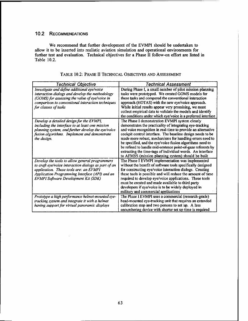
10.2 RECOMMENDATIONS
We recommend that further development of the EVMPI should be undertaken to allow it to be inserted into realistic aviation simulation and operational environments for further test and evaluation. Technical objectives for a Phase II follow-on effort are listed in Table 10.2.
TABLE 10.2: PHASE II TECHNICAL OBJECTIVES AND ASSESSMENT
Technical Objective Technical Assessment Investigate and define additional eye/voice interaction dialogs and develop the methodology (GOMS)for assessing the value of eye/voice in comparison to conventional interaction techniques for classes of tasks
During Phase I, a small number of pilot mission planning tasks were prototyped. We created GOMS models for these tasks and compared the conventional interaction approach (HOTAS) with the new eye/voice approach. While initial results appear very promising, we must collect empirical data to validate the models and identify the conditions under which eye/voice is a preferred interface
Develop a detailed design for the EVMPI, including the interface to at least one mission planning system, and further develop the eye/voice fusion algorithms. Implement and demonstrate the design.
The Phase I demonstration EVMPI system clearly demonstrates the practicality of integrating eye-tracking and voice recognition in real-time to provide an alternative cockpit control interface. The baseline design needs to be made more robust, mechanisms for handling errors need to be specified, and the eye/voice fusion algorithms need to be refined to handle mid-sentence point-of-gaze referents by extracting the time-tags of individual words. An interface to AFMSS (mission planning system) should be built
Develop the tools to allow general programmers to craft eye/voice interaction dialogs as part of an application. These tools are: an EVMPI Application Programming Interface (API) and an EVMPI Software Development Kit (SDK)
The Phase I EVMPI implementation was implemented without the benefit of software tools specifically designed for constructing eye/voice interaction dialogs. Creating these tools is possible and will reduce the amount of time required to develop eye/voice applications. These tools must be created and made available to third party developers if eye/voice is to be widely deployed in military and commercial applications
Prototype a high performance helmet-mounted eye- tracking system and integrate it with a helmet having support for virtual panoramic displays
The Phase I EVMPI uses a commercial (research-grade) head-mounted eye-tracking unit that requires an extended calibration step and two persons to set up. A less encumbering device with shorter set up time is required
63

REFERENCES
Astheimer, P., "Sonification Tools to Supplement Dataflow Visualization," in Patrizia Palamidese (Ed.), Scientific Visualization Advanced Software Techniques, Ellis Horwood, New York, 1993, pp. 15-36.
Bates Madeleine, Bobrow, Robert, Kubala, Francis, Ingn, Robert, Makhoul, John, Miller, Scott, Nguyen, Long, Peters, Sandra, Schwartz, Richard, Stallard, David, and Zavahagkos, George, "Usable, Real-Time, Interactive Spoken Language Systems," BBN Systems and Technologies, September, 1994.
Bly, S. A., "Communicating with Sound," Proceedings of CHI '85 Conference on Human Factors in Computer Systems, 1985, pp. 115-119.
Bolt, Richard A., The Human Interface: Where People and Computers Meet, Lifetime Learning Publications, London, UK, 1984.
Borah, Joshua, "Helmet Mounted Eye Tracking for Virtual Panoramic Display Systems, Volume I: Review of Current Eye Movement Measurement Technology," Final Report, AAMRL-TR-89-019, Armstrong Aerospace Medical Research Laboratory, Wright- Patterson AFB, OH, August, 1989. ,
Borah, Joshua, "Helmet Mounted Eye Tracking for Virtual Panoramic Display Systems, Volume II: Eye Tracker Specification and Design Approach," Final Report, AAMRL-TR- 89-019, Armstrong Aerospace Medical Research Laboratory, Wright-Patterson AFB, OH,
August', 1989. . . . -r u • Borah Joshua, "Investigation of Eye and Head Controlled Cursor Positioning Techniques,
Final Report, Contract No. F41624-93-C-6006, Applied Science Laboratories, Bedford, MA, August, 1995. .
Borah, Joshua, Personal communication, Applied Science Laboratories, Bedford, MA, August, 1995.
Bradford, James H, "The Human Factors of Speech-Based Interfaces: A Research Agenda," SIGCHI Bulletin, Vol. 27, No. 2, April, 1995, pp. 61-67.
Buxton, William, "Introduction to This Special Issue on Nonspeech Audio," Human- Computer Interaction, Vol. 4, 1989, pp. 1-9. „:,„...
Calhoun, Gloria L., Arbak, Christopher J. and Boff, Kenneth R, "Eye-Controlled Switching for Crew Station Design," Proceedings of the Human Factors Society, 28th Annual Meeting, 1984.
Calhoun, Gloria L. and Janson,William P., "Eye Line-of-Sight Control Compared to Manual Selection of Discrete Switches," AL-TR-1991-0015, Armstrong Laboratory, Human Engineering Division, 1991.
Card, Stuart, Moran, Thomas and Newell, Allen, The Psychology of Human-Computer Interaction, Lawrence Erlbaum Associates, Hillsdale, NJ, 1983.
Diaper, Dan, Task Analysis for Human Computer Interaction, Ellis Horwood Publishers, Chichester, UK, 1989.
Fairchild, Kim M., Poltrock, Steven E., and Furnas, George W., "SemNet: Three- Dimensional Graphic Representations of Large Knowledge Bases," in Raymonde Guindon (Ed.), Cognitive Science and its Applications for Human-Computer Interaction, Lawrence Erlbaum Associates, Hillsdale, NJ, 1988.
Foley, James D., van Dam, Andries, Feiner, Steven K. and Hughes, John F., Computer Graphics, Principles and Practice, Addison-Wesley Publishing, Reading, MA, 1990.
Gaines, B.R. and Boose J. (Eds.), Knowledge Acquisition for Knowledge-based Systems, Knowledge Based Systems Series Vol. 1, Academic Press, London, UK, 1988.
Gaver, William, "The SonicFinder: An Interface That Uses Auditory Icons," Human- Computer Interaction, Vol. 4, 1989, pp. 67-94.
64

Glenn, Floyd A., Harrington, Nora, Iavecchia, Helene P. and Stokes, James, "An Oculometer and Automated Speech Interface System," Analytics, Technical Report 1920, Analytics, Willow Grove, PA, May, 1984.
Gong, Richard and Kieras, David, "A Validation of the GOMS Model Methodology in the Development of a Specialized, Commercial Software Application," Proceedings of Human Factors in Computing Systems, CHI '94, ACM Press, New York, NY, 1994, pp. 344-350.
Gray, W. D., John, B. E., and Atwood, M. E., "The Precis of Project Ernestine or An Overview of a Validation of GOMS," Proceedings of the CHI '92 Conference on Human Factors in Computing Systems, Addison-Wesley, NY, 1992, pp. 307-312.
Gray, W. D., John, B. E., and Atwood, M. E., "Project Ernestine: Validating GOMS for Predicting and Explaining Real-World Task Performance," Human Computer Interaction., Vol. 8(3), 1993, pp. 237-309.
Hatfield, F. and Cromarty, A., "Visualization and Analysis for Cruise Missiles (Final Report)," Technical Report TR-J101-2, Synthetic Environments, Inc., McLean, VA, June, 1994.
He, Taosong and Kaufman, Arie E., "Virtual Input Devices for 3D Systems," Proceedings Visualization '93, IEEE Computer Society, San Jose, CA, October 25-29, 1993, pp. 142- 148.
House, A.S., The Recognition of Speech by Machine - A Bibliography, Academic Press, NY, 1988.
Irving, Sharon, Poison, Peter, and Irving, J.E., "A GOMS Analysis of the Advanced Automated Cockpit," Proceedings of Human Factors in Computing Systems, CHI '94, ACM Press, New York, NY, 1994, pp. 344-350.
Jacob, Robert J.K., "The Use of Eye Movements in Human-Computer Interaction Techniques: What You Look At Is What You Get," ACM Transactions on Information Systems, Vol. 9, No. 3, April, 1991, pp. 152-169.
Jacob, Robert J.K., "Eye-Movement Based Human-Computer Interaction Techniques: Toward Non-Command Interfaces," in H. Rex Hartson and Deborah Hix (Eds.), Advances in Human-Computer Interaction, Vol. 4, Ablex Publishing Corporation, Norwood, NJ, 1993.
John, Bonnie E. and Gray, Wayne, "GOMS Analysis for Parallel Activities," Tutorial presented at the Conference on Human Factors in Computing Systems, April 24-28, 1994.
John, Bonnie E. and Kieras, David E., "The GOMS Family of Analysis Techniques: Tools for Design and Evaluation," CMU Technical Report CMU-CS-94-181, Carnegie-Mellon University, 24 August 1994.
Kalawsky, Roy S., The Science of Virtual Reality and Virtual Environments, Addison-Wesley Publishing Company, Wokingham, England, 1993.
Kocian, D.F., "Design Considerations for Virtual Panoramic Display (VPD) Helmet Systems," AGARD Joint Flight Mechanics/Guidance and Control Panels Symposium on the Man-Machine Interface in Tactical Aircraft Design and Combat Automation, No. 22, Stuttgard, GE, October, 1987.
Koons, David B., Sparrell, Carlton J. and Thorisson, Kristinn R., "Integrating Simultaneous Input from Speech, Gaze, and Hand Gestures," in Mark T. Maybury (Ed.), Intelligent Multimedia Interfaces, AAAI Press / The MIT Press, Menlo Park, CA, 1993.
Mansur, D.L., Blattner, M.M., and Joy, K.I., "Sound Graphs: A Numerical Data Analysis Method for the Blind," Proceedings of the 18th Hawaii International Conference on System Sciences, Vol. 18, 1985, pp. 163-174.
Meyer, Mary A. and Booker, Jane, Eliciting and Analyzing Expert Judgement, Knowledge Based Systems Series Vol. 5, Academic Press, London, UK, 1991.
Moitra, D., Montanaro, G.D. and Chalek, C, "Graphical Techniques for Force Level Planning, Vol. II," Technical Report RL-TR-91-239, Rome Laboratory, Air Force Systems Command, Griffis* Air Force Base, NY, 991. (DTIC AD-A242 545)
65

Montanaro, G. D., Schroeder, W.J., Yamrom, B., Lorensen, W., Moitra, D. and Meenan, P.M., "Graphical Requirements for Force Level Planning, Vol. I," Technical Report RL- TR-91-239, Rome Laboratory, Air Force Systems Command, Griffiss Air Force Base, NY, 1991. (DTIC AD-A242 544)
Negroponte, Nicholas P. and Bolt, Richard A., "Advanced Concurrent Interfaces for High- Performance Multi-Media Distributed C3 Systems," MIT Media Lab, Rome Laboratory Technical Report RL-TR-93-17, Air Force Materiel Command, Griffiss Air Force Base, NY, March, 1993. (DTIC AD-A267 051)
Negroponte, Nicholas P. and Bolt, Richard, A., "Virtual Environments in Command & Control for Ultra-High Definition Displays," Technical Report RL-TR-94-24, Rome Laboratory, Griffiss Air Force Base, New York, NY, April, 1994, pp. 45-53. (DTIC AD-A281-054)
Newell, Alan and Simon, Herbert, Human Problem Solving, Prentice Hall, Englewood Cliffs, NJ, 1972.
Nielsen, Jakob, Usability Engineering, Academic Press, Boston, MA, 1993. OMG, Object Management Architecture Guide, OMG TC Document 92.11.1, Rev. 2.0, 2nd
Edition, 1992. Rabiner, Lawrence and Juang, Biing-Hwang, Fundamentals of Speech Recognition, Prentice
Hall, Englewood Cliffs, NJ, 1993. Rime, B. and Schiaratura, L., "Gesture and Speech," in R.S. Feldman and B. Rim,
Fundamentals of Nonverbal Behavior, University of Cambridge Press, New York, NY, 1991, pp. 239-281.
Robertson, George, Card, Stuart, Mackinlay, Jock, "Information Visualization Using 3D Interactive Animation," Communications of the ACM, Vol. 36, No. 4, April, 1993, pp. 57-71.
Rudnicky, Alexander I. and Hauptmann, Alexander G., "Multimodal Interaction in Speech Systems," in M.M. Blattner and R.B. Dannenberg (Eds.), Multimedia Interface Design, ACM Press and Addison-Wesley Publishing Co., Reading, MA, 1992, pp. 147-171.
Scaletti, Carla, "Sound Synthesis Algorithms for Auditory Data Representation," Proceedings of the 1992 International Conference on Auditory Display, 1992.
Schmandt, Christopher, Voice Communication with Computers: Conversational Systems, Van Nostrand Reinhold, New York, NY, 1994.
Searle, John R., "The Classification of Illocutionary Acts," Language in Society, Vol. 5, 1976, pp. 1-24.
Slavinski, Richard, Personal communication, USAF Rome Laboratories, Rome, NY, October 26, 1995.
Starker, I. and Bolt, R.A., "A Gaze-Responsive Self-Disclosing Display," Proceedings ACM CHI '90 Human Factors in Computing Systems, ACM Press, Seattle, WA, 1990, pp. 3-9.
Stokes, Alan F. and Wickens, Christopher D., "Aviation Displays," in E.L. Weiner and D.C. Nagel (Eds.), Human Factors in Aviation, Academic Press, Inc., San Diego, CA, pp. 387- 431.
Stytz, Martin R, Block, Elizabeth G., Kunz, Andrea, Soltz, Brian, and Wilson, Kirk, "Tools to Aid In Comprehending Large-Scale, Complex Virtual Environments," Proceedings of the 1994 Image VII Conference, Tuscon, AZ, 12-17 June, 1994, pp. 221-233.
Taylor, R.M, "Integrating Voice, Visual and Manual Transactions: Some Practical Issues from Aircrew Station Design," in M.M. Taylor, F. Neel, and D.G. Bouwhuis (Eds.), The Structure of Multimodal Dialogue, Elsevier Science Publishers B.V., North Holland, Amsterdam, 1989, pp. 259-265.
Wahlster, Wolfgang, "User and Discourse Models for Multimodal Communication," in J.W. Sullivan and S.W. Tyler (Eds.), Intelligent User Interfaces, ACM Press, Addison-Wesley Publishing Company, New York, 1991, pp. 45-67.
Wauchope, Kenneth, "Eucalyptus: Integrating Natural Language Input with a Graphical User Interface," Naval Research Laboratory Technical Report NRL/FR/5 510-94-9711, Naval Research Laboratory (NCARAI), February 25, 1994. (DTIC AD-A276 914)
66

Weinstein, C.J., "Opportunities for Advanced Speech Processing in Military Computer-Based Systems," Technical Report 904, Lincoln Laboratory, Massachusetts Institute of Technology, Lexington, MA, February, 1991. (DTIC AD-A233 724)
Wernecke, Josie, The Inventor Mentor, Addison-Wesley Publishing Company, Reading, MA, 1994.
Young, L.R. and Sheena, D., "Survey of Eye Movement Recording Methods," Behavior Research Methods and Instrumentation, Vol. 7, No. 5, 1975, pp. 397-429.
67

APPENDIX A
ANNOTATED BIBLIOGRAPHY
68

This appendix contains an annotated bibliography of selected research papers and technical reports. Some of the paper descriptions provided here have been summarized or otherwise adapted for inclusion in the body of this report as part of the literature review. The paper descriptions are included here as well to provide the reader easy access to the content of specific papers. A number of papers were reviewed beyond those that are listed here. The fact that a paper cited in the body of the report does not also appear in this appendix should not be interpreted as an indication of our opinion of the quality or relevance of the paper to this research.
Bolt, Richard A., The Human Interface: Where People and Computers Meet, Lifetime Learning Publications, London, UK, 1984.
This book describes advanced human-computer interface research conducted at the Massachusetts Institute of Technology (MIT) during the early 1980s. The book reviews MIT's work in developing interfaces that, among other things, feature speech and gesture recognition as well as eye-tracking. Given the limitations of the technology (e.g., speech recognition) that existed at the time, most of the interface concepts proposed relied upon exploiting features of the application and display context to constrain the interpretation of the various modalities. For example, to compensate for inaccuracies in deictic gestures (or eye-tracking point of gaze) in an object selection task, the information in a speech utterance might be used to disambiguate the item referred to. This strategy to improve intent interpretation is still valid today even though the core technologies (speech recognition and eye- tracking) have improved dramatically. The book includes a description of Bolt's "Put-That-There" speech and gesture recognition system.
Borah, Joshua, "Helmet Mounted Eye Tracking for Virtual Panoramic Display Systems, Volume I: Review of Current Eye Movement Measurement Technology," Final Report, AAMRL-TR-89-019, Armstrong Aerospace Medical Research Laboratory, Wright- Patterson AFB, OH, August, 1989.
This paper summarizes the three categories of eye tracking technology: electro-oculography, scleral coil - contact lens, and optical techniques. The author discusses how each technique works, what eye features
are measured, the accuracy possible, and the limitations of each approach, e.g., degree of invasiveness, size, and constraints on operator movement.
Bradford, James H., "The Human Factors of Speech-Based Interfaces: A Research Agenda," SIGCHI Bulletin, Vol. 27, No. 2, April, 1995, pp. 61-67.
This paper discusses some of the issues and challenges in making speech-based human-machine interfaces more closely resemble human-human conversation. The paper begins with the observation that there are practical limits to the reliability of speech signal processing and that the recognition of user actions (utterances) is "inherently error prone." (For comparison, human performance in isolated word recognition is reported to be only about 97%.) To reduce recognition errors, systems must exploit syntax, semantics and task pragmatics. While natural, connected word speech raises the possibility of multiple recognition errors, the additional words may provide sufficient contextual clues in order to disambiguate user intentions. Additional research is needed to determine the optimal granularity for spoken commands. The author argues for analyzing how human-human conversational techniques (e.g., clarification, back channel utterances, dialog repair, turn taking and topic introduction) can be adapted for use in human-computer conversations. The potential for exploiting prosody and register to improve recognition rates is also discussed. The effect of human emotion (e.g., stress) on speech is noted and the author argues for research into recognition algorithms that will normalize speech that has been modified by emotion.
69

Calhoun, Gloria L., Arbak, Christopher J. and Boff, Kenneth R, "Eye-Controlled Switching for Crew Station Design," Proceedings of the Human Factors Society, 28th Annual Meeting, 1984.
This paper describes the use of eye-tracking for the selection of switches in a cockpit. A smoothing algorithm is applied to eye point-of-gaze time-series data in order to determine the point of regard in a fixed coordinate system. Switch locations are mapped into this coordinate system and when the eye point-of-gaze is computed to be within a specified switch location (within 2 cm of the center of the switch) for a period of time (or number of data samples) above some threshold amount, the switch is considered "selected." A switch that has been selected is highlighted to provide the subject with feedback. The subject may also have the capability to confirm (or provide consent for) the selection by manually pressing a button or making a verbal confirmation utterance. The authors identified several general classes of tasks to which this technology could be applied in the cockpit: searching for targets, monitoring displays and continuous tracking.
Card, Stuart K., Mackinlay, Jock D. and Robertson, George G., "The Design Space of Input Devices," Proceedings of CHI '90, Association of Computing Machinery, New York, NY, 1990, pp. 117-124. Also appears in M.M. Blattner and R.B. Dannenberg (Eds.), Multimedia Interface Design, ACM Press, New York, NY, 1992, pp. 217-232.
These authors define a methodology for generating points in the design space of input devices. Underlying this approach is the view (due to Baecker) that "an input device is a transducer from the physical properties of the world into logical values of an application." The methodology consists of a small vocabulary for describing primitive movements and a set of operators for combining them. The authors then test selected points in this design space using the criteria of expressiveness (e.g., what degree of precision does the task require) and effectiveness (e.g., what degree of precision is the device capable of). The suitability of a device for a particular task can be determined by comparing the bandwidth of the human muscles that manipulate the device (e.g., neck, arm, wrist and finger) and the bandwidth required of the task (e.g., pointing to a paragraph vs. pointing to an individual character). The authors apply the methodology to show that movement of a cursor by a "head mouse" (instrumented head movement) will not achieve the precision required to select small targets unless the head mouse is used in conjunction with another device (e.g., a conventional mouse) to acquire the target in a final phase.
Dillon, Richard F., Edey, Jeff D. and Tombaugh, Jo W., "Measuring the True Cost of Command Selection: Techniques and Results," SIGCHI Proceedings, 1990.
The authors measured the time to accomplish command selection embedded within a task. They investigated multiple input modalities, including voice, touch, single mouse, and two mice. They found that voice was significantly faster than any of the mouse conditions. They also observed that in some applications, smooth integration of the selection method with the task may be more important than the speed of target selection.
Gaver, William, "The SonicFinder: An Interface That Uses Auditory Icons," Human- Computer Interaction, Vol. 4, 1989, pp. 67-94.
The author proposes the use of auditory icons or ordinary everyday sounds that are intended to convey information about what is going on in the model world of a computer by analogy with everyday events. The author used this idea in developing the Macintosh-based SonicFinder interface which adds sound to computer events such as copying and deleting files and opening windows. He proposes a theory why the mappings used in this interface seem intuitive and concludes that intuitive mappings of sounds to events in a computer modeled world are those that are constrained as much as possible by the types of correspondences found in the everyday world. One implication of this theory is that, wherever possible, use of iconic (as opposed to symbolic or metaphorical) representation should be used because iconic representations depict causal relationships (what you think made the sound) between the visual or auditory cue and the modeled event.
70

Glenn, Floyd A., Harrington, Nora, Iavecchia, Helene P. and Stokes, James, "An Oculometer and Automated Speech Interface System," Analytics, Technical Report 1920, Analytics, Willow Grove, PA, May, 1984.
These authors describe the Oculometer and Automated Speech Interface System (OASIS), a system that integrates voice recognition and eye-tracking to interact with a graphical display; the display may be either desktop-mounted or head-mounted. The paper presents the overall OASIS concept, reviews the component technologies and surveys a range of potential applications, including air traffic control, computer access for the disabled and teleoperator control. The utility of voice to convey discrete messages (commands) and eye-tracking to disambiguate verbal utterances is noted. The use of eye- tracking in OASIS is oriented around cursor control and there is an underlying assumption that a feedback cursor generally needs to be displayed. The OASIS design uses special time-tagged words, e.g., "NOW," that trigger time-position reference processing. Upon detection of one of these special words, the OASIS system controller takes note of the eye point-of-gaze at the time the special word was uttered. In the interaction dialogs described, the operator typically must coordinate the special time- tagged words with his/her point-of-gaze. This approach may unduly force the operator to attend to point-of gaze and verbalizations, i.e., the mechanisms for accomplishing a task, rather than the substance of the task itself.
Gong, Richard and Kieras, David, "A Validation of the GOMS Model Methodology in the Development of a Specialized, Commercial Software Application," Proceedings of Human Factors in Computing Systems, CHI '94, ACM Press, New York, NY, 1994, pp. 351-357.
This paper describes the application of the GOMS methodology to the redesign of an industrial ergonomics design tool. The authors' initial results from application of GOMS resulted in an over- prediction of task execution times. The over-prediction was attributed to overlapping perceptual and mental operations, which had originally been treated as serially executed operators. Correction for the concurrent operator execution resulted in a close correspondence between task execution predictions and observations.
He, Taosong and Kaufman, Arie E., "Virtual Input Devices for 3D Systems," Proceedings Visualization '93, IEEE Computer Society, San Jose, CA, October 25-29, 1993, pp. 142-148.
This paper proposes a device unified interface, a generalized and extensible protocol for communicating between applications and input devices. Such an interface provides a level of abstraction for computer input that shields an application from the details of the hardware input devices. The authors also provide a classification of input devices and rate their suitability for use in performing various input activities, e.g., locating, choosing, commanding and valuating (i.e., inputting a numerical value).
Irving, Sharon, Poison, Peter, and Irving, J.E., "A GOMS Analysis of the Advanced Automated Cockpit," Proceedings of Human Factors in Computing Systems, CHI '94, ACM Press, New York, NY, 1994, pp. 344-350.
This paper describes an application of the GOMS methodology to examine the task knowledge needed to operate a control and display unit (CDU) for a Boeing 737 flight management computer. Similar in functionality to an up front control (UFC) used in a combat aircraft, the CDU has alphanumeric keys, function keys and selection buttons arrayed around the periphery of an LCD display. In addition to using GOMS to identify weaknesses in the CDU interface design, the authors noted that a relatively small number of common methods were used across the different tasks that can be accomplished with the CDU. Many of the CDU tasks made significant demands on memory recall; the military cockpit (UFC) situation similarly places severe demands on pilot memory.
71

Koons, David B., Sparrell, Carlton J. and Thorisson, Kristinn R., "Integrating Simultaneous Input from Speech, Gaze, and Hand Gestures," in Mark T. Maybury (Ed.), Intelligent Multimedia Interfaces, AAAI Press / The MIT Press, Menlo Park, CA, 1993.
This paper describes work at the Massachusetts Institute of Technology (MIT) Media Lab to develop a prototype system that combines speech, gesture and eye-tracking in the interface. The.prototype system fuses time-stamped eye and hand positional information with time-stamped speech through a process of multiple frame instantiation (one for each modality). By applying constraint reasoning, these frames can be merged into a single interpretation of the interaction event. For example, the utterance "the square below the red triangle" may be sufficient to disambiguate the referents in an uncluttered scene, but when this utterance is combined with deictic gesture, it may remove all ambiguity and/or enhance interpretation performance by limiting the spatial area within which to search. The prototype system implemented gesture and eye-tracking for deictic purposes only, but explores the uses of gesture and eye features/behavior to convey other meaning. The speech recognition component in the prototype is discrete word and is able to time-tag individual words in an utterance, allowing for a fine grain analysis of the utterance.
Moitra, D., Montanaro, G.D. and Chalek. C, "Graphical Techniques for Force Level Planning, Vol. II," Technical Report RL-TR-91-239, Rome Laboratory, Air Force Systems Command, Griffiss Air Force Base, NY, 1991. (DTIC AD-A242 545)
This technical report, a companion to Montanaro et al., 1991 below, presents specific interactive techniques for supporting Air Force mission planning. Techniques for resource allocation, scheduling and cost-benefit analysis are given. The authors view the mission planning problem as an iterative process and emphasize the importance of using interactive graphical techniques to visualize the interdependence among decision variables and problem parameters as the plan is being developed. Examples of specific techniques suggested for visualizing scheduling interdependencies are use of sliders to change decision variables that illustrate the marginal effect on plan quality and use of sound to exploit the benefits of multiple input modalities.
Montanaro, G.D., Schroeder, W.J., Yamrom, B., Lorensen, W., Moitra, D. and Meenan, P.M., "Graphical Requirements for Force Level Planning, Vol. I," Technical Report RL-TR- 91-239, Rome Laboratory, Air Force Systems Command, Griffiss Air Force Base, NY, 1991. (DTIC AD-A242 544)
This technical report identifies graphical support requirements for Air Force tactical mission planning. Organized in terms of the tasks to be performed in mission planning (i.e., mission preparation, simulation, execution and review), the authors identify salient characteristics of maps, threat zones, weather and route planning that pervade all mission planning tasks and that can benefit from graphical support. The analysis provided in this report helps define the role that general graphical techniques can play in reducing operator cognitive load and increasing understanding of the tactical situation and resource allocation alternatives.
Negroponte, Nicholas P. and Bolt, Richard, A., "Virtual Environments in Command and Control for Ultra-High Definition Displays," Technical Report RL-TR-94-24, Rome Laboratory, Griffiss Air Force Base, New York, NY, April, 1994, pp. 45-53. (DTIC AD- A281-054)
This report provides a summary of recent work at the MIT Media Laboratory in support of the US Air Force's Rome Laboratory. The paper summarizes the current work in integrating gesture and speech for resolving references. Deictic and iconic gestures are examined.
72

Pausch, Randy and Grossweiler, Rich, "Application-Independent Object Selection from Inaccurate Multimodal Input," in M.M. Blattner and R.B. Dannenberg (Eds.), Multimedia Interface Design, ACM Press / Addison-Wesley Publishing Company, New York, NY, 1992.
This paper introduces the concept of "presentation attributes" which are general characteristics that are understood by both the human user and an interface's rendering engine. Examples of attributes include size, color and spatial position of objects in a visual display or loudness and pitch in an aural display. The problem addressed by the authors is how multimodal input can be used to select objects in a generalized display (i.e., one having visual, aural and haptic dimensions) in a way that does not entail application-specific knowledge. The authors' solution to this problem is to define an n-dimensional space of display attributes. The application software maps each display object into these dimensions, defining an n-dimensional vector for every display object. When the user "selects" an object, inputs (e.g., speech, point-of-gaze, gesture) are mapped into a point in this same n-dimensional space. The software then determines what object is nearest in the n-dimensional space; this object becomes the selected object. Three dimensional graphics languages typically have efficient functional primitives that work in the domain of object type, shape, color, etc. and the authors' solution can exploit these built-in primitives while at the same time providing an interface that is natural to untrained users. This solution is actually more general than what we need in EVMPI since we can expect that our users would undergo some level of training to use the system. Moreover, our database of display objects are more specifically known, such as airfields and buildings rather than abstract geometric objects. This information can be effectively used to constrain the interpretation task.
Robertson, George, Card, Stuart, and Mackinlay, Jock, "Information Visualization Using 3D Interactive Animation," Communications of the ACM, Vol. 36, No. 4, April, 1993, pp. 57- 71.
The authors propose a user interface architecture called the Cognitive Coprocessor Architecture which is oriented around information access rather than document editing. The architecture provides an animation loop and scheduler which does "impedance matching," i.e., coordinates inputs and outputs across three sets of processing time scales corresponding to the user, the user interface, and the problem- solving application. A great deal of emphasis is placed on smooth, interactive animation because it shifts the user's task from primarily a cognitive one to perceptual activity, which frees user cognitive capacity for application tasks.
Rudnicky, Alexander I. and Hauptmann, Alexander G., "Multimodal Interaction in Speech Systems," in M.M. Blattner and R.B. Dannenberg, (Eds.), Multimedia Interface Design, ACM Press / Addison-Wesley Publishing Co., New York, NY, 1992, pp. 147-171.
This paper provides a set of principles for the design of spoken language systems. These principles cover such topics as user plasticity (speakers adapt their style to the listener), the design of interaction protocols, error recovery, system response time, exploiting the constraints of dialog structure, and the synergistic effect of multimodal interaction. An explicit assumption in the paper is that speech interfaces, unlike keyboard interfaces, are inherently errorful. In keyboard interfaces, a keystroke has an unambiguous interpretation, but word/phrase recognition cannot, in general, be unambiguously interpreted. The authors argue for speaker independent systems because they allow casual users to access applications; they argue for connected speech, rather than isolated word recognition, because connected speech systems do not require the speaker to attend to his/her speech (e.g., pause between words) as is the case in isolated word recognition; they argue for large vocabularies, where the application warrants it, because they provide a more flexible, natural way to interact with the system. Of particular interest is the author's discussion on using alternate interaction protocols to recover from incorrect word/phrase recognition. Some empirical results are given that indicate that "inline disconfirmation" of failed word/phrase recognition is both more natural and more efficient in systems with relatively high successful recognition rates. The authors briefly discuss one experiment in combining voice and gesture for efficient and natural interaction, but point out that more research is required to obtain conclusive results that show how system functions should be optimally allocated to different modalities.
73

Schmandt, Christopher, Voice Communication with Computers: Conversational Systems, Van Nostrand Reinhold, New York, NY, 1994.
This recent book provides a comprehensive discussion of speech-based interfaces, beginning with the physiological components of speech production and perception, and covering such topics as speech encoding, recognition and synthesis techniques, and the engineering of speech for interactive applications. Interaction techniques that deal with various recognition error classes are presented, and a discussion of alternative confirmation strategies and error recovery techniques is presented.
Sturman, David and Zeltzer, David, "A Survey of Glove-Based Input," IEEE Computer Graphics & Applications, Vol. 14, No. 1, January, 1994.
This paper reviews glove-based input devices, including methods for position tracking and hand shape (gesture) recognition. Glove system accuracy, latency and cost are discussed, as well as several applications, including sign language interpretation, teleoperation and robotic control and basic point, reach and grab applications. Visualization of mission plans in 3-D space will depend critically on being able to navigate this space efficiently and without losing orientation. Glove-based input and other techniques, e.g., trackball navigation, may provide alternatives to conventional mouse-based navigation, which is designed for 2-D windowed applications. Some of the lessons from use of gloves to point and navigate should be reviewed for their applicability to integrating eye-tracking and voice.
Taylor, R.M, "Integrating Voice, Visual and Manual Transactions: Some Practical Issues from Aircrew Station Design," in M.M. Taylor, F. Neel, and D.G. Bouwhuis (Eds.), The Structure of Multimodal Dialogue, Elsevier Science Publishers B.V., North Holland, Amsterdam, 1989, pp. 259-265.
This paper discusses practical problems with the introduction of speech (both recognition and generation) into the cockpit. The paper is based on two experiments, one in a single seat fighter cockpit simulator and the other in a Wessex 2 helicopter. The author reports the need to (1) augment voice recognition with visual prompts to avoid problems with pilot memorization of restricted vocabularies, and (2) provide some form of feedback to the pilot that utterances have been correctly interpreted (particularly if the recognition process is errorful). The author also points out that the hierarchical structure associated with multi-function displays need not be retained in the speech dialog; rather, dialog can be organized in a flatter structure. The design trade then becomes between the increased access speed to commands in a level structure and the increased memory load to remember all the allowable commands.
Wahlster, Wolfgang, "User and Discourse Models for Multimodal Communication," in J.W. Sullivan and S.W. Tyler (Eds.), Intelligent User Interfaces, ACM Press, Addison-Wesley Publishing Company, New York, 1991, pp. 45-67.
This paper addresses the problem of combining verbal and non-verbal behavior (gesture) in an interface and describes the XTRA (Expert Translator) architecture for a multimodal interface that features a gesture analysis component. In the relatively limited number of systems combining graphical user interfaces with gesture, there has always been a one-to-one mapping between the region that the user points to (the demonstrantum) and the region that the user intends to refer to (the referent). In this paper, this assumption is relaxed and the user is permitted to make inexact pointing gestures and point to a part of the interface when he/she wants to refer to a larger part as a whole (pars-pro-toto deixis). Dealing with this more general case means that the multi-modal interface must have and maintain a fairly sophisticated discourse model, whereby the dialog can be tracked and contextually-based inferences can be made with regard to the denotation of dialog referents.
74

Wauchope, Kenneth, "Eucalyptus: Integrating Natural Language Input with a Graphical User Interface," Naval Research Laboratory Technical Report NRL/FR/5 510-94-9711, Naval Research Laboratory (NCARAI), February 25, 1994. (DTIC AD-A276 914)
This paper describes how a natural language (NL) interface (Eucalyptus) featuring speech input has been integrated with a conventional graphical user interface (GUI). The purpose of Eucalyptus is to show that graphical and NL interfaces have complementary strengths when used together. Eucalyptus supports deixis, a form of reference in which pointing gestures accompany NL expressions (processed spoken utterances). Eucalyptus is designed to be integrated with an existing GUI rather than replacing it; the functionality in the existing GUI remains intact. The intent is not to verbally operate the GUI widgets, but to directly interact with the underlying application program and application-level objects. This design approach (or philosophy) is applicable to our EVMPI effort, since the real payoff in combining voice and eye input will not be simply to provide a better means of manipulating multi- function and other menu-based displays (though it could be used in this manner), but to provide an alternative to the hierarchical, menu-based approach altogether. The application domain used to illustrate the Eucalyptus concept is a hypothetical command and control system located in a Navy E2 Airborne Early Warning aircraft. The Eucalyptus environment includes a Speech Systems, Inc. PE200 voice recognition system, an earlier and workstation-based version of the PE500 speech recognition system that SEI is using in this contract.
75
APPENDIX B
MISSION PLANNING SCENARIOS
76
There are five (5) scenarios representative of the major air warfare missions:
• Suppression of Enemy Air Defenses (SEAD) • Counter Air • Strike • Theater Missile Defense (TMD) • Close Air Support (CAS).
Each of these is described below in terms of its objectives, planning considerations and mission support and coordination requirements. A profile for a typical scenario is also given.
B.1 SUPPRESSION OF ENEMY AIR DEFENSES (SEAD)
B.l.l Mission Overview
SEAD is an air attack mission designed to weaken the enemy's integrated air defense system (IADS). Reducing or delaying the enemy's ability to detect incoming air targets provides friendly air forces greater tactical flexibility and survivability. SEAD is usually performed prior to or in conjunction with air strike missions, creating a safe haven for the dedicated strike aircraft.
B.l.l Mission Objectives
SEAD mission objectives include destroying or denying enemy surface-to-air missile (SAM) sites, radar sites and related command, control and communication (C3) sites.
B.1.3 Planning Considerations
SEAD targets can be known fixed or mobile sites and unknown sites (targets of opportunity). Targets may also be identified as radiating (RF energy) or non-radiating.
B. 1.4 Mission Support and Coordination
The SEAD mission commander relies heavily on current targeting information. Targeting information includes target type, location, number, operational status, defense capability and posture. The SEAD mission commander will coordinate his activity with the strike commanders) whose missions depend on IADS weakness for success. He will also coordinate with other SEAD support assets such as electronic warfare (EW) missions and airborne early warning (AEW) missions.
B.1.5 Scenario Profile
Two F-15Cs are tasked with providing SEAD protection for a strike package of four F-15Es. The target is a petroleum, oil and lubricants depot (POL) on a major river 200 miles inside enemy territory. The enemy IADS includes long-range SAM sites along the route, short-range SAMs and anti-aircraft artillery (AAA) near the target. The long-range SAM locations near the ingress route are known. The air threat is low.
77

The F-15Cs precede the strikers by several minutes along the route. As the attack unfolds, the F-15Cs, equipped with radar warning receivers, locate and suppress the long-range enemy SAM sites and nearby command nodes with four of tbHr eight high speed antiradiation missiles (HARM). The F-15Cs proceed to the target area launching two more HARM at the active SAM sites protecting the POL. The F-15Cs two remaining HARMs are available for SAM "targets of opportunity" and protecting the strike package as they return from the target area.
B.2 COUNTER AIR
B.2.1 Mission Overview
The Counter Air mission is designed to defend against or preemptively destroy enemy aircraft. Counter Air missions target enemy aircraft that represent current or potential threats to friendly air, land and sea forces. Counter Air is often performed prior to or in conjunction with air strike missions, creating a safe haven for the dedicated strike aircraft.
B.2.2 Mission Objectives
The Defensive Counter Air (DCA) mission objective is to place an aerial barrier between the friendly force disposition being defended and threat aircraft. The Offensive Counter Air (OCA) mission objective is to preemptively engage and destroy threat aircraft that pose a potential threat to friendly forces.
B.2.3 Planning Considerations
Counter Air targets can be fixed sites (e.g., airfields, bunkers, etc.), known Combat Air Patrol (CAP) positions or airborne targets of opportunity. The fighter mission commander must differentiate between friendly, neutral and threat targets prior to prosecution. Specific Rules of Engagement (ROE) are delineated in the air tasking order (ATO).
B.2.4 Mission Support and Coordination
The Counter Air mission commander relies heavily on current threat information. Threat information includes aircraft type, location, number, operational status, defensive and offensive capability and posture. The Counter Air mission commander will coordinate his activity with the strike commander(s) whose missions depend on suppression of airborne threats for success. He will also coordinate with other Counter Air support assets such as electronic warfare (EW) missions and airborne early warning (AEW) missions.
B.2.5 Scenario Profile
Four F-15Cs are tasked with providing Offensive Counter Air protection for a strike package of two B-ls. The target is an airfield on the outskirts of a major city 200 miles inside enemy territory. The enemy air posture at the airfield is low due to previous attacks. The nearest air threat emanates from an airfield 100 miles away. The threat is known to keep two fighters airborne during daylight hours and two fighters on strip alert around the clock.
78

The F-15Cs precede the strikers by several minutes along the route. As the attack unfolds, the F-15Cs, equipped with onboard long-range sensors, beyond-visual-range advanced medium-range air-to-air missiles (AMRAAMs) and within-visual-range AIM-9 missiles, sweep beyond the target area toward the known threat CAP. AEW controllers act as the F-15Cs' "eyes" until they can locate the airborne threat with their own sensors. Once the F-15Cs are detected by the threat early warning radar, the two alert fighters launch on an intercept profile for the strike package. The F-15Cs split into two elements and separately intercept and prosecute the two airborne threat groups. Meanwhile, the strike package delivers its ordnance at the target airfield and begins egressing from enemy territory. The F-15Cs fall into an escort position, protecting the strike package as they return from the target area.
B.3 STRIKE
B.3.1 Mission Overview
The Strike mission is designed to destroy enemy ground targets with airborne weapons platforms. Strike aircraft and weapons vary widely in capability, capacity and force. The aircraft and weapons used for a particular strike mission depend heavily on the nature and location of the target.
B.3.2 Mission Objectives
The Strike mission objectives are to ingress safely to the target, deliver ordnance on target at the appropriate time, and egress safely from the target.
B.3.3 Planning Considerations
Strike targets can be fixed sites (e.g., airfields, bunkers, etc.) and mobile targets (e.g., troop concentrations, armored vehicles, etc.). The strike mission commander must differentiate between targets and non-targets prior to prosecution. Specific rules of engagement (ROE) are delineated in the air tasking order (ATO).
B.3.4 Mission Support and Coordination
The Strike mission commander relies heavily on current targeting information. Targeting information includes target type, location, number, defense capability and posture, direction and speed of movement (if mobile). The Strike mission commander will coordinate his activity with various support missions: SEAD missions, Counter Air missions, electronic warfare (EW) missions and airborne early warning (AEW) missions, etc.
B.3.5 Scenario Profile
Four F-16s are tasked with striking two aircraft hangars at an airfield on the outskirts of a major city 200 miles inside enemy territory. The enemy air posture at the airfield is low due to previous attacks. The nearest air threat emanates from an airfield 100 miles away. The threat is known to keep two fighters on strip alert around the clock.
The F-16s, loaded with two GBU-class laser-guided bombs (LGBs) each, will accomplish their mission by successfully completing several mission phases:
79

Navigate To The Target Area. The F-16s will use onboard inertial navigation system (INS) and visual navigation to fly the planned route through enemy territory to arrive at the target area on time Search For Target. The F-16s will use onboard INS, sensors and sight to search for the correct target Acquire Target. The F-16s will use onboard INS, sensors and sight to detect, recognize and designate the proper target Provide Guidance Information To Weapon. The F-16s will use onboard or offboard sensors to provide laser guidance for the LGB to the designated target Launch Weapon. The F-16s will launch the weapon inside the prescribed weapons release envelope Guide Weapon To Impact. The F-16s will maintain target illumination (if onboard) to target impact Defend Against Threat. The F-16s will use aggressive maneuvering and defensive counter-measures to counter target area defenses Navigate To Home Base. The F-16s will use onboard inertial navigation system (INS) and visual navigation to fly the planned route through enemy territory to arrive at home base safely.
B.4 THEATER MISSILE DEFENSE (TMD)
B.4.1 Mission Overview
TMD is an air attack mission designed to preemptively defend against the launch of tactical ballistic missiles (TBMs).
B.4.2 Mission Objectives
The TMD mission objective is to locate and destroy enemy TBMs and their support structures.
B.4.3 Planning Considerations
TMD targets can be known fixed or mobile sites and unknown sites (targets of opportunity). Most often, TBMs are mobile and therefore difficult to locate and prosecute.
B. 4.4 Mission Support and Coordination
The TMD mission commander relies heavily on real-time targeting information. Targeting information includes target type, location, number and operational status. The TMD mission commander will receive real-time targeting information through an airborne early warning (AEW) controller.
B.4.5 Scenario Profile
Two F-15Es are tasked with TMD for a geographical region believed by intelligence sources to have the highest probability of TBM activity. The F-15Es use a combination of offboard command and control and onboard sensors to search for, recognize, acquire, identify and designate the TBM targets. Once the targets have been designated, the F-15Es will deliver precision guided munitions (PGM) to destroy the TBMs and their support structures.
80

B.5 CLOSE AIR SUPPORT (CAS)
B.5.1 Mission Overview
CAS is an air attack mission designed to support battlefield operations.
B.5.2 Mission Objectives
The CAS mission objective is to locate and destroy enemy ground forces engaged with friendly ground forces.
B.5.3 Planning Considerations
CAS targets can be fixed sites (e.g., revetments, bunkefs, etc.) or mobile targets (e.g., troop concentrations, armored vehicles, etc.). Most often, CAS targets are small, mobile and difficult to locate and prosecute. The CAS mission commander must differentiate between targets and non-targets prior to prosecution. Specific rules of engagement (ROE) and identification requirements are delineated in the air tasking order (ATO).
B.5.4 Mission Support and Coordination
The CAS mission commander relies heavily on real-time targeting information. Targeting information includes location and target type. The CAS mission commander will receive real-time targeting information from a forward air controller (FAC).
B.5.5 Scenario Profile
Two A-10s are tasked with CAS for a geographical region. As they arrive on station they are assigned a FAC who controls their activity. The A-10s use a combination of offboard command and control (FAC) and onboard sensors to search for, recognize, acquire, identify and designate the battlefield targets. Once the targets have been designated, the A- 10s will deliver a combination of "smart" and "dumb" ordnance to destroy the battlefield targets.
81

APPENDIX C
STRIKE PLANNING SCENARIO TIMELINE
82

C. 1 STRIKE MISSION SCENARIO TIMELINE
This appendix contains a description of the strike mission planning scenario timeline that was used to identify tasks that could potentially benefit from eye/voice interaction.
C.l.l Mission Overview
In order to effectively illustrate EVMPI improvements to mission planning, we examine the typical functions of a fighter tasked with a strike mission. The fighter, an F-16, will gather data, formulate a plan, execute the plan and make adjustments to the plan throughout the mission. We describe this process in phases as mission planning and mission execution.
C.l.l Mission Objectives
The Strike mission is intended to destroy enemy ground targets with airborne weapons platforms. Strike aircraft and weapons vary widely in capability, capacity and force. The aircraft and weapons used for a particular strike mission depend heavily on the nature and location of the target. Strike mission objectives are to ingress safely to the target, deliver ordnance on target at the appropriate time, and egress safely from the target.
C.1.3 Planning Considerations
Strike targets can be fixed sites (e.g., airfields, bunkers, etc.) and mobile targets (e.g., troop concentrations, armored vehicles, etc.). The strike mission commander must differentiate between targets and non-targets prior to delivering ordnance. Specific rules of engagement (ROE) are delineated in the air tasking order (ATO).
C. 1.3.1 Planning Phase
The pilot will gather data pertinent to his assigned mission from various intelligence sources. He will use that data to build a comprehensive strike plan with the support of a computer-based Mission Planning System (MPS). The MPS will emulate generic mission planning processes such as: navigation planning, strike tactics planning, weapons planning, aircraft system planning and mission coordination. The mission planning process output consists of printed navigation charts, kneeboard data cards and a programmed mission data cartridge which can be inserted directly into the aircraft mission computer.
C. 1.3.2 Navigation
Navigation planning results in the selection of the optimum route to and from the target based on geography, the enemy's Integrated Air Defense System posture/capabilities and the own-force's goals and capabilities/limitations. The navigation objective is to arrive at the target on-time and return safely. The following information is used to describe a target:
Location Route (Lat/Long, Visual / IR Description, Altitude, Airspeed, Time, Fuel Remaining, Threat):
83

Waypoints (Inertial, Visual, FLIR, Radar) Legs (Inertial, Visual, FLIR, Radar) Initial Point Initial Point to Target
Target Area: Visual Cues
Elevation Population (Buildings) Geography
Weather / Time of Day Effects Threat (Type, Capability, Posture, Location, Countermeasures):
Target Area Defenses Initial Point to Target Defenses Route Defenses Air Threat
C.l.3.3 Tactics
Strike tactics address the decisions that optimize aircraft capabilities against offenses and defenses. The goal is to avoid/counter/react to enemy surface and air threats successfully in order to accurately locate and destroy the target.
Ingress Formation Speed/Altitude Turns Visual Lookout / Mutual Support Responsibilities Counter Air (Radar, Weapon, Communications Responsibilities)
Strip Criteria Intercept Timeline Commit Criteria Engagement Considerations Post-merge Considerations Abort Criteria
Counter Surface (Countermeasures (CM)) CM System Settings Detection Cues Electronic CM Criteria Expendables Usage Maneuvers
Weapons Delivery Type Delivery (Visual, IR, Radar, Standoff) Systems Settings Attack Parameters
Pop Point Delivery Profile (Altitudes, Pitch angles)
Visual Lookout / Mutual Support Responsibilities Counter Air Considerations Counter Surface Considerations Bomb Damage Assessment
84

Egress Rejoin point Formation Speed / Altitude Turns Visual Lookout / Mutual Support Responsibilities Battle Damage Loss of Mutual Support Considerations
C. 1.3.4 Weapons
Weapons planning addresses the need to load and deliver the appropriate weapon type in the appropriate quantity from the proper position to ensure the desired results. The goal is to match weapons with targets and tactics. The following are key considerations:
Target Type Required Probability of Kill (Pk) Number of Aircraft Route Profile (Range, Altitude, Airspeed, Fuel Required) Threat (Air, Surface, Weapons and Sensors) Other External Weapons, Assets
C.1.4 Aircraft Systems
Aircraft system planning takes place throughout each of the planning processes mentioned. Given an aircraft's limited carriage and capability, a pilot must monitor and assess each offensive and defensive system throughout the mission. The goal is to dispense aircraft consumables appropriately while optimizing aircraft systems for each phase of the mission. The following are key considerations:
Inertial Navigation System (or GPS Waypoints) Fuel System Radar System
Air-to-Air Air-to-Ground
FLIR System LASER Designator Weapons System
Air-to-Air Air-to-Ground
Radar / IR Warning Receiver Countermeasure Systems
Electronic Expendable
Mission Recorder
C.1.5 Mission Support and Coordination
The Strike mission commander relies heavily on current targeting information. Targeting information includes target type, location, number, defense capability and posture,
85

direction and speed of movement (if mobile). The Strike mission commander will coordinate his activity with various support missions: SEAD missions, Counter Air missions, electronic warfare (EW) missions and airborne early warning (AEW) missions, etc.
C. 1.6 Mission Execution Phase
In our scenario, a single fighter is tasked with striking two aircraft hangars at an airfield on the outskirts of a major city 200 miles away. The enemy air posture at the airfield is low due to previous attacks. The nearest air threat originates from an airfield 100 miles away from the target. The threat is known to keep two fighters on strip alert at that airfield. Fig. C-l depicts the strike planning scenario used in this timeline.
The F-16, loaded with two GBU-class laser-guided bombs (LGBs), will accomplish the mission by successfully completing several mission phases as described below.
Initial Point 5 _Pop-up Point "" 6 Target
Threat Airfield -Strip Alert
Enemy Territory
Climb/Descend
Land \ Planning > Start-up \ Initialize Systems Set Systems \
Figure C-l: Strike Planning Scenario
86

C. 1.6.1 On Deck Phase
The data gathered in the planning phase is carried to the cockpit and entered into aircraft systems as appropriate.
Start-up
Initialize / Set Systems
Radio (UFC) Initialize on UFC Set to ATIS on UFC
IFF - Initialize on UFC
Inertial Navigation System (UFC / MFD) Initialize on UFC Input Own Airfield coordinates on UFC Input Enemy Airfield coordinates on UFC Input Navigation Waypoints (Number, Lat/Long, Altitude) on UFC -Point 1 - Departure Turn -Point 2 - Weapons Check / Descent -Point 3 - Begin Low level Route -Point 4 - Counter Air -Point 5 - Initial Point / Pop Up Point -Point 6 - Target -Point 7 - Resume Low level Route -Point 8 - End Route / Ascent -Point 9 - Home Field Check Waypoint Sequence visually on MFD Set to Point 1 on MFD
Weapons System (MFD) Check System (Built-in Test) on MFD Check Stores Recognition on MFD Air-to-Air Radar Set Radar Modes on MFD
-Azimuth -Elevation -Range -Search Mode -Track History -Weapon Type - Select on stick, match with desired mode on MFD
Select appropriate weapon on stick for desired search mode Air-to-Ground Radar -Range -Search Mode FLIR - Initialize / Check on MFD LASER Designator - Initialize / Check on MFD
Radar Warning Receiver (RWR)
Countermeasure Systems (MFD / UFC)
87

Electronic - Set initial mode on MFD Expendables - Input on UFC Type Number Dispensing Rate
Mission Recorder (UFC) Zeroize Set to Standby
Clock - Set Local time and date
Systems / Emergency Warning Checks
Flight controls
Hydraulics
Computers
Emergency Backup Systems
Emergency Warnings
Taxi
Radio (UFC) Change Frequency Communicate
Navigation System - Check (MFD)
Clock - Monitor
Takeoff Checklist - Complete (MFD)
C. 1.6.2 Ingress Phase
The F-16 will use onboard inertial navigation system (INS) and visual navigation to fly the planned route through enemy territory to arrive at the target area on time.
To Point 1:
Takeoff
Accelerate (HUD)
Steer
Landing Gear - Retract
Radio
88

Change Frequency Communicate
Climb
Navigate to Point 1 (HUD / MFD)
Turn
Navigation System - Update (MFD)
To Point 2:
Descend
Navigation System - Update (MFD)
To Point 3:
Weapons Systems Checks (HOTAS / MFD / HUD)
Radar System (HOTAS) Air-to-Air Modes Modes - Check Missiles - Check Modes - Select Search Air-to-Ground Modes - Check
FLIR - Check (HOTAS / MFD)
LASER Designator - Check (HOTAS / MFD)
Radar Warning Receiver - Monitor (RWR)
Aircraft Maneuverability Check
Radio Changes / Communications (UFC)
Visual Lookout
Navigation System - Update (MFD)
Clock - Monitor
Heading / Altitude Changes to enter route on-time
IFF - On (UFC)
Mission Recorder - On (UFC)
Navigation System - Update (MFD)
89

To Point 4:
Low Level Navigation Phase
Enter Route
Speed/Altitude - monitor (HUD)
Navigate
Visual Cues - monitor Waypoints - Update on MFD Clock - Monitor
Radar / IR Warning Receiver - Monitor
Visual Lookout
Navigation System - Update (MFD)
To Point 5:
C.1.7 Counter Air Phase
The F-16 encounters hostile aircraft launching out of enemy airfield.
Radar
Correlate Targets with offboard descriptions Monitor Targets Commit Decisions Sort Targets Lock Targets
Beyond Visual Range (BVR) Weapons Employment
Launch missile(s) against hostile aircraft in weapons employment zone
Within Visual Range (WVR) Weapons Employment Weapons Select - Select WVR weapon (HOTAS) Launch missile(s) against hostile aircraft in weapons employment zone
Post-merge
Navigation System - Update (MFD)
To Point 6:
90
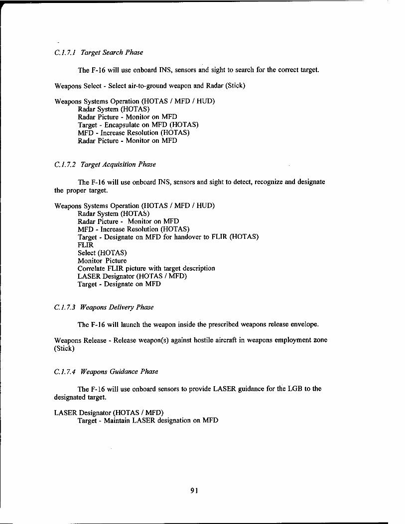
C. 1.7.1 Target Search Phase
The F-16 will use onboard INS, sensors and sight to search for the correct target.
Weapons Select - Select air-to-ground weapon and Radar (Stick)
Weapons Systems Operation (HOTAS / MFD / HUD) Radar System (HOTAS) Radar Picture - Monitor on MFD Target - Encapsulate on MFD (HOTAS) MFD - Increase Resolution (HOTAS) Radar Picture - Monitor on MFD
C. 1.7.2 Target Acquisition Phase
The F-16 will use onboard INS, sensors and sight to detect, recognize and designate the proper target.
Weapons Systems Operation (HOTAS / MFD / HUD) Radar System (HOTAS) Radar Picture - Monitor on MFD MFD - Increase Resolution (HOTAS) Target - Designate on MFD for handover to FLIR (HOTAS) FLIR Select (HOTAS) Monitor Picture Correlate FLIR picture with target description LASER Designator (HOTAS / MFD) Target - Designate on MFD
C. 1.7.3 Weapons Delivery Phase
The F-16 will launch the weapon inside the prescribed weapons release envelope.
Weapons Release - Release weapon(s) against hostile aircraft in weapons employment zone (Stick)
C. 1.7.4 Weapons Guidance Phase
The F-16 will use onboard sensors to provide LASER guidance for the LGB to the designated target.
LASER Designator (HOTAS / MFD) Target - Maintain LASER designation on MFD
91

C. 1.7.5 Bomb Damage Assessment Phase
The F-16 will use visual references inside and outside the cockpit to assess damage to the target resulting from weapons impact.
Navigation System - Update (MFD)
To Point 7;
C. 1.7.6 Counter Surface Phase
The F-16 will use aggressive maneuvering and defensive countermeasures to counter target area defenses.
Counter Surface Phase (Countermeasures (CM))
CM System Settings
Detection Cues
Electronic CM - On (UFC)
Expendables - Dispense (HOTAS)
Maneuver to Defend
Navigation System - Update (MFD)
To Point 8:
C. 1.7.7 Egress Phase
The F-16 will use onboard inertial navigation system (INS) and visual navigation to continue the planned route through enemy territory to arrive safely at home base.
Enter Route
Speed/Altitude - monitor (HUD)
Navigate Visual Cues - monitor Waypoints - Update on MFD Clock - Monitor
Radar / IR Warning Receiver - Monitor
Visual Lookout
Navigation System - Update (MFD)
92

APPENDIX D
GOMS ANALYSIS
93

This appendix contains documentation describing the current state of the activity level and CPM-GOMS models for the Target Designation Task. Section D.l lists the activity level operators that are used to construct the activity level models from the functional level model framework. Section D.2 contains the activity level model of the hands-busy version of the Target Designation Task and section D.3 contains the activity level model of the eye/voice version of the Target Designation Task. Section D.4 shows operators for the CPM-GOMS level analysis of the Target Designation Task. Sections D.5 and D.6 contain, respectively, the CPM-GOMS models of the hands-busy and eye/voice versions of the Target Designation.
D. 1 ACTIVITY LEVEL OPERATORS OF THE TARGET DESIGNATION TASK
The activity level operators that are used to construct the activity level models from the functional level model framework (described in Chapter 9 of the final report) are as follows:
select MFD with HOTAS selector switch select press-tile on MFD move crosshair to menu button activate menu list search menu list move crosshair to item in menu list select menu item scan display for target move crosshair to target set mark on display speak command gaze at MFD maintain gaze on target.
94

D.2 ACTIVITY LEVEL MODEL (HANDS-BUSY)
This section contains the activity level model of the hands-busy version of the Target Designation Task. Using the GOMS methodology and notation described in Chapters 8 and 9, each line in the model represents either a goal, subgoal or operator of the task. Lines beginning with the label GOAL are either a goal or subgoal. All other lines are operators. The indentation level shows the hierarchical relationship of the goals and operators, where the goals and operators at a particular level of indentation implement the goal above (that is indented one level less).
GOAL: SEARCH FOR TARGET GOAL: SELECT MULTI-FUNCTION DISPLAY (MFD)
GOAL: SELECT MFD SELECT MFD WITH HOTAS SELECTOR SWITCH (RADAR MFD)
GOAL: CHANGE RADAR MODE GOAL: CHANGE RADAR MODE (FROM AIR TO SURFACE)
MOVE CROSSHAIR TO SOFT BUTTON (RADAR MODE) ACTIVATE MENU LIST SEARCH MENU LIST (for SURF) MOVE CROSSHAIR TO ITEM IN MENU LIST (to SURF) SELECT MENU ITEM (SURF)
GOAL: LOCATE TARGET GOAL: LOCATE TARGET IN MFD
SCAN DISPLAY FOR TARGET GOAL: PLACE STEERPOINT ON TARGET
GOAL: MARK TARGET POSITION ON MFD MOVE CROSSHAIR TO TARGET SET MARK ON DISPLAY
GOAL: SET STEERPOINT AT MARKED POSITION SELECT MFD WITH HOTAS SELECTOR SWTCH (HSI MFD) MOVE CROSSHAIR TO SOFT BUTTON (NAV DESIG) SELECT SOFT BUTTON (NAV DESIG)
FLIGHT-TIME GOAL: REFINE STEERPOINT LOCATION
GOAL: SELECT MULTI-FUNCTION DISPLAY (MFD) GOAL: SELECT MFD
SELECT MFD WITH HOTAS SELECTOR SWITCH (RADAR MFD) GOAL: LOCATE TARGET
GOAL: LOCATE TARGET IN MFD SCAN DISPLAY FOR TARGET
GOAL: EXPAND RADAR IMAGE GOAL: MARK TARGET POSITION ON MFD
MOVE CROSSHAIR TO TARGET SET MARK ON DISPLAY
GOAL: EXPAND RADAR AT MARKED POSITION MOVE CROSSHAIR TO SOFT BUTTON (EXP1) SELECT SOFT BUTTON (EXP1)
GOAL: LOCATE TARGET GOAL: LOCATE TARGET IN MFD
SCAN DISPLAY FOR TARGET GOAL: PLACE STEERPOINT ON TARGET
GOAL: MARK TARGET POSITION ON MFD MOVE CROSSHAIR TO TARGET SET MARK ON DISPLAY
GOAL: SET STEERPOINT AT MARKED POSITION SELECT MFD WITH HOTAS SELECTOR SWITCH (HSI MFD) MOVE CROSSHAIR TO SOFT BUTTON (NAV DESIG) SELECT SOFT BUTTON (NAV DESIG)
95

D.3 ACTIVITY LEVEL MODEL (EYE/VOICE)
This section contains the activity level model of the eye/voice version of the Target Designation Task.
GOAL: SEARCH FOR TARGET GOAL: SELECT MULTI-FUNCTION DISPLAY (MFD)
GOAL: SELECT MFD GAZE AT MFD (RADAR MFD)
GOAL: CHANGE RADAR MODE GOAL: CHANGE RADAR MODE (FROM AIR TO SURFACE)
SPEAK COMMAND ("RADAR MODE SURFACE") GOAL: LOCATE TARGET
GOAL: LOCATE TARGET IN MFD SCAN DISPLAY FOR TARGET
GOAL: PLACE STEERPOINT ON TARGET GOAL: MARK TARGET POSITION ON MFD
MAINTAIN GAZE ON TARGET GOAL: SET STEERPOINT AT MARKED POSITION . SPEAK COMMAND ("NAV DESIGNATE STEERPOINT")
FLIGHT-TIME GOAL: REFINE STEERPOINT LOCATION
GOAL: SELECT MULTI-FUNCTION DISPLAY (MFD) GOAL: SELECT MFD
GAZE AT MFD (RADAR MFD) GOAL: LOCATE TARGET
GOAL: LOCATE TARGET IN MFD SCAN DISPLAY FOR TARGET
GOAL: EXPAND RADAR IMAGE GOAL: MARK TARGET POSITION ON MFD
MAINTAIN GAZE ON TARGET GOAL: EXPAND RADAR AT MARKED POSITION
SPEAK COMMAND ("RADAR ZOOM ONE") GOAL: LOCATE TARGET
GOAL: LOCATE TARGET IN MFD . SCAN DISPLAY FOR TARGET
GOAL: PLACE STEERPOINT ON TARGET GOAL: MARK TARGET POSITION ON MFD
MAINTAIN GAZE ON TARGET GOAL: SET STEERPOINT AT MARKED POSITION . SPEAK COMMAND ("NAV DESIGNATE STEERPOINT")
96

D.4 COGNITIVE/PERCEPTUAL/MOTOR LEVEL OPERATORS (CPM-GOMS)
This section lists the operators for the CPM-GOMS level analysis of the Target Designation Task. These operators are divided into the human subsystems of cognitive, perceptual, and motor operators.
Cognitive Operators:
Initiate eye-movement Attend-visual Initiate speech Initiate MFD selector switch press Initiate TDC press Initiate TDC move Attend-aural Verify-<info>.
Perceptual Operators:
• Recognize target - Eye • Verify Steerpoint symbol at current location - Eye. (Perceive visual binary) • Verify Cursor at MFD - Eye • Verify menu activated.
Motor Operators:
Press push-tile - Hand (Which tile? Which hand?) Press Target Designate Cursor (TDC) - Hand (Which hand?) Press MFD selector switch - Hand (Which hand?) Maneuver cursor with TDC - Hand (Which hand?) Scan Display - Eye (Which display?) Track cursor to target - Eye Say-<command> - Verbal Home Hand - Hand (Which hand? to stick, to throttle) Eye movement.
97

D.5 CPM-GOMS MODEL (HANDS-BUSY)
This section contains the CPM-GOMS activity networks for the hands-busy version of the Target Designation Task, expressed in the PERT-chart format described in Chapters 8 and 9. Note that the execution times of the operators shown in the charts below have not been added to the model yet. Moreover, there are two types of operators that pertain to the system itself, namely "Other System Response Time" and "System Display Time" that are specific to the implementation; these have not been shown either because the times are not yet available.
The charts are read from left to right and multiple charts may be used to represent a single task. Off-page connectors (circles with letters in them) are used to show where an activity chart is continued. The hands-busy task networks are shown for the two major goals:
• Goal: Search for Target • Goal: Refine Steerpoint Location.
Visual Perception
Aural Perception
Cognitive Operators
L. Hand Movements
R. Hand Movements
Verbal Responses
Eye Movements
niüate TDC Move
Initiate TDC
Press
Figure D-l: Activity Network for "Search for Target" Goal Hands-Busy Version
98

Visual Perception
Verbal Responses
Eye Movements
Figure D-l: Activity Network for "Search for Target" Goal Hands-Busy Version (Continued)
Maneuver Cursor
withTDC
Press TDC
Verbal Responses
Eye Movements
Figure D-l: Activity Network for "Search for Target' Hands-Busy Version (Continued)
Goal
99

Visual Perception
Verbal Responses
Eye Movements
Figure D-2: Activity Network for "Refine Steerpoint Location" Goal Hands-Busy Version
Visual Perception
Aural Perception
Eye Movements
Figure D-2: Activity Network for "Refine Steerpoint Location" Goal Hands-Busy Version (Continued)
100

Visual Perception
Aural Perception
Verbal Responses
Eye Movements
Figure D-2: Activity Network for "Refine Steerpoint Location' Hands-Busy Version (Continued)
Goal
101

D.6 CPM-GOMS MODEL (EYE/VOICE)
This section contains the CPM-GOMS activity networks for the eye/voice version of the Target Designation Task, expressed in the PERT-chart format described in Chapters 8 and 9. Note that the execution times of the operators shown in the charts below have not been added to the model yet. Moreover, there are two types of operators that pertain to the system itself, namely "Other System Response Time" and "System Display Time" that are specific to the implementation; these have not been shown either because the times are not yet available.
The charts are read from left to right and multiple charts may be used to represent a single task. Off-page connectors (circles with letters in them) are used to show where an activity chart is continued. The eye/voice task networks are shown for the two major goals:
• Goal: Search for Target • Goal: Refine Steerpoint Location.
Visual Perception
Aural Perception
Cognitive Operators
L. Hand Movements
R. Hand Movements
Verbal Responses
Eye Movements
Maintain Gaze on Target
Initiate Speech
■Nav Designate Steerpoint*
Figure D-3: Activity Network for "Search for Target" Goal Eye/Voice Version
102

Visual Perception
Aural Perception
Verbal Responses
Eye Movements
Figure D-4: Activity Network for "Refine Steerpoint Location" Goal Eye/Voice Version
Visual Perception
Eye Movements
Figure D-4: Activity Network for "Refine Steerpoint Location" Goal Eye/Voice Version (Continued)
U. S. Government Printing Office 1996 750-071/00181
103
Copyright © 2022 FDOKUMEN