A Numerical Method for Turbomachinery Aeroelasticity
7
P. Cinnella Dipartimento di Ingegneria dell’Innovazione, Universita di Lece, Via Monteroni, 73100 Lecce, Italy e-mail: [email protected] P. De Palma e-mail: [email protected] G. Pascazio e-mail: [email protected] M. Napolitano e-mail: [email protected] Dipartimento di Ingegneria Meccanica e Gestionale and Centro di Eccellenza in Meccanica Computazionale, Politecnico di Bari, via Re David 200, 70125 Bari, Italy A Numerical Method for Turbomachinery Aeroelasticity This work provides an accurate and efficient numerical method for turbomachinery flutter. The unsteady Euler or Reynolds-averaged Navier-Stokes equations are solved in integral form, the blade passages being discretised using a background fixed C-grid and a body- fitted C-grid moving with the blade. In the overlapping region data are exchanged be- tween the two grids at every time step, using bilinear interpolation. The method employs Roe’s second-order-accurate flux difference splitting scheme for the inviscid fluxes, a standard second-order discretisation of the viscous terms, and a three-level backward difference formula for the time derivatives. The dual-time-stepping technique is used to evaluate the nonlinear residual at each time step. The state-of-the-art second-order ac- curacy of unsteady transonic flow solvers is thus carried over to flutter computations. The code is proven to be accurate and efficient by computing the 4th Aeroelastic Standard Configuration, namely, the subsonic flow through a turbine cascade with flutter instability in the first bending mode, where viscous effect are found practically negligible. Then, for the very severe 11thAeroelastic Standard Configuration, namely, transonic flow through a turbine cascade at off-design conditions, benchmark solutions are provided for various values of the inter-blade phase angle. @DOI: 10.1115/1.1738122# Introduction In modern turbomachinery design and development, it is crucial to predict the blade vibratory stresses arising from self-excitation or inlet flow distortion. This is particularly true for aircraft com- pressor and fan blade rows, that may work at highly loaded off- design conditions, but also for the last stages of steam and gas turbines. The prediction of the unsteady pressure loads on the blading may involve the computation of shock waves, shock/ boundary layer interaction and boundary layer separation, which could not be accounted for in early approaches based on potential methods, see e.g., @1#. Therefore, time-linearized methods have become very popular for turbomachinery aeroelastic computa- tions, since they take into account such strongly nonlinear phe- nomena, at least for the steady flow field, see, e.g., @2,3#. How- ever, these methods, which are very reliable when the blade vibrations add only a small disturbance to the steady flow, are clearly inadequate when studying the fluid/structure interaction and the blade displacements are not known a priori. In order to remove this limitation, a time-accurate solver of the Euler, thin layer, or complete Reynolds-averaged Navier-Stokes ~RANS! equations is to be used, depending on the nature of the phenomena of interest. Recently, several researchers have developed and ap- plied numerical methods for solving such equations, using differ- ent spacial and time discretisations, see, e.g., @4–8#. However, none of them employs all state-of-the-art features of current un- steady compressible flow solvers. In this paper, a second-order- accurate state-of-the-art RANS solver is extended to flutter com- putations to provide a significant accuracy improvement over existing codes when strongly nonlinear phenomena are present in the flow field. Moreover, the proposed approach, using a dual- time-stepping technique, is very apt to ultimately solve the full system of aeroelastic equations for both fluid and solid. It is note- worthy that the code can solve the Euler and the thin-layer RANS equations, by simply switching off the appropriate terms. How- ever, only the full RANS equations are considered for the present viscous computations, insofar as they provide a more complete description of the flow, with a minimal additional cost. The proposed method is applied to compute two aeroelastic test cases, for which detailed experimental data are provided by Bo ¨lcs and Fransson @4# and Fransson et al. @9#, respectively ~details about the experimental setup together with the electronic files containing the experimental data are available at: http:// www.egi.kth.se!. The first test case is the 4th Aeroelastic Standard Configuration, i.e., the subsonic flow through a turbine cascade with flutter instability in the first bending mode, where no sepa- ration occurs and the pressure loads are well predicted by the Euler equations. The second test case is the very severe 11th Aeroelastic Standard Configuration, i.e., a transonic off-design flow through a turbine cascade, where both leading-edge separa- tion and shock/boundary layer interaction are present. For both test cases, the experimental data and the numerical solutions avail- able to date are not in good agreement, so that the present thor- ough numerical investigation is warranted to validate the experi- mental data and to provide benchmark numerical solutions. Governing Equations The two-dimensional unsteady RANS equations for compress- ible flow are written for a moving control volume V( t ) with boundary G ( t ), as d dt E V~ t ! wd V1 R G~ t ! ~ f e 2f v 2w s! • nd G 50. (1) In Eq. ~1!, w is the conservative variable vector based on the components of the absolute velocity vector in the fixed reference frame, s is the speed of the surface G ( t ), n is the outer normal to G ( t ), and f e and f v are the inviscid and viscous fluxes, given in Cartesian coordinates as f x e 5 S r u p 1r u 2 r u v r uH D , f y e 5 S r v r u v p 1r v 2 r v H D , (2) Contributed by the International Gas Turbine Institute ~IGTI! of THE AMERICAN SOCIETY OF MECHANICAL ENGINEERS for publication in the ASME JOURNAL OF TURBOMACHINERY. Paper presented at the International Gas Turbine and Aeroengine Congress and Exhibition, Amsterdam, The Netherlands, June 3– 6, 2002; Paper No. 2002-GT-30321. Manuscript received by IGTI, December 2001, final re- vision, March 2002. Associate Editor: E. Benvenuti. 310 Õ Vol. 126, APRIL 2004 Copyright © 2004 by ASME Transactions of the ASME
-
Upload
technology-iraq -
Category
Documents
-
view
0 -
download
0
Transcript of A Numerical Method for Turbomachinery Aeroelasticity
utter.tegralbody-be-
ployses, awarded tor ac-
. Thendardbility, for
ugh arious
P. CinnellaDipartimento di Ingegneria dell’Innovazione,
Universita di Lece,Via Monteroni,
73100 Lecce, Italye-mail: [email protected]
P. De Palmae-mail: [email protected]
G. Pascazioe-mail: [email protected]
M. Napolitanoe-mail: [email protected]
Dipartimento di Ingegneria Meccanica eGestionale and Centro di Eccellenza in
Meccanica Computazionale,Politecnico di Bari,
via Re David 200,70125 Bari, Italy
A Numerical Method forTurbomachinery AeroelasticityThis work provides an accurate and efficient numerical method for turbomachinery flThe unsteady Euler or Reynolds-averaged Navier-Stokes equations are solved in inform, the blade passages being discretised using a background fixed C-grid and afitted C-grid moving with the blade. In the overlapping region data are exchangedtween the two grids at every time step, using bilinear interpolation. The method emRoe’s second-order-accurate flux difference splitting scheme for the inviscid fluxstandard second-order discretisation of the viscous terms, and a three-level backdifference formula for the time derivatives. The dual-time-stepping technique is usevaluate the nonlinear residual at each time step. The state-of-the-art second-ordecuracy of unsteady transonic flow solvers is thus carried over to flutter computationscode is proven to be accurate and efficient by computing the 4th Aeroelastic StaConfiguration, namely, the subsonic flow through a turbine cascade with flutter instain the first bending mode, where viscous effect are found practically negligible. Thenthe very severe 11th Aeroelastic Standard Configuration, namely, transonic flow throturbine cascade at off-design conditions, benchmark solutions are provided for vavalues of the inter-blade phase angle.@DOI: 10.1115/1.1738122#
ct
o
ch
vu
l
trh
mdf
ov
u
lete
testo
lesp://ardadea-the11thignara-othvail-thor-eri-
ss-
thence
in
a2l
IntroductionIn modern turbomachinery design and development, it is cru
to predict the blade vibratory stresses arising from self-excitaor inlet flow distortion. This is particularly true for aircraft compressor and fan blade rows, that may work at highly loadeddesign conditions, but also for the last stages of steam andturbines. The prediction of the unsteady pressure loads onblading may involve the computation of shock waves, shoboundary layer interaction and boundary layer separation, wcould not be accounted for in early approaches based on potemethods, see e.g.,@1#. Therefore, time-linearized methods habecome very popular for turbomachinery aeroelastic comptions, since they take into account such strongly nonlinear pnomena, at least for the steady flow field, see, e.g.,@2,3#. How-ever, these methods, which are very reliable when the bvibrations add only a small disturbance to the steady flow,clearly inadequate when studying the fluid/structure interacand the blade displacements are not known a priori. In orderemove this limitation, a time-accurate solver of the Euler, tlayer, or complete Reynolds-averaged Navier-Stokes~RANS!equations is to be used, depending on the nature of the phenoof interest. Recently, several researchers have developed anplied numerical methods for solving such equations, using difent spacial and time discretisations, see, e.g.,@4–8#. However,none of them employs all state-of-the-art features of currentsteady compressible flow solvers. In this paper, a second-oraccurate state-of-the-art RANS solver is extended to flutter cputations to provide a significant accuracy improvement oexisting codes when strongly nonlinear phenomena are presethe flow field. Moreover, the proposed approach, using a dtime-stepping technique, is very apt to ultimately solve the fsystem of aeroelastic equations for both fluid and solid. It is noworthy that the code can solve the Euler and the thin-layer RAequations, by simply switching off the appropriate terms. Hoever, only the full RANS equations are considered for the pres
Contributed by the International Gas Turbine Institute~IGTI! of THE AMERICANSOCIETY OF MECHANICAL ENGINEERSfor publication in the ASME JOURNAL OFTURBOMACHINERY. Paper presented at the International Gas TurbineAeroengine Congress and Exhibition, Amsterdam, The Netherlands, June 3–6,Paper No. 2002-GT-30321. Manuscript received by IGTI, December 2001, finavision, March 2002. Associate Editor: E. Benvenuti.
310 Õ Vol. 126, APRIL 2004 Copyright © 2
ialion-ff-gasthek/ichntialeta-he-
adeareion
toin
enaap-
er-
un-der-m-er
nt inal-
ullte-NSw-ent
viscous computations, insofar as they provide a more compdescription of the flow, with a minimal additional cost.
The proposed method is applied to compute two aeroelasticcases, for which detailed experimental data are provided by B¨lcsand Fransson@4# and Fransson et al.@9#, respectively~detailsabout the experimental setup together with the electronic ficontaining the experimental data are available at: httwww.egi.kth.se!. The first test case is the 4th Aeroelastic StandConfiguration, i.e., the subsonic flow through a turbine cascwith flutter instability in the first bending mode, where no sepration occurs and the pressure loads are well predicted byEuler equations. The second test case is the very severeAeroelastic Standard Configuration, i.e., a transonic off-desflow through a turbine cascade, where both leading-edge seption and shock/boundary layer interaction are present. For btest cases, the experimental data and the numerical solutions aable to date are not in good agreement, so that the presentough numerical investigation is warranted to validate the expmental data and to provide benchmark numerical solutions.
Governing EquationsThe two-dimensional unsteady RANS equations for compre
ible flow are written for a moving control volumeV(t) withboundaryG(t), as
d
dt EV~ t !wdV1 R
G~ t !~ f e2f v2ws!•ndG50. (1)
In Eq. ~1!, w is the conservative variable vector based oncomponents of the absolute velocity vector in the fixed refereframe,s is the speed of the surfaceG(t), n is the outer normal toG(t), and f e and f v are the inviscid and viscous fluxes, givenCartesian coordinates as
f xe5S ru
p1ru2
ruvruH
D , f ye5S rv
ruvp1rv2
rvHD , (2)
nd002;re-
004 by ASME Transactions of the ASME

st
ni
ck-nceted
he
f xv5S 0
txx
txy
bx
D , f yv5S 0
tyx
tyy
by
D , (3)
where
txx5m@2]u/]x2~2/3!~]u/]x1]v/]y!#,
txy5tyx5m@]u/]y1]v/]x#,
tyy5m@2]v/]y2~2/3!~]u/]x1]v/]y!#,
bx5utxx1vtxy1k]T/]x,
by5utyx1vtyy1k]T/]y.
The above formulation can treat both fixed and moving gblocks covering the computational domain. The viscous flux acontains the contribution of turbulent stresses, evaluated ueither the Baldwin-Lomax@10# algebraic model or the SpalarAllmaras @11# one-equation model:
]n
]t52u•¹n1cb1Sn1
1
s Re@¹•~~n1 n !¹n !1cb2~¹n!2#
21
ReFcw1f w2cb1
k2 f t2GF n
dG2
, (4)
wheren is the modified kinematic eddy viscosity coefficient athe right-hand-side terms represent convection, production, dsion, and destruction, respectively, see@11#, for details.
Fig. 1 Moving grid strategy and boundary conditions
Fig. 2 4th Standard Configuration, steady solution. Pressurecoefficient contours „DCpÄ0.05….
Journal of Turbomachinery
ridlsoing
-
dffu-
Numerical MethodThe system of conservation laws~1! and~4! is discretised using
a cell-centered finite volume method for structured multiblogrids. Equations~1! and ~4! are written for each cell of the computational mesh, which can move with respect to a fixed refereframe. The convective fluxes at the cell interfaces are evaluausing Roe’s approximate Riemann solver,@12#, with a fully up-wind unlimited second-order-accurate MUSCL extrapolation. Teigenvalues of Roe’s matrix are corrected as in@13# to allow
Fig. 3 4th Standard Configuration, steady solution. IsentropicMach number distributions at the wall
Fig. 4 4th Standard Configuration. Amplitude „upper … andphase „lower … distributions of the pressure first harmonic,IBPAÄÀ90 deg.
APRIL 2004, Vol. 126 Õ 311

t
ina
ie
f
a
a
-ae
i
ue
forg
e iningsed
.9,thegth
cidhaveich ishe.is--lts
ionsentt is
enough dissipation at the sonic points. A standard centesecond-order-accurate approximation is used for the viscfluxes.
For steady flows, the solution is marched in time usingfour-stage Runge-Kutta scheme proposed by Jameson et al.@14#.Local time stepping, implicit residual smoothing, and multigr@15#, are used to speed up the convergence. The turbuleclosure equation~4!, when employed, is solved at every lociteration after Eq.~1!. For unsteady flow computations, the timderivative is discretised using a three-level second-order-accubackward difference scheme and the dual time stepping techn@16#, is used to advance the solution in time. Such a stratguarantees the nonlinear coupling of Eq.~1! and ~4! at everyphysical time level; moreover, within a general procedureaeroelastic computations, it would simplify the implicit couplinof the flow and structural solvers with respect to approximfactorization schemes,@6,8#.
For turbomachinery flutter calculations, two main difficultiearise: the blade is moving with respect to the flow net and eblade may vibrate with a constant phase difference, called inblade phase angle~IBPA!. In this work such difficulties are overcome as follows. Each blade passage is covered with a bground fixed C-grid, which allows to easily impose the inloutlet, and inter-passage conditions, and a body-fitted movC-grid, with an overlapping region, as shown inFig. 1, inter-blockboundary conditions being imposed by bilinear interpolationthe variables at the overlapping boundaries; a similar procedhas been employed in@17#. A multipassage computational domais employed, using a number of blade passages,np(np.1), givenas
Fig. 5 4th Standard Configuration. Amplitude „upper … andphase „lower … distributions of the pressure first harmonic,IBPAÄ180 deg.
312 Õ Vol. 126, APRIL 2004
redous
he
d,ce-l
erateque,gy
orgte
sch
ter-
ck-t,ing
ofuren
np5360°z
uIBPAu, IBPAÞ0,
wherez is the minimum integer which leads to an integer valfor np . Such an approach is more general than thedirect storemethod proposed in@18#, used to employ a single passage alsoIBPAÞ0, insofar as it allows to compute mistuned oscillatincascades.
Results
4th Standard Configuration. The experimental data for the4th Standard Configuration refer to an annular turbine cascadwhich the blades are sinusoidally oscillated in the first bendmode. The same oscillation amplitude and frequency are impofor all blades, whereas several IBPAs are considered,@4#. Theflow is subsonic, with isentropic exit Mach number equal to 0and the inlet flow is inclined 45 deg downward with respect toaxial direction. The Reynolds number, based on the chord lenand the inlet conditions, is equal to 8.23105. C-grids with 256332 and 384348 cells have been used to compute the invisand viscous steady solutions, respectively. These meshesbeen selected after an appropriate mesh-refinement study, whnot reported for brevity. For the viscous flow computation taverage value ofh1 for the first cell near the wall equals 5Figure 2 provides the pressure coefficient contours for the invcid computation. InFig. 3 the experimental isentropic Mach number distribution at the wall is compared with the numerical resuobtained by solving the Euler equations and the RANS equatclosed by the Baldwin-Lomax turbulence model. The agreemwith the experimental data is good, considering that no attemp
Fig. 6 4th Standard Configuration. Amplitude „upper … andphase „lower … distributions of the pressure first harmonic,IBPAÄ90 deg.
Transactions of the ASME
bes
itialpu-inner
ncy,, isthe
each.thethetal
ly ond inthefor
ntse thesta-
e-ANSurate
Fig. 7 Aerodynamic damping coefficient „J… versus IBPA forthe 4th Standard Configuration
Fig. 8 11th Standard Configuration, steady solution. Pressurecoefficient contours „DCpÄ0.075….
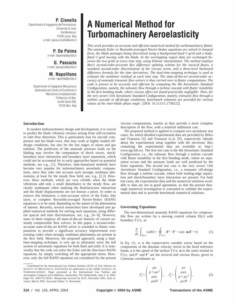
Fig. 9 11th Standard Configuration, steady solution. Stream-lines at the leading edge.
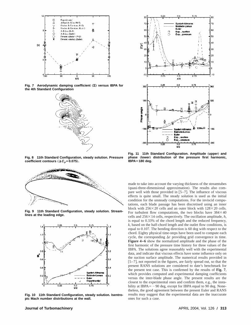
Fig. 10 11th Standard Configuration, steady solution. Isentro-pic Mach number distributions at the wall.
Journal of Turbomachinery
made to take into account the varying thickness of the streamtu~quasi-three-dimensional approximation!. The results also com-pare well with those provided in@5–7#. The influence of viscouseffects is quite small. The steady solution is used as the incondition for the unsteady computations. For the inviscid comtations, each blade passage has been discretised using anblock with 256320 cells and an outer block with 128320 cells.For turbulent flow computations, the two blocks have 384340cells and 256314 cells, respectively. The oscillation amplitude,h,is equal to 0.33% of the chord length and the reduced frequek, based on the half-chord length and the outlet flow conditionsequal to 0.107. The bending direction is 60 deg with respect tochord. Eighty physical time-steps have been used to computecycle, the correspondingDt providing grid convergence in timeFigure 4–6 show the normalized amplitude and the phase offirst harmonic of the pressure time history for three values ofIBPA. The solutions agree reasonably well with the experimendata, and indicate that viscous effects have some influence onthe suction surface amplitude. The numerical results provide@5–7#, not reported in the figures, are fairly spread out, so thatpresent RANS solutions are considered to date’s benchmarkthe present test case. This is confirmed by the results ofFig. 7,which provides computed and experimental damping coefficieversus the inter-blade phase angle. The present results arclosest to the experimental ones and confirm them, e.g., the inbility at IBPA5290 deg, except for IBPA equal to 90 deg. Nontheless, the good agreement between the present Euler and Rresults may suggest that the experimental data are the inaccones for such a case.
Fig. 11 11th Standard Configuration. Amplitude „upper … andphase „lower … distribution of the pressure first harmonic,IBPAÄ180 deg.
APRIL 2004, Vol. 126 Õ 313
ue
o
t
ae
w
tn
d
utletnceEx-f thee
am-he
win-ell
NSarepartnnotthe
anic
ockic
h ai-ults.lart-erl forur-ovide
11th Standard Configuration. The very severe 11th Standard Configuration is a transonic flow through a turbine cascadoff-design conditions. The isentropic exit Mach number is eqto 0.99 and the inlet flow is inclined 34 deg upward with respto the axial direction. The Reynolds number, based on the chlength and inlet conditions, is equal to 1.23106. For such flowconditions, the stagnation point is located at about 6% ofchord on the pressure surface of the blade. The flow stronaccelerates around the sharp leading edge forming a tiny susonic region. The flow then separates on the suction side ofblade from the leading edge to 30% of the chord. After reattament, the flow accelerates again to supersonic speed and a soccurs at about 75% of the chord. Steady inviscid and visccomputations have been performed using grids with 288332 and288348 cells, respectively. For the viscous flow computationaverage value ofh1 for the first cell near the wall equals 1. Fothe unsteady computations, the moving and fixed blocks areways composed of 288320 and 144320 cells, respectively.Fig-ure 8 provides the pressure coefficient contours for the steviscous computation, whereas the streamlines at the leading-separation region are shown inFig. 9. In Fig. 10, the steady isen-tropic Mach number distributions obtained by solving the Euequations and the RANS equations closed by the Baldwin-Lomand the Spalart-Allmaras turbulence models are comparedthe experimental data. The inviscid solution is very far from texperiments in the front part of the suction side, due to separaThe viscous solution is in good agreement with the experimedata, especially when the Spalart-Allmaras model is employFor the unsteady case, the blades oscillate in the first benmode, with bending angle equal to 90 deg with respect to
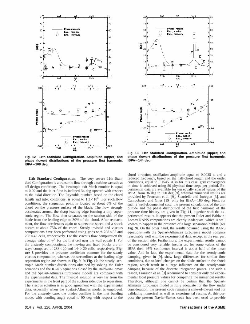
Fig. 12 11th Standard Configuration. Amplitude „upper … andphase „lower … distributions of the pressure first harmonic,IBPAÄ108 deg.
314 Õ Vol. 126, APRIL 2004
-e atalctord
theglyper-the
ch-hockus
heral-
dydge
leraxith
heion.taled.ing
the
chord direction, oscillation amplitude equal to 0.0035c, and areduced frequency, based on the half-chord length and the oconditions, equal to 0.1545. Also for this case, grid convergein time is achieved using 80 physical time-steps per period.perimental data are available for ten equally spaced values oIBPA, from 36 deg to 360 deg@9#, whereas numerical results arprovided by Fransson et al.@9#, Sbardella and Imregun@3#, andCampobasso and Giles@19# only for IBPA5180 deg. First, forsuch a well-documented case, the present calculations of theplitude and the phase distribution of the first harmonic of tpressure time history are given inFig. 11, together with the ex-perimental results. It appears that the present Euler and BaldLomax RANS computations are clearly inadequate, which is wknown to happen in the presence of a large separation bubble~seeFig. 9!. On the other hand, the results obtained using the RAequations with the Spalart-Allmaras turbulence model compreasonably well with the experimental data, except in the rearof the suction side. Furthermore, the experimental results cabe considered very reliable, insofar as, for some values ofIBPA their 95% confidence interval is about half of the mevalue. And in fact, the experimental data for the aerodynamdamping, given in@9#, show large differences for similar flowconditions, due to local changes on the blade surface in the shregion, which result in a large influence on the aerodynamdamping because of the discrete integration points. For sucreason, Fransson et al.@9# recommend to consider only the expermental local pressure values for comparing the numerical resTherefore, although one cannot be certain that the SpaAllmaras turbulence model is fully adequate for the flow undconsideration, the present code remains a state-of-the-art toovalidating numerical as well as experimental results. At this ppose the present Navier-Stokes code has been used to pr
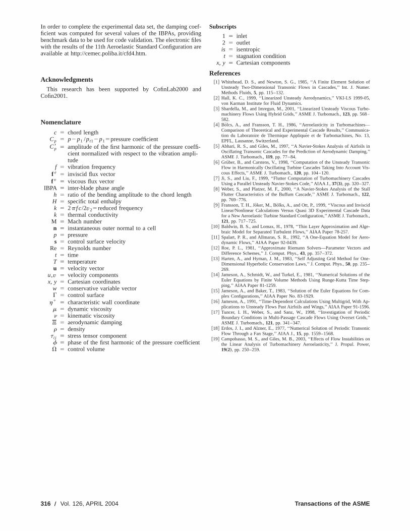
Fig. 13 11th Standard Configuration. Amplitude „upper … andphase „lower … distributions of the pressure first harmonic,IBPAÄ144 deg.
Transactions of the ASME

,
ht
o
ud
t
l
dellar,ladeaser-ov-
on,ck/herties.
benchmark solutionsfor the following values of IBPA: 108 deg144 deg, 216 deg, and 252 deg, in addition to the 180 deg casewhich the experimental data are less unreliable. Such resultsgiven in Fig. 12, 13, 14, and15, together with the experimentadata. Once again, a quite nice agreement with the experimedata is found, the numerical solution being always located witthe experimental error bars, except for the phase distribution arear part of the suction side. This behavior has been also obsein the other numerical results available in the literature. The dcrepancies could be due to the turbulence model inadequacaccurately predict the shock/boundary layer interaction but, juslikely, to the inaccuracy of the experimental data. For compleness, the results for the aerodynamic damping coefficient aresented inFig. 16. According to the present Spalart-AllmaraRANS solutions, the configuration is stable for almost all consered IBPAs, is marginally stable~aerodynamic damping close tzero! for IBPA5315 deg, and is unstable for IBPA5324 deg andIBPA5337.5 deg.
ConclusionsA numerical method has been developed for solving the co
pressible Euler and Reynolds averaged Navier-Stokes~RANS!equations for flows through two-dimensional oscillating cascadThe method has been used to solve the well-documented 4th Sdard Aeroelastic Configuration, namely, the subsonic flow throa turbine cascade with flutter instability in the first bending mowhere the very good agreement between the present EulerRANS solutions and the experimental data demonstratesbenchmark accuracy. Then, the very severe 11th Aeroelastic Sdard Configuration, i.e., a transonic off-design flow through a tbine cascade, has been considered. For such a problem, on
Fig. 14 11th Standard Configuration. Amplitude „upper … andphase „lower … distributions of the pressure first harmonic,IBPAÄ216 deg.
Journal of Turbomachinery
, forare
lntalinthe
rvedis-y tot aste-pre-sid-
m-
es.tan-ghe,and
heirtan-ur-y the
RANS equations with the Spalart-Allmaras turbulence mocompare reasonably well with the experimental data. In particuthe amplitude and phase of the pressure first harmonic at the bsurface, computed for several values of the inter-blade phangle~IBPA!, lay almost everywhere within the experimental eror bars, except in the rear part of the suction side, where a ming shock-wave impinges on the boundary layer. In this regithe use of a linear turbulence model for computing the shoboundary layer interaction can be inappropriate; on the othand, experimental data are affected by considerable uncertain
Fig. 15 11th Standard Configuration. Amplitude „upper … andphase „lower … distributions of the pressure first harmonic,IBPAÄ252 deg.
Fig. 16 Aerodynamic damping coefficient „J… versus IBPA forthe 11th Standard Configuration
APRIL 2004, Vol. 126 Õ 315
ifi
-
ofer.
,
bo-
—ica-,
ng,’’
nicis-
des
tall
atah.,
-
ro-
and
e-
theep-
m-
p-6.dicds,’’
nic
oner,
In order to complete the experimental data set, the damping cficient was computed for several values of the IBPAs, providbenchmark data to be used for code validation. The electronicwith the results of the 11th Aeroelastic Standard Configurationavailable at http://cemec.poliba.it/cfd4.htm.
AcknowledgmentsThis research has been supported by CofinLab2000
Cofin2001.
Nomenclature
c 5 chord lengthCp 5 p2p1 /pt12p15pressure coefficientCp8 5 amplitude of the first harmonic of the pressure coef
cient normalized with respect to the vibration amplitude
f 5 vibration frequencyf e 5 inviscid flux vectorf v 5 viscous flux vector
IBPA 5 inter-blade phase angleh 5 ratio of the bending amplitude to the chord lengthH 5 specific total enthalpyk 5 2p f c/2v25reduced frequencyk 5 thermal conductivity
M 5 Mach numbern 5 instantaneous outer normal to a cellp 5 pressures 5 control surface velocity
Re 5 Reynolds numbert 5 time
T 5 temperatureu 5 velocity vector
u,v 5 velocity componentsx, y 5 Cartesian coordinates
w 5 conservative variable vectorG 5 control surface
h1 5 characteristic wall coordinatem 5 dynamic viscosityn 5 kinematic viscosityJ 5 aerodynamic dampingr 5 density
t i j 5 stress tensor componentf 5 phase of the first harmonic of the pressure coefficieV 5 control volume
316 Õ Vol. 126, APRIL 2004
oef-ngles
are
and
fi-
nt
Subscripts
1 5 inlet2 5 outletis 5 isentropict 5 stagnation condition
x, y 5 Cartesian components
References@1# Whitehead, D. S., and Newton, S. G., 1985, ‘‘A Finite Element Solution
Unsteady Two-Dimensional Transonic Flows in Cascades,’’ Int. J. NumMethods Fluids,5, pp. 115–132.
@2# Hall, K. C., 1999, ‘‘Linearized Unsteady Aerodynamics,’’ VKI-LS 1999-05von Karman Institute for Fluid Dynamics.
@3# Sbardella, M., and Imregun, M., 2001, ‘‘Linearized Unsteady Viscous Turmachinery Flows Using Hybrid Grids,’’ ASME J. Turbomach.,123, pp. 568–582.
@4# Bolcs, A., and Fransson, T. H., 1986, ‘‘Aeroelasticity in TurbomachinesComparison of Theoretical and Experimental Cascade Results,’’ Communtion du Laboratoire de Thermique Applique´e et de Turbomachines, No. 13EPFL, Lausanne, Switzerland.
@5# Abhari, R. S., and Giles, M., 1997, ‘‘A Navier-Stokes Analysis of Airfoils iOscillating Transonic Cascades for the Prediction of Aerodynamic DampinASME J. Turbomach.,119, pp. 77–84.
@6# Gruber, B., and Carstens, V., 1998, ‘‘Computation of the Unsteady TransoFlow in Harmonically Oscillating Turbine Cascades Taking Into Account Vcous Effects,’’ ASME J. Turbomach.,120, pp. 104–120.
@7# Ji, S., and Liu, F., 1999, ‘‘Flutter Computation of Turbomachinery CascaUsing a Parallel Unsteady Navier-Stokes Code,’’AIAA J.,37„3…, pp. 320–327.
@8# Weber, S., and Platzer, M. F., 2000, ‘‘A Navier-Stokes Analysis of the SFlutter Characteristics of the Buffum Cascade,’’ ASME J. Turbomach.,122,pp. 769–776.
@9# Fransson, T. H., Jo¨ker, M., Bolks, A., and Ott, P., 1999, ‘‘Viscous and InviscidLinear/Nonlinear Calculations Versus Quasi 3D Experimental Cascade Dfor a New Aeroelastic Turbine Standard Configuration,’’ASME J. Turbomac121, pp. 717–725.
@10# Baldwin, B. S., and Lomax, H., 1978, ‘‘Thin Layer Approximation and Algebraic Model for Separated Turbulent Flows,’’ AIAA Paper 78-257.
@11# Spalart, P. R., and Allmaras, S. R., 1992, ‘‘A One-Equation Model for Aedynamic Flows,’’ AIAA Paper 92-0439.
@12# Roe, P. L., 1981, ‘‘Approximate Riemann Solvers—Parameter VectorsDifference Schemes,’’ J. Comput. Phys.,43, pp. 357–372.
@13# Harten, A., and Hyman, J. M., 1983, ‘‘Self Adjusting Grid Method for OnDimensional Hyperbolic Conservation Laws,’’ J. Comput. Phys.,50, pp. 235–269.
@14# Jameson, A., Schmidt, W., and Turkel, E., 1981, ‘‘Numerical Solutions ofEuler Equations by Finite Volume Methods Using Runge-Kutta Time Stping,’’ AIAA Paper 81-1259.
@15# Jameson, A., and Baker, T., 1983, ‘‘Solution of the Euler Equations for Coplex Configurations,’’ AIAA Paper No. 83-1929.
@16# Jameson, A., 1991, ‘‘Time-Dependent Calculations Using Multigrid, With Aplications to Unsteady Flows Past Airfoils and Wings,’’ AIAA Paper 91-159
@17# Tuncer, I. H., Weber, S., and Sanz, W., 1998, ‘‘Investigation of PerioBoundary Conditions in Multi-Passage Cascade Flows Using Overset GriASME J. Turbomach.,121, pp. 341–347.
@18# Erdos, J. I., and Alzner, E., 1977, ‘‘Numerical Solution of Periodic TransoFlow Through a Fan Stage,’’ AIAA J.,15, pp. 1559–1568.
@19# Campobasso, M. S., and Giles, M. B., 2003, ‘‘Effects of Flow Instabilitiesthe Linear Analysis of Turbomachinery Aeroelasticity,’’ J. Propul. Pow19„2…, pp. 250–259.
Transactions of the ASME