A Novel WLAN Vehicle-To-Anything (V2X) Channel Access ...
23
applied sciences Article A Novel WLAN Vehicle-To-Anything (V2X) Channel Access Scheme for IEEE 802.11p-Based Next-Generation Connected Car Networks Jinsoo Ahn 1 , Young Yong Kim 1 and Ronny Yongho Kim 2, * 1 School of Electrical & Electronics Engineering, Yonsei University, Seoul 03722, Korea; [email protected] (J.A.); [email protected] (Y.Y.K.) 2 Department of Railroad Electrical and Electronic Engineering, Korea National University of Transportation, Gyeonggi 16106, Korea * Correspondence: [email protected]; Tel.: +82-31-460-0573 Received: 15 September 2018; Accepted: 29 October 2018; Published: 1 November 2018 Featured Application: V2X system for next-generation connected car networks. Abstract: To support a massive number of connected cars, a novel channel access scheme for next-generation vehicle-to-anything (V2X) systems is proposed in this paper. In the design of the proposed scheme, two essential aspects are carefully considered: backward compatibility and massive V2X support. Since IEEE 802.11p-based V2X networks are already being deployed and used for intelligent transport systems, next-generation V2X shall be designed considering IEEE 802.11p-based V2X networks to provide backward compatibility. Since all future cars are expected to be equipped with a V2X communication device, a dense V2X communication scenario will be common and massive V2X communication support will be required. In the proposed scheme, IEEE 802.11-based extension is employed to provide backward compatibility and the emerging IEEE 802.11ax standard-based orthogonal frequency-division multiple access is adopted and extended to provide massive V2X support. The proposed scheme is further extended with a dedicated V2X channel and a scheduled V2X channel access to ensure high capacity and low latency to meet the requirements of the future V2X communication systems. To demonstrate the performance of the proposed scheme thoroughly and rigorously, the proposed scheme is mathematically analyzed using a Markov model and extensive simulations are performed. In the dense V2X communication networks of the future, the proposed V2X communication scheme will provide high performance and reliability. Keywords: V2X; OFDMA; random access; UORA; wireless LAN; resource unit; trigger frame; channel access 1. Introduction Connected cars are attracting attention increasingly and several commercial products for the connected car are expected in the near future. After a dedicated spectrum at 5.9 GHz was allocated for intelligent transport systems (ITSs), both in the US and in Europe in 1999 and 2008, respectively, different families of standards have been developed: the IEEE/SAE dedicated short-range communication (DSRC) in 2010 in the US, Release 1 of the ETSI/CEN Cooperative-ITS (C-ITS) in 2013 in Europe, and 3GPP Cellular-V2X (C-V2X) in early 2017 as a feature of Release 14 of the LTE standard [1–7]. DSRC and C-ITS both use the IEEE 802.11p standard [4,6,7], which is a short-range technology for connected car communications, for the physical and data link layers [4]. Based on the IEEE 802.11p standard, the SARTRE project, which ran from 2009 to 2012, deployed a platoon of Appl. Sci. 2018, 8, 2112; doi:10.3390/app8112112 www.mdpi.com/journal/applsci
-
Upload
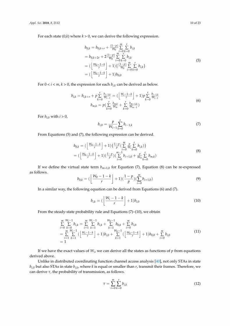
khangminh22 -
Category
Documents
-
view
1 -
download
0
Transcript of A Novel WLAN Vehicle-To-Anything (V2X) Channel Access ...

applied sciences
Article
A Novel WLAN Vehicle-To-Anything (V2X) ChannelAccess Scheme for IEEE 802.11p-BasedNext-Generation Connected Car Networks
Jinsoo Ahn 1 , Young Yong Kim 1 and Ronny Yongho Kim 2,*1 School of Electrical & Electronics Engineering, Yonsei University, Seoul 03722, Korea;
[email protected] (J.A.); [email protected] (Y.Y.K.)2 Department of Railroad Electrical and Electronic Engineering, Korea National University of Transportation,
Gyeonggi 16106, Korea* Correspondence: [email protected]; Tel.: +82-31-460-0573
Received: 15 September 2018; Accepted: 29 October 2018; Published: 1 November 2018�����������������
Featured Application: V2X system for next-generation connected car networks.
Abstract: To support a massive number of connected cars, a novel channel access scheme fornext-generation vehicle-to-anything (V2X) systems is proposed in this paper. In the design ofthe proposed scheme, two essential aspects are carefully considered: backward compatibility andmassive V2X support. Since IEEE 802.11p-based V2X networks are already being deployed andused for intelligent transport systems, next-generation V2X shall be designed considering IEEE802.11p-based V2X networks to provide backward compatibility. Since all future cars are expectedto be equipped with a V2X communication device, a dense V2X communication scenario will becommon and massive V2X communication support will be required. In the proposed scheme, IEEE802.11-based extension is employed to provide backward compatibility and the emerging IEEE802.11ax standard-based orthogonal frequency-division multiple access is adopted and extendedto provide massive V2X support. The proposed scheme is further extended with a dedicated V2Xchannel and a scheduled V2X channel access to ensure high capacity and low latency to meet therequirements of the future V2X communication systems. To demonstrate the performance of theproposed scheme thoroughly and rigorously, the proposed scheme is mathematically analyzedusing a Markov model and extensive simulations are performed. In the dense V2X communicationnetworks of the future, the proposed V2X communication scheme will provide high performanceand reliability.
Keywords: V2X; OFDMA; random access; UORA; wireless LAN; resource unit; trigger frame;channel access
1. Introduction
Connected cars are attracting attention increasingly and several commercial products forthe connected car are expected in the near future. After a dedicated spectrum at 5.9 GHz wasallocated for intelligent transport systems (ITSs), both in the US and in Europe in 1999 and 2008,respectively, different families of standards have been developed: the IEEE/SAE dedicated short-rangecommunication (DSRC) in 2010 in the US, Release 1 of the ETSI/CEN Cooperative-ITS (C-ITS) in2013 in Europe, and 3GPP Cellular-V2X (C-V2X) in early 2017 as a feature of Release 14 of the LTEstandard [1–7]. DSRC and C-ITS both use the IEEE 802.11p standard [4,6,7], which is a short-rangetechnology for connected car communications, for the physical and data link layers [4]. Based onthe IEEE 802.11p standard, the SARTRE project, which ran from 2009 to 2012, deployed a platoon of
Appl. Sci. 2018, 8, 2112; doi:10.3390/app8112112 www.mdpi.com/journal/applsci
Appl. Sci. 2018, 8, 2112 2 of 23
multiple connected cars driven autonomously in close formation [8]. In Japan, the fully automatedtruck platooning with a connected car system was tested on an express way in the Energy ITS projectin 2012 [9]. The European Truck Platooning Challenge demonstrated the automated trucks of six majortruck vendors that were driven in platoons on public roads [10].
Since currently wireless communication networks for connected cars are based on the IEEE 802.11pand wireless access in vehicular environments (WAVE) standards, the future wireless communicationnetwork for connected cars should provide a backward compatibility with IEEE 802.11p- andWAVE-based communication networks [11–13].
To enhance the safety and user experience of next-generation autonomous vehicles, not onlyenhancements in signal processing but also wireless network-based ITSs have been developed [14,15].To provide a wireless network-based ITS, vehicle-to-anything, denoted as V2X, communication systemsare expected to be used in autonomous driving vehicles [14–18]. V2X is a wireless communicationtechnology used to exchange ITS information among cars, between a car and infrastructure networkaccess points (APs), or among user devices in the car. Therefore, in the future V2X communication,from the V2X communication point of view, connected cars will include autonomous cars.
To effectively provide users with a comfortable and safe driving environment, the ITS AP shallbe considered as an ITS sensor or an ITS beacon for every navigating connected car. In other words,the ITS AP shall accommodate ITS information from connected cars, ITS pedestrians, and some localsensors. Then, it shall transmit the information gathered and processed by the ITS AP or crucial ITSinformation received from a remote node, such as ITS service provider servers, remote vehicles tonumerous ITS nodes including connected cars and ITS pedestrians by using its wired and wirelessconnections. Therefore, the numerous communication links between ITS nodes and an AP mustbe reliable and need to have low delay properties for the AP to perform the role of a reliable ITSbeacon. Unfortunately, if the number of ITS nodes that an AP needs to support is too large, the ITS APcannot establish those wireless connections rapidly in a random-access-based V2X network. Becauseconnected cars have large mobility, the connection establishment delay caused by many ITS nodes innext-generation V2X networks is much more important than in other wireless network scenarios.
In this paper, the next-generation V2X (NG-V2X) scenario described in Figure 1 is considered. ITSsensors are sensors collecting information related to ITS system. They can collect weather information,pavement condition information (road surface temperature, water film thickness, residual salt, etc.),and traffic information including vehicle classification [19,20]. They are anticipated to be usedmore widely for safety in various ITS scenarios in the future. The NG-V2X system must providecommunications between a vehicle and anything including pedestrians, ITS sensors, vehicles, and ITSAPs [21,22]. In another word, the NG-V2X must provide V2X communications. Thus, the NG-V2Xsystem needs to consider communications among various and numerous stations (STAs) than everbefore. Usually, 1000 m is considered as the ideal coverage range of an IEEE 802.11p-based systemunder the assumption of Line of Sight (LOS) communications environment like highway [23–27]without considering obstacles and severe fading and shadowing, which is not a realistic scenario [28].It means that the IEEE 802.11p STAs can deliver data frames without any problem if there are notso many vehicles, as in a rural area or an uncrowded road unless there are shadowing and fadingwhich can make the IEEE 802.11p coverage range smaller [29,30]. However, even though the actualcoverage range is smaller than ideal coverage range of IEEE 802.11p-based system, the coveragerange is sufficient to accommodate a large number of connected cars that could cause channel accessproblems in traffic jam scenarios because every car will be required to equip a V2X system in the nearfuture [31–33]. Furthermore, the NG-V2X network we consider may include various STAs includingpedestrian STAs and ITS sensor STAs as shown in Figure 1; this means that the NG-V2X network maysuffer severe channel access problems without novel and efficient channel access schemes. In otherwords, supporting numerous V2X STAs including all cars required to be equipped with the V2Xsystem, ITS pedestrians, and ITS sensors will be difficult without novel and efficient NG-V2X channelaccess schemes.

Appl. Sci. 2018, 8, 2112 3 of 23Appl. Sci. 2018, 8, x FOR PEER REVIEW 3 of 24
ITS Sensor
ITS Sensor
PedestrianPedestrian
Connected Car
Connected Car
ITS AP
Pedestrian 1UL DATA
UORA Trigger Frame
ByITS AP
Connected Car 1UL DATA
ITS Sensor 1UL DATA
M-BA
Figure 1. A sample scenario of the next-generation vehicle-to-anything (V2X) system components. ITS, intelligent transport system; AP, access point.
These kinds of scalability problems are the most well-known problems of wireless networks. However, different from other cases, downlink ITS information has a broadcast property and uplink ITS information may not require a large size of frames. Furthermore, the presence of a large number of connected cars in the area of an AP means that their mobility might be reduced than in usual cases, and hence the data frames become more delay tolerable. In other words, if there is no traffic jam, a connected car will pass through a coverage range of an ITS AP installed on the roadside in a short time. However, if there is a heavy traffic jam, the car cannot leave the coverage range soon. Figure 2 shows the concept of these two scenarios. An ITS AP can be installed on the roadside and ITS sensors can be installed on the roadside or buried under the road for these two scenarios. Figure 2a shows a sparse case, and Figure 2b shows a dense case. In the Figure 2a scenario, the initial channel access delay is important, not a collision. On the other hand, in the Figure 2b scenario, a collision may occur as shown in Figure 3; after collision, an additional channel access delay needs to be considered because of the enhanced distributed channel access (EDCA) procedure of the IEEE 802.11 standard. It is worth noting that the delay after channel collision could be much longer than the data collision time. This means that the time loss due to collision, which is inevitable because random access is the only solution for a newcomer STA unless there were prior procedures such as an association or a dedicated resource scheduling, is not so long relatively, but the delay generated by random back-off after collision has a large value relatively. Hence, the random back-off delay needs to be minimized or eliminated for an effective channel access procedure.
(a)
(b)
Figure 2. Two different scenarios of V2X system: (a) Sparse scenario of V2X; (b) Dense scenario of V2X.
Figure 1. A sample scenario of the next-generation vehicle-to-anything (V2X) system components. ITS,intelligent transport system; AP, access point.
These kinds of scalability problems are the most well-known problems of wireless networks.However, different from other cases, downlink ITS information has a broadcast property and uplinkITS information may not require a large size of frames. Furthermore, the presence of a large number ofconnected cars in the area of an AP means that their mobility might be reduced than in usual cases,and hence the data frames become more delay tolerable. In other words, if there is no traffic jam,a connected car will pass through a coverage range of an ITS AP installed on the roadside in a shorttime. However, if there is a heavy traffic jam, the car cannot leave the coverage range soon. Figure 2shows the concept of these two scenarios. An ITS AP can be installed on the roadside and ITS sensorscan be installed on the roadside or buried under the road for these two scenarios. Figure 2a showsa sparse case, and Figure 2b shows a dense case. In the Figure 2a scenario, the initial channel accessdelay is important, not a collision. On the other hand, in the Figure 2b scenario, a collision may occuras shown in Figure 3; after collision, an additional channel access delay needs to be considered becauseof the enhanced distributed channel access (EDCA) procedure of the IEEE 802.11 standard. It is worthnoting that the delay after channel collision could be much longer than the data collision time. Thismeans that the time loss due to collision, which is inevitable because random access is the only solutionfor a newcomer STA unless there were prior procedures such as an association or a dedicated resourcescheduling, is not so long relatively, but the delay generated by random back-off after collision has alarge value relatively. Hence, the random back-off delay needs to be minimized or eliminated for aneffective channel access procedure.
Appl. Sci. 2018, 8, x FOR PEER REVIEW 3 of 24
ITS Sensor
ITS Sensor
PedestrianPedestrian
Connected Car
Connected Car
ITS AP
Pedestrian 1UL DATA
UORA Trigger Frame
ByITS AP
Connected Car 1UL DATA
ITS Sensor 1UL DATA
M-BA
Figure 1. A sample scenario of the next-generation vehicle-to-anything (V2X) system components. ITS, intelligent transport system; AP, access point.
These kinds of scalability problems are the most well-known problems of wireless networks. However, different from other cases, downlink ITS information has a broadcast property and uplink ITS information may not require a large size of frames. Furthermore, the presence of a large number of connected cars in the area of an AP means that their mobility might be reduced than in usual cases, and hence the data frames become more delay tolerable. In other words, if there is no traffic jam, a connected car will pass through a coverage range of an ITS AP installed on the roadside in a short time. However, if there is a heavy traffic jam, the car cannot leave the coverage range soon. Figure 2 shows the concept of these two scenarios. An ITS AP can be installed on the roadside and ITS sensors can be installed on the roadside or buried under the road for these two scenarios. Figure 2a shows a sparse case, and Figure 2b shows a dense case. In the Figure 2a scenario, the initial channel access delay is important, not a collision. On the other hand, in the Figure 2b scenario, a collision may occur as shown in Figure 3; after collision, an additional channel access delay needs to be considered because of the enhanced distributed channel access (EDCA) procedure of the IEEE 802.11 standard. It is worth noting that the delay after channel collision could be much longer than the data collision time. This means that the time loss due to collision, which is inevitable because random access is the only solution for a newcomer STA unless there were prior procedures such as an association or a dedicated resource scheduling, is not so long relatively, but the delay generated by random back-off after collision has a large value relatively. Hence, the random back-off delay needs to be minimized or eliminated for an effective channel access procedure.
(a)
(b)
Figure 2. Two different scenarios of V2X system: (a) Sparse scenario of V2X; (b) Dense scenario of V2X. Figure 2. Two different scenarios of V2X system: (a) Sparse scenario of V2X; (b) Dense scenario of V2X.
Appl. Sci. 2018, 8, 2112 4 of 23
Appl. Sci. 2018, 8, x FOR PEER REVIEW 4 of 24
In the design of the proposed scheme, two essential aspects, namely, backward compatibility and massive V2X support, are carefully considered. Since the IEEE 802.11p-based V2X network is already being deployed and used for ITSs, NG-V2X networks shall be designed under the consideration of the IEEE 802.11p-based V2X network to provide backward compatibility. Since all future cars are expected to be equipped with V2X communication devices, dense V2X communication scenarios will be common and massive V2X communication support will be required.
As part of the efforts to solve two challenging issues of V2X network, the IEEE 802.11 working group has started to study the NG-V2X system. A study group for NG-V2X (NGV-SG) has been formed to consider various scenarios for the V2X communication system. It is expected that the study group will produce an NG-V2X standard based on the conventional IEEE 802.11p standard to ensure backward compatibility. It is considering a V2X system that will be more reliable, have a higher capacity, and support higher mobility, though specific details of the requirements are being discussed.
STA1
STA2
AP
STA3
STA4
STA5
STA6
STA8
STA7
STA1 UL DATA
USER1 UL DATA BA
BABUSY
STA3UL DATABUSY
BUSY
BUSY
BUSY
BUSY
BUSY
BUSY
BUSY
BUSY
BUSY
BUSY
BUSY
BUSY
BUSY
BUSY
BUSY
BUSY
BUSY
Collison
Collison
BUSY BUSY
STA5UL DATA
STA2UL DATA
STA8UL DATA
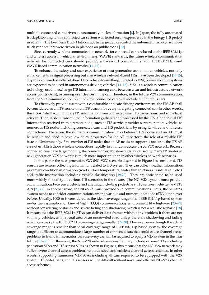
Figure 3. Channel collision in dense scenario of V2X.
In the proposed scheme, an IEEE 802.11-based extension is employed to provide backward compatibility, ability to operate in a mode in which the devices can interoperate with conventional IEEE 802.11p devices [34], and the emerging IEEE 802.11ax standard-based orthogonal frequency-division multiple access (OFDMA) is adopted and extended to provide massive V2X support. This paper proposes a novel NG-V2X channel access scheme based on uplink OFDMA. Our main contributions in this paper consist of two parts: (1) a scalable and efficient channel access method using modified IEEE 802.11ax uplink OFDMA random access (UORA) appropriate for massive V2X support and (2) an accurate mathematical modeling and analysis on the adopted IEEE 802.11ax uplink OFDMA random access (UORA). The adopted IEEE 802.11ax-based OFDMA schemes including UORA for the proposed NG-V2X channel access is modified to work in 10 MHz channel bandwidth by doubling the symbol length of IEEE 802.11ax symbols. The operation frequency band of the proposed NG-V2X channel access scheme is the 5.9 GHz ITS band which is the same operation band as the conventional IEEE 802.11p based ITS systems. The proposed scheme includes a scalable channel access method appropriate for V2X applications, and it also enables effective communication between ITS sensors and ITS APs without impacting V2X system performance. Furthermore, a scheduled NG-V2X channel access scheme is also proposed for the extra optimization. To show how the proposed NG-V2X channel access scheme can enhance network scalability,
Figure 3. Channel collision in dense scenario of V2X.
In the design of the proposed scheme, two essential aspects, namely, backward compatibility andmassive V2X support, are carefully considered. Since the IEEE 802.11p-based V2X network is alreadybeing deployed and used for ITSs, NG-V2X networks shall be designed under the consideration ofthe IEEE 802.11p-based V2X network to provide backward compatibility. Since all future cars areexpected to be equipped with V2X communication devices, dense V2X communication scenarios willbe common and massive V2X communication support will be required.
As part of the efforts to solve two challenging issues of V2X network, the IEEE 802.11 workinggroup has started to study the NG-V2X system. A study group for NG-V2X (NGV-SG) has beenformed to consider various scenarios for the V2X communication system. It is expected that the studygroup will produce an NG-V2X standard based on the conventional IEEE 802.11p standard to ensurebackward compatibility. It is considering a V2X system that will be more reliable, have a highercapacity, and support higher mobility, though specific details of the requirements are being discussed.
In the proposed scheme, an IEEE 802.11-based extension is employed to provide backwardcompatibility, ability to operate in a mode in which the devices can interoperate with conventional IEEE802.11p devices [34], and the emerging IEEE 802.11ax standard-based orthogonal frequency-divisionmultiple access (OFDMA) is adopted and extended to provide massive V2X support. This paperproposes a novel NG-V2X channel access scheme based on uplink OFDMA. Our main contributionsin this paper consist of two parts: (1) a scalable and efficient channel access method using modifiedIEEE 802.11ax uplink OFDMA random access (UORA) appropriate for massive V2X support and(2) an accurate mathematical modeling and analysis on the adopted IEEE 802.11ax uplink OFDMArandom access (UORA). The adopted IEEE 802.11ax-based OFDMA schemes including UORA for theproposed NG-V2X channel access is modified to work in 10 MHz channel bandwidth by doublingthe symbol length of IEEE 802.11ax symbols. The operation frequency band of the proposed NG-V2Xchannel access scheme is the 5.9 GHz ITS band which is the same operation band as the conventionalIEEE 802.11p based ITS systems. The proposed scheme includes a scalable channel access methodappropriate for V2X applications, and it also enables effective communication between ITS sensorsand ITS APs without impacting V2X system performance. Furthermore, a scheduled NG-V2X channelaccess scheme is also proposed for the extra optimization. To show how the proposed NG-V2X channel

Appl. Sci. 2018, 8, 2112 5 of 23
access scheme can enhance network scalability, mathematical modeling, and analysis, more accurateand closer to real standards than ever to the best of our knowledge on uplink OFDMA random access(UORA) are provided. In the mathematical modeling of UORA, some errors of the previous works arefixed and the actual UORA procedure of the IEEE 802.11ax standard is considered. Then, the delay anduser capacity performance of the proposed NG-V2X channel access scheme, including some furtheroptimization methods, are evaluated in various simulation scenarios to demonstrate how the proposedschemes enhance user capacity performance of the NG-V2X network.
The rest of paper is organized as follows. In Section 2, we introduce some background technologiesincluding the conventional IEEE 802.11p standard and UORA, which are used as a basic channel accessconcept in this work. In Section 3, the proposed NG-V2X channel access scheme using the UORAprocedure is explained. In Section 4, mathematical models of UORA and novel and efficient V2Xenhancing methods including scheduled NG-V2X channel access are explained. Since the proposedmathematical modeling of the UORA procedure considers the latest updates on UORA procedure ofIEEE 802.11ax, the proposed modeling is the most up-to-date and accurate modeling to the best ofour knowledge. The proposed NG-V2X scheme is specifically designed to transport ITS informationin dense scenarios for the next-generation V2X networks. In Section 4, the system performance ofthe proposed uplink V2X channel access is investigated through extensive simulation. In Section 5,delay and packet loss rate performances are examined in various simulation scenarios includingconventional IEEE 802.11p and high priority channel access scheme proposed by previous studies tocompare the channel access schemes. The conclusion with a remark of relationship with NG-V2X ispresented in Section 6.
2. Background Technology
In the IEEE 802.11p standard, different from other IEEE 802.11 standards, authentication andassociation processes, which cause a large delay before real data transmission, are not required. EachIEEE 802.11p STA can transmit its data to an AP after receiving the beacon frame with the channelaccess procedure. Figure 4 shows the conventional IEEE 802.11 transmission procedure with largedelay link establishment and the IEEE 802.11p procedure with simplified link establishment. AlthoughIEEE 802.11p has a simplified link establishment procedure, the channel access procedure is stilltime-based random access; hence, if multiple STAs transmit their data simultaneously, all the dataframes collide in the air. Because the random-access-based channel access procedure of IEEE 802.11 isdistributed and involves a large retransmission delay, it is not suitable for highly dense connected carscenarios like the interchange and urban traffic jam cases.
Appl. Sci. 2018, 8, x FOR PEER REVIEW 5 of 24
mathematical modeling, and analysis, more accurate and closer to real standards than ever to the best of our knowledge on uplink OFDMA random access (UORA) are provided. In the mathematical modeling of UORA, some errors of the previous works are fixed and the actual UORA procedure of the IEEE 802.11ax standard is considered. Then, the delay and user capacity performance of the proposed NG-V2X channel access scheme, including some further optimization methods, are evaluated in various simulation scenarios to demonstrate how the proposed schemes enhance user capacity performance of the NG-V2X network.
The rest of paper is organized as follows. In Section 2, we introduce some background technologies including the conventional IEEE 802.11p standard and UORA, which are used as a basic channel access concept in this work. In Section 3, the proposed NG-V2X channel access scheme using the UORA procedure is explained. In Section 4, mathematical models of UORA and novel and efficient V2X enhancing methods including scheduled NG-V2X channel access are explained. Since the proposed mathematical modeling of the UORA procedure considers the latest updates on UORA procedure of IEEE 802.11ax, the proposed modeling is the most up-to-date and accurate modeling to the best of our knowledge. The proposed NG-V2X scheme is specifically designed to transport ITS information in dense scenarios for the next-generation V2X networks. In Section 4, the system performance of the proposed uplink V2X channel access is investigated through extensive simulation. In Section 5, delay and packet loss rate performances are examined in various simulation scenarios including conventional IEEE 802.11p and high priority channel access scheme proposed by previous studies to compare the channel access schemes. The conclusion with a remark of relationship with NG-V2X is presented in Section 6.
2. Background Technology
In the IEEE 802.11p standard, different from other IEEE 802.11 standards, authentication and association processes, which cause a large delay before real data transmission, are not required. Each IEEE 802.11p STA can transmit its data to an AP after receiving the beacon frame with the channel access procedure. Figure 4 shows the conventional IEEE 802.11 transmission procedure with large delay link establishment and the IEEE 802.11p procedure with simplified link establishment. Although IEEE 802.11p has a simplified link establishment procedure, the channel access procedure is still time-based random access; hence, if multiple STAs transmit their data simultaneously, all the data frames collide in the air. Because the random-access-based channel access procedure of IEEE 802.11 is distributed and involves a large retransmission delay, it is not suitable for highly dense connected car scenarios like the interchange and urban traffic jam cases.
Beacon FrameAP
STA
Association Request
ACKAssociation Response
DATA
(a)
Figure 4. Cont.

Appl. Sci. 2018, 8, 2112 6 of 23Appl. Sci. 2018, 8, x FOR PEER REVIEW 6 of 24
Beacon FrameAP
STA
Data
ACK
(b)
Figure 4. IEEE 802.11 procedures for transmitting its data frame to an unassociated AP: (a) Conventional IEEE 802.11 procedure; (b) IEEE 802.11p procedure.
An uplink delay of IEEE 802.11p frame delivery can be described as
{ }2 _
__ _0
( ) ( ) ( )
V X CCH duration TXOP
CCH duration
M
back off SCH busy timei
T T T
T i T i N i T
α
−=
= +
+ ++ (1)
where α represents the ratio of the partial control channel (CCH) duration if the frame arrives during the CCH duration. M is the number of retransmissions until transmission success or failure. N(i) is the number of CCHs for each retransmission. If i is 0, the value came from initial transmission. TCCH_duration is a value of a CCH duration usually set to 50 ms or 0 ms. TTXOP is a time component for transmitting a data frame and receiving its immediate response. Tback-off represents a random delay during which an IEEE 802.11 STA must wait before transmitting its frames to avoid wireless channel collision. The back-off value is chosen randomly between 0 and the value of the congestion window (CW) size, and the STAs must reduce the back-off value every time slot interval if the channel is idle during the time slot and the value is positive.
Because IEEE 802.11p could switch its logical channel repeatedly, an uplink channel access procedure by connected cars can be performed during the service channel (SCH) duration only. Basically, IEEE 802.11p could switch its logical channel every 50 ms. In IEEE 802.11p, there are two types of logical channel: CCH and SCH; CCH is used for transmitting downlink ITS information by an ITS AP, and SCH can be used for every ITS station if the STAs have received a beacon frame from the ITS AP. If a V2X system deploys a dedicated frequency channel for the logical CCH and SCH, the V2X delay, TCCH_duration can be set to 0. In this case, TV2X can be described as below.
{ }2 _ _0
( ) ( )V X TXOP
M
back off SCH busy timei
T T T i T i−=
= ++ (2)
Because recent V2X systems tend to use a dedicated channel structure rather than to use a channel switching structure in a single channel [35,36], we determined to use this dedicated CCH structure in this study. Figure 5 describes an example of the channel structure considered in this study.
CCHSCHSCHSCHSCH SCH SCH SCH SCH
CH#1 CH#9CH#2 CH#3 CH#4 CH#5 CH#6 CH#7 CH#8
Figure 5. Example of IEEE 802.11p Channel Structure.
Figure 4. IEEE 802.11 procedures for transmitting its data frame to an unassociated AP: (a) ConventionalIEEE 802.11 procedure; (b) IEEE 802.11p procedure.
An uplink delay of IEEE 802.11p frame delivery can be described as
TV2X = αTCCH_duration + TTXOP
+M∑
i=0
{Tback−o f f (i) + TSCH_busy_time(i) + N(i)TCCH_duration
} (1)
where α represents the ratio of the partial control channel (CCH) duration if the frame arrives duringthe CCH duration. M is the number of retransmissions until transmission success or failure. N(i)is the number of CCHs for each retransmission. If i is 0, the value came from initial transmission.TCCH_duration is a value of a CCH duration usually set to 50 ms or 0 ms. TTXOP is a time component fortransmitting a data frame and receiving its immediate response. Tback-off represents a random delayduring which an IEEE 802.11 STA must wait before transmitting its frames to avoid wireless channelcollision. The back-off value is chosen randomly between 0 and the value of the congestion window(CW) size, and the STAs must reduce the back-off value every time slot interval if the channel is idleduring the time slot and the value is positive.
Because IEEE 802.11p could switch its logical channel repeatedly, an uplink channel accessprocedure by connected cars can be performed during the service channel (SCH) duration only.Basically, IEEE 802.11p could switch its logical channel every 50 ms. In IEEE 802.11p, there are twotypes of logical channel: CCH and SCH; CCH is used for transmitting downlink ITS information by anITS AP, and SCH can be used for every ITS station if the STAs have received a beacon frame from theITS AP. If a V2X system deploys a dedicated frequency channel for the logical CCH and SCH, the V2Xdelay, TCCH_duration can be set to 0. In this case, TV2X can be described as below.
TV2X = TTXOP +M
∑i=0
{Tback−o f f (i) + TSCH_busy_time(i)
}(2)
Because recent V2X systems tend to use a dedicated channel structure rather than to use a channelswitching structure in a single channel [35,36], we determined to use this dedicated CCH structure inthis study. Figure 5 describes an example of the channel structure considered in this study.
Appl. Sci. 2018, 8, x FOR PEER REVIEW 6 of 24
Beacon FrameAP
STA
Data
ACK
(b)
Figure 4. IEEE 802.11 procedures for transmitting its data frame to an unassociated AP: (a) Conventional IEEE 802.11 procedure; (b) IEEE 802.11p procedure.
An uplink delay of IEEE 802.11p frame delivery can be described as
{ }2 _
__ _0
( ) ( ) ( )
V X CCH duration TXOP
CCH duration
M
back off SCH busy timei
T T T
T i T i N i T
α
−=
= +
+ ++ (1)
where α represents the ratio of the partial control channel (CCH) duration if the frame arrives during the CCH duration. M is the number of retransmissions until transmission success or failure. N(i) is the number of CCHs for each retransmission. If i is 0, the value came from initial transmission. TCCH_duration is a value of a CCH duration usually set to 50 ms or 0 ms. TTXOP is a time component for transmitting a data frame and receiving its immediate response. Tback-off represents a random delay during which an IEEE 802.11 STA must wait before transmitting its frames to avoid wireless channel collision. The back-off value is chosen randomly between 0 and the value of the congestion window (CW) size, and the STAs must reduce the back-off value every time slot interval if the channel is idle during the time slot and the value is positive.
Because IEEE 802.11p could switch its logical channel repeatedly, an uplink channel access procedure by connected cars can be performed during the service channel (SCH) duration only. Basically, IEEE 802.11p could switch its logical channel every 50 ms. In IEEE 802.11p, there are two types of logical channel: CCH and SCH; CCH is used for transmitting downlink ITS information by an ITS AP, and SCH can be used for every ITS station if the STAs have received a beacon frame from the ITS AP. If a V2X system deploys a dedicated frequency channel for the logical CCH and SCH, the V2X delay, TCCH_duration can be set to 0. In this case, TV2X can be described as below.
{ }2 _ _0
( ) ( )V X TXOP
M
back off SCH busy timei
T T T i T i−=
= ++ (2)
Because recent V2X systems tend to use a dedicated channel structure rather than to use a channel switching structure in a single channel [35,36], we determined to use this dedicated CCH structure in this study. Figure 5 describes an example of the channel structure considered in this study.
CCHSCHSCHSCHSCH SCH SCH SCH SCH
CH#1 CH#9CH#2 CH#3 CH#4 CH#5 CH#6 CH#7 CH#8
Figure 5. Example of IEEE 802.11p Channel Structure.
Figure 5. Example of IEEE 802.11p Channel Structure.

Appl. Sci. 2018, 8, 2112 7 of 23
V2X systems consist of several components including vehicle-to-vehicle (V2V), vehicle-to-infrastructure (V2I), vehicle-to-device (V2D), etc., and V2V and V2I communications shall be operatedin identical frequency bands if the V2X system is supported by a single communication protocolrather than using complex multiple vehicular communication systems. Only the channels in the bandscan be diversified for each purpose. Some channels could be defined as CCHs, and others as SCHs.Some SCHs might be used for V2I, and others for V2V or a mixed purpose. As we mentioned earlier,the delay this paper focuses on is a V2I delay in an SCH. More specifically, this paper considers the V2Iuplink delay in the SCH channel. Because each vehicle transmits its own frames to a V2X infrastructureSTA without any centralized control, the delay and collision they cause could be a great threat againstcontention-based V2X systems.
Although the IEEE 802.11p standard is not a very recent standard, it is verified and being deployedfor novel V2X systems. Although the latest research groups, including 3GPP and IEEE, are consideringNG-V2X network standards, they are still considering IEEE 802.11p as the baseline technology forNG-V2X systems. Therefore, we consider IEEE 802.11p-based V2X channel access schemes for theNG-V2X systems in this work.
The NG-V2X system that we consider shall support backward compatibility to IEEE 802.11p. Thismeans that if the SCH or CCH is used for both conventional IEEE 802.11p and NG-V2X, the existence ofconventional IEEE 802.11p STAs needs to be considered and conventional IEEE 802.11p communicationshould not be adversely affected. This can be interpreted that the channel access scheme we proposeneeds to be examined under the scenarios of legacy IEEE 802.11 coexistence.
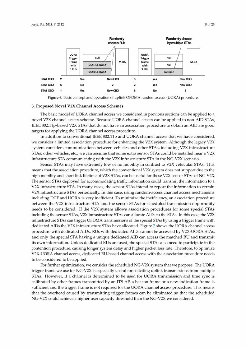
In this study, we propose a specific uplink channel access mechanism based on IEEE 802.11p.We consider highly dense scenarios of V2X vehicles in a traffic jam to measure how reliable andscalable the V2X system is in extreme scenarios. To handle the dense scenario, we have chosen touse the trigger frame that is defined in the IEEE 802.11ax standard but not in IEEE 802.11p. Basically,the trigger frame is used for soliciting uplink multiuser transmission by an STA whose address isindicated in the trigger frame. Because the trigger frame needs the target uplink STAs’ addresses,using the trigger frame for soliciting uplink multiuser transmissions in the V2X system that doesnot have an association procedure for exchanging STA information is not appropriate. Therefore,performing uplink multiuser transmission in the V2X system requires a random-access-based channelaccess procedure and not dedicated scheduling using the basic trigger frame. Fortunately, a resourceunit (RU)-based random-access procedure called UORA procedure is defined in the IEEE 802.11 axstandard as an optional feature.
The UORA is a unique channel access scheme for allowing STAs to perform RU-based randomaccess. Figure 6 shows the basic concept and operation of the UORA procedure. In this procedure,the AP allows STAs to access some RUs indicated as UORA RUs, which are indicated by a special valueof association ID (AID). If the AID of some RUs is written in the special AID value, any STA receivingthe UORA trigger frame counts the number of UORA RUs. The number is used for decreasing theSTAs’ back-off counter as in the conventional IEEE 802.11 distributed coordinating function back-offprocedure. Unlike in the conventional procedure, the back-off counter decreases based on the numberof RUs and not based on the number of time slots the STAs have waited.
Although the UORA procedure is not defined for IEEE 802.11p and hence cannot be used in theexisting IEEE 802.11p-based V2X system, we propose to use the UORA procedure for the NG-V2Xsystem by demonstrating its performance gain by proposing novel enhancing algorithms in this work.
Appl. Sci. 2018, 8, 2112 8 of 23
Appl. Sci. 2018, 8, x FOR PEER REVIEW 7 of 24
V2X systems consist of several components including vehicle-to-vehicle (V2V), vehicle-to-infrastructure (V2I), vehicle-to-device (V2D), etc., and V2V and V2I communications shall be operated in identical frequency bands if the V2X system is supported by a single communication protocol rather than using complex multiple vehicular communication systems. Only the channels in the bands can be diversified for each purpose. Some channels could be defined as CCHs, and others as SCHs. Some SCHs might be used for V2I, and others for V2V or a mixed purpose. As we mentioned earlier, the delay this paper focuses on is a V2I delay in an SCH. More specifically, this paper considers the V2I uplink delay in the SCH channel. Because each vehicle transmits its own frames to a V2X infrastructure STA without any centralized control, the delay and collision they cause could be a great threat against contention-based V2X systems.
Although the IEEE 802.11p standard is not a very recent standard, it is verified and being deployed for novel V2X systems. Although the latest research groups, including 3GPP and IEEE, are considering NG-V2X network standards, they are still considering IEEE 802.11p as the baseline technology for NG-V2X systems. Therefore, we consider IEEE 802.11p-based V2X channel access schemes for the NG-V2X systems in this work.
The NG-V2X system that we consider shall support backward compatibility to IEEE 802.11p. This means that if the SCH or CCH is used for both conventional IEEE 802.11p and NG-V2X, the existence of conventional IEEE 802.11p STAs needs to be considered and conventional IEEE 802.11p communication should not be adversely affected. This can be interpreted that the channel access scheme we propose needs to be examined under the scenarios of legacy IEEE 802.11 coexistence.
In this study, we propose a specific uplink channel access mechanism based on IEEE 802.11p. We consider highly dense scenarios of V2X vehicles in a traffic jam to measure how reliable and scalable the V2X system is in extreme scenarios. To handle the dense scenario, we have chosen to use the trigger frame that is defined in the IEEE 802.11ax standard but not in IEEE 802.11p. Basically, the trigger frame is used for soliciting uplink multiuser transmission by an STA whose address is indicated in the trigger frame. Because the trigger frame needs the target uplink STAs’ addresses, using the trigger frame for soliciting uplink multiuser transmissions in the V2X system that does not have an association procedure for exchanging STA information is not appropriate. Therefore, performing uplink multiuser transmission in the V2X system requires a random-access-based channel access procedure and not dedicated scheduling using the basic trigger frame. Fortunately, a resource unit (RU)-based random-access procedure called UORA procedure is defined in the IEEE 802.11 ax standard as an optional feature.
The UORA is a unique channel access scheme for allowing STAs to perform RU-based random access. Figure 6 shows the basic concept and operation of the UORA procedure. In this procedure, the AP allows STAs to access some RUs indicated as UORA RUs, which are indicated by a special value of association ID (AID). If the AID of some RUs is written in the special AID value, any STA receiving the UORA trigger frame counts the number of UORA RUs. The number is used for decreasing the STAs’ back-off counter as in the conventional IEEE 802.11 distributed coordinating function back-off procedure. Unlike in the conventional procedure, the back-off counter decreases based on the number of RUs and not based on the number of time slots the STAs have waited.
STA3 UL DATA
UORA Trigger Frame with
3 RUsSTA1 UL DATA
null
STA1 OBO
STA2 OBO
STA3 OBO
2
5
1
3
2
6
M-BA
Yes
No
Yes
New OBO
2
New OBO
Collision
UORA Trigger Frame with
3 RUs
nullM-BA
Yes
Yes
No
New OBO
New OBO
3
null
Randomly chosen RUs
Randomly chosen by multiple STAs
Figure 6. Basic concept and operation of uplink OFDMA random access (UORA) procedure. Figure 6. Basic concept and operation of uplink OFDMA random access (UORA) procedure.
3. Proposed Novel V2X Channel Access Schemes
The basic model of UORA channel access we considered in previous sections can be applied to anovel V2X channel access scheme. Because UORA channel access can be applied to non-AID STAs,IEEE 802.11p-based V2X STAs that do not have an association procedure to obtain an AID are goodtargets for applying the UORA channel access procedure.
In addition to conventional IEEE 802.11p and UORA channel access that we have considered,we consider a limited association procedure for enhancing the V2X system. Although the legacy V2Xsystem considers communications between vehicles and other STAs, including V2X infrastructureSTAs, other vehicles, etc., we can assume that some extra sensor STAs could be installed near a V2Xinfrastructure STA communicating with the V2X infrastructure STA in the NG-V2X scenario.
Sensor STAs may have extremely low or no mobility in contrast to V2X vehicular STAs. Thismeans that the association procedure, which the conventional V2X system does not support due to thehigh mobility and short link lifetime of V2X STAs, can be useful for these V2X sensor STAs of NG-V2X.The sensor STAs deployed for accommodating traffic information could transmit the information to aV2X infrastructure STA. In many cases, the sensor STAs intend to report the information to certainV2X infrastructure STAs periodically. In this case, using random-access channel access mechanismsincluding DCF and UORA is very inefficient. To minimize the inefficiency, an association procedurebetween the V2X infrastructure STA and the sensor STAs for scheduled transmission opportunityneeds to be considered. If the V2X system allows association procedures for some special STAsincluding the sensor STAs, V2X infrastructure STAs can allocate AIDs to the STAs. In this case, the V2Xinfrastructure STAs can trigger OFDMA transmissions of the special STAs by using a trigger frame withdedicated AIDs the V2X infrastructure STAs have allocated. Figure 7 shows the UORA channel accessprocedure with dedicated AIDs. RUs with dedicated AIDs cannot be accessed by V2X-UORA STAs,and only the special STA having a unique dedicated AID can access the matched RU and transmitits own information. Unless dedicated RUs are used, the special STAs also need to participate in thecontention procedure, causing longer system delay and higher packet loss rate. Therefore, to optimizeV2X-UORA channel access, dedicated RU-based channel access with the association procedure needsto be considered to be applied.
For further optimization, we consider the scheduled NG-V2X system that we propose. The UORAtrigger frame we use for NG-V2X is especially useful for soliciting uplink transmissions from multipleSTAs. However, if a channel is determined to be used for UORA transmission and time sync iscalibrated by other frames transmitted by an ITS AP, a beacon frame or a new indication frame issufficient and the trigger frame is not required for the UORA channel access procedure. This meansthat the overhead caused by transmitting trigger frames can be eliminated so that the scheduledNG-V2X could achieve a higher user capacity threshold than the NG-V2X we considered.

Appl. Sci. 2018, 8, 2112 9 of 23
Appl. Sci. 2018, 8, x FOR PEER REVIEW 8 of 24
Although the UORA procedure is not defined for IEEE 802.11p and hence cannot be used in the existing IEEE 802.11p-based V2X system, we propose to use the UORA procedure for the NG-V2X system by demonstrating its performance gain by proposing novel enhancing algorithms in this work.
3. Proposed Novel V2X Channel Access Schemes
The basic model of UORA channel access we considered in previous sections can be applied to a novel V2X channel access scheme. Because UORA channel access can be applied to non-AID STAs, IEEE 802.11p-based V2X STAs that do not have an association procedure to obtain an AID are good targets for applying the UORA channel access procedure.
In addition to conventional IEEE 802.11p and UORA channel access that we have considered, we consider a limited association procedure for enhancing the V2X system. Although the legacy V2X system considers communications between vehicles and other STAs, including V2X infrastructure STAs, other vehicles, etc., we can assume that some extra sensor STAs could be installed near a V2X infrastructure STA communicating with the V2X infrastructure STA in the NG-V2X scenario.
Sensor STAs may have extremely low or no mobility in contrast to V2X vehicular STAs. This means that the association procedure, which the conventional V2X system does not support due to the high mobility and short link lifetime of V2X STAs, can be useful for these V2X sensor STAs of NG-V2X. The sensor STAs deployed for accommodating traffic information could transmit the information to a V2X infrastructure STA. In many cases, the sensor STAs intend to report the information to certain V2X infrastructure STAs periodically. In this case, using random-access channel access mechanisms including DCF and UORA is very inefficient. To minimize the inefficiency, an association procedure between the V2X infrastructure STA and the sensor STAs for scheduled transmission opportunity needs to be considered. If the V2X system allows association procedures for some special STAs including the sensor STAs, V2X infrastructure STAs can allocate AIDs to the STAs. In this case, the V2X infrastructure STAs can trigger OFDMA transmissions of the special STAs by using a trigger frame with dedicated AIDs the V2X infrastructure STAs have allocated. Figure 7 shows the UORA channel access procedure with dedicated AIDs. RUs with dedicated AIDs cannot be accessed by V2X-UORA STAs, and only the special STA having a unique dedicated AID can access the matched RU and transmit its own information. Unless dedicated RUs are used, the special STAs also need to participate in the contention procedure, causing longer system delay and higher packet loss rate. Therefore, to optimize V2X-UORA channel access, dedicated RU-based channel access with the association procedure needs to be considered to be applied.
STA3 UL DATA
UORA Trigger Frame with
3 RUsSTA1 UL DATA
Sensor 3 UL DATA
STA1 OBO
STA2 OBO
STA3 OBO
2
4
1
3
2
6
M-BA
Yes
No
Yes
New OBO
2
New OBO
STA2 UL DATA
UORA Trigger Frame with
3 RUs
Sensor 5 UL DATAM-BA
No
Yes
No
1
New OBO
4
null
Randomly chosen RUs
Randomly chosen RUs
Figure 7. V2X UORA channel access procedure with dedicated resource unit(s) (RUs).
For further optimization, we consider the scheduled NG-V2X system that we propose. The UORA trigger frame we use for NG-V2X is especially useful for soliciting uplink transmissions from multiple STAs. However, if a channel is determined to be used for UORA transmission and time sync is calibrated by other frames transmitted by an ITS AP, a beacon frame or a new indication frame is sufficient and the trigger frame is not required for the UORA channel access procedure. This
Figure 7. V2X UORA channel access procedure with dedicated resource unit(s) (RUs).
4. System Model
Some researchers have tried to model the UORA procedure using a Markov chain model withsome assumptions for simplified analysis in the early stage of IEEE 802.11ax standardization. As theIEEE 802.11ax standard has been developed, the specific procedure of UORA has been defined.To modify and correct the Markov model and the analysis method, Lanante et al. tried to generatea more generalized model and analysis method [37]. Many researchers have tried to evaluate itsperformance, especially its efficiency and throughput [38,39]. One of the purposes of this paperis similar to that of those studies on system modeling. Because the research is almost close to theactual IEEE 802.11ax UORA procedure, a small disagreement still exists between the Markov chainmodel and the actual UORA procedure. Therefore, we tried to enhance the Markov model and theanalysis method.
4.1. Markov Chain Model
As an example, assume the UORA trigger frame with nine UORA RUs. Because the 20-MHz IEEE802.11ax trigger frame can have nine RUs at most, this is a reasonable situation. Figure 8 shows theMarkov chain model of the 9-RU UORA procedure. If the UORA counter of an STA is smaller than thenumber of UORA RUs in the received trigger frame, the STA can transmit its frame via the UL OFDMAtransmission opportunity. If the initial random back-off number the STA obtained is 0 or smaller thanthe number of UORA RUs in the trigger frame, the STA can transmit its frame just after receiving thetrigger frame with UORA RU(s). Based on Figure 8, each probability branch can be described as below.
P{0, k|i, l} = (1− p)/W0 k ∈ (0, W0 − 1) l ∈ (0, 9) i ∈ (0, m)
P{i, k|i, k + 9} = 1 k ∈ (0, Wi − 10) i ∈ (0, m)
P{i, k|i− 1, l) = p/Wi k ∈ (0, Wi − 1) l ∈ (0, 9) i ∈ (0, m)
P{m, k|m, l) = p/Wm k ∈ (0, Wm − 1) l ∈ (0, 9)
(3)
where m is the required number of retransmissions to reach the maximum UORA CW size.The maximum UORA CW size is called OCWmax and the initial size of UORA CW is called OCWmin.Once the OCW reaches OCWmax for successive retransmission attempts, the OCW, Wi in (3), shallremain at the value of OCWmax, Wm in (3), until the OCW is reset. The probability p means theprobability of transmission failure when an STA transmits its frame via the UORA procedure. If weassume that the transmission is always successful unless there are collisions, p can be interpreted asthe probability of UORA collision.
From the Markov chain model and probability branches, we can derive the stationary distributionof the Markov chain.
From the state (0,0), the following can be derived:
b0,0 =(1− p)
W0
m
∑i=0
r
∑k=0
bi,k (4)
Appl. Sci. 2018, 8, 2112 10 of 23
For each state (0,k) where k > 0, we can derive the following expression.
b0,k = b0,k+r +(1−p)
W0
m∑
i=0
r∑
k=0bi,k
= b0,k+2r + 2 (1−p)W0
m∑
i=0
r∑
k=0bi,k
= (⌊
W0−1−kr
⌋+ 1){ (1−p)
W0
m∑
i=0
r∑
k=0bi,k}
= (⌊
W0−1−kr
⌋+ 1)b0,0
(5)
For 0 < i < m, k > 0, the expression for each bi,k can be derived as below.
bi,k = bi,k+r + pr∑
k=0
bi−1,kWi−1
= (⌊
Wi−1−kr
⌋+ 1)p
r∑
k=0
bi−1,kWi−1
bm,k = p(r∑
k=0
bm,kWm
+r∑
k=0
bm−1,kWm−1
)(6)
For bi,0 with i > 0,
bi,0 =p
Wi−1
r
∑k=0
bi−1,k (7)
From Equations (5) and (7), the following expression can be derived.
b0,k = (⌊
W0−1−kr
⌋+ 1){ 1−p
p (m∑
i=0
pWi
r∑
k=0bi,k)}
= (⌊
W0−1−kr
⌋+ 1)( 1−p
p )(m−1∑
i=0bi+1,0 +
pWm
r∑
k=0bm,k)
(8)
If we define the virtual state term bm+1,0 for Equation (7), Equation (8) can be re-expressedas follows.
b0,k = (
⌊W0 − 1− k
r
⌋+ 1)(
1− pp
)(m
∑i=0
bi+1,0) (9)
In a similar way, the following equation can be derived from Equations (6) and (7).
bi,k = (
⌊Wi − 1− k
r
⌋+ 1)bi,0 (10)
From the steady-state probability rule and Equations (7)–(10), we obtain
m∑
i=0
Wi−1∑
k=0bi,k =
m∑
i=1
Wi−1∑
k=1bi,k +
W0−1∑
k=1b0,k +
m∑
i=0bi,0
=m∑
i=1
Wi−1∑
k=1(⌊
Wi−1−kr
⌋+ 1)bi,0 +
W0−1∑
k=1(⌊
W0−1−kr
⌋+ 1)b0,0 +
m∑
i=0bi,0
= 1
(11)
If we have the exact values of Wi, we can derive all the states as functions of p from equationsderived above.
Unlike in distributed coordinating function channel access analysis [40], not only STAs in statebi,0 but also STAs in state bi,k, where k is equal or smaller than r, transmit their frames. Therefore, wecan derive τ, the probability of transmission, as follows.
τ =m
∑i=0
r
∑k=0
bi,k (12)

Appl. Sci. 2018, 8, 2112 11 of 23
From the transmission probability, we can re-express the UORA collision probability p as follows.
p = 1− (1− τ)n−1 (13)
Because every steady-state probability can be expressed as a function of p, we can obtain exactsteady-state probabilities if we have specific Wi, r, and n values.
Appl. Sci. 2018, 8, x FOR PEER REVIEW 11 of 24
From the transmission probability, we can re-express the UORA collision probability p as follows.
11 (1 )np τ −= − − (13)
Because every steady-state probability can be expressed as a function of p, we can obtain exact steady-state probabilities if we have specific Wi, r, and n values.
0,2 0,4 0,5 0,80,0 0,1 0,3 0,6 0,7 0,9
0,11 0,13 0,14 0,170,10 0,12 0,15 0,16 0,18
0,W0-3 0,W0-10,W0-4 0,W0-2...
1
1 1 1 1 1 1 1 1 1
1 1 1 1
(1-p)/W0
1,2 1,4 1,5 1,81,0 1,1 1,3 1,6 1,7 1,9
1,11 1,13 1,14 1,171,10 1,12 1,15 1,16 1,18
1,W1-3 1,W1-11,W1-4 1,W1-2
...
1
1 1 1 1 1 1 1 1 1
1 1 1 1
p/W1
m,2 m,4 m,5 m,8m,0 m,1 m,3 m,6 m,7 m,9
m,11 m,13 m,14 m,17m,10 m,12 m,15 m,16 m,18
m,Wm-3 m,Wm-1m,Wm-4 m,Wm-2
...
1
1 1 1 1 1 1 1 1 1
1 1 1 1
p/Wm
...
Figure 8. Markov chain model of UORA channel access with 9 resource units (RUs).
4.2. Simplified Markov Chain Model
The Markov model we have analyzed in the traditional way is slightly complicated, and we can simplify the Markov model. As can be observed from the Markov chain model shown in Figure 8 and the equations we have derived, all r states have similar stochastic properties except the first r + 1 states and some last states. We call the set of states with similar properties as a stage. We try to use this number of stages as a representative residual UORA back-off value.
We use Bi,n as a state probability of each stage where i is the number of retransmissions as earlier and n is the number of stages. The stage-based Markov model is described in Figure 9, and each state indicates Bi,n we defined. For each i, the maximum number of stages Ni and Ri, number of states in Bi,n where n = Ni, can be described as follows.
21i
i
WN
r
−= +
(14)
( 11)i i iR W r N= − −− (15)
0,0 ,00
(1 )m
ii
B p B=
= − (16)
Figure 8. Markov chain model of UORA channel access with 9 resource units (RUs).
4.2. Simplified Markov Chain Model
The Markov model we have analyzed in the traditional way is slightly complicated, and we cansimplify the Markov model. As can be observed from the Markov chain model shown in Figure 8and the equations we have derived, all r states have similar stochastic properties except the first r + 1states and some last states. We call the set of states with similar properties as a stage. We try to use thisnumber of stages as a representative residual UORA back-off value.
We use Bi,n as a state probability of each stage where i is the number of retransmissions as earlierand n is the number of stages. The stage-based Markov model is described in Figure 9, and each stateindicates Bi,n we defined. For each i, the maximum number of stages Ni and Ri, number of states inBi,n where n = Ni, can be described as follows.
Ni =
⌊Wi − 2
r
⌋+ 1 (14)
Ri = Wi − r(Ni − 1)− 1 (15)
B0,0 = (1− p)m
∑i=0
Bi,0 (16)
Bi,0 = pBi−1,0 = piB0,0 for 0 < i < m (17)

Appl. Sci. 2018, 8, 2112 12 of 23
Bm,0 = pBm−1,0 + pBm,0 → Bm,0 =p
1− pBm−1,0 =
pm
1− pB0,0 (18)
Bi,n = {(Ni − n− 1)r + Ri}pi
WiB0,0 where 0 ≤ i < m, n > 0 (19)
Bm,n = {(Nm − n− 1)r + Rm}p
Wm(Bm,0 + Bm−1,0) = {(Nm − n− 1)r + Rm}
pm
Wm(p + 1)B0,0 (20)
From the total probability rule,
m∑
i=0
Ni−1∑
n=0Bi,n =
m−1∑
i=0
Ni−1∑
n=1Bi,n +
Nm−1∑
n=1Bm,n + B0,0
= B0,0{m−1∑
i=1
pi
Wi{(Ni − 1)2r + (Ni − 1)Ri − Ni
2 r}
+ pm
Wm(p + 1){(Nm − 1)2r + (Nm − 1)Rm − Nm
2 r}+ pm
1−p + 1} = 1
(21)
The simplified model we derived also provides the steady-state distribution as a function ofprobability if specific UORA CW sizes and RU size are given.
As in Section 4.1, the probability of transmission can be derived as follows.
τ =m
∑i=0
Bi,0 =1
1− pB0,0 (22)
From Equations (13), (21), and (22), we can obtain specific values of the steady-state distributionand the transmission probability of the simplified model if we have specific system parameters.
Appl. Sci. 2018, 8, x FOR PEER REVIEW 12 of 24
,0 1,0 0,0i i
iB pB p B−= = for 0<i<m (17)
,0 1,0 ,0 ,0 1,0 0,01 1
m
m m m m m
p pB pB B B B B
p pp− −= =
− −+ → = (18)
, 0,0{( 1) }i
i n i i
i
pB N n r R B
W= − − + where 0 ≤ i < m, n > 0 (19)
, ,0 1,0 0,0{( 1) } {( 1) } 1( ) ( )m n m m m m m m
m m
mp pB N n r R B B N n r R p B
W W−= − − + + = − − + + (20)
From the total probability rule,
1 1 11
,n ,n ,n 0,00 0 0 1 1
12
0,01
2
{ {( 1) ( 1) }2
( 1){( 1) ( 1) } 1} 12 1
i i mN N Nm m
i i mi n i n n
imi
i i ii i
m m
mm m m
m
B B B B
NpB N N R r
W
Np pp N r N R r
W p
r
− − −−
= = = = =
−
=
= + +
= − + − −
+ + − + − − + + =−
(21)
The simplified model we derived also provides the steady-state distribution as a function of probability if specific UORA CW sizes and RU size are given.
0,0 0,1 0,2 0,N0-11 1
i,0 i,1 i,2 i,Ni-11p
m,0 m,1 m,2 m,Nm-11
r(1-p)/W0
r(1-p)/W0
R0(1-p)/W0
...1
(r+1)(1-p)/W0
rp/Wi
1
(r+1)p/Wi
rp/Wi
Rip/Wi
1-p
p
rp/Wm
1
(r+1)p/Wm
rp/Wm
Rm*p/Wm
1-p
1
1...1
1...1
...
Figure 9. Simplified Markov chain model of UORA channel access. Figure 9. Simplified Markov chain model of UORA channel access.

Appl. Sci. 2018, 8, 2112 13 of 23
4.3. Delay Analysis from Simplified Model
Assume that each state in the simplified Markov chain can be expressed as a random variableof an initial UORA back-off value. This means that if an STA gets a random UORA back-off value,the value can be mapped to an appropriate value of the stage. Simply, let us set a random variable Nas the number of UORA trigger intervals for transmission given Rth retransmission. Now, the averageoverall delay can be described as
E[Toverall ] = E[TInitial ] + E[Tcontention] (23)
Toverall is the total delay from generating a frame to delivering it or to discarding it after Mretransmissions. Tinitial is the waiting time for receiving the first UORA trigger frame after generatinga frame. Tcontention is the time delay from receiving the first UORA trigger frame to successive deliveryor to Mth retransmission failure. Because the time includes UORA back-off delays and retransmissiondelays, it is called contention delay in this paper.
From the simplified model, we can obtain the probability distribution of the random variable Neasily. For a given number of retransmission j,
P[Nj] =
r+1Wj
Nj = 0r
Wj0 < Nj <
⌊Wj−2r
⌋Wj−r
⌊Wj−2
r
⌋−1
WjNj =
⌊Wj−2r
⌋ (24)
where j ∈ [0, M], r is the number of RUs in the UORA trigger frame, and Wj is the size of the UORACW for the given retransmission index j.
To determine the average delay, we must obtain the average number of stages for each STA.
E[Nj] =b
Wj−2r c
∑N=0
NP[Nj] (25)
The intervals of the UORA trigger frames can be described as a random variable as well. We use arandom variable I to represent it and describe the delay as below.
E[Toverall ] = E[TInitial ] + [M
∑i=0
i
∑j=0
E[Tj]P[R = i]] (26)
E[Toverall ] = E[TInitial ] + [E[I]M
∑i=0
i
∑j=0
E[Nj]P[R = i]] (27)
where R is the number of retransmissions with the distribution:
P[R = j] = (1− p)pj j ∈ (0, M− 1)
P[R = M] = 1−M−1∑
k=0(1− p)pk = pM (28)
The probability p is an identical parameter we used in the Markov chain model. Not only can wecontrol p value to model UORA channel contention directly, but we can also set the p value to the valuewe obtained from Equation (13). If we assume that Wj and r are constant values over every j, E[Nj] willhave a constant value N from Equation (24). In this case, Equation (27) can be re-expressed as follows.
E[Toverall ] = E[TInitial ] + [E[I]NM
∑i=0
(i + 1)P[R = i]] (29)

Appl. Sci. 2018, 8, 2112 14 of 23
E[Toverall ] = E[TInitial ] + (E[I]N1− pM+1
1− p) (30)
If we assume that the interval I is deterministic and the initial frame generation time is random,Equation (30) can be expressed as
E[Toverall ] =Ic
2+ IcN
1− pM+1
1− p(31)
where Ic is a constant value of the UORA trigger interval. If the interval follows an exponentialdistribution and the interval I has an average value Ip, then
E[Toverall ] = Ip + IpN1− pM+1
1− p(32)
The delays shown in Equations (31) and (32) are special cases as we referred. To simplify theequation, we assumed a constant size of CWs along with a constant size of RUs. If we have morecomplex patterns of CW size, the distribution of Nj will change and hence we need to calculateEquation (27) with appropriate calculation methods. Basically, computational software packages cancalculate it easily even though Nj has a complex distribution. As a result, the delay can be calculatedby using Equation (27), where (24), (25), and (28) are for the general UORA delay case.
5. Performance Analysis
To support a real-world V2X system, a reasonable data arrival rate of V2X vehicular STAs mustbe considered. In this work, a 10-Hz V2X uplink data frame arrival rate is assumed to analyze V2Xchannel access performance. In other words, each V2X vehicle generates its data frame to a V2Xinfrastructure STA every 100 ms. As the V2I uplink delay is the key delay factor of the NG-V2Xsystem, we focus on the channel access delay and packet loss rate (PLR) performance of the proposedV2X-UORA channel access.
To demonstrate specific performance enhancement of the proposed V2X-UORA channel access,legacy IEEE 802.11p-based channel access simulation is also performed. The simulation is asystem-level simulation and communication range is determined depending on its received signalpower instead of its actual distance. Wideband operation can also be performed with a various numberof channels and the wideband operation procedure follows IEEE 802.11 wideband operation rules.Conventional IEEE 802.11p system supports 2-band wideband operation by utilizing 2 contiguous10 MHz channels and we assumed at most 4-band wideband operation can be supported in thenext-generation V2X system. Each simulation was performed in a limited traffic generation time anda limited simulation time. Because we set unlimited retransmission tries, packet loss that affects thevalue of PLR means that the data packet has not been delivered in simulation time after it is generated.Therefore, the PLR is not the main target of our performance comparison but it is a constraint parameterwhich needs to be 0 value if the number user value is under user capacity threshold. The simulationtime was set to five times the traffic generation time. This means that each V2X STA generates uplinkdata traffic during traffic generation time and then stops generating data frames for four times the trafficgeneration time. Conventional channel access procedures for transmitting data frames were performedduring the whole simulation time in a conventional IEEE 802.11p scenario, and a V2X infrastructureSTA transmits an UORA trigger frame every trigger frame interval over the whole simulation time.Simulation parameters we used are listed in Table 1. Transmission Opportunity (TXOP) duration andframe arrival rate parameters on the list are calculated based on the corresponding specifications andOCW value for each case are determined by experimental results.

Appl. Sci. 2018, 8, 2112 15 of 23
Table 1. Simulation parameters.
Description Value
NV Number of V2X Vehicles X-axis
OCW Contention window size of UORANV/10 (1-band)NV/20 (2-band)NV/40 (4-band)
TV2X Transmission Opportunity (TXOP) duration of NG V2X transmission 2880usTS-V2X Transmission Opportunity (TXOP) duration of S-NG V2X transmission 2700us
TLegacy Transmission Opportunity (TXOP) duration of NG-V2X transmission720us (1-band)405us (2-band)225us (4-band)
MQueue Size of frame queue in number of frames 1000 framesλV2X Frame arrival rate of each V2X vehicle. 10 Hz
Nsensor Number of ITS sensor 0 or 30
In Figure 10, we can observe the delay and the PLR of the conventional IEEE 802.11p-basedchannel access procedure with 80 STAs using a single 10-MHz channel. In Figure 10a, the delay andthe PLR of a single STA in a scenario with 60 V2X STAs are shown, whereas in Figure 10b, the delayand the PLR of a single STA in a scenario with 80 V2X STAs case are shown. It can be observed thatconventional IEEE 802.11p works well in the 60 STAs case but not in the 80 STAs case. Almost all thepackets are delivered in 10 ms and no packet loss is observed. Unlike in the 60 STAs case, we canobserve that the delay does not have a convergence value. This means that conventional IEEE 802.11pcannot support 80 V2X STAs with a single V2X infrastructure STA in the environment we assumed.In other words, the user capacity threshold is a value between 60 and 80 for the case of the Figure 10.
Appl. Sci. 2018, 8, x FOR PEER REVIEW 15 of 24
is generated. Therefore, the PLR is not the main target of our performance comparison but it is a constraint parameter which needs to be 0 value if the number user value is under user capacity threshold. The simulation time was set to five times the traffic generation time. This means that each V2X STA generates uplink data traffic during traffic generation time and then stops generating data frames for four times the traffic generation time. Conventional channel access procedures for transmitting data frames were performed during the whole simulation time in a conventional IEEE 802.11p scenario, and a V2X infrastructure STA transmits an UORA trigger frame every trigger frame interval over the whole simulation time. Simulation parameters we used are listed in Table 1. Transmission Opportunity (TXOP) duration and frame arrival rate parameters on the list are calculated based on the corresponding specifications and OCW value for each case are determined by experimental results.
Table 1. Simulation parameters.
Description Value NV Number of V2X Vehicles X-axis
OCW Contention window size of UORA NV/10 (1-band) NV/20 (2-band) NV/40 (4-band)
TV2X Transmission Opportunity (TXOP) duration of NG V2X transmission 2880us TS-V2X Transmission Opportunity (TXOP) duration of S-NG V2X transmission 2700us
TLegacy Transmission Opportunity (TXOP) duration of NG-V2X transmission
720us (1-band) 405us (2-band) 225us (4-band)
MQueue Size of frame queue in number of frames 1000 frames λV2X Frame arrival rate of each V2X vehicle. 10 Hz
Nsensor Number of ITS sensor 0 or 30
In Figure 10, we can observe the delay and the PLR of the conventional IEEE 802.11p-based channel access procedure with 80 STAs using a single 10-MHz channel. In Figure 10a, the delay and the PLR of a single STA in a scenario with 60 V2X STAs are shown, whereas in Figure 10b, the delay and the PLR of a single STA in a scenario with 80 V2X STAs case are shown. It can be observed that conventional IEEE 802.11p works well in the 60 STAs case but not in the 80 STAs case. Almost all the packets are delivered in 10 ms and no packet loss is observed. Unlike in the 60 STAs case, we can observe that the delay does not have a convergence value. This means that conventional IEEE 802.11p cannot support 80 V2X STAs with a single V2X infrastructure STA in the environment we assumed. In other words, the user capacity threshold is a value between 60 and 80 for the case of the Figure 10.
(a)
(b)
Figure 10. Delay and packet loss rate (PLR) of a single V2X STA for conventional IEEE 802.11p channel access in a single band transmission: (a) 60 V2X STAs scenario; (b) 80 V2X STAs scenario. Figure 10. Delay and packet loss rate (PLR) of a single V2X STA for conventional IEEE 802.11p channelaccess in a single band transmission: (a) 60 V2X STAs scenario; (b) 80 V2X STAs scenario.
In Figure 11a, the average delay and the PLR performance over the number of users in asingle-channel conventional IEEE 802.11 scenario are shown. The X-axis represents the number ofusers and the delay values are log scaled. We can observe that the case of 80 users makes catastrophicdelay and it is not recommended to accommodate over 80 users in the system. V2X-UORA is alsosimulated in a similar scenario. In a single channel, the UORA trigger frame can allocate nine RUs foruplink OFDMA transmission at most. Therefore, we use UORA trigger frames with nine RUs in theV2X-UORA channel access scenario. Similar to Figure 11a, Figure 11b shows the average delay and thePLR performance of STAs using a single-band transmission. The only difference between Figures 11aand 11b is that Figure 11b depicts the V2X-UORA channel access this paper proposes. Because OCWsizes can affect delay and PLR performance, we set the OCW size to one-tenth the number of users foradaptive OCW control.

Appl. Sci. 2018, 8, 2112 16 of 23
Appl. Sci. 2018, 8, x FOR PEER REVIEW 16 of 24
In Figure 11a, the average delay and the PLR performance over the number of users in a single-channel conventional IEEE 802.11 scenario are shown. The X-axis represents the number of users and the delay values are log scaled. We can observe that the case of 80 users makes catastrophic delay and it is not recommended to accommodate over 80 users in the system. V2X-UORA is also simulated in a similar scenario. In a single channel, the UORA trigger frame can allocate nine RUs for uplink OFDMA transmission at most. Therefore, we use UORA trigger frames with nine RUs in the V2X-UORA channel access scenario. Similar to Figure 11a, Figure 11b shows the average delay and the PLR performance of STAs using a single-band transmission. The only difference between Figure 11a and Figure 11b is that Figure 11b depicts the V2X-UORA channel access this paper proposes. Because OCW sizes can affect delay and PLR performance, we set the OCW size to one-tenth the number of users for adaptive OCW control.
Del
ay (m
s)
Pack
et L
oss
Rat
e(PL
R)
(a)
(b)
Figure 11. Average delay and PLR in a single band transmission case (dashed circle is the converged delay range): (a) Conventional IEEE 802.11p channel access scenario; (b) Proposed V2X-UORA channel access scenario.
OCW control can be performed by IEEE 802.11 beacon frames transmitted by the V2X infrastructure STA. Because an IEEE 802.11p V2X STA needs to receive the beacon frame before transmitting its frame to the V2X infrastructure STA, receiving the OCW control value included in the beacon frame is reasonable and easy to implement in NG-V2X systems. After receiving the OCW control value, each V2X can generate its own UORA back-off value for UORA channel access based on the received OCW control value. We will examine the effects of this OCW size in the last part of this section.
In this paper, we will call the largest number of users that have convergence value of delay with 0 PLR as the user capacity threshold. Therefore, we will need to examine the user capacity threshold in various scenarios. As can be observed from Figure 11, the proposed V2X UORA enhances its user capacity threshold performance slightly. However, the specific value of performance gain could vary, depending on the specific implementation method. In some bad implementation methods, the overhead of V2X-UORA may degrade the performance gain. In some bad implementation scenarios, it is possible that the V2X-UORA channel access has a smaller user capacity than the conventional channel access case. An important thing we can observe from Figure 11 is that the delay value in the converged delay range (dashed circles) has a relatively averaged delay value rather than having fluctuating values of delay, unlike the conventional IEEE 802.11p case.
Figure 12 shows the average delay and the PLR in a two-band transmission scenario. Figure 12a shows a conventional IEEE 802.11p channel access scenario simulated and the proposed V2X-UORA channel access applied is shown in Figure 12b. Because a larger band allows small transmission opportunity (TXOP) duration in the conventional IEEE 802.11 case, the user capacity threshold is improved compared with the single band case. Unfortunately, V2X-UORA channel access cannot take advantage of the reduced TXOP duration from the expanded bandwidth. Instead of the reduced TXOP, V2X-UORA channel access can allocate more RUs, owing to wideband operation. According
Figure 11. Average delay and PLR in a single band transmission case (dashed circle is the convergeddelay range): (a) Conventional IEEE 802.11p channel access scenario; (b) Proposed V2X-UORA channelaccess scenario.
OCW control can be performed by IEEE 802.11 beacon frames transmitted by the V2Xinfrastructure STA. Because an IEEE 802.11p V2X STA needs to receive the beacon frame beforetransmitting its frame to the V2X infrastructure STA, receiving the OCW control value included inthe beacon frame is reasonable and easy to implement in NG-V2X systems. After receiving the OCWcontrol value, each V2X can generate its own UORA back-off value for UORA channel access basedon the received OCW control value. We will examine the effects of this OCW size in the last part ofthis section.
In this paper, we will call the largest number of users that have convergence value of delaywith 0 PLR as the user capacity threshold. Therefore, we will need to examine the user capacitythreshold in various scenarios. As can be observed from Figure 11, the proposed V2X UORA enhancesits user capacity threshold performance slightly. However, the specific value of performance gaincould vary, depending on the specific implementation method. In some bad implementation methods,the overhead of V2X-UORA may degrade the performance gain. In some bad implementation scenarios,it is possible that the V2X-UORA channel access has a smaller user capacity than the conventionalchannel access case. An important thing we can observe from Figure 11 is that the delay value inthe converged delay range (dashed circles) has a relatively averaged delay value rather than havingfluctuating values of delay, unlike the conventional IEEE 802.11p case.
Figure 12 shows the average delay and the PLR in a two-band transmission scenario. Figure 12ashows a conventional IEEE 802.11p channel access scenario simulated and the proposed V2X-UORAchannel access applied is shown in Figure 12b. Because a larger band allows small transmissionopportunity (TXOP) duration in the conventional IEEE 802.11 case, the user capacity threshold isimproved compared with the single band case. Unfortunately, V2X-UORA channel access cannot takeadvantage of the reduced TXOP duration from the expanded bandwidth. Instead of the reduced TXOP,V2X-UORA channel access can allocate more RUs, owing to wideband operation. According to thelatest version of the IEEE 802.11ax standard, the trigger frame can allocate 18 UL OFDMA RUs atmost. For a realistic simulation, 18 RUs are used in the two-band transmission case of the V2X-UORAchannel access. From Figure 12a,b, we can observe that the V2X-UORA channel access is much morescalable although it requires a slightly larger delay in the case of a small number of STAs. This meansthat the V2X-UORA channel access shows a much better user capacity threshold property comparedto the conventional channel access case in the two-band transmission case. If the V2X system requiresa quality of service (QoS) delay threshold less than 10 ms, the V2X-UORA channel access could meetthe QoS requirement with the averaged delay and it uses the extended bandwidth more efficientlythan the conventional wideband channel access case.

Appl. Sci. 2018, 8, 2112 17 of 23
Appl. Sci. 2018, 8, x FOR PEER REVIEW 17 of 24
to the latest version of the IEEE 802.11ax standard, the trigger frame can allocate 18 UL OFDMA RUs at most. For a realistic simulation, 18 RUs are used in the two-band transmission case of the V2X-UORA channel access. From Figure 12a,b, we can observe that the V2X-UORA channel access is much more scalable although it requires a slightly larger delay in the case of a small number of STAs. This means that the V2X-UORA channel access shows a much better user capacity threshold property compared to the conventional channel access case in the two-band transmission case. If the V2X system requires a quality of service (QoS) delay threshold less than 10 ms, the V2X-UORA channel access could meet the QoS requirement with the averaged delay and it uses the extended bandwidth more efficiently than the conventional wideband channel access case.
(a)
(b)
Figure 12. Average delay and PLR in two bands transmission case: (a) Conventional IEEE 802.11p channel access scenario; (b) Proposed V2X-UORA channel access scenario.
To show the tendency of wideband operation more obviously, the four-bands case is also examined. Because four-band transmission is commonly applied in recent IEEE 802.11 systems and eight-band transmission is usually implemented by 4 bands + 4 bands transmission structure, examining up to 4 bands wideband operation is reasonable. Figure 13a shows the overall average delay and the PLR of the conventional IEEE 802.11 DCF procedure with a single, two, and four bands cases. This shows that the wideband procedure of the conventional channel access procedure can result in a shorter delay when the number of users is small, but the user capacity threshold does not increase linearly despite the number of bands increasing linearly. Figure 13b shows the overall average delay and the PLR of the proposed V2X-UORA channel access procedure with a single, two, and four bands cases. Unlike Figure 13a, Figure 13b shows that using wideband transmission enhances the user capacity threshold performance more efficiently although it does not enhance delay performance and it only meets the QoS delay requirement.
(a)
Figure 12. Average delay and PLR in two bands transmission case: (a) Conventional IEEE 802.11pchannel access scenario; (b) Proposed V2X-UORA channel access scenario.
To show the tendency of wideband operation more obviously, the four-bands case is also examined.Because four-band transmission is commonly applied in recent IEEE 802.11 systems and eight-bandtransmission is usually implemented by 4 bands + 4 bands transmission structure, examining up to 4bands wideband operation is reasonable. Figure 13a shows the overall average delay and the PLR ofthe conventional IEEE 802.11 DCF procedure with a single, two, and four bands cases. This shows thatthe wideband procedure of the conventional channel access procedure can result in a shorter delaywhen the number of users is small, but the user capacity threshold does not increase linearly despitethe number of bands increasing linearly. Figure 13b shows the overall average delay and the PLR ofthe proposed V2X-UORA channel access procedure with a single, two, and four bands cases. UnlikeFigure 13a, Figure 13b shows that using wideband transmission enhances the user capacity thresholdperformance more efficiently although it does not enhance delay performance and it only meets theQoS delay requirement.
In addition to the V2X-UORA performance analysis, we need to consider the extra optimizationmethod we mentioned in the previous section. We have assumed that NG-V2X systems can havean association procedure for some special STAs including sensor STAs deployed to gather trafficinformation near a V2X infrastructure STA. In this case, dedicated RUs can be allocated in the UORAtrigger frame for the STAs. Because of the dedicated RUs, the number of UORA RUs decreases but thededicated RU is always occupied by the indicated STA if there are no frame errors. This means thatusing the dedicated RUs increases RU utilization and hence can enhance the overall delay performanceas well. Figure 14a shows that the delay and the PLR performance of the proposed V2X with andwithout dedicated RUs. We assumed 30 sensor STAs and the X-axis represents the extra numberof V2X STAs that excludes the 30 sensor STAs. Each STA generates its data packet including trafficinformation every 100 ms. Figure 14b shows how the dedicated RU with an association procedureenhances the user capacity threshold performance. Unless the dedicated RU is used, the 30 sensors arealso considered as contention STAs. However, replacing only a single UORA RU in the UORA triggerframe to a dedicated RU makes the sensor STAs not participate in the UORA contention procedure. Asthe number of sensor STAs increases, the dedicated RU method becomes more effective.
To examine the performance of the scheduled NG-V2X channel access, we compared theperformance with that of legacy channel access, high-priority EDCA (HP-EDCA) and (nonscheduled)NG-V2X in Figure 15. HP-EDCA is the IEEE 802.11p channel access procedure with high prioritychannel access parameters (AC_VO). Some studies have shown that applying the highest priority accesscategory (AC_VO) to IEEE 802.11p channel access procedure improves its channel access efficiencythrough their analysis and simulation results [41,42]. As can be observed, scheduled NG-V2X showshigher user capacity performance than legacy channel access, HP-EDCA and NG-V2X cases we havestated. Although scheduled NG-V2X not only requires a more preliminary procedure including timing

Appl. Sci. 2018, 8, 2112 18 of 23
synchronization and RU indication but is also less adaptive than nonscheduled NG-V2X, it showsattractive user capacity performance gains.
Appl. Sci. 2018, 8, x FOR PEER REVIEW 17 of 24
to the latest version of the IEEE 802.11ax standard, the trigger frame can allocate 18 UL OFDMA RUs at most. For a realistic simulation, 18 RUs are used in the two-band transmission case of the V2X-UORA channel access. From Figure 12a,b, we can observe that the V2X-UORA channel access is much more scalable although it requires a slightly larger delay in the case of a small number of STAs. This means that the V2X-UORA channel access shows a much better user capacity threshold property compared to the conventional channel access case in the two-band transmission case. If the V2X system requires a quality of service (QoS) delay threshold less than 10 ms, the V2X-UORA channel access could meet the QoS requirement with the averaged delay and it uses the extended bandwidth more efficiently than the conventional wideband channel access case.
(a)
(b)
Figure 12. Average delay and PLR in two bands transmission case: (a) Conventional IEEE 802.11p channel access scenario; (b) Proposed V2X-UORA channel access scenario.
To show the tendency of wideband operation more obviously, the four-bands case is also examined. Because four-band transmission is commonly applied in recent IEEE 802.11 systems and eight-band transmission is usually implemented by 4 bands + 4 bands transmission structure, examining up to 4 bands wideband operation is reasonable. Figure 13a shows the overall average delay and the PLR of the conventional IEEE 802.11 DCF procedure with a single, two, and four bands cases. This shows that the wideband procedure of the conventional channel access procedure can result in a shorter delay when the number of users is small, but the user capacity threshold does not increase linearly despite the number of bands increasing linearly. Figure 13b shows the overall average delay and the PLR of the proposed V2X-UORA channel access procedure with a single, two, and four bands cases. Unlike Figure 13a, Figure 13b shows that using wideband transmission enhances the user capacity threshold performance more efficiently although it does not enhance delay performance and it only meets the QoS delay requirement.
(a)
Appl. Sci. 2018, 8, x FOR PEER REVIEW 18 of 24
(b)
Figure 13. Overall average delay and PLR: (a) Conventional IEEE 802.11p channel access scenarios; (b) Proposed V2X-UORA channel access scenarios.
In addition to the V2X-UORA performance analysis, we need to consider the extra optimization method we mentioned in the previous section. We have assumed that NG-V2X systems can have an association procedure for some special STAs including sensor STAs deployed to gather traffic information near a V2X infrastructure STA. In this case, dedicated RUs can be allocated in the UORA trigger frame for the STAs. Because of the dedicated RUs, the number of UORA RUs decreases but the dedicated RU is always occupied by the indicated STA if there are no frame errors. This means that using the dedicated RUs increases RU utilization and hence can enhance the overall delay performance as well. Figure 14a shows that the delay and the PLR performance of the proposed V2X with and without dedicated RUs. We assumed 30 sensor STAs and the X-axis represents the extra number of V2X STAs that excludes the 30 sensor STAs. Each STA generates its data packet including traffic information every 100 ms. Figure 14b shows how the dedicated RU with an association procedure enhances the user capacity threshold performance. Unless the dedicated RU is used, the 30 sensors are also considered as contention STAs. However, replacing only a single UORA RU in the UORA trigger frame to a dedicated RU makes the sensor STAs not participate in the UORA contention procedure. As the number of sensor STAs increases, the dedicated RU method becomes more effective.
(a)
(b)
Figure 14. Average delay and PLR in a single band transmission with 30 sensor STAs: (a) Conventional IEEE 802.11p channel access scenario; (b) Proposed V2X-UORA channel access scenario with the dedicated RU method.
Figure 13. Overall average delay and PLR: (a) Conventional IEEE 802.11p channel access scenarios;(b) Proposed V2X-UORA channel access scenarios.
Appl. Sci. 2018, 8, x FOR PEER REVIEW 18 of 24
(b)
Figure 13. Overall average delay and PLR: (a) Conventional IEEE 802.11p channel access scenarios; (b) Proposed V2X-UORA channel access scenarios.
In addition to the V2X-UORA performance analysis, we need to consider the extra optimization method we mentioned in the previous section. We have assumed that NG-V2X systems can have an association procedure for some special STAs including sensor STAs deployed to gather traffic information near a V2X infrastructure STA. In this case, dedicated RUs can be allocated in the UORA trigger frame for the STAs. Because of the dedicated RUs, the number of UORA RUs decreases but the dedicated RU is always occupied by the indicated STA if there are no frame errors. This means that using the dedicated RUs increases RU utilization and hence can enhance the overall delay performance as well. Figure 14a shows that the delay and the PLR performance of the proposed V2X with and without dedicated RUs. We assumed 30 sensor STAs and the X-axis represents the extra number of V2X STAs that excludes the 30 sensor STAs. Each STA generates its data packet including traffic information every 100 ms. Figure 14b shows how the dedicated RU with an association procedure enhances the user capacity threshold performance. Unless the dedicated RU is used, the 30 sensors are also considered as contention STAs. However, replacing only a single UORA RU in the UORA trigger frame to a dedicated RU makes the sensor STAs not participate in the UORA contention procedure. As the number of sensor STAs increases, the dedicated RU method becomes more effective.
(a)
(b)
Figure 14. Average delay and PLR in a single band transmission with 30 sensor STAs: (a) Conventional IEEE 802.11p channel access scenario; (b) Proposed V2X-UORA channel access scenario with the dedicated RU method.
Figure 14. Average delay and PLR in a single band transmission with 30 sensor STAs: (a) ConventionalIEEE 802.11p channel access scenario; (b) Proposed V2X-UORA channel access scenario with thededicated RU method.
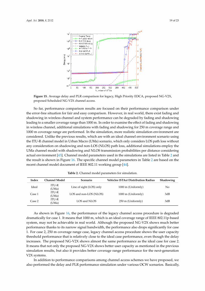
Appl. Sci. 2018, 8, 2112 19 of 23
Appl. Sci. 2018, 8, x FOR PEER REVIEW 19 of 24
To examine the performance of the scheduled NG-V2X channel access, we compared the performance with that of legacy channel access, high-priority EDCA (HP-EDCA) and (nonscheduled) NG-V2X in Figure 15. HP-EDCA is the IEEE 802.11p channel access procedure with high priority channel access parameters (AC_VO). Some studies have shown that applying the highest priority access category (AC_VO) to IEEE 802.11p channel access procedure improves its channel access efficiency through their analysis and simulation results [41,42]. As can be observed, scheduled NG-V2X shows higher user capacity performance than legacy channel access, HP-EDCA and NG-V2X cases we have stated. Although scheduled NG-V2X not only requires a more preliminary procedure including timing synchronization and RU indication but is also less adaptive than nonscheduled NG-V2X, it shows attractive user capacity performance gains.
Figure 15. Average delay and PLR comparison for legacy, High Priority EDCA, proposed NG-V2X, proposed Scheduled NG-V2X channel access.
So far, performance comparison results are focused on their performance comparison under the error-free situation for fair and easy comparison. However, in real world, there exist fading and shadowing in wireless channel and system performance can be degraded by fading and shadowing leading to a smaller coverage range than 1000 m. In order to examine the effect of fading and shadowing in wireless channel, additional simulations with fading and shadowing for 250 m coverage range and 1000 m coverage range are performed. In the simulation, more realistic simulation environment are considered. Unlike the previous results, which are with an ideal channel environment scenario using the ITU-R channel model in Urban Macro (UMa) scenario, which only considers LOS path loss without any consideration on shadowing and non-LOS (NLOS) path loss, additional simulations employ the UMa channel model with shadowing and NLOS transmission probabilities per distance considering actual environment [43]. Channel model parameters used in the simulations are listed in Table 2 and the result is shown in Figure 16. The specific channel model parameters in Table 2 are based on the recent channel model document of IEEE 802.11 working group [44].
Table 2. Channel model parameters for simulation.
Index Channel Model Scenario Vehicles (STAs) Distribution Radius Shadowing
Ideal ITU-R (UMa)
Line of sight (LOS) only 1000 m (Uniformly) No
Case 1 ITU-R (UMa)
LOS and non-LOS (NLOS) 1000 m (Uniformly) 3dB
Case 2 ITU-R (UMa)
LOS and NLOS 250 m (Uniformly) 3dB
Figure 15. Average delay and PLR comparison for legacy, High Priority EDCA, proposed NG-V2X,proposed Scheduled NG-V2X channel access.
So far, performance comparison results are focused on their performance comparison underthe error-free situation for fair and easy comparison. However, in real world, there exist fading andshadowing in wireless channel and system performance can be degraded by fading and shadowingleading to a smaller coverage range than 1000 m. In order to examine the effect of fading and shadowingin wireless channel, additional simulations with fading and shadowing for 250 m coverage range and1000 m coverage range are performed. In the simulation, more realistic simulation environment areconsidered. Unlike the previous results, which are with an ideal channel environment scenario usingthe ITU-R channel model in Urban Macro (UMa) scenario, which only considers LOS path loss withoutany consideration on shadowing and non-LOS (NLOS) path loss, additional simulations employ theUMa channel model with shadowing and NLOS transmission probabilities per distance consideringactual environment [43]. Channel model parameters used in the simulations are listed in Table 2 andthe result is shown in Figure 16. The specific channel model parameters in Table 2 are based on therecent channel model document of IEEE 802.11 working group [44].
Table 2. Channel model parameters for simulation.
Index Channel Model Scenario Vehicles (STAs) Distribution Radius Shadowing
Ideal ITU-R(UMa) Line of sight (LOS) only 1000 m (Uniformly) No
Case 1 ITU-R(UMa) LOS and non-LOS (NLOS) 1000 m (Uniformly) 3dB
Case 2 ITU-R(UMa) LOS and NLOS 250 m (Uniformly) 3dB
As shown in Figure 16, the performance of the legacy channel access procedure is degradeddramatically for case 1. It means that 1000 m, which is an ideal coverage range of IEEE 802.11p-basedsystem, may not be achievable in real world. Although the proposed NG-V2X shows much betterperformance thanks to its narrow signal bandwidth, the performance also drops significantly for case1. For case 2, 250 m coverage range case, legacy channel access procedure shows the user capacitythreshold performance that is relatively close to the ideal case performance, even though the delayincreases. The proposed NG-V2X shows almost the same performance as the ideal case for case 2.It means that not only the proposed NG-V2X shows better user capacity as mentioned in the previoussimulation results, but also it provides better coverage range performance for the next-generationV2X systems.
In addition to performance comparisons among channel access schemes we have proposed, wealso performed the delay and PLR performance simulation under various OCW scenarios. Basically,

Appl. Sci. 2018, 8, 2112 20 of 23
it is easily expected that a too small OCW may cause frequent collisions and a too large OCW maycause unnecessary channel access delay. To check the exact influence of the OCW, we performedV2X-UORA channel access simulation multiple times with different OCW values and a fixed numberof users. Figure 17 shows the simulation results in the case of two-band transmission. In Figure 17a,b,we cannot observe an exact tendency unlike in the case with various number of STAs that we haveanalyzed. However, it is obvious that there are some sweet spot ranges for a given number of STAs,as in Figure 17a. Therefore, if the OCW value makes the delay converged without packet loss for agiven number of STAs, obtaining a specific optimal value of the OCW is not a critical issue becausethe sweet spot range that meets QoS requirements is wide enough. Thus, it can be interpreted as thecontrolling OCW not requiring extremely sensitive and immediately adaptive algorithms. Based onsensing results of sensor nodes and incoming data packets, a V2X infrastructure STA can control theOCW value with a relatively long-term decision-making algorithm.Appl. Sci. 2018, 8, x FOR PEER REVIEW 20 of 24
Figure 16. Average delay and PLR comparison between legacy and proposed NG-V2X for various channel cases (ideal channel case, case 1 and case 2).
As shown in Figure 16, the performance of the legacy channel access procedure is degraded dramatically for case 1. It means that 1000 m, which is an ideal coverage range of IEEE 802.11p-based system, may not be achievable in real world. Although the proposed NG-V2X shows much better performance thanks to its narrow signal bandwidth, the performance also drops significantly for case 1. For case 2, 250 m coverage range case, legacy channel access procedure shows the user capacity threshold performance that is relatively close to the ideal case performance, even though the delay increases. The proposed NG-V2X shows almost the same performance as the ideal case for case 2. It means that not only the proposed NG-V2X shows better user capacity as mentioned in the previous simulation results, but also it provides better coverage range performance for the next-generation V2X systems.
In addition to performance comparisons among channel access schemes we have proposed, we also performed the delay and PLR performance simulation under various OCW scenarios. Basically, it is easily expected that a too small OCW may cause frequent collisions and a too large OCW may cause unnecessary channel access delay. To check the exact influence of the OCW, we performed V2X-UORA channel access simulation multiple times with different OCW values and a fixed number of users. Figure 17 shows the simulation results in the case of two-band transmission. In Figure 17a,b, we cannot observe an exact tendency unlike in the case with various number of STAs that we have analyzed. However, it is obvious that there are some sweet spot ranges for a given number of STAs, as in Figure 17a. Therefore, if the OCW value makes the delay converged without packet loss for a given number of STAs, obtaining a specific optimal value of the OCW is not a critical issue because the sweet spot range that meets QoS requirements is wide enough. Thus, it can be interpreted as the controlling OCW not requiring extremely sensitive and immediately adaptive algorithms. Based on sensing results of sensor nodes and incoming data packets, a V2X infrastructure STA can control the OCW value with a relatively long-term decision-making algorithm.
Figure 16. Average delay and PLR comparison between legacy and proposed NG-V2X for variouschannel cases (ideal channel case, case 1 and case 2).
Appl. Sci. 2018, 8, x FOR PEER REVIEW 21 of 24
(a)
(b)
Figure 17. Average delay and PLR in two bands transmission over UORA congestion window (CW) value: (a) Below user capacity threshold (190 STAs); (b) Below user capacity threshold (200 STAs).
6. Conclusions
We presented the analysis of UORA channel access and the performance enhancement of the proposed V2X-UORA channel access procedure to support IEEE 802.11p-based NG-V2X systems. Unlike conventional IEEE 802.11p channel access, the proposed V2X-UORA channel access does not reduce the average channel access delay when more channel bandwidth is used. This means that using conventional IEEE 802.11p channel access is still a good option if a V2X application requires a much lower delay in a sparse STAs scenario. However, the proposed V2X-UORA exhibits better user capacity performance in terms of meeting the QoS delay requirement in wideband transmission and dense STAs scenarios. This means that the proposed V2X UORA is a more suitable channel access method for dense V2X STAs scenarios. Furthermore, we examined how dedicated RU-based V2X UORA channel access considerably enhances V2X user capacity performance. If the IEEE 802.11p-based NG-V2X system considers sensor STAs gathering traffic information, the proposed V2X UORA with dedicated RUs need to be considered. As we observed in the analysis of the UORA procedure, the UORA contention window can affect UORA channel access performance. Fortunately, we could observe that controlling OCW can be performed with a long-term decision-making algorithm because the performance does not change dramatically if the UORA CW value lies in the range of the UORA CW sweet spot. Because all proposed methods in this paper are designed under the consideration of backward compatibility and real implementation, they can be expected to be considered as an option in the NG-V2X channel access procedure.
Author Contributions: Conceptualization, J.A.; Data curation, J.A.; Formal analysis, J.A.; Funding acquisition, R.Y.K.; Investigation, J.A. and R.Y.K.; Methodology, J.A. and R.Y.K.; Project administration, R.Y.K.; Resources, R.Y.K.; Software, J.A.; Supervision, Y.Y.K. and R.Y.K.; Validation, Y.Y.K. and R.Y.K.; Writing—original draft, J.A.; Writing—review & editing, Y.Y.K. and R.Y.K.
Funding: This research was supported by Basic Science Research Program through the National Research Foundation of Korea (NRF) funded by the Ministry of Science, ICT & Future Planning, grant number NRF-2017R1A2B4003987.
Conflicts of Interest: The authors declare no conflict of interest.
References
1. Kenney, J.B. Dedicated Short-Range Communications (DSRC) Standards in the United States. Proc. IEEE 2011, 99, 1162–1182, doi:10.1109/JPROC.2011.2132790.
2. ETSI. ETSI TR 101 607 (v1.1.1), Intelligent Transport Systems (ITS), Cooperative ITS (C-ITS), Release 1; ETSI: Sophia Antipolis, Valbonne, France, 2013.
3. 3GPP. 3GPP TS 36.300: Evolved Universal Terrestrial Radio Access (E-UTRA) and Evolved Universal Terrestrial Radio Access Network (E-UTRAN), Overall Description Stage 2; 3GPP: Sophia Antipolis, Valbonne, France, 2018.
Figure 17. Average delay and PLR in two bands transmission over UORA congestion window (CW)value: (a) Below user capacity threshold (190 STAs); (b) Below user capacity threshold (200 STAs).

Appl. Sci. 2018, 8, 2112 21 of 23
6. Conclusions
We presented the analysis of UORA channel access and the performance enhancement of theproposed V2X-UORA channel access procedure to support IEEE 802.11p-based NG-V2X systems.Unlike conventional IEEE 802.11p channel access, the proposed V2X-UORA channel access does notreduce the average channel access delay when more channel bandwidth is used. This means that usingconventional IEEE 802.11p channel access is still a good option if a V2X application requires a muchlower delay in a sparse STAs scenario. However, the proposed V2X-UORA exhibits better user capacityperformance in terms of meeting the QoS delay requirement in wideband transmission and dense STAsscenarios. This means that the proposed V2X UORA is a more suitable channel access method for denseV2X STAs scenarios. Furthermore, we examined how dedicated RU-based V2X UORA channel accessconsiderably enhances V2X user capacity performance. If the IEEE 802.11p-based NG-V2X systemconsiders sensor STAs gathering traffic information, the proposed V2X UORA with dedicated RUsneed to be considered. As we observed in the analysis of the UORA procedure, the UORA contentionwindow can affect UORA channel access performance. Fortunately, we could observe that controllingOCW can be performed with a long-term decision-making algorithm because the performance doesnot change dramatically if the UORA CW value lies in the range of the UORA CW sweet spot. Becauseall proposed methods in this paper are designed under the consideration of backward compatibilityand real implementation, they can be expected to be considered as an option in the NG-V2X channelaccess procedure.
Author Contributions: Conceptualization, J.A.; Data curation, J.A.; Formal analysis, J.A.; Funding acquisition,R.Y.K.; Investigation, J.A. and R.Y.K.; Methodology, J.A. and R.Y.K.; Project administration, R.Y.K.; Resources,R.Y.K.; Software, J.A.; Supervision, Y.Y.K. and R.Y.K.; Validation, Y.Y.K. and R.Y.K.; Writing—original draft, J.A.;Writing—review & editing, Y.Y.K. and R.Y.K.
Funding: This research was supported by Basic Science Research Program through the NationalResearch Foundation of Korea (NRF) funded by the Ministry of Science, ICT & Future Planning, grantnumber NRF-2017R1A2B4003987.
Conflicts of Interest: The authors declare no conflict of interest.
References
1. Kenney, J.B. Dedicated Short-Range Communications (DSRC) Standards in the United States. Proc. IEEE2011, 99, 1162–1182. [CrossRef]
2. ETSI. ETSI TR 101 607 (v1.1.1), Intelligent Transport Systems (ITS), Cooperative ITS (C-ITS), Release 1; ETSI:Sophia Antipolis, Valbonne, France, 2013.
3. 3GPP. 3GPP TS 36.300: Evolved Universal Terrestrial Radio Access (E-UTRA) and Evolved Universal TerrestrialRadio Access Network (E-UTRAN), Overall Description Stage 2; 3GPP: Sophia Antipolis, Valbonne, France, 2018.
4. IEEE. IEEE Standard for Information Technology—Telecommunications and Information Exchange betweenSystems—Local and Metropolitan Area Networks—Specific Requirement, Part 11: Wireless LAN Medium AccessControl (MAC) and Physical Layer (PHY) Specifications; IEEE: Piscataway, NJ, USA, 2010.
5. Le, L.; Festag, A.; Baldessari, R.; Zhang, W. Vehicular wireless short-range communication for improvingintersection safety. IEEE Commun. Mag. 2009, 47, 104–110. [CrossRef]
6. Vukadinovic, V.; Bakowski, K.; Marsch, P.; Garcia, I.D.; Xu, H.; Sybis, M.; Sroka, P.; Wesolowski, K.; Lister, D.;Thibault, I. 3GPP C-V2X and IEEE 802.11p for vehicle-to-vehicle communications in highway platooningscenarios. Ad Hoc Netw. 2018, 74, 17–29. [CrossRef]
7. Uhlemann, E. Introducing Connected Vehicles [Connected Vehicles]. IEEE Veh. Technol. Mag. 2015, 10, 23–31.[CrossRef]
8. Chan, E. Overview of the SARTRE Platooning Project; SAE Technical Paper; SAE: Warrendale, PA, USA, 2012.[CrossRef]
9. Tsugawa, S.; Kato, S.; Aoki, K. An automated truck platoon for energy saving. In Proceedings of the2011 IEEE/RSJ International Conference on Intelligent Robots and Systems, San Francisco, CA, USA,25–30 September 2011; pp. 4109–4114.

Appl. Sci. 2018, 8, 2112 22 of 23
10. European Truck Platooning Challenge. Available online: https://www.eutruckplatooning.com (accessed on4 September 2018).
11. Sun, B.; Zhang, H. IEEE 802.11-18/0861 802.11 NGV Proposed PAR. Available online: https://mentor.ieee.org/802.11/dcn/18/11-18-0861-06-0ngv-ieee-802-11-ngv-sg-proposed-par.docx (accessed on4 September 2018).
12. Delice, M.D.; Ghandour, A.J.; Artail, H.; Bononi, L. Enhancing the performance of safety applications inIEEE 802.11p/WAVE Vehicular Networks. In Proceedings of the 2012 IEEE International Symposium on aWorld of Wireless, Mobile and Multimedia Networks (WoWMoM), San Francisco, CA, USA, 25–28 June 2012;pp. 1–9.
13. Antonopoulos, A.; Skianis, C.; Verikoukis, C. Network coding-based cooperative ARQ scheme for VANETs.J. Netw. Comput. Appl. 2013, 36, 1001–1007. [CrossRef]
14. Gerla, M.; Lee, E.; Pau, G.; Lee, U. Internet of vehicles: From intelligent grid to autonomous cars andvehicular clouds. In Proceedings of the 2014 IEEE World Forum on Internet of Things (WF-IoT), Seoul, Korea,6–8 March 2014; pp. 241–246.
15. Kwon, D.; Park, S.; Baek, S.; Malaiya, R.K.; Yoon, G.; Ryu, J. A study on development of the blind spotdetection system for the IoT-based smart connected car. In Proceedings of the 2018 IEEE InternationalConference on Consumer Electronics (ICCE), Las Vegas, NV, USA, 12–14 January 2018; pp. 1–4.
16. Hobert, L.; Festag, A.; Llaster, I.; Altomare, L.; Visintainer, F.; Kovacs, A. Enhancements of V2X communicationin support of cooperative autonomous driving. IEEE Commun. Mag. 2015, 53, 64–70. [CrossRef]
17. Kokuti, A.; Hussein, A.; Marin-plaza, P.; de la Escalera, A.; Garcia, F. V2X communications architecturefor off-road autonomous vehicles. In Proceedings of the 2017 IEEE International Conference on VehicularElectronics and Safety (ICVES), Vienna, Austria, 27–28 June 2017; pp. 69–74.
18. Cao, H.; Gangakhedkar, S.; Ali, A.R.; Gharba, M.; Eichinger, J. A 5G V2X testbed for cooperative automateddriving. In Proceedings of the 2016 IEEE Vehicular Networking Conference (VNC), Columbus, OH, USA,8–10 December 2016; pp. 1–4.
19. Kapitulík, J.; Micek, J.; Jurecka, M.; Hodon, M. Wireless sensor network—Value added subsystem of ITScommunication platform. In Proceedings of the 2014 Federated Conference on Computer Science andInformation Systems, Warsaw, Poland, 7–10 September 2014; pp. 1017–1023.
20. Bajwa, R.; Rajagopal, R.; Varaiya, P.; Kavaler, R. In-pavement wireless sensor network for vehicle classification.In Proceedings of the 10th ACM/IEEE International Conference on Information Processing in SensorNetworks, Chicago, IL, USA, 12–14 April 2011; pp. 85–96.
21. Liu, Z.; Liu, Z.; Meng, Z.; Yang, X.; Pu, L.; Zhang, L. Implementation and performance measurement of aV2X communication system for vehicle and pedestrian safety. Int. J. Distrib. Sens. Netw. 2016, 12. [CrossRef]
22. Seo, H.; Lee, K.; Yasukawa, S.; Peng, Y.; Sartori, P. LTE evolution for vehicle-to-everything services. IEEECommun. Mag. 2016, 54, 22–28. [CrossRef]
23. Stibor, L.; Zang, Y.; Reumerman, H. Evaluation of Communication Distance of Broadcast Messages in aVehicular Ad-Hoc Network Using IEEE 802.11p. In Proceedings of the 2007 IEEE Wireless Communicationsand Networking Conference, Kowloon, China, 11–15 March 2007; pp. 254–257.
24. Gonzalvez, J.; Sepulcre, M.; Bauza, R. IEEE 802.11p vehicle to infrastructure communications in urbanenvironments. IEEE Commun. Mag. 2012, 50, 176–183. [CrossRef]
25. Bilstrup, K.; Uhlemann, E.; Strom, E.G.; Bilstrup, U. Evaluation of the IEEE 802.11p MAC Method forVehicle-to-Vehicle Communication. In Proceedings of the 2008 IEEE 68th Vehicular Technology Conference,Calgary, BC, Canada, 21–24 September 2008; pp. 1–5.
26. Gukhool, B.S.; Cherkaoui, S. IEEE 802.11p modeling in NS-2. In Proceedings of the 2008 33rd IEEE Conferenceon Local Computer Networks (LCN), Montreal, QC, Canada, 14–17 October 2008; pp. 622–626.
27. Yao, Y.; Rao, L.; Liu, X.; Zhou, X. Delay analysis and study of IEEE 802.11p based DSRC safety communicationin a highway environment. In Proceedings of the 2013 Proceedings IEEE INFOCOM, Turin, Italy,14–19 April 2013; pp. 1591–1599.
28. Masini, B.M.; Bazzi, A.; Zanella, A. A Survey on the Roadmap to Mandate on Board Connectivity and EnableV2V-Based Vehicular Sensor Networks. Sensors 2018, 18, 2207. [CrossRef] [PubMed]
29. Campolo, C.; Molinaro, A.; Berthet, A.O. Full-duplex communications to improve platooning control inmulti-channel VANETs. In Proceedings of the 2017 IEEE International Conference on CommunicationsWorkshops (ICC Workshops), Paris, France, 21–25 May 2017; pp. 936–941.
Appl. Sci. 2018, 8, 2112 23 of 23
30. Bazzi, A.; Masini, B.M.; Zanella, A.; Thibault, I. On the Performance of IEEE 802.11p and LTE-V2V for theCooperative Awareness of Connected Vehicles. IEEE Trans. Veh. Technol. 2017, 66, 10419–10432. [CrossRef]
31. Rakouth, H.; Alexander, P.; Brown, A., Jr.; Kosiak, W.; Fukushima, M.; Ghosh, L.; Hedges, L.; Kong, H.;Kopetzki, S.; Siripurapu, R.; et al. V2X Communication Technology: Field Experience and ComparativeAnalysis. Proc. FISITA 2012 World Automot. Congress 2012, 200, 113–129. [CrossRef]
32. Kanchanasut, K.; Boonsiripant, S.; Tunpan, A.; Kim, H.K.; Ekpanyapong, M. Internet of cars throughcommodity V2V and V2X mobile routers: Applications for developing countries. KSCE J. Civ. Eng. 2015, 19,1897–1904. [CrossRef]
33. Naranjo, J.E.; Jiménez, F.; Anaya, J.J.; Talavera, E.; Gómez, O. Application of vehicle to another entity (V2X)communications for motorcycle crash avoidance. J. Intell. Trans. Syst. 2017, 21, 285–295. [CrossRef]
34. Haran, O.; Sarris, I. NGV Terminology. In Proceedings of the IEEE 802 Plenary Session, San Diego, CA, USA,8–13 July 2018; IEEE: Picastaway, NJ, USA.
35. Hartenstein, H.; Laberteaux, L.P. A tutorial survey on vehicular ad hoc networks. IEEE Commun. Mag. 2008,46, 164–171. [CrossRef]
36. Wang, Q.; Leng, S.; Fu, H.; Zhang, Y. An IEEE 802.11p-Based Multichannel MAC Scheme with ChannelCoordination for Vehicular Ad Hoc Networks. IEEE Trans. Intell. Trans. Syst. 2012, 13, 449–458. [CrossRef]
37. Lanante, L.; Uwai, H.O.T.; Nagao, Y.; Kurosaki, M.; Ghosh, C. Performance analysis of the 802.11axUL OFDMA random access protocol in dense networks. In Proceedings of the 2017 IEEE InternationalConference on Communications (ICC), Paris, France, 21–25 May 2017; pp. 1–6.
38. Zhang, Y.; Li, B.; Yang, M.; Yan, Z.; Zuo, X. An OFDMA-based joint reservation and cooperation MACprotocol for the next generation WLAN. Wirel. Netw. 2017, 1–15. [CrossRef]
39. Lee, G.; Kim, C. Centralized Contention Based MAC for OFDMA WLAN. IEICE Trans. Inf. Syst. 2017,E100-D, 2219–2223. [CrossRef]
40. Bianchi, G. Performance analysis of the IEEE 802.11 distributed coordination function. IEEE J. Sel.Areas Commun. 2000, 18, 535–547. [CrossRef]
41. Zheng, J.; Wu, Q. Performance Modeling and Analysis of the IEEE 802.11p EDCA Mechanism for VANET.IEEE Trans. Veh. Technol. 2016, 65, 2673–2687. [CrossRef]
42. Togou, M.A.; Khoukhi, L.; Hafid, A. IEEE 802.11p EDCA performance analysis for vehicle-to-vehicleinfotainment applications. In Proceedings of the 2017 IEEE International Conference on Communications(ICC), Paris, France, 21–25 May 2017; pp. 1–6.
43. ITU-R. M.2135-1: Guidelines for Evaluation of Radio Interface Technologies for IMT-Advanced; ITU-R: Geneva,Switzerland, 2009.
44. Liu, J. IEEE 802.11-14/0882r4 IEEE 802.11ax Channel Model Document. Available online: https://mentor.ieee.org/802.11/dcn/14/11-14-0882-04-00ax-tgax-channel-model-document.docx (accessed on17 October 2018).
© 2018 by the authors. Licensee MDPI, Basel, Switzerland. This article is an open accessarticle distributed under the terms and conditions of the Creative Commons Attribution(CC BY) license (http://creativecommons.org/licenses/by/4.0/).


![How does enabling XMP affect anything? [Solved] -RAM -Memory](https://static.fdokumen.com/doc/165x107/632359814d8439cb620cdda2/how-does-enabling-xmp-affect-anything-solved-ram-memory.jpg)