
Developing a collaborative knowledge sharing framework to promote English learning retention
Upload
khangminh22Category
view
0download
0
A KNOWLEDGE BASED FRAMEWORK FOR PLANNING
HOUSE BUILDING PROJECTS
by
CARLOS TORRES FORMOSO
A thesis submitted to the
UNIVERSITY OF SALFORD
for the degree of
DOCTOR OF PHILOSOPHY
University of Salford
Department of Quantity and Building Surveying
February 1991

TABLE OF CONTENTS
TABLE OF CONTENTS (i)
LIST OF TABLES AND ILLUSTRATIONS (viii)
ACKNOWLEDGEMENTS (xx)
ABSTRACT (xxii)
CHAPTER 1: INTRODUCTION
1.1 The emergence of knowledge engineering 1
1.2 Knowledge based systems and expert systems 3
1.3 The relevance of knowledge engineering for theconstruction industry
1.4 The motivation for the work 6
1.5 Aims of the research 9
1.6 Outline of the thesis 11
CHAPTER 2: THE PLANNING TASK
2.1 Introduction 13
2.2 Planning in general
2.2.1 Definition of planning 13
2.2.2 Planning models 15
2.3 Planning in construction management
2.3.1 The complexity of construction 17
2.3.2 The role of planning 17
2.3.3 The vertical dimension of planning J9
2.3.4 The horizontal dimension of planning 21
2.3.5 Construction planning in practice
2.3.5.1 Preparation of plans 22
2.3.5.2 Information gathering 25
2.3.5.3 Information diffusion 26
2.3.6 Improving the effectiveness of formal planning 27
2.4 Summary and conclusions 27
CHAPTER 3: ARTIFICIAL INTELLIGENCE IN CONSTRUCTION PLANNING
3.1 Introduction 29
3.2 Artificial intelligence applications for planning
3.2.1 Domain independent planning systems 29
(i)

3.2.2 Domain specific planning systems 31
3.3 Conventional knowledge based systems 32
3.4 Tools and languages 33
3.5 Al applications for construction planning
3.5.1 Early models of expertise 34
3.5.2 Time 35
3.5.3 Elsie 36
3.5.4 Callisto 37
3.5.5 Construction Planex 38
3.5.6 CONSAS 38
3.5.7 Platform 39
3.5.8 Mason 40
3.5.9 GHOST 40
3.5.10 MIRCI 41
3.5.11 Ratu-aj 42
3.5.12 SIPEC 42
3.5.13 OARPLAN 43
3.5.14 PREDICTE 43
3.5.15 Discussion 44
3.6 Guidelines for this research 47
3.7 Summary and conclusions 49
CHAPTER 4: A CHARACTERIZATION OF HOUSE BUILDING
4.1 Introduction 51
4.2 The progress of work in house building
4.2.1 Comparing repetitive building to a production line 52
4.2.2 The low intensity of work 54
4.2.3 The spreading of work to various construction units 55
4.2.4 Lack of continuous flow of work 55
4.2.5 The overlapping of theoretically sequential activities 58
4.2.6 Varying rate of deployment of resources 59
4.2.7 Lack of compulsory sequence of work 60
4.3 The role of key resources 60
4.4 The natural rhythm 62
4.5 Predicting the production process
4.5.1 The chaotic nature of construction 63
4.5.2 The use of mathematical and statistical models 65
4.5.3 The application of knowledge based models 67
4.6 Summary and conclusions 68

CHAPTER 5: THE DEVELOPMENT OF THE APPLICATION
5.1 Introduction 69
5.2 Choice of a methodology
5.2.1 Lack of an adequate methodology 70
5.2.2 Proposed methodology 71
5.3 Conceptual stage
5.3.1 Investigating the availability of expertise 72
5.3.2 Knowledge elicitation techniques 75
5.3.3 The development of the prototype
5.3.3.1 Knowledge elicitation 78
5.3.3.2 Software tool used 80
5.3.3.3 Knowledge analysis and implementation 81
5.4 A more detailed specification of the system
5.4.1 Task model 82
5.4.2 Role of the application 84
5.4.3 Types of knowledge 85
5.4.4 Context knowledge 86
5.4.5 Outputs of the system 87
5.4.6 Inputs of the system 89
5.4.7 Man-machine interface 89
5.5 Choice of the shell
5.5.1 Crystal 91
5.5.2 Criteria used in the selection 91
5.5.3 Comparison of the alternatives
5.5.3.1 Xi Plus 94
5.5.3.2 Savoir 94
5.5.3.3 Leonardo 95
5.5.3.4 Goldworks 95
5.5.4 Final decision 96
5.6 Model building stage
5.6.1 Participation of more experts 98
5.6.2 The development of the working system
5.6.2.1 Knowledge acquisition 99
5.6.2.2 Elicitation techniques 100
5.6.2.3 Issues related to the involvementmultiple experts 102
5.7 Summary and conclusions 103
CHAPTER 6 AN ANALYSIS OF THE EXPERTS' APPROACH
6.1 Introduction 106
6.2 Main planning sub-tasks 106
6.3 Forming a description of the job
6.3.1 Organizing the relevant variables 108
6.3.2 Default data 112
6.4 Establishing the sequence of construction
6.4.1 Dividing the job into work places 113
6.4.2 Sequence of work places 115
6.5 Dividing the Work into activities
6.5.1 General approach 116
6.5.2 Work breakdown criteria 117
6.5.3 Selection of activities 119
6.6 Establishing the pace of work
6.6.1 Types of activities 121
6.6.2 General approach 122
6.6.3 Shell peak rate
6.6.3.1 The experts' approach 124
6.6.3.2 Choice of the learning curve 123
6.6.3.3 A model for estimating theproductivity of bricklayers 129
6.6.4 Finishing peak rate 131
6.6.5 Foundation peak rate 133
6.6.6 Relationships between peak rates 134
6.6.7 Rate profiles 137
6.6.8 Pace of site preparation and landscapeactivities 139
6.7 Defining the profile of activity starts
6.7.1 General approach 140
6.7.2 A model for establishing activity precedencerelationships
6.7.2.1 Main elements of the model 141
6.7.2.2 Activity dependencies 142
6.7.2.3 Link type 144
6.7.2.4 Floats and overlapping 145
6.7.3 Definition of constraints 146
6.8 Assembling the plans 147
6.9 Summary and conclusions 149
(iv)

CHAPTER 7 DESCRIPTION OF THE APPLICATION
7.1 Introduction 152
7.2 General view of the system 152
7.3 Internal structure of the system
7.3.1 Rules and frames 155
7.3.2 Class objects 158
7.3.3 Procedures 159
7.3.4 Organizing the knowledge in modules 159
7.3.5 Inference control mechanism 163
7.3.6 Man-machine interface facilities
7.3.6.1 Default screens 163
7.3.6.2 Screen design utility 165
7.3.6.3 Screens generated by procedures 166
7.4 Input module
7.4.1 Main consultation steps 167
7.4.2 Content of each group of variables
7.4.2.1 General information 169
7.4.2.2 Design parameters 169
7.4.2.3 Site conditions 170
7.4.2.4 Specification of components 170
7.4.2.5 Sequence of construction 170
7.5 Context module 171
7.6 Build module
7.6.1 Main consultation steps 172
7.6.2 Establishing the pace of work 173
7.6.3 Selecting activities and defining profile ofactivity starts 175
7.6.4 Final steps 176
7.7 Lessons learnt from the implementation of the system 180
7.8 Summary and conclusions 184
CHAPTER 8: VALIDATION OF THE SYSTEM
8.1 Introduction 186
8.2 Software quality models 187
8.3 Difficulties in validating of knowledge based systems
8.3.1 The nature of models of expertise 189
8.3.2 Validation criteria 189
8.3.3 Gold standard 190
8.3.4 Test cases 190
(v)

8.3.5 When to validate 191
8.3.6 Cost of validation 191
8.3.7 Control of bias 192
8.3.8 Complex results 192
8.3.9 Disagreement between experts 192
8.4 Techniques currently used 193
8.5 Validation of the implemented system
8.5.1 Practical constraints 195
8.5.2 General view of the validation process 196
8.5.3 Predictive validation
8.5.3.1 General description 198
8.5.3.2 Total project duration 199
8.5.3.3 Activity content 202
8.5.3.4 House completion time 205
8.5.3.5 Pace of work 208
8.5.3.6 Activity dependencies 211
8.5.3.7 Durations of bar chart activities 211
8.5.4 Robustness tests 213
8.5.5 Sensitivity tests 216
8.5.6 Field tests 218
8.5.7 Face validation 219
8.6 Summary and conclusions 220
CHAPTER 9: CONCLUSIONS
9.1 Summary of conclusions 223
9.2 Lessons for the future
9.2.1 Knowledge acquisition 224
9.2.2 Model of expertise 225
9.2.3 Implementation of the system 226
9.2.4 Model validation 227
9.3 Suggestions for further work 228
GLOSSARY 231
APPENDIX 1: DATABASE OF BUILDING STEREOTYPES
234
APPENDIX 2: LIST OF CONSTRUCTION ACTIVITIES 235
( vi )

APPENDIX 3: PRODUCTIVITY INDICES
A3.1 Design simplicity 236
A3.2 Work concentration 237
A3.3 Geographical continuity 237
A3.4 Design repetitiveness 238
APPENDIX 4: A TYPICAL CONSULTATION SESSION TO THE SYSTEM
A4.1 Input Module 239
A4.2 Context Module 280
A4.3 Build Module 294
APPENDIX 5: AN EXAMPLE OF SCHEDULE OF CONSTRUCTION ACTIVITIES 310
BIBLIOGRAPHICAL REFERENCES 312

LIST OF TABLES AND FIGURES
Table 2.1: Degree of detail of plans for each level of 20management
Figure 2.1: A model of the planning and control process
22
Figure 5.1: The knowledge acquisition process
72
Figure 5.2: Levels of construction planning
82
Figure 5.3: Example of construction programme generatedby the expert
88
Table 5.1: Comparison of four shells 97
Figure 6.1: Main planning sub-tasks 107
Figure 6.2: Hierarchy of main construction elements 109
Figure 6.3: Hierarchy of alternative infra-structureelements 110
Figure 6.4: Hierarchy of site elements geometric variables 110
Figure 6.5: Hierarchy of concrete geometric variables 111
Table 6.1: Main factors that affect the selection ofactivities 120
Figure 6.6: Line of balance typically found in thehistorical cases 123
Figure 6.7: Line of balance usually found in text books 123
Figure 6.8: A model for estimating the productivity ofbricklayers 131
Figure 7.9: Strategy adopted for establishing maximumfinishing rate 133
Figure 7.10: Resources considering for choosing thefoundation rate
134
Figure 6.11: Typical shapes of construction programmes 136
Figure 6.12: Non cumulative "S" curve adopted for theapplication
138
Table 6.2: Ranges of parameters for rate profiles 138
Figure 6.13: Activity precedence model 142
Figure 7.1: General view of the system 154

Figure 7.2: Main ruleset of the Input module 156
Figure 7.3: Examples of object frames 157
Figure 7.4: Example of quantification rule 159
Figure 7.5: Ruleset concerned with road construction 160
Figure 7.6: Frame for the activity "roof carcass" 162
Figure 7.7: Example of input screens 164
Figure 7.8: Main consultation steps in the Input module 168
Figure 7.9: Main consultation steps in the Build module 174
Figure 7.10: Ruleset used for choosing ground flooractivities 175
Figure 7.11: An example of resource schedule 177
Figure 7.12: A construction programme in a bar chart form 178
Figure 7.13: A schedule of milestones 179
Table 8.1: Summarized description of test cases 198
Table 8.2: Comparison of total durations 201
Table 8.3: Comparison of No. of activities 202
Table 8.4: Activities included in the system's plans butnot in the experts' 204
Table 8.5: Activities included in the experts' plans butnot in the system's 204
Table 8.6: Comparison of house completion times 206
Table 8.7: Comparison of activity lead-lag times 207
Table 8.8: Comparison of average building rates 209
Table 8.9: Rate profiles adopted by the experts 210
Table 8.10: Main conflicts in the activity dependencies 212
Table 8.11: Comparison of bar chart activity durations 214-215
Figure 8.1: Some examples of sensitivity tests 217
Table 8.12: Analysis of the effect of project size 218

ACKNOWLEDGEMENTS
I would like to express my gratitude to Prof. Peter Brandon for his
most appreciated guidance and encouragement.
I also would like to thank CAPES (Postgraduate Education Federal
Agency from the Brazilian Government) for the financial support.
Many thanks to Ian Hilton, Mike Cotgrave, Mark Hingenbotham, Colin
Mawson, Bill Robinson, David Betterton, and Martin Ward, the experts
that provided the expertise for carrying out this research. Without
their help it would not have been possible to carry out this research.
I am grateful to Drs. Ian Watson, Arkadi Retik, and Mustapha
Alshawi for their very helpful constructive criticism.
Thanks also to North Housing Association for the information
provided.
I wish to extent my gratitude to the staff of the Federal
University of Rio Grande do Sul, Department of Civil Engineering for
their encouragement to undertake this work, especially to Dr. Luiz F.
Heineck and Prof. Jose S. Franco.
Finally, I wish to say a very personal thank you to my family for
their continuous support and love.
(x)

TO LISA

ABSTRACT
This thesis describes the development of a knowledge based system
which encapsulates some of the expertise used by a number of
experienced construction planners for planning the construction stage
of low rise house building projects in the U.K.
The general objective of the research was to investigate the
feasibility of using knowledge engineering for developing models of
construction planning expertise, which could be employed for tackling
some of the existing knowledge bottlenecks in the construction
industry.
The resulting system can be described as a knowledge based
framework designed for supporting the decision making process involved
in planning house building at a tactical level. One of the main
features of this framework is its ability to cope with incomplete
information.
The knowledge acquisition process involved both the elicitation
of knowledge directly from experts, and the analysis of construction
plans from several past housing developments. The model was
implemented on an expert system shell called LEONARDO Level 3, which
runs in any standard IBM-PC micro-computer or compatibles.
The evaluation of the system focused on the validity of the
model, i.e. the degree at which the outcomes of the system resembled
the outcomes of the human expertise being modelled in the knowledge
base. A prescriptive method of validation was devised specifically for
this study, involving both experts that had provided expertise for the
system, and external experts.

CHAPTER I: INTRODUCTION
1.1 The emergence of knowledge engineering
Artificial intelligence is a branch of computer science that
emerged in the Fifties, concerned with symbolic processing, as opposed
to numeric processing. Nowadays, this field deals with the issue of
designing and programming machines that emulate humans, by appearing
to be intelligent or by mimicking human intelligence or human problem
solving (Fenves, 1987). It covers a number of diverse areas, such as
natural language processing, image recognition, knowledge engineering,
and robotics. Newton (1986) stated that the term artificial
intelligence is a misnomer, since this topic covers not only
intelligence but also all the qualities that distinguish the human
from the empty box, such as flexibility, reasoning, communication,
etc.
Knowledge engineering is the process of encapsulating knowledge
into computer systems to solve problems that normally require human
attention and intelligence, using knowledge representation and
processing techniques from the field of artificial intelligence
(Sagalowicz, 1984). Such systems are popularly known as expert systems
or knowledge based systems.
The need for knowledge engineering has emerged because traditional
software engineering has some limitations in supporting decision-
making. The application of conventional computer programs has been
limited to very definite and routine tasks, for the following reasons:
(i) Conventional computer programs are developed in a prescriptive
manner. Every sequential step must be determined in the very early
stages of development, like someone else's interpretation of the
problem - not the user's (Newton, 1986);
(ii) They are primarily designed for computer efficiency, rather
than for human understanding. Usually only their developers are able
to understand and modify them (Lansdown, 1982);
(iii) They cannot provide the user with justification for their
results nor explain why they need a particular piece of information
(Lansdown, 1982); and

(iv) Information is usually input in a standardised way and they
cannot perform their task if any piece of information is missing
(Hamilton & Harrison, 1986).
On the other hand, many important problems do not have tractable
algorithmic solutions. They originate in complex social or physical
contexts, in which the available information is often "noisy", full of
uncertainty and errors, incomplete, and sometimes inconsistent
(Schutzer, 1987).
Ortolano & Perman (1987) pointed out that there are two basic
characteristics that distinguish knowledge based systems from
conventional computer programmes. The first one, often termed as
transparency, refers to the ability of a user to stop a program in the
middle, in order to find out why a particular question is asked or
what reasoning was used by the system to deduce a particular
conclusion. The second distinctive feature is that the knowledge
pertaining to a problem, placed in the knowledge base, is kept
distinct and separate from the procedures, or inference mechanism,
which manipulate that knowledge.
There are some other characteristics commonly associated with
knowledge based systems, which may also be found occasionally in
conventional programs. These are:
(i) They contain a great deal of information about very specific
domains (Lansdown, 1982);
(ii) They give advice in a way similar to a consultant (Lansdown,
1982);
(iii) Uncertain data to reach probable conclusions can be used
(Hamilton & Harrison, 1986); and
(iv) The knowledge is represented in a very explicit and uniform
way, normally embodied in separate modules (Lansdown, 1982).
Brandon et al. (1988) stated that knowledge based systems have
expanded the range of problems that can be tackled by the use of
computers. As these systems represent a more human-like form of
computing than do conventional systems, they allow computers to deal
with less structured problems. However, those authors stressed that
the current state of knowledge engineering does not allow knowledge
2

based systems to replace completely domain experts in all kinds of
problems. Knowledge based systems still have a number of shortcomings
in comparison to human thinking capabilities, such as:
(i) Knowledge based systems can only be used for relatively deep
and narrow areas of knowledge (Brachman et al., 1983);
(ii) They cannot take into account the kind of wide-range
information that humans use for solving some problems (Brandon et al.,
1988);
(iii) They cannot easily process the unstructured information that
is usually obtained by human senses, such as touch, smell, sound, or
sight (Basden, 1983); and
(iv) They are not able to easily discover similarities between
complex, non-identical objects (Brandon et al., 1988).
Sagalowicz (1984) stated that the most important benefit from
extracting knowledge from humans and representing it in a computable
form is the reduction in the costs of knowledge reproduction and
exploitation, specially in domains where there is a knowledge
bottleneck, i.e. fields where knowledge is unavailable, poorly
distributed, difficult to maintain, update or organise.
In the long term, knowledge based systems have the potential of
becoming depositories of knowledge for specific domains. Because the
knowledge base is usually an explicit representation of domain
knowledge, it is possible to maintain it in a form which is accessible
for more than one kind of use Schutzer (1987). Some authors, such as
Kidd & Welbank (1984) and Hayes-Roth et al. (1983), pointed out that
the ultimate importance of knowledge engineering may be in
formalising, structuring and making public an expert's knowledge,
rather than in the production of high performance computer programs.
1.2 Knowledge based systems and expert systems
Some authors make a distinction between the terms "experts system"
and "knowledge based system". Harmon & King (1985), for instance,
referred to expert systems as large systems, and to knowledge based
systems as small systems.
Ibbs (1986) reported on a seminar about the future for computerized
construction research in the USA, in which a distinction was made
3

between "expert system", "knowledge based system" and "knowledge based
expert system". An "expert system" was defined as a computer program
that contains some particular human expertise (surface knowledge),
based exclusively on heuristics or rules of thumb. On the other hand,
a "knowledge based system" was regarded as being founded on knowledge
of physical processes (deep knowledge). The term "knowledge based
expert system" was used to describe systems that combines both surface
and deep knowledge.
However, there seems to be no widely accepted definition for any of
them. In practice, the terms "expert system" and "knowledge based
system" have interchangeably been used to describe a wide range of
computer systems that are able to hold human-like knowledge as well as
to process this knowledge in a more human-like fashion than do
conventional computer systems (Basden, 1983; Fenves, 1987).
The expression "expert system" suggests that such a system captures
knowledge from experts. In reality, these systems very rarely contain
knowledge that has been exclusively elicited from humans (Harmon &
King, 1985). For this reason, the term "knowledge based system" was
chosen to be used throughout this thesis. It generally refers to all
computer systems that have both the characteristics of transparency of
knowledge, and separation between the knowledge base and the inference
engine, as discussed above.
1.3 The relevance of knowledge engineering for the construction
industry
Several authors, such as Lansdown (1982), Wager (1984), De La Garza
& Ibbs (1986) and Ashley & Levitt (1987), have pointed out that the
nature of the construction industry puts it in a position to get many
benefits from artificial intelligence techniques, and, in particular,
of knowledge engineering. They all agree that the great potential of
knowledge engineering in construction is related to the fact that
knowledge from experts, such as designers, planners, managers, and
estimators, is intensively used in this industry during all phases of
the construction process.
Construction projects are characterized by a high variability,
resulting from both its one-off production technology and from
external influences such as weather, site conditions, regulatory
4

agencies, etc. (Bishop, 1972). The decision making process must be
fast, and is very much influenced by site- and time-specific events,
involving both technical and managerial issues (Levitt, 1986). Also,
the acquisition of meaningful data to use in formal optimization
models is difficult and costly to obtain, since the processes involved
in construction are far less repetitive than in the traditional
manufacturing industry (Wager, 1984). For these reasons, practical
experience and intuition are much more fruitful sources of knowledge
in construction than are scientific investigation or mathematical
modelling (Levitt, 1986).
There seems to be a considerable number of knowledge bottlenecks
amongst the several distinct specialities involved. Traditionally, the
industry is faced with a sharp division between the design team and
the construction team (Bishop, 1972; Gray, 1983). The design team
usually does not have access to the construction team's expertise, and
vice versa. Also, the increasing sophistication of construction
projects have forced a further partitioning of the design activity
into a number of specialized disciplines (Newton, 1986; Logcher,
1989).
As a result, there is a large number of independent organizations
involved in the construction process, each one having its own
specialists. Specialist groups are frequently physically separated
from each other, which makes their inter-communication difficult.
Moreover, some of these organizations operate in a relatively small
scale, and cannot afford to have as many highly qualified experts as
they need.
Knowledge based systems have the potential of providing individual
organizations involved in the construction process with some expertise
which is needed, but that is not available directly from their staff.
This could greatly improve the quality of decision making in
construction. Even large companies which have a wide range of
specialists are able to get benefit from the use of knowledge based
systems, by freeing the experts available to give more attention to
less trivial tasks.
Another important potential role for knowledge engineering in
construction is training (Basden, 1983). Experts usually gain their
knowledge through experience, long periods of training,
apprenticeship, and observation. The learning process normally takes
5

many years, and may be expensive in the case experience is gained
through mistakes made in real situations. The access of students to
the formalized domain knowledge could improve the cost-effectiveness
of their training, and shorten the learning period needed to become an
expert. Also, this type of knowledge based system can protect an
organization from the loss of expertise when key experts retire or
leave for other jobs.
The potential of knowledge engineering for refining construction
expertise is highlighted, amongst others, by Ashley & Levitt (1987).
They pointed out that, because construction research has not reached
much beyond the empirical stage, there is a potential for knowledge
based systems to become "an important stepping stone toward a robust
body of theory" in this field.
1.4 The motivation for the work
The initial motivation for this study was the issue of improving
the effectiveness of the construction industry. The author comes from
Brazil, a third world country that has a tremendous shortage of good
quality buildings. The country is faced with a colossal housing
deficit, which has been estimated as something between six and seven
million dwellings for the following ten years, as well as with a large
shortage of hospitals, schools, and other public buildings (FundacZo
Joao Pinheiro, 1984). At the same time, there is a high potential
demand for civil engineering investments, since the country needs
urgently to improve the amount and quality of public services provided
to its population, such as water supply, sanitation, electricity, and
transportation.
The resources available to carry out so many building and civil
engineering projects at the same time are limited. The amount of money
the government has been able to invest in such projects during the
last twelve years has been drastically cut because of the huge
external debt which the country is faced with (Roddick, 1988).
Pressure for a rational use of resources also comes from the need to
preserve the environment. The extensive use of some natural resources,
such as hardwood, aluminium, crushed rocks, sand, etc., has been
recently associated to the rapid destruction of the natural
environment.
6

Construction planning is one of the knowledge intensive tasks
within the construction process that is closely related to the aim of
improving the effectiveness of construction projects in terms of cost,
time, and quality. Baker et al. (1979) described a survey amongst
people experienced in project management, in which satisfaction with
the project and control system was perceived as an important factor
for the success of a project. The Business Roundtable (1982) report
concluded that an effective use of planning techniques can potentially
improve methods of project management, leading to shorter durations of
construction projects, and, consequently, to cost savings to clients.
Arditi (1985) reported on two studies conducted at the Illinois
Institute of Technology, in which planning received the highest score
in terms of importance amongst contractors as one of the factors of
productivity improvement in construction, at company headquarters.
Construction planning usually involves the choice of alternative
construction technologies, the definition of work tasks, the
estimation of required resources and durations of individual tasks,
and the identification of any interactions or constraints amongst
different tasks (Hendrickson et al., 1987).
There are indications that this domain is suitable for knowledgeengineering applications. It is a very time consuming task (Laufer &
Tucker, 1988), and the domain experts generally perform it in a very
intuitive and unstructured fashion, with a great deal of reliance on
their judgement (Hendrickson et al., 1987; Levitt & Kunz, 1985). The
ill-structured nature of the problem makes it difficult to develop a
precise and efficient algorithm for generating plans and monitoring
construction projects (McGartland & Hendrickson, 1985; Navinchandra et
al., 1988). Moreover, a knowledge bottleneck exists because the number
of experts available is very small (Mason, 1984; Gray, 1986; Levitt et
al., 1988), training people in this field takes a considerably long
time, and there are very few textbooks that contain real expertise.
Since the introduction of the first software tools for construction
planning in the early Sixties, computers have had relatively little
impact in supporting decision making in this field. Levitt & Kunz
(1985), Hendrickson et al. (1987), and Echeverry et al.(1989) pointed
out that most existing commercial tools are completely knowledge
independent, i.e. the knowledge which experts use for defining
activities, estimating durations, and establishing the pace of work
7

cannot be captured and re-used by these tools. They all agreed that
such tools are employed only as a computer aided framework where
planners input their decisions whenever a new cycle of planning is
performed. Also, the reasoning used for making the programme is not
made available to other people involved in the subsequent stages of
planning, for tasks such as interpreting and updating the schedule,
evaluating project performance, and performing real time control
(Levitt & Kunz, 1985).
Several authors have claimed that there is a demand for knowledge
based tools for construction planning, which could expand the expert's
capability to manipulate and utilise qualitative and experiential
information, making production planning a less painstaking task, and
freeing experts for the work that essentially requires human decisions
(Levitt & Kunz, 1985; Hendrickson et al., 1987; Logcher, 1987;
Warszawski, 1988). They also stressed that explanation facilities
available in such systems could be useful for providing credibility
for correct decisions, as well as for highlighting decisions which are
inconsistent.
Knowledge based tools for construction planning also seem to have a
great potential amongst contractors that do not have a scale of
operation in which it is cost effective to employ highly qualified
construction planners. In such companies this task is usually carried
out in a very informal way by people that have only general knowledge
about the domain, or that do not have enough time to perform formal
planning. Knowledge engineering could provide the means for these
companies to access some of the expertise they lack, quickly, and at a
reasonable cost.
The innovating effect that models of construction planning
expertise can potentially have in terms of enhancing the communication
between design and production have drawn the attention of several
authors, such as Flanagan (1980), Gray (1986), Atkin (1987), Beeston
(1987).
Cost planning procedures have been systematically used in the UK by
consultant quantity surveyors, seeking to improve the economic
performance of construction projects. It is widely accepted that cost
planning is most effectively applied during the early design stages,
when the major cost significant decisions are made (Ferry & Brandon,
1980).
8

The cost models traditionally employed by quantity surveyors, based
on price information collected in bills of quantities from past
projects, have suffered intense criticism from researchers in the
field of cost estimating. Beeston (1987) stated that the way in which
construction prices are estimated in such models has only a remote
relationship to the way costs are incurred on site, making it
difficult to examine accurately the effect of design changes in the
production costs. A research study carried out at the University of
Reading (1981) suggested that the most hopeful source of more
efficient improvement in the quantity surveyors' method of estimating
lies in considering the way construction costs actually arise on site.
Another drawback of the traditional cost planning methods is the fact
that, although time usually is a factor of major importance for
construction projects, such methods do not offer any reliable guide
for the relationship between design and the duration of activities on
site (Flanagan, 1980).
The main obstacle for the use of contractors' cost estimating
techniques for cost planning is the fact that the design team do not
have enough expertise about construction methods. Although non
conventional forms of contracting have been used in order to bring the
advice of contractors to the early design stages, the contractor's
role still commences too late during the design process to have a
major impact in the economic efficiency of a project (Gray, 1983).
Unless the structure of the construction industry radically
changes, it seems that knowledge engineering is the most promising
means through which the existing knowledge bottleneck between the
contracting side of the industry and the design team can be overcome.
Knowledge engineering has the potential of being used for developing
sound models of construction planning expertise. Such models could be
used by clients and their consultants for considering the effect that
their decisions are likely to have in the production process.
1.5 Aims of the research
Based on the discussion presented in the previous sections, three
hypotheses were formulated. These are:
(i) Knowledge engineering can provide tools for improving the
construction planning experts' capability of manipulating qualitative
9

and experiential information, removing some of the painstaking work
from their hands, as well as allowing them to analyse a large number
of construction alternatives in a short time;
(ii) Knowledge engineering can improve the integration of the
construction industry by establishing a knowledge link between the
construction team and the design team. Such link consists of making
available to the design team construction planning expertise that
could be used for several tasks, such as estimating the amount of
resources required, forecasting the project duration, etc.; and
(iii) Knowledge engineering can provide the means for formalizing,
structuring, and refining a robust body of knowledge on construction
planning, that can be accessed for more than one kind of use,
improving the dissemination of expertise within the industry as well
as being used as a basis for establishing the research needs in this
field.
Considering the limitations of this research project in terms of
time and resources available, the decision was made to focus the
research on testing the first hypothesis. Based on that, the general
objective of this study was established. It consists of investigating
the feasibility of using knowledge engineering for developing models
of construction planning expertise, which could be applied for
tackling some of the existing knowledge bottlenecks in the
construction industry.
This investigation was carried out by developing a practical
application, which encapsulates knowledge elicited from a number of
construction planning experts from the industry. The specific
objectives of such development are depicted below:
(i) To examine the suitability of available knowledge elicitation
techniques and methodologies specifically for developing applications
in the field of construction planning, considering the practical
constraints of carrying out the study in collaboration with the
industry;
(ii) To understand the nature of the expertise employed by
construction planners in practice, and to find out how much of this
expertise can be modelled in a knowledge engineering application;
(iii) To analyse the difficulties of implementing a model of
10

construction planning expertise as a knowledge base system, in
relation to issues such as knowledge representation, inference
control mechanism, man-machine interface, etc.; and
(iv) To assess the extent to which the expertise encapsulated in a
knowledge based system for construction planning can be formally
validated.
Although the scope of the study excludes formally examining the
second and third hypotheses outlined above, this research can also be
expected to provide some guidance towards their investigation in
further studies.
1.6 Outline of the thesis
The thesis is divided in two main parts. The first part comprises
Chapters 1 to 4, and consists of a review of the theoretical
background which this research is based on. The second one embodies
Chapters 5 to 8, and focuses on the description of the knowledge
engineering application.
Chapter 2 discusses the planning problem, with particular emphasis
on the task of planning the production stage of construction projects.
It also examines the limited impact that the traditional construction
planning techniques have had in the construction industry.
Chapter 3 provides a general discussion on the application of
artificial intelligence techniques to construction planning. It
reviews some of the main knowledge engineering applications developed
in this field so far, and establishes a number of general guidelines
for the development of the application.
Chapter 4 presents a general description of the production process
involved in house building. Such description is mostly based on
several activity sampling studies which have particularly investigated
this kind of project.
Chapter 5 covers some basic aspects of the application, such as
system specification, sources of knowledge, knowledge elicitation
techniques, and software tool choice. The basic structure of the model
of expertise developed in this research is presented in Chapter 6,
while Chapter 7 concentrates on describing the main features of the
implemented system.
11

Chapter 8 discusses the problem of validating knowledge based
systems, as well as describes the approach adopted in the current
study. Finally, a summary of the conclusions, lessons for the future,
and suggestions for further research are given is Chapter 9.
Through this thesis, the author uses a number of expressions widely
used in the field of artificial intelligence, such as rules, frames,
forward and backward chaining, object oriented programming, etc. The
meaning of such expressions have been exhaustively defined in several
publications. They can also be found in the glossary of terms
presented at the end of this work.
12

CHAPTER 2: THE PLANNING TASK
2.1 Introduction
Planning is a cognitive activity familiar to everyone. It plays a
key role in decision making by enabling individuals to deal with
changing and complex situations. Planning influences a wide range of
activities, from the most trivial ones, such as how to get to work in
the morning, to the most consequential, such as the allocation of
resources in a country's economy. Plans are used, either formally or
informally, for guiding any activity that has not been entirely
automatized (Hoc, 1988).
Planning is one of the essential ingredients of construction
management. Although a lot of research has been made during the last
few decades, some dissatisfaction with the application and results of
construction planning still remains (Business Roundtable, 1983; Laufer
& Tucker, 1987). However, it seems that people involved in
construction management still consider that a more effective approach
to construction planning can bring considerable improvements in the
performance of the industry (Baker et al., 1979, Business Roundtable,
1983; Arditi, 1985).
This chapter initially discusses the meaning of planning as well as
the basic cognitive mechanisms that are behind the planning task. The
second part of the chapter is devoted to the role of planning in
construction management. The vertical and horizontal dimensions of
planning throughout a construction project are discussed, and the
major deficiencies of construction planning in practice are presented.
2.2 Planning in general
2.2.1 Definition of planning
There is a large number of distinct definitions of planning as far
as the literature in this field is concerned. Hayes-Roth & Hayes-Roth
(1979) defined planning as the first stage of a two stage problem-
solving process named 'planning and control', in which planning is the
predetermination of a course of action aimed at achieving a certain
goal, and control consists of monitoring and guiding the execution of
the plan to a successful conclusion. Hoc (1988) defined planning as
13

making a decision on the basis of predictions of the probable outcome
of a situation through extrapolation from past events, considering
that the decision to act usually has the effect of modifying the
events to more satisfactory goals. Laufer & Tucker (1987) accepted the
definition of planning as a decision making process performed in
advance of action that attempts both to design a future and effective
ways of achieving it. In summary, planning can be defined as the
process of setting goals and establishing the procedures to attain
them, being only effective if intertwined with the process of
controlling activity execution.
According to Hoc (1988), planning mechanisms intervene in
situations where a response cannot be obtained from rules triggered by
current environment information. He also points out that when this
occurs, individuals must anticipate on future information, usually in
a schematic fashion, based on previously acquired information.
Therefore, if a task requires a totally new elaboration, no
anticipation and, consequently, no planning can be carried out.
Uncertainty about the future is a common feature of most problems
involving planning, since much of the knowledge human beings use for
anticipation is qualitative, uncertain, and judgmental, defying
rigorous analysis (Fiksel & Hayes-Roth, 1989). In very unpredictable
situations, individuals may have to elaborate plans in the form of
working hypothesis (Hoc, 1988).
The necessity of using a schematic representation of a task is a
consequence of both the limited capacity of the human working memory
and the uncertainty involved in anticipation. When dealing with very
complex problems, individuals usually abstract only a number of
relevant data from details, increasing the portion of problem space
that they are able to tackle, resulting in the construction of
schematic representations. Additionally, a schematic representation
enables plans that are generated in a very uncertain environment to
remain probable, since they can summarize a large family of possible
alternative solutions. This schematization process raises the level of
control a human being has over an activity (Hoc, 1988).
The choice of the level of representation is usually a kind of
compromise, since it must be detailed enough in order to be able to
guide activity, but it must also be schematic enough so as to cope
14

with the limited capacities of individuals' working memory (Hoc,
1988). Plans for very simple tasks include very detailed information,
at a level close to activity execution. Complex and uncertain problems
need plans at a higher level, where only strategic information is
taken into consideration.
Plans can be state anticipations, named declarative plans (e.g. an
architectural plan), or procedure anticipations, known as procedural
plans (e.g. a computer programme). They are often not only schematic,
but also hierarchical, since their structure expresses the
organization levels of what they represent as well as the relations
between these levels (Hoc, 1988).
The planning process can be assumed to operate in a two dimensional
planning space, the two dimensions being time and abstraction level
(Hayes-Roth & Hayes-Roth, 1979). The lowest abstraction level is named
'basic level', where plans include all the detailed information
necessary for action execution (Hoc, 1988).
2.2.2 Planning models
Although it is accepted that planning is a multi-stage, multi-level
process, some describe it as a top-down, systematic, complete, and
hierarchical process, while others hold that people plan in a multi-
directional, incremental, and heterarchical mode (Laufer & Tucker,
1987). None of the cognitive models of planning proposed so far have
been widely accepted as reliable by researchers in the field of
planning (Laufer & Tucker, 1988).
Early models of planning, adopted in pioneering artificial
intelligence systems, described planning as a top-down, systematic,
complete, and hierarchical process (Hoc, 1988). They assume that plans
are initially generated at the more abstract levels, and are
successively refined into the lower level spaces, towards the basic
level. Also, they presuppose that complete plans exist at all levels
of abstraction and that all decisions involved fit a hierarchical
structure.
• Hayes-Roth & Hayes-Roth (1979) proposed a less rigid approach to
planning, named "opportunistic" model. This approach assumes that
planning involves both coherent and incoherent decision sequences, in
extreme cases appearing to be chaotic. The opportunistic approach
15

assumes that planning is a multi-directional, incremental, and
heterarchical process.
Multi-directional means that both top-down and bottom-up processing
are simultaneously employed, i.e. conclusions arisen from planning at
a more abstract level can guide subsequent planning at a lower level,
and vice versa. The incremental aspect of planning is concerned with
the fact that complete plans are rarely produced for each abstract
level, and that tentative solutions are proposed without the
requirement of fitting into a higher level integrated plan. In other
words, a developing plan does not necessarily grow as a coherent
integrated plan. Finally, heterarchical means that some of the
planning decisions does not fit into a single hierarchical structure
(e.g. decisions about how to allocate cognitive resources).
Hayes-Roth & Hayes-Roth (1979) regarded the top-down, systematic,
complete and hierarchical approach as a particular case of the
opportunistic model. They stress that both models are suitable for
describing different situations, and suggest a number of variables
that can influence the approaches adopted by planners in particular
problems. These are:
(i) Problem characteristics: some problems have an inherent
hierarchical structure that planners can naturally use in their
schematic representations. Also, individuals tend to adopt a top-down
approach if a problem imposes severe time constraints;
(ii) Expertise: an experienced planner working on a familiar,
constrained problem may have well-learned, reliable abstract plans
available. In cases where planners are not so experlenced, or the
problem is relatively unconstrained, opportunistic methods tend to be
more advantageous; and
(iii) Individual preferences: some individuals have a strong
preference for bottom-up approach, regardless of problem
characteristics, while others are more flexible, adopting an
appropriate approach in response to problem characteristics or
instructions.
16

2.3 Planning in construction management
2.3.1 The complexity of construction
A construction project usually poses a unique problem to the people
involved in managing the production process (Bennett & Ormerod, 1984).
The design and location of each project are distinct from all others.
A large number of different organizations and individuals are involved
in the design and in the production process, each one having a
different set of priorities and objectives (Bishop, 1972).
Construction generally involves a large number of different
technologies, as well as alternative combinations of labour and
equipment. Additionally, a large number of imponderable factors are
bound to affect the production process, such as weather, material
shortages, labour problems, unknown sub-surface conditions, inaccurate
estimates of durations and cost, changes in the design, etc. (Levitt,
1986). All these considerations make the problems that construction
managers have to face of a type and magnitude not usually found in
other industries (Bennett & Ormerod, 1984).
Considering the limited capacity of human working memory,
construction managers normally need some kind of formal plans that can
expand their capacity for understanding complex situations.
Construction plans can be regarded as procedural plans, since they
anticipate and represent in a schematic way a group of actions to be
executed. However, before generating a construction plan, planners
need to translate all the information available, such as architectural
plans (brief, sketch design, or detailed design), and site conditions
(if known), into another abstract representation of the project. Such
representation is possibly a sort of declarative plan, which consists
of the planner's own view of the final product, expressed in terms of
its main construction components.
2.3.2 The role of planning
People involved in construction management are required to perform
a large number of functions (Harrison, 1985; Neale & Neale, 1989),
which can be classified under four main headings: guiding execution,
co-ordination, control, and searching for improved solutions. The
basic role of planning is to assist managers to fulfil each of those
functions (Laufer & Tucker, 1987).
17
Guiding execution is concerned with directing the parties involved
in the implementation of a project. A construction plan can be seen
as a model of the installation of components and assemblies, which
provides information about the tasks required, their sequence, their
duration, and their required resources (Echeverry et al., 1989). Plans
can be used as either direct assignments or at least as guidelines for
lower management to make decisions later on (Laufer & Tucker, 1987).
The second function consists of providing a means of communication
amongst the different project participants, such as owner, designers,
site management, sub-contractors, suppliers, etc. This is done by
informing which tasks each participant is expected to do (Echeverry et
al., 1989). Here, the planning role is focused on harmonizing and
facilitating clusters of tasks that are characterized by a high degree
of interdependence (Laufer & Tucker, 1987).
Control involves measuring and evaluating performance, and taking
corrective actions in order to ensure that the course of action is
maintained and the project goals are reached. In this respect,
planning must establish the targets and the course of action to attain
such goals , in a format that is convenient to the control function
(Echeverry et al., 1989).
Searching for improved solutions is concerned with generating and
comparing several alternative plans for the production process, in
terms of cost, time, and demand for resources. This function can be
carried out at different points in the construction stage. For
example, alternative plans can be used at the design stage for
comparing a number of design solutions from the point of view of the
duration of the construction stage (GRAY, 1983). Contingency planning
could also be included under this heading. It consists of preparing
several plans for likely contingencies in order to minimize response
time when a new plan is needed (Laufer & Tucker, 1987).
Planning the construction process is a highly complex task that
involves a large number of activities, a great deal of uncertainty,
being usually subjected to a number of conflicting constraints, such
as time, space, cost, and availability of resources (Levitt, 1986).
Consequently, the optimization approach, often employed in other
engineering fields, is largely ineffective in construction practice
(Warszawski, 1987). Generally construction planning searches for an
18

acceptable, or feasible arrangement of actions, rather than an optimum
one.
2.3.3 The vertical dimension of planning
In most medium and large construction projects, construction
management is usually carried out by a number of different people,
each one tackling the problem at a distinct level of specificity.
The different levels of management for which plans are produced define
a vertical dimension of the planning process.
Laufer & Tucker (1987), for instance, divided construction
management in three levels: top, middle and lower management. Top
management is mostly involved in setting the objectives of a project.
Middle management is more involved in selecting the resources for
reaching those objectives. And finally, lower management assists
middle management in selecting and devising the solutions.
Each level of management requires construction plans at a
convenient degree of detail. If plans contain too many details, a long
time is needed to elaborate and update them, making them ineffective
to influence short term decisions. Also, very detailed plans can make
the planning and control process very expensive and time-consuming,
since a huge amount of paper work is necessary, both for issuing
instructions and for reporting the work carried out. On the other
hand, if activities are planned without the necessary details, a plan
cannot fulfil its functions of execution, co-ordination and control,
since important relationships between activities can be lost, and
major deviations in the course of the project cannot be picked up by
the control system.
The most adequate level of detail of a plan is also affected by the
level of uncertainty, as discussed in Section 2.2. In a highly
unpredictable environment such as construction, changes often disrupt
the original plans, making frequent modifications necessary.
Otherwise, plans become out of date, losing the confidence of users
very quickly (Harrison, 1985). Plans that contain too many details may
be ineffective in the presence of high uncertainty, due to the
excessive effort needed for constantly updating them.
Several authors, such as Nuttal (1965), Bishop, (1972); Harrison
(1985), and Neale & Neale (1989) suggested that very unpredictable
19

situations can be more effectively dealt with by giving lower level
management some discretion in the day-to-day work. In this case, plans
must have some degree of flexibility, working as a general framework
where lower level managers can fit their decisions. This approach is
what Neale & Neale (1989) named as dynamic planning.
The construction process is often divided into fundamental units of
work, named work packages, each one consisting of a continuous action
taken by an operative or group of operatives working together, without
being interrupted by any other gang (Forbes, 1977). The amount of work
packages in each project usually ranges from several hundreds to
dozens of thousands, depending on the complexity and size of the work
to be done (Harrison, 1985).
Plans for top managers are usually much less detailed than the work
package level. They are first generated early in the project cycle,
often before its location and design are known, integrating the
production activities into a more general framework, which includes
also events related to other stages of the building process, such as
design, contractual procedures, and commissioning the project (Neale &
Neale, 1989).
The level of work package is probably convenient for site
managers, who have to co-ordinate and control the work of all gangs.
At a lower level of management, such as first level supervisors on
site, or sub-contractors, plans probably have to be elaborated at a
level of detail finer than the work package level, since the work of
each operative has to be controlled on a short term basis. Table 2.1,
extracted from Neale & Neale (1989), illustrates the level of detail
plans are likely to have among the different levels of management.
MANAGEMENTLEVEL
POSITIONIN THE COMPANY
TIMESCALE
LEVEL OFDETAIL
TIMEUNIT
Top
Middle
Lower
Managingdirector
Constructionmanager
Site managerSub-contractorsForeman
From feasibilityto commissioning
Tendering andproduction phases
Production phaseStages of workStages of work
Project phases
Stages of work
Work packageWork package/TaskTask
month
week
daydayday
Table 2.1: Degree of detail of plans for each level of management(compiled from Neale & Neale, 1986)
20
In summary, construction planning can be described as a multi-stage
process, carried out by people situated at several different levels in
the management hierarchy. The higher the level of management, the more
comprehensive, abstract the plans are, and the greater the uncertainty
involved in planning. Whether this process can be better described as
a top-down, systematic, complete, and hierarchical process, or as
multi-directional, incremental, heterarchical process is a question
still to be answered.
2.3.4 The horizontal dimension of planning
Project planning should be a continuous process which starts at the
conception of the project and extends until the project has reached
satisfactory conditions (Harrison, 1985). The horizontal dimension of
planning is concerned with the different phases involved in this
continuous process, as well as with their timing.
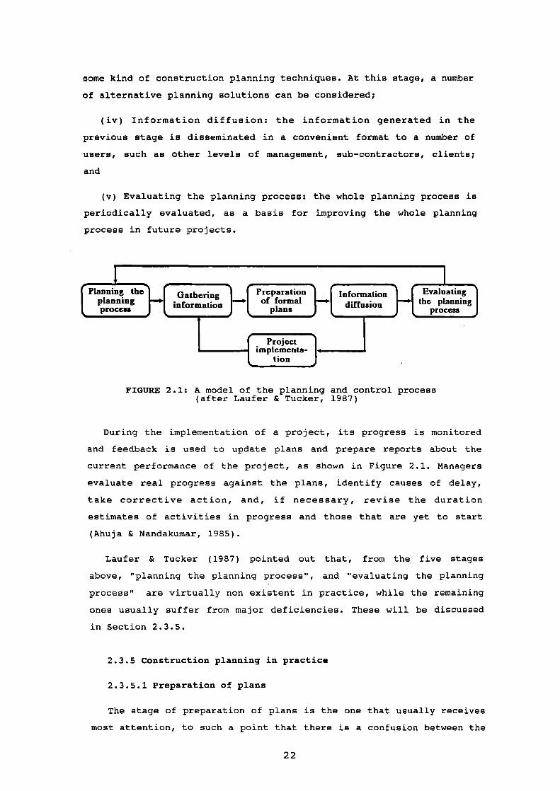
Laufer & Tucker (1987) describes a theoretical model of the
planning and control process in construction, reproduced in the Figure
2.1, which contains features that are often prescribed by textbooks in
the field of project management, such as Harrison (1985), and Neale &
Neale (1989). In this model, the planning process is divided into five
stages, as follows:
(i) Planning the planning process: a number of key decisions
concerning the planning process is made at this stage, such as what
plans are needed, how they will be used, how detailed they will be,
what techniques will be appropriate, when the plans will be prepared,
etc. (Harrison, 1985). Projects that are unique are likely to require
more effort at this stage than the ones that are carried out in a
routine basis;
(ii) Information gathering: this stage generally requires a
considerable amount of resources (Laufer & Tucker, 1987). There are
several sources of information at the beginning of the project, such
as design, contract documents, report on site conditions, data about
labour productivity, and constraints or goals imposed by higher level
management or by the client. Additionally, information concerning the
actual progress on site has to be collected throughout the production
stage;
(iii) Preparation of formal plans: the plans are worked out, using
21
e—I17:277)L.....
diffusion___________
Evaluatingthe planning
process
some kind of construction planning techniques. At this stage, a number
of alternative planning solutions can be considered;
(iv) Information diffusion: the information generated in the
previous stage is disseminated in a convenient format to a number of
users, such as other levels of management, sub-contractors, clients;
and
(v) Evaluating the planning process: the whole planning process is
periodically evaluated, as a basis for improving the whole planning
process in future projects.
1( Planning the' PreparationGatheringplanning
.—n of formal— informationnormaon plansprocess i iInMIO
Projectimplementa-
tion
FIGURE 2.1: A model of the planning and control process(after Laufer & Tucker, 1987)
During the implementation of a project, its progress is monitored
and feedback is used to update plans and prepare reports about the
current performance of the project, as shown in Figure 2.1. Managers
evaluate real progress against the plans, identify causes of delay,
take corrective action, and, if necessary, revise the duration
estimates of activities in progress and those that are yet to start
(Ahuja & Nandakumar, 1985).
Laufer & Tucker (1987) pointed out that, from the five stages
above, "planning the planning process", and "evaluating the planning
process" are virtually non existent in practice, while the remaining
ones usually suffer from major deficiencies. These will be discussed
in Section 2.3.5.
2.3.5 Construction planning in practice
2.3.5.1 Preparation of plans
The stage of preparation of plans is the one that usually receives
most attention, to such a point that there is a confusion between the
22

concepts of project management and construction planning, and the
application of planning techniques (Baker et. al., 1979).
There is a number of techniques that can be applied for the
preparation of plans (Gantt bar chart, linked bar chart, critical path
method, line of balance, etc.), each one having its own advantages and
disadvantages (Harrison, 1985; Neale & Neale, 1989). Critical path
method (CPM) based techniques have been usually accepted as the only
ones that are able cope with the large number of activities involved
in construction and their complex inter-relationships (Harrison,
1985). They are often mentioned as indispensable aids for planning and
scheduling construction projects (Levitt et al., 1988).
However, the success of CPM based techniques have been reported as
very limited, although they have been used for more than three
decades. A survey published by Davis (1974) indicated that, amongst
400 large construction companies in the USA, 45% of them never or
seldom used CPM. Another study regarding large companies in the same
country found that only 43% used CPM effectively (Business Roundtable,
1982). Allem (1988) reported that only 4.9% of a sample of CPM users
in the UK applied it in all projects and that 68.3% used it in less
than half of their projects.
The limitations of CPM have been extensively discussed by several
authors, such as Peer (1974), Birrel (1980), Roderick (1977), Parsons
(1983), Heineck (1983), Jaafari (1984), Trimble (1984), and White
(1985). Generally, CPM is criticized as being incompatible with the
essence of the construction process, since it was created for projects
of national importance in which cost control and efficient use of
resources had low priority compared to the project duration. In such
projects, contractors usually have central control over the resources
to be allocated, which does not exist in ordinary construction
projects, especially considering the increasing role of sub-
contractors in the industry (Piggot, 1972; Birrel, 1980). Other
important weaknesses of CPM techniques can be summarized as follows:
(i) CPM techniques do not attempt to ensure full continuity of work
for the gangs, which is the backbone of operational planning in
construction, since they refer mainly to technological constraints
rather than limitations of resources (Laufer & Tucker, 1987). Trimble
(1984) pointed out that scheduling a project is more efficiently
23
carried out if critical resources are used as a starting point, rather
than activities;
(ii) CPM is more suitable for sequential operations which
characterize an assembling type of work. Construction usually involves
a number of bulk operations, being similar to an installation type of
work, in which the detailed sequencing of activities is not very
important (Laufer & Tucker, 1987);
(iii) The sharp separation between the work of the various trades,
as assumed by CPM techniques, does not exist for the majority of
building activities, since they tend to overlap with a score of
preceding and succeeding items, instead of being in sequence (Heineck,
1984; Jackson, 1986). The timings of activities are not only linked by
start and finish relationships but also by rates of development
(Roderick, 1977);
(iv) Creating or updating a cPM network for complex projects is a
very time-consuming task that constantly requires the work of
construction planning experts (Bromilow, 1978; Parsons, 1983; Levitt &
Kunz, 1985). As discussed in Section 1.4, computers have had
relatively little impact in this task, since most commercial
scheduling tools require a complete construction plan as input. CPM
software packages merely carry out computations on data provided by
construction planners (Levitt et al., 1988). Laufer & Tucker (1987)
pointed out that the development of sophisticated CPM based computer
packages might have created the misconception that CPM techniques have
progressed more than they actually had;
(v) CPM techniques require plans to be elaborated in a bottom-up
approach, in which the crucial planning decisions are concerned with
detailed construction activities, such as duration, resource
allocations, probabilities, etc. On the other hand, research studies
carried out by Birrel (1980) and Gray & Little (1985b) indicated that,
in practice, planners' crucial decisions involve more general aspects
of a project, such as its division in work locations, the sequence of
work through these locations, and the pace of work; and
(vi) It has been reported that site managers have difficulties in
understanding the complexities of cPM networks (Birrel, 1980; Business
Roundtable, 1982; Allam, 1988).
Harrison (1985) and Allam (1988) reported that the disappointment
24

of several companies with CPM techniques have brought back to use the
technique of Gantt bar charts. Birrel (1980) and Harrison (1985)
pointed out that several companies carry out planning using CPM
primarily because of clients' demands. Furthermore, there is a growing
tendency to use CPM as an administrative tool for litigation and for
allocating contractual responsibilities, rather than as a planning
instrument (Jaafari, 1984; Royer, 1986).
The unavoidable frequent planning revisions and the long time
needed to update formal plans, undermine to a great extent the
influence that planning can have in regulating operations in a real
time basis (Laufer & Tucker, 1987). The cycle that involves the stages
of "information gathering", "preparation of formal plans",
"information diffusion", and "project implementation" (see Figure 2.1)
is often too slow, restricting the intended role of formal planning,
which is to regulate operations while in progress (Laufer & Tucker,
1989). Consequently, updating formal plans is usually an archival
record-keeping process, rather than a re-planning process (Levitt &
Kunz, 1985).
2.3.5.2 Information gathering
The major deficiency in the information gathering stage is the fact
that uncertainty is usually not adequately considered. One of the main
reason for that seems to be the scarcity of information about the
variability of labour performance, both in the industry and in
published sources. Duff (1980) and Bennett & Ormerod (1984) reported
on how the libraries of output rates kept by contractors have been
reduced to databases of single figures, in order to attend
deterministic demands of a commercial environment.
There have been attempts to develop simulation based planning
models that incorporate the effect of variability in the planning
process (Bennett & Ormerod, 1984; Ahuja & Nandakumar, 1985). However,
the insufficiency of data about variability and the difficulty of
accommodating the interdependency between variables involved have
highly restricted their application as a comprehensive and detailed
planning tool (Laufer & Tucker, 1987).
The usefulness of simulation techniques in practice has been
restricted to analysing the construction process in qualitative terms,
25

such as for comparing the importance of specific uncertainties in
relation to the main project objectives, or for highlighting thoseareas which would most benefit from attempts to reduce or control
uncertainty. This is the case, for instance, of the study carried out
by Legard (1983).
Laufer & Tucker (1987) reported that, besides the existing shortage
of information about variability, the majority of planners make very
little effort to seek additional information towards the use of
stochastic models of planning. In practice, planning is usually
carried out considering that variability is a brief intrusion into a
predictable sequence of operations, although it is an undisputed factthat variability is the norm rather than the exception in the
construction process (Heineck, 1983).
2.3.5.3 Information diffusion
The information diffusion stage suffers from two major
deficiencies. Firstly, individuals may be prejudiced against planning,
imposing obstacles to its implementation. This fact has been reported
both inside (O'Brien, 1984) and outside (Laufer & Tucker, 1987) the
construction industry. Secondly, an excessive amount of information,
organized in an inappropriate format can be as harmful as a shortage
(Laufer & Tucker, 1987; Birrel, 1980). The latter problem can be
aggravated by the introduction of computers, that often induce the
creation of over-elaborate, unnecessary, or irrelevant data (Mason,
1984).
Several authors offered evidence that project management currently
deals with two separate systems of information that coexist side by
side (Piggot, 1972; Trimble, 1984; Harrison, 1985; Laufer & Tucker,
1987; Levitt et. al., 1988). At a higher level the information systemis formal and has a limited effect on site execution. It is based on
the head office of the company and usually involves computerized
resources. Its main functions are to monitor the current status of
projects, and to keep historical data for future forecasts. At a lower
level, a system of informal information and decision making exists. It
is mainly situated at the site, and dictates the actual execution on a
short term basis.
Field managers often abandon CPM networks for more informal bar
charts or activity lists, when developing their detailed work plans
26

(Levitt et al., 1988). Harrison (1985) pointed out that, in extreme
cases, complicated looking plans are produced not to be used in the
management of the work on site, but are generated at the beginning of
the project and then left unchanged on the office walls, for
impressing clients.
2.3.6 Improving the effectiveness of formal planning
Laufer & Tucker (1987) argued that the lack of long term formal
planning in construction works against the effectiveness of the
industry as a whole, for the following reasons: (i) resources
requiring long lead time cannot be delivered early enough; (ii)
integrating the plans of several different projects is very difficult;
(iii) maintaining consistency between decisions from several levels of
management is not feasible; and (iv) improving efficiency of
production through the analysis of alternative construction methods is
ruled out.
Several suggestions have been made for improving the effectiveness
of formal planning, including adequate training of managers and
engineers (Arditi, 1983; Laufer & Tucker, 1987), concentrating
research efforts on other stages of planning - not so much on the
stage of preparation of formal plans (Laufer & Tucker, 1987); and the
application Jrartificial intelligence techniques to the planning and
control process (McGartland & Hendrickson, 1985; Levitt & Kunz, 1987;
Hendrickson et al., 1987; Navinchandra et al., 1988; Alshawi et al.,
1989).
The present research can be regarded as an attempt to improve the
effectiveness of formal planning in the construction industry, by
means of developing a knowledge engineering application in the field
of construction planning.
2.4 Summary and conclusions
Anticipation and schematization are the two basic mechanisms of the
planning task. Planning the production stage of construction projects
is a very difficult task. Anticipation has to be carried out in a very
uncertain environment, and the complexity and the scale of
construction usually requires planning to be carried out at different
levels of management, each one using a different abstract
27
representation of the construction process.
The planning and control process that exist in practice usually
differs from what is prescribed in several textbooks on project
management. There is an excessively large emphasis on the stage of
preparation of plans, while other stages are neglected to a great
extent. Moreover, despite all the research effort concentrated on the
development of network based planning techniques during the last
thirty years, they still present major deficiencies as practical
planning aids.
Construction planning is perceived as being too informal. According
to some research studies, on-site construction is usually based on
short term informal planning, and formal plans have very limited use
as real time control tools. This approach has imposed a number of
limitations in the performance of construction management (Laufer &
Tucker, 1989).
Knowledge engineering has been suggested as one of the fields of
research that have the potential of improving the effectiveness of
formal planning. In the next chapter, some of the research carried out
in the field of artificial intelligence applied to planning will be
described, and the main knowledge engineering applications developed
specifically for construction planning so far will be discussed.
28

CHAPTER 3: ARTIFICIAL INTELLIGENCE IN CONSTRUCTION
PLANNING
3.1 Introduction
In the previous chapter, the main problems related to the lack of
effectiveness of formal planning in construction management have been
discussed, and the application of artificial intelligence (Al)
techniques has been pointed out as one of the measures that have the
potential for improving the current situation.
The state-of-the-art of Al research concerned with the construction
planning problem is reviewed in this chapter. Several studies that
involved the development of Al planning systems or conventional
knowledge based systems are discussed in some detail. Al applications
for planning fall into two broad areas: (i) knowledge-lean, general
purpose, domain-independent planning systems; and (ii) knowledge-
intensive, domain specific planning systems (Levitt et al., 1988).
The current state of Al techniques for planning and the lessons
learnt from the development of various systems were the basis for
establishing the main features of the knowledge engineering
application developed in this research. The general guidelines for
setting the working objectives of this application are presented at
the end of the chapter.
3.2 Artificial intelligence applications for planning
3.2.1 Domain independent planning systems
General purpose planning systems that can automatically produce
sequences of activities have been an active research topic within Al
since the early Sixties. Echeverry et al. (1989) described them as
systems that are able to produce plans for any type of discipline,
since they are properly given the available actions and the goal to be
accomplished by the plan.
In general terms, domain-independent Al systems perform the
planning task by defining a search space and then seeking a point
within this space that is defined as a solution (Tate, 1985). Most
systems use a means-ends approach, in which an initial state and a
29

goal state are represented each one by a set of facts (Levitt et al.,
1988). A number of potential actions are defined, as well as their
preconditions and their effects on the current state. Based on that,
the system searches through available actions and select the action
that can reduce most of the differences between the current state and
the goal state. This procedure is repeated until a sequence of
actions, or a plan, capable of transforming the initial state into the
goal state, is generated (Levitt et al., 1988).
The two major problems related to applying Al planning systems to
practical problems are combinatorial explosion and interactions
between sub-goals (Cohen & Fiegenbaum, 1982). Combinatorial explosion
is a consequence of the huge number of possible paths in the search,
even for relatively simple problems, most of which do not lead to goal
achievement. The problem of interacting sub-goals arises from the
difficulty of making explicit all the preconditions needed for an
action to be feasible (Fiksel & Hayes-Roth, 1989).
Of particular importance to construction are the systems that
generate non-linear plans (i.e. plans in which activities can be
carried out in parallel, rather than being strictly linear), since
they could be used for supporting planning using CPM networks
(Navinchandra et al., 1988). NOAH (Network of Action Hierarchies) was
the first non-linear planning system to be developed (Levitt et al.,
1988). Tate (1976) extended NOAH and developed NONLIN, which has been
applied to the problem of generating plans for house building. Work is
currently under way to rewrite and generalize NONLIN as 0-PLAN, in
order to enhance its abilities in the area of project scheduling and
resource management (Levitt et al., 1988).
Despite the continuous advance in general purpose Al planning
systems, several authors have recognised that there are still several
limitations in using such systems for generating plans in very complex
real situations (Hendrickson et al., 1987; Levitt et al., 1988; Fiksel
& Hayes-Roth, 1989).
Levitt et al. (1988) pointed out that Al planning systems do have
major limitations in terms of feasibility, expressiveness, and
utility, since they do not provide powerful mechanisms for
representing domain specific knowledge other than heuristics for
search control. As an example, such authors discussed the limitations
of NONLIN for tackling the construction planning problem. Their main
30

criticism was concerned with the fact that, like in CPM algorithms, no
new knowledge was generated by NONLIN, but it only made explicit a
number of implicit relationships that had to be input by experts.
Fiksel & Hayes-Roth (1989) stated that existing algorithms for
generating and optimizing plans have had only limited success, even in
relatively narrow domains, because the knowledge required for planning
in most real situations has great temporal and conceptual complexity,
as well as inherent instability and uncertainty.
In the specific case of construction planning, general purpose Al
planning systems have also the following major drawbacks:
(i) They assume that a complete set of primitive actions is
available and that the preconditions and effects of each actions are
known. In contrast, in construction, and other problems involving
human beings, a complete enumeration of possible primitive actions is
not available, nor is a precise definition of their preconditions and
effects (Darwiche et al., 1988);
(ii) They usually incorporate only a relatively small number of
actions (typically fewer than ten), that are repeated many times. On
the other hand, the number of activities involved in construction is
very large, implying relatively little repetition (Levitt et al.,
1988);
(iii) Construction planning involves the selection of the
appropriate resources to be employed, while in problems such as block
stacking and job shop scheduling, all resources are given (Hendrickson
et al., 1987); and
(iv) The trade-offs between cost, technology, and activity
duration, so important for construction planning, are not considered
in such Al planning models (Hendrickson et al., 1987).
3.2.2 Domain specific planning systems
Some of the more recent Al planning research have focused on
developing planning systems which are able to incorporate some
problem-specific knowledge (Levitt et al., 1988). The production of
such systems results from the application of knowledge engineering,
and sometimes involves the use of techniques generated in the
development of general purpose planning systems.
3].

Domain specific planning systems have been developed with a
specific narrow planning domain in mind. They have been much more
successful than general purpose planning systems in terms of producing
plans for real tasks (Levitt, 1990). However, they lack the generality
of the general-purpose planners: as any knowledge based systems, they
require significant amounts of re-programming before they can be
applied to even a slightly different planning domain (Darwiche et al.,
1988).
Such systems can be regarded as a particular type of knowledge
based systems. They encapsulate models of human expertise, and use
the same knowledge representation formalisms usually found in
conventional knowledge based systems. Their only peculiarity is the
fact that to some extent they have been built in an architecture
oriented towards solving planning problems.
Callisto (Sathi et al., 1986), Construction Planex (Hendrickson et
al., 1987), GHOST (Navinchandra et al., 1988), OARPLAN (Darwiche et
al., 1988), and SIPEC (Kartam & Levitt, 1989), for instance, are among
the Al applications specifically designed for the fields of
construction planning and project management, which fall under this
category of systems. They will be discussed later in this chapter.
3.3 Conventional knowledge based systems
There are also a relatively large number of Al applications
which encapsulates some domain-specific knowledge from the field of
construction planning, but that have been developed using a more
general purpose architecture. Their scope is usually restricted to
small number of planning tasks, and to a very narrow range of
problems.
Such systems tend to be fairly small, and implemented in cheap
hardware. Differently from Al planning systems, the development of
some of them have involved very intensive knowledge elicitation
exercises. They generally fit the description of conventional
knowledge based systems.
Time (Gray, 1986), Elsie (Brandon et al., 1988), CONSAS (Ibbs & De
La Garza, 1988), PREDICTE (Stretton & Stevens, 1990), MIRCE (Alshawi
et al., 1990), Mason (Hendrickson; Martinelli & Rehak, 1987), and
32

Ratu-aj (KahkOnen, 1989) can be classified under this category of
systems.
Section 3.5 will discuss some of the most important knowledge based
systems developed so far, either planning systems or not. This review
describes only those systems that have approached in a way or another
the task of generating plans. It does not include systems that were
developed for selecting mechanical equipments, such as for lifting
(e.g. Gray & Little, 1985a; Wijesundera & Harris, 1987; Cooper, 1987)
or earth moving (e.g. Christian & Caldera, 1987).
Before starting to describe such applications, it is convenient to
make a brief introduction to the tools and languages used to develop
them. This will be presented in Section 3.4.
3.4 Tools and languages
Knowledge based systems can be built using either high level
languages or software tools specifically designed for knowledge
engineering. High level languages can be Al oriented, such as LISP and
PROLOG, or not, e.g. FORTRAN, BASIC, PASCAL. Knowledge engineering
tools, on the other hand, can be classified as either programming
environments or as shells (Ortolano & Perman, 1987).
Programming environment is a software tool associated with a
particular high language, which contains chunks of code written in
that language that are useful for particular programming tasks (Harmon
& King, 1985). Such tools are generally characterized as hybrid, since
they combine approaches from several different areas of computer
science (Ortolano & Perman, 1987). They usually incorporate an editor,
interfaces to the outside world, multiple knowledge representation
schemes, interactive graphics, and a programming language. Generally,
they require expensive, sophisticated hardware, such as workstations
and mainframes.
There are a number of programming environments, named mixed Al
planners, that have been particularly designed for developing domain
specific Al planning systems. They are able to capture significant
amounts of domain specific knowledge and, at the same time,
incorporate some search and constraint propagation techniques (Levitt
& Kunz, 1987). The 881 blackboard approach (Hayes-Roth, 1985), and
SIPE (System for Interactive Planning and Execution Monitoring)
33

(Wilkins, 1984) are among such tools.
Shells are tools designed to facilitate the rapid development of
knowledge engineering applications (Ortolano & Perman, 1987). They are
normally much cheaper than programming environments, and run on widely
available micro-computers. Generally, they incorporate very specific
strategies for knowledge representation, and use fairly rigid
inference control mechanisms. Their suitability is restricted to a
much narrower range of problems than programming environments or high
level languages (Harmon & King, 1985).
The range of facilities offered by commercial available shells have
increased dramatically in recent years, in response to technological
advance and market demands (Ortolano & Perman, 1987). Some of the
micro-computer shells available in the market are able to replicate
some the features that used to be found only in knowledge engineering
programming environments (Alshawi et al., 1990).
Most shells currently available are to some extent oriented towards
solving diagnosis and evaluation. Their basic principles have been
extracted from abstracting high level representation and reasoning
concepts from a series of domain-specific knowledge based system
applications in those two types of problem (Levitt, 1990). Tools more
adequate to tackle plan generation can be expected to appear when
developers of planning systems manage to do likewise.
3.5 Al applications for construction planning
3.5.1 Early models of expertise
Models of construction planning expertise have risen the interest
of the research community long before the emergence of knowledge
engineering. In the early Seventies, a computer programme named COCO
(COsts of Contractors Operations) was developed by the Department of
Environment (1971), UK, for giving advice to the design team about the
cost and the construction duration for fairly large buildings, at the
tender stage.
COCO was developed to the stage of working prototype, using
expertise from planning staff of four British contractors. It modelled
the decision process of construction planners concerned with
determining the required plant, labour, and construction time. The
developed prototype covered a limited number of building components:
34

frame, cladding, and internal partitions. Based on a small number of
design elements, such as frame type, length of reach required for the
crane, number of floors, COCO was able to estimate the cost of a
number of resources, as well as the duration of some stages of work.
That was probably the first attempt in the UK to encapsulate the
expertise of construction planners into a computer programme, in order
to give cost advice to the design team.
Several years later, Flanagan (1980) proposed a building duration
model that could be used by quantity surveyors for predicting the
duration of the construction stage of building projects, during early
design stages. This model was based upon pre-established CPM networks,
using algorithms for estimating the duration of activities, and for
establishing delay ratios between activities, i.e. the percentage of
completion of one activity that allows the start of its succeeding.
Such algorithms encapsulated some expertise of construction planners.
The main objective of that research was to produce a price prediction
technique for quantity surveyors, which could take into consideration
both the construction method and construction duration.
3.5.2 Time
Time, developed at the University of Reading, was the first
knowledge based system developed in the UK for generating plans for
construction projects (Gray, 1986). Originally, its main objective was
to compare different design alternatives from the point of view of
the durations of major stages of work. The system is able to provide a
prediction of the overall construction time at a very early, formative
stage in the design process, when alternative forms of construction
are being considered (Gray, 1988).
Time uses knowledge elicited from experts in construction planning
for selecting activities, establishing precedences, and estimating
their durations. Its scope is limited to a number of construction
technologies and building types. The system asks questions about the
dimensions of the building, construction technology employed, and the
chosen lifting equipment. A construction programme is generated in a
conventional bar chart format, being possible to interrogate the
system about specific details of the chosen activities. An interesting
feature of the system is that it is possible to nest into it another
knowledge based system called Cranes, which contains specific
35

knowledge for the selection of an appropriate crane (Gray, 1987). Time
is written in PROLOG, and runs in IBM PC compatible micro-computers.
One of the main contributions of the research was the
identification of some common features in the decision making process
followed by different construction planning experts. Gray & Little
(1985b) were able to formalize heuristic procedures used by planners
to break down construction projects into activities, as well as to
extract from them a number of rules used for establishing precedences
among activities.
3.5.3 Elsie
Elsie, developed at the University of Salford, is probably the only
knowledge based system for the construction industry in the UK that
has reached the stage of a commercial package so far (Brandon et al.,
1988). Elsie was designed to be used in the strategic planning of a
project, prior to formal design, and consists of four separate
modules: Budget, Procurement, Time, and Development Appraisal.
The Time module is concerned with forecasting the duration of the
whole building process, from the point at which the client decides to
contemplate a project, through the design and construction phases, to
completion. It encapsulates the expertise of both quantity surveyors
and construction planners. A panel of construction planners provided
the expertise for estimating the duration of the construction phase,
while quantity surveyors provided the expertise for forecasting the
duration of the other phases (feasibility, design, procurement, etc.).
Elsie asks questions concerned with the quality of the building,
soil characteristics, site conditions, project cost range, a few
project dimensions (average area per floor and number of floors), and
whether there is a basement. A very general construction plan is
generated in bar chart format, in which a project is divided only in
major stages of work, such as "initial site works", "substructure",
"superstructure", etc. Such plan is much less detailed than the one
generated by the Time knowledge based system, described in Section
3.5.2. Also, a report accounting all the assumptions made by the
system is provided.
Elsie was built using the knowledge based shell Savoir, and runs in
IBM PC compatible micro-computers. It was initially developed for
36

dealing with office blocks only, but its knowledge base has been
expanded to handle other types of buildings.
3.5.4 Callisto
Callisto is a knowledge based system for supporting project
management of large engineering projects that has been developed at
the Robotics Institute, Carnegie-Mellon University, in the USA. The
aim of this research project is to apply results of Al research to
support project management, through modelling of project environments
and managerial and analytical expertise (Sathi et al., 1986). It has
included the development of methods for supporting several project
management tasks, such as generating, updating, analysing, and
evaluating project plans, tracking project events, and providing means
of communication and negotiation between different levels of
management.
Roth (1987) summarizes the three main areas of research within the
Callisto project as follows:
(i) Development of a semantic representation of projects: the main
objective has been to develop a knowledge representation scheme rich
enough for supporting a variety of scheduling, analysis, and reasoning
capabilities, as well as the creation of a detailed historical record
of a project;
(ii) Automatic generation of text and graphical explanations: the
main objective is concerned with developing an explanation approach
for assisting managers in the analysis and search for relevant
information across large updated schedules.
(iii) Developing a distributed approach to project management
systems: here, the goal has been to investigate ways to support the
communication process amongst the several levels of management
involved, either by providing a language for managers to communicate
about project plans and conflicting constraints, or by providing
methods by which some negotiation between managers can be performed.
Callisto has been built using a knowledge engineering programming
environment called SRL (which was later upgraded to become the
commercial product Knowledgecraft). It uses CPM networks for
representing construction plans.
37

3.5.5 Construction Planex
Construction Planex is a generic knowledge based framework
developed at the Carnegie-Mellon University, USA, that can be used as
an automated planning assistant (Hendrickson et al., 1987). It
attempts to emulate construction planning expertise at a very fine
level of detail.
The system takes as input the description of elementary building
components, site conditions, and resource availability. During the
planning process, the system creates and uses a description of the
project that consist of hierarchies of design elements and
construction activities. As output, it assists in the selection of
appropriate construction technologies, aggregates activity elements
into project activities, generates plans using precedence data that is
provided in advance rather than deduced, and estimate activity
durations and costs.
Construction Planex scope was initially limited to the ground
works, foundations and frame erection operations of modular high rise
buildings. More recently, the system was generalized for other areas,
such as electric wiring harness assembly. It is implemented in the
programming environment named Knowledgecraft, and runs in a Texas
Instruments' Explorer LISP workstation.
3.5.6 CONSAS
CONSAS (CONstruction Scheduling Analysis System) is a knowledge
based system developed by a joint effort of the University of Illinois
and the US Army Corps of Engineers. It intends to emulate the
reasoning process that experienced project managers use for accessing
the correctness and soundness of a contractor's initial project
plans, and for evaluating construction progress, both from the point
of view of the client (Ibbs & De La Garza, 1988). The overall goal of
the research is to develop an intelligent assistant capable of
supporting the work of less experienced project managers. The research
is limited to a specific type of building: medium to high rise
reinforced concrete buildings.
A large emphasis of the research was given to the knowledge
acquisition process. Multiple sources of expertise were involved: a
38

senior project manager from a large building contractor,
representatives from the client (US Army Corps of Engineers), a
construction planning consultant, and a number of staff from the
University of Illinois. Some of those experts were involved in a
knowledge elicitation controlled experiment, described by De La Garza
et al. (1988).
CONSAS runs in IBM PC micro-computers and compatibles, and involves
three different software packages: (i) Personal Consultant Plus, a
knowledge based system shell; (ii) Primavera Project Planner, a
commercial project control system; and (iii) DBASE III Plus, a
database management system. In the long term, this system will be
further developed, involving other project management tasks, such as
estimating, scheduling, and control. The programming environment ART
(Automated Reasoning Tool), running in the Explorer workstation, was
chosen as the tool for the future developments (Ibbs & De La Garza,
1988).
3.5.7 Platform
Platform was built at Stanford University, USA, with the aim of
investigating whether an Al hybrid environment is able represent and
use construction planning knowledge for enhancing the power of
traditional project management systems as real time control tools
(Levitt & Kunz, 1985). It was developed to the prototype stage,
involving a very specific type of project, offshore oil drilling
platforms.
Platform's most significant enhancement in relation to conventional
CPM based planning systems is to perform automated schedule updating.
The system not only corrects the network with actual project data for
completed activities, but also looks for significant risks that appear
to have impacted their durations. It encapsulates heuristic knowledge
for identifying those risk factors that have had some effect in the
durations of activities, either positive (called "knights") or
negative (called "villains"). The durations of future activities are
then revised to a more optimistic or to a more pessimistic value,
according to the risk factors that are impacting each of them.
Platform II is an enhanced version of the original Platform, which
uses interactive graphics for representing construction plans.
Platform was developed in the Intellicorp KEE (Knowledge
39

Engineering Environment) programming environment, operating on
workstations such as XEROX 1100 Series, Symbolics 3600 Series, and
Texas Instruments' Explorer. This system has been extended to be used
in other project management domains, such as software project
management and factory automation (Levitt & Kunz, 1987).
Platform III is another knowledge based system that was built for
illustrating the use of the artificial intelligence technique of
"multiple worlds" in making project feasibility decisions under
uncertainty (Levitt & Kunz, 1987). This technique assists project
managers in making decisions under an uncertain environment, by
generating worlds that describe all the possible combinations of
choices available, as well as the implications and the outcome of
those decisions.
3.5.8 Mason
Mason is a knowledge based system prototype, developed at Carnegie-
Mellon University, USA, that is able to estimate the duration of
bricklaying activities (Hendrickson; Martinelli & Rehak, 1987). Its
knowledge base was built using expertise from a professional
bricklayer and a labourer, both of them having many years of
experience in the field.
The system initially estimates the maximum productivity that can be
expected for a particular activity. Then, it reduces this value,
according to a number of characteristics of the job, such as work
content, gang size, temperature, height, type of operatives (union and
non union labour), etc. In addition to the estimating procedures,
Mason also makes recommendations concerning appropriate gang
compositions and technologies.
The system is implemented in the OPS5 programming language. A
probable extension of the system will be to develop it as a general
knowledge based system framework for estimating a much wider range of
activities.
3.5.9 GHOST
GHOST (Generator of Hierarchical networks for cOnSTruction) is a
knowledge based system that is part of a larger integrated knowledge
based environment for construction planning, named CONPLAN, currently
40

being developed at the Massachusetts Institute of Technology (MIT),
USA. CONPLAN takes as input: (i) design; (ii) resources available and
material delivery times; (iii) availability of trades and project
personnel; and (iv) knowledge about past projects. And it will
produce: (i) project networks optimized by trade, resources, and cost;
(ii) activity durations; and (iii) network analysis (Navinchandra et
al., 1988).
GHOST is essentially a programme that defines activities and
establishes precedences between them. It does not extract activities
from construction drawings, nor does it estimate activity durations.
It takes as input a list of objects to be constructed, such as
foundations, walls, floor slabs.
GHOST's initial step consists of producing an optimistic, but
non feasible CPM network, in which all activities are in parallel. It
then modifies the network in order to make it feasible, introducing
linearizations wherever activities cannot be done in parallel. The
establishment of such precedences is based on a number of construction
principles, such as enclosure, support, etc. (Navinchandra et al.,
1988).
GHOST is written in IMST, a knowledge engineering programming
environment developed at the MIT.
3.5.10 MIRCI
MIRCI (Management Interface foR the Construction Industry) is a
system developed jointly by the University of Salford and Liverpool
Polytechnic, that is aimed to investigate the feasibility of
automating the generation of CPM networks, using micro-computer based
knowledge based systems. It integrates three distinct software units:
(i) a knowledge based system, built using the shell Leonardo Level 3;(ii) Pertmaster Advanced, a commercial CPM based planning tool; and
(iii) DBASE III Plus, a database management system (Alshawi et al.,
1990).
MIRCE breaks down the project into activities and establishes
precedences between them. The information generated is then passed on
to Pertmaster Advanced, enabling the activities to be displayed in a
variety of ways, including a graphical presentation of the network.
DBASE III Plus is used as an interface between the knowledge based
41

system and Pertmaster Advanced. The user can interact with the system
through any of the units, the knowledge based system, the database, or
the planning tool.
Like Construction Planex, MIRCI uses a frame-based representation
scheme for creating a hierarchical description of the project in terms
of design elements and construction activities. Currently, MIRCI is at
a prototype stage, being able only to establish precedences between
known activities.
3.5.11 Ratu-aj
Like Mason, Ratu-aj is a knowledge based system prototype for
estimating the duration of construction activities. It is the result
of a pilot project, developed at the Technical Research Centre of
Finland, for computerizing information that had been available in
manuals for construction project planning in that country (KdhkOnen,
1989).
The current version of Ratu-aj is limited to estimating the
duration of large panel shuttering activities. The user has to input
the size of the gangs, their level of experience, the work content,
and conditions related to the weather, site, and equipment. Besides
estimating a deterministic duration of the activity, the system
produces a linked bar chart representing all sub-activities involved.
The development environment consists of a knowledge based system
shell NEXPERT, running on a Macintosh II micro-computer. Future
developments of Ratu-aj include transferring the system to an IBM PC
micro-computer, and linking it to a commercial project planning and
control systems.
3.5.12 SIPEC
SIPEC is an Al planning system, developed at Stanford University,
USA, which is able to generate a construction plan for fairly simple
multi-storey buildings (Kartam & Levitt, 1989). One of the main aims
of the study was to investigate the utility of Al planning techniques
for construction planning.
SIPEC uses fundamental knowledge to derive precedence relationships
between activities, rather than having activity precedences "hard
42

wired" into the system (Levitt, 1990). However, it does not consider
resource requirements and resource limits, being unable to support the
calculation of activity durations.
The Al mixed planner SIPE, developed by Wilkins (1984), was used
for implementing the system. It has been also been integrated to a CAD
system, so that component descriptions for a project and their
topology can be read in from a CAD database (Levitt, 1990).
3.5.13 OARPLAN
OARPLAN (Object-Action-Resource Planning System) is an Al planning
system which is part of an integrated design and construction
environment, currently being developed at Stanford University (Levitt,
1990).
The system takes as input a description of a facility to be
constructed, and generates a hierarchical project plan for the
construction of such facility. Like GHOST and SIPEC, OARPLAN reasons
with knowledge concerned with basic construction principles to derive
precedence relationships among activities (Darwiche et al., 1988).
One of the main objectives of the research is to develop a planning
shell for construction projects that (i) provides a natural and
powerful constraint language for expressing construction planning
knowledge, and (ii) produces construction plans by satisfying
constraints expressed in this language (Darwiche et al., 1988).
The initial version of OARPLAN was implemented using the BB1
blackboard environment (Hayes-Roth, 1985). More recently, a second
version was implemented using two LISP based shells, named Framekit
and Rulekit. OARPLAN contains interfaces to CAD systems, and to a
commercial CPM based planning tool, named Micro Planner.
3.5.14 PREDICTE
PREDICTE (PRoject Early Design-stage Indicative Construction Time
Estimate) is a knowledge based system developed by Digital Equipment
Corporation (DEC), and Civil & Civic, two private companies from
Sydney, Australia.
The system was designed to be used as a decision support system
which estimates the construction time of concrete framed multi-storey
43

buildings, during early design stages, when little information about
the project is available. One of the main objectives of this project
was to provide a powerful tool for helping to evaluate and improve
early design concepts for multi-storey projects, using construction
time as criterion (Stetton & Stevens, 1990).
The knowledge encapsulated in the system was elicited from an
expert from Civil & Civic, before he retired, in order to avoid the
loss of his expertise. Like Elsie, it has also reached the stage of a
marketable tool (Stretton & Stevens, 1990).
PREDICTE usually asks between 100 and 140 questions about the
location, size, shape, appearance, ground conditions, and surroundings
of the project being analysed. Its main output is a list of the main
stages of work, which shows the starting day, duration, and completion
day. The system was implemented using a representation language named
Candle, which was developed by DEC.
3.5.15 Discussion
Brandon et al. (1988) classified knowledge based systems in five
different categories, according to their stages of development:
skeleton system, demonstration system, working system, usable system,
and commercial system. Most systems described above have not succeeded
beyond the stage of a working system. Only two of them, Elsie and
PREDICTE, have reached the stage of a commercial system.
None of the models developed so far is capable of performing an
automated generation of detailed construction programmes, although
this seems to be the long term objective of a number of research
projects, such as the ones at the MIT (Navinchandra et al., 1988), and
Carnegie-Melon University (Hendrickson et al., 1987).
In the UK, several research studies have emerged from demands of
the quantity surveying profession. The models of construction planning
expertise developed by the Department of Environment (1971), Flanagan
(1980), Gray (1986) and Brandon et al. (1988) have been built for
providing advice to clients and design teams, in the early stages of
the building process.
Like PREDICTE, both Time and Elsie are able to generate fairly
simple plans for the production stage of construction projects.
However, such plans are not detailed enough for guiding execution,
44
being rather like estimates of the durations of the main stages of the
work. They can be used to forecast the duration of the whole project,
and to compare different design alternatives using construction time
as criterion. Such models of planning expertise can be seen, after
all, as attempts to produce pricing techniques for quantity surveyors
that take into consideration both the construction method and
construction duration.
In the USA, most studies have developed applications related to the
use of CPM techniques for construction planning. They have generally
attempted to automate some of the task performed by planners or
managers when updating a network (Levitt & Kunz, 1985); criticising a
network (De La Garza & Ibbs, 1987); estimating activity durations
(Hendrickson; Martinelli & Rehak, 1987); or establishing activity
precedences (Navinchandra et al., 1989). Such studies can be
criticized for having entirely accepted the concept of CPM as a
convenient model for construction planning. They have not considered
all the evidences offered by the literature about the incompatibility
of network based planning techniques with the essence of the
construction process, previously discussed in the Section 2.3.5.1.
While most systems in the UK were built using micro-computer based
shells, in the USA a large number of applications were developed in
sophisticated knowledge engineering programming environments, running
on expensive hardware.
Clearly there are two main areas of research amongst the studies
described. Some studies have focused on the knowledge acquisition side
of the problem. They have concentrated on the problem of extracting
from human experts sound models of construction planning expertise.
This is the case of the research carried out at the University of
Reading (Gray & Little, 1985b), University of Salford (Brandon et al.,
1988), Carnegie-Mellon University (Hendrickson; Martinelli & Rehak,
1987); University of Illinois (De La Garza et al., 1988); and
Technical Research Centre of Finland (Kahkänen, 1989).
On the other hand, there are studies that have emphasized the
issues of finding an adequate general architecture for construction
planning expertise, involving the development of sophisticated
knowledge representation schemes, inference control mechanisms,
interactive computer graphics, and the application of techniques
45

developed in general purpose Al planning systems. This is the case of
the research at Carnegie-Mellon University (Hendrickson et al., 1987);
Stanford University (Levitt et al., 1988); and MIT (Navinchandra et
al., 1988). This area of research usually demands the use of powerful
programming environments, and expensive hardware.
All research studies described have approached only a very narrow
aspect of planning, in order to limit the size of the domain
knowledge. The boundaries were established by means of (i) approaching
a small number of planning tasks, such as generating plans (e.g.
Construction Planex), updating plans (e.g. Platform), criticizing
plans (e.g. CONSAS), estimating activity duration (e.g. Mason, Ratu-
aj), rather than the whole process; and (ii) dealing only with a
specific type of building or a small number of construction
technologies, such as office blocks (e.g. Elsie), offshore platforms
(e.g. Platform), reinforced concrete framed buildings (e.g. CONSAS,
Construction Planex, SIPEC, PREDICTE).
Another common characteristic of all applications described is that
none of them is aimed at replacing human experts completely. They have
been developed rather like decision support systems, which are able to
free planners or managers from time consuming or tedious work.
According to Brandon (1990), knowledge engineering applications
have not proved yet to be capable of performing difficult tasks at the
level of human experts, except in well structured, very narrowed
domains, with clear boundaries. He stated that what most current
applications can do is to provide some kind of decision support, by
giving a convenient starting point for human decision making, or, in
other words, a "sounding board" for human ideas.
This limitation is particularly severe in domains that can be
classified as soft, wide, and shallow. Such domains are characterized
by a large number of potentially relevant items which are linked by a
dense matrix of weak relationships. The knowledge is therefore not
very reliable and most decisions often involve empirical associations
in the form of heuristics or rules-of-thumb (BASDEN et al., 1987).
Considering the description presented in Chapter 2, construction
planning can be included in such category of domains.
Warszawski (1988) pointed out that it is very difficult to develop
knowledge based systems which can replace human experts in the field
46

of construction planning, even if the planning process is broken down
into a number of individual tasks in order to limit the scope of the
domain knowledge. He stressed that, given the complexity of
construction planning, there are interdependences among different
planning tasks, which are difficult to eliminate.
3.6 Guidelines for this research
The review of the main domain specific Al systems for construction
planning provided some guidelines for establishing the main features
of the knowledge engineering application developed in this research.
One of the main restrictions for the development of this
application was concerned with the hardware and software available.
The limited amount of resources available for the research discarded
the use of knowledge engineering programming environments and
workstations.
The decision of using a commercial micro-computer based shell,
rather than building a system from scratch using a programming
language, was made because of limited time available for this study.
Such tools are convenient for rapid prototyping (Ortolano & Perman,
1987), and they are usually better designed than would be the case
with a knowledge representation formalism designed in-house (Brandon
et al., 1988).
The decisions concerned with hardware and software geared the
research towards exploring the problem of using knowledge acquisition
for extracting models of expertise from people involved in
construction planning. Although the aim of devising a convenient
architecture for knowledge engineering applications in this field has
not been neglected, the author was aware that the potential
contribution of a micro-computer based application to issues such as
knowledge representation and inference control mechanism for
construction planning is very unlikely to be in the forefront of
innovation.
Another important decision was concerned with establishing the
boundaries of the domain knowledge. Based on previous research work,
it seemed convenient to approach only a portion of the planning
problem, and to deal with a narrow range of building types and
construction technologies.
47

The choice of the planning tasks to be approached depended to a
great extend on the availability of expertise, and could not be
precisely specified before the knowledge acquisition process had
started. However, the initial proposal was to focus on the production
of construction plans.
Considering all the evidences provided by the literature about the
limitations of CPM techniques, the initial proposal was to develop a
model of construction planning expertise based on the way the
construction process really happens on site, rather than simply
adopting the CPM concept.
Another important feature chosen for the application was the
ability to cope with incomplete information, so that it could be used
in the early stages of the building process, such as feasibility,
design, and tendering. It was envisaged that such feature would give
an interesting contribution towards the use of models of construction
planning expertise by the design team.
The range of building types chosen was traditional technology low
rise houses. The author has had an specific interest for house
building projects for the reasons presented in Section 1.4.
Moreover, no other type of building has been more investigated through
activity sampling studies in the UK during the last thirty years than
house building. Most of these studies were carried out by the Building
Research Establishment (BRE), and they could be used as an additional
source of knowledge for the application by providing a scientifically
based description of the construction process, as it really happens on
site.
The choice for traditional technologies rather than industrialized
ones was made because they seem to be in favour nowadays, both in the
public and in the private sector in the UK (Leopold & Bishop, 1983;
National House Building Corporation, 1990). In general terms,
traditional house building technologies involve the use of the
following components: (i) strip, pad, raft or piled foundations; (ii)
load bearing cavity wall, brickwork on the outer leaf and concrete
blockwork on the inner leaf; (iii) concrete slab or timber joisted
floor at ground level; (iv) precast concrete slab or timber joisted
floor at upper floor levels; (v) timber staircases; (vi) pitched
timber roofs, covered with concrete tiles; and (vii) concrete block or
48

stud partitions.
The limited time scale of this research restricted the development
of the application to the stage of a working system. At that stage of
development, a system is reasonably validated and debugged, being able
to generate accurate results: it could, in theory, be used in
practical situations, but its questions and reports are still clumsy
for users not sympathetic towards it (Brandon et al., 1988).
Finally, for the reasons discussed previously in Section 3.5.15,
the system had to be designed as a decision making support system for
people that possess some construction expertise, rather than as a
consultancy type of knowledge based system that stands on its own.
3.7 Summary and conclusions
In the first part of this chapter the current state of Al research
on general purpose, domain independent planning systems was discussed.
Although research in this field has fulfilled the role of testing
ground for some Al planning techniques (Tate, 1985), the applicability
of such systems in the field of construction planning so far has shown
to be very limited.
On the other hand, several domain specific, knowledge intensive Al
models of construction planning expertise, either planning systems or
conventional knowledge based systems, have been successfully
developed. However, most of them have not succeed beyond the stage of
working prototype.
A review of some of the most important applications developed for
construction planning revealed the existence of two main areas of
research. Some studies have emphasized the development of models of
human expertise, while others have focused on the search for an
adequate knowledge based architecture for planning systems.
None of the applications described aimed at completely replacing
human experts. Instead, they were developed as decision making support
systems, tackling a very limited portion of the planning problem.
Furthermore, the size of the domain knowledge was generally restricted
by dealing with only a narrow range of building types and construction
technologies.
Some general guidelines for the development of an application were
49

established, based on the lessons learnt from other studies, and on
the limitations of this research in terms of resources and time. This
application will be a micro-computer based decision support system,
aimed at modelling expertise concerned with traditional house building
projects in the UK. It will be built using a commercial knowledge
based system shell, and the main issue involved in its development
will be devising a sound model of construction planning expertise,
rather than searching for an innovative architecture for construction
planning Al systems.
The model will not use CPM as a framework, like most other studies
in this field. Its structure will reflect the way the construction
process really happens on site, according to the literature, coping,
at the same time, with the lack of complete information which is
typical during the early stages of the building process.
The following chapter consists of a review of the literature about
the production process involved in house building, which has supported
the knowledge acquisition process involved in the development of the
application.
50

CHAPTER4: A CHARACTERIZATION OF HOUSE BUILDING
4.1 Introduction
In Chapter 2, the difficulties of using CPM as a tool for
construction planning were discussed. The main limitation of the CPM
concept is concerned with the fact that it makes assumptions about
construction activities that have been denied by the experience of
some site engineers and by scientific reports: the construction
process seems to be much more complex than is usually assumed by
several CPM textbooks (Forbes, 1977; Roderick, 1977; McLeish, 1981;
Heineck, 1983). For that reason, the development of the system using
any of the available CPM based programming techniques as a framework
was rejected.
No other kind of building has had its production process studied in
the UK as much as low rise house building. Since the end of the Second
World War, several productivity studies concerning house building
projects have been developed in this country, most of them carried out
by the Building Research Establishment (BRE). The main objective of
such studies has been to get a better understanding of the actual
process of house building. During the Sixties and early Seventies,
research in that field reached a peak, but, in recent years, only
limited exercises have been carried out, probably because work study
techniques have not been in favour any more (Bennett & Ormerod, 1984).
This chapter consists of a description of the production process in
low rise house building projects, as it really happens on site, based
on several publications that resulted from the studies mentioned
in the previous paragraph. The objective of this analysis is to
provide qualitative information that can be used in the task of
building the model which had its guidelines proposed in Chapter 3.
In Section 4.2, the progress of work in house building is compared
to the traditional concept of production line, and the main strategies
used by the construction industry for building repetitive projects are
discussed. The role played by key resources in traditional house
building is analysed in Section 4.3, and the way the pace of work is
usually established in house building projects is presented in Section
4.4. Finally, Section 4.5 consists of a discussion about the
difficulties of making predictions related to the production process.
51

4.2 The progress of work in house building
4.2.1 Comparing repetitive building to a production line
A great proportion of building work consists of the construction of
a series of similar units. This is found in low rise house building,
and also in multi-storey building, where the units may be dwellings,
bays, or storeys.
Nuttal (1965) compared the progress of work in repetitive
construction projects to the flow of work in a production line, by
describing the construction process as a series of queues: the
different trades are the servers and each similar work unit is a
customer to be served; the service time is equal to the required time
to perform an operation on each unit; and the interval between
arrivals of customers in the queue is the interval between completions
of units in the preceding operation. If the average time to perform an
operation is longer than the average interval between completions of
the preceding operation, a gradually lengthening queue of units will
be formed between the two operations.
In a traditional production line the units to be produced are
identical and the uncertainty related to each operation is low. The
use of balanced gangs usually avoids that the work of one trade
affects the work of others. It means that it is possible to adjust the
size of each gang so that all gangs serve the sequence of units at
approximately the same rate.
If the construction process was similar to a production line, the
only restriction to the perfect balancing of all gangs would be
concerned with the physical limits to the size of gangs. For most
trades involved in construction, the work is more efficiently
performed if small gangs are used, rather than large ones (Pigott,
1972). Also, there is usually an optimum proportion between the number
of skilled operatives and the number of unskilled ones for each trade,
for instance 2:1 or 3:2 (Forbes, 1971; Clapp, 1978). Since the pace of
work is usually established by choosing a number of operatives for
each trade that is a multiple of the optimum gang size, the rate of
progress of individual activities can only be varied in steps: it is a
discrete variable, not a continuous one (Heineck, 1983).
However, the actual construction process is far less uniform than a
52

production line. Many projects are difficult to break into a number of
similar units. Even in repetitive projects it is hardly possible to
balance gangs perfectly. The method of balancing is based on
assumptions such as the amount of work is approximately the same and
the durations are constant for the same operation on different units.
Nuttal (1965) presents the reasons why neither of these assumptions
are entirely valid in practice: (i) variations in site conditions and
design may change the amount of work to be carried out in each unit;
(ii) the average duration of each activity normally is different from
the estimate used when balancing the gangs; (iii) the times taken to
perform the same activity on different construction units are variable
due to differences in the performance of distinct gangs or individuals
and to the learning effect; and (iv) there are delays caused by
external interferences such as materials shortage and inclement
weather.
In fact, there may be occasions when there are no units waiting to
be tackled, because of variations in the service time, resulting that
the men engaged in the following operation will have unproductive
time. This is particularly likely to happen at the beginning of the
job, before the queue of units to be served has time to grow (Nuttal,
1965).
An additional complexity of the construction process in relation to
a traditional production line is concerned to the existence of loops
in the flow of work (Nuttal, 1965). A single gang may be involved in
more than one activity along the production of one unit. Such
situations require a gang to halt before finishing the work in a
location, and return to complete it at a later date. For instance, in
traditional house building, usually the same gang of bricklayers
builds the external wall of a house in separate lifts, since floor
joists need to be placed at the first floor level, and scaffolds need
to be mounted at each 1500 mm lift.
In summary, the production process involved in building repetitive
units looks much more complex and chaotic than a traditional
production line. In order to cope with the unavoidable variability and
uncertainty related to the production process on site, the
construction industry developed a number of strategies, that have been
reported by the literature, such as: (i) low intensity of work; (ii)
the spreading of work to various construction units; (iii) lack of
53

continuous flow of work; (iv) the overlapping of theoretically
sequential activities; (v) varying rate of deployment of resources to
individual activities; and (vi) the lack of compulsory sequence of
work. In the following sections of this chapter, each one of these
strategies is analysed, and the main difficulties faced by traditional
planning techniques, such as CPM and line of balance, are highlighted.
4.2.2 The low intensity of work
One of the tactics adopted by the construction industry for
avoiding the interference between the work of different gangs is to
build relatively slowly, by creating buffers between the visits of
sequential gangs to each work place (Bishop, 1982). This procedure
reduces the incidence of non-productive time within gangs but also
extends the duration of the project as a whole, since it causes long
periods of inactivity during the building of any one house (Eden,
1972).
Obviously, the project duration cannot be increased indefinitely in
order to avoid all possible interferences between gangs. Waiting times
between operations represent capital tied up in the contract (Nuttal,
1965). Clients' capital costs and contractors' indirect costs tend to
increase with the duration of the construction duration. There is a
conflict between reducing the men's unproductive time and the unit's
waiting time. In actual projects, the parties involved usually have to
reach a compromise between the total amount of non-productive time and
the whole duration of the project (Nuttal, 1965).
The low intensity of work in house building has been confirmed by
average figures provided by the literature for the total duration and
man-hour requirements of real projects. The average time taken to
build individual traditional houses on sites of a repetitive nature
has been reported by Heineck (1983) to be in the range of 23 to 59
weeks. Considering a labour content in the range of 1200 to 1700 man-
hours (Lemessany & Clapp, 1978; Fraser & Evans, 1980), the average
weekly allocation of labour could be estimated as something between 20
and 50 man-hours per week. Such figures correspond to approximately an
average of 0.5 to 1.5 man-weeks throughout the whole construction
period. This intensity of work is very low if it is considered that
the usual minimum crew is made up of at least two operatives (Heineck,
1983).
54

4.2.3 The spreading of work to various construction units
If there is no particular necessity of finishing the work in each
work place quickly, the complex organizational problems can also be
tackled by creating a pipeline of unfinished houses, so that each gang
is able to find a job somewhere on the site, if the work is
interrupted for any reason (Bishop, 1966).
This strategy is particularly feasible in low rise house building
projects, since the site is naturally divided in independent work
locations, such as single houses or blocks, which often have
independent access. If necessary, it is possible to start working on
several houses simultaneously, spreading the work over a wide area.
Multi-storey buildings tend to have more restrictions to the progress
of work at certain stages of the project than do low rise buildings.
For instance, building the reinforced concrete structure of a high
rise building has necessarily to follow a sequence of work places,
from the lower to the higher floors.
The research studies carried out by Forbes (1977) and Heineck
(1983) confirmed that in low rise house building much of the non-
productive time within the gangs is avoided by spreading the
construction work horizontally, increasing the number of alternative
work locations for each gang, but also increasing the time needed to
conclude a single unit.
The extent to which the work is spread on site may also be
constrained by external factors. For instance, some contractors
involved in speculative house building have every incentive to deliver
completed houses as soon as possible, since such developments have to
meet the demands of a volatile market (Leopold & Bishop, 1983a). The
rates of building speculative houses have been reported to be
significantly higher than the rates of building local authority houses
(Forbes, 1969; Leopold & Bishop, 1983a).
4.2.4 Lack of continuous flow of work
Several site studies have shown that the work on building sites is
done discontinuously. It proceeds in small intermittent amounts over
most of the project, instead of completion in small neat periods of
time (Roderick, 1977). Each trade pays several visits to each work
55

place, specially those involved in the services and finishing stages
(Forbes, 1977; McLeish, 1981). In the study carried out by Heineck
(1983), the discontinuity was such that, from the beginning to the end
of individual activities, the number of weeks without work exceeded
the number of weeks in which work was observed.
Several causes have been identified for the discontinuity on
building sites: delays on the work of preceding trades, design
demanding several visits of each trade (Bishop, 1966); the way
subcontractors undertake their work simultaneously in several
different sites (Pigott, 1972); number of variation orders issued by
architects; shortage of materials; unavailability of labour resources
(Heineck, 1983); inclement weather (Clapp, 1966); theft and vandalism;
labour strikes (Bennett & Ormerod, 1984), etc.
In the particular case of house building, there are indications
that the high discontinuity of building work is to a great extend
caused by the large number of work packages needed to the completion
of a traditional house. Forbes (1977) reported that as many as 300
work packages have been identified in activity sampling studies,
rather than the 100 theoretically required in a traditional house
building site.
Bishop (1972) pointed out that the discontinuity of the work on
building sites is a direct consequence of the discontinuity,
fragmentation, and lack of commitment in the construction industry at
a macro-economic level, caused by uncertain and fluctuating demand.
A significant correlation has been found in several research
studies between the total man-hour requirements and the number of
separate visits of each gang (Pigott, 1972; McLeish, 1981; Horner &
Talhouni, 1990), indicating that interruptions tend to cause a loss of
productivity in the work of operatives. Horner & Talhouni (1990)
pointed out two main reasons for this loss in productivity: first, the
operatives tend to slow down the pace of work when they perceive an
impending delay, in order to minimize the chance of a complete
stoppage; second, the shorter the uninterrupted time available for
carrying out a task, the greater the proportion of time consumed in
preparatory tasks (e.g. mixing mortar for bricklaying), and in
completion tasks (e.g. cleaning up and protection).
A considerable effort has been devoted to the task of increasing
56

the continuity of building work in order to improve the productivity
of the industry. In general terms, most strategies proposed have
either tackled the problem by improving the buildability of design or
by concentrating the management effort on reducing the impact of
unavoidable external interferences (Bennett & Ormerod, 1974).
Buildability is a word of relatively recent origin, focusing on the
idea of designing for ease of construction, but considering the
overall requirements of the completed building (CIRIA, 1983). It
emphasizes the rationalization of design elements in order to improve
on-site productivity, encouraging the type of design that enables as
much work as possible to be completed by a gang without interruptions
from the work of other men (Leopold & Bishop, 1983a).
However, there has been no indications from the literature that the
pattern of work in construction has changed significantly. Heineck
(1983), for instance, reported on the progress of work on three house
building sites, in which the electrical installation had been
specially designed in order to be executed during a single visit.
Although the majority of work was carried out in the 2 or 3 initial
weeks, several visits by the gang of electricians were still required
to each work place, resulting in a total duration in the region of 15
weeks.
Some components largely used in house building nowadays involve
several work packages of very low work content, causing interferences
between gangs. Porch roof, for instance, is a design element that
requires the work of a number of gangs: plumbers, joiners, roof
tilers, decorators, and sometimes bricklayers and electricians.
Installing kitchen units, on the other hand, involves the work of only
two trades, but usually requires more than one visit by each of them,
characterizing the situation named by Nuttal (1965) as looped
operation.
Both the low intensity of work and the lack of continuous flow of
work lead to construction activities of relatively large durations, if
compared to the time needed to perform all the work in each work place
and to the total project duration (Roderick, 1977; Heineck, 1983).
57

4.2.5 The overlapping of theoretically sequential activities
Several studies have indicated that the rigid precedence between
activities of a head and tail type is the exception rather than the
rule on building sites (Roderick, 1977; Birrel, 1980; Heineck, 1983).
Most activities tend to overlap with other activities, in order to
accommodate the relatively long durations, previously referred in
Section 4.2.4.
Roderick (1977) described a research study carried out at the
BRE, involving a large office block and a central store warehouse, in
which the actual sequence and timing of activities were compared to
the CPM network prepared by a contractor. He concluded that the
pattern of work was very different from the logic of the network:
several activities were carried out simultaneously, implying a much
larger number of ladder type relationships than established in the
contractor's network.
Heineck (1983), in his study of three house building sites,
concluded that the technical precedence between stages of work does
not necessarily require the completion of a supposedly preceding
activity to allow the succeeding one to start. According to that
author, most construction activities tend to overlap, instead of being
in sequence, and the sharp separation between the work of the various
trades, as assumed by traditional network techniques, does not occur.
Moreover, there are indications that the concept of logic link
between construction activities should also involve some degree of
flexibility. Birrel (1980) pointed out that the work of different
gangs can be related to each other by absolute logic, or by
preferential logic. Absolute logic means that the precedence between
two activities is mandatory: roof tiling, for instance, must be
carried out necessarily after roof carcassing.
Preferential logic, on the other hand, is concerned with the fact
that, although there is a preferable sequence of carrying out groups
of activities, the order in which they are performed can be changed to
a certain extent. For example, services and finishing work is
advisable to start only after the house is water tight and safe.
However, if the work of glaziers is delayed for any reason, the
services and finishing activities are likely to start before external
58

glazing is carried out. It is possible that the flexibility introduced
by preferential logic causes a further increase on the degree of
overlapping between activities.
Some alternative approaches
relationships between activities.
have been proposed to represent
Roderick (1977) suggested that the
timing of related activities should be established not only by start
and finish relationships but also by rates of development. The
proposition of Heineck (1983) consists of not establishing the
sequence of work as a rigid chain of tasks, but defining precedences
through the proportions of work that need to be accomplished in
preceding activities. This concept of precedence could be applied not
only to different activities carried out in the same work place, but
also to similar activities performed in sequential units.
4.2.6 Varying rate of deployment of resources
Considering the site as a whole, the typical pattern of employment
of resources follows an "S" curve, consisting of a slow build-up of
the number of operatives employed at the beginning, reaching a peak
about the middle and tapering off towards the end of the contract
(Shippam, 1968). Obviously, such pattern is to some extent a
consequence of the small number of work places available at the
beginning and at the end of the job. The smaller the contract, the
greater the starting and finishing effects, and less remains of the
middle period when the number of work places is at its maximum
(Nuttal, 1965).
Fleming (1967) observed that the "S" curve pattern is only an
approximation of what really happens on site: there is not a gradual
build up of labour, but a number of minor peaks spread over a good
part of the contract period.
The allocation of resources to each activity also seems to follow a
pattern similar to an "S" curve (Roderick, 1977): high intensity of
work occurs only during part of the duration of activities, their
start and finishing being undertaken with small allocations of
resources. In the research carried out by Heineck (1983), the
allocation of work was not constant throughout the duration of the
activities: some particular weeks were responsible for the major use
of resources, the major effort taking only a small number of weeks of
the total duration.
59

An irregular pattern of allocation of resources to activities is
also confirmed by the study of McLeish (1981), in which a stable gang
structure was found only for the bricklayer trade. The trades that
usually have the least regular pattern of allocation are those for
which there is not enough work to occupy one man continuously during
a relatively long period. Such trades do not carry out their work in a
smooth flow, but intermittently. They leave the site if there is no
work, and come back only when there is a clear run of work available
(Bishop, 1972). This type of work is usually sub-contracted (Fleming,
1967).
4.2.7 Lack of compulsory sequence of work
Several authors have reported a lack of rigid sequence of work for
most construction activities in house building sites.
Pigott (1972) studied the progress of work in three sites in the
Republic of Ireland, and concluded that the operatives moved from
block to block without any apparent logic. In the three sites analysed
by Heineck (1983), no two stages of work followed the same order of
start from unit to unit: wherever work was made available, operatives
moved in, without being restricted by the sequence of house blocks
that the work was supposed to followed.
Eden (1972) pointed out that the flow of work should not be
established in terms of the best sequence of work from unit to unit,
but by considering the group of units that can be better dealt with
simultaneously at each point in time. Heineck (1983) suggested that
the sequencing of work should be seen as the creation of pools of work
which can be tackled simultaneously by a number of trades, rather than
an orderly arrangement of consecutive activities and units.
The difficulty of following a unique sequence of work from unit to
unit imposes serious problems to the practical application of line of
balance programming techniques (Heineck, 1983).
4.3 The role of key resources
In construction planning, the activity that controls the pace ofwork within a stage is traditionally called the key activity. The key
activity may be the one that takes the longest time (Building Research
60

Station, 1956), or one that involves a leading resource (Duff, 1980),
i.e. a resource that is critical by its cost or availability. In
labour intensive construction, such as traditional house building, the
number of operatives available for manning each key activity
establishes the rate of production for each stage of work.
In the particular case of traditional house building in the UK,
most activities have their rate of progress usually established by the
work of skilled operatives, rather than by the pace of work imposed by
some mechanical equipment (one of the few exceptions is the excavation
of foundations).
Traditionally, the activities carried out by bricklayers play a key
role in the construction of traditional houses. Bricklayers are
skilled operatives, and in
shortage (Law et al., 1987)
most regions in the UK they have been in
. The construction of the shell of a house
not only represents a significant part of its labour content (Forbes,
1971; Pigott, 1972; Lemessany & Clapp, 1978; Fraser & Evans, 1980),
but it also makes available a work place for several other trades,
including those which create a work place protected from the weather.
Bricklayers usually have the lowest non-productive man-hours
element among all trades (Forbes & Stjernstedt, 1972). Historically,
bricklaying has been organised into relatively large, independent
operations, producing an apparent improved productivity in comparison
to other trades (McLeish, 1981). The percentage of unproductive time
in the work of bricklayers tend to be significantly smaller than for
most other trades (Forbes, 1971).
Bennett & Ormerod (1984) pointed out that brickwork is a sort of
dominant activity in house building: the progress of work of other
activities is usually organized in such a way that continuity of work
is given to the bricklaying trade at a constant gang size. This is
confirmed by the research work developed by McLeish (1981) in which
bricklayers were the only trade with a clear and stable structure.
Compared to the brickwork activities, the services and finishes
activities tend to have a more chaotic pattern of work, involving
shorter, less continuous working periods (McLeish, 1981). Many
activities are carried out in parallel at these stages, and there is a
high incidence of interferences between the work of different gangs
(Forbes & Stjernstedt, 1972).
61

Once the building shell is completed, the plastering activities
assume a key role in the progress of work. They are dependent for
starting upon the completion of the work of several other trades (e.g.
joiners, plumbers, electricians), being the last kind of wet work to
be executed in each work place. Consequently, plastering holds up all
other work in the building that needs a dry environment to be executed
(Eden, 1972).
Some stages of work might not have their pace established by a key
activity. For instance, the sub-structure stage (including foundations
and ground floor) usually can proceed at a much faster rate than the
rest of the work (Nuttal, 1965; Forbes & Stjernstedt, 1972; Heineck,
1983). However, if the rate of progress of sub-structure is much
higher than the ones chosen for the following stages, a lock up of
capital may be created on site. For that reason, the substructure
stage is sometimes slowed down or interrupted, in order to let the
other stages catch up (Heineck, 1983).
4.4 The natural rhythm
The concept of natural rhythm is often used in connection to the
line of balance technique, corresponding to the theoretical optimum
rate of output that a crew of optimum size is able to produce: any
rate of output that differs from a multiple of the natural rhythm is
bound to yield some idle time for labour or equipment (Arditi &
Albulak, 1986). Such meaning of natural rhythm seems to be more
applicable to a production line type of problem than to repetitive
construction.
Lumsden (1968) interpreted the concept of natural rhythm in a more
practical way, as the time taken to complete an activity if it is
performed by a single, "natural" crew, and just allowed to happen
under natural conditions prevailing in the construction industry.
Heineck (1983) pointed out that the reason behind this concept is that
durations tend to converge to specific values, given present
technology, methods of construction, rates of progress normally
accepted, and the expectations of those involved: increases in the
speed of construction demands a multitude of new requirements
different from the ones the parties involved are acquainted with,
while decreases in the speed of construction may affect wage standards
and contractors' turnover. In other words, the durations of activities
62
are not necessarily a direct function of single variables, such as
labour content, amount of resources allocated, output of these
resources, or targets established by the management. Instead, they
result from the combination of a large number of factors.
Natural rhythm can also be interpreted as a convenient pace of work
that has been established by the construction industry in an
evolutionary way, since the complexity and uncertainty involved in
construction undermines the application of operational research
techniques for choosing an optimum rate of progress (Levitt, 1986).
Such convenient pace of work is probably the result of a compromise
between the usually conflicting interests of the several participants
of a project, such as client, contractor, designers, sub-contractors,
suppliers, unions, etc.
Since the rate of progress bears an important relationship to the
organization capabilities of each company, different contractors may
have distinct natural rhythms for certain activities. In fact, some
studies of house building sites indicated that different types of
contractors built at different rates of progress. In the studies of
Fleming (1967) and Fraser & Evans (1980), larger contracts tended to
build faster than smaller ones, while in several studies carried out
by the BRE, contractors specialized in house building were usually
faster than the ones that were not specialized in this type of project
(Bishop, 1965).
The concept of natural rhythm can also be expanded to a
construction project as a whole: the existence of natural rhythms for
individual activities probably leads to a natural rhythm for the site
as a whole. However, considering the degree of flexibility that exist
in the inter-relationships between activities, as discussed in Section
4.2.5, it seems reasonable to accept that there is a range of
durations for each project that is compatible with the natural rhythms
of individual activities.
4.5 Predicting the production process
4.5.1 The chaotic nature of construction
In Chapter 2, anticipation of future events was described as one of
the two basic mechanisms of planning. In the context of construction,
planning involves making predictions about several aspects of the
63

production process, based on previously acquired information.
In factory environments, the production times are usually
controlled by the speed of machinery, or by well established social
practices of the work force (Fine, 1977). Such a production process
tends to have a deterministic nature, and its main variables are
relatively predictable.
In contrast, the environment in which construction is carried out
is plagued with randomness and uncertainty. Generally, construction
projects are complex and non-repetitive. There is a multitude of
controllable and non-controllable factors that affect the outcome of
each decision (Warszawski, 1988). It is widely accepted that there is
a very high variability in the work of building operatives: ranges of
3:1 between man-hour requirements of different houses, in the same
site, and 4:1 between the productivity of different gangs performing
the same activity are fairly typical (Walker, 1971; McLeish, 1981).
A traditional view of uncertainty assumes that the incorporation of
uncertainty in predictive models is merely an artificial method of
performing even more lengthy calculations (Fine, 1982a). In this
sense, using uncertainty is simply a shortcut, in order to avoid time
consuming or expensive calculations. Such a view of uncertainty
accepts that it is possible to eliminate randomness by gradually
increasing the understanding on the reasons for the existing
variability (Duff, 1980).
An alternative view of uncertainty is to assume that uncertainty is
not ignorance or inadequacy, but an essential content of a system
(Fine, 1987). This second approach has been often applied to systems
that present some kind of chaotic behaviour, as it is often the case
in the field of sub-atomic Physics. According to Fine (1987), this is
the kind of uncertainty that exists in the construction field.
Fine (1987) also pointed out that one of the main differences
between the production of an artefact and the production of a building
is the fact that the latter cause social changes which eliminate the
chance of predictability. He argued that construction projects are the
infrastructure of the society: "We are changing society as we build.
This is a dynamic process and the changes are non-linear" (Fine,
1982b).
64

4.5.2 The use of mathematical and statistical models
A considerable amount of effort has been devoted to the task of
developing mathematical and statistical models for predicting
variables such as labour productivity, activity durations, rates of
deployment of resources, and total project duration.
However, very few of these models have had, in practice, any impact
in the task of construction planning. The main difficulties of
applying such techniques are related to the chaotic nature of the
construction process, and also to the lack of systematic collection of
data from construction sites (Duff, 1980). The adversities that exist
in the task of estimating the productivity of building operatives
provide some good examples of such problems.
The number of factors that affect the productivity of labour on
site is known to be huge (Duff, 1979), and several exhaustive listings
and classifications have been produced by the literature (Shaddad &
Pilcher, 1984; Thomas & Yiakoumis, 1987; Herbsman & Ellis, 1990).
Several studies have approached the problem of modelling the
individual effect of some productivity factors on site, such as
repetition (United Nations, 1965; Gates & Scarpa, 1972; Verschuren,
1984; Thomas et al., 1986; Duff et al., 1987), weather (Clapp, 1966;
Thomas & Yiakoumis, 1987), building type, gross floor area, and region
(Clapp, 1978). However, the effect of each one of the factors has not
been easy to isolate, since the interdependencies between them are
complex (Horner & Talhouni, 1990).
Some other studies have focused on the application of regression
analysis techniques, aiming at identifying a multitude of factors
that, for a given level of significance, have a correlation with
labour productivity (Fraser & Evans, 1980; Herbsman & Ellis, 1990).
One of the main limitations of employing such techniques is the huge
amount of data that is needed for establishing relationships which are
valid for a wide range of situations.
Despite of all those efforts, very little is yet known about the
quantitative effects of the productivity factors (Duff, 1980).
According to Bishop (1965), it is unlikely that any study about
productivity can possibly distinguish cause-and-effect relationships
between measurable factors and achievement which could be applied to
65

the industry at large. He pointed out that the best that can be done
is to demonstrate associations between certain factors and the level
of labour requirements, and to infer from the conditions that are
likely to lead to an improvement in performance.
An additional limitation of regression analysis techniques is that
they have also all the disadvantages of black box models. They only
reflect the collective influence of several different factors, and
obviously do not consider any unusual condition not included in the
data (Christian & Kallouris, 1990). Since the identified relationships
are not necessarily causal, regression analysis techniques may not be
reliable for sensitivity analysis, and they do not explain the
behaviour of the model (Beeston, 1987).
Despite of the limitations of regression analysis techniques, they
have been successfully employed as prediction tools in a limited
number of cases. They have been used, for instance, for predicting
cost-time curves which model the consumption of resources in
construction projects. The most common type of cost-time curve is the
"S" curve, which is a very useful tool for controlling the cash flow
of construction projects.
Another major application of regression analysis to the prediction
of variables related to the construction process is the model
developed by Bromilow (1987) in Australia for predicting the duration
of constructions projects carried out by the Commonwealth Department
of Housing Construction. Bromilow (19871 proposed in the early
Seventies a formula for predicting the duration of construction
projects, using the estimated cost as an independent variable. Such
formula was based of data from a large sample of past projects, and
its parameters have been recently updated in order to incorporate long
term changes in the construction industry.
Although it is theoretically possible to establish the project
duration using traditional programming techniques, final handover
dates are generally set at a higher level of management, often through
a direct negotiation between the client and the contractor (Birrel,
1980; Heineck, 1983). Therefore, models such as the one developed by
Bromilow (1987) could provide a rough estimate of the natural or
normal duration of construction projects, which would be useful as a
starting point for the establishment of a negotiated duration for a
specific project.
66

4.5.3 The application of knowledge based models
Incorporating human expertise in predictive models for construction
seems to be a very attractive way to overcome some of the difficulties
confronted by mathematical and statistical modelling. The way
in which information in the human brain is stored and manipulated
results in an extraordinary capacity to cope with chaotic situations
(Gleick, 1987). Human beings are very good at solving complex problems
that require pattern recognition capabilities, and wide ranging
knowledge (Brandon et al., 1988).
In fact, several attempts have been recently made for developing
knowledge based systems that make
process. Knowledge based systems
labour productivity (Boussabaine
predictions about the construction
have been devised for estimating
& Duff, 1990), activity durations
(Hendrickson, Martinelli & Rehak, 1987; KahkOnen, 1989), total project
durations (Gray, 1986; Brandon et al., 1988; Stretton & Stevens,
1990), etc. Some of those systems have been developed for performing
tasks similar to the ones that have been traditionally been tackled by
using mathematical or statistical techniques.
In relation to regression models, most knowledge based systems have
the advantage of relying on causal relationships, yhien wakes themsuitable for sensitivity analysis, as well as capable of explaining
their own behaviour. Obviously, knowledge engineering cannot be seen
as a general solution for all predictions that have to be made in the
construction planning process, since they have their own limitations,
which have already been discussed in Chapter 1.
A compromising approach would be to develop knowledge based and
regression based models in a complementary way, exploring the strong
points of each of them. Christian & Kallouris (1990), for instance,
suggested a predictive model for "S" curves, in which regression
analysis is used for getting some kind of first opinion about future
building costs, while a knowledge based system would be able to refine
such predictions, based on the experience and knowledge of domain
experts.
67

4.6 Summary and conclusions
In the first part of this chapter, the progress of work in low rise
repetitive house building was analysed, based on the extensive
literature available. The production process involved in building
repetitive units was characterized as much more complex and chaotic
than what usually happens in a production line. In summary, the
strategy adopted by the construction industry for building such
projects involve: low intensity of work, the spreading of work to
various construction units, lack of continuous flow of work, the
overlapping of theoretically sequential activities, varying rate of
deployment of resources to individual activities, and the lack of
compulsory sequence of work.
The role of key resources in the progress of house building was
discussed in the Section 4.3, with particular emphasis on the dominant
role performed by the bricklaying trade. The concept of natural
rhythm, which has a major importance in the construction planning
process, was reviewed in the Section 4.4.
Making predictions about production related variables, such as
labour requirements, activity durations, and rates of deployment of
resources, is a major difficulty in the construction planning process.
Some of the mathematical and statistical predictive models developed
so far in this field were referred and their main weakness pointed out
in the Section 4.5.
The qualitative description of the construction process presented
in this chapter was one of the sources of domain knowledge used for
the knowledge engineering application developed in this research. The
next three chapters consist of a description of the process of
building such model and of the model itself.
68

CHAPTER 5: THE DEVELOPMENT OP THE APPLICATION
5.1 Introduction
The development of the application can be divided in three main
phases: (i) conceptual stage; (ii) model building; and (iii) model
validation. Although these three stages are described as sequential in
this thesis, some overlapping between them occurred in practice.
The objective of the conceptual stage was to identify the role that
the application could play in the problem environment, and to outline
the boundaries of the domain knowledge needed to devise the model. At
the end of the conceptual stage, the basic structure of the problem
domain was identified. This made possible to expand the previously
proposed guidelines into a more detailed system specification, and to
choose an adequate knowledge based system shell for developing the
full version of the application.
The second phase consisted of performing a detailed elicitation of
knowledge and its implementation as a computer application. Two main
sources of knowledge were used: expertise from a number of experienced
construction planners from the industry, and information extracted
from the literature.
The model validation consisted of performing a formal validation of
the proposed model at the end of its development. The main objective
of this stage was to check whether the system has reached a reasonable
level of quality, and to identify a number of possible limitations of
the model.
This chapter is divided in five main parts. Section 5.2 discusses
the design methodology chosen for this study. The first phase of
development is described in Section 5.3. Sections 5.4 presents a more
detailed specification of the system, which was established at the end
of the conceptual stage. Section 5.5 describes the process of choosing
the software tool that was used for developing the full system.
Finally, Section 5.6 discusses, in general terms, the second stage of
the system development. The stage of model validation will be
discussed in Chapter 8.
69
5.2 Choice of a design methodology
5.2.1 Lack of an adequate methodology
Although knowledge based systems have been produced since the mid
Seventies, no comprehensive methodology for modelling the knowledge of
human experts and representing it into the machine has yet proved to
be effective (Stockley, 1987; De La Garza et al., 1988). It seems that
such a methodology will be able to emerge only after more advances are
made in the fields of cognitive psychology and knowledge engineering
(Slatter, 1987; Gaines, 1987).
The absence of adequate methodologies has resulted in most
knowledge based systems being designed through an ad hoc process known
as a rapid prototyping: knowledge is elicited from experts and
implemented into a prototype, which is subsequently reviewed by domain
experts and reformulated by the developers in iterative cycles
(Buchanan et al., 1983).
Born (1989) pointed out that early prototyping is so widely used in
knowledge engineering projects for the following reasons: (i) some
significant system requirements are unknown at the beginning of the
development stages; (ii) a highly effective way of eliciting knowledge
from experts seems to be showing them the effects of implementing
their rules; (iii) finding an appropriate way of representing and
structuring knowledge sometimes requires experimentation through
prototyping; and (iv) it is very difficult to determine requirements
for the user interface when development commences.
On the other hand, the prototyping approach has been criticized for
being too informal. As elicited knowledge is often translated directly
into code, there is no complete and explicit statement of the
knowledge encapsulated in the system (Watson, 1989). This can make
both re-implementation and updating cumbersome, and seriously distort
the elicitation process, since the development tools usually imposes a
pre-determined format which the elicited knowledge must fit in
(SLATTER, 1987).
For this reason, a number of more formal approaches have been
proposed for the process of analysing the knowledge elicited from
experts. These can be divided into two main groups. The first one
consists of analysing the elicited knowledge on paper before it is
implemented, using a representation formalism that is independent from
70

the implementation language. Such formalism is usually known as
intermediate representation, because it can be situated between the
form in which the expert's knowledge is expressed and the implemented
code. The second group involves the use of automated tools
specifically designed for the analysis of the elicited knowledge.
The practice of using paper models has been strongly recommended by
the literature (Alexander et al., 1986; Wielinga & Breuker, 1986;
Slatter, 1987; Young, 1989; Davies & Hakiel, 1988). However, this
approach has also been criticized for not providing rigorous
methodologies, and for still having inadequate representational
formalisms (Watson, 1989).
The development of automated knowledge analysis tools emerged
because of the intricacy of constructing an intermediate
representation of domain knowledge, and the subsequent problems in
implementing the model. KADS (Breuker & Wielinga, 1989) and KEATS
(Botta et al., 1989) are among such tools. This approach has also a
number of limitations, since each of the tools available has at least
one of the following drawbacks: (i) it is limited to a single
knowledge elicitation technique; (ii) it does not produce
implementation; (iii) it imposes a problem solving strategy onto the
model; or (iv) it is not fully independent of the resulting
implementation (Watson, 1989). Neither of these tools are commercially
available at the present moment.
5.2.2 Proposed methodology
The development of this knowledge engineering project had an
exploratory character. At the beginning of the study, the availability
of expertise in the industry was not known, neither existed any
experts committed to providing expertise. Furthermore, the development
of the application had to start without having a formal system
specification. The only guidelines available at that stage of the
research were those established in Chapter 3.
This suggested that developing an early prototype was a
appropriate, since it could be used for assessing whether the system
was feasible, and, at the same time, be employed as an instrument for
communicating the objectives of this study.
However, considering the limitations of the early prototyping
71

approach, the decision was made to proceed the analysis of the
elicited knowledge using an intermediate representation paper model,
simultaneously to the development of the prototype. The intention was
not to construct a formal and complete paper model of the expertise,
but, instead, to use a variety of schemes that could be useful for
storing, structuring, and analysing subsets of the domain knowledge.
The general structure of the knowledge acquisition process proposed
for this research is presented in Figure 5.1. Knowledge elicitation
results in transcripts that are analysed and represented using an
which is independent from the
paper model is further refined
is implemented in an iterative
criticism of the expert a few
intermediate representation formalism,
implementation language. The resulting
during the interviews. The prototype
way: it is submitted directly to the
times before its completion.
Knowledgeelicitation
Transcripts
Knowledgeanalysis
Paper model
Knowledgeimplementation
( Application
Figure 5.1: The knowledge acquisition process
5.3 Conceptual stage
5.3.1 Investigating the availability of expertise
The first step of the conceptual stage was to investigate the
availability of expertise in the construction industry, and to
identify a number of experts willing to contribute in this research
72

project.
Research in the field of knowledge engineering has indicated that,
in certain cases, eliciting knowledge from a diverse collection of
human experts is more adequate than modelling the expertise from a
single expert. Mittal & Dym (1985) and Basden (1990) pointed out for
the fact that, in complex and varied domains, experts are often
knowledgeable only about a small subset of tasks in the domain, and
that many different kinds of expertise may co-exist in what appears to
be a single domain of expertise. At a more theoretical level, the
operational model on the notion of human expertise proposed by Gaines
(1987) corroborated the importance of considering groups of experts in
the development of knowledge based systems. He claimed that the basic
cognitive system that should be considered in knowledge engineering is
the social organization, rather than the individual.
Using a multiple expert approach to knowledge engineering is based
on the assumption that a common body of knowledge exists in the
domain. One of the limitations of such an approach is that it is not
feasible in domains where there is very little agreement amongst
experts. Obviously, some kind of disagreement is bound to occur in
most domains. According to De La Garza et al. (1988) and Basden
(1990), the contradictions and conflicts that may turn up when
eliciting knowledge from multiple experts are, in fact, beneficial to
the process of modelling expertise, since such difficulties indicate
areas for further research.
Construction planning seems to be one of such complex and varied
domains, which are more suitable to a multiple expert approach.
Construction projects tend to be very complex, the number of
alternative components and techniques is very large, and each single
project is usually affected by unique design solutions and site
conditions. Each expert is bound to have experienced only a limited
range of project conditions and construction technologies. Even for a
specific type of project, knowledge about construction planning is
likely to be found diffusely spread amongst several different experts
(De La Garza et al., 1988).
The existence of a common body of knowledge in the construction
industry has been accepted by several authors, and, more recently,
confirmed by some knowledge engineering controlled experiments.
73

Construction was described by Birrel (1980) as a process made up of a
finite set of tasks, chosen from an existing feasible set of tasks
carried out by the industry as whole. Beeston (1987) claimed that
there is an intense exchange of staff and ideas among contractors
which tends to lead to a common, economical method of planning and
execution for any given design.
The experiment carried out by Gray & Little (1985b) in the UK
indicated that, given no artificial constraints of market or risk,
construction planners generate plans for the production stage in a
very similar way: "they choose a similar number of activities which
are linked together in accordance with a similar logic to produce a
duration which is also similar". One of the main conclusions from the
knowledge engineering experiment carried out by De La Garza et al.
(1988) in the USA was that a common body of knowledge in the
construction field exists, and it can be meaningfully categorized,
structured, and applied within a knowledge based system.
In this particular research, the development of an application that
could encapsulate some of that common body of knowledge seemed to be a
very attractive alternative, since the model to be developed could be
widely used throughout the industry, rather than by an individual
user.
A large number of house building contractors were contacted at the
beginning of the conceptual stage, ranging from small companies to
major house building contractors in the UK. Most small and medium size
companies were not able to provide the expertise needed for this study
because they did not employ any expert in construction planning at
that moment in time. In such companies, planning was usually carried
out in a very informal way by people that had only general knowledge
on the field of construction planning. This initial difficulty in
finding experts confirmed to a certain extent the existence of a
knowledge bottleneck in the field of construction planning, previously
referred in Section 1.4.
From the companies that had experts in construction planning
available, most were reluctant to participate in this study due to
pressures of work. A few of them also were worried about disclosing
information that was considered as confidential.
Giving the initial difficulty of forming a panel of experts, the
74

decision was made to develop a working prototype of the system in a
short period, using the expertise of a single expert. This approach
was expected to give better means to communicate the objective of the
research and to show the potential of expert systems in the field of
construction planning to other possible contributors, who could get
involved in the stage of model building.
5.3.2 Knowledge elicitation techniques
Before the knowledge acquisition exercise started for the
development of the prototype, a review was made on techniques
available for eliciting knowledge from human experts.
Several authors have agreed that the task of eliciting knowledge
from experts is both difficult and time consuming (Buchanan et al.,
1983; Kidd & Welbank, 1984; Burton et al., 1989; De La Garza et al.,
1988). Knowledge elicitation is often claimed to be a major bottleneck
in the process of building knowledge based systems (Slatter, 1987).
The main difficulties usually found in the knowledge elicitation task
can be summarized as follows:
(i) No scientific framework for knowledge engineering has been
established yet, and present techniques are usually based on
intuition, experience and empirical results, rather than on deep
foundations (Gaines, 1987). They are not particularly robust and often
have limited applicability (Welbank, 1983);
(ii) Experts are usually very busy people, in high demand within
their organizations. They may have other duties that prevent them of
spending an adequate amount of time with the knowledge engineer
(Trimble, 1986);
(iii) Experts may be unenthusiastic towards the development of a
knowledge based system, if they feel threaten by the purpose of the
project (Slatter, 1987);
(iv) It is difficult for an expert to describe knowledge in terms
that are precise, complete and consistent enough for use in a computer
program (Buchanan et al., 1983);
(v) Some knowledge may not be accessible through human experts, not
only because they cannot express it, but also they may not be aware of
its significance to their activity (Gaines, 1987); and
75

Several different knowledge elicitation techniques have been used
in knowledge engineering projects, some of them being adapted from the
field of clinical psychology (Gaines, 1987). Since they have already
been widely discussed by the literature (Welbank, 1983; Slatter, 1987;
Stockley, 1987), only a summarized description of the moot commonly
used techniques is presented in this thesis, as follows:
(i) Interviews: it is the most familiar, and widely used technique.
Although time consuming, it is relatively easy to perform, and is able
to elicit quickly much of the knowledge that is explicit to the expert
(Slatter, 1987). It is reckoned to be very useful early on for
eliciting the basic structure of a domain (Welbank, 1983). Its main
disadvantage is that it relies heavily on uncued recalls, something at
which humans are notoriously bad (Welbank, 1983). Consequently, it may
be inefficient for eliciting detailed or inaccessible domain knowledge
(Slatter, 1983);
(ii) Verbal protocols: The expert is required to give a verbal
commentary on what he/she is thinking about whilst working through a
problem. It is more natural to the task situation than interviews, and
permits the inference of knowledge the expert cannot directly
verbalize (Slatter, 1987). One of the main disadvantages of this
technique is the fact that giving a protocol can interfere with the
work of an expert, causing him/her to adopt a more systematic approach
than normal (Stockley, 1987). Moreover, there are indications that
this technique can also be time consuming, and that it retrieves a
substantially smaller amount of information that comparable techniques
(Burton et al., 1989);
(iii) Machine induction: it consists of inputting a large database
of documented examples from the task domain into a system and applying
an inductive algorithm to discover the simplest set of rules which
will generate those examples (Kidd & Welbank, 1984). Its main
advantages include a reduction in the need for a knowledge engineer
and the fact that it accounts for all cases available (Slatter, 1987).
However, extensive trials of such algorithms have revealed some
disconcerting problems, such as: similarly to regression analysis (see
Section 4.5.2), the identified relationships does not necessarily
reflect causal connections (Trimble, 1986); the rules generated may be
unstable, since a single added example can sometimes change some of
the induced rules (Slatter, 1987); rule induction programs still need
76

considerable knowledge engineering work, since humans need to supply
constraints (Stockley, 1987);
(iv) Observational studies: similar to verbal protocols, except
that the knowledge elicitation activity does not interfere in the
expert's normal task performance. It can take such forms as videoing
or recording. It helps to overcome preconceived ideas, being
useful for finding out the actual role of the domain experts, and for
drawing attention to the user's contribution (Slatter, 1987). It is
only effective if the expert makes explicit most decision making
steps, for example, through a conversation with the user, or by
drawing sketches;
(v) Conceptual sorting: this technique basically consists of
obtaining a set of concepts that roughly covers a domain; transferring
each concept to a card; asking the expert to sort cards into several
different groups; and combining these groups to form a hierarchy in an
iterative way. It is suitable for establishing the global structure of
the domain knowledge when a large amount of information has to be
organized in a hierarchical way (Slatter, 1987);
(vi) Goal decomposition: the problem space is represented as a
hierarchy of goals - terminating in the solutions to the problem. The
elicitation exercise is started by randomly entering into the space,
and then moving around it with prepared probes to explore up, down,
and across the hierarchy. The space is drawn gradually on a piece of
paper, in front of the expert (Burton et al, 1989). This technique
seems to be suitable for what Fenves (1987) described as a derivation
or interpretative kind of problem, in which a number of possible
solutions and the conditions under which they are acceptable are
previously established;
(vii) Introspection: the expert gives an account of how he/she
would solve an imaginary, but typical case (Wielinga & Breuker, 1985).
It can be performed considering a number of constraints, such as
limited information available, or limited time (De La Garza et al.,
1988); or focusing on only one small aspect of the job at a time,
rather than considering the full analysis of a situation (Stockley,
1987); and
(viii) Step listing: the expert is asked to list in a piece of
paper all the steps that are relevant for performing a task, not
77

necessarily in the order they are executed (Cooke & McDonald, 1986).
This technique is very useful for eliciting typical sequences of
events.
This list is not exhaustive and some of the techniques have
variations. They differ in their effectiveness at eliciting different
types of knowledge (Slatter, 1987; Cooke & McDonald, 1986), and at
eliciting knowledge from different types of experts (Burton et al.,
1989). Kidd & Welbank (1984) and Stockley (1987) suggested that the
most adequate approach can be obtained by using as many of the
different techniques available as possible in a carefully tuned
combination.
In this particular research, interviewing was the only technique
chosen for the conceptual stage, because the aim of this phase was
simply to identify the general structure of the domain knowledge, on
which the development of the prototype could be based. The application
of other elicitation techniques was left to the stage of model
building, when more information about the characteristics of the
domain knowledge, and about the experts involved in the study could be
obtained.
5.3.3 The development of the prototype
5.3.3.1 Knowledge elicitation
The company involved in the development of the prototype (named
Contractor A in this study) was a major contractor in the UK, which
had carried out several different kinds of building and civil
engineering projects in most parts of the country. The expert who
provided the expertise was the chief planning engineer of this company
in the North West Region. He had planned several house building
projects in recent years, all of them carried out on a contract basis,
either for local authorities or for housing associations.
One of the main constraints of the knowledge elicitation process
was the limited amount of time that the expert could devote to the
study. The literature on knowledge elicitation has suggested that
working through examples is a very useful strategy for improving the
effectiveness of interviews, since it provides cues for the expert to
remember all the relevant information (Kidd & Welbank, 1984).
78

For that reason, the expert was asked to provide some information
related to a number of past projects, which could provide beforehand
some information about the way the planning task was carried out, and
also be used as a basis for the discussions.
Information about nine historical cases was supplied by the
contractor. It included the construction plan, some architectural
plans, a description of the site, and the main contract conditions,
for each project. This information was used for pre-establishing some
structure in the elicitation interviews, which made possible to use
the expert's time in a relatively efficient way,
Simultaneously to the knowledge elicitation process, a literature
review on the field of low rise house building technology, and
productivity studies (which has been summarized in Chapter 4) was
carried out. The objective of such review was to clarify some of the
concepts used in the model as well as to consider some of the findings
of scientific studies up to date in its development.
The interviews initially indicated that the expert relied heavily
on a small number of rules-of-thumb for planning house bui/ding
projects. He was able to produce a number of simple rules-of-thumb
very quickly, such as: "after carrying out a lot of jobs, we know that
the time to the first handover from the start of foundations is within
a week or two more or less than twenty six weeks ...".
Such heuristic rules were not considered suitable for the model.
The aim was to elicit knowledge beyond shallow rules-of-thumb,
uncovering the underlying knowledge that is summarized by those rules.
Attarwala & Basden (1985) and Berry & Broadbent (1986) identified
several benefits that this approach can bring to knowledge engineering
projects: (i) agreement amongst experts about the causality of a
domain is more likely than about rules-of-thumb; (ii) explanations
tend to be more useful; (iii) knowledge from the domain literature can
be incorporated into the system; and (iv) the completeness of the
knowledge base can be more easily checked.
Using a causal approach does not imply that the knowledge has to be
elicited up to a very elemental level, such as to the level of Physics
and Chemistry principles. According to Attarwala & Basden (1985), that
would not be possible in most domains, because the detailed causality
is not known. Those authors pointed out that the level of detail to be
79

reached in the elicitation process is usually limited by the knowledge
available, by the purpose of the system, and by the kind of
explanation demanded by the user.
Following the recommendation of Attarwala & Basden (1985), the
practice of posing the questions "Why?", "What else?", and "When not?"
to the expert was systematically adopted during the interviews. Such
questions were useful for identifying cause-effect relationships
between concepts, as well as to separate out different categories of
knowledge (this will be discussed later in this chapter).
Five interviews proved to be enough for eliciting the knowledge
needed for building a simple working prototype, each of them lasting
for approximately one and a half hour. The interviews were all tape
recorded, and later transcribed.
5.3.3.2 Software tool used
The choice of an adequate shell for implementing the prototype
could not be based on detailed attributes of the domain knowledge,
since very little knowledge had been elicited up to that time. For
that reason, such decision was made considering a number of more
general criteria. These were:
(i) Low cost: the shell could not be expensive, because it would
not necessarily be the tool used for implementing the full system;
(ii) Easy to use: the time necessary to learn how to use it had to
be relatively short, due to the time scale of the research;
(iii) good facilities for handling numerical information: this
feature was required, because the task of construction planning
usually involves a considerable amount of calculations (e.g. areas,
gang sizes, activity durations, etc.);
(iv) Good interface capabilities: this was necessary for developing
an attractive interface to the user; and
(v) Interfaces to external files: it could be useful to be able to
use and update information handled by widely used conventional
software packages, such as databases and spreadsheets.
Crystal was the shell chosen for developing the prototype, because
it generally satisfied the above criteria. This shell can be briefly
80
described as a deterministic, backward chaining rule based tool, which
employs propositional logic as the basic knowledge representation
scheme. The main advantages and limitations of this shell will be
discussed in more detailed in Section 5.5.1.
5.3.3.3 Knowledge analysis and implementation
The knowledge contained in the transcripts from the interviews was
analysed and represented as a paper model, using a wide range of
formalisms. Inference nets, tables, lists of steps, precedence
diagrams, English written rules were the main intermediate
representation schemes employed. Some examples of such schemes will be
used in Chapter 6 for describing the model of construction planner's
expertise.
The prototype was implemented in stages, rather than after the
completion of the paper model, because of the limited time scale of
this study. Generally, implementation took place whenever a coherent
subset of knowledge was identified.
The paper model worked as a record of the elicited knowledge, which
was independent of Crystal's knowledge representation scheme, acting
as a quick way of communicating the knowledge elicited so far to the
expert, so that he could check it before it was implemented into the
machine.
During the conceptual stage, the paper model was kept relatively
complete and updated. The aim was to used it as a source for re-
implementing the application into another software tool at a later
stage, if that was necessary, without having to repeat much of the
elicitation procedure.
At the end of the conceptual stage, a general idea about the way
in which the knowledge is structured in this domain was obtained. This
led to the establishment of a more detailed specification for the
development of the application, which is presented in Section 5.4.
Also, it made possible to establish some more detailed criteria for
choosing the shell used in the implementation of the full system. The
choice of the shell is discussed in Section 5.5.
81

[
TACTICALPLA WIG
((planning experts)
• PRODUCTION
5.4 A more detailed specification of the system
5.4.1 Task model
The first requirement for defining a knowledge engineering
application is to model the task that the system will have to perform
(Breuker & Wielinga, 1989).
The role of construction planning in the organizational structure
of the company was coherent with the description of planning as a
multi-stage process, presented in Section 2.3.3. For most projects,
planning the construction stage was performed at two distinct levels,
as it is shown in Figure 5.2.
At a higher level, a general plan of methods which integrates the
entire project is produced by specialist construction planners, who
are based in the main office of the company. The plans produced are
normally used for establishing a number of key dates related to the
production stage as well as for checking the content of a number of
critical resources. These plans are not very detailed, being mainly
used for feasibility studies, tendering purposes, and as a contractual
instrument. They are also employed by planning experts for monitoring
the construction process in a broad basis. Such feedback consists of
monitoring only a small number of variables that are considered to be
of crucial importance for the progress on site.
GeneralFormalMedium &long term
FEASIBIUTY STUDIESTENDERINGCONTRACTGUIDELINES TO SITE
(general guide)
Detailed OPERATIONALInformal PLANNINGShort tenm site management)
(feedback)
a
Figure 5.2: Levels of construction planning
82

At a lower level, very informal plans are produced by personal
involved in the site management on a short term basis, usually daily
or weekly. Generally, site managers and sub-contractors use the
general plan produced in the main office as a framework in which they
have to fit their short term decisions.
The lower level was named operational level, since it is closely
related to the execution of the job. The higher level plans were
designated tactical plans, since they are situated between the
operational and the strategic planning level, which is generally
related to top level management.
The task chosen to be investigated was to plan construction at a
tactical level. Modelling the expertise of construction planning at an
operational level would imply eliciting a huge amount of very detailed
knowledge from a much larger number of people, such as site managers,
foremen, sub-contractors, etc., which could not be performed within
the resources and time scale available for this study.
The task of planning construction at a tactical level can be
divided in two main groups of sub-tasks: establishing default data,
and generating a plan. The need for default data occurs because the
expert usually has to generate plans without having a complete set of
information about the project: the design is often incomplete, and
there is usually a lot of uncertainty related to the site conditions
and availability of resources. In extreme situations, such as in
feasibility studies, only a general description of the job is
available. In that case, the expert has to assume typical values for
several aspects of the job, which have been learnt through the
experience of planning a large number of similar jobs.
The strategy adopted by the expert for generating plans was
consistent with some research studies that have analysed planning
procedures in construction companies, previously referred in Chapter 2
(Birrel, 1980; Laufer & Tucker, 1987). Although some elements of CPM
were found in the experts' decision making process, his planning
strategy was not characterized by the bottom-up approach that is the
essence of network techniques. The experts' crucial decisions were not
primarily concerned with accurate duration estimates and resource
allocations for individual tasks. They involved rather more aggregate
aspects of the job, such as defining a breakdown of locations,
sequencing the work through these locations, establishing the pace of
83

work, and estimating the maximum amount of a number of key resources
for the whole job. This confirmed that it was not convenient to use
CPM based planning techniques as a starting point for constructing the
model.
The main sub-tasks involved in the generation a construction plan
are: (i) to choose a sequence of work places; (ii) to divide the job
into activities; (iii) to establish the pace of work for the main
construction stages; (iv) to define a profile of activity starts; and
(v) to make final adjustments in the plan, such as to adapt the plan
to a calendar, to establish stage buffers, and to eliminate minor
inconsistencies in the plan. Each one of them can be further divided
into a number of more detailed operations (see Chapter 6). For most
real projects, these major sub-tasks are not performed sequentially:
they usually overlap, and a number of loops may occur.
5.4.2 Role of the application
Another important aspect of the application that must be included
into a general specification is the way in which the user and the
system will co-operate, i.e. the definition of the sub-tasks that will
be assigned to the system and the ones which will be left to the user
(Breuker & Wielinga, 1989).
The reasons for constructing a decision support system rather than
an autonomous problem solver type of system have already been
discussed in Section 3.5.15. The aim is to develop an application that
encapsulates the expertise necessary to perform a number of planning
sub-tasks, specially those that are repetitive or time-consuming.
Then, the role of the experts in the task can be reduced to the sub-
tasks which essentially require human decisions.
The interviews conducted during the conceptual stage indicated that
the expert often does not have enough time to generate plans as
detailed and as consistent as he would like them to be. Therefore,
there is scope not only for automating some of the work that is
performed by the expert manually, but also for increasing the
consistency and completeness of the planning process, by improving the
way in which some of the sub-tasks are performed.
One requirement that seems to be essential is to make the system
flexible enough in terms of coping with different levels of expertise,
84

otherwise it cannot be employed by a wide range of users in the
industry. The way chosen to create this flexibility was to design a
system capable of proposing solutions for most aspects of a
construction plan, even if such decisions are not founded in very deep
reasoning, giving an adequate justification for each proposition. The
user will then bring his/her own reasoning to the problem by being
given the option to alter or confirm the values proposed by the
system.
From the five major sub-tasks listed in Section 5.4.1, only the
first one - the choice of the sequence of work places - was considered
to be entirely unsuitable to be performed by the system. In order to
carry out such sub-task, the system would have to be interfaced to a
CAD system, through which a good description of the site, and the
location of the houses could be input, and transformed into a numeric
form. The development of such a sophisticated facility was not
considered feasible in this research, due to the limited resources
available. In this particular sub-task, the role of the system has to
be restricted to providing some guidelines to the user on how to
establish a convenient sequence of work.
5.4.3 Types of knowledge
The division of the domain knowledge into different categories have
been recognized as beneficial to the process of knowledge elicitation,
because it enhances the possibility of re-using domain knowledge, and
of identifying problem solving strategies that are common to certain
types of problems (Wielinga & Breuker, 1986). Most methodologies for
knowledge analysis have been based on some kind of classification of
knowledge.
Several different classifications for types of knowledge have been
proposed in the literature, but no agreement about terminology has
emerged yet (Wielinga & Schreiber, 1989). In fact, there are
indications that the distinctions between categories of knowledge are
far from rigid (Alexander et al., 1986).
The most common distinction is between declarative knowledge and
procedural knowledge (Hoc, 1988, Watson et al., 1989). Declarative
knowledge bears on facts, is static, consisting of domain concepts,
their attributes, and relationships (Hoc, 1988), while procedural
85

knowledge refers to the execution of operations involving those
concepts (Watson et al., 1989).
Another common distinction is between knowledge that define
operations to be performed, and knowledge that guide the selection of
those operations. Alexander et al. (1986) called the first as dynamic
knowledge and the second as epistemic knowledge. A similar
differentiation was used by Breuker & Wielinga (1989).
Considering that no rigorous intermediate representation formalism
was used in this research for constructing the paper model, there was
no need to define categories of knowledge up to a very fine level of
detail. For this reason, the knowledge elicited from the expert was
simply divided in three categories: declarative knowledge, inferential
knowledge, and task knowledge.
Declarative knowledge corresponds to the physical objects of the
domain, and their inherent properties and relationships. Inferential
knowledge includes all operations that manipulate those objects
directly. Task knowledge also involves operations, but at a more
strategic level, being concerned with the problem solving strategies
adopted by the expert.
5.4.4 Context knowledge
The development of the prototype indicated that it was also
convenient to identify that knowledge which is likely to change
quickly and that which remains fairly stable.
The reason for this distinction was that a number of rules and
parameters used by the expert were only valid if applied under a
certain context. They were affected by a combination of intangible
factors, such as company policy, market situation, site location, or
personal preferences of people involved in construction planning. The
deep reasoning behind the combined influence of such factors did not
seem to be worthwhile to investigate, since it involved a great deal
of wide ranging information.
From the practical point of view, the main objective of such
division is to develop a facility in the system where context related
rules and parameters can be easily checked and updated. Such facility
aimed at allowing the system to be fine tuned, according to the
context in which the user is currently operating. A similar approach
86

was taken in the development of the knowledge based system Elsie
(Brandon et al., 1988).
5.4.5 Outputs of the system
The aim was to design a system that is able to produce a set
outputs similar to the ones generated by the expert. The most common
kinds of outputs generated by the expert were: a general programme for
the whole construction stage, schedules of a number of key resources,
and a site plan where the sequence of construction is indicated.
The general construction programme produced by the expert for one
of the historical cases analysed during the development of the
prototype is presented in Figure 5.3. It consists of a matrix of
numbers complemented by a Gantt bar chart. The job is usually divided
into six stages. Gantt bar charts were used for describing the first
and the sixth stages, named "site preparation" and "landscaping"
respectively. These stages involved activities that cannot usually be
associated to individual houses. In the stages two to six, named
"foundations", "shell/roofing", "first fix/plaster", and "second
fix/finals", each activity was scheduled by allocating the number of
houses handed over each week.
The expert does not use any kind of probabilistic calculation for
generating plans. The way in which he copes with the uncertainty
consists of keeping the plans at a low level of detail, which gives a
high degree of flexibility for the short term decisions that have to
be made by site management. For instance, the contract duration is
usually divided in weeks, despite of the fact that several activities
have a duration much shorter than such period. Also, many activities
are not depicted up to the level of work package, as defined in
Section 2.3.3, but consist of highly aggregate groups of tasks,
sometimes involving more than one trade.
Therefore, there seemed to be no need for increasing the level of
detail adopted for the general construction programme, since such
level is a consequence of the uncertainty involved, as well as it is
intended to give some degree of flexibility to the site management.
87

ITEM
WEEK No. 11111111112222222222333333333344444444445555551234567890123458789012345678901234567890123458789012345
DESCRIPTION
SITE PREPARATION1 Set up site/hoarding ises2 Out & fill preparation for vibro3 Vibro-comoaction 1ml4 Main drainage U.5 Excavate roads6 Road gullies • =I7 Stone to sub-base8 Kerb race & channels Men9 Road base & base course =NM
FOUNDATIONS10 Excavate & concrete footings 22 22222333333333222222211 Brickwork to foundations 2222222333333333222222212 Internal drainage & services 2222222333333333222222213 Concrete slabs 2222222333333333222222214 House drainage 22222223333333332222222
SHELL/ROOFING15 Brickwork tat lift 2222222223333333332222218 Erect scaffold 2222222223333333332222217 let floor joists 2222222223333333332222218 Brickwork 2nd lift 2222222223333333332222219 Roof carcaasing 2222222223333333332222220 SVP & RWP gutters & fleshings 2222222223333333332222221 Felt batten & flashing 2222222223333333332222222 Strip scaffold 222222233333333333222223 Fix windows 222222233333333333222224 Glazing externals 2222222333333333332222
FIRST FIX/PLASTER25 Plumbing & heating 1st fix 2222222223333333332222228 Joiner let fix 2222222223333333332222227 Electrician & TV 1st fix 2222222223333333332222228 Plate ceiling 2222222223333333332222 229 Paramount & stud partitions 2222222223333333332222 230 Plaster backing coat 222222222333333333222 22
SECOND FIX/FINALS31 Joiner 2nd fix 22222222222333333333 22232 Plaster skim 22222222222333333333 22233 Front & back doors 2222222222233333333 322234 Electric & gas cupboards 2222222222233333333 322235 Plumber 2nd fix 2222222222233333333 322238 Electrician 2nd fix 2222222222233333333 322237 Gas services 2222222222233333333 322238 Electric services 2222222222233333333 322239 Water services 2222222222233333333 322240 Gas meters 222222222223333333 3322241 Electric meters 222222222223333333 3322242 Kitchen units 222222222223333333 3322243 Heating test & comission 22222222222333333 33322244 Loft insulation 22222222222333333 33322245 Porch roof 22222222222333333 33322248 Artex 2222222222233333 333322247 Joiner final fix 2222222222233333 333322248 Wall tiler 2222222222233333 333322249 Prepare for painter 2222222222233333 333322250 Painter 222222222223333 3333322251 Floor tiler 22222222222333 33333322252 Ironmongery 22222222222333 33333322253 Clean out & C.O.W. notes 22222222222333 33333322254 Handover 2222222222233 3333333222
LANDSCAPE55 Water mains Me=56 Gas mains NMI57 Electric mains58 British Telecom59 Street lighting & TV80 Top soil61 Fencing & boundary62 Kerbs63 Paving to footpaths64 Brick paving85 Wearing course
Figure 5.3: Example of construction programme generated by the expert
88

5.4.6 Inputs of the system
The house building projects that were object of this study consist
of housing estates with between 20 and 150 residential units. These
units are usually detached, semi-detached, and terraced houses, or,
more rarely, flats and maisonettes. The job includes not only the
construction of houses, but also site preparation (demolitions,
excavation to reduced level, drainage, road construction, etc.),
construction of service mains, and landscaping.
The knowledge acquisition process indicated that the expert is
capable of generating construction plans even at the early stages of
the project, when very little information about the job is available.
This confirms to some extent the results of the study carried out by
Gray & Little (1985b), in which experts in construction planning were
reported to generate plans using only a small number of basic
characteristics of the job.
In general terms, the information that an expert needs about each
project consists of: (i) some general contract conditions; (ii) the
availability of a number of critical resources for the job; (iii) the
main design dimensions; (iv) a general description of the site; and
(v) the specification of a number of key components.
The main requirement of the system in terms of input is the ability
to cope with missing information, so that it can be used in the early
stages of a construction project. Also, the system must be able to use
detailed information about the design and the site, if that is
available. On the other hand, there must be a limit in the amount of
questions that the user is required to answer: the expert that is
using the system must not be asked to collect more information than
he/she is used to do. Otherwise, he/she may loose interest in using
the system.
5.4.7 Man-machine interface
Several authors have pointed out that a good man-machine interface
is an essential requirement for the effectiveness and acceptability of
a knowledge based system (Kidd & Cooper, 1985; deal & Heaton, 1988).
A study carried out by Berry & Broadbent (1986) suggested that poor
man-machine interface is one of the most common reasons behind the
fact that very few knowledge based systems have actually made it to
89

the user is able to have
system, rather than being
exhaustive set of yes/no
system. This tends to make
(Berry & Broadbent, 1986).
prefer to be led by the
explanation facilities, the
a more flexible interaction
everyday field use.
In this particular research, a good man-machine interface was an
important requirement not only for the final form of the application,
but also during the development stage, since early versions of the
system were often submitted to the criticism of the experts, as part
of the knowledge acquisition process.
Considering the evident importance of the human-computer
interaction for the success of the research, a number of guidelines
were established for the development of the system's man-machine
interface, as presented below:
(i) Jones (1978) recommended that man-computer dialogue should be
preferably modelled on concepts that the user has already experienced.
This implies that problems must be divided into components which bear
some resemblance to the users' understanding of the task, and the
technical language used must be as familiar as possible to the user;
(ii) Some concepts may have different meanings according to the
context in which they are inserted. Consequently, the meaning of all
model variables must be very clearly explained to the user, specially
when there are imprecise concepts involved;
(iii) The user cannot be expected to use the system without making
typing mistakes. The system must have some safeguards which prevent
the user from paying an excessive penalty for making a mistake;
(iv) It is desirable to develop a man-machine interface in which
some control over the interaction to the
submitted to a rigid consultation with an
or menu style questions initiated by the
a system usable for a wider range of users
While the less experienced users usually
machine, and to make the most of the
more experienced ones are likely to prefer
with the system;
(v) There is an almost unanimous agreement among several authors
that it is very important for knowledge based systems to have good
explanation facilities (Kidd & Cooper, 1985; Berry & Broadbent, 1986;
deal & Heaton, 1988). Such facilities assure the more expert users
that the system's knowledge and reasoning process are appropriate, and
90

instruct the less expert users by uncovering some knowledge
encapsulated in the system.
(vi) The user must feel visually motivated while using the system.
This can be achieved by several different means, such as by designing
screens that look attractive, by not Imposing a very long time between
the system's responses, or by keeping the user informed about what the
system is presently doing (Jones, 1978).
Such guidelines were actually regarded as some ideal targets to be
aimed at, since the extent to which they could be applied was
obviously restricted by the software and hardware employed, as well as
by the limited resources available for this research study.
5.5 Choice of the shell
5.5.1 Crystal
The main advantages of using Crystal for developing the prototype
can be summarized as follows:
(i) Crystal is very easy to use. Learning how to use it takes a
very short time, since there is a very good documentation and no
knowledge of computing or formal training is required. It is entirely
menu driven, and the knowledge base can be quite readable if the
application is of a small scale;
(ii) Unlike most other commercial shells available at that time,
Crystal has a wide range of commands and functions for handling
numeric variables;
(iii) Crystal has very powerful interfaces with other software
packages, such as Lotus 123 and DBASE III. This feature gives the
possibility of using the facilities provided by such packages for
storing and accessing some of the information used in the knowledge
base; and
(iv)The facilities available for generating screens are relatively
good, which makes possible to develop a good interface to the user.
5.5.2 Selection criteria
Once the general structure of knowledge was identified, it became
possible to assess the requirements of the system in terms of software
91
tool. The very simplicity that made Crystal so attractive for
developing the prototype in a short period, also restricted its
utility for developing the full system. The main limitations of
Crystal for the implementation of this particular application were:
(i) The only form of knowledge representation available in Crystal
are production rules, which are inadequate for defining terms and
describing objects and static relationships (Fikes & Kehler, 1985).
Much of the domain knowledge elicited so far turned out to be
essentially declarative. For instance, it was necessary to describe a
building in a hierarchical way, dividing them into a number of
elements at several different levels of detail. Also, it was necessary
to create a library of activities, in which each one of them had to be
linked to several attributes, such as durations, man-hour
requirements, dependencies, etc. Frame based systems have much more
expressive power for structuring this category of knowledge.
Production rules tend to become excessively verbose in the absence of
classes of objects and sets of attribute descriptions;
(ii) Some sub-tasks involved a large number of calculations.
Crystal does not provide any facility for writing any conventional
sub-routines separately from the production rules, and the interface
for writing external programs is relatively difficult to use. During
the development of the prototype, such calculations had to be mixed
with statements in production rules, which reduced the clarity of the
knowledge base;
(iii) The development of the prototype indicated that a very large
number of rules would be needed for the full system. In rule based
systems, as the knowledge based grows, it becomes more difficult to
understand the interactions among the rules, to debug them, and to
control their behaviour (Pikes & Kehler, 1985). Crystal does not
provide any formalism that enables the rules from a very large
knowledge base to be organized into small, manageable modules;
(iv) The rule language available in Crystal uses propositional
logic, rather than predicate logic, which means that it is not
possible to reason about items within propositions (Allwood et al.,
1985). This may lead to a large number of rules having to be written
for relatively simple steps of reasoning;
(v) The control strategy in Crystal is established by a rigid
92

decision tree, in which a static list of goals has to be pre-
established by the knowledge engineer. It means that decisions about
knowledge representation and control strategy have to be made
simultaneously. Other shells provide separate facilities for
establishing a number of alternative control structures, which makes
easier the task of knowledge implementation. More importantly, there
is a possibility, in such shells, of devising very flexible ways of
using the knowledge base during consultation, making the system appear
more intelligent to the user (Allwood et al., 1985);
(vi) Crystal's inference control mechanism does not provide real
opportunistic forward chaining, which makes the use of rules
relatively inefficient;
(vii) Crystal does not provide any powerful facility for
approximate reasoning. Although reasoning under uncertainty was not
considered to be an essential feature of the application at that
stage, the availability of facilities for handling uncertainty seemed
to be an attractive option, since it could provide a valuable
upgrading route for the system;
(viii) The runtime facilities provided by Crystal are relatively
limited. There are not any built-in facilities that give the user the
opportunity of volunteering information, stepping back a question or
making what-if questions;
(ix) The size of a knowledge base in Crystal is limited by the
amount of memory available. Consequently, any large application has to
be divided into several independent knowledge bases;
The subsequent upgrades of Crystal indicated that the policy
adopted by its developers has not been to increase the expressive
power of its knowledge representation structure, or the flexibility of
its inference control mechanism. The emphasis has been to improve it
as a general purpose tool, which could be used as an alternative to
conventional programming languages.
Giving the limitations of Crystal, other commercial shells
available in the market were considered for the development of the
application. A set of criteria was established for comparing a number
of such tools, including the following items: adequacy of the
knowledge representation structures, flexibility of the inference
93

control mechanism, availability of facilities for writing procedural
routines, availability of facilities for handling uncertainty,
readability of the knowledge base, quality of the development
environment, availability of run-time facilities, quality of the
interface to other software packages, speed, hardware requirements,
and cost.
Four shells were considered for the development of the application:
Xi Plus, Savoir, Leonardo, and Goldworks. Each one roughly represents
a different category of shells available for micro-computers at that
time, in the British market. Shells not marketed in this country were
not considered, because of the possible lack of technical support.
5.5.3 General description of shells
5.5.3.1 Xi Plus
Xi Plus represents a category of rule based shells, written in
PROLOG, which are suitable for small to medium size knowledge
engineering projects. A large emphasis is given to the readability of
the knowledge base: the rules usually have an English-like syntax. The
rule language is based on predicate logic, either using the default
predicates provided by the shell - "is" and "includes" - or using a
limited range of predicates that can be defined by the knowledge
engineer. A small number of more sophisticated knowledge structures,
such as "is-a" hierarchies is also provided to supplement the rules.
The inference control mechanism is relatively flexible, using
demons for introducing forward chaining, and an agenda for
establishing the order of sub-goals. Unlike the other three shells, no
mechanism for approximate reasoning is provided in Xi Plus.
5.5.3.2 Savoir
Savoir is a rule based shell, written in PASCAL, which encourages
the developer of the application to regard the knowledge base as a
network. Besides rules, Savoir also uses templates that can be
considered as primitive types of frames: each variable or question
used in the knowledge base has an associated number of qualifications,
such as standard messages, format, range of allowed values, formulae
for calculation, etc.
One of the main strengths of this shell is the variety of
94
facilities available for approximate reasoning: Bayesian operators,
extended Boolean logic, and fuzzy logic operators. Also, very flexible
inference control strategies can be built in Savoir: there is no
default inference strategy, and the inference is controlled by a
mechanism called "action", which instructs the system to investigate
distinct goals at different times.
Knowledge bases have to be prepared in a text file using a
conventional word processor and have to pass through two stages of
compilation, which makes very time-consuming the task of debugging a
system. On the other hand, the shell provides a considerable large
number of useful runtime facilities, such as volunteering information,
amplifying questions, stepping back to previous questions, etc.
5.5.3.3 Leonardo
Leonardo is a hybrid shell, written in FORTRAN. The knowledge base
is structured in an object-oriented fashion, using rules and frames
simultaneously as knowledge representation structures. The rule
language is based on predicate logic, using a number of predicates
provided by the shell, such as "is", "includes", "excludes",
"overlaps", and "equiv".
Each object in Leonardo is given a frame, which contains several
slots. Such slots can be used for displaying messages, generating
screens, controlling inference, or for storing information about some
object attributes. Moreover, frames can be organized hierarchically
using special objects, named class objects, which are able to support
property inheritance.
One of the outstanding features of Leonardo is that it provides a
very powerful programming language, similar to FORTRAN, which can be
used for writing procedural routines. The use of such routines does
not affect the readability of the knowledge base, since there is a
fine mechanism for integrating them to the rules.
5.5.2.4 Goldworks
Goldworks is the most sophisticated of the four shells examined. It
is written in LISP, and contains several facilities that are usually
found only in workstation based knowledge engineering environments.
95

Like Leonardo, this shell is also object-oriented, using a
rule/frame hybrid knowledge representation scheme. However, Goldworks
allow frames to be hierarchically organized by establishing parent-
child relationships between any objects, rather than using class type
objects. Also, the message passing mechanism available is considerable
more sophisticated than in Leonardo: the slots in which messages are
passed can also be associated to a number of attributes, called
facets, which hold some additional information, such as functional
behaviour, and restrictions on the type of value that the slot is
allowed to accept.
A very flexible inference control is provided in Goldworks: the
order of rule firing can be entirely established by the knowledge
engineer through facilities named multiple agendas and priority
values.
Unlike the other three shells, Goldworks does not run in any
standard PC. Its minimum hardware configuration is an IBM PC AT or
100% compatibles (i.e. 80282 chip based micro-computers), with 512
kilobytes of base memory, 5 megabytes of extended memory, and 10
megabytes of free space in the hard disk.
5.5.4 Final decision
Table 5.1 presents a summary of the properties of the tools
investigated, based on the eleven criteria established in Section
5.5.2. All four shells considered seem to have several advantages in
relation to Crystal, in this particular study.
Obviously, the most critical item was the extent to which the
domain knowledge could fit the knowledge representation structures
available in each shell. Previous experience in the development of
other knowledge engineering projects in the field of construction
planning and control had indicated that pure rule based systems cannot
usually cope with the complexity of the knowledge in this domain
(Logcher, 1987). In this respect, both Leonardo and Goldworks had the
advantage of having a hybrid object-oriented knowledge representation
structure.
Table 5.1 indicates that the only advantages of choosing Xi Plus
were its low cost and the readability of the knowledge base. None of
them seemed to compensate the lack of hybrid knowledge representation.
96

Poor
Good
Good
Good
Poor
CRITERION
Xi Plus
Savoir I Leonardo GoldworksKnowledge represent- Rules
Rules Rules &
Rules &ation
Frames
Frames
Procedural languageavailable
Flexibility of theinference mechanism
Mechanisms forhandling uncertainty
Externalroutinesin C orASSEMBLER
Good
none
Externalroutinesin PASCAL
Bayesianoperators,certaintyfactors,and fuzzylogic
FORTRAN,externalroutinesin anylanguage
Bayesianoperators,andcertaintyfactors
LISP,externalroutinesin C
Certaintyfactors
Good IFair
Very good
Readability of theknowledge base
Quality of thedevelopment environ-ment
Availability of run-time facilities
Interfaces to othersoftware packages
Speed
Very good
Fair
Fair
Good
Poor
Poor IGood
Poor IGood
Very good Good
Poor Good
Fair Fair
Hardware requirements Standard
Standard
Standard
StandardPC
PC
PC
PC + mem.extension
Cost (educational) £ 275
£ 1,500
£ 1,000
£ 2,000
Table 5.1: Comparison of four shells
The main advantage of Savoir in relation to Leonardo and Goldworks
was its powerful mechanisms for handling uncertainty. Since
approximate reasoning was not one of the main features of the
application, this alternative was eliminated.
The final decision was between Leonardo and Goldworks. Goldworks
had the advantages of having a richer knowledge representation
structure, and a more flexible inference control mechanism. On the
other hand, Leonardo had a very efficient way to integrate procedural
routines and rules, and had a relatively readable rule language.
97

The factor that eventually discarded the alternative of choosing
Goldworks was its minimum hardware requirements. The cost of buying
this shell and the five megabytes of memory extension required was
beyond the resources available for this research project. Also, if
Goldworks was chosen, it would not be possible to run the system in
any of the contractors' main offices. This could affect the knowledge
acquisition process, since the experts would not be able to directly
criticize interim versions of the system.
5.6 Model building
5.6.1 Participation of more experts
At the beginning of the building model phase, the search for
contractors willing to provide expertise for the application resumed.
At this stage, however, a prototype of the system was available for
demonstrating the objectives of the study.
This prototype played a key whole in getting the participation of
other contractors in this study. In general, construction planners
seemed to get much more interested in the development of the system
once they could see something running in the computer.
Two construction companies eventually agreed in providing the
expertise for developing , a full working version of the system. Each of
them had two experts in construction planning working in the North
West Region who were able to devote some time to this research. One of
the companies was a medium-size contractor (named Contractor B in this
study), which had carried out a large number of house building
projects in the Region. The other one (called Contractor C) was, like
Contractor A, a major national contractor in the UK. Both Contractors
B and C had a large experience in carrying out house building projects
in a contract basis, for either local authorities or housing
associations.
Some contribution was also obtained from one of the biggest housingassociations in the UK, based on the North East Region. Although that
organization did not have any expert in construction planning
available, it was able to provide some information about a number of
past projects, which could be used in the knowledge acquisition
process as historical cases.
98

5.6.2 The development of the working system
5.6.2.1 Knowledge acquisition
The knowledge acquisition process during the model building phase
essentially followed the same procedure adopted during the conceptual
stage, described in Section 5.3, and diagrammatically presented in
Figure 5.1. The only differences at this stage were the diversity of
knowledge elicitation techniques employed (this topic will be
discussed in Section 5.6.2.2), and the fact that there was a panel of
five experts involved, rather than a single one.
A number of additional historical cases were provided both by the
contractors and by the housing association. On the whole, there were
information about twenty three house building projects: ten fromContractor A, six from Contractor B, four from Contractor C, and three
from the housing association. Two of the housing association projects
had been carried out by a large national contractor, named Contractor
D, and one of them by a small regional contractor, named Contractor E.
The amount of information available for each project was variable.
Some projects had a very complete documentation, including all
architectural plans and the bill of quantities, while others had only
a summarized description of the job, accompanied by a general
construction programme.
The level of detail of the programmes generated by Contractors B
and D was
Figure 5.3)
detailed.
very similar to the ones produced by Contractor A (see
. The programmes produced by Contractors C and E were less
However, the role of construction planning in the
organizational structure of the three companies that provided experts
for the knowledge elicitation process (A, B, and C) was, in general
terms, very similar: there were two main levels of planning, one at a
tactical level, performed by experts, and another at an operational
level, executed by the site management, as described in Section 5.4.1.
During the building model stage, it was not possible to mantain the
paper model updated up to a very fine degree of detail. No special
purpose automated tool was used for representing the elicited
knowledge, and adding every single new piece of detailed knowledge to
the model turned out to be a very time consuming task. Consequently,
the role of the paper model as a way of interacting with the experts
during the elicitation of very detailed knowledge was considerably
99

reduced.
This problem was partially surmounted by increasing the role of the
interim versions of the system during the elicitation of some subsets
of knowledge. The experts were encouraged to criticize the implemented
model before its completion, using two main validation techniques,
named sub-system validation and static validation.
The first one consists of running separate sub-systems of the
knowledge base for a number of test cases, and asking the experts to
check the soundness of the results (O'Keefe et al., 1987). In the
second technique the experts are asked to check directly frames and
rules implemented in the system (Hollnagel, 1989). The latter kind of
interaction was only possible in this particular research because
Leonardo has a relatively readable rule language.
The issue of validating knowledge based systems, during development
and after completion, will be discussed in more detail in Chapter 8.
No formal method of approximate reasoning was incorporated in the
model. The main reason for such decision was the fact that the experts
felt unease about expressing their expertise in terms of precisely
quantified probabilities. This problem has also been reported in
several other studies (Welbank, 1983; Allwood et al., 1985; Schutzer,
1987; and Slatter, 1987)
5.6.2.2 Elicitation techniques
From the techniques presented in Section 5.3.2, four of them -
observational studies, conceptual sorting, goal decomposition, and
machine induction - were considered to be unsuitable for this
particular knowledge engineering project.
Observational studies was not selected because it seemed to be
disadvantageous in relation to verbal protocols, since it was not
possible to get much verbal or written information from the experts
while they were performing the task, without interrupting them.
Conceptual sorting was not considered to be very relevant because
the amount of declarative knowledge that had to be organized in a
hierarchical way in this study was relatively limited.
Goal decomposition was not selected because of the nature of the
100

construction planning task. Planning is essentially a generative type
of problem, rather than an interpretative one. In a generative
problem, the possible solutions are not previously known (there is
usually an infinite number of solutions), and conditions are given in
the form of constraints, which have to be satisfied by a chosensolution (Fenves, 1987). As mentioned earlier in this chapter, goal
decomposition is a technique more suitable for interpretative
problems, in which all possible goal states are previously
established.
Finally, machine induction was discarded because of all its
limitations, already reported in Section 5.3.2. Moreover, considering
the multitude of factors that affect the construction process, the
number of historical cases available did not seem to be large enough
to provide valid results from an induction algorithm.
The usage of the remaining elicitation techniques was to a great
extent restricted by the limited amount of time that the experts were
able to allocate to this study. Unfortunately, it was not possible to
carry out any kind of controlled experiment in which cognitive
aspects of the construction planning task could be investigated.
Another practical restriction in this study was the fact that this
knowledge elicitation phase coincided with a period of very low amount
of work in the house building sector. For that reason, it was not
possible to apply the technique of protocol analysis.
Both the techniques of introspection and step listing turned out to
be very natural to the experts. Step listing was a very efficient way
of eliciting the sequence of work that experts follow when performing
a sub-task that is considered to be normal or typical, e.g. accounts
of typical sequences of work on site.
On the other hand, introspection was very useful for making the
experts to analyse some exceptional or unusual cases, for which no
historical cases were available. Both techniques were employed in a
relatively informal way, being usually intermingled with the
interviews.
On the whole, seventeen knowledge elicitation sessions were carried
out during the model building phase, corresponding to approximately
forty five hours of expert's time. Besides the verbal data, some of
the experts also provided some written material that they are used to
101

employ as planning aids, such as checklists, lists of activities,
activity sub-networks, compilations of output rates, etc.
5.6.2.3 Issues related to the involvement of multiple experts
The experts involved in the study distinguished from each other not
only in terms of types of projects and technologies that they had
experienced, as it was expected, but also in terms of level of
experience.
The most clear difference in terms of level of expertise was
between the two experts from Contractor B. One had many years of
experience as a planner, while the other one had been working only for
a few years in this task. This difference turned out to be very
beneficial to the knowledge elicitation process. The more experienced
expert had some difficulty in accessing the causal relationships that
were behind his heuristic knowledge, and was invariably busy. The less
experienced expert was more able to articulate his knowledge in an
orderly way, and had more time to devote to the study. This
relationship between the level of expertise and the capability of
articulating deep knowledge has already been reported by the
literature (Slatter, 1987).
The strategy adopted during knowledge elicitation was to elicited
as much knowledge as possible from the less experienced expert, taking
advantage of the time he had available, and of his capability for
explaining his own thinking. The relatively short time available from
the more experienced planner was then used for focusing on some
difficult aspects of the task, about which the less experienced expert
did not have a lot of knowledge.
The experts were usually interviewed in an individual basis.
However, if two experts from the same company were available at the
time, both of them were invited to participate of the discussion. The
sessions that had contributions from two experts generally resulted in
a more productive elicitation exercise: more cases were brought to the
discussion, and the experts tended to search more for causal
relationships, rather than just giving shallow rules-of-thumb, in
order to reach an agreement between themselves.
In spite of the causal approach adopted in the knowledge
acquisition process, a number of disagreements existed among the
102

experts involved. Some of these disagreements will be discussed in
Chapter 6.
Two main criteria were employed for selecting an approach amongst
the ones followed by different experts. The first criterion consisted
of choosing the alternative that was used by the majority of experts.
If that did not existed, the alternative chosen was the one that, from
the point of view of the author, was the most coherent in relation to
other aspects of the model.
5.4 Summary and conclusions
The most important steps taken during the first and second phases
of the development of the application have been described in this
chapter. A pragmatic strategy for knowledge acquisition was adopted in
the study, because of a number of existing practical restrictions.
The first stage involved the development of an early prototype of
the system, based on the expertise provided by only one construction
planner, and using a very simple software tool. At the end of this
stage, it was possible to produce a more detailed specification of the
system, and to select an adequate software environment.
In the second stage, a panel of experts was formed, involving five
practitioners from the industry. Three different knowledge elicitation
techniques were employed: interviews, introspection, and step listing.
The main constraint to the knowledge acquisition process at this stage
was the limited availability of time from the experts. Consequently,
knowledge elicitation was performed in a relatively informal way,
without carrying out any kind of controlled experiment.
A number of lessons were learnt during these two stages. They can
be summarized as follows:
(i) The development of an early prototype played a key role in
forming a panel of multiple experts. The experts were able to
understand more clearly the objectives of the research when they were
shown the prototype. In general, they felt much more motivated by the
study once they were able to see something running in the computer;
(ii) Working through the several historical cases available seemed
to be a very useful strategy for using efficiently the limited time
available from the experts. Such cases were used by the author as a
103

source of information about the task, prior to the elicitation
sessions, providing a number of cues which were used for focusing the
elicitation process into a narrow aspect of the problem;
(iii) The use of a paper model enabled the experts to check some of
the knowledge analysed before it was implemented in the knowledge
base, specially during the early stages of knowledge elicitation. Such
documentation was also useful when the application had to be
transferred from one shell, where the prototype had been implemented,
to the environment where the full working system was developed.
The role of the paper model was considerably reduced during the
elicitation of detailed knowledge, due to the excessive manual work
required. As a result, the documentation of the model was not carried
out to a very fine level of detail.
It seems that this problem can be overcome in future knowledge
engineering projects, once some affordable knowledge analysis
automated tools can be used for constructing paper models. The use of
such tools will probably result in a much more organized and complete
system documentation, compared to the one that resulted from the
development of the paper model in this study;
(iv) Two of the knowledge elicitation techniques employed - step
listing and introspection - were relatively successful because they
were very natural to the experts. It seems to be worthwhile to further
investigate the applicability of both techniques for studying
cognitive aspects of the construction planning task, through the
development of some controlled experiments in this field.
(v) The interim versions of the system played an important role in
the task of extracting detailed knowledge, by running the system in
the presence of experts, and asking them to check directly some of the
pieces of knowledge implemented in the system.
(vi) Building a model of expertise using knowledge elicited from
multiple experts was confirmed to be an interesting approach. The
elicitation sessions in which two experts were simultaneously involved
were generally more productive than the ones that had the
participation of only one expert. As expected, the experts had
experience in slightly different types of projects and technologies.
Each one of them was encouraged to focus his contribution in those
104

particular aspects that he was more specialized in. The fact that
there were experts with distinct levels of expertise also turned out
to be beneficial to the study: while the most experienced planners
were able to find solutions for the most difficult situations, the
less experienced ones were able to explain causal relationships in a
more orderly way.
The next chapter consists of a description of the model of
expertise extracted from the experts, in which some sections of the
paper model that resulted from the knowledge analysis are presented.
The main features of the implemented system will be discussed in
Chapter 7.
,
105

CHAPTER 6: AN ANALYSIS OF THE EXPERTS' APPROACH
6.1 Introduction
This chapter consists of a general description of the model of
construction planning expertise that was constructed in this study.
This model encapsulates knowledge provided by a panel of five
practitioners from the industry, as well as information extracted from
literature.
The description presented along this chapter is relatively
independent from the formalism available in the software tool used for
implementing the model. It is essentially based on the paper model
that was developed during the knowledge acquisition process. Several
of the intermediate representation schemes employed in the paper model
are used to illustrate this description.
The approach described in this chapter is a distillation of the
strategies employed by different experts. Although some reference is
made to the their disagreements, no formal comparison between these is
reported.
Such comparison was not worthwhile to carry out because of the lack
of comparability between the knowledge elicited from different
experts. This was a result from the fact that the elicitation
sessions were relatively informal. Each expert expressed his own
expertise in a different way, although similar sets of questions were
posed to all of them at the beginning of the elicitation process.
Furthermore, each expert tended to talk in more depth about the
aspects of house building which he was more experienced in.
6.2 Main planning sub-tasks
In the previous chapter, the planning task was divided into two
main groups of sub-tasks. The first one consisted of forming a
description of the job, while the second group was more specifically
concerned with producing construction plans.
Figure 6.1 presents the main planning Bub-tasks, and their position
in the decision making process. The planning process starts by the
collection of information from a number of project documents, such as
106

Is the plansatisfactory?
END
C,olectingproject
l. information
Establishingdefault data
Making minoradjustments )
=traction plan
11Job description
Dividing workInto activities
Definingprofile of
activity starts
architectural plans, specification, bill of quantities, contract, site
report, etc. When there is any information missing, some default data
is used by the expert, so that a complete, though not necessarily
detailed description of the job can be formed.
Once a thorough description of the job is available, the main
parameters of the construction plan can be established through four
separate sub-tasks performed by the expert. They are: choosing the
sequence of work places, dividing the work into activities,
establishing the pace of work, and defining a profile of activity
starts. The sequence in which such sub-tasks are carried out does not
follow a fixed pattern among different experts. These sub-tasks are
usually performed simultaneously, since a number of interactions may
occur between some of them.
After establishing the main parameters of the construction plan,
the experts start to assemble it. At this stage, a number of more
detailed decisions related to the plan are made, such as adjusting the
plan to a real calendar, introducing buffers between stages, deciding
whether to build temporary roads, etc. There may be situations in
which the expert has to make some minor adjustments in some of the
parameters established during the four previous sub-tasks.
If the plan is aimed at providing guidelines to the site
management, it is usually checked against a number of general
requirements for the particular project, and sometimes submitted to
the criticism of a higher level manager. If any of these requirements
is not satisfied, other alternative plans will have to be generated,
until an acceptable solution is found.
Figure 6.1: Main planning sub-tasks
107

In the following sections, each of the main planning sub-tasks will
be discussed in some detail.
6.3 Forming description of the job
6.3.1 Organizing the relevant variables
The elicitation of knowledge related to the first group of sub-
tasks initially focused on identifying and organizing all the project
variables that the experts considered to be relevant for generating a
construction plan. The aim was to form an abstract representation of
house building projects, which could be used for describing the main
aspects of the work to be done.
The project representation elicited from the experts turned out to
be a very simplified model of real projects, since the experts
employed only a relatively small amount of information for generating
fairly detailed plans, as previously discussed in Section 5.4.6.
Employing a much more detailed representation than the experts' was
not considered to be advantageous in this study, because this would
require the user of the system to input a very large amount of data.
This further development could be considered in the future, if the
system is adequately interfaced to a CAD package, which would free the
user from inputting the project geometric description.
The variables selected for describing the job were organized in an
object oriented form. This approach was the first step towards
organizing the static knowledge related to construction elements into
a lattice of frames, allowing a number of different types of
relationships to be established between such elements.
The main construction elements involved in the description of the
project were hierarchically organized, as shown in Figure 6.2, using a
"part of" type of relationship. This figure indicates that the
construction elements differ from each other in terms of the level of
detail in which they are described. The elements related to the
operations carried out by bricklayers are detailed up to a relatively
fine level, since the work of this trade needs to be carefully planned
by the experts. On the other hand, very few elements related to the
finishings and services are included in the description, despite the
large variety of materials and trades involved in such operations.
108

...INFRA-STRUCTURE
vibro-cosipaction
Cote:audio° 1
ground floor beam
foundation wall
Iground floor
wall
cavity wail--
cavity wainner lea
Fr7n4T7 -17-1:11mifix ktif
partition lining
external linialtinp
Iwall lining I
-on POCIITATESceiling lining Iheavy
partitionEXTERNAL SRILVICES I
bightpartition
heating ern=ILANDSCAPD40
decorationparty wall
ceiling Idecoration
porch wall I
utapended floor
roof
•IMn
BUILDINGSIIELL PINISHINGS/SERV.
porch roof
ROADS
DRAINAGE
IEXTERNAL WALLS I
PMMECT
Figure 6.2: Hierarchy of main construction elements
Most construction elements were also involved in another type of
hierarchical tree in which the objects were related to each other by a
"kind of" type of relationship. Figure 6.3, for instance, presents the
trees which contain all the possible alternatives considered for each
of the elements from the infra-structure.
The variables employed in the geometric description of the building
and the site were also organized in hierarchical trees, by employing
three different types of links. Firstly, some of the variables that
expressed volumes or areas were linked to the variables that expressed
the elemental dimensions, such as width, length, and thickness. Figure
6.4, for instance, presents all the elemental dimensions related to
the variable "road excavation volume". In the second type of link, the
geometric variables were also related to the more aggregated
variables: for example, all the variables related to concrete volume
were linked to a global variable named total concrete volume, as shown
in Figure 6.5. The third kind of link concerned with the geometrical
variables connected them to the construction element that each one of
them was related to, as presented in both Figures 6.4 and 6.5.
109

GROUND FL BEAMS
CAST IN PLACEBEAMS
PRECASTBEAMS
—1171at—
raft
wide toe raft IdtMellite
Icut in phi=driven pile
wide strip
trench Ell 1
INFRA-STRUCTUR
VIBRO -COMPACTION
FOUNDATION
bored rite I
PAD I PIER
FOUNDATIONWALL
CONCRETE FLOOR CAST IN PLACE -..\ TIMBER FLOOR IPRECAST
hollow beamsk
=reinforcedcoocrete slab
beano' blocksreinforcedconcrete slab
ROADSROAD EXCAVATION VOLUME
excavation depth ge road
road area
kerb length
averawt: road I
DRAINAGE
EXTERNAL WALLS
FOOTPATHS
primarydrainage length
external wall area
secondary 1drainage length
external wall length
GROUND FLOOR
Figure 6.3: Hierarchy of alternative infra-structure elements
I EXTERNALSERVICES
1 LANDSCAPING I
Figure 6.4: Hierarchy of site elements geometric variables
110

BEAM VOLUM
foundationlength
average beamsection area
— SLAB VOLUME —
ground floorma
averageslab thickness
- RAMS", GROUND FL. B
FOUNDATION IWALL
...GROUND FLOOR
.1POUNDATION-STRIP VOLUME — RAFT VOLUM -PILE CAPS VOL.- - PAD/ PIER VOL-
,foundation ground floor average cap luternelength arca volumes pad width
strip width average raftthickness number of caps average
pad thickness
strip thickness number ofpads
overagepier width
average foun-dation depth
n INFRASIAUCIE
VIBRO-COMPACTION TOTAL CONCRETE VOLUME
Figure 6.5: Hierarchy of concrete geometric variables
In order to limit the number of geometric variables included in the
project description, most of the geometric variables were expressed in
terms of its approximate or average value. The dimensions of houses,
for example, were expressed by axis to axis distances, without
considering the thickness of each wall, while most foundation
elemental dimensions were expressed by average values, e.g. "average
foundation depth", "average pile depth", etc..
Besides variables related to construction elements and their
dimensions, the experts also include in the job representation some
variables concerned with other aspects of house building projects, as
follows:
(i) Contractual conditions: date in which the construction stage is
due to start, maximum duration of the construction stage, required
strategy for delivering the houses, etc.;
111

(ii) Availability of a number of potentially critical resources;
and
(iii) General description of the site: type of urban area in which
the site is located, average slope, initial site preparation needed,
etc.
6.3.2 Default data
In order to make the system able to cope with missing information,
the experts were asked to provide some default data for most of the
variables involved in the description of the job. The experts did not
find much difficulty in providing default data, because they are used
to generating such information while performing the planning task
manually.
The experts were able to provide a straight forward fixed default
value for several of the variables involved in the model. They all
agreed that certain geometric dimensions, and material specifications
can be considered as standard in traditional house building projects.
For instance, when the value of the floor-ceiling height is not
available, they all assume that it is 2400 mm.
On the other hand, there are a number of geometric variables which
do not have such straight forward default values, because they tend to
vary considerably. These variables usually have their values derived
from other variables, using either one of the following procedures:
(i) Some variables that express areas or volumes can be calculated
from the default values of elemental dimensions, which the experts are
able to establish more easily. For example, when the experts need to
provide a default value for the total concrete volume of strip
foundations, they can calculate it from the default values of the
average width, average depth, and length of strip dimensions; or
(ii) The geometric values which cannot be calculated from elemental
dimensions are roughly estimated from a correlated variable. For
instance, if the kerb length is not known, some experts estimate its
value based on the number of houses available, and the average width
of each piece of land.
The most complex set of default data required for the model was the
dimensions of the houses. The experts sometimes have to generate
112

construction plans without having the architectural drawings of each
house type. In such cases, the only kind of information available
about the design consists of a general description of each unit,
expressed in terms of number of floors, type of house (detached, semi-
detached, or terraced), number of bedrooms, number of people, etc.
Such default data was organized by creating a database of building
stereotype descriptions. The design types included in this database
were chosen from a wide range of design types available, which were
provided by the experts, or obtained from a number of studies
concerned with the design of low rise house building projects in the
UK (National Building Agency, 1969; Leopold & Bishop, 1983b).
The procedure adopted for selecting the house stereotypes consisted
of defining several categories of houses, expressed by the shape of
the house, number of floors, number of bedrooms, number of people, and
frontage type (wide, medium, or narrow). The house type that had the
gross floor area nearest to the average among those in each group was
chosen as the representative. The database of building stereotypes is
presented in Appendix 1.
6.4 Establishing the sequence of construction
6.4.1 Dividing the job into work places
Low rise house building projects are naturally divided into a
number of discrete work places, such as individual houses, or blocks
of houses. The way a project is sectioned into work places in a
construction plan depends on the personal preference of the expert, on
the amount of data available, and on the particular trades that are
considered.
Sometimes the planner does not have enough information for
establishing the sequence of work places, or it is the practice in
his/her company to leave this decision for the site management. In
such cases, the most adequate way of sectioning a project is to
consider each individual house as a work place, so that the
construction plan can be expressed in terms of generic houses.
If the planner wants to specify the sequence of work at a very
detailed level, more than one type of sectioning may be used
simultaneously in the same project. The main reason for this is the
fact that the work of some trades can be naturally sectioned in terms
113

of individual houses, while the work of other trades can only be
segmented using blocks of houses as units. The trades involved in
finishing activities, such as plasterers, decorators, glaziers, etc.
usually belong to the first group: the work in each house often is
independent from the work in the rest. On the other hand, trades
involved in activities such as brickwork, and roof tiling usually see
their work as divided in house blocks, since there is continuity of
work along houses from the same block.
Some construction planners also divide house building projects into
wider sections, named pools of work, each one containing a number of
blocks. This is usually made in order to organize the way the houses
will be tackled by the gangs on site, and subsequently handed over to
the client. Each pool of work corresponds to a group of blocks that
will be tackled simultaneously by a number of gangs. This practice is
consistent with the description of the construction process presented
in Chapter 4, which contradicts the assumption that repetitive house
building projects are carried out in a sequential and orderly way.
The number of houses in each pool of work depends on the extent to
which the contractor wants to spread out the work on site. It may also
be affected by the way the client requires the houses to be handed
over: blocks of houses may have to be delivered one by one, in groups,
or all at the end. In the first two cases, the contractor is
encouraged to finish each block, or group of blocks, as early as
possible, rather than spreading the work on a large number of work
places. The size of each pool of work among the contractors involved
in this study ranged from 5 to 18 houses.
The following guidelines were used by the experts for dividing the
job into pools of work:
(i) It is preferable to join in the same section blocks of houses
that are relatively near to each other, and not separated by any
natural division, such as roads, deep drains, or service mains. This
facilitates the movement of gangs, and the transportation of materials
within each section.
(ii) In most house building projects there is a variety of house
types, and blocks in which the houses are arranged. Also, houses in
the same site may require different types of foundations, or have
distinct specifications of components. The houses included in the same
114

pool should be as similar as possible, in order to limit the number of
different trades involved, as well as to create conditions for the
learning effect to occur.
6.4.2 Sequence of work places
In general, the sequence of work places is left to the contractor's
choice. Very rarely, the client requires the houses to be delivered
according to a pre-established order. Only one exception was reported
by the experts involved in this research. It occurred in a particular
site, where there was a number of occupied buildings to be demolished,
and the work carried out by the contractor had to follow the order in
which such buildings were to be vacated.
In the absence of a pre-established sequence, the main factors
considered by the experts for establishing the sequence of work are
the following:
(i) Access of houses by road: contractors usually prefer to start
the job by houses that already have road access, or by the ones for
which the necessary access can be quickly constructed, so that they
can start to build houses earlier.
(ii) Avoiding excessive movement: an excessive movement of gangs
and equipment around the site obviously should be avoided. Therefore,
sequential work places should be located as near as possible to each
other.
(iii)Position of the compound: the compound should be put in a
position where there is an easy road access throughout the whole
project. The section of the site where the compound is located should
preferably be one of the last ones to be concluded, so that the
traffic concerned with the movement of the operatives, and the
transportation of materials does not have to cross sections where the
work has already been concluded.
(iv)Housing estates in the neighbourhood: in areas where vandalism
is very likely, the newly completed houses can be used, after being
delivered, as a barrier between the construction site and other
housing estates in the neighbourhood. It means that the project should
start by those work places that are adjacent to existing housing
estates.
115

(v) Requirements of individual gangs: if a plan is generated up to
the level of individual gangs, it may be necessary to define a
sequence of work places, based on the requirements of individual
gangs. Such requirements can include the maximization of the learning
effect, and fair distribution of work among several gangs.
None of the experts use any kind of objective criteria for
comparing the effect of alternative sequences of work in the cost and
duration of the project. They usually make their decisions based on
subjective considerations, and the relative importance given to each
of those factors mentioned above often varies from one expert to
another.
The deep knowledge that is used by the experts for making such
decisions was not investigated in this study, because of the limited
role of the application in this particular sub-task. For the reasons
presented in Section 5.4.2, the system will provide only some general
guidelines on how to perform this task, as well as a facility for
inputting the chosen sequence.
6.5 Dividing the work into activities
6.5.1 General approach
The study of this sub-task was divided into two main stages. The
first stage consisted of creating a library of construction activities
that could be used by the system. The second one involved the
elicitation of the knowledge that the experts would use for selecting
the activities necessary to carry out a particular project, from the
library of activities created.
The development of a library of activities within the system seemed
to be an important step towards improving the consistency and
completeness of construction plans. Providing such a facility for the
work of a construction planner may encourage him/her to use the same
work breakdown criteria in several different projects, as well as may
act as a check-list during the planning task, so that none of the
activities necessary for carrying out the job is forgotten.
The elicitation of knowledge related to this sub-task initially
focused on the identification of a coherent set of general criteria
for breaking down the job into activities. This strategy was adopted
116

because there was a need for a common basis which could be used for
amalgamating knowledge elicited from different experts. There were
several differences between the level of detail of work breakdown
employed by the experts involved, and it would be very difficult to
reach an agreement among them about the most convenient way of
dividing the job into activities, without investigating the deepknowledge behind their choice.
Breaking down all the work into activities as detailed as the level
of work package was considered to be unsuitable for this particular
application. Such a measure would lead to an excessive number of
activities, probably several hundred of them, which is much larger
than the number that the experts are used to deal with in the task of
planning at a tactical level. They usually divide the work into higher
level activities, most of them aggregating a number of work packages.
This approach inherently assumes some kind of interference between the
work of gangs involved in different activities.
The most detailed plans amongst the historical cases available were
the ones produced by Contractors A, B, and D, in which the number of
activities ranged from 50 to 70. The level of detail found in those
plans was used as a basis for creating the library of activities,
since the aim was to design a system capable of producing a set of
outputs similar to the plans manually generated by the experts.
6.5.2 Work breakdown criteria
The establishment of the set of criteria for activity breakdown was
mainly based on the functions that construction plans are expected to
perform in project management, already described in Section 2.3.2. On
the whole, five main criteria were identified:
(i) Single trade: each activity must include work of a single
trade, and each trade must be represented by at least one separate
activity. This measure makes construction plans more efficient and
complete tools for guiding execution and co-ordinating the work of
interacting gangs. In the historical cases, most activities defined by
the experts followed a very clear operational concept, consisting of
the work carried out by a single trade at a specific work place.
Generally, there were only a few activities which involved the work of
more than one trade. These were defined by design elements, and had to
be broken down.
117

(ii) Starting and finishing activities: it is usual practice among
construction planners to employ two standard activities for pointing
out the beginning and the conclusion of the construction stage. Each
one of them usually contains a large number of small tasks. Although
they may include the work of more than one trade, the experts find it
convenient not to split them up because they vary considerably. They
are the only exceptions to the single trade criteria. This criterion
was also identified by the research of Gray & Little (1985b).
(iii) Work performed by key trades: the role of key trades in
construction have already been discussed in Section 4.3. The project
management tends to impose a tighter control over such trades than
over less critical trades. For that reason, the work carried out by
trades considered to be of key importance must be broken down to a
finer level of detail than the work performed by non key trades. In
some companies, there is also less need for detailing the work of non
key trades because they are sub-contracted.
The most detailed activities found in the programmes available were
the ones related to the construction of foundations, brick walls, andplastering. For instance, the construction of brick walls was usually
divided into several bricklaying lifts, in order to consider the
interruptions caused by other trades. On the other hand, those
programmes also contained several activities that aggregated several
tasks, and had a relatively high work content. That was the case ofactivities related to site preparation, landscaping, and the
finishings of houses.
(iv)Important events: a number of important events on site must be
pointed out in the plan in order to make explicit important project
targets, as well as to facilitate the control of the project at a
strategic level. This can be done by including a number of very
detailed activities related to such events, each one defining a
milestone in the project, such as conclusion of foundations, house
closure, end of wet trades, and house handover.
(v) Familiarity to the experts: as discussed in Section 5.4.7, the
names used for defining activities must be as familiar as possible to
experts in construction planning. For instance, all experts agree in
dividing the work of a number of trades into first fix, and second
fix, each one of them grouping a large number of different tasks. Some
118

of these widely accepted criteria for grouping tasks have been
originated on the way bills of quantities are usually broken down
(Gray & Little, 1985b).
Based on the five criteria above, a library of approximately 130
activities was created. Appendix 2 presents a complete list of all
activities contained in the library, grouped according to the stage of
work which they belong to. Obviously this library of activities does
not cover all possible types of house building projects, but is able
to handle a relatively wide range of situations, which the experts
involved in this study have been through.
6.5.3 Selection of activities
The strategy followed by the experts for selecting activities from
the library available consisted of organizing the activities into
groups and associating each group to a segment of the project. Such
segments corresponded to sub-divisions of the stages of work, and a
number of alternative groups of activities can be found for most of
these sub-stages.
The selection of a group of activities for each sub-stage is made
by the expert according the value of some variables from the job
description. Once the activities were conveniently organized into
groups, it was relatively straight forward to extract from the experts
the rules that they use for such selection.
Table 6.1 presents the main factors that affect the choice of
activities for each sub-stage. No factor is mentioned for a number of
sub-stages in this table because only one option exists. This is the
case of the first and the last sub-stages, which contain respectively
the starting and the finishing activity, and of the sub-stages named
"house closure" and "first fix". Although there may exist a wide
variation in the construction tasks involved in work content of these
sub-stages, their activity content remains constant, due to the level
of generality in which the activities are defined. For instance, the
sub-stage "first fix" always consists of the following activities:
"joinery 1 st fix", "plumbing 1 st fix", "heating 1 st fix", and
"electricity 1 st fix". Each one of them is made up of several smaller
construction tasks, which may vary considerably from project to
project.
119

cr0I-0aII.
-0a)L-I-3aa)
L03
cLCl)
4-)xa)
-(0(0WCDC C 0. -0oo>,a)-,--,--p i_4)4.)4.) -1--1--r-C=0000cc—m004-)Loom
-owCD cD a) C -C3C4) 4-) 3 CU
0-r---1-00ZWWW=
L0
as c
a)a.
(D>,0. 4-)>,.ps..
0COOr-—4-,4-)m-0vcc 3= 0OL-sLO
a)a.>,4-)
L
01-4-
-0CD
a)0.cozco
-coL0o,4-
4-0oa
›.,L4)me_0 4- a)EOC=00ZfrZ
-a)c
-,-c
-.-,-,-,-ca3
4.-oco-,-4)mo,4-,
a) 0Ca)00_ZW
co0)c-,-.c(0
-,-c
-r-(4-
4-0
c0
-1-0J4)am>,c)4),
4-.0 r-00La)00.0..c0
13a)L
-,--
3a'Cl)L.
cow,c,---,as al
"0 3 EaL.,--m-r- Of ()
=c,0 L >W W L.L.- 4-) CD
X 0)•.)L- 4-
OVO3C
mm, oasmccowL0) 4-)M cc; u) CD
-7- C4-'LCXMX0WOWZ
Li)0<I-Cl)
I03D(I)
Co c
Pc,CU O4)4-)L- ()as4)J
CD 0) a cri L-4-)CW04)-1-0L-CM(0 -1- a. = c
4) 000.- 1- V 4- 03 I- C
o=0.-04)E0W0moLoow000m
u)co
pstiVCs._3 0004,-
4-3O -13,---c.-mMO_cs..coo
a)L=0)0,--0
,- w,-4--coMO=zoowmm
X,4- L-
al4)4)cooLm,—LLD_
X,4-
VU)c,omocw—wu.
u)CD
enaSLcaa)
n,co,--.0r-c
CD 0 -1-C30>,
-I- E CU0.1- 3M M cD caC.) C 0wL,L-0w>mC4-)LCDmxm,-.)11)(no
ui0-rtI-U)
Co
-,--4)asL(ClO.(1)L-a(I)4)
,
(r)
Cl)Lp4)
c.)=L-P(.0I
CUL4-c
1--1
a)c
-,-4-00s-
.--,--Cl)_c0)
L(I)-P(0co,-O.
X-I-ti--4-)0)L,U.
co
asc"-4-
X-1-4-
-0c00a)cn
a,c-I-O.mc.)(i)13Cca...)
120

The first and the last stages of work contain sub-stages that have
their activities chosen according to the current conditions of the
site, such as the availability of road access, and the existence of
service mains, as well as to the external work that is required (e.g.
landscaping, road construction, footpaths, etc.). On the other hand,
the activity content of the sub-stages concerned with the construction
of houses is mostly affected by the geometric shape of the buildings,
and by the specification of components.
Each group of activities in reality corresponds to an ordered list
of activities, which roughly reflects the sequence of tasks in which
the job will be carried out on site. Consequently, the organization of
activities into groups had to be performed simultaneously to the
elicitation of knowledge related to the establishment of dependencies
between those activities. The precise definition of activity
precedences will be discussed later in this chapter.
6.6 Establishing the pace of work
6.6.1 Types of activities
The method employed by the experts for establishing the pace of
work varies according to the type of activity. Two main categories of
activities were initially identified in this study: bar-chart, and
repetitive. Each one of them was further divided into two sub-
categories, named continuous and stretched.
Repetitive activities are those that have to be repeatedly
performed, once for each house or block of houses. They were usuallyrepresented in the plans from the historical cases by the number of
houses completed in each particular week, as shown in Section 5.4.5.
Bar-chart activities are those which cannot usually be directly
related to the construction of houses, such as, for example, the
activities related to site preparation, road construction, and service
mains. They were given this name because the experts usually represent
them as a bar-chart in the construction plans.
The concepts of continuous activity and stretched activity were
introduced in order to differentiate between the activities performed
by gangs that stay continuously on the site, and those which are
carried out by gangs that come and leave the site several times during
the project. Therefore, the term continuous activity in this context
121

does not mean that this type of activity is necessarily performed with
no interruptions.
The gangs involved in stretched activities are usually
subcontracted, and tend to start their work only when a clear run of
work is available. Such activities normally have a duration much
shorter than the period available for their execution.
6.6.2 General approach
The rate in which each repetitive
expressed in terms of houses per week,
usually starts at a low value, grows to
while, and then goes down in the last
activity is carried out,
varies along the job. It
a peak that is kept for a
few units. This pattern is
fairly compatible with the traditional view that resources in
construction are consumed according to a "S" curve, which has
been discussed in Section 4.2.6.
If the construction plans from the historical cases were
represented by a line of balance, they would look like the example
presented in Figure 6.6, rather than the typical line of balance
shapes found in some text books, such as the one shown in Figure 6.7.
The experts usually adopt the same profile of building rates for
all the repetitive activities, either continuous or stretched, from
the same stage of work. Obviously, the profiles of stretched
activities in practice can be expected to be less smooth than the ones
from continuous activities.
Differences in the rate profile usually occur at the level of
stages of work. In general, the earlier the stage, the higher is the
peak rate employed, such as in the example shown in Figure 6.6. This
strategy leads to a gradual increase in the float between stages of
work, as the gangs move from one house to another.
Three different rate profiles for the activities related to the
construction of houses are usually established by the experts. The
first one is for the foundation stage, the second for the
shell/roofing stage, and the third for all finishing activities, which
includes both the first fix/plaster and second fix/finals stages.
122

FOUNDATIONS SHELLJR0OFING FINISHINGSUNITNUMBER
FOUNDATIONS SHELLIROOFING FINISHINGSUNITNUMBER
TIME
Figure 6.6: Line of balance typically found in the historical cases
Figure 6.7: Line of balance shape usually found in text books
123

The experts initially produce a peak building rate for each one
of the rate profiles, according to what they assume to be their
natural rhythm. This decision is based on the availability of the
leading resources, or on the rate of deployment that is considered
to be the most economic one. In other words, the peak rate of each
profile is initially calculated according to the rate of progress
chosen for the activities that involve leading resources, and all the
other activities in the same stage are supposed to follow the same
pace of work.
The final decision about those three building rates is made
jointly, since the experts find convenient to keep certain ratios
between them. Once the peak rates have been finally chosen, the
experts are able to draw the rate profiles, based on "S" curves that
are considered typical in their companies.
Several distinct criteria are used for establishing the pace of•
work for the activities from the site preparation and landscape
stages. Some have their durations individually estimated in the
traditional way, by calculating the quantities of work needed and
choosing a convenient intensity of deployment of resources. Others
have their pace related to the rate in which some of the activities
concerned with the construction of houses are carried out.
In the following sections, each of the steps taken by the experts
for establishing the pace of work is discussed in more detail. Section
6.6.3 to 6.6.6 describe the way in which the experts establish the
the peak rates for the stages concerned with the construction of the
houses. Section 6.6.7 discusses how the rate profiles are drawn.
Finally, Section 6.6.8 examines the strategy employed by the experts
for establishing the pace of work for the site preparation and
landscape activities.
6.6.3 Shell peak rate
6.6.3.1 The experts' approach
The key role played by the work of bricklayers in low rise
traditional house building projects has already been discussed in
Section 4.3. Bricklayers are the leading resource in the shell/roofing
stage, and are often the leading resource for the whole project. In
fact, the availability of bricklayers can effectively impose a limit
124

to the pace of work: the experts reported several projects in which
the whole job had to be slowed down because of the shortage of
bricklayers in the region.
The fact that bricklayers are in general the leading resource in
traditional house building implies that the experts tend to examine
the pace of work of the activities carried out by this trade in much
more detail than for any other kind of speciality.
The main factors that the experts consider for establishing the
peak shell rate are: the number of bricklayers that are likely to be
available for a particular project, the estimated productivity of
bricklayers, and the quantities of work that have to be carried out by
this trade.
The number of bricklayers available is predicted by the experts
according to knowledge they have about the supply of labour in the
construction industry, or by consulting somebody from the company that
has this kind of information.
Getting the quantities of brickwork and blockwork that have to be
built is a relatively straight forward task. They can be obtained from
the bill of quantities, when there is one available, or by directly
measuring architectural plans.
On the other hand, estimating the productivity of building
operatives is a very complex task that demands a considerable amount
of expertise. In fact, there is a number of fairly complex knowledge
engineering applications that have been devised with the specific
objective of modelling the expertise related to estimating the
productivity of a single building trade, and the duration of a few
construction activities. Two of them, Mason and Ratu-aj, have been
described in Chapter 3.
The knowledge elicitation process indicated that the experts used a
relatively unstructured approach for estimating the productivity of
bricklayers. The only kind of productivity data that was
systematically collected in their companies consisted of a list of
average output rates related to a variety of bricklayers' tasks. The
experts usually estimated the output of bricklayers for a particular
task by adding or deducting a heuristic allowance, expressed in
percentage terms, from each average figure, according to the general
125

impression that they had about the job.
Although it is widely recognized that there is a very large number
of factors that affect the productivity of building trades, the
experts involved in this study considered only a few of them for
estimating the bricklayers' output rates for a particular job. There
are two main reasons for this simplification.
Firstly, the experts assume that some of those factors are
relatively stable within a given context, and that their effect is
already incorporated in the productivity data available. This is the
case, for instance, of the quality of site management in the company,
and the quality of the workmanship available. Secondly, there are
several factors that normally are not under the control of the
company's management, and the experts find it very difficult to
predict their effect in the productivity of a specific gang early in
the project, such as when tactical plans have to be generated. The
effect of strikes, shortage of materials, and inclement weather are
among these factors.
On the whole, there are five project characteristics that the
experts normally take into account for estimating the bricklayers'
output rates. They can be described as follows:
(i) Design simplicity: the simpler is the geometric shape of the
houses and the layout of the site the shorter is the time needed to
complete the work, for the same number of operatives;
(ii) Number of repetitive units: the larger is the number of work
places in which different gangs have to carry out similar work the
greater is the improvement in the productivity by the learning effect;
(iii) Design repetitiveness: the more repetitive is the design of
houses the greater is the possibility of increasing labour
productivity by the learning effect;
(iv) Work concentration: the larger is the amount of work in each
work location the shorter is the time that the operatives have to
spend in non-productive tasks, such as moving, carrying materials and
tools and preparing the work place; and
(v) Geographical continuity: if the project is spread in more than
one site, the productivity of operatives is likely to be reduced, for
two main reasons. Firstly, the interruption in the work sequence that
126

happens when a gang finishes the work in one site and starts in
another tends to increase the non-productive time. Secondly, the
larger the number of sites the more difficult the site management
tends to be.
From the five productivity factors listed above, only design
repetitiveness and the number of repetitive units, both related to the
learning effect, have had their influence in the productivity of
building trades investigated for a wide range of situations. The
effect of such factors have been isolated in several research studies,
such as United Nations (1965), Gates & Scarpa (1972), Piggot (1972),
Verschuren (1984), Thomas et al. (1986), and Duff et al. (1987), by
introducing the concept of learning curves. The incorporation of a
learning curve in the model was considered to be an attractive idea,
since this concept was well accepted by the experts, and such measure
would allow some of the results obtained in research studies on the
field of labour productivity to be used in the model.
In the following section, a very brief literature review on the
learning effect is presented, in which a learning curve suitable for
the model is chosen.
6.6.3.2 Choice of a learning curve
The learning effect in repetitive operations is the combined effect
of several factors, such as increased work familiarization, improved
equipment and gang co-ordination, improved job organization, better
engineering support, better day-to-day management and supervision,
development of more efficient techniques and methods, development of
more efficient material supply systems, and stabilized design leading
to fewer modifications (Thomas et al., 1986). As not all these factors
are directly related to the content of the operation, the learning
effect can occur even when the units are not completely repetitive
(Piggot, 1972; Verschuren, 1984).
The learning effect is usually expressed by a learning rate, which
expresses the percentage of increase in the productivity of a gang
that occurs when the number of units carried out is doubled. In
general, the learning rate varies according to the nature of the
operation: operations that involve reading drawings, making
adjustments and dimensional setting out, or verification tend to have
127

a learning curve higher than operations in which these procedures are
virtually absent (Verschuren, 1984).
The learning rate can also vary within a single operation. Indeed,
the learning effect can be divided in four main phases:
(i) Operation learning phase: the learning rate is usually very
high in the first few units, as the operatives acquire sufficient
knowledge on the task to be performed;
(ii) Routine-acquiring phase: after the operation learning phase,
the learning rate tends to decrease, as a more gradual improvement is
achieved through a growing familiarity with the job and through
refinements in organization (Thomas et al., 1986);
(iii) Stable productivity phase: a stable operational time is
eventually attained if the number of repetitive units is very large
(Thomas et al., 1986); and
(iv) End-effect phase: this is normally a very short period in
which the productivity is decreased due to relaxation of supervision
and disorganization of the site, as well as the fear among the workers
that they may be unable to obtain a new job when the present one is
finished (United Nations, 1965).
Several mathematical models for the learning curve have been
suggested in the literature. The most widely used one is the straight-
line model, in which the learning rate is assumed to be constant
throughout the execution of the operation. Thomas et al. (1986)
recommended the use of non-linear models which are able to consider
variations in the learning rate. Duff et al. (1987), on the other
hand, pointed out for the fact that the non-linear models need
parameters which are very difficult to estimate in practice, and that
the precision achieved by a constant rate model in its cumulative
version is fairly acceptable for the construction industry. Studies in
Sweden and Finland (United Nations, 1965) and in Holland (Verschuren,
1984) have also confirmed the reasonable accuracy of the straight-line
model for a number of cases.
The cumulative constant rate model was the learning curve adopted
in this study. The main advantage of this curve is its simplicity: it
is easy to use, and its parameters can be easily monitored in
practice. Moreover, the assumption of a constant learning rate does
128

not seem to be very inaccurate for the specific case of bricklaying.
As the work pace of bricklaying is established by skilled operatives,
the learning rate in the operation-learning phase does not tend to be
much higher than in the routine-acquiring phase. Also, the stable
productivity phase may not be reached in projects as small as those
studied in this research project.
Some of the research studies developed so far have indicated that
bricklaying is among those operations that normally have a low
learning rate. In well organized sites, the non cumulative learning
rate of building trades usually ranges from 2 to 20%, while in the
specific case of bricklayers this rate has been reported to vary
between 6.5 and 10% (United Nations, 1965; Verschuren, 1984; Thomas et
al., 1986; Duff et al., 1987).
6.6.3.3 A model for estimating the productivity of bricklayers
The model for estimating the productivity of bricklayers that was
developed in this study is restricted to the task of predicting the
output rates of bricklayers in a particular operation, named "building
half brick wall". This is one of the most frequent operation performed
by bricklayers, being present in virtually all traditional house
building projects. All the experts had much experience on this
operation, and they found it easier to estimate the man-hour
requirements of a project in terms of an equivalent amount of half
brick wall, instead of estimating the output rates related to each
operation individually.
Once the productivity of bricklayers is estimated for that
particular operation, the output rates for all other operations can be
calculated by using coefficients of conversion. This approach is
supported by the study of Clapp (1978), in which a significant
correlation was found between the output rates achieved by bricklayers
in several different operations.
A diagrammatic representation of the model is presented in Figure
6.8. The starting point of the process is a range of output rates,
provided by the experts, which express the usual range of bonus scheme
targets set for the work of bricklayers. Such range is used for
estimating the initial output of bricklayers, i.e. the rate achieved
in the first few units, before the learning effect starts to occur.
This output rate is calculated as follows:
129

initial_output = min_output + (max_output - min_output) (6.1)
* ((DS_weight * DS_index) + (WC_weight * WC_index)
+ (CC weight * GC_index))
In the above formula, min_output and max_output are the extreme
values of the range of output rates; DS_index, WC_index, and GC index
are productivity indices related to design simplicity, work
concentration, and geographical continuity, respectively, for a
particular job; and DS_weight, WC_weight, and GC_weight are the
weights related to each of these factors.
The indices are objective measures of each of the productivity
factors, obtained from a number of characteristics of the job. Their
values range from 0 to 1, and their methods of calculation are
summarized bellow:
(i) Design simplicity index: it is the average of the design
simplicity indices of individual houses. The index of each house
depends on its shape. The simplest possible house is a rectangular
detached house, while the most complex one in an irregular terraced
house, in a block with steps and staggers;
(ii) Work concentration index: this index is calculated by
comparing the average man-hour content of bricklayers per house with
the man-hour content of this trade in two arbitrarily chosen blocks of
houses, one very small and the other very large; and
(iii) Geographical continuity index: the lower extreme corresponds
to the situation where there are as many plots as blocks of houses,
and the upper extreme to the situation in which there is only one
plot.
The weights related to each productivity factor were provided by
the experts, and they reflect the relative importance of each factor
in the initial output rates achieved by bricklayers. The experts were
asked to provide the percentage of variation that they expected to
happen in the output rates when each of the productivity indices
varied from its minimum to its maximum value (i.e. from 0 to 1), while
keeping the other factors unchanged. Based on such percentages, it was
possible to calculate the relative weight of each factor.
130

RANGE OFOUTPUT RATES
SIM-(
DESIGN SIM-
(DESIGN
PucrrY WEIGHT ) PLICITY INDEX
OUTPUT CONCENT.CONCENT)(WORKWEIGHT RATE
(WORKINDEX
GROG RAPI-L CONT. PROJECTCONT)(GEOGRAPH.WEIGHT INDEX DESCRIPTION
RANGE OFLEARNING RATES
DESIGN REPETITI-VENESS INDEX
AVERAGEOUTPUT RATE
NUMBER OFREPWITT. UNITS
The average output rate for the whole job is obtained by entering
in a learning curve the initial output of bricklayers, and the average
number of repetitive units carried out by each gang. The learning rate
used in this curve is calculated from a range of learning rates
provided by the experts, using another productivity index, related to
the repetitiveness of design. This index also ranges from 0 to I, the
higher extreme corresponding to the situation in which the houses have
all the same design, and the lower extreme when each house has a
unique design. The methods used for all four productivity indices are
described in more detail in Appendix 3.
Figure 6.8: A model for estimating the productivity of bricklayers
It is evident that this predictive model is very much based on
heuristic assumptions which have not been validated by any scientific
study. However, the causal relationships that it encapsulates are
consistent with the decision making process followed by the experts.
Also, despite the uncertain accuracy of the model, the objective
consideration of some productivity factors in the process of
estimating output rates seems to represent an advance in comparison to
models based on single average figures.
6.6.4 Finishing peak rate
As mentioned in Section 4.3, the finishing activities tend have a
much more chaotic pattern of work, if compared to the activities from
the foundation and shell/roofing stages. During the finishing stages,
131

there is usually a number of activities carried out concurrently ineach work place, and there is a high incidence of interference between
the work of different gangs (Forbes & Stjernstedt, 1972). For this
reason, the experts considered that the effectiveness of site
management has a much more decisive influence in the pace of work of
finishing activities than in any other stage of work.
The experts employed the concept of availability of management for
referring to the effectiveness of site management, rather than
expressing it as quality of management. Availability of management
denotes the amount of attention that the managers of a company can
allocate to a specific project, in relation to its average productive
capacity. This concept assumes that everyone in the company is
competent, given the necessary time to perform a task.
Based on the current availability of management, the experts are
able to predict a maximum peak finishing rate, beyond which the site
management is likely to have difficulties in co-ordinating the several
gangs involved in the finishing stages. This rate is obviously
affected by the complexity of the finishings and services specified:
the more complex they are the lower the peak finishing rate that the
site management is able to cope with.
Based on these two factors, a range of maximum peak finishing rates
was elicited from the experts, in which all possible combinations of
availability of management, and complexity of finishings and services
were considered.
From the several gangs involved in finishing activities, the
plasterers' were the only one systematically checked by the experts.
As discussed in Section 4.3, the plastering activities usually assumes
a key role in the progress of work of the finishing stages, because
they hold up the work of several other trades.
Although the experts reported that very rarely a short supply of
plasterers can impose limitations in the pace of work, they preferred
to keep the number of plastering gangs below a certain limit. The main
reason for this strategy is the fact that, unlike other trades such as
joiners, the work performed by plasterers is concentrated in a short
period of house construction, the end of the first fix/plaster stage.
The experts fear that, in the case of unexpected delays in the
preceding activities, it may be difficult to find alternative work
132

.‘..(7AILABILITY OF
MANAGEMENT
(compuDarroE)
FINISHINGSASERV
MAXIMUMFINISHING RATE
(OWPILF:=RgS)
CMAXIMUM
No. PLASTERERS-)
(QUANTITIES OF
W)PLASTERORX
places for a large number of plastering gangs. The maximum limit
considered by the experts involved in this research was around five to
six gangs of two plasterers each.
The number of plasterers for a particular project is calculated
from the amount of work that has to be carried out by this trade, as
measured from the design. The output rates of plasterers are obtained
in a much more expedited way than the bricklayers': the experts simply
use average figures available in their companies, without adding or
reducing any kind of allowance.
The decision making process performed by the experts for
establishing the maximum finishing rate is summarized in Figure 6.9.
The peak rate chosen is the least among the maximum rates established
by the availability of management and the maximum number of
plasterers.
Figure 6.9: Strategy adopted for establishing maximum finishing rate
6.6.5 Foundation peak rate
As discussed in Section 4.3, the foundation stage can usually be
carried out at a much faster pace than the following stages. However,
the experts usually avoided employing a foundation rate much higher
than the shell rate, in order to reduce the lock up of capital between
these two stages. This strategy frequently results in a rate of
deployment of resources much lower than the optimum. Indeed, the
experts reported that the mechanical equipment used for excavating
foundations and concrete pouring are often under-utilized in house
building projects.
The only resource whose shortage might impose some limitation to
the peak foundation rate is the bricklaying trade, in case there is
133

brickwork or blockwork to be built below the damp proof course (DPC)
level. However, the availability of bricklayers is much less likely to
restrict the pace of work in the foundation rate than in the
shell/roofing stage, since the quantities of work in the former are
usually much smaller than in the latter.
In the absence of a concrete limitation to the pace of work of the
foundation stage, most experts establish the peak foundation rate
according to what they consider to be the rate of deployment of
resources that the site management
house building projects are used to.
mentioned that, although his company
and the work force involved in
For instance, one of the experts
was used to carrying out building
projects in which several hundred cubic meters of concrete were poured
a week, he preferred to keep a limit of around 150 to 160 cubic meters
a week in most low rise house building projects. such pace of work can
be interpreted as the natural rhythm for this activity in this
particular type of project.
(
MAXIMUM No. OFBRICKLAYERS
VOLUME OFEXCAVATION (
VOLUME 01? )CONCRETE
( No. OF FORM- )WORK JOINERS
BRICKLAYERS'OUTPUT RATES
(
USUAL RATESOP EXCAVATION)
USUAL RATES 0CONCR_ POURING
(
OUTPUT RATESFOR FORMWORK)
QMPLICUTIRSOFBRICKWORK
QUANITrIFIS OFFORMWORK
FOUNDATIONRATS
Figure 6.10: Resources considered for choosing the foundation rate
On the whole, four main resources have their rate of deployment
checked by the experts. They are: bricklayers, concrete, mechanical
excavation equipment, and formwork joiners. Figure 6.10 summarizes the
strategy employed by the experts for establishing the peak foundation
rate.
6.6.6 Relationships between peak rates
Although the leading resource defines the most convenient peak rate
for each individual stage, the resulting combination of such rates may
not be the most adequate for the project as a whole. The experts
usually make some adjustments in the building rates in order to keep a
134
certain ratio between them.
From one side, either the client of the contractor wants to avoid
an undesirable lock up of capital in the project, by keeping a small
ratio between the building rates of consecutive stages. On the other
hand, the contractor may find desirable to use a distinct pace of work
for each stage, so as to create buffers between the conclusion of one
stage, and the beginning of the following one.
The solution adopted is usually some kind of compromise between
these two situations. The choice of the most adequate solution is
affected by a number of factors, such as the contract conditions,
contractor's aversion to risk, and site management's efficiency
The experts involved in this research were able to identify three
main types of situations, which are diagrammatically presented in
Figure 6.11.
In the majority of projects carried out in a contracting basis, the
foundation rate is higher than the shell rate, and the shell rate is
higher than the finishing rate, as shown in Figure 6.11a. This
strategy allows the first few units to be delivered relatively early
in the project, and, at the same time, creates an increasing float
between the end of one stage and the beginning of the following one,
along the subsequent units. In the experts' opinion, both the ratios
between the foundation rate and the shell rate, and between the shell
rate and the finishing rate should be around 1.2 in such cases.
There may be situations in which the contractor wants to avoid any
lock up of capital, and prefers to employ very similar building rates
in all stages, in spite of the risk of delays caused by interferences
between the work of gangs from different stages. This strategy is
shown in Figure 6.11b. It usually occurs when the contractor is not
gradually paid by the work done on site, such as in speculative
developments.
Another exception to the standard case occurs when the contractor
performs the finishing activities at a higher rate than the activities
from the shell/roofing stage, in order to minimize the costs of
preventing vandalism (see Figure 6.11c). This situation usually
happens when all houses are due to be handed over to the client at the
end of the project, and the risk of vandalism in the area is very
high.
135

ACTIVITIES
(b)
ACTIVITIES
FOUNDATIONS
SHELL/ROOFING
(a)
(c)
SHELL/ROOFING
FINISHINGS
TIME
ACTIVITIES
FOUNDATIONS
SHELL/ROOFING
FINISHINGS
TIME
Figure 6.11: Typical shapes of construction programmes(a) Standard solution(b) Avoiding lock up of capital(c) Minimizing the costs of preventing vandalism
FINISHING!'
TIME
FOUNDATIONS
136

Unfortunately, it was not possible to elicit knowledge related to
this aspect of the planning task to a deeper level for two main
reasons. Firstly, none of the experts was experienced in a wider range
of contract conditions, which could affect the ratio between peak
rates to a greater extent. Secondly, deep reasoning about this aspect
of the job would necessarily involve estimating construction costs,
which is outside the scope of this research.
6.6.7 Rate profiles
After establishing the three main building rates for the stages
related to the construction of houses, the experts have to define a
strategy for accelerating and decelerating the pace of work, in each
of these stages. This strategy can be usually represented by an "S"
curve.
The "S" curve is a concept that has been intensively investigated
by researchers in the field of construction management, mainly as a
tool for financial control. A number of typical curves concerned with
the value of the work done for a project as a whole have been produced
in the literature, for several different types of construction
projects (Stallworthy, 1979). However, very little has been published
about usual "S" curves at the level of stages of work. Heineck (1983)
and Christian & Kallouris (1990) pointed out for the necessity of
studying further the shape of "S" curves related to individual
activities in order to increase the applicability of such models to
the task of construction planning.
On the other hand, the knowledge elicitation process indicated that
the experts established the profiles of building rates in a pure ad
hoc basis. No consistency was found among the several "S" curves
employed in the historical cases, and in none of the companies
involved there was a collection of information about typical patterns
of allocation of resources.
It seems that there is a gap in the knowledge available about this
particular aspect of the planning task: neither the research community
nor the practitioners have developed models for the "S" curve that
could be readily employed for establishing the rate profiles in this
study.
137

BUILDINGRATE
(houses
per week)
peak rate
acceleratim
peak
deteleration
TIMEperiod
period period
Figure 6.12: Non cumulative "S" curve adopted for the application
Consequently, the choice of an "S" curve for drawing the rate
profiles had to be made on an arbitrary basis. The model chosen was an
"S" curve which has, in its non-cumulative version, the shape of a
trapezoid, as shown in Figure 6.12. This model was chosen because of
its simplicity: the shape of the profile is defined by only two
parameters, the ratio between the peak and the average rate and the
ratio between the acceleration and the deceleration period, both
having a very clear meaning to the experts.
All the experts agreed about some basic characteristics of the
profiles. For instance, they considered that the acceleration period
is usually longer than the deceleration period. Also, they all
confirmed that the acceleration period in the foundation stage should
be proportionally longer than in the other stages, since the
foundation stage starts in the first few weeks of the project, when
the site is still being organized.
However, no agreement about the actual parameters of the model was
achieved among the experts. Table 6.2 presents the range of values
elicited from the experts for each of the parameters. Such
disagreement might be a consequence of the distinct strategies that
each of the companies involved employ for accelerating and
decelerating the pace of work in house building.
STAGE Peak/average rate ratio Acc/decelerat. period ratio
Foundation 1.20 to 1.40 1.50 to 3.00Shell 1.05 to 1.20 1.50 to 3.00
Finishing 1.05 to 1.20 1.50 to 3.00
Table 6.2: Ranges of parameters for the rate profiles
138

6.6.8 Pace of site preparation and landscape activities
As mentioned in Section 6.6.2, the experts used a number of
different criteria for establishing the pace of work of the activities
from the site preparation and landscape stages. Both bar-chart and
repetitive activities can be found in the landscape stage, while all
activities from the site preparation stage are usually assumed to be
bar-chart activities.
A number of categories of activities were identified within these
two stages of work, based on the criteria employed by the experts for
establishing the pace of work. These are described below:
(i) Starting and finishing activities: the need for such activities
has already been discussed in Section 6.5.2. Both of them have fixed
durations assigned, independently of the work content of the job to be
carried out;
(ii) Site shaping, deep foundation, and road construction
activities: these have their durations usually established in an
individual basis, by calculating the quantities of work needed, and
choosing a convenient rate of allocation for a leading resource. Such
durations are normally predicted in a relatively expedite way, in
order to avoid the need for a large collection of information;
(iii) Activities concerned with external walls and detached
garages: the pace of work of these activities is defined by the site
management in a short term basis, since both external walls and
detached garages may be used as spare work places for some of the
gangs involved in the construction of houses (e.g. bricklayers, roof
tilers, joiners). In the case any of these gangs is run out of work
places, they can work temporarily in such activities. Otherwise this
work is carried out after the completion of the houses. At the
tactical level of planning, the experts are only able to define the
starting and completion time of the activities, but not their actual
pace of work;
(iv) Activities concerned with external work around the houses:
this is the only category that contains repetitive activities. These
activities follow the pace of work in which the houses are handed
over, and, therefore, their profile of building rates is the same as
for the finishing activities; and
139

(v) Activities carried out by external boards: there are a number
of activities related to service mains and connections that are
carried out by gangs that are not under the control of the contractor.
Like the third category of activities, these activities cannot have
their pace of work defined in advance. The planners are only able to
establish the likely dates when they must be started and completed.
Some of the site preparation and landscape activities have critical
links to activities related to the construction of the houses. For
instance, the foundation stage cannot start before some site
preparation activities have been carried out to a certain extent. For
this reason, some of the decisions related to the pace of work
described in this section are likely to be affected by decisions
related to the profile of activity starts, which are discussed in the
following section.
6.7 Defining a profile of activity starts
6.7.1 General approach
The profile of activity starts is an essential element of the
construction plans studied in this research project. It defines the
time necessary for the completion of the first unit, and plays an
important part in the establishment of the total duration of the
construction stage.
The experts establish the profile of activity starts by assigning
precedence relationships between activities, or between an activity
and a site event. Such precedence relationships define the week in
which each particular activity will start.
The process of assigning precedences can be divided into two
phases. In the first phase, the expert establishes precedence
relationships between activities following the order in which they
start, beginning from the first activity in the project, up to the
last activity in the second fix/finals stage, named "handover". At
this point, the total duration of the project can be established. Then
the second phase starts, in which the remaining activities, all from
the landscape stage, are scheduled from the completion date backwards.
This strategy is employed because most landscape activities are left
for the latest possible time, in order to minimize the possibility of
damages caused the work of other trades.
140

In most CPM based computerized planning systems, the activity
precedence relationships are expressed as constraints (e.g. activity A
will start one week after the beginning of activity 8). This approach
has been highly criticized as being a very shallow form of
representing construction planning expertise (Levitt & Kunz, 1985;
KahkOnen & Atkin, 1990; Waugh & Froese, 1990). Plans generated in that
way do not contain any information about the reasons and assumptions
underlying the inclusion of each constraint into the network. This has
important implications in terms of failing to convey critical details
of the plan for other members of the project team, involved in the
execution of the job (Waugh & Froese, 1990), and in the project
control (Levitt & Kunz, 1985).
Another disadvantage of this approach, experienced in the present
study during the early stages of knowledge acquisition, is concerned
with the fact that it is difficult to get an agreement among experts
about every single constraint. This was consistently observed in the
historical cases available: several differences were found in the
plans, both in terms of the sequence of work, and the extent in which
the activities overlapped, even for projects that had a very similar
activity content.
Based on these two facts, the decision was made to investigate the
expertise related to activity precedences beyond the level of
constraints. The aim was to elicit a body of knowledge that contained
some more general principles about the sequencing of work, rather than
simply hard coding constraints provided by the experts into the
system.
Such body of knowledge resulted in the development of a conceptual
model for establishing activity precedence relationships, which acted
as a framework for the knowledge elicitation process related to this
particular sub-task. This model is presented in the following section.
6.7.2 A model for establishing activity precedence relationships
6.7.2.1 Main elements of the model
The model is diagrammatically presented in Figure 6.13. As in the
study carried out by KahkOnen & Atkin (1990), each precedence
relationship can be represented in this model by three different
141

( DEPENDENCY )
FACTOR
1
levels of abstraction.
At the higher level, precedence relationships are expressed by a
mmther of factors, which denote the construction principles that make
an activity to be dependent on another activity or on a particular
event. Below that level, each precedence relationship is depicted into
four basic elements, named dependency, link type, float, and
overlapping extent. Finally, at the lower level precedence
relationships are expressed by constraints, such as the ones discussed
in Section 6.7.1.
Constraints in this model are regarded only as the final expression
of precedence relationships that is incorporated in the plan. The
elements involved in the two upper levels of abstraction were used as
a focus for eliciting the causal knowledge behind each constraint.
CONSTRAINT
ACTIVITY )
Figure 6.13: Activity precedence model
6.7.2.2 Activity dependencies
Each construction activity usually has precedence relationships
with a large number of other activities. However, only a few of such
dependencies are relevant for generating a construction plan, because
the great majority of them are redundant.
The experts involved in the knowledge acquisition process were able
to provide a list of all possible non-redundant dependencies for each
142

activity from the library. They were also asked to define the
conditions in which each of them occurs, and the dependency factor
that is behind each precedence relationship.
The number of alternative dependencies for each activity ranged
from one to five. This number is fairly small because of the
relatively low level of detail of the work breakdown adopted in this
particular study.
Most disagreements about activity dependencies among the experts
can be explained by the nature of the dependency factors. Some of
these factors lead to a mandatory dependency between activities, while
others usually admit a number of feasible alternative sequences of
work. The following dependency factors have been identified as
relevant in the types of projects considered in this study:
(i) Structural: this occurs when an activity produces an element
which provides a fixing base for another element, which is
subsequently produced by another activity;
(ii) Covering: when there is a multi-layer sequence of materials to
be placed, the activity that involves the material to be hidden
obviously must come before the activity concerned with the material
that provides covering. Alternatively, if there is a sequence of
materials to be removed, the activity that involves the more external
materials have to precede the activity concerned with the removal of
the more internal ones;
(iii) Avoid damaging: it may happen that an activity has to precede
another in order to avoid that the execution of the first one damages
the result of the second;
(iv) Providing a service: some activities provide a service without
which the following activities cannot be carried out. For instance,
each stage of scaffolding provides a working platform for carrying out
the correspondent lift of brickwork;
(v) Protected environment: some activities provide a protected
environment for the execution of other activities;
(vi) Flexibility: when several activities are concentrated in one
particular area, the fixing order should be the least flexible
followed by the more flexible;
143

(vii) Safety: some activities must come before others in order to
guarantee the safety for operatives or outsiders;
(viii) Resource: some activities are required to be carried out in
a certain sequence, so as to keep the continuous usage of certain
resources;
(xix) Work area: if there is a restricted working area, a limit
must be set to the number of activities that can be performed
simultaneously; and
(x) Delivery time: some materials have a long delivery time, which
may imply a restriction to the beginning of some activities.
The structural factor, for instance, defines a mandatory type oflink: in no circumstance can "brickwork 2nd lift" be carried out
before "brickwork 1st lift", due to their structural relationship. The
other factors that do not admit alternative sequences of work are:
covering, providing a service, safety and delivery time.
All the remaining factors are less restrictive in relation to the
sequence of work. For example, some experts placed the activity "house
drainage" soon after "service entries", in order to keep continuity in
the work of drain layers; while other experts preferred to schedule
"house drainage" later in the sequence of work, after the completion
of floor screed, so as to minimize the possibility of damaging the
drainage. This kind of flexibility in the sequencing of activities is
concerned with the concept of preferential logic, which has already
been discussed in Section 4.2.5.
Generally, the experts do not use any objective method for
comparing the advantages and disadvantages of each alternative
sequencing of activities: this choice is usually based on their
personal experience, or on the practices adopted by each contractor.
6.7.2.3 Link type
Four main types of link can be established between two activities
involved in a precedence relationship in this particular model. These
are:
(i) Start-start: this is the type of link most frequently used by
the experts involved in the study. It assumes some overlapping between
the activities;
144

(ii) End-start: it corresponds to the traditional head and tail
type of relationship. When this kind of link is used, the expert may
place a float between the end of the preceding activity and the start
of the succeeding one;
(iii) End-end: such link also implies some overlapping between
activities. It was mostly used for the activities that usually have
their execution left for the latest possible time, so as to minimize
the possibility of damages caused by the work of other trades, as
described in Section 6.7.1; and
(iv) Parallel link: this link was used for expressing the
relationship between pairs of activities in which a very clear
interaction was assumed between the work of the gangs involved in each
of them.
The circumstances in which parallel and end-end types of link occur
are relatively easy to identify. On the other hand, the choice between
start-start and end-start types of link depends on whether or not the
activities involved in the precedence relationship are overlapped.
6.7.2.4 Floats and overlapping
Overlapping between two activities occurs when each work place is
further divided into individual working areas, and the preceding and
the succeeding activities can be performed simultaneously, each one of
them in a distinct working area. This is the case, for instance, of
the activities "plasterboard" and "skim coat": it is possible to have
one gang placing plasterboards in the lower floor of the house, while
there is another gang skimming the walls in the upper floor, where the
activity "plasterboard" has already been concluded. Therefore, in
practice, an overlapping may occur even when a mandatory type of
dependency is involved.
The decision concerned with whether to overlap two activities, or
to have a float between them is based on the general strategy
established by the expert for delivering the houses. If the contractor
wants to deliver houses very early, the activities will have to be
overlapped as much as possible, and the floats reduced. This
characterizes a vertical type of project. In the opposite situation,
when the contractor prefers to spread the job horizontally in the
145

whole site, the amount of overlapping must be reduced, and the floats
increased.
From the point of view of the contractor, it is advantageous in
some cases to deliver individual houses as soon as possible in order
to avoid problems such as vandalism, or deterioration of the work
already done. Also, if the project is carried out in a speculative
basis, the contractor may want to deliver houses early in order to
attend the demands of a volatile market (Leopold & Bishop, 1983a). On
the other hand, some contractors prefer to avoid vertical projects
because they impose a high demand on site management, since different
gangs are more likely to interfere with each other.
The choice between a vertical and a horizontal type of project,
like many other decisions involved in construction planning, is a
compromise between a number of conflicting objectives. The amount ofoverlapping and floats between activities adopted in this study
reflects an average between the strategies followed by the experts
involved in the knowledge acquisition process.
6.7.3 Definition of constraints
In traditional CPM based planning techniques, activity constraintsare usually defined according to the estimated durations of the
activities involved, as well as the float between the preceding and
the succeeding activities, or the extent to which the succeeding
activity overlaps on the preceding one.
This approach was not adopted in most precedence relationships for
the following reasons: (i) it was not the approach employed by the
experts in practice; (ii) such approach would demand each constructionactivity to be broken down further up to the level of work package,
and the project duration to be further divided in periods shorter than
a week; and (iii) that approach does not seem to consider the
discontinuity in which each construction task is actually performed on
site, which was discussed in Section 4.2.4.
Bearing in mind the conceptual model described in the previous
section, a number of general principles for defining activity
constraints were elicited from the experts. These are summarized
below:
(i) The kind of constraint varies according to the type of link: if
146

the link type is parallel, both activities should start in the same
week; when the link type is end-end, the succeeding activity should
finish at least one week after the end of the preceding one; and when
the link type is either start-start or end-start the succeeding
activity should start one week after the preceding one, in most cases;
(ii) In the case of start-start and end-start link types, the
nature of the constraint is also influenced by whether it is possible
to divide each work place in several working areas, and on the
duration of the activities involved. The preceding and succeeding
activities can start in the same week if both of them allow several
working areas to be defined, and when any of them has a very short
duration (typically, less than one day);
(iii) A sharp separation between the end of the preceding activity
and the start of the succeeding one usually exists when the former is
a project milestone. For this reason, a float is recommended for such
precedence relationships. This float was established by starting the
succeeding activity one week after the conclusion of the preceding
one; and
(iv) When the preceding and the succeeding activities are carried
out by the same gang in a continuous way, the constraint can be
established by estimating the duration of each individual activity, as
in traditional CPM techniques. This was the case of some activities
carried out by both bricklayers and plasterers.
6.8 Assembling the plans
Once all the main parameters of the construction plan 'name 'va.z.n
established, the experts can start assembling it. As mentioned in
Section 6.2, the experts may find necessary to make some minor
adjustments in the plan at this stage.
The first major decision made by the experts when assembling a plan
is to establish the week in which the actual construction of the
houses will start. If there is already a reasonable access for the
first few units, the foundation stage can start as soon as the site is
set up. However, if it is necessary to construct an access before
starting to work on foundations, the experts have to decide whether to
build temporary roads, or to postpone the beginning of the foundations
until some of the permanent roads up to the base course level are
147

built.
If the date in which the project will start is known, it is
essential to adapt the plan to the actual calendar dates. This step
allows the experts to include in the plan the company collective
holidays, usually two weeks at Christmas and one week at Easter, as
well as to consider the possible effect of winter months in the job.
The main concern of the experts in relation to winter months is to
minimize the effect of inclement weather on the activities that have
to be carried out in an unprotected environment, specially those from
the foundation stage. Their main strategy consists of reducing the
number of houses which have their foundations carried out during the
period considered to be the most critical one in terms of weather,
which is between Christmas holidays and Easter holidays.
If the foundation stage is due to start a few weeks before
Christmas, the experts may try to increase the number of houses that
have their foundations executed before that date. This can be done by
increasing the foundation rate. The main disadvantage of this measure
is that it may lead to an even higher lock up of capital in the
foundations. If the beginning of foundations is dependent on road
access, this action could also be taken by building temporary roads,
in case this decision has not been taken yet, so that the foundation
stage can start earlier.
If it is not possible to carry out all foundations before winter,
the experts could simply slow down the foundation stage during the
winter period, so that some of the units would have their foundations
built after Easter. A more radical alternative to this strategy would
be to split up the foundation stage into two phases, one before
Christmas and the other after Easter. The main disadvantage of this
approach would be the interruption it causes in the work of the gangs
involved in the foundation stage, and possible delays it may cause to
the beginning of the shell/roofing stage.
If the project is due to start in the final weeks of the winter
period, the expert may decide to postpone its start for the first week
after Easter. This measure not only reduces the possibility of
inclement weather affecting the foundation stage, but also avoids
having a forced disruption in the pace of work during the first few
weeks of the project. This strategy is not always feasible, since
148

there might exist some factors outside the planners control that force
the beginning of the project to be at a certain date.
Another important decision made by the experts during the process
of assembling the plan is the inclusion of buffers between stages of
work. Such buffers consist of floats placed at certain points of the
project in order to prevent the interference of delays caused by any
unforeseen events in the work of subsequent trades. Generally, four
different stage buffers are considered by the experts: (i) between
site preparation and foundation stage; (ii) between foundation and
shell/roofing stage; (iii) between shell/roofing and first fix/plaster
stage; and (iv) between first fix/plaster and second fix/finals.
Once the first draft of the plan is produced, some of its main
variables have to be checked against restrictions imposed by the
client or by higher level management, such as the total duration of
the project, period of time between the beginning of the job and the
first handover, and the rate in which the houses will be delivered. If
any of these requirements is not satisfied, some of the sub-tasks
related to the plan generation will have to be performed again.
6.9 Summary and conclusions
This chapter presented a general description of the model of
construction planning expertise developed in this research work.
The project representation used by the experts for generating a
construction plan was relatively simple, if compared with the amount
of information that is usually employed for describing a complete
construction project. In this study, the decision was made to keep
this representation at the same level of detail employed by the
experts in order to limit the number of questions that future users
would have to be asked.
A substantial amount of expertise concerned with the generation of
default data was elicited from the experts, so as to make the system
able to cope with missing information. The experts did not have much
difficulty in providing such information, since they are usually
required to do so when working in real projects.
The expertise related to the generation of plans was grouped
according to five main sub-tasks: choosing the sequence of work
149

places, dividing the work into activities, establishing the pace of
work, defining the profile of activity starts, and making minor
adjustments. In practice, these sub-tasks are often performed
simultaneously in an interactive way, since the knowledge involved in
each of them is highly inter-related to the knowledge concerned with
the others.
As discussed in Section 5.4.2, the choice of the sequence of work
places was the only Bub-task considered to be unsuitable to be
performed by the system. For this reason, only some general guidelines
for carrying out this sub-task were elicited from the experts.
The elicitation of expertise related to the division of the work
into activities lead to the development of a library of activities
from which the system can choose a list of activities for each
particular project. This library was created according to a number of
selection criteria that were elicited from the experts.
The study of the sub-task concerned with the establishment of the
pace of work indicated that the experts only consider the rate of
deployment of a small number of key resources. A relatively detailed
model for estimating the productivity of bricklayers was developed,
since this trade often imposes a limit in the pace of work for the
whole project. Such model incorporates both heuristic knowledge
provided by human experts, and some theoretical knowledge obtained in
the literature.
An important gap in construction planning expertise was revealed
during the study of this sub-task: neither the research community nor
the practitioners involved in this study were able to provide any
reliable "S" curve models that could be employed for establishing the
building rate profiles related to the main stages of work.
A conceptual model of activity dependency was specifically
developed for eliciting knowledge related to the sub-task named
defining a profile of activity starts. In such model, activity
precedences were described at three different levels of abstraction.
This conceptual model acted as a framework for eliciting rules related
to each precedence relationship, playing a key role in the
establishment of a common basis about which the experts could reach an
agreement.
Although the model developed is expected to provide some sound
150

advice to the work of construction planners, it clearly has the
potential of being improved in terms of increasing the depth of the
expertise it contains. This can be done either by incorporating
results from research studies as they come up, or by eliciting more
knowledge related to the construction process from other experts, such
as site managers, estimators, etc. In this respect, the present model
can act as a skeleton for organizing the expertise related to the task
of planning house building projects at several levels of detail.
151

CHAPTER 7: DESCRIPTION OF THE APPLICATION
7.1 Introduction
The model of construction planning expertise described in theprevious chapter was implemented as a computer application using
Leonardo Level 3, Version 3.18. The reasons for the choice of this
knowlegde based system shell have already been explained in Section
5.5.4.
This chapter presents a general description of the implemented
system. Section 7.2 outlines the main elements of the application, and
the way in which they interact. Section 7.3 discusses the internal
structure of the system, and describes some important features of
Leonardo.
The major steps involved in a consultation session to the three
modules of the system (Input, Build, and Context), are described in
Sections 7.4, 7.5, and 7.6, respectively. An example of a typical
consultation in each of the modules is presented in Appendix 4. The
main lessons learnt from the implementation of the system are
discussed at the end of the chapter.
Details of Leonardo are only approached in this chapter where it is
necessary for illustrating some particular features of the system. A
more comprehensive description of this shell can be found in its user
guide (Creative Logic, 1990).
7.2 General view of the system
The main elements of the system are presented in Figure 7.1. The
system was divided into three separate knowledge bases, named Input,
Context, and Build. This partition was necessary in order to make the
knowledge base easier to be managed, and because Leonardo had some
limitations in terms of size of knowledge bases. These limitations
will be discussed later in this chapter.
In the Input module, the user is able to input a description of the
particular project to be planned. This module encapsulates expertise
on the way in which construction planning experts generate default
information when the project description available is incomplete.
152

Additionally, it allows the user to establish the sequence in which
the houses or block of houses will be carried out. The main output of
this module is a complete description of the job to be done.
In the Context module, construction planning experts are given
facilities for quickly altering some of the knowledge used by the
system for generating construction plans. The portion of knowledge
that can be modified in this module is likely to remain constant for a
number of similar projects, but may vary according to changes in the
environment in which house building projects are carried out, or
according to the personal preference of experts.
The Context module makes the system usable for a large number of
users. As some of the rules used for generating the construction plan
can actually be altered in this module, its use must be restricted to
expert users who are familiarized with the knowledge encapsulated in
the system.
Based on the job description created in the Input module, the user
can use the Build module for producing a general plan for the
construction stage in a conversational fashion: the system sAlgqests
values for all the main parameters of the plan, and the user is
required to confirm or overwrite them at certain key points. Some kind
of explanation can usually be obtained for the suggestions made by the
system.
This mode of operation chosen for the Build module has already been
discussed in the general specification of the application, in Section
5.4.2. It aims at making the system flexible in terms of coping with
different levels of expertise. The less experienced planners are
likely to accept the suggestions made by the system, and learn from
the explanations given. On the other hand, the more experienced users
are given the option of altering the system's propositions, if they
find convenient, being able to evaluate the consequences of their
choices in the whole plan in a relatively quick way.
The three knowledge bases are chained together, so that after
running one of the modules the user is given the choice of directly
starting any of the other modules, without having to leave the system.
The communication of data between the three modules is automatically
executed by the system, through a number of external files, most of
them configured as ASCII files.
153

154

There are also a number of external files configured as DBASE
files, which store information used by the system. It means that they
can be updated by using the database management system named DBASE
III Plus, or its upgrades. All the information concerned with the
description of building stereotypes, the library of standard house
types, and the library of output rates are stored in such files.
The main advantage of using DBASE configured external files is that
the information stored in such files can be easily updated or reported
through DBASE III Plus. That software is one of the most widely used
software packages of its kind in the UK.
7.3 Internal structure of the system
7.3.1 Rules and frames
Leonardo rule language is based on the well known condition-action
format, which is demarcated by the keywords IF and THEN: conditions
are formed from one or more antecedent clauses linked by AND or OR
connectives, and one or more consequent clauses or actions follow the
keyword THEN.
Each clause is usually formed by three elements: the first is a
value carrying object, the second a predicate, and the third either
another value carrying object or a value. Actions can be of several
different types, such as asking a question, displaying a screen,
displaying a message, or running a procedure.
Value carrying objects in Leonardo can be of three different types:
(i) real objects, which can carry a numeric value; (ii) text objects,
which can carry a string value; and (iii) list objects, in which a
list of strings can be stored.
Figure 7.2 shows some examples of the system's rules, which were
created using Leonardo's rule language. Such rules were used for
expressing both inferential and task knowledge since Leonardo does
not offer any specific formalism for separating them.
In Leonardo, each object is assigned a frame, such as the ones
presented in the Figures 7.3(a) and 7.3(b), which are concerned with
the objects named "cav_wall_inner_leaf" and "floor_ceiling_height",
respectively. Some slots of the frames can only be altered by Leonardo
155

itself. This is the case, for instance, of the slots called "Name",
"Type", "Value", "Certainty", and "DerivedFrom". All the other slots
can be used by the system designer for carrying out a wide range of
functions, such as displaying messages, controlling inference, running
procedures, creating screens, linking the object to a class of
objects, storing the value of attributes, etc.
Leonardo frames provide a facility for automatically assigning
default values to objects. If a variable has a fixed default value,
this can be stored in the "DefaultValue" slot of the frame. During a
consultation, whenever the user informs the system that the value of
an object is unknown, the value stored in that slot is automatically
assigned to the object. This facility cannot be used for variables
that have the default value derived from other variables. In such
cases, the default value needs to be inferred by a rule, or
established by a procedure.
Main ruleset 20-Jan-91 12:02
1 : control common2:3 : seek data_input4:5 : ask job6:7 : if job is old8 : and project_name is not unknown9 : and project_database is updated10 : and next_sted is not unknown11 : then data_input is done
1213 : if job is new14 : and project_name is not unknown15 : and project_database is created16 : and next_step is not unknown17 : then data_input is done1819 : if next_sted is 'run INPUT MODULE again'20 : then cycle_mode is 'autocycle'2122 : if next_step is 'quit HOUSE PLANNER'23 : then cycle_mode is 'stop'2425 : if next_sted is 'run BUILD MODULE'26 : then run set_chain_pointer(next_step);27 : cycle_mode is 'stop'
Figure 7.2: Main ruleset of the Input module
156

Object Number : 85 Name: cav_wall_inner_leaf
20-Jan-91 11:55
1 : Name: cav_wall_inner_leaf2 : LongName:
3 : Type: Text4 : Value:5 : Certainty:8 : DerivedFrom:7 : DefaultValue: 100mm heavy concrete block8 : AllowedValue: 100mm medium concrete block,9 : 140mm medium concrete block,215mm medium concrete block,
10 : 100mm heavy concrete block,140mm heavy concrete block,
11 : 215mm heavy concrete block12 : QueryPrompt: The specification for cavity wall inner leaf is:13 : QueryPreface: CAVITY WALL INNER LEAF
1415 : (if job is old then)16 : The previous specification of cavity wall inner leaf is
17 : [cav_wall_inner_leaf].
1819 : IsA: cavity_wall
20 : MemberSlots:21 : ground_level_area: 022 : 1st_floor_area: 023 : 2nd_floor_area: 024 : 3rd_floor_area: 025 : gable_level_area: 0
(a)
Object Number : 150 Name: floor_ceiling_height 20-Jan-91 11:47
1 : Name: floor_ceiling_height2 : LongName:3 : Type: Real4 : Value:5 : Certainty:
: DerivedFrom:7 : DefaultValue: 24008 : AllowedValue: >= 2300.0 and <= 3200.09 : QueryPrompt: Please, enter the floor-ceiling height:10 : QueryPreface: FLOOR TO CEILING HEIGHT1112 : {if job is old then}13 : The previous value for the floor-ceiling height is14 : (if status: of floor_ceiling_height is not unknown_value then)
15 : [floor_ceiling_hei ght xxxx] mm.
1617 : (endc}18 : {if status: of floor_ceiling_height is unknown_value then}
19 : unknown.2021 : (endc)22 : {endc}23 : You may answer unknown24 : BoxWidth: 72526 : IsA: house_dimension27 : MemberSlots:28 : status:
(b)
Figure 7.3: Examples of object frames(a) "cav_wall_inner_leaf" object frame(b) "floor_ceiling_height" object frame
157

7.3.2 Class objects
Based on the hierarchical trees described in Section 6.3.1, several
relationships were established between the variables of the model by
using class objects. Such objects allow value carrying objects to be
grouped into classes, employing a "kind of" type of relationship. The
class(es) which an object belongs to is(are) indicated in the "IsA"
slot of the frame.
The use of class objects in Leonardo is the basis for two important
features of this shell. The first one is the property inheritance
mechanism, in which the member objects of a class are able to inherit
attributes from the objects that lie above them in the hierarchy. This
enables descriptive information concerned with a class of objects to
be shared among its members, avoiding the repetitive process of having
to allocate the same properties to similar objects.
The attributes of an object can be stored into a number of special
slots of the frame, named "member slots". For instance, the
"cav wall inner leaf" frame shown in Figure 7.2(s), which is a member
of the class called "wall", contains several member slots,
such as "ground_level_area", "lst_floor_area", "2nd_floor_area",
"3rd floor area", and "gable level area".
Such attributes can be inherited from the frame of the class
object, if they are shared by several of its members. They can also be
overwritten in case a particular object has an attribute different
from the other members of its class. This can be done either by
storing another value in the respective member slots of the object, or
by dynamically establishing such value through a rule or procedure.
The second important feature concerned with class objects is the
capability of expressing knowledge by using a special category of
abstract rules named quantification rules. Such rules can be
repetitively used by more than one object from the same class, which
allow a considerable economy of rules to be made in the knowledge
base. For instance, the quantification rule in Figure 7.4, shown
below, is fired several times, once for each object included in the
class "sitedimension".
158

For all site dimensionif status: of sitedimension is default_valuethen default objects]. include name: of sitedimension
Figure 7.4: Example of quantification rule
Leonardo Version 3.18 allows only single level inheritance to be
made, since it does not have any direct mechanisms for establishing
hierarchical links between classes of objects. Consequently, the
hierarchical trees formed for organizing the description of house
building projects, as discussed in Section 6.3, could not be wholly
represented in the knowledge base. Instead, they had to be segmented
into several smaller two-level lattices of frames.
7.3.3 Procedures
Several procedures were also included in the knowledge base, using
Leonardo's procedural language. They x.tere used or carrying out same
tasks which could not be executed using the rule language, such as
(i) to perform complex arithmetic computations; (ii) to read data from
or to write data to external files; (iii) to use functions that are
only available in the procedural language; and (iv) to manipulate
screens at a level of flexibility not available in other screen
generation methods.
Each procedure in Leonardo also corresponds to an object, and they
are usually called directly from a rule. The ruleset from Figure 7.2,
for instance contains a rule in which the procedure named
"set chain pointer" is called. This mode of integration between rules
and procedures is one of the most positive features of Leonardo
knowledge representation structure, since it makes possible for the
system designer to employ both kinds of representation in the same
knowledge base, without sacrificing the readability of the rules.
7.3.4 Organizing knowledge in modules
Considering the three modules together, the final version of the
system contains approximately 1100 rules. This number is fairly large,
if compared to other knowledge based systems developed for micro-
computers.
One of the main problems of building large rule based systems is
that it is very difficult for the system designer to understand the
159

interactions among the rules, to debug them, and to control their
behaviour, if they are not properly organized (Fikes & Kehler, 1985).
The frame based knowledge representation scheme available in Leonardo
provides a mechanism for overcoming this difficulty: the rules can be
grouped into small, easily managed groups of rules, named rulesets,
each one of them being placed in a particular frame. Moreover, the use
of such rulesets allows the knowledge base to be organized in a
modular way, by joining all the rules concerned with a particular
aspect of the task in the same ruleset.
Object Number : 80 Name: road_data
20-Jan-91 11:50
1 : Name: road_data2 : LongName:3 : Type: List
4 : Value:5 : Certainty:6 : DerivedFrom:7 : RuleSet:8:9 : if site_location is known10 : and external_works does not overlap "roads,wearing course"11 : then road_exc_volume = 0;12 : kerb_length = 0;13 : road_area = 0;14 : road_digging_depth = 0;15 : road_data include "volume"1617 : if site_location is known18 : and external_works include "roads"19 : then ask road_exc_volume;20 : ask kerb_length;21 : ask road_area;22 : road_data include "volume"2324 : if site_location is known25 : and external_works does not include "roads"26 : and external_works include "wearing course"27 : then road_exc_volume = 0;
28 : ask kerb_length;29 : ask road_area;30 : road_digging_depth = 0;31 : road data include "volume"3233 : if site_location is known34 : and external_works include "roads"35 : and status: of road_exc_volume is unknown_value36 : then ask road_digging_depth;37 : road_data include "digging_depth"
3839 : if site_location is unknown40 : or status: of external_works is unknown_value41 : then road_data include "unknown"
Figure 7.5: Ruleset concerned with road construction
160

This method of organizing knowledge was adopted in all the three
modules of the system. In fact, Figure 7.2 shows the main rule set of
the Input module, which contains only five rules. The remaining rules
of this module are distributed into several other rulesets. The
ruleset shown in Figure 7.5, for instance, contain rules that make
inferences or request information about the objects used for
describing road construction.
Perhaps the best example of modular organization of knowledge in
the system is the way in which the library of activities was
structured in the Build module.
Each activity from the library of activities was regarded as an
object in the Build module. The frames associated to the activ'l:tias
were grouped into six different classes, each one of them
corresponding to a stage of work. Figure 7.6 shows the frame created
for the activity called "roof carcass".
A number of attributes related to construction activities are
represented by member slots in the frame. These attributes describe
several features of each activity, such as type of activity, main
trade involved, stage of work, duration, man-hour content, etc.
If an attribute has a fixed value, it can be stored in the
respective member slot of the frame. This is the case, for instance,
of the "activtype", "trade", "stage", and "posslinks" slots of the
frame "roof carcass", shown in Figure 7.6. When the value of an
attribute is variable, it can be dynamically established in Leonardo
by a rule or procedure.
All the rules and procedures used for establishing the value of
activity attributes are gathered in the ruleset of the frame of each
activity. This means that all the knowledge concerned with the
attributes of a particular activity is represented in its frame,
either in its member slots or in the ruleset.
This way of organizing the knowledge related to each activity
turned out to be very convenient in this study, in terms of checking
the validity of the knowledge, updating it, or expanding the
knowledge base in a modular way.
161

Object Number : 369
Name: roof carcass 20-Jan-91 17:39
1 : Name: roof carcass2 : LongName:3 : Type: Text4 : Value:6 : Certainty:8 : DerivedFrom:7 : IsA: activity38 : MemberSlots:9 : activtype: continuous10 : trade: joiner11 : stage: shell/roofing12 : num:13 : dependency:14 : linktype:15 : manhours:18 : duration:17 : firstweek:18 : posslinks: brickwork to peaks,scaffold 2nd stage,scaffold 4th stage,19 : scaffold 6th stage20 : factor:2122 : RuleSet:2324 : Control noforward2528 : For some activity327 : if name: of activity3 is "roof carcass"28 : and precedence is not unknown29 : and overlapping is done30 : then number = number + 1;31 : num: of activity3 = number;32 : dependency: of activity3 is precedence;33 : preced_num = num: of &precedence;34 : run build_schedule(num: of activity3,duration: of activity3,35 : firstweek: of activity3,preced_num,36 : activtype: of activity3,stage: of activity3,37 : dependency: of activity3,trade: of activity3,38 : name: of activity3,holi_weeks);39 : 'roof carcass' is done4041 : if roof_type is gable42 : then precedence is "brickwork to peaks"4344 : if roof_type is hipped45 : and num_bungalows = n_house46 : then precedence is "scaffold 2nd stage"4748 : if roof_type is hipped49 : and num_2_floor_houses > 050 : and num_3_floor_houses = 051 : then precedence is "scaffold 4th stage"5253 : if roof_type is hipped54 : and num_2_floor_houses = 055 : and num_3_floor_houses > 056 : then precedence is "scaffold 6th stage";5758 : if precedence is "brickwork to peaks"59 : then firstweek: of 'roof carcass' = firstweek: of &precedence;60 : linktype: of 'roof carcass' is "parallel";61 : factor: of 'roof carcass' is "multi-layer";62 : overlapping is done6364 : if precedence is not "brickwork to peaks"65 : then firstweek: of 'roof carcass' = firstweek: of &precedence + 1;66 : linktype: of 'roof carcass' is "end-start";67 : factor: of 'roof carcass' is "provide service";68 : overlapping is done
Figure 7.6: Frame for the activity "roof carcass"
162

7.3.5 Inference control mechanism
The standard method of inferencing in Leonardo can be described as
a depth-first backward chaining with opportunistic forward chaining.
It means that the system looks for rules with the goal object as their
final conclusion and attempts to satisfy them in a depth-first manner,
but it also propagates the immediate results of obtaining a value for
any object.
Leonardo provides some limited facilities for changing the default
method of inferencing. There are some control directives which can
simply turn off and on either the backward chaining or the forward
chaining inference mechanism.
However, Leonardo does not have any sophisticated mechanism for
establishing an explicit strategy of firing rules. The sequence in
which rules are used is determined by their position in the ruleset.
As meta-rules have to be represented in the same way as any ordinary
rules, they have very limited control over the way in which the
inference mechanism works. It is not possible, for instance to set
rules to 'unfired', or to re-run a portion of the knowledge base.
7.3.6 Man-machine interface facilities
7.3.6.1 Default screens
The man-machine interface in Leonardo can be developed using three
different methods: employing Leonardo default screens, using the
Screen Design utility, or executing a procedure.
Figures 7.7(a) and 7.7(b), for instance, present the default
screens produced by Leonardo in the Input module for querying the
value of the objects named "cav wall inner leaf", and
"floor_ceiling_height", respectively. All the messages displayed in
such screens were determined by the contents of the slots
"QuerryPrompt" and "QuerryPreface", which are shown in Figure 7.4.
163

epln
CAVITY WALL INNER LEAF
The previous specification of cavit y wall inner leaf is140mm heavy concrete block.
The specification for cavity wall inner leaf is:
100mm medium concrete block140mm medium concrete block100mm heavy concrete block140mm heavy concrete blocktimber frame panelsunknown
FKeys: 1 Hel p 2 Quit 3 Why? 7 Expand 8 Review
11%,•nn
(a)
FLOOR TO CEILING HEIGHT
The previous value for the floor-ceiling height is2350 mm.
You may answer unknown
Please, enter the floor-ceiling height:
FKeys: 1 Help 2 Quit 3 Why? 7 Expand 8 Review
(b)
Figure 7.7: Example of input screens(a) "cav_wall_inner_leaf" input screen(b) "floor ceiling height" input screen_ _
164

The control over the values entered in a default screen can be done
through the content of the "AllowedValue" frame slot. In the case of a
real object, such as"floor_ceiling_height", this slot allows a range
of acceptable values to be declared, as shown in Figure 7.4(b). If the
user inputs a value outside the specified range, the system displays
the error message contained in the "OnError" slot, or Leonardo's
default error message if this slot is empty or inexistent.
In the case of text or list objects, a number of alternative values
for the object can be stored in the "AllowedValue" slot. During run-
time sessions, the system displays a menu from which the user can
choose one of the options, when the object is a text object, or
multiple options, if it is a list object. Tne screen reprodm.oeci in
Figure 7.4(a) is an example of such menu type of screen.
Leonardo's default screen has the capability of displaying anyadditional explanatory text at the request of the user. This can be
done by storing a piece of text in the "Expansion" slot of the frame.
During a consultation, whenever the user .gteases the "F7" key, the
system displays the information contained in that slot.
The default screen also provides two facilities which are intended
to give the user some control over the consultation: one allows the
user to volunteer the value of any object, and the other gives the
user the option of moving back to the previous screen. However, the
user is not encouraged to use any of them in the current application,
because they sometimes result in a confusing sequence of queries and
actions.
Standard screens were intensively used in the Input module, for
querying the values of most variables involved in the job description.
The main advantage of the interface facilities offered by such screens
is that they allow a great amount of text to be displayed to the user,
without any coding other than the text itself.
7.3.6.2 Screen Design utility
The Screen Design utility was used whenever it was necessary to
have a higher level of control over the interface than Leonardo
default screens could provide. In the Input and Context modules, this
facility was mainly used for producing an interaction mode in which
165

the user was required to input the values of more than one object in
the same screen, and when it was necessary to display information in a
very basic graphic fashion.
Some of the facilities available for the default screen can also be
used by the screens generated through the Screen Design utility. This
is the case, for instance, of the input control set by the
"AllowedValue" slot, and the capability of displaying additional text
stored in the "Expansion" slot.
Another important feature of the Screen Design utility is the
capability of linking a number of screens into a chain: the user can
be allowed to page forward and back among the screens from the chain,
until all the data displayed or input in the entire screen set is
considered to be adequate. Such capability gives the user a higher
level of control over the consultation than it is provided in default
screens. The main disadvantage of using chained screens is that the
knowledge concerned with the sequencing of screens is not expressed
anywhere as rules, but it is implicit in the internal code ot the
screens.
7.3.6.3 Screens generated by procedures
The need for using procedures for generating screens occurs when it
is necessary to impose a more complex control over the user input than
it is enabled by the "AllowedValue" slot.
In the present application, for instance, there are situations in
which groups of variables need to have their input checked in
combination: if there is any inconsistency between them, the system
must be able to start the querying process again, as many times as
necessary, until the user inputs consistent data. As Leonardo rules
cannot be set to "unfired", there is no effective way of performing
such loops using the rule language. Consequently, the screens used for
querying the user in such cases had to be executed by procedures.
166

7.4 Input module
7.4.1 Main consultation steps
The main steps involved in a consultation session to the Input
module are presented in Figure 7.8. Through this module, the user can
either create a description of a new job, or update a projectdescription which has been previously input.
The variables used for describing house building projects in this
study were grouped under the five main headings: general information,
design parameters, site conditions, specification of components, and
sequence of construction. Section 7.4.2 describe the content of each
of these groups in general terms.
This classification was created in order to organize the sequence
in which the questions are asked to the user, as well as to take into
account some relationships that exist between variables from the same
group. For instance, when the user informs that the type of foundation
needed is strip, the system will immediately ask the dimensions of the
strip foundations, and infer that all the dimensions related to the
other types of foundations are equal to zero. From the point of view
of the user, it makes much more sense if all the questions related to
a particular aspect of the job are asked jointly, rather than spread
over the consultation session.
When the project is new, the user obviously has to go through
questions related to all the five groups of variables. However, if the
user needs to update a job description, he/she can choose which
particular groups of variables to go through. This avoids the user to
be locked into a lengthy consultation in case only a few items need to
be changed.
The number of entries that the user has to make for a new job
varies according to the complexity of the project, and the amount of
information available about the job. It usually ranges from 20 to 200
items.
As mentioned in Section 7.3.6.1, most screens used in the
application for querying the user are default screens generated by
Leonardo. In general, the data initially displayed to the user in such
screens is limited to some essential information for guiding the user
167

( IS THE JOB OLD 7
N\
RETRIEVEPREVIOUS DATA
MENUChoose data to u a
INPUT GENERALINFORMATION
INPUT DESIGNPARAMETERS
INPUTSITE CONDITIONS
INPUT SPECIFICATION IOF COMPONENTS
ESTABLISHHOUSE SEQUENCE
INPUTJOB NAME
INPUTJOB NAME
( LEONARDO MENU )
DISPLAYINTTIAL SCREEN
PREPARE DATA IFOR BUILD MODULE I
RUNBUILD MODULE
SAVENEW DATA
MENUChoose next stepLEONARDO MENU
through the consultation, so as to avoid an overload of information to
experienced users. For those variables that might not have a clear
meaning among less experienced users, the system is also able to
provide some additional explanation at the user's request.
At the end of the consultation the system performs some
calculations in order to put some of the data into a suitable format
for the Build module. After that, the complete description of the job
is saved in a number of external files. The data concerned with the
description of house types and block types are stored into DBASE
files, and all the remaining variables are stored into ASCII files.
RUNI CONTEXT MODULE
Figure 7.8: Main consultation steps in the Input module
168

7.4.2 Content of each group of variables
7.4.2.1 General information
General information includes a miscellaneous of variables related
to several different aspects of the project: (i) the date in which the
project is due to start; (ii) some restrictions that might have been
imposed by the client or higher level management; and (iii) the
availability of the two most potentially critical resources -
bricklayers and management, both expressed in qualitative terms.
If the user is able to inform the starting date, the system
automatically generates a calendar for the project. Otherwise, the
construction plan will have to be expressed in terms of week numbers,
rather than real dates.
7.4.2.2 Design parameters
The design parameters comprise all the variables which describe
the buildings in geometric terms. It is usually the group that
involves the largest number of items: the user has to input a
geometric description for each house type and terraced block type, as
well as the main dimensions of external walls (i.e. walls not
incorporated into the main body of the houses).
If a complete set of architectural plans is available, the user is
asked to input the main dimensions of each house type, and to describe
the way in which the terraced houses are grouped into blocks. This is
quite a lengthy process, since several items have to be entered for
each house or block type.
The system is able to use descriptions of standard house types that
have been previously stored in a DBASE file. This facility is useful
for construction planners who are involved in planning several
projects for clients whose house building projects involve only a
limited number of house types. In such cases, the user only needs to
enter the number of units for each design type, and the system obtains
its description from the respective DBASE file.
The system can also cope with the situation in which a complete set
of architectural plans is not available. In such case, the user is
required to define each house type by some of its of general features,
such as the number of floors, number of bedrooms, number of people,
169

frontage type (narrow, medium, wide), and shape (rectangular, or "L"
shaped). The system consults the database of building stereotypes,
stored in a DBASE file, and adopts the dimensions of the particular
stereotype that matches the general description of the house type.
7.4.2.3 Site conditions
Site conditions include all variables related to the current state
of the site chosen for the project. Some of these variables are simply
used for describing the general conditions of the site, such as the
type of urban area in which the project is located, and the average
slope. Other variables define more specifically the external works
that need to be executed, such as roads, drainage, services,
landscaping, etc., and the kind of infra-structure required tor the
buildings.
The system is able to cope with the situation in which the site has
not been chosen yet. In this case, the system asks only a few general
questions about the site, and assigns default values for all the
remaining variables.
7.4.2.4 Specification of components
Specification of components groups all the variables used for
describing the specification of a number of building components that
are considered to be of key importance for the construction plan.
The system can also handle the situation in which a design
specification is not available. In such case, the user is simply
required to inform the level of complexity of the finishings and
services, expressed in qualitative terms, and the system establishes
default values for the remaining variables from this group.
7.4.2.5 Sequence of construction
The group named sequence of construction contains a number of
variables used for describing the sequence in which the houses or
block of houses will be built. The user is required to input the
sequence in which the units will be carried out, one by one, by
defining the type of block (detached, semi-detached, or terraced), the
design type number, and the pool of work in which it is located.
170

Before these variables are entered, the system is able to provide
some general advice, at the user's request, on how to divide the site
into pools of work, and which factors to consider when choosing the
sequence of construction.
If the user is unable to establish a sequence of construction, the
construction plan generated in the input module will have to be
expressed in terms of generic houses.
7.5 Context module
Through this module, the user can either create a description of a
new context, or update a set of parameters that have been previously
input.
The user is initially required to identify the context being
described in terms of location, period, and the range of project size
which the set of parameters will be valid for. After that, the system
asks the user to input or confirm the value of each of the parameters.
At the end of the consultation, the complete set of parameters is
saved into an ASCII file.
The way in which the user and the system interact in the Context
module is fairly similar to what happens in the Input module. The
entries which the user is required to make are organized in groups
containing related parameters. The screens displayed to the user
contains only a limited amount of information about the particular
parameter(s) being asked, but the system usually provides some
additional explanations at the user's request.
The context parameters were organized in seven main groups. These
are:
(i) Range of bricklayers' availability: this range expresses
numerically the amount of bricklayers that can be hired in extreme
situations in terms of availability;
(ii) "S" curve parameters: contains the parameters from three
different "S" curves, one for each main stage of work (i.e.
foundations, shell/roofing, and finishings);
(iii) Range of excavation rate: it expresses, in global terms, a
range of usual paces of work for reduced level excavation;
171

(iv) Usual allocation of some resources in the foundation stage:
this includes the usual size of formwork joiner gangs and the average
volume of concrete poured each week;
(v) Maximum number of plasterers;
(vi) Bricklayers' productivity data: these include usual range of
output targets, usual range of repetition effect, weights of
productivity factors, design simplicity indices for individual house
types; and
(vii) Range of building rates for the finishing stages.
Several different context files can be created for each user of the
system, although only one of them is assumed by the Build module to be
the current one. The possibility of having a number of different sets
of context parameters can be useful for contractors that have to carry
out house building projects in different environments.
A default context file was established in the system using
parameters elicited from the experts involved in this study. This file
can be employed by users who are not able to set the context
parameters.
7.6 Build module
7.6.1 Main consultation steps
Figure 7.9 diagrammatically represents the main steps followed in
a consultation to the Build module. The process of generating a
construction plan in this module Was divided in three phases:
establishing the pace of work, selecting activities and defining the
profile of activity starts, and final steps.
The first phase consists of establishing the profile of building
rates for each of the stages of work related to the construction of
the houses. In the second one, the system performs simultaneously two
of the planning sub-tasks described in Section 6.4: breaking down the
job into construction activities, and defining a profile of activity
starts. The final phase includes generating schedules for a number of
key resources, printing or displaying the construction programme in a
number of different formats, and choosing the next task to be
performed in the system.
172
7.6.2 Establishing the pace of work
In this phase, the system initially proposes a value for each of
the main building rates, i.e. shell rate, finishing rate, and
foundation rate. The user can either confirm or overwrite them, and
the system offers an explanation about the way such rates have been
inferred, as indicated in Figure 7.9.
After the user has confirmed or overwritten the value of each
building rate, the system calculates the corresponding values of a
number of parameters which depend on such rate, and displays them. The
total duration of the activities from the stage(s) of work concerned,
the rate of deployment of the resources that are potentially critical,
and the name of the resource that is more likely to be the critical
one are among such parameters. In the particular case of the shell
rate, the system also displays the expected productivity of
bricklayers, which is usually the critical resource for the
shell/roofing stage. Such sequence of screens allow the user to
visualize immediately the main consequences of his/her choice of
building rates.
All the screens used for inputting the building rates are inserted
in a set of chained screens, which was designed by using the Screen
Design utility. The user has an absolute control over the interaction
with the system in this phase: it is possible to move forward and back
in the chain, as shown in Figure 7.9, until a suitable combination of
building rates for the job being analysed is established.
Whenever the user changes the value of a building rate, the system
recalculates the value of all related parameters, and display them to
the user. This mechanism allows the user to try several different
values for each rate, in a 'what if' fashion, until a convenient level
of resource deployment is set.
Once the building rates have been chosen, the system draws a rate
profile for each of the corresponding stages of work, based on the "S"
curve parameters set in the Context module.
173
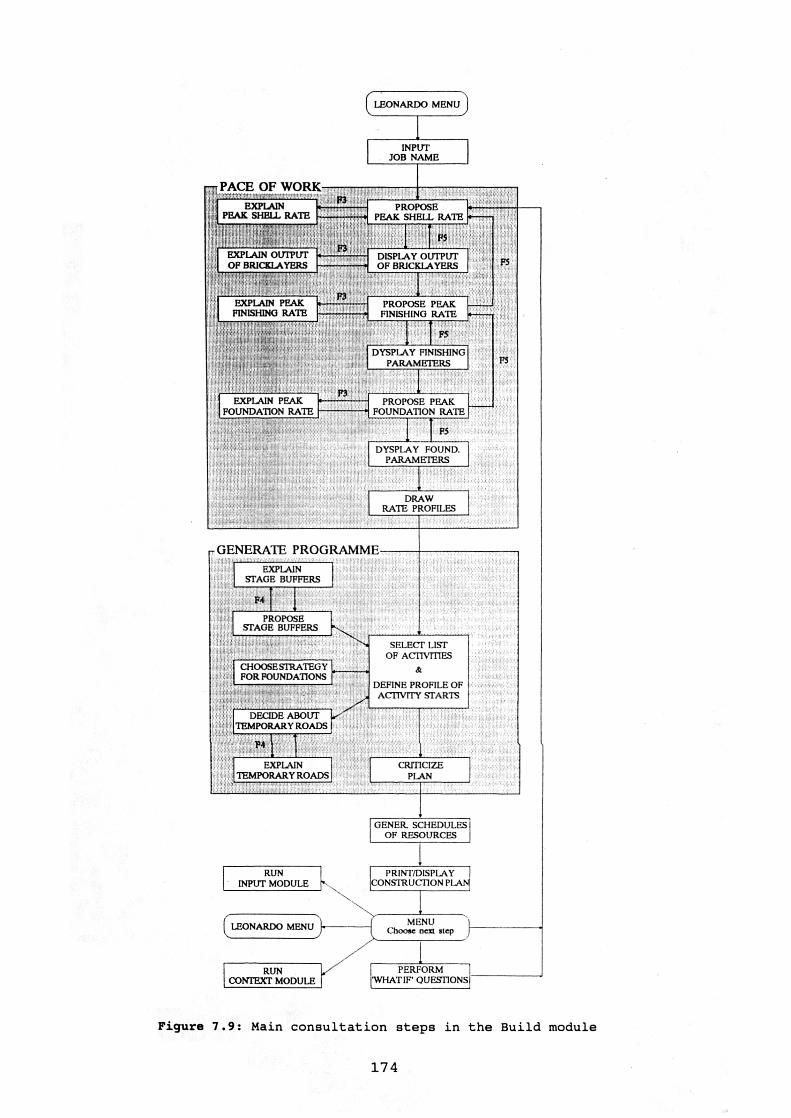
PACE OF WORK
EXPLAIN PEAKFOUNDATION RATE
PROPOSE PEAK FOUNDATION RATE
IFS
DYSPLAY FOUND.PARAMETERS
DRAWRATE PROFILES
- GENERATE PROGRAMMEEXPLAIN
STAGE BUFFERS
F4
PROPOSESTAGE BUFFERS
SELECT LISTOF ACTIVITIES
CHOOSE STRATEGYFOR FOUNDATIONS
DEFINE PROFILE OFACTIVITY STARTS
DECIDE ABOUTTEMPORARY ROADS
P4
EXPLAINTEMPORARY ROADS I
CRITICIZEPLAN
EXPLAINPEAK SHELL RATE
EXPLAIN OUTPUTOF BRICKLAYERS
EXPLAIN PEAKFINISHING RATE
PROPOSEPEAK SHELL RATE
PS
DISPLAY OUTPUTOF BRICKLAYERS
PROPOSE PEAKFINISHING RATE
F5
DYSPLAY FINISHINGPARAMETERS F5
FS
LEONARDO MENU
INPUTJOB NAME
GENER SCHEDULESOF RESOURCES
1RUN
INPUT MODULEPRINT/DISPLAY I
CONSTRUCTION PI ANI
LEONARDO MENU Choose...-(`
MI:NU
0/7
nen step )
iRUN
CONTEXT MODULEPERFORM I
WHAT IF QUESTIONS!
Figure 7.9: Main consultation steps in the Build module
174

7.6.2 Selecting activities and defining profile of activity starts
As this phase involves a relatively large number of minor
decisions, the user is not given the option of overwriting all
suggestions made by the system, in order to avoid the consultation to
be excessively lengthy.
The breakdown of the job into activities is established by
selecting a number of construction activities for each stage of work
from the library of activities available in the Build module. The
system uses a number of relatively straight forward rules for making
these decisions, such as the ones presented in Figure 7.10, which are
concerned with the choice of ground floor activities.
As discussed in Section 6.7, the sub-task of defining a profile of
activity starts involves assigning precedence relationships between
activities, and between activities and site events. Each precedence
relationship is defined in the system by a number of attributes of the
succeeding activity. Such attributes can be either stored in the frame
of the activity, or dynamically established by a rule or procedure.
The way in which the knowledge concerned with activity attributes is
organized in the system has already been explained in Section 7.3.4.
Object Number : 201
Name: g round_floor_list 20-Jan-91 17:42
1 : Name: ground_floor_list2 : LongName:3 : Type: List4 : Value:5 : Certainty:6 : DerivedFrom:7 : RuleSet:8:9 : if foundation_type is raft10 : then ground_floor_list equiv nothing1112 : if ground_floor is not 'timber floor'13 : and ground_floor is not 'suspended concrete slab'14 : and foundation_type is not raft15 : and hardcore is done16 : and 'concrete slab' is done17 : then ground_floor_list includes "hardcore,concrete slab"1819 : if ground_floor is 'suspended concrete slab'20 : and susp_concrete_slab is 'precasted hollow beams'21 : and 'hollow beams(gr.)' is done22 : then ground_floor_list includes "hollow beams(gr.)"2324 : if ground_floor is 'suspended concrete slab'25 : and susp_concrete_slab is 'precasted beams & blocks'26 : and 'beams/blocks(gr.)' is done27 : then ground_floor_list includes "beams/blocks(gr.)"2829 : if ground_floor is 'timber floor'30 : and 'gr.floor joists' is done31 : then ground_floor_list includes "gr.floor joists"
Figure 7.10: Ruleset used for choosing ground floor activities
175

While the general programme for the construction stage is
assembled, it is displayed to the user activity by activity in a bar
chart form. This programme is similar to the one reproduced in Figure
5.3, which was generated by one of the experts involved in the
knowledge acquisition process.
Each type of activity is represented by a different convention: bar
chart activities are expressed by a bar; repetitive continuous
activities are expressed by the number of houses finished each week;
and stretched activities are indicated by a double line.
The process of assembling the programme is interrupted at certain
points, when the system requires the user to confirm or overwrite some
decisions concerned with the inclusion of stage buffers, whether
temporary roads are to be built, or rescheduling the foundation stage
in case it has been programmed to be carried out during winter months.
Such decisions give the user some control over the profile of activity
starts.
After the construction plan has been generated, some of its main
variables are checked against any restrictions that might have been
imposed by the client or higher level management. These can include a
maximum duration for the project, a maximum period of time between the
beginning of the job and the first handover, or a minimum rate in
which the houses are delivered to the client or users. In case any of
them is not satisfied, the system proposes some possible changes in
some parameters of plan, which, if implemented, can make the plan
acceptable.
7.6.3 Final steps
The current version of the system is able to produce automatically
the schedules of only a few resources. These are formwork joiners,
bricklayers, and plasterers. The system does not generate schedules
for all trades involved in house building projects, because that would
demand the user to input much more data than it is currently needed.
Moreover, most of the experts involved in the knowledge acquisition
process find unnecessary to obtain the schedule of all trades
involved, since many of them are usually sub-contracted. Figure 7.11
shows the schedule of bricklayers produced for a particular project.
176

68
121212121212
64
222
SCHEDULE OF BRICKLAYERS
PROJECT NAME: epsom DATE: 26-Jan-91 14:30
WEEK FIRST DAY MANHOURS No.OF OPERATIVESNo.
1 08Jan1990 0.00 0
2 15Jan1990 0.00
3 22Jan1990 0.00
4 29Jan1990 0.00
5 05Fev1990 6.42 2
6 12Fev1990 22.45 2
7 19Fev1990 41.70 2
8 26Fev1990 57.74 2
9 05Mar1990 73.77 2
10 12Mar1990 93.02 2
11 19Mar1990 129.62 4
12 26Mar1990 204.12
13 02Apr1990 286.35
14 09Apr1990 0.00
15 16Apr1990 368.59 10
16 23Apr1990 456.66 12
17 30Apr1990 524.32 14
18 07May1990 565.75 14
19 14May1990 598.36 • 16
20 21May1990 601.38 1621 28May1990 599.64 16
22 04Jun1990 549.14 1423 11Jun1990 498.6424 18Jun1990 503.4025 25Jun1990 485.8126 02Ju11990 503.4127 09Ju11990 494.6128 16Ju11990 444.6929 23Ju11990 338.9330 30Ju11990 197.9931 06Aug1990 139.2832 13Aug1990 112.8833 20Aug1990 53.8634 27Aug1990 6.22
Figure 7.11: An example of resource schedule
A hard copy of the general construction programme can be obtained
in three different formats. Besides the bar chart format, described
above, the system is also able to print the programme as a schedule of
milestones, and as a list of activities with all their attributes.
Figures 7.12 presents an example of construction programme in a bar
chart form. The dependency of each activity is indicated in this
programme by the preceding activity number (column 3).
Figure 7.13 shows an example of a schedule of milestones. This
schedule indicates the target dates for the main project milestones,
for each individual work place. If the sequence of work has not been
defined yet, the schedule of milestones is related to generic houses,
otherwise it is defined in relation to each individual block of
houses, or pool of work.
177
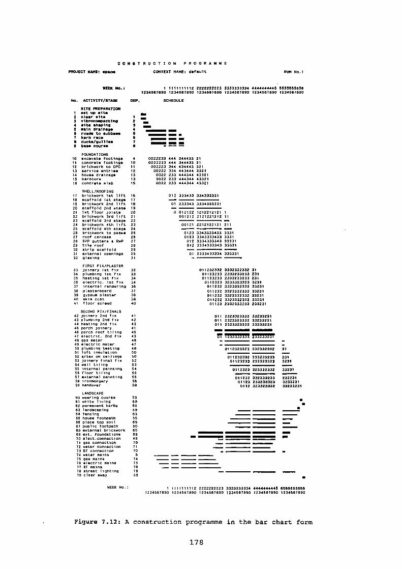
No. ACTIVITY/STAGE
SITE PREPARATION1 set up site2 clear site3 vibrocompacting4 site shaping6 main drainage• roads to subbase7 kerb raceS ducts/gullies9 base course
FOUNDATIONS10 excavate footings11 concrete footings12 brickwork to DPC13 service entries14 house drainage15 hardcore16 concrete slab
SHELL/ROOFING17 brickwork let lift18 scaffold 1st stage19 brickwork 2nd lift20 scaffold 2nd stage21 1st floor joists22 brickwork 3rd lift23 scaffold 3rd stage24 brickwork 4th lift25 scaffold 4th stage26 brickwork to peaks27 roof carcass28 SVP gutters & RWP29 tile roof30 strip scaffold31 external openings32 glazing
FIRST FIX/PLASTER33 joinery 1st fix34 plumbing 1st fix35 heating 1st fix38 electric. 1st fix37 Internal rendering38 plasterboard39 gy psum plaster40 skim coat41 floor screed
SECOND FIX/FINALS42 joinery 2nd fix43 plumbing 2nd fix44 heating 2nd fix45 porch joinery48 porch roof tiling47 electric. 2nd fix48 gas meter49 electric meter50 plumbing testing51 loft insulation52 artex on ceilings53 joinery final fix54 wall tiling55 internal painting58 floor tiling57 external painting58 ironmongery59 handover
LANDSCAPE80 wearing course61 white lining82 permanent kerbs63 landscaping84 fencing65 house footpath66 place top soil87 public footpath88 external brickwork69 ext. foundations70 elect.connection71 gas connection72 water connection73 BT connection74 water mains75 gas mains78 electric mains77 BT mains78 street lighting79 clear away
CONSTRUCTION PROGRAMME
PROJECT NAME: epsom CONTEXT NAME: default
RUN No.1
WEEK No.:
1 2 2222222223 3333333334 4444444445 55555556561234687890 1234667890 1234667890 1234667890 1234667890 1234667890
DEP. SCHEDULE
mm2 mi34 • MI=
• EMS MI• 1=1 NM
7 • MI=8
4 0022233 444 344433 2110 0022233 444 344433 2111 002223 344 434443 32112 00222 334 443444 332113 0022 233 444344 4332113 0022 233 444344 4332115 0022 233 444344 43321
16 012 333433 33433333117
01 233343--
33343333311819
0 012122 121221212120 121 001212 2121221212 1122
00121 221212212123 21124
0123 334333343325 333126 0123 3343333433 333127 012 3334333343 3333128 012 3334333343 3333129
2333433334 33333129 0131
32 011232332 3332332332 3133 01123233 2333233233 23134 01123233 2333233233 23134 0112323 3233323323 323138 011232 3323332332 3323137 011232 3323332332 3323138 011232 3323332332 3323138 011232 3323332332 3323140 01123 2332333233 233231
41 011 2323323332 3323323142 011 2323323332 3323323143 011 2323323332 33233231414543 1232332333 233233231464748 0112323323 332332332 315050 231011232332 33323323352 01123233 233323323 32315354 0112323 323332332 332315555 011232 332333233 23323158 01123 233233323 323323158 0112 323323332 33233231
59606059835585
IMMIMEM
808588 MEI
49 MN
707170
57475787659
WEEK No.: 1 1111111112 2222222223 3333333334 4444 44444 5 65555555561234567890 1234567890 1234567890 1234567890 1234567890 1234567890
Figure 7.12: A construction programme in the bar chart form
178

SCHEDULE OF MILESTONES
PROJECT NAME:seafo2 CONTEXT NAME:default DATE:26-Jan-91 18:33 RUN No.
YEAR: 85 86
MONTH: JJJJJJAAAASSSSSOOOONNNNODDDDJJJJFFFFMMMMMAAAAMMMMJ
WEEK STARTING ON: 2001220112001230122011200123012201120112301220112041852952982983074184185298308307307430741741852982
WEEK No.: 1111111111222222222233333333334444444444512345678901234567890123456789012345678901234567890
UNIT
No.
1
2
3456789
101112
1314
UNIT TYPE SIZE DESNo.
semi-detached 2 6terraced 2 1terraced 2 2terraced 2 2terraced 2 3detached 1 9semi-detached 2 7semi-detached 2 7semi-detached 2 adetached 1 10detached 1 9semi-detached 2 8terraced 2 4terraced 2 4
111
1111
1111
111
2222222222
333
2222
3333333333
4
3
44
444444444 -44
1 - End of substructure2 - Shell water tight3 - Wet trades completion4 - Unit handover
Figure 7.13: A schedule of milestones
The main project milestones corresponds to the conclusion of the
four stages of work related to the construction of houses: conclusion
of the infra-structure, completion of the water tight shell,
completion of the work of all wet trades, and unit handover.
Appendix 5 presents an example of construction programme expressed
as a list of activities and their attributes.
At the end of each cycle in the Build module, the user can perform
some "what if" type of questions: a limited number of variables from
the job description can be provisionally altered, and the whole cycle
repeated. This facility enables the user to generate a variety of
construction plans for a range of slightly different scenarios.
The construction plan that is generated using the suggestions made
by the system can be regarded as representing the natural pace of work
proposed by the system. Different "what if" scenarios could be
created, for instance, for assessing the effect that changes in the
job description are likely to have in such natural pace of work.
179

7.7 Lessons learnt from the implementation of the system
A number of lessons were learnt from the implementation of the
system. Some of them are specifically related to the features of the
shell used, while others involve broader issues. They were grouped in
nine main headings, as follows:
(i) Usage of memory: as Leonardo does not need to load the whole
knowledge base into the memory of the machine, the size of each module
is not limited by the remaining amount of RAM available, as it is the
case of CRYSTAL.
In practice, however, the size of a knowledge base in Leonardo is
limited by the total amount of text that it contains, because of the
way the usage of memory is managed in Leonardo. It means that, when
developing large knowledge bases, the system designer has to bear in
mind the necessity of minimizing the amount of text used in screens,
rulesets, and procedures.
This limitation turned out to be even more severe in Leonardo
Versions 3.20 and 3.22. Unfortunately, none of them so far has been
able to cope with the size and complexity of the current system,
despite of the great effort carried out by the author for optimizing
its usage of memory. Consequently, it has not been possible yet to
use of any of the new features of Leonardo provided by these new
versions in the development of the current application.
Unless Leonardo is not improved in this particular aspect, it will
not be possible to extend the application much further without having
to split both the Input and Build modules into a number of smaller
modules.
(ii) Number of objects: another limit to the size of a knowledge
base in Leonardo, when running in a PC, is the number of permanent
objects in each knowledge base - one thousand objects is the maximum
amount.
Such limitation was partially overcome in the application by
defining the variables used exclusively in procedures as local
variables - these do not count as permanent objects. This restriction
could be virtually eliminated in Leonardo if it was also possible to
declare objects that are used exclusively in a particular ruleset as
180

local.
(iii) Speed of the system: the duration of each consultation
depends on the complexity and size of the job, and obviously on the
hardware used. Using a 80386 microprocessor based micro-computer, each
cycle in the Build module usually takes between 15 and 25 minutes, and
the time needed for collecting and entering the complete description
of a job in the Input module normally ranges from 15 minutes to 2
hours. This indicates that the system performs quite well in terms of
time savings, since the experts typically take between 1 and 5 working
days to perform this task manually.
The system can also run in slower machines, such as 8088 or 80286
microprocessor based PC's. However, some of these machines can make
the consultation boring, because of the relatively long waiting times
that the user is submitted to, specially when the hard disk has a long
access time.
From the point of view of the system designer, 80386 based machines
are also highly recommended for developing applications as complex as
the present one. A high productivity in the implementation stage is
very difficult to be achieved in slow machines: each knowledge base
needs to be compiled frequently and the compilation time for large
knowledge bases can be quite long in some 8088 or 80286 based micro-
computers. For instance, the compilation of the Build module in such
machines usually takes 40 to 50 minutes
(iv) Knowledge representation: both frames and rules in Leonardo
can be designed in a fairly readable way, specially when expressing
pure domain knowledge. Moreover, the way in which rules and procedures
are integrated allow some conventional procedural routines to be run
from the knowledge base without affecting the clarity of the rule
language.
As Leonardo contains no specific formalism for representing task
knowledge, several meta-rules had to be represented in the same way as
rules related to domain knowledge. To some extent, this resulted in a
reduction of clarity in the knowledge base.
One of the main drawbacks of the frame based formalism in Leonardo
Version 3.18 is the lack of multi-level inheritance. For that reason,
the hierarchical trees formed for organizing the project description
181

could not be totally represented in the knowledge base. This
limitation has already been eliminated in the Versions 3.20 and 3.22
of this shell.
Another limitation related to class objects in Leonardo is the fact
that only "IsA" links are allowed in a lattice of frames. As a result,
sometimes the class objects created have to be artificially adapted to
this particular type of link, whenever other kinds of hierarchical
relationship are required. For instance, the object "foundation" in
the current application had to be expressed as an "IsA" member of the
class called "building_component", instead of being simply expressed
as an "a part of" member of the class named building.
(v) Control over the consultation: the runtime facilities available
in Leonardo's default screen for transferring the user some control
over the consultation turned out to be largely ineffective in this
particular application.
Whenever it was necessary to give more control over the
consultation to the user, special purpose facilities had to be
designed in the system, by using either sets of chained screens or
procedures. Such facilities could not be effectively developed through
Leonardo's rule language, because of the limited flexibility of its
inference control mechanism.
The use of sets of chained screens and procedures usually implies a
reduction in the explicitness of the knowledge base, which is one of
the main advantages of knowledge based systems over conventional
computer systems. In this situation, the system designer must always
balance the benefits of transferring the control over the consultation
to the user against a loss in the explicitness of the knowledge base.
(vi) Explanation facilities: when the default screen is used,
Leonardo can trace the rules used by the system, as a form of
explaining why a question is being asked, or how a certain conclusion
has been reached. Although this facility was very useful during the
development stage as a tool for debugging rules, it very rarely
provides an acceptable explanation to the user.
The same problem has already been identified in several other
knowledge based system shells (Kidd & Cooper, 1985; Berry & Broadbent,
1987; Brandon, 1990). The limitation of such explanation facilities is
caused by the fact that much of the knowledge vital to providing a
182
good explanation is not completely expressed by the rules, but it is
partly implicit in the way groups of rules are structured. For this
reason, most explanations provided by the system during a consultation
consist of canned texts, generally developed through the Screen Design
utility.
(vii) Updating and expanding the knowledge base: the way in which
the domain knowledge was organized in the system allows to some extent
each knowledge base to be modified or expanded without having to
radically change its structure, or without having to spend much time
in checking the modified system. This is possible because of the
clarity of Leonardo's rules and frames, and the fact that its rules
can be grouped into small, self-contained rulesets. Obviously,
modifications at this level must not be carried out by an ordinary
user, but by people that have some knowledge about Leonardo and the
structure of the system.
(viii) Effort spent in the development of the interface: the
development of the application has confirmed the importance of the
cost of devising the man-machine interface in relation to the total
cost of implementing the system. Although the aim of this study was
to develop the application up to the stage of a working system, rather
than to a commercial stage, approximately 60% of the time needed for
implementing the system was actually spent in the development of the
man-machine interface, and only 40% spent in the reasoning part of the
system. Similar percentages have also been found in the development of
several other knowledge based system (Berry & Broadbent, 1987; Brandon
et al., 1988).
(xix) Pitfalls of the early prototyping approach: some of the main
advantages and disadvantages of developing a prototype of the system
early in the development process have already been discussed in
Chapter 5. The development of the current application has also
pointed out some pitfalls which this approach has specifically in
relation to the implementation process.
The first main pitfall was concerned with the fact that early
versions of the system were constantly used in the knowledge
acquisition process, as an expedite mean of checking the validity of
the knowledge being modelled. This practice required the man-machine
interface to be kept relatively attractive to the experts, and the
183

system reasonably debugged. Both these procedures demanded a
considerable amount of effort, in relation to the total time spent in
the implementation of the system.
The second main difficulty was related to the way in which the
structure of the knowledge base evolved. The initial versions of the
system were based on a very simplified model of the task to be
performed, because only a small amount of knowledge had been elicited
from the experts by then. Several upgrades had to be performed in the
system up to its final version, as more complex aspects of the task
were modelled and new situations were considered. Several of the early
upgrades required very time consuming restructuring of the knowledge
base, because the interim versions of the system did not provide the
necessary structural hooks, and processing mechanisms that could cope
with the new demands. This problem would probably much less severe if
the implementation of the system had started later in the development
process.
7.8 Summary and conclusions
This chapter presented a general overview of the knowledge
engineering application developed in this study.
The implementation of the system in Leonardo Level 3 can be
considered as reasonably successful. The main advantages of using this
shell were: fairly good speed, availability of a wide range of
facilities for developing the man-machine interface, clarity of the
knowledge base, and availability of formalisms for organizing the
knowledge base in a modular way. Its main shortcomings in this
particular study were: limitations in the amount of text contained in
each knowledge base, lack of a specific formalism for representing
task knowledge, and lack of more effective runtime facilities for
transferring the control over the consultation to the user.
The final version of the system is a fairly large application in
terms of number of rules, if compared to other knowledge based systems
developed for standard micro-computers. The performance of the system
in terms of time savings is quite good: the user usually takes between
35 minutes and 2.5 hours to perform a task that can take from 1 to 5
working days, when executed manually.
In the next chapter, the process of validating the system will be
184

described. Although such process focused on testing the validity of
the model of expertise, rather than on the overall performance of the
system, some of conclusions attained are actually related to the way
in which the system was implemented.
185

CHAPTER 8 — VALIDATION OF THE SYSTEM
8.1 Introduction
The third and final stage of development of the application
consisted of the validation of the implemented system. The approach to
validation adopted in this study is similar to the one used in the
field of operational research, which is concerned with testing the
agreement between the behaviour of the model and the real world system
being modelled (Finlay & Wilson, 1987). In the particular case of
knowledge based systems, validity can be defined as the degree at
which the outcomes of the resulting system resembles the outcomes of
the human expertise modelled in the knowledge base (Preece, 1989).
In more specific terms, the aims of the validation stage were: to
check whether the system has reached a reasonable level of quality at
the end of its development; to identify any necessary improvements in
the system; and to make explicit gaps in the knowledge base, which
could guide future knowledge acquisition exercises or research in the
field of construction planning.
The importance of formally validating knowledge based systems is
concerned with the scientific respectability of artificial
intelligence. Many fields will not accept technological innovation
without rigorous demonstration of the breadth and depth of the new
products capabilities (Buchanan & Shortliffe, 1984; Green & Keyes,
1987).
Although much of effort has been devoted to the tasks of designing
and constructing knowledge based systems, very little has been
reported on the measurement of their performance (Ludvigsen et al.,
1988). The techniques that have been used for validating knowledge
based systems are usually "ad hoc", informal and of dubious value
(O'Keefe et al., 1987).
Validation is frequently confused with verification. While
validation is related to model correctness, software verification is a
more specific concept, concerned with testing that a computer code
fully and exclusively implements the requirements of a superior
specification (Ortolano et al., 1990; Ludvigsen et al., 1988; Finlay
et al., 1988; O'Keefe et al., 1987). Particularly in connection to
186

knowledge based systems, verification is also applied to testing that
the knowledge base is logically sound and complete (Suwa et al., 1982;
Preece, 1989).
Validation is one dimension of a much broader area named software
evaluation, which is concerned with the process of assessing the
overall quality of software products (O'Keefe et al., 1987; Ortolano
et al., 1990). This research has focused on the validity of the model
of expertise developed, rather on the evaluation of the global quality
of the implemented system, because the primary objective of the study
was not to develop a high performance commercial package. Another
reason for emphasizing the issue of testing the validity of the system
is the fact that validation is the corner-stone of the evaluation of
computer systems: highly efficient implementations of invalid systems
are useless (O'Keefe et al., 1987).
On the other hand, there have been indications that it is difficult
to separate completely performance validation from the measurement of
other quality characteristics (O'Keefe et al., 1987). For instance,
testing the validity of a knowledge base is impossible if the system
is unreliable, or if it does not have an adequate man-machine
interface. For this reason, a preliminary investigation was made on
the applicability of software quality models to the evaluation of the
system, which is presented in Section 8.2.
In Section 8.3, the major problems found in the validation of
knowledge based systems are discussed, and some of the techniques
available are examined. Section 8.4 is devoted to reporting the
validation procedures prescribed for this research and the results
achieved.
8.2 Software quality models
Software quality is defined by Watts (1987) as the degree of
compliance (or non-compliance) of a product with specified
requirements. A number of quality models have been proposed, in which
the global concept of quality is broken down into a variety of
attributes or characteristics, such as: usability, security (or
integrity), efficiency, correctness, reliability, maintainability,
testability, flexibility, re-usability, portability, and inter-
operability (Watts, 1987).
187

A number of techniques have been proposed for measuring each of the
quality characteristics mentioned above. These techniques are based
either on subjective rating methods performed by experts, or on
formulae which consider aspects of computer programmes that are
possible to quantify, such as the number of lines of code, the average
length of sentences and words displayed to the user, etc. The main
limitation of such techniques is that most of their outcomes have not
been actually proved to be correlated to the characteristics they are
supposed to measure (Watts, 1987).
The measurement of the overall quality can be obtained by a
weighted summation of the measures of individual attributes. Watts
(1987) introduces six methods that can be used for getting such a
global measure, in which the relative significance of each
characteristic is subjectively established. The relative importance of
each attribute varies according to the type of software. For example,
usability is one of the characteristics that is likely to be highly
rated for decision support systems.
Gillies (1990) pointed out some major shortcomings of current
software quality measures, as follows: (i) there are several measures
associated with maintainability and reliability, but other
characteristics are not conveniently measured by any existing
measures; (ii) the single 'figure of merit' used for measuring the
overall quality is of limited practical value; and (iii) the range of
characteristics is usually oriented towards system developers, rather
than users.
Considering the relative character of the measurement involved in
software quality models, it seems that their usefulness is restricted
to comparing the performance of a number of alternative systems or
comparing the performance of a single system to an acknowledged gold
standard. Such procedures can only be effective if incorporated into a
long term software quality control programme, usually carried out by
organizations that systematically develop or use a wide range of
software products.
In the particular case of knowledge based systems, there are a
number of additional difficulties concerned with the measurement of
software quality. Firstly, knowledge bases are usually built on the
top of another software, a shell or a knowledge engineering
188

environment. Any attempt at measuring the quality of a knowledge based
system would have to consider the combination of the knowledge base
with the programming tool. Secondly, the approach of rapid
prototyping, widely used for developing knowledge based systems,
generally leads to a lack of precise specification which the system's
performance can be compared to (Taylor, 1989). Finally, knowledge
engineering is an emerging technology, which is under a very rapid
pace of development. Most systems developed so far have not reached a
stage of commercial tools, in which they would be able to contribute
to a database of quality measurements.
For the reasons presented above, the application of the software
quality models currently available was not considered feasible for
this research project.
8.3 Difficulties in validating knowledge based systems
8.3.1 The nature of models of expertise
"The paradox of applying knowledge based systems is that we
want them to do perfectly things that we don't really
understand" (Hollnagel, 1989).
This quotation illustrates one of the major difficulties in the
process of validating knowledge based systems: knowledge based systems
may occasionally make mistakes (McDermot, 1981). While conventional
programs are designed to produce a supposedly correct answer every
time, knowledge based systems are designed to a certain extent to
behave like human experts, usually producing correct answers, but
sometimes producing incorrect ones (Waterman, 1986).
Besides that, there are a number of important practical issues
involved in devising the validation process. They are summarized in
the following sections.
8.3.2 Validation criteria
Validation may involve several different criteria, such as the
correctness and accuracy of the final results, the correctness of the
internal reasoning, model sensitivity, model robustness, time savings,
cost effectiveness (Hollnagel, 1989). Each one of the different
parties involved in the development of a knowledge based system (i.e.
189

client, developer, expert, and users) probably disagree about the
relative significance of the various criteria (Gaschnig et al., 1983).
Gaschnig et al. (1983) stated that the larger the number of
distinct criteria included in the validation process, the more
information would be available on which to base an overall validation.
O'Keefe et al. (1987) highlighted the importance of validating the
internal reasoning of knowledge based systems, even when a knowledge
based system is apparently giving accurate results. They stated that
neglecting the validation of the internal reasoning may lead to a lack
of robustness, specially when the knowledge base has to be frequently
updated or expanded.
8.3.1.3 Gold standard
Validation requires an objective standard of excellence, i.e. a
generally accepted correct answer to which the system's conclusions
can be compared (Buchanan & Shortliffe, 1984). This "gold standard"
can be human expert performance or data from the real world. In some
fields, the only gold standard available is the human expert
performance, because the cost of obtaining data from the real world is
very high (Weiss & Kulikowski, 1984). In such cases it may be
difficult to know how the system performs in relation to the real
world, since there might not be an adequate measure of the quality of
human expertise (Berry & Broadbent, 1987).
The standards of performance should be defined realistically
(Gaschnig et al., 1983). It is not fair to expect a knowledge based
system to have a very high performance if it encapsulates the
knowledge of human experts who are imperfect in their understanding.
8.3.4 Test cases
Since it is very unlikely that a set of test cases available can
cover all possible combinations of inputs in most real complex
problems, it is necessary to ensure that the test cases used are
representative of the situations that may possibly occur (Hollnagel,
1989). The main issue is not the number of test cases, but their
coverage, i.e. how well they reflect the input domain (O'Keefe et al.,
1987). Ortolano et al. (1990) suggested to use both routine and
difficult cases: the latter serve to 'push' the knowledge based system
190

in order to learn its limitations.
If not enough historic cases are available for the validation, it
may be possible to use a number of hypothetical test cases created by
experts. The main limitation of using hypothetical cases is that they
might not represent a well-stratified sample of possible cases, and
the experts are unlikely to spend as much time and effort on them as
on real problems (O'Keefe et al., 1987).
8.3.5 When to validate
Validation is an intrinsic part of the process of developing a
knowledge based system (Buchanan & Shortliffe, 1984). The validation
process should be continuous, beginning with system design, extending
in an informal way through the early stages of development, and
becoming increasingly formal as the system begins to achieve a real-
world implementation (Gaschnig et al., 1983).
Most knowledge based systems never reach a state of stati_c
completion, since human expertise generally grows and changes
continuously (Welbank, 1983). For this reason, such systems should
also have their validity periodically tested while they are being used
in the field.
Some validation criteria are more appropriate than others at a
particular stage of the validation process (BUCHANAN & SHORTLIFFE,
1984). Validating the internal reasoning should start early in the
development process, while validation of the final advice is more
adequate to later stages of development (O'Keefe et al., 1987).
8.3.6 Cost of validation
Developing a system is a process of negotiation and compromise, in
which the final product is one that is feasible, given a number of
practical constraints, rather than an ideal one (Hart, 1990).
Validation may be time consuming and expensive. For instance, the
validation process involved in the development of the knowledge based
systems MYCIN and R1 required over a year (Gaschnig et al., 1983), and
approximately thirty per cent of the total effort needed for
developing the knowledge based system DEMOTOX was devoted to formal
evaluation (Ludvigsen et al., 1988).
It is difficult to establish exactly when to stop validating a
191

system. The value of validation depends on the value of the system to
its users and on the risk involved in using a poor validated system
(O'Keefe et al., 1987).
8.3.7 Control of bias
There are two main types of bias. The first one relates to the
experts involved in validation who might have bias against (or for)
results produced by computer programmes. Such bias can be controlled
by using blinded validation, in which the experts are not able to
distinguish which results were produced by the computer and which ones
were produced by human experts.
The other kind of bias relates to the difficulties that the
development team (developers and experts) might have in validating
their own system, once they are very much involved in the project.
This problem can be minimized by having an independent team for the
validation stage.
8.3.8 Complex results
Even when an adequate gold standard is available, validating a
knowledge based system might not be easy if its results cannot be
easily classified as absolutely correct or absolutely incorrect.
If a system produces a piece of text from the concatenation of
several statements as a conclusion, it may be difficult to break that
text in a number of firm endpoints that can be compared to a gold
standard (Weiss & Kulikowski, 1984). In such cases, it may be
necessary to use a range of acceptance measures (e.g. ideal, highly
acceptable, acceptable, unacceptable, etc.), rather than simply
reducing the analysis to a binary decision (e.g. correct, or
incorrect). Weiss & Kulikowski (1984) stressed that validating complex
results usually demands some kind of subjective validation, such as
showing external experts the system's results and asking whether they
agree with the conclusions.
8.3.9 Disagreement between experts
The difficulties of copying with disagreements between experts in
the knowledge acquisition process have already been discussed in
Chapter 5. This problem obviously also affects the validation process,
192
since different experts may disagree about the validity of a
particular piece of knowledge encapsulated in the system.
8.4 Techniques currently used
Validation can range from formal to informal. Informal validation
is a long-term feedback process which cycles between knowledge
engineers, domain experts, and users, beginning at project initiation
and extending throughout software development (Ludvigsen et al.,
1988). Formal evaluation, on the other hand, usually begins once a
prototype has been developed, focusing on testing design objectives
and identifying system improvements via a structured approach
(Ludvigsen et al., 1988).
Validation methods can be either qualitative or quantitative.
Qualitative validation employs subjective comparisons of performance,
while quantitative validation employs statistical techniques to
compare knowledge based system performance to a gold standard (O'Keefe
et al., 1987).
Qualitative validation does not mean informal validation. It is
possible to develop a highly formal qualitative validation. O'Keefe et
al. (1987) and Hollnagel (1989) described some commonly used
qualitative validation techniques:
(i) Face validation: the system performance is subjectively
compared to the human experts' by the developers, users, or people
knowledgeable about the application domain. The results obtained from
a knowledge based system are compared to a prescribed acceptable
performance range, for a given set of test cases. Its main
disadvantage is that it requires availability of time from human
experts.
(ii) Predictive validation: the system is used in some historical
cases and its results are compared to corresponding results - either
known results or those obtained from human experts. It needs a number
of representative historical cases.
(iii) Field tests: a prototypical knowledge based system is placed
in the field and performance errors are corrected as they occur. This
technique cannot be used in critical applications, where the cost of
imperfect answers is very high, or where lives are at risk (O'Keefe et
193

al., 1987). It is recommended for the later stages of validation, when
the system has already reached a reasonable standard of performance
(Buchanan & Shortliffe, 1984). One of the main advantage of field
tests is that they place the burden of testing upon users (O'Keefe et
al., 1987).
(iv) Sensitivity analysis: the knowledge based system's inputs are
changed over some range of interest and the effect upon system
performance is observed. It is especially useful when few or no test
cases are available. Also, it is highly appropriate for systems that
use uncertainty measures, since these can be altered and the effect on
intermediate or final results can be examined. This approach was
adopted for validating the knowledge based system for the selection of
contract strategy for construction projects developed by Sodipo
(1987).
(v) Visual interaction: a visual animation of the knowledge based
system task which allows human experts to interact, altering
parameters as desired, is provided. In essence, it is simply an
environment for other validation methods.
(vi) Sub-system validation: the system is decomposed into sub-
systems, which are individually validated using some of the methods
above. This technique usually makes validation easier, since sub-
systems are less complex and more manageable than the whole system,
making error detection less time-consuming. Also, sub-system
validation can be carried out along the several stages of development,
before the whole system is completed. Its main limitation is that a
successful validation of sub-systems does not necessarily imply that
the whole system is validated.
(vii) Static validation: the set of rules that make up the
knowledge base are simply checked by experts. The main limitation of
this approach is that it assumes the rules are stable, and that the
inference engine works correctly. It is feasible for only relatively
small rulesets, since the number of alternative paths grows
exponentially with the number of rules (Hollnagel, 1989).
(viii) Robustness tests: the robustness of the knowledge base can
be tested by using a number of hypothetical test cases that reflect
extreme conditions which the system may be submitted to.
Very few systems have been submitted to a complete formal
194
validation so far (O'Keefe et al., 1987). The most common approach has
been to show a system to experts and to ask them if they agree with
the conclusions for a number of test cases (Gaschnig et al., 1983).Very little has been reported on the validation of knowledge based
systems in the construction field, probably because only few of themhave reached an operational stage. From the knowledge based systems
for construction planning described in the Section 2.3, only Elsie,CONSAS and Mason have had their validation process reported.
8.5 Validation of the implemented system
8.5.1 Practical constraints
Considering that there is still no widely accepted, reliable
methods for conducting validation studies (O'Keefe et al., 1987; Green
& Keyes, 1987; Ortolano et al., 1990), a prescriptive method was
devised for validating the present system. The proposed method
involves some degree of pragmatism, since there were practical
constraints concerned with the objectives and limitations ot this
particular research project, as well as with the nature of the
construction planning process.
One of the main constraints related to the construction planning
process was the difficulty of obtaining a single gold standard which
could be compared to the advice given by the system. Due to the
complexity and the uncertainty involved in the construction process,
it is very difficult, or even impossible to find a unique best
solution for the planning problem. The optimisation approach, used in
other engineering fields, is largely ineffective in the construction
practice (Levitt, 1986). Generally, construction planners search for a
feasible arrangement of actions for the production stage of a project,
rather than an optimum one (Laufer & Tucker, 1987).
Considering that there is an infinite number of feasible
arrangement of actions for any real construction project, it is very
unlikely that the construction plans generated by different human
experts for the same project can be identical. For the same reason, it
is not fair to expect that a programme generated by a knowledge based
system that encapsulates the expertise from a number of practitioners
should be identical to any chosen gold standard.
Another important difficulty related to the planning task is the
195

fact that construction planning is a multi-response problem (O'Keefe
et al., 1987). There are a large number of variables that make up a
construction plan, such as activity durations, activity precedences,
stage buffers, building rates, milestones, gang sizes, etc. The
process of validating knowledge based systems for construction
planning must consider not only the validity of each individual
variable, but also the validity of the resulting plans as a whole.
The main constraints related to this particular research are
summarized as follows:
(i) The author had a limited amount of time for carrying out the
validation process;
(ii) The experts in construction planning could devote only a
limited amount of time to the research, due to the normal pressures of
a commercial environment. They did not have time, for instance, to
create and analyse a large set of hypothetical test cases;
(iii) The number of real projects which could be used as test cases
was not very large, undermining the possibility of using statistically
based quantitative techniques;
(iv) The information available about each historical case did not
include the way the construction process really happens on site. Thus,
it was not feasible to validate the system's performance againat data
from the real world;
(v) None of the historical cases available had been planned by more
than one of the experts involved in the study. Consequently, no
evidence could be provided about how different are the strategies
followed by different experts when planning the same project; and
(vi) None of the experts contacted was considered to have a
significant higher level of expertise than the others. For that
reason, it was not possible to build a panel of third-party expert
evaluators able to judge the performance of the other experts and the
system's.
8.5.2 General view of the validation process
The approach adopted in this research aimed at performing
validation as formal, as unbiased, and as exhaustive as possible. For
196

that reason, the validation process consisted of a combination of as
many techniques as possible, involving not only experts that had
provided the expertise for the system, but also some external experts.
The role of the experts in the validation process was restricted to
analysing the main aspects of the system. Most of the detailed work
was carried out by the author, in order to make an efficient use of
the experts' time.
From the eight validation techniques described in Section 8.4, only
visual interaction could not be used in this research , because the
man-machine interface facilities available in Leonardo are limited in
this respect. The more formal techniques focused on those aspects of
construction plans that are possible to quantify, while the less
formal ones concentrated on more subjective matters.
The techniques of sub-system validation and static validation have
already been mentioned in Chapter 5. They were carried out during the
second stage of the system's development, and their role consisted of
providing a short term feedback to the knowledge acquisition process.
The remaining techniques were applied during the validation stage
itself, i.e. as soon as the first full version of the system was
finished. A detailed description of each technique and the main
results accomplished will be presented in Section 8.5.3.
The presence of several rules-of-thumb in the knowledge base, and
the fact that some disagreement was found among experts indicate that
a fine-tuning of the system will be periodically needed during its
working life, especially before it is used in a new context.
However, the development of a formal method for validating the system
while it is being used in the field is outside the scope of the
research, because of the limited time available for this research.
There is no evidence that the method of validation devised for this
particular application can be applied in the development of other
systems. However, it can be expected that some of the lessons learnt
in the validation of the system will contribute towards the
development of more general methods for validating knowledge based
systems in the field of construction planning, since several of the
difficulties faced along this study are likely to be found in other
similar studies. O'Keefe et al. (1987) and Green & Keyes (1987)
pointed out that widely accepted methods for validating knowledge
197

based systems will evolve only in the light of future collective
experience, and critical appraisal of that experience.
8.5.3 Predictive validation
8.5.3.1 General description
This technique consisted of comparing, in a very detailed way,
construction plans generated by the experts who provided the expertise
to the system to the ones suggested by the system for the same
projects. This analysis was mostly carried out by the author. Only
major inconsistencies were taken to further discussion with the panel
of experts.
Fifteen historical cases were employed, all of them selected
amongst the twenty three projects that were available during the
knowledge acquisition process. These fifteen projects were chosen
because the information available about t'neim al%t. .2te
conditions was enough for carrying out a meaningful analysis, and also
because they corresponded to a fair variety of project types. Their
descriptions are summarized in Table 6.1.
-FIRM PROJ.
No.TOTALHOUSES
DET1f1 2f1
HOUSES3f1 1f1
S.DET.HOUS.2f1 3f1
TER.1f1 2f1
HOUSES3f1
FLATS TOTALBLOCKS
AAAAAB
B
B
B
C
C
C
D
D
E
1
23456789
101112131415
515576
134484839442550
145101654975
1
33
2
20122410
2
5612224382
1010501418
2
1
39
648
928427210
48
9065194943
1846
30
1015386724249
221325482897
13
Table 8.1: Summarized description of test cases
198

Appendix 6 lists the variables from the construction plans, which
were selected for performing predictive validation. It was necessary
to consider approximately seventy variables, so that the reasons
behind any discrepancies between the system's and the experts' plans
could be traced down. Not all variables could be considered in every
historical case, because some of the plans available were not very
detailed: the less detailed was the construction plan generated by the
experts, the smaller was the set of variables considered.
Considering that there is an infinite number of feasible
alternative plans for the same construction project, predictive
validation did not concentrate in the accuracy of the system's plans
in relation to the experts'. Instead, it focused on checking whether
the approach followed by the system was acceptable from the point of
view of the experts, and whether the system provided the necessary
facilities to work as a decision support system, during the planning
task.
As shown in Appendix 6, the variables were grouped into six main
headings, according to the aspect of the plan that they were mostly
related to. These are: (i) total project duration; (ii) activity
content; (iii) house completion time; (iv) pace of work; (v) activity
dependencies; and (vi) durations of bar chart activities. The main
conclusions extracted from each item will be presented later in this
chapter.
The data available about each project during the validation process
did not necessarily corresponded to the job description employed by
the experts when the planning task was actually carried out:
unfortunately, some of this information was not kept in the records of
the company. Consequently, the default data encapsulated in the system
had also to be employed for replenishing any information concerned
with the project description that had been lost.
8.5.3.2 Total project duration
The total duration established in the experts' plans for each
project was initially compared to the duration that resulted from the
pace of work proposed by the system. As discussed in Section 7.6.3,
such pace of work can be regarded as the natural rhythm that the
system suggests for each particular project.
199

A comparison between the duration chosen by the experts and the
natural duration proposed by the system is presented in Table 8.2. The
system's durations were on average 14.90% longer than the experts'.
However, this comparison has a fairly limited significance, since, as
previously discussed in Section 4.5.2, the total duration chosen for a
project is usually established at a more strategic level of decision.
In other words, the resulting total duration of a project may not
correspond to what construction planners consider to be the natural
pace of work, but instead, the experts may have to adjust their plans
to a pre-established duration.
For that reason, the validation of the model in this particular
respect focused on examining whether the system provides suitable
facilities for quickly adapting a plan to required duration. Such
investigation was performed by attempting to adjust each of tk%s
suggested by the system to the duration established in the
corresponding expert's plan.
The adjusted plans were generated by cycling through the Build
module a few times. Table 8.2 also presents the project duration
established in the adjusted plans (column 5), and the changes that had
to be made in order to achieve such duration (column 6). All the
comparisons performed in predictive validation were based on these
adjusted plans.
In four cases, the plan was adapted to the required duration by
simply changing one of the building rates proposed by the system. When
that was not possible, the required duration had to be achieved by
changing the value of some variables from the job description, such as
the availability of management, and the availability of bricklayers.
Both variables can have their values altered through a "what if" type
of question. Only the project No. 10 could not have its duration
reduced through the Build module, because the leading resource was the
plastering trade, and the number of plasterers was already at its
maximum level. Such limit can only be altered through the Context
module.
Further discussions with the experts indicated that they find
necessary the system to have facilities for quickly adapting a
construction plan to a wider range of durations, even if it demands to
temporarily change some of the assumptions which the plan generation
was based on.
200

-C .0 -C .0 .00) 0) 0) C7) 0), •I ,c c .0
0>s >,L- L.0 0> >
>0% >, -CL. L COCD CD -0-> > .c
-C0/•-_c
>,La)>
0
4.)
13
04.)
0
0
O 0 0 0 0 0 0▪ +3 4-1 4.) +3 +3
-0 -0 -0 -0 -0 -0 17CD CD G) 0 (D 0 a)co co CO U) U) U) 00 03 03 CO 03 03 03
0)0)0)00) CD a)L- 1- L L. L. .0 L L
O 000003U 0
CCCCC4-C C
4- •- 4- 4- 4-- ..c 4- -r-
4-1 4.) +3 4a 4-1 0 +34.)
C C C C C4.1 C C
0)0)0)0)0)0 03 0 a) a)EEEEEVE E
0)0)0)0)0)0) 0) CD
0)0)0)0)0)0)0)CD 0) 03 0 CO 0)
as CO 03 CIS 0 al 0 0
CZCCCCDC c
113 CS 03 03 03 sk- CO cri
EEEEE0E eC
05 ea oil cil 03 -0- otl ea17
cacacocococam ID C C 0 C
L. L- L L L L I.- Sa X X L 3
0) 0)0)0)0)0)0)CD 0 CD al 0 0 0 0 CD 0>, >% >, >, CD MI 0>s0'0
ca 03 ca CO CO 03 03 L 030 -0 '0 n-• '0
..Y Y Y _Y ..Y C CD CD CD
O 000000 '0-3303
4- 4- 4- F 4- 4- 0 0 - 0- 0
I.- L L- L L. L. L a) ,-- .- t.- 1-
I] la ID Ja la JD 11 .1.P lb tt gl 41ca
4- 4- 4- 4- 4- 4- 4- L- 0 CD 4- a)O 0 0 0 0 0 0 CD 0) 0 CO
0)0)0)0 0C4)443 • 4-1
13 .0 .0 .0 .C1 .0 .0 -0- 0 CO .0 COO 0 03 03 CO 03 03 _C 03
(o .- r- 1.- r-•r. F F F -r o- -v-
C CD CD CO CD-r- C C > -C4- (03 u) 0 CO
0 03 0 03 CO 0 COO > > > > > >0000000
(DC)— r- 01 T- T-O UP 0) et 0 0
03 r- cm UP 01o o
•••••.
0
CD 03 00 CO C) C) OD et C) Ps C) r-C) e- CD r- CD C) 01 0 03 C) 00 e- T- CD e-
CD 03 Ul 00 0 CD T- 01 CV CO 03 0 CD et00 00 01 LU e- e- e- I e- I I 01 I
CO (ON 0) 0 0 0 CO 0 co r.) Nu) '0 0)
N r- r- 0) (0(0 (0(0 0 04 CD 0 0••••
CD UP rs et CD CD CQ C4 C\I CD 01 v- CD CMPs LO LU Ps at (0(0(0(0(0—UP UP T- T- 0 0 t•-
.-
• CV 01 et t (Or- (00)0—CD e- CQ 01 et Ul
••
0 0IX Z •-•
201

It seems that the most effective way to improve the flexibility of
the system in this particular respect is to increase the number of
items that can be altered through "what if" questions. The main
advantages of using such facilities are: they can be quickly accessed
by the experts at the end of each cycle in the Build module; and the
value of each item is only altered in a temporary basis. In future
upgrades of the system, all variables and parameters used by the
system which have a significant influence in the total duration should
be adjustable by "what if" questions, including those that currently
can only be updated through the Context module.
8.5.3.3 Activity content
Table 8.3 compares the number of construction activities from the
plans generated through the system, with the number of items from the
plans manually produced by the experts. It can be observed that the
work breakdown of the system's plans tends to be more detailed than
the experts'.
In five historical cases (Nos. 5, 10, 11, 12, and 15), the plans
produced by the experts were segmented into a small number of major
stages of work, much more aggregated than the construction activities
used in the system's plans. For this reason, suck cases were not used
in the comparison of activity content.
PROJ.No.(1)
EXPERTS'(2)
No. OF ACTIVITIESSYSTEM'S
J (3)
1 69 802 89 753 65 774 70 775 11 786 63 777 61 808 49 779 48 67
10 19 7411 11 7412 10 7013 44 7314 44 7315 8 75
MIN 8 67MAX 70 80
AVER. 42.73 75.13CV 55.01 4.53
Table 8.4: Comparison of No. of activities
202

Tables 8.4 and 8.5, respectively, list the names of the activities
that were included in the system's plans but not in the experts', and
of the activities that were found in the experts' plans but not in the
system's. The main reasons behind such differences are summarized
below.
Most differences in activity content were concerned with level of
detail of the plans. Often, the same construction tasks that were
represented in the system's plans by a group of activities, were
expressed in the experts' plans by a single item. The inverse
situation also was found, although more rarely.
As the activities employed in the system's plans were selected from
a library of activities, such plans generally had a more consistent
activity content than the plans produced by the experts. For instance,
the experts admitted that their plans had a number of unintended
omissions, such as the absence of the activities ducts(gunies,
service entries, gas meter, electric meter (see Table 8.4). Moreover,
some of the experts used distinct criteria for breaking down virtually
the same job in different projects. The expert from Company A, for
example, segmented the construction of walls into five phases in two
plans, but into only two phases in the other two cases, although no
radical difference existed in the design of the walls, or in the way
in which such work was going to be executed.
Differences in the activity content were also caused by distinct
forms of dividing the work between trades. For instance, some experts
employed a particular activity, named "builders' work" for
representing the preparatory work necessary before starting the
hydraulic and electrical installations, because they assumed that such
work was to be executed separately by a gang of specialist sub-
contractors. On the other hand, the system assumed that such work was
performed by the plumbing and electricity trades. Similar
circumstances justify the inclusion of a number of other activities in
the experts' plans, such as paramount partitions, and kitchen units.
203

ACTIVITYNAME
PROJ.No.
2
34
6
789
13
14
- Paramount partitions, electric & gas cupboard,permanent external doors, kitchen units.
- Prep. for vibro-compaction, paramount partAtions,electric & gas cupboard, permanent external doors,kitchen units.
- Paramount partitions, kitchen units.- Paramount partitions, prepare for electr./gas meters,
permanent external doors, kitchen units.- Joiner bay windows, Joiner skirts & archs.,
vehicular drives.- Joiner skirts & archs., kitchen units, pre-paint snags- Builders' work.- Builders' work.- Builders' work, floor boards & ceiling noggins,ceiling plasterboard, pergolas trellis & seats
- Remove existing kerbs, builders' work,floor boards & ceiling noggins, ceiling plasterboard,pergolas trellis & seats.
PROJ.No.
ACTIVITYNAME
1 - Brickwork 2nd lift, brickwork 4th lift, brickwork to peaks,floor screed, permanent kerbs.
2 - Brickwork 2nd lift, brickwork 4th lift, brickwork to peaks,floor screed, permanent kerbs.
3 - External openings, heating 1st & 2nd fix, floor screed,permanent kerbs.
4 - Ducts/gullies, service entries, external openings, floorscreed, permanent kerbs.
6 - Ducts/gullies, service entries, electric meter, gas meter.7 - Service entries, porch joinery, porch roof tiling.8 - External openings, glazing, porch joinery, porch roof
tiling, gas meter, electric meter, plumbing testing,joinery final fix, loft insulation.
9 - External openings, porch wall, porch joinery, porch rooftiling, gas meter, electric meter, plumbing testing,joinery final fix, loft insulation.
13 - Brickwork 2nd lift, brickwork 4th lift, external openings,floor screed, gas meter, electric meter, permanent kerbs
14 - Brickwork 2nd lift, brickwork 4th lift, external openings,floor screed, gas meter, electric meter, permanent kerbs
Table 8.4: Activities included in the system's plans but not in theexperts'
Table 8.5: Activities included in the experts' plans but not in thesystem's
204

A few omissions were also found in the plans generated through the
system, usually involving activities from the site preparation and
landscape stages (e.g. "pergolas trellis & seats", "vehicular
drives"). The main difficulty related to these two stages of work is
that their activities tend to be much less recurrent than the ones
directly related to the construction of houses: it is very difficult
to establish a priori all possible alternative activities, since the
construction work involved has a very close relationship with the
uniqueness of the site conditions. This problem could be circumvented
by providing the system with a facility for incorporating any activity
defined by the user in the schedule of activities from those two
stages of work.
8.5.3.4 House completion time
Table 8.6 shows the house completion time, and the lead-lag times
between the project milestones from both the system's and the experts'
plans, for each of the historical cases. It can be observed that the
house completion times proposed by the system are generally shorter
than the ones established by the experts.
An investigation was made on the lead-lag times between activities,
in order to check whether there was any remarkable inconsistency
between the approach adopted by the experts and the system's. Table
8.7 lists the activity lead-lag times which had distinct values in the
experts' and in the system's plans. This table shows that, although
there were many dissimilarities, none of them appeared in the majority
of projects.
The experts explained such discrepancies by the fact that the
nature of the construction process allows overlapping extents and
floats between activities to vary a lot, even in similar projects
carried out by the same company. In their opinion, the system lacks
flexibility in terms of copying with different degrees of overlapping
between activities.
205

206
Z X CC1-1 < LL1 >X X > C.)
0 0 •-Z•-•
0-
UJ aft •-•X • (D CD 03 0) r- Cn ul 01 C) CV cn CD CO a) CV N 03
UL m- 01 01 Y- 1- 1 CV co nt I •41' •
C3CLx •
C) U/ Mt 0 01 CV 01 04 Cu y- U) CD ‘t C4 42)et 01 01 01 01 0) 0) 01 01 0) 01 et 01 00 CO
• CD et 0001 et 01
a) 0 01) C) U) mt 03 0.1 y- co et 004 01 01 00 cu 0) cy 01 00 01 CV CY 01 00 CV
• u) 03 et0.1 07 cy
r- 0D y- et C) CD CD 00 a) r- CD 00 cn cu ,-
y- u) 0.1 y- 1 1 CO 01 01 0.1 r-
1 1
Nt 0/ V CV 7- 1.•• CV CD y- CQ y- CV
cy 03 et et CD Y- C) CV 01 u) up c0 y- cn
u) ul r- C) C) ul CD CD 01 up up C) r- et U3CV r- e- UD C\I CD 0/ r- r- et
I 1 I
CD r- r- 00 u) u) U5 mD m) r- r- r- r- (c) r- (42 07 CO CV
(4)
et et u) UI CO 01 UD cn et et U3 UP r- et co a) o• co
U1
3- r- ul ul e- r- ul r- CD ul CD cn cnUl UD CV CV r- 7- 01 CD a) up up I 1(0
I m- I'-
- 000000CD C) CD C) CD C) CD CO y- U3 CD C) y- cn ul CD 01
Is• (0 CO CO 0.) CM CO (0 (0 4- 4- (0
C) 03 C) CD r- r- CD CD CD C) CD r- r- CDcy 01 01 C) uD u, et UD UD U3
I
UD Ul UD UD Ul UP Ul Ul et Ul r- r- Ul Ul OD nt rs U3 Ul•
U) CO Ul 01 01 et 01 Ul nt Ul Ul 01 01 nt ootoco• co
Mt
e- cy 01 et 0 OD r- CD CD e- C4 01 et Ul

PROJ.No.
PRECEDINGACTIVITY
SUCCEEDINGACTIVITY
SYSTEM'SL.L.TIME
EXPERTS'L.L.TIME
Service entries House drainage 1 2SVP gutters & RWP Roof tiling 1Strip scaffold External openings 1 0External openings Glazing 0Joinery 2nd fix Plumbing 2nd fix 1Plumbing 2nd fix Electric. 2nd fix 1 0
2 Concrete footings Brickwork to DPC 1 2Service entries House drainage 2Roof carcass SVP gutters & RWP 0SVP gutters & RWP Roof tiling 1Strip scaffold External openings 0External openings Glazing 1 0Plumbing 2nd fix Electric. 2nd fix 0Floor tiling Ironmongery 0Artex on ceilings Joinery final fix 0Artex on ceilings Wall tiling 0
3 Service entries Concrete slab 1 0Brickwork to peaks Roof carcass 1SVP gutters & RWP Tile roof 1Joinery 2nd fix Plumbing 2nd fix 1Loft insulation Artex on ceilings 2Floor tiling Ironmongery 1 0
4 Brickwork to peaks Roof carcass 1Tile roof Strip scaffold 1Plumbing 1st fix Electric. 1st fix 2Joinery 2nd fix Plumbing 2nd fix 2
6 Concrete footings Brickwork to DPC 1 2Joinery 2nd fix Plumbing 2nd fix 0 1
7 Set up site Site shaping 1Joinery 2nd fix Plumbing 2nd fix 2Internal painting External painting 2
8 Plumbing 2nd fix Heating 2nd fix 2House footpath Fencing 0 1
9 Plumbing 2nd fix Heating 2nd fix 0 2House footpath Fencing 1
10 Roof carcass SVP gutters & RWP 1 2
13 SVP gutters & RWP Roof tiling 0Joinery 2nd fix Plumbing 2nd fix 0
14 SVP gutters & RWP Roof tilingJoinery 2nd fix Plumbing 2nd fix 0
Table 8.7: Comparison of activity lead-lag times
207

Two main suggestions for improving the system resulted from further
discussions with the experts. Firstly, the system should have a
facility which allows the user to decide whether the site management
will give priority to the quick conclusion of the first house, or to
keep a high rate of progress for all activities. In the first case,
the system would increase the extent to which some activities are
overlapped, and, at the same time, slow down the pace of work.
The second suggestion is concerned with the confirm/overwrite
points which exist while the system is generating the plan. In the
experts' opinion, the user should be allowed not only to introduce
buffers between stages of work in such points, but also to overlap
them, in case he/she finds necessary.
8.4.3.5 Pace of work
In Table 8.8, a comparison is made between the average building
rates employed by planners and the ones suggested by the system for
the foundation, shell/roofing, and finishing stages. The rates used by
the system had to be higher than the experts' in most cases because of
the longer house completion times adopted by the system.
In the plans generated by the system, the average foundation rate
is consistently higher than the average sfteLL rate, and the averagetbe
shell rate is higher than average finishing rate in most cases. This
approach was recommended by the experts in the knowledge acquisition
process, as reported in Chapter 6.
On the other hand, only six of the plans produced by t'ne expsmts
have an average foundation rate higher than the average shell rate, and
nine of them have a finishing rate lower than the average shell rate.
208

000,-0000••*00.-411c00000N-000NT-00,-000
CI (13 0 CY) 01 r-- c0 r-- 0 0 ,- •er c0 N •.:t00000.-0,-COOCW•erNO
00000OLL100•1'00,01.0C000 0 0 0 0 .•- CJ) LO Cy) 0 Cr) .- r•- r-- 0
C•1
C/)
,-- 0.1 01 et 0 0 ts CO cn CD ss CV 09 et 0
•
a)a)
La)o.U)a)U)noi:
4-0
La)
-CDE=C
4-0
COEs_a)•.)
c-1--
17a)COCOa)L0.Xa)
a)s_co
COa)4.)03L-
I....
as
wI-0z
01..4
I-4CCC
•Z
u)-x ...-.W .1-I- *--U) •-•>-u)
0CV
•
CD ts •- 03 r- L40 ts 03 Ps CD OD ts CV cnCD e- CV CD CV e- C) C) e- CD e- 01 e- e-
• • • • • • • • • • • • • •
to r--- 0 coCD 01. e-. .-:
.,- .V. .1. 03
0 (0 Is.- 1...0 CD — CO(0
. . . .1.n ••n ,.. 0)
OD OD Ts UD cn CV CD 01 00 CO 0 03 e- 03 etet CD co 00 0 CO 0 CO ts 01 e- COO) 0 cn
,-. 01 01 01 01 CV CV CV e- CV CV e- e- 04 ..--
.1... CD OD 0 CD CD 0 Tr OD CD ao 04 CV 03 I'sCV 01 C) CI C) 01 CD et UD CD 03 00 03 OD LO
,- cv 0 01 et 01 CV 01 ss CV ss ss ss CV ss
01 0 CV OD CD CV CD et CV 03 UD co cy op T-03 C) 04 C) CD et C) CD r- ,- cn OD 03 01
e- 01 et et et 01 01 01 e- CV CV e- CV CV CV
..- cn up CV CD CD Ul 00 CO CD OD OD CD OD Ps04 01 CD Ps CD 04 CD cn r- ca co et CD C) Ul
• • • • • • • • • • • • • • •e- CV 0 01 et 01 04 04 e- 04 vs vs 00 01 vs
COw -I-
I- •-•OD
2: )-CD ODFA Ps CO< ••0 I- •-•Z CC CVn LU •••••0 Q.LL X
W
0) 01 CV CD OD CD U, t- r-. et ct 0 Cv c) c)03 CV CV e- 01 C) CV qD 0 cn oa CD 03 U) Tr
... 0/ Mt Mt Mt Mt 01 0, CI 04 CV CV 01 00 CV
*- cn up .cr ca cn CD CD Ps CD CD C) 0 et is-CV 01 CD Cn C) OD an,- cP uP OD CV Tt U1
vs Cl UD 01 Tt 01 07 et et CV CV —IL) 111 vs
209

Further discussions with the experts revealed that the main reason
for this inconsistency is the fact that the experts often have to
generate very simplified plans, because of the limited time available
for performing the planning task. They admit that sometimes a single
pace of work is established for the whole project, based only on the
lowest building rate - usually the finishing rate. In such cases, the
other stages of work are represented as if they followed the same
pace. In this respect, the system introduces an improvement in the
planning process, since it enables planners to generate construction
plans which are more consistent with the strategies that they assume
to be correct, in a much shorter time.
Another important aspect related to the pace of work that can be
observed in Table 8.8 is the wide range of ratios between the
foundation activity duration (i.e. total duration of foundation
activities) and shell activity duration, and between shell activity
duration and finishing activity duration. These large variations
contrast with the fixed relationships between peak rates recommended
by the experts during the knowledge acquisition process. Such
discrepancy can be explained by the fact that the knowledge used by
the experts for establishing ratios between building rates was not
investigated to a very deep level, for the reasons em .plained in
Section 6.6.6.
PROJ.No.(1)
EXPERT'SFOUND.(2)
PEAKSHELL(3)
RATEFINIS.(4)
FOUND.(5)
PEAK RATIOSHELL(6)
FINIS.(7)
FOUND.(8)
ACC/DEC.PERIODSHELL(9)
RATIOFINIS.(10)
1 2 2 2 1.64 1.64 1.64 0.94 0.94 0.942 6 6 6 1.18 1.18 1.18 * * *3 3 3 3 1.25 1.25 1.25 1.00 1.80 3.604 5 4 4 1.26 1.47 1.19 1.00 1.00 0.785 4 4 4 1.00 1.00 1.00 * 1.00 1.006 4 3 3 1.08 0.94 0.94 * * *
10 2 2 2 1.00 1.00 1.00 * * *
NOTES: Only seven of the experts' plans indicated the building rates.In projects Nos.2 and 10 the building rates were constant. (*)indicates that there is no acceleration or/and decelerationperiod. All rates are expressed in number of houses per week.
Table 8.9: Rate profiles adopted by the experts
210

Table 8.9 presents some information about the building rate
profiles adopted by the experts in the test cases. It can be observed
that eight of the plans produced by the experts do not make explicit
the way in which each stage of work would accelerate and decelerate.
Moreover, from the plans that make explicit the rate profile, two have
all the peak ratios equal to one, which can be taken as a
simplification. In this particular respect, the plans generated
through the system generally offer more information than the ones
produced by the experts.
8.5.3.6 Activity dependencies
A comparison was made between the activity dependencies established
by the system and the ones employed by the experts. This cympamison
made explicit a number of alternative sequences of work for certain
groups of construction tasks. The reasons behind such variations have
already been discussed in Section 6.7.
Table 8.10 presents the variations in the activity dependencies
that were most frequently found in the historical cases. Such
conflicts were further discussed with the experts, leading to a
thorough review of the rules from the knowledge base concerned with
activity dependencies.
8.5.3.7 Durations of bar chart activities
Table 8.11 compares the durations of bar chart activities
established by the system to the ones estimated by the experts. It can
be observed that they diverge a lot: the average difference between
such durations, expressed as a percentage of the experts' duration,
ranged from -117% to 174%.
In some cases, the disparity between the estimated durations can be
explained by the fact that a different classification of activity
types was adopted by the system and by the experts. For instance, some
of the bar chart activities were defined as continuous in the system,
but as stretched by some of the experts (e.g. permanent kerbs); while
others were assumed to be stretched activities in the system, but as
continuous in a number of experts' plans (e.g. public footpath,
service mains, base course, wearing course).
211

ACTIVITYNAME
ALTERNATIVE ACTIVITY LINKDEPENDENCIES TYPE
House drainage
SVP gutters & RWP
Tile roof
Glazing
Service entries start-startFloor screed start-start
Roof carcass start-startTile roof parallel
SVP gutters & RWP parallelRoof carcass start-start
External openings start-startElectric. 1st fix start-startSkim coat start-startFloor screed start-startJoinery 2nd fix start-start
Glazing end-startPlumbing 2nd fix start-start
Joinery 1st fix start-startGlazing end-startElectric. 1st fix start-start
Joinery 1st fix
Plumbing 1st fix
Electric. 1st fix
Floor screed
Joinery 2nd fix
Plumbing 2nd fix
Electric. 2nd fix
Porch roof *
Permanent kerbs
External painting
Plumbing 1st fixJoinery 1st fixGlazing
Skim coatJoinery 2nd fixTile roof
Floor screedPlumbing 2nd fixElectric. 2nd fix
Joinery 2nd fixFloor screed
Plumbing 2nd fixJoinery 2nd fix
Floor screedLoft insulationRoof carcassExternal rendering
Wearing courseKerb race
Internal paintingInternal paintingStrip scaffold
start-startstart-startstart-start
end-startend-startend-start
end-startstart-startstart-start
start-start
start-startstart-start
end-startstart-startparallelend-end
end-endstart-start
start-startend-endend-end
NOTE: "porch roof" represents the first activity relatedto the construction of the porch, e.g. porch brick-work, porch joinery.
Table 8.10: Main conflicts in the activity dependencies
212
Another factor that may have contributed to the dispersion between
the experts' and the system's durations is the fact that the method
of estimating durations adopted by the system is relatively
simplified, for the reasons explained in Section 6.6.8. Additionally,
the quantities of work related to several bar-chart activities were
unavailable when the plans were generated through the system. Such
quantities had to be roughly estimated by using the system's default
data, which might have contributed to lower the system's accuracy.
The low accuracy of bar chart activity durations does not greatly
affect the quality of the plan, because they have very little
influence in the main variables of the construction plan, such as
total duration of the project, the house completion time, or the pace
of work. However, the improvement of the system in this particular
respect is advisable for its future upgrades, especially if there is
intention of increasing the level of detail of the plans produced.
8.5.4 Robustness tests
Performing robustness tests consisted of using the system for
generating plans for a number of unusual job descriptions. The aim was
to check whether the system was able give a meaningful response or
degrade gracefully, in case the job to be carried out had some extreme
conditions. Such tests were performed by the author.
A battery of test cases was created, each one focusing on testing a
particular aspect of the system. The extreme conditions considered
included: (i) very simple and very complex design; (ii) very small and
very large project size; (iii) very little information available; (iv)
very large amount of site preparation required; and (v) very fast pace
of work.
In practice, the role of robustness tests was more concerned with
verifying the correctness of the knowledge base, rather than checking
its validity. They were also employed for re-testing the system
whenever significant modifications were made in the knowledge base, in
order to check whether its consistency has been maintained.
213

cy cm cy cm cy cy cy cy Cy Cy CM cm cg cm cy
(DC\IC\l•-•-Cf)C\ICOCIM CV CV Cf)
N 0 0
e- 0) up op• Tr
Cq
z-a
Li)
�a(t
C.LJJ • CD 1- up r- 00 0 CD
U. T r- cy Co Tr r- CDe( 1-4 1 I ••••Z1-1
Cr CO CO Cu ul C5 e- et et UD LO 0 N LOCM (0
r- 1, up el wt et N N LO10 et
CD ulCV r-
N 0 0Co 10 •
10 C") it) coN • wt
11) Ps Is- 1,-• CI)
cr)
• Cm CD C) r- .zt r- CD C) C) (7) 0LL CID 01 00 et et e- et UP LC)
< 1-4 II I I II-- 00
cn up r- 01 Cn 0, r- r- CO r- co) cn>- •-•
U) •-•ca< •0 cw) C) CD 00 (1) ul r- 0
xuJ
e- e- •- ••••
0 XZ • ce,
LLo--1 n-•
00
000 00 0LO 00
•••• 1- (\II I
0 0 r-w-
N w-1
•
(1) c\J0 D-oU) •••••0
cm cm 04 e- CV CV CICf)
CO CL.x
••-•
r- •- Ln NNcl r- co N• cO
• 0OIL —z1-4 ••-•" 0CL
r- CD CD C) C) CD C) CD 01 C) —000CD CDup CD Cy up Lc) et CD 01 up r- up up
I I e- I e- I I IIIr- up•
I e- CD
<
1 10 0)>-(I)
LLI
01 et et up 01 up 01 et cy et e- 04 0J Nt v- up 00 Tr• Cr)
Cr'
'-"-SI-l a-U)0 X •-•
LU
r- cm up Cy cm ul 01/44 01 C) v). it) is) ete-
c\I et e- up•-• • Up
0
• — 0 r-(0 Cr) Tr
I I Iw
co
(c)cc >-<
cycm Cy cy cy 04 cm cy cm cm 04 cm (‘.1 CV 0 0
CM
a.
LL1_JCP CL Lo ul 0 L()
X •-•uJ
• cqet
r- C) C) C) CD 01 cD 01 01 01 0 0 01 (C)N- 0 C0LLI U- wt upCD CD 01 01 01 01 cri (13 C)
1-4 '- '- I I I I I CM
• • 0-) • Z OC0 0 cm co -I. Lo(0 r- 100) 0 N U) NI* It) 1-4 LU
Z •-• :E :*O.
214

aft .•••nCl) • 0)Z LI- •-I-4 1-1 ,....< 0I
0 0 CY) CO 00) 0)0) Cr) Is- 10'It 0 (1) nt CnI C \ I C‘.1 or) N r-.- CO N I CV Tt
U)0 vl•.4' 0 rn
I (0 ••••
• .4-,LU CO CO0 ).- ..,1-1 U) •-••>
vt .- 0 •-• c0 CO CO CO CO •4' 0 0) 01N N CV N .-• .-. r .-• r N N r CV
CO V . 0 rr CV CV r
cr . •-n
wa r-U) X .-
LU .....
0 c) co 0 co 'It 'It (0 101•gtst r r r r
CO 0 CY) 0d• ••• CO
X aft •-nI- • (1)< U_ ra. 1-1 •••••1-00
1`.• CO L0 0 It) ••- rs co 0 vt r-r 1- CI CI N N 1- CV
1 1 1 1 1 CV
Ul10 1 10CI r •I N N
.4
0 •LL U) 10
>- ••••0 CO ••-••rI
10 CO 0 0 01 I's U1 1 1:I• 0 CY) 0 CV 0) rCy) r C‘l 1 N (13 CO N r (1)
f••• 0)U) 0)r-0)r (0 0.1 in
, • ..-.CO Q. mtD X r•0- W •••-•'
C \ I N •••••• 0 0 el• It 0) st r- to1 CV CO NI' C \I r r r ••••• r
r•••NNO•Ii• N U1
* ..-..• cf)
C.9 Li..-Z I-I ••-•1-1 0a.
r- co ••••• 0 co •- r-- co cv) (ID 't CO•-• CV r el Cf) N r r /- CI)
I I I I I 1 CV r
LO10110Cv) *- •I N N
CV
< •C.) C.0 NU)>-.-0 CO •••-•Z
10 CO r 0 CY) r-- in Lo .ct •- -4- 0 (\I 0) ..-cc) *- c\I 1 N CO CD N r (Y)
ce) ..i. r- coI- CO N LO
< • ..-..-1 Q_ r
X ..-ILI ......
N 'et 0) 0 0 Cf) .4• 0 CO in r- coV CV 1- wi• CV r r CV .- (14
r- N •-• r•Ct (‘1 10
W N •-•••U) • 0I LL rD1-1 ,--•00
0 t•-• 0 0 1*-• 0 0 Ca (s- 010 CO LO CO (1:1 co a) co cr)1111 1 1 1 1 1
CO 0 t•-CO 10
1 1
0
0 cr) cy)Z>• •-•1-• U)CC
.r.• n• CM ••n •••n• r r CV v- CSJ v- ..- ,- I- 0.1 N Izt• CI
',-< . ..--..Wa co
X......LU
N Cr) cl• LO Cy) CV CV (0 0)04N CV CO •I• C•1• in
CI
(J) NCO • •-••CC Li. r•-•W1-1,......
a
l'••• N 111 0 LO 0 000(0 0) a) "Ct rs. cr) cr)1111 1 1
CV 0 0co co NI-
1 i
I— •z En coLU ) . •-•Z U)<
— cv o cn — +-NC') NO NNN,-
..-CD(0 Tt•••• • CO
N
I•CC cL Lc)W X •-•0- W
C') 1'1 L0Tt in •:1. CV 1 N N('4 CY)
N 1:t 01 'I'Cr) • N
CO r
*•
LL1 LL 'I'(0 0-1 .....X CI
0000 0 0 10/1) CV VI r•-•
I I I
LO 0 Nr-- CV CV
I I
=0 •C.) U) Cr/
>•• ..-..LO U)
CM Cr) (r) .4* (0 Cr) C.) ,- (r) ,- ••:1' C \ / ••••,-
,- ,- CO CO•••.• • (0
cy)U)< . ..-..CO CL N
X ••••••W
'I' CY) LO CO CY) r 'I' r CO 0 0• LO
•zt
•
0 0 rCC Z •-•Q-
r CV CI 'I LO (.0 r"- CO CA 0 r N CY) 1:1• 10 M i > 0
•Z X CC
4 •:( W >
<
•4.3
LL1
I-0
215

Although performing these robustness tests has turned the system
less prone to errors, it is worth noting that large and complex
computer programs, such as this, are never proven to be correct
(Hollnagel, 1989).
8.5.5 Sensitivity analysis
A number of sensitivity tests were carried out by the author, in
order to test how the system's reasoning reacted to subtle changes in
the value of some variables from the job description. Such tests
allowed some inconsistencies to be detected in the system. As in the
application of robustness tests, this technique also acted as an
effective tool for debugging the knowledge base.
The main project variables considered in such tests were: job size,
geographical continuity, design dimensions, work concentration, design
repetitiveness, design complexity, availability of management, and
availability of bricklayers. Figure 8.1, for instance, presents a
number of graphs which resulted from some of the sensitivity tests.
They express the effect of several project variables in the total
duration of the construction stage.
One of the main inconsistencies in the model made explicit through
sensitivity tests was the effect of the job size on the house
completion time. The system was used for generating the plans of nine
different hypothetical projects, each of them containing a different
number of semi-detached houses with identical design. All the other
conditions were kept unchanged.
Table 8.12 shows the value of some variables from the resulting
plans. It can be observed that there is a wide variation in the house
completion time from the smallest to the largest project. Such
variation is a consequence of the combined effect of the chosen "S"
curve model, and the method adopted for establishing floats between
stages of work. Neither the experts nor the literature provided any
evidence that the house completion time should increase as the number
of houses grows. This indicates that it is advisable to revise the way
in which the house completion time is established, in future versions
of the system.
216

Duration (weeks)120
11010090so
60504030
0
(a)
20 40 60 80 100 120 140 160 180 200Number of houses
NOTE: all houses are 2-floor, 3-bedroom,5-people, semi-detached houses.
Duration (weeks)90 I
(b)
80 -
70 -
60 -
50
40
30 1
118.60 58.32
51 5356
56
58
77.76 79.20 87.12 95.04 97.20 130.53
48
65
House 6FA (m2)
NOTE: Each project has 50 identicalsemi-detached houses.
Duration (weeks)12011010090 -I80 -I
(c) 7060 -I50 -I40 -I
89
6256
51 51
30 n
very low low medium high very high
Bricklayer availab.
NOTE: f:111 projects have 50 two-floor,three-bedroom, five-people,semi-detached houses.
Duration tweeks)90
80 7
70 66
59 56 56 5660 -I(d)
50 -1
40
30very low low medium high very high
Management availab.
NOTE: Pi11 proJects have 50 two-floor,three-bedroom, five-people,semi-detached houses.
Figure 8.1: Some examples of sensitivity tests(a) Total duration(b) Total duration(c) Total duration(d) Total duration
No. of houseshouse gross floor areabricklayers availabilitymanagement availability
217

Besides its relevance as a validation technique, sensitivity
analysis can also be used as a management tool. For instance, several
families of curves, such as the ones from Figure 8.1, could be used by
managers for estimating the total duration of the construction stage,
when making strategic decisions at the early stages of the project.
No.OFUNITS
BRICK-WORK
CONTENT
TOTALPROJECTDURATION
HOUSECOMPLET.
TIME
FINISH.ACTIV.DURATION
(1) (2) (3) (4) (5)
10 1720 35.00 28.00 5.0030 5160 44.00 31.00 12.0050 8600 53.00 31.00 21.0070 12040 81.00 32.00 28.0090 15480 72.00 35.00 37.00110 18920 81.00 36.00 45.00130 22360 91.00 38.00 54.00150 25800 98.00 37.00 62.00180 30960 114.00 38.00 78.00
-
NOTES: The brickwork content :Ns expressed -in termsof the equivalent amount of half brick wall,m2. All periods of time are expressed in weeks.
Table 8.12: Analysis of the effect of project size
8.5.6 Field tests
This system seems to be suitable for field validation because it
can be used experimentally in real situations, without causing any
serious trouble to the users. As it has been designed for supporting
experts during the planning task, rather than replacing them, the user
has an overall control over the final form of the plans.
A run-time version of the system was installed in the offices of
two construction companies for several months, with the objective of
giving to some of the experts the chance of using the system without
the author's help.
The outcome of such tests was relatively limited for two main
reasons. Firstly, the experts unfortunately did not have much chance
to use the system in real projects, because those two companies were
not intensively involved in house building during that particular
period.
218

The second difficulty was concerned with the stage of development
of the system: although it has reached the stage of a working system,
there is still a lack of man-machine interface facilities and
documentation which would allow non-familiarized users to use it
confidently. Consequently, the feedback obtained from this validation
technique was mostly related to the quality of the man-machine
interface, rather than to the model validity.
Their main critiques to the man-machine interface were: (i) they
find rather tedious to input the word "unknown", whenever the value of
a real object is not available; (ii) they pointed out that making
small changes in an existing job description in the INPUT module is
time consuming, since the number of items in each group of variables
is fairly large; and (iii) they perceived the format of the print-outs
as somewhat crude, and suggested some improvements. The first problem
is a drawback of Leonardo's default screen, while the other two can be
overcome by enhancing the knowledge base in the next upgrades of the
system.
8.5.7 Face validation
This validation technique involved experts that had not
participated in the knowledge acquisition process. Two experts
participated of this panel, one from Company B, and the other from a
major national contractor, specialized in house building, named
Company F in this research.
Face validation was carried out in two phases. The first phase
involved making a very detailed demonstration of the system to
experts. The second one consisted of using the system for generating
the construction plans of a number of past projects, provided by the
two external experts, and comparing the outcome of the system to the
plans manually generated by them.
Four historical cases were used in this second phase, three from
Contractor B, and one from Contractor F. The knowledge base had to be
extended in order to cope with the historical case provided by
Contractor F, because the houses from that project were timber framed,
rather than traditional.
The aim was to use these four projects for performing the same kind
of analysis and discussion which was carried out during predictive
219

validation. However, the external experts were unable to comment on
the knowledge base content, except in general terms, due to the
limited amount of time that they could devote to this research. Their
criticism was relatively informal, and focused only on general aspects
of the system.
In broad terms, both the externals experts agreed with the general
planning strategy adopted in the system. As in field tests, they
also provided several comments about the system's man-machine
interface.
Perhaps their most valuable contribution from the external experts
was a list of likely project conditions which the system is presently
unable to handle, which should be considered in its future upgrades.
Most drawbacks of the system in this respect related to the fact that
some of the variables from the job description are assumed to be the
same for all houses. For instance, the system cannot cope with a mix
of traditional and timber framed houses, different types of
foundations in the same site, a variety of external cladding, etc.
8.6 Summary and conclusions
This chapter presented a review of some fundamental concepts
related to the validation of knowledge based systems, and examined the
validation exercise carried out at the end of the system's
development.
The validation method prescribed involved some degree of
pragmatism, due to existing practical constraints. These were mostly
concerned with the limited resources available for this study, and to
the complex nature of the planning process.
Five different techniques were employed during the validation
stage. One of these techniques involved two experts who had not been
involved in the knowledge acquisition process, in order to introduce a
more independent view on the validity of the model.
The main conclusions that resulted from the application of
validation techniques are summarized as follows:
(i) One major advantage of using several different techniques was
that to some extent they complemented each other. They should not be
thought as being mutually exclusive, since each of them tends to focus
220

on a different aspect of the system's validity;
(ii) Predictive validation provided the most detailed analysis
among the techniques. Its role can be regarded as a structured
extension of the knowledge acquisition process, compensating to some
extent the fact that knowledge elicitation was relatively informal.
The application of this technique provided some indications that the
plans generated through the system had some improvements in terms of
consistency and completeness in relation to the plans manually
produced by experts;
(iii) Robustness tests were more effective as a debugging procedure
than as a validation technique. They played an important role in
keeping the consistency of the knowledge base, when the system had to
be updated or expanded;
(iv) Sensitivity analysis was an useful technique for detecting
inconsistencies in the knowledge base, which cannot be easily detected
by simply running the system through individual cases. With reference
to this particular application, this technique also seems to have a
good potential as a management tool;
(v) Field validation was not very successful because the man-
machine interface was not completely developed, and the system was not
thoroughly documented. This technique seems to be more suitable for
more advanced stages of validation;
(vi) Face validation involved the participation of external experts
not familiarized with the knowledge base. Their contribution tended to
be restricted to general aspects of the system, such as the man-
machine interface, or the range of situations which the system can
handle. Getting them to examine some more detailed features of the
system would demand much more time than they were able to devote to
this research;
(vii)A number of improvements in the system were suggested by both
internal and external experts, as a result of the application of
validation techniques. These suggestions will be considered in future
upgrades of the system; and
(viii) A number of gaps in the knowledge encapsulated in the system
were made explicit or highlighted during the validation process. These
include: lack of an adequate "S" curve model for the building rates,
221

need for investigating deeper knowledge concerned with the ratio
between building rates, inadequate method for establishing the house
completion time, and lack of more sophisticated methods for estimating
the duration of bar-chart activities.
It seems that the main outcome of the validation stage was that it
led to a more systematic appreciation of the structure and limits of
the expertise modelled by the system. Whether the system has reached
an acceptable level of performance in global terms is a subjective
matter. However, the results produced by the validation process, and
the interest demonstrated by construction planning experts offered
indications that it is worthwhile to continue investing in its
development.
222

CHAPTER 9: CONCLUSIONS
9.1 Summary of conclusions
The general objective of the research project described in this
thesis was to investigate the feasibility of using knowledge
engineering for modelling construction planning expertise through the
development of a practical application. The resulting application can
be described as a knowledge based framework which is able to support
the work of construction planners, during the process of planning the
production stage of house building projects at a tactical level.
This application was developed in close co-operation with people
from the industry, and had a number of practical limitations in terms
of time and resources available. This seemsto be both a strength and a
weakness of this study. On one hand, the research involved modelling
expertise that is actually used in real projects, covers a range of
situations that are typical of construction companies, and considered
the practical needs of the industry in terms of planning tools.
On the other hand, the research had some constraints resulting from
the pressures of work that exist in a commercial environment: the time
that the experts were able to devote to knowledge elicitation and
model validation was very limited. For this reason, several decisions
made during the study involved some degree of pragmatism.
The application was developed up to the stage of a working system.
Its present version is a fairly large application in terms of number
of rules (approximately 1100), if compared to other knowledge based
systems developed for standard micro-computers. As far as the
literature in the field of construction planning is concerned, this is
the first application of this kind, designed specifically for low
rise, repetitive building projects.
The system seems to perform very well in terms of time savings: a
user familiarized with the system is expected to take between 35
minutes and 2.5 hours to carry out a task that can take between one
and five working days, when executed manually. Also, a comparison
between the outcomes of the system and the plans manually produced by
experts, for a number of historical cases, indicated that the system
223

tends to improve the performance of the experts in terms the
completeness and the consistency of the plans produced.
Besides these advantages, the system also offers a number of
facilities that enable planners to extend their role in the planning
task. For instance, they can quickly generate alternative plans, or to
perform sensitivity analysis by asking "what if" questions to the
system.
The general response given by the experts involved in both
knowledge elicitation and model validation to the development of the
application was fairly good. All of them agreed that such kind of tool
would be very useful for supporting their work in the task of planning
the construction stage of house building projects.
The hypothesis which guided this research stated that knowledge
engineering can provide tools for improving the construction planning
experts' capability of manipulating qualitative and experiential
information, removing some of the painstaking work from their hands,
and allowing them to analyse a large number of construction
alternatives in a short time. The conclusions presented above indicate
that this hypothesis was successfully proved: knowledge based systems
seems to be able to improve substantially the performance of
construction planning experts, even if implemented in standard micro-
computers.
The main lessons learnt from the development of the application
are summarized in Section 9.2. They can be grouped under four main
headings, which correspond to the four specific research objectives
established in Section 1.4: knowledge acquisition, model of expertise,
implementation of the system, and model validation.
9.2 Lessons for the future
9.2.1 Knowledge acquisition
The main conclusions related to knowledge acquisition are
summarized below:
(i) The development of an early prototype played a key role in
forming a panel of multiple experts, and in keeping them motivated;
(ii) Working through the several historical cases available was a
very useful strategy for using efficiently the limited time available
224

from the experts;
(iii) The use of a paper model was useful for performing checks in
the knowledge elicited from experts before it was implemented,
especially during the early stages of knowledge acquisition. Such
documentation was also useful when the application had to be
transferred from one shell, where the prototype had been implemented,
to the environment where the full working system was developed. Its
role was gradually reduced as more detailed knowledge were elicited,
due to the excessive manual work required;
(iv) The knowledge elicitation techniques of step listing and
introspection were relatively successful in this study, because they
were very natural to the experts; and
(v) Eliciting knowledge from multiple experts was confirmed to be
an interesting approach for three main reasons. Firstly, the
elicitation sessions in which two experts were simultaneously involved
tended to be more productive in relation to the ones that had the
participation of only one expert. Secondly, each expert was able to
focus his contribution in those particular aspects that he was more
specialized in. Finally, the most experienced planners were able to
find solutions for the most difficult situations, while the less
experienced ones were, in general, able to explain causal
relationships in a more orderly way.
9.2.2 Model of expertise
Relative to the model of expertise, it is worth mentioning the
following remarks:
(i) The project representation used by the experts for generatimg a
construction plan was relatively simple, if compared with the amount
of information that is usually employed for describing a complete
construction project;
(ii) The experts have not had much difficulty in providing default
data for variables from the site description, since they are usually
required to do so when working in real projects;
(iii) The expertise related to the generation of plans was grouped
according to five main sub-tasks. One of them, named choosing the
sequence of work places, was considered to be unsuitable to be
225

performed by the system, because of the limitations of this research
project in terms of time and resources. For this reason, only some
general guidelines for carrying out this sub-task were elicited from
the experts;
(iv) The study of the sub-task concerned with the establishment of
the pace of work indicated that the experts only consider the rate of
deployment of a small number of leading resources. Most activities
follow the same pace of work established by such resources;
(v) Investigating the deeper knowledge behind shallow rules-of-
thumb was an effective approach for getting an agreement among the
experts. Furthermore, this approach made possible to incorporate in
the model some results from past research studies; and
(vi) The knowledge acquisition process revealed some gaps in the
domain knowledge. The most important one was the lack of a reliable
"S" curve model for drawing the profiles of building rates.
9.2.3 Implementation of the system
The main lessons learnt from the implementation of the system are
outlined below:
(i) The implementation of the system in Leonardo Level 3 was
reasonably successful. The main advantages of using this knowledge
based system shell include: fairly good speed, if running on 80386
microprocessor based microcomputers; availability of a wide range of
facilities for developing the man-machine interface; clarity of the
knowledge base; and availability of formalisms for organizing the
knowledge base in a modular way;
(ii) The main shortcomings of Leonardo in this particular study
were: limitations in the amount of text contained in each knowledge
base, lack of a specific formalism for representing meta-rules, and
lack of more effective runtime facilities for transferring the control
over the consultation to the user;
(iii) As in most other shells, the default explanation facilitiesprovided in Leonardo are based on tracing the rules used by thesystem. Although this facility was very useful during the development
stage as a tool for debugging rules, it very rarely provided an
acceptable explanation to the user;
226

(iv) The development of the application has confirmed the
importance of the cost of devising the man-machine interface in
relation to the total cost of implementing the system: approximately
60% of the time needed for implementing the system was actually spent
in the development of the man-machine interface; and
(v) Two important pitfalls related to the early prototyping
approach were identified in this particular study. Firstly, as the
early versions of the system were intensively used during knowledge
elicitation, a considerable amount of effort had to be spent in
keeping the the man-machine interface attractive to the experts and
the system reasonably debugged. Secondly, several of the early
upgrades of the system required radical alterations in the structure
of the knowledge base, which were considerably time consuming.
9.2.4 Model validation
The main conclusions concerned with the process of model validation
were:
(i) Using several different validation techniques was an useful
approach because they complemented each other to some extent. Each
technique tends to focus on a different aspect of the system's
validity;
(ii) Predictive validation was regarded as a structured extension
of the knowledge acquisition process, compensating to some extent the
fact that knowledge elicitation was relatively informal;
(iii) Robustness tests played an important role in keeping the
consistency of the knowledge base, whenever the system had to be
updated or expanded;
(iv) Performing sensitivity analysis helped noticing some
inconsistencies in the knowledge base, which could not be easily
detected by simply running the system through individual cases;
(v) Field validation was not very successful at the current stage
of development of the system. This technique seems to require a
more developed man-machine interface as well as a more supportive
documentation of the system;
(vi) Involving external experts through the technique of face
227

validation introduced a fresh perspective in the validation process.
However, due to the limited time available, their criticism tended to
be restricted to general aspects of the system, such as the man-
machine interface, or the limited range of situations which the system
is capable of handling; and
(vii) Formally validating the model at the end of its development
provided a more systematic appreciation of the structure and limits of
the expertise that it encapsulates. It emphasized some positive
features of the system, identified a number of necessary improvements
for future upgrades, and highlighted the main gaps in the domain
knowledge.
9.3 Suggestions for future work
Several suggestions for future research work came out from this
study. They are summarized below:
(i) The results achieved in this study and the relatively good
response given by people from the industry indicate that the system
has a good potential of being further developed, up to the stage of a
commercial package. In order to make such upgrading, it would be
necessary to enhance the man-machine interface; to improve the
system's documentation; and to implement a number of minor changes in
the knowledge base, some of which have been suggested by the experts
during the model validation stage;
(ii) If the system is developed as a commercial package, this could
take two different forms: as a decision support system for experts in
construction planners which work for construction companies, or as a
consultancy type of system for other construction professionals. In
the first case, the system would contain facilities similar to the
ones available in its present version. The second one would correspond
to a compact version of the system, which would simply have the
capability of estimating some variables related to the duration of the
construction stage, similarly in some respects to the Time module of
Elsie. This compact alternative has the potential of improving the
integration of the construction industry, by making available to the
design team some expertise from construction planning specialists;
(iii) The presence of several rules-of-thumb in the knowledge base,
and the fact that some disagreement was found among experts indicate
228

that a fine tuning of the system will be periodically needed during
its working life, especially before it is employed in a different
context. This indicates the necessity of developing a formal method
for continuously validating the system, in case it is actually used in
the field;
(iv) The choice of the sequence of work is the only planning sub-
task that the system is currently unable to perform. One possible
upgrading for future versions of the system is to make it also capable
of performing this particular planning be sub-task. This would
required the development of an interface to a CAD system, and,
obviously, the elicitation of knowledge related to the choice of the
sequence of work places, at a deeper level;
(v) Developing an interface to a CAD package can also enable the
system to obtain automatically the geometric description of buildings.
This would substantially reduce the number of items that the user
needs to input for describing a job;
(vi) Another way of extending the system's capability would be to
interface it to other similar knowledge based tools. In this
particular respect, the most common suggestion made by the experts
involved in this study was the need for developing similar tools for
cost estimating and for project control. One of the main advantages of
such integration would be the possibility of using information
produced by the other tools in the construction planning task, and
vice-versa. For instance, cost estimates obtained from a knowledge
based cost estimating tool could be used by the current system for
choosing the ratio between building rates;
(vii) In the long term, the application has the potential of being
used as a skeleton for organizing expertise concerned with the task of
planning house building. This could be done by either increasing the
depth of the expertise that is encapsulated in the system, or by
increasing the number of alternative designs, site conditions, and
construction technologies that it is able to handle. The depth of
knowledge can be increased by considering other sources of expertise,
such as results from research studies as they come up, or eliciting
knowledge from other specialists involved in the construction process,
e.g. site managers, estimators, etc.;
(viii) The development of the system revealed a number of gaps in
229

the domain knowledge which could be fulfilled by developing research
in the construction planning field. The following studies, for
instance, are likely to produce some results that could be used for
making improvements in the system: to develop mathematical "S" curve
models for predicting the pattern of building rates for each main
stage of work; to study the relationship between peak rates and the
factors that affect their choice; to develop more sophisticated models
for estimating the productivity of key trades;
(xix) The knowledge acquisition process was carried out in a
relatively informal way in this research project, due to limitations
of time and resources. It would be worthwhile, in the future, to
develop some controlled experiments for studying some cognitive
aspects of the construction planning task. These could be used, for
instance, for investigating the applicability of the techniques of
step listing and introspection in this particular field;
(xx) The role of the paper model in the final stages of knowledge
acquisition was considerably reduced, because of the excessive manual
work that was required to keep it updated up to a fine degree of
detail. This indicates the need for developing automated tools for
knowledge analysis, which could reduce the time necessary for building
and updating paper models in complex domains;
(xx) Several suggestions for improving the knowledge based shell
Leonardo came out from this research. These include: need for a more
efficient way of managing the usage of memory; ability to declare
objects that are exclusively used in a particular ruleset as local
objects; development of specific formalisms for representing task
knowledge; introduction of other types of parent-child relationship in
the lattice of frames (only "IsA" links are currently allowed); and
improvement in the runtime facilities available in the default screen,
in order to give more control over the consultation to the user; and
(xxii) Leonardo is a diagnosis oriented knowledge based system
shell, as are most shells currently available in the UK market. In the
near future, it is likely that some planning oriented shells will also
be available at an affordable price. It would be interesting to
consider developing construction planning applications, such as the
present one, in such tools, since they have formalisms specifically
designed to tackle planning problems.
230

GLOSSARY
approximate reasoning: any reasoning technique designed to describe
uncertain or incomplete information in knowledge based systems.
They usually attempt to emulate the manner in which humans approach
and think about uncertain situations or relationships.
ASCII: American National Standard Code for Information Exchange.
backward chaining: a control procedure that attempts to achieve goals
recursively, first by enumerating antecedents that would be
sufficient for goal attainment, and second by attempting to achieve
or establish the antecedents themselves as goals (Hayes-Roth et
al., 1983).
Bayesian logic: representation of uncertainty based on Bayes theorem.
It considers a measure of the degree of belief (or disbelief) in a
hypothesis when a piece of evidence is true and also a degree of
disbelief (or belief) when the evidence is false (Allwood et al.,
1985).
Boolean logic: logic system which allows a proposition to have only
two possible logic values: true or false (Allwood et al., 1985).
certainty factor: numerical measure of uncertainty (in some ways
analogous to a probability), which expresses a degree of certainty
in the statement or rule. Some knowledge based system shells have a
way of combining these factors in order to make inferences (Hart,
1986).
CAD: Computer Aided Design.
class: abstract description of one or more similar objects (Stefik &
Bobrow, 1986).
depth-first search: a search technique that evaluates only one item at
a given level of the search space before proceeding to the next
level (Allwood et al., 1985).
forward chaining: a control procedure that produces new decisions
recursively, by affirming the consequent propositions associated
within an inferential rule with antecedent conditions that are
currently believed. As new affirmed propositions change the current
231

set of beliefs, additional rules are applied recursively (Hayes-
Roth et al., 1983).
frame: a knowledge representation scheme that associates one or more
features with an object in terms of various slots and particular
slot values (Hayes-Roth et al., 1983).
fuzzy logic: a method of approximate reasoning which uses relative
values or indicators, such as "true", "not very true", "many", and
"few" (Brandon et al., 1988)
hybrid knowledge representation: knowledge based representation
structures which integrate more than one kind of formalisms, such
as production rules and frames (Pikes & Kehler, 1985).
inference control mechanism: the part of a knowledge based system that
takes the given facts and rules and works out the conclusions that
follow from them (Brandon et al., 1988).
knowledge base: the repository of knowledge in a computer system
(Hayes-Roth et al., 1983).
lattice: it is similar to a tree, but each member admits more than one
parent (Stefik & Bobrow, 1986).
message passing: an operation to be performed on an object. It is
similar to a procedure call, except that the operation is named
indirectly through a selector whose interpretation is determined by
the class of the object, rather than a procedure name with a single
interpretation (Stefik & Bobrow, 1986).
meta-rules: rules that prescribe the manner in which ordinary rules
should be employed (Hayes-Roth et al., 1983).
objects: entities that combine the attributes of procedures and data.
They store data in variables, and respond to messages by carrying
out procedures (Stefik & Bobrow, 1986).
object-oriented programming: very wide range of programming techniques
which have objects as primitive elements. All actions in object-
oriented programming come from sending messages between objects.
predicate logic: a logic system that deals with the validity of
declarative sentences made up of predicates and connectives.
Predicates break up the sentences used in propositional logic, so
232

that each sentence can be examined and considered in more detail
(Allwood et al., 1985).
production rule: an item of knowledge which takes the form "IF this
condition is true, THEN this action is appropriate" (Slatter,
1987).
property inheritance: the ability of an object from the knowledge base
to assume the characteristics of a parent object, higher up in the
structure or hierarchy.
propositional logic: a logic system that reaches a conclusions from a
series of statements controlled by a set of rules. It only deals
with the syntax of the relationships (e.g. and, or, not, implies,
etc.). Unlike predicate logic, it does not reason about the
semantics of propositions (Allwood et al., 1985).
slot: a feature or component description of an object in a frame.
Slots may correspond to intrinsic features such as name,
definition, or creator; or may represent derived attributes such as
value, significance, or analogous objects (Hayes-Roth et al.,
1983).
233

OD CD et et CD CV Tt U0 0) CD 01 CV 03 CO CM C)Cl) M Ecn Ps * 0001.-CD CV es CD r- st 04 Ul 01 CD CO OV 00
• • • • • • • • • • • • • • • •0 0 < Ps CO Ul cn tn U3 Ps Ps P- Ps 00 CM cn c) 00M W r- 03 cn cn co CO Ps 03 cn et MD et 181 Ps etCC
I- • E'-'0 E
Z•-•< 0 1-
LL
0000000000000000CD CD CD CD CD C) C) CD CD C) CD C) C) CDCD C) CD C) C) CD CD Ul CD C) CD C) C) CD C) C)OD et 01 0)0 ('100C) CV CD et 01 CO cv r-• (D ss ss 04 01 U1 0) CD 01 OD CO 00 01 et co 01 CV
Ul CD 01 CV r- cm r- CO CD U) 03 CO Ul CD Ul CDCV 00 00 OD 03 OD 01 Ps U) Ps 03 07 04 100110CV Ul• • • • • • . • • • . • • • • •01 CM 01 03 ('JO CO ss CM et Ps cn cm rm Ul(0(0 Ps r- iss Ps Ps et 01 U) CV et 01 et Is- 01
0010Ul Ul CD CD CD CV CD 01 0010100Ul Ul CDU0 0010100CV C) CD Ul 10 1000C) CD rs r- 141 01• • • • • • • • • • • • • • • •
et CO 0) OD C) 01 r- CO C) C) ss CM CD C) C)CV 04 CV CV 01 01 01 et U1 U) CV CV I.- 04
rz E
0. Ez w
0000000000000 000CD C7 C0 CD C7 C0 CD C) C) CD CD CD CD CD000CD00 0,
Ul Ul
0 0 0 0 0 0 0 0 0 0 0 0 0 0 0 0000 (0 (0 CA0)0)0)
0 0 0 0 0 0 0 0 0 0 0 0 0 0 0 00 0 0 0 0 0 0 0 0 0 0 0 0 0 0 00 C/) o (NI qtr * to o cs,
co co a) a) co co r— 10 101010 CO •Ct et .4 0)
1- EQEwca
E0EI-4
0 0 0 0 0 0 0 0 0 0 0 0 0 0 0 00 0 0 0 0 0 0 0 0 0 0 0 0 0 0 0COCOCOCOUDOCDCLI.-ONNLOC\100"It •c1- (0 (010 N C 0) r• N rn•• 0 CM CD
n•••
•cc
• • •0. 0. 0.
CC1 CD CC! •4-) -43 43 43 4-) 4-) 43 4-3 43 4.3 4-) 4 ) .0 .0 4-)O 00(30UOUL)0OUL0000)0CD 0 (D CD CD ID CD 11) 13) 1110L LLLLLLLLLLL-J-J-IL
3333EEEO 000D=0L LLL4- -r- OW a) a) ow e• L L 11 T1 73 73 -0 13 13 13 '0 -0 '0 11• ca 03 0 0 0 61) 4- 4- 4- 4- 4- 4- 4- 4-C0CCEEE33333331E
et 111 0) 00 UD CO et Ul 0) 0.1 01 01 01 et Cv
01 01 01 et 01 0) 0)0)0)01 01 Tt —01 —0401-CV CV s-
0101010101010101010104 04 CV CV 04 04 04 04 CV
s- 04 01 et Ul OD Ps CO 0) 0—s- CV 01 et 1010
234

UIatC_)Cl)0Z<-I
r- OfI0 C U),- (I) -.- 13/ L C
0 .0 OD L C .- C 0 0• .12 .0 •-- 4.3 C 0 0 0) >. 4- ,- 4- C -••• 0)601.- 4.) ,- 0 -.- 0,-,-1-1-)L4-)04-)L L
CALO CI (3043 4-1,-0 00,-00 4-C 3 X 01 a CO 4.1 .0 > 0 0 C 4- ,- CD 40 (D 4- CD 0-O C 4) 0 011-103,-OCCUC4-1 C E >.C04.) ,-0 0.0,- C 00,-C00O3-0 0
-.-• C QO o .4- - .- 3.- 4-)1.4-000•03C00/ 3.- c* e 0 .4- co 4-1 0 0 0 000CE•1-,-0O3
CCU C 1140C4-000(1) 0 •C 0L,-•,-000,-0,-03 LCI)Cn 17/1-04.30LE+3 03t-4-) LE110300.-0E • 003113100 UU• 0 E 0,-OLC3CO.CILE40 .4.31-LL-41 MO 4000 0.00000(1).-34•10XX000030,-I-003.-1-.-330..-c4.-aa00000)cno)33)00330)0c0t.)
Cl)-J<ZIAU......X14IL0Z0C)11.1C/3
*** ** *X CR X 0) 00
X 4- C Of 4- 0) C CX ,- X 4- ,- C4- C" 4--4- 1I" ,- L 4- 4- 4-) 4-)4- 9-D >,•,- C l-).- .- C C
'0 L L 4) 1.) CCel -.- 4- 0) 4-13 C "0 CM 0 0 • C 0) al 0 C 0 >.C (14 C .- C 4- E 4) -,- C C C.) a ., 0. L_
OA cv • •-• 4- 0 L 4- -,- 0 .- CDOf 0 0 0 0 49 C.) Cr) r- ,- c .- •.- ..- 13) L
>. C 01,- 3 4-) I.. 4-I 4- C >...- 4.) 0 03 4.) 03 C CDL ..- c I_ 0L4-L400 C CO>0 .0 ,- 40 .0 .0 .0 E 4-) .0 0 .- X I- I- L E 0C E 4) C) U0C) OEC.-30)(DOCDC0,- 3 0 cp 4.. L L 0 a) 3 ,- .-- ca 40 4.) 0 c0 0 C0.-0,-0000.---00ci..c,-xt-al4-) a .0 0 O. a a 0) 0 0. ,-) 3 ,- 0 ,- 4- CD ,- _C
(CWI-co<-I0.--...XI-4U.I-(I)CC,oU.
* * * *01 0)C X L CO•,- X -,- ',- (3)C. X -,- X ci- L cID 13 4- 4- ,- 0 L ,-V •- 4- 4- 4-) V 0 0) .-CO 40 a) C V 40 CD ,-0 4- 4-, 03 4-3 .- 0 L 0 , - 0 0)(-4-0).-0 LEO .-(1)CU
C.- •- • 0 ,- 4-, .- L 0'-0 0) 0 .- .0 O. 0 0 u r- CC(1)>.00)-.-CL 000)4-10C L. ..-CL-CcDEU ca4-am.43,-4..) 1- 4-) 7 a) 1 - ,-- X0 ..- C E 40 c..) 0 0 0 E 40 0 3 (D40 L -.- 3 0 CD 4-) 0 (1,- al 0 a) 4..)X.1-10.-43).-L,-),X,-,-CL0 cii 4-) a .0 (D ,- C/ 0) 0) O. 4- ..- 0
(7Z4-ill-
8Cr-,..JJ11.1x(I)
* * * * * *-1C4) 03-1-3 CD -I-3 CD 40 0 40 CD 40 0 03L 4- 13) 4- CO .-. •-• •-• 4- 0) 4- 0) -, - - 4- 0) 4- CO X 13_ 0) CO 0)0 ,- 0 ,- 0 c-) CO 4-) 4-) ,- 0 ,- 0 '0 0) V -10 ,- 0 ,- 0 0 3 C 0) CI - 40 .- 4-) u) 40 U) CI) .- 4-) .- 4-3 C 4.) C C .- 4-3 r- 4-) CD Ct 0) .- C ,-
CO V C -V 0 V) .-- cc) •-- ..- CO 0) c‘i C.0 CV Cs) 0) 0) 0. C -I-3 "13 •,- e-4., ,- 0 (3 J.) '0 ..... -g- •--- ..... v r .....• ...- ._... - r r co 4- C .- C >.,-0130,- ,-U) 4-1 C -0 00)0/L134)r 0 (004) L -13 .0 0 CO -0 • r- 0 CD L 4)
-00., . 0 II- -1-) 1. .- 01 (4 C 0 4-1 E X CI I- < 4) CO ,--, E X (C) 4.) (C) 4-) (.) 0 0) 03 4- a 0a) 13 a) *- u .0 - (4 13 CO el st LI COO ul CO CL 0 a 4- 0 r- C 4-4-1 01 LOO Y Y 3LCD0 Y .0 7L(1)0Y .3C YUCD4-,-- • .- .,- 00400UuL.-L0L-0400.0,-L0L-04.00.0,-Li3L-OLL4-300.-0.- COO0.- C.) ..- 03 CO 03 0 0 .- 0 r- 0 0 -0 0 ,- 0 .- CO 0 .0 0 .- 0 - 0 as 4.) 0 0 co 0 co 3 ,-) 1-a 3 L C3030 •,..3030 • 03030mi-Lc cc
134.) L 40 .- L X 4- X 4- .0 4- 0 01 0C 4- x 4- .0 4- 0 0) .0 4- -0 4- _x 0) cD L a i- r- -C .0 r0 (.) 0 U 0 0 0 4- t.) 4- V .-E04.-04-0 -E04-04.-04- (D .0 CD ,- CD N 0 0 C)•-• 0) CD 0 0 C 40 •- 0 4- 0 0 40 - 0 .- 0 4- 0 0 XI .- 0 4- 0 .- 0 .- 0 CL ,- E 4-) L 4-1 CO L L L0 0 .- .-- L 0 X L (0 I- I.) 0 0 0 (D I- 0 L. U 0 C 0 CD L () LOLO>..--,-)(4)30-0000) 01 • 4- • Cc. (D .0 CO .0 0) .- .- .0 .0 .0 tO .0 CO c- C(I .0 .0 .0 4) .0 CO .0 L Cn 43 4-, a) 0) 0 CA a a a
U)20i-•I-<0Z00U.
4.1 x 4.) E 4.) •coco)4.)Lc al al C CO Y 0 L • 03 0 ^ •-••0)00)4-00 a) a 0 aLL-0.x0EE • •cEcia3E 0 0 CO 000 .-L.Looso) 0 I._ L4- 0 4- L E cD 0 0 U Z 4- CL 0 0 CD cD CD a) 40 Cn Of4-1 C.) 40 LOXCI04) .X00) EC-...34-.0.04-0) .00).-....--oL0I-OLL0)4-LLLaLL,13EC • LO 0,-0)C0 0 0 0 4- 0 0 13 0 0 0 0 CO 0 0 CD 05 L ,- i_ 40 4) c r- 0 E _09-9-4-4-cc- 4- 4- 3 al 1- 4-- 3 4- 0 4- 4- L C3 0 CD 01 C C ,- 0 4-1 0 0
c EcE C C 4.. c- ,- 0 0 CO CD -•- CD 0 03 .r. L 0 CD • L. .- CD 0 L I- (I) CO LW(DL13,-4-)a) +3 4) CD CD 0 41 4-) 4.)00 .04.3 004.)EE4-)-)0 -01-4.3 0 .r)0L00.13L4-•004-t-00,-0000-...0 0003,,> C.> L L > L. > a CL L 0 (I) L 0) - ,- CD () L ,- 0 00 • 0 0 0 4) 4) (.) C.) 0 W CO (3 ar....-,.0.0.000>u)13 04-.-c- CO
UL C 0 0) 4- 4- C C C) CI a C 0 "0 13 C • • C 0 L 3 L C • .- 0XI-00X -0 03 0 00X0300X000L.L0 .-0000101-0 0)0 0) (3 CDOLLOU.900007110.00)0)0a0).C.000).C.0
Z0n-•)-<CC<O.LLICr0.ILII-..Cl)
0)L 0)
-CD)0) 03..- .- C 00 -.- C C CO0) CD 40 0) 00.0 0
CD' C.)()C CO 3 4-a)40 000. 0,- CO .-(0,- ,- 40 0 •-• a a ,- 0) .- LIt) .0 4- 4) (-EC 00077
CO CO 4- 0 .0 L. 4-1 0 0) 0C1 4- 0 4- 0 0) 0)13 L. -... C.)7.-L>,..0 C CO 0
0100 . L CD •,- C '0 .0 4.) CD40 E 0) Eu.134.3.--, CO 1- (.) 4100:14-CDX,-,-,-000)30(01301-0)>00.ELX-0.0
235

APPENDIX 3: PRODUCTIVITY INDICES
A3.1 Design simplicity
The design simplicity index related to the whole project is the
average of the design simplicity indices of the individual houses.
In relation to design simplicity, fourteen different categories of
house types were identified. These are:
(i) Rectangular detached house;
(ii) "L" shaped detached house;
(iii) Irregular (i.e. any other shape) detached house;
(iv) Rectangular semi-detached house;
(v) "L" shaped semi-detached house;
(vi) Irregular semi-detached house;
(vii) Rectangular terraced house in a block with neither steps nor
staggers;
(viii) Non rectangular terraced house in a block with neither steps
nor staggers;
(xix) Rectangular terraced house in a block with steps but no
staggers;
(x) Non rectangular terraced house in a block with steps but no
staggers;
(xi) Rectangular terraced house in a block with staggers but no
steps;
(xii) Non rectangular terraced house in a block with staggers but
no steps;
(xiii) Rectangular terraced house in a block with both staggers and
steps;
(xiv) Non rectangular terraced house in a block with both staggers
and steps;
The experts were asked to provide an index for each category of
house. When planning a job, the system uses the description of the
236

houses to choose an index for each of them, and then calculate the
average index for the whole project.
A3.2 Work concentration
This index is based on the work content of two arbitrarily chosen
blocks of houses, which try to reflect extreme conditions in relation
to the concentration of the work of bricklayers.
The lower extreme consists of a small detached bungalow (5400 mm x
5400 mm), while the upper extreme is a block of 10 large two floor
terraced houses (8400 mm x 6800 mm). The work content of each block
was calculated in terms of the equivalent amount of half brick wall.
The work concentration index related to the whole project is
established by comparing the average work content per block of houses
to those two extreme situations. Three different situations may occur:
(i) If the average work content of the blocks is less or equal to
the work content of the small detached bungalow, then the work
concentration index is 0;
(ii) If the average work content of the blocks is greater or equal
to the work content of the large terraced house block, then the work
concentration index is 1;
(iii) If the average work content of the blocks is between those
two extremes, then the work concentration index is interpolated
between 0 and 1;
A3.3 Geographical continuity
The geographical continuity index (GC index) is calculated as
follows:
GC_index = (num_blocks - num_plots) / (num blocks - 1)
(A3.1)
In the above formula, "num_blocks" is the total number of separate
blocks in the project, either detached, semi-detached, or terraced;
and "num_plots" is the number of separate plots in which the site is
divided.
The geographical concentration index is equal to 0 when the number
of blocks is equal to the number of plots, and equal to one when all
237

blocks are located in the same plot.
A3.4 Design repetitiveness
The design repetitiveness index (DR_index) is established as
follows:
DR_index = (num_houses - num_des_types) / (num houses - 1)
(A3.2)
In the above formula, num_houses is the total number of houses in
the project, and num_des_types is the number of different house design
types.
When all houses have the same design, the number of design types is
1 and the design repetitiveness index is equal to 0. If there are as
many design types as houses, then the design repetitiveness index is
equal to 0.
238

UNIVERSITY OF SALFORD
DEPARTMENT OF QUANTITY AND BUILDING SURVEYING
HOUSE PLANNER - V. 2.20
INPUT MODULE
Hit any key to continue
OLD OR NEW JOB
Please, inform whether this job is old or new:
oldnew
FKeys: 1 Hel p 2 Quit 3 Why? 5 Volunteer 6 Backup 7 Expand 8 Review
APPENDIX 4: A TYPICAL CONSULTATION SESSION TO THE SYSTEM
A4.1 Input Module
Screen Ii
NOTE: option "old" chosen
Screen 12
239

INFORMATION TO UPDATE
Use the <Ins> and <Del> keys to select.
Which kind of information would you like to confirm ?
general questionsdesign parameterssite conditionscomponent specificationhouse sequence
FKeys: 1 Help 2 Quit 3 Why? 5 Vol 6 Back 7 Exp 8 Rev <Ins> Add <Del> Remove
NAME OF THE PROJECT
Could you type the name of the project (max 6 characters):
Epsom
FKeys: 2 Quit
Screen 13
NOTE: all five alternatives selected
Screen 14
240

YEAR
The previous value for the starting year is 1990.
Please, enter the year in which the job will start:
198519861987198819891990unknown:
FKeys: 1 Help 2 Quit 3 Why? 7 Expand 8 Review
BEGINNING MONTH
The previous value for the beginning month is Jan.
Please, enter the month in which the job will start:
JanFeyMarAprMayJunJulAugSepOctNovDecunknown
FKeys: 1 Help 2 Quit 3 Why? 7 Expand 8 Review
Screen 15
Screen 16
241

8
FKeys: 1 Help 2 Quit 3 Why? 7 Expand 8 Review
PROJECT DURATION LIMIT
Could you inform whether a limit in the duration of the project isrequired or not.
The previous value for the project duration limit is required.
Please, choose the correct answer:
FKeys: 1 Help 2 Quit 3 Why? 7 Expand 8 Review
STARTING DAY
The previous value for the starting day is 8.
You may type unknown.
Please, enter the day in which the job will start:
Screen 17
NOTE: option "required" chosen
Screen 18
242

4.4411.
MAXIMUM DURATION OF THE JOB
The previous maximum duration of the job is 85 weeks.
Please, enter the maximum duration of the job, in weeks:
al
FKeys: 1 Help 2 Quit 3 Why? 7 Expand 8 Review
41n111%
TYPE OF ORGANIZATION
Could you inform the type of organization that is used in the currentproject.
The previous value for type of organization is conventional.
Please, choose the correct answer:
conventionaldesign-buildspeculative
FKeys: 1 Help 2 Quit 3 Why? 7 Expand 8 Review
Screen 19
Screen 110
243

HANDOVER STRATEGY
The previous value for the handover strategy ishouses delivered gradually in groups.
Please, enter the handover strategy required:
houses delivered gradually one by onehouses delivered gradually in groupsall houses delivered at the end
FKeys: 1 Help 2 Quit 3 Why? 7 Expand 8 Review
AVAILABILITY OF MANAGEMENT
Could you inform what is the situation within the company in terms ofavailability of management for the current job.
The previous value for the availability of management ismedium.
Please, type the correct answer:
very high,highmediumlowvery lowunknown
FKeys: 1 Help 2 Quit 3 Why? 7 Expand 8 Review
n
Screen 111
Screen 112
244

AVAILABILITY OF BRICKLAYERS
Could you inform how intense is the availability of bricklayers in themarket at the moment.
The previous value for the availability of b r i cklaye rs ismedium.
Please, type the correct answer:
7 Expand 8 Review
very highhighmediumlowvery lowunknown
FKeys: 1 Help 2 Quit 3 Why?
HOUSE PLANS
The previous value for house plans is available.
Please, inform whether house plans are available:
FKeys: 1 Help 2 Quit 3 Why? 7 Expand 8 Review
Screen 113
NOTE: option "available" selected
Screen 114
245

NUMBER OF HOUSES
In the current context, the project size can range from 10 to 180houses.
Please, enter the total number of houses:
FKeys: 1 Help 2 Quit 4 FldHelp
NUMBER OF HOUSE TYPES
Please, type the number of units for each house type:
Number of detached houses 0Number of semi-detached houses: 48Number of terraced houses 0
FKeys: 2 Quit
Screen 115
Screen 116
246

ROOF TYPE
The previous value for the roof type is gable.
The specification for roof type is:
gablehippedunknown
FKeys: 1 Help 2 Quit 3 Why? 7 Expand 8 Review
ROOF ANGLE
The previous value for the roof angle is 23.
You may answer unknown.
The angle specified for the roof, in degrees is:
FKeys: 1 Help 2 Quit 3 Why?
7 Expand 8 Review
Screen 117
Screen 118
247

FLOOR TO CEILING HEIGHT
The previous value for the floor-ceiling height is2350 mm.
You may answer unknown
Please, enter the floor-ceiling height:
2350
FKeys: 1 Help 2 Quit 3 Why? 7 Expand 8 Review
FLOOR THICKNESS
The previous value for the floor thickness is 200 mm.
You may answer unknown
Please, enter the floor thickness:
FKeys: 1 Help 2 Quit 3 Why? 7 Expand 8 Review
Screen 119
Screen 120
248

EXTERNAL WALL LENGTH (IN THE WHOLE SITE)
The previous value for the external wall length is998 m.
You may answer unknown.
Please, enter the length of external walls, in m:
998
FKeys: 1 Help 2 Quit 3 Why? 7 Expand 8 Review
EXTERNAL WALL AREA (IN THE WHOLE SITE)
The previous value for the external wall area is1858 m2.
You may answer unknown.
Please, enter the area of external walls, in m2:
FKeys: 1 Help 2 Quit 3 Why? 7 Expand 8 Review
Screen 121
Screen 122
249

PORCH ROOF
The previous value for the porch roof is existent.
Please, inform whether any houses have porch:
existentnon existentunknown
FKeys: 1 Help 2 Quit 3 Why?
7 Expand 8 Review
J
PORCH WALL AREA
The previous value for the porch wall area is 0 m2
You may answer unknown.
Please, enter the total area of porch wall, in m2:
0
Screen 123
FKeys: 1 Help 2 Quit 3 Why? 7 Expand 8 Review
Sr
Screen 124
250

nn111‘,
EXTERNAL GARAGES
The previous value for external garages is non existent.
Please, inform whether there are external garages:
I
existentnon existent
n=11,
FKeys: 1 Help 2 Quit 3 Why?
7 Expand 8 Review
1nn
STANDARD DESIGN DATABASE
The previous value for standard design database is not available.
Is there a database of standard designs available?
_.iFKeys: 1 Help 2 Quit 3 Why?
IN.....--..........w
7 Expand 8 Review
Screen 125
NOTE: option "not available" selected
Screen 126
251

NUMBER OF SEMI-DETACHED HOUSE DESIGN TYPES
The maximum number of semi-detached house design types is 24.
Please, enter the number of semi-detached house design types:
FKeys: 1 Help 2 Quit 4 FldHelp
...nn=0,
Number of houses...: 24 Type -semi-detachedNumber of floors -1 Shape... :rectangularHouse width.: 6445 mmHouse depth.: 9115 mmGross floor area - 58.75 m2
Part. area: Heavy: 0.00 m2 Light: 65.01 m2Partitions foundations length 0 mm
DESIGN TYPE No. 1
Please, type F3 to confirm or F4 to retype parameters:
FKeys: 2 Quit 3 Confirm 4 Retype
Screen 127
NOTE: option "confirm" selected"
Screen 128
252

Number of houses...: 20 Type *semi-detachedNumber of floors *2 Shape...:rectangularHouse width.: 4522 mmHouse depth.: 7745 mmGross floor area • 70.05 m2
Part. area: Heavy: 23.27 m2 Light: 31.35 m2Partitions foundations length 9902 mm
DESIGN TYPE No. 2
Please, type F3 to confirm or F4 to retype parameters:
FKeys: 2 Quit 3 Confirm 4 Retype
Number of houses...: 4 Type .semi-detachedNumber of floors •2 Shape...: rectangularHouse width.: 5196 mmHouse de pth.: 7745 mmGross floor area - 80.49 m2
Part. area: Heavy: 24.85 m2 Light: 43.64 m2Partitions foundations length 10576 mm
DESIGN TYPE No. 3
Please, type F3 to confirm or F4 to retype parameters:
FKeys: 2 Quit 3 Confirm 4 Retype
NOTE: option "confirm" chosen
Screen 129
NOTE: option "retype" selected
Screen 130
253

Number of houses...: 4 Type *semi-detachedNumber of floors •2 Shape...: rectangular
Gross floor area • 80.49 m2
FKeys:
2 Quit
SEMI-DET TERRACED TOTALDATA PREVIOUSLY ENTEREDTotal number of design types •
DETACHED0 3 0 3
Number of design types already entered: 0 2 0 2Total number of houses 0 48 0 48Number of houses already entered 0 44 0 44
Please, enter the parameters concerning the design type No. 3:
NUMBER OF UNITS FOR EACH DESIGN TYPE
Gross floor area - 80.49 m2
Screen 131
elln
TYPE OF DESIGN
Please type either detached, semi-detached or terraced
Please, enter the parameters concerning the design type No. 3:
FKeys:
2 Quit
0.....nMIW
Screen 132
Number of houses...: 4 Type .semi-detachedNumber of floors .2 Shape...:rectangular
254

Number of houses...: 4 Type •semi-detachedNumber of floors 2 Shape...: rectangular
Gross floor area • 80.49 m2
Number of houses...: 4 Type semi-detachedNumber of floors •2 Shape...:rectangular
Gross floor area - 80.49 m2
SHAPE OF THE HOUSE
The options available are rectangular, L-shaped andirregular (any other shape).
Please, enter the parameters concerning the design type No. 3:
FKeys:
2 Quit
NUMBER OF FLOORS
The options available are: 1, 2 and 3
Please, enter the parameters concerning the design type No. 3:
FKeys:
2 Quit
nEng,
Screen 133
Screen 134
255

DESIGN MAIN DIMENSIONS
Please, enter the parameters concerning the design type No. 3:
Number of houses...: 4 Type •semi-detachedNumber of floors 2 Shape...: rectangularHouse width.: 5198 mmHouse depth.: 7745 mmGross floor area • 80.49 m2
FKeys:
2 Quit
Part. area: Heavy: 24.85 m2 Light: 43.84 m2Partitions foundations length • 10576 mm
NUMBER OF PLOTS
The previous value for the number of plots is 1.
You may type unknown.
How many plots is the site divided in?
Screen 135
FKeys: 1 Help 2 Quit 3 Why? 5 Volunteer 6 Backup 7 Expand 8 Review
Screen 136
256

SITE LOCATION
The previous value for the site location is known.
Please, inform whether the site location is known:
FKeys: 1 Help 2 Quit 3 Why? 7 Expand 8 Review
SITE ZONE
The previous value for site zone is near city centre.
Please, enter the type of zone where the site is located:
rural areaoutskirts of a townnear city centreinner city
NOTE: option "known" selected
Screen 137
FKeys: 1 Help 2 Quit 3 Why? 7 Expand 8 Review
...,
Screen 138
257

SITE ZONE
(1) Rural area: Very few developments in the area.Site is a green field. Roads, drainage,service mains, and other infra-structureworks are probably needed.
(ii) Outskirts of a town: Very few developments in thearea. Site is likely to be agreen site. Some infra-structureworks are likely to be needed.
(iii) Near city centre: The site may have been previouslydeveloped. There may be restrictionsto working hours and access. Only afew infra-structure works are needed.
(iv) Inner city: The site has been previously developed.Demolitions and rubbish removal are likelyto be needed. Services and drainage needto be checked and/or repaired.
Hit any key to continue
1 excavate and fill cellarsmain drainagematswearing courseservice mainsservice branchespublic footpathstreet lightingcommunal TV aerialhouse footpathfencinglandscapingnoneunknown
Please, enter the external works needed:
FKeys: 1 Help 2 Quit 3 Why?
7 Exp 8 Rev <Ins> Add <Del> Remove
NOTE: this screen displays an explanation required from Screen 138
Screen 139
,
EXTERNAL WORKS
Use <Ins> and <Del> keys to select the options.
\
Screen 140
258

t.
FKeys: 1 Help 2 Quit 3 Why?
7 Expand 8 Review
SITE SLOPE
The previous value for the site slope is medium.
Please, enter the existing site slope:
flatapproximately flatmediumsteepvery Steepunknown
FKeys: 1 Help 2 Quit 3 Why? 7 Expand 8 Review
PRESENT CONDITIONS OF THE SITE
The previous value for present conditions of the site isdemolition rubbish.
You may answer unknown.
Please, choose the correct answer:
buildings to be demolisheddemolition rubbishvegetationtop soilreduced levelunknown
Screen 141
Screen 142
259

SITE SLOPE
Each category of site slope is concerned with a certain number ofcharacteristics, as follows:
(1) Flat: The site is virtually flat. No cutting and filling isneeded.
(ii) Approximately flat: The site is approximately flat. Very littlecutting and filling is needed.
(iii) Medium: The site has a medium slope. Some cutting and fillingis needed.
(iv) Steep : The site has a stee p slope. A moderate amount of cuttingand filling is neeaed. Some blocks may have to be builtin steps.
(v) Very steep: The site has a very stee p slope. A lot of cuttingand filling is needed. Most blocks are likely to bebuilt in steps.
Hit any key to continue
NOTE: this screen displays an explanation required from Screen 142
Screen 143
VOLUME OF EXCAVATION FOR REDUCE LEVELS
The previous value for the reduce level excavation volume is2428.00 m3.
You may type unknown.
Please, type the volume of excavation, in m3:
Fkeys: 1 Help 2 Quit 3 Why?
7 Expand 8 Review
Screen 144
260

VOLUME OF EXCAVATION FOR ROADS
The previous value for the road excavation volume is442.00 m3.
You may type unknown.
Please, type the volume of excavation, in m3:
1442
FKeys: 1 Help 2 Quit 3 Why? 7 Expand 8 Review
VOLUME OF EARTHMOVING FOR GROUND FILLING AND COMPACTION
The previous value for the volume of ground filling is0 m3.
You may type unknown.
Please, type the volume of ground filling, in m3:
0
FKeys: 1 Help 2 Quit 3 Why? 7 Expand 8 Review
Screen 145
n
Screen 146
261

ROAD AREA
The previous value for the area of roads is 1475 m2.
You may type unknown.
Please, enter the area of roads in m2:
1475
FKeys: 1 Help 2 Quit 3 Why? 7 Expand 8 Review
KERB LENGTH
The previous value for the length of kerbs is 295 m.
You may type unknown.
Please, enter the total length of kerbs in m:
EMI
FKeys: 1 Help 2 Quit 3 Why? 7 Expand 8 Review
Screen 147
Screen 148
262

557
PRIMARY DRAINAGE LENGTH
The previous value for the primary drainage length is557 m.
You may answer unknown.
Please, enter the length of primary drainage, in m:
1114,11111n
FKeys: 1 Help 2 Quit 3 Why?
7 Expand 8 Review
el••n•n
SECONDARY DRAINAGE LENGTH
The previous value for the secondary drainage length is996 m.
You may answer unknown.
Please, enter the length of secondary drainage, in m:
FKeys: 1 Help 2 Quit 3 Why? 7 Expand 8 Review
Screen 149
Screen ISO
263

FOUNDATION TYPE
The previous value for foundation type is strip.
Please, input the foundation type required:
strippadpileraftunknown'
FKeys: 1 Help 2 Quit 3 Why? 7 Expand 8 Review
NOTE: option "strip" selected
Screen 151
TYPE OF STRIP FOUNDATION
The previous value for the type of strip foundation is trench fill.
Please, enter the type of strip foundation required:
FKeys: 1 Help 2 Quit 3 Why? 7 Expand 8 Review
nO,
Screen 152
264

DPC LEVEL
Could you enter the average distance between the ground and the OPClevel.
The previous value for the distance to the DPC level is300 mm.
You may answer unknown.
Please, enter the DPC level, in mm:
300
FKeys: 1 Help 2 Quit 3 Why? 7 Expand 8 Review
STRIP DEPTH
Press F7 to explain.
The previous value for strip depth is 600 mm.
You may answer unknown.
Please, enter the average strip depth, in mm:
FKeys: 1 Hel p 2 Quit 3 Why? 7 Expand 8 Review
Screen 153
Screen 154
265

VOLUME OF CONCRETE FOR FOUNDATIONS
The previous value for the foundations concrete volume is534.00 m2.
You may type unknown.
Please, type the volume of concrete, in m2:
1534
Fkeys: 1 Help 2 Quit 3 Why? 7 Expand 8 Review
•
VOLUME OF EXCAVATION FOR FOUNDATIONS
The p revious value for the foundations excavation volume is458.00 m2.
You may type unknown.
Please, type the volume of excavation, in m2:
Fkeys: 1 Help 2 Quit 3 Why?
7 Expand 8 Review
Screen 155
Screen 156
266

VIBRO-COMPACTION
Could you inform whether the soil under the foundations or the floorslab needs to be vibro-compacted.
The previous value for vibro-compaction is needed.
Please, type the correct answer.
7 Expand 8 Review
needednot neededunknown
FKeys: 1 Help 2 Quit 3 Why?
VIBROCOMPACTION DEPTH
The previous value for the average vibrocompaction depth is2850 mm.
You may answer unknown.
Please, enter the average vibrocompaction depth, in mm:
FKeys: 1 Hel p 2 Quit 3 Why? 7 Expand 8 Review
NOTE: option "needed" selectedScreen 157
Screen 158
267

NUMBER OF VIBROCOMPACTION POINTS
The previous value for number of vibrocompaction points is432.
You may type unknown.
Please, enter the number of vibrocompaction points:
FKeys: 1 Help 2 Quit 3 Why?
7 Expand 8 Review
SPECIFICATION OF COMPONENTS
The previous value for the specification of components isavailable.
Please, inform whether the specification of components is
1
availablenot available
FKeys: 1 Help 2 Quit 3 Why? 7 Expand 8 Review
.nnnnn•1
Screen 159
NOTE: option "available" selected
Screen 160
268

very simplesimplemediumcomplexvery complexunknown
n11446
COMPLEXITY OF FINISHINGS AND SERVICES
Press F7 to explain.
The previous value for the complexity of finishings and services issimple.
Please, choose the correct option:
Fkeys: 1 Help 2 Quit 3 Why? 7 Expand 8 Review
COMPLEXITY OF FINISHINGS AND SERVICES
(i) Very simple: wall lining is likely to be dry lining; ceilingdecoration is artex, or similar material; floor tiling is likely to4mm carpet, and thermoplastic in the wet areas; minimum number ofelectric sockets; very simple hydraulic installations; fairlysimple heating system.
(ii) Simple: intermediary between very simple and medium.
(iii) Medium: wall lining is either dry lining or plasterboard &plaster; some amount of wall tiling is required; heating system islikely to include hot water radiators; standard electrical andhydraulic installations.
(iv) Complex: intermediary between medium and very complex.
(v) Very comp lex: high quality wood in doors and windows; walls arelikely to be all rendered; a large amount of wall tiling is required;floor tiling is likely to include ceramic tiles; heating system isfairly complex; several electric sockets per room.
Hit any key to continue
Screen 161
NOTE: this screen displays an explanation required from screen 161
Screen 162
269

EXTERNAL FINISHINGS
The previous value for the external finishinge isfacing bricks.
The specification for external finishings is:
facing bricks18mm two coat renderingunknown
FKeys: 1 Help 2 Quit 3 Why? 7 Expand 8 Review
CAVITY WALL INNER LEAF
The p revious specification of cavity wall inner leaf is140mm heavy concrete block.
The specification for cavity wall inner leaf is:
100mm medium concrete block140mm medium concrete block100mm heavy concrete block140mm heavy concrete blocktimber frame panelsunknown
FKeys: 1 Help 2 Quit 3 Why? 7 Expand 8 Review
Screen 163
Screen 164
270

CAVITY WALL OUTER LEAF
The previous specification of cavity wall outer leaf ispointed half facing brick.
The specification for cavity wall outer leaf is:
pointed half facing brickrough half common brickfacing brick and timber claddingunknown
FKeys: 1 Help 2 Quit 3 Why? 7 Expand 8 Review
Screen 165
HEAVY PARTITIONS
The previous specification for heavy partitions is100mm medium concrete block.
The specification for heavy partitions is:
100mm medium concrete block140mm medium concrete block100mm heavy concrete block140mm heavy concrete blocknoneunknown
FKeys: 1 Help 2 Quit 3 Why? 7 Expand 8 Review
Namwr
Screen 166
271

WALL UP TO DPC
The previous specification for the foundation wall issame as cavity wall.
The specification for walls u p to DPC is:
same as cavity wallpointed 11/2 common brickspointed two common bricksunknown
FKeys: 1 Help 2 Quit 3 Why?
7 Expand 8 Review
Screen 167
PARTY WALL
The previous specification for party wall is140mm heavy concrete block.
The specification for party wall is:
double 100mm medium concrete block140mm medium concrete blockdouble 100mm heavy concrete block140mm heavy concrete blockdouble rough half common brickrough one common brickrough 11/2 common bricksunknown
FKeys: 1 Help 2 Quit 3 Why? 7 Ex pand 8 Review
Screen 168
272
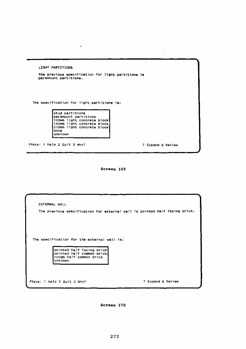
vot
EXTERNAL WALL
The previous s pecification for external wall is pointed half facing brick.
The specification for the external wall is:
pointed half facing brickpointed half common brickrough half common brickunknown
FKeys: 1 Help 2 Quit 3 Why?
7 Expand 8 Review
LIGHT PARTITIONS
The previous specification for light partitions isparamount partitions.
The specification for light partitions is:
stud partitionsparamount partitions100mm light concrete block140mm light concrete block215mm light concrete blocknoneunknown
FKeys: 1 Help 2 Quit 3 Why? 7 Expand 8 Review
Screen 169
Screen 170
273
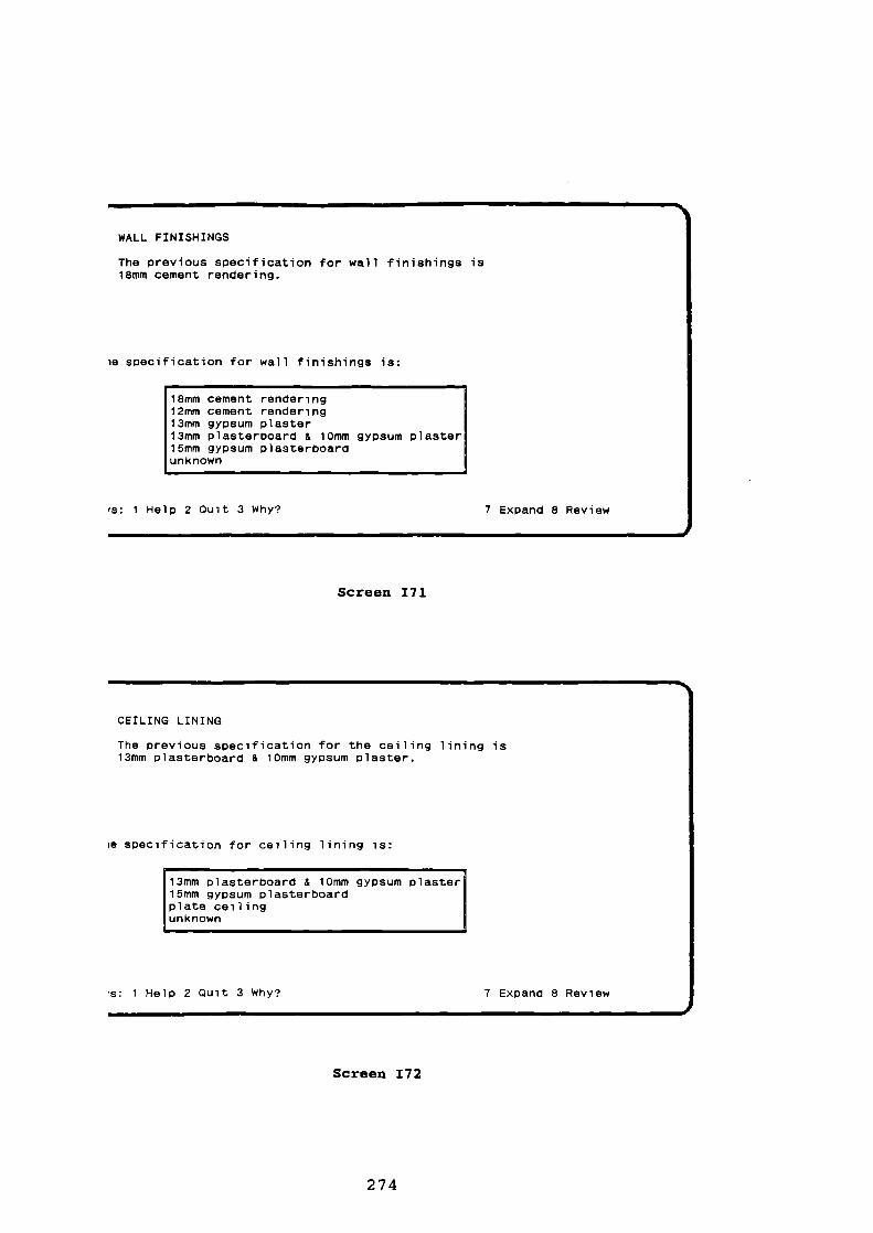
WALL FINISHINGS
The previous specification for wall finishings is18mm cement rendering.
le specification for wall finishings is:
18mm cement rendering12mm cement rendering13mm gypsum plaster13mm plasterboard & 10mm gypsum plaster15mm gypsum plasterboardunknown
es: 1 Help 2 Quit 3 Why? 7 Ex pand 8 Review
Screen 171
CEILING LINING
The previous specification for the ceiling lining is13mm p lasterboard & 10mm gypsum plaster.
m s pecification for ceiling lining is:
13mm plasterboard & 10mm gypsum plaster15mm gypsum plasterboardplate ceilingunknown
m: 1 Help 2 Quit 3 Why? 7 Expand 8 Review
Screen 172
274

11n11%
FLOOR SLAB
The previous specification of floor slab is reinforced concrete slab.
The specification for the floor slab is:
unreinforced concrete slabtimber floorreinforced concrete slabsuspended concrete slabunknown
FKeys: 1 Help 2 Quit 3 Why? 7 Expand 8 Review
VOLUME OF CONCRETE FOR GROUND FLOOR
Please, enter the total volume of concrete for floor slab and cavitywall filling.
The previous value for the ground floor concrete volume is unknown.
You may type unknown.
Please, type the volume of concrete, in m2:
FKeys: 1 Help 2 Quit 3 Why? 7 Expand 8 Review
Screen 173
Screen 174
275

GROUND FLOOR SLAB THICKNESS
The previous value for the slab thickness is unknown.
You may answer unknown
Please, enter the groung floor thickness, in mm:
unknown
FKeys: 1 Hel p 2 Quit 3 Why? 7 Expand 8 Review
Screen 175
SUSPENDED FLOOR
The previous specification for the suspended floor istimber floor.
The specification for the suspended floor is:
timber floorsuspended concrete slabunknown
FKeys: 1 Help 2 Quit 3 Why? 7 Expand 8 Review
Screen 176
276

TYPE OF HEATING
The previous specification for type of heatin g is gas.
The specification for type of heating system is:
gaselectricgas and electricunknown
FKeys: 1 Help 2 Quit 3 Why? 5 Volunteer 6 BackuP 7 Expand 8 Review
SEQUENCE OF CONSTRUCTION
The previous value for the se quence of construction isunknown.Type F7 to get some guidelines for establishing the sequence ofconstruction.
Please, inform whether the construction sequence is known:
knownunknown
FKeys: 1 Help 2 Quit 3 Why? 7 Expand 8 Review
Screen 177
NOTE: option "unknown" selected
Screen 178
277

SEQUENCE OF WORK PLACES
If the sequence in which the houses will be delivered has not beenpreviously established by the client, I suggest the following guide-lines for establishing the sequence of construction:
(i) The job should start by houses that have already road access, orby the ones for which the necessary access can be quickly constructed;
(ii) Sequential work places should be located as near as possible fromeach other, in order to avoid an excessive movement of gangs andequipment around the site;
(iii) The section of the site where the compound is located shouldpreferably be one of the last ones to be concluded, so that thetraffic concerned with the work on site does not have to cross sectionswhere the houses have already been concluded; and
(iv) If vandalism in the area is likely, the newly completed houses canbe used, after being delivered, as a barrier between the site and otherhousing states in the neighbourhood.
Hit any key to continue
NOTE: this screen displays an explanation required from Screen 78
Screen 179
ROAD ACCESS TO ALL HOUSES
The sequence of houses In this project is unknown. However, you mightknow whether there is road access for all houses.
The previous value for access to all houses is unknown.
Please, inform whether road access to all houses exist:
existentnon existentunknown
FKeys: 1 Help 2 Quit 3 Wh y?7 Expand 8 Review
Screen 180
278

NEXT STEP
Please, choose the next step:
quit HOUSE PLANNERrun INPUT MODULE againrun BUILD MODULE
FKeys: 1 Hel p 2 Quit 3 Why? 7 Expand 8 Review
Screen 181
279
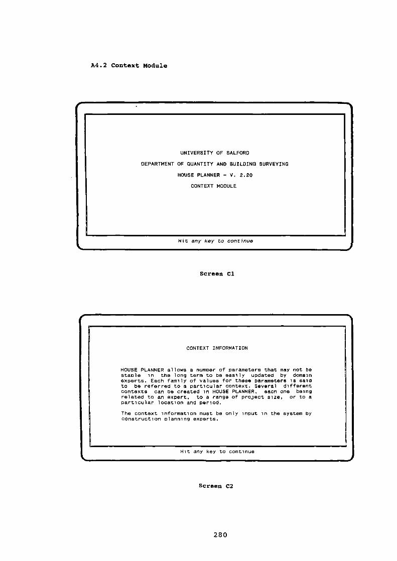
UNIVERSITY OF SALFORD
DEPARTMENT OF QUANTITY AND BUILDING SURVEYING
HOUSE PLANNER - V. 2.20
CONTEXT MODULE
Hit any key to continue
CONTEXT INFORMATION
HOUSE PLANNER allows a number of parameters that may not bestable in the long term to be easily updated by domainexperts. Each family of values for these parameters is saidto be referred to a particular context. Several differentcontexts can be created in HOUSE PLANNER, each one beingrelated to an expert, to a range of project size, or to aparticular location and period.
The context information must be only input in the system byconstruction planning experts.
Hit any key to continue
A4.2 Context Module
Screen Cl
Screen C2
280

OLD OR NEW CONTEXT
Could you inform whether the context you want to use is old or new.
Please, choose the correct answer:
FKe ys: 1 Help 2 Quit 3 Why? 5 Volunteer 6 Backup 7 Expand 8 Review
Could you type the name of the context (max 8 characters):
NOTE: option "old" selected
Screen C3
Screen C4
281
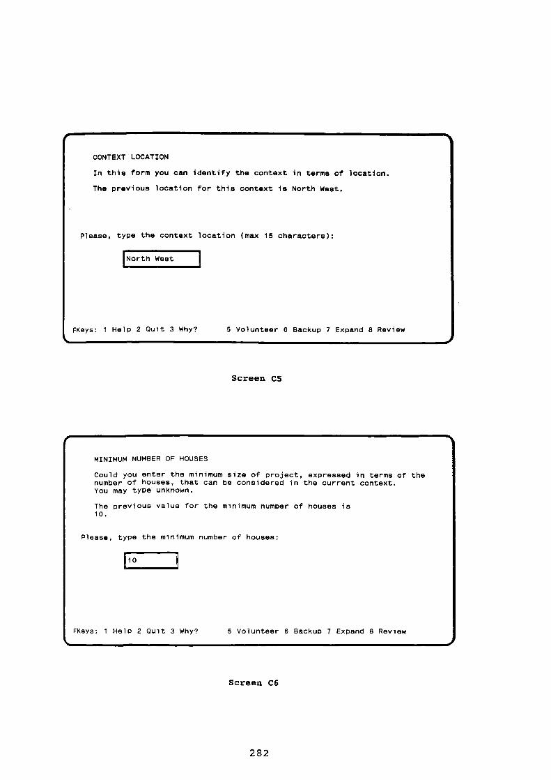
CONTEXT LOCATION
In this form you can identify the context in terms of location.
The previous location for this context is North West.
Please, type the context location (max 15 characters):
North West
Fkeys: 1 Help 2 Quit 3 Why? 5 Volunteer 6 Backup 7 Expand 8 Review
MINIMUM NUMBER OF HOUSES
Could you enter the minimum size of p roject, expressed in terms of thenumber of houses, that can be considered in the current context.You may type unknown.
The previous value for the minimum number of houses is10.
Please, type the minimum number of houses:
Fkeys: 1 Hel p 2 Quit 3 Why? 5 Volunteer 6 Backup 7 Expand 8 Review
Screen C5
Screen C6
282

MAXIMUM NUMBER OF HOUSES
Could you enter the maximum size of project, expressed in terms of thenumber of houses, that can be considered in the current context.You may type unknown
The previous value for the maximum number of houses is180.
Please, type the maximum number of houses:
1180
FKe ys: 1 Help 2 Quit 3 Why? 5 Volunteer 6 Backup 7 Expand 8 Review
Screen C7
MINIMUM AVAILABILITY OF BRICKLAYERS
Could you enter the maximum number of bricklayers that might beexpected to be hired for a single p roject in a situation of shortageof labour in the market, in the current context.You may type unknown.
The previous value for minimum availability of bricklayers is8.
Please, type the number of bricklayers available:
FKeys: 1 Help 2 Quit 3 Why? 5 Volunteer 6 Backup 7 Expand 8 Review
Screen CS

MAXIMUM AVAILABILITY OF BRICKLAYERS
Could you enter the maximum number of bricklayers that might beexpected to be hired for a single project in a situation of highavailability of labour in the market, in the current context.You may type unknown.
The previous value for maximum availability of bricklayers is30.
Please, type the number of bricklayers available:
130
FKeys: 1 Help 2 Quit 3 Why? 5 Volunteer 6 Backup 7 Ex pand 8 Review
RATIO BETWEEN PEAK AND AVERAGE FOUNDATION SPEED
Could you enter the number of times the peak rate should be greaterthan the average rate in the foundation stage.
You may type unknown.The previous value for the ratio between peak and average foundationspeed is 1.40.
Please, enter a number, or type F7 for explain:
FKeys: 1 Help 2 Quit 3 Why? 5 Volunteer 6 Backu p 7 Expand 8 Review
Screen C9
Screen C10
284

RATIO BETWEEN PEAK AND AVERAGE SHELL SPEED
Could you enter the number of times the peak rate should be greaterthan the average rate in the shell/roofing stage.
You may type unknown.The previous value for the ratio between peak and average shellspeed is 1.20.
Please, enter a number, or type F7 for explain:
FKeys: 1 Help 2 Quit 3 Why? 5 Volunteer 6 Backup 7 Expand 8 Review
RATIO BETWEEN PEAK AND AVERAGE FINISHING SPEED
Could you enter the number of times the peak rate should be greaterthan the average rate in the finishing stages.
You may type unknown.The previous value for the ratio between peak and average finishingspeed is 1.20.
Please, enter a number, or type F7 for explain:
FKeys: 1 Help 2 Quit 3 Why? 5 Volunteer 6 Backu p 7 Expand 8 Review
Screen C11
Screen C12
285

RATIO BETWEEN ACCELERATION AND DECELERATION PERIOD
Could you enter the ratio between the length of the acceleration periodand the length of the deceleration period.
You may type unknown.
The previous value for the ratio between the acceleration and thedeceleration period is 2.00.
Please, type a number:
FKeys: 1 Help 2 Quit 3 Why? 5 Volunteer 6 Backup 7 Expand 8 Review
MINIMUM EXCAVATING RATE
In this form you can enter the minimum amount of reduced levelexcavation, expressed in terms of m3/week, that can be consideredas reasonable for house building projects.
You may type unknown.The previous value for the minimum excavating rate is
500 m3/week.
Please, enter the economic minimum excavating rate:
FKeys: 1 Help 2 Quit 3 Why? 5 Volunteer 6 Backup 7 Expand 8 Review
Screen C13
Screen C14
286

MAXIMUM EXCAVATING RATE
In this form you can enter the maximum amount of reduced levelexcavation, ex p ressed in terms of m3/week, that can be consideredas reasonable for house building projects.
You may type unknown.The previous value for the maximum excavating rate is
5000 m3/week.
Please, enter the economic maximum excavating rate:
FKeys: 1 Help 2 Quit 3 Why? 5 Volunteer 6 Backup 7 Ex pand 8 Review
MAXIMUM CONCRETING RATE
In this form you can enter the maximum amount of concrete that isconsidered as reasonable to be casted per week in a house buildingsite.
You may type unknown.The previous value for the maximum concreting rate is160 m3.
Please, enter the maximum weekly concreting rate in m3:
1160
FKeys: 1 Help 2 Quit 3 Why? 5 Volunteer 6 Backup 7 Expand 8 Review
Screen C15
Screen C16
287

MAXIMUM FORMWORK GANG SIZE
You may type unknown.
The previous value for the maximum formwork gang size is6.
Please, enter the maximum formwork gang size:
FKeys: 1 Help 2 Quit 3 Why? 5 Volunteer 6 Backup 7 Expand 8 Review
MAXIMUM PLASTERER GANG SIZE
You may type unknown.
The previous value for the maximum plasterer gang size is12.
Please, enter the maximum plasterer gang size:
FKeys: 1 Help 2 Quit 3 Why? 5 Volunteer 6 Backup 7 Expand 8 Review
Screen C17
Screen C18
288

BRICKWORK TARGET RANGE
In this form you can answer whether a range of usual targets forbricklayers is available.
The previous value for brickwork target range is available.
Please, choose the correct answer:
FKeys: 1 Hel p 2 Quit 3 Why? 5 Volunteer 6 Backup 7 Expand 8 Review
RANGE OF TARGETS FOR THE BRICKLAYING GANGS
In this form you can enter a range of targets you consider as normal forthe bricklaying gangs. This range is expressed in terms of square metersof facing half brick wall per week, and it is used for estimating theinitial output of bricklayers (without considering the repetition effect).
Please enter the minimum and the maximum target for bricklayers:
1
Minimum target: 20.00 m2/weekMaximum target: 38.00 m2/week
FKeys: 1 Help 2 Quit 4 FldHelp
NOTE: option "available" selected
Screen C19
Screen C20
289

RANGE OF REPETITION EFFECT ON BRICKLAYING GANGS
In this form you can enter a ran ge of repetition effect that you consideras normal for the bricklaying gangs. The repetition effect reflects thepercentage the productivity rates are expected to be reduced to if thenumber of units to be built doubles. The maximum effect is related tothe situation in which all houses have identical design, while theminimum effect implies houses with distinct design.
Please, enter the minimum and the maximum repetition effect:
I 1Minimum repetition effect: 98 %Maximum repetition effect: 98 %
FKeys: 1 Help 2 Quit 4 FldHelp
Design simplicity factor Brickwork concentration factor:Geographica l continuit y factor:
FKeys: 1 Help 2 Quit 4 FldHelP
40 %5%5%
Screen C21
RANGES FOR THE PRODUCTIVITY OF BRICKLAYERS
The initial productivit y of bricklayers (the expected productivity withoutconsidering the repetition effect) is estimated by using three indices:design simp licity, geographi cal continuity , and brickwork concentration.The values of these indices range from 0 to 1. Considering all the otherfactors constant, you can choose a range of productivity variability foreach factor. For instance, a range of 10% for the Design Simp licity factormeans that the productivit y of bricklayers will range from -5% to +5%around the average, considering the other two factors constant.
Please, enter the brickwork productivit y factors' range:
Screen C22
290

HOUSE DESIGN SIMPLICITY INDICES
Each house design type has a design simplicity indexassociated to it. The value of this index ranges from 0to 1, from the most complex design to the most simp le one,respectively. This index is used for estimating theproductivity of bricklayers.
Please, enter the design simplicity indices:
Rectangular detached house • 1.00L-shaped detached house 0.90Irregular detached house - 0.60Rectangular semi-detached house.: 1.00L-shaped semi-detached house • 0.90Irregular semi-detached house...: 0.60
FKeys: 1 Help 2 Quit
4 FldHelp
BLOCK DESIGN SIMPLICITY INDEX
Each block design type has a design simplicity indexassociated to it. The value of this index ranges from 0to 1, from the most complex design to the most simple one,res pectively. This index is used for estimating theproductivity of bricklayers.
Please, type the following design simplicity indices:
Rectangular terraced house block with no staggers and no steps.: 0.70Irregular terraced house block with no staggers and no ste ps...: 0.60Rectangular terraced house block with steps but no staggers • 0.50Irregular terraced house blocks with ste ps but no staggers 0.40Rectangular terraced house block with staggers but no steps 0.30Irregular terraced house block with staggers but no steps 0.20Rectangular terraced house block with ste ps and staggers 0.10Irregular terraced house block with ste ps and staggers • 0.05
FKeys: I Help 2 Quit
4 FldHelp 5 Prey Screen
Screen C23
Screen C24
291
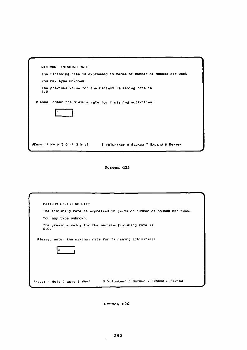
MINIMUM FINISHING RATE
The finishing rate is expressed in terms of number of houses per week.
You may type unknown.
The previous value for the minimum finishing rate is1.0.
Please, enter the minimum rate for finishing activities:
1
FKeys: 1 Help 2 Quit 3 Why? 5 Volunteer 6 Backup 7 Expand 8 Review
MAXIMUM FINISHING RATE
The finishing rate is expressed in terms of number of houses per week.
You may type unknown.
The previous value for the maximum finishing rate is5.0.
Please, enter the maximum rate for finishing activities:
FKeys: 1 Help 2 Quit 3 Why? 5 Volunteer 6 Backu p 7 Expand 8 Review
Screen C25
Screen C26
292

Fkeys: 1 Hel p 2 Quit
4 FldHelp 5 Prev Screen
\
FINISHINGS AVAILABILITY OF MANAGEMENTCOMPLEXITY very low low medium high very high
verycomplex 1.5 2.0 2.5
2.53.0
3.03.5
medium 2.0 2.5 3.0 3.5 4.0Si mple 2.5 3.0 3.5 4.0 4.5very simple 3.0 3.5 4.0 4.5 5.0
2.01.0 1.5complexl
FINISHING RATES
The finishing activities maximum economic rate estimate is based on howcomplex the finishings are and on the availability of management in thecompany. This rate ranges between the minimum and the maximum finishingrate previously input. The finishing rate is expressed in terms of num-ber of houses per week.
please, confirm or overwrite the following rates:
Screen C27

iepsom i
A4.3 Build Module
UNIVERSITY OF SALFORD
DEPARTMENT OF QUANTITY AND BUILDING SURVEYING
HOUSE PLANNER - V. 2.20
BUILD MODULE
Hit any key to continue
Screen B1
NAME OF THE PROJECT
Could you type the name of the project (max 6 characters):
Fkeys: 2 Quit
Screen B2

PEAK SHELL RATE
I propose the peak shell rate of 3.2 house(s) Per week.
The maximum shell rate is 3.2 house(s) per week, considering the maximumnumber of bricklayers in the current context as 18.
Please, confirm or overwrite the proposed value, or type F3 for explain:
I3.2 house(s)/wee k 1
FKeys: 1 Help 2 Quit 3 ScrnHel p 4 FldHelp
SHELL RATE
The proposed shell rate (3.2 houses/week) corresponds to the maximumshell rate for this particular project.
The maximum finishing rate was calculated by the following formula:
max_shell_rate = n_house * brick_output max_num_bricklayers /equiv_half_brick
where n_house is the total number of houses ( 48); brick_output is theestimated average output of bricklayers (40.06 m2/week), expressed interms of the eauivalent amount of half brick wall; max_num_bricklayersis the maximum number of bricklayers for the present job (18); andequiv_half_brick is the total work content on the bricklaying trade,also expressed by the equivalent amount of half brick wall ( 10927m2).
Hit any key to continue
Screen B3
NOTE: this screen displays an explanation required from Screen 133
Screen B4
295

441.
INDEX VALUE 1050
Design simplicityDesign repetitivenessGeog raphical continuityBrickwork concentration
1.000.981.000.10
OUTPUT OF BRICKLAYERS
The output of bricklayers is estimated accordin g to four indices. Thevalue of each index ranges from 0 to 1. The higher the index the higheris the p roductivity of bricklayers.
These are the productivity indices for the current job:
Hit any key to continue
OUTPUT OF BRICKLAYERS
The expected output of bricklayers in the current project, expressedin terms of equivalent sq.meters of half brick wall, is displayedbellow as well as the minimum and the maximum targets for the currentcontext.The peak shell rate of 3.2 houses/week is feasible. The number ofbricklayers required for this job is 18, and the total duration ofshell/roofing activities is 18 weeks.
Please, p ress RETURN to confirm or F5 to change peak shell rate:
20.00 38.00
38.50 m2/week
Fkeys: 1 Help 2 Quit 3 ScrnHelp 4 FldHel p 5 Prey Screen
Screen B5
NOTE: this screen displays an explanation required from Screen BS
Screen B6
296

PEAK FINISHING RATE
I Propose the peak shell rate of 2.7 house(s) per week.
The maximum finishing rate in the current context is 3.5 house(s) per week.
Please, confirm or overwrite this value, or type F3 for explain:
1 2.7 house(s)/week
FKeys: 1 Help 2 Quit 3 ScrnHel p 4 FldHel p 5 Prev Screen
FINISHING RATE
The proposed finishing rate was calculated by the following formula:
finishing_rate = shell_rate / shell_finishing_ratio
The value of the shell_finishing_ratio is based on the type of projectorganization and on the likelyhood of vandalism in the area. In thisparticular job, this value was established by the following rule:
IF organization_type is conventionalAND vandalism is not relevantTHEN shell_finishing_ratio = 1.2
Hit any key to continue
Screen B7
NOTE: this screen displays an explanation required from Screen B7
Screen BS
297

FINISHING PARAMETERS
The number of plasterers needed for carrying out the finishing stage ata rate of 2.7 house(s) Per week is 6. The most critical resource forthe finishing speed is management.
The total duration of finishing activities for this rate is 21 weeks.
Please, press <RETURN> to confirm or FS to change peak finishing rate:
FKeys: 1 Help 2 Quit
4 FldHelp 5 Pre y Screen
s.
Screen B9
PEAK FOUNDATION RATE
pose the peak foundation rate of 3.8 house(s) per week.I pro
The maximum foundation rate in the current context is 7.3 house(s)/week.The most critical resource for the foundation speed is bricklayers
Please, confirm or overwrite this value, or press F3 to explain:
3.8 house(S)/We
FKeys: 1 Helo 2 Quit 3 ScrnHe l o 4 FldHelp 5 Pre y Screen
Screen 810
298

FOUNDATION RATE
The proposed foundation rate was calculated by the following formula:
foundation_rate = shell_rate * foundation_shell_ratio
The value of the foundation_shell_ratio is based on the type of projectorganization. In this particular case, this value was established bythe following rule:
IF organization_type is conventionalTHEN founaation_shell_ratio = 1.2
Hit any key to continue
FOUNDATION PARAMETERS
Foundation excavation rate 35 m3/weekFormwork rate 0 m2/weekNo. of formwork joiners 0Concreting rate 42 m3/weekNo. of bricklayers for foundations: 4Total duration of activities 18 weeks
Please, press <RETURN> to confirm or F5 to change peak foundation rate:
I3.8 house(s)/week
FKeys: 1 Help 2 Quit 4 F1dHele 5 Pre y Screen
NOTE: this screen displays an explanation required from Screen B10
Screen B11
Screen B12
299

1 set up site2 clear site3 vibrocompacting4 site shaping5 main drainage6 roads to subbase7 kerb race8 ducts/gullies9 base course 7
BUFFER BETWEEN SITE PREPARATIONAND FOUNDATIONS
The foundation stage is due tostart at week No.12.Please, confirm or overwrite thestage buffer p roposed below orpress F4 to explain:
11=114oSTAGE: site preparation DEPENDENCY: ducts/
FKeys: 1 Hel p 2 Quit 4 FldHelp
I
CONSTRUCTION PROGRAMMEPROJECT NAME: epsom CURRENT CONTEXT: default CURRENT DATE: 26-Jan-91 13:50
WEEK 1 1111111112 2222222223 3333333334 4444444445No. 1234567890 1234567890 1234567890 1234567890 1234567890
tiln ....nIs
DISTRIBUTION OF TWO FLOOR HOUSES ON SITE
Please, enter how the two floor houses are distributed:
concentrated in the beginningequally distributedconcentrated in the endunknown
FKeys: 1 Help 2 Quit 3 Why?
5 Volunteer 6 Backup 7 Expand 8 Review
Screen B13
Screen B14
300

BUFFER BETWEEN SITE PREPARATION AND FOUNDATIONS
This buffer was established from the following rules:
If starting_month is 'Dec'or starting_month is 'Jan'or starting_month is 'Fey'then buffer = 1
if starting_month is not 'Dec'and starting_month is not 'Jan'and starting_month is not 'Fey'then buffer = 0
Hit ESC to quit
1 set up2 clear3 vibroc4 site s5 main d8 roads7 kerb r8 ducts/9 base c
444444445234587890
ARATION
due to
rite thelow or
STAGE: site preparation DEPENDENCY: ducts/t FKeys: 1 Help 2 Quit 4 FldHelp
TEMPORARY ROADS
If temporary roads are not built, the foundation can only start inweek No.12.I strongly advise to build temporar y roads.
Press F7 for explanation.
Please, confirm whether tem porary roads are to be built:
not to be bullto be built
FKeye: 1 Help 2 Quit 3 Why? 7 Expand 8 Review
CONSTRUCTION PROGRAMMEPROJECT NAME: epsom CURRENT CONTEXT: default CURRENT DATE: 28-Jan-91 13:50
NOTE: this screen displays an explanation required from Screen B14
Screen B15
option "to be built" selectedNOTE:
Screen B16
301

CONSTRUCTION PROGRAMMEPROJECT NAME: epsom
WEEKNo.
CURRENT CONTEXT: default CURRENT DATE: 28-Jan-91 13:57
1 1111111112 2222222223 3333333334 44444444451234587890 1234587890 1234567890 1234587890 1234587890
123
set up siteclear sitevibrocompacting
EMMN
MO4 site shaping nI5 main drainage um8 roads to subbase —U7 kerb race mom mm89ducts/gulliesbase course
mom mm-
444 34443310 excavate footings 0022233 2111 concrete footings 0022233 444 344433 2112 brickwork to DPC 002223 344 434443 32113 service entries 00222 334 443444 332114 house drainage 0022 233 444344 4332115 hardcore 0022 233 444344 43321
STAGE: foundations
DEPENDENCY: service entries
TRADE: general labourerHit any key to continue
16 concrete slab
STAGE: foundationsFKeys: 1 Hel p 2 Quit
0022 233 4443
DEPENDENCY: hardco4 FldHelp
BUFFER BETWEENFOUNDATION AND SHELL/ROOFING
The shell/roofing stage is dueto start at week No.11.Please, confirm or overwrite thestage buffer proposed below, orpress F4 to explain.
1
CONSTRUCTION PROGRAMMEPROJECT NAME: epsom
CURRENT CONTEXT: default CURRENT DATE: 26-Jan-91 13:58
WEEK 1 1111111112 2222222223 3333333334 4444444445No. 1234567890 1234567890 1234567890 1234567890 1234567890
Screen B17
Screen B18
302

FOUNDATIONS DURING WINTER MONTHS
The foundation stage is scheduled to be carried out during thewinter months. I suggest to change this schedule in order toavoid that inclement weather interferes in the continuity andproductivity of weather sensitivity activities.
Please, type F3 to confirm or F4 to keep the schedule unchanged:
The possible actions are:
[
Postpone the whole jobSlow down job start
FKeys:
1\w
2 Quit 3 Confirm 4 Cancel action
CONSTRUCTION PROGRAMMEPROJECT NAME: epsom CURRENT
WEEKNo.
CONTEXT: default CURRENT DATE: 26-Jan-91 14:20
1 1111111112 2222222223 3333333334 44444444451234567890 1234567890 1234567890 1234567890 1234567890
16 concrete slab 0022 233 444344 4332117 brickwork 1st lift 012 333433 33433333118 scaffold 1st stage
01 233343 333433333119 brickwork 2nd lift20 scaffold 2nd stage
012122 121221212121 1st floor joists 0 122 brickwork 3rd lift 001212 2121221212 1123 scaffold 3rd stage
00121 221212212124 brickwork 4th lift 21125 scaffold 4th stage
0123 3343333433 333126 brickwork to peaks27 roof carcass 0123 3343333433 333128 SVP gutters & RWP 012 3334333343 3333129 tile roof 012 3334333343 3333130 strip scaffold
STAGE: shell/roofing
DEPENDENCY: tile roof TRADE: scaffolderHit any key to continue
NOTE: option "cancel action" selected
Screen B19
Screen B20
303
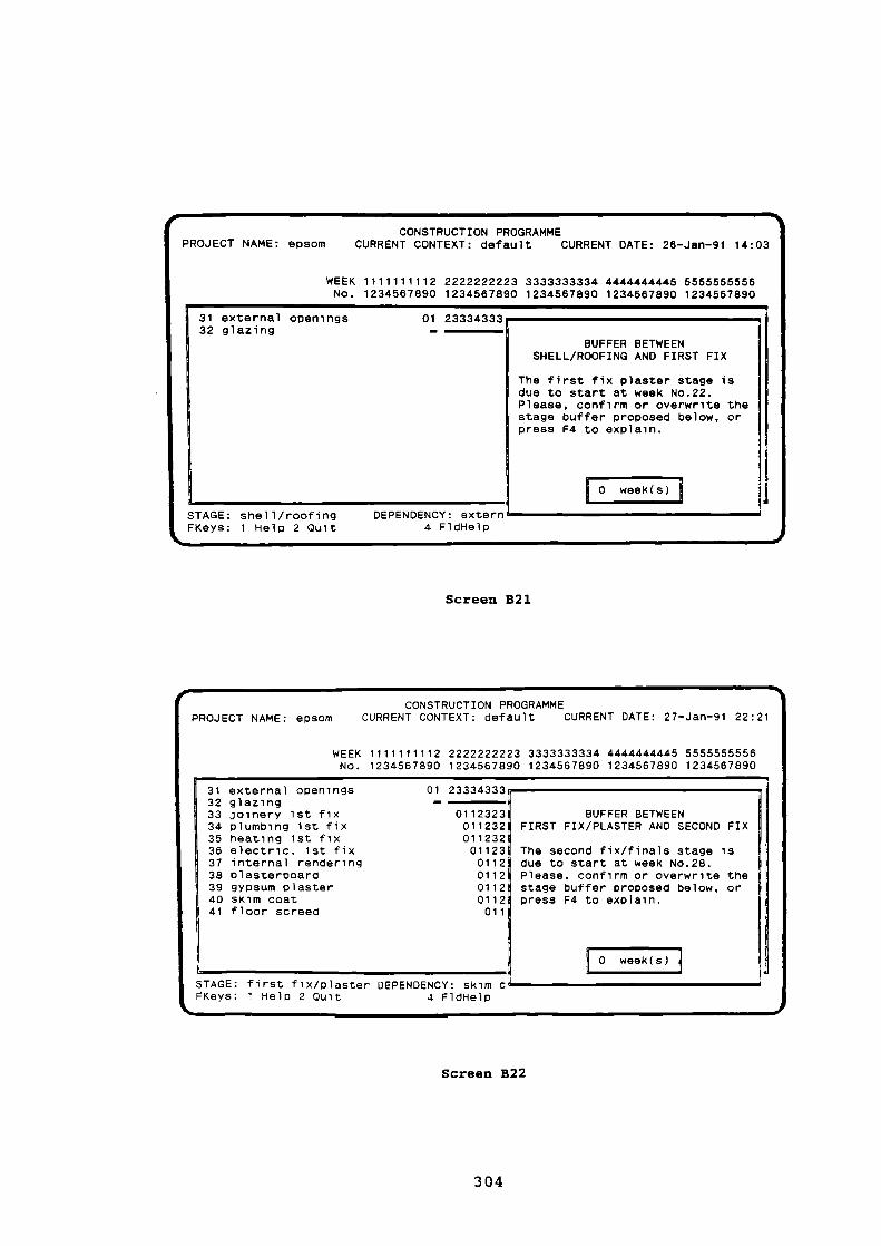
PROJECT NAME: epsomCONSTRUCTION PROGRAMME
CURRENT CONTEXT: default CURRENT DATE: 26-Jan-91 14:03
2222222223 3333333334 4444444445 55555555561234567890 1234567890 1234587890 1234567890
WEEK 1111111112No. 1234567890
The first fix plaster stage isdue to start at week No.22.Please, confirm or overwrite thestage buffer proposed below, orpress F4 to explain.
31 external openings32 glazing
01 23334333I=
BUFFER BETWEENSHELL/ROOFING AND FIRST FIX
ISTAGE: shell/roofing
DEPENDENCY: externFKeys: 1 Help 2 Quit
4 FldHelp
BUFFER BETWEENFIRST FIX/PLASTER AND SECOND FIX
The second fix/finals stage isdue to start at week No.28.Please, confirm or overwrite thestage buffer proposed below, orpress F4 to explain.
0 week(s)
.1"CONSTRUCTION PROGRAMME
PROJECT NAME: epsom CURRENT CONTEXT: default CURRENT DATE: 27-Jan-91 22:21
WEEK 1111111112 2222222223 3333333334 4444444445 5555555556No. 1234567890 1234567890 1234567890 1234567890 1234567890
31 external openings32 glazing33 joinery 1st fix34 plumbing 1st fix35 heating 1st fix36 electric. 1st fix37 internal rendering38 plasterboard39 gypsum plaster40 skim coat41 floor screed
STAGE: first fix/ p laster DEPENDENCY: skim cFKeys: 1 Help 2 Quit 4 FldHelp
01 23334333—
0112323011232011232011230112011201120112011
n11,
Screen B21
Screen B22
304

BUFFER BETWEEN FIRST FIX/PLASTER AND SECOND FIX/FINALS
This buffer was established from the following rules:
if management_availab is 'very high'or management_availab is 'high'or management_availab is 'medium'then buffer = 0
if management_availab is 'very low'or management_availab is 'low'then buffer = 1
Hit ESC to cult
31 extern32 glazin33 joiner34 plumbi35 heatin38 electr37 intern38 plaste39 gypsum40 skim c41 floor
CONSTRUCTION PROGRAMMEPROJECT NAME: epsom CURRENT CONTEXT: default CURRENT DATE: 28-Jan-91 14:20
555555558234567890
COND FIX
age is28.rite thelow, oryou wantchoose
STAGE: first fix/plaster DEPENDENCY: skim cFKeys: 1 Help 2 Quit 4 FldHelp
31 external openings32 glazing33 joinery 1st fix34 plumbing 1st fix35 heating 1st fix36 electric. 1st fix37 internal rendering38 plasterboard39 gypsum plaster40 skim coat41 floor screed42 joinery 2nd fix43 p lumbing 2nd fix44 heating 2nd fix45 porch joinery
011232332 3332332332 3101123233 2333233233 23101123233 2333233233 2310112323 3233323323 3231011232 3323332332 33231011232 3323332332 33231011232 3323332332 33231011232 3323332332 3323101123 2332333233 233231
011 2323323332 33233231011 2323323332 33233231011 2323323332 33233231
01 2333433334 3333313=1
CONSTRUCTION PROGRAMMEPROJECT NAME: epsom
CURRENT CONTEXT: default CURRENT DATE: 26-Jan-91 14:03
WEEK 1111111112 2222222223 3333333334 4444444445 5555555556No. 1234567890 1234567890 1234587890 1234567890 1234567890
STAGE: second fix/finals DEPENDENCY: floor screed
TRADE: joinerHit any key to continue
NOTE: this screen displays an explanation required from Screen B22
Screen B23
Screen B24
305

CONSTRUCTION PROGRAMMEPROJECT NAME: epsom
CURRENT CONTEXT: default CURRENT DATE: 26-Jan-91 14:05
3333333334 4444444445 5555555556 66686666671234587890 1234567890 1234587890 1234567890
WEEK 2222222223No. 1234567890
46 porch roof tiling47 electric. 2nd fix48 gas meter49 electric meter50 plumbing testing51 loft insulation52 artex on ceilings53 joinery final fix54 wall tiling55 internal painting56 floor tiling57 external painting58 ironmongery59 handover60 wearing course
..01 ;IT= ?TM!'
0112323323
01123233201123233
0112323
011232011230112
332332332 31
333233233 231233323323 3231
323332332 33231
332333233 233231233233323 3233231323323332 33233231
•STAGE: landsca pe
DEPENDENCY: handover
TRADE: subcontractorHit any key to continue
61 white lining62 permanent kerbs63 landscaping64 fencing65 house footpath66 place top soil67 public footpath68 external brickwork69 ext. foundations70 elect.connection71 gas connection72 water connection73 BT connection74 water mains75 gas mains
STAGE: landscape
DEPENDENCY: water mains
TRADE: gas boardHit any key to continue
=InEN
i
i MN
.n
.n1
IN
IN
CONSTRUCTION PROGRAMMEPROJECT NAME: epsom
CURRENT CONTEXT: default CURRENT DATE: 26-Jan-91 14:07
WEEK 1111111112 2222222223 3333333334 4444444445 5555555556No. 1234567890 1234567890 1234567890 1234587890 1234567890
Screen B25
Screen B26
306

CONSTRUCTION PROGRAMMEPROJECT NAME: ePsom CURRENT CONTEXT: default CURRENT DATE: 26-Jan-91 14:10
1111111112 2222222223 3333333334 4444444445 55555555561234567890 1234567890 1234567890 1234567890 1234567890
STAGE: landscape
DEPENDENCY: handover TRADE: general labourerHit any key to continue
WEEKNo.
76 electric mains77 BT mains78 street lighting79 clear away
RESOURCES TO BE SCHEDULED
Please, enter the resources you want to be scheduled:
formwork joinerjoinerplastererbricklayernone
FKeys: 1 Help 2 Quit 3 Why? 7 Exp 8 Rev <Ins> Add <Del> Remove
Screen B27
NOTE: option "none" selected
Screen B28
307

NEXT STEP
Please, choose the next step:
I
quit HOUSE PLANNERrun BUILD MODULE againrun INPUT MODULEperform WHAT IF questions
FKeys: 1 Help 2 Quit 3 Why? 7 Expand 8 Review
nn=0.1,
TYPE OF OUTPUT
Please, choose the kind of output you would like to have:
display general programmeprint general programmeprint schedule of milelstonesprint list of activitiesnone
FKeys: 1 Help 2 Quit 3 Why? 7 Exp 8 Rev <Ins> Add <Del> Removenmmdf
NOTE: option "none" selected
Screen B29
NOTE: option "perform WHAT IF questions" selected
Screen B30
308

OBJECTS TO CHANGE FOR WHAT IF SESSION
Choose the objects you would like to change the value:
bricklayer availabilitymanagement availabilitybricklayers' over time indexmax durationmax period for first handoverfinishing complexitytemporary roadsNo. houses with access
FKeys: 1 Help 2 Quit 3 Why?
7 Exp 8 Rev <Ins> Add <Del> Remove
n=01,
AVAILABILITY OF MANAGEMENT
Could you inform what is the situation within the company in terms ofavailability of management for the current job.
The previous value for the availability of management ismedium.
Please, type the correct answer:
very highhighmediumlowvery lowunknown
FKeys: 1 Hel p 2 Quit 3 Why? 7 Expand 8 Review
NOTE: option "management availability" selected
Screen B31
NOTE: after changing the value of this variable, the system goes backto Screen B3 and starts a new cycle
Screen B32
309
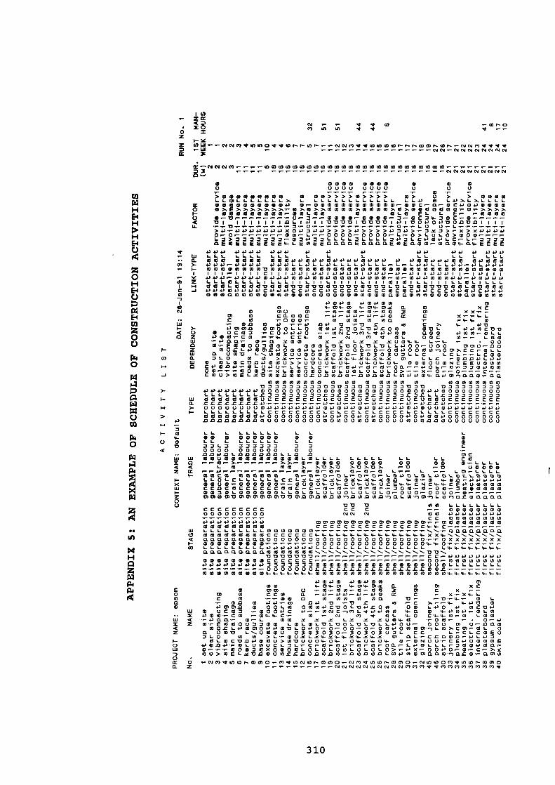
'U)- ZM
N 4 4 W• X0 V) 10 10 Mo XI- IC
:C CO IM c4 c.) 4 0 0 CD 41 . 4 0 r- csi V 4 0 u) co r- r- r- a) 0) Tn ,T .4 .1. NN.-NNNNNNNN
3c
M^NNNCOCOW0M00000WWWWWWW0c0W000000m30 ..-
NNNNNNNNN
Co
p.
P04
0
00
CO
0
rzi
CO
0
a
• WELL WELL co a) 0O 0000 0000 0 0 0..- -.- a) ..- .->000000000 0 Nel>>>>0>>>> 10> 0 > > OMMM
›.. L .1.) M 1.4-1)n L),LLLLX 0000000000.0 0,-mmommea00e00-mac-a-mcomo0e00O co NEN>, >, >. CO ).. 0 >, >, 0 WEE0 70) 0 CO CO CO NIO NCO (D co co co o) (I) . 1- CO ., N7•.›.)..I- 000000000.--MOLOW 0 OLO EL L E0- r117000C.) 0..-.17 , 0 o- 3 .- .- 0 (D 0 0 ,- CD CD (D CD ,- 3o- 0) C 34- 3 CD C • .- (0 . 0- f- r- r•- e-••C 171 1 1 1 1 1 1 147L14.1 1 117 '0 17 17117 17 17 1714, 1170000 17017 17 VI IIIU. •,r•Orrn--,=•,-(3,-.,-.,--.,-,-,-I-LC) (.).,L..--,,--.-
>4,04,004,04,X04,704,>>>>0>>>>030>3X2>,-X>X0000r.-0 0C(01-0000,-0000P-L.•0>LULO>000-L a>aaamaam.waoaaLLLLaLLLLaoaLc000Lc.L,-nazaaEWEEEEEEE4-LEWEEaaaaEaaaaEmEatow.waw4-0.4-EEEE
000 0000 000 o 4.) 4.) 00 04-1 4, 000
LLIL LLLL LLL L L L LL LL L LLL000 0000 00000000000000000 0 00000000 0000004, 0 ,-0000 4,00LL0LLOLLLL4JLLLe-Lr-L00LLL00,-.0L4,04,00000WWOMM000000000000(000000000)0)00000000000II I •• I III CI I I 00100 1 0 4, 0 010 0 4, r- 0 •- 01 I 000 I l •-• 10I II
4.3 4.) 4.1 4) 10+) +14.P CO 0 4.) a) a) 1.) WEEa) 0 4.3 CO CO 01.- Mr- a) 4.) 4.) Cl) 0 (04.14-1.-0 104.74.344L LI-OLLLLILLLIILIILIII1L11101M1LLIIILLOLILLL00101-000017000MOCMOMM17170171717LDL010OMMVOOL017000O 4100004J43C04J4JCCIJCCIJCCCCOCCCOCOC4.)1OCCC0000C04J4Jwwwawwwwwwwwwwwwwwwwwwwwwwawawwwwwwwwamwwww
owoco owowco CnCO In 1- 01 4- 0) 4- 0/ 4- 0) X 0. Cl) x c
O ci) 0 0) .,- 0.,- 004- 000 3 Cn XXrrCT CO CMCONC .-4,.-4-10.-4,e-.00 CC CC 0 .raMM.c- M NW 0 wa ..- .- 4- 4- Wr 111.0 N 0 rr4., DP '0 - 1:1 r ..3 c >. V- OV
+10)01.00).0 a) 0)0 0 L L 0 CO U) 4, C17 0 L'O 0-C 0 0 0-CIL 000C17.0M ()cam ,-004.).1a4J0 .- .-MNC ,-)COL Nt4, 4, (00) CIWO) 00(0.-0LL4, 010 •,-C30 ,-,-4.. CC4- CO .- w el V. (CIL 00C 0.-.-. LOO-.-oaa,- 0.0. x00 x x LX X Y0CD4-4- L.I-4- .- • 0 00 ,- E00007001. OMOLVLVOLLIL'OLL4.100..- 000 0)0n0.- 0Wa 0017 L n 003000003030,-3030307LLC
COOL L POML4, 0000L40 .-0 .-00 r-0 ,-000000022t C,.C:2163L0 0 CO >,C,-,-1-0LX4-X4-4-X4-X4-X M LLL ,ODDOLOO
0 OLOCV.04.1000>>0'0004-04.. 04-04-04- MCDM0010NCEE0M1000C4-10.0P-T.COLC,00,-LLCLC..-0,-00,-0,M,-0M.-.-00L,..M....7704-)0000,-,--T-0007,-XLMMOOOLULOCOLULULO>.,-,-X.-0,-.-0.--.--C,-.-CM0>COXLXMWM.00OMUZU0MDC0.-.00.00.0L04.74.)M4-MOMmMacO.,aa
NMOMOMNN M NM N WM 0 NOMOMMONM33333377 .07 .077M3M7333 173 .0 V373337730000000000000000000000000000000000000000000C73777377L3L73LOZ7737C7cLL.C73337737
W 000000000CCCCCCCCUCUCCUCUCCCC0C00700CCCCCCCCM L.C.C.C.C.C.C.0O3.--r-,-,-4,-,0,-.,-4,..-44-1,-4,C.C4,,,-..--,-,-.-).- 0000000000004,000000000000000000000000000000I- LLLLLLLLL CCCCCCCCLCLCCLCLCCCCLCLLLLCCCCCCCCwwwwwwww0000000000000000000000000sm000000000.0.0.0.0.0.0.0.00)000000000)00)00000100000W 000.0.01000000000
L L L LLLLLL L L LEL a) a) a) a) a) a) 0 0 0 a)L L L LLLLLL L L (1)771.3 azamma a 7 c0000 000000 0 0 ,-.0 M .0 X) L .0 .0 .0 .0 .0 M L L M D MC
W wouwwwwwwwwwwwLcoLLLL LLLLL LL LL CMO r.. .-0.-), >,),- M,-M004) 1000010 00 WO 0..-LLLL< L 0 1010 >, >, '0 >, -0 >. 0 >. -0 >, ,- .0 ,- .17 00000M rr4., 10-10-10- 0 •-• 07,-01 L..- .- L .s-r- L0) n•••LLLL1- 0000 000000 10.-0,-.0,-0%.,-0,-0,-).-W0-W0W0
LI-01-C LLLLLL Cci-xl-x4-Y4-0-)C4-x4-0.0 4-0 .,-M 4-00004J4J0comum,-000000,-..-00004-04-cu4-04-uCE4-4-cNc4-4-CE*)00000CCMCOCCCCcCO0C-c-0,-0,-,-00,..-700-0,-00,-700000000701-0000001-1-0L0L0 L00L0L0L0.-000-0000-0 mmoommommommvpmmmnconw-nnwnwn-naLco-nm.nLw.narcoaaaa
DV pccccccccc CC C .-,- 00000000000000000 NN N 00 4.1004.,04.)4J0
CC NMMNCONNW000000000 0)0)0)0)0)0)0)0)0)0)0)0)0)0)0)0)9-0000000000 0 0 0 0 0 0030 CCCCCCCCCCCCCCCC4-4-c
W LLLLLLLLL cowwwwww-,...--,...."-,-,-,-aaaaaaaaO wwwwwwwwoccccccce-4-4-xx4---. nnnnnO aaaaaaaaa00000000000000000000000,-...-oxxxxxxxx. wwwwwwwww-,,--00000000000000004-4---,-,-W LLLLLLLL L .04.).1J 4J .0 .04O LLLLLL L LLLLL LLLL L4-4-4-4-4
aaaaaaaaawwwwwww nnnn •nnn •nnn ,...on-,ppp -o pp m c.- o oo 4)
a) 0 CD OD(DealtIltDCCCC C 0 0 .- 0 CO 0) 0 U) CI) U) COcJ 4J4J04.) .04.)04.)7777=D70000000000000000000 LLLLLLLL
000000LCX.C.C.C.C.C.C.C.C.C.C.CLZ00.---O 000000004-4-4-00000000000000000004-4-4-
43 0.1.2 0 00 .000 cr)0)0) 4-0)4-0)4- 01 4- M 4- C3) X 0. co 0) XC
E 0 MM 0 ,-0,-00 ,-10 ..-070 X (7) C X r-,-O 0) 0 CC L CL r- 4, .-- 4, 4, r- 0 ,- 0 0 CC C ,- X.,-X4-C-co c 0 ..- .,- EL 0 V/ COO) LO 0) 0. ti .--10,-4- 0 L
a 4- con w oo-,-0 no m ..-m r o .c ,...-.4- 4-4n wa) 430)01m W ooLco owcooc p oLmorow ow Loo o wcpo
W 0 00O3 ..-0000C .0.-..-0)NCm0IL.0.04JCOM 4- a 0 4- 000 - 0LOX 000,- CM .- 04- 4- C, 0 .- N m -4- OL 4-0 C4-4-(0.--CO LOCO•ct •,- +3 a 11,- tD ••• L MO X X X LX X X004-0 ..-003,- .-• 0.-0Z 0.,-E00007700 LOLaILMLumLwLvLc-cJOU- 000 M 0.--00.m
mocLoom000m p L000-o-00-0,--omoowwm,-)Lco>,cm-0L oa UMM L n UnJOU 0303030-30303071- CC L-CLCMEUD LO In 0 >L.,-0UsLs4-.x4-4-s4-s4- m 0.1_,-cc0.0.0,0Lo7
Oc-MCM.0 .000U>0170004-04- 04- 04- 04- 0,- WN00CEOUOMME00.000LUOUCL7LC.1-0,-00,-0,0,0MrLOCOLLL,D00000..-w.....,-wommexomocoLoLoLowLuLoLo>,-ox-0000.-w-c.)...xcou>weLspncouwzmnunwnw-nconconLwowcumaaco-nacw.,amw
O r• 0.1 VI et XI rn a) cn C) 0 CV 03 C- 03 CT) C) T.- CV CT) ,4 0 rn CO 01 Cl C1J ll") C) V) gT In a) CO al C, 01 010101010101010101CV CV OJ CsJ CV 04 CSJ OJ 0/ C, ) C/ 0 .01') CI CT) Cc) e") 0') el
310

1(0Z CCAC n
• X 0 .-0 X
Z CO UJ mn t- r- p- cl) r- c0 0) 01 C3 Di CV .- to mt mt 0 co 0 mt c0 c0 cD cv mt .- N 0 co uD 0 p- co pm pmUJ DA CV DA DA CV C4 DI DA CV 0) 01 00 0) 01 01 00 C.) CI W) 09 C4 MD DJ 01 00 01 01 DI DA DA C4 IL) IC)1
DC
OD Cs.ICV CV C4 OA DA OA DJ 04 DA CY CV C4 CY DA CY DJ DA DJ 0J C4 01 01 CV CV OA DA DI CY DJ OA CY DI 0l('1
03..0
W OW 0 In In(3 I/ U 0 0 0
..-• 0 0 ..-0 03 CO > U 0 > > 0/ CD (00 > 0 0 > 0 0 0 0 0 0 0) 0) 0) (0 > CO CO COCD L I. L 03 03 47 1- L 0) L 4.2 4-, L 0) L 0) CO L 13) L CO 0) 0) 0/1 LLLLLLL r- L
Er 0311/013) CL o.c0 (D 0 OCC003 0 03000:11-.001001000000000WO E >. >, c0 0 0) Id GP CO (0 E >s CD CD >NE In EECOEIDNEEEE>37,>371/0)>)›.> >,I-- W 03 cl3 LE 03 03 0 0 03 41 11) 03 CO 0 L 0 W 0 0 0 03 0 0 0 01 03 0 0C..) D. 1- (11 4- 4- 3 C 0 0 17 ,- C C .-• '0 0 /1) V t) CD 17 3 /- 17 17 '0 '0 /.,-,-n 0 r, r•- 1-r1C 110043000 1001 117 '0 43 I 1 1 I 1 0 1 1 1 1U. 0 - 1- ' 1- ..- • '0 3,- 000000D0•
..- 0 .0 > Y Y 3 ,-- > 3-, 4-1 m- m- .1-) .,- 0 > (1) m- m- > m- 3 1-1 m-m- m- -, 13 +1 43 13 > .13 41 4,-) PC (D0 ,- .- 00 01-> 0 0 0 .-. >>.- 0010 COO 0 OL.-0000.-,-,-,-(3.-c-NNC>371-03014.1 CLL>OCC3>CDLO>> 1->43 7>>>>3 3 3 3 L. 3 3 3 3 omEEn.-,-00analEo(DEIOLO.C11:1030.03 0)000 OWEEEEWEEEEC
4-1 4.J 4.) 4.) 4.14.' 4-) 4.) 4-) 4-)4- I 1-1 4-) 4J 4.)L L 1- L LL LLLL03 47 of as 4-) 4-) 4-) 03 43 CO 03 4-3 43 10 03 03 03 4-) 1.' 4) 10031010014311+.3 L 43 47 L L 1- 47 1- 4-1 43 1. L 43 4- ) a) 4-3 L. LL 43 43 43 43 4-1 L CCO In (OW CO In 03 In 10 In In In 03 In In Ul CD 0 03170 In 0317171701717131717 0) 0 CO CO 0 03 014-3 Ir-143 4-3 43 143 1 147 43 1 I I 143 CC47.1-3 CCCCCCCCCI I I 11431
4-1 10 4-3 r- +3 (OW (1) 43 U) 4) P) In 0 +3 43 43 4-1 0 CD In (OW In In In In In In In In 0 43 43 43 4.3 43 CO 43L I LOLI I I LI LLI 11.-1-1-1-1 I I 1 I I I 1 I 1 I III IL03 1:3 CO L CO 13 0 -0 al T3 0 0U '0 CO In CO 03 17 '0 '0 '0 '0 17 '0 -0 '0 '0 '0 '0 /7 '0 In In 0 0 0 17 In4.3 C43 0343CCC43 C474-1CC474-34-147 CC CC CC CCCCCCCC434.34.343 43 C4.)(I) 0 maw 0 0 0 10 CD (0 (0 CD ID 0) W 0:1 U) ID 0 0 01 0 0 CD 0 CD 0 0 0 ID 0 0) CO 03 CO (0 0 (0
-X0) X (OX 0) 0) L. o)
xx c.- 03 ,- 0) 03 CC 0 c c cX ,-.,- -.-4- c4-cc ..- • r- 3 .1- 0 0•r- 4- 4- r• ,- • .- • 1- 4-3 4-30) (O 0 -X -C 4.3 .c C ..- L ..- U) 13)4- >,-.-0 --41 4-)CC COCCOUP1 C 430+3 0 4.., CD C 0)
13 17 MI 17 L 43 C ,- al U) U) ..- ..- 0) L ,- L ,- 0 • 6- 0 -,- C) .0 I) 0) ,- L0 17 C cw 0) (31 0 C 0 CD 0) 03 0 C >, 3 0 3 1- a 03 01 O. 4-, CD 0 CD 0 CO In 313) C CV CV (1) C 4- 0,-4-143C0.11.1-1- 0E07343 0C430CECCC 00
47 L (3.1 L ,- 0 • 1- 4- .1- '-In 0 I) 0 .1•17 OC C.,,-0 U1130 030300000C 0)171,-/-1-,--0)L (..) 1-01-r (100000003C(7 LO to >, c c 0 mn L m- +J 0 >.0 C . .- c0 01 +1 C CD 0) ,. CD 0 4- 0 W 0 4- C 0 ., 0 L E ..- ..- CD CDO L_ m- m- L0) L,-.r.PCC 0>C c c L
LO-0.0L.C.C.13 EXID-17.0 LLLE0,-4-1.,LOOLC000+34-347 LE43,-0E OCEE0000 IDCEE.-(1)(1)000L0LOUI01111713) UOUCID OLD,- 0 ,- D 3 0 L L CD CD 4-, .,- 3 7 ,- 4-) 4J 0 0 C CO CD al 0 3 C 4.) C 3 0 0 0) CD .,- 0 CO CD 0 C_V ,-- 0 .- .-..- 0 0 ..- 0 L 0 .- .- ca C c ,- L 0 CD .- CD X 0 c0 C CO 0 41 r- .- .- lo cri co .- a) 00) 4- •,-) CI 0.4- O. CL (1) 0) 03 ' 1-) O. CI 3 • 1- .r- 4- ./- -C 3 (D 3 1/1 -C .0 .1- I- .0 0) W 0) (D E 3 0) CD 3 .0O U) CO (.0 a) (0 (11 CO CO CO 0 CO3 3 3 3 3 -0 '0 3 3 '0 -0 3 3 13 3 3 7 00 '0 17 '0 1:1 17 '0 '0 '0 17 '0 '0 17O 0 0 0 0 47 47 CD 0 0 0 ID CD 0 0 0 0 0 0 47 (1) 0 43 43 43 0 0 (D CD CD ID 0 0) 0 (D (1) CD 4-3 473 3 3 3 7 L L .0 .0 3 JCC 3 3 -C 3 3 3 L .0 -C L L L .0 .0 .0 -C ..0 -C -C .0 .0 .0 .0 -C 1 LCCCCC 0 mooccuoccocccouwas 03 cauouou000000000
Ill m- r r. ..- • I- -C ..0 4-) 4-) ..- •/- +) 4-3 ..- ,- 43 ..• .r •/- -C 4-1 43 .0 .0 .0 4.) 4-1 4-1 0 0 .0 4-1 4-1 4J .0 4J 4-) .0 .0.0 0 U CD a) 0 0 a) CD 0 0 al .0 0 +3 U 0 0 0 U U CD 0 0) CD 0 0 CD tD (D (1) 0 0 U U
71- CCCCCLLLLCCLLCCLCCCLLLLLLLL LLLLLLLLLLLLI- 0 0 0 0 0 0 03 43 47 0 0 4-3 47 0 0 4-3 0 0 0 0 4-3 47 CO 03 03 43 4-3 4-3 4-1 4.3 43 47 43 4-3 43 43 47 cci a!
O 0 0 0C)U-0.13COCOUC)(0(000C0000-13COW13.0.0COLOCOWCOW U) WCOCCI CO 0 .0 .04.,
.4 P...
= L L L L L
1- In In p - 0 0 0 00 E In4- 0 L L L L LO 0 L
(7 In c 0 L LLL 3 L3Ln 00 poi- 3
0 ..- 0 0 000 0 0000 0 CD L 0 0 04C 0)C 13 0 L 0 0 0 SI 0 11 .0 13 13 .0.-0/3 ea r- .0 /3
CO L L CI a) UOU COLUOUCOL CD L 0000C.) 010 L 0 ,- II . 1 "0 • CD cci L L r- L 0 0 0 .-- a) 03r- 813 . 030 . 4-100.04-In,-O
03,-0 0) 0 c- L 0 ,- t_ 0 0 ,- 0 LLL T.L. L OLU OL L< L L 0) ,- •c- CO ..- L ,- 4-, 4J 4-) 4-, 4-, 4-, 4-, 4-,c- 03 4-, c- 4-1 c- .0 113 ••- .0 .0 0 • .0 4.) .-CC 0 L CD C L L Ai 0 L- QC L- A3 C 0 03 COL CCCLO3CO3C63 COLO 01-100O31- 47 ww,-.).) 0 .04.1.00.0 ID 0 1.- 1- L 1- CD 0 0 0 0 L X 0 L 0 1- 1- .0 43 +- L .0 43 ..- 0 L
O 0043 0 C4- oEc.-00000c 000.0017001000 0430 04.30003,- 3 0 C D ..- 0 01 CD 3 .1-0-.0 U 0 0 0-, .013.13 L C •c-.0 C .0 C +3 CO ID m- PI 0 0 m- .0 C.--0.--.(1).- 00 0 r--- 0 al 3 CD (1) .-- DI 0 3 3 3 CD CD L 3 (D 3 (D 0 al L 41 aS .- L 3 CDCL ..-A O. .0 W"-) L 0) a) 0. ,-) 3 0 17 '0 4- 17 ,-) 0 (0 (0 -X 0) 13 CD 01(0 0)Z 0) 0 CO 3 17) 0 CO CO 0)
L (0 0 CI) CS) 0 U) CO U) U) U) CO U) N U) 0) 0 LO 0)In4-, CO 03 03 03 In In CO In In 03 CO 03 0 03 CO 03 In InO CCCCCCCCCCCCCCCCCC0 . 1-- ,- ..-r- 4- ci- cf- 4- .4- 4- ,I- ce- cl- cl- 9- 4- '4- .4- ,I- cl- 4- ci-O. -, ', -, ..... `... *--..,..,.. ',..,, ',.. ---.. `,.. -...,...,..*--. n..
LIJ •-.XXXXXXXXXXXXXXXXXX0 X ., • 1- •.-- •.- •.- •.- • /- •,- • r- •/- •/- •/- •/- ,- •r- ,- •/- •1- (1) 0 (1) (D 0 CD 0 CD 0 (11 0 CD 0 0 11) 0 0 0 CD (1)4( ,- 4- 4- 4- 4- 4- 4- 4- 4- 4- 4- 4- 4- 4- 4- 4- 4- 4- 4- CL CI CL CI CL CL CL CI CI CI CI CL CI CI CL CI CI CI CL ar- 4- 03 0 03 CO 03 03 03 133 0 0 03 03 0 al €0 of 0 al a) caCO 137313130-0131313131300'0-0'013000000000000000000000
4-) C C C C C C C C C C C C C C C C C C 01 CO CO tO N CO 0) 0) LO 01 10 01 0 CO CO CO CO 0 0 CON 0 0 0 0 0 0 0 0 0 0 0 0 0 0 0 0 0 0 17 17 17 '0 '0 '0 .0 -0 17 17 17 17 -0 17 '0 '0 '0 '0 17 17L OL)00 00170000000000()CCCCCCCCCCCCCCCCCCCC..- 0 () CD cD a) (D a) a) a) cD CD a) cD 0 CD W 0 11) 0 0 0 03 03 0 03 03 CO 01 CO 41 ICI 0 0 0 0 0 0 0'I-In CD CO 40 In In (11 CO (0 In In In (0 10 0 CO CO 011
sX 0) X CO O) 0) L
X ,- C 01 .r. 0) C C U) 0 c C
X ..- X 4- m-- C9- C C , m- .0 CD CO C 3 0 0L. 0 , +3 43 0 1-1 C .0 0 Y .0 N -, C m- 0
4- 4- 13 >I ,- CD 4-) c-- .r- o-- C C 0) 03 ..- L ,- 0 4-, • n•• 4-, 0 4-, C CLI 0 C L 4-, 4.., LO MI 43 ., m- IT ., L O. 43 (1) 47 ..- In 0 0 ,- 0 0 ,- 01ID 17 C -0 C‘I CD 0) ID C 0) 0 0 0 C 03 >. 3 47 .0 Y 03 L CD CI (11 0 4-3 0 ,-. 0 In C(DCP1C C4- Ep3,C.-00,-CIL 000) 17.0 C43 c 0 c 4..1 C E ..- >,ill L Cs.1 C•1 • .-- 0 L 4- c- 7 r- In U0••4-,C ..-0 CLCCICO3-0) COX 0 0) 000000) .-11)C.-.r-/- 01 1.- 4- .- C 7 .-fao oocoalascu(,- 3
.0 0 J... C 0) r ,--) L 1.1 , C >..•, C 0 111 47 03 C (13 0/ 0 0 0 0 1F 0343 0 C 0 C 0,-,- C,. 133Z LCL CD I- ,-L4-, ,- C C0>C04-,C4-00 C 0 • C CO L •,-
1- 0) .0 .- 4-, Z C E 4-, -0 0 xLLLEO.,•.-CDO 1-010-,WL(..14J0LE0c0CDLO CEPUOU OECr- 4-1 CDC000.1C171-.- OE • 07701000 000 oei-) alO .- 70CD L L003 .- ,-4-4J 4-, 04-, OCCO.CI L L-4-, 4J C7CO34-, (1)W 4-1 0 0 '- CD.- 0 .- 0 c.- 00 03 r- .. 0 ICI 0 L C .- X L CO CD 7 +3 In X X 0 0 In'- CO 03 1- I- 0 03 ,- I- .0 .--4- F-) O. -C 01 a (1 0/ (I) 17. ,-) 3 .- 03 ,-. 4- a),-.cx CI CD O. a) (1) r- .0 cl- O. 3 (7) CD CO 3 0) CO 03 3 0.- cm co 4 r 0 0 co 01 0 0) mA , DJ 0 0 N 0 01 0 N 0 0.1 cm 0) 0) LL1 In 0 CY .- 0 CO sr U) 1.0 1...- ..- 0.)#44.11' TI. I' St Tt V. er cc) cc) 1.0 co ul co V) In V) is) co co r c0 0 0 0 CO 0 0 r r r r r N r-- N 0 r-
e;
311

BIBLIOGRAPHICAL REFERENCES
AHUJA, H. & NANDAKUMAR, V. (1985). Simulation model to forecastproject completion time. Journal of Construction Engineering andManagement, New York, ASCE, 111(4): pp.325-342.
ALEXANDER, J. H. et al. (1986). Knowledge level engineering:ontological analysis. In: FIFTH NATIONAL CONFERENCE ON ARTIFICIALINTELLIGENCE, Philadelphia, USA, 11-15 Aug.1986. Proceedings.Philadelphia, AAAI. V.2, pp.963-968
ALLAH, S. I. G. (1988). Multi-project scheduling: a new categorizationfor heuristic rules in scheduling problems. Construction Managementand Economics, London, Spon, 6(2): pp.93-115.
ALLWOOD, R. J. et al. (1985). Evaluation of expert system shells forconstruction industry applications. Loughborough, Univ. ofTechnology, Dept. of Civil Engineering.
ALSHAWI, M. et al. (1990). The application of expert systemstechnology in project planning and control. In: INTERNATIONALSYMPOSIUM ON BUILDING ECONOMICS AND CONSTRUCTION MANAGEMENT.Sydney, 14-21 Mar.1990. Building Economics and ConstructionManagement. Design Economics and Expert Systems. Sydney, CIB &Univ. of Technology. V.2, pp.373-384
ARDITI, D. (1985). Construction productivity improvement. Journal ofConstruction Engineering and Management, New York, ASCE, 111(1):pp.1-14.
ARDITI, D. & ALBULAK, M. Z. (1986). Line-of-balance scheduling inpavement construction. Journal of Construction Engineering andManagement, New York, ASCE, 112(3): pp.411-424.
ASHLEY, D. B. & LEVITT, R. E. (1987) Expert systems in construction:work in progress. Journal of Computing in Civil Engineering, NewYork, ASCE, 1(4): pp.303-311.
ATKIN, B. (1987) A time/cost planning technique for early designevaluation. In: BRANDON, P. S. (Ed.) Building cost modelling andcomputers. London, Spon. pp.145-153.
ATTARWALA, F. T. & BASDEN, A. (1985) A methodology for constructingexpert systems. R & D Management, 15(2): pp.141-149.
BAKER, B. N. et al. (1979) The value of project planning and controltechniques in perspective. In: SIXTH INTERNET CONGRESS, Munich,1979. Proceedings. Munich, INTERNET. pp.27-36
BASDEN, A. (1983) On the application of expert systems. InternationalJournal of Man-machine Studies, London, Academic Press, 19: pp.461-477.
BASDEN, A. et al. (1987) Developing expert systems in wide and shallowdomains. Salford, Univ. of Salford, Dept. of Civil Engineering.
Unpublished paper
312

BASDEN, A. (1990) Towards a methodology for building expert systems.
Codex. Uxbridge, Creative Logic, 2(1): pp.15-19.
BEESTON, D. (1987) A future for cost modelling. In: BRANDON, P. S.(Ed.) Building cost modelling and computers. London, Spon.pp. 17-24.
BENNETT, J. & ORMEROD, R. (1984) Simulation applied to constructionprojects. Construction Management and Economics, London, Spon,2(2): pp.225-263.
BERRY, D. C. & BROADBENT, D. E. (1986) Expert systems and the man-machine interface. Expert Systems, Oxford, Learned Information,3(4): pp.228-231.
BERRY, D. C. & BROADBENT, D. E. (1987) Expert systems and the man-machine interface. Part two: the user interface. Expert Systems,Oxford, Learned Information, 4(1): pp.18-28.
BIRREL, G. S. (1980) Construction planning - beyond the critical path.Journal of the Construction Division, New York, ASCE, 106(3):pp.389-407.
BISHOP, D. (1965) Labour requirements for house building: advantagesof continuity of work and experience. Garston, Building ResearchStation. Current Paper, Construction Series 18
BISHOP, D. (1966) Architects and productivity. Garston, BuildingResearch Station. Current Paper, Design Series 57
BISHOP, D. (1972) Productivity in the building industry. PhilosophicalTransactions of the Royal Society of London, London, Royal Society,A272: pp.533-563.
BISHOP, D. (1982) Productivity: whose responsibility? In: BRANDON, P.S. (Ed.) Building cost techniques: new directions. London, Spon.pp. 27-39
BORN, G. (1989) Guidelines for quality assurance of expert systems.Specialist Group on Expert Systems Newsletter, London, BritishComputer Society, 22: pp.25-43.
BOUSSABAINE, A. & DUFF, A. R. (1990) Estimating activity durations byexpert systems. In: SEVENTH INTERNATIONAL SYMPOSIUM ON AUTOMATIONAND ROBOTICS IN CONSTRUCTION. Bristol, 5-7 June 1990. Proceedings.Bristol, CIB & Bristol Polytechnic. V.2, pp.629-636
BRACHMAN, R. J. et al. (1983) What are expert systems. In: HAYES-ROTH,F. et al. (Eds.) Building expert systems. Reading, Massachusetts,Addison-Wesley. pp.31-57.
BRANDON, P. S. et al. (1988) Expert systems: the strategic planning ofconstruction projects. The RICS/ALVEY research for charteredquantity surveyors. London, RICS.
313

BRANDON, P. S. (1990) Expert systems - after the hype is over. In:INTERNATIONAL SYMPOSIUM ON BUILDING ECONOMICS AND CONSTRUCTIONMANAGEMENT. Sydney, 14-21 Mar.1990. Building Economics andConstruction Management. Design Economics and Expert Systems.Sydney, CIB & Univ. of Technology. V.2, pp.314-344
BREUKER, J. & WIEILINGA, B. (1989) Models of expertise in knowledgeacquisition. In: GUIDA, G. & TASSO, C. (Eds.) Topics in expertsystem design. Amsterdam, North-Holland. pp.265-295
BROMILOW, F. J. (1978) Multi-project planning and control inconstruction authorities. The Building Economist: pp.208-213.
BROMILOW, F. J. (1987) Report on time and cost performance ofDepartment of Housing and Construction building contracts.Melbourne, CSIRO.
BUCHANAN, B. G. et al. (1983) Constructing an expert systems. In:HAYES-ROTH, F. et al. (Eds.) Building expert systems. Reading,Massachusetts, Addison-Wesley. Ch.5, pp.127-167
BUCHANAN, B. G. & SHORTLIFFE, E. H. (1984) The problem of evaluation.In: BUCHANAN, B. G. & SHORTLIFFE, E. H. (Eds.) Rule-based expertsystems. The MYCIN experiments of the Stanford heuristicprogramming project. Reading, Massachusetts, Addison-Wesley. Ch.30,pp.571-588
BUILDING RESEARCH STATION. (1956) The programming of house building.Garston. Digest No.91.
BURTON, A. M. et al. (1989) A formal evaluation of knowledgeelicitation techniques for expert systems: domain 1. In: MORALEE,D. J. (Ed.) Research and Development in Expert Systems IV.Cambridge, Cambridge Univ. Press. pp.285-286. British ComputerSociety Workshop Series.
BUSINESS ROUNDTABLE. (1982) Modern management systems. In: BUSINESSROUNDTABLE. A construction industry cost effectiveness projectreport. New York. Report A6
CHRISTIAN, J. & CALDERA, H. (1989) The development of a knowledgebased expert system for the selection of earthmoving equipment. In:TOPPING, B. H. V. The application of artificial intelligencetechniques to civil and structural engineering. Edinburgh, Civil-comp. pp.55-59
CHRISTIAN, J. & KALLOURIS, G. (1990) Predictive cost-time models forconstruction activities. In: INTERNATIONAL SYMPOSIUM ON BUILDINGECONOMICS AND CONSTRUCTION MANAGEMENT. Sydney, Australia, 14-21Mar.1990. Building Economics and Construction Management. ManagingProjects. Sydney, CIB & Univ. of Technology of Sydney. V.4,pp. 157-168
CIRIA (1983) Buildability: an assessment. London. Special Publication26
CLAPP, M. A. (1966) Weather conditions and productivity: detailedstudy of five building sites. Building, London, The Builder, 211:pp.171-180, 14 Oct.1966.
314

CLAPP, M. A. (1978) Bricklayers labour and materials - a study ofresource inputs and productivity. Garston, Building ResearchEstablishment. Note 177/78.
CLEAL, D. M. & HEATON, N. O. (1988) Knowledge based systems:implications for human-computer interfaces. Chichester, EllisHorwood.
COHEN, P. R. & FIEGENBAUM, E. A. (1982) The handbook of artificialintelligence. London, Pitman. V.3
COOKE, N. M. & McDONALD, J. E. (1986) A formal methodology foracquiring and representing expert knowledge. Proceedings of theIEEE, New York, IEEE, 74(10): pp.1422-1430.
COOPER, C. N. (1989) CRANES - a rule-based assistant with graphics forconstruction planning engineers. In: TOPPING, B. H. V. Theapplication of artificial intelligence techniques to civil andstructural engineering. Edinburgh, Civil-comp. pp.47-54
CREATIVE LOGIC. (1989) Leonardo: User guide. Uxbridge, Creative Logic
DARWICHE et al. (1988) OARPLAN: generating project plans by reasoningabout objects, actions and resources. Al for Engineering Design,Analysis and Manufacturing, London, Academic Press, 2(3): pp.169-181
DAVIES, M. & HAKIEL, S. (1988) Knowledge harvesting: a practical guideto interviewing. Expert Systems, Oxford, Learned Information, 5(1):pp.42-49.
DAVIS, E. W. (1974) CPM use in top 400 construction firms. Journal ofthe Construction Division, New York, ASCE, 100(C01): pp.39-49.
DE LA GARZA, J. M. & IBBS, C. W. (1987) Issues in constructionscheduling knowledge representation. In: LANSLEY, P. R. & HARLOW,P. A. (Eds.) Managing construction worldwide. Systems for managingconstruction. London, Spon. V.1, pp.543-553
DE LA GARZA et al. (1988) Knowledge elicitation techniques forconstruction scheduling. In: ADELI, H. (Ed.) Micro-computer basedexpert systems in civil engineering. New York, ASCE.
DEPARTMENT OF ENVIRONMENT (1971). Directorate of Quantity SurveyorDevelopment. Cost consequences of design decisions. Cost ofContractors' Operations (COCO). London.
DUFF, A. R. (1980) A stochastic analysis of activity duration.Construction Papers. Ascot, CIOB, 1(1): pp.63-69.
DUFF, A. R. et al. (1987) Factors affecting productivity improvementthrough repetition. In: LANSLEY, P. R. & HARLOW, P. A. (Eds.).Managing construction worldwide. Productivity and human factors inconstruction. London, Spon. V.2, pp.634-645
315

ECHEVERRY, D. et al. (1989) A knowledge based approach to support thegeneration of construction schedules. In: TOPPING, B. H. V. (Ed.)Artificial intelligence techniques and applications for civil andstructural engineers. Edinburgh, Civil-comp. pp.115-122
EDEN, J. F. (1972) The assembly process in house building. Building,London, The Builder, 222: pp.98-104, 23 June 1972.
FENVES, S. (1987) Expert systems on civil engineering - state of theart. In: FOURTH INTERNATIONAL SYMPOSIUM ON ROBOTICS AND ARTIFICIALINTELLIGENCE IN BUILDING CONSTRUCTION. Haifa, 22-25 Jun.1987.Proceedings. Haifa, TECHNION. pp.XV-XXXV
FERRY, D. J. & BRANDON, P. S. (1980) Cost planning of buildings. 4 ed.London, Granada.
FIKES, R. & KEHLER, T. (1985) The role of frame-based representationin reasoning. Communications of the ACM, New York, ACM, 28(9):pp.904-920.
FIKSEL, J. & HAYES-ROTH, F. (1989) Knowledge systems for planningsupport. IEEE Expert, Los Alamitos, USA, IEEE Computer Society,4(3):pp.16-23.
FINE, B. (1977) Production management. London, Fine & Curtis.
FINE, B. (1982a) The control of site costs. In: BURGESS, R. A. (Ed.)Construction projects: their financial policy and control. Harlow,Construction Press. pp.79-83
FINE, B. (1982b) The use of simulation as a research tool. In:BRANDON, P. S. (Ed.) Building cost techniques: new directions.London, Spon. pp.61-69
FINE, B. (1987) Kitchen sink economics and the construction industry.In: BRANDON, P. S. (Ed.) Building cost modelling and computers.London, Spon. pp.25-30
FINLAY, P. N. & WILSON, J. M. (1987) The paucity of model validationin operational research projects. Journal of the OperationsResearch Society, London, 38(4): pp.303-308
FINLAY, P. N. et al. (1988) The validation of expert systems -contrasts with traditional methods. Journal of the OperationsResearch Society, London, 39(10): pp.933-938
FLANAGAN, R. (1980) Tender price and time prediction for constructionwork. Birmingham, University of Aston. Ph.D. Thesis.
FLEMING, M. C. (1967) House building productivity in Northern Ireland.Urban Studies, Glasgow, Univ. of Glasgow, 4(2): pp.122-136.
FORBES, W. S. (1969) A survey of the progress in house building.Garston, Building Research Station. Current Paper No.25/69
FORBES, W. S. (1971) Dimensional disciplines and the output ofbricklayers: a case study. Garston, Building Research Station.Current Paper No.34/71
316

FORBES, W. S. & STJERNSTEDT, R. (1972) The Finchampstead Project.Garston, Building Research Station. Current Paper 23/72
FORBES, W. S. (1977) The rationalization of house building. Garston,BRE. Current Paper No.48/77
FRASER, R. & EVANS, R. W. (1980) A study of Scottish house buildingperformance. Construction Papers, Ascot, CIOB, 1(2): pp.17-27.
FUNDACAO JOX0 PINHEIRO (1984). Diretoria de Projetos. Diagn6sticoNacional da Ina:stria da Construes°. Relatftio Sintese. 2 ed. BeloHorizonte. V.1
GAINES, B. R. (1987) Foundations of knowledge engineering. In: BRAMER,M. A. Research and Development in Expert Systems III. Cambridge,Cambridge Univ. Press. pp.13-24. British Computer SocietyWorkshop Series.
GASCHNIG, J. et al. (1983) Evaluation of expert systems. In: HAYES-ROTH, F. et al. (Eds.) Building expert systems. Reading,Massachusetts, Addison-Wesley. Ch.8, pp.241-280
GATES, M. & SCARPA, A. (1972) Learning and experience curves. Journalof the Construction Division, New York, ASCE, 98(C01): pp.79-101.
GILLIES, A. (1990) Software quality: a collaborative research project.In: ITI QUALITY WORKSHOP. Salford, Jan.1990. Research Notes.Salford, Univ. of Salford, IT Institute.
GLEICK, J. (1987) Chaos: making a new science. London, Cardinal.
GRAY, C. (1983) Buildability - the construction contribution. Ascot,CIOB. Occasional Paper No.29.
GRAY, C. & LITTLE, J. (1985a) A systematic approach for the selectionof an appropriate crane for a construction site. ConstructionManagement and Economics, London, Spon, 3(2): pp.121-144.
GRAY, C. & LITTLE, J. (1985b) The classification of work packages todetermine the relationship between design and construction.Reading, Univ. of Reading, Dept. of Construction Management.Occasional Paper No.18
GRAY, C. (1986) 'Intelligent' construction time and cost analysis.Construction Management and Economics, London, Spon, 4(4): pp.135-150.
GRAY, C. (1987) Expert system development for predicting time ofconstruction at the early design stage. In: BRANDON, P. S. (Ed.)Building cost modelling and computers. London, Spon. pp.429-440.
GRAY, C. (1988) Integrated expert systems for modelling theconstruction management task. In: BRITISH-ISRAELI SEMINAR ONBUILDING ECONOMICS. Haifa, 26 May 1988. Proceedings. Haifa,TECHNION. pp.77-81
GREEN, C. J. R. & KEYES, M. M. (1987) Verification and validation ofexpert systems. In: WESTERN CONFERENCE ON EXPERT SYSTEMS (WESTEX).Anaheim CA, USA, 1987. Proceedings. Anaheim, USA, IEEE. pp.38-43
317

HAMILTON, G. & HARRISON, A. (1986) Expert systems for the constructionand building industry. Bracknell, BSIRIA.
HARMON, P. & KING, D. (1985) Expert systems - artificial intelligencein business. New York, John Willey.
HARRISON, F. L. (1985) Advanced project management. Aldershot, Gower.
HART, A. (1986) Knowledge acquisition for expert systems. London,Kogan Page.
HART, A. (1990) Software quality - what and how? In: ITI QUALITYWORKSHOP. Salford, Jan.1990. Research Notes. Salford, Univ. ofSalford, IT Institute.
HAYES-ROTH, B. & HAYES-ROTH, F. (1979) A cognitive model of planning.Cognitive Science, New Jersey, Ablex, 3: pp.275-310.
HAYES-ROTH, B. (1985) A blackboard architecture for control.Artificial Intelligence. Amsterdam, Elsevier, 26: pp.251-321
HAYES-ROTH, F. et al. (1983) An overview of expert systems. In: HAYES-ROTH, F. et al. (Eds.). Building expert systems. Reading,Massachusetts, Addison-Wesley. pp.3-29.
HEINECK, L. F. M. (1983) On the analysis of activity durations. Leeds,University of Leeds. Ph.D. Thesis
HENDRICKSON, C. et al. (1987) Expert system for construction planning.Journal of Computing in Civil Engineering, New York, ASCE, 1(4):pp.253-269.
HENDRICKSON, C.; MARTINELLI, D. & REHAK, D. (1987) Hierarchical rule-based activity duration estimation. Journal of ConstructionEngineering and Management, New York, ASCE, 113(2): pp.288-301
HERBSMAN, Z. & ELLIS, R. (1990) Research of factors influencingconstruction productivity. Construction Economics and Management,London, Spon, 8(1): pp.49-61.
HOC, J. M. (1988) Cognitive psychology of planning. London, AcademicPress. Translated by C. Greenbaum.
HOLLNAGEL, E. (1989) Issues in the reliability of expert systems. In:HOLLNAGEL, E. (Ed.) The reliability of expert systems. Chichester,Ellis Horwood. Ch.7, pp.168-209
HORNER, M. W. & TALHOUNI, B. T. (1990) Causes .of variability inbricklayers' productivity. In: INTERNATIONAL SYMPOSIUM ON BUILDINGECONOMICS AND CONSTRUCTION MANAGEMENT. Sydney, 14-21 Mar.1990.Building Economics and Construction Management. Managing thebuilding firm. Sydney, CIB & Univ. of Technology. V.6, pp.238-250
IBBS, C. W. (1986) Future directions for computerized constructionresearch. Journal of Construction Engineering and Management, NewYork, ASCE, 112(3): pp.326-345.
318

IBBS, C. W. & DE LA GARZA, J. M. (1987) Knowledge engineering for aconstruction scheduling analysis system. In: ADELI, H. (Ed.) Expertsystems in construction and structural engineering. London, Chapman& Hall. pp.137-159
JAAFARI, A. (1984) Criticism of CPM for project planning analysis.Journal of Construction Engineering and Management, New York, ASCE,110(23): pp.222-233.
JACKSON, M. J. (1986) Computers in construction planning and control.London, Allen & Unwin.
JONES, P. F. (1978) Four principles of man-computer dialogue. ComputerAided Design, Guildford, IPC, 10(3): pp.197-202.
KAHKONEN, K. E. E. (1989) A knowledge based system approach todetermine durations on site activities. In: TOPPING, B. H. V. (Ed.)Artificial intelligence techniques and applications for civil andstructural engineers. Edinburgh, Civil-comp. pp.71-76
KAHKONEN, K. E. E. & ATKIN, B. L. (1990) Modelling activitydependencies for construction project planning. In: INTERNATIONALSYMPOSIUM ON BUILDING ECONOMICS AND CONSTRUCTION MANAGEMENT.Sydney, 14-21 Mar.1990. Building Economics and ConstructionManagement. Managing the building firm. Sydney, CIB & Univ. ofTechnology. V.6, pp.251-262
KARTAM N. & LEVITT, R. E. (1989) Intelligent planning of constructionprojects. Journal of Computing in Civil Engineering. New York,ASCE, 4(2): pp.155-176.
KIDD, A. L. & COOPER, M. B. (1985) Man-machine interface issues in theconstruction and use of an expert system. International Journal ofMan-machine Studies, London, Academic Press, 22: pp.91-102.
KIDD, A. L. & WELBANK, M. (1984) Knowledge acquisition. In: Expertsystems: state of the art report. London, Pergamon. Ch.7
LANSDOWN, J. (1982) Expert systems: their impact in the constructionindustry. London, RIBA.
LAUFER, A. & TUCKER, R. L. (1987) Is construction project planningreally doing its job? A critical examination of focus, role andprocess. Construction Management and Economics, London, Spon, 5(3):pp.243-266.
LAUFER, A. & TUCKER, R. L. (1988) Competence and timing dilemma inconstruction planning. Construction Management and Economics,London, Spon, 6(4): pp.339-355.
LAW, P. et al. (1987) Death of a craftsman. Building, London,Building, 7481: pp.26-29.
LEGARD, D. A. (1983) Probabilistic analysis of an idealized model ofconstruction projects. Construction Management and Economics,London, Spon, 1(1): pp.31-45.
319

LEMESSANY, J. & CLAPP, M. A. (1978) Resource inputs to construction:the labour requirements of house building. Garston, BuildingResearch Establishment. Current Paper No.76/78
LEOPOLD, E. & BISHOP, D. (1983a) Design philosophy and practice inspeculative house building: part 1. Construction Management andEconomics. London, Sport, 1(2): pp.119-144.
LEOPOLD, E. & BISHOP, D. (1983b) Design philosophy and practice inspeculative house building: part 2. Construction Management andEconomics. London, Spon, 1(2): pp.233-268.
LEVITT, R. E. & KUNZ, J. C. (1985) Using knowledge of construction andproject management for automated schedule updating. ProjectManagement Journal, 16(5): pp.57-76.
LEVITT, R. E. (1986) Expert systems in construction. In: KIM, S. S. etal. (Eds.) Survey of the state-of-the-art expert/knowledge basedsystems in civil engineering. Champaign, Illinois, US Army Corps ofEngineers. Ch.2.
LEVITT, R. E. & KUNZ, J. C. (1987) Using artificial intelligencetechniques to support project management. Stanford, StanfordUniversity. Working Paper #1
LEVITT, R. E. et al. (1988) Artificial intelligence techniques forgenerating construction project plans. Journal of ConstructionEngineering and Management, New York, ASCE, 114(3): pp.329-343.
LEVITT, R. E. (1990) Knowledge planning systems: an engineeringperspective. In: FIRST INTERNATIONAL CONFERENCE ON EXPERT PLANNINGSYSTEMS. Brighton, 27-29 June 1990. Expert planning systems.London, IEEE. pp.181-185
LOGCHER, R. D. (1987) Adding knowledge based systems technology toproject control systems. In: O'CONNOR, M. J. & de la GARZA, J. M.(Eds.) Proceedings of the workshop on expert systems forconstruction scheduling. Champaign, Illinois, US Army Corps ofEngineers.
LOGCHER, R. D. (1989) Better AEC products: directions in research atMIT. In: SYMPOSIUM ON CURRENT RESEARCH AND DEVELOPMENT ININTEGRATED DESIGN, CONSTRUCTION AND FACILITY MANAGEMENT. Stanford,USA, 28-29 Mar.1989. Proceedings. Stanford, Stanford University.
LUDVIGSEN, P. J. et al. (1988) Formal evaluation of the knowledgebased system DEMOTOX. Journal of Computing in Civil Engineering,New York, ASCE, 2(4): pp.398-412.
LUMSDEN, P. (1968) The line-of-balance method. Oxford, Pergamon.
MASON, D. (1984) The CPM technique in construction: a critique. In:AACE. Transactions of the American Society of Cost Engineers.Montreal. pp. E2.1-E2.10.
McDERMOTT, J. (1981) Rl's formative years. AI Magazine, 2(2):pp.21-29.
320

McGARTLAND, M. R. & HENDRICKSON, C. (1985) Expert systems forconstruction project monitoring. Journal of ConstructionEngineering and Management, New York, ASCE, 111(3): pp.293-307.
McLEISH, D. C. A. (1981) Manhours and interruptions in traditionalhouse building. Building and Environment, Oxford, Pergamon, 16(1):
pp. 59-67.
MITTAL, S. & DYM, C. L. (1985) Knowledge acquisition from multipleexperts. At Magazine, 6(2): pp.32-36.
MOTTA, E. et al. (1989) A methodology and tool for knowledgeacquisition in KEATS-2. In: GUIDA, G. & TASSO, C. (Eds.) Topics inexpert system design: methodologies and tools. New York, NorthHolland. pp.297-322
NATIONAL BUILDING AGENCY (1969) Metric housing in brick: design guide.London, NBA. V.1
NATIONAL HOUSE BUILDING CORPORATION. (1990) Private house buildingquarterly statistics. London, NHBC, Quarter 1/1990.
NAVINCHANDRA, D. et al. (1988) GHOST: project network generator.Journal of Computing in Civil Engineering, New York, ASCE, 2(3):pp.239-254.
NEALE, R. H. & NEALE, D. E. (1989) Construction planning. London,Thomas Telford.
NEWTON, S. (1986) Design decision making and computer intelligence.Portsmouth, Portsmouth Polytechnic.
NUTTAL, J. F. (1965) The control of repetitive construction. Garston,Building Research Station. Current Paper, Research Series 34.
O'BRIEN, J. J. (1984) CPM in construction management. 3 ed. New York,McGraw-Hill.
O'KEEFE, R. M. et al. (1987) Validating expert system performance.IEEE Expert, Los Alamitos, USA, IEEE Computer Society, 2(4):pp.81-90.
ORTOLANO, L. & PERMAN, C. (1987) Software for expert systemsdevelopment. Journal of computing in Civil Engineering, New York,ASCE, 1(4): pp.225-240.
ORTOLANO, L. et al. (1990) Expert system for sewer networkmaintenance: validation issues. Journal of Computing in CivilEngineering, New York, ASCE, 4(1): pp.37-54.
PARSONS, R. M. (1983) Is total CPM really the answer for super-projects? Civil Engineering. New York, ASCE, 53(11): pp.70-71.
PEER, S. (1974) Network analysis and construction planning. Journal ofthe Construction Division. New York, ASCE, 100(CO3): pp.203-210.
PIGOTT, P. T. (1972) A productivity study of house building. Dublin,An Foras Forbatha.
321
PREECE, A. (1989) Verification of rule-based expert systems in widedomains. In: SHADBOLT, N. (Ed.) Research and development of expertsystems IV. Cambridge, Univ. of Cambridge. pp.66-77. BritishComputer Society Workshop Series
RODDICK, J. (1988) The dance of millions. Latin America and the debtcrisis. London, Latin America Bureau.
RODERICK, I. F. (1977) Examination of the use of critical path methodsin building. Garston, BRE. Current Paper No.12/77
ROTH, S. (1987) CALLISTO: an intelligent system for supporting projectmanagement. In: O'CONNOR, M. J. & DE LA GARZA, J. M. (Eds.)Proceedings: Workshop on expert systems for constructionscheduling. Champaign, Illinois, US Army Corps of Engineers.pp.51-57
ROYER, K. (1986) The federal government and the critical path. Journalof Construction Engineering and Management, New York, ASCE, 112(2):pp.220-225.
SAGALOWICZ, D. (1984) Development of an expert system. Expert Systems,Oxford, Learned Information, 1(2): pp.137-141.
SATHI, A. et al. (1986) Callisto: an intelligent project management
system. Al Magazine, 7(4): pp.34-52.
SCHUTZER, D. (1987) Artificial intelligence; an applications-oriented
approach. New York, Van Nostrand Reinhold.
SHADDAD, M. Y. I. & PILCHER, R. (1984) The influence of management onconstruction system productivity - towards a conceptual systemcausal research model. In: FOURTH INTERNATIONAL SYMPOSIUM ONORGANIZATION AND MANAGEMENT OF CONSTRUCTION, Waterloo, Canada,Apr.1984. Organizing and managing construction. Computers andproductivity. Waterloo, Univ. of Waterloo & CIB. V.2, pp.613-627
SHANLEY, L. F. & KEARNEY, B. J. (1970) An examination of labourcontent in house building. Dublin, An Foras Forbatha.
SHIPPAM, R. (1968) House building productivity in USA. Garston,Building Research Station. Current Paper No. 28/68.
SLATTER, P. E. (1987) Building expert systems: cognitive emulation.Chichester, Ellis Horwood.
SODIPO, K. O. (1987) The application of Savoir to the decision makingprocess in contract strategy. Manchester, UMIST. Ph.D. Thesis.
STALLWORTHY, E. A. (1979) Developments in project cost control.Engineering and process economics, Amsterdam, Elsevier, 4:pp.29-36.
STEFIK, M. & BOBROW, D. G. (1986) Object-oriented programming: themesand variations. Al Magazine, 6(4): pp.40-62.
STOCKLEY, J. E. (1987) Knowledge acquisition for expert systems. In:BRANDON, P. S. (Ed.) Building cost modelling and computers. London,Spon. pp.477-489
322
STTRETON, A. & STEVENS, G. (1990) PREDICTE: an expert system forestimating indicative construction times for multi-storey buildingsat concept stages. In: INTERNATIONAL SYMPOSIUM ON BUILDINGECONOMICS AND CONSTRUCTION MANAGEMENT. Sydney, 14-21 Mar.1990.Building Economics and Construction Management. Design Economicsand Expert Systems. Sydney, CIB & Univ. of Technology. V.2,pp.590-601
SUWA, M. et al. (1982) An approach to verifying completeness andconsistency in a rule based expert system. Al Magazine, 3(4):pp.16-21.
TATE, A. (1976) Project planning using a hierarchic non-linearplanner. Edinburgh, Univ. of Edinburgh, Dept. of ArtificialIntelligence. Research Report No.25.
TATE, A. (1985) A review of knowledge based planning techniques. TheKnowledge Engineering Review, Cambridge, Cambridge Univ. Press,1(2): pp.4-17.
TAYLOR, J. R. (1989) Control of software reliability. In: HOLLNAGEL,E. (Ed.) The reliability of expert systems. Chichester, EllisHorwood. Ch.3, pp.37-63
THOMAS, H. R. et al. (1986) Learning curve modelsproductivity. Journal of Construction EngineeringNew York, ASCE, 112(2): pp.245-258.
THOMAS, H. R. & YIAKOUMIS, I. (1987) Factor modelproductivity. Journal of Construction EngineeringNew York, ASCE, 113(4): pp.623-639.
of constructionand Management,
of constructionand Management,
TRIMBLE, G. (1984) Resource-oriented schedule. International Journalof Project management, Guildford, Butterworth, 2(2): pp.70-74.
TRIMBLE, G. (1986) Expert systems: some practical issues. In:HAMILTON, G. & WAGER, D. (Eds.) Expert systems for construction andservices engineering. London, CICA & BSIRIA. pp.91-98
UNITED NATIONS. (1965) Economic Commission for Europe. Effect ofrepetition on building operations. New York, UN.
UNIVERSITY OF READING. (1981) Department of Construction Management.Cost planning and computers. Croydon, PSA.
VERSCHUREN, C. P. (1984) Effect of repetition on the programming anddesign of buildings. In: FOURTH INTERNATIONAL SYMPOSIUM ONORGANIZATION AND MANAGEMENT OF CONSTRUCTION. -Waterloo, Canada,Apr.1984. Organizing and Managing Construction. Computers andproductivity. Waterloo, Univ. of Waterloo & CIB. V.2 , pp.651-661
WAGER, D. M. (1984) Expert systems and the construction industry.Cambridge, CICA.
WALKER, A. (1971) A study of the variation of output in buildingoperatives. The Architect and Surveyor, 16: pp.10-14.
323

WARSZAWSKI, A. (1987) The potential contribution of novelinformation/automation technologies to the construction process.In: FOURTH INTERNATIONAL SYMPOSIUM ON ROBOTICS AND ARTIFICIALINTELLIGENCE IN BUILDING CONSTRUCTION. Haifa, 22-25 June 1987.Proceedings. Haifa, TECHNION. pp.IX-XIV
WARSZAWSKI, A. (1988) Expert systems for construction planning. In:BRITISH-ISRAELI SEMINAR ON BUILDING ECONOMICS. Haifa, 26 May 1988.Proceedings. Haifa, TECHNION. pp.82-99
WATERMAN, D. (1986) A. How do expert systems differ from conventionalprograms? Expert Systems, Oxford, Learned Information, 3(1):pp.16-19.
WATTS, R. (1987) Measuring software quality. Manchester, NCC.
WATSON, I. et al. (1989) A knowledge analysis methodology using anintermediate knowledge representation based on conceptual graphs.In: NINETH INTERNATIONAL WORKSHOP ON EXPERT SYSTEMS AND THEIRAPPLICATIONS. Avignon, 1989. Proceedings. V.1, pp.183-198
WATSON, I. (1989) A methodology for knowledge analysis. Liverpool,Univ. of Liverpool. Ph.D. Thesis
WAUGH, L. M. & FROESE, T. M. (1990) Constraint knowledge forconstruction scheduling. In: FIRST INTERNATIONAL CONFERENCE ONEXPERT PLANNING SYSTEMS. Brighton, 27-29 June 1990. Expert planningsystems. London, IEEE. pp.114-118
WEISS, S. M. & KULIKOWSKI, C. A. (1983) A practical guide to designingexpert systems. London, Chapman & Hall.
WELBANK, M. (1983) A review of knowledge acquisition techniques forexpert systems. Ipswich, British Telecom.
WHITE, A. (1985) The critical path method and construction contracts:a polemic. Construction Management and Economics, London, Spon,3(1): pp.15-24.
WIELINGA, B. J. & BREUKER, J. A. (1985) Interpretation of verbal datafor knowledge acquisition. In: O'SHEA, T. (Ed.) Advances inArtificial Intelligence. Amsterdam, Elsevier. pp.3-12
WIELINGA, B. J. & BREUKER, J. A. (1986) Models of Expertise. In: DUBOULAY, B. et al. (Eds) Advances in artificial intelligence.Amsterdam, North Holland. pp.306-318
WIELINGA, B. J. & SCHREIBER, G. (1989) In: SHADBOLT, N. (Ed.) Researchand Development in Expert Systems VI. Cambridge, Cambridge Univ.Press. pp.288-301. British Computer Society Workshop Series
WIJESUNDERA, D. H. & HARRIS, F. C. (1989) The integration of an expertsystem into the construction planning process. In: TOPPING, B. H.V. The application of artificial intelligence techniques to civiland structural engineering. Edinburgh, Civil-comp. pp.31-37
WILKINS, D. (1984) Domain independent planning: representation andplan generation. Artificial Intelligence, Amsterdam, North Holland,22(3): pp.269-301.
324

YOUNG, R. (1989) Role of intermediate representations in knowledgeelicitation. In: MORALEE, D. S. (Ed.) Research and Development inExpert Systems IV. Cambridge, Cambridge Univ. Press. pp.285-286.British Computer Society Workshop Series.
Copyright © 2022 FDOKUMEN