
A fuzzy inference approach to template-based visual tracking
13
Machine Vision and Applications manuscript No. (will be inserted by the editor) A Fuzzy Inference Approach to Template-Based Visual Tracking J. Pablo Ramirez-Paredes · Raul E. Sanchez-Yanez · Victor Ayala-Ramirez the date of receipt and acceptance should be inserted later Abstract The tracking of visual features using appear- ance models is a well studied but still open area of com- puter vision. In the absence of knowledge about the structural constraints of the tracked object, the valid- ity of the model can be compromised if only appear- ance information is used. We propose a fuzzy inference scheme that can be used to selectively update a given template based model in tracking tasks. This allows us to track moving objects under translation, rotation and scale changes with minimal feature drift. Moreover, no rigidity constraint needs to be enforced on the moving target. Some experiments have been performed using several targets, and the results are very close to the ground truth paths. The computational cost of our ap- proach is low enough to allow its application in real- time tracking using modest hardware requirements. Keywords Target tracking, deformable template, fuzzy system, real-time vision. 1 Introduction Many approaches have been proposed to address the problem of object tracking in computer vision. In most instances, researchers have used extracted features such as edges, interest points, color blobs, etc., as pointed out by Chaumette [1]. While it might be clear that using full image templates is the object representation with the most information content, the interpretation of this information is a difficult task. As an object moves in J-P Ramirez-Paredes · R. E. Sanchez Yanez · V. Ayala-Ramirez Engineering Division, Universidad de Guanajuato, Campus Irapuato-Salamanca. Salamanca, Gto., M´ exico. Tel.: +52-464-6479940 Fax: +52-464-6479940 ext 2311 E-mail: [email protected]. the observed scene, its appearance changes. An open problem is the tracking of objects that change their 3D pose over time. It is evident that the appearance of an object will change under such a transformation, and this object can even disappear from the field of view. For tracking applications, the need of comparing sin- gle template models for matching arises. There have been some recent advances on this field, like that of Bigot et al. [2]. They propose the use of M-estimators to obtain a mean pattern image, useful for classifica- tion and retrieval applications. Their focus is on dif- feomorphic deformations, so other transformations de- rived from perspective projection are not considered. While not directly dealing with object tracking, these approaches deal with the fundamental template match- ing problem, introducing deformations. Modeling the object using several facets extracted from different points of view is a way of coping with the aforementioned problem. Jurie and Dhome [3] track ob- jects by storing several templates and matching them. These template collections allow them to estimate the 3D pose of the target. They discuss the different ap- pearance of objects as they are observed from different points of view. Hager and Belhumeur [4] attempt to track objects that change their appearance using models of illumi- nation and geometric changes. They achieve good per- formance although the construction of such models re- quires sets of training images of the model. This pre- vents their approach from working with novel objects from arbitrary image sequences. A more recent work by Hager and Stewart [5] uses the Sum of Squared Differ- ences (SSD) as a search function, using different kernels to extract information from feature histograms. This certainly outperforms a pure SSD tracker, although they
Transcript of A fuzzy inference approach to template-based visual tracking

Machine Vision and Applications manuscript No.(will be inserted by the editor)
A Fuzzy Inference Approach to Template-Based VisualTracking
J. Pablo Ramirez-Paredes · Raul E. Sanchez-Yanez · Victor
Ayala-Ramirez
the date of receipt and acceptance should be inserted later
Abstract The tracking of visual features using appear-
ance models is a well studied but still open area of com-
puter vision. In the absence of knowledge about thestructural constraints of the tracked object, the valid-
ity of the model can be compromised if only appear-
ance information is used. We propose a fuzzy inference
scheme that can be used to selectively update a giventemplate based model in tracking tasks. This allows us
to track moving objects under translation, rotation and
scale changes with minimal feature drift. Moreover, norigidity constraint needs to be enforced on the moving
target. Some experiments have been performed using
several targets, and the results are very close to theground truth paths. The computational cost of our ap-
proach is low enough to allow its application in real-
time tracking using modest hardware requirements.
Keywords Target tracking, deformable template,
fuzzy system, real-time vision.
1 Introduction
Many approaches have been proposed to address the
problem of object tracking in computer vision. In most
instances, researchers have used extracted features suchas edges, interest points, color blobs, etc., as pointed out
by Chaumette [1]. While it might be clear that using
full image templates is the object representation withthe most information content, the interpretation of this
information is a difficult task. As an object moves in
J-P Ramirez-Paredes · R. E. Sanchez Yanez · V. Ayala-RamirezEngineering Division, Universidad de Guanajuato, CampusIrapuato-Salamanca. Salamanca, Gto., Mexico.Tel.: +52-464-6479940Fax: +52-464-6479940 ext 2311E-mail: [email protected].
the observed scene, its appearance changes. An open
problem is the tracking of objects that change their 3D
pose over time. It is evident that the appearance of anobject will change under such a transformation, and
this object can even disappear from the field of view.
For tracking applications, the need of comparing sin-gle template models for matching arises. There have
been some recent advances on this field, like that of
Bigot et al. [2]. They propose the use of M-estimators
to obtain a mean pattern image, useful for classifica-tion and retrieval applications. Their focus is on dif-
feomorphic deformations, so other transformations de-
rived from perspective projection are not considered.While not directly dealing with object tracking, these
approaches deal with the fundamental template match-
ing problem, introducing deformations.
Modeling the object using several facets extracted
from different points of view is a way of coping with the
aforementioned problem. Jurie and Dhome [3] track ob-jects by storing several templates and matching them.
These template collections allow them to estimate the
3D pose of the target. They discuss the different ap-pearance of objects as they are observed from different
points of view.
Hager and Belhumeur [4] attempt to track objectsthat change their appearance using models of illumi-
nation and geometric changes. They achieve good per-
formance although the construction of such models re-quires sets of training images of the model. This pre-
vents their approach from working with novel objects
from arbitrary image sequences. A more recent work by
Hager and Stewart [5] uses the Sum of Squared Differ-ences (SSD) as a search function, using different kernels
to extract information from feature histograms. This
certainly outperforms a pure SSD tracker, although they

2
focus on using color as the feature to track instead of
using the raw pixel data of the templates.
Color based features have been used successfully to
track objects with appearance changes, even over vary-
ing backgrounds. Collins et al. [6] achieve this by select-
ing among a set of features derived from the RGB colorspace, using a variance ratio to establish their discrim-
inability. They also propose a measure for distraction,
that is, objects similar to the one tracked, and discuss away to minimize its effects. The mean shift algorithm is
used as the fundamental tracking mechanism. This al-
gorithm, coupled with an SSD tracker of SIFT features,is the approach proposed by Zhou et al. [7]. They re-
port results that outperform any of those techniques by
itself.
Another set of solutions for the tracking of deformable
templates attempt to overcome changes of appearancedue not only to 3D displacements but also to the ab-
sence of rigidity constraints. An example of these meth-
ods are the Active Appearance Models (AAM) by Cooteset al. [8]. They use angle relationships in a mesh formed
by several image patches. This approach is mainly used
to track and match face images, and it also uses eigen-images to reduce the search space. A derivation of the
AAM, the online appearance models proposed by Jep-
son et al. [9], combines several approaches, including
steerable pyramids with a generative model in order totrack nonrigid objects under various transformations.
In general, active appearance models use deformable
grids to track feature sets and some of these approachesattempt to overcome partial occlusion, like that of Gross
et al. [10].
After reviewing the current literature on tracking
nonrigid objects, a question arises. Is it possible to pro-pose a tracker capable of dealing with object appear-
ance changes, delivering near real-time performance?
Even with more computing power increasingly avail-
able in new devices, the complexity of algorithms withreal-time goals has to be limited to achieve good perfor-
mance. In this paper, we use the model template sim-
ilarity as the single object property. By using a fuzzylogic approach, we are able to track objects in scenarios
where standard trackers based on correlation-like mea-
sures fail, all while keeping a fairly low computationalcomplexity. This allows us to reach 10 frames per sec-
ond using off-the-shelf hardware.
The main contribution of this work is the possibil-
ity of tracking image templates over sequences where
their appearance changes, in real time. The results ofour experiments show that, even if there is some feature
drift, the selected objects are tracked successfully. The
final position error is low even for objects that gradu-
ally experiment simultaneous rotation and translation
in space, or that change their configuration.
This paper is organized as follows: in Section 2 an
overview of the proposed system is presented. Next, inSection 3, the process of selecting and extracting candi-
date image templates for tracking is described, includ-
ing the use of a Kalman filter for linear position pre-
diction. Section 4 contains the description of the fuzzyinference method that is applied to image templates in
order to track them. This completes the description of
the developed system. Section 5 presents execution re-sults of our implementation that show its real-time per-
formance, and Section 6 includes experiments to eval-
uate its performance. Finally, Section 7 is a discussionof the results of our approach.
2 Overview
At its core, our approach consists of a template-based
tracker, modified to introduce an update procedure forthe template under tracking. As shown in Fig. 1, the
basic building blocks for our system include the image
acquisition, the search for the reference or model tem-
plate, and its location. First, some fuzzy sets to be usedin the system have to be initialized using correlation
data from the object to be tracked or from other exper-
imental source, as will be described in Section 4. Then,there is an image capture stage, where an image coming
from a camera or a previously stored file is acquired. If
the system is at time step zero, it needs to be initializedwith the model of the target to be tracked. In the case
of appearance based trackers, like in our approach, the
target needs to be salient enough to be detectable in
the following images. In order to select suitable targets,we use an interest point detector to provide features as
cues.
From the next iteration onwards, the model tem-
plate at that step k is compared with those included
in a Region of Interest (ROI) for the tracker. We use
a correlation measure to estimate the position of thetarget in the current frame. At the end of this posi-
tion estimation stage, the position information used by
the tracker is updated in another stage that provides alocation for the object.
The location at this time step serves as the basis for
the search in the next iteration, since we perform thesearch for the model inside a region of interest only. To
cope with object appearance changes, we introduced a
model update method that is based on the principles offuzzy logic.
Fuzzy logic has been applied successfully in several
areas in engineering. Control systems in particular have

3
Fig. 1: Overview of the complete tracking system for
our approach.
been formulated with basis on fuzzy logic [11]. This ap-
proach to reasoning under uncertainty has special ap-
peal in areas where human knowledge needs to be trans-lated into machine instructions. By using fuzzy logic, it
is possible to construct inference engines that gather
human expert knowledge. In the area of computer vi-sion, for instance, motion analysis using fuzzy logic to
detect certain patterns of interest has been explored by
Anderson et al. [12] and by Chen et al. [13].
In our proposal, we have applied fuzzy logic to de-
termine if the target model needs to be updated and if
so, to what extent the target needs to be modified in
order to better represent the current appearance of thetarget. This results in a novel method to update the
model in a target tracking system that requires a low
computational cost for its implementation.
3 Template Selection and Tracking
As it was mentioned before, our approach to objecttracking starts from the selection of a template with
good features to track. After a certain image point is
selected, the image template formed by the surrounding
pixel neighborhood is used as initialization data for the
tracker. As the tracked object undergoes different kindsof motion, its appearance changes. This effect appears
also if the object remains fixed and the camera moves.
Using a correlation based measure, we determine thedegree of similarity between the current model template
and the template that is most alike within a ROI. This
ROI is the image region to which search is restricted.In tracking tasks, the question of which features to
track is of the utmost importance. When we follow a
particular object with no rigidity constraints, we have
to rely on correlation-like methods to detect an imagetemplate from frame to frame. For these methods not
to fail, the visual distinctiveness of the template with
respect to its surroundings is crucial. Several methods[14] [15] have achieved the detection of such regions.
In this work we use the Harris and Stephens de-
tector [16], a well accepted technique that is based oncomputing the autocorrelation function for local pixel
neighborhoods. By using this detector, we obtain some
tolerance to noise and small changes in translation or
rotation of the object. There is a modification of thiskind of detector that provides invariance under affine
transformations as well [17], although Mikolajczyk et
al. [18] have shown in a performance comparison thatlittle is gained by deviating from the original detector
for object tracking.
The detector by Harris and Stephens provides a ro-bust method to extract regions of an image with enough
information content to make them worth tracking. The
response of this detector is isotropic with respect to the
intensity changes. Specifically, it is able to detect edgesand corners at any angle.
A procedural formulation of this detector is as fol-
lows: first, the image gradients in the horizontal andvertical directions are obtained. These gradients are
computed from the convolution of small pixel neigh-
borhoods for each image location with the first orderdifferential of a Gaussian kernel. This kernel has a stan-
dard deviation σ.
Ix(x, y, σ) = I(x, y) ⋆ Gx(x, y, σ) (1)
Iy(x, y, σ) = I(x, y) ⋆ Gy(x, y, σ) (2)
The autocorrelation matrix, M, is computed fromthe directional derivatives. Such a matrix contains the
information needed to determine if the point under anal-
ysis is an interest point. The notation here is slightly
simplified, omitting the arguments of functions Ix andIy.
M(x, y, σ) =
[
I2x IxIyIxIy I2y
]
(3)

4
Fig. 2: An image with its interest points marked with
squares.
The determination of the interest point quality of acertain image location depends on a response function
R(x, y, σ). This function peaks around interest points,
but nonmaximal suppression is needed to isolate indi-
vidual locations.
R(x, y, σ) = det(M(x, y, σ))− α tr2(M(x, y, σ)) (4)
A sample of the results from this interest point de-tector is given in Figure 2. The regions with few inter-
est points detected are discarded for tracking purposes
in this work, since their lack of saliency would cause an
early failure of our approach. For some applications, theHarris detector has been superseded by the use of SIFT
features, as proposed by Lowe [14]. The SURF detector
by Bay et al. [19] is a fast alternative. Although thesedevelopments provide features that can be detected at
different scales, our approach could use them only in the
initialization stage to select good candidate regions totrack. After that, the performance of the tracker would
depend mostly on the fuzzy inference component.
3.1 Similarity measure
In order to find an image template in a defined image
neighborhood, it is necessary to establish some criterionto measure the similarity of the template compared to
the area surrounding each pixel in the neighborhood.
Full convolution or correlation is computationally ex-pensive, so several alternatives have been proposed. In
an image registering survey, Zitova and Flusser [20] de-
scribed and analyzed several correlation-like methods,some of which we use. For our application, it is crucial
to have a function with a constant domain as the sim-
ilarity measure. Because of this constraint, we settled
on the usage of the Normalized Correlation Coefficient(NCC). Our system is aimed to run in a platform with a
framegrabbing interface with a performance of around
10 frames per second. Computing the NCC for each
point in the image requires a large number of opera-
tions. A first approach to reduce the number of opera-tions to be performed is to restrict the object search to
the pixel neighborhood of the object, a common heuris-
tic in template based methods, as discussed by Yilmazet al [21].
NCC(x, y) =∑
W [W − E(W )][I(x, y)− E(I(x, y))]√∑
W [W − E(W )]2∑
I [I(x, y)− E(I(x, y))]2(5)
The NCC can be obtained for each image point as
described in Eq. 5. Here, the function E(W ) denotes
the expected value of the data inside some square win-dow W of the image under analysis. An image window
centered at the point (x, y) of the sought template is de-
noted as I(x, y). The normalization that distinguishesthe NCC from simple correlation begins by subtracting
the expected value of each window before performing
the correlation itself. The result must also be dividedby the standard deviation of the data windows. These
operations make the NCC a bounded quantity in the
interval [−1, 1], similar to computing a projection be-
tween normalized vectors. As in that case, comparingidentical patterns results in a value of 1. The additional
operations to perform make the NCC more costly than
simple correlation to implement. An alternative metricthat can be used to locate a template in a region is the
SSD, shown in Equation (6).
SSD(x, y) =∑
m,n∈N
[W (m,n)− I(x+m, y + n)]2 (6)
Minimizing this measure gives the approximate lo-
cation of the object sought. Computing this quantity
takes less operations than the NCC, but its value is notclearly bounded, since high energy regions of an image
compared to the template may have a high SSD value.
A compromise between precise target location and awell defined similarity metric can be reached by com-
bining the SSD and NCC measures. In this work, the
SSD is used first to obtain an estimate of the location ofthe target at any moment. Then, the NCC between the
original template and the one found using the SSD is
obtained as the similarity measure. It is worth mention-
ing that these template matching algorithms are usedon grayscale versions of the processed images. The ob-
ject search performed in this work does not use color
information.

5
3.2 Searching for the tracked object
Fast object localization is a priority when dealing with
tracking problems. Most of the time it is unfeasible toperform a global search to locate a template. Hence,
the concept of a search window has to be introduced.
In our case, we have empirically determined that most2D translations over the image plane can be followed
using a search window of one tenth of the total image
side length.
When analyzing each frame, instead of maximizing
the NCC with regression methods we only search for the
local maximum at the discrete locations on the imagegrid. This can be considered as a measurement contam-
inated with quantization noise. In order to both over-
come this limitation and to have a way to predict mo-
tion of the template under tracking, we use a Kalmanfilter. The Kalman filter can estimate the state of a
linear system, assuming a Gaussian distribution of the
system state.
In our implementation we considered a simplified
model for object motion, where x = xk − xk−1. Com-
puting y is achieved in a similar way. The state vectorfor such a system is given by x = [x y x y]T .
The Kalman filter consists of two stages. First, atime update stage changes the a priori state estimation
and estimation error covariance. The a priori qualifier
is due to the measurements not having taken place yet.
This is illustrated in the following equations.
x−
k = Axk−1 +Buk−1 (7)
P−
k = APk−1AT +Q (8)
In these equations, x−
k is the a priori state vector es-timation at time step k. The vector uk−1 is the desired
state input. The a posteriori state vector estimation
from the previous time step, xk−1, is required for the
current step. Also on this stage, the a priori estimationerror covariance is updated, P−
k , using the a posteri-
ori estimation error covariance from the previous step,
Pk−1, and Q, which is the process error covariance. Itis constant and should be given at the beginning of the
procedure.
The state transition matrix, A, describes the dy-
namics of the system. The simplified model used for
object motion mentioned before gives rise to the fol-
lowing state transition matrix.
A =
1 0 1 0
0 1 0 10 0 1 0
0 0 0 1
(9)
Matrix B, representing any operations to be per-
formed over the state inputs, is equal to zero in ourimplementation, since no state inputs are considered
for the model.
After the a priori estimations have been updated,
the measurement update stage takes place. It is in this
stage that the Kalman gain is computed. The matrixKk determines the amount in which the state measure-
ments affect the state estimation, and is computed as
follows.
Kk = P−
kHT (HP−
kHT +R)−1 (10)
This Kalman gain equation is the optimal solution
that minimizes the a posteriori estimation error covari-ance. In Eq. 10, R is the measurement error covariance.
This is constant and must be determined or approxi-
mated beforehand. The remaining equations from thisstage update the a posteriori state and error covariance
estimations. To this effect, the measurement vector zkis compared with a measurement prediction Hx−
k .
xk = x−
k +Kk(zk −Hx−
k ) (11)
Pk = (I−KkH)P−
k (12)
It is important to note that we use the Kalman filteras a method to improve localization of the tracked ob-
ject and that it is mostly decoupled from the template
updating stage. There is one point were both stages in-
teract, though. The fuzzy inference stage can influencethe time update stage of the Kalman filter. We address
this particular case in the following paragraphs.
4 Fuzzy Inference for Object Tracking
In the proposed approach, the model update procedureis based on the fuzzy similarity of the appearance of
the target in the current frame, with respect to its ap-
pearance in the previous frame of the sequence beingprocessed. In order to evaluate the similarity using a
fuzzy approach, we define a Similarity linguistic vari-
able. The parameters of the membership functions of
the fuzzy sets associated to the linguistic labels weredetermined by using a fuzzy clustering method.
For a number of targets, we have perturbed their
appearance by translating and rotating the target in
the image. See Fig. 3 for an example. For each of these
positions, we have computed the NCC value of the tar-get patch with respect to the previous one. Figure 4
shows the values of the NCC between frames over time
for the previous example.

6
The NCC dataset is then fed into a Fuzzy C-means
(FCM) algorithm in order to find the parameters ofthe fuzzy sets associated to the linguistic variable Sim-
ilarity. Specifically, three mean values from the FCM
algorithm become the main parameters of their corre-sponding fuzzy sets.
The FCM method assigns a membership functioncorresponding to each class to each datum. After some
iterations the membership of each datum tends to in-
crease for a certain class and to diminish for others.
A detailed discussion of the FCM method and its ex-tensions has been discussed by Hathaway et al. [22],
but a discussion is presented here for the sake of com-
pleteness. The FCM algorithm solves the problem ofminimizing the data point to cluster center distance,
represented as the function of Eq. 13.
J(U,v) =
c∑
i=1
n∑
k=1
Umik ||xk − vi||2 (13)
Here, vi is the center of the ith data cluster, while xkis the kth point in the data set. In our application these
are scalar quantities, but the FCM algorithm is useful
for multidimensional data sets. There is a parameter,called the fuzzification constant, set tom > 1. If a value
close to m = 1 is chosen, the FCM method behaves like
the k -means method, while a value m > 2 increases the
convergence time.
Matrix U contains the degree of membership for
every datum in every cluster. The set of all the clustercenters is represented as a single matrix v. The mem-
bership of datum xk in cluster i is denoted as Uik. The
FCM alternates between updating the cluster centers
and updating the membership matrix. Updating thecluster centers is done using Eq. 14.
vi =
∑n
k=1 Umikxk
∑n
k=1 Umik
(14)
This must be done for each of the cluster centers,
so i = 1, . . . , c. Updating the membership matrix U isdone element by element, as in Eq. 15. The function dijis a distance metric, usually Euclidean, between some
datum xi and the jth cluster center. In this case, dij =||xi − vj ||
2.
Uik =
[
c∑
k=1
dijdik
]
−1
m−1
(15)
The algorithm stops when the error is below some
threshold ǫ. A useful and often applied criterion is to
Fig. 3: Samples of a training set used for an object.
0 50 100 150 200 250 300 350 4000.6
0.65
0.7
0.75
0.8
0.85
0.9
0.95
1
Frame
Nor
mal
ized
Cor
rela
tion
Coe
ffici
ent
Fig. 4: Plots of similarity change over time, for the
sequence of Figure 3. The resulting parameters aresl = 0.859, sm = 0.935 and sh = 0.985.
take the max norm from the difference of the member-ship matrix at iteration t− 1 and at the current step t.
This criterion is shown in Eq. 16.
maxij
{|U(t−1)ij − U
(t)ij |} < ǫ (16)
We empirically determined that the data gatheredfrom the NCC change over time describes three differ-
ent events. In the first case, the visual target experi-
ences slight appearance variations due to illuminationchanges and other noise generating phenomena. The
second case refers to a change of pose of the target, due
to translation or rotation of the object. As expected,the change in the NCC is greater than in the first case.
Finally, the last case corresponds to a loss of visibil-
ity of the target due to severe occlusion or a change in
pose that exceeds the capacity of the system to recog-nize it. Such three clusters hypothesis translates into
Low, Medium and High similarity situations that must
be coped with.
7
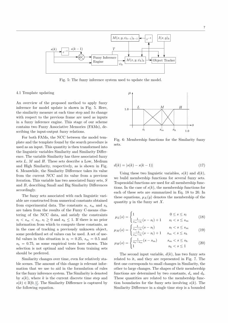
Fig. 5: The fuzzy inference system used to update the model.
4.1 Template updating
An overview of the proposed method to apply fuzzy
inference for model update is shown in Fig. 5. Here,
the similarity measure at each time step and its changewith respect to the previous frame are used as inputs
in a fuzzy inference engine. This stage of our scheme
contains two Fuzzy Associative Memories (FAMs), de-scribing the input-output fuzzy relations.
For both FAMs, the NCC between the model tem-
plate and the template found by the search procedure isused as an input. This quantity is then transformed into
the linguistic variables Similarity and Similarity Differ-
ence. The variable Similarity has three associated fuzzy
sets L, M and H. These sets describe a Low, Mediumand High Similarity, respectively, as is shown in Fig.
6. Meanwhile, the Similarity Difference takes its value
from the current NCC and its value from a previousiteration. This variable has two associated fuzzy sets, S
and B, describing Small and Big Similarity Differences
accordingly.
The fuzzy sets associated with each linguistic vari-
able are constructed from numerical constants obtained
from experimental data. The constants sl, sm and share taken from the results of the Fuzzy C-means clus-tering of the NCC data, and satisfy the constraints
sl < sm < sh, sl ≥ 0 and sh ≤ 1. If there is no prior
information from which to compute these constants, asin the case of tracking a previously unknown object,
some predefined set of values can be used. A set of use-
ful values in this situation is sl = 0.25, sm = 0.5 andsh = 0.75, as some empirical tests have shown. This
selection is not optimal and values from training sets
should be preferred.
Similarity changes over time, even for relatively sta-
ble scenes. The amount of this change is relevant infor-
mation that we use to aid in the formulation of rules
for the fuzzy inference system. The Similarity is denotedby s(k), where k is the current discrete time step and
s(k) ∈ R[0, 1]. The Similarity Difference is captured by
the following equation.
Fig. 6: Membership functions for the Similarity fuzzy
sets.
d(k) = |s(k)− s(k − 1)| (17)
Using these two linguistic variables, s(k) and d(k),
we build membership functions for several fuzzy sets.
Trapezoidal functions are used for all membership func-tions. In the case of s(k), the membership functions for
each of these sets are summarized in Eq. 18 to 20. In
these equations, µX(y) denotes the membership of thequantity y in the fuzzy set X.
µL(s) =
{
1 0 ≤ s ≤ sl1
sm−sl(s− sl) + 1 sl < s ≤ sm
(18)
µM (s) =
{
1sm−sl
(s− sl) sl < s ≤ sm−1
sm−sl(s− sl) + 1 sm < s ≤ sh
(19)
µH(s) =
{
1sh−sm
(s− sm) sm < s ≤ sh
1 sh < s ≤ 1(20)
The second input variable, d(k), has two fuzzy setsrelated to it, and they are represented in Fig. 7. The
first one corresponds to small changes in Similarity, the
other to large changes. The shapes of their membership
functions are determined by two constants, ds and db.These quantities are related to the membership func-
tion boundaries for the fuzzy sets involving s(k). The
Similarity Difference in a single time step is a bounded

8
Fig. 7: Fuzzy sets for the Similarity Difference input
variable.
Fig. 8: Membership functions for the output variable,
the fusion coefficient ψ.
quantity, since we use the absolute value of d(k) and
||d(k)|| ≤ 1 ∀ k. In the mean case, where Similarity
changes from one frame to the next are small, d(k) hasa value in the order of 1×10⁻³. Hence, the values of dsand db are given by Eq. 21 and 22. A useful value for γ
is 1/10. This value was determined using experimental
data gathered from the same image sequences that areused to determine the Similarity fuzzy sets boundaries.
ds = γ|sh − sm| (21)
db = γ|sh − sl| (22)
The first FAM determines whether the object should
be tracked or not, since there are cases in which the sys-tem should consider the target to be lost. This means
that the model should not be updated with the avail-
able visual information, and the measurements of theKalman filter should not be updated either. To take into
account these instances, we used a single rule Mamdani-
Assilian model with a singleton output. The output
variable is Boolean and controls whether the trackershould update its position measurement or not, and also
if the model template should be updated. The output
fuzzy sets are Track, and Stop and they determine if the
L M H
S 0 F3 F1
B F4 F2 0
Table 1: Decision table for the output variable Fusion.
tracker should update its measurements. The output isthe result of evaluating a single rule:
IF s is L AND d is S then STOP
The behaviour of the tracker when this FAM hasa Stop output is equivalent to waiting for an occlu-
sion to clear. The object position is not updated, while
the model template is not modified either. If the ob-ject remains in a position covered by the ROI after the
occlusion clears, the tracking procedure resumes. This
strategy works as long as the occluding object enters
the ROI quickly enough to trigger the Stop responseand not become part of the tracked template data.
The second FAM is the mechanism that enables the
system to incorporate new template information intothe model template. An output coefficient that is used
for the model fusion is computed from the Similarity
and Similarity Difference inputs.
In order to determine the fusion coefficient we use
the Mamdani implication method of inference. The fuzzy
IF-THEN rules are based on the Similarity and Simi-larity Difference values as antecedents, and they have
the fusion coefficient as their consequent. The fusion
coefficient, ψ, has four related fuzzy sets. The mem-
bership functions for those sets are F1 to F4, describingLow Fusion, Medium-Low Fusion, Medium-High Fusion
and High Fusion, respectively. The membership func-
tions for the output fuzzy sets are shown in Fig. 8. Thesummary of the control rules for the fusion output is
the fuzzy associative memory (FAM) given in Table 1.
Eq. 23 to Eq. 26 describe the aggregation that is usedto compute the membership of each of the output fuzzy
sets.
µF1= min[µH(s), µS(d)] (23)
µF2= min[µM (s), µB(d)] (24)
µF3= min[µM (s), µS(d)] (25)
µF4= min[µL(s), µB(d)] (26)
Since ψ needs to be a crisp quantity for our system,
we used a defuzzification method at the end of the in-ference engine. The center of sums is a fast alternative
to the centroid method. The center of sums equation
for our system is shown in Eq. 27.

9
Fig. 9: Example of a decision surface for the ψ output
variable.
ψ′ =
∫
ψψ∑4k=1 µFk
(ψ)dψ∫
ψ
∑4k=1 µFk
(ψ)dψ(27)
The decision surface formed by the output of thisFAM is dependent upon the values of sl, sm and shfrom the NCC clustering data or from manually selected
values. An example for a particular case of these values
is given in Fig. 9.
4.2 Model fusion
The appearance model of the visual target is updated
using the output from the fuzzy inference stage. Themodel is mixed with a new measurement using a fu-
sion function. In our tracker implementation, we do not
modify the size of the template under inspection. Foreach discrete location on the model template, an update
procedure occurs at every iteration. Both the amount
of information that is preserved and the amount that is
updated are determined by the quantity derived fromthe fuzzy inference stage, ψ. We call this quantity the
fusion coefficient. The fusion coefficient at time step k
is denoted by ψk.Each pixel of the updated model is a function of the
old model template, the new matching template and
the fusion coefficient. This function is called the modelfusion function and is given in Eq. 28.
M(x, y, ψk)k = (1− ψk)M(x, y, ψk−1)k−1
+ ψkI(x, y)k (28)
5 Implementation issues
One of the goals that the proposed tracker was meant
to achieve is low computational complexity. This is a
11 31 51 71 91
NCC 0.586 28.034 201.333 770.126 2030.536
SSD+NCC 0.204 5.480 38.278 138.871 362.763
Table 2: Average processing time per frame, in millisec-
onds, for different template sizes. A NCC-based tracker
and a SSD-based tracker with NCC computation forthe target are considered.
problem that every template-based tracker must over-
come. The main obstacle for this kind of trackers is thecomplexity of the correlation algorithm. The most ba-
sic form of correlation is generally a O(N2) operation.
This can be improved upon by using the convolutiontheorem of the Fourier transform and the Fast Fourier
Transform algorithm. The best case scenario for the
FFT is of O(N logN) complexity. Lewis [23] noted that
there is a trade off that makes the FFT inconvenient touse below a certain template size. Coupled with the fact
that a ROI is often used in real-time implementations
to restrict the object search area, under the assump-tion that the translational velocity of the object in the
image plane will remain below some amount, the exact
template size for which using the FFT becomes moreconvenient is difficult to establish.
Moreover, our fuzzy inference scheme depends on
the use of the NCC, as detailed before. This is an op-
eration even more costly than simple correlation. Thefact that the expected value for different pixel windows
needs to be calculated increases the complexity. A way
to overcome this is using an image representation called
an integral image. These integral images are used forfeature extraction by Viola and Jones [24], and can be
used to obtain the sum of the pixel values in any given
area by performing only four operations.
In this work, the necessity for a bounded quantityto represent template similarity is limited to the fuzzy
inference stage. This means that the initial location of
the template can be obtained by any alternative proce-dure. Since the SSD, the NCC and simple correlation
can be used to minimize the quadratic error between
the template and a region of the current image, any ofthem can be used. It is important to note that using
the faster alternatives to the NCC can mean entering
potential pitfalls. With the SSD, regions of low energy
in the image can give rise to false positives, while thesame thing may happen with regions of high energy and
correlation.
As a compromise, we use the SSD to locate the
template position at any given time. Using this spa-tial information we proceed to get the NCC between
the template and the neighborhood of its location. It
is this NCC that allows us to compute the amount of

10
fusion between the current template and the previous
one. The speedup resulting from this approach is no-ticeable even at small template sizes. Table 2 shows the
average processing time per frame obtained by track-
ing image regions of different sizes, comparing usingthe NCC only to using the SSD+NCC approach. These
rates include the time taken by our Kalman filter im-
plementation and the fuzzy inference stage. The timevalues computed for this table were obtained by using
an inexpensive video camera. For this hardware config-
uration, the camera had a resolution of 640×480 pixels
and a frame rate of 6 fps. The machine ran at 1.67 GHz.
6 Tracker evaluation
For the purpose of assessing the performance of ourmethod, a series of tests involving comparisons with
a baseline SSD tracker were conducted. Determining
the performance of a tracking method is an importantand non trivial task. It is evident that this evalua-
tion is not possible in any satisfactory manner if some
ground truth is not available. We use sequences forwhich ground truth is widely available. This allows us
to measure the error of our method and compare it
to results offered by others. Video or image sequences
captured from real world scenery are difficult to usein performance evaluation. The project called Context
Aware Vision using Image-based Active Recognition
(CAVIAR) [25] from the European Commission usesimage sequences tagged by humans. These sequences
are useful to an extent, although they allow some uncer-
tainty to enter the process, in the form of subjectivityfrom the volunteers.
Another approach to benchmarking tracking algo-rithms is the use of synthetic sequences. The work by
McCane et al. [26] is one example of this. Their bench-
mark is oriented towards optical flow algorithms. How-ever, the motion vectors provided as ground truth can
be used to generate motion paths useful to track the
objects. It can be argued that this kind of benchmarkis more precise, as it uses optical flow data generated
with the images. This benchmark is well suited for the
initial testing of trackers.
We ran a set of tests using the benchmark by Mc-
Cane et al. The comparison between the given opticalflow vectors and the output from our Kalman filter at
each time step provides evidence of the performance
of our approach. Without noticeable noise and cam-
era jitter, the performance of our tracker is close tothat of a full optical flow algorithm. Besides these tests,
we also used image sequences from the aforementioned
CAVIAR project. These sequences contain significantly
complex foreground and background objects whose ap-
pearance may change in time. The ground truth forthese sequences was generated by human observers and
provides a natural, qualitative performance assessment.
A pure SSD tracker, including the Kalman filter, is
the basis for comparison. This tracker has good per-formance under pure X-Y translation of the target. Its
shortcomings are Z translation (scale change) and all
kinds of rotation. The fuzzy tracker is aimed at theseproblems and our results show that it is successful in
a number of situations. The following case descriptions
contain the tests that were performed, and discussionsabout the results.
6.1 Case I: the medium sequence
The first sequence used to test our approach is the im-
age sequence medium from the benchmark of McCane
et al. This sequence includes translation and rotation of
a 3D model which is on top of a checkerboard pattern.The sequence consists of 10 images, 400× 300 pixels in
size. Fig. 10 contains the starting and ending frames for
this sequence, with a marker placed upon the trackedregion. The evolution of the tracked template is shown
as well. In this figure one can qualitatively assert that
the tracker is, in fact, overcoming a large translationover the Z axis. A direct comparison of the location
of the tracked template in some frames according to
the optical flow algorithm and our approach is shown
there. This comparison shows a remarkable qualitativesimilarity between the ground truth and our tracker.
It is relevant to note that the templates shown for our
tracker are the result of applying the model fusion func-tion, instead of pixel neighborhoods from the bench-
mark frames. Hence, this image mosaic does not reflect
the exact appearance of the object, showing fused in-formation instead.
These rotations and translations cause an early fail-
ure of an SSD-only tracker, but our fuzzy variant tracks
the object successfully.
The error for both trackers, expressed as the Eu-clidean distance from the center of the target to the po-
sition in the ground truth, in pixels, is shown in Fig. 12.
The error for our tracker is low considering the nature
of the image sequence.
6.2 Case II: the street sequence
Another interesting sequence in the benchmark set ofMcCane et al. is called street. This sequence combines
camera movement with objects moving inside the scene.
The size of each image is 200 × 200 pixels. This low

11
(a) (b) (c)
Fig. 10: Evolution of the tracked template for the medium sequence over time.
(a) (b) (c)
Fig. 11: Evolution of the tracked template for the street sequence over time.
0 1 2 3 4 5 6 7 8 90
10
20
30
40
50
60
70
Euc
lidea
n di
stan
ce to
targ
et (
pixe
ls)
Frame
Fuzzy Tracker
SSD Tracker
Fig. 12: Errors for the medium sequence.
resolution causes great appearance changes in textured
areas, even under small camera displacements. Fig. 11shows the starting and ending frames of the street se-
quence, with an overlaid marker for the tracked zone.
Also, the evolution over time of the model template forthis sequence, compared to the benchmark is shown.
The optical flow vectors reach a point of near con-
stant Y coordinate around frame 30. This corresponds
with the frames where the tracked feature is no longer
0 10 20 30 40 50 600
5
10
15
20
25
30
35
40
45
Frame
Euc
lidea
n di
stan
ce to
targ
et (
pixe
ls)
Fuzzy Tracker
SSD Tracker
Fig. 13: Errors for the street sequence.
visible. Likewise, our tracker loses the target completely
at this point, since the occlusion is total. The occlusion
lasts long enough for our fuzzy tracker to update themodel template with information of the occluding ob-
ject. The error in pixels over time can be found in Fig.
13.

12
(a) (b) (c)
Fig. 14: Evolution of the tracked template for the street sequence over time.
6.3 Case III: the Walk2 sequence
The CAVIAR sequences provide a challenging data set.
We ran some tests using this benchmark and obtainedpromising results. The sequence titled Walk2 consists
of images taken from a surveillance camera in a com-
mercial venue. This images contain moving humans.
The camera itself had a very wide angle lens attached,adding radial distortion that increased the difficulty.
Perspective correction of the image is possible, since
the sequence included information to compute the ho-mography using the floor as a plane. We refrained from
applying any perspective correction to the images, since
our purpose was to evaluate the performance of ourtracker under non-rigid transformations.
Some frames from the sequence are illustrated by
Fig. 14, with the evolution of the model template over
time.
Our tracker was able to follow the target, a human
walking over a concrete floor, until it disappeared from
the field of view. Error from our tracker compared tothe ground truth is low and more constant than in other
cases, as Fig. 15 shows.
As in other implementations of template-based tar-
get tracking systems, ours lacks robustness when bothbackground and foreground change simultaneously. How-
ever, the use of the fuzzy inference system reduces fea-
ture drifts and delays the loss of the target. Prolongedocclusion of the target results in its loss. Nevertheless,
our tracking system can handle partial oclussions dur-
ing short time intervals without problems.
6.4 Error comparison
As a useful metric, we present the tracking errors for
the sequences presented above. Table 3 contains themean Euclidean distances from the center of the de-
tected regions to the feature position as it appears in
the ground truth. These averages were taken from the
0 20 40 60 80 100 120 140 1600
10
20
30
40
50
60
Frame
Euc
lidea
n di
stan
ce to
targ
et (
pixe
ls)
Fuzzy Tracker
SSD Tracker
Fig. 15: Errors for the CAVIAR Walk2 sequence.
Medium Street Walk2
Fuzzy Tracker 7.394 5.617 10.777
SSD Tracker 15.019 18.218 18.726
Table 3: Average error, by sequence, for the fuzzy
tracker and the SSD-only tracker. This represents theaverage Euclidean distance to the tracked feature.
whole sequences, except for the Walk2 case, since theSSD tracker loses the target early. In that particular
case, the average error only takes into account the por-
tion of the sequence were both trackers successfully fol-
low the object or feature.The error for our approach is smaller than that of
a pure SSD-based tracker. The SSD only approach is
more sensitive to appearance changes of the target,making it more vulnerable to noise and object rotations
and translations.
7 Conclusion
We propose a novel approach to template-based object
tracking in images, using fuzzy logic to make decisions

13
regarding model updates. From different tests, we could
observe that the tracker discussed is able to cope withsome degree of 3D transformations and also with some
nonrigid transformations. The only requirement for our
tracker to work is a saliency assumption. This meansthat the tracked regions must be selected using an in-
terest point detector.
The limitations of our approach include severe oc-clusion and degradation over time of the saliency of
the tracked region. Another problem that requires fur-
ther analysis is the case of simultaneously dynamic fore-ground and background. This causes the tracker to drift
over time.
An important result from this work is that the hard-ware requirements for a real-time implementation of our
tracker are fairly low. The search window does not need
to be large, assuming that no large translations wouldtake place. We consider that the work discussed in this
paper shows that fuzzy reasoning is useful in dealing
with problems that seem difficult for most object track-ers. We also concede that there are cases in which our
method could fail and we tried to point them out.
Acknowledgements J. Pablo Ramirez-Paredes would like to
thank the Mexican National Council for Science and Technology(CONACyT) for the scholarship grant number 253761/213845.
References
1. F. Chaumette. Image moments: a general and useful set offeatures for visual servoing. Robotics, IEEE Transactions
on, 20(4):713–723, Aug. 2004.
2. J. Bigot, S. Gadat, and J-M Loubes. Statistical M-Estimation and consistency in large deformable models for
image warping. Journal of Mathematical Imaging and Vi-
sion, 34(3):270–290, 2009.
3. F. Jurie and M. Dhome. Real time 3D template matching.
In Computer Vision and Pattern Recognition, 2001. CVPR
2001. Proceedings of the 2001 IEEE Computer Society Con-
ference on, volume 1, pages 791–796, 2001.
4. G. D. Hager and P. N. Belhumeur. Efficient region trackingwith parametric models of geometry and illumination. Pat-
tern Analysis and Machine Intelligence, IEEE Transactions
on, 20(10):1025–1039, Oct. 1998.
5. G.D. Hager, M. Dewan, and C.V. Stewart. Multiple kerneltracking with SSD. Computer Vision and Pattern Recog-
nition, IEEE Computer Society Conference on, 1:790–797,2004.
6. R.T. Collins, Y. Liu, and M. Leordeanu. Online selection
of discriminative tracking features. Pattern Analysis and
Machine Intelligence, IEEE Transactions on, 27(10):1631–1643, 2005.
7. H. Zhou, Y. Yuan, and C. Shi. Object tracking using SIFTfeatures and mean shift. Computer Vision and Image Un-
derstanding, 113(3):345–352, 2009.
8. T. F. Cootes, G. J. Edwards, and C. J. Taylor. Active appear-ance models. Pattern Analysis and Machine Intelligence,
IEEE Transactions on, 23(6):681–685, June 2001.
9. A.D. Jepson, D.J. Fleet, and T. F. El-Maraghi. Robust onlineappearance models for visual tracking. Pattern Analysis and
Machine Intelligence, IEEE Transactions on, 25(10):1296–
1311, Oct. 2003.10. R. Gross, I. Matthews, and S. Bakera. Active appear-
ance models with occlusion. Image and Vision Computing,
24(6):593–604, 2006.11. S.H. Lee, R.J. Howlett, and S.D. Walters. Small engine con-
trol by fuzzy logic. Journal of Intelligent and Fuzzy Systems,15:207–217, 2004.
12. D. Anderson, J.M. Keller, M. Skubic, X. Chen, and Z. He.Recognizing falls from silhouettes. In IEEE 2006 Int. Conf.
of the Engineering in Medicine and Biology Society, pages6388–6391, 30 2006-Sept. 3 2006.
13. X. Chen, Z. He, D. Anderson, J.M. Keller, and M. Skubic.Adaptive silouette extraction and human tracking in complex
and dynamic environments. In Image Processing, 2006 IEEE
International Conference on, pages 561–564, Oct. 2006.14. D.G. Lowe. Object recognition from local scale-invariant fea-
tures. In Computer Vision, 1999. The Proceedings of the
Seventh IEEE International Conference on, volume 2, pages
1150–1157 vol.2, 1999.15. T. Kadir and M. Brady. Saliency, scale and image descrip-
tion. International Journal of Computer Vision, 45(2):83–105, 2004.
16. C. Harris and M. Stephens. A combined corner and edgedetection. In Proceedings of The Fourth Alvey Vision Con-
ference, pages 147–151, 1988.
17. K. Mikolajczyk and C. Schmid. Scale & affine invariant in-terest point detectors. International Journal of Computer
Vision, 60(1):63–86, 2004.18. K. Mikolajczyk and C. Schmid. A performance evaluation of
local descriptors. Pattern Analysis and Machine Intelligence,
IEEE Transactions on, 27(10):1615–1630, Oct. 2005.19. H. Bay, A. Ess, T. Tuytelaars, and L. Van Gool. Speeded-
up robust features (SURF). Computer Vision and Image
Understanding, 110(3):346–359, 2008.20. B. Zitova and J. Flusser. Image registration methods: a sur-
vey. Image and Vision Computing, 21(11):977–1000, October
2003.21. A. Yilmaz, O. Javed, and M. Shah. Object tracking: A sur-
vey. ACM Computing Surveys, 38(4), 2006.22. R.J. Hathaway, J.C. Bezdek, and Y. Hu. Generalized fuzzy
C-means clustering strategies using Lp norm distances. FuzzySystems, IEEE Transactions on, 8(5):576–582, Oct. 2000.
23. J.P. Lewis. Fast template matching. In Vision Interface 95,
pages 120–123, 1995.24. P. Viola and M. Jones. Robust real-time object detection.
International Journal of Computer Vision, 57(2):137–154,2002.
25. European Commission. CAVIAR Project. IST 2001 37540.
26. B. McCane, K. Novins, D. Crannitch, and B. Galvin. Onbenchmarking optical flow. Computer Vision and Image Un-
derstanding, 84:126–143, 2001.