A Framework to Support Interoperability among Semantic Resources
618
Pre-proceedings of the First International Conference on Interoperability of Enterprise Software and Applications INTEROP-ESA’2005 Geneva, Switzerland, February 23 - 25, 2005 Technical Sessions
Transcript of A Framework to Support Interoperability among Semantic Resources

Pre-proceedings of the
First International Conference on
Interoperability of Enterprise Software and Applications
INTEROP-ESA’2005
Geneva, Switzerland, February 23 - 25, 2005
Technical Sessions


������������ �������������
��������� �"!$#&%
'�(*)+(-,/.+021�(*354�.+6�7�18(�497:18.<;<(-,&4=.�6>.5? 4=(-@�AB354C(*@C.D0E(*@=7+FGA/,BAB4 H�7+,B.D3GI�4=JG(K0G@C.<;<LEMN4O,BAB6>(*M-HDPM�,/(Q4C@97+M�(R7:FGA/,/AS4 HTVUXWEY�ZC[-\^]`_<U`acbed9dN\gf&be]ih�Ukjlb:f&Y-mnmporq*q-q-q*q-q*q-q-q-q-q-q*q-q*q-q-q*q-q�q*q-q*q-q-q*q-q*q-q�q*q-q-q*q-q*q-q-q*q�q-q*q-q�s
t`LE?uA/3G(*?=?wvc@=.<M�(*?=?yxX(*z5LGA/@C(*1�(*354=?*{O|}.�;G(-,/AB3GIr~�(*M9JG3GA^z5LG(+{l7+32;���4=7:3E;G7:@9;��O�X.���4=.A/;<(*354CAB6>HyA/3D4=(-@=.+0&(-@97:FGA/,/AS4 H�I57:02?O.D3�7�0G@=.<M�(*?=?O,/(-)+(*,� Uk���D�Db�fVo���be]��8U��eb:f}T&�Bo*o:m�Y-fG]���Uk��U�TEmpY��:�"Y9Y�q*q-q-q*q-q*q-q�q*q-q-q*q-q*q-q-q*q�q-q*q-q*q-q-q*q-q*q�q-q�sR�
� 3 � @9M9JGAB4C(*M�4CLG@=(K6>.+@���(*1�7:354CA^M��c354C(*@C02@CA^?u( � 020G,BA^M-7:4CA/.+3w�p354C(*I+@97�4CA/.+3w�54=7+32;G7+@=;G?� Uk��f2\��-\���] � U����eY9[-\��N]���U�_<o�f&Y�d}q-q*q-q*q-q-q*q-q�q*q-q*q-q-q*q-q*q-q�q*q-q-q*q-q*q-q-q*q�q-q*q-q*q-q-q*q-q*q�q-q*q-q-q� +¡
��������� �"!$#�¢
�p3D4=(-@CP £�@=ID7+3GA/¤*7�4=AB.D3¥�p354=(-@=.+0&(-@97:FGA/,BAB4 H�AB3¦~�@97:32?C0E.D@u4�§`J27:A/32?�¨�?uA/3GI � ;G7+0<4C(*@=?KtO7+?C(*;.+3}£�0E(*3��<.+LG@9M�(�©G@=(-(*��7+@C(jlUkª�b��R\�«ed9d-o�fG]i¬cU���b:�dNmpY9«�mn]i_<UXW�®o�ZNfV¯��<\^dNm�q-q-q*q�q-q*q-q*q-q-q*q-q*q�q-q*q-q-q*q-q*q-q-q-q-q-q*q-q*q-q-q*q-q"�D¡
| � ©��u� � P�7:3 � @9M9JGAB4C(*M�4CLG@97:,G'�(*?=M�@=A/0<4CA/.+38©G@97:18(-��.+@=°V���i±<0E(*@CA/(-3EM�(`6>@C.D1²4CJ2(X�X(*7+,S4=J§�7:@=(Q'�.+1�7+AB3TVUK³�b��B«DY�ZC´2b��+�:]iµlU�T&m�b:�-]iT�Uk¬�¶+�R�DYwWEo��bed9d-Y-fG]�¬"U���¶5dNmpb+«e] � U � Z=Y=«DY�·}oRY¸q-q-q*q�¹D¹
�u�2£²�5497:32;27:@9;G?�6>.+@l�p354C(*@C.D0E(*@=7+FGA/,BAB4 HV��7�M-.+18027+@CA^?u.D3��U��8o:fGd-b�f<�+Y�q-q*q�q-q*q-q*q-q-q*q-q*q�q-q*q-q-q*q-q*q-q-q-q-q-q*q-q*q-q-q*q-q�q*q-q*q-q-q*q-q*q�q-q*q-q-q*q-q*q-q-q-q-q-q*q-q*q-q-q*qQº+»
��������� �"!$#�¼
£K½ � x�� � 3¸£�354C.+,/.+IDAB(R? PptO7+?C(*;}��(*@C)�A^M�(¾£�@CA/(-354=(*; � 0G0G,/A/M*7�4=AB.D3¿�p354C(*I+@97�4=AB.D3¿©G@97:18(-P�`.D@C°ª�UXWEY=�:mpo�f2\�«:\^d9]���U � o*�:8b�]�ÀXU�ÁXb�mÂ�BY-Ãe]c·¦U�TVb��/b��ÄGb�d9\^d�q�q-q*q-q*q-q-q*q-q*q�q-q*q-q-q*q-q*q-q-q-q8¡DÅ
� ¨�3GASÆE(*;¸©2@=7+18(-��.+@=°¦6>.D@��"3D4=(-@=0G@=A/?C(¾�p354C(*I+@97�4CA/.+3 � 3r£�354=.+,/.+I+H5Pp'�@=A/)+(-3Ç��(*@C)�A^M�(-P£�@CA/(-354C(R; � 0G0G@=.D7DM9JTVU��C[9[Rbe]�¬"UQÈ�\gfV�9Y�fEm�]�jlU � �<ZN�Bb�mQq*q�q-q*q-q-q*q-q*q-q�q*q-q-q*q-q*q-q-q*q�q-q*q-q*q-q-q*q-q*q�q-q*q-q-q*q-q*q-q-q-q-q-q*qiÉ:Å
� ©G@97:18(-��.+@=°84C.¾��LG020E.D@u4X�p354C(*@C.D0E(*@=7+FGA/,BAB4 H¾7:18.+32I8��(*1�7:354CA^M�xl(*?C.+L2@=M-(*?aiU�¬�\g�be]�acUkÊ�Y�ZNZCY-\gZCb:Ëu«+b�Ë�T&\g�Ì��be]�acU�¬�YKª��2��]���U�Í�b:ZN�Ì\Xq-q*q-q*q-q-q-q-q-q*q-q*q-q-q*q-q�q*q-q*q-q-q*q�»DÎ
��������� �"!$#DÏ
Ð�A/@u4=L27:,it�@C(*(*;<A/3GI��c3�)�AB@=.+3G18(*3D4R� � ©�A/@=?u4 � 0G0G@=.D7DM9J�4C.w¨X32;G(-@9? 497:32;¦Ñ¿.D@C°�A/3GI¥7+32;��J27:@=A/3GI�vc@=AB32M-AB02,B(R?� UVÀXb��/Y=b:f&o�T8Òb�f&�9´GY9[�]�ª�UD��ÄGo:�Ì\gf&b:Z�ÀO�2Y�ZNZ=blÍ��2Ó-\�b-�5be]�_<U+��mpb*´��2b:� Ä2bl�NZN\S�5o�Ã+Y-f�ÀXo:f�[`Òb��BY9[�]��U�·¦o��Ì\gfVbÔq*q-q-q*q-q*q�q-q*q-q-q*q-q*q-q-q-q-q-q*q-q*q-q-q*q-q�q*q-q*q-q-q*q-q*q-q�q*q-q-q*q-q*q-q-q*q�q-q*q-q*q-q-q*q-q�q*q-q*q-q-q*qXs*Î5
|�.<;<(-,/AB32I87+32;�L2?CAB3GI8FGLE?uA/3G(*?=?lM�.D,B,^7:F&.+@97�4=AB.D32?ÀlU � ZN�<f&oÕq-q-q-q-q*q-q*q-q-q*q-q�q*q-q*q-q-q*q-q*q-q�q*q-q-q*q-q*q-q-q*q�q-q*q-q*q-q-q*q-q*q�q-q*q-q-q*q-q*q-q�q*q-q-q*q-q*q-q-q*q�q-q�s+s*¹
�"?u4=7:F2,BA^?uJ2AB3GI8�p354C(*@C.D0E(*@=7+FGA/,BAB4 H�.:6c§`.5.D@=;GAB327:4CA/.+3wvc@=.:4=.�M-.+,^?"A/3�7+;�P�JG.<MK�p354C(-@CP£�@CI57:3GA/¤*7:4CA/.+327+,�§`.D,B,^7:F&.+@97�4=AB.D32?� U � b*[-\ Ö-b:f&Y9�N]c��Uk���BÓ9b:f2\^]��8UXW<�<Z=o���dC��\�q-q*q-q-q*q-q*q-q�q*q-q-q*q-q*q-q-q*q�q-q*q-q*q-q-q*q-q*q�q-q*q-q-q*q-qQsR +¡
��������� �"!$#�×
£�3D4=.+,/.+IDHDP�F27D?u(R;Ç�p354C(*@C.D0E(*@=7+FGAB,/AB4 HØ��(*@C)�A^M�(*?�6>.+@��<(-1�7:354CA^M¦§`.+,/,^7:F&.+@97�4CA/.+3rA/3Ù£�0E(*3½X(�4 ��.+@=°+(R;¥��H<?u4C(*18?TVU�acbedNmpb�f&o�]���UkÊ�Y-ZNZCb�ZCb�]iTVU�·¦o�fEm�b:f&Y-�g�Ì\�q-q*q-q�q*q-q*q-q-q*q-q*q-q�q*q-q-q*q-q*q-q-q*q�q-q*q-q*q-q-q*q-q*q�q¾s*��É
�p3D4=(-@=.+0&(-@97:FGA/,/AS4 H¿4CJG@=.+L2I+JÔA/3D4=(-ID@=7:4CA/3GI¿��(*187+354CA^M¾Ñ�(-F�~�(*M9J23G.+,/.+IDH+{kÑ�(-Fr��(-@=)�A/M-(*?*{7:32;¥Ñ¿.D@C°5Ú2.���|�.<;<(-,/A/3GI_�U���ZCo=�:d9mÂ\�Y�]XaiU�ÈEY�Z=YNd9]lÀXU�TE\gfV«�ZCY�q-q*q-q*q-q-q*q�q-q*q-q*q-q-q*q-q�q*q-q*q-q-q*q-q*q-q�q*q-q-q*q-q*q-q-q*q�q-q*q-q8sRº+Î
� 3¿| � Pp½X(-LG4C@97:,�A/3<6>@97+?u4C@=L2MN4=LG@=(�6>.+@�FG@=A/;<IDAB32Iy18.<;<(-,�(-3GIDAB32(-(-@=A/3GI¥7+32;�.+354=.+,/.+I+H¥(-3<PI+A/3G(-(*@CA/3GI_�U � ÒY9[�\g�R\gfG]�È�U�ª�Y���Y9«*[-\��N]�ª�U�ª"ÖN�<ZN\��N]�_�UB·¦UkÊ�b��RZCY9b���]�ª�U�ÀXbed-Y-�*\���]�Ê�Ui_<o��2b:�<�ÌmÛs*¡5º
��������� �"!$#�Ü
§`.+354C@97+M�4uPpt�7D?u(R;��p354C(*@C.D0E(*@=7+FGAB,/AB4 H86>.+@l(*t�L2?CA/3G(*?=?l~�@97:3E?C7DMN4CA/.+3E?TVUk��ZNmÂÃedu´2�=´2Y��*]�h�UK³wY-\S�Db:f&«Ýq-q-q*q-q*q�q-q*q-q-q*q-q*q-q-q-q-q-q*q-q*q-q-q*q-q�q*q-q*q-q-q*q-q*q-q�q*q-q-q*q-q*q-q-q*q�s*Å+¹
�p3D4=(-@=.+0&(-@97:FGA/,/AS4 H�18A^;G;<,/(-�O7:@=("6>.D@�6>(*;<(*@=7:4C(*;�(-354=(-@=0G@CA^?C(�7+0G0G,/A/M*7�4CA/.+3E?�A/38�`(*F<PpvcA/,/7+@=M-.D?¬cU����<mn��o�fVY�f2]KW�U����2oR�+o:�Bb�\gfVY�f2]`_<U�·¦Y�mnd-oe]`_<UVh�bDb�mpbpÖ-b¸q-q-q*q-q*q-q�q*q-q-q*q-q*q-q-q*q�q-q*q-q*q�s*»D¡

��������� �"!$#GÞ
~�@97:32?u6>.+@=18AB32I�Ñ�.+@=°5Ú2.��ÙßK@97:0GJ2?_�UkµX«+Y-Z9]�³wU�ÀOZN�2Ó9Y-Z9]�h�Ukj�\��9´��BY-Z}q*q-q�q*q-q-q*q-q*q-q-q-q-q-q*q-q*q-q-q*q-q�q*q-q*q-q-q*q-q*q-q�q*q-q-q*q-q*q-q-q*q` :ÎD»
�p3D4=(-@=.+0&(-@97:FGA/,/AS4 H�� ?=?uL2(*?OA/3w|}(�4=7+18.�;G(-,/,BA/3GI�vc,^7�4C6>.+@=18?h�U��Ø®�D´�f2]i·}U�·��<ZC[RY9�àq*q-q-q*q-q�q*q-q*q-q-q*q-q*q-q�q*q-q-q*q-q*q-q-q*q�q-q*q-q*q-q-q*q-q*q�q-q*q-q-q*q-q*q-q-q-q-q-q*q-q*qK + D
~�.��O7:@9;G?O¨�?CAB32I8¨�|}á 6>.+@X|�.<;<(*,B,/A/3GI�Ñ¿(*F}��(-@=)�A/M-(�§`.D,B,^7:F&.+@97�4=AB.D3yvc@=.:4=.<M�.+,^?ÀlU���ZCb:��/Y�Z9]�µXU���b9ÄEd-b���Y�Z9]�³wU���Y�mnd-�=´<\gmg[RY��*�5Y-Z9]XÀlU��8b9Ä+Ä2Y��Xq*q-q*q-q-q*q-q*q�q-q*q-q-q*q` :�2s
��������� �"!$#�â
ã L27:354CAB4=7:4CA/)+( � 3E7:,/H�?CA^?O.:6��"354C(-@=0G@=A/?C( � @9M9JGAS4=(*M�4CLG@=(*?·}U/ËnµXUk�-bD�=oDÓN]�h�U�_<o�f<�+Y-Z9d¦q-q*q�q-q*q-q*q-q-q*q-q*q�q-q*q-q-q*q-q*q-q-q-q-q-q*q-q*q-q-q*q-q�q*q-q*q-q-q*q-q*q-q�q*q-q-q*q-qX �¹5»
|}7:0G02AB3GI¾��0&(*M-ASÆ&M-7�4=AB.D3wAB3�|}' � �2©G@=.+1ä~OJG(-.D@CH�4=.�vc@97+MN4=A/M-(ª�Uk¬�o=Ä2YNd9]cT�UVh�b���o��2«�\^]�_�U � ÒY9[�\g�R\gfG]cÊ�U�_�o:�2b��<�Ìm�q-q*q�q-q*q-q*q-q-q*q-q*q�q-q*q-q-q*q-q*q-q-q-q-q-q� :¡+¹
�i±<0E(*@CA/18(-354lAB3�|�.<;<(*,�'�@CA/)+(*3¥Ðc7+,BA^;G7�4=AB.D3¥.+6�tOv`�"áå��0E(RM�ABÆEM-7:4CA/.+32?ª�Uæh�Uk�l�+Y9´��<Z9dNm�q*q-q*q-q-q*q-q*q-q�q*q-q-q*q-q*q-q-q*q�q-q*q-q*q-q-q*q-q*q�q-q*q-q-q*q-q*q-q-q-q-q-q*q-q*q-q-q*q�q-q*q-q*q-q-q*q-q*q� DÉDÉ
��������� �"!$#�ç
�p3D4=(-ID@=7:4CA/3GI�t�L2?CA/3G(*?=?lvc@=.<M�(*?=?C(*?��lAS4=J�v�(-(-@CPÂ4C.:Ppv�(-(*@c4=(*M9JG3G.D,B.DI+HÊ`U����RÄ&d��9´5]�ª�UK³�Y�ZNm>´èq-q�q*q-q*q-q-q*q-q*q�q-q*q-q-q*q-q*q-q-q-q-q-q*q-q*q-q-q*q-q�q*q-q*q-q-q*q-q*q-q�q*q-q-q*q-q*q-q-q*q�q-qX»2s
'�(R?uA/I+3w7:32;��p180G,/(-18(-35497�4CA/.+3w.+6�78v�(-(*@uPÂ4C.+P�v�(*(-@`'K7�497 ã L27:,/AS4 H¥t`@=.+°D(-@ª�U�·�\g�Bb:f&oe]`·¦U�TV�9b�fEf&b=ÄV\�Y9�=o�]�W�U�acb�mpb�ZC�-\¾q*q�q-q*q-q-q*q-q*q-q�q*q-q-q*q-q*q-q-q*q�q-q*q-q*q-q-q*q-q*q�q-q*q��+ÎD�
|�.�)�AB3GI�6>@=.+1é�p354=(-@=327:,V4=.8�c±�4C(-@=327+,���(-@=)�A/M-(*?�L2?CAB3GI � ?u0&(*M�4=?·}U�h�Y-f��DY��æ]XÀXU � oedNmÂZ�®o��]`_<UK³Ù®b:Ã�ZNÃ�f&Y-féq-q*q-q-q*q-q*q�q-q*q-q-q*q-q*q-q-q-q-q-q*q-q*q-q-q*q-q�q*q-q*q-q-q*q��D D
��������� �"!$#&%kê
|�(�4=JG.<;<.+,/.+IDHy6>.D@X4CJ2(�;<(-Æ23GAB4CA/.+3}.+6"7¾ID,B.5?C?=7:@=H¾A/3¦7yM-.+,/,/7+FE.D@=7:4CA/)+(�@=(*?C(*7:@9M9Jw0G@=.:ë (*M�47:32;¥AS49?X7:020G,BA^M-7:4CA/.+3¥4C.¾78�[email protected](R7:3¥½�(�4 ��.+@=°�.:6i�i±GM�(*,B,/(-3EM�(jlUQÈEY-�Bb�Z=«�\^]���U�jlo:�BY-Z9]�_<U�È�UXWEo��ÒbedÇq-q*q-q*q-q-q-q-q-q*q-q*q-q-q*q-q�q*q-q*q-q-q*q-q*q-q�q*q-q-q*q-q*q-q-q-q-q-qQ�+�D�
£�3D4=.+,/.+IDHDP�F27D?u(R;y��(-1�7+3D4=A/MK�p354C(*@C.D0E(*@=7+FGA/,BAB4 H¾~�.�.D,/?�6>.D@���(-@=)�A/M-(Q'�H�327:18A^M�'�A^?=M�.�)+(*@CHª�U � \�b�fV�=´<\gf2\^]�È�U�ª�YQ��f2mpo�fVY��g�S\^d}q-q-q*q-q*q-q-q-q-q-q*q-q*q-q-q*q-q�q*q-q*q-q-q*q-q*q-q�q*q-q-q*q-q*q-q-q*q�q-q*q-ql�:¹�º

� ;<(-354CAB6>H�AB32I¾t`LE?uA/3G(*?=?�§`.+180&.+3G(*354=?O.+3¥4CJ2(�F27+?CA/?O.+6�7+3��"354C(-@=0G@=A/?C(�£�3D4=.+,/.+IDH��Uk���BÓ9b�fE\^]"_<Uk¬cUÂÀXUkª�\�Y�m>[�q*q-q*q-q-q*q�q-q*q-q*q-q-q*q-q*q�q-q*q-q-q*q-q*q-q-q-q-q-q*q-q*q-q-q*q�q-q*q-q*q-q-q*q-q*q�q-q*q`�Dº+»
��������� �"!$#&%c%
¨�?CAB3GI8§`.+3G3G(RMN4=.+@9?�6>.+@"'�(-0G,/.�H�18(-354".:6k��(�4C(*@C.DI+(*3G(-.DL2? � 0G02,BA^M-7:4CA/.+32?iA/384CJ2(K§`.+354C(-±�4.:6"£K|¦ß²'Kì�§è�<0E(RM�ABÆEM-7:4CA/.+3¬cU � �<�BY>Ö9]�W�U � �<ZCY�d�q-q*q-q-q*q-q*q-q�q*q-q-q*q-q*q-q-q*q�q-q*q-q*q-q-q*q-q*q�q-q*q-q-q*q-q*q-q-q-q-q-q*q-q*q-q-q*q�q-q*q-q*q-q-q��5É<s
'�(*)+(-,/.+021�(*354X.:6c7:3w�p354C(*I+@97�4C(R;wxl(�4=@CA/(-)�7:,���H<? 4=(-1í.+3�'�A^?u4C@=ABFGLG4C(*;�î�xX�u�<~ � á�P :ÎDÎD ��H<? 4=(-1�?l�lAB4CJ�|�(�497+;G7:4=7��p3<6>.D@C1�7�4=AB.D3ï U/Ë��8U � b:�]XÀXU/Ë _<U�a�´Go�\^] � U/Ë�ª�U�¬�Y9Y�q-q-q*q-q�q*q-q*q-q-q*q-q*q-q�q*q-q-q*q-q*q-q-q*q�q-q*q-q*q-q-q*q-q*q�q-q*q-qc�+ÅD�
Ñè�<|}tK�27�18A/;G;G,B(*��7+@C(K6>.+@l(*3GJ27+32M�(R;yÑ�(-F}?C(-@=)�A/M-(*?�AB354=(-@=.+0&(-@97:FGA/,BAB4 HW�U � UV��\�Y�f2]���Ukµ�ZNZ=b+«�\^]ijlU�·¦b*´2YNdC´��"b:ZN\�q*q-q*q-q-q*q-q*q�q-q*q-q-q*q-q*q-q�q*q-q-q*q-q*q-q-q*q�q-q*q-q*q-q-q��+»D¡
��������� �"!$#&%�¢
� '�.D187+AB3w|�.<;<(*,�6>.+@O4=JG(��u�<~Ù�p3<6>@=7D? 4=@CLEMN4CL2@C(_�U�ÀXoRoed9d-Y�fVb+Y-ZNm�dØq-q*q-q�q*q-q-q*q-q*q-q-q*q�q-q*q-q*q-q-q*q-q*q�q-q*q-q-q*q-q*q-q-q-q-q-q*q-q*q-q-q*q-q�q*q-q*q-q-q*q-q*q�q-q*q-q�¹DÎ�É
~�.��O7:@9;G?�7�32(-�¸A/3<6>@97+?u4C@=L2MN4=LG@=(O?CLG0G0&.+@C4CA/3GIQA/3D4=(-@=.+0&(-@97:FGA/,/AS4 H�.+6EA/3<6>.+@=1�7�4CA/.+3�?uH<?u4C(*18?AB3�;<(*)+(-,/.+021�(*354*��4CJ2(��p3<6>.+@=1�7�4CA/.+3���H<?u4C(-1äLG0&.+3��p3<6>.+@=1�7�4CA/.+3���H<?u4C(-1�?W�U�¬�Y�ª�\gf<´Øq-q�q*q-q*q-q-q*q-q*q-q�q*q-q-q*q-q*q-q-q*q�q-q*q-q*q-q-q*q-q�q*q-q*q-q-q*q-q*q-q�q*q-q-q*q-q*q-q-q*q�q-q*q-q*q-q-q*q-q*q�qc¹5 +Î
'�(R?uA/I+3���.+,/L<4=AB.D32?O6>.+@l�p354=(-@=.+0&(-@97:FGA/,BAB4 H�L2?CAB32I878v"@C.<M�(R?C?O|}7+327:ID(-@jlUi_<o*´2b�f2fVYNd9d-o�f2]�µlU�jlY-ZgÖ-o�f2d9] � UK³�b�f��:�/Y�Z9]���U/Ë�·}U�ð�l´�� ñ�Y-�B«�m�q-q*q-q�q*q-q-q*q-q*q-q-q*q�q-q*qc¹D�5
òàóèô �C!äõ<ö��Ù#G�O÷ùø�úG�cûcú2ü�ý ��������� �"!��
þkÿ����������*þ���
~OJG(�� �������nÿ����&ÿ�� ÿ�� ½�(�4 ��.+@=°�.:6i�i±GM�(*,B,/(-32M-( q-q*q-q*q-q-q*q-q�q*q-q*q-q-q*q-q*q-q�q*q-q-q*q-q*q-q-qK¹+¹D¹
�p3D4=(-@=.+0&(-@97:FGA/,/AS4 H¥§`.D3D4=@CA/FGL<4=AB.D32?O.:6���� ��������� �! q*q-q*q�q-q*q-q-q*q-q*q-q-q-q-q-q*q-q*q-q-q*q�q-q*q-qQ¹+¹5¡
"$#&%('*) þ�� Pk½X(-4 �`.D@C°D(*;�£�@=ID7+3GA/?=7�4=AB.D32?VP�xl(*?C(*7+@=M9J�AB354C.Q�54=7+32;G7+@=;G?�7:3E;��5497:32;G7+@=;<PA/?=7�4=AB.D3 q*q-q-q*q-q*q-q�q*q-q-q*q-q*q-q-q-q-q-q*q-q*q-q-q*q-q�q*q-q*q-q-q*q-q*q-q�q*q-q-q*q-q*q-q-q*q�q-q*q-q*q-q-q*q-q*q�q-q*q-q-q*q-q*q-q�¹5º+Î

þkÿ����������*þ��,+
þ.-/10 )2'�% �3 "ÛP�|�(-4CJG.<;G?86>.D@84CJG( � 327:,/H<?uA^?8.:6���LG020G,BHؽX(-4 �`.D@C°¸v"@C.<M-(*?=?u(R?�7:4�cLG@=.+0&(*7+3��<|}�`? q*q-q-q*q-q*q-q-q*q�q-q*q-q*q-q-q*q-q*q�q-q*q-q-q*q-q*q-q-q-q-q-q*q-q*q-q-q*q-q�q*q-q*q-q-q*q-q*q-q�q*q-q-q*q-q*q"¹5º:¹
" � )2'�# - ½�(�4 ��.+@=°�.:6i�i±GM�(*,B,/(-3EM�( q*q-q-q*q-q*q-q-q*q�q-q*q-q*q-q-q*q-q*q�q-q*q-q-q*q-q*q-q-q-q-q-q*q-q*q-q-qK¹5º+¡
42��5 )�" 4 P � ;G)e7+32M�(R;w~�(RM9JG3G.+,/.+IDAB(R?`©2.+@l�p354C(*@C.D0E(*@=7+FGA/,BAB4 H�.:6��X(�4=(-@=.+ID(-3G(*.+L2?O�c3GP4C(-@=0G@=A/?C(�½X(-4 �`.D@C°<? � 32;w~OJG(*AB@ � 0G0G,/A/M*7�4=AB.D32? q*q-q-q*q-q*q-q�q*q-q-q*q-q*q-q-q*q�q-q*q-q*q-q-q*q-q*q�q-q*q�¹D¡DÎ
�`ÿ �!� ÿ��6��7 �E(RßK.�)+(*@C321�(*354�A/354C(-@=.+0&(-@97:F2AB,/AS4 H�.D3�7�?C(-1�7+3D4=A/M*7:,/,BH¾;G@CA/)+(*3¥��.+@=,/; q�¹D¡+¹
#D!98�:��Dõ<ú2� ü<;¾��������� �`!��
þkÿ����������1��
�c354C(*@C0G@=A^?u( � @9M9JGAB4C(*M�4CLG@=(KPp�<LG@C)D(-H¾.+6�v"@=7DMN4CA^M�(R?O7:32;��p3GAB4CA^7�4=AB)D(*?Ê�ZCb:f���¬�\g�g�BY9´Gb*�DY-fG]iª�b*���8b:ZN�æd-Y�fùq*q-q-q*q-q*q-q-q-q-q-q*q-q*q-q-q*q-q�q*q-q*q-q-q*q-q*q-q�q*q-q-q*q-q*q-q-q*q�q-q*qc¹�É:¡
~�.��O7:@9;G?�7:3y�p354=(-@=.+0&(-@97:FGA/,BAB4 H¾©G@97:18(*�`.D@C°�6>.+@X|�.<;<(*,SPp'�@CA/)+(*3¥'�(-)+(*,B.D0G18(-354O.:6��<.:6g4uP��7+@C(���H<? 4=(-1�?� ZN\�b:f�µ��S�eY�d>=�mpY-Z9]��@?�Y-�2h�b*´<fG]���ZNfVY�Ë _:¶<Zn�DY-f � Y�ZNZCY�]QWEo�Z � Y�ÄV�BY¿q-q-q*q-q�q*q-q*q-q-q*q-q*q"¹DÅ+¹
� §`.+,/,/7+FE.D@=7:4CA/.+3¥©2@=7+18(-��.+@=°�6>.D@�§`@C.5?C?uP�(-354C(*@C0G@=A^?u(Kt`LE?uA/3G(*?=?Ovc@=.<M�(*?=?O|}7:3E7:I+(*18(-354ÁlUk��«+b:�]���U�h�ouñ�Y�Z9]cT�U�Í�b�f���]XacUkh�b��8Y-Z9]i·¦Ui_<Y�ZNZ=Y�fEmnZN�RÄ&]�T�Uk¬�Y-\gf&Y-f&Ó9bD�=´ q�¹D»D»
þkÿ����������1�,+
� 3��c180GA/@CA^M-7+,��54CLE;<Hy.+6�4CJ2(�¨�|}áÔ|�.<;<(*,�~�@=7+32? 6>.D@C1�7:4CA/.+3¥~�.�.+,BAn¨�|}~@C��o�Ã�ÀOZC¶<f2�oe]`_<o�f¸Á��/«+Y-�*\B�àq-q-q-q-q-q*q-q*q-q-q*q-q�q*q-q*q-q-q*q-q*q-q�q*q-q-q*q-q*q-q-q*q�q-q*q-q*q-q-q*q-q�q*q-q*q-q�º<sDs
��H�32;<A^M-7�4=(Ô'�7:4=7Ø�p32M�.D@C0&.+@97�4=AB.D3ÝA/3D4=.à'�7:4=7ØÑ�7+@C(*JG.+LE?u(R?-��§`.+354=@=7D? 4=AB3GIݧ`.+3E?uLG18(*@vc@=.+FG,/(-1�?��lAS4=J}��LG0G0G,/A/(-@XÐ�AB(*�l0E.DAB354=?·}b:mnmÂ\�bed�T&mnZ=b�f&«yb�f&« � Ö�®o:ZNf�¬i�<f&«DY��g��q-q*q-q-q-q-q-q*q-q*q-q-q*q�q-q*q-q*q-q-q*q-q*q�q-q*q-q-q*q-q*q-q-q-q-q-q*q-q�º+ +�
§`.+3<6>.D@C1�7:3EM�(X~�(*?u4CA/3GI�.:6�£�0&(-3��p354C(*@u6�7DM�(*?cAB3¾��(*7:,B4CJEM-7:@=( � 0G02,BA^M-7:4CA/.+32?cPi§�7+?C(�§`.+3GP4C(�±�4�|}7+327:ID(-18(-354W2b:f-Ö-båW2o:ZCo�\^]`_5�D´2b8·�Ã*�*�c®b�fVY�f2]���f2fVY�µlY-ZCo:�Bb²q*q-q*q-q-q*q-q*q�q-q*q-q-q*q-q*q-q-q-q-q-q*q-q*q-q-q*q-q�q�º:�5º
�<©�� ' � ��AB354=(-@=.+0&(-@97:FGA/,BAB4 H¦A/3ÇA/3G3G.�)�7�4=AB)D(yMNP�FGL2?CA/3G(*?=?�18.<;<(-,^?�6>.D@��<|¦�"?�4=JG@=.+LGIDJå7+3(-327+FG,BA/3GI¾ßK@=A/;�0G,^7�4C6>.+@=1·}U����B«�\gfE�2�=�-\^]iTVU�ÀO��dN�Y�ZCo:�Ì\^]c·¦UQÈEb:f2fVYNd-�9´�\^]i·¦UQÈ�\g�g�/bàq-q*q-q*q-q-q*q�q-q*q-q*q-q-q*q-q*q�q-q*qKº�¹<É

þkÿ����������1��D�p1�0E7+MN4X.+6�|�.<;<(*@=7:4CA/.+3¥4CJG@=.+L2I+J¥4CJG(�'�A/?u4C@=A/FGL<4C(R;�Ð�A/@u4=L27:,��"354C(-@=0G@=A/?C(QákAB6>(�§`H<M-,B(��Y-\gm>´yjlo9Ä+Ä&�/Y��"Y-�g�æ]l_�Y-f2fEÃ�h�b:ZC«�\gf�� q-q*q-q�q*q-q*q-q-q*q-q*q-q�q*q-q-q*q-q*q-q-q*q�q-q*q-q*q-q-q*q-q*q�q-q*q-q-q*q�º+º+Å
~OJG(�©G(R;<(-@97�4=AB)D(Kv"@CA/32M�A/0G,/(QAB3�t�L2?CAB3G(R?C? � @=M9J2AS4=(*MN4=LG@=(���<ZNm"TV�9´��"b:ZC[*Y-f&Ó9bD�=´2Y�Z�b:f&«¥_<o*´Gb:f2fÙ³wb*�:fVY�Z�q-q*q-q-q*q-q�q*q-q*q-q-q*q-q*q-q�q*q-q-q*q-q*q-q-q*q�q-q*q�º:¡�É
'�(R?uA/I+3w7:3�H��lJG(-@=(+{Gt�LGA/,^;�7+3�H5�lJ2(-@=(��f2f&Y}³wb:Ã��"Y��g��q*q-q*q-q�q*q-q-q*q-q*q-q-q*q�q-q*q-q*q-q-q*q-q�q*q-q*q-q-q*q-q*q-q�q*q-q-q*q-q*q-q-q*q�q-q*q-q*q-q-q*q-q*q�q-q*q-qyº:ÅDÎ
�p3D4=(-@=.+0&(-@97:FGA/,/AS4 H�.+6�îQ3G.��l,/(*;GI+(Qt�7D?u(R;¥�"3GI+A/3G(*(-@=AB3GI���.+6g4 ��7+@C(E �"YK��b:��ñ98b:f�b:f&«�����d9d-Y��g�l³�UOa��Bb:��d¾q-q-q*q-q*q-q�q*q-q-q*q-q*q-q-q*q�q-q*q-q*q-q-q*q-q*q�q-q*q-q-q*q-q*q-q�qcº:ÅD»
þkÿ����������1��F|�(�4=JG.<;G?O6>.+@O4=JG( � 3E7:,/H�?CA^?O.:6��<LG0G0G,/H¥½�(�4 ��.+@=°yvc@=.<M�(*?=?C(*?�7�4��[email protected](R7:3��G|}�"?·}b:ZC����d���b+Ó9YÔq*q-q-q*q-q*q-q-q-q-q-q*q-q*q-q-q*q-q�q*q-q*q-q-q*q-q*q-q�q*q-q-q*q-q*q-q-q-q-q-q*q-q*q-q-q*q-q�q*q-q*q-q-q*q-q*q-q�q*qKº:»2s
~OJG( � M*M�.+L23D4=AB32I��p3G6>.+@=187:4CA/.+3���J27+@CA/3GI8|�.<;<(-,�6>.D@���J27+3GI+J27+A^ßK@=A^; s_D\�bD«�\ ï ��]�·�\gf��:�Ì�¥¬i\^] ï \gf���¬i\^]�Ê�Y�f���h�o:f5�èq-q*q-q�q*q-q-q*q-q*q-q-q*q�q-q*q-q*q-q-q*q-q*q�q-q*q-q-q*q-q*qKº:»D�
� 3 � ID(-354uP�F27+?C(*;�'K�`����LG0G0&.+@C4C(R;�|}.�;G(-,/AB3GI¾©2@=7+18(-��.+@=°�6>.D@X�c354C(*@C02@CA^?u(R?TE\g�o�f&b��N�<�Ì\�b:f&b¦acb�ZCb:�\B´2b�\Qq-q*q-q�q*q-q-q*q-q*q-q-q*q�q-q*q-q*q-q-q*q-q*q�q-q*q-q-q*q-q*q-q�q*q-q-q*q-q*q-q-q*q�q-q*q-qi¡+Î2s

Development of a metamodel to foster interoperability along the product lifecycle traceability
Sergio Terzi1,2, Jacopo Cassina1, Hervé Panetto2,
1 Politecnico di Milano, Department of Economics, Management and Industrial Enginee-ring, Piazza Leonardo da Vinci, 32,
20133, Milano, Italy [email protected]
2 Centre de Recherche en Automatique de Nancy, CRAN CNRS UMR 7039, BP239 - F54506 Vandoeuvre-les-Nancy - France
Abstract. The paper summarizes the effort spend by the authors in developing a model enabling the interoperability of systems for managing the product traceability along the entire product lifecycle. The research effort adopts an holonic definition of the traceability problem and, analysing the current most important standard in product representation, proposes a reference data model.
1 Introduction
Within the actual competitive world, enterprises are ever more stressed and subjected to high market requests. Customers are becoming more and more pretentious in terms of products quality and related services. The best product, at the low price, at the right time and into the right place is the only key success for the modern enterprise. In order to maintain or gain competitive advantages, modern enterprise has to manage itself along two main directions:
1. Improve internal and external efficiency, reducing all the not-relevant costs; 2. Improve innovation: innovation of product, process, structure, organization.
According to these needs, enterprises have to focus on their core-competences in order to improve the gained efficiencies (managing innovation) and to reduce the inefficiencies. Looking to this research, the product is re-becoming, after the soap-bubble new-economy experiences, the real enterprise value creator and the whole production process is re-discovering its role. By this way, within the globally scaled scenario, product and production management have been become complex processes where more problems are overlapping each others. Product development might ever more take into account improved customers’ tastes and requests in a shorter time-to-market. The related engineering activities are consequently stressed, while inefficien-cies in the production and distribution functions not are ever tolerated.
INTEROP-ESA'05
Page 1

This way, the product and production lifecycle and its related management are be-coming unavoidable key aspects, creating such a “product centric” or “product-drien” problem. The integrated management of all the information regarding the “product” and its production is one of the related questions.
1.2 Product Lifecycle Management
One of the answers to these questions is already on going and could be advocated as a new emerging paradigm, defined as Product Life Cycle Management (PLM). In fact, listening to the enterprise questions, several vendors, coming from the diverse worlds interested into the product and production management, are more and more providing answers, stabling a growing tagged PLM market. Looking to this market, it is clear as a variety of “solution-providers” aim to be considered:
1. Vendors coming from the digital engineering world (UGS PLM Solutions, Tecnomatix, IBM-Dassault), which start from PD (Product Development) and MSE (Manufacturing System Engineering) processes and are trying to connect Enterprise Engineering and Management processes;
2. Vendors coming from the ERP world (Baan, SAP, Oracle), which, at the contrary, start from Enterprise Management processes for turning to connect PD/MSE tools and platforms;
3. Vendors coming from the ICT world, dealing software with architecture and platforms, which aim to establish such collaborative environments for PLM integration (Microsoft, MatrixOne, Agile), basically using web technologies.
It is important to notice that the needed product and production management is intrin-sically related to the management of the information, so it is obvious that the related emerging market is IT characterized. Nevertheless, PLM is not primary an IT prob-lem, but at first, is a strategic business orientation of the enterprise ([1],[2]). From a strategic organization point of view, the adoption or a product and production centric approach signifies a (re-)modelling of the all relations established between the re-sources (people and equipment) involved into the relevant business processes ori-ented to a “product” lifecycle directions, with all that it concerns in terms of task allocations and measurement of the obtainable performances. From the ICT point of view, a centric product and production management is no more than a “database” problem, which physically enables the previous business process modelling. Informa-tion about products and processes are dispersed along a variety of information sys-tems, which - until now - has been executed no more than “isolated islands” (e.g. PDM (product Data management) and ERP). The trend and issue currently on going deal with the integration of these “islands” into a larger integrated (even if distrib-uted) repository, in order to provide a wider and more effective use of product and production information. From a structural point of view, the instantiation of a product and production centric management approach signifies the product centric design and management of several elements:
1. An information infrastructure, which concerns with IT network establish-ment;
INTEROP-ESA'05
Page 2

2. A resource infrastructure, which concerns with the design and the manage-ment of all physical elements involved along a product and production life-cycle (e.g. machines, plants, people, suppliers, warehouses…);
3. A product itself “infrastructure” where the same product has become a re-source to be managed directly, traced into its same lifecycle.
1.3 Interoperability dimensions in the Product Lifecycle Management
The main problem of this “PLM world” is the interoperability dimension: interopera-bility in terms of product data at ICT levels, but also interoperability in terms of per-sons, resource and systems that might cooperate and be in contact. The dimension of interoperability with a product-centric point of view becomes the problem of manag-ing the tracing of the product along its lifecycle, or in other words, a problem of traceability. This paper aims to discuss the problem of traceability as a problem of interoperabil-ity; in particular the paper aims to present the development of a reference metamodel for product traceability in a PLM wider scenario. The paper shows the preliminary results of a common effort, conducted by Politecnico di Milano and CRAN (Centre de Recherche en Automatique de Nancy), for providing an effective and reliable model to trace product and foster interoperability in the whole product lifecycle. The paper is organized as follows: - The second paragraph will present the definition of traceability in the lifecycle
and will introduce an innovative point of view (based on holons) as a solution for product traceability and PLM interoperability.
- The third paragraph will illustrate the development of the proposed metamodel, realized on a reference model of product lifecycle considering the requirements of a potential user of this model, and taking into account the current status of in-teroperability in PLM, searched in Enterprise Standards.
- The fourth paragraph will will conclude the paper.
2 Product Traceability
The term “traceability” related to the product or manufacturing has been defined since the 90ies [3], when a series of industrial needs had been highlighted into the establishment of ISO 9000 procedures. Generally, product traceability is the ability of a user (manufacturer, supplier, vendor…) to trace a product through its processing procedures, in a forward and/or backward direction [4]. Physically, the product trace-ability deals with maintaining records of all materials and parts along a defined life-cycle (e.g. from raw material purchasing to finished goods selling) using a coding identification. Traceability systems are adopted, according to laws, in the food sector, in manufac-turing, in the pharmaceutical sector, in distribution, in constructions. Traceability systems can be useful to increase quality and safety of the product, for brand protec-tion, and can increase efficiency in production and distribution.
INTEROP-ESA'05
Page 3

Traceability has different meaning in literature: Internal Traceability, that is the traceability inside the factory and the production system and External that follows the product into his relations with customers, maintainers, suppliers, etc. [3]. Another meaning is between Backward and Forward Traceability [4] (Figure 1). Backward Traceability records information and data on the past history of the product. Forward traceability explains what will happen to a certain product, all the processes and out-put that the product in question went into. These information are written before the product production begins and aims to give all the information that are needed to the production. This kind of traceability could be very useful in automated manufac-tures[5].
Present condition ForwardBackward
Time
Figure 1. Backward and Forward traceability.
2.1 Towards a Holonic Traceability
At the present, the product traceability problem concerns with the identification of a product, even if often is only the type of product, using a coding system (e.g. bar code, laser code, EPC code [5]). All the information related to the coded “product” are then stored into one (or more) database. Therefore, a merging activity between the product and its information is an obligatory step, also in the most advanced issues (e.g. Auto-Id efforts in [5], or Dialog effort in [7]). This re-merging activity is still not risk-free; even if it’s could be already conducted in an automated manner (e.g. [5], [6]), transactions breakdowns could occur [7] in searching for information into the database. In general, two main problems could be advocated:
1. Accessibility. Database could be off-line or unavailable for a short or long period.
2. Timing and Costing. Database could become too large and so expensive (or many database could be needed), moreover reducing efficient reading time.
A solving attitude could be identified in the concept partly illustrated in [8], where a simple 2D bar-code attached to physical elements had been adopted to translate high-density information (whole plant drawings) from the plant designer to the contractor. Taking into account this example, each product could be provided with an advanced “product information store system” (e.g. RFID based), in order to be (i) from one side tracked into a system (e.g. a plant) and, from another side, (ii) to be able to provide itself the needed information. In such a vision, the product itself become the medium of the data set, instantiating a kind of “intelligent product” ([7], [9]), able to interop-erate in the environment, exchanging information (which are into the product itself) in real-time with different resources (e.g. machines and transporters into a plant sce-nario, or trucks and inventory database into a warehouse, or with refrigerators and dishwasher at home…).
INTEROP-ESA'05
Page 4

Looking to the literature, the paradigm of “product + information” had been already developed and it is defined as holonic worldview. The word Holon was introduced by Koestler in 1967 [10], as a combination of the Greek Holos (whole) with the suffix –on, which as in proton and neutron suggests a particle or individual part. In the 1993, the holonic term was applied to the manufacturing world, creating the Holonic Manu-facturing Systems (HMS) community. For this community a Holonic Manufacturing “is an autonomous and co-operative building block of a system fro transforming, transporting, storing and/or validating information and physical objects. The holon consists of an information processing part and often a physical processing part. An holon can be part of another holon.” [11]. A holonic-based product traceability could be a killer application into a PLM context. Lot of improvement could be gained establishing an intelligent product, sensibly reducing inefficiency in different processes, from the manufacturing one, to the dis-tribution, to the after sales, to the quality assessment, till product accounting and selling.
3. Development of a metamodel for product lifecycle traceability
Looking to the Holonic Product Traceability research effort and thinking to the fu-ture, in some years a product holon could be inserted in more systems (e.g. a plant, a supply chain, a warehouse) where it will have to exchange information with different resource holons ([5], [9]). Hence, the problem of information exchange could easily arise and further standardization efforts will be needed, so establishing a kind of bar-riers to the diffusion of the same holonic traceability. In order to reduce these further barriers, but ever more in order to improve the cur-rently definition and the study of Holonic Product Traceability, a research effort could be spent since now, looking to the actual situation of enterprise information systems (where product information are resident) and try to elaborate it in an holonic view, creating a conceptual HMS product-oriented architecture. The current situation of the enterprise information systems could be registered in the analysis of the current accepted standard, which are specifically created fro the inte-gration of IT systems. The analysis of standard is a basic step that could reduce the research effort, avoiding a long state of the art analysis of enterprise IT systems.
3.1 Product Lifecycle phases
Traceability is an ability needed along the whole product lifecycle. In order to de-velop a wider reference model, a definition of lifecycle is needed. In literature there are many different “life cycle” models; trying to merge diverse kind of Product Life-cycle model, it is possible to identify the following Product Lifecycle Model, which will be considered in the work. This model standardizes a product lifecycle composed by four different phases:
1 Product Development: it deals the developing phase of the product, starting from product design and ending, through process and plant design. Each of
INTEROP-ESA'05
Page 5

these four product development sub-phases usually starts from the require-ments analysis (requested performances, costs, marketing strategies and so on) and proceeds with a first draft for ending with the detailed design.
2 Product Production: it comprises both production and distribution activities. Production phase may be very complex and often includes pre-production and prototyping, manufacturing, assembling, finishing, testing, packaging, etc. Distribution, on the other side, is related with product storage and deliv-ery.
3 Product Use: this is the proper product life phase and represents all activities which take place during product use: they comprise product usage and con-sumption, maintenance and support.
4 Product Dismiss: in this last phase the product is destroyed, or rather disas-sembled and recycled.
3.2 Analysis of Enterprise Standards
One of basic requirements for the development of a product traceability model was that of achieving an easy understanding of such a model by people or organizations of different countries, languages and cultures. This suggests avoiding misunderstand-ing of concepts, ideas or definitions making use, whenever possible, of shared stan-dards. The authors had conducted a literature survey on standards for manufacturing control, product design, product support and so on. It is a matter of fact that there are many standards, each of one focused on a specific area of the product lifecycle, but none including all the information needed in the whole lifecycle chain, as shown in the next figure.
STEP
Product Development
Product Production Product Use Product
Dismiss
PLM@XML
ISA-95
MANDATE
PLCS
Figure. 2. Standards through Life Cycle Phases
Four standards or initiatives seem interesting to be studied because they are comple-mentary in the PLM. They are ANSI/ISA-95 (or the new ISO/IEC 62264 standard which is derived from it), Mandate (ISO 15531), PLCS (ISO 103003-239), and PLM@XML. These standards share in common some properties and features, but are
INTEROP-ESA'05
Page 6

also distinguished by a lot of remarkable differences. First of all, they were designed by different organizations, with different scopes and for different targets. STEP, PLCS and Mandate can at first sight be grouped together, because each of them is an ISO (International Organization for Standardization) standard; furthermore, PLCS is an application protocol of STEP. STEP is an industry standard for product data repre-sentation and it’s composed of several parts (application protocols) whose aim is to focus on a specific industrial context. There are application protocols for product design, for mechanical and electrical engineering, for sheet-metal manufacturing, for product assembly, for automotive industry and so on. PLM@XML is an open stan-dard developed mainly by EDS (Electronic Data Systems Corporation) and it deals with the product design phase. ISA-95 is an ANSI (American National Standard Institution) standard, but its first part, ANSI/ISA-95.00.01, is also an ISO standard (ISO 62264-1). ANSI/ISA-95 Parts I, II, and III describe the interfaces and activities between an enterprise’s business systems and its manufacturing control systems: it focuses, thus, mainly on the area corresponding to our product production phase. Another interesting initiative is the Physical Markup Language (PML), under devel-opment at Auto-ID laboratories [5]. PML is intended to be a general, standard means for describing the physical world. The objective of PML is a simple, general language for describing physical objects for use in remote monitoring and control of the physi-cal environment. PLM was thought as a part of a wider structure, built around four major components: electronic tags, Electronic Product Code (EPC), Physical Mark-up Language (PML) and Object Naming Service (ONS).
3.3 Definition of the requirements of the model
In order to develop a comprehensive model, the User Requirements and General Requirements had been developed analyzing the literature; the first are needs explic-itly explained in literature by traceability users, the latter are implicit in literature and are useful for every possible user. The User Requirements are more specific for each single industrial sector, for example it exists specific requirements for pharmaceutical industries, others for the distribution etc. These are also specific for each life cycle phase, as showed in figure 3. General requirements are needs implicitly written in literature and not clearly de-clared. Sometimes, in literature, authors are concerned with some matters of product traceability, especially when referring to a specific context of application. Product traceability is usually dealt by people with different cultural backgrounds, just be-cause traceability is required – and thus studied – for agricultural uses as well as for manufacturing industry, for software development as well as for healthcare. This way it’s possible to look at the problem concentrating only on a little part of it and losing a wide-spread view. The defined General requirements are:
1. Product Descriptive Power: The model should be able to describe very dif-ferent products.
2. Multi-Scenario Descriptive Power: In Literature there are many scenarios and many mono-scenario models, but a multi-scenario model is missing [12]. The model has not to fit a special scenario, industrial sector, context of appli-
INTEROP-ESA'05
Page 7

cation or environment, but shall fit each time any different context without needs for modifications.
3. Updatable: The model has to follow the evolution of the product, and keep track of information describing modifications and operations made on it. It’s shall include information and data necessary for forward traceability and, at the same time, guarantee recording of product history (backward traceabil-ity).
4. Lifecycle scalability: The model should describe different phases of lifecycle, and should describe them in such a way to be useful for both single phase oriented users and whole chain lifecycle oriented user.
5. Detail scalability: The model should describe different detail level, compris-ing product as well as subcomponents.
6. Being distributable: The information should be stored in different supports (RF tags, barcodes, and database). Due to technological reasons, for example the amount of free memory on an RF tag for storing information, it’s some-times impossible to keep the whole description of product lifecycle together with the physical product itself; so the information has to be divided part on the product part on a remote storage.
7. Shareable: The information should be shared between many users and indus-tries.
8. Trusted access: To grant information restraint to different kinds of users. 9. Unambiguously understandable: Many users of different cultures and lan-
guages have to access information; the model should avoid misunderstand-ings. For this purpose we suggest usage of standardized information and model, taking into account wide spread standards whenever possible.
ProductProduct DevelopmentDevelopment
Unique product identificationQuality Design documentationPrevent mistakes duringmodificationReuse, rework, recycling managementProduct support informationRequirements traceability
ProductProduct ProductionProduction
Unique product identificationQualitySecurityValue-brand protectionDesign documentationEco-compatibilityProduction performance optimization.Product – Process LinkingCollect information on productProductionReal time product production statusBound product and informationProducts inventory Products trackingProduct sub-components traceabilityTracing CostsPerformance traceabilityMonitoring suppliersCustomer centered supply chain model
Management of Delivery chain
ProductProduct UseUse
Unique product identificationSecurityTransparency of user-addressed informationValue-brand protectionRisk management Collect information on product life and usageReadability of informationAchieve Customer Loyalty Legal and ethical responsibilitiesEco-compatibilityCustomer centered supply chain modelProduct support informationRecall procedures managementBound product and informationProduct trackingGood Replenishment Theft detection Remote maintenance and service provisionAvoiding incorrect information and productdescription
ProductProduct DismissDismiss
Unique product identificationRe-usage managementLegal and ethical responsibilitiesEco-compatibilityProduct support informationBound product and informationProduct trackingGood ReplenishmentReuse, rework and recyclingmanagement
Figure 3. User Requirements in Life Cycle Phases.
3.4 The Holonic Traceability Model
Taking into account the previously presented requirements and the Holon concept defined in [13] (figure 4), the model for Holonic Product Traceability is hereafter defined.
INTEROP-ESA'05
Page 8

Figure 4 explains that the Holon results from the linking of a Physical Object and some information. There are many information related to the product and they are defined by the ObjectInformation class. If the link between the physical object and its related information is missing the idea of Holon vanishes and the traceability model miss its target. The link can be established using many technologies, barcodes and databases, RF Tags, etc, but this technological implementation is out of the aim of this work; in fact it is concentrated on the information needed to ensure traceability.
Physical Object
ObjectInformation
Life cycle phase
0..*
1..*
Set of informationobjects in life cycle
phase0..1* 1..*0..1
Holon
depends on
Figure 4. Definition of Holon (derived from [13])
The proposed model is mainly focused on defining the Information needed to ensure traceability (figure 5). ObjectInformation is a group of information that can summa-rize all the life of the product; it can follow the product during its lifecycle phases, like, for example, during its production, or use. The ObjectInformation class contains general information on the product as the identification, class and batch information, a description of the product, it’s characteristics and the results of possible tests made on it. The main elements of this class were derived from ISA/ANSI 95 and ISO 10303 AP 239 (PLCS).
INTEROP-ESA'05
Page 9

ObjectInformation
0..1
*
Where
*0..1
Life cycle phase
Product Use
Product Development
Product Dismiss
Product Production
Description
*
0..1
*
*
1
*
1
*
1
ObjectLot
ObjectClass
1
1
1
*
defines
depends on
uses
is used in
uses
is used in
uses
is used in
ObjectProperties
ObjectTestSpecification
{disjoint, complete}
0..1 *
0..1
defines
*1
Set of information objects in lifecycle
phase 0..1
1..*
Figure 5. The Object Information schema
It also records information about the lifecycle of the product contained into four spe-cialization of the Life Cycle Phase class (figure 6). This class describes a generic phase of the lifecycle, using the Event, Activity and Resource classes. An Event causes an Activity that uses Resources. The model can be used both for backward both for forward traceability; for the backward it’ll use the EventAsOccurs class that records how and when the event occurs and ActivityAsRealized class that describes how the activity has been fulfilled. It is also possible to implement a Forward Trace-ability using the EventAsPlanned class that describes how and when an event has to occur and the ActivityAsPlanned that explains how to do it. When the event and the activity really occur they are recorded into the model as backward traceability, ex-ploiting the EventAsOccurs and the ActivityAsRealized classes. The model has a fractal structure. It is used recursively to describe the components of the tracked product. All the classes are more detailed; for example ID is composed by an ObjectId that identifies each istance of the physical product and a ONS (Object Naming Service) as proposed by Auto-Id [5].
INTEROP-ESA'05
Page 10

8 Conclusions
With this work it has been proposed a innovative vision that is the Holonic approach, for the traceability as well as the management of life cycle data. This innovative ap-proach aims to foster interoperability along the diverse enterprise applications, in particular at a manufacturing stage. We propose a meta-model supporting the informa-tional part for the traceability of products (or Holons-products), along its life cycle. This model was established, re-using, at best, existing work around some standards: PLCS, Mandate, ANSI/ISA-95, PLM/XML and PML-EPC. The model is technology independent and fits to different application domains. The model can trace the his-tory of the product in details, or can be less detailed, but more compact such a way all the information can be written on a 2D barcode. The model can also use a combina-tion of barcode and remote databases; on the barcode could be written the most fre-quently used information; the remote database could record less exploited informa-tion. The model could also be implemented on RFID tags that could contain all the necessary information. The ongoing research particularly relates to the methodologi-cal aspects regarding the modeling process of enterprise and manufacturing proc-esses, by taking into account, a priori, the products traceability objectives during the design stage and the integration phase of the productions systems, or when reengi-neering the existing ones. Also data management has to be deepened, especially the security and the privacy which is an mandatory for consumers. Finally, cost estima-tion on the implementation and the management of traceability systems is needed.
W h e re
R e s o u rc e
A c tiv ity
In fo rm a t io n R ig h ts
D e s c r ip t io n
0 . .1
*
O c c u re s in
L o c a te d in
E v e n t
*
0 ..1
O c c u re s in
E v e n tA s P la n n e d
E v e n tA s O c c u rs
A c tiv ity A s P la n n e d
A c tiv ity A s R e a liz e d
D e fin e s
D e fin e s
H a s a s s o c ia te d a n* M a y c a u s e
*
U s e s
U s e s
L ife c y c le p h a s e
*
1
*
*
*
1
*
1
*
1
*
0 ..1
* *
*
*
*
0 ..1
0 ..1
0 ..1
1
1
1
*
0 ..1
*
{ d is jo in t , c o m p le te } { d is jo in t , c o m p le te }
Figure 6. The Life Cycle Phase class
X
INTEROP-ESA'05
Page 11

References
[1] CimData, 2004, www.cimdata.org [2] Garetti M. Terzi S., Product Lifecycle Management: definition, trends and open issues,
Proceedings at III International Conference On Advances In Production Engineering, 17 - 19 June 2004, Warsaw, Poland
[3] Cheng M.L. and Simmons J. E. L., 1994, Traceability in manufacturing systems. Interna-tional Journal of Operations and Production Management, 14, 4-16
[4] Jansen-Vullers J., A. van Dorp, B. Beulens, 2003, Managing traceability information in manufacture, 2003, International Journal Of Information Management 23 : 395-413
[5] McFarlane D., J. Sarma, G. Chirn, J. Wong, A. Ashton, 2003, Auto-ID systrems and intelli-gent manufacturing control, Journal of Engineering Applications of Artificial Intelligence, 16 : 365 – 376
[6] McFarlane D. J., Bussmann D., 2000, Developments in Holonic Production Planning and Control, Int. Journal of Production Planning and Control, Vol. 11, No. 6, pp. 522 - 536
[7] Kärkkäinen J., G. Holmström, J. Främling, G. Artto, 2003, Intelligent products – A step towards a more effective project delivery chain, Computers in Industry 50 : 141-151
[8] Finch F., M. Flanagan, M. Marsh, 1996, Electronic document management in construction using auto-ID, Automation in Construction, 5 : 313-321
[9] Morel G., H. Panetto, A. Zaremba, G. Mayer, 2004, Manufacturing enterprise control and management system engineering rationales and open issues, IFAC Annual Reviews in Con-trol, 27 : 199-209
[10] Koestler A., 1967, The Ghost in the Machine, Arkana Books, London [11] Seidel D., Mey M., 194, IMS – Holonic Manufacturing Systems: systems components of
autonomous models and their distributed control – Vol 0. Also known as The Book of HMS, TC5 project
[12] Ramesh B., Stubbs C., Powers T., Edwards M., 1997, Requirements traceability: Theory and practice, Annals of software engineering
[13] Gouyon D., Simão J. M., Alkassem K., Morel G., 2004, Work in progress for product driven manufacturing automation, 2004, Proceedings of IFAC INCOM Symposium, April 7th-9th, Salvador de Bahia, Brasil
INTEROP-ESA'05
Page 12

Business Process Requirements, Modeling Technique, and Standard: How to identify interoperability gaps on a process level
Boriana Rukanova, Kees van Slooten, Robert Stegwee
University of Twente Department of Business Information Systems
P.O.Box 217
7500AE Enschede, The Netherlands Telephone: +31 53 489 40 64
Fax: +31 53 489 21 59 E-mail: {b.d.rukanova, c.vanslooten, r.a.stegwee}@utwente.nl
Abstract
In business-to-business setting there is a growing need for organizations to be interoperable. Information systems involved in automating parts of a business process need to be process-aware, in order to become an integral part of it. Before automation is achieved, the part of the business process to be automated needs to be made explicit and then operationalized. Business process models could be used to make the process explicit. Domain standards could be used to make it operational. However, there is no approach available to evaluate to what extent both the chosen modeling technique and standard are able to cover the actual requirements of the business process. In this paper, we construct an evaluation framework to identify the fit between business process requirements, a modeling technique and a standard. To construct the framework, we first identify some important characteristics of a business process and then link them to the FRISCO ontology of information systems concepts. The framework we construct is very general. However, its elements could be further elaborated to allow for a more detailed level of comparison. We demonstrate with an example how the framework could be used to identify the fit between business process requirements, a modeling technique and a standard. Improvement of the framework and in-depth elaboration of its concepts will be subject of further research.
1. Introduction In business-to-business settings, there is a growing need for different business organizations to work together and communicate, in order to achieve the desired business goal. Computer systems have a great potential to automate parts of the business communication and business processes. In that respect, the notion of interoperability becomes of great importance. According to the IEEE definition, interoperability is defined as “The ability of two or more systems or components to exchange information and to use the information that has been exchanged”. However, it has been argued that to achieve interoperability between organizations, the implicit notion of a system as a computer-based information systems, needs to be expanded to organizational system as a socio-technical system (see Stegwee & Rukanova, 2003).
INTEROP-ESA'05
Page 13

2
Following the ideas from organizational semiotics, it has been argued that in business communication, information is inter-subjectively defined, and it can be faultlessly interpreted only if the different parties share the same meanings and intentions (Stamper, 1996). Thus, information directly depends on the context of communication (Vermeer, 2000). When two or more information systems are involved in automating parts of a business process, they need to be process-aware in order to handle complex communication. If we want to use computer systems to support part of a business process, this requires the disparate information systems to be able to express, and especially interpret a broader range of meanings. Thus, the applications that support the business processes, not only have to be able to express what needs to be said, but also to interpret it, and act upon this interpretation in an intelligent manner. Thus the shared communication context of the business process needs to be captured and made operational. One possibility to make this context operational and embed it in the system is by using domain standards1 (see also Rukanova et al., 2003). EDI2 standards promised significant advantages in facilitating the exchange between business partners, reducing errors, increasing speed, cutting cost, and building in competitive advantage (Kerke & Mukhopadyay, 1992; Mackay, 1993; Wrigly et al., 1994; Jelassi & Figon, 1994, Sokol, 1995; Damsgaardn, 2000). However, the EDI standards failed to capture the shared communication context, in order to support the complex business communication. They were more like languages for depositing character strings into a particular place of a remote computer, than languages for exchange of knowledge. EDI standards were lacking clear and complete lexicon; did not have fully specified grammar, and had nearly no semantics. Furthermore, the focus of many IS professionals on EDI was how to provide technical tools, rather than to support the way people do business (Huang, 1998; Covington, 1997; Kimbrough, 1999). New standards, which strive to allow for interoperability between disparate systems, are currently developed. These standards try to capture the communication context of a business process, in order to allow for meaningful communication (for example, in the healthcare domain two such standards are HL73 standard for clinical data interchange and DICOM4 for digital images). Standard development organizations or consortia of companies develop such standards, based on their specific interpretation of the domain. However, in order to have value for a particular business process, a standard needs to be linked to a particular situation, which might be different from what the developers had in mind. Thus, the standard needs to be evaluated (for a specific business process) whether it can cover the communication context (of the particular business process), which needs to be embedded in the system. Failure to cover parts of this context can lead to inter-organizational interoperability problems. The communication context of a business process might be to a large extent implicit. Thus, before making it operational (by using standards), it first needs to be made explicit. Models could be used to capture and to make this communication context explicit. A commonly accepted way of modeling does not exist (Wand, 1989). However, the modeling power of various methodologies, their weaknesses and strengths, can be analyzed in terms of ontologically based common set of constructs (Wand et al, 1989; Söderström et al., 2002).
1 We will refer mainly to three types of standards: standards that define the meaning of the data, standards that describe what is communicated in a message, and standards that define the intentions of the message. 2 More than thirty years ago the idea was born to eliminate the use of paper documents for exchanging business data, by linking computer systems together. This concept became known as Electronic Data Interchange (EDI) and later on, two domain standards emerged: ANSI X.12 and UN/EDIFACT. 3 HL7 is a HL7 standard for Clinical data interchange 4 DICOM: Digital Imaging and Communication in Medicine
INTEROP-ESA'05
Page 14

3
From the description above, a few issues arise. First, how to evaluate whether a modeling technique has the capability to cover different elements of the communication context of the business process? Second, how to evaluate to what extent a standard can capture these elements? If we refer to the elements of the communication context of a business process, which need to be embedded in the system, as business process requirements, we can rephrase the issues described above as follows:
How to evaluate the fit between business process requirements, a modeling technique, and a standard?
In this paper we construct an evaluation framework to identify the fit between business process requirements, a modeling technique, and a standard. To construct the framework, we follow the idea of Wand et al. (1989) and Söderström et al. (2002) and try to make the evaluation in terms of an ontology-based common set of constructs. As we want to make the evaluation specific for a business process, we first identify some important characteristics of a business process and then link these characteristics with key concepts, defined in the FRISCO report (Falkenberg et al., 1998). FRISCO provides the ontology to be used in constructing the framework. The framework can be applied to identify mismatches at a high level. Each element of the framework could be further elaborated. This would allow for a more detailed comparison. However, the improvement of the framework and the thorough elaboration of its elements will be done in further research. The rest of the paper is structured as follows: In part two, we explain our approach; we describe some main characteristics of a business process and we introduce FRISCO, which we use for the construction of the framework. In part three, we demonstrate the process of constructing the framework and the elaboration of some of its elements. The use of the framework to identify the fit between business process requirements, a modeling technique and a standard is illustrated in part four. We end this paper with conclusions and further research. 2. Setting the basis 2.1. Approach In order to evaluate the fit between business process requirements, a modeling technique and a standard, we will follow the idea of Wand (1989) and Söderström et al. (2002) and try to make the evaluation in terms of ontologically based common set of constructs. We take the FRISCO report as a starting point, because we try to make the comparison at a level, at which we can also consider the appropriateness of a standard to make the business process requirements operational (that is, to embed them in the computer system). The goal of FRISCO is to help solving the problem of miscommunication between parties, coming from different domains, by providing a commonly accepted conceptual reference and terminology. However, the concepts in FRISCO are generally defined and do not directly refer to a business process. In order to facilitate the evaluation of the fit between business process requirements, a modeling technique and a standard, we need to be able to capture abstract elements related to business processes and link them to concepts from the information systems domain. Thus, we construct a framework for evaluating the fit between business process requirements, modeling technique, and standard by linking business process concepts to FRISCO concepts.
INTEROP-ESA'05
Page 15

4
To construct the framework, we first identify some key concepts, characterizing a business process. We then try to link them with key FRISCO concepts. At the end we use some additional literature to complete the framework. In the next section we identify some key concepts related to business processes. 2.2. Key elements of a business process Business processes are widely discussed in literature. In order to understand the main characteristics of a business process, we will look at how a business process is defined. In this paper we do not aim to conduct a full analysis of business process concepts. Rather, we will try to come to a first operationalization, so that we can illustrate the idea of how a comparison between business process concepts, a modeling technique and a standard can be done. Davenport (1993, p. 5) describes a business process as “a chain of activities whose final aim is the production of a specific output for a particular customer or market”. According to Ågerfalk (1999), a business process consists of activities ordered in a structured way with the purpose to provide valuable results to the customer. And further, according to Stock and Lambert (2001), a business process can be viewed as a structure of activities designed for action with focus on the end customer and the dynamic management of flows involving products, information, cash, knowledge and ideas. Fernandes (2001) refers to a business processes from a more organizational perspective. According to him, in an organization with business process thinking, the emphasis is on the process, as opposed to hierarchy. The vision in business process oriented companies is derived from customer requirements. And according to McCormack (1999), a business process view captures the process from beginning to end. Table 1 below is a summary of these ideas. The table is organized in terms of authors and business process related concepts.
Authors Concepts
Davenport Ågerfalk Stock and Lambert
Fernandes McCormack
Activity Structured order of activities
a chain of activities
activities ordered in a structured way
structure of activities
Aim final aim Purpose production Result (Value)
specific output
valuable results
Customer particular customer or market
customer. End customer customer requirements
Beginning to end beginning to end
Table 1: Some key business process concepts
The list of elements, describing a business process is not complete and is based on a limited literature review (this list will be enriched in our further research). However we can use it to illustrate how business process concepts can be linked to ontology of information systems concepts. 2.3. FRISCO
INTEROP-ESA'05
Page 16
5
In the FRISCO report (Falkenberg et al., 1998), a number of assumptions are made, and different definitions are introduced. Some of the concepts are fundamental concepts, for example “thing” and “relationship”. Composite concepts, such as “action” and “actor”, are defined using predefined concepts. Some of the characteristics of the predefined concepts are inherited by the composite concepts. For instance, in the definition of the composite concept “action”, the concept “transition” is used. That means that “action” inherits characteristics of a “transition”. When we construct the framework, we use composite concepts. Each of them however could be further elaborated. Why do we need FRICO? As we said in the beginning of this paper (See part 1), when two or more information systems are involved in automating parts of a business process, they need to be process-aware, in order to handle complex communication. Thus we need to find a way to link abstract business concepts to information system concepts, so that we are able to capture and make operational the shared communication context of the business process. The concepts defined in FRISCO can help us establish this link. In this section we do not define the FRISCO concepts. A complete definition of these concepts is easily accessible via the Internet. 3. Constructing the framework
3.1. Construction of the high-level framework
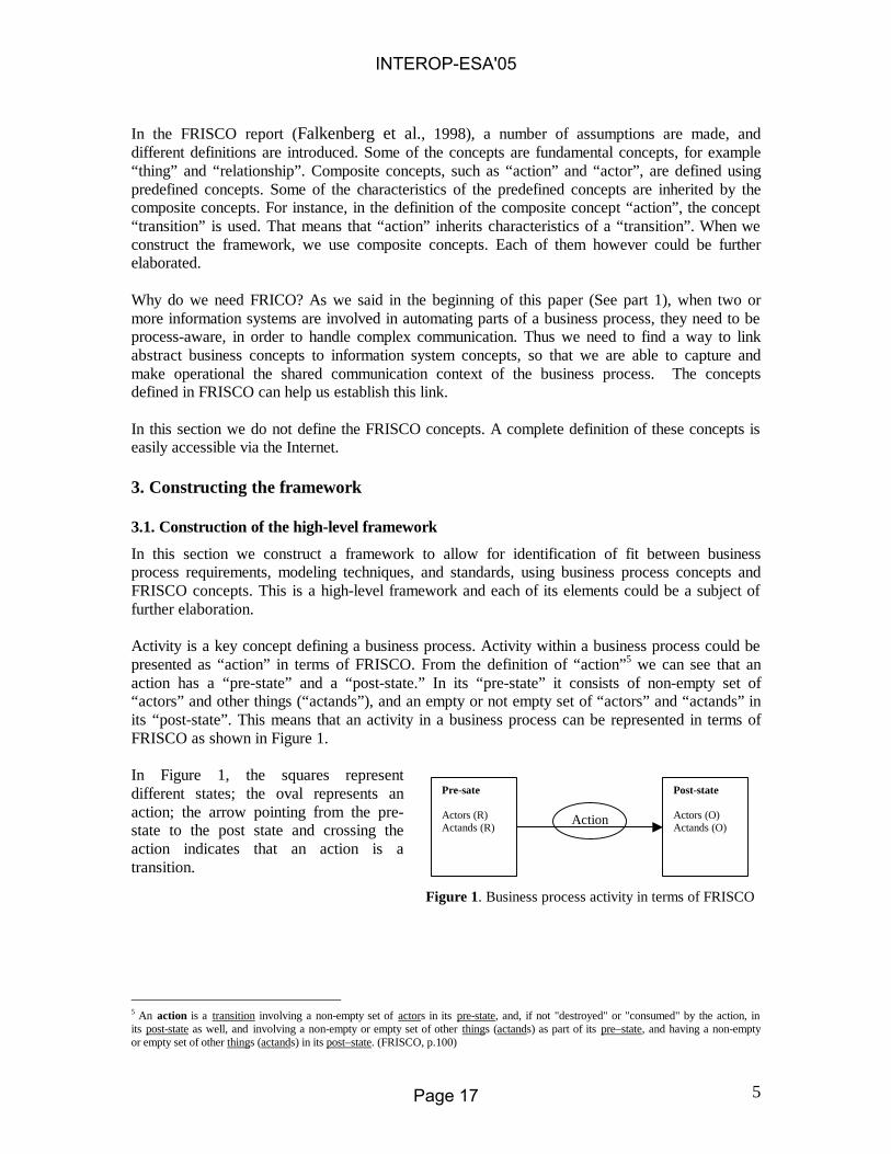
In this section we construct a framework to allow for identification of fit between business process requirements, modeling techniques, and standards, using business process concepts and FRISCO concepts. This is a high-level framework and each of its elements could be a subject of further elaboration. Activity is a key concept defining a business process. Activity within a business process could be presented as “action” in terms of FRISCO. From the definition of “action”5 we can see that an action has a “pre-state” and a “post-state.” In its “pre-state” it consists of non-empty set of “actors” and other things (“actands”), and an empty or not empty set of “actors” and “actands” in its “post-state”. This means that an activity in a business process can be represented in terms of FRISCO as shown in Figure 1. In Figure 1, the squares represent different states; the oval represents an action; the arrow pointing from the pre-state to the post state and crossing the action indicates that an action is a transition.
Pre-sate Actors (R) Actands (R)
Post-state Actors (O) Actands (O)
Action
Figure 1. Business process activity in terms of FRISCO
5 An action is a transition involving a non-empty set of actors in its pre-state, and, if not "destroyed" or "consumed" by the action, in its post-state as well, and involving a non-empty or empty set of other things (actands) as part of its pre–state, and having a non-empty or empty set of other things (actands) in its post–state. (FRISCO, p.100)
INTEROP-ESA'05
Page 17

6
In the pre- state of an action there is a non-empty set of actors and actands ((R) stands for required or non- empty). In the post-state the set of actors and actands might be empty or not empty ((O) stands for optional).6 We can continue with the construction of the framework, now including the concept of a business process itself. A business process consists of activities ordered in a structured way and it has a beginning and an end (See Table 1). A similar concept in FRISCO is the “composite action,” which is defined as a structure of actions, with a unique “pre-state” and a unique “post-state.” Thus the business process itself could be presented as a composite action (see Figure 2), which contains actions. In Figure 2 the fact that we have a number of actions is represented by “Action 1..N,” and each action has the characteristics described in Figure 1. The actions (1..N) form the composite action (this is represented by the double-lined shape that originates from the composite action). The “time” concept could help expressing the business process concept “activities ordered in a structured way”. It will govern the order of the occurrence of the different actions within the composite action. Also, in FRISCO, the allowed states and transitions are specified by the “rule.” Thus, the “time” and “rule” concepts are added in the framework, to both composite action and actions. They are depicted with shaded rectangles. The strait lines link “time” and “rule” to the concepts, to which they apply. Customer is another important concept of a business process. To illustrate that a customer is an external party of the business process, we use the FRISCO concept of “system”. As the concepts that we use to construct the framework are “things”, in terms of FRISCO, and the concept of domain applies to all “things,” we included it in Figure 2 as well. To make the picture complete, we added also the concept of “domain environment” (system, domain and domain environment are represented with dotted rectangles).
6 Figure 1 has commonalties with Petri nets, where the states (the pre-state and the post-state) could be seen as places (an input place and an output place) in Petri nets, and the Action corresponds to transition. However, we aim to achieve detailed elaboration of each of these concepts in order to be able to better capture the communication context of a business process.
INTEROP-ESA'05
Page 18

7
Pre-sate 1..N Actors (R) Actands (R)
Post-state 1..N Actors (O) Actands (O)
Action 1..N
Rule
Time
Composite action (Business process)
Pre-sate Actors (R) Actands (R)
Post-state Actors (O) Actands (O)
System
Domain
Domain Environment
Time
Rule
Substantive aspect Communicative aspect Control aspect
Substantive Communicative Control
Figure 2: High-level evaluation Framework
Up till now we managed to cover most of the business process related concepts, described in Table 1. However, we need to take into account that a business process could be viewed from different aspects. In literature there is often the distinction between substantive actions and communicative actions (Stamper, 1988; Goldkuhl, 2001). Stamper (1988) refers also to a third type: control. The substantive aspect focuses on activities that take place in order to achieve the goal. The communicative aspect refers to the messages necessary in order to have the substantial activities in place effectively. The control aspect comes to assure that the necessary activities are being performed. Minzberg (1983) and Galbraith (1977) elaborate on the concept of coordination, which includes both the control and communicative aspects. We can then say that a composite action (business process) consists of substantive, communicative, and control aspect (on figure 2 this is presented with brackets, where the dotted line expresses that a composite action can be decomposed to these three aspects). The same is true for action.
3.2. Elaboration of concepts of the framework
What we did up till now was to try to link some important business process related concepts to Information systems concepts, defined mainly in FRISCO. Each element in the framework is a composite concept that can be further elaborated. This could allow to identify the fit between business process requirements, a modeling technique and a standard at a more detailed level.
INTEROP-ESA'05
Page 19

8
Below we demonstrate the elaboration of some concepts. A complete elaboration, however, will be a subject of a further research. An important characteristic of a business process is that it has a purpose (aim). This could be represented through the concept of “goal”. In FRISCO “the goal of an action is a special input actand of that action, pursued by the actors of that action and stating the desired output state intentionally.” When we relate the goal concept to the business process, two types of goals can be identified: the goal of the composite action (as one type of input actand of the composite action) and the goal of the individual actions (as a type of an input actand of the constituent actions). The goal of the composite action is a high-level goal, which relates to the aim of the business process. Each of the constituent actions has its own goal, which is governed by the goal of the composite action. In Figure 3B, the main goal of the business process is presented as elaboration of the concept “actand” in the pre-state of the composite action (the elaboration of the concepts is presented as a dotted rectangle linked with dashed lines to the main concept. A number of concepts in the dotted rectangle can link to one main concept). The symbol (G) next to Goal indicates that this is a main goal. The lower level goals of the actions contained in the composite action are presented as elaboration of the concept “actand” of the pre-states (1..N) of the constituent actions. We call them goal 1..N (G) to represent that each action has its own goal, which is governed by the goal of the composite action (see Figure 3B).
Pre-state(Compositeaction)
Actand (R)Goal (G)
Figure 3A: Elaboration of actand: goal as a special
type of actand in the pre-state of the composite
action
Pre-state 1..N(action)
Actand (R)Goal 1..N (G)
Figure 3B: Elaboration of actand: goal as a special
type of actand in the pre-states of the actions 1..N.
The purpose of a business process is to provide a valuable result. Thus defining a separate concept concerning the result is important for the framework. Although a “result” concept is not explicitly specified in FRISCO, by using the analogy with goal, we will include the result as a part of the post-states of the composite action and actions respectively (See Figure 4A and Figure 4B).
Post-state(Compositeaction)
ActandResult
Figure 4A: Elaboration of actand: result as a special type of actand in the post-state of the composite action
Post-state(Action 1..N)
ActandResult (1..N)
Figure 4B: Elaboration of actand: result as a special type of actand in the post-state of the actions 1..N
Customer is another important concept of a business process. In terms of FRISCO the “goal pursuing actor” of the composite action could capture this concept. As the customer is external to the system, we will call him an external goal-pursuing actor. We will call the actors, pursuing the goals of the individual actions internal goal-pursuing actors (See figure 5A and 5B).
INTEROP-ESA'05
Page 20

9
Pre-state(Compositeaction)
Actor (R)Goal-pursuing actor
(External)
Figure 5A: Elaboration of actor: the external goal-pursuing actor as a special type of actor in the pre-state of the composite action
Pre-state(Action 1..N)
Actor (R)Goal-pursuing actor
(Internal)
Figure 5B: Elaboration of actor: the internal goal-pursuing actor as a special type of actor in the pre-state of the actions 1..N.
In this paper we will go no further in improving the framework and elaborating the concepts. This will be a subject of future research.
4. Usage In the introduction we stated that information systems need to be process-aware, in order to become an integral part of the business process. We also pointed out that different modeling techniques could capture the requirements of a business process. Standards can be used to embed these requirements into the information system. The main concern was how to identify the fit between business process requirements, a modeling technique and a standard. In section 3.1., we constructed a general framework to help in identification of this fit. The framework links some business process concepts with information system concepts. In section 3.2., we illustrated how concepts of the general framework could be further elaborated. This elaboration could allow for identification of the fit on a more detailed level. Although neither the framework nor the elaboration of the concepts is complete, below we illustrate the use of such an approach with a simple example. We take as an example a business process from the Healthcare industry. For one requirement of the business process, we evaluate to what extent it could be covered by a certain modeling technique and a standard. The modeling technique that we analyze is “process charting” and the standard is the HL7 v3.0 standard. Brief description of the business process
Let us look at a situation, where a doctor requests a laboratory to do a blood test. To do the test, the laboratory needs to perform several activities. First, it needs to obtain a blood sample from the patient. After that, the sample has to be transported to a specified location for analysis. Once the sample is analyzed, the results are interpreted, before being sent to the interested parties. Using the framework to specify business requirements.
Let us have a situation, where parts of the business process described above (e.g. ordering of a blood test and receiving of observation results) need to be supported by disparate applications. We have to identify which elements of the business process need to be captured and embedded into the computer systems. Walking through the elements of the framework (See Figure 2) and brainstorming with parties involved in the business process, we might identify, that knowledge about actors needs to be embedded in the systems. For example, it might be important to know who orders a specific blood test; who collects the samples; who interprets the results. Thus, one important business requirement is to be able to capture the concept of actor. For the purpose of this example we focus only on this requirement. Below, we analyze whether the chosen modeling technique and the chosen standard could cover this requirement.
INTEROP-ESA'05
Page 21

10
The modeling technique
For the purpose of this example we evaluate a modeling technique used in practice called “Process charting” (McSheffrey, 2001). With the process charting, it is possible to model a business event, a business result, elementary processes, mandatory sequences and optional paths (See Figure 6).
Businessevent
Businessresult
Process Mandatorysequence
Optionalpath
Figure6: Notation of elements, used in process charting.
Let us try to analyze, which elements of the framework does the process charting cover. The business event refers to the pre-state of the composite action (an example of a business event could be the order of a blood test) and the business result refers to the post-state of the composite action (an example could be the receipt of the observation result). This business event indicates the desired outcome of the business process, so we can link it to the goal of the composite action. The business result refers to the result of the composite action. (See Figure 3A and Figure 4A). Processes corresponds to actions within a composite action; the time concept of the framework can be covered by concepts of mandatory sequence (mandatory sequence can capture the relative time). The allowed set of business events, business results, processes, mandatory sequences and optional paths is governed by rule. In summary we can say that the “process charting” covers the following elements of the framework7: the goal and the results of the composite action, the actions within the composite action, the time and the rule concepts. In the previous section, for our blood test example, we identified the need to capture the knowledge about actors. In this section, we analyzed the process charting as a modeling technique. However, from the description above it is clear, that with the process charting the concept of “actor” cannot be modeled8. The standard For the purpose of this example we look at the HL7 v.3.0. standard, which is a leading standard in the Healthcare industry. For simplicity reasons we only check whether the concept of actor can be covered using this standard. The HL7 v.3.0. standard is developed based on the HL7 Reference Information Model (RIM). The RIM captures important concepts from the Healthcare domain. Although the RIM is very generic, it is the starting point for deriving more concrete models, like the Domain message information models and the Refined message information models, which capture the information exchanged between different applications (that take part in the business process). The HL7 RIM identifies two major "high-level" concepts that are fundamental to understanding the world of healthcare information: intentional "actions" or "services" (Acts), and "people,
7 We also refer to the elaboration of the concepts of the framework 8 There are other elements that cannot be modeled with process charting, but for the purpose of this example we will focus on the concept of actor
INTEROP-ESA'05
Page 22

11
places and things" that are of interest in the world of healthcare (Entities). The RIM places two additional classes - Role and Participation - between Act and Entity. The Role class models several important concepts. First, Role captures the fact that the various "static" entities may "temporally" assume one or more "roles" in a particular healthcare context. Second, the concepts of "capability" are also modeled using instances of the Role class. A special class “Participation” is introduced to identify “Entity-in-a-Role”, which participates in a specific “Act.” Going back to our example, we can say that the concept of “actor” can be represented in terms of the RIM concepts as Entity in a Role, which participates in a specific Act. Within the example described above we used the framework to specify one requirement of a business process (the requirement that knowledge about actors needs to be embedded within the systems, supporting the business process). We evaluated process charting as a modeling technique and we identified that it cannot cover the concept of actor. We analyzed the HL7 v. 3.0. standard and we found out, that the concept of actor could be captured. Thus we identified a mismatch between a business process requirement, a modeling technique and a standard. This mismatch might not allow knowledge about the actor to be embedded in the information system (even if the standard is capable to cover the concept of “actor”, the chosen modeling technique is not able to model this business process requirement). The result could be a technically functioning system, which however might not be able to become a fully integral part of the business process. 5. Conclusions and further research We started this paper saying that systems, used to automate part of a business process, need to be business process-aware in order to become an integral part of it. We pointed out the need to evaluate the fit between business process requirements, a modeling technique and a standard. A framework was constructed to facilitate the evaluation of this fit. We further argued a mismatch between the requirements, the modeling technique and the standard can pinpoint inter-organizational interoperability problems. In that respect the framework could be used as a tool for such problem identification. The intended use of the framework was demonstrated with a simple example. The question that we asked in the beginning of this paper was how to evaluate the fit between business process requirements, a modeling technique and a standard. For simplicity reasons, we presented a very small example of how to identify this fit. The purpose of this example was mainly to illustrate how to work through the framework. However, we can envision situations, in which more complex analysis needs to be performed. For instance, concerning the modeling technique, such an analysis might lead us to the conclusion that the modeling technique does not provide the means for synchronization of process steps, thus it does not provide enough richness of the rules (this can be identified by the rule concept of the framework and its elaborations). Similar analysis could identify gaps in the standard. For instance, in the HL7 v.2.2., the concepts of a “general practitioner” did not exist (in the US, where the standard is developed, the concept of general practitioner does not exist, however, in other countries using the standard, it does). This gap can be identified through the actor concept of the framework and its elaboration. Further, the HL7 standard is very limited in terms of modeling the sequence of actions, which is suggested by the rule and time elements of the framework. In this paper we constructed a general framework. This framework can be seen as a first attempt to reason about to what extent a modeling technique and a standard are capable to cover the
INTEROP-ESA'05
Page 23

12
actual business requirements. Such an evaluation is needed, to check whether the chosen modeling technique is capable to make explicit and correctly capture the business process logic and whether a chosen standard is capable to formalize it. As argued earlier, such an evaluation is important, so that interoperability problems can be identified at an early stage. Each element of this framework could be further elaborated. This would make possible to have a more accurate comparison between requirements of the business process, the modeling technique and the standard. However, the improvement of the framework and the thorough elaboration of its concepts will be a subject of further research. References
Ågerfalk, P., Goldkuhl, G., Cronholm, S. (1999). Information Systems Actability Engineering- Integrating Analysis of Business Process and Usability Requirements. Proceedings of 4th International Workshop on the Language Action Perspective on Communication Modeling (LAP’99). Copenhagen, Denmark, September 12-13.
Biazzo, S. (2000). Approaches to Business Process Analysis: a Review, Business Process Mnagement Journal, Vol. 6 No. 2, 2000, pp. 99-112.
Covington, M.A. (1997). On Designing a Language for Electronic Commerce. International Journal of Electronic Commerce, vol. 1, no 4, Summer 1997, pp. 31–48.
Damsgaard J., Truex, D. (2000), Binary Trading Relationships and the Limits of EDI Standards: The Procrustean Bed of Standards. European Journal of Information Systems, vol. 9, no 3, pp. 173-188.
Davenport T.H. (1993). Process innovation. Reengineering work through information technology. Harvard Business School Press, Boston.
Davenport, T. and Short, J. (1990), The new industrial engineering information, technology and business process redesign., Sloan Management Review, Vol. 31 No. 4, pp.11-27.
Falkenberg, E. D., Hesse, W., Lindgreen, P., Nilsson, B. E., Han Oei, J. L., Rolland, C., Stamper, R.K., Van Assche, F.J.M., Verrijn-Stuart, A. A., Voss, K. (1998), A Framework of Information System Concepts: The FRISCO Report, IFIP (1998), available on- line at: http://www.liacs.nl/~verrynst/frisco.html
Fernandes, K.J., Raja V., Autony, J. (2001). Optimal level of goal mapping in a reengineering environmnent”, Business Process Management Journal, Vol. 7 No. 1, 2001, pp. 24-32.
Galbraith, J. (1977), Organization Design. Reading. MA: Addison- Wesley
Goldkuhl, G., (2001), Communicative vs. material actions: Instrumentality, sociality and comprehensibility, In: M. Schoop and J. Taylor (Eds.), Sixth International Workshop on the Language Action Perspective on Communication Modelling (LAP 2001), Montreal, Canada, 1-19
HL7: Health Level 7 http://www.hl7.org/
Huang K. (1998), Organizational Aspects of EDI: a Norm-oriented Approach, PhD thesis, ISBN 90-3651095-3
Jelassi, T. and Figon, O. (1994), Competing through EDI at Brun Passot: Achievements in France and Ambitions for the Single European Market, MIS Quarterly, 18(4), pp. 337-352.
Kekre, S. and Mukhopadyay, T. (1992), Impact of Electronic Data Interchange Technology on Quality Improvement and Inventory Reduction Programs: A Field Study, International Journal of Production Economics, vol. 28, no. 3, pp. 265-282.
INTEROP-ESA'05
Page 24

13
Kimbrough S.(1999), EDI, XML, and the Transparency Problem in Electronic Commerce. Available on-line: http://grace.wharton.upenn.edu/~sok/sokpapers/1999-0/indiana-transparency/paper.pdf
Mackay, D.R. (1993), The Impact of EDI on the Components Sector of the Australian Automotive Industry, Journal of Strategic Information Systems, vol. 2, no. 3, pp. 243-263.
McCormack, K. (1999), Business Process Orientation (BPO): What is it and How do you know when you have it?
McSheffrey, E. (2001), Integrating Business Process Models with UML System Models, A Popkin Software White Papere. Available on-line at: www.popkin.com
Mintzberg, Henry,
Reijswoud, V.E. van, J.L.G. Dietz. (1999). DEMO Modelling Handbook: Volume 1. Available on-line: http://www.demo.nl/DEMO/Literatuurbron/handbook.pdf
Rukanova, B. D., Slooten, C. van, Stegwee, R.A. (2003).Beyond the Standard Development and the Standard Adoption. In Jakobs, K. (Ed): Proceedings of the 8th EURAS Workshop on Standardization, July 11-12, 2003, Aachen, Germany.Mainz Publishers, ISBN: 3-86073-762-7, pp. 120-138
Söderström, E., Andersson, B., Johanesson, P., Perjons, E., & Wangler, B., (2002), Towards a Framework for Comparing Process Modeling Languages”, In Pidduck et al. (Eds.), CAISE 2002, LNCS 2348, pp. 600-611, 2002, © Springer- Verlag Berlin Heidelberg, 2002
Sokol, P. K. (1995), From EDI to Electronic Comemrce- a Business Initiative, McGraw-Hill, Inc., New York, ISBN 0-07-059512-7.
Stamper, R. (1988), Computerized assistance During the Information System Life Cycle, T.W. Olle, Verijn-Stuart, L. Bhabuta (eds), Elsevier Science Publishers B.V. (North-Holand) © IFIP, 1988
Stamper, R. (1996), Organisational Semiotics. In: Information Systems: An Emerging Discipline, F.Stowell & J. Mingers (eds.), London and New York, McGraw-Hill.
Stamper, R.K. (1992), Signs, Organizations, Norms and Information Systems, Proceedings of the Third Australian Conference on Information Systems, University of Wollongong, Australia
Stegwee, R.A., Rukanova, B.D. (2003). Identification of Different Types of Standards for Domain-Specific Interoperability. In: Proceedings of MIS Quarterly Special Issue on Standard Making: A Critical Research Frontier for Information Systems: Pre-Conference Workshop ICIS 2003. pp. 161- 170, available on line at: http://www.si.umich.edu/misq-stds/proceedings/
Stock, J.R. and Lambert, D.M. (2001), Strategic Logics Management, McGraw-Hill?Irwin
Structure in Fives: Designing Effective Organizations; Englewood Cliffs : Prentice Hall, 1983.
Vermeer, B. (2000). How Important is Data Quality for Evaluating the Impact of EDI on Global Supply Chain, Proceedings of the 33 Hawaii International Conference on System Science, vol. 7.
Wand, Y. & Weber, R. (1989), An Ontological Evaluation of System Analysis and Design”, In: Falkenberg, E.D. & Lindgreen, P. (Eds.) Information System Concepts: An In-depth analysis, Elsevier Science Publishers B.V. (North-Holand) © IFIP, 1989
Wrighly, C.D., Wagenaar, R.W., and Clarke, R. (1994), Electronic Data Interchange in National Trade: Frameworks for the Strategic Analysis of Ocean Port Communities, Journal of Strategic Information Systems, 3(3), pp. 211-234.
INTEROP-ESA'05
Page 25

An Architecture for Semantic Enterprise Application
Integration Standards
Nenad Anicic1, 2, Nenad Ivezic1, Albert Jones1
1 National Institute of Standards and Technology, 100 Bureau Drive Gaithersburg, MD, USA
{nenad.anicic|nenad.ivezic|albert.jones}@nist.gov
2 Faculty of Organization Sciences, 154 Jove Ilica Street 11000 Belgrade, Serbia and Montenegro
Abstract. Large, industry-wide interoperability projects use syntax-based stan-dards approaches to accomplish interoperable data exchange among enterprise applications. We are investigating Semantic Web to advance these approaches. In this paper, we describe an architecture for Semantic Enterprise Application Integration Standards as a basis for experimental assessment of the Semantic Web technologies to enhance these standards approaches. The architecture re-lies on our automated translation of the XML Schema-based representation of business document content models into an OWL-based ontology. Based on this architecture, we use the Semantic Web representation and reasoning mecha-nisms to support consistency checking of ontological constructs and constraints specified within the ontology. The proposed architecture is relevant (1) when managing multiple enterprise ontologies derived from, and dependent on, a common ontology and (2) when dealing with model-driven integration using customizable interface models and testing of such integration efforts.
1 Introduction
The scope of the effort reported in this paper is defined partially by the type of indus-trial problems we identify and partially by the traditional standards usage for enter-prise application integration (EAI). Both are discussed below.
1.1 A Prototypical Problem
Two independent but related industry consortia have developed enterprise applica-tion integration standards in the form of business document content models. Stan-dards in Automotive Retail (STAR), an automotive retail consortium, has developed XML Schema-based standards to encode business document content models enable message exchanges among automotive manufacturers and their retail houses. Each
INTEROP-ESA'05
Page 26

STAR application adopts and implements the proposed STAR XML-based interface model [1]. Automotive Industry Action Group (AIAG), an automotive supply chain consortium, has developed XML Schema-based standards to encode its own business document content models that enable message exchanges among automotive manu-facturers and their suppliers. Each AIAG application adopts and implements the AIAG interface model [2].
Both STAR and AIAG base their interface models on the same ‘horizontal’ XML document standard – the Open Applications Group (OAG) Business Object Docu-ments (BODs) [3]. The OAG BODs are specifications of general XML Schema com-ponents and general aggregations that make up XML Schema-based business document content models from these components. STAR and AIAG independently use the OAG BODs specifications to customize their own business document content models and define rules of usage and constraints. Typically, usage rules and con-straints are captured outside of the XML Schema using syntactic constructs such as Schematron. A significant manual task is required to identify and reconcile differ-ences among constraints and rules of the two standards [4]. Consequently, major problems can arise whenever a STAR application attempts to exchange automotive parts ordering data with an AIAG application.
In this paper, we describe an approach to enable automated checking of compati-bility among rules and constraints that are independently developed within the two (or more) standards that have a common terminology as their bases. Once this ap-proach is implemented, we expect more capable testability of integration efforts and, consequently, more efficient application integration.
1.2 Traditional EAI Standards Architecture
Enterprise application integration (EAI) is being used extensively today. The left portion of Figure 1 shows how a traditional EAI standards architecture could be ap-plied to our STAR-AIAG integration problem assuming, a pure XML Schema-based approach. The following steps are required to translate data and to verify the business document translation: 1. Identify and resolve manually any semantic and syntactic similarities and differ-
ences between the interface models. 2. Create two XSLT stylesheet transformations from source to target and vice versa. 3. Based on 2, apply translation to the source XML Schema interface model to
obtain a business document conformant to the target XML Schema interface model.
4. Validate translation using equivalence test. This validation may be done by ap-plying an equivalence test between the initial source business document and the final source business document that is obtained through a sequence of two (for-ward and reverse) translations compatible with XSLT transformations from step 2.
Validation using an equivalence test is not straightforward because issues that re-quire capabilities beyond a simple, syntax-based equivalence checking arise often. Consider the following two examples. First, elements that are ordered differently
INTEROP-ESA'05
Page 27

syntactically may, in fact, be equivalent semantically, if that order is not significant. Second, a time period can be specified either by a start date with an end date or with a start date and a duration. While they are semantically equivalent, they are syntacti-cally quite different.
Fig. 1. Traditional and Semantic Web-based EAI Standards Architectures.
2 A Semantic Web-Based EAI Standards Architecture
For our approach, which is shown in the right portion of Figure 2, we use the OWL-DL Web ontology language to integrate enterprise applications. The language is based on a subset of the First Order Logic formalism called Description Logics. To do this, we assume that the OAG, STAR, and AIAG business document content mod-els have been rendered into OWL-DL ontologies – a step that will be discussed in detail later in the document. This, in turn, enables us to readily use automated reason-ing methods provided by DL reasoners such as Racer [5]. These reasoning methods are fundamental enablers of automated transformations, mapping and translation functions, between OWL-DL interface models that are independently developed but based on a common terminology.
The following steps are envisioned to translate and verify the translations in the proposed architecture. We provide details of executing these steps below. • Perform model-based equivalence analysis of STAR and AIAG schemas.
o Create ontologies of the common OAG-based general terminology and from respective XML Schemas for STAR and AIAG.
INTEROP-ESA'05
Page 28

o Create a merged ontology from independently developed STAR and AIAG ontologies and check for unsatisfiability.
o Identify similarity between two schemas based on the comparison of their respective semantic models. (We assume that a high degree of equivalence may be obtained as a result of common usage of core com-ponents of the OAG standard.)
• Apply semantic translation using the merged ontology and an OWL-DL rea-soner.
o Translate the source (STAR) XML instance to the source (STAR) OWL representation.
o Check for consistency and sufficiency w.r.t the merged (source-STAR+target-AIAG) ontology.
o Classify the source OWL individual into the target ontology (AIAG) and perform validation and serialization.
3 A Semantic Web-based Integration Methodology
Figure 2 illustrates the proposed Web-based integration methodology using a sce-nario-based view of the semantic integration architecture. The top portion shows the ontology-creation activities. These activities, which occur at design time, help us to define and test possible interoperable data exchanges. The bottom portion shows translation activities. These activities, which occur at run time, help us to reason about concrete XML data to transform the data from one format to another.
Fig. 2. Scenario-based view of the semantic integration architecture.
INTEROP-ESA'05
Page 29

We give a brief summary of the sequence of the eleven activities shown in Figure 2. 1. Apply Xsd2Owl Transformation. We began by applying an automated t
formation to the OAG XML Schema representation to obtain an OAG OWLbased generalized ontology. This is a generalized ontology that contains concepdescriptions only and no definitions
rans--
t i-
tion is cap-
1. The automated transformation was possble because we took into account the decisions and the rationale that led to the OAG components and document design. The automated transformatured in the XSLT transformation rules.
2. Calculate concept subsumption and check satisfiability of the new OAG ontology. This results in a new subsumption hierarchy for the OAG generalized ontology and an indication from the reasoner that the new ontology is either sat-isfiable or not. It can be unsatisfiable for several reasons. For example, an ele-ment that is mandatory in the super-type declaration is only optional in the new declaration. All such conditions must be resolved before proceeding.
3. Create an OAG regular terminology. Once we have a satisfiable generalized terminology, any individual application integrator, typically a human being, can use the terminology to specify additional constraints or to provide definitions for concepts in a particular context. The original STAR and AIAG Schemas include free-text descriptions of the additional document constraints that need to be ‘lay-ered on top’ of the OAG generalized terminology. For each such schema, these constraints are used to specify concept definitions based on the original concept descriptions. The outcome of this step is a regular STAR or AIAG terminology.
4. Check satisfiability of each individual regular ontology. Similar to Step 2, the outcome of this step is an indication from the reasoner whether each individual ontology is satisfiable. All unsatisfiable conditions must be resolved before pro-ceeding to step 5.
5. Apply automated transformation from source (STAR) XML data to OWL data. This step initiates the run-time activities required for a successful and in-teroperable data exchange. We transform XMLSchema instances into OWL-DL individuals that conform to the OWL model-based assumptions used in ontologi-cal reasoning. The outcome is transformed STAR OWL data that corresponds to the initial XML data.
6. Validate source data. Validation of STAR OWL data includes consistency checking under both Open World Assumption (OWA) and Closed World As-sumption (CWA). The outcome of this step, if successful, is an indication from the reasoner that the STAR OWL data are consistent with respect to the STAR ontology. An individual is valid only if it is consistent (belongs to specific con-cept) in both OWA reasoning and CWA reasoning. Validation is necessary to check the transformation and to check other semantic constraints, which are de-
1 Concept refers to expressions that define a class in the OWL-DL language, which also
provides constructs for establishing relationships between concepts. The meaning of concepts is specified using logical semantics, which distinguishes between concept description and concept definition. Concept description refers to a class with necessary conditions only; con-cept definition refers to a class with both necessary and sufficient conditions.
INTEROP-ESA'05
Page 30

fined in the corresponding ontology. Examples of such constraints include addi-tional semantic business rules based on Schematron rules and free-text descrip-tions provided with a schema.
7. Create a merged ontology. In order to translate from STAR to AIAG OWL data, we need to create a merged ontology from the two individual ones and cal-culate new, concept-subsumption hierarchy2. Because new independently defined ontologies are based on the same generalized OAG terminology, a reasoner may combine axioms and calculate the new, concept-subsumption hierarchy. In the merged ontology one concept might be dependent on some concepts in the other ontology namespace. The merged semantics provides support for inferences over the source data that may yield unexpected results (such as those we discussed in the previous section).
8. Check satisfiability of the merged ontology and consistency of the source (STAR) data with the new ontology. The successful outcome of this step is an indication from the reasoner that the merged ontology is satisfiable and, simi-larly, that all STAR OWL source data are consistent with respect to the merged ontology. Because the integration tool is a complete reasoner that includes consistency checkers, all axioms of the merged ontology must be loaded. The tool has to check satisifiability for every concept of the merged ontology and consistency of source individuals with respect to the merged ontology.
9. Compute classification of the source (STAR) OWL data in the target (AIAG) ontology. Assuming successful completion of the preceding steps, then we can use the individual classification capability of a DL reasoner to compute target data in the AIAG ontology. The result is an assignment of the STAR OWL data to the specific AIAG class(es). At this point, specific STAR XML data may be successfully translated into target AIAG XML data. This, however, doesn’t mean that all STAR data may be successfully translated to AIAG.
10. Apply validation of newly created target (AIAG) OWL data. The outcome of this step, if successful, is an indication from the reasoner that the AIAG OWL data are consistent with respect to the AIAG ontology. As discussed above, this requires OWA consistency and validation that the same individual is a valid instance of the target concept in the CWA reasoning. The individual consistencychecking in OWA is already done with respect to the merged ontology. The OWL individuals classified to the AIAG concept hierarchy have to be checked for sufficiency with respective to target (AIAG) concepts. If an individual is inconsistent in CWA, then translation is not possible. If successful, however, then we can be sure that specific XML source data can be translated into a taOWL data and that the integration will succeed.
rget
11. Apply serialization of AIAG OWL data into AIAG XML data. The outcome of this step is an AIAG XML instance that preserves semantics defined in the original STAR OWL data. For serialization into XML format we use concept and property hierarchy. If we use default XSD serialization from our OWL on-tology, then the serialization is also provided. If we have a customized mapping
2 We include this step in the run-time activities, but it could also be done at design time.
INTEROP-ESA'05
Page 31
to specific XMLSchema syntax (e.g., a sequence of elements defined in separate file), then that serialization is dependent on the mapping rules.
4 Initial Findings and Lessons Learned
In this section, we discuss some initial findings and lessons learned.
4.1 Individual Equivalence Test
When dealing with B2B application integration, it is imperative to determine if two business documents are semantically equal. As mentioned before, during XML to OWL transformation, every new OWL individual is assigned a new URI identifier. That identifier is only necessary for individual classification and its actual value is not significant. That means that the same XML business document instance may be trans-formed to individuals with different URI identifiers but the same content. For datatypes, "semantically equal" means that the lexical representation of the literals maps to the same value. For individuals it means that they either have the same URI reference or are defined as being the same individual. We have developed a tool that helps us to do this. It is described below.
For every individual, the testing tool creates a temporary concept definition that contains the values constrained to the values specified in the individual properties. In addition, cardinality constraints on the properties of the temporary concept definition are based on the property occurrence in the particular individual. All the temporary concepts are considered by the reasoner to determine mutual equivalence. Then, for every pair of equivalent concepts, the tool asserts sameAs mapping between two indi-viduals. This means that the tool creates an assertion that explicitly defines equality between the two individuals. That new assertion will help the reasoner to calculate any new equivalence. For example, two aggregate concepts may be determined equivalent based on individual concept equivalence. The process is iterative and will end when no new concept equivalence is identified.
We emphasize that a reasoner can calculate a new subsumption tree and identify new concept equivalence by taking into account both concept definitions and individ-ual assertions.
4.2 Concept equivalence with inconsistent business document instances
We investigated whether two ontologies can facilitate interoperable data exchange and we used reasoner capabilities to perform satisfiability check between them. We determined that a necessary condition for interoperable data exchange is that there are no contradictory concepts in the merged ontology. It is, unfortunately, not a suffi-cient condition because some individuals may violate business constraints defined for a particular concept. Consider the following example.
INTEROP-ESA'05
Page 32

Suppose a mandatory property, a necessary condition, is present within the target concept. Since the reasoner uses only definitions to calculate subsumption and equivalence among concepts and since a mandatory property is only a necessary condition, it will not be part of definition. This may give rise to an inconsistent source individual if the source concept specifies that property as optional. In a general case, any logical constraint that is not a part of either target or source concept definition but only their necessary conditions may cause a similar inconsistency and prevent inter-operable data exchange.
Human designers face a similar problem every time they create a normalized on-tology for a new business document content model specification. This problem deals with establishing whether an axiom is a part of concept definition, which includes necessary and sufficient conditions, or only a part of concept description, which in-cludes necessary conditions only. This distinction is critical because a concept defini-tion is the mechanism used to classify concepts.
We are in a position to develop a tool that helps the designer evaluate alternative ways to specify concept description and concept definitions and to determine the potential drawbacks of each. We also plan to investigate ontology design patterns, which may avoid the “concept equivalence-individual inconsistency” type of transla-tion problem. Additionally, we may expand default reasoner satisfiability checking to provide additional testing capability.
4.3 Lessons Learned
Based on our initial examination of Semantic Web technologies, we believe that they are sufficiently mature to allow experimental assessment in a fairly realistic enter-prise-application-integration context. Our experiments used production-level XML Schema encoding of OAGIS 9.0 core components. The Xsd2Owl transformation takes a complete set of core component types from OAGIS 9.0 and is capable of creating OWL-DL ontology successfully. We worked successfully with some, but not all, examples of XML Schema definitions for OAGIS Business Object Docu-ments (BODs).
The currently available tools are clearly not sufficiently robust and scalable to war-rant risk-free development of specialized add-on tools to support industrial interop-erability efforts with all the complexities typically encountered. However, the rate of maturation and adoption of these tools is encouraging and it seems that these issues of robustness and scalability may be addressed in the near future.
When planning for future usage of the Semantic Web technologies within realistic industrial enterprise application integration efforts, it is important to provide a transi-tioning path for moving from XML Schema-based to OWL-based application integra-tion. While there are potentially other significant issues, one that we addressed suc-cessfully early on is to show that it is possible to translate XML instances into OWL individuals and, in the opposite direction, to serialize OWL individuals as XML in-stances conforming to a specific XML Schema. This capability is important when presenting these new approaches to industrial communities as it shows that the exist-ing legacy applications do not have to change all their interfaces over night to enjoy
INTEROP-ESA'05
Page 33

the benefits of this new technology. We were encouraged by the initial positive reac-tions from industry to the initial results from our experimental approach.
5 Conclusions
In this paper, we described a Semantic Web-based approach and a methodology to enhance syntax-based standards for enterprise applications integration (EAI). The methodology contains a number of integration and validation steps that are performed both at design time and run time. During design time, the methodology supports development of generalized and normalized ontologies and allows model-based similarity analysis of these ontological models. During run time, the methodology enables semantic translation of instances of business documents using the previously developed ontologies and automated reasoning tools.
Initial findings in testing the methodology show interesting capabilities such as the ability to perform individual equivalence tests that are content based. Through ex-perimental work, we have gained a significant insight into the issues of necessary and sufficient conditions for achieving interoperable data exchange. The lessons learned so far indicate that the Semantic Web technologies are sufficiently mature to allow experimental assessment in a fairly realistic enterprise application integration context.
Our immediate future work will focus on further assessment of the initial ideas for Semantic Web-based EAI standards. The work will draw from on-going industrial standards-based integration efforts such as the ones going within STAR and AIAG industrial groups. We expect to identify key technical issues for the proposed ap-proach, and through experimental demonstration show how such issues may or may not be addressed using the proposed approach. Our key contribution, we anticipate, will be to provide an increased understanding of whether and how Semantic Web technologies may be applied in a near future to realistic industrial integration efforts.
Disclaimer
Certain commercial software products are identified in this paper. These products were used only for demonstration purposes. This use does not imply approval or endorsement by NIST, nor does it imply these products are necessarily the best avail-able for the purpose.
References
1. Standards for Technology in Automotive Retail (STAR) Web Site, accessed November 2004. Available at http://www.starstandard.org/
2. Automotive Industry Action Group (AIAG) Web Site, accessed November 2004. Available at http://www.aiag.org/
INTEROP-ESA'05
Page 34

3. Open Applications Group (OAG) Web Site, accessed November 2004. Available at http://www.openapplications.org/
4. D.Trastour, C.Preist , and D.Coleman, “Using Semantic Web Technology to Enhance Cur-rent Business-to-Business Integration Approaches”. 7th IEEE International Enterprise Dis-tributed Object Computing Conference, EDOC 2003, Brisbane, Australia, Sept 16-19th , 2003
5. V. Haarslev and R. Moller. Description of the RACER system and its applications. In Pro-ceedings InternationalWorkshop on Description Logics (DL-2001), 2001
INTEROP-ESA'05
Page 35

Inter-Organization Interoperability in Transport Chains
Using Adapters Based on Open Source Freeware
Paul Davidsson1, Linda Ramstedt2, and Johanna Törnquist2
Blekinge Institute of Technology, Department of Systems and Software Engineering 1 372 25 Ronneby, Sweden 2 374 24 Karlshamn, Sweden
{Paul.Davidsson, Linda.Ramstedt, Johanna.Tornquist}@bth.se
Abstract. The significance of electronic information exchange in transport chains and its influence on the performance of the logistics processes is well-known. While much focus is still on the various techniques for information ex-change, many SMEs experience problems that are not primarily caused by an absence of technology. Several advanced solutions exist but investment possi-bilities within many SMEs are very limited while their needs for electronic data exchange may be very similar as for the large companies. We describe a general “adapter” solution based on open source freeware that make it possible (in principle) for any business system to exchange information with any other business system. It has been successfully applied in a pilot study involving two companies (the transport operator being an SME) using different business sys-tems (Hogia Mobilast and Movex). The solution was evaluated with the result that it met the requirements of the companies and is now planned to be used for future data exchange between the companies.
1 Introduction
A transport chain usually involves a large number of actors, and in order to reach an acceptable level of efficiency it is important to synchronize these actors and their activities. For example, information concerning the status of the cargo needs to be available to the right person, at the right place, and at the right time. Although this is obvious for everyone involved and that advanced technology to collect and distribute information exist, this is seldom achieved. We argue that the main reasons are not due to lack of solutions, but rather based upon difficulties to integrate existing software systems and the high costs associated. Many companies are small or medium-sized enterprises (SMEs) with a limited possibility to invest in the existing solutions, while their needs to perform electronic data interchange to act competitive may not be so much different from those of the large companies. Instead, a large amount of trans-port-related information, such as bookings and cargo specification, is exchanged manually via fax machines and phone. Problems that arise due to the manual work required are for instance that information may not be accessible at a certain place
INTEROP-ESA'05
Page 36

when needed and also information duplication is complicated. The question that re-mains to be answered then is; are advanced and expensive systems required to solve these problems, or are there other, simpler and less expensive, solutions?
The project “Transport informatics for increased cooperation between the parts in a logistic chain”, also called AIS 42, (http://www.ec.se/ais/) focused on this question. The project had a reference group of companies located in, or close to, the city of Karlshamn, Sweden. One of the goals was to show that by using only simple and cheap solutions it is possible to establish adequate electronic information ex-change between different actors in transport chains that have different prerequisites and preferences. The overall aim of the project was to develop and demonstrate the use of a common platform where the companies are able to exchange the necessary information between themselves as well as their other customers and suppliers. Moreover, the platform should work independently of the existing information sys-tems and routines used by the different actors.
The project was based on two case studies of which we will focus on one. These were studied in detail and the needs for improvements to support the transport activi-ties were identified. The needs were analyzed and classified into categories such as:
- simplification of transport booking and other administrative activities, - tracing and positioning of goods and carriers, - deviation detection, - support for calculations of environmental load, and - logging of freight-related data,
all of which require (different levels of) system interoperability. The needs of im-provements were ranked based on importance which resulted in a requirement speci-fication for the software platform to be developed. The platform and its functional-ities were later demonstrated on one of the transport chain case studies and evaluated. Besides the software platform, the project also generated insights in the problems related to technological aspects as well as organizational issues within the freight transportation industry.
The next section describes related work. Section 3 then describes the solution that was developed to support and facilitate information exchange, while Section 4 pre-sents one of the case studies upon which the project is based. Section 5 provides a discussion of the results and pointers to future work.
2 Related Work
The review includes two parts; related research, in particular projects with similar aims, and existing software solutions available on the market.
INTEROP-ESA'05
Page 37

2.1 Research Projects
There are a number of projects that have addressed the problem of information ex-change and IT solutions for freight transportation. Many of them are projects funded by the EU that focus on how to create solutions and processes for transport mode-independent information exchange that can provide traceability, as well as, a stan-dardized and smooth way to communicate. Some of these projects are:
- INTRARTIP (Intermodal transport real time information platform) [1] - ITESIC (Integration of technologies for European short intermodal corridors) [1] - PISCES (Pipeline intermodal system to support control, expedition and schedul-
ing) [1] - D2D (Demonstration of an integrated management and communication system for
door-to-door intermodal freight transport operations) [6]. Other projects focus specifically on traceability and straight-forward combinations of technologies to achieve this for cross-border transportation. Two examples are SITS (Simple intermodal tracking and tracing) [1] and MULTITRACK (Tracking, tracing and monitoring of goods in an intermodal and open environments) [3].
Even though the projects mentioned above and AIS 42 have some issues in com-mon, AIS 42 focus on the particular situation for SMEs. Consequently, usability, simplicity, interoperability, and cost-effectiveness are the primary factors in the choice of technology.
2.2 Existing Technology
Support for electronic information exchange is often found in large business system, e.g., ERP (Enterprise Resource Planning) systems. Such systems often focus on a specific type of company, e.g., a transport buyer or a transport operator. The systems do often have some ability to exchange information with other types of business sys-tems, but this is often limited to a standard set of formats and systems. There exist several off-the-shelf TA (Transport Administrative) systems for storage, synthesis and communication of data, such as Movex (http://www.intentia.com/), Hogia Mobi-Last (http://www.hogia.se/godstrafik/), and many more. These systems and the other systems that support electronic data interchange have varying characteristics, but all of them require substantial investments both to procure and to use. As a consequence, SMEs are able only to invest in one system, if any at all. This, in turn, makes it im-possible to carry out electronic business activities with several companies using dif-ferent business systems due to system interoperability problems.
One existing solution that meet some of the interoperability requirements is Micro-soft BizTalk (http://www.microsoft.com/biztalk/). The main purpose with BizTalk is to facilitate system communication independently of the individual communication formats in the systems by acting as an interpreter between the systems. It is based upon a central server through which all exchanged information pass. It uses XML and supports the main protocols for e-mail and http. However, being a proprietary client-
INTEROP-ESA'05
Page 38

server solution it has several disadvantages, such as, making the actors dependent of third party, being expensive and possible risks for communication bottlenecks.
3 The Adapter Solution
As mentioned in the introduction, some of the most important needs of improvements identified were: simplification of administrative activities, such as, transport booking, tracing of goods and carriers, deviation detection, and calculations of environmental load. Many of these require a complete unbroken process with gathering of data, data processing and information distribution. We decided to focus on the first point that concerns the reduction of usage of fax machines and other manual ways of informa-tion exchange (reducing the administrative costs as well as the number of error caused by the human factor) and increase the accessibility of information by making electronic information exchange possible.
Considering the requirement specification, a group of 15 students from Blekinge Institute of Technology developed a software prototype for electronic information exchange. The prototype is built using only on freeware with open source code such as, Java, MySQL, j2ee, jboss etc., and uses state-of-the-art technology like XML and Web services. The prototype provides the possibility for different business systems to communicate and supports information exchange via web portals, e-mail, fax and SMS. The prototype is an information carrying system meaning that the system acts independent on what type of data that is transferred through it.
The basic idea can be seen as a generalization of the well-known Adapter design pattern [7] used within object-oriented software engineering. It is also similar to the concept of wrapper agents [8] as used within the area of multi-agent systems [9]. To each (legacy) business system an adapter is built that enables the system to interact with other the other business systems in the transport chain. Such an adapter is mainly composed of three parts; a “bridge”, an “interpreter”, and a “message handler”. (See Fig. 1) The Bridge handles the interaction with the business system, and the Interpreter translates the data from the format the sending business is using to the format the receiving business system is using (and vice versa). The Message handler takes care of the communication with the adapters of the other business systems. The bridge typically makes use of the functions for exporting and importing information that most business systems are equipped with. If this is not the case, more sophisti-cated methods must be used.
Fig. 1. The structure of the adapter software.
Legacy business system
Adapter
BridgeInter- preter
Message handler
Interaction with other
business systems
INTEROP-ESA'05
Page 39

The Adapter prototype software is available as freeware and is relatively easy to install. It is structured as a program that includes general message handling compo-nents, and shells for the interpreter and the bridge. Much effort was spent on reusabil-ity making it easy to adapt the software to arbitrary business system (at least those that have basic data import and export functionality). Also modifiability was consid-ered and since the software is module-based, extensions of the system are facilitated. The system requires “log in” for usage, and encryption and digital labeling is in-cluded to increase the security.
4 Pilot Study
The transport chains that were selected as the case studies of the project are not very complicated consisting of just a few actors and little or no cross-border traffic. The focus is on SMEs based in the region of Blekinge, Sweden, with partly very limited resources for investments in IT but still needs the functionalities to stay competitive. Many of the needs of improvements and opportunities identified in the specific case studies can, however, also be found in many other companies in the transportation business of varying size, nationality and resources.
The transport chain we will focus on here consists of a truck transport carried out by Karlshamns Expressbyrå (KE) containing packaged temperature-sensitive cargo from the production facility of Karlshamns AB (KAB) in Karlshamn to the customers of KAB localized in Northern Europe. KE uses a system developed by SA-data for surveillance and booking. History of cargo temperature stored in the cooling systems in the trucks is made available by TermoKing. During the project, KE decided to start using Hogia Mobilast which is a system that supports the planning of transports since available transport resources can be controlled, transport orders can be administered via the system etc. KAB uses Movex for administration of orders, transport prices etc.
Through interviews the following aspects were identified as important for KE: - Simplification and speeding up of administration of a transport assignment. - Control of truck space utility. - Cargo follow-up during and after transport regarding temperature and time.
Deviation detection important. - Calculation and reporting of environmental impact.
Whereas the following aspects were regarded as important by KAB: - Delivery time precision (punctuality) - Status of the cargo regarding deviations, i.e. traceability. - Simplification and speeding up of the administration associated with transport
bookings. Thus, a common aspect of interest for both companies is to minimize the administra-tion connected to transport bookings, and this is what we decided to focus upon in the demonstration experiment.
INTEROP-ESA'05
Page 40

The prototype platform was tested by having two different major business systems; Hogia Mobilast and Movex, in two different companies, KE and KAB, interacting via the platform (see Fig. 2). In the demonstration experiments the actual business sys-tems (together with the associated adapters) were executing at the two companies. A number of functionalities were tested. For instance, KAB was able to make transport requests from Movex directly into the Hogia Mobilast system at KE. Similarly, KE was able to confirm the request from inside its system directly to Movex at KAB. Further functionalities include monitoring active requests.
Fig. 2. The setting of the pilot study.
The most complex part of an Adapter is typically the Bridge. As an example, we take a closer look at the Bridge of the Hogia Mobilast adapter which is composed of three threads:
− Import, which receives XML messages from the Message handler via a web service client, and saves them as files in the “In” folder.
− Export, checks the “Out” folder every fifth minute (this time interval was used in our experiments; it should, of course, be chosen based on the response time requirements for the particular application) and when a new file is detected, it is sent via a web service client to the Interpreter for further processing. When it gets an acknowledgement from the Message handler that the message was successfully sent, the file is moved from the Out folder to a “Sent Orders” folder.
− Status monitor, monitors changes regarding the orders that are currently ac-tive, by making requests concerning the status of these orders each 20 second (in our experiment) and saves them as XML-requests to the In folder of Hogia Mobilast. It then reads the reply from the Out folder and sends it to Interpreter for further processing.
Bridges for other business systems with import and export facilities work in a simi-lar way.
Hogia
Hogia adapter
Movex adapter
Movex
KABKE
INTEROP-ESA'05
Page 41

5 Conclusions and Future Work
An evaluation of the practical relevance and economical gain of the prototype was made and based on interviews of the participating companies. The prototype provides a direct use since it offers cost-effective (due to the use of freeware and easiness of adaptation) and platform-independent communication. Thus, the prototype seems to perform well with respect to attributes such as modifiability and compatibility with several interfaces. These benefits make the prototype useful in several contexts and not only for the project participants. A cost-effective communication solution gener-ates in addition several implicit benefits such a possible reduction of error in docu-ments that are exchanged (due to minimization of manual duplication work) and in-creased information accessibility.
The economical impacts are more difficult to approximate partly due to that they are long-term effects and partly that they are associated with other factors related to the companies and their adjustments technology-wise. The selection of technology used in the prototype was considered appropriate and in line with their needs and future business plans.
It is hard to create a fully generic communication solution that does not require any adjustments at all. Even our platform requires some adjustments and further devel-opment before it can offer a full-scale solution at KE and KAB. We have, however, demonstrated the possibility to achieve basic and sufficient communication function-alities like the large-scale TA systems offer but to a considerable lower cost. This is something that is of significant importance for the survival of smaller actors with same needs as the larger players but with a much more limited investment possibility.
Compared to existing centralized solutions, such as BizTalk, the proposed solution has a number of advantages, e.g., being independent of third parties and avoiding central communication bottlenecks.
We are currently working with applying the prototype to additional companies and business systems. Moreover, we have investigating the possibilities of developing a (or using an existing) ontology so that a common communication language can be used between the adapters. This would significantly reduce the need of developing interpreters, since there for each business system only need to be translation into one language, independent of which business system it will interact with.
Acknowledgements
The AIS 42 project was financially supported by VINNOVA (The Swedish Agency for Innovation Systems). We also wish to acknowledge the valuable input from the participants of the project (ABU AB, Carlshamn Mejeri AB, DFDS Tor Line AB, Elektronikcentrum i Svängsta AB, FoodTankers AB, ICA Handlarnas AB, Karl-shamns AB, AB Karlshamns Expressbyrå, Karlshamns Hamn AB, Södra Cell AB, TFK, Växjö University), as well as the group of third year students from the Software Engineering program at Blekinge Institute of Technology, who developed the soft-ware used in the pilot study.
INTEROP-ESA'05
Page 42

References
1. EUROMAR EEIG (2000), ITESIC Final report for publication, Deliverable to the Euro-pean Commission DGVII (Available at http://europa.eu.int/comm/transport/extra/ )
2. INTRARTIP Consortium (2000), Final Report for Publication, Deliverable to the Euro-pean Commission DGVII (Available at http://europa.eu.int/comm/transport/extra/)
3. MULTITRACK Consortium (1999), MULTITRACK Final Report, Deliverable to the European Commission (Available at http://www.cordis.lu)
4. PISCES Consortium (2000), PISCES Final Report, Deliverable to the European Commis-sion (Available at http://europa.eu.int/comm/transport/extra/)
5. SITS Consortium (2000), SITS Final Report, Deliverable to the European Commission (Available at http://www.phys.uu.nl/~durr/TransportStuff/sits/)
6. D2D web site, http://prosjekt.marintek.sintef.no/d2d/ or http://www.bmt-ts.com/d2d/ for other information
7. E. Gamma, R. Helm, R. Johnsson, and J. Vlissides, Design Patterns: Elements of Reus-able Object-Oriented, Addison-Wesley, 1994.
8. M. Kolp, T. T. Do and S. Faulkner. Introspecting Agent-Oriented Design Patterns, In S. K. Chang (Eds.), Advances in Software Engineering and Knowledge Engineering, vol. III, World Publishing, 2004.
9. M. Wooldridge. An Introduction to Multi-Agent Systems, Wiley, 2002.
INTEROP-ESA'05
Page 43

MAFIIA - an Architectural Description Framework: Experience from the Health Care Domain
Erlend Stav, Ståle Walderhaug, Stein Løkke Tomassen, Lillian Røstad, Nils Brede Moe
SINTEF ICT, 7465 Trondheim, Norway { erlend.stav | stale.walderhaug | stein.l.tomassen | lillian.rostad | nils.b.moe }@sintef.no
Healthcare information systems are characterized by having many stakeholders, roles, complex and diverse information systems, high degree of formalized working practices and an intense focus on quality concerns like interoperability, security and reliability. There is an emerging need for a structured architectural tool for supporting system developers and architects working with this kind of critical infrastructure. This paper presents MAFIIA - an architectural descrip-tion framework specialized for the health care domain. The framework has been used in the development of three very different healthcare information systems: a system for individual care plans, a platform for image-guided surgery and a patient evacuation support system. The experience from the case studies shows that the framework is a useful and flexible tool for creating an architectural de-scription, and assists in keeping the focus on selected quality concerns.
1. Introduction
In health-care organizations a conglomerate of software systems is used. Develop-ment and maintenance of such systems are challenging, as special focus is required on security and usability, as well as integration and interoperability with other systems. To handle this challenge, it is essential that the developers and other personnel re-sponsible for the development, maintenance and administration get a good under-standing of the system's architecture, its interfaces to environment, and the context in which the system will be used.
For the central concepts of architecture and architectural description we use the fol-lowing definitions from [1], and for interoperability the definition from [9]: • Architecture: The fundamental organization of a system embodied in its compo-
nents, their relationships to each other, and to the environment, and the principles guiding its design and evolution.
• Architectural Description: A collection of products to document an architecture. • Interoperability: a) The ability of systems, units, or forces to provide services to
and accept services from other systems, units or forces and to use the services so exchanged to enable them to operate effectively together. b) The condition achieved among communications-electronics systems or items of communications-electronics equipment when information or services can be exchanged directly and satisfactorily between them and/or their users.
INTEROP-ESA'05
Page 44

In this paper we will use information integration as an interoperability mechanism since the same requirements and architectural decisions apply to both.
Unfortunately, architectural descriptions for healthcare information systems (HIS) vary in structure and content – if they exist at all. They seldom include important in-formation like the stakeholders the system was originally built for, which laws and regulations affected the system, which standards that were applied, and which other systems it was built to collaborate with.
From the end users' perspective, successful implementation of a HIS is dependent on the developer’s ability to understand the working processes the target system must support. From a high-level viewpoint, a major concern is that the new system must not interfere with other existing systems.
Non-existing architectural descriptions, problems adapting the system to the work-ing processes, and a need for information integration and interoperability was our mo-tivation to develop an architectural description framework called MAFIIA (Model-based Architecture description Framework for Information Integration Abstraction). Collaborative design is encouraged and supported by the framework, to ensure that the systems are built based on real understanding of the needs of the end users and the requirements from environment system interfaces. The framework assures a common structure and content of architectural descriptions for an organization’s systems. At the same time, it provides the flexibility to focus on the concerns defined by the or-ganization. This will assist developers in maintenance and evolution as well as devel-opment and description of new systems.
This paper presents MAFIIA and our experience from three case studies where the framework was used to develop architectural descriptions of HISs with a special con-cern for functionality, reliability and interoperability. For each case study we briefly present the background before we summarize our experience from applying MAFIIA to it. In the discussion, we address the following questions based on the case studies: • How did the prescribed development process of the framework fit the case, and did
it help us document what we needed? • How did the framework address the interoperability concern? • Was the framework flexible enough to support the individual differences between
the cases? • Was the framework equally suitable when introduced at the start of the develop-
ment as when used to continue the development of an existing system? Before describing MAFIIA we first present the background for development of the framework. MAFIIA is presented in section 3 before the case studies are described in sections 4, 5 and 6. The experiences are discussed in section 7 before we provide som concluding remarks in section 8.
2. Background
SINTEF ICT is a research institute in Norway that works with organizations from many sectors, including defense and health. Both the defense and health sectors are characterized by having many stakeholders, roles, complex and diverse information systems, high degree of formalized working practices and an intense focus on quality
INTEROP-ESA'05
Page 45
concerns like security and reliability. Developing, maintaining and extending such time critical systems, some of which cannot be taken offline, can be very difficult. There is an emerging need for a structured architectural tool for supporting system developers and architects working with this kind of critical infrastructure. An explicit system architecture description framework that includes business aspects as well as traditional systems engineering aspects can help addressing these concerns.
Based on the experiences from architecture description frameworks for command-control systems in the defense sector [2, 3], SINTEF ICT has developed a model based architecture description framework for information systems with a special focus on information integration, called MAFIIA.
The MAFIIA framework adopts the terminology and conceptual framework de-fined in IEEE 1471 [1], which is a standard of recommended practice for describing the architecture of software-intensive systems. Compared to IEEE 1471, MAFIIA gives further normative guidelines, including the use of UML as notation, a set of predefined viewpoints and a reference architecture.
3. MAFIIA
MAFIIA is a framework for creating architectural descriptions of software intensive systems. The framework assists the architect by: • Supporting cooperative design through the definition of a set of views and selec-
tion of notation that allow end user involvement in important parts of the work. • Supporting development and description of the architecture of new systems, as
well as documentation of the architecture of existing (legacy) systems. • Providing use guidelines for architectural patterns applicable to systems that need
to integrate information from several heterogeneous environment systems • Providing a structure that ensures that documentation of different systems devel-
oped using the framework will have a uniform structure and content. • Presenting a list of quality related concerns that the architect should consider when
creating the architecture, and instructing how to include description of the concerns of particular importance.
An architectural description created using MAFIIA is structured around a set of views, each of which describes the system from a certain viewpoint. Views are useful for illustrating different aspects of the same target system, and are also the basis for RM-ODP [4]. Concerns that are of special importance to the target system, e.g. secu-rity and interoperability, must be identified and described. A set of system assets, e.g. standards and laws, that is useful for describing and understanding the architecture is also included. A reference architecture is defined by MAFIIA. This reference archi-tecture can be refined for a specific target system, or for a set of related systems.
It should be emphasized that the main purpose of the architectural description is to give the reader an understanding of the fundamental aspects of the system and its con-text. Thus, the architectural description is kept at a relatively high abstraction level and does not include e.g. full user requirements, complete business process models, or more detailed design information.
In the following subsections, each part of MAFIIA is described in more detail.
INTEROP-ESA'05
Page 46

3.1 Concerns
MAFIIA defines how to describe concerns of special importance to the system. These concerns will need special attention within all or most of the views described in 3.4. A concern may require special models or other formal descriptions to be created to en-sure that the architecture description is correct and complete.
Functional aspects that are considered to be of such importance that they should be treated separately and be specifically visible in the documentation should be identified and treated as a concern.
In a HIS, security should always be treated as a special concern due to patient pri-vacy issues. Confidentiality, availability and integrity – the key characteristics of in-formation security – are essential in health care information systems. Security should be addressed in a dedicated model in each view of the architectural description.
For a HIS, interoperability is a special concern. A HIS must operate in a context where many other critical systems both provide and rely on information from the sys-tem being architected. The security concern has a major impact on the interoperabil-ity. Single sign-on mechanisms and shared role based access control are requirements that should to be handled by the interoperability concern as well. The focus on inter-operability will require the architects to carefully design the information and opera-tion interfaces to the environment, as well as the distribution and realization of the system components.
3.2 System Assets
System assets are sources of information that can be used when developing an archi-tectural description. System assets can be considered as implicit requirements, which are not necessary to include in the requirement view, however assets may be included in component, deployment and realization views. Short descriptions of the most common assets for architectural description of a HIS are: • Dictionary: A dictionary is a reference list of concepts important to a particular
model aspect or concern along with discussion and/or definition of their meanings and applications.
• Standards: A standard is a formalized model or example developed by a stan-dardization organization or established by general consent. When implementing a HIS, a set of national and international standards will probably be used, and these must be referenced or documented.
• Laws and regulations: For a HIS, laws and regulations will affect how the system can be used, and how it has to be built. The architectural description should include references to the laws and regulations that have been considered, including com-ments on how these apply to the target system.
• Patterns: A pattern is a description of a recurring, well-known problem and a sug-gested solution. Patterns are identified and can be used on many system levels. The MAFIIA framework includes guidelines for when to apply well-known patterns in the architecture. Summary descriptions of recommended patterns are included, along with references to sources such as [5, 6, 7], where the full pattern description can be found. The framework suggests a number of patterns related to interopera-
INTEROP-ESA'05
Page 47

bility and information integration. The selected patterns are referenced in the archi-tectural description of the target system, and specialized in the view(s) where they are applied.
The use of dictionaries and standards are important for information interoperability between different systems. If two systems should be allowed to interoperate across national or organizational boundaries, they should be in accordance with the same laws and regulations. Correspondingly, the use of architectural patterns will facilitate interoperability between systems and sub-systems.
3.3 Reference Architecture
MAFIIA defines an overall reference architecture for information integration systems. This is a high-level, generic architecture which is used as a basis for development of target system architectures, and to compare architectures of existing systems. The MAFIIA reference architecture defines four logical tiers, and the interface to the envi-ronment as shown in Figure 1. The tiers are frequently referred to in the descriptions in the different views.
Target System Other parts of environment
Interfacesto system
environment
User Interface (UI)
User Service (US)
Business Service (BS)
Resource Service (RS)
Env. inter-facing(EI) Legacy System 1
(LS1)
Legacy System 2 (LS2)
Legacy System n (LSn)
Fig. 1. MAFIIA Reference architecture for information integration systems
3.4 Views and Viewpoints
A central part of MAFIIA is its definition of a set of viewpoints. Each viewpoint de-fines how a specific view of the target system shall be described, and prescribes a set of models that the view shall include. The notation to use for each model is also de-fined – normally a set of UML diagrams with accompanying textual description is used. Architectural descriptions created with MAFIIA contain the following views: • Context view: The context view describes the business-related aspects and stake-
holders of the target system and its environment. Environment systems that will be involved in or influence the operation of the target system are identified, and their interfaces and collaborations with the target system are described. The context view should be created in collaboration between end users or domain experts, and software architects. The description in this view is important during the initial de-velopment of the architecture, but may be even more valuable during maintenance
INTEROP-ESA'05
Page 48

and integration with other systems, as it provides background motivation for the architecture that may otherwise be forgotten and hard to reconstruct.
• Requirement view: The requirement view describes functional and quality re-quirements that can affect the architecture of the target system. This does not in-clude complete user requirements, but instead generalized versions of each type of user requirement that are of importance to the architecture. The models in this view are based on use case diagrams and tables of prioritized requirements, and are best constructed in collaboration between software architects and end users. Interopera-bility requirements are derived from the interfacing systems described in the con-text view, and the framework also provides a set of requirement choices guiding the process of eliciting integration requirements.
• Component view: The component view describes the decomposition of the system into components, including their interfaces, interaction, and the information that is handled. The security model is an important part of this view, and describes secu-rity mechanisms and how these are integrated with the rest of the system. The models of this view are kept at a logical and platform independent level, and do not include realization details. For this view, the framework presents a set of architec-tural design issues for information integration systems, and proposes patterns and other solutions that can be suitable when the issue has specific characteristics.
• Distribution view: This view describes the logical distribution of components and roles. It describes which components that must be together on a node, which com-ponents that must be distributed to different nodes, and which components that may optionally be distributed. The framework includes recommendations for dis-tribution choices based on parameters such as system size, geographical distribu-tion, and communication capacity. The distribution choices can be limited by the current deployment of components in environment systems, as well as their secu-rity infrastructure.
• Realization view: This view describes how to implement the system described in the other views on a selected target platform. It includes mapping of the architec-ture to the selected technology platform (e.g. Java or .Net), and also describes the actual deployment of the system on the selected nodes. Both technology platform and deployment choices can be limited by the requirements for integration and in-teroperability with the environment systems. An important aspect of deploying a new system into an existing information infrastructure includes interoperability testing. The realization view includes a "System Integration Test Model" that de-scribes a set of test scenarios to be conducted during system deployment.
Examples of models from the first four views are included in the case studies in sec-tions 4, 5 and 6.
3.5 Process
The MAFIIA framework recommends an iterative development process. As described in Figure 2, an iteration of the architectural description work usually starts with de-scribing the context view, and ends with the realization view. The work does not pro-ceed in a strict sequence, but frequently returns to previous views when new insight is acquired. Each iteration results in a version of the architectural description that is re-
INTEROP-ESA'05
Page 49

viewed. More than one iteration may however be necessary to complete the architec-tural description.
Start architecting
AD finishedCreate Context View
Create Component View
Create Distribution View
Create Realization View
Create Requirements View
AD finished?
new iteration
Fig. 2. MAFIIA view description process
4. Case 1: Individual Care Plans
In the SamPro project SINTEF ICT cooperated with the local health care region and the company Visma Unique AS to develop a system for individual care plans. SINTEF ICT was responsible for developing the system architecture, while Visma Unique AS was responsible for implementing the system.
According to the Norwegian health law, patients with long-lasting health problems and with the need for coordinated health services, have the legal right of an individual care plan. The objectives of making an individual care plan are: • To support a coordinated, unified and individual health service, and ensure a re-
sponsible care provider for the patient at all times. • To map the patient’s objectives, resources and needs for different services in dif-
ferent domains and coordinate and evaluate actions to meet those needs. • To increase cooperation between a service provider, patient and other involved
(peer/family), between service providers and other organizations at the same or across levels of service.
A system for individual care plans needs to read, present and report information a va-riety of health care information systems. To do this it is necessary to identify stake-holders and understand and describe the work processes, user requirements and exist-ing laws and regulations that affect the system, as well as interfaces to the environment systems. MAFIIA was chosen to develop and describe the architecture of the system.
The next section describes how MAFIIA were applied, and results and experience from the use of the method.
4.1 MAFIIA Applied to Individual Care Plans
The users of an individual plan come from different levels of the public health ser-vice, and from different health institutions. Some of the users are even outside of the health sector, e.g. patients, relatives and social workers. The main challenge is to en-
INTEROP-ESA'05
Page 50

sure that the users of the system at all times can access the information they have the right and need to see. The most important concern was security. The most central sys-tem assets were relevant laws and standards concerning health informatics and secu-rity.
The users participated in developing the Context and Requirement views. Together with the end-users we described the system stakeholders, their relationship to each other and to the new tool. This information was essential for understanding the com-plex domain, and gave an overview of all the contributors to the requirements. A process model for the new system was developed as part of the context view, to help understand the work-processes a system for individual care plans needs to support. A model describing environment systems was developed to identify candidate systems for integration (see Figure 3). The care plan contains only a short description of the different services a patient receives. The service providers each have a more thorough documentation in their own information systems. The goal was to identify if and how the care plan system should be integrated with these systems. Another integration is-sue was the use of a common user database. Users, that are health care personnel, should be able to log on to the care plan system using their regular username and password. This requires that the care plan system be integrated with a common user database for health care personnel.
Electronic Patient Journal (EPJ)
EPJ for Childen and Youth Psychiatry
Procedure Handbook
Individual Care Plan
Rehabilitation Systems
Nursing and Care Systems
Domain Specific Research Databases
IPLOS
Norwegian Patient Register
EPJ for Hospitals
EPJ for Specialist
EPJ for General Practioner
Social Security Systems
Fig. 3. Individual care plan and environment systems
In component view the system was decomposed into sub-systems and their compo-nents. Figure 4 illustrates the main subsystems in an individual care plan system. The access control components were grouped in a separate sub-system that is used by all the other sub-systems. A model for role based access control combined with informa-tion categorization was developed as a part of the architectural description.
The system was to be designed as a service in the regional health network. The dis-tribution view described where to place the different logical layers of the system in the network, and the chosen protocols for secure network communication.
.Net was chosen as the implementation platform for the individual care plan sys-tem. The realization view therefore included description of mapping to .Net technol-ogy components, including mapping of the security mechanisms described in compo-nent view to the .Net security model.
INTEROP-ESA'05
Page 51

Planning
Access rights administration
Plan templatePlan administration
Access control
Fig. 4. Care plan system decomposition model
One of the main challenges in the project was to communicate the system architec-ture to the developers. One person from the development team was involved in archi-tectural meetings to help this process, and after the project ended we had an evalua-tion meeting with the developers to identify any problems or suggestion for improvement. The meeting confirmed that the use of a structured and model-based framework, such as MAFIIA, resulted in an architectural description that was easy to understand and adopt for the developers, with minimal help from the architectural team.
Visma Unique AS is continuing to work on the system, and is planning to release it as a commercial product on the market in 2005.
5. Case 2: CustusX
CustusX is a platform for image-guided therapy developed by the Center of Compe-tence - 3D Ultrasound in Surgery, which consists of St. Olavs Hospital, Norwegian University of Science and Technology (NTNU), and SINTEF. The goal with CustusX is safer, more accurate, and less invasive surgical procedures.
The initial idea behind CustusX was to have a navigation platform for clinical test-ing of new procedures in the operating theatre. One of the requirements was that the software should be cross platform executable and run on both ordinary personal com-puters and in large-scale visualization installations.
Today, the system consists of a dual processor Macintosh computer, a position sensing system, and a navigation software (cross-platform compatible with Macintosh OS X, UNIX, and Microsoft Windows systems). The system is tailored for image-based planning and intra-operative guidance during surgery but can also be used for post-operative control, teleradiology, and simulation or training.
The development of CustusX has been demo driven – that is, repeatedly new func-tionality has been requested and then implemented. This had led to a system with no structured documentation of the architecture and consequently very difficult to main-tain. It was also acknowledged that the system had become too big and complicated, and consequently did not support the needs of the different target groups very well. It was therefore recognized that the system had to be reorganized to make it both more maintainable and configurable to better meet the needs of the different user groups. The first step in this work was to specify an architectural description of the current
INTEROP-ESA'05
Page 52

system and then for the future system. The resulting architectural description would be of great help for the system architects and the developers both in the further evolvement of CustusX and in making more accurate estimates of the work to be done. MAFIIA was chosen for this task for several reasons; it defines a structure for the documentation, it is user centric, and provides support for HIS development.
Fig. 5. A screenshot from the CustusX application running on a Macintosh OS X platform.
5.1 MAFIIA Applied to CustusX
CustusX has evolved to be quite an extensive platform for image-guided therapy, which has led to a great number of potential stakeholders that have a strong interest in the use of this system. It was therefore vital to identify all these stakeholders as they may affect the final architectural system description. For instance, some users need the application for telemedicine purposes, e.g. in situations where there is a need of an expert opinion and where the expert is located remotely. This would influence how to describe which components that needs to be distributed.
One important step defined by MAFIIA is to identify all relevant concerns. The concerns identified by the architectural group (including end users) were configurabil-ity, performance, reliability, safety, and security. Since CustusX will be used in many different clinical applications like surgery planning, surgery guidance, radiology in-tervention procedures, radiation therapy, simulation, and training it needs to be highly configurable. The Graphical User Interface (GUI) and the visualization of data should be able to adapt to different users and roles. The system should also be able to inte-grate seamlessly with environment systems by being able to make use of these sys-tems, e.g. knowing how to communicate with existing Picture Archive and Commu-nication System (PACS). Security was important since the system will contain patient information and be distributed.
INTEROP-ESA'05
Page 53
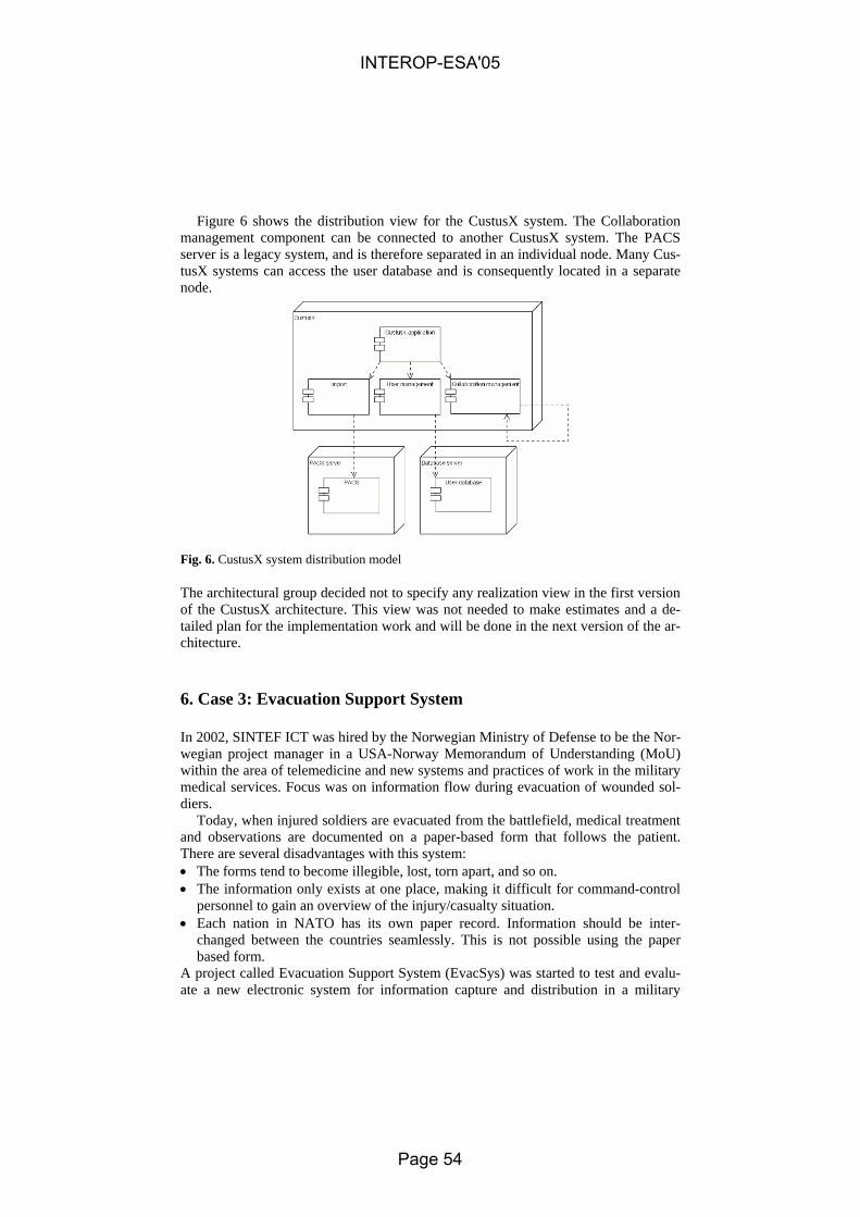
Figure 6 shows the distribution view for the CustusX system. The Collaboration management component can be connected to another CustusX system. The PACS server is a legacy system, and is therefore separated in an individual node. Many Cus-tusX systems can access the user database and is consequently located in a separate node.
Fig. 6. CustusX system distribution model
The architectural group decided not to specify any realization view in the first version of the CustusX architecture. This view was not needed to make estimates and a de-tailed plan for the implementation work and will be done in the next version of the ar-chitecture.
6. Case 3: Evacuation Support System
In 2002, SINTEF ICT was hired by the Norwegian Ministry of Defense to be the Nor-wegian project manager in a USA-Norway Memorandum of Understanding (MoU) within the area of telemedicine and new systems and practices of work in the military medical services. Focus was on information flow during evacuation of wounded sol-diers.
Today, when injured soldiers are evacuated from the battlefield, medical treatment and observations are documented on a paper-based form that follows the patient. There are several disadvantages with this system: • The forms tend to become illegible, lost, torn apart, and so on. • The information only exists at one place, making it difficult for command-control
personnel to gain an overview of the injury/casualty situation. • Each nation in NATO has its own paper record. Information should be inter-
changed between the countries seamlessly. This is not possible using the paper based form.
A project called Evacuation Support System (EvacSys) was started to test and evalu-ate a new electronic system for information capture and distribution in a military
INTEROP-ESA'05
Page 54

medical evacuation. Using personal electronic memory tags, wireless military tactical communication, state-of-the art portable computing terminals and a new military Electronic Health Record (EHR) called SANDOK, a complete distributed information system was specified, developed and tested. EvacSys involved many stakeholders and the system had to be interoperable with both national and other NATO nations' health information systems, as well as the underlying military command and control infra-structure. To handle this concern, MAFIIA was used as a handbook for specifying and developing the EvacSys architecture.
6.1 MAFIIA Applied to EvacSys
The first step in the MAFIIA framework is to identify concerns and system assets. Focus was put functionality, usability, reliability and interoperability. Major system assets were NATO standards and Norwegian laws and regulations for medical docu-mentation and exchange.
The MAFIIA framework's context view was found very useful when describing the context in which the EvacSys will operate. The Environment Systems Model and the Business to System Mapping Model explicitly illustrates interoperability concerns, thus providing important input to the succeeding viewpoints. Identifying and docu-menting the environment information and operational interfaces required a lot of time and effort, as much of this documentation was impossible to find.
The Context view models provided an important input to the system requirements models. Figure 7 shows how the different actors interact with EvacSys. Use case and sequence diagrams were used for functional requirements, whereas non-functional re-quirements had to be expressed in textual rationale descriptions. As a part of the Components View, the information and processing components were carefully modeled to optimize robustness and integration and interoperability with ex-isting infrastructure. The System Information Model was based on national informa-tion representation standards, but had to be "abstracted" into a higher level notation to be suitable for use by other systems. The difference between Norwegian and Eng-lish/American person identifiers and naming conventions required some additional components to be specified.
The EvacSys Distribution View models explicitly express reliability and interop-erability related concerns. Critical operational components were distributed onto dif-ferent logical nodes. The distribution models emphasized that there are no "single point of failure" at the different logical locations (battlefield, mobile aid station, transport etc.) in the EvacSys. For example, all terminals used for information input and output are generic in the way that they have no components that are specialized for one specific user or patient. Information-intensive components such as pulse-oxymetri sensors were put on separate nodes and shared filtered information through standard communication syntax and protocol. The data replication mechanism used to distribute patient data at the field hospitals was implemented according to the push model of the Publisher-Subscriber pattern.
INTEROP-ESA'05
Page 55

Write
Read
Examine Patient
Treat PatientMedic
MiTag<<Actor>>
Data Entry
Use MDA
Interface MiTag
<<include>>
<<include>>
<<include>>
<<include>>
Medical DataTracking Data
Transport Medic Transport Patient
MAP Medic Transmit Data
LFH Medic Import Data
SANDOK EHR<<Actor>>
Command-Control (C2IS)<<Actor>>
Receive Data Prepare for Patient<<include>>
Fig. 7. EvacSys requirements view.
Fig. 8. Military exercise where EvacSys was tested
Military standards and instructions were important input to the realization view de-scription. Only a limited set of equipment, platforms and protocols are approved for use in an operational setting.
The first prototype of the EvacSys system was tested and evaluated during a 5-day military exercise in northern Norway (Setermoen) in December 2003 (Figure 8). The medical battalion of the 6th division conducted several evacuation run-throughs with both the EvacSys system and the traditional paper-based system. The evaluation re-port concludes that the system architecture and information flow worked according to system requirements.
INTEROP-ESA'05
Page 56

7. Discussion
This section discusses experiences from using MAFIIA based on the cases presented and addresses the questions stated in the introduction. It should be noted that MAFIIA was used as a tool in the architectural work of the projects, and were not itself the re-search focus of the projects. The discussion presented here is thus mainly based on a subjective evaluation from the different researchers that participated in the projects, and to some degree on feedback from other participants in the projects. All of the cases are based on projects of approximately 15-25 person months. There is also great variation in type of systems of the cases, even though all of the cases are within the health care domain.
The feedback from the cases indicates that the development process described in MAFIIA was easy and useful to follow. The combination of a description of what to do, and a checklist of what to include of models, standards etc, helped the developers in the work. The assistance provided by the framework in identifying quality related concerns was reported as important to all the cases, e.g. security in all cases and con-figurability in CustusX. Also the context view was consistently reported to be very valuable in all the cases.
With respect to interoperability concerns, all three cases have been tested in a real environment. Feedback from all of the cases showed that the context view was an es-sential tool for understanding the complex domains, and gave an overview of all the contributors to the requirements. The EvacSys prototype was successfully tested in an integrated operational setting. SAMPRO was the first system designed for external access within the Norwegian Health Network.
The flexibility of the framework was essential in supporting the necessary varia-tions in the description which the different cases required. The ability to select differ-ent concerns to focus on, and the ability to extend each view with new models were utilized in all three cases. There were some differences between the cases in how the requirements were specified. Some used use cases while other preferred only textual descriptions. There were no reports of problems using either.
The framework was found equally useful in the two cases were it was introduced from the start or early in the development process for a new system, and in the case where used for architectural clean-up and further development of an existing system.
8. Related Work
There exist a number of related architectural frameworks that are commonly in use today. RM-ODP (Reference Model of Open Distributed Processing) [4] is a frame-work that provides the developers a standard for creation of systems that support dis-tributed information processing services to be realized in heterogeneous environ-ments. The method uses five different viewpoints to describe the system. The framework is neutral in the selection of tools for describing the architecture.
TOGAF (The Open Group Architecture Framework) [11] is an enterprise architec-ture framework that "consists" of a subset of architectures: business, data, application, and technology respectively. TOGAF consists of a set of tools and methods for devel-
INTEROP-ESA'05
Page 57

oping different architectures. The goal of TOGAF is to become an industry standard method that is neutral to both selection of tools and technologies.
ATAM (The Architecture Tradeoff Analysis Method) [8] is an analysis method used to understand the various tradeoffs that have to be made when creating architec-ture for software intensive systems.
NATO has started a Multilateral Interoperability Program [10] that focuses on in-teroperability between member nations' command and control systems.
9. Conclusion
The findings from the case studies indicate that the use of the MAFIIA facilitates de-velopment of systems that will operate in a complex environment. Despite the indi-vidual differences of the case studies presented here, the framework has proven to provide good assistance for the architectural work, and results in a well-structured ar-chitecture description. The method gives excellent support when developing architec-ture with a strong focus on specific selected concerns, and security in particular.
Applying an architectural description framework like MAFIIA will have best effect if it is used as a standard for all software intensive systems developed within and for the organization. We believe that large organizations, e.g. public health care within a state or country, is in a position where they can require that at least all new system that they acquire or developed are described in a standard of their choosing.
References
1. IEEE Recommended Practice for Architectural Description of Software-Intensive Systems. IEEE Std 1471-2000. ISBN 0-7381-2518-0.
2. J.Ø. Aagedal, A-J. Berre, B.W. Bjanger, T. Neple, C.B. Roark, “ODP-based Improvements of C4ISR-AF”. 1999 Command and Control Research and Technology Symposium, U.S. Naval War College, Rhode Island, USA. June 29 - July 1, 1999.
3. B. Elvesæter, T. Neple, J.A. Aagedal, R.K. Rolfsen, “MACCIS 2.0 – An Architecture De-scription Framework for Technical Infostructures and their Enterprise Environment”, Sub-mitted to 2004 Command and Control Research and Technology Symposium.
4. Basic Reference Model of Open Distributed Processing – Part 1: Overview and guide to use the Reference Model. ITU-TS, Rec. X901 (ISO/IEC 10746-1), Standard 1995
5. E. Gamma, R. Helm, R. Johnson, J. Vlissides, Design Patterns. Elements of Reusable Ob-ject-Oriented Software, Addison Wesley, 1995.
6. F. Buschmann, R. Meunier, H. Rohnert, P. Sommerlad, M. Stal. Pattern-Oriented Software Architecture. A System of Patterns. John Wiley & Sons, Ltd, 1996.
7. D. Schmidt, M. Stal, H. Rohnert, F. Buschmann. Pattern-Oriented Software Architecture. Patterns for Concurrent and Networked Objects. John Wiley & Sons, 2000.
8. P. Clements, R. Kazman, M. Klein, Evaluating Software Architectures: Methods and Case Studies, Addison-Wesley, 2001.
9. Federal Standard 1037C, Department of Defense Dictionary of Military and Associated Terms in support of MIL-STD-188.
10. Multilateral Interoperability Program, http://www.mip-site.org/, accessed 2004-11-30 11. TOGAF, Open Group, web site: http://www.opengroup.org/togaf/, accessed 2004-11-30
INTEROP-ESA'05
Page 58

ISO Standards for Interoperability:
a comparison
K. Kosanke
CIMOSA Association e.V., Stockholmer Str. 7, D-71034 Böblingen, Germany
Abstract. The lack of interoperability between ICT systems is becoming more and more a bottleneck in the collaboration and co-operation of enterprises. Co-operating parties have to exchange business information and have to have the same understanding of the meaning of the exchanged information and to trust both the communication itself and the validity of its contents. The paper re-views two ISO standards which are aiming on the interoperability issue com-paring the different aspects of these standards and introduces a new work item in standardisation, which expects support from two current European initiatives on interoperability and others.
1 Introduction
Operating in the global business environment requires worldwide co-operations be-tween enterprises sharing their core competencies in order to exploit short term mar-ket opportunities. Besides the timely availability of products and services, the real time exchange of related business information between the co-operating partners is even more important. Such exchanges are needed for both operational control and to an even larger extend for the decision making processes during the establishment of the cooperation, with market opportunity exploration and co-operation planning and implementation. Therefore, the easy communication between the people involved and the quality of interoperation between the supporting systems of information and communication technology (ICT) play a key role in such co-operations. The urgent need for organisational interoperation and decision support on all levels of the enter-prise operation is recognised in the areas of business and academia as well as in stan-dardisation [1].
Major issues in global collaboration and co-operation of enterprises are the prob-lems in communication between people, between people and ICTs and between dif-ferent ICTs. Whereas the first one is due to different cultures, languages and even professional jargons and can only be addressed by either a common language, which is very unlikely, or through translations between the different languages and mean-
INTEROP-ESA'05
Page 59
ings. The other two problem areas originate from the different software and hardware implementations of the information and communication technology. These areas require both human and machine understanding of the exchanged information.
But what is the meaning of interoperability? First of all interoperability is domain specific. Besides the three domains of people, people and ICT, and ICT itself identi-fied above, there are the different business domains like industry, finance, health, each one having sub-domains like categories of humans (managers, experts, opera-tors), of devices (controllers, actuators, sensors), and of systems (computers, ma-chines, communication networks) with their specific needs for interoperation.
But the ability to interoperate within the ICT supported business arena is a rather complex task. The heterogeneity of ICT implementation is such that there exist dif-ferent solution spaces depending on the combination of existing systems and in many cases such solutions are not transferable to other cases. According to Chen and Doumeingts [2], who reported on the results of a European initiative on a develop-ment for road maps to interoperability, there exist several levels of interoperability. They identified interaction between two systems can at least take place at the three levels: data, resource and business process and interoperability may therefore be achieved on multiple levels: inter-enterprise coordination, business process integra-tion, semantic application integration, syntactic application integration, and physical integration.
The recommendations in Chen and Doumeingts are to address the subject of inter-operability through three main research themes or research domains: enterprise mod-elling, architectures and platforms, and ontologies. These three areas deal with a) the representation of the inter-networked organisation to establish interoperability re-quirements; b) define the implementation solution to achieve interoperability; and c) address the semantics necessary to assure interoperability. These areas have been and are continuously addressed as well by both international standards organisations and industry consortia. A multiplicity of standards exist in the three fields identified above. General state of the art reports have been issued by both the European Net-work of Excellence (NoE) initiative INTEROP [3] and the EU Integrated Project (IP) ATHENA [4].
2 Definitions on Interoperability
There exist numerous definitions on interoperability; e.g. a very careful chosen web search produced 22 entries on interoperability. Selected examples are:
Interoperability: 1. achieved only if the interaction between two systems can, at least, take place
at the three levels: data, resource and business process with the semantics de-fined in a business context (Chen, Doumeingts) [2]
2. ability of two or more systems or components to exchange information and to use the information that has been exchanged (IEEE) [5].
3. ability to communicate with peer systems and access their functionality (Ver-nadat) [6]
INTEROP-ESA'05
Page 60

4. ability of different types of computers, networks, operating systems, and ap-plications to work together effectively, without prior communication, in order to exchange information in a useful and meaningful manner. There are three aspects of interoperability: semantic, structural and syntactical (from www) [7]
5. (computer Science) ability to exchange and use information (usually in a large heterogeneous network made up of several local area networks) (WordNet) [8]
Related definitions are: 1. Interoperable: (computer Science) able to exchange and use information
(WordNet) [8] 2. Interoperation: implies that one system performs an operation on behalf of
another (Chen, Doumeingts) [2] 3. Interoperation may occur between two (or more) entities that are related to
one another in one of three ways (ISO 14258) [9]: a. Integrated where there is a standard format for all constituent systems b. Unified where there is a common meta-level structure across constitu-
ent models, providing a means for establishing semantic equivalence c. Federated where models must be dynamically accommodated rather
than having a predetermined meta-model IEC TC 65/290/DC [10] identifies degrees of compatibility depending on the qual-
ity of communication and application features (see Figure 1).
Figure 1 Compatibility levels (adapted from IEC TC 65/290/DC) [10]
The related definitions: 1. Incompatibility: inability of two or more devices to work together in the same
application
INTEROP-ESA'05
Page 61

2. Coexistence: ability to of two or more devices operate independently of one another in the same communication network
3. Interworkability: ability of two or more devices to support transfer of device parameters
4. Interoperability: ability of two or more devices to work together in one or more applications
5. Interchangability: ability of two or more devices to replace each other in working together in one or more application
However, it seems very unlikely that in reality interoperability or interoperation will occur in any one of the three ways identified in ISO 14258 (see above), but in a mixture of those three ways. Assuming a global environment there will be no possi-bility for global unification nor for global integration and even federation in the dy-namic mode identified above seems very hard to achieve without any a priory knowl-edge about the entities that have to interoperate. The two standards analysed in the following try to provide this knowledge by creating profiles of their entities – applications and manufacturing software units, respectively.
3 ISO 15745 -Industrial automation systems and integration — Open systems application integration frameworks [11]
The standard consists of four parts: Part 1: Generic reference description; Part 2: Reference description for ISO 11898-based control systems; Part 3: Reference de-scription for IEC 61158-based control systems; Part 4: Reference description for Ethernet-based control systems.1
This standard defines an Application Integration Framework (AIF) - a set of ele-ments and rules for describing application interoperability profiles, which will enable a common environment for integrating applications and sharing life cycle information in a given application domain. The generic elements and rules are providing for de-veloping templates for Application Interoperability Profiles (AIPs), and their compo-nent profiles - process profiles, resource profiles, and information exchange profiles.
Such profiles may describe profiles based upon particular technologies and there-fore makes this standard applicable to application integration frameworks developed for industrial automation environments. Environments such as discrete manufactur-ing, process automation, electronics assembly, semiconductor fabrication, wide-area material handling, and other automation and control sectors such as utility automa-tion, agriculture, off-road vehicles, medical and laboratory automation, and public transport systems.
1 Note: Application here means industrial automation applications, which comprise
several types of interconnected devices which perform a variety of functions.
INTEROP-ESA'05
Page 62

4 ISO 1600 Industrial automation systems and integration — Manufacturing software capability profiling for interoperability [12]
The standard consists of four parts as well: Part 1: Framework (relating to ISO 15745); Part 2: Profiling Methodology; Part 3: Interface services, protocols and capa-bility templates; Part 4: Conformance test methods, criteria, and reports.
ISO 16100 specifies a framework for the interoperability of a set of software prod-ucts used in the manufacturing domain and to facilitate integration into manufacturing applications. The framework addresses models for information exchange, software objects, interfaces, services, protocols, capability profiles, and conformance test methods. The standard specifies a methodology for constructing profiles of manufac-turing software capabilities and requirements for interface services and protocols used to access and edit capability profiles and associated templates used in the capability profiling method. In addition, conformance test method and criteria for the capability profiling of a manufacturing software unit are specified.
5 Relations between the two standards
The main content identified in each standard is shown in Table 1. It identifies subtle differences owing to the difference in scope of the two standards. Whereas Frame-work elements in ISO 16100 are solely concerned with the interfacing requirements for interoperability of manufacturing software units (MSUs), their roles and the enti-ties they have to support, ISO 15745 identifies a larger set of such elements needed to support interoperability between the components of applications.2 Similarly for framework rules, where again ISO 15745 provides a larger set. However, some of the missing items in ISO 16100 are listed under framework aspects, an entry that does not exist in ISO 15745.
The latter uses the concepts of life cycle and model to classify the requirements in terms of a set of interfaces, services, components and configurations intended to guide the developers of industrial automation applications.
The three integration model types identified in Table 1 correspond to three differ-ent profile classes and a complete integration model of an application corresponds to a set of application interoperability profiles (AIPs), which identify the particular in-terfaces, services, protocols, and timing used by the different components within the application.
2 Note: Template is seen differently in the two standards. Being an element in 15745 it is
identified as a rule in 16100.
INTEROP-ESA'05
Page 63

Table 1: content of ISO 15745 and ISO 16100 ISO 15745 Open systems application integration frameworks
ISO 16100 Manufacturing software ca-pability profiling for interoperability
application integration framework (AIF) - framework elements:
diagram, model, profile, template, specification
- framework rules: diagram notation and semantics, model composition, profile template and taxonomy, template confor-mance and exchange syntax
Mfg. software interoperability framework - framework elements:
roles, activities, artefacts associated with software entities when dealing with manufacturing process, imation, and resources
nfor-
- framework rules relationships, templates, and confor-mance statements needed for con-structing a capability class
- framework aspects:
- syntax and semantics shared be-tween MSUs;
- functional relationships exist be-tween MSUs;
- services, interfaces, and proto-cols offered by MSUs;
- ability to provide MSU capabil-ity profiling.
Concepts and constructs used: - Application life cycle - AIF integration models:
1. process integration model (PIM) presents views of process con-trol, material and information flow
2. resource integration model (RIM) identifies devices, communica-tion networks equipment, mate-rial/product, and operators (hu-mans) needed in the PIM
3. information Exchange integration model (IEIM) identifies syntax, semantics, structure, and se-quences of information pro-duced, consumed, organized, stored, and retrieved by the re-sources involved in the PIM
Concepts and constructs used: - manufacturing software unit (MSU)
INTEROP-ESA'05
Page 64

Table 1: content of ISO 15745 and ISO 16100 (continued)
ISO 15745 Open systems application integration frameworks
ISO 16100 Manufacturing software ca-pability profiling for interoperability
Application interoperability profiles (AIPs) consists of: - one process profile - one or more resource profile(s) - one or more information exchange
profile(s) AIP concepts and rules: - combine the interface specification
option selections as required by the application
- shall be a single specification aimed at providing a defined function
- shall comprise a specific combina-tion of profiles
AIPs shall be constructed by: 1. documenting the functional re-
quirements as noted by a PIM; 2. selecting the appropriate base speci-
fications for the object interfaces denoted in the integration models;
3. selecting (conforming) sets of op-tions, or subsets, in the base specifi-cations;
4. combining references to a set of compatible base specifications in order to meet the identified applica-tion functional requirement.
5. describing it in terms of an interface definition language
Software capability profile - taxonomy - capability classes and rules:
types of mfg. domain, activity, com-puting system, services, protocols, supplier, others
- capability templates and rules - common part contains general
information about SMU - specific part contains SMU spe-
cific lists of attributes, methods, resources, constraints, others
capability profiling process 1. analyse software requirements 2. identify/create template 3. enter profile data
ISO 16100 provides only one concept and construct: the manufacturing software
unit (MSU). Again to support interoperability a software capability profile is defined. Capability classes and rules as well as templates and rules provide the elements for constructing the capability profiles of the software units.
The actual process of profile creation is shown as AIP construction (ISO 15745) and capability profiling process (ISO 16100) in the lower part of the Table 1. The number of steps identified in the two standards vary from 3 for ISO 16100 to 5 for ISO 15745. However, the process itself is rather similar considering the difference in scope of the two standards.
INTEROP-ESA'05
Page 65

6 Summary and Conclusions
The two standards presented in this paper address the issue of interoperability be-tween ICTs. With their focus on interoperability within manufacturing applications and between manufacturing software units, respectively, the two standards are both using the concept of profiles to capture the information needed to identify the capa-bilities of the entities, which have to interoperate.
In respect to the three types of interoperation identified in ISO 14258 [9] the two standards contribute to a semi federated approach of interoperation at the ICT level, providing means for identifying a priory information that can be mapped or matched at run time to/with the profile of the partner entity.
However, the comparison between the two standards also shows the need for har-monisation of standards. Both terminology and structure of the two standards differ and any potential user, who has to employ both standards will be confused by their difference.
In addition, the two standards do not yet address sufficiently the human aspects of interoperation. For the communication between people and between people and ma-chines, information about the internal structure and the dynamics of the application may be even more important than the information about the potential exchange itself. Such information can be provided by business process models with their focus on semantic unification and orientation on end-user needs.
Work on standards for interoperability has been started in ISO. In TC 184 SC5/WG1 a new work item ‘Requirements for establishing information interoperabil-ity in manufacturing-enterprise-processes and their models’ will address this aspect of interoperability. These standards have to improve the ICT interoperability as well by providing a base for unifying the needed information exchange between the parties involved, may it be between operational processes during enterprise operation or between their models during decision support. Inputs to this work will also be pro-vided besides others by the two European initiatives ATHENA and INTEROP.
Standardisation for enterprise interoperability is considered an important subject. However, the current state of standardisation is not yet sufficient to allow easy im-plementation at the operational level. Many of the standards are still on the concep-tional level and more details are still required to make them truly useable in the opera-tion. Work is required in areas of languages and supporting platforms, especially for the business process model creation and execution. To enable cross-organisational decision support especially the subject of ‘common’ semantics has to be addressed. In ISO/CEN 19440 [13] modelling constructs are defined using a meta-model and ac-companying text (sufficient to define an intuitive semantics as well as to define a model repository database). However, the capture of finer details of these meanings requires even more detailed formal semantics. Ontologies will play an important role in the area of semantic unification.
INTEROP-ESA'05
Page 66

References
1. Kosanke, K. (1997), Enterprise Integration and Standardisation, in Kosanke, K. & Nell, J.G. (Eds.). Enterprise Engineering and Integration: Building International Consensus Proceedings of ICEIMT’97 (Intern. Conference on Enterprise Integration and Modelling Technology), Springer-Verlag, pp 613-623
2. Chen, Doumeingts, (2003), European initiatives to develop interoperability of enterprise applications—basic concepts, framework and roadmap, Annual Reviews in Control 27, pp 153–162
3. INTEROP (2004), Knowledge map of research in interoperability in the INTEROP NoE, Deliverable D1.1, EU-NoE Project IST-508 011, www.interop.noe.org
4. ATHENA, (2004), Document Deliverable D.A1.1.1, Project A1: Enterprise Modelling in the Context of Collaborative Enterprises ATHENA, EU IP- Project - No 507849
5. IEEE (1990), IEEE (Institute of Electrical and Electronics Engineers): Standard Computer Dictionary- A Compilation of IEEE Standard Computer Glossaries
6. Vernadat, F.B. (1996) Enterprise Modelling and Integration: principles and applications; Chapman & Hall, ISBN 0 412 60550 3
7. www (2001) library.csun.edu/mwoodley/dublincoreglossary.html 8. WordNet 1.7.1, Princeton University Cognitive Science Lab 9. ISO 14258 (1999), Industrial automation systems and integration – Concepts and rules for
enterprise models, ISO TC 184 SC5 10. IEC TC 65/290/DC (2002), Device Profile Guideline, TC65: Industrial Process Measure-
ment and Control 11. ISO 15745 (2000), Industrial automation systems and integration — Open systems appli-
cation integration frameworks, ISO/TC/184/SC5 12. ISO 16100 (2002), Industrial automation systems and integration — Manufacturing soft-
ware capability profiling for interoperability, ISO/TC/184/SC5 13. CEN-ISO 19440 (2003), Constructs for Enterprise Modelling CEN TC 310/WG1 and ISO
TC 184/SC5/WG1
INTEROP-ESA'05
Page 67

ONAR: AN ONTOLOGIES-BASED SERVICE ORIENTED APPLICATION INTEGRATION
FRAMEWORK
Dimitrios Tektonidis1, Albert Bokma2, Giles Oatley2, Michael Salampasis3
1 ALTEC S.A., Research Programmes Division, M.Kalou 6, GR – 54629, Thessaloniki, Greece
2 Centre for Electronic Commerce, University of Sunderland, Sunderland, SR6 0DD, United Kingdom
[email protected];[email protected]
3Department of Informatics, Technological Educational Institute of Thessaloniki, Thessaloniki, Greece,
Abstract. The evolving technologies of Semantic Web and Web services are providing new means for application integration frameworks. The need for se-mantically enriched information exchange over the flexible environment of the internet provides a valuable enhancement to traditional methods and technolo-gies for Enterprise Application Integration. However the utilization of the Se-mantic Web and Service Oriented Architecture (SOA) is not as straightforward as it appears and has specific limitations and inefficiencies due to the fact that is was not originally designed for that purpose. This paper presents a methodol-ogy that aims at the exploitation of these two technologies and the definition of an ontologies based enterprise application integration framework (ONAR).
1 Introduction
The application integration between heterogeneous applications such as ERP systems between companies as well as B2B environments in general is a challenge that has been confronted with a plethora of technologies and methodologies. In our research [1] we have seen that the key aspect in from simple integration to more complex cases [2] is the semantics. When we refer to the semantics we signify the meta-information that describes the exchanged information.
INTEROP-ESA'05
Page 68

Service oriented application integration (SOAI) as it is presented in [3] exploits the capabilities for the functional description of web services that are used for the actual integration. This paper presents our work on the creation of an integration framework based on SOAI that utilizes Semantic Web Technologies [4] in order to enrich the semantics of the exchanged information.
The Ontologies Based Enterprise Application Integration (ONAR) Framework [5] utilizes web ontologies to create semantic conceptualizations of the business concepts that exist inside an application. This conceptualization is used for the creation and the registration of the Web services in a UDDI based registry.
Fig. 1. Ontologies Based Enterprise Application Integration (ONAR) Framework.
2 Conceptualizing Information System using OWL Ontologies
Ontologies are used for the formal definition of concepts in a given domain. However the utilization of ontologies for software component definition is not as simple as the definition of concepts alone. Research on this domain as presented in [6] and [7] shows that the utilization of the ontologies requires some modification in the princi-pals of the frame-based ontologies languages. The state of the art ontologies lan-guages are presented evaluated in [8] and [9], but even a purely frame-based logic is still insufficient as there are important differences principally with respect to object-oriented modeling. Of course ontologies were not designed for software engineering, and thus their utilization for this purpose requires creating a semantic layer that will describe and define the technical infrastructure of an application.
Our work has focused on creating associations between the conceptional models and the application logic. To facilitate this we have developed a graphical tool (fig. 1) that enables the creation of the conceptual models using ontologies and associating these models to the actual system resources.
INTEROP-ESA'05
Page 69

Fig. 2. Ontologies based Information System conceptualization using ONAR Concepts and Services Designer
2.1 Definition of Logical Entities
Following the OWL [10] frame based logic, the concepts that represents a logical entity inside the application are defined by an OWL class. The entities inside the ONAR conceptualization methodology inherit all the features of the OWL classes. However their semantics changes in order to be adapted to the semantic description of a system resource.
Inheritance is permitted allowing some class features to be inherited from one class to another. The relation between the parent class and child classes follows the same-rules that both object oriented engineering and frame-based logic supports, however multiple inheritance is not permitted. This constraint is due to the fact that in complex information system polymorphism of some concepts will unduly increase the com-plexity of conceptualization.
In our approach, the conceptualization of the system is not application centric but integration centric. This means that the creation of a conceptualization is developed and the need of the integration and not regarding the structure of the system. This increases the reusability of the concepts definition that can be reused in different cases.
Entities are allowed to have properties that correspond to OWL datatype proper-ties. A property can belong to more than one entities and is contrary to the usual prin-ciples of object oriented modeling. This principle derives from the frame based logic of OWL ontologies and extends the object oriented engineering where a property belongs to only one class.
Finally both entities and properties are enriched with notional properties like lexi-cal descriptions, the ability to define the inverse of a concept and the ability that a property can potentially be derived from another property. These enrichments are used to increase the inference for the semantics of the concepts and their properties inside a model following the OWL principles.
INTEROP-ESA'05
Page 70

2.2 Defining Relations between Entities
Apart from the definition of entities and their properties, our work has focused on creating semantics in the relations between concepts. The existing semantics of rela-tions that are expressed in object oriented class diagrams in UML or Entities Rela-tions (E-R) diagrams pose limits to the semantic two concepts may have at the logical level. Therefore using the four types of relations (object relations) that are defined in OWL we have adjusted these relations types in order to increase the inference capa-bilities of the conceptualizations. We have followed the OWL logic and syntax hav-ing the two (or more) entities that participate in a relation divided into:
a) Domains of the relation: that is consisted of the concepts that consist of the area of definition of the relation.
b) Ranges of the relation: that the domains concepts of the relation can receive values from.
More precisely we have used and adjusted the following relations between entities:
• Functional relation: where the domain concepts instance can be related to more than one instance of the range concepts.
• Inverse Functional relation: where the range concepts instances can be related to more than one domain concepts instances.
• Symmetric relation: 1 to 1 relation between the instance of the domain and the range concepts.
• Transitive relation: we have defined transitive property as an inferential symmetric property to facilitate the logical allocations of concepts.
However we have to limit the syntax of OWL which permits the existence in a re-
lation of more than one concepts as ranges and domains. In our approach (in a rela-tion) if the domains contain more than one concept then the range should be defined from only one concept and vice versa. This ensures that in the association of the logi-cal model to the system resources will not create indeterminism.
3 Associating logical entities to information system repository
One of the most important results of our work is the association between the logical model and the repository of the system. In our early attempts we have tried to extend OWL in order to include mapping mechanisms. However we have discovered that the new “extended OWL” syntax will be too complicated and it will mix up semantic with syntactic issues. This of course would decrease the reusability of the conceptu-alizations.
Therefore we distinguish the conceptualization into two ontologies that are: a) The conceptualization ontologies based on OWL that define semantics as-
pect of the conceptualizations.
INTEROP-ESA'05
Page 71

b) The association ontologies that association the conceptualization ontology to the repository of the application.
The disassociation between the semantic and the syntactic description has as the
following results: a) To increase the reusability of the conceptualizations ontologies: The same
conceptualization ontologies can be used to different information system. b) To reduce cost of maintainability when changes happened in to the applica-
tion repository. c) To enable the creation of common vocabularies that can be shared between
heterogeneous applications. In our work so far we have achieved the application of the ONAR framework to
relational databases but where the goal is to support any type of repository including application servers.
4 SOAI using semantic conceptualizations
The creation of a Service Oriented Architecture that will implement the integration between the applications is also based on the semantic conceptualizations. In fact the ONAR framework software components (Web services) are based on the conceptu-alization schema (the set of the conceptualizations) of the application. This strong relation between the conceptualizations and the web services server is the actual in-novation compared with other existing approaches [11][12].
The ONAR integration process is the methodology that should be followed in or-der an integration case to be defined and implemented using the ONAR framework. The process consists of the following phases:
a) Conceptualization phase where the entities that need to participate in the integration case are conceptualized to shared conceptualizations (OWL on-tologies). The set of the conceptualizations create the conceptual schema of the integration.
b) Association phase. The conceptual schema is associated to the information systems repositories that participate in the integration.
c) Design phase. In this phase using the conceptual schema the definition of the software instances takes place.
d) Deployment phase where the software instances are implemented as soft-ware components (Web services) and deployed.
e) Publication phase. The framework uses a UDDI registry enriched with OWL-S profile features (from semantic invocation) to publish its software instances. Using the semantic meta-information that the conceptual schema provides the framework publish information regarding the utilization of the web services.
INTEROP-ESA'05
Page 72

4.1 Designing web services based on the conceptual schema
In our work, the whole web services design creation and their registration to the UDDI registry is related to the conceptual schema. The design of the software in-stance is the process where elements of a conceptualization are used to define the input and the output of the Web service. The design of a web service consists (figure 3) of its syntactic definition and its semantic description.
Conceptualization Analysis
Web-Service Input
Web-Service Output
Fig. 3. Designing Web services using a conceptualization Ontology
The syntactic definition defines the input and the output as well as the behavior of the Web service. This definition is based one conceptualization of the conceptual schema. Starting from one basic entity the Web service designer can use all the concepts that are necessary for his definition. The syntactic definition (ONAR Service Model) of the service contains all the semantic and syntactic relations between the basic entity (primary concept) and the secondary concepts. The ONAR Service Model [5] is an XML document that contains a conceptualization ontology and an association ontol-ogy of the functionality of a Web service. The reason of having a new definition document for the syntactic definition of the service, apart from maintenance purposes, is to increase the portability of the web services. We have implement the necessary functionality that enable us to automati-cally generate the source code (C#) of a Web service based only to the conceptualiza-tion ontology the association ontology and the ONAR Service Model. Therefore if two applications share the same conceptualization ontologies but have different struc-tures (different association ontologies) they can exchange Web services.
4.2 Creating semantic description for supporting SOAI
The Web Service Definition Language (WSDL) is used to describe web services at the technical level. However the use (or consumption) of a web service requires first
INTEROP-ESA'05
Page 73

the technical implementation and an understanding of its functionality. The capabili-ties of the WSDL at this level are limited as it was not designed to serve this purpose. Instead other protocols have been produced in order to support Web services discov-ery and description. Our work has been based on M.Paolucci attempts [13][14] to integrate a powerful UDDI discovery and categorization mechanisms with the semantics of OWL-S [15]. We have extended UDDI using OWL-S elements in order to include semantic de-scription of the web services. Apart from the ONAR service model that a service designer defines with the definition of the behavior of the web service (Inputs, Out-puts and effects), the designer should describe the web service behavior at the seman-tic level.
1. Categories Definition
ONAR Service Publication
ONAR Service =+
2. Contacts Definition
Fig. 4. ONAR Service Publication
3.Parameters Definition
This Service Publication Profil
Web service designer defines:
1. The categories of the the web service designevice.
2. The contact list of thethe service and their typ
INTEROP-ESA'05
Model
Profile
e defines the semantic o
service: Using the UDDIr defines the categories t
service: A list of personse and responsibilities
Page 74
Profile (OWLS)
f the web services. The
categorization schemas hat apply to the web ser-
that are associated with

3. The parameters of the service: Special features of the services that do not belong to a particular categorization schema.
Inside the Service Publication Profile we have also included the elements of the
Service Model (Inputs, Outputs and Effects). These elements that are parts of certain conceptualizations carry also semantic descriptions that are also registered to the UDDI registry.
These semantic descriptions of the web service leverage the semantic discovery of the web services reducing the errors of incorrect usage of the web services. This is considered essential for effective SOAI solutions regarding the number of the web services required to support complex integrations and the complexity of each Web service.
5. Extending UDDI registries to support semantics
In order to include semantic meta-information to UDDI registries we have ex-
tended both the UDDI and OWL-S profiles. Our work was based on M.Paolucci work in this domain and also some recommendations from [16]. The ONAR Service Publi-cation Profile is based on OWLS profile syntax with some additions that can be summarized (further information can be found on [5]) as follows:
a) Enhancement of the OWL-S input and OWL-S output class in order to define
the related classes and relations. b) Enhancement of the OWL-S Service Category and Service Parameter is order
to exploit all the UDDI description capabilities c) Additional Models to support OWL-S concepts like Input, Output, Effect,
Actor and Service Parameter This integration between the UDDI and OWL profile leverage the search capabili-
ties that can be based on concepts of conceptualizations. We have developed a search facility (figure 5) that enables the user to choose semantic filters in the level of class properties or relation between classes apart from the typical UDDI inquiry. The search can use both of the techniques lead to more accurate results.
INTEROP-ESA'05
Page 75
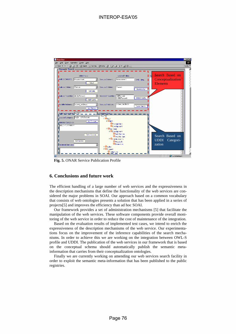
Search Based on Conceptualization Elements
Search Based on UDDI Categori-zation
Fig. 5. ONAR Service Publication Profile
6. Conclusions and future work
The efficient handling of a large number of web services and the expressiveness in the description mechanisms that define the functionality of the web services are con-sidered the major problems in SOAI. Our approach based on a common vocabulary that consists of web ontologies presents a solution that has been applied in a series of projects[5] and improves the efficiency than ad hoc SOAI.
Our framework provides a set of administration mechanisms [5] that facilitate the manipulation of the web services. These software components provide overall moni-toring of the web service in order to reduce the cost of maintenance of the integration.
Based on the evaluation results of implemented test cases, we intend to enrich the expressiveness of the description mechanisms of the web service. Our experimenta-tions focus on the improvement of the inference capabilities of the search mecha-nisms. In order to achieve this we are working on the integration between OWL-S profile and UDDI. The publication of the web services in our framework that is based on the conceptual schema should automatically publish the semantic meta-information that carries from their conceptualization ontologies.
Finally we are currently working on amending our web services search facility in order to exploit the semantic meta-information that has been published to the public registries.
INTEROP-ESA'05
Page 76

References
1. D. Tektonidis, A. Vontas, U. Hess, J. Meschonat “Handling the Shop-Floor of an Industry through ERP systems – A functional Integration Model”, International Conference on E-business & E-Work 2002, Prague 2002
2. M. Themistocleous, Z. Irani, R. O’Keefe & R. Paul “ERP Problems and Application Inte-gration Issues: An Empirical Survey” Proc. of the 34th Hawaiian International Conference on Systems Science, Hawaii Big Island 7-10 January 2001, USA, IEEE 0-7695-0981-9/01
3. David Linthicum “Next Generation Application Integration: From Simple Information to Web Services”, Addison-Wesley 2003, ISBN: 0201844567, USA
4. W3C, Semantic Web Description, 2001, available at http://www.w3.org/2001/sw/ , as accessed in 10 Nov. 2002
5. ONAR, Ontologies based Enterprise Application Integration Framework, 2004, available at http://research.altec.gr/ONAR , as accessed in 10 Oct. 2004
6. Li min Liu & M. Halper - “Incorporating semantic relationships into an object oriented database system”Proc. of the 32th Hawaiian International Conference on Systems Science, Hawaii Big Island 5-8 January 1999, USA, IEEE 0-7115-1405-9/99Baldonado, M., Chang, C.-C.K., Gravano, L., Paepcke, A.: The Stanford Digital Library Metadata Architecture. Int. J. Digit. Libr. 1 (1997) 108–121
7. Chia-Chu Chiang - “Wrapping legacy systems for use in heterogeneous computing environ-ments”, Information and Software Technology, Volume 43, Issue 8, July 2001, Pages 497-507
8. O. Corcho, M. Fernández-López and A. Gómez-Pérez “Methodologies, tools and languages for building ontologies. Where is their meeting point?” , Data & Knowledge Engineering, Volume 46, Issue 1, July 2003, pages 41-64
9. V. Ratnakar, and Y. Gil, "A Comparison of (Semantic) Mark-up Languages", Proceedings of the 15th International FLAIRS Conference, Special Track on Semantic Web, Pensacola, Finland , May 2002.
10. OWL 2003, W3C (2001b) OWL 1.0 Syntax Specification, available at http://www.w3.org/TR/owl-ref/ , as accessed in 15 May, 2003
11. M. Mecella & C.Batini “Cooperation of Heterogeneous Legacy In-formation Systems: a Methodological Framework” Proceedings of the 4th International Enterprise Distributed Object Com-puting Conference, Makuhari, Japan, 2000
12. Wache, H., Vögele, T., Visser, U., Stuckenschmidt, H., Schuster, G., Neumann, H., & Hübner, S. “Ontology-based Integration of In-formation - A Survey of Existing Ap-proaches”, In: Proceedings of the IJCAI-01 Workshop: Ontologies and Information Sharing, Seattle, USA, pages 108-117.
13. M. Paolucci, T. Kawamura, T. R. Payne, K. Sycara. “Semantic Matching of Web Services Capabilities”, International Semantic Web Conference (ISWC), 2002, pp 333-347
14. M. Paolucci, T. Kawamura, T. R. Payne, and K. Sycara. Importing the Semantic Web in UDDI. In Proceedings of E-Services and the Semantic Web Workshop, 2002
15. DARPA, DARPA Agent Markup Language Web Services (DAML-S) Version 0.7 Specifi-cation, 2002, available at http://www.daml.org/services/daml-s/0.7/ , as accessed in 10 Nov. 2002
16. Dogac, A., Kabak, Y., Laleci, G., "Enriching ebXML Registries with OWL Ontologies for Efficient Service Discovery", 14th International Workshop on Research Issues on Data En-gineering, Boston, USA , March 28-29, 2004.
INTEROP-ESA'05
Page 77

A Unified Framework for Enterprise Integration An Ontology-Driven Service-Oriented Approach
Saïd Izza, Lucien Vincent, Patrick Burlat Laboratoire G2I, Ecole des Mines de Saint-Etienne
158 Cours Fauriel, Saint-Etienne, France [email protected], [email protected], [email protected]
Abstract. Today, enterprise integration (EI) is still facing many problems and the crucial one is the semantic heterogeneity. This problem is not correctly ad-dressed by today's EI solutions that focus mainly on the technical and syntacti-cal integration. Addressing the semantic aspect will promote EI by providing it more consistency and robustness. Some efforts are suggested to solve the se-mantic problem at different level, but they are still not mature. This article will propose an approach that combines both ontologies and web services in order to address this hard integration problem.
1 Introduction
Over the last decade, a new technology and a new industry sector, typically known as enterprise application integration (EAI) technology, have emerged as a sub-field of enterprise integration (EI) [22]. In essence, EAI technologies provide tools to inter-connect multiple and heterogeneous enterprise information systems (EIS) such as ERP (Enterprise Resource Planning) systems, CRM (Customer Relationship Management) systems, SCM (Supply Chain Management) systems, and legacy systems. The most difficulty of this interconnection is due to the fact that the integrated systems were never designed to work together.
More recently, Web Services (WS) have emerged with the advent and the evolution of the Internet and they provide a set of standards for EAI. Even if WSs are not fully mature, they seem to became the linga franca of EAI [14]. This will notably make integration simpler and easier through using web protocols and standards.
Despite the whole range of available tools and widespread standards adoption, the main goal of EAI which is the semantically correct integration of EISs is not yet achieved [6]. Indeed, EAI still provides technical and syntactical solutions but does not address correctly the semantic problem which is the hard problem in EI.
This paper will propose an approach in order to address the semantic integration in the context of EAI. In the rest of this paper, we will firstly present the integration problem; secondly, we will briefly review the current state-of-the-art in EAI through presenting two kinds of solutions: traditional EAI systems and Web-Services-based EAI systems. Then, we will describe some aspects of our work attempting to provide a
INTEROP-ESA'05
Page 78

solution for the integration problem, and finally before concluding, we will outline some important related works.
2 Integration Problem
Enterprise information system (EIS) is defined as an enterprise application system or an enterprise data source that provides the information infrastructure for an enterprise. Typically, an EIS can take many different types including batch applications, tradi-tional applications, client/server applications, web applications, application packages, relational databases and so on [17]. This systems are often materialized in enterprise reality in form of relational databases, ERP (Enterprise Resource Planning) systems, CRM (Customer Relationship Management) systems, SCM (Supply Chain Manage-ment) systems and legacy systems.
An appropriate characterization of EISs in context of EAI is that these systems are HAD (heterogeneous, autonomous, distributed) [16] [6]: - Heterogeneous means that each EIS implements its own data and process model. - Autonomous refers to the fact that EISs run independently of any other EIS. - Distributed means that EISs locally implement their data model which they generally do not share with other EISs.
The consequence of the characteristics above is that EISs are standalone software entities which constitute what [31] labels "islands of information" and what [24] calls "islands of automation". Of course, none of the islands contain enterprise-wide proc-essing and information, which makes it then necessary to integrate the islands in order to create unified enterprise information and process system. In this case, any form of integration of these islands (EISs) must happen outside of the involved islands (EISs), by using integration systems such as EAI systems. This integration consists then in interconnecting the interfaces of each EIS using technologies supported by the integra-tion systems such as queuing systems, file systems, databases or remote invocations.
Despite the importance of the all the problems described above, we focus only on the heterogeneity problem, precisely the semantic heterogeneity problem which is the hard problem of enterprise integration in general and EAI in particular [6].
3 Today's EAI Solutions
The fundamental EAI drivers are related to the existence of EISs which are HAD (heterogeneous, autonomous and distributed) systems. Generally, this is the conse-quence of the emergence of e-business, enterprise mergers and consolidations, and the rise of application packages and COTS (Commercial On The Shelf) [11]. In the rest of this paper, we consider only two main solutions which are the most important ones in the context of EAI: traditional EAI systems and WSs. These solutions can fulfill major integration requirements such as data synchronization and integration, business process execution, fast deployment of new applications and so on.
INTEROP-ESA'05
Page 79

3.1 Traditional EAI Systems
Currently, EAI systems are based on a lot of technologies such as: message bro-kers, process brokers, message-oriented middleware (MOM), etc. [17]. Even if EAI systems may differ from a technological point of view, the main functionalities remain the same, and we can mainly distinguish five components which constitutes a hierar-chy of layers and provide respectively transport services, connectivity services, trans-formation services, distribution services and process management services. The trans-port services provides communication of data, and it is generally based on asynchro-nous middleware technology such as message queuing systems. The connectivity services provides adapters/connectors that connect EISs to the transport services layer. The transformation services provide translation of the exchanged data between EISs in order to conciliate the syntactical differences. The distribution services is responsible for routing the messages. At last, process management services provides mechanisms to manage and coordinate business processes by using workflow or BPM (Business Process Management) engines.
The principle of EAI systems is based on using interfaces (adapters/connectors) to integrate EISs. The interfaces convert all traffic to canonical formats and protocols. These interfaces constitute the only mean to access EISs and they can occur in differ-ent levels: user-interface level, business logic level and data level [21].
Although EAI systems address technical and syntactical integration, nevertheless they must address the semantic level which is more difficult and which can provide more added-value. Since the EIS's interfaces are generally immutable, both from syn-tactic and semantic perspective, the EAI systems must be able to conciliate between messages of the different EISs on a syntactic level as well as on the semantic level. On the syntactic level, EAI systems must be able to receive any particular format from any EIS, transform it and transmit it to any other EIS. On the semantic level, the same process must happen with the help of semantic mediation in order to ensure that the semantics of messages will be preserved during exchanges.
Today, no traditional EAI system can provide mechanism that correctly supports semantics. In most cases, data is passed between EISs by-value, and in general no shared semantic concepts are explicitly used to define semantics through different messages or to describe the functions that are provided. As far as we know, only few systems such as Unicorn system [35] can support semantic concept with the help of a canonical and corporate ontology. Furthermore, constructing such an ontology is costly if not impractical especially when the enterprises are large and the EISs usually change and evolve over time. So this approach do not really solve the integration problem.
3.2 Web Services
WSs are considered as a result of convergence of Web with distributed object tech-nologies [2]. They are defined as an application providing data and services to other applications through the Internet [18]. WSs promotes an SOA (Service-Oriented Architecture) that distinguishes fundamentally three roles: service provider, service
INTEROP-ESA'05
Page 80
requestor and service broker; and three basic operations: publish, find and bind, and any particular EIS can play any or all these roles [20].
WSs constitute the most important instantiation of the SOA model. They can be deployed inside (in the context of EAI) or outside (in the context of B2B) the enter-prise. In all cases, WSs are published with appropriate URLs by WS providers over the internet or intranet. Once published, these WSs are accessible by WS consumers via standards Web such as HTTP (HyperText Tranfer Protocol), SOAP (Simple Ob-ject Access Protocol), WSDL (Web Service Description Language) and UDDI (Uni-versal Description, Discovery and Integration) [3]. In addition to this, WSs can be used for integrating EISs via standards such as BPEL (Business Process Execution Level) or WSFL (Web Service Flow Language).
WSs are increasingly playing an important role in EAI [20] [30]. They are pre-cisely taking the role of the EAI bus to which all EISs connect [3]. In this case, the connecting EISs are often wrapped by WSDL interfaces, or they are in some cases converted to modern web-service-based-applications via a migration process. These wrappers and migrations are generally done by existing web service toolkits.
WSs are very promising in solving the integration problem [23]. Today, some new integration products based on WSs standards exist and will certainly replace in the near future the proprietary solutions that are the traditional EAI systems. Examples of such new products are Cape Clear, XML Global, Colloxa, etc. [4]. A widespread adoption of WSs may enhance the evolving technology standards.
Even if WSs are promising, however they do not correctly address the semantic definition that is currently somewhat supported mainly by UDDI registries with the help of some standard taxonomies such as NAICS (North American Industrial Classi-fication Scheme), UN/SPSC (Universal Standard Products and Services Classifica-tion) and ISO 3166 (Geographical taxonomy) [9]. In addition, WSs do not provide neither data nor behavior mediation [8] [12] [7]. These drawbacks are mainly due to the lack of service ontology and mediation support in current WSs. This lack penal-izes the efficiency of current WS integration in the context of EAI. Nevertheless, we must mention the existence of some important initiatives around the concept of semantic web service [33] [9] [25] that aims to bridge the above current WS gap such as OWL-S [37], BPEL [10], WSMF [12], METEOR-S [27]. But, most of these efforts do not provide mature concepts for both data and behavior mediation in the particular context of EAI. The approach we propose in the following section takes and improves some of the best ideas emerged from these efforts and which we attempt to apply to the EAI context.
4 ODSOI Approach
This section succinctly describes some important characteristics of our approach called ODSOI (Ontology-Driven Service-Oriented Integration) that rely on the use of both ontologies and WSs technologies, and that aims to extend the state-of-the-art in EAI in order to address the semantic problem.
INTEROP-ESA'05
Page 81

4.1 General principles
First of all, ODSOI approach is a solution to the information system integration problem. This means that our approach addresses the heterogeneity problem by pro-viding an ontology-driven integration solution that is based on ontology mediation. Indeed, our approach is service-oriented (based on SOA) since it uses WSs for inte-grating EISs. The result architecture integration that we suggest is called ODSOA (Ontology-Driven Service-Oriented Architecture). This latter extends SOA with a semantic layer that aims to enhance service mediation in the context of EAI.
Furthermore, our approach can support both static and dynamic oriented integra-tion. This latter means that the binding services of target EISs can be performed at run time according to special binding rules, contrarily to a static integration solution where an integration scenario predefines every detail of potentially connectable EISs (Kwak, 2002). The reasons of this choice are that the dynamic solution is sometimes more flexible and scalable form of integration than static one. In addition to this, the integration scenario becomes simpler and the configuration EIS interfaces can be changed and new systems can be added easily, even while the EAI system is running.
4.2 Global Architecture
The ODSOA concept provides a unified framework in order to integrate EISs. In this framework, three main types of services are defined: data-services, functional-services and business-services. This different types can respectively address data, application and process integration.
Data-Services (DS) are services that expose data sources (EDS – Enterprise Data Sources) as services. Functional-Services (FS) are services that expose application systems, fundamentally functional systems (EAS – Enterprise Application Systems) as services. Business-Services (BS) are defined as the combination of the above services in order to expose business processes (EPS – Enterprise Process Systems) as services. Our service typology enrich somewhat the topology proposed in [34] and which is based on two types that are SaaS (Software-as-a-Service) and DaaS (Data-as-a-Service).
Fig. 1. Global view of ODSOA Architecture
Figure 1 which is a particular SOA recapitulates these important types of services. Indeed, there are, of course, some other important technical services that are mainly
INTEROP-ESA'05
Page 82

service broker, ontology services, mediation services, infrastructure services and utility services. Some of them will be described below.
A cross section of the integration bus (also called ODESB – Ontology-Driven En-terprise Service Bus) (figure 2) shows many concentric standard layers such as Trans-port layer, Exchange layer, Description layer, Registry layer and Transversal layer. In addition to these standard and currently existing layers, we suggest to adopt, in a similar way as semantic web service concept [33], an other layer, called semantic layer and which contains two sub-layers that are ontological layer and mediation layer.
Fig. 2. Cross Section of the ODESB Bus
The Ontological layer aims to describe the three fundamental types of services de-scribed above using specific descriptions such as DSD (Data Service Description) for DSs, FSD (Functional Service Description) for FSs, and BSD (Business Service De-scription) for BSs. All these descriptions exploit some ontologies and are specializa-tions of OWL-S (Web Ontology Languages-Services) that constitutes a semantic ori-entation to the description of WSs, contrary to WSDL (Web Service Description Lan-guage) which provides only a description based on a syntactic orientation.
The mediation layer provides mechanisms to perform the resolution of semantic differences (semantic mediation). In the next sub-section, the services of semantic layer which are the important ones in our approach will be developed.
4.3 Semantic Layer Services
Semantic services are the main services that address the semantic problem. They are divided into ontology services and mediation services. Each type of services will be described below.
INTEROP-ESA'05
Page 83

4.3.1 Ontology Services The principle of ODSOA is based on the semantic services that perform mediation
processes in order to resolve mainly the semantic heterogeneity problem. These proc-esses exploit some formal ontologies which take important part in our architecture. Ontology services aims to define the semantic description of services using ontology concepts. According to Gruber, an ontology is defined as an explicit and formal speci-fication of a conceptualization [15]. In the context of information integration, two fundamental approaches can be selected to achieve semantic integration: shared ontol-ogy approach and non-shared (local) ontology approach [38]. In general, we use an hybrid approach that combines the two approaches and that consists to map local ontologies onto a shared ontology [38].
For our purpose, we have chosen a variant of the hybrid approach. This can be mo-tivated by the fact that in a large enterprise of autonomous EISs, the definition of a single set of ontology standards that are suitable for everyone is nearly impossible. Indeed, this can also be motivated by the difficult leveraging when adopting multiple independent ontologies.
In our approach, we have defined three major types of ontologies that are similar to those briefly cited in [21]: information or data-based ontologies, behavior or func-tional–based ontologies and process or business-based ontologies (figure 3). These ontologies are used in service descriptions such as DSD (Data Service Description), FSD (Function Service Description) and BSD (Business Service Description) to ex-plicit the semantics of respectively DSs, FSs and BSs.
Data-based ontologies are the most basic ones. They provide semantic description of the data (DSs). Theses ontologies are required in all cases, no matter if we leverage functional-based or business-based ontologies. This means that, data integration is a precondition for any other integration type.
Functional-based ontologies define semantic description around functions that pro-vided by the multiple EISs (FSs) and that can be remotely invoked. These ontologies are generally required in order to provide a better reuse of functionalities.
Business-based ontologies define semantic description around coordinating busi-ness processes. These ontologies are generally required in order to integrate business processes.
In addition to this, ontology services are based on the context of a service (service-context) which is defined by a set of ontologies related to the concerned service. This service-context is also called local ontology which means that there are several ontol-ogy levels. This is generally appropriate within a large and complex enterprise with several different business domains such as the studied society that is large and con-cerns the multidisciplinary microelectronics area. For our purpose, three ontology levels have been identified: local level, domain level and global level (figure 9).
In essence, local ontologies concerns services, whereas domain ontologies concern the generalization of local ones that belong to the same domain (Production, Metrol-ogy, Packaging, etc.) and they can serve in aligning some local ontologies. At last, global ontology is considered as generalization of domain ontologies. It is the root of the ontology hierarchy, and it can serve in aligning domain ontologies and may also be used in B2B integration that can constitute a natural extension of our approach.
INTEROP-ESA'05
Page 84

The ontology taxonomy defines somewhat a clusterization process which is firstly used in [36]. This clusterization is an important concept which defines the ontology structuration within an enterprise and can be used in order to master the ontology construction and evolution. We call this clusterization: ontology urbanization and it takes an important role in our integration approach.
Fig. 3. ODSOI ontology taxonomy
4.3.2 Mediation Services Mediation services are generally invoked by service brokers in order to perform
matching or resolution of semantic heterogeneity between services. They exploit the descriptions provided by the ontology services described above.
Since we use an hybrid ontology approach, this require the integration and media-tion of ontologies which are performed by Ontology Mediation Services (OMS) and that are based on ontology mapping [19]. This latter is the process whereby two or more ontologies are semantically related at conceptual level. According to the seman-tic relations defined in the mappings, source ontology instances can then be trans-formed (or matched with) into target ones (Noy, 2004).
In addition to OMS and according to the above different fundamental types of ser-vices, we can distinguish mainly three other types of mediation services: Data Media-tion Service (DMS), Functional Mediation Service (FMS), Business Mediation Ser-vice (BMS). These mediation services aims to mediate respectively between DSs, FSs, BSs and they are based on OMS that match and mediate between different ontologies. To be performed, OMS can exploit two particular utility services that are inference service and matching service. These particular services can be respectively supported by academic or commercial inference engine and matching tool. For the initial proto-type that is ongoing, we decide to use Racer engine [29] and OLA (OWL Lite Align-ment) matcher [28] that seems be appropriate to our approach.
INTEROP-ESA'05
Page 85

4.4 Overview of the Integration Process
ODSOI approach provides a uniform framework to integrate EISs at different lev-els: data, application and process integration level that are provided by three specific services or sub-frameworks that are respectively ODSODI (Ontology-Driven Service-Oriented Data Integration) framework, ODSOAI (Ontology-Driven Service-Oriented Application Integration) framework and ODSOBI (Ontology-Driven Service-Oriented Business Integration) framework. Figure 4 illustrates the general principle of the three components of the global framework (ODSOI framework).
Fig. 4. General vision of ODSOI framework
DSs can be integrated with the ODSODI framework by using data ontology media-
tion, whereas FSs can be integrated in similar way by using both data and functional ontology mediation. At last, in case of process integration, BSs can be integrated by using data, functional and business ontology mediation. These three sub-frameworks define a stratification so that each level include its inferior levels. Since we can not detail the different sub-frameworks in this paper, so we just give a generic synopsis about the integration process.
The heart of integration process is realized by mediation services with the help of a service broker. This latter is composed of different technical services such as integra-tion service, discovery service, and execution service. The generic scenario of the integration process (figure 5) starts once the WSs have been described (semantic de-scription) by using ontology services. After that, they are published (semantic publica-tion) in enhanced private UDDI registries (by ontology services) and then they can be discovered (semantic discovery) by discovery service in order to carry out the realiza-tion of a given task modeled as a service template (that corresponds to a user or ser-vice query) by the integration service. The discovery service can use mediation service in order to perform the semantic matching. The invoked mediation services exploit a similarity function that calculate rapprochement between ontology concepts and then between the involved characteristics of services. Once the desired WSs have been
Fig. 5. Generic integration process
INTEROP-ESA'05
Page 86

discovered, they are also mediated in order to resolve the semantic heterogeneity dif-ferences by the mediation service. Finally, the mediated services are executed by the execution service and can invoke the integration service which can then perform an-other similar loop of the integration process. Furthermore, the above process include dynamic integration which is made possible by some binding rules contained in the knowledge base. These rules exploits mainly the characteristics of services such as preconditions, effects and so on.
5 Related works
The integration problem constitutes a hard and complex domain addressed by sev-eral communities such as database community, software engineering community, data mining community, enterprise information system community and so on. In this sec-tion, we will briefly and without any exhaustiveness present some important related works.
First, in the context of data integration, there are many general works which use on-tology-based approaches such as COIN (Context Interchange) project [13], OBSERVER (Ontology Based System Enhanced with Relationships for Vocabulary Heterogeneity Resolution) project [26], INFOSLEUTH project [39], BUSTER project [32] and so on. All these work are not concerned about the mediation in the context of SOA.
In addition to the listed related works above, there are some other works that are addressing the WS viewpoint such as Active XML from GEMO project [1] and SODIA (Service-Oriented Data Integration Architecture) from IBHIS (Integration Broker for Heterogeneous Information Sources) project [34]. Active XML extends XML language by allowing embedding of calls to WSs. SODIA is an implementation of Federated Database System in the context of WSs. These work do not support any mediation services.
Furthermore, in the context of application and process integration, some important initiatives and works exist such as OWL-S [37], BPEL [10], WSMF [12], METEOR-S [27]. OWL-S provides an ontology markup language in order to semantically de-scribe capabilities and proprieties of WSs. BPEL is a standard providing a language to define business processes that can be used in application integration. WSMF, METEOR-S are initiatives that provide frameworks in order to support the concept of semantic web service which are defined WSs with a formal description (semantics) that can enable a better discovery, selection, composition, monitoring, and interopera-bility [8]. WSMF are based on the extension of DAML-S and OWL-S whereas METEOR-S is an effort which provides semantic web services through the extension of existing standards such as WSDL and UDDI. But, most of these efforts do not provide mature concepts for mediation in the context of EAI.
Finally, none of the related works provide a unified framework in the context of SOA to integrate semantically both data, application and processes.
INTEROP-ESA'05
Page 87

6 Conclusion
The semantic integration of enterprise information systems is a crucial problem that can concern data, applications and processes. This problem needs semantic mediation and is best resolved in the context of service oriented architectures.
This paper has focused on proposing a unified approach for enterprise application integration that exploit both ontology mediation and web services. This approach called ODSOI (Ontology-Driven Service-Oriented Integration) aims to extend the current web services stack technology by a semantic layer offering semantic services that can define the service semantics and also perform semantic mediation in the con-text of EAI. A typology of services and also of ontologies have been suggested, and a global vision of the integration framework is described. We intend to materialize in the future our work with an initial prototype addressing the data aggregation problem within the study society (International Microelectronics Society) which provides us an operational environment in order to verify the pertinence and validity of our approach.
References
1. Abiteboul S., Benjelloum O., Milo T., 2002. Web Services and Data Integration. INRIA report.
2. Acharya R., 2003. EAI: A business perspective, eAI Journal. [Online]. Available at: www.bijonline.com/ PDF/Apr03Acharya.pdf.
3. Amjad U., 2004. The Emerging Role of the Web for Enterprise, Proceedings of the IEEE, 92(9), pp. 1420-1438..
4. BIJOnline, www.bijonline.com. 5. BPEL4WS, http://www-128.ibm.com/developerworks/ library/ws-bpel/. 6. Bussler C., 2003. The Role of Semantic Web Technology in EAI. In the Bulletin of the IEEE
Computer Society Technical Committee on Data Engineering. 7. Bussler C., 2004. Semantic Web Services. ICWE'04. Munich. 8. Cardoso J., Bussler C., Sheth A., Fensel D., 2002. Semantic Web Services and Processes:
semantic Composition and Quality of Service. Tutorial at Federated Conferences. 9. Dogac A., 2004. Semantic Web Services, ICWE'04, Munich. 10. EBPML, www.ebpml.org. 11. Erasala N., Yen D. C., Rajkumar T. M., 2003. Enterprise Application Integration in the
electronic commerce world. Computer Standards & Interfaces 25 (69-82). Elsevier. 12. Fensel D., Bussler C., 2002. The Web Service Modeling Framework WSMF. In Electronic
Commerce Research and Applications, 1(2). Elsevier, Sciences B. V. 13. Goh C. H., 1997. Representing and Reasoning about Semantic Conflicts in Heterogeneous
Information Sources. Phd Thesis, MIT. 14. Gorton I., Thrman D., Thomson J., 2003. Next Generation Application Integration: Chal-
lenges and New Approaches, Information Sciences and Engineering, Richland. 15. Gruber R. T., 1993. Towards Principles for the Design of Ontologies Used for Knowledge
Sharing. KSL, Standford University.
INTEROP-ESA'05
Page 88

16. Hasselbring W., 2000. Information System Integration, Communications of the ACM Vol 43(6), 33-38.
17. Izza S., Vincent L., Burlat P., Solignac H., Lebrun P. Intégration d'applications: Etat de l'art et Perspectives. 2èmes Journées d'Informatique pour l'Entreprise JIE 2' 04 - Algérie.
18. Kadima H., 2003. Monfort V., Les Web Services. Dunod. 19. Kalfoglou Y., Schorlemmer M., 2003. Ontology Mapping: The State of The Art. The
Knowledge Engineering Review, Vol. 18(1), 1-31. Cambridge University Press. 20. Kontogiannis K., Smith D., O'Brien L., 2002. On the Role of Services in Enterprise Appli-
cation Integration. In the Proceedings of the 10th International Workshop on Software Technology and Engineering.
21. Linthicum D. S., 2004. Next Generation Aplication Integration. Addison-Wesley. 22. Lithicum D. S., 1999. Enterprise Application Integration, Addison-Wesley. 23. Lublinsky B., Tyomkin D., 2003. Dissecting Service Oriented Architectures. BI Journal. 24. Lublinsky B., 2001. Achieving the Ultimate EAI Implementation. eAI Journal. 25. McIlraith S., Son T., Zeng H., 2001. Semantic Web Services, IEEE Intelligent Systems, pp
46-53. 26. Mena E., Kashyap V., Sheth A., Illarramendi A., 1996. OBSERVER: An approach for
query processing in global information systems based on interoperability across pre-existing ontologies. In Proceedings 1st IFCIS International Conference on Cooperative In-formation Systems, Brussels.
27. METEOR-S, http://lsdis.cs.uga.edu/Projects/METEOR-S. Noy N. F., 2004. Semantic Integration: A Survey Of Ontology- Based Approaches. Standford
Medical Informatics. Standford. 28. OLA, www.iro.umontreal.ca/~owlola/alignment.html. 29. Racer, http://www.racer-systems.info. 30. Roszko A., Kontogiannis K., 2003. Revolutionizing EAI with Enterprise Web Services.
STEP'03, IEEE International Conference on Software Maintenance, ICSM'03. 31. Stonebraker M., 1999. Integrating Islands of Information, eAI Journal. 32. Stuckenschmidt H., Wache H., Vogele T., Visser U, 2000. Enabling technologies for inter-
operability. Workshop on the 14th ISCSEP, pages 35-46, Germany. 33. SWSI. Semantic Web Services Initiative, www.swsi.org. 34. Turner M., Zhu F., Kotsiopoulos I., Russel M., Bennett K., Brereton P., Keane J., Rigby
M., 2004. Using Web Service Technologies to Create an Information Broker: An Experi-ence Report. 26th International Conference on Software Engineering (ICSE'04). IEEE Computer Society. pp 552-561.
35. Unicorn, www.unicorn.com. 36. Visser P., Tamma V., 1999. An experience with ontology clustering for information inte-
gration. In Proceedings of the IJCAI-99 Workshop on Intelligent Information Integration, Sweden.
37. W3C, www.w3.org. 38. Wache H., Vögele T., Visser U., Stuckenschmidt H., Schuster G., Neumann H., Hübner S.,
2001. Ontology-Based Integration of Information - A Survey of Existing Approaches. Intel-ligent Systems Group, Germany.
39. Woelk D., Tomlinson C., 1994. The infosleuth project: intelligent search management via semantic agents. In Second World Wide Web Conference ’94: Mosaic and the Web.
INTEROP-ESA'05
Page 89
A Framework to Support Interoperability among
Semantic Resources
C. Lima1, C. Ferreira-da-Silva1, C. Le Duc1, A. Zarli1
1 CSTB, Centre Scientifique et Technique du Batiment, Routes de Lucioles BP209, 06904 Sophia Antipolis, France
{c.lima, ferreira-da-silva, chanleduc,alain.zarli}@cstb.fr
Abstract. This paper presents the framework to support the interoperability among Semantic Resources1 (SRs) proposed by the FUNSIEC project. FUNSIEC aims at studying the feasibility of building and maintaining an Open Semantic Infrastructure for the European Construction Sector (OSIECS). FUNSIEC adopted a layered approach where the SRs are mapped at the meta-schema and schema levels. This process produces the respective OSIECS meta-schema and schema, which support the design of the OSIECS kernel – the heart of the OSIECS infrastructure. This paper presents and discusses the elements involved in FUNSIEC’s work (e.g. framework, architecture, methodology). Some conclusions and future work complete the paper.
1 Introduction
The FUNSIEC project touches a dynamic, constantly evolving subject: the meaning of things or in a word, their semantics. Manufacturing industry has faced a worth-while challenge in the last two decades, finding ways to communicate precisely (i.e. without ambiguity) and indeed good technical results have been achieved (e.g. STEP-related works, EDI, and more recently the ebXML initiative). The construction indus-try faced the same challenge and found similar tools to cope, aided by the develop-ment and promotion of the Industry Foundation Classes (IFC model & tools) estab-lished by the IAI collaborative initiative [13]. Other projects and initiatives have worked in the same domain and produced related contributions to raise awareness in the whole sector, such as the LexiCon from Stabu [14], the e-COGNOS IST project [5], the CEN/ISSS eConstruction Workshop [14], to name just a few.
FUNSIEC is a continuation of some of these efforts aiming at to evaluate the fea-sibility of building and maintaining an Open Semantic Infrastructure for the European
1 Semantic Resource is an expression coined in the SPICE project which refers all ontology-
similar entities, such as taxonomies, dictionaries, thesauri, etc.. Two arguments supported this choice: there is no consensus about what ontology really is and there is a myriad of ex-pressions currently available to define ontologies and similar resources.
INTEROP-ESA'05
Page 90

Construction Sector (OSIECS), intended mainly to support the e-business needs of Construction. FUNSIEC targets the current situation where standards (both official and de facto), classification systems, taxonomies, ontologies, and related technologies and tools are used in a complementary or even in a completely isolated way to pro-duce the "desirable but feasible" framework where the previously described elements can be combined in an inter-related and holistic fashion.
OSIECS has been created with the SRs currently available that support e-business practices. Following the recommendation provided by the CEN/ISSS eConstruction Workshop [14] the SRs were selected and the most relevant have been mapped among themselves at meta-schema and schema levels respectively. This mapping is expected to produce OSIECS meta-schema and schema.
This paper focuses on the development of OSIECS, describing the FUNSIEC ap-proach to achieving the goal. The document is structured as follows: section 2 de-scribes the context in which the work is carried out; section 3 presents the FUNSIEC approach to develop OSIECS; section 4 discusses the architecture of the OSIECS kernel; section 5 concludes the paper and points out what is next in FUNSIEC.
2 Context of Work
As previously mentioned, the FUNSIEC approach to developing OSIECS is based on the selection and mapping of the most relevant SRs. The mapping is made at two levels in a semi-automatic way, with experts and supporting software tools creating the liaisons among the SRs that form the essence of OSIECS. This is, indeed, a kind of pivot providing the necessary bridges to handle semantic queries concerning all the SRs mapped through OSIECS.
2.1 The FUNSIEC Project
The FUNSIEC project focuses on the interoperability of semantic resources through the design of the OSIECS infrastructure. FUNSIEC is not a classical R&D project in the sense that it targets mainly the feasibility of building and maintaining OSIECS at a technical, organisational and business level. As such, the answer must be pragmatic and take advantage of the resources currently available, including public results pro-duced by international initiatives and EC-funded projects. The feasibility study also evaluates the alternatives to maintain semantic mappings amongst the available SRs in order to foster complementarities amongst them and favour the emergence of new electronic services (especially those supporting multiple languages). The develop-ment of OSIECS is expected be an effective mechanism to provide answers to the business needs related to the use of SRs.
The main elements involved in the work of FUNSIEC are e-business, standards, and semantic resources (the inputs) and the OSIECS infrastructure and the education dimension (the major outputs). All are evidenced in the FUNSIEC Semantic Experi-ence Centre (FSEC) a kind of hands-on learning experience. The semantic resources are evaluated and mapped among themselves. Standards and recommendations pro-
INTEROP-ESA'05
Page 91

vided by standardisation bodies are included in a thorough way in FUNSIEC. The FSEC is, of course, the key element supporting the education axis in FUNSIEC. The (e)business side of the story is related to the very essence of the feasibility study on the use of SRs. How they can be used effectively and how they can provide business advantage are the questions FUNSIEC seeks to answer.
FUNSIEC intends to be an instrument that promotes e-business practices to the construction community. It aims to become a useful and extensible aid relating to the semantic resources theme, a place where people can obtain educational support. Such support will be provided by the creation of a showroom of SRs available and poten-tially usable by the construction sector in Europe, including usage scenarios, on-line tutorials and demonstrations. FUNSIEC is not about reinventing the wheel; rather it is oriented towards reuse and adoption/adaptation of what seems best in helping the construction sector to be educated in the meaning, development and use of SRs.
2.2 The FUNSIEC Framework
The FUNSIEC framework contains three domains, namely User, Application, and Resource (figure 1). The User domain contains the actors involved in the e-business arena. The Application domain holds the e-business areas of application. Finally, the Resource domain offers the SRs used by the application areas and brings in two new elements, namely OSIECS meta-schema and schema. Together these provide the cornerstone supporting the mapping (at different levels) between SRs.
Res
ourc
e D
omai
n
KnowledgeManagement e-Procurement
Call for tenders
RegulationCheck
e-CataloguesBuilding
Maintenance
App
licat
ion
Dom
ain
DesignerArchitectProject Manager
Facilities Manager
ConsultantContractor
Use
rsD
omai
n
OSIECS Meta-Schema/Schema
Lexi
Con
(ISO
1200
6)
BS
6100
e-C
OG
NO
SO
ntol
ogy
IFC
bcXM
LTa
xono
my
SalesProcess
Res
ourc
e D
omai
n
KnowledgeManagementKnowledge
Management e-Procuremente-ProcurementCall for tendersCall for tenders
RegulationCheck
RegulationCheck
e-Cataloguese-CataloguesBuilding
MaintenanceBuilding
Maintenance
App
licat
ion
Dom
ain
DesignerDesignerArchitectArchitectProject ManagerProject
ManagerFacilities ManagerFacilities Manager
ConsultantConsultantContractorContractor
Use
rsD
omai
n
OSIECS Meta-Schema/Schema
Lexi
Con
(ISO
1200
6)
BS
6100
e-C
OG
NO
SO
ntol
ogy
IFC
bcXM
LTa
xono
my
SalesProcess
SalesProcess
Fig. 1. The FUNSIEC framework
The approach to conceiving OSIECS started with the selection of the SRs that form it. Since they are not described in a uniform language, their respective meta-schemas were converted to a single format adopted by FUNSIEC (i.e. the Ontology Web Language – OWL) allowing (semi)automatic detection and validation of com-monalities amongst the meta-schemas. This process produces the OSIECS meta-
INTEROP-ESA'05
Page 92

schema that supports the mapping amongst the SRs in OSIECS. The OSIECS meta- schema is then used to guide the mapping of the entities (i.e., concepts, relations, properties, etc.) defined in each schema of the OSIECS components. The final end result is the OSIECS schema.
3 The FUNSIEC Approach
ith the success factors, have be
demonstration scenario. These steps are described in more detail in the next sections.
3.1 The Three Layers Vision in FUNSIEC
of bc
Beyond the “simple” pooling of linguistic resources, FUNSIEC aims at creating a harmonised environment where each resource is clearly characterised (in terms of content, scope, usage, etc.) and situated in the overall map of resources, where se-mantic links are created among them. Currently, the lack of visibility together with the absence of agreed standards on a large scale are two of the main factors explain-ing why end-users and service providers are not using exploiting resources more intensively. Moreover, the creation of consistent linguistic resources is most often a very tedious task for content providers with no guarantee of return for the effort. Certainly a major challenge for FUNSIEC is to overcome these problems and create “critical mass” interest and confidence needed to encourage content and service pro-viders. Therefore, the potential risks of failure, along w
en carefully evaluated during this feasibility project. The FUNSIEC approach to developing the OSIECS infrastructure consists of the
following steps: (i) identification and selection of the SRs to provide the input for the creation of the OSIECS meta-schema; (ii) analysis of structure, syntax, and semantics of the respective meta-schema of the SRs selected in step i; (iii) design of the OSIECS Kernel, a software tool to help creating the OSIECS meta-schema/schema; (iv) semi-automatic conversion of the meta-schemas for the same format; (v) semi-automatic mapping of the converted meta-schemas producing the (unified) OSIECS meta-schema; (vi) production of the OSIECS schema from the meta-schema; and (vii) design the OSIECS infrastructure and putting in place a
All semantic resources follow some underlying meta-schema and schema, even if not always stated explicitly. In order to enable interoperability among different Semantic Resources it is essential to understand beforehand the meta-schemas they follow. By way of illustration only, figures 2, 3 and 4 show the beXML meta-schema, part
BuildingDefinitions taxonomy and a catalogue (bcXML compliant) of products. The CEN/ISSS eConstruction Workshop2 recommends the use of frameworks
structured in two levels, namely meta-schema and schema. FUNSIEC considers a third level in this framework, the instances. At the highest level, there are meta-schemas that describe very general and abstract concepts that are necessary when
2 The CEN/ISSS Workshop on eConstruction was a mechanism to facilitate “e-volution” in
European Construction by providing an open discussion forum to achieve the required con-sensus on a number of interrelated specifications needed for outworking of eConstruction.
INTEROP-ESA'05
Page 93

structuring an information model and those that describe broadly sharable ideas usu-ally being specific to building construction. From a top-down perspective, specialisa-tion is the axis transforming a meta-schema into instances and generalisation supports the other way round. The lower levels are more detailed and real things whilst higher levels are more abstract and intangible things.
©ISO TC59/SC13/WG6CEN/ISSS eConstruction WSIST eConstruct / ICCI IST ROADCON RoadmapPAIS [NL]2000 - 2002
anyUri<<datatype>>
string<<datatype>>
anySimpleType<<datatype>>
integer<<datatype>>
NativeLanguagelanguage
<<datatype>>
ExplanationName
ExternalReference
NativeName<<key>>
NativeExplanation
Taxonomy11
Translation
11
0..10..111
MinCardinality MaxCardinality
Relationship
0..10..1 0..10..1
RestrictedValue
Object
1..*1..*
0..1
0..*
+SupertypeRef0..1
0..*
0..n0..n
0..n
+PartRef
0..n
0..n0..n
1
+TargetObjectRef
1
Description<<group>>
110..10..1
11
0..n0..n
11
11
Property
0..n0..n
0..*0..*
11
Unit
mkgs...all currencies
<<enumeration>>
Context
Measure
0..*0..*
0..10..1
0..10..1
Fig. 2. The bcXML Meta-schema
Fig. 3. Partial view of bcBuildingDefinitions taxonomy
INTEROP-ESA'05
Page 94

A meta-schema can therefore be regarded as a schema on a high level of abstrac-tion. In the second level, the schema represents an agreed structure expressed in some suitable (mostly formal) language able to describe things on different ‘description levels’ (e.g. a taxonomy or an ontology). It should be able to handle both definitions and specifications (types and occurrences) of construction-related products and ser-vices. Finally, at the bottom level, instances are very specific representations of a schema; for instance a catalogue of products where all the properties that define a given product have the correct values defined (e.g. catalogues of products).
inte
rnal
Exte
rnal
Loca
tion
door
Leaf
Wid
th
door
Shap
e
edge
Shap
e
door
Leaf
Hei
ght
door
Leaf
Thic
knes
s
face
Shap
e
coef
ficie
ntO
f Hea
tTra
nsfe
r
oper
atio
nalD
urab
ility
fireR
esis
tanc
eRel
ated
ToSe
par
atio
nFun
ctio
n
fireR
esis
tanc
eRel
ated
ToSe
par
atio
nFun
ctio
n
smok
eTig
htne
ss
soun
dRed
uctio
n
nam
e
desc
riptio
n
trade
-nam
e
prod
uctL
ine
wei
ghtP
erSq
uare
Met
re
SI Base Unit m m m W/(m
^2*K
)
min
ute
m^3
/m/h
dB kg/m
^2
SI prefix m m m
Context ofProperty
NEN
606
9
BWF
CER
TIFI
RE
-01- [340,1200] -01- -01- [1981,3000] 44 -01- 1.5 Heavy_Duty 3 19 C00001 Internal Solid CoSolidcor DESIGNER 23-01- [340,1200] -01- -01- [1981,3000] 44 -01- 1.5 Heavy_Duty 30 FD30 3 19 C00002 Internal Solid CoSolidcor 30 DESIGNER 23-01- [340,1200] -01- -01- [1981,3000] 45 -01- 1.63 Heavy_Duty 60 FD60 3 21 C00003 Internal Solid CoSolidcor 60 DESIGNER 28-02- [340,1056] -01- -01- [1981,2600] 44 -01- 1.93 Severe_Duty 3 21 C00004 External Solid CLamcor DESIGNER 33-02- [340,1056] -01- -01- [1981,2600] 44 -01- 1.93 Severe_Duty 30 FD30 3 21 C00005 External Solid CLamcor 30 DESIGNER 33-02- [340,1056] -01- -01- [1981,2600] 44 -01- 1.68 Severe_Duty 60 FD60 3 21 C00006 External Solid CLancor 60 DESIGNER 36
Solid Timber Flush Door
Fig. 4. Typical Door Catalogue Content
3.2 Mapping the Semantic Resources
Mapping semantic entities, even if they are formally defined, is a considerable chal-lenge involving several aspects. Quite often it requires identifying pair-wise similarity between entities and computing the best match for them [2]. There are many different possible ways to compute such similarity with various methods designed in the con-text of data analysis, machine learning, language engineering, statistics, or knowledge representation. FUNSIEC relies on semantic methods [3] to deal with the problem. The basic assumption behind semantic methods is that they aim at discovering rela-tions between (pairs of) entities belonging to different schemata based on the mean-ing of the two entities (their semantics!).
OSIECS is formed by SRs from the following: bcBuildingDefinitions taxonomy, e-COGNOS, ISO 12006, and IFC. The first step in the development of OSIECS is mapping their meta-schemas. The bcBuildingDefinitions is the taxonomy developed by the eConstruct project in order to demonstrate the power of bcXML3, an XML-based language tailored to the representation of products/services in the construction sector. The bcXML meta-schema is the model of bcXML taxonomy [4].
3 bcXML primarily supports simple eCommerce communication of products (materi-als, components, equipment, documents) and services within or across borders.
INTEROP-ESA'05
Page 95

The e-COGNOS ontology [5] focuses on construction concepts related to the con-sistent knowledge representation of (construction) knowledge items. The e-COGNOS ontology comprises two taxonomies (concepts and relations). Those concepts and relations are grounded in the IFC entities, which form the highest level taxonomies.
The primary target of the IFC model is interoperability of software applications in the building and construction sector. IFC classes are therefore defined according to the scope and the abstraction level of software systems dealing with Construction specific content. The entities of the IFC model are grouped in layers where the kernel and core extension layers deal with general, abstract concepts whilst the shared ele-ments and domain layers deal with specialised concepts of the real world [6].
Table 1. Similarities among entities of several meta-schemas
Meta-schema
Item eCognos bcXML ISO 12006-3 IFC
Semantic Resource identification Object (abstract) Taxonomy XtdRoot (ABS) IfcRoot (ABS)
Concept eCognosConcept Object XtdObject (ABS) IfcObject (ABS) Relation Relation Relationship xtdRelationship IfcRelationship Property Attribute Property xtdProperty IfcProperty Assign properties to objects Attribute Property xtdRelAssign-
sProperties IfcRelDefined-ByProperties
Description ObjectCon-ceptDefinition Description xtdDescription Description (at-
tribute) Reference to an external resource / entity
- Exter-naReference xtdReference IfcExternalRefer-
ence
The ISO 12006-3 [7] is a Construction specific standard that defines a schema for a taxonomy model, which enables concepts to be defined by means of properties, the grouping of concepts and defining relationships between concepts. Objects, collec-tions and relationships are the basic entities of the model. The role that an object should play can be designated through the model and this provides the capability to define the context in which the object is used [8].
Despite of the differences of the SRs described above found among the meta-schemas, the preliminary results produced by analysis in FUNSIEC brought positive signs for the possibility of building a pivot meta-schema bridging (semantically) those SRs. The table 1 presents the partial results of such analysis.
4 The Architecture of the OSIECS Kernel
Based on the framework described above, the preliminary version of the OSIECS Kernel is depicted in figure 5. Essentially it covers both meta-schema and schema levels. In the former, the Kernel is formed by: the Syntax Converter, the Semantic Analyser, the Converter, the Detector of Similarities, and the Validator. In the latter, the Kernel relies on the Entities Matcher.
INTEROP-ESA'05
Page 96

Sche
ma
Leve
lM
eta-
Sche
ma
Leve
lSyntax
ConverterSemanticAnalyser
Converter
Detector of Similarities
Validator
Entities Matcher
OSIECS KERNEL
Experts
OSIECSMeta-schema
OSIECSSchema
Sche
ma
Leve
lM
eta-
Sche
ma
Leve
lSyntax
ConverterSemanticAnalyser
Converter
Detector of Similarities
Validator
Entities Matcher
OSIECS KERNEL
Experts
OSIECSMeta-schema
OSIECSSchema
Fig. 5. The OSIECS Kernel
The formalism adopted to represent both OSIECS meta-schema and schema is the OWL language, for two main reasons: i) the expressiveness; and ii) the explicitness of its semantic representation which allows some automated deduction. Last, but not least, OWL is the ontology representation promoted and recommended by the Seman-tic Web group.
The Syntax converter and the Semantic analyser work together using the meta-schemas of the respective SRs as input in order to produce the conversion rules to be used by the Converter for guiding the production of the OWL meta-schemas for each of the SRs in the Kernel. The Detector of Similarities (which is, indeed, the ONDIL system briefly introduced in section 4.1) works with the OWL-converted meta-schemas in creating the OSIECS meta-schema. This meta-schema is then analysed and assessed by the Validator. Then moving one level down, the schemas of the OSIECS components are matched by the Entities Matcher. The output of this process is the OSIECS schema.
With the help of software tools, the experts play a very important role in this proc-ess. They act in both levels taking care of: (i) the manual analysis of the SRs and their respective meta-schemas/schemas; (ii) analysis of the rules of conversion; (iii) the assessment of the detection of similarities; (iv) checking of the validation process; and finally (v) the assessment of the output of the Entities Matcher.
4.1 The ONDIL System
As previously refereed, within the OSIECS Kernel the ONDIL system is responsible for the detection of similarities among meta-schemas. Broadly speaking, ONDIL provides inference services for Description Logic-based ontologies [9]. The expres-siveness of such ontologies allows semantics of modelling languages to be formalised (e.g UML [11], EXPRESS [12]) and to make the semantics as explicit as possible. It is worth emphasising that formal and explicit semantics are crucial to automated deduction.
The ONDIL system comprises three modules, namely ontology management, me-diator, and inference engine. The heart of ONDIL is an inference engine that uses the
INTEROP-ESA'05
Page 97

structural algorithms developed in [9] for non-standard inferences and the optimised algorithms for standard inferences. ONDIL uses the inference engine to deduce new knowledge using the ontologies (one or many) as the primary source of knowledge. The knowledge deduced is essentially new relations among the ontological concepts. ONDIL considers initially that the ontology manager may need some help to exploit all the possible relationships among the concepts in a single ontology. This help is even more essential when considering several semantic resources (likely) developed independently from each other. The relationships among them (if they exist) are usu-ally only implicit. These relationships can be viewed more as knowledge to be de-tected rather than knowledge to be predefined in the semantic resources. Therefore, in FUNSIEC the ONDIL system is used to establish mappings among the semantic resources.
4.2 Syntax Conversion and Semantic Analysis
As previously explained, the mapping process involves three main elements of SRs, namely the structure, the syntax, and the semantics. The solution most recommended for syntax and semantics problems is to represent (through a conversion) the original SRs in a neutral formal format. These converted versions are then free of syntactical problems. Both structural and semantic-related problems are solved through a semi-automatic process where the experts are aided by software tools. This is where the Converter component (figure 6) comes in. Needless to say, the knowledge of experts is vital to ensure good results.
Validator
XMI, EXPRESS, …, and OWL
Syntactic Converter &Semantic Analyser
Translation Rules from each native formalism Converter
Transformers
Other formats
UML Express
Meta-schemasin OWL
List of subsumed entities
Detector of Similarities (ONDIL)OSIECS Meta-schema
List of equivalent entities
Validator
XMI, EXPRESS, …, and OWL
Syntactic Converter &Semantic Analyser
Syntactic Converter &Semantic Analyser
Translation Rules from each native formalism
Translation Rules from each native formalism Converter
Transformers
Other formats
UML Express
Meta-schemasin OWL
List of subsumed entities
Detector of Similarities (ONDIL)OSIECS Meta-schema
List of equivalent entities
Fig. 6. Creating the OSIECS Meta-schema
The meta-schemas forming OSIECS are originally represented in different formal-isms: EXPRESS in ISO 12006-3 and IFC, and UML in e-COGNOS and bcXML.
The Converter works with the meta-schemas in their original formalisms and pro-duces the correspondent OWL versions (figure 6). The experts play a very strategic
INTEROP-ESA'05
Page 98

role in this phase. They analyse the SRs meta-schemas and create a set of conversion rules (written in Java) that allows converting each entity from their original format (in a given meta-schema) in OWL. This transformation must preserve the semantics of the entities. The set of rules is used by the JavaCC [10] tool to generate a compiler capable of translating any meta-schema written in the original formalism automati-cally into OWL. As part of the OSIECS development, two compilers were generated to support the translations of both EXPRESS and UML to OWL. Now the inclusion of new SRs represented in EXPRESS or UML no longer require human intervention.
Table 2 shows the translation of an ENTITY ISO-12006 (in EXPRESS) into OWL. The EXPRESS ENTITY is firstly represented in description logic and this representation is translated into OWL. The class XtdRelAssociates defines a set of instances that satisfy the following property: each instance of class XtdRelAssociates is associated with an instance I0 of class XtdObject via the attribute RelatingObject and with n instances I1,…,In of class XtdObject via the attribute RelatedObjects. The constraint WR1 states that the instance I0 is different from all instances I1,…, In.
Table 2. An example showing the conversion EXPRESS-OWL
EXPRESS Description Logic OWL ENTITY XtdRelAssociates; RelatingObject: XtdObject RelatedObjects: SET[1 :?] OF XtdObject; WHERE WR1:
SIZEOF(QUERY(
Result<*RelatedObjects |
RelatingOb-ject:=:Result))=0;
END_ENTITY;
relatingObject ⊑ relationship relatedObjects ⊑
relationship XtdRelAssociates ⊑∀relatedObjects. XtdObject XtdRelAssociates ⊑ ≥n relatedOb-
jects.⊤ XtdRelAssociates ⊑ ≤n relatedOb-
jects.⊤
<owl:ObjectProperty rdf:ID="relatingObject"> <rdfs:subPropertyOf rdf:resource="#relationship"
/> </owl:ObjectProperty> <owl:ObjectProperty rdf:ID="relatedObjects"> <rdfs:subPropertyOf rdf:resource="#relationship"
/> </owl:ObjectProperty> <owl:ObjectProperty rdf:ID="invRelationship"> <owl:inverseOf rdf:resource="#relationship"/> </owl:ObjectProperty> <owl:ObjectProperty
rdf:ID="invRelatedObjects"> <owl:inverseOf rdf:resource="#relatedObjects"/> </owl:ObjectProperty> <owl:ObjectProperty
rdf:ID="invRelatingObject"> <owl:inverseOf rdf:resource="#relatingObject"/> </owl:ObjectProperty> </owl:Class>
4.3 Detection of Similarities
The Detector of Similarities uses the ONDIL inference engine to detect similarities between each of two concepts belonging to different meta-schemas. The similarity between two concepts is defined in four levels according to its granularity.
Consider two concepts C1 and C2 belonging to different meta-schemas. Firstly, the inference engine verifies whether they are equivalent according to OWL semantics. If so, the result is sent to the Validator. If not, they are sent to the Subsumption Detec-tion component to check if one concept is subsumed by (i.e. part of) the other. If that is not the case, similarity is evaluated by the Intersection Detection and LCS and
INTEROP-ESA'05
Page 99

Difference Detection components that take care of intersections, unions and differ-ences among the concepts. This allows more precise detection of similarities between the two concepts. The similarities among the meta-schemas are validated in order to produce the OSIECS meta-schema.
4.4 Matching the Entities
The similarities found in the previous stage are used over the SRs schemas following a specialisation approach. Therefore, the Entities Matcher applies a similarity de-tected between two entities (at the meta-schema level) to the entities at the schema level. For instance, if A is an entity from the e-COGNOS meta-schema and B an en-tity from the ISO 12006-3 meta-schema, then S(A, B) represents a similarity between those entities. This similarity is matched to the entities of the corresponding e-COGNOS and LexiCon schemas, S’(a, b). All entities matched in the schema of the selected SRs comprise the OSIECS schema.
5 Conclusions and Future Work
The FUNSIEC framework supporting the interoperability of SRs for the construction sector has been presented with emphasis on the development of OSIECS infrastruc-ture. The heart of such infrastructure is the OSIECS Kernel, which relies strongly on the OSIECS meta-schema/schema, both developed from the respective meta-schemas/schemas of the SRs used in OSIECS. The OSIECS Kernel and the OSIECS Meta-schema/schema, to be released by the end of 2004, are the major results of the FUNSIEC project.
Both OSIECS meta-schema and schema are created semi-automatically by experts in a process aided by specially developed software tools. The FUNSIEC approach began with the analysis of the meta-schemas/schemas of the SRs chosen to form OSIECS. The selected SRs, represented in EXPRESS and UML, were converted to OWL, the neutral representation language adopted in FUNSIEC. For that, rules of conversion from EXPRESS/UML were manually generated to feed the JavaCC tool, which in turn generated two compilers to automatically transform any SRs from EXPRESS/UML to OWL. The converted meta-schemas were semantically compared and mapped. The final output is the OSIECS meta-schema, which is used afterwards to produce the respective OSIECS schema. The OSIECS infrastructure, now being developed, aims to prove the usefulness of these components.
The future of FUNSIEC remains full of challenges. The project is in its crucial phase where the concepts and ideas have to be demonstrated and assessed properly. Most of the OSIECS infrastructure will be in operation by January 2005 and by that time the underlying assumptions behind FUNSIEC should be confirmed. Specifically, the work started by translating EXPRESS expressions used in ISO-12006-3 into OWL (which produced the EXPRESS-OWL transformer). The extension of this process targets the translation of EXPRESS expressions used in IFC into OWL. Ad-ditionally, in order to guarantee the formal basis of the conversion its technical and
INTEROP-ESA'05
Page 100
semantical soundness and completeness are required to be studied. Finally, the inclu-sion of fuzzy logics to provide a degree of equivalence when mapping the meta-schemas is another challenge facing FUNSIEC.
References
1. Lima, C., Fiès, B., Ferreira-da-Silva, C.: Setting up the Open Semantic Infrastructure for the Construction Sector in Europe – the FUNSIEC Project. In: 5th European Conference on Product and Process Modelling in the Building and Construction Industry – ECPPM 2004, Istambul, Turkey (2004)
2. Euzenat J., Le Bach T., Barrasa J., Bouquet P., De Bo, J., Dieng R. et al.: D2.2.3: State of the art on ontology alignment – Knowledge Web project, realizing the semantic web, IST-2004-507482 Programme of the Commission of the European Communities (2004)
3. Benerecetti M., Bouquet P., Zanobini S.: Soundness of Semantic Methods for Schema Matching. Workshop on Meaning Coordination and Negotiation at the 3rd International Semantic Web Conference, Japan (2004)
4. Lima, C. P., Stephens, J., Bohms, M.: The bcXML - Supporting eCommerce and Knowl-edge Management in the construction industry. Itcon Journal, v. 8, (2003) p. 293-308
5. Lima, C. P., Fiès, B., Lefrancois, G., Diraby, T. E. (2003). The challenge of using a domain Ontology in KM solutions: the e-COGNOS experience. In: 10TH ISPE 2003, Funchal, Por-tugal. International Conference on Concurrent Engineering: Research and Applications, (2003) p. 771-778
6. The International Alliance for Interoperability web site, http://www.iai-international.org/iai_international/
7. ISO/DIS 12006-3 – Building construction Organization of information about construction works — Part 3: Framework for object-oriented information exchange (2002). http://www.icis.org/tc59sc13wg6/WG6-104%20ISO_PAS_12006_3_VERSION_2X.pdf
8. European eConstruction Meta-Schema (EeM), CEN Workshop Agreement – CWA3. Documents produced by the CEN/ISSS eConstruction Workshop, Brussels (2004)
9. Le Duc, C.: Transformation d’ontologies basées sur la Logique de Description – Applica-tion dans le Commerce Electronique. PhD Thesis, Université de Nice, France (2004)
10. JavaCC, https://javacc.dev.java.net/ 11. UML: Unified Modeling Language, Object Management Group, http://www.uml.org/ 12. EXPRESS-G - annex A of ISO 10303-11 - Industrial automation systems and integration --
Product data representation and exchange -- Part 11: Description methods: The EXPRESS language reference manual (1994)
13. Wix, J., Liebich, T. (2003) IFC: Current Reality and Future Potential, In Proceedings of 10th ISPE International Conference on Concurrent Engineering: Research and Applications, Madeira, Portugal, July 2003.
14. CWA3 – CEN Workshop Agreement, European eConstruction Meta-Schema (EeM), 2004. Documents produced by the CEN/ISSS eConstruction Workshop, Brussels, 2004.
INTEROP-ESA'05
Page 101

Virtual Breeding Environment: A First Approach to Understand Working and Sharing Principles
Nathalíe Galeano Sánchez1, David Apolinar Guerra Zubiaga1, Jaime Atahualpa Irigoyen González1, Arturo Molina1
1 Centre for Integrated Manufacturing Systems, Eugenio Garza Sada 2501, 64849 Monterrey, Mexico
{ngaleano, david.guerra, atairigoyen, armolina}@itesm.mx http://csim.mty.itesm.mx/english/home.htm
Abstract. Collaboration is one way to achieve competitiveness in a global market. Virtual Organization Breeding Environments (VBEs) motivate the creation of Virtual Organizations (VO) as organizations that respond with high flexibility to rapid changes in market needs. VBEs define (implicit or explicit) main working and sharing principles in order to impulse collaboration between members and assure long-term benefits. This paper presents the results of a first stage of an action-research effort focused on finding VBE working and sharing principles that will define main elements for a VBE Framework, such as actors, activities, knowledge sharing, organizational structure and culture.
1 Introduction
Globalization and market aggressiveness face the need to strongly use collaboration mechanisms sharing valuable knowledge. Competitiveness has leaded to increase productivity in a global environment, however the success and sustainability in a long term is not achieved in majority of cases. Collaborative Networks (CN) and their forms, such as a Virtual Organisation (VO, also known as a network) created out of a Virtual Breeding Environment (VBE, also known as a cluster), provide accepted benefits, such as capitalizing on knowledge and market power existent in the partners, which give them the edge in a competitive situation [1].
Clusters (VBE) that are dynamic have moved beyond simple hierarchical networks to become characterized by numerous repeated connections between individuals, firms and institutions that constantly shift and expand (VO creation) [2]. In order to reproduce these effective VBE, a model that can embrace the internal dynamics is needed as an initial effort to develop a framework. An approach to develop the model above is modelling the actors that have developed collaboration readiness inside a VBE throughout networks and relationships [3]. The aim of this paper is to present the first results a VBE action-research effort in which organizational forms, actors, activities, culture and policies have been identified in order to understand its working and sharing principles.
INTEROP-ESA'05
Page 102
2 VBE Research Context
A large variety of Collaborative Networks (CN) has emerged during the last years as a result of the challenges faced by both the business and scientific worlds [4]. In this research, two manifestations of CN are relevant and their brief description is presented below:
� Virtual Organization (VO): A set of independent organizations that share resources
and skills to achieve its mission or goal [4]. � VO Breeding Environment (VBE): A VBE represents an association (also known
as a cluster) or pool of organizations and their related supporting institutions that have both the potential and the will to cooperate with each other through the establishment of a “base” long-term cooperation agreement and interoperable infrastructure. When a business opportunity is identified by one member (acting as a broker), a subset of these organization can be selected and thus forming a VO [4].
Cortada et. al. [5] notice that the success starts always on the environment comprehension. Following this guideline, the beginning of successful generation of VO is the understanding of the environment in which the VBE is breed. A VBE encourages collaboration between enterprises allowing them to complement their competencies. An effective VBE Model requires: well identified actors, roles explicitly described, and interrelations between them outlined.
3 Research Methodology
Action Research (AR) is the methodology used in this research [6]. The research is planed in three action research cycles as showing in Figure 1. First a review of actual VBE models and state of the art is carried out, the output of this stage is a draft Model that identifies main VBE working and sharing principles. After a first model is developed, two spirals of the action research methodology should be performed: The first cycle aims to apply the draft principles in a small pilot case analysis (a group of 3 or 4 enterprises that collaborate for a specific purpose in a VBE), and the second cycle aims to apply the redefined principles in a second industry case (automotive VBE in Mexico).
The research results presented in this paper are related to the first action research spiral, a firs approach of a VBE Model based on interactions and focused on VO creation is drawn from this exercise. The activities involved in this cycle explained above.
Plan Activities: 1) A plan for the review of the actual VBE research is done including resources
allocation and time spent. 2) A format is developed to extract specific information from VBE cases. The
VBE Structure is a data sheet template that consists of eight areas: General
INTEROP-ESA'05
Page 103

(includes name, location, age, brokers’ name, mission and objectives), Impact, Actors, Intellectual Property, Financial, Products/Services, ICT and Annex (CNO Cases) in which there are several blanks to fill, i.e. broker’s name, VBE location on life cycle, stages in development of the industrial cluster, value creation sources and integrators’ names.
Fig. 1. Action Research Cycles.
Act Activities: 1) VBE Cases are identified all around the world, focusing in collaboration acts. 2) A sample is selected looking for industrial heterogeneity, economic variety,
and geographical diversity in order to achieve complete findings (see Figure 2). The cases were selected because of documented representative collaboration inside them.
3) Collect and document the information of the VBE cases in the VBE template.
Mining, Antofagasta, CLShoes, Sinos Valley, BR
Business Services, Phoenix, US
ICT, Helsinki, FI
Software, Bangalore, IN
Knitwear, Carpi, IT
Knowledge Cluster, Basque Country, SP
Biotechnology, Massachusetts, US
Biotechnology, Ontario, CA Racing Cars, Motor sport Valley, UK
Manufacturing, IECOS (Monterrey), MX
ICT (Electronics -Software), Guadalajara, MX
In Birth In Growth In Maturity
INTEROP-ESA'05
Page 104

Fig. 2. Sample of VBE Cases. Observe Activities: 1) VBE key factors identification. The triggered question for identify key
factors is: What make successful a given VBE? (Table 1). 2) Classification of VBE cases regarding to level of technology applied and age. 3) Basis of success factors are grouped according to its presence in high,
medium and low tech VBE and are quantitative qualified according to the strong, secondary and complementary presence.
4) Group each key factor according to which VBE is more connected: in High Tech Case, Medium Tech Case, Low Tech Cases, and All Cases.
Reflecting Activities: 1) Analyze results: VBE key factors identified and its relation with the type of
VBE (high, medium and low tech). 2) Analyze and model VBE actors: the key factors help to discover entities that
participate in VBE life cycle. The connections between these actors define the VBE dynamic.
3) Analyze the influence of diverse types of VBE structures and VBE culture issues.
Table 1. Success Bases on VBE Cases.
A A A A A L L M HM HM HM H H H H H
The success is based on ... ->
Brok
erag
e Ac
tiviti
es
Ope
ratio
nal S
uppo
rt
ICT
Use
Inno
vatio
n
Ric
hnes
s G
ener
atio
n (P
rofit
abili
ty)
Flex
ibili
ty
Hor
izon
tal C
oope
ratio
n
Plan
ning
(to
Gro
w)
Educ
atio
n
ICT
Ava
ilabi
lity
Inte
gral
Sol
utio
ns
Info
rmat
ion
Cul
ture
Know
ledg
e Sh
arin
g
Verti
cal C
oope
ratio
n
Res
earc
h In
dust
ry L
ink
Tech
nolo
gy P
ush
Stra
tegy
Biotechnology, Ontario, CA . O O O O o . O O O o O O O O OICT, Helsinki, FI O O O O O o . . O O O O o O O OBiotechnology, Massachusetts, US o o o o o o o O O . o o O . O .Racing Cars, Motor sport Valley, UK o O o O O . . O . o . . . o O oBusiness Services, Phoenix, US O o o o O o . O . o O o . o . .Software, Bangalore, IN o O O o O O o o O o O . . o . .Knowledge Cluster, Basque Country, SP o O o . o O O O . o . o O . . .ICT (Electronics to Software), Guadalajara, MX O o o o o O O o O o O o . . . .Manufacturing, Monterrey (IECOS), MX O o o o O O o o o . o o . o o .Knitwear, Carpi, IT O O . O o O O . . . . . o . . .Mining, Antofagasta, CL O O o . o O O o o . . . . . . .Shoes, Sinos Valley, BR O O . o o O o . . . . . o O . .
H: Common in High Tech Cases O Strong BasisM: Common in Medium Tech Cases o Secondary BasisL: Common in Low Tech Cases . Complementary BasisA: Common in All Cases
Appl
ied
Tech
nolo
gy
From the analysis of the VBE key factors, it was found that, they are present in
many environments, but their connection with each other is what makes synergy. Synergy is needed because network collaborative enterprises can create a new and unique value propositions by complementing, integrating and leveraging their capabilities and competencies [7]. The success bases in VBEs related to high tech cases imply intellectual activities (e.g. design in integral solutions and knowledge
INTEROP-ESA'05
Page 105

sharing) and proximity between research and industry. Factors like VBE planning, education and integral solutions are strong presented in medium tech VBE cases. Moreover, flexibility, horizontal cooperation and brokerage activities are strong presented in low-tech VBE cases.
These key factors are results of activities developed by one or several entities, which are the actors playing roles in a VBE. Following section propose a VBE Model based on actors’ interactions and focused on VO creation.
4 VBE Model
In analogy with neurons and thoughts inside the brain, enterprises are interconnected in temporal events called Virtual Organizations. The brain must to be in healthy conditions to generate networks of neurons (thoughts), as the VBE to generate networks of enterprises (VOs). Actors identified inside the VBE should provide conditions for an effective collaboration. Figure 3 represents the seven actors identified in VBE Research and depicts VO generation upon a business opportunity. These actors are: Brokers, Integrators, Manager, Advisor, Members, Government, Universities, and, Research and Development Centres.
Fig. 3. VBE Model based on Actors’ Interaction.
Broker: The broker functions are specialized in the business opportunities search that is the starter element for VOs creation, and in the communication act to the integrators.
Integrator: This role is mainly the project manager for the VO Operation to develop the ideas (business opportunities) selected by the broker. Broker and integrator roles, could be performed by the same entity but are separated in this model because of the nature of their activities in which the broker activities imply creativity
INTEROP-ESA'05
Page 106

and extensive use of right hemisphere of the brain. In the case of integrator, activities are related to the left hemisphere of the brain because are associated with verbal, logical and analytical thinking through fixed guidelines.
VBE Manager: Its main responsibility is to provide the best medium to encourage collaboration between VBE members (i.e. availability of ICT tools, infrastructure and legal framework).
Advisor: As majority of systems, monitoring and control activities are required to enhance productivity. In the case of a VBE system, the Advisor performs these activities.
VBE Members: Collaboration and Productivity are their main responsibilities (mainly achieved by Horizontal and Vertical Cooperation [8]). The more trust in VBE members, the more the collaboration cases, without trust, environment trends to be stunted. An example of active VBE Members is the companies associated in Aportia, a software integrator in Guadalajara, Mexico [9]. They offer Information Technologies Products and Services; also work in programs for Capability Maturity Model (CMM) Certifications or equivalents for Aportia members [10].
Government, who should facilitate the access to public infrastructure, stimulates growth, and avoids gradual deterioration of the industrial infrastructure [11].
Universities and Research and Development (R&D) Centres: The goal for these actors is to raise intellectual capital, its creation encompasses the whole spectrum of knowledge-based activities from replication to innovation [12].
4.1 Organizational Structure in VBE
Work, Individuals, Organizational Formal Agreements and Informal Organization are the four components needed to define an organization [13]. Regarding to a VBE, Individuals are the seven actors identified; Work is related with the VBE operational activities; Organizational Formal Agreements are the roles and responsibilities of the actors; and, the Informal Organization is presented on the interactions between VBE members.
Three main types of structures in VBE Cases have been identified during the research: Cellular, Boxes and Chain (names given by the authors). See Figure 4.
Cellular: This is a common type of organization to create temporal VOs with high speed. It is present in environments with members that have high entrepreneurship; lightness to incubate SMEs for satisfying VBE’s customer needs is one advantage.
Boxes: This is a structure that enhances the creation of more structured VOs oriented to large projects. It’s used in environments with well-identified members, who have a structured profile that certifies their capabilities and that are grouped in specialized areas.
Chain: It presents less interaction between members; their interaction is limited to the relationships in a plain value chain during VO Operation. VO partners work according to a plan already developed and under well-defined roles. This is common for product development projects. A disadvantage of this structure is the little knowledge sharing potential because of limited interaction between partners in the design and planning activities.
INTEROP-ESA'05
Page 107

Cellular Boxes
Chain Fig. 4. Types of Structures used in VBE Cases for creating VOs
Table 2. Map of Structures Identified in VBE Cases
VBE Cellular Boxes Chain
Biotechnology, Ontario, CA √
ICT, Helsinki, FI √
Biotechnology, Massachusetts, US √
Racing Cars, Motor sport Valley, UK √
Business Services, Phoenix, US √
Software, Bangalore, IN √
Knowledge Cluster, Basque Country, SP √
ICT (Electronics to Software), Guadalajara, MX √
IECOS, Monterrey, MX √
Knitwear, Carpi, IT √
Mining, Antofagasta, CL √
Shoes, Sinos Valley, BR √
From the three major categories of organizational structure presented in the table
above, two constants can be identified about their elements: the members should be closely communicated, so a horizontal and plain architecture fits very well; and someone needs to coordinate different efforts in order to gain synergy between the VOs. This means that in successful VBE, there are well-developed support industries
INTEROP-ESA'05
Page 108

in such a way that VOs can be easily developed. These support industries can achieve a cluster denomination because of their integration with the main industry. This is integration in value chain and the organizational structure should make easy this process as happens in Singapore VBE which has focused the entire country's organizational structure to support its growth [14].
After this analysis, an expeditious conclusion is that an appropriate VBE must to have few levels in its hierarchical organization in order to enhance VOs creation through a rapid process. Proof of functionality of this size of structure are the cases of Aportia in Guadalajara, Mexico [15], ICT Cluster in Helsinki, Finland [16], the Industrial Districts all around Italy [17] and the Software Manufacturing Industry in Bangalore [18]; in which, small and medium enterprises (SMEs) are organized by simple teams with no more than two levels of hierarchy. A deep structure could slow the process because of many authorizations to achieve and the source of competitiveness of a VBE Model could be gone.
4.2 Culture in VBE
The environment in which a VO is created has a typical collaboration culture. The Collaboration culture that a VBE requires, remarks trust in partners. The more trust, more the collaboration cases. And without trust, environment trends to be stunted. Trust between organizations is a competitiveness requirement, but this phrase is really a misnomer because trust is something that only people can do. The build-up of trust between organizations is founded upon the inter-personal bonding via trust developed between the individuals in the different organizations (or indeed between different units within a single organization) [19]. This means that a successful VO only can be generated with partners working in a collaborative culture inside their own organizations.
The culture of collaboration involves the ability of team working because it is the optimal organizational solution when a complex problem has a strategic element complicating the optimum solution, and a significant amount of planning is inevitable due to the complexity of the issues [20]. Regarding to clusters, implementing a modular solution (VO as a team) to respond the market needs decreases complexity in the challenge of be competitive in a changing market.
4.3 Knowledge Sharing in VBE
The seven actors defined in the VBEs are focused on generation of a long term competitive environment complementing competencies between them. Complementary competencies are an integral part of knowledge-based collaboration [21]. A VBE search this type of collaboration because the sustainability resides there: a VO can be temporal but it should provide the knowledge acquired in its life cycle to the VBE in order to improve other VOs (in present and in future). In a more general view, the entire VBE can evolve into a better one by learning about itself (knowledge sharing).
INTEROP-ESA'05
Page 109

To describe knowledge sharing in a VBE is necessary to define common knowledge concepts. First it is important to differentiate data, information and knowledge: Data is only text that does not answer questions to a particular problem [22], Information can be defined as data with meaning [23] and, Knowledge is information with added detail relating to how it may be used or applied [24].
An important requisite for knowledge usage is adequate knowledge structure definitions, describing the role of each knowledge type in overall context [25]. Explicit knowledge as the first word implies, is knowledge that has been articulated and very often captured in the form of text, tables, diagrams, product specifications and so on [26]. Tacit knowledge is highly personal and hard to formalize, thus making it difficult to communicate or share with others [27]. Implicit Knowledge is the type of knowledge that can be articulated but has not [28].
The types of knowledge described (explicit, implicit and tacit) are mapped on the actors of the VBE Model. Table 2 indicates these relations and depicts in what type of knowledge are largely based the activities of given actor. The description of the knowledge type found in Broker, Integrator and VBE Members activities is detailed below.
Table 3. Type of Knowledge largely based for activities of Actors in a VBE.
Explicit Implicit TacitBroker . O OIntegrator O . oVBE Manager O o oAdvisor . o OVBE Members o O OGovernment O o oUniversities and R&D Centres O O o
O Strong Basiso Secondary Basis. Complementary Basis
Act
or
Knowledge Type
The broker is certainly an important source of tacit knowledge because there is a “feeling” in the ability to find the best business opportunities. This is the result of the acquired experience in a broker (see Figure 3). A broker compiles many data about market and trends and processes it to produce information that use in the business opportunities search. The vision of VO as a solution to market needs is developed via applied knowledge and is not formerly registered.
INTEROP-ESA'05
Page 110

Fig. 5. Tacit Knowledge in Broker Activities within VBE model
The knowledge in the integrator is focused to the project management, because the life of a VO is a project that needs to be managed. The main thrust of Process Management is the concept of knowledge management [29].
In the VBE members, the knowledge that is important to develop for enhance the collaboration between them is the know-how needed to create effective partnerships. An important issue in this ability is trust, a complex factor that is related to tacit knowledge. This knowledge has potential value in a VBE if it were spread over many other members.
When collaboration is the objective, a holistic vision of the actors highlights the value of knowledge sharing in the environment as a source of competitiveness. A combination of knowledge from different perspectives impels abilities to create new opportunities and to respond to challenges in innovative ways [21].
5 Conclusions and Further Research
The results of a first cycle of an action-research effort focused on finding VBE working and sharing principle have been presented. The research methodology has been described and the main elements for a VBE Framework have been depicted: 1) actors have been identified and their interactions portrayed in a Model, 2) the knowledge sharing that occurs inside a VBE has been indicated, 3) three types of organizational structure in VBE cases analyzed have been showed bespeaking their characteristics and, 4) culture main findings have been exhibited in this document.
Next stages in this research will focus on next two cycles in the Action Research Methodology planned, considering knowledge management as the medium for achieving a sustainable development in VBE, a team based as the optimum organizational structure for an efficient operation, and a culture of collaboration as the social environment required for accomplish the main goal in a VBE: competitiveness and VO creation.
INTEROP-ESA'05
Page 111

6 Acknowledgements
The research presented in this document is a contribution for the European Collaborative Networked Organizations Leadership Initiative (ECOLEAD) project, funded by the European Community under the “Information Society Technology” Programme. A special thankfulness to the Centre for Integrated Manufacturing Systems (CSIM) of ITESM University for support this research.
References
1. Noran, Ovidiu: Towards a Meta-Methodology for Collaborative Networked Organisations in Virtual Enterprises and Collaborative Networks. Kluwer Academic Publisher (2004) 71-78
2. Brown, Peter and McNaughton, Rod B.: Global Competitiveness and Local Networks: A Review of the Literature, Global Competition and Local Net-works, Ashgate (2002).
3. Kandampully, Jay: B2B relationships and networks in the Internet age. Management Decision (2003) Vol. 41 No. 5 p. 443
4. Camarinha-Matos, Luis M. and Afsarmanesh, Hamideh: The Emerging Discipline of Collaborative Networks in Enterprises and Collaborative Networks. Kluwer Academic Publisher (2004)
5. Cortada, James W.; Hargraves, Thomas S. And Wakin, Edwards: Into the Networked Age, How IBM and Other Firms are Getting There Now. Translated by Fernando Martínez and Othon Juárez. Oxford University Press (2000)
6. Kemmis, S., & McTaggart, R. (Eds.). (1988). The Action Research Planner (3rd ed.). Geelong: Deakin University
7. Bititci, U; Martinez, B; Albores, P and Parung, J: Creating and managing value in collaborative networks. International Journal of Physical Distribution & Logistics Management (2004), Vol. 34, No. 3 p. 251
8. Johansson, Svenningsson and Kaplan, Achieving advantages of scale in small companies through horizontal networking in Proceedings of the 10th International Conference on Concurrent Enterprising. ICE (2004)
9. APORTIA HomePage, consulted on October (2004) http://www.aportia.com 10. Secretaría de Economía, Estudio Del Perfil De La Industria Mexicana De Software
Para Definir Los Nichos De Mercado Internacional Acordes Al Perfil Y Competitividad De La Industria, ESANE Consultores, May (2004)
11. Castells, Mannuel and Himanen Pekka: The Information Society and the Welfare State: The Finnish Model. Translated by Jesús Albores. Alianza Editorial. (2002)
12. Pöyhönen and Smedlund: Assessing intellectual capital creation in regional clusters. Journal of Intellectual Capital (2004), Vol. 5 No. 3, p. 351 – 365
13. Nadler, David A. and Tushman, Michael L.: El diseño de la Organización como Arma Competitiva, El poder de la Arquitectura Organizacional. Oxford (1999) p. 31.
14. Kelly, Michael and Boulton, William: Electronics Manufacturing in the Pacific Rim, World Technology Evaluation Center, (1997)
15. Donoso, Juan: Cluster Fénix, Industria Electrónica, MANUFACTURA, July (2004) 16. Tukianen, Janne: ICT Cluster Study Helsinki Region, University of Helsinki,
Department of Economics (2002)
INTEROP-ESA'05
Page 112

17. Ferrari, Andrea: El surgimiento de la pequeña y mediana empresa en Italia y el desarrollo de los distritos industriales, ICE (Instituto nacionale per il Commercio Estero) October (2004)
18. NASSCOM: Indian SMEs Poised for Growth, Indian SME Fact Sheet, National Association of Software & Service Companies: SME FORUM, August (2004)
19. Edwards, J.S. and Kidd, J.B.: Knowledge management sans frontiers, The Journal of the Operational Research Society. Oxford, Feb (2003), Vol.54, Iss. 2; pg. 130
20. Sheard, A.G. and Kakabadse, A.P.: A process perspective on leadership and team development, The Journal of Management Development, (2004) Volume: 23 Number: 1 Page: 7 –10.
21. Skyrme, David J.: Knowledge Networking, Creating the Collaborative Enterprise. ButterWorth Heinemann. (2003).
22. Quigley, E. J. and Debons, A.: Interrogative Theory of Information and Knowledge in Proceedings of SIGCPR '99, ACM Press, New Orleans, LA., (1999) pp. 4-10.
23. Spek, R. v.d. and Spijkervet, A., Knowledge Management: Dealing Intelligently with Knowledge, CIBIT, Utrecht (1997)
24. Harding, J.A.: A Knowledge Representation Model to Support Concurrent Engineering Team Working. Loughborough University of Technology, Loughborough (1996)
25. Guerra, David: A Manufacturing Model to Enable Knowledge Maintenance in Decision Support Systems. Loughborough University of Technology, Loughborough (2004)
26. Mahe, S. and Rieu, C.: A pull approach to Knowledge Management: Using IS as a Knowledge Indicator to Help People Know When to Look for Knowledge Reuse. PAKM - International Conference (1998)
27. Nonaka, I. and Takeuchi, H.: The Knowledge Creating Company. Oxford. University Press, NY (1995)
28. Nickols, F. The Knowledge in Knowledge Management (KM). Butterworth-Heinemann. (2000)
29. WIKIPEDIA Home Page, consulted on November 2004, http://en.wikipedia.org/
INTEROP-ESA'05
Page 113

Modeling and using business collaborations
Giorgio Bruno
Dip.Automatica e Informatica Politecnico di Torino, Torino, Italy
Abstract. Business processes interact with each other by sending and receiving messages; how such interactions take place (i.e. in which order and with which timing constraints) has to be defined in advance with a collaboration model, so the parties can be developed separately in conformity with it. With orchestration languages, however, the role of a collaboration model is that of an interface, so it is the run-time responsibility of the activities of the business process to guarantee that messages are exchanged in proper order and time. This paper motivates the need of run-time collaboration instances, which, by keeping the state of ongoing collaborations, relieve business processes of the burden of checking the conformity of the actual operations with the collaboration model. Moreover this paper presents a software environment, called bProgress, which we have developed so as to experiment with business processes and collaboration ones.
1 Introduction
At the basic level of e-business, organizations interact by sending and receiving messages, however in order to attain a given common goal, the parties have to exchange a number of messages with appropriate content and order. For this reason it is important to focus the attention on all the messages exchanged for a particular purpose rather than on single interactions. The term collaboration (or conversation) is used to refer to the flow of messages taking place between two parties for a given purpose; it is a particular view on the whole set of the messages exchanged in a multi-party system.
The parties involved in a collaboration are often referred to as services or business processes or simply software applications. Usually one party takes the role of the “provider”, the other that of the “requester”.
A well-known example of collaboration is the purchasing of goods or services, which can be described as follows: organization A’s purchasing service (the requester) sends a request for quote (rfQ) to organization B’s selling service (the provider), which responds with a quote; if the purchasing service accepts the quote, it will then send an order to the selling service. This example will be used throughout this paper.
Although, from an external point of view, a collaboration is a flow of messages (such as the flow consisting of an rfQ, a quote, and an order), it is perceived by each
INTEROP-ESA'05
Page 114
party as an ordered flow of message-oriented activities. For the selling service the above-mentioned collaboration implies that first it has to receive an rfQ, then it has to send a quote, and finally it might receive an order.
The actual flow of messages can vary from case to case. In fact the selling service might not reply or the quote might not be accepted and in that case the order won’t be sent. Therefore, in one case the collaboration might consist of only an rfQ message, while in another case it might be made of all the three messages (rfQ, quote and order).
Anyway an actual collaboration can take place only because the parties in advance have agreed on how to put it into practice. Such an agreement is based on an abstract representation of the collaboration, i.e. on a collaboration model.
There is growing interest in modeling collaborations as processes as a process denotes an ordered flow of activities. Moreover the parties involved in collaborations can be modeled as processes as well since they, too, consist of ordered flows of activities.
Although similar in structure, the processes used to model collaborations are different from those related to services or applications; in this paper the former will be called collaboration processes, the latter business processes.
The activities in a business process fall into three major categories: manual activities, automatic activities and control-flow ones. Manual activities require human intervention and they are usually performed through a web-based user interface, so their implementation is outside the scope of the business process. Automatic activities and control-flow ones, instead, are in charge of the process (either directly or indirectly) as will be shown later on. For example the selling business process might consist of the following activities: receiving an rfQ, preparing a quote, sending it to the requester, receiving an order, and processing the order; the activity of preparing a quote and that of processing the order probably require some human intervention (hence they are manual), while the others could automatically be performed by the system.
A collaboration process, instead, is meant to be a contract between the parties, therefore it is mainly made up of message-oriented activities, whose purpose is to show which messages have to be sent or received.
As an example WSCL [1] presents collaboration processes as UML activity diagrams in which activities fall into four categories: ReceiveSend, Receive, Send, and SendReceive. Messages carry XML documents which are defined in appropriate schemas, and the actual protocols are defined using WSDL. The collaboration is presented from the point of view of the provider, the requester’s one being easily obtainable if sending activities are turned into receiving ones and vice versa.
While business processes are intended to be operational, collaboration processes are meant to specify the behavior, in terms of the messages to be exchanged, the business processes have to conform with.
In fact with orchestration languages, such as BPEL [2] and BPML [3], business processes are executable, so they exist at run-time in the form of business process instances, just as types exist in the form of variables. Collaboration processes, instead, do not have real-time counterparts, since they are interpreted as interfaces, which are defined in a choreography providing the global view of all the interactions in the system. Special languages, called choreography languages, such as WSCI [4] and
INTEROP-ESA'05
Page 115

WS-CDL [5], have been defined for that purpose. As an interface a collaboration process is to be implemented by a provider and used by a requester.
However, since it is extremely difficult, in general, to statically prove the conformity of a business process to the collaboration process it has to implement or use, it is the responsibility of the activities of the business process to guarantee proper behavior at run-time. As an example assume that an rfQ has a deadline after which the quote won’t be taken into account by the requester; then the burden of deciding whether it is worth sending the quote or not is entirely on the provider. If there were a collaboration instance (i.e. a run-time representative of the collaboration process, which knows the state of the collaboration) that decision could automatically be taken by it, so the activities of the provider’s business process would be simplified. A collaboration instance can be thought of as a channel through which a party sends and receives messages belonging to a given collaboration.
The purpose of this paper is to motivate the need of run-time collaboration instances, which, by keeping the state of ongoing collaborations, relieve business processes of the burden of checking the conformity of the actual operations with the collaboration model. In addition collaboration processes can be made more flexible with the introduction of parameters, which can be tailored to actual collaborations; such parameters need to be kept in collaboration instances.
Moreover this paper presents a software environment, called bProgress, which we have developed so as to experiment with business processes and collaboration ones; it consists of modeling tools and of services for implementing business processes and collaborations.
This paper is organized as follows. Section 2 describes how collaboration processes are modeled with bProgress, while section 3 shows how business processes use collaboration instances. Then the bProgress environment is illustrated in section 4 and finally a comparison with related work is presented in section 5.
2. Collaboration processes
Basically a collaboration process consists of message-oriented activities placed within a control structure providing for sequential, alternative, and parallel paths as well as for timeout-related paths. In bProgress processes are represented as UML activity diagrams.
The model shown in Fig. 1 is the selling collaboration process introduced in the previous section.
A message-oriented activity is a receiving activity (such as receiveRfQ) if it is connected to an input signal, it is a sending activity (such as sendQuote) if it is connected to an output signal. For simplicity we consider asynchronous messages only. Messages are represented by signals, and each message has a name and a type (not shown in Fig. 1). The types of the messages are defined in an XML schema associated with the collaboration process. Each message-oriented activity has a deadline (such as t1), which appears in the label of the outgoing timeout transition. When a deadline has been reached, a timeout exception occurs and the activity fails.
INTEROP-ESA'05
Page 116

Unlabelled transitions represent precedence contraints; timeout transitions (i.e. those labelled with the keyword timeout) show the effects of timeouts; in this example timeouts end the collaboration. The structure of a collaboration process can get much more complicated if alternative paths or parallel ones are needed.
Collaborations can have parameters; in this case the three deadlines are parameters.
receiveRfQ
sendQuote
receiveOrder
rfQMsg
orderMsg
quoteMsg
Parameters: t1, t2, t3
timeout(t1)
timeout(t2)
timeout(t3)
Fig. 1. The selling collaboration process
Parameters have to be agreed upon by the parties before an actual collaboration is made effective; so there is the need of a preliminary phase in which parameters are set, this phase being itself a special case of collaboration. If the preliminary phase is successful, the collaboration is started.
The model in Fig. 1 shows that, after the collaboration has been started, the provider is ready to receive an rfQ message (rfQMsg) sent by the requester; if that message does not arrive before instant t1, a timeout will occur and the collaboration will end. After the rfQ message has been received, the provider has to reply with a quote message; if it doesn’t so before instant t2, a timeout will occur and the collaboration will end. After the quote message has been sent, the provider is ready to accept the order message but, if it is not received before instant t3, a timeout will occur and the collaboration will end.
The three deadines, t1, t2 and t3, are parameters, so they can be tailored to the actual collaboration.
From an operational point of view, a collaboration process requires two representatives, a requester collaboration process instance, rcpi, on the sender’s side and a provider collaboration process instance, pcpi, on the provider’s side. A pcpi operates in conjunction with a provider business process instance (pbpi), whilst an rcpi operates in conjunction with a requester business process instance (rbpi).
INTEROP-ESA'05
Page 117

Activating a new collaboration requires a standard protocol at the end of which parameters have been agreed upon and both the rcpi and the pcpi have been started (and they know of each other).
From the point of view of the provider the selling collaboration takes place as follows. After the collaboration has been activated, the provider (i.e. the pcpi) can receive an rfQ message; when it receives it, it will pass it to the business process (i.e. the pbpi). Then the provider can get a quote message from the pbpi; when it gets it, it will send it to the requester (i.e. the rcpi). Finally the provider is able to receive an order message; if it receives it, it will pass it to the pbpi. The purpose of a receiving activity is to pass the related business process instance the message received from the requester, whilst the purpose of a sending activity is to send the requester the message got from the business process instance.
The requester interprets the same collaboration process by turning sending activities into receiving ones and vice versa.
Collaboration process instances accomplish several tasks: they perform the actual sending and receiving of messages and maintain the state of the collaboration (by keeping local states aligned with each other) as well as the history of the messages exchanged. They prevent a party from sending a message in the wrong order or at the wrong time; for example, if the provider tries to send a quote after deadline t2 has expired, its collaboration process instance will reject it. In addition, their presence automatically guarantees the correlation of messages to business process instances, thus relieving the process activities of that burden.
3. Using collaborations
Collaborations in bProgress are managed by business processes and this section illustrates how this is done.
A business process is made up of a number of activities, which fall into three major categories (exception handling is not considered, for simplicity): manual activities, automatic activities and control-flow ones.
Manual activities require human intervention and they are usually performed through a web-based user interface, so their implementation is outside the scope of the business process. Automatic activities and control-flow ones, instead, are in charge of the process, in the sense that the process will use software components (called process-support components) able to perform such activities. In bProgress we can associate actions (i.e. blocks of code) with the model’s activities so as to give a complete description of the business process; a code generation tool of the bProgress environment is able to produce process-support components incorporating those actions within suitable contexts.
There are two business processes interested in managing selling collaborations, the purchasing business process and the selling business process; the former is shown in Fig. 2, the latter in Fig. 4.
The purchasing business process operates as follows. The first activity, as it consists in preparing an rfQ, is a manual activity to be performed by a purchaser. A manual activity is connected to the role required. For example activity prepareRfQ
INTEROP-ESA'05
Page 118

requires a purchaser; this means that it has to be performed by a person playing that role. The next activity, sendRfQ, has to send the rfQ to all the suppliers invited, i.e. the suppliers that have been chosen in the previous activity. Quotes will be received, one at a time, by receiveQuote. When all the quotes expected have been received, or the deadline of receiveQuote has expired, manual activity selectQuote can be performed. If a quote has been accepted, an order to the supplier will be sent by activity sendOrder. The deadline of receiveQuote is a parameter, so it can be tailored to the specific purchasing process instance.
It results from the above description that business processes cannot be described separately from the business entities they are related to; so it is necessary to explain the nature of such inter-relations before the details of the activities are presented.
Business entities are related to each other and such relationships are usually presented in an entity-relationship (or class-relationship) model, such as the data model of the purchasing organization shown in Fig. 3.
From this model it is evident that an rfQ is connected to the suppliers invited (i.e the organizations invited to the purchasing auction), as well as to the quotes received.
sendRfQ
receiveQuote
selectQuote
sendOrder
rfQMsg
orderMsg
quoteMsg
purchaser
Parameters: t1
prepareRfQ purchaser
timeout(t1)
allQuotesReceived
selectionSuccessful
Fig. 2. The purchasing business process
INTEROP-ESA'05
Page 119

In bProgress business process instances are business objects, too, and they are represented by an entity called BPI (business process instance). Likewise, actual collaborations are business objects and they are represented by entity RCPI (requester collaboration process instance) if they refer to a requester-side collaboration, or by entity PCPI (provider collaboration process instance) if they refer to a provider-side collaboration. A BPI can be involved in multiple RCPIs or PCPIs; however a given RCPI (or PCPI) is connected to just one BPI (the one involved in the collaboration).
Of course a process instance is related to the corresponding process model but such connections belong to a different level and are outside the scope of this discussion.
In general in bProgress a business process is meant to take care of a given business entity and, by extension, of those associated with it, as in the case of the purchasing process which manages the lifecycle of an rfQ. For this reason a business process instance (BPI) can be connected to any business object implementing interface WFItem (workflow item); entity RfQ implements that interface, so an rfQ is process-driven (in other words it is a controlled business object).
In general, the actions associated with automatic activities and control-flow ones operate on the business objects through a set of classes providing an object/relational mapping.
BPI
RfQ Supplier
Order
Quote
RCPI
«interface»WFItem
«interface»Provider
+ rfQs 0..* + suppliers 1..*
+ order0..1
+ quote
1
+ quotes0..*
+ supplier 1
+ quotes 0..*
+ rfQ1
+ rCPIs
1..*+ bPI
1
+ rCPIs0..*
+ provider1
+ bPI0..1
+ wFItem1
Fig. 3. The business entity model of the purchaser
In fact, while business objects are mapped onto records in a relational database, such records are not acted on directly as it would be too awkward and error-prone. They are, instead, operated on through an object/relational interface consisting of a set of classes, which provide methods for generating, retrieving and modifying the records and also methods for navigating among the records along the relationships defined in the business entity model.
INTEROP-ESA'05
Page 120

The actions are presented below as blocks of pseudo-java code. Each action must be considered to be placed in a context including a reference (bpi) to the current business process instance and a reference to the controlled business object; the name of the second reference is that of the class of the controlled business object with the initial in lower case (such as rfQ). At run-time those references will be properly initialized by the bProgress process engine (cf. next section). The actions of the activities of the purchasing business process are as follows.
sendRfQ:
for Supplier s in rfQ.getSuppliers() {
RCPI rcpi = new RCPI(“SellingCP”, s, bpi);
rcpi.addParameter(“t1”, rfQ.getT1()); //idem for t2 and t3
rcpi.start();
if (rcpi.getState().equals(“accepted”))
rcpi.sendMsg(“rfQMsg”, rfQ.getMessage());
else rcpi.remove();
}
receiveQuote:
Quote q = new Quote(quoteMsg, rfQ);
allQuotesReceived:
return rfQ.getQuotes().size() == bpi.getRCPIs().size();
selectionSuccessful:
return rfQ.getQuote(“state = ‘accepted’”) != null;
sendOrder:
Quote q = rfQ.getQuote(“state = ‘accepted’”);
Order o = new Order(rfQ, q);
for RCPI rcpi in bpi.getRCPIs() {
if (rcpi.getProvider().equals(q.getSupplier()) {
rcpi.sendMsg(“orderMsg”, o); break;
}}
INTEROP-ESA'05
Page 121

Activity sendRfQ invites suppliers to submit quotes; the suppliers to be invited are those that have been associated with the current rfQ in manual activity prepareRfQ. For each supplier a new collaboration is activated and an rfQ message is sent.
Method getSuppliers is a navigational method, which retrieves all the suppliers (business objects) related to the current rfQ. A supplier implements the Provider interface: this is a synthetic way of indicating that a supplier business object has all the information (e.g. the url of the service) needed to establish a collaboration with the corresponding organization.
For each supplier to be invited a new requester collaboration process instance (rcpi) is generated; the constructor of class RCPI takes as parameters the name of the collaboration process, the provider with which the collaboration has to be established, and the current business process instance. For simplicity we assume that each supplier supports the selling collaboration process shown in Fig. 1. The values of the three parameters are then added to the rcpi; they are taken from the rfQ business object in which they have been defined by the purchaser during activity prepareRfQ. Next the collaboration is started with a synchronuos interaction with the provider. If the collaboration is accepted, the rfQ message will be sent; method sendMsg is provided by class RCPI and takes two parameters, the name of the message and its content (which is provided by method getMessage of class RfQ). Method sendMsg performs all the checks required, in particular it won’t send the message if it is late, and in that case it will return a negative result.
Activity receiveQuote is in charge of receiving a quote message; then it transforms the message into a quote business object and connects the latter to the supplier and to the rfQ (this is actually done by the constructor of Quote).
Activity allQuotesReceived returns true if all the quotes expected have been received (i.e. there are as many quotes as the number of collaborations started).
Activity selectionSuccessful returns true if there is a quote whose state is “accepted”. The selection is made by manual activity selectQuote; the best quote, if any, has been put into state “accepted”, while the others remain in state “received”.
Activity sendOrder sends the order to the winner: it searches the collaboration process instances to find the one related to the supplier of the winning quote.
The code of the selling business process is similar and is not shown. A short account of its activities is as follows. After the rfQ has been received, manual activity prepareQuote is enabled (and scheduled for an account manager). The quote is then sent. If the order is received, it will be processed otherwise the quote will be closed. The timeouts of the receiving activities are those signalled by the provider collaboration process instance; for this reason the values of timeouts are not specified in their labels.
When a provider accepts a request for a new collaboration, it starts a provider collaboration process instance and it also normally activates the corresponding provider business process instance (and associates the two).
INTEROP-ESA'05
Page 122

receiveRfQ
sendQuote
receiveOrder
rfQMsg
orderMsg
quoteMsg
prepareQuote
closeQuote
accountMgr
processOrder
accountMgr
timeout
timeout
Fig. 4. The selling business process
4. The bProgress environment
We have developed a java environment (based on Eclipse), called bProgress, in order to prototype business processes and collaborations.
The three types of models presented in this paper, i.e. business entity models, business processes and collaboration processes have a graphical UML representation (based on EMF activity diagrams) and also an XML representation. The XML representation can be written directly or can automatically be produced from the XMI version of the UML models.
There are two code generators in bProgress. One takes the XML representation of a business entity model and produces: a) the scripts for generating the corresponding relational tables; b) a set of classes providing an object-oriented interface to those relational tables. The other code generator takes the XML representation of a business process (including the code of automatic activities) and produces the corresponding process-support software component.
Business and collaboration processes are loaded into the database by the process loader. The environment includes a process engine, which manages process instances by interpreting the corresponding business processes. Collaborations are managed by specific bProgress components which use the SOAP protocol and run on top of the JBoss application server.
Transactional aspects in collaborations is of primary importance as shown by the OASIS ebXML [6] and BTP initiatives [7]; and bProgress is meant to support experimentation in that research field. At the moment we address binary transactions
INTEROP-ESA'05
Page 123

by having receipt signals and acceptance signals automatically managed at the implementation level; current work is being devoted to multi-party transactions for which we envisage a new kind of processes, i.e. coordination processes acting as a bridge between business processes and collaboration processes.
5. Comparison with related work
Business process languages fall into two major categories, orchestration languages and workflow languages, each category emphasizing a particular point of view.
Orchestration languages, such as BPEL [2] and BPML [3] are mainly devoted to supporting interactions between services described in WSDL and ignore manual activities (as first-class constructs); on the contrary, workflow languages such as XPDL [8] support manual activities but are weaker in message processing.
As to the control flow, XPDL has a graph structure where activities (i.e. the nodes) can have multiple incoming/outgoing transitions; although the language has an XML representation, it is difficult to manually write a program made up of nodes and links. Orchestration languages, on the other hand, enforce structured programming through the use of nested blocks.
Collaboration types, in general, are considered to be different from business processes.
WSCI [4] describes collaboration types as interfaces and it is meant to provide a global view (i.e. a choreography) of all the parties involved in a complex interaction. WS-CDL [5] provides more features than WSCI while basically following the same approach.
We believe that collaborations are inherently binary, so, in our opinion, a global picture describing several collaborations provides too much information.
Furthermore we consider collaboration types as abstract processes consisting of message-oriented activities placed within a suitable control structure; deadlines, and hence timeouts, are of primary concern. Parameters are also important as they allow a generic process to be tailored to specific situations.
Collaboration types are shown from the provider’s point of view although we envisage a peer-to-peer relationship between the parties. Alternatively it is possible to take a neutral position, as it is done in [9], if the model directly focuses on the message flow rather than on message-oriented activities; however as the direction of messages has to be specified, it is not really different to take one direction, i.e. that of the provider, as the reference one.
Collaboration types are public processes acting as standards the interested parties have to conform to. The notion of public process has been introduced in [10] within workflow languages, as a Petri net showing the interactions between two organizations, one acting as the contractor, the other as the subcontractor. Each organization is responsible of a distinct portion (public subflow) of the public workflow and it can then develop a private workflow which has to comply with the respective public subflow. Rules are given so conformity can automatically be checked.
INTEROP-ESA'05
Page 124

In bProgress we use run-time collaboration instances, which, by keeping the state of ongoing collaborations, are able to prevent a party from sending/receiving a message in the wrong order or at the wrong time.
In bProgress a business process is definitely a workflow process, so manual activities are first-class activities. The process control structure should be as rich as possible yet amenable to direct writing, so we have selected a number of constructs and represented them with XML tags and UML activity diagrams. Such constructs meet the programming patterns required in workflow applications as shown in [11].
6. Conclusion
This paper has addressed the issue of modeling cross-enterprise collaborations and has presented an approach based on collaboration processes.
Basically a collaboration process consists of message-oriented activities placed within a control structure providing for sequential, alternative, and parallel paths as well as for timeout-related paths.
A collaboration process is a special case of business process and this uniformity entails several advantages both in conceptual and in practical terms.
This paper has also presented the bProgress environment whose tools make the models of business and collaboration processes operational.
References
1. W3C: Web Services Conversation Language Version 1.0. http://www.w3.org/ TR/2002/NOTE-wscl10-0020314/ (2002).
2. IBM: Business Process Execution Language for Web Services Version 1.1. http://www-106.ibm.com/developerworks/library/ws-bpel/ (2003).
3. BPMI.org: Business Process Modeling Language. http://www.bpmi.org/ (2002). 4. W3C: Web Services Choreography Interface Version 1.0. http://www.w3.org/
TR/2002/NOTE-wsci-20020808/ (2002). 5. W3C: Web Services Choreography Description Language Version 1.0.
http://www.w3.org/TR/2004/WD-ws-cdl-10-20040427/ (2004). 6. UN/CEFACT and OASIS: ebXML Business Process Specification Schema Version 1.01.
http://www.ebxml.org/specs/ebBPSS.pdf (2001). 7. OASIS: Business Transaction Protocol Version 1.0.9.1. http://www.oasis-
open.org/committees/workgroup.php?wg_abbrev=business-transaction (2004). 8. WfMC: Workflow process definition interface - XML Process Definition Language.
http://www.wfmc.org/standards/docs/TC-1025_10_xpdl_102502.pdf (2002) 9. Dubray, J-J.: OAGIS implementation using the ebXML CPP, CPA and BPSS specifications
Version 1.0. http:// xml.coverpages.org/OAGI-ebXML-WhitePaper-103.pdf (2001). 10. van der Aalst, W.M.P.: Inheritance of interorganizational workflows: how to agree to
disagree without loosing control? Information Technology and Management Journal (2002), 195-231.
11. Russell, N., Hofstede, A.H.M. ter, Edmond, D., van der Aalst, W.M.P.:Workflow data patterns. QUT Technical report, FIT-TR-2004-01, Queensland University of Technology, Brisbane (2004).
INTEROP-ESA'05
Page 125

Establishing Interoperability of Coordination Protocols in ad-hoc Inter-Organizational Collaborations
Bettina Bazijanec, Antonia Albani, Klaus Turowski
Business Informatics and Systems Engineering University of Augsburg
Universitätsstraße 16, 86135 Augsburg, Germany {bettina.bazijanec, antonia.albani, klaus.turowksi}@wiwi.uni-augsburg.de
Abstract: In the area of inter-organizational collaboration many standards and technologies have been developed in order to support interoperability between enterprises, but limited success has been achieved so far. Especially for ad-hoc collaboration there is no technical support available allowing the dynamic composition and connection of sub-systems for collaborating partners. Since companies are increasingly collaborating in dynamic changing value networks, the necessity for ad-hoc collaboration support becomes more and more impor-tant. In this paper we therefore propose a process for establishing interoperabil-ity of coordination protocols in ad-hoc inter-organizational collaboration. This process describes the necessary steps in automatically constructing an agreed overall coordination protocol addressing business-related as well as communi-cation-related tasks.
1. Introduction
In inter-organizational collaboration business processes that span multiple partner organizations have to be efficiently supported while preserving autonomy of each partner. Due to the fact that no internal process details should be disclosed only mes-sages containing relevant information can be exchanged between business partners for coordination purposes. It is crucial that messages reach business partners on time and that they contain exactly the information necessary to complete the next internal proc-ess step. Therefore, collaboration partners agree on coordination protocols that define valid messages and a chronological order for the information exchange. Every partner is then able to implement a binding of these protocols to internal business processes and applications. In ad-hoc collaborations the agreement on coordination protocols is much harder to achieve, because in such a scenario it is not guaranteed that every partner knows each other’s capabilities. Hence, at the beginning of every ad-hoc col-laboration there has to be a setup phase where partners agree upon basic facts regard-ing their joint business activities. This may also include providing trust between part-ners as this is a crucial factor in inter-organizational collaboration. The focus of this paper is set on establishing technical interoperability assuming that a necessary level of trust between business partners already exists.
INTEROP-ESA'05
Page 126

In the aforementioned setup phase two main activities have to be performed: agree-ing on collaboration content as well as on the chronological order of collaboration tasks. Agreement of collaboration content includes the definition of desired collabora-tion goals and necessary tasks that will lead to these goals e.g. tasks like order or quote are relevant to the goal supply of material. The assignment of roles (e.g. buyer or seller) based on identified tasks and the partition of tasks into sub-tasks are also included in this phase (see figure 1).
Fig. 1. Agreement on collaboration content
As sub-tasks have to be performed in a coordinated way to achieve the given goal their chronological order based on causal connections and technical capabilities of the participating partners has to be defined by the means of coordination protocols.
In this paper a setup process for ad-hoc collaborations will be introduced that de-scribes these main setup activities in detail and shows how to obtain an interoperable, overall coordination protocol. At first, section 2 introduces tasks that are relevant to inter-organizational collaboration and how transition systems can be used to formally define coordination protocols. These concepts are then used in section 3 to describe and explain the process steps. In section 4 related work is discussed and in section 5 conclusions are drawn and an outlook on future work is given.
2. Collaboration tasks and coordination protocols
In the following sections two important concepts are introduced that will later al-low to specify necessary steps in the setup phase of an inter-organizational collabora-tion: tasks and coordination protocols.
INTEROP-ESA'05
Page 127

2.1. Types of collaboration tasks
In a single collaboration scenario several tasks that address different aspects of col-laboration have to be coordinated at the same time. Hence, different types of collabo-ration tasks can be identified [3] that fall into one of the following categories: • Setup related tasks: As already outlined above, these tasks have to be performed
before an ad-hoc collaboration can start and include search for potential collabora-tion partners that are capable to perform certain tasks (e.g. in a central registry), negotiation of collaboration content and adjustment of remaining incompatibilities.
• Business related tasks: These tasks define the collaboration subject i.e. those steps that are necessary to achieve the desired goal. Since every new collaboration sce-nario may have other goals than previous ones partners have to agree on these tasks each time again.
• Context related tasks: Communication in inter-organizational collaboration is per-formed between two or more partners over open networks. Therefore, additional tasks have to be carried out in order to assure correct, secure, and consistent deliv-ery and storage of business-related information. Hence, they constitute the execu-tion context of business-related tasks.
Fig. 2. Setup-, business- and context-related coordination tasks
Figure 2 shows the identified task categories and corresponding task types. Whereas the number of setup and context related tasks is more or less limited there are a lot of business related tasks that partners can choose from. However, during the setup phase a set of business-related tasks will be fixed for the scope of the collabora-tion scenario (see section 3). Every collaboration task generates a coordination effort between the partners that has to be mastered by the means of message exchange, e.g. the task order implies the exchange of a purchase order by the buyer role such that the seller role can process it and then acknowledge or deny. Hence, for each task a proto-col can be defined. As setup-related tasks have to be performed in order to agree on business-related and context-related tasks it is assumed that the setup process as it will be introduced in this paper can be understood and performed by each potential part-ner.
INTEROP-ESA'05
Page 128

2.2. Definition of coordination protocols
As already mentioned, coordination protocols define message exchanges that are necessary when performing inter-organizational collaboration tasks. A protocol can be formally defined following the definition of transition systems [10] as a 5-tuple p=(Q, Σ, δ, s0, F) where Q is a finite set of states and Σ is a finite set of valid labels that represent protocol messages which are exchanged during an interaction. Mes-sages are marked out if they represent outgoing messages and in if they represent incoming messages. δ ⊆ Q × Σ × Q is transition relation, s0∈Q is the initial state, and F is a set of final states. The resulting transition system is specific for a particular role in an interaction. Each outgoing message in the protocol description corresponds to an incoming message of another role’s protocol description. As an example, a simple purchase protocol from a seller’s viewpoint can be defined as follows:
Q = {q0, q1, q2, q3, q4}, Σ = {RFQ, QUOTE, PO, POA}, F = {q4}, s0 = q0 δ = {(q0, in:RFQ, q1), (q1, out:QUOTE, q2), (q2, in:PO, q3), (q3, out:POA, q4)}
First, the seller receives a request for quote (RFQ) which leads to a protocol state change from q0 to q1. In this state he is able to send out a QUOTE-message that con-tains current conditions. After sending out the message he again changes his state where he is then able to receive a purchase order (PO) and finally to send out a pur-chase order acknowledgement (POA).
This kind of protocol definition only uses a set of message names that denote the types of corresponding messages. In order to also define these types a data structure is used describing the respective message, i.e. if a purchase order message and its corre-sponding purchase order type are defined, then every message with the same data structure is considered to be a purchase order [4]. Data structures have a specific in-formation content and can be described on three semiotic layers (see figure 3): syntax, semantics, and pragmatics [11].
Fig. 3. Messages: syntax, semantics and pragmatics
The syntax describes which expressions are valid and which rules are used to build up the message’s data structure from these expressions. A schema definition can provide this kind of description. Since the mentioned expressions and also data structures that are build up from expressions, refer to real world objects they have a specific meaning which is called semantics. Although two expressions are different they may have the same meaning e.g. addr. and mailaddress can both refer to a postal address. Another aspect of semantics is the information content that is captured in a data struc-
INTEROP-ESA'05
Page 129

ture [14], because different partners may have defined separately a type with the same name that should denote the same real world object but nevertheless they are different because one type includes more information than the other, e.g. an address may be defined with or without providing country information. If, for example, an organiza-tion is only acting within the US then this information is not relevant. Therefore is has to be clear which information content is minimal to define the shared semantics of a message. Figure 3 gives an example: if square and circle define one real world object then (a) and (b) are representations of this object although (a) provides more informa-tion. (c) does not refer to the same object (even if it has the same name as described above). If only the square defines an object then all three messages would represent the same object. Ideally, two separately defined message types with the same name should have the same information content. Finally, the pragmatics of a message pro-vides causal relations between a received message and the following action. With regard to protocol definitions a received message can enforce the sending of a mes-sage with a specific type, e.g. a request for quote requires to be followed by a quote (see also figure 3 on the right). It is also possible that a message requires some par-ticular action to be taken by the receiving actor that are not obviously linked to the next following message, e.g. a message requires a specific processing or it has to be decoded by a specific algorithm so that the content can be read out.
3. Establishing coordination protocol interoperability
A collaboration scenario is a combination of various coordination steps supporting several tasks. These tasks have to be identified and agreed upon by the participating parties. Necessary coordination steps for each task are defined by the means of so called protocol definitions as described in the previous section. As every protocol introduces its own messages and sequences an overall collaboration protocol has to be composed from single coordination protocols in a way that it leads to the desired collaboration outcome. This process of setting up an ad-hoc relation between collabo-ration partners is shown in figure 4 and will be described in the following sections:
Fig. 4. Collaboration setup process (overview)
INTEROP-ESA'05
Page 130

3.1. Agreement on the collaboration content
In order to identify relevant tasks for an inter-organizational collaboration goals have to be defined and partners have to be found. In an ad-hoc scenario there is typi-cally one organization that has some kind of demand and tries to satisfy this demand by requesting some value-adding activities from one or more other organizations. This can be the shipment of physical goods as well as the computation of driving directions on the Internet. Since potential partners are not known in advance some kind of directory is needed to search for them. This is a common approach also used in the field of Web Service discovery [1]. The directory provides contact information and a classification of enterprises based on industry sector or even based on a service classification. After having identified a set of potential partners (assuming the general willingness to collaborate) negotiation in form of direct interaction can begin in order to gain knowledge about different task types which need to be performed. In this negotiation, first a common language has to be determined. There could be a different understanding of task identifiers e.g. a task purchase could only include the exchange of order information or it could also include prior exchange of price information. A possible way to overcome such problems is to agree on a taxonomy that contains a hierarchy of business related tasks. Today, taxonomies are well-known in the field of material classification (e.g. eCl@ss [6]). After having established a common under-standing of task types the agreement on tasks themselves can start. Figure 5 shows a possible outcome of this task agreement step.
Fig. 5. Agreed business tasks and roles
Three roles have been identified and for each role tasks have been defined. At this time no sequencing of tasks is expected, only the capability to perform these tasks in the given role is relevant. Since each task execution relies on the usage of coordina-tion protocols, as introduced in section 2.2, two so-called protocol vectors can be defined, namely one protocol vector BV for business-related and one protocol vector
C for context-related tasks. A protocol vector represents one possible protocol com-bination to coordinate given tasks and is defined as a tuple n
VPPPV ×××∈ L21 where
is the set of protocols that coordinate task i. In order to be able to agree on a common protocol vector it is first necessary to determine the set of possible
iP nii pp ,,1 K
INTEROP-ESA'05
Page 131

coordination protocols for each of the positions in both of the vectors i.e. all partners have to provide information about their supported protocols.
3.2. Adjustment of coordination protocols
This process step begins with the publication of supported coordination protocol standards (for BV as well as for CV ) by each business partner. These can be standard-ized protocols like for example described in a RosettaNet PIP or in an OpenTrans document exchange. If no standard can be referenced a protocol description has to be provided. These descriptions can be specified with the help of standards like BPEL or ebXML/BPSS which allow to define view-specific coordination protocols [1]. Since both references to standardized protocols and self defined protocols can be found in this negotiation step they have to be made comparable. As formal protocol descrip-tions like transitions systems (see section 2.2) or Petri Nets [15] allow reasoning about correctness or compatibility of definitions [17] a mapping from protocol stan-dards to transition systems has to be provided. For example, compatibility of proto-cols can be tested by computing the intersection of two transition systems as de-scribed in [17]. If a protocol is defined according to a reference standard then addi-tionally a formal description has to be provided for this protocol. If a description standard is used then a mapping of description language constructs to the formal nota-tion is necessary. If protocols are defined in an aggregated way (e.g. a complete pur-chasing protocol including task like quote, order, and payment) these have to be split so that a sub-protocol for each task can be provided. The goal here is to be able to compare protocols and reason about their compatibility. This is necessary because there can be protocol mismatches that hinder partners to interoperate through given protocols [18], [5]. Those problems are: • Message mismatch: Data structures representing message types may differ in their
syntax or semantics. Ideally, two separately defined types with the same name should have the same schema and the same information content, but that is de-pendent on the actors that defined these types. In an inter-organizational scenario with many participants it is desirable to agree upon a data schema in order to avoid problems with differently defined types. Especially in ad-hoc collaborations this can not be achieved so these problems may occur.
• Sequence mismatch: Mismatches can also occur regarding message exchange or-ders. If patterns of interaction do not fit together [8] problems like deadlock or un-specified reception may arise [18]. Although partners support coordination of the same task they are not able to do so. Sequence problems may be caused by differ-ent message pragmatics (i.e. different reactions of partners are expected after re-ceiving a message e.g. because of internal processing restrictions), or different se-mantics of same message types (i.e. types of the same name do not describe the same information content).
Some message and sequence mismatches can be resolved. This is called mediation and is based on the construction of a mediator [16], also named proxy or adapter, that interposes message exchange. This mediator is able to transform messages i.e. to map a source to a target schema which includes for example rearrangement and aggrega-
INTEROP-ESA'05
Page 132

tion of expressions [13]. Mediators may therefore filter out unnecessary information or add information from external sources. Mediators may also resolve sequence mis-matches by collecting or splitting information and generating new messages [18]. For those coordination protocol mismatches that remain unsolved human intervention is necessary to resolve these problems if possible. At best, all partners use the same reference standard for a certain coordination task e.g. RosettaNet PIP 3A4 for the order task. In this case a simple adaption of technology can achieve interoperability as long as all parties can agree on essential protocol parameters. If not, then for each task their protocol descriptions have to be analyzed with regard to protocol compati-bility i.e. if potential message or sequence mismatches can be resolved.
3.3. Construction of an overall collaboration protocol
If an agreement on one coordination protocol is possible for every position in vector B then the overall sequencing of business related tasks has to be defined i.e. an
overall business protocol on a higher aggregation level has to be constructed. Here again, potential problems due to sequencing mismatches may be encountered. For example, the buyer wants to receive the goods before payment but the seller only ships goods after payment. The techniques used to check compatibility of single coor-dination protocol can again be used in this process step. After having finished this first construction step an overall collaboration protocol has to be constructed where protocol information stored in vector CV is added to the overall business protocol. As context-related tasks may be performed at each single step of a business protocol one context protocol may appear more than once in the overall coordination protocol (e.g. if multiple transactions have to be implemented). Also, context protocols may affect the construction of a business messages (e.g. if encryption is necessary). Figure 6 shows an example of a simple purchasing protocol generated from four business tasks (quote, order, ship and pay). This protocol has to be extended with context related tasks, namely transport, confidentiality, authorization, and transaction. Collaboration partners have to specify where each context related task has to be performed, so that an overall protocol can be constructed. In this example two transport protocols are used for different business protocol steps e.g. t1 represents HTTP and t2 represents SMTP. So, all message exchanges except the exchange of quote information, which is done via SMTP, will be performed using HTTP. For the other three context-related tasks there exist also agreed protocols. The transition definition part of each protocol is given in figure 6 (gray background color):
V
INTEROP-ESA'05
Page 133

Fig. 6. Construction of overall collaboration protocols (example)
It is also shown how an overall protocol definition can be generated using single protocols (see right column in figure 6). Sometimes it is only necessary to concatenate a context related protocol like the authorization protocol in this example. Other proto-cols are inserted between business protocol steps like the part of the transaction proto-col that coordinates the two-phase commit (PREPARE/CONFIRM–CANCEL). Then there are protocols that change business protocol messages. This can simply be addi-tional processing information in a header (brief X[<…>]) or a message encoding like
INTEROP-ESA'05
Page 134

ciphering (brief Y(<…>)). In this case placeholders are used in the protocol descrip-tions that are specified by the partners.
4. Related Work
This paper introduces a process model for establishing interoperability in ad-hoc collaborations. The approach to publish capabilities and select intersecting capabili-ties for configuration of the partners’ integration systems can also be found in ebXML. There, a so-called collaboration protocol agreement (CPA) is built up from the partners’ collaboration protocol profiles (CPP) but the specification of single supported business tasks is very limited because it is only possible to reference whole business processes specified as ebXML artifacts [9] what simplifies the automatic negotiation of CPAs. However, a definite negotiation process is still not specified in the ebXML standard although the OASIS/ebXML CPPA Technical Committee is currently working on it. [2] describe requirements for the process of e-contracting including consistency rules. The proposed framework can be used to check correct-ness and consistency when constructing a negotiation process itself but gives no guid-ance how to specify or negotiate business protocols [2]. The problem of business protocol interoperability is addressed by several authors (cf. [17], [12]). The goal is to automatically decide if protocols are compatible which allows building architectures for ad-hoc collaboration. Approaches in the field of component interoperability, e.g. [18], [7], refer to similar problems so that their results, e.g. automatic generation of mediators form protocol descriptions, can be used with business protocols as well.
5. Summary and Outlook
This paper presents the definition of a setup process that has to be performed be-fore an ad-hoc inter-organizational collaboration can start. Within this process agree-ment on collaboration content can be achieved as well as an overall coordination protocol can be constructed which defines a chronological order of tasks out of single protocols that describe the information exchanges that are necessary to coordinate given tasks. Our goal is to define a component-based architecture that implements this process and uses the outcomes to dynamically configure itself. Using this architecture it will be possible to technically support a wide range of ad-hoc collaboration scenar-ios as long as mismatches can be resolved. Due to the extensibility of component-based architectures it will be possible to easily deploy additional components imple-menting for example a new coordination standard for transactions which then can be used as one possible assignment to a protocol vector position. Future work therefore is twofold: the presented setup process has to be refined and implemented, and the component model as well as the composition model for the architecture has to be defined. For negotiation, compatibility testing, and mediator generation previous work in the fields of agent communication and component interoperability will be further examined and integrated.
INTEROP-ESA'05
Page 135

References
1. Alonso, G., Casati, F., Harumi, K., Machiraju, V., Web Services - Concepts, Architectures and Applications, Springer-Verlag, Berlin, 2004.
2. Angelov, S., Grefen, P., An Approach to the Construction of Flexible B2B E-Contracting Processes, University of Twente, 2002.
3. Bazijanec, B., Winnewisser, C., Albani, A., Turowski, K., A Component-based Architecture for Protocol Vector Conversion in Inter-organizational Systems, International Workshop on Modeling Inter-Organizational Systems, Larnaca, Cyprus, Springer, LNCS 3292, 2004, pp. 556-567.
4. Bussler, C., B2B Integration, Springer, Berlin, 2003. 5. Bussler, C., Public Process Inheritance for Business-to-Business Integration, Technologies
for E-Services, Third International Workshop, TES 2002, pp. 19-28. 6. eCl@ss - Standardized Material and Service Classification, http://www.eclass-online.com. 7. Farias, A., Südholt, M., On components with explicit protocols satisfying a notion of cor-
rectness by construction, DOA/CoopIS/ODBASE 2002 Confederated International Confer-ences 2002, pp. 995-1012.
8. Garlan, D., Allen, R., Ockerbloom, J., Architecture Mismatch: Why Reuse is so Hard, IEEE Software, 12 (1995), pp. 17-26.
9. Hofreiter, B., Huemer, C., Klas, W., ebXML: Status, Research Issues, and Obstacles, 12th Int.l Wrkshp on Research Issues in Data Engineering: Engineering e-Commerce/ e-Business Systems (RIDE.02) 2002, pp. 7-16.
10. Hopcroft, J. E., Motwani, R., Ullman, J. D., Introduction to Automata Theory, Languages, and Computation, Addison Wesley, 2001.
11. Liu, K., Semiotics in Information Systems Engineering, Cambridge University Press, Cam-bridge, UK, 2000.
12. Mallya, A. U., Singh, M. P., A Semantic Approach for Designing Commitment Protocols, Third International Joint Conference on Autonomous Agents and Multiagent Systems (AAMAS'04) 2004.
13. Rahm, E., Bernstein, P. A., On Matching Schemas Automatically, VLDB Journal, 10 (2001), pp. 334-350.
14. Sheth, A., Data Semantics: What, Where, and How?",, in R. Meersman and L. Mark: Data Semantics (IFIP Transactions), Chapman and Hall, London, 1996, pp. 601-610.
15. van der Aalst, W. M. P., Weske, M., The P2P Approach to Interorganizational Workflows, Proceedings of the 13th International Conference on Advanced Information Systems Engi-neering 2001, pp. 140-156.
16. Wiederhold, G., Mediation in information systems, ACM Computing Surveys, 27 (1995), pp. 265–267.
17. Wombacher, A., Fankhauser, P., Mahleko, B., Neuhold, E., Matchmaking for Business Processes Based on Choreographies, IEEE International Conference on e-Technology, e-Commerce and e-Service (EEE'04) 2004, pp. 359-368.
18. Yellin, D. M., Strom, R. E., Protocol Specifications and Component Adaptors, ACM Trans-actions on Programming Languages and Systems, 19 (1997), pp. 292-333.
INTEROP-ESA'05
Page 136

Ontology-based Interoperability Services forSemantic Collaboration in Open Networked
Systems ?
Silvana Castano, Alfio Ferrara, Stefano Montanelli{castano,ferrara,montanelli}@dico.unimi.it
Universita degli Studi di MilanoDICo - Via Comelico, 39, 20135 Milano - Italy
Abstract. In this paper, we describe an ontology-based collaborationmodel for supporting semantic interoperability in open networked sys-tems. We characterize discovery and matchmaking semantic interoper-ability services for retrieving information resources semantically relatedto a target request, to enable a coordinated and virtualized access todistributed heterogeneous information resources.
Key Words: Semantic Interoperability, Ontologies, Networked Organi-zations
1 Introduction
Semantic interoperability is a crucial problem in open networked systems wheremany different and independent enterprise parties need to cooperate and shareheterogeneous information resources often in response to opportunities or chal-lenges that cannot be anticipated in advance and require a rapid response. Ac-cessing heterogeneous and distributed informational resources in a coordinatedand virtual way requires appropriate semantic interoperability techniques to en-able a seamless access and retrieval of the right information resources, whilepreserving the information representation and management requirements of eachsingle party involved in the coalition [1, 15]. In addition, a further requirement foreffective semantic interoperability techniques regards the availability of semanti-cally rich descriptions of information resources in use by an enterprise party [12].Ontologies are generally recognized as an essential tool for allowing communica-tion and knowledge sharing among distributed users and applications, by pro-viding a semantically rich description and a common understanding of a domainof interest. Due to the Semantic Web, a large body of research has been recentlydevoted to ontologies and ontology language standard proposals [2]. In this con-text, a crucial role is related to the availability of matchmaking techniques basedon Semantic Web technologies (e.g., OWL [16]) in order to discover information
? This paper has been partially funded by NoE INTEROP, IST Project n. 508011 -6th EU Framework Programme.
INTEROP-ESA'05
Page 137

resources based on available ontology descriptions. Work related to this topic hasbeen addressed in [3, 8], where intelligent techniques based on a Description Log-ics approach are described, which compare the knowledge contained in differentconcept ontologies, by looking for semantic mappings denoting similar concepts.Recent research in P2P systems focuses on providing techniques for evolvingfrom basic P2P networks supporting only file exchanges using simple filenamesas metadata, to more complex systems like schema-based P2P networks, capableof supporting the exchange of structured contents (e.g., documents, relationaldata) by exploiting explicit schemas to describe knowledge, usually using RDFand thematic ontologies as metadata [10, 11].In this paper, we focus on the information resource discovery problem, and wepropose a semantic collaboration model for open networked systems, where au-tonomous enterprise parties require a coordinated access to heterogeneous anddistributed information resources. We rely on ontologies for representing thestructure and the semantics, including interdependencies and relationships, ofthe information resources required and in use by a given enterprise. We charac-terize semantic interoperability services which exploit ontology descriptions forrealizing a semantic collaboration model for networked organization contexts [7,9, 10]. In particular, we characterize three ontology-based interoperability ser-vices, namely, the matching service for performing semantic affinity evaluationson ontology elements, the discovery service for query composition, propagation,and processing, and the acquisition service for information resource access.The paper is organized as follows. In Section 2, we discuss semantic interoper-ability requirements and a collaboration model for open networked systems. InSection 3, we present ontology-based semantic interoperability services. In Sec-tion 4, we describe an application example of the proposed collaboration model.Finally, concluding remarks are presented in Section 5.
2 Semantic interoperability requirements in opennetworked systems
The following features affect collaboration in open networked systems, and needto be addressed by appropriate techniques: (i) dynamism of the system, regardsthe fact that enterprise parties are allowed to join and leave the networked or-ganization at any moment; (ii) autonomy of enterprises, in that each enterpriseis responsible for its own information resource management and representation;(iii) absence of a-priori agreement, about ontology specification vocabulary andlanguage to be used for knowledge specification; (iv) equality of responsibilities,no centralized entities with coordinating tasks are recognized and each partyenforces interaction facilities with other parties for resource sharing and collab-oration.In an open networked system, each involved enterprise party is autonomous andacts as a node (peer) like in typical open distributed systems (e.g., P2P, Grid).In particular, each enterprise party takes part to the networked system by ex-
INTEROP-ESA'05
Page 138

posing the information resources to be shared and by providing an ontologicalrepresentation for them.
2.1 Ontology-based information resource description
In order to support the discovery of relevant information with respect to a targetrequest, information resources need to be described in a way that is understand-able and usable by the networked organization. To this end, each enterprise partyprovides an ontological description of its information resources, according to aSemantic Web-compatible language for its specification (e.g., OWL [16]). In or-der to describe the interoperability services in an ontology language-independentway, we refer to a reference ontology model, in terms of concepts, properties andsemantic relations between concepts. A concept is characterized by a name and aset of properties that represents its features. We distinguish between strong andweak properties, to denote mandatory properties (i.e., properties with minimalcardinality ≥ 1), and optional properties (i.e., properties with minimal cardi-nality = 0), respectively. Each property is associated with a name and a value,which can be a datatype or a reference to another concept. Semantic relationsare defined between concepts, to express the most appropriate relations existingbetween them. In particular, semantic relations that are specified include thetypical relations provided by the Semantic Web languages (e.g., equivalentClass,subClassOf in the OWL language). For example, a detailed description of how tomap OWL on the reference model is provided in [5].As an example, we consider the enterprise party EP1 which provides informa-tion resources related to the travel domain. As shown in Figure 1(a), the EP1
ontology contains the Accommodation, Reservation, and Travel document concepts;the Reservation concept is a specialization (i.e., subClassOf) of the Travel document
concept. Furthermore, the value of the property Accommodation of the Reservation
concept refers to the Accommodation concept. In Figure 1(b), the fragment ofOWL code specifying the Reservation concept is reported. In particular, strongproperty constraints are defined with a property restriction by setting the min-Cardinality clause to the value 1 (e.g., reservation code).
2.2 The peer-based collaboration model
The peer-based collaboration model enforces resource sharing and discovery inopen networked systems by exploiting a number of internetworked ontologies.The effectiveness of the knowledge discovery process depends on the capabilityof retrieving the information related to a target resource request, by exploitingsemantic features of enterprise ontology descriptions.Each enterprise party in the system acts both as a client and as a server in thenetworked organization interacting with other parties directly, by submittingqueries containing a request for one or more resources. The architecture of thepeer-based collaboration model is shown in Figure 2. Two different query typesare supported in the peer-based collaboration model, namely the probe query
INTEROP-ESA'05
Page 139

Accommodation
category
name
costlocation
Reservationarrival
reservation_codenumber_of_persons
departure
Travel_documentaccommodation
code
date
Strong propertyWeak property
Ontology concept EquivalentClass
SubClassOf
Property domain
Property value
Legenda
(a)<owl:Class rdf:ID=“Reservation”><rdfs:subClassOf rdf:resource=“#Travel document”/><rdfs:subClassOf><owl:Restriction><owl:onProperty rdf:resource=“#accommodation”/><owl:someValuesFrom rdf:resource=“#Accommodation”/>
</owl:Restriction></rdfs:subClassOf><rdfs:subClassOf><owl:Restriction><owl:onProperty><owl:DatatypeProperty rdf:ID=“reservation code”/>
</owl:onProperty><owl:minCardinality rdf:datatype=“&xsd;int”>1</owl:minCardinality>
</owl:Restriction></rdfs:subClassOf>
</owl:Class>
<owl:DatatypeProperty rdf:about=“#reservation code”><rdfs:domain rdf:resource=“#Reservation”/><rdfs:range rdf:resource=“&xsd;string”/>
</owl:DatatypeProperty><owl:DatatypeProperty rdf:ID=“arrival”><rdfs:domain rdf:resource=“#Reservation”/><rdfs:range rdf:resource=“&xsd;string”/>
</owl:DatatypeProperty><owl:DatatypeProperty rdf:ID=“departure”><rdfs:domain rdf:resource=“#Reservation”/><rdfs:range rdf:resource=“&xsd;string”/>
</owl:DatatypeProperty><owl:DatatypeProperty rdf:ID=“number of persons”><rdfs:domain rdf:resource=“#Reservation”/><rdfs:range rdf:resource=“&xsd;int”/>
</owl:DatatypeProperty>
(b)
Fig. 1. (a) An example of enterprise party ontology; (b) a fragment of OWL code
and the search query. A probe query is used for discovering potential collabo-rating enterprises, and contains specifications of target concepts describing theresources of interest. A search query is used in order to acquire resource datarelated to one or more target resources, once a collaborating enterprise has beenidentified. In order to support ontology-based resource sharing and discovery,each enterprise party realizes three semantic interoperability services:
– The discovery service: it is responsible for performing the activities related toprobe query composition and propagation, and of invocation of probe queryprocessing. The discovery service is invoked by an enterprise party in orderto discover which collaborating parties within the networked organizationcan provide relevant information resources with respect to a target request,based on ontology descriptions.
– The matching service: it performs probe query processing against the ontol-ogy of an enterprise party. The matching service is based on a set of flexiblematchmaking techniques which enable each enterprise party to compare theincoming requests against its ontology in order to identify whether there areinformation resources (i.e., concepts) matching the target.
– The acquisition service: it is related to the accomplishment of the collabora-tion between two enterprise parties by realizing the acquisition of resourcedata. The acquisition services of two collaborating parties are responsible for
INTEROP-ESA'05
Page 140

Matchin
g ser
vice
Discovery service
Acquisition service
Ontology
Enterprise party
Open networked systeminfrastructure
Matchin
g ser
vice
Discovery service
Acquisition service
Ontology
Enterprise party
Matchin
g ser
vice
Discovery service
Acquisition service
Ontology
Enterprise party
Matchin
g ser
vice
Discovery service
Acquisition service
Ontology
Enterprise party
Fig. 2. Architecture of a open networked system for peer-based collaboration
managing search queries and for retrieving resource data by exploiting theinternal services (e.g., Web services) for data access.
In the remainder of the paper, we describe these interoperability services in moredetail and we provide an example of their application for semantic collaboration.
3 Semantic interoperability services
In this section, we describe the interoperability services by showing how theyexploit ontology knowledge for supporting inter-enterprise semantic collabora-tion.
3.1 The matching service
The matching service is responsible for performing comparison of ontology con-cept descriptions for probe query processing. According to the ontology modelpresented in Section 2, the meaning of ontology concepts depends basically onthe names chosen for their definition and on their contexts, that is, the proper-ties and the relations they have with other concepts in the ontology. Differentontologies can describe the same resources using different modeling choices. Forthis reason, the matching service is based on a set of ontology matchmakingtechniques capable of coping with different levels of detail in modeling the re-sources of interest, by considering various ontology elements separately or incombination. With the goal of providing a wide spectrum of metrics suited fordealing with many different matching scenarios, ontology matchmaking tech-niques support four different matching models: surface, shallow, deep, and intensive
INTEROP-ESA'05
Page 141

matching models. Each model calculates a semantic affinity value SAc,c′ of twoconcepts c and c′ which expresses their level of matching. SAc,c′ and is producedby considering linguistic and contextual features of concept descriptions [5].
– Linguistic features. Linguistic features refer to names of ontology elementsand their meaning. To capture the meaning of names in an ontology, thematching service refers to a thesaurus Th of terms and terminological rela-tionships among them. Th is automatically derived from the lexical systemWordNet [13]. In order to express the implication of terminological relation-ships for semantic affinity, a weight Wtr ∈ [0, 1] is associated with eachterminological relationship tr derived from WordNet.
– Contextual features. Contextual features refer to properties and concepts di-rectly related to a given concept (i.e., adjacents) in an ontology. A weightWsr ∈ [0, 1] is associated with each semantic relation sr to denote thestrength of the connection expressed by the relation on the involved conceptsfor semantic affinity evaluation purposes. The greater the weight associatedwith a semantic relation, the higher the strength of the semantic connec-tion between concepts. Furthermore, a weight Wsp is associated with strongproperties sp, and a weight Wwp with weak properties wp, respectively, withWsp ≥ Wwp to capture the importance of the property in characterizing theconcept for matching.
With respect to the matching models available in the matching service, thesurface matching considers only concept names. The shallow matching considersconcept names, concept properties, and information about the presence of cardi-nality constraints on properties. The deep matching model is defined to considerconcept names and the whole context of concepts, in terms of properties andsemantic relations. In addition to the previous model, the intensive matchingincludes also property values in the matching process. In each matching model,the semantic affinity evaluation is calculated as a weighted sum of linguisticand contextual features, whose relevance in the semantic affinity evaluation pro-cess can be properly established, by setting the weight of the linguistic affinityWla ∈ [0, 1].We have implemented and tested such matchmaking techniques in the frameworkof Helios, a peer-based system where knowledge sharing and evolution is basedon interactions among peer and on peer ontologies for resource description. Amore detailed description of these matchmaking techniques is given in [4, 6].
3.2 The discovery service
The discovery service performs all the activities related to composition, propa-gation, and processing of probe queries.The discovery service is based on a query/answer paradigm in which there is nota centralized authority managing the collaborations, and the involved parties aredynamically selected based on the semantic affinity of the information resourceswith the given target. Given a target request, the discovery service is invoked in
INTEROP-ESA'05
Page 142

order to query a set of prospective collaborating parties and evaluate the affinitywith respect to the target using ontology descriptions. The receiving parties,compare the request against their ontologies and reply whether they can providerelevant information resources (i.e., resources matching the target). In particu-lar, query management requires an expressive representation capable to supportthe description of target resources in terms of ontology concepts searched (targetconcept(s)), with possible properties and semantic relations. To this end, a ref-erence query template for information resource discovery is provided in Figure 3and it is composed of the following clauses:
– Find: list of target concept(s) names.– With: (optional) list of properties of the target concept(s).– Where: (optional) list of conditions to be verified by the property values,
and/or (optional) list of concepts related to the target by a semantic relation.– Matching model: (optional) specification of the matching model asked by the
requesting peer to process the query.– Matching threshold: (optional) specification of the threshold value t, with
t ∈ (0, 1] to be used for the selection of matching concepts based on thesemantic affinity value determined by the matching process. If a matchingthreshold is not specified in the query, the answering peer adopts its owndefault threshold.
Probe query template
Find Target concept name [, ...][With 〈Property name〉 [, ...]][Where Condition, 〈related concept, semantic
relation name〉 [, ...]][Matching model Matching model to be used][Matching threshold t ∈ (0, 1]]
Fig. 3. The reference query template
At the same, the discovery service has to provide an expressive representa-tion of query answers. A query answer can be considered as a list of matchingconcepts. As described in Figure 4, the structure of the answer template containsthe following clauses:
– Concept: name of the matching concept.– Properties: (optional) list of properties of the matching concept.– Adjacents: (optional) list of concepts related to the matching concept by a
semantic relation.– Matching: set of pairs 〈target concept, affinity value〉, specifying the tar-
get concept with which the matching concept matches, together with thecorresponding affinity value.
INTEROP-ESA'05
Page 143

– Matching model: specification of the matching model applied to process thequery.
– Matching threshold: (optional) specification of the threshold value t, witht ∈ (0, 1] used for the selection of matching concepts based on the semanticaffinity value determined by the matching process.
Probe answer template
{Concept Concept name[Properties 〈Property name〉 [, ...]][Adjacents 〈related concept, semantic relation
name〉 [, ...]]Matching 〈Target concept, affinity value〉[, ...]Matching model Matching model name[Matching threshold t ∈ (0, 1]]}
Fig. 4. The reference answer template
3.3 The acquisition service
The acquisition service is responsible of the collaboration establishment betweentwo enterprise parties. When a requesting enterprise has identified a relevantpartner for the collaboration, it sends a search query in order to access andacquire data about shared information resources. Search queries contain theFind, With and Where clauses of the probe query template. An enterprise partyprovides appropriate techniques to access its repositories containing resourcedata, in order to support search query processing.
– The Web Service-based approach. Each enterprise party provides a standardaccess to its shared information resources by means of a Web Service. Stan-dard protocols (e.g., SOAP, WSDL) can be adopted by the acquisition servicein order to interact with the Web Service and provide a seamless access to theunderlying information resources. The acquisition service interacts with theWeb Service by means of the SOAP protocol which supports well-definedXML-based message communications. The WSDL document provides thespecification of the set of methods which can be invoked by the acquisi-tion service as well as the structure of the returned data extracted from theinformation resources.
– The Wrapper-based approach. The access to the shared information resourcesis provided by means of a wrapper service. The acquisition service interactswith the wrapper service by submitting target queries for information re-source access. The wrapper service manages mapping rules defining the con-cepts of the enterprise ontology and the underlying information resourcesin order to reformulate the target query in terms of queries over specific
INTEROP-ESA'05
Page 144

structures of the repository where the information resources are stored (e.g.,relational database structure). Finally, the answer to a search query sentback to the requesting party is an XML document containing the informa-tion about the shared information resources.
4 Exploiting interoperability services for semanticcollaboration
In this section, we describe the use of interoperability services in the peer-basedcollaboration model wuth an application example.
4.1 The peer-based semantic collaboration model
In Figure 5, we outline the main interactions, together with service invocations,between two collaborating parties in the peer-based model. An enterprise party
Discovery serviceAcquisition service
Discovery serviceAcquisition service
Probe query (T)
Probe query answer (T)
Search query (T)
Search query answer (XML data)
Matchingservice
Matchingservice
Webservice
Wrapper
Webservice
Wrapper
.
.
.
Party A Party B
Discovery sessionAcquisition session
Fig. 5. Interactions and services in the peer-based collaboration model
invokes its discovery service when it intends to find potential collaborating enter-prises of the networked organization capable to provide information semanticallyrelated to one or more target concepts of interests. According to the query tem-plate of Figure 3, a probe query is composed by exploiting the discovery servicecontaining the specified target concepts. Such a request is submitted to the otherenterprise parties (i.e., B in Figure 5). In the context of a peer-based collabo-ration, many enterprise parties can be involved in the organization, and if eachprobe query is propagated to all the nodes of the network, performance and effi-ciency of the overall system can drop dramatically. For this reason, the discoveryservice of the requesting enterprise party defines semantic routing rules in orderto restrict the query propagation to a subset of nodes following semantic criteria:the probe query is sent to the parties whose ontologies are expected to contain
INTEROP-ESA'05
Page 145

relevant concepts with respect to the target query. Preliminary results on thistopic are described in [14]Receiving a probe query, the discovery service of a receiving enterprise partyinteracts with the matching service in order to identify if there are conceptsmatching the target request. In particular, the discovery service provides to thematching service an ontological description of the target concept(s) (extractingsuch information from the Find, With, and Where clauses), as well as the match-ing model and the threshold to apply (derived from the Matching model andthe Threshold clauses, respectively). As a result, the matching service returnsa (possibly empty) ranked list of concepts semantically related to the target,and, for each entry, the corresponding semantic affinity value in the range (0, 1],computed by the ontology matchmaking techniques. Finally, the results of thematching service are organized according to the answer template in Figure 4 bythe discovery service, and such an answer is replied to the requesting enterpriseparty (i.e. the answer T in Figure 5).Collecting query replies from answering parties, the requesting enterprise evalu-ates the results and decides whether to establish a collaboration with the enter-prise parties found to be relevant by the discovery service (collaborating enter-prise(s)). To this end, the acquisition service is invoked to send an appropriatesearch query formulated over the matching concepts of each collaborating enter-prise (i.e., the concepts provided in the probe query answer during the discoverysession). The acquisition service retrieves data for a search query according tothe information resource access approach supported by the answering party, andsends back resource data in an XML format (i.e., search query answer in Fig-ure 5).
4.2 Application example
As an example of discovery in a peer-based collaboration, we consider networkedorganization composed of four enterprise parties, namely EP1, EP2, EP3, andEP4. As shown in Figure 6, the ontology of each enterprise party contains con-cepts related to the travel domain. We suppose that EP1 intends to discoverwhether any enterprise party in the networked organization can provide relevantresources with respect to the Accommodation concept. To this end, EP1 invokethe discovery service and submits to the system the query in Figure 7. Exploitingits semantic routing rules, EP1 sends the query to EP2 and EP3. The discoveryservice of EP2 and EP3 catches the incoming query and invokes the match-ing service which performs ontology matching using the deep model to evaluatethe semantic affinity between the incoming query and the concepts contained ineach enterprise ontology. According to the matching service results, the discov-ery service of EP2 replies to EP1 with the answer shown in Figure 8. Followingthe same procedure, EP3 does not identify matching concepts over the specifiedthreshold in its ontology, since the matching results between the concepts flight
and car and the target concept accommodation are 0 and 0.125, respectively. Nev-ertheless, by exploiting its semantic routing rules, EP3 forwards the query toEP4 which is expected to provide semantically related concepts. According to
INTEROP-ESA'05
Page 146

Accommodation
category
name
EP1
EP2
EP3
EP4
costlocation
Reservationarrival
reservation_codenumber_of_persons
departure
Travel_document
accommodation
Hotel
class
name
town
Hostel
rooms name
address
cost
nameaddress
Inn
Car model
code
producer
cost
location
Flight
code
departure
company
arrival
code
date
Fig. 6. An example of networked enterprise ontologies
FIND accommodationWITH name, category, locationMatchingmodel
deep
Matchingthreshold
0.5
Fig. 7. The probe query submitted by EP1 for resource discovery
its matching service results, the discovery service of EP4 replies directly to EP1
with the answer shown in Figure 9.
5 Concluding remarks
In this paper, we have presented an ontology-based collaboration model andsemantic interoperability services for supporting discovery and sharing of hetero-geneous information resources. Future research issues will regard the implemen-tation of the semantic interoperability services. For what concern the matchingservice, we have developed H-Match, an algorithm for ontology matching andwe are now testing performance and effectiveness of such an algorithm [5]. In thecontext of the discovery service, we are working on the development of a semanticrouting protocol, in order to enhance the discovery functionalities by adoptingadvanced network protocols, capable of taking into account information aboutsemantic neighborhood among nodes of the organization for semantic query for-warding [14]. Finally, we are working on the definition of flexible techniques for
INTEROP-ESA'05
Page 147

CONCEPT hotelPROPERTIES name, class, townMATCHING 〈accommodation, 0.75〉MATCHING MODEL deepMATCHING THRESHOLD 0.5
Fig. 8. The answer provided by EP2
CONCEPT hostelPROPERTIES name, address, roomsADJACENTS 〈inn, equivalentClass〉MATCHING 〈accommodation, 0.625〉MATCHING MODEL deepMATCHING THRESHOLD 0.5
CONCEPT innPROPERTIES name, address, costADJACENTS 〈hostel, equivalentClass〉MATCHING 〈accommodation, 0.625〉MATCHING MODEL deepMATCHING THRESHOLD 0.5
Fig. 9. The answer provided by EP4
the acquisition service capable to deal with different scenarios in informationresource access.
References
1. H. Afsarmanesh, C. Garita, and L.O. Hertzberger. Virtual Enterprises and Fed-erated Information Sharing. In Proc. of the 9th Int. Conference on Database andExpert Systems Applications (DEXA 1998), pages 374–383, Vienna, Austria, Au-gust 1998. LNCS.
2. T. Berners-Lee, J. Hendler, and O. Lassila. The Semantic Web. Scientific Ameri-can, May 2001.
3. P. Bouquet, B. Magnini, L. Serafini, and S. Zanobini. A SAT-based Algorithm forContext Matching. In Proc. of the 4th Int. and Interdisciplinary Conference onModeling and Using Context (CONTEXT 2003), pages 66–79, Stanford, CA, USA,June 2003. Springer Verlag.
4. S. Castano, A. Ferrara, and S. Montanelli. H-MATCH: an Algorithm for Dy-namically Matching Ontologies in Peer-based Systems. In Proc. of the 1st VLDBInt. Workshop on Semantic Web and Databases (SWDB 2003), Berlin, Germany,September 2003.
5. S. Castano, A. Ferrara, S. Montanelli, and G. Racca. From Surface to IntensiveMatching of Semantic Web Ontologies. In Proc. of the 3rd DEXA Int. Workshop onWeb Semantics (WEBS 2004), Zaragoza, Spain, September 2004. IEEE ComputerSociety.
INTEROP-ESA'05
Page 148

6. S. Castano, A. Ferrara, S. Montanelli, and G. Racca. Matching Techniques for Re-source Discovery in Distributed Systems Using Heterogeneous Ontology Descrip-tions. In Proc. of the Int. Conference on Coding and Computing (ITCC 2004), LasVegas, Nevada, USA, April 2004. IEEE Computer Society.
7. S. Castano, A. Ferrara, S. Montanelli, and D. Zucchelli. HELIOS: a General Frame-work for Ontology-based Knowledge Sharing and Evolution in P2P Systems. InProc. of the 2nd DEXA Int. Workshop on Web Semantics (WEBS 2003), Prague,Czech Republic, September 2003. IEEE Computer Society.
8. A. Doan, J. Madhavan, P. Domingos, and A. Halevy. Learning to Map betweenOntologies on the Semantic Web. In Proc. of the 11th Int. World Wide WebConference (WWW 2002), pages 662–673, Honolulu, Hawaii, USA, May 2002.
9. J. Broekstra et al. A Metadata Model for Semantics-Based Peer-to-Peer Systems.In Proc. of the 1st WWW Int. Workshop on Semantics in Peer-to-Peer and GridComputing (SemPGRID 2003), Budapest, Hungary, May 2003.
10. W. Nejdl et al. EDUTELLA: a P2P Networking Infrastructure Based on RDF.In Proc. of the 11th Int. World Wide Web Conference (WWW 2002), Honolulu,Hawaii, USA, May 2002.
11. A. Kementsietsidis, M. Arenas, and R. J Miller. Mapping Data in Peer-to-PeerSystems: Semantics and Algorithmic Issues. In Proc. of ACM SIGMOD Int. Con-ference on Management of Data, San Diego, California, USA, June 2003.
12. L. Li, B. Wu, and Y. Yang. An Ontology-Oriented Approach for Virtual Enter-prises. In Proc. of the 6th Asia-Pacific Web Conference (APWeb 2004), pages834–843, Hangzhou, China, April 2004. LNCS.
13. G. A. Miller. WordNet: A Lexical Database for English. Communications of theACM (CACM), 38(11):39–41, 1995.
14. S. Castano and A. Ferrara and S. Montanelli and E. Pagani and G. P. Rossi andS. Tebaldi. On Combining a Semantic Engine and Flexible Network Policies forP2P Knowledge Sharing Networks. In Proc of the 1st DEXA Workshop on Gridand Peer-to-Peer Computing Impacts on Large Scale Heterogeneous DistributedDatabase Systems (GLOBE 2004), Zaragoza, Spain, September 2004. IEEE Com-puter Society. To Appear.
15. N. Silva, J. Rocha, and J. Cardoso. E-Business Interoperability Through Ontol-ogy Semantic Mapping. In Proc. of the Processes and Foundations for VirtualOrganizations, IFIP TC5/WG5.5 4th Working Conference on Virtual Enterprises(PRO-VE 2003), pages 315–322, Lugano, Switzerland, October 2003. Kluwer.
16. Michael K. Smith, Chris Welty, and Deborah L. McGuinness (Eds.). OWL WebOntology Language Guide, 2004.
INTEROP-ESA'05
Page 149

Interoperability through integrating Semantic Web Technology, Web Services, and Workflow Modeling
John Krogstie, Csaba Veres, Guttorm Sindre
Department of Computer and Information Science Norwegian University of Science and Technology (NTNU)
{krogstie,veres,guttors}@idi.ntnu.no
Abstract. A number of technologies are mentioned under the rubric of “The Semantic Web”, but good overviews of these technologies with an eye toward practical applications are scarce. Moreover, much of the early focus in this field has been on the development of representation languages for static conceptual information, while there has been less emphasis on how to make semantic web applications practically useful in the context of knowledge work. To achieve this, a better coupling is needed between ontology, service descriptions and workflow modeling. This paper reviews all the basic technologies involved in this, and outlines what can be achieved by merging them in the context of real world workflow descriptions.
1. Introduction
“The Semantic Web” [1] is seen as the next generation of web systems, providing
better information retrieval, better services, and enhanced interoperability between different information systems . The Semantic Web initiative is currently overseen in the semantic web activity of the W3C1, and includes a number of core technologies. Some core technologies that will be relevant to this overview are XML, RDF, RDF/S, OWL, and Web Services (SOAP, WSDL, UDDI). While these technologies are promising, it can still be argued that alone, they are not sufficient to achieve interoperability in the business domain, allowing for a smooth integration between different information systems within and between organizations. For this to be accomplished, it is not enough to describe ontological metadata about the information and services available – one also needs to know the work context in which the different types of information and services are requested. Hence there is a need to integrate ontologies and service descriptions with models of workflows and business processes. The purpose of this paper is as follows:
1http://www.w3.org/2001/sw/
INTEROP-ESA'05
Page 150

a) to provide a survey of the relevant technologies (ontology, service models, workflow models). While there is much literature about each of them, there is no one unified survey.
b) To show how these technologies fit together, both in theory (presented as something called “The interoperability pyramid”) and in practice (illustrated by an example of how the technologies could be used).
The rest of this paper is structured as follows: .Sections 2-4 survey ontologies, service models, and workflow models, respectively. Section 5 then presents an integrated approach to enterprise and IS development, where interoperability among the various systems (and enterprises) would be a major focus. Finally, section 6 provides some concluding remarks.
2. Ontology
The lower level technologies XML, RDF, and RDF/S are less relevant to us due to their shortcomings for semantic annotation. Also, we assume that they are well known (or otherwise easily investigated by the reader looking at other sources), so we jump directly to the level of ontology languages.
A good starting point for understanding what an ontology entails, is to consider figure 1, adopted from [9], which places a number of knowledge models on a continuum. As you go from the lower left corner to the upper right, the richness of the expressible semantics increases. This is shown on the right side of the arrow with some typical expressions that have some sort of defined semantics for the particular model. The names for the knowledge models are given on the left of the arrow. It is important to note that all of the terms on the left hand side have been called an “ontology” by at least some authors, which is part of the source for confusion about the word.
INTEROP-ESA'05
Page 151

Figure 1. The ontology spectrum
Representational models on the various points along the ontology spectrum have different uses [14]. In the simplest case, a group of users can agree to use a controlled vocabulary for their domain. This of course does not guarantee that they will use the terms in the same way all the time, but if all the users including database designers chose their terms from an accepted set, then the chances of mutual understanding are greatly enhanced.
Perhaps the most publicly visible use for simple ontologies is the taxonomies used for site organization on the World Wide Web. This allows designers to structure information and users to browse and search. Yahoo is one such hierarchy. In addition the DMOZ (www.dmoz.com) project attempts to establish a taxonomy of resources that are administered by its very large number of volunteer editors. Taxonomies can also help with sense disambiguation since the context of a term is given by the more general terms in the taxonomy.
Structured ontologies provide more sophisticated usage scenarios. For instance, they can provide simple consistency and completeness checks. If all products must have a price then web sites can automatically be checked for missing or conflicting information. Such ontologies can also provide completion where partially specified information can be expanded automatically by reference to the terms in the ontology. This expanded information could also be used for refining search, for instance.
Ontologies can facilitate interoperability, by aligning different terms that might be used in different applications. For example an ontology in one application might define a StanfordEmployee as a Person whose employer property is filled with the individual StanfordUniversity. If another application does not understand StanfordEmployee or employee but does understand Person, employer and
Weak semantics
Strong semantics
Taxonomy
Thesaurus
Conceptual Model
Local Domain Theory
Is subclassification of
Has narrower meaning than
Is subclass of
Is disjointsubclass ofwith transitiveproperty
ER
Schema
Extended ER
RDF/S
UMLOWL
Description logic
First Order Logic
INTEROP-ESA'05
Page 152

StanfordUniversity, then it is possible to make the two applications talk to each other if the second application can intelligently interpret the ontology of the first [14].
Now we are in a position to see why the ontologies on the most formal end of the spectrum are often taken as the default interpretation in the context of the semantic web, providing the conceptual underpinning for “ ... making the semantics of metadata machine interpretable” [15]. But for the semantics of a domain model to be machine interpretable in any interesting way, it must be in a format that allows automated reasoning in a flexible manner. Obviously, taxonomies can specify little in this sense. Database schemas are more powerful, but limit the interpretation to a single model. The only automated reasoning that can be performed is what is allowed by the relational model, and the semantics can only be understood through complex inferences supplied by humans (e.g., the database designer). Formal logic based ontologies provide multiple possible models allowing machine based inferences, but still limit the set of formal models to the set of intended meanings. They are at the same time more formally constrained and more semantically flexible than database schemas. Ontologies based on different logical models can support different kinds of inference, but a minimal set of services should include reasoning about class membership, class equivalence, consistency, and classification [13].
The ontology representation language adopted by the Web Ontology Working Group of the W3C2 is the Web Ontology Language (OWL). OWL is a response to a number of requirements [16] including the need for a language with formal semantics that enables automated reasoning, and to address the inherent limitations of RDF/S.
2.1 OWL
According to the original design goal, OWL was to be a straightforward extension of RDF/S, guaranteeing downward compatibility such that an OWL aware processor could also understand RDF/S documents without modification. Unfortunately this did not succeed because the generality of some RDF/S elements (e.g. the semantics of class as “the class of all classes”) does not make RDF/S expressions tractable in the general case. In order to maintain computational tractability, OWL processors include restrictions that prevent the interpretation of some RDF/S expressions. OWL comes in three flavors: OWL Full, OWL DL, and OWL Lite, and OWL Full is upward and downward compatible with RDF but OWL DL and OWL Lite are not.
The names of the three sub languages of OWL describe the expressiveness of the languages, keeping in mind a fundamental tradeoff between expressiveness, efficiency of reasoning, and support for human understanding. OWL Full has constructs that make the language undecidable. Developers should therefore only use OWL Full if the other two sub languages are inadequate for modeling the relevant domain. Similarly, OWL DL should be used if OWL Lite is not sufficient. Details of the syntax and semantics can easily be obtained from the technical documentation web site of the W3C, http://www.w3.org/TR/
In order for ontology based technologies to be useful, it is necessary to have development tools and platforms. There are currently a large number of tools
2http://www.w3.org/2001/sw/WebOnt/
INTEROP-ESA'05
Page 153

available for authoring, managing, visualizing, and merging ontologies. The ontology editor survey3 is a valuable resource comparing most of the available tools on a number of dimensions. One popular tool (with almost 20000 registered users) is Protégé4, maintained at Stanford University. It is a freely available, Java based platform that has a rich feature set that is easily expandable through a plug-in based architecture. In addition, the Protégé web site contains a large number of links to ontology resources, and an interesting guide to building ontologies5.
3. Web Services
There is a great deal of interest about web services and service oriented architectures in general. A useful definition can be found in [9]: “Web services are software applications that can be discovered, described, and accessed based on XML and standard Web protocols over intranets, extranets, and the Internet.” This definition exposes the main technical aspects of web services, to do with discovery and description, as well as the role of WWW technologies for data exchange and communication. These core concepts along with the associated technologies are shown in figure 2 below.
Figure 2. The basic layers of Web services [9]
The basic steps involved in composing a web service to meet a given application scenario are as follows: 1. the client application discovers information about Web Service A in a UDDI
registry 2. the client application gets the WSDL for Web Service A from the UDDI registry to
determine Web Service A's API. 3. the client application sends a request to Web Service A using SOAP 4. the client application receives a SOAP response from Web Service A.
3http://www.xml.com/2004/07/14/examples/Ontology_Editor_Survey_2004_Table_-
_Michael_Denny.pdf 4http://protege.stanford.edu/ 5http://protege.stanford.edu/publications/ontology_development/ontology101.html
INTEROP-ESA'05
Page 154

It is important to situate the role of Web services in the real world. Daconta, Obrst and Smith [9] argue that the most important factor for determining the future of a new technology is not “... how well it works or how “cool” it is ...” but on business adoption. Along this line they see a bright future for Web services which is being promoted by Microsoft, IBM, Sun, as well as the open source community. But why such widespread support? One reason is the promise of interoperable systems. Once businesses adopt standardized web service descriptions, the possibility of exchanging data and sharing the cost of services increases. In addition, the open standards prevent monopolization of applications, preventing the dreaded “vendor lock-in” associated with proprietary solutions. Finally, a widespread adoption of Web service protocols means that existing applications can be leveraged by turning them into Web services. As an example, it is even possible for .NET clients and servers to talk to J2EE servers using SOAP.
The point of all this is that Web services enable interoperability at the level of business processes without having to worry about interoperating between different applications, data formats, communication protocols, and so on. We will see in the next section that this has profound implications for the way workflows and knowledge based work processes are modeled and instantiated in particular work environments.
Details of the various technologies can be found in many sources, and will not be covered here. The purpose of the technologies is to provide some means of discovering services that can be orchestrated into an application that accomplishes some need. The Web services technologies combined with Ontologies can provide the infrastructure, protocols, and semantics to get the job done. The final remaining problem is in defining the job that needs to get done. This is where workflow technology must be considered.
4. Workflow and enterprise process modeling
The unprecedented flexibility of web services provides a particular challenge for how to integrate their use in enterprise work practices. On the one hand demand based service provision promises to be a blessing for facilitating problem solving; on the other hand, the instance based variability provided through the relatively free range of solutions offered in service composition could result in a serious challenge to established workflow modeling paradigms.
Process modeling implicates a family of techniques used to document and explicate a set of business and work processes in a way that allows their analysis at various levels, and for various purposes. Our specific interest in the current project is to use workflow modeling to analyze the work contexts that are likely to be involved in the day to day activities of an enterprise, with the aim of improving the timely delivery of appropriate information related resources and services. The purpose is to integrate workflow modeling with the potential of web services, to capture the likely usage scenarios under which the services will need to operate and to model this integrated use. The aim is that the model of work practices will allow better specification of actual information needs, which will in turn allow for richer
INTEROP-ESA'05
Page 155

requirements for the service descriptions expected from a web service, which will facilitate service composition and interoperability. The research problems therefore complement one another: workflow modeling helps web service design, but the availability of these services in turn improves workflow modeling techniques.
The challenge for us is to construct modeling approaches that maintain sufficient expressive power for the required points of view as well as to allow flexibility for changing situations. Jørgensen [20] argues that static workflow models cannot handle the changing demands of real world situations, and that adaptive models, while providing greater flexibility, still cannot adequately handle the instance based user driven modifications needed in many situations. He argues for interactive models that can be dynamically configured by users.
4.1 Workflow and Process Modeling Languages
Workflow modeling has been used to learn about, guide and support practice in a number of different areas including software process improvement [21], [22]; enterprise modeling [23], [24]; process centric software engineering [25]; and workflow systems [26]. The process modeling languages employed in these areas have been usefully categorized into one of the following types: transformational, conversational, role-oriented, constraint-based, and systemic [27]. In addition, [20] argues that UML based approaches need to be considered as a sixth category as they are becoming increasingly widely used. A summary of each type is given in [20] where they are considered for their suitability as interactive modeling paradigms.
Transformational languages represent the majority of process modeling languages in use, adopting an input-process-output approach. Some well known languages adopting this approach are Data Flow Diagrams (DFD), Activity diagrams, Event-driven Process Chains (EPC), and Petri nets. While there are clear differences between the formalisms, it is possible to generalize in terms of their basic expressive commitments and therefore suitability for modeling dynamic, flexible workflows [28], [29], [30], [31]. The standards defined by the Workflow Management Coalition (WfMC) [26], the Internet Engineering Task Force (IETF) [32], and the Object Management Group (OMG) [33] are all predicated on a common perspective. We consider a few languages from this perspective.
The WfMC standards for process definition interchange between systems [34] include a large portion of the primitives involved in transformational languages. Processes are modeled with hierarchical decomposition, control flow structures for sequences, iteration, AND and XOR branching. Activities can be associated with organizational roles and actors, tools and applications. The core terminology of the WfMC is shown in figure 3 below. Note the distinction between process definition (idealized process) and instance (actual work),
INTEROP-ESA'05
Page 156
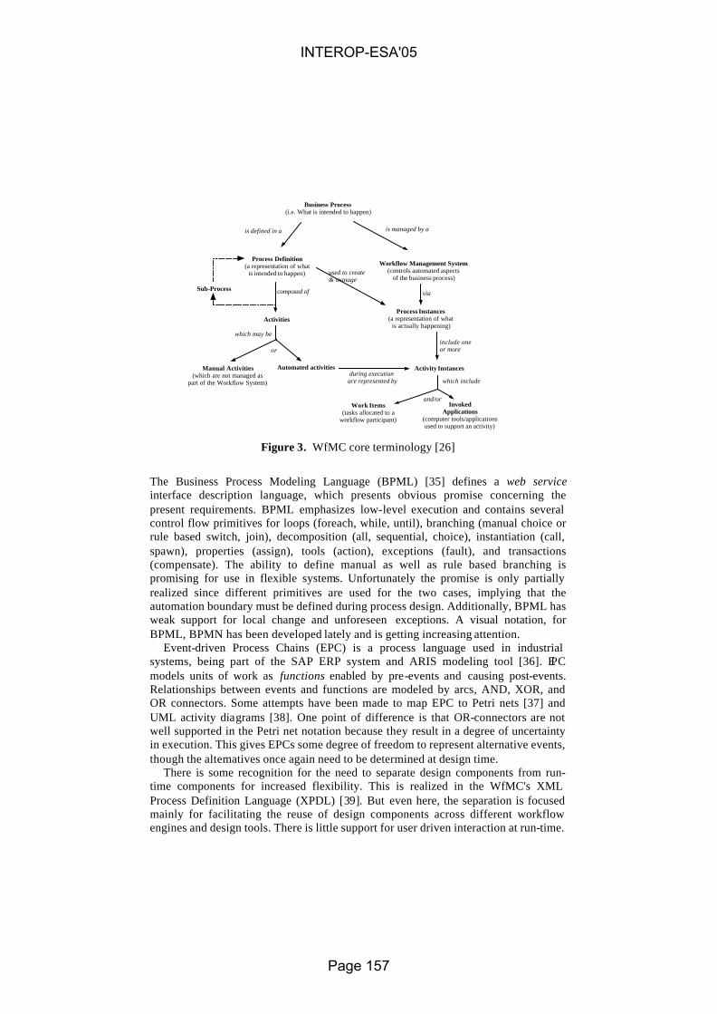
Figure 3. WfMC core terminology [26]
The Business Process Modeling Language (BPML) [35] defines a web service interface description language, which presents obvious promise concerning the present requirements. BPML emphasizes low-level execution and contains several control flow primitives for loops (foreach, while, until), branching (manual choice or rule based switch, join), decomposition (all, sequential, choice), instantiation (call, spawn), properties (assign), tools (action), exceptions (fault), and transactions (compensate). The ability to define manual as well as rule based branching is promising for use in flexible systems. Unfortunately the promise is only partially realized since different primitives are used for the two cases, implying that the automation boundary must be defined during process design. Additionally, BPML has weak support for local change and unforeseen exceptions. A visual notation, for BPML, BPMN has been developed lately and is getting increasing attention.
Event-driven Process Chains (EPC) is a process language used in industrial systems, being part of the SAP ERP system and ARIS modeling tool [36]. EPC models units of work as functions enabled by pre-events and causing post-events. Relationships between events and functions are modeled by arcs, AND, XOR, and OR connectors. Some attempts have been made to map EPC to Petri nets [37] and UML activity diagrams [38]. One point of difference is that OR-connectors are not well supported in the Petri net notation because they result in a degree of uncertainty in execution. This gives EPCs some degree of freedom to represent alternative events, though the alternatives once again need to be determined at design time.
There is some recognition for the need to separate design components from run-time components for increased flexibility. This is realized in the WfMC's XML Process Definition Language (XPDL) [39]. But even here, the separation is focused mainly for facilitating the reuse of design components across different workflow engines and design tools. There is little support for user driven interaction at run-time.
Business Process(i.e. What is intended to happen)
Process Definition(a representation of what
is intended to happen)
Activities
Manual Activities(which are not managed as
part of the Workflow System)
Automated activities
Workflow Management System(controls automated aspects
of the business process)
Process Instances(a representation of what
is actually happening)
Activity Instances
Work Items(tasks allocated to a
workflow participant)
InvokedApplications
(computer tools/applicationsused to support an activity)
is defined in a is managed by a
used to create& manage
composed of
during execution are represented by which include
and/or
which may be
or
via
include oneor more
Sub-Process
INTEROP-ESA'05
Page 157

It appears that current approaches are not designed with the flexibility required to accommodate the adaptive workflows that are enabled by Web Services technologies. One approach worth pursuing is the interactive models of Jørgensen [20].
5. Integrating enterprise and IS development
The different approaches outlined above can be combined with more traditional model-driven system development to support a number of problem situations from very static, to very dynamic, even emergent processes. The different process types decide the extent to which the underlying technology can be based on hard-coded, predefined, evolving or implicit process models. This gives a number of development approaches. On one extreme; systems are manually coded on top of a traditional runtime environment, and on the other enterprise process models are used directly to generate solutions. In between these, we have the approaches typically described in MDA, namely the development of Platform Independent Models (PIMs) for code-generation (e.g. on top of a UML Virtual Machine), or for Platform Specific Models (PSMs) for more traditional code-generation.
In figure 4, we outline the different types of interoperability across these different levels, being illustrated as a pyramid of different interoperating levels [40]. Whereas traditional systems use special APIs and approaches such as EDI for interchange of data, on the next level (PSM), we can identify Web Services Interfaces. Above this level, there is a lot of work on specific business process execution platforms, with a possibility to exchange directly using a BPI. Finally, projects such as EXTERNAL(http://www.external-ist.org) and UEML (http://www.ueml.org) have provided solutions for how to interoperate on the enterprise model level, using different modeling languages and different tools in the process. Standards and ontologies can be used across all levels, and also between
levels to make the interoperation happen more smoothly. ICT
Interoperability Pyramid
Programming platform
Enterprise Model(EM, CIM)
Business process model (PIM)
Platform SpecificModel
EM platform
Business process execution platform
(PIM)
Web service execution platform (PSM)
Programming platform
Programcode
EDI
API
WSI
BPI
EMI
Enterprise interoperability
Platform SpecificModel
Business process execution platform
(PIM)
Business process model (PIM)
EM platform
Enterprise Model(EM, CIM)
Web service execution platform (PSM)Program
code
Ontology, standards etc.
INTEROP-ESA'05
Page 158

Figure 4. Interoperability between different platforms We will try to clarify this picture with an example which originally had focus on
the enterprise level and cross-organizational business processes to support dynamically networked organizations. The infrastructure to support networked organizations originally developed in the EXTERNAL IST project (which is currently further developed in the ATHENA (http://www.athena-ip.org), MONESA and WISEMOD projects) can be described as consisting of three layers. These layers are identified as: • Layer 1, the information and communication technology (ICT) layer: – defining
and describing the execution platform, software architectures, tools, software components, connectivity and communication.
• Layer 2, the knowledge representation layer: - defining and describing constructs and mechanisms for mo deling, including ways of annotating models and meta-models with content from ontologies.
• Layer 3, the work performance and management layer; - modeling and implementing customer solutions, generating work environments as personalized and context -sensitive user interfaces available through web-portals.
5.1 The ICT Layer
The ICT -infrastructure is an integration of the enterprise and process modeling tools, such as: • METIS [41], a general purpose enterprise modeling and visualization tool, • XCHIPS [42], a cooperative hypermedia tool integrated with process support and
synchronous collaboration, • SimVision [43], a project simulator used to analyze resource allocation,
highlighting potential sources of delay and backlogs. • WORKWARE [44],[20] a web-based emergent workflow management system
with to-do-lists, document sharing, process enactment and awareness mechanisms. • FrameSolutions [45], a commercially available framework for building automated
workflow applications. The architecture has 3-tiers, clients, application servers, and data servers. The implementation is web-based, utilizing HTTP both for control and data integration, and XML for data exchange. Three types of integration mechanisms are provided : 1. Data-centered integration: based on a common EXTERNAL XML DTD, XML
importing/exporting utilities are implemented in each of the enterprise modeling tools for data exchange between the tools or with an XML repository.
2. Control-centered integration: uses the APIs provided by the tools and the repository to be integrated. With the APIs, the tools can call each other and access the shared repository. Some of the APIs may have parameters for denoting content objects, whose implementation requires data-centered integration capabilities.
3. Worktop-based integration: this is a service-oriented integration at the user-interface level, utilizing both data-centered integration and control-centered integration to access shared models, information objects, and tools.
INTEROP-ESA'05
Page 159

New components can be developed on a need-driven basis, using the approaches of service oriented architecture (SOA) or model-driven architecture (MDA).
5.2 The Knowledge Representation Layer
The knowledge representation layer defines how models, meta-models and meta-data are represented, used and managed. A version of Action Port Modeling (APM) [46], [20] constitutes the core of the modeling language (EEML). The kernel concepts are shown in Figure 5 as a simplified logical meta-model of EEML. The process logic is mainly expressed through nested structures of tasks and decision points. The sequencing of the tasks is expressed by the flow relation. Roles are used to connect resources of various kinds (people, organizations, information, and tools) to the tasks. Hence, modeling in EEML captures an extensive set of relationships between the goals, organizations, people, processes and resources. This is particularly useful considering the dynamic nature of networked organizations. For new partners joining the network, the rich enterprise models provide a valuable source of knowledge on how to “behave” in the network. We plan to further enable the annotation of such models with OWL-ontologies, improving model matching and mo del interoperability across organizations.
InformationObject
ToolPerson
is- filled-byis-filled-byis-filled-byn:1
n:1 n:1
OrganisationUnit
is-filled-byn:1
InformationObject
InformationObject
ToolToolPersonPerson
is- filled-byis-filled-byis-filled-byn:1
n:1 n:1
OrganisationUnit
OrganisationUnit
is-filled-byn:1
Role
Decision Point Task
has-resource-role
flows-to
flows-to
has-parthas-part
1:n1:n
n:m
n: m1:n
InformationObject
ToolPerson
is- filled-byis-filled-byis-filled-byn:1
n:1 n:1
OrganisationUnit
is-filled-byn:1
InformationObject
InformationObject
ToolToolPersonPerson
is- filled-byis-filled-byis-filled-byn:1
n:1 n:1
OrganisationUnit
OrganisationUnit
is-filled-byn:1
Role
Decision Point Task
has-resource-role
flows-to
flows-to
has-parthas-part
1:n1:n
n:m
n: m1:n
Figure 5. Simplified meta-model of EEML
Moreover, the interactive nature of the models, meaning that the users are free to refine them during execution, increases their potential as sources of experience and knowledge. As such they document details on how the work was actually done, not only how it was once planned. EEML can be extended to link into for formal process modeling (E.g. BPMN) as well as languages used in the SOA and MDA approaches, particularly UML, through the meta-modeling features of METIS, which is the main implementation platform for EEML.
From a knowledge management perspective, process models are carriers of process knowledge; knowledge of how to do things. But through the possibility in EEML of attaching information resources to the tasks at any level, such a model also imposes a structure upon the set of information resources relevant for the work described by the process model. That way, the process models themselves form the basis for information management. Further extensions with semantic annotations based on
INTEROP-ESA'05
Page 160

OWL would enhance this even further, combining process ontologies with more traditional structural ontologies.
5.3. The Work Performance and Management Layer
Users access their solutions through project portals. A project portal for a networked organization must have support for methodology adaptation, communication, co-ordination and collaboration. Project management, reporting and other services must be offered, and finally project work must be performed with possibilities for repetition, providing security and privacy for knowledge workers.
In our infrastructure, the web-based portal registers and qualifies users, and invokes other tools through WORKWARE, an example of what we term a model-generated workplace (MGWP). The modeled tasks are also executed through the invocation of tools and applications from the web based user environment comprised of the portal and WORKWARE. WORKWARE sets up the context for each task, giving access to the knowledge and resources needed to perform the task. The actual work performance is done by invoking appropriate web services. The task performers may access desktop tools, organizational information systems, web services, or automated processes (in FrameSolutions) through this user environment.
User environments are generated dynamically based on the definition of tasks using EEML. Forms and components for interacting with different model objects are selected and composed based on user interface policies.
The dynamically generated work management interface includes services for work performance, but also for process modeling and meta-modeling. The worktop is the main component in this interface. In addition to the services for performing and managing the task, it contains links to all knowledge in the process models that is relevant for the task. Since the worktop is dynamically generated, subject to personal preferences, the skill levels of task performers can be taken into account, e.g. to provide more detailed guidelines for people who have not previously worked on such tasks. Similarly, customized worktops for project management can support the project management team. The contents may include an overview of the project, adopted management principles, applicable methodologies, project work-break-down structure, results, plans and tasks, technologies and resources, status reporting and calculations. Further details on this approach can be found in [20], [47].
6. Conclusion
This paper has provided a unified survey of relevant technologies for achieving semantic interoperability in the context of enterprise information systems, namely ontologies, service descriptions, and workflow models including both automated and interactive tasks. The Interoperability Pyramid, together with the example explanations of this, illustrates how the combination of these technologies can provide more advanced interoperability that with current systems. We suggest that “interoperability” in the abstract may be an untenable goal, at least in the immediate
INTEROP-ESA'05
Page 161

future. But interoperability in the context of dynamic and interactive workflows, as the next best thing, is very much within our reach.
Acknowledgements
Csaba Veres is funded by the Norwegian Research Council through the WISEMOD project (NFR IKT-2010). John Krogstie has been funded by the projects ATHENA and MONESA. The ideas of this paper are pursued in the context of the EU NoE project INTEROP, and we thank other partners of INTEROP for valuable inspiration.
References
1: Berners-Lee, T., Hendler, J., and Lassila, O. The Semantic Web., Scientific American, 2001, May, 2: Manola, F., Miller, E. RDF Primer, W3C Recommendation 10 February 2004, 2004,
http://www.w3.org/TR/rdf-primer/, 3: Broekstra, J., Kampman, A., van Harmelen, F. Sesame, in Spinning the Semantic Web,
Fensel, D., Hendler, J., Lieberman, H., Eds. , MIT Press, 2003, Cambridge, MA 4: Powers, Shelly Practical RDF, O'Reilly, 2003 5:Orbis Latinus, Linguistic Terms, 2004, http://www.orbilat.com/General_References/Linguist, 6: Butler, H.M. Barriers to real world adoption of semantic web technologies , Technical
Report, 2002, Hewlett Packard, Filton Road Bristol BS34 8QZ UK 7: Hayes, P. RDF Semantics, , http://www.w3.org/TR/rdf-mt/, 8: The RDF Validation Service, 2004, http://www.w3.org/RDF/Validator/, 9: Daconta, M.C., Orbst, L.J., Smith, K.T The Semantic Web, Wiley, 2003 10: Brickley, D. RDF: Understanding the Striped RDF/XML Syntax, 2001,
http://www.w3.org/2001/10/stripes/, 11: Miles, A. RDFMolecules:Evaluating Semantic Web Technology in a Scientific
Application, 2003 12: Klein, M., Broekstra, D., Fensel, F., van Harmelen, F., Horrocks, I Ontologies and Schema
Languages on the Web, in Spinning the Semantic Web, Fensel, D., Hendler, J., Lieberman, H., Eds., MIT Press, 2003, Cambridge, MA
13: Grigoris, A. & v. Harmelen, F. Web Ontology Language: OWL, in Handbook On Ontologies, , Eds. International Handbooks on Information Systems, Springer, 2004, Berlin, Germany
14: McGuiness, D. L. Ontologies Come of Age, in Spinning the Semantic Web, Fensel, D., Hendler, J., Lieberman, H. Wahlster, W, Eds., MIT Press, 2003, Cambridge, MA.
15: Staab, S. & Studer , R. , Handbook On Ontologies , International Handbooks on Information Systems, Springer, Berlin, Germany, 2004
16: OWL Web Ontology LanguageUse Cases and Requirements , 2004, http://www.w3.org/TR/webont-req/, Accessed Aug. 23, 2004
17: OWL Web Ontology LanguageSemantics and Abstract SyntaxSection 2. Abstract S, 2004, http://www.w3.org/TR/owl-semantics/syntax.html,
18: OWL Web Ontology LanguageGuide, 2004, http://www.w3.org/TR/owl-guide/, Accessed Aug. 23, 2004
19: OASIS/ebXML Registry Technical Committee OASIS/ebXML Registry Information Model v2.6, 2004, http://www.oasis-open.org/committees/download.php/,
INTEROP-ESA'05
Page 162

20: Jørgensen, H. D., 2004, Interactive Process Models , PhD-thesis, NTNU, Trondheim, Norway, ISBN 82-471-6203-2.
21: Bandinelli, S., Fuggetta, A., Lavazza, L., Loi, M., and Picco, G.P. Modeling and Improving an Industrial Software Process, IEEE Transactions on Software Engineering, vol. 21, no. 5, 1995.
22: Derniame, J. C. Software Process: Principles, Methodology and Technology, , LNCS 1500, Springer, Berlin, Germany, 1998
23: Brathaug, T. A., and Evjen, T. A. Enterprise Modeling, , STF 38 A96302 ,1996, , Trondheim, Norway
24: Fox, M. S. and Gruninger, M. Enterprise Modeling, AI Magazine, 2000 25: Ambriola, V., Conradi, R., and Fuggetta, A. Assessing Process-Centered Software
Engineering Environments , ACM Transactions on Software Engineering and Metho, 6, 3, 1997
26: WfMC Workflow Handbook 2001, , Workflow Management Coalition, Lighthouse Point, Florida, USA, 2000
27: Carlsen, S Conceptual Modeling and Composition of Flexible Workflow Models , Norwegian University of Science and Technology, 1997
28: Conradi, R. and Jaccheri, M. L. Process Modelling Languages, in Software Process: Principles, Methodology and Tech, , Eds. Lecture Notes in Computer Science, Springer LNCS 1500, 1998,
29: Curtis, B., Kellner, M. I., and Over, J. Process Modeling, Communications of the ACM, 35, 9, 1992.
30: Green, P. and Rosemann, M. Integrated Process Modeling: An Ontological Evaluation, Information Systems, 25, 3, 2000
31: Lei, Y. and Singh, M. P. A. A Comparison of Workflow Metamodels, in ER Workshop on Behaivoral Modeling, , Eds. , Springer LNCS 1565, 1997,
32: Bolcer, G. and Kaiser, G. SWAP: Leveraging the Web to Manage Workflow, IEEE Internet Computing, 3, 1, 1999, ,
33: OMG Workflow Management Facility v. 1.2, , Object Management Group, , 2000 34: WfMC Workflow Management Coalition, Interface 1: Process Definition Interch, Draft
5.0, Workflow Management Coalition, , 1996 35: Arkin, A. Business Process Modeling Language - BPML 1.0 Working Draft, BPML.org,
2002, , 36: Scheer , A. W. and Nuttgens, M. ARIS Architecture and Reference Models for Business
Process Management, in Business Process Management, W. v. d. Aalst, J. Desel, and A. Oberweis, Eds. , Springer LNCS 1806, 2000, Berlin, Germany
37: Aalst, W. M. P. v. d. Formalization and Verification of Event-driven Process Chains, Information and Software Technology, 41, 10, 1999, ,
38: Loos, P. and Allweyer, T. Process Orientation and Object Orientation - An Approach for Integrating UM, , , University of Saarland, Germany, 1998
39: Workflow Process Definition Interface -- XML Process Definition Language, 2002, http://www.wfmc.org/standards/docs/TC-1025_10_xpdl, Accessed Aug. 19, 2004
40: Krogstie, J. Integrating Enterprise and IS-development Using a Model-Driven Approach. in 13th International Conference on Information Systems Development. 2004. Vilnius, Lithuania: Kluwer.
41: Lillehagen, F. , 1999, Visual extended enterprise engineering embedding knowledge management, systems engineering and work execution, Proceedings of IEMC '99, IFIP International Enterprise Modelling Conference, Verdal, Norway.
42: Haake, J. M., and Wang, W., 1997, Flexible support for business processes: Extending cooperative hypermedia with process support, Proceedings of GROUP '97, Phoenix, Arizona USA
INTEROP-ESA'05
Page 163

43: Kuntz, J. C., Christiansen, T. R., Cohen, G. P., Jin, Y., and Levitt, R. E., 1998, The virtual design team: A computational simulation model of project organizations, Communications of the ACM, vol. 41, no. 11.
44: Jørgensen, H. D., 2001, Interaction as a framework for flexible workflow modeling. Proc International ACM SIGGROUP Conference on Supporting Group Work, Boulder CO, September.
45: Kallåk, B. H., Pettersen, T. B., and Ressem, J. E. , 1998, Object-oriented workflow management: Intelligence, flexibility, and real support for business processes, Proceedings of OOPSLA Workshop on Implementation and Application of Object-Oriented Workflow Management Systems, Vancouver, Canada.
46: Carlsen, S., 1998, Action port model: A mixed paradigm conceptual workflow modeling language, Proceedings of Third IFCIS Conference on Cooperative Information Systems (CoopIS'98), New York.
47: Krogstie, J., and Jørgensen, H. D., 2004, Interactive models for supporting networked organizations. Proceedings of CAiSE’2004, June 9-11 Latvia, Riga.
INTEROP-ESA'05
Page 164

An M3-Neutral infrastructure for bridging model engineering and ontology engineering
J. Bézivin(1), V.Devedzic(2), D. Djuric(2), J.M. Favreau(1), D. Gasevic(2), , F. Jouault(1)
(1)ATLAS Group (INRIA & LINA), University of Nantes 2, rue de la Houssinière - BP 92208 44322 Nantes Cedex 3, France
http://www.sciences.univ-nantes.fr/lina/atl/ (2)GOOD OLD AI Group, FON – School of Business Administration, University of Belgrade
POB 52, Jove Ilića, 11000 Belgrade, Serbia and Montenegro http://goodoldai.org.yu
Abstract. In this paper we start from the conjecture that a convenient organization of various technical spaces in three "metamodeling" layers offers a convenient working environment. The main message of this work is that it is possible to consider software engineering and ontology engineering as two similarly organized areas, based on different metametamodels (M3-level). Consequently, building bridges between these spaces at the M3-level seems to offer some significant advantages that will be discussed in the paper. The initial results presented in this paper may also apply to other technical space as well.
1. Introduction
Model driven engineering (MDE) is being considered as an important departure from traditional techniques in such areas as software engineering, system engineering and data engineering. In software engineering, the MDA™ approach proposed by OMG in November 2000 allows separation of platform dependent from platform independent aspects in software construction and maintenance. More generally, MDE is proposing to use models to capture specific aspects of a system under construction or maintenance, not only the business and platform aspects.
Recently a new variant of MDE called Software Factories [Greenfield, 2004] has been proposed by Microsoft. The software factories approach is different from MDA mainly because it focuses more on small, well defined and engineered DSLs (Domain Specific Languages) than on the existence of a huge multi-purpose modeling language like UML 2.0. Apart from that, the Microsoft approach is completely in line with the general MDE ideas. Technical spaces have recently been introduced as a means to structure the solution space and to figure out how to work more efficiently by using the best possibilities of different technologies, including MDA [Kurtev et al 2002]. Nowadays, using only a single
INTEROP-ESA'05
Page 165

technology in solving different engineering problems is usually not enough. For example, software engineers can benefit from ontological engineering, or database developers can find useful improvements in using the XML technology.
In this paper we propose the idea that it should be possible to establish generic coordination between different technical spaces by making explicit the M3-level properties and providing domain-independent transformation facilities at this level. This would be more efficient than providing ad-hoc, case-by-case transformation between various DSLs belonging to the same or different technical spaces.
This paper is thus organized as follows. In section 2 we introduce some general considerations on the three-layer conjecture. Section 3 presents the domain of ontology engineering. In Section 4, we show how the idea of defining bridges between these spaces at the M3-level may bring a lot of significant economies and other advantages. Section 5 provides more in-depth thinking about mappings between ontology engineering and model engineering. In particular it introduces the conceptual notion of projectors to define bridges between technical spaces. In section 6 we compare the proposed M3 mapping techniques to more conventional M2-mappings. Finally we conclude by summarizing the project goals and sketching possible extension paths.
2. The 3-Layer Conjecture
In this section we recall the main characteristics of the three-layer conjecture and introduce the term of technical space. We are also discussing Model Driven Architecture (MDA), an important technical space widely accepted by software industry.
2.1. MDA basics
In November 2000 the OMG proposed a new approach to interoperability named MDA™ (Model-Driven Architecture) [9]. MDA is one example of a much broader approach known as Model Driven Engineering encompassing many popular research trends like generative programming, domain specific languages, model-integrated computing, model management and much more. The central part of MDA is the layered architecture that has a number of standards defined at each of its layers (see Figure 1). Most of MDA standards are developed as metamodels using metamodeling. The topmost layer (M3) is called metametamodel and the OMG’s standard defined at this layer is Meta-Object Facility (MOF). This is a self-defined language intended for defining metamodels. In terms of MDA, a metamodel makes statements about what can be expressed in the valid models of a certain modeling language. In fact, a metamodel is a model of a modeling language [Seidewitz, 2003]. Examples of the MDA’s metamodels are UML and Common Warehouse Metamodel (CWM). The MDA’s metamodel layer is usually denoted as M2. At this layer we can
INTEROP-ESA'05
Page 166

define a new metamodel (e.g., a modeling language) that would cover some specific application domains (e.g., ontology development, object-oriented programming, data base handling, etc.). The next layer is the model layer (M1) – the layer where we develop real-world models (or domain models). In terms of UML models, that means creating classes, their relations, states, etc. There is an XML-based standard for sharing metadata that can be used for all of the MDA’s layers. This standard is called XML Metadata Interchange (XMI). The bottom layer is the instance layer (M0). There are two different approaches to explaining this layer, and we note both of them: 1. The instance layer contains instances of the concepts defined at the model layer (M1),
e.g. objects in programming languages. 2. The instance layer contains things from our reality – concrete (e.g. Mark is an
instance of the Person class, Lassie is an instance of the Dog class, etc.) and abstract (e.g. UML classes – Dog, Person, etc.) [Atkinson & Kühne, 2003]. Other authors also mentioned that difference, like Bezivin [Bezivin, 2004], who says that the M0 layer covers program executions as well.
Meta-metamodel (MOF)
Metamodel (UML, CWM)
Models (UML classes, objects)
Model Driven Architecture
M3
M2
M1 M0
X M
I
Ling
uist
ic in
stan
tiatio
n
Ontological instantiation
Real-world things, program execution
representedBy
conformantTo
Fig. 1. The four-layer Model Driven Architecture and its orthogonal instance-of relations: linguistics and ontological
In this paper we advocate the second approach, but we should give more details about its impact on UML. In UML, both classes and objects are at the same layer (the model layer) in the MDA four-layer architecture. Actually, MDA layers are called linguistic layers. On the other hand, concepts from the same linguistic layer can be at different ontological layers. Hence, UML classes and objects are at different ontological layers, but at the same linguistic layer. We give an excerpt from the Petri net ontology [Gašević & Devedžić, 2004] as an illustration of this approach (see Figure 2). There is the concept of modules in Petri nets that means components of Petri net models we can reuse in other different Petri net models. In fact, Petri net modules are similar to UML classes – it is a sort of template that we use for creating module instances. However, both of them we
INTEROP-ESA'05
Page 167
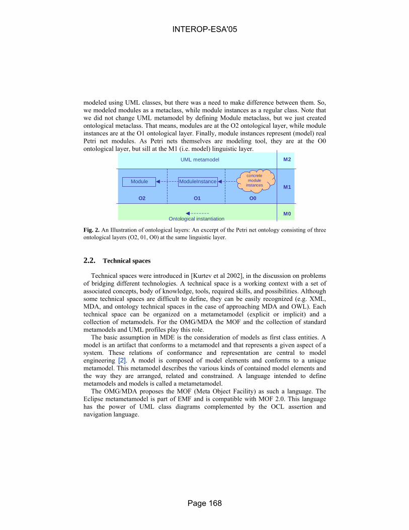
modeled using UML classes, but there was a need to make difference between them. So, we modeled modules as a metaclass, while module instances as a regular class. Note that we did not change UML metamodel by defining Module metaclass, but we just created ontological metaclass. That means, modules are at the O2 ontological layer, while module instances are at the O1 ontological layer. Finally, module instances represent (model) real Petri net modules. As Petri nets themselves are modeling tool, they are at the O0 ontological layer, but sill at the M1 (i.e. model) linguistic layer.
UML metamodel
Module ModuleInstance
O2 O1 O0
concrete module
instances
Ontological instantiation
M2
M1
M0
Fig. 2. An Illustration of ontological layers: An excerpt of the Petri net ontology consisting of three ontological layers (O2, 01, O0) at the same linguistic layer.
2.2. Technical spaces
Technical spaces were introduced in [Kurtev et al 2002], in the discussion on problems of bridging different technologies. A technical space is a working context with a set of associated concepts, body of knowledge, tools, required skills, and possibilities. Although some technical spaces are difficult to define, they can be easily recognized (e.g. XML, MDA, and ontology technical spaces in the case of approaching MDA and OWL). Each technical space can be organized on a metametamodel (explicit or implicit) and a collection of metamodels. For the OMG/MDA the MOF and the collection of standard metamodels and UML profiles play this role.
The basic assumption in MDE is the consideration of models as first class entities. A model is an artifact that conforms to a metamodel and that represents a given aspect of a system. These relations of conformance and representation are central to model engineering [2]. A model is composed of model elements and conforms to a unique metamodel. This metamodel describes the various kinds of contained model elements and the way they are arranged, related and constrained. A language intended to define metamodels and models is called a metametamodel.
The OMG/MDA proposes the MOF (Meta Object Facility) as such a language. The Eclipse metametamodel is part of EMF and is compatible with MOF 2.0. This language has the power of UML class diagrams complemented by the OCL assertion and navigation language.
INTEROP-ESA'05
Page 168

There are other representation systems that may also offer, outside the strict MDA or object-oriented boundaries, similar model engineering facilities – other technical space [3]. They are often based on a three level organization like the metametamodel, metamodel and model of the MDA. One example is grammarware [5] with EBNF, grammars and programs but we could also consider XML documents, Semantic Web, DBMS, ontology engineering, etc. A Java program may be considered as a model conforming to the Java grammar. As a consequence we may consider strict (MDA)-models, i.e. MOF-based like a UML model but also more general models like a source Java program, an XML document, a relational DBMS schema, etc.
In order to get a synergy of different technical spaces we should create bridges between them, and some of these bridges are bi-directional. The bridges can be created in a number of ways (e.g. in the XML technical space by using XSLT, in ontological engineering through transformations that can be mapped into XSLT, etc.). Note that technical spaces can be classified according to their layers of abstraction (e.g. MDA and ontological engineering are high-level spaces, whereas XML and databases are low-level spaces). The Semantic Web integrates XML and ontological engineering technical spaces.
The main role of the M3-level is to define the representation system for underlying levels. The MOF for example is based on some kind of non-directed graphs where nodes are model elements and links are associations. The notion of association end plays an important role in this representation system. Within the grammarware space we have the specific representation of abstract syntax trees while within the XML document space we also have trees, but with very different set of constraints.
Associated to the basic representation system, there is a need to offer a navigation language. For MDA the language that plays this role is OCL, based on the specific nature of MDA models and metamodels. OCL for example know how to handle association ends. For the XML document space, the corresponding notation is XPath that takes into account the specific nature of XML trees. As a matter of fact OCL is more than a navigation language and also serves as an assertion language and even as a side-effect free programming language for making requests on models and metamodels. At the M3-level when the representation system and corresponding navigation and assertion notations are defined, there are also several other domain-independent facilities that need to be pro-vided. In MDA for example generic conversion bridges and protocols are defined for communication with other technical spaces: XMI (XML Model Interchange) for bridging with the XML space JMI (Java Model Interchange) for bridging with the Java space CMI (Corba Model Interchange) for bridging with the Corba space
Obviously these facilities may evolve and provide more capabilities to the MDA technical space. We may even see many other domain-independent possibilities being available at the M3-level like general repositories for storing and retrieving any kind of model or metamodel, with different access modes and protocol (streamed, by element navigation, event-based, transaction based, with versioning, etc.).
INTEROP-ESA'05
Page 169

3. Ontologies, ontology languages and their architecture
Ontologies have been around for quite some time now. Since early 1990s researchers in the domain of artificial intelligence and knowledge representation have studied ontologies as means for knowledge sharing and reuse among knowledge-based systems. However, even an early survey of the field of ontologies [Fridman-Noy, 1997] has identified a number of application classes that benefit to a large extent from utilizing ontologies although some of them are not necessarily knowledge-based systems in the traditional sense. Later on, researchers have recognized explicitly that ontologies are not just for knowledge-based systems, but for all software systems – all software needs models of the world, hence can make use of ontologies at design time [Chandrasekaran et al, 1999]. Nowadays, ontologies and ontological engineering span such diverse fields as qualitative modeling, language engineering, database design, information retrieval and extraction, knowledge management and organization, ontology-enhanced search, possibly the largest one, e-commerce (e.g., Amazon.com, Yahoo Shopping, etc.), and configuration [McGuinness, 2002].
3.1. Ontological engineering
The engineering part of developing ontologies comprises a complex set of activities that are conducted during conceptualization, design, implementation and deployment of ontologies. Ontological engineering covers a whole range of topics and issues, such as the basics (philosophical and metaphysical issues and knowledge representation formalisms), methodology of ontology development, recent Web technologies such as XML [Bergholz, 2000] and its relatives [Klein, 2001], business process modeling, commonsense knowledge, systematization of domain knowledge, Internet information retrieval, standardization, evaluation, ontology integration with agents and applications, and many more [Devedžić, 2002]. It also gives us design rationale of a knowledge base, helps us define the essential concepts of the world of interest, allows for a more disciplined design of a knowledge base, and enables us to accumulate the knowledge about it. The disciplines tightly interwoven with ontological engineering include modeling, metamodeling, and numerous fields of software engineering.
3.2. Ontology languages
Several ontology languages have been developed during the last few years [Gómez-Pérez & Corcho, 2002]. In the first time, the most used ontology languages were Lisp-like ones, like Knowledge Interchange Format (KIF), Loom, Algernon, etc. By combining Semantic Web and XML technologies, many XML-based ontology languages have been defined like Ontology Exchange Language (XOL), SHOE, and Ontology Markup Language
INTEROP-ESA'05
Page 170

(OML). On the other hand, we have the languages Resource Description Framework (RDF) and RDF Schema as general languages for the description of metadata on the Web [Corcho et al, 2001]. The Web Ontology Language (OWL) is a current semantic markup language for publishing and sharing ontologies on the WWW adapted by W3C [Bechhofer et al, 2004]. OWL is developed as a vocabulary extension of RDF and is derived from the DAML+OIL Web Ontology Language. OWL has three variants: OWL Lite, OWL DL, and OWL Full. OWL is designed for use by applications that need to process the content of information instead of just presenting information to humans. OWL facilitates greater machine interpretability of Web content than that supported by XML, RD
itecture of ontologies languages that allow us to find similarities to the MDA architecture.
F and RDFS by providing additional vocabulary along with a formal semantics. We have tried to identify different meta-layer in definitions of ontology languages as it
is given for MDA. However, there is not any similar widely accepted architecture, so we draw the architecture in Figure 3. Generally, ontologies covers knowledge that represents (or models) some domains from the reality. In order to find relations with MDA-based modeling languages we can say that an ontology: from one hand, consists of ontology structure: definitions of concepts, their mutual relations, properties, and restrictions (i.e. axioms); on the other hand, consist of instances (individuals) created in accordance to the ontology structure. Accordingly, we can say that the place of ontologies is the M1 (model) layer. We can say that ontology languages are defined at the M2 layer similarly to MDA’s metamodels. In this case we call those definitions metaontology. Examples of metaontologies are: the Frame ontology developed by Gruber [Gruber, 1993] or the specification of the OWL language [Bechhofer et al, 2004]. The main difference from MDA’s metamodels is that there is no any general language that we use for defining ontology languages, or more simply, there is no any explicitly defined metametaontology at the M3 layer. However, we can assume one of the present ontology languages (e.g. OWL) as a metametaontology since we can define semantics of other ontology languages by using that presumed metametaontology. Of course, the meaning of this figure is not completely true, as some of ontology languages do not make differences between meta-layers, while in some of them we can define that a class is an instance of the other class (e.g. OWL Full). However, developers mainly see ontology languages as we do, so we can say that the architecture in Figure 3 represents a pragmatic arch
INTEROP-ESA'05
Page 171

Metametaontology
Metaontology (Frame, OWL)
Ontology (classes, induviduals)
Ontology langauges
M3
M2
M1 M0
XML
Ling
uist
ic in
stan
tiatio
n
Ontological instantiation
Real-world things representedBy
conformantTo
Metametaontology
Fig. 3. Meta-layers in terms of ontological engineering
3.3. MDA-based ontology languages
Since most of practitioners are mainly unfamiliar with ontology development techniques, many researches have proposed using well-known tools and techniques (e.g. UML) for ontology development as a solution of this problem [Kogut et al, 2002]. The problem of using UML for ontology development has been firstly addressed in [Cranefield, 2001]. In fact, this was a pioneering work in integrating MDA and ontologies. Currently, there is an OMG initiative aiming to define a suitable language for modeling Semantic Web ontology languages in the context of MDA [OMG ODM, 2003]. In the context of that initiative we present in Figure 4 our proposal for such an architecture [Djurić et al, 2005]. The key components in the architecture are: Ontology Definition Metamodel (ODM); Ontology UML Profile (OUP) – a UML notation for ontology definition; Two-way mappings between OWL and ODM, ODM and OUP, and from OUP to
other UML profiles.
INTEROP-ESA'05
Page 172

Fig. 4. Ontology modeling in the context of MDA and the Semantic Web
However, the idea of using MDA concepts for ontological engineering is not only present in the OMG’s initiative, but some important ontology tools (i.e. editors) also use the same principles. Probably the leading ontological engineering tool Protégé has a formally defined MOF-based metamodel. This metamodel is extensible and adaptable. This means that Protégé can be adapted to support a new ontology language by adding new metaclasses and metaslots into a Protégé ontology. Introduction of these new metamodeling concepts enable users to add necessary ontology primitives (e.g. the Protégé class has different features from OWL class). In that way it can, for instance, support RDFS [Noy et al, 2000] or OWL.
3.4. Ontology technical space
As we have already explained MDA technical space we describe ontology technical spaces as well. Starting from the main intention of ontologies to be used for sharing knowledge we can say that ontologies do not exist without any knowledge about surrounding technical spaces. According to the Semantic Web initiative ontologies are based on XML and RDF(S), and thus we use XML technologies for sharing ontologies. This also assumes that ontologies are related with grammarware and EBNF as MDA is. There is another relation between ontologies and grammarware – APIs for manipulation of ontologies (e.g. Protégé’s API, Jena, etc.), or repositories of ontology-aware knowledge in the form of databases (e.g. DBMS technical space). On the other hand, the presented ontology metamodels (ODM and OUP) are MOF-compliant languages defined in the context of the MDA’s metamodeling architecture. In that way, ontologies are connected with MDA technical space. Since we can use JMI for accessing to MOF-based repositories we have an alternative way that connects ontology technical space with grammarware technical space. Of course, we have not listed all possible technical spaces the ontology technical space has connection with. Our idea is to show the importance of defining relations between ontologies and other different technical spaces. In the rest of the paper we discuss the transformations between model engineering and ontological engineering.
4. Relations between technical spaces
Generally, each technical space has different purposes. For instance, ontological engineering technical space covers shared knowledge; while MOF-based modeling languages (e.g. UML) do not necessarily represent domain knowledge. However, we can easily recognize some overlaps between different technical spaces. That means, the same real-world thing can be captured by different technical spaces. For example, UML models
INTEROP-ESA'05
Page 173

in model engineering technical space represent things from the reality. On the other side we use XMI for sharing UML models, so the same UML model can be also represented in the grammarware (i.e. EBNF) technical space.
4.1. Classification of technical spaces
Following the previous discussion we can classify technical spaces into two parallel groups of technical spaces: 1. Conceptual technical spaces – are about conceptual (abstract or semantic) things, like
models, ontologies, mathematical logics, etc. They are not interested in techniques for representation of sharing their abstractions. However, we must have some techniques to materialize (or serialize) those technical spaces.
2. Concrete technical spaces – have techniques that allow us to have more material (i.e. physical, syntactical) representation of conceptual things. The examples of these technical spaces are different kind of grammars (e.g. KIF and XML for ontologies, XMI for MOF-based models). Also, MOF-based repositories are often based on DBMSs for storing metamodels, so we represent the model engineering (conceptual) technical space in the context of the DBMS (concrete) technical space.
Very often developers have misunderstanding of these two kinds of technical spaces. For example, most of beginners in ontological engineering do not understand difference between XML and ontologies. The problem is that most of current ontology editors and systems is based on XML, but generally speaking the same ontology can be represented by many different grammars. We can represent the same ontology semantics by many XML schemas [Decker et al, 2000]. Furthermore, those grammars should not be XML-based. One example is the regular-text based M3 notation. Finally, we can store the ontologies into DBMSs, so we can represent ontologies in the DBMS technical space.
4.2. Mappings between technical spaces
According to the previous classification we give the following conclusions regarding mappings between different conceptual technical spaces: 1. Mappings between two conceptual technical spaces. We can only define mappings at
the conceptual level. The mappings defined at the conceptual level give recommendation for their implementation.
2. A physical implementation of mappings between two conceptual technical spaces always must be done through a concrete technical space.
From the fist statement we recognize logical relations between two technical spaces. That means, we find out epistemological equivalences between them. Since we are trying to have mappings at the M3 layer we need to represent each technical space as a three-layer architecture. Afterwards we specify their mutual mappings at the M3 layer. Those
INTEROP-ESA'05
Page 174

mappings should be prorogated to lower meta-levels (i.e. M2 and M1) of the three-layer architecture.
The second conclusion states that we always must use concrete technical space for implementing mappings between conceptual spaces. For example, implementation of mappings between ontological engineering and model engineering can be through the EBNF technical space as both of these technical spaces have XML bindings. However, the statement about implementation is also valid for mappings inside the same technical space. For example, in case of mappings between ODM and UML (i.e. inside the model engineering technical space) we could implement through either the EBNF technical space or the DBMS technical space. The EBNF technical space we use in a case we are dealing with XMI documents. In this case we can use either XSLT or a programming language as an implementation tool. The DBMS technical space we use when we have a MOF-based repository stored in a DBMS. We can use a MOF2 QVT language in this case if the repository supports one of them.
5. Mappings between ontological engineering and model engineering
In this section we try to identify ways for connecting different technical spaces in the main emphasis on the relations between ontological engineering and model engineering. This problem is mainly being solved partially by defining a pair of transformations between languages from two different technical spaces we are going to connect to (e.g. ODM from MDA technical space and OWL from ontology technical space). That mainly means developing transformations according to M2 layer, so that we can transform models at M1 layer. In fact, this is represented by principle of metamodel-driven model transformations [Bézivin, 2001]. One important question is: should we always define as a pair of mappings between different languages belonging to different technical space, or can we find some commonalities among all of them? We believe that if we can achieve mappings between technical spaces at the M3 layer we can get many significant economies and other advantages. The most important one is the decrease of the number necessary transformations for bridging different technical spaces.
5.1. Epistemological relations between technical spaces
In order to clarify mappings between ontological engineering and model engineering we start from the organizational architectures of their languages (Figure 1 and Figure 3).
INTEROP-ESA'05
Page 175

From those figures we can deduce that either of them consist of three layers. Epistemologically, those layers are equivalent1: ME.M3 ⇔ OE.M3 ME.M2 ⇔ OE.M2 ME.M1 ⇔ OE.M1 In order to illustrate these statements we use the MOF-based ontology language
(ODM) as a language from the model engineering technical spaces. It is important to note that ODM is defined at M2 layer. On the side of ontological engineering we have a definition of an ontology language (e.g. OWL) at the M2 layer. Concrete real world models are at M1 layer and they consist of classes and their instances for both model engineering and ontology engineering technical spaces. That means, we must not have one ontological layer at M1 layer according to [Atkinson & Kühne, 2003], and we have two ontological layers: one for classes and one for class instances (i.e. objects).
Fig. 5. Mappings between ontological engineering and model engineering through the EBNF technical space
5.2. Pragmatic relations between technical spaces
We see here the high potential impact of considering these technical spaces as explicit and semi-formal entities. In most of these spaces we have for example internal
1 In this example we use the following notation: name-of-technical-space.meta-level, namely
ME.M3 means the M3 layer of the model engineering technical space.
INTEROP-ESA'05
Page 176
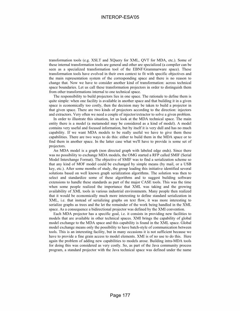
transformation tools (e.g. XSLT and XQuery for XML, QVT for MDA, etc.). Some of these internal transformation tools are general and other are specialized (a compiler can be seen as a specialized transformation tool of the EBNF/Grammarware space). These transformation tools have evolved in their own context to fit with specific objectives and the main representation system of the corresponding space and there is no reason to change that. Now we have to consider another kind of transformation: across technical space boundaries. Let us call these transformation projectors in order to distinguish them from other transformations internal to one technical space.
The responsibility to build projectors lies in one space. The rationale to define them is quite simple: when one facility is available in another space and that building it in a given space is economically too costly, then the decision may be taken to build a projector in that given space. There are two kinds of projectors according to the direction: injectors and extractors. Very often we need a couple of injector/extractor to solve a given problem.
In order to illustrate this situation, let us look at the MDA technical space. The main entity there is a model (a metamodel may be considered as a kind of model). A model contains very useful and focused information, but by itself it is very dull and has no much capability. If we want MDA models to be really useful we have to give them these capabilities. There are two ways to do this: either to build them in the MDA space or to find them in another space. In the latter case what we'll have to provide is some set of projectors.
An MDA model is a graph (non directed graph with labeled edge ends). Since there was no possibility to exchange MDA models, the OMG started a RFP called SMIF (Serial Model Interchange Format). The objective of SMIF was to find a serialization scheme so that any kind of MOF model could be exchanged by simple means (by mail, or a USB key, etc.). After some months of study, the group leading this initiative identified several solutions based on well known graph serialization algorithms. The solution was then to select and standardize some of these algorithms and to suggest building software extensions to handle these standards as part of the major CASE tools. This was the time when some people realized the importance that XML was taking and the growing availability of XML tools in various industrial environments. Many people then realized that it would be economically much more interesting to define standard serialization in XML, i.e. that instead of serializing graphs on text flow, it was more interesting to serialize graphs as trees and the let the remainder of the work being handled in the XML space. As a consequence a bidirectional projector was defined by the XMI convention.
Each MDA projector has a specific goal, i.e. it consists in providing new facilities to models that are available in other technical spaces. XMI brings the capability of global model exchange to the MDA space and this capability is found in the XML space. Global model exchange means only the possibility to have batch-style of communication between tools. This is an interesting facility, but in many occasions it is not sufficient because we have to provide a fine grain access to model elements. XMI is of no use to do this. Here again the problem of adding new capabilities to models arose. Building intra-MDA tools for doing this was considered as very costly. So, as part of the Java community process program, a standard projector with the Java technical space was defined under the name
INTEROP-ESA'05
Page 177

JRS #40. The capability to access models elements in MDA was given with the help of the Java technical space. This projector is known today under the name JMI.
As we may see, every projector has a specific purpose. In the UML 2.0 initiative, the diagram interchange part deals partially with the separation of content and presentation for MDA models [OMG, 2003]. In order to help model presentation, specific tools could have been added to the MDA space, but with a high implementation cost. Here again a solution was found in the XML space, by using the SVG standard for scalable vector graphics. Although the solution is limited to only certain kind of models, here again we see the interest of using important investments of other technical spaces to bring economically and rapidly functionalities to a given space (here the MDA) with the help of projectors.
Many other examples could be found showing the need for a very precise definition of the goal of any projector. For example, after the introduction of XMI, it was rapidly found that this projector was not bringing the facility of easy textual reading to the MDA space. Many solutions were possible, including applying XSLT transformation to XMI-serialized models to make them more usable for human operator (considering that XMI is sufficient for computer operators). Then the OMG decided to address this problem separately and a solution involving the EBNF space was defined under the name HUTN (Human Usable Textual Notation). HUTN offers three main benefits: (1) It is a generic specification that can provide a concrete HUTN language for any MOF model; (2) the HUTN languages can be fully automated for both production and parsing; (3) the HUTN languages are designed to conform to human-usability criteria. Later it was found that HUTN was not sufficient and that the set of projector should be completed in a bidirectional way with the anti-Yacc proposal (Hearnden, 2002) by DSTC. In the same spirit, SINTEF is today studying more general kinds of projectors between the MDA and the textual flat-file technical space (Oldevik, 2004).
So we can see all the gain that could be reaped from the homogeneous consideration of bridges between technical spaces with the help of generic projectors. There are many activities presently going on in this area with technical spaces like data base (SQL projectors, E/R diagram projectors), in the OS technical space (Unix projectors), in the legacy technical spaces (Cobol, ADA, PL/1 projectors to name only a few of them), in the natural language processing technical space for requirement engineering applications, etc.
One goal of the collaboration between the ATLAS group in Nantes and the GOOD OLD AI group in Belgrade is to define and build a set of generic projectors between the model engineering and the ontology engineering technical spaces.
INTEROP-ESA'05
Page 178

6. Comparing the proposed M3 bridging to present ways of mappings
6.1. M3 level as representation ontologies
In this paper we have advocated the interest of factoring out the technical bridge work by considering relations at the M3 level. This is based on the conjecture that each space could exhibit such a M3 level. Much evidence can be found to support such a conjecture.
In this three-space conjecture, we assume the existence at level M3 of some form of representation ontology with a set of associated facilities. There is not infinity of possibilities at level M3 like there are at level M2. The representation systems are based on known algebraic structures with well defined properties. Very often these structures are based on trees, graphs, hypergraphs or categories. Mapping between these algebraic structures have been studied and their properties are known. For example transforming a graph into a tree is a reasonably known operation, even if there are many ways to perform it. Hypergraphs have been found very convenient to express some situations in visual languages, but mapping between graphs and hypergraphs have also been studied.
Of course each category comes into a variety of flavors. For example abstract syntax trees and XML trees are not exactly similar trees, but their properties may be studied and compared. MOF models are non directed graphs with labeled edges extremities, somewhat different from what others would se for expressing models as directed labeled graphs. Here again the precise conversion algorithms should be expressed at the M3 level and not reinvented at the M2 level.
So, in some cases we can find entities in various technical spaces that nearly correspond semantically. In this case the gain is very high because we can apply generic M3-based projectors to do automatic conversion. We could for example make correspondence between a Java grammar, a Java XML schema, a Java metamodel or a Java ontology at a very low cost. At the other extreme of the spectrum, if we have two M2-based entities with no direct correspondence, there is no more we can do. For example if we want to match MusicML and MathML, there is no obvious way to do this.
So we see that there are really three levels of technology involvement: a) Specialized: someone works only inside a given technology space,
with a M2 commitment. For example a given team only works with the UML modeling language or the Java programming language considering that these offer sufficient expression capabilities for their work.
b) Generic: someone works inside a given technical space, with several M2-based commitments. This is happening mainly in the XML space, the software factories MDE space (with different DSLs), etc.
c) Universal: someone works with the possibility of mapping his/her problem on several technical spaces. A given information system problem for example may be more easily and generally solved by an XML solution, a Java solution, an MDA solution, an ontology
INTEROP-ESA'05
Page 179

solution. This level provides the best level of agility to solve computer engineering problems. This is the solution we are advocating here. It presupposes the existence of well designed generic projectors between the various spaces so that a given user may never become captive of a given technology.
The figure below can illustrate that current techniques understand that mappings from
conceptual TS to concrete TS can be at different meta-levels. According to our approach we will have only one transformation between conceptual TS (model engineering) to a concrete TS (XML TS), so we will avoid such a complicated procedures.
Mapping MDA metametamodel, metamodels, and models to XMI
The following section illustrates a diversity of techniques that can be used for
mappings between different technical spaces. The main problem is that all of them are relayed on the M2 layer. This suggests a metric evaluation of benefits of the approach we advocate in the paper: at M2 layer we have 2N mappings for N metamodels we want to connect to. In our approach we will have only one pair of mappings at M3 layer.
6.2. Current ways for transformations between technical spaces and their lacks
It is obvious from the previous descriptions that we cannot provide direct mappings between the MDA technical space and the OWL technical space. In fact, this transformation can only be defined through the XML technical space. It is important to define a pair of transformations in order to enable two-way mapping (one transformation for either direction) between all OWL ontologies and all ontologies represented in an MDA-based ontology language. The transformations can be based on “meta-definitions”
INTEROP-ESA'05
Page 180

of OWL (i.e. on its meta-ontology) and an MDA-compliant language (i.e. a metamodel). This transformation principle is compliant with the principle of metamodel-based model transformation [Bézivin, 2001]. Table 2 gives some guidelines on how to make transformation between each pair of the languages discussed above.
Target language
ODM OUP OWL
XML TS MDA TS XML TS ODM – XSLT QVT XSLT
XML TS MDA TS XML TS OUP XSLT QVT
– XSTL
OWL TS XML TS OWL TS XML TS
Sour
ce la
ngua
ge
OWL RDQL XSLT RDQL XSLT
–
7. Conclusions
We have presented here some initial work on the ways of bridging model engineering and ontology engineering. The main idea is that the M2-based solution seems quite costly and may not scale-up. We thus suggest using M3-based projectors to provide a general solution to this problem. Many benefits may be reaped from this approach. This paper has only presented our first investigations in this area, with some documentation evidence. We are planning to go ahead with the practical study of this increasingly important engineering problem.
The notion of technical space has been found to be essential in this investigation. However we must bring more conceptual formality to this study. A technical space is defined by a three-level organization, by a top-level representation ontology sometimes called a metametamodel, by a collection of related M2-level domain specific languages (metamodels or schemas or grammars, etc.) and by a number of facility implemented by widely available tools.
Building generic bridges at the representation level (i.e. the M3-level) seems a very promising engineering practice. We have provided some illustrations in support of this hypothesis. There is still much work to be done in this area. However if the general framework is shown feasible in these areas of model and ontology engineering, it may probably also be applied to many other areas as well.
Several of the ideas presented in this paper are supported by initial prototypes developed in the research groups in Belgrade and Nantes. Work is going on in developing these prototypes, learning from previous experiments and building up a collaborative research on the subjects discussed in this paper.
INTEROP-ESA'05
Page 181

8. Acknowledgements
Parts of this work has been supported by the "Interop" European network of excellence and by the "Modelware" IST European project 511731.
9. Bibliography
[Atkinson & Kühne, 2002] C. Atkinson and T. Kühne, Profiles in a strict metamodeling framework, Science of Computer Programming, Vol. 44, No. 1 (2002) 5-22.
[Atkinson & Kühne, 2003] C. Atkinson and T. Kühne, Model-Driven Development: A Metamodeling Foundation, IEEE Software, Vol. 20, No. 5 (2003) 36-41.
[Bechhofer et al, 2004] S. Bechhofer, F. van Harmelen, J. Hendler, I. Horrocks, D. L. McGuinness, and P. F. Patel-Schneider, L. A. Stein, OWL Web Ontology Language Reference, W3C Recommendation (2004) [Online]. Available: http://www.w3.org/TR/2004/REC-owl-ref-20040210/
[Bergholz, 2000] A. Bergholz, Extending Your Markup: An XML Tutorial, IEEE Internet Computing, Vol. 4, No. 4 (2000) 74-79.
[Berners-Lee et al, 2001] T. Berners-Lee, J. Hendler, and O. Lassila, The Semantic Web, Scientific American, Vol. 284, No. 5 (2001) 34-43.
[Bézivin, 2001] J. Bézivin, From Object Composition to Model Transformation with the MDA, In Proceedings of the 39 International Conference and Exhibition on Technology of Object-Oriented Languages and Systems,
th
Santa Barbara, USA (2001) 350-355. [Bézivin, 2004] Bézivin, J.: In search of a Basic Principle for Model Driven Engineering,
Novatica/Upgrade, Vol. V, N°2, (April 2004), pp. 21-24, http://www.upgrade-cepis.org/issues/2004/2/upgrade-vol-V-2.html
[Booch, 2004] Booch G., Brown A., Iyengar S., Rumbaugh J., Selic B.: The IBM MDA Manifesto The MDA Journal, May 2004, http://www.bptrends.com/publicationfiles/05-04%20COL%20IBM%20Manifesto%20-%20Frankel%20-3.pdf
[Brachman, 1979] R.J. Brachman, On the Epistemological Status of Semantic Networks, in Findler, N.V. ed. Associative Networks: Representations and Use of Knowledge by Computers (Academic Press, 1979) 3-50.
[Chandrasekaran et al, 1999] B. Chandrasekaran, J. R. Josephson, and V. R. Benjamins, What Are Ontologies, and Why Do We Need Them?, IEEE Intelligent Systems, Vol. 14, No. 1 (1999) 20-26.
[Cranefield, 2001] Cranefield, S. Networked Knowledge Representation and Exchange using UML and RDF. Journal of Digital information, 1(8), 2001. http://jodi.ecs.soton.ac.uk
[Decker et al, 2000] S. Decker, S. Melnik, F. van Harmelen, D. Fensel, M. Klein, J. Broekstra, M. Ederman, and I. Horrocks, “The Semantic Web: The Roles of XML and RDF,” IEEE Internet Computing, Vol. 4, No. 5 (2000) 63-74.
[Devedžić, 2002] V. Devedžić, Understanding Ontological Engineering, Communications of the ACM, Vol. 45, No. 4 (2002) 136-144.
[Djurić et al, 2005] D. Djurić, D. Gašević, and V. Devedžić, Ontology Modeling and MDA, Journal on Object Technology, Vol. 4, No. 1 (2005) forthcoming.
INTEROP-ESA'05
Page 182

[Fridman-Noy, 1997] N. Fridman-Noy and C.D. Hafner, The State of the Art in Ontology Design: A Survey and Comparative Review, AI Magazine, Vol. 18, No. 3 (1997) 53-74.
[Gašević & Devedžić, 2004] Gašević, D., Devedžić, V., “Reusing Petri Nets through the Semantic Web,” In Proceedings of the 1st European Semantic Web Symposium, Heraklion, Greece (Lecture Notes in Computer Science, Vol. 3053, Springer-Verlag, 2004) 284-298.
[Gómez-Pérez & Corcho, 2002] A. Gómez-Pérez and O. Corcho, Ontology Languages for the Semantic Web, IEEE Intelligent Systems, Vol. 17, No. 1 (2002) 54-60.
[Greenfield, 2004] Greenfield, J., Short, K. , Cook, S., Kent, S. Software Factories : Assembling Applications with Patterns, Models, Frameworks and Tools. Wiley Publishing, September 2004, ISBN 0-471-20284-3
[Hearnden, 2002] David Hearnden, Kerry Raymond, Jim Steel, Anti-Yacc: MOF-to-textD. Hearnden, K. Raymond, J. Steel. AntiYacc: MOF-to-text. In Proceedings 6th IEEE International Enterprise Distributed Object Computing Conference, (EDOC 2002), pp 200-211.
[Klein, 2001] M. Klein, Tutorial: The Semantic Web - XML, RDF, and Relatives, IEEE Intelligent Systems, Vol. 16, No. 2 (2001) 26-28.
[Kogut et al, 2002] Kogut, P., Cranefield, S., Hart, L., Dutra, M., Baclawski, K., Kokar, M. and Smith, J. UML for Ontology Development. The Knowledge Engineering Review, 17(1), 2002. 61-64.
[Kurtev, 2002] Kurtev, I., Bézivin, J., Aksit, M.: Technological Spaces: An Initial Appraisal. Int. Federated Conf. (DOA, ODBASE, CoopIS), Industrial track, Irvine, 2002.
[McGuinness, 2002] D. L. McGuinness, Ontologies Come of Age, In D. Fensel, J. Hendler, H. Lieberman, and W. Wahlster (eds.) Spinning the Semantic Web: Bringing the World Wide Web to Its Full Potential (MIT Press, Boston, 2002) 171-194.
[Oldevik, 2004] Jon Oldevik, Tor Neple, Jan Øyvind Aagedal, "Model Abstraction versus Model to Text Transformation," In Proceedings of the Second European Workshop on Model Driven Architecture (MDA) with an emphasis on Methodologies and Transformations, Canterbury, England, September 7th-8th 2004
[OMG ODM, 2003] Ontology Definition Metamodel Request for Proposal, OMG Document ad/2003-03-40 (2003) [Online]. Available: http://www.omg.org/cgi-bin/doc?ad/2003-03-40
[OMG, 1997] OMG/MOF: Meta Object Facility (MOF) Specification. OMG Document AD/97-08-14, September 1997. Available from www.omg.org
[OMG, 1998] OMG/XMI: XML Model Interchange (XMI) OMG Document AD/98-10-05, October 1998. see also OMG XMI Specification, v1.2. OMG Document formal/02-01-01, (2002), http://www.omg.org/cgi-bin/doc?formal/2002-01-01
[OMG, 2002] OMG/RFP/QVT: MOF 2.0 Query/Views/Transformations RFP, OMG document ad/2002-04-10. Available from www.omg.org
[OMG, 2003] UML 2.0 Diagram Interchange, January 6 2003, http://www.jeckle.de/files/UML2DIRevSub.pdf
[Seidewitz, 2003] E. Seidewitz, “What Models Mean,” IEEE Software, Vol. 20, No. 5 (2003) 26-32. [Soley, 2000] Soley, R. & the OMG staff: MDA, Model-Driven Architecture, (November 2000),
http://www.omg.org/mda/presentations.htm
INTEROP-ESA'05
Page 183

CONTRACT-BASED INTEROPERABILITY FOR E-BUSINESS TRANSACTIONS
Sergei Artyshchev, Hans Weigand
Infolab, Tilburg University, PO Box 90153, 5000 LE Tilburg, The Netherlands [email protected], [email protected]
Abstract. Due to the heterogeneous nature of web services, interoperability is a crucial aspect, and this interoperability has not only a data aspect (ontologies) but also a process aspect To ensure correctness of e-business processes, some kind of transaction support (e.g. WS-TXM [16]) is necessary but not sufficient. In this paper, we define correctness in terms of contract compliance. Being contract-guided, e-business processes require a contract-dependent transaction protocol that can be represented as a set of formally specified agreements and obligations between participants. In current standards and frameworks, contract-based interoperability is only referred to, but not specified in details. This paper contributes to contract-based interoperability is the following aspects: for the first time it attempts to classify characteristics for various degrees (levels) of contract-based interoperability; it provides formal deontic logic definitions of basic support operations - check and lock -, and their semantics is defined.
Keywords: e-business, transactions, deontic logic, locking, interoperability
1. Introduction
Interoperability of web services is a crucial aspect of the enterprise integration. Interoperability can be loosely defined as the ability of enterprise software and applications to interact. True interoperability is more than connectivity and communication. It includes the possibility that one role performs some activity for the other role, and so it assumes that there is shared understanding of what the meaning of the request is: both the content semantics (activity name, parameters) and the pragmatics (the intended effect, e.g. that the other role executes the request or sends a reject message). This “shared understanding” can be implicit in the code, or be more explicit in an agreed-upon protocol definition, “collaboration agreement” (ebXML), or “contract”. In this paper, we are interested in contract-based interoperability, defined as: “the ability of applications to interact and work together on the basis of a contract”, where a contract is defined as: “an agreement between two or more roles
INTEROP-ESA'05
Page 184

2 Sergei Artyshchev, Hans Weigand
that governs their interaction in terms of obligations and permissions”. A contract need not be explicit, although this does have certain advantages. In principle, every interaction is contract-based, as every interaction assumes certain semantics/ pragmatics of the communication to be in place, but typically these pragmatics are implicit in the standard protocol that is imposed from the beginning. Several frameworks (ebXML, WS-Coordination) provide the participants with the possibility to define new or extended protocols (agreements) with specifically defined semantics. When we use the term “contract” in this paper, we mainly refer to these user-defined agreements, but sometimes we also use it in the more general sense of the agreement underlying any interaction.
We will define different levels of contract-based interoperability, depending on the level of support of various contract manipulation procedures. Common procedures for contract manipulation include but are not limited to: contract establishing, contract verification, contract evolution during transaction execution, contract monitoring, sub-contract handling and inclusion, etc.
This paper is organized as follows: first we introduce the contract-based interoperability levels; then, section 3 introduces basic concepts to achieve contract-based interoperability, such as locking; section 4 provides operational semantics for these basic concepts, and the final section contains conclusions and future work guidelines.
2. Levels of Contract-Based Interoperability
In the context of collaborative business development, contract-based interoperability of web services can be divided into six categories. Both external and internal contract-related functionalities are the basis for classification. Each higher-level category includes functionality of lower level.
2.1 Contract-based interoperability levels
Fig. 1. Six levels of contract-based interoperability
transactional interoperability
contract enabling
contract monitoring
contract adaptation
full contracting Complexity
reflection (functionality verification)
INTEROP-ESA'05
Page 185
CONTRACT-BASED INTEROPERABILITY FOR E-BUSINESS TRANSACTIONS 3
Level 0 indicates that no contract-based interoperability features are supported. Internal functionality of participants of this level allows execution of pre-designated operations, however, only final results (and, sometimes, intermediate status) are externalised. Other participants could locate its profile in the registry, however, no communication except for request for service/result output, is possible. It can execute advertised functionality, but no interoperation protocol support is defined. Level 1. A participant can not only advertise, but also confirm (verify), if requested, its functionality and make a choice for the most appropriate operation (of the same type) to be employed at a run-time. Internally a participant should have a request processor which performs communication with other parties and, if necessary, a self-test mechanism that can generate latest status/performance relevant characteristics upon request. Externally, such participant allows request processing (with appropriate authentication, if necessary), basic two-way communication, and a check operation (to be defined in section 3).
Level 2. A participant supports one or (preferably) several transactional protocols. Support of level 2 interoperability indicates transactional interoperability – the capability to be engaged in transactions with some kind of (relaxed) ACID properties. To correspond to this level, a web service should support at least one transaction protocol and this capability should be advertised in a registry.
Level 3. The basic functions are in place that allow participants to make commitments and fulfill them. This assumes message-processing capabilities (to accept, process and respond to incoming messages), transactional interoperability, but, most importantly, what is supported at this level is outcome reservation (locking, to be defined in section 3), outcome determination, and other basic contract-enabling operations. Level 4. Participants can monitor a contract. Monitoring contract assumes that participants are capable to understand, execute and verify compliance of other parties’ activities to contract clauses. Understanding the contract means the capability to interpret contractual clauses (expressed in some XML-based contract definition language), and support the operations defined in the contract. Execution refers to the internal functionality to fulfill obligations assumed as part of a contract. Finally, monitoring itself refers to the capability to verify other parties’ activities against contract clauses and response with contract-defined corrective actions. Contract monitoring has been the subject of several recent research projects [6,10,12].
Level 5. Participants cannot only execute a given contract, but also adapt a contract by means of negotiation and refinement. This level requires rather developed conversation capabilities and support of obligation-based contract composition. At this level participants are not yet assumed to establish a complete contract from scratch, rather, they should reuse already existing contacts (or templates), compose a contract from other contracts (as in supply chain scenario) or refine already existing
INTEROP-ESA'05
Page 186

4 Sergei Artyshchev, Hans Weigand
contract with clauses and parameters relevant to the concrete business scenario. This level has been explored in [11] in the context of agent societies.
Level 6 Participants are able not only to refine contract templates, but also to setup a new contract, typically on the basis of explicit goals and preference structures from each participant. This functionality implies the use of goal-based negotiations and the ability to extract or compose contractual clauses from sources other then pre-defined templates and samples.
Those proposed interoperability levels could be utilized to characterize the level or
degree to which a participant is interoperable as part of the architecture. If an architecture as a whole is specified in terms of proposed levels, then the interoperability specifications for each participant might be derived. Another possible implementation might be to use these levels in the WSDL description in a registry thus facilitating the discovery of business partners with appropriate characteristics.
Contract-based interoperability can also be used to assess current state-of-the-art
technology. If we look at current web service standards such as BTP [14] and WS-Transaction [15], we can characterize them as level2. They do provide transactional interoperability by means of which parties can synchronize a certain event, but the business semantics of these synchronized events (in some cases called “BusinessAgreement”) are not specified. Therefore, there is also no monitoring of obligations, the only monitoring, if any, concerns the transaction protocol execution. If we look at current agent models (mainly confined to research labs) dealing with contracts (see the references above), we can characterize them as level 4 to 5. Level6 technology doesn’t exist yet. However, contract drafting is a research topic in the area of negotiation support and e-commerce, see e.g. [7]. If we look at the ebXML framework, we can observe that in principle, it supports all levels of contract interoperability. However, in practice collaboration profile agreements (CPA) are still composed manually, and the notion of commitment or obligation is not explicit, so ebXML is better characterized as level2.
The objective of this paper is to close the gap between web service technology and
agent theory by addressing precisely the level that is still not supported by current web service standards and, at the same time, is largely implicit in the agent models – that is, the basic level3 contract functions. We do not have a complete list yet of what these basic functions are, but we claim that the check and lock operations introduced in section 3 are very essential. The formal semantics are given in section 4.
3. Locking as an Interoperability Mechanism
In the previous section we defined locking as a level3 contract-enabling function. In this section, we list the main requirements on e-business transactions [13] and then introduce our locking model. For a more elaborate discussion of the model, see [2].
INTEROP-ESA'05
Page 187

CONTRACT-BASED INTEROPERABILITY FOR E-BUSINESS TRANSACTIONS 5
3.1 Locking Requirements
The following requirements of e-business transactions distinguish them from advanced transaction models (ATM) defined in the ‘90s [3]:
- Participants are dynamic (volatile) – while initially advertising their functionality in UDDI-type registry, they might change as a whole or some of its characteristics only – therefore locks should address actual functionality, not assumed or initial;
- Participants are autonomous entities, sometimes exhibiting opportunistic behavior – locks could be removed not only by Requestor, but also by Provider itself;
- The transactions’ technical infrastructure (media, protocols, etc.) might be unreliable, creating issues of recovery and preservation of locks;
- Rather then being focused on execution speed, e-business transactions use schedules and timeouts (specified duration); being contract-governed execution duration is predefined. While almost insignificant for traditional transaction models, process execution isn’t instantaneous and is subject to coordination and scheduling.
- Participants have functional and capacity restrictions on their operations. Functional reflect internal business capabilities of the participants that are hard to change, capacity addresses participants’ characteristics at the execution time.
Although their semantics have shifted since the time they were introduced in the
context of database transactions, locks are still a valuable mechanism to arrange mutual reservation on participant’s capacity. E-business locking guarantees that either a functionality is exercised as requested or the party, incurred losses due to another party’ obligation un-fulfillment, is compensated, as it is agreed upon when lock is applied (or specified in contract).
The principal difference between database and e-business transactions is based on participants’ behavior. A database is a passive entity and the owner is reactive only. In business transactions the participants are dynamic and owners are active agents that can decide whether and how they will execute a certain request. In complex scenarios, there might be even a negotiation about behavior of locked resource before lock’s application is attempted.
3.2 E-business locking model
In order to cope with the requirements listed in section 3.1, e-business locks should be modified compared to those of ATM. Transaction preparation might be split into two sub-phases: prepare and locking [4]. Technically, e-business locking is an asynchronous message exchange between prospective participants and a change of the Provider’s state in case lock is applied successfully. While not being explicitly addressed, e-business transaction execution is enclosed with support/service phases addressing reliability and correctness issues.
INTEROP-ESA'05
Page 188

6 Sergei Artyshchev, Hans Weigand
Although the distinction between a prepare and a locking phase is made in several e-business transaction models, the exact meaning is not always clear [1]. We suggest the following characterization:
Prepare phase – at this phase we propose functionality verification of prospective participants. Being part of pre-transaction phase of typical e-business transaction, it precedes both locking and execution. Other preparatory mechanisms (protocol-specific) might involve application of holds, initializations, soft locks, etc. We assume this phase’s activities verify functionality and capacity of prospective participants and don’t impose any definite reservation, neither they impose an obligation on any party (therefore, the terms lock and hold may be misleading). In case of completion or execution failure the preparation doesn’t require compensation. Because the participant’s profile, initially published in a registry might reflect actual functionality incorrectly (being outdated) or incompletely (containing insufficient information to invoke provider’s functionality), the requesting party might want to check this information. Checking (or verification) is performed either by the provider itself (if it is trusted party) or by a third party.
While functionality restrictions are quite rigid, capacity restrictions vary due to resources’ utilization by other parties. Exact capacity value (or, rather, available capacity) is correct only at lock application, however, any estimate performed before invocation also contributes to efficiency of execution scenario because it allows excluding (potentially) unavailable participants from the scenario without the need of a lock.
Locking Phase – some protocols employ explicit locking to ensure prospective
participants’ enlistment. A lock creates commitments. This phase follows the prepare phase and typically, it assumes the existence of a contract or similar agreement specifying the type of locks to be applied and their characteristics, but this contract can also be more general and implicit. The lock type should be supported both by requesting party and by functionality-proving participants.
As we said, checking applies either to a participant or the participant capacity (its available resources). The same is true for the locking (Table 1).
PARTICIPANT CAPACITY
PREPARE Check Participant Check Capacity
LOCK Lock Participant Lock Capacity
Table 1. Phase/object orthogonal representation
Participant lock serves as a gateway to capacity (or in case of web-services,
operation) locks. It allows the use of functionality of the locked participant limited by arrangements specified at the time of locking. This type of lock might be the only one needed if the participant provides only one operation or if it can receive all necessary information to apply operations locks transitively. This kind of lock is not exclusive.
INTEROP-ESA'05
Page 189

CONTRACT-BASED INTEROPERABILITY FOR E-BUSINESS TRANSACTIONS 7
Capacity (operations) lock is an actual locking, it creates mutual obligations between participants. This lock is used as an execution correctness preservation mechanism. With the participants’ autonomy, it might be up to the provider to designate, depending on request characteristics, an actual operation to be executed.
This orthogonal architecture provides the following benefits: - it allows transitivity of properties and functionality from participant (Provider) to capacity (resources) it controls, thus optimizing speed of locking (no need to provide additional information for every operation); - it minimizes cost and quantity of compensation. Application of participant/capacity locks could be relatively extended in time, allowing reservation costs to be minimized. For example, a check can be performed in January, a participant lock in March (for the rest of the year), a capacity lock in June, when the production planning is finalized, while the actual execution is only performed in October. When the check in January fails, another supplier can be looked for. Similarly, when the participant lock fails in March, another pre-selected supplier can be chosen. Etc. In this way, the risks are minimized against minimal costs.
Both prepare and locking phase are preliminary to transaction execution, but their
impact is quite different. While check verifies functionality and requests additional information, lock is applied upon known functionality; the check request is based on advertised functionality, while lock is based on confirmed (verified) functionality; in the case of locking, compensations might follow for unlocking, while check is a request for information with no compensations defined or needed. The provider is considered to be a prospective one before lock application and actual after.
4. A formal model of e-business locking
In this section, we provide formal semantics for the locking and unlocking operations in terms of Dynamic Deontic Logic [8,9]. This logic allows for the specification of actions (locking, unlocking, requesting, compensating etc) and for the specification of obligations (which we need to model the commitment aspect of e-business locks).
4.1 Basic Definitions
Let L be a first-order language. DDL [8,9] is L extended with deontic operators (see below) and a dynamic operator. That is, if � is a wff in DDL and � is an action, then [�]� is a wff in DDL, with the intuitive meaning: � holds after action � has been performed. The action can also be composite: �1;�2 stands for sequential, and �1&&�2 stands for parallel execution. ¬� stands for not-doing �.
In this case, we have at least the action lock(r,id,t) and unlock(id), where r is a resource, id a lock identifier and t a lock type (worked out below). The following minimal axioms hold:
INTEROP-ESA'05
Page 190

8 Sergei Artyshchev, Hans Weigand
Definition 1 (general semantics of lock and unlock) ∀r,id,t [lock(r,id,t)] lock-ed(r,id,t)
∀r,id,t lock-ed(r,id,t) � [¬unlock(id)] lock-ed(r,id,t) ∀r,id,t lock-ed(r,id,t) � [unlock(id)] ¬lock-ed(r,id,t)
These axioms just state that a resource is locked by a lock action, and remains locked until an unlock action is performed. We identify a lock by some unique identifier rather than by the resource as sometimes multiple locks on the same resource are allowed. Note that for simplicity we omit here any variable typing.
The lock operation is performed by the Provider (this agent is not included as a parameter, as we deal here only with one Provider at a time). If a Requestor wants a lock, he has to send a request message to the Provider. The Provider either accepts or rejects this request (negotiations are not in the scope of this paper). In the case of an accept, the Provider gets an obligation to perform the lock. In fact, this communication logic holds not only for lock but also for unlock and any other operation that P could perform.
Definition 2 (semantics of request)
∀R,P,m,� [request(R,P,�,m); accept(P,R,m)] Obl(P,R,�) ∀R,P,m,� ¬Obl(P,R,�) � [request(R,P,�,m); reject(P,R,m)] ¬Obl(P,R,�)
In this case, the m acts as identifier of the request. Obl is the deontic operator for obligation. The most important property of Obl is expressed in the following axiom:
Obl(P,R,�) � [¬�] Violated which says that if P is obliged to R to perform some action, not doing that action leads to a violation. Note that this scheme is a bit naive about time; normally, some deadline will be specified, and the violation only arises when the action is not done before the deadline [5]. For the time being, our abstraction suffices. The semantics of request applied to locking results in: ∀R,P,m,� [request(R,P,lock,m); accept(P,R,m)] Obl(P,R,lock) that is, the Provider is obliged to lock the resource. If this does not result in a locking action (which can never be excluded, given the autonomy of P), then P certainly has something to explain (within a certain marketplace or agent society, P may get trouble with the market owner).
4.2 Operational semantics of locking (basic model)
The operational semantics of locking are explored here by considering the intended lock properties one by one. Because of space limitations, we omit our definition of exclusive lock and define reserve lock only. Suppose that an “exclusive lock” has been set, then no one else can use the resource, but what happens when the legitimate requestor appears, with the right id. Does it mean that in that case the Provider is obliged to accept the request? We do not think this is necessary in all cases. That would mean that P has reserved r for R, and that R would be able to charge P if for
INTEROP-ESA'05
Page 191

CONTRACT-BASED INTEROPERABILITY FOR E-BUSINESS TRANSACTIONS 9
some reason, P does not grant the request (perhaps because the resource is no longer available at all). If R wants a firm commitment from P that the resource is and remains available for him, this is something that is independent from the exclusiveness property. For this purpose, we introduce the notion of reserve lock as a conditional obligation.
Definition 4 (reserve lock)
∀r,id,P,R,m lock-ed(r,id,reserve) � [request(R,P,r,m) && pass(R,P,id) ] Obl(P,accept(P,R,m)) ∀r,id,P,R,m lock-ed(r,id,reserve) �
[request(R,P,r,m); do(r)] Perm(P,unlock(id))
The first rule says that P becomes obliged to accept the service request. P could still for some reason fail to accept the request, but then this leads to a violation, and makes him liable for sanctions or compensations (see below). Note that we take reserve and exclusive to be orthogonal properties: although they will often go together, other combinations are also possible. For example, reserve but not exclusive: for the requestor in a e-business transaction, usually the most important thing is that he can use the resource, and putting an exclusive lock would be only a means to achieve that. The combination exclusive/no reserve may be useful for example in maintenance situations where some party wants to prevent the resource to be used for some time but without the intention to use it himself. The combination non-exclusive/no reserve is possible theoretically, but then there are no specified effects of the locking at all, and so the operation looses its meaning.
The second rule says that when the Provider has performed the requested operation, he is permitted1 to unlock and thereby lift the obligation. This is the normal situation: the obligation is fulfilled when the service has been performed. However, the abnormal situations are also relevant and need to be specified. What about the Provider unlocking the resource on his own initiative? In a business context, this may very well occur, for various reasons. For example, because the production capacity of the Provider went down, or because a better-paying service request comes in from another Requestor. Because this may very well occur, it is customary to specify some compensation when it happens, either in the contract or together with the locking request.
If the Provider removes the reserve lock, this leads automatically to the lifting of the obligation (assuming a closed interpretation of the rule in definition 4), so we do not specify that explicitly. However, we do specify that self-unlock is forbidden, that is, leads to a violation. The consequences of that violation differ from one contract to another and can’t be specified here.
Definition 5 (self unlock is forbidden, but not impossible)
∀P,id ¬Perm(P,unlock(id)) � For(P,unlock(id))
1 Permitted is a strong version of the deontic P operator. It implies that doing the action does
not lead to a violation (in other words, is not forbidden), but is stronger because it must be set explicitly, cf. the concept of authorization [8].
INTEROP-ESA'05
Page 192

10 Sergei Artyshchev, Hans Weigand
So unlocking is forbidden unless permitted (which is at least the case after successful performance, def. 4). We might want to specify in addition that self-unlock, if it happens, leads to an obligation to inform the requestor about this unhappy failure. This would be a good rule for a locking message protocol, but such a protocol is beyond the scope of this paper.
Intention and commitment
Usually, a lock also expresses an intention of the requestor to use the resource. The Provider can see the lock operation as a sign that the resource is going to be used, and could anticipate on that. However, from the agent literature we know that the semantics of “intentions” is rather weak, so we refrain from formalizing it.
What can be important in e-business transactions is that the Requestor commits himself to use the resource. A commitment is much stronger than an expression of intent. It means that the requestor is liable to charges (compensation) if he doesn’t use the resource. This can be very relevant in business transactions: the Provider may loose interesting business operations because of the locking, and so the lock has an economic value. One could think of various ways to formalize this commitment. The following rule is again naive about timing, but suffices for the idea, Applying a reserve lock creates a commitment to use the service (unless unlocked later).
Definition 6a (reserve locking creates a commitment)
∀R,P,r,id,m [request(R,P,lock(r,id,reserve),m);accept(P,R,m)]
locked(r,id,reserve) � Obl(request(R,P,r,_)) We must also account for the situation that the Requestor requests an unlock. In that case, he authorizes the Provider to unlock. Usually, when there is a penalty on not using the service, there is also a penalty for the Requestor on unlocking (otherwise, the first penalty could be easily circumvented), but the conditions and details often differ. For example, the conditions may say that unlocking is possible without penalty till a certain point in time. The following definition deals with unlocking by the Requestor. It says that the Provider should always grant an unlock request (he can not ignore it if that would be more convenient), but at the same time, it is regarded as something the Requestor should not do (that is, it is forbidden and liable to penalty).
Definition 6a (unlocking is forbidden, but not impossible ) ∀R,P,id,m [request(R,P,unlock(id),m] Obl(P,accept(P,R,m)) ∀R,P,r,id locked(r,id,reserve) �
For(R,request(R,P,unlock(id),_))
Compensation
In traditional transaction models (database and advanced) rollback brings participants to the state preceding the locking attempt, while in the case of failure of an e-business
INTEROP-ESA'05
Page 193

CONTRACT-BASED INTEROPERABILITY FOR E-BUSINESS TRANSACTIONS 11
transactions return to the previous state might be unnecessary or impossible. Rather, compensation is used to bring the participants into some state specified by a contract. In the formal model developed in this paper, compensation can be defined as an action specified in the contract that removes a violation of one of the obligations or prohibitions around locking. Note that in the above, we already have identified a number of possible violations, such as failure to deliver the locked service, failure to use the locked service and pre-emptive unlocking. Each violation requires a different compensation. The details of these are specified in the contract, or agreed upon at the time of the lock request, or may even follow from general law.
Definition 7 (violations can be compensated)
∀X,Y,�,r,n (violated(X,r,n) ∧ (violated(x,r) � Obl(X,�)) ∧
¬compensated(X,Y,r,n)) � [�] compensated(X,Y,r,n) Here X and Y are participants (subjects), r is some rule identifier, n is used to
identify a particular violation of that rule (the rule might be violated several times), and � is the compensatory action specified in the contract. We assume here that the DDL is powerful enough to distinguish different violation predicates and is able to count their instances. Note that, strictly speaking, compensation does not remove the violation (which remains as an historical fact, so to say), but only specifies when it is compensated, which is sufficient. Note also that the compensatory action is itself an obligation, and when it fails it may necessitate additional compensations.
Participant lock Up till now we have considered locking of resources (capacity) only. What is a reasonable semantics for participant locking? We propose to define participant locking as an authorization by means of which P commits himself to accept locking requests (perhaps conditionally, only when capacity is available at that time):
∀R,P,m,� [request(R,P,lock,m)] Obl(P,R,accept(P,R,m)) This helps to increase the chance that the business transaction will be successful. It is not needed in all circumstances, but in some uncertain situations, it can be helpful.
5. Conclusions and Future Work
While technical aspects of transactions are currently addressed by several industrial standards and protocols, many contract business-related issues are left at the discretion and implementation of business partners, in many cases leaving interoperability issues open. Therefore, a general contract-based interoperability definition should be provided and mechanisms for its contractual specifications should be defined. This paper addresses transactions from contract-based prospective introducing five levels of interoperability and providing descriptions for their
INTEROP-ESA'05
Page 194

12 Sergei Artyshchev, Hans Weigand
characteristics. The main focus is on contract enabling, which is implemented as a set of e-business transaction steps: check and lock.
Further development of contract-based interoperability involves adaptation of one of the available conversation languages to contract negotiation. There is also a need for more empirical research on the business requirements for web service technology.
Acknowledgements This work has been partially supported by NWO (Netherlands Organisation for Scientific Research) and the European NoE INTEROP.
References
1. Alonso, G., Casati, F., Kuno, H., Machiraju, V.: Web services – Concepts, Architectures and Applications. Springer Verlag, 2004.
2. Artyshchev, S, Weigand, H. “Interoperable transactions for e-business”. Submitted. 3. Elmagarmid, A. (Editor) “Database transaction models for advanced applications” Morgan
Kaufmann, San Mateo, 1995. 4. Little, M. “Transactions and Web Services” CACM, 46(10): pp.9-54, 2003. 5. Marjanovic, O. Milosevic, Z.. "Figaro Should Be in Sydney by the 2nd of July" - Contracting
in Many-To-Many e-Services. B. Schmid et al (Eds.): Towards The E-Society: E-Commerce, E-Business, and E-Government, (Proc. I3E 2001). Kluwer 2001, pp.431-444.
6. Z. Milosevic, G. Dromey, “On expressing and monitoring behaviour in contracts” In: Proc. 6th Int. Conf. on Enterprise Object Computing (EDOC’02), Lausanne, Switzerland, September 2002.
7. Y.H. Tan, W. Thoen,“Electronic Contract Drafting Based on Risk and Trust Assessment”. Int. Journal of Electronic Commerce 7(4), 2003, pp.55-72.
8. Weigand. H., F. Dignum, E.Verharen, 1997. "Integrated Semantics for Information and Communication Systems". In: R. Meersman, L. Mark (eds), Database Application Semantics. Chapman & Hall
9. Wieringa, R.J., J.-J.Ch.Meyer, and H. Weigand, "Specifying dynamic and deontic integrity constraints", Data & Knowledge Engineering (4) 2, 1989, pp.157-191.
10. Weigand, H. and Heuvel, W.J.A.M. van den. Cross-organizational workflow integration using contracts. Decision Support Systems, 33(3), 2002, pp.247-265.
11. Weigand, H., Dignum, V., Meyer, J.J.C. & Dignum, F. “Specification by refinement and agreement: Designing agent interactions using landmarks and contracts”. In Petta, P., Tolksdorf, R. & Zambonelli, F. (Ed.), Engineering Societies in the Agents World III (ESAW 2002). (LNCS, 2577, pp. 257-269). Berlin: Springer-Verlag.
12. Lai Xu and Manfred A. Jeusfeld, “Pro-active Monitoring of Electronic Contracts”, In. Proc.15th Conference On Advanced Information Systems Engineering (CAiSE 2003), 2003. Lecture Notes of Computer Science, Springer-Verlag.
13. J. Yang and M.P. Papazoglou, “Interoperation Support for Electronic Business”, CACM, Vol. 43, No. 6, pp. 39-47, June 2000.
14. Business Transaction Protocol (BTP). An OASIS Committee specification V.1.0 June 2002; See http://www.oasis-open.org
15. Web Services Transactions(WS-T). Joint specification by IBM, Microsoft, and BEA, August 2002; http://www-106.ibm.com/developerworks/library/ws-transpec/
16. Web service Transaction Management (WS-TXM) Joint Specification by Arjuna, Fujitsu, IONA, Oracle, and Sun V1.0 July 2003
http://developers.sun.com/techtopics/webservices/wscaf/wstxm.pdf
INTEROP-ESA'05
Page 195

����������� ����������������������������������� �!"�#�!�$�����%�&�%�$�'�$�������%�����()�����������*+�&����"��(#���,�-���/.102�����"�%*+"(
3)46587&9;:=<?>A@B46@DC1E�>A@BF)GH9B>AI?>AJK5LFM@B46@DCON?5L@B@14&PQ4�:SR=>BCTNA9BU15LVXW46IYI!5[Z\5?5!:S5L]^5
_+`�aOb�cedgf�`�h!dji6k)l%i6f�aYmAdg`SconAp�qr`�h?p�`ts?u+h?qwvt`ScgxeqydXz{i6kD|o`�}rxeqrhY~LqKsO��qrhY}wb�hO��L�t�D���t�L�t�L���A���L�L�������!�!�!�����t�Y�����A�
�"�D�������O�6�t &¡ }r`�pSdecgi6hYqrpo¢?mYxeqrhY`Sxex)h?`SdX£%i6cg~Lx¥¤Ob�v�`¢;`Sp�itf�`h?`�p�`�xexgb�cez¦k§i6c)dg¤Y`xem?pS¨p�`Sxex\i�k©`�h!dg`Scga?cgqrxe`�x�ª�«¬cgp^¤Yqydg`�p=dgm?cg`�xHb�hO�dgi!it}rx\k§i6c\}ri�£`ScgqrhY®8dg¤?`&p�i6x¯d°i�kjp�i6}w}wb�¢?¨i�c^b�dgqrith�`�x¯d^b6¢?}wqrxe¤?f�`�h!d�b�hO�qrf�a?cgi�vLqwh?®�dg¤Y`HkKb6pSqw}rqydgqr`�x�kMi�c$f"b6hYb6®6qwh?®[b�hO�f"b6qrhA¨d^b�qwh?qrhY®"dg¤Y`\hY`Sd�£i6cg~Lx$b�cg`¦m?hO�?`=c�b�pSdgqrv�`&�A`�v�`�}rita?f�`�h!d�ª;±¤?`\£%`�¢?¨�²¥qw}wb�cgp�itx\³j´�³f�qw�Y�A}r`S£jb�cg`\qrxo�?`�xeqr®6hY`��[k§i6coqwh!dg`Scgi6a;`Sc^b6¢?qr}wqyd�z8i6k�b�m?dgith?itf�i6mYx©`�h!dg`Scga?cgqrxe`\b6a?aY}rqy¨p�b�dgqrithYx¬qrh8qrh!dg`Scgi6cg®tb6hYqrxgb�dgqwi6hOb�}Dp�ith!dg`SµLd�ªY±¤Y`Hb6a?a?cgitb6p^¤8qrx+b°k§`��?`=c^b�dg`��8i6hY`t¶O«o}r}¢?mYxeqrhY`�xex�b6a?aY}rqrp�b�dgqri6hYxb�cg`¬�?`�v�`S}wi6a;`��&qrhO�A`�a;`�hO�A`�h!dg}yz!stb�hO�°dg¤?`©³j´6³Qf�qw�Y�A}w`=£jb�cg`xe`ScgvLqrp�`�xb�cg`+m?xe`��&kMi�cj`�hYxemAcgqrhY®$dg¤Ob�d%dg`�p^¤Yh?qwp�b6}KsLxe`�f"b6h!dgqrptsLb�hO��a?c^b�®tf"b�dgqwp¬qrh!dg`Sce¨i6a;`Sc^b6¢?qw}rqydXz�qrx$f"b6qrh!d^b6qrhY`��·qrh/dg¤Y`¦¢?mYxeqrhY`Sxex$hY`Sd�£i6cg~;ª1¸Xh/dg¤Y`¦�?`�xeqr®6hTs�b�dedg`�h!dgqrith¤Yb6x¢;`�`Sh�®tqrv�`�h"ith�dg¤?`+�Lz?hYb6f�qrp�qydXz¦b6hY��`�v�it}rmAdgqwi6h{b6xea;`�pSdi6kBdg¤Y`¬hY`Sd�£i�cg~Bª!±¤YqrxaYb6a;`Sco�?qrxep�m?xexe`�x©dg¤Y`�p�i6hYp�`Sa?dgx©a?cgi�vLqw�?`��"kMi6cob�aYaY}rqrp�b�dgqwi6h/b6hY��¢Ym?xeqrhY`�xex©hY`=dX£i�cg~i�£©hY`=cgx¥b6hO�Hp�i6h?¹O®6m?c^b�dgi6cgx�s6b6hY�$dg¤?`%f�qw�Y�A}r`S£jb�cg`%~LhYi�£©}r`��?®6`�k§i6c¥qrh!dg`Scgita;`Sc^b�¢Yqr}rqydXzxem?aYa;i6ced�ª
º »?¼o½O¾1¿$À\Á°Â�½;Ãg¿©¼
E�UB4"ÄAJM>?Å15LJMFMÆ65L:=FM>A@8>LÇjÅB9TR^FM@B4tR=RH5A@1È�É�>?ÊÊ4�Ë�É�4¦Ê/5LIA4tR�4�@Y:=46Ë=Ì1Ë=FKR=46R�FM@1É�ËS465?R^FM@BÄ?JMÍ[È;46ÌT46@;VÈ;4�@Y:H>A@�:SUB4�FMË$É�>O>AÌ�4�Ë�5!:SFM>A@·ÌT5LË=:=@B46ËSR�ÎBÉ�>AÊÌ�4�:SF§:=FM>A@:�5LI?46R�ÌBJK5AÉ�4°Å�4�:gÏ+4�46@ÐR^9BÌ1ÌBJMÍ·É�U15LFM@1R5L@1ÈÐ@14�:gÏ+>AËSIOR\>LÇ©46@?:S4�ËSÌBËSFMR=46R�ÑBÒe@Q:SUBFKR\É�>AÊÌ�4�:=F§:SF§>?@DCB:SUB4"Ó14�Ô;F§Å1F§JMF§:gÍ/>AÇ©4�@Y:=46Ë=ÌBËSFKR^4�FM@;ÇÕ>?Ë^VÊ/5!:=FM>?@�R=ÍOR^:=46Ê/RÅT4tÉ�>?Ê46RÉ�ËSF§:=FKÉ�5AJ�Ñ!E�UB4$ÒgEÖR=ÍOR^:=46Ê/R5L@1È8È;46<A4�JM>?ÌBÊ4�@Y:%:=465AÊ/RjR^U1>A9BJKÈ�ÅT45LÅBJM4�:=>�Ë=4tR^Ì�>A@TÈQ:SF§Ê46JMÍ�:S>�:=UB4ËS46×Y9BFMËS4�Ê4�@Y:�RHËSFMR=FM@BÄÇÕËS>AÊØ:SUB4/É�U15A@BÄAFM@BÄ�É�>LV¯>AÌ�4�Ë�5!:SFM>A@@B4�:gÏ+>AËSI;R+5A@1È·:=UB46F§ËHÉ�>AÊÊ[9B@BFKÉ�5L:=FM>A@TR@B4�4tÈBR�ÑÙBËS>AÊ#:=UB4[É�>AÊÌ19;:=FM@BÄFM@;ÇÕË�5AR^:=ËS91É�:S9BËS4"R^FKÈ;4ACB:=UB4[4�@Y:S4�ËSÌBË=FKR=4&@B4�4tÈBR°É65L@ÐÅ�4�5?ÈBÈ;ËS46RSR^4tÈ
ÅYÍÚ5A@Û5LË�É�UBF§:=46É�:=9BËS4ÐÏ$UB46Ë=4QÅ191R^FM@B4tR=R·JM4�<A46J\R=4�ËS<YFKÉ�46R�CoÜ$ÝLÜ#ÊFMÈ1È;JM4�Ï�5LËS4LC©5L@1ÈÚ5AÅ1R^:=Ë�5AÉ�:É�>AÊÊ[9B@BFKÉ65!:=FM>?@&R=4�ËS<OFKÉ�46R5AË=4$É�JM4t5LËSJ§Í�R=4�Ì15AËS5L:=4tÈ"ÇÕËS>AÊÞ4t5AÉ�U8>L:SUB4�Ë6CA5L@TÈ{:SUB4$ËS4�JK5!:SF§>?@1R=UBFMÌ1RÅT4�:gÏo464�@ÛÉ�>?JMJM5AÅT>?ËS5L:=FM>A@ßJMF§ÇÕ46É�Í;É�JM4LC¬Ü$ÝLÜàÊFKÈBÈ;JM4�Ï�5LËS4LCj5L@1ÈÚR=>LÇK:gÏ�5LËS4Ð4�@1ÄAFM@B4�46Ë=FM@BÄ :=>O>?JMR5LËS4[É�U15A@BÄA4tÈÐÇÕËS>AÊØ:SUB48:=Ë�5AÈBFá:SFM>A@15AJ�5LÌ1ÌBË=>Y5AÉ�UDÑDÜ+ÍâÜ$ÝLÜ2ÊFKÈBÈBJ§46Ï+5AË=4�Ï+48Ê465A@âÄA46@B4�Ë�5LJF§@BÇÕËS5?Rg:SË=91É�:=9BËS4\R=4�ËS<OFMÉ�46R:SU15!:+ÌBËS>!<YFKÈ;4tR¬É�>A@1É�4�Ì;:�Ro5A@1È>AÌ�4�Ë�5!:SFM>A@1RÇÕ>?ˬÇÕ>?Ë=ÊFM@BÄ�46JM46É�:SË=>?@BFKÉÅB91R=F§@146RSRo@14�:gÏ+>AËSIOR�C;4�ão>?ÊÊ�9B@1Fá:SFM46R�C?5L@1È�Ê/5A@15LÄ?F§@1Ä�:=UB46FMË+JMF§ÇÕ46É�Í;É�JM4LÑE�UB4"Ü$ÝLÜÛÊFKÈBÈBJ§46Ï+5AË=4¦É�>?@1É�46Ì;:SRH5A@1È�>AÌ�4�Ë�5!:SFM>A@1R�R=UB>A9BJKÈ�ÅT4�R^91É�U¥C1:=UT5!:°R^:=Ë�5!:S4�ÄAFKÉ65LJXC
ÌBË=>;É�46RSRgV¯Ë=46JK5!:=4tÈ�5A@1È8:S46É�UB@B>?JM>AÄAFKÉ65LJ;@B4646ÈBRo>LÇ)46JM46É�:SË=>?@BFKÉ+ÅB91R=F§@146RSR©@B4�:gÏo>?Ë=I[Ê/5L@15AÄA46Ê4�@Y:FMR+äTJ§JM4tÈ�Ñ;å;91É�U�@B4�4tÈBR�Ïo4�Å�4�JMFM4�<?4H:S>[FM@1É�JM91È;4°:=UB4&ÇÕ>?J§JM>!Ï$FM@BÄ
æ ÇÕ>AËSÊç@B46ÏèÅB9TR^FM@B4tR=R+@B4�:gÏo>?Ë=I;Ro:=U15L:HÌBËS>!<YFKÈ;4¦5AÈBÈB46È�<!5LJM9B4&R^46Ë=<OFKÉ�4tR©ÇÕ>?ËHÉ�JMFM4�@Y:SR�Îæ ]g>AFM@/:S>8Ê�9BJ§:SF§Ì1J§4$@14�:gÏ+>AËSIOR+5!:�:SUB4�R=5AÊ4H:=FMÊ4¦Ï$F§:=UB>?9;:+91@B@B46É�46RSR=5AË=Í8ËS46R^:=ËSFKÉ�:=FM>?@1Rj>A@:=4tÉ�UB@B>AJM>?ÄAFM46R¬>AË$>AÌ�4�Ë�5!:SFM>A@15AJTÌ�>AJMFKÉ�FM46R�Îæ :S5AIA4&9BÌ�@B4�ÏéÅB91R=FM@B46RSR+ÌBËS>OÉ�46RSR^4tR�5L@1È�R^46Ë=<OFKÉ�4tRoÉ�U1465LÌ1J§Í�Îæ Ê>!<A4H4�Ô;FMR^:=FM@BÄ{ÅB91R=F§@146RSR¬@B4�:gÏo>?Ë=I;R¬:=>[@B4�ÏêÌBU15AR=46Ro>LÇ%JMFáÇÕ4tÉ�Í;É�JM4HR=>{:SU15!:�@B46ÏêÉ�>?J§JK5AÅT>AVËS5L:=FM>A@·ÇÕ>AËSÊ/R�É�5L@�Å�4�91R^4tÈ�Îæ Ê>A@BF§:S>AËo:=UB4�ÌBËS>AÄ?Ë=4tR=R+5L@TÈ�É�>AËSË=4tÉ�:=@146RSRo>AÇ�:SUB4"É�>?JMJM5AÅT>?ËS5L:=FM<A4�ÌBËS>;É�4tR=R=46R�Îæ 5L9;:S>AÊ/5L:=4&R^>?Ê4¦É�>AJMJK5LÅ�>AË�5!:=FM>?@[4tRg:�5LÅBJMFKR=UBÊ4�@Y:o5A@1È�É�>AËSË=4tÉ�:SF§>?@/4�<?4�@Y:SR�Î15L@TÈ
INTEROP-ESA'05
Page 196
æ ÌBËS>L:=4tÉ�:$JM>;É�5LJ�R=4�ËS<YFKÉ�46R¬5A@1È�É�>AÊÌ19;:=FM@BÄ{R=>AJM9;:SFM>A@1R©ÇÕË=>?Êë:=UB4�É�U15A@BÄA4tRo5A@1È·Ç�5LFMJM9BË=4tR©>AÇ:=UB4"É�>AJMJK5LÅ�>AË�5!:SF§>?@8Ì15LË=:=@B46Ë$R^46Ë=<OFKÉ�4tRo5A@1È�R^>?J§9B:=FM>A@1R�Ñ
E)Ë�5AÈ;F§:SF§>?@15LJMJMÍLC=F§@Y:S4�Ë=VX46@?:S4�ËSÌBËSFMR=4�É�>AJMJK5LÅ�>AË�5!:SF§>?@$U15AR¥Ë=4t×?91F§ËS46È°FM@Y:=4�Ä?ËS5L:=FM>A@°>LÇO4�@Y:=46Ë=Ì1Ë=FKR=4É�>AÊÌ19;:=FM@BÄHR=Í;Rg:S4�Ê/RD>?Ë�5LÌ1ÌBJMFMÉ65!:SF§>?@1R�Ñ�E�U14¬ÅB91R=FM@B46RSRD@B4�:gÏo>?Ë=I;R�5LËS4©4�Ô;Ì�4�@1R=FM<A4:=>°46R^:S5AÅBJMFMR=U5L@1È Ê/5LFM@Y:S5AF§@¥CT5L@1Èâ:=U148É�>?R^:¦>AÇ+É�U15A@BÄA4tR\FM@â:=UB48@B4�:gÏo>?Ë=IQR^:=ËS91É�:S9BËS4�>?˦Ê46Ê�Å�4�Ë�R=UBFMÌ�FKRUBFMÄAUDÑ)E�UB4/:=>AÌ1FMÉ65LJjFM@Y:=46ÄAË�5!:=FM>?@Ð:=4tÉ�UB@BFK×Y9B46R&<!5LËSÍQÇÕËS>AÊì@B4�ÏíÄA46@B4�Ë�5!:SFM>A@âîoG$W�R=ÍOR^:=46Ê/R�CÌBË=>;É�46RSRgV¯>AËSFM4�@Y:S5L:=FM>A@[:=>È;FKR^:=ËSFMÅB9;:=4tÈ/Ï+>AËSIYÓ1>!ÏÚÊ/5L@15AÄA46Ê4�@Y:+R=Í;Rg:S4�Ê/R�Ñï :¦ÌBËS46R=4�@Y:6CDR=FMÄA@BF§äTÉ65L@Y:°5AÊ>A9B@Y:°>AǬËS46R=465LË�É�UÐFKR°ÇÕ>OÉ�91R=F§@1Ä·>A@ <OF§Ë=:=9T5LJ%4�@Y:=46Ë=ÌBËSFKR^4�5LÌ;V
ÌBË=>Y5AÉ�UB4tR�Ñ?ð\FMË^:S915LJ�4�@Y:S4�ËSÌBË=FKR=46Rj5AË=4¬]g>AFM@Y:¬<A46@?:S9BËS46R©>AÇ)FM@1È;46ÌT46@1È;4�@Y:+4�@Y:=46Ë=ÌBËSFKR^4tR�]g>AFM@BFM@BÄ{5R^U15AË=4tÈ8É�>AJMJK5LÅ�>AË�5!:SFM>A@�ÌBËS>;É�46RSR�ÑAÒe@Ê/5L@OÍ"ÌBËS>L]g4tÉ�:�R�CAJMFMIA4�W¬GHñ¦ò¦óHî¬Eõô§ö�÷XCYP ï åBåYø¦ð\îÛôyÝ�÷XCÙ�îoE�Ò^å;Z$V¯î¬E$Ùçô ù!÷\5A@1ÈûúÛÒ^åOîüô ý1C�þ�÷XC:=UB4ÐR=9BÌBÌ�>AË=:4�@O<OF§ËS>A@1Ê4�@Y:{É�>?@1R^FKR^:SR�>LÇ&5 Å1Ë=4646ÈOVF§@1Ä�46@Y<OFMËS>A@BÊ46@?:�5L@1È�>?ÌT46ËS5L:=FM>A@15AJT46@O<YFMËS>A@BÊ46@Y:�ÑYE�U14�ÅBË=4646È;FM@BÄ[4�@O<OFMË=>?@BÊ4�@Y:+ÌBË=>!<OFKÈ;4tRÇ�5AÉ�FMJMF§:=FM46RoÇÕ>?Ë\@B46ÄA>L:SFK5!:=FM@BÄ85L@TÈÐÊ>;È;4�JMFM@BÄ�:=UB4[É�>AJMJK5LÅ�>AË�5!:SFM>A@/ÌBËS>;É�4tR=R=46R�ÎB:=U14{>AÌ�4�Ë�5!:SFM>A@15AJ4�@O<OF§ËS>A@1Ê4�@Y:%É�>A@Y:=ËS>AJKR):=UB4H46@15AÉ�:=Ê46@?:j>AÇT:SUB4$ÌBËS>OÉ�46RSR^4tR�ÑAPâ5L@OÍ">LÇ�:=U14H<OF§Ë=:=9T5LJO4�@Y:=46Ë=Ì1Ë=FKR=4R^9BÌ1ÌT>?Ë^:4�@O<OFMË=>?@BÊ4�@Y:SR)91R=4+5°9B@BF§ä14tÈ{5LË�É�UBF§:=4tÉ�:S9BË=4o5LÌBÌBËS>?5?É�UDÿt:=UB46Ë=4+FKR%5¦R=U15LËS46È"5AÅ1R^:=Ë�5AÉ�:Ê>OÈB4�J�:=>8Ï$UBFKÉ�U�5LJMJ�4�@Y:=46Ë=Ì1Ë=FKR=46RoU15�<A4°:=>/5?ÈB5LÌ;:�:SUB4�FMË$JM>;É�5LJDR=4�ËS<OFMÉ�46R�ÑÒe@·É�>?@?:SËS5?Rg:o:=>{:=UBFKR�C?:SUB4¦5AÌBÌBËS>?5?É�UF§@/:=UB4¦Ïo46Å;V¯W©FMJM5AËSÉ�>?RÌBËS>L]g4tÉ�:+FMR¬ÇÕ46ÈB4�Ë�5!:=4tÈ�ÿO4�@Y:=46Ë^V
ÌBË=FKR=46RoR^464�I8>A9;:+Ì15LË=:=@14�Ë�Rj:=UT5!:�U15�<A4\R=4�ËS<OFKÉ�46R©Ï$Fá:SU/Ï$UBFKÉ�U:SUB4�Í/5AË=4\5AÅBJM4$:=>[FM@Y:=4�ËS>AÌ�4�Ë�5!:S4� Ï$F§:=UBFM@ :SUB4�R^:=Ë�5!:S4�Ä?FMÉ65LJMJMÍÐ5AÉ�É�4�Ì;:�5LÅBJM4/JMFMÊF§:SR���Ñ ï É�>AJMJK5LÅ�>AË�5!:SFM>A@âÊ>;È;46J � ÅB91R=F§@146RSR"@B4�:^VÏo>?Ë=IQÊ>;È;46JXCDÜ�ó°P��¦FKR&91R^4tÈ ÇÕ>AË"4�ÔOÌ1J§FKÉ�Fá:SJMÍ�4�ÔOÌ1Ë=4tR=R=FM@BÄ·Ï$U15L:"IOF§@TÈâ>AÇ�É�>AJMJK5LÅ�>AË�5!:=FM>?@�FKRÏ+5A@?:S46È 5L@1ÈQÇÕ>A˦<A4�ËSF§ÇÕÍOF§@1Ä8:=U15L:&4t5AÉ�UQÌT5LË=:=@B46˦UT5AR¦5�É�>A@;ÇÕ>?Ë=Ê/5A@?:°<YFM46Ï2>A@Q:SUB48Ë=91J§4tRH>AÇ:=UB4¦É�>AJMJK5LÅ�>AË�5!:SFM>A@DÑ�Òe@·5AÈ1È;F§:=FM>A@[:=>{:=UB4°@B>AËSÊ/5LJ1ÅB91R=F§@146RSR©ÌBËS>;É�46RSR=46RjËS46×Y9BFMËS46È�ÇÕ>AËo:=UB4¦É�>?JáVJM5AÅT>?ËS5L:=FM>A@¥C�:=U14H5LÄAËS4�46Ê4�@Y:@B4�4tÈBR%:=>"É65LÌ;:S9BË=4�Ì�>L:S4�@Y:=FK5LJ;Å1Ë=4t5AÉ�U�R=F§:=915L:=FM>A@TR�5A@1È[Ë=4tÉ�>!<A46Ë=ÍÌBË=>;É�46RSR^4tR¬ÇÕËS>AÊç:=UB46Ê�ÑÒe@ÐÏo46Å;VXW¬F§JK5AËSÉ�>?R�C;Ü�ó°PQR � ÅB91R=FM@B46RSRH@B4�:gÏo>?Ë=I�Ê>;È;4�JKR���5LËS4"@B>L:°91R^4tÈ�ÇÕ>AË°4�@15?É�:SÊ4�@Y:�C
ÅB9;:{5AR&R=4�Ê/5A@?:SFKÉ"FM@Y:=4�ËS>AÌ�4�Ë�5LÅ1F§JMF§:gÍ<A46Ë=F§äTÉ65!:SF§>?@�:=>O>AJXÑDî©@15?É�:SÊ4�@Y:¦>AÇ+R=4�ËS<OFMÉ�46R¦5L@1È JM>;É�5LJÅB91R=F§@146RSRjÌBËS>OÉ�46RSR^4tR©5LËS4HËS46×Y9BFMËS46È{ÇÕ465!:S9BËS46R©>AÇD:=UB4¦R^46Ë=<OFKÉ�4�Ê/5A@15LÄ?4�Ê4�@Y:Ç�5AÉ�FMJ§F§:SF§4tR)>AÇ¥465?É�UÉ�>AÊÌ19;:=FM@BÄ·R=Í;Rg:S4�ÊüFM@O<A>AJM<?46È�F§@Q:=UB484�ão>?ÊÊ�91@BF§:gÍLÑTåO46Ë=<OFKÉ�4"ËS46×Y9B4tRg:�R\>?˦R=4�ËSFM46R$>AÇ©:S5?R^I;RÉ�5L@ ÅT4�FM@BF§:=FK5!:S46È 5L@TÈ Ì�4�Ë=ÇÕ>AËSÊ46Èß46Fá:SUB4�Ë[5AÉ6É�>AË�È;FM@BÄ�:S>â:SUB4ÐÉ�>A@Y:SË=>?J¬>LǦ5L@ 5AÌBÌBJMFKÉ�5L:=FM>A@>AË°5·JM>OÉ65LJ¥Ï+>AËSIYÓ1>!ÏéÊ/5L@15AÄA4�Ê46@Y:�R=Í;Rg:S4�Ê�ÑTÒe@TRg:S465AÈQ>LÇ©È;4�Ì1Ë=FM<OFM@BÄ8:=UB4[5LÌBÌ1J§FKÉ65!:=FM>?@1Ro:=UB4ÌT>YR=R=FMÅBFMJ§F§:SF§4tR�>LÇ1ËS46×Y9B4tRg:SF§@1Ä\R^46Ë=<OFKÉ�4tRDÇÕËS>AÊÞ5\Ë=46Ê>L:=4AC�É�>AJMJK5LÅ�>AË�5!:SF§@1Äo46@?:S4�ËSÌBËSFMR=4LC6:=UB4$5AÌBÌBJMF§VÉ�5!:SFM>A@1R©5AË=4$Å19BFMJá:¬:=>"FM@1É�J§9TÈ;4�:=UB4tR^4°5AÉ�:SFM<YF§:SF§4tR�ÑA3)>;É�5LJ1ÌT>?J§FKÉ�F§4tR � >?ÅBJMF§ÄY5!:SF§>?@1R�CtÌ�4�ËSÊFKR=R=FM>A@1R�CÌBË=>?UBFMÅBF§:=FM>A@TR��%5LËS4H:SUB4�@�91R=46È/ÇÕ>AË�Rg:S>AÌBÌBFM@BÄ{9B@15AÉ6É�46Ì;:S5AÅBJM4\ËS46×Y9B46R^:SR+5!:+>AÌ�4�Ë�5!:SF§>?@15LJ1:=FMÊ4LÎ:=UBFKRFKR@B46É�46RSR=5AË=ÍACL5AR%:=U14HÉ�>A@Y:S4�ÔO: � R^:=Ë�5!:S4�ÄAFKÉ+É�>?@?:S4�ÔO:ÇÕË=>?Ê2:=U14H4�@Y:=46Ë=Ì1Ë=FKR=4¬Ì�>AFM@Y:>AÇ�<OFM4�Ï��É�5L@�É�>?@Y:=FM@O9B>A91R=JMÍÉ�U15L@BÄ?4LÑE�UBFKR+ÈB46R=F§Ä?@�É�UB>?FKÉ�4¦U15AR�Å�4�46@�Ê/5?È;4¦F§@�>AË�È;46Ëo:S>8Ê/5LIA4°:=U14�4�<A>?JM9;:=FM>A@>AÇÜ�ó°PQR$5L@1È
ÅB91R=F§@146RSRo@14�:gÏ+>AËSIORo:SUB4�Ê/R=4�JM<A4tR¬Ê>?Ë=4°Ó14�ÔOFMÅBJM4AÑ1ãoUT5L@BÄ?46R�FM@·:SUB4�Ê>;È;4�J�:S>8ÇÕ>AJMJM>!ÏÚF§@TÈ;4�4tÈË=4t×?91F§ËS4+:=U15L:j:=UB4\Ê>OÈB4�JBFKRj4�ÔOÌ1J§FKÉ�Fá:SJMͦ5�<!5LFMJK5LÅ1J§4o5!:©:SUB4H>AÌ�4�Ë�5!:SFM>A@15AJ?:SFMÊ4LCA5L@TÈ{:SU15!:¬:=UB46Ë=4FMR°5·R=ÍO@1É�UBËS>A@BFMÆ65L:=FM>A@�5L@1ÈQ@B4�Ä?>L:=FK5L:=FM>A@�Ê46É�U15A@BFKR^ÊàÇÕ>AË°Ì15LË=:=@B46ËSRH:=>�Ë=4t5AÉ�UÐ5·RS5!ÇÕ4�ÌT>?FM@?:Ï$UB4�ËS4&@B4�ÏéË=91J§4tR�É�5L@�Å�4"5AÈ;>?Ì;:=4tÈ�ÑåO46É�:=FM>A@�Ý�È;FKR=É�91RSR^4tR�F§@Y:S4�ËS>AÌ�4�Ë�5LÅBFMJ§:gÍ+É�UT5LJMJM4�@BÄ?46RTF§@¦:SUB4¬É�>?@Y:=4�ÔO:¥>AÇY4!ão>AÊÊ[9B@BF§:gÍ$Ê/5L@;V
5LÄA46Ê4�@Y:�CO5L@1È�åO4tÉ�:=FM>?@·ù"ÅBËSFM4�Ó1ÍÈ;4tR=É�Ë=FMÅ�46R¬:=UB4¦Ï+4�Å;V¯W©FMJK5LË�É�>?R¬Ü�ÝAÜ ÊFMÈ1È;JM4�Ï�5LËS4HR^46Ë=<OFKÉ�4tR5L@1È�ËS4�Ì�>?R=F§:=>AËSFM46R�ÑOåO4tÉ�:SF§>?@�ý/5AÈBÈ;ËS46RSR=46R+:=U14{FM@;ÇÕ>AËSÊ/5!:SFM>A@ËS4�Ì�>?R=Fá:S>AËSFM46RoÌBË=4tR^46@Y:=46È�ÅOÍ�:=UB4Ïo46Å;VXW¬F§JK5AËSÉ�>?R"ÊFKÈBÈBJ§46Ï+5AË=4AÑåO4tÉ�:SF§>?@ þ È;FKRSÉ�91RSR=46R�Ê4�:=U1>OÈ1R8>LǦä1@1È;FM@BÄ FM@Y:=4�ËS>AÌ�4�Ë�5LÅ1F§JMF§:gÍÌBË=>?ÅBJM4�Ê/Ro5L@1È�ÌT>A:=46@?:SFK5LJ�Ë=4t5AÉ�:=FM>A@1R¬>A@�:=UB46Ê�Ñ1E�UB4&Ì15LÌ�4�Ë�FKR�É�>?@1É�JM91È;4tÈ/ÅOÍ·É�>AÊÊ4�@Y:�5LËSÍ>A@�:=UB4"É�9BË=ËS4�@Y:$ÌBËS>L:S>L:gÍOÌT4�R^:S5L:=91R�Ñ
Ý
INTEROP-ESA'05
Page 197
� �� ¿��2Á°¼\Ãe½� ���%¼��������¥¼+½��¼¦ÀüÃg¼+½��¥¾1¿����D¾����¦Ã��gÃe½�
E�UB4/Ï+4�Å;V¯W©FMJK5LË�É�>?R&5AËSÉ�UBF§:S46É�:S9BËS4�ÌBËS>AÌ�>?R=46R{5ÐÊ>;È;4�J©>AÇ$F§@Y:S4�Ë=VX46@?:S4�ËSÌBËSFMR=4�É�>AJMJK5LÅ�>AË�5!:SF§>?@1R5ARj4!ão>AÊÊ[9B@BF§:=FM46R�É�>?ÊÌBË=FKR=FM@BÄH>LÇDFM@1È;46ÌT46@1È;46@?:SJMÍ{È;4�<?4�JM>AÌ�46È�ÅB91R=FM@B46RSRj5LÌ1ÌBJMFMÉ65!:SF§>?@1R�ÑtE�UB45LÌBÌBJMFKÉ�5L:=FM>A@TR¬:SUB4�Ê/R=4�JM<?46R+ÌBËS46R=4�@Y:\JM>;É�5LJ)ÅB91R=F§@146RSRHR^46Ë=<OFKÉ�4tR$5L@1ÈQÌBË=>;É�46RSR^4tR�CT5A@1ÈÐ5LËS4"5LÅ1J§4:=>É�>?J§JK5AÅT>?ËS5L:=4HÏ$F§:=U�>L:SUB4�Ë$46@Y:=4�ËSÌBËSFKR^4tR¬Ï$F§:=U1F§@�:=U1>?R=4¦JMFMÊF§:SR�ÑE�UB4/Rg:SËS5L:=46ÄAFKÉ�5AJ%ËS46×Y9BFMËS4�Ê46@?:�R\>AÇ�5A@ ÅB91R=F§@146RSR&@B4�:gÏ+>AËSIQÊ4�Ê[Å�4�Ë&:=>!Ï�5LË�ÈBR°:=U14·É�>?JáV
JM5AÅT>?ËS5L:=FM>A@�5LËS4+4�Ô;ÌBË=4tR=R=46È�5AR©5¦Ê4�:S5LJM46<A4�JOÊ>;È;46JO:=U15L:¬È;4�ä1@146R©5&R=4�:©>LÇ�4�ÔO:S4�ËS@15LJBÅ191R^FM@B4tR=RÌBË=>;É�46RSR^4tR�Ñ¥E�UB4R^:=ËS91É�:S9BË=48FKR&È;4�äT@B46È FM@â:S4�ËSÊ/R¦>LÇoËS>AJM4tR°5A@1ÈâFM@Y:=46ËS5?É�:SF§>?@1RHÅ�4�:gÏ+4�46@ :=UB4Ë=>?J§4tR�Ñ;ÙB>?Ë$465?É�U·ËS>AJM4LCB5ARSR=F§Ä?@BÊ4�@Y:¬ËS9BJM46R�È;4�ä1@B4�5AÈ1È;F§:=FM>A@15AJTËS46×Y9BFMËS4�Ê46@?:�RjÇÕ>?Ë�:=UB4�R=4�ËS<YFKÉ�4>� �4�Ë°:=U15L:�É65L@QÅ�45AÉ6É�4�ÌB:=46ÈÐ:=>�ÇÕ9BJ§ä1JMJ�F§:�C¥5A@1ÈQÉ�>?@;ÇÕ>AËSÊ/5L@TÉ�4"ËS9BJM46R°È;4�:S4�ËSÊF§@14"JMF§ÊF§:�R�ÇÕ>AË5AÉ�É�4�Ì;:�5LÅBJM4[ÅT46U15�<OFM>A9BË�È;9BËSFM@BÄ�:=UB4·4�ão>AÊÊ[9B@BF§:gÍ�>AÌ�4�Ë�5!:SF§>?@DÑ)E�UB44�ÔOÌ1J§FKÉ�Fá:¦91R=4>LÇ$R^91É�UÊ>OÈB4�J;5LJMJM>!ÏHR¥É�>?ÊÌ15LËSFKR^>?@�5L@1È�Ê/5!:�É�UBFM@BÄH>LÇ�Rg:SËS5L:=46ÄAFKÉ�5AJ�C6ÌBËS5AÄAÊ/5L:=FKÉ�5AJLÄA>Y5LJKR¥>AÇTÊ4�Ê[Å�4�Ë�RF§@�:=U14�@B4�:gÏ+>AËSI�Ññ°9B˦5AFMÊ FKR°:=UT5!:&F§@Y:S4�ËS>AÌ�4�Ë�5LÅBFMJMF§:gÍFMR&5·ÇÕ9B@1É�:=FM>A@15AJMFá:gÍ�ÌBËS>!<YFKÈ;4tÈ�ÅOÍ�:=UB48ÊFKÈBÈ;JM4�Ï�5LËS4
R^46Ë=<OFKÉ�4tR�C;5�:=Ë�5L@1R=Ì15LËS4�@Y:$5AR=ÌT4tÉ�:$ÇÕ>?ËH5LÌBÌBJMFKÉ�5L:=FM>A@R=4�ËS<OFMÉ�46R�ÑBE�UB4�5LÌBÌBJMFKÉ�5L:=FM>A@TRj:=U14�Ê/R=4�JM<A4tR@B4�4tÈû>?@BJMÍ :S>ßÉ�>A@TÉ�4�@Y:SËS5L:=4·>?@ :SUB4�J§>;É65LJ+ÅB91R=F§@146RSR�JM>?ÄAFKÉ!C%F§ÊÌ1J§46Ê4�@Y:=4tÈ >A@ :SUB4�FMË8JM>;É�5LJÉ�>AÊÌ19;:=FM@BÄ�ÌBJK5!:^ÇÕ>?Ë=Ê�ÑBão>AJMJK5LÅ�>AË�5!:SF§>?@[5A@1È�4�ão>AÊÊ[9B@BF§:gÍ[Ê4�Ê[ÅT46ËSR=UBFMÌ/5AR=Ì�46É�:�Ro:=>AÄ?4�:SUB4�ËÏ$Fá:SUÐÌBË�5LÄAÊ/5L:=FKÉHÌ1Ë=>;É�4tR=R^Ve5�Ï+5AË=46@B46RSR�COUB>!Ï+4�<?4�Ë6CBË=4t×?91F§ËS4"5LÌ1ÌBJMFMÉ65!:SF§>?@/JM4�<?4�J)É�>A@1É�4�Ì;:�RH5L@1ÈR^46Ë=<OFKÉ�4tR�Ñ?E�U14\FM@Y:=4�Ë=V¯4�@Y:=46Ë=ÌBËSFKR^4�É�>?JMJM5AÅT>?ËS5L:=FM>A@{Ê/5L@15AÄA4�Ê46@Y:jÉ�>A@1É�4�Ì;:�RoR=9BÌBÌ�>AË=:=4tÈÅOÍ[:=UB4Ïo46Å;VXW¬F§JK5AËSÉ�>?R¬5AËSÉ�U1Fá:S46É�:=9BËS4\FM@1É�J§9TÈ;4\:SUB>?R=4&>LÇæ 5L@ 4�ão>AÊÊ[9B@BF§:gÍÐ:SU15!:8ËS4�ÌBËS46R=4�@Y:SR�5âR=ÌT4tÉ�F§äTÉ�É�>AJMJK5LÅ�>AË�5!:SFM>A@DCDF§:SR{>AÌ�4�Ë�5!:=FM>?@DC%5AÄAËS4�4�VÊ4�@Y:SRo5L@1È·Rg:�5!:=4AÎ?:SUB4\4!ão>AÊÊ[9B@BF§:=FM4tR%É65LËSË=Í�FKÈ;4�@Y:=F§:SF§4tRj5L@1È·5LËS4HÊ/5L@15AÄA4tÈ[5?É�É�>AË�È;FM@BÄ:=>8:SUB4�FMË�4�ão>?ÊÊ�9B@1Fá:gÍ8É�>?@Y:=Ë�5AÉ�:$FM@;ÇÕ>?Ë=Ê/5L:=FM>A@DÎæ R^46Ë=<OFKÉ�4tR¦:=U15L:�5LËS4/ÌBËS>!<OFKÈ;46È ÅOÍ 46@?:S4�ËSÌBËSFMR=46R�CD91R=46È 5?R�Ê4�Ê[ÅT46ËSR&FM@ 4�ão>?ÊÊ�91@BF§:=FM46R�C5L@1È�5AË=4¦Ê/5AÈ;4¦ÌB9BÅ1J§FKÉ�J§Í5�<!5LFMJK5LÅ1J§4\ÅYÍ·4�Ô;ÌT>?Ë^:SFM@BÄ[R=4�ËS<OFKÉ�4\>� �46ËSR�Î15L@TÈæ 5�R=4�:�>AÇoÜ$ÝLÜéÊFKÈBÈ;JM4�Ï�5LËS4"R^46Ë=<OFKÉ�4tR$ÇÕ>?˦4tRg:�5LÅBJMFKR=UBFM@BÄBCBÊ>;È;F§ÇÕÍOFM@BÄBC�Ê>A@BF§:=>?Ë=FM@BÄ1C15L@1È:=46Ë=ÊFM@15L:=FM@BÄ+4�ão>AÊÊ[9B@BF§:SF§4tR�CS>AË¥JM>O>AIOFM@BÄoÇÕË=>?ÊÛ:SUB4o5AÌBÌBJMFKÉ�5!:SFM>A@\R=4�ËS<OFMÉ�4�Ì�>AFM@Y:¥>LÇ;<OFM4�Ï&C>AÌ�4�Ë�5!:SF§>?@1R�ÇÕ>AË)]g>AFM@BFM@BÄ&5L@1È[JM465�<OFM@BÄ&5L@84�ão>?ÊÊ�9B@1Fá:gÍ&46Fá:SUB4�ˬ<A>AJM9B@Y:�5LËSF§JMͦ>AËjÅOÍ8É�>AÊ8VÊ�91@BF§:gÍ/È;46É�FMR=FM>A@DÑE)>âR=9BÌBÌ�>AË=:�FM@Y:=46Ë=>?ÌT46ËS5AÅBFMJMFá:gÍ�:=Ë�5L@TR^Ì15AË=46@1É�FM4tR¦:=UB4�ÊFMÈ1È;JM4�Ï�5LËS4�@B4646ÈBR{:=> ÌBËS>!<YFKÈ;4/5
R^4�:H>LÇ�ËS4�Ì�>?R=F§:=>?Ë=FM46R©ÇÕ>AËSÊFM@BÄ�5A@�46<A>?J§<OFM@BÄ"IO@B>!Ï$JM4tÈ;ÄA4°Å15AR=4"5LÅ�>A9;:$Ê4�:S5LÊ>;È;46JKR©ÇÕ>?ËHÉ�>AÊ8VÊ�9B@1Fá:SFM46R�C�>?@?:S>AJM>AÄ?FM46RH>AÇ�R=4�ËS<OFKÉ�4�:gÍYÌ�46R�C)5L@TÈ R=4�ËS<OFKÉ�46R�Ñ�úÛF§:=U :=UBFKR�FM@;ÇÕ>�F§:�FMR&Ì�>?RSR=F§Å1J§4{:=>Ê/5!:SÉ�U�FM@;ÇÕ>AËSÊ/5!:SF§>?@Ë=46ÌBËS46R=4�@Y:S5L:=FM>A@·R^:gÍOJM46R�COFM@Y:=46Ë^Ç�5?É�4tR�C;5L@1È�R=4�ËS<OFMÉ�46R�ÑÒe@ :=UB4·É�>A@Y:=ËS>AJ¬>LÇ�:=UB4�4�ão>?ÊÊ�9B@1Fá:gÍÐJMF§ÇÕ46É�Í;É�JM4LC�:=U14/46RSR^46@Y:=FK5LJ©46JM4�Ê4�@Y:�FKR�4�ão>?ÊÊ�9BV
@BF§:gÍ É�>A@Y:=Ë�5AÉ�:�Ñ+E�U14 É�>?@Y:=Ë�5AÉ�:·É�>AÊÌBËSFKR^4tR8>LÇ�:SUB4âÅB9TR^FM@B4tR=R@14�:gÏ+>AËSI Ê>;È;46J � :S> È;4�ä1@B4:=UB4�@B4�:gÏ+>AËSI�R^:=ËS91É�:=9BËS4!��CTFM@;ÇÕ>AËSÊ/5!:SFM>A@�5AÅT>?9;:\:SUB4{Ê46Ê�Å�4�Ë°R^46Ë=<OFKÉ�4tR$5!:°4t5AÉ�UÐËS>AJM4LC�R^>?Ê4>!<A4�ËS<OFM4�Ï�R^:S5L:=4/FM@;ÇÕ>?Ë=Ê/5L:=FM>A@â5AÅT>?9;:":SUB4/ÌBËS>AÄ?Ë=4tR=R&>AÇ+:SUB4/4�ÔY:S4�ËS@15LJ¬ÅB91R=F§@146RSR�ÌBËS>OÉ�46RSR^4tR�C5L@1È�Ê4�:SUB>;ÈBR+ÇÕ>AËHÉ�U15A@BÄAFM@BÄ{:=UB4"É�>A@Y:=Ë�5AÉ�:$Fá:�R^46J§ÇeÑE�UB4&4�ão>AÊÊ[9B@BF§:gÍ8É�>?@?:SËS5?É�:$É�5AÌ;:=9BËS46R$R=U15AË=4tÈ/Ê4�:�5LFM@;ÇÕ>?Ë=Ê/5L:=FM>A@85LÅ�>A9;:$:SUB4�É�>?J§JK5AÅT>AV
ËS5L:=FM>A@DÎ!ËS4�Ó14tÉ�:SF§<?4¬Ê4�:=UB>;ÈBRj5AË=4�91R=46È{:=>�I?4�4�Ì�:=U14$Ë=4t5LJBR=ÍOR^:=46Ê�5!:j4t5AÉ�U[F§@O<?>AJM<A4tÈ�É�>AÊÌ19;:^VF§@1ĦR=F§:=4�É�>AËSËS46R=ÌT>?@1È;4�@Y:%Ï$Fá:SU{:SUB4�Ê4�:�5LFM@;ÇÕ>AËSÊ/5!:SFM>A@DÑ ï :j465?É�U�5?È;ÊFM@BFKRg:SËS5L:=FM<A4jÉ�>?ÊÌB9;:SF§@1ÄÈ;>AÊ/5AF§@¥C�:SUB4�ËS48FKR�5�J§>;É65LJÊ/5L@15AÄA46Ê4�@Y:¦5AÄA4�@Y:&:=UT5!:{UB>?JKÈBR&5L@1È 91R=46R�IO@B>!Ï$JM4tÈ;ÄA4[5LÅ�>A9;:J§>;É65LJMJMÍ\È;4�Ì1J§>!Í?46È�R=4�ËS<OFMÉ�46R¥5A@1È&:SUB4�FMË%<�5AË=FM>?91RDÊ/5L@T5LÄA46Ê4�@Y:¥Ê4�:SUB>;ÈBR�Ñ�E�UB4+JM>;É�5LJ?Ê/5L@15AÄA4�VÊ4�@Y:%FM@Y:=46Ë^Ç�5?É�4tR)5LËS4+UB>AÊ>?ÄA4�@1F§Æ646ȦÅOÍ"5#"�Rg:�5L@1È15LË�È$"ÌBËS>L:S>OÉ�>AJ?ÇÕ>AËËS46×Y9B46R^:=FM@BÄ\:=UB4�R=ÍOR^:=46Ê:=>¦ÌBË=46Ì15LËS4©ÇÕ>?Ë�ËS9B@B@1F§@1Ä°5¦R^46Ë=<OFKÉ�4 � Ë=4tR^>?9BËSÉ�FM@BÄ%��Ct×Y9B4�ËSÍOFM@BÄ\5LÅ�>A9B:É�>AÊÊ[9B@BFKÉ�5L:=FM>A@°ÌT>?F§@Y:�R�CË=46J§4t5AR=FM@BÄ&:=UB4�R=4�ËS<OFMÉ�4LCY4�:SÉLÑ13¥FMIA46Ï$FKR^4ACY5LJMJ�Ë=46JM4�<!5L@Y:oÉ�U15A@BÄA4tR+F§@/:=UB4&ËS465LJDR=Í;Rg:S4�Êç5LËS4\@1>L:=F§Vä146È85L@TÈ{:SUO91R©É�U15A@BÄA4o:=UB4$Ê4�:S5AF§@BÇÕ>AËSÊ/5!:=FM>?@&5?É�É�>AË�È;FM@BÄAJMÍLÑ�E�UB4$4�ão>?ÊÊ�91@BF§:gÍ&É�>A@Y:=Ë�5AÉ�:%FKR5L@Ð5AÉ�:=FM<A4¦>AÅ;]g4tÉ�:$F§:SR=4�J§ÇeCB5L@1È�FM@1É�J§9TÈ;46R+JM>AÄ?FMÉH:=U15L:HÊ/5�ÍË=4t5AÉ�:+:S>/É�U15L@1ÄA46R+FM@�:=UB4�Ê4�:S5LFM@;VÇÕ>AËSÊ/5!:=FM>?@�5L@TÈ�Ë=4t×?9146R^:\JM>OÉ65LJ¥R=F§:=46R$ÇÕ>AËHÇÕ91Ë^:SUB4�Ë°@B4�Ä?>L:=FK5L:=FM>A@1R+>?Ë\É�U15L@1ÄA46R�FM@�:SUB4{R=ÍOR^:=46ÊRg:�5!:=4AÑ
ù
INTEROP-ESA'05
Page 198

î¬Rg:�5LÅBJMFKR=UBFM@BÄ54�ão>?ÊÊ�9B@1Fá:gÍACB>AË°4�@Y:=46Ë=FM@BÄ·5·@B4�ÏÞR=4�ËS<OFKÉ�4�FM@Y:=>·5A@Q4�Ô;FKRg:SFM@BÄ8>A@B4AC�FM@;V<A>AJM<?46R�FM@Y:=4�ËS>AÌ�4�Ë�5LÅ1F§JMF§:gÍÉ�UB46É�IOFM@BÄ1Ñ ï R°Ïo4�Ï$FMR=U�:=>�ÌBË=46Ì15LËS4�ÇÕ>?Ë°É�U15A@BÄA4tRH5L@1ÈQ4�<A>?JM9;:=FM>A@¥CÏo4É�5A@B@B>A:"4�Ô;ÌT4tÉ�:"FKÈ;46@?:SFKÉ�5LJR=>AJM9;:=FM>?@1RHÇÕËS>AÊ :=UB4Ì�4�46ËSR&U14�ËS4LC¥ÅB9;:�@B4�4tÈâ:S>Ð5LJMJM>!ÏÞÉ�>AÊ8VÊ�9B@1FMÉ65!:SF§>?@�Ï$UB4�@ FM@?:S4�@Y:SR\Ç�5LJMJFM@Y:=>�RS5LÊ4&"�4t×?91F§<!5AJ§46@1É�4"É�JK5ARSR!"&Ï$F§:SUBFM@QÏ$UBFKÉ�UQ:SËS5A@1RgÇÕ>?Ë^VÊ/5!:=FM>?@1R©É�5A@/Å�4&ÈB>A@B4AÑYÌBËS>AÅ1J§46Ê/R:=UT5!:�@B4�4tÈ·5L9B:=>AÊ/5L:=4tÈR^>?J§9B:=FM>A@1R¬È;465AJTÏ$F§:=U·Ï$U15!:�IOF§@TÈ>LÇ�FM@Y:=46ËSÉ�4�Ì;:S>AË�R¬5AË=4¦@B4�4tÈ;46ÈDCBÏ$UB4�ËS4&F§@·:=UB4�É�>AÊÊ[9B@BFKÉ�5L:=FM>A@8É�U15L@1@B4�JXC;5L@1È�5!:$Ï$U15L:$É�>?R^:�ÑPÐ>A@BF§:S>AËSF§@1Ä�FM@Y:=46Ë=>?ÌT46ËS5AÅBFMJMFá:gÍQÈB9BË=FM@BÄQ:=UB4�>AÌ�4�Ë�5!:SFM>A@ß>LÇ\:=UB4�4�ão>?ÊÊ�9B@1Fá:gÍ Ë=4t×Y9BFMË=4tR
R^46@1R^>?ËSR�5L:{465?É�UßÉ�>AÊÊ[9B@BFKÉ65!:=FM>?@QÉ�U15L@B@14�J¬46@1È�Ñ�ú 4·5?R=R=9BÊ4/5A@ 5AÅ1R^:=Ë�5AÉ�:{É�>AÊÊ[9B@BFKÉ�5LV:=FM>A@ F§@BÇÕËS5?Rg:SË=91É�:=9BËS4·Ï$F§:SU R=4�JM46É�:S5AÅBJM4/:=Ë�5L@TR^Ì15AË=46@1É�FM4tR{5L@TÈ R=9BÌBÌ�>AË=:8ÇÕ>AË@B>?@;V�ÇÕ91@1É�:SF§>?@15LJ5AR=ÌT4tÉ�:SR�Ñ¥E�UB48É�>AÊÊ[9B@BFKÉ65!:=FM>?@·FM@;ÇÕË�5AR^:=ËS91É�:S9BË=4{FMR¦É�>?@1R=FMÈB4�ËS46ÈÐ5AR¦5L@ 4�Ô;ÌBJMFKÉ�F§:�CTÊ46È;FK5!:SFM@BÄR^46Ë=<OFKÉ�4+:=UT5!:¬@B4646ÈBR©4�Ô;ÌBJMFKÉ�F§:=JMͦ:=>"Å�4'"�Ì15LË�5LÊ4�:=ËSF§Æ646È$"ÇÕ>AˬÈ;4tÉ�FKÈ;FM@BÄ&F§:SRjFM@Y:=46Ë=@T5LJBR^:=ËS91É�:S9BË=45L@1È JM4�<?4�J©>AÇ\R^46Ë=<OFKÉ�4[:S>QÅT4�ÌBËS>!<YFKÈ;4tÈ�Ñ¥Òe@ß:SU15!:�ÇÕËS5AÊ4LC)4t5AÉ�UßÉ�>?ÊÊ�9B@1FMÉ65!:SF§>?@Q4�@TÈ;ÌT>?FM@?:FMR�46×Y9BFMÌBÌ�46ÈûÏ$F§:=Uû5 ÄA915AËSÈDÑÙ1Ë=>?Ê :=UB4�R^46Ë=<OFKÉ�4�R^Ì�46É�Fáä�É�5!:SFM>A@1R{Fá:[FKR{IO@B>!Ï$@ Ï$U15!:[:=Ë�5!ÇKVäTÉ�R=UB>?9BJKÈßÅT4�R=4�4�@ 5L@1È F§@ûÏ$UBFKÉ�U >AË�È;4�Ë6ÎF§@ûÌBË=FM@1É�FMÌBJM48:=UB4�Ë=91J§4tR{É65L@ûÅ�4�4�ÔO:=46@1È;46È :=><YFM46Ï :=UB4Ð5AÉ6É�46Ì;:S5AÅBFMJ§F§:gÍ >LÇ°É�>A@Y:=46@?:�R8Rg:SË=91É�:=9BËS46R85A@1È Ê/5AIYFM@BÄQ:=ËS91Rg:8ËS4�JK5!:S46È È;4tÉ�FKR=F§>?@1R�ÑE�UB4�Ê>?@BF§:=>?Ë=FM@BÄR=ÍOR^:=46ÊØË=46ÌT>?Ë^:�RHÇÕËS>AÊØÈ;4�:=4tÉ�:=4tÈ R=F§:=915L:=FM>A@TR � :�5AR=IQRg:�5LË=:=46ÈDC�É�>AÊÌBJM4�:S46È�C9B@15AÉ6É�46Ì;:S5AÅBJM4H:=Ë�5)(/É°>AË�JK5AÉ�I8>LÇ%4�Ô;Ì�46É�:S46È·:=Ë�5)(/É*��Ñ;Òe@�Ê>?@BF§:=>AËSFM@BÄBCA:=UB4�É�U15AJ§JM46@BÄA4tRjJMF§4°FM@:=UB4�Ì�4�Ë=ÇÕ>AËSÊ/5L@1É�4\>AÇ):=U14&É�>AÊÊ[9B@BFKÉ�5L:=FM>A@8R=ÍOR^:=46Ê�CO:=UB4"È;4tR^FMÄ?@·>LÇ%Ê>A@BF§:S>AËSF§@1Ä�Ë=9BJM4tR�C;5L@1ÈÈ;46É�FMR=FM>A@/46@BÄAFM@B4AÑ
+ ,.-��0/1�2�4365âÃ����%¾TÂ�¿87:9;��9<íÃ^À°À4���2/1�%¾��=�%¾TÂ>-°Ãe½?�)Â�½;ÁH¾��
E�UB4 Ü$ÝAܬV¯ÊFKÈBÈ;JM4�Ï�5LËS4�ÌBJK5!:^ÇÕ>?Ë=Ê�ÌBËS>!<OFKÈ;46R/5%�·5?È;<!5L@1É�46ÈèR^46Ë=<OFKÉ�4âÈBFMRSÉ�>!<?4�ËSÍûÅ15?R^4tÈÚ>A@F§ÊÌ1Ë=>!<?46È{R=4�ËS<OFKÉ�46R%:gÍOÌBFM@BÄ"5A@1ÈÉ�>?@1R^:=Ë�5LFM@Y:ÅT5AR=46È8R^46JM46É�:SFM>A@DCLÅ@�¬É�>?@?:SËS5?É�:©Å15?R^4tÈ8Ê/5L@15AÄA4�VÊ4�@Y:">LÇ$É�>?J§JK5AÅT>?ËS5L:=FM>A@ÐÅ�4�:gÏ+4�46@ 5L9;:S>A@B>?Ê>A91R&R=4�ËS<YFKÉ�46R�CD5A@1ÈßÉ*��ÌBË=>Y5AÉ�:=FM<A4�J§>;É65LJ©Ê>?@BF§V:=>AËSFM@BÄ8>LÇ©É�>?@Y:=Ë�5AÉ�:HÉ�>A@;ÇÕ>?Ë=Ê/5A@1É�4AÑ1ÙB9BË=:=UB46Ë=Ê>?Ë=4ACBË=46ÌT>YR^F§:S>AËSF§4tR¬Ï$F§:SU�ËS4�JK5L:=FM>A@1R=UBFMÌ:S>·É�>?JáVJM5AÅT>?ËS5L:=FM>A@�Ê>;È;4�JMFM@BÄ1C1R^>AÇK:gÏ+5AË=4�46@BÄAFM@B464�ËSF§@1ÄBCT5A@1ÈQÈ;46ÌBJM>!ÍYÊ46@Y:�Ì1Ë=4tR^46@?:°:=UB4[IO@B>!Ï$JM46È;Ä?4Å15AR=4&Ë=4t×?91F§ËS46ÈÇÕ>AË\Ü$ÝLÜÖFM@Y:=46Ë=>?ÌT46ËS5AÅBFMJMFá:gÍ�R^9BÌ1ÌT>?Ë^:6ÑE�UB4·R=4�ËS<YFKÉ�44�JM4�Ê46@?:�R&>LÇ�:=U14·Ï+4�Å;V¯W©FMJK5LË�É�>?R¦ÊFKÈBÈ;JM46Ï+5AË=4[5LË�É�UBF§:=46É�:=9BËS4/5AÈ1È;Ë=4tR=R�:=UB4
@B4�4tÈ >LǬ]g>AFM@BFM@BÄ�ÇÕ>A91Ë�FMÊÌ�>AË=:S5L@Y:{Ì1Ë=>;É�4tR=R=46R�ÿ%5%�"FM@Y:=ËS>;È;91É�:=FM>A@ >LǦÜ+ó°PQR{:=> :=UB4�Ê>;È;4�JË=46ÌT>YR^F§:=>?Ë=ÍAC15L@1ÈQF§@Y:SË=>;È;91É�:=FM>A@�>AǬR^9BÌ1ÌT>?Ë^:SF§@1Ä/R^46Ë=<OFKÉ�4&:gÍOÌ�46R\:=>/:SUB4":gÍOÌ�4{ËS4�Ì�>?R=F§:=>AËSÍ�Î1Å@�R^>AÇK:gÏ+5AË=4�4�@BÄ?F§@14�4�ËSFM@BÄÌBËS>;É�46RSR=46R\:=>�ÌBË=>!<OFKÈ;4�F§ÊÌ1J§46Ê4�@Y:S5L:=FM>A@TR¬:SU15!:"É�>AËSË=4tR^Ì�>A@1È�:S>�:=UB4IY@1>!Ï$@ R=4�ËS<YFKÉ�4�:gÍOÌT4tR¦5A@1ÈÐ:SUO91R�5LËS4�5AÌBÌBJMFKÉ�5LÅ1J§4&ÇÕ>?Ë\:SUB48IO@B>!Ï$@ Ü�ó\PâR�Î¥É*�¦È;46ÌBJM>!ÍOÊ4�@Y:>LÇjR^46Ë=<OFKÉ�4tRo5A@1È·4�Ô;ÌT>?Ë^:$>LÇjÉ�>?Ë=ËS46R=Ì�>A@1È;FM@BÄ�R^46Ë=<OFKÉ�4¦>� �4�Ë�R+:=>[:=Ë�5AÈB4�Ë�R�CB4A �4tÉ�:=FM<?4�JMÍ8Ê/5LIOFM@BÄ5{É�>?ÊÊF§:=Ê4�@Y::=>[IA464�Ì:SUB4&R^46Ë=<OFKÉ�4\É�>A@1R=FKRg:S4�@Y:¬Ï$F§:=U/:=UB4&R^46Ë=<OFKÉ�4$>� �46Ë�Î;È��o4�ão>?ÊÊ�91@BF§:gÍ46R^:S5LÅ1J§FKR=UBÊ4�@Y:¬Ì1Ë=>;É�4tR=R�9TR^FM@BÄ�:=UB4�Ì1Ë=>!<OFKÈ;46È/F§@BÇÕ>AËSÊ/5!:=FM>?@DÑE�UB46R=4{ÌBËS>;É�4tR=R=46R°5LËS4{>A@1J§Í�JM>O>?R=4�JMÍ·FM@Y:=46Ë=JM465�<?46È�Ñ1Ü+91R=FM@B46RSRH@14�:gÏ+>AËSI�Ê>;È;46JMR\5L@1ÈQ:=UB4
5AÉ�:S915LJ�5LÌBÌ1J§FKÉ65!:=FM>?@[R=4�ËS<OFMÉ�46RjÉ65L@/Å�4°È;46<A46J§>?ÌT4tÈ[F§@TÈ;4�Ì�4�@1ÈB4�@Y:=JMÍ�ÇÕË=>?Ê-4t5AÉ�U/>A:=UB46Ë�ÎYF§@TÈ;4�4tÈ:=UB46F§Ë+È;4�<?4�JM>AÌ1Ê4�@Y:jÇÕ>AËSÊë5{×Y9BF§:=4¦R^46Ì15LË�5!:S4HÌBËS>LÇÕ46RSR=F§>?@DÑAÒe@:SUB4¦ÌBJK5!:^ÇÕ>?Ë=Ê�CA:=UB4tR^4&É�>?@1É�46Ì;:SRU15�<A4°:=>Ê464�:H5!:�:=U14"R^46Ë=<OFKÉ�4&È;46RSÉ�ËSFMÌ;:=FM>?@/JM4�<A46JXÑE�UB4$Ü�ÝAÜ ÊFKÈBÈ;JM4�Ï�5LËS4j4�JM4�Ê46@Y:SR)5AË=4+FMJMJ§9TRg:SËS5L:=46È&FM@[Ù�FMÄ1ÑOöAÑAE�UB4$Ü�ó\P È;46R=FMÄA@"ÌBËS>;É�4tR=R
F§@O<?>AJM<A4tRjFM@?:SË=>;È;9TÉ�:=FM>?@/5L@1È·<A4�ËSF§äTÉ�5L:=FM>A@8>AÇ)@B4�ÏèÊ>;È;4�JKRj:S>�Å�4�Rg:S>AËS46È·F§@Y:S>":=U14°ËS4�Ì�>?R=F§:=>LVË=FM46R�ÑOÒeÊÌBJM4�Ê4�@Y:�5!:=FM>?@�>AÇ)@B4�ÏéR^46Ë=<OFKÉ�4tR©>?ËoFM@Y:=ËS>;È;91É�:SFM>A@>LÇ%JM4�Ä?5?É�Í85LÌBÌ1J§FKÉ65!:=FM>?@1RFM@Y<?>AJM<A4tRF§@Y:S4�Ë�5AÉ�:SFM>A@&Ï$F§:=U":SUB4+:gÍOÌT4+Ë=46ÌT>YR^F§:S>AËSÍLÑtò°4�Ì1J§>!ÍOÊ46@?:�ÌBË=>;É�46RSR^4tR)5LËS4+@15!:S9BËS5AJMJ§Í¦5L9BÄ?Ê4�@Y:=4tÈÏ$Fá:SU·R=4�ËS<YFKÉ�4H>� �4�Ë+4�Ô;Ì�>AË=:SR�ÑYE�UB4tR^4¦ÌBËS>OÉ�46RSR^4tRjÇÕ4646È/FM@/Ê4�:S5AJ§46<A46J;IY@1>!Ï$J§4tÈ;ÄA4\>LÇ¥Ì�>L:=46@Y:=FK5LJÌ15LË=:=FKÉ�FMÌ15A@Y:SR°F§@ É�>?ÊÊ�9B@1Fá:SFM46R$:S>�ÅT48ÇÕ>?Ë=Ê4tÈ�Ñ)E�UB4[ÇÕ4�4tÈ;FM@BÄ�ÌBË=>;É�46RSR^4tR¦5AË=4[FM@1È;46ÌT46@1È;4�@Y:ÇÕË=>?Êç465?É�U�>A:=UB46Ë�CB46<A4�@�Ï$F§:=U1ÈBËS5�Ï$FM@BÄ�>AË$È;4�Ì1Ë=4tÉ�5!:SFM@BÄ�FM@;ÇÕ>?Ë=Ê/5L:=FM>A@Ê/5�Í[:�5LIA4&ÌBJK5?É�4LÑE�UB4[ÇÕ9B@1É�:SFM>A@15AJj4�JM4�Ê46@?:�R¦ÌBË=4tR^46@Y:=46È FM@ Ù%FMÄBÑ©ö5?ÈBÈ;ËS46RSR¦:=UB44!ão>AÊÊ[9B@BF§:gÍ�JMF§ÇÕ46É�Í;É�JM4
Ê/5L@15AÄA4�Ê46@Y:°>AÌ�4�Ë�5!:SFM>A@1R�Ñ�E�U14CB4D�EGF?HJI�KLD)M&91R=46R�5�ÄAFM<?4�@âÜ�ó\P ÇÕ>?Ë�4�@1R=9BËSF§@1Ä·:SUB4ÌBË�5LÄLVÊ/5!:=FKÉ�FM@?:S4�ËS>AÌ�4�Ë�5LÅBFMJMF§:gÍ/>LÇ�Ì15AË^:S@B4�Ë�R°:=>Ð5�4�ão>?ÊÊ�9B@1Fá:gÍ�Î�Fá:"5AJMR=>�91R^4tR�5�R^4�:">LÇ$É�>AÊÌ19BJ§VR^>?Ë=Íß5AR=Ì�46É�:�R[F§@ R^46Ë=<OFKÉ�4�>� �4�Ë�R�:=> È;4�:S4�ËSÊF§@14�R=4�ËS<YFKÉ�4:gÍOÌT4tR�C¬É�>AÊÊ[9B@BFKÉ�5L:=FM>A@ É�U15L@1@B4�J
ý
INTEROP-ESA'05
Page 199

Ë=4t×?91F§ËS4�Ê46@Y:SR�CY5L@TÈ·@B>?@;ÇÕ9B@1É�:=FM>A@T5LJD5AR=ÌT4tÉ�:�R+:=>8ÅT4�5AÄAËS4�46È·>A@�ÇÕ>AË�:SUB4&4�ão>AÊÊ[9B@BF§:gÍAÑYE�UB4ÌT>?ÌB9BJK5!:S>AËË=46ÌBËS46R=4�@Y:SR5¦ÅBËS4�46ÈBF§@1Ä°ÌBËS>;É�4tR=RÏ$UB46Ë=4$R=4�ËS<OFMÉ�46R%5LËS4$R^46J§4tÉ�:S46È�ÇÕ>?Ë©4�ão>?ÊÊ�91@BF§:gÍË=>?J§4tR�Ñ�E�UB4{Ì�>AÌB91JM5L:=FM>A@�ÌBËS>;É�4tR=R\FMR°5·É�>A@1R^:=Ë�5LFM@Y:\R=5L:=FKR^Ç�5AÉ�:SFM>A@ÐÉ�U15LJMJM4�@1ÄA4&ÅT4�:gÏo464�@âÉ65L@1ÈBFáVÈB5!:S46RANY5!:=:=ËSFMÅB9;:=4\<�5AJM9B4\R=Ì15AÉ�46R©5A@1È/É�>?@1R^:=Ë�5LFM@Y:SRÄAFM<?4�@[ÇÕ>AËoË=>?J§4tRFM@8:=UB4°ÅB91R=F§@146RSR©@B4�:gÏo>?Ë=IÊ>OÈB4�JXÑ�E�UB48R=4�ËS<YFKÉ�4�:gÍOÌT48È;4�äT@BF§:=FM>A@1R°È;FKÉ�:�5!:=4{:=UB485!:=:=ËSFMÅB9;:=4tR°5A@1Èâ5L:^:SË=FMÅB9;:S4{<!5LJM9B4�R^4�:SR@B46É�46RSR=5AË=Í�:=>�È;46RSÉ�ËSFMÅT4{:=UB48R=4�ËS<YFKÉ�4LC�5A@1ÈÐ:SUB45AÉ�:=915AJ�<!5LJM9B4tRHÇÕ>?Ë&465AÉ�UâÌB9BÅBJMFKR^U146ÈÐR=4�ËS<YFKÉ�4FMR¬ÇÕ>A91@1È/FM@·R=4�ËS<OFMÉ�4H>� �4�Ë+ËS4�Ì�>?R=Fá:S>AËSÍLÑ ï Ro:=UB46Ë=4¦FKRoÈ;46ÌT46@1È;46@1É�FM46RoÅ�4�:gÏ+4�4�@�R^46J§4tÉ�:S46È>� �46ËSRF§@�FM@Y:=4�Ë�5AÉ�:=FM@BÄ"ËS>AJM4tR � >A@�É�U15L@1@B4�JKR�5L@1È�ó°Ù ï ��C1:=UB4�ÌBËS>;É�4tR=R+FKR$É�>?ÊÌBJM4�Ô�Ñ
meta ateach enterprise
global metaenvironment
populator
repository service offer business
process modelrepository
typerepository
local processingand resource manager
policy repository
localprocessmonitor
management agent
management agent
local processingand resource manager
contract object
componentservice
policy monitor
real system
federated binding object
meta−sensor
channelsegment
refusal
eventreport
breachreport
repopulate
management agents
commit
release
remove
prepare
joinentersanctioning
O�PRQ !SO ±¤Y`o£`�¢A¨X²¥qr}wb�cgp�i6xo³´6³ f�qw�Y�A}w`=£jb�cg`+b�cgp^¤Yqydg`�pSdgmAcg`ts?b6hY��TYi�£ i�kDf�`�xexgb�®t`�x£©¤?`�h[b\aOb�ce¨dgqrp�qraYb6h!d©cg`SkMm?xe`�x¬b¦xe`ScgvLqrp�`H�?m?`�dgi¦a;it}rqrpSz�p�ith�TOqrpSd�ª
E�UB4&ÌT>?ÌB9BJK5!:S>AË�ÌBËS>!<YFKÈ;4tR¬F§:�R+É�JMF§46@Y:SR+Ï$F§:=U�5[R=4�:$>AÇ%FM@Y:=46Ë=>?ÌT46ËS5AÅBJM4\É�>?ÊÊ�9B@1Fá:SFM46R�C?5L@1È:=UB48R^91ÄAÄA4tRg:SFM>A@1R�@B4646È�ÇÕ91Ë^:SUB4�Ë°:=>�ÅT4[@B4�Ä?>L:SFM5L:=4tÈ�>?@DÑDE�UB4{Ì�>AÌB91JM5L:=>?Ë$ÇÕ9B@1É�:=FM>A@15AJMFá:gÍ�É�5A@ÅT4°91R^4tÈ8@B>L:+>A@BJMÍ{ÇÕ>AËjÇÕ>?Ë=ÊFM@BÄ�5�@B46ÏÚ4�ão>?ÊÊ�9B@1Fá:gÍ&ÅOÍÈ;FKR=É�>!<A46Ë=Í�>AÇ�Ì�>L:S4�@Y:=FK5AJBÌ15LË=:=@14�Ë�R�ÑG$46É�>A@;ä1Ä?9BË�5!:=FM>?@ >AÇ�5A@Ú4�Ô;FKRg:SFM@BÄ 4�ão>AÊÊ[9B@BF§:gÍ FM@Ú@B4�4tÈÖ>LÇ"ËS4�ÌBJK5?É�4�Ê46@Y:[Ì15AË^:S@B4�Ë�R�C¬>AË>A@B4ÐÌ15AË^:S@B4�Ë/É�UT5L@BÄ?F§@1ÄQ:=> 5ßR=FMÄA@BF§äTÉ65L@Y:=JMÍ È;FJ �46Ë=46@?:·R=4�ËS<OFKÉ�4·FMÊÌBJM46Ê4�@Y:S5L:=FM>A@ß5LËS4Ð5LJKR=>R^F§:=9T5!:=FM>?@1R¬Ï$U14�ËS4¦FM@Y:=46Ë=>?ÌT46ËS5AÅBFMJMFá:gÍ{ÌBË=4tÉ�>?@1È;F§:=FM>A@TR¬@B4646È·:=>Å�4"É�UB46É�I?46È�ÑE�UB4/4�ão>?ÊÊ�91@BF§:gÍQÊ/5L@15AÄA46Ê4�@Y:¦FKR�È;>A@B4�FM@ É�>O>AÌ�4�Ë�5!:SF§>?@ Ï$F§:SUVUWF�XZY\[G]^X�X`_�]*KbacD)Med
fgI�[GI*hi]Aj`]A[@K�k8hi]A[@KmlnU8_ofmkWp�5A@1È :=UB4rq�D�[@KbMeI�s*KH>?Å;]g46É�:�ÑoE�U14â5LÄ?4�@Y:SR/5AË=4�ËS46R=ÌT>?@1R=FáVÅBJM4°ÇÕ>?Ë$Ê/5L@15AÄAFM@BÄ&:SUB4�FM@?:S4�Ë=VX>?Ë=ÄY5L@BFMÆt5!:=FM>?@15!JBÉ�>O>?ËSÈ;FM@15L:=FM>A@/5A@1È�Ê/5L@15AÄA4�Ê46@Y:oÌBËS>L:S>OÉ�>AJKR�ÑE�UB4"É�>?@?:SËS5?É�:�>AÅ;]g4tÉ�:$FKR+Ë=4tR^Ì�>A@1R=FMÅBJM4HÇÕ>?Ë$Ê/5LIOFM@BÄ�È;4tÉ�FKR=F§>?@1R©ËS4�ÄY5LË�È;FM@BÄ":SUB4�4�ão>?ÊÊ�91@BF§:gÍFMR¦ËS4�ÌBËS46R=4�@Y:�R�Ñ ï :"465?É�U 5?È;ÊFM@BFKRg:SËS5L:=FM<A4�È;>?Ê/5LFM@DC�:=U14�ËS4[FKR&5�Ü�ó\P ï 5AÄA4�@Y:&:=>Ð5?É�:{5AR�5Ë=46ÌBË=4tR^46@Y:S5!:SFM<A4©Å�4�:gÏ+4�46@{:SUB4$4�ão>?ÊÊ�9B@1Fá:gÍ&5L@TÈ":SUB4$JM>OÉ65LJOR^46Ë=<OFKÉ�4�VXÌ1Ë=>!<OFKÈ;FM@BÄ$R^Í;R^:=46Ê�Ñ!Ù1>AËJ§>;É65LJ¥5AÈBÊF§@1FMR^:=Ë�5!:S>AË�Rj:SUB4{5LÄ?4�@Y:SRHÌBË=>!<OFKÈ;4�5L@�Ê/5A@15LÄ?4�Ê4�@Y:�FM@?:S4�Ë=Ç�5AÉ�4°ÇÕ>?Ë\É�>?ÊÊ�91@BF§:=FM46R�ÑÜo4�:gÏo464�@ :=U14�Ê/R=4�JM<A4tR¦:=UB4�5LÄA46@Y:SR&U15�<?4/5ÐÌBËS>L:=>;É�>AJ¬5A@1È FM@?:S4�Ë=Ç�5AÉ�46R¦ÇÕ>AË�@B>L:SF§äTÉ�5L:=FM>A@1R¦>AÇ:S5AR=IQÉ�>?ÊÌBJM4�:SF§>?@1R�C1@B>L:SF§äTÉ�5L:=FM>A@1R\>LÇ�É�>A@Y:SËS5?É�:°Å1Ë=4t5AÉ�UB4tR�C¥5L@TÈQ@B46ÄA>L:SFK5!:=FM>?@Q5L@1È É�>AÊÊF§:=VÊ4�@Y:�ÌBËS>L:S>;É�>AJKR&ÇÕ>?Ë\]g>?FM@?:8É�>?@?:SËS5?É�:8É�U15L@BÄ?46R�Ñ�î¬5?É�UûJM>;É�5AJo5LÄ?4�@Y:�ËS46É�4�FM<A4tR�@B>A:=F§äTÉ�5L:=FM>A@TR>LÇ%É�>A@Y:=Ë�5AÉ�:+Å1Ë=4t5AÉ�UB4tRo5A@1È/:�5AR=I·É�>?ÊÌBJM4�:SF§>?@1RÇÕËS>AÊçJM>;É�5AJTÊ>?@BF§:=>?ËSRo5L@1È�ÌBËS>AÌ15AÄ?5!:S46R¬:=UBFKRF§@BÇÕ>AËSÊ/5!:=FM>?@�ÇÕ>AËSÏ+5AËSÈ�:S>�>L:=U14�Ë"5LÄ?4�@Y:SR&5?R°@14�46ÈB46È�Ñ�3)>;É�5LJj5AÄA4�@Y:"5LJKR=>/ÇÕ4646ÈBR&Ê>?@BF§:=>AËSFM@BÄF§@TRg:SË=91É�:=FM>A@TR©:S>8:=UB4&Ê>A@1Fá:S>AË6ÑE�UB4t]�q�D)j#j'F?[@YuKnv1s�D�[@KbMeI�s*KoFá:�R^46J§Ç�FKR[5QI?4�Í 4�JM4�Ê46@?:�F§@ :=UB4�5LË�É�UBF§:=46É�:=9BËS4LC%ÅT4tÉ�5A91R^4
Fá:�Ê/5LIA4tR"5�<!5LFMJK5LÅBJM4[5!:�>?ÌT46ËS5L:=FM>A@T5LJ:=FMÊ4/5?R^Ì�46É�:SR�ÇÕËS>AÊ È;FJ �4�ËS4�@Y:"JM4�<?4�JKR�w!<OF§46Ï$ÌT>?FM@?:�RH>AÇ:=UB4[ÅB91R=FM@B46RSRH@B4�:gÏo>?Ë=I�Ñ ï R¦É�5L@âÅT4[<OF§46Ïo4tÈ�ÇÕË=>?ÊØÙ�FMÄ1ÑDÝ:=UB4[É�>A@Y:SËS5?É�:°RSÉ�UB4�Ê/5·É�5LÌB:=9BËS46R
þ
INTEROP-ESA'05
Page 200

5AR&Ï+4�JMJ%:=46É�U1@BFKÉ�5LJXCDR^46Ê/5L@Y:=FKÉ65LJXC � 4�ÔO:=4�ËS@15AJjÅB91R=F§@146RSR��\ÌBËS>OÉ�46RSRgV¯ËS4�JK5!:S46È�C�5L@1È ÌBË�5LÄAÊ/5L:=FKÉ�5AJ5AR=ÌT4tÉ�:SR�ÑAE�46É�UB@BFKÉ65LJOFM@;ÇÕ>AËSÊ/5!:SF§>?@�FM@1É�JM91È;4tRR^46Ë=<OFKÉ�4¬:gÍYÌ�46R¬5L@1È�Ë=46JK5!:=4tÈ"Å�4�U15�<OFM>A91Ë%È;4tR=É�Ë=FMÌ;V:=FM>A@1R�C?Å1F§@TÈ;FM@BÄ&:gÍOÌT4tR¬Å�4�:gÏ+4�46@/R^46Ë=<OFKÉ�4tR�CAFMÊÌBJM46Ê4�@Y:S5L:=FM>A@{R=Ì�46É�F§äTÉHÊ46RSR=5AÄA46R>?Ë©ÇÕ9B@TÉ�:=FM>?@Ì15LË�5LÊ4�:=4�Ë�R�CT5L@1ÈâÌT>?JMFMÉ�FM46R$91R=46ÈâFM@Q:=U14�4!ão>AÊÊ[9B@BF§:gÍLÑTE�U14[R^:=ËS91É�:S9BËSF§@1Ä/4�JM4�Ê46@Y:°>LǬ:=UB4É�>A@Y:SËS5?É�:oFKRo:=U14&Ü�ó°P 91R=46È·ÇÕ>AË+:SUB4&4�ão>AÊÊ[9B@BF§:gÍ�ÿAî¬5?É�U�ËS>AJM4HFKR�R=9BÌBÌBJM4�Ê46@Y:=46È/Ï$Fá:SU·FM@;VÇÕ>AËSÊ/5!:=FM>?@"ÇÕËS>AÊíÌ15LË=:=FKÉ�FMÌ15A@Y:SRR^46Ë=<OFKÉ�4+>� �4�Ë6C?4t5AÉ�U8ÅBFM@1È;FM@BÄ&Ï$F§:=U/É�>A@B@146É�:S>AËjÌ15AËS5AÊ4�:SË=FMÆ65LV:=FM>A@ FM@;ÇÕ>?Ë=Ê/5L:=FM>A@¥Ñ�åO4�Ê/5A@?:SFKÉ�5LJo5AR=ÌT4tÉ�:SR8É�>!<A4�Ë�FM@;ÇÕ>AËSÊ/5!:SF§>?@ ËS4�Ì1Ë=4tR^46@?:�5!:SF§>?@ ÇÕ>AËSÊ/5!:SR{FM@Ê46RSR=5AÄA46Ro4�ÔBÉ�U15A@BÄA4tÈ�ÑBE�UB4�ÌBË�5LÄ?Ê/5!:=FKÉ°5AR=ÌT4tÉ�:SR$É�>!<A46Ë=4tÈ/FM@1É�JM91ÈB4\ÇÕ9B@TÉ�:=FM>?@15LJ¥È;4tR=É�Ë=FMÌ;:SFM>A@>LÇ�ÅB91R=F§@146RSR&ÌBË=>;É�46RSR^4tR�CDÌ�>AJMFKÉ�FM46R¦É�>?@1Rg:SËS5AFM@BFM@BÄ·ËS>AJM46R�C¥5L@1È @B>?@;VXÇÕ9B@1É�:SFM>A@15AJ5?R^Ì�46É�:SR�Ñ�E�UB4@B>A@;VXÇÕ9B@1É�:=FM>A@T5LJ?5?R^Ì�46É�:SR�ÄA>!<?4�ËS@&ÇÕ465!:S9BËS46R¥JMFMIA4©:=ËS91Rg:6C�R=46É�9BËSFá:gÍAC)x°>Oå¦:=U15L:5AË=4©:=Ë�5AÈ;F§:=FM>?@15LJMJMÍÉ�>A@TR^FKÈ;46Ë=4tÈ/5AR+5AÈBÈBFá:SFM>A@15AJ1ÌBJK5!:=ÇÕ>AËSÊëJM4�<A46J�R=4�ËS<OFKÉ�4\R=>AJM9;:SF§>?@1R©ËS46×Y9BFMËS46È�ÑYÒe@�5?ÈBÈ;F§:=FM>?@DCY@1>A@;VÇÕ9B@1É�:SFM>A@15AJ?5AR=Ì�46É�:�R)ËS4�JK5L:=46È°:S>\ÅB91R=FM@B46RSR¥Ì1Ë=>;É�4tR=R)Ê>;È;4�JKR¥É65LÌ;:S9BË=4¬Ê>AËS4jÅB91R=F§@146RSR¥>AËSFM4�@Y:=4tÈÇÕ465!:S9BËS46R�CBJ§FMI?4\ÅB91R=FM@B46RSR+Ë=91J§4tR � É�5AÌ;:=91Ë=4tÈ�5?R�ÌT>?JMFMÉ�FM46R¬5A@1È�Ê>A@BF§:=>?Ë=FM@BÄ{Ë=9BJM4tRoU14�ËS4!��Ñ
y{z}|�~������}�}�{�}���8����~����Z�n�{|��e���e�{z��e�{|��{�e�L�{�^�b�y{�}���L������z����y{������~��L�{������~����Z�b�L��z������e�{zL�}�{�e�L��|��{��z����{����{�L�����Z�b�����ezb���{�}|{�������e�L�A�b���y{������~��L�{������~����Z�\���b���e�b�e�e�����{�L���}�^�b�����{z����{�}|��L�����e���*�b���y{������~��L�{������~����Z�\�����{�b���{���L�e�L���e|}�����e|}�e������{�L�����Z�n�e�L���J���������e�Z�b���y{������~��L�{������~����Z��z}|��e���e�{z��Z�n A���{�L���}�Z�n�e�}�)�J�������b�e�Z�b�{�y{������~��L�{������~����Z��z}|��e¡e�L���}�}���}|��{¢��{z}|L¡e�}�{�}���e|ez}�{�������{�L���}�Z�b�����{zb���{��|������������A�b���y{������~��L�{������~����Z�n�{�{�{z����b�{���}|��A���{�}���}�Z�n���L�)�J���{���b�e�Z�����y{������~��L�{������~����Z�b���e�} ��L�e�����e�L���}�Z�b�e�L�)�£�e�L�e�L����~����b���y{������~��L�{������~����Z�n�{��|L�����L¢e�ez}|L¡e�L�e�}���e|{z��{���}�{���¤�{�}���}�Z����~����6�£¥����e�}�{¦}§e¨L���e|ez}�{���������y{������~��L�{������~����Z�\~�|}�e���L�e|��e��z��}�{�����e�L���}�Z�L�b~����6�©¥}���e�}�e¦L§e¨L�e|{�{��zL�Z�����y{������~��L�{������~����Z�\~e�}¢�|��������{�}���}�Z�n���L�)�J���{���b�e�Z�����y{������~��L�{������~����Z�\���L�{����z��b�����{�������e�L���}�Z�L�b~����6�©¥}���e�}�e¦L§e¨L�e�}������z��������{���b�{§e|��b�{�y{������~��L�{������~����Z�u�e|��{�L�e|��{�{z��}�{�����e�L���}�Z�������{zb���{�}|����i���e���A�����y{������~��L�{������~����Z�u�e|��{�L¢e�{z}|}¡e�L�{�}�{�e|{z}�{�{�}�{�����{�L�����Z�b�����ezb���{�}|{�������e�L�A�b���y{������~��L�{������~����Z�����e�}���} ��L�������{�L�����Z�n�e�L���£�{�L�e�}���b~��������y{������~��L�{������~����Z�����e�}�e�����{�}���}�Z�n���L�)�J�b�e�^�b���y{������~��L�{������~����Z�\~��{�{�}�}�{�{�����{�L���}�^���b~����)�£¥}���e���{¦L§e¨}���L�{¨������}�{�L���Z�b���y{������~��L�{������~����Z���}�{�{���}|��������{�L���}�^���b~����)�£¥}���e���{¦L§e¨}�e|��{���e�ez��eª��{�{���}|��A�����y{������~��L�{������~����Z�b|L§�§��L�������{�}���}�Z����~����6�£¥����e�}�{¦}§e¨�ª��L�{¡���z}��¦}§�§e�L�^�����«{«�«y��{���}�L�����Zz}���y��{z}|�~{�����}�}�e�L�����y{z}|�~������}�}�{�}���8����~����Z�u�e�L�{����z��b�����{���n�e§e|��b�y{�}���L������z����«{«�«y{������~��L�{������~����Z��z}|�|}�{�e�b���}�e|L�^���{�}���}�Z�n���L�)�¬��|{|��������*�b���y{������~��L�{������~����Z�b��|{z��L���}|��*���{�L���}�^�n�e�L�)�R�������b���Z�b���y{������~��L�{������~����Z�\~������}�{��~��L�{�}{�e�Z���e�L���}�Z�b�e�L�)�J�L�����b�e�^�b���y{������~��L�{������~����Z�\����~������{�L���}�Z�n�e�}�)�J�������b�e�Z�b�{�y{������~��L�{������~����Z�u�e|��{�����{�L���}�Z�n�e�}�)�J�������b�e�Z�b�{� «{«�«y��{���}�L�����Zz}���y��{z}|�~{�����}�}�e�L�����
OcPRQ ^®1 �¯W°`± ¨XnAp^¤Y`�f"b$i6k¥pSith!dec^b6pSd�ª
fgD�[�YuKLD)M�X©5LËS4$Ì15AË^:¬>AÇ�:=UB4¦É�>AÊÊ[9B@BFKÉ65!:=FM>?@"É�U15L@B@14�J1Å�4�:gÏ+4�46@Ì15LË=:=FKÉ�F§ÌT5!:=FM@BĦR^46Ë=<OFKÉ�4tR�Ñï Ê>A@1Fá:S>AË�U15?R)5$Ä?4�@B46Ë=FKÉjR=4�@1R=>AË¥46JM4�Ê4�@Y:�:=UT5!:%É65L@�Å�4¬É�>?@;ä1Ä?9BË=4tȦ:=>$äTJá:S4�ËD:SËS5�(/ÉjÅOͦÉ�JM5?RgVR^F§ÇÕÍOFM@BÄ�F§:$:S>4�Ô;ÌT4tÉ�:S46È�5L@1È�9B@14�Ô;ÌT4tÉ�:S46È�4�<?4�@Y:HR^4t×Y9B4�@1É�46R�ÑTE�UB4"Ü�ó\P ï 5LÄA46@Y:SR�ÌBËS>!<OFMÈB4465AÉ�U�Ê>?@BF§:=>AË$5Å�4�UT5�<YFM>?9BË$5L9;:S>AÊ/5!:�5�:=>ÇÕ>?J§JM>!Ï&C;Å15?R^4tÈ�>?@�:=UB4�R^46Ë=<OFKÉ�4�É�UB>?Ë=46>AÄAË�5LÌ1UBFM46RÈ;46RSÉ�ËSFMÅT4tÈ[ÇÕ>AËo:=UB4&É�>?Ë=ËS46R=ÌT>?@1È;FM@BÄ&ËS>AJM4LÑ?PQ>A@BF§:=>?Ë=FM@BÄ�ËS4�Ì�>AË=:SRoÉ�5A@/ÅT4&5AÉ�:=4tÈ>A@/FM@<!5LËSFM>A91RÏ+5�Í;R�C)R=É65LJMFM@BÄ/ÇÕËS>AÊ Ì�>?R^:^V¯>AÌ�4�Ë�5!:SFM>A@15AJ%5A91È;F§:=FM@BÄ�:=>ÐÌBËS>?5?É�:SF§<?4{ÌBËS4�<?4�@Y:=FM>?@â>LÇ�9B@OÏ�5L@Y:=4tÈ4�<A46@Y:SR�Ñ1Òe@QÏ+4�Å;V¯W©FMJK5LË�É�>?R�CY:=UB4�F§@Y:S4�@Y:HFKR�:=>·5AJMJ§>!ÏêÊ/5!]g>AË$Å1Ë=4t5AÉ�UB4tR$>A@Q5AÄAËS4�46È�Å�4�U15�<OFM>A9BË>AË{Ì�>AJMFKÉ�FM4tR\:S>âÅ�4�5?É�:=4tÈß>A@ ÈB9BË=FM@BÄQ:=UB4�4�ão>AÊÊ[9B@BF§:gÍÐ>?ÌT46ËS5L:=FM>A@DC%5L@1È 5AJMJ§>!Ï$FM@BÄ�5L9;:S>LVÊ/5!:=FKÉ�ËS46É�>!<A46Ë=Í�ÌBË=>;É�46RSR^4tR$:=>�ÅT48R^:S5LË=:=4tÈ�Ñ�Òe@Q:=U1FMR°ËS46R=ÌT4tÉ�:�C�:=U14�Ï+4�Å;V¯W©FMJK5LË�É�>YR$5LÌBÌBËS>?5?É�UÈ;FJ �46ËSR[ÇÕËS>AÊ ËS4�JK5L:=46ÈûÌBËS>L]g46É�:SR � J§FMI?4 ô ²!÷u��:=U15L:/>L:SUB4�ËSÏ$FKR^4�91R^4QR=FMÊFMJM5AË�:=4tÉ�UB@BFK×Y9B46R�ѬÜ+4�VÉ�5L9TR^4&:SUB4"È;4�äT@BF§:=FM>A@�>LÇ4"�R=4�<?4�ËS4°ÅBËS465?É�U¤"¦5L@1È�:SUB4"5LÌBÌ1Ë=>?ÌBË=FK5L:=4¦Ê4�:=U1>OÈ1R�>LÇÌT>A:=4�@Y:SFM5AJMJ§ÍË=46ÌBJK5AÉ�FM@BÄ[ÊFKR^Å�4�UT5�<YFM@BÄ�Ì15LË=:=@14�Ë�R$5LËS4"R^Ì�46É�Fáä�ɦ:=>·5AÌBÌBJMFKÉ�5!:SFM>A@·È;>?Ê/5LFM@DC;:SUB>?R=4�Ë=91J§4tR$5L@1È
²
INTEROP-ESA'05
Page 201

ÌBË=>;É�46RSR+ÈB4�ä1@BF§:SF§>?@1R+5LËS4¦É�>AÊÌB9BJKR=>AËSÍ{Ì15AË^:�R+>LÇ%Ü�ó°PQR�Ñ1E�U146R=4&ÈB4�ä1@BF§:SF§>?@1R+5LËS4¦5?R=R=>;É�FK5!:S46È:=>R^46Ë=<OFKÉ�4AC;Ë=>?J§4&5L@TÈ�Ü�ó\P JM4�<?4�JXC;5AR$R=UB>!Ï$@�FM@�Ù�FMÄ1ÑTÝOÑ
³ »?¼o½?�D¾T¿����D¾����°Ã{�gÃe½� �´�¼°¿$/V���)À4�c�éÃ^¼ü½�-��µ�c�g¿�����`íÃ^À\À����2/1��¾@�
E�UB4�:=U1Ë=464�Ê4�:S5AFM@;ÇÕ>AËSÊ/5!:SF§>?@8Ë=46ÌT>YR^F§:=>?Ë=FM4tR¬FM@�:=UB4"Ü$ÝAÜÛÊFKÈBÈ;JM4�Ï�5LËS4HU15�<?4"5É�46@?:SËS5AJDË=>?JM4F§@ 4tRg:�5LÅBJMFKR^U1F§@1Ä�5A@ßF§@TÉ�ËS465AR=FM@BÄ·IO@B>!Ï$JM4tÈ;ÄA48Å15?R^48:SU15!:85LJMJM>!ÏHR°FM@Y:=46Ë=>?ÌT46ËS5AÅBFMJMFá:gÍ·:=4tRg:�R">A@:=>Å�4�Ê/5AÈ;4AÑBî¬5AÉ�U�ËS4�Ì�>?R=Fá:S>AËSÍ8FMR�@146É�4tR=RS5LËSFMJMÍ[È;FKR^:=ËSFMÅB9;:=4tÈÇÕ>?Ë\R=É65LJK5LÅ1F§JMF§:gÍ�5A@1È�F§ÊÌ1Ë=>!<?46È5AÉ�É�46RSR^FMÅBFMJMF§:gÍLÑ?ò°9B4&:S>8ÈBF© �4�ËS4�@Y:�:gÍOÌT4�>AÇ�JM>?5?È�CO:=UB4�Ä?>O>OÈ�È;FKR^:=ËSF§Å19;:=FM>A@/R^:gÍOJM46R�È;FJ �46Ë�ô¬¶�÷�Ññ°@?:S>AJM>AÄ?FKÉ�5LJBR=9BÌBÌ�>AË=:�:=>[ÅT4&FM@1É�>AËSÌT>?ËS5L:=46È8Ï$F§:SUBFM@·465?É�U·ËS4�Ì�>?R=F§:=>AËSÍLCO5L@1È·FM@�5AÈ1È;F§:=FM>A@DC
Ê�9BJ§:SF§Ì1J§4�5AÉ6É�46Ì;:S5AÅBJM4$Ë=46JM5L:=FM>A@TR�Å�4�:gÏ+4�46@/É�>?@1É�46Ì;:SR¬F§@/ÈBF© �4�ËS4�@Y:©ËS4�Ì�>?R=F§:=>AËSFM46R�ÇÕ>AˬË=4691R=5AÅBFMJ§VFá:gÍû>LÇ&Ê>OÈB4�JKR�ÑjÒ¯:/FKR846R=Ì�46É�FK5AJ§JMÍ FMÊÌT>?Ë^:�5L@Y:{:SU15!:�R=4�ËS<OFKÉ�4/:gÍOÌ�46R/5A@1ÈÖÜ�ó\PQR/É65L@ U15�<A4R^46Ì15LË�5!:S4/JMFáÇÕ4tÉ�Í;É�JM4tR�Î�:=U1FMR�ÌBËS>!<OFMÈB46R&FKR^>?JK5!:=FM>?@âJK5�ÍA46ËSR¦:SU15!:[IA4�46Ì JM>;É�5LJoÉ�U15L@BÄ?46R"ÇÕË=>?ÊìFM@;V<A>AJM<OFM@BĦ:=UB4°Ï$UB>AJM4H4!ão>AÊÊ[9B@BF§:gÍ"5L@TÈÊFM@BFMÊF§Æ646R�:=U14\4^ �46É�:SRo>LÇ)Ü�ó\P 4�@BUT5L@1É�4�Ê4�@Y:�R:=>J§>;É65LJ©R=4�ËS<YFKÉ�46R�ÑDÙ19BË=:=UB46Ë=Ê>?Ë=4AC�4t5AÉ�U Ê>;È;4�J©ËS46×Y9BFMËS46R¦>A@1J§Í 5�Ë=4t5AR=>A@15AÅBJMÍ�@T5LËSË=>!ÏÞ4�Ô;ÌT46Ë^V:=FKR^4�:=>�É�ËS465L:=4AÑ�Òe@ 5AÈ1È;F§:=FM>A@�:S>�ÈBF§ËS46É�:°ËS4�JK5!:SFM>A@1R=UBFMÌ1R$Å�4�:gÏ+4�46@âÊ>;È;4�JKR�CT:SUB48Ë=46ÌT>YR^F§:S>AËSF§4tRRg:S>AËS4·:SËS5A@1RgÇÕ>?Ë=Ê/5L:=FM>A@ ËS9BJM46R[5L@1È É�>?ÊÌT>?@B4�@Y:�R"ÇÕ>?Ë[FMÊÌBËS>!<A4tÈ :=Ë�5L@1R^ÇÕ>AËSÊ4�Ë^w�FM@Y:=46ËSÉ�4�Ì;:S>AËË=4691R=5AÅBFMJMFá:gÍ�ô�¶t÷XÑ
·�¸�¹ º#»¤¼!½n¾�¿�¼*¼#¾¤¿%À�ÁÃÂ@Ä6ÅÇÆ;Â$Ȥ¿�É�Ä)¿%ÊcÂG¼*½nÀ*Â@Ä!Ë
E�UB4"Ü�ó\PìË=46ÌT>YR^F§:=>?Ë=Í8ÌBËS>!<OFKÈ;46RoFM@?:S4�Ë=Ç�5AÉ�46RoÇÕ>AË$ÌB91ÅBJMFMR=UBFM@BÄ�@B4�ÏèÊ>OÈB4�JKR�C;<?4�ËSFáÇÕÍOFM@BÄ�:SUB4�FMËÌBË=>?ÌT46Ë^:SFM46R�C�É�>?ÊÌ15LËSFM@BÄ8Ê>;È;4�JKR�C�5L@TÈâ×Y9B4�ËSÍOFM@BÄÊ>;È;4�JKR$ÇÕ>?Ë\:SUB48Å15AR=FKRH>AÇ©ÌT>?ÌB9BJK5!:SF§>?@Ð>AËR^>AÇK:gÏ+5AË=4¦4�@BÄ?FM@B4�46Ë=FM@BÄ"Ì1Ë=>;É�4tR=R=46R�ÑE�UB4·R^:=ËS91É�:S9BË=4 � :=>?ÌT>?JM>AÄAÍ>�¦5L@TÈßÌBËS>AÌ�4�Ë=:=FM46R&>AÇ$5QÅB91R=F§@146RSR�@B4�:gÏ+>AËSI 5AË=4�È;4�ä1@146È ÅOÍ
Fá:�R�Ü�ó°P :=UT5!:84�Ô;ÌBJMFKÉ�5!:S46R&:SUB4�Ë=>?J§4tR�>LÇ°Ì15LË=:=@B46ËSR�5L@1Èß:=UB4�FM@?:S4�Ë�5AÉ�:=FM>A@1R"ÅT4�:gÏo464�@ ËS>AJM46R:=U15L:&5AË=4�@B4�4tÈ;46ÈQÇÕ>AË&Ë=4t5AÉ�UBFM@BÄ8:SUB48>AÅ;]g4tÉ�:SF§<?4">LǬ:=UB4[4�ão>?ÊÊ�9B@1Fá:gÍAÑ ï Ü+ó°P É�>AÊÌBËSFKR^4tR5ûÉ�>?JMJ§4tÉ�:SF§>?@ >AÇ{ËS>AJM46R�Co5ûR=4�:�>LÇ{É�>A@B@146É�:S>AË�R·5A@1Èê5 R^4�:�>LÇ[5LË�É�UBF§:=46É�:=9BËS4QR=ÌT4tÉ�F§äTÉQ@1>A@;VÇÕ9B@1É�:SFM>A@15AJ�Ì1Ë=>?ÌT46Ë^:SF§4tR�Ñ;E�UB4�5LÌ1ÌBË=>Y5AÉ�U/É�>AÊ[ÅBFM@B46R¬FMÈB465ARoÇÕËS>AÊ#ñ¦ò°W 46@Y:=4�Ì1Ë=FKR=4\<OFM4�Ï$Ì�>AFM@Y:JM5A@BÄA9T5LÄA4�ô Ì!÷¥5A@1È:SUB>?R=4\>AÇ�R^46Ì15LË�5!:SFM@BÄ&ÇÕ9B@1É�:=FM>A@15AJT91@BF§:SR�5L@1È/:=UB46FMˬFM@Y:=4�Ë�É�>?@B@B4tÉ�:=FM>?@[FM@Y:=>È;FKRg:SF§@TÉ�:$É�>A@TÉ�4�ÌB:SR�>LÇjÉ�>?ÊÌT>?@B4�@Y:�R+5A@1È�É�>A@1@B46É�:=>AË�R¦ô ÍL÷�Ñï ËS>AJM4/ËS4�ÌBËS46R=4�@Y:SR�5QJM>AÄ?FKÉ�5LJjÅ191R^FM@B4tR=R�R^46Ë=<OFKÉ�4·>AË{46@Y:=F§:gÍ FM@û5A@û5AÈBÊF§@1FMR^:=Ë�5!:SFM<A48È;>LV
Ê/5LFM@DѬE�UB4QËS>AJM4ÐÈ;4�ä1@BF§:=FM>A@ 4�Ô;ÌBËS46RSR=46R[:=U14ÐÇÕ9B@1É�:=FM>A@15AJ\5L@TÈÖ@B>A@;VXÇÕ9B@1É�:=FM>A@T5LJ$ÌBËS>AÌ�4�Ë=:=FM46RË=4t×?91F§ËS46ÈDÑ;GH>AJM4¦ÇÕ9B@1É�:SFM>A@15AJ§F§:gÍFKR$È;4tR=É�Ë=FMÅ�46È�5ARH5É�>AÊÌ�>?R=Fá:SFM>A@>LÇjR=4�ËS<YFKÉ�4°:gÍOÌ�46RH5A@1È�Ë=>?JM4R^Ì�46É�Fáä�ɦR=ÍO@1É�UBËS>A@BFMÆt5!:=FM>?@[ÌT5!:^:S4�ËS@1R�ÑTåO4�ËS<OFMÉ�4\:gÍOÌ�46R$5AË=4°ÇÕ>AËSÊ/5LJDÈ;4�ä1@BF§:=FM>A@TRo>AÇ%R=4�ËS<OFMÉ�4\FM@;V:=4�Ë=Ç�5AÉ�4"R^ÍO@Y:S5LÔ�CTÉ�>?ÊÊ�9B@1FMÉ65!:SF§>?@/R^46Ê/5L@Y:=FKÉ6Ro5A@1È�ÅT46U15�<OFM>A9BË6C;Ë=4�:=ËSF§46<!5LÅBJM4°ÇÕË=>?Êç:=U14�:gÍOÌT4Ë=46ÌT>YR^F§:=>?Ë=ÍAÑ%åOÍO@1É�UBËS>A@1F§Æt5!:SF§>?@ ÌT5!:^:S4�ËS@1R�4�Ô;ÌBËS46RSR{É�5A91RS5LJ¬ËS4�JK5L:=FM>A@1R=UBFMÌ1R&Å�4�:gÏ+4�46@û5AÉ�:=FM>A@1RF§@ È;FKRg:SFM@1É�:°R=4�ËS<OFKÉ�46R\>LÇo5�ËS>AJM4 � ÅOÍâR=4�:=:=FM@BÄ�ÌBË=4tÉ�>?@1È;F§:=FM>A@TR�ÇÕ>AË&FM@Y:=4�Ë�5AÉ�:=FM>A@TR$91R=F§@1Ä:=46Ë=Ê/RÅT4�ÇÕ>AËS4LC15!ÇK:S4�ËH4�:SÉ!��ÑÒe@?:S4�Ë�5AÉ�:=FM>A@QËS4�JK5L:=FM>A@1R=UBFMÌ1R\ÅT4�:gÏo464�@ Ë=>?J§4tR¦>LÇ+5AË=4È;4tR=É�Ë=FMÅ�46ÈâÅYÍÏÎ%Ð)Ñ�Ñ@Ò?Î�Ó@Ô�Ð�Ñ2ÕOC1465?É�U
>LÇ�Ï$UBFKÉ�UâFM@1É�JM91ÈB4[5�R=4�:">LÇ4Î%Ð)Ñ�Ñ@Ò?Î�Ó?ÐiÖ�4�JM4�Ê46@Y:SR�Ñ�î¬5?É�U:ÎiÐ�Ñ�Ñ@Ò?Î�Ó>ÐiÖ·46JM4�Ê4�@Y:�È;4�äT@B46R"5ÅBFMJM5L:=46ËS5AJ)É�>?@B@B46É�:=FM>A@âÅT4�:gÏo464�@ R=4�ËS<OFKÉ�4{FM@Y:=46Ë^Ç�5?É�4tR�Ñ¥ão>A@B@B4tÉ�:S>A˦Ê/5�Í�5AJKR^>·ÈB46RSÉ�ËSF§Å�4{ËS9BJM46RÉ�>A@TÉ�4�ËS@BFM@BÄ$4!ão>AÊÊ[9B@BF§:gÍHÉ�>O>AË�È;FM@15L:=FM>A@DÑ�E�U146R=4oR=ÍY@TÉ�UBË=>?@BFMÆ65L:=FM>A@°Ì15!:=:=4�ËS@1R�5LËS4¬R^FMÊFMJK5LËT:=>:=UB>YR^4">AÇ©4LÑ ÄBÑDNL>?F§@BV¯É65LJKÉ�9BJM91R°ô§ö*×!÷XÑ ï R^ÍO@1É�U1Ë=>?@BFMÆ65!:SFM>A@/Ì15L:^:S4�ËS@QFKRH5ËS9BJM4�Ï$Fá:SUâ5ÌBËS4�ÊFKR=45L@1È 5ARSR^>;É�FK5L:=46È 5?É�:=FM<OF§:gÍLÑ�Ù1>AË84�ÔB5AÊÌBJM4LC�51ÎiÐ�Ñ�Ñ@Ò?Î�Ó>ÐiÖ?ØÐÅ�4�:gÏ+4�4�@rÙÚ]AH\H©]AM{5L@1È�ÛÃ]AH�Y\Ü)]^MZvÉ�5L@ È;4�äT@B45mÝiÞ@ßiÖ�à�46J§46Ê4�@Y:�C�Ï$UBFKÉ�UQFKR¦91R=46ÈÐ:S>ÐÉ�>O>AË�È;FM@15!:S4�:=U14[4!ão>AÊÊ[9B@BF§:gÍ�F§@ R^91É�U5ÐÏ+5�Í :=UT5!:{:SUB4&U4F?v�]AM�FMR{@B>L:SF§ä146È Ï$UB46@B4�<?4�Ë{5Çs�D)[*ácMZjâÛ']AH�Y\Ü6]AMZvÊ46RSRS5LÄA4FKR�ËS46É�4�FM<A4tÈÅYÍtÙ2]^H\H©]AM�Ñ�ão>A@B@146É�:S>AË�RHÊ/5�Í�È;4�äT@B4{>A:=UB46˦É�>AÊÊ[9B@BFKÉ�5L:=FM>A@�Ë=46JM5L:=4tÈ�Ì1Ë=>?ÌT46Ë^:SF§4tR�C�R^9TÉ�Uâ5ARÉ�>A@Y:SË=>?J¥>AË\È15!:S5·5AÈB5AÌ;:=FM>A@¥CB4�ão>AÊÊ[9B@BF§:gÍ/É�>Y>?ËSÈBF§@T5!:=FM>?@�5L@TÈ�@B>A@;VXÇÕ9B@1É�:=FM>A@T5LJDÌBËS>AÌ�4�Ë=:=FM46R>LÇjÉ�>AÊÊ[9B@BFKÉ65!:=FM>?@DÑ
¶
INTEROP-ESA'05
Page 202

óH>A@BÇÕ9B@1É�:SFM>A@15AJ?ÌBËS>AÌ�4�Ë=:=FM4tR)5LËS4+Ê/5L@15AÄA46È�5?R%@15LÊ4tÈ�<!5LJM9B46R):=UT5!:©5LË%91R=46È{ÇÕ>AËjR^46JM46É�:SFM@BÄ:=UB4�Ë=FMÄ?U?:{:=46É�U1@BFKÉ�5LJ�É�>?@;ä1Ä?9BËS5L:=FM>A@TR¦ÇÕË=>?Ê :=UB4�9B@1È;46Ë=JMÍOFM@BÄÐÌBJK5!:=ÇÕ>AËSÊ�ÑåO>?Ê4/ÌBËS>AÌ�4�Ë=:=FM46R5LËS4\91R=46È/ÇÕ>AË�È;ÍO@15LÊFKÉ$ÅBË�5L@TÉ�FM@BÄ">AÇ)ÅT46U15�<OFM>A9BË+5!:o>?ÌT46ËS5L:=FM>A@T5LJB:SFMÊ4LÑYE�U14°ËS>O>L:SRo>LÇ):=UB4tR^4È;46É�FMR=FM>A@1R\5LËS4{5!:°:=UB4[ÅB91R=FM@B46RSRHJM4�<?4�JXC1ÅB9B:°:SUB4�@14�ÄA>A:=FK5!:SFM>A@Ð5L@1ÈâÉ�>AÊÊF§:SÊ4�@Y:$ÌBË=>A:=>;É�>?JKR@B4�4tÈ;46È�5LËS4¦ÌBË=4�ÇÕ4�ËSËS5AÅBJMÍ[:=Ë�5L@1R=Ì15LËS4�@Y:+:=>8:SUB4&ÅB91R=F§@146RSR$R^46Ë=<OFKÉ�4tR�ÑE�UB4°Ï+4�ÅBVXW©FMJK5LË�É�>YR%:=>O>AJKR+È;>{@1>L:�ÌBË=>!<OFKÈ;4\5�Ê>;È;4�JMFM@BÄ&:S>Y>?JXÑOE�>O>AJKR¬È;4tR^FMÄ?@B46È8ÇÕ>?ËoÅ191R^F§V
@B46RSR\Ì1Ë=>;É�4tR=R\>AË°Ïo>?Ë=IYÓ1>!ÏéÊ>;È;4�JMFM@BÄÉ�>?9BJKÈ�ÅT4�91R^4tÈÐ:S>·ÌBËS>!<OFMÈB4°:SUB4[Ê>OÈB4�JKR�Ñ�ZH>!Ï+4�<A46Ë�C:=UB4¦91R=915LJMJMÍ�9TR^4tÈ·R^:=ËS91É�:S9BFM@BÄ">LÇ�Ê>OÈB4�JKR©FM@Y:=>�ÌBË=>;É�46RSR^4tR©>AËoÓ1>!ÏHRoU15AR¬:=>[Å�4\:SËS5A@1RgÇÕ>?Ë=Ê4tÈF§@Y:S>H5$Ë=>?JM4�VXÇÕ>OÉ�91R=46ÈH<OFM4�Ï&ÑtE�UBFKRDFKRD@B46É�46RSR=5AË=ͦ5ARD4t5AÉ�U&ËS>AJM4Ï$F§JMJLÅ�4j:S46É�UB@BFKÉ65LJMJMÍ$ÅT4©Ä?>!<A46Ë=@B4tÈÅYÍ�5L@Ð5L9;:S>A@B>?Ê>A91R+5AÈBÊF§@1FMR^:=Ë�5!:SFM<A4$È;>AÊ/5AFM@DÑ
·�¸uã ä�Ë2Êc¿�å>¾�Èæ¼!¿iÄ6ç�½bè�¿gÂ@éc¿%ÄêÄ)¿iÊ8Â@¼!½uÀ!Â�Ä)½n¿�¼
E�UB4�Kbv�E>]ëMe]}E>D)XZYuK�D�MZv/ÌBËS>!<YFKÈ;4tR�5QR^:=ËS91É�:S9BË=4tÈßRg:S>AË�5LÄ?4�ÇÕ>?Ë":gÍOÌ�4/FM@;ÇÕ>AËSÊ/5!:SF§>?@âËS4�JK5!:S46Èâ:=>R^46Ë=<OFKÉ�4tR+5A@1È�FM@?:S4�Ë=Ç�5AÉ�46RoÇÕ>AË\5?É�É�46RSR^FM@BÄ�:=UB4�R^46Ë=<OFKÉ�4tR�ÑBE�UB4�Ï+4�Å;V¯W©FMJK5LË�É�>YRj:gÍOÌT4{Ë=46ÌT>YR^F§:=>?Ë=ÍÈ;46R=FMÄA@ÖÏ+5?RFM@BF§:=FK5LJMJMÍ ÅT>?Ë=@ÛÈB9BË=FM@BÄ :SUB4â46<A>AJM9;:SFM>A@û>AÇ[ñ¦ò\Wç:gÍYÌ�4QËS4�Ì�>?R=F§:=>AËSÍÛô§öAö�÷°5L@1Èñ¦P�ìëP ñ¦ÙÚR=ÌT4tÉ�F§äTÉ65!:=FM>?@1R"ô§ötÝ!÷�Ñ)ñ°ÌT46ËS5L:=FM>A@TR\5LËS4[ÌBË=>!<OFKÈ;4tÈ�ÇÕ>AË&ÌB9BÅBJMFKR=UBFM@BÄ@B4�ÏÞ:gÍYÌ�46R�CÉ�>AÊÌT5LËSF§@1Ä�:gÍOÌT4tR�CT5A@1È�É�ËS465!:SFM@BÄ{ËS4�JK5!:SFM>A@1R=UBFMÌ1R©Å�4�:gÏ+4�46@·:gÍOÌ�46R�ÑE�UB4�Ê>YRg:&46RSR=4�@Y:=FK5LJ�:S5AË=Ä?4�:&É�>A@TÉ�4�ÌB:¦:S>�Å�48Ê/5L@15AÄA4tÈÐFM@Q:gÍOÌT48ËS4�Ì�>?R=F§:=>AËSÍ�R^Í;R^:=4�ÊØFKR
X^]AMZÜ!Yns�]íKbv�E>]�Ñ?åO46Ë=<OFKÉ�4¬:gÍYÌ�46Rj5AË=4�5LÅTRg:SËS5?É�:jÈ;46RSÉ�ËSFMÌ;:=FM>A@TR¥>LÇ�ÅB91R=FM@B46RSRR^46Ë=<OFKÉ�4¬ÇÕ9B@1É�:SFM>A@15AJ§F§:gÍAÑåO4�ËS<OFMÉ�46R5AR¬É�>A@TR^FKÈ;46Ë=4tÈ{5AR¬R^46JáÇDÈ;4tR=É�Ë=FMÅBFM@BÄ°F§@TÈ;4�Ì�4�@1ÈB4�@Y:¬É�>?ÊÌT>?@B4�@Y:SR�CA5AR©F§@/åO46Ë=<OFKÉ�4Hñ°ËSFáV4�@Y:=4tÈ�ão>AÊÌ19;:=FM@BÄ{5AÌBÌBËS>?5?É�UÐôáötù!÷XÑ;åO46Ë=<OFKÉ�4¦È;46RSÉ�ËSFMÌ;:=FM>?@1RjÌBËS>!<OFMÈB4HFM@;ÇÕ>AËSÊ/5!:SF§>?@{:S>�46@1R=9BË=4:=46É�U1@BFKÉ�5LJ&É�>?@B@B4tÉ�:=FM<OF§:gÍLC�R^46Ê/5L@Y:=FKÉÐFM@Y:=46Ë=>?ÌT46ËS5L:=FM>A@Ö5L@1ÈêÅT46U15�<OFM>A9BË�5LJ¦É�>AÊÌT5!:=FMÅBFMJMF§:gÍßFM@ÌT>YR=R=FMÅBJMÍ�UB4�:S4�ËS>AÄA46@B4�>?91R4�@O<OFMË=>?@BÊ4�@Y:�R�Ñ ï :¬:SUB4\RS5LÊ4+:=FMÊ4LCAR=4�ËS<OFKÉ�4$È;46RSÉ�ËSFMÌ;:=FM>?@1R�R=UB>?9BJKÈ@B>L:$4�Ô;Ì�>?R=4&F§@Y:S4�ËS@15LJ�ÌBËS>AÌ�4�Ë=:=FM46R+>LÇR^46Ë=<OFKÉ�4tRo5?Ro:=UBFKR$È;4tÉ�ËS465AR=46R¬:=U14�ÌT>YR=R=FMÅBFMJ§F§:SF§4tR>LÇ%Ë=4691R^45L@1È 4�<?>AJM9;:=FM>?@�>AÇ+R=4�ËS<OFMÉ�46R�ÑTÒeÊÌBJM46Ê4�@Y:S5L:=FM>A@ÐR=ÌT4tÉ�F§äTÉ�F§@BÇÕ>AËSÊ/5!:=FM>?@DCTR=91É�U 5?R°Å1F§@TÈ;FM@BÄ·>AÇ5[R=4�ËS<OFKÉ�4HFM@Y:=>8R^Ì�46É�F§äTÉ°É�>AÊÊ[9B@BFKÉ�5L:=FM>A@[ÌBËS>L:S>OÉ�>AJ�>AË$5AÈ1È;Ë=4tR=R�C;FKRo@1>L:HÉ�>!<?4�ËS46ÈÅOÍ/R=4�ËS<YFKÉ�4:gÍYÌ�4LÑåO4�ËS<OFMÉ�4{:gÍOÌ�4FKR&F§@Y:S9BF§:=FM<A46J§Í�JMF§I?4[5A@ 5AÅ1R^:=Ë�5AÉ�:�FM@Y:=46Ë^Ç�5?É�4[>AË"5�É�>?@?:SËS5?É�:6C¥Ï$UBFKÉ�U 5L@5AÉ�:S915LJ¥R=4�ËS<OFKÉ�4\Ê[91R^:$F§ÊÌ1J§46Ê4�@Y:�ÑåO4�ËS<OFMÉ�4":gÍOÌ�46R"5AË=48È;46RSÉ�ËSFMÅT4tÈQ91R=FM@BÄ�5ëî¦PQ3DVgå;É�UB46Ê/5âô§ö�ý1CZïA÷jÏ$UBFKÉ�U F§@TÉ�JM91È;4tR°5A@ FM@;V
:=4�Ë=Ç�5AÉ�4�È;4tR=É�Ë=FMÌ;:SFM>A@�5ARH46Ê�Å�46È1È;46ÈQ5AÅ1R^:=Ë�5AÉ�:\úèå;ò°3¥V¯ÈB>OÉ�9BÊ4�@Y:6C�R=4�ËS<YFKÉ�4"5!:^:SË=FMÅB9B:=46R°5L@1È5L@ F§@Y:S4�Ë=Ç�5AÉ�4�ÌBËS>L:=>;É�>AJXÑåO46Ë=<OFKÉ�4�FM@?:S4�Ë=Ç�5AÉ�4�R=ÍY@Y:�5!Ô FM@ûÏ+4�Å;V¯W©FMJK5LË�É�>YR�FKR[ÈB46RSÉ�ËSF§Å�46Èû91R=F§@1Ä5L@�5LÅ1R^:=Ë�5AÉ�:+úèåBò°3ßÈ;4tR=É�Ë=FMÌ;:SFM>A@/Ï$UBFKÉ�U�È;>O46R�@B>A:\É�>?@?:�5LFM@:SUB4�FMÊÌBJM4�Ê4�@Y:�5!:=FM>?@8R=Ì�46É�F§äTÉð Ô!Ñ�à@Ô!Ñ?Ý >AËmÕ�ÒiÖ�ñGÔiÎiÒÐVX46JM4�Ê4�@Y:�R � R=4�4 ôáö�þ�÷u��ѬåO4�ËS<OFKÉ�4Å�4�U15�<OFM>A9BË�FKR{È;4�ä1@B46È 5AR{:=UB4�4�ÔOV:=4�ËS@15AJ§JMÍQ<OFKR=F§Å1J§4�Ê46RSR=5AÄA484�ÔBÉ�U15A@BÄA4ÌT5!:^:S4�ËS@Dÿ�Ï$UT5!:{IOFM@1È >LÇ$Ê46RSRS5LÄA4tR�5LËS4Ë=4tÉ�46F§<?46È >AËR^46@?:"5A@1È F§@ Ï$U15L:&>?ËSÈB4�Ë6Ñ�îo5AÉ�UßR^46Ë=<OFKÉ�4[R^91ÌBÌT>?Ë^:�R&>A@BJMÍQ>?@B48IOF§@TÈâ>AÇoÅ�4�U15�<OFM>A9BË6ÎDÈ;FJ �46Ë^V4�@Y:[Å�4�UT5�<YFM>?9BË"FMÊÌBJMFM46R�È;FJ �4�ËS4�@Y:[R=4�ËS<OFMÉ�4:gÍOÌT4AÑú 4�Ë=4�ÇÕ4�Ë�:=> :=UB4�È;4�ä1@BF§:=FM>A@ß>AÇ°R=4�ËS<YFKÉ�4ÅT46U15�<OF§>?9BË$5ARoY\[GK�]AMuò^I�s�]4EGMeD�K�D!s�D)H;Ï$UBFKÉ�U�FKR$58ÌBË=>;É�46RSRgV¯JMF§I?4HÅ�4�U15�<OFM>A9BË�5LJ�È;4tR=É�Ë=FMÌ;:SF§>?@/:SU15!:È;4�ä1@146R©<!5AJ§FKÈ{ÅT46U15�<OF§>?9BË©5!:©>?@B4H46@1È;Ì�>AFM@Y:©>LÇD5�ÅBFMJK5!:=46ËS5AJYÉ�>AÊÊ[9B@BFKÉ�5L:=FM>A@¥Ñ6Òe@Y:=46Ë^Ç�5?É�4$ÌBËS>LV:=>;É�>?JMR�FM@"Ï+4�Å;V¯W©FMJK5LË�É�>?RD5AË=4+Å15?R^4tÈ�>A@{:=UB4�@B>A:=FM>A@�>AÇ�R=46RSR^FM>A@&:gÍOÌ�46R�C!F§@Y:SË=>;È;91É�46È�ÅOÍ"Z\>A@1ÈB54�:�5AJ�Ñoôáö!²!÷o5A@1È;ì&5�Í 5A@1ÈßZH>?JM4�ô§ö6¶�÷�ÑÙB>?Ë"ÅT46U15�<OFM>A9BË�5LJ©È;4tR=É�Ë=FMÌ;:SFM>A@1R¦Ï+4U15�<A4/5QR=FMÊÌBJM4î°PQ3¥VXÅ15?R^4tÈ ÌBËS>;É�4tR=R8È;4tR=É�Ë=FMÌ;:SF§>?@1R"JK5A@BÄA915AÄA4AC%Ï$UBFKÉ�U U15AR�úèå;ò¦3õ>AÌ�4�Ë�5!:SF§>?@ûÉ�5AJMJMR�5L@1ÈJM5AÅT46JM46È�ÅBËS5A@1É�UBFM@BÄ5AR°É�>?ÊÊ�9B@1FMÉ65!:SF§>?@ÌBËSF§ÊF§:SF§<?46Ro5L@1ÈÐR=46RSR^FM>?@�4tRg:�5LÅBJMFKR^U1Ê4�@Y:�C;Ì15AËS5AJ§JM46JÉ�>AÊÌ�>?R=F§:=FM>A@¥CL@15LÊ4HU1FMÈBF§@1Ä{5L@1È·É�>A@TÈ;F§:=FM>A@15AJBÅBË�5L@1É�U1F§@1Ä"5AR+Rg:SË=91É�:=9BËSFM@BÄ"É�>?@1R^:=ËS91É�:�R\ô§ö*ÌL÷�ÑåO4�Ê/5A@?:SFKÉ©FM@Y:=4�ËS>AÌ�4�Ë�5LÅ1F§JMF§:gÍ$>LÇ�R^46Ë=<OFKÉ�4tR¥FKRR^91ÌBÌT>?Ë^:S46È{ÅYÍ{ÅBFM@1È;FM@BÄH>?@?:S>AJM>AÄ?FKÉ�5LJ?É�>A@TÉ�4�ÌB:SR�:=>:=UB4H4�ÔBÉ�U15L@BÄ?46È[È;>;É�9BÊ46@Y:SR�Ñ�î°PQ3¥VXÅT5AR=46È[>A@Y:=>?JM>AÄAÍ�È;4tR=É�Ë=FMÌ;:SFM>A@{JK5A@BÄA915AÄA4tR�CLR=91É�U5ARjÄ?4�@;V4�Ë�5LJÌB9BËSÌT>YR^4È;4tR=É�Ë=FMÌ;:SFM>A@ÐJK5L@BÄ?915LÄ?46R°GHò°Ù � å>��5L@TÈ ñ$úê3éôáö!Í;C�Ý�×!÷>AË&Ê>AËS48R^Ì�46É�FM5AJMF§Æ646Èî°PQ3¥VXÅ15?R^4tÈ·>?@Y:=>AJM>?ÄAFM46R©R=91É�UÐ5AR$GH>?R=4�:^:�5Aó\4�:�C1É65L@�ÅT4�9TR^4tÈ ôyÝ;ö�÷�ÑåO4�ËS<OFMÉ�4$:gÍOÌT4tR$5LËS4\ÌB91ÅBJMFMR=UB4tÈÅOÍF§@TRg:SFá:S9;:=FM>?@1R©ËS46R=ÌT>?@1R=F§Å1J§4HÇÕ>AË$5{Å191R^FM@B4tR=R+È;>?Ê/5LFM@>AË
ÅYÍ·4�@Y:=46Ë=ÌBËSFKR^4tR¬Ï$FMJMJMFM@BÄ&:=>8ÌBËS>AÊ>A:=4\9TR^4&>LÇ%@B4�ÏèIOF§@TÈBR+>LÇ%R=4�ËS<OFKÉ�46R�Ñ;ÙB>AËSÊ/5LJ�R^:S5L@TÈB5LË�È;FMÆ65LV
Ì
INTEROP-ESA'05
Page 203

:=FM>A@ >LÇ$5�@14�Ï-R=4�ËS<OFKÉ�4":gÍOÌ�4FKR°U1>!Ïo46<A4�˦@B>A:&@146É�4tR=RS5LËSÍÐÅ�46É�5A91R=4�:SUB4/5LÌ1ÌBJMFMÉ65LÅBFMJMF§:gÍ/5L@1È5AÈ;>?Ì;:S5A@1É�4&>LÇ�:=UB4"R=4�ËS<OFKÉ�4°:gÍYÌ�4&FKR$È;4�:S4�ËSÊF§@146ÈÅOÍ·Ì�4�46ËH5AÉ6É�4�ÌB:S5L@TÉ�4LÑE�UB4oR^:=ËS91É�:S9BËSF§@1ÄHË=91J§4tR)>AÇB:=U14¬:gÍOÌ�4+R=Í;Rg:S4�Êé:=U15L:É65LÌ;:S9BËS46R�ÅT46U15�<OF§>?9BË�5LJAR=46RSR^FM>?@&:gÍYÌ�46R�C
R^9BÌ1ÌT>?Ë^:�RHRg:SË=9TÉ�:=91ËS5AJ¥Ê/5!:�É�UBFM@BÄ8>LÇ©R^ÍO@Y:S5?É�:SFMɦFM@;ÇÕ>?Ë=Ê/5L:=FM>A@·5A@1ÈÐR=9BÌBÌ�>AË=:SRHR=4�Ê/5A@?:SFKÉ\ËS4�JK5!V:=FM>A@1RÅT5AR=46È�>A@8È;46RSÉ�ËSFMÌ;:=FM>A@{J§>?ÄAFKÉHô§ö*²BC�Ý?ÝOCZïA÷XÑAåO9BÅ;:gÍOÌBFM@BÄAVXJMFMIA4¬Ë=46JM5L:=FM>A@TR^UBFMÌ1RD:=U15L:¬R^9BÌ1ÌT>?Ë^:R^46Ë=<OFKÉ�4©46<A>?J§9B:=FM>A@�5LËS4�5LJKR^>\F§ÊÌ�>AË=:S5A@Y:�ÿtR=>AJM9;:SFM>A@1R�ÇÕ>?ËjR^ÍO@Y:S5?É�:=FKÉLC6Å�4�U15�<OFM>A9BË�5LJY5L@1È�R^46Ê/5L@;V:=FKÉ&R^46Ë=<OFKÉ�4\:gÍYÌ1F§@1Ä[UT5�<A4¦ÅT464�@�Ë=46ÌT>?Ë^:S46È ô ÝAù;Ctö6¶YC^ïA÷�ÑE�UB4¬:gÍOÌ�4+ÈBFMRSÉ�FMÌBJMFM@B4jFM@"Ï+4�Å;V¯W©FMJK5LË�É�>YRDÌBJK5!:=ÇÕ>AËSÊéFKR%Rg:SË=FKÉ�:=JMÍ°Ê/5A@15LÄ?46È�Ñtî©<A46Ë=Í&:gÍOÌ�4+ÈB4�ÇKV
F§@1Fá:SFM>A@{Ê[91R^:jÅT4\É�>A@Y:S5AFM@B46È�ÅOÍ�5¦:gÍOÌT4\Ë=46ÌT>YR^F§:=>?Ë=ÍAÑ!î¬5AÉ�U[:gÍOÌT4\@15LÊ4ACLF�Ñ 4LÑ%ó\G$Ò�CYÊ�91R^:©5LJKR=>FMÈB4�@Y:=F§ÇÕÍ�:=UB4\:gÍYÌ�4¦Ë=46ÌT>YR^F§:=>?Ë=Í{Ë=4tR^Ì�>A@1R=FMÅBJM4+ÇÕ>AË+Ê/5L@15AÄAFM@BĦ:=UB4¦É�>?Ë=ËS46R=ÌT>?@1È;FM@BÄ&@15AÊ46R=Ì15AÉ�45L@1ÈF§:�Rj:gÍOÌT4&È;4�ä1@BF§:=FM>A@TR�ÑLúÛF§:SUB>A9;:�Rg:SË=FKÉ�:¬Ê/5L@15AÄA46Ê4�@Y:j>LÇD:gÍOÌBFM@BÄ"FM@;ÇÕ>?Ë=Ê/5L:=FM>A@�Fá:+Ïo>?9BJKÈÅT4[FMÊÌT>YR=R=FMÅBJM4\:S>�46@1R^91Ë=4{:=U15L:°:gÍOÌ�46R¦5LËS4{9B@15AÊ�Å1F§Ä?9B>A9TR^JMÍ@15AÊ46È�C�ÌT46ËSR=FKRg:S4�@Y:=JMÍ�Rg:S>AËS46È�C<A4�ËSF§ä146È:=>8ÅT4"É�>AËSË=4tÉ�:6CO5A@1È·ËS4�JK5L:=FM>A@1R=UBFMÌ1RjÅ�4�:gÏ+4�46@·:gÍOÌ�46R�<?4�ËSFáäT46È/5A@1È·FM@Y:S5?É�:&ô¬¶�÷�ÑBEoÍOÌT4Ë=46ÌT>YR^F§:=>?Ë=FM4tR\É�5A@ß5LJKR^>�ÅT4·>AËSÄ?5L@1FMR=46È�FM@Y:=>Ð5�UBFM46ËS5AËSÉ�UOÍ�ÇÕ>AË"Ì15AË^:SF§:=FM>A@BFM@BÄ·>LÇo@T5LÊ46R=Ì15?É�46R� É�>?ÊÌ15LËS4°:=>ò°ó¦å ô ÝLýL÷u��ÑE�UB4CXA]AMZÜ*Yns�]CD{ô�]^M#Me]}E>D)XZYuK�D�MZv"Ë=4�ÇÕ4�Ë�RH:S>�R=4�ËS<OFMÉ�46R$JMFMIA4�ó°ò°ò°Ò"ôyÝAþ!÷5A@1È ñ¦ò°WÛ:=Ë�5AÈBF§@1Ä
R^46Ë=<OFKÉ�4�ô Ý�²!÷XÑDE�U14[Ì19BË=Ì�>?R=48FKRH:S>�JM>;É�5L:=48R^46Ë=<OFKÉ�4tR$:SU15!:{5AË=4[ÌB9BÅBJMFKR=UB46ÈÐ9TR^FM@BÄ�Rg:SË=9TÉ�:=91Ë=4tÈÊ4�:S5AFM@;ÇÕ>AËSÊ/5!:SF§>?@È;46RSÉ�ËSFMÌ;:=FM>A@>AÇ�:SUB4�R^46Ë=<OFKÉ�4AÑ;Òe@·:SUB4�Ïo46Å;V¯W©FMJM5AËSÉ�>?R¬4�@O<OF§ËS>A@1Ê4�@Y:�C?:=UB4tR^4È;46RSÉ�ËSFMÌ;:=FM>A@TR¬5LËS4\4tR=R=4�@Y:SFM5AJMJ§Í[É�>?@1R^FKÈ;46Ë=4tÈ5AR+ÅBFM@1È;FM@BÄ�>� �4�Ë�R©ÇÕ>?Ë+:=UB4�R=4�ËS<YFKÉ�4LÑOÒe@�5AÈ1È;F§:=FM>A@DCÏ$UB4�@Q58@B46ÏéR=4�ËS<OFKÉ�4¦>� �4�ËHFKR�ÌB9BÅ1J§FKR=UB46ÈDC;:gÍYÌ�4"ËS4�Ì�>?R=F§:=>AËSÍ[ÇÕ9B@1É�:=FM>A@15AJMFá:gÍFKR�91R=46È�:S>/<!5LJMF§VÈB5!:S4�:=UB4[É�>?@;ÇÕ>AËSÊ/5L@1É�4&ÅT4�:gÏo464�@Ð:SUB4{>� �46Ë°5L@TÈ�:=UB4[É�>AËSËS46R=ÌT>?@1È;FM@BÄR^46Ë=<OFKÉ�4¦:gÍOÌ�4LÑ�Ò¯Çj:=UB4<�5AJMFMÈ15!:=FM>?@{FKR¬R=91É�É�46RSRgÇÕ91J�COR^46Ë=<OFKÉ�4�>� �46ËoFKRjÌB91ÅBJMFMR=UB4tÈ8F§@Y:S>"5{R=4�ËS<YFKÉ�4+>� �46ËoËS4�Ì�>?R=F§:=>?Ë=Í"Ï$F§:SU:=UB4�É�JK5LFMÊ46È R^46Ë=<OFKÉ�4[:gÍOÌ�4LÑjE�UB4·R=4�ËS<YFKÉ�4[>� �46Ë{ÌB91ÅBJMFMR=UBFM@BÄ�ÌBËS>OÉ�46RSR�ËS46×Y9BFMË=4tR&ÌBËS46È;4�ä1@B46ÈR^46Ë=<OFKÉ�4\:gÍYÌ�46R�Ñ
õ ö��¥¾1Ã}÷¦ÂÚ�%½;Ãg¿©¼ø�¼°À ¿��í7%�D¾>ù�%½;Ãg¿©¼Ø¿�ú/Ã^¼o½?�D¾T¿����D¾����°Ã{�gÃe½�
E�UB4�Ïo46Å;V¯W©FMJM5AËSÉ�>?RjÊFKÈBÈBJ§46Ï+5AË=4°5LFMÊ/R©ÇÕ>?Ë$Ê/5LFM@Y:S5AF§@1F§@1Ä&É�>AËSË=4tÉ�:$É�>?J§JK5AÅT>?ËS5L:=FM<A4�Å�4�U15�<OFM>A9BËF§@[4�ão>?ÊÊ�91@BF§:=FM46R�C�FM@O<A>AJM<OFM@BÄHR=4�<A46ËS5AJ;5AR=ÌT4tÉ�:SR>AÇ�FM@Y:=46Ë=>?ÌT46ËS5AÅBFMJMFá:gÍ\Ë=4t×?91F§ËS4�Ê46@Y:SR�ÑtE�UB4$ËS4�V×?91F§ËS4�Ê46@Y:SR¬É�>!<A46ˬ:S46É�UB@BFKÉ65LJXCYR=4�Ê/5A@?:SFKÉ!C;5L@1È·ÌBËS5AÄAÊ/5L:=FKÉH5AR=Ì�46É�:�R�C;FXÑ 4LѧC;5�Ï�5LËS4�@146RSR©>LÇÉ�>?JáVJM5AÅT>?ËS5L:=FM<A4+Å�4�U15�<OFM>A9BËo5L@1È8Ì�>AJMFKÉ�FM46R�ÑAE�ËS5?È;F§:=FM>A@15AJO<A4�ËSF§äTÉ�5L:=FM>A@[5L@1È·Rg:�5!:=FKÉH5A@15LJMÍ;R=FMR%Ê4�:=U;V>OÈ1R"5LËS4/É�>?ÊÌBJM4�Ê4�@Y:S46ÈÐÅOÍ ÈBÍY@T5LÊFKÉ[>AÅ1R=4�ËS<!5!:=FM>?@â>LÇ�Å�4�U15�<OFM>A9BË�É�>A@;ÇÕ>?Ë=Ê/5A@1É�485LÄY5LFM@1R^::=UB4"É�>A@Y:=Ë�5AÉ�:=46È�Ü�ó\P 5L@1È�Ì�>AJMFKÉ�FM46R�ÑE�UB4"ËS46R=465LË�É�U�5L@1È�ÌBËS>L:S>L:gÍOÌ�4�ÅB9BFMJKÈ;FM@BÄ�FM@�:SUB4"Ï+4�Å;V¯W©FMJK5LË�É�>?RoÌBËS>L]g4tÉ�:HÇÕ>;É�9TR^4tR$>A@ÐFM@;V
:=4�ËS>AÌ�4�Ë�5LÅ1F§JMF§:gÍ&5L@1È[4�ão>?ÊÊ�91@BF§:gͦÊ/5A@15LÄ?4�Ê46@?:ÌBËS>AÅBJM46Ê/R�5L:j:=UB4HÅ191R^FM@B4tR=RjR=4�ËS<OFKÉ�4�JM4�<A46JXCF�Ñ 4LÑ+5!::=U14QJM4�<A46J$>LÇ�4�ão>?ÊÊ�91@BF§:gÍLCFá:�RÌ15AË^:SFMÉ�FMÌ15L@Y:SR�CÅT46U15�<OF§>?9BË/5L@TÈ JMF§ÇÕ46É�Í;É�JM4LÑ ï R·Ïo4ÌBË=4tR^91Ê4H:=UT5!:HR^46Ë=<OFKÉ�4tRo5AË=4¦FMÊÌBJM4�Ê46@?:S46È[>AË�Ï$Ë�5LÌBÌ�46È·91R=F§@1Ä{ú 4�ÅÐåO4�ËS<OFKÉ�46R¬:=4tÉ�UB@B>?J§>?ÄAÍAC:=46É�U1@BFKÉ�5LJ�FM@?:S4�ËS>AÌ�4�Ë�5LÅBFMJMF§:gÍ5!:¦:=UB4[JM>!Ïo46ËHÌBËS>L:=>;É�>AJ)JM46<A4�JKR$FKR°Ïo46JMJ)ÌBËS>!<OFMÈB46È�ÅOÍÐ5·R=4�ËS<YFKÉ�4>AËSF§46@Y:=46È/:=4tÉ�UB@BFKÉ�5AJ�ÊFKÈBÈBJ§46Ï+5AË=4$JK5�Í?4�Ë6ÑÒe@?:S4�ËS>AÌ�4�Ë�5LÅBFMJMF§:gÍQÌBËS>AÅBJM46Ê/R"FM@ R=>LÇK:gÏ�5LËS4�R=Í;Rg:S4�Ê/R[Rg:S4�Ê Ê/5AFM@BJMÍQÇÕËS>AÊ É�>AÊÌ�>A@B46@?:�R^N
F§ÊÌ1J§FKÉ�Fá:\5A@1È F§@TÉ�>AËSËS46É�:&5ARSR^91ÊÌ;:=FM>A@TR°5AÅT>?9;:�ÅT46U15�<OF§>?9B˦>LÇ+:=UB46F§Ë�R=9BËSË=>?9B@1È;FM@BÄ�4�@O<OF§ËS>A@BVÊ4�@Y:\ôyÝi¶t÷XÑAî©<?4�ËSÍ[5?R^Ì�46É�:o>AÇDR=4�ËS<OFKÉ�4$5L@1È/4�ão>AÊÊ[9B@BF§:gÍ&ÇÕ9B@TÉ�:=FM>?@15LJMF§:gÍ�Ê�9TRg:¬Å�4HÊ/5?È;4H4�ÔOVÌBJMFMÉ�F§:o91R=FM@BÄ�91@15LÊ[ÅBFMÄA9B>?91Ro@B>L:�5!:=FM>?@1R�ÑTão>?@1É�46Ì;:SR�>AÇ%É�>?ÊÌ15!:SFMÅBFMJ§F§:gÍ{5A@1È�R^91Å1Rg:SF§:=9;:�5LÅBFMJMF§:gÍ5LËS4°I?4�ÍFKR=R=9B4tR¬FM@·FM@Y:=46ÄAË�5!:SF§>?@>LÇ5L9;:S>A@B>?Ê>A91RoR^46Ë=<OFKÉ�4tR¬FM@Y:=>[É�>AÊÊ[9B@BF§:SF§4tR�ÎYÈ;46RSÉ�ËSFMÌ;:=FM>A@TR>LÇjR^46Ë=<OFKÉ�4tRo5A@1È�É�>AÊÊ[9B@BF§:=FM4tRjÊ�9TRg:�:=U14�ËS4�ÇÕ>AË$Å�4&ÇÕ>A91@1È;46È�>?@·ÇÕ>?Ë=Ê/5AJ�ÅT5AR=FMR�ÑúÛUB4�@ 5L@ 4�ão>AÊÊ[9B@BF§:gÍ�FMR°46R^:S5AÅBJMFKR^UB4tÈ�CTÏ+4[4�@1R=9BËS4mXZF^û�s^Yn]A[@KÉ�>?@1È;F§:=FM>?@1R$ÇÕ>?˦FM@Y:=46Ë^V
>AÌ�4�Ë�5LÅBFMJMF§:gÍ·>LÇ�R^46Ë=<OFKÉ�4tR\È;91Ë=FM@BÄ�R^46Ë=<OFKÉ�4�È;FKR=É�>!<A4�ËSÍ�5L@1È ÌT>?ÌB9BJK5!:SFM>A@DÑ�Ò¯Ço4�<?4�ËSÍY:=UBFM@BÄ�ÄA>O46R5AR[ÌBJK5L@B@146È�Cj:SUB4�4�ão>AÊÊ[9B@BF§:gÍ Ï$FMJ§J+Ê4�4�:Fá:�R[ÅB91R=F§@146RSR�Ä?>?5AJ�ÑE�UBFKR[UB>!Ïo46<A46Ë[È;>O4tR8@B>L:Ê465L@/:=U15L:�È;91Ë=FM@BÄ{:=UB4¦>AÌ�4�Ë�5!:SF§>?@>LÇ¥:SUB4&4�ão>?ÊÊ�9B@1Fá:gÍ{@B>L:SUBFM@BÄ�É65L@·Ä?>{Ï$ËS>A@BÄ1ÑYWj5AË^:SFMÉ�F§VÌ15L@Y:SR>AÇ�5¦4�ão>?ÊÊ�91@BF§:gÍ°Ê/5�Í�Å�4�U15�<?4oFM@1É�>AËSË=4tÉ�:SJ§Í&È;9B4+:S>�>A9;:�ÈB5!:S46È[R^46Ë=<OFKÉ�4+È;46RSÉ�ËSFMÌ;:=FM>A@TR
Í
INTEROP-ESA'05
Page 204

� Å�46É�5A91R=4°>AÇ�5L9;:S>A@B>?ÊFKÉ$4�<?>AJM9;:=FM>?@[>AÇ%R=4�ËS<OFMÉ�46R���COÉ�U15L@BÄ?46ÈÅ191R^FM@B4tR=RoÌ�>AJMFKÉ�FM46Rj>?Ë+:=46É�U1@BFKÉ�5LJÌBË=>?ÅBJM4�Ê/R�ÑOE�>>!<A46ËSÉ�>AÊ4ACY>?Ë\5!:HJM465?Rg:�FKÈ;4�@Y:SFáÇÕÍACBFM@?:S4�ËS>AÌ�4�Ë�5LÅBFMJMF§:gÍ{ÌBËS>AÅ1J§46Ê/RoÈB9BË=FM@BÄ8>?ÌT46Ë^V5!:=FM>?@â>LÇ�É�>?ÊÊ�9B@1Fá:SFM46R$Ï+48U15�<A485AÈ;>?Ì;:=4tÈ 5A@ 5AÌBÌBËS>?5?É�UQÅ15AR=46È >A@ ËS9B@Y:=FMÊ4{Ê>?@BF§:=>AËSFM@BÄ>LÇ4�ão>AÊÊ[9B@BF§:gÍ8É�>?@?:SËS5?É�:�R�ÑE�UB4¦R=9?(/É�FM46@?:�É�>?@1È;F§:=FM>A@TRjÇÕ>AË$5A@·FM@Y:=4�ËS>AÌ�4�Ë�5LÅ1J§4�4!ão>AÊÊ[9B@BF§:gÍ�5AË=4\ÇÕ9BJ§ä1JMJ§4tÈ8ÅOÍ8:=UBËS4�4
R^>?J§9B:=FM>A@1R�ÑAÙ%FMËSR^:�C?:=UB4°91R^4°>LÇ)5�<?4�ËSF§ä146È8Ü�ó\P 5?R¬5{Å15AR=FKÉ$Rg:SË=91É�:=9BËSFM@BÄ�ËS9BJM4�ÇÕ>AËo:=UB4°4�ão>AÊ8VÊ�9B@1Fá:gÍ�Î%:=UB4�<!5LËSFM>A91R{ÅB91R=F§@146RSR{ÌBËS>;É�4tR=R[Ê>;È;4�JKR{F§@Y:S4�Ë=:gÏ$F§@146È FM@Y:=>Q:SUB4�@B4�:gÏ+>AËSI Ê>;È;4�JÉ�5L@�Å�4{<?4�ËSFáäT46È:S>/Å�4�ÇÕ>AËH4�ÔB5LÊÌBJM4�È;465?È;JM>;É�I8ÇÕË=464{5L@1ÈÐÉ�>AÊÌBJM4�:=4¦ÅYÍ�:=Ë�5AÈBFá:SFM>A@15AJTÌBËS>L:S>LVÉ�>AJ<?4�ËSFáä�É�5!:SFM>A@�:=>O>AJKR�ÑDå;46É�>?@1È�C�:=U14�91R=48>LÇoÉ�>A@1R^:=Ë�5LFM@Y:\Ê/5L:SÉ�UBFM@BÄÇÕ>?Ë�5AÉ�É�4�Ì;:SFM@BÄ·R=4�ËS<YFKÉ�4>� �4�Ë�R":S>QÇÕ9BJ§ä1JMJ¬ËS>AJM4tR"FM@ :=UB4�Ü�ó\P Ñ ï @1Èß:SUBFMËSÈ�C%:=U14�5A9BÄAÊ46@?:�5!:SF§>?@ >AÇ$:=UB4�É�>?@1R^:=Ë�5LFM@Y:Ê/5!:SÉ�U1F§@1Ä°ÌBËS>;É�4tR=RÅOÍ�:=UB4HFM@Y:=46Ë^ÇÕ46Ë=46@1É�4�>AÇTÇÕ9BË=:=U14�ËoÉ�>A@1R^:=Ë�5LFM@Y:SR5AË=FKR=F§@1ÄHÇÕËS>AÊÞ:SUB4\R=4�JM46É�:=4tÈ>� �4�Ë�R+ÇÕ>AË$@B46F§Ä?UOÅT>?9BËoËS>AJM4tR�ÑG$4�JM4�<!5A@?:oFMRSR=9B46R¬F§@ËS>AJM4HËS4�JK5L:=46ÈÉ�>A@1R^:=Ë�5LFM@Y:SR¬É�>!<A46Ë©FM@Y:=4�Ë=Ç�5AÉ�4\R=ÍY@Y:�5!Ô8Ï$Fá:SU/Å�4�U15�<OFM>A9BË
È;46RSÉ�ËSFMÌ;:=FM>A@TR�C¥R=ÍY@Y:�5!Ô >AÇ�ÈB>OÉ�9BÊ4�@Y:�R&:=>ÐÅ�4·4�Ô;É�UT5L@BÄ?46È�C)R=4�Ê/5A@?:SFKÉ�5LJj5?R^Ì�46É�:SR�>AÇ�É�>A@Y:=ËS>AJ5L@1ÈßFM@;ÇÕ>?Ë=Ê/5L:=FM>A@ Ó1>!ÏHR�C5A@1Èß@B>?@;ÇÕ9B@1É�:=FM>A@T5LJo5?R^Ì�46É�:SR�JMF§I?4:=ËS91R^:[5A@1ÈßÅB91R=FM@B46RSR"Ì�>AJMFKÉ�FM4tR:=U15L:$ÇÕ9BË^:SUB4�Ë$ËS46R^:=ËSFKÉ�:+:=UB4�Å�4�UT5�<YFM>?9BË�ÑE)>ßÌBËS>AÊ>A:=4�4�<?>AJM9;:=FM>?@û>LÇ"R=ÍO@?:�5AÉ�:=FKÉ�Rg:SË=91É�:=9BËS46R8>AÇ"R^46Ë=<OFKÉ�4tR�CjÏ+4QÏ$FMJ§J$5?È;>AÌ;:�ÌBË=FM@;V
É�FMÌBJM46R¦>LÇ$ÅOÍYV¯R^:=ËS91É�:=9BËS48Ê/5!:SÉ�U1F§@1Ä�FM@1R^:=4t5AÈ >LÇ$ÅOÍ?V¯@15AÊ4�Ê/5L:SÉ�UBFM@BÄ�ÇÕ>AË{R=4�ËS<OFKÉ�48FM@?:S4�Ë=Ç�5AÉ�4É�>AÊÌT5LËSFMR=>A@TR&ô Ý�Ì!÷XÑDÙ1>AË�R=ÍY@Y:�5AÉ�:SFKÉ"Ê/5!:�É�UBFM@BÄ/Ï+4�Ê/5AÌâR^:=ËS91É�:S9BË=4tR¦>LǬúèåBò°3Ö5L@TÈgî°Pâ3DVå;É�UB4�Ê/5&JK5A@BÄA915AÄA4tR):S>&ÇÕ9B@1É�:=FM>A@;VSC?Ì1Ë=>;È;91É�:^V�5A@1È89B@BFM>?@�:gÍOÌ�46Ro5L@1È[:SUB4�FMˬÉ�>AÊÌ�>?R=Fá:SFM>A@1R%5ARÈ;46RSÉ�ËSFMÅT4tÈ[5AÅT>!<?4LÑió°R^FM@BÄ�Rg:SË=91É�:=9BË�5LJB:gÍYÌ1F§@1Ä"É�>A@TRg:SË=91É�:=>?ËSRÇÕ>?Ë©úèå;ò¦3â5A@1Èêî¦PQ3DVgå;É�UB46Ê/5È;4�ä1@1Fá:SFM>A@1RjÏ+4\É65L@/È;4tÉ�FKÈ;4$F§Ç�:gÏo>�úèåBò°3âF§@Y:S4�Ë=Ç�5AÉ�4$È;4tR=É�Ë=FMÌ;:SFM>A@1Rj5AË=4HR^:=ËS91É�:S9BË�5LJMJMÍ"46×Y915AJ�ÑE�UBFKR"FM@Y:=4�Ë=Ç�5AÉ�4/Ê/5!:�É�UBFM@BÄ�FKR�È;>?@B4·9TR^FM@BÄQ5 5LÌBÌBËS>?5?É�U R^FMÊFMJK5LË°:=U15L:�FM@Y:=ËS>;È;91É�4tÈ FM@Ûô Ý�Í;CÝAÝ�÷XC¬:SU15!:�FMR�C¬91R=FM@BÄßÅBFKR=F§Ê[9BJK5!:SFM>A@ßËS4�JK5!:SF§>?@û>AÇ�:=4�ËSÊ�5L9;:S>AÊ/5!:�5 Ë=46ÌBË=4tR^46@Y:=FM@BÄ FM@?:S4�Ë=Ç�5AÉ�4Rg:SË=91É�:=9BËS46R�Ñ
ó\R=4�ÇÕ9BJ?ÇÕ>AË%FM@;ÇÕ>AËSÊ/5!:SF§>?@\4�Ô;É�UT5L@BÄ?4©5LËS4j:=UB4o:gÍOÌT4tR)>AÇ>î°PQ3¥VeåBÉ�UB4�Ê/5BÑ6E�UB4¬Ï+4�ÅBVXW©FMJK5LË�É�>YRÌBJK5!:^ÇÕ>?Ë=Êà91R^4tRHÅB91F§J§:=VXFM@/:gÍOÌ�46RH5?R$ÌBËSFMÊFá:SFM<A4\Ä?Ë=>?9B@1È·:gÍOÌT4tR � R=4�4·ô¬ïA÷u�$5L@TÈ�5AJKR^>8Ê/5LFM@Y:S5AFM@1RÉ�>AÊÌ1J§4�Ô{:gÍOÌ�4°È;4�ä1@BF§:=FM>A@TR©5L@1È:=UB46F§ËoFM@?:S4�Ë=VXËS4�JK5L:=FM>A@1R=UBFMÌ1R�ÑLão>?ÊÌBJM4�Ô":gÍOÌ�4¦É�>A@1R^:=ËS91É�:SR¬5AË=4F§@Y:S4�ËSÌBË=4�:=4tÈ 5?R8ä1@BF§:=4QÉ�>AÊÊ[9;:S5L:=FM<A4�ÌBËS>OÈB91É�:�5A@1È 9B@BFM>A@ :gÍOÌ�46RÐô ù�×L÷\Ï$UB4�@ÛR^:=ËS91É�:=9BË�5LJ46×Y9BFM<!5LJM4�@1É�4�>AÇ�ÈB>OÉ�9BÊ4�@Y:�R°FKR&<!5LJMFKÈB5L:=46ÈDÑ�ì¦ËS>A91ÌBFM@BÄ�R^:=ËS91É�:=9BËS4&Õ�Òiü�Þ@Ò�ÑGÎiÒ�Ê/5�ÍQ5AJMR=>�ÅT4F§@Y:S4�ËSÌBË=4�:=4tÈ�5AR%5L@{>?ËSÈB4�ËS46È&ÌBËS>;È;91É�:%:gÍOÌT4+F§ÇBÊ>AËS4¬È;FKRSÉ�ËSF§ÊFM@15L:=FM@BÄ+FKÈ;4�@Y:=F§äTÉ65!:SF§>?@°>AÇTR^:=ËS91É�V:=9BËS46R�FKR�@B4646È;4tÈ�ÑåO4�ËS<OFMÉ�4QR^46JM46É�:SFM>A@Ö5L@1ÈÖÊ/5L:SÉ�UBFM@BÄ Å15?R^4tÈÖ>A@êR=4�Ê/5A@?:SFKÉ�É�>A@1É�4�Ì;:�R/FKR/@1>L:�5?ÈBÈ;ËS46RSR^4tÈ
F§@ :=U14ÌBË=4tR^46@Y:¦<?4�Ë�R^FM>A@â>LÇ+:=UB4Ï+4�Å;V¯W©FMJK5LË�É�>YR$ÌBJK5!:=ÇÕ>AËSÊØÅB9;:"F§:�Ï$F§JMJÅ�4F§ÊÌ1J§46Ê4�@Y:=4tÈ�FM@ÇÕ9;:=9BËS4�<A46ËSR=FM>A@1R�Ñ6PQ5L:SÉ�UBFM@BÄ°>LÇTR=4�Ê/5A@?:SFKÉjÉ�>A@TÉ�4�ÌB:SRR^UT5LJMJ?Å�4�FMÊÌBJM4�Ê4�@Y:S46È°91R^FM@BĦRg:�5L@1È15LË�È:=UB46>AËSF§4tR�5L@1È�:S>Y>?JKR�CBR=91É�UÐ5ARHÈ;4tR=É�Ë=FMÅ�46È�FM@ ô ùBö�÷�Ñ1PQ465L@1F§@1Ä?R+ÇÕ>AË\4�ÔBÉ�U15L@1ÄA46È�Ê46RSRS5LÄA4tRo5AË=4È;46RSÉ�ËSFMÅT4tÈ Ï$Fá:SU R^46Ê/5L@Y:=FKÉ[4�ÔO:S4�@1R=FM>A@ 5!:=:=ËSFMÅB9;:=4tR">AÇ$úèå;ò°3êÊ46RSR=5AÄA4tR"5AR{ÌBË=>?ÌT>YR^4tÈ ÇÕ>AË4�ÔB5LÊÌBJM4°F§@ ô ù?Ý�÷XÑÜo46U15�<OFM>A9BË�5LJ;FM@Y:=46Ë=>?ÌT46ËS5AÅBFMJ§F§:gÍ�FKR+É�>A@TR^FKÈ;46Ë=4tÈFM@:=UB4&4�ÔY:S4�@Y:�>LÇ�<?4�ËSF§ÇÕÍYFM@BÄ&:SU15!:$R=4�ËS<YFKÉ�4
>� �4�Ë�R¬5L@TÈ8Ë=>?J§4$ËS46×Y9BFMËS4�Ê46@?:�R%ÇÕ>AË+R^46Ë=<OFKÉ�4�Å�4�U15�<OFM>A9BˬÊ/5!:SÉ�U¥C?5ARoÈ;FKR=É�91R=R=46È[FM@·åO4tÉ�:=FM>?@ëï?ïÇÕ>AËH5AÉ6É�46Ì;:=FM@BÄ8R^46Ë=<OFKÉ�4°>� �4�Ë�R+:=>8:SUB4�Ë=46ÌT>YR^F§:S>AËSÍLÑú 4¦4�<?4�@·È;>�@B>L:$R=4�4�I[:S>[É�>AÊÌBJM4�:S4�JMÍ"ÌBËS>!<A4H:=U15L:�5�4�ão>?ÊÊ�9B@1Fá:gÍ{ÅT46U15�<A4tRoÉ�>AËSË=4tÉ�:=JMÍAC
5AR8:SUBFKR8Ïo>?9BJKÈû@B4646ÈÖ<?4�ËSFáä�É�5!:SFM>A@ >AǦÅ�4�U15�<OFM>A91ËSR[Å�4�:gÏ+4�4�@Ö46<A4�ËSÍ Ì�>?RSR^FMÅBJM4�Ì15LË=:=FKÉ�F§ÌT5L@Y:F§@�5{4!ão>AÊÊ[9B@BF§:gÍ�È;91Ë=FM@BÄ"F§:�Ro4tRg:�5LÅBJMFKR=UBÊ4�@Y:jÌBËS>OÉ�46RSR�ÑOî©<?4�@·FM@·:=UB46>AËSÍLC;5�É�>AÊÌBJM4�:S4HÌBËS4�V>AÌ�4�Ë�5!:=FM>?@15LJ?<A4�ËSF§äTÉ�5L:=FM>A@&>AÇT5\4!ão>AÊÊ[9B@BF§:gÍ\Å�4�UT5�<YFM>?9BË)Ï+>A9BJKÈ�Å�4�FMÊÌT>YR=R=FMÅBJM4LC�Å�46É�5A91R=4o>AÇÈ;ÍO@15LÊFKÉ�É�U15A@BÄA4tRHFM@�:=UB48R=ÍOR^:=46Ê�C�R=91É�Uâ5?R\46<A>AJM<OFM@BÄ[ÅB91R=F§@146RSRHÌ�>AJMFKÉ�FM46R�ÑBÒe@1R^:=465?ÈQR=4�ËS<YFKÉ�4:gÍYÌ�46R[5LËS4/É�>?@1R=FMÈB4�ËS46È 5AR�É�>A@Y:SËS5?É�:SR�C�5A@1È :=UB4�R^91Å;:gÍOÌBFM@BÄQ>LÇHR=46RSR^FM>?@ :gÍOÌ�46R�5AR"Ì1Ë=>O>LÇ$>AÇÉ�>A@BÇÕ>AËSÊ/5L@1É�4LÑTÒe@14�<OF§:S5LÅ1J§4�ÅT46U15�<OFM>A9BË&5L@1ÈâÌT>?JMFMÉ�ÍÐÉ�>A@BÓ1FKÉ�:SR¦5LËS4[>AÅ1R=4�ËS<A4tÈQ5L@1È 5AÉ�:=4tÈQ>A@È;9BËSF§@1Ä�>?ÌT46ËS5L:=FM>A@15AJ1:SFMÊ4LC;ÅOÍ:=UB4�Ê>?@BF§:=>?Ë=FM@BÄ{R=Í;Rg:S4�Ê�Ñï J§:=UB>?9BÄAU[:SUB4\Ê>?@BF§:=>AËSFM@BÄ°R=Í;Rg:S4�ÊíÏ$FMJ§J1ÅT4¦È;FKR=É�91R=R=46È[FM@8ÇÕ9BË=:=UB46ËoÈ;4�:S5AF§JTFM@85A@/5AÉ6É�>AÊ8V
Ì15L@OÍOFM@BÄ8Ì15LÌ�4�Ë"ô ùAùL÷�C�R^>?Ê4"É�>AÊÊ46@Y:SR+>A@�:=U14{FKR=R=9B4tR$5L@1È�4A �4tÉ�:SR\>LÇjÈ;4�:S46É�:=46ÈQÅBË=4t5AÉ�UB4tR�Ñ
ö!×
INTEROP-ESA'05
Page 205
ï R�:SUB4�Ê>A@BF§:S>AËSF§@1Ä{R^Í;R^:=46Ê#É�5A@�Å�4"Ä?F§<?4�@�5{Ç�5AFMË=JMÍ8ÇÕËS4�4�R^4�:H>LÇË=91J§4tRo:=>Ê>A@1Fá:S>AË+Ì15ARSR=F§@1ÄÊ46RSR=5AÄA4¦:=Ë�5)(/É!C�È;FJ �46Ë=46@?:HFM@;ÇÕ>?Ë=Ê/5L:=FM>A@T5LJ�5L@1È�Å�4�U15�<OFM>A91ËS5AJ�5?R^Ì�46É�:SRH5AË=4&Ç�5AFMË=JMÍ·R^:=Ë�5LFMÄAUY:=VÇÕ>AËSÏ+5AËSÈ&:S>&Ê>A@BF§:=>?Ë�ÑtE�UB4$É�U15LJMJM4�@BÄ?46R¥5AË=FKR=4©ÇÕËS>AÊ2Ì�4�Ë=ÇÕ>AËSÊ/5L@1É�4¬Ì�4�@15AJ§:=FM46R�5L@1È{:=FMÊ4�JMFM@B4tR=R�ÑåO>AÊ4©Å1Ë=4t5AÉ�UB4tRD:=UT5!:©É�5A@"ÅT4�È;4�:=46É�:=4tÈ{ÅOÍ&Ê>A@BF§:S>AËSF§@1Ä+FM@1É�JM91È;4¬5%�¥Ê4tR=RS5LÄ?46R�ÇÕËS>AÊõÌ15AË^V
:=FM46R¬@B>L:¬ÌT5LË=:=@B46ËSRjFM@8:SUB4\4!ão>AÊÊ[9B@BF§:gÍ�Î�ÅG�:=Ë�5L@TR=5?É�:=FM>?@1R%:=U15L:+5AË=4H@1>L:o5?É�É�46Ì;:S5AÅBJM4$FM@8:=UB4É�9BËSË=46@Y:+R^:S5!:S4\>AÇ¥:=UB4¦4�ão>?ÊÊ�91@BF§:gÍ{JMF§ÇÕ46É�Í;É�J§4�>?Ëo@B>A:oÇÕ91JáäTJ§JMFM@BÄ&ÌBËS46É�46È;46@1É�4°Ë=4t×?91F§ËS4�Ê46@Y:SR�ÎÉ*�{F§@BÇÕ>AËSÊ/5!:=FM>?@ É�>?@Y:=4�@Y:�R{FKR"@1>L:5LJMJM>!Ïo4tÈQ:S>âÅ�4�4�Ô;É�UT5L@BÄ?46È � 4AÑ Ä1ÑáCÌBËSFM<�5L:=4·ÈB>OÉ�9BÊ4�@Y:�R�C9B@BIO@B>!Ï$@ßRg:SË=9TÉ�:=91Ë=46��Î)È��&4�Ô;ÌT4tÉ�:=4tÈ Ó1>!Ï->AÇ+FM@;ÇÕ>?Ë=Ê/5L:=FM>A@ÐFKR&ÅBËS>AI?4�@DÎ)5A@1È 4!�¦>?ÅBJMF§ÄY5!:S>AËSÍ:=Ë�5L@1RS5AÉ�:=FM>A@1R+5LËS4¦@B>L:HÌ�4�Ë=ÇÕ>AËSÊ46È�Ñî¬5AÉ�U5AÈBÊF§@1FMR^:=Ë�5!:SFM<A4©È;>?Ê/5LFM@�É65L@U15�<?4o:SUB4�FMË©>!Ï$@È;4tÉ�FKR=F§>?@{Ê4�:=UB>;È[>A@8UB>!ÏÖÉ�ËSF§:=FKÉ�5AJ
5âÅBËS465?É�UßFKR�É�>A@1R=FKÈ;4�ËS46È�ÑE�UB4�4�ão>AÊÊ[9B@BF§:gÍâÉ�>A@Y:=Ë�5AÉ�:�ÌBËS>!<OFKÈ;46R�Ê4�:=UB>;ÈBR�ÇÕ>?Ë[Ü�ó\P ï R:=>/FM@O<A>?IA4¦F§@ÐÉ65AR=4¦>AÇjÅBË=4t5AÉ�UB4tR�CB46F§:=UB46Ë$ÇÕ>AËHFM@;ÇÕ>?Ë=Ê/5L:=FM>A@·>A@BJMÍLCB>?Ë$ÇÕ>AËH:=UB4"ËS4�Ê>!<!5AJ�>AÇ:=UB4Ì15LË=:=@B46ËFM@ Ç�5A9BJ§:�ÑoE�U14Ð4�ão>AÊÊ[9B@BF§:gÍßÉ�>?@Y:=Ë�5AÉ�:Ê[91R^:É65LËSË=ÍûË=9BJM4tR{ÇÕ>?Ë·È;4tÉ�FKÈ;FM@BÄ Ï$UBFKÉ�U5AÉ�:SFM>A@ :S> :S5AIA4LC¬5A@1È Ï$U15!:/ËS46É�>!<A46Ë=Í ÌBËS>;É�46RSR[:=> 91R=4LÑoÒe@Ö5?ÈBÈ;F§:=FM>?@DC:=UB4ÐËS46É�>!<A4�ËSÍß5L@1ÈR=5A@1É�:SF§>?@·ÌBËS>;É�4tR=R=46R+U15�<?4\:S>ÅT4�Ì15AË^:$>AÇ):=U14"É�>A@Y:SËS5?É�:$FM@BF§:=FK5LJMJMÍLÑ
ý � ¿¬¼°ÂÚ�gÁí7?Ã^¿©¼
E�UB4¬Ï+4�Å;V¯W©FMJK5LË�É�>YR�5AÌBÌBËS>?5?É�U&R=9BÌBÌ�>AË=:SR�5L9;:S>A@B>?Ê>A91R)R^46Ë=<OFKÉ�4tR�:=>HÇÕ>?Ë=ÊèÇÕ46ÈB4�Ë�5!:=4tÈ"É�>?ÊÊ�9BV@BF§:=FM46R�ÑOÙ146È;46ËS5L:=4tÈ·5LÌ1ÌBË=>Y5AÉ�UÊ4t5L@1R¬:=U15L:�:=UB46Ë=4¦FKRo@1>�>!<?4�Ë�5LË�É�UBFM@BÄ�R^U15AË=4tÈ/É�>?JMJM5AÅT>?ËS5L:=FM>A@Ê>OÈB4�JYÇÕË=>?ÊÞÏ$UBFKÉ�U":SUB4HR=4�ËS<YFKÉ�46R¥Ï+>A91JMÈ{ÅT4HÈB4�ËSF§<?46È�Ñ�Òe@1R^:=4t5AÈ�C!:SUB4HR^46Ë=<OFKÉ�4tR)R^:S5A@1È{>?@{:SUB4�FMË>!Ï$@ 5A@1È FM@?:S4�ËS>AÌ�4�Ë�5LÅBFMJMF§:gÍ/ÇÕËS>AÊ É�>AJMJK5LÅ�>AË�5!:SFM>A@ÐÌBËS>;É�46RSR�C)R^46Ê/5L@Y:=FKÉ[5L@1È :=4tÉ�UB@BFKÉ�5AJj<OF§46ÏÊ�91R^:{Å�4�Ê/5AFM@?:�5LFM@B4tÈâ4�ÔOÌ1J§FKÉ�Fá:SJMÍLÑ)E�UB4�Ïo46Å;VXW¬F§JK5AËSÉ�>?R&ÊFKÈBÈ;JM4�Ï�5LËS4[ÌBË=>!<OFKÈ;4tR"R^>?Ê4:=>O>?JMRÇÕ>AË�:=U1FMR�C1R=>�:SUB4"R=4�ËS<YFKÉ�4\FMÊÌBJM4�Ê46@?:S>AË�Rj@B4646È�@B>L:�:S>Ïo>?Ë=ËSÍ5LÅ�>A9;:$:SUB46R=4�5AR=ÌT4tÉ�:SR�ÑÙBËS>AÊ :=U14&Ü�ó°P CBF§:�Ï+>A91JMÈ/ÅT4&Ì�>?RSR^FMÅBJM4H:S>891R^4°:=U14�ÌT>?ÌB9BJK5LË+Ê>;È;4�JDÈ;ËSFM<A4�@�5LÌBÌBËS>?5?É�U
5L@1ÈÐÄ?4�@B46ËS5L:=4"5AÌBÌBJMFKÉ�5!:SFM>A@1R�É�>?@;ÇÕ>AËSÊFM@BÄ[:=>·:=UB4[5LÅ1R^:=Ë�5AÉ�:\Ê>;È;4�JKR�ÑTZH>!Ï+4�<?4�Ë6CB:=UB4�Ê>;È;4�JÈ;Ë=FM<?4�@�5AÌBÌBËS>?5?É�U·FKR+Ê>AËS4¦R=9BF§:S5AÅBJM4HÇÕ>AË$FMÊÌBJM46Ê4�@Y:=FM@BÄ�FM@Y:=46ÄAË�5!:=4tÈ·R=>AJM9;:SF§>?@1R�ÑOÜ+9;:6CB:=UB>YR^45LËS4¬@B>A:ËS46R=FKRg:�5L@Y:¥ÇÕ>?Ë%46<A>?J§9B:=FM>A@�@B4646ÈBR�ÿ�:=4tÉ�UB@BFKÉ�5AJYÉ�>AÊÌB9;:SFM@BÄHÌBJK5!:=ÇÕ>AËSÊ/R)É�U15A@BÄA4AÎLR^46Ë=<OFKÉ�4tRÌBË=>!<OFKÈ;4tÈûÅOÍû46@Y:=4�ËSÌBËSFKR^4tR[É�UT5L@BÄ?4LάÅB9TR^FM@B4tR=R8Ì�>AJMFKÉ�FM46R[É�U15A@BÄA4AÎo5L@1È ÅB9TR^FM@B4tR=RÌ1Ë=>;É�4tR=R=46RÉ�U15L@BÄ?4LÑ;ÙB>?Ë+FM@1ÈBF§<OFKÈ;915AJTR=4�ËS<OFMÉ�46R�CA:SUB4�PQò ï R^:gÍYJM4°ÌBË=>;È;9TÉ�:=FM>?@/ÌBËS>OÉ�46RSR¬FKR�5LÌ1ÌBJMFMÉ65LÅBJM4AC?5ARJ§>?@BÄ85AR+:=U14"5LÌBÌBJMFKÉ�5L:=FM>A@/5AËSÉ�U1Fá:S46É�:=9BËS4\FKR�5LÌBÌ1Ë=>?ÌBË=FK5L:=4LÑ;E�UBFKR+ÇÕ9BË=:=UB46ËHÈ;FKR=É�91RSR^4tÈQô ùLýBC�ù?þ!÷�ÑE�UB4HÇÕ4tÈ;4�Ë�5!:S46È·5AÌBÌBËS>?5?É�UU15ARoÅT464�@�É�ËSFá:SFKÉ�FMÆ�4tÈ{ÇÕ>?ˬ:SUB4¦JM5?É�I�>AÇ�5AÈB<YFKR=4$ÇÕ>AË�R=4�ËS<YFKÉ�4H4�JM4�V
Ê4�@Y:SR©:=>{Å�4°ÈB4�<A46JM>AÌ�46È�ÑOZH>!Ï+4�<A46Ë�C?Ê/5LIOFM@BÄ&4�Ô;FKRg:SF§@1Ä�ÅB91R=F§@146RSRj@B4�:gÏ+>AËSI[Ê>OÈB4�JKRÄAJM>AÅT5LJMJMÍ5�<�5AFMJM5AÅBJM4"5L@1È :SUY9TR&4�Ô;ÌT>YR^FM@BÄ�ËS4�Ì�465!:SFM@BÄ�ÌT5!:^:S4�ËS@1R&>LÇ+Ë=>?JM46R°VHFXÑ 4AÑáC¥4�ÔOÌ�46É�:=4tÈâJM>;É�5AJ%Å191R^F§V@B46RSR&ÌBËS>OÉ�46RSR^4tR¦VHÄAFM<A4tR¦Ë=4t×?91F§ËS46ÈâÄA9BFKÈB5A@1É�4AÑ)åO91É�U ÌB9BÅBJMFKR=UBFM@BÄ·U15?R�5LJMËS465AÈBÍ�:�5LI?4�@ ÌBJK5AÉ�4Ï$Fá:SU G$>YR^4�:^:�5AóH4�:[4�:SÉLÎ>?9BË8R^>?J§9B:=FM>A@ßFKR{:=> ÌBË=>!<OFKÈ;4·5 ËS4�Ì�>?R=Fá:S>AËSÍQÇÕ>?Ë[4�ÔO:=4�ËS@15AJoÌBËS>;É�4tR=RÈ;46RSÉ�ËSFMÌ;:=FM>A@TR�:=U15L:&É65L@QÅ�485L9BÄ?Ê4�@Y:=4tÈ�>A@âÈ;46Ê/5L@1ÈDC�5L@TÈÐ:=UT5!:&Ï$F§JMJ¥Ì1Ë=>!<OFKÈ;4{5A@Q4�JM4�Ê46@Y:>LÇo46<A>?J§9B:=FM>A@âR=9BÌBÌ�>AË=:�Ñ)E�U146R=4[Ê>;È;46JjÈ;4�ä1@1Fá:SFM>A@1R&É�5A@ Å�4/5AÈ1È;46Èâ:=>�:=U14Ë=46ÌT>YR^F§:=>?Ë=FM4tRH5!:Ï$F§JMJXC1Ï$F§:=U1>A9;:&FM@?:S4�Ë=ÇÕ4�ËSFM@BÄ/5LJMËS465AÈBÍ�>?ÌT46ËS5L:=FM>A@15AJ)É�>?ÊÊ�91@BF§:=FM46R�ÑBîjÔ;FKRg:SF§@1Ä/Ê>;È;4�JKR\É65L@ ÅT4ÇÕË=>?Æ�4�@QR=>:SU15!:\@14�ÏÞÉ�>?ÊÊ�91@BF§:=FM46R+5LËS4�@B>L:&5L@OÍ·Ê>?Ë=4&ÇÕ>?Ë=Ê4tÈ�91R^FM@BÄ8:SUB4�Ê�C�ÅB9;:&5LËS4�@B>L:5AÉ�:S915LJMJMÍÐËS4�Ê>!<A4tÈâ5A9;:=>?Ê/5!:=FKÉ65LJMJMÍLÑTE�UB4·<A4�ËSF§äTÉ�5L:=FM>A@ 5L@1È Ê/5!:�É�UBFM@BÄ�UBFM4�Ë�5LË�É�UBFM46RHÏ$F§:SUBFM@:=UB4&ËS4�Ì�>?R=Fá:S>AËSFM46RjÊ/5�Í/È;46ÌT46@1È�>A@�:=UB46Ê�C;5A@1È�>LÇ%É�>A9BË�R=4LC;>AÌ�4�Ë�5!:SF§>?@15LJ�É�>?ÊÊ�9B@1Fá:SFM46RjÊ/5�ÍÈ;>8Ë=4�ÇÕ4�ËS4�@1É�46R�Ñï @[>L:=U14�Ë©É�ËSF§:=FKÉ�FKR=ÊÛÇÕËS46×Y9B46@?:SJMÍ"5LËSFMR=FM@BÄHFKR�:=UB4�Ì�4�Ë=ÇÕ>AËSÊ/5L@1É�4¬Ì�4�@15AJ§:gÍ�>LÇ1:SUB4$4�ão>?ÊÊ�9BV
@BF§:gÍ{FM@Y:=4�ËS>AÌ�4�Ë�5LÅ1F§JMF§:gÍ°É�U146É�IOFM@BÄBÑAÙ1Ë=>?Ê�>A91Ë©465AË=JMFM4�Ë%ÌBËS>L:=>A:gÍOÌT4$>?@�:SUB4HÌ�>AÌB91JM5L:=>?ËjÌBË=>;É�46RSR�CÏo4�É�5L@â]g91È;Ä?4·:SU15!:[:=UB4�É�>YRg:[>LÇH:SUB4�ÌBË=>;É�46RSR�5A@1ÈßF§:SR[R=É65LJK5LÅ1F§JMF§:gÍQ5LËS4�5?É�É�4�Ì;:�5LÅBJM4Qô ù�²L÷�Ñú 4âÉ�>AÊÌ15AË=4tÈ :SUB4 É�>?R^:/>LÇ�Ì�>AÌB9BJK5L:=FM>A@ ÌBËS>OÉ�46RSRÏ$F§:=UÚÈ;FKRSÉ�>!<A46Ë=Íß>AÇ"5LJMJHÌ15AË^:S@B4�Ë�R�C¬:=UB4R^9BÅTR^4t×?914�@Y:©@B4�Ä?>L:SFM5L:=FM>A@{ÌBË=>;É�46RSRj5L@1È�:=U14$4�ão>AÊÊ[9B@BF§:gͦ:=46Ë=ÊFM@15L:=FM>A@�R^4t×?914�@1É�4o:S>"5¦:=Ë�5!VÈ;F§:=FM>A@15AJ¬R=ÍOR^:=46Ê/R�Ï$UB46Ë=4/@T5LÊ4/R=4�ËS<YFKÉ�4FMR{91R=46È :=> È;FKR=É�>!<A46˦ÌT5LË=:=@B46ËSR�Ñ%E�UB4�5AÈBÈBFá:SFM>A@15AJÌT46Ë^ÇÕ>?Ë=Ê/5A@1É�4\É�>?R^:+Ï�5AR+5LËS>A91@1ÈQö!×#þ � ötþ�×{ÊFMJ§JMFKR=46É�>?@1ÈBR���CLÈ;>?ÊF§@T5!:=4tÈ8ÅOÍ8:=UB4&4�ão>?ÊÊ�9BV@BF§:gÍQ46R^:S5AÅBJMFMR=UBÊ46@?:¦ÌBU15?R^4 � @1465LËSJMÍ ö*×i×·ÊFMJMJMFKR^4tÉ�>A@TÈBR���ÑTE�UB4Ê4t5AR=9BË=46Ê4�@Y:SR°Ï+4�ËS48ÈB>A@B4
ö?ö
INTEROP-ESA'05
Page 206

Ï$Fá:SUâ5�ã$ñ¦G\Ü ï É�>?ÊÌT>?@B4�@Y:SRHÅ15AR=46ÈÐ46@O<YFMËS>A@BÊ46@Y:�Ï$F§:SUâPÐFKÉ�>;ã$ã+P � ãWÿâÿ-FMÊÌBJM4�Ê46@;V:S5!:SFM>A@@�5A@1È·ñ°ÌT46@�ã$ã+P � N?5�<!5&FMÊÌBJM4�Ê4�@Y:�5!:=FM>?@@�¥E�UB4°R^FMÄA@1Fáä�É�5L@TÉ�4+>LÇ�:=UBFKR©É�>?R^:oÈ;46ÌT46@1ÈBR>A@Ú:SUB4âJM4�@1ÄL:=UÚ>AÇ�:=UB4 4�ão>?ÊÊ�9B@1Fá:gÍûJ§F§ÇÕ4QR=Ì15L@¥Ñ�åOFM@1É�4Q:=U1>?R=4QÊ465?R^9BËS4�Ê46@Y:SR8Ï+4QU15�<A45L@�F§ÊÌ1Ë=>!<?46ÈFMÊÌBJM4�Ê46@Y:S5!:SFM>A@�:=U15L:HFMR+Ê>?Ë=4&È;FMË=4tÉ�:S46È:S>!Ï+5AËSÈ1RoFM@Y:=46Ë=>?ÌT46ËS5AÅBFMJMFá:gÍ":=46R^:=FM@BÄ@B4�4tÈBRH5L@TÈ�UT5ARH5A@�FMÊÌBËS>!<A4tÈ5LJMÄA>?Ë=F§:SUBÊíÇÕ>AËHÌBËS>AÌT5LÄ?5L:=FM@BÄ[5AÈBÈ;F§:SF§>?@15LJ�É�>?@1R^:=Ë�5LFM@Y:SR+Ë=FKR=FM@BÄÇÕË=>?Ê 5LJMËS465AÈBÍ�R=4�JM4tÉ�:=4tÈQÌ15AË^:SFKÉ�FMÌ15L@Y:�R^N�ÌBË=>?ÌT46Ë^:SFM46R�Ñ�Ù19BË^:SUB4�Ë�@14�46È1R�5LËS4�FM@ 4�ÔO:=46@1È;FM@BÄ�:=UB4Ë=46ÌT>YR^F§:=>?Ë=FM4tR¬È;4tR=É�Ë=FMÅ�46È/FM@�:=UBFKR+Ì15AÌT46Ë�CT5A@1È�F§@�È;FKR^:=ËSF§Å19;:=FM@BÄ�:SUB>?R=4&Ë=46ÌT>YR^F§:S>AËSF§4tR�ÑBão9BËSË=46@?:Ïo>?Ë=I8ÇÕ>;É�9TR$FKRo>?@·:SUB4�Ê>A@1Fá:S>AËSFM@BÄ{R=ÍOR^:=46Ê�Ñ
� Â?´$¼°¿$/:�{�)À4����¥¼+½
E�UBFKR°5AË^:SFMÉ�JM4�FMR\Å15AR=46ÈQ>A@âÏ+>AËSI�ÌT46Ë^ÇÕ>?Ë=Ê4tÈ�F§@Q:=UB4[W©FMJK5LË�É�>?R\5L@1ÈÐÏ+4�ÅBVXW©FMJK5LË�É�>YR�ÌBËS>L]g46É�:SR5!:+:=UB4&ò\46Ì15LË=:=Ê46@Y:¬>LÇão>?ÊÌB9;:S4�Ë+åBÉ�FM4�@1É�4°5L:¬:=U14íó\@BFM<A4�Ë�R=Fá:gÍ�>LÇ�Z\4�JKR=F§@1IYFXÑ?E�U14\W©FMJK5LË�É�>YRÌBË=>A]g46É�:oÏ�5AR¬ÇÕ9B@1È;4tÈ/ÅOÍ8:=UB4&ó\5L:=FM>A@T5LJTE�46É�U1@B>AJM>AÄ?Í ï ÄA4�@TÉ�ÍE�î¬7&îoå·FM@·Ù%F§@1JM5A@1È�COóH>AIOFK5;CåOÍ;R�ñ°Ì�4�@ 5L@1È E)46JMJM5AÅ1R�Ñ�Òe@ Ïo46Å;V¯W©FMJM5AËSÉ�>?R�CT5AÉ�:=FM<A4�Ì15LË=:=@14�Ë�R°UT5�<A4[ÅT464�@ ð°E$E¦C¥î©JMFKR=5�5L@1ÈåOÍ;R�ñ°Ì�4�@DÑHE�UB4 Ï+4�Å;V¯W©FMJK5LË�É�>YR8ÌBË=>A]g46É�:�FKR�5ûÊ46Ê�Å�4�Ë�FM@Û@15!:SFM>A@15AJ°î¬3ñ ÌBËS>AÄ?ËS5AÊ � îjVÜo9TR^FM@B4tR=R+3¥>?ÄAFKRg:SFKÉ�R��+ô ù�¶t÷XÑ;E�U14°Ï+>AËSI8Ê�91É�U·F§@Y:S4�ÄAË�5!:S46R¬Ï$Fá:SU�GHPÐVgñ¦ò°W R^:S5A@1ÈB5LË�ÈBR+Ï+>AËSITC5L@1È�Ë=4tÉ�46@?:SJMÍU15AR+ÇÕ>?9B@1È�5L@�FM@?:S4�ËS46R^:=FM@BÄ[É�>A@Y:S4�ÔO:$F§@�Ògó\E�îoG$ñ°WÚó\>AîÚÉ�>?J§JK5AÅT>?ËS5L:=FM>A@DÑ
� �$ú��¥¾��¥¼°ÂÚ�¤7
� ªH«©kMxgb�f"b6hY`Sxe¤Ts¥|°ªrs���b�cgqyd^bLsjloªrs)|+`Sced��S¢;`Scg®t`Sc�s�³oªrs%n?b�h!dgitx{nAqr}rv6bAs��°ªr¶ ° b6hYb6®tf�`ShLd&i6k$�Aqrx¯¨decgqr¢?m?dg`��Hqrh?kMi�cgf"b�dgqrith¦qwh¦vAqycedgmYb6}L`�h!dg`Scga?cgqrxe`�xD¨Bdg¤Y`²��+_ � ¡ ±Ðb�aYaAcgi�b6p^¤Tª?¸Xh1¶�²Dcgi!p�`�`��?qrhY®6xi�k¸¯l ¡�� ��� ¨©¸Xh!dg`ScghOb�dgqrithOb�}�l%ith?k§`Scg`�h?p�`�ith�l%ith?p�m?cecg`�h!d ¡ h!dg`Scga?cgqrxe`�qrh?®?s��+i6dedgqrh?®t¤Ob�f8sBu��� � ������� ¤Ldedga1¶ ����£j£j£$ª m?hYqrhYi�v6bAª a?d����a?cgiL�AhY`Sd�ª
´Lª�ob6¢;`S}wiAs�Hªrstlb6f"b�cgqrh?¤Ob�¨ ° b�dgitx�s ± ª ° ªrs���b6}r}r`��ei6x�s�Hª �\ªr¶Y«¬®t`�h!de¨�¢Ob�xe`��H¢?cgit~t`Sc^b6®6`kMi6c)vLqycedgmOb�}`ShLdg`=cga?cgqrxe`�p=cg`�b�dgqrithâqrhÐdg¤Y`{f�itmY}w�Ax°qrhO�AmYx¯decez!ª·¸Xh1¶ ¡ ¨�¢?mYxeqrhY`Sxex&b6hY� �+qycedgmOb�} ¡ h!dg`ScgaAcgqrxe`�x�ª� ´"!�!#! � ¤Ldedga1¶ ����®6xeqr®tf"b�¨�®�cgmYp�i6hTª m?k§xeptª ¢?c���f"b�xex¯zAv�`tª
$ ª\lb�f"b�cgqrhY¤Yb�¨ ° b�dgi6x�s ± ª ° ªrs!«©kMxgb�cgf"b6hY`Sxe¤Ts�|\ªr¶BnA`=cgvAqrp�`jk§`��?`Sc^b�dgqrith�qrh�vLqrcedgmYb6}Ai6cg®tb6hYqrxgb�dgqwi6hYx�ª¸�hT¶?²%� ± « ° «)± � ! � sO³%mY�Yb�¢;`�x¯d�sY|omYh?®�b�cez � ´"!�! � �
&?ª ± b#��p�b6hYiAs¥«\ªrs¥«¬}rithYxeiAs��°ªrs)nAp^¤LmY}w�Ad�sT|°ªrs)nLp=¤Lm?}w`=c�s¥loªr¶�±¤Y`�£©qrxe`8b6a?a?cgitb6p^¤�dgi·`S}w`SpSdecgith?qwppSitf�f�`Scgp�`6ªt¸�hLdg`=cghOb�dgqri6hOb6}('titm?cghYb6}!i�k;l%i6f�aYm?dg`=c¥nLzAx¯dg`�f�x�nApSqw`ShYp�`�b6hY� ¡ hY®6qrhY`�`Scgqrh?® � ´#!#!�! �
) ªH«¬}rithYxeiAs*�°ªr¶,+ßqrxe`t¶Y³%m?xeqwh?`�xex©dgi¦¢Ym?xeqrhY`�xex©`S¨�p�i6f�f�`Scgp�`tª�¸XhT¶?²Dcgi!p�`�`��AqrhY®tx¬i6k�dg¤Y` � dg¤�£i�cg~!¨xe¤?ita�ith[cg`�xe`�b�cgp^¤8qrxexemY`�x¬ith[�Yb�d^b°`�hY®6qwh?`�`ScgqrhY® � ¬¸X_ ¡ ¨-� ¡.� ����� sOn!z?�?hY`=z � � ���#�(�
/ ª��o`�b6}KstnBªrstl%it}r`ts#'Yª ³oªrs ± qrhYqrhY®�dgithTs6²�ª �%ªrs ° qr}ritxe`�vLqrpts(0Dªrs��+qr¢Yxeith1stnBªrs"�$mY}r~tb�cghYqKstnBªr¶L¸¯�A`�h!dgqyk§zAqrhY®cg`21Lm?qycg`�f�`�h!dgx1k§i6c¥¢?mYxeqrhY`�xexDpSith!dec^b6pSd�}áb�hY®6mOb6®6`t¶tb¬f�i6hYqydgi6cgqrhY®¬a;`Scgxea;`�p=dgqwvt`tªL¸Xh1¶ ¡ _3$lj´"!�! $ ª� ´"!�! $ �
� ª��$mAdgv�ith?`�hTs ± ªw¶·±1c^bt�?qrh?®xe`ScgvLqwpS`�x¦qrhÐita;`ShQ�?qrx¯decgqr¢Ym?dg`���`�hLvAqycgi6hYf�`�h!dgx�ª[²)¤?_Þdg¤?`�xeqrx�sD_�`S¨aYb�cedgf�`�h!dji�k)l%itf�a?m?dg`SconLp�qr`�hYpS`tsYuohYqrv�`Scgxeqyd�z�i�kD|+`S}wxeqrh?~Aq � � �#��4��
4 ª$¸¯n5���¸ ¡ l '�±©l � ¶B¸XhAkMi�cgf"b�dgqrith�±T`�p=¤?hYi6}wi6®6z367+a;`�h"n!z?x¯dg`Sf�x�¸Xh!dg`Scgp�i6hYh?`�pSdgqrith1s�_$b�d^b ° b6hA¨b�®t`�f�`ShLd�b6hY�8+a;`�h$_�qrx¯decgqr¢Ym?dg`��\²Dcgi!p�`�xexeqrh?®?ª�+_$² ¡ hLdg`=cga?cgqrxe` ± b6h?®tmOb�®t`tª � ´"!�! $ � ¸¯n �9$ ´ $�) ª
� ªH«¬}r}w`ShTs�\ªrs:��b�cg}wb6h1sD_¦ªr¶8�?i6cgf"b6}rq;��qrhY®/b�cgp=¤?qydg`�pSdgm?c^b�}%p�i6hYh?`�pSdgqrith1ª[¸�hT¶�²¥cgi!p�`S`��?qrhY®6x°i�kjdg¤Y`nLqyµAdg`S`�h!dg¤â¸�h!dg`ScghOb�dgqwi6hOb�}¬l%ith?k§`Scg`�h?p�`ith nAi6kádX£b�cg` ¡ hY®6qwh?`�`ScgqrhY®AsjnLi6cecg`�h!dgiAs�¸�d^b6}yz � � �#� & �� � 6 4 !
� !AªH�?itm?cgh?`Sd�s)loªrs��+ith!dg¤Yqr`Sc�s<�°ªr¶â±¤?`='�i6qwh lb6}rp�m?}rmYx�¶�« ± b6h?®tmOb�®t`{kMi6c"_+qwx¯decgqr¢?m?dg`�� ° it¢?qr}w`²Dcgit®�c^b6f�f�qrhY®AªD¸Xh[³b�cedg¤?`ts>�°ªws?_+zA¢(�e`Sc�s?²�ªrsO²¥qrhLdgiAs ± ªrs;nAb�c^b6qrv6bAs�'YªrsY`��?x�ªr¶O«¬aYa?}wqr`��[nA`�f"b�h?¨dgqrp�x�¶t«©�?v6b6h?p�`�� ± `�pSdgmAcg`�x�ª��)it}rm?f�`©´ $ � ) i6k ± `�pSdgmAcg`?�+i�dg`�x¥qwh�l%itf�aYmAdg`Sc�nApSqw`ShYp�`tª;nAaAcgqwh?®t`Sc�)`Scg}wb6® � ´#!�!t´ � ´ / 4 6 $#$ ´
�#� ª$¸¯n5���¸ ¡ l@'!±©l � ¶ � ¸Xh?k§i6cgf"b�dgqwi6hH±�`�p^¤Yh?it}rit®�z 6�+a;`Sh¦n!zAx¯dg`�f�xT¸�h!dg`Scgp�ith?hY`�p=dgqwi6hTs�_�b�d^b ° b6hA¨b�®t`�f�`ShLd�b�hO�A+a;`�h�_�qrx¯decgqr¢YmAdg`���²Dcgi!p�`�xexeqrhY®Aª�+_$²�±)zAa;`�¬`�a;itxeqydgi6cez��YmYh?pSdgqrith � ¸¯n � & � & / ª
� ´Lª8+¢(�e`SpSd ° b6hOb�®t`�f�`ShLdB�ocgi6mYa1¶�l%itf�f�ith[�Ob6pSqw}rqydgqr`�x�+�D²D¨ ) ¶ ° `Sd^b�¨C+¢(�e`�pSdo�Ob�p�qr}rqrd�zBª � � �#��4�� ° �Ú±©l _�i!p�m?f�`�h!djpSkD� � / ¨�! ) ¨�!t´Lª
ö�Ý
INTEROP-ESA'05
Page 207

�2$ ªH²Db�aOb"��it®6}wi6mTs ° ª ²�ªrsE�+`�i�cg®�b6~tita;itm?}ritx�sB_¦ªr¶nA`ScgvLqrp�`S¨�i6cgqr`�h!dg`���p�itf�a?m?dgqrhY®Aªjl%i6f�f¦mYh1ª?«ol °F*G � ´#!�! $ � ´"&H6A´ 4
� &?ª + $ lo¶ ¡ µLdg`�h?xeqw¢?}r` ° b�cg~LmYa ± b6h?®tmYb6®t` � ¯�°`±,� � ª !LªL´o`��?hTª � ´"!�!�! � + $ l o`Sp�itf�f�`�hY�Yb�dgqwi6hTª�9) ª\l%¤Acgqrx¯dg`�hYxe`�h1s ¡ ªws�l%m?cg¢;`Sc^bLs��%ªrs ° `Scg`��Aqrdg¤1s"�°ªrs2+�`S`Sc^b�£jb�c^b�hObLs6nBªr¶#+�`�¢\nA`=cgvAqrp�`Sx�_�`�xep=cgqwaAdgqrith
± b6h?®tmOb�®t` � +ûnL_ ±,� � ª � ª%+ $ loª � ª � `��AhTª � ´#!#! � ��2/ ªH±�b6~�`�m?p=¤?qKs,�&ªrsD|+i6hO�YbLs,�&ªrs%�$mY¢;iAs ° ªr¶Ð«ohÐqrh!dg`Sc^b�pSdgqrith?¨�¢Yb6xe`��Q}wb6hY®6mOb�®t`8b�hO�Ðqydgx¦dXzAa?qwh?®x¯zAx¯dg`�f8ª?¸Xh1¶ / dg¤ ¡ mAcgita;`�b�h{l%ithAkM`Scg`�h?p�`©ith"²Db�c^b6}r}r`�};«¬cgp^¤Yqydg`�p=dgm?cg`�x�b6hY� ± b�hY®tmYb6®6`�x�ª � � �#� & �$ ��4 6(& �2$
� � ª8��b�z!s?n;ªwsL|oit}r`ts ° ªr¶D±¥z?a;`Sxjb6hY�{xem?¢?dXzAa;`�x)kMi�cjp�}rqr`�h!de¨�xe`=cgv�`Scjqrh!dg`Sc^b6p=dgqwi6hYx�ª ± `�pSdgmAcg`��+i�dg`�xqrhl%i6f�aYmAdg`Sc¬nApSqw`ShYp�` SJI>K G � � ���#�(�.� &H6 � !
� 4 ª$|oithY�YbAsL�&ªrsJ��b6xep�i6hYp�`�}ri6x�s5�\ª ±+ªrsJ�$mY¢;iAs ° ªw¶ ± b6h?®tmYb6®t`+a?cgqrf�qydgqwvt`�xjb6hY�"d�zAa;`��?qrxep�qra?}wqrh?`+kMi�cx¯decgm?pSdgm?cg`��[p�itf�f°mYh?qwp�b�dgqrithA¨�¢Yb6xe`��{a?cgi6®6c^b6f�f�qrh?®?ªj¸�hT¶Y²¥cgi!p�`S`��?qrhY®6x�i6kDdg¤?` � dg¤ ¡ m?cgita;`�b6hn!zAf�a;itxeqrmYfèith8²Dcgit®�c^b6f�f�qrhY®As;nLa?cgqrhY®6`Sce¨-��`=cg}áb�® � � �#��4�� � ´t´96 �9$ 4
� � ª + $ lo¶A¬_$�M�)i!p�b6¢?mY}wb�cez·_�`�xep=cgqwaAdgqrith ± b6hY®6mOb�®t` � ª !L¶:¬_$� nAp^¤Y`�f"bLª � ´#!#!#& � + $ lN¬`�pS¨i6f�f�`�hO�?b�dgqrith � !¦�Y`�¢?cgmYb�cez[´#!#!#&Aª
´"!Aª + $ lo¶E.+ ± +�`S¢O+h!dgit}rit®�z ± b6hY®6mOb�®t`B�+mYqw�?`6ª � ´#!#!#& � + $ lP¬`�p�i6f�f�`�hO�?b�dgqrith � !$�Y`S¢?cgm?¨b�cez[´#!�!"&?ª
´ � ª&¶ oi6xe`Sded^b6h?`Sdõqrf�a?}w`Sf�`�h!d^b�dgqrithükác^b6f�`S£%i6cg~;¶ l%i6cg`-xea;`�p�qy¹Op�b�dgqrith vJ!t´Lª !�!Lª !#! � ´#!#!#& �¤!dedga1¶ �#��£j£j£$ª cgitxe`=ded^b6hY`=d�ª i�cg®(�!ª
´6´Lª�'t¤ObAsOnBªrsY²Db6}rxe¢;`Scg®As*'YªrsQ0;¤Ob�i?sY±+ªw¶ ¡,R p�qr`�h!do±)zAa;` ° b�dgp^¤Yqrh?®?ª ± `�p=dgm?cg`��+i�dg`�x©qrh/l%itf�a?m?dg`ScnLp�qr`�hYpS` ®>S5T*S � ´"!�!�´ � � 4�� 6A´#! /
´ $ ª$_+q%l%i6xef�i?sU\ªrs�²�i6dedgqr`Sc�s��%ªwsUBVSf°z!s;_¦ªr¶[nAm?¢?d�z?a?qrhY®"cg`�p�m?cgxeqrv�`&d�zAa;`�x$f�iL�?m?}wi[b6xexei!p�qwb�dgqwvt`pSitf�f¦mAd^b�dgqrv�`¬a?cgiL�AmYpSdgx�ª¥uohYaYm?¢Y}rqrxe¤Y`����Ac^b�k§d¬f"b6hLmYxep=cgqwaAd � ´#!#! $ �
´H&?ª ° i!p^~6b6a;`Sdecgqrx�sT²�ªw¶°_�i6f"b6qrh/hOb6f�`Sx+¨©p�ith?p�`�aAdgx$b6hY�/kMb6p�qr}rqydgqw`Sx�ª"±�`�p^¤Yh?qwp�b6}Dcg`�a;i6ced�s1¸�hLdg`=cghY`Sd¡ hY®6qrhY`�`Scgqrh?®�±�b6xe~��Yi�cgp�` � � �#4���� o��l � ! $ &Aª
´ ) ª8¬«�nL¸en p�ith?xei6cedgqrmYf8¶ u+_�_�¸ v�`Scgxeqrith $ ª ! a?mY¢?}wqrxe¤?`�� xea;`�p�qy¹Yp�b�dgqrith1ª � ´#!#!�´ �¤!dedga1¶ �#��£j£j£$ª mO�?�?qKª i6cg®�xea;`Sp�qy¹Op�b�dgqwi6hTª ¤!dgf�}Kª
´ / ª$¸¯n5���¸ ¡ l '�±©l � ¶B¸XhAkMi�cgf"b�dgqrith�±T`�p=¤?hYi6}wi6®6z367+a;`�h"n!z?x¯dg`Sf�x�¸Xh!dg`Scgp�i6hYh?`�pSdgqrith1s�_$b�d^b ° b6hA¨b�®t`�f�`ShLd)b�hO�O+a;`Sh&_�qrx¯decgqr¢Ym?dg`��¦²Dcgi!p�`�xexeqrhY®AªLo`Sk§`Scg`�h?p�` ° iL�?`�}Yi6k�+a;`�h°_�qrx¯decgqw¢?m?dg`��¦²¥cgi�¨pS`�xexeqrhY®?ª*+_$²â±Tc^bt�Aqwh?®¦kMm?hYpSdgqri6hTªY²Db�ced � ¶OnAa;`�pSqr¹Yp�b�dgqri6hTª � � ������� ¸en �2$ ´ $�) ¨ � ª
´ � ª8��b�cg}wb6hTs�_°ªws�«o}r}r`�hTsHHªrs"+p=~t`Scg¢Y}ri!itf8sW'Yªr¶L«¬cgp^¤Yqydg`�p=dgm?c^b6}tf�qwxef"b�dgp=¤$i�c�£©¤!z$qyd � x�¤Yb�c^��dgi©¢YmYqr}w�x¯zAx¯dg`�f�x%itm?d©i�kD`SµAqrx¯dgqrhY®&aYb�cedgx�ªD¸�hT¶?²¥cgi!pS`�`��?qrh?®tx¬i6k�dg¤?` � � dg¤[qrh!dg`ScghOb�dgqwi6hOb�}Tp�i6h?k§`Scg`�hYpS`$ithnLi6kádX£jb�cg`$`�hY®6qrhY`�`Scgqrh?®?s;«¬l ° ²Dcg`�xex � � ��� ) � � �"� 6 � 4 )
´ 4 ª�¬mYi6~�it}wb�qwh?`�hTs1±+ªr¶&l%itf�a;i6hY`�h!d�qrh!dg`Scgi6a;`Sc^b6¢?qw}rqydXz!ª ° b�x¯dg`Sc � xHdg¤?`�xeqrx�s1_�`�aOb�cedgf�`�h!d�i�k©l%itf&¨a?m?dg`SconLp�qr`�hYpS`tsYuohYqrv�`Scgxeqyd�z"i6k¥|+`S}wxeqrh?~Aq � ´"!�!#& � ¸�h8��qrhYh?qrxe¤Tª
´ � ªH²Db�}rxe¢;`Scg®?s('?ªwsL0B¤Yb6i?s�±+ªr¶ ¡%R pSqw`ShLd%b6hY��TO`=µ?qr¢?}w`©f"b�dgp=¤?qwh?®�i6kBcg`�pSm?cgxeqrv�`dXzAa;`�x�ªO¸Xh?k�ªLl%i6f�aYm?d�ªSJK>S � ´#!#! � � $�/ &"6 $ 4��
$ !AªH²¥qr`Scgp�`ts1³¬ª loªr¶�±)zAa;`�x�b�hO�/²Dcgit®6c^b�f�f�qrhY® ± b�hY®6mOb6®6`�x�ªH±¤?` ° ¸X± ²Dcg`�xex�sTlb6f°¢?cgqw�?®6`ts ° «� ´"!�!t´ �
$L� ª\n!cgqr¤Ob�cg`S`ts��\ªws!nA`�h?qrv�ith?®txe`tsL±+ªr¶B_�qrxep�i�v�`=cgqwh?® +�`�¢{nL`ScgvLqrp�`�x)u+xeqrhY®H³%`S¤Ob�vLqwi6m?c^b�}Bl%ith?x¯dec^b6qrh!dgxb�hO�X+h!dgit}rit®�z1ªL¸�h&n!dg`SkKb�hYqKs"'Yª ³oªrst_+`�f�`�m?cg`6s�¸=ªrs�|�b�®tqrf�ith!d�s�_¦ªrs�`��?x�ªr¶"&6dg¤\¸Xh!d�ª�l%i6h?k§`Scg`�hYpS`jith_+qwx¯decgqr¢?m?dg`��/«oa?aY}rqrp�b�dgqri6hYxHb6hY�·¸�h!dg`Scgita;`Sc^b�¢Y}r`�n!zAx¯dg`�f�x�ª*�+m?f¦¢;`Sc�´ 4#� $ qrh ± `�p=dgm?cg`7�oi6dg`�xqrh8l%itf�aYmAdg`SconApSqw`ShYp�`ts?¸¯��¸X² ±©l / s1nAaAcgqrhY®t`=ce¨��)`Scg}wb6¢ � ´#!#! $ �
$ ´LªH²�`S`Sc�s"'Yªr¶Y³)cgqwh?®tqrhY®odgit®t`=dg¤Y`Sc¥xe`�f"b�h!dgqwp�£`�¢°b6hY�\£`S¢°xe`ScgvLqrp�`�x�ª ± `SpSdgm?cg`<�+i6dg`SxDqwh&l%itf�a?m?dg`ScnLp�qr`�hYpS` ®>S F ® � ´"!�!�´ � ´ �#� 6A´ � �
$#$ ª��$mAdgv�ith?`�hTs ± ªrs ° `=dgxei?s>'?ªws�¬mYit~tit}wb6qrhY`ShTsY±+ªws?|�b6b�d^b2�gbLs>'Yªr¶%l%it}r}wb6¢;i�c^b�dgqrithf"b�hOb6®6`�f�`�h!djqrh�LzAhOb6f�qrpo¢YmYxeqrh?`�xex©hY`Sd�£i6cg~Lx�ª � ´"!�!#& � nLmY¢?f�qrdedg`��"f"b�hLmYxepScgqra?djdgi¦¸C��± ¡ ��²D¨ ¡ n?«Hª
$ &?ª��$mAdgv�ith?`�hTs ± ªr¶Yo`S}áb�dgqrhY® ° _+«çb�hO� qrh!dg`Sce¨�`�h!dg`Scga?cgqrxe`/p�it}r}wb6¢;i�c^b�dgqrith f"b6hOb�®t`�f�`ShLd�ªÛ¸�h«¬~�`�¤Lm?cgx¯d�s6_¦ªrs�`��1ªr¶AnA`Sp�ithY� ¡ mAcgita;`�b�hZ+�i6cg~Lxe¤?ita�ith ° iL�A`�}O_+cgqrv�`Sh"«¬cgp^¤Yqydg`�pSdgmAcg` � ° _o« � suohYqrv�`Scgxeqyd�z"i6k%�$`�h!d � ´"!�!#& ��4 &"6 4�4
$�) ª��$mAdgv�ith?`�hTs ± ªr¶¦l%¤Ob6}r}r`�h?®t`�x$kMi�cX+_$²D¨�¢Yb6xe`��/qrh?kác^b6x¯decgmYp=dgm?cg`¦k§i6cHf"b6hYb6®6qwh?®[�LzAhOb6f�qrp°³j´6³h?`SdX£%i6cg~Lx�ªÖ¸�h[��b6}r}r`�p�qr}r}wiAs©«\ªrs ± qrhYqrhY®�dgith1sj²�ªrs�+�i!iL�Bs©³oªrs`��?x�ªr¶�+�i6cg~Lxe¤Yi6a ith\+_$²ÛkMi�c¡ h!dg`Scga?cgqrxe`Hl%i6f�aYmAdgqwh?® � +[+_$² ¡ l ´#!#!#& � ª � ´#!#!#& � ) � 6 / &
$#/ ª���]6¤5]tb6¤?i?s ° ªrst|+btb�d^b2�gbLs('Yª ²�ªrs ° `SdgxeiAs�'Yªrs�nAmYi�c^b6h!d^bAst±+ªrs��$mAdgv�ith?`�hTs ± ªw¶Y²¥qw}wb�cgp�itx�a?cgi6dgi�dXzAa;`¸e¸^ª©±�`�p^¤Yh?qrp�b6}�cg`Sa;i6ced�s;_�`SaOb�cedgf�`ShLd©i�k%l%itf�aYmAdg`Sc�nAp�qr`�h?p�`tsOuohYqrv�`Scgxeqyd�z[i�k�|o`�}rxeqrhY~Lq � ´#!#!�´ �_oc^b�k§d�sAdgi&¢;`�a?mY¢?}wqrxe¤?`���qrh/´"!�! $ ª
$ � ªH± ¡ � ¡ nB¶ ¡$± Öa?cgi6®6c^b6f8ª � ´#!#! $ � ¤!dedga1¶ �#��£j£j£$ª dg`�~�`Sx�ª ¹*��aAcgit®6c^b�f�x^��`�}riAª
ötù
INTEROP-ESA'05
Page 208

Transforming Workflow Graphs
Johann Eder, Wolfgang Gruber, and Horst Pichler
University of KlagenfurtDepartment of Informatics-Systems
{eder,gruber,pichler}@isys.uni-klu.ac.at
Abstract. Workflow management systems are very useful for integrat-ing separately developed application systems by controlling flows of exe-cution. For various purposes (e.g. distribution of activities, workflow evo-lution, time calculation, etc.) it is necessary to change the representationof a workflow, the structure of a workflow graph without changing it’ssemantics. We provide an equivalence definition of workflow graphs andintroduce a set of basic transformation operations defined on workflowgraphs which keep the semantics. We show how these basic operationscan be combined to achieve complex transformations and briefly describea prototypical transformation tool.
1 Introduction
Workflow management systems (WFMSs) improve business processes by au-tomating tasks, getting the right information to the right place for a specific jobfunction, and integrating information in the enterprise [8, 12, 10, 1]. Workflowmanagement systems were also considered as integration tools from the very be-ginning, with the idea that they allow the representation of processes comprisingof activities which are executed within different application systems.
Numerous workflow models have been developed, based on different mod-elling concepts (e.g. Petri Net variants, precedence graph models, precedencegraphs with control nodes, state charts, control structure based models) and ondifferent representation models (programming language style text based models,simple graphical flow models, structured graphs, etc.). Transformations betweenrepresentations can be difficult (e.g. the graphical design tools for the controlstructure oriented workflow definition language WDL of the workflow systemPanta Rhei had to be based on graph grammars to ensure expressiveness equal-ity between text based and graphical notation [5]).
Another sort of transformation is to change the structure of a workflow withinits representation model. Such transformations are needed in several situations.During workflow design, it allows the designer to view a workflow graph fromdifferent perspectives and change the representation to enhance readability andunderstandability. For distributing the activities of a workflow to separate infor-mation systems, or among different stakeholders in a virtual organization, it isuseful to change the workflow graph to make this distribution explicit and easyto understand and to support the dispatcher at runtime. For workflow evolution
INTEROP-ESA'05
Page 209

2 Johann Eder, Wolfgang Gruber, and Horst Pichler
[7] two workflow graphs (initial and final workflow) have to be compared anda manifold of hybrid workflows have to be generated. This task is much easier,if both workflow graphs are previously prepared in a way that the compari-son is facilitated by structural equivalence to the greatest possible extent, suchthat the comparison of the workflow only has to deal with the actual changesof the workflow which lead to different executions and not with mere repre-sentational alterations. Furthermore, such transformations are needed for timemanagement[4], or for organizational changes [2, 16].
The main contributions of this paper are: We present a notion for equivalenceof workflow models based on the idea that two workflows are equal, if they ad-mit the same workflow instances at the level of atomic activities. We introducea series of basic transformations which preserve this semantics of the workflows.We show how complex transformations can be constructed from the basic op-erations and briefly describe a workflow model management tool prototypicallyimplementing these transformations.
2 Workflow Model
2.1 Structured Workflow Definition
A workflow is a collection of activities, agents, and dependencies between ac-tivities. Activities correspond to individual steps in a business process, agents(software systems or humans) are responsible for the enactment of activities,and dependencies determine the execution sequence of activities. We assumethat workflows are well structured: A well-structured workflow consists of m se-quential activities, T1 . . . Tm. Each activity Ti is either elementary, i.e. it cannotbe decomposed any further, or it is complex. A complex activity consists of ni
parallel (and), sequential (seq), conditional (or) or alternative (alt) sub-activitiesTi
1, . . . , Tini , each of which is either elementary or complex (cf. [3]). (Complex)
activities between seq-split and seq-join are always executed in sequence. Anand-split node refers to a control element with several immediate successors, allof which are executed in parallel. An and-join node synchronizes the workflowas it can only be executed if all of its immediate predecessors have finished theirexecution. An or-split node refers to a control element whose immediate succes-sor is determined by evaluating some boolean expression (conditional) and thesuccessor node of and alt-splits is selected by (user-)choice. Note that our seman-tics of or-splits and alt-splits demands that exactly one of many successors maybe executed. During Or-joins and alt-joins refer to control elements that join allthe branches after or-splits and alt-splits respectively. Additionally, predicateshave to be defined for each successor node of an or-split, representing a booleanexpression which must yield true as precondition for execution (due to the ex-clusive semantics of an or-split only one of many successors may be executed,thus the predicates must be defined accordingly). Structured Workflows are of-ten represented by structured workflow graphs , where nodes represent activities(rectangles) or control elements (circles) and edges correspond to dependencies
INTEROP-ESA'05
Page 210

Transforming Workflow Graphs 3
between nodes (see Fig. 1). Predicates are displayed in angle brackets, attachedon top of a node.
A3
A1
S2 or-split
J2 or-join
J1 seq-join
S1 seq-split
A2
A4 S4
and-split J4
and-join A5
<PA1>
<PA2>
Fig. 1. Workflow graph example
According to the definition presented above a workflow graph must be well struc-tured , as each split node is associated with exactly one join node and vice versaand each path in the workflow graph originating in a split node leads to itscorresponding join node. For the purpose of allowing more transformations (seesection 3) and the separation of workflow instance types in the workflow modelwe offer the notion of a structured workflow graph. Here a split node may beassociated with several join nodes, however, a join node corresponds to exactlyone split node. Each path originating in a split node has to lead to an associatedjoin node. Such graphs are results of equivalence transformations.
2.2 Workflow Instance Types
Due to conditionals not all instances of a workflow will process the same activi-ties. We classify workflow instances into workflow instance types according to theactual executed activities. Similar to [14], a workflow instance type refers to (aset of) workflow instances that contain exactly the same activities, i.e., for eachor-split node in the workflow graph, the same successor node is chosen; resp. foreach conditional complex activity the same child-activity is selected. Therefore,a workflow instance type is a submodel of a workflow where each or-split hasexactly one successor; resp. each conditional or alternative complex activity hasexactly one subactivity [3].
2.3 Equivalence of Workflows
Our goal is to support the transformation of a workflow without changing thesemantics. For this purpose we need a clear definition when workflows are equiv-alent. Our definition is based on the consideration that workflows are equivalentif they provide the same tasks. Therefore, the equivalence of correct workflowsbases on equivalent tasks and identical execution order. Workflows are equiva-lent, if they execute the same activities in exactly the same order. Therefore, theequivalence of structured workflows (WF1 ≡ WF2) is based on equivalent setsof workflow instance types [9].
INTEROP-ESA'05
Page 211

4 Johann Eder, Wolfgang Gruber, and Horst Pichler
Equivalence of workflows Two workflows are equivalent (WF1 ≡ WF2) iftheir sets of instance types are equivalent. Two instance type sets are equiv-alent if and only if for each element of one set there is an equivalent elementin the other set.
Equivalence of instance types Two workflow instance types IT1 and IT2are equivalent (IT1 ≡ IT2) if they consist of the same (elementary) activitieswith identical execution order, where the position of or-splits and or-joinsin instance types is irrelevant, since an or-split has only one successor in aninstance type.
3 Workflow Transformations
Workflow transformations are operations on a workflow SWF resulting in a dif-ferent workflow SWF’ (e.g. moving splits or joins) [9]. It is essential that suchchanges are introduced systematically and that their impact is clearly under-stood. Workflow model transformation is a suitable approach for this purpose[15]. The application of pre-defined transformation operations can ensure thatthe modified process conforms to constraints specified in the original model. Inthe following we provide a set of transformations, which do not change the se-mantics of the workflow according to the definition of equivalence given above.Complex transformations can be established on this basic set of transforma-tions by repeated application. Transformations are feasible in both directions,i.e. from SWF to SWF’ and vice versa from SWF’ to SWF. We differ betweenbasic and complex workflow transformations, where complex transformations arecomposed of consecutively applied basic transformations. Each transformation ofa structured workflow graph must result in another structured workflow graph.
3.1 Basic Workflow Transformations
a) Sequence Encapsulation, Coalescing Nodes and Path Separation
• Encapsulation in a Sequence (WFT-S) An activity can always be encap-sulated between two sequence control elements (seq-split and seq-join).
• Or-Join Coalescing (WFT-JC1) In a workflow SWF with a nested or-structure two succeeding or-joins and their according or-splits can be coalescedinto a single or-structure. It is necessary to adjust the predicates according tothe changed sequence of split-nodes S1 and S2 by applying the conjunction(*, logical and). An example for this transformation is given in Fig. 2. Thistransformation is similar to the structurally equivalent transformation presentedin [15] as far as the differences in the workflow models are concerned.
• Alt-Join Coalescing (WFT-JC2) This transformation is performed analo-gously to WFT-JC1, by replacing each or -split with an alt-split and each or -joinwith an alt-join and vice versa. Note that there are no preconditions to considerin such a scenario.
INTEROP-ESA'05
Page 212

Transforming Workflow Graphs 5
• Separating a Conditional or Alternative Path (WFT-PS) In a workflowSWF with an or-structure or alt-structure each path can be separated by meansof duplicating join-node J1, if (and only if) J1 has no successor (see Fig. 2).
A1
S1 or-s S2
or-s A2
A3
J2 or-j
J1 or-j
A3
S1 or-s
A1
A2 J1 or-j
WFT-JC1
<PA1>
<PA3>
<PA2> <PS2>
<PA1>
A3
S1 or-s
A1
A2 J1 or-j
<PA1>
<PS2 * PA2>
<PS2 * PA3>
<PA2>
<PA3> A3
S1 or-s
A1
A2
J1-1 or-j
<PA1>
<PA2>
<PA3> J1-2 or-j
WFT-PS
Fig. 2. Coalescing nodes and path separation
b) Moving JoinsMoving Joins means changing the topological position of a join control element(and-join, or-join, alt-join, or seq-join). This transformation separates the in-trinsic instance types contained in a workflow model. Some of the followingtransformations require node duplication. In some cases moving a join elementmakes it necessary to move the corresponding split element as well.
• Moving Join over Activity (WFT-J1) A workflow SWF with an or-join oran alt-join J1 followed by an activity A3 can be transformed to a workflow SWF’applying node duplication, so that the join J1 is shifted behind the duplicatesA3-1 and A3-2 of activity A3 as shown in Fig. 3. This transformation, and allof the following ones, can be applied to structures with any number of paths.• Moving Join over Seq-Join (WFT-J2) A workflow SWF with an or-joinor an alt-join J1 followed by a sequence join J2 can be transformed to workflowSWF’ applying node duplication, so that the join J1 is delayed after J2 as shownin Fig. 3. Here, J2 will be replaced by its duplicates J2-1 and J2-2, such thatJ1 is the successor of J2-1 and J2-2, and A1 is the predecessor of J2-1 and A2is the predecessor of J2-2.• Moving Or-Join over Or-Join (WFT-J3) In a workflow SWF with anested or-structure (i.e. within an or-structure with the split S1 and the cor-responding join J1 there is another or-structure with the split S2 and the cor-responding join J2 ), the inner join J2 can be moved behind the outer join J1,which makes it necessary to move the corresponding split element S2 and toadjust the predicates according to the changed sequence of S1 and S2 by con-junction (*, logical and) or disjunction (+, logical or). This change causes theinner or-structure to be put over the outer (see Fig. 3).
INTEROP-ESA'05
Page 213

6 Johann Eder, Wolfgang Gruber, and Horst Pichler
A1 S1 or-s
J1 or-j
A2
A1 S1 or-s
J1 or-j
A2 A3
A3-1
A3-2
WFT-J1
A1 S1 or-s
J1 or-j
A2
J2 seq-j
WFT-J2 A1 S1 or-s
J2-1 seq-j
A2
J1 or-j J2-2
seq-j
A1
A2 S1 or-s
S2 or-s
A3
A4
J2 or-j
J1 or-j
A3
A4 S2 or-s
S1 or-s
A1
A2
J1 or-j
J2 or.j
WFT-J3
A1 S1
alt-s
S2 or-s
A2
A3
J2 or-j
J1 alt-j
S2 or-s
S1-2 alt-j
A1-2
A3
J1-2 alt-j
J2 or-j
WFT-J5
S1-1 alt-j
A1-1
A2
J1-1 alt-j
<PA1> <PA1>
<PA2>
<PA1>
<PA2>
<PA1>
<PA2>
<PA2>
<PA2>
<PA2>
<PA1>
<PA4>
<PA3>
<PS2 * PA3>
<PA1>
<PA2>
<PS2>
<PS2 * PA4>
<PA1 + PA2>
<PA3>
<PA2>
<PA3>
Fig. 3. Moving Joins (1)
• Moving Alt-Join over Alt-Join (WFT-J4) This transformation is per-formed analogously to WFT-J3, by replacing each or -split with an alt-split andeach or -join with an alt-join. Note that there are no preconditions to considerin such a scenario.
• Moving Or-Join over Alt-Join (WFT-J5) In a workflow SWF with anested alt/or-structure, i.e. within an alt-structure with the split S1 and thejoin J1 there is an or-structure with the split S2 and the join J2, the inner joinJ2 can be moved behind the outer join J1. This makes it necessary to move thecorresponding split element S2 and to duplicate control elements and activitiesand adjust the predicates. In fact, the inner or-structure is put over the outerstructure (see Fig. 3).
• Moving Alt-Join over Or-Join (WFT-J6) This transformation is per-formed analogously to WFT-J5, by replacing each or -split with an alt-split andeach or -join with an alt-join and vice versa.
• Unfold: Moving Join over And-Join (WFT-J8) The unfold transforma-tion produces a structured graph-based structure with multiple sequential suc-cessors, which means that a node, with the exception of splits, can have morethan one sequential successor. However, in each instance type of such a graphevery node except for and-splits has again exactly one successor. An or-join oralt-join J2 can be moved behind its immediately succeeding and-join J1, requir-ing duplication of control elements. An example for this transformation is shownin Fig. 4. To move J2 behind J1 we place a copy of J1 behind every predecessorof J2, so that each of these copies of J1 has additionally the same predecessor
INTEROP-ESA'05
Page 214

Transforming Workflow Graphs 7
as J1 except for J2. A copy of J2 is inserted, such that it has the copies of J1as predecessor and the successor of J1 as successor. Then J1 is deleted with allits successor and predecessor dependencies. If J2 has no longer a successor, itwill also be deleted. Partial unfold, as it is described in [9], is a combination ofalready described transformations.
A1
S1 and-s
S2 or-s
A2
A3
J2 or-j
J1 and-j
<PA1>
<PA3>
<PA2>
S3 or-s
A4
A5
J3 or-j <PA5>
<PA4>
WFT-J8
A1
S1 and-s
S2 or-s
A2
A3 J2 or-j
J1-1 and-j
<PA1>
<PA3>
<PA2>
S3 or-s
A4
A5
J3 or-j <PA5>
<PA4> J1-2 and-j
S1 or-s
S2 and-s
A1
A2
J2 and-j
J1 or-j <PS3>
<PS2>
S3 and-s
A3
A4
J3 and-j
WFT-J9 S1 or-s
S2 and-s
A2
A3 J2 and-j
J1-1 or-j
S3 and-s
A4
A5
J1-2 or-j
<PS3>
<PS2> A5-1
A6-1
A5-2
A6-2
A5
A6
Fig. 4. Moving Joins (2)
• Moving And-Join over Or-Join or Alt-Join (WFT-J9) This transfor-mation is introduced in [11]. Starting with a workflow SWF with an or-join J1,which has only and-joins J21 . . . J2m as predecessors, each of these and-joinsJ2i ∈ {J21 . . . J2m} has the identical set of predecessors M1 . . . Mn. Let thesets of the predecessors of M1 . . . Mn for every and-join be S1 . . . Sm. The or-joinJ1 can be moved before the predecessors of the and-joins, which necessitates theduplicating and coalescing of control elements. The transformation is shown inFigure 4. In order to move J1 we place a copy of J1 for every predecessor of anand-joins J2i ∈ {J21 . . . J2m}, so that each copy of J1 has the same number ofpredecessors as J1 and every copy of J1 has as predecessor one element fromevery set S1 . . . Sm, so that every element from Si ∈ {S1 . . . Sm} has only onesuccessor. Furthermore, we place a copy of an and-join J2i with its predecessors,so that every copied predecessor of the copied and-join J2i has exactly one copyof J1 as its predecessor. The copy of the and-join J2 has as successor the suc-cessor of J1, if existent. Now, the and-joins J21 . . . J2m with their predecessorsand with all their successor and predecessor dependencies are deleted.
c) Moving SplitsMoving Splits changes the position of a split control element. This transformationseparates (moving splits towards start) or merges (moving splits towards end)the intrinsic instance types contained in a workflow model, in analogy to joinmoving. Not every split can be moved: Moving alt-splits is always possible and
INTEROP-ESA'05
Page 215

8 Johann Eder, Wolfgang Gruber, and Horst Pichler
for or-splits the predicates have to be considered. Another aspect of or-splitmoving to be considered is that the decision which path of an or-split is selectedwill be transferred towards the workflows start, so that decision uncertaintiesdue to or-splits will be reduced.
• Moving Split before Activity (WFT-S1) A workflow SWF with an or-split or alt-split S1 with activity A1 as predecessor can be transformed in theworkflow SWF’ through node duplication, so that S1 is located before A1 (seeFig. 5). Here, A1 will be replaced by its duplicates A-1 and A-2, so that S1 isthe predecessor of A-1 and A-2, and A2 is the successor of A1-1 and A3 is thesuccessor of M1-2. Predicates are adjusted.
• Split Moving Over Seq-Join (WFT-S2) A workflow SWF with an or-split or alt-split S2 proceeded by a sequence split S1 can be transformed to aworkflow SWF’ through node duplication, so that the split S1 is delayed afterS2 as shown in Fig. 5. Here, S1 will be replaced by its duplicates S1-1 andS1-2, so that S2 is the predecessor of S1-1 and S1-2, and A1 is the successor ofS1-1 and A2 is the successor of S1-2. This transformation results in a structuredworkflow (see Fig. 5 for an example).
A2 S1 or-s
J1 or-j
A3
A1-1 S1 or-s
J1 or-j
A1-2 A1
A2
A3
WFT-S1
<PA2>
<PA3> <PA3>
A1 S2 or-s
J2 or-j
A2
S2 or-s
J2 or-j
A1
A2
WFT-S2
<PA2>
<PA3> <PA2> S1
seq-s
<PA2>
<PA1>
S1-2 seq-s
S1-1 seq-s
Fig. 5. Split Moving Over Seq-Split
3.2 Complex Transformations
The basic workflow transformations described above are used to define morecomplex transformations as compositions with facultatively repeated applica-tion of these basic transformations within their composition. These complextransformations do not change the semantics of the workflow either. Complextransformations are established to e.g. address the time constraint incorpora-tion problems as stated in [4]. In that paper, three complex transformations areconstructed: (1) the backward unfolding procedure, (2) the partial backward un-folding procedure, and (3) the forward unfolding procedure. Unfolding means thator-joins or alt-joins are moved topologically to the rear and or-splits or alt-splitsare moved as near to the start as possible, for a simple separation of differentinstance types.
INTEROP-ESA'05
Page 216

Transforming Workflow Graphs 9
a) Backward UnfoldingA procedure for generating an equivalent backward unfolded workflow UW fora workflow W is described in [9]. The transformation specifies how a workflowhas to be modified to become fully unfolded. An alternative approach to unfolda workflow is to apply the above listed basic transformations in a way thatno or-join or alt-join element has an activity as successor. Every structuredworkflow can be fully unfolded, because for every constellation there is a basictransformation that can be applied in order to move the corresponding jointopologically backwards. The following constellations have been identified:
– or-/alt-join before activity → use WFT-J1– or-/alt-join before and-join → use WFT-J8– or-/alt-join before seq-join → use WFT-J2– or-/alt-join before or/alt-join → use WFT-J3, WFT-J4, WFT-J5, or WFT-J6– separate path → use WFT-PS
The above procedure suffers from the potential explosion of the number of “du-plicate” nodes in the unfolded workflow, since it considers each instance typeseparately. This is not always desirable when discriminating between instancetypes. To avoid this problem, we developed the partial unfolding technique.
b) Partial Backward UnfoldingWe can unfold the workflow only where it is desired. The procedure of partiallyunfolding a workflow W to a partially unfolded workflow PUW begins by se-lecting a hot-node, with the side effect that all instance types going through thehot-node are factored out, or intuitively, the workflow graph reachable from thehot-node is duplicated. In principle, every node can be a hot-node. For practicalreasons, we assume that a hot-node is an immediate predecessor of an or-join.Once a hot-node is identified, partial unfolding takes place as follows:
1. Mark all (transitive) successors of the hot-node;2. Apply the transformations WFT-J1, WFT-J2, WFT-J3, WFT-J4, WFT-
J5, WFT-J6, WFT-J8, WFT-PS on the marked workflow elements so thatno or-join or alt-join element has an activity element as successor in thecontext of the marked workflow elements;
Note that the transformation step order is of great importance to avoid unnec-essary cancellation of operations (for details see [9]).
c) Forward Unfold ProcedureA procedure for generating an equivalent forward unfolded workflow UW for aworkflow W is described below. In order to unfold a workflow forward, the trans-formations listed above must be applied, such that no or-split and no alt-splitelement has an activity element as predecessor. Because of data dependenciesnot every structured workflow can be fully forward unfolded. For the followingconstellations there is a basic transformation that can be applied in order tomove the corresponding split topologically forward. The following constellationshave been identified:
INTEROP-ESA'05
Page 217

10 Johann Eder, Wolfgang Gruber, and Horst Pichler
– or-/alt-split after activity without data dependencies → use WFT-S1– or-/alt-split after seq-split → use WFT-S2– or-/alt-split after or/alt-join → use WFT-J3, WFT-J4, WFT-J5, or WFT-J6
For the constellations or-/alt-split after and-join no transformation exists.
4 Graphical Workflow Designer
Our Graphical Workflow Designer (GWfD) has been developed as proof-of-concept prototype, which currently supports workflow modeling, workflow trans-formations, modeling of time and verification of time constraints. The require-ments for the GWfD architecture were primarily platform independency, per-sistent data management, modularity, extensibility and simplicity. To assureplatform independency the GWfD has been implemented in Java.
To achieve a modular and extensible structure we designed a three layeredarchitecture, where each layer provides services used by the layer below. TheData Source Connectivity Layer represents the API to the GWfD datasource. Either relational databases (accssed via JDBC) or XML files (accessedvia JAXP) serve as data source, where workflows are durably stored, using therelational model from our workflow metamodel [3]. The Application Layerimplements the application logic and functionalities, which are: create, modify,and delete workflow specifications, deduce workflow models from the specifica-tion, and perform transformations and time calculations on the workflow model.The Presentation Layer is responsible for the intuitive graphical visualiza-tion of workflow specifications and models. For the implementation we appliedthe recommended architectural design pattern Model-View-Controller (MVC),using the freely available Swing Component JGraph for the representation andmodification of graph-based workflow models.
Figure 6 shows the three main views of the editor: In the Edit View (on theright hand side) a workflow can be created or modified. Here the basic build-ing blocks of a workflow are specified, which are elementary activities (markedwith the key word ’elem’) and complex activities (marked as ’seq’, ’cond’, ’par’and ’alt’). The workflow structure is defined using a bottom-up approach byassigning (complex) activities to superior complex activities. If the workflow def-inition is complete a correctness-verification of the workflow specifications canbe launched, which detects and displays modelling errors (in order to achievea well structured workflow graph). The graphical visualization of the specifica-tion is presented in the Specification View, where the hierarchy of elements,as defined in the Edit View can be examined. Finally, the Model View re-flects an initially generated graph-based master workflow model, which allowsno transformations.
From the master model any number of Child-Models can be derived, eachdisplayed in its own Child-Model View, where workflow transformations can beapplied. Figure 7 and figure 8 show an example workflow graph before and afterthe unfold operation, which is applied on the conditional-join M4.
INTEROP-ESA'05
Page 218

Transforming Workflow Graphs 11
Fig. 6. Specification Editor, Specification View and Master Model View
In order to separate the intrinsic instance types in a workflow model, weapply the partial unfold transformation operation. Therefore, we have to specifythe instance type to be separated. As illustrated in Figure 7, we select an ad-jacent predecessor of an or-join and invoke the context menu by right-clickingthe mouse. When selecting the item transform in the context menu, a list ofall possible transformation operations in this context appears, which is in thiscase only (partial) unfold. When selecting this operation the workflow model isaccordingly modified and the graphical representation is updated, as we can seein Figure 8. The other transformation-operations are implemented in a similarmanner, where depending on which workflow elements are selected, the GWfDproposes all possible transformation operations.
5 Conclusions
It is generally a good engineering principle to consider manipulations of designartifacts, study their properties and make applications of such manipulations in-strumental in design processes. We introduce an equivalence definition on work-flow models based on the notion of instance types and thus capture the semantics
INTEROP-ESA'05
Page 219

12 Johann Eder, Wolfgang Gruber, and Horst Pichler
Fig. 7. Before Unfold
Fig. 8. After Unfold
of workflow models as the set of admitted partial orders of their basic activities.The main contribution of this work is the development of a set of basic schematransformation that maintain this semantics.
There are several applications for the presented methodology. It serves assound basis for design tools. It enables analysts and designers to start from aninitial model and improve the quality of the model step by step. We can provideautomatic support to achieve certain presentation characteristics of a workflowmodel. A model can be transformed to inspect it from different points of view. Inparticular a model suitable for conceptual comprehension can be transformed toa model better suited for implementation. For workflow evolution it is possibleto isolate those parts of a workflow which is actually changed. For cooperatingworkflows it is possible to arrange a workflow model in a way, that those partsof a workflow which are visible from outside are raised to the highest level while
INTEROP-ESA'05
Page 220
Transforming Workflow Graphs 13
only internal parts of a workflow are hidden in complex activities. Workflowdefinitions can also be prepared to applied in different organizational settings,where activities are distributed among other application systems.
References
1. Work Group 1. Interface 1: Process definition interchange. Workflow Management
Coalition, V 1.1 Final(WfMC-TC-1016-P), October 1999.2. F. Casati, S. Ceri, B. Pernici, and G. Pozzi. Conceptual modeling of workflows.
Lecture Notes in Computer Science 1021. Springer, 1995.3. J. Eder and W. Gruber. A Meta Model for Structured Workflows Supporting
Workflow Transformations. Lecture Notes in Computer Science 2435. Springer,2002.
4. J. Eder, W. Gruber, and E. Panagos. Temporal modeling of workflows with condi-tional execution paths. Lecture Notes in Computer Science 1873. Springer, 2000.
5. J. Eder, H. Groiss, and W. Liebhart. The workflow management system pantarhei. In A. Dogac, et. al. (eds.), Advances in Workflow Management Systems and
Interoperability, Springer, 1997.6. J. Eder and W. Liebhart. The workflow activity model WAMO. In S. Laufmann,
et.al, editors, Cooperative Information Systems, 3rd Int. Conf., CoopIS, 1995.7. J. Eder and M. Saringer. Workflow Evolution: Generation of Hybrid Flows. in:
OOIS,Lecture Notes in Computer Science 2817. Springer, 2000.8. D. Georgakopoulos, M. F. Hornick, and A. P. Sheth. An overview of workflow
management: From process modeling to workflow automation infrastructure. Dis-
tributed and Parallel Databases, 3(2):119–153, 1995.9. W. Gruber. Modeling and Transformation of Workflows with Temporal Con-
straints. Akademische Verlagsgesellschaft, Berlin, 2004.10. D. Hollingsworth. The workflow reference model. Workflow Management Coalition,
Issue 1.1(TC00-1003), January 1995.11. B. Kiepuszewski, A.H.M. ter Hofstede, and C. Bussler. On structured workflow
modelling. Lecture Notes in Computer Science 1789. Springer, 1999.12. P. Lawrence. Workflow Handbook. John Wiley and Sons, New York, 1997.13. W. Liebhart. Fehler- und Ausnahmebehandlung im Workflow Management. PhD
thesis, Universitat Klagenfurt, 1998.14. O. Marjanovic and M. E. Orlowska. On modeling and verification of temporal
constraints in production workflows. Knowledge and Information Systems, KAIS,vol 1. Springer, 1999.
15. W. Sadiq and M. E. Orlowska. On business process model transformations.Lecture Notes in Computer Science 1920. Springer, 2000.
16. W. M. P. van der Aalst, et.al. Advanced workflow patterns. Lecture Notes in
Computer Science 1901. Springer, 2000.
INTEROP-ESA'05
Page 221

Interoperability Issues in Metamodelling Platforms
Harald Kühn1, #, Marion Murzek2, * 1BOC Information Systems GmbH, Platform Development
Rabensteig 2, A-1010 Vienna, Austria 2Women's Postgraduate College for Internet Technologies (WIT),
Vienna University of Technology, Austria E-Mail: [email protected], [email protected]
Abstract
Metamodelling platforms are getting more and more base technology, therefore interoperability of metamodelling platforms becomes a crucial aspect in managing corporations' knowledge assets. This paper describes a generic metamodelling platform architecture and presents an overview of interoperability issues according to conceptual domains in metamodelling platform architectures. Some of these issues are illustrated by a case study from the insurance sector. The collection of interoperability issues can serve as a starting point to stimulate further research on interoperability problems in the metamodelling platform domain.
1. Introduction Metamodelling platforms are software environments allowing the definition, usage and maintenance of a method's elements: (a) metamodels describing problem-specific modelling languages, (b) mechanisms & algorithms working on models and their underlying metamodels, and (3) procedure models representing process descriptions how to apply the metamodels and the corresponding mechanisms. Some of their functional and non-functional requirements are multi-product ability, web-enablement, multi-client ability, adaptability, and scalability [6]. Metamodelling approaches are an active research field since the past 15 years and since then have found serious application areas in the software and information technology industries. Some of them are Enterprise Model Integration (EMI) [9] in the context of Enterprise Application Integration (EAI) [12], Model Integrated Computing (MIC) [11], domain specific modelling languages such as the Unified Modelling Language (UML) [22] based on Meta Object Facility (MOF) [18], the Unified Enterprise Modelling Language [27], and model-driven development approaches such as Model Driven Architecture (MDA) [19]. Additionally, metamodelling approaches serve as valuable base technology to merge different modelling approaches into a problem specific modelling language. Since widespread industrial and research usage of metamodelling technology such as ADONIS [1], MetaEdit+ [13] or METIS [14], the integration and interoperability of metamodelling platforms is moving into focus of applied research and product-quality implementations [16]. The goal of this paper is to provide an overview of interoperability issues in the domain of metamodelling platforms. This overview can serve as a starting point to stimulate further research on interoperability problems in this domain. The remainder of the paper is organized as follows: chapter 2 presents a generic metamodelling platform architecture. Chapter 3 gives an overview of issues in metamodelling platform interoperability. These issues provide input for further research areas in metamodelling platform interoperability. Chapter 4 presents a case study in metamodelling platform interoperability. Related work is discussed in chapter 5. Finally, chapter 6 summarizes the paper and gives an outlook to future work. # This work is partially supported by the Commission of the European Communities under the sixth framework programme (INTEROP Network of Excellence, Contract N° 508011, <http://www.interop-noe.org>). * This research has been partly funded by the Austrian Federal Ministry for Education, Science, and Culture, and the European Social Fund (ESF) under grant 31.963/46-VII/9/2002.
INTEROP-ESA'05
Page 222

2. Metamodelling Platform Architecture Figure 1 presents a generic architecture of metamodelling platforms [6, 8]. An important element is the meta-metamodel (meta2 model). The meta2 model defines general concepts available for method definition and method usage such as "metamodel", "model type", "class", "relation", "attribute" etc. Semantic schemas are tightly coupled with the meta2 model. They describe the semantics of each method element defined by using the meta2 model. Semantic schemas can be described by using approaches such as ontology [5], semantic engines ("mechanisms") etc. The metamodel base contains metamodels of concrete modelling languages. Metamodel editors are used for the definition and maintenance of metamodels. The metamodel base is based on the meta2 model. The metamodel base forms the foundation of the model base, in which all models are stored. Models can be created, changed and visualized by using appropriate editors. All mechanisms and algorithms used for evaluating and using models are stored in the mechanism base. Mechanism editors are used for definition and maintenance of mechanisms. The mechanism base is based on the meta2 model. Procedure models describe the application of metamodels and mechanisms. They are stored in the procedure model base. Procedure model editors are used for definition and maintenance of procedure models. The procedure model base is based on the meta2 model. Persistency services support the durable storage of the various bases. These services abstract from concrete storage techniques and permit filing of modelling information in heterogeneous databases, file systems, web services etc. Access services serve two main tasks: on the one hand they enable the open, bi-directional exchange of all metamodelling information with other systems using API or file based. interfaces. On the other hand they cover all aspects concerning security such as access rights, authorization, en-/decryption etc.
Java
IDL
C++
...
XML
XMI
ProprietaryFormats
...
Persistency Services
DB1 DBn...
API
FILE
...
Meta2 Model
ModelBase
Procedure ModelBase
MechanismBase
MetamodelBase
Procedure ModelEditor
MechanismEditor
MetamodelEditor
Access Services
ModelEditor
Repository
Method Workbench
SemanticSchemas
SemanticSchema Editor
Java
IDL
C++
...
Java
IDL
C++
...
XML
XMI
ProprietaryFormats
...
XML
XMI
ProprietaryFormats
...
Persistency Services
DB1 DBn...
API
FILE
...
Meta2 Model
ModelBase
Procedure ModelBase
MechanismBase
MetamodelBase
Procedure ModelEditor
MechanismEditor
MetamodelEditor
Access Services
ModelEditor
Repository
Method WorkbenchMethod Workbench
SemanticSchemas
SemanticSchema Editor
Figure 1: Generic Architecture of Metamodelling Platform
3. Interoperability Issues OUSKEL AND SHETH identified two major categories of interoperability problems: information heterogeneity and system heterogeneity [24]. In the context of metamodelling platforms, information heterogeneity maps to the modelling hierarchy of meta2 models, metamodels and models of each platform ("model heterogeneity"). System heterogeneity maps to the diversity of available access services, mechanisms, persistency services, and implementation technologies of each platform (see fig. 2). The further description of interoperability issues in metamodelling platforms will be structured according to the conceptual domains of the generic metamodelling platform architecture as described in fig. 1.
INTEROP-ESA'05
Page 223

ModelHierarchy
System
Metamodelling Platform A
ModelHierarchy
System
Metamodelling Platform B
Model Heterogeneity
System Heterogeneity
ModelHierarchy
System
Metamodelling Platform A
ModelHierarchy
System
Metamodelling Platform A
ModelHierarchy
System
Metamodelling Platform B
ModelHierarchy
System
Metamodelling Platform B
Model Heterogeneity
System Heterogeneity
Figure 2: Model Heterogeneity and System Heterogeneity
3.1 Meta2 Model Domain The meta2 model provides the basis for the other conceptual domains (see fig 1.). Interoperability problems in this domain may arise in the syntax, semantics and expressiveness of underlying metamodelling languages to define, integrate and represent a method's elements [8], and appropriate transformation mechanisms for metamodel transformation. Some important aspects to be considered by metamodelling languages are: • inheritance and meta-class features for metamodel definition. • the expressive power and cardinality features of meta-relationships such as aggregation
(part-of), object-orientation (is-a), pointer (link), and binary or n-ary relationships. • the amount of available meta-attributes to define concrete attributes of a certain type. Some important aspects to be considered by metamodel transformation mechanisms are: • handling of different relationship concepts such as n-ary relationships, and circular and
recursive dependencies. • nesting of elements and their handling in flattened structures during metamodel
transformation. • uniqueness of element identification and the possibility of using model annotations to
store information in the target metamodel to avoid information loss during transformation. 3.2 Metamodel Domain Interoperability issues in the metamodel domain may occur in the definition, integration and representation of the syntax, semantics and notation of modelling languages. Additionally, model transformation mechanisms for the horizontal and vertical model transformation are aspects to be considered in interoperable metamodelling platforms. Some important aspects to be considered on the metamodel level are: • identification and consideration of syntactic and semantic mismatches among modelling
languages (same name – different concept, different name – same concept etc.). • identification and usage of domain-specific ontology to consider domain-specific aspects
and knowledge to establish metamodel interoperability. • measurements for analysis and evaluation of modelling languages and their underlying
metamodels to identify interoperable and non-interoperable parts. • definition of "hot spots" in participating metamodels to provide linking points for
metamodel integration. 3.3 Model Domain Models correspond to their underlying metamodel. Therefore, the interoperability problems on this level are influenced by the problems concerning metamodels (see 3.2). Some important additional aspects to be considered in model interoperability are: • existence of non-corresponding model fragments, i.e. their metamodels are partly not
corresponding. This can result in information loss or in hidden information to avoid losing information in bidirectional model exchange.
• diversity of graphical representations and diversity of the underlying coordinate system to place and arrange modelling objects. In worst case, models cannot be understood after model exchange because of complete loss of graphical information.
INTEROP-ESA'05
Page 224

• models are input or provide parameters for mechanisms such as simulation, analysis, reporting, and code generation. Even if models correspond to its metamodel, it may occur that mechanisms cannot be used because of incomplete models.
• existence of appropriate domain ontology to support a proper model interpretation in each platform.
• history logs to record model changes which can be necessary in model synchronisation in distributed model change scenarios.
3.4 Mechanism Domain Mechanisms provide possibilities to generate added-value out of the different model bases. Typical examples for mechanisms are version management, multi language support, model analysis, and simulation. Some important aspects to be considered in mechanism interoperability are: • mechanisms can be implemented either on meta model level or meta2 model level. Before
exchanging mechanisms between metamodelling platforms, the interdependencies of a mechanism to these both levels have to be analyzed.
• the technology used to implement a mechanism (scripting, programming language, query language etc.) has strong influence on its interoperability. A possible way to implement interoperable mechanisms, is using wrapper concepts.
3.5 Procedure Model Domain Procedure models describe the processes how to apply modelling languages and mechanisms to solve certain problem scenarios. This includes concepts such as phases, milestones, responsibilities, work steps, results etc. Important aspects to be considered in interoperability of procedure models are: • the availability and mismatch of special procedure model fragments such as contradictory
work step descriptions. • merging of procedure models into consolidated procedure descriptions. 3.6 Semantic Schema Domain Semantic schemas describe the semantics of each method element. They are connected either to elements of the model level, meta level or meta2 level. A semantic schema can be defined e.g. by semantic engines ("script libraries") or by using ontology. Important aspects to be considered in interoperability of semantic schemas are: • semantic similarity among semantic schemas and the measurement of the similarity. • mismatches of ontological constructs used in the semantic schemas. • merging and integrating semantic schemas into a consolidated and shared semantic
schema. 3.7 Persistency Services Domain Persistency services provide support for durable storage of the various bases. Some of the relevant interoperability issues in this domain are: • heterogeneous structures of underlying data sources such relational DBMS, object-
oriented storage systems, XML-based databases or file systems. • different transaction systems to counter effect an interoperable commit strategy. • heterogeneous user, user profiles and connect definitions to make consistent data access
difficult or even impossible (single sign-on).
INTEROP-ESA'05
Page 225

3.8 Access Services Domain Interoperability issues in this domain are mainly caused by system heterogeneity. It can be separated into problems of direct (via API) or indirect (via files) exchange: Direct exchange can be supported by metamodelling platform API. Some important interoperability issues are: • the involved providers must agree on necessary interfaces regarding their programming
languages, method signatures and in general about the security handling and the access rights.
• Agreement on standardized "protocols" as suggested in [2] by using a general "model bus" where each vendor could get attached by implementing one of the provided protocols.
In indirect exchange the supported file formats play an important role such as XMI [17], HUTN [20], XML, and proprietary formats: • In case of proprietary formats a parser must be implemented to be able to interpret the file
syntax. Then rules must be defined to convert the semantic content and the target file (format) must be generated.
• Standard formats and languages have the advantage that their syntax and partly their semantics are given. Also standardized script languages e. g. XSLT or XQuery for XML are provided.
4. Case Study On the basis of an example from the financial services sector, namely the insurance sector, interoperability issues in the metamodel and the access service domain are demonstrated. The example consists of three metamodels which are instances of the ADONIS [1] meta2 model (quality management, business process management and ERP introduction metamodel). These and an additional metamodel of a fixed metamodelling platform should be integrated into a new metamodel (fig. 3). In the following the four metamodels and their integration on the metamodel and model level is described.
QMMetamodel
ADONIS® Meta2 Model
QMModels
BPMModels
ERPModels
BPMMetamodel
ERPMetamodel
Models
Fixed Metamodel
IntegratedMetamodel
TransformedModels
ImplicitMeta2 model
QMMetamodel
ADONIS® Meta2 Model
QMModels
BPMModels
ERPModels
BPMMetamodel
ERPMetamodel
ModelsModels
Fixed Metamodel
IntegratedMetamodel
TransformedModels
TransformedModels
ImplicitMeta2 model
Figure 3: Integration and Interoperability of four Different Metamodels
The main part of the ERP metamodel (fig. 4 top right) consist of a process flow and additional process objects. The process flow generalizes the components event, function and the logical operators. There are two types of functions: basic functions and decomposition functions. Specializations of the additional objects are organizational unit, information system, and information object. The quality management metamodel (fig. 4 top left) contains four different model types: process overview, business process model, organizational model and system model. The differences of the type business process model and the process model in the ERP metamodel are the missing class event and the missing operator XOR. Therefore it contains additionally classes such as start and end. The process overview contains processes which could refer to other processes or to business model processes. Additionally, a process could reference a document. The organizational model consist of organisational units and actors which have a role and which could be referenced by an activity from the business process model. The system model contains system components which could be connected via data flows. There
INTEROP-ESA'05
Page 226

are two types of system components, systems and subsystems which could refer to another system model. The systems are referenced by input/output information classes. The business process metamodel is mainly contained in the quality management model which is described above. The ERP metamodel and the fixed metamodel are very similar. Therefore and due to a lack of space only two of the four different source metamodels are illustrated in fig. 4. To ensure syntactical interoperability, in the target metamodel all of these concepts must be integrated. To enable the transformation of the existing models from the old platform to the new one the mapping of the classes between each source metamodel and the new integrated metamodel must be defined. Fig. 4 graphically illustrates the syntactical mapping between the metamodels. The new integrated metamodel is shown at the bottom of fig. 4. It contains seven model types, the same four as the quality management metamodel and additional three new pool model types. The pool models summarize all documents, all roles and all process owners. Due to the fact that the new system model does not provide the class subsystem, the structure of the ERP models has to be flattened what means a loss of information. Also for each ERP model a process start and an end must be newly created to match the syntax of the integrated metamodel. The events in the ERP models have to be eliminated and the logical operator XOR must be converted in a decision. Moreover, many classes have to be renamed, for example function in activity and decomposition function in sub process as shown in fig. 4.
Event-56541
Process FlowObject-56524
DecompositionFunction
AdditionalProces Objects
eEPC
OrganizationalUnit
InformationSystem
InformationObject
Process FlowObject
Event LocigalOperator
Basic Function
Function
follows
decomposes
ORXOR AND
is assigned torefines
System-57058
organizationalunit-56924
Process-56910
Function-56892Flow Object-
56885
Activity
Flow Object
DecisionEndStart
Subprocess
Task
successor information flow
BusinessProcess Model
called process
Processreferenced process
ProcessOverview referenced process
Actor
RoleOrganizational
unit
belongs to
is subordinated
has role
Join Split
InputInformation
OutputInformation
has actor
produces output gets input
SystemComponents
OrganizationalModel
dataflowSystem Model
referenced system
Subsystem
referenced system
System
Document
references
System-57058
organizationalunit-56924
Process-56910
Function-56892Flow Object-
56885
Activity
Flow Object
DecisionEndStart
Subprocess
Task
successor information flow
BusinessProcess Model
called process
Processreferenced process
Process Mapreferenced process
Actor
Role Organizationalunit
belongs to
is subordinated
has role
Organizationalunit-56930document
has subdocument
references
Join Split
InputInformation
OutputInformation
has actor
DocumentModel
produces outputgets input
System
OrganizationalModel
dataflow
System Model
referenced system
Responsibleperson
Owner Pool
Process Owner
referenced owner
Role Model
Figure 4: Integration of Metamodels
To physically transform the models to fit to the new integrated metamodel the interoperability problems concerning the access service domain must be solved. In our case the models of three source metamodels are described with the same format, the ADONIS XML format. The additional models of the fixed metamodel environment are also described in XML but in a different structure. So first of all the models which are described differently must be converted into the structure of ADONIS XML format. This transformation could be done by the means of an XSLT script which does this conversion. After that all model files exist in the same structure. Now a transformation tool is needed to automatically transform the models to
INTEROP-ESA'05
Page 227

fit to the new integrated metamodel. For this purpose the BOC Model Transformer (BMT) [10, 15] has been used. It is a tool that supports the transformation of models between different modelling languages within ADONIS. Different kinds of navigations, rules, functions, conditions and definitions make it possible to specify a rule file which contains the semantical mappings for the transformation of the models between each source metamodel and the new integrated metamodel. Furthermore the BMT supports the creation of graphical information for new objects, for example the start and end classes. Also the interdependencies within and between the models are preserved and new references could be created automatically. After the transformation of all models they fit to the integrated metamodel and could be imported into the new metamodel which has been configured in ADONIS. 5. Related Work Due to the fact that this work provides an overview of existing problems regarding interoperability issues in metamodelling platforms, the following related work concentrates on technology and approaches in the metamodelling domain. ADONIS is a meta business process management tool [1]. It offers a three-step modelling hierarchy with a rich meta2 model. Meta models can be customized as instances of the meta2 model. Mechanisms such as "simulation" or "analysis" are defined on the meta2 level and can be redefined on the metamodel level. The scripting language AdoScript provides mechanisms to define specific behaviour and functionalities. MetaEdit+ offers also a three-step modelling hierarchy [13]. The meta2 model forms the "GOPRR" model, offering the basic concepts "Graph", "Object", "Property", "Relationship" and "Role". A diagram editor, object and graph browsers and property dialogs support the definition of a new modelling language without hand coding. Furthermore MetaEdit+ includes XML import and export, an API for data and control access and a generic code generator. The OMG´s Meta Object Facility (MOF) [18], the open source Eclipse Modelling Framework (EMF) [26] and the Graphical Editor Framework (GEF) [25] are no metaCASE tools themselves. With the MOF the OMG created a meta2 model standard, which provides a basis for defining modelling frameworks. UML [22] and the Common Warehouse Metamodel (CWM) [21] are examples of instantiated meta models of the MOF. Interoperability issues concerning the meta model and the model domain are addressed by the ongoing standardisation of MOF Query/Views/Transformations (QVT) [23] which should provide mechanisms for mappings between models and meta models. The EMF which was influenced by the MOF is a shared code base for public use. Together with the GEF it provides a possibility to create a new modelling tool. The main difference between meta tools such as MetaEdit+ or ADONIS and the MOF or the EMF is that meta tools provide the user a graphical environment to create new meta models, whereas in EMF and GEF everything must be coded. It is easier and faster to build new meta models within meta tools, but due to the implemented meta2 model the degree of freedom to create the specific meta model desired is lower than in modelling frameworks like EMF [7]. In [4] E-MORF - a XSLT-based transformation tool - is introduced. E-MORF supports the conversion between MOF and EMF. The transformation is executed by applying the XSLT to XMI which is supported by MOF and EMF. Beside the mapping concept where all fragments of both meta2 models are opposed also the mapping problems for example "non-corresponding fragments" and "name mangling" are described. The XMF (eXecutable Metamodelling Facility) [3] created by Xactium is a metamodelling facility that fully supports language definition. The heart of the XMF is the XCore which represents its metamodel which is comparable to the MOF model. To support mappings
INTEROP-ESA'05
Page 228

between models two further language are defined. XMap which is a unidirectional pattern based mapping language and XSync which is a bidirectional synchronisation language. 6. Conclusion Metamodelling platforms are getting more and more a kind of base technology [6]. Additionally, domain specific languages, model transformation approaches, and lifecycle management within large model bases are active research issues. The interoperability of metamodelling platforms becomes a crucial aspect in managing corporations' knowledge assets. This paper presented an overview of interoperability issues according to conceptual domains in metamodelling platform architectures. Some of these aspects were illustrated by a case study from the insurance sector. The issues overview can serve as a starting point to stimulate further research on interoperability problems in the metamodelling platform domain. Additionally to interoperability, we see three important trends in the area of metamodelling platforms in the near future: • Metamodelling gets commodity: metamodelling provides suitable concepts for flexible
modelling platform solutions. Furthermore, metamodelling concepts diffused more and more in other domains such as MOF, into language design such as the language definition of UML 2.0 or in Software Engineering e.g. in product family-based approaches. We expect, metamodelling will also attract more attention in domains such as Workflow Management, IT Architecture Management and Knowledge Management. Expecting this, challenging interoperability issues will have to be solved.
• Integration of business-oriented and IT-oriented methodologies: we see strong demands integrating approaches such as Strategy Management, Process Management and IT Management into single, integrated methods. A promising approach is MOF and MDA. Nevertheless, their focus is currently focused on systems development. Upper-level models such as business specifications and computation independent models (CIM) are not well represented until now. Here, research need in areas such as low-loss transformations and treatment of heterogeneous semantics is expected.
• Method Integration and Knowledge Management: our society is seen as a "knowledge society". Methods represent experts knowledge, they represent the know how to do and process things in a certain way. As a future research domain we see the investigation of interdependencies of Knowledge Management and Method Engineering and corresponding issues in integrating both.
References 1. ADONIS Homepage. www.boc-eu.com, access 30 November 2004. 2. X. Blanc, M. Gervais, P. Sriplakich: Model Bus: Towards the interoperability of modelling tools, Proceedings of Model-Driven Architecture: Foundations and Applications 2004, Linköping, Sweden. 3. T. Clark; A. Evans; P. Sammut; J. Willans: Applied Metamodelling – A Foundation for Language Driven Development, Version 0.1, Xactium, August 2004. 4. K. Duddy; A. Gerber; K. Raymond: Eclipse Modeling Framework (EMF) import/export from MOF / JMI, DSTC Technical Report, May 2003. 5. Gruber, T. R.: Toward principles for the design of ontologies used for knowledge sharing. In: Guarino, N.; Poli, R. (Eds.): Proceedings of the International Workshop of Formal Ontology, Padova, Italien, August 1993. 6. D. Karagiannis; H. Kühn: Metamodelling Platforms. Invited paper in: Bauknecht, K.; Min Tjoa, A.; Quirchmayer, G. (eds.): Proceedings of the Third International Conference EC-Web 2002 - Dexa 2002, Aix-en-Provence, France, September 2-6, 2002, LNCS 2455, Springer-Verlag, Berlin, Heidelberg, p. 182.
INTEROP-ESA'05
Page 229

7. S. Kelly: Comparison of Eclipse EMF/GEF and MetaEdit+ for DSM, http://www.softmetaware.com/oopsla2004/kelly.pdf, access 20 November 2004 8. H. Kühn: Methodenintegration im Business Engineering. PhD Thesis, University of Vienna, April 2004. 9. H. Kühn; F. Bayer; S. Junginger; D. Karagiannis: Enterprise Model Integration. In: Bauknecht, K.; Tjoa, A M.; Quirchmayr, G. (Hrsg.): Proceedings of the 4th International Conference EC-Web 2003 - Dexa 2003, Prague, Czech Republic, September 2003, LNCS 2738, Springer-Verlag, pp. 379-392. 10. H. Kühn; M. Murzek; F. Bayer: Horizontal Business Process Model Interoperability using Model Transformation. In: INTEREST’2004 Workshop at ECOOP 2004, Oslo, Norway, June 2004. 11. Ledeczi A., Maroti M., Bakay A., Karsai G., Garrett J., Thomason IV C., Nordstrom G., Sprinkle J., Volgyesi P. The Generic Modeling Environment, Workshop on Intelligent Signal Processing at WISP’2001, Budapest, Hungary, May 17, 2001. 12. Linthicum, D. S.: Enterprise Application Integration. Addison-Wesley, 2000. 13. MetaEdit+ Homepage. www.metacase.com, access 30 November 2004. 14. METIS Homepage. www.computas.com, access 30 November 2004. 15. M. Murzek: Methodenübergreifende Modelltransformationen am Beispiel von ADONIS. Diploma Thesis, University of Vienna, April 2004. 16. NoE INTEROP, Interoperability Research for Networked Enterprises Applications and Software, IST Network of Excellence, www.interop-noe.org, 2004. 17. Object Management Group: OMG XML Metadata Interchange (XMI) Specification, Version 1.2, January 2002. http://www.omg.org/cgi-bin/doc?formal/02-01-01.pdf, access 10 November 2004. 18. Object Management Group: Meta Object Facility (MOF) Specification, Version 1.4, April 2002. http://www.omg.org/cgi-bin/doc?formal/02-04-03.pdf, access 30 November 2004. 19. Object Management Group: MDA Guide, Version 1.0.1, 12. June 2003. http://www.omg.org/cgi-bin/apps/doc?omg/03-06-01.pdf, access 30 November 2004. 20. Object Management Group: Human-Usable Textual Notation (HUTN) Specification, Final Adopted Specification December 2002, http://www.omg.org/docs/ptc/02-12-01.pdf, access 30 November 2004. 21. Object Management Group: Common Warehouse Metamodel (CWM), OMG Specification/203-03-02, March 2003, http://www.omg.org/docs/formal/03-03-02.pdf, access 30 November 2004. 22. Object Management Group: Unified Modeling Language Specification, OMG Specification/2003-03-01, March 2003, http://www.omg.org/docs/formal/03-03-01.pdf, access 30 November 2004. 23. Object Management Group: Revised submission for MOF 2.0 Query/Views/ Transformations RFP, OMG Specification/2003-08-18, August 2003, http://www.omg.org/docs/ad/03-08-08.pdf, access 30 November 2004. 24. A. M. Ouskel; A. Sheth: Semantic Interoperability in Global Information Systems. A brief Introduction to the Research Area and the Special Section, SIGMOD Record Vol. 28, No. 1, March 1999. 25. The Graphical Editing Framework (GMF), http://www.eclipse.org/gef/ 26. The Eclipse Modeling Framework (EMF), http://www.eclipse.org/emf/ 27. UEML – Unified Enterprise Modelling Language, http://www.ueml.org, access 30 November 2004.
INTEROP-ESA'05
Page 230

Towards Using UML 2 for Modelling Web
Service Collaboration Protocols
Gerhard Kramler1, Elisabeth Kapsammer2, Werner Retschitzegger2, GertiKappel1
1 Business Informatics Group, Vienna University of Technology, Austria{kramler, gerti}@big.tuwien.ac.at
2 Department of Information Systems, Johannes Kepler University of Linz, Austria{ek, werner}@ifs.uni-linz.ac.at
Abstract. In a web environment, graphical specifications of service col-laborations which focus on the protocols of collaborating services areespecially important, in order to attain the desired properties of inter-operability and loose coupling. Different to modelling of generic softwarecomponent collaborations, additional requirements must be considered,including security and transaction aspects, and the characteristics of spe-cific target technologies such as ebXML and BPEL. This paper describesa UML-based approach for platform independent modelling web servicecollaboration protocols, which takes into account the specific require-ments, and supports mappings to relevant target technologies.
1 Introduction
Web services are being used for the coordination of communicating processes,e.g., in the automation of business collaborations such as the standard airlineticketing example. Specification of such collaborations in a manner that facil-itates interoperability and loose coupling is provided by a so-called collabora-tion protocol, which provides a global public view on multiple cooperating webservices. Collaboration protocols, also called choreographies [13] or conversa-tion policies [7], can be specified using languages like ebXML Business ProcessSpecification Schema (BPSS) [11] and Web Services Choreography DescriptionLanguage (WS-CDL) [13].
Related to collaboration protocols are interface specification and implemen-tation of a web service. An interface describes the public aspects of a web service,including both its provided and required operations as well as its observable be-havior. The behavioral aspect of an interface is also called choreography [5, 12],orchestration [5], and abstract process [1]. Web service interfaces are specifiedusing languages like WSDL, BPEL, and WSCI. An implementation (also calledexecutable process [1]) is the private aspect of a web service, specified by alanguage such as BPEL, Java, etc.
Using current Web Services languages, i.e., BPEL and WSDL for the specifi-cation of web service collaborations brings up three problems: (1) the languagesare XML-based, lacking a standardized graphical representation, which would
INTEROP-ESA'05
Page 231

ease modelling and understanding of collaboration protocols, (2) there is nosupport for collaboration protocols but only for individual interfaces, leading topotential consistency problems [4], and (3) the level of abstraction is too low forconveniently expressing transactions, as specifically useful in business collabora-tions [3].
Although there are approaches addressing these problems, no complete solu-tion has been found yet. There is a UML profile for BPEL [6] addressing problem(1). WS-CDL complements BPEL by addressing problem (2) but does not pro-vide a graphical representation. BPSS addresses (3) and there is also a UMLrepresentation for BPSS [10] addressing (2), however, these approaches does notsupport Web Service specification languages and lack flexible specification ofintra-transactional interactions. One of the origins of BPSS, the UN/CEFACTModeling Methodology (UMM) addresses (1-3) but it is limited to the domainof business collaborations and not supporting the specifics of Web Service tech-nology.
Our approach to cope with the identified problems is a UML-based modellingtechnique that supports platform independent modelling of web service collabo-ration protocols and that is closely aligned with BPEL and BPSS concepts. Thecontributions of our work are as follows:
– The semantics of UML 2 are refined for applying it to collaboration protocolmodelling. This way, no new language and notation need to be invented andproblems (1-2) are addressed.
– Different levels of abstraction are supported, thereby supporting both top-down and bottom-up development and addressing problem (3).
– Our modelling constructs support much of the expressive power of BPSSand BPEL, such that a mapping to the target technologies can be defined.Although a detailed mapping is subject of further work, a sketch of themapping to the target technologies is presented
The levels of abstraction are introduced in Section 2. The used UML diagramsand specific semantics are elaborated in sections 3–5. A mapping of UML to thetarget technologies is sketched in Section 6. A brief comparison of our approachto related work is given in Section 7. For the reader not mature in the usedtechnologies, the appendix provides a brief overview of the major concepts ofBPEL, BPSS, and UML 2.
2 The Big Picture
The main idea of our approach is to explore UML’s existing modelling conceptsfor collaboration protocol modelling. Therefore, we attempt to identify modellingconcepts in UML that are similar to those of the target technologies. Sincein many cases no direct equivalence can be found, we first define a platformindependent modelling technique, and in a second step define a mapping tospecific platforms.
2
INTEROP-ESA'05
Page 232

Our proposed modelling technique supports modelling of collaborations atthree different levels of abstraction, as shown in Fig. 1. The different levelsare interrelated by refinement and usage relationships, meaning that elementsspecified in one level are refined at lower levels, and conversely, specificationelements can be re-used at upper levels. Thus both top-down and bottom-updevelopment is supported.
The collaboration level is concerned with participants and their collaborationand communication relationships, thus providing an overview of a collaboration.This is expressed in the collaboration model, a UML collaboration diagram.
The transaction level considers transactions and transactional processes, eachtransaction being performed by a set of participants in collaboration. This levelabstracts from the distribution of state and control in a collaboration to providea convenient high-level model. Two kinds of models are proposed in this level.The object model uses class diagrams and protocol state machines to define theattributes and states of objects that are used as pre- and post-conditions oftransactions. The activity model, a UML activity diagram, defines transactionalprocesses, which refine collaborations as defined in the collaboration level.
The interaction level specifies the messages actually exchanged among par-ticipants, thus being at a low level of abstraction. Again two kinds of models areproposed. The message content model is a class diagram defining the content ofmessages. The interaction model, a UML interaction diagram, defines the detailsof a transaction in terms of message exchanges among the participants, thusrefining the individual transactions of the activity model.
The following sections discuss how UML is employed to realize the modelsintroduced above, i.e., how a subset of UML 2 is used and what the specificinterpretation of the employed UML concepts is.
3 Collaboration Level
All of the modelling concepts of UML’s collaboration diagrams are used in thecollaboration model, with specific interpretation and restrictions as follows.
A collaboration models the overall situation of collaborating participants atan abstract level. A collaboration can be used within other collaborations asa sub-collaboration, with the roles of the sub-collaboration bound to roles ofthe using collaboration. A behavior specification can be attached, either as anactivity model or an interaction model. In case collaborations are defined solelyby sub-collaborations, the behavior specification may be omitted, meaning thatthere are no behavioral dependencies among the sub-collaborations (except ofany pre- and post-conditions defined by the sub-collaborations’ behaviors). Inthat case, the collaboration acts as an abstract grouping mechanism which canbe used to capture, e.g., business areas.
A role represents a collaboration participant. An optional read-only con-straint means that a particular role must be fulfilled by the very same partici-pant throughout the whole collaboration, i.e., it must not change dynamically,
3
INTEROP-ESA'05
Page 233

S i m p l e S C M
: S h i p T oO r d e r
S u p p l i e r: O b t a i nC a t a l o gC l i e n t
S i m p l e S C MS i m p l e S C M
: S h i p T oO r d e r
S u p p l i e r: O b t a i nC a t a l o gC l i e n t
C r e a t e O r d e rS h i p G o o d s
S h i p T o O r d e r
O r d e rO r d e r
[ a c c e p t e d ]
C a n c e l O r d e r O r d e r[ c a n c e l e d ]
C r e a t e O r d e rS h i p G o o d s
S h i p T o O r d e r
O r d e rO r d e r
[ a c c e p t e d ]
C a n c e l O r d e r O r d e r[ c a n c e l e d ]
O r d e ro r d e r I dv a l u e
s m O r d e r { p r o t o c o l }
s h i p p e d
a c c e p t e d
d e n i e d
s h i p D e n i e d
c a n c e l e d
O r d e r I t e m
c d S h i p T o O r d e r
O r d e ro r d e r I dv a l u e
s m O r d e r { p r o t o c o l }
s h i p p e d
a c c e p t e d
d e n i e d
s h i p D e n i e d
c a n c e l e d
O r d e r I t e m
c d S h i p T o O r d e r
r e q u e s t ( q : O r d e r R e q u e s t )
r e s p o n s e ( r : O r d e r R e s p o n s e )
s i g n a l ( r R e c e i p t : S i g n a l M e s s a g e )
s d C r e a t e O r d e r ( o u t o : O r d e r )
B u y e r S e l l e rr e q u e s t ( q : O r d e r R e q u e s t )
r e s p o n s e ( r : O r d e r R e s p o n s e )
s i g n a l ( r R e c e i p t : S i g n a l M e s s a g e )
s d C r e a t e O r d e r ( o u t o : O r d e r )
B u y e r S e l l e r
O r d e r R e q u e s to r d e r I dv a l u e
O r d e r R e s p o n s eo r d e r I di s P o s i t i v e
A c t i o n M e s s a g e
c d O r d e r M e s s a g e s
O r d e r R e q u e s to r d e r I dv a l u e
O r d e r R e s p o n s eo r d e r I di s P o s i t i v e
A c t i o n M e s s a g e
c d O r d e r M e s s a g e s
C o l l a b o r a t i o n M o d e l
O b j e c t M o d e l A c t i v i t y M o d e l
M e s s a g e C o n t e n t M o d e l I n t e r a c t i o n M o d e l
Colla
bora
tion
Leve
lTr
ansa
ction
Leve
lIn
terac
tion
Leve
l
r e f i n e s / u s e s
u s e s
u s e s
r e f i n e s / u s e s
Fig. 1. Abstraction levels and kinds of models
although the participant may not be known at the very beginning of the collab-oration.
A connector between a set of roles means that these roles communicate witheach other directly.
Example 1. Fig. 2 (left) shows the “SimpleSCM” (Simple Supply Chain Man-agement) collaboration between two roles, client and supplier. The collaborationuses two sub-collaborations, the specification of one of them is included in Fig. 2(right). There is no behavior attached to the “SimpleSCM” collaboration, mean-ing that the two sub-collaborations can be performed independent of each other.The sub-collaboration “ShipToOrder” specifies that the two roles, “Buyer” and“Seller”, communicate with each other. The behavior of that collaboration willbe further discussed in Example 3.
4 Transaction Level
4.1 Object Model
The object model specifies the objects (i.e., both data structure and their be-havior) that the collaborative transactions operate on. These objects representthe knowledge common to some or all participants of the collaboration. Notethat objects are different from messages. Messages specify the data exchanged
4
INTEROP-ESA'05
Page 234

S i m p l e S C MS i m p l e S C M
B u y e r S e l l e r
S h i p T o O r d e rS h i p T o O r d e r
: S h i p T oO r d e r
S u p p l i e r: O b t a i nC a t a l o gC l i e n t
b u y e r s e l l e r
Fig. 2. A simple supply chain collaboration (left) and the sub-collaboration “ShipTo-Order” in detail (right)
among participants, whereas objects specify requirements on the participants’data resources. In many cases, messages represent updates to the objects.
For the purpose of collaboration protocol modelling, only those attributesand states are necessary which are needed for defining the coordination logic,including control flow and data flow constraints. If no decision conditions and noconstraints on data are needed, the collaboration object model can be omitted.
Since the collaboration object model must not prescribe the objects usedby the participants internally, only interfaces and protocol state machines areused, depicted in a class diagram and state machine diagrams respectively. Aninterface specifies the structure of collaboration-relevant data. Only attributesand associations are used, no operations. A protocol state machine is used tospecify the states and permissible state transition of such an interface. The stateswill be used as pre- and post-conditions of transaction specifications (see below),and the transitions and any transition conditions will be used for consistencychecks with the use of objects in activity models. Therefore neither triggeringevents nor transition conditions need to be specified formally.
Example 2. Fig. 3 (left) shows a class diagram for the data relevant to the “Ship-ToOrder” collaboration. The specification of the permissible states of an “Order”is shown in the protocol state machine in Fig. 3 (right). Note that transitionevents are modelled only informally, transition conditions are modelled not atall.
4.2 Activity Model
The activity model specifies the behavior of a collaboration in terms of transac-tional processes, using UML activity models. A UML activity is used to define atransactional process, each action within that process representing a transactionperformed collaboratively by two or more participants of the overall collabora-tion. Each transaction may in turn be refined by another activity model, or byan interaction.
We emphasize that - opposite to the usual interpretation of activity diagrams- a collaboration activity does not prescribe centralized control. Rather, it repre-sents emergent behavior of all the participants, i.e., each of the participants must
5
INTEROP-ESA'05
Page 235

« i n t e r f a c e »O r d e r
o r d e r I dv a l u e
s m O r d e r { p r o t o c o l }
s h i p p e d
a c c e p t e d
d e n i e dc r e a t e
s h i p
s h i p D e n i e d
c a n c e l e dc a n c e l
« i n t e r f a c e »O r d e r I t e m
* i t e m
1
c d S h i p T o O r d e r
Fig. 3. A data structure used in the collaboration (left) and its permissible behavior(right)
behave such that the resulting behavior of the overall collaboration correspondsto the defined collaboration activity.
An activity models the behavior of a collaboration or the behavior of a com-posite transaction in terms of a process of actions among the participants (cf.Fig. 4). Its input and output parameters define pre- and post-conditions in termsof collaborative objects (with state constraints) consumed and produced by theactivity, respectively. Additional pre- and post-conditions on object values canbe defined. Top-level activities, i.e., activities used to define the behavior of acollaboration, must not have parameters.
An activity partition represents a collaboration participant, which can beassociated with actions and object nodes. Since modelling concepts are associ-ated with more than one participant, we cannot use the traditional notation ofswimlanes; we use the textual notation of UML2 (cf. “(Buyer, Seller)” in Fig. 4).
An action represents a transaction between two or more participants (e.g.,“CreateOrder” in Fig. 4). Therefore, it must be associated with at least twopartitions. Only behavior invocation actions are allowed, and invoked behaviorhas to be specified either in terms of another collaboration activity model whichthus defines a complex sub-transaction, or in terms of an interaction modeldefining a simple sub-transaction. The pins of an action must correspond to theparameters of the invoked behavior. Furthermore, the participants involved inthe invoked behavior must be the same as the ones the action is associated with.
Object nodes, namely pin, centralBuffer, and parameter represent pre- andpost-conditions of actions and activities (e.g. “Order” in Fig. 4). They mustbe typed by one of the classes or interfaces of the object model. Like actions,object nodes must be assigned to at least two participants, meaning that thepre- and post-conditions apply to those participants. Pins in particular must beassociated to a subset of the participants that the pin’s action is associated with;parameters similarly. If a parameter is of direction inout, the state constraining
6
INTEROP-ESA'05
Page 236

the outgoing object node must be reachable from the state constraining theincoming object node, i.e., integrity of the state machines must be preserved.
A key constraint is a specific kind of constraint which specifies for an objectnode that some of the attributes of the objects contained in the node must beunique among all concurrent instances of the activity. In other words, the keyattributes must unambiguously identify the activity instance. This is correspond-ing to BPELs concept of correlation set. A key constraint defined for one objectnode implies the same constraint for all object nodes reachable by object flow,i.e., through data flow edges or through actions with inout parameters. Since keyconstraints are not natively supported by UML, the proprietary notation “{key:field1, field2, ...}” is introduced.
All of UML’s control nodes are applicable. Regarding the join node, we in-troduce an extension to support specifying how objects (of potentially differenttypes) that flow from the multiple input flows are joined into a single object flow-ing out of the join. This extension is necessary since the work-around of using anexplicit action to do the transformation conflicts with the semantics of an actionin our approach. Therefore, our proposed solution is to add a transformation be-havior on the join node, with one input parameter for each incoming flow, andone output parameter delivering the joined object. A similar extension could bedesigned for the fork node, although in that case the transformation capabilityof object flows can be used for a work-around. Note that these extensions arenot specific to our approach but generally applicable.
The basic control flow edges are applicable, however certain restrictions mustbe met to produce realizable collaboration protocols. A control flow can only bemodelled between actions which share at least one participant, otherwise no oneof the participants of the succeeding action would have knowledge about whento start. Similarly for forks, joins, decisions, and merges. We did not yet considerUML’s advanced concepts such as interrupts, edge weight, etc.
Also object flow edges can only be used with restrictions. First, object flow isonly allowed if the target object node is assigned to a subset of the participantsthat the source object node is assigned to. Second, in case of non-deterministicchoice, i.e., when multiple data flows originate from an object node, the oneaction will be selected which is initiated first. To allow for unambiguous decisiondetection, at least one participant must be involved in all of the alternativeactions, and the actions must be distinguishable by the first message that isexchanged (cf. interaction level). Regarding the advanced features of data flowedges, transformation behavior is required to support chaining of actions withdifferently structured output and input objects; other features such as multi-castand edge weight have not been considered.
Example 3. The activity shown in Fig. 4 defines the behavior of the “ShipTo-Order” collaboration. It comprises the “CreateOrder” action which, in case ofsuccess, is followed either by “ShipGoods” or “CancelOrder”, based on a non-deterministic choice. Object nodes are used to define pre- and post-conditionson the actions, in particular, state constraints and a key constraint.
7
INTEROP-ESA'05
Page 237

( B u y e r , S e l l e r )C r e a t e O r d e r
( B u y e r , S e l l e r )S h i p G o o d s
S h i p T o O r d e r
( B u y e r , S e l l e r )O r d e r
( B u y e r , S e l l e r )O r d e r
[ a c c e p t e d ]( B u y e r , S e l l e r )
C a n c e l O r d e r
{ k e y : o r d e r I d }{ v a l u e < 1 0 . 0 0 0 }( B u y e r , S e l l e r )
O r d e r[ e l s e ]
[ inac
cept
ed]
( B u y e r , S e l l e r )O r d e r
[ c a n c e l e d ]
Fig. 4. Activity model of the “ShipToOrder” collaboration
An activity may be used to specify the behavior of a collaboration. If thecollaboration is used as a top-level collaboration, its activity must not haveinput and output parameters (e.g., as in Fig. 4). Furthermore, if the collaborationis composed of sub-collaborations, the composite collaboration’s activity mustinclude (i.e., invoke) its constituent collaborations’ activities.
5 Interaction Level
5.1 Message Content Model
The message content model specifies the requirements on message contents. Themessage model can be specified either completely or in an abstract way. A com-plete message model defines the message contents unambiguously, i.e., all ex-changed documents are specified. Conversely, an abstract message model speci-fies only the minimal requirements, as needed for the collaboration specification.It will be aligned with the object model, by using the same attributes and, if ap-propriate, by directly including parts of the object model. An abstract messagemodel facilitates re-use of variants of complete message models, e.g., differentbusiness document standards could be supported. In that case, the abstract mes-sage model must only include a subset of the data supported by the differentdocument standards.
The concepts used in the message model are interfaces and classes. Interfacesare used to specify an abstract message model. Interfaces can have attributes,associations, and operations that implement queries based on the interfaces.Classes are used to specify complete message models. Again, message classescan have attributes, associations, and query operations. The relationship to anabstract message model is specified by implementation relationships. A class im-plements the interface’s attributes and associations. For specifying XML-relatedcharacteristics of message contents, an appropriate UML profile has to be used[2].
Example 4. The example in Fig. 5 shows an abstract message model for themessages in the “ShipToOrder” collaboration. The messages are based on genericebXML messages “SignalMessage” and “ActionMessage”.
8
INTEROP-ESA'05
Page 238

« i n t e r f a c e »S i g n a l M e s s a g ei s P o s i t i v e
« i n t e r f a c e »O r d e r R e q u e s t
o r d e r I dv a l u e
« i n t e r f a c e »O r d e r R e s p o n s e
o r d e r I di s P o s i t i v e
« i n t e r f a c e »A c t i o n M e s s a g e
c d O r d e r M e s s a g e s
Fig. 5. Abstract messages used by the “CreateOrder” interaction
5.2 Interaction Model
The interaction model specifies the interactions among the participants of atransaction in terms of asynchronous message exchanges. The behavior of indi-vidual participants is considered, i.e., the notion of a shared state is no longermaintained, but rather different states of the participants and the means ofsynchronization and coordination need to be defined. Interaction models are in-tended to be used at a low level of granularity and complexity with request/responseas minimal interaction patterns. They refine actions or collaborations. If an in-teraction model is used to refine an individual action, its parameters must becompatible.
Interaction models must specify how participants achieve a common outcomeof the transaction, i.e., at the end of an interaction the participants must knowthe common outcome in terms of the interaction’s output data and the transac-tion’s state. The tasks performed by the participants are, however, out of scopeof a collaboration model. It is only the overall transaction which represents acommon/synchronous task.
Modelling concepts are those of UML interaction diagrams, with a few ex-ceptions, as well as some additional constraints.
A lifeline represents a participant from the collaboration.
A message defines a communication between two participants. Only asyn-chronous messages must be used, as synchronous messages make a statementabout message processing, which by definition is out of scope of a collaborationprotocol. Message arguments are limited to be either constants, or parametersof the interaction, or symbolic names representing wildcards. If, within a singleinteraction, the same symbolic name is used in different messages, it means thatthe contents is the same. Symbolic names may refer to lifelines, meaning that areference to the corresponding participant is being communicated.
Regarding interaction fragments, i.e., control flow structures, the followingconstraints must be met in order to obtain a realizable collaboration protocol.Guards on interaction fragments must be completely specified (using OCL),based on interaction parameters and on message arguments that are sent from
9
INTEROP-ESA'05
Page 239

or received by the participant on which the guard is specified, i.e., the participantthat initiates the first message in the interaction fragment. For simplicity, themodel is limited to LL(1)-like traces, i.e., for each lifeline each incoming messagemust unambiguously determine the following control path.
A data flow constraint is a UML constraint used to relate the contents ofindividual messages to each other as well as to the input and output param-eters of the interaction. We distinguish three classes of data flow constraints.Deterministic data flow constraints define equality of data items in differentmessages or parameters. They are required for key constraints (see below) andfor specification of post-conditions. Non-deterministic constraints may also useinequations. Conditional constraints use implications. They are required to spec-ify post-conditions in case of alternative control flow paths. Data flow constraintsmust be defined based solely on interaction parameters and message arguments,such that both sender and receiver of the involved messages are able to observethe constraint variables.
A participation constraint is used to interrelate data flow and participants.A participation constraint relates a lifeline with the contents of a message ora parameter, meaning that a reference to the concrete participant playing thatrole is being communicated. Participation constraints are an extension to UML’scapability of using parameters as lifelines, and to using lifelines as symbolicnames of message arguments, as defined above.
A key constraint specifies, for a message, that some of the message’s argu-ments (or argument’s attributes) must be unique among all concurrent instancesof the interaction. In other words, the message must unambiguously identify theinteraction instance based on the specified key. Note that sender and recipient(lifelines) may also be used as key components. The same set of key attributestypically appears in a series of succeeding messages. Only the first message ofsuch a series must have a key constraint, the applicability to succeeding mes-sages is implied by deterministic data flow constraints. Data flow constraints alsospecify the flow of key constraints on input and output parameters, as defined inthe activity model. If a key constraint is already defined on an input parameter,no additional message key constraint is required for the same set of attributes.Since key constraints are not natively supported by UML, proprietary notation“{key: field1, field2, ...}” is introduced.
A time constraint must be specified such that there is at least one participantable to observe it. Observable are interaction parameters and messages sent toand received by the participant.
A post-condition specifies the outcome of the interaction in terms of con-straints on the output parameters. The same rules as to data flow constraintsapply. Furthermore, the post-condition constraints must be observable by allparticipants who are assigned to the respective output parameter. The resultingvalue of all output parameters must be defined, and in case of alternative con-trol flows, each of the flows must lead to a defined output. In case of alternativeoutput parameter sets, for each set there must be a flow defining it completely.
10
INTEROP-ESA'05
Page 240

Concepts of UML related to the specification of individual participants arenot used, other than message send and receive. Although it would be possible touse concepts such as participant attributes, sate, and execution occurrences, it isnot necessary for collaboration specification and therefore not used to maintainloose coupling.
Example 5. The interaction depicted in Fig. 6 corresponds to a BPSS interac-tion pattern. It comprises a request and a response message, and accompanyingacknowledgement signal messages. Positive acknowledgement messages are a pre-requisite for the interaction to proceed successfully. The data flow constraintsshown on the right correlate the “orderId” attributes of the “OrderRequest”and “OrderResponse” messages, and, conditionally, the “isPositive” attributesof the “OrderResponse” and “rReceipt” messages. The post-condition defines thestate and value of the output parameter. In particular, the “order” is in state“accepted” only if “rReceipt” was positive, otherwise it is in state “denied”.
r e q u e s t ( q : O r d e r R e q u e s t )
r e s p o n s e ( r : O r d e r R e s p o n s e )
s i g n a l ( q R e c e i p t : S i g n a l M e s s a g e )
s i g n a l ( q A c c e p t a n c e : S i g n a l M e s s a g e )
s i g n a l ( r R e c e i p t : S i g n a l M e s s a g e )
{ 0 . . 2 4 }
s d C r e a t e O r d e r ( o u t o : O r d e r )
[ q R e c e i p t . i s P o s i t i v e ]
« p o s t c o n d i t i o n »
o p t
o p t [ q A c c e p t a n c e . i s P o s i t i v e ]
{ 0 . . 2 }
{ 0 . . 2 }
{ 0 . . 4 }
o i n a c c e p t e d o r o i n d e n i e d ;r R e c e i p t . i s P o s i t i v e i m p l i e s o i n a c c e p t e d ;n o t r R e c e i p t . i s P o s i t i v e i m p l i e s o i n d e n i e d ;o . v a l u e = q . v a l u e ; o . o r d e r I d = q . o r d e r I d
B u y e r S e l l e r
{ n o t r . i s P o s i t i v e i m p l i e s n o tr R r e c e i p t . i s P o s i t i v e }
{ q . o r d e r I d = q R e c e i p t . o r d e r I d ;q . o r d e r I d = q A c c e p t a n c e . o r d e r I d ;q . o r d e r I d = r . o r d e r I d ;q . o r d e r I d = r R e c e i p t . o r d e r I d }
{ k e y : o r d e r I d }
Fig. 6. Interaction refining the “CreateOrder” action
Presumably, transactions are often defined based on generic interaction pat-terns such as the one used in Example 5. Such generic interaction patterns canbe supported by means of interaction templates having template parameters forspecification of participants, message types, and timing constraints.
11
INTEROP-ESA'05
Page 241

6 Mapping to Target Technologies
In this section we want to clarify the relationships between the proposed mod-elling concepts and concepts of the target technologies by sketching a possiblemapping between the two. The mappings, as shown in Table 1, demonstratefeasibility and limitations of such an attempt, but are not elaborated in fulldetail.
Designing the mapping to BPSS is relatively straight forward, although notall concepts can be mapped (cf. Table 1). The mapping to BPEL is much moredifficult, since it actually involves two steps. First, the collaboration protocolhas (at least conceptually) to be transformed into a set of interfaces for the par-ticipating web services, and then each of these interfaces has to be transformedto BPEL. In particular, this means that for each partition of a top-level activitya separate BPEL specification has to be produced, which covers only a part ofthe activity; similarly for interactions. Furthermore, detection and to some ex-tent also handling of failures depends on implementation decisions, therefore amapping can only be defined by assuming some generic implementation.
When roughly comparing the expressiveness of our approach to BPSS, BPSShas several limitations, e.g., the focus on 2 participants, predefined interactionpatterns, no key constraints, only limited constraints on message data. On thecontrary, our approach lacks specification of atomicity, failure handling, and the“onInitiation” control flow dependency. In comparison to BPEL, BPEL lacksa support of re-usable behavior specification, and has restrictions on messageproperties which limit expressiveness of key constraints. Also, non-deterministicchoice with different initiators is cumbersome to express in BPEL. Our approach,on the other hand, lacks support for exception handling, compensation, and eventhandling.
7 Related Work
Several approaches to graphically modelling collaboration protocols exist, relatedto BPSS and based on UML. Considering the web services area, most researchdeals with modelling of interfaces and implementation of individual web servicesrather than with collaboration protocols.
Kim [10] takes an approach very similar to ours in that he investigates howUML (version 1.x) diagrams can be used to graphically specify collaborationprotocols with an automatic mapping to BPSS. His solution covers the transac-tion level and the interaction level. At the transaction level, activity diagramsare used. Furthermore, sequence diagrams are used also at the transaction level,with synchronous messages used to represent transactions. This way, behaviorof multi-party collaboration protocols is modelled. At the interaction level, bothinteraction diagrams and class diagrams are used. The major difference of ourapproach is that we support data flow constraints, both at the interaction leveland at the transaction level. Furthermore, our approach is not bound to the lim-itations imposed by BPSS and is therefore more expressive regarding possibleinteraction patterns and collaboration processes.
12
INTEROP-ESA'05
Page 242

M UML BPSS BPEL
c collaboration - binary collaboration protocol, ormultiparty cp., or business trans-action
role process partyconnector partner link type and partner
(limited to binary connectors)-
collaborationuse
- (see nesting of activities) composition of business activities(limited to 2 participants)
o interface XSD type -protocol sm. - -
a activity - binary cp. (2 participants only)or multi-party cp. (restrictions oncontrol flow and data flow)
partition abstract process, or scope if anested activity
authorized role
action scope including the mapping ofthe invoked activity/interaction
binary cp. or business transaction(limited to 2 participants)
object node variable -key constr. property and correlation set -control node structured activity (limited to reg-
ularly structured control flow)equivalent control nodes, except ofdecision which is mapped to tran-sition constraints
control flow structured activity transitiondata flow variable assignment -non-determ.choice
a switch on opaque data, or a pick,depending on who is deciding
transitions without mutually ex-clusive guards
m interface message properties (limited tosimple data types)
-
class XSD type XSD type
i interaction - business transaction (limited topredefined interaction patterns)
lifeline abstract process or nested scope predefinedmessage invoke or receive+reply, and a
variable for holding the messagepredefined signal or business mes-sage
fragment structured activity -data flowconstr.
variable assignment (limited toequality constr.) and a correlationif related to a key constraint
-
participationconstr.
assignment not allowed
key constr. correlation set and related prop-erty aliases (limited to simple datatypes and equality constraints)
-
time constr. - predefined timeToPerform, etc.pre-/post-conditions
- pre-/post-conditions (informal)
Table 1. Mapping of UML concepts in the different models to BPSS and BPEL
13
INTEROP-ESA'05
Page 243

UMM [9] provides not only a rich set of UML-based modelling concepts forB2B collaboration protocols, but also methodological guidance ranging from re-quirements elicitation to implementation design. UMM has provided the concep-tual foundation of BPSS, and since then it was further improved. In particular,it now supports so-called business entities, i.e., business domain objects whichare modelled in terms of class diagrams and state diagrams. Furthermore, abusiness collaboration protocol (the equivalent to a BPSS binary collaborationprotocol) can use business entities to define pre- and post-conditions of businesstransactions. Business entities and their use in business collaboration protocolsare very similar to our object model and its use in the activity model. The dif-ference is that business entities capture business semantics, whereas our objectmodel is defined in technical terms. In particular, our object model is formallyconnected to the messages exchanged in the interaction level, thereby creatingan aggregated form of data flow constraint, which is not the case with businessentities.
There exists also a mapping from a subset of UMM to BPEL [8]. It supportsthe UMM/BPSS interaction patterns, as well as the control flow of business col-laboration protocols. In comparison to our approach, that mapping is elaboratedin full detail. It considers, however, only a subset of the concepts defined in ourmodels. Difficult mapping problems, e.g., non-deterministic choice, or mappingof failure handling, are still open issues.
The approach described in [7, 4] is not restricted to the business domainbut supports web service collaboration protocols in general. Collaboration pro-tocols are specified in terms of a state machine, with states representing theglobal state of the collaboration, and state transitions representing messages ex-changed among its participants. A strong point of this work is that it supportsformal verification of consistency between global behavior, i.e., the collabora-tion protocol, and local behavior of participants, i.e., the interface. In contrastto our approach, only the interaction level is considered, no notion of transac-tion is provided. Furthermore, it is a purely conceptual model without graphicalnotation.
8 Summary and Outlook
We have presented a technique for modelling collaboration protocols, which seeksto support the main concepts of both BPSS and BPEL by exploring the featuresof UML 2. The modelling technique generalizes some of the key concepts ofBPSS and UMM, resulting in a language which is no longer specific to the B2Bdomain but rather supports generic transactional collaboration protocols.
However, several important issues remain open for further research:
– Specification of failures and failure handling has not yet been addressed.At the transaction level, extensions to the activity model are required thatcope with failure handling in order to realize transactional properties oflong running transactions. At the interaction level, failures of the messagingsystem have to be considered.
14
INTEROP-ESA'05
Page 244

– Non-functional properties such as security and transactional characteristicsare still missing. In particular, the respective requirements of BPSS are ofinterest.
– The mapping to the target technologies has to be elaborated in more detail,to enable automatic code generation. Furthermore, support for WS-CDLwould be logical but has not yet been included.
– Finally, to support better integration in a software development process, itwould be interesting to consider the relationship of collaboration protocolmodels to models of web service interfaces and deployments.
References
1. BEA, IBM, Microsoft, SAP, and Siebel. Business Process ExecutionLanguage for Web Services, Version 1.1. http://ifr.sap.com/bpel4ws/
BPELV1-1May52003Final.pdf, May 2003.
2. M. Bernauer, G. Kappel, and G. Kramler. Representing XML Schema in UML –A Comparison of Approaches. In Proceedings of the 4th International Conference
on Web Engineering (ICWE2004), 2004.
3. M. Bernauer, G. Kappel, G. Kramler, and W. Retschitzegger. Comparing WSDL-based and ebXML-based Approaches for B2B Protocol Specification. In Proceed-
ings of the 1st International Conference on Service Oriented Computing (ICSOC
2003), 2003.
4. T. Bultan, X. Fu, R. Hull, and J. Su. Conversation specification: a new approachto design and analysis of e-service composition. In WWW, pages 403–410, 2003.
5. DERI. Web Service Modeling Ontology - Standard, WSMO Working Draft. http://www.wsmo.org/2004/d2/v02/, March 2004.
6. T. Gardner. UML Modelling of Automated Business Processes with a Mappingto BPEL4WS. In Object-Oriented Technology: ECOOP 2003 Workshop Reader,
ECOOP 2003 Workshops, Darmstadt, Germany, July 21-25, 2003, Final Reports.Springer LNCS 3013, 2004.
7. J.E. Hanson, P. Nandi, and S. Kumaran. Conversation support for Business ProcessIntegration. In Proceedings 6th IEEE International Enterprise Distributed Object
Computing Conference (EDOC-2002), pages pp. 65–74.
8. B. Hofreiter and C. Huemer. Transforming umm business collaboration models tobpel. In Proc. of the OTM Workshop on Modeling Inter-Organizational Systems
(MIOS 2004), oct 2004.
9. B. Hofreiter, C. Huemer, and K.-D. Naujok. Un/cefact’s business collaborationframework - motivation and basic concepts. In Proc. of the Multi-Konferenz
Wirtschaftsinformatik (MKWI 2004), mar 2004.
10. H. Kim. Conceptual Modeling and Specification Generation for B2B BusinessProcesses based on ebXML. volume 31 of SIGMOD Record.
11. UN/CEFACT and OASIS. ebXML Business Process Specification Schema, Version1.01. http://www.ebxml.org/specs/ebBPSS.pdf, May 2001.
12. W3C. Web Service Choreography Interface (WSCI) 1.0, W3C Note. http://www.w3.org/TR/wsci, August 2002.
13. W3C. Web Services Choreography Description Language Version 1.0, W3C Work-ing Draft. http://www.w3.org/TR/ws-cdl-10/, October 2004.
15
INTEROP-ESA'05
Page 245

9 Appendix - Review of Major Technology Concepts
As a prerequisite to the main part, we review the major specification conceptssupported by the target technologies, as they define the requirements on theexpressiveness of our platform independent modelling technique. Furthermore,we give a brief overview of the relevant concepts of UML 2 used in our approach.
We have chosen BPEL and BPSS as potential target technologies, for thefollowing reasons. BPSS because it is a collaboration protocol language and itprovides interesting higher-level concepts, i.e., transactions. And BPEL becauseit is well accepted and it provides powerful specification concepts for web serviceinterfaces and implementations. Since BPEL supports interface and implemen-tation rather than collaboration protocols, it is only an indirect target language.Nevertheless, its specification concepts should be supported also at the collabo-ration protocol level.
9.1 BPSS Concepts
BPSS, as a collaboration protocol specification language, supports the specifi-cation of emergent behavior, i.e., behavior that emerges from a group of col-laborating web services. Behavior as specified by BPSS is not intended to beused as instructions for some execution engine, but rather defines constraintson the observable behavior of the participants in the collaboration. If all of theparticipants follow the constraints imposed on them according to their role inthe collaboration protocol, the collaboration will be able to achieve the commongoal.
The distinguishing feature of BPSS is that it is based on the concept ofbusiness transaction, which is an interaction between two parties leading to eithera successful outcome or having no effect at all (atomicity property). A businesstransaction is defined by one out of a set of predefined interaction patterns. Theseinteraction patterns are an extension of the request/reponse pattern, and can beconfigured in terms of the types of documents exchanged, timing and securityconstraints required, etc. Specification of failures is supported in two aspects.First, application-level failures can be defined in terms of negative responses.Second, system-level failures such as connection failure or protocol failure aresupported by predefined exception states. In both cases it is assumed that thebusiness transaction had no business effect, i.e., was rolled back.
A binary collaboration protocol specifies the collaboration between two par-ties, based on business transactions and nested binary collaboration protocols(these two are called business activities). Like a business transaction, a binarycollaboration protocol exhibits the atomicity property. A binary collaborationprotocol is defined by its constituent collaboration activities and the control flowdependencies between them. No data flow is supported at the level of binary col-laboration protocols; however, the guard condition of a transition can be definedbased on the documents exchanged in the preceding business transaction.
Failures in binary collaboration protocols can be specified in that it can leadto different result states, indicating either success or failure, and, in case of
16
INTEROP-ESA'05
Page 246

failure it is assumed that the overall binary collaboration protocol has no busi-ness effect, i.e., was rolled back. Failure handling is specified by means of specifictransition conditions support conditional branches, depending on whether a pre-ceding collaboration activity succeeded or failed. Using this simple mechanism,failure handling to the effect of compensating transactions can be designed, al-though no specific compensation concept is available.
A multi-party collaboration protocol defines a set of interrelated binary col-laboration protocols. A Multi-party collaboration protocol supports no transac-tional properties and only limited means for behavior specification.
9.2 BPEL Concepts
BPEL, in combination with WSDL, supports specification of both implementa-tion and interfaces of an individual web service.
BPEL is based on WSDL port types which define the operations providedby a web service. So-called service link types are introduced to define a mutualusage relationship between two port types.
A process specifies the executable behavior of a web service. A process maycommunicate with multiple partner web services, the relationship to each partnerbeing defined by a service link type. A process is defined in a block-structuredmanner, with basic statements being variable assignment and the communica-tion primitives receive, reply, and invoke. Available control flow structures aresequence, flow (parallelism), choice, and pick (choice based on event selection).A scope is a nested part of a process which supports exception handlers, a com-pensation handler, and event handlers. Using these mechanisms, it is possibleto design user-defined failure handling. The coordination between collaboratingweb services in the presence of failures, however, is out of scope of BPEL.
Specific concepts are provided with regard to data handling. First, so-calledproperties provide abstract accessors to message contents, which can be refinedfor particular message types in terms of property aliases. Second, based on prop-erties, correlation sets can be defined, which facilitate unambiguous associationof a given message to its corresponding process instance. Finally, partner refer-ences are specific data types enabling run-time selection and communication ofpartners.
An abstract process is a view on an executable process, which specifies aninterface of a web service. An abstract process is an incomplete behavior spec-ification in that it is allowed to omit any parts of internal (non-observable)behavior. Specifically concerning data flow, so-called opaque data is supported,i.e., data which appears in the process but its computation is not defined.
9.3 UML 2 Concepts
UML 2 provides a set of specification concepts covering structural and behav-ioral aspects. We briefly review those relevant to our work. Note that we takeadvantage of the enhanced concepts of UML 2 opposite to UML 1, particularlycollaboration, protocol state machine, activity, and interaction.
17
INTEROP-ESA'05
Page 247
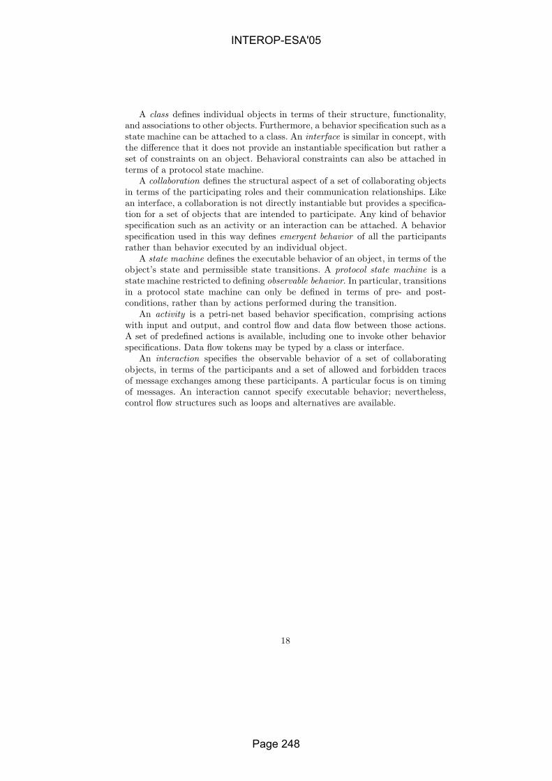
A class defines individual objects in terms of their structure, functionality,and associations to other objects. Furthermore, a behavior specification such as astate machine can be attached to a class. An interface is similar in concept, withthe difference that it does not provide an instantiable specification but rather aset of constraints on an object. Behavioral constraints can also be attached interms of a protocol state machine.
A collaboration defines the structural aspect of a set of collaborating objectsin terms of the participating roles and their communication relationships. Likean interface, a collaboration is not directly instantiable but provides a specifica-tion for a set of objects that are intended to participate. Any kind of behaviorspecification such as an activity or an interaction can be attached. A behaviorspecification used in this way defines emergent behavior of all the participantsrather than behavior executed by an individual object.
A state machine defines the executable behavior of an object, in terms of theobject’s state and permissible state transitions. A protocol state machine is astate machine restricted to defining observable behavior. In particular, transitionsin a protocol state machine can only be defined in terms of pre- and post-conditions, rather than by actions performed during the transition.
An activity is a petri-net based behavior specification, comprising actionswith input and output, and control flow and data flow between those actions.A set of predefined actions is available, including one to invoke other behaviorspecifications. Data flow tokens may be typed by a class or interface.
An interaction specifies the observable behavior of a set of collaboratingobjects, in terms of the participants and a set of allowed and forbidden tracesof message exchanges among these participants. A particular focus is on timingof messages. An interaction cannot specify executable behavior; nevertheless,control flow structures such as loops and alternatives are available.
18
INTEROP-ESA'05
Page 248

Quantitative Analysis of Enterprise
Architectures
Maria-Eugenia Iacob and Henk Jonkers
Telematica Instituut, P.O. Box 589, 7500 AN Enschede, the NetherlandsE-mail: {MariaEugenia.Iacob, Henk.Jonkers}@telin.nl
Abstract. Enterprise architecture is concerned with a description of allthe relevant elements that make up an enterprise and how these elementsinter-relate. It covers aspects ranging from the technical infrastructure,through software applications, to business processes and products. Therelations between these layers play a central role. Also from a quanti-tative analysis perspective, the layers are interrelated: the higher layersimpose a workload on the lower layers, while the performance charac-teristics of the lower layers directly influence the performance of thehigher layers. This paper presents an approach for quantitative analysisof layered, service-based enterprise architecture models, which consistsof two phases: a ‘top-down’ propagation of workload parameters, and a‘bottom-up’ propagation of performance or cost measures. By means ofan example we demonstrate the application of the approach, and showthat a seamless integration with other performance analysis methods(e.g., queueing analysis) can be achieved.
1 Introduction
An enterprise can be viewed as a complex ‘system’ consisting of multiple domainsthat influence each other. Architectures are used to describe components, theirrelations and underlying design principles of a system [10]. Constructing archi-tectures for an enterprise may help to, among others, increase the insight andoverview required to successfully align the business and ICT. Although the valueof architecture has been recognised by many organisations, mostly architecturesfor various organisational domains, such as business processes, applications, in-formation and technical infrastructure, are developed in isolation. The relationsbetween these architectures often remain unspecified.
Enterprise architecture is a discipline that focuses on making these relationsexplicit. The term refers to a description of all the relevant elements that makeup an enterprise and how those elements interrelate. Models play an importantrole in all approaches to enterprise architecture. Models are well suited to expressthe interrelations among the different elements of an enterprise and, especiallywhen visualised in different ways, they can help to reduce the language barriersbetween domains. However, currently they strongly focus on functional aspects.
In contrast to detailed design models within domains, the quantitative as-pects of such enterprise architecture models have hardly received any attention
INTEROP-ESA'05
Page 249

in literature. Nevertheless, quantitative properties are also important at the en-terprise architecture level. For example, “the business” imposes performancerequirements on the applications and technical infrastructure, while the perfor-mance characteristics of systems influence the quantitative behaviour of businessprocesses. The availability of global performance and cost estimates in the earlyarchitectural design stages can provide invaluable support for system design de-cisions, and prevent the need for expensive redesigns at later stages.
In this paper we present an approach for quantification and performanceanalysis of enterprise architectures. This approach is based on the propagation ofquantitative input parameters and of calculated performance measures througha service-oriented architectural model. It complements existing detailed perfor-mance analysis techniques (e.g., queueing analysis), which can be plugged in toprovide the performance results for the model elements.
2 State of the art in architecture performance analysis
As mentioned, enterprise architecture covers a wide range of aspects, from thetechnical infrastructure layer (e.g., computer hardware and networks), throughsoftware applications running on top of the infrastructure, to business processessupported by these applications. Within each of these layers, quantitative anal-ysis techniques can be applied, which often require detailed models as input.In this section, we will only be able to give a global impression of analysis ap-proaches for each of these layers.
We also noted earlier that enterprise architecture is specifically concernedwith how the different layers interoperate. Also from a quantitative perspectivethere is need for interoperability across layers: higher layers impose a workloadon lower layers, while the performance characteristics of the lower layers directlyinfluence the performance of the higher layers. However, techniques that coverquantitative analysis throughout this whole ‘stack’ hardly exist.
2.1 Infrastructure layer
Traditionally, approaches to performance evaluation of computer systems andcommunication systems [6] have a strong focus on the infrastructure domain.Queueing models, for example, describe the characteristics of the (hardware)resources in a system, while the workload imposed by the applications is capturedby an abstract stochastic arrival process. Also, a lot of literature exists aboutperformance studies of specific hardware configurations, sometimes extended tothe system software and middleware level. Most of these approaches have incommon that they are based on detailed models and require detailed input data.
2.2 Application layer
Performance engineering of software applications [18] is a much newer disciplinecompared to the traditional techniques described above. A number of papers
INTEROP-ESA'05
Page 250

consider performance of software architectures at a global level. Bosch and Grahn[1] present some observations about the performance characteristics of a numberof often-occurring architectural styles. Performance issues in the context of theSAAM method [14] for scenario-based analysis are considered in [15].
Another direction of research address the approaches that have been pro-posed to derive queuing models from a software architecture described in anarchitecture description language (ADL). The method described by Spitznageland Garlan [19] is restricted to a number of popular architectural styles (e.g.,the distributed message passing style but not the pipe and filter style). In [3]queueing models are derived from UML 2.0 specifications which, however, inmost cases do not have an analytical solution.
Compositionality is an important issue in architecture. In the context of per-formance analysis, compositionality of analysis results may also be a useful prop-erty. This means that the performance of a system as a whole can be expressedin terms of the performance of its components. Stochastic extensions of processalgebras [7] are often advocated as a tool for compositional performance analy-sis. However, these approaches tend to be fairly computation-intensive, becausethey still suffer from a state space explosion.
2.3 Business layer
Several business process modelling tools provide some support for quantitativeanalysis through discrete-event simulation. Also, general-purpose simulation toolsuch as Arena or ExSpect (based on high-level Petri nets) are often used forthis purpose. A drawback of simulation is that it requires detailed input data,and for inexperienced users it may be difficult to use and to correctly interpretthe results. Testbed Studio (http://www.bizzdesign.com/) offers, in addition tosimulation, a number of analytical methods. They include completion time andcritical path analysis of business processes [11] and queueing model analysis [13].Petri nets (and several of its variations) are fairly popular in business processmodelling, either to directly model processes or as a semantic foundation. Theyoffer possibilities for performance analysis based on simulation, as describedabove, but they also allow for analytical solutions (which are, however, fairlycomputation-intensive). Business process analysis with stochastic Petri nets isthe subject of, among others, [16].
3 The ArchiMate enterprise modelling language
Enterprise architecture refers to a consistent whole of principles, methods andmodels that are used in the design and realisation of organisational structure,business processes, information systems, and infrastructure. However, these do-mains are not approached in an integrated way, which makes it difficult to judgethe effects of proposed changes. Every domain speaks its own language, draws itsown models, and uses its own techniques and tools. Communication and decisionmaking across domains is therefore seriously impaired.
INTEROP-ESA'05
Page 251

In contrast to languages for models within a domain (e.g., the Unified Mod-elling Language, UML [17] for modelling applications and the technical infras-tructure, or the Business Process Modelling Notation BPMN [2] for modellingbusiness processes), a language for enterprise architecture should describe theelements of an enterprise at a relatively high level of abstraction, and should payparticular attention to the relations between these elements.
This line of thinking, towards integrated models, can also be recognised in theModel Driven Architecture (MDA) approach to software development [5]. MDAis a collection of standards of the Object Management Group (OMG) that raisethe level of abstraction at which software solutions are specified. Recently, OMGhas extended its focus to more business-oriented concepts and languages, to bedeveloped within the MDA framework. These developments make MDA just asrelevant for enterprise architecture as it is now for software development.
Following the principle of cross-domain integration, the ArchiMate project(http://archimate.telin.nl) concentrates on modelling, visualisation and analysisof architectures, providing architects with concepts, techniques and tools forarchitectural design. The development of an architecture language that picturevarious architectural domains and their relations forms the core of the project.Since the analysis technique we present in this paper was designed for ArchiMatemodels, we will first briefly introduce this modelling language.
As the basis for our analysis approach, we use a simplified version of theArchiMate enterprise modelling language. Figure 1 shows an informal represen-tation of the metamodel of this language with the main concepts and the rela-tions that they may have. They cover the business layer of an enterprise (e.g.,the organisational structure and business processes), the application layer (e.g.,application components) and the technical infrastructure layer (e.g., devices andnetworks), as well as relation betweens the layers. The language considers thestructural, behavioural and informational aspects within each layer. For a de-scription of the full language, we refer to [12].
In order to allow for the quantitative analysis of models expressed in thislanguage, attributes are added to quantify some of the concepts and relations.There can be attributes for both input parameters and analysis results, althoughthe distinction may not always be sharp: the result of one analysis phase maybe the input of a later analysis phase. In our approach we identify the specificquantitative attributes that we use for ArchiMate models.
4 Viewpoints on architecture performance
Architectures can be described from different viewpoints, which result in dif-ferent views on architectural models [10]. These views are aimed at differentstakeholders that have an interest in the modelled system. Also for the perfor-mance aspects of a system, a number of viewpoints can be discerned, resultingin different (but related) performance measures:
– User/customer view (stakeholders: customer; user of an applica-tion/system): response time, the time between issuing a request and receiving
INTEROP-ESA'05
Page 252
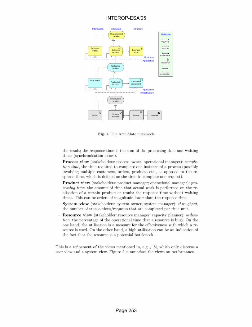
Businessactor
Applicationfunction
Businessobject
Artifact DeviceSystemsoftware
Network
Businessprocess
Information
Application
ApplicationInfrastructure
Data objectApplicationcomponent
Behaviour Structure
Business
triggering
used by
assignment
realisation
access
association
RelationsOrganisationalservice
Applicationservice
Infrastructureservice
Fig. 1. The ArchiMate metamodel
the result; the response time is the sum of the processing time and waitingtimes (synchronisation losses).
– Process view (stakeholders: process owner; operational manager): comple-tion time, the time required to complete one instance of a process (possiblyinvolving multiple customers, orders, products etc., as opposed to the re-sponse time, which is defined as the time to complete one request).
– Product view (stakeholders: product manager; operational manager): pro-cessing time, the amount of time that actual work is performed on the re-alisation of a certain product or result: the response time without waitingtimes. This can be orders of magnitude lower than the response time.
– System view (stakeholders: system owner; system manager): throughput,the number of transactions/requests that are completed per time unit.
– Resource view (stakeholder: resource manager; capacity planner): utilisa-tion, the percentage of the operational time that a resource is busy. On theone hand, the utilisation is a measure for the effectiveness with which a re-source is used. On the other hand, a high utilisation can be an indication ofthe fact that the resource is a potential bottleneck.
This is a refinement of the views mentioned in, e.g.,, [8], which only discerns auser view and a system view. Figure 2 summarises the views on performance.
INTEROP-ESA'05
Page 253

Process view Product view
Resource view System view
User view
Responsetime
Completiontime Processing
time
Utilisation Throughput
Fig. 2. Performance viewpoints
4.1 Integration of models and analysis results
As indicated in [12], one of the aims of the ArchiMate language is to provide away to integrate detailed design models expressed in languages such as BPMN[2] for the business layer or UML [17] for the application and infrastructurelayers. The ArchiMate model shows the global structure within each domainand the relations between the domains, and contains references to the designmodels for the details. Language and model integration also forms the basis oftool integration, as described in [21]. Since some modelling tools aimed at aspecific domain also offer quantitative analysis capabilities, we ultimately alsoaim for the integration of quantitative results: in that case, the detailed analysisresults are the input for quantitative analysis at the enterprise architecture level.A prerequisite for this is the compositionality of analysis results.
5 Analysis of enterprise architecture models
In this section we present our approach for the quantitative analysis of service-oriented models expressed in the ArchiMate language.
5.1 Model structure
The metamodel presented in Figure 1 shows that an architecture model displayssome regular structure. Such a model may be viewed as a hierarchy of “layers”.Within the global metamodel layers we can distinguish layers of two types: ser-vice layers and realisation layers. A service layer exposes external functionalitythat can be used by other layers, while a realisation layer models the realisationof services in a service layer. Thus, we can separate the externally observablebehaviour (expressed as services) from the complex internal organisation (con-tained within the realisation layers). Figure 6 shows an example of a layered viewof an ArchiMate model. Looking at the horizontal structure of the metamodel,we notice that realisation layers basically contain three types of elements. Theymight model some pieces of internal behaviour (expressed as processes, functionsor system software). Further, each behaviour element can access one ore moreobjects and it is assigned to exactly one resource (see Figure 3).
INTEROP-ESA'05
Page 254
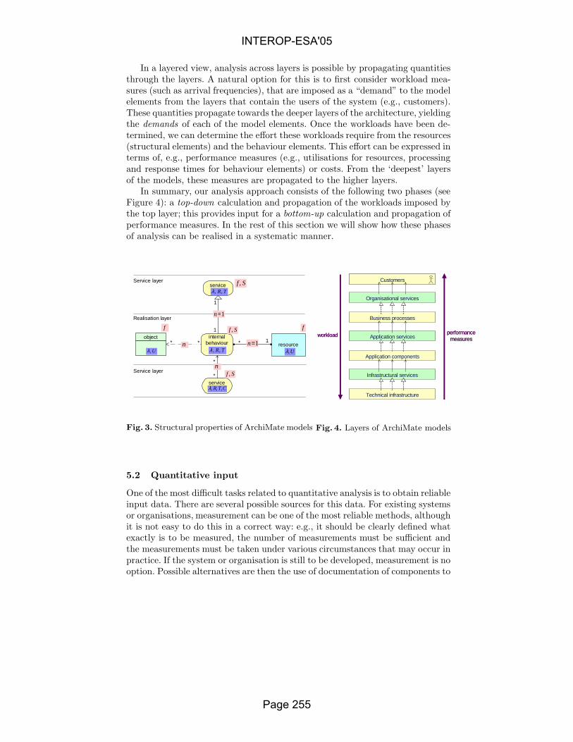
In a layered view, analysis across layers is possible by propagating quantitiesthrough the layers. A natural option for this is to first consider workload mea-sures (such as arrival frequencies), that are imposed as a “demand” to the modelelements from the layers that contain the users of the system (e.g., customers).These quantities propagate towards the deeper layers of the architecture, yieldingthe demands of each of the model elements. Once the workloads have been de-termined, we can determine the effort these workloads require from the resources(structural elements) and the behaviour elements. This effort can be expressed interms of, e.g., performance measures (e.g., utilisations for resources, processingand response times for behaviour elements) or costs. From the ‘deepest’ layersof the models, these measures are propagated to the higher layers.
In summary, our analysis approach consists of the following two phases (seeFigure 4): a top-down calculation and propagation of the workloads imposed bythe top layer; this provides input for a bottom-up calculation and propagation ofperformance measures. In the rest of this section we will show how these phasesof analysis can be realised in a systematic manner.
service
resource
service
1
1
1
*
*
object* *
internalbehaviour *
TR,,λ
CTR ,,,λ
U,λ
TR,,λ
U,λ
f Sf ,
Sf ,
Sf ,
f
1=n
1=n
nService layer
Service layer
Realisation layer
n
Fig. 3. Structural properties of ArchiMate models
workloadworkload performancemeasures
performancemeasures
Technical infrastructure
Infrastructural services
Application components
Application services
Business processes
Organisational services
CustomersCustomers
Fig. 4. Layers of ArchiMate models
5.2 Quantitative input
One of the most difficult tasks related to quantitative analysis is to obtain reliableinput data. There are several possible sources for this data. For existing systemsor organisations, measurement can be one of the most reliable methods, althoughit is not easy to do this in a correct way: e.g., it should be clearly defined whatexactly is to be measured, the number of measurements must be sufficient andthe measurements must be taken under various circumstances that may occur inpractice. If the system or organisation is still to be developed, measurement is nooption. Possible alternatives are then the use of documentation of components to
INTEROP-ESA'05
Page 255

be used, or to use estimates (e.g. based on comparable architectures). However,it often is very difficult to correctly interpret available numerical data, and toevaluate the reliability of the available data.
We assume that the following input is provided for analysis (see Figure 3):
– For any ’used by’ and ’access’ relation e a weight ne, representing the averagenumber of uses/accesses. For any ’realisation’ and ’assignment’ relation, weset ne = 1: they represent a 1-to-1 mappings of a behaviour element to aservice and to a resource, respectively.
– For any behaviour element a, a service time Sa representing the time spentinternally for the realisation of a service (excluding the time spent waitingfor supporting services). Since a service represents the externally observablebehaviour of a behaviour element a, we may assume that it inherits theservice time from the behaviour element that realises it. Therefore, we leavethe choice of specifying this input value for either one of these nodes.
– For any resource r a capacity Cr. By default Cr = 1.– For any node a, an arrival frequency fa. Typically, arrival frequencies are
specified in the top layer of a model, although we do allow for the specifica-tion of arrival frequencies for any node in the model.
5.3 Quantitative results:
The goal of our approach is to determine the following performance measures(see Figure 3):
– the workload (arrival rate) λa for each node a. (Provided that no resourcesare overloaded, the throughput for each node is equal to its arrival rate.)
– the processing time Ta and the response time Ra, for each behaviour elementor service a
– the utilisation Ur, for each resource r.
5.4 Analysis
To derive performance measures, given the inputs, we proceed in three steps:
1. We first ”normalise” the model, using model transformations, in order togenerate a model that conforms to the structure presented in Figure 3.
2. Top-down calculation of workloads (arrival rates) λ.3. Bottom-up computation of performance measures T , U and R.
Step 1: Model normalisation. Typical ArchiMate models do often not fullyconform to the ArchiMate metamodel. This is due to the fact abstraction rulesmay be used to create simplified views on the architecture. These abstractionshave a formal basis in an operator that has been derived for the compositionof relations (see [20] for the details). For instance, a ‘realisation’ relation with aconsecutive used by’ relation may be replaced by a new ‘used by’ relation thatshort-circuits a service.
INTEROP-ESA'05
Page 256

The first step in our approach is a model transformation, deriving a nor-malised version of the input model. The normalised model conforms to thestructure described in Figure 3. Since some concepts and relations are irrel-evant for our approach, normalisation starts with eliminating them from themodel. The remaining model will then be subjected to a series of transforma-tions steps, an example of which is given in Figure 5. There is a limited setof transformation rules, which has been determined in a rather straightforwardmanner. The application of these rules eventually leads to the normalised model.Because model normalisation is not the primary focus of this paper, we omit aformal description of the normalisation algorithm.
The following two steps will be applied to the resulting normalised model.
Resource A
Resource B
Resource B
Resource A
Service B
Internalbehaviour A
Internalbehaviour B
Fig. 5. Example of a normalisation step
Step 2: Top-down workload calculation. For a normalised model, we cancalculate the arrival rate for any node a with the following recursive expression:
λa = fa +d+
a∑
i=1
na,kiλki , (1)
where d+
a denotes the out-degree of node a and ki is a child of a. In other words,the arrival rate for a node is determined by adding the requests from higherlayers to the local arrival frequency fa.
Step 3: Bottom-up performance calculation. Once the workloads onthe various model components have been calculated, we can proceed with thebottom-up calculation of the performance measures. The approach is similar tothe top-down approach. We focus here on the bottom-up propagation of perfor-mance measures. The following recursive expressions apply:
– The utilisation of any resource r is Ur = 1
Cr
dr∑i=1
λkiTki , where dr is the number
of internal behaviour elements ki to which the resource is assigned.
INTEROP-ESA'05
Page 257

– The processing time and response time of a service a coincide with thesemeasures for the internal behaviour element realising it, i.e.: Ta = Tk andRa = Rk, where (k, a) is the realisation relation with a as end point. (Theservice merely exposes the functionality of the internal behaviour element tothe environment: there is no additional time consumption).
– The processing time and response time of an internal behaviour element ais computed using the following recursive formulas:
Ta = Sa +d−
a∑
i=1
nki,aRki Ra = F (a, ra) (2)
where d−a denotes the in-degree of node a, ki is a parent of a and ra is theresource assigned to a and F is the response time expressed as a function ofattributes of a and ra.
For example, if we assume that the node can be modelled as an M/M/1 queue[6], this function is
F (a, ra) =Ta
1 − Ura
(3)
We can replace this by another equation in case other assumptions apply: e.g.,the Pollaczek-Khinchine formula for an M/G/1 if Ta has a non-exponential dis-tribution, or the solution for an M/M/n queue based on the Erlang C formulafor a structural element with a capacity greater than 1:
Ra = Ta +Ta
1 − Ura
· (CraUra)Cra
(CraUra)Cra + Cra !(1 − Ura)Cra−1∑
j=0
(CraUra )j
j!
(4)
In most cases, this will lead to approximate results because the queueingnetworks are not separable [6]. At the enterprise architecture level, where we aregenerally interested in global performance estimates, we expect such approxi-mations to be good enough. We might even consider more global solutions, e.g.operational performance bounds [4]. In case more precise results would be re-quired, instead of simple queueing formulas, more detailed techniques such assimulation can be applied in combination with our approach.
6 Example
In this section we give an example to illustrate the analysis approach describedin the previous section. Consider an insurance company that uses a documentmanagement system for the storage and retrieval of damage reports. We assumethat the document management system is a centralised system, used by multipleoffices throughout the country, which means that it is quite heavily used. Weshow how performance measures of this system, including resource utilisations
INTEROP-ESA'05
Page 258
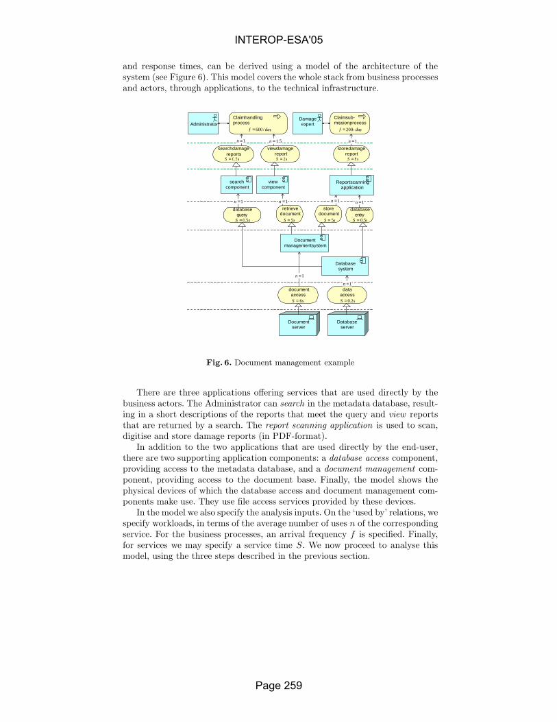
and response times, can be derived using a model of the architecture of thesystem (see Figure 6). This model covers the whole stack from business processesand actors, through applications, to the technical infrastructure.
Claim handlingprocess
Claim sub-mission process
search damagereports
view damagereport
store damagereport
Report scanningapplication
searchcomponent
viewcomponent
databasequery
storedocument
retrievedocument
databaseentry
Databasesystem
Documentmanagement system
Databaseserver
Documentserver
documentaccess
dataaccess
DamageexpertAdministrator
dayf /600= dayf /200=
1=n 5.1=n 1=n
sS 5.0= sS 2= sS 8=
1=n 1=n 1=n 1=n
sS 5.0= sS 5.0=sS 5= sS 5=
1=n
1=n
sS 2.0=sS 6=
Fig. 6. Document management example
There are three applications offering services that are used directly by thebusiness actors. The Administrator can search in the metadata database, result-ing in a short descriptions of the reports that meet the query and view reportsthat are returned by a search. The report scanning application is used to scan,digitise and store damage reports (in PDF-format).
In addition to the two applications that are used directly by the end-user,there are two supporting application components: a database access component,providing access to the metadata database, and a document management com-ponent, providing access to the document base. Finally, the model shows thephysical devices of which the database access and document management com-ponents make use. They use file access services provided by these devices.
In the model we also specify the analysis inputs. On the ‘used by’ relations, wespecify workloads, in terms of the average number of uses n of the correspondingservice. For the business processes, an arrival frequency f is specified. Finally,for services we may specify a service time S. We now proceed to analyse thismodel, using the three steps described in the previous section.
INTEROP-ESA'05
Page 259

Step 1: Model normalisation. We first derive a normalised model that iscompliant with the modelling rules described in Figure 3. Figure 7 shows thenormalised version of the model in Figure 6. The input parameters for the work-load on the ‘used by’ relations are the same as in the original model. The servicetimes are now transferred also to the inserted internal behaviour elements.
Claim handlingprocess
Claim submisstionprocess
search damagereports
view damagereport
store damagereport
Reportscanning
application
searchcomponent
viewcomponent
databasequery
storedocument
retrievedocument
databaseentry
Databasesystem
Documentmanagement
system
Databaseserver
Documentserver
documentaccess
dataaccess
DamageexpertAdministrator
Businesslayer
Applicationlayer
Infrastructurelayer
dayf /600= dayf /200=
1=n 5.1=n 1=n
1=n 1=n1=n
1=n
1=n 1=n
1=n 1=n
sS 5.0= sS 2= sS 8=
sS 5.0= sS 5.0=sS 5= sS 5=
sS 2.0=sS 6=
sS 5.0=
sS 5= sS 5=
sS 5.0=
sS 2.0=sS 6=
sS 8=sS 2=sS 5.0=
Fig. 7. Normalised model
Step 2: Top-down workload analysis. Table 1 shows the workload for theservices s in the model, in terms of the arrival rates λs. The arrival rates dependon the frequencies of the customer input requests and the cardinalities n of the‘used by’ relations. The table also shows the scaled arrival rates expressed inarrivals/second (assuming that systems are operational eight hours per day).
Step 3: Bottom-up performance analysis. Table 1 shows the performanceresults for the example model, i.e., the processing and response times for the ser-vices and the utilisations for the resources at the application and infrastructurelayer (we assume that the business layer is only relevant because it provides theinput for the workloads; however, the performance results can easily be extendedto the business layer).
For simplicity, we assume Poisson arrivals and exponentially distributed ser-vice times in this example, so that every structural element a can be modelled asan M/M/1 queue [6]. The response time function is then given in equation (3).
INTEROP-ESA'05
Page 260

Resource (r) Service (s) λs Ts Rs Ua
(sec−1) (sec) (sec)Doc. srv. doc. acc. 0.0382 6.0 7.8 0.229DB srv. data acc. 0.0278 0.2 0.2 0.006Doc.mgt. sys. retr. doc. 0.0313 12.8 25.0 0.488Doc.mgt. sys. store doc. 0.0069 12.8 25.0 0.488DB syst. DB query 0.0278 0.7 0.7 0.019DB syst. DB entry 0.0069 0.7 0.7 0.019Search comp. search rep. 0.0278 1.2 1.2 0.025View comp. view rep. 0.0313 27.0 174.0 0.843Rep. scanning store rep. 0.0069 33.7 44.0 0.234
Table 1. Workloads and performance results
The results show that queueing times from the lower layers accumulate in thehigher layers, resulting in response times that are orders of magnitude greaterthan the local service times. E.g., the ‘view’ component of the ‘claim handlingsupport’ application has a utilisation of over 84%, which results in a responsetime of the ‘view damage report’ application service of almost 3 minutes.
Using our approach, it is easy to study the effect of input parameter changeson the performance. For example, Figure 8 shows how the response time of theView component depends on the arrival frequency associated with the Adminis-trator (assuming a fixed arrival frequency for the Damage expert). The maximumarrival frequency, which results in a utilisation of the View component of 100%,is 651 arrivals per day. In the design stage these results may help us to decide,e.g., if an extra View component is needed.
0
50
100
150
200
250
300
350
0 100 200 300 400 500 600 700
R(V
iew
com
pone
nt)
f(Administrator)
Fig. 8. Arrival rate vs. response time
7 Conclusions and future work
Although the importance of enterprise architecture modelling has been recog-nised, hardly any attention has been paid to the analysis of their quantitativeproperties. Most existing approaches to performance evaluation focus on detailed
INTEROP-ESA'05
Page 261

models within a specific domain. In this paper we demonstrated the applicabilityof quantitative modelling and analysis techniques for the effective evaluation ofdesign choices at the enterprise architectures level. We discerned a number ofarchitecture viewpoints with corresponding performance measures, which can beused as criteria for the optimisation or comparison of such designs.
We introduced a new approach for the propagation of workload and perfor-mance measures through an enterprise architecture model. This can be used asan analysis framework where existing methods for detailed performance analy-sis, based on, e.g., queueing models, Petri nets or simulation, can be pluggedin. The presented example illustrates the use of our top-down and bottom-uptechnique to evaluate the performance of a document management system forthe storage and retrieval of damage reports. Using a simple queueing formulafor the response times, we showed that queueing times from the lower layers ofthe architecture accumulate in the higher layers, which results in response timesthat are orders of magnitude greater than the local service times. A prototypehas been developed for further illustration and validation of the approach.
Several improvements and extensions to the approach are conceivable. Forexample, in [9] we show that our “vertical” approach to calculate and propagateworkloads and performance measures could also be combined with “horizon-tal” analysis techniques to evaluate, e.g., critical paths and completion timesin business processes [11]. Finally, for a further integration of architecture de-sign process, combining quantitative analysis with functional analysis approaches(e.g., “impact of change” analysis based on quantitative results) or visualisationtechniques could be fruitful.
Acknowledgement
This paper results from the ArchiMate project (http://archimate.telin.nl). TheArchiMate consortium consists of ABN AMRO, Stichting Pensioenfonds ABP,the Dutch Tax and Customs Administration, Ordina, Telematica Instituut, Cen-trum voor Wiskunde en Informatica, Radboud Universiteit Nijmegen, and theLeiden Institute of Advanced Computer Science.We would like to thank Renevan Buuren, Timber Haaker and Hugo ter Doest for their useful remarks thathelped to improve our approach.
References
1. J. Bosch and H. Grahn. Characterising the performance of three architecturalstyles. In Proceedings First International Workshop on Software and Performance,Santa Fe, NM, Oct. 1998.
2. Business Process Management Initiative. Business process modeling notation.working draft (1.0), Aug. 2003.
3. A. Di Marco and P. Inverardi. Compositional generation of software architectureperformance QN models. In J. Magee, C. Szyperski, and J. Bosch, editors, Pro-ceedings Fourth Working IEEE/IFIP Conference on Software Architecture, pages37–46, Oslo, Norway, June 2004.
INTEROP-ESA'05
Page 262

4. D. Eager and K. Sevcik. Bound hierarchies for multiple-class queueing networks.Journal of the ACM, 33:179–206, Jan. 1986.
5. D. Frankel. Model Driven Architecture : Applying MDA to Enterprise Computing.John Wiley & Sons, 2003.
6. P. Harrison and N. Patel. Performance Modelling of Communication Networks andComputer Architectures. Addison-Wesley, 1992.
7. H. Hermanns, U. Herzog, and J.-P. Katoen. Process algebra for performance eval-uation. Theoretical Computer Science, 274(1–2):43–87, Mar. 2002.
8. U. Herzog. Formal methods for performance evaluation. In Lectures on FormalMethods and Performance Analysis: First EEF/Euro Summer School on Trends inComputer Science (LNCS 2090), pages 1–37. Springe Verlag, 2001.
9. M.-E. Iacob and H. Jonkers. Quantitative analysis of enterprise architectures. Tech-nical Report ArchiMate D3.5b, Telematica Instituut, Enschede, the Netherlands,Mar. 2004.
10. IEEE Computer Society. IEEE standard 1471-2000: Recommended practice forarchitectural description of software-intensive systems, 2000.
11. H. Jonkers, P. Boekhoudt, M. Rougoor, and E. Wierstra. Completion time andcritical path analysis for the optimisation of business process models. In M. Obai-dat, A. Nisanci, and B. Sadoun, editors, Proceedings of the 1999 Summer ComputerSimulation Conference, pages 222–229, Chicago, IL, July 1999.
12. H. Jonkers, M. Lankhorst, R. van Buuren, S. Hoppenbrouwers, M. Bonsangue, andL. van der Torre. Concepts for modelling enterprise architectures. InternationalJournal of Cooperative Information Systems, 13(3), Sept. 2004.
13. H. Jonkers and M. van Swelm. Queueing analysis to support distributed sys-tem design. In Proceedings of the 1999 Symposium on Performance Evaluationof Computer and Telecommunication Systems, pages 300–307, Chicago, IL, July1999. M.S. Obaidat and M. Ajmone Marsan.
14. R. Kazman, L. Bass, G. Abowd, and M. Webb. SAAM: A method for analyzing theproperties of software architectures. In Proceedings 16th International Conferenceon Software Engineering, pages 81–90, Sorento, Italy, 1994.
15. C.-H. Lung, A. Jalnapurkar, and A. El-Rayess. Performance-oriented softwarearchitecture analysis: An experience report. In Proceedings First InternationalWorkshop on Software and Performance, Santa Fe, NM, Oct. 1998.
16. A. Schomig and H. Rau. A petri net approach for the performance analysis ofbusiness processes. Technical Report 116, Lehrstuhl fur Informatik III, UniversitatWurzburg, 1995.
17. K. Scott. Fast Track UML 2.0. Apress, 2004.18. C. Smith. Performance Engineering of Software Systems. Addison-Wesley, 1990.19. B. Spitznagel and D. Garlan. Architecture-based performance analysis. In Proceed-
ings 1998 Conference on Software Engineering and Knowledge Engineering, SanFrancisco Bay, June 1998.
20. R. van Buuren, H. Jonkers, M.-E. Iacob, and P. Strating. Composition of rela-tions in enterprise architcture models. In H. Ehrig, G. Engels, F. Parisi-Presicce,and G. Rozenberg, editors, Graph Transformations – Proceedings of the SecondInternational Conference (LNCS 3256), pages 39–53, Rome, Italy, Sept. 2004.
21. D. van Leeuwen, H. ter Doest, and M. Lankhorst. A tool integration workbench forenterprise architecture. In Proceedings 6th International Conference on EnterpriseInformation Systems, Porto, Portugal, Apr. 2004.
INTEROP-ESA'05
Page 263

Mapping Specification in MDA:From Theory to Practice ?
Denivaldo Lopes1,2, Slimane Hammoudi1,Jean Bezivin2, and Frederic Jouault2,3
1 ESEO, France2 Atlas Group, INRIA and LINA, University of Nantes, France
3 TNI-Valiosys, France{dlopes, shammoudi}@eseo.fr
{Jean.Bezivin, Frederic.Jouault}@lina.univ-nantes.fr
Abstract. In this paper, we present a metamodel for supporting themapping specification between two metamodels. A mapping model basedon this proposed metamodel defines correspondences between elementsfrom two metamodels. It can then be used to generate a transformationdefinition, e.g. using Atlas Transformation Language (ATL). This meta-model is based on the Eclipse Modeling Framework (EMF). A plug-infor Eclipse implements this metamodel for mapping with the aim of pro-viding a tool for supporting mapping specification and for generating thetransformation definition.
1 Introduction
Recently, the Object Management Group (OMG) has stimulated and promotedthe adoption of the Model Driven Architecture (MDATM )4 [1] approach fordeveloping large and complex software systems. In this approach, models becomethe hub of development, separating platform independent characteristics (i.e.Platform-Independent Model - PIM) from platform dependent characteristics(i.e. Platform-Specific Model - PSM).
The MDA approach aims to provide an architecture with which complex soft-ware systems (such as B2B applications on the Internet) can evolve for meetingnew requirements or new technologies, business logic is protected against thechanges in technologies, and legacy systems are integrated and harmonized withnew technologies. However, before that becomes a mainstream reality, severalissues in MDA approach need solutions, such as mapping, transformation [2],handling of semantic distance between metamodels [3], bidirectional mapping[4], and so on.
In this paper, we limit our objectives to providing some insights into map-ping specification and transformation definition. We propose a metamodel for? This work has been done in the context of the INTEROP European Network of
Excellence.4 MDATM is a trademark of the Object Management Group (OMG).
INTEROP-ESA'05
Page 264

mapping and a tool for editing mapping models based on this metamodel. After-wards, we can use this tool to generate transformation definition. Our approachis implemented through a tool using a plug-in for Eclipse [5].
This paper is organized in the following way. Section 2 is an overview ofMDA. Section 3 presents our approach for mapping two metamodels within thecontext of MDA. Section 4 shows the implementation of our proposed metamodelfor mapping through a plug-in for eclipse. Section 5 contains conclusions andpresents the future directions of our research.
2 Overview
Some areas, such as civil and electrical engineering, have assimilated the im-portance of models. In these areas, the model predates the building. Moreover,in some countries, it is impossible to start a building without its models (i.e.an electrical and civil engineering project). Models are largely used during thebuilding, and then for maintenance, for modification (i.e. evolution) and forcriminal investigation (such as police investigation in the case of a building thatcrumbles). In fact, we have much to learn from good practice in other areas. Attimes, we need to develop more the discipline of model engineering in computerscience and its use in software enterprises.
For a long time, modeling languages, such as UML, were only used for docu-menting software systems, but nowadays models become the impetus for softwaredevelopment thanks to the MDA approach.
MDA is based on an architecture with four meta-layers: metametamodel,metamodel, model and information (i.e. an implementation of its model). Inthis approach, everything is a model or a model element, and a high level ofabstraction and comprehension about a problem and its solution are provided.
The MDA approach has been accepted by companies, universities, govern-ments and organizations as a potential solution for the problem of complexity inthe development and maintenance of software systems. The period of skepticismabout MDA seems to be over. Several case studies have demonstrated some ben-efits of the MDA approach, such as gain in productivity and protection againsterror-prone factors linked with manual programming [6]. Other possible benefitsof MDA include:
– an increase in the return on investments in technology.– a uniform approach for business models and for technologies to evolve to-
gether.– an architecture ready for handling the problems of yesterday, today and
tomorrow; and for integrating old, current and new technologies used insoftware development [7].
Several potential benefits need time to be demonstrated. However, the MDAapproach has been used with success in some projects such as the case studypresented at [6].
INTEROP-ESA'05
Page 265

Before reaching a stage comparable to civil and electrical engineering, theMDA approach needs to be more developed and experimented. Recently, someinitiatives have contributed to enhancing MDA, such as some response [8] [9] tothe RFP-QVT [2] and the creation of tools for implementing the concepts aroundMDA [10] [11] [12] [13]. Among these initiatives, we call attention to the eclipseprojects based on the concepts of MDA, such as Eclipse Modeling Framework(EMF) [10] developed under an open source philosophy. This project providedthe basis for researchers to develop and implement their ideas and contributionson software engineering. Our aim is to contribute to this project providing anapproach for mapping specification and transformation definition.
In fact, the transformation of a PIM into a PSM is a process [7]. Here, weextend this process, separating mapping specification and transformation defini-tion. This new proposed process involves several entities: a metametamodel (suchas MOF and Ecore), a source and target metamodel (such as UML), a sourceand target model, a mapping model, a transformation language model (such asa model based on the ATL [14] and YATL [15] metamodel), and a transforma-tion engine. Mapping model specifies correspondences between the source andtarget metamodel. A transformation model is generated from a mapping model.A transformation program is based on its transformation model. The transfor-mation is achieved by a transformation engine that executes a transformationprogram. The transformation engine takes a source model, executes the trans-formation program, and provides a target model as output. Figure 1 depicts thetransformation process, relating each involved entity.
In this paper, we use the term mapping as a synonym for correspondencebetween the elements of two metamodels, while transformation is the activityof transforming a source element into a target element in conformity with thetransformation definition. Following these two concepts, the mapping specifica-tion precedes the transformation definition. Figure 2 presents three categories ofmapping: one-to-one, one-to-many and many-to-one. This classification is basedon the concept of similar structure and semantics between the elements of meta-models. Two or more elements from two metamodels present similar structureand semantics, if the target element(s) can represent the same information con-tained in the source element(s).
A one-to-one mapping is characterized by one element from a target metamo-del that may represent the similar structure and semantics of one element froma source metamodel. A one-to-many mapping is characterized by a non-emptyand non-unitary set of elements from a target metamodel that presents similarsemantics to one element from a source metamodel. A many-to-one mappingis characterized by an element from a target metamodel that presents similarsemantics to a non-empty and non-unitary set of elements from a source meta-model. This last mapping is not directly implemented in some languages suchas ATL, but it can be simulated using a transformation rule that takes only oneelement from the source metamodel and determines the other elements based onthe relationships between the first element with the others.
INTEROP-ESA'05
Page 266

MMM
mapping MM
source MM target MM
mapping Mtransformation MM
transformation M
source M target Mtransformation engine
transformation programbasedOnbasedOn
execsource target
basedOn
left right
basedOn
basedOn
basedOnbasedOn
generatedFrom
basedOn
MM : metamodel M : modelMMM : metametamodel
basedOn
Fig. 1. Transformation Process in MDA
Several research projects have studied the specification of mapping betweenmetamodels [16] [17] [18]. However, the ideas around mapping are not sufficientlydeveloped to create efficient tools to enable automatic mappings.
3 Mapping
The creation of mapping specification and transformation definition is not aneasy task. In addition, the manual creation of mapping specification and trans-formation definition is a labor-intensive and error-prone process [19]. Thus thecreation of an automatic process and tools for enabling them is an importantissue. Some propositions enabling the mapping specification have been based onheuristics [18] (for identifying structural and naming similarities between mo-dels) and on machine learning (for learning mappings) [20]. Other propositionsenabling transformation definition have been based on graph theory [21]. Map-ping specification is not a new issue in computer science. For a long time, thedatabase domain has applied mappings between models (i.e. schema) and trans-formation from different conceptual models, e.g. entity-relationship (ER), intological or physical models (relational-tables and SQL schema). However, thesesame issues have taken a new dimension with the sprouting of MDA, becausemodels become the basis to generate software artifacts (including code) and inorder to transform one model into another model, mapping specification is re-quired. So, both mapping specification and transformation definition have beenrecognized as important issues in MDA [7].
INTEROP-ESA'05
Page 267

A1+attrA11 : Type1+attrA12 : Type2
B1+attrB11 : Type3+attrB12 : Type4
An+attrB1 : Typem+attrB2 : Typen
B1+attrB11 : Type3+attrB12 : Type4
A1+attrA11 : Type1+attrA12 : Type2
B1+attrB11 : Type3+attrB12 : Type4
Bn+attrB21 : Typem+attrB22 : Typen
A1+attrA11 : Type1+attrA12 : Type2
Source Element Target ElementMapping
Csource
targetcorrespondence
A2B
A*2B
A2B*
(a)
(b)
(c)
Fig. 2. Categories of mappings: (a)one-to-one, (b)one-to-many and (c) many-to-one
In this section, we present our proposition for specifying mappings (i.e. cor-respondences between metamodels). This approach for mapping is based on ametamodel and implemented as a tool on Eclipse. This tool provides supportfor mapping, which is a preliminary step before the creation of a transformationdefinition, e.g. using Atlas Transformation Language (ATL) [14].
3.1 Foundation for mapping
Given M1(s)/Ma, M2(s)/Mb, and CMa→Mb/Mc, where M1 is a model of a sys-
tem s created using the metamodel Ma, M2 is a model of the same system screated using the metamodel Mb, and CMa→Mb
is the mapping between Ma
and Mb created using the metamodel Mc, then a transformation can be definedas the function Transf(M1(s)/Ma, CMa→Mb
/Mc) → M2(s)/Mb. In this section,we aim to detail CMa→Mb
/Mc. In general, Ma, Mb and Mc are based on thesame metametamodel which simplifies the mapping specification. For now, wecan define CMa→Mb
⊇ {Ma ∩Mb}, where ∩ is a binary operator that returns theelements of Ma and Mb which have equivalent structure and semantics.
INTEROP-ESA'05
Page 268

The process of identifying and characterizing inter-relationships betweenmetamodels is denominated schema matching [18]. In fact, mapping describeshow two metamodels 5 are related to each other. So, schema matching resultsin a mapping. According to model management algebra [22], a mapping is gene-rated using an operator called match which takes two metamodels as input andreturns a mapping between them.
The identification of inter-relationships between metamodels is generallybased on the structure of the metamodels. The structure of a metamodel isa consequence of relationships between its elements. These relationships relatetwo metamodel elements and have some characteristics such as kind. Generally,five relationship kinds can relate a model element to another model element [17]:Association, Contains, Has-a, Is-a, Type-of.
These relationship kinds can be formalized as follow:
– Association: A(a, b) means a is associated with b.– Contains: C(c, d) means container c contains d.– Has-a: H(e, f) means e has an f .– Is-a: I(g, h) means g is an h.– Type-of : T (i, j) means i is a type of j.
In [17], the authors propose the five cross-kind-implications:
– if T (q, r) and I(r, s) then T (q, s).– if I(p, q) and H(q, r) then H(p, r).– if I(p, q) and C(q, r) then C(p, r).– if C(p, q) and I(q, r) then C(p, r).– if C(p, q) and I(q, r) then H(p, r).
In [17], two models are defined equivalents “if they are identical after allimplied relationships are added to each of them until a fix point is reached”.Applying these relationship kinds and cross-kind-implications to metamodels,they can also be simplified and compared between them to find equivalences andsimilarities.
3.2 Eclipse Modeling Framework (EMF)
Eclipse Modeling Framework (EMF) is a modeling framework and code gene-ration facility for supporting the creation of tools and applications driven bymodels [10]. EMF represents the efforts of Eclipse Tools Project to take into ac-count the driven model approach. In fact, MDA and EMF are similar approachesfor developing software systems, but each one has different technologies. MDAwas first designed by OMG using MOF and UML, while EMF is based on Ecoreand stimulates the creation of specific metamodels.
EMF is a framework which meets the requirements of Domain-Specific Lan-guages (DSL) [3]. DSLs are defined by Steve Cook as “languages that instead of5 In our approach, we prefer employ the term metamodel in the definition of the term
mapping.
INTEROP-ESA'05
Page 269

being focused on a particular technological problem such as programming, data in-terchange or configuration, are designed so that they can more directly representthe problem domain which is being addressed” [3]. DSL presumes the existence ofmany metamodels, despite UML which is a general-purpose metamodel. MOFcan also be used for creating DSLs, but OMG has focused its efforts on theadoption of UML and UML profiles, to the detriment6 of specific metamodels.
Within the eclipse’s philosophy, EMF is one more plug-in that can be usedsuch as it is or extended by other plug-ins. In the context of Eclipse, plug-in isthe mechanism for extending the basic architecture of Eclipse with things thathave common or different purposes, where they share a common environment[23].
EClass
EAttribute
EReference
+containment : EBoolean
+lowerBound : EInt
+upperBound : EInt
EDataType
EClassifier ETypedElement
ENamedElement
+name : EString
EOperation
EParameter
EModelElement
EPackage
EStructuralFeature
0..1+eOpposite
+eAttributeType+eAttributes
0..*
0..*
+eReferences
+eSuperTypes0..*
+eReferenceType
0..1
+eType
+eOperation
+eParameters
0..*
+eContainingClass
0..*
+eOperations
0..*
+eAlIOperations
+ePackage
0..*+eClassifiers
0..*+eSuperTypes
0..*
+eContainingClass
+eOperations
+eAlIOperations
0..*
+eAttributeType0..*
+eAttributes
+eReferences
0..*+eReferenceType
+eOpposite0..1
Fig. 3. Ecore metamodel (fragment)
Figure 3 presents a fragment of Ecore metametamodel [10]. Ecore has somepoints in common with MOF, but the former is more simple than the latter7.In addition, the serialization of a metamodel based on Ecore is more clear andsimple than the similar metamodel based on MOF.
3.3 A metamodel for mappings
In order to define a mapping, we need a metamodel which enables:6 The OMG has provided a limited number of metamodels, such as UML and Enter-
prise Distributed Object Computing (EDOC).7 This comparison is made using MOF 1.4. However, MOF 2.0 (i.e. Essential MOF -
EMOF) is closer to Ecore.
INTEROP-ESA'05
Page 270

– identification of what elements have similar structures and semantics to bemapped.
– explanation of the evolution in time of the choices taken for mapping oneelement into another element.
– bidirectional mapping. It is desirable, but is often complex [4].– independence of model transformation language.– navigation between the mapped elements.
Figure 4 presents a metamodel for mapping specification.
Fig. 4. Metamodel for Mapping Specification
In this metamodel, we consider that a mapping can be unidirectional orbidirectional. In unidirectional mapping, a metamodel is mapped into anothermetamodel. In bidirectional mapping, the mapping is specified in both directions.Thus, we prefer to denominate two metamodels in a mapping as left or rightmetamodels.
This metamodel presents the following elements:
– Element is a generalization for the other elements.– Historic enables the explanation of the different choices taken for making
the mapping. It has the date of the last update, a note, and the number ofthe last version, and a collection of Definitions.
INTEROP-ESA'05
Page 271

– Definition is the main element and it contains all correspondences (i.e.Correspondence) between two metamodels (i.e. each correspondence has oneleft element and many right elements).
– Correspondence is used to specify the correspondence between two or moreelements, i.e. left and right element. The correspondence has a filter thatis an OCL expression. When bidirectional is false, a mapping is unidi-rectional (i.e. left to right), and when it is false it is bidirectional (i.e. inboth directions). It has two TypeConverters identified by typeconverterRL
and typeconverterLR. typeconverterRL enables the conversion of the ele-ments from a right metamodel into the elements from a left metamodel.typeconverterLR enables the conversion of the elements from a left metamo-del into the elements from a right metamodel. We need often specify onlythe typeconverterLR.
– Left is used to identify the left element of a mapping.– Right is used to identify the right element of a mapping.– MetaModelHandler is used to navigate into a metamodel. It has the infor-
mation necessary for accessing a metamodel participating in a mapping. Amapping is itself a model, and it must not interfere with the two metamodelsbeing mapped.
– ElementHandler enables access to the elements being mapped without chang-ing them.
– TypeConverter enables the type casting between a left and a right element. Ifone element of a left metamodel and another element of a right metamodelare equals, then the mapping is simple and direct. However, if one elementof a left metamodel and another element of a right metamodel are similar,then the mapping is complex and it is achieved using type converter, i.e. acomplex expression to adapt a left element to a right element.
4 A Plug-in for Eclipse
A tool supporting our proposed metamodel for mapping should provide:
– simplification for visualizing mappings. In order to specify a mapping, twometamodels are necessary. From experience, metamodels have generally aconsiderable number of elements and associations. So the visualization be-comes complex, putting two metamodels so large side by side and the map-ping in the center. A tool should allow the creation of views, navigation andencapsulation of details unnecessary for each mapping in order to facilitatethe visualization and comprehension of the mapping without modifying theinvolved metamodels.
– creation of transformation definition from mapping specification. A mappingspecification is a model itself, then it can also be transformed into anothermodel. For example, a mapping model can be transformed into a transfor-mation model.
INTEROP-ESA'05
Page 272

4.1 An illustrative example
Figure 5 presents our proposed tool to support mapping specification. This toolis denominated Atlas Model Weaver. In fact, mapping is a form of weaver [24].It was implemented as a plug-in for Eclipse that uses our proposed metamodelfor mapping (see sections 3.1 and 3.3).
Fig. 5. Atlas Model Weaver (AMW): support for mappings
This tool presents a first metamodel on the left side, a mapping model inthe center, and a second metamodel on the right. In this case, a fragment of theUML metamodel is mapped into a Java metamodel. In the bottom, the propertyeditor of mapping model is shown. A developer can use this property editor toset the properties of a mapping model.
According to figure 5, C2JC maps UML Class into Java JClass, mapping alsothe attributes such as name and visibility from Class into the correspondingattributes of JClass.
This tool simplifies the creation of mapping specification and provide someother features such as:
– verification of the conformity between a mapping model and our proposedmetamodel for mapping.
– transformation of mappings and metamodels into a simplified text represen-tation which makes them more understandable.
INTEROP-ESA'05
Page 273
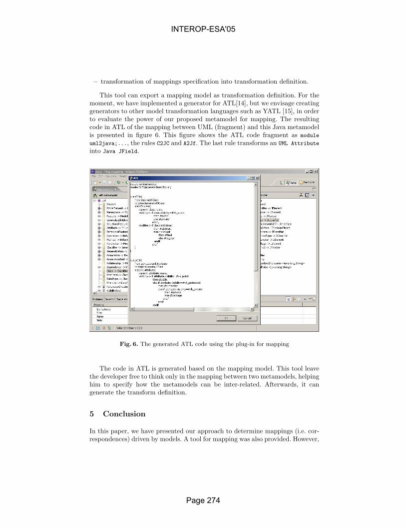
– transformation of mappings specification into transformation definition.
This tool can export a mapping model as transformation definition. For themoment, we have implemented a generator for ATL[14], but we envisage creatinggenerators to other model transformation languages such as YATL [15], in orderto evaluate the power of our proposed metamodel for mapping. The resultingcode in ATL of the mapping between UML (fragment) and this Java metamodelis presented in figure 6. This figure shows the ATL code fragment as module
uml2java;..., the rules C2JC and A2Jf. The last rule transforms an UML Attribute
into Java JField.
Fig. 6. The generated ATL code using the plug-in for mapping
The code in ATL is generated based on the mapping model. This tool leavethe developer free to think only in the mapping between two metamodels, helpinghim to specify how the metamodels can be inter-related. Afterwards, it cangenerate the transform definition.
5 Conclusion
In this paper, we have presented our approach to determine mappings (i.e. cor-respondences) driven by models. A tool for mapping was also provided. However,
INTEROP-ESA'05
Page 274

the schema matching [18], i.e. finding correspondences between models, was notsufficiently covered here, because in the current stage of our research, we con-centrated our efforts on taking into account mapping driven by models, defininga metamodel and tool for mapping.
If transformation is the heart of MDA, and to transform a PIM into a PSM,it is necessary to find correspondences between metamodels, then mapping spe-cification is also another important issue within MDA context.
MDA simplifies the development of software, but this is not obtained with-out effort. In fact, MDA allows developers to develop, maintain and evolve theirsystems encapsulating the complexity in models, model transformation, map-ping, and so on. Thus, what a developer must know in order to develop softwareartifacts with MDA is only the tip of the iceberg, i.e. models.
In future research, we will develop more fully the schema matching and theweaving technique in order to integrate them also into our plug-in for Eclipse.
References
1. OMG: Model Driven Architecture (MDA)- document number ormsc/2001-07-01.(2001)
2. OMG: Request for Proposal: MOF 2.0 Query/Views/Transformations RFP. (2002)Available at http://www.omg.org/docs/ad/02-04-10.pdf.
3. Cook, S.: Domain-Specific Modeling and Model Driven Architecture. MDA Journal(2004) 1–10
4. Kent, S., Smith, R.: The Bidirectional Mapping Problem. Electronic Notes inTheoretical Computer Sciences 82 (2003)
5. Eclipse Project: Eclipse (2004) Available at http://www.eclipse.org.6. Middleware Company: Model Driven Development for J2EE Utilizing a Model
Driven Architecture (MDA) Approach. Technical report, The Middleware Com-pany (2003) Available at www.middleware-company.com/casestudy.
7. Bezivin, J., Hammoudi, S., Lopes, D., Jouault, F.: Applying MDA Approachfor Web Service Platform. 8th IEEE International Enterprise Distributed ObjectComputing Conference (EDOC 2004) (2004)
8. Interactive Objects Software GmbH and Project Technology, Inc.: 2nd RevisedSubmission to MOF Query / View / Transformation RFP. (2004)
9. QVT-Merge Group: Revised submission for MOF 2.0Query/Views/Transformations RFP (ad/2002-04-10). (2004)
10. Budinsky, F., Steinberg, D., Merks, E., Ellersick, R., Grose, T.J.: Eclipse ModelingFramework: A Developer’s Guide. 1st edn. Addison-Wesley Pub Co (2003)
11. GMT: Generative Model Transformer Project (2004) Availa-ble at http://dev.eclipse.org/viewcvs/indextech.cgi/ checkout /gmt-home/description.html.
12. Java Community Process: JavaTMMetadata Interface(JMI) Specification, Version1.0. (2002)
13. netBeans.org: Metadata Repository (MDR) (2004) Available athttp://mdr.netbeans.org.
14. Bezivin, J., Dupe, G., Jouault, F., Pitette, G., Rougui, J.E.: First Experimentswith the ATL Model Transformation Language: Transforming XSLT into XQuery.2nd OOPSLA Workshop on Generative Techniques in the context of Model DrivenArchitecture (2003)
INTEROP-ESA'05
Page 275

15. Patrascoiu, O.: Mapping EDOC to Web Services using YATL. 8th IEEE Interna-tional Enterprise Distributed Object Computing Conference (EDOC 2004) (2004)
16. Jan Hendrick Hausmann, S.K.: Visualizing Model Mappings in UML. ProceedingsACM 2003 Symposium on Software Visualization (SOFTVIS 2003) (2003) 169–178
17. Pottinger, R.A., Bernstein, P.A.: Merging Models Based on Given Corresponden-ces. Proceedings of the 29th VLDB Conference (2003)
18. Rahm, E., Bernstein, P.A.: A Survey of Approaches to Automatic Schema Mat-ching. VLDB Journal 10 (2001) 334–350
19. Madhavan, J., Bernstein, P.A., Domingos, P., Halevy, A.Y.: Representing and Rea-soning about Mappings between Domain Models. Eighteenth National Conferenceon Artificial intelligence (AAAI’02) (2002) 80–86
20. Martin S. Lacher, G.G.: Facilitating the exchange of explicit knowledge throughontology mappings. 14th International FLAIRS conference (2001) 21–23
21. Agrawal, A., Levendovszky, T., Sprinkle, J., Shi, F., Karsai, G.: Generative Pro-gramming via Graph Transformation in the Model-Driven Architecture. OOPSLA2002 Workshop on Generative Techniques in the Context of Model Driven Archi-tecture (2002)
22. Bernstein, P.A.: Applying Model Management to Classical Meta Data Problems.Proceedings of the 2003 CIDR (2003)
23. Gamma, E., Beck, K.: Contributing to Eclipse: Principles, Patterns, and Plug-Ins.1st edn. Addison-Wesley Pub Co (2003)
24. Bezivin, J., Jouault, F., Valduriez, P.: First Experiments with a ModelWeaver.OOPSLA 2004 - Workshop on Best Practices for Model Driven Software Develop-ment (2004)
INTEROP-ESA'05
Page 276

Experiment in Model Driven Validation of BPEL Specifications
D.H.Akehurst
University of Kent at Canterbury [email protected]
Abstract. The Business Process Execution Language (BPEL) is an XML based language; the BPEL standard defines the structure, tags and attributes of an XML document that corresponds to a valid BPEL specification. In addition, the standard defines a number of natural language constraints of which some can be ambiguous and are complex. This paper uses the Unified Modelling Language (UML) and Object Constraint Language to provide a model of the XML based BPEL language. Based on this model the paper shows how OCL can be used to give a precise version of the natural language constraints defined in the BPEL standard. We then use this precise specification to generate a Validation tool automatically that can check that a BPEL document is well-formed.
1 Introduction The problems of interoperability can be viewed as having two aspects: one being
the matching of concepts and ontologies; the other being the problem of matching different technologies. In fact, most interoperability problems straddle this division, requiring both conceptual and technological compatibility to be addressed at the same time. If we can simplify one of these two aspects, we free up the engineering process to focus more fully on the other.
BPEL or BPEL4WS (Business Process Execution Language for Web Services) [4] is a language for specifying the Business Process logic that defines a choreography of interactions between a number of Web Services [9]. It is a technology that can be used to address aspects of interoperability between components that offer their services as Web Services. Although the language provides technical means to specify choreography patterns, it does not directly provide support for understanding the conceptual information associated with the related services. Making the use of this language as simple as possible via provision of good support tools will enable an engineer to focus on the conceptual issues rather than focusing on the difficulties of the language itself.
The BPEL4WS language is an XML based language and the BPEL standard defines the structure, tags and attributes of an XML document that corresponds to a valid BPEL specification. In addition to the precise specification of tag names and attributes, the standard defines a number of constraints on the way in which the XML elements should be put together. These constraints are given using natural language, which although being very descriptive is not always precise and some of the constraints are ambiguous. In addition some of the constraints are so complex that it is difficult to understand from the text what the constraint is actually saying; this leaves
- 1 of 15 -
INTEROP-ESA'05
Page 277

the possibility of creating what appears to be a valid XML BPEL document, which in actual fact violates one or more usage constraints.
This paper uses the Unified Modelling Language (UML) [8] and Object Constraint Language (OCL) [5] to provide a model of the XML based BPEL language. Based on this model the paper shows how OCL can be used to give a precise version of the natural language constraints defined in the BPEL standard.
The model and constraints are subsequently used to automatically generate a BPEL validation tool as a plug-in to IBM’s eclipse IDE. The plug-in uses the Eclipse Modelling Framework (EMF) [3] code generation facilities along with the OCL code generation tools developed at the University of Kent [2].
Section 2 of this paper gives an explanation of the Model Driven approach to constructing the validator. Section 3 shows the UML model of the BPEL language (a BPEL metamodel) that we use. Section 4 specifies (some of) the OCL constraints that correspond to natural language from the BPEL4WS standard. Section 5 discusses some of the more difficult issues involved in mapping the model and constraints to an implementation. The paper concludes in section 6.
2 Explaining the Approach Model Driven Development (MDD) or Model Driven Architecture (MDA) [7] is
an approach to software development in which the focus is on Models as the primary artefacts. Model Transformations are considered the primary operation on models, used to map information from one model to another. One of the simplest instantiations of MDD is the idea of code generation from UML models, which can be viewed as a transformation from the UML model to a Code model.
Code generation is not new and has been around for far longer than the recent activity surrounding MDD. What we consider to be of interest with regards to the work in this paper is the combination of code generation from models and code generation from constraints; with the resulting code facilitating the validation of the constraints against instances of the model. In particular, the model code and the constraint code are generated separately, see Figure 1.
Validator
BPEL model Constraints
EMF Kent OCL tools
Java Code
Java Code
Figure 1 Code Generation from Model and Constraints
- 2 of 15 -
INTEROP-ESA'05
Page 278
The work carried out in this paper is (as implied by the title) an experiment in using a modelling and constraint based approach to specifying the BPEL4WS language and automatically generating a tool that aids a user in writing valid BPEL specifications. This is different from the work described in [6] where UML is used as a language for writing BPEL specifications.
A set of UML Class Diagrams are created to model of the structural aspects of the BPEL language. We then use OCL as a mechanism for formally specifying constraints on instances of the model; these constraints on the model correspond to constraints on how elements of the BPEL language can be put together. A model constraint that fails would indicate an invalid combination of BPEL constructs.
OCL is a text based constraint language that has been officially part of the UML standard in recent versions. The language is based primarily on Set theory concepts and can be written using the ASCII character set. Although, defined initially as a “constraint” language the core expression part of OCL can also be used as an object-based Query Language.
3 BPEL Model The BPEL language, as described above, is defined as an XML document. In order
to write constraints using OCL we form a UML model that represents the structure of the BPEL XML document. The following figures illustrate part of the model, the rest can be found in the technical report [1]. The model of the BPEL language defined here is in accordance with the version 1.1 of the BPEL standard. There are however a few points to note regarding the modelling of the language:
• All yes/no options from the specification are mapped to Booleans; with ‘true’ representing ‘yes’.
• The BusinessProcess class extends the class Scope. There is a large overlap between the two classes (partly due to changes from version 1.0 to 1.1), and the extension simplifies the model. The BusinessProcess class now contains PartnerLinks, these were not part of the BPEL 1.0 specification.
• The notion of ‘imports’ to a business process have been added (for the purpose of this work) in order to aid the reading of BPEL specifications and their reference to other documents.
• An additional Layer has been added to the activity hierarchy. The StructuredActivity and BasicActivity classer partitions the activities into those that contain sub-activities and those that don’t. This helps with defining constraints to model the restrictions on links and the boundary crossing conditions.
• The class modelling the construct for a sequence of activities is renamed ActivitySequence (originally Sequence) as the original name clashes with the OCL type Sequence.
• PartnerLink is the version 1.1 replacement for the version 1.0 ServiceLinkType.
- 3 of 15 -
INTEROP-ESA'05
Page 279

ExtensibleElement(from wsdl)
Scope
Rolename : string
PartnerLinkTypename : QName
Partnername : String
getServiceLinkType()
PartnerLinkname : String
1..*
0..*
1..*
0..*
0..*
0..1
0..*
+myRole
0..1
0..*
0..1
0..*+partnerRole0..1
11
Import
namespaceURI : StringlocationURI : String
(from wsdl)
BusinessProcesstargetNamespace : StringqueryLanguage : StringexpressionLanguage : StringenableInstanceCompensation : Boolean = falseabstractProcess : Boolean = false
1 0..*1 0..*
0..*0..*
0..*0..*
Figure 2 Business Process
Receive
StructuredActivity
OnMessage OnAlarm
Activity
CatchfaultName : String
CorrelationSet FaultHandler
0..*0..*
EventHandler
11
Activity
0..1+catchAll
0..111
Variable
0..1 +faultVariable0..1
ScopevariableAccessSerializable : Boolean
0..*0..*0..10..1
1..*1..*
+eventScope
11 0..1+compensationHandler0..10..*0..*
must name this end as OnMessage inherits from both Activity and EventHadler, thus having two navigations to Scope.
Figure 3 Scope
- 4 of 15 -
INTEROP-ESA'05
Page 280

PartnerActivity
Invoke Receive
Wait
Reply
Terminate
Assign
Empty
Throw
While
ActivitySequence
Switch
Scope
Expression
exprBody : String
BooleanExpression
Compensate
Flow
StructuredActivity
TargetSourceActivity
name : StringjoinCondition : BooleanExpressionsuppressJoinFailure : Boolean = false
OnMessage
Pick
+ parent
0..1
+ targetOf
*
1+ sourceOf
*
1
Figure 4 Activity Hierarchy and Standard Parts
4 The Constraints The BPEL4WS standard contains approximately 20 natural language constraints
that we have mapped into OCL constraints on the BPEL metamodel. The full details of this work can be found in the technical report [1], in this paper we have room to show only a few. We start by showing a simple constraints, then move on through successively more complex (and interesting) constraints until the final one that effectively require us to construct a BPEL model checker.
The following subsections address successively more complex constraints. Each of the subsections give an extract from the BPEL standard, defining a natural language constraint on the use of the language, which is then expressed using OCL to give a more precise specification as a constraint on the UML model of BPEL. The later constraints of greater complexity require the definition of additional model properties; OCL, through the use of the ‘def’ context, enables us to give these definitions, which can subsequently be used to specify the required OCL expressions.
4.1 Partner definitions must not overlap The first constraint we look at is quite a simple constraint to define, however it
does highlight an interesting issue regarding the relationship between the structural model of the language, OCL constraints on that model, and the implementation policy.
“7.3 Business Partners
- 5 of 15 -
INTEROP-ESA'05
Page 281

… Partner definitions MUST NOT overlap, that is, a partner link MUST NOT appear in more than one partner definition.”
This constraint is a restriction on the connections between a ‘partner’ construct and a ‘partnerLink’ construct. These two constructs are represented in BPEL as sub elements of the top level ‘BusinessProcess’ element. E.g. the following two XML segments show a valid and an invalid process specification:
pr
ho[0to wepoto im
[0wiimnoins
violinasch
an
INTEROP-ESA'05
<process name="Invalid" ... <partner name="SellerShipper" xmlns="http:..."> <partnerLink name="Seller"/> <partnerLink name="Shipper"/> </partner> <partner name="Shipper"> <partnerLink name="Shipper" ... </process>
This constraint requires that the union of pocess is a Set; i.e. each partnerLink in that uWe could attempt to enforce this constrainwever; i.e. if we model the relationship b..1]-to-[0..*] association, this states that anya single partner and thus the above constra consider the generation of a BPEL validlicy is important; the structure of the XMLbe broken, so we must look at the process plementation of the BPEL model. A typical implementation of a [0..1]-to-[0..
..1] end if an object were added to the [0.thin the EMF implementation). So a nplementation of the partner and partnerLtification that the constraint was broken, it tances. For a BPEL validator, it is essential that nolated. So either, the mapping from XML tk between partner and partnerLink has notsociation as a [0..*]-to-[0..*] association aeck that the required uniqueness properties aAs can be seen by the UML diagrams abovd the necessary OCL constraint is given belocontext bpel::Process inv partnerDefinitionsMustNotOv let
- 6 of 1
Page 2
<process name="Valid" ... <partner name="SellerShipper" xmlns="http:..."> <partnerLink name="Seller"/> <partnerLink name="Shipper"/> </partner> <partner name="Shipper"> <partnerLink name="Shipper2" ... </process>
artnerLink objects from all partners in a nion is unique. t by the structure of the BPEL model, etween Partner and PartnerLink as an one partnerLink can only be associated int would not be violated. However, if ator, this is where the implementation language happily allows the constraint of mapping the XML document into an
*] association would simply update the .*] end (this is certainly what happens aïve mapping from XML to model ink constructs would not provide any would simply update the links between
tification is given that the constraint is o model instance should check that the already been set; or we can model the nd add an explicit OCL constraint to re met.
e, we have adopted the second approach w.
erlap :
5 -
82
x=self.partner.partnerLink in x->asSet()->asBag() = x->asBag()
As can be seen by this example, there is a balance to be made between constraining the BPEL language by the structural model and by constraining it using OCL constraints.
4.2 Instantiation of a Process This next constraint deals with the instantiation of a business process. This adds a
constraint to the first actions that are allowed to occur in the process as a whole, and thus require us to extract a set of possible ‘initial activities’ from the complete activity graph define in the specification.
“11.4. Providing Web Service Operations … The only way to instantiate a business process in BPEL4WS is to annotate a receive activity with the createInstance attribute set to "yes" (see 12.4. Pick for a variant). The default value of this attribute is "no". A receive activity annotated in this way MUST be an initial activity in the process, that is, the only other basic activities may potentially be performed prior to or simultaneously with such a receive activity MUST be similarly annotated receive activities.”
To check this constraint we first provide a property definition to extract the set of ‘initial activities’ for a BusinessProcess. The constraint is defined on ‘Scope’ a supertype of BusinessProcess to facilitate its reuse:
context bpel::Scope def: initialActivities : Set(bpel::Activity) = self.activity.initialActivities
This property definition simply states that the initial activities of a BusinessProcess (or Scope) construct are the initial activities of the Activity construct that it contains. Thus we must also define the property ‘initialActivities’ as a property of ‘Activity’ and override the property in all subclasses of Activity in order to specify the correct definition for each type of activity. For reasons of space these overriding definitions are not given here, and the reader is directed to the technical report for full details.
We also provide a property ‘process’ on class ‘Activity’ that returns the business process containing the activity.
context bpel::Activity def: process : bpel::BusinessProcess = if self.parent.oclIsUndefined() then self.oclAsType(bpel::BusinessProcess) else self.parent.process endif
Given the definition of these properties we can provide two invariants that check the natural language constraint given above:
context bpel::Receive inv allReceivesMarkedAsCreateInstanceMustBeInitial : self.createInstance implies self.process.initialActivities->includes( self )
- 7 of 15 -
INTEROP-ESA'05
Page 283

context bpel::BusinessProcess inv allInstantiationActivitiesAreMarkedCreateInstanceAsYes : self.instantiationActivities->forAll( act | act.oclIsTypeOf(bpel::Receive) and act.oclAsType(bpel::Receive).createInstance )
4.3 Link Control Cycles and boundary crossing Some of the most complex constraints to check manually are those that define the
use of Links within the Flow construct; i.e. those that check for boundary crossing conditions and control cycles. By using OCL to defining some additional (temporary) properties on the model we can construct OCL invariants that check the constraints.
Consider the following natural language constraints: “… Every link declared within a flow activity MUST have exactly one activity within the flow as its source and exactly one activity within the flow as its target. The source and target of a link MAY be nested arbitrarily deeply within the (structured) activities that are directly nested within the flow, except for the boundary-crossing restrictions. … In general, a link is said to cross the boundary of a syntactic construct if the source activity for the link is nested within the construct but the target activity is not, or vice versa, if the target activity for the link is nested within the construct but the source activity is not. … A link MUST NOT cross the boundary of a while activity, a serializable scope, an event handler or a compensation handler (see 13. Scopes for the specification of event, fault and compensation handlers).”
We can illustrate a specification with Links that do and don’t adhere to these constraints in Figure 5. The specifications are shown using a graphical notation rather than the XML syntax of BPEL as it is easier to see the links between activities in this manner. The arrows in the diagram represent links between activities. The top link is invalid as it crosses the boundary of a while activity; the lower link is valid.
INTEROP-ESA'05
Flow
Sequence Sequence
Activity
Activity
Activity
While
Activity
Activity
Figure 5 Links in a Flow Activity
- 8 of 15 -
Page 284
To express this constraint in OCL, we require a property subActivities to be defined for each subtype of Activity. The property returns a set containing all activities directly nested within that Activity. Also required is a property allSubActivities which returns all nested and sub-nested activities. For basic Activities this set will typically be empty. These properties are defined for each Activity subtype in the technical report, overriding the property defined on their common supertype Activity as shown here:
context bpel::Activity def: subActivities : Set(bpel::Activity) = Set{}
def: allSubActivities : Set(bpel::Activity) = self.subActivities ->union( self.subActivities.allSubActivities->asSet() )
The constraint requiring the source and target activity for each link of a flow to be contained within the flow can be expressed as follows:
context bpel_11::Flow inv sourceAndTargetActivitiesAreContainedWithinTheFlow : self.link->forAll( lnk | self.allSubActivities->includes( lnk.source.activity ) and self.allSubActivities->includes( lnk.target.activity ) )
We can subsequently test for boundary crossing violations on While, Scope and EventHandler constructs as follows:
context bpel::While inv boundryCrossing : self.allSubActivities->includesAll( self.allSubActivities.sourceOf.activity ) and allSubActivities->includesAll( self.allSubActivities.targetOf.activity )
context bpel::Scope inv boundryCrossing : not self.variableAccessSerializable.oclIsUndefined() implies (self.variableAccessSerializable implies self.allSubActivities->includesAll( self.allSubActivities.sourceOf.activity ) and self.allSubActivities->includesAll( self.allSubActivities.targetOf.activity ) )
context bpel::EventHandler inv boundryCrossing : self.activity.allSubActivities->includesAll( self.activity.allSubActivities().sourceOf.activity ) and self.activity.allSubActivities->includesAll( self.activity.allSubActivities().targetOf.activity )
Lastly, we check that links do not create control cycles in accordance with this natural language constraint:
- 9 of 15 -
INTEROP-ESA'05
Page 285

“… Finally, a link MUST NOT create a control cycle, that is, the source activity must not have the target activity as a logically preceding activity, where an activity A logically precedes an activity B if the initiation of B semantically requires the completion of A. Therefore, directed graphs created by links are always acyclic.”
This constraint requires us to construct expressions that enable navigation around a causality graph of the BPEL specification. To enable this we define properties that return the set of possible ‘next’ or ‘previous’ activities for any activity. Given the possibility to mix structured flow constructs (Switch, While, etc) with free form (Flow) constructs, it is not trivial to construct expressions that define ‘next’ and ‘previous’ properties.
If we define the property ‘next’, along with a transitive closure version ‘allNext’ that returns the set of all following activities, we can define a constraint that ensure links do not create control cycles as follows:
context bpel::Link inv noControlCycles : self.target.allNext->flatten()->excludes(self.source)
The complex part of this constraint is hidden in the expressions that form the ‘next’ properties, part of the definition for these properties is given below, the overriding versions for the other Activity subtypes can be found in the technical report:
context bpel::StructuredActivity def: next(prev:bpel::Activity) : Set(Activity) = Set{}
context bpel::Activity def: next : Set(bpel::Activity) = let x = self.parent.next(self) in if x->isEmpty() then self.parent.next else x endif
def: allNext : Sequence(Set(bpel::Activity)) = Sequence{Set{self}}->transitiveClosure(x|x.next->asSet())
context bpel::While def: next(prev:bpel::Activity) : Set(Activity) = self.activity.initialActivities ->union( self.parent.next )
Note here that we require a transitive closure operation in order to define the ‘allNext’ property. It would potentially be possible to manage without it; however the definition of ‘allNext’ would require the use of additional recursive operations and be more complex to define.
4.4 Correlations between Receive and Reply Activities By far the most complex constraints described using natural Language are those
that discuss the relationship between receive and reply activities that use the same correlation sets, operations and ports. A correlation set is a mechanism for identifying a particular instance of a remote statefull service. These constraints address the situation of receiving a message from just such a remote service and the subsequent
- 10 of 15 -
INTEROP-ESA'05
Page 286

reply to that service. They attempt to reduce the possibility of causing deadlocks and inconsistencies due to miss matching of receive-reply pairs.
The following is one of the constraints addressing this issue: “… The correlation between a request and the corresponding reply is based on the constraint that more than one outstanding synchronous request from a specific partner link for a particular portType, operation and correlation set(s) MUST NOT be outstanding simultaneously. The semantics of a process in which this constraint is violated is undefined. ...”
To construct an OCL constraint to check that this situation does not occur, it is necessary to form an expression that first collects the sequence of activities that may possibly follow a receive activity; we can potentially use the previously define ‘next’ and ‘allNext’ properties to do this. This sequence of following activities must then be searched for the first matching reply activity, and finally an expression needs to formed to check that no other matching receive activity occurs in-between the first receive activity and first subsequent matching reply activity. The following OCL invariant forms the required constraint:
context bpel_11::Receive inv noSimultaneousOutstandingSynchronousRequests : let request = self, actionSeq = self.allNext->flatten(), replySeq = actionSeq->select( a | a.oclIsTypeOf(bpel_11::Reply) ).oclAsType(Sequence(bpel_11::Reply)), reply = replySeq->select( r | r.portType= request.portType and r.operation = request.operation and r.correlation = request.correlation )->first(), replyIndex = actionSeq->indexOf(reply) in not actionSeq->subsequence(0,replyIndex) ->select(a|a.oclIsTypeOf(bpel_11::Receive)) .oclAsType(Sequence(bpel_11::Receive)) ->exists( rec | rec.portType= request.portType and rec.operation = request.operation and rec.correlation = request.correlation )
Unfortunately this constraint does not fully perform an accurate check. The semantics of the Link construct cause execution to block at the target of a link until the action at the source of a link has completed. The defined property ‘next’ on the Flow activity does not take into consideration the full link-semantics of the language; thus causing the constraint to falsely fail under conditions that are in actual fact not a problem. To provide a fully accurate check the definition of the ‘next’ property would need to take into consideration the blocking semantics of links between activities that are nested within a Flow activity. This would amount to providing a true flow analysis of the activity structure and although it may be possible to do this using OCL, the complexity of the expressions comes close to constructing a model checking algorithm, and we consider this to be outside the scope of appropriate use of OCL.
- 11 of 15 -
INTEROP-ESA'05
Page 287

4.5 getLinkStatus Function There are a couple of constraints in the BPEL standard that apply to the build in
function “bpws:getLinkStatus('linkName')”; e.g. “9.1 Expressions … [ bpws:getLinkStatus ('linkName') ] function MUST NOT be used anywhere except in a join condition. The linkName argument MUST refer to the name of an incoming link for the activity associated with the join condition. These restrictions MUST be statically enforced.”
To check this constraint using OCL it would require us to parse the contents of the ‘expression’ attribute on a number of BPEL constructs. We feel that to construct such a parsing algorithm using OCL would most definitely be inappropriate in the context of adding constraints to a structural model.
5 Generating a BPEL Validator It is all very well to draw a few diagrams containing boxes, lines and snippets of
text and then write constraints in a funny kind of ASCII compatible set theory – but what use is it?
Firstly, it does allow us to define unambiguously and precisely the usage constraints of the language.
Secondly, and even more usefully, we can automatically generate a validation tool that will check that the constraints have been adhered to, for any particular language expression (in this case, any particular BPEL document).
Using one of the UML (or MOF or ECORE) model to code automatic generation tools, such as the Eclipse Modelling Framework (EMF), we can quickly and easily generate a tool that supports a model based representation of a BPEL specification.
At the University of Kent we have developed an OCL library that operates in conjunction with EMF repositories to facilitate both the evaluation of OCL constraints and the generation of code that corresponds to an OCL constraint.
Thus, using these two tools (EMF and Kent OCL) the core code for a BPEL validator can be generated. The code can then be wrapped up to give the required user interface; for example we have wrapped up the validator as an eclipse plug-in, see Error! Reference source not found..
There are two mechanisms provided by the Kent OCL library for evaluating OCL expressions. There is an interpreter, that directly evaluates an expression and there is a code generation interface that converts the OCL expression into equivalent Java code. For the BPEL validator we use the Java code generation interface, as this allows the validator to be used independently from the OCL library. Constructing the BPEL validator has helped to develop the code generation facility of the Kent OCL library.
There are several issues worth drawing out regarding our experiences of mapping OCL expressions to Java code, in addition to the highlighting of inconsistencies in the specification of the OCL standard; below we discuss a couple of the more interesting OCL-to-Java issues.
The first issue we consider worth mentioning is the mapping of Boolean expressions between OCL and Java. The Java language uses true two-value Boolean logic, whereas the Boolean logic of OCL is actually based on three-value logic; i.e. true, false, and undefined. Providing a mapping from the three-value OCL to the two-
- 12 of 15 -
INTEROP-ESA'05
Page 288
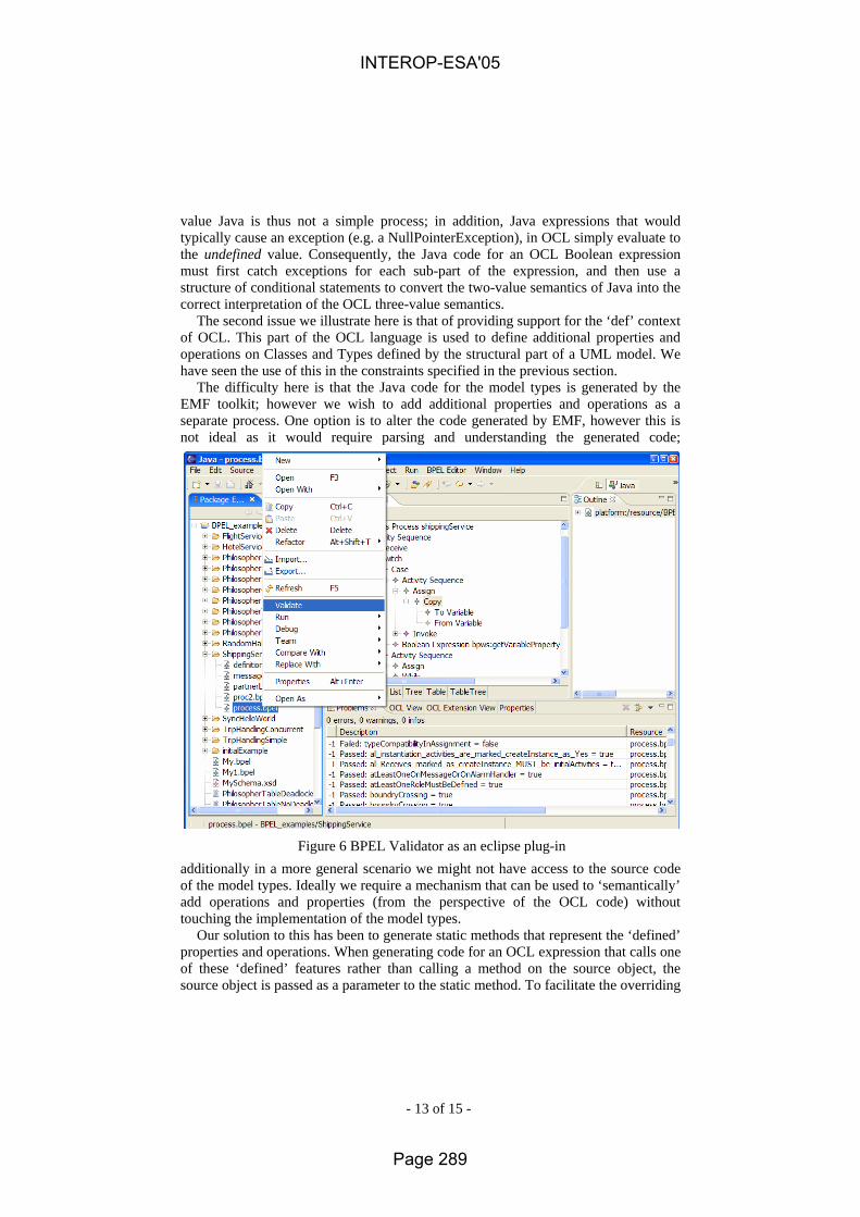
value Java is thus not a simple process; in addition, Java expressions that would typically cause an exception (e.g. a NullPointerException), in OCL simply evaluate to the undefined value. Consequently, the Java code for an OCL Boolean expression must first catch exceptions for each sub-part of the expression, and then use a structure of conditional statements to convert the two-value semantics of Java into the correct interpretation of the OCL three-value semantics.
The second issue we illustrate here is that of providing support for the ‘def’ context of OCL. This part of the OCL language is used to define additional properties and operations on Classes and Types defined by the structural part of a UML model. We have seen the use of this in the constraints specified in the previous section.
The difficulty here is that the Java code for the model types is generated by the EMF toolkit; however we wish to add additional properties and operations as a separate process. One option is to alter the code generated by EMF, however this is not ideal as it would require parsing and understanding the generated code;
INTEROP-ESA'05
Figure 6 BPEL Validator as an eclipse plug-in
additionally in a more general scenario we might not have access to the source code of the model types. Ideally we require a mechanism that can be used to ‘semantically’ add operations and properties (from the perspective of the OCL code) without touching the implementation of the model types.
Our solution to this has been to generate static methods that represent the ‘defined’ properties and operations. When generating code for an OCL expression that calls one of these ‘defined’ features rather than calling a method on the source object, the source object is passed as a parameter to the static method. To facilitate the overriding
- 13 of 15 -
Page 289

semantics, the static method itself is not called directly, but called via a special method that looks for a parameter match on the closest runtime type of the source object.
6 Conclusion In this paper we have shown the use of OCL and UML to provide a precise version
of natural language constraints on the structuring of BPEL XML documents. From these precise specifications of the constraints we can automatically build a validator to check that the constraints have been met for any example BPEL document. This is particularly useful in the case of BPEL as some of the natural language constraints are ambiguous or complex to understand.
We have discussed in this paper a number of consecutively more complex forms of constraint: those that can be formed directly from OCL expressions; those that require the addition of extra properties; and those that require complex algorithms.
In particular, the constraint discussed in section 4.1 highlights an interesting requirement to balance constraints impose indirectly by the structure of a model, explicit constraints added using OCL and the implementation strategy involved. The later constraints of sections 4.4 and 4.5 illustrate a limit to what we consider appropriate use of OCL and the constraints in section 4.3 illustrate the requirement for a transitive closure operation to be added to OCL.
Finally the paper has discussed some of the issues regarding the automatic generation of code, in this case a BPEL validator, using OCL constraints as the source.
References [1] Akehurst D. H., "Validating BPEL Specifications Using OCL," University of
Kent at Canterbury, technical report: 15-04, August 2004. [2] Akehurst D. H. and Patrascoiu O., "OCL 2.0 – Implementing the Standard
for Multiple Metamodels," in proceedings UML 2003 Workshop, OCL 2.0 - Industry standard or scientific playground?, San Francisco, USA, October 2003.
[3] Eclipse.org, "Eclipse Modelling Framework (EMF)," www.eclipse.org/emf[4] IBM, "Business Process Execution Language for Web Services," 2003,
www.ibm.com/developerworks/library/ws-bpel/[5] Kleppe A. and Warmer J., "The Object Constraint Language and its
application in the UML metamodel," in proceedings <<UML>>'98 Beyond the Notation, Mullhouse, France, June 1998.
[6] Mantell K., "From UML to BPEL," 2003, http://www-106.ibm.com/developerworks/webservices/library/ws-uml2bpel/
[7] OMG, "Model Driven Architecture (MDA)," Object Management Group, ormsc/2001-07-01, July 2001.
[8] OMG, "The Unified Modeling Language Version 1.5," Object Management Group, formal/03-03-01, March 2003.
[9] W3C, "Web Services Definition Language (WSDL) 1.1," 2001, http://www.w3.org/TR/wsdl
- 14 of 15 -
INTEROP-ESA'05
Page 290
Integrating Business Processes with Peer-to-Peer
technology
Florian Kupsch1, Dirk Werth2
1 German Research Center for Artificial Intelligence (DFKI), Stuhlsatzenhausweg 3, D-66123 Saarbrücken, Germany [email protected]
2 German Research Center for Artificial Intelligence (DFKI), Stuhlsatzenhausweg 3,
D-66123 Saarbrücken, Germany [email protected]
Abstract. Since file sharing tools as eDonkey or Grokster are one of the fa-vourite applications for a large number of internet users, the peer-to-peer para-digm experiences a new boom, as it enables very robust, scalable and fault-tolerant architectures. Indeed, the functionality of current applications is limited to quite simple operations such as searching and downloading music files or movies. Hence, to benefit economically from the characteristics of Peer-to-Peer technology, there is need of additional, innovative applications for business us-age. A predestined scope of application is the context of Business Integration, where various distributed IT-systems act jointly by exchanging data records and the corresponding control flow. In this article, we present the concept of a Peer-to-Peer based integration architecture that solves the structural problems of traditional integration approaches. It allows a holistic integration of data, ap-plications and business processes without the common insufficiencies of exist-ing EAI solutions.
1 Introduction
Emerging the internet was an unpredictable development. All the same, important operating criteria such as reliability, local structures and robustness always came to the fore. As a result, users had the opportunity to get access to a highly available international data network that stays operative even in case of a breakdown of some single nodes. One important aspect of globalization is concentration. As a logical consequence, international companies have to merge or to collaborate with each other to meet the requirements for a global distribution of their goods and services. In a networked economy, these enterprises are bound to unseal some parts of their IT-infrastructure to allow the engaged parties an exchange of product and accounting data as well as current status information in order to sustain the supply chain.
INTEROP-ESA'05
Page 291

Furthermore, employees need improved business applications with enhanced func-tionalities to manage their all-day work. These applications replenish existing legacy systems by degrees. Long-ranging, these enhancements result in a heterogeneous network of computers and applications, as all those components require each other and have to be consolidated. In the context of integrating distributed business application systems, the vision of redundancy and robustness was not resumed consequently: A changing business environment results in new technical developments and increasing demand of IT supported execution of business processes. A first naive solution to provide an interaction of different systems is shown in figure 1. Apparently, an appropriate description for this point-to-point integration of single applications and platforms is described with the term Spaghetti Integration. This (n:n)-connection of resources is not able to be maintained properly, as it contains too many non-standardized interfaces. In the last resort, the number of interfaces that have to be implemented will arise quadratic.
Packaged Applications
1 2 34 5 67 8 9
* 8 #
Front Office Back Office
RDBMS
RDBMS
Mainframes
C CS IMS
Mainframes
Internet
WWW
Internet
Middleware
MOSeriesActiveX /COM
Corba
Objekt / MiddlewareTechnologies
Custom Applications
C / C++
JavaCobol
Custom Systems
Applications
Customer Service
Fig. 1. Heterogeneous IT-Infrastructure
After having widely experienced those scenarios, most enterprises recognized that there has to be found another solution for a reliable integration of business applica-tions. Some years later, the efforts of bringing together single systems to one logical unit are paraphrased with the term Enterprise Application Integration (EAI) [1]. EAI means a bold venture, as the interaction of business applications is restricted due to several constraints: • different communication protocols and interfaces, • syntactical differences between data of the single applications • proprietary semantic of particular system messages, and finally • Business modelling methodology differs from the technical implementation.
There is an essential difference between an integration at technical level and business process integration
INTEROP-ESA'05
Page 292

However, the market for specific integration software is estimated to grow up to 30 billion US$ in 2004 [2]. In chapter 2, we mention why the existing state-of-the-art solutions for business inte-gration have tremendous disadvantages. We will also propose an advanced Peer-to-Peer (P2P) integration architecture. Certain applications based on P2P technology are already in use for non-commercial purposes. A prominent example is the exchange of music, movies and software via file-sharing networks where single peers communicate directly without detouring via any central servers. In the specific field of business integration, most development activities focus on ‘old-school’ solutions that rely on client/server architectures. All the same, some crucial advantages of P2P technology (performance, resilience, load-balancing, etc.) are well-known to many software architects. Chapter 3 gives an over-view about existing P2P applications. A widely used standard for exchanging data between enterprises is Electronic Data Interchange (EDI) and its sectoral implementations such as EDIFACT. Hence, these standards determine a relationship where only two parties are involved. As soon as an inter-organizational process stretches across more than two companies, conventional EDI operations will fail. With the appearance of Web-Services, a new paradigm was born. Now, it is technically possible to encapsulate functionality within services that are made available via internet. The interaction of these services is syntactically sup-ported by the XML standard. Unfortunately, common Web-Services are stateless and therefore do not include any functionality that would be capable to control complex business processes. Furthermore, one needs a central Directory for the Universal Description, Discovery and Integration of Web Services (UDDI) where a catalogue of all offered services is stored. However, there are ambitions to enable Event-Driven architectures using Web Services [3]. At this time, P2P technology comes into play: Why should it not be possible to ac-complish a P2P-based integration architecture that is not dependent on any central server and that allows a standardized exchange of both, business process data and control information? The advantages would be evident: The abandonment of EAI-Servers that are hard to maintain is as fascinating as the easy customization of the single peers and the dy-namic aggregation of new peers during run-time. Chapter 4 will introduce our idea of a P2P integration environment.
2 Business Integration and EAI
As already mentioned in the first chapter, an integration of the core IT-systems is essential to guarantee a frictionless handling of business processes. In an optimal scenario, the result would be a seamless IT infrastructure that is completely transpar-ent for all participants: It appears as one single system, supporting a service-oriented interaction of all relevant business processes. So far, the efforts to manage this integration are pooled with the keyword Enterprise Application Integration (EAI). They contain a set of technologies and concepts such as Middleware, ETL-Tools and EAI-Software that focus on a central planning and
INTEROP-ESA'05
Page 293

control of business application data in real-time. In figure 2, an example for embed-ding an EAI Server into the enterprise architecture is shown:
1 2 34 5 67 8 9
* 8 #
Fig. 2. EAI Scenario
In this scenario, a central EAI-Server manages the coordination of both, control and data flow, between the attached systems. In this manner, the number of required inter-faces can be reduced, as there exists only one bidirectional connection from each system to the server. Because of the central component (which is ordinarily called Information Hub), these approaches cause several problems that complicate a reliable integration of numerous systems. Major well-reported problems are the following: • Single point of failure: The Information Hub is the central node between the
different applications. In case of a breakdown, all business processes are af-fected, possibly even inoperable.
• Bottleneck: All network traffic has to be forwarded through the Information Hub. This results in an extremely high load of data that has to be handled. In a situation of peak load, the system performance will crash down dramatically.
• Configuration Icebergs: The EAI application must contain all relevant business transactions: The distribution of information has to be represented by formal rules for transformation and routing. Because of its complexity, interdependen-cies and lots of exceptions, the number of configuration rules increases exponen-tially. This may cause insufficient and fault-prone integration solutions.
We consider EAI systems as mission critical applications whose blackout is associ-ated with a substantial business risk. In recent years, awareness of cost-intensive administration and insufficient management of complex business application systems by centralistic approaches has arisen. New fields of research such as Autonomic
INTEROP-ESA'05
Page 294

Computing gave thought-provoking impulses to find better alternatives for an effi-cient management of business integration [4].
3 Recent P2P-applications
As denoted at the end of the last chapter, an important field of research consists in Autonomic Computing. However, the underlying principles are not new, but became popular by the introduction of file sharing systems, and thus have found their break-through. P2P means a networked structure where the participants (herein called peers) interact and share resources directly and equitable, i.e. “sharing of computer resources and services by direct exchange between systems”. In contrast to client/server architec-tures, P2P networks do not include any kind of hierarchical structure. In the follow-ing, the term peer describes a participant within a P2P network. In principle, single peers are independent from certain hardware platforms. This com-prises a wide range of supposable systems, ranging from PDAs via desktop com-puters up to mainframes [5]. They are all characterized by the following properties [6]: • Client and server functionality: Every peer is able to receive data from other
peers as well as to provide data for others. • Direct exchange: There is no central coordinating instance controlling the com-
munication between the peers. • Autonomy: It is in charge of each single peer at which time it provides which
service, data or output to the network. Especially the property of autonomy is of special importance for the integrated use of mobile computers such as notebooks, PDAs or mobile smart phones, as these per se can not be available to the network permanently. Nowadays, P2P technology is used for non-commercial, private or academic pur-poses. Well-known examples are file-sharing applications (e.g. Napster, eDonkey, Kazaa) or grid computing projects (e.g. seti@home).
Peer-to-PeerApplications
CommunicationSupport
RessourceSharing
InstantMessaging
VideoConferencing
FileSharing
DistributedComputing
Fig. 3. Typical P2P applications
INTEROP-ESA'05
Page 295

Current applications that are usable within business integration scenarios are seldom [7]. In particular, existing approaches can be categorized in two main clusters as shown in figure 3 Communication support is the most common kind of applications for P2P networks within enterprises. The best known representatives are Microsoft’s Netmeeting (for video conferencing) as well as ICQ, AOL Instant Messenger or the Microsoft Instant Messanger for sending and receiving instant messages. These applications are charac-terized by an open and highly dynamic number of participants. Instant messaging applications are used for the direct, real-time communication be-tween peers. Thus, they allow the determination who of the known participants is online at a particular time. This accelerates business communication processes, as it ensures a synchronous, text-based communication that enables a direct reaction on incoming messages and accordingly business events. For example, the retailer Land’s End uses instant messages for after-sales service and support. The probability of selling goods was enhanced by 67%, compared to customers not being supported by this instrument [8]. Video conferencing means the real-time transmission of video and audio data between two or more participants. It mainly serves as an appliance to support cooperation and collaboration processes. Thus, natural communication trough wide distances is possi-ble. Currently, real meetings can be substituted by the use of videoconferencing. Simultaneously, time and traveling costs can be reduced significantly. Moreover, video conferencing systems are deployed for personal education purposes (classroom function) [9]. Resource sharing can benefit from the exponential development of computer per-formance in the last decades. In parallel, the price for computation power has de-creased in at least the same dimension. Subsequently, the available capacity of to-day’s clients is only rarely used, as most of the work load is assigned to server(s). P2P can profit from these idle resources and hereby achieve a drastic cost reduction, combined with other competitive advantages. The sharing of resources is imple-mented in two concepts: File sharing provides shared access to any files that are stored locally. It consists of special, efficient mechanisms for searching as well as algorithms for a non-central storage [10]. Compared to central data storage applications, this kind of data access eliminates the single point of failure, transfers data to low-cost mass storages and levels off the peaks in network traffic. The main problem is to ensure data consistency within the network as well as a 24/7 availability. After all, only those applications that do not affect mission-critical cases found their way in the business context. Distributed computing is used for complex business computing tasks such as product development, simulation, financial forecasting or data mining tasks. The main re-source for these time-consuming processes is computation power. Distributed com-puting can substitute powerful single computer systems with a network of peers by decomposing (dividing) the problem in small sub-problems and spreading them within the network. Hereby in the ideal case, the computation power of host systems can be reached with a fractional amount of the costs being calculated originally. The
INTEROP-ESA'05
Page 296

costs even can be minimized by using idle time of the peers to calculate single com-putation tasks. Thus such computations can be even processed by small or medium-sized enterprises (SME) that usually do not have the capability to invest in powerful host systems [11]. Even world-class enterprises use distributed computing for this purpose: Intel introduced distributed computing in 1990 for the development of new microprocessors [12].
4 Our P2P Integration approach
Assigning the peer-to-peer paradigm to the context of business integration means that all systems and components of an enterprise work in a self-organizing manner. Thereby, administration and integration costs can be reduced. [13] A basis for this approach is the non-centralized architecture of a peer-to-peer system which can offer the following advantages: • Non-central topology: The complete IT-infrastructure is defined by a variable
number of flat (non-hierarchical) peers. Every peer offers (and receives) at least one service (e.g. generate an order, create an invoice, check consistency of data, dispose payment, etc.), where several peers may contain the same services.
• Reliability: There is no central component that may cause problems. If a peer breaks down, another peer with similar functionality can replace the broken peer. If a peer with unique services crashes, only those business process instances are affected that require that service.
• Scalable performance: The performance of the network can be enhanced nearly unlimited by appending additional peers. Already existing components do not have to be replaced.
• Easy configuration: It is no longer necessary to customize the whole EAI sys-tem by central transformation rules. Every peer only contains the business knowledge it requires to accomplish its functionality. The configuration of the complete architecture results from the sum of the configuration of the single peers.
• Adaptive self-configuration: By implementing intelligent search mechanisms, a peer can find the next service in the process chain by a broadcast into the net-work. If another peer is able to offer the desired service, it responds. From now on, this peer is part of the process chain and can accept tasks from other peers as well as delegating services to any peers.
While the advantages mentioned above are mainly of a technical nature, these fea-tures will not be sufficient to manage the complete field of business integration. There is also a high demand of adequate logical representations of business processes to provide an essential process-oriented view that focuses also economical aspects. The vision of both, distributed business processes that are associated with distributed IT-systems, allows an optimization of business processes as well as improving IT appli-cations without interacting each other. In our research project Peer-to-Peer Enterprise Environment (P2E2), we develop an integration architecture that focuses typical business integration scenarios. As a proof
INTEROP-ESA'05
Page 297

of concept, we will also implement and evaluate a prototypic system. For achieving this ambitious goal, we collaborate with the working group for Databases and Infor-mation Systems of the Max-Planck-Institute in Saarbruecken (Germany) and several partners of the software industry. In Figure 4, a P2P scenario is shown that gives a first impression of our intention:
1 2 3
4 5 67 8 9
* 8 #
Fig. 4. P2E2 integration scenario
Every application system (AS) that participates in the whole business process is en-capsulated by a P2P-Adapter. Every Adapter enhances the functionality offered by the single components with additional Web Services (WS) that allow a composition of very complex services by a dynamic interaction of different adapters. A peer can initiate business processes, embed local processes in the application flow and even get embedded by other peers. It only has its own local business knowledge, but can also acquire global business knowledge by interacting with other peers. In this way, a comprehensive management of meta-data can be achieved without requiring central-istic client/server architectures. To implement the P2E2 Adapter, a technical architecture was specified. It consists of four detailed interface specifications, whose interrelation is illustrated in Figure 6. The Configuration Interface reads the configuration data provided by the P2E2 Con-figurator. The Business API (BAPI) is an automated interface for executable Business Process models that can be created with standard BPM tools such as the ARIS toolset by IDS Scheer AG. To find the following Service that provided the next step in a process chain, a Search API is implemented that offers efficient P2P-Search algo-rithms. The completed API consists in the monitoring and controlling component; it covers the whole BPM-Lifecycle and allows to specify Controlling queries to meas-ure the performance of the integration environment.
INTEROP-ESA'05
Page 298

Mon
itor/
Con
tr. A
PI
Co
nfig
ura
tion
In
terf
ace
Fig. 6. Architecture of a P2E2 Adapter
To ensure the efficient use of the procedure models and methods, we will conceptu-ally and technologically develop an integrated support tool that includes an Adapter Development Kit as well as some important pre-customized standard adapters and an Adapter Management Tool. The problem faced above is complex and versatile. Therefore, a highly structured and planned proceeding will be necessary. In contrast to other approaches, we follow a ‘meet in the middle’ strategy, analysing the problem space and creating solving con-cepts both from the business oriented as well as from the system/technology oriented direction. This ensures that the conceptual solutions are suitable for the business problems targeted and that they are realizable with today’s state-of-the-art technolo-gies. The business oriented approach will evaluate the requirements of enterprises within internal or collaborative business integration scenarios. The main reference object here is the (abstract) business process that has to be supported. Thus, the business oriented conceptual solution has to provide mechanisms and techniques how to inter-connect independent business processes using the P2P paradigm. The main challenge is the lack of a central coordination instance. As a logical consequence, appropriate business process negotiation techniques have to be developed. Looking at the system oriented problems, the main question is how to find a mapping between heterogeneous application systems in conformity with the business processes and rules to be supported. This does not only mean to connect interfaces, but also requires to find reasonable matches within concrete contexts, as well as to handle a reliable control of the interaction. Peer-to-peer technologies have been proven to be very flexible and robust. Hence, new methods and algorithms for a distributed interface and interaction management will be created using the P2P paradigm. Our idea is to enable an auto-configuration of the interaction between two independent application systems that succeeds to prede-fined business processes and that is also compliant to existing, constraining business rules.
INTEROP-ESA'05
Page 299

Finally, only developing the two solving concepts described above is not sufficient, as there are strong interdependencies between business- and system-layer. The forma-tion of business process chains within business integration use cases is always limited by the capabilities of the existing applications supporting the business processes. On the other hand, applications themselves can only be interconnected in a way that the combination of systems is realizing a predefined business process. Hence, a relationship between the two partial solutions has to be found and specified. The combination of these three concepts will be a conceptual methodology for a dy-namic binding of business processes to the behaviour of the distributed environment via a (semi)automatic reconfiguration in case of need. The technological P2E2 results will consist of a family of congeneric components (adapters) that can be linked to application systems. These components will provide a non-central IT-support for interactive business processes within distributed business integration environments. Interactive business processes are business processes that are structurally influenced by humans (user interaction). Therefore supporting inter-active business processes have to provide operative user interfaces (front-end) whereas non-interactive ones only need a system-to-system connection (EDI). The adapters themselves will not have to rely on a central control unit. It mainly addresses those business cases where a central integration approach is not reasonable, not de-sired or not realizable due to organizational or technical restrictions. Moreover, P2E2 extends the focus of classic EAI solutions by the aspect of user’s interaction and influence. This also reflects the business level view where such a distinction is not reasonable. Expected properties of the P2E2 implementation are robustness, fault tolerance, adaptability, dynamic behaviour and scalability. For business usage, a coherent computing of business process is necessary, but not sufficient. For the purpose of analyzing and optimizing processes continuously, a detailed history of key performance indicators (KPI) is required. This data is in par-ticular used on tactical, dispositive level to manage the performance of critical core processes. Within business integration scenarios with several systems involved, the gathering of these figures by measuring the processes is difficult and complex. P2E2 will cope with this problem domain by integrating special measurement and control instruments within each peer. Thus, an integrated and consistent business process controlling and measurement within distributed environments will be enabled. Hence, P2E2 will develop the measuring methods, implement them in the adapters as well as create a reporting and analyzing tool for an efficient process performance measure-ment.
5 Conclusions
The sustainable success of peer-to-peer technology within the non-commercial sector (file sharing and instant messaging) advises it also for the business sector. Within enterprises, there were several potential application cases for the productive use of P2P technology. Especially for business integration scenarios, P2P seems to be an interesting alterna-tive, in particular those with are characterized by non-hierarchical, flat organization
INTEROP-ESA'05
Page 300

structures. Thus, the integration of application systems using peer-to-peer technology is obvious. Indeed, only integrating applications is not sufficient for efficient usage in business environments. In order to effectively and efficiently run a business, the respective business process is the central object. Therefore, an efficient support and integration of operative business processes is the primary objective. P2E2 addresses this aim by creating a family of generic components that provide a general connectivity between business application systems and that act with client and server functionality. Hence, the classical separation between client and server will be resolved in favor of functional ad-hoc decisions. The coordination and control between the single adapters will not be managed by a central unit, but case-based negotiated between the adapters and afterwards transferred as needed. Thus, there is no functional dependency of the whole functionality network from only one edge. Within a consortium of 6 partners, covering basic academic research, applied re-search, software industry and IT-consultancy, P2E2 deals with that problem domain for a total of 24 months. During the project lifetime, several showcases realizing real business scenarios are built up and deployed in order to prove the practical use of the project results. Finally, the use of P2P technologies within business integration scenarios marks a young area of research and development within the field of business information systems. It will remain an interesting object for actual research. P2E2 has made a first step into this domain trying to solve some of the common problems, leaving some others open and maybe also rising some new ones. The way to consistent, operative environments that integrate enterprises and enterprise application trough peer-to-peer technology will be long, but with P2E2 we have entered the road.
References
1. Linthicum, D.: Enterprise Application Integration. Boston (2000) 2. Meta Group: E-Business und Enterprise Application Integration. (2001) 3. Smith, D.: Web Services Enable Service-Oriented and Event-Driven Architectures. In: Busi-
ness Integration Journal, (May 2004) 12-14 4. Kephart, J.; Chess, D.: The vision of Autonomic Computing. IEEE Computer, (2003) 5. Intel Corporation: P2P Filesharing at work in the Enterprise. http://www.intel.com/
deutsch/ebusiness/pdf/ wp011301_sum.pdf, online: 2004-01-21 6. Schoder; D., Fischbach, K.: Peer-to-Peer: Anwendungsbereiche und Herausforderungen. In:
Schoder, D.; Fischbach, K.; Teichmann, R. (Ed.): Peer-to-peer: ökonomische, technische und juristische Perspektiven. (Springer) Berlin et al. (2002) 3-21
7. Saini, A.: Peer to Peer Distributed Business Processes. http://www.dmreview.com/white-paper/WID463.pdf, online: 2004-06-10
8. Tischelle, G.; Swanson, S.: Not just Kid Stuff. http://www.informationweek.com/ story/showArticle.jhtml?articleID=6506155, online: 2004-06-14
9. ViDe Video Conferencing Cookbook, www.videnet.gatech.edu/cookbook/ , online: 2004-04-02
10. Schoder, D.; Fischbach, K.: Peer-to-Peer : Anwendungsbereiche und Herausforderungen. In: Schoder, D.; Fischbach, K.; Teichmann, R. (Ed.).: Peer-to-peer: ökonomische, techni-sche und juristische Perspektiven. (Springer) Berlin et al. (2002) 3-21, 6
INTEROP-ESA'05
Page 301

11. Intel Corporation: Peer-to-Peer Computing in the Enterprise: Implications of IT and Busi-ness Decision Makers, http://www.intel.com/deutsch/ebusiness/pdf/ wp020702_sum.pdf, online: 2003-02-12, 3
12. Intel Corporation: Peer-to-Peer: Rechenleistung auf breitester Basis. http://www.intel.com/deutsch/eBusiness/ products/peertopeer/ar011102_p.htm, online: 2004-03-01
13. Leymann, F.: Web Services: Distributed Applications Without Limits. In: Weikum, G.; Schöning, H.; Rahm, E. (Ed.), Proceedings of the 10. Conference of Databases for Busi-ness, Technology und Web (BTW 2003). LNI 26, Gesellschaft für Informatik, (2003)
14. Zieger, A.: What Can P2P Apps Do for Enterprise Users. http://e-serv.ebizq.net /p2p/zieger_1a.html, online: 2003-04-17
INTEROP-ESA'05
Page 302

Design and Implementation of a Peer-to-PeerData Quality Broker
Diego Milano, Monica Scannapieco and Tiziana Catarci
Dipartimento di Informatica e Sistemistica,Universitá degli Studi di Roma �La Sapienza�,
Via Salaria 113, Rome, Italy{milano,monscan,catarci}@dis.uniroma1.it
Abstract Data quality is becoming an increasingly important issue inenvironments characterized by extensive data replication. Among suchenvironments, this paper focuses on Cooperative Information Systems(CISs), for which it is very important to declare and access quality ofdata. Indeed, a system in the CIS will not easily exchange data withanother system without a knowledge on its quality, and cooperation be-comes di�cult without data exchanges. Also, when poor quality dataare exchanged, there is a progressive deterioration of the quality of datastored in the whole CIS.In this paper, we describe the detailed design and implementation of apeer-to-peer service for exchanging and improving data quality in CISs.Such a service allows to access data and related quality distributed inthe CIS and improves quality of data by comparing di�erent copies ofthe same data. Some experiments on real data will show the e�ectivenessof the service and the performance behavior.
1 Introduction
Data quality is a complex concept de�ned by various dimensions such as accu-racy, currency, completeness, consistency [18]. Recent research has highlightedthe importance of data quality issues in various contexts. In particular, in somespeci�c environments characterized by extensive data replication high quality ofdata is a strict requirement. Among such environments, this paper focuses onCooperative Information Systems.
1.1 Data Quality & CISs
In current government and business scenarios, organizations start cooperating inorder to o�er services to their customers and partners. Cooperative InformationSystems (CISs) are all distributed and heterogeneous information systems thatcooperate by sharing information, constraints, and goals [14]. Quality of data isa necessary requirement for a CIS. Indeed, a system in the CIS will not easilyexchange data with another system without a knowledge on their quality, andcooperation becomes di�cult without data exchanges. Also, when poor quality
INTEROP-ESA'05
Page 303

data are exchanged, there is a progressive deterioration of the quality of datastored in the whole CIS. Moreover, when a CIS is a data integration system, dataintegration itself cannot be performed if data quality problems are not �xed. Asan example, results of queries executed over local sources must be reconciledand merged, and quality problems resulting from a comparison of results needto be solved in order to provide the data integration system with the requiredinformation [5].
On the other hand, the high degree of data replication that characterizes aCIS can be exploited for improving data quality, as di�erent copies of the samedata may be compared in order to detect quality problems and possibly solvethem.
1.2 The DaQuincis project
The DaQuinCIS architecture 1 has been designed to manage data quality incooperative contexts, in order to avoid the spread of low-quality data and toexploit data replication for the improvement of the overall quality of cooperativedata [16,11].
The DaQuinCIS architecture o�ers several quality-oriented services that aredepicted in Figure 1.
The core component is the Data Quality Broker. The Data Quality Brokerhas two main functionalities: (i) quality brokering, that allows users to select datain the CIS according to their quality; (ii) quality improvement, that di�uses bestquality copies of data in the CIS.
With reference to the quality brokering functionality, the Data Quality Bro-ker is in essence a data integration system that allows the access to the bestavailable quality data without having to know where such data are stored. TheData Quality Broker adopts a wrapper-mediator architecture, in which wrappershide technological and model-related details of organizations, while a mediatorinteracts with the user, presenting a uni�ed view of the databases on whichqueries can be posed.
With reference to the quality improvement functionality, when retrievingdata, they can be compared and a best quality copy can be constructed. Organi-zations having provided low quality data are noti�ed about higher quality datathat are available in the CIS.
This paper will focus on the design and implementation features of the DataQuality Broker as a Peer-to-Peer (P2P) system. More speci�cally, the Data Qual-ity Broker is implemented as a peer-to-peer distributed service: each organizationhosts a copy of the Data Quality Broker that interacts with other copies and hasboth the functions of wrapper and mediator. While the functional speci�cationof the Data Quality Broker is not a contribution of this paper, and has been pre-sented in [11], its detailed design and implementation features as a P2P system1 The DaQuinCIS approach has been developed in the context of the project �DaQuin-CIS - Methodologies and Tools for Data Quality inside Cooperative InformationSystems� (http://www.dis.uniroma1.it/∼dq/).
INTEROP-ESA'05
Page 304

are a novel contribution of this paper. Moreover, we will present some resultsfrom tests made to prove the e�ectiveness and e�ciency of our system. A �rstset of experiments has been performed on two real databases owned by Italianpublic administrations in order to show the e�ectiveness of the Data QualityBroker in improving their quality. Also, some experiments will be described thatillustrate the performance features of the Data Quality Broker. These tests showthe system's overhead due to its quality related features.
Apart from the Data Quality Broker, other fundamental components of theDaQuinCIS system are the Quality Factory service, responsible for evaluatingthe quality of data stored within organizations; the Quality Noti�cation Service,which is a publish/subscribe engine allowing users to be noti�ed on changes ofthe quality of speci�c data sets; and the Rating Service, that associates trustvalues to data sources in the CIS. These components will be not described inthis paper. The interested reader may �nd further details in [16].
Cooperative Gateway
Quality NotificationService (QNS)
Data QualityBroker (DQB)
QualityFactory (QF)
back-end systems
internals of the organizationOrg1
CommunicationInfrastructure
Rating Service
Cooperative Gateway
Cooperative Gateway Org2
OrgN
Cooperative Gateway
Quality NotificationService (QNS)
Data QualityBroker (DQB)
QualityFactory (QF)
back-end systems
internals of the organizationOrg1
CommunicationInfrastructure
Rating Service
Cooperative GatewayCooperative Gateway
Cooperative GatewayCooperative Gateway Org2
OrgN
Figure 1. The DaQuinCIS architecture
1.3 Peer-to-Peer SystemsA peer-to-peer system is every distributed system in which nodes can act bothas clients and servers. In other words, all nodes provide access to some of theresources they own, enabling a basic form of interoperability.
A large number of systems, having di�erent objectives and functionalities,could be included in the basic de�nition given above.
In [2], an interesting classi�cation of P2P systems can be found which dis-tinguishes between three models, namely: (i) a Decentralized Model in whichthe architecture is completely decentralized, without common elements sharedby peers; (ii) a Centralized Model in which peers share at least one commonelement (e.g. a peer search index); and (iii) a Hierarchical Model, that may be
INTEROP-ESA'05
Page 305
considered as an intermediate case between the other two, in which some nodes,called super-peers, assume particular functions such as peer address index orlocal control.
We further classify P2P systems, on the basis of their interaction level, intoLoosely and Tightly coupled systems. In the former type of systems, there areno pre-de�ned data exchanges. Data exchanges only consist of independent re-quest/reply interactions between peers. In the latter type, exchanges are basedon pre-de�ned processes that cross organizational boundaries. Such processescan even be transactional, thus originating a very tight interaction among thedi�erent organizations that participate to the system. All data exchanges areplaced within a de�ned process.
For the Data Quality Broker, we have chosen a peer-to-peer architectureadopting a decentralized model with tightly coupled interactions. The choice ofa P2P architecture for the Data Quality Broker is motivated by the need ofbeing as less invasive as possible in introducing quality controls in a coopera-tive system. Indeed, cooperating organizations need to save their independencyand autonomy requirements. Such requirements are well-guaranteed by the P2Pparadigm which is able to support the cooperation without necessarily involvingconsistent re-engineering actions; in Section 6, we will better detail this point,comparing our choice with a system that instead does not adopt a P2P architec-ture. Decentralization and tightly coupling are both features that well-supportparticular type of cooperative systems, such as CISs enabling e-Government [10].
1.4 Organization of the Paper
The rest of this paper is organized as follows. In Section 2, an overview of both thecomponent architecture and the system architecture of the Data Quality Brokeris provided. In Sections 3 and 4, the modules Query Processor and TransportEngine of the Data Quality Broker are respectively described in detail. The setof performed experiments is described in Section 5. Finally, related work andconclusions are presented in Sections 6 and 7.
2 The Data Quality Broker Architecture
In this Section, we provide an overview of the Data Quality Broker from threedi�erent perspectives. First, we summarize the Data Quality Broker functionalityin Section 2.1; then, in Section 2.2, the design of the Data Quality Broker as apeer-to-peer system is described, while in Section 2.3 the system architecture isdetailed.
2.1 The Data Quality Broker Functionality
In the DaQuinCIS architecture, all cooperating organizations export their appli-cation data and quality data (i.e., data quality dimension values evaluated for
INTEROP-ESA'05
Page 306

the application data) according to a speci�c data model. The model for export-ing data and quality data is referred to as Data and Data Quality (D2Q) model[11]. The Data Quality Broker allows users to access data in the CIS according totheir quality. Speci�cally, the Data Quality Broker performs two tasks, namelyquery processing and quality improvement.
The Data Quality Broker performs query processing according to a global-as-view (GAV) approach by unfolding queries posed over a global schema, i.e.,replacing each atom of the original query with the corresponding view on lo-cal data sources [17,9]. Both the global schema and local schemas exported bycooperating organizations are expressed according to the D2Q model. The spe-ci�c way in which the mapping is de�ned stems from the idea of performing aquality improvement function during the query processing step. Concept fromthe global schema may be de�ned in terms of extensionally overlapping conceptsat sources. When retrieving results, data coming from di�erent sources can becompared and a best quality copy can be constructed. Speci�cally, in our set-ting, data sources have distinct copies of the same data with di�erent qualitylevels, i.e., there are instance-level con�icts. We resolve these con�icts at queryexecution time by relying on quality values associated to data: when a set ofdi�erent copies of the same data are returned, we look at the associated qualityvalues, and we select the copy to return as a result on the basis of such values.More details on the algorithm implemented for processing queries can be foundin [16]. The best quality copy is also di�used to other organizations in the CISas a quality improvement feedback.
2.2 The Data Quality Broker Component Architecture
The Data Quality Broker is implemented as a peer-to-peer distributed service:each organization hosts a copy of the Data Quality Broker that interacts withother copies (see Figure 2, left side). Each copy of the Data Quality Brokeris internally composed by four interacting modules (see Figure 2, right side).The modules Query Processor and Transport Engine are general and can be in-stalled without modi�cations in each organization. We have implemented boththe Query Processor and the Transport Engine; details on their implementa-tion will be provided in the next sections. The module Wrapper has to be cus-tomized for the speci�c data storage system. The module Propose Manager isimplemented by each cooperating organization according to the policy chosenfor taking into account quality feedbacks.
The Query Processor performs query processing, as detailed in Section 3.It unfolds queries posed over the global schema and passes local queries to theTransport Engine module. On receiving query results, a query refolding phase isperformed, in order to make the execution of the global query possible. A recordmatching activity is then performed in order to identify all copies of same datareturned as results. Then, matched results are ranked on the basis of associatedquality. Finally, the Query Processor selects the best quality copy(ies) to bereturned as a result.
INTEROP-ESA'05
Page 307

The Wrapper translates the query from the language used by the broker tothat of the speci�c data source. In this work the wrapper is a read-only modulethat accesses data and associated quality stored inside organizations withoutmodifying them.
The Transport Engine is a communication facility that transfers queries andtheir results between the Query Processor module and data source wrappers.
The Propose Manager receives feedbacks sent to organizations in order toimprove their data. This module can be customized by each organization ac-cording to the policy internally chosen for quality improvement. As an example,if an organization chooses to trust quality improvement feedbacks, an automaticupdate of databases can be performed on the basis of the better data providedby improvement noti�cations.
DQB2
ORG2
DQB1
ORG1
DQB3
ORG3
DQB1
QueryProcessor
TransportEngine
DATABASE
Wrapper
ProposeManager
invoke( ) propose( )
ORG1
DQB2
ORG2
DQB2
ORG2
DQB1
ORG1
DQB1
ORG1
DQB3
ORG3
DQB3
ORG3
DQB1
QueryProcessor
TransportEngine
DATABASE
Wrapper
ProposeManager
invoke( ) propose( )
ORG1
Figure 2. The Data Quality Broker as a P2P system and its internal architecture
The Query Processor is responsible for query execution. The copy of theQuery Processor local to the user query, receives the query and splits it intoqueries local to the sources, on the basis of the de�ned mapping. Then, the localQuery Processor also interacts with the local Transport Engine in order to sendlocal queries to other copies of the Query Processor and receive the answers.
The Transport Engine provides general connectivity among all Data QualityBroker instances in the CIS. Copies of the Transport Engine interact with eachother in two di�erent scenarios:
� Query execution: the requesting Transport Engine sends a query to the lo-cal Transport Engine of the target data source by executing the invoke()operation (see Figure 2, right side) and asynchronously collects the answers.
� Quality feedback: when a requesting Transport Engine has selected the bestquality result of a query, it contacts the local Transport Engines to enactquality feedback propagation. The propose() operation (see Figure 2, rightside) is executed as a callback on each organization, with the best qualityselected data as a parameter. The propose() can be di�erently implementedby each organization: a remote Transport Engine simply invokes this opera-tion.
INTEROP-ESA'05
Page 308

Another function performed by the Transport Engine is the evaluation ofthe availability of data sources that are going to be queried for data. This fea-ture is encapsulated into the Transport Engine as it can be easily implementedexploiting Transport Engine's communication capabilities.
2.3 The Data Quality Broker System Architecture
The Data Quality Broker system architecture is based on web services technolo-gies. To implement web services, we have chosen the J2EE 1.4 Java Platform,speci�cally the Java API for XML-based Remote Procedure Call (JAX-RPC)[8]. In JAX-RPC, request/response of remote methods is performed through theexchange of SOAP messages over an HTTP connection. Each copy of the DataQuality Broker is implemented by two web services, namely the Query Process-ing Web Service and the Data Manager Web Service as shown in Figure 3. Inthe Figure, the invoke() operation is executed by a client with a user query asinput, thus making the Quality Processing Web Service call the invoke() oper-ations, executed by the Data Management Web Services of the remote copies ofthe Data Quality Broker (see also Section 4).
DBCLIENT
User Interface
Query Processor
Transport Engine
Propose Manager
DQBi
WRAPPER
Web Service Invoker
Invoke() Propose()
Quality Processing
Web Service
Data Management
Web Service
Propose(data)
Invoke(query)
Invoke (query)
D2Q
Schema
Figure 3. The Data Quality Broker system architecture
3 The Query Processor Design and Implementation
The Query Processor module of the Data Quality Broker implements the me-diation function of a data integration architecture [19]. It performs query pro-cessing according to a GAV approach, by unfolding queries posed over a globalschema. Both the global schema and local schemas exported by cooperating or-ganizations are expressed according to the D2Q model. The D2Q model is a
INTEROP-ESA'05
Page 309

semistructured model that enhances the semantics of the XML data model [7]in order to represent quality data. The schemas and instances of the D2Q modelare almost directly translated respectively into XML Schemas and XML docu-ments. Such XML-based representations are then easily and intuitively queriedwith the XQuery language [4]. The unfolding of an XQuery query issued on theglobal schema can be performed on the basis of well-de�ned mappings with localsources. The exact de�nition of the mapping is beyond the scope of this paper,but the interested reader can �nd more details in [13].
3.1 Query Processing StepsQuery processing is performed according to the sequence of steps described inFigure 4.
UNFOLDING REFOLDING
PEExtraction
Translation
Re-Translation
Materialization
Global Query Execution
Global Query
Queries to Local Sources
Results fromLocal Sources (Data+Quality)
Query Result
TE
PEPre-processing
Framing
Figure 4. Sequence of steps followed in the query processing phase
The entire process may be logically divided into two phases: an Unfoldingphase, which involves a global query and produces a set of sub-queries to be sentto local organizations, and a Refolding phase, which collects the results of localsub-queries execution, rewrites the global query and �nally executes the globalquery. In the following, we will brie�y revise the steps of these two phases.
The Unfolding phase starts by receiving a global query and analyzing it in or-der to extract those path expressions that access data from the integrated view.Only these parts of the query will be actually translated and sent to wrappers forevaluation. During the path expression extraction phase, the Query Processorlooks for path expressions. The extraction is straightforward most of the times2.2 In some cases, a nested expression may contain direct or indirect references to data inthe global view. Such cases must be handled in a slightly di�erent way. Our current
INTEROP-ESA'05
Page 310
The result of the path expression extraction phase is a number of path expres-sions that have been identi�ed and need to be translated. Before the translationphase, they are submitted to some preprocessing steps.
The preprocessing step decomposes each path expression into a set of pathexpressions whose concatenation yields a result equivalent to that of the originalexpression. The elements of this set are still expressed over the global schemaalphabet, and are therefore translated into local organizations alphabets, accord-ing to the mapping speci�cation.
After translation, sub-queries are ready to be executed at local sources. Afurther preliminary step is needed to make possible to re-translate their results.Usually, results of a query contain nodes and their descendants. Any informa-tion regarding their ancestors is lost. We adopt a framing mechanism in orderto keep trace of ancestors and thus simplifying the retranslation phase. Afterretranslation, framing elements may be discarded and result fragments may besafely concatenated to form a single document.
After all the steps of the Unfolding phase have been completed, sub-queriesmay be passed to a Transport Engine module, which is in charge of redirectingthem to local sources for execution and to subsequently collect results.
The Refolding phase starts with a step in which the received results are re-translated according to the global schema speci�cation. Results coming fromdi�erent organizations answering the same global path expression are then con-catenated into a single, temporary �le.
Each occurrence of a path expression previously extracted from the globalquery is replaced with a special path expression that accesses one of the tempo-rary �les built during the previous step. In this way, the global query is changedinto a query that only uses local �les, and can then be executed. Execution of aquery yields a result that may contain duplicate copies of the same objects com-ing from di�erent sources. For each object, a best quality representative mustbe chosen or constructed. For this purpose, results undergo a record matchingphase that identi�es semantically equivalent objects and groups them into clus-ters. Copies in each cluster are compared and a best quality object is eitherselected or constructed; more details on this process can be found in [16]. Fi-nally, the results best �tting with the user query requirements are sent back tothe user. Moreover quality feedbacks are sent to the Transport Engine that is incharge of propagating them throughout the system.
3.2 Implementation
The Query Processor has been implemented as a Java application. Figure 5shows the main components; the phases of query processing that are executedby each component module are also represented.
approach is to split any path expression containing a problematic step and to treatthe two parts separately. Speci�cally, when reverse steps are involved, they must betaken into account to perform the splitting properly.
INTEROP-ESA'05
Page 311

UNFOLDING REFOLDING
Query parser
Translator/ReTranslator
IPSI-XQ
•PE Extraction•PE Pre-processing
•Global QueryExecution
•Translation• Framing•Re-Translation•Materialization
Figure 5. Implementation Modules of the Query Processor
The Query Parser performs the �rst query processing steps. To implement it,a parser for the XQuery language has been generated with the help of the JavaCCtools. The Translation/Retranslator module manages everything related to thetranslation and retranslation of queries and their results. For query execution athird-party query engine may be used. The engine used in our implementationis IPSI-XQ [1]. Let us note that we made IPSI-XQ quality-aware by addingsome quality functions to it. These functions are written in XQuery, and allowto access quality data; they are simply added to the query prolog of each querysubmitted to the engine. Further details on this aspect may be found in [13].
4 The Transport Engine Design and Implementation
The Transport Engine component of the Data Quality Broker provides the con-nectivity and communication infrastructure of the DaQuinCIS system. In Figure6 the internal components of the TE are shown; the sequence of interactionsamong such modules is also depicted.The Availability Tester module works in background continuously executingconnectivity tests with servers from other organizations. It executes a ping func-tion on the servers in the cooperative system opening HTTP connections onthem.
The Transport Engine Interface is the module that interfaces the Query Pro-cessor and the Transport Engine. Speci�cally, it uses a data structure to storequeries and query results, once the latter have been gathered from each organiza-tion. The data structure is organized as an array: each element is representativeof a single query execution plan and is composed by a list of queries that arespeci�c of such a plan. Such queries are passed by the Query Processor (step 1).Then, the Transport Engine Interface activates the Execute-Query module withplans as input parameters (step 2).
The Execute-Query interacts with the Availability Tester module that per-forms an availability check of the sources involved in the query execution (step
INTEROP-ESA'05
Page 312

Transport EngineInterface
Execute-Query
Web ServiceInvoker
Threads Request/Response
Request/Response
Request/Response
AvailabilityTester
(2)
(4)
(5)
QP
(6)
ProposeManager
TEi(1)
(3)
Transport EngineInterface
Execute-Query
Web ServiceInvoker
Threads Request/Response
Request/Response
Request/Response
Web ServiceInvoker
Threads Request/Response
Request/Response
Request/Response
AvailabilityTester
(2)
(4)
(5)
QP
(6)
ProposeManager
TEi(1)
(3)
Figure 6. Internal modules of the Transport Engine of organization i
3). Then, the Execute-Query activates the Web Service Invoker module that car-ries out the calls to the involved organizations (step 4). The call is performed inan asynchronous way by means of suitable proxy SOAP client. Before invokingdata management web services, an availability check is performed by the Avail-ability Tester module. When the result of the di�erent plans are sent back, theExecute-Query module stores them in a speci�c data structure and gives it tothe Transport Engine Interface (step 5) that, in turn, gives it back to the QueryProcessor (step 6). The data structure is very similar to the input one; the maindi�erence is the substitution of the query �eld with a special record containingdata and associated quality provided as query answers.
Notice that the same interaction among modules shown in Figure 6 occurswhen quality feedbacks need to be propagated. The Query Processor selects thebest quality copies among the ones provided as query answers and then sendsback the result to the Transport Engine Interface that activates the Execute-Query module with the best quality copies and the organizations to be noti�edabout them as input parameters. The best quality copies are then sent by theWebService Invoker. On the receiver organization side, the Execute-Query modulenoti�es the Propose Manager modules of involved organizations about the betterquality data available in the system, thus implementing the quality feedbackfunctionality that the Data Quality Broker provides at query processing time.
Notice that the Execute-Query module, on the sender organization side, alsointeracts with the Availability Tester modules: this makes quality noti�cation
INTEROP-ESA'05
Page 313

not to be performed in a one-step process. Instead, a transaction starts thatcommits only when the set of sources that has to be noti�ed is exhausted.
5 Experiments
In this Section, we �rst show the experimental methodology that we adopted inSection 5.1; then, in Sections 5.2 and 5.3, we show respectively quality improve-ment experiments and performance experiments.
5.1 Experimental MethodologyWe performed two types of experiments. The �rst set shows the e�ectiveness ofthe Data Quality Broker to improve data quality. The second set shows someperformance features of the Data Quality Broker.
We used two real data sets, each owned by an Italian public administrationagency, namely:
� the �rst data set is owned by the Italian Social Security Agency, referred toas INPS (in Italian, Istituto Nazionale Previdenza Sociale). The size of thedatabase is approximately 1.5 millions of records;
� the second data set is owned by the Chambers of Commerce, referred to asCoC (in Italian, Camere di Commercio). The size of the database is approx-imately 8 millions of records.
Some data are agency-speci�c information about businesses (e.g., employeessocial insurance taxes, tax reports, balance sheets), whereas others are commonto both agencies. Common items include one or more identi�ers, headquarter andbranches addresses, legal form, main economic activity, number of employees andcontractors, information about the owners or partners.
As far as quality improvement experiments, we have associated quality valuesto the INPS and CoC databases. Speci�cally, we have associated completenessand currency quality values to each �eld value. Completeness refers to the pres-ence of a value for a mandatory �eld. As far as currency values, timestamps werealready associated to data values in the two databases; such timestamps refer tothe last date when data were reported as current. We have calculated the degreeof overlapping of the two databases that is equal to about 970000 records.
As far as performance experiments, a P2P environment has been simulated.Each data source has been wrapped by a web service; such web services are de-ployed on di�erent computers connected by a LAN at 100 Mbps and interactingeach other using the SOAP protocol.
5.2 Quality Improvement ExperimentsThe experimental setting consists of the two described real data bases that arequeried by a third data source that cooperates with them. We consider how thisCIS behaves with regards to the quality of its data, in two speci�c cases. In the
INTEROP-ESA'05
Page 314

�rst case, a �standard� system is considered; this system does not perform anyquality based check or improvement action. In the second case, the CIS uses theData Quality Broker functionality of query answering and quality improving.
Values for the frequency of queries and updates on the data bases and av-erage query result size are derived from real use cases. We have estimated thefrequency of changes in tuples stored in the two databases to be around 5000tuples per week. Average query frequency and query result size are, respectively,of 3000 queries per week and 5000 tuples per query. In a real setting, updatesare distributed over a week. Anyway, to simplify our experimental setting, wehave chosen to limit updates to the beginning of each week.
We consider how the quality of the entire CIS changes throughout a period of�ve weeks. Note that such variations are due to both updates on the databasesand exchanges of data between them. In the standard system, these exchangesare only due to queries. With the Data Quality Broker, each time a query isperformed, an improvement feedback may be propagated. For both the DataQuality Broker and the standard system, we calculate the overall Quality of thesystem, as the percentage of the high quality tuples in the system. We adoptsimpli�ed quality metrics by considering that a tuple has high quality if it iscomplete and current on all its �elds. Conversely, a tuple has low quality if it isnot complete and/or current on some �elds.
To clarify how the two systems reacts to updates, we have considered anupdate set composed by both high quality and bad quality tuples equally dis-tributed.
In the Figure 7, the behaviors of the Data Quality Broker and the standardsystem with respect to quality improvement are shown. In the standard system(Figure 7.a), the overall quality is roughly constant, due to the same numberof high quality and low quality tuples spread in the system. Instead, with theData Quality Broker (Figure 7.b), the improvement of quality in each period isenhanced by data quality feedbacks performed by the system and low qualitydata are prevented to spread. This causes a growing trend of the Data QualityBroker curve, in spite of low quality inserted tuples. The actual improvement isabout 0.12%; given that the size of the two databases is about 9.500.000 tuples,the improvement consists of about 11.500 tuples.
As a further experiment, in Figure 8 we show the detailed behavior of theData Quality Broker when considering a single period and varying the number ofperformed queries and the size of the result. This curve better shows the typicaltrend of the Data Quality Broker improvement due to quality feedbacks.
5.3 Performance Experiments
For the performance set of experiments, we have considered the Data QualityBroker and the standard system behavior with �ctitious sources, in order to varysome parameters in�uencing performance experiments.
The �rst performance experiment shows the time overhead of the Data Qual-ity Broker system with respect to the standard system. In such experiment we
INTEROP-ESA'05
Page 315

79,5
79,55
79,6
79,65
79,7
79,75
79,8
79,85
79,9
79,95
80
0 7 14 21 28 35
Days
Qu
alit
y o
f th
e C
IS (
%)
(a) Data quality improvement in the standard system
79,5
79,55
79,6
79,65
79,7
79,75
79,8
79,85
79,9
79,95
80
0 7 14 21 28 35
Days
Qu
alit
y o
f th
e C
IS (
%)
(b) Data quality improvement with the Data QualityBroker
Figure 7. Data quality improvement in the standard system and with the Data QualityBroker.
INTEROP-ESA'05
Page 316

5
5,5
6
6,5
7
7,5
8
8,5
9
9,5
10
0 1 2 3 4 5 6 7
Days
Nu
mb
er o
f Im
pro
ved
tupl
es (
Thou
san
ds)
200 queries, result size: 5000 tuples
300 queries, result size: 5000 tuples
200 queries, result size: 10000 tuples
Figure 8. The Data Quality Broker improvement within a single period while varyingquery size and query number
draw a normalized transaction time de�ned by the fraction:
DataQualityBrokerElaborationTime−StandardElaborationtimeStandardElaborationtime
The elaboration time is the time required by the system for processing aquery. The normalized transaction time is drawn when varying the degree ofoverlapping of data sources. The overlapping degree signi�cantly in�uences theData Quality Broker. Indeed, the Data Quality Broker accomplishes its func-tionalities in contexts where data sources overlap and such an overlapping canbe exploited to improve the quality of data. The Figure 9 shows how the nor-malized transaction time varies in dependance on the percentage of data sourcesoverlapping with two �xed query result sizes, namely q1=1000 tuples, q2= 5000tuples. The number of overlapping sources is �xed to 3. This means that oncea query is posed over the system, three sources have data that can be providedas answer to the query, though the system can have a larger number of sources.The Figure 9 shows the actual time overhead of the Data Quality Broker sys-tems with respect to a standard system. The Data Quality Broker system hasan acceptable time overhead. The worst depicted case is for the query result sizeq2=5000 and a percentage of overlapping equal to 40%; in such a case, there isa 50% time overhead with respect to the standard system.
The second performance experiment shows the normalized transaction timewith query size varying (see Figure 10). For a �xed degree of overlapping equalsto 15%, we draw the normalized transaction time for three di�erent numbersof overlapping organizations, namely n1=3, n2=4 and n3=5. This experimentshows the behavior of the Data Quality Broker when increasing the number oforganizations and the size of queries. Speci�cally, the normalized transactiontime increases slowly with an almost linear trend. The positive result shown in
INTEROP-ESA'05
Page 317

0
0,2
0,4
0,6
0,8
1
0 5 10 15 20 25 30 35 40
Percentage of overlapping
No
rmal
ized
Tra
nsa
ctio
n
Tim
e
5000 records 1000 records
Figure 9. Normalized transaction time wrt percentage of overlapping data sources
Figure 10 is that when the number of overlapping data sources increases, thetrend does not substantially change.
0
0,2
0,4
0,6
0,8
1
5000 7000 9000 11000 13000 15000
Query Size
No
rmal
ized
Tra
nsa
ctio
n
Tim
e
3 Overlapping Organizations 4 Overlapping Organizations
5 Overlapping Organizations
Figure 10. Normalized transaction time wrt query sizes
6 Related Work
Data quality has been explicitly addressed in a few works. In [15], an algorithmfor querying for best quality data in a LAV integration system is proposed.The mapping between the local schemas and the global schema is expressed bymeans of assertions called Query Correspondence Assertions (QCA's). Qualityvalues are statically associated to QCA's and to data sources. Instead, somequality values are associated to user queries at query time. In the Data QualityBroker framework, we share with [15] the idea of querying for best quality data.However, the main di�erence of our work with respect to [15] is the semanticsof our system. Our aim is not only querying, but also improving quality of data.To such a scope, the query processing step has a speci�c semantics that allowsto perform quality improvement on query results.
The MIT Context Interchange project (COIN) [6] is based on the idea ofmodeling a �context" for integrating heterogeneous sources. Such a context con-sists of metadata that allows for solving problems, such as instance level con�ictsthat may occur in the data integration phase. An integration system based onthe LAV approach implements query processing with contexts. The Data Qual-ity Broker di�ers mainly for considering a much more general and explicit way
INTEROP-ESA'05
Page 318

of representing quality of data. Instead, the COIN approach focuses only on oneaspect of data quality, namely data interpretability.
In [12], the basic idea is querying web data sources by selecting them on thebasis of quality values on provided data. Speci�cally, the authors suggest to pub-lish metadata characterizing the quality of data at the sources. Such metadataare used for ranking sources, and a language to select sources is also proposed.
In the Data Quality Broker system, we associate quality to data (at di�erentgranularity levels) rather than to a source as a whole. This makes things moredi�cult, but allows to pose more speci�c queries. For instance, the Data QualityBroker easily treats the quite common cases in which a source has some datawhich have a low quality and some other ones that have instead a higher quality,by making the source be an actual data provider only for better quality data.No improvement feature is present in [12].
As an e-Government initiative, the Italian Public Administration in 1999started a project, called �Services to Businesses�, which involved extensive datareconciliation and cleaning [3]. The approach followed in this project consistedof three di�erent steps: (i) linking once the databases of three major Italianpublic administrations, by performing a record matching process; (ii) correct-ing matching pairs and (iii) maintaining such status of aligned records in thethree databases by centralizing record updates and insertions only on one ofthe three databases. This required a substantial re-engineering of administrativeprocesses, with high costs and many internal changes for each single adminis-tration. Di�erently from the approach adopted in the �Services to Businesses�project, the choice of implementing the Data Quality Broker functionality in acompletely distributed way through a P2P architecture avoids bottlenecks on asingle cooperating organization. Even more important, no kind of re-engineeringactions need to be engaged when choosing to use the Data Quality Broker, asquery answering and quality improvement can be performed with a very lowimpact in terms of changes on cooperating organizations.
7 Concluding Remarks
In this paper, we have described the detailed design and implementation of theData Quality Broker service, and in particular two modules, namely the QueryProcessor and the Transport Engine. We have also described some experimentsthat validate our approach with respect to quality improvement e�ectiveness.Such experiments show that the Data Quality Broker succeeds in controllingand improving quality of data in a CIS. Moreover, when compared to a standardsystem, i.e. a system with no quality management features, the Data QualityBroker exhibits a limited performance degradation. Such a performance degra-dation is not a serious problem in speci�c scenarios, such as e-Government, inwhich the quality of data is the main enabling issue for service provisioning.Indeed, we remark that such scenarios are the reference ones for the DaQuinCISsystem. Future works will include the deep validation based on the adoption ofthe proposed P2P system in some Italian e-Government pilot initiatives.
INTEROP-ESA'05
Page 319

References
1. IPSI-XQ, Available from http://ipsi.fhg.de/oasys/projects/ipsi-xq/index_e.html.
2. K. Aberer and Z. Despotovic, Managing Trust in a Peer-2-Peer Information Sys-tem, Proceedings of the 10th International Conference on Information and Knowl-edge Management (CIKM'01), Atlanta, Georgia, USA, 2001.
3. M. Bertoletti, P. Missier, M. Scannapieco, P. Aimetti, and C. Batini, Improv-ing Government-to-Business Relationships through Data Reconciliation and Pro-cess Re-engineering, Advances in Management Information Systems-InformationQuality Monograph (AMIS-IQ) Monograph (Richard Wang, ed.), Sharpe, M.E.,to appear, 2004. Shorter version also in ICIQ 2002.
4. S. Boag, D. Chamberlin, M.F. Fernandez, D. Florescu, J. Robie, and J. Simèon,XQuery 1.0: An XML Query Language, W3C Working Draft. Available fromhttp:///www.w3.org/TR/xquery, November 2003.
5. M. Bouzeghoub and M. Lenzerini (editors), Special Issue on Data Extraction,Cleaning, and Reconciliation, Information Systems 26 (2001), no. 8.
6. S. Bressan, C.H. Goh, K. Fynn, M.J. Jakobisiak, K. Hussein, K.B. Kon, T. Lee,S.E. Madnick, T. Pena, J. Qu, A.W. Shum, and M. Siegel, The COntext INter-change Mediator Prototype, Proceedings ACM SIGMOD International Conferenceon Management of Data (SIGMOD 1997), Tucson, Arizona, USA, 1997.
7. M.F. Fernandez, A. Malhotra, J. Marsh, M. Nagy, and N. Walshand,XQuery 1.0 and XPath 2.0 Data Model, W3C Working Draft. Available fromhttp:///www.w3.org/TR/query-datamodel, November 2002.
8. JSR-101 Expert Group, Java(tm) api for xml-based remote procedure call (jax-rpc)speci�cation version 1.1, Sun Microsystems, Inc., October 2003.
9. M. Lenzerini, Data Integration: A Theoretical Perspective, Proceedings of the 21stACM Symposium on Principles of Database Systems (PODS 2002), Madison, Wis-consin, USA, 2002.
10. M. Mecella and C. Batini, A Review of the First Cooperative Projects in the Italiane-Government Initiative, Proceedings of the 1st IFIP Conference on e-Business, e-Commerce, e-Government, Zurich, Switzerland, 2001.
11. M. Mecella, M. Scannapieco, A. Virgillito, R. Baldoni, T. Catarci, and C. Batini,The DaQuinCIS Broker: Querying Data and their Quality in Cooperative Infor-mation Systems, Journal of Data Semantics 1 (2003), no. 1. Shorter version alsoappeared in CoopIS 2002.
12. G. Mihaila, L. Raschid, and M. Vidal, Using Quality of Data Metadata for SourceSelection and Ranking, Proceedings of the 3rd International Workshop on the Weband Databases (WebDB'00), Dallas, Texas, 2000.
13. D. Milano, M. Scannapieco, and T. Catarci, Quality-driven Query Processing ofXQuery Queries, Submitted to International Conference, 2004.
14. J. Mylopoulos and M.P. Papazoglou (eds.), Cooperative Information Systems (Spe-cial Issue), IEEE Expert Intelligent Systems & Their Applications 12 (1997), no. 5.
15. F. Naumann, U. Leser, and J.C. Freytag, Quality-driven Integration of Heteroge-nous Information Systems, Proceedings of 25th International Conference on VeryLarge Data Bases (VLDB'99), Edinburgh, Scotland, UK, 1999.
16. M. Scannapieco, A. Virgillito, M. Marchetti, M. Mecella, and R. Baldoni, TheDaQuinCIS architecture: a Platform for Exchanging and Improving Data Qualityin Cooperative Information Systems, Information Systems (to appear, 2004).
INTEROP-ESA'05
Page 320

17. J.D. Ullman, Information Integration Using Logical Views, Proceedings of the 6thInternational Conference on Database Theory (ICDT '97), Delphi, Greece, 1997.
18. R.Y. Wang and D.M. Strong, Beyond Accuracy: What Data Quality Means to DataConsumers, Journal of Management Information Systems 12 (1996), no. 4.
19. G. Wiederhold,Mediators in the Architecture of Future Information Systems, IEEEComputer 25 (1992), no. 3.
INTEROP-ESA'05
Page 321

Moving from Internal to External Services using Aspects
Martin Henkel1, Gustav Boström and Jaana Wäyrynen
Department of Computer and Systems Science Stockholm University and Royal Institute of Technology
Forum 100, SE-164 40 Kista, Sweden 1 Contact author, Tel: +46 16 16 42, Fax: +46 8 703 90 25
[email protected], [email protected], [email protected]
Abstract. Service oriented computing and web service technology provide the means to structure an organisation’s internal IT resources into a highly integrated network of services. In e-business and business process integration the internal services are interconnected with other, external organisations’ resources to form virtual organisations. This move from using services internally to external use puts new non-functional requirements on the service implementation. Without any supporting technologies, meeting these new requirements can result in re-writing or changing a large part of the service implementation. In this paper we argue that aspect oriented programming is an important technique that can be used to facilitate the implementation of the new requirements that arises when moving from internal to external services. The suggested solution is illustrated by an example where quality of service metrics is implemented by using aspect oriented programming. Keywords: Service oriented computing, Non-functional requirements, Interoperability, Aspect oriented programming Topics: Separation of concerns, Connecting legacy applications to services, Monitoring service executions
1 Introduction
Service oriented computing, in particular the web service technologies, has drawn a lot of attention in recent years. The reason for this attention is multi-faceted. One reason is based on the view that service oriented computing is a natural step of evolution from object-oriented and component based computing. Another aspect that makes services interesting is that they can be used to structure and interconnect an organisation’s internal IT systems. Even more importantly, services can be used externally to enable interconnection of enterprises [1], thus enabling the forming of networked or “virtual” enterprises [2].
INTEROP-ESA'05
Page 322

The interconnecting of enterprises via service technology requires that part of an enterprise’s internal systems must be made available to external organisations. This shift from internal to external use puts new requirements on existing IT systems. First of all, the systems must be able to communicate, regardless of differences in platforms and languages. This interoperability can be achieved by conforming to technical standards. The existing and upcoming web service standards such as SOAP [3] and WSDL [4] are important steps towards interoperable services. A second, somewhat overlooked part is that providing external services also puts new non-functional requirements on existing systems, such as scalability, security and quality. These requirements are sometimes also called “illities” [5].
Within the border of a company these requirements might be implicitly met by assumptions about the company’s secure intranet, the well-defined number of users, the support departments ability to monitor the quality etc. However, exposing parts of the system to external partners will require that these implicit assumptions need to be converted into explicit, measurable, and monitorable implementations. Furthermore, the new non-functional requirements posed need to be implemented as part of the existing systems.
Implementations of new non-functional requirements often cuts across the entire system, i.e. a large part of the existing system code is affected by new non-functional requirements. Thus, when moving from internal to external service use, a potentially large part of the system code needs to be changed. The need to change large portions of code to implement new non-functional requirements is a problem, since it increases the risk of major redesign when moving from internal to external use of services. The question is how to overcome this problem.
Aspect Oriented Programming (AOP) is proposed as a technique to implement functionality that cuts across an entire system [6]. Thus, aspect orientation may be a solution that can facilitate the implementation of the non-functional requirements that arises when internal systems are to be exposed as external services.
In this paper we argue that aspect oriented programming can be a useful technique for moving from internal to external services. The paper begins with a short introduction to service oriented computing and aspect oriented programming. The introduction is followed by a description of the problem and the proposed solution. Then, we provide an example of how aspect-orientation can be applied in the context of a service that needs to be changed due to changed non-functional requirements. The article ends with a discussion of the proposed solution’s applicability and a discussion of further work.
1.1 Service Oriented Computing
A service is an “act or performance offered by one party to another” [7]. Services offered by IT systems have been dubbed “e-Services” [8] and “software services”. In this paper the term service denotes services offered by one system to another system, i.e. where both parties are software systems. This excludes services that are offered to (human) users via graphical user interfaces.
INTEROP-ESA'05
Page 323

Service Oriented Computing (SOC) builds on the component based development (CBD) principles of building systems by combining software parts. In contrast to components, a service is a run-time programming interface rather than a physical/binary entity that needs to be installed before use. This distinction between runtime provisioning and implementation is made by component based development methods [9]. The distinction might seem finicky, but it has a profound impact on how services are used. A provider of a service is responsible for the run-time availability of the service, whereas a component provider is only responsible for the construction and delivering of the binary component. Thus, building a component based system is about assembling software parts, while building a service-oriented system is about communicating with services offered by different providers.
The focus on run-time availability and provider responsibility makes services an ideal metaphor for interconnecting an organisation’s IT-systems (internal use), where each system is a separate run-time entity. For the same reason, service oriented computing can play a major role in the interconnection of systems belonging to separate organisations (external use).
1.2 Aspect Oriented Programming
Aspect oriented programming is a paradigm that attempts to help in implementing concerns that are present in many modules and therefore crosscuts a system, that is cross-cutting concerns. Cross-cutting concerns are difficult to modularise using existing object-oriented techniques since there is no logical place in which to implement them. An illustrative example is logging of method-calls. Using existing object-oriented techniques the code for implementing this would be spread out in all methods that require logging. Changing the way logging is done, and especially, where it is performed is therefore difficult to accomplish without changing all methods that need to be logged. This poor modularisation leads to code that is difficult to maintain. The fact that you need to deal with several concerns, logging and business logic, in the same method also adds to the complexity of the code.
Aspect oriented programming provides a way to modularise these cross-cutting concerns in an efficient manner by factoring out logic belonging to a specific concern into an Aspect [10]. In this article we use AspectJ as a tool to implement aspect oriented programming [11]. An aspect in AspectJ consists of Pointcuts, and Advice (in AspectJ an aspect can also contain Inter Type declarations, but this concept is not used in this article). Pointcuts describe where the aspect should apply in terms of the object-oriented systems structure, e.g. the pointcuts of the logging aspect would describe where in the system logging should be performed in terms of the classes and methods of the system. Advice describes what should happen at these pointcuts, e.g. how the logging should be carried out. The AspectJ keywords aspect, pointcut and advice are added to the Java-syntax in order to support these concepts. The process of combining the aspects and the classes into an executable system is called aspect weaving.
INTEROP-ESA'05
Page 324

1.3 Functional, non-functional and cross-cutting requirements
Functional requirements are statements of services that the system should provide. This can also be said as describing what the system should do. Non-functional requirements, on the other hand, are focused on how the system should perform the services [12]. An example of a functional requirement on an ATM-machine could for example be that an ATM-machine should be able to dispense money to the bank’s customers. A non-functional requirement could be that this service has to be performed securely and with an acceptable response time. Other examples of non-functional requirements are performance, traceability, scalability and error handling. A problem with non-functional requirements is that they are often crosscutting, i.e. they affect many modules of the system. For example, security needs to be addressed in many parts of an ATM-system. It is therefore difficult to modularise crosscutting requirements. This can make systems difficult to maintain and evolve [13].
2 Moving from Internal to External Services
As stated in the introduction, service oriented computing promises to interconnect organisations. This is done by integrating and automating business processes that span across several organisations. Service oriented architectures (SOA) and service technologies, such as web services form the fundament for such integration. Integrating business processes and automating them relies on the integration of the organisation’s IT systems. This in turn, requires that integration points between the systems need to be established. Systems, which previously only where used within a company, need to exchange information with external systems through these integration points. Interconnecting the processes of two organisations commonly do not require that all the IT systems need to be integrated. Rather than making an entire system available externally, a selection of functionality is made. This functionality is then exposed as services that can be used by external organisations [14]. As mentioned earlier, the exposed services commonly need to adhere to a new set of non-functional requirements. Examples of new non-functional requirements are security, quality of service measurements, and performance monitoring. Implementing support for these new requirements is instrumental in making the services available externally.
There exist several solutions to this problem. The first solution that comes to mind is to rework the entire code to support the new requirements. This can be achieved by following common refactoring principles, such as those proposed by Fowler [15]. However, this solution requires a lot of work, since each method that should adhere to the new requirements has to be reviewed. More generic approaches have also been proposed, such as the addition of an extra layer to existing component-environments by using generated proxies controlled by proprietary description languages [16]. These generic approaches have a much better chance of reducing the amount of work required. They are, however, based on proprietary languages and technologies. The ideal would be a technique which is generic (to avoid too much rework), and at the
INTEROP-ESA'05
Page 325

same time does not rely on proprietary technologies, servers, and languages. We propose that aspect oriented programming can be such a technique.
Aspect oriented programming separates the code required to fulfil the new requirements from the existing code. The new requirements can thus be separately implemented as aspects, without changing the existing code. These aspects can then selectively be applied (by aspect weaving) to the parts of the code that need to adhere to the new requirements. Applying the aspects does not require changing the original code. For a large system this can save a lot of time.
In the next section we will give an example of how aspect oriented programming can be used to implement non-functional requirements without a major rework of the original system.
3 An example: Adding QoS Metrics to Web services
The example in this section describes the steps necessary to extend a web service with quality of service metrics monitoring (QoS monitoring). The example elucidates the main point of this paper, that by using aspects, the move from internal services to external services do not require a major rework of the code. The need to extend web services with QoS metrics is selected as an example both because it is a likely scenario, and because it clearly demonstrates how non-functional requirements can be implemented using aspects. What makes the scenario likely is that enterprises starting to use the web service technology internally will need to further define, and monitor their quality of service when starting to use web service technologies as an external communication mean between enterprises, thus the need to add QoS metrics to web services.
3.1 Scenario
To illustrate how AOP will help in implementing non-functional requirements such as QoS metrics let’s imagine a company that provides financial services such as mortgages and loans for cars. In this business it is essential to know your customers’ credit worthiness. Credit worthiness is determined using the customers’ credit history, income and other variables. Different financial services require different definitions and levels of credit worthiness. This information is used in determining whether to grant applications for both loans and mortgages. Since credit checking is an important part of this organisation’s business, it is implemented as a web service that can be reused from all systems within the organisation. Figure 1, below, shows how the interface to this credit checking service might look like implemented in Java.
INTEROP-ESA'05
Page 326
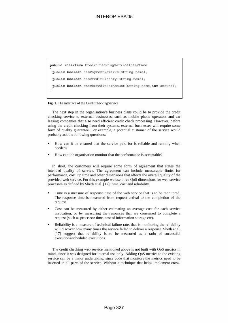
public interface CreditCheckingServiceInterface { public boolean hasPaymentRemarks(String name); public boolean hasCreditHistory(String name); public boolean checkCreditForAmount(String name,int amount); }
Fig. 1. The interface of the CreditCheckingService
The next step in the organisation’s business plans could be to provide the credit checking service to external businesses, such as mobile phone operators and car leasing companies that also need efficient credit check processing. However, before using the credit checking from their systems, external businesses will require some form of quality guarantee. For example, a potential customer of the service would probably ask the following questions:
How can it be ensured that the service paid for is reliable and running when
needed?
How can the organisation monitor that the performance is acceptable?
In short, the customers will require some form of agreement that states the
intended quality of service. The agreement can include measurable limits for performance, cost, up time and other dimensions that affects the overall quality of the provided web service. For this example we use three QoS dimensions for web service processes as defined by Sheth et al. [17]: time, cost and reliability.
Time is a measure of response time of the web service that is to be monitored.
The response time is measured from request arrival to the completion of the request.
Cost can be measured by either estimating an average cost for each service invocation, or by measuring the resources that are consumed to complete a request (such as processor time, cost of information storage etc).
Reliability is a measure of technical failure rate, that is monitoring the reliability will discover how many times the service failed to deliver a response. Sheth et al. [17] suggest that reliability is to be measured as a ratio of successful executions/scheduled executions.
The credit checking web service mentioned above is not built with QoS metrics in
mind, since it was designed for internal use only. Adding QoS metrics to the existing service can be a major undertaking, since code that monitors the metrics need to be inserted in all parts of the service. Without a technique that helps implement cross-
INTEROP-ESA'05
Page 327

cutting, non-functional requirements such as QoS metrics, developers are running the risk of having to redesign a major part of the code. However, applying aspect oriented programming can reduce this risk. An example of how aspects can be applied in this case is described in the next section.
3.2 Applying Aspects
Let’s look at how aspects could be applied in the described scenario. The three QoS dimensions time, cost and reliability define what is to be measured. Before implementing the actual metrics, it has to be decided where in the application code the dimensions should be measured. A basic approach would be to add code to register each metric in the beginning and end of each request, i.e. before and after each call to the web service. Without using aspects, this approach would require additional code that has to be inserted in all web service methods. However, using an aspect-oriented approach, adding QoS metrics to web services would only require the metrics aspects and their join points to be defined once, without any change to the original web service implementation.
To implement QoS metrics for the credit checking service, one aspect for each of the QoS dimension can be implemented. Thus, as an example we have implemented the aspects PerformanceQoSAspect, CostQoSAspect and ReliabilityQoSAspect .
public aspect PerformanceQoSAspect { Timer timer=new Timer(); pointcut timedMethods() : ( execution(public * CreditCheckingService.* (..))); before() : timedMethods() { // Start timing } after() : timedMethods() { // End timing } }
Fig. 2. Performance QoS aspect
INTEROP-ESA'05
Page 328

3.3 Performance Aspect
The performance aspect is intended to measure the Time QoS dimension. Time can be measured by recording the request/method name, when the request arrived and when the response was sent. The implementation of this metric requires that two aspect join points are defined; one at the beginning of each method call and one at the end. These join points are defined within the AspectJ pointcut “timedMethods”, see figure 2, above.
3.4 Cost Aspect
Cost can be measured by recording the request/method name for each request. Using predefined cost for each type of request, the total cost can be calculated. The measurement of cost can be done by using a join point at the end of each web service method. The AspectJ example in figure 3 show how an aspect that logs each method call can be implemented.
F
3
rme
INTEROP-ESA'05
public aspect CostQoSAspect { pointcut costMethods() : ( execution(public * CreditCheckingService.* (..))); after() : costMethods() { // Log the cost of the executed method } }
ig. 3. Cost QoS aspect
.5 Reliability Aspect
Reliability can be measured by recording if the response of a request is a valid esponse or an error. In this case, a join point can be defined at the end of each ethod. The AspectJ implementation shown in figure 4 defines an aspect that logs
very method call that ends with a non-application Exception.
Page 329

public aspect ReliabilityQoSAspect { pointcut reliabilityMethods() : ( execution(public * CreditCheckingService.* (..))); after() throwing(Exception e): reliabilityMethods() { if(!(e instanceof ApplicationException)) { // Log error } } }
Fig. 4. Reliability QoS aspect
The example given above can be extended with more QoS metrics. This example illustrates the main points in using aspects for the implementation of non-functional requirements.
4 Conclusion
In this article we proposed that AOP could help the transition from internal to external services. By using AOP, non-functional requirements can be implemented without doing a major redesign of the existing system. The feasibility of the proposed solution has been demonstrated with a simple example written in AspectJ.
The example demonstrated that AOP could be a useful tool when an application needs to accommodate QoS metrics that have not been previously designed into the system. It also shows that this can be easily achieved using just a few lines of code. In fact, the bigger the application, the more amount of time will be saved by using aspects.
AspectJ was used in the example. However, there are other ways to implement non-functional requirements in an “aspect oriented” way. It could be argued that by using a component technology such as Enterprise Java Beans (EJB), QoS metrics could be provided by the application server (e.g. through the use of method interceptors in the JBoss EJB server [18]). The implementation of these interceptors however, are not currently standardised, they would therefore be different for each component server (Interestingly the latest version of the JBoss features heavy use of AOP to implement non-functional requirements). It would also require the application to be built as a component-based application from the start, which is often a lot more time-consuming and skill-intensive than using plain Java objects. Using design patterns such as the “proxy” pattern [19] could also alleviate the need for using
INTEROP-ESA'05
Page 330

specific AOP technologies such as AspectJ. An example of this is provided by Filman et al. [5]. This approach, however, is considerably more time-consuming and therefore also more error-prone.
The proposed solution is applicable when the move from internal to external services poses new non-functional requirements. Clearly, if no additional non-functional requirements need to be fulfilled, the need to introduce aspect-oriented concepts is not as obvious. Furthermore, the proposed solution presumes that the non-functional requirements can be implemented in a generic, separated way using aspects. In the case that not all new requirements can be implemented in this way, aspects can still contribute to the implementation of some of the requirements. Thus, we believe that the use of aspect-oriented programming can be a valuable technique when moving from internal to external services.
5 Further work
In this paper we examined how aspect oriented programming can be used to tackle the non-functional requirements when moving from internal to external services. However, when integrating processes it is likely that other changes need to be implemented in parallel with the new non-functional requirements. For example, when integrating processes there might be a need for further process automatisation, i.e. new functional requirements. A possible future extension of our work might include principles guiding the combination of aspect-oriented programming with traditional refactoring techniques to implement both non-functional and functional requirements.
Another interesting question is whether AOP could prove useful for solving other “architecture breaking” problems. There are several indications that this could be the case. De Win et al. [20] have shown how AspectJ can be used to help implement security features in an application. Filman et al. [5] have described how AOP can be used for inserting “ilities”, such as stability and reliability.
References
1. Fremantle, P., Weerawarana, S., Khalaf, R., Enterprise Services. Communications of the ACM, October 2002, Vol. 45, No 10 (2002)
2. Yang , J., van den Heuvel, W. J., Papazoglou, M. P., Service Deployment for Virtual Enterprises. Australian Computer Science Communications, Vol. 23, Iss. 6 (2001)
3. Gudin, M., Hadley, M., Mendelsohn, N., Moreau, J., Nielsen, H. F., SOAP Version 1.2. W3C Candidate Recommendation. (2002)
4. Chinnici, R., Gudin, M., Moreau, J., Weerawarana, S., Web Services Description Language (WSDL) Version 1.2. W3C Working Draft (2003)
5. Filman R., et al., Inserting Ilities by Controlling Communications. Communications of the ACM, Vol. 45 (2002)
INTEROP-ESA'05
Page 331

6. Duclos F., Estublier J., Morat P., Describing and Using Non Functional Aspects in Component Based Applications. 1st International Conference on Aspect-Oriented Software Development (2002)
7. Lovelock, C., Vandermerwe, S., Lewis, B., Services Marketing. Prentice Hall Europe (1996)
8. Piccinelli, G., and Stammers, E., From E-Process to E-Networks: an E-Service-oriented approach. OOPSLA Workshop on Object-Oriented Web Services (2001)
9. Allen, P., Frost, S., Component-Based Development for Enterprise Systems: Applying the Select Perspective. Cambridge University Press (1998)
10. Elrad, T., Filman, R., Bader, A., Aspect-oriented Programming an Introduction, Communications of the ACM Vol. 44 ( 2001)
11. AspectJ, www.aspectj.org. Accessed in April 2003 12. Cysneiros, L., do Prado Leite, J., Non-Functional Requirements: From Elicitation to
Modelling Languages. International Conference on Software Engineering (2002) 13. Moriera, A., Araújo, J., Brito, I., Crosscutting Quality Attributes for Requirements
Engineering. 1st International Conference on Aspect-Oriented Software Development (2002)
14. Georgakopolos, D., Schuster, H., Cichocki, A., Baker, A., Managing Process and Service Fusion in Virtual Enterprises. Information System Vol. 24, No6 (1999) 429-456
15. Fowler, M., Refactoring – Improving the Design of Existing code. Addison-Wesley (1999) 16. Becker, C., Geihs, K., Quality of service and object-oriented middleware - multiple
concerns and their separation. International Conference on Distributed Computing Systems (2001) 117 -122
17. Sheth A., Cardoso J., Miller J., Kochut K., Kang M., QoS for Service-Oriented Middleware.. Proceedings of the Conference on Systemics, Cybernetics and Informatics, (2002)
18. JBoss, www.jboss.org, Accessed in November 2004 19. Gamma E., Helm R., Johnson R., Vlissides J., Design Patterns – Elements of Reusable
Object-Oriented Software. Addison-Wesley (1995) 20. De Win, B., Vanhaute, B., De Decker, B., How Aspect-Oriented Programming Can Help to
Build Secure Software. Informatica Journal, Vol. 26, (2002) 141-149
INTEROP-ESA'05
Page 332

Methodology for the definition of a glossary in a collaborative research project and its application to a
European Network of Excellence
Paola Velardi1, Raúl Poler2, José Vicente Tomás2
1 University of Rome “La Sapienza”, Via Salaria 113, 00198 Rome, Italy {[email protected]}
2 Polytechnic University of Valencia, Camino de Vera, s/n, 46002 Valencia, Spain
{rpoler, [email protected]}
Abstract. The aim of this paper is to describe the methodology of creation of a Glossary in a collaborative research project and its application to the Network of Excellence IST-508011 INTEROP “Interoperability Research for Networked Enterprise Applications and Software” for the definition of a glossary in the area of interoperability of enterprise applications and software. The proposed methodology is based on an adaptation of a method of the University of Rome for the semiautomatic acquisition of terms and definitions starting from a source of documents related to the research areas of a collaborative project.
1 Introduction
Knowledge Management has been gaining significant importance within organisations and is considered an important success factor in enterprise operation. For some time, there have been many techniques to model processes and other elements of the enterprise in order to capture the explicit knowledge. Modelling in this context means creating an explicit representation, usually computable, for the purposes of understanding the basic mechanics involved. But knowledge can mean different things to different people and companies must spend some time looking for an appropriate mechanism to avoid misunderstanding in knowledge transmission. One mechanism to avoid this problem is to build a Glossary. The goal is to make accessible the organizational knowledge by unifying the language used in representing explicit knowledge. The semantic unification is a key factor for the success of the knowledge dissemination and diffusion through an organization.
2 Methodology to obtain a glossary
A general method for constructing a glossary is: collect a vocabulary, collect definitions, establish format rules, establish rules for writing definitions, examine definitions for multiple meanings, write basic definitions, review and compare for
INTEROP-ESA'05
Page 333
consistency of meaning, classify, select preferred words, group words, review and finalize the glossary. In practice, some of these steps are omitted, while other steps are developed to considerable depth, depending on the final objective of the glossary. The complexity of detail for any phase of the glossary depends upon the scope of the glossary, the size of the vocabulary, and the number of persons participating in the project. This is understandable because a large working group reflecting a wide range of subjects, introduces more words for consideration and supplies multiple meanings relative to different backgrounds. Starting from a wide list of terms with the objective of building a whole glossary with inputs of several researchers could consume a great amount of time and effort. Therefore, a specific methodology was defined:
• 1st stage: to define the purpose of the glossary. • 2nd stage: to built an initial list of terms and definitions using a semi-
automatic glossary acquisition. • 3rd stage: to set up the collaborative glossary online module to support the
sharing and extension of the glossary. • 4th stage: to complete the glossary by means of manual inputs and reviews,
that is, the extension of the glossary.
2.1. 1st Stage: Purpose of the Glossary
In a collaborative environment, all participants must have in mind what is the main purpose of the glossary and the benefits they are going to obtain as well. Because of this, the project representatives must meet in order to clarify objectives and possible applications of the glossary. This fact becomes critical when the research project has different related research areas. There are several benefits in creating a durable glossary facility:
• Semantic unification: the glossary represents an informal, but shared view of relevant concepts. This activity will let semantics emerge naturally from applications and collaborative work.
• Classification/retrieval of documents: glossary terms may be used as meta-data for indexing documents and databases.
• Integration of competences from different research areas.
2.2. 2nd Stage: Semi-automatic glossary acquisition
The second stage of the methodology will lead to obtain the first version of the Glossary. This stage is based on a semi-automatic tool for ontology building called OntoLearn. This first version of the Glossary must be addressed as a preliminary stage for the generation of the final glossary. The extension and the diffusion between the research community are strictly required to meet the projected requirements. Main steps of OntoLearn semi-automatic procedure. Figure 1 provides a snapshot of the OntoLearn ontology learning methodology.
INTEROP-ESA'05
Page 334

Term Extraction
Extraction of NaturalLanguage Definitions
CompositionalInterpretation (SSI)
Human SpecialistsInput
GlossParsing
OntologyMapping
full glosses
partial glossesno glosses
on-line corpora, documents, glossaries
domainontology
forest of domain trees
core ontology
Fig. 1. An outline of the ontology learning phases in the OntoLearn system
The following steps are performed by the system: Step 1. Extract pertinent domain terminology. Simple and multi-word expressions are automatically extracted from domain-related corpora, like enterprise interoperability (e.g. collaborative work), hotel descriptions (e.g. room reservation), computer network (e.g. packet switching network), art techniques (e.g. chiaroscuro). Statistical and natural language processing (NLP) tools are used for automatic extraction of terms [3]. Statistical techniques are specifically aimed at simulating human consensus in accepting new domain terms. Only terms uniquely and consistently found in domain-related documents, and not found in other domains used for contrast, are selected as candidates for the domain terminology. Step 2. Search on the web for available natural language definitions from glossaries or documents. Available definitions are searched on the web using on-line glossaries or extracting definitory sentences in available documents. A context free (CF) grammar is used to extract definitory sentences. An excerpt is: S → PP ‘,’ NP SEP NP → N1 KIND1 KIND1 → MOD1 NOUN1 MOD1 → Verb | Adj | Verb ‘,’ MOD1 | Adj ‘,’ MOD1 NOUN1 → Noun N1 → Art | Adj SEP → ‘,’ | ‘.’ | Prep | Verb | Wh PP → Prep NP
INTEROP-ESA'05
Page 335
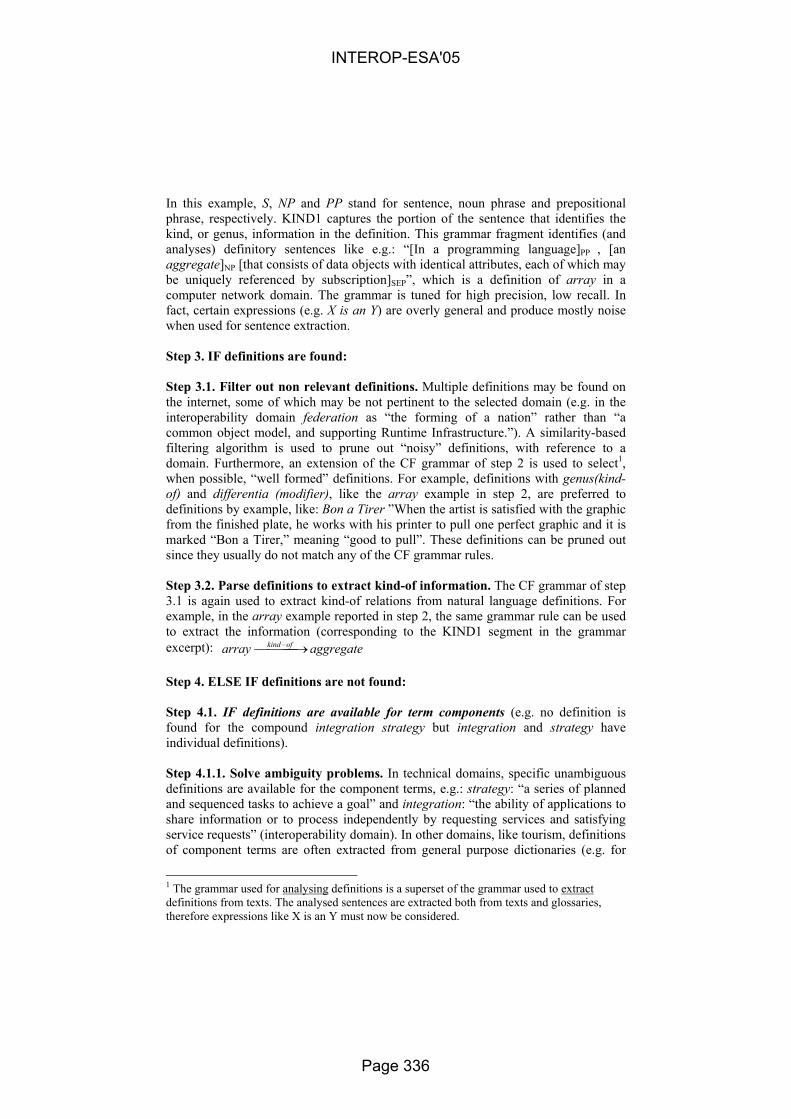
In this example, S, NP and PP stand for sentence, noun phrase and prepositional phrase, respectively. KIND1 captures the portion of the sentence that identifies the kind, or genus, information in the definition. This grammar fragment identifies (and analyses) definitory sentences like e.g.: “[In a programming language]PP , [an aggregate]NP [that consists of data objects with identical attributes, each of which may be uniquely referenced by subscription]SEP”, which is a definition of array in a computer network domain. The grammar is tuned for high precision, low recall. In fact, certain expressions (e.g. X is an Y) are overly general and produce mostly noise when used for sentence extraction. Step 3. IF definitions are found: Step 3.1. Filter out non relevant definitions. Multiple definitions may be found on the internet, some of which may be not pertinent to the selected domain (e.g. in the interoperability domain federation as “the forming of a nation” rather than “a common object model, and supporting Runtime Infrastructure.”). A similarity-based filtering algorithm is used to prune out “noisy” definitions, with reference to a domain. Furthermore, an extension of the CF grammar of step 2 is used to select1, when possible, “well formed” definitions. For example, definitions with genus(kind-of) and differentia (modifier), like the array example in step 2, are preferred to definitions by example, like: Bon a Tirer ”When the artist is satisfied with the graphic from the finished plate, he works with his printer to pull one perfect graphic and it is marked “Bon a Tirer,” meaning “good to pull”. These definitions can be pruned out since they usually do not match any of the CF grammar rules. Step 3.2. Parse definitions to extract kind-of information. The CF grammar of step 3.1 is again used to extract kind-of relations from natural language definitions. For example, in the array example reported in step 2, the same grammar rule can be used to extract the information (corresponding to the KIND1 segment in the grammar excerpt): aggregatearray ofkind → − Step 4. ELSE IF definitions are not found: Step 4.1. IF definitions are available for term components (e.g. no definition is found for the compound integration strategy but integration and strategy have individual definitions). Step 4.1.1. Solve ambiguity problems. In technical domains, specific unambiguous definitions are available for the component terms, e.g.: strategy: “a series of planned and sequenced tasks to achieve a goal” and integration: “the ability of applications to share information or to process independently by requesting services and satisfying service requests” (interoperability domain). In other domains, like tourism, definitions of component terms are often extracted from general purpose dictionaries (e.g. for
1 The grammar used for analysing definitions is a superset of the grammar used to extract definitions from texts. The analysed sentences are extracted both from texts and glossaries, therefore expressions like X is an Y must now be considered.
INTEROP-ESA'05
Page 336

housing list, no definitions for list are found in tourism glossaries, and in generic glossaries the word list is highly ambiguous). In these cases, a word sense disambiguation algorithm, called SSI2 [4] [5], is used to select the appropriate meaning for the component terms. Step 4.1.2. Create definition compositionally. Once the appropriate meaning components have been identified for a multi-word expression, a generative grammar is used to create definitions. The grammar is based on the presumption (not always verified, see [5] for a discussion) that the meaning of a multi-word expression can be generated compositionally from its parts. According to this compositional view, the syntactic head of a multi-word expression represents the genus (kind-of), and the other words the differentia (modifier). For example, integration strategy is a strategy for integration. Generating a definition implies, first, to identify the conceptual relations that hold between the complex term components3, and then, to compose a definition using segments of the components’ definitions. For example, given the term integration strategy, the selected underlying conceptual relation is purpose:
nIntegratioStrategy purpose →
and the grammar rule for generating a definition in this case is:
<MWE> = a kind of <H>, <HDEF>, for <M>, <MDEF> . (1)
Where MWE is the complex term, H is the syntactic head, HDEF is the main sentence of the selected definition for H, M is the modifier of the complex term and MDEF is the main sentence of the selected definition for M. For example, given the previous definitions for strategy and integration, the following definition is generated by the rule (1): integration strategy: a kind of strategy, a series of planned and sequenced tasks to achieve a goal, for integration, the ability of applications to share information or to process independently by requesting services and satisfying service requests. As better discussed in [5] this definition is quite verbose, but has the advantage of showing explicitly the sense choices operated by the sense disambiguation algorithm. A human supervisor can easily verify sense choices and reformulate the definition in a more compact way. Step 4.2. ELSE ask expert. If it is impossible to find even partial definitions for a multi-word expression, the term is submitted to human specialists, who are in charge of producing an appropriate and agreed definition. Step 5. Arrange terms in hierarchical trees. Terms are arranged in forests of trees, according to the information extracted in steps 3.2 and 4.1.1.
2 The SSI algorithm (Structural Semantic Interconnections) is one of the novel and peculiar aspects of the OntoLearn system. SSI recently participated to an international challenge, Senseval-3, obtaining the 2nd best score in a word sense disambiguation task. 3 Machine learning techniques are used to assign appropriate conceptual relations.
INTEROP-ESA'05
Page 337

Step 6. Link sub-hierarchies to the concepts of a Core Ontology. The semantic disambiguation algorithm SSI (mentioned in step 4.1.1) is used to append sub-trees under the appropriate node of a Core Ontology. In our work, we use a general purpose wide-coverage ontology, WordNet. This is motivated by the fact that sufficiently rich domain ontologies are currently available only in few domains (e.g. medicine). Step 7. Provide output to domain specialists for evaluation and refinement. The outcome of the ontology learning process is then submitted to experts for corrections, extensions, and refinement. In the current version of OntoLearn, the output of the system is a taxonomy, not an ontology, since the only information provided is the kind-of relation. However, extensions are in progress, aimed at extracting other types of relations from definitions and on-line lexical resources.
2.3. 3rd Stage: Setting up a glossary online collaborative platform
Once completed the first list of terms and definitions using a semi-automatic glossary acquisition, the procedure selected to extend the glossary is the use of a Glossary Collaborative Online Module (GCOM). At the same time, this tool allows the sharing and utilization of the glossary. A methodology to implement the GCOM is defined: i) GCOM requirements definition: data, safety and interfaces, ii) Existing Glossary based tools analysis and iii) Selection of the solution to be implemented.
2.4. 4th Stage: Glossary extension and sharing
The last stage of the methodology comprises the extension and validation of the glossary by means of the GCOM. The semi-automatic glossary acquisition procedure generates a set of interrelated terms inside a domain starting from a group of documents of that same domain. Although this procedure generates an important number of definitions, it is common that some terms belonging to the research domain may be excluded, either because they don't appear in enough number in the evaluated documents or because they have appeared in later dates to the development of the stage 2. Based on this, the project researchers must extend the glossary terms to complete the final version of the glossary. Likewise, the project researchers must unify their approaches regarding the generated definitions. Therefore, this stage consists on a combined process of sharing-extension-validation using the newest ICT and developed by all the researchers of the project. The stage may be split up in:
• Step 1. Glossary sharing: The glossary must be uploaded in the GCOM in
order to share the definitions between the research community. • Step 2. Glossary extension: Then, the project researchers will extend the
glossary with new definitions. • Step 3. Glossary validation: The project researchers must check each term
and definition in terms of clarity and coherency.
INTEROP-ESA'05
Page 338

3 Application of the methodology
3.1. Introduction
INTEROP is a Network of Excellence (NoE) whose primary goal is to sustain European research on interoperability for enterprise applications and software. The originality of the project lies in the multidisciplinary approach merging different research areas which support the development of interoperable systems: architectures and platforms, enterprise modelling, and ontology. To speed up the glossary definition, the Department of Computer Science of the University of Roma made available a battery of ontology building algorithms and tools, the OntoLearn system [3] [2]. The OntoLearn system builds a domain ontology relating domain terms to the concepts and conceptual relations of the WordNet4 lexicalised ontology. The final ontology is therefore an extended and trimmed version of WordNet. In OntoLearn, WordNet acts as a “general purpose” upper ontology, but other more specialised upper ontologies can be used, if available. Since the use of WordNet as a reference ontology is not a current choice of the INTEROP project, and since for the glossary acquisition task some additional feature was foreseen, we conceived a partly new experiment, using some of the tools and algorithms provided by the OntoLearn system, and some new feature that we developed for the purpose of the task at hand. In this chapter the methodology and the results of this experiment are described, that led to the acquisition of a hierarchically structured glossary of about 380 interoperability terms, subsequently evaluated by a team of 6 domain experts.
3.2. 1st Stage: Purpose of the glossary for the INTEROP NoE
Semantic unification is needed in order to facilitate the existing knowledge exchange within the NoE. The creation of a glossary is then a critical task for the project. Several INTEROP working groups have ascertained the need of identifying a glossary of interoperability terms for a variety of tasks, e.g.:
• Building a knowledge map and classifying knowledge domains. • Classifying partner’s competences for the INTEROP mobility matrix. • Providing a list of relevant domain concepts for educational objectives. • More in general, indexing with a set of common meta-data the various
deliverables, state of art, scientific papers and databases. Finally, the glossary will be used as main information source to build an Ontology on Interoperability. This ontology will allow structuring the knowledge all over the NoE, facilitating the information retrieval and clustering on the collaborative platform.
4 http://www.cogsci.princeton.edu/~wn/
INTEROP-ESA'05
Page 339
3.3. 2nd Stage: Application of the semi-automatic glossary acquisition procedure on the interoperability domain. The INTEROP experiment
For the purpose of the INTEROP glossary acquisition task, step 6 of the proposed methodology has been omitted, since an interoperability Core Ontology was not available, and the adoption of an available reference ontology (like WordNet) is not agreed in the project. The preliminary objective in this phase of INTEROP was to obtain a sort of partially structured glossary, rather than an ontology, i.e. a forest of term trees, where, for each term, the following information has to be provided: definition of the term, source of the definition, kind-of relation. Step 1. Term extraction: The first step of the INTEROP glossary procedure was to derive an initial list of terms using the evidence provided by interoperability-related documents. The INTEROP collaborative workspace was used to collect from all partners the relevant documents, among which, the proceedings of INTEROP workshops and deliverables, highly referenced scientific papers, partners’ papers, tutorials, etc. The OntoLearn TermExtractor module [3] extracted from these documents 517 terms. A generic computer science glossary was used to remove overly general technical terms and the list was then quickly reviewed manually to delete clearly identifiable spurious terms. The final list included 376 terms. Step 2. Generation of definitions: Given the list of terms, we activated step 2 of the automatic glossary acquisition procedure. During this step, 28 definitions were not found, 22 were generated compositionally, and the remaining terms were extracted either from glossaries or from available documents. For each definition, we kept track of the source (URL of the web page). For some term, more than one definition survived the well-formedness and domain similarity criteria (step 3.1 of the OntoLearn semi-automatic procedure), therefore the total number of definitions submitted to the experts for revision was 358. Step 3. Evaluation by experts: Six domain experts5 in INTEROP were asked to review and refine the glossary. Each expert could review (rev), reject (rej), accept (ok) or ignore (blank) a definition, acting on a shared database. The experts added new definitions for brand-new terms, but they also added new definitions for terms that may have more than one sense in the domain. There have been a total of 67 added definitions, 33 substantial reviews, and 26 small reviews (only few words changed or added). Some term (especially the more generic ones, e.g. business domain, agent, data model) was reviewed by more than one expert who proposed different judgements (e.g. ok and rev) or different revised definitions. In order to harmonise the results, a first pass was conducted automatically, according to the following strategy: If a judgement is shared by the majority of voters, then select that judgement and ignore the others (e.g. if a definition receives two ok and one rev, then, ignore rev and accept the definition as it is). If the only judgement is rej(ect), then delete the definition. If a definition has a rej and one (or more) reviewed versions, then, ignore the reject and keep the reviews. This step led to a final glossary including 425
5 The experts have been chosen according to their expertise in the three INTEROP domains.
INTEROP-ESA'05
Page 340

definitions, 23 of which with a surviving ambiguity that could not be automatically conciliated. Therefore a second, short manual pass was necessary, involving this time only three reviewers. After resolving ambiguity, one definition (the most representative) per term was selected. Final glossary has 283 terms and definitions. Step 4. Speed-up factors: The objective of the methodology is to speed-up the task of building a glossary by a team of experts. Evaluating whether this objective has been met is difficult, since no studies are available for a comparison. We consulted several sources, finally obtaining the opinion of a very experienced professional lexicographer6 who has worked for many important publishers. He outlined a three-steps procedure for glossary acquisition including: i) internet search of terms, ii) production of definitions, and iii) harmonization of definitions style. He evaluated the average time spent in each step in terms of 6 minutes, 10 min. and 6 min. per definition, respectively. He also pointed out that conducting this process with a team of experts could be rather risky in terms of time7, however he admits that in very new fields the support of experts could be necessary. Though the comparison is not fully possible, the procedure described in this paper has three phases in which man-power is requested: After term extraction (step 1), to prune non-terminological and non-domain relevant strings. This requires 0.5 minutes per term. After the extraction of definitions (step 2), to evaluate and refine definitions. We asked each expert to declare the time spent on this task, and we came out with an average of 4 minutes per definition. Since some definition was examined by more than one expert, this amount must be increased to 6 min. approximately. In a second-pass review, to agree on the conflicting judgements. This depends on the number of conflicts, that in our case was less than 10%, mostly solved automatically (section 3.3). Overestimating, we may still add 1 minute per definition. The total time is then 7.5 minutes per definition, against the 16 declared by the lexicographer for steps 1 and 2 of his procedure. In this comparison we exclude the stylistic harmonisation (step 3 of the lexicographer), which is indeed necessary to obtain a good quality glossary, but has not been conducted in the case of the INTEROP experiments. However, since this phase would be necessarily manual in both cases, it does not influence the computation of the speed-up factor. The above evaluation is admittedly very questionable, because on one side we have an experienced lexicographer, on the other side we have a team of people that are certainly experts of a very specific domain, but have no lexicographic skills. Our intention here was only to provide a very rough estimate of the manpower involved, given that no better data are available in literature. Apparently, a significant speed-up is indeed obtained by our procedure. Generation of domain sub-trees. As remarked in the introduction, the glossary terms must have some kind of hierarchical ordering, leading eventually to a formal ontology. A hierarchical structure simplifies the task of document annotation, and is a
6 We thank Orin Hargraves for his very valuable comments. 7 To cite his words: “no commercial publisher would subject definitions to a committee for fear of never seeing them in recognizable form again”
INTEROP-ESA'05
Page 341

basis for further developments such as automatic clustering of data (e.g. for document classification), identification of similarities (e.g. for researchers mobility), etc. In other words, it is a first step towards semantic annotation. To arrange terms in term trees, we used the procedure described in steps 3.2 and 4.1.1 of the OntoLearn semi-automatic procedure. The definitions have been parsed and the word, or complex term, representing the hyperonym (genus) has been identified. Given the limited number of definitions, we verified this task manually, obtaining a figure of 91,76 % precision, in line with previous evaluations that we did on other domains (computer networks, tourism, economy). Contrary to the standard OntoLearn algorithm, we did not attached sub-trees to WordNet, as motivated in previous sections. Overall, the definitions were grouped in 125 sub-trees, of which 39 including only 2 nodes, 43 with 3 nodes, and the other with >3 nodes. Examples of two term trees are shown:
component
interactingcomponent
applicationcomponent
system
businessapplication
artificialintelligencesystem
knowledgebase, KB
computersystem
agent expertsystem
communicationsystem
enterprise-widenetwork
network
open systemsnetwork
computer-basedsystem
capability
businesscapability
competencysoftwarecapability functionality
conceptualfunctionality
softwarerequirement
service
businessservice
businessobjectfacility(BOF) b2b connectivity
security service
Fig 2. Sub-trees extracted from the Interoperability domain In figure 2, the collocation of the term system might seem inappropriate, since this term has a very generic meaning. However, the definition of system in the interoperability glossary is quite specific: “a set of interacting components for achieving common objectives”, which justifies its collocation in the tree. A similar consideration applies to service in the bottom tree. An interesting paper [1] provides an analysis of typical problems found when attempting to extract (manually or automatically) hyperonymy relations from natural language definitions, e.g. attachments too high in the hierarchy, unclear choices for more general terms, or-conjoined heads, absence of hyperonym, circularity, etc. These problems are more or less evident – especially over-generality – when analysing the term trees forest extracted from the glossary. However, our purpose here is not to overcome problems that are inherent with the task of building a domain concept hierarchy: rather, we wish to automatically extract, with high precision, hyperonymy relations embedded in glossary definitions, just as they are: possibly over-general, circular, or-conjoined. The target is, again, to speed up the task of ontology building and population, extracting and formalizing domain knowledge expressed by human specialists in an unstructured way. Discrepancies and inconsistencies can be corrected later by the human specialists, who will verify and rearrange the nodes of the forest.
INTEROP-ESA'05
Page 342

Conclusion. As already remarked, the glossary provides a first set of shared terms to be used as metadata for annotating documents and data in the INTEROP platform. Several features/improvements are foreseen to improve this initial result, both on the interface/architecture and the methodological side. For example, annotation tools must be defined and integrated in the INTEROP platform. The taxonomic structuring of the glossary must be manually reviewed in the light of a core ontology to be defined, and methods to include new terms must be provided. Finally, the use of terms for document access, clustering and retrieval must be implemented and evaluated.
3.4. 3rd Stage: Setting up the INTEROP Glossary Web Module
Extending, accessing and using the glossary are collaborative and sharing activities that need to be supported by specific tools. Furthermore, the spreading of the glossary requires tools that can have a wide access by the research community. Currently, web environments have proved to be a suitable solution to address interaction based applications between several actors in different locations. The main features of web environments are the use of standard interfaces, the ease of implementation, the Worldwide access and the advanced interaction capabilities. These features provide the required functionality in order to allow a controlled and validated development of the future INTEROP Glossary. A methodology has been defined in order to facilitate the definition of the technical and operational specifications of the Glossary Module. Furthermore, this methodology is also aimed to select the software to support the INTEROP Glossary Web Module (GWM in what follows). The stages of this methodology are:
• Stage 1. Define INTEROP GWM requirements: A set of requirements will be defined related to the data and graphical user interface specifications.
• Stage 2. Analysis of existing Glossary Web based modules. • Stage 3. Selection of the solution: Based on the previous analysis, the
software to support the INTEROP GWM will be selected. Stage 1 was done based on the requirements defined by the project researchers. Concerning to stages 2 and 3 some decisions were taken. Based on the general specifications, the Glossary module must be integrated within the INTEROP collaborative platform (PLONE-based system8) in order to take profit of the benefits of the mutual existence of a glossary and a set of resources (documents, papers, etc.). A search of glossary tools in the market has been performed. There exist some glossary building tools and some OpenSource e-learning platforms that provide glossary facilities, but none of them are integrated in PLONE. These solutions are discarded. Furthermore, there does not exist any commercial software based on PLONE to support the building of a glossary. This fact leads to consider the possibility to develop by an external company an ad hoc software on PLONE to support the Glossary extension and spreading.
8 http://www.plone.org
INTEROP-ESA'05
Page 343

3.5. 4th Stage: Extending the INTEROP Glossary
The INTEROP Project has foreseen 5 tasks to be developed in the next year:
• Glossary Format and structuring: Currently, the glossary is a “flat” list of terms and textual definitions. This flat structure may be inadequate for many tasks. A first activity is to structure the terms in taxonomic order. Taxonomic structuring of keywords is a first step towards concept-based search.
• Glossary extension and updating: In this sub-task the procedures and software tools for updating and extending the glossary will be defined.
• Glossary Usages: New usages must be specified in the working groups. • Implementation of defined glossary-based applications. • Evaluation and assessment: Finally, an evaluation will be carried out to
check the consistency of the tasks developed.
4 Conclusions
A 4-stage methodology to create a glossary in a collaborative research project has been defined. The new proposed methodology is based on an adaptation of a methodology of the University of Rome for the semiautomatic acquisition of terms and definitions starting from a source of documents related to the research areas of the collaborative project. Based on this methodology, a first glossary of terms related to the interoperability domain has been obtained inside the IST-508011 INTEROP Network of Excellence. The requirements of a web tool to share and to permanently enlarge the INTEROP glossary have been defined. An analysis of the existing glossary tools has been carried out. As conclusion, an ad hoc tool will be developed. References 1. Ide N. and Véronis J. (1993). Refining Taxonomies extracted from machine
readable Dictionaries, In Hockey, S., Ide, N. Research in Humanities Computing, 2, Oxford University Press.
2. Navigli R., Velardi P and Gangemi A. (2003). Ontology Learning and its Application to Automated Terminology Translation. IEEE Intelligent Systems, vol. 18, pp. 22-31
3. Navigli R. and Velardi P. (2004). Learning Domain Ontologies from Document Warehouses and Dedicated Web Sites. Computational Linguistics, vol. 50 (2).
4. Navigli R. and Velardi P. (2004b). Structural Semantic Interconnection: a knowledge-based approach to Word Sense Disambiguation, Proc. 3rd Workshop on Sense Evaluation, Barcelona.
5. Navigli R., Velardi P., Cucchiarelli A. and Neri F. (2004). Quantitative and Qualitative Evaluation of the OntoLearn Ontology Learning System. Proc. 20th COLING 2004, Geneva.
INTEROP-ESA'05
Page 344

Ontology-based Semantic Interoperability Tools
for Service Dynamic Discovery ⋆
D. Bianchini and V. De Antonellis
University of BresciaDept. of Electronic for Automation
Via Branze, 3825123 Brescia - Italy
bianchin|[email protected]
Abstract. Enterprises and networked enterprises need today effectivecommunication and exchange of distributed data and services under dy-namic and context-dependent requirements. Semantic interoperability isconsidered a key issue to enforce dynamic discovery and composition ofdistributed data and services. In this paper we specifically address theproblem of service discovery and we present an ontology-based approachfor dynamic discovery in a highly variable environment when cooperativeenterprises interoperate to dynamically combine available services select-ing the best possible offers in a given moment. The ontology structureand its deployment are discussed.
1 Introduction
Enterprises and networked enterprises require advanced semantic interoperabil-ity methods and tools to enable cooperation and communication at applicationlevel. In particular, semantic interoperability techniques are being proposed tosupport data and service discovery and sharing [14]. Current approaches for ser-vice discovery address the treatment of dynamical aspects both with respect tothe continuous addition and removal of services in a highly variable environmentand with respect to different contexts in which a service could be invoked [5, 6].Other works stressed the possibility of using Description Logics to implementmatching algorithms and reasoning procedures to enhance service discovery [7,13]. Ontologies are considered as an enabling technology for the Semantic Weband methods and tools for ontology definition are being studied for interoper-ability purposes. The use of ontology during service search allows for scalabilityof the systems when a large number of services is considered. In [2] a serviceretrieval approach based on the use of ontologies is presented. In [15] a serviceontology specifies a domain, a set of synonyms to allow a flexible search for the
⋆ This work has been partially supported by the MAIS (Multichannel Adaptive In-formation Systems [10]) FIRB Project funded by the Italian Ministry of Education,University and Research, and by NoE INTEROP [9] IST Project n. 508011 - 6th EUFramework Program.
INTEROP-ESA'05
Page 345

domain and a set of service classes to define the properties of services, furtherspecified by its attributes and operations. The service ontology also specifies aservice quality model that is used to describe non functional aspects. In [4] anew technique for Web service discovery which features a flexible matchmakingby exploiting DAML-S ontologies is proposed.
In this paper we specifically address the problem of service discovery and wepresent an ontology-based approach for dynamic discovery in a highly variableenvironment when cooperative enterprises interoperate to dynamically combineavailable services selecting the best possible offers in a given moment. Withrespect to existing approaches to ontology-based service discovery, original con-tribution of our approach regards: (i) the ability of abstracting service character-istics from their operating environment to be able to dynamically select serviceson the basis of contextual features; in fact, our ontology has a three-layer archi-tecture with different abstraction levels properly exploited to scale service dis-covery; (ii) the possibility of selecting services through semantic-based matchingalgorithms according to a scored mechanism taking into account semantic rela-tionships among services. The aim of the present work is to present how the useof an ontology-based approach can support service dynamic discovery and se-lection. We propose an approach in which an ontology-based service descriptionis used as a basis for providing service retrieval in an enhanced UDDI Registry.Instead of associating semantic information directly to services, semantic infor-mation is extracted from published services on the basis of a domain ontologyand used as a basis to provide advanced searching functionalities.
The paper is organized as follows: in Section 2 we propose a three-layer serviceontology architecture; in Section 3 we present a logical framework for serviceontology representation; in Section 4, service discovery based on the proposedontological framework is discussed and in Section 5 the architecture underlyingour work is presented. Finally, conclusions are discussed in Section 6.
2 The Service Ontology Model
The proposed service ontology architecture organizes services at different layersof abstraction according to proper semantic relationships [3]. Semantic relation-ships, as explained in the next section, are the basis for a semantic searchingengine, to improve traditional service discovery mechanisms (mainly based onkeyword-driven search) with more sophisticated retrieval modalities based onreasoning services. Basic components in our approach are:
– a set of concrete services, described by means of their WSDL interfaces, oneor more concrete bindings (for example, SOAP or HTTP binding) and oneor more endpoints (that is, the physical localization of the concrete service);the service WSDL interface is described by means of the name of the serviceitself, the names of its operations and the names of inputs and outputs foreach operation;
– an UDDI Registry, where concrete services are classified in terms of standardavailable service classifications (for example, UNSPSC or NAICS); UDDI
INTEROP-ESA'05
Page 346

Registry offers searching utilities that are mainly keyword-based; one of theaims of our work is to maintain backward compatibility with these existingtechnologies and their searching functionalities;
– a domain ontology, where concepts used for operation and I/O entity namesare organized by means of semantic relationships, i.e., subsumption and equiv-alence; a weight is assigned to each kind of semantic relationship in thedomain ontology.
The conceptual model of the ontology is shown in Figure 1. The service ontol-ogy contains concrete services, abstract services and subject categories, organizedinto three layers (called Concrete, Abstract and Category layer, respectively).
– Concrete services are directly invocable services and they are featured bytheir public WSDL interface, which is used to group them on the basis oftheir functional similarity (as explained in the following), and by bindingsto specific implementations.
– Abstract services are not directly invocable services, but represent the capa-bilities of sets of similar concrete services; abstract service capabilities arealso described by means of a WSDL interface and are obtained from the con-crete service operations by means of an integration process; mapping rulesare maintained among the abstract capabilities and the original concrete op-erations; abstract services are related to each other by two kinds of semanticrelationships: (i) specialization/generalization, when an abstract service of-fers at least the same functionalities of another one; (ii) composition, whenthe functionalities offered by a single abstract service can be provided alsoby a group of other abstract services, considered in their totality; in thiscase, the first services is often called the composite service, while the otherones are called the component services.
– Subject categories organize abstract services into a standard available tax-onomy (such as unspsc or naics) to provide a topic-driven access to theunderlying abstract and concrete services.
The three-layer service ontology is intended to enhance finding of generic ser-vices (abstract services) describing the required capabilities that can be actuallyprovided by several specific existing services (concrete services). Thus, abstractservices are intended to shorten the way towards a variety of alternative concreteservices that can be invoked. Both abstract and concrete services are describedby means of a functional description, that is, a set of capabilities (for the ab-stract service) or operations (for the concrete ones) with required inputs andprovided outputs. Context information and quality requirements can be furtherconsidered to refine and filter the set of candidate concrete services. In addition,subject categories give the user a mechanism for an easy access to the underlyinglevels on the basis of standard topics.
Example 1 - Figure 2 shows a portion of three-layer service ontology intourism domain.
INTEROP-ESA'05
Page 347

Fig. 1. Conceptual model of three layer service ontology.
Fig. 2. A portion of three-layer service ontology in tourism domain.
INTEROP-ESA'05
Page 348

3 A Description Logic for representing services in the
ontology
In order to enhance semantic interoperability, Description Logics have beenadopted for representing services in the ontology and for reasoning in service dis-covery. Description Logics are knowledge representation formalisms with enoughexpressiveness and inference procedures that are sound, that is, the terminationof the reasoning algorithms is guaranteed. We consider the SHOIN (D) Descrip-tion Logic, that is the logical formalism to which the OWL DL ontology language(a sub-language of OWL [11]) can be mapped directly [8]. We choose OWL DLas the representation language for the service and domain ontologies because ofthe expressiveness of its constructs and for the readability of its abstract syntaxinfluenced by frame-based languages. SHOIN (D) allows for the definition ofconcepts and roles, defined on a domain D [1].
We start from a set of concept names (that are names of services and opera-tions), each of them denoted by the letter A, a set of individual names, each ofthem denoted by the letter i and a set of role names, each of them denoted bythe letter R; a concept C can be defined recursively as follows:
– a concept name A is a concept (called atomic concept);
– an enumeration of individuals {i1, i2, . . . in} is a concept;
– given two concepts C1 and C2, C1 ⊓C2 (conjunction), C1 ⊔C2 (disjunction),¬C and (C) are concepts;
– ∃R.C (existential role restriction) and ∀R.C (universal role restriction) areconcepts.
Moreover, the universal (⊤) and empty concept (⊥) are defined. In SHOIN (D)it is possible to define:
– terminological equivalence (A1 ≡ A2) between atomic concepts;
– transitivity of the role R (Tr(R));
– inclusion (C1 ⊑ C2) and disjointness (C1 ⊑ ¬C2) between concepts to ex-press intentional knowledge about them;
– the inverse role R−;
– not qualified cardinality constraints, that is, ≤ nR (which stands for ∃≤n y R(x, y)),≥ nR (which stands for ∃≥n y R(x, y)) and = nR (which stands for ≤nR ∩ ≥ nR).
We define an ontology ONT as a set of assertions on concepts used to for-malize abstract and concrete services (as explained in the next section).
The semantics of concepts is defined by an interpretation I = (∆I , •I),consisting of an abstract domain ∆I and an interpretation function •I ; given anatomic concept A, a role name R with arity n, a set of individuals {i1, i2, . . . in},two generic concepts C1 and C2, we have:
INTEROP-ESA'05
Page 349

AI ⊆ ∆I
RI ⊆ (∆I)n
iI ∈ ∆I
({i1, i2, . . . in})I = {(i1)
I , (i2)I , . . . (in)I}
(C1 ⊓ C2)I = (C1)
I ∩ (C2)I
(C1 ⊔ C2)I = (C1)
I ∪ (C2)I
(¬C)I = ∆I − CI
(∃R.C)I = {c ∈ ∆I | ∃d ∈ ∆Is.t.(c, d) ∈ RI ∧ d ∈ CI}(∀R.C)I = {c ∈ ∆I | ∀d ∈ ∆Is.t.(c, d) ∈ RI ⇒ d ∈ CI}(≤ nR)I = {x s.t. |{y.〈x, y〉 ∈ RI}| ≤ n}(≥ nR)I = {x s.t. |{y.〈x, y〉 ∈ RI}| ≥ n}(= nR)I = {x s.t. |{y.〈x, y〉 ∈ RI}| = n}
(R−)I = (RI)−
(Tr(R))I = (RI)+
The empty concept is mapped to the empty set, while the universal conceptis mapped to ∆I . An assertion A1 ≡ A2 is satisfied by an interpretation I if(A1)
I = (A2)I ; an assertion C1 ⊑ C2 is satisfied by I if (C1)
I ⊆ (C2)I ; an
assertion C1 ⊑ ¬C2 is satisfied by I if (C1)I ∩ (C2)
I = ∅. An interpretationI that satisfies all the assertion in ONT is called a model for ONT ; a genericconcept C is satisfiable in ONT if ONT allows for a model I such that CI 6= ∅;ONT logically implies an assertion between generic concepts if, for each modelI of ONT , the application of I to the assertion is satisfiable.
3.1 Service description
We consider the chosen Description Logic to represent the functional descrip-tion of abstract and concrete services. To do this, we do not exploit the fullexpressiveness of SHOIN (D), but we make a limited use of its constructs. Weconsider subsumption, conjunction, disjunction and negation of atomic and com-plex concepts and existential restriction; in particular, we use four specific roles:the role hasCategory to express the association link of a service with a subjectcategory, the role hasOperation to express the relationship of a service with itsoperations or capabilities and the role hasInput (resp., hasOutput) to specifythat a given concept is the input (resp., the output) of an operation.
We describe the functional description of a service Sk as a conjunction of thefollowing parts:
– an atomic concept, to represent the service name we denote it as Name(Sk);– a conjunction of concepts of the form ∃hasCategory.C, where C is a con-
junction of concept names, to represent the associated subject categories; wedenote such conjunction as Categories(Sk);
– a conjunction of concepts of the form ∃hasOperation.OP , where OP isa concept representing an operation of the current service; we denote suchconjunction as Operations(Sk); each operation OP is described as the con-junction of:
INTEROP-ESA'05
Page 350

• an atomic concept, to represent the operation name; we denote it asName(OP );
• a concept of the form ∃hasInput.I, where I is a conjunction of atomicconcepts representing the inputs of the operation; each concept could alsobe defined as an enumeration of individuals in the form ∃R.ℓ, where R isthe name of the input and ℓ = {i1, i2, . . . in} is the optional enumerationof individuals; we denote the set of such concepts as Inputs(OP );
• a concept of the form ∃hasOutput.O, where O is a conjunction of atomicconcepts representing the outputs of the operation; each concept couldalso be defined as an enumeration of individuals; we denote the set ofsuch concepts as Outputs(OP ).
Moreover, to distinguish among abstract and concrete services, we add to theconjunction a new concept of the form ∃hasType.C, where C is an atomic con-cept abstractService or concreteService. Finally, for each abstract servicewe can add a concept of the form ∃hasConcrete.CS, where CS is a conjunc-tion of concepts corresponding to the names of concrete services associated tothe abstract one.
Example 2 - If we consider the abstract service ReserveFlight in Figure 2,the following new concept is added to the ONT knowledge base:
ReserveFlight ⊓ ∃hasCategory.AirTransfer ⊓∃hasOperation.(searchFlight ⊓ ∃hasInput.(departureCity ⊓
arrivalCity ⊓ departureTime ⊓ arrivalTime) ⊓∃hasOutput.flightTicket) ⊓
∃hasOperation.(bookFlight ⊓ ∃hasInput.flightTicket ⊓∃hasOutput.bookingConfirmation) ⊓ ∃hasType.abstractService ⊓
∃hasConcrete.(KLM ⊓ Alitalia ⊓ Lufthansa)
Semantic relationships among abstract services (specialization/generalizationand composition) are represented by means of subsumption (⊑) and disjunction(⊔) constructs, that is:
– if an abstract service Sa1 is a specialization of another one Sa2, then we addSa1 ⊑ Sa2 to ONT ;
– if an abstract service Sa1 is composed by a set of abstract services Sa2, Sa3,. . . San, then we add Sa2 ⊔ Sa3 ⊔ . . . ⊔ San ⊑ Sa1 to ONT .
Example 3 - In the service ontology shown in Figure 2 we have:
ReserveFlight ⊔ ReserveHotel ⊑ ReserveAirTravel
ReserveLowCostFlight ⊑ ReserveFlight
3.2 Service request description
We represent a functional request R as well as the functional description of aservice, with the only difference that in the request R the specification of re-
INTEROP-ESA'05
Page 351

quired subject categories could be optional.
Example 4 - We consider the request of a flight booking service for a trip fromMilan or Venice to Rome that allows for payment by credit card. The requiredcapabilities will be two: the first one to book a flight, inserting departure andarrival city (defined by enumeration) and receiving the flight ticket, the secondone to pay the flight by credit card, inserting card information and receiving areceipt via e-mail. The request R will be represented as follows:
∃hasCategory.(AirTransfer ⊓ TravelService) ⊓∃hasOperation.(flightBooking ⊓
∃hasInput.(∃departureCity.{Milan,Venice} ⊓∃arrivalCity.{Rome}) ⊓
∃hasOutput.flightTicket) ⊓∃hasOperation.(paymentByCreditCard ⊓
∃hasInput.(creditCardHolder ⊓creditCardExpiration ⊓ creditCardNumber) ⊓
∃hasOutput.(∃paymentReceipt.{email})
4 An ontological infrastructure for service discovery
In this section we show how to exploit the proposed ontological infrastructure toenhance service discovery by means of a matching and ranking algorithm thatfinds desired concrete services according to a set of functionalities required bythe user (that is, a request R) and ranks them with respect to their degree ofsimilarity with R. First of all, we give the definition of similarity coefficientsuseful for matching a request R and an abstract service Sai. Then, we presentour matching and ranking algorithm for service discovery.
4.1 Functional similarity coefficients
The functional similarity analysis is supported by the domain ontology used toannotate I/O entities and operation names, where concepts are organized bymeans of weighted semantic relationships (equivalence with weight equal to 1,subsumption with weight equal to 0.8).
The domain ontology is organized as a graph 〈N , E〉, where N is the set ofnodes (i.e., concepts) and E the set of edges (i.e., semantic relationships betweennodes). Each edge is represented in the form 〈(nh, nk), t, w〉, where nh ∈ N isthe source node, nk ∈ N is the destination node, t is the kind of relationship andw ∈ (0, 1] is the weight associated to that kind of relationship. We call path p
between two nodes n, n′ ∈ N a finite ordered sequence 〈e1, e2, . . . en〉, where thesource node of e1 is n and the destination node of en is n′. Between two nodesin the ontology there can exist more than one path. We define P ⊆ 2E the set ofall possible paths in the ontology. The strength of a path p ∈ P is the value ofthe function W : P → (0, 1] that associates to p the product of the weights of all
INTEROP-ESA'05
Page 352

the relationships belonging to it. We say that two terms n and n′ have affinity(n ∼= n′) if:
– there exists at least one path in the ontology between n and n′;– the strength of this path is greater or equal to a given threshold; if there
exist more than one path, the one with the highest strength is chosen; theaffinity value A(n, n′) ∈ (0, 1] is equal to the strength of the path.
Given a request R and an abstract service Sai, we consider each pair ofoperations opR and opi, one from R and one from Sai. The similarity betweenopR and opi is evaluated considering the domain ontology, that is,
OpSim(opR, opi) = A(nR, ni) ∈ (0, 1] (1)
where nR and ni are the concepts associated to the names of opR and opi. If apath of relationships does not exist among nR and ni names, OpSim(opR, opi) =0. If OpSim(opR, opi) 6= 0, then also similarity among I/O entities is verifiedexploiting the domain ontology through the formula
ESim(opR, opi) =2 · Atot(IN(opR), IN(opi))
| IN(opR) | + | IN(opi) |(2)
+2 · Atot(OUT (opR), OUT (opi))
| OUT (opR) | + | OUT (opi) |∈ [0, 1]
where Atot represents the total value of affinity between the pairs of I/O entities,one from opR and one from opi (obtained by summing up the affinity values ofall the pairs of I/O entities with affinity) and | | denotes the cardinality of agiven set of I/O entities; the higher the number of pairs of entities with affinity,the higher the value of ESim(opR, opi).
The affinity evaluation between inputs and outputs must consider both as-sociated concept names and optional enumerated values. For example, if weconsider two input entities I1 and I2 defined as ∃n1.ℓ1 and ∃n2.ℓ2, respectively,where n1 and n2 are concept names, ℓ1 and ℓ2 are enumerations of individuals,we firstly evaluates A(n1, n2), then we verify if for at least one of the two inputsℓ is defined; in such a situation, if ℓ1 ≡ ℓ2 then we put A(n1, n2) := A(n1, n2)∗1,else if ℓ1 ⊑ ℓ2, then we put A(n1, n2) := A(n1, n2) ∗ 0.8. If ℓ is defined for onlyone input, for the other one it is interpreted as “all possible values accepted”.
For each pair of operations, a global similarity coefficient GSim(opR, opi) isevaluated through a weighted sum of the values of ESim(opR, opi) andOpSim(opR, opi):
GSim(opR, opi) = α · ESim(opR, opi) + β · OpSim(opR, opi) ∈ [0, 1] (3)
The weights α and β, with α, β ∈ [0, 1] and α + β = 1, are properly setto assess the desired relevance of each kind of similarity, depending on flexible
INTEROP-ESA'05
Page 353

comparison strategies (generally, α = β = 0.5). Two operations opR and opi areglobally similar if the value of GSim(opR, opi) is equal or greater than a giventhreshold λ.
Finally, the degree of functional similarity between a request R and an ab-stract service Sai is computed as the ratio among the sum of GSim values foreach pair of globally similar operations in R and Sai and the total number ofrequired operations:
FSimR(R, Sai) =
∑s,t
GSim(opR, opi)
| operations in R |(4)
for each opR of R and for each opi of Sai such that GSim(opR, opi) ≥ λ.
Given a threshold φ, if FSimR(R, Sai) ≥ φ then we can assess functionalcompatibility, that is, isCompatible(R, Sai).
We pose two main assumptions, derived from the meaning of semantic re-lationships between abstract services; the first one asserts that, if an abstractservice Sa1 is a specialization of another one Sa2 and Sa2 satisfies the userrequest R, then also Sa1 satisfies R, that is
if ONT |= Sa1 ⊑ Sa2 ∧ isCompatible(R, Sa2) then isCompatible(R, Sa1)
The second assumption asserts that, if an abstract service Sa1 is composedby a set of abstract services Sa2, Sa3, . . . San and Sa1 satisfies the user requestR, then R is also satisfied by the overall set {Sa2, Sa3, . . . San}, that is
if ONT |= (Sa1 ≡ Sa2 ⊔ Sa3 ⊔ . . . ⊔ San) ∧ isCompatible(R, Sa1) thenisCompatible(R, Sa2 ⊔ Sa3 ⊔ . . . ⊔ San)
4.2 The FC-MATCH algorithm for service discovery
The algorithm is organized in four main phases as shown in Figure 3. Duringthe first one (rows (9)-(16)) subject categories optionally specified in the requestare used to reduce the set of candidate abstract services: only abstract servicesthat are associated to at least one selected subject category (marked(Sai) in thealgorithm) are further considered for the evaluation of their functional compat-ibility with the request. If no subject categories are specified, then all abstractservices are considered in the next phase.
In the second phase (rows (17)-(23)), candidate abstract services are com-pared with the request R to evaluate their degree of functional compatibilitywith R. Only abstract services Sai for which FSimR(R, Sai) is equal or greaterthan a given threshold φ are further considered.
In the third phase (rows (24)-(29)) semantic relationships between abstractservices are exploited to make more efficient selection of candidate abstract ser-vices, according to assumptions presented in Section 4. This phase can reduce
INTEROP-ESA'05
Page 354

(1) Algorithm FunctionalCompatibilityMatch(2) Input service ontology ONT , a request R, a threshold φ
(3) Output a set CSC of pairs (Sci, score(Sci)), where Sci are concreteservices returned to the user, ranked with respect to score(Sci)
(4) AS := set of available abstract services //initialization
(5) foreach Sai ∈ AS(6) score(Sai) := 0;(7) ASC := ∅ //set of candidate abstract services
(8) CSC := ∅
(9) if Categories(R) 6= ∅ //category level filtering (optional)
(10) foreach Sai ∈ AS(11) foreach Cath ∈ Categories(R)(12) if Cath ∈ Categories(Sai) then mark Sai
(13) if marked(Sai) then
(14) add Sai to ASC;(15) remove Sai from AS;(16) else ASC := AS //if no categories are specified, all available abstract
//services are candidate services
(17) AS := ASC; //maintain only abstract services associated to the
//selected categories, if specified
(18) ASC := ∅;(19) foreach Sai ∈ AS //functional similarity evaluation
(20) if FSimR(R, Sai) ≥ φ then
(21) score(Sai) := FSimR(R, Sai);(22) add Sai to ASC;(23) remove Sai from AS;(24) foreach Saj 6= Sai such that ONT |= Saj ⊑ Sai then
//exploitation of specialization relationships between
//abstract services
(25) score(Saj) := score(Sai);(26) add Saj to ASC;(27) remove Saj from AS ;(28) foreach {Saj} 6= Sai such that ONT |= (⊔{Sai} ⊑ Sai) then
//exploitation of composition relationships between
//abstract services
(29) score{Saj} := score(Sai);(30) add {Saj} to ASC;(31) remove {Saj} from AS;(32) else remove Sai from AS ;
(33) foreach Sai ∈ ASC then //mapping from the abstract to the concrete world
(34) foreach Sck ∈ concretes(Sai)(35) score(Sck) := score(Sai);(36) add (Sck, score(Sck)) to CSC;
(37) return CSC ranked with respect to score(Sci);
Fig. 3. The FC-MATCH algorithm.
INTEROP-ESA'05
Page 355

Fig. 4. The compat system architecture.
the set of abstract services for which the evaluation of FSimR(R, Sai) coefficientis needed, decreasing the complexity of the algorithm.
Finally, concrete services associated to the selected abstract ones are returnedto the user, ranked according to the degree of their functional compatibility withthe functional requirements (rows (31)-(35)). Future work will address furtherrefinement of the set of concrete services taking into account contextual infor-mation and QoS issues. In such a case, the value of score(Scj) of each selectedconcrete service Scj will be further modified according to contextual and QoS as-pects. Notice that we addressed scalability purposes by exploiting the three-layerstructure of the service ontology (we progressively reduce the set of candidateservices by considering the organization of services into subject categories andabstract services) and semantic relationships between abstract services.
5 The compat system architecture
Figure 4 shows the proposed architecture for the compat ontology-based sys-tem to enhance service discovery according to compatibility degree. The coreelements of the architecture are the Compatible Service Provider, the JENA
API and the JENA DIG Interface. The Compatible Service Provider imple-ments the matching algorithm presented in Section 4 to find available concreteservices with respect to the user requests. The Compatible Service Provider
does not access directly the ontology, but it uses the JENA API, a Java inter-face that includes a subsystem for management of ontologies supporting OWL,
INTEROP-ESA'05
Page 356

DAML+OIL and RDF. JENA uses an internal model to represent ontologies, onwhich it is possible to add a plug-in to perform reasoning tasks. An automaticreasoner, RACER [12], has been developed to implement reasoning tasks onSHOIN (D); it can be used by means of the Jena DIG-HTTP interface. TheCompatible Service Provider satisfies the request of a service both from ahuman user, that can interact with the system by means of a Graphical User
Interface (GUI), implemented using Java Servlet and Java Server Pages tech-nologies, and directly from a software application to automate service selectionand discovery.
6 Conclusions
In this paper we have addressed the problem of semantic interoperability inservice discovery to support enterprises in dynamically selecting the best possibleoffers in a given moment. We have proposed a service ontology architecture anda matching algorithm to exploit it in order to find concrete services according toa given service request. We have also proposed a mechanism to rank the resultingset of concrete services. In this paper we have considered only functional aspectsof services, while future works will address also a QoS-based and context-awareselection of concrete services. The basic idea is to take into consideration QoSand contextual aspects to filter concrete services selected by the FC-MATCHalgorithm. Negotiation techniques could also be considered in this phase. Atthe moment, a prototype of the architecture shown in the previous section andthe experimentation in the domain of touristic information services are beingcompleted.
References
1. F. Baader and P. Hanschke. A schema for integrating concrete domains into con-cept languages. In Proc. of the IJCAI 1991, pages 452–457, 1991.
2. A. Bernstein and M. Klein. Towards High-Precision Service Retrieval. In Proc. of
the International Semantic Web Conference (ISWC 2002), pages 84–101, Sardinia,Italy, June 9-12th 2002.
3. D. Bianchini, V. De Antonellis, B. Pernici, and P. Plebani. Ontology-based Method-ology for e-Service discovery. Accepted for publication on Journal of Information
Systems, Special Issue on Semantic Web and Web Services, 2004.4. A. Brogi, S. Corfini, and R. Popescu. Flexible Matchmaking of Web Services Using
DAML-S Ontologies. In Proc. Forum of the Second Int. Conference on Service
Oriented Computing (ICSOC 2004), New York City, NY, USA, November 15-19th2004.
5. F. Casati, M. Castellanos, U. Dayal, and M. Shan. Probabilistic, Context-Sensitiveand Goal-Oriented Service Selection. In Proc. of the Second Int. Conference on
Service Oriented Computing (ICSOC 2004), pages 316–321, New York City, NY,USA, November 15-19th 2004.
6. I. Elgedawy, Z. Tari, and M. Winikoff. Exact Functional Context Matching for WebServices. In Proc. of the Second Int. Conference on Service Oriented Computing
(ICSOC 2004), pages 143–152, New York City, NY, USA, November 15-19th 2004.
INTEROP-ESA'05
Page 357

7. J. Gonzalez-Castillo, D. Trastour, and C. Bartolini. Description logics for match-making of services. Technical report, HPL-2001-265, Hewlett-Packard, 2001.
8. I. Horrocks and P. Patel-Schneider. Reducing OWL entailment to DescriptionLogic satisfiability. In Proc. of the 2nd International Semantic Web Conference
(ISWC2003), Sanibel Island, Florida, USA, October 2003.9. The INTEROP NoE Portal. http://www.interop-noe.org/.
10. The MAIS Project Home Page. http://black.elet.polimi.it/mais/index.php.11. D. L. McGuinness and F. van Harmelen. OWL Web Ontology Language Overview.
World Wide Web Consortium (W3C) Recommendation, February 10th 2004.http://www.w3.org/TR/2004/REC-owl-features-20040210/.
12. The Racer Home Page. http://www.sts.tu-harburg.de/ r.f.moeller/racer/.13. B. Motik S. Grimm and C. Preist. Variance in e-Business Service Discovery.
In Proc. of the Third International Semantic Web Conference (ISWC 2004), Hi-roshima, Japan, November 8th 2004.
14. HP - Web Services concepts. A technical overview.http://www.bluestone.com/downloads/pdf/web services tech overview%w.pdf.
15. L. Zeng, B. Benatallah, M. Dumas, J. Kalagnanam, and H. Chang. QoS-AwareMiddleware for Web Services Composition. IEEE Transactions on Software Engi-
neering, 30(5):311–327, 2004.
INTEROP-ESA'05
Page 358

Identifying Business Components on the basis of an Enterprise Ontology
Antonia Albani1, Jan L.G. Dietz2
1University of Augsburg, Business School Chair of Business Informatics and Systems Engineering,
86159 Augsburg, Germany [email protected]
2 Delft University of Technology Chair of Information Systems
PO Box 5031, 2600 GA Delft, The Netherlands [email protected]
Abstract. Companies are more and more focusing on their core competencies, outsourcing business tasks to their business partners. In order to support collaboration between business partners, adequate information systems need to be built automating inter-organizational business processes. The bases for such information systems are business components combining software artefacts from different vendors to applications which are individual to each customer. The crucial factors in identifying and building reusable, marketable and self-contained business components are the appropriateness and the quality of the underlying business domain models. This paper therefore introduces a process for the identification of business components based on an enterprise ontology, being a business domain model satisfying well defined quality criteria.
1. Introduction
The software components of an information system that support directly the activities in an enterprise are usually called business components [1, 2]. All other software components are considered either to deliver services to these business components or to offer some general functionality. The identification of business components thus is the first step in the development of an information system according to current standards (component-based, object-oriented etc.). Needless to say that this step is a very crucial one and that it consequently should be performed at the highest possible level of quality. The starting point is the set of requirements that have been elicited from the business domain. Requirements engineering is still a weak link, although considerable progress has been made since it is being based on a business domain model. These models offer a more objective starting point for extracting requirements and a more objective criterion for evaluating them than the traditional ‘waiter strategy’ [3]. In a very true sense however, this new approach to engineering requirements only shifts the problem to an earlier stage instead of solving
INTEROP-ESA'05
Page 359

2 Antonia Albani, Jan L.G. Dietz
it. The crucial factor now is the appropriateness and the quality of the business domain model. In [4] some quality criteria are proposed regarding a business domain model, which we adopt for our current research:
• It should make a clear and well-founded distinction between the essential business actions and informational actions. For example, requesting a supplier to deliver articles is essential, but computing the amount of articles is informational (it is no new fact, only the outcome of a computation).
• It should have the right granularity or level of detail. "Right" means in this respect: finding the actions that are atomic from the business point of view. They may be composite only in their implementations. For example, the request to a supplier is atomic from the business point of view, but to perform a request by postal mail, a number of non-essential actions have to be taken like mailing the order form, transporting it and delivering it to the supplier.
• It should be complete, i.e. it should contain everything that is necessary and it should not contain anything that is irrelevant. As will be shown in the sequel, this requirement is probably the most hard to satisfy since it is common practice in most organizations to perform several kinds of coordination acts tacitly, according to the rule "no news is good news".
We will call a business domain model that satisfies these requirements an enterprise ontology. The goal of the research that is reported in this paper is to identify business components on the basis of an enterprise ontology. It builds on previous work regarding enterprise ontology [5] and regarding business components [6, 7]. The outline of the paper is as follows. In section 2, the method is presented that we apply to arrive at a right ontological model of an enterprise and to derive from this model the business components. In section 3, the method is applied to the example of strategic supply network development (SSND), as reported in [8, 9]. On the basis of the ontological model that is the outcome of section 3, we derive the corresponding business components in section 4. Discussions of the findings as well as the conclusions that can be drawn are provided in section 5.
2. The method and the example case
A precondition to component based development of application systems by using business components is a stable component model. In order to obtain stable business component models, a well defined identification process is necessary. The basis for the identification of reusable, marketable and self-contained business components is an appropriate and high quality business domain model. Such a model not only serves to satisfy the requirements for a single application system but rather for a family of systems – and therefore for a certain domain. In order to achieve that, we adapted the Business Component Modeling (BCM) [6] process by modeling the business domain using an enterprise ontology as introduced in section 1. An overview of the adapted Component Based Domain Analysis phase of the BCM process is given in Fig. 1. In this paper we concentrate on the Domain Scope and the Business Components Identification sub phases and will not describe the Specification sub phase.
INTEROP-ESA'05
Page 360

Identifying Business Components on the basis of an Enterprise Ontology 3
Fig. 1 Component Based Analysis Phase of the BCM process
In the Domain Scope sub phase, the method that is used for constructing the ontology of an enterprise is taken from DEMO (Design & Engineering Methodology for Organizations) [10-12]. As is explained in [10, 11] a distinction is made between production acts and facts and coordination acts and facts. The transaction axiom puts these acts/facts together in the standard pattern of the (business) transaction. Consequently, two worlds are distinguished: the production world (P-world) and the coordination world (C-world). The complete ontological model of an organization in DEMO consists of four aspect models (Fig. 2).
SMPM
AM
Actor Transaction Diagram
Information Use Table
Process Step Diagram
Action Rule Specifications
Object Property Table
Object Fact Diagram
Transaction Result Table Bank Contents Table
Actor Bank Diagram
CM
Organization Construction Diagram
Fig. 2 The four aspect models
The Construction Model (CM) specifies the composition, the environment and the structure of the organization: the identified transaction types and the associated actor roles, as well as the information links between the actor roles and production banks or coordination banks. The Process Model (PM) contains for every transaction type in the CM the specific transaction pattern of the transaction type. Next to these patterns, it contains the causal and conditional relationships between transactions. The Action Model (AM) specifies the action rules that serve as guidelines for the actors in dealing with their agenda. It contains one or more action rules for every agendum type. These rules are grouped according to the actor roles that are distinguished. The State Model (SM) specifies the entity types and fact types in the P-world, but only those object classes, fact types and ontological coexistence rules that are contained in the AM.
In Fig. 2, the CM triangle is split by a dashed line in a left and a right part. This has got to do with the logical sequence of producing the aspect models. First, the left part of the CM can be made straight away after having applied the elicitation procedure as discussed in [13]. It contains the active influences among actor roles, through their
INTEROP-ESA'05
Page 361

4 Antonia Albani, Jan L.G. Dietz
being initiator or executor of a transaction type. The CM is expressed in an Actor Transaction Diagram (ATD) and a Transaction Result Table (TRT). Next, the Process Step Diagram (PSD), which represents a part of the PM, is produced, and after that the AM, which is expressed in Action Rule Specifications (ARS). The action rules are expressed in a pseudo-algorithmic language, by which an optimal balance is achieved between readability and preciseness. Then the SM is produced, expressed in an Object Fact Diagram (OFD) and an Object Property Table (OPT). Next, the right part of the CM is produced. It consists of an Actor Bank Diagram (ABD) and a Bank Contents Table (BCT). Usually the Actor Bank Diagram is drawn as an extension of the Actor Transaction Diagram. Together they constitute the Organization Construction Diagram (OCD). After that we are able to complete the PM with the Information Use Table (IUT).
Having defined the enterprise ontology, the complete information related to the business domain is available in order to identify business components as denoted in the Business Components Identification sub phase of the BCM process in Fig. 1. In order to optimize the process of identifying high quality, reusable and marketable business components the Business Components Identification (BCI) method is used. BCI is based upon the Business System Planning (BSP) [14] method and has been modified for the field of business components identification. BCI takes as input the object classes and fact types from the SM and the process steps from the PM, obtained from the domain scope phase and summarized in the Create/Use Table (CUT), an extension of the IUT. Using a genetic algorithm a number of possible solutions (component models) are generated in order to select the most suitable solution fitting best to the specified quality factors. One of the most important quality factors concerning component models is the minimal communication between components. The result of the BCI is an abstract business component model with defined dependencies between components.
To illustrate the domain scope and component identification sub phases with their resulting diagrams and models, the BCM process is applied to the domain of strategic supply network development in the next sections. The main tasks in the domain of strategic supply network development derive from the tasks of strategic sourcing. The most evident changes regard the functions with cross-enterprise focus. Purchasing has become a core function in enterprises in the 90ies. Current empiric research shows a significant correlation between the establishment of a strategic purchasing function and the financial success of an enterprise, independent from the industry surveyed [15]. One of the most important factors in this connection is the buyer-supplier-relationship. At many of the surveyed companies, a close cooperation between buyer and supplier in areas such as long-term planning, product development and coordination of production processes led to process improvements and resulting cost reductions that were shared between buyer and suppliers [15]. In practice, supplier development is widely limited to suppliers in tier-1. With respect to the superior importance of supplier development we postulated the extension of the traditional frame of reference in strategic sourcing from a supplier-centric to a supply-network-scope [8] i.e., the further development of the strategic supplier development to a strategic supply network development. This refocuses the object of reference in the field of strategic sourcing by analysing supplier networks instead of single suppliers.
INTEROP-ESA'05
Page 362

Identifying Business Components on the basis of an Enterprise Ontology 5
3. Constructing the ontology of the SSND case
This section contains the result of applying the method for constructing the ontology of an enterprise, as presented above, to the SSND case. Space limitations prohibit us to provide a more extensive account of how the models in the figures below are arrived at. Also, we will not present and discuss the action rules. Fig. 3 exhibits the Organization Construction Diagram (OCD). The Transaction Result Table (TRT) that belongs to it is shown in Table 1.
Fig. 3. Organization Construction Diagram of the SSND case
transaction type resulting P-event type T01 offering PE01 supply contract C is offered T02 engineering PE02 the BoM of assembly A is determined T03 exploring PE03 supply contract C is a potential contract T04 evaluating PE04 supply contract C is evaluated T05 concluding PE05 supply contract C is concluded
Table 1. Transaction Result Table of the SSND case
The top or starting transaction type is T01. Instances of T01 are initiated by the environmental actor role CA01, which is a company in tier n-1 and executed by actor role A01. This company asks for an offer regarding the supply of a particular product P. In order to make such an offer, A01 first initiates a T02, in order to get the bill of material of P. This is a list of (first-level) components of P, produced by A02. Next, A01 asks A03 for every such component to get offers from companies that are able to supply the component. So, a number of transactions T03 may be carried through within one T01, namely as many as there are components of P. In order to execute each of these transactions, A03 has to ask companies for an offer regarding the supply of a component of P. Since this is identical to the starting transaction T01, we model this also as initiating a T01. Now however, the executor of the T01 is a company in tier n+1. Consequently, the model that is shown in Fig. 3 must be understood as to be repeated recursively for every tier until the products to be supplied are elementary, i.e. non-decomposable. Note that, because of the being recursive, an offer (the result of a T01) comprises the complete bill of material of the concerned component of P.
INTEROP-ESA'05
Page 363

6 Antonia Albani, Jan L.G. Dietz
Every offer from the companies in tier n+1 is evaluated in a T04. So, there is a T04 for every ‘output’ T01. The result of a T04 is a graded offer for some component of P. So, what A03 delivers back to A01 is a set of graded offers for every component of P. Next, A01 asks A05, for every component of P, to select the best offer. The result is a set of concluded offers, one for every component of P. This set is delivered to A01. Lastly, A01 delivers a contract offer for supplying P, together with the set of concluded offers for delivering the components of P. Because of the recursive character of the whole model, this offer includes the complete bill of material of P, regardless its depth. The OCD in Fig. 3 contains three external production banks. Bank CPB01 contains the data about a company that are relevant for the evaluation of offers. Bank CPB02 contains the different evaluation methods that can be applied. In every instance of T04, one of these methods is applied. CPB03 contains identifiers of all companies that may be addressed for an offer. Lastly, in the transaction result table (Table 1), the supply of product by a (supplying) company to a (customer) company is called a contract.
Fig. 4 Process Step Diagram of the SSND case
Fig. 4 exhibits the process step diagram of the SSDN case. It shows how the distinct transaction types are related. From the state T01/pm (promised) a number of transactions T03 (possibly none) and a number of transactions T05 (possibly none) are initiated, namely for every first-level component of a product. This is expressed
INTEROP-ESA'05
Page 364

Identifying Business Components on the basis of an Enterprise Ontology 7
by the cardinality range 0..k. Likewise, from the state T03/pm, a number of transactions T01 and a number of transactions T04 are initiated, namely for every offer or contract regarding a first-level component of a product. The dashed arrows, from an accept state (e.g. T02/ac) to some other transaction state, represent waiting conditions. So, for example, the performance of a T03/rq has to wait for the being performed of the T02/ac. Fig. 5 exhibits the object fact diagram and Table 2 the object property table. Together they constitute the State Model of the example case.
COMPANY
SC supplies product P to CC
CC P
C is offered
PRODUCT
P A
P is a part of APE01
SC
CC
PE04
C is evaluated
C is a potential contract
PE03
C
CONTRACTC is concluded
PE05
C
EVALUATION METHOD
A
PE02
the BoM of assembly A is determined
ASSEMBLY
M C
C is evaluated with M
Fig. 5 Object Fact Diagram of the SSND case
property type object class scale < company information > COMPANY < aggregated data > < contract terms > CONTRACT < aggregated data > sub_products(*) PRODUCT set of PRODUCT #sub_products(*) PRODUCT NUMBER companies(*) PRODUCT set of COMPANY sub_contracts(*) CONTRACT set of CONTRACT evaluation_mark CONTRACT NUMBER evaluation_marks(*) CONTRACT set of NUMBER
Table 2. Object Property Table of the SSND case
Properties are nothing more or less than binary fact types that happen to be a pure mathematical function of which the range is set of, usually ordered, values, called a scale. The OFD is a variant of the ORM model [16]. Diamonds represent unary fact types that are the result of transactions, also called a production event type. They correspond with the transaction results in Table 1. An ellipse around a fact type or a role defines a concept in an extensional way, i.e. by specifying the object class that is its extension. For example, the ellipse around the ternary fact type “SC supplies product P to CC” defines the concept of contract. The ellipse around the production event type “C is evaluated” defines the concept of evaluated contract. Lastly, the ellipse around the role “A” of the fact type “P is a part of A” defines all assemblies, i.e. all products that do have parts. The property types marked by “(*)” in the OPT are derived fact types. The derivation rules are as follows:
sub_products (P) = {X | X is a product and X is a part of P}; #sub_products(P) = card(sub_products (P)); companies(P) = {X | X is a company and X supplies P to the ‘this company’};
INTEROP-ESA'05
Page 365

8 Antonia Albani, Jan L.G. Dietz
sub_contracts(C) = {X | X is a contract and the product of X is Z and the product of C is Y and Z is a part of Y};
evaluation_marks (C) = {X | X is an evaluation mark of C};
object class or fact type process steps PRODUCT T01/rq T01/pm T02/rq T02/pm T02/st T02/ac T03/rq T03/pm product P is a part of product A T02/st T03/pm the BoM of assembly A is determined T02/ac COMPANY T01/rq T03/pm T04/pm < company information > T04/pm T04/st CONTRACT T01/rq T01/pm T02/ac T03/rq T03/pm T01/st T01/ac T04/rq
T04/pm T04/st T04/ac T03/st T03/ac T05/rq T05/pm T05/st T05/ac
< contract terms > T05/st supply contract C is offered T01/ac supply contract C is a potential contract T03/ac supply contract C is evaluated with method M T04/ac supply contract C is concluded T05/ac EVALUATION METHOD T04/pm T04/st sub_products(*) T02/st T03/rq T03/pm #sub_products(*) T02/st T03/rq companies(*) T03/pm sub_contracts(*) T03/pm T03/st T01/st T03/ac T04/rq T04/ac evaluation_mark(*) T04/st T04/ac T03/st T04/pm T03/ac evaluation_marks(*) T03/st
Table 3. Create/Use Table of the SSND case
Table 3 exhibits the Create/Use Table of the SSND case. It consists of an Information Use Table, extended with the process steps in which an instance of an object type or fact type is created. These steps are printed in italics, as are the fact types that are production event types.
4. Identifying Business Components for the SSND case
Based on the enterprise ontology introduced in the previous section and providing a complete and formal description of the business domain, business components for the domain of strategic supply network development are identified in this section and the resulting component framework is introduced.
The underlying idea of business components combines components from different vendors to an application which is individual to each customer. This principle of modular black-box design demands reusable, marketable, self-contained, reliable and manageable business components. Therefore the business components need to provide services at the right level of granularity and a formal and complete specification of its external view. The description of the specification step of the BCM process is not within the scope of this paper. Instead, for the identification of business components, an enhanced version of the Business Component Identification (BCI) [6] method is applied to the SSND domain and is described next.
The basis for BCI builds the Create/Use table (see Table 3) of the enterprise ontology. In a first step a matrix is built defining the relationships between the object class respectively fact types and the single process steps, gained from the Create/Use Table. The relationships are visualized inserting “C” and “U” in the matrix. “C”
INTEROP-ESA'05
Page 366

Identifying Business Components on the basis of an Enterprise Ontology 9
denotes that the object class respectively fact types are created in a specific process step and “U” denotes the usage of informational data by a given process step. In changing the order of the rows and the columns and placing the “C” as far left and as up as possible in the matrix, groups of relationships can be recognized (see Fig. 6). These groups identify potential business components.
cont
ract
sub_
cont
ract
s
cont
ract
term
s
supp
ly c
ontr
act C
is a
pot
entia
l con
trac
t
supp
ly c
ontr
act C
is e
valu
ated
with
met
hod
M
supp
ly c
ontr
act C
is c
oncl
uded
supp
ly c
ontr
act C
is o
ffere
d
prod
uct
prod
uct P
is p
art o
f pro
duct
A
sub_
prod
ucts
#sub
_pro
duct
s
the
BoM
of a
ssem
bly
A is
det
erm
ined
eval
uatio
n_re
sults
eval
uatio
n_re
sult
eval
uatio
n m
etho
d
com
pani
es
com
pany
info
rmat
ion
com
pany
T03/pm c c u u u u uT05/st u cT03/ac u u c uT04/ac u u c u uT05/ac u cT01/st u uT04/rq u uT01/pm u uT01/ac u cT02/st c c c cT03/rq u u u uT02/ac u u cT01/rq u uT02/rq uT02/pm uT03/st u u c uT04/pm u u u u uT04/st u c u uT05/rq uT05/pm u
Manual execution:
External banks:
Business Components:
Process steps
Object class and fact types
Fig. 6 Business Components Identification Matrix
In order to ensure optimal grouping regarding required metrics – such as minimal communication between components, maximum compactness of components – an optimization problem needs to be solved for which a genetic algorithm has been developed. The genetic algorithm starts with a predefined solution (specific assignment of process steps to components) and while iterating, generates better solutions using mutation and crossing-over of the best generated solutions available. For any iteration, the algorithm assigns each process step to a potential component (1, 2, 3, etc) and evaluates the potential solution with the following quality function:
∑∑=ps io
iorpspiopsmeq ))(),(),,(( (4.1)
ps: process step in the matrix (row) io: information object (object class or fact type) in the matrix (column) p(ps) a Ν : assignment of a ps to a component Ν∈ (4.2) r(io) a Ν : assignment of an io to a component Ν∈ (4.3) m(ps,io)∈ { }'','','' ouc : content of matrix entry (create; use; other) (4.4)
e(m(ps,io),p(ps),r( io))
≠=
=)()(:)),((
)()(:)),((
iorpspiopsme
iorpspiopsme
out
in (4.5)
INTEROP-ESA'05
Page 367

10 Antonia Albani, Jan L.G. Dietz
e in (m(ps,io))=
=∨=''),(:1.0
''''),(:0
oiopsm
cuiopsm (4.6)
e out (m(ps,io))=
=∞+==
''),(:
''),(:1
''),(:0
ciopsm
uiopsm
oiopsm
(4.7)
The evaluation function (4.5) evaluates for each potential solution any entry in the matrix as follows. Entries which are a use or a create and located in a component are evaluated with the value 0, anything else is evaluated with a 0.1 (see formula 4.6). Entries outside a component which are a use are evaluated with 1 and a create with + ∞ (see formula 4.7). The quality function (4.1) calculates the entire sum over each evaluation for all entries in the matrix. After all iterations the min(q) provides the best component solutions for a given matrix, whereby different solutions with the same min(q) may exist. That means that all creates are located inside a component, few uses are outside of the components and few other (empty entries) are inside a component, fulfilling the required metrics of minimal communication and maximum compactness.
cont
ract
sub_
cont
ract
s
cont
ract
term
s
supp
ly c
ontr
act C
is a
pot
entia
l con
trac
t
supp
ly c
ontr
act C
is e
valu
ated
with
met
hod
M
supp
ly c
ontr
act C
is c
oncl
uded
supp
ly c
ontr
act C
is o
ffere
d
prod
uct
prod
uct P
is p
art o
f pro
duct
A
sub_
prod
ucts
#sub
_pro
duct
s
the
BoM
of a
ssem
bly
A is
det
erm
ined
eval
uatio
n_re
sults
eval
uatio
n_re
sult
eval
uatio
n m
etho
d
com
pani
es
com
pany
info
rmat
ion
com
pany
T03/pm (generate sub-contracts)T05/st (define contract terms)T03/ac (select sub-contracts)T04/ac (request sub-contract selection)T05/ac (conclude contract)T01/st (offer contract)T04/rq (aggregate sub-contract)T01/pm (offer contract)T01/ac (offer contract)T02/st (execute BoM explosion)T03/rq (request contract)T02/ac (execute BoM explosion)T01/rq (request offer)T02/rq (execute BoM explosion)T02/pm (execute BoM explosion)T03/st (define best sub-contract)T04/pm (evaluate contract)T04/st (provide evaluation result)
External banks:
Business Components:
Supply Network Contract Development
Product Manager
Evaluation Manager
Process Steps & Component Services
Object class and fact types
Fig. 7 Identified SSND Business Components
The result of the BCI is an abstract business component model with already defined dependencies between components. The dependencies are defined by the uses which are located outside the components and which are substitute by arrows as shown in Fig. 7. The first business component shown in Fig. 7 offers services for the development of the contract offers for the whole supply network and is therefore called supply network contract development. The second business component is responsible for the specification of products and for the execution of the bill of material explosion and is therefore called product manager. The last component identified is the one responsible for the evaluation of the offered contracts.
INTEROP-ESA'05
Page 368

Identifying Business Components on the basis of an Enterprise Ontology 11
For the business components identified, the services they provide need to be defined. Single process steps need therefore to be assigned to component services. The mapping for the strategic supply network development domain is shown in Fig. 7 in the row process steps and component services. As can be seen, some process steps are mapped one to one to business component services, e.g. T03/pm is mapped to generate sub-contracts, or T05/st is mapped to define contract terms, whereas other process steps are combined to one business component service e.g. T01/st, T01/pm, T01/ac are all mapped to one and the same component service offer contract. Fig. 8 shows the refined business component model with the services defined for each component.
Fig. 8 SSND Business Components with provided Services
The information for the mapping of process steps to business component services is gained from the action rules of the enterprise ontology. A detailed description of the mapping would go beyond the scope of this paper.
5. Conclusion
In this paper, we have addressed the problem of identifying business components, defined as the highest level software components, i.e. the software components that directly support business activities. Although component-based software development may be superior to more traditional approaches, it leaves the problem of requirements engineering unsolved. Put differently, the component-based approach provides no criteria for determining that a set of identified components is complete (no component is missing) and minimal (there are no redundant components). Next to that, it provides no means for determining the point of departure, i.e. an appropriate model of the business domain.
The method presented and demonstrated in this paper does solve these problems. First, the enterprise ontology constructed by means of DEMO is an appropriate model of the business domain. It satisfies the quality criteria as proposed in the introduction. As a consequence, the identified business components do really and directly support the business activities in which original new facts are created. Moreover, since the process steps (cf. Fig. 4) are atomic from the business point of view, one can be sure to have found the most fine level of granularity that has to be taken into account. Also, one can be sure that this set of process steps is complete and minimal.
Second, the BCI method, based on the resulting models and tables of the enterprise ontology, provides an automated approach for the identification of business components satisfying defined metrics which are relevant for the development of reusable, marketable and self-contained business components. The metrics defined in this paper – being minimal communication between and maximum compactness of
INTEROP-ESA'05
Page 369

12 Antonia Albani, Jan L.G. Dietz
business components – are the basic metrics for the component-based development of inter-organizational business applications focusing on the deployment of components which can be on different enterprise systems. Additional metrics can easily be added to the BCI method in extending the genetic algorithm.
6. References
1. Turowski, K. and J.M. Zaha, Methodological Standard for Service Specification. International Journal of Services and Standards, 2004.
2. Turowski, K., Fachkomponenten: Komponentenbasierte betriebliche Anwendungssysteme. 2003, Aachen: Shaker Verlag.
3. Dietz, J.L.G. and J.A. Barjis. Petri net expressions of DEMO process models as a rigid foundation for requirements engineering. In 2nd International Conference on Enterprise Information Systems. 2000. Escola Superior de Tecnologia do Instituto Politécnico, Setúbal: ISBN: 972-98050-1-6.
4. Dietz, J.L.G. Deriving Use Cases from Business Process Models. In Conceptual Modeling - ER 2003, LNCS 2813. 2003: Springer Verlag.
5. Dietz, J.L.G. and N. Habing. A meta Ontology for Organizations. In Workshop on Modeling Inter-Organizational Systems (MIOS), LNCS 3292. 2004. Larnaca, Cyprus: Springer Verlag.
6. Albani, A., et al. Domain Based Identification and Modelling of Business Component Applications. In 7th East-European Conference on Advances in Databases and Informations Systems (ADBIS-03), LNCS 2798. 2003. Dresden, Deutschland: Springer Verlag.
7. Albani, A., et al. Identification and Modelling of Web Services for Inter-enterprise Collaboration Exemplified for the Domain of Strategic Supply Chain Development. In On The Move to Meaningful Internet Systems 2003: CoopIS, DOA, and ODBASE - OTM Confederated International Conferences CoopIS, DOA, and ODBASE 2003, LNCS 2888. 2003. Catania, Sicily, Italy: Springer Verlag.
8. Albani, A., et al. Dynamic Modelling of Strategic Supply Chains. In E-Commerce and Web Technologies: 4th International Conference, EC-Web 2003 Prague, Czech Republic, September 2003, LNCS 2738. 2003. Prague, Czech Republic: Springer-Verlag.
9. Albani, A., C. Winnewisser, and K. Turowski. Dynamic Modelling of Demand Driven Value Networks. In On The Move to Meaningful Internet Systems and Ubiquitous Computing 2004: CoopIS, DOA and ODBASE, LNCS. 2004. Larnaca, Cyprus: Springer Verlag.
10. Dietz, J.L.G., The Atoms, Molecules and Fibers of Organizations. Data and Knowledge Engineering, 2003. 47: p. 301-325.
11. Dietz, J.L.G. Generic recurrent patterns in business processes. In Business Process Management, LNCS 2687. 2003: Springer Verlag.
12. van Reijswoud, V.E., J.B.F. Mulder, and J.L.G. Dietz, Speech Act Based Business Process and Information Modeling with DEMO. Information Systems Journal, 1999.
13. Dietz, J.L.G. The notion of business process revisted. In OTM confederated International Conferences (CoopIS, DOA, ODBASE), LNCS 3290. 2004. Larnaca, Cyprus.
14. IBM, Business Systems Planning-Information Systems Planning Guide, ed. I.D. (Ed.). 1984, Atlanta: International Business Machines.
15. Carr, A.S. and J.N. Pearson, Strategically managed buyer - supplier relationships and performance outcomes. Journal of Operations Management, 1999. 17: p. 497 - 519.
16. Halpin, T.A., Information Modeling and Relational Databases. 2001, San Francisco: Morgan Kaufmann.
INTEROP-ESA'05
Page 370

Using Connectors for Deployment of Heterogeneous Applications in the Context of OMG D&C Specification
Lubomír Bulej 1,2, Tomáš Bureš 1,2
1 Charles University, Faculty of Mathematics and Physics, Department of Software Engineering
Malostranske namesti 25, 118 00 Prague 1, Czech Republic {bulej,bures}@nenya.ms.mff.cuni.cz
http://nenya.ms.mff.cuni.cz
2 Academy of Sciences of the Czech Republic Institute of Computer Science
{bulej,bures}@cs.cas.cz http://www.cs.cas.cz
Abstract. The OMG Deployment and Configuration specification is an attempt at standardizing the deployment process of component-based applications in distributed environment. A software connector is an abstraction capturing interaction among components. Apart from middleware independence, connectors provide additional services (e.g. adaptation, monitoring, etc.) and benefits, especially in the area of integration of heterogeneous component-based applications. This paper presents an approach for using connectors in the context of the deployment process defined by the OMG Deployment and Configuration specification to overcome incompatibilities in different component models and allow for deployment of truly heterogeneous component applications.
1. Introduction
Component-based software engineering is a paradigm advancing a view of constructing software from reusable building blocks, components. A component is typically a black box with a well defined interface, performing a known function. The concept builds on the techniques well known from modular programming, which encourage the developers to split a large and complex system into smaller and better manageable functional blocks and attempt to minimize dependencies between those blocks.
Several ideas of the component-based programming have been embraced by the software development industry and as a result, there are now several component models, such as Enterprise Java Beans [12] by Sun Microsystems, CORBA Component Model [8] by OMG, and .Net [5] by Microsoft, which are extensively used for production of complex software systems.
There are also a large number of other component models, designed and used mainly by the academic community. While most of the academic component models
INTEROP-ESA'05
Page 371

Using Connectors for Deployment of Heterogeneous Applications in the Context of OMG D&C Specification 2
lack the maturity of their industrial counterparts, they aim higher with respect to fulfilling the vision of the component-based software engineering paradigm. This is mainly reflected in support for advanced modeling features, such as component nesting, or connector support. While we are aware of a number of component models used in academia, we are most familiar with SOFA [11,7] and Fractal [6].
Typically, component applications are modeled as distributed and platform independent, with a particular execution platform selected during development. However, the current trends in software industry concerning enterprise integration may hint that platform independence on the level of design is not enough.
Our aim is to make possible creating heterogeneous applications which, in addition to the above, can consist of components written using different component models. This brings us two problems that need to be solved – 1) making the different components work together, and 2) deploying the resulting heterogeneous application.
The two problems may seem orthogonal, but in fact they are connected due to the nature of the differences between component models. These differences comprise mainly component packaging format and deployment, component instantiation and lifecycle management, communication middleware, hierarchical composition of components, etc. To make the different components work together and create a truly heterogeneous component application, we need to overcome those differences.
A key problem in making components from different component models work together is communication. Connections in different component models have different semantics and typically use different communication middleware to achieve distribution. The contemporary solutions to this problem usually employ middleware bridges (e.g. BEA WebLogic, Borland Janeva, IONA Orbix and Artix, Intrinsyc J-Integra, ObjectWeb DotNetJ, etc.) to connect components form different component technologies, which only tackles the issue of different middleware and leaves out the issue of different semantics and other (connection related) differences between the component models.
We propose to use software connectors [1] to define the semantics for connections between components from different component models. Based on requirements put on a specific connection, the implementation of a connector can be automatically generated or, if the semantics allows it, a suitable middleware bridge can be used to mediate the connection.
Deployment of component applications is one of the most burning problems for the majority of component models. The deployment process generally consists of several steps, which have to be performed in order to successfully launch a component application. Without deployment support and tools, a component model is unusable for serious software development.
Most of the component models have addressed the deployment issue in some way, but the differences between various component models have made it difficult to arrive at a common solution. Therefore the deployment process for component applications is specific to particular component technology and vendor. Worse, even applications written for a standardized component technology have to be deployed in a vendor specific way using the vendor’s proprietary tools (e.g. EJB).
INTEROP-ESA'05
Page 372

Using Connectors for Deployment of Heterogeneous Applications in the Context of OMG D&C Specification 3
Provided interface
Required interface
Client B
Servercomponent
Client C
Client A
Component binding
Fig. 1. A model of a simple component application. There is a server component providing two different services with two clients connected to one service and another client connected to the other service.
The above situation makes the integration of components from different component models and the deployment and maintenance of the resulting application practically impossible.
A promising approach to deployment of heterogeneous component applications is modeling the application in a platform independent manner and mapping the platform independent model into the target environment to ensure interoperability. The first step in this direction has been done by the Object Management Group (the body behind CORBA and the CORBA Component Model [8]), who has published a specification concerning deployment and configuration of distributed component-based applications [9]. Following the MDA [10] approach, the specification presents a platform independent models of the application, target environment, and the deployment process, which are then expected to be transformed to platform specific models suitable for specific component technologies and mapped to particular programming environment.
Upon careful examination, though, the OMG specification stops short of providing support for deployment of heterogeneous component applications. The failure rests with the fact that the OMG expects the platform independent model to be mapped into a single target environment at a time. In effect, this means that the specification can be used to define a number of deployment mechanisms, but each of the deployment mechanisms will only support a single target environment. Interoperability between heterogeneous target environments is only provided at a conceptual level, which is rather insufficient.
We believe that the specification should support deployment of heterogeneous applications, rather than conceptually compatible but functionally incompatible deployment mechanisms for heterogeneous target environments. We extend the OMG specification to support deployment of heterogeneous component applications by introducing connectors as bridges between the heterogeneous parts of an application, and by extending the model to support construction of connectors during deployment.
Throughout the paper, we will use a model of a simple component application depicted in Figure 1 as a running example. The rest of the paper is organized as follows. Section 2 presents an overview of software connectors and their use in overcoming the differences between component models. Section 3 provides a short
INTEROP-ESA'05
Page 373

Using Connectors for Deployment of Heterogeneous Applications in the Context of OMG D&C Specification 4
Provided interface
Required interface
Client B
Servercomponent
Client C
Client A
Component binding
Distribution boundary
Server connector unit
Client connector unit
Fig. 2. A model of a simple component application using connectors to capture inter-component interactions. Each connector is split into two parts respecting the distribution boundary. In the case of the procedure call-based connectors (i.e. those used in the example) there is typically one server unit and zero to many client units.
overview of the relevant parts of the OMG specification, and Section 4 demonstrates the deployment of a heterogeneous application using connectors and the OMG model of deployment process. We discuss related work in Section 5 and conclude the paper in Section 6.
2. Software Connectors
Software connectors are first class entities capturing communication among components. Although connectors may be very complex, modeled by complicated architectures reflecting different communication styles [4], it is sufficient for the purpose of this paper to view a connector as a number of connector units attached to respective components (see Figure 2).
Apart from modeling and representing inter-component communication, connectors have another important feature – it is possible to generate them automatically based on higher level description expressed in terms of a communication style and non-functional properties [4]. That allows a developer to be concerned just with components’ business logic and not to deal with glue code (containing often middleware dependent parts).
The whole trick of using connectors is to plug an appropriate connector instance between every two components. However, as the concept of connectors is not typically present in current component models, it is often necessary to extend them to support connectors. That is easily done by hooking in the process of component instantiation and binding. Upon instantiation of a component, we create the server connector units and make sure that whenever component interfaces are queried a connector reference to a corresponding server connector unit is returned (instead of returning a reference directly to an interface). Similarly, whenever an interface is being connected to another component, a client connector unit is created and bound
INTEROP-ESA'05
Page 374

Using Connectors for Deployment of Heterogeneous Applications in the Context of OMG D&C Specification 5
Fig. 3. An overview of the component data model
using the connector reference. In our approach, the connector reference is a container holding a set of server unit identities depending on available transport methods (e.g. Java reference for in-address-space connections, RMI reference for RMI connections, or IOR for CORBA connections).
The information what implementation is to be used for a particular connector unit is contained in a connector configuration map. The map contains couples <interface discriminator, connector unit implementation>. The interface discriminator specifies uniquely either a server interface by 2-tuple <component, interface name> or a client interface by 5-tuple <client component, client interface name, server dock name, server component, server interface name>. Such a description reflects the fact that a connector unit attached to a server interface is created in advance and can exist standalone, while a connector unit attached to a client interface is created during component binding when the binding target is already known.
3. Overview of the OMG D&C Specification
As mentioned earlier, the OMG Deployment and Configuration Specification is the first step towards unified deployment of component applications. The specification provides three platform independent models, the component model, the target model, and the execution model. These models represent the three major abstractions used during the deployment process, which uses these models to deploy an application.
For use with specific component models, the platform independent models should be transformed to platform dependent models, capturing the specifics of the concrete platform. A more detailed overview can be found in [3], and yet more details can be found in the specification itself [9].
To reduce the complexity, the models are split into the data model and the management (runtime) model, with the management models describing runtime
INTEROP-ESA'05
Page 375

Using Connectors for Deployment of Heterogeneous Applications in the Context of OMG D&C Specification 6
entities dealing with the data models. The management models and not important in the scope of this paper, therefore we will only deal with the data models.
Fig. 4. A detailed view of the component assembly description
3.1 Component Data Model
The component data model captures the logical view of the component application. The high level overview component data model is depicted in Figure 3. The key concept is a component package, which represents a reusable work product. A component package is a realization of a specific component interface, and contains possibly multiple implementations of the component interface. As a reusable product, the package contains configuration of the encapsulated implementations, and selection criteria for choosing an implementation by matching the criteria to the capabilities of individual implementations.
The implementation of a component interface can be either monolithic, or an assembly of other components. A monolithic implementation consists of a list of implementation artifacts that make up the implementation. The artifacts can depend on each other and can be associated with a set of deployment requirements and execution parameters. The requirements have to be satisfied before an artifact can be deployed.
An assembly of components, shown in Figure 4, contains references to other component packages to serve as subcomponents of the assembly. The instances of subcomponents are connected together using connections between endpoints defined by subcomponents and external endpoints of the assembly. To allow for configuration of an assembly, which in itself does not carry any implementation code, the configuration properties of an assembly are delegated to its subcomponents through a defined mapping.
INTEROP-ESA'05
Page 376

Using Connectors for Deployment of Heterogeneous Applications in the Context of OMG D&C Specification 7
Fig. 5. An overview of the execution data model
3.2 Target Data Model
The target data model describes the computational environment into which the application is deployed. The environment, termed domain, consists of computational nodes, interconnects and bridges. Since the target model is not important in the scope of the paper, we will not describe the model in greater detail.
3.3 Execution Data Model
The execution data model depicted in Figure 5 describes the physical structure of the component application. The model is a flattened view of the original component application model, and describes the application in terms of component instances, connections between endpoints of the instances, and assignment of the instances to computational nodes in the target environment
The component instances carry configuration properties which can be used to influence the behavior of the component, and are in turn described in terms of implementation artifacts. The artifacts, which are binary files containing implementation code, can carry individual execution parameters, which can be used to tell the computational node how to treat a particular implementation artifact. Since the artifacts can be shared by multiple implementations, the execution parameters can be also defined per implementation.
INTEROP-ESA'05
Page 377

Using Connectors for Deployment of Heterogeneous Applications in the Context of OMG D&C Specification 8
3.4 Deployment Process
Prior to deployment, the component application must be developed, packaged, and published by the provider and obtained by the user. The deployment process defined in the specification then consists of five stages and is performed by a designated actor called deployer. Installation. During installation, the software package and its component data model is put into a repository, where it will be accessible from other stages of deployment. The location of the repository is not related to the domain the software will execute in. Also, the installation does not involve transfer of binary files to the computational nodes in a domain. Configuration. When the software is installed in the repository, its functionality can be configured by the deployer. The software can be configured multiple times for different configurations. The configuration stage is meant solely for functional configuration of the software, therefore the configuration should not concern any deployment related decisions or requirements. Planning. After a software package has been installed into a repository and configured, the deployer can start planning the deployment of the application. The process of planning involves selection of computational nodes the software will run on, the resources it will require for execution, deciding which implementation will be used for component instances, etc. The planning does not have any immediate effects on the environment, but produces a description of the application in the execution data model, termed deployment plan. Preparation. Unlike the planning stage, the preparation stage involves performing work in the target environment in order to prepare the environment for execution of the software. The actual transfer of files to computational nodes in the domain can be postponed until the launch of the application. Launch. After preparation, the application is brought to the executing state during the launch stage. As planned, instances of components are created and configured on computational nodes in the target environment and the connections among the instances are established. The application then runs until terminated.
4. Integrating Connectors with Deployment
We have presented two basic concepts that we intend to employ to support deployment of heterogeneous component applications. Software connectors, described in Section 2 will be used to overcome the differences between various component models, while OMG D&C Specification, briefly introduced in Section 3 will be used to model the deployment process of a heterogeneous application.
INTEROP-ESA'05
Page 378

Using Connectors for Deployment of Heterogeneous Applications in the Context of OMG D&C Specification 9
Since the OMG specification does not support the description of heterogeneous component applications and does not directly support connectors, we have to find a way to integrate the two approaches together. To use connectors with a component application, there are basically two tasks that need to be done, and which need to be integrated with the OMG deployment process: 1. At some point, the implementation of all connectors needs to be generated, which
comprises connectors for component bindings a) present in the initial architecture of an application, and b) that can emerge at runtime as a result of passing a reference to component interface
2. The connectors need to be instantiated and bound to their respective components when launching an application. Additionally, the connector configuration map must be prepared for each node to allow for later instantiation of connectors that result from reference passing.
4.1. Preparing connectors
To generate a connector, a connector generator needs to have enough information concerning the requirements for the communication the connector is expected to mediate. The specification of connector features has the form of communication style and non-functional properties. Each connection among instances of components in an assembly can have different requirements.
The planning stage of the deployment process appears to be the most suitable moment for generating connectors. The planning is performed by the deployer using a planner tool. The input takes as input the component data model, describing the component application, and the target data model, describing the target environment. Using the tool, the deployer assigns instances of components to nodes in the target environment and verifies that an instance can be placed on a particular node. The planner tool has all the information required for generation of connectors, except for the connection requirements.
The specification of connection requirements is not a part of the OMG specification, which therefore needs to be slightly modified. To make the information available, we have extended the AssemblyConnectionDescription in the component data model class with another association named connectionRequirement. The association is used to describe the connection requirements.
The connector-aware part of the planner can then communicate with a connector generator [4] and provide it with necessary information. For each assembly connection, the generator synthesizes the implementation artifacts and configuration required to instantiate connector and returns the code fragments to the planner. The connector-aware part of the planner then replaces the assembly connections in the component data model with pairs of components encapsulating the connector units connected to the original components.
This step in fact transforms the enhanced component data model (see Figure 6) back into the original plain data model, which can be then transformed to deployment plan according to the original specification, and for which the planner does not need to be modified.
INTEROP-ESA'05
Page 379

Using Connectors for Deployment of Heterogeneous Applications in the Context of OMG D&C Specification 10
Provided interface
Required interface
Client B
Servercomponent
Client C
Client A
Component binding
Client Connector
Unit(Client A)
Server Connector
Unit
Client Connector
Unit(Client B)
Server Connector
Unit
Client Connector
Unit(Client C)
Distribution boundary
Inter-unit reference
What is important to note, though, is that while we transform connectors to components in the context of the OMG specification, connectors are not really components that would be present in the architecture of an application. Connectors are instantiated at runtime, the instance depends on the type of server a connector unit connects to, and their encapsulation in components as seen in the component data model is merely an implementation convenience.
4.2. Instantiating connectors
The output of the planning stage is a deployment descriptor, describing the physical structure of the application as assigned onto nodes in the target environment. The plan is then broken into pieces following the distribution boundary and disseminated to nodes. The runtime on each of the nodes uses the fragments of the deployment plan to instantiate components and connector units. Depending on the type of the connector unit one of the following actions is taken: 1. Server connector unit is instantiated and bound to its corresponding component.
The unit registers its reference (using a name obtained from execution parameters in the deployment plan) in a naming service so as to be accessible by clients.
2. Bound client connector unit (i.e. representing a binding in the initial architecture) is instantiated and its corresponding component is bound to it. The unit retrieves a reference to a previously registered server connector unit from the naming service (using a name obtained from the deployment plan) and establishes the binding.
3. Future client connector unit (i.e. a unit that does not exist in the initial architecture but which can emerge at runtime as the result of reference passing) is stored in the connector configuration map for later use. Since the implementation of a client connector unit depends also on the server
component, there can be multiple implementations of a client unit. This is addressed by providing all the implementations in the deployment plan as different artifacts implementing one component and performing the actions 2 or 3 stepwise for the single artifacts.
Fig. 6. Application architecture after transformation of the enhanced description
INTEROP-ESA'05
Page 380

Using Connectors for Deployment of Heterogeneous Applications in the Context of OMG D&C Specification 11
5. Evaluation and Related Work
Our approach to deployment of heterogeneous component applications builds upon ware connectors, which is used to define ents from different component models, and
the concept proposed by the OMG D&C specification, which unifies deployment of co
two major concepts, the concept of softsemantics of connections between compon
mponent based applications on conceptual level, but which in itself cannot provide for deployment of heterogeneous applications.
The original component data model present in the specification assumed direct communication between components. That requires that the artifacts providing component endpoints have to be connected together, which makes it impossible to abstract away the middleware technology used for communication. We have made a slight modification to the specification to enable specification of connection requirements in form of communication styles and nonfunctional properties, which can be used to generate connectors. This allows postponing the selection of communication middleware until the planning stage of the deployment process, or introducing logging, monitoring, or encryption into communication without changing the original application or its description.
We have also described the integration of the connector generator into the deployment process and pointed out places where the planner tool needs to be modified to support the connector generator. By transforming the enhanced component data model to the original component data model, we have avoided excessive modifications to the planner tool. The transformation of component data models is a generic process that can be used to enhance the expressive power of the component data model as long as the advanced constructs can be transformed back to the original data model.
To our knowledge, there is no other work concerning use of connectors and the OMG specification to support deployment of heterogeneous component applications. There are, however, a number of mature business solutions for interconnecting the leading business component models such as EJB [12], CCM [8], and .NET [5]. A common denominator of these models is the lack of certain features (e.g. component nesting), which makes the problem of their interconnection a matter of middleware bridging. Each of those component models has a native middleware for communication in distributed environment (RMI in case of EJB, CORBA in case of CCM, and .NET remoting in case of .NET).
Even though the bridges represent mature software products, they limit the heterogeneity of the application by prescribing the use of specific communication mechanisms for the components. The connectors, on the other hand, represent a high level view on the connection between components, and allow for the bridges to be employed in the implementation of a connector if necessary.
INTEROP-ESA'05
Page 381

Using Connectors for Deployment of Heterogeneous Applications in the Context of OMG D&C Specification 12
6. Conclusion
We have presented an approach which we consider a step forward towards deployment of heterogeneous component applications, which allows us to create component applications composed of components implemented in different component models. We have shown how to employ software connectors to overcome the differences between component models and integrated the use of connectors with the OMG D&C specification for unified deployment of component applications.
The presented solution is generic and platform independent, and can be used for different component models. We have verified our approach on a prototype implementation, which supports interconnection of components from SOFA, Fractal, and EJB component models, and are currently developing basic tools for deploying and execution of heterogeneous component applications. Mainly due to space constraints, we had to omit some of the details, which can be found in [3].
In the future, we plan to enhance the connector generator and develop more sophisticated tools, mainly the deployment planner and its integration with the connector generator.
References
[1] Balek, D., Plasil, F., Software Connectors and Their Role in Component Deployment, Proceedings of DAIS'01, Krakow, Kluwer, Sep 2001
[2] Bulej, L., Bures, T., A Connector Model Suitable for Automatic Generation of Connectors, Tech. Report No. 2003/1, Dep. of SW Engineering, Charles University, Prague, Jan 2003
[3] Bulej, L., Bures, T., Addressing Heterogeneity in OMG D&C-based Deployment, Tech. Report No. 2004/7, Dep. of SW Engineering, Charles University, Prague, Nov 2004
[4] Bures, T., Plasil, F., Communication Style Driven Connector Configurations, Copyright Springer-Verlag, Berlin, LNCS3026, ISBN: 3-540-21975-7, ISSN: 0302-9743, pp. 102-116, 2004
[5] Microsoft Corporation, .NET, http://www.microsoft.com/net, 2004 [6] ObjectWeb Consortium, Fractal Component Model, http://fractal.objectweb.org, 2004 [7] ObjectWeb Consortium, SOFA Component Model, http://sofa.objectweb.org, 2004 [8] Object Management Group, Corba Components, version 3.0,
http://www.omg.org/docs/formal/02-06-65.pdf, Jun 2002 [9] Object Management Group, Deployment and Configuration of Component-based
Distributed Applications Specification, http://www.omg.org/docs/ptc/04-08-02.pdf, Feb 2004
[10] Object Management Group, Model Driven Architecture, http://www.omg.org/docs/ormsc/01-07-01.pdf, Jul 2001
[11] Plasil, F., Balek, D., Janecek, R., SOFA/DCUP: Architecture for Component Trading and Dynamic Updating, Proceedings of ICCDS'98, Annapolis, Maryland, USA, IEEE CS Press, May 1998
[12] Sun Microsystems, Inc., Java 2 Platform Enterprise Edition Specification, version 1.4, http://java.sun.com/j2ee/j2ee-1_4-fr-spec.pdf, Nov 2003
INTEROP-ESA'05
Page 382

Development of an Integrated Retrieval System on Distributed KRISTAL-2002 Systems with Metadata
Information
Young-Kwang Nam1, Gui-Ja Choi1, Byoung-Dai Lee2
Department of Computer Science, Yonsei University, Korea1
{yknam, gjchoi}@dragon.yonsei.ac.kr
Digital Home Solution Lab, Samsung Electronics, Co. LTD., Korea2
Abstract. In this paper, we propose an integrated information retrieval system for multiple KRISTAL-2002 systems for different areas or systems for the same area with the different schemas by using the metadata information so that the users can get the answers by once from the whole systems. Our approach utilizes integrated metadata and mapping information between the metadata and the actual database schema information of participating systems. Therefore, we do not require modification of the participants for integration. We have implemented and deployed the proposed system that integrates six different databases distributed across multiple sites.
1. Introduction
Since the early 70’s, many organizations in diverse areas have been developing and deploying information retrieval systems. Due to the availability of Internet, user demand for integrated search through the information retrieval systems that have been deployed has increased while the speed with which these systems are integrated does not catch up with the user demand. Integrating the information retrieval systems in each special area requires storing millions of bibliographic information either into different tables through generalization as in relational database systems or into a single table. The former approach may suffer from poor performance caused by JOIN operations. The latter approach may have low space utilization because there is significant duplicate information.
From service provider’s point of view, it is not appropriate to modify existing information retrieval systems to build an integrated information retrieval system because they may need to stop servicing. However, from user’s point of view, it is tedious to visit, register and search each system manually whenever they need information. In this paper, we propose an integrated information retrieval system (, which we call Integrated Server) that does not require modification of participant systems (, which we call Source Server). In the proposed system, mapping information between integrated metadata and actual databases or tables of each source
INTEROP-ESA'05
Page 383

2 Young-Kwang Nam1, Gui-Ja Choi1, Byoung-Dai Lee2
server is maintained and is utilized for integrated search. For integrated metadata, we follow ISO/IEC 11179 metadata registry procedure.
In order to make the integration process simple, the source server administrator is able to map the database schema of the source server to the meta-fields that will be used for integrated search. In this approach, users are able to search distributed information sources without considering their locations and the kinds of information each server maintains. The user query, however, must be re-generated for each source server based on the mapping information. This relationship is shown on Fig. 1.
Fig. 1. Relationship between meta fields and actual fields.
We have implemented and deployed the proposed system using KRISTAL-2002 system, which will be explained in later section. We include six sources servers in different areas that are currently servicing independently: Science Literature DB, Scientific Technical Trend DB, Scientific Technical Report DB, Scientific Technical Analysis DB, Patent DB and Human Resource DB.
The paper is organized as follow: Section 2 gives related work and Section 3 describes KRISTRAL-2002 system. Section 4 presents the proposed integrated information retrieval system in details. Section 5 presents the prototype implementation and finally, we conclude in section 5.
2. Related Work
There have been considerable efforts in developing algorithms and protocols for integrating heterogeneous data distributed across multiple sources. However, schema integration and schema mapping techniques dealing with discrepancies of schema among distributed data sources require more research to address semantic interoperability.
Techniques for web search engines and directory-based portal services are the driving forces for advancing the information retrieval area. They must be able to search a large amount of data with short queries given by users. To address the problem, these techniques utilize ranking algorithms that use link information or structural information of the documents. This type of information is not included in
M1 M2 … Mn
Meta Fields
A1 A2 … An
Actual Fields
Query: M1=”Data”
Actual Query: A1=”Data”
M1 M2 … Mn
Mapping Information
INTEROP-ESA'05
Page 384

Development of an Integrated Retrieval System on Distributed KRISTAL-2002 Systems with Metadata Information 3
the original documents. Crawling [18] is a new technique for web search engines. It collects and indexes documents distributed across multiple sites and the primary focus of crawling technique is how fast a given document can be included in the search target. To be more effective, it must address issues related to collecting, storing documents and serving user queries. Clustering [19] focuses on presenting accurate information to users by combining related search results. It, however, must improve performance and accuracy of clustering. Meta-searching technique ([20][21]) sends a user query to multiple web search engines and presents the results after combining the partial results obtained from them. It does not require web crawler or indexing a large amount of documents. However, it must be able to combine the results effectively that are found by different ranking algorithms of each source system. Ontology ([8][9][10][11]) and similar researches address semantic interoperability between metadata in consideration of mapping the meaning and the presentation of source data into real-life objects and concepts. Examples of such research include RDF [4], Schema Integration [14], Intelligent Integration of Information [15] and Knowledge Sharing Effort [16], to name a few
3. KRISTAL-2002
KRISTAL-2002 is an information retrieval and management system developed by Korea Institute of Science & Technology. It runs on both Windows and Unix systems. KRISTAL-2002 consists mainly of five modules (Job Scheduler, FIRE, Data Manager, Set Manager and Indexer) and they communicate one another through sockets or pipes (Figure 2.). Job Scheduler distributes user requests to FIRE, which conducts actual searching. Set Manager stores and manages documents found by FIRE. Data Manager processes Document Update or Document Store requests from Job scheduler. Once it completes the requests, it sends acknowledgement to the Job Scheduler. If the operation is successful, it contacts Set Manager so that the Set
Fig. 2. The architecture of KRISTAL-2002.
INTEROP-ESA'05
Page 385

4 Young-Kwang Nam1, Gui-Ja Choi1, Byoung-Dai Lee2
Manager can update the documents it maintains. Indexer is able to analyze input documents and extract indexing words that can best describe the documents. Indexer supports analysis of Korean morpheme, English stamping, Chinese character conversion and user-defined dictionary, to name a few. FIRE, Data Manager, Set Manager and Indexer are integrated into a single daemon and it is able to manage multiple databases.
KRISTAL-2002 database supports processing simultaneous user queries and on/off-line data management and fast and safe backup. Searching and processing
Web Gateway Web GateWay Web Gateway
KRISTAL KRISTAL KRISTAL
Source Server A Source Server B Source Server C
Query Processor
Query Regenerator
Integrated
Search
Engine
Post-Processor
Result
Set
Manager
Integrated ServerAdministrator
UserIntegratedSchemaManager
Schema Mapping Manager
Source ServerManager
Source ServerMonitor
MDRManager
MetaDataManager
Source ServerAdminstrator
Fig. 3. System architecture of the integrated information retrieval system.
SSASSA ISAISA
IS_ADM_INFO
SS_ADM_INFO
SS_INFO
MDM
SSnSS2SS1…. SSnSS2SS1….
SSnSS2SS1…. SSnSS2SS1….
SSnSS2SS1…. SSnSS2SS1…. UserUser
• Admin registration
• Admin Login/out
• Source ServerRegistration
• Schema Mapping
• Admin registration
•Admin Login/out
• SS Admin Confirmation
• SS Confirmation
• Integrated Schema Management
• SS Monitoring
Source Server (SS)
DDSIM
SS Schema Mapping -> MDM
Integrated Server
Participating in server
Service participation determination
Source ServerInfo
“Recorded” status of SS
Meta Info stored in MDR
SS Admin Confirm
SS Info
Source Server Search
SS Monitoring
MDR Info
“standard” status
MDM Meta Fields
MetaDataRegistry
Fig. 4. Control and information flow between the source server and the integrated server.
INTEROP-ESA'05
Page 386

Development of an Integrated Retrieval System on Distributed KRISTAL-2002 Systems with Metadata Information 5
BLOB (Binary Large OBject) is time-consuming. To address this, KRISTAL-2002 utilizes multiple threads for distributed query processing. The primary components of the databases are: Catalog, Document and Index, and Result Set. Catalog database maintains schema information such as table structures, indexing methods and primary keys and so on. Document and Index database is structured by a single or multiple clusters and each cluster is composed of tables that have the same schemas. Cluster is the basic unit of ranking. Each table in Document and Index database is composed of documents, primary keys, and index database and the structure of the table is defined by table schema stored in Catalog database. Result Set database maintains documents found so that it can respond to user requests quickly.
4. System Architecture of the Integrated Information Retrieval System
4.1 System Architecture
The proposed integrated information retrieval system is based on KRISTAL-2002 and it utilizes metadata information registered by participating source servers. To address the heterogeneity of data and schema information of each source server, metadata maintained in the integrated server is used for structural integration. Furthermore, standardized procedure proposed in ISO/IEC 11179 is employed for metadata registry procedure. Schema information of each source server must be mapped into metadata maintained in the integrated server. Therefore, schema that hasn’t been mapped will not be considered for search process. Figure 3. shows the system architecture of the proposed system.
The source server administrator manages the source server and the structural information of the database maintained by the source server while MDR (MetaData Registry) manager standardizes data elements for metadata registry. Integrated server administrator manages and controls all the information of the whole system to support rapid and effective user query processing. Each component of the system will be explained in more details in later sub sections.
The control and information flow among the source servers and the integrated servers is depicted in Figure 4. Each source server administrator registers necessary information to the integrated server and the integrated server administrator authorizes the source server administrator so that he or she can register the source servers. The registered source servers must go through the same authorization process as with the source server administrator to participate in the whole system. Once the registered source servers are authorized by the integrated server, the source server administrators are entitled to do schema mapping. As with previous steps, schema mapping done by the source server must be confirmed by the integrated server. After these steps, the source server is included for integrated search.
INTEROP-ESA'05
Page 387
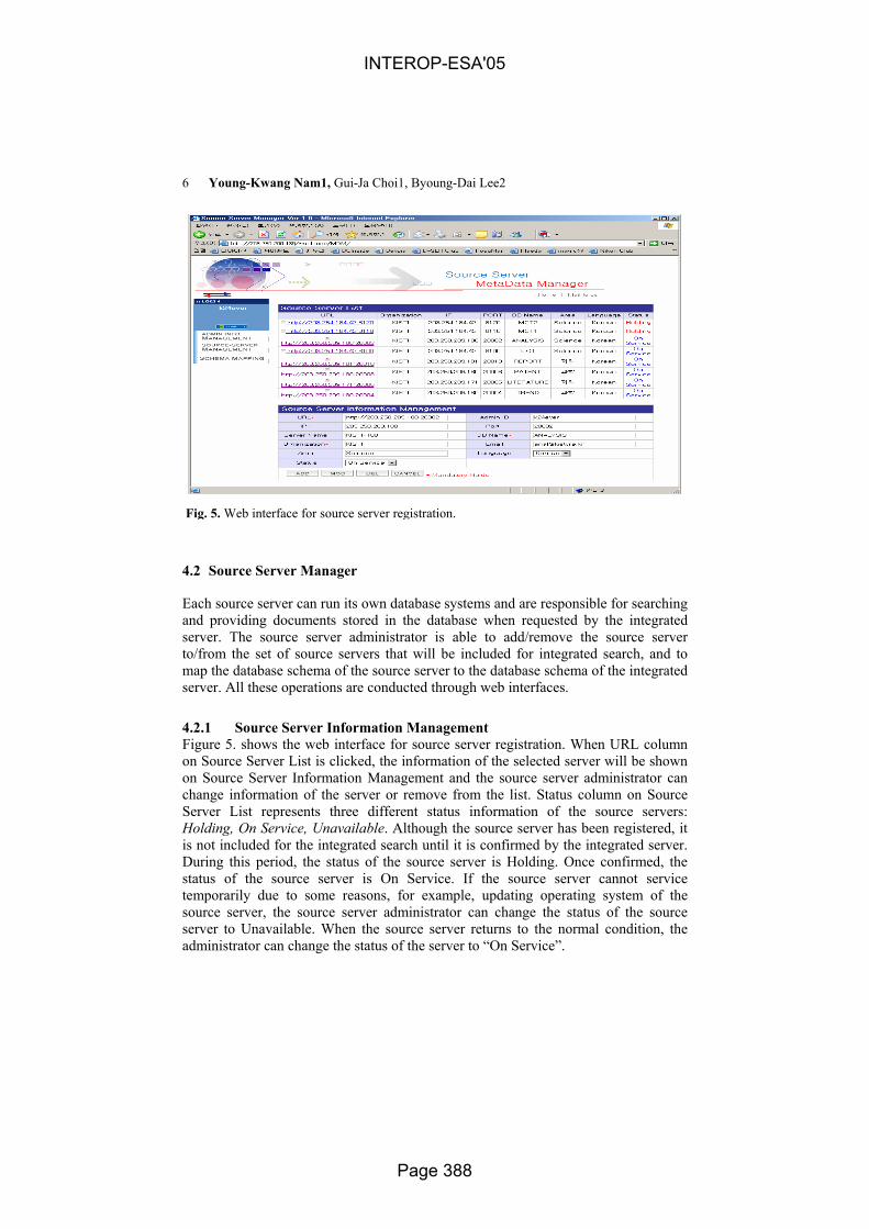
6 Young-Kwang Nam1, Gui-Ja Choi1, Byoung-Dai Lee2
4.2 Source Server Manager
Each source server can run its own database systems and are responsible for searching and providing documents stored in the database when requested by the integrated server. The source server administrator is able to add/remove the source server to/from the set of source servers that will be included for integrated search, and to map the database schema of the source server to the database schema of the integrated server. All these operations are conducted through web interfaces.
4.2.1 Source Server Information Management Figure 5. shows the web interface for source server registration. When URL column on Source Server List is clicked, the information of the selected server will be shown on Source Server Information Management and the source server administrator can change information of the server or remove from the list. Status column on Source Server List represents three different status information of the source servers: Holding, On Service, Unavailable. Although the source server has been registered, it is not included for the integrated search until it is confirmed by the integrated server. During this period, the status of the source server is Holding. Once confirmed, the status of the source server is On Service. If the source server cannot service temporarily due to some reasons, for example, updating operating system of the source server, the source server administrator can change the status of the source server to Unavailable. When the source server returns to the normal condition, the administrator can change the status of the server to “On Service”.
Fig. 5. Web interface for source server registration.
INTEROP-ESA'05
Page 388

Development of an Integrated Retrieval System on Distributed KRISTAL-2002 Systems with Metadata Information 7
4.2.2 Source Server Schema Mapping Figure 6. shows the web interface for schema mapping for the source server. If multiple source servers are managed by an administrator, only those source servers whose statuses are On Service are listed on the web page. MetaField column represents integrated meta schemas loaded from metadata registry and Label column represents the names of the meta schemas. When values in MetaFields are clicked, the detailed information of the meta field is shown on a different window (Figure 7.). RealField represents database schema of the source server mapped into the integrated meta schema. The values listed in the combo box are loaded directly from the source server.
Fig. 6. Web interface for schema mapping.
Fig. 7. Metadata information
INTEROP-ESA'05
Page 389

8 Young-Kwang Nam1, Gui-Ja Choi1, Byoung-Dai Lee2
4.3 Integrated Server Manager
The role of the integrated server is to register metadata based on ISO/IEC 11179 and to maintain integrated meta schema and mapping information registered by the source servers. It also plays a role of entry point for the integrated search. Integrated server administrator determines which source servers will be included for the integrated search service and validity of schema mapping of the source servers. It monitors the status of the source servers included in the service. When it is detected that some source servers are not running correctly, the integrated server immediately exclude the servers from the source server list.
4.3.1 Source Server Confirmation Integrated server administrator is able to confirm the requests from the source server administrators who want to participate in the integrated search service (Figure 8). Once confirmed, the source server administrators are entitled to add their source servers into the service (see 4.2.1.). For the source servers registered by the source server administrator, the integrated server administrator needs to decide whether or not to add them into the server list that will actually service end-users (Figure 9). Note
Fig. 8. Source server administrator confirmation.
Fig. 9. Source server confirmation.
INTEROP-ESA'05
Page 390

Development of an Integrated Retrieval System on Distributed KRISTAL-2002 Systems with Metadata Information 9
that these two processes are different in that the former validates the source server administrators while the latter validates the source servers that the valid source server administrator registered.
4.3.2 Schema Mapping Management Schema Mapping Manager of the integrated server determines integrated metadata schema and given schema mapping registered by the source server administrator (see 4.2.2), it checks the validity of the mapping (Figure 10.). Each row in Figure 10 provides schema mapping information of all the source servers participating in the integrated search service. ListView and SpecView columns determine which meta fields will be shown to users after search completes. Typically, those fields marked as ListView will give rough information of the selected documents while those fields marked as SpecView will be used to provide more detailed information of the documents. BasicSearch and SpecSearch columns determine which meta fields must be compared against the given user query. We support two different modes for search operation: Basic Search and Specific Search. In basic search, user query will be
Fig. 10. Source server schema mapping manager.
Fig. 11. Source server monitor.
INTEROP-ESA'05
Page 391

10 Young-Kwang Nam1, Gui-Ja Choi1, Byoung-Dai Lee2
compared to every target meta fields defined by the integrated server. However, in specific search, the user is able to determine which meta fields he/she wants to compare the query to.
When the actual fields of the source server is clicked, schema information of the source server is shown and the mapped fields for the given meta field are shown checked. By allowing multiple fields to be selected, we support ontology.
When an administrator clicks MetaField column, the detailed information of the meta field, is loaded from meta data registry, is shown on a different window. The information shown in Figure 6 is the subset of this information.
4.3.3 Source Server Monitor Source Server Monitor monitors the status of the all the source servers participating in the integrated search service (Figure 11.). O mark in the status column indicates the source server is running normally. Otherwise, X mark will be shown. When the status of a source server is marked as X, by clicking checkbox on the leftmost column, the integrated server administrator can eliminate the selected server from the server list.
4.4 Integrated Query Processing
4.4.1 Distributed Query Processor (DQP)
Given the user query, DQP re-generates queries for source servers using schema mapping information and sends them to the corresponding source servers. DQP transforms user-input queries into Boolean or Vector queries. Figure 12. shows the relationship between DQP and other modules in the system. For the user-input entries,
[BIB:(B_PY:2004)] &
[TOC:(T_TI:Distributed)&(T_YEAR:2004)]
Distributed Query ProcessorDistributed
Data Set Integration
Manager
DistributedData Set
IntegrationManager
MD정보
Single Query
MDM
ResultsResultsTable
TableTable
DBn1
DBnn
MDM
TableTable
Table
DB21
DB2n
TableTable
Table
DB11
DB1n
……
[BIB:(B_PY:2004) & (TOC:(T_TI:Distributed) & (T_YEAR:2004)) in DB1] |
[BIB:(B_PY:2004) & (TOC:(T_TI:Distributed)&(T_YEAR:2004)) in DBn]
………………………
Distributed
2004
Fig. 12. Relationship between DQP and other modules in system.
INTEROP-ESA'05
Page 392

Development of an Integrated Retrieval System on Distributed KRISTAL-2002 Systems with Metadata Information 11
DQP first read schema mapping information of each source server. If the source server has mapped the meta fields used for the integrated search into the actual fields of the database it manages, DQP extracts the table names and the actual fields that correspond to the user-input entries and regenerates new query as follows: [table name: (actual field name: user-input entry)]. If user-input entries are connected with AND or OR operations, then sub queries of the new query must be connected with the same Boolean operators. The following table shows an example.
1) AND operation
[BIB: (B_PY:2004)] & [TOC:(T_TI:Distributed) & (T_YEAR:2004)]
2) OR operation [BIB: (B_PY:2004)] | [TOC:(T_TI:Distributed) & (T_YEAR:2004)]
4.4.2 Distributed Data Set Integrated Manager (DDSIM) DDSIM is responsible for collecting and displaying the search results to users (Figure 12.). For the documents found by the source servers, it extracts those fields specified by schema mapping manager of the integrated server (See 4.3.2). Using the values, it generates HTML documents.
5. Prototype Implementation
We have implemented and deployed the proposed integrated information retrieval system. We have included six sources servers in different areas that are currently servicing independently: Science Literature DB, Scientific Technical Trend DB, Scientific Technical Report DB, Scientific Technical Analysis DB, Patent DB and Human Resource DB.
Fig. 13. Web interfaces for integrated search service.
INTEROP-ESA'05
Page 393

12 Young-Kwang Nam1, Gui-Ja Choi1, Byoung-Dai Lee2
Two types of search services in the current implementation are provided: Basic Search and Specific Search (Figure 13.). In basic search mode, users enter query words in a single text area of the web page. Users are able to select target source servers, the number of documents per page and the maximum search time. The user-input entries are compared against all of the meta fields marked for BasicSearch (see 4.3.2). When there are multiple meta fields for basic search, they are connected with OR operators. Unlike basic search mode, in specific search mode, users are allowed to select target meta fields that will be compared to the user-input entries. These target meta fields are those meta fields that have been marked for SpecSearch by the integrated server administrator (see 4.3.2). In addition, the Boolean connectors also can be determined by users.
Figure 14. shows the search results. Once the searching process completes, DDSIM shows only the summarized information of the selected documents. If the user wants more detailed information, he/she clicks the document and can obtained detailed information. The actual fields of source servers used for displaying documents are defined dynamically by the source server administrator (see 4.3.2)..
6. Conclusion
In this paper, we proposed an integrated information retrieval system that does not require modification of existing information sources. The proposed system consists of Source Server Manager, Integrated Server Manager, MetaData Registry Manager, Distributed Query Processor and Distributed Data Set Integrated Manager. We have implemented and deployed the proposed system and tested and verified it using six source servers that use different database schema.
Future work includes developing a system that does not assume that participating source servers are running the same database system.
Fig. 14. Search results.
INTEROP-ESA'05
Page 394

Development of an Integrated Retrieval System on Distributed KRISTAL-2002 Systems with Metadata Information 13
References
[1] Z39.50 Gateway, http://www.loc.gov/z3950/gateway.html. [2] ANSI/NISO Z39.50 Revision, January 2002.
http://www.loc.gov/z3950/agency/revision/revision.html. [3] http://giis.kisti.re.kr/download/k-protocol-03-02-14.pdf. [4] D. Brickley, R. Guha, eds. Resource Description Framework Schema Specification. W3C
Proposed Recommendation, March 1999. [5] Metadata Registry, http://metadata-stds.org/11179. [6] K. Beard, T. Smith. A Framework for Meta-Information in Digital Libraries, In Sheth A,
Klas W (eds) Multimedia Data Management: Using Metadata to Integrate and Apply Digital Media. Mc Graw Hill: 341-365, 1998.
[7] Online Computer Library Center, Inc. 1997 Dublin Core Metadata Element Set: Reference Description. 1997. Office of Research and Special Projects, Dublin, Ohio. http://www.oclc.org:5046/research/dublin_core.
[8] Ontology, http://www.w3.org/2001/sw/WebOnt. [9] D Calvanese, G. Giacomo, and M. Lenzerini. Ontology of Integration and Integration of
Ontology, Proceedings of the 2001 Description Logic Workshop (DL 2001), 2001. [10] D. Calvanese, G. Giacomo, M. Lenzerini, D Nardi, R. Rosati. Description Logic
Framework for Information Integration, Proceedings of Principles of Knowledge Representation and Reasoning (KR’98), 1998.
[11] A. Farquhar, R. Fikes and J. Rice. The Ontiliqua Server: A Tool for Collaborative Ontology Construction. International Journal of Human-Computer Studies, 1997.
[12] D. Egnor and R. Lord. Structured Information Retrieval using XML, ACM SIGIR Workshop on XML and Information Retrieval, 2000.
[13] M. Kobayashi and K. Takeda, Information Retrieval on the Web, IBM Research Report, RT0347, 2000.
[14] Nishizawa Itaru, Takasu Atsuhiro, Adachi Jun. A Schema Integration and Query Processing Information Retrieval, IPSJ SIGNotes Database System Abstract, No.094009, 1993.
[15] Intelligent Integration of Information, http://mole.dc.isx.com/13. [16] Knowledge Sharing Effort, http://www-ksl.stanford.edu/knowledge-sharing. [17] Robert M. Losee and Lewis Church Jr., Information Retrieval with Distributed Databases:
Analytic Models of Performance, IEEE Transactions on Parallel and Distributed Systems, Vol.14, No. 12, 2003.
[18] Soumen Chakrabarti, Martin van den Berg and Byron Dom, Focused Crawling: A New Approach to Topic-Specific Web Resource Discovery, Elsevier Science, 1999.
[19] Oren Zamir and Oren Etzioni, Web Document Clustering: A Feasibility Demonstration, SIGIR, 1998.
[20] Hsinchun Chen, Haiyan Fan, Michael Chau, and Daniel Zeng, MetaSpider: Meta-Searching and Categorization on the Web, Journal of American Society for Information Science and Technology, Vol. 52, No. 13, 2001.
[21] Luis Gravano, Chen-Chuan K. Chang, Hector Garcia-Molina, STARTS: Stanford Proposal for Internet Meta-Searching, Proceedings of ACM SIGMOD, 1997.
[22] KRISTAL-2002 User’s Manual V1.1, KISTI, 2002.
INTEROP-ESA'05
Page 395

WSMB: a middleware for enhanced Web services interoperability
Trung Nguyen Kien, Abdelkarim Erradi and Piyush Maheshwari
School of Computer Science and Engineering The University of New South Wales, Australia
{trungnk, aerradi, piyush}@cse.unsw.edu.au
Abstract. Service-Oriented Architecture (SOA) using Web services is considered as the state-of-the-art approach to support interoperability between distributed sys-tems and therefore facilitates complex interactions between heterogeneous and autonomous systems both within the enterprise and for cross-organizational collabo-ration. Message-based interactions are seen as the core building block in this new document-centric computing paradigm. Building SOA-based applications is a com-plex undertaking, design patterns and frameworks have an important role to play to ease the process and to provide high interoperability. This paper reviews interop-erability challenges and possible solutions to address them then it reports our ex-periments with Web Services Message Bus (WSMB), a lightweight service-oriented integration framework for dependable Web services interactions using broker pat-tern. The main goal that guided the framework’s deign is to maximize interoperabil-ity through a scalable mediation service to cope with the inherit heterogeneity of systems involved. We discuss the system architecture, some implementation issues and report our experiences in building WSMB as well as some initial performance re-sults.
1. Introduction
The increasing move towards extensive automation of business processes coupled with the need for agile inter-enterprise cooperation over the Web, has fuelled interest in Service Oriented Architecture (SOA) as business processes are likely to involve high number of participants with diverse and incompatible technologies. SOA is an approach for design-ing, architecting and delivering interoperability-centric and loosely coupled integration where software capabilities are seen as services delivered and consumed on demand [1]. Message-based interactions using an orchestrated sequence of message exchanges (rather than invoking methods on interfaces) are seen as the core building block for appli-
INTEROP-ESA'05
Page 396

cations using this emerging computing paradigm as they provide the glue that ties ser-vices together [1].
Web services offer a strong foundation for software interoperability through the core open standards of XML, SOAP, WSDL, and UDDI. Moving Web services beyond simple point-to-point applications to Internet-scale application-to-application interoperation, requires a paradigm shift from RPC-based/object-based architecture to a loosely-coupled, message-focused and service-oriented architecture. This paper contributes to an improved understanding of Web services interoperability challenges. It presents WSMB, as a light-weight integration framework that mediates Web services interactions to enhance interop-erability and reliability. WSMB adds value and directly addresses some of the most critical issues surrounding the enterprise-grade deployment of Web services.
The rest of this paper is organized as follows. Section 2 discusses background material about Web services interoperability challenges and solutions while Section 3 discusses related work. Section 4 describes the architecture and features of WSMB. Section 5 pre-sents initial evaluation results and discusses interoperability and performance aspects of WSMB. Section 6 finally concludes the paper and provides some thoughts on future work.
2. Background and problem area
Interoperability between systems is becoming more challenging in the Web era because the increased level of connectivity, the information space is large and dynamic, the data formats and semantics are becoming more diverse, systems are autonomous and there is a need for integration to be simple, fast, secure and adaptable to changes.
Interactions between heterogenous and autonomous applications require interoperabil-ity at three layers: communication, content and business process layer [4]. Interacting applications need to agree on their joint business process (e.g., documents format, con-tracts), the content of the exchanged documents as well as the communication protocol to exchange messages.
The communication layer (Transport) provides protocols for exchanging messages among applications (e.g., HTTP, JMS...). The objective of interoperability at this layer is to achieve seamless interactions over various communication protocols (e.g., RMI, JMS, DCOM…). Gateways could be used to mediate between heterogeneous protocols.
The content layer (Data) provides languages and models to describe and organize in-formation. The objective of interoperability at this layer is to resolve semantic and struc-tural heterogeneity issues in order to achieve a seamless integration of data formats, data models, and languages, through reconciliation/transformation among disparate representa-tions, vocabularies, and semantics.
The business process layer (Services composition) is concerned with semantic consis-tency in business processes such as ordering, billing, or shipping, by explicitly defining
INTEROP-ESA'05
Page 397

the implications of processing of messages and what responses are expected, etc. The objective of interoperability at this layer is to allow autonomous and heterogeneous part-ners to advertise their terms and capabilities, and engage in peer-to-peer interactions.
The objective of achieving software interoperability at different layers has been there
for years and still remained a main research focus. Before Web services came into picture, there have already been number of prior technologies like EDI (Electronic Data Inter-change), CORBA (Common Request Broker Architecture), DCOM (Distributed Component Object Model) and Java RMI (Remote Method Invocation) with limited success. Neither of the existing technologies could gain broad industry supports and acceptance due to their complexities (e.g., CORBA, DCOM), cost factors (EDI), or platform/language specifics (e.g., RMI). Nevertheless, these attempts have yielded tightly coupled systems that are not suitable for B2B integration [3]. Web services promises to overcome these limitations by promoting standards-based interoperability and loose coupling.
Web services are software components that expose some computational or data offer-ing capabilities in a standard format and accessible using standard Internet protocols [1]. Web services interactions are based on exchanging standards-based XML documents (i.e., message-based interoperability). Interoperability is one of the main features that Web services promise. Along with its open standards, Web services permit seamless communi-cation between applications in a platform and language neutral way.
Simple Object Access Protocol (SOAP) is one of the most important standards in build-ing a backbone infrastructure for Web services communication [9]. SOAP deals with ob-jects serialized to plain text and not with remote object references, distributed garbage collection has no meaning and is not covered. For the same reason, SOAP clients do not hold any stateful references to remote objects. Due to these characteristics, using SOAP, disparate components implemented in different programming languages and different technologies can talk to each other in a distributed, decentralized environment, as long as component frameworks can issue and process XML messages.
In a fully autonomous collaboration, a Web service can be viewed as a black box that is able to exchange messages conforming to well-defined schemas. This gives interacting partners more local control over implementation and operation of services, and flexibility to change their processes without affecting each other.
However, the capabilities of current Web services frameworks are limited and do not address the potential mismatches that hinders Web services interoperability, particularly data mismatch (data structure and semantic), protocols mismatch (the interacting applica-tions might use different protocols) and semantic mismatch (the interacting parties might interpret the same information in different way). We propose a mediation layer named Web Services Message Bus (WSMB) that bridges differences in communication protocols, data formats and in future work will extend the framework to support the reconciliation of in-compatibilities in business protocols and processes .
INTEROP-ESA'05
Page 398

3. Related work
Several ongoing efforts recognize the need to extend the current technological infra-structure to foster wider adoption of Web services and SOA. In our early work [5], we tried to explore enhancing Web services by introducing Message Oriented Middleware (MOM) in the architecture. We came to the conclusion that it is unlikely that Web services can simply adapt existing MOM technologies to achieve higher QoS properties, given that they try to address interoperability on a scale at whic h conventional technologies have failed. Hence there is a clear need for new wide-area messaging infrastructure to enhance service delivery in web-centric environment. WSMB is a first step towards achieving this. Its design was initially inspired from ideas introduced by the Web services Invocation Framework (WSIF) [6] but it adds more advanced QoS features as well as support for mes-sage-oriented interactions instead of RPC-based invocations promoted by WSIF. Web services are also an active area of standard ization; our approach builds upon the building blocks of these standards and seeks to refine them by providing early implementations. The efforts around Enterprise Service Bus (ESB) [8] are closely related to our work but their focus is on Enterprise Application Integration (EAI). In our approach we contribute to the realization of ESB vision while putting more focus on decentralized architecture, and broadening ESB application space as well as validating its feasibility and benefits.
Our future work will leverage the outcomes of Harmonized Messaging Technology (HMT) project [9] which is working on defining a formal and generic specification lan-guage to express and capture rules and constraints that govern messaging-based interac-tions.
WSMB aims to extend and leverage the principles of messaging systems as well as the emerging Web services standards to support more interoperable and manageable Web services interactions using a decentralized architecture. The next stage of our research is to complete the development of the framework and to develop a number of services to fully test the features of WSMB.
4. WSMB – A highly interoperable middleware for Web services
WSMB is an important architectural component for SOA-based applications. It is a service intermediary that enhances the delivery of Web Services by providing run-time support for reliable messaging, routing, monitoring and managing Web Services. It can be used inter-nally and in B2B scenarios. WSMB aims to facilitate large scale deployment of Web ser-vices in a secure, reliable and consistent manner by offering the following features:
INTEROP-ESA'05
Page 399

§ Multi-protocol services to bridge interfaces and protocol differences. This is moti-vated by the difficulty to dictate specific protocols and policies to business partners. Therefore, WSMB infrastructure acts as a service façade exposing services via num-ber of protocols and policies that can be declaratively defined and enforced. For ex-ample, for secure access, a Web service client can choose between HTTS and WS-Security over http.
§ Protect applications from emerging and rapidly evolving Web services standards: WSMB provides an extensible infrastructure to abstract away and implement stan-dards compliance without application changes.
§ Protect servers from overload by queuing or redirecting messages when the average response time goes beyond a certain threshold that is configured on a specific Web service using WSMB management console. Interested parties can also subscribe to violation alert notifications by e-mail or SOAP action. For example, a trigger could be configured for an order processing service to raise an alert when more than 10 orders are being processed per second or if order processing takes more than 5 seconds. WSMB could then be configured to respond to the trigger by queuing orders or by processing high value orders first. This allows WSMB to perform basic load balancing and fail-over.
This paper concentrates on the interoperability features of WSMB.
4.1 Architecture overview
Figure 1. WSMB architecture overview
Figure 1 illustrates WSMB architecture. Though WSMB is implemented by using the basic Message Oriented Middleware (MOM) concepts [13], it serves as a bus, analogous to computer hardware bus system, rather than a normal queuing system. This bus architec-ture emphasizes on the integration capability among connected applications (e.g., Service clients, Web service endpoints, MOM application, etc).
INTEROP-ESA'05
Page 400

The core idea of WSMB is to act as a bus which conveys SOAP messages from one end to another regardless the transport protocols (e.g., HTTP, JMS) being used in either ends.
4.2 WSMB communication layer interoperability
HTTP is considered as the standard transport protocol for exchange SOAP messages. Consequently, Most of the current Web services frameworks like Axis are almost exclu-sively geared to synchronous invocation over HTTP which might not be suitable for ap-plications with high reliability requirements.
As a middleware bridging between clients and Web service providers, WSMB provides a configurable framework for reliable Web services interactions. WSMB provides various channels to access the registered Web services (each service is bound to one or more channels). The incoming message is assessed on arrival through the channel to determine the destination service. Filters bound to the destination service –if any- intercept and manipulate both request and response messages (e.g., transform old-format messages into new formats). The message is then passed through a reliability layer where it is checked -for expiration, duplication, and ordering- and then it get queued for pro cessing. WSMB then dispatches the message to the destination Web service and the response is passed back to the requester via the same path. The diagram in Figure 2 shows WSMB communi-cation layer interoperability.
......
JMSSOAPHTTP
SOAPJMS
HTTPSOAP
Target Web
servicesSOAPClient WSMB
Figure 2. Supporting multiple transport protocols enhances interoperability
WSMB handles interception of messages and protocol bridging to allow interactions over multiple communication protocols (e.g., HTTP, JMS, MSMQ…). The choice of the appropriate protocol to use can be decided based on the required Quality of Service (QoS) and available infrastructure. WSMB allows the Web service client to choose the desired transport without directly interfacing any deployed middleware that transports SOAP. From the schema of the endpoint URL of the destination Web service (e.g., jms :) WSMB transparently uses the appropriate communication channel. Our goal here is to allow a client to transparently send a message to queue as it would to an http-based endpoint. WSMB demonstrates the ability to effectively switch between transports protocols by
INTEROP-ESA'05
Page 401

simply altering the target endpoint from a HTTP URL, to a listener waiting on JMS or WebsphereMQ queue in synchronous and asynchronous fashion.
Multi-protocol support helps to preserve interoperability while leveraging existing in-frastructure. For instance, a purchase order encapsulated in a SOAP message could arrive using HTTP then WSMB could place the SOAP message in a message queue to be to be pickup, validated, prioritized and processed by an order processing workflow system. The requesting process will eventually receive a SOAP message confirming or rejecting the order through WSMB mediation. This allows shielding external users and partners from the internal implementation details while keeping data losses to a minimum.
4.2 WSMB content layer interoperability
WSMB infrastructure is based on interception (Figure 3). At start -up it loads the con-figuration and starts a pool of listeners to begin receiving messages. The listeners read messages from different channels and then call a series of configurable handlers to ma-nipulate both request and response messages (e.g., transform old-format messages into new formats) as instructed by the configuration settings. Messages travels along a con-figurable pipeline made of a series of operations for processing and relaying messages . WSMB support two types of operations generic (like validate a message against a schema, transform a message with XSLT, split, route, encrypt/decrypt message…) and specific (like a custom handler to evaluate or enforce a business rule). Operations can be assigned to different nodes in the infrastructure. Each node receives the messages into a private queue, and processes them through a configurable sequence of handlers, after that the message(s) could leave the node to a certain destination or set of destinations.
INTEROP-ESA'05
Page 402

Figure 3. SOAP handler pipeline mechanism enhances content level interoperability
5. Evaluation and discussion
5.1 Performance Evaluation
Our performance tests aimed at comparing the direct invocation using SOAP-over-HTTP with channelling interactions through WSMB. We run independent tests with increasing number of clients, and fixed the number of re-quests sent by each client to 50 requests per client. The graph in Figure 5 summarizes some of the results.
INTEROP-ESA'05
Page 403

Muliple clients - multiple requests (50 request per client)
0
50
100
150
200
250
5 10 20 30 50 70 100 200
Number of clients
Res
po
nse
tim
e in
sec
on
ds
AxisWSMB
Figure 1. Multiple clients send multiple requests
Looking at the graph, we can observe that direct SOAP-over-HTTP using Axis slightly outperforms channelling SOAP messages through WSMB. However, Axis cannot handle more than 70 clients. Whereas scalability of WSMB still grows up to 200 clients. So mes-saging through WSMB is more resilient and the response time is more predictable.
5.2 Interoperability Evaluation
SOAP over HTTP is commonly used to invoke Web services. In this evaluation, we dis-cuss an alternative approach to convey SOAP messages to the target Web service (i.e., SOAP-over-JMS).
Scenario 1 – SOAP/JMS: Invoking Web service deployed in Oracle AS J2EE 10g
In this scenario, we deployed a NewsService [14] in OC4J.
INTEROP-ESA'05
Page 404

Figure 6: SOAP/JMS with OC4J
The above figure illustrates the work flow of the scenario. NewsService is a JMS Document Style Web Service which exposes a JMS Queue (News
Queue) as a Web Service. This service accepts messages (clients send messages by in-voking the 'send()' operation of the Web Service), extracts the news content from the mes-sage, persists to the data source and finally publishes to a JMS Topic (News Topic).
The JMS Topic (News Topic) is also exposed as a JMS Document Style Web Service and hence all clients can subscribe to this Topic and receive news items. This is done by invoking the 'receive()' operation of the Web Service.
The above scenario illustrates the interoperability features of WSMQ with a commercial Web services container.
6. Discussion and Conclusion
In this paper we argue that XML-based messaging accompanied by a uniform accessi-ble and manageable communication bus fulfils the interoperability and scalability require-ments among services in a generic and dynamic manner.
We presented an initial design and prototype implementation of WSMB, a lightweight messaging framework using broker pattern, it builds on current standards to meet the in-teroperability and manageability requirements of Web services based applications. WSMB is a first step towards the realization of an interoperable and QoS-aware integration infra-structure to move SOA beyond simple point-to-point service integration by facilitating large-scale implementation of the SOA principles with suitable service levels and manage-ability. The fundamental principle behind WSMB is abstracting away interoperability fea-tures so they can be configured and enforced instead of being hand-coded into the service logic. This results in a greater flexibility and a better maintainability and reuse. While not claiming to be a sliver bullet, WSMB has achieved (in non-invasive way) some success in enhancing interoperability through virtualization of communication protocols and end-points as well as the provision of a configurable SOAP handlers pipeline to ease the rec-onciliation of content layer mismatches. However, the framework needs to be improved by adding support for semantic transformation, content-based routing, and advanced recon-ciliation services using ontological information to allow increased interoperability.
INTEROP-ESA'05
Page 405

References
1. Gustavo Alonso, Fabio Casati, Harumi Kuno, and Vijay Machiraju: Web Services Concepts, Architectures and Applications. 2004: Springer.
2. W3C: Web Services Glossary. http://www.w3.org/TR/2004/NOTE-ws-gloss-20040211/. Febru-ary 2004
3. IBM Web Services Architecture Team: Web Services Architecture Overview. http://www-106.ibm.com/developerworks/library/w -ovr/. September 2000
4. Dabous, F. T., Rabhi, F. A., Ray, P. K. and Benatallah, B., 'Middleware Technologies for B2B Integration', The International Engineering Consortium (IEC) Annual Reviews of Communica-tions, IEC Press, USA, Vol 56,July, 2003.
5. Maheshwari, P., Nguyen, T. and Erradi, A., 'QoS-based Message-Oriented Middleware for Web services', in WISE 2004 Web Services Quality Workshop, Brisbane, Australia, LNCS 3307, pp. 241-251.
6. Mukhi, N. K., Khalaf, R. and Fremantle, P., 'Multiprotocol web services for enterprises and the grid', in Proceedings of the EuroWeb 2002 Conference on the Web and the Grid: From e-science to e-business, Oxford, UK
7. SonicSoftware: SonicMQ Datasheet. http://www.sonicsoftware.com/products/docs/sonicmq.pdf. Accessed on October 2004
8. Chappell, D. 2004, Enterprise Service Bus, O'Reilly, ISBN 0-596-00675-6. 9. Sadiq, S. W., Orlowska, M. E., Sadiq, W. and Schulz, K., 'Facilitating Business Process Man-
agement with Harmonized Messaging', in 6th International Conference on Enterprise In-formation Systems (ICEIS 2004), Porto, Portugal
10. Wipro Web Service Team: Interoperability Issues of Web Services- An Overview. http://whitepapers.zdnet.co.uk/0,39025945,60045354p-39000542q,00.htm (registration required). March 2003
11. Microsoft Soap Interop Server . http://www.mssoapinterop.org/. 12. SOAPBuilders Interoperability Lab. http://www.xmethods.net/ilab/. 13. Piyush Maheshwari, Hua Tang, and Roger Liang: Enhancing Web Services with Message-
Oriented Middleware. in Proceedings of the IEEE International Conference on Web Ser-vices. July 2004. San Diego.
14. Oracle, JMS Web Service Sample (News Service application). Accessed on October 2004. http://www.oracle.com/technology/sample_code/tech/java/web_services/jmsws/index.html
INTEROP-ESA'05
Page 406

A Domain Model for the IST Infrastructure
Jan B.M. Goossenaerts
Eindhoven University of Technology, Dept. of Technology Management POBox 513, 5600 MB Eindhoven, The Netherlands
Abstract. A model driven engineering (MDE) approach is positioned w.r.t. collaborations of multiple agents acquiring information society technology (IST) capabilities. Our focus is on the stakeholders of work systems, their adaptive cycles, and their aligned assets, computation independent models in particular. When referring to the state-of-the-art in the software application interoperability area, three “missing” fragments of the domain model for the IST Infrastructure are explored: a Total Asset Methodology (TAM), an Extended Generic Activity Model (EGAM), and a concept for TOken-based eXecution In Knowledge Spaces (TOXIKS).
1 Introduction
This paper positions a model driven approach in the context of cultural historical activity theory [20] and IT-reliant work systems [4]. It considers society, enterprises and persons as goal-oriented agents that acquire IT capability (also called IST instruments or IST infrastructure)[11]. Earlier preliminary results on architecture descriptions for an information infrastructure[12] are extended. Relevant state of the art is vast and a systematic recollection does not fit in the available pages for this paper. Interested readers are referred to INTEROP state of the art reports, or to the listed references. Focus in this paper is on fragments in the domain model that complement the current Model Driven Engineering “received view” and its modelling foundation. Particular focus is on the early phases of IST instrument acquisition in IT-reliant work systems. Total Asset Methodology (TAM) and Extended Generic Activity Model (EGAM) have a focus on generic requirements, for society and its members. The TOken-based eXecution In Knowledge Spaces (TOXIKS) execution concept has a focus on how TAM and EGAM can deliver.
INTEROP-ESA'05
Page 407

2 Goal-oriented Agents, IST Instruments and Infrastructure
An IST infrastructure consists of the information models, data, and information processing services and tools that are shared by the different autonomous agents that collaborate or interact in a community or society. The trend towards an ubiquitous information infrastructure builds on the connectivity and low-cost high-performance computing and communication facilities provided by computers, the Internet and wireless communications, ranging from Bluetooth to satellite-based. An IST infrastructure is defined for and embedded in a society to support (all) the society’s members and communities.
The term society has the meaning of “all people, collectively, regarded as constituting a community of related, interdependent individuals”. A community is “a group of people having interests or work in common, and forming a smaller (social) unit within a larger one.” This definition thus covers enterprises, public bodies, municipalities, nations, sports clubs, schools, hospitals, etc. All members of the society are persons with equal rights. Each person may belong to several communities. A community has no member outside society.
An ubiquitous IST infrastructure will support interactions that involve at least three kinds of agents and their IST instruments. At each level, one can apply the concepts of the IT-reliant work system.
Humans or micro-agents use personal IST instruments. Their win conditions include a.o. empowerment, legal security, efficient operations, optimal propagation of change, minimal inconsistencies, data protection and privacy[6].
Meso-agents such as businesses, universities, public bodies or any other kind of organisation, have mission-oriented IST instruments. Their success depends on the support that its members receive for their relevant actions, conform the processes or collaborations that have been enacted within it, conform the society’s law or rules. E.g., the certification of a new type airplane by the relevant authorities, or the carrying out of tax payments and elections. Change must happen smoothly, without disrupting the community’s processes, and with a minimal burden to its members.
Society, the (socio-industrial) eco-system in which micro-agents and meso-agents exist, has an IST infrastructure to share information, publicly, for certain missions, or in the context of contracts. The society as a whole pursues compliance to its enacted institutions and agreed upon policy goals (e.g. fair trade and protection of property in the global society). It could have goals such as rapid implementation of new “rules” or charters and it could use the subsidiarity principle to organize its institutions and ensure that each problem is addressed at the level at which it is common for all the lower-level stakeholders.
Each pair of agent and instrument has become a “software/data/knowledge intensive system” for which the standard IEEE 1471-2000[13] defines architecture .
Typically, each agent will deploy applications serving its interests. Maybury for instance, describes Collaborative Virtual Environments for distributed analysis and collaborative planning for intelligence and defense[16]. The DIISM conferences have been dedicated to the design of the information infrastructure systems for
INTEROP-ESA'05
Page 408

manufacturing and engineering enterprises[5]. Virtual communities in relation to Peer-to-Peer collaboration architectures are discussed in[15].
Section 3 proposes a synthetic change framework and adapted modelling primitives. Section 4 addresses missing fragments of the domain model for the IST Infrastructure.
3 Anchoring IST Instrument Acquisition by Models
The current state of the IST infrastructure is that physical view aspects of its architecture are better understood than the conceptual view aspects. A crisp problem statement can be found in DODAF [10,page 3-1]: Requirements were often developed, validated, and approved as stand-alone solutions to counter those specific threats or scenarios, not as participating elements in an overarching system of systems. This approach fosters an environment in which DoD Components make acquisition decisions that, in a joint context are not fully informed by, or coordinated with other components. ..acquisition pipeline that is inefficient, time consuming, and does not support interoperability ...Additionally, acquisition management focuses solely on materiel solutions and does not adequately or fully consider the profound implications that changes in joint Doctrine, Organization, Training, Leadership & education, Personnel, and Facilities (DOTMLPF) may hold for the advancement of joint warfighting.” This statement points at the broad-scope context in which interoperability problems emerge. Anchoring the IST instrument acquisitions w.r.t. available assets, including the goals, needs, domain models and context of work of the acquiring agents, is one of the drivers for the Total Asset Methodology (TAM). The TAM promise is that acquisition decisions can prevent the emergence of semantic interoperability problems, thus limiting the need for curative approaches [18] to legacy systems. The OMG-proposed Model Driven Architecture (MDA) puts the model, a specification of the system functionality, on the critical path of software development, prior to the implementation of that functionality on a specific technology platform. Beyond OMG-MDA, TAM aims for an end-to-end role of computation independent domain models in the re-engineering of work systems and the acquisition of IST instruments.
3.1 Computation Independent Models in Work System Change Projects
Intuitively, the vision of model driven engineering can be linked to a combination of Boehm’s Win-win Spiral model [7] and Kruchten’s 4+1 view model [14] of (software) systems architecture. This combination proved effective in several change projects in companies. The collaborative foundation of the Win-win spiral ensures that the end-users drive the IT capability acquisition. The model also introduces milestones to anchor the acquisition process, and to assess and mitigate risks. The 4+1 view model is adopted because the re-engineering of IT-reliant work systems are situated in an
INTEROP-ESA'05
Page 409

engineering context where a large portion of specifications (expressed as models), software systems and data, and hardware systems are (re-)used and/or have to inter-operate (in a software intensive system), and evolve over time.
For the specification of the domain of IT-reliant work systems we introduce Activity Patterns as a modelling formalism. It has traits of High Level Petri nets but adopts the concepts of Cultural Historical Activity Theory. UML Class diagrams are used for entity modelling. All models in the conceptual view are computational independent models (CIM) in the sense of MDA. The platform specific models (PSM) are part of the physical view.
Assume now that there is an existing work system (AS-IS) with identified stakeholder needs. Then the re-engineering spiral in Figure 1 is model enabled: stakeholder needs are identified, analysis and design phases deliver an extended or new system specification, often with refinements in the logical view and the activity patterns. Development and implementation deliver the TO-BE physical realization meeting the identified needs. The logical view models, activity patterns and system specifications are soft assets, maintained and available for future change projects.
Conceptual Views(MDA: CIM)
A S-I S
hascertain
respondsto
views & models
Physical view(MDA: PSM)
stakehol -derneeds
TO -BE
(re-) engineering spiral
Development View
SystemSpecification (connecting severalActivity patterns andentity models)
Logical view(entity model)UML class diagram
ActivityView
Object View
SubjectView
Activity Patterns
Fig. 1. A re-engineering spiral anchored by views and models
3.2 Introducing Activity Patterns
Cultural-Historical Activity Theory (CHAT) is suitable to perform contextual analysis for cognitive processes in which the cognition is embedded in broader institutional
INTEROP-ESA'05
Page 410

structures and long-term historical trajectories of development and change[20]. Concepts and tools that the society has developed during its history culturally mediate interactions of the human in the world. For analyzing an activity, we must consider its subject, the entity performing the activity, and its object, the necessary entity that allows realizing the outcome. A tool can be anything used in the transformation process, including both material tools and cultural mediators. The cultural mediators or artifacts that individuals (subjects) use also carry the typical intentions and objectives of people in specific situations. CHAT regards enterprise and society development as a process of remediation: the substitution of old mediating artifacts (for instance sentences on papers and in documents) with new artifacts (including the IST instruments), which better serve the needs of the activity concerned. Remediation means that the external objects are seen in a new context.
Drawing on the CHAT conceptual framework the Activity Pattern modelling formalism articulates three primitive building blocks: the activity block (rectangular), the object block (oval) and the subject block (pentagonal). Between blocks of the same kind, the arc (+ ) denotes a sub-block relationship (e.g., a sub-object is part of an object). An arc associating an activity block to an object block denotes an involvement (of the object in the activity). Directed arcs may be used to express that an object is the output or the input of an activity. An arc associating a subject block to an activity block denotes a participates relationship (active involvement, the subject performs the activity). A subject structure consisting of a hierarchical structure with several subject blocks, can be used to describe an organisational structure: in this case the subject blocks represent organisational elements or units. An activity structure (a hierarchical structure with several activity blocks) corresponds to a work break down structure. A product structure can be represented as an object structure (a hierarchical structure with several object blocks). Activities can take objects as input and produce outputs. For activities, the distinction between reliance on assets (stock) and the consumption or production of objects (flow) is represented by connecting the arc to a different side of the rectangle: left or right side for flow; bottom side for reliance on assets. Subject blocks are linked to the topside to express participation in the activity. In this paper we do not address the allocation of activities to subjects.
INTEROP-ESA'05
Page 411

asset
activity
sub_activity
sub_object
subject
sub_subject
inputoutput flow
stock
Fig. 2. The building blocks and arcs of Activity Patterns A first characteristic of the activity pattern is its generic aspect: all blocks are
open, and can be refined at any time. For a given work system, multiple activity patterns must be specified. The transitions of asset tokens (e.g., a databases) or moves of flow token (e.g., a cases) are synthesized from the specifications of multiple activity patterns. While the Activity Pattern has similarities with many other models, its distinguishing features include symmetric treatment of object, activity and subject, compositional properties that reflect epistemic pluralism, and a decoupled token based execution concept explained later in the paper. In what follows we liberally build upon the semantic constructs of Colored Petri nets to explain TOXIKS.
4 Total Asset Methodology for the IT-reliant Society
To explain TAM for IT-reliant agents in an information society we use GERA phases (Generic Enterprise Reference Architecture, Annex A to ISO 15704) to describe the agent’s adaptive cycle. Regarding the model enabled aspect of TAM, we use the OMG MDA terms. After briefly introducing relevant elements from these frameworks, two specific themes are highlighted to illustrate the value-focussed flexible inter-operation of agents: (i) EGAM as a decisional reference model that emphasizes the frequent need for change in the work systems, and (ii) TOXIKS as an execution concept that reconciles stability in operations with dynamism in the knowledge spaces.
INTEROP-ESA'05
Page 412

Socio-industrial eco-system
IST Infrastructure
Enterprise IS*Person IS*
E_I
E_C
E_R
E_D
E_I
E_O
E_D
Enterprise AC
E_A
P_I
P_C
P_R
P_D
P_I
P_O
P_D
Person AC
P_A
S_asset
Iden
Con
Req
Des
S_IS_CS_R
S_D
S_IS_OS_D
Society AC
ISO 15704 Annex A
(GERA)
S_E_P_Assetalignment
Fig. 3. GERA phases, assets and IST instruments for society and its members
4.1 Asset Alignment in the IT-reliant Society
The GERA phases (ISO FDIS 15704 - Annex A GERA) are used to distinguish the phases in the adaptive cycles in which the S-, E, and P-agents cope with new necessities. It is convenient to introduce S-GERA, E-GERA and P-GERA phases and name them: S-identification (S_I: Identification for Societal level), E-identification (E_I: Identification for Enterprise level) and P-identification (P_I: Identification for Person level), etc. The asset alignment activity is indicated for the objects supporting the respective GERA phases. All GERA phases for the society, enterprise and person agents may be ongoing. Each phase maintains specific assets to produce its outcome.
The activity patterns in Figure 3 are in the Conceptual View of Figure 1. The arrows in the lower part of Figure 3 give an abstract picture of the socio-industrial eco-system, its members and their IST instruments in the Physical View. The observed meso-agent variety in society is in the physical view. It is a result of “close-to-biological” evolution as comprehensively described by McCarthy et al. [17].
For any goal-oriented agent, the adaptive cycle is overseen by a planning process. Russell Ackoff defines planning as “a process that involves making and evaluating each of a set of interrelated decisions before action is required, in a situation in which it is believed that unless action is taken a desired future is not likely to
INTEROP-ESA'05
Page 413

occur, and that, if appropriate action is taken, the likelihood of a favourable outcome can be increased” [2].
4.2 TAM for IT-reliant work systems: Model Driven Engineering
The adaptation of IT-reliant work systems faces two huge hurdles[11]: socio-diversity and techno-diversity. To illustrate these hurdles, consider the society goal of reducing greenhouse gas emissions. The diversity at the operational layer is evident: gasses are emitted in a myriad of different situations. The people and businesses that are within the scope of any measure use multiple technologies and (software) solutions. This complicates the enactment of measurement and trading schemes such as proposed in Kyoto Protocol implementation schemes.
For overcoming similar hurdles, businesses have made explicit (externalised) their structure and operating procedures, especially with a focus on computer support for improved operations. These trends have already given rise to the large-scale use of enterprise models and the use of several dimensions to manage the complexity of enterprises applying ICT [3]. Enterprise Architecture tools are gaining importance in the market, and focussed architectural frameworks are being developed [10].
In the TAM road towards a knowledge society, the model and data assets will play a key role in designing and implementing policy measures in a calm manner, in accordance with the relevant legal principles, and for the available technology. As consolidated models are (becoming) available for the socio-technical contexts of work, any adaptive cycle (project) will deliver a “delta-specification” to realize a particular new scenario in a given socio-technical context. For a given subject (S, E or P) and its work system, the models at the three MDE layers (computation independent, platform independent and platform specific) result from different GERA phases, and are part of different asset layers. In the planning perspective each asset layer offers its own contribution to the reduction of risks[9] and to the system design. The Computation Independent Model (CIM) shows the system in the environment in which it will operate, and thus helps in presenting exactly what the system is expected to do (Concept). It is useful as an aid to understanding a problem and for communication with the stakeholders, it is essential to mitigate the risks of addressing the wrong problem, or disregarding needs. The use of platform independent and platform specific models (PIM and PSM) mainly matter when IST instruments are part of the solution.
4.3 A Decisional Reference Model
The model driven engineering (MDE) has no internal mechanism to identify problems in the work system. For the goal driven agent, IST instrument acquisition should be problem driven and asset enabled. In general, a problem refers to a situation, condition, or issue that is unresolved or undesired. In society, a problem can refer to particular social issues, which if solved would yield social benefits, such as increased
INTEROP-ESA'05
Page 414

harmony or productivity, and conversely diminished hostility and disruption. In business a problem is a difference between actual conditions and those that are required or desired. We assume that the values held by society are related to the so-called livelihood1 assets: human, natural, physical, social assets in addition to financial assets. Given an indicator system, performance objectives are expressed and evaluated for a work system (object system) that performs a function. The environment is the source of inputs and the sink (market) for the outputs. The model in Figure 4 is called an Extended Generic Activity Model (EGAM) because it also includes the reflective activities that influence the operations of an object system. The governance activity, the management activity and the analysis&design activity support reflective functions of determining/setting the artefacts (objectives, problem, etc.) linked from their right-hand side. A quantitative difference between objectives and performance data signals a problem to the management activity. In pull-based change, the management activity will call upon the analysis&design activity to analyse the problem of the object system, to create new designs (TO_BE model & technology), and to compare performance. Governance and management activities decide about the implementation and acquisition of new capability proposed by the analysis and design activity in a management or governance advice (m_advice or g_advice).
In particular, the activities are defined as follows: • The object-system operation: The operational processes that are performed by the
object system, and for which performance objectives are expressed and evaluated, • The environment processes: The processes of the environment in which the object
system operates or performs a function – the environment is the source of inputs and the sink (market) for the outputs. Also resources originate from the envi-ronment, and wastes are deposited there (not in the figure),
• The governance activity: The activity in which objectives (stylistic and performance) are expressed for the object system, taking into consideration relevant constraints (natural, social, etc.) that exist for the capital assets in the factory’s environment, it gives a mandate to the management activity.
• The management activity: The activity in which the operations of the object system are monitored and controlled. If one or more performance targets are not met, a problem is signalled to the analysis & design activity,
• The design and analysis activity: In this activity, performance problems of the object system are analysed, redesigns performed and evaluated, and advices given to the management or governance activity deciding which solution to adopt.
1 Your livelihood is the job or other source of income which gives you the money to buy things
that you need in your daily life. (Collins Cobuild English Language Dictionary). Means of living or of supporting life; subsistence (Webster’s New World Dictionary.)
INTEROP-ESA'05
Page 415

object system(os)
analysis&design act.
input output
problem
environment
observationsignals
managementactivity (ma)
governanceactivity (ga)
objectives
performance data
action means
mandate
measurementactivity
AS_IS model&technology
TO_BE model&technology
controlmodel repository
technologyoffer
assets
m_adviceg_advice
Fig. 4. The Extended Generic Activity Model (EGAM)
4.4 Token based Execution in Knowledge Spaces (TOXIKS)
Work systems must be adaptive to survive. EGAM draws one possible picture of the adaptive cycle. GERA draws another one. In the vision of TAM, multiple models and data must be reused. These models must also evolve. How can work system operations be liberated from the tyranny of the models in systems modelling? This question generalizes the question on instances and classes asked by Parsons and Wand[19]. TOXIKS is a tentative answer that draws on Bunge’s distinction between ontology and epistemology[8] and generalizes the emancipating guidelines of Parsons and Wand. In essence, the token or instance is seen as an ontological construct, and the activity pattern or class as an epistemic entity. Such interpretations are generalized to transitions (actions, as instances of “class-like” activities), and to subjects (actors or agents as instances of subject-classes). A Knowledge Space is composed of some domain models (in UML), some activity patterns, and system specifications that specify transitions and related token classes over the activity patterns and the domain models (as in Colored Petri nets). Hence, a knowledge space is an epistemic construct. It usually is shared within an enterprise, a community, a science discipline, or culture.
INTEROP-ESA'05
Page 416

target
Management, analysis & design
TO BECurrent SituationAS-IS
Vision
TimePast FuturePresent
Problem Domain(Identification)
Solution Domain(ConceptualView)
(Develop-ment View)
System(PhysicalView)
event
CIM 1 + δCIM 1,2..n extend
extend
action
con-trol
-----Tokens/ Transitions/ Agent Operational-><-
script
Configure&
Map
SolvingScenario
TechnologyTrend
Governance:Open Policy: Mission fulfilment; Competition
NeedTrend
CIM 2CIMCIM …
CIM 1
CIM 2
CIMCIM n
Problem
<<< -----Strategic--------------------------------------------------------------------------->>>
<<Tactical- >>solve
PSMPSM ’
Outcome plan
Assetplan
reporting
targettarget
Fig. 5. Operations under Changing Knowledge Spaces.
A Knowledge Space is expressed as a CIM model, and defines meanings for operations and tokens as sketched in Figure 5. The knowledge spaces allows epistemic pluralism: multiple knowledge spaces coexist for a single object of analysis or discourse. Events in the work system are interpreted differently in the knowledge spaces pertaining to business (management), the workers, and societal monitoring systems, a.o. The workflow or work system operations (system row) is token based and has an ontological status. The token game is relatively stable and bound by laws in the hosting ontological stratum[1]. In contrast the knowledge spaces are highly adaptable, expandable and even dispensable for the operations. Their purpose lies in planning, though.
The development of the knowledge spaces is “driven” by the adaptive cycle initiated in a management or governance activity: a problem is identified. As part of an advice, the analysis&design activity proposes a scenario that solves the problem (pull style) or explains a promise (push style). The execution of the IT-reliant agent’s MDE-GERA phases inludes the scripting of scenario’s by specifying δCIM models w.r.t. the consolidated reference CIM models and by selecting suitable knowledge spaces (CIM’=CIM+δCIM); the δCIM is mapped to δPSM models; the δPSM models are included in the action prescriptions that will control the event flow and support the reporting demands. For instance, if there is a need for additional (new) measurements of ongoing event streams (ontologically, the same work system operations or primary process), then the measurements are defined as δ-actions for
INTEROP-ESA'05
Page 417

selected events. Information about these events is recorded in accordance with the (new) interpretative structures (knowledge spaces, epistemic commitments) defined in δCIM and mapped to δPSM.
5 Conclusion and Future Work
This paper has proposed consistent fragments of the computation independent models of the domain that goal-oriented agents and their IT-reliant work systems share. The proposed models may evolve into assets in an IST infrastructure. A Total Asset Methodology (TAM), an Extended Generic Activity Model (EGAM) and an execution concept (TOXIKS) have been proposed. TOXIKS reconciles ontological invariance with epistemic pluralism and dynamism, and thus is a necessary feature of TAM at work. The validity of the proposed models and concepts must be further demonstrated. MDE-GERA style planning and development processes must be performed with aligned assets, multiple scenario’s must be scripted with respect to these assets, and TOXIKS must be tested in IT-reliant work systems.
References
1. Abramov V.A., J.B.M. Goossenaerts, P. De Wilde, L. Correia (2005) Ontological stratification in an ecology of infohabitants. In: E. Arai, J. Goossenaerts, F. Kimura, K. Shirase, (eds.) Knowledge and Skill Chains in Engineering and Manufacturing: Information Infrastructure in the Era of Global Communications, Springer, pp 101-109.
2. Ackoff, R.L. (1970) A Concept of Corporate Planning, Wiley-Interscience. 3. Aerts, A.T.M., J.B.M. Goossenaerts, D.K. Hammer & J.C. Wortmann, 2004,
"Architectures in context: on the evolution of business, application software, and ICT platform architectures," Information & Management, vol. 41, no. 6.
4. Alter, S (2003) 18 reasons why IT-reliant work-systems should replace the “IT-artifact” as the core subject matter of the IS field. Communications of the Association for Information Systems, Vol. 12, 2003, pp. 366-395.
5. Arai, E., J. Goossenaerts, F. Kimura, K. Shirase, editors (2005) Knowledge and Skill Chains in Engineering and Manufacturing: Information Infrastructure in the Era of Global Communications, Springer.
6. Berkers, F., Goossenaerts, J., Hammer, D.K., Wortmann, J.C., 2001, Human Models and Data in the Ubiquitous Information Infrastructure. In: H. Arisawa, Y. Kambayashi, V. Kumar, H.C. Mayr, I. Hunt (eds) Conceptual Modeling for New Information Systems Technologies. LNCS 2465, Springer Verlag, pp 91-104
7. Boehm, B., Egyed,A., Kwan,J., Port,D., Shah,A., Madachy, R. (1998) Applying the WinWin Spiral Model: a Case Study, IEEE Computer, July 1998, pp 33-44.
INTEROP-ESA'05
Page 418

8. Bunge, M. (1983). Epistemology & Methodology I: Exploring the World, Treatise on Basic Philosophy Vol. 5, Reidel, Boston.
9. Dick, J., J. Chard, 2003, Requirements-driven and Model-driven Development: Combining the Benefits of Systems Engineering, Telelogic White Paper, www.telelogic.com
10.DoDAF (2004) DoD Architecture Framework Working Group: DoD Architecture Framework Version 1.0, Volume 1: Definitions and Guidelines, 9 February 2004.
11.Goossenaerts, J.B.M. (2004) Interoperability in the Model Accelerated Society (2004) in: P. Cunningham and M. Cunningham (2004) eAdoptation and the Knowledge Economy: Issues, Applications, Case Studies. IOS Press Amsterdam, pages 225-232.
12.Goossenaerts J.B.M. (2005) Architecting an ubiquitous and model driven information infrastructure. In: E. Arai, J. Goossenaerts, F. Kimura, K. Shirase, (eds.) Knowledge and Skill Chains in Engineering and Manufacturing: Information Infrastructure in the Era of Global Communications, Springer.
13.IEEE. IEEE Recommended Practice for Architectural Description of Software-Intensive Systems. IEEE Std 1471-2000.
14.Kruchten, P., Architectural Blueprints - The “4+1” View Model of Software Architecture, IEEE Software, November 1995, 12 (6)
15.Lechner, U. (2002) Peer-to-Peer beyond File Sharing. In: Unger,H., Boehme,T.,& Mikler, A. Innovative Internet Computing Systems, LNCS 2346, pp. 229-249, Springer Verlag.
16.Maybury, M. (2001) Collaborative Virtual Environments for Analysis and Decision Support, Communications of the ACM, Dec. 2001, 44(12) pp. 51-54
17.McCarthy, I., K. Ridgway, M. Leseure, Fieller, N. (2000) Organisational diversity, evolution and cladistic classifications, Omega, The International Journal of Management Science, 28, pages 77-95
18.Park, Jinsoo & Ram, Sudha (2004) Information Systems Interoperability: What lies beneath? ACM Transactions on Information Systems, 22(4) pp. 595-632
19.Parsons, J. & Wand, Y. (2000) Emancipating Instances from the Tyranny of Classes in Information Modeling, ACM Transactions on Database Systems, 25(2) pp 228-268
20.Virkkunen, J. & K. Kuutti, "Understanding organizational learning by focusing on "activity systems"," Accounting, Management and Information Technologies, vol. 10, no. 4, pp. 291-319, Oct. 2000.
INTEROP-ESA'05
Page 419

����������������� ��� ��������� ���
� ��������� ����������� ������ ����������� ��
�������� ������ ������������ ������ ���
������������
���������������������� ��������������������
������������������ !��"�����#�
��� ��� �������$�$����##��������������������������$���%��������������&����������
��&��' (� ���#�����$&���)�*++��#��������������&������ ����&��$�������&��
����� ����&��' (����$��$���#��������!����������+��������&��������#�+���#��
����� �����&������ ������+������#� ��� �#�����$&����$��+���)�����$��$���#��$�
$���+��+����#���� ����� +��+�$������$�+���+���������� �����&�����������&������ ����
���#�&������+��������������������&������������+��,���#����������������������+����
��������� ���&��������#�+���#������+��+�$������$�+���+������)�������$��#�������
����+��+�$��������&�!��-�����%���#������#�&������������ ����$�������#�����
+��#������!�����#����������$��������&��������#�+���#������+��+�$������$�+���+��
�����)�
���� ����� ���
��!�#����� �����&������ �����&��' (������$�����&�#� ��+���������� �&$������� ������
���%����%����������#�������&��������+����)���!�������������������$����#���� �#�����
�$&����� &���� ������"������� ����� ��$$����#� %�� �������� �������������� �$$��+��������
����!������������������!�������#�����$&�����������!��+����������#������#����+���#������
!��������������)��
*����&�����������+�����������������#��+�������.�����&����������$���%��������������&��
��#����������#���� �#�����$&����$��+���)��������.����&����+����������&������$�����
������#����������%�����������#�� ���+�������+���������� ��� ����+�$�+���� ���&����������+�
���������+���������&����)��
�������������� $����#���� ������$���%������ ��� �����&�� ��#� ������ ��� ���� ����&���+��
������ ��� ���� �����+����� %�+����� �����&�� ��#� ������!����/��#������#� ��� ������$������ ���
�����������0�1)�2��������������������������+����+��������$����#����������$���%�������������
����&�������������!��+����$��������������&����+�+���������������&���������#�$��#����
!������+������������#�+���+�������&$��&��������)�
�����%3�+�������������$�$���������$��$��������$�+��������&�����������&��������$$�����
������$���%������ ��� �����&������ �����&�� ��� #�����$&���)� ����� �����&������ �����&� ���
+����#����������������� ������������������� ��� �' (�0�1)����� ��!��+��
INTEROP-ESA'05
Page 420

��$$�����������$���%��������������&�����������&�����#�����$&�����!����$����+�$�����������
� ���������+�����������+��������+�������$������������!����������+�������#�!����+��4����
!�������������������+�����)��
5���������������#��!������������������+��+�$������$�+���+�����������%���#����$����
����&$�������������������#�������%����������� �#�����$&����$��+���)��
�#��#���$�+���+������������%����+����#���#�����&$������������&������������+��������
&����� +����� ��������&� ������� ��� )� ��!������ ��+�� �����&������ �����&�� �$�����#��
������ ������+��� ������ ����� ����� �%������)�������!����/�� ���&�+�� ������� ���-��$� ������
�����&������������+����$����#���)�
�� ���� �$$���+��� �$�+���+�������� ��$�+������ +��+�$����� �$�+���+�������� ���� ���#� ���
+�$���������-��!��#����%���������&�����������&����#����#������$$����������$���%������
��������&�����������&�������������&�����������)�
2������&�����&���� ��+���+��� �$�+���+������� ���� ���� �&$��&���������� ��� +��+�$�����
�$�+���+������)� ����������� ��+�� ���� ������$���%������ ��� +��+�$����� �$�+���+������� ���
������#������������&�����������������������$���%���������������+���+����$�+���+���������#�
%��������#���������������&���+��������!����%�������#��++��#�����)���
�����.�������������$�$���+���������!�����������&�!��-�����%���#������#�&��������
���� �� ��+��#���� ��!� ��� �#�������� ��$�������� &������ ��#� +���#������ +��+�$�����
�$�+���+���������������&�����������&�)��
������&���������������$�$������$��$���#�������������!����6� �+�������$����������!�
����#�������#���������+�������������+��+�$������$�+���+������)� �+�����7�#��+�������%����
������$���������������+��+�$������$�+���+������)� �+�������+��+�����!���� ����&������
&���� ��� +��+�$����� �$�+���+������)� �+����� 8� #��+��%��� ��!� ��� +���#������ �$�+���+��
������!��������#�%��!����#�����$&����$��3�+��)� �+�����9�+�&��������#�!����+��+���
�������#��������!��-�)�
����� ����� ���������� ������������ ����
�����$�$��������������������0���7���1�������������������$�����������������&�!��-)�
����:;�&����#�$��$�������������&�#���������$�������#�����������$�+��������� ���+��
������� ����+�����&�+����#�����������������$�+��)��
���� ����+���$�+����$����������������+�������������&�����,��������&�+���$�+����$���
������������������&��������������&�����,���#����������������$�+����$������������+�����
��+����������&�����)�
�������� ������������ ������� ��� � ������� �
���+�$������$�+���+�������������� ����+���$�+��#��+��%��!������$����������&�������4�
������ ������ ����+������ ��� !���� ��� ������ ����������������$�)� ������ ���� ���� +���������� ���
+��+�$������$�+���+���������� ���� ����+���$�+����+�����*��&�+�+��������$���+���������
$��+������*����%�����<������#� �%���$��+����)�
�
INTEROP-ESA'05
Page 421

*���%3�+����$����#�����������%3�+�������������$��#��������+����)�����������������-��#��
���+������6�*��&�+�+��������$���+�������#���$��+����6�
• *��� ���� ���������#�����#������$��&������+������!��+�������#�+�&$���%��)�
5%3�+������������&�+�+������������$����+�����+����+�������+6��������#���������
�������������������)�
• *� ��� ������+���������%3�+����������������&������+�������#�������&��%��
�������)�*�����+������������$���+��������+����+����"�#�%����������������%����)�
����%����������������$���+����������$�������#�%�����������&����#�)�
• *����������� �������%�������+����������������+����+��#�%����������������-��
����������� �!��������&%�������081)�= ��+���!��-��������$��+�������������
$���+����)������.������������$���+�����������$�+������������������$��+����)�
��������������������$��%��!��������+������/�+��+�$������#����������+��+�$�����+�����
*����%�����<�����#� �%���$��+����6�
• *��� ���� ��������$��+�������������+����������+�����$��#������������%3�+��
����������$��+������������������%3�+����������������+����)��
• *!���������$��+��������#�����#�%������������$�+���������%�����+���%�����#�
���#����������������%3�+�����&��������%3�+������������&����$��+����)�
• *���$��+�����+���#������������� ����������)����������$����������������%�
��$��+���������4�+��������������������#����������������������$�������������������
$�����$��+����� ���� !��+�� ���� �$�+����������� +��#������ ���������� ��� %��
>����?)�
�������� ������������ ������� ��"���������� �
������:;�&����#�������������!������������%��������6��������������#�����#��������
%�������������%3�+����������$��+��������#���������������#�����#��������%�����������
���� � ��� �� $���� ��� )� ���� +���������� ��� +��+�$����� �$�+���+������� ��� ���� ���&�+�
��$�+���������&�+��������:����#�����������#�@��+���)�
������+���%��������������$�������#�%������+��+�$��������������������#��������
• "������� � ���������%3�+������&�#�����������������#������!��+��+�������
&����#������>���%��#?���#�������&����#������>#���%��#?)��
• *�� �����������$��+�����������#������������%��!��������#���&�+����������
�����%3�+�������������$��+����)�����+�����&���������&����#�����������������
���#���&�+��������������������������#���&�+���������������$��+����)�
5���������������#���������%���%��������������$�������#�%������+��+�$��������������#�
����� 6�
• #� � ��� ��&��-�%��� $����&���� �����#�� ��� ���� �����&������ �����&� �����
&��� $����-�� �� +��������� ���� #���&�+� ������)� �� ��+��� ���� ������ ����+�����
���$�����#�����������������+��������� �!���������������&����)�
• *����������������#%�+-�������� ���������++�����+�������������)�����+�����
$��+����$�����&������������&������������������#���&�+��������������� )��
INTEROP-ESA'05
Page 422

��$����� ������������ ������� ��� ��� ����������� �
����+�������������+��+�$������$�+���+������������������������������$�+���������������
������ +�$���@��&��������#�A��-)��
�� ��+��� ���� ��������� �������$�+�� ��+��#��� ���� +��+�$��� ��+����� ���� ���!���� ��#�
����������!�����������������������������$����+������������#�! ��0916�
• � ��� �������'A(������� ���������$�����������%�����������������������
����"�����)�*��A��+����������������+���+��#������#�����#��������$���+�������
�����+���%���$�+����#����&�������#��������#�%��$��+���������&����#�)�
• ������ ��� ��� A���$������� ����+����4�������� A� ��+��#���� �� ������� ��$���
+����������!��+������A�����%����#�����#)��
• *������ ��������%���+��$���������������$���+�������+�������+��"�������#�$
�������#�������)������4�+�����������$��&������&����������� ��������#������
������A)��
• %��!���������$����%���������������������������+������+����������&�����)���
$���+�$���������-����#�����#�������+�$����#���$��&�����)���$����+��������$��
+�������������+�����������#������$��&���������������#��$����%�������$�+��������
������#������%�������������-)�
$��%��� � ���������� ������������ ����
�������+�����+��+�����!������!������$���������������+����������%����������#�����+��
�����+�����+��+�$������$�+���+������)�
$���� ��� ���������� ������������ ����
������ ����+��+�$������$�+���+�����������$�������#�%������%3�+�)���+��+�����������
+��+�$������$�+���+������� ��� ��$�������#�%������$��+������������ )���$��+����������
���� �����+����#��������������� � ��
�
��%�����$��$���������������+���$��+������)��
INTEROP-ESA'05
Page 423

��������&����������������
� ����� ������������
��� �
������ � ��� ����������� � �
*��&�+�+����� *��&�+�+����� ���������
��$��+����� ��$��+����� ���������� ��$���+������ �%���$��+������
*����%�������#�<���
*����%���� *����%���� ������������#���$��+������
�
����+���$�+��
<��� <��� ������������$��+��������#�*����%����
���&�+�������
�
���&�+�
������
�%���$��+��������#���$��+������
�
:����#��
�
:����#� ���&�+� ������� �%���$��+������ ��#� ���
$��+�����
������ ������ �
�
�
���&�+���$�+��
@��+���� @��+���� ���������$��+��������#�:����#��
�
�������������� �������������� ��������������� +�$�����#�A��-�
+�$�� +�$�� �����������������$���+��������#���$��+�����
�
��������� �����
��$�+�� A��-� A��-� +�$���@��&��������#�*����%����
�����6�"��� ���� ��$���+����� ��� ���� ��������"������ ���%����$��� � ��$���+����� ��#�
&������� ���$���+����)�*���%3�+�����"��� ������$���+�����+���%������%3�+�����%����$
��� ��$���+������������%3�+�����&������� ���$���+����)�
2�����������������������4���4�&$���$������������&������� �������+���$��+������)�
�4�&$��6� ���+��������&������� ��$�+���+������)�
&������� � ��$��+����� ��� ���� ������+� ��$��+����� ��� ���� � ����� ��$�������� ����
�$�+���+������������$��+���������������&�����������&�)��
&������� ���$��+��������#�����#������
����-���+����6�&������� ���$���+����)�
5%3�+��� ��� ��$��+����� ��$���+����� ����
�%3�+��� ��� "��� ���� ��$���+����)� �� ����
��&��&������� �%3�+��� ������$��������
��#� '����$��� � ��$���+������� ���� �����
�%3�+��� ��� ��$��+����� ��$���+����� ��#�
�����������%3�+������"��� ������$���+����)��
2��&� ��� �%3�+�� ��� &������� �� ����
+��� ��������� ��� ��� �%3�+�� ��� ���$
&������� ��$���+����� '������ ���� ��$
�������� $�� �����%���(�� �� ���� ��� �%3�+���
���%����������$���+�����'������������ �$
&������� � �����%���(�� ��#� �� ���� ��� �%�
3�+������(����$���+�����'�������������$��$
&������� ������%���()��
AttributeOID
CategoryName
IS-Atupleclass
IS-A sub-hyperclass
IS-Ahyperclass
sub-hyperclass
of
Category
Hyperclass
Sub-hyperclass
Tuple class
CategoryOID
Specializationcondition
OID
String
Name
AttributeNameorigin
Hyperclass
Attribute
Key
Name
KeyName
KeyOID
OID
OID
Name
Tuple-class
Specialisation
Atomic-class
Key-class ofa hyperclass
key-of-Hyperclass
�'����� ��� � ��� ��� ��� (��������� �����
�����������
INTEROP-ESA'05
Page 424

$���������������� ������������ �����
����+������+�����+��+�$������$�+���+������� ������������#�%�� ���� �������������������
���� )����������&�!��-����������������������������� �����+����#������������������
���� )���#��#������������������������+��+�����!��������+�����&�������+��+�$������$�+��
��+������)�
*���%3�+�������������+���$��+������������ �������#6�>���%��+�����&�#?��������������
�����#� ���� ���� ������+� ���������� �����)� ������ ���� �!�� ��$��� ��� ������+� ���������� �����6�
���������#����������� ����� )�
�
����+��+�$����������� ����������+�����������������������+��+�$�����>��������������?����
����&����&�#��������)��#��#��������������������������+���#��������!��������&����&�#���
���+���������������#��������������%3�+�����������+���$��+������)��
= ����#��������&�#������ ����%3�+�� ��� �� ������+���$��+������ �����&�#���+������&���
�������� ��������#���� �������!��+�� ���� +��+����#� �%���� ������%3�+�)� �� ����&�#���+������
����������������������������������%3�+�����%���������������������������)�5������+���������
�����������������������)��
2���������+������������������#���������������#�����%3�+��������$��+�����������+���$���
+�������+����6�>'�������������� ������ ����������� ���� � �������� )��� )
��� ��$�������� � �� �������*)�
�
����+��+�$���������� ����������������#��������$��+�$������%��������������"��
�������#����������!���#������#����������������������"�)�����+�������#�+���������#���������
�%���� ����+�&$��������������+��+�$������$�+���+������#�$��#����� ��������������!��-��
��#� ���� ���%������ ��� ���� +������������ ��� ���� �����!���#��!��+�� ����&�#����#�!���� �����
�$�+���+�����)� ����������� #��������� !��� ���� ���$����%��� ���� &�������� +�&$���������
������!����#�+�#��������+�&$���������������)�
2����4�&$����>��������� �� ��������� �������� ?������+�&$�������������)���
�����+���������#���������!���#�+�#���!���������������>��+������?������%����������������
$��+��������������#���$�+����#���������!�����$�+��������+�&$���������������)�
$�$�������������������� ������������ ����
���� %��������� ��� +��+�$����� �$�+���+������ ��� ��$�������#� %�� ���� ������+� #���&�+�
����������+��+�$������$�+���+���������#�����+�����$��#�����%3�+�������+�+���)�
*���������������� ����� �����#���&�+�������������� ���������+�&&���������������
�%3�+�� ����� +�+���� ��� +���������� ��� +��+�$����� �$�+���+������)� �� ������ !��#��� ������
#���&�+���������4����������������%3�+�������+�+���)��
= ��$��$�������������!����#���&�+�������6�!����������+�)�����+��),���)��$
����)"��������)#����������)�����������)��##�����������-
2���������������%3�+�������������+���$��+������!��+����$����������+��+�$������$�+����
+������������!��#���&�+�������6�%���� ���� ����)�%�����������������������#��� ����)��
��������������������)�
INTEROP-ESA'05
Page 425

�+��#����!��������%3�+�������������"�#�����������#6�>���%��+�����&�#?������������������#�
��������+�����&�������������+��#��������#������#�+�&$��������������)��
�����������������4��#���&�+������������$��$���#6��
• *�����B��������������������������%3�+�������������#�B#����������#���������+���
+����#�����#���������,��
• ����� ��B�+����� ��������������������%3�+�������������#�B#����������#�
��������+��+����#�+�&$��������������)�
2������������#���&�+�������������#�+�������������%3�+�������������+���$��+���������&�
$��&����#�'������(������������+������)������.�������������!��������+�#���&�+�������6�
����� ����#�+����� �����������$��$���#)�
�
������ ��$$���+�������#�����$&����$��+���������+��+�$������$�+���+������+���%��
���������� ��$�������#�%�� ����������������� ���������)�*�&����#���� ���� � �����&���
+������ ����������+�#���&�+���������������%3�+�� ���+����#�������������������2��������
$������������������+��%3�+�������+�+�������������@���������0;1)�
*���%3�+��%������ �������������������������!����������+�������)�*��������������������
'�����������+�./�&����#(�������%3�+�����������������+�����������#����#������$��+����
����%��������&����#�)�2��� ������+������ ������#�����%��.�����#�%������0����./�&����#)�
= ��������%3�+�����+�����#����������������������������#�������������#�#�����������
������)��
*��������������./�������+�&����#��+���%�����#����%���������%3�+�����&�����������
���������������,��������������+�������)�*++��#����������������"�����1���������./����
����+� &����#�� +��� %�����#� ��� %����� ��� �%3�+�� ���&� ����#����������� ������ ����� ����
"��������� ������)� 5�� ���� ������ ���#�� ����������1���������./ ������+� &����#� &���
%���������%3�+����������������#����������������)�
*�� �%3�+�� +��� %�� �&$��&����#�
!�������������,���������)�= �������
�%3�+�� ��� ��� ���� #������������
������������������!��$����%�������6�
• ����� �%3�+�� ��� ����#� %���
���� ���� ���� +�&$����#��
��!������ ���� ���$����%���
$������ #�+�#��� ��� �&$���
&���� ��)� �� ����� +����� ���
#����������$
��������./� &����#�
+������ ���� ������ ����� ��$
���������,
• ����� �%3�+�� ���,���� ��#�
"���������� ��#� ����� ��
"��������$��������./�
&����#� +������� ���� ������
����������������)�
Conceptualspecification
Technicalspecification
Impl
emen
t
Technicalspecification
Development of aconceptual specification
Delete-dependent()
Create-dependent()
Initialize() Finalize()
Specify()
Uncompletedimplement()
Query()
Evolve()
Completedimplement() Implemented
Completed
Unimplemented
Uncompleted
Valid
Invalid
Initialized
Ready to initialize
Dynamic state
Method
Notes:
�
'�����������������,� �����������
INTEROP-ESA'05
Page 426

:���������!��������%3�+������������������������������������������!��$����%�������6�
• ������%3�+��&���%��+�&$����#������������+�&$����#��������������"��������$
��������./&����#� ���#����������$��������./&����#� +��� %�� �4�+���#)�
������&����#��#������+���������������,�
• ������ ��������#�����������������)� �������+���������������./�&����#�+���$���
���&���������������$��&������)��������$�����&����#��#��������+����������������
����%3�+�)�
2�������� ��� �%3�+�� ��� ���� �����+��� ������� $��%�%��� �&$��&����#� ��� ���� �&$���
&����#��+���%��������"�#�%������������2���+�./�&����#)������&����#�%�����������%�
3�+����������������!����������+�������)�
-��. ���� �������� ������������ ����
�������+�������������$���������!����� �������+��+�$������$�+���+�������������+���
�������!������������������+����+������������ )�
-���/����)� ��������� ���� �������
*���4+��$���������&����&�#����������������"����������$�+��������� �$����������!�
���� ���������#�&����������+��+�$������$�+���+�������'2������7()�
�
Mono-valueattributeMulti-value
attribute
Notes:
Tuple class
Atomicclass
specialization
Role
takeson
Contributor
Specification
Responsibilityzone Conceptual
specificationTechnical
specification
PrivateSpecification
Commonspecification
referred by
belongedto
includes
overlappedbetween
implementedby
produces
consumes
constructedBy
Informationresources
watchesperforms
Activity
sub-activity-of
�
'�����$��. � �������� ��/����)� ��������� ���� ��������
���+����������������������%����+�����������������!����$�������$�+���+������6�"�����$
���� ������������#�'������� ��������� )���+���+����$�+���+���������$�����������
���������#��������� ���� �����&�����������&�� �����#� ����+������ �������%���$�����&��+��
��������������$������&)�*�+��+�$������$�+���+������+���%���&$��&����#���������������
�������+���+����$�+���+������)�
*�� ����������� ������ �����$�+-������� �$�+���+������� ���������+����&�#����$���
#�+�#�%�������+����������������#�����$&����$��+���)��
INTEROP-ESA'05
Page 427

*������������#�����#��������������!��-������&���$��#�+�����+����&��+�������������
&������������+��)�*+���������+���%�������#6������+�������+����4$��#���������������+�����
������������!��������)�*���+�������+���%��$�����&�#�%�������������������#�+���%��!��+��#�
%����������������������)�
!��� � ��$������� �� ���� ��� ��+������� ���$����%��������� ������������ ��#� +�$�%�������� ���
$�����&� ���� �4�+������ ��� �+��������� ��� ���!��+��'&������(� ���� �4�+������ ��� �+���������
$�����&�#�%�����������������)��
*������������ �����$������ �����$����+�$����� ��� ���� �#�����$&����$��+���)�*�+���
���%�����&�����-������������������)��
*��� ��� ����+���'AC(������$�������!��-�����������&���������&���+������������
�#�����$&����$��3�+�)�*�AC���+��#���������+�����%����������+����#���������)�
���+�����������������������AC��������������!���$�+����"�����������$�+���+�����6���$
���� ���������� ��#�"����� ���������)�*�$������� �$�+���+����� ��� %������#� ���
���������AC)�:���!��������+�&&����$�+���+���������������$$�#�%��!������������AC�)�
�����.�������� �� +�&&��� �$�+���+������ +��� %�� �������#� %�� �������� $������� �$�+���+��
�����)�
-���/����������� � ������ �������
NAVIGATORservice
component
Common workspace
Developmenttools
SPECIFICATIONINTEGRATION
servicecomponent
SERVICEINTEGRATION
servicecomponent
Integration layer
Repository
Private workspace
ADMINISTRATORservice
component
INTRA-ISCOORDINATION
servicecomponent
INTER-ISCOORDINATION
servicecomponent
Representation layerCoordination layer
ISIS users
�
'�����-��/����������� � ������ ��������
�
2�������������#�+�����������������+����+������������ )������� ���$�+���+�������
���� �����#� ��� ���� � ��$�������)� ����� ��$�������� ��+��#��� �!��!��-�$�+��6�������
3��� ����� ��#�"�����3��� ����)�@�������!��-�$�+�� ������� $������� �$�+���+�������
��� ���$����%������ "����)� :���!������ +�&&��� !��-�$�+�� ������� +�&&��� �$�+���+��
�����)��
5�� �������������#�� ������ ���� ������������� �����$����#�� ��+�������� ��� ��$�������������
#�����&�������������������#�+���#�������$�+���+���������+�������������������������#��
���������#�A�$������������������)�
�����������������$����#���������+����������������������$�+���+������������#����#�����
�$&������������#��$�+���+������������#�������� )��������������+��#��6��
INTEROP-ESA'05
Page 428
• ����������$��� ����� ��������������6�$����#������+���������������������
�$�+���+������������#����������!�����$�+���+������������#�������� ,�
• ������$��� ����� ��������������6� ��+��#���� ��+�������� ��� ���������� ����
��+���$����#�#�%����������#������+���$����#�#�%������ )��
���� ��������������$����#��� ������+���������������� ��������#�����$������#��#�
&������������+���!��-�!�����$�+���+������������#�������� ���$�����������+��#���6�
• 4�� ����� ��������������6�$����#���������������+���������!����� �������
����$�+������#�+�&$����������$�+���+������,�
• %��� ������� ����� ���������6� $����#���� ��+�������� ��� ��$$���� ���� �
�#&����������)��
������������� ����� $����#��� ���� ��+�������� ��� ��$$���� ������$���%��������� �$�+���+��
������!��������#�%��!�������$����%������"����)��������������+��#��6�
• �����$������������ ��������������6���$$������� ������$���%���������$���
������$�+���+����������������&��AC,�
• �����$�� ���������� ����� ���������� ��$$������� ������$���%������ ���
+�&&����$�+���+����������#���������AC�)�
0��������� ���������� ������������ ����
�����������!�����!��#��+�����%��������������������������+���#����������#������������
��!� ��� �&��� ��$$���� #��������� �������������� +���#�������)� �#��#�� ������ ���� �!��
����������������������+���#�������6������ �+���#����������#������ �+���#�������-
�����$��������������������+���#�����������$�������+��+�$������$�+���+�������&���
���#�%������&�����$����%������"���)�:���!�����������$��������������������+���#����
��������+�&&���+��+�$������$�+���+������������#�%��#������������$����%������"����)�
0���� �� ���������� ���
������ ������#�����$&����$��+���������+��+�$������$�+���+�����������$�������#�%��
��� �%3�+������� +�+��� ��� ���� +�����$��#���� ������+���$��+����)������������ ���� �����#��
$��#��+����%��!���� +��+�$������$�+���+�������+���%�������"�#�%���#���� ���� �����#��
$��#��+�������#���&�+����������������������+�+���)�
�� ��+��� !���� �� +��+�$����� �$�+���+������ +������� ���� #���&�+� �������� ����� +������
&������#� ��� ����+����������#���&�+�����������������+��+�$������$�+���+��������!��+��
������������������������$�!���������+��+�$������$�+���+�����)�
2���������+���>3�������������� �������������������� ������ ,���)�
� ���� ���� ��� ��� � ��$�������� � ) �������� ) ������ �� � �� �,�����$
���� ����?)�
���� �&$�+�� ���&�������#� �%���� +��� %�� �&$��&����#������� +���#�������� �����)� ��
������!��#��������$$��������+���#������������%3�+�������+�+�������������+���$��+��������
���� ����#�������������������+���#���������������!��+����$������������&$�+���������
+����������#���&�+������������%3�+������������+���$��+������)�
INTEROP-ESA'05
Page 429

2���������+���������4����%���$������������+���#��������������������#����������$��+�����
������+� ��$��+����)� ������ +���#�������� ������ +��+����� !���� ���� +���#�������� ��� #��
��&�+������������%3�+������&������� ���#�����#�$��#����������+���$��+�������'��+�����
���$�������� ��%����������#�(��()�
��%��� �6�����#�������� ������+��+������� ���� +���#����������� �%3�+������ ������$���
+�����������+���$��+�������!�����%3�+������������������+���$��+������)�
����� ��������
������ �
�� ��������
D��E�� ��$��+����� �� �� ��$��+���� ��� ��� F���� ������ ����� ���� ��%���$��+��������
�����%��������#�-����&����%����������,���������)�
D��E�� ��$��+����� ������$��+����� ������������������� ���������$��������$��+��������
��������������������)�
D��E7� ��$��+����� ������$��+�����������"��������������������������%���$��+��������
�����%��������#�-����&����%�����"��������������)�
D��E�� ��$��+����� ������$��+����� ��� ���#����������������� ���������$��������$���
+�����������#����������������)�
0���� � ���������� ���
�����$�������������+��+�����!����+�&&���+��+�$������$�+���+��������!��+�����
���+�����������#�$��#��+���%��!����#������������$����%������"����)������������#�$��#�
��+���+���%����$�������#�%��������� ������ ���#�������$�����������������$�����#�%��
��������������� )�
*�� ������� �� �� ��� �++���� !���� ������ ��� ��� ������ ���� +����� ��� ���� $��+���� ���
+�&&��������������AC�)�������������������$������������$�����������6��
• � ������������������+�&&���+�������#����+�&&���$��+����%��!����AC�)��
• 5�������� ������������+�&&���+��������%������+�&&���$��+���)�
• 5��������� 6� ����������+�&&���+����������#�+�&&���$��+�������!��+��$���
���&��$������������������+�&&���+������)�
*������������ ����� �����$����+������������!����AC����$�����&������!��$��+������
��+�������#� ���&�����������$��+���������������AC���!��+��+����������+�������!��$��+�
�����)��
����+������������$�$����+�����+��#��������������&����+������������#����&���������+���
#�+�� ����+���#�����������#���������AC�)�*�� ���� ��&��%������!��$��$���� ���� �����!����
+������������������$�$����+���6
• 63��� ��$�� �������������������$$������!��+��AC�!���#�$����������������
�����3����������+��+�&&����%3�+�)������!�����������%3�+����-����������$�����
%����������#���������#�����$������#�&�������������)�����������AC��&���+�&&��
��+������������!��������%����������&�������%����������%3�+�)�
• ������$�� �������������������$$������!��+��AC�!���#�$��������������������
��������������+��+�&&����%3�+�)�����$����#����������%3�+����-����������$���
��%����������$����#���������+���������#����������%3�+�)������$����+������!��������
AC��������#�����7�� ����$�����&���$��+����������$����#��)����&����������$���
INTEROP-ESA'05
Page 430

��#���!����$�����&�������.�����#�$��+������#����������������������������.�����#�
AC)
• 5����$�� ����������������������!����AC����&�����������+����.���+���!����
������ AC�� $�����&�#� �� $��+����� !��+�� ��� ������$$�#� %��!���� ���&)� �#��#��
��+��AC�$�����������������������$�3����������+��+�&&����%3�+�)�
1�����������
�������$�$����!����������!���$������&$��������������!����������+�����%���#�������
������������ ������������������� ��� �' (��!��+����$$�����������$���%������
��������&�����������&�����#�����$&���)�= �������$��$���#���+��+�$��������&�!��-�����
%���#������#�&������������ �%���#����+��+�$������$�+���+������)�
����+�����%�������������!��-�������$����#�������.�����#�+�����������&�!��-������$�
�������� +���#��������#�����#����+��+�$������$�+���+���������� �����&�����������&�)�����
$���$�+����� ��� ����� !��-� ��� ��� $����#�� ��� ����+����� ��+����+����� ����� !���#� %�� %����
�����#� ���� ���� ������$���%������ ��� �4������� ������ ��#� �����&�����#� ��� � #�����$&����
%���#����+��+�$������$�+���+������)�
�� �������!��-��!��!���� ��+������� ������+�����#�����������#�%���#������ ����� �����
��$$���������#�����$&����������� �����$����+���������&�#�������$����)�����������!����
���$� ���� � $������������� ��� �#�$�� ��#� ��� %���#� ������ �!�� � +�����&���� ��� ������
�����$����)�2���������+��������+���#��������#���$�������#���������+��������������$�+����
+������� +�����&���� ��� ������ #�����$&���� &����#��� ��#� ����+�� ���� ������$� $����+����
+�����&�������������+��������������"����������������#��4���������+���������)��
%�����
�)�:)� ����%��-����>���������������#���������&�����?���*�G�������� �$���HHH)�
�)���)����������)�2��.�����G)����������#�:)��I����#��>� �4� $�+����������%�������&������ ���
��&��������?��@��+)����2@�=��-������������+���������5%3�+��5������#�*$$���+�������
���&������ ����&���J�I%�+������#���5+��%����HH��
7)� ��)� �������� K��I�������� #��� �$I+���+������� #������� +��+�$����� #��� ����L&��� #M�����&�������
��L���#��#�+������#���M ��������I�#�����L����2�+���I�#��� +���+����+���&�.������� �+�������
�HH9)�
�)��)��������>����&������ ����&��$�������&������ ����&6�*�+��+�$��������&�!��->��@�)�
�����������8;;��2�+���I�#��� +���+����+���&�.������� �+������� ����������������������NN�)�
8)� ��&� ���-��� �� K��$��+����6� ��!��#�� �� ��!� -��#� ��� ��#�$��#��+�� ��� ����&����#� ���&� ����
�+��&�K���� �����#�#�A���� $������NN�)�
9)��: )��I����#��>����&������ ����&����������������������������+�����+��� ����&������������?��
-���������+������8����� ��*������O�2���+���*$�����NN7)�
;)��G)�)�@���������K@������������������#�����&�#��������������&�K��@�����+���������HP�)�
INTEROP-ESA'05
Page 431

Design Solutions for Interoperability using a Process Manager
Paul Johannesson*, Erik Perjons*, Benkt Wangler**, Rose-Mharie Åhlfeldt**
*Department of Computer and Systems Sciences, Stockholm University/KTH, Forum 100, S-164 40 Kista, Sweden, email: {pajo, perjons}@dsv.su.se
** Department of Computer Science, University of Skövde, S-541 28 Skövde Sweden, email:{benkt.wangler, rose-mharie.åhlfeldt}@his.se
Abstract
The healthcare domain is in urgent need for solutions to making clinical and administrative systems, perhaps belonging to different healthcare units, interoperable and hence making them deliver timely and correct information as needed in particular situations. Process manager technology allows making all actors (humans or information systems) involved in healthcare processes communicate along these processes. The paper argues that process manager technology is essential for achieving interoperability in healthcare, but that some serious problems need to be overcome to realise its full potential. A number of design solutions to address these problems are proposed.
1 Introduction Healthcare personnel, such as nurses, physicians, administrators and managers, need a vast amount of clinical and administrative information to fulfil their tasks and to deliver high-quality, secure and efficient patient care [Haux et al, 2004]. To achieve such goals, the information must be on time, correct, up-to-date, and presented in a format that facilitates interpretation. Information about the patient may, however, be spread out in the organisation, not giving a complete picture in one single place of the care of the patient (i.e., the patient’s medical history, current diagnosis and planned investigations and therapies). Therefore, integrated information systems are fundamental in healthcare. The trend in Europe towards specialised and distributed patient care has also made it important to integrate information from different healthcare units, such as home healthcare, primary care, hospitals and laboratories. Non-integrated information in healthcare may lead to:
• That the business operations is more costly than it would have to; • That information needed for treating some patient does not reach the healthcare unit in time; • That information is false or outdated; • That information is distributed to non-authorized personnel; • That the source of information is not recorded.
Therefore there is a need for:
• Solutions that facilitate analysis and improvement of healthcare processes that cross boundaries between healthcare units;
• Solutions that facilitate integration of IT systems • Solutions that facilitate analysis of security aspects (e.g., availability, confidentially, and
accountability) as well as quality aspects of the information.
A possible solution would be to introduce a process manager. Process managers transparently integrate existing IT system by executing graphical process diagrams that visualise the integration. The process diagrams executed in the process manager also reflect and support healthcare processes within and among healthcare units. Focus on healthcare processes can provide a more efficient care, by reducing unnecessary and redundant activities, and by placing the patient at the centre of healthcare, since, after all, the patient process is the most important healthcare process, see for example [Vissers, 1998].
INTEROP-ESA'05
Page 432

Despite the promises of process managers, they face a number of shortcomings that need to be addressed. In this paper, we will address three of these issues:
- Business orientation. Process diagrams are typically expressed through low level concepts like control flow structures and message passing. Such concepts are not easily understood by domain experts and users, who instead prefer to understand processes through business oriented notions like value exchanges and resource flows.
- Traceability. Constructing a process diagram includes taking a number of design decisions that affect the structure of the diagram. It should be possible to trace these design decisions back to explanations and motivations expressed in business terms.
- Information correctness. The process manager does not maintain control over external applications, which means that these applications can be updated without the process manager being notified. As a consequence, there may be incorrect and conflicting information in the distributed system.
The purpose of this paper is to propose a number of design solutions that will address the issues of business orientation, traceability, and information correctness. The solutions are based on experiences from two case studies, a project in the telecom domain (Process Broker project) [Johannesson et al, 2001] and a project in the healthcare domain (VITA Nova project) [Perjons et al, 2004; Wangler et al, 2003], in which process manager technology was used. The paper is structured in as follows: Section 2 gives an overview of process manager technology. Section 3 introduces a method used in the healthcare case study (Vita Nova project) in order to provide a context for the design solutions introduced. Section 4 describes three design solutions. Section 5 concludes the paper by presenting how the design solutions address the identified issues and gives suggestions for further research. 2 Process Managers Various approaches to managing the integration of IT systems have been developed such as distributed objects (CORBA), message brokers and Internet portals [Linthicum, 2001]. Recently, Web Services have appeared as a new approach to integrate IT systems through XML documents over Internet protocols [Oellermann, 2001]. However, with the exception of some recent developments of Web Services, such as BPEL4WS, these technologies mostly function as interfaces to existing IT systems and do not lend adequate support to the business processes. Therefore, a new type of process oriented integration architectures have been developed, referred to as process managers (sometimes business process management systems, process brokers, or process automation systems), which closely reflect the business processes (in healthcare: healthcare processes), see Figure 1 [Dayal et al, 2001; Linthicum, 2001; Johannesson el al, 2001].
Figure 1. The process manager may be viewed as a layer of abstraction above the IT systems. The process manager both
visualises and manages the communication between the IT systems and human actors via e.g. desktop computers.
IT-system
IT-systemIT-system
Process Manager (e -processes)CORBAWeb services
IT-system
Healthcare Processes
IT-system
IT-systemIT-system
process manager (e -processes)CORBAWeb services
IT-system
Healthcare Processes
healthcare processes
IT-system
IT-systemIT-system
Process Manager (e -processes)CORBAWeb services
IT-system
Healthcare Processes
Healthcare Processes
IT-system
IT-systemIT-system
process manager (e -processes)CORBAWeb services
IT-system
Healthcare Processes
healthcare processes
INTEROP-ESA'05
Page 433
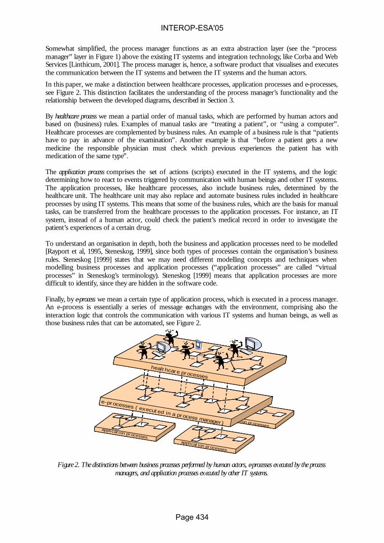
Somewhat simplified, the process manager functions as an extra abstraction layer (see the “process manager” layer in Figure 1) above the existing IT systems and integration technology, like Corba and Web Services [Linthicum, 2001]. The process manager is, hence, a software product that visualises and executes the communication between the IT systems and between the IT systems and the human actors.
In this paper, we make a distinction between healthcare processes, application processes and e-processes, see Figure 2. This distinction facilitates the understanding of the process manager’s functionality and the relationship between the developed diagrams, described in Section 3.
By healthcare process we mean a partial order of manual tasks, which are performed by human actors and based on (business) rules. Examples of manual tasks are “treating a patient”, or “using a computer”. Healthcare processes are complemented by business rules. An example of a business rule is that “patients have to pay in advance of the examination”. Another example is that “before a patient gets a new medicine the responsible physician must check which previous experiences the patient has with medication of the same type”.
The application process comprises the set of actions (scripts) executed in the IT systems, and the logic determining how to react to events triggered by communication with human beings and other IT systems. The application processes, like healthcare processes, also include business rules, determined by the healthcare unit. The healthcare unit may also replace and automate business rules included in healthcare processes by using IT systems. This means that some of the business rules, which are the basis for manual tasks, can be transferred from the healthcare processes to the application processes. For instance, an IT system, instead of a human actor, could check the patient’s medical record in order to investigate the patient’s experiences of a certain drug.
To understand an organisation in depth, both the business and application processes need to be modelled [Rayport et al, 1995, Steneskog, 1999], since both types of processes contain the organisation’s business rules. Steneskog [1999] states that we may need different modelling concepts and techniques when modelling business processes and application processes (“application processes” are called “virtual processes” in Steneskog’s terminology). Steneskog [1999] means that application processes are more difficult to identify, since they are hidden in the software code.
Finally, by e-process we mean a certain type of application process, which is executed in a process manager. An e-process is essentially a series of message exchanges with the environment, comprising also the interaction logic that controls the communication with various IT systems and human beings, as well as those business rules that can be automated, see Figure 2.
Figure 2. The distinctions between business processes performed by human actors, e-processes executed by the process
managers, and application processes executed by other IT systems.
application processes
e-processes ( executed in a process manager)application processes
application processes
healthcare processes
application processes
e-processes ( executed in a process manager)application processes
application processes
healthcare processes
application processes
e-processes ( executed in a process manager)application processes
application processes
healthcare processes
INTEROP-ESA'05
Page 434

The benefits of a process manager are many. The communication between the IT systems and between the IT systems and the human actors may be changed at any time. This can be done by changing the e-process, which is executed in the process manager. The process manager also contains specific tools for e-process design and change. Since the process manager executes the graphical diagrams, it also facilitates monitoring the e-process. The process diagrams can then be used to study the state of the instances of a single patient process while it is running, e.g., to check the transfer of information concerning a particular treatment for the specific patient between two or more healthcare providers. It is also possible to let the process manager simulate process scenarios in order to come up with an optimal communication pattern.
Much effort is presently spent on developing process manager technology. Some products that use this philosophy are Vitria Technology’s BusinessWare, IBM’s Websphare MQ Workflow , Microsoft’s Biztalk Server, and Visuera Integration AB’s Visuera Process Manager (PM). Furthermore, message brokers and application servers enhance their functionality with graphical process model management, to get closer to process manager functionality [Linthicum, 2001]. 3 Method support for process managers In the Vita Nova projects, the Visuera Process Manager [Visuera, 2004] was used, together with a method in which Business Model Language (BML), a graphical process modelling language for modelling and executing e-processes. BML, was integrated with UML Activity diagrams, which describes the healthcare processes.
Figure 3. Healthcare processes (modelled using UML Activity diagram), e-process (modelled using BML) and integrated IT system in different swim lanes.
Home care e-processes
Primary care healthcare processes
Home Care healthcare processes
Nurse
Process manager
Home care
Patient
Primary care e-processes
Home care healthcare processes
Primary care healthcare processes
Nurse
Process manager
Primary care
Patient
Physician
StartTimer
Wait for
Event
Expire Timer
End register
admissionreply
StartTimer
Wait for
Event
Expire Timer
End register
admissionreply
IT System AIT System B
-
IT System B
-
IT System C
IT System D
IT System A
IT System D
IT System C
AHome care e-processes
Primary care healthcare processes
Home Care healthcare processes
Nurse
Process manager
Home care
Patient
Primary care e-processes
Home care healthcare processes
Primary care healthcare processes
Nurse
Process manager
Primary care
Patient
Physician
StartTimer
Wait for
Event
Expire Timer
End register
admissionreply
StartTimer
Wait for
Event
Expire Timer
End register
admissionreply
StartTimer
Wait for
Event
Expire Timer
End register
admissionreply
StartTimer
Wait for
Event
Expire Timer
End register
admissionreply
IT System AIT System B
-
IT System B
-
IT System C
IT System D
IT System A
IT System D
IT System C
A
INTEROP-ESA'05
Page 435

BML [Johannesson et al, 2001; Wåhlander et al, 2001 ] has similarities with Specification and Description Language (SDL), but is more adapted to IT systems integration. BML’s metamodel consists of a limited number of concepts; the main are: “receive message”, “send message”, “automated task”, “choice”, “start timer” and “timer expired”. In Visuera Process Manager, BML is used directly as an implementation language and replaces, to some extent, ordinary programming languages.
UML Activity diagrams are used for modelling the healthcare processes. By adding swim lanes (in UML 2.0 called partitions) to the method, diagrams of different healthcare processes can be related, e.g, the patients’ process, nurses’ process and physicians’ process.
In Figure 3, two different swim lane models, the home healthcare processes and the primary care healthcare processes, are specified. For each healthcare unit the different healthcare processes (patient, nurse and physician) are specified using UML Activity diagrams. These diagrams are related to each other and to the e-processes, represented as BML diagrams. The BML diagrams will be executed in the process manager. Finally, the e-processes are related to the IT system, which the e-process integrate. In Figure 3 the relations (i.e., message passing) between the healthcare processes, the e-processes and the IT systems are visualised as dotted lines. Note that IT system from different healthcare units also are integrated via the process manager (see A in Figure 3).
The different IT systems’ application processes were not modelled in the Vita Nova projects. Such a task will probably be time consuming since experiences from the Vita Nova projects showed that a several existing IT system were poorly documented. However, a major idea in the Vita Nova projects was to transfer the business rules from the applications to the e-processes, which will create a flexible integration solution.
4 Design solutions In this section we present a number of design solutions, i.e., laboratory solutions which are not yet implemented in industry. However, they have been partially validated in the Process Broker and Vita Nova project. The design solutions are described by the following form:
• Context – describe the situation/circumstances to situate the targeted interoperability problem
• Problem – an explicit statement of the interoperability problem concerned • Solution – describe the implemented practice (proposed solution) to solve the problem
defined • Strength – the strong point of the solution and its possible limitation
4.1 Value based process modelling Context Conceptual models have become important tools for designing and managing complex, distributed and heterogeneous systems, e.g. e-commerce and e-health [UN/CEFACT, 2003]. In e-commerce and e-health it is possible to identify two basic types of conceptual models: business models and process models. A business model focuses on the what in a system, identifying agents, resources, and exchanges of resources between agents. Thus, a business model provides a high-level view of the activities taking place in e-commerce and e-health. A process model, on the other hand, focuses on the how in an e-commerce or e-health system, specifying operational and procedural aspects of business communication. The process model moves into a more detailed view on the choreography of the activities carried out by agents [Gordijn et al, 2000]. Problem In order to realize interoperability between services and systems, it is required to make their underlying processes interoperable. Designing and understanding the interrelationships between a numbers of complex interacting processes can be a difficult and time consuming task. Furthermore, it is often difficult to understand why a process model has been designed in a certain way and what consequences alternative designs would have.
INTEROP-ESA'05
Page 436

Solution Process models should be given a declarative foundation by basing them on business models that describe the exchange of value. Two instruments for a declarative foundation of process models are process patterns and activity dependencies. A process pattern is a generic template for a set of interrelated activities between two agents, while an activity dependency expresses a sequential relationship between two activities [Bergholtz et al, 2004]. There exist many different kinds of patterns for business processes. These include basic workflow patterns [Aalst el at, 2003], transaction patterns as in ebXML [UN/CEFACT, 2003] and more complex patterns like the Action Workflow pattern [Winograd el at, 1986]. Such patterns provide a basis for a partial ordering of the activities taking place in a business process. However, the ordering derived from such process patterns only provide a starting point for designing complete business process diagrams, i.e., it needs to be complemented by additional interrelationships among the activities in the process diagram to be designed. These interrelationships should have a clear business motivation, i.e., every interrelationship between two activities should be explainable and motivated in business terms. We suggest formalizing this idea of business motivation by introducing the notion of activity dependencies. An activity dependency is a pair of activities, where the second activity for some reason is dependent on the first one. We identify four different kinds of activity dependencies, each one providing a particular reason expressed in business terms, for the interrelationship between the activities. Flow dependencies. A flow dependency [Malone et al, 1999] is a relationship between two activities, which expresses that the resources obtained by the first activity are required as input to the second activity. An example could be a retailer who has to obtain a product from an importer before delivering it to a customer. Another example could be that a healthcare unit needs to have a delivery of a certain resource type before a therapy could be performed. Trust dependencies. A trust dependency is a relationship between two activities, which expresses that the first activity has to be carried out before the other one as a consequence of low trust between the agents. Informally, a trust dependency states that one agent wants to see the other agent do her work before doing his own work. An example could be a car dealer who requires a down payment from a customer before delivering a car. Another example could be that a patient’s insurance company has to pay the healthcare unit before a therapy could be performed. Control dependencies. A control dependency exists when one agent wants information about another agent before establishing a contract with that agent. A typical example could be a company making a credit check on a potential customer. Another example could be that a healthcare unit needs to check with another unit about a patient’s status, before treating the patient. Negotiation dependencies. A negotiation dependency expresses that an agent is not prepared to establish a contract with another agent before she has established another contract with a third agent. One reason for this could be that an agent wants to ensure that certain resources can be procured before entering into a contract where these resources are required. Another reason could be that an agent does not want to procure certain resources before there is a contract for an activity where these resources are required. An example could be that a healthcare unit need to establish a contract with another healthcare unit before promising to perform a therapy. A business process diagram can be understood and designed based on process patterns and activity dependencies. Designing a business process diagram is not a trivial task but requires a large number of design decisions. In order to support a designer in this task, we propose an automated designers assistant that guides the designer through the task by means of a sequence of questions. The questions can be divided into four steps, see Figure 4.
Step 1 during which the business model is established. The information gathered in this phase is about the agents involved in the business process, the resources exchanged between them, and the activities through which these resources are exchanged. The result from this step is a business model.
INTEROP-ESA'05
Page 437

Step 2 during which information about the (partial) order between the activities is gathered. The result from this step is an ordering of the activities in the execution phase of a process model.
Step 3 during which information about existing negotiation dependencies is gathered. The result from this step is an ordering of the activities in the negotiation phase of a process model.
Step 4 during which the communicative acts needed to handle the activities are introduced and the (partial) order between them is established. The result from this step is an ordering of activities that crosses the negotiation and execution phases.
Step 5 during which set of production rules needed to be applied on introduced patterns with respect to execution, negotiation and process orders.
Q-A Session Q-A Session Q-A Session Q-A Session Auto Generation
Business Model Execution Order Negotiation Order Refined Order ProcessModel
Step 1 Step 2 Step 3 Step 4 Step 5
Figure 4. Steps of the Designer Assistant
Strength Process models that are given a declarative foundation based on business models would provide justifications, expressible in business terms, for design decisions made in process modelling, thereby facilitating communication between systems designers and business users. Following the layered approach of section 2 and 3, we have by introducing the value concept added a third level, the business model, describing the value foundation of the business. Graphically this can be viewed as in Figure 5.
Figure 5. A business model layer added above the healthcare processes. The business model provides justification to the design decisions made in process modelling.
4.2 View based process modelling
Context
Process diagrams have become an important tool for specifying and analysing the business processes and the e-processes, which are constructed to be executed in process managers. However, when integrating
IT-system
IT-system IT-system
e-processesCORBA
Web services
IT-system
healthcare processes
business models
INTEROP-ESA'05
Page 438
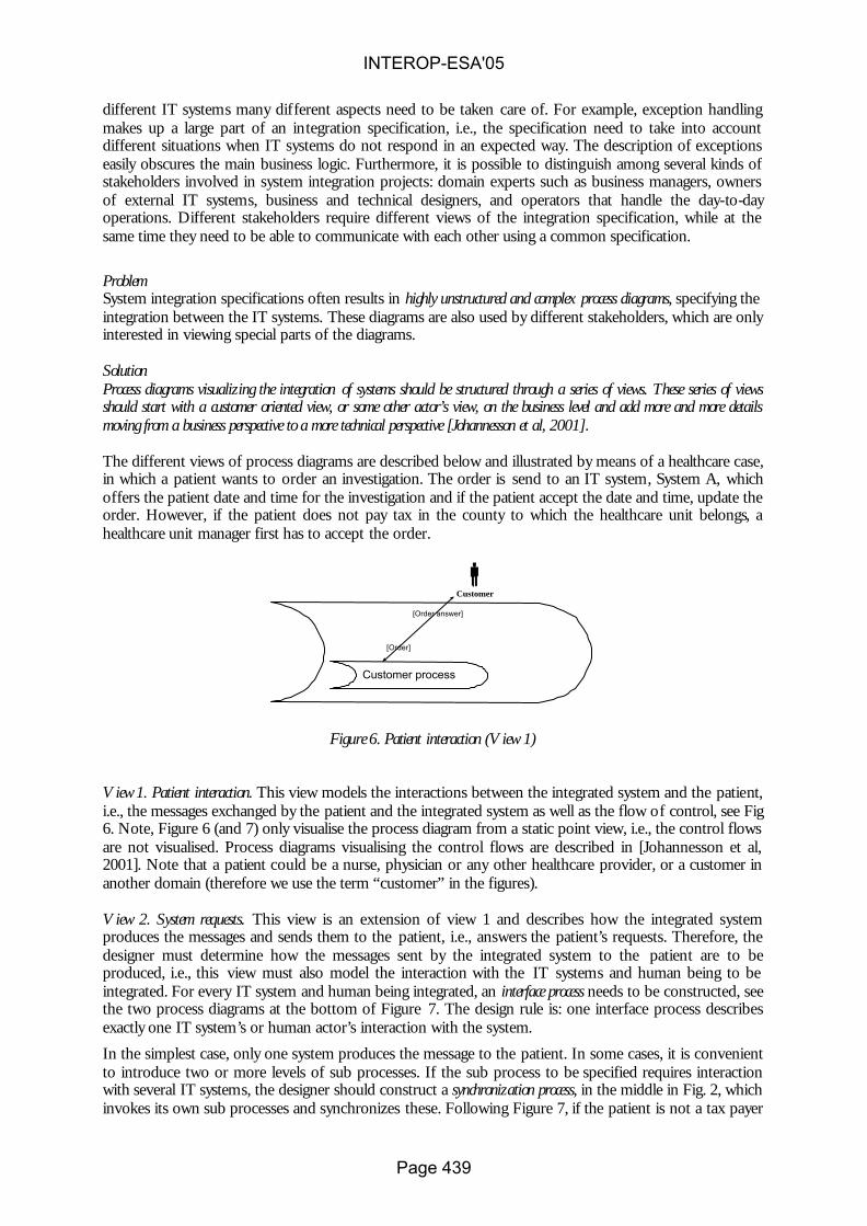
different IT systems many different aspects need to be taken care of. For example, exception handling makes up a large part of an integration specification, i.e., the specification need to take into account different situations when IT systems do not respond in an expected way. The description of exceptions easily obscures the main business logic. Furthermore, it is possible to distinguish among several kinds of stakeholders involved in system integration projects: domain experts such as business managers, owners of external IT systems, business and technical designers, and operators that handle the day-to-day operations. Different stakeholders require different views of the integration specification, while at the same time they need to be able to communicate with each other using a common specification.
Problem System integration specifications often results in highly unstructured and complex process diagrams, specifying the integration between the IT systems. These diagrams are also used by different stakeholders, which are only interested in viewing special parts of the diagrams. Solution Process diagrams visualizing the integration of systems should be structured through a series of views. These series of views should start with a customer oriented view, or some other actor’s view, on the business level and add more and more details moving from a business perspective to a more technical perspective [Johannesson et al, 2001]. The different views of process diagrams are described below and illustrated by means of a healthcare case, in which a patient wants to order an investigation. The order is send to an IT system, System A, which offers the patient date and time for the investigation and if the patient accept the date and time, update the order. However, if the patient does not pay tax in the county to which the healthcare unit belongs, a healthcare unit manager first has to accept the order.
Customer process
Customer
[Order answer]
[Order]
Figure 6. Patient interaction (View 1)
View 1. Patient interaction. This view models the interactions between the integrated system and the patient, i.e., the messages exchanged by the patient and the integrated system as well as the flow of control, see Fig 6. Note, Figure 6 (and 7) only visualise the process diagram from a static point view, i.e., the control flows are not visualised. Process diagrams visualising the control flows are described in [Johannesson et al, 2001]. Note that a patient could be a nurse, physician or any other healthcare provider, or a customer in another domain (therefore we use the term “customer” in the figures). View 2. System requests. This view is an extension of view 1 and describes how the integrated system produces the messages and sends them to the patient, i.e., answers the patient’s requests. Therefore, the designer must determine how the messages sent by the integrated system to the patient are to be produced, i.e., this view must also model the interaction with the IT systems and human being to be integrated. For every IT system and human being integrated, an interface process needs to be constructed, see the two process diagrams at the bottom of Figure 7. The design rule is: one interface process describes exactly one IT system’s or human actor’s interaction with the system.
In the simplest case, only one system produces the message to the patient. In some cases, it is convenient to introduce two or more levels of sub processes. If the sub process to be specified requires interaction with several IT systems, the designer should construct a synchronization process, in the middle in Fig. 2, which invokes its own sub processes and synchronizes these. Following Figure 7, if the patient is not a tax payer
INTEROP-ESA'05
Page 439

in the region, the synchronization process sends a message to both Interface process a and b. Interface process b sends a massage to the Manager, which has to accept the order or not.
Customer process
Customer[Order answer]
Synchronisation process
[Order]
App A
Interface process b
Manager
Interface process a
[Order2][Order answer2]
[Question manager]
[Manager answer] [Update answer][Update]
[Manager answer2]
[Question manager2]
[Update answer2]
[Update2]
Figure 7. System request (view 2)
View 3. Exception handling and resource releasing. First, this view specifies the exception handling. Views 1 and 2 specify only the normal course of events. In view 3, the process diagrams specify how to handle exceptions, i.e. situations where an external IT system or a human actor has not replied to a request within a pre-specified time limit. Secondly, this view describes resource releasing. When a process cannot be completed as intended, it becomes necessary to release the resources that have been reserved or booked during the process. View 4. Notifications. This view adds all notifications messages. We have identified three situations where notification messages are required. First, when an exception has occurred, it is customary to inform an operator about this event so that he or she may take appropriate action. Secondly, a notification about essential states of affairs may be sent to a maintenance process which redundantly stores the information. The need for such a maintenance process is described in Section 4.3. Thirdly, a notification can be sent to a data warehouse, which uses the information for strategic analysis and decision. Strength The views presented above can be used for two reasons. First, it could help the designer to construct the process diagrams. A designer could utilize the views by first constructing a process diagram according to view 1 and then gradually refining it until a set of diagrams in view 4 is obtained. Therefore, the views can be seen as steps in a method for designing process diagrams. Secondly, it can be used for presentation purposes to show or hide parts of process diagrams. Business oriented users can choose to see only the top view or views, while technical designers and implementers can proceed to the lower views. Even for the latter category of stakeholders, the layered views can help to understand a system by allowing the focus on an essential business perspective first and thereafter proceed to a technical perspective. Different categories of users, for example customers/healthcare providers, business and technical designers, have the possibility of suggesting input on the right level in the modelling process. Business designers probably want to concentrate on the important parts of the business processes to clarify how they want the main business logic to work. The views presented above may apply to the healthcare process as well as the e-processes. 4.3. Master storage for process managers Context Integration of IT systems can be supported by many different architectures. One architecture for integrating IT systems is the point-to-point solution where every IT system is directly connected to every
INTEROP-ESA'05
Page 440

other IT system, see Figure 8 (left). This solution could work for a small number of IT systems, but as the number of IT systems increases, the number of connections quickly becomes overwhelming. By using a central message broker, see Figure 8 (middle) or process manager, see Figure 8 (right), this complexity is reduced, i.e., the number of interfaces will be reduced, tools to facilitate the format conversions can be applied, and the visualisation added by the process manager enables different categories of people to take part in the process design.
Figure 8. Point-to-point solution to the left, and many-to-many solutions in the middle (a massage broker) and to the right (a process manager).
Problem Integration of IT systems is a complex task and it is seldom possible to integrate every IT system at one occasion. Therefore, integrated IT systems can still communicate with external systems, which are not part of the integrated solution. These IT systems can be updated without the message broker or process manager being notified. For example, information about a patient can be changed by mistake when an external system communicates with IT system connected to the integrated solution. Solution When integrating different IT system, for example by using a message broker or process manager, a master storage should be developed that duplicates part of the data in the integrated IT systems [Johannesson et al, 2001]. Strength There are several reasons for maintaining redundant information in a master storage. First, it is possible that the integrated IT system can be updated without the message broker or process manager being notified. By using an internal storage the system has complete and correct data saved in one place. Secondly, if the patient or customer service quickly requires information about, for example, an order, the system does not have to query several IT systems; it only has to query the master storage. It is not unusual that information about a patients or customer is distributed over several IT systems. In that case, the internal storage is from a performance perspective, an important improvement of a system. Thirdly, the opportunity to notify an internal storage of important events that occur in the system, makes it possible to create a data warehouse that is updated in real-time. A message broker or process manager can support data movement in real-time and it thereby can provide business managers with constantly new information, which can be aggregated. 5 Conclusions In section 1 we introduced the following issues that need to be addressed: Business Orientation, Traceability, and Information correctness. Business Orientation is about describing the business processes in business terms. This is addressed through both the value and view based process modelling. These design solutions focus on business oriented concepts like value, customer and provider, instead of going directly into procedural details. This allows a stakeholder to get a high level overview of the process expressed in familiar business terms.
IT system A IT system B
IT system CIT system C
Process Manager
Human Role
Message Broker
IT system AIT system B
IT system CIT system D
IT system A
IT system B
IT system C
Application AApplication AApplication AIT system D
INTEROP-ESA'05
Page 441

Furthermore, when the stakeholder wants to get deeper into the details of the process she can use the views of the models to hide details irrelevant for her present purposes. Traceability is about understanding and tracking the reasons for design decisions in a process model. This is also addressed through the value based process modelling. Reasons for process design are based on value concepts complemented by action dependencies and process patterns. These allow a stakeholder to understand specific process designs in terms of higher level concepts, which also provides a basis for generating and comparing alternative designs, Information correctness is about maintaining a consistent and correct view of the information in the entire distributed system in spite of local autonomy. This problem is addressed by the master storage design solution, which offers an additional storage for ensuring information correctness. We believe that the proposed design solutions will provide important benefits for process modelling and managers, thereby strengthening one of the most promising approaches for interoperability. Further work will include the identification of additional process patterns as well as empirical validation in healthcare IT systems.
Acknowledgement The authors would like to thank all the VITA Nova project members. The VITA Nova – Hemma project is sponsored by the Vinnova (Swedish Agency for Innovation Systems) program for IT in home healthcare. The project is part of the joint research activities “Design principles for interoperability” (WP6) and “Enterprise interoperability architectures” (WP9) of the INTEROP Network of Excellence sponsored by EU. References
[Aalst et al, 2003] van der Aalst, W.M.P., ter Hofstede A.H.M., Kiepuszewski B., and Baros A.P.: Workflow Patterns”, Distributed and Parallell Databases, 14(3), July, 2003
[Bergholz et al, 2004] Bergholz, M.. Jayaweera, P., Johannesson, P., Wohed, P.: A pattern and dependency based approach to the design of process models, accepted at ER 2004, Shanghai, China, 2004
[Dayal et al, 2001] Dayal U., Hsu M., Ladin R.: Business Process Coordination: State of the Art, Trends, and Open Issues, In: Proceedings of the 27th International Conference on Very Large Data Bases, September 11-14, Roma, Italy, pp. 3-13, 2001
[Gordijn et al, 2000] Gordijn, J., Akkerman J.M. and Vliet J.C.,: Business Modelling, is not Process Modelling, Proc. of the 1th International workshop on Conceptual Modeling Approaches for e-Business (eCOMO’2000) (2000)
[Haux et al, 2004] Haux R., Winter A., Ammenwerth E., Birgl B., Strategic Information Management i Hospoitals. An introduction to Hospital Information Systems, Health Informatics Series, Springer, 2004
[Johannesson et al, 2001] Johannesson P., Perjons E.: Design principles for process modelling languages in enterprise application integration, Information System, 26, pp. 165-184, 2001
[Linthicum, 2001] Linthicum, S. D.: B2B Application Integration – e-Business-Enable Your Enterprise, Addison-Wesley, 2001
[Malone et al, 1999] Malone, T., Crowston, K., Lee J., Pentland, B., Dellarocas C., Wyner, G., Quimby, J., Osborn, C., Bernstein, A., Herman, G., Klein, M., and O´Donnell, E. (1999), “Towards a Handbook of Organisational Processes”, Management Science, Vol 45, No 3, pp. 425-443.
[McCarthy, 1992] McCarthy, W.E.: The REA Accounting Model: A Generalized Framework for Accounting Systems in Shared Data Environment, The Accounting Review (1992)
INTEROP-ESA'05
Page 442

[Oellerman, 2001] Oellermann W. L.:Architecting Web Services, Apress, 2001
[Perjons et al, 2004] Perjons E., Wangler B., Wäyrynen J., Åhlfeldt R.-M.: "Introducing a Process Manager in Healthcare. An experience report", In: Proceedings of The Ninth International Symposium on Health Information Management Research (ISHiMR), Sheffield, June 15 – 17, 2004
[Steneskog, 1999] Steneskog G.: Business Process Models Revised: Challanging the Physical Metaphor, in Nilsson A. G., Tolis C., Nellborn C. (eds): Perpectives on Business Modelling, Springer-Verlag, 1999
[Rayport et al, 1995] Rayport J.F., Svikola J.J: Exploiting the Virtual Value Chain, Harvard Business Review, Nov-Dec, 1995
[UN/CEFACT, 2003] UN/CEFACT Modelling Methodology (UMM), Revision 10, available at (2003-04-04) http://www.untmg.org/doc_bpwg.html (2003)
[Vissers, 1998] Vissers, J. M. H.: Health care management modelling: a process perspective, Health Care Management Science, 1, pp. 77-85, 1998
[Visuera, 2004] Visuera Process Manager, Visuera Integration AB, [online] http://www.visuera.com [accessed Jan 2004]
[Wangler et al, 2003] Wangler B., Åhlfeldt R.-M., Perjons E.: Process oriented information systems architectures in healthcare, Health Informatics Journal, Vol 9(4), pp. 253-265, 2003
[Winograd et al, 1986] Winograd, T., and Flores, F.: Understanding Computers and Cognition: A New Foundation for design, Ablex, Norwood, N.J. (1986)
[Wåhlander, et al, 2001] Wåhlander, C., Nilsson, M., Törnebohm, J., 2001. Visuera Process Manager.Visuera Integration AB.
INTEROP-ESA'05
Page 443

The Knowledge Web Network of Excellence
Enrico FranconiFaculty of Computer Science, Free University of Bozen-Bolzano, Italy
http://www.inf.unibz.it/∼franconi/
Abstract
In a nutshell, the mission of Knowledge Web isto strengthen the European industry and serviceproviders in one of the most important areas of cur-rent computer technology: Semantic Web enablede-work and e-commerce. We will concentrate ourefforts around the outreach of this technology to in-dustry. Naturally, this includes education and re-search efforts to ensure the durability of impact andsupport of industry. Therefore, the main objectivesof Knowledge Web are: Outreach to Industry, Out-reach to Education and Coordination of Research.
1 Summary of ActivitiesKnowledge Web (KW) is a 4 year Network of Excellenceproject funded by the European Commission 6th FrameworkProgramme. Knowledge Web began on January 1st, 2004.Supporting the transition process of Ontology technologyfrom Academia to Industry is the main and major goal ofKnowledge Web.
The mission of KnowledgeWeb is to strengthen the Euro-pean industry and service providers in one of the most im-portant areas of current computer technology: Semantic Webenabled E-work and E-commerce. The project concentratesits efforts around the outreach of this technology to industry.Naturally, this includes education and research efforts toen-sure the durability of impact and support of industry. There-fore, Knowledge Web devotes its efforts to the following mainareas:
• Outreach to Industry. The main objective of KnowledgeWeb’s outreach to industry area is to promote greaterawareness and faster take-up of Semantic Web technol-ogy within Europe in full synergy with the research ac-tivity. This outreach will help to reduce time needed totransfer the technology to industry and to market.
• Outreach to Education. Knowledge Web aims to worktowards the establishment of a Virtual Institute for Se-mantic Web Education (VISWE), which will act as theprincipal focus for educational activities on SemanticWeb.
• Coordination of Research. The objective of KnowledgeWeb will be to ensure that the research as performed by
the leading groups in this area will be sufficiently coordi-nated to avoid both duplication and fragmentation. Suchcoordination is particularly important for the SemanticWeb: since it is an inter-disciplinary area, joint collabo-rations among and across various research communitiesis necessary. The objective of Knowledge Web is to co-ordinate the European research effort to make SemanticWeb and Semantic Web Services a reality.
The Knowledge Web consortium is coordinated by theUniversity of Innsbruck, Austria and consists of 18 leadingpartners in Semantic Web, Multimedia, Human LanguageTechnology, Workflow and Agents.
At the end of its first year the Knowledge Web networkis in good shape. Partners are doing integrated research onthe themes defined in the JPA: scalability, heterogeneity, dy-namics, web services and language extensions. The networkhas started an exchange program for researchers to work for aprolonged period at another institute. At this early stage thereare already visible signs of impact, such as the W3C note onthe semantic-web rule language SWRL. One look at the pro-ceedings of the 2004 International Semantic Web Conferencein Hiroshima (acceptance rate: 22%) makes clear that Knowl-edge Web partners are (the) key players in this field. Anothersign is the fact that a Knowledge Web participant won the2004 Semantic Web Challenge (a contest for semantic webapplications, seehttp://challenge.semanticweb.org/), beating for example a large NASA project. In ad-dition, the network is starting outreach activities, includingsetting up an growing industrial board. The outreach activityis focusing on realistic use cases and showcase applications.Network partners also play a key role in the new W3C Se-mantic Web Best Practices and Deployment Working Group,which is in the process of producing low-entry advisory notesfor application developers. Finally, the network has been ac-tive in creating an educational infrastructure, such as a poolof learning modules and the organization of a highly-praisedsummer school in Spain. Overall, the network is in pole po-sition to make the Semantic Web work.
2 Important Work Areas :: IndustryWe are dedicated to promoting greater awareness and fastertake-up of Semantic Web technology within Europe in fullsynergy with the research activity in order to reduce time
INTEROP-ESA'05
Page 444

needed to transfer the technology to industry and so to mar-ket. We have established an industry board as an effectivecommunication channel between industry and academia, inorder to: understand industry needs and difficulties of migrat-ing Semantic Web technologies to industry; survey and pro-file the existing ontologies, tools, infrastructures etc.;makerecommendations, guidelines and standards to help industryorganize, design and implement their migration into SemanticWeb technology enabled IT systems; and promote awarenessof the added value of the Semantic Web technologies in theincreasingly competitive knowledge economy.
Industry BoardWe have established an industrial board composed of indus-trial organizations that should benefit from ontology tech-nologies (both technology push and technology pull organi-zations). The current board consists of 28 industry member.The members of our Industry board are given a privilegedaccess to our network of top leading expertise and upstreamtechnology. We aim to increase this number by 50 membersevery year, resulting in 200 members (at least) by the end ofthe project.
Understanding industrial needsWe are actively working on collecting and analyzing use andbusiness cases from industry. Our analyses will on the onehand show how semantic web technologies have or couldhave solved (hypothetically) concrete business issues, ontheother hand evaluate the applicability of semantic web tech-nologies in real business cases. We are mainly focusing ontestifying the utility of the current semantic web tools, inter-operability of tools and services, and ontology content evalu-ation and usability.
We are currently busy capturing best practices of the bestapplications using empirical evidence given by the Industrypartners on the board and from our own objective evaluations.
Promotion of ontology technologiesSeveral technology show events have been organized (andplanned) with the aim of promoting the main achievementsto public and private institutions. These events take the formof international forums where speakers from both industryand academia are invited to present their view on the topicsaddressed by Knowledge Web.
3 Important Work Areas :: ResearchThe network is actively working in the important research ar-eas required to make the Semantic Web a reality for Europeanand global commercial enterprises and for the benefit of Eu-ropean society. Work on making the tools and infrastructurehas been actively tackled by X number of institutions fromY different countries in Z meetings involving W researchersto: scale the semantic web to the size of the web; able to dealwith the diversity and heterogeneity of the semantic web; ableto embrace the dynamic and changing nature of the semanticweb; and able to support a distributed communitys develop-ment and maintenance of the semantic content necessary topopulate a semantic web. In-depth and wide-spread analysisof the state of the art for all these research areas have beencompleted and published.
Development of standardsBuilding on the success of the W3C Web Ontology Lan-guage OWL, standardized chiefly through the efforts of theOntoWeb thematic network, a unified framework has beendeveloped and published by Knowledge Web in which the ex-isting (and future) proposals of integrating different sorts ofrule based language with OWL can be compared. This willfeed the W3Cs Semantic Web activity standardisation efforts,and is directly linked with the work of the FP6 REWERSENoE.
A virtual research communityAs part of its activity to sustain a vibrant pan-organisation re-search environment we have established a topic-oriented re-searcher exchange (T-REX) program to enable long-term im-pact.
The short-term goal of T-REX is to encourage, supportand manage primarily the exchange of researchers across allKnowledge Web members, but also to encourage exchangeswith external parties. The long-term goal of T-REX is tostrengthen the European research area by establishing strongand lasting links across research organizations.
4 Important Work Areas :: EducationA conventional learning unit repository is now available atL3S (http://ubp.learninglab.uni-hannover.de/EducaNext/ubp). In order to collect existing learningunits about the Semantic Web and related topics, a question-naire was prepared and distributed among all KnowledgeWebpartners. Based on the feedback to the questionnaire, a firstset of educational metadata has been selected, which has tobe specified by each provider of learning units. A first setof over 30 learning units has already been inserted into thedelivery platform and can be booked by interested users.
As a pilot implementation of semantic add-ons to theconventional learning unit repository we deployed Mag-pie, http://kmi.open.ac.uk/projects/magpie,a tool which supports no-cost semantic web browsing andhelps a user to make sense of material on the web. Mag-pie operates by making use of domain ontologies to dynami-cally annotate texts. Starting with the published materials inthe repository, Magpie supports the user in interpreting com-plex scientific materials by extracting key aspects and dynam-ically linking them to resources outside the repository andto semantic web services. These resources capture declara-tive knowledge agreed to be of significance by the particularknowledge community - in this case that of Semantic WebStudies (SWS).
First experiments using Magpie in the learning and teach-ing context have been conducted in the domain of climatol-ogy. We expect that lessons learned in this pilot will providefurther data to shape the design and implementation of theadvanced semantic platform for learning, which is the mainfocal point of our work in the upcoming months.
Virtual Institute for Semantic Web Education (VISWE)VISWE is intended as an umbrella for all education area ac-tivities within Knowledge Web, i.e. it is intended to be theorganizational umbrella for the summer school and also to
INTEROP-ESA'05
Page 445

be responsible for the learning unit repository. It has beenagreed that VISWE shall be founded as an association ac-cording to German civil law which ensures endurability ofthe Knowledge Web educational activities even after the endof the project. VISWE will, however, not take responsibilitiesfor the content being stored in the platform, as the copyrightfor these materials will remain with the authors of the learn-ing units.
5 User Involvement, Promotion andAwareness
The industry board of Knowledge Web comprises 28 highlydedicated members. Several meetings are planned tostrenghten the links between these members and the Knowl-edge Web project.
Among the very successful events which contribute to thenotoriety of Knowledge Web are the summer school orga-nized last summer. The participation of Knowledge Webmembers in various programme committees, W3C workinggroups and its organization of events (like next ISWC in Gal-way) contribute to the visibility of the network.
FP6 integrated projects SEKT, DIP, and Knowledge webhave created the SDK cluster for facilitating the coordinationbetween these projects and promoting them. This cluster re-volve around two interest groups dedicated to Ontologies andSemantic web services. It also organizes the two first Euro-pean Semantic Web Conference. Knowledge Web cooperateswith the Rewerse NoE on industry, research and education ac-tivities. It also has cooperations with FP6 projects AgentLinkIII and Ontogrid and FP5 projects Ontoweb, Esperonto andSWWS.
Summer School 04The SSSW-04 took place in July in Cercedilla (Spain) underthe direction of Prof Enrico Motta (Open University, UK) andProf. Asun Gomez-Perez (UPM, Spain). The SSSW seriesof summer schools has established itself as the key educa-tional event in the area of semantic technologies and it is nosurprise that we have received many testimonials from stu-dents, tutors and invited speakers. As an example, Prof. JimHendler, head of the W3C working group on ontology lan-guages and one of the invited speakers to SSSW-04, pointedout that the week he spent at the summer school was the ”mostfun I’ve had in a long time (academically speaking)” One ofthe key reasons for the success of the school is its construc-tivist approach, which is in contrast with most other summerschools. Hands-on sessions allow the students to familiarizethemselves with key technologies, while team-based work ona week-long project gives them the possibility to explore re-search ideas in collaboration with other students and with thesupport of the tutors. At the end of the school the studentspresent their work and prizes are awarded for the best efforts.
The Knowledge Web Semantic PortalSince March 1st 2004, the public version of the KWportal has been running athttp://knowledgeweb.semanticweb.org/. The portal includes a public areawith public information to be used by anybody interested inknowledge technologies, and also a restricted area to be used
by KW partners. The portal has highly visibility and it is inthe second position in Google at the time of writing this re-port. The first prototype of the Knowledge Web SemanticPortal has the following functionalities:
• Knowledge Presentation. This is done by means of user-defined visualizations of ontology classes, relations andinstances with different browsing permissions for por-tal users. The knowledge stored in the portal can be ac-cessed with menus generated automatically from ontolo-gies that are synchronized, and can be viewed differentlyaccording to the various types of information stored inthem.
• Knowledge Editing. This portal allows inserting, updat-ing and removing class instances, their attributes and re-lation instances, in multiple inter-linked ontologies andwith different edition permissions for the portal users.
• Knowledge Search and Querying based either on key-words or on the structured information provided by theontologies inside the system.
• Administration Services, which allow managing the se-mantic portal users, the editing and visualization permis-sions, and some other portal needs.
The Knowledge Web Semantic Portal is able to managemultiple ontologies. To use this semantic portal as a toolfor monitoring the Knowledge Web NoE, the first draft ofthe ontologies includes information about the project (mile-stones, workpackages, etc.), the organizations participating,the people involved in the project, the documents related tothe project (deliverables, minutes, etc.), and the events associ-ated with such project. That is, currently, five domain-specificontologies (Documentation, Event, Organization, Person andProject) have been developed to be included in the Knowl-edge Web Semantic Portal.
6 Future WorkThe network is currently performing a self-assessment whichwill lead to a new JPA. At this stage it is safe to say that we donot foresee major changes in the network. There will howeverbe some natural focus changes. Whereas the research workpackages have mainly worked internally in the first year, weexpect to see more cross fertilization between work packagesin the second year. Also, the exchange program is expectedto grow significantly, possibly also including visits from em-ployees of industry board members to network partners aswell as exchanges with other IST networks. With respectto outreach, the network is expected to focus even more onshowcase applications to demonstrate clearly the added valueof semantic-web technology to foster uptake by newcomers.We expect more organizations to join the industry board, in-cluding nonprofit organizations. There will also be a steadyflow of Knowledge Web output to the various standards bod-ies. The summer school will be continued but the networkwill consider organizing also educational activities for mem-bers of the industry board. In addition, educational moduleswill become available, supported by semantic-web technol-ogy. We are looking forward to the second year of the net-work.
INTEROP-ESA'05
Page 446

Interoperability Contributions of CrossWork
Nikolay Mehandjiev1, Iain Duncan Stalker1, Kurt Fessl2, Georg Weichhart2
1 School of Informatics, the University of Manchester, UK [email protected]
2 Profactor Produktionsforschung GmbH, Austria
Effective cross-organisational collaboration enables a company to focus on its core business within a dynamic network of partners providing complementary expertise. This allows companies of all sizes to pursue immediate opportunities in the market-place through participation in virtual organizations and dynamic supply chains. Such collaboration-based business models, however, place substantial demands on soft-ware infrastructures to ensure robust intersystem communication, meaningful infor-mation exchange and successful coordination of processes and activities. Interopera-bility at all levels is paramount and significant advances in enabling software tech-nologies are needed to support this.
Interoperability issues are addressed by several EC-funded projects under the 6th Framework Programme. The focus here is on the specific contributions of one of them, CrossWork*, which pursues the automated creation of cross-organisational workflows to support opportunistic collaborations among members of Networks of Automotive Excellence. These collaborations, also known as task groups or virtual enterprises, are formed to pool together resources in the pursuit of business opportu-nities, for example responding to a call for tender, and are characterised by their de-centralised decision-making and transient nature.
Effective collaboration among task group members is a key success factor. This includes coordination of activities distributed amongst members, supported by cross-organisational workflows. Such workflows have to be formed in concert with the formation of the task group in a dynamic and opportunistic fashion.
Achieving such level of process interoperability relies on frictionless information exchange between the information processing infrastructures of the group members, or interoperability at the systems level, within the context of compatible legal and organisational structures predicating interoperability at the business level. Any suc-cessful collaboration is informed and underpinned by a shared understanding and this reveals a fundamental need for semantic interoperability at the information level and beyond.
Within this context, CrossWork focuses on the issues at process interoperability and semantic interoperability levels. We see interoperability as a systemic property of the set of collaborating entities, which arises in the context of their collaboration, rather than as an individual property of system components. We are therefore focused
* The RTD project Crosswork (www.crosswork.info) is partially supported by the European
Community under the Innovation Society Technologies (IST) programme of the 6th Frame-work Programme, contract IST-507590.
INTEROP-ESA'05
Page 447

on interoperability issues arising when two or more entities attempt to coordinate their activities and communicate in a meaningful manner. This has impacted the mechanisms chosen to underpin CrossWork’s approach to interoperability as follows:
Semantic interoperability in CrossWork is based on the use of ontologies and meaning negotiation processes to achieve common ground among interacting group members and a shared ontological committment. This results in a core ontology shared by all group members, and peripheral ontologies which are specific to sub-groups or to individual organisations. Novel negotiation protocols, informed by the theory of utility, and ontology mapping mechanisms enable the evolution of the cen-tral and the peripheral ontologies: for example, to incorporate new capabilities and services within the task team. Automatic reasoning within this context is under-pinned by the use of Formal Concept Analysis [3] and Lattice Theory [1]. The resultant model [5], which we call devolved ontologies, integrates centralised and distributed approaches to ontology engineering.
Process interoperability in CrossWork relies on the use of collaborating software agents to achieve the goal-driven dynamic formation of both the team and the workflow needed to coordinate team activities. Intelligent agent technology can pro-vide the capabilities for deliberative reasoning; dynamic goal-oriented behaviour; and explicit declaration of interaction intent and structure. Agents are therefore used to represent collaborating business entities, providing natural representations in software for business autonomy, information hiding, self-interested behaviour and coalition formation. Agents are also a natural choice for linking with the ontology-based approach to semantic interoperability, because they employ sophisticated communication mechanisms based on explicit declaration of intent and ontological commitment, and provide the negotiation and reasoning capabilities necessary to maintain a devolved ontology model.
CrossWork is based on the outcome of the EC-funded project MaBE (Multi-agent Business Environment), a distributed, service oriented architecture and middleware. MaBE supports both syntactic and semantic interoperability between partners in a virtual enterprise, using a simplified version of the devolved ontologies model [2] to inform the semantic interoperability mechanisms. It also provides support for the processes of negotiating and changing interoperability agreements and structures in open eBusiness environments. The MaBE consortium has decided to distribute the MaBE kernel via a public board under an open source license model (LGPL). The MaBE middleware is based on a widely established open source agent platform named JADE (Java Agent Development Environment), which is also organised via a public board using an LGPL licence model. Both initiatives work closely with the standardisation organisation FIPA (Foundation for Intelligent Physical Agents).
Technically, Crosswork extends MaBE to enable interoperability at process level. At the same time it serves as an application of MaBE, testing its capabilities to achieve automatic coordination of distributed, cross-organisational development processes in the domain of automotive manufacturing. Software agents are used to represent group members in the formation of both the group and the workflow which is to then coordinate the activities of this group. The team and workflow design [6] is based on the principles of Gero’s FBS design framework [4] and executed as a com-bination of distributed planning and pattern-based workflow composition approaches.
INTEROP-ESA'05
Page 448

This takes into account local rules and processes of collaborating partners whilst preserving their business autonomy and allows hiding of information regarding their business processes.
The process relies on the use of the standard process modelling framework XRL [7], which is based on Petri Nets. This provides the necessary formal basis to enable reasoning over models and constraints, and predictive analysis regarding their consis-tency and performance.
The dynamics of the resulting system involving humans and computers require novel approaches to dynamic user interface generation, providing necessary and suf-ficient information to the individual users at different locations. Role-based enact-ment of business-logic and security is also used to provide the necessary level of abstraction and ease of maintenance.
These core contributions provide the necessary complement of techniques for seamless collaboration and process integration within the target context of distributed and dynamic coordination of work.
The CrossWork’s consortium has been chosen to provide key expertise in re-search, requirements and development in all these areas by including research centers, universities, automotive companies and systems integrators. Nine organizations joining the consortium are: Atos Origin sae (Spain, systems integration); University of Manchester (United Kingdom); Profactor Produktionsforschungs GMBH (Austria, research center); Technology Universiteit Eindhoven (The Netherlands); Växjö Universitet (Sweden); Institute for Communications Engineering Kepler University Linz (Austria); Exodus SA (Greece, software development); Intier Automotive Ebyl Interiors GMBH (Germany, automotive industry); OÖ. Technologie und Marketinggesellschaft m.b.H. (Austria, automotive industry).
References
1. Birkhoff, G.: ‘Lattice Theory (3rd Ed.)’. AMS Colloquium Publ., Providence, RI (1967) 2. Carpenter M., Gledson, A. and Mehandjiev, N.: ‘Support for Dynamic Ontologies in
Open Business Systems’. in Proceedings of the AAMAS'04 AOIS Workshop. 2004 3. Ganter, B, Wille, R.: ‘Formal Concept Analysis. Mathematical Foundations.’ Springer-
Verlag (1999) 4. Gero, J. S. : ‘Design protoypes: A knowledge representation schema for design’, AI
Magazine, 26–36 (1990) 5. Stalker, I D.: ‘Extended Abstract: Dynamic Ontologies for Evolving Domains and Multi-
ple Contexts’, The Potential of Cognitive Semantics for Ontologies, Workshop of 3rd In-ternational Conference on Formal Ontology in Information Systems (FOIS-04), Turin (2004)
6. Stalker, I D, Mehandjiev, N., Weichhart, G, Fessl, K.: ‘Agents for Decentralised Process Design – Extended Abstract’, OTM Workshops, On the Move to Meaningful Internet Systems 2004: OTM 2004, Aiga Napa, Cyprus (2004)
7. van der Aalst, W.M.P, Verbeek, H.M.W, Kumar, A.: XRL/Woflan: Verification of an XML/Petri-net based language for inter-organizational workflows. In K. Altinkemer and K. Chari, editors, Proceedings of the 6th Informs Conference on Information Systems and Technology (CIST-2001), pages 30-45. Informs, Linthicum, MD, 2001.
INTEROP-ESA'05
Page 449

Networked Organisations –Research into Standards and StandardisationNO-REST: An FP6 IST Project
Knut Blind, The Fraunhofer Institute for Systems and Innovation Research, FhG-ISI
Kai Jakobs. Aachen University, CoSc Dept, Informatik IV
1 BackgroundSystems supporting e-commerce do not emerge in a vacuum, but are intimatelylinked with a wide range of existing systems. Their purpose is to ensure effectiveinteroperability between systems that are developed and operated in differentarenas of control (in different organisations or in businesses and the home). Thismeans that the issue of technical interoperability becomes accentuated. However, inaddition to this there are issues of organisational interoperability, of interoperabilityof the business semantics and process models. In order to achieve this, one needs toensure that the way that information is handled at all ends is compatible with thenature of the co-operation. The interpretation and handling of the informationtransferred through, stored and manipulated by these systems needs to beeffectively co-ordinated. This adds another layer of complexity as, again, there is nocentral authority to enforce such co-ordination. Standards play an important role inthis situation, for example, as templates for business processes or in providingmechanism for translation. There may, however, also be severe side-effects ofstandardisation since it can be expected that inter-organisational technologies exhibitstrong network externalities which may lead to unwanted lock-in to particularbusiness models.
The project NO-REST focuses on the study of the evolution of standards, and theirimplementation, in a dynamic environment, and on the mutual influences betweenthem. To this end, NO-REST will look at the application of standards, and willanalyse how standards, and their implementations, are subject to change incurred bythe environment within which they are implemented. Moreover, the origin ofstandards (i.e., SDOs, consortia, etc.) will be analysed with respect to the impact thisorigin may have on a standard’s market success. The environment within which astandard will be implemented has many facets, some of which may change overtime. These include, for example, the IT environment, business models andprocesses, as well as relations with customers, suppliers, and business partners, etc.The implementation of a standard needs to be adaptable to changes in such anenvironment. As a result, the original implementation will likewise change overtime, and may well become incompatible to the original standard. This effect may beobserved in many different local environments, potentially yielding a number ofincompatible implementations of a standard. NO-REST will analyse thisdevelopment, and will devise an analytical framework for a causal model of suchchanges. This, in turn, will help understand the nature of these changes and willallow for the formulation of adequate counter-measures or – even better – for thederivation of conclusions for developing standards in the future and possiblemechanisms to feed back these changes continuously into dynamic standardsbuilding.
INTEROP-ESA'05
Page 450

Once the dynamic elements in the life cycle of a standard have been understood, theproject will develop a methodology for an integrated impact assessment of astandard. This will be based upon, and integrate, the insights gained thus far. Thiswill enable an assessment of the likely impact a given standard may have in an e-business / e-government environment.
2 Project Tasks - A Brief OutlineBased on the above background and the objectives of the project, the conceptualstructure of the project assumes the existence of a market place for standards andstandardisation processes. Accordingly, the project will focus on both the supplyside and the demand side of standards for networked organisations, and on theirinteraction, which causes the dynamics of standards. Consequently, the followingthree aspects of standards and standardisation will be investigated by NO-REST.
2.1 Demand for and Supply of StandardsThese two aspects were originally supposed to be looked at separately. However, itsoon turned out that, for many considerations, this dichotomy is artificial instandards setting. This is not least due to the fact that the same stakeholders whohave identified a demand for standards will also be involved in its supply, byparticipating in, or possibly even initiating, a standards development process.
Looking at the origins of standards, the institutional setting and the internalmechanisms of the different standards setting bodies (SSBs, including SDOs,consortia, industry fora) have been analysed, as well as various other characteristicswhich may have an impact on the uptake and performance of a standard in themarket place. Since we observe an increasing competition between the differentsuppliers of standards products and related services, not least caused by the need tocope with the ‘dynamics’ of standards and the progress in IT infrastructuretechnologies, new organisations evolved and former traditional ‘business’ andorganisational models are substituted by new – often Internet-based – models. Forexample, by now even national SDOs have introduced remote access tostandardisation processes.
The analysis includes also the adaptability of SSBs in the sense of how well theindividual organisations cope with, and possibly influence, changes of theenvironment within which they have to function. Also, aspects such as the‘credibility’ of a standards-setting organisation in a specific technical domain will beanalysed.
To complement the above, the project will also analyse the impact of theenvironment within which networking organisations are integrated. Derived fromtheir objectives, including business models, and the relevant framework conditions,we will derive their demand for standards. Work will also include a study if, andhow, the business model of the implementing organisation has an impact on animplemented standard.
2.2 The dynamics of standardsThe various factors that impact the emergence and the implementation of a standardare being identified and analysed. These activities also integrate the work describedabove and the outcome of a critical review of the existing relevant literature.
INTEROP-ESA'05
Page 451

Moreover, the gradual modification of (the implementation of) a standard throughits adaptation to a specific environment has been examined, as well as the resultingfeedback to the standardisation organisations and possible further generations of theformer standard (if any). Taken together, these research results will yield a goodunderstanding of the dynamics of standards, i.e. how their implementations changeover time due to external influences. The new model about the dynamics ofstandards reminds of the discharge of the linear model of innovation by non-linearmodels taking into account various feedback loops. Appropriate measures forpreserving the compatibility and interoperability of the various differentimplementations will be devised.
2.3 Impact assessmentThe above three working steps provide the basis for the development of a dynamicmodel of standardisation and standards. Although in the dynamic evolution ofstandards we have already considered the impacts on the standardisation processitself, the objective here is to assess the impact of (the implementations of) standardsand their dynamics on both private and public networking organisations at themicro-level, and their comprehensive impact on the systems or macro-level. In a firststep, the relevant impact dimensions have been identified. In a second step, we aredesigning assessment tools for both ex-post and ex-ante impact assessments. Finally,we will select appropriate examples to perform an impact assessment in practice.The feasibility, methods, and results of this impact assessments will be evaluated.Based on these experiences, final guidelines for tools for an impact assessment willbe proposed and distributed among the relevant stakeholders in standardisationprocesses.
3 A Preliminary Sample FindingAs project work is still under way, and the final outcome will not be available foranother couple of months, this chapter will only present one preliminary finding.
Perceived Relation Between a Standard’s Source and It’s Success in the MarketStandards emerge from very different sources, ranging from sufficiently powerfulindividual companies to voluntary global standards developing organisations. Eachof these entities has its own rules and bylaws, works in a specific environment,attracts a certain group of stakeholders, and can be described by a unique set ofattribute types and values (which has been done).
It could be hypothesised that stakeholders select a specific SSB for (some of) theirfuture standardisation activities based on best matches between an SSBscharacteristics and their own business models, strategies, and/or technical needs.Likewise, it could be assumed that a stakeholder’s selection of a specific standard(out of a set of competing ones) will be based on similarly objective criteria (such as,for instance, functionality, technical fit, performance, etc).
On the other hand, one could also suspect that other, less tangible reasons may alsoplay a role in such selection processes. Fore example, aspects like individualpreferences and prejudices of working group members, reputations of atechnology’s source, technologies that are considered ‘hot’, even media hype, mayhave considerable impact. One typical example here is the common wisdom that theoutcome of the formal SDOs’ process is of ‘higher value’ than the outcome of anindustry consortium (recently, the number of those who subscribe to the opposedview has been increasing, though).
INTEROP-ESA'05
Page 452

Accordingly, the impact of an SSB’s perceived ‘credibility’, or reputation, on thesuccess of its products in the market has been studied. That is, the more ‘intangible’factors that may have an impact in the process of selecting either a platform forstandards setting, or a standard for implementation, have been analysed.
A set of hypotheses on the intangible factors that may play a role in the selection ofan SSB or a standard has been developed, partly based on a review of the relevantliterature. These hypotheses have been translated into a questionnaire which servedas the basis for a survey (analysis of which is still ongoing). In some respect, theoutcome of this survey is at odds with some elements of ‘common wisdom‘.
So far, it would appear that companies who need to either implement or setstandards are not that much interested in issues like ‘consortium vs SDO’. In fact, itseems that this distinction is hardly valid any more. This conclusion is further re-enforced by the fact that several respondents mixed up formal SDOs and consortia.This is understandable if one considers that the rules and regulations of several (ofthe long established) consortia (such as, e.g., OASIS or W3C) can hardly bedistinguished from those adopted by many SDOs. Likewise, within e.g. ETSI, acompany’s number of votes depends on the membership fee it is paying, an aspecttypically associated with consortia.
Rather, considerable importance is assigned to the processes adopted by an SSB.Here, IPR aspects seem to play the most important role. More generally, an SSB’scharacteristics need to be compatible with a company’s strategy and its businessmodel. Accordingly, preferences will frequently depend on the characteristics of theindividual case; there’s hardly any general ‘SSB of choice’ (with the possibleexception of ‘specialist’ SSBs, which are – at least temporarily – the sole occupants ofa market segment (e.g., the ATM Forum)). Obviously, SDOs enjoy a competitiveadvantage in cases where regulatory requirements call for ‘formal’ standards.However, given the above, this increasingly artificial distinction may need to berevisited.
Finally, the important role the individual can play in the process has beenhighlighted by many. Whilst difficult to evaluate, it may be worthwhile – andindeed inevitable – to integrate this aspect into any future evaluations of an SSB andits processes. Thus far, the outcome of the study also re-enforces the analysis on thelinks that exist between stakeholders, business models, standards, and SSBs.
INTEROP-ESA'05
Page 453

Methods for the Analysis of Supply Network Processes
at European SMEs
Markus Rabe
Fraunhofer IPK, Pascalstr. 8-9, 10587 Berlin, Germany,
Abstract. Business Process Modelling (BPM) is a well-understood method to analyse enterprise processes. As today more and more essential processes are conducted across the enterprise borders, this induces additional challenges in terms of different languages, process types and ontology. This paper indicates techniques which support such cross-enterprise BPM. The work reported has been conducted in three company networks including SMEs within different European regions, identifying potentials and constraints for a more sophistica-ted supply chain control.
1 Introduction
The SPIDER-WIN project (with financial contribution of the European Commission, IST Project 507 601) [1] aims to achieve efficient, simple and context-aware SME co-operation in supply networks with low-level local software requirements, focussed on the exchange of order status changes. This is achieved by an ASP platform with asynchronous data exchange between the platform and the enterprises.
In order to prepare the definition of the required functionalities and interfaces, three supply networks from different European regions have been analysed. In the preparation phase, reference models and documents have been developed as the base for the local studies. In the analysis phase, similarities between the different work-flows have been identified.
2 Modelling Techniques Applied
Due to the process orientation of the project’s subject, a process oriented approach is required. Therefore, the Integrated Enterprise Modelling (IEM) Method [2] has been applied. Through the object oriented approach of the IEM the use of reference classes is very efficient, simplifying the task of defining common terms, structures and attri-butes.
Reference models are a very efficient means to increase the efficiency of model-ling, to raise the quality level of the developed models, and to improve the reusability of the models. Such reference should include class structures, template models and a manual which describes the correct and efficient use of the reference models as well as the validity and constraints of the model [3]. Especially for distributed systems,
INTEROP-ESA'05
Page 454

where different persons perform the modelling task at different locations, reference models can improve the work, significantly [4]. The Supply Chain Operations Reference Model (SCOR) is a reference model, too, as it incorporates additional elements like standard descriptions of processes, standard metrics and best-in-class practices [5].
Before starting interviews, a reference model based on IEM methodology and SCOR terminology was developed, in order to guarantee that all information and requirements detected can be systematically documented within one single, consistent model. A Guideline Document Suite includes a description of the processes, variables and metrics to be considered as well as supporting documents and document templates. The guidelines supported the structure and completeness of the interview as well as the comparison of the results from the different supply networks.
3 Results
First, the single company models have been established. They have then been merged to models of the three different supply networks, thereby identifying additional poten-tials and challenges at the company interfaces. In total, 103 sub-models (“levels”) have been established, with a total of 1852 process elements.
Based on the study results, a “general model” of the as-is-situation could be extrac-ted from the three network models, which describes general and specific process ele-ments, systematically documented within one single, consistent model. It contains the SCOR compliant process names, specific “information categories”, relations between processes and information categories and further application rules. Therefore, by comparison of a specific supply chain model with the general model, the specifics of the supply chain can be identified.
The study has demonstrated, that a well-adapted reference model is an important base for the conduction of cross-enterprise business process studies. The IEM Method turned out to be a very efficient means for this purpose, allowing to switch the terms between two languages (the native interview language and English). The reference class trees significantly improved the development of models with comparable struc-tures, without urging the interviewers into pre-defined processes. SCOR was a good base to establish common understanding between the coaches.
References 1. IST 507 601 SPIDER-WIN project, www.spider-win.de 2. Mertins, K.; Jochem, R.: Quality-oriented design of business processes. Kluwer Academic
Publishers, Boston (1999) 3. Rabe, M.; Mertins, K.: Reference models of Fraunhofer DZ-SIMPROLOG. In: Bernus, P.;
Mertins, K.; Schmidt, G. (Eds.): Handbook on Architectures of Information Systems. Springer, Berlin, Heidelberg, New York (1998) 639-649
4. Rabe, M.; Jaekel, F.-W.: The MISSION project – demonstration of distributed supply chain simulation. In: Kosanke, K.; Jochem, R.; Nell, J.G.; Ortiz Bas, A. (Eds.): Enterprise inter- and intra-organizational integration. Kluwer, Boston, Dordrecht, London (2003) 235-242
5. Supply-Chain Council: Supply-Chain Operations Reference Model - Overview of SCOR 5.0. Supply Chain Council, Pittburg (2002)
INTEROP-ESA'05
Page 455

INTEROP Network of Excellence
Partnership INTEROP consortium is composed of 50 members coming from 15 countries (13 EU Member States, Norway and Switzerland). The network co-ordinates around 180 researchers and 100 Doctoral Students.
University Bordeaux 1 (LAP/GRAI) France GRAISOFT France Université Henri Poincaré – Nancy 1 – CRAN & LORIA France University of Namur Belgium Fraunhofer Gesellschaft zur Foerderung der angewandten Forschung e.V. IPK-Berlin Germany Cimosa Association e.V Germany Institute for Information Systems at the German Research Center for Artificial Intelligence GmbH - DFKI Germany Universita’degli Studi di Torino Italy C.R.F. Societa Consortile per Azioni Italy Consiglio Nazionale delle Ricerche – CNR-IASI Italy TXT e-solutions Italy GRUPPO FORMULA SPA Italy Technische Universität Eindhoven Netherlands Stiftelsen for Industriell log Teknisk Forskning ved NTH – SINTEF Norway COMPUTAS AS Norway UNINOVA Portugal Universidad Politecnica de Valencia Spain AIDIMA Spain Cimmedia Limited UK University of Helsinki Finland Ecole Centrale de Nantes France University of Valenciennes and Hainaut Cambresis France Ecole Centrale de Lille France University of Nantes France Institut für Informatik-Systeme der Universität Klagenfurt Austria BOC Information Systems GmbH Austria University of Oldenburg Germany Technische Universität Berlin Germany Universität Duisburg-Essen Germany National and Kapodistrian University of Athens Greece Singular Software SA Greece Universita degli Studi di Milano Italy Universita di Brescia Italy Free University of Bolzano-Bozen Italy Universita Politecnica delle Marche Italy Politecnico di Bari Italy University degli Studi di Roma “La Sapienza” Italy Politecnico di Milano Italy Centro Studi Sistemi Concettuali Italy Centre de Recherche Public Henri Tudor Luxemburg Stichting Telematica Insituut Netherlands Tilburg University Netherlands Norwegian University of Science and Technology Norway University of Bergen Norway Kungl Tekniska Högskolan Sweden Högskolan I Skövde Sweden Universität Jaume I Spain The University of Kent UK University of Geneva Switzlerdand University of Lausanne Switzerland
INTEROP-ESA'05
Page 456

Project Main Goals Research in the interoperability domain in Europe remains insufficiently structured, is fragmented, sometimes overlapping. There is no global vision of research consistency, no co-ordination between European research centres, university laboratories or other bodies. This situation is not only true for research, but also in the training and education areas. Consequently, the primary goal of INTEROP is the sustainable structuring and shaping of European research activities on Interoperability for Enterprises Applications and Software and the emergence of a lasting European Research Community that will influence standards, affect policy and solve recurrent problems in networked enterprises.
Key Issue The Interoperabilty is seen as the capability of a system or a product to work with other systems or products without specific effort from the user. For INTEROP, it means the capacity of an enterprise software or application to interact with others. Today enterprises and organizations must be able to adapt to market changes through efficient outsourcing and collaboration strategies. Collaborative business requires reliable exchange of commercial, financial and technical data as well. Legacy ERP, SCM, LCM and CRM enterprise applications commonly manage the information required for collaboration, but the software itself was for the most part conceived and programmed to be run within specific organizational boundaries. Even if many applications use unified technologies, business and data models remain heterogeneous. Despite standardisation efforts, describing and orchestrating business processes across multiple systems is at best a semi-manual process. Meanwhile, IT budgets are shrinking and new intrinsically interoperable systems are unfeasible for most IT directors. In Europe, the cost of non-interoperability is estimated to 40% of enterprises IT budget. Reducing this factor of cost is one of the keys of European industry’s competitiveness.
System implementation budgetApplication integration license revenue
B$
(Source: the Yankee Group 2001)
Integration40%
Imp. Services
20%
Software 10%
Hardware10%
Misc.20%
INTEROP-ESA'05
Page 457

Technical Approach The originality of the project is to take a multidisciplinary approach by merging three research areas supporting the development of Interoperability of Enterprise Applications and Software: - Architecture & Platforms: to provide implementation frameworks (A&P), - Enterprise Modelling: to define Interoperability requirements and to support solution implementation (EM), - Ontology: to identify Interoperability semantics in the enterprise (ONT).
Architectures & Platforms
EnterpriseModelling Ontology
Knowledge integration for Interoperability research
INTEROP
Architectures & Platforms
EnterpriseModelling Ontology
Architectures & Platforms
EnterpriseModelling Ontology
Knowledge integration for Interoperability research
INTEROP
INTEROP work programme comprises the following activities : • Integrating Activities
- INTEROP Knowledge map - INTEROP method of work and collaboration platform - Mobility of researchers - Method for Scientific Integration and Assessment
• Joint research activities
- Common Enterprise Modelling Framework in distributed environments
- Generation of customised Enterprise Software from Enterprise)
- Ontology-based Integration of Enterprise Modelling and Architecture & Platforms
- New architectures and platforms for Interoperability
• Spreading of Excellence activities - Training by e-learning - Dissemination and Communication - Transfer of research to Industry
Expected Achievement / Impact The main expected achievement of INTEROP is the emergence of a durable European research community on interoperability of enterprise applications and software by setting up a virtual laboratory on Enterprise Interoperability with maximum research and industrial audience.
INTEROP-ESA'05
Page 458

The provision of e.learning services and the set up of an European Master on Interoperability will impact the awareness of Interoperability requirements and spread excellence in the field. To ensure a significant industrial impact, in particular through future standardisation, INTEROP specifically and explicitly interacts with FP6 IST ATHENA Integrated Project “Advanced Technologies for interoperability of Heterogeneous Enterprise Networks and their Applications” ( www.athena-ip.org ). From a scientific point of view, the value-added by INTEROP is the achievement of the knowledge integration process which will turn three initial disciplinary components (Architectures and Enabling technologies, Enterprise Modelling and Enterprise Ontologies) into a new multi-disciplinary knowledge corpus specifically addressing Interoperability of Enterprise application software.
Coordinator Contact Details Name Prof. Jean-Paul BOURRIERES, Project Manager Organisation University Bordeaux 1 – Laboratoire d’Automatique et de Productique – GRAI
351, cours de la Liberation, 33405 Talence, France
Telephone +33 (0)5 40 00 37 52 Email [email protected] www.interop-noe.org
Project details Contract Number : IST 508011
Project Name: Interoperability Research for Networked Enterprises Applications and Software
Priority/ Priority Component : Sixth Framework Programme - Priority 2 - Information Society Technologies (IST).
INTEROP NoE addresses “Priority 2.3.1.9. Networked businesses and governments” both focusing on
‘Management of dynamic collaborative networks’ and ‘Technologies for interoperability’.
Commission support European Contribution : 6.5 M€ on 36 months - Total Budget : about 12 M€
INTEROP-ESA'05
Page 459

ATHENA – ADVANCED TECHNOLOGIES FOR INTEROPERABILITY
OF HETEROGENEOUS ENTERPRISE NETWORKS AND THEIR APPLICATIONS
Rainer Ruggaber SAP Research, SAP AG
Abstract: Organisations are engaging in more and more sophisticated business networks to improve collaboration. These business networks can range from more static relationships like Supply Chains to very dynamic networks like virtual organisations. A prerequisite to enable business networks is the interoperability of the participants systems and applications. ATHENA is an Integrated Project funded by the European Commission under Framework Programme 6 that addresses Interoperability of Enterprise Systems and Applications proposing a holistic approach. ATHENA will provide technical results like reference architectures, methodologies and infrastructures complemented by business results that provide ROI calculations and impact predictions for new technologies. This paper provides insights into ATHENA and how proposed approaches and expected results support business networks. Keywords: Interoperability, Reference Architectures, Business Processes, Enterprise Modelling, Semantics, Services
1. INTRODUCTION One of the trends in the global market is the increasing collaboration among enterprises during the entire product life cycle. This trend requires, that enterprise systems and applications need to be interoperable in order to achieve seamless business interaction across organisational boundaries, and realise networked organisations. The European Commission considers the development of interoperability of enterprise applications and software as a strategic issue for European companies to strengthen their cooperation and gain competitiveness in the global market. In the context of the EU Framework Program 6 (FP 6) the integrated project ATHENA (Advanced Technologies for Interoperability of Heterogeneous Enterprise Networks and their Applications) has been funded [1]. It consists of a set of projects and is to lead to prototypes, technical specifications,
guidelines and best practices that form a common European repository of knowledge. ATHENA takes a holistic approach to solving the Interoperability problem taking a technical as well as a business viewpoint into account. Previous activities in that space led to fragmented solutions addressing only part of the problem. From a standards viewpoint in the B2B space there is rather a proliferation than a lack of standards. ATHENA itself is driven by industry scenarios and requirements. Industrial users in the consortium provide examples from aeronautics, automotive, telecommunications and the SME space. The approach of ATHENA is to go from the specific scenarios provided industrial users to generic requirements applicable to a whole industry. ATHENA looks at the scenarios provided by industrial users in detail and then tries to abstract to industry scenarios common for an industry by identifying commonalities and differences.
INTEROP-ESA'05
Page 460

Currently users from the automotive, aerospace, telecommunication equipment and furniture industry are participating in ATHENA. The main section of this document gives an introduction into ATHENA and discusses the research activities and the expected outcomes in detail.
2. ATHENA INTEGRATED PROJECT
The ATHENA IP (Integrated Project) [2] aims to enable interoperability by providing reference architectures, methods and infrastructure components. In ATHENA Research & Development will be executed in synergy and collaboration with Community Building: research will be guided by business requirements defined by a broad range of industrial sectors and integrated into Piloting and Technology Testing as well as Training. ATHENA consists of three action lines in which the activities will take place [3]. In Action Line A, the research and development activities will be carried out. Action Line B will take care of the community building whereas Action Line C will host all management activities [2]. Relations between the three action lines are shown figure 1.
TelecomAerospace
Automotive
Furniture
Other domain ….
Business
Knowledge
Industry Sector Action Line B: Community Building
Actio
n Li
ne A
: Res
earc
h an
d D
evel
opm
ent
Actio
n Li
ne C
:M
anag
emen
t
ICT System
B1:
Com
mun
ity C
reat
ion
B4: D
ynam
ic R
equi
rem
ent D
efin
ition
B5: P
ilotin
g in
clud
ing
Tech
nolo
gy
Test
ing
Coo
rd. a
nd P
ilot I
nfra
stru
c.
B3: B
usin
ess
Inte
rope
rabi
lity
Res
earc
h
B2: K
now
ledg
e S
harin
g
B6:
Tra
inin
g
ATH
EN
A In
tero
pera
bilit
y Fr
amew
ork
Sem
antic
Sup
port
C1: ProgrammeAdministration
C2: ScientificCo-ordination C3: Exploitation C4: IT Infrastructure
Fig.1 Interaction of ATHENA Action Lines
2.1 Approach
Scenarios play an important role in ATHENA as sources of requirements and for the validation of results. Scenarios represent the industrial sector-specific implementation of a process and capture industry-specific requirements of a given process. Industry-independent characteristics are described on the process level and are abstracted from the industry-specific scenarios. Scenarios used for validation of results need to be extended with business issues, software and infrastructure, and operational applications used in enterprises. Amongst other criteria, they will be selected based on their general relevance to current and future business paradigms, their general (i.e. industry-independent), industry specific and company-
specific characteristics, and their coverage of the anticipated ATHENA approach, methods, and tools. These criteria apply to scenarios provided by partners before the start of ATHENA and to future scenarios. For each selected business scenario, the partners will provide detailed descriptions. These descriptions will be analysed and compared in order to identify commonalities and differences. The description will be based on a common methodology to capture user requirements.
One of the initial tasks (Dynamic Requirements Definition) in Action line B is to provide this methodology to users in order to be able to systematically capture user requirements.
The selection of processes and industries identified in the initial phase will be extended during the course of the project. At first, the scenarios of Supply Chain Management, Collaborative Product Development, e-Procurement and Portfolio Management will be investigated. Industrial requirements that are not fully covered by available scenarios will be anticipated through the Community Building Activities in Action Line B. This continuous process of identifying further industries and processes ensures that the quality of scenario selection will be maintained for the whole duration of ATHENA.
2.2 R&D projects
In Action Line A six research topics/projects were defined for the first stage of the IP. The definition of these R&D projects was based on the roadmaps elaborated by IDEAS (see Section 3.4): - Enterprise Modelling in the Context of Collaborative Enterprises (A1) aims at developing methodologies for management and modelling of situated processes, flexible resource allocation and assignment. Furthermore, it investigates methodologies for work management and execution monitoring. For externalising the dynamic dependencies between participants and processes, methodologies of content based routing and collaborative processes will be developed. This project will enable scalable Enterprise Modelling methodologies and infrastructures, repository services and portal server services for “benefit driven Enterprise Modelling involvement”. - Cross-Organisational Business Processes (A2) deals with modelling techniques to represent business processes from different organisations on a level that considers the privacy requirements of the involved partners. Such models will have two perspectives: an enterprise modelling perspective that assigns a process to its context in the enterprise, and a formal aspect to perform computational transformations in order to allow for re-use of a process in a cross-organisational environment. Such models need to be enriched
INTEROP-ESA'05
Page 461

through ontological information and need to be executed through IT systems, such as workflow management systems. These systems need to be enabled to operate efficiently in an architectural environment that adapts to particular business scenarios. - Knowledge Support and Semantic Mediation Solutions (A3) aim at the development of methods and tools for the semantic enabled enterprise, with a focus on supporting enterprise and application software interoperability. A key objective is to build an integrated software environment that is able to manage the semantics of different abstraction levels that can be found in an enterprise. Focus is to use formal semantics, organised in domain ontologies, to annotate the business processes and the software components in order to reconcile the mismatches that may be encountered in unanticipated cooperation activities. - Interoperability Framework and Services for Networked Enterprises (A4) is concerned with the design and implementation of the infrastructure supporting interoperability in scenarios adopting the Integrated Paradigm (i.e. where there is a standard format for all constituent sub-systems) by enriching existing state-of-the-art interoperability architectures with enterprise semantics and models derived from the Enterprise Interoperability Infrastructures of the organisations involved. The project will provide methodologies and develop seamless and configurable inter-connection software components. The resulting toolset will be the basic set of software and engines that is to prepare any enterprise in the adoption and exploitation of interoperability support infrastructures. - Planned and Customisable Service-Oriented Architectures (A5) is to develop the understanding, tools and infrastructures required for service-oriented architectures which can be achieved more easily through the planning and later customisation of solutions for better application to user scenario requirements. Although the project will consider available business services, an increasing emphasis will be given to the development of an environment for easier application development that natively provides better customisation. - Model-driven and Adaptive Interoperability Architectures (A6) is to provide new and innovative solutions for the problem of sustaining interoperability through change and evolution, by providing dynamic and adaptive interoperability architecture approaches. The project aims to advance the state-of-the-art in this field by applying the principles of model-driven, platform independent architecture specifications, and dynamic and autonomous federated architecture approaches, including the usage of agent technologies.
2.3 Remarks
Though the programme as a whole adopts a holistic perspective on interoperability, there is an initial emphasis of individual projects on individual building blocks rather than on achieving solutions that address interoperability in a holistic manner. However, the individual results of the projects taken together will eventually be combined to an integral solution.
Four out of six initial research projects (projects A1, A2, A5, and A6) address relatively focused topics. Project A3 is rather supportive in its focus on semantic issues that will be evaluated and used by all other projects. Finally, project A4 integrates the results and methodologies reached in the other projects. This project is a first reconciliation attempt that will provide an integral solution resulting in the ATHENA Interoperability Framework. Major impacting results from ATHENA could be stated as follows: - A generic, common platform for Networked Organisations, integrated by an open Infrastructure. - Interoperability services to assist enterprise designers, knowledge workers and system developers in composing and adapting executable solutions, reusing knowledge and software components. - Specific platforms built to support the research projects, the communities, use-cases, scenarios, test-beds, training and learning facilities, and collaborative experimentation.
2.4 Research Environment
ATHENA builds on results and experience of the thematic network IDEAS - Interoperability Development of Enterprise Applications and Software [5]. Goal of IDEAS was the definition of a roadmap for Interoperability of Enterprise Systems and Applications [4]. This roadmap was used in ATHENA to define the R&D Projects described in the previous section. Furthermore, besides ATHENA the European Commission approved a Network of Excellence addressing a similar problem space: INTEROP (Interoperability Research for Networked Enterprises Applications and Software) [6] aims at integrating expertise in relevant domains for sustainable structuration of European Research on Interoperability of Enterprise applications. ATHENA is closely related to INTEROP.
3. CONCLUSION
This paper presented the EU project ATHENA that addresses Interoperability of Enterprise Systems and Applications. Its holistic approach and the
INTEROP-ESA'05
Page 462

individual research approaches and expected results were presented. Ongoing work focuses on research activities, building prototypes and applying them to pilot implementations.
ACKNOWLEDGEMENT This paper is partly funded by the European Commission through the ATHENA IP. It does not represent the view of the European Commission, and authors are solely responsible for the paper's content.
REFERENCES [1] ATHENA - Advanced Technologies for
Interoperability of Heterogeneous Enterprise Networks and their Applications, FP6-2002-IST-1, Integrated Project – Annex I, 2004.
[2] ATHENA Integrated Project, Homepage: http://www.athena-ip.org.
[3] Chen, D.; Stevens, R.; Schulz, K.; Doumeingts, G.: European Approach on Interoperability of Enterprise Applications – Thematic Network, Integrated Project and Network of Excellence. IFAC04, Brazil.
[4] Doumeingts, G.; Chen, D.: Interoperability of Enterprise Applications and Software – An European IST Thematic Network Project: IDEAS, e2003 eChallenges Conference, 22-24 October 2003, Bologna, Italy.
[5] IDEAS Project Deliverables (WP1-WP7), Public Reports, www.ideas-road map.net, 2003.
[6] INTEROP - Interoperability Research for Networked Enterprises Applications and Software, Network of Excellence, Proposal Part B, April 23, 2003.
INTEROP-ESA'05
Page 463

Terregov: eGoverment interoperability on a semantically driven world
Santos Vicente, María Pérez, Xavier García, Ana Gimeno and Javier Naval GFI Informática. Serrano Galvache, 56 28033 Madrid
00 34 91 383 63 20 [email protected]
Abstract: In a context of different administrations procedures integration and distributed responsibilities, the capacity of interaction between different agencies regardless of in home nomenclature or language would be a must. Semantic Interoperability Technologies will allow this kind of multicultural environments by the fact of standardising the concepts under a business area and after that, providing definitions based on these concepts for the different procedures provided for all the entities on the system. Once all the procedures on a system are defined according to these standardised concepts, automatic search based on concepts would be a take off point for enabling non supervised information systems interaction and automatic service discovery. On this article we will put the focus on providing an extended overview about semantic interoperability technologies from the relying concepts to practical experiences which are going on. After providing the overall technological picture, the focus will be granted to semantically enabled web services as one of the most promising approaches to allow the final deployment of these technologies as key enablers of agencies integration. Finally a pragmatic overview will be provided through the presentation of typical use cases and the description of practical experiences coming both from the research and enterprise world. Closing the article, a conclusions section would be provided showing current advantages and weaknesses of semantic technologies.
INTEROP-ESA'05
Page 464

1 Introduction Public services within the European countries are demanding increasingly more interconnections among them nowadays. Integration and distributed responsibilities of the agencies involved in the government administrations are required very intensively. The variety of environments to be interconnected and different types and standards of the information make the integration of heterogeneous administration procedures a complex task. Besides, automatic search processes would be a key feature to allow sharing the common knowledge and services among the interconnected communities. Semantic Technologies provide a solution to implement the described environments. In this paper, we will focus on providing an overview of interoperability applied to semantic technologies and some practical experiences implemented within European projects. In the context of public services, the tendency is to move towards a more distributed and interconnected process environment. The new term eGovernment, short for electronic government, includes this way of proceeding and implementing public services. eGovernment uses the information and communication technology in public administrations combined with organisational changes and new skills in order to improve public services and democratic processes and strengthen support to public policies. The potential of eGovernment goes far beyond the early achievements of online public services[1]. The reorganization, modernization and reinvention of government means inter-linking the existing systems to benefit from the exchange of information. Interoperability enables sharing information and knowledge and exchanging data. Different departments and remote institutions involved in the eGovernment will be able to work in a transparent manner. Interoperability also involves some concerns regarding organisational issues, such as co-ordinating processes that span not only intra-organisational boundaries, but also co-operate with partner organisations that may well have different internal organisation and operations. Interoperability has been carried out within the European Union by the development of the frameworks and practical experiences applied to public services. These frameworks require data import / export procedures which respect both the integrity of the data and the structure of the exchanged documents, as well as secure procedures such us identity proof, authenticity proof and certification’s procedure. Security is highlighted as an important issue to take into account when deploying these frameworks. The eGovernment solutions are widely supported by Web Services as a way for agencies, other governments, businesses and citizens to make queries and discover the interoperable information available in their systems. A Web service is implemented as an application that exposes a function accessible using Web technology that adheres to Web services standards. This is a significant feature since Web services are developed for and deployed onto any platform using any programming language. In practical terms, Web services can announce themselves across the Internet and expose their functionality to other applications. There is a strong momentum to bring Web services technology into the mainstream of network computing. They are seen as fuelling the next major wave of e-business growth and process efficiencies. Web services appear to become more widely adopted in coming years, allowing much broader integration. Increasingly, developers will require automated systems for service discovery, enabling further Web services interaction with even human effort.
INTEROP-ESA'05
Page 465

However, traditional web services solutions encounter some problems such as information overload, poor content aggregation and limit searches since are only based on syntactic terms. Additionally, the inexistence of web service repositories force manual intervention in the discovery web services. The fundamental roots to these problems are the lack of semantic definitions in individual systems, the lack of semantic integration between data, and the lack of semantic interoperability across disparate systems. The solution to these issues are achieved with the addition of semantic descriptions to the traditional web services and their dynamic discovery. Semantic technologies appear in this context to extend beyond the capabilities of the current Web and existing information technologies, enabling more effective collaborations and interconnection among systems. eGovernment benefits from these approach when interconnecting the agencies and discover their services in a transparent manner. Service requests are responded by search processes, conceptual frameworks and performing intelligent reasoning.
2 Semantic Technologies Semantic technologies provide a very innovative implementation for eGovernment solutions to solve the necessities within public services to exchange and interoperate among the different agencies regardless their location or nature of their information. Semantics add the key feature to standardise the information as concepts and to enable automatic service discovery. Information is given explicit meaning, making it easier for machines to automatically process and integrate information available on the Web. The difficulty in ensuring flexible discovery and service initiation, as well as operational use of information exchanged with Web services, has led to incorporate semantic technologies to the traditional web. One of the exponents of semantic technologies is the Semantic Web. It is an extension of the current World Wide Web, not a separate set of new and distinct websites. It builds on the current Web adding further capabilities by defining machine-processable data and relationship standards along with richer semantic associations. Building a Semantic Web is the next phase of the current web and adheres the semantic benefits to the already broadly used web services. Figure1 bellow shows a conceptual stack for the Semantic Web, illustrating how semantic technologies can be added to extend the capabilities of the current web.
INTEROP-ESA'05
Page 466

Figure 1: Semantic Web Conceptual Stack
In Figure1 it is shown at the bottom level of the architecture the web protocols used in standard web, such as HTTP and SOAP. On top of this level data is stored in databases representing information in the form of documents, services...The semantic web is then achieved adding the following level in the stack by interoperability frameworks which adopt some of the semantic standards (RDF, OWL …) These frameworks are not static documents since they may have to be adapted over time as technologies, standards and administrative requirements change. Finally, on top of the semantic web conceptual stack there are semantic brokers and semantic agents which allow automatic service discovery, inference and content management. The addition of these layers on top of the traditional web architecture build up the semantic web which will be capable of representing, acquiring and utilizing knowledge over the web. When representing knowledge in semantic web, an ontology is used to describe and represent the interrelationships of the information. An ontology adds semantic features to the traditional information available in the web. Moving from traditional web to semantic web is supported by a number of available tools to automate the process of adding knowledge and incorporating semantic descriptors from the defined ontology to the existing web services. Additional information can also be inferred by agents using the semantics defined. In Feb 2004, The World Wide Web Consortium released the Resource Description Framework (RDF) and the OWL Web Ontology Language (OWL) as W3C Recommendations. RDF is used to represent information and to exchange knowledge in the Web. OWL is used to publish and share sets of terms called ontologies, supporting advanced Web search, software agents and knowledge management. RDF, Resource Description Framework, is used to describe any Internet resource such as a Web site and its content. An RDF description (referred as metadata) can include the authors of the resource, date of creation or updating, the organization of the pages on a site, key words for search engine data collection, subject categories, etc OWL, Web Ontology Language, is a markup language that enables ontology sharing via the Web.
INTEROP-ESA'05
Page 467

Ontologies are used by people, databases, and applications that need to share domain information. Ontologies include computer-usable definitions of basic concepts in the domain and the relationships among them. They encode knowledge in a domain and also knowledge that spans domains. In this way, they make that knowledge can be reusable. An ontology is formed by a set of concepts, their attributes and relationship among them, describing knowledge about a specific domain, and being intelligently shared between people, databases and applications. Following is an example of an ontology which is defined in a XML file with owl extension: <?xml version="1.0" ?> <rdf:RDF xmlns="http://osm.cs.byu.edu/CS652s04/ontologies/OWL/carads.owl#" xmlns:carads="http://osm.cs.byu.edu/CS652s04/ontologies/OWL/carads.owl#" xml:base="http://osm.cs.byu.edu/CS652s04/ontologies/OWL/carads.owl#" xmlns:example="http://osm.cs.byu.edu/CS652s04/ontologies/annotatedPages/carSrch1_semweb.html#" xmlns:owl="http://www.w3.org/2002/07/owl#" xmlns:rdf="http://www.w3.org/1999/02/22-rdf-syntax-ns#" xmlns:rdfs="http://www.w3.org/2000/01/rdf-schema#" xmlns:xsd="http://www.w3.org/2001/XMLSchema#"> <owl:Ontology rdf:about=""> <rdfs:comment>OWL ontology example </rdfs:comment> <rdfs:label>Car Advistisement Ontology</rdfs:label> </owl:Ontology> <owl:Class rdf:ID="CarAds">
<rdfs:label xml:lang="en">CarAds</rdfs:label> <rdfs:subClassOf>
<owl:Restriction> <owl:onProperty rdf:resource="#hasMake" /> <owl:minCardinality rdf:datatype="http://www.w3.org/2001/XMLSchema#nonNegativeInteger">0</owl:minCardinality> </owl:Restriction>
</rdfs:subClassOf> </owl:Class>
… <owl:DatatypeProperty rdf:ID="featureValue">
<rdfs:domain rdf:resource="#Feature" /> <rdfs:range rdf:resource="http://www.w3.org/2001/XMLSchema#string" />
</owl:DatatypeProperty> <owl:ObjectProperty rdf:ID="hasMake">
<rdf:type rdf:resource="http://www.w3.org/2002/07/owl#FunctionalProperty" /> <rdfs:domain rdf:resource="#CarAds" /> <rdfs:range rdf:resource="#Make" />
</owl:ObjectProperty> <owl:ObjectProperty rdf:ID="featureFor">
<owl:inverseOf rdf:resource="#hasFeature" /> </owl:ObjectProperty> <owl:DatatypeProperty rdf:ID="carAdsValue">
<rdfs:domain rdf:resource="#CarAds" /> <rdfs:range rdf:resource="http://www.w3.org/2001/XMLSchema#string" />
</owl:DatatypeProperty>
… <CarAds rdf:ID="CarAdsIns1">
<carAdsValue rdf:datatype="http://www.w3.org/2001/XMLSchema#string">001</carAdsValue>
</CarAds> </rdf:RDF>
… The ontology expresses the domain knowledge in the form of concepts which are defined by classes (owl:Class tags); subclasses which define the hierarchy and relationships of these concepts (owl:subClassOf tags); attributes of the concepts which are defined by properties (owl:DatatypeProperty, owl:ObjectProperty tags) and instances of the classes, which are the actual information values (CarAdsIns1 in the example above).
INTEROP-ESA'05
Page 468
In the context of web services, Web Ontology Language (OWL) led to the definition of another standard to cater for the web services requirements. The standard is called OWL-S. OWL-S supplies a core set of markup language constructs for describing the properties and capabilities of their Web Services in unambiguous, computer-interpretable form. OWL-S markup of Web services will facilitate the automation of Web service tasks including automated Web service discovery, execution, interoperation, composition and execution monitoring. Following the layered approach to markup language development, the current version of OWL-S builds on top of W3C’s standard OWL. OWL-S enables declarative advertisements of service properties and capabilities that can be used for automatic service discovery. It can also perform automatic invocation of a web service by a computer program or agent, given only a declarative description of that service. There is an API that includes the semantics of the arguments to be specified when executing the web services, and the semantics of that is returned in messages when the services succeed or fail. OWL-S also allows automatic web service composition and interoperation of web services to perform some complex task, given a high-level description of an objective. It provides declarative specifications of the prerequisites and consequences of application of individual services , and a language for describing service compositions and data flow interactions. The description of a web service in OWL-S consists of the following layers:
− a Profile, which tells "what the service does", − a Process Model, which tells "how the service works", − and a Grounding, which tells "how to access the service".
Following the layered approach to markup language development, the current version of OWL-S builds on top of OWL. The following example gives the upper part of the ontology with the concepts of service, profile, process and grounding. <!-- Service --> <owl:Class rdf:ID="Service"> <rdfs:label>Service</rdfs:label> <rdfs:comment>See comments above</rdfs:comment> </owl:Class> <!-- Service Profile --> <owl:Class rdf:ID="ServiceProfile"> <rdfs:label>ServiceProfile</rdfs:label> <rdfs:comment>See comments above</rdfs:comment> </owl:Class> <!-- Service Model --> <owl:Class rdf:ID="ServiceModel"> <rdfs:label>ServiceModel</rdfs:label> <rdfs:comment>See comments above</rdfs:comment> </owl:Class> <!-- Service Grounding --> <owl:Class rdf:ID="ServiceGrounding"> <rdfs:label>ServiceGrounding</rdfs:label> <rdfs:comment>See comments above</rdfs:comment> </owl:Class>
Each of the classes defined in this top layer are defined in 3 different .owl files following the owl standards: − Service.owl: sets all the properties of the service <owl:ObjectProperty> − Profile.owl: definition of the Profile class. Details of the service are specified, such as,
service profile, service name, contact, text description, contact information, functionality description (hasParameter, HasInput, hasOutput , hasPrecondition, hasResult), profile attributes (serviceParameter, serviceCategory) …
INTEROP-ESA'05
Page 469
− Process.owl: process parameter Class with details such as participants, inputs, outputs, preconditions and results.
− Grounding.owl: grounding instances and definitions for grounding (protocol and message formats, serialization, transport, and addressing).
3 Applications in eGovernment Web services are the most chosen implementation in the eGovernment context. Several European projects are in progress providing solutions to implement the administration procedures and interaction with citizens. The European project SWAD (Semantic Web Advances Development in Europe [20]) aims to highlight practical examples of where real value can be added to the Web through the Semantic Web. SWAD provides real examples of how the Semantic Web can address problems in areas such as: sitemaps, news channel syndication ; thesauri, classification, topic maps; calendaring, scheduling, collaboration; annotations, quality ratings, shared bookmarks; Dublin Core for simple resource discovery; Web service description and discovery; trust and rights management ; and how to mix all these together. Some other projects in the context of eGovernment interoperability are described bellow: • Integrate an Open System City Platform: it provides interactive city-wide online
applications and services for users that make all aspects of what is “going on” in the city available to everyone ([11] Intelcities).
• Enable local governments to manage their policies in a transparent and trustable way through an actual evaluation of services performance and of citizens satisfaction and expectations ([12] Qualeg).
• Ontology-based methodology/platform for facilitating consistent composition, reconfiguration and evolution of eGovernment services ([13] Ontogov).
• Open, secure, interoperable and cost effective eGovernment platform for municipal eGovernment applications ([14] Emayor).
Increasingly more IT companies are including semantic solutions in their commercial products. They include features to convert information and terms in different languages, authenticate data or point out inference between the data. Following there is a few reference to some of them:
• Siderean [21] offers a search engine product using advances Semantic Web principles to create a frame-of-reference for users to navigate digital information and find information that might otherwise miss using conventional solutions.
• Iona [22] explores semantic integration using existing integration techniques to neutralize the barriers caused due to inconsistent naming and typing. Iona software products make applications and platforms interoperable with high performance and enterprise qualities of service.
• Kalido [23] delivers consolidated views of corporate performance without requiring operational systems to be standardized. It offers enterprise data warehousing software that enables complex organizations to obtain a single, consistent view of data.
• Semagix [24] offers a sophisticated application development platform, which utilises semantic technologies to empower enterprises. It allows to represent context-or subject-specific knowledge; that is, facts, concepts and inter-relationships between individual pieces of information. It does this through creating and populating a knowledge store, or ‘ontology’ from a range of user-specified internal and external sources, including both structured and. free-text documents information. The tool adds
INTEROP-ESA'05
Page 470

considerable value in areas such as Enterprise Information Management, Enterprise Information Integration and Enterprise Content Management.
3.1 A practical experience: TERREGOV The TERREGOV project is an European Union funded project which aim is to enable local governments to deliver online services, specially in the Social Care environment, in a straightforward and transparent manner regardless of the administrations actually involved in providing those services. Semantic enrichment of web services is the philosophy developed by TERREGOV in which web services and plain text documents are described using an ontology. Such an ontology provides a language-independent mechanism to support the automatic discovery of an answer to a citizen’s request regardless of administrations or organization. A constraint is that all information exchanged has to be achieved through the translation of data into the unique ontology for TERREGOV and always based on semantic knowledge of information in accordance with rules for interconnectivity and dynamic discovery. Access to web services could be transparent but with restrictions because of the different legislative constraints and authorization limits in the different administrations involved. TERREGOV´s requirements include the use of standards for implementing web services; use of ontologies for structuring knowledge, allowing to describe web services unambiguously, implementing human-machine interfaces, indexing and retrieving information; use of natural language processing for automating partially the ontology developments and improving the human-machine dialogs. Overall, the goal of the project is to deliver eGoverment services in a transparent manner. The TERREGOV solution provides ontologies used for organizing the relevant knowledge, and indirectly driving the business processes. They will be useful in different tasks, namely: (i) structuring knowledge for knowledge management, leading to the enrichment of web services meta-data with semantic descriptors; (ii) driving Human-Machine dialogs; (iii) semantic indexing/retrieval of text and documents. The implementation of the project takes place in different European pilots in which administrations in the context of social care are involved. The most expected use case of TERREGOV is that a civil servant, point of contact between citizen and public administration, is asked about a problem. In order to solve it and to report the solution to the citizen, the civil servant, through the use of TERREGOV solution, can collaborate with other civil servants and experts to get hints; get access to the specific knowledge base, and search for information; discover the best service for the specific citizen’s case and invoke the execution of the selected service and monitor its execution.
INTEROP-ESA'05
Page 471

eProcedures Semantic,Ontology,NLP
Collaboration environment
Basic Services
CivilServants
Experts
Services byAdministrations
eProcedureseProcedures Semantic,Ontology,NLP
Semantic,Ontology,NLP
Collaboration environmentCollaboration environment
Basic ServicesBasic Services
CivilServants
Experts
Services byAdministrations
Figure 2: Terregov project: environment diagram
The citizen can call on a range of services helped by an administrative agent or civil servant to make requests to public services. With search tools based on a semantic approach and natural language, the civil servant or the citizen will be able to call e-procedures at a local, county, regional or national level. Each administration is responsible for defining the web services it wants to offer. The functionalities include the dynamic discovery of the Web Service using semantic description and searching. It also includes an interface that allows electronic registration and entry of citizen’s data. This interface will include complete tools to extended with semantic capabilities like an electronic agenda for notes and appointments, an email connection service with other civil servants for information exchange, automatic printing of documents or automatic generation of letters for citizens and connection with database systems. A registry of citizens’ personal data and their completed requests are stored in databases. Then the TERREGOV web service will automatically offer a specialized referent based on a citizen’s own criteria and will update the citizen’s record. The file is stored in the database and is sent electronically to a buffer zone. Storing the queries made to the system could help TERREGOV in learning about the efficiency of requests, optimum indexing of web services and strengths/weaknesses of connection among administrations. The answer is generated through workflows to get dynamic discovery of services. TERREGOV adopts the principles of a service oriented architecture (SOA[19]) based on interoperable components with dynamic support for finding services. The idea is strengthened by the fact that information, services and administrations are spread over several information systems. The architecture contains a set of collaborative tools for eGovernment web services semantically enriched. The solution is built on a multi-layer approach where citizens from any location and using different languages can access the services. This view is in line with the Clearing House approach, where a global server providing different applications over a common back-office is used to solve interoperability and semantic problems. The figure bellow illustrates the functional architecture used in TERREGOV.
INTEROP-ESA'05
Page 472

CivilServants
Citizens?
TerregovPilot Applications
Community of Practice
Free Text
Meta Data Social Ontology
Content and Knowledgeadquisition modules
Semantic Enhanced Data and services
Semantic Query Server
Dynamic Service discovery agent
Business components Dynamic WorkFlow
TerregovRepositories
Terregov Clearing House
Providers?
App
Logi
c / X
ML
/ Web
Ser
vice
sUsers Front-End Back-Office
MaintenanceTools
Administration Services / Information
Figure 3: Terregov´s functional architecture
The Frond End layer is composed of different applications demanded from the system. The platform is potentially extensible to enable later integration of new applications. A set of pilot applications and a community of practice are defined as well as an additional administration interface. The Back Office layer is the internal group of subjacent technical modules. It integrates all the infrastructure required in order to operate on top of different organizations. Interoperability between the different Administrations is carried out by defining flexible eGovernment interoperable web services combined in end-to-end process workflows. The orchestration of these web services provides an open, standards-based approach for connecting them together to create higher-level business processes. The use of the standard BPEL provides sufficient information to bind the web services together, such that they can be automatically invoked, processed and orchestrated. Once the business process has been encoded in BPEL, it can be submitted to a BPEL compliant orchestration engine, and that engine can then execute the encoded process. The semantic enhanced data and web services from the registry are enriched with semantic descriptions from ontologies by a Web Services Semantic Binder module. These can come from various sources and fusion tools will merge them to make them compatible. Finally, it is worth highligting the fact that TERREGOV is potentially an important step towards the next generation of Internet-based interoperables services enriched with semantic descriptions. Up to now, most services offered no semantic description of their input, outputs, or of how to use them. The use of ontologies to describe various aspects of the services will permit to make explicit these descriptions, and allow for computer-based interoperability within eGovernment environments.
4 Conclusions From this study one can infer that web services and ontologies have very little in common. Indeed, approaches and formalisms are very different. Web services are developed within the web technology and are grounded on a firm XML basis. Ontologies were developed in the
INTEROP-ESA'05
Page 473

field of artificial intelligence and use more esoteric formalisms. However, ontologies are beginning to migrate towards the web environment. In addition, web services lack a semantic layer despite the existence of meta-data, which makes web services and ontologies complementary. Efforts are being produced to match semantic approaches with web services techniques. It can be also concluded the existence of a number of available open source tools in each domain. Since the field of semantic description and enrichment of Web Services is rather recent, knowledge about this approach is not yet widespread, and there are very few applications already deployed that use such semantic information. Semantic solutions in the eGovernment domain are being implemented in slow progress evolving along with the advance in semantic technologies. Practical experiences show difficulties to standardise the structure of the public administrations involved in the eGovernment interoperability. Efforts should be put during the first stages of the implementation of the solutions to define the structures as abstract as possible. There are also legislative constraints and authorization barriers that should not be discarded to be able to access the web services in a transparent manner.
INTEROP-ESA'05
Page 474
REFERENCES [1] Europa , portal site of the European Union <http://www.europa.eu.int/>, Jan 2005. [2] Terregov, Impact of eGovernment on Territorial Government Services, Terregov D1.1 Technological State of Art v1, < http://terregov.eupm.net/ >, Jan 2005. [3] Vasilis Peristeras, Prof. Konstantinos Tarabanis, Towards an Information Architecture for Public Administration, 2001. [4] Gómez-Pérez, Fernández-López Corcho. Ontological Engineering. Springer 2004. [5] Fensel D., C. Bussler, and A. Maedche. Semantic Web Enabled Web Services. In ISWC 2002. Vol. pp.1 –2:LNCS 2342, Springer-Verlag, Berlin Heidelberg. 2002. [6] W3C, DAML+OIL Reference Description <http://www.w3.org/TR/daml+oil-reference>, Nov 2001. [7] DARPA, DARPA Agent Markup Language Web Services (DAML-S) Version 0.7 Specification, 2002, <http://www.daml.org/services/daml-s/0.7/>, Nov 2002. [8] SICoP, Introducing Semantic Technologies and the Vision of the Semantic Web, Sept. 2004 <http://colab.cim3.net/file/work/SICoP/WhitePaper>. [9] Web Services Journal, Semantic Discovery for Web Services, April 2003. <http://www.sys-con.com/webservices/article.cfm?id=507>. [10] Semwebcentral, Open Source development web site for the Semantic Web, <http://semwebcentral.org/>, Jan 2005. [11] Intelcitiesproject , Research and technological development project for e-government services. <http://www.intelcitiesproject.com/>, Jan 2005. [12] Qualeg , European project for Quality of Service and Legitimacy in eGovernment <http://www.qualeg.eupm.net/my_spip/index.php>, Jan 2005. [13] Ontogov, European project for Ontology-enabled e-Gov Service Configuration http://www.ontogov.com, , Jan 2005. [15] Web Services Journal, Semantic Discovery for Web Services <http://www.sys-con.com/webservices/articleprint.cfm?id=507>, Jan 2005. [16] Ralph Hodgson, The Potential Of Semantic Technologies for e-Government, eGov Conference 2003 <http://www.coolheads.com/egov/opensource/topicmap/s167/abstract.html> [17] Terregov, Impact of eGovernment on Territorial Government Services, D4.2&4.3 Definition of TERREGOV Prototype, < http://terregov.eupm.net/ >, Jan 2005. [18] Ontology example <http://osm.cs.byu.edu/CS652s04/ontologies/OWL/carads.owl>, Jan 2005 [19] SOA, Service Oriented Architecture <http://webservices.xml.com/lpt/a/ws/2003/09/30/soa.html>, Jan 2005. [20] SWAD, Semantic Web Advances Development in Europe < http://www.w3.org/2001/sw/Europe/ >, Jan 2005 [21] Siderean Software, <http://www.siderean.com/>, Jan 2005 [22] Iona, <http://www.iona.com/>, Jan 2005 [23] Kalido, <http://www.kalido.com/>, Jan 2005 [24] Semagix, <http://www.semagix.com/>, Jan 2005
INTEROP-ESA'05
Page 475

Enterprise Architectures – Survey of Practices and Initiatives Frank Lillehagen and Dag Karlsen Computas AS, Norway, [email protected] and [email protected]
1 INTRODUCTION
Enterprise architectures are developed for more efficient operations of a business venture. Enter-prise architecture models are developed to give busi-ness managers a better understanding of the things the enterprise owns, operates, and produces so they can make better business decisions. Likewise, in-dustrial and military planners need architecture mod-els so they can understand what they have, what they don’t have, and what capabilities they need to have to fill the gaps. This information is used to make better decisions about which capabilities to develop with limited budgets. The features and functions to be provided by hardware and software systems are often described in architecture models in such a way that the proposed systems can be evaluated for how much they contribute to increased effectiveness of business and war-fighting operations.
1.1 Background
Enterprise architectures gained popularity when John Zachman developed his framework for dealing with large information systems. [Zachman87] These frameworks originally focused on data processing using mainframe computers, so their emphasis was on the data aspects of a business. Later there was an emphasis on information processing in the business (during the so-called Information Age). In the past decade there has been an increasing interest in “knowledge management” and services, since it has been recognized as a key ingredient in the success of
businesses today. However, architecture frame-works still have a focus on the information aspects of the business and little if any treatment of the knowledge aspects. 1.2 Context Enterprise architecture (EA) is a simplified and ag-gregated representation of the basic structure and or-ganisation of the enterprise. It is a plan which shows the main features and characteristics of the enter-prise and its assets that are to be analysed, justified and agreed before the detailed technical design. It is shared and discussed enterprise-wide at a high level of abstraction between all stakeholders.
In the current industrial and economic context, enterprise systems need to be constantly and smoothly re-engineered to respond to changing mar-ket demand and technological evolution. Enterprise architecture, considered as the foundation of enter-prise systems, has emerged as a ‘tool’ to help stake-holders to manage system engineering and changes. It is not only an IT issue, but also strategy, business and knowledge ones. 1.3 Practises Enterprise architecture, as an integrating enterprise concept is today developed and delivered as meth-odology models. For decades, shipbuilding and con-struction industry have used architecture in the de-sign and construction of their product families. Their “architecture” utilizes standard symbols that can be
ABSTRACT: This paper presents an overview of current practices and development initiatives in the field of Enterprise Architecture, focusing on their underlying concepts and principles. The paper gives a brief historic overview of the field, followed by a description of ongoing initiatives to transform from enterprise architec-ture methodologies used by consultants and managers to architectures that also guide and support new ways of developing, executing and managing computing solutions. To conclude the paper presents an outline of existing architecting research approaches, and draws some pre-liminary conclusions. Based on this survey, some recommendations for future research are discussed.
1
INTEROP-ESA'05
Page 476
recognized and understood by all members of their industry for carrying out detailed design, construc-tion and engineering work.
The enterprise engineering community by com-parison has never had the advantage of this type of “time tested” structure. Instead, since the beginning, many heterogenous architecture proposals have been developed. They are often overlapping approaches and the underlying concepts are not explicitly de-fined. Different architecture description languages are not interoperable between them. These languages are either too detailed or lack expressive significance to represent system features. Similarities and differ-ences between architectures can not be perceived by users; and this creates obstacles for its correct under-standing in industry and finally its acceptance and use. The lack of a generally agreed terminology and semantically enriched knowledge corpus in this do-main is also a bottleneck for its efficient application. 2 ARCHITECTURAL PRACTICES
2.1 What is an enterprise architecture Giving a precise and concise definition on Enterprise Architecture (EA) is challenging. Confronting to the demand of customers, James Martin (2004) lists the following requirements to define EA: (1) must be one sentence; (2) may elaborate from that single sen-tence to make certain clarifications; (3) must be un-derstandable by executives; (4) must be useful to those who will develop the EA; (5) must be applica-ble to a government organization; (6) must be put into context of baseline and target EAs; and (7) must provide the executives with the proper expectations of what can be delivered to them and what they can use it for.
Usually, architecture has various meanings de-pending on its contextual usage (Open Group, 2000): (1) A formal description of a system at com-ponent level to guide its implementation; (2) The structure of components, their interrelationships, and the principles and guidelines governing their design and evolution over time; (3) Organizational structure of a system or component.
Generally speaking, EA should be organized in a way that supports reasoning about the structural properties of the system. It defines the components that make up the overall system, and provides a plan from which the system can be developed.
2.1.1 Enterprise architecture vs. business objectives EA does not start with technology, but a strategic framework, the vision, goals, and priority business activities. According to James Martin (2004), an EA is a specific arrangement of business objectives, fea-tures and functions. The purpose of a "should-be"
(target) EA is to maximize a set of business goals and objectives given a set of constraints, conditions, and challenges. The purpose of an "as-is" architec-ture (baseline) is to document the current arrange-ment such that a transition to the desired target state can be determined. Furthermore, the baseline could have been optimized for a prior set of constraints, conditions, and challenges and any changes to these usually demand a change to the current architecture.
2.1.2 Enterprise architecture as a ‘skeleton’ Independently of business goals or strategies, EA is, first of all, the foundation of enterprise systems. Ac-cording to ISO 15704 (2000), an architecture is a de-scription of the basic arrangement and connectivity of parts of a system (either a physical or a concep-tual object or entity). The software community also considers that architecture is the fundamental or-ganization of a system embodied in its components, their relationships to each other and to the environ-ment and the principles guiding its design and evolu-tion (IEEE 1471, 2000). Specifically, software archi-tecture is ‘a set of software components, externally visible properties of those components, and relation-ships among them’ (Florijn, 2002). More generally an architecture must:
- have properties that can be verified with respect to user needs (ex. open or closed architecture, inter-operable or not, centralised or decentralised…).
- be simple so that business people can easily un-derstand, check, analyse, discuss as a ‘language’ shared at corporate level.
- have a style (by comparison with construction where architecture can represent some particular characteristics of a building such as ‘gothic’, ‘ro-maine’…). EA should be able to characterise enter-prise systems (ex. ‘fractal’, ‘holonic’, or ‘agile’...). 2.2 Enterprise architecture methodologies ISO 15704 (2000) has considered that there are two and only two types of architectures that deal with en-terprise integration:
System architectures (sometimes referred to as "type 1" architectures) that deal with the design of a system, e.g. the system part of an overall enterprise integration;
Enterprise-reference projects (sometimes referred to as "type 2" architectures) that deal with the or-ganisation of the development and implementation of a project such as an enterprise integration or other enterprise development programme.
In other words, type 1 architecture represents sys-tem or sub-system in terms of its structure and be-haviours. The type 2 architecture is actually frame-work aiming at structuring activities/tasks necessary to design and build a system. For example, Zach-man’s architecture is type 2 architecture.
INTEROP-ESA'05
Page 477

Some other works make distinction between concep-tual and technical architectures. The conceptual ar-chitecture is derived from business requirements; and are understood and supported by senior man-agement. The technical architecture provides the technical components that enable the business strategies and functions.
Sometimes conceptual architecture is also called functional or business architecture; and technical ar-chitecture, ICT architecture. TOGAF (Open Group, 2000) considers four types of architecture which are subsets of EA: Business architecture, Information Technology architecture, Data/information architec-ture; and Application (systems) architecture.
Lillehagen et al. (2002) advanced the concept of ‘knowledge architecture’. Separation between busi-ness, knowledge and ICT architectures should be seen as a design principle (Tinella, 2003).
In software engineering, EA is viewed in a different way. Malan (2002-b) mentioned three types of archi-tectures: (1) conceptual architecture (identification of components and allocation of responsibilities to them); (2) logical architecture (design of component interactions, connection mechanisms and protocols; interface design and specification…); (3) execution architecture (assignment of the runtime component instances to processes; how physical resources are allocated to them). In some other approaches for ex-ample (IEEE 1471), enterprise architecture is seen as a complementary architecture to software architec-ture, to document system-wide organisation and business context in which software operate. 2.3 The benefits of enterprise architecture The concept of architecture is closely related to en-gineering. There should be significant difference be-tween a system built with architecture and one with-out. Architecture allows managing complexity and risks due to various factors such as technology, size, interface, context and stakeholders. Design large scale systems (like enterprise) requires high level abstractions. It means we need a mechanism to allow organising enterprise system at sub-system and module levels.
2.3.1 Architecture vs. stakeholders expectations EA at high level of abstraction is a means of com-munication with and among stakeholders. It allows representing stakeholder’s expectations in terms of features of enterprise system rather than document-ing detailed requirements on functions, data or re-sources that will be specified in the later stage.
The role of the architect is to address concerns, show how the concerns and the requirements are go-ing to be addressed, and by showing the trade-offs
that are going to be made in reconciling the poten-tially conflicting concerns of different stakeholders. Without the architecture, it is highly unlikely that all the concerns and requirements will be considered and met (Open Group, 2000).
2.3.2 Enterprise architecture as a ‘blueprint’ Like in construction, EA allows to create a vision of the future system. This vision is represented as a high level solution structure (Florijn, 2002) that lays down the foundation for design. It is a kind of ‘skeleton’ focusing on essential features and charac-teristics of the system. Forces and weakness can be then more easily detected and analysed.
Considering architecture as a high level solution is remarkable. Usually engineering design is divided in preliminary and detailed designs. Preliminary de-sign is also called architecture design. During the preliminary design phase, only solution types are de-fined. For example, ‘prefer matrix organisation than hierarchical one’; ‘privilege wireless network than cabled one’, etc. Working on high level solution also facilitates the use of deign principles which is an-other adjacent research subject. 2.4 Some tentative clarifications
2.4.1 Architecture vs. infrastructure An infrastructure is not architecture; an infrastruc-ture is a system which may have architecture. At the origin, the concept ‘infrastructure’ is used in urban engineering referring to some common services of a city. For example, water supplies, electricity net-work, transport, etc. Similarly, Enterprise infrastruc-ture is a set of services common to all enterprise ac-tivities such as ‘information exchange, data storage, communication services, local area network, etc.
Ring (2003) also considered that ‘An infrastruc-ture provides such common functions such as; a) en-suring the location of modules within whatever co-ordinate system is pertinent, b) providing access or interconnection, c) providing isolation, and d) ensur-ing stability throughout a dynamic scenario of traf-fic, wear, contextual changes and internal innova-tions’.
Separation between EA and infrastructure is de-sirable. When EA evolves as business changes, the infrastructure should not be re-engineered every time. On the other hand, when technology evolves, new services can be implemented without the neces-sity to modify the enterprise architecture.
2.4.2 Architecture vs. architectural framework The term ‘architectural framework’ is a different concept from system architecture. In (CIO, 1999), an architecture framework is defined as an organizing mechanism for managing the development and
3
INTEROP-ESA'05
Page 478

maintenance of architecture descriptions. TOGAF (Open Group, 2000) also considers architectural framework as a tool to use for developing a broad range of different architectures.
The framework contains: (1) a method for design-ing a system in terms of a set of building blocks, and for showing how the building blocks fit together; (2) a set of tools and a common vocabulary; (3) a list of recommended standards and compliant products to implement the building blocks.
The term ‘architectural framework’ is also close to another adjacent concept which is ‘modelling framework’, for example the CIMOSA modelling framework is type 2 architecture.
2.4.3 Enterprise architecture vs. enterprise model Another adjacent concept to EA is enterprise model (EM). EM describes the EA from various viewpoints in detail to allow specifying and implementing the systems. EA is not executive entity, but an enterprise model can be.
In other words, the focus of EA and enterprise model is different. EA amplifies significant charac-teristics or features of a system; while enterprise model describes and specifies the system.
Lillehagen (2002) considers that an enterprise model will have an Enterprise Architecture, and En-terprise modelling languages have meta-models that are components of the EA at the knowledge layer.
2.5 Distinguish architectural decisions Another adjacent subject is architectural decisions i.e. decisions to take to arrange architecture in this way rather than that way. Architectural decisions are those that must be made from an overall system per-spective. According Bass (1997), those decisions identify the system’s key structural elements, and their relationships, and they define how to achieve significantly architectural requirements. Indeed, en-terprise engineering involves many decisions, some are architectural, and most of them are not. The ra-tionale is to show how the decisions are architec-tural. Malan (2002-a) points out that if you can achieve the requirement by deferring the decision to a lower level, it is not architecturally significant, and the decision is not an architectural one. 3 ARCHITECTURE FRAMEWORKS
There are many architecture frameworks avail-able to assist the architects in doing their work [Mar-tin 2004]:
(a) Zachman (b) Gartner Group
(c) TOGAF (d) SIMA (e) San Francisco (f) CORBA (g) Federal Enterprise (h) Treasury Enterprise (i) C4ISR (j) Archimate
A new framework was in 2003 developed by the
US Department of Defense called the DOD Archi-tecture Framework [Dodaf04]. DODAF is an evolu-tionary upgrade of the C4ISR Architecture Frame-work both of which prescribe three views of the architecture: Operational, Technical and Systems. 3.1 The DoDAF Framework
Architecture products are graphical, textual, and tabular views that are developed in the course of building a particular architecture description. DO-DAF is composed of three main views as depucted in the figure below.
DODAF specifies 26 standard products to be
used to develop architecture descriptions with a common approach. The products are shown in the table below.
View Type
Framework Product Framework Product Name
AV-1 Overview and Summary Information AV-2 Integrated Dictionary OV-1 High-Level Operational Concept GraphicOV-2 Operational Node Connectivity DescriptionOV-3 Operational Information Exchange MatrixOV-4 Organizational Relationships Chart OV-5 Operational Activity Model
OV-6a Operational Rules Model OV-6b Operational State Transition DescriptionOV-6c Operational Event-Trace Description OV-7 Logical Data Model SV-1 Systems Interface Description SV-2 Systems Communications Description SV-3 Systems-Systems Matrix SV-4 Systems Functionality Description SV-5 Operational Activity to Systems Function Traceability MatrixSV-6 Systems Data Exchange Matrix SV-7 Systems Performance Parameters MatrixSV-8 Systems Evolution Description SV-9 Systems Technology Forecast
SV-10a Systems Rules Model SV-10b Systems State Transition Description SV-10c Systems Event-Trace Description SV-11 Physical Schema TV-1 Technical Standards Profile TV-2 Technical Standards Forecast
All Views
Operational
Systems
Tech-nical
INTEROP-ESA'05
Page 479

The major products in DODAF are related to each other through a set of simple relationships. A change on any product can propagate to other prod-ucts. It is important to maintain all products in such a way so that they are all consistent with each other.
3.2 The AFEAF Framework
The US Air Force has recently developed an en-terprise architecture framework [AFEAF] to bridge the gap between DODAF and FEAF. The AFEAF has three levels (or “perspectives”): Architecture Reference Models level, Mission Area and Cross-Mission Area level, and Program and Node level. These three perspectives are illustrated below along with how the DODAF and FEAF map into these levels.
The most commonly known framework for enter-prise modeling is the Zachman Framework for in-formation systems. [Zachman87, Zachman92, Cook96] The framework is a matrix consisting of six columns and five rows. The columns represent the six interrogatives of What (data), How (func-tion), Where (network), Who (people), When (time), and Why (motivation). The rows represent the five perspectives of the Planner, Owner, De-signer, Builder, and Subcontractor.
The Federal Enterprise Architecture Framework provides “an organized structure and a collection of common terms by which Federal segments can inte-grate their respective architectures into the Federal Enterprise Architecture.” [FEAF] The Federal En-terprise Architecture Framework is based on Zach-man framework and is shown in the figure below.
Many have examined DODAF [Ring 2004] and
the frameworks listed [Martin 2005] to determine to
Now a relevant question to ask is what extent of “knowledge modeling” is addressed by these frameworks. The result of several analysis is that none of them support active knowledge modeling, that is they are all collections of static information views. They are offline methodologies with no direct connection to systems execution or business or field operations.
4 ARCHITECTURAL APPROACHES
4.1 Architectures for enterprise integration) The architecture frameworks are concerned with concepts and principles for integrated enterprise modelling and engineering. They do not deal with the representation of how an enterprise is structured or operated. In other words, they do not represent processes, data, organisation etc. Rather, they define the key concepts that are necessary to describe en-terprise systems so that models built are consistent and easily integrated across stakeholders.
AF Enterprise Architecture Descriptions
Air Force Architecture Reference Models
Mission Area & Cross Mission Area Architecture Views &
Products
Program & NodeArchitecture Views &
Products
Architecture Perspectives
AF Enterprise Architecture Descriptions
Air Force Architecture Reference Models
Mission Area & Cross Mission Area Architecture Views & Products
Program & Node
Architecture Perspectives Architecture Perspectives
Architecture Views & Products
Operational View
Technical View
System View
Federal Enterprise
Architecture Framework
(FEAF)
DOD Architecture Framework
(DODAF)
Relevant Architecture Frameworks
Five Reference Models
(Adapted from FEAF)
Relevant Reference
Models & ViewsDescriptions
Air Force Architecture Reference Models
Mission Area & Cross Mission Area Architecture Views &
Products
Program & NodeArchitecture Views &
Products
Architecture Perspectives Descriptions
Air Force Architecture Reference Models
Mission Area & Cross Mission Area Architecture Views & Products
Program & Node
Architecture Perspectives Architecture Perspectives
Architecture Views & Products
Descriptions
Air Force Architecture Reference Models
Mission Area & Cross Mission Area Architecture Views &
Products
Program & NodeArchitecture Views &
Products
Architecture Perspectives
Air Force Architecture Reference Models
Mission Area & Cross Mission Area Architecture Views & Products
Program & Node
Architecture Perspectives Architecture Perspectives
Architecture Views & Products
Operational View
Technical View
System View
Operational View
Technical View
System View
Federal Enterprise
Architecture Framework
(FEAF)
DOD Architecture Framework
(DODAF)
Relevant Architecture Frameworks
Federal Enterprise
Architecture Framework
(FEAF)
DOD Architecture Framework
(DODAF)
Relevant Architecture Frameworks
Five Reference Models
(Adapted from FEAF)
Relevant Reference
Models & Views
Five Reference Models
(Adapted from FEAF)
Relevant Reference
Models & Views
4.1.1 Early architectural initiatives During 80’s, research were carried out in Europe and U.S.A. to develop enterprise architectures. Among them the most known: the Purdue Enterprise-Reference Architecture (PERA) (Williams 1991), the GIM architecture (Chen and Doumeingts, 1996), the Computer Integrated Manufacturing Open Sys-tem Architecture (CIMOSA) (Amice 1993) etc. These architectures are mainly developed along the system life cycle to show what must be done to model, design and implement an integrated enter-prise system.
The Zachman architecture is another example of these initiatives. It structures various enterprise modelling and engineering concepts according to ‘the perspectives of various stakeholders involved in the enterprise engineering effort. This is because dif-ferent stakeholders use different levels of abstraction to consider an enterprise and expect different deliv-erables.
4.1.2 IFAC/IFIP Task force to develop GERAM The IFAC/IFIP Task Force on architecture for enter-prise integration has studied some existing architec-tures to propose harmonization. The result is Gener-alised Enterprise-Reference Architecture and Methodology (GERAM) (Bernus, 1997). GERAM identifies, in its most important component called GERA (Generalised Enterprise Reference Architec-ture), the basic concepts to be used in enterprise en-gineering and integration.
5
INTEROP-ESA'05
Page 480

4.1.3 Standardization works Two institutional standardization bodies active to develop type 2 architecture standards are: CEN TC310/WG1 and ISO TC184 SC5/WG1. Main out-puts achieved are: ISO 15704 (1998) - Requirements for Enterprise Reference Architecture and Method-ologies, and ISO/EN I9439 (2003) - Enterprise Inte-gration – Framework for Enterprise Modelling. However, these works are not well known in indus-try and not widely used.
4.1.4 New Initiatives Another significant framework is TOGAF. It con-
tains two main parts: The Architecture Development Method (ADM) and Foundation Architecture with generic functions or services on which specific ar-chitectures and building blocks can be built. The Ar-chitecture Development Method is a recommended approach to building TOGAF compliant architec-tures.
All the frameworks and approaches mentioned 4.2 Architectures of enterprise systems There are few works done at the conceptual level concerning system architectures, except some partial approaches dealing with for example, manufacturing data (ISO 15531, MANDATE), enterprise-control system interfaces (IEC 62264), etc. These ap-proaches are developed in a very detailed level so that they are more reference models rather than en-terprise system architectures. More recently the European Technical Specification (CEN TS 14818: Decisional Reference Model) was approved. It is based on the GRAI approach and shows a basic de-cision-making structure defined at a fairly high level abstraction.
Most of bottom-up system approaches are concerned with ICT architectures or infrastructures. For exam-ple, ENV 13550 - Enterprise Model Execution and Integration Services (EMEIS) is a European experi-mental standard. It focuses on services to allow exe-cution of an enterprise model to control industrial processes.
Other standards concerning IT architectures are: ISO 13281.2 -Manufacturing Automation Program-ming Environment (MAPLE), Open Management Architecture (OMA) known as CORBA developed by Open Management Group.
The functional architecture of MAPLE focuses on manufacturing application interconnection and in-teroperation, it is not an enterprise-wide architecture. CORBA architecture also supports application inte-gration focusing on issues affecting distributed ob-ject-oriented systems.
Some research work towards intelligent infra-structure has been reported in (Lillehagen, 2002). An
Intelligent Infrastructure is a layered representation of knowledge in various forms and formats. It can cover not only the ICT layer, but also the knowledge and business layers.
5 ARCHITECTING PRINCIPLES
Architecting principles are rules to use when elabo-rating enterprise architectures. Architecting princi-ples may be generic i.e. apply to all enterprises (re-flecting some best practices), or specific (reflecting a level of consensus among the various elements of a particular enterprise, and form the basis for making future decisions). Sometimes too many principles can reduce the flexibility. Many organizations prefer to define only high level principles, and to limit the number to between 10 and 20 (Open Group, 2002). 5.1 General principles General enterprise architecture principles can be found in the literature such as for example (UNCC, 2003): (a) Business processes drive technical infra-structure, (b) Primary purpose of architecture is to facilitate rapid change, (c) EA must emphasize reus-able component building blocks, (d) Architecture must be enterprise-wide, (e) EA must optimize the enterprise system as a whole, etc.
Open Group has proposed similar kind of princi-ples ranging from business to data, application and technical principles (Open Group, 2002). Once again these principles are at high level of abstraction. They are no directly related to architecture features and properties. Moreover, they don’t provide examples showing how to implement the principles.
Another approach can be found in the Govern-ment of Canada’s Federated Architecture (2001) where some principles were proposed, for example: (1) Reduce integration complexity to re-engineer ap-plication systems to be "highly modular" and "loosely coupled" to be able to reuse components; (2) Adopt holistic approach with a (whole of enter-prise) approach; (3) Business event-driven systems; (4) Plan for growth and construct for growth and expansion of services (known requirements) across enterprise; (5) Robustness, responsive, and reliable with appropriate redundancy to protect against sys-tem failure, etc. More generally speaking, when developing EA, the principle of fitness-for-purpose should be followed. It means that the architecture should be developed only to the point at which it is fit for purpose. 5.2 Technical principles Cockburn (2003) have proposed some architecting design principles, for example: (1) Create an inter-face around predicted points of variation (because
INTEROP-ESA'05
Page 481

things change, and we must protect the system integ-rity across changes); (2) Separate subsystems by staff skill requirements; (3) Make one owner for each deliverable (People get confused if ownership is unclear); (4) The program is totally program driven, with the user interface just one driving pro-gram (because user interface requirements change a lot); (5) Provide a single point of call to volatile in-ter-team interfaces (Protect developers against re-work due to an interface change), etc.
Malan (2002-b) also suggested three principles to develop a ‘Minimalist Architecture’: (1) if a decision could be made at a more narrow scope, defer it to the person or team who is responsible for that scope; (2) only address architectural decisions at high-priority architecturally significant requirements; (3) as decisions are added to the architecture, they should be evaluated from the point of view of their impact on the overall ability of the organization to adopt the architecture.
In TOGAF (2000) some principles underlying the design and successful use of specific architectures were proposed, for example: (1) An architecture need only specify those services that it requires; (2) Elements of an architecture may specify one, more than one, or only part of a service; (3) Elements of an architecture should be defined in terms of stan-dards relevant to the services they specify; (4) Ele-ments of an architecture should be reused from all the categories of the Architecture Continuum and should support reuse of solution elements of the So-lution Continuum; (5) Elements of the solution (or implementation) should be reused from all the cate-gories of the Solutions Continuum; (5) An architec-ture must be followed, or it is useless: formal IT Governance practices are therefore recommended.
6 ACTIVE KNOWLEDGE MODELING
An active knowledge modeling approach will in the future be part of most architecture frameworks, approaches and solutions.
Existing frameworks and approaches are mostly describing abstracted views of the systems domains, but many initiatives will be launched in 2005 to de-velop approaches and platforms for business and knowledge architectures and enterprise domains.
The following steps summarize some proposed approaches towards developing active knowledge modeling support for architectures design and opera-tional architecting:
1) Provide an integrated visual knowledge
modeling and execution platform 2) Develop services for active knowledge mod-
eling, supporting design and re-iteration 3) Develop services for model-driven solutions
and work execution 4) Develop knowledge management services 5) Re-engineer and integrate present framework
domains and views 6) Mode-generate easy to use workplaces for all
stakeholders to engage in architecting, oper-ating and managing their knowledge
The major contribution of this research and de-
velopment is the integration of a knowledge model-ing techniques and services, and the introduction of a common platform for use in development of enter-prise architectures and solutions and work execution.
7 RECOMMENDATIONS FOR RESEARCH
Research is needed on active knowledge model-ing as part of an overall architecture development process. The following steps summarize a proposed approach for introducing active knowledge modeling and integrated modeling and execution platforms.
1) Understand the nature, context and benefits
of active knowledge modeling 2) Define a methodology and language for ac-
tive knowledge modeling 3) Develop a knowledge modeling technique,
an integrating platform and services 4) Apply approach to the existing Architecture
Framework models 5) Evaluate suitability and benefits of approach
and solution. These steps are being considered by partners and
stakeholders that have experiences and competence in both TOGAF and DODAF. Concerning enterprise systems architectures, more development of some reference architectures at higher abstraction levels is also needed. This would help re-use of some mature solution types to save time and cost of enterprise en-gineering projects.
It seems interesting to develop simple architec-ture representation language that allows to better ex-hibit key characteristics of enterprise systems at high abstraction level. Current enterprise modeling lan-guages (IDEF for example) seem not well adapted to
Signals
Data
Information
Knowledge
Wisdom
Signals
Data
Information
Knowledge
Wisdom
Signals
Data
Information
Knowledge
Wisdom
Signals
Data
Information
Knowledge
Wisdom
System Domains
Enterprise Domains
Signals
Data
Information
Knowledge
Wisdom
Signals
Data
Information
Knowledge
Wisdom
Signals
Data
Information
Knowledge
Wisdom
Signals
Data
Information
Knowledge
Wisdom
System Domains
Enterprise Domains
7
INTEROP-ESA'05
Page 482

represent architectures features. Differentiation and clarification between enterprise architecting and en-terprise modeling are necessary using some concrete examples. The two approaches and application areas are closely related.
Moreover differentiations between various archi-tectures in terms of properties and features also need to be explicitly identified so that comparison and choice can be more easily made at a high level of abstraction and early stage of design. The frame-works and their views must become active or living knowledge related to work throughout life-cycles.
It is also necessary to continue the effort of har-monization. At least, a standard terminology is needed. This requires establishing collaboration be-tween enterprise modeling community developing business oriented architectures, and software engi-neering people concerning the IT oriented ones.
Architecture design principles were not devel-oped to a satisfactory level that brings significant improvement to enterprise architecting. Further re-search is also needed in this area. Developing archi-tecting principles can be bottom-up based on best practices, and/or top-down by studying some theo-retical paradigms.
8 CONCLUSIONS
This paper has tentatively reviewed basic concepts and principles of enterprise architectures. A survey on some main architectural frameworks and ap-proaches is presented. To day, the architecture con-cept is not sufficiently exploited as a high level solu-tion structure defining solutions types. One of the reasons is the lack of proper architecture representa-tion formalisms providing characteristic features and properties of enterprise knowledge dimensions and domains. ACKNOWLEDGEMENT This paper is partly funded by the E.C. through the Interop NoE. It does not represent the view of the EU nor the Interop NoE project. The figures are taken from papers by James Martin, US Air Force. The authors are The authors are responsible for the paper’s content.
9 REFERENCES
AMICE (1993), CIMOSA - Open System Architecture for CIM, 2nd edition. Springer-Verlag, Berlin.
Bass, L., Clements, R. and Kazman, R. Software Architecture, in Practice, Addison-Wesley, 1997.
Bernus, P. and Nemes, L. (1997), The Contribution of GERAM to Consensus in the Area of Enterprise Integration, in: Ko-sanke K. and Nell J.G. (Eds.) Enterprise Engineering and
Integration: Building International Consensus, Springer-Verlag, Berlin, pp. 175-189.
Chen, D., Doumeingts, G. (1996), The GRAI-GIM reference model, architecture and methodology, in: Bernus P. et al. (Eds.) Architectures for Enterprise Integration, Chapman & Hall, London.
CIO, (1999), Federal Enterprise Architecture Framework, Ver-sion 1.1, September 1999, The Chief Information Officers Council.
Cockburn, A. (2002), On the Interaction of Social Issues and Software Architecture, http://members.aol.com/acockburn, Humans and Technology ([email protected]).
ENV 13550 (1995), Enterprise Model Execution and Integra-tion Services (EMEIS), CEN, Brussels.
Florijn, G. (2002), Software Architecture - Introduction & Overview, (slides), SERC, 2002.
Government of Canada (2001), www.cio-dpi.gc.ca/fap-paf/documents/iteration/iterationtb_e.asp
IEEE 1471-2000, Recommended Practice for Architectural De-scription of Software-Intensive Systems.
ISO 15704:2000(E), Industrial automation systems - Require-ments for enterprise-reference architectures and method-ologies.
ISO/EN I9439 (2003) - Enterprise Integration – Framework for Enterprise Modelling.
Lillehagen, F. & Krogstie, J. 2002, Active Knowledge Models and Enterprise Knowledge Management, in Enterprise In-ter- and intra-organizational integration, Kluwer Aca-demic Publishers, Kosanke K. et al (ed.)
Lillehagen, Frank (2003a) and Helge Solheim, “The Founda-tions of AKM Technology,” Concurrent Engineering Con-ference 2003, Madeira, July 2003.
Lillehagen, Frank (2003b) and J. Kostie, S. Tinella, H.G. Sol-heim, D. Karlsen, “From Enterprise Modeling to Enterprise Visual Scenes,” Concurrent Engineering Conference 2003.
Malan, R. and Bredemeyer, D. (2002-a), Less is More with Minimalist Architecture, IT Professional IEEE Computer Society, September/October 2002.
Malan, R and Bredemeyer, D. (2002-b), Software Architecture: Central Concerns, Key Decisions, Software Architecture, 2002 BREDEMEYER Consulting.
Martin, J. (2004), Enterprise architecture - Definition, internal communication note, 2004.
Martin J. (2005). Proposal for Doctoral Dissertation, private communications with the author.
Open Group (2000), TOGAF: The Open Group Architecture Framework, Document No. 1910, Version 6, December.
Open Group (2002), www.opengroup.org, Architectural Prin-ciples, 2003.
Ring, J. (2003), E-Business Infrastructure Capability Assess-ment, 2003.
Tinella S. et al (2003), Model Driven Operational Solution: The User Environment Portal Server, CE 2003, Madeira.
UNCC (2003), Architecture, www.uncc.edu. Williams, T.J. (1991), The Purdue Enterprise Reference Archi-
tecture, Instrument Society of America, Research Triangle Park, North Carolina.
INTEROP-ESA'05
Page 483

Towards an Interoperability Framework for Model-Driven Development of Software Systems
Brian Elvesæter1, Axel Hahn2, Arne-Jørgen Berre1, Tor Neple1
1 SINTEF ICT, P. O. Box 124 Blindern, N-0314 Oslo, Norway {brian.elvesater, arne.j.berre, tor.neple}@sintef.no 2 Wirtschaftsinformatik Universität Oldenburg, D-26111 Oldenburg, Germany
Abstract. This paper presents an interoperability framework for enterprise ap-plications and software systems. The framework provides a foundation for model-driven development of software systems supporting the business inter-operability needs of an enterprise. This is achieved through a set of reference models that addresses interoperability issues for conceptual integration, techni-cal integration and applicative integration of software systems.
1 Introduction
Enterprises today face many challenges related to lack of interoperability. Enterprise applications and software systems need to be interoperable in order to achieve seam-less business across organisational boundaries and thus realise virtual networked organisations. IEEE [1] defines interoperability as “the ability of two or more systems or components to exchange information and to use the information that has been exchanged”.
Model-driven development (MDD), and in particular OMG’s Model-Driven Ar-chitecture® (MDA®1) [2], is emerging as the state of practice for developing modern enterprise applications and software systems. The MDD paradigm provides us with a better way of addressing and solving interoperability issues compared to earlier non-modelling approaches. However, developing correct and useful models to address interoperability is not an easy task. We believe that there is a need for an interopera-bility framework that provides guidance on how MDD should be applied to address interoperability.
In this paper we present initial results from ATHENA [3] and INTEROP [4] in de-fining an interoperability framework for model-driven development of enterprise applications and software systems. The framework provides a foundation, consisting of a set of reference models, for how to apply MDD in software engineering disci-plines in order to support the business interoperability needs of an enterprise.
1 Model Driven Architecture® and MDA® are registered trademarks of the Object Manage-
ment Group
INTEROP-ESA'05
Page 484

The paper is structured as follows: In section 2 we provide some background in-formation. In section 3, the main body of this paper, we present the interoperability framework and its reference models for integration. In section 4 we discuss the usage of the reference models in an example scenario focusing on inventory replenishment. In section 5 we describe some related work. Conclusions and future work are pre-sented in section 6.
2 Background
We use the term model-driven development (MDD) to refer to model-driven systems development in a broad sense. The OMG MDA can be seen as a specific implementa-tion of MDD with respect to software systems development. However, while the OMG MDA is heavily focused on software integration technologies, we see MDD as a new architectural approach for developing software systems based on requirements derived from enterprise and business models. Interoperability solutions should be driven by business needs first and software solutions second.
Model-driven development in our view represents a business-driven approach to software systems development that starts with a computation independent model (CIM) describing the business context and business requirements. The CIM is refined to a platform independent model (PIM) which specifies services and interfaces that the software systems must provide to the business, independent of software technol-ogy platforms. The PIM is further refined to a platform specific model (PSM) which describes the realisation of the software systems with respect to the chosen software technology platforms. In addition to the business-driven approach, a model-driven framework should also address how to integrate and modernise existing legacy sys-tems according to new business needs. This approach is known as architecture-driven modernisation (ADM) in the OMG.
In order to structure the various models developed and used within an enterprise we adopt the recommendations of IEEE 1471 [5] which provide a terminology for structuring descriptions of systems according to viewpoints. Viewpoints help to sepa-rate the specification into views that address different areas of concern for different stakeholders. A view can be represented by a set of visual models expressed using a modelling language such as UML [6-8]. The interoperability framework described in this paper adopts the following terms from IEEE 1471 standard:
− System: A collection of components organised to accomplish a specific function or set of functions.
− Stakeholder: An individual, team, or organisation (or classes thereof) with interests in, or concerns relative to, a system.
− Concern: Those interests which pertain to the system's development, its operation or any other aspects that are critical or otherwise important to one or more stake-holders. (In this paper we will also use the term aspect as a synonym for concern.)
− View: A representation of the whole system from the perspective of a related set of concerns.
INTEROP-ESA'05
Page 485

− Viewpoint: A specification of the conventions for constructing and using a view. A pattern or template from which to develop individual views by establishing the purposes and audience for a view and the techniques for its creation and analysis.
− Model: A representation of an entity in the real world.
3 Interoperability Framework
The interoperability framework presented in this paper is designed to fulfil these design rationales:
− Identification of interoperability issues related to software models, using a holistic approach where software architectures and enterprise architectures can be related.
− Identification of the relevant software architecture components, and explaining the relationships between these components.
− Integration of model-driven software development processes. − Structuring of software technologies, frameworks and methodologies which can be
found today.
The interoperability framework itself is structured according to the three main inte-gration areas defined in ATHENA [3]:
1. Conceptual integration which focuses on concepts, meta-models, languages and model relationships. It provides us with a foundation for systemising various as-pects of software model interoperability.
2. Technical integration which focuses on the software development and execution environments. It provides us with development tools for developing software mod-els and execution platforms for executing software models.
3. Applicative integration which focuses on methodologies, standards and domain models. It provides us with guidelines, principles and patterns that can be used to solve software interoperability issues.
For each of these three areas we developed a reference model to describe and support the application of model-driven development of software systems.
3.1 Reference Model for Conceptual Integration
The reference model for conceptual integration has been developed from a MDD point of view focusing on the enterprise applications and software system. A compu-tation independent model (CIM) corresponds to a view defined by a computation independent viewpoint. It describes the business context and business requirements for the software system(s) under consideration. A platform independent model (PIM) corresponds to a view defined by a platform independent viewpoint. It describes software specifications independent of execution platforms such as WebService, J2EE, .net, agents and P2P technologies. A platform specific model (PSM) corre-sponds to a view defined by a platform specific viewpoint. It describes the realisation
INTEROP-ESA'05
Page 486

of software systems in the chosen set of execution platforms. Figure 1 shows this relationship with respect to an enterprise system, where the CIM is embedded within the enterprise, the PIM is embedded within a computational system, and the PSM is embedded within an execution platform, which itself is embedded within the compu-tational system. The figure also shows how the MDA and ADM could be perceived as a “top-down” and a “bottom-up” approach to software development and integra-tion.
The models at the various levels may be semantically annotated using ontologies which help to achieve mutual understanding on all levels. The use of reference ontol-ogy will also aid us in doing model transformations and mappings between and across the three model levels. We also see the usage of interoperability patterns for horizon-tal and vertical integration.
Models are used to describe different concerns of a software system. We have identified four categories of system aspects where specific software interoperability issues can be addressed by conceptual integration.
1. Service aspects: Services are an abstraction and an encapsulation of the function-ality provided by an autonomous entity, e.g. a software component. Services are typically provided through well-defined interfaces or contracts that specify their usage and behaviour.
2. Information aspects: Information aspects are related to the messages or structures exchanged, processed and stored by software systems or software components. Business concepts are represented in software as information messages or struc-tures that are provided or required by services and processes.
3. Process aspects: Processes describe sequencing of work in terms of actions, con-trol flows, information flows, interactions, protocols, etc. They can be applied to business aspects (e.g. workflow management) as well as technical aspects (e.g. communication protocols).
4. Non-functional aspects: Extra-functional qualities that can be applied to services, information and processes.
These four aspects can be addressed at all three CIM, PIM and PSM levels. Specific concerns regarding them can be made explicitly visible through visual models defined by viewpoints used by different stakeholders within an enterprise. Other categories of aspects may be introduced, but we feel that the four identified here will provide a good baseline for discussing conceptual integration.
All of the elements discussed above are integrated into figure 1 where we look at horizontal and vertical integration between two enterprise systems A and B. The same principles could of course be applied when addressing integration between multiple enterprise systems.
INTEROP-ESA'05
Page 487

Computational System A
Enterprise System A(MDD Abstraction)
Execution Platform A
Ontologies
Model-DrivenArchitecture (MDA)&Architecture-DrivenModernisation (ADM)
Platform IndependentModel (PIM)
Computational IndependentModel (CIM)
Architecture-DrivenModernisation (ADM)
SemanticAnnotation
SemanticAnnotation
Model-DrivenArchitecture (MDA)
Platform SpecificModel (PSM)
SemanticAnnotation
Computational System B
Enterprise System B(MDD Abstraction)
Execution Platform B
Ontologies
Model-DrivenArchitecture (MDA)&Architecture-DrivenModernisation (ADM)
Platform IndependentModel (PIM)
Computational IndependentModel (CIM)
Architecture-DrivenModernisation (ADM)
SemanticAnnotation
SemanticAnnotation
Model-DrivenArchitecture (MDA)
Platform SpecificModel (PSM)
SemanticAnnotation
Service
AspectsInformationAspects
ProcessAspects
Non-
Functional
Aspects
Horizontal Integration
Vert
ical
I
nteg
ratio
n
ReferenceOntology
MT
MT
MT
MT Model Transformation
MT
MT Model Transformation
MI
MI
InteroperabilityPatterns
Model Interoperability
Fig. 1. Reference model for conceptual integration
We will use this reference model to address model interoperability, where amongst other things meta-models and ontologies will be used to define model transformations and model mappings between the different views of an enterprise system. In literature [9, 10] different dimensions of system design are identified:
− System abstraction: This dimension of system design reflects the abstraction in terms of implementation independency and is addressed by MDD.
− Genericity: is an important design rational and has impact on the adaptability and reusability of the system components.
− Viewpoint: System models represent a complex and strongly interrelated network of model entities. To address different issues and for complexity reduction differ-ent viewpoint on the model are used. This viewpoint may also be regarded for in-teroperability.
− Composition: Systems are iteratively composed in a hierarchy from individual objects to the system in the enterprise context. On each of this aggregation layers the entities have to be interoperable
− Time: The system itself is modified in status, configuration and design. − Model abstraction: Meta-models help to describe and analyse the used models
These dimensions can be used to analyse software systems or help to structure the system modelling process and to catalyse design decisions. Each of these dimensions may support interoperability achievements or could represent a challenge of interop-erability. Figure 2 graphically organises these integration dimensions around the four identified system aspects defined in the interoperability framework.
INTEROP-ESA'05
Page 488

Viewpoints
System abstraction Genericity
Model abstraction
Time
Composition
M0 M1 M2 M3
Code
PSM
PIM
CIM
System, Product
Product-line, Framework, Pattern
State
Evolution
(Virtual)Enterprise
Service
Component
Object
Service
Aspects
InformationAspects
ProcessAspects
Non-
Functional
Aspec
ts
Realisation Viewpoint
System Viewpoint
Business Viewpoint
Enterprise Viewpoint
Fig. 2. Integration dimensions with respect to the four system aspects
We need to be aware of these integration dimensions when analysing how to achieve model interoperability. When looking at two or more different models we need to ask ourselves questions such as: Do the models describe the same or different set of con-cerns. Do the models describe a generic problem or specific problem? Who are the stakeholders, what is the intended use of the models, and how are the different mod-els related through different viewpoints? How are the models composed, and what are the relationships to sub-models? Are we looking at a fairly static or a highly dynamic model of a certain aspect of the system? Are the models on the same abstraction level or different abstraction levels? These questions are important with respect to the model-driven development being applied. If we are not conscious of how the differ-ent models relate to each other we will not be able achieve model interoperability.
3.2 Reference Model for Technical Integration
The reference model for technical integration has been developed from a service-oriented point of view where a software system provides a set of services required by the businesses and users of the enterprise. Services implemented by software should provide functionality to support e.g. business transactions, business collaborations and business processes, and business tasks performed by users.
The architecture of the enterprise applications and software systems can be de-scribed according to a 4-tier reference architecture where each tier provides different software services required by the enterprise. The software system itself is coupled to a service bus that provides the necessary communication infrastructure required to deploy a distributed system. Infrastructure services such as composition, mediation,
INTEROP-ESA'05
Page 489

matchmaking and transformation that enables interoperability between software sys-tems should be provided in such an environment. In addition we see that registries and repositories will play an important role in integrating software systems. We see the need for a model repository for managing models of various kinds, a service reg-istry for managing naming, directory and location of services, an execution repository for managing information and state needed in the execution of software services and processes, and a data repository for managing results and traces of the executions.
We use the service bus as an architectural pattern for handling technical integration of software systems. Figure 3 shows how a service bus comes into play when inte-grating two (or more) enterprises systems. The service bus will make use of infra-structure services, and registry and repository.
Software System Software System
Service Bus
Enterprise A(Physical World)
Enterprise B(Physical World)
Business
BusinessTransactions
BusinessProcesses
BusinessCollaborations
Users
BusinessTasks
VerticalIntegration
Business
BusinessTransactions
BusinessProcesses
BusinessCollaborations
Users
BusinessTasks
VerticalIntegration
Infrastructure ServicesInfrastructure Services
Registry/Repository
ModelMgmt.
ServiceMgmt.
Exec.Mgmt.
DataMgmt.
Serv
ice
Bus
Serv
ice
Bus
Use
r Int
erfa
ce S
ervi
ces
Use
r Ser
vice
s
Bus
ines
s Se
rvic
es
Res
ourc
e Se
rvic
es
Use
r Int
erfa
ce S
ervi
ces
Use
r Ser
vice
s
Bus
ines
s Se
rvic
es
Res
ourc
e Se
rvic
es
Fig. 3. Reference model for technical integration
A software system can be structured according to a tiered architecture. We have de-fined a reference architecture that separates the architecture of a software system into four logical tiers. The reference architecture consists of a local user-space called the user service domain, and a shared transactional business-space called the business service domain. The four tiers are as follows:
1. User interface tier provides presentation and user dialog logic. Sometimes, it is useful to make the presentation and user dialog separation explicitly, in particular to support reuse of user dialog on multiple platforms with different graphical ca-pabilities, e.g. Web, PDA and Mobile phones.
2. User service tier provides the user’s model, which may include user session logic and user-side representations of processes and information. It is an abstraction for
INTEROP-ESA'05
Page 490
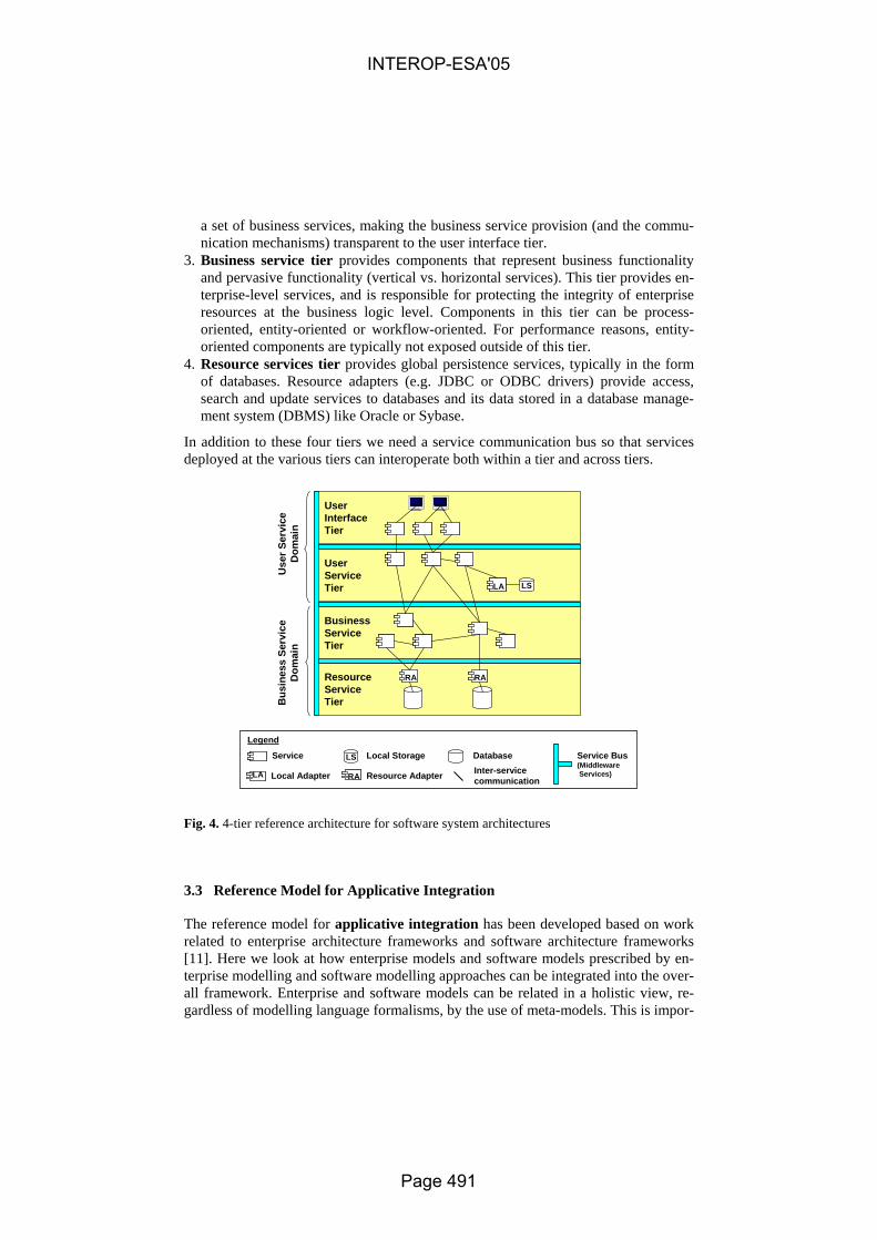
a set of business services, making the business service provision (and the commu-nication mechanisms) transparent to the user interface tier.
3. Business service tier provides components that represent business functionality and pervasive functionality (vertical vs. horizontal services). This tier provides en-terprise-level services, and is responsible for protecting the integrity of enterprise resources at the business logic level. Components in this tier can be process-oriented, entity-oriented or workflow-oriented. For performance reasons, entity-oriented components are typically not exposed outside of this tier.
4. Resource services tier provides global persistence services, typically in the form of databases. Resource adapters (e.g. JDBC or ODBC drivers) provide access, search and update services to databases and its data stored in a database manage-ment system (DBMS) like Oracle or Sybase.
In addition to these four tiers we need a service communication bus so that services deployed at the various tiers can interoperate both within a tier and across tiers.
Legend
ServiceInter-servicecommunication
Use
rSer
vice
Dom
ain
Bus
ines
s Se
rvic
eD
omai
n
LS
Resource AdapterRALA Local Adapter
Local Storage Database
ResourceServiceTier
BusinessServiceTier
UserServiceTier
UserInterfaceTier
LS
RARA
LA
Service Bus(MiddlewareServices)
Fig. 4. 4-tier reference architecture for software system architectures
3.3 Reference Model for Applicative Integration
The reference model for applicative integration has been developed based on work related to enterprise architecture frameworks and software architecture frameworks [11]. Here we look at how enterprise models and software models prescribed by en-terprise modelling and software modelling approaches can be integrated into the over-all framework. Enterprise and software models can be related in a holistic view, re-gardless of modelling language formalisms, by the use of meta-models. This is impor-
INTEROP-ESA'05
Page 491

tant in order to understand the dependencies between the different models and views of a system, and will help us in achieving interoperability.
The MDD methodology for software system development needs to follow a struc-tured approach where interoperability requirements from business operations in a networked enterprise drive the development of software solutions. This means that MDD methodology for software systems needs to be related to enterprise architec-tures. A specific part of the methodology needs to address how the MDD concepts and the technical software components are reflected in a model world of the enter-prise. Figure 5 shows how the model world, reflecting the applicative integration, is related to the reference model for conceptual integration and the reference model for technical integration. Enterprise and software models can be built to understand and analyse the physical world of an enterprise.
An enterprise model describes a set of enterprise aspects, which amongst other things includes descriptions of the business operations that we refer to as business models. These business models provide a context for the software solutions that needs to be developed and integrated, and thus needs to be reflected in the software model.
Software models describe how software systems are used to support the businesses of an enterprise. The software models further refines the business models in terms of software specification and software realisation models. The business model, the specification model and the realisation model for a software system should include descriptions of the four system aspects identified in the reference model for concep-tual integration. The software models can be classified as CIM, PIM or PSM models according to a MDD abstraction.
Software System
Enterprise Architecture A(Model World)
SoftwareModel
SpecificationModels
BusinessContext
Business
Enterprise A(Physical World)
BusinessTransactions
BusinessProcesses
BusinessCollaborations
Models of Service, InformationProcess and Non-Functional Aspects
EnterpriseModel
BusinessModels
RealisationModels
Users
BusinessTasks
VerticalIntegration
Computational System A
Enterprise System A(MDD Abstraction)
Execution Platform A
OntologiesModel-DrivenArchitecture (MDA)&Architecture-DrivenModernisation (ADM)
Platform IndependentModel (PIM)
Computational IndependentModel (CIM)
Architecture-DrivenModernisation (ADM)
SemanticAnnotation
SemanticAnnotation
Model-DrivenArchitecture (MDA)
Platform SpecificModel (PSM)
SemanticAnnotation
MT
MT
MT Model Transformation
Use
r Int
erfa
ce S
ervi
ces
Use
r Ser
vice
s
Bus
ines
s Se
rvic
es
Res
ourc
e Se
rvic
es
Serv
ice
Bus
MT
MT
MTMT
MT
Models of other Enterprise Aspects
Fig. 5. Reference Model for Applicative Integration
The model world corresponds to the set of models prescribed by a MDD methodol-ogy. In our interoperability framework we have identified a set of models that we see
INTEROP-ESA'05
Page 492

useful in achieving interoperability. However, we also acknowledge the fact that this is just a baseline. Different enterprises must be able to develop their own software views that they see purposeful in each business operation. It is important that the applicative integration supports the development of a set of shared views amongst different stakeholders and provides means for managing the dependencies between these views. In order to satisfy these criteria we believe a viewpoint-based integration approach must be chosen. This allows incorporating viewpoints, which are implicitly or explicitly defined by other enterprise or software modelling approaches into an applicative framework. The number of viewpoints to be used depends on the nature of the system and its stakeholders.
In ATHENA [3] we will develop interoperability profiles that provide specific guidelines for how to apply model-driven development of software systems in four different business domains; Supply chain management where stable supply chains and dynamic supply networks will be considered. Collaborative product development in which cross-functional and cross-organisational teams collaborate in product de-velopment. e-Procurement focusing on electronic purchasing and selling of goods and services. Portfolio management focusing on project classifications, selection, prioritisation, and resource allocation. In each of these business domains we find domain-specific dictionaries, thesauri, nomenclatures and coding that will have im-pact on the development and usage of domain-specific reference ontologies. Further-more, industry standards, and legislations and regulations given by the national legis-lative assemblies must also be taken into consideration. Each of these domains may prioritise specific software concerns and aspects differently and require their own custom-tailored views or models.
We have identified three basic viewpoints that can be used as a starting point for viewpoint-based integration of software systems; Context viewpoint focusing on the business context of the software system, system viewpoint focusing on the specifica-tion of the main components of the software system, and realisation viewpoint focus-ing on the implementation of the software system. Figure 6 illustrates the viewpoint metaphor exemplified using the three basic viewpoints. A business analyst is con-cerned with aspects related to the business context of the software system within the networked enterprise. The business view includes e.g. business process models. A system architect is concerned with aspects related to the specification of the software system. The specification view includes e.g. service and interface models. A software developer is concerned with aspects related to the realisation of the software system. The realisation view includes e.g. interaction and data models
INTEROP-ESA'05
Page 493

BusinessAnalyst
Bus
ines
s Vi
ewARCADE data
FOFAS børkunneoppdatereARCADE
: COP
Actual and planned
draft TASKORG : Frequency requirements
verified list : Frequencies
From Div 6, FO/I, KA mobile avd, LV
final TASKORG : Frequency requirements
temp verified list : Frequencies
Receive ARCADE data
Generate Frequency list
Receive frequency requirements from lower level
Receive COP
Establish/maintain frequency pool
temporary list : Frequencies
Verify security level
Distribute Frequency list
Verify Frequency list
new operationnew campaign
list : Frequencies
new operationDistribute temporary Frequency list
new campaign
Joint LevelLower Echelon UnitCOPdistributorARCADE system
ARCADE data
FOFAS børkunneoppdatereARCADE
: COP
Actual and planned
draft TASKORG : Frequency requirements
verified list : Frequencies
From Div 6, FO/I, KA mobile avd, LV
final TASKORG : Frequency requirements
temp verified list : Frequencies
Receive ARCADE data
Generate Frequency list
Receive frequency requirements from lower level
Receive COP
Establish/maintain frequency pool
temporary list : Frequencies
Verify security level
Distribute Frequency list
Verify Frequency list
new operationnew campaign
list : Frequencies
new operationDistribute temporary Frequency list
new campaign
Joint LevelLower Echelon UnitCOPdistributorARCADE system
e.g. BusinessProcess Model
SystemArchitect
Spec
ifica
tion
View
Deployed Unit #1InformationService #1
Command Center
iProcess
InformationService #2
Deployed Unit #2
iNotification iPublishNotificationService
ProcessingService
Ethernet
Satelite
Radio
InformationInformation
Deployed Unit #1InformationService #1
Command Center
iProcess
InformationService #2
Deployed Unit #2
iNotification iPublishNotificationService
ProcessingService
Ethernet
Satelite
Radio
InformationInformation
e.g. Service &Interface Model
SoftwareDeveloper
cryptoKeys
Frequencies
Subnet- nettId- nettType- name- frequency- frequencyChangeTime- newFrequency- frequencyFMprai- frequencyDigPray- areaCode- KVTid- KVTchangeTime
Main frequencies- emitterType- frequency- emissionType- area(polygon, circle)- class of station(mobile, point-point, ground-air)
Frequency requirements- emitterType- emiss oinType- area- class of station[mobile, point-point, ground-air]- timerange- usage[send, receive,...]- securityLabel[(NATO) unclassified, restricted, confidential, s ecret]
Decoding list
Telephone DirectoryAddressee
SOICOP
op1
op2
op1
op2e.g.Interaction
&Data
Model
Rea
lisat
ion
View
NetworkedEnterprise
SoftwareSystem
Legend
BusinessViewpoint
SpecificationViewpoint
RealisationViewpoint
Fig. 6. Illustration of the three basic viewpoints and their corresponding views
4 Example – Inventory Min/Max replenishment scenario
As a part of the work of defining the framework presented in this paper a student project was performed over a couple of months. The task for the students was to take an example integration scenario and create a set of models that were sufficient to be used for further transformations into new models and code. The goal was to be able to generate a running business process performing the integration scenario. The target platform for execution was BPEL running on IBMs BPWS4J2 server. In addition to creating models and code the students were to come up with observations of short-comings in the different tools, methods and modelling languages. The experiences from this exercise were brought into the process of defining the framework presented in this paper.
The scenario that was chosen was “Inventory Min/Max replenishment” as defined by the Automotive Industry Action Group (AIAG) [12], related to supply chain man-agement. The idea behind this process is to let the supplier see the inventory level of the customer with minimum and maximum levels of inventory for a specific inven-tory item. Based on this information the supplier can perform inventory replenish-
2 BPWS4J, http://www.alphaworks.ibm.com/tech/bpws4j
INTEROP-ESA'05
Page 494

ment so that the actual inventory level for an item is “automatically” kept between the minimum and maximum levels defined. The document defines the process and the information passed using the UN/CEFACT Unified Modeling Methodology [13].
At a high level one can say that there were three main models. Initially the parti-tion into these three main model types was taken from [14], but indicated below, these are easily mapable to the aspects defined in this paper;
1. Activities, a model that defined the Min/Max process including actors, activities and information flow. This model describes the process aspects as defined in the interoperability framework.
2. Interactions, a model that defined the different computational services that would be part of the automated process and how they interact using defined interfaces. This model describes the service aspects as defined in the interoperability frame-work.
3. Information, a model that defined the information that was passed between the different activities and services in the process. This model describes the informa-tion aspects as defined in the interoperability framework.
No models describing the non-functional aspects were created in this exercise. All of the models created can be viewed as platform independent models.
One of the ideas behind the framework is that different languages or notations can be used to define the needed models. In order to discuss pros and cons of different methods and notations it was chosen to create 2 sets of models, one using the Busi-ness Process Modelling Notation (BPMN) [15] and one using the Business Process Definition Metamodel (BPDM) [16]. These would be used to generate the needed BPEL and WSDL descriptions using the UMT3 tool for code generation.
BPMN models for the scenario were created using the Metis4 tool from Computas. BPDM has defined a UML 2.0 profile for definition of BPDM models. In this exer-cise the Enterprise Architect5 tool from Sparx Systems was chosen since just about was the only tool that had support for UML 2.0 at the point in time that this exercise was carried out. Due to limitations in the chosen tools it was hard to export the model information to a format that could be used by the UMT tool. It would be possible to implement, but this would mean spending resources on something that would not really add value to the exercise. To get around this problem it was chosen to create a UML 1.4 model based on the BPDM and the BPMN model using the ACE-GIS UML profile [17, 18]. From this model information UMT was able to generate BPEL and WSDL information that had to be manually crafted to be executed by the execution engine. The resulting web services (as executed by the execution engine) are business services as defined in the business service tier of 4-tier reference architecture de-scribed in section 3.2.
The approach of modelling process, service and information aspects, as defined in the framework, does provide enough domain information in order to create platform specific models.
3 UML Model Transformation Tool, http://umt-qvt.sourceforge.net/ 4 Metis, http://www.computas.com/metis 5 Enterprise Architect, http://www.sparxsystems.com.au/ea.htm
INTEROP-ESA'05
Page 495

5 Related Work
The IDEAS Interoperability Framework, developed in the IDEAS project [19], pro-vides four different areas for structuring interoperability issues of enterprise applica-tions; Business layer focusing on business environment and business processes. Knowledge layer focusing on organisational roles, skills and competencies of em-ployees, and knowledge assets. ICT systems layer focusing on applications, data and communication components. Semantic dimension, cutting across the three identified layers, focusing on supporting mutual understanding on all layers.
The ECMA/NIST (European Computer Manufacturers Association/National Insti-tute of Standards and Technology) has developed a reference model for distributed system integration [20]. The ECMA/NIST approach separates integration into four different categories; Data Integration addressing the degree to which tools are able to share common data and information. Control Integration addressing the degree to which tools are able to interact directly with each other, by requesting and providing services. Process Integration addressing the degree to which the user’s working proc-ess and use of tools can be guided by a model of the work process and the methodol-ogy to be followed. Presentation Integration addressing the degree to which a user-interface program might provide access to the functionality needed by the user through a common look and feel.
E-Commerce Integration Meta-Framework (ECIMF) defines recommended inter-operability methodology, and the technical specification and base tools needed to prepare specific comparisons of concrete frameworks [21]. The proposed ECIMF methodology for analysis and modelling of the transformations between e-commerce frameworks follows a layered approach. In order to analyse the problem domain one has to split it into layers of abstraction, applying top-down technique to classify the entities and their mutual relationships.
The Reference Model for Open Distributed Processing (RM-ODP) [22-25] is an ISO standard focusing on open distributed processing systems. RM-ODP divides the specification of ODP systems into five different, but related, viewpoints. The view-points in RM-ODP are: enterprise viewpoint (focuses on purpose, scope and poli-cies), information viewpoint (focuses on information processing and relationships between information objects), computational viewpoint (focuses on functional speci-fication and decomposition), engineering viewpoint (focuses on how to solve distri-bution issues), and technology viewpoint (focuses on specific technology and solu-tions).
The interoperability framework presented in this paper addresses much of the same interoperability elements identified in the above framework and approaches, but re-lates them more closely to software models in a model-driven development environ-ment.
INTEROP-ESA'05
Page 496

6 Conclusions and future work
We will conclude this paper by addressing each of the objectives or design rationales for the development of the interoperability framework.
− The reference model for applicative integration clearly indicates that software solutions cannot be developed in isolation if the goal is to achieve interoperability between business units within and across virtual networked enterprises. The soft-ware development process and models must be related to the enterprise and busi-ness needs of an enterprise. We believe that a viewpoint-based integration ap-proach provide a good foundation for relating different models and views in a ho-listic approach where software architectures and enterprise architectures can be re-lated.
− The reference model for technical integration provides a 4-tier reference architec-ture for describing software systems as a set of services addressing business and user needs. These software services are connected using a service bus that provides infrastructure, registry and repository services for integrating software.
− The reference model for conceptual integration provides a basic understanding of MDD concepts that can be integrated into model-driven software development processes.
− Finally, we believe that the reference models provided can be used to structure software technologies, frameworks and methodologies which can be found today.
The reference models described will be used in the development of more structured methodologies focusing on different business domains as well as the development of infrastructure, registry and repository services to enable interoperability between software systems. In particular we will look into the specification of a set of UML 2.0 profiles for the four system aspects identified in the reference model for conceptual integration.
This work is carried out in the context of ATHENA [3] and INTEROP [4]. ATHENA is an Integrated Project supported by the European Commission and INTEROP is a Network of Excellence supported by the European Commission. The main research challenge of both projects is to address interoperability for enterprise applications and software.
References
1. IEEE, "IEEE Standard Computer Dictionary: A Compilation of IEEE Standard Computer Glossaries," Institute of Electrical and Electronics Engineers, New York, NY 1990.
2. Object Management Group, "MDA Guide Version 1.0.1," Object Management Group omg/2003-06-01, 12th June 2003.
3. ATHENA, "ATHENA Public Web Site", http://www.athena-ip.org/, (accessed: 2004). 4. INTEROP, "INTEROP Portal", http://www.interop-noe.org/, (accessed: 2004). 5. IEEE, "IEEE Std 1471-2000: IEEE Recommended Practice for Architectural Description of
Software-Intensive Systems," IEEE, October 2000.
INTEROP-ESA'05
Page 497

6. Object Management Group, "OMG Unified Modeling Language Specification Version 1.5," Object Management Group, Specification formal/03-03-01, March 2003.
7. Object Management Group, "UML 2.0 Infrastructure Final Adopted Specification," Object Management Group, Specification ptc/03-09-15, 2003.
8. Object Management Group, "UML 2.0 Superstructure Final Adopted Specification," Object Management Group, Specification ptc/03-08-02, 2003.
9. C. Atkinson, J. Bayer, C. Bunse, E. Kamsties, O. Laitenberger, R. Laqua, D. Muthig, B. Paech, J. Wust, and J. Zettel, Component-based Product Line Engineering with UML: Ad-dison-Wesley, 2002.
10. D. F. D'Souza and A. C. Wills, Object, Components, and Frameworks with UML - The Catalysis Approach: Addison Wesley Longman, Inc., 1998.
11. B. Elvesæter, T. Neple, J. Ø. Aagedal, R. K. Rolfsen, and O. Ø. Stensli, "MACCIS 2.0 - An Architecture Description Framework for Technical Infostructures and their Enterprise En-vironment," presented at Command and Control Research and Technology Symposium, San Diego, USA, 2004.
12. "Inventory Visiblilty and interoperability Min/Max Replenishment," Automotive Industry Action Group (AIAG) 2003.
13. UN/CEFACT, "UN/CEFACT Modelling Methodology (UMM) User Guide," UN/CEFACT CEFACT/TMG/N093, 2003.
14. "Infrastructure for electronic commerce - Application readable models in an open infra-structure," Norsk Edipro 2002.
15. "Business Process Modeling Notation (BPMN)," Business Process Management Initiative (BPMI) 2004.
16. "Updated Joint revised Business Process Definition Metamodel submission," Object Man-agement Group bei/04-01-02, 2004.
17. D. Skogan, R. Grønmo, and I. Solheim, "Web Service Composition in UML," presented at The 8th International IEEE Enterprise Distributed Object Computing Conference (EDOC), Monterey, California, USA., 2004.
18. R. Grønmo, D. Skogan, I. Solheim, and J. Oldevik, "Model-Driven Web Service Develop-ment," International Journal of Web Services Research (JWSR), vol. 1, 2004.
19. IDEAS, "IDEAS Home Page", http://www.ideas-roadmap.net/, (accessed: 2004). 20. ECMA, "Reference Model for Frameworks of Software Engineering Environments, 3rd
ed," ECMA, Technical Report NIST 500-211, ECMA TR/55, 1993. 21. ECIMF, "E-Commerce Integration Meta-Framework - General Methodology (ECIMF-
GM)," CEN/ISSS/WS-EC/ECIMF, Draft Version 0.3, 28.11 2001. 22. ITU-TS, "Basic Reference Model of Open Distributed Processing - Part 1: Overview and
guide to use the Reference Model," Rec.X901 (ISO/IEC 10746-1), 1995. 23. ITU-TS, "Basic Reference Model of Open Distributed Processing - Part 2: Descriptive
model," Rec.X902 (ISO/IEC 10746-2), 1995. 24. ITU-TS, "Basic Reference Model of Open Distributed Processing - Part 3: Prescriptive
model," Rec.X903 (ISO/IEC 10746-3), 1995. 25. ITU-TS, "Basic Reference Model of Open Distributed Processing - Part 4: Architectural
Semantics," Rec.X904 (ISO/IEC 10746-4), 1995.
INTEROP-ESA'05
Page 498
A Collaboration Framework for Cross-enterprise
Business Process Management
O. Adam1, A. Hofer1, S. Zang1, C. Hammer2, M. Jerrentrup
2, S. Leinenbach
2
1 Institute for Informations Systems (IWi) at the
German Research Center for Artificial Intelligence (DFKI)
66123 Saarbruecken, Germany [adam|hofer|zang]@iwi.uni-sb.de
2 Interactive Software Solutions GmbH
66115 Saarbruecken, Germany [hammer|jerrentrup|leinenbach]@interactive-software.de
Abstract. New forms of cooperation like collaborative business scenarios re-
quire a deep but flexible integration of enterprises. In order to manage interor-
ganizational business processes, existing concepts for business process man-
agement need to be adapted and extended. In this paper a framework is pre-
sented, that shows how cross-enterprise processes can be planned, implemented
and controlled. The framework is based on the differentiation of global knowl-
edge within the network and local knowledge of each participating company.
Another important part of it is the process life-cycle model that serves as a
guideline for the process-oriented setting-up and operation of cooperations. By
the use of graphic representations of BPM-models and intuitive metaphor-based
model-generation and -visualization tools a broad acceptance for the interor-
ganizational BPM-effort can be achieved.
1 Innovation through business process interoperability
The growing importance of cooperation is a result of globalization in combination
with the disappearance of political borders and above all technological advances
caused mainly by the Internet [1], [2]. Thus, enterprises have to react to the raised
innovation pressure and facilitate flexible collaboration on a global scale by aligning
their business processes. The borderless enterprise has been the subject of scientific
discussion for years [3], [4] and the collaborative production of goods and services
has been established as a crucial factor in the consciousness of economic entities. The
opening of the organizations’ borders is no longer regarded as a necessary evil, but
rather as a chance with strategic importance. [3]
Current approaches that address solutions to specific problems of dynamically in-
teracting organizations are summarized under the term “Business Integration”; the
field of investigation is referred to as “Collaborative Business (C-Business)” [5]. C-
Business describes the Internet-based interlinked collaboration of all participants in an
INTEROP-ESA'05
Page 499

added-value network – from the raw material supplier to the end-consumer [6]. It
allows a comprehensive information exchange not only between employees but also
between departments and even between enterprises and encourages creative coopera-
tions at all levels. As first case-studies show, the increase in added-value is out of
proportion to the amount of participants in the network. Unlike former concepts, as
e.g. E-Procurement, which focused only on small parts of the value chain, C-Business
incorporates all stages of added value [7].
While the technological interoperability[8] on the one hand and the lifecycle of co-
operation [9] on the other hand have already been intensively researched, too little
consideration is given to the interconnecting business management concepts. A re-
thinking from the pure technology-driven implementation or profit-driven business
model discussion to an integrated view that spans from the conceptual level to the
system blueprint is needed. From a conceptual point of view business processes have
proven to be the ideal design item in conjunction with the use of graphical methods.
These models can then be transformed into Information and Communication Technol-
ogy (ICT) -based specifications. With the use of open, standardized technologies, such
as web services, they enable Business Process Automation, i.e. the automatic negotia-
tion of process interfaces.
For these purposes a proposal for a Cross-enterprise Business Process Management
Framework is developed in this paper, based on the findings the two overlapping
research projects InfoCitizen and ArKoS, that are introduced later on.
2 The foundation of the Collaboration Framework
Compared to traditional business processes, the complexity of interorganizational
processes has risen considerably as a result of the numerous possibilities of inter-
action as well as the strategic, structural and cultural differences between the partners
[11]. The allocation of performances and resources of the business partners, the de-
termination of responsibilities for material and financial exchange relationships as
well as the information and data exchange over interfaces have to be planned, ar-
ranged and “lived” together. Thus the demands on Business Process Management
(BPM) increase.
Existing BPM methods and phase models are used as a foundation in the archi-
tecture presented here, which had to be adapted to the specifications of collaborative
scenarios. Especially because of its completeness of vision and its proven practicabil-
ity, both in the scientific and the economic context, the “ARIS House” [12] is ac-
cepted as a generic framework for business process management and serves as a basis
for further considerations. The ARIS House describes a business process, assigning
equal importance to the questions of organization, functionality and the required
documentation. First, it isolates these questions for separate treatment, in order to
reduce the complexity of the field of description, but then all the relationships are
restored using the Control View introduced for this purpose.
The Cross-enterprise Business Process Management Architecture is presented
here in a three-tier framework that is connected through control loops, following the
INTEROP-ESA'05
Page 500

concept of business process excellence of Scheer [13], which consists of a model to
track a complete lifecycle model of business process management, including model-
ing, real-time control and monitoring of business processes. The first layer focuses on
the collaboration strategy. In the centre of the second layer, C-Business Process
Engineering, there are design, optimization and controlling of both enterprise span-
ning and internal processes. The third layer, C-Business Execution, deals with the
(operational) implementation of business processes in value-added networks as well as
their support through information and communication technologies. The structure of
the layer model is clarified in Figure 1.
Fig. 1. Architecture for Collaborative Business Process Management
2.1 Views on Business Process Models
As described above, the framework is based on the ARIS House and divides it into a
vertical axis of global knowledge of all collaboration partners and a horizontal axis of
local knowledge of the single participants (cf. Fig. 2). The organisation view and the
output view are global knowledge because a goal-oriented collaboration is impossible
without them.
At the time the interaction occurs between two partners, local knowledge is shared
(bilaterally) between the partners, i.e. additional information, like data structures and
semantics, are exchanged. Updates of the local knowledge do not influence the net-
work as network knowledge has to be available for all partners. This information is
stored in the description of interfaces between the process modules of the partners (cf.
section 2.3). Changes in the global network knowledge and as a consequence changes
in the output and organization view have to be accessible to all partners immediately,
INTEROP-ESA'05
Page 501

for example if a company leaves the network or if a product or service is no longer
available within the network.
Global and local knowledge merge gradually in the step-by-step development of C-
Business process engineering. Following the distinction between global and local
knowledge, a language is needed for the exchange of these knowledge fragments.
Because the necessary detail functions and data schemes of the respective enterprise
are determined in the data and the function view, these are treated from a micro per-
spective. They are characterized by an intensive internal interdependence, whereas
externally a standardized encapsulation has to be provided. Interfaces of the data and
function views to other network participants become visible in the process view in
form of attribute correlations to process modules and concern the technological field
of the cooperation during the realisation much more intensely than the conceptual one.
This technique enables the generation of public (visible to network partners) and
private (enterprise-internal) views and levels of detail for management, process
owner and IT-experts out of a C-Business model.
Fig. 2. Global and local knowledge in value-added networks
2.2 C-Business Strategy
Enterprise spanning business processes are not planned in detail at the strategic level,
but are designed as concentrated, high-level process modules. Thus, they combine the
public knowledge about the collaborative processes that is shared by all participants.
C-Business scenario-diagrams that are used e. g. by SAP Ltd. for the description of
my-SAP.com collaboration scenarios, aim at the representation of the cooperation of
different enterprises and participants by means of an easily understandable method
and the documentation of the value-added potentials resulting from it [14]. The re-
sponsibility for each process step, indicated by swimlanes, is of central importance to
the determination of the scenario. This method is integrated into the ARIS concept and
INTEROP-ESA'05
Page 502
combined with methods of (classical) business process and data modeling used at the
C-Business Process Engineering layer.
The question of core competences in the enterprises is directly associated with the
question which processes remain in the enterprise and which are supposed to be as-
signed to partner enterprises or collaboratively operated [15].
2.3 C-Business Process Engineering
On this layer each partner considers their part in the inter-enterprise process. Each
party models its own internal processes. The event-driven process chain (EPC), that
has been developed for the last 15 years at the Institute for Information Systems,[12]
is used for the design of the process flow within an enterprise (local view). A possibil-
ity to reduce complexity and to focus on special aspects is the use of different views
like data, organizational, function or output view.
The global view on the collaborative process is generated in order to manage the
common processes and to reduce the complexity of integrating the participating organ-
izational units into one virtual unit. In doing so it is important that the partners provide
access to all relevant information described as global knowledge beforehand and at
the same are able to hide their business secrets. Both aims are achieved by enhancing
the EPC with a new construct, the process module [16]. It serves as an abstraction for
more detailed sub-processes that contain the local knowledge and thus encapsulates
crucial process information. Additionally the object-type interface is introduced. The
interface contains relevant information about data and input/output structures in order
to match and interconnect process modules.
The view concept presented in section 2.1 allows generating different views on the
collaborative process depending on the degree of collaboration. In some cases closely
interlinked collaboration partners allow each other inspection of their internal EPC
models or parts thereof. By consolidating the processes at their interfaces a detailed
collaborative process that can be used for further optimization and implementation
emerges. More often the partners expose only parts of their individual processes to the
partners because of the reasons above-mentioned. Thus, they grant access to their
process knowledge at the process module level. A high-level public view of the col-
laborative process consisting of process modules and their interfaces is created. The
information whether the detailed EPC or the high-level process module should be
disclosed in a certain public view is stored as an attribute in each process module
object.
The collaboration partners have to continuously compare the result of the imple-
mentation with their goals and adjust deviations. Hitherto the management has ob-
tained its knowledge about the company’s success from figures of the past, e.g. cash-
flow, trading volume or profit made. The causes for fluctuations, requiring immediate
counter measures, were not discernible. Until the problem was recognized, valuable
time has elapsed. Therefore new measurement categories, which allow a reliable and
contemporary evaluation of process efficiency, are required. The information needed
cannot be extracted from the record and transaction oriented applications alone. Key
performance-indicators must be defined based on records, logfiles, time stamps etc.
INTEROP-ESA'05
Page 503
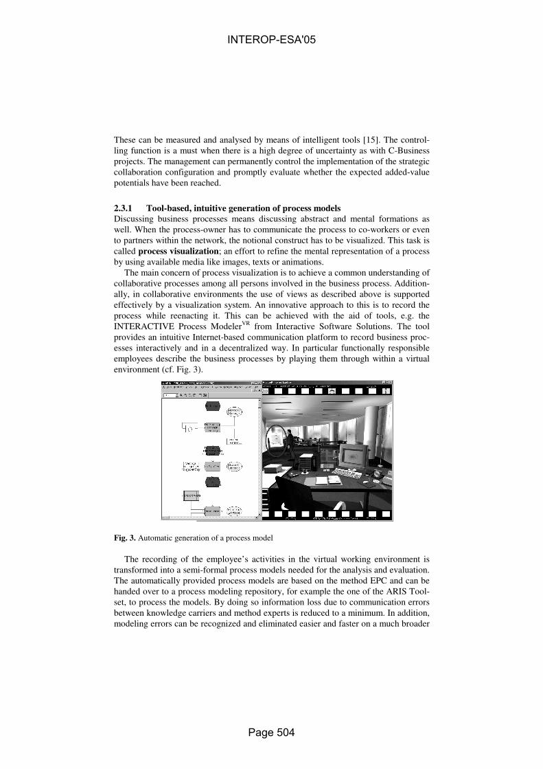
These can be measured and analysed by means of intelligent tools [15]. The control-
ling function is a must when there is a high degree of uncertainty as with C-Business
projects. The management can permanently control the implementation of the strategic
collaboration configuration and promptly evaluate whether the expected added-value
potentials have been reached.
2.3.1 Tool-based, intuitive generation of process models
Discussing business processes means discussing abstract and mental formations as
well. When the process-owner has to communicate the process to co-workers or even
to partners within the network, the notional construct has to be visualized. This task is
called process visualization; an effort to refine the mental representation of a process
by using available media like images, texts or animations.
The main concern of process visualization is to achieve a common understanding of
collaborative processes among all persons involved in the business process. Addition-
ally, in collaborative environments the use of views as described above is supported
effectively by a visualization system. An innovative approach to this is to record the
process while reenacting it. This can be achieved with the aid of tools, e.g. the
INTERACTIVE Process ModelerVR
from Interactive Software Solutions. The tool
provides an intuitive Internet-based communication platform to record business proc-
esses interactively and in a decentralized way. In particular functionally responsible
employees describe the business processes by playing them through within a virtual
environment (cf. Fig. 3).
Fig. 3. Automatic generation of a process model
The recording of the employee’s activities in the virtual working environment is
transformed into a semi-formal process models needed for the analysis and evaluation.
The automatically provided process models are based on the method EPC and can be
handed over to a process modeling repository, for example the one of the ARIS Tool-
set, to process the models. By doing so information loss due to communication errors
between knowledge carriers and method experts is reduced to a minimum. In addition,
modeling errors can be recognized and eliminated easier and faster on a much broader
INTEROP-ESA'05
Page 504
basis and errors resulting from formalisation of the surveyed process by method ex-
perts are avoided. Furthermore, expensive method training courses and the use of
modelling experts can be reduced to a large extent.
2.3.2 Tool-based communication of process models
Within the process execution phase the implementation of target processes, the
evaluation of the existing processes and the permanent optimization of processes re-
quire an adequate visualization of the processes in order to establish a common under-
standing of the processes among all persons involved. Otherwise, specialized divi-
sions´ employees with knowledge of the operations often take a rather passive role.
This holds especially true for interorganizational processes.
In order to achieve the demanded participation by employees in validation and dis-
cussion of the process concepts produced in reorganization projects the business proc-
esses are visualized close-to-reality. By the intuitive representation weak points and
opportunities for improvements can be identified and used for the construction of
optimized target processes.The new form of business process visualization can serve
to reach a quality improvement of conventional semi-formal business process model-
ing methods.
When the optimization should go across corporate frontiers the challenge gets more
demanding, because of the higher complexity, as described in section 2. The distrib-
uted modeling approach, combined with the use of close-to-reality metaphors can
cause an immense boost for the success of business process management within dis-
tributed modeling environments.
2.4 C-Business Process Execution
Instead of closed systems that have been used so far, C-Business requires the integra-
tion of different applications. Component based architectures that are process-driven
and rely on fully developed standards and interfaces can be seen as a state-of-the-art
approach to overcome these problems [17]. The term “process-driven” emphasizes the
importance of the process models created on the preliminary layer. On the execution
layer these models are used e. g. for the orchestration of web services. Orchestration
in this context describes the composition of business objects in a process flow. In
detail it defines the complex interaction between business objects, including the busi-
ness logic and execution order of the interactions and the exchange of messages be-
tween them.
3 Collaborative Business Process Management Lifecycle
The lifecycle -model presented in this section serves as a manual for the process-
oriented setting-up and operation of cooperations. Using a consistent phase model and
standardized modeling methods increases transparency and structuring of cooperations
and creates a basis for communication between participants, including management
INTEROP-ESA'05
Page 505

that lays down strategies, process-owners in the departments and IT-experts that inte-
grate the different application systems.
Despite the increased complexity of network processes in comparison to internal
processes, those involved have to adapt to constantly occurring changes in a fast and
flexible way. The model is a fusion of classic phase-models with lifecycle -models of
virtual enterprises [18]. The resulting dynamic model is consistent with the structure-
oriented Cross-enterprise Business Process Management Architecture (cf. section 2)
and represents a cyclical approach.
Protecting internal know-how is of paramount importance to the network partici-
pants, even though the business process knowledge has to be used jointly. Following
the view concept presented in paragraph 2.1, this implies that the lifecycle alternates
between phases that focus on global and on local issues in order to reach a coherent
solution (cf. Fig. 4).
PrivateKnowledge
Awareness
Exploration
Reconfiguration
Public
Knowledge
Strategy
Partner Analysis
1st Phase
Strategy
Partner Analysis
1st Phase
Local
Implementation
4th Phase
Local
Implementation
4th Phase
Global
To-Be-Concept
3rd Phase
Field
data
Module
1
Module
2
Module
3a
Module
3b
Module
4I
I
I
I
Process
Owner
Applicat ion
System
Global
To-Be-Concept
3rd Phase
Global
To-Be-Concept
3rd Phase
Field
data
Module
1
Module
2
Module
3a
Module
3b
Module
4I
I
I
I
Process
Owner
Applicat ion
System
Collaboration
Execution
5th Phase
Collaboration
Execution
5th Phase
Collaboration
Execution
5th Phase
Local
To-Be-Concept
2nd Phase
NotwendigeKompetenzgegeben
Darlehens-antrag
entscheidenSachbearbeite r
DarlehenSachbearbeite r
Darlehen
KREBEAPRG
KREBEAPRG
Darlehens-entscheidungDarlehens-
entscheidung
vorschlagerstellt
Entscheidungs-träger
auswählenSachbearbeite r
DarlehenSachbearbeite r
Darlehen
KREBEAPRG
KREBEAPRG
Darlehens-entscheidungDarlehens-
entscheidung
Local
To-Be-Concept
2nd Phase
Local
To-Be-Concept
2nd Phase
NotwendigeKompetenzgegeben
Darlehens-antrag
entscheidenSachbearbeite r
DarlehenSachbearbeite r
Darlehen
KREBEAPRG
KREBEAPRG
Darlehens-entscheidungDarlehens-
entscheidung
vorschlagerstellt
Entscheidungs-träger
auswählenSachbearbeite r
DarlehenSachbearbeite r
Darlehen
KREBEAPRG
KREBEAPRG
Darlehens-entscheidungDarlehens-
entscheidung
Fig. 4. Collaborative Business Process Management Lifecycle
3.1 Pre-phase and reconfiguration
Prior to the use of the architecture is the awareness of one or more enterprises that
they can profit by collaboration with complementary core competence partners. The
decision if and with which enterprises a C-Business scenario should be implemented is
taken by every single enterprise individually and rationally; for this reason it depends
INTEROP-ESA'05
Page 506

highly on the expected economical profit of the individual partner. In this model, it is
assumed, that a set of potential network participants is given.
After conducting the cooperation the companies regroup or split and reconfigurate
themselves. The lifecycle returns to its starting position “awareness”.
3.2 Main-phases
In the first phase Strategy Partner Analysis or formation phase, also referred to as
initiation and agreement of the enterprise network, the collaboration partners are de-
termined by the shared goals of the collaboration and the aspired win-win situation of
all partners. The joint aims of the collaboration have to be defined as synthesis of the
individual aims.
To facilitate the collaborative service or product delivery, graphical methods, like
product models, are used in this stage for the determination of a common service or
product bundle. They simplify and put the often implicit objectives into concrete
terms. In addition to the characteristic features of a service or a product over its entire
lifecycle , the organizational units participating in the production are contained in a
product model [19]. By means of product trees enterprises can conceal detailed ser-
vice descriptions in an internal view that puts special focus on the organizational as-
pects of the product offered by the partners. In an external view they just provide the
information required for the configuration of the common service bundle in form of
product bundle models [20].
Having completed the strategy finding, in the second phase, Local To-Be-
Concept, an existing or a new (local) as-is model and the (global) to-be concepts are
compared. According to predefined conditions about collective product creation,
intra-organizational business processes can be derived. Each partner considers their
part in the inter-enterprise process. Starting with process modelling and optimisation
over process controlling up to implementation, the processes involved are aligned with
the requirements of the collaborative scenario agreed on in the former phase.
In the third phase Global To-Be-Concept coordinated public parts are allocated
over the network, establishing a collective to-be concept. Every partner is able to
connect their own private model with every other public process model. Every partner
gains their partial view of the collaborative process or in other words a virtual process
chain of the whole collaboration is designed. The Business Process Modeling Lan-
guage (BPML) can be considered as an appropriate exchange-language. Global
knowledge is described in a public interface, which can be provided by a BPMN rep-
resentation. The public processes as well as the message formats and contents can be
formally defined by B2B protocols like RosettaNet or ebXML. Furthermore the se-
mantic combination of models of the different partners is necessary. As long as ontol-
ogy-based approaches don’t reach a productive state this combination process is a
manual action.
The integrated collaborative business process model enables all partners to config-
ure their application systems locally in a fourth phase called Local Implementation.
Reference systems for interfaces are provided by interface definitions of the collective
to-be concept.
INTEROP-ESA'05
Page 507

Now every partner is prepared for the execution of interactions within the collabo-
rative framework. That is the transition to the fifth phase Collaboration Execution.
Based on bilateral bases interacting information systems are able to communicate by
using the standardized protocols and interfaces. The transactions are arranged and
executed. The aim of this phase is to support collaboration through the appropriate use
of ICT. That requires primarily the configuration of interfaces and the implementation
of interorganizational workflows; at the same time the permanent monitoring and
adaption of the collaboration, based on business ratio defined in the conception phase,
must be assured. [6]
In order to automate inter-organizational processes the conceptual models are trans-
formed into formal models that are used as configuration data for the orchestration of
business objects. The applications of the partners have to communicate bilaterally to
negotiate the interface specifications based on the formal models, defined in the re-
pository. The local knowledge is generated by this negotiation for a certain situation.
After this collaboration task has ended no updates of configuration changes etc. are
reported to any other party except at the time when a new direct interaction occurs. In
this context multiagent systems offer a solution to achieve an automated or at least
semi-automated interface-configuration [21], [22].
With the use of XML the technological basis for interoperability has been estab-
lished, the interoperability between the semantic business process definitions however
is still missing. Efforts like BPMI’s Business Process Modeling Notation (BPMN)
promise standardization for the management of inter-organizational business proc-
esses that involve different applications, departments and business partners [10].
Therefore a mapping mechanism has been developed allocating EPC-elements to
BPMN constructs. Besides, a wide acceptance of the Business Process Execution
Language for Web Services (BPEL4WS) by BEA, IBM, and Microsoft as well as the
newly finalized specification of the Web Services Choreography Interface (WSCI)
mainly driven by BEA, Intalio, SAP and Sun show the importance of a second stan-
dardization level for interoperability [23]. While BPMN is more focused on the con-
ceptual level, the latter two focus on the transformation into the system-level by or-
chestrating web services.
4 Towards an Intuitive Cross-enterprise Business Process
Management
In this paper a framework and a lifecycle model were developed, that provide a ge-
neric solution concept, which transfers business recommendations into ICT-solutions
based on a holistic business process management approach and supported by intuitive
tools. The greatest demand for further research can be seen in the formulation of trans-
formation methods especially in a methodologically sound transfer of process models
into ICT-configurations. Another aspect that requires further research is the use of
supporting tools that ease the task of exchanging process models between different
enterprises and to distinguish between private and public knowledge. User-specific
views on the business process models will enable new user groups to use BP-models,
INTEROP-ESA'05
Page 508
as the example of intuitive metaphor based process modeling points out. Moreover
ICT can support actively business process management by checking, verifying or even
automatically negotiating consistency and interoperability of models.
The described conceptual design of inter-enterprise business processes and the
open research questions are currently elaborated in the research project “Architecture
for Collaborative Scenarios (ArKoS)”[24], funded by the German Federal Ministry of
Education and Research (BMBF). As a proof of concept the presented distributed
process enactment was implemented in a agent-based software prototype and evalu-
ated in a four countries showcase by the EU-funded project “InfoCitizen”[25].
References
1. Scheer, A.-W., Erbach, F., Thomas, O.: E-Business – Wer geht? Wer bleibt? Wer kommt?.
In: Scheer, A.-W. (ed.): E-Business – Wer geht? Wer bleibt? Wer kommt?. 21. Saarbrücker
Arbeitstagung 2000 für Industrie, Dienstleistung und Verwaltung. Physica-Verlag, Heidel-
berg (2000) 3-45
2. Naisbitt, J.: Megatrends 1986. Ten New Directions Transforming Our Lives. 6th ed., War-
ner Books, New York
3. Kanter, R. M.: Transcending Business Boundaries: 12,000 World Managers View Change.
In: Harvard Business Review 69 (1991) 3, 151-164
4. Picot, A., Wigand, R., Reichwald, R.: Information, Organization and Management – Ex-
panding Markets and Corporate Boundaries. Wiley, Chichester
5. Scheer, A.-W., Grieble, O., Hans, S., Zang, S.: Geschäftsprozessmanagement – The 2nd
wave. In: Scheer, A.-W. (ed.): IM Information Management & Consulting 17 (2002) Son-
derausgabe, 9-15, 10 et seq.
6. Scheer, A.-W., Grieble O., Zang, S.: Collaborative Business Management. In: Kersten, W.
(ed.): E-Collaboration - Prozessoptimierung in der Wertschöpfungskette. Deutscher Uni-
versitäts-Verlag, Wiesbaden, 30 et seq.
7. Scheer, A.-W.; Feld, T., Zang, S.: Vitamin C für Unternehmen – Collaborative Business. In
Küting, K., Noack, Chr. (eds.): Der große BWL-Führer. Die 50 wichtigsten Strategien und
Instrumente zur Unternehmensführung. F.A.Z.-Institut, Frankfurt, pp. 123-129, 124 et seq.
8. Linthicum, D. S.: Enterprise Application Integration. 4. ed., Addison-Wesley, Boston et al.,
2003
9. Liebhart, U. E.: Strategische Kooperationsnetzwerke: Entwicklung, Gestaltung und Steue-
rung. Dt. Univ.-Verl., Wiesbaden, 2002
10. White, S. A.: Business Process Modeling Notation (BPMN), 2004
11. Scheer, A.-W., Beinhauer, M., Habermann, F.: Integrierte E-Prozessmodellierung. In:
Industrie Management 16 (2000) 3, 19-26, 20 et seqq.
12. Scheer, A.-W.: ARIS – Vom Geschäftsprozess zum Anwendungssystem. 4th ed. (2002)
Springer, Berlin
13. Scheer, A.-W., Borowsky, R.: Supply Chain Management – die Antwort auf neue Logistik-
anforderungen. In: Kopfer, H., Bierwirth, C. (eds.): Logistik Management – Intelligente
I+K Technologien. Springer, Berlin, 3-14
INTEROP-ESA'05
Page 509

14. Hack, S.: Collaborative Business Scenarios – Wertschöpfung in der Internetökonomie. In:
Scheer, A.-W. (ed.), E-Business – Wer geht? Wer bleibt? Wer kommt?. 21. Saarbrücker
Arbeitstagung für Industrie, Dienstleistung und Verwaltung., Physica-Verlag, Heidelberg
85-100, 88 et seqq.
15. Jost, W., Scheer, A.-W.: Geschäftsprozessmanagement: Kernaufgabe einer jeden Unter-
nehmensorganisation. In: Jost, W, Scheer, A.-W. (eds.): ARIS in der Praxis: Gestaltung,
Implementierung und Optimierung von Geschäftsprozessen. Springer, Berlin, 33-44, 38, 42
et seqq.
16. Grieble, O., Klein, R., Scheer, A.-W.: Modellbasiertes Dienstleistungsmanagement. In:
Scheer, A.-W. (ed.): Veröffentlichungen des Instituts für Wirtschaftsinformatik. No. 171,
Saarbrücken, 22
17. McMichael, C.: Business process integration may eclipse EDI, EAI. In: HP Chronicle 17
(2003) 6, 1, 6
18. Mertens, P., Faisst, W.: Virtuelle Unternehmen – eine Organisationsstruktur für die Zu-
kunft?. In: technologie & management 44 (1995), 61-68
19. Genderka, M.: Objektorientierte Methode zur Entwicklung von Produktmodellen als Basis
Integrierter Ingenieursysteme. Shaker, Aachen, 13
20. Scheer, A.-W., Herrmann, K., Klein, R.: Modellgestütztes Service Engineering – Entwick-
lung und Design neuer Dienstleistungen. In: Bruhn, M., Stauss, B. (eds.): Dienstleistungs-
innovationen: Dienstleistungsmanagement Jahrbuch 2004. Gabler, Wiesbaden, in print
21. Blake, M. B.: Coordinating multiple agents for workflow-oriented process orchestration.
http://www.cs.georgetown.edu/~blakeb/pubs/blake_ISEB2003.pdf
22. Denti, E., Ricci, A., Rubino, R. : Integrating and orchestrating services upon a MAS coor-
dination infrastructure. http://www.ai.univie.ac.at/~paolo/conf/
ESAW03/preproc/E0011.pdf
23. Shapiro, R.: A Comparison of XPDL, BPML and BPEL4WS: Cape Visions. Rough Draft,
1-17
24. Adam, Otmar; Hofer, Anja; Zang, Sven; Hammer, Christoph; Jerrentrup, Mirko; Leinen-
bach, Stefan: Architecture for collaborative business process management - enabling dy-
namic collaboration, accepted in European Conference on Product and Process Modeling
ECPPM 2004, Istanbul Turkey, Balkema, September 2004.
25. Adam, O.; Werth, D.; Zangl, F.: ARIS in Cross-Border E-Government - Integrated Auto-
mation of Public Services for the InfoCitizen, in: Scheer, A.-W.; Abolhassan, F.; Jost, W.;
Kirchmer, M.: Business Process Automation - ARIS in Practice, Springer, Berlin et al.,
2004, pp. 159-178.
INTEROP-ESA'05
Page 510

An Empirical Study of the UML Model Transformation Tool (UMT)
Roy Grønmo, Jon Oldevik
SINTEF Information and Communication Technology, Post Box. 124, Blindern, 0314 OSLO, Norway
roy.gronmo|[email protected]
Abstract. Development of distributed enterprise solutions can be a complex and time consuming process, involving many concepts, tools and configuration issues before and during coding and deployment. This paper presents UML Model Transformation Tool (UMT) - an open source tool that uses UML mod-els to support a model-driven development process. The tool enables a trans-formation architect to define transformations to do code generation, reverse en-gineering or model-to-model mappings. A number of transformations have been developed, including transformers for EJB and XDoclet, XML Schema and Web Services (WSDL, BPEL4WS). We identify a set of desired properties for UML transformation tools and evaluate UMT against these. These proper-ties and the UMT approach are related to the ongoing activities within the Ob-ject Management Group for developing transformation specifications.
1 Introduction
In order to achieve interoperability across enterprises, it is essential to develop new services and to define transformations between data and applications. These devel-opment processes are more efficient when using model-driven techniques. Model-driven development has been around for decades, supported by various modeling languages, case tools and methodologies. For a long time, this landscape was charac-terised by the variations in languages and non-standardised ways of modeling. The appearance and standardisation of the Unified Modeling Language (UML) changed this by giving us a common form of expression, and many tools that support the same language. The model-driven architecture (MDA®) initiative from Object Management Group (OMG) has given further motion for tools and techniques that can bring model-driven development some steps further. The OMG MOF 2.0 Query/Views/Transformations RFP (QVT) [1, 2] process is trying to define a stan-dard for model-to-model transformations. The OMG MOF Model to Text Transfor-mation Language RFP [3] process is trying to define a standard for generating text from models, e.g. for code generation. These standards will lead the way for tools that hopefully will comply to the same set of standards for model driven development.
Model-to-model transformation, code generation and reverse-engineering are es-sential to succeed with model-driven development. The process requires highly skilled developers that can operate on many abstraction levels and with many tech-
INTEROP-ESA'05
Page 511
nologies, which calls for new roles in the development process, such as a transforma-tion architect. We define a transformation architect to be a developer that design and implement transformations. These tasks tend to be complex and need to be supported by good tools. Making good tools for model transformation however, is not a trivial task. Some tools today provide code generation functionality, such as ready-made code generation templates and scripting functionality. These are often hard to custom-ize, and tightly linked with the modeling tool and uses a proprietary language or API.
In this paper we introduce the UML Model Transformation Tool (UMT) that meets some of the demands of the transformation architect. Although several model-driven transformation tools have been developed in the last few years, there lacks a proper framework that can be used to evaluate the quality of transformation tools. An impor-tant question arises: Is it possible to identify a set of fairly objective and easily check-able requirements that measures the quality of a model-driven transformation tool? This paper attempts to identify such requirements and use them to evaluate UMT.
2 Requirements
This section identifies a list of requirements for a UML transformation tool and its transformation language. Many of these requirements are already identified by OMG and by previous research papers. We discuss the relationship to related work in sec-tions 5 and 6. Each requirement is defined as a desired property that is either satisfied or not, and a motivation is given for why the property is important. The transforma-tion language itself is considered particularly important. At the same time it is very difficult to identify neutral requirements for a transformation language. As with other programming languages it is often a matter of taste. We have identified seven desired qualities of the transformation language, which are either satisfied or not. We believe that there could be a fair consensus in the IT community that these transformation language requirements are desirable, although the list may not be complete and it could be discussed if they should have different weights. Quality of transformation language. • Commonly-used language. A language is considered well-known if has been
widely used for a number of years or it recently has gained massive attention and practical, successful usage. A language that is well-known and commonly used has well-established tools and a community that knows how to use the language. New, proprietary languages have a higher learning curve and require more effort to adopt.
• Inheritance. A language supports inheritance if transformations can be special-ized or refined to make new transformations. This ability makes it quicker to de-fine new transformations and to maintain changes that are relevant to many trans-formations.
• Graphical notation. A language supports graphical notation if the transforma-tions can be specified graphically. This requirement is considered particularly important for UML-to-UML transformations where both source and target are graphical models. The graphical models provide a higher-level view on the trans-formation that is easier to communicate than the lexical counterpart.
INTEROP-ESA'05
Page 512

• Lexical notation. A language supports lexical notation if the transformations can be specified lexically. This is needed in order to handle complex or detailed transformations, as the graphical notations tend to have a scalability problem.
• Declarative. A language is declarative if it supports statements that specify what the transformation shall do rather than giving a procedural description on how to do it. Furthermore a declarative language does not operate on the state of the computer system, and does not allow the programmer to change the value of a variable or declaration. This makes the language side-effect free, and hopefully the number of errors in the written code is reduced.
• Bidirectional. A language is bidirectional if it supports the definition of a trans-formation that is applicable two-ways. This requirement is not satisfied if this must be established in two separate transformations. The advantage is easier specification and maintenance of bidirectional transformations.
• XML support. A language has XML support if it provides built-in support to consume or produce XML, such as special support for handling general XML elements, attributes and namespaces. This requirement is important for the UML-to-text and text-to-UML due to wide-spread usage of XML specifications and data formats.
Text-to-UML (reverse engineering). This means the ability to specify reverse-engineering transformations from text/code to UML models. This is important since much of the existing legacy code, web services etc. exist without a relation to higher-level, graphical UML models that can improve documentation and be further ex-ploited in a model-driven setting. UML-to-UML. This means the ability to specify transformations from a UML model to another UML model. This is important in order to transform between platform-independent models and platform-specific models. UML-to-text. This means the ability to specify transformations from a UML model to code, documentation or other text format. This is important in order to achieve code generation as a basis for implementation of a running system as well as for documen-tation purposes. UML tool independence. UML tool independence is the ability to support transforma-tion of models represented in several UML tools. This requirement is desirable so that the solution is not tied to a single UML tool. No proprietary intermediate structures. This requirement is not satisfied if the trans-formation specification requires the knowledge of an intermediate, proprietary struc-ture. Such an additional structure increases the complexity for the transformation architect. Traceability. This means the ability to provide explicit traces of every target element back to the corresponding source elements. This makes it easier to understand the transformation as well as modifying the transformation and the source model in order to get better results. Metamodel-based. This means that the source and target metamodels are explicitly defined and exploited in order to drive the transformation specification. In the context of UML, the metamodel language is OMGs Meta Object Facility (MOF) [4]. Meta-model-based is desired so that it can be ensured that the transformation specification
INTEROP-ESA'05
Page 513

is correct and to check if all the elements in the source metamodel have been handled by an explicit transformation rule.
There are many other aspects that should be considered when a transformation ar-chitect chooses a transformation tool such as pricing, robustness, usability, and ven-dor dependability. These requirements are not considered important in this context since these can always be improved with lots of resources put into a product. The requirements identified here aims at evaluation towards the best transformation tool architecture and functionality.
3 UMT
UML Model Transformation Tool (UMT) is an open source tool available at Sourceforge with a Lesser GNU Public License. UMT is designed to support UML model transformation tasks only and it is not a modeling tool. Thus it needs to be used in combination with a UML modeling tool. An important design goal for UMT is to be UML tool independent. Since many UML tools support import and export of XML Metadata Interchange (XMI) [5] documents, it was chosen to use XMI also for UMT when importing and exporting UML models.
Figure 1 shows the architecture of UMT. Internally, UMT uses an intermediate structure called XMI Light, which eliminates unnecessary complexity from the XMI-representation. XMI Light is a simplification of XMI and a common denominator for a set of XMI versions. The simplification is only with respect to the representation form as the information content is the same in XMI Light as in XMI when handling UML models (Figure 2). XMI version 1.0 suffered especially from not having XML Namespace support and being DTD based instead of XML Schema. All element names needed to be globally unique, which lead to very long element names and poor readability of the XMI. With the introduction of XML Schema in XMI 2.0, this prob-lem is gone. Still XMI Light is more readable, since it is specialized for UML repre-sentation, while XMI is generated from the more general MOF model. Although the readability of newer XMI versions are approaching the same readability as XMI Light, the use of XMI Light as the intermediate format still has the advantage that it can be integrated with tools only supporting old XMI versions. More importantly, the transformers are isolated from changes to the external XMI format. When new XMI versions arrive, all that needs to be done is to implement a mapping from the new XMI to XMI Light, and every transformer can be left untouched. Note that the trans-formers still need to be changed if one wants to exploit the new constructs in UML/XMI or if some of the old constructs are removed in the new UML/XMI. UMT currently supports UML structural models (class models) and activity models in terms of mappings between XMI and XMI Light for this subset of the complete UML stan-dard. Other kinds of UML models or UML 2.0 are not supported yet. Diagram layout is also not handled by UMT, since this is not part of the current XMI standard. OMG is working on a Diagram Interchange Format as a part of UML 2.0. UMT supports the three main kinds of transformations: UML-to-text, UML-to-UML and text-to-UML. We briefly describe the processes of these transformations:
INTEROP-ESA'05
Page 514

UML modelC1
C2
C4
C3
A1
A2objA3
XMI XMI Light
Transformers
Execute transformer Target platform code
J2EE, WSDL, XML Schema, workflow, ….
UMT
Figure 1. UMT architecture
<datatypeclass
attributeclass
id nameabstract id name
cardinality name type
="dt_Integer" ="Integer"/>< ="false" ="class_MyClass" =“MyClass">
< ="1..1" =“myAttribute" ="dt_Integer"/></ >
<UML:Class xmi.id = 'sm$1264eab:fe524af40b:-7fd4' name = 'MyClass' visibility = 'public'isSpecification = 'false' isRoot = 'false' isLeaf = 'false' isAbstract = 'false‘ isActive = 'false'><UML:Classifier.feature>
<UML:Attribute xmi.id = 'sm$1264eab:fe524af40b:-7fd5' name = 'myAttribute'visibility = 'public' isSpecification = 'false' ownerScope = 'instance‘ changeability = 'changeable'><UML:StructuralFeature.multiplicity>
<UML:Multiplicity xmi.id = 'sm$1264eab:fe524af40b:-7fd6'><UML:Multiplicity.range>
<UML:MultiplicityRange xmi.id = 'sm$1264eab:fe524af40b:-7fd7' lower = '1‘ upper = '1'/></UML:Multiplicity.range>
</UML:Multiplicity></UML:StructuralFeature.multiplicity><UML:StructuralFeature.type>
<UML:DataType xmi.idref = 'sm$1264eab:fe524af40b:-7fc7'/></UML:StructuralFeature.type>
</UML:Attribute></UML:Classifier.feature>
</UML:Class><UML:DataType xmi.id = 'sm$1264eab:fe524af40b:-7fc7' name = 'integer' visibility = 'public‘isSpecification = 'false' isRoot = 'false' isLeaf = 'false' isAbstract = 'false'/>
XMI 1.2
XMI LightMyClassmyAttribute : Integer [1]
Figure 2 Simple class representation in XMI Light and XMI 1.2
UML-to-text transformation. UML models are exported to XMI from a UML tool. XMI is converted to XMI Light by UMT. The transformation architect then imple-ments a new transformer or runs an existing transformer from XMI Light to the de-sired text or code format. The transformer is written as standard XSLT or Java with input source as XMI Light. UML-to-UML transformation. UML models are exported to XMI from a UML tool. XMI is converted to XMI Light. The transformation architect then implements a new transformer or runs an existing transformer from XMI Light to XMI Light. The trans-former is written as standard XSLT or Java where both source and target is XMI Light. The produced XMI Light can then be imported in a UML tool. Text-to-UML transformation. A transformation architect implements a new trans-former or runs an existing transformer with input source as the text or code-format to reverse engineer, and the target is XMI Light. Note that an XSLT transformer for this can only be written when the input is XML. XSLT can produce any text, but requires XML as input source. The produced XMI Light is then transformed by UMT to XMI, which can be imported in a UML tool.
INTEROP-ESA'05
Page 515

Several transformers have already been specified and implemented within UMT and thus proves that transformation in UMT works in practice, e.g. UML to J2EE, UML to and from WSDL [6] , UML-model to BPEL4WS [7]. A part of the latter transformation is shown here to illustrate usage of UMT. The target is a web-service-oriented workflow description represented by a BPEL4WS document. The source is a UML activity model. This example concentrate on one part of the transformation, from a web service activity to a BPEL4WS invoke statement, and the reader is guided through the transformation steps. Figure 3 shows the UML web service activity in UML (Get Wind Information) on the left side, and the corresponding XMI Light description generated by UMT on the right side.
windInformation : windInformation
<<WebServiceCall>>Get Wind Information{provider=CapeScience,
operation=getWind,service=AirportWeather,
wsdl=AirportWeather.wsdl,portType=Station}
Get Nearest Airport<<WebServiceCall>>
airportCodeInfo : getWind
airportCode : airportCode
<<transformation>>argO = icao
cityName : string
<ActivityGraphPseudoStatePseudoStateActivityObjectFlowObjectFlowObjectFlowObjectFlow
Activity
outgoingoutgoingincomingincomingtaggedValuetaggedValuetaggedValuetaggedValuetaggedValue
ActivityActivityGraph
namekindkind
name “…namenamename …name
namestereoType
targetIdtargetsourceIdsource
tag valuetag valuetag valuetag valuetag value
="UML2004">< ="initial“…/>< ="final“…/>< ="Get Nearest Airport />< ="cityName“…/>< ="windInformation“…/>< ="airportCode“ />< ="airportCodeInfo…/>
< ="Get Wind Information“="WebServiceCall">
< =“final-ID"/>< ="windInformation“…/>< =“Get Nearest Airport-ID"/>< ="airportCodeInfo“…/>< ="provider" ="CapeScience"/>< ="operation" ="getWind"/>< ="service" ="AirportWeather"/>< ="wsdl" ="AirportWeather.wsdl"/>< ="portType" ="Station"/>
</ ></ >
Figure 3 From UML activity model to UMT’s XMI Light
<stylesheettemplatetemplate
choosewhenvariable
variable
out:invoke
call-templateout:invoke
choosecall-template
with-paramcall-template
templatetemplate
stylesheet
>< ="ActivityGraph" />< ="Activity">
< >< ="@stereoType='WebServiceCall'">< ="operation"
="taggedValue[@tag='operation']/@value"/>< ="portType"
="taggedValue[@tag='portType']/@value"/>< ="{$provider}-{$operation}"
="{$portType}"="{$operation}">
< ="inputOutputDataObjects"/></ >...
</ >< ="outgoingFlows">
< ="current" ="."/></ >
</ >< ="genDataTransformations />
</ >
name ...match
testname
selectname
selectpartner
portTypeoperation
name
namename select
name "...
<< >
< ="cityName />< ="GetNearestAirport />
< ="Station"="windStr"
="getWind"="airportCodeInfo"
="CapeScience-getWind"/>< ="windInformation />
</ ></ >
processsequence
receiveinvoke
invoke
replysequence
process
name "...operation "...
portTypeoutputVariableoperationinputVariablepartner
name "...
Figure 4 From XMI Light to a BPEL4WS document using XSLT
The transformation architect will provide Java or XSLT code to transform in-stances of XMI Light into BPEL4WS. In this example we use XSLT (Figure 4). The
INTEROP-ESA'05
Page 516

left part shows the XSLT code and the right part shows the resulting BPEL4WS document. A single template rule matches all XMI Light Activity tags. Inside this template there is a conditional when branch that is executed for all Activities with stereotype named “WebServiceCall”. Here, a BPEL4WS invoke tag is emitted di-rectly and is assigned proper attribute values taken from the UML tagged values that specify the exact web service operation to invoke and its incoming and outgoing object flow.
4 Evaluation of UMT
Table 1 shows an evaluation of UMT towards the requirements identified in sec-tion 2. To show if UMT is a significant contribution, we also compare it with related tools and languages published in the literature. The other efforts are further explained in section 5. UMT is shown with XSLT as the chosen transformation language. If Java is used instead, then inheritance will be satisfied while declarative and XML support will not be. None of the other approaches support all the three transformation types (UML-to-UML, UML-to-text and text-to-UML). The commonly-used language and XML support are also major benefits of the UMT approach compared to the other approaches. The weakest parts of UMT compared to the others are not being meta-model-based and the use of a proprietary, intermediate structure.
Table 1 Comparing UMT with other tools and languages
Requirements UMT w/XSLT
ATL YATL BOTL MOLA UMLX VMT
Commonly-used lan-guage
yes no no no no no partly
Inheritance no yes no no no no yes Graphical notation no no no yes yes yes yes Lexical notation yes yes yes no no no yes Declarative yes no no yes no yes no Bidirectional no no no yes no no no XML support yes no no no no no no Text-to-UML yes no no no yes no no UML-to-UML yes yes yes yes yes yes yes UML-to-text yes yes no no no no no UML tool independence yes yes yes yes no yes no No proprietary interme-diate structures
no yes yes yes yes yes yes
Traceability no no yes no no yes yes Metamodel/MOF-based no yes yes yes yes yes no
5 Related work
OMG have initiated the standardization of two transformation initiatives, MOF 2.0 Query/Views/Transformations (QVT) [2] and MOF Model to Text Transformation Language (MTT) [3]. QVT will provide a standard language for transformation be-tween MOF-based models, and MTT will provide a language for transformations from MOF models to text. The MMT process has just started and the first proposals
INTEROP-ESA'05
Page 517

are expected early 2005, while QVT is approaching its final stages. The QVT-Merge Group [1] will work on a final joint proposal from the different submitters. They have currently proposed a pattern-based language with ability to define the transformation partially with a graphical notation and refinement in a textual notation. It includes a new pattern matching language and use of OCL as the query language. The outcomes of QVT and MTT have identified many of the same requirements that we have used in section 2. While the OMG activities aim for MOF-based transformations, we have a specialized framework for transformations involving UML models only and we also target reverse-engineering.
Sendall and Kozaczynski [8] identify desirable properties of a UML-to-UML transformation language. In addition to the ones proposed in this paper, they suggest efficiency of the transformations and a way to “define the conditions under which the transformation is allowed to execute”. We consider efficiency to be essential for transformations that are used dynamically as part of a system run time, but not essen-tial as part of system development. Gardner and Griffin [9] and Langlois and Farcet [10] both have proposed recommendations for the final QVT specification. Both propose a declarative language for querying. Gardner and Griffin propose a hybrid transformation language of declarative constructions for simple transformations and imperative for complex transformations.
Patrascoiu [11] proposes the YATL transformation language to do model-to-model transformations. It is a hybrid textual language that uses OCL expressions for query-ing UML models and new imperative constructions to create target instances. Bezivin et al [12] propose the textual ATL transformation language that builds on OCL. The paper suggests that ATL specifications may be compiled into many executable trans-formation languages such as XSLT. Bichler [13] proposes model-to-text transforma-tions based on XMI as the input. An intermediate XML format is used to simplify the XMI and the XSLT operates on this simplified XML representation of the XMI con-tent. This is the same approach as with UMT. We have additionally shown how this architecture can be used to do text-to-model and model-to-model transformations and UMT has a graphical user interface to configure and run the transformations.
The transformation languages mentioned above are all textual. There are also sev-eral promising alternatives of graphical transformation languages targeting model-to-model transformations. Braun and Marschall [14] present BOTL as a UML-based transformation language for doing UML-to-UML transformations. It uses graph transformation rules to specify bidirectional transformations. Kalnins et. al [15] sug-gest MOLA as a graphical model-to-model transformation language, which is an iterative language with loops, sequences and branches. This is combined with trans-formation constructs for pattern matching and instantiation of the target instances. Stein et. al [16] propose a new graphical notation based on UML as an alternative. Willink [17] proposes a graphical transformation language UMLX to do model-to-model transformations. UMLX transformations are defined as UML extensions inte-grated with input and output instance class diagrams. Such a specification is then transformed into XSLT that executes the transformation between XMI instances. Sendall [18] suggests VMT as a graphical UML-to-UML transformation language, which is based on graph matching for source and result selection, metamodel rules, OCL constraints and UML activity models to compose transformations.
INTEROP-ESA'05
Page 518

A majority of the MDA transformation approaches so far deal with model-to-model transformations. A few efforts also deal with transformation languages and tools for code generation and reverse engineering. Paige and Radjenovic [19] have shown how to use the TXL tool for text-to-text transformation and proposes to use it also for model-transformations. A transformation definition consists of specifying the grammar of the input and output format as well the transformation rules. By letting TXL take XMI as the input, output or both, it can also operate on UML models. A possible improvement of this approach could be to specify the grammar of XMI Light in TXL and use XMI Light as the input or output text format.
6 Discussion
In this section we discuss our set of requirements and the design choices of UMT against related work. Many of the requirements seem to have consensus in the MDA community, but a few of our requirements are more original or debated and will get most attention in this section.
In this paper we describe a set of requirements and a model transformation tool that unifies the three transformation kinds (model-to-model, code generation and reverse engineering) in one tool. The advantage is that the transformation architect can use one tool and the same transformation language for all the demands. The dis-advantage is that the three different kinds of transformations are different and one unified approach may not be suitable. This needs further investigation. The OMG’s MTT [3] also aims for unification by proposing that the MTT is an extension of the forthcoming QVT standard. Text-to-model transformation is not yet identified as subject for standardization.
UMT has been designed to support only models expressed as UML. QVT and MTT on the other hand will support any kind of MOF-based model. The advantage of the UML specialization is a simpler, easier-to-use framework for transformation with UML models. The disadvantage is less flexibility.
UMT’s design for UML tool integration through XMI is a result of the tool inde-pendence requirement. This requirement has also been identified by Langlois and Farcet [10] as a recommendation for the finalization of QVT. This will require an exchange format for the outcome transformation language from QVT. They recom-mend that the UML Action Semantics [20] shall be used for interchange of the im-perative parts of the transformation language.
The transformation framework of UMT uses transformations implemented in Java or XSLT [21]. Most of our transformations in UMT have been written in XSLT and not Java. We recommend XSLT over Java as a transformation language, since XSLT is a declarative language that is specialized for doing transformations when the input is XML. Note that the output can be any text, such as Java code. There are several criticisms towards XSLT as a transformation language. Czarnecki and Helsen [22] states that: “XSLT quickly leads to non-maintainable implementations because of the verbosity and poor readability of XMI and XSLT”. UMT has addressed the problem of complex and verbose XMI, by transforming it into XMI Light so that transforma-tion architects can deal with a readable XML representation of a UML model. Several papers have criticized XSLT for being too low-level [23, 24]. There are a few ap-
INTEROP-ESA'05
Page 519

proaches that deal with an improved XSLT syntax that does not use XML ([25] and www.gigascale.org/caltrop/NiceXSL). It is also debated if XSLT is an imperative or declarative language, although it is “generally regarded as being declarative” [26]. In our evaluation of the quality of XSLT as a transformation language, we have defined it as a declarative language due to the non-ordered pattern rules and the side-effect free capability.
We have identified declarative to be a desired property of a transformation lan-guage. There is a strong tendency that most agree that this is a desired property, but it is discussed to what extent. Some researchers propose a declarative transformation language or claim it is a desired property [27], others say the transformation language should be a hybrid between imperative and declarative [10, 11]. For QVT the current proposal [1] suggests to use the declarative OCL at least for the querying part. Al-though Patrascoiu [11] proposes YATL as a hybrid transformation language he states that “The recommended style of programming is declarative.” In our view, a declara-tive language gives a natural way to specify relations between source and target. It is normally higher-level than imperative and side-effect free, which reduces the risk of errors in the code. The main disadvantage is that most programmers have more ex-perience using imperative languages such as Visual Basic, C++ and Java.
Several papers including Bézivin et. al. and the QVT-Merge Group [1, 12, 23, 24], have suggested OCL-based model to model transformations. It is however question-able if OCL code gets unmanageable for complex transformation specification and if it is suited also for model to text and and text to model transformations. Stein et. al. [16] show that OCL “quickly leads to complex query statements even for simple queries”. OCL was also originally designed to express model constraints by defining invariants, pre- and post-conditions. A dedicated transformation language could be more desirable.
There are several recent proposals for graphical transformation languages [1, 13-17, 23]. All of these concentrate on model-to-model transformations. It should also be investigated if graphical notations apply when text is the input or output in the trans-formation. The graphical notations tend to have a scalability problem when the trans-formations become complex or extensive. Thus it is essential to have the ability to zoom in and out when viewing and editing graphical transformation models as well as having a relation between a graphical notation and a lexical notation.
We have added the requirement of XML support in a transformation language since XML is the de-facto standard for exchange formats and for specifications on the Web. Bidirectionality is considered as a desired property by many authors [9-11, 14], although Patraiscou [11] proposes a unidirectional since “otherwise it cannot be used for large scale models”.
7 Conclusions and future work
Most of the MDA research so far has been focused on model-to-model transforma-tions. The UMT tool has the capability to do such transformations for UML models including UML-to-text (code generation) and text-to-UML (reverse engineering) transformations. By these three capabilities the tool enables a transformation architect to specify and execute all kinds of transformations needed for successful model-
INTEROP-ESA'05
Page 520

driven development. UMT’s applicability has been proven by several implemented transformations in the last few years, from UML to J2EE and XDoclet, WSDL-to-UML and UML-to-WSDL [6], UML-to-BPEL4WS [7].
We have identified a set of fairly objective and easily checkable requirements that can be used to compare transformation tools and transformation languages. These requirements may not be complete and it should also be discussed if they should be weighted. But it is a first step towards an evaluation framework for transformation tools. An important future step would be to identify benchmark cases, at least one for each of the three kinds of transformations. Then one could apply the same transfor-mation cases to the different tools to see which provide the most elegant solution.
Our evaluation of UMT against the requirements of section 2 reveals desired prop-erties that are not satisfied. One of these is the graphical notation for the transforma-tion language of which much promising work has been suggested for model-to-model transformations. One or more of these graphical notations could be built on top of UMT or integrated with UMT and then be applied to case studies to reveal if there are any shortcomings or scalability problems. Furthermore it is a question if a graphical notation also could be successfully applied to transformations of code generation and reverse engineering. Future work also need to reveal if the same transformation lan-guage is best suited for all the three main kinds of transformations or if they are so different that two or three different transformation languages are better.
Acknowledgements. The work reported in this paper is carried out in the context of MODELWARE, an EU IP-project in FP62003/IST/2.3.2.3.
References
1.QVT-Merge_Group, Revised submission for MOF 2.0 Query/Views/Transformations RFP (ad/2002-04-10). 2004,www.omg.org.
2.OMG, Object Management Group MOF 2.0 Query / Views / Transformations RFP. 2002,www.omg.org.
3.OMG, Object Management Group MOF Model to Text Transformation Language. 2004,www.omg.org.
4.OMG, Meta Object Facility (MOF) Specification. 1997, Object Management Group,www.omg.org.
5.OMG, XML Metadata Interchange (XMI) Version 1.2. 2002, Object Management Group,www.omg.org.
6.Grønmo, R., et al. Model-driven Web Services Development. in The 2004 IEEE International Conference on e-Technology, e-Commerce and e-Service (EEE-04),. 2004. Taipei, Taiwan.
7.Skogan, D., R. Grønmo, and I. Solheim. Web Service Composition in UML. in The 8th Inter-national IEEE Enterprise Distributed Object Computing Conference. 2004. Monterey, Cali-fornia.
8.Sendall, S. and W. Kozaczynski, Model Transformation – the Heart and Soul of Model-Driven Software Development. IEEE Software, Special Issue on Model Driven Software De-velopment, 2003.
9.Gardner, T. and C. Griffin. A review of OMG MOF 2.0 Query / Views / Transformations Submissions and Recommendations towards the final Standard. in MetaModelling for MDA Workshop. 2003. York, England, UK.
INTEROP-ESA'05
Page 521

10.Langlois, B. and N. Farcet. THALES recommendations for the final OMG standard on Query / Views / Transformations. in 2nd OOPSLA Workshop on Generative Techniques in the context of Model Driven Architecture. 2003. Anaheim, California, USA.
11.Patrascoiu, O. YATL: Yet Another Transformation Language. in First European Workshop on Model Driven Architecture with Emphasis on Industrial Application. 2004. University of Twente, Enschede, the Netherlands.
12.Bézivin, J., et al., The ATL Transformation-based Model Management Framework. 2003, Université de Nantes: Nantes
13.Bichler, L. A flexible code generator for MOF-based modeling languages. in 2nd OOPSLA Workshop on Generative Techniques in the context of Model Driven Architecture. 2003. Anaheim, California, USA.
14.Braun, P. and F. Marschall, Transforming Object Oriented Models with BOTL. Electronic Notes on Theoretical Computer Science, 2002. 72(No. 3).
15.Kalnins, A. and E.C. Barzdins. Basics of Model Transformation Language MOLA. in Work-shop on Model Driven Development (WMDD 2004) at ECOOP 2004. 2004. Oslo, Norway.
16.Stein, D., S. Hanenberg, and R. Unland. A graphical notation to specify model queries for MDA transformations on UML models. in Model Driven Architecture: Foundations and Ap-plications (MDAFA 2004). 2004. Linköping, Sweden.
17.Willink, E.D. UMLX: A graphical transformation language for MDA. in 2nd OOPSLA Workshop on Generative Techniques in the context of Model Driven Architecture. 2003. Anaheim, California, USA.
18.Sendall, S., et al. Supporting Model-to-Model Transformations: The VMT Approach. in Workshop on Model Driven Architecture: Foundations and Applications; Proceedings pub-lished in Technical Report TR-CTIT-03-27. 2003. University of Twente, The Netherlands.
19.Paige, R. and A. Radjenovic. Towards Model Transformation with TXL. in Metamodelling for MDA Workshop 2003. 2003. York, UK.
20.Sunyé, G., et al., Using UML action semantics for model execution and transformation. Information Systems, Elsevier, 2002. 27(6): p. 445-457.
21.W3C, XSL Transformations (XSLT), version 1.0. 1999, World Wide Web Consor-tium,http://www.w3.org/TR/xslt.
22.Czarnecki, K. and S. Helsen. Classification of Model Transformation Approaches. in 2nd OOPSLA Workshop on Generative Techniques in the context of Model Driven Architecture. 2003. Anaheim, California, USA.
23.Appukuttan, B., et al. A model driven approach to model transformations. in Workshop on Model Driven Architecture: Foundations and Applications (MDAFA 2003). 2003. Enschede, The Netherlands.
24.Pollet, D., D. Vojtisek, and J.-M. Jézéquel. OCL as a Core UML Transformation Language. in WITUML: Workshop on Integration and Transformation of UML models in conjunction with ECOOP 2002. 2002. Malaga, Spain.
25.Kiselyov, O. and K. Lisovsky. XML, XPath, XSLT implementations as SXML, SXPath, and SXSLT. in International Lisp Conference, ILC 2002. 2002. San Francisco, California, USA.
26.Tratt, L. and T. Clark. Using Icon-Derived Technologies to Drive Model Transformations. in UML 2003 Workshop in Software Model Engineering. 2003. San Francisco, California, USA.
27.Duddy, K., et al., Declarative Transformation Language for Object-Oriented Models. Transformation of Knowledge, Information and Data: Theory and Applications. 2004: Idea Group
INTEROP-ESA'05
Page 522

Syndicate Data Incorporation into Data Warehouses: Contrasting Consumer Problems with Supplier
Viewpoints
Mattias Strand and Björn Lundell
School of Humanities and Informatics, University of Skövde, Sweden Box 408, SE-541 28 Skövde,
{mattias.strand,bjorn.lundell}@his.se
Abstract. The research reported in this paper extends current knowledge of problems related to syndicate data incorporation into data warehouses (DWs). It does so by employing an interview study towards syndicate data suppliers (SDSs). The result gives a contextualization of syndicate data incorporation problems, from a supplier perspective, by contrasting the problems experienced by user organizations. The results show that the user organizations and the syndicate data suppliers have unresolved interoperability issues. Specifically with respect to the business and knowledge layers, whereas the interoperation on the ICT-systems layer seems to been prioritized and therefore achieved a higher degree of interoperability.
Keywords. Data Warehousing, Syndicate data, Syndicate data supplier
1 Introduction
Organizations have problems with their initiatives on incorporating syndicate data into data warehouses (DWs) and therefore, they are not able to fully exploit the potential thereof (Strand et al., 2003 and Strand and Wangler, 2004). For clarification, a DW is a: “subject-oriented, integrated, non-volatile, and time variant collection of data in support of management’s decisions” (Inmon, 1996, p.33). From a user organization perspective, these problems have been categorized and verified, whereas the supplier side of the problem, i.e. how they interoperate with the user organizations, and tensions between the suppliers and the consumers1, is unexplored (Strand et al., 2005). The syndicate data supplier (SDS) perspective is important, as the user organizations incorporate most of their external data from these specialized data suppliers (e.g. Strand et al., 2003). Therefore, we present the results of an interview study towards SDSs, partly aimed at contrasting the enhanced list of
1 For the rest of this paper, user organization and consumer will be used interchangeably to
denote an organization that buys syndicate data from one or several SDSs.
INTEROP-ESA'05
Page 523
syndicate data incorporation problems experienced by user organizations (Strand et al., 2005), with the viewpoints, experiences, and work routines of the SDSs.
Contrasting the problems experienced by the consumers, from a SDS perspective, is important for at least three reasons. Firstly, it allows for an evaluation of the interoperability between the user organizations and the SDSs. Syndicate data incorporation is a multi-facetted undertaking, covering organizational as well as technological aspects and therefore such an interoperability evaluation may cover all three layers given by Chen and Doumeingts (2003): the business layer, the knowledge layer, and the ICT systems layer. Secondly, it extends the current body of knowledge of syndicate data incorporation into DWs, by describing tensions and collaborations between the consumers and the SDSs. Thirdly, it contributes with important details when developing a hands-on support for organizations incorporating syndicate data into their DWs (as suggested by Strand and Wangler, 2004), by including details on e.g. how they establish business relationships with their customers and to what degree the SDSs allow the user organizations to tailor the syndicate data.
In articulating our findings, we identify a number of important collaborations and tensions between the consumers and the SDSs, indicating that the two parties are rather mature in their interoperability on the ICT-systems layer, whereas more attention should be given the interoperability on both the business- and knowledge layers.
The rest of the paper is organized as follows: Section 2 describes briefly some related work. In Section 3, the research method is described and motivated. Section 4 presents the analysis of the interview study. Section 5 gives the results of the paper. In Section 6, we summarize the paper and outline future work.
2 Related Work
Kimball (1996) gives the first instances of the concepts syndicate data and SDSs. However, he does not define syndicate data. Therefore, we have adopted the following definition from Strand et al. (2005): “Business data (and its associated metadata) purchased from an organization specialized in collecting, compiling, and selling data, targeted towards the strategic and/or the tactical decision making processes of the incorporating organization”.
Furthermore the syndicate data incorporation problems, experienced by the user organizations, are given in Table 1. The problems are categorized according to the activities of the external data incorporation process, i.e. identification, acquisition, integration, and usage. (For a more detailed description of the process activities we refer to Strand and Wangler, 2004). These activities are not unique for syndicate or even external data (external data is a more general concept, including syndicate data as a subtype, due to its acquisition from specialized data suppliers. Other external data may be acquired from e.g. industry organizations or business partners (Strand et al., 2003)). On the contrary, they may be considered as rather generic, since they are also included in most data warehouse development processes, regardless of whether the
INTEROP-ESA'05
Page 524

data has an internal or external source (e.g. Inmon, 1996; Hammer, 1997; Hessinger, 1997; and Damato, 1999). Still, the process of including syndicate data (or external data) differs from the process of incorporating internal data in two ways: 1) the data is acquired from outside the organizations and thereby crosses organizational boundaries, which may cause other types of problems than those experienced with internal data (Oglesby, 1999, Strand and Wangler, 2004) and 2) syndicate data is bought from special suppliers and therefore have a monetary cost associated (Kelly, 1996, Kimball, 1996).
Table 1. The enhanced list of syndicate data incorporation problems (adopted from Strand et al., 2005). Identification problems Id.1 – Identifying new entrants Id.2 – Overlapping suppliers’ capabilities Id.3 – Overlapping data or products/services
Acquisition problems Ac. 1 – Acquiring incomplete data sets Ac.2 – Varying data source stability Ac.3 - The syndicate data is expensive
Integration problems In.1 – Demanding to design and maintain transformation processes In.2 – Diverging data representations and structures In.3 – Assuring data consistency In.4 – Missing data identifiers In.5 – Diverging time-stamps In.6 – Conflicting data from multiple sources In.7 – Hiding data quality issues in commercial ETL-tools In.8 – Varying source content
Usage problems Us.1 – Misunderstanding the meaning of data Us.2 – Missing metadata Us.3 – Lacking routines for data quality assurance Us.4 – Making decisions on outdated data Us.5 – Trusting the data Us.6 – Contradicting data from multiple sources Us.7 – Ignoring syndicate data for DW purposes Us.8 – Restricting laws and regulations
3 Research Approach
The research approach of this work is to conduct an interview study towards SDSs. The interview study partly focused on contrasting the syndicate data incorporation problems in Table 1, towards the SDSs’ perspectives, experiences, and work-routines.
INTEROP-ESA'05
Page 525

For being able to contrast the answers from the suppliers, with these problems, the interview questions were constructed from an opposite perspective with respect to the problems. For example, one of the problems given in Table 1 is that organisations find it demanding to design and maintain transformation processes Problem – In.1. As a consequence, the question stated towards the SDSs was: to what degree do you allow your customers to tailor the data so that it fits with their own needs? (question translated from Swedish). In addition, follow-up questions were also stated, when the respondents answered the questions too generally or in an avoiding manner, or to broaden the material and acquire illustrative examples. Therefore the interviews may be considered as semi-structured (Williamson, 2002).
The interview study included 9 interviews covering 8 different SDSs. Due to the strong competition and strong relation between different companies, all respondents wanted to stay anonymous and they will only be denoted as Respondent 1-9. In addition, as all companies sell data for many different purposes, the respondents have answered the questions with respect to specific data or services/products targeted towards DW incorporation. Furthermore, Company B was covered by two respondents due to their broad coverage of different databases and services. In addition, in one of the interviews, two respondents were participating. There answers were therefore separated in the transcript and they are denoted as 8A and 8B, respectively. The interviews were conducted via telephone and the interviews were taped and transcribed. The interview lasted in an average of 90 minutes and the transcripts of the interviews ranged from 3560 to 7334 words (5356 words in average). The transcripts were then returned to the respondents for validation, allowing them to, for example, correct misunderstandings or complement their answers. When the transcripts had been validated, they were included in the analysis.
4 Contrasting Problems Experienced by User Organizations
In this section, we contrast the problems in Table 1 with the viewpoints, experiences, and work-routines of the SDSs. Some of the problems were impossible to respond to by individual suppliers, e.g. Problem 3.6 – Conflicting data from multiple sources. (All questions and quotations are translated from Swedish). Instead, these problems have been contrasted with the authors summarized understand of the particular topic, based on the statements of all or some respondents.
4.1 Contrasting the identification problems
Id.1 – Identifying new entrants All respondents claimed that the industry is under a strong competition, even though a few suppliers are benefiting from a monopoly situation. All respondents also stated that due to the strong competition, they exercise a strong supplier-push towards the consumers. Every supplier had internal resources or bought outsourced capacities for conducting sales initiatives towards prospects or established customers.
INTEROP-ESA'05
Page 526

Id.2 – Overlapping suppliers’ capabilities The analysis of the suppliers’ data, products or services shows that many suppliers are capable of delivering approximately the same data and services. As a consequence, a majority of the suppliers indicated that they naturally compete with data and services offered, but equally much with other, competitive means, like e.g. availability, degree of refinement, and support. Above all, a majority of the respondents claimed that the refinement aspect, i.e. the intelligent combination of the customers’ internal data and novel, relevant syndicate data added by the suppliers, was considered as the main competitive edge for the suppliers.
Id.3 – Overlapping data or products/services The analysis shows that most of the suppliers strived towards offering different standardized sets or packages of data, of which the user organizations must select one or several for procurement. Normally, the data sets or packages are overlapping and the different sets are arranged according to the amount of data contained. As a consequence, the consumers sometimes are forced to procure a more expensive and extensive data set, with respect to content, for being able to acquire a specific parameter or attribute. However, a majority of the suppliers also claimed that they allow a high degree of tailoring of the data, since the customers have such varying demands. To illustrate, Respondent 6 gave the following statement: “We try to have standardized solutions, but it has been shown that our customers have very varying demands, so for being able to compete, flexibility is a key-word. Therefore, we try to build a generic platform that allows flexibility towards each and every customer”.
4.2 Contrasting the acquisition problems
Ac. 1 – Acquiring incomplete data sets The analysis shows that all respondents accounted for a high data quality awareness and claim that it is a prerequisites for being able to survive at the market, because “without a high quality of the data, you are out of the market” (Respondent 8b). Most suppliers also conducted tool-based automatic data verifications, e.g. verifying that every record identifier had a corresponding record or that the data sets are complete and a majority also conducted manual data verifications, e.g. contacting organizations if important data are missing.
Ac.2 – Varying data source stability The analysis shows that the root of this problem is handled very differently by the suppliers. Some of the respondents acquired the internal data from their customer, refined it, and sent it back via FTP to the customers. With this approach, the problems should not appear, as the user organizations are not the active part going in and downloading data from e.g. a web-hotel or a FTP-mailbox. A majority of the suppliers also applied alternative distributed techniques, like CDs/DVDs or e-mail attachments, which also avoids this type of problem. However, a few organizations required the customer to be the active part and access FTP-mail-boxes or Web-hotels.
Ac.3 - The external data is expensive The analysis shows that most suppliers claimed that the pricing of the external data is under a strong pressure and upon a question related to the competition of the market,
INTEROP-ESA'05
Page 527

Respondent 5 states: “it is very hard […] and the price for the raw data is fast approaching the marginal cost”. Consequently, and naturally, the suppliers and the user organizations have varying opinions on whether the syndicate data is expensive or not. More interestingly, the suppliers indicated two other reasons for why the consumers may consider syndicate data as expensive: 1) most respondents claimed that the ordering competence is very varying among the user organizations, which may result in data acquisitions that do not meet the actual needs or expectations, and 2) a majority of the suppliers claimed that the consumers do not exploit the full potential of the data they buy.
4.3 Contrasting the integration problems
Generally, one may claim that the suppliers have a very good understanding of the problems related to integration and some of the suppliers have taken another approach to the data transformation problem, by receiving the data from the user organizations and integrate and refine it on the supplier side, before returning it back to the user organization. A few respondents even claimed that they constantly kept mirrors of the users’ data, which they were periodically updating, e.g. customer master dimensions. Still, a majority of the suppliers do apply the more traditional approach of data sales, i.e. the suppliers distribute the data to the consumers, which cater for the integration efforts, either as the only approach or upon the customers’ choice. Therefore most issues or examples given further on are related to the traditional approach.
In.1 – Demanding to design and maintain transformation processes An analysis shows that all suppliers allow for some degree of tailoring of the data, but one should also be aware that the degree of tailoring is vastly shifting. A majority of the suppliers claimed that they allow for a high degree of tailored acquisitions, but it should also be brought forward that most of these tailored acquisitions still are based upon standardized outtakes of data, which do delimit the customers’ abilities to totally customize their acquisitions. Respondent 3 was even more outspoken and claimed that: “The abilities to tailor the data are big, BUT, in practice we rarely do that because it is a question of how we should use our resources. It is always risky to tailor data acquisitions, as they create a maintenance need that becomes very costly for us”.
In.2 – Diverging data representations and structures Some of the respondents exemplified on internal codes for e.g. arranging companies according to industries or business, which diverged from the governmentally established code. They proposed structuring and analysis issues for introducing novel codes. A majority of the suppliers also promoted the XML as a key standard, as it allows for more flexible structuring and restructuring of the data. For example, Respondent 5 stated that “XML in combination with the Internet is, for us that have been writing communication protocols, like a dream come true. It is a complete dream” Furthermore, A few respondents indicated that they cooperate, or planned to collaborate, with software suppliers on special certificates. The underlying idea was that SDSs and software agree upon different representations of data and thereafter certifies these representations, meaning that a user organization following the
INTEROP-ESA'05
Page 528

certificate, i.e. procure the software from the particular vendor and the data from the particular SDSs, do not have to transform the syndicate data being incorporated. Thereby, the user organizations drastically reduce the resource they have to spend on data transformations and integration.
In.3 – Assuring data consistency This issue was very difficult for the suppliers to relate to, as they normally do not know the internal systems structure at the customer side. However, a few respondents briefly indicated that one may question if the consumers really have a full control of their internal systems or if they have designed their systems so that the syndicate data updates are reflected all-over.
In.4 – Missing data identifiers Besides the general comment given in the introduction to this section, the analysis of the study gives no further details on why this problem occurs. Still, a majority of the suppliers have specifically pinpointed the importance of identifiers for their internal data quality verifications and storage.
In.5 – Diverging time-stamps Since this is very much related to how the user organizations design their integration processes, the suppliers could not comment upon this. Still, in those cases where the non-traditional integration approach is applied, the suppliers should cater for a correct time-stamping.
In.6 – Conflicting data from multiple sources Due to the reference to multiple suppliers or sources, the respondents could not contribute with any details to this problem. Still, one may imagine that organizations encounter this problem, if combining demographic data from one supplier and economic data from another, since some of these suppliers have overlapping data/services.
In.7 – Hiding data quality issues in commercial ETL-tools Since this is very much related to how the consumers design their integration processes, the suppliers could not comment upon this. Still, in those cases where the non-traditional integration approach is applied, the SDSs should cater for a correct time-stamping.
In.8 – Varying source content All respondents claimed that they are very careful with changing the data and most have contracts with the user organizations, regulating e.g. data content, data format, data structures. Still, based upon the answers of the respondents, one may derive that approximately 50 % of all DW customers acquire the syndicate data on-demand, instead of subscribing to it. Such customer may end up in problems, as they may have ETL-processes that have been out-dated due to the fact that the suppliers have changed the data formatting they allows or the data content they deliver.
4.4 Contrasting the usage problems
Us.1 – Misunderstanding the meaning of data
INTEROP-ESA'05
Page 529

In order to prevent that the consumers misunderstand the meaning of the data, a majority of the suppliers worked together with the user organizations in projects, when starting up a business relationship. Since the incorporation of syndicate data into DWs is a rather extensive undertaking, the project form was considered as a necessity for being able to establish all the needs of the user organizations. To exemplify, Respondent 6 stated that “most important in such a project is to establish a specification of the customers’ needs, since we may then use the specification as a validation instrument and show the customer how the data contributes and which needs it fulfil”. However, some of the respondents gave the impression of working in more loosely coupled supplier-consumer constellations, where no detailed contacts are established between the two parties and in such cases one may assume that misunderstandings arise, especially since most respondents claimed the order competence of the consumers as strongly varying.
Us.2 – Missing metadata All respondents claimed that metadata was included with the data that was distributed to the customers. In addition a few respondents claimed that they have a metadata service, which the users could use for verifying the meaning of the data incorporated.
Us.3 – Lacking routines for data quality assurance As indicated previously, all respondents were shown to be very data quality aware and a majority of the suppliers spent a lot of resources on conducting automatic and manual data quality verifications. A few respondents even claimed that they hire external organizations, labelled data quality verifiers, to manually verify that the data is correct. For example, by phoning private persons and ask if their names are spelled correctly or by contacting companies and verify that a certain person still is the manager of a certain department or division.
Us.4 – Making decisions on outdated data This problem transcends from the data sources of the SDSs and some of the respondents claimed that their sources are sometimes rather slow on generating procurable data. For example, it may take one and a half year before a SDS gets the annual accounts of an organizations or it may take more than a month before an established organization is registered in the SDSs’ databases and possible for user organizations to get informed of. Respondent 8 further exemplified that: “it happens that our customers inform us that they have found an organization or a part of an organization that we do not have in other systems”. Still, a majority of the suppliers have not acknowledged this as a problem and that it mostly comes down to the routines of the user organization on whether they make decisions on out-dated data or not.
Us.5 – Trusting the data The suppliers had problems to give any particular details to this, but they indicated on an average that 50% of their customers were subscribing the data and that the customers acquiring on-demand tended to be rather faithful, which could be seen as an indication that the consumers trust their suppliers. Naturally, the selection of the respondents effects the response regarding this problem, since the suppliers participating were established and with a good reputation. Still, most of the respondents claimed that they were actively working for having a constructive
INTEROP-ESA'05
Page 530

relationship with their customers and a majority of the respondents exemplified on novel data or products/services that were a result of long business relations.
Us.6 – Contradicting data from multiple sources Due to the reference to multiple suppliers or sources, the respondents could not contribute with any details to this problem. Still, one may imagine that organizations encounter this problem, if combining demographic data from one supplier and economic data from another, since some of these suppliers have overlapping data/services.
Us.7 – Ignoring external data for DW purposes A few respondents indicated that many organizations have problems bridging different parts of the organizations as the systems are stow-piped, making the syndicate data updates isolated or fragmented. Respondent 1 gave the following illustrative example: “An organization may have 7-8 registries that do not interact, so there are many integration benefits that may be achieved. For example, an organization may have a customer registry, a supplier registry, a prospect registry, and a competitor registry, which are not integrated in any way. If merging these together, into e.g. a DW, one may find that a supplier is also a customer and a supplier may also be a prospect in other occasions. There I think it is a lot that needs to be done”. A majority of the respondents also claimed that incorporating syndicate data into DWs is a rather novel concept, compared to acquiring syndicate data for more operative purposes, e.g. verifying the customer address of a single customer or acquiring the solidity of a particular organization. Thereby, many user organization are rather immature when it comes to incorporating syndicate data in DWs and therefore do not have the experience for being able to fully exploit the potential thereof. However, most of the respondents claimed that the syndicate data incorporation will inevitably steer into a DW direction, as the combination of DW technology and syndicated data caters for novel and powerful abilities to perform various types of business analysis. Furthermore, a majority of the respondents also claimed that they try to influence organizations to make better use of the syndicate data, by indicating the possibilities of incorporating into DWs, if the user organizations were not already exploiting that possibility.
Us.8 – Restricting laws and regulations A majority of the respondents informed the consumers on what they may legally do with the data, whereas some of the suppliers clearly stated that it is up to the user organizations to stay updated on law and regulations. In addition, all respondents established contracts with the consumers, in which they, amongst other things, regulated for what purposes the syndicate data may be applied. For example, all suppliers stated in their contracts that the data they sell may not be applied for establishing competing business, i.e. the consumers are not allowed to sell the data in their turn. The laws and regulations, combined with the contracts established by the suppliers, may also be hinderers for the user organizations to fully exploit the potential of the data acquired (see problem Ac.3), as the consumers may not dare to apply the data for other purposes than those regulated in the contracts, since the regulations and laws are very complex and requires a lot of resources to stay updated with.
INTEROP-ESA'05
Page 531

5 Results
The analysis of the problems gives a lot of details related to the suppliers’ viewpoints, experiences, and work-routines related to their part of the problem and thereby contextualize the problems from a SDS perspective. In addition, the analysis also reveals some collaborations and tensions on all three interoperability layers of the organizations, which facilitate or hinder interoperability between the user organizations and the SDSs. These collaborations and tensions are given below:
Collaborations: § The user organizations and SDSs collaborate in projects, when incorporating
syndicate data into DWs, as these initiatives are rather demanding undertakings, stating technological challenges, as well as organizational challenges. § The consumers and data suppliers are collaborating on developing novel services,
based upon the demands of the user organizations or based upon the competencies of the suppliers, knowing what types of data or services the organizations may benefit from. § The suppliers are very data quality aware and collaborate with the consumers on
identifying missing data. § The suppliers know that the user organizations have problems with their data
quality verifications and therefore have a strong focus on assisting the consumers with these issues. § The user organizations seem to be rather pleased with their suppliers and satisfied
with their services, as approximately half of the consumers are subscribing on syndicate data for longer time-periods and the suppliers consider their customers as rather faithful. § The data suppliers collaborate with the user organizations in order to assist them
in exploiting the potential of the syndicate data as efficiently as possible.
Tensions: § The SDSs strive towards standardized data sets or packages, since it facilitates
the maintenance thereof and is cost efficient, as tailored solutions become expensive for the SDSs to maintain, especially if every single customer would like to tailor their acquisitions of data. Unfortunately, the standardization sometimes forces the user organizations to procure more expensive and extensive standardized data sets, than they actually need, for being able to acquire a specific parameter or attribute. § The suppliers are conducting a strong marketing and sales push towards the
consumers for buying novel data, despite the fact that they know that the user organizations do not exploit the potential of syndicate data already being incorporated. § The suppliers regulates the consumers with contracts, which may hinder the user
organizations to fully exploit the potential of the data acquired, as they may not dare to apply the data for other purposes than those exactly stated in the contracts, since the contracts are very complex and requires a lot of resources to stay updated with.
INTEROP-ESA'05
Page 532

§ The consumers and the suppliers have very diverging opinions on whether the syndicate data is expensive or not and pricing issues may naturally cause tensions between the user organizations and the supplier. § The suppliers state that the ordering competency is very varying among the user
organizations, but still some of them outsource their marketing and sales initiatives. Thereby, it becomes even harder for the consumers to actually acquire the most appropriate data, since this intermediate actors distances the user organizations from suppliers. § User organizations spend a lot of internal resources on transforming syndicate
data and pays for non-relevant data, as the suppliers strive towards standardized data sets.
It is interesting to reflect upon the tensions and collaborations as some of them contradict each other, e.g. on one hand the suppliers conduct a strong push for selling novel data and at the same time they assist the consumers to fully exploit the potential in already acquired data. In addition, five out of six tensions are relatable to the business and knowledge layers. Together these indicate that the two parties are rather immature in their interoperability on these layers, whereas on the ICT-systems layer, covered by the acquisition and identification problems, only one tension were identified, and it was a consequence of incorporating data according to the traditional approach, instead of letting the suppliers handle the integration and refinement. As another example for a higher maturity on ICT-systems layer, the mirroring of the customers data could be given, showing that the suppliers and the user organizations interoperate to produce the best possible result.
6 Summary and Future Work
As indicated in the introduction, a SDS contextualization of the syndicate data incorporation problems experienced by the consumers served several purposes. Firstly, the contextualization allowed for evaluating the maturity of the interoperability between the SDSs and the user organizations. As shown in the results, the more organizational oriented aspects need more attention, as most of the tensions were of such a kind. Therefore, it is reasonable to conduct further research aimed at improving the interoperability between them. Consequently, one should focus on the tensions and try to solve the causes generating these tensions, by e.g. trying to develop models for calculating and making the pricing of the syndicate data for DW incorporation more obvious. Secondly, the contextualization gave general tensions and collaborations between the two parties. Future work could be devoted to deepened and detail the descriptions of and causes for these tensions. Finally, the contextualization contributed with important details for a hands-on support for organizations incorporating syndicate data into their DWs (as suggested by Strand et al., 2005), by including details on e.g. how they establish business relationships with customers, to what degree they allow the organizations to tailor the data, and how they respond to suggestions for novel services. The development of such a hands-on support is now being undertaken and will be presented in the shape of detailed
INTEROP-ESA'05
Page 533

guidelines or heuristics, accompanied with descriptions of the problem context and possible solutions.
References
Chen, D. and Doumeingts (2003) European initiatives to develop interoperability of enterprise applications – basic concepts, frameworks and roadmap. Annual Reviews of Control (27) pp. 153-162. Damato, G. M. (1999) Strategic information from external sources: a broader picture of business reality for the data warehouse. Available at Internet: http://www.dwway.com/file/20020726170552_get_ext_data.pdp [Accessed 03.02.20] Hammer, K. (1997) “Migrating data from legacy systems”, in Building, using, and managing the data warehouse, in Ramon Barquin & Herb Edelstein (Eds), New Jersey: Prentice Hall PTR, pp. 27-40. Hessinger, P. (1997) “A renaissance for information technology” in Data warehouse practical advice from the experts, Joyce Bischoff and Ted Alexander (Eds), New Jersey: Prentice Hall PTR, pp. 16-29. Inmon, W. H. (1996) Building the data warehouse, 2nd edition. New York: John Wiley & Sons. Kelly, S. (1996) Data warehousing: the route to mass customization. New York: John Wiley & Sons. Kimball, R. (1996) The Data Warehouse Toolkit. New York: John Wiley & Sons. Oglesby, W. E. (1999) Using external data sources and warehouses to enhance your direct marketing effort. DM Review. Available at Internet: http://www.dmreview.com/editorial/dmreview/print_action.cfm?EdID=1743 [Accessed 03.02.21]. Strand, M., Wangler, B. & Olsson, M. (2003) Incorporating external data into data warehouses: characterizing and categorizing suppliers and types of external data. In Proceedings of the Americas Conference on Information Systems (AMCIS’03), 4-6 August, 2003, Tampa, Florida, USA, pp-2460-2468. Strand, M. & Wangler, B. (2004) Incorporating external data into data warehouses - problems identified and contextualized. Presented at the 7th International conference on information fusion (Fusion’04), June 28- July 1, Stockholm, Sweden. Strand (2005) Syndicate data incorporation inom data warehouses: a categorization and verification of problems. Submitted to 13th European Conference on Information Systems (ECIS2005), 26-28 May, Regensburg, Germany. Williamson, K. (2002) Research methods for students, academics and professionals. 2nd Edition, Thousand Oaks: Sage Publications, Inc.
INTEROP-ESA'05
Page 534

Conformance Testing of Open Interfaces in Healthcare Applications - Case Context Management
Tanja Toroi11, Juha Mykkänen2, Anne Eerola1
1 University of Kuopio, Department of Computer Science, P.O.B 1627, FIN-70211 Kuopio, +358-17-162563, Fax +358-17-16 2595
{tanja.toroi, anne.eerola}@cs.uku.fi 2 University of Kuopio, Information Technology Centre,
HIS Research and Development Unit, P.O.B 1627, FIN-70211 Kuopio [email protected]
Abstract. In this paper we describe the conformance testing model of the open interfaces developed and applied in the PlugIT project in Finland during 2003-2004. Conformance testing is needed to integrate different software products without a vast amount of extra adaptation work, and to improve software inter-operability. The model has been developed and evaluated with co-operation of several healthcare software companies and hospital districts. The clinical con-text management interface specification is used as an example in this paper.
1 Introduction
The number of information systems and integration needs between these systems is large in healthcare organizations. For example, in Kuopio University Hospital there are more than 180 information systems which have to communicate with each other. At the moment, new systems are integrated to existing ones by tailoring them sepa-rately. This is extremely expensive in the long run. If systems have open, standard-based interfaces their interoperability improves, introduction and integration become easier and less local adaptation work is needed. Also, conformance testing is needed to examine if the systems really conform to the standards or other specifications. When certificates (brands) are issued to specification-based software, software devel-opers can use them in marketing and documentation. Also, customers, such as health-care organizations can benefit from the specifications and brands. They can append specifications to the invitations for tenders and require specification-based software. Software components, which conform to specification can be easily integrated with or replaced by other components.
ISO/IEC defines that conformance is the fulfilment of a product, process or service of specified requirements [8]. A conformance clause is defined as a section of the specification that states all the requirements or criteria that must be satisfied to claim conformance. Conformance testing is a way to verify implementations of the specifi-cation to determine whether or not deviations from the specifications exist [10]. Con-
1 Responsible for correspondence
INTEROP-ESA'05
Page 535

formance testing is necessary, but not sufficient, for interoperability, because confor-mance clauses (or specifications) typically only cover some aspects of interoperabil-ity.
In conformance testing software products are black boxes; only the interfaces and their relationship to the specifications are examined. In other words, when the soft-ware, which offers functionality or services through an interface receives an input, it is tested if the interface can handle and respond to the input correctly.
Conformance testing has been studied quite a lot but there is no proper interface-based testing service available. Australian Healthcare Messaging Laboratory (AHML) [1] has a conformance testing service for the testing of single healthcare messages. The Software Diagnostics and Conformance Testing Division (SDCT), part of NIST's (National Institute of Standards and Technology) Information Technology Laboratory [12] develops software testing tools and methods that improve software quality and conformance to standards. They have made efforts mainly to the XML-based mes-sages and their conformance. Health Level 7 conformance SIG (Special Interest Group) [5] provides a mechanism to specify conformance for HL7 messages and pro-vide a framework for facilitating interoperability using the HL7 standard. Even if, conformance testing has been studied quite a lot around the world, it has not been performed very much in Finland. In the PlugIT project (see http://www.plugit.fi/english/index.html) we noticed that conformance testing of open interfaces in the healthcare software products need to be examined and elaborated. Thus, we have developed a conformance testing model to test open interfaces. The model consists of four phases: an initial phase, testing performed by the developer, testing performed by the testing lab, and certificate issuing (see Section 4). In our model a HL7 standard, CCOW, is adapted to and only the most essential parts of it have been included to the minimum level specification (see Section 2.2). We have also developed reference implementations to test and evaluate the test cases for con-formance testing. Although, we have studied healthcare information systems and their integration similar integration needs can be found in, and our model is applicable to the other domains or integration models.
However, it should be noticed that conformance testing can not be used as verifica-tion. Conformance testing only increases the probability that applications are imple-mented according to the interface specification. Normal software inspections and test-ing processes must be performed by the developer before conformance testing.
The rest of the paper is organized as follows: In Section 2 the background of the in-tegration and specifications are described. Related work in conformance testing is re-ferred in Section 3. Our conformance testing model is described in Section 4. Discus-sion and challenges in conformance testing are discussed in Section 5.
2 Background
2.1 Integration Level in Finland
National Project to Secure the Future of Healthcare in Finland has given recommen-dation in spring 2002: ”The interfaces between healthcare systems shall be made
INTEROP-ESA'05
Page 536

obliging to all healthcare actors by degree by the Ministry of Social Affairs and Health by the year 2007.” The PlugIT project was one step forward by contributing to the implementation of the recommendation by developing solutions for common ser-vices and clinical context management, which can be nationally standardized. PlugIT (2001-2004) was a research project, which aimed at decreasing the introduction threshold of healthcare software applications by developing efficient and open stan-dard solutions for integrating them in practice. The results are promising [9]. We have noticed that conformance testing is needed to assure that the applications follow inter-face specifications so that the application integration and introduction can be done without any extra adaptation or development work. We have developed a model for testing the open interfaces. In the model the applications are given certificates (or brands) if they are in accordance with the interface specification. Specifications de-veloped in the PlugIT project are discussed in Section 2.2 and our model in Section 4.
2.2 Interface Specifications
New means for interoperability have been developed in the PlugIT project by devel-oping healthcare interface specifications for clinical context management (Context manager and Context data interfaces) and common services (User and access rights interface, Patient data interface, and Terminology interface). The developed context management interface specification (see Table 1) is a simplified specification of CCOW (Clinical Context Object Workgroup) standard. CCOW is a vendor-independent standard developed by the HL7 organization to allow clinical applica-tions to share information at the point of patient care [3]. CCOW allows information in separate healthcare applications to be synchronized so that each individual applica-tion is referring to the same patient, encounter or user. However, CCOW is too exten-sive and complex to use in context management in healthcare information systems in Finland. That is why, only the most essential and worthwhile parts of the CCOW standard, i.e. user and patient context management, are included in the minimum level specification.
Table 1. Minimum level context management interface specification
Interface Method Raises exceptions JoinCommonContext(string applicationName)
AlreadyJoined, TooManyParticipants, GeneralFailure, NotImplemented
ContextManager
LeaveCommonContext (long participantCoupon)
UnknownParticipant, GeneralFailure, NotImplemented
ContextData SetItemValues(long participantCoupon, string[] itemNames, string[] itemValues)
UnknownParticipant, NameValueCountMismatch, BadItemNameFormat, BadItemType, BadItemValue, GeneralFailure, NotImplemented
INTEROP-ESA'05
Page 537

GetItemValues(long participantCoupon, string[] itemNames)
UnknownParticipant, BadItemNameFormat, UnknownItemName, GeneralFailure, NotImplemented
During the PlugIT project, reference implementations have been implemented and
two companies have released commercial implementations of the context management solution. HL7 Finland Association has accepted minimum level context management interface specification as a national recommendation. The specification will be further developed in the SerAPI project [11] and HL7 Finland Common Services SIG (Special Interest Group).
s.
At the moment conformance testing has been performed against the minimum level context management interface specifications, but in future also the other interfaces (e.g., common service interfaces produced by the PlugIT project) will be covered. Examples in this paper deal with context management interface
Fig. 1. Relationship between software (below) and specification (above), and conformance test-ing model in the PlugIT project
The relationship between the software and specifications, and the conformance testing model in the PlugIT project is illustrated in Fig. 1. In the figure, specification is above the dashed line and software is below. Specifications are in different states. At first, specifications are drafts. When a draft specification is accepted by manage-ment group it becomes an accepted version of the specification. If an accepted speci-fication is published it becomes a publicly available specification. Software has three states, available, implemented or conformable to specification. An available state
INTEROP-ESA'05
Page 538

means that there exists the software but it does not necessarily have any implemented interfaces accordant to the specifications. An implemented state means that the speci-fied interfaces have been implemented to software. When the developer has imple-mented interface implementations to the software, testing has to be performed to ver-ify conformance to the specification. A Certificate issuer / Testing lab performs conformance testing and if the software passes the tests the software becomes con-formable to specification state and the brand can be issued to the software. The model is described in more detail in Section 4.
3 Related Work
Australian Healthcare Messaging Laboratory (AHML) [1] is part of the Collaborative Centre for eHealth (CCeH) at the University of Ballarat. AHML provides message testing, compliance and certification services for developers and vendors, system integrators and users within the healthcare industry. Clients can send electronic healthcare messages via Internet to the AHML Message Testing Engine. Messages are tested against healthcare messaging standards. Test cases are built using messaging standards and client-specific requirements, if any. Test history is saved and test reports can be viewed in detail or in summary level.
ication.
ng model.
The Software Diagnostics and Conformance Testing Division (SDCT), part of NIST's (National Institute of Standards and Technology) Information Technology Laboratory is working with industry by providing guidance on conformance topics, helping to develop testable specifications, and developing conformance tests, methods and tools that improve software quality and conformance to standards [12]. SDCT has especially focused on developing XML conformance test suites, and has also written guidance on how to write better specifications.
Health Level 7 (HL7) Conformance SIG (Special Interest Group) attempts to improve interoperability and certification processes [5]. HL7 provides a mechanism to specify conformance for HL7 Version 2.X and HL7 Version 3 messages and provide a framework for facilitating interoperability using the HL7 standard. The problem with HL7 standards is that they are too complex to use in practice and the users are unable to ascertain compliance with standard against their specific needs. As a solution HL7 has developed message profiles, which add specificity to existing messages and identifies scenarios by providing a template for documenting particular uses of HL7 messages. In our model a HL7 standard, CCOW, is adapted to and only the most essential parts of it have been included to the minimum level specif
Applications can use several interaction styles in application integration, such as direct database access, database-based interoperability adapters, interoperability tables or API-based interfaces with broker techniques [6]. Furthermore, for example, in a layered architecture integration can be performed in workspace, business logic or resource tiers, and every tier has its own special features. We use API-based, workspace tier interface integration in our conformance testi
INTEROP-ESA'05
Page 539

4 Conformance Testing in the PlugIT project
4.1 General
We have developed and used a conformance testing model in the PlugIT project during 2003-2004. Carnahan et al. [2] have introduced that interaction among roles and activities in conformance testing process can be illustrated by a diamond where each role (seller, certificate issuer, testing lab and control board) is in the corner of the diamond. In the PlugIT project certificate issuer and testing lab were not separate roles. Thus, we have adapted the idea and describe the interaction by a triangle. Interaction among roles and activities in conformance testing model in the PlugIT project is illustrated in Fig. 2 (adapted from [2]). A buyer (customer) requires from a seller (developer) that a product is conformable to the specification, and asks the developer to append the brand to the invitation for tenders. The developer develops an application with certain interface implementations and applies for the brand to the application. The testing lab/certificate issuer (=PlugIT project) performs interface testing and issues the brand if the application successfully completes the conformance testing. The control board is answering queries and disputes related to the testing process. The developer is responsible for the product even if it had got the brand and passed the conformance testing.
Fig. 2. Interaction among roles and activities (adapted from [2])
The brand is issued to the product which conforms to the specification. To have the brand means that the product has passed the conformance testing process of the open interface specifications. The criterion for issuing the brand is that all the test cases (100%) for required features have to be passed. The brand also means that the product is supported by adequate documentation describing how to introduce, configure and
INTEROP-ESA'05
Page 540

use the integration solution in the product. The brands have been issued by the PlugIT project. Conformance testing does not remove responsibility from the developer. The developer has to perform normal system and integration testing and documentation before applying for the brand. Conformance testing assures that the interface operates in a tested environment with tested test cases. However, it can not guarantee operation in different environments, as the platform (or infrastructure) of the software is not covered by the integration specification. Developers can use brands in documentation and marketing. Customers can require brands in invitations for tenders.
The brand includes the following information: − the software product and the version of the software product, − the interface specification and the version of the specification, − the level of conformance, if the specification has different conformance levels (e.g.
minimum, basic, advanced), and − date and signatures.
4.2 Phases of the Model
The conformance testing model consists of four phases: An initial phase, testing performed by developer, testing performed by a testing lab, and issuing the brand. The phases will be further discussed in the following subsections.
the integration implementation.
4.2.1 Initial Phase In the initial phase, the developer informs the testing lab/certificate issuer that the integration solution is implemented into the product. The developer has to define to which product version the brand is being applied, which interface specifications and what level of conformance is implemented, and who is the contact person for the brand issuing process. The developer delivers the product interoperability description of the implementation to the certificate issuer. The product interoperability description includes all the things concerning interoperability, integration, and introduction, but it does not include any inner details of the implementation. However, implementation-specific additions, expansions, deviations and removals of the specification, if any, must be stated clearly, so not causing contradictions when integrating the implementation with other software. The description includes also instructions for the introduction, installation and configuration. Additionally, it is recommended that the description has usage examples of
4.2.2 Testing Performed by the Developer The developer can start this phase when normal integration and system testing, and inspections have been performed and passed. The aim of the conformance testing per-formed by the developer is to assure conformance and to fix failures before applying for the brand. Developer tests the product with test cases received from the testing lab and with own test cases. It is essential that only the interfaces in the specification are tested, not the whole implementation and implementation-specific features. In the PlugIT project reference implementation of the context management server was de-veloped to support the testing of the client part. Test cases (see Section 4.3) were de-
INTEROP-ESA'05
Page 541

veloped using the black box testing method and the reference implementation. Test cases were sent to the developer for the self testing.
4.2.3 Testing Performed by the Testing Lab/Certificate Issuer The aim of the testing in the testing lab is to complement testing, to ensure confor-mance to the specification, and to make sure that the implementation is functioning in practice. PlugIT project itself acted as both testing lab and certificate issuer. Testing was organized in practice using reference implementations. Testing environments were both in developer’s development environment and customer’s introduction envi-ronment.
Not all the same test cases as in the previous phase are necessarily retested. Which of the test cases have to be retested depends on resources and situation, such as reli-ability of the developer, and how critical the interface is. We need to study this further to get as reliable and adequate test cases as possible. It is also possible to test the product together with the other products which have already gained the brand. If the testing is passed, a test report, which includes the summary of the test cases and their pass/fail information, is generated (see Section 4.4). Also the documentation is checked if it contains necessary information for the introduction of the integration so-lution.
4.2.4 Issuing the Brand The last phase in the conformance testing model is the brand issuing. If all the tests have been passed and the documentation is adequate the certificate issuer issues the brand and delivers it to the contact person of the developer. Test reports are made public and published, for example, on the web page, with the permission of the devel-oper.
4.3 Test Cases
In this Section we give some examples of the context management test cases used in conformance testing in the PlugIT project. The basic context management operation flow follows, for example, the following path: − A client application joins the context management (JoinCommonContext). − The client application asks a user context (GetItemValues). − The client application asks a patient context (GetItemValues). − The client application changes the patient (SetItemValues). − The client application updates the patient context (SetItemValues). − The client application leaves the context (LeaveCommonContext).
Test cases are generated based on the previous path and on error situations. Each test case includes definition, precondition, input, output, and pass/fail information. Input is in URL format and is suitable for testing of the interfaces. Some of the values must be replaced with site-specific or application-specific parameters, such as IP ad-dress and application names. Some test cases can have an input value that is an output value of another operation, such as participantCoupon is an output value of Join-CommonContext and an input value for SetItemValues. Examples of the test cases in
INTEROP-ESA'05
Page 542

conformance testing are described in Tables 2-4. First there are two general context management operations: joining the context and getting the values from the context. Next there is a typical failure where the coupon, which is used to the identification of the session, is used after leaving the context.
A test input (see Table 2) and its different parts are built up as follows: http://url.fi/cm?interface=ContextManager&method=JoinCommonContext¶m=...
Network address of Interface Method Parameters the called component
In the previous test input the Context Manager (cm) component is located in the network address http://url.fi/cm and its interface ContextManager and method Join-CommomContext are called with certain parameters.
Table 2. JoinCommonContext
Definition: Client application joins the context management. Precondi-tion:
Application name must be accepted and another application has not joined the context with the same application name.
Input: http://193.167.225.119/cm.pp?interface=ContextManager&method=JoinCommonContext&applicationName=LoginMaster
Output: participantCoupon=11900200 Pass/Fail:
Table 3. GetItemValues
Definition: Client application asks the patient context Precondi-tion:
Application has joined the context, item has been set, participant-Coupon has been received when joined.
Input: http://193.167.225.119/cm.pp?interface=ContextData&method=GetItemValues&participantCoupon=11900347&itemNames=Patient. Id.NationalIdNumber
Output: itemValues=Patient.Id.NationalIdNumber|220345-XXXX Pass/Fail:
Table 4. Coupon used after leaving the context
Definition: Coupon used after leaving the context. Precondi-tion:
Application has left the context, participantCoupon has been ex-pired.
Input: http://193.167.225.119/cm.pp?interface=ContextData&method=GetItemValues&participantCoupon=11900347&itemNames=Patient. Id.NationalIdNumber
Output: e.g. exception=GeneralFailure&exceptionMessage=General failure Pass/Fail:
INTEROP-ESA'05
Page 543
4.4 Test Report
If conformance testing is passed the test report, which includes the information about the implementation under test, implementation-specific settings and special considera-tions, and test cases with the pass/fail information, is published. The information of the implementation under test describes the product and its version, the interface specification and its version, the role of the application in the integration, names of the testers, and date. Application-specific settings and special considerations could be, for example, accepted application and item names (optional features in context serv-ers), address of the service, number of joining applications, and installation instruc-tions. Additionally, any special information, which must be taken into consideration in integration is informed. Test cases are reported similarly as in Section 4.3. Inputs and outputs are written to the log file but they are not in the public test report.
4.5 Present State of the Model
The conformance testing model has been developed and evaluated with co-operation of several healthcare software companies and hospital districts. The evaluation has been performed for a context management server implementation. At the moment, there are several commercial implementations of the context manager, of which one has received a brand for the context management implementation. Conformance test-ing revealed different interpretations of the context management specification. They were corrected to the product in question, and clarified in further versions of the specification. At the moment, we are studying the conformance testing processes more and our model is further elaborated.
5 Discussion and Challenges in Conformance Testing
The conformance testing model developed in the PlugIT project is on one hand a light and rapid model and on the other hand it assures that products conform to the re-quirements of the specifications. However, the model is not complete. Some chal-lenges, which have to be solved before applying the model further, are described here.
Software product versions are introduced in rapid cycles. How to do the re-evaluation of the product? Rosenthal et al. [10] have presented that a brand could be issued for a longer period (e.g. 2 years) if no errors are found in conformance testing. In our case, new software versions can be released, for example, once every two week. Thus the brand has to be renewed much more often and re-evaluation has to perform automatically using, for example, web-based testing services.
The test data can not be real patient (or production) data. We have to create test cases which correspond as much as possible to the real (patient) scenarios. However, to be able to create such scenarios we need to have good domain knowledge. In our case, the testing model has to be flexible enough to cover both testing the client and server parts of context management solutions, and also other types of service inter-faces, such as common services. The conformance testing model has to also support testing of the workflow. Therefore, test cases have to constitute a flow of test cases, in
INTEROP-ESA'05
Page 544

which the order of the execution matters. All these different types of solutions require different test cases.
Some requirements of the solution (e.g. context server) are implicit. For example, the context management interface specification does not clearly state, that setting con-text from one workstation must not affect contexts set from other workstations. How-ever, it is a basic requirement for server-based applications, which contain work-station-specific data, such as context management. Thus, integration specifications must contain enough information about the requirements for the solutions, in addition to mere interface signatures.
Some parameters are acquired during the execution chain of the test case. Some of them are static for a given environment, but several are specific to the applications used or to the implementation of the server. A standard way of identifying and classi-fying this sort of parameters for test case definitions is needed. Furthermore, some re-quirements for the parameters can not be easily tested. For example, the specification states, that the participantCoupon parameters returned by the service must be unique during the execution of the service. Complete testing for such uniqueness would re-quire far too many different test cases in practice.
Extension points in specifications (such as an optional feature for context servers to accept only some named applications), which are not required features must be tested, if the specification has conformance levels for such extensions. Thus, the integration specifications and standards should be developed to express clearly, which options are implementation-specific or optional. In addition, specifications should provide guid-ance on how should implementation-specific features be documented and used.
In our context management case, the contents of the parameters in test cases are quite simple and have well-specified semantics. However, when testing complex data structures (e.g. patient records), value sets for the parameters, and interpretations of different operations and data elements must be precise. Versioning of these value sets (e.g. different versions of disease classifications) further complicates the interopera-bility and conformance testing.
If software customers coherently require standard-based ("branded") interfaces in invitation for tenders, the quality and interoperability of solutions is improved. This does not prevent free competition, but promotes standardization in widely-used inter-faces and reduces local “fixes”. However, customers need advice when gathering and setting their requirements. Interface specifications do not currently contain all the needed information, including basic requirements, conformance levels, and different types of parameters, which must be conformed to. Questions of the customers have to be answered and quality of interoperability specifications improved in order to get software customers to demand certified and interoperable software products.
As we can see, interface standards are only one part of interoperability. There can be products that conform to the specifications but are not interoperable. There can also be products that do not exactly conform to the specification but can be interoper-able with other products [4]. Thus, when developing interface specifications and con-formance testing models all the things influencing integration and interoperability have to be taken into consideration and specified. One step in this direction is integra-tion profiles by IHE initiative (Integrating Healthcare Enterprise) [7]. IHE integration profiles offer a common language that healthcare professionals and software develop-ers can use in communicating requirements for the integration of products. Integration
INTEROP-ESA'05
Page 545
profiles describe real-world scenarios or specific sets of capabilities of integrated sys-tems.
Our conformance testing model has been successfully used in conformance testing of healthcare application interfaces. Although the model is simple and the test cases as well as the specification are inadequate for comprehensive interoperability, the model is a good starting point to develop more efficient model for conformance test-ing. The model will be further elaborated in our next projects, OpenTE and SerAPI. In the OpenTE project testing environments for several web-based testing services, for example, CDA R1, CDA R2, minimum level context management, and common ser-vice interfaces will be developed. We have to also resolve how to handle confor-mance testing for healthcare application integration in national (even international) level in future and who will issue the brands.
6 Acknowledgement
This paper is based on research in the PlugIT project (2001-2004), funded by the Na-tional Technology Agency TEKES, software companies and hospital districts. The authors thank all the involved participants in these projects.
References
1. Australian Healthcare Messaging Laboratory. Referred October 12 2004. URL: http://www.ahml.com.au/
2. Carnahan L., Rosenthal L., Skall M.: Conformance Testing and Certification Model for Soft-ware Specification. ISACC ’98 Conference (1998).
3. CCOW information for the healthcare industry. Referred October 12 2004. URL: http://www.ccow-info.com/
4. Eichelberg M., Riesmeier J., Jensch P.: DeNIA: Computer Supported Interoperability As-sessment for DICOM Devices. In: Niinimäki J., Ilkko E., Reponen J., eds. EuroPACS 2002. Proceedings of the 20th EuroPACS annual meeting, Oulu university press (2002) 55-58
5. Health level 7 (HL7). Referred November 5 2004. http://www.hl7.org/ 6. Herzum P., Sims O.: Business Component Factory. Wiley Computer Publishing, New York
(2000) 7. HIMSS, RSNA: Integrating the Healthcare Enterprise - IHE Technical Framework Volume I
- Integration Profiles, Revision 5.3. HIMSS/RSNA. (2002) 8. ISO/IEC Guide 2: 1996 Standardization and Related Activities: General Vocabulary (1996) 9. Mykkänen J, Porrasmaa J, Rannanheimo J, Korpela M.: A process for specifying integration
for multi- tier applications in healthcare. Int. J. Med. Inf. 70(2-3) (2003) 173-182 10. Rosenthal L., Skall M., Carnahan L.: White paper. Conformance Testing and Certification
Framework. NIST (2001) 11. Service-oriented Architecture and Web Services in Healthcare Application Production and
Integration. Home page of the SerAPI project. Referred Oct 25 2004. URL: http://www.uku.fi/tike/his/serapi/english.html
12. The Software Diagnostics and Conformance Testing Division, Information technology Laboratory, National Institute of Standards and Technology. Referred Oct 12 2004. URL: http://www.itl.nist.gov/div897/
INTEROP-ESA'05
Page 546

SFIDA: interoperability in innovative c-business models for SMEs through an enabling Grid platform
M. Aldinucci1, S. Gusmeroli2, M. Vanneschi3, M. Villa4
1 Inst. of Information Science and Tech. (ISTI – CNR), 56124, Via Moruzzi 1, Pisa, Italy
2 TXT e-Solutions, via Frigia 27, 20126, Milano, Italy [email protected]
3 Computer Science Dept. – University of Pisa, 56127, Largo B. Pontecorvo 3, Pisa, Italy
TXT e-Solutions, via Frigia 27, 20126, Milano, Italy [email protected]
Abstract. This position paper describes the objectives of project “SFIDA” (co-funded by the Italian Government), aiming at developing a GRID-based inter-operability platform able to support next generation Supply Chain Management applications specifically addressing the needs of SMEs belonging to industrial districts and dynamic supply networks. Next generation SCM applications are intended in SFIDA to be based on componentization (e-services), intelligence (mining), collaboration (c-business) and customer business-processes orienta-tion. The platform and the next generation SCM applications running on top of it will be tested in various typical industrial cases, spanning from automotive, textile, food, white goods and media retail.
1 Introduction
This position paper summarizes the main objectives of “SFIDA”, a project co-funded by the Italian Ministry of Research, University and Instruction (MIUR). The project started on 1st January 2005, so it is currently only possible to describe its goals and to
INTEROP-ESA'05
Page 547

show how they address the area of interoperability of enterprise software and applica-tions.
1.1 The Context
Project SFIDA is driven by a long-term view in which SMEs belonging to industrial districts and supply chain will be fully enabled to establish and run collaborative busi-ness relationships with their partners, beyond technological, economic, cultural and political barriers. This “plug & do business” view represents an ambitious challenge to the IT industry, requiring it the capability to provide new solutions and enabling plat-forms allowing SMEs to synchronize the business processes and the inter-operability of their systems.
Recent progresses and efforts in the systems integration area proved that without considering also the business context in which they are inserted, and without consid-ering also knowledge management, use and sharing issues, it would be extremely diffi-cult to have them accepted by final users [21].
Notwithstanding this model, even if made inter-operable, it is still based on IT products licensing, which is valid for medium-big companies, but which represents a great barrier for SMEs, due to the fact that very often SMEs need only a small portion of the functionalities that big “monolithic” solutions offer, while they have to pay for the entire product. On the other hand “ad-hoc” solutions require a long set-up and configuration process that are often more expensive than a license.
Moreover SMEs communities have specific classes of problems that currently are not being addressed, like:
1 they are not able to overcome the problems related with the establishment of faithful relationships amongst various actors when a direct human contact is not present
2 the lack of IT-based added value services to support cooperation amongst SMEs, in particular to model their applicative domain
3 the lack of efficient co-operative models for the “virtual” world 4 their inability to use existing technologies to improve inter-dependencies inside
and outs ide the company
1.2 The Process-Oriented Collaborative Model
SFIDA is planning to support the collaborative business processes of SMEs, hav-ing identified the following steps as necessary in order to achieve a “collaborate to compete” objective [22]:
1 to focus on “strategic competences” (organizational, procedures, technical, human capital, etc…) through “self-awareness” mechanisms
2 to expose such competences in a structured way, to other (possible) partners 3 to compose competences exposed by other partners according to semantic in-
teroperability rules, ensuring knowledge sharing independently of a specific cultural or linguistic context
INTEROP-ESA'05
Page 548

4 to manage a collaborative process, by measuring and monitoring performances parameters, and by supporting business operations by processes synchroniza-tion, knowledge sharing and exchange, cooperative work, and IT systems in-teroperability
Anyway, even if such points are basically accepted and felt relevant by SMEs, there are still economic, social and cultural barriers [23] that are slowing down the adoption of such model.
For this reason SFIDA is planning to develop a new methodology, specifically tar-geted to SMEs belonging to Italian industrial districts and supply chains, leveraging on cultural similarities deriving from geographic proximity, and by providing specifica-tions for IT systems to support SMEs in the process of “becoming collaborative”. More in particular, the idea is to define a new IT solutions development paradigm based on a new IT service-based model oriented to collaborative processes.
The they key aspects of such development paradigm are: 1 a components-based view of enterprise applications 2 a components seamless and flexible composition and integration 3 de-centralized architectures with central (or hierarchical) coordination 4 the adoption of an “e-business Grid Computing” platform.
1.3 GRID Computing as the Enabling Technology
Grid Computing concerns essentially a range of technologies intended to abstract and support resource cooperation and data sharing between groups of platforms [1]. These may be complex distributed architectures, whose nodes are parallel machines of any kind, including PC/workstation clusters. In general such platforms are character-ized by heterogeneity of nodes, and by dynamicity in resource management and allo-cation. A key issue of Grid computing technologies is the ability of dynamically bridg-ing a suitable subset of resources and services to support the execution of large-scale applications. Among them, “naturally” distributed applications are of major interest. These applications are composed of different software modules, which exploit different needs in terms of geographic localization and disclosure proprieties of data and code, hardware architecture, O.S., and software developing tools.
Enabling technologies for Grid-aware application include: ? A high-level programming environment and toolkit supporting the development of
configurable code and the binding of legacy code. This environment should en-force the minimization of developing cost by enabling the (static and dynamic) re-configuration of the application to target different customer scenarios, while ex-ploiting an optimal/maximal performance/cost ratio over a broad class of hardware platforms. The programming environment should also cope with legacy code by providing the programmer with a suitable set of adaptors for standard software technologies (Corba, CCM, Java Beans, DCOM, etc.)
? An advanced run-time support for developed code able to seamlessly adapt the application structure to the current platform status. It should transparently man-
INTEROP-ESA'05
Page 549

age faulty events and performance degradations of the underlying platform, which should be considered the standard behavior of a large-scale distributed platform. The run-time support should cope with the complexity, which entangle complex system management and optimization by equipping their parts with autonomic fa-cilities: self-configuration, self-healing, self-optimization, self-protection, and, as a combination of all, self-management [2]. Even if truly autonomic systems are years away, although in the nearer term, autonomic early autonomic system may threat the five “selves” as distinct aspects, with different solutions that address each one separately.
These aspects are currently addressed also within the Italian national project
Grid.it concerning enabling technologies for Grid Computing. The Grid.it project is coordinated by CNR (by means of the ISTI–CNR institute and the university of Pisa, who are also SFIDA partners), and embodies the excellence among research centers in the area of Grid Computing.
International standardization bodies have a clear strategic relevance in Grid Com-puting, has shown by the interest of major IT manufacturers (IBM, SUN, Microsoft, HP), and by the growing relevance of the Global Grid Forum (GFF) activity (involving SFIDA partners, such as ISTI–CNR, ICAR–CNR, and University of Calabria). Major European strategic projects, such as the Network of Excellence CoreGRID, and the special support action GridCoord also involve SFIDA partners in key positions.
Within the Grid.it project, the ASSIST programming environment evolved from its very first version, only targeting workstation clusters, to the current version, targeting Grids and solving many critical problems related to expressive power, flexibility, inter-operability and efficiency. ASSIST (A Software development System based upon Integrated Skeleton Technology) [3, 4, 5, 6, 7] is a programming environment oriented to the development of parallel, distributed, high-performance, Grid-aware applications according to a unified approach. It provides the application programmer with a high-level language and its compiler, providing the need glue to effectively bridge different component technologies (e.g. CCM, Web Services). The compiler relies on an ad-vanced run-time support dynamically enforcing Quality of Services constraints on the application by means of self-configuration and self-optimization features.
In project SFIDA, the e-services platform will be based on a Grid computing-based
platform, stressing its specific features on inter-operability, adaptability, dynamicity, and Quality of Service in distributed applications. The generality of the Grid comput-ing approach will allow to optimize the e-services platform according to different appli-cation needs and to different hardware/software systems. This approach will bring various benefits:
1 to establish a tight correlation between services composition and inter-operability and QoS indices
2 the configurability of the tools for knowledge management, either at data, proc-esses and competences level, through distributed learning mechanisms
3 a complete independency from the underlying software and hardware platforms
INTEROP-ESA'05
Page 550

2 The GRID-based platform
Currently, Grid applications are often designed according to a low-level approach (i.e., by relying on the Middleware services directly, possibly through a Grid portal) and, in many cases, they consist in single jobs or in limited forms of job composition (e.g. DAGs). Parallelism, where present, is limited inside single jobs, in a way that does not affect the overall workflow of the application (e.g. a job may be a MPI program). The result is that Grid applications are rarely highly optimized for high-performance. As discussed in the previous section, our point of view is radically different. It is based on the definition and realization of a programming model with the following features:
1. applications are expressed as compositions of high performance comp onents, 2. a uniform approach is followed for distributed and parallel programming: in
general components exploit internal parallelism and are executed in parallel with each other,
3. the strategies to drive the dynamic adaptation of applications are expressed in the same high-level formalism of the programming model.
Figure 1 summarizes their interrelationships, which form the conceptual frameworks on which we found our research approach. A programming model implementing this set of features will be able to automatically implement proper and effective optimizations that depend on the kind of target architecture (nodes) considered, thus relieving the pro-grammer from such a heavy and error prone duty. As both parallel execution of com-ponents and internally parallel components are taken into account, our “high perform-ance” keyword does not (only) refer to the classical high performance computing framework, but rather it refers to a pervasive attention to the implementation of very efficient mechanisms supporting Grid-aware application execution.
Feature 1 is based on the proper exploitation of the component technology [8,9]. In our view, components are the basic mechanism to achieve compositionality by guaran-teeing software interoperability and reuse.
Achieving high-performance in component technology is currently an important re-search issue [10, 11, 12, 13]. Currently, we are evaluating how the existing standards (CCA [14], Java Beans [15], CCM [16], Web Services [17,18]) can be assumed as start-ing points to define and realize a robust component-based high-performance pro-gramming model, that can be widely accepted and that is able to interoperate in many application areas.
INTEROP-ESA'05
Page 551

Figure 1. The conceptual framework for Grid-aware programming environments Grid-aware applications as compositions of high-performance components
ASSIST provides the abstraction of high-performance components and high-
performance composition of components, independently of any commercial standard. This allows us to understand the basic features that high-performance components should possess, in particular from the point of view of computation structuring, paral-lelism exploitation and modularity. These features will be properly merged with one or more commercial standard, or their future high-performance versions, in order to achieve extensive interoperability and reuse. The merging of high-performance pro-gramming and component technology must allow the designer to structure the applica-tion as the proper composition of components, i.e. some of which may be already exis t-ing/legacy (possibly in binary form), and other ones are programmed from scratch (e.g. written in ASSIST) or as the combination of existing software into new parallel struc-tures.
The current version of ASSIST (ASSIST 1.2) supports heterogeneity and the inter-operability with several currant standards, in particular the CORBA interoperability [19, 20]: that is, an ASSIST program can act as a client of a CORBA server, but also ASSIST programs can be easily defined as, and automatically transformed into, CORBA servers invoked by any CORBA client. The performance penalties introduced by the CORBA infrastructure, with respect to pure ASSIST programs, are quite ac-ceptable for many applications with reasonable granularity. Though referred to as an object-oriented approach, this experience proves that interoperability features can be
INTEROP-ESA'05
Page 552

merged into the ASSIST model, in order to design applications as composition of components, some of which are possibly parallel.
2.1 SFIDA project software architecture
The general architecture on which SFIDA relies on is sketched in Figure 2. The ap-proach assumes the clear distinction between teams involved in business processes modeling and specialist in Grid technologies. Following this approach, the overall environment shall provide business experts a complete toolkit to model, design, de-velop, tune, and deploy effective solutions without any concern of the underlying software technology. They are required to focus on business model only, and finally to express required level of Quality of Service of the designed solution.
The Process Management Environment layer is build on top of a Grid platform, which in turn is composed of two tiers: development (programming model), and mid-dleware.
The former (development) enable the development of complex software supporting process business and supply chain typical formalisms by means of high-performance component technology. This level enforces business processes interoperability and provides the needed tools to cope with Grid hardware performance unsteadiness by means of self-optimizing component implementation. Here, run-time adaptability, Qual-ity of Service managers, and interoperability techniques (such as Web and Grid Ser-vices) are exploited.
The latter (middleware) enable the management of resources by means of standard technologies such as OGSA/OGSI platforms.
Eventually, the bottom layer (hosting framework) enforces back-end compatibility with on-the-self component technologies and their evolutions (e.g. J2EE, .NET).
INTEROP-ESA'05
Page 553

Figure 2. SFIDA project software architecture.
3 Results Validation
The project is expected to be completed by the end of year 2006: the last six months of work will be dedicated to the validation of the results, by testing them in a representa-tive set of industrial test cases, and by analyzing the results through performance criteria.
3.1 Industrial Test Cases
The new business models, the GRID-based platform and the supporting environments will be validated through some important industrial cases. The most meaningful ones will be: ? Retail Planning in the consumer media sector: the case will consist in the estab-
lishment of the collaborative infrastructure between a brand owner and a network of point of sales, in order to improve the quality of the replenishments planning. In fact, currently there is not a real collaboration, since data are simply collected by the brand owner from the POS, who then performs all the computation in a central-ized way. This cause serious performance problems due to the enormous amount of data to be processed. The adoption of a common GRID-based infrastructure will help in de-centralizing the computation, resulting in an overall improvement of the
INTEROP-ESA'05
Page 554

performances and in a better forecast of the sales, eventually in a better retail planning
? Collaboration with Suppliers in Product Design phase: this case will be focused in the automotive sector, aimed at creating a pro-active collaboration with second tier suppliers (SMEs). The process will be based on “call for sub-projects” in the scope of framework contracts, where call success criteria will be based also on suppliers capability to certify their processes and their comp etences in order to ensure the quality of the final product
? Logistic Management in a multi-plant environment. The goal of this test case will be the improvement of the distribution network, by directly involving the suppli-ers SMEs thanks to the common GRID-based infrastructure. In particular the plat-form will enable suppliers to have access to productive plants data that are neces-sary to perform the planning of their distribution activities (i.e. progress control), more specifically by making their systems inter-operable and synchronized.
3.2 Performance Criteria
The success criteria of SFIDA will be measured according to the different research areas of the project itself, in particular, regarding the IT tools, it should be considered two levels of abstractions: 4 the GRID-based platform: the objectives here are computational performances,
inter-operability, scalability, re-usability, adaptability, security, robustness and fault tolerance, Quality of Service, hosting environments and resources independ-ency
4 c-business supporting tools: the objectives at this level are to have a user-friendly environment, completeness of services and functionalities, configurability, adaptability to different models, generality of the solution.
4 Conclusions
During its 30 months work-plan, project SFIDA is expected to face problems that are felt as extremely relevant in the current e-business scenario, especially in the SMEs area, and to solve them thanks to innovative technologies and methodologies, such as Grid computing as the key enabling technology. The final test-cases will be a key part of the project, since they will constitute the proof that the solutions developed within the project will be really ready to be adopted by the industrial world, and not only a “research exe rcise”.
INTEROP-ESA'05
Page 555
References
1. I. Foster and C. Kesselman, editors, The Grid 2: Blueprint for a New Computing Infrastructure. Morgan Kaufmann, San Francisco, CA, 2003.
2. J. O. Kephart and D. M. Chess. The vision of autonomic computing. IEEE Com-puter, 36(1):41–50, 2003.
3. M. Vanneschi. The programming model of ASSIST, an environment for parallel and distributed portable applications. Parallel Computing 28(12), 2002, 1709-1732.
4. M. Aldinucci, M. Coppola, M. Danelutto, M. Vanneschi, C. Zoccolo. ASSIST as a Research Framework for High-Performance Grid Programming Environments. Chapter in Grid Computing: Software environments and Tools, Jose C. Cunha and Omer F. Rana (eds), Springer Verlag, 2005. Available as TR-04-09, Dept. of Computer Science, University of Pisa, February, 2004.
5. M. Aldinucci, S. Campa, P. Ciullo, M. Coppola, S. Magini, P. Pesciullesi, L. Potiti, R. Ravazzolo, M. Torquati, M. Vanneschi, C. Zoccolo. The Implementation of ASSIST, an Environment for Parallel and Distributed Programming. In Proc. of Euro-Par2003: Parallel and Distributed Computing, LNCS n. 2790, Springer, August 2003.
6. M. Aldinucci, S. Campa, P. Ciullo, M. Coppola, M. Danelutto, P. Pesciullesi, R. Ravazzolo, M. Torquati, M. Vanneschi, C. Zoccolo. A framework for experiment-ing with structured parallel programming environment design. In Proc. of Intl. Conference ParCo2003: Parallel Computing, Dresden, Germany, September 2003.
7. M. Aldinucci, S. Campa, M. Coppola, M. Danelutto, D. Laforenza, D. Puppin, L. Scarponi, M. Vanneschi, C. Zoccolo. Components for high performance Grid programming in the Grid.it Project. In Proc. of Intl. Workshop on Component Models and Systems for Grid Applications. Held in conjunction with ACM ICS 2004. Saint-Malo, France, July 2004
8. G. Beneken, U. Hammerschall, M. Broy, M.V. Cengarle, J. Jürjens, B. Rumpe, and M. Schoenmakers. Componentware - State of the Art 2003. Background paper for the Understanding Components Workshop, Venice, 7-9 October 2003.
9. C. Szyperski. Component Software: Beyond Object-Oriented Programming. Addi-son-Wesley, 2002.
10. R. Armstrong, D. Gannon, A. Geist, K. Keahey, S. Kohn, L. McInnes, S. Parker, and B. Smolinski. Toward a common component architecture for high perform-ance scientific computing. Proc. 8th High Performance Distributed Computing (HPDC'99), 1999
11. K. Keahey, D. Gannon. PARDIS. a parallel approach to CORBA. 6th IEEE Int. Symp. on High Performance Distributed Computing, 1997, 31-39.
12. C. Perez, T. Priol, A. Ribes, PaCO++: a parallel object model for high performance distributed systems. In Distributed Object and Component-based Software Sys-tems, Hawaii Int. Conf. On System Sciences, IEEE (2004).
13. T. Priol. Programming the Grid with Distributed Objects. In Proc. of Workshop on Performance Analysis and Distributed Computing (PACD 2002), 2002
INTEROP-ESA'05
Page 556

14. CCA Forum home page. http://www.cca-forum.org/ 15. Sun M.sys. JavaBeans home page. http://java.sun.com/products/javabeans. 16. The CORBA & CCM home page. http://ditec.um.es/~dsevilla/ccm/ 17. I. Foster et al. Grid Services for Distributed System Integration. Computer, vol.
35, n. 6, 2002, 37-46. 18. F. Burbera et al. Unraveling the Web Services Web: an introduction to SOAP,
WSDL, and UDDI. IEEE Internet Computing, vol. 6, n. 2, 2002, 86-93. 19. M. Aldinucci, S. Campa, M. Coppola, S. Magini, P. Pesciullesi, L. Potiti, R. Ravaz-
zolo, M. Torquati, C. Zoccolo. Targeting heterogeneous architectures in ASSIST: experimental results. In Proc. of the Intl. Conference EuroPar2004: Parallel and Distributed Computing, Pisa, Italy, LNCS n. 3149, Sept. 2004.
20. S. Magini, P. Pesciullesi, C. Zoccolo. Parallel Software Interoperability by Means of CORBA in the ASSIST Programming Environment. In Proc. of the Intl. Con-ference EuroPar2004: Parallel and Distributed Computing, Pisa, Italy, LNCS n. 3149, Sept. 2004.
21. EU research projects: IDEAS (IST-2001-37368), UEML (IST-2001-34229), ATHENA (IST IP-507849) and INTEROP (IST NoE-508011)
22. EU project EXPIDE (IST-1999-29105) 23. EU project COMPANION (IST-2001-37493)
INTEROP-ESA'05
Page 557

Impact of Moderation through
the Distributed Virtual Enterprise Life Cycle
Keith Popplewell1, Jenny Harding2
1 Coventry University, School of Engineering, Priory Street, Coventry, Cv1 5FB, UK
2 Loughborough University, Wolfson School of Mechanical & Manufacturing Engineering,
Loughborough, Leicestershire, LE11 3TU, UK
Abstract. The increasing application of the Virtual Enterprises (VE) model of partners collaborating to exploit a single product through its life cycle implies complex requirements for communication and collaboration. Distributed deci-sion making from concept design, through product and manufacturing system design, volume production and on into obsolescence engenders significant risk of highly expensive conflicts in collaborative decision making. This paper ex-plores the opportunity to apply intelligent, hybrid, knowledge based software Moderators, already demonstrated in the domains of product and manufacturing systems design, to support and enhance collaboration throughout the product and virtual enterprise life cycle.
1 The Virtual Enterprise
The concept of a Virtual Enterprise (VE) was proposed by Onosato and Iwata [1] in response to a changing industrial environment, where product lines have a signifi-cantly shorter lifetime. For example from the early 1960s for a period of some 30 years the design of home telephones was virtually unchanged: companies could be established to manufacture one stable product and know that there was a stable mar-ket. However with the advent of mobile telephones, and their status as fashion acces-sories, the marketable life of a product line once launched is measured in, at best, months. Indeed the life cycle from product concept to obsolescence is likely to be less than a year.
To meet this challenge, supply chains take the form of collaborating consortia of specialist partners who come together to provide the expertise necessary to exploit
INTEROP-ESA'05
Page 558

Fig. 1. The Virtual Enterprise Life-Cycle
just one product, and it is such a consortium which is termed a Virtual Enterprise. A number of features distinguish this particular kind of supply chain:
• Collaboration on the selected product is close, well-co-ordinated and open, so as have the agility to maximise the exploitation of the product.
• Partners may not collaborate on any other products. Indeed it is probable that they will be competitors on other products. This implies a need for confiden-tiality, militating against the need for openness noted above, complicating collaboration issues.
• The life-cycle of a VE is limited to that of the product, as in Figure 1, and partners have no obligation beyond that.
• Partners may be added to the VE or leave it as the product life-cycle pro-gresses;
• The VE will include contributors responsible for products and manufactur-ing engineering the early stages at least, as these activities must be concur-
INTEROP-ESA'05
Page 559

rent with one another and with the formation of the VE consortium. Indeed selection of VE partners is a major aspect of manufacturing engineering.
2 Moderation of Distributed VE Design Activity
Where a single site manufacturing system is developed there is the opportunity for all members of the manufacturing system engineering (MSE) team to collaborate closely with one another, and where concurrent engineering principles are embraced, to col-laborate closely with the product design team. Indeed it is probable that the members of both teams are co-located, precisely to ensure communication and mutual under-standing. This is problematical in the distributed VE: the MSE expertise contributed by a partner is concentrated in the partner’s own personnel, who are by definition physically separated from other partners’ experts, and although modern electronic communication helps interaction between MSE team members in the distributed part-ners, there are still problems of terminology, language and even time-zones which lead to MSE design conflict. MSE design decisions will be made by distributed groups of manufacturing engineers, some working on the VE as a whole, some with interests at the local, VE partner level, and some primarily concerned with logistics.
At the same time the very drivers for the creation of a VE demand rapid and effi-cient collaboration in the MSE design process. The product must be brought to mar-ket rapidly, or the market opportunity will be lost to competing products, whilst the life-cycle of the product is so short that there is no opportunity to develop the manu-facturing system after product launch to improve subsequent profitability: the product will be obsolete to soon.
The MISSION project (IMS/ESPRIT Project 29656) demonstrated that informa-tion modelling methods can be used to address the problems of both maintaining a shared model [2] of the MSE design and of reducing the potential damage caused by inadvertent design conflicts being introduced by distributed engineers. Global manufacturing system design was enhanced in the MISSION project by the application of a Manufacturing Systems Engineering Moderator (MSEM) [3]. This hybrid knowledge based software uses its own knowledge about the knowledge used by each contributor to the developing VE design to analyse both the results of modelling and the decisions based thereon, to detect potential conflicts as they arise.
2.1 An Example of Manufacturing Systems Engineering Moderation
An example of Moderation presented in the MISSION Final Report [4], demonstrated simulation of the entire manufacturing system (MS) at a point in the project where considerable detail had been added to the MS design. Earlier design work had used only estimates of VE partners’ performance in global simulations, and performance predictions so generated were added to the MSE database, being adequate to meet strategic requirements. However the new more precise simulation generates new performance predictions, which are in their turn added to the database.
INTEROP-ESA'05
Page 560

Fig.2. Manufacturing Systems Engineering Moderation
The MSEM monitors all changes to the design database as they occur. MSEM processing is illustrated in Figure 2. System design changes are identified as changes to its predicted performance, so any previously accepted predictions are first retrieved from the MS design database, allowing the nature and magnitude of the changes to be compared with thresholds derived from MSEM knowledge of the interests of MSE partners. If no thresholds are reached, then the MSEM takes no further action. Other-wise, for example if the confidence limits on predicted work in progress have broad-ened indicating that excessive variation may occur, the MSEM again uses its own knowledge of partners interests to determine who to inform of the potential design
INTEROP-ESA'05
Page 561

conflict, in this case the Project Agent, responsible for overall project outcomes, and the Supply Chain Agent, responsible for MS performance against strategic targets.
2.2 Manufacturing Engineering Moderator Implementation
The Manufacturing Systems Engineering Moderator functions as a background proc-ess monitoring decisions as they are recorded in the MS design database, and coming to the notice of partners in the design process only when potential design conflicts are detected. It is implemented as a hybrid knowledge based system, as a combination of artificial intelligence paradigms that are needed to achieve conflict detection across MSE domains.
It is also essential that an MSEM has capability to dynamically add to its knowl-edge base, both to reflect the discovery of new expertise that the enterprise gains about the process of MSE, and to reflect the current state of an individual project. To achieve this the MSEM is implemented as knowledge objects in an objected oriented database, structured as three main modules: a Moderation Module which drives the process of moderation and maintains information on current project status; a Design Agent Module containing sub-modules, each of which stores and applies knowledge about the areas of interest of one the MSE collaborators; and a knowledge acquisition module.
3 The Application of Moderation Throughout the VE Life-Cycle
We see from the above that there is significant potential benefit in applying a com-bination of simulation and moderation in the design phase of the VE life cycle, and this is summarised on Figure 3. The same issues are relevant to any subsequent changes to the manufacturing system design during the life of the VE.
However, this same approach of intelligent moderation working with simulation has potential application at subsequent stages of the VE life cycle, as suggested in Figure 4. Here we see that the potential for decision conflict remains through the life cycle, both in operations management of the MS to meet current, changing demands, and in terms of planning to respond to the product life-cycle. Intelligent moderation uses operational information, together with its knowledge about the distributed, spe-cialist contributors to the VE to identify conflicting decisions where these may be critical to current and future VE performance. Moderation knowledge can also be applied to external information, such as market conditions, to identify where this may conflict with existing or proposed VE activity. These applications, their benefits to industry and the research issues to be addressed to achieve these benefits may be summarised as follows.
INTEROP-ESA'05
Page 562

Fig. 3. Moderation Application in Manufacturing System Design
Fig. 4. Moderation in VE Ramp-Up, Operation and Run-Down
INTEROP-ESA'05
Page 563

3.1 Ramp-Up
In this phase of its life cycle the VE is expanding from prototype production, up to a launch capacity, and then on to planned full production. Partners colaborate to plan and monitor capacity, selecting additional partners as necessary, and consistently expanding the logistics activity. Potential for introducing inadvertent conflict re-mains, including, for example, differences in technical capabilities (eg. tolerances capabilities) in selected new partners, mismatched expansion rates (eg. component capacity runs ahead of assembly capacity, creating stocks), transport mode conflicts (eg. new partner does not have rail access where existing logistics are based on rail transport).
3.2 Operation
Although at this stage of the life cycle VE demand is relatively stable, it will normally be subject to seasonal and/or random variability. Partners must collaborate to plan to meet varying demand, but distribution offers the potential for conflicting responses (eg. assembly is planned to build to stock in a low demand period whilst component suppliers plan to reduce output). In a more durable VE it is possible that partners may need to be replaced during this phase, re-introducing many of the possible conflicts met during ramp-up. Changes in transport cost structures are particularly likely to conflict with the basis of earlier logistics planning, and moderation may be applicable in triggering response to such externally imposed change.
3.3 Obsolescence
At this stage collaboration to maximise exploitation of the product is especially vul-nerable as partners plan exit strategies to meet their own business needs with reduced incentive to consider the VE as a whole. Conflicting plans on shutdown timing are probable. At the same time, depending on product, industry, and perhaps regulation, there is a requirement to ensure implementation of a co-ordinated plan to provide a continuing supply of spares. Conflicting plans in response to a now falling demand are more likely than during operation.
3.4 An Evolving Moderator Knowledge Base
As described above an essential feature of any moderator software is its dynamic knowledge base, able to acquire new knowledge for future moderation, but also able to prioritise the application of its knowledge depending on the state of progress of the project to which it is applied. This means that there is no need for different modera-tors or even moderator knowledge bases, to be contructed for each stage in the VE life-cycle. Indeed it is perfectly possible that moderator knowledge normally associ-
INTEROP-ESA'05
Page 564

ated with, say, the design phase could on occasion be relevant to run-down: the prob-ability of such a situation is clearly lower, and so the knowledge has lower applica-tion priority in this phase.
Thus there is a functional benefit in maintaining a single moderator knowledge base applied to the entire VE life-cycle. Although the underlying functionality of any moderator is generic, its application domain is determined by this knowledge base, so that the owner of a VE Moderator can apply the same core software and knowledge base to all VEs for which he is responsible, whilst adding new knowledge gained from each to the common knowledge base supporting all current and future VEs. Each moderated VE must have its own instantiation only of knowledge specific to that VE and its current status and history.
4 Conclusions
The application of moderation has already been demonstrated in support of manufac-turing system design activities. Here we have examined the feasibility of extending this application to the entire life-cycle of a virtual enterprise, and we see that this promises significant benefits in improved performance, and increased agility.
Moderator technology offers a method of first detecting decision conflict arising from the distributed nature of decision-making and the resulting restricted communi-cation of mutual understanding between VE partners, and then driving resolution. In principle a user could operate a single moderator knowledge base, and moderator instances for each virtual enterprise under consideration, each instance holding only information and knowledge peculiar to its VE and its current status.
However research issues remain if this potential is to be realised. These fall into two main categories: the first is the interfacing of moderator software with the soft-ware and information bases available to all the members of the VE. These issues are similar to all the known problems of interoperability of heterogeneous systems, and can be addressed in similar ways. There is therefore reason to believe that the issues will be resolved in general in the foreseeable future, and that the general resolution will be applied to moderator interoperation.
The second issues arise out of the need for maintenance of the evolving moderator knowledge base. The moderator structures demonstrated in the past have the capabil-ity for adding to and evolving knowledge primarily through a user driven knowledge acquisition module. Such an interface is likely to be a feature of all moderator imple-mentations as it allows the intelligent, explicit editing of the knowledge base needed to ensure that knowledge derived through human observation can be applied. How-ever in the extended environments for moderation envisaged above, there is also scope for automated knowledge generation, for example through knowledge discov-ery methods [5], [6], and through the development of ontological approaches to knowledge generation and retention [7].
INTEROP-ESA'05
Page 565

References
1. Onosato, M., Iwata, K., 1993, "Development of a Virtual Manufacturing System by Inte-grating Product Models and Factory Models" Annuals of the CIRP, 42:1, pp.475-478
2. Harding, J.A. and Popplewell, K., “Simulation modelling agent, an aid to enterprise design and performance evaluation”, The New Simulation in Production and Logistics: Proceed-ings of the 9th ASIM (Arbeitgemeinschaft Simulation) Dedicated Conference on Simula-tion in Production and Logistics, Mertins, K. and Rabe, M. (eds), Berlin, Germany, March 2000, pp 443-451, ISBN 3-8167-5537-2
3. Popplewell, K. and Harding, J.A., "A manufacturing systems engineering moderator: iden-tifying conflicts in the design of distributed manufacturing systems" Proceedings of 4th EUROSIM Congress, EUROSIM 2000: Shaping Future with Simulation, Eds. Heemink, A.W., Dekker, L., de Swaan Aarons, H., Smit, I. & van Stijn, Th.L., Delft, Netherlands, June 2001
4. Modelling and Simulation Environments for Design, Planning and Operation of Globally Distributed Enterprises (MISSION) IMS-ESPRIT Project Deliverable D24 Final Report
5. Shahbaz, M., Harding, J.A. and Srinivas, ''Knowledge Extraction from Manufacturing Process and Product Databases Using Association Rules'' , Proceedings of the Product Data Technology Europe 2004 Conference, 13th Symposium , Stockholm, Sweden, October 2004, pp 145-153, ISBN 9-16315-416-1
6. Neaga, E.I. and Harding, J.A., ''A Review of Data Mining Techniques and Software Sys-tems to Improve Business Performance in Extended Manufacturing Enterprises'' , Interna-tional Journal of Advanced Manufacturing Systems , 5(2) , 2002, pp 3-19, ISSN 1536-2647
7. Lin, H.K. and Harding, J.A., ''An Ontology Driven Manufacturing System Engineering Moderator for Global Virtual Enterprise Teams'' , Advances in Manufacturing Technology XVII , Y. Qin and N. Juster (eds), Professional Engineering Publishing Ltd, UK, Proceed-ings of the International Conference on Manufacturing Research , Strathclyde, UK, Sep-tember 2003, pp 365-370, ISBN 1-86058-412
INTEROP-ESA'05
Page 566

The Federative Principle in Business Architecture
Kurt Schwarzenbacher1 and Johann Wagner2
1Siemens AG Oesterreich, Program and System Engineering, Werner-von-Siemens-Platz 1,
5021 Salzburg, Austria [email protected]
http://www.siemens.at 2Siemens Business Services, Systems Strategy, Otto Hahn-Ring 6,
81739 Munich, Germany [email protected] http://www.siemens.com
Abstract. The article is based on the idea that the federative principle, which has proven itself as a behavioral pattern in natural organisms and successful communities, can also be a course of action for globally operating companies. This enables smaller units to do their jobs as autonomously as possible without jeopardizing the general objective, while at the same time increasing the system’s overall benefits and reducing costs. If the federative principle is accepted as strategic behavior, the applications and IT structures themselves must be subject to this principle and designed federatively.
1 The Federative Principle
The shared characteristic of all federative behavior is the principle of maintaining each member’s independence while obligating them to perform for the common good according to their ability.
As an entrepreneurial principle, federalism promotes the clear and differentiated expansion of corporate networks and processes. As a structural and organizational element, it protects the smaller entity against the larger higher-level entity without depriving it of the support it needs to accomplish its tasks and granting it a large degree of freedom in its activities.
Federalism is therefore the structural and organizational principle by which basically independent, autonomous entities join forces to form a higher-level whole in order to combine a required level of uniformity with the kind of diversity that is indispensable if the organization wants to be successful. Federative behavior is natural for all living things, from the basic building blocks of life to functioning social structures [8].
INTEROP-ESA'05
Page 567

Federative Businesses
Business are successful when they are sufficiently — not necessarily optimally — aligned with the general conditions prevailing in their economic environment. Uniformity of syntax and semantics is a sufficient prerequisite for efficient communication, the trust-based exchange of information, orientation towards shared goals, and the development and manufacture of products that fit together seamlessly. The diversity of their parts is the necessary prerequisite for maintaining their organization’s adaptability to the continuous changes and demands of their economic environment. Diversity ensures survival. A business acting federatively — and the federation itself — profits from its network when the overall benefits increase and the overall costs drop.
Federatively organized companies are characterized by a central and shared interest in forming a joint value creation network that leaves the individual members as much freedom as possible. Federative organizations are led by a company that is close to its markets. All related companies operate within a space comprising shared processes, standards, guidelines and ethical norms [8].
Federative corporate processes are distributed over different autonomous units. From a given point in their value creation network, they affect any other point and its process. Federative processes accelerate the development, production and market introduction of goods and services, lower costs by allowing the partners to focus on their core competencies, and increase flexibility in the design and adaptation of corporate processes.
2 Business Architecture: Vision and Reality
Business architecture is built on a vision of the current and future core competencies. Basically, the business architecture takes into consideration the strategy of the company, its long-term goals and objectives, and its technological and external environment.
The Unified Business Architecture
The unified business architecture starts with a single database which contains all the information the businesses, partners and customers need. It is based on the joint supply of services and portlets (graphical user interface modules), which can be combined via a network to new solutions or portals. It builds on the cross-company orchestration of automated and intellectual services through workflows (see Figure 1).
Business functions, applications, processes or components are available in the form of web services. Their interfaces are specified in a uniform standard and can be activated network-wide using a standardized message format [6].
INTEROP-ESA'05
Page 568

Fig. 1. The fiction of a unified enterprise encompasses a standardized platform for all applications together with an all-encompassing data model and a single shared database in a network of customers, suppliers, and the employees of the company itself
Business Architecture in Reality
Today’s large companies have grown as a result of a variety of organizational activities — activities which both shaped the IT environment and, vice versa, were initiated by it. There are many systems and solutions, each of which is aimed at a particular service. Many solution variants, often from the same manufacturer, and proprietary interfaces make integrating and improving these systems cumbersome. If you look at an end-to-end value creation chain as a virtual organization, the number of product and manufacturer combinations increases exponentially.
The unified enterprise will always be a fiction. Business concerns depend on country culture. And people want to be different. Business and IT solutions even have different views on the same matter. That’s why it’s important to respect the natural heterogeneity and deal with it.
While headquarters that tighten the links to their divisions and subsidiaries increase the power and shorten the response time of their organization as a whole, they also increase the likelihood that factors from outside the business or from company units affect their organization more directly.
In accordance with the German proverb that you should never go to see the prince unless he summons you, federative units look for solutions independently and try to avoid disturbing the higher-ranking system if it can be avoided. The growing corporate trend of freeing yourself from overly close relationships with your own departments and partner companies goes hand in hand with the maturing of
INTEROP-ESA'05
Page 569

technological standards (such as service-oriented architectures) which support this trend on the information technology side.
3 Federative Integration and Interoperation
Traditionally, companies manage their processes and transactions for the more part within their own corporate borders: a business process starts and ends within the company. Interactions with the outside world are handled via letters, phone calls, fax, e-mail or »Electronic Data Interchange« (EDI). Technical advances notwithstanding, people continue to be the main transmitters of information at the company’s borders. But besides a time delay, each human intervention also generates costs.
To continue to be part of a global and federative value creation network, companies will — indeed, will have to — design machine-to-machine interfaces in accordance with federative principles and implement them at their borders to the outside world.
Applications that support business processes across the company’s borders or which integrate services from different departments of a company or from various other companies will shape the coming years of IT. Such applications include various application services (production planning systems, order processing, warehouse management, etc.) or databases.
The central motivation for the current development of so-called web services is the need for an uninterrupted flow of information across technical and organizational borders combined with the reuseability of applications in a far-ranging network.
Web services are modular, encapsulated IT functions with their own data sovereignty which can in turn use other web services to perform complex tasks on the internet or intranet within new solutions. Web services are nothing but applications, frequently legacy systems, which are addressed by a client via a message in SOAP format over HTTP, i.e. over a network.
The widespread use of web services therefore has the potential to integrate and, if necessary, adapt many different applications (services) on different platforms quickly and efficiently over IT networks.
Today, there are frequent requests for integration on the basis of standard solutions from companies like SAP, Siebel, PeopleSoft or Oracle. Such solution packages, which are referred to as best-of-breed, enjoy wide popularity. However, combining these standard solutions into a total system will in most cases result in multiple different databases for similar or even the same content, and these databases must constantly be reconciled with each other (Fig. 2).
INTEROP-ESA'05
Page 570

Fig. 2. Synchronization of databases in enterprise applications. The best-of-breed ideology of the past did away with the ideal of a shared operational database, necessitating mechanisms for synchronizing the data management systems of different products
There is good reason for the multiple storage of information, namely the problem of data overlaps. A CRM solution needs customer data every bit as much as an ordering system does. Even different versions of products from the same manufacturer may feature different versions of customer information, although the customer himself is always the same.
Having their own data is an important characteristic of autonomous, federative systems and their services. The merging of databases would signify the loss of power by individual partners as well as a weakening of the applications in the whole value creation network. In addition, it would result in an unjustifiable watering-down of the overall semantics and subsequently lead to a »loss of culture«.
Deciding whether or not the information about a customer in one system is really the same as that in another system is difficult and makes no sense without also taking the applications that use this information into account. This is the real reason why integrations at the database level are almost always unsuccessful. You cannot view data separately from the programs that process it, and you cannot see programs separately from their data.
As a result, the workflow for the business must always be accompanied by a more or less complex workflow for the synchronization of the virtual database. For example, whenever a customer’s address changes, this synchronization process ensures that this is communicated to all the systems involved in the process (on-demand synchronization).
Data synchronization is therefore the price we have to pay for autonomous services or standalone standard solutions. This synchronization process reconstructs quasi-permanently the shared database of the unified enterprise (Fig.1.)
INTEROP-ESA'05
Page 571

Integration at the data level is rarely satisfactory, as the remote effects on dependent sub-solutions are simply too extreme. Synchronizing different data inventories via messages is the better choice in most cases, particularly when not all sub-solutions can be freely controlled. As is customary in real business processes, you must define in a special process when synchronizing certain data is advisable or necessary in order to make the overall system consistent.
Since services are generally developed and run separately, they may (e.g. during reporting) contain or use similar but partly inconsistent data about one and the same real object, such as a specific customer. In this case, it is unavoidable that the data for a real object is inconsistent at a given moment in time (Fig. 3). Each program therefore constructs its own model of reality [9].
Fig. 3. Federative integration of different world views by messages. Program with semantic A and program with semantic B use information from the same scenario of real applications, such as information about the same customer. To ensure an efficient and consistent workflow, data should be synchronized at regular intervals
4 The Principles of Service-Oriented Architecture
First and foremost, service-oriented architecture (SOA) is an organizational concept for the communication and exchange of IT services. SOA is based on the heterogeneousness of technologies and suppliers with respect to services, and most of all on the autonomy of the partners in the network. Since web services are a technical implementation of the federative principle, they are useful for setting up an SOA [3].
INTEROP-ESA'05
Page 572

To use and account for services there must be prior agreements (security, service level agreements).
Fig. 4. The principle of a service-oriented architecture (SOA). To be able to activate a service via the network, its interface is defined via WDSL. The service manages its own data autonomously. The communication between services depends on the infrastructure on which the service and its consumer operate. Since a service is not normally »owned« by the consumer, service level agreements are needed
A service-oriented architecture has the following distinctive features: − It often spans wide geographic distances. − It includes areas with different security mechanisms. − It uses different platforms for its services.
The major characteristics of services in a service-oriented architecture (Fig. 4) include: − The communication of services is based exclusively on the explicit transmission of
messages. The communication takes place asynchronously via queues. − A service can be activated at any time. − A service in an SOA hides the data and the type of data management it uses from
the client. − The implementation of the service itself is hidden from the client as much as possible. − The communication of services is not controlled by a central entity. − In SOA applications, partial failures can occur without this being made known
automatically to other services. To counteract the possible effects of such failures, other technologies must be deployed, e.g. transaction management, persistent queues, redundant distribution of services or failover mechanisms.
INTEROP-ESA'05
Page 573

− Services send and receive messages (via URLs) which are subject to a type scheme. Unlike OO classes, services are not an abstraction of data structures and functions under a clear-cut identifier. The asynchronous communication of services requires the following:
− The correlation between sent and received messages via identifiers, i.e. replies that arrive after a long period of time must be assigned to the process and the context information that triggered them.
− The definition of UNDO processes (compensations) for long transactions that have failed. These are workflows which attempt to reset changes; otherwise, a switch from the automated to the intellectual level is required (business activity monitoring, portals).
− A mechanism for handling services that cannot be reached (mobile devices, system failures, etc.).
5 The Choreography of Services
The commercial success of a company depends on how well its internal workflows are synchronized with the preferences and processes of consumers, customers, suppliers and others so that each transaction is immediately communicated to all affected parties [2]. The foundation for such a business model is the integration of all participants into a universal network which they can all use from anywhere, with any access device, and — especially important — also via voice communication.
The »choreography« is the protocol which negotiates between the processes of different partners at the system borders. It documents the partner system’s behavior when certain system conditions are present, such as the queries possible at this point or the responses expected now or in the future (see Fig. 5).
Many things happen at the same time and nevertheless affect each other. Such a system is embedded into its global environment and is not ascertainable as a rule.
Consistent end-to-end processes do not exist. All companies are linked to each other via choreographies. These choreographies require standardized behavior, but this does not imply that the implementation of an internal process is standardized as well. During the development process, the external choreography is translated into any suitable programming language, to which the necessary data definitions and message formats are then added. The resulting workflow program is then compiled and executed directly in machine language.
Of course, many companies don’t want to divulge all the details of their internal processes to other parties and would rather design these details freely to best meet their internal requirements. In such cases, the confidential process flows are encapsulated rather than divulged to an outside business partner.
INTEROP-ESA'05
Page 574

Fig. 5. Choreography of services. The principle of workflows is based on the external orchestration of services in accordance with the specifications of the abstract process, which can be compared as a protocol with the use cases of UML. The abstract process serves primarily the development of the consumer component in coordination with the service provider’s possible responses, but in many cases it is a development tool for the service itself
Industry supporting federative interoperation
In the industrial area the new term of adjusted IT has emerged, meaning IT has to enable not to follow business demands. Unlike their earlier behavior IBM, Microsoft, and SAP extend their business through a common however refined nonproprietary orchestration technology today. Together they define standards for Web Services and Business Process Execution Language (BPEL). − ESA [10] and the NetWeaver Middleware of SAP enable integration of packaged
process solutions with solutions of providers like PeopleSoft, Siebel, Oracle. SAP co-operates with IBM and Microsoft on bridges for interoperation between platforms using meta directories.
− Microsoft renewed BizTalk for BPEL and will deliver a Web Services Framework named Indigo. Indigo supports ad-hoc workflows and Business Activity Monitoring in Office Tools.
− IBM Web Service Interaction Framework supports different service interoperation protocols and provides process patterns for 12 different lines of business. All three vendors decline distributing their specific architecture on various
computing platforms. They focus on standards of interoperation of federated IT solutions now.
INTEROP-ESA'05
Page 575

6 The Modern Enterprise and its Federative Infrastructure
With the rising number of internal and external interactions and the growing variability of these relationships, the organization’s complexity increases accordingly. At the same time, operational performance requires more and more coordination.
Traditional hierarchical organization structures are too slow to respond to rapidly changing requirements. The hierarchical organization is characterized by the physical and personal separation of conceptual, controlling and monitoring tasks — of planning and execution. The processes are designed to be broken down into standardized work steps, with the focus on increasing productivity in individual sectors of the company through specialization, which is practiced predominantly in manufacturing areas.
Typical features of modular organizations include weak interdependencies between the modules and strong interdependencies within them [5]. In turn, the intended effects include fewer relationships between the modules and intensive relationships within them. The analogy to the increasing modularity in software development is plain to see. Modular forms of organization are prerequisites for the federation [8]. The performance increase resulting from the distribution of software services in a network is equivalent to the savings in transaction costs in modular, federative organizations [1].
At the beginning of industrial production was the division of labor with individual workers specializing in certain tasks. In a next step, the focus shifted from the company’s own production to its relationship with the outside world. The performance of a company was no longer measured exclusively in operational terms, but was viewed as a link in a value creation chain.
Federatively organized companies take this a step further by moving the focus from their concrete work to strategic areas. The responses a company can provide to the business opportunities currently presented by the market have moved to the forefront.
Managers have recognized that they stand to benefit particularly strongly from using their employees’ intelligence, experience and initiative whenever the simple tasks can be delegated to technology. They realize that it makes a lot more sense to demand from their employees what machines cannot provide: initiative, ways of dealing with exceptions, recognizing new opportunities, abstracting information, imagination, and most of all the courage to act.
Looking at it this way, automated workflows are designed to relieve alert, creative and responsible employees from routine activities, involve them only when something goes wrong and help bring about a new type of enterprise. Workflows will eventually disappear into the background and become routine, as is already the case in the automation of invoice checking.
INTEROP-ESA'05
Page 576

Fig. 6. Symbiotic network of intellectual and automated services. The increasing use of tools and applications leads to a federalization of the organization. Within a company, the services are provided by both parties both intellectually and fully automated in a symbiotic mix. Employees use services via portals, and business partners access them directly via programs or indirectly via portals on the extranet
The new paradigm of automated services which are at their core controlled via workflows and integrated via messages can and must be expanded to the services provided by people. A service node bundles both types of services (see Fig. 6). This does not make the people equivalent to technical applications. Rather, they carry the responsibility, act as partners for service level agreements and perform those services which cannot be provided automatically [7].
By merging portal functions with communication functions, observers are able to detect irregularities in a process’s structure or execution which arrive at the portal in the form of messages. These can then be straightened out immediately with the responsible party. The observer sees in the portal window whether or not he or she is available, clicks a button and is immediately connected.
Whenever conflicts occur, they can interfere immediately and use their knowledge, imagination and politeness to save the company both money and trouble. Consequently, this clear trend towards more qualified employees leads to further automation of routine processes through workflow technology.
The service nodes indicated are the leftovers of earlier organizational units or departments. Companies become borderless in their internal and external interactions. The federative principle can be applied recursively in both technical and intellectual applications. The result is a sensitive federation in value creation for customers and enterprises.
INTEROP-ESA'05
Page 577

7 Future Outlook
When you look at the history of computer technology you will notice that each newly found paradigm claimed to be universal. Looking back, all technologies left their mark and are to some extent still used to this day as tools for solving problems. One development that had a huge effect on the architecture of solutions was the invention of the relational database model. With the introduction of browsers on stationary and mobile terminals, the solutions have become increasingly independent from the underlying databases.
Today we are facing the beginning of another modularization of the application architecture involving workflows and service interfaces. The workflow technology provides a flexible tool for combining all kinds of loosely linked components and thus meets the needs of enterprise software.
From the workflow’s point of view, the choreography is the most important tool for integrating additional services and their internal workflows. These integrated services can be of different types and have different origins. The integrated solution is per se heterogeneous. This makes the workflow a bridge between proven technologies and creates new opportunities for system integration and cooperation in federative enterprises.
INTEROP-ESA'05
Page 578

Fig. 7. Outlook: Permanent synchronization of federative services. In the future, solution architectures will be segmented differently. These solutions will have components (services) which cross organizational boundaries and reuse the services of contract partners. The data storage of these services will be continuously synchronized, making the direct re-integration of stored data unnecessary. Services are the successors of objects; they are their corrective element. Federative enterprises provide services and are nodes in the global grid of the future
Figure 7 shows a wider modularization of the architecture of applications in the form of orchestrated services. Similar to the introduction of relational databases in the 1990s, the development described can lead to a deregulation of the market for standard solutions. The core of the technology will consist of the orchestration of services and of background processes for synchronizing their data storage. The standardization of workflow and communication technologies will create completely different markets for solutions.
In future corporate networks, the federative principle will possibly become the guiding principle for the behavior of individual companies and subsequently for the integration of all intellectual and automated services on the basis of a corresponding IT infrastructure.
Referencesi
1. Fielding, T. R.: Architectural Styles and the Design of Network-based Software Architecture. Dissertation, University of California, Irvine (2000)
2. Leymann, F., Roller, D.: Production Workflow: Concepts and Techniques. Prentice Hall, New Jersey (2000)
3. Newcomer, E.: Understanding SOA with Web Services. Addison-Wesley Professional (in press)
4. Parnas, D.: On the Criteria to Be Used in Decomposing Systems into Modules. Communications of the ACM, 15(12) (1972) 1053-1058
5. Picot, A., Reichwald, R. & Wigand, R. T.: Die Grenzenlose Unternehmung. Information, Organisation und Management. Gabler, Wiesbaden (2003)
6. Rust, R. T. & Kannan, P. K.: e-Service. New Directions in Theory and Practice. M. E. Sharpe, New York (2002)
7. Senge, P.: The Fifth Discipline: The Art and Practice of the Learning Organization. Doubleday Books (1994)
8. Wagner, J., Schwarzenbacher, K.: Foederative Unternehmensprozesse. Publicis Corporate Publishing, Erlangen (2004)
9. Watzlawick, P.: How Real is Real? Random House (1977) 10. Woods, D.: Enterprise Service Architecture. O`Reilly, Sebastopol (2003)
iAll figures except Figure 2 are taken from [8]
INTEROP-ESA'05
Page 579

Design anywhere, Build anywhere
Anne Waywell1
1 CSC Computer Sciences Ltd, c/o BAE SYSTEMS, Warton Aerodrome (W16), Warton, Preston, Lancs., PR4 1AX, UK
Abstract. This paper is a case study of a large UK Enterprise's inter-enterprise interoperability strategy and achievements. It covers the background years of IT development, the current interoperability requirement, the architecture of the solution, the benefits, experience and conclusions. The manufacturing back-ground is covered with details of earlier attempts at integration of large IT sys-tems, both proprietary and bespoke and how this has progressed to today’s so-lution. The ultimate benefit being the ‘design anywhere, build anywhere’ for the enterprise.
1 Objective
To share experience of trying to solve Interoperability problems.
2 Background
The concept of ICT enabled collaborative working has been around for 40 to 50 years. The ways of collaborative working were usually framed in Memorandums of Understandings (MoUs) where IPR and investment is involved, but were actually made to work in practice by humans. There have also been various levels of integration between various software systems, forming so called islands of automation: DNC – Distributed or Direct Numerical Control 1980 In the beginning DNC stood for Direct Numerical Control. A computer provided machine instructions for a NC milling machine that were transmitted over telephone lines. Later the term DNC evolved to mean a system where a group of CNC ma-chines are linked to a central computer. Or conversely a combination of computers are each linked to one or more CNC machines and the computers are linked together by way of a local area network. Distributed Numerical Control where by NC pro-grams are sent (distributed) to the memory of a CNC machine. The program is then run from the CNC memory. Computerized Numerical Control (CNC) refers to ma-
INTEROP-ESA'05
Page 580
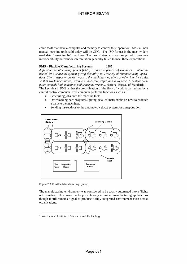
chine tools that have a computer and memory to control their operation. Most all non manual machine tools sold today will be CNC. The ISO format is the most widely used data format for NC machines. The use of standards was supposed to promote interoperability but vendor interpretation generally failed to meet these expectations. FMS – Flexible Manufacturing Systems 1985 A flexible manufacturing system (FMS) is an arrangement of machines.... intercon-nected by a transport system giving flexibility to a variety of manufacturing opera-tions. The transporter carries work to the machines on pallets or other interface units so that work-machine registration is accurate, rapid and automatic. A central com-puter controls both machines and transport system... National Bureau of Standards 1
The key idea in FMS is that the co-ordination of the flow of work is carried out by a central control computer. This computer performs functions such as:
• Scheduling jobs onto the machine tools • Downloading part-programs (giving detailed instructions on how to produce
a part) to the machines. • Sending instructions to the automated vehicle system for transportation.
Figure 2 A Flexible Manufacturing System
The manufacturing environment was considered to be totally automated into a ‘lights out’ situation. This proved to be possible only in limited manufacturing applications though it still remains a goal to produce a fully integrated environment even across organisations.
1 now National Institute of Standards and Technology
INTEROP-ESA'05
Page 581

OBA – Overall Business Architecture 1983 The OBA took this philosophy to the factory level in the mid to late 1980s. It was a first generation Integrated Business System between design, planning, materials, manufacturing, procurement and invoicing applications systems. But the individual applications were locked together, difficult to maintain and inhibited business change and therefore affected the competitiveness of the business. Applications were built to aid a discipline and not to integrate with other disciplines’ applications. The informa-tion was locked in the application. To integrate these applications, expensive point to point interfaces were developed. There is a need for a more modular approach, where
• Data is seen as being separate from the application, which manipulates that data
• Information is a key company asset and should be treated differently from the application systems
• Data/information needs to be protected as it has a life expectancy • Data standards are used – XML-xx standards need to be developed
like a platform following the schema produced by STEP for exchanging data across PDM’s via a neutral data standard. This approach was used for the next generation of integration for e-business and outsourced business. A large UK enterprise’s business depends upon the interface between Product Data Management (PDM) systems and Enterprise Resource Planning (ERP) systems to transfer Parts and Bills of Material (BOMs) to allow designed items to be purchased or manufactured. For one Business Group, the multiple PDM systems were integrated with the multiple ERP systems using point-to-point interfaces, and a TIBCO-based interface existed between their previous PDM System, Sherpa, and ERP System at one site. For an-other Business Group, a similar interface existed between their Sherpa PDM and ERP Systems. The large UK enterprise’s first Business Group launched a programme to replace their existing PDM systems with a single common system based upon EDS’ Meta-phase, hosted on a single corporate server. There may be different site-specific data implementations dependent on the data transferred from their Sherpa systems. The second Business Group similarly moved onto Metaphase, converting their data from Sherpa. This was totally separate implementation of Metaphase and is different from the Avionics implementation. All the application software, both PDM and ERP, is the same but differences existed in the implementations of the ERP System to satisfy local business requirements.
INTEROP-ESA'05
Page 582

3 Enterprise Integration
The first Business Group then required an interface between Metaphase and their ERP Systems. This interface is required to enable Product Structure data (i.e. single parts, single level BOM structures or multiple level BOMs) to be transferred from the single PDM database to any of the ERP databases identified, the choice of which ERP installation being made by the user. This to satisfy the concept of ‘design anywhere, manufacture anywhere’ and today some sites design but do not manufacture, so the data needs to be transferred to those sites who will undertake the manufacturing. The second Business Group also required an interface between Metaphase and their ERP System but because their Metaphase implementation was different than the first Business Group’s, there were different data translations to be performed.
4 Architecture
To meet this concept of transferring Metaphase Parts and BoMs to any ERP System, the interface needed to be designed and the data translations needed to be understood. Some sites have previously used a proprietary Message Broker and to also meet the needs of interfacing to an External Marketplace system from their ERP and other systems, a new corporate Message Broker was sought and acquired for this purpose, known as an Enterprise Application Infrastructure (eAI), supplied by webMethods. Until recently, integration issues fell into several different camps with solutions pro-vided by specific point products. However, the newer releases of Integration type platforms rise to the challenges, resulting from the broadening scope and depth of integration requirements by delivering a business-driven interoperability that fully encompasses data, packaged and customer applications, legacy systems, Web ser-vices, business partners, and human workflow. Recognising evolving and expanding requirements, these products integrate key elements into a comprehensive solution containing broad and deep support for all initiatives such as A2A, B2B, B2C, EAI, BPM, BPA, EDI and more. They deliver true end to end integration and interopera-bility between packaged and custom applications, mainframe system transactions, front- and back-office systems, Web services, and human workflow. Users can define disparate business processes that incorporate resources into comprehensive business processes that maintain a process context across the extended enterprise. So the high level business process of the solution became
INTEROP-ESA'05
Page 583

UPL
OAD
ER
EXT
RA
CT
PDMMetaphase
EDSeAI BrokerIS
AdapterIS
Adapter ER
PN
etw
orks
MTO
Man
ugis
tics
BOMBOM
webMethodsBAE SYSTEMS
eAI Backbone
ManugisticsUploader
MetaphaseExtract
Application 2Application 1
Read
Publish
Extract
Write
Subscribe
Write Upload
CSCeAI PDMAdapter
CSCeAI MTOAdapter
Return errorse
Net
wor
k P
rocu
rem
ent
Man
ugis
tics
Application 3
Fig. 1. Generic Business Process Model for the first Business Group’s EDS Metaphase to ERP Interface
As can be seen there are three main components:
• The PDM (Metaphase), ERP (Networks MTO) and Network Procurement (if installed) systems (Application 1, 2 and 3 if installed). Network Procure-ment is not installed for all sites but the NWP capability exists within the in-terface and is dependent upon a user specified parameter to invoke it and NWP being installed.
• The software vendors (EDS (Metaphase extract), webMethods (eAI Broker and initial Adapters), CSC (eAI PDM & MTO Adapters), Manugistics (MTO Uploader)).
• The data to be transferred from Metaphase to MTO, dependent on whether Network Procurement is installed via a user configurable parameter (Bill of Material – BOM).
In addition, Fig. 1 also illustrates the generic steps and the direction of the data flow. The Extractor program selects and extracts through user screen interfaces and writes the data to be transported into a file. The eAI Adapter will read this file from the PDM environment and transport it to the MTO environment, dependent upon whether Network Procurement is installed, translating the data according to business rules defined by the Business Group. Once the file is in the MTO environment, the eAI MTO Adapter is then responsible for invoking the Uploader program via a script to load the BOM data into MTO, the data conversion and transfer being dependent on
INTEROP-ESA'05
Page 584

whether Network Procurement is installed for a particular site. Codes are returned from the Uploader and translated by the eAI MTO Adapter into messages and re-turned, by email, in a message report file to the person initiating the transfer. Note: The PDM Adapter, the MTO Adapter and the Uploader are common software across all interfaces but it is the choice of the user when to take these releases, so some sites have different releases installed. It is recommended that the latest release is tested, accepted for production release and installed, in line with business priorities. Data integrity across this interface is paramount, so open source software could not be used as it is untested and unsupported. However, using software vendors’ solu-tions doubled the cost and also increased the time delay by 100%.
Metaphase to MTO Interface
Infra
stru
ctur
e
Infra
stru
ctur
e
Metaphase AP
I ES(Enterprise
Server)
ISAdapter
ISAdapter A
PI
Generic eAIServices:
LogX-Ref
Adapter
Metaphase Server MTO Server
eAI Broker Server
Application API +
Broker pack & Bridge= IS Adapter +
ISAdapter
ISAdapter
MTOAdapter
PDMAdapter
UploaderMetaphaseExtract
MTO
Net
wor
kP
rocu
rem
ent
Fig. 2. Logical Application Architecture for the first Business Group’s EDS Metaphase to ERP Interface
The second Business Group also required transferring Production Metaphase data to their Test ERP System, in addition to their Production ERP System. This was to satisfy a number of requirements, such as
• if during support and maintenance, there was a problem sending data across their Production interface, they could repeat the sending of the data but into their Test ERP System,
• for testing ERP System upgrades, without the need to fully replicating data into their Test Metaphase System, saving both time and cost.
This meant their business process and architecture is slightly different but this facility is now available for the first Business Group should they choose to install it.
INTEROP-ESA'05
Page 585

UP
LOA
DE
R
EXT
RA
CT
PDMMetaphase
EDS
ProductioneAI Broker
ISAdapter
ISAdapter E
RP
Net
wor
ks M
TOM
anug
istic
s
BOMBOM Application 2Application 1
Read
Publish
Extract
Write
Subscribe
Write Upload
Return errorse
UP
LOA
DE
R
TesteAI Broker
ISAdapter E
RP
Net
wor
ks M
TOM
anug
istic
s
Return errorse
webMethodsBAE SYSTEMS
eAI Backbone
ManugisticsUploader
MetaphaseExtract
CSCeAI PDMAdapter
CSCeAI MTOAdapter
FTP*
PRODUCTIONPRODUCTION
TEST
Net
wor
kP
rocu
rem
ent
Net
wor
kP
rocu
rem
ent
Application 3
EXT
RA
CT
PDMMetaphase
EDS
ISAdapter
TEST
Fig. 3. Generic Business Process Model for the second Business Group’s EDS Metaphase to ERP Interface
Network Procurement is not installed for the second Business Group but the NWP capability exists within the interface and is dependent upon a user specified parameter to invoke it and NWP being installed. In addition, Figure 2 also illustrates the generic steps and the direction of the data flow. The Extractor program, through user screen interfaces, selects, extracts and writes the data to be transported into a file. The eAI PDM Adapter Build 3 will proc-ess this file from the PDM environment and transport it to the respective MTO envi-ronment, dependent upon whether the user has specified Production or Test and also whether Network Procurement is installed, translating the data according to business rules defined by the Business Group. Once the file is in the Production or Test MTO environment, the eAI MTO Adapter is then responsible for invoking the Uploader program via a script to load the BOM data into the specified MTO System, the data conversion and transfer being dependent on whether Network Procurement is in-stalled for a particular site. Codes are returned from the Uploader and translated by the eAI MTO Adapter into messages and returned, by email, in a message report file, to the person initiating the transfer.
INTEROP-ESA'05
Page 586

Infra
stru
ctur
e
Metaphase to MTO Interface
Infra
stru
ctur
e
Infra
stru
ctur
e
Metaphase API ES
(EnterpriseServer)
ISAdapter
ISAdapter AP
I
Generic eAIServices:
LogX-Ref
Adapter
Production Metaphase Server Production MTO Server
eAI ProductionBroker Server
MTOAdapter
PDMAdapter
UploaderMetaphaseExtract
MTO
Net
wor
kPr
ocur
emen
t
Infra
stru
ctur
e
ISAdapter AP
I
Test MTO Server
MTOAdapter
Uploader
ES(Enterprise
Server)
Generic eAIServices:
LogX-Ref
Adapter
eAI Test Broker Server
MTO
Net
wor
kPr
ocur
emen
t
FTP
Metaphase API IS
Adapter
Test Metaphase Server
PDMAdapter
MetaphaseExtract
Application API +
Broker pack & Bridge= IS Adapter +
ISAdapter
ISAdapter
Fig. 4. Logical Application Infrastructure for the second Business Group’s EDS Metaphase to ERP Interface
5 Benefits
The benefits of this approach are that there is a single software solution in place con-sisting of 4 main modules, utilising the EAI Infrastructure solution, with separate paths as required for each business. The businesses cannot manage without this interface, as the recent migrations to the Production Metaphase System have shown, as they have been held for ‘go live’, pending the release of the metaphase to ERP Interface. The software is easier to maintain and once facilities are developed for a site, then they are available for other sites to use as well. The solution supports the concept of ‘design anywhere, manufacture anywhere’, reducing ordering times by 50% or even higher and reducing the number of internal buyers / procurement staff.
INTEROP-ESA'05
Page 587

4 Experience
Experience with the Large UK enterprise has also shown that it is now possible to link:
• internal procurement systems i.e. SAP, BaaN, Networks MTO to the exter-nal Marketplace. EXOSTAR, i.e. to supplier catalogues and to order parts totally electronically.
• HR Systems to other HR Systems within and external to the company.
5 Conclusions
The eAI approach allows the modular (component) building of a system that has a degree of dynamic reconfigurability to meet business need of delivering capability to a contract need. The cost needs to be addressed as do the analysis, modelling and, of course, the in-formation Ontologies embedded in standards.
INTEROP-ESA'05
Page 588

INTEROP-ESA’2005
1
Interoperability of Knowledge Based Engineering Software
Uwe Kaufman Fraunhofer IPK
and Russell W. Claus
NASA Glenn Research Center
Abstract
The design process of manufacturing goods like vehicles, airplanes, and spaceships is increasingly being driven by conflicting requirements. There is a need to shorten the product development time while performing more rigorous multidisciplinary analysis of increasingly complex systems. There is a need to involve a larger group of design partners while retaining core competencies within the design group. Knowledge Based Engineering software has been used to ameliorate these challenges, but market acceptance of the software has been growing only slowly due to their weak integration into the overall product development process. Knowledge Based Engineering software provides a systematic approach to capture design knowledge so that it can be used in future applications (such as redesign or product lifecycle support). It supports linking requirements to design artifacts and captures constraints and relationships in a manner that allows integration with Computer Aided Design (CAD) software. Product Data Management (PDM) today is widely accepted as a means to store design data, especially CAD models and metadata. The new challenges of the most developed manufacturing enterprises is the implementation of a Product Lifecycle Management system, which often is referred to being an extension of PDM, but actually represents a process for the capturing of all data that concerns the whole product lifecycle, including the knowledge that lead to the specific design solution. A past National Institute for Standard and Technology (NIST) workshop highlighted the lack of interoperability as a key reason for slow market acceptance of KBE software. Current international standards efforts have not yet closed this gap. One previous effort that attempted to address this challenge was the Methodology for Knowledge Based Engineering Applications (MOKA) project. MOKA was a European-sponsored research effort to develop a methodology for KBE that would, first, find ways to represent the product and process knowledge for design and, second, build a software tool to enable the methodology. MOKA used the Unified Modeling Language (UML) as one tool to represent product knowledge and followed a systematic, Object-Oriented approach to capture product and process knowledge. Going beyond MOKA in terms of the development of KBE tools, a Function Oriented Design (FOD) system was developed in the framework of the German national project iViP (Integrated Virtual Product Creation). FOD is a conceptual design tool that allows the functional decomposition of a product, which is an abstract representation of a virtual product. This abstraction is needed to capture design knowledge independently of the
INTEROP-ESA'05
Page 589

INTEROP-ESA’2005
2
CAD system and to allow an easy way to reuse existing design solutions. To ease the adoption of FOD systems, standard interfaces to access and store design information were chosen, such as OMG’s PDM Enablers and CAD Services. At the same time it reveled the absence of higher level interfaces to store and retrieve knowledge related information. The Object Management Group (OMG) is an international standards organization supporting the development of software standards through a Model Driven Architecture (MDA) approach. The wide-scale industry adoption of OMG's MDA provides application developers and users with the means to build interoperable software systems distributed across all major hardware, operating system, and programming language environments. One of these industry wide efforts is under the umbrella of the Manufacturing Technology and Industrial Systems (ManTIS) Domain Task Force. The ManTIS’s mission is to foster the emergence of cost effective, timely, commercially available and interoperable manufacturing domain software components through MDA standards. Its goals include: ? Recommend technology for adoption that enables the interoperability and modularity
of manufacturing domain software components. ? Encourage the development and use of MDA manufacturing domain software
components, thereby growing the object technology market. ? Leverage existing OMG specifications. Recommend liaison with other appropriate
organizations in support of the preceding goals. In this framework a number of industry relevant specifications have been submitted and adopted, like Product Data Management (PDM) Enablers, Computer Aided Design (CAD) Services, Data Acquisition from Industrial Systems (DAIS & HDAIS), Product Lifecycle Management (PLM) Services, Utility Management Systems (UMS) Data Access Facility, and Distributed Simulation Systems. The work on an interface model specification for Knowledge Based Engineering (KBE) software has recently begun. This specification should enable the interoperability of design knowledge between various KBE systems and related software. Based on industry feedback, a Request for Proposal (RFP) has been drafted that calls for the specification of a standard interoperable KBE interface model that enables the interoperability stated above. The principal motivation is to achieve functional interoperability and exchange of data and knowledge without loss of information, tolerance or robustness in Computer-Aided Engineering (CAE) applications, in general, and Knowledge Based Engineering (KBE) applications , in particular. It is anticipated that this activity will increase user acceptance; enable long-term design knowledge capture and retrieval of engineering information; add formalism to an informal process, thus improving the design process; provide a vehicle for university research that could lead to improved knowledge representations; provide vendors with increased market acceptance; and possibly promote the development of a user group that could solve user problems without vendor expense.
INTEROP-ESA'05
Page 590
Methods for the Analysis of Supply Network Processes
at European SMEs
Markus Rabe
Fraunhofer IPK, Pascalstr. 8-9, 10587 Berlin, Germany,
Abstract. Business Process Modelling (BPM) is a well-understood method to analyse enterprise processes. As today more and more essential processes are conducted across the enterprise borders, this induces additional challenges in terms of different languages, process types and ontology. This paper indicates techniques which support such cross-enterprise BPM. The work reported has been conducted in three company networks including SMEs within different European regions, identifying potentials and constraints for a more sophistica-ted supply chain control.
1 Introduction
The SPIDER-WIN project (with financial contribution of the European Commission, IST Project 507 601) [1] aims to achieve efficient, simple and context-aware SME co-operation in supply networks with low-level local software requirements, focussed on the exchange of order status changes. This is achieved by an ASP platform with asynchronous data exchange between the platform and the enterprises.
In order to prepare the definition of the required functionalities and interfaces, three supply networks from different European regions have been analysed. In the preparation phase, reference models and documents have been developed as the base for the local studies. In the analysis phase, similarities between the different work-flows have been identified.
2 Modelling Techniques Applied
Due to the process orientation of the project’s subject, a process oriented approach is required. Therefore, the Integrated Enterprise Modelling (IEM) Method [2] has been applied. Through the object oriented approach of the IEM the use of reference classes is very efficient, simplifying the task of defining common terms, structures and attri-butes.
Reference models are a very efficient means to increase the efficiency of model-ling, to raise the quality level of the developed models, and to improve the reusability of the models. Such reference should include class structures, template models and a manual which describes the correct and efficient use of the reference models as well as the validity and constraints of the model [3]. Especially for distributed systems,
INTEROP-ESA'05
Page 591

where different persons perform the modelling task at different locations, reference models can improve the work, significantly [4]. The Supply Chain Operations Reference Model (SCOR) is a reference model, too, as it incorporates additional elements like standard descriptions of processes, standard metrics and best-in-class practices [5].
Before starting interviews, a reference model based on IEM methodology and SCOR terminology was developed, in order to guarantee that all information and requirements detected can be systematically documented within one single, consistent model. A Guideline Document Suite includes a description of the processes, variables and metrics to be considered as well as supporting documents and document templates. The guidelines supported the structure and completeness of the interview as well as the comparison of the results from the different supply networks.
3 Results
First, the single company models have been established. They have then been merged to models of the three different supply networks, thereby identifying additional poten-tials and challenges at the company interfaces. In total, 103 sub-models (“levels”) have been established, with a total of 1852 process elements.
Based on the study results, a “general model” of the as-is-situation could be extrac-ted from the three network models, which describes general and specific process ele-ments, systematically documented within one single, consistent model. It contains the SCOR compliant process names, specific “information categories”, relations between processes and information categories and further application rules. Therefore, by comparison of a specific supply chain model with the general model, the specifics of the supply chain can be identified.
The study has demonstrated, that a well-adapted reference model is an important base for the conduction of cross-enterprise business process studies. The IEM Method turned out to be a very efficient means for this purpose, allowing to switch the terms between two languages (the native interview language and English). The reference class trees significantly improved the development of models with comparable struc-tures, without urging the interviewers into pre-defined processes. SCOR was a good base to establish common understanding between the coaches.
References 1. IST 507 601 SPIDER-WIN project, www.spider-win.de 2. Mertins, K.; Jochem, R.: Quality-oriented design of business processes. Kluwer Academic
Publishers, Boston (1999) 3. Rabe, M.; Mertins, K.: Reference models of Fraunhofer DZ-SIMPROLOG. In: Bernus, P.;
Mertins, K.; Schmidt, G. (Eds.): Handbook on Architectures of Information Systems. Springer, Berlin, Heidelberg, New York (1998) 639-649
4. Rabe, M.; Jaekel, F.-W.: The MISSION project – demonstration of distributed supply chain simulation. In: Kosanke, K.; Jochem, R.; Nell, J.G.; Ortiz Bas, A. (Eds.): Enterprise inter- and intra-organizational integration. Kluwer, Boston, Dordrecht, London (2003) 235-242
5. Supply-Chain Council: Supply-Chain Operations Reference Model - Overview of SCOR 5.0. Supply Chain Council, Pittburg (2002)
INTEROP-ESA'05
Page 592

The Accounting Information Sharing Model for ShanghaiGrid 1
Jiadi Yu, Minglu Li, Ying Li, Feng Hong
Department of Computer Science and Engineering,Shanghai Jiao Tong University, Shanghai 200030, P.R.China
{jdyu, li-ml, liying, hongfeng}@cs.sjtu.edu.cn
Abstract. The ShanghaiGrid, as a Grid Computing Environment, is an information Grid to serve the public in the city, and all resources are regarded as Grid Services in Open Grid Services Architecture (OGSA). The primary goal of ShanghaiGrid is to build a general shared information grid platform. Charging and accounting is an important part of grid computing system in computational economy environment. An accounting procedure based upon a computational economy model is a promising way of solving the problem of resource allocation in a grid environment. The aim of this paper is to propose an accounting information sharing model to be used within the ShanghaiGrid project. In this paper, we introduce firstly an overview of ShanghaiGrid. Then we describe architecture of charging and accounting system and its key technologies. Afterward, we discuss mechanisms of the grid charging and accounting in ShanghaiGrid.
1 Introduction
Grid computing, which are able to harness distributed resources for solving large-scale computationally intensive problems, has been widely accepted as a promising paradigm for large-scale distributed systems in recent years [1,2,3], and the main goal of it is sharing large-scale resources and accomplishing collaborative tasks [2] in science, engineering, and commerce. In the past few years, the main application of grid computing was mostly academic or exploratory in nature and did not enforce the grid economy mechanisms. However, with the emergence of Web Services technologies and the Open Grid Services Architecture (OGSA) [4,5], Grid infrastructures move increasingly towards a multi-institutional production scale and need infrastructure that supports various services: security, uniform access, resource management, scheduling, application composition, computational economy, and accounting. Therefore grid economy and accounting is becoming increasingly important.
A charging and accounting service to be functional in a grid environment will
1 This paper is supported by 973 project (No.2002CB312002) of China, ChinaGrid Program of MOE of China, and grand project of the Science and Technology Commission of Shanghai Municipality (No. 03dz15026, No. 03dz15027 and No. 03dz15028).
INTEROP-ESA'05
Page 593
manage the cost of usage of grid and support the economic activity according to the computational economy. It needs to be decentralized, scalable and flexible. An accounting system is responsible for carrying out several functions: metering, data collection, pricing, charging and payment.
Charging and accounting for grid has been taken into account for some grid projects and researchers. DGAS [6] presented a accounting system for European DataGrid project; GridBank[7] was introduced as a grid accounting services architecture for computational grids; IBM ’s ‘Extreme Blue’ grid accounting project proposed a grid accounting framework GSAX [8] with dynamic pricing strategies independent of economic model. The problem of the accounting on a computational resource can be faced in many different ways. Different grids have different accounting structure and technologies to adapt to their own Grid Computing Environment. The aim of this paper is not to describe analyze the details of all these approaches but to propose our vision of the problem, and present an accounting model for ShanghaiGrid.
The paper is organized as follows. In Section 2, we introduce background and architecture of the ShanghaiGrid. Then, we present the grid accounting model and key technologies of ShanghaiGrid in Section 3. In Section 4, we briefly describe accounting and charging mechanism in ShanghaiGrid. Finally, we give the conclusion of this paper and the future work in Section 5.
2 An Overview of ShanghaiGrid
The ShanghaiGrid is an ongoing Grid Computing Environment based on the Grid Service standards and the Open Grid Services Architecture, which funded by the Shanghai Science and Technology Development Foundation. As a City Grid, the ShanghaiGrid is to provide a general shared information Grid platform for various Grids. The primary aim of ShanghaiGrid is to develop a set of system software for the information grid and establish an infrastructure for the grid-based applications [9], and promote Shanghai become one of the most advanced information cities in the world. The subjects to be researched in the project cover a wide range, including infrastructure, standard protocol, software, and collaboration platform [10].
The first stage projects of ShanghaiGrid have drawn the investment of ¥28 million. Participants are Shanghai Jiaotong University, Tongji University, Fudang University, Shanghai University, Shanghai Supercomputer Center, Shanghai Transportation Information Center, East China Institute of Computer Technology, IBM, Intel, etc. The nearest goal of ShanghaiGrid is to going to connect all supercomputers in this metropolis together to form a sharing environment for massive storage and grid computing [9].
Fig.1. [10] shows architecture of the ShanghaiGrid. It consists of the following components [10]: Resource Management, Data Access and Transfer, Resource Discovery and Grid Monitoring, Data Sharing and Integration, Grid Service Middleware, Security Service, which are organized according to the requirements of the OGSA.
INTEROP-ESA'05
Page 594
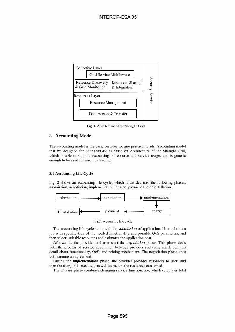
3 Accounting Model
The accounting model is the basic services for any practical Grids. Accounting model that we designed for ShanghaiGrid is based on Architecture of the ShanghaiGrid, which is able to support accounting of resource and service usage, and is generic enough to be used for resource trading.
3.1 Accounting Life Cycle
Fig. 2 shows an accounting life cycle, which is divided into the following phases: submission, negotiation, implementation, charge, payment and deinstallation.
The accounting life cycle starts with the submission of application. User submits a job with specification of the needed functionality and possible QoS parameters, and then selects suitable resources and estimates the application cost.
Afterwards, the provider and user start the negotiation phase. This phase deals with the process of service negotiation between provider and user, which contains detail about functionality, QoS, and pricing mechanism. The negotiation phase ends with signing an agreement.
During the implementation phase, the provider provides resources to user, and then the user job is executed, as well as meters the resources consumed.
The change phase combines changing service functionality, which calculates total
submission negotiation implementation
charge paymentdeinstallation
Fig.2. accounting life cycle
Collective Layer
Resources Layer
Grid Service Middleware
Resource Discovery & Grid Monitoring
Resource Sharing & Integration
Resource Management
Data Access & Transfer
Security Service
Fig. 1. Architecture of the ShanghaiGrid
INTEROP-ESA'05
Page 595
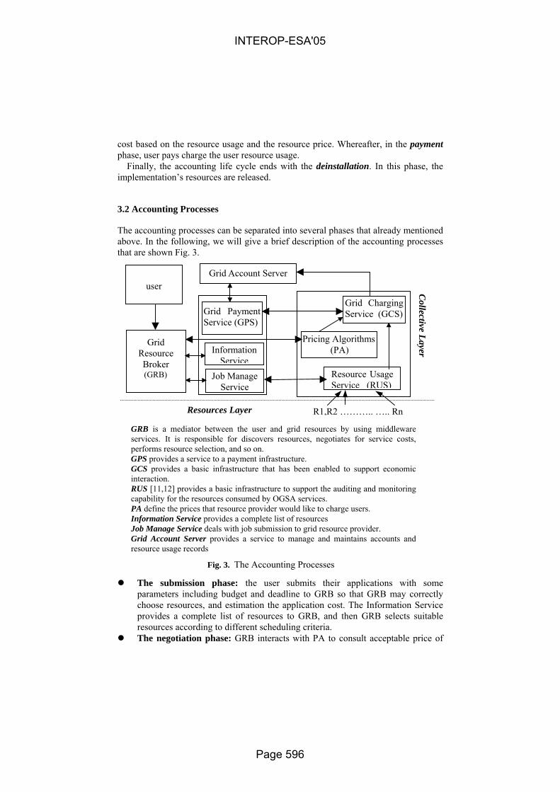
cost based on the resource usage and the resource price. Whereafter, in the payment phase, user pays charge the user resource usage.
Finally, the accounting life cycle ends with the deinstallation. In this phase, the implementation’s resources are released.
3.2 Accounting Processes
The accounting processes can be separated into several phases that already mentioned above. In the following, we will give a brief description of the accounting processes that are shown Fig. 3.
The submission phase: the user submits their applications with some
parameters including budget and deadline to GRB so that GRB may correctly choose resources, and estimation the application cost. The Information Service provides a complete list of resources to GRB, and then GRB selects suitable resources according to different scheduling criteria.
The negotiation phase: GRB interacts with PA to consult acceptable price of
Fig. 3. The Accounting Processes
user
Grid Resource Broker (GRB)
Grid PaymentService (GPS)
Pricing Algorithms(PA)
Resource Usage Service (RUS)
R1,R2 ……….. ….. Rn
Grid Account Server
Grid Charging Service (GCS)
Information Service
Job ManageService
GRB is a mediator between the user and grid resources by using middleware services. It is responsible for discovers resources, negotiates for service costs,performs resource selection, and so on. GPS provides a service to a payment infrastructure. GCS provides a basic infrastructure that has been enabled to support economicinteraction. RUS [11,12] provides a basic infrastructure to support the auditing and monitoringcapability for the resources consumed by OGSA services. PA define the prices that resource provider would like to charge users. Information Service provides a complete list of resources Job Manage Service deals with job submission to grid resource provider. Grid Account Server provides a service to manage and maintains accounts and resource usage records
Collective Layer
Resources Layer
INTEROP-ESA'05
Page 596

services for both grid resource provider and user. If they come to an acceptable price, PA informs GCS about accepted price. The GRB, having received the job description and select suitable resources for the given job, estimate the overall cost of the job.
The implementation phase: GRB submits user job to grid resource provider via Job Manage Service. Grid resource provider provides the service by executing the user job and RUS meters the resources consumed while processing the user job. After the job finished, RUS will obtain the usage statistics of the grid resources, and then generates a standard Resource Usage Record (RUR) [12].
The charge phase: GCS receives the price from PA, which negotiates with resource users, and the data from RUR. Then It calculates total cost based on the resource usage and pricing algorithms that the mutually agreed. Afterward, GCS sent the total service cost and the resources usage statistics to Grid Account Server.
The payment phase: GCS contacts GPS with a request to charge the user account. User will pay resource usage charge by using payment strategies of GPS.
The deinstallation phase: GRB returns the results to the user, and resources are released.
3.3 Grid Account Server
Grid Account Server was designed to store and manage accounting information about provided resources. When a job is done, accounting information of resources usage is sent to Grid Account Server who then transfers an amounting of “money” from the user’s account to the resource provider’s account. Fig. 4 shows Grid Account Server architecture.
An authorized manager creates user accounts, called initial account, at the Grid
Account Server. An amount of “money” and a credit value are stored to Grid Account Server according to the credit rating of the user. When a user starts a request for an application, the server checks and charges the user’s account for its application in
Fig.4. Grid Account Server Architecture
Grid Account Server API
Administration
DBSecurity Protocol
API provides a Grid Account Server interface to other services. Security Protocol performs authentication and authorization of users. Authentication process uses Generic Security Services (GSS) API, which is implemented by Globus Toolkit I/O [13]. Administration provides basic account operation and management such as open account, update account, close account, deposit, transfer, etc. DB is a database that stores account and resources usage information.
INTEROP-ESA'05
Page 597

order to determine whether the user can afford the job to be computed or not. In order to execute a submitted job, the user needs to have an account at Grid Account Server with a positive amount of money.
Communication between user and Grid Account Server must relate to security and access protection. User isn’t able to change his identification, and isn’t trusted to manipulate server’s central storage. An authentication server should be implemented, which handles login and logout procedures. Once clients are authenticated, the client is authorized to establish a connection between client and server. Clients cannot send any requests if a connection is refused. Clients will be checked for their identification every time when they request an accounting service and communicate with server. Clients will be able to access only their own data, unless they have special administration privileges.
3.4 Dynamic Account Manager
To access grid resources, each user will request a local account. However, it is neither desirable nor feasible to allocate an account for each user and accurately maintain a great deal accounts of user. Therefore, we use dynamic or template accounts to manager account, which can meet the requirements of accounting and system management. System administrator will check the user’s membership during authentication, and authorize the user as a dynamic account if she does not have a static account. The dynamic account is chosen from the pool of template accounts [14]. Each dynamic account is a local system account created on the pool of template accounts, but without a permanent user associated with it. A dynamic account bound to a user is temporary. When a user submits some application to resource provider, one of the template accounts from the pool of template accounts will be dynamically assigned to user. To bind of current user to a template account, user’s Certificate Name is temporarily mapped to the account. At the termination time, the processes running and all files with this account as owner will be killed and deleted. Finally, the template account is relaxed, and returned to the pool.
3.5 Accounting Protocols
Accounting protocols can be distinctive the following two types: Security Protocol and data Transfer Protocol.
Security Protocol: It is developed an architecture for authentication and authorization of clients. The architecture is client-server architecture. Authentication is based on Public Key Infrastructure (PKI) using X509v3 certificate [15], and certificates can be issued by certificate authority (CAs). The clients send authentication request to server, and server decides whether the user is authorized to use grid resources.
Data Transfer Protocol: TCP-based transfer protocols such as SMTP, FTP, or HTTP can be used to transfer information of payment and charge between user account and provider account. These protocols is reliable, efficient, and security.
INTEROP-ESA'05
Page 598

4 Accounting Mechanisms
The accounting mechanism describes the accounting policies, and determines the resources exchange rates during the performance of accounting, which maximize benefits of grid resource provider and consumer. The accounting mechanism should be simple enough to be understood by all resource providers and users.
Accounting Items: It is necessary to decide for which resource elements one should pay. Any services invocation will consume a wide range of resources. However, a services provider may only be interested in a relatively small subset of these resources for the purposes of deciding a price to use a service. The consumption of the following resources may be accounted and charged [11]: CPU, Memory, Disc, Wall Clock Time, Node Count, Network, Processors, Software and Libraries accessed.
Book and Estimate: After the job description was received and select suitable resources for the given job, user need book a portion of resources to execute job. Then, resource consumption should be estimated, which has two constituents: rate of consumption, and estimated maximum durations. The overall estimated resource consumption would then be (rate of consumption) × (expected duration).
Resource Pricing: Pricing schemes should base on the supply and demand for resources and the QoS requirements. GBR was requested to mediate resources price by grid resource producers and users. GBR sets firstly a price for a resource and then queries both producers and consumers whether or not accept that price. With time elapsing, GRB increases or decreases the price by a small amount ε after each negotiation, namely P(t) =Ρ±εΔt, until producers and users come to an acceptable price.
Accounting Checking: The overall cost of the job is estimated by multiplying resource price with estimated resource consumption. The user’s account is checked whether there is a positive amount of “money” to pay. If the estimated overall cost of the job exceeds the user's funds, the resource provider may provide a loan for user according to the credit rating of the user.
Accounting Policies: Account policies concern is how to charge for resource usage in some particular situations. We propose the following system policies: 1. If user job is cancelled during execution because of user action, resource provider will charge for resources already used; 2. If user job is suspended because of resource provider action, resource provider don’t charge to the user; 3. If the resource usage expectations is underrated, resource provider provide a loan to user so as to complete whole job; 4. If the expected resource usage is overrated, the job is executed.
5 Conclusions and Further Work
Charging and accounting is an important part of ShanghaiGrid. In this paper, we describe briefly the background and framework of the ShanghaiGrid. Then, we have shown that an account sharing model for ShanghaiGrid, which is a complex system that involves many services interaction, and is a standard architecture for supporting
INTEROP-ESA'05
Page 599

generation and distribution of accounting information. Afterward, we give an introduction to accounting mechanisms of ShanghaiGrid.
Other work needs to be considered and need further investigation. The next steps will study reliability and fault tolerance of accounting model, increase security mechanisms, selects suitable payment policies, analyze the related economic model that suitable for ShanghaiGrid.
References
1. Foster, I., Kesselman, C.(eds.).: The Grid: Blueprint for a New Computing Infrastructure. Morgan Kaufmann (1999)
2. Foster, I., Kesselman, C., Tuecke S.: The Anatomy of the Grid: Enabling Scalable Virtual Organizations. International Journal of High Performance Computing Application, 15(3) (2001) 200–222
3. Foster, I., Kesselman, C., Nick, J., Tuecke, S., The Physiology of the Grid: An Open Grid Services Architecture for Distributed Systems Integration.
4. Tuecke, S., Czajkowski, K.,Foster, I., Frey, J. Graham, S., Kesselman, C., Vanderbilt, P.: Grid Service Specification. Global Grid Forum (2003)
5. Globus Project – http://www.globus.org 6. C.Anglano, S.Barale, L.Gaido, A.Guarise, S.Lusso, A.Werbrouck.: An accounting system
for the DataGrid project -Preliminary proposal. draft in discussion at Global Grid Forum 3, Frascati, Italy, October, 2001. Available: http://server11.infn.it/workload-grid/docs/DataGrid-01-TED-0115-3_0.pdf
7. Alexander, B., Rajkumar, B.: GridBank: A Grid Accounting Services Architecture (GASA) for distributed systems sharing and integration. In 17th Annual International Parallel and Distributed Processing Symposium (IPDPS 2003) Workshop on Internet Computing and E-Commerce, 2003
8. Magowan, J.: Extreme Blue Grid Accounting Project (Grid Service Accounting Extensions–GSAX). GGF Resource Usage Service Working Group. 2003
9. Minglu Li, Hui Liu, Changjun Jiang, Weiqin Tong, Aoying Zhou, Yadong Gui, Hao Zhu, Shui Jiang, Ruonan Rao, Jian Cao, Qianni Deng, Qi Qian and Wei Jin. ShanghaiGird in Action: the First Stage Projects. Proceedings of the Second International Workshop on Grid and Cooperative Computing, Shanghai. December, 2003. LNCS Volume 3032.
10. Ruonan Rao, Baiyan Li, Minglu Li, and Jinyuan You The Delivery and Accounting Middleware in the ShanghaiGrid, Proceedings of the Second International Workshop on Grid and Cooperative Computing, Shanghai. December, 2003. LNCS Volume 3032.
11. Global Grid Forum, Gird Economic Services Architecture (GESA) http://www.gridforum.org/3_SRM/gesa.htm
12. Global Grid Forum, RUR - Resource Usage Record Working Group, http://www.gridforum.org/3_SRM/ur.htm
13. GLOBUS I/O API, http://www-unix.globus.org/api/cglobus-2.0-beta1/globus_io/ 14. Hacker, T., Athey, B., Account Allocations on the Grid,
http://www.nas.nasa.gov/~thigpen/accountswg/Documents/accounttemplates.pdf, 2002. 15. Foster, I., Kesselman, C., Tsudik, G., Tuecke, S., A Security Architecture for
Computational Grids, Proceedings of the 5th ACM Conference on Computer and Communication Security, 1998.
INTEROP-ESA'05
Page 600

An Agent-based DES Supported Modeling Framework for Enterprises
Simona Iuliana Caramihai
POLITEHNICA University of Bucharest
Control Engineering and Computer Science Faculty 313 Splaiul Independentei, 77206 Bucharest, Romania
Abstract -The paper presents a unified modeling framework, agent based and supported by the Discrete Event System theory. This framework is intended to provide generic models, applicable at all enterprise levels, allowing evaluating interactions among different subsystems, in a complete customer-transparent manner. The evaluation is concerned with two main properties: meeting a given deadline for the whole process and allowing certain undesirable states as mutual blockings. The modeling procedure was explained for a simple case study of manufacturing cell. A software application for this evaluation procedure is under development; at this moment it allows to check for undesired states.
I. Introduction The concept of interoperability was defined as “the ability for a system or a product to work with other systems or products without special effort of the part of the customer”. More specific, interoperability could be seen as “the ability of Enterprise software and applications to interact […] The interoperability is considered to be achieved if the interaction can, at least, take place at the levels: data, application and business enterprise”.[1] From a system theory approach, this definition mainly results in primarily finding a common modeling framework for all the subsystems of a large scale heterogeneous system (the enterprise), then elaborating a methodology to combine modeling blocks according to given specifications and finally obtaining a possibility to compare different combinations from a certain performance point of view. The common modeling framework is necessary for offering the same working environment for customers, without regard of systems/ products implied. The combining methodology is necessary for testing different possible interactions as multiple solutions to the same problem (which is the case for the majority of complex problems). Finally, the evaluation allows choosing the most appropriate solution for a given problem and a given set of objectives. An appropriately chosen modeling support should allow stepwise extending models at different complexity levels. From a generic point of view, the same kind of problem can be identified either as the real-time control of a (eventually flexible) manufacturing system or the control of a mobile (eventually intelligent) robot working into a low defined environment.
INTEROP-ESA'05
Page 601

Similarities are: the complexity of the considered systems (a manufacturing system is composed of very numerous devices that should interact exchanging data and materials into a synchronized manner; a mobile robot is composed of an electro mechanic system moving according to information offered by sensors); their heterogeneity (devices composing a manufacturing system are from very different types, running different applications and changing different types of data and materials – as applications that should interact in enterprises; mobile robots have to synchronize mechanics, electronics and software for one single move and/or decision); the necessity to use simplified models – which leads to uncertainties, high dynamics of the processes, existence of multiple solutions for different problems, a.s.o. Starting from these similarities, a possible solution for an interoperability-oriented modeling framework is to consider a modeling approach used for real-time manufacturing control. The purpose of this paper is to present such an approach and to advocate it for interoperability. 2. Agent-based Modeling Approach 2.1. Context One of the main characteristics of the interoperability approach as well as of the real-time manufacturing control, for instance, is that interactions between subsystems are not concerned with their detailed functioning. Every subsystem can be seen as a black-box that can fulfill a certain list of non-decomposable activities (tasks). Those activities are interesting from the interaction point of view only as input/output data (for implementation purposes) and as having one of the following discrete states: idle, in progress, break -down (for state-space purposes). The state of the overall system is obtained by composing the subsystems’ states; the state evolution is obtained by the occurrence of events as “start task”/ “end-task ”/ “task breakdown”. In manufacturing real-time control the goal is to obtain a certain desired state, by a sequence of events occurring from the initial one and, eventually to avoid other undesired states. Basically, there are two evaluation criteria for manufacturing control architectures, that the majority design approaches proved as contradictory: - Robustness (the capability of the control structure to bypass the effects of
eventual resource/ activity break-downs in the controlled system so as to accomplish manufacturing goals – usually achieved by on-line rescheduling)
- Global optimality of the control policy in terms of system efficiency (one of the most important optimality criteria being the time spent by parts in the manufacturing system)
Consequently, there are two design approaches for control architectures: hierarchical and agent based. In the case of hierarchical control architectures, the control problem is vertically stepwise decomposed at enterprise/ shop floor/ cell levels, where the basic criterion for differentiating levels is complexity (of data & process structure). Every level is
INTEROP-ESA'05
Page 602
furthermore decomposed in modules, based on their respective functionality, thus resulting hierarchical distributed control structures. These structures are usually very efficient from the point of view of the global optimality of the control policy, that can be off-line analyzed and evaluated. Other advantages are the clear modularization of the control system, implying the reusability of codes, lent degradation of performances in case of breakdowns, different frequencies of processing on different levels. From the robustness point of view, performances of hierarchical distributed architectures are not very good: usually is necessary to prepare special procedures to treat breakdowns and it proves to be extremely complicated and costly, due to the complexity of the overall system. The agent-based design approach is intended to ensure the robustness of the control system vs. breakdowns by the dynamic reconfiguration. The basic idea is to use a functional horizontal decomposition of the control problem in order to create specialized modules, capable to locally solve, by dedicated algorithms, pre-defined goals. The main difference between these modules and those composing static hierarchical architectures is their position versus the environment. Without an hierarchical stratification, all the basic control functions - as task-planning, scheduling, monitoring, data upgrading and processing - need to be performed by the same module – the agent -, based on information obtained from other similar control entities. Several heterarchical architectures [2], [3], [4] were developed for manufacturing control, having important advantages as the robustness to break downs and the facile extension of the control architecture with new modules but also important disadvantages of non-optimality and blocking. One of the reasons of those disadvantages is that usually agents are not conceived to have a formal model and it is difficult to make off-line evaluation of solutions. In the following a formal agent based model will be proposed in order to compensate the above mentioned disadvantages. 2.2. Proposed modeling framework The modeling framework considers that every complex system could be interpreted as a network of servers and clients queuing for server provided services. Every service could have a given duration and a cost, thus allowing the evaluation of the overall system’s performances. Every client and every server are driven by agents, software structures capable of interactions and negotiations by a system of questions-answers. The approach is inspired by Lin and Solberg’s negotiation model [2], by Albus’ classical model of an intelligent agent [5] and is completed by a formal support. The generic structure of an agent includes four basic blocks (Figure 1.):
INTEROP-ESA'05
Page 603

PERCEPTION DECISIONMAKING
ACTIONS
WORLDMODEL
Fig. 1. Generic structure of an agent
- The perception block - receives every information from the environment and modifies, if necessary, the internal model of the agent;
- The decision making block – it decides either how to process the received data (with direct and explicit consequences on the immediate actions of the agent) or how to modify information and knowledge contained in the world model block (with implicit consequences on the whole behavior of the agent); usually based on the calculus of a multi-criterial cost function;
- The action block - is basically a communication interface with the environment: it either starts tasks performed by a server or sends typified questions for other agents;
- The World Model block - is a structured knowledge base containing the internal model of the agent (including relevant knowledge about the environment, i.e. the state of temporary links with other agents, its own) and a rule base on "how to take decisions".
The world model has to have intrinsic updating mechanisms for its two main parts, verifying and ensuring the global consistency of data. 2.3. Basic types of agents There are two basic types of agents, every one having a specific internal organization. These basic types are the "client agent" and the "server agent". The client agents are in charge with the realization of a specific product or of a list of activities, by negotiating with server agents controlling the necessary resources. A server agent is controlling a specific resource in order to ensure processing for clients. The communication between different types of agents is a negotiation procedure called “centered on the client” (i.e. client agents start negotiations and, if necessary, decide about the server agents they should choose). The world model of a server agent should contain: - the list of processing tasks that the resource could perform - with their respective
duration and cost - the (up-datable) current state of the resource - the (up-datable) history of negotiations with client agents and their basic
characteristics (solicited operations - cost requested - result of transactions) - the (up-datable) efficiency (evaluation) function value
INTEROP-ESA'05
Page 604

- information about agents with which are established in-course negotiations: solicited operations, cost, allocated priorities.
The decision making block should contain basically the rules for constructing an evaluation function for client-agents offers. These rules should be subject of modifications, based on the history of successful/ unsuccessful negotiations and of the current value of the efficiency function. Other rules included in the decision making part should be with regard to the realization of physical processing, allocation of auxiliary materials a.s.o. As concerning a client agent, its world model could be more complex, including: - for a product: all the technological available variants of the physical basic
product; for an activity: the workflow of tasks composing the activity - (up-datable) limits of cost functions allowed for different operations/ activities - functional constraints as the due date, priority level, maximal costs, etc. - the actual state - the current value of its cost function and its history - the upper time limit for duration - the details of the in-course negotiations. Negotiations should develop following a determined protocol and containing a typed set of questions-answers, both in order to simplify the communication procedure and mainly in order to finish in a given time limit. At this level the communication protocol will be not detailed; it si considered as an implementation detail and should be transparent for the user. In order to successfully finish a negotiation is necessary a mutual agreement of both parts, meaning that before allocating a server to a client, both agents should cancel other negotiations. This condition implies that an agent could negotiate in the same time with several others, this approach being intended to optimize the efficiency of the system in terms of cost functions and considering that there could be several servers able to perform certain tasks. In this case, imposing a maximum duration for a negotiation process of an agent could prove a good measure against the possibility to loose time trying to obtain the better server, especially when other alternatives are available. 3. Off-line evaluation and formal support 3.1. Evaluation and supervisory module The proposed modeling approach could offer a support for considering into an unified way any kind of interaction into a system, from product-resource manufacturing level, to enterprise-enterprise into a virtual organization, provided that a communication protocol is ensured between negotiating agents. However, some difficulties can arise when there are concerned several servers and several client competing for the same resources, as for instance: - a critical server is requested by two clients with comparable cost functions for the
operations in cause - blocking situation - two (or more) clients are needing at least two servers each for performing their
tasks; every one has reserved one server and needs the servers reserved by others (the Chinese philosophers problem)
INTEROP-ESA'05
Page 605

- a client agent lasts in the system more than its upper time limit because its negotiating procedure is not enough “aggressive” comp ared with other agents – delay situation
For solving and/ or preventing this kind of problems and for ensuring a global degree of optimality, an off-line performance evaluation of negotiations could be performed. The software module that can perform such an evaluation will be denoted as the supervisory module. A supervisory module can evaluate a given group of agents. Considering their respective internal models – goals included – the supervisor is intended to combine them into a global model and to off-line synthesize and evaluate all their possible interactions. Finally it can select and recommend the optimal one. The consistency of the evaluation is ensured by the modeling support of agents/ world models. 3.2. The modeling support The structure of agents is designed so as the following aspects are distinct: - the environment - represented dually by its model and its perception as feedback
for actions - the goals - decomposable in tasks - the methods for executing tasks and for decomposing goals - the actions on the environment as the results of tasks Based on these considerations it results that the world model would have a dual representation: in terms of rules for goals, methods and actions and in a dedicated formal support for the environment. This modeling support should meet some minimal conditions as: - to reflect the typical behavior of client/ servers - to permit modeling at different complexity levels agents and their goals - to allow a modular approach - to integrate time, - to allow condition/ rules driven evolution of models but also quantitative
evaluation A formalism meeting these requirements are (timed) Petri Nets [6]. The off-line evaluation by a supervisor is based on the principles presented in [7]. An off-line evaluation procedure will have the following steps: 1. Selection of the interesting agent models - from the client agents world model
(implying decisions if the clients have different variants of action) 2. Selection of the necessary server models - taking into account only the operations
requested by the actual clients 3. Construction of the closed loop functioning model, based on the synchronous
composition of models 4. Evaluation Case study: There is a system consists of two servers, M1 and M2, each of them being capable of performing two types of operations (opi Mj – i is the operation number, j is the server that makes the operation):
INTEROP-ESA'05
Page 606

M1 : op1 M1, op2 M1; M2 : op1 M2, op2 M2 Two products, Pr1 and Pr2, are to be realised in parallel, each of them requiring two operations, Pr1 : op1M1, op1M2; Pr2 : op2M1, op2M2 The system could be modeled by two server agents representing M1 and M2, and two client agents, Pr1 and Pr2. The sequences of operations for the client agents represent a restriction for the system evolution. The PN model of the global system is presented in Figure 2. In Table 1 are presented the signification of the places (Pi) and of the transitions (Tj). Usually, in PN models transitions model events and/or actions and places – states and/or conditions. A marking in a place means that the respective condition is fulfilled.
P1
P11P2
P3
P4
P5
FP1FP2
P6
P7
P8
P9
P10
T 2
T 1T 6
T 7
T 3
T 5
T 4T 9
T 8
T 10
T11
P12
Fig. 2. : PN model of the FMS
INTEROP-ESA'05
Page 607

Table 1. Node significance P1 Number of parts of Pr1 type P2 Processing a part Pr1 on the resource M1 P3 Parts Pr1 processed on M1 P4 Processing a part Pr1 on the resource M2 P5 Parts Pr1 processed on M2 P6 Number of parts of Pr2 type P7 Processing of a Pr2 part on the resource M1 P8 Parts Pr2 processed on M2 P9 Processing of a Pr2 part on the resource M2 P10 Parts Pr2 processed on M1 P11 M1 free P12 M2 free FP1 Pr1 ended the operations FP2 Pr2 ended the operations T1 Begin of processing Pr1 on the M1 T2 Uncontrollable End of processing Pr1 on the M1 T3 Begin of processing Pr1 on the M2 T4 UncontrollableEnd of processing Pr1 on the M2 T5 End evolution of Pr1 T6 Begin of processing Pr2 on the M2 T7 UncontrollableEnd of processing Pr2 on the M2 T8 Begin of processing Pr2 on the M1 T9 UncontrollableEnd of processing Pr2 on the M1 T10 End evolution of Pr2 T11 End of the cycle of the manufacturing When a client agent desires to perform a given operation, it simply requests for servers able to perform it. The server agents whose resources are idle and able to perform the operation answer to the request, giving additional information on the duration and quality parameters the resource can offer. A negotiation starts between the client agent and the servers whose information is convenient, aiming to establish a mutually acceptable cost of the operation. All the possible interactions of the agents could be obtained by analyzing the state space of the Petri Net. By specifying undesired states – as blockings – the supervisory module can eliminate those interactions leading to them. In [7] is presented in detail a methodology for the elimination of interactions leading to undesired states. A software application was already designed for implementing this methodology for untimed systems. Figure 3 is presenting the state space of solutions for the case study, as well as the acceptable state space, obtained after eliminating blockings. Petri Nets allows for a very easy inclusion of time in the logical model – by simply associating durations to the nodes modeling activities. Timed model allow for comparing solutions from the duration point of view and – by extension – by every defined cost function.
INTEROP-ESA'05
Page 608
Conclusion The paper presents a modeling framework that allows evaluating interactions between heterogeneous subsystems of a complex structure. The main hypothesis is that every complex system could be modeled as a client/server queuing network and consequently represented as a two-type agent based structure. The evaluation of agent interactions and the elimination of possible problems as blocking could be made based on the synchronous composition of the Petri Nets world models of the agents. The agent composition as well as the evaluation is supported by a dedicated software application. Future research directions are the evaluation of timed models and the realization of a software shell for creating an agent library. References
1. http://interop-noe.org/INTEROP/presentation, page.2 2. Lin, Y., Solberg, J. "Autonomous control for open manufacturing systems", Computer Control
of Flexible Manufacturing Systems. (Joshi S. and Smith J (Ed.)), Chapman & Hall, 1994 3. McFarlane, D. "Holonic manufacturing systems in continuous processing: concept and control
requirements", Proceedings of the Annual Conference of ICIMS-NOE, ASI '95, pp. 273-282, Cascais, Portugal, June 25-28, 1995
4. Wyns, J., Van Brussel, H., Valckenaers, P. "Design pattern for deadlock handling in holonic manufacturing systems", Production Planning and Control, Vol. 10, No. 7, pp. 616-626. 1999
5. Albus J.S., Barbara A.J., Nagel R.N., "Theory and practice of hierarchical control", Proc. IEEE Computer Soc.Int.Conf Compcon Falls, National Bureau of Standards, Washington DC, 1995
6. Rene David, Hassane Alla: Discrete, Continuous and Hybrid Petri Nets, Springer, 2004 7. CIFA sau similar (CSCS ?)
INTEROP-ESA'05
Page 609

Fig. 3: The state space: a) complete b) desirable
a)
b)
INTEROP-ESA'05
Page 610