A Flexible Bioreactor System for Constructing In Vitro Tissue and Organ Models
12
ARTICLE A Flexible Bioreactor System for Constructing In Vitro Tissue and Organ Models Federico Vozzi, 1 Daniele Mazzei, 2 Bruna Vinci, 2 Giovanni Vozzi, 2 Tommaso Sbrana, 2 Leonardo Ricotti, 2 Nicola Forgione, 3 Arti Ahluwalia 1,2 1 CNR Institute of Clinical Physiology, Pisa, Italy 2 Interdepartmental Research Center ‘‘E.Piaggio,’’ Faculty of Engineering, University of Pisa, via Diotisalvi 2, 56126 Pisa, Italy; telephone: þ39-050-2217056; fax: þ39-050-2217051; e-mail: [email protected] 3 Department of Mechanical, Nuclear and Production Engineering, Faculty of Engineering, University of Pisa, Pisa, Italy Received 17 December 2010; revision received 28 March 2011; accepted 30 March 2011 Published online 14 April 2011 in Wiley Online Library (wileyonlinelibrary.com). DOI 10.1002/bit.23164 ABSTRACT: To develop in vitro models of cells, tissues and organs we have designed and realized a series of cell culture chambers. Each chamber is purpose designed to simulate a particular feature of the in vivo environment. The bioreactor system is user friendly, and the chambers are easy to produce, sterilize and assemble. In addition they can be connected together to simulate inter-organ or tissue cross- talk. Here we discuss the design philosophy of the bioreactor system and then describe its construction. Preliminary results of validation tests obtained with hepatocytes and endothelial cells are also reported. The results show that endothelial cells are extremely sensitive to small levels of shear stress and that the presence of heterotypic signals from endothelial cells enhances the endogenous metabolic func- tion of hepatocytes. Biotechnol. Bioeng. 2011;108: 2129–2140. ß 2011 Wiley Periodicals, Inc. KEYWORDS: bioreactor; laminar flow; fluid-dynamic si- mulation; multi-compartmental chamber; connected cell culture; cell testing Introduction Systems and devices for maintaining cells and tissues in controlled physical conditions, or bioreactors, have become an important tool in many areas of research. This is not only due to the growing interest in tissue engineering, but also because it is now being increasingly recognized that cells respond not only to their biochemical (Graber et al., 1994; Kiefer et al., 2002; McMahon and Monroe, 1992), but also to their physical environment (Hsieh and Nguyen, 2005; Myers et al., 2007; Prior et al., 2004; Schmalzriedt et al., 2003) and both cues are necessary to create a biomimetic habitat. The design of a cell culture bioreactor requires a basic understanding of both chemical reactor design and cell biology. First, engineers must understand the effects of reaction rates and stoichiometry, mass transfer, heat transfer, and turbulence and mixing on product distribu- tion, reactor productivity, size, and operational character- istics. These phenomena need to be expressed in accurate but tractable models that can be used for design and optimization calculations. Secondly, an active dialogue between engineers and biologists is necessary so that engineers can appreciate the sensitivity of cells to their environment and construct adequately scaled in vitro models. The most common method for culturing mammalian cells is in petri dishes or microplates inside cell culture incubators. Incubators are large and cumbersome while mechanical stimuli are just about absent in the petri dish. The method is nevertheless used ubiquitously and their results quoted as ‘‘standards’’ of in vitro protocols. Several alternative culture methods have been proposed, and many systems are currently available commercially. Amongst these are low shear perfusion systems (Chen, 1992; Mercille et al., 2000), stirred tank bioreactors (Reuss, 1995), airlift bioreactors (Wang et al., 2005), and rotary cell culture reactors (Saxena et al., 2007). The main advantages of these systems with respect to an incubator are the introduction of fluid-dynamics; the cells are subject to shear stresses and increased nutrient perfusion which are known to stimulate growth and positively influence cell function. A second generation of bioreactors has more recently been realized; these are systems for tissue engineering which provide a high degree of oxygenation through fibers or mem- branes, allowing adequate oxygen partial pressure with Correspondence to: G. Vozzi ß 2011 Wiley Periodicals, Inc. Biotechnology and Bioengineering, Vol. 108, No. 9, September, 2011 2129
Transcript of A Flexible Bioreactor System for Constructing In Vitro Tissue and Organ Models
ARTICLE
A Flexible Bioreactor System for Constructing InVitro Tissue and Organ Models
Federico Vozzi,1 Daniele Mazzei,2 Bruna Vinci,2 Giovanni Vozzi,2 Tommaso Sbrana,2
Leonardo Ricotti,2 Nicola Forgione,3 Arti Ahluwalia1,2
1CNR Institute of Clinical Physiology, Pisa, Italy2Interdepartmental Research Center ‘‘E.Piaggio,’’ Faculty of Engineering, University of Pisa,
via Diotisalvi 2, 56126 Pisa, Italy; telephone: þ39-050-2217056; fax: þ39-050-2217051;
e-mail: [email protected] of Mechanical, Nuclear and Production Engineering, Faculty of Engineering,
University of Pisa, Pisa, Italy
Received 17 December 2010; revision received 28 March 2011; accepted 30 March 2011
Published online 14 April 2011 in Wiley Online Library (wileyonlinelibrary.com). DOI 10.1002/bit.23164
ABSTRACT: To develop in vitro models of cells, tissues andorgans we have designed and realized a series of cell culturechambers. Each chamber is purpose designed to simulate aparticular feature of the in vivo environment. The bioreactorsystem is user friendly, and the chambers are easy toproduce, sterilize and assemble. In addition they can beconnected together to simulate inter-organ or tissue cross-talk. Here we discuss the design philosophy of the bioreactorsystem and then describe its construction. Preliminaryresults of validation tests obtained with hepatocytes andendothelial cells are also reported. The results show thatendothelial cells are extremely sensitive to small levels ofshear stress and that the presence of heterotypic signals fromendothelial cells enhances the endogenous metabolic func-tion of hepatocytes.
Biotechnol. Bioeng. 2011;108: 2129–2140.
� 2011 Wiley Periodicals, Inc.
KEYWORDS: bioreactor; laminar flow; fluid-dynamic si-mulation; multi-compartmental chamber; connected cellculture; cell testing
Introduction
Systems and devices for maintaining cells and tissues incontrolled physical conditions, or bioreactors, have becomean important tool in many areas of research. This is not onlydue to the growing interest in tissue engineering, but alsobecause it is now being increasingly recognized that cellsrespond not only to their biochemical (Graber et al., 1994;Kiefer et al., 2002; McMahon andMonroe, 1992), but also totheir physical environment (Hsieh and Nguyen, 2005; Myers
et al., 2007; Prior et al., 2004; Schmalzriedt et al., 2003) andboth cues are necessary to create a biomimetic habitat.
The design of a cell culture bioreactor requires a basicunderstanding of both chemical reactor design and cellbiology. First, engineers must understand the effects ofreaction rates and stoichiometry, mass transfer, heattransfer, and turbulence and mixing on product distribu-tion, reactor productivity, size, and operational character-istics. These phenomena need to be expressed in accuratebut tractable models that can be used for design andoptimization calculations. Secondly, an active dialoguebetween engineers and biologists is necessary so thatengineers can appreciate the sensitivity of cells to theirenvironment and construct adequately scaled in vitromodels.
The most common method for culturing mammaliancells is in petri dishes or microplates inside cell cultureincubators. Incubators are large and cumbersome whilemechanical stimuli are just about absent in the petri dish.The method is nevertheless used ubiquitously and theirresults quoted as ‘‘standards’’ of in vitro protocols. Severalalternative culture methods have been proposed, and manysystems are currently available commercially. Amongst theseare low shear perfusion systems (Chen, 1992; Mercille et al.,2000), stirred tank bioreactors (Reuss, 1995), airliftbioreactors (Wang et al., 2005), and rotary cell culturereactors (Saxena et al., 2007). The main advantages of thesesystems with respect to an incubator are the introduction offluid-dynamics; the cells are subject to shear stresses andincreased nutrient perfusion which are known to stimulategrowth and positively influence cell function. A secondgeneration of bioreactors has more recently been realized;these are systems for tissue engineering which providea high degree of oxygenation through fibers or mem-branes, allowing adequate oxygen partial pressure withCorrespondence to: G. Vozzi
� 2011 Wiley Periodicals, Inc. Biotechnology and Bioengineering, Vol. 108, No. 9, September, 2011 2129
3-dimensional (3-D) constructs (De Bartolo et al., 2006;Schwartlander et al., 2007; Ye et al., 2007). Most of thesedevices are tissue-specific and so have a narrow range ofapplication.
Finally, the third generation comprises micro-fluidicsystems in which small Reynolds number laminar flows areeasily established. These include microfabricated devicessuch as the perfused microarray bioreactor (Powers et al.,2002), the micro cell culture chamber assay (Lee et al., 2006),and the micro cell-culture analog (Sung and Shuler, 2009).Third generation systems have one main drawback as far astissue engineering applications are concerned; they aresmall. This implies that they cannot be used for culturinglarge numbers or volumes of cells or tissue; in a closed loopsystem, fluid sampling and analysis can therefore be difficult.Furthermore, in microfabricated systems, surface and edgeeffects are amplified whereas physiological cell–cell inter-actions are under-represented (Mazzei et al., 2001).
Keeping in mind the advantages and limitations of eachsystem, our aim was to develop novel in vitro models of avariety of mammalian cells, tissues and organs usingbioreactors operating in a dynamic culture environment.Three different bioreactor cell culture chambers weredesigned and are described here; a laminar flow chamber(LFC), a multi compartmental bioreactor (MCB) and itsevolution, the multi compartmental bioreactor module(MCmB). The first was designed to simulate shear stresses inthe cardiovascular system, whereas the MCB and MCmBwere designed for constructing in vitro models of differentorgans and systems, with particular regard to tissuesinvolved in maintaining metabolic homeostasis. Our focuswas therefore on hepatocytes, as the main orchestrators ofmetabolism and endothelial cells for their importance inmodulating metabolites as they are transported in thebloodstream.
One of the main features of the culture chambers is theirease of fabrication, which renders them highly flexible andsimple to modify or remodel and the low cost ofmanufacturing which renders them disposable and compa-tible with high throughput systems. Furthermore, each ofthe chambers can be used independently or together withother chambers in order to construct increasingly complextissue, organ, or system models. In this article we describe thebioreactor system starting from its design philosophy and itsconstruction and report on preliminary results of validationtests obtained with hepatocytes and endothelial cells.
Design Philosophy
Ideally a system for reproducing 2 and 3 dimensional tissueand organ models in vitro should have the followingcharacteristics:
� A cell culture chamber whose design permits areconstruction of the fluid-dynamic conditions as afunction of flow and fluid parameters.
� The system should be modular so that culture chamberscan be added sequentially or in parallel to simulate amultiple organ system.
Additional features which facilitate practical use are: easyto fabricate, assemble, disassemble, and sterilize.
As far as the culture chamber is concerned, our approachwas to use the methods and materials commonly employedin microfluidic fabrication, but at scales compatible withclassical culture systems such as petri dishes and multiwells,or small scaffolds. This renders the bioreactors moreamenable to use by biologists and enables the use of celldensities comparable with classic systems as well as the use ofconventional assaying techniques. The cell culture chamberis thus made out of polydimethylsiloxane (PDMS), usingsoft-moulding with micro- or mini-machined masters, orwhat we call ‘‘Soft Milli-molding.’’ PDMS was chosenbecause it is biocompatible, easy to sterilize and inexpensive,and has excellent sealing properties (McDonald andWhitesides, 2002).
An important consideration in cell culture is the supply ofnutrients; owing to its solubility, oxygen is considered as thelimiting nutrient in in vitro systems. To ensure thatsufficient oxygen is available and that CO2 is eliminated so asto maintain physiological pH, a mixing chamber is added tothe flow circuit. An important element of the systems is aperistaltic pump, which recreates flow or perfusionconditions. This was preferred to a syringe pump becauseunless two way syringes and complicated valves are used,syringe pumps do not allow closed loop flow and are alsocomparatively higher in cost.
Materials and Methods
Fluid-Dynamic Simulation of Laminar Flow Chamber
The LFC was designed to reproduce the shear stresses foundin the human vascular system (Caro et al., 1978; Fung, 1997)for application to the study of endothelial cell physiologyand to simulate specific pathological conditions. The fluiddynamics in the LFC cell culture chamber were simulatedusing Fluent 6.0 (Fluent, Inc., Joins ANSYS, Inc.,Canonsburg, PA) with the purpose of defining an optimumgeometrical cell configuration, so as to reproduce suitableshear rates over a range of volumetric flow rates. The shearstress values were calculated for a fluid with a viscosity ofh¼ 0.0014 Pa s, and density d¼ 1,000 kg/m3.
The design goals were:
� to minimize the internal volume of the cell, so as reducethe volume of culture medium;
� to obtain an area close to that of standard 12 or24 multiwell plates with a uniform shear rate in the cellculture zone;
� to reduce recirculation regions near the active zone for cellculture;
2130 Biotechnology and Bioengineering, Vol. 108, No. 9, September, 2011
� to embed a leakage-free glass slide in the structure of thecell the inlet and outlet of the chamber (tubes of innerdiameter 1.6mm) for optical observation of cells in thechamber;
� to keep the dimensions of the chamber small enough to beplaced on a microscope stage;
� to keep the dimensions of the inlet section of the cellaround 2� 2mm to allow the correct insertion of thecircular inlet and outlet tubes.
As a starting point, the following geometrical parameterswere fixed:
� chamber height in the cell culture zone s¼ 2mm� chamber width in the cell culture zone L¼ 20mm
A technical detail considered in the fluid-dynamicsimulation was the presence of a step of about 0.5mm inthe upper surface of the cell culture zone, necessary to place aglass slide in base of the PDMS chamber. A 3-D stationaryComputational Fluid Dynamic (CFD) model was applied tosimulate the flow in the channel. For this problem, the valuesof the variables at the control volume boundaries wereobtained via the well-known First Order Upwind lawinterpolation scheme and the discretized equations werenumerically solved by the Semi-Implicit Method forPressure Linked Equations (SIMPLE) algorithm, chosenamong the available code options in Fluent [http://www.fluent.com/]. The RNG (renormalization group)theory k–e model was employed to describe the turbulentflow in the core region of the flow whereas the two-layermodel was accounted for dealing with the viscosity-affectednear-wall region up to the viscous sublayer (Glockner andNaterer, 2005). As the chamber is rectangular but the inletand outlet tubes are circular, a circular tube 1.6mm ofdiameter was joined to the square 2� 2mm inlet and outletsection of the cell, using a structured grid in which the
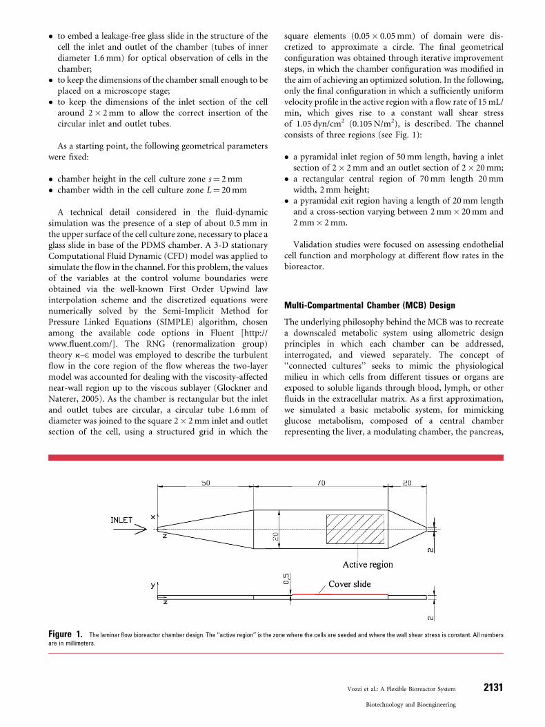
square elements (0.05� 0.05mm) of domain were dis-cretized to approximate a circle. The final geometricalconfiguration was obtained through iterative improvementsteps, in which the chamber configuration was modified inthe aim of achieving an optimized solution. In the following,only the final configuration in which a sufficiently uniformvelocity profile in the active region with a flow rate of 15mL/min, which gives rise to a constant wall shear stressof 1.05 dyn/cm2 (0.105N/m2), is described. The channelconsists of three regions (see Fig. 1):
� a pyramidal inlet region of 50mm length, having a inletsection of 2� 2mm and an outlet section of 2� 20mm;
� a rectangular central region of 70mm length 20mmwidth, 2mm height;
� a pyramidal exit region having a length of 20mm lengthand a cross-section varying between 2mm� 20mm and2mm� 2mm.
Validation studies were focused on assessing endothelialcell function and morphology at different flow rates in thebioreactor.
Multi-Compartmental Chamber (MCB) Design
The underlying philosophy behind the MCB was to recreatea downscaled metabolic system using allometric designprinciples in which each chamber can be addressed,interrogated, and viewed separately. The concept of‘‘connected cultures’’ seeks to mimic the physiologicalmilieu in which cells from different tissues or organs areexposed to soluble ligands through blood, lymph, or otherfluids in the extracellular matrix. As a first approximation,we simulated a basic metabolic system, for mimickingglucose metabolism, composed of a central chamberrepresenting the liver, a modulating chamber, the pancreas,
Figure 1. The laminar flow bioreactor chamber design. The ‘‘active region’’ is the zone where the cells are seeded and where the wall shear stress is constant. All numbers
are in millimeters.
Vozzi et al.: A Flexible Bioreactor System 2131
Biotechnology and Bioengineering
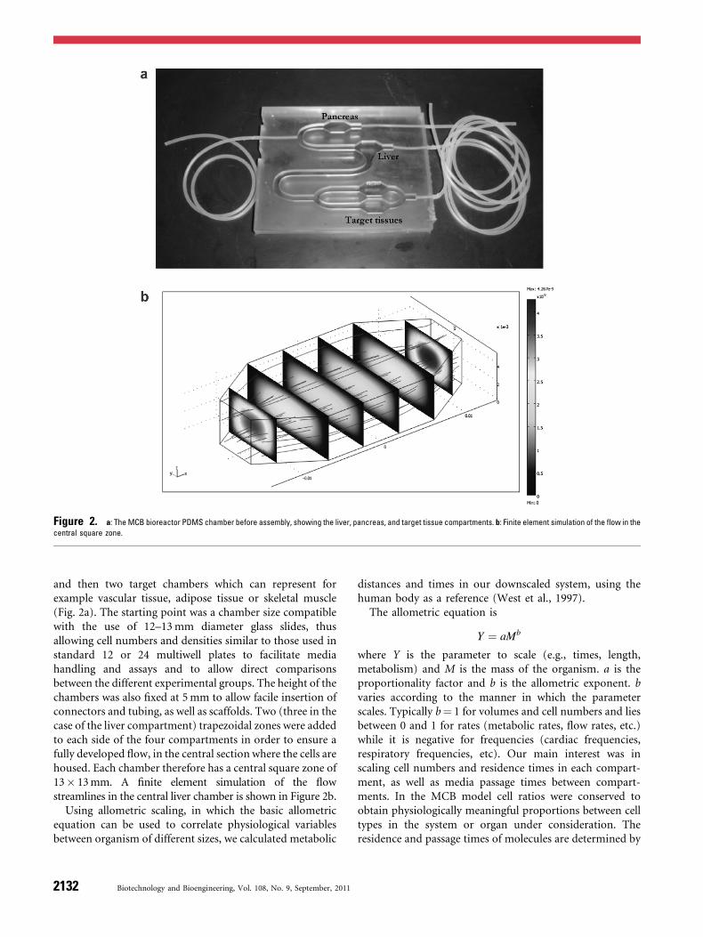
and then two target chambers which can represent forexample vascular tissue, adipose tissue or skeletal muscle(Fig. 2a). The starting point was a chamber size compatiblewith the use of 12–13mm diameter glass slides, thusallowing cell numbers and densities similar to those used instandard 12 or 24 multiwell plates to facilitate mediahandling and assays and to allow direct comparisonsbetween the different experimental groups. The height of thechambers was also fixed at 5mm to allow facile insertion ofconnectors and tubing, as well as scaffolds. Two (three in thecase of the liver compartment) trapezoidal zones were addedto each side of the four compartments in order to ensure afully developed flow, in the central section where the cells arehoused. Each chamber therefore has a central square zone of13� 13mm. A finite element simulation of the flowstreamlines in the central liver chamber is shown in Figure 2b.
Using allometric scaling, in which the basic allometricequation can be used to correlate physiological variablesbetween organism of different sizes, we calculated metabolic
distances and times in our downscaled system, using thehuman body as a reference (West et al., 1997).
The allometric equation is
Y ¼ aMb
where Y is the parameter to scale (e.g., times, length,metabolism) and M is the mass of the organism. a is theproportionality factor and b is the allometric exponent. bvaries according to the manner in which the parameterscales. Typically b¼ 1 for volumes and cell numbers and liesbetween 0 and 1 for rates (metabolic rates, flow rates, etc.)while it is negative for frequencies (cardiac frequencies,respiratory frequencies, etc). Our main interest was inscaling cell numbers and residence times in each compart-ment, as well as media passage times between compart-ments. In the MCB model cell ratios were conserved toobtain physiologically meaningful proportions between celltypes in the system or organ under consideration. Theresidence and passage times of molecules are determined by
Figure 2. a: The MCB bioreactor PDMS chamber before assembly, showing the liver, pancreas, and target tissue compartments. b: Finite element simulation of the flow in the
central square zone.
2132 Biotechnology and Bioengineering, Vol. 108, No. 9, September, 2011
the flow rate in the bioreactor, as well as its total volume.Time scales as b¼ 0.25, therefore, considering a bioreactorwith a total volume of 20mL, or a mass of 20 g, the passagetimes between individual compartments were calculatedusing the in vivo data for glucose metabolism humansdescribed in Basu et al. (2003). For a given volume, theallometric scaling model allows us to establish a flow ratewhich is high enough to provide a dynamic stimulus in theform of flow and concentration gradients but low enough toensure that metabolites and signaling molecules produced inone compartment can be sensed and transduced by the cellsin other compartments. The aim of our first validation studywas to demonstrate the increased metabolic activity of cellsin the MCB when cultured in the presence of other cell typesin adjacent chambers.
Modular Multi-Compartmental Chamber(MCmB) Design
The modular bioreactor is an evolution of the MCB. Whilethe former has a fixed number of compartments, the MCmBmodules can be configured in different ways to obtainseries or parallel circuits of any number of chambers.Furthermore, the modules were designed to minimize shearstress on the cells, so are suitable for stress sensitive cells suchas hepatocytes. The design and fluid dynamic modeling ofthe MCmB is described fully in Mazzei et al. (2001).
The Bioreactors
Laminar Flow Chamber (LFC) Fabrication
The Soft Milli-molding technique is based on the use of amicro or milli-machined master used to produce PDMScomponents which make up the bioreactors. After the finiteelement model was complete and an optimal geometry wasestablished, a negative mold of the LFC model was drawnusing the 3-D Computer Aided Design (CAD) software tool
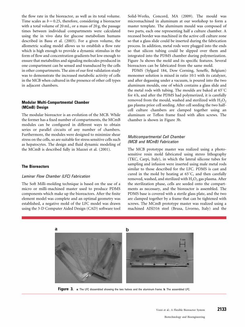
Solid-Works, Concord, MA (2009). The mould wasmicromachined in aluminum at our workshop to form amaster template. The aluminum mould was composed oftwo parts, each one representing half a culture chamber. Arecessed border was machined in the active cell culture zoneso that a glass slide could be inserted during the fabricationprocess. In addition, metal rods were plugged into the endsso that silicon tubing could be slipped over them andintegrated into the PDMS chamber during polymerization.Figure 3a shows the mold and its specific features. Severalbioreactors can be fabricated from the same mold.
PDMS (Sylgard 184, Dow Corning, Seneffe, Belgium)monomer solution is mixed in ratio 10:1 with its catalyzer,and after degassing under a vacuum, is poured into the twoaluminum moulds, one of which contains a glass slide andthe metal rods with tubing. The moulds are baked at 658Cfor 4 h, and after the PDMS had polymerized, it is carefullyremoved from the mould, washed and sterilized with H2O2
gas plasma prior cell seeding. After cell seeding the two half-cell culture chambers are clamped together using analuminum or Teflon frame fixed with allen screws. Thechamber is shown in Figure 3b.
Multicompartmental Cell Chamber(MCB and MCmB) Fabrication
The MCB prototype master was realized using a photo-sensitive resin mold fabricated using stereo lithography(TKC, Carpi, Italy), in which the lateral silicone tubes forsampling and infusion were inserted using male metal rodssimilar to those described for the LFC. PDMS is cast andcured in the mold by heating at 658C, and then carefullyremoved, washed, and sterilized with H2O2 gas plasma. Afterthe sterilization phase, cells are seeded onto the compart-ments as necessary, and the bioreactor is assembled. ThePDMS base is covered with a sterile glass plate, and the twoare clamped together by a frame that can be tightened withscrews. The MCmB prototype master was realized using amachined AISI316 steel (Brusa, Livorno, Italy) and the
Figure 3. a: The LFC dissembled showing the two halves and the aluminum frame. b: The assembled LFC.
Vozzi et al.: A Flexible Bioreactor System 2133
Biotechnology and Bioengineering
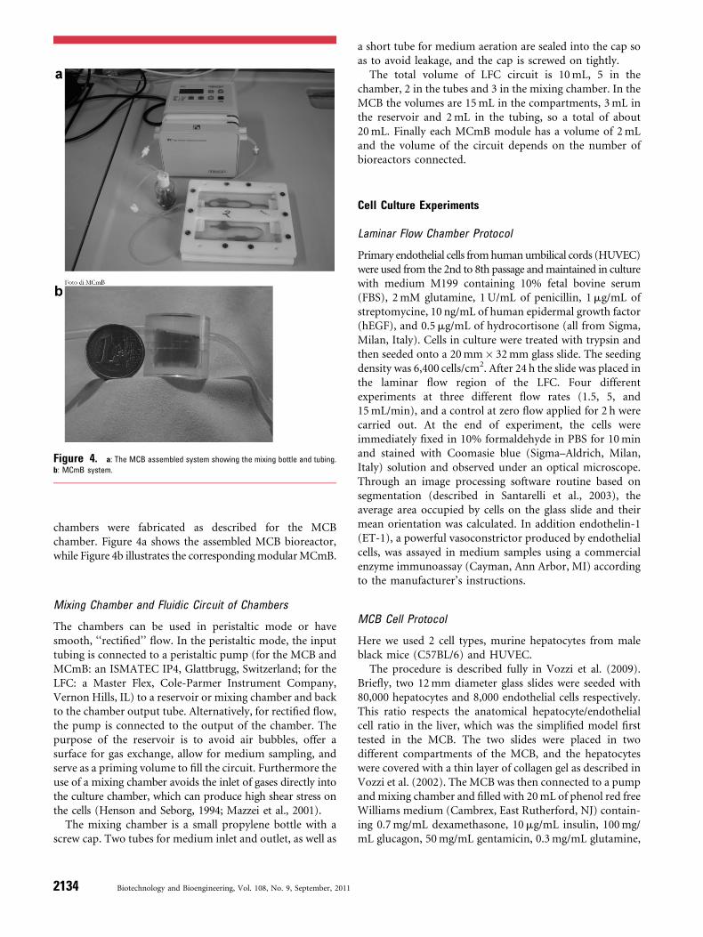
chambers were fabricated as described for the MCBchamber. Figure 4a shows the assembled MCB bioreactor,while Figure 4b illustrates the correspondingmodularMCmB.
Mixing Chamber and Fluidic Circuit of Chambers
The chambers can be used in peristaltic mode or havesmooth, ‘‘rectified’’ flow. In the peristaltic mode, the inputtubing is connected to a peristaltic pump (for the MCB andMCmB: an ISMATEC IP4, Glattbrugg, Switzerland; for theLFC: a Master Flex, Cole-Parmer Instrument Company,Vernon Hills, IL) to a reservoir or mixing chamber and backto the chamber output tube. Alternatively, for rectified flow,the pump is connected to the output of the chamber. Thepurpose of the reservoir is to avoid air bubbles, offer asurface for gas exchange, allow for medium sampling, andserve as a priming volume to fill the circuit. Furthermore theuse of a mixing chamber avoids the inlet of gases directly intothe culture chamber, which can produce high shear stress onthe cells (Henson and Seborg, 1994; Mazzei et al., 2001).
The mixing chamber is a small propylene bottle with ascrew cap. Two tubes for medium inlet and outlet, as well as
a short tube for medium aeration are sealed into the cap soas to avoid leakage, and the cap is screwed on tightly.
The total volume of LFC circuit is 10mL, 5 in thechamber, 2 in the tubes and 3 in the mixing chamber. In theMCB the volumes are 15mL in the compartments, 3mL inthe reservoir and 2mL in the tubing, so a total of about20mL. Finally each MCmB module has a volume of 2mLand the volume of the circuit depends on the number ofbioreactors connected.
Cell Culture Experiments
Laminar Flow Chamber Protocol
Primary endothelial cells fromhuman umbilical cords (HUVEC)were used from the 2nd to 8th passage andmaintained in culturewith medium M199 containing 10% fetal bovine serum(FBS), 2mM glutamine, 1U/mL of penicillin, 1mg/mL ofstreptomycine, 10 ng/mL of human epidermal growth factor(hEGF), and 0.5mg/mL of hydrocortisone (all from Sigma,Milan, Italy). Cells in culture were treated with trypsin andthen seeded onto a 20mm� 32mm glass slide. The seedingdensity was 6,400 cells/cm2. After 24 h the slide was placed inthe laminar flow region of the LFC. Four differentexperiments at three different flow rates (1.5, 5, and15mL/min), and a control at zero flow applied for 2 h werecarried out. At the end of experiment, the cells wereimmediately fixed in 10% formaldehyde in PBS for 10minand stained with Coomasie blue (Sigma–Aldrich, Milan,Italy) solution and observed under an optical microscope.Through an image processing software routine based onsegmentation (described in Santarelli et al., 2003), theaverage area occupied by cells on the glass slide and theirmean orientation was calculated. In addition endothelin-1(ET-1), a powerful vasoconstrictor produced by endothelialcells, was assayed in medium samples using a commercialenzyme immunoassay (Cayman, Ann Arbor, MI) accordingto the manufacturer’s instructions.
MCB Cell Protocol
Here we used 2 cell types, murine hepatocytes from maleblack mice (C57BL/6) and HUVEC.
The procedure is described fully in Vozzi et al. (2009).Briefly, two 12mm diameter glass slides were seeded with80,000 hepatocytes and 8,000 endothelial cells respectively.This ratio respects the anatomical hepatocyte/endothelialcell ratio in the liver, which was the simplified model firsttested in the MCB. The two slides were placed in twodifferent compartments of the MCB, and the hepatocyteswere covered with a thin layer of collagen gel as described inVozzi et al. (2002). The MCB was then connected to a pumpandmixing chamber and filled with 20mL of phenol red freeWilliams medium (Cambrex, East Rutherford, NJ) contain-ing 0.7mg/mL dexamethasone, 10mg/mL insulin, 100mg/mL glucagon, 50mg/mL gentamicin, 0.3mg/mL glutamine,
Figure 4. a: The MCB assembled system showing the mixing bottle and tubing.
b: MCmB system.
2134 Biotechnology and Bioengineering, Vol. 108, No. 9, September, 2011
and 10% FBS (all from Sigma). A flow rate of 175mL/minwas applied for 24 h during which 2mL of medium werewithdrawn from the mixing chamber for analysis of albuminat 160, 260, and 360min and at 24 h. Albumin and glucosewere assayed using commercial colorimetric kits (GlucoseAssay Kit: Megazyme International Ireland Ltd, Bray,Ireland; Albumin Kit: Bray, Ireland; Albumin Kit: BethylLaboratories, Montgomery, TX). Each time medium waswithdrawn it was replaced with 2mL of fresh medium. At theend of the experiments the cells were also assayed for viabilityand counted. Control experiments were carried out withhepatocyte andHUVECmonocultures under flow in theMCB.
MCmB Protocol
The validation tests for the MCmB were focused on thedevelopment of a three dimensional in vitro model of theliver. Three dimensional scaffolds of poly(lactic-co-glycolicacid) (PLGA) 75:25, MW 270,000; Boehringer Ingelheim,Ingelheim, Germany were microfabricated using the PressureAssisted Microsyringe (PAM) (Vozzi et al., 2002). Thescaffolds can host high density functional cultures of HepG2cells for up to a week and their fabrication, preparation andcharacterization is reported in Vinci et al. (2010a). HepG2 cellsfrom a human hepatoblastoma line (Malek et al., 1993),were seeded on collagen-coated PLGA scaffolds placed on12mm glass coverslips in 24 well microplates at a density of100,000 cells per scaffold. Two milliliters of Eagle’s minimalessential medium (EMEM, glucose 1 g/L) supplementedwith 5% FBS, 1% non-essential aminoacids, 1% EMEMvitamins, 2mM L-glutamine, 100U/mL penicillin and100mg/mL streptomycin was added to each well. After24 h the slides were carefully transferred to the MCmB andcoated with an alginate film consisting of 250mL 1% sodiumalginate dissolved in serum free medium, cross linked with50mL of 1% CaCl2. Excess alginate was removed with apipette. The alginate coating was used to protect the cellsfrom direct mechanical stress, whilst allowing adequatenutrient diffusion (Vinci et al., 2010a). Finally 2mL of freshmedium was added to each bioreactor module to begin theexperiment. Three bioreactors were connected in series withthe mixing chamber, in a closed loop with a flow rate of250mL/min. Cells were maintained on the structures fora week and cell counting and medium collection wasperformed daily for analysis of cell number and albuminexpression. Control experiments consisted in scaffoldsseeded in a multiwell.
Connected Culture With LFC and MCmB
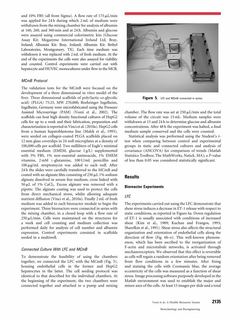
To demonstrate the feasibility of using the chamberstogether, we connected the LFC with the MCmB (Fig. 5),housing endothelial cells in the former and HepG2hepatocytes in the latter. The cell seeding protocol wasidentical to that described for the individual chambers. Atthe beginning of the experiment, the two chambers wereconnected together and attached to a pump and mixing
chamber. The flow rate was set at 250mL/min and the totalvolume of the circuit was 15mL. Medium samples werewithdrawn at 15 and 24 h to determine glucose and albuminconcentrations. After 48 h the experiment was halted, a finalmedium sample conserved and the cells were counted.
Statistical analysis was performed using the Student’s t-test when comparing between control and experimentalgroups in static and connected cultures and analysis ofcovariance (ANCOVA) for comparison of trends (MatlabStatistics Toolbox; The MathWorks, Natick, MA); a P-valueof less than 0.05 was considered statistically significant.
Results
Bioreactor Experiments
LFC
The experiments carried out using the LFC demonstrate thatshear stress induces a decrease in ET-1 release with respect tostatic conditions, as reported in Figure 6a. Down regulationof ET-1 is usually associated with conditions of increasedshear (Kim et al., 1989; Kuchan and Frangos, 1993;Sharefkin et al., 1991). Shear stress also affects the structuralorganization and orientation of endothelial cells along thedirection of flow (Fig. 6b–e). This well-known phenom-enon, which has been ascribed to the reorganization ofF-actin and microtubule networks, is activated throughmechanoreceptors. We observed that this effect is reversibleas cells will regain a random orientation after being removedfrom flow conditions in a few minutes. After fixingand staining the cells with Coomassie blue, the averageeccentricity of the cells was measured as a function of shearstress. Image processing software purposely developed in theMatlab environment was used to establish the major andminor axes of the cells. At least 15 images per slide and a total
Figure 5. LFC and MCmB connected in series.
Vozzi et al.: A Flexible Bioreactor System 2135
Biotechnology and Bioengineering
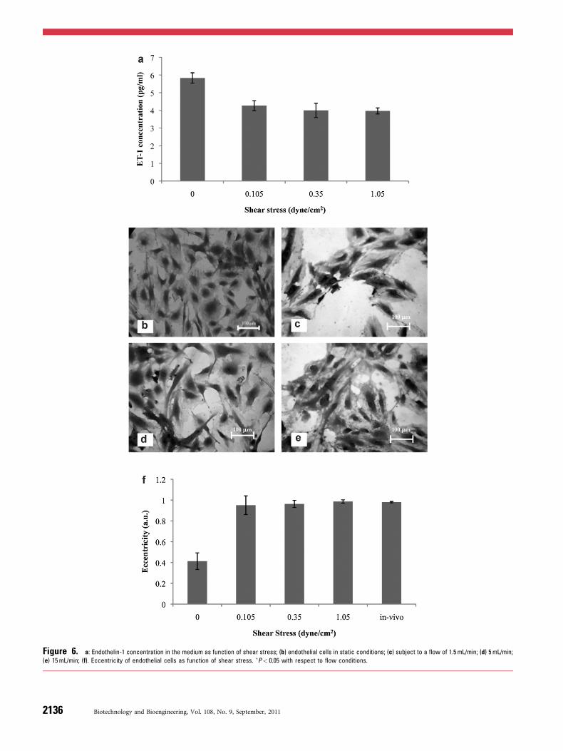
Figure 6. a: Endothelin-1 concentration in the medium as function of shear stress; (b) endothelial cells in static conditions; (c) subject to a flow of 1.5 mL/min; (d) 5 mL/min;
(e) 15 mL/min; (f). Eccentricity of endothelial cells as function of shear stress. �P< 0.05 with respect to flow conditions.
2136 Biotechnology and Bioengineering, Vol. 108, No. 9, September, 2011
of about 50 cells per flow rate were measured and cell shapesapproximated to an ellipse, applying the formula:
e ¼ffiffiffiffiffiffiffiffiffiffiffiffiffiffiffiffiffiffiffi1� b2
a2
� �s
where e is the eccentricity, a and b are major axis and minoraxis respectively. Using data from Kim et al. (1989), theeccentricity value of human endothelial cells in vivo wascompared with the experimental results obtained using theLFC. The eccentricity approximated those of endothelialcells in the ascending aorta at the maximum shear stress used(1.05 dyn/cm2). Typical shear stresses in the vascular systemare around 1–10 dynes/cm2, while aortic shear stresses rangebetween 7 and 15 dyne/cm2 indicating that the cells areextremely sensitive to flow even at the comparatively lowvalues of shear stress used in these experiments.
MCB Experiments
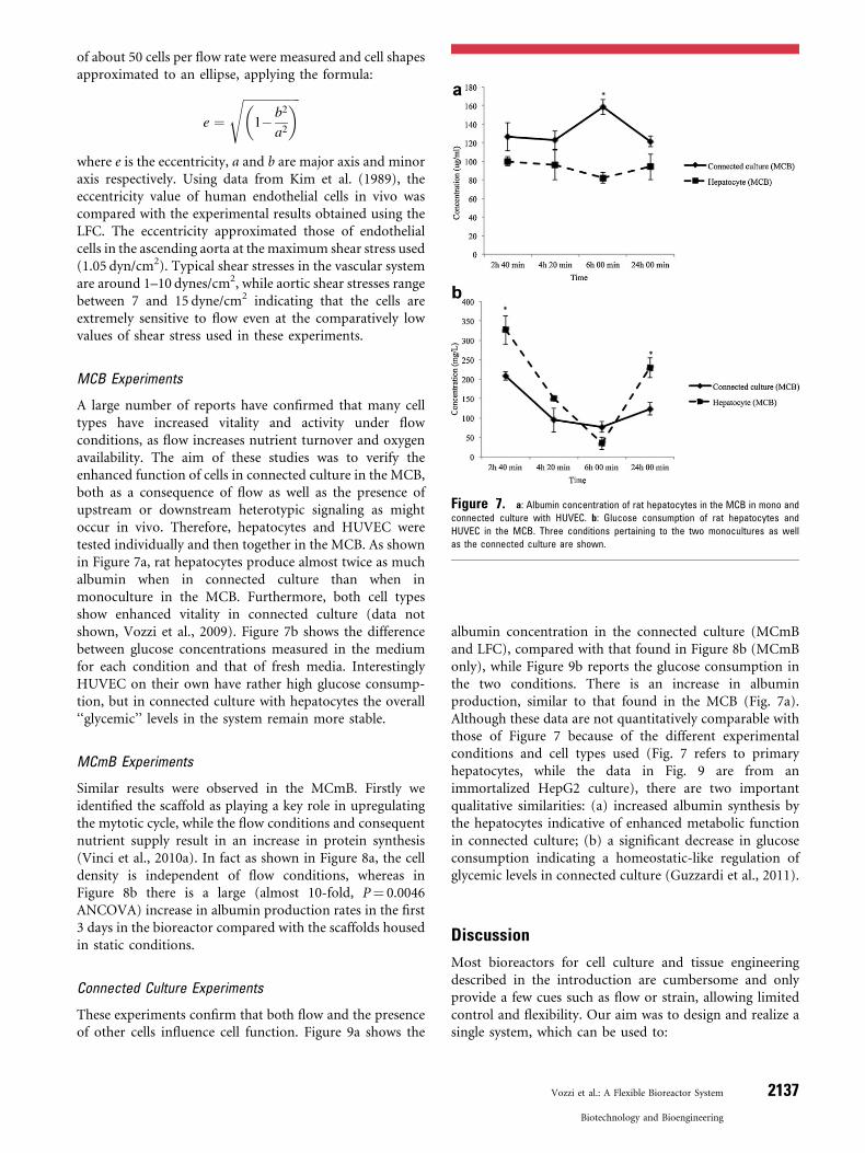
A large number of reports have confirmed that many celltypes have increased vitality and activity under flowconditions, as flow increases nutrient turnover and oxygenavailability. The aim of these studies was to verify theenhanced function of cells in connected culture in the MCB,both as a consequence of flow as well as the presence ofupstream or downstream heterotypic signaling as mightoccur in vivo. Therefore, hepatocytes and HUVEC weretested individually and then together in the MCB. As shownin Figure 7a, rat hepatocytes produce almost twice as muchalbumin when in connected culture than when inmonoculture in the MCB. Furthermore, both cell typesshow enhanced vitality in connected culture (data notshown, Vozzi et al., 2009). Figure 7b shows the differencebetween glucose concentrations measured in the mediumfor each condition and that of fresh media. InterestinglyHUVEC on their own have rather high glucose consump-tion, but in connected culture with hepatocytes the overall‘‘glycemic’’ levels in the system remain more stable.
MCmB Experiments
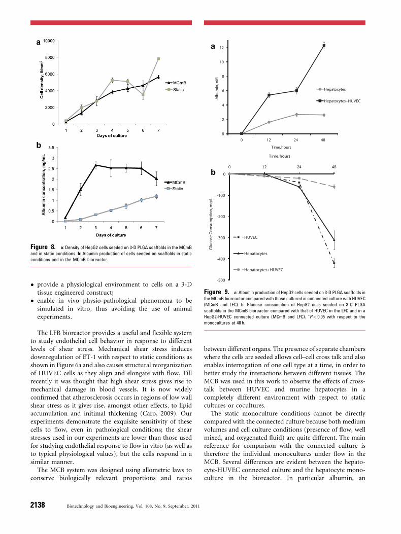
Similar results were observed in the MCmB. Firstly weidentified the scaffold as playing a key role in upregulatingthe mytotic cycle, while the flow conditions and consequentnutrient supply result in an increase in protein synthesis(Vinci et al., 2010a). In fact as shown in Figure 8a, the celldensity is independent of flow conditions, whereas inFigure 8b there is a large (almost 10-fold, P¼ 0.0046ANCOVA) increase in albumin production rates in the first3 days in the bioreactor compared with the scaffolds housedin static conditions.
Connected Culture Experiments
These experiments confirm that both flow and the presenceof other cells influence cell function. Figure 9a shows the
albumin concentration in the connected culture (MCmBand LFC), compared with that found in Figure 8b (MCmBonly), while Figure 9b reports the glucose consumption inthe two conditions. There is an increase in albuminproduction, similar to that found in the MCB (Fig. 7a).Although these data are not quantitatively comparable withthose of Figure 7 because of the different experimentalconditions and cell types used (Fig. 7 refers to primaryhepatocytes, while the data in Fig. 9 are from animmortalized HepG2 culture), there are two importantqualitative similarities: (a) increased albumin synthesis bythe hepatocytes indicative of enhanced metabolic functionin connected culture; (b) a significant decrease in glucoseconsumption indicating a homeostatic-like regulation ofglycemic levels in connected culture (Guzzardi et al., 2011).
Discussion
Most bioreactors for cell culture and tissue engineeringdescribed in the introduction are cumbersome and onlyprovide a few cues such as flow or strain, allowing limitedcontrol and flexibility. Our aim was to design and realize asingle system, which can be used to:
Figure 7. a: Albumin concentration of rat hepatocytes in the MCB in mono and
connected culture with HUVEC. b: Glucose consumption of rat hepatocytes and
HUVEC in the MCB. Three conditions pertaining to the two monocultures as well
as the connected culture are shown.
Vozzi et al.: A Flexible Bioreactor System 2137
Biotechnology and Bioengineering
� provide a physiological environment to cells on a 3-Dtissue engineered construct;
� enable in vivo physio-pathological phenomena to besimulated in vitro, thus avoiding the use of animalexperiments.
The LFB bioreactor provides a useful and flexible systemto study endothelial cell behavior in response to differentlevels of shear stress. Mechanical shear stress inducesdownregulation of ET-1 with respect to static conditions asshown in Figure 6a and also causes structural reorganizationof HUVEC cells as they align and elongate with flow. Tillrecently it was thought that high shear stress gives rise tomechanical damage in blood vessels. It is now widelyconfirmed that atherosclerosis occurs in regions of low wallshear stress as it gives rise, amongst other effects, to lipidaccumulation and initimal thickening (Caro, 2009). Ourexperiments demonstrate the exquisite sensitivity of thesecells to flow, even in pathological conditions; the shearstresses used in our experiments are lower than those usedfor studying endothelial response to flow in vitro (as well asto typical physiological values), but the cells respond in asimilar manner.
The MCB system was designed using allometric laws toconserve biologically relevant proportions and ratios
between different organs. The presence of separate chamberswhere the cells are seeded allows cell–cell cross talk and alsoenables interrogation of one cell type at a time, in order tobetter study the interactions between different tissues. TheMCB was used in this work to observe the effects of cross-talk between HUVEC and murine hepatocytes in acompletely different environment with respect to staticcultures or cocultures.
The static monoculture conditions cannot be directlycompared with the connected culture because both mediumvolumes and cell culture conditions (presence of flow, wellmixed, and oxygenated fluid) are quite different. The mainreference for comparison with the connected culture istherefore the individual monocultures under flow in theMCB. Several differences are evident between the hepato-cyte-HUVEC connected culture and the hepatocyte mono-culture in the bioreactor. In particular albumin, an
Figure 8. a: Density of HepG2 cells seeded on 3-D PLGA scaffolds in the MCmB
and in static conditions. b: Albumin production of cells seeded on scaffolds in static
conditions and in the MCmB bioreactor.
0
2
4
6
8
10
12
0 12 24 48
Albu
min
, nM
T ime, hours
Hepatocytes
Hepatocytes+HUVEC
-500
-400
-300
-200
-100
0
0 12 24 48
Glu
cose
Con
sum
ptio
n, m
g/L
T ime, hours
HUVEC
Hepatocytes
Hepatocytes+HUVEC
a
b
Figure 9. a: Albumin production of HepG2 cells seeded on 3-D PLGA scaffolds in
the MCmB bioreactor compared with those cultured in connected culture with HUVEC
(MCmB and LFC). b: Glucose consumption of HepG2 cells seeded on 3-D PLGA
scaffolds in the MCmB bioreactor compared with that of HUVEC in the LFC and in a
HepG2-HUVEC connected culture (MCmB and LFC). �P< 0.05 with respect to the
monocultures at 48 h.
2138 Biotechnology and Bioengineering, Vol. 108, No. 9, September, 2011
important marker of hepatocyte synthetic function is up-regulated by up to twofold as reported in Figure 7a, whileglucose consumption is stabilized (Fig. 7b). Additionally themetabolic function of HUVEC was also improved, asdescribed in Vozzi et al. (2009). In the study presented here,only two cell types are examined and only for a short periodof time, but clearly the presence of additional cell typesenhances cell function as the system comes closer to aphysiological multicomponent environment. Co-cultures oftwo or more cell types also increase cell function and vitalitybut it is difficult to separate physical interactions fromsoluble signaling. Moreover mixed cell populations cannotbe examined individually.
The MCB has a fixed topology and only four chamberswhich together have a large volume. We therefore developedthe smaller modular system to enable a stepwise increase ofthe number of cell chambers. HepG2 cells were seeded on 3-D scaffolds and cultured in the presence of flow and withHUVEC. In these experiments cell density increasedsmoothly over time and was similar to that in staticconditions (Fig. 8a). On the other hand a large increase inalbumin production per cell was observed in dynamicculture. In the first 3 days the albumin production rate wasten times higher in the MCmB than in static conditions afterwhich the dynamic system maintained a value of about 2–3times higher than in static culture (Fig. 8b). Theseexperiments established that 3-D HepG2 cultures in adynamic environment are metabolically more efficient thanstatic monolayer hepatocyte cultures and that the criticalfactor that drives endogenous metabolism in our experi-ments is the interstitial-like flow. Further experimentsreported in Vinci et al. (2011) demonstrate that theexogenous metabolism of long-term human hepatocytecultures in theMCmB is also upregulated and close to that offreshly isolated hepatocytes.
In the connected MCmB and LFB system, the presence ofHUVEC cells increases albumin production of hepatocytesto around six times that of the HepG2monoculture (Fig. 9a)confirming once again that cell-cross-talk and flow togetherfurther enhance cell function and metabolism. These studiespave the way for further investigations on integrated whole-body in vitro models which can be used to simulate organcross-talk and metabolic diseases such as diabetes or obesity(Vinci et al., 2010b, submitted).
Conclusions
Our aim was to develop novel in vitro models of cells,tissues, and organs using bioreactors operating in a dynamicculture environment. Each bioreactor chamber has adifferent design so as to simulate different physiologicalsystems, such as blood vessels (with a laminar flow chamber)and metabolic cross-talk (with a multicompartmental andmodular multi-compartmental bioreactor).
In this article we describe the design philosophy, design,realization, and the initial cell experiments performed with
the bioreactor chambers and show how the system can beused to construct different models which can mimicphysiological and pathological conditions in vitro.
References
Basu R, Camillo BD, Toffolo G, Basu A, Shah P, Vella A, Rizza R, Cobelli C.
2003. Use of a novel triple tracer approach to assess postprandial
glucose metabolism. Am J Physiol Endocrinol Metab 284:E55.
Caro CG. 2009. Discovery of the role of wall shear in atherosclerosis.
Arterioscler Thromb Vasc Biol 29:158.
Caro CG, Pedley TJ, Schroter RC, Seed WA. 1978. The Mechanics of the
Circulation. Oxford medical publications, New York City, Oxford
University Press.
Chen Y. 1992. A perfusion system for high productivity of monoclonal
antibody by hybridoma cells in a CelliGen bioreactor. Chin J Biotechnol
8(3):179–186.
De Bartolo L, Salerno S, Morelli S, Giorno L, Rende M, Memoli B, Procino
A, Andreucci VE, Bader A, Drioli E. 2006. Long-term maintenance of
human hepatocytes in oxygen-permeable membrane bioreactor. Bio-
materials 27(27):4794–4803 [Epub 2006 June 6].
Fung YC. 1997. Biomechanics: Circulation. 2nd edition. New York:
Springer.
Glockner PS, Naterer GF. 2005. Near-wall velocity profile with adaptive
shape functions for turbulent forced convection. Int Commun Heat
Mass Transf 32(1–2):72–79.
Graber R, Sumida C, Nunez EA. 1994. Fatty acids and cell signal transduc-
tion. J Lipid Mediat Cell Signal 9(2):91–9116. Review.
Guzzardi MA, Domenici C, Ahluwalia A. Metabolic control through
hepatocyte and adipose tissue cross-talk in a multicompartmental
modular bioreactor. Tissue Eng Part A 2011.
Henson MA, Seborg DE. 1994. Adaptive nonlinear control of a pH
neutralization process. IEEE Trans Control Syst Technol 2(3):169–
182.
Hsieh MH, Nguyen HT. 2005. Molecular mechanism of apoptosis induced
by mechanical forces. Int Rev Cytol 245:45–90. Review.
Kiefer F, VogelWF, Arnold R. 2002. Signal transduction and co-stimulatory
pathways. Transpl Immunol 9(2–4):69–82. Review.
Kim DW, Gotlieb AI, Langille BL. 1989. In vivo modulation of endothelial
F-actin microfilaments by experimental alterations in shear stress.
Arterioscler Thromb Vasc Biol 9:439–445.
KuchanMJ, Frangos JA. 1993. Shear stress regulates endothelin-1 release via
protein kinase C and cGMP in cultured endothelial cells. Am J Physiol
264(1 Pt 2):H150–H156.
Lee HL, Boccazzi P, Ram RJ, Sinskey AJ. 2006. Microbioreactor arrays with
integrated mixers and fluid injectors for high-throughput experimen-
tation with pH and dissolved oxygen control. Lab Chip 6(9):1229–1235
[Epub 2006 July 27].
Malek AM, Greene AL, Izumo S. 1993. Regulation of endothelin 1 gene by
fluid shear stress is transcriptionally mediated and independent of
protein kinase C and cAMP. Proc Natl Acad Sci USA 90(13):5999–
6003.
Mazzei D, Guzzardi MA, Giusti S, Ahluwalia A. 2001. A low shear stress
modular bioreactor for connected cell culture under high flow rates.
Biotechnol Bioeng 106(1):127–137.
McDonald JC, Whitesides GM. 2002. Poly(dimethylsiloxane) as a material
for fabricating microfluidic devices. Acc Chem Res 35(7):491–499.
Review.
McMahon SB, Monroe JG. 1992. Role of primary response genes in
generating cellular responses to growth factors. FASEB J 6(9):2707–
2715. Review.
Mercille S, Johnson M, Lanthier S, Kamen AA, Massie B. 2000. Under-
standing factors that limit the productivity of suspension-based perfu-
sion cultures operated at high medium renewal rates. Biotechnol
Bioeng 67(4):435–450.
Vozzi et al.: A Flexible Bioreactor System 2139
Biotechnology and Bioengineering
Myers KA, Rattner JB, Shrive NG, Hart DA. 2007. Hydrostatic pressure
sensation in cells: Integration into the tensegrity model. Biochem Cell
Biol 85(5):543–551. Review.
Powers MJ, Janigian DM, Wack KE, Baker CS, Beer Stolz D, Griffith LG.
2002. Functional behavior of primary rat liver cells in a three-dimen-
sional perfused microarray bioreactor. Tissue Eng 8(3):499–513.
Prior BM, Yang HT, Terjung RL. 2004. What makes vessels grow with
exercise training? J Appl Physiol 97(3):1119–1128. Review.
Reuss M. 1995. Stirred tank bioreactors. Bioprocess Technol 21:207–255.
Review.
Santarelli MF, Sani L, Ahluwalia A, Vozzi G, Landini L, De Rossi D. 2003.
A new method for quantitative cellular imaging on 3-D scaffolds using
fluorescence microscopy. IEEE Trans Nanobiosci 2(2):110.
Saxena R, Pan G, McDonald JM. 2007. Osteoblast and osteoclast differ-
entiation in modeled microgravity. Ann NY Acad Sci 1116:494–498.
Review.
Schmalzriedt S, Jenne M, Mauch K, Reuss M. 2003. Integration of physiol-
ogy and fluid dynamics. Adv Biochem Eng Biotechnol 80:19–68.
Review.
Schwartlander R, Schmid J, Brandenburg B, Katenz E, Vondran FW, Pless
G, Cheng X, Pascher A, Neuhaus P, Sauer IM. 2007. Continuously
microscopically observed and process-controlled cell culture within the
SlideReactor: Proof of a new concept for cell characterization. Tissue
Eng 13(1):187–196.
Sharefkin JB, Diamond SL, Eskin SG, McIntire LV, Dieffenbach CW. 1991.
Fluid flow decreases preproendothelin mRNA levels and suppresses
endothelin-1 peptide release in cultured human endothelial cells. J Vasc
Surg 14(1):1–9.
Sung JH, Shuler ML. 2009. A micro cell culture analog (microCCA) with
3-D hydrogel culture of multiple cell lines to assess metabolism-
dependent cytotoxicity of anti-cancer drugs. Lab Chip 9(10):1385–
1394.
Vinci B, Cavallone D, Vozzi G, Mazzei D, Domenici C, Brunetto M,
Ahluwalia A. 2010a. In vitro liver model usingmicrofabricated scaffolds
in a modular bioreactor. Biotechnol J 5(2):232–241.
Vinci B, Murphy E, Iori E, Marescotti MC, Avogaro A, Ahluwalia A. 2010b.
Flow-regulated glucose and lipid metabolism in adipose tissue,
endothelial cell and hepatocyte cultures in a modular bioreactor.
Biotechnol J 5(6):618–626.
Vinci B, Duret C, Klieber S, Gerbal-Chaloin S, Sa-Cunha A, Laporte S, Suc
B, Maurel P, Ahluwalia A, Daujat-Chavanieu M. 2011. Medium flow
stimulates expression and activity of detoxification genes in primary
human hepatocytes cultured in a multicompartment modular bior-
eactor. Biotechnol J DOI: 10.1002/biot.20100326.
Vinci B, Murphy E, Iori E, Meduri F, Fattori S, Marescotti MC, CastagnaM,
Avogaro A, Ahluwalia A. Submitted. An in-vitro model of metabolism
connecting adipose tissue, endothelial cells and hepatocytes in a multi-
compartmental bioreactor. Biotechnology J.
Vozzi G, Previti A, De Rossi D, Ahluwalia A. 2002. Microsyringe-based
deposition of two-dimensional and three-dimensional polymer scaf-
folds with a well-defined geometry for application to tissue engineering.
Tissue Eng 8(6):1089–1098.
Vozzi F, Heinrich JM, Bader A, Ahluwalia A. 2009. Connected culture of
murine hepatocytes and human umbilical vein endothelial cells in a
multicompartmental bioreactor. Tissue Eng Part A 15(6):1291–1299.
Wang D, Liu W, Han B, Xu R. 2005. The bioreactor: A powerful tool for
large-scale culture of animal cells. Curr Pharm Biotechnol 6(5):397–
403. Review.
West GB, Brown JH, Enquist BJ. 1997. A general model for the origin of
allometric scaling laws in biology. Science 276(5309):122–126.
Ye H, Xia Z, Ferguson DJ, Triffitt JT, Cui Z. 2007. Studies on the use of
hollow fibre membrane bioreactors for tissue generation by using rat
bone marrow fibroblastic cells and a composite scaffold. J Mater Sci
Mater Med 18(4):641–648.
2140 Biotechnology and Bioengineering, Vol. 108, No. 9, September, 2011